turbo codes with rate-m/(m+1) constituent convolutional codes
TRANSCRIPT

DRAFT
Turbo Codes with Rate-m / (m + 1) Constituent Convolutional Codes
Catherine Douillard and Claude Berrou
PRACOM/ENST Bretagne Technopole Brest-Iroise - CS 83818
29 238 Brest Cedex France
July 29, 2004 Submitted to IEEE Transactions on Communications
Address for correspondence: Catherine Douillard ENST Bretagne Technopôle Brest-Iroise CS 83818 29 238 Brest Cedex 3 France Phone: 33 229 00 12 83 Fax : 33 229 11 11 84 e-mail: [email protected]

DRAFT
Abstract
The original turbo codes, presented in 1993 by Berrou et al., consist of the parallel concatenation
of two rate-1/2 binary Recursive Systematic Convolutional (RSC) codes. This paper explains
how replacing rate-1/2 binary component codes by rate-m / (m + 1) binary RSC codes can lead to
better global performance. The encoding scheme can be designed so that decoding can be
achieved closer to the theoretical limit while showing better performance in the region of low
error rates. These results are illustrated with some examples based on double-binary (m = 2) 8-
state and 16-state turbo codes, easily adaptable to a large range of data block sizes and coding
rates. The double-binary 8-state code has already been adopted in several telecommunication
standards.
Keywords
turbo code, rate-m / (m + 1) RSC code, iterative decoding, permutation.

1 DRAFT
Turbo Codes with Rate-m / (m + 1) Constituent Convolutional Codes
Catherine Douillard and Claude Berrou
I. INTRODUCTION
A classical turbo code (TC) [1] is a parallel concatenation of two binary Recursive Systematic
Convolutional (RSC) codes based on single-input Linear Feedback Shift Registers (LFSRs).
The use of multiple-input LSFRs, which allows several information bits to be encoded or
decoded at the same time, offers several advantages compared to classical TCs. In the past, the
parallel concatenation of multiple-input LFSRs had mainly been investigated for the construction
of turbo trellis-coded modulation schemes [2][3][4], based on Ungerboeck trellis codes.
Actually, the combination of such codes, providing high natural coding rates, with high-order
modulations leads to very powerful coded modulation schemes.
In this paper, we propose the construction of a family of TCs calling for RSC constituent codes
based on m-input LFSRs, that outperforms classical TCs. We provide two examples of TCs with
reasonable decoding complexity, that allow decoding to be achieved very close to the theoretical
limit and, at the same time, show good performance in the region of low error rates.
Section II describes the structure adopted for m-input RSC component encoders, along with
some conditions that guarantee large free distances regardless of coding rate.
In section III, we describe the turbo encoding scheme, and the advantages of this construction
compared with classical TCs.
Section IV presents some practical examples of TCs with m = 2 and their simulated performance.
The 8-state family has already been adopted in the DVB standards for return channel via satellite
(DVB-RCS) [5] and the terrestrial distribution system (DVB-RCT) [6], and also in the 802.16a
standard for local and metropolitan area networks [7]. Combined with the powerful technique of
circular trellises, this m = 2 TC offers good performance and versatility for encoding blocks with
various sizes and rates, while keeping reasonable decoding complexity. Replacing the 8-state
2 DRAFT
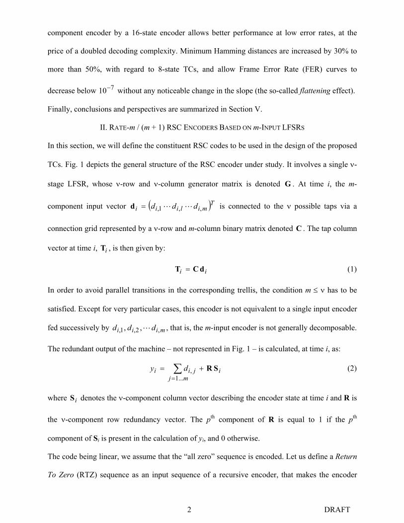
component encoder by a 16-state encoder allows better performance at low error rates, at the
price of a doubled decoding complexity. Minimum Hamming distances are increased by 30% to
more than 50%, with regard to 8-state TCs, and allow Frame Error Rate (FER) curves to
decrease below 710− without any noticeable change in the slope (the so-called flattening effect).
Finally, conclusions and perspectives are summarized in Section V.
II. RATE-m / (m + 1) RSC ENCODERS BASED ON m-INPUT LFSRS
In this section, we will define the constituent RSC codes to be used in the design of the proposed
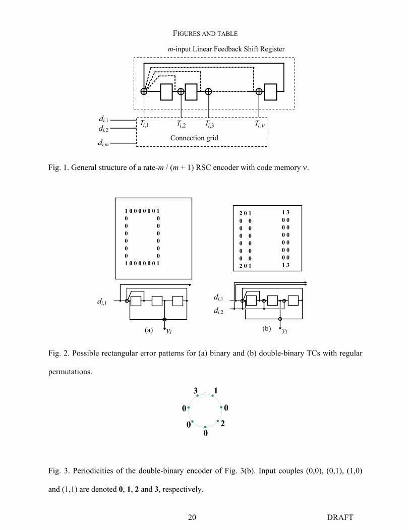
TCs. Fig. 1 depicts the general structure of the RSC encoder under study. It involves a single ν-
stage LFSR, whose ν-row and ν-column generator matrix is denoted G . At time i, the m-
component input vector ( )Tmiliii ddd ,,1, LL=d is connected to the ν possible taps via a
connection grid represented by a ν-row and m-column binary matrix denoted C . The tap column
vector at time i, iT , is then given by:
ii dCT = (1)
In order to avoid parallel transitions in the corresponding trellis, the condition m ≤ ν has to be
satisfied. Except for very particular cases, this encoder is not equivalent to a single input encoder
fed successively by miii ddd ,2,1, ,, L , that is, the m-input encoder is not generally decomposable.
The redundant output of the machine – not represented in Fig. 1 – is calculated, at time i, as:
imj
jii dy SR+= ∑= ...1
, (2)
where iS denotes the ν-component column vector describing the encoder state at time i and R is
the ν-component row redundancy vector. The pth component of R is equal to 1 if the pth
component of Si is present in the calculation of yi, and 0 otherwise.
The code being linear, we assume that the “all zero” sequence is encoded. Let us define a Return
To Zero (RTZ) sequence as an input sequence of a recursive encoder, that makes the encoder
3 DRAFT
leave state 0 and return to it again. Calculating the minimum free distance of such a code
involves finding the RTZ sequence path with minimum output Hamming weight.
Leaving the null path at time i implies that 0S ≡i and, at least one component of id is equal
to 1. In this case, (2) ensures that the Hamming weight of ),,,( ,2,1, imiii yddd L is at least 2
when leaving the reference path, since the inversion of one component of di implies the inversion
of yi.
Moreover, as
iii TSGS +=+1 (3)
it can be shown that iy may also be written as
1-1
...1, +
=+= ∑ i
mjjii dy SGR (4)
on the condition that
0CGR 1 ≡− (5)
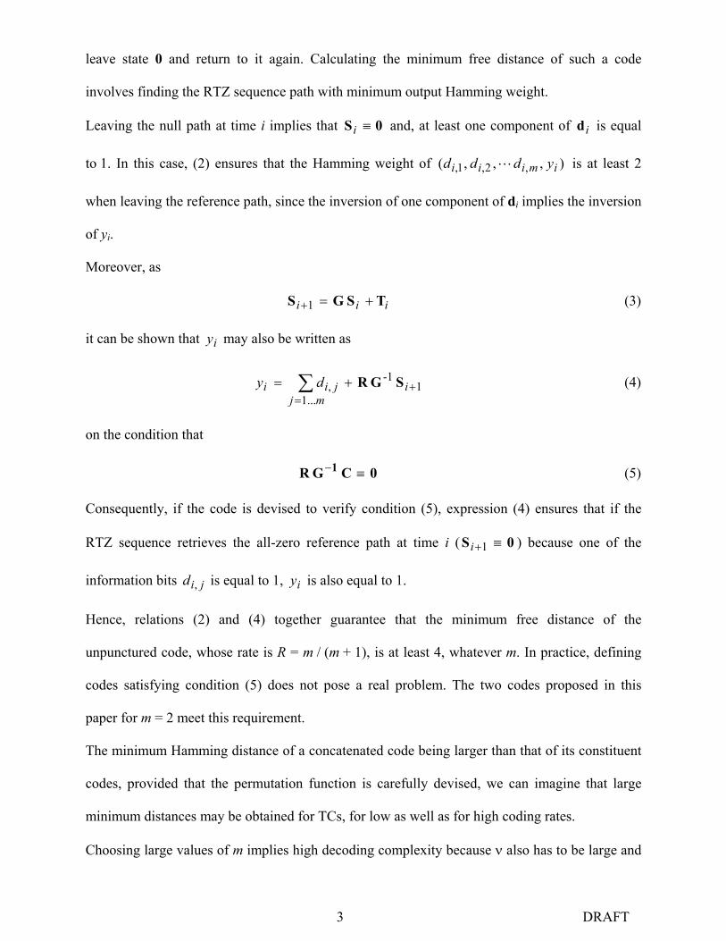
Consequently, if the code is devised to verify condition (5), expression (4) ensures that if the
RTZ sequence retrieves the all-zero reference path at time i ( 0S ≡+1i ) because one of the
information bits jid , is equal to 1, iy is also equal to 1.
Hence, relations (2) and (4) together guarantee that the minimum free distance of the
unpunctured code, whose rate is R = m / (m + 1), is at least 4, whatever m. In practice, defining
codes satisfying condition (5) does not pose a real problem. The two codes proposed in this
paper for m = 2 meet this requirement.
The minimum Hamming distance of a concatenated code being larger than that of its constituent
codes, provided that the permutation function is carefully devised, we can imagine that large
minimum distances may be obtained for TCs, for low as well as for high coding rates.
Choosing large values of m implies high decoding complexity because ν also has to be large and
4 DRAFT
2m paths have to be processed for each trellis node. For this reason, only low values of m can be
contemplated for practical applications for the time being (typically m = 2, possibly 3 or 4).
Up to now, we have only investigated the case m = 2 in order to construct practical coding and
decoding schemes in this new family of TCs. In the sequel, we call such m = 2 RSC or turbo
encoders double-binary. Double-binary RSC codes have a natural rate of 2/3. When higher
coding rates are required, a simple regular or quasi-regular puncturing pattern is applied.
The decoding solution calling for the application of the Maximum A Posteriori (MAP) algorithm
based on the dual code [8] can also be considered for large values of m, since it requires fewer
edge computations than the classical MAP algorithm for high coding rates. However, for
practical implementations, its application in the log-domain means the computation of transition
metrics with a far greater number of terms and the computation of the max* (Jacobian) function
requires great precision. Consequently, the relevance of this method for practical use is not so
obvious when the rate of the mother code is not close to 1.0.
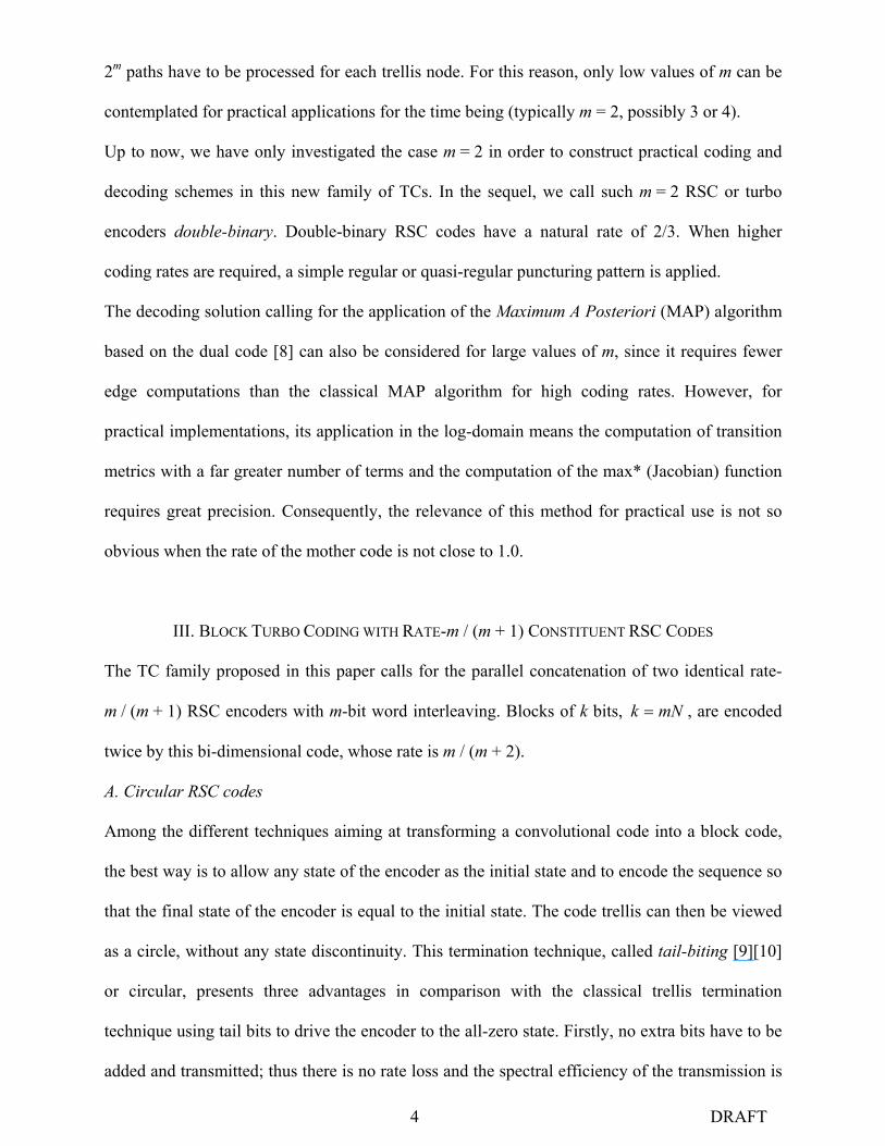
III. BLOCK TURBO CODING WITH RATE-m / (m + 1) CONSTITUENT RSC CODES
The TC family proposed in this paper calls for the parallel concatenation of two identical rate-
m / (m + 1) RSC encoders with m-bit word interleaving. Blocks of k bits, mNk = , are encoded
twice by this bi-dimensional code, whose rate is m / (m + 2).
A. Circular RSC codes
Among the different techniques aiming at transforming a convolutional code into a block code,
the best way is to allow any state of the encoder as the initial state and to encode the sequence so
that the final state of the encoder is equal to the initial state. The code trellis can then be viewed
as a circle, without any state discontinuity. This termination technique, called tail-biting [9][10]
or circular, presents three advantages in comparison with the classical trellis termination
technique using tail bits to drive the encoder to the all-zero state. Firstly, no extra bits have to be
added and transmitted; thus there is no rate loss and the spectral efficiency of the transmission is

5 DRAFT
not reduced. Next, when classical trellis termination is applied for TCs, a few codewords with
input Hamming weight 1 may appear at the end of the block (in both coding dimensions) and can
be the cause of a marked decrease in the minimum Hamming distance of the composite code.
With tail-biting RSC codes, only codewords with minimum input Hamming weight 2 are
transmitted. In other words, tail-biting encoding avoids any side effects. Moreover, in a tail-
biting or circular trellis, the past is also the future and vice versa. This means that a non-RTZ
sequence produces effects on the whole set of redundant symbols stemming from the encoder,
around the whole circle. Thanks to this very informative redundancy, there is very little
probability that the decoder will fail to recover the correct sequence.
In practice, the circular encoding of a data block consists of a two-step process [9]: at the first
step, the information sequence is encoded from state 0 and the final state is memorized. During
this first step, the outputs bits are ignored. The second step is the actual encoding, whose initial
state is a function of the final state previously memorized. The double encoding operation
represents the main drawback of this method, but in most cases it can be performed at a
frequency much higher than the data rate.
The iterative decoding of such codes involves repeated and continuous loops around the circular
trellis. The number of loops performed is equal to the required number of iterations. The state
probabilities or metrics, according to the chosen decoding algorithm, computed at the end of
each turn are used as initial values for the next turn. With this method, the initial – or final – state
depends on the encoded information block and is a priori unknown to the decoder at the
beginning of the first iteration. If all the states are assumed to be equiprobable at the beginning of
the decoding process, some side errors may be produced by the decoders at the beginning of the
first iteration. These errors are removed at the subsequent iterations since final state probabilities
or metrics computed at the end of the previous iteration are used as initial values.
6 DRAFT
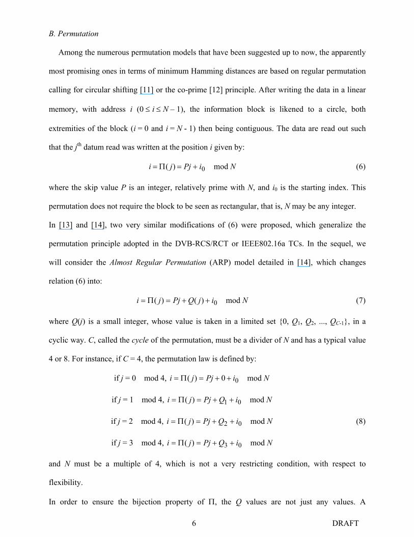
B. Permutation
Among the numerous permutation models that have been suggested up to now, the apparently
most promising ones in terms of minimum Hamming distances are based on regular permutation
calling for circular shifting [11] or the co-prime [12] principle. After writing the data in a linear
memory, with address i (0 ≤ i ≤ N – 1), the information block is likened to a circle, both
extremities of the block (i = 0 and i = N - 1) then being contiguous. The data are read out such
that the jth datum read was written at the position i given by:
NiPjji mod )( 0+=Π= (6)
where the skip value P is an integer, relatively prime with N, and i0 is the starting index. This
permutation does not require the block to be seen as rectangular, that is, N may be any integer.
In [13] and [14], two very similar modifications of (6) were proposed, which generalize the
permutation principle adopted in the DVB-RCS/RCT or IEEE802.16a TCs. In the sequel, we
will consider the Almost Regular Permutation (ARP) model detailed in [14], which changes
relation (6) into:
NijQPjji mod )()( 0++=Π= (7)
where Q(j) is a small integer, whose value is taken in a limited set {0, Q1, Q2, ..., QC-1}, in a
cyclic way. C, called the cycle of the permutation, must be a divider of N and has a typical value
4 or 8. For instance, if C = 4, the permutation law is defined by:
if j = 0 mod 4, NiPjji mod 0)( 0++=Π=
if j = 1 mod 4, NiQPjji mod )( 01 ++=Π=
if j = 2 mod 4, NiQPjji mod )( 02 ++=Π= (8)
if j = 3 mod 4, NiQPjji mod )( 03 ++=Π=
and N must be a multiple of 4, which is not a very restricting condition, with respect to
flexibility.
In order to ensure the bijection property of Π, the Q values are not just any values. A

7 DRAFT
straightforward way to satisfy the bijection condition is to choose all Qs as multiples of C.
The regular permutation law expressed by (6) is appropriate for error patterns which are simple
RTZ sequences for both encoders, that is, RTZ sequences which are not decomposable as a sum
of shorter RTZ sequences. A particular and important case of a simple RTZ sequence is the 2-
symbol RTZ sequence, which may dominate in the asymptotic characteristics of a TC (see [15]
for TCs with m = 1). A 2-symbol sequence is a sequence with two nonzero m-bit input symbols,
which may contain more than one nonzero bit. Let us define the total spatial distance (or total
span) S(j1,j2) as the sum of the two spatial distances, before and after permutation according to
(6), for a given pair of positions j1 and j2:
))(),(f(),f(),( 212121 jjjjjjS ΠΠ+= (9)
where
{ }vuNvuvu −−−= ,min),f( (10)
Finally, we denote Smin the minimum value of S(j1,j2), for all possible pairs j1 and j2:
{ }),(min 21
2,1min jjSS
jj=
(11)
It was demonstrated in [16] that the maximum possible value for Smin, when using regular
interleaving, is:
mkNSS 22)( maxmin ===
(12)
If any 2-symbol RTZ sequence for one component encoder is transformed by Π or Π-1 into
another 2-symbol RTZ sequence for the other encoder, the upper bound given by (12) is amply
sufficient to guarantee a large weight for parity bits, and thus a large minimum binary Hamming
distance. This is the same for any number of symbols, on the condition that both RTZ sequences
before and after permutation, are simple RTZ sequences.
On the other hand, ARP aims at combating error patterns which are not simple RTZ sequences
but are combinations of simple RTZ sequences for both encoders. Instilling some controlled
8 DRAFT
disorder, through the Q(j) values in (7), tends to break most of the composite RTZ sequences.
Meanwhile, because the Q(j) values are small integers, the good property of regular permutation
for simple RTZ sequences is not lost, and a total span close to N2 can be achieved. Reference
[14] describes a procedure to obtain appropriate values for P and for the set of Q parameters.
The algorithmic permutation model described by (7) is simple to implement, does not require
any ROM and the parameters can be changed on-the-fly for adaptive encoding and decoding.
Moreover, as explained in [14], massive parallelism, allowing several processors to run at the
same time without increasing the memory size, can be exploited.
In addition to the ARP principle and the advantages developed above, the rate-m / (m + 1)
component code adds one more degree of freedom in the design of permutations: intra-symbol
permutation, which enables some controlled disorder still to be added into the permutation
without altering its global quasi-regularity. Intra-symbol permutation means modifying the
contents of the m-bit symbols periodically, before the second encoding, in such a way that a large
proportion of composite RTZ sequences for both codes can no longer subsist. Let us develop this
idea in the simplest case of m = 2.
Fig. 2(a) depicts the minimal rectangular error pattern (weight w = 4), for a parallel
concatenation of two identical binary RSC encoders, involving a regular permutation (linewise
writing, columnwise reading). This error pattern is a combination of two weight-2 RTZ
sequences in each dimension, leading to a composite RTZ pattern with distance 16, for coding
rate 1/2. If the component encoder is replaced by a double-binary encoder, as illustrated in
Fig. 2(b), RTZ sequences and error patterns involve couples of bits, instead of binary values.
Fig. 2(b) gives two examples of rectangular error patterns, corresponding to the minimum
distance of 18, still for coding rate 1/2 (i.e. no puncturing). Data couples are numbered from 0 to
3, with the following notation: (0,0):0; (0,1):1; (1,0):2; (1,1):3. The periodicities of the double-
binary RSC encoder, depicting all the combinations of pairs of input couples, different from 0,
9 DRAFT
that are RTZ sequences, are summarized in the diagram of Fig. 3. For instance, if the encoder,
starting from state 0, is fed up with successive couples 1 and 3, it retrieves state 0. The same
behavior can be observed with sequences 201, 2003, 30002, 3000001 or 30000003 for example.
The change from binary to double-binary code, though leading to a slight improvement in the
minimum distance (18 instead of 16), is not sufficient to ensure very good performance at low
error rates. Let us suppose now that couples are inverted (1 becomes 2 and vice versa) once
every other time before second (vertical) encoding, as depicted in Fig 4. In this way, the error
patterns displayed in Fig. 2(b) no longer remain error patterns. For instance, 20000002 is still an
RTZ sequence for the second (vertical) encoder but 10000002 is no longer RTZ. Thus, many
error patterns, especially short patterns, are eliminated thanks to the disorder introduced inside
input symbols. The right-hand side of Fig 4 shows two examples of rectangle error patterns, that
remain possible error patterns after the periodic inversion. The resulting minimal distances, 24
and 26, are large enough for the transmission of short data blocks [17]. For longer data blocks (a
few thousand bits), combining this intra-symbol permutation with inter-symbol ARP, as
described above, can lead to even larger minimum distances, at least with respect to the
rectangular error patterns with low input weights we gave as examples.
C. Advantages of TCs with Rate-m / (m + 1) RSC Constituent Codes
Parallel concatenation of m-input binary RSC codes offers many advantages in comparison with
classical (1-input) binary TCs, which have already been partly commented on in [18].
1) Better convergence of the iterative process
This point was first observed in [19] and commented on in [20]. The better convergence of the
bi-dimensional iterative process is explained by a lower error density in each code dimension,
which leads to a decrease in the correlation effect between the component decoders.
Let us consider again relation (12) which gives the maximum total span achievable when using
regular or quasi-regular permutation. For a given coding rate R, the number of parity bits
involved all along the total span, and used by either one decoder or the other, is:

10 DRAFT
2
12
1)(paritymk
RRSm
RRSn
−
=
−
= (13)
Thus, replacing a classical binary (m = 1) with a double-binary (m = 2) TC multiplies this
number of parity bits by 2 , though dividing the total span by the same value. Because the
parity bits are not a matter of information exchange between the two decoders (they are just used
locally), the more numerous they are, with respect to a given possible error pattern (here the
weight-2 patterns), the less correlation effects between the component decoders.
Raising m beyond 2 still improves the turbo algorithm, regarding correlation, but the gains get
smaller and smaller as m increases.
2) Larger minimum distances
As explained above, the number of parity bits involved in simple 2-symbol RTZ sequences for
both encoders is increased when using rate-m/(m + 1) component codes. The number of parity
bits involved in any simple RTZ sequence, before and after permutation, is at least equal to
nparity(S), regardless of the number of nonzero symbols in the sequence. The binary Hamming
distances corresponding to all simple RTZ sequences are then high, and do not pose any problem
with respect to the minimum Hamming distance of the composite code. This comes from error
patterns made up of several (typically 2 or 3) short simple RTZ sequences on both dimensions of
the TC. Different techniques can be used to break most of these patterns, one of them (ARP)
having been presented in section III.B.
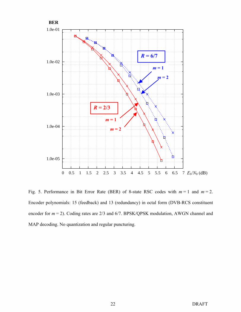
3) Less sensitivity to puncturing patterns
In order to obtain coding rates higher than m/(m + 1), from the RSC encoder of Fig. 1, fewer
redundant symbols have to be discarded, compared with an m = 1 binary encoder. Consequently,
the correcting ability of the constituent code is less degraded. In order to illustrate this assertion,
Fig. 5 compares the performance, in terms of Bit Error Rate (BER), of two 8-state RSC codes for
m = 1 and m = 2, with the same generator polynomials (15, 13), in octal notation. The 2-input
RSC code displays better performance than the 1-input code, for both simulated coding rates.

11 DRAFT
4) Higher throughput and reduced latency
The decoder of an m / (m + 1) convolutional code provides m bits at each decoding step. Thus,
once the data block is received, and for a given processing clock, the decoding throughput is
multiplied by m and the latency is divided by m, compared to the classical case (m = 1).
However, the critical path of the decoder being the ACS (Add-Compare-Select) unit, the decoder
with m > 1 has a lower maximum clock frequency than with m = 1. For instance, for m = 2, the
Compare-Select operation has to be done on 4 metrics instead of 2, thus with an increased
propagation delay. The use of specialized look-ahead operators and/or the introduction of
parallelism, in particular the multi-streaming method [21] makes it possible to increase
significantly the maximum frequency of the decoder, and even to reach that of the decoder with
m = 1.
5) Robustness of the decoder
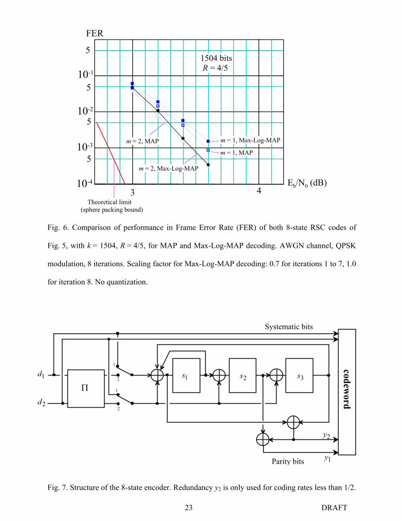
Fig. 6 represents the simulated performance, in Frame Error Rate (FER) as a function of Eb/N0,
of four coding/decoding schemes dealing with blocks of 1504 information bits and coding rate
4/5: binary and double-binary 8-state TCs mentioned in subsection III.C.2, both with the full
MAP decoding algorithm [22][23] and with the simplified Max-Log-MAP version [24]. In the
latter case, the extrinsic information is less reliable, especially at the beginning of the iterative
process. To compensate for this, a scaling factor, lower than 1.0, is applied to extrinsic
information [25]. The best observed performance was obtained when a scaling coefficient of 0.7
for all the iterations, except for the last one, was applied.
In Fig. 6, both codes have ARP internal permutation with optimized span. We can observe that
the double-binary TC performs better, at both low and high Eb/N0, and the steeper slope for the
double-binary TC indicates a larger minimum binary Hamming distance. These characteristics
were justified by points 1) and 2) of this section.
What is also noteworthy is the very slight difference between the decoding performance of the
double-binary TC, when using the MAP or the Max-Log-MAP algorithms. This property of non-

12 DRAFT
binary turbo decoding actually makes unnecessary the full MAP decoder (or the Max-Log-MAP
decoder with Jacobian logarithm correction [24]), which requires more operations than the Max-
Log-MAP decoder. Also, the latter does not need the knowledge of the noise variance on
Gaussian channels, which is a nice advantage. The rigorous explanation for this quasi-
equivalence of the MAP and the Max-Log-MAP algorithms, when decoding m-input TCs, has
still to be found.
IV. PERFORMANCE OF DOUBLE-BINARY TCS
This section describes two examples of double-binary TCs, with memory 3 and 4, whose
reasonable decoding complexity allows them to be implemented in actual hardware devices for
practical applications. Simulation results for transmissions over an AWGN channel with QPSK
modulation are provided.
A. Eight-State Double-Binary TC
The parameters of the component codes are:
=
010001101
G
=
111
001
C [ ]0111 =R [ ]0012 =R (14)
The diagram of the encoder is described in Fig. 7.Redundancy vector R2 is only used for coding
rates less than 1/2. For coding rates higher than 1/2, puncturing is performed on redundancy bits
in a regular periodical way, following patterns that are described in [5]. These patterns are
identical for both constituent encoders.
The permutation function )( ji Π= is performed on two levels, as explained in section III.B:
For 1,,0 −= Nj L
• Level 1: Inversion of 1,jd and 2,jd in the data couple, if 02mod =j .
• Level 2: this permutation level is described by a particular form of (8)
NjQjPi mod)1)(( ++×= , with

13 DRAFT
0)( =jQ if 04mod =j
12/)( PNjQ += if 14mod =j (15)
2)( PjQ = if 24mod =j
32/)( PNjQ += if 34mod =j
Value 0i = 1 is added to the incremental relation in order to comply with the odd-even rule [26].
The disorder is instilled in the permutation function, according to the ARP principle, in two
ways:
− A shift by N / 2 is added for odd values of j. This is done because the lowest sub-period of
the code generator is 1 (see Fig. 3). The role of this additional incrementation is thus to
spread to the full the possible errors associated with the shortest error patterns.
− 1P , 2P and 3P act as local additional pseudo-random fluctuations.
Notice that the permutation equations and parameters do not depend on the coding rate
considered. The parameters can be optimized to provide good behavior, on average, at low error
rates for all coding rates, but seeking parameters for a particular coding rate could lead to
slightly better performance.
B. Sixteen-State Double-Binary TC
The parameters of the best component code we have found are:
=
0100001000011100
G
=
1011
0001
C [ ]0111=R (16)
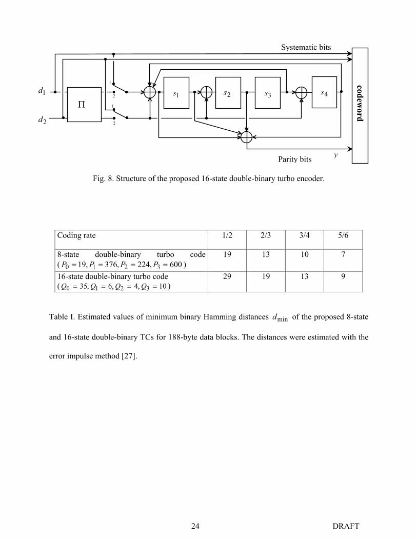
The diagram of the encoder is described in Fig. 8.
Puncturing is performed on redundancy in a periodical way with identical patterns for both
constituent encoders. It is usually regular, except when the puncturing period is a divisor of the
LFSR period. For example, for coding rate 3/4, the puncturing period is chosen equal to 6, with
puncturing pattern [101000].

14 DRAFT
For this code, the permutation parameters have been carefully chosen following the procedure
described in [14] in order to guarantee a large minimum Hamming distance, even for high rates.
The level 1 permutation is identical to the intra-permutation of the 8-state code. The level 2 –
inter-symbol – permutation is given by:
For 1,,0 −= Nj L
• NjQjPi mod)3)(( ++×= , with
0)( =jQ if 04mod =j
1)( QjQ = if 14mod =j (17)
204)( QQjQ += if 24mod =j
304)( QQjQ += if 34mod =j
The spirit in which this permutation was designed is the same as that already explained for the 8-
state TC. The only difference is that the lowest sub-period of the 16-state generator is 2, instead
of 1. That is why the additional shift (by 4Q0) is applied consecutively twice every four values of
j.
Table I compares the minimum binary Hamming distances of the proposed 8-state and 16-state
TCs, for 188-byte data blocks and 4 different coding rates. The distance values were estimated
with the so-called “Error Impulse Method”, a fast computational method described in [27], that
provides distance values with a precision of approximately 5 %. We can observe a significant
increase in the minimum distance when using 16-state component codes: the gain varies from
30% up to more than 50% depending on the case considered. With this code, we were also able
to define permutation parameters leading to minimum distances as large as 33 for 2/1=R , 22
for 3/2=R and 16 for 4/3=R for (10×188)-byte blocks.
From an implemention point of view, the complexity of the corresponding decoder is about twice
the complexity of the 8-state decoder.

15 DRAFT
C. Simulation results
We have simulated and compared these two codes for two block sizes and three coding rates for
transmissions over an AWGN channel with QPSK modulation. The simulation results take actual
implementation constraints into account. In particular, the decoder inputs are quantized for
hardware complexity considerations. In our experience, performance degradation due to input
quantization is not significant beyond 5 bits. The observed loss is less than 0.15 dB for 4-bit
quantization and about 0.4 dB for 3-bit quantization. When quantization is applied, clipping
extrinsic information at a threshold around twice the maximum range of the input samples does
not degrade the performance, while limiting the amount of required memory.
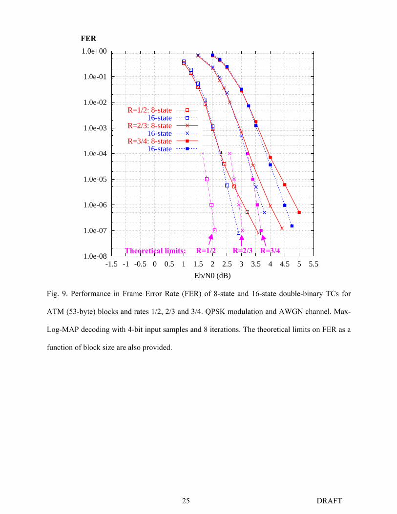
Solid line curves in Figs. 9 and 10 show the Frame Error Rate (FER) as a function of 0/ NEb
for the transmission of ATM (53-byte) and MPEG (188-byte) packets for 3 different values of
coding rate of the 8-state double-binary TC. The component decoders use the Max-Log-MAP
algorithm, with input samples quantized on 4 bits. Eight iterations were simulated and at least
100 erroneous frames were considered for each point indicated, except for the lowest points
where approximately 30 erroneous frames were simulated.
We can observe good average performance for this code whose decoding complexity is very
reasonable: for a hardware implementation, less than 20,000 logical gates are necessary to
implement one iteration of the decoding process when decoding is performed at the system clock
frequency, plus the memory required for extrinsic information and input data. Its performance
improves predictably with block size and coding rate in relation to the theoretical limit. The
reported limit points take the block size and the target FER into account. They are derived from
Shannon’s sphere packing bound, as described in [28]. At FER = 10-4, the simulated curves lie
within 0.6 to 0.8 dB from the limit, regardless of block size and coding rate. To improve the
performance of this code family at FER below 10-5, the more powerful 16-state component code
has to be selected so as to increase the overall minimum Hamming distance of the composite
16 DRAFT
code.
Dotted line curves in Figs. 9 and 10 show the 16-state TC performance for the same simulation
conditions as for the 8-state code. Similarly to this code, the permutation parameters are related
to the block size, not to the coding rate.
We can observe that the selected code does not lead to a convergence threshold shift of the
iterative decoding process in comparison with the previous 8-state code: for FERs above 10-4,
16-state and 8-state codes behave similarly. For lower error rates, thanks to the increase in
distance, there is no noticeable floor effect for the simulated SNR ranges, that is, down to a FER
of 10-7. Again, performance improves predictably with block size and coding rate in relation to
the theoretical limit. At FER = 10-6, the simulated curves lie within 0.7 to 1.0 dB from the limits,
regardless of block size and coding rate, even with the simplified Max-Log-MAP algorithm.
V. CONCLUSION
Searching for perfect channel coding presents two challenges: encoding in such a way that large
minimum distances can be reached and achieving decoding as close to the theoretical limit as
possible. In this paper, we have explained why m-input binary TCs combined with a two-level
permutation represent a better answer to these challenges than classical one-input binary TCs.
In practice, with m = 2, we have been able to design coding schemes with moderate decoding
complexity and whose performance approaches the theoretical limit by less than 1 dB at
FER = 10-6. The 8-state TC with m = 2 has already found practical applications through several
international standards.
Furthermore, the parallel concatenation of RSC circular codes leads to flexible composite codes,
easily adaptable to a large range of data block sizes and coding rates. Consequently, as m-input
binary codes are well suited for association with high order modulations, in particular M-QAM
and M-PSK modulations, TCs based on these constituent codes appear to be good candidates for
most future digital communication systems based on block transmission.

17 DRAFT
REFERENCES
[1] C. Berrou and A. Glavieux, “Near optimum error correcting coding and decoding: turbo
codes”, IEEE Trans. Commun., vol. 44, n° 10, pp. 1261-1271, Oct.1996.
[2] P. Robertson and T. Wörz, “Bandwidth-efficient turbo trellis-coded modulation using
punctured component codes,” IEEE J. Select. Areas Commun., vol. 16, pp. 206-218, Feb.
1998.
[3] S. Benedetto, D. Divsalar, G. Montorsi, and F. Pollara, “Parallel concatenated trellis coded
modulation,” in Proc. IEEE Int. Conf. Communications., vol. 2, Dallas, TX, June 1996, pp.
974-978.
[4] C. Fragouli and R. D. Wesel, “Turbo-encoder design for symbol-interleaved parallel
concatenated trellis-coded modulation,” IEEE Trans. Commun., vol. 49, no. 3, pp. 425-435,
March. 2001.
[5] DVB, “Interaction channel for satellite distribution systems,” ETSI EN 301 790, V1.2.2,
pp.21-24, Dec. 2000.
[6] DVB, “Interaction channel for digital terrestrial television,” ETSI EN 301 958, V1.1.1,
pp.28-30, Feb. 2002.
[7] IEEE Std 802.16a, “IEEE standard for local and metropolitan area networks,” 2003,
available at http://standards.ieee.org/getieee802/download/802.16a-2003.pdf.
[8] S. Riedel, “Symbol-by-symbol MAP decoding algorithm for high-rate convolutional codes
that use reciprocal dual codes,” IEEE J. Select. Areas Commun., vol. 16, no. 2, pp. 175-185,
Feb. 1998.
[9] C. Weiss, C. Bettstetter, S. Riedel and D. J. Costello, “Turbo decoding with tail-biting
trellises,” in Proc. IEEE Int’l Symposium on Signals, Systems, and Electronics, Pisa, Italy,
October 1998, pp. 343-348.
[10] R. Johannesson, K. Sh. Zigangirov, Fundamentals of convolutional coding, Chap. 4, New
York, IEEE Press, Series on digital & mobile communication, 1999.

18 DRAFT
[11] S. Dolinar and D. Divsalar, “Weight distribution of turbo codes using random and
nonrandom permutations,” TDA Progress Report 42-122, JPL, NASA, Aug. 1995.
[12] C. Heegard and S. B. Wicker, Turbo Coding, Chap. 3, Kluwer Academic Publishers, 1999.
[13] S. Crozier, J. Lodge, P. Guinand and A. Hunt, “Performance of turbo codes with relatively
prime and golden interleaving strategies,” in Proc. 6th Int'l Mobile Satellite Conf., Ottawa,
Canada, June 1999, pp. 268-275.
[14] C. Berrou, Y. Saouter, C. Douillard, S. Kerouédan and M. Jézéquel, “Designing good
permutations for turbo codes: towards a single model,” in Proc. IEEE Int. Conf.
Communications, Paris, France, June 2004.
[15] S. Benedetto and G. Montorsi, “Design of parallel concatenated convolutional codes,” IEEE
Trans. Commun., vol. 44, no. 5, pp. 591 – 600, May 1996.
[16] E. Boutillon and D. Gnaedig, “Maximum Spread of D-dimensional Multiple Turbo Codes,”
submitted to IEEE Trans. Commun., temporarily available at http://lester.univ-
ubs.fr:8080/~boutillon/articles/IEEE_COM_spread.pdf.
[17] C. Berrou, E. A. Maury and H. Gonzalez, “Which minimum Hamming distance do we
really need?,” in Proc. 3rd Symposium on Turbo Codes, Brest, France, Sept. 2003, pp. 141-
148.
[18] C. Berrou, M. Jézéquel, C. Douillard and S. Kerouédan, “The advantages of non-binary
turbo codes,” Proc. Information Theory Workshop, Cairns, Australia, Sept. 2001, pp. 61-63.
[19] C. Berrou, “Some clinical aspects of turbo codes,” Proc. Int. Symp. on Turbo Codes &
Related Topics, pp. 26-31, Brest, France, Sept. 1997.
[20] C. Berrou and M. Jézéquel, “Non binary convolutional codes for turbo coding,” Electronics
Letters, Vol. 35, N° 1, pp. 39-40, Jan. 1999.
[21] H. Lin and D. G. Messerschmitt, “Algorithms and architectures for concurrent Viterbi
decoding,” in Proc. IEEE Int. Conf. Communications, Boston, June 1989, pp. 836-840.
[22] L. Bahl, J. Cocke, F. Jelinek, and J. Raviv, “Optimal decoding of linear codes for
19 DRAFT
minimizing symbol error rate,” IEEE Trans. Inform. Theory, vol. 20, pp.284-287, March
1974.
[23] S. Benedetto, D. Divsalar, G. Montorsi, and F. Pollara, “A soft-input soft-output APP
module for iterative decoding of concatenated codes,” IEEE Commun. Lett., vol. 1, no. 1,
pp. 22–24, Jan. 1997.
[24] P. Robertson, P. Hoeher, and E. Villebrun, “Optimal and suboptimal maximum a posteriori
algorithms suitable for turbo decoding,” European Trans. Telecommun., vol. 8, pp.
119-125, Mar./Apr. 1997.
[25] J. Vogt and A. Finger, “Improving the max-log-MAP turbo decoder,” Electron. Lett., vol.
36, no. 23, pp. 1937-1939, Nov. 2000.
[26] A. S. Barbulescu, Iterative Decoding of Turbo Codes and Other Concatenated Codes, Ph.D.
thesis, University of South Australia, Feb. 1996
[27] C. Berrou, S. Vaton, M. Jézéquel and C. Douillard, “Computing the minimum distance of
linear codes by the error impulse method,” Proc. Globecom’02, Taipei, Taiwan, Nov. 2002.
[28] S. Dolinar, D. Divsalar and F. Pollara, “Code performance as a function of block size,”
TMO Progress Report 42-133, JPL, NASA, May 1998.
20 DRAFT
FIGURES AND TABLE
Fig. 1. General structure of a rate-m / (m + 1) RSC encoder with code memory ν.
Fig. 2. Possible rectangular error patterns for (a) binary and (b) double-binary TCs with regular
permutations.
1
2
3
0
00
0
Fig. 3. Periodicities of the double-binary encoder of Fig. 3(b). Input couples (0,0), (0,1), (1,0)
and (1,1) are denoted 0, 1, 2 and 3, respectively.
(a) (b)
di,1
di,2
yi
di,1
yi
1 0 0 0 0 0 0 1 0 0 0 0 0 0 0 0 0 0 0 0 1 0 0 0 0 0 0 1
2 0 10 00 00 00 00 00 02 0 1
1 3 0 0 0 0 0 0 0 0 0 0 0 0 1 3
m-input Linear Feedback Shift Register
di,1
di,m
di,2 T TT Ti,1 i,3 i,2 i,ν
Connection grid

21 DRAFT
Fig. 4. Couples in gray spaces are inverted before second (vertical) encoding. 1 becomes 2, 2
becomes 1; 0 and 3 remain unaltered. The three patterns on the left-hand side are no longer error
patterns. Those on the right-hand side remain possible error patterns, with distances 24 and 26
for coding rate 1/2.
2 0 10 00 00 00 00 00 02 0 1
1 3 0 0 0 0 0 0 0 0 0 0 0 0 1 3
3 0 0 0 0 0 0 30 00 00 02 0 0 0 0 0 0 2
3 0 0 0 0 0 0 3 0 0 0 0 0 0 0 0 0 0 0 0 3 0 0 0 0 0 0 3
1 3 0 0 0 0 0 0 0 0 0 0 0 0 0 0 0 0 0 0 0 0 0 0 0 0 0 0 1 3
22 DRAFT
Fig. 5. Performance in Bit Error Rate (BER) of 8-state RSC codes with m = 1 and m = 2.
Encoder polynomials: 15 (feedback) and 13 (redundancy) in octal form (DVB-RCS constituent
encoder for m = 2). Coding rates are 2/3 and 6/7. BPSK/QPSK modulation, AWGN channel and
MAP decoding. No quantization and regular puncturing.
1.0e-05
1.0e-04
1.0e-03
1.0e-02
1.0e-01
0 0.5 1 1.5 2 2.5 3 3.5 4 4.5 5 5.5 6 6.5 7 Eb/N0 (dB)
BER
m = 1
m = 2
R = 2/3
m = 1
m = 2
R = 6/7
23 DRAFT
FER
5
5
5
510-3
10-4
10-1
10-2
Eb/N0 (dB)3 4
m = 2, MAP m = 1, Max-Log-MAP
m = 2, Max-Log-MAP
m = 1, MAP
Theoretical limit(sphere packing bound)
1504 bits R = 4/5
Fig. 6. Comparison of performance in Frame Error Rate (FER) of both 8-state RSC codes of
Fig. 5, with k = 1504, R = 4/5, for MAP and Max-Log-MAP decoding. AWGN channel, QPSK
modulation, 8 iterations. Scaling factor for Max-Log-MAP decoding: 0.7 for iterations 1 to 7, 1.0
for iteration 8. No quantization.
1
2
2
1
codeword
Fig. 7. Structure of the 8-state encoder. Redundancy y2 is only used for coding rates less than 1/2.
1y
2y
2d
1d 1s 2s 3sΠ
Systematic bits
Parity bits
24 DRAFT
1
2
2
1
codeword
Fig. 8. Structure of the proposed 16-state double-binary turbo encoder.
Coding rate 1/2 2/3 3/4 5/6
8-state double-binary turbo code ( 600,224,376,19 3210 ==== PPPP )
19 13 10 7
16-state double-binary turbo code ( 10,4,6,35 3210 ==== QQQQ )
29 19 13 9
Table I. Estimated values of minimum binary Hamming distances mind of the proposed 8-state
and 16-state double-binary TCs for 188-byte data blocks. The distances were estimated with the
error impulse method [27].
2d
1d1s 2s 3s
Π
Systematic bits
Parity bits
4s
y
25 DRAFT
1.0e-08
1.0e-07
1.0e-06
1.0e-05
1.0e-04
1.0e-03
1.0e-02
1.0e-01
1.0e+00
-1.5 -1 -0.5 0 0.5 1 1.5 2 2.5 3 3.5 4 4.5 5 5.5
Eb/N0 (dB)
R=1/2: 8-state16-state
R=2/3: 8-state16-state
R=3/4: 8-state16-state
Fig. 9. Performance in Frame Error Rate (FER) of 8-state and 16-state double-binary TCs for
ATM (53-byte) blocks and rates 1/2, 2/3 and 3/4. QPSK modulation and AWGN channel. Max-
Log-MAP decoding with 4-bit input samples and 8 iterations. The theoretical limits on FER as a
function of block size are also provided.
FER
Theoretical limits: R=1/2 R=2/3 R=3/4

26 DRAFT
1.0e-08
1.0e-07
1.0e-06
1.0e-05
1.0e-04
1.0e-03
1.0e-02
1.0e-01
1.0e+00
-1.5 -1 -0.5 0 0.5 1 1.5 2 2.5 3 3.5 4 4.5
Eb/N0 (dB)
R=1/2: 8-state16-state
R=2/3: 8-state16-state
R=3/4: 8-state16-state
Fig. 10. Performance in Frame Error Rate (FER) of 8-state and 16-state double-binary TCs for
MPEG (188-byte) blocks and rates 1/2, 2/3 and 3/4. QPSK modulation and AWGN channel.
Max-Log-MAP decoding with 4-bit input samples and 8 iterations. The theoretical limits on FER
as a function of block size are also provided.
FER
Theoretical limits: R=1/2 R=2/3 R=3/4