technical specifications - philippine rural
TRANSCRIPT

1
TECHNICAL SPECIFICATIONS
Project ID Number: PRDP-1R-R04B-PAL-013-ABO-001-2019
Project Name: Construction of Banana Production, Processing and Marketing Facilities
Location: Aborlan, Palawan
2
SPL-1 – PROJECT BILLBOARD AND WARNING SIGNS SPL-1.1 Description This item shall consist of all materials stated on plan and below. SPL-1.2 Requirements
Warning Signs & Project Billboard
a.) Warning Signs – 2’ x 4’ x ½” marine plywood on 2” x 2” wooden frame with painting and lettering.
b.) Project Billboard – 4’ x 8’ x ½” thick marine plywood on 2” x 2” wooden frame
on 2” x 3” post with informative sheet. Project directory on tarpaulin sheet.
ITEM 800 (Refer to ITEM 100) ITEM 100 – CLEARING AND GRUBBING 100.1 Description This item shall consist of clearing, grubbing, removing and disposing all vegetable and debris as designated in the contract, except those objects that are designated to remain in place or are to be removed in consonance with other provisions of this Specification. The work shall also include the preservation from injury or defacement of all objects designated to remain. 1002. Construction Requirements 100.2.1 General The Engineer will establish the limits of the work and designate all trees, shrubs, plants and other things to remain. The Contractor shall preserve all objects designated to remain. Paint required for cut or scarred surface of trees or shrubs selected for retention shall be an approve asphaltum base paint prepared specially for tree surgery. 100.2.2 Clearing and Grubbing All surface objects and all trees, stumps, roots and other protruding obstructions, not designated to remain, shall be cleared and/or grubbed, including mowing as required, except as provided below. (1.) Removal of undisturbed stumps and roots and nonperishable solid objects with a minimum of 900 mm. (36 inches) below sub grade or slope of embankments will be required (2.) In areas outside of the grading limits of cut and embankments areas, stumps and nonperishable solid objects shall be cut off more than 150mm. (6 inches) above the ground line or low water level. (3.) In areas to be rounded at the top of the cut slopes, stumps shall be cut off flush with or below the surface of the final slope line. (4.) Grubbing of pits, channel changes and ditches will be required only to the depth necessitated by the proposed excavation within such areas.
3
Except in the areas to be excavated, stump holes and other holes from which obstructions are removed shall be backfilled with suitable material and compacted to the required density. If perishable materials are burned, it shall be burned under the constant care of competent watchmen at such times and in such a manner that the surrounding vegetation, other adjacent property, or anything designated to remain on the right of way will not be jeopardized. If permitted, burning shall be done in accordance with applicable laws, ordinance, and regulations. The contractor shall use high intensity burning procedures, (i.e. incinerators, high stacking or pit and ditch burning with forced air supplements) that produce intense burning with little or visible smoke emission during the burning process. At the conclusion of each burning session, the fire shall be completely extinguished so that no smoldering debris remains. In the event that the Contractor is directed by the Engineer not to start burning operations or to suspend such operations because of hazardous weather conditions, material to be burned which interferes with subsequent construction operation shall be moved by the Constructor to temporary location clear of construction operations and later, if directed by the Engineer, shall be placed on a designated spot and burned. Materials and debris which cannot be perishable burned material maybe disposed of by methods and at location approved by the Engineer, on or of the project. If disposal is by burying, the debris shall be placed in layers with the material so disturbed to avoid nesting each layer shall be covered or mixed with earth material by the land-fill method to fill all voids. The top layer of material buried shall be covered with at least 300mm. (12 inches) of earth or other approve material shall be graded, shaped and compacted to present a pleasing appearance. If the disposal location is off the project, the Contractor shall make all necessary arrangement with property owners in writing for obtaining suitable disposal locations which are outside the limits of view from the project. The cost involve shall be included in the bid price. A copy of such agreement shall be furnished to the Engineer. The disposal area shall be seeded, fertilize and mulched at the contractor’s expense. Woody material may be disposed of by chipping. The wood chips may be used for mulch, slope erosion control or maybe uniformly spread over selected areas as directed by the Engineer. Wood chips used as mulch for slope control shall have a maximum thickness 12mm. (1/2 inch) and not exceeding 3900 sq.mm. (6 square inches) on any individual surface area. Wood chips not designated for use under other sections shall be spread over the designated areas layers not to exceed 75 mm. (3 inches) loose thickness diseased trees shall be buried or disposed of as directed by the Engineer. All merchantable timber in the clearing area which has not been removed from the right of way prior to the beginning of construction shall become the propriety of the Contractor, unless otherwise provided. Low hanging braches and unsound or unsightly branches on trees or shrubs designated to remain shall be trimmed as directed. Branches of trees exceeding over the roadbed shall be trimmed to give a clear height of 6 m (20 feet) above the roadbed surface. All trimming shall be done by skilled workmen or accordance with good side surgery practices. Timber cut inside the area staked for clearing shall be felled within the areas to be cleared. 100.2.3 Individual Removal of Trees or Stumps Individual trees or stumps designated by the Engineer for removal and located in areas other than those establish for clearing or grubbing and road side clean up shall be removed and
4
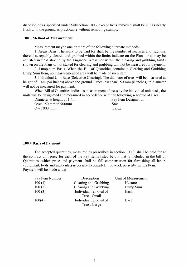
disposed of as specified under Subsection 100.2 except trees removed shall be cut as nearly flush with the ground as practicable without removing stumps. 100.3 Method of Measurement Measurement maybe one or more of the following alternate methods: 1. Areas Basis. The work to be paid for shall be the number of hectares and fractions thereof acceptably cleared and grubbed within the limits indicate on the Plans or as may be adjusted in field staking by the Engineer. Areas not within the clearing and grubbing limits shown on the Plans or not staked for clearing and grubbing will not be measured for payment. 2. Lump-sum Basis. When the Bill of Quantities contains a Clearing and Grubbing Lump Sum Item, no measurement of area will be made of such item. 3. Individual Unit Base (Selective Clearing). The diameter of trees will be measured at height of 1.4m (54 inches) above the ground. Trees less than 150 mm (6 inches) in diameter will not be measured for payment. When Bill of Quantities indicates measurement of trees by the individual unit basis, the units will be designated and measured in accordance with the following schedule of sizes:
Diameter at height of 1.4m Pay Item Designation Over 150 mm to 900mm Small Over 900 mm Large
100.4 Basis of Payment The accepted quantities, measured as prescribed in section 100.3, shall be paid for at the contract unit price for each of the Pay Items listed below that is included in the bill of Quantities, which price and payment shall be full compensation for furnishing all labor, equipment, tools and incidentals necessary to complete the work prescribe in this Item. Payment will be made under:
Pay Item Number Description Unit of Measurement 100 (1) Clearing and Grubbing Hectare 100 (2) Clearing and Grubbing Lump Sum 100 (3) Individual removal of Each Trees, Small 100(4) Individual removal of Each Trees, Large
5
ITEM 803 – STRUCTURAL EXCAVATION 803.1 Description This item shall consist of the necessary excavation for foundation of bridges, culverts, under drains and other structures not otherwise provided for in the specifications. Except as otherwise provided for pipe culverts, the backfilling of completed structures and the disposal of all excavated materials, shall be in accordance with these Specification and in reasonably close conformity with the Plans or as established by the Engineer. This Item shall include necessary diverting of live streams, bailing, pumping, draining, sheeting, bracing, and the necessary construction of cribs and cofferdams, and furnishing the materials therefore, and the subsequent removal of cribs and cofferdams and the placing of all necessary backfill. It also includes the furnishing and placing of approved foundation fill material to replace unsuitable material encountered below the foundation elevation of structures. No allowance will be made for classification of different types of material encountered. 803.2 Construction Requirements 803.2.1 Clearing and Grubbing Prior to starting excavation operations, I any area, all necessary clearing and grubbing in that area shall be performed in accordance with Item 100, Clearing & Grubbing. 803.2.2 Excavation
(1) General, all structures. The Contractor shall notify the Engineer sufficiently in advance of the beginning of any excavation so that cross-sectional elevations and measurements may be taken on the undisturbed ground. The natural ground adjacent to the structure shall not be disturbed without permission of the Engineer. Trenches or foundation pits for structures or structure footings shall be excavated to the lines and grades or elevations shown on the Plans or as staked by the Engineer. They shall be of sufficient size to permit the placing of structures or structure footings of the full width and length shown. The elevations of the bottoms of footings, as shown on the Plans, shall be considered as approximate only and the Engineer may order, in writing, such changes in dimensions or elevations of footings as may be deemed necessary, to secure a satisfactory foundation.
Boulders, logs, and other objectionable materials encountered in excavation shall be removed.
After each excavation is completed, the Contractor shall notify the Engineer to that effect and no footing, bedding material or pipe culvert shall be placed until the Engineer has approved the depth of excavation and the character of the foundation material.
(2) Structures other than pipe culverts. All rock or other hard foundation materials shall
be cleaned all loose materials, and cut to a firm surface, either level, stepped, or serrated as directed by the Engineer. All seams or crevices shall be cleaned and grouted. All loose and disintegrated rocks and thin strata shall be removed. When
6
the footing is to rest on material other than roc, excavation to final grade shall not be made until just before the footing is to be placed. When the foundation material is soft or mucky or otherwise unsuitable, as determined by the engineer, the Contractor shall remove the unsuitable material and backfill with approved granular material. This foundation fill shall be placed and compacted in 150 mm (6 inches) layers up to the foundation elevation. When foundation piles are used, the excavation of each pit shall be completed before the piles are driven and any placing of foundation fill shall be done after the piles are driven. After the driving is completed, all loose and displaced materials shall be removed, leaving a smooth, solid bed to receive the footing.
(3) Pipe Culverts. The width of the pipe trench shall be sufficient to permit satisfactory
jointing of the pipe and thorough tamping of the bedding material under and around the pipe.
Where rock, hardpan, or other unyielding material is encountered, it shall be removed below the foundation grade for a depth of at least 300 mm or 4 mm for each 100 mm of fill over the top of pipe, whichever is greater, but not to exceed three-quarters of the vertical inside diameter of the pipe. The width of the excavation shall be at least 300 mm (12 inches) greater than the horizontal outside diameter of the pipe. The excavation below grade shall be backfilled with selected fine compressible material, such as silty clay or loam, and lightly compacted in layers not over 150 mm (6 inches) in uncompacted depth to form a uniform but yielding foundation. Where a firm foundation is not encountered at the grade established, due to soft, spongy, or other unstable soil, such unstable soil under the pipe shall be removed to the depth directed by the Engineer and replaced with approved granular foundation fill material properly compacted to provide adequate support for the pipe, unless other special construction methods are called for on the Plans. The foundation surface shall provide a firm foundation of uniform density throughout the length of the culvert and, if directed by the Engineer, shall be cambered in the direction parallel to the pipe centerline. Where pipe culverts are to be placed in trenches excavated in embankments, the excavation of each trench shall be performed after the embankment has been constructed to a plane parallel to a proposed profile grade and to such height above the bottom of the pipe as shown on the Plans or directed by the Engineer.
803.2.3 Utilization of Excavated Materials All excavated materials, so far as suitable, shall be utilized as backfill or embankment. The surplus materials shall be disposed of in such manner as not to obstruct the stream or otherwise impair the efficiency or appearance of the structure. No excavated materials shall be deposited at any time so as to endanger the partly finished structure. 803.2.4 Cofferdams
7
Suitable and practically watertight cofferdams shall be used wherever water-bearing strata are encountered above the elevation of the bottom of the excavation. If requested, the Contractor shall submit drawings showing his proposed method of cofferdam construction, as directed by the Engineer. Cofferdams or cribs for foundation construction shall in general, be carried well below the bottoms of the footings and shall be well braced and as nearly watertight as practicable. In general, the interior dimensions of cofferdams shall be such as to give sufficient clearance for the construction of forms and the inspection of their exteriors, and to permit pumping outside of the forms. Cofferdams or cribs which are tilted or moved laterally during the process of sinking shall be righted or enlarged so as to provide the necessary clearance. When conditions are encountered which, as determined by the Engineer, render it impracticable to dewater the foundation before placing the footing, the Engineer may require the construction of a concrete foundation seal of such dimensions as he may consider necessary, and of such thickness as to resist any possible uplift. the concrete for such seal shall be placed as shown on the Plans or directed by the Engineer. The foundation shall then be dewatered and the footing placed. When weighted cribs are employed and the mass is utilized to overcome partially the hydrostatic pressure acting against the bottom of the foundation seal, special anchorage such as dowels or keys shall be provided to transfer the entire mass of the crib to the foundation seal. When a foundation seal is placed under water, the cofferdams shall be vented or ported at low water level as directed.
Cofferdams shall be constructed so as to protect green concrete against damage from sudden rising of the stream and to prevent damage to the foundation by erosion. No timber or bracing shall be left in cofferdams or cribs in such a way as to extend into substructure masonry, without written permission from the Engineer.
Any pumping that may be permitted from the interior of any foundation enclosure shall be done in such a manner to preclude the possibility of any portion of the concrete material being carried away. Any pumping required during the placing of concrete, or for a period of at least 24 hours thereafter, shall be done from a suitable sump located outside the concrete forms. Pumping dewater a sealed cofferdam shall not commerce until the seal has set sufficiently to withstand the hydrostatic pressure.
Unless otherwise provided, cofferdams or cribs, with all sheeting and bracing involved therewith, shall be removed by the Contractor after the completion of the substructure. Removal shall be effected in such manner as not to disturb or may finished masonry.
803.2.5 Preservation of Channel Unless otherwise permitted, no excavation shall be made outside of caissons, cribs, cofferdams, or sheet piling and the natural stream bed adjacent to structure shall not be disturbed without permission from the Engineer. If any excavation of dredging is made at the side of the structure before caissons, cribs, or cofferdams are sunk in place, the Contractor shall, after the foundation base is in place, backfill all such excavations to the original ground surface or stream bed with material satisfactory to the Engineer. 803.2.6 Backfill and Embankment for Structures Other Than Pipe Culverts Excavated areas around structures shall be backfilled with free draining granular material approved by the Engineer and placed in horizontal layers not over 150 mm (6 inches) in thickness, to the level of the original ground surface. Each layer shall be moistened or dried as required and thoroughly compacted with mechanical tampers.
8
In placing backfills or embankment, the material shall be placed simultaneously in so far as possible to approximately the same elevation on both sides of an abutment, pier, or wall. If conditions require placing backfill or embankment appreciably higher on one side than on the opposite side, the additional material on the higher side shall not be placed until the masonry has been in place for 14 days, or until tests made by the laboratory under the supervision of the Engineer establishes that the masonry has attained sufficient strength to withstand any pressure created by the methods used and materials placed without damage or strain beyond a safe factor. Backfill or embankment shall not be placed behind the walls of concrete culverts or abutments or rigid frame structures until the top slab is placed and cured. Backfill and embankment behind abutments held at the top by the superstructure, and behind the sidewalls of culverts, shall be carried up simultaneously behind opposite abutments or sidewalls. All embankments adjacent to structures shall be constructed in horizontal layers and compacted as prescribed in Subsection 104.3.3 except that mechanical tampers may be used for the required compaction. Special care shall be taken to prevent any wedging action against the structure and slopes bounding or within the areas to be filled shall be benched or serrated to prevent wedge action. The placing of embankment and the benching of slopes shall continue in such s manner that at all times there will be horizontal berm of thoroughly compacted materials for a distance at least equal to the height of the abutment or wall to the backfilled against except insofar as undisturbed material obtrudes upon the area. Broken rocks or coarse sand and gravel shall be provided for a drainage filter at weep holes as shown on the Plans. 803.2.7 Bedding, Backfill, and Embankment for Pipe Culverts Bedding, Backfill, and Embankment for Pipe Culverts shall be done in accordance with Item 500, Pipe Culverts and Storm Drains. 803.3 Method of Measurement 803.3.1 Structure Excavation The volume of excavation to be paid for will be the number of cubic meters measured in original position of material acceptably excavated in conformity with the Plans or as directed by the Engineers, but in no case, except as noted, will any of the following volumes be included in the measurement for payment:
(1) The volume outside the vertical planes 450 mm (18 inches) outside of and parallel to the neat lines of footings and the inside walls of the pipe and pipe-arch culverts at their widest horizontal dimensions.
(2) The volume of excavation for culverts and section s outside the vertical plane for culverts stipulated in (1) above.
(3) The volume outside the neat lines of underdrains as shown on the Plans and outside the limits of foundation fills as ordered by the Engineer.
(4) The volume included within the staked limits of the roadway excavation, contiguous channel changes, ditches, etc., for which payment is otherwise provided in the Specification.
(5) Volume of water or other liquid resulting from construction operations and which can be pumped or drained away.
(6) The volume of any excavation performed prior to the taking of elevations and measurements of the undisturbed ground.
9
(7) The volume of any material rehandled, except that where the Plans indicate or the Engineer directs the excavation after embankment has been placed and except that when installation of pipe culverts by the imperfect trench method specified in Item 500 is required, the volume of material re-excavated as directed will be included.
(8) The volume for excavation for footings ordered at a depth more than 1.5m (60 inches) below the lowest elevation for such footings shown on the original Contract Plans, unless the Bill of Quantities contains a pay item for excavation ordered below the elevations shown on the Plans for individual footings.
803.3.2 Bridge Excavation
The volume of excavation, designated on the Plans or in Special Provisions as “Bridge Excavation” will be measured as described below and will be kept separate for pay purposes from the excavation for all structures.
The volume of bridge excavation to be paid shall be the vertical 450 mm (18 inches) outside of and parallel to the neat lines of the footing. The vertical planes shall constitute the vertical faces of the volume for pay quantities regardless of excavation inside or outside of these planes. 803.3.3 Foundation Fill The volume of foundation fills to be paid for will be the number of cubic meters’ measures in final position of the special granular material actually provided and placed below the foundation elevation of structures as specified, complete in place and accepted. 803.3.4 Shoring, Cribbing, and Related Work Shoring, cribbing, and related work whenever included as a pay item in Bill of Quantities will be paid for at the lump sum bid price. This work shall include furnishing, constructing, maintaining, and removing any and all shoring, cribbing, cofferdams, caissons, bracing, sheeting water control, and other operations necessary for the acceptable completion of excavation included in the work of this Section, to a depth of 1.5m below the lowest elevation shown on the Plans for each separable foundation structure. 803.3.5 Basis of Payment The accepted quantities, measured as prescribed in Section 103.3, shall be paid for at the contract unit price for each of the particular pay items listed below that is included in the Bill of Quantities. The payment shall constitute full compensation for the removal and disposal of excavated materials including all labor, equipment, tools and incidentals necessary to complete the work prescribed in this Item, except as follows:
(1) Any excavation for footings ordered at a depth more than 1.5 m below the lowest elevation show on the original Contract Plans will be paid for as provided in Part K, measurement and Payment, unless a pay item for excavation ordered below Plan elevation appears in the Bill of Quantities.
(2) Concrete will be measured and paid for as provided under Item 405, Structural Concrete.
(3) Any roadway or borrow excavation required in excess of the quantity excavated for structures will be measured and paid for as provided under Item 102.
10
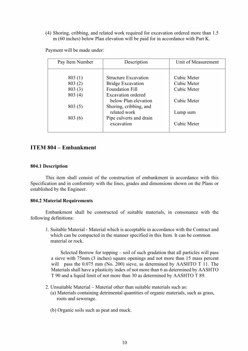
(4) Shoring, cribbing, and related work required for excavation ordered more than 1.5 m (60 inches) below Plan elevation will be paid for in accordance with Part K.
Payment will be made under:
Pay Item Number Description Unit of Measurement
803 (1) 803 (2) 803 (3) 803 (4)
803 (5)
803 (6)
Structure Excavation Bridge Excavation Foundation Fill Excavation ordered below Plan elevation Shoring, cribbing, and related work Pipe culverts and drain excavation
Cubic Meter Cubic Meter Cubic Meter Cubic Meter Lump sum Cubic Meter
ITEM 804 – Embankment 804.1 Description This item shall consist of the construction of embankment in accordance with this Specification and in conformity with the lines, grades and dimensions shown on the Plans or established by the Engineer. 804.2 Material Requirements Embankment shall be constructed of suitable materials, in consonance with the following definitions:
1. Suitable Material - Material which is acceptable in accordance with the Contract and which can be compacted in the manner specified in this Item. It can be common material or rock.
Selected Borrow for topping – soil of such gradation that all particles will pass a sieve with 75mm (3 inches) square openings and not more than 15 mass percent will pass the 0.075 mm (No. 200) sieve, as determined by AASHTO T 11. The Materials shall have a plasticity index of not more than 6 as determined by AASHTO T 90 and a liquid limit of not more than 30 as determined by AASHTO T 89.
2. Unsuitable Material – Material other than suitable materials such as: (a) Materials containing detrimental quantities of organic materials, such as grass, roots and sewerage. (b) Organic soils such as peat and muck.
11
(c) Soils with liquid limit exceeding 80 and/or plasticity index exceeding 55. (d) Soils with a natural water content exceeding 100%. (e) Soils with very low natural density, 800 kg/m³ or lower. (f) Soils that cannot be properly compacted as determined by the Engineer. 804.3 Construction Requirements 804.3.1 General Prior to construction of embankment, all necessary clearing and grubbing in that area shall have been performed in conformity with Item 100, Clearing and Grubbing. Embankment construction shall consist of constructing roadway embankments, including preparation of the areas upon which they are to be placed; the construction of dikes within or adjacent to the roadway; the placing and compacting of approved material within roadway areas where unsuitable material has been removed; and the placing and compacting of embankment material in holes, pits, and other depressions within the roadway area. Embankment and backfills shall contain no muck, peat, sod, roots or other deleterious matter. Rocks, broken concrete or other solid, bulky materials shall not be placed in embankment areas where piling is to be placed or driven. Where shown on the Plans or directed by the Engineer, the surface of the existing ground shall be compacted to a depth of 150 mm (6 inches) and to the specified requirements in this Item. Where provided on the Plans and Bill of Quantities the top portion of the roadbed in both cuts and embankments, as indicated, shall consist of selected borrow for topping from excavations. 804.3.2 Method of Construction Where there is evidence of discrepancies on the actual elevations and that shown on the Plans, a preconstruction survey referred to the datum plane used in the approved Plan shall be undertaken by the Contractor under the control of the Engineer to serve as basis for the computation of the actual volume of the embankment materials. When embankment is to be placed and compacted on hillsides, or when new embankment is to be compacted against existing embankments, or when embankment is built one-half width at a time, the existing slopes that are steeper than 3:1 when measured at right angles to the roadway shall be continuously benched over those areas as the work is brought up in layers. Benching will be subject to the Engineer’s approval and shall be of sufficient width permit operation of placement and compaction equipment. Each horizontal cut shall begin at the intersection of the original ground and the vertical sides of the previous cuts. Material thus excavated shall be placed and compacted along with the embankment material in accordance with the procedure described in the Section.
12
Unless shown otherwise on the Plans or special Provisions, where an embankment of less than 1.2 m (4 feet) below subgrade is to be made, all sod and vegetable matter shall be removed from the surface upon which the embankment is to be placed, and the cleared surfaced shall be completely broken up by plowing, scarifying, or steeping to a minimum depth of 150 mm except as provided in Subsection 102.2.2. This area shall then be compacted as provided in Subsection 104.3.3. Sod not required to be removed shall be thoroughly disc harrowed or scarified before construction of embankment. Wherever a compacted road surface containing granular materials lies within 900 mm (36 inches) of the subgrade, such old road surface shall be scarified to a depth of at least 150 mm (6 inches) whenever directed by the Engineer. This scarified material shall then be compacted as provided in Subsection 104.3.3. When shoulder excavation is specified, the roadway shoulders shall be excavated to the depth and width shown on the Plans. The shoulder material shall be removed without disturbing the adjacent existing base course material, and all excess excavated materials shall be disposed of as provided in Subsection 102.2.3. If necessary, the areas shall be compacted before being backfilled. Roadway embankment of earth material shall be placed in horizontal layers not exceeding 200 mm (8 inches), loose measurement, and shall be compacted as specified before the next layer is placed. However, thicker layer maybe placed if vibratory roller with high compactive effort is used provided that density requirement is attained and as approved by the Engineer. Trial section to this effect must be conducted and approved by the Engineer. Effective spreading equipment shall be used on each lift to obtain uniform thickness as determined in the trial section prior to compaction. As the compaction of each layer progresses, continuous leveling and manipulating will be required to assure uniform density. Water shall be added or removed, if necessary, in order to obtained the required density. Removal of water shall be accomplished through aeration by plowing, blading, discing, or other methods satisfactory to the Engineer. Where embankment is to be constructed across low swampy ground that will not support the mass of trucks or other hauling equipment, the lower part of the fill may be constructed by dumping successive loads in a uniform distributed layer of a thickness not greater than necessary to support the hauling equipment while placing subsequent layers. When excavated material contains more than 25 mass percent of rock larger than 150 mm in greatest diameter and cannot be placed in layers of the thickness prescribed without crushing, pulverizing or further breaking down the pieces resulting from excavation methods, such material be placed on the embankment in layers not exceeding in thickness the approximate average size of the larger rocks, but not greater than 600 mm (24 inches). Even though the thickness of layers is limited as provided above, the placing of individual rocks and boulders greater than 600 mm in diameter will be permitted provided that when placed, they do not exceed 1200 mm (48 inches) in height and provided they are carefully distributed, with the interstices filled with finer material to form a dense and compact mass. Each layer shall be leveled and smoothed with suitable leveling equipment and by distribution of spalls and finer fragments of earth lifts of material containing more than 25 mass percent of rock larger than 150mm in greatest dimensions shall not be constructed above an elevation 300mm (12 inches) below the finished subgrade. The balance of the embankment shall be composed of suitable material smoothed and placed in layers not exceeding 200 mm (8 inches) in loose thickness and compacted as specified for embankments.
13
Dumping and rolling areas shall be kept separate, and not lift shall be covered by another until compaction complies with the requirements of Subsection 104.3.3. Hauling and leveling equipment shall be routed and distributed over each layer of the fill in such a manner as to make use of compaction effort thereby and to minimize rutting and uneven compaction. 804.3.3 Compaction Compaction Trials Before commencing the formation of embankments, the Contractor shall submit in writing to the Engineer for approval his proposals for the compaction of each type of fill material to be used in the works. The proposals shall include the relationship between the types of compaction equipment, and the number of passes required and the method of adjusting moisture content. The Contractor shall carry out full scale compaction trials on areas not less than 10 m wide and 50 m long as required by the Engineer and using his proposed procedures or such amendments thereto as may be found necessary to satisfy the Engineer that all the specified requirements regarding compaction can be consistently achieved. Compaction trials with the main types of fill material to be used in the works shall be completed before work with the corresponding materials will be allowed to commence. Throughout the periods when compaction of earthwork is in progress, the Contractor shall adhere to the compaction procedures found from compaction trials for each type of material being compacted, each type of compaction equipment employed and each degree of compaction specified. Earth The Contractor shall compact the material placed in all embankment layers and the material scarified to the designated depth below sugrade in cut sections, until a uniform density of not less than 95 mass percent of the maximum dry density determined by AASHTO T 99 Method C, is attained, at a moisture content determined by Engineer to be suitable for such density. Acceptance of compaction may be based on adherence to an approved roller pattern developed as set forth in Item 106, Compaction Equipment and Density Control Strips. The Engineer shall during progress of the Work, make density tests of compacted material in accordance with AASHTO T 191, T 205, or other approved field density tests, including the use of properly calibrated nuclear testing devices. A correction for coarse particles may be made in accordance with AASHTO T 224. If, by such test, the Engineer determines that the specified density and moisture conditions have not been attained, the Contractor shall perform additional work as may be necessary to attain the specified conditions. At least one group of three in-situ density tests shall be carried out for each 500 m of each layer of compacted fill. Rock Density requirements will not apply to portions of embankments constructed of materials which cannot be tested in accordance with approved methods.
14
Embankment materials classified as rock shall be deposited, spread and leveled the full width of the fill with sufficient earth or other fine material so deposited to fill the interstices to produce a dense compact embankment. In addition, one of the rollers, vibrators, or compactors meeting the requirements set forth in Subsection 106.2.1, Compaction equipment, shall compact the embankment full width with a minimum of three complete passes for each layer of embankment. 804.3.4 Protection of Roadbed During Construction During the construction of the roadway, the roadbed shall be maintained in such condition that it will be well drained at all times. Side ditches or gutters emptying from cuts to embankments or otherwise shall be so constructed as to avoid damage to embankments by erosion. 804.3.5 Protection of Structure If embankment can be deposited on one side only of abutments, wing walls, piers or culvert headwalls, care shall be taken that the area immediately adjacent to the structure is not compacted to the extent that it will cause overturning of, or excessive pressure against the structure. When noted on the Plans, the fill adjacent to the end bend of a bridge shall not be placed higher than the bottom of the backfill of the bent until the superstructure is in place. When embankment is to be placed on both sides of a concrete wall or box type structure, operations shall be so conducted that the embankment is always at approximately the same elevation on both sides of the structure. 804.3.6 Rounding and Warping Slopes Rounding-Except in solid rock, the tops and bottoms of all slopes, including the slopes of drainage ditches, shall be rounded as indicated on the Plans. A layer of earth overlaying rock shall be rounded above the rock as done in earth slopes. Warping-adjustments in slopes shall be made to avoid injury in standing trees or marring of weathered rock, or to harmonize with existing landscape features, and the transition to such adjusted slopes shall be gradual. At intersections of cuts and fills, slopes shall be adjusted and warped to flow into each other or into the natural ground surfaces without noticeable break. 804.3.7 Finishing Roadbed and Slopes After the roadbed has been substantially completed, the full width shall be conditioned by removing any soft or other unstable material that will not compact properly or serve the intended purposes. The resulting areas and all other low sections, holes of depressions shall be brought to grade with suitable selected material. Scarifying, blading, dragging, rolling, or other methods of work shall be performed or use as necessary to provide a thoroughly compacted roadbed shaped to the grades and cross-sections shown on the Plans or as staked by the Engineer. All earth slopes shall be left with roughened surfaces but shall be reasonably uniform, without any noticeable break, and in reasonably close conformity with the Plans or other
15
surfaces indicated on the Plans or as staked by the Engineer, with no variations there from readily discernible as viewed from the road. 804.3.8 Serrated Slopes Cut slopes in rippable material (soft rock) having slope ratios between 0.75:1 and 2:1 shall be constructed so that the final slope line shall consist of a series of small horizontal steps. The step rise and tread dimensions shall be shown on the Plans. No scaling shall be performed on the stepped slopes except for removal of large rocks which will obviously be a safety hazard if they fall into the ditch line or roadway. 804.3.9 Earth Berms When called for in the Contract, permanent earth berms shall be constructed of well graded materials with no rocks having a diameter greater than 0.25 the height of the berm. When local material is not acceptable, acceptable material shall be imported, as directed by the Engineer. Compacted Berm Compacted berm construction shall consist of moistening or dying and placing material as necessary in locations shown on the drawings or as established by the Engineer. Material shall contain no frozen material, roots, sod, or other deleterious materials. Contractor shall take precaution to prevent material from escaping over the embankment slope. Shoulder surface beneath berm will be roughened to provide a bond between the berm and shoulder when completed. The Contractor shall compact the material placed until at least 90 mass percent of the maximum density is obtained by AASHTO T 99, Method C. The cross-section of the finished compacted berm shall reasonably conform to the typical cross-section as shown on the Plans. Uncompacted Berm Uncompacted berm construction shall consist of drying, if necessary and placing material in locations shown on the Plans or as established by the Engineer. Material shall contain no frozen material, roots, sod or other deleterious materials. Contractor shall take precautions to prevent material from escaping over the embankment slope. 804.4 Method of Measurement The quantity of to be paid for shall be the volume of material compacted in place, accepted by the Engineer and formed with material obtained from any source. Material from excavation per Item 102 which is used in embankment and accepted by the Engineer will be paid under Embankment and such payment will be deemed to include the costs incidental to the work. Material for Selected Borrow topping will be measured and paid for under the same conditions specified in the preceding paragraph.
16
804.5 Basis Payment The accepted quantities, measured as prescribed in Section 104.4, shall be paid for at the Contract unit price for each of the Pay Items listed below that is included in the Bill of Quantities. The payment shall continue full compensation for placing and compacting all materials including all labor, equipment, tools, and incidentals necessary to complete the work prescribed in this Item. Payment will be made under:
ITEM 900 - REINFORCED CONCRETE 900.1 Description This Item shall consist of furnishing, placing and finishing concrete in buildings and related structures, flood control and drainage, ports, and water supply structures in accordance with this specification and conforming to the lines, grades, and dimension shown on the plans. 900.2 Materials Requirements 900.2.1 Portland Cement
This shall conform to the requirement of ITEM 700, Volume II (BlueBook), Hydraulic cement. 900.2.2 Concrete Aggregates
Concrete aggregate shall conform to the requirements of subsection 311.2.2 and 311.2.3 under Item 311 of Volume II, (Blue Book) and ASTM C 33 for lightweight aggregates, except that aggregates failing to meet these specifications but which have been shown by special that or actual service to produce concrete of adequate strength and durability may be used under method (2) of determining the proportion of concrete, where authorized by the Engineer.
Except as permitted elsewhere in this section, the maximum size of the aggregate shall
be not larger than one-fifth (1/5) of the narrowest dimensions between sides of forms of the member for which the concrete is to be used nor larger than three-fourths of the minimum clear spacing between individual reinforcing bars or bundles of bars or pretensioning strands.
Pay Item number Description Unit Measurement
804 (1) 804 (2)
804 (3)
804 (4)
Embankment Selected, Borrow for Topping, Case 1 Selected, Borrow for Topping, Case 2 Earth Berm
Cubic Meter Cubic Meter Cubic Meter Meter
17
900.2.2.1 Aggregate Tests
Samples of the fine and coarse aggregates to be used shall be selected by the Engineer for tests at least 30 days before the actual concreting operations are to begin. It shall be the responsibility of the contractor to designate the source or sources of aggregate to give the Engineer sufficient time to obtain the necessary samples and submit them for testing.
No aggregate shall be used until official advice has been received that it has satisfactorily passed all test, at which time written authority shall be given 'for its use.
900.2.3 Water
Water used in mixing concrete shall conform to the requirement of subsection 311.2.4 under Item 311, Part E, of Volume II, (BlueBook).
900.2.4 Metal Reinforcement Reinforcing steel bars shall conform to the requirements of the following Specifications:
Deformed & Plain Billet Steel Bars for concrete Reinforcement (ASTM A 615) Bars for concrete Reinforcement AASHTO M 31 Deformed Rail - Steel and Plain Bars for Concrete Reinforcement ASTM A 616 Deformed A x b - Steel and Plain Bars for Concrete Reinforcement ASTM A 617
If reinforcing bars are to be welded, these ASTM specifications shall be supplemented
by requirements assuring satisfactory weldability.
Bar and rod mats for concrete reinforcement ASTM A 187
Cold-Drawn Steel Wire for (ASTM A 82)
concrete reinforcement AASHTO M 32
Welded steel wire fabric (ASTM A 185) for concrete reinforcement AASHTO M55 except that the weld shear strength requirement of those specification shall be extended to include a wire size differential up to and including six gages.
Wire and Strands for prestressed ASTM A 416 concrete ASTM A 421 Used in making strands for post-tensioning shall be cold- drawn and either stress-relieved in the case of uncoated strands, or hotdip galvanized in the case of galvanized strands.
High strength alloy steel bar for post- tensioning shall be proofstressed to 90 % of the granted tensile strength. After proofstressing, the bars shall conform to the following minimum properties:
18
Tensile strength fs' 1000 MPa Yield strength (0.2 offset) 0.90 fs' Elongation at rupture in
20 diameters 4 percent Reduction of area at rupture 25 percent Structural steel ASTM A 36 Steel Pipe for concrete-filled pipe columns ASTM A 53 Cast-Iron Pipe for composite ASTM A 377 columns
900.2.5 Admixtures
Air-entraining admixtures, if used, shall conform to ASTM C 260. Water-reducing admixtures, retarding ad- mixtures, water-reducing and retarding
admixtures and water reducing and accelerating admixtures, if used, shall conform to the requirements of ASTM C 494. 900.2.6 Storage of Materials
Cement and aggregates shall be stored in such a manner as to prevent their deterioration or the intrusion of foreign matter. Cement shall be stored, immediately upon arrival on the site of the work, in substantial, waterproof bodegas, with a floor raised from the ground sufficiently high to be free from dampness. Aggregates shall be stored in such a manner as to avoid the inclusion of foreign materials. 900.3 Construction Requirements
Notations: The notations used in these regulations are defined as follows:
f'c = compressive strength of concrete
Fsp = ratio of splitting tensile strength to square root of compressive strength. 900.3.1 Concrete Quality
All plans submitted for approval or used for any project shall clearly show the specified strength, fc', of concrete of the specified age for which each part of the structure was designed.
Concrete that will be exposed to sulfate containing or other chemically aggressive solutions shall be proportioned in accordance with "Recommended Practice for Selecting Proportions for Concrete (ACI 613)" and Recommended Practice for Selecting Proportions for Structural Lightweight Concrete (ACI 613A)." 900.3.2 Methods of Determining the Proportions of Concrete
The determination of the proportions of cement, aggregate, and water to attain the required strengths shall be made by one of the following methods, but lower water-cement ratios may be required for conformance__ with the quality of concrete.
19
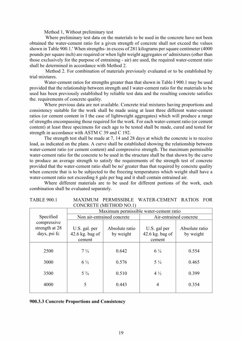
Method 1, Without preliminary test Where preliminary test data on the materials to be used in the concrete have not been
obtained the water-cement ratio for a given strength of concrete shall not exceed the values shown in Table 900.1.' When strengths- in excess of 281 kilograms per square centimeter (4000 pounds per square inch) are required or when light weight aggregates or' admixtures (other than those exclusively for the purpose of entraining - air) are used, the required water-cement ratio shall be determined in accordance with Method 2.
Method 2. For combination of materials previously evaluated or to be established by trial mixtures.
Water-cement ratios for strengths greater than that shown in Table I 900.1 may be used provided that the relationship between strength and I water-cement ratio for the materials to be used has been previously established by reliable test data and the resulting concrete satisfies the. requirements of concrete quality.
Where previous data are not available. Concrete trial mixtures having proportions and consistency suitable for the work shall be made using at least three different water-cement ratios (or cement content in I the case of lightweight aggregates) which will produce a range of strengths encompassing those required for the work. For each water-cement ratio (or cement content) at least three specimens for each age to be tested shall be made, cured and tested for strength in accordance with ASTM C 39 and C 192.
The strength test shall be made at 7, 14 and 28 days at which the concrete is to receive load, as indicated on the plans. A curve shall be established showing the relationship between water-cement ratio (or cement content) and compressive strength. The maximum permissible water-cement ratio for the concrete to be used in the structure shall be that shown by the curve to produce an average strength to satisfy the requirements of the strength test of concrete provided that the water-cement ratio shall be no' greater than that required by concrete quality when concrete that is to be subjected to the freezing temperatures which weight shall have a water-cement ratio not exceeding 6 gals per bag and it shall contain entrained air.
Where different materials are to be used for different portions of the work, each combination shall be evaluated separately. TABLE 900.1 MAXIMUM PERMISSIBLE WATER-CEMENT RATIOS FOR
CONCRETE (METHOD NO.1)
Specified compressive strength at 28 days, psi fc
Maximum permissible water-cement ratio Non air-entrained concrete Air-entrained concrete
U.S. gal. per
42.6 kg. bag of cement
Absolute ratio
by weight
U.S. gal per
42.6 kg. bag of cement
Absolute ratio
by weight
2500
3000
3500
4000
7 ¼
6 ½
5 ¾
5
0.642
0.576
0.510
0.443
6 ¼
5 ¼
4 ½
4
0.554
0.465
0.399
0.354
900.3.3 Concrete Proportions and Consistency
20
The proportions of aggregate to cement for any concrete shall be such as to produce a mixture which will work readily into the corners and angles of the form and around reinforcement with the method of placing employed on the work, but without permitting the materials to segregate or excess free water to collect on the surface. The methods of measuring concrete materials shall be such that the proportions can be accurately controlled and easily checked at any time during the work. 900.3.4 Sampling and Testing of Structural Concrete
As work progress, at least one (1) set of sample consisting of three (3) concrete cylinder test specimens, 150 x 300 mm shall be taken from each class of concrete placed each day, and each set to represent not more than 75 cu m of concrete. 900.3.5 Consistency
Concrete shall have a consistency such that it will be workable in the required position. It shall be such a consistency that it will flow around reinforcing steel but individual particles of the coarse aggregate when isolated shall show a coating or mortar containing its proportionate amount of sand. The consistency of concrete shall be gauged by the ability of the equipment to properly placed it and not by the difficulty of mixing water shall be determined by the Engineer and shall not be varied without his consent. Concrete as dry as it is practical to place with the equipment specified shall be used. 900.3.6 Strength Test of Concrete
When strength is a basis for acceptance, each class of concrete shall be represented by at least five test (10 specimens). Two specimens shall be made for each test at a given age, and not less than one test shall be made for each 150 cu yd. of structural concrete, but there shall be at least one test for each days concreting. The Building Official may require a reasonable number of additional tests during the progress of the work. Samples from which compression test specimens are molded shall be secured in accordance with ASTM C 172. Specimens made to check the adequacy of the proportions for strength of concrete or as a basis for acceptance of concrete shall be made and laboratory-cured in accordance with ASTM C 31. Additional test specimens cured entirely under field conditions may be required by the Building Official to check the adequacy of curing and protection of the concrete. Strength tests shall be made in accordance with ASTM C 39.
The age for strength tests shall be 28 days of, where specified, the earlier age at which the concrete is to receive its full load or maximum j stress. Additional test may be made at earlier ages to obtain advance information on the adequacy of strength development where age-strength relationships have been established for the materials and proportions used. To conform to the requirements of this Item:
1. For structures designed in accordance with the working stress design method of this chapter, the average of any five consecutive strength tests of the laboratory-cured specimens representing each class of concrete shall be equal on or greater than the specified strength, fc', and not more than 20 percent of the strength test shall have values less than that specified.
2. For structures designed in accordance with the ultimate strength design method of this chapter, and for prestressed structures the average of any three consecutive strength test of
21
the laboratory, cured specimens representing each class of concrete shall be equal to or greater than the specified strength, fc' and not more than 10 percent of the strength tests shall have values less than the specified strength.
When it appears that the laboratory-cured specimens will fail to conform to the requirements for strength, the Engineer shall have the right to order changes in the concrete sufficient to increase the strength to meet these requirements. The strengths of the specimens cured on the job are intended to indicate the adequacy of protection and curing of the concrete and may be used to determine when the forms may be stripped, shoring removed, or the structure placed in service. When, in the opinion of the Building Official, the strengths of the job-cured specimens, the contractor may be required to improve the procedures for protecting and curing the concrete, or when test of field-cured cylinders indicate deficiencies in protection and curing, the Engineer may require test in accordance with ASTM Specification C 42 or order load tests as outlined in the load tests of structures for that portion of the structure where the questionable concrete has been placed. 900.3.7 Splitting Tensile Test of Concrete
To determine the splitting ratio, Fsp, for a particular aggregate, test of concrete shall be made as follows:
1. Twenty-four (24) 15 cm. dia. by 30 cm long (6 in. dia. by 12 in. long) cylinders shall be made in accordance with ASTM C 192, twelve at a compressive strength level of approximately 210 kilograms per square centimeter (3000 psi) and twelve at approximately 280 kilograms per square centimeter (4000 psi) or 350 kilograms per square centimeter (5000 psi). After 7 days moist curing followed by 21 days drying at 23C (73F) and 50 percent relative humidity, eight of the test cylinders at each of the two strength levels shall be tested for splitting strength and four for compressive strength.
2. The splitting tensile strength shall be determining in accordance with ASTM C 496, and compressive strength in accordance with ASTM C 39.
The ratio, Fsp, of splitting tensile strength to the square root of compressive strength shall be obtained by using the average of all 16 splitting tensile test and all 8 compressive tests.
Minimum Strength, Concrete other than fill, shall have a minimum compressive strength at 28 days of 140 kilograms per square centimeter (2000 psi). 900.3.8 Batching
Batching shall conform to the requirements of Item 405, Structural Concrete. 900.3.9 Mixing and Delivery
Mixing and delivery shall conform to the requirements of Item 405, Structural Concrete. 900.4 Concrete Surface Finishing: General
This shall be in accordance with Item 407, Concrete Structures. 900.5 Curing Concrete (See subsection 407) 900.6 Acceptance of Concrete
22
The strength of concrete shall be deemed acceptable if the average of 3 consecutive strength test results is equal to or exceed the specified strength and no individual test result falls below the specified strength by more than 15 %.
Concrete deemed to be not acceptable using the above criteria may be rejected unless contractor can provide evidence, by means of core tests, that the quality of concrete represented by the failed test result is acceptable in place. Three (3) cores shall be obtained from the affected area and cured and tested in accordance with AASHTO T24. Concrete in the area represented by the cores will be deemed acceptable if the average of cores is equal to or at least 85 % and no sample core is less than 75 % of the specified strength otherwise it shall be rejected. 900.7 Method of Measurement
The quantity of concrete to be paid shall be the quantity shown in the Bid Schedule, unless changes in design are made in which case the quantity shown in the Bid Schedule will be adjusted by the amount of the change for the purpose of payment. No deduction will be made for the volume occupied by the pipe less than 101 mm (4") in diameter nor for reinforcing steel. anchors, weepholes or expansion materials. 900.8 Basis of Payment
The accepted quantities of structural concrete completed in place will be paid for at the contract unit price for cubic meter as indicated on the Bid Schedule.
Pay Item and Description Unit of measurement Structural Concrete Cubic Meter
Such prices and payment shall be full compensation for furnishing all materials,
including metal water stops, joints, joint fillers, weep holes, and rock backing and timber bumpers; for all form and false work; for mixing, placing, furnishing, and curing the concrete; and for all labor, materials, equipment, tools and incidentals necessary to complete the item, except that reinforcing steel shall be paid for at the contract unit price per kilogram for reinforcing steel metal pipes and drains, metal conduits and ducts, and metal expansion angles shall be paid for as structural steel that when the proposal does not include an item for structural steel these miscellaneous metal parts shall be paid for as reinforcing steel. ITEM 902 - REINFORCING STEEL 902.1 Description This item shall consist of furnishing, bending, fabrication and placing of steel reinforcement of the type, size, shape and grade required in accordance with this specification and conformity with the requirements shown on the Plans or as directed by the Engineer. 902.2 Material Requirements Reinforcing steel shall meet the requirements of item 902, Reinforcing Steel and Wire Rope. 902.3 Construction Requirements
23
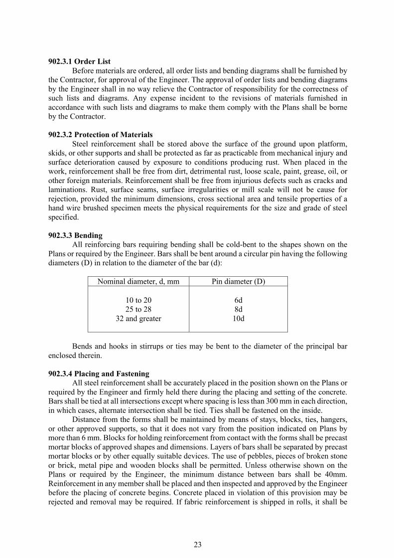
902.3.1 Order List Before materials are ordered, all order lists and bending diagrams shall be furnished by the Contractor, for approval of the Engineer. The approval of order lists and bending diagrams by the Engineer shall in no way relieve the Contractor of responsibility for the correctness of such lists and diagrams. Any expense incident to the revisions of materials furnished in accordance with such lists and diagrams to make them comply with the Plans shall be borne by the Contractor. 902.3.2 Protection of Materials Steel reinforcement shall be stored above the surface of the ground upon platform, skids, or other supports and shall be protected as far as practicable from mechanical injury and surface deterioration caused by exposure to conditions producing rust. When placed in the work, reinforcement shall be free from dirt, detrimental rust, loose scale, paint, grease, oil, or other foreign materials. Reinforcement shall be free from injurious defects such as cracks and laminations. Rust, surface seams, surface irregularities or mill scale will not be cause for rejection, provided the minimum dimensions, cross sectional area and tensile properties of a hand wire brushed specimen meets the physical requirements for the size and grade of steel specified. 902.3.3 Bending All reinforcing bars requiring bending shall be cold-bent to the shapes shown on the Plans or required by the Engineer. Bars shall be bent around a circular pin having the following diameters (D) in relation to the diameter of the bar (d):
Nominal diameter, d, mm Pin diameter (D)
10 to 20 25 to 28
32 and greater
6d 8d 10d
Bends and hooks in stirrups or ties may be bent to the diameter of the principal bar enclosed therein. 902.3.4 Placing and Fastening All steel reinforcement shall be accurately placed in the position shown on the Plans or required by the Engineer and firmly held there during the placing and setting of the concrete. Bars shall be tied at all intersections except where spacing is less than 300 mm in each direction, in which cases, alternate intersection shall be tied. Ties shall be fastened on the inside. Distance from the forms shall be maintained by means of stays, blocks, ties, hangers, or other approved supports, so that it does not vary from the position indicated on Plans by more than 6 mm. Blocks for holding reinforcement from contact with the forms shall be precast mortar blocks of approved shapes and dimensions. Layers of bars shall be separated by precast mortar blocks or by other equally suitable devices. The use of pebbles, pieces of broken stone or brick, metal pipe and wooden blocks shall be permitted. Unless otherwise shown on the Plans or required by the Engineer, the minimum distance between bars shall be 40mm. Reinforcement in any member shall be placed and then inspected and approved by the Engineer before the placing of concrete begins. Concrete placed in violation of this provision may be rejected and removal may be required. If fabric reinforcement is shipped in rolls, it shall be
24
straightened before being placed. Bundled bars shall be tied together at not more than 1.8m intervals. 902.3.5 Splicing All reinforcement shall be furnished in the full lengths indicated on the Plans. Splicing of bars, except where shown on the Plans, will not be permitted without the written approval of the Engineer. Splices shall be staggered as far as possible and with a minimum separation of not less than 40 bar diameters. Not more than one-third of the bars may be spliced in the same cross-section, except where shown on the Plans.
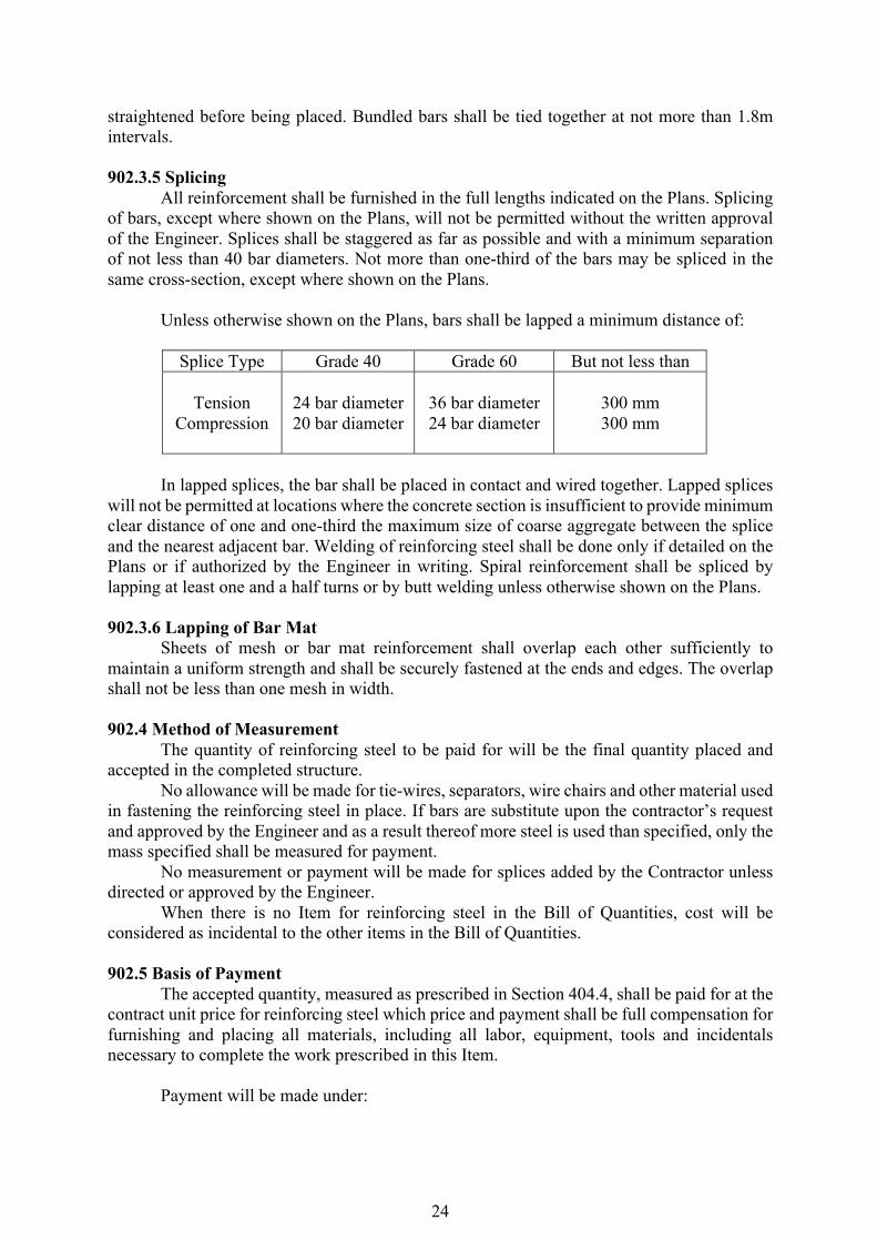
Unless otherwise shown on the Plans, bars shall be lapped a minimum distance of:
Splice Type Grade 40 Grade 60 But not less than
Tension Compression
24 bar diameter 20 bar diameter
36 bar diameter 24 bar diameter
300 mm 300 mm
In lapped splices, the bar shall be placed in contact and wired together. Lapped splices will not be permitted at locations where the concrete section is insufficient to provide minimum clear distance of one and one-third the maximum size of coarse aggregate between the splice and the nearest adjacent bar. Welding of reinforcing steel shall be done only if detailed on the Plans or if authorized by the Engineer in writing. Spiral reinforcement shall be spliced by lapping at least one and a half turns or by butt welding unless otherwise shown on the Plans. 902.3.6 Lapping of Bar Mat Sheets of mesh or bar mat reinforcement shall overlap each other sufficiently to maintain a uniform strength and shall be securely fastened at the ends and edges. The overlap shall not be less than one mesh in width. 902.4 Method of Measurement The quantity of reinforcing steel to be paid for will be the final quantity placed and accepted in the completed structure. No allowance will be made for tie-wires, separators, wire chairs and other material used in fastening the reinforcing steel in place. If bars are substitute upon the contractor’s request and approved by the Engineer and as a result thereof more steel is used than specified, only the mass specified shall be measured for payment. No measurement or payment will be made for splices added by the Contractor unless directed or approved by the Engineer. When there is no Item for reinforcing steel in the Bill of Quantities, cost will be considered as incidental to the other items in the Bill of Quantities. 902.5 Basis of Payment The accepted quantity, measured as prescribed in Section 404.4, shall be paid for at the contract unit price for reinforcing steel which price and payment shall be full compensation for furnishing and placing all materials, including all labor, equipment, tools and incidentals necessary to complete the work prescribed in this Item. Payment will be made under:
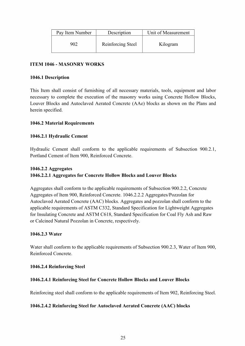
25
Pay Item Number Description Unit of Measurement
902
Reinforcing Steel
Kilogram
ITEM 1046 - MASONRY WORKS 1046.1 Description This Item shall consist of furnishing of all necessary materials, tools, equipment and labor necessary to complete the execution of the masonry works using Concrete Hollow Blocks, Louver Blocks and Autoclaved Aerated Concrete (AAe) blocks as shown on the Plans and herein specified. 1046.2 Material Requirements 1046.2.1 Hydraulic Cement Hydraulic Cement shall conform to the applicable requirements of Subsection 900.2.1, Portland Cement of Item 900, Reinforced Concrete. 1046.2.2 Aggregates 1046.2.2.1 Aggregates for Concrete Hollow Blocks and Louver Blocks Aggregates shall conform to the applicable requirements of Subsection 900.2.2, Concrete Aggregates of Item 900, Reinforced Concrete. 1046.2.2.2 Aggregates/Pozzolan for Autoclaved Aerated Concrete (AAC) blocks. Aggregates and pozzolan shall conform to the applicable requirements of ASTM C332, Standard Specification for Lightweight Aggregates for Insulating Concrete and ASTM C618, Standard Specification for Coal Fly Ash and Raw or Calcined Natural Pozzolan in Concrete, respectively. 1046.2.3 Water Water shall conform to the applicable requirements of Subsection 900.2.3, Water of Item 900, Reinforced Concrete. 1046.2.4 Reinforcing Steel 1046.2.4.1 Reinforcing Steel for Concrete Hollow Blocks and Louver Blocks Reinforcing steel shall conform to the applicable requirements of Item 902, Reinforcing Steel. 1046.2.4.2 Reinforcing Steel for Autoclaved Aerated Concrete (AAC) blocks

26
Dowels and tie bars shall conform to the applicable requirements of AASHTO M 322M or ASTM A996M, Standard Specification for Rail-Steel and Axle-Steel Deformed Bars for Concrete Reinforcement. 1046.2.5 Mortar for Concrete Hollow Blocks and Louver Blocks Mortar shall consist of sand, cement and water conforming to the requirements of Item 900, Reinforced Concrete, mixed in the proportion of one (1) part cement to three (3) parts sand by volume, and sufficient water to obtain the required consistency. 1046.2.6 Quicklime for Autoclaved Aerated Concrete (MC) Blocks Quicklime shall conform to the applicable requirements of ASTM C5, Standard Specification for Quicklime for Structural Purposes. 1046.2.7 Gypsum for Autoclaved Aerated Concrete (MC) Blocks Gypsum shall conform to the applicable requirements of ASTM C22M, Standard Specification for Gypsum. 1046.2.8 Aeration Agent for Autoclaved Aerated Concrete (MC) Blocks Aeration agent shall conform to manufacturer's specifications. 1046.2.9 Thin-bed Mortar for Autoclaved Aerated Concrete (MC) Blocks Thin-bed mortar shall conform to the applicable requirements of ASTM C1660, Standard Specification for Thin-bed Mortar for Autoclaved Aerated Concrete (AAC) Masonry. 1046.2.10 Backer Rod for Autoclaved Aerated Concrete (MC) Blocks Backer rod shall conform to the applicable requirements of ASTM 05249, Standard Specification for Backer Material Use with Cold- and Hot- Applied Joint Sealants in PortlandCement Concrete and Asphalt Joints. 1046.2.11 Concrete Hollow Blocks and Louver Blocks Width, height and length of concrete hollow blocks and louver blocks shall be ±3.20 mm from the specified dimension shown on the Plans. 1046.2.11.1 Load-Bearing Concrete Hollow Blocks
27
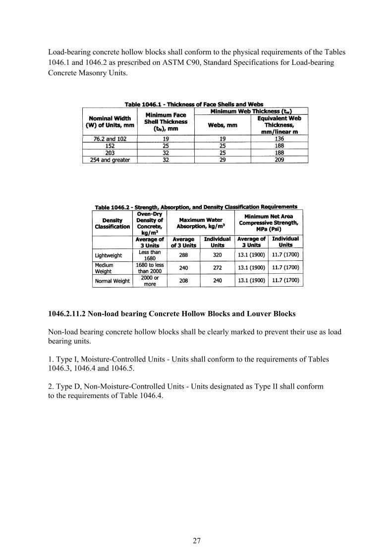
Load-bearing concrete hollow blocks shall conform to the physical requirements of the Tables 1046.1 and 1046.2 as prescribed on ASTM C90, Standard Specifications for Load-bearing Concrete Masonry Units.
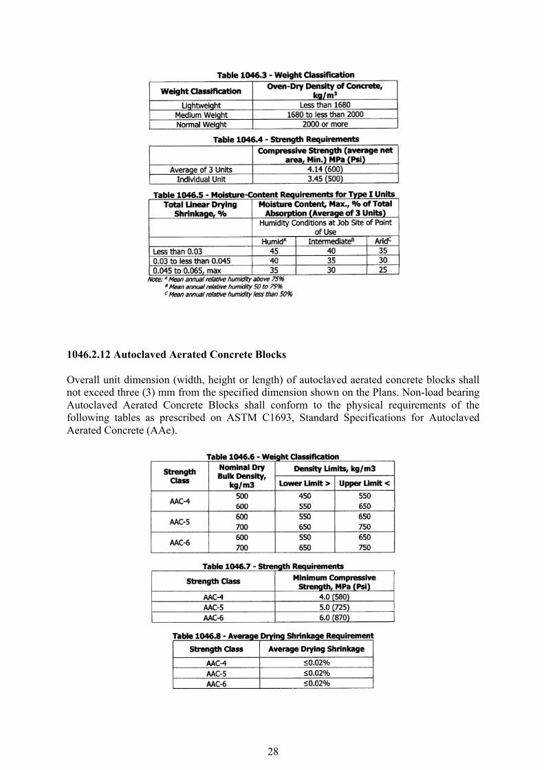
1046.2.11.2 Non-load bearing Concrete Hollow Blocks and Louver Blocks Non-load bearing concrete hollow blocks shall be clearly marked to prevent their use as load bearing units. 1. Type I, Moisture-Controlled Units - Units shall conform to the requirements of Tables 1046.3, 1046.4 and 1046.5. 2. Type D, Non-Moisture-Controlled Units - Units designated as Type II shall conform to the requirements of Table 1046.4.
28
1046.2.12 Autoclaved Aerated Concrete Blocks Overall unit dimension (width, height or length) of autoclaved aerated concrete blocks shall not exceed three (3) mm from the specified dimension shown on the Plans. Non-load bearing Autoclaved Aerated Concrete Blocks shall conform to the physical requirements of the following tables as prescribed on ASTM C1693, Standard Specifications for Autoclaved Aerated Concrete (AAe).
29
1046.2.13 Other Constituents for Concrete Hollow Blocks and Louver Blocks Air-entraining agents, coloring pigments, integral water repellents, finely ground silica, and other constituents that are previously established as suitable for use in concrete masonry shall conform to applicable ASTM standards. 1046.3 Construction Requirements 1046.3.1 Concrete Hollow Blocks and Louver Blocks 1046.3.1.1 Mixing Concrete shall be mixed well using the proportion specified by the Engineer. Hand mixing shall be done, using shovels, on a level concrete slab or steel plate. Mix aggregate and cement until the color is uniform. Spread the mixture out, sprinkle water over the surface and ~ix. Continue with this process until the right amount of water has been mixed in. Mixture shall be free from impurities such as dirt and grass. If batch mixer is used, accurate timing and measuring devices shall be observed as per manufacturer's recommendation. 1046.3.1.2 Moulding Hand operated machines shall be used as manufacturer's recommendation. The mould of a powered machine should be filled until six (6) to eight (8) cycles of compaction are required to bring the compacting head to its stops. Demoulding or removal of the mould shall be done carefully so that the fresh blocks are not damaged. Fresh blocks shall be protected from rain with plastic sheets or any suitable covering during the first day and from the drying effects of the sun and wind until curing starts. 1046.3.1.3 Curing After being removed from the mold, the Concrete Hollow Blocks (CHB) and Louver Blocks shall be covered with a plastic sheet or tarpaulin and kept damp and shaded for at least seven (7) days in order to effectively cure. This can be achieved by continually spraying them with water or keeping them under water in tanks. 1046.3.1.4 Installation 1. All masonry work shall be laid true to line, level, plumb and neat in accordance with the Plans. 2. Units shall be cut accurately to fit all plumbing ducts, opening for electrical works, and all holes shall be neatly patched. 3. No construction support shall be attached to the wall except where specifically permitted by the Engineer. 4. Masonry unit shall be sound, dry, clean and free from cracks when placed in the structure. 5. Proper masonry units shall be used to provide for all window, doors, bond beams, lintels, plasters etc., with a minimum of unit cutting. 6. Where masonry units cutting is necessary, all cuts shall be neat and true to line.
30
7. Units shall be placed while the mortar is soft and plastic. Any unit disturbed to the extent that the initial bond is broken after initial positioning shall be removed and re-Iaid in fresh mortar. 8. Mortar should not be spread too far ahead of units, as it will stiffen and loose plasticity, especially in hot weather. Mortar that has stiffened should not be used. ASTM C270, Standard Specification for Mortar for Unit Masonry requires that mortar be used within 21/2 hours of initial mixing. 1046.3.1.5 Reinforcement for Concrete Hollow Blocks Reinforcement shall be done in accordance with the structural Plans as to size, spacing and other requirements of Section 902.3 of Item 902, Reinforcing Steel. Reinforcement shall be clean and free from loose, rust, scales and any coatings that will reduce bond. 1046.3.1.6 Finish and Appearance 1. All units shall be sound and free of cracks or other defects that interfere with the proper placement of the unit or significantly impair the strength or permanence of the construction. Minor cracks, incidental to the usual method of manufacture or minor chipping resulting from customary methods of handling in shipment and delivery, are not grounds for rejection. 2. Where units are to be used in exposed wall construction, the face or faces that are to be exposed shall not show chips or cracks, not otherwise permitted, or other imperfections when viewed from a distance of not less than 6.1 m under diffused lighting. a. Five (5) percent of a shipment containing chips, not larger than 25.4 mm in any dimension, or cracks not wider than 0.5 mm and not longer than 25 percent of the nominal height of the unit, is permitted. 3. The color and texture of units shall be specified by the purchaser. The finished surfaces that will be exposed in place shall conform to an approved sample, consisting of not less than four (4) units, representing the range of texture and color permitted. 4. A shipment shall not contain more than five (5) percent of units, including broken unit that do not meet the requirements of the above provisions. 1046.3.1.7 Sampling and Testing for Concrete Hollow Blocks and Louvers Method of Sampling for Quality Test shall be as follows: 1. One (1) Quality Test for every 10,000 units or fraction thereof. 2. Six (6) specimens to be submitted for one (1) quality test in which three (3) specimens for Compression Test and the remaining three (3) for Moisture Content and Water Absorption. Units shall be tested in accordance with ASTM C14O, Standard Test Methods for Sampling and Testing Concrete Masonry Units and Related Units and ASTM C426, Standard Test Method for Linear Drying Shrinkage of Concrete Masonry Units. 1046.3.1.8 Storage and Handling of Masonry Works The blocks shall be stored in such a way as to avoid contact with moisture at site. They shall be stock-piled on planks or other supports free from contact with ground and covered to protect against wetting. The block shall be handled with care and damaged units shall be rejected.
31
1046.3.2 Autodaved Aerated Concrete (AAC) blocks 1046.3.2.1 Installation 1. Establish reference lines based on the given Plan. 2. Make layout adjustments or opening rectifications (plumbing ducts or opening for electrical works) before laying masonry units. 3. Masonry unit shall be clean and free from dust or loose particles on it. 4. Floor and wall area shall be moistened prior to laying first layer of masonry unit. Mortar setting with 2:1 sand:cement ratio shall be provided as starter blocks if slab is unleveled beyond two (2) em. 5. Adhesive shall be mixed using manufacturer's specified proportion of water using a power mixer and a non-absorptive pail or mixing container. Adhesive that has stiffened should not be used. Refer to manufacturer's instructions for the pot life of the adhesive mix. 6. Thin bed adhesive shall be set and screed with notched trowel on the starter blocks to receive initial layer of masonry unit. 7. Laying of masonry unit shall be continued until the lateral layer is complete before moving on to the next layer. Adhesive shall be applied at five (5) mm thick using a notched trowel on the required portions and maintaining three (3) - five (5) mm gap on the wall side surface to allow any wall movement. Alignment and levelness shall be regularly checked using rubber mallet and level bar. 8. Gaps and joints shall be filled with adhesive. Excess adhesive should be spread on the surface or used to fill the gaps. 9. Rebar dowel, 10 mm in diameter, shall be installed spaced at 600 mm on the wall sides and along the affected beam and slab soffit. Dowel should be embedded at least 50 mm into the side and top structures, exposing 100 mm to support lateral movement. No epoxy is needed. 10. Polyethylene backer rod, 20 mm in diameter, shall also be simultaneously installed at the slab or beam soffit. 11. When cutting of masonry unit is necessary, it shall be downsized first before applying the adhesive. Ice or wood saw can be used for this matter. 12. Comer interlocking setup is recommended. 1046.3.2.2 Finish and Appearance 1. All units shall be sound and free of cracks or other defects that interfere with the proper placement of the unit or significantly impair the strength or permanence of the construction. Minor cracks, incidental to the usual method of manufacture or minor chipping resulting from customary methods of handling in shipment and delivery, are not grounds for rejection. 2. Where units are to be used in wall construction, the face or faces that are to be exposed shall not show chips or cracks, not otherwise permitted, or other imperfections when viewed from a distance of not less than 6.1 m under diffused lighting. Five (5) percent of a shipment containing chips and cracks not longer than one-third (1/3) of the dimension where it is found and not wider than five (5) mm is permitted. 3. The color and texture of units shall be specified by the purchaser. The finished surfaces that will be exposed in place shall conform to an approved sample, consisting of not Jessthan four (4) units, representing the range of texture and color permitted. 4. A shipment shall·not contain more than five (5) percent of units, including broken unit that do not meet requirements of the above provisions.
32
1046.3.2.3 Sampling and Testing Method of Sampling for Quality Test shall be as follows: 1. Two (2) Quality Tests for every 10,000 units or a fraction thereof 2. Three (3) specimens to be submitted for every one (1) quality test namely, Compression Test and Moisture Content & Bulk Density Determination. Units shall be tested in accordance with ASTM C1693, Standard Specifications for Autoclaved Aerated Concrete (MC). 1046.3.2.4 Storage and Handling of Masonry Works The blocks shall be stored in such a way as to avoid contact with moisture at site. They shall be stock-piled on planks or other supports free from contact with ground and covered to protect against wetting. The block shall be handled with care and damaged units shall be rejected. ITEM 1003(1)a1 – FIBER CEMENT BOARD CEILING 1003.1 Description The work under this item shall consist of furnishing all required materials, fabricated woodwork, tools, equipment and labor and performing all operations necessary for the satisfactory completion of all carpentry and joinery works in strict accord with applicable drawings, details, and the Specifications. 1003.2 Material Requirements 1003.2.1 Lumber Lumber of different species herein specified for the various parts of the structure shall be well seasoned, sawn straight, sundried or kiln dried and free from defects such as loose unsound knots, pitch pockets, sapwood, cracks and other imperfections impairing its strength, durability and appearance.
1003.2.1.1 Grades of Lumbers and Usage a. Stressed grade is seasoned, close-grained and high quality lumber of the specified
specie free from defects and suitable for sustaining heavy loads. Stress grade lumber shall be used for wooden structural members subject to heavy
loads, and for sub-floor framing embedded or in contact with concrete or masonry. b. Select grade lumber of the specified specie is generally of high quality, of good
appearance, without imperfections, and suitable for use without waste due to defects and suitable also for natural finish.
Select grade lumber shall be used for flooring, sidings, fascia and base boards, trims, mouldings, millwork, railings, stairs, cabinet work, shelvings, doors, windows and frames of openings.
33
c. Common grade lumber has minimum tight medium knot not larger than 25 mm in diameter, with minimal imperfections, without sapwood, without decay, insect holes, and suitable for use with some waste due to minor defects and suitable also for paint finish.
Common grade lumber shall be used for light framework for wall partitions, ceiling joist and nailers.
1003.2.1.2 Lumber Species and Usage Unless otherwise specified on the Plans, the following lumbers species shall be used as
indicated: a. Yacal (stress grade) for structural member such as post, girders, girts, sleepers, door
and window frames set or in contact with concrete or masonry. b. Guijo (selected grade) for door and window frames set in wooden framework, for stairs,
for framing supporting ceramic or cement tiles, for floor joists and other wooden structural parts.
c. Apitong (common grade) for roof framing supporting light roofing materials such as galvanized iron, aluminum or asbestos sheets, for wall framing, ceiling joists, hangers and nailers.
d. Tanguile (select grade) for doors and windows, fascia and base boards,trims, mouldings, millwork, railings, stairs,cabinet, work, shelvings, flooring and siding.
e. Narra (select grade) for stair railings, flooring boards, wall panels base boards, trims, mouldings, cabinet work, millwork, doors and windows when indicated as such in the Plans.
f. Dao (select grade) for parts of the structures as enumerated under Section 1003.2.1.2 (e), when indicated as such on the Plans. 1003.2.1.3 Moisture Content Rough lumber for framing and siding boards shall be air-dried or sun-dried such that its moisture content shall not exceed 22 percent. Dressed lumber for exterior and interior finishing, for doors and windows, millwork, cabinet work and flooring boards shall be kiln-dried and shall not have a moisture content in excess of 14 percent at the time of installation in the structure. 1003.2.1.4 Substitution in Lumber Specie Any lumber equally good for the purpose intended may be substituted for the specified kind subject to the prior approval of the Engineer,provided the substitution shall be an equal or better specie acceptable to the Engineer. In case of substitution with a better specie, no additional cost therefore shall be allowed to the contractor. 1003.2.2 Plyboard
Plyboard shall be good grade and made of laminated wood strips of uniform width and the thickness bounded together with water resistant resin glue. The laminated core shall be finished both faces with select grade tanguile or red lauan veneers not less than 2 mm thick similarly bonded to the core. The plyboard of not less than 19 mm thick shall be free from defects such as split in veneer, buckling or wraping.
1003.2.3 Plywood
34
Plywood shall conform to the requirements of the Philippine Trade Standards 631.02. Thickness of a single layer laminae shall not be less than 2 mm. The laminae shall be superimposed in layers with grains crossing at right angles in successive layers to produce stiffness. The face veneers shall be rotary cut from select grade timber. The laminae and face veneers shall be bonded with water resistant resin glue, hot pressed and pressure treated. Ordinary tanguile or red lauan plywood with good quality face veneers, 6 mm thick shall be used for double walling and ceiling not exposed to moisture; waterproof or marine plywood shall be used for ceiling exposed to moisture such as at toilets and eaves, and ceiling to be finished with acrytex.
1003.2.4 Lawanit
Lawanit, when required per plans, shall be 6 mm thick, tempered or oil impregnated for moisture/water resistance. Texture of lawanit shall be subject to the approval of the Engineer. 1003.2.5 Materials Other Than Lumber 1003.2.5.1 Plastic Sheet When required for the counter top, plastic sheet such as Formica shall not be less than 1.500mm thick and shall have hard, durable and glossy surface resistant to stain, abrasion and heat. Color and design shall be as selected from the manufacturer’s standard and approved by the Engineer. 1033.2.5.2 Glue Glue shall be from water resistant resins which, upon hardening, shall not be dissolved nor lose its bond or holding power even when soaked with water for extended period. Glue in powder form be in sealed container and shall be without evidence of lumping or deterioration in quality. 1003.2.5.3 Fasteners Nails, screw, bolts and straps shall be provided and used where suitable for fixing carpentry and joinery works. All fasteners shall be brand new and of adequate size to ensure rigidity of connections.
a. Nails of adequate size shall be steel wire, diamond-pointed, ribbed shank and bright finish.
b. Screws of adequate size shall be cadmium or brass plated steel with slotted head. c. Lag screws or adequate size, for anchoring heavy timber framing or in concrete
masonry, shall be galvanized steel. d. Bolts and nuts shall be of steel having a yield point of not less than 245 MPa. Bolts
shall have square heads and provided with standard flat steel washers and hexagonal nuts. Threads shall conform to American coarse thread series. The threaded portion shall be long enough such that the nut can be tightened against the bolted members without any need for blocking. The bolt’s thread end shall be finished smooth for ease engaging and turning of the nut.
e. Wrought iron straps or angles, when required in conjunction with bolts or log screws to provide proper anchorage, shall be of the shape and sizes shown in the Plans.
1003.3 Construction Requirements
35
1003.3.1 Quality of Materials
All materials to be incorporated in the carpentry and joinery works shall be of the quality specified under Section 2. Before incorporation in work, all materials shall have been inspected/accepted by the Engineer of his authorized representative.
1003.3.2 Storage and Protection of Materials
Lumber and other materials shall be protected from dampness during and after delivery at the site. Materials shall be delivered well in advance of actual need and in adequate quantity to preclude delay in the work. Lumber shall be piled in orderly stack at least 150 mm above ground and at sheltered place where it will be of least obstruction to the work. 1003.3.3 Shop Drawings
Shop drawings complete with essential dimensions and details of construction, as may be required by the Engineer in connection with carpentry and joinery work, shall be submitted for approval before proceeding with work.
1003.3.4 Rough Carpentry
Rough carpentry covers timber structural framing for roof, flooring, siding, partition and ceiling.
a. Framing shall be stress grade or common grade lumber of the specie specified under
Section. b. Rough carpentry shall be done to lines, levels and dimensions. It shall be squared,
aligned, plumbed and well fitted at joints. c. Trusses and other roof framing shall be assemble, fitted and set to exact location
and slope indicated on the Plans. d. Fasteners, connectors and anchors of appropriate type and number shall be provided
and fitted where necessary. e. Structural members shall not be cut, bored or notched for the passage of conduits
or pipes without prior approval of the Engineer. Members damage by such cutting or boring shall be reinforced by means of specifically formed and approved steel plates or shapes, otherwise, damaged structural members shall be removed and replaced to the satisfaction of the Engineer.
f. Timber framing in contact with concrete or masonry shall be treated with termite-proofing solution and after drying coated with bituminous paint.
1003.3.5 Finished Carpentry
Finished carpentry covers works on flooring, siding and ceiling boards, stairs, cabinets, fabricated woodwork, millwork and trims. a. Framing lumber shall be select grade, free from defects and where exposed in
finished work, shall be selected for color and grain. b. Joints of framing shall be tenoned, mortised or doweled where suitable, closely
fitted and secured with water resistant resins glue. Exterior joints shall be mitered and interior angles coped.
36
c. Panels shall be as fitted allow for contraction or expansion and insure that the panels remain in place without warping, splitting and opening of joints.
d. Plyboard shall be as specified under Section 1003.2.3 unless otherwise indicated on the Plans.
e. Plywood shall be specified under Section 1003.2.4. f. Exposed edges of plywood or plywood for cabinets shall be provided with select
grade hardwood strips, rabetted as necessary, glued in place and secured with finishing nails. To prevent splitting, hardwood for trims shall be drilled before fastening with nails or screws.
g. Fabricated woodwork shall be done preferably at the shop. It shall be done true to details and profiles indicated on the Plans. Where set against concrete or masonry, woodwork shall be installed when curing is completed.
h. Exposed wood surfaces shall be free from disfiguring defects such as raised grains, stains, uneven planning, sanding, tool marks and scratches. Exposed surfaces shall be machine or hand sanded to an even smooth surface, ready for finish.
ITEM 1010(2)a – WOODEN FLUSH DOOR ITEM 1010(2)b – WOODEN PANEL DOOR 1010.1 Description This item shall consist of furnishing all materials, hardware, plant, tools, labor and services necessary for complete fabrication installation of wooden doors and windows of the type and size as shown on the Plans and accordance with the following specifications and applicable specifications under Item 1003 on Carpentry and Joinery Works. 1010.2 Material Requirements 1010.2.1 Lumber Lumber doors, windows and jambs, and panels when required, shall be kiln – dried with moisture content of not more than 14 % and shall be of the specie indicated on the Plans and/or specified under Item 1003 on Carpentry and Joinery Works. 1010.2.2 Plywood Plywood for venner of solid core and hollow core flush door shall be 3-ply, rotary cut, and 6 mm thick ordinary plywood, Class B grade. Marine or waterproof plywood, rotary cut, 3-ply, 6 mm thick shall be used for flush doors at toilets and bathrooms or at places where these are exposed to moisture. 1010.2.3 Adhesive Adhesive shall be water resistant resins and shall be non – staining. 1010.2.4 Glass Glass for window panes shall be 3 mm thick, smoked or industrix type unless otherwise shown on the Plans or indicated in the Schedule of Doors and Windows.
37
1010.2.5 Capiz Shells Capiz shells, when required for windows sashes, shall be of selected quality, free from dirt of blemishes and shall be large enough to obtain flat square pice. 1010.2.6 Hardware Hardware shall be as specified under Item 1004 on Building Hardware. 1010.3 Construction Requirements 1010.3.1 Fabrication Wooden doors and windows, including frames, shall be fabricated in accordance with the design and sizes shown on the Plans. The fabricated product shall be finished square, smoothly sanded and free from damage or warpage. a. Flush type Hollow Core Doors Flush type hollow core doors shall be adequately framed with stiles and top and bottom rails having a minimum thickness of 44 mm and width of 75 mm. Two intermediate rails at least 44 mm wide shall be provided for stiffness. The stiles and the top and bottom rails shall be rabbeted at least 10 mm wide to receive the 6 mm thick plywood veneer. A lock block shall be provided at each stile, long enough to connect to the two intermediate rails and at least 75 mm wide for mounting the lockset. The plywood veneer shall be glued and nailed to the framing with 25 mm long finishing nails space at not more than 150 mm on centers. b. Flush Type Solid Core Doors Flush type solid core doors shall be fabricated in the same manner as the hollow core type except that the spaces between stiles and rails shall be filled and fitted with wood blocks of the same species and of uniform thickness thinner by about the thickness of the plywood veneers. The filler blocks shall be secured to either stiles or rails by nails. Stiles and rails of flush doors shall be joined by means of blind mortise and tenon joint, tightly fitted, glued and locked with bamboo pin 5 mm round. c. Panel Doors Stiles and rails of panel doors shall have a minimum thickness of 44 mm and width of 140 mm. Rails minimum thickness of 44 mm and width of 140 mm. Rails shall be framed to stiles by mortise and tenon joint. Rabbets or grooves of stile by mortise and tenon joint. Rabbets or grooves of stiles and rails to receive panels shall be 6.5 mm wide and 20 mm deep. Integral mouldings formed on both faces of stiles and rails framing the panels shall be true shape and well defined. Intersections of mouldings shall be mitered and closely fitted. Panels of the same species and having a minimum thickness of 20 mm shall be bevelled around its edges up to a minimum width of 50 mm both faces. The bevelled edges shall closely fit into the grooves of stiles and rails, but free to move to prevent splitting when shrinkage occurs. d. Window Sashes with Glass Panes or Woods Panels Window sashes shall be fabricated in conformity with the design, sizes and type of installation shown on the Plans. Unless otherwise shown on the Plans, stiles and rails shall be Tanguile with minimum thickness of 30 mm and with of 70 mm. Jointing of stiles and rails
38
shall be mortise and tenon secured with glue and bamboo pin. Stiles and rails shall be rabbeted at the exterior face for mounting glass panes or wood panels. Integral mouldings formed as frames for panes or panels shall be true to shape, sharply defined and mitered at joints. Separate mouldings of the same design shall be provided for fixing glass panes and wood panels from the outside. e. Window Sashes wit Capiz Shells Stiles and rails shall be of the same sizes specified under the Item 1010.3.1 (d) and assembled with mortise and tenon joint. Unless otherwise indicated on the Plans, lattices for framing capiz shall be tanguile, 8 mm thick and 15 mm wide, spaced at not more than 60 mm on center bothways. Grooves 2 mm wide and 5 mm shall be made at sides of lattices to receive the preformed capiz shells. The lattices shall be assembled with half lap joints at their intersections and the assembled lattices containing the capiz shells shall be framed into the stiles and rails Selected capiz shells shall be washed to remove dirt and blemishes and dried under the sun for bleaching effect. Capiz shell shall be cut square to required sizes with sharp bench cutter to produce non – serrated and non – peeling edges. f. Sliding Type Window Sashes Stiles of sliding type window sashes shall be framed to the top and bottom rails with mortise and tenon joints. Tenons shall be formed on the stiles. Joint shall be tightly fitted, glued and locked with bamboo pins.Top and bottom rails shall be 10 mm wider than the stiles. Top rails shall be rabbeted to form tongue flush with the outer face, with width of 8 mm and height of 10 mm. The stiles and rails shall be rabbeted as specified under Item 1010.3.1 (d) to receive glass panes or wood panels g. Awning Type Window Sashes Tenons of rails shall be fitted into the mortises formed on the stiles and the joint glued and locked. The stiles and rails shall be rabbeted as specified under Item 1010.3.1 (d) for mounting of glass panes. Series of sashes to be installed vertically shall have their meeting rails rabbeted for half lapping when in closed position. h. Casement Type Window Sashes Rails of casement type window sashes shall be fitted to stiles with mortise and tenon joint. Tenons shall be formed in the rails. Meeting rails shall be rabbeted to provide for half lapping when in closed position. The stiles and rails shall be rabbeted as specified under Item 1010.3.1 (d) for mounting of glass panes or wood panels. i. Door and Window Frames Framing of the specie(s) specified under Item 1003 shall be fabricated in conformity with the profile and sizes shown on the Plans. Frames shall be assembled with tightly fitted tongue and groove joint mitered at both sides, and nailed. The assembled frames shall be finished square and flat on the same plane. Assembled frames shall be braced temporarily to prevent their distortion during delivery to the site and installation. 1010.3.2 Installation a. Frames shall be set plumb and square in concrete/masonry work or framework of walls or partitions. Frames set in concrete or masonry shall be painted with hot asphalt at its contact surface and provide with two rows of common wire nails 100 mm long for anchorage.
39
The nails shall be staggered and spaced at 300 mm on center along each row. Frame set in concrete shall be installed in place prior to concrete work. Frames set in masonry work may be installed after laying of hollow concrete blocks, bricks or adobe. Space between frames and masonry shall be fully filled with cement mortar proportioned 1:3. b. Hinge Doors Hinged doors, whether panel or flush type with standard height of 2100 mm and width of not more than 900 mm shall be hung with four loose – pin butt hinges, 100 mm x 100. Swing out exterior doors shall be hung with four fast – pin butt hinges. Two hinges shall be fitted 150 mm from top and bottom edge of door. The outer two hinges shall be fitted at third point between top and bottom hinges. Care should be taken to ensure that the hinges are fitted such that their pins are aligned for ease of pin intersection and smoothness of operation. For added smoothness pins should be lightly greased. Hammering of hinges to attain proper alignment shall not be allowed. For wider and heavier doors such as narra panel doors, an additional hinge shall be fitted 100 mm below the top hinge to counteract the door tilting action. Mounting screws shall be screwed in place in their entire length, not forced into place by hammering. Hammering of screw into place shall not be permitted. c. Sliding Doors Overhead tracks, standard, locally manufactured as per Plans shall be installed level and mounting bracket secured in place with lag screws supplied with set. Brackets shall be spaced 1000 mm on centers. Hangers, two each per door leaf, shall be perfitted and bolted to the door rail. For panel doors the hangers shall be centered on the door stiles. For flush doors, the hangers shall be centered 100 mm from the edge of the door. If there is no adequate space for installing the door with its attached rollers, though either end of track the perfittedhangers shall be disassembled for connection to the rollers. After installation on the track, set the door plumb and in alignment by means of the adjustment mechanism integrated with the roller assembly. d. Lock Installation Locks of doors shall be fitted at the same height, centered 1000 mm above the finishing floor level. Lock shall be installed in conformity with the templates and instruction supplied with lockset. Holes for mounting lock shall be properly formed to provide snug fit and rigid attachment of the lock to the doors. Strike plate shall be fitted on the door frame in alignment with the lock latch. e. Sliding Type Window Sashes Sashes shall be trimmed to fit height of opening. A clearance of 2 mm shall be provided between the tongue’s base at the top rail and the bottom of the window head. The same clearance shall be provided between the sash tongue and the groove at the window head. Paraffin wax shall be applied to the contacts of sliding surfaces. The bottom rails shall be fitted with standard brass guided spaced 75 mm from both ends of the rail, mounted flush with the inner face and secured with three brass screw each guide. f. Case Type Window Sashes Sashes shall be trimmed to fit size opening, with provision for half lapping of meeting stiles. Right side sash shall lap onto the left side sash. Sashes shall be fitted with two brasses – plated narrow hinges, 50 mm x 75 mm, spaced 150 mm from top and bottom of
40
stiles. In lieu of hinges, sashes maybe hung with cadmium – plated steel casement adjuster 200 mm long, subject to prior approval of the Engineer. The top and bottom rails of casement type window sashes shall be milled to provide for the installation of adjuster. g. Awning Type of Window Sashes Installation of awning type sashes shall be by means of casement adjuster specified under Item 1010.3.2 (f) 1010.4 Measurement of Payment Frames of doors and windows shall be measured and paid for on the basis of number of sets completely installed and accepted by the Engineer. Doors and windows shall be measured and for based on the number of square meters involved in the complete and accepted installation. Payment per square meter shall included cost of required hardware and all incidental expenses, but exclusive of locks for doors. Locks shall be paid per set completely installed. The different pay items under Wooden Doors and Windows shall be designated the following number, description and unit of measure: Pay Item Number Description Unit of Measurement 1010 (a) Frames (Jambs, sills, head, transom m² and mullions ) 1010 (b) Door (Flush or Panel) m² 1010 (c) Window Sashes m² 1010 (d) Door Lock m² ITEM 1011 – ROLLING UP DOORS 1011.1 Description This item shall consist of furnishing all plant, labor, tools, equipment and rolling up door required as shown on the Plans and in accordance with the Specification. 1011.2 Materials Requirements Rolling up door shall be surfaced mounted type designed for exterior service opening as indicated on the Plans. Component parts shall conform with the following materials specifications: 1. Curtain – shall be manufactured of interlocking curved or flats slats, rolled from
galvanized and bonderized steel, aluminum or stainless steel as the case maybe, Slats shall be of size and thickness to withstand 0.957 KPawindload.
Curtain is composed of:
a. Interlocking slats shall roll up on a drum supported at head of opening of brackets and shall be balance by helitical spring.
b. Endlocks – shall be malleable iron riveted to each ends of slats. These called continues when they reinforced both ends of all slats, alternate when
every other slat.
41
c. Bottom bar – shall be manufactured from two equal sized angles, minimum 3 mm thick back to back with appropriate half slot at lowest edge of curtain. In addition, exterior door shall have compressible and replaceable rubber or vinyl weather seal attached to bottom rail.
2. Counter balance barrel assembly – shall include spring barrel which serves as load carrying beam encases counter balance mechanism and provide axis around curtain coils. Asit arises barrelrings are involute shapes of malleable iron to assure proper counter balance for all points of travel. Oil tempered torsion type counter balance spring are wound from heat treated steel, to provide accuracy in balancing door.
3. Hood – shall be manufactured from 0.60mm thick (minimum) galvanized sheet metal, flanged at top attachment to header and flanged at bottom to provide longitudinal stiffness. Hood shall enclose curtain coil and counter balance mechanism.
4. Brackets – shall be made of precisely formed plate with permanently sealed ball bearings, designed to enclose end of the curtain coil and provide support for counter balance pipe at each end.
5. Guides – shall be fabricated from structural steel angles or precision roll formed channels and angles. Especially adaptable for doors exposed to heavy wind pressure.Designed with groove depths varying from 50mm to 150mm depending upon the width of the door, and set cut from the face of the wall to facilitate the travel of the curtain.
1011.3 Construction Requirements Doors shall be mechanically operated and with provision for manual operation by means
of hand chain. Accessories needed for the satisfactory performance of the door shall be built-in with the unit.
1011.3.1 Erection/Installation
a) Set and install structural steel angles properly aligned, plumb, level, square true to profile section and rigidly anchored with adjacent concrete surface walls.
b) Allow all adjacent items of work to be completed before any installation work is started except the installation of structural steel angles.
c) Assemble rolling up doors in accordance with the manufacturers instruction manual or as indicated in the shop drawing approved.
d) All anchors and insets for guides, brackets and other accessories shall be located accurately.
1011.3.2 Locking Devices
Curtain shall be located at each end of bottom bar by concealed slide bolts which shall engage a lock wedge in each guide. A plunger type cylinder lock is provided as standard equipment.
1011.3.3 Warranty Upon completion and before final acceptance of the equipment, the Contractor shall furnish the DPWH/Owner a written guaranty stating that the rolling up to door equipment and accessories are free from defects. The guaranty shall be for the period of one (10 year from the date of final acceptance of the work. Any part of the equipment that becomes defecting during the term of the guaranty shall be replaced and made good by the Contractor at his own expense a manner satisfactory to the DPWH/Owner.
42
1011.3.4 Method of Measurement The work executed under this item shall be measured by actual units of rolling up door installed at jobsite complete and ready for service. The computed unit shall bear type of materials and area of opening covered and shall be accepted by the Engineer. 1011.3.5 Basis of Payment The accepted work quantified and provided in the Bill of Quantities shall be paid for at the unit Bid price which constitutes full compensation for furnishing all materials, labor, tools, equipment and other incidentals necessary to complete this Item. Payment shall be made under: Payment Item Description Unit of Number Measurements 1011(a) Rolling up door (indicate metal Unit/set door size and type of curtain slats) ITEM 1008 – ALUMINUM GLASS WINDOWS 1008.1 Description This Item shall consist of furnishing all aluminum glass window materials, labor, tools and equipment required in undertaking the proper installation as shown on the Plans and in accordance with this Specification. 1008.2 Material Requirement 1008.2.1 Frame and panel members shall be fabricated from extruded aluminum section true to details with clean, straight, sharply defined profile and free from defects impairing strength or durability. Extruded aluminum section shall conform to the specification requirements defined in ASTM B 211. 1008.2.2 Screws, nuts, washers, bolts, rivets and other miscellaneous fastening devices shall be made of non-corrosive materials such as aluminum, stainless steel, etc. 1008.2.3 Hardware for fixing and locking device shall be closely matched to the extruded aluminum section and adaptable to the type and method of opening. 1008.2.4 Weather-strip shall be first class quality flexible vinyl forming an effective seal and without adverse deformation when installed. 1008.2.5 Glazing shall conform to the requirement specified in Item 1012. 100.2.6 Pile weather strip shall be silicon treated and free from residual wetting agents made of soft hair as on wool, fur, etc. 1008.3 Construction Requirements
43
For all assembly and fabrication works the cut end shall be true and accurate, free of burrs and rough edges. Cut-outs recesses, mortising and grinding operation for hardwares shall be accurately made and properly reinforced. 1008.3.1 Installation Procedure 1008.3.1.1 Main frame shall consist of head, sill and jamb. 1008.3.1.2 Window sash 1008.3.1.3 Window panel shall be jointed at corners with miter and fixed rigidly to ensure weather tightness. 1008.3.1.4 Sliding windows shall be provided with nylon sheave. Sliding panels shall be suspended with concealed roller overhead tracks with bottom guide pitch outward and slotted for complete drainage. The sliding panels shall be provided with interior handles. The locking device shall be a spring loaded extruded latch that automatically engages special frame hips. 1008.3.1.5 Casement window type shall be provided with two hinges fabricated from extruded aluminum alloy. They shall open on stay arms having adjustable sliding friction shoes to control window panel operations. Locking device shall be one arm action handle for manual operations complete with strike plate. 1008.3.1.6 All joints between metal surface and masonry shall be fully caulked. 1008.8.1.7 Aluminum parts in contact with steel members shall be properly insulated by a coat of zinc chromate, primer/bituminous paint applied to steel surface. 1008.3.2 Shop Finish Exposed aluminum surface shall be electrotype hard coat such as anodize, satin, etc. 1008.3.3 Protection All aluminum parts shall be protected adequately to ensure against damage during transit and construction phase. 1008.3.4 Clearing 1008.3.4.1 The contractor does not only protect all entrance unit during the construction phase but shall be also responsible for removal of protective materials and cleaning the aluminum surface including glazing before work is accepted by the Engineer. 1008.3.4.2 Aluminum shall be thoroughly cleaned with kerosene or gasolines diluted with water and then wipe surface using clean cloth rugs. 1008.3.4.3 No abrasive cleaning materials shall be permitted in cleaning surface. 1008.4 Method of Measurement
44
Aluminum glass window fully equipped with fixing accessories and locking devices shall be measured in square meters actually installed in-placed and accepted to the satisfactory of the Engineer. 1008.5 Basis of Payment The area of aluminum glass window in square meters ready for service as provided in the Bill of Quantities shall be the bases of payment based on the unit bid or contract unit price which price payment constitute all materials, labor including incidentals. Payment will be made under: Pay Item Number Description Unit of Measurement 1008 (1) Aluminum Sliding Windows m² 1008 (2) Aluminum Casement Windows m² ITEM 1018(1) –GLAZED TILES ITEM 1018(2) – UNGLAZED TILES 1018.1 Description This Item shall consist of furnishing all ceramic tiles cementitious materials, tools and equipment including labor required in undertaking the proper installation of walls and floor tiles as shown on the Plans and in accordance with this Specification. 1018.2 Material Requirements 1018.2.1 Ceramic tiles and trims shall be made of clay, or a mixture of clay and other materials which is called the body of the tile. Tile bodies are classified by ASTM C 242 as to their degree of water absorption. Ceramic tiles and trims are manufactured either by dust-presses process in which the clays are ground to dust mixed with a minimum of water shaped in steel dies and then fired or by plastic process in which the clays are made plastic by mixing with water, shaped by extrusion or in molds and then fired. 1018.2.1.1 Glazed Tiles and Trims Glazed tiles and trims shall have an impevious face of ceramic materials fused onto the body of the tiles and trims. The glazed surface may be clear white or colored depending on the color scheme approved by the Engineer. Standard glazes may be bright (glossy) semimalle (Less glossy) matte (dull) or crystalline (mottled and textured; good resistance to abrasion). Glazed tiles are used principally for walls; crystalline glazed tiles may be used for floors provided however that these are used as light duty floors. 1018.2.1.2 Unglazed Tiles Unglazed tiles shall be hard dense tile of homogeneous composition. Its color and characteristics are determined by the materials used in the body, the method of manufacture and the thermal treatment. It is used primarily for floors and walks. 1018.2.1.3 Trims Trims are manufactured to match wall tile color, texture and to coordinate within the dimension. These are shape in various ceramic trim units such as caps, bases, coves, bullnoses,
45
corners, angles, etc. that are necessary for edging or making a transition between entersecting planes. 1018.2.1.4 Accessories Accessories some like soap holders and shall be wall mounted type with colors to reconcile with the color of the adjacent tiles. 1018.2.1.5 Cement Cement shall be portland conforming to the specification requirements defined in item 700, Hydraulic Cement. 1018.2.1.6 Sand Sand shall be well graded fine aggregate clean river sand, free from soluble salts and organic impurities. 1018.2.1.7 Lime Lime shall be hydrated lime with free unhyrdrated oxide and magnesium oxide content not to exceed 8 percent by weight. 1018.3 Construction Requirements Tile work shall not be started until roughing-ins for plumbing, electrical and other trades have been completed and tested. The work of all other trades shall be protected from damage. 1018.3.1 Surface Separation
a) Mortar mix for scratch coat and setting bed shall consist of one part portland cement ¼ part lime and 3 parts sand by volume. Surface to receive tile must be level, true to elevation, dry, free from dirt, oil and other ointments. Allow at least seven days curing of scratch coat and setting bed. Installation work shall not be allowed to proceed until unsatisfactory conditions are correct.
b) Bond coat shall be portland cement paste.
1018.3.1.1 Thoroughly dampen surfaces of masonry or concrete walls before scratch coat is applied. 1018.3.1.2 On masonry or concrete surface first apply a thin coat with pressure, then bring it out sufficiently to compensate for the major irregularities of the surface to a thickness not less than 10mm at any point. 1018.3.1.3 Evenly rate scratch coat to provide good mechanical key before the mortar mix has fully hardened. 1018.3.2 Installation Procedure Ceramic tiles shall be soaked in clean water prior to installation for a minimum of one hour. 1018.3.2.1 Ceramic Glazed Wall Tiles
a) Determine and mark layout ceramic tiles, joint location, position of trims and fixtures so as to minimize cut less than one-half tile in size.
b) Thoroughly dampen surface of wall but do not saturate surface.
46
c) Apply a bond coat mix with consistency of cram paste 1.5mm thick to the wall surface or to back of the tile to be laid.
d) Lay the tiles true to profile then exert pressure and tamp tile surface before the bond coat mix has initially set.
e) Continue with next full tile to laid and pressed firmly upon the bed tamped until flush and in place of the other tiles.
f) Intersections and returns shall be formed accurately using the appropriate trims. g) All lines shall be kept straight and true to profiles, plumbed and internal corners
rounded using the appropriate trims. 1018.3.2.2 Vitrified Unglazed Floor Tiles
a) Before tile is applied the floor surface shall be tested for levelness or uniformity of slope by flooding it with water, area where water ponds are filled or levelled, shall be retested before the testing bed is applied.
b) Establish lines of borders and center of the walls at the field work in both direction to permit the patent to be laid with a minimum of cut tiles.
c) Clean concrete subfloor then moisten but do not soak. Then sprinkle dry cement over the surface and spread the mortar on the setting bed.
d) Apply and spread mortar mix for setting bed and tamp to assure good bond over the entire area to be laid with tile.
e) Pitch floor to drain as shown on Plans or as directed by the Engineer. f) Allow the setting bed to set sufficiently to be worked over then spread a bond coat over
the surface and lay tile in accordance with Items 1019.3.2.1 a, b, c, d, e, f, g.
1018.3.3 Grouting and Pointing 1018.3.3.1 Tiles shall have laid in place for at least 24 hours before grouting of joints is started. Grouting mortar shall be white portland cement or blended with pigments to acquire the color appropriate for the ceramic tile. 1018.3.3.2 Grouting mortar shall be applied over the tile by float or squeegee stroked diagonally across the joints. Remove excess mortar with a wet sponge stroked diagonally or in a circular motion after 12-15 minutes. Follow with a barely damp or dry sponge to remove remaining haze while smoothing all grouted joints. 1018.3.4 Cleaning
a. Clean ceramic tile surfaces thoroughly as possible upon completion of grouting. b. Remove all grout haze, observing tile manufacturers recommendations as to use of acid
of chemical cleaners. c. Rinse tile thoroughly with clean water before and after using chemical cleaners. d. Polish surface of tile with soft cloth.
1018.3.5 Protection from Construction Dirt
a. Apply a protective coat of neutral cleanser solution diluted with water in the proportion of 1:4 or 1 liter cleanser concentrate to one gallon water.
47
b. In addition, cover tile flooring with heavy-duty nonstaining construction paper, taped in place.
c. Just before final acceptance of the work to remove paper and rinse protective coat of neutral cleaner from tile surface. Do not let protective paper get from torn or removed.
1018.4 Method of measurement All works performed under this item shall be measured in square meters for areas actually laid with ceramic tiles and accepted to the satisfaction of the Engineer. 1018.5 Basis of Payment Ceramic tile work determined and provide in the bill of Bill of Quantities shall be paid for based at the unit bid price which price and payment constitute full compensation for furnishing all materials, tools, equipment and other incidentals necessary to complete this item.
Payment shall be made under: Pay Item Description Unit of Number Measurement
1018.2.1.1 Glazed tiles and trims m2
1018.2.1.2 Glazed tiles m2
ITEM 1027- CEMENT PLASTER FINISH 1027.1 Description This Item shall consist of furnishing all cement plaster materials, labor, tools and equipment required in undertaking cement plaster finish as shown on the Plans and in accordance with this Specification. 1027.2 Material Requirements Manufactured materials shall be delivered in the manufacturer’s original unbroken packages or containers which are labelled plainly with the manufacturers name and trademark. 1027.2.1 Cement Portland cement shall conform with the requirements as defined in Item 700, Hydraulic cement. 1027.2.2 Hydrate Lime Hydrated lime shall conform with the requirements as defined in Item 701, Hydrated lime. 1027.2.3 Fine aggregates Fine aggregates shall be clean, washed sharp river sand and free from dirt, clay, organic matter or other deleterious substances. Sand derived from crushed gravel or stone may be used
48
with the engineer’s approval but in no case shall such sand be derived from the stone unsuitable for use as coarse aggregates. 1027.3 Construction Requirements 1027.3.1 Mixture
a) Mortar mixture for brown coat shall be freshly prepared and uniformly mixed in the proportion by volume of one part Portland cement, three (3) parts sand and one fourth (¼) part hydrated lime.
b) Finish coat shall be pure Portland cement properly graded conforming to the requirements of Item 700, Hydraulic Cement and mixed with water to approved consistency and plasticity.
1027.3.2 Surface Preparation a) After removal of formworks reinforce concrete surface shall be roughened to improve
adhesion of cement plaster. b) Surfaces to receive cement plaster shall be cleaned of all projections, dust, loose
particles, grease and bond breakers. Before any application of brown coat is commenced all surfaces that are to be plastered shall be wetted thoroughly with clean water to produce a uniformly moist condition.
1027.3.3 Application a) Brown coat mortar mix shall be applied with sufficient pressure starting from the lower
portion of the surface to fill the grooved and to prevent air pockets in the reinforced concrete/masonry work and avoid mortar mix drooping. The brown coat shall be lightly broomed/or scratch before surface had properly set and allowed to cure.
b) Finish coat shall not applied until after the brown coat has seasoned for seven days and corrective measures had been done by the contractor on surfaces that are defective. Just before the application of the finish coat, the brown coat surface shall be evenly moistened with potable water. Finished coat shall be floated first to a true and even surface, then troweled in a manner that will forced the mixture to penetrate into brown coat. Surfaces applied with finish coat shall then be smooth with paper in a circular motion to remove trowel marks, checks and blemishes. All cement plaster finish shall be 10 mm thick minimum on vertical concrete and/or masonry walls.
Wherever indicated on the Plans to be “Simulated Red Brick Finish”, the Contractor shall render brick design on plaster surface before brown coat had properly set then to dry. Cement plaster shall not be applied directly to:
a) Concrete or masonry surface that had been coated with bituminous compound and, b) Surfaces that had been painted or previously plastered.
1027.3.4 Workmanship Cement plaster finish shall be true to details and plumbed. Finish surface shall have no visible junction marks where one (1) Day’s work adjoins the other. Where directed by the
49
Engineer or as shown on the Plans vertical and horizontal groove joints shall be 25 mm wide and 10 mm deep. ITEM 1032(1)a – MASONRY PAINTING ITEM 1032(1)b – WOOD PAINT 1032.1 Description This Item shall consist of furnishing all pint materials, varnish and other related products, labor, tools, equipment and plant required in undertaking the proper application of painting, varnishing and related works indicated on the Plans and in accordance with the Specification. 1032.2 Materials Requirements All types of paint material, varnish and other related product shall be subject to random test as to material composition by the Bureau of Research and Standard, DPWH or the National Institute of Science and Technology, (Use the following approved and tested brand name: Boysen, Davies, Dutch Boy, Fuller O Brien, or any approved equal). 1032.2.2 Tinting Colors Tinting colors shall be first grade quality, pigment ground in alkyd resin that disperses and mixed easily with paint to produce the color desired. Use the same brand of paint and tinting color to effect good paint body. 1032.2.3 Concrete Neutralizer Concrete neutralizer shall be first grade quality concentrate diluted with clean water and applied as surface conditioner of new interior and exterior walls thus improving paint adhesion and durability. 1032.2.4 Silicon Water Repellant Silicon water repellant shall be transparent water shield especially formulated to repel rain and moisture on exterior masonry surfaces. 1032.2.5 Patching Compound Patching compound shall be fine powder type materials like calciumine that can be mixed into putty consistency, with oil base primers and paints to fill minor surface dents and imperfections. 1032.2.6 Varnish Varnish shall be a homogeneous solution of resin, drying oil, drier and solvent. It shall be extremely durable clear coating, highly resistant to wear and tear without cracking, peeling, whitening, spotting, ect. with minimum loss of gloss for a maximum period of time. 1032.2.7 Lacquer Lacquer shall be any type of organic coating that dries rapidly and solely by evaporation of the solvent. Typical solvent are acetates, alcohols and ketones. Although lacquers were generally based on intrecellulose, manufactures currently use, vinyl resins, plasticizers and reacted drying oils to improve adhesion and elasticity.
50
1032.2.8 Shellac Shellac shall be a solution of refined lac resin in denatured alcohol. It dries by evaporation of the alcohol. The resin is generally furnished in orange and bleached grades. 1032.2.9 Sanding Sealer Sanding sealer shall be quick drying lacquer, formulated to provide quick dry, good holdout of succeeding coats, and containing sanding agents such as zinc stearate to allow dry sanding of sealer. 1032.2.10 Glazing Putty Glazing putty shall be alkyd-type product for filling minor surface unevenness 1032.2.11 Natural Wood Paste Filler Wood paste filler shall be quality filler for filling and sealing open grain of interior wood. It shall produced a level finish for following coats of paint varnish/lacquer and other related products. 1032.2.12 Schedule Exterior
a.) Plain cement plastered - 3 coats Acrylic base finish to be painted masonry paint
b.) Concrete exposed aggre- - 1 coat water repellent gate and/or tool finish
c.) Ferrous metal - 1 coat primer and 2 coats enamel paint
d.) Galvanized metal - 1 coat zinc chromate primer and ‘- 2 coats Portland cement paint
e.) Wood painted finish - 3 coats oil based paint f.) Wood varnished finish - varnish water repellent
Interior a.) Plain cement plastered - 2 coats acrylic base
Finish to be painted masonry paint b.) Concrete exposed aggre- - clean surface
gate and/or tool finish c.) Ferrous metal - 1 coat primer and 2 coats
enamel paint d.) Woodwork sea-mist - 3 coats of 3 parts thinner 1
part lacquer e.) Woodwork varnish - 1st coat, of one part sanding
sealer to one part solvent 2nd coat of 2/3 sanding sealer to 1/3 coats of oil base paint
f.) Woodwork painted - 3 coats of oil base paint Finish
g.) Ceiling boards - 1 coats oil based paint textures finish allow to dry then patch surface unevenness and apply textured paint coat
51
1032.3 Construction Requirements
The Contractor prior to commencement of the painting, varnishing and related work shall examine the surfaces to be applied in order not to jeopardize the quality and appearances of the painting varnishing and related works.
1032.3.1 Surface Preparation All surface shall be in proper condition to receive the finish. Woodworks shall be hand-sanded smooth and dusted clean. Knotholes pitch pockets or sappy portions shall be sealed with natural wood filler. Nail holes, cracks or defects shall be carefully puttied after the first coat, matching the color of paint. Interior woodworks shall be sandpapered between coats. Cracks, holes of imperfections in plaster shall be filled with patching compound and smoothed off to match adjoining surfaces. Concrete and masonry surfaces shall be coated with concrete neutralizer and allowed to dry before and painting primer coat is applied. When surface is dried apply first coating. Hairline cracks and unevenness shall be patched and sealed with approved putty or patching compound. After all defects are corrected apply the finish coats as specified on the Plans (color scheme approved). Metal shall be clean, dry and free from millscale and rust. Remove all grease and oil from surfaces. Wash,unprimed galvanized metal with etching solution and allow it to dry. Where required to prime coat surface with Red Lead Primer same shall be approved by the Engineer.
In addition the contractor shall undertake the following: 1. Voids, cracks, nick etc. will be repaired with proper patching material and finished
flushed with surrounding surfaces. 2. Marred or damage shop coats on metal shall be spot primed with appropriate metal
primer. 3. Painting and varnishing works shall not be commenced whet it is too hot or cold. 4. Allow appropriate ventilation during application and dying period. 5. All hardware will be fitted and removed or protected prior to painting and
varnishing works. 1032.3.2 Application Paints when applied by brush shall become non-fluid, thick enough to lay down as adequate film of wet paint. Brush marks shall flawed out after application of paint. Paints made for application by roller must be similar to brushing pint. It must be nonsticky when thinned to spring viscosity so that it will break up easily into droplets. Paint id atomized by high pressure pumping rather that broken up by the large volume of air mixed with it. This procedure change the required properties of the paint. 1032.3.3 Mixing and Thinning At the time of application paint shall show no sign of deterioration. Paint shall be thoroughly stirred, strained and kept at a uniform consistency during application. Paints of different manufacture shall not be mixed together. When thinning is necessary, this may be done immediately prior to application in accordance with the manufacturer’s directions, but not in excess of 1 pint of suitable thinner per gallon of the paint. 1032.3.4 Storage
52
All materials to be used under this Item shall be stored in a single place to be designed by the Engineer and such place shall be kept neat and clean at all time. Necessary precaution to avoid fire must be observed by removing oily rags, waste, etc. at the end of daily work. 1032.3.5 Cleaning All cloths and cotton waste which constitute fire hazards shall be place to be metal containers or destroy at the end of daily works. Upon completion of the work, all staging, scaffolding and paint containers shall be removed. Paint drips, oil, or attains on adjacent surfaces shall be removed and the entire job left clean and acceptable to the Engineer. 1032.3.6 Workmanship in General
a.) All paints shall be evenly applied. Coats shall be of proper consistency and well brushed out so as to show a minimum of brush marks.
b.) All coats shall be thoroughly dry before the succeeding coat is applied. c.) Where surfaces are not fully covered or cannot be satisfactorily finished in the number
of coats specified such preparatory coats and subsequent coats as may be required shall be applied to attain the desired evenness of surface without extra cost to the owner.
d.) Where surface is not in proper condition to receive the coat the Engineer shall be notified immediately. Work on the questioned potion(s) shall not start until clearance be proceed is ordered by the Engineer.
e.) Hardware, lighting fixture and other similar items shall be removed or protected during the painting varnishing and related work operations and re-installed after completion of the work.
1032.3.7 Procedure for Sea-Mist Finish
a.) a.)Depress wood grain by steel brush and sand surface lightly. b.) Apply sanding sealer. c.) apply two coats of industrial lacquer paint. d.) Spray last coat of industrial lacquer paint mixed with sanding sealer. e.) Apply wood paste filler thinned with turpentine or paint thinner into the wood surface. f.) Wipe of f wood paste filler immediately. g.) Spray flat or gloss lacquer whichever is specified.
1032.3.8 Procedure for Varnish Finish
a.) Sand surface thoroughly. b.) Putty all cracks and other wood imperfections with wood paste filler. c.) Apply oil stain. d.) Apply lacquer sanding sealer. e.) Sand surface along the grain. f.) Spray three (3) coats of clear dead flat lacquer. g.) Polish surface coated using cloth pad. h.) Spray gloss lacquer or flat lacquer whichever is desired or specified.
1032.3.9 Procedure for Ducco Finish
53
a.) Sand surface thoroughly. b.) Apply primer surface white or gray by brush or spray. c.) Apply lacquer spot putty in thin coat. Allow each coat for become thoroughly dry before
applying next coat. d.) Apply primer surfaces and then allow to dry in two (2) hours before applying the next
coat. e.) Apply a coat of flat tone semi-gloss enamel as per color scheme submitted and
approved by the Engineer. ITEM 1047 – METAL STRUCTURES 1047.1 Description
This work shall consist of steel structures and the steel structure portions of composite structures, constructed in reasonably close conformity with the lines, grades and dimensions shown on the Plans or established by the Engineer.
The work will include the furnishing, fabricating, hauling, erecting, welding and painting of structural metals called for in the Special Provision or shown on the Plans. Structural metals will include structural steel, rivet, welding, special and alloy steels, steel forgings and castings and iron castings. This work will also include any incidental metal construction not otherwise provided for, all in accordance with these Specifications, Plans and Special Provisions.
1047.2 Material Requirements
Materials shall meet the requirements of Item 712, Structural Metal; Item 409, Welded Structural Steel, and Item 409, Welded Structural Steel; and Item 709, Paints. 1047.3 C onstruction Requirements 1047.3.1 Inspection
The Contractor shall give the Engineer at least fifteen (15) days’ notice prior to the beginning of work at the mill or shop, so that the required inspection may be made. The term “mill” means any rolling mill, shop or foundry where material for the work is to be manufactured or fabricated. No material shall be rolled or fabricated until said inspection has been provided.
The Contractor shall furnish the Engineer with copies of the certified mill reports of the structural steel, preferably before but not later than the delivery of the steel to the job site.
The Contractor shall furnish all facilities for inspection and the Engineer shall be allowed free access to the mill or shop and premises at all times. The Contractor shall furnish, without charge, all labor, machinery, material and tools necessary to prepare test specimens.
Inspection at the mill or shop is intended as a means of facilitating the work and avoiding errors and it is expressly understood that it will not relieve the Contractor from any responsibility for imperfect material or workmanship and the necessity for replacing same. The
54
acceptance of any material or finished member at the mill or shop by the Engineer shall not preclude their subsequent rejection if found defective before final acceptance of the work. Inspection of welding will be in accordance with the provision of Section 5 of the “Standard Code for Arc and Gas Welding in Building Construction” of the American Welding Society.
1047.3.2 Stock Material Control
When so specified in the Contract, stock material shall be segregated into classes designated as "identified” or “unidentified”. Identified material is material which can be positively identified as having been rolled from a given heat for which certified mill test can be produced. Unidentified material shall include all other general stock materials. When it is proposed to use unidentified material, the Engineer shall be notified of such intention at least fifteen (15) days in advance of commencing fabrication to permit sampling and testing. When so indicated or directed, the Contractor shall select such material as he wishes to use from stock, and place it in such position that it will be accessible for inspection and sampling. The Contractor shall select identified material from as few heat numbers as possible, and furnish the certified mill test reports on each of such heat numbers. Two samples shall be taken from each heat number as directed, one for a tension test and one for a bend test.
In the case of unidentified stock, the Engineer may, at his discretion, select any number of random test specimens.
Each bin from which rivets or bolts are taken shall subject to random test. Five rivets or bolts may be selected by the Engineer from each bin for test purposes.
Structural material, either plain or fabricated, shall be stored above the ground upon platforms, skids, or other supports. It shall be kept free from dirt, grease, or other foreign matter, and shall be protected as far as practicable from corrosion.
1047.3.3 Fabrication
These Specifications apply to riveted, bolted and welded construction. The Contractor may, however, with approval of the Engineer, substitute high tensile strength steel bolts equivalent to the rivets in any connection.
Workmanship and finish shall be in accordance with the best general practice in modern bridge shops. Portions of the work exposed to view shall be finished neatly. Shearing, flame cutting, and chipping shall be done carefully and accurately.
Structural material, either plain or fabricated, shall be stored above the ground upon platforms, skids or other supports. It shall be kept free from dirt, grease or other foreign matter, and shall be protected as far as practicable from corrosion.
Rolled material before being laid off or worked must be straight. If straightening is necessary, it shall be done by methods that will not injure the metal. Sharp kinks and bends will be cause for rejection of the material.
Preparation of material shall be in accordance with AWS (American Welding Society) D 1.1, paragraph 3.2 as modified by AASHTO Standard Specification for Welding of Structural Steel Highway Bridges.
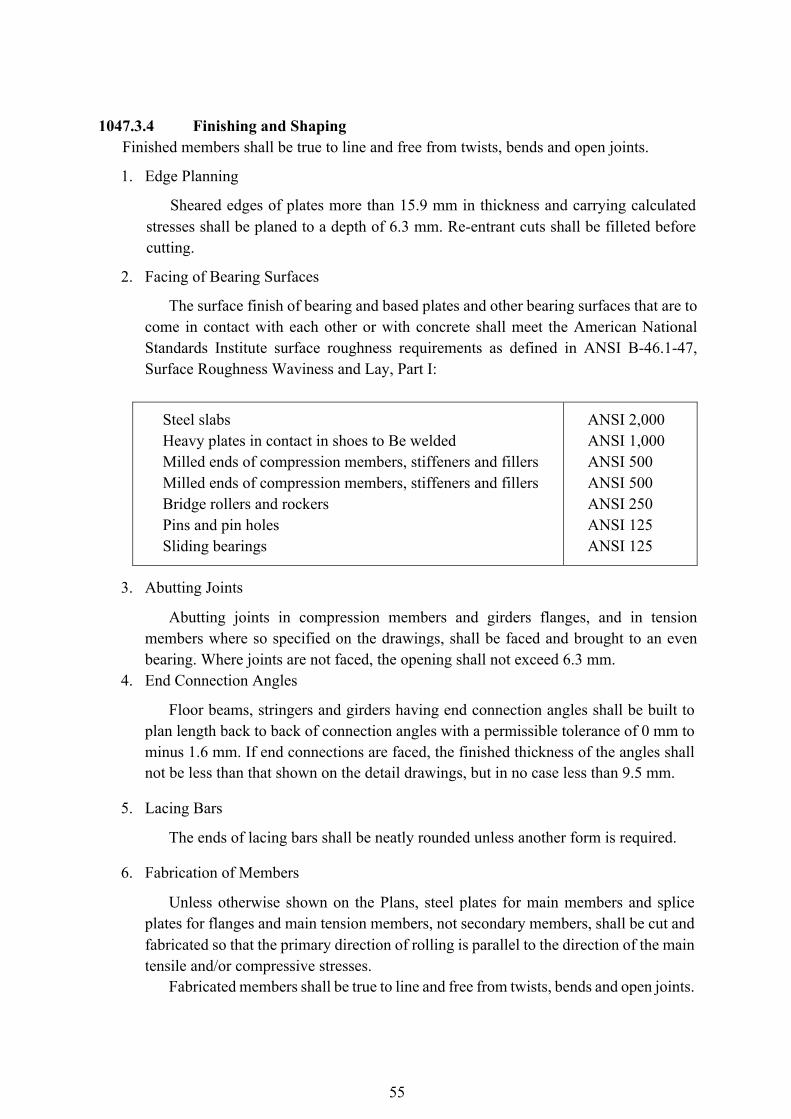
55
1047.3.4 Finishing and Shaping
Finished members shall be true to line and free from twists, bends and open joints.
1. Edge Planning
Sheared edges of plates more than 15.9 mm in thickness and carrying calculated stresses shall be planed to a depth of 6.3 mm. Re-entrant cuts shall be filleted before cutting.
2. Facing of Bearing Surfaces
The surface finish of bearing and based plates and other bearing surfaces that are to come in contact with each other or with concrete shall meet the American National Standards Institute surface roughness requirements as defined in ANSI B-46.1-47, Surface Roughness Waviness and Lay, Part I:
Steel slabs Heavy plates in contact in shoes to Be welded Milled ends of compression members, stiffeners and fillers Milled ends of compression members, stiffeners and fillers Bridge rollers and rockers Pins and pin holes Sliding bearings
ANSI 2,000 ANSI 1,000 ANSI 500 ANSI 500 ANSI 250 ANSI 125 ANSI 125
3. Abutting Joints
Abutting joints in compression members and girders flanges, and in tension members where so specified on the drawings, shall be faced and brought to an even bearing. Where joints are not faced, the opening shall not exceed 6.3 mm.
4. End Connection Angles
Floor beams, stringers and girders having end connection angles shall be built to plan length back to back of connection angles with a permissible tolerance of 0 mm to minus 1.6 mm. If end connections are faced, the finished thickness of the angles shall not be less than that shown on the detail drawings, but in no case less than 9.5 mm.
5. Lacing Bars
The ends of lacing bars shall be neatly rounded unless another form is required.
6. Fabrication of Members
Unless otherwise shown on the Plans, steel plates for main members and splice plates for flanges and main tension members, not secondary members, shall be cut and fabricated so that the primary direction of rolling is parallel to the direction of the main tensile and/or compressive stresses.
Fabricated members shall be true to line and free from twists, bends and open joints.
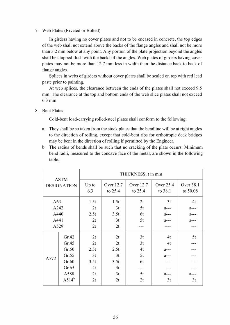
56
7. Web Plates (Riveted or Bolted)
In girders having no cover plates and not to be encased in concrete, the top edges of the web shall not extend above the backs of the flange angles and shall not be more than 3.2 mm below at any point. Any portion of the plate projection beyond the angles shall be chipped flush with the backs of the angles. Web plates of girders having cover plates may not be more than 12.7 mm less in width than the distance back to back of flange angles.
Splices in webs of girders without cover plates shall be sealed on top with red lead paste prior to painting.
At web splices, the clearance between the ends of the plates shall not exceed 9.5 mm. The clearance at the top and bottom ends of the web slice plates shall not exceed 6.3 mm.
8. Bent Plates
Cold-bent load-carrying rolled-steel plates shall conform to the following:
a. They shall be so taken from the stock plates that the bendline will be at right angles to the direction of rolling, except that cold-bent ribs for orthotropic deck bridges may be bent in the direction of rolling if permitted by the Engineer.
b. The radius of bends shall be such that no cracking of the plate occurs. Minimum bend radii, measured to the concave face of the metal, are shown in the following table:
ASTM DESIGNATION
THICKNESS, t in mm
Up to 6.3
Over 12.7 to 25.4
Over 12.7 to 25.4
Over 25.4 to 38.1
Over 38.1 to 50.08
A63 A242 A440 A441 A529
1.5t 2t
2.5t 2t 2t
1.5t 3t
3.5t 3t 2t
2t 5t 6t 5t ---
3t a--- a--- a--- ----
4t a--- a--- a--- ---
A572
Gr.42 Gr.45 Gr.50 Gr.55 Gr.60 Gr.65 A588 A514b
2t 2t
2.5t 3t
3.5t 4t 2t 2t
2t 2t
2.5t 3t
3.5t 4t 3t 2t
3t 3t 4t 5t 6t --- 5t 2t
4t 4t
a--- a--- --- ---
a--- 3t
5t --- --- --- --- ---
a--- 3t
57
a.) It is recommended that steel in this thickness range be bent hot. Hot bending however, may result in a slight decrease in the as-rolled mechanical properties.
b.) The mechanical properties of ASTM A 514 steel results from a quench-and-temper- operation. Hot bending may adversely affect these mechanical properties. If necessary to hotbend, fabricator should discuss procedure with steel supplier,
c.) Before bending, the corners of the plate be rounded to a radius of 1.6 mm throughout that portion of the plate where the bending is to occur.
9. Fit of Stiffeners
End stiffeners of girders and stiffeners intended as supports for concentrated loads shall have full bearing (either milled, ground or on weldable steel in compression areas of flanges, welded as shown on the Plans or specified) on the flanges to which they transmit load or from which they receive load. Stiffeners not intended to support concentrated loads shall, unless shown or specified otherwise, fit sufficiently tight to exclude water after being painted, except that for welded flexural members, the ends of stiffeners adjacent to the tension flanges shall be cut back as shown on the Plans. Fillers under stiffeners shall fit within 6.3 mm at each end.
Welding will be permitted in lieu of milling or grinding if noted on the Plans or in the Special Provisions. Brackets, clips, gussets, stiffeners, and other detail material shall not be welded to members or parts subjected to tensile stress unless approved by the Engineer.
10. Eyebars
Pin holes may be flame cut at least 50.8 mm smaller in diameter than the finished pin diameter. All eyebars that are to be placed side by side in the structure shall be securely fastened together in the order that they will be placed on the pin and bored at both ends while so clamped. Eyebars shall be packed and matchmarked for shipment and erection. All identifying marks shall be stamped with steel stencils on the edge of one head of each member after fabrication is completed so as to be visible when the bars are nested in place on the structure. The eyebars shall be straight and free from twists and the pin holes shall be accurately located on the centerline of the bar. The inclination of any bar to the plane of the truss shall not exceed 1.6 mm to 305 mm.
The edges of eyebars that lie between the transverse centerline of their pin holes shall be cut simultaneously with two mechanically operated torches abreast of each other, guided by a substantial template, in such a manner as to prevent distortion of the plates.
11. Annealing and Stress Relieving
Structural members which are indicated in the Contract to be annealed or normalized shall have finished machining, boring and straightening done subsequent to
58
heat treatment. Normalizing and annealing (full annealing) shall be in accordance with ASTM E 44. The temperatures shall be maintained uniformly throughout the furnace during heating and cooling so that the temperature at no two points on the member will differ by more than 37.8°C at any one time.
Members of A514/A517 steels shall not be annealed or normalized and shall be stress relieved only with the approval of the Engineer.
A record of each furnace charge shall identify the pieces in the charge and show the temperatures and schedule actually used. Proper instruments including recording pyrometers, shall be provided for determining at any time the temperatures of members in the furnace. The records of the treatment operation shall be available to and meet the approval of the Engineer.
Members, such as bridge shoes, pedestals, or others which are built up by welding sections of plate together shall be stress relieved in accordance with the provisions of Subsection 403.3.11 when required by the Plans, Specifications or Special Provisions governing the Contract.
12. Tests
When full size tests of fabricated structural members or eyebars are required by the Contract, the Plans or Specifications will state the number and nature of the tests, the results to be attained and the measurements of strength, deformation or other performances that are to be made. The Contractor will provide suitable facilities, material, supervision and labor necessary for making and recording the tests. The members tested in accordance with the Contract will be paid for in accordance with Subsection 403.3.5.1. The cost of testing, including equipment handling, supervision labor and incidentals for making the test shall be included in the contract price for the fabrication or fabrication and erection of structural steel, whichever is the applicable item in the Contract, unless otherwise specified.
1047.3.5 Pins and Rollers
Pins and rollers shall be accurately turned to the dimensions shown on the Plans and shall be straight, smooth, and free from flaws. Pins and rollers more 228.6 mm or less in diameter may either be forged and annealed. Pins and rollers 228.6 mm or less in diameter may either be forged and annealed or cold-finished carbon-steel shafting.
In pins larger than 228.6 mm in diameter, a hole not less than 50.8 mm in diameter shall be bored full length along the axis after the forging has been allowed to cool to a temperature below the critical range under suitable conditions to prevent injury by too rapid cooling and before being annealed.
Pin holes shall be bored true to the specified diameter, smooth and straight, at right angles with the axis of the member and parallel with each other unless otherwise specified.
59
The final surface shall be produced by a finishing cut.
The distance outside to outside of holes in tension members and inside to inside of holes in compression members shall not vary from that specified more than 0.8 mm. Boring of holes in built-up members shall be done after the riveting is completed.
The diameter of the pin hole shall not exceed that of the pin by more than 0.51 mm for pins 127 mm or less in diameter, or 0.8 mm for larger pins.
The pilot and two driving nuts for each size of pin shall be furnished, unless otherwise specified. All holes for rivets or bolts shall be either punched or drilled. Material forming parts or a member composed of not more than five thickness of metal may be punched 1.6 mm larger than the nominal diameter of the rivets or bolts whenever the thickness of the material is not greater than 19 mm for structural steel, 15.9 mm for high-strength steel or 12.7 mm for quenched and tempered alloy steel, unless subpunching and reaming is required for field connections.
When there are more than five thicknesses or when any of the main material is thicker than 19 mm for structural steel, 15.9 mm for high-strength steel, or 12.7 mm for quenched and tempered alloy steel, all holes shall either be subdrilled or drilled full size.
When required for field connections, all holes shall either be subpunched or subdrilled (subdrilled if thickness limitation governs)
4.8 mm smaller and, after assembling, reamed 1.6 mm larger or drilled full size 1.6 mm larger than the nominal diameter of the rivets or bolts.
When permitted by design criteria, enlarged or slotted holes are allowed with high-strength bolts. For punched holes, the diameter of the die shall not exceed the diameter of the punch by more than 1.6 mm. If any holes must be enlarged to admit the fasteners, they shall be reamed. Holes shall be clean cut, without torn or ragged edges. Poor matching of holes will be cause for rejection.
Reamed holes shall be cylindrical, perpendicular to the member, and not more than 1.6 mm larger than the nominal diameter of the fasteners. Where practicable, reamers shall be directed by mechanical means. Drilled holes shall be 1.6 mm larger than the nominal diameter of the fasteners. Burrs on the outside surfaces shall be removed. Poor matching of holes will be cause for rejection. Reaming and drilling shall be done with twist drills. If required by the Engineer, assembled parts shall be taken apart for removal of burrs caused by drilling. Connecting parts requiring reamed or drilled holes shall be assembled and securely held while being reamed or drilled and shall be matchmarked before disassembling.
Unless otherwise specified, holes for all field connections and field splices of main truss or arch members, continuous beams, towers (each face), bents, plate girders and rigid frames shall be subpunched (or subdrilled if subdrilling is required) and subsequently reamed while assembled in the shop in accordance with Subsection 403.3.7.
All holes for floor-beam and stringer field end connections shall be subpunched and reamed to a steel template reamed while being assembled.
Reaming or drilling full size of field connection through templates shall be done after
60
templates have been located with the utmost care as to position and angle and firmly bolted in place. Templates used for the reaming of matching members, or of the opposite faces of one member, shall be exact duplicated. Templates for connections which duplicate shall be so accurately located that like members are duplicates and require no matchmarking.If additional subpunching and reaming is required, it will be specified in the Special Provisions or on the Plans.
Alternately, for any field connection or splice designated above in lieu of sub-sized holes and reaming while assembled, or drilling holes full-size while assembled, the Contractor shall have the option to drill bolt holes full-size in unassembled pieces and/or connections including templates for use with matching sub-sized and reamed holes means of suitable numerically-controlled (N/C) drilling equipment subject to the specific provisions contained in this Subsection.
If N/C drilling equipment is used, the Engineer, unless otherwise stated in the Special Provisions or on the Plans, may require the Contractor, by means if check assemblies to demonstrate that this drilling procedure consistently produces holes and connections meeting the requirements of conventional procedures.
The Contractor shall submit to the Engineer for approval a detailed outline of the procedures that he proposes to follow in accomplishing the work from initial drilling through check assembly, if required, to include the specific members of the structure that may be N/C drilled, the sizes of the holes, the location of common index and other reference points, composition of check assemblies and all other pertinent information.
Holes drilled by N/C drilling equipment shall be drilled to appropriate size either through individual pieces, or any combination of pieces held tightly together.
All holes punched full size, subpunched or subdrilled shall be so accurately punched that after assembling (before any reaming is done), a cylindrical pin 3.2 mm smaller in diameter than the nominal size of the punched hole may be entered perpendicular to the face of the member, without drifting, in at least 75 percent of the contiguous holes in the same plane. If the requirement is not fulfilled, the badly punched pieces will be rejected. If any hole will not pass a pin 4.8 mm smaller in diameter than the nominal size of the punched holes, this will cause for rejection.
When holes are reamed or drilled, 85 percent of the holes in any continuous group shall, after reaming or drilling, show no offset greater than 0.8 mm between adjacent thickness of metal.
All steel templates shall have hardened steel bushings in holes accurately dimensioned from the center lines if the connections as inscribed on the template. The center lines shall be used in locating accurately the template from the milled or scribed ends of the members.
1. Fitting for Riveting and Bolting
Surfaces of metal in contact shall be cleaned before assembling. The parts of a member shall be assembled, well pinned and firmly drawn together with bolts before reaming or riveting is commenced. Assembled pieces shall be taken apart, if necessary,
61
for the removal of burrs and shavings produced by the reaming operation. The member shall be free from twists, bends and other deformation. Preparatory to the shop riveting of full-sized punched material, the rivet holes, if necessary, shall be spear-reamed for the admission of the rivets. The reamed holes shall not be more than 1.6 mm larger than the nominal diameter of the rivets.
End connection angles, and similar parts shall be carefully adjusted to correct positions and bolted, clamped, or otherwise firmly in place until riveted.
Parts not completely riveted in the shop shall be secured by bolts, in so far as practicable, to prevent damage in shipment and handling.
2. Shop Assembling
The field connections of main members of trusses, arches, continuous beam spans, bents, towers (each face), plate girders and rigid frames shall be assembled in the shop with milled ends of compression members in full bearing, and then shall have their sub-size holes reamed to specified size while the connections are assembled. Assembly shall be “Full Truss or Girders Assembly” unless "Progressive Chord Assembly” or “Special Complete Structure Assembly” is specified in the Special Provisions or on the Plans.
Check assemblies with Numerically-Controlled Drilled Fields Connections shall be in accordance with the provision of 2 (f) of this Subsection.
Each assembly, including camber, alignment, accuracy of holes and fit of milled joints, shall be approved by the Engineer before reaming is commenced or before an N/C drilled check assembly is dismantled.
The fabricator shall furnished the Engineer a camber diagram showing the camber at each panel point in the cases of trusses or arch ribs and at the location of field splices and fractions of span length (0.25 points minimum, 0.10 points maximum) in case of continuous beam and girders or rigid frames. When the shop assembly is Full Truss or Girder Assembly or Special Complete Structure Assembly, the camber diagram shall show the camber measured in assembly. When any of the other methods of shop assembly is used, the camber diagram shall show calculated camber. Methods of assembly shall be described below:
a. Full of Truss or Girders Assembly shall consist of assembling all members of each truss, arch rib, bent, tower face, continuous beam line, plate girder or rigid frame at one time.
b. Progressive Truss or Girder Assembly shall consist of assembling initially for each truss, arch rib, bent, tower face, continuous beam line, plate girder, or rigid frame.all members in at least three continuous shop sections or panels but not less than the number of panels associated with three continuous chord lengths (i.e., length between field splices) and not less than 45.72 m in case of structures longer than 45.72 m. At least one shop section or panel or as many panels as are associated with a chord length shall be added at the advancing end of the assembly before any member is removed from the rearward end so that the assembled portion of the structure is never less than
62
that specified above.
c. Full Chord Assembly shall consist of assembling with geometric angles at the joints, the full length of each chord or each truss or open spandrel arch, or each leg of each bent or tower, than reaming their field connection holes while the members are assembled; and reaming the web member connections to steel templates set at geometric (not cambered) angular relation to the chord lines. Field connection holes in web members shall be reamed to steel templates. At least one end of each web member shall be milled or shall be scribed normal to the longitudinal axis of the member and the templates of both ends of the member shall be accurately located from one of the milled ends or scribed line.
d. Progressive Chord Assembly shall consist of assembling contiguous chord members in the manner specified for Full Chord Assembly, and in the number and length specified for Progressive Truss or Girder Assembly.
e. Special Complete Structure Assembly shall consist of assembling the entire structure, including the floor system. (This procedure is ordinarily needed only for complicated structures such as those having curbed girders, or extreme skew in combination with severe grade or camber). The assembly including camber, alignment, accuracy of holes and fit of milled joints shall be approved by the Engineer before reaming is commenced.
A Contractor shall furnished the Engineer a camber diagram showing the camber at each panel point of each truss, arch rib, continuous beam line, plate girder or rigid frame. When shop assembly is Full Truss or Girder Assembly or Special Complete Structure Assembly, the camber diagram shall show the camber measured in assembly. When any of the other methods of shop assembly is used, the camber diagram shall show calculated camber.
f. Check Assemblies with Numerically-Controlled Drilled Field Connections. A check assembly shall be required for each major structural type of each project, unless otherwise designated on the Plans or in the Special Provisions, and shall consist of at least three contiguous shop sections or, in a truss, all members in at least three contiguous panels but not less than the number of panels associated with three contiguous chord lengths (i.e., length between field splices). Check assemblies should be based on the proposed order erection, joints in bearings, special complex points, and similar considerations. Such special points could be the portals of skewed trusses, etc.
Use of either geometric angles (giving theoretically zero secondary stresses under
deadload conditions after erection) or cambered angles (giving theoretically zero secondary stresses under no-load conditions) should be designated on the Plans or in the Special Provisions.
The check assemblies shall be preferably be the first such sections of each major structural type to be fabricated.
No matchmaking and no shop assemblies other than the check assemblies shall be required.
63
If the check assembly fails in some specific manner to demonstrate that the required accuracy is being obtained, further check assemblies may be required by the Engineer for which there shall be no additional cost to the contracting authority.
1047.3.8 Rivets and Riveting
The size of rivets called for on the Plans shall be the size before heating. Rivet heads shall be of standard shape, unless otherwise specified, and of uniform size for the same diameter of rivet. They shall be full, neatly made, concentric with the rivets holes, and in full contact with the surface of the member. Sufficient rivets for field connections shall be furnished to rivet the entire structure with an ample surplus to replace all rivets burned, lost or cut out. Rivets shall be heated uniformly to a “light cherry red color” and shall be driven while hot. Any rivet whose point is heated more than the remainder shall not be driven. When a rivet is ready for driving, it shall be free from slag, scale and other adhering matter. Any rivet which is sealed excessively, will be rejected.
All rivets that are loose, burned, badly formed, or otherwise defective shall be removed and replaced with satisfactory rivets. Any rivet whose head is defective in size or whose head is driven off center will be considered defective and shall be removed. Stitch rivets that are loosened by driving of adjacent rivets shall be removed and replaced with satisfactory rivets. Caulking, recapping, or double gunning of rivets heads will not be permitted.
Shop rivets shall be driven by direct-acting rivet machines when practicable. Approved bevelled rivet sets shall be used for forming rivet heads on sloping surfaces. When the use of a direct-acting rivet machine is not practicable, pneumatic hammers of approved size shall be used. Pneumatic bucking tools will be required when the size and length of the rivets warrant their use.
Rivets may be driven cold provided their diameter is not over 9.5mm. 1047.3.9 Bolted Connections, Unfurnished, Turned and Ribbed Bolts
1. General
Bolts under this Subsection shall conform to “Specifications for Carbon Steel Externally and Internally Threaded Standard Fasteners”, ASTM A 307. Specifications for high strength bolts are covered under Subsection 403.3.10.
Bolts shall be unfinished, turned or an approved form of ribbed bolts with hexagonal nuts and heads except that ribbed bolts shall have button heads. Bolted connections shall be used only as indicated by the Plans or Special Provisions. Bolts not tightened to the proof loads shall have single self-locking nuts or double nuts. Bevel washers shall be used where bearing faces have a slope or more than 1:20 with respect to a plane normal to the bolt axis. Bolts shall be of such length that will extend entirely through their nuts but not more than 6.3 mm beyond them.
Bolts shall be driven accurately into the holes without damage to the threads. A snap shall be used to prevent damage to the heads. The heads and nuts shall be drawn tight against the work with the full effort of a man using a suitable wrench, not less than 381 mm long for bolts of nominal diameter 19 mm and over. Heads of bolts shall be
64
tapped with a hammer while the nuts are being tightened.
2. Unfinished Bolts
Unfinished bolts shall be furnished unless other types are specified. The number of bolts furnished shall be 5 percent more than the actual number shown on the Plans for each size and length.
3. Turned Bolts
The surface of the body of turned bolts shall meet the ANSI roughness rating value of 125. Heads and nuts shall be hexagonal with standard dimensions for bolts of the nominal size specified or the next larger nominal size. Diameter of threads shall be equal to the body of the bolt or the nominal diameter of the bolt specified. Holes for turned bolts shall be carefully reamed with bolts furnished to provide for a light driving fit. Threads shall be entirely outside of the holes. A washer shall be provided under the nut.
4. Ribbed Bolts
The body of ribbed shall be of an approved form with continuous longitudinal ribs. The diameter of the body measured on a circle through the points of the ribs shall be 1.98 mm greater than the nominal diameter specified for the bolts.
Ribbed bolts shall be furnished with round heads conforming to ANSI B 18.5 unless otherwise specified. Nuts shall be hexagonal, either recessed or with a washer of suitable thickness. Ribbed bolts shall make a driving fit with the holes. The hardness of the ribs shall be such that the ribs do not mash down enough to permit the bolts to turn in the holes during tightening. If for any reason the bolt twists before drawing tight, the holes shall be carefully reamed and an oversized bolt used as a replacement. The Contractor shall provide and supply himself with oversize bolts and nuts for this replacement in an amount not less than ten percent (10%) of the number of ribbed bolts specified.
1047.3.10 Bolted Connections (High Tensile-Strength Bolts)
1. Bolts
Bolts shall be AASHTO M 164 (ASTM A 325orAASHTO M 253) tensioned to a high tension. Other fasteners which meet the chemical requirements of AASHTO M 164 or M 253 and which meet the mechanical requirements of the same specification in full size tests and which have body diameter and bearing areas under the head and nut, or their equivalents, not less than those provided by a bolt and nut of the same nominal dimensions prescribed above, may be used subject to the approval of the Engineer. Bolts lengths shall be determined by adding the grip-length values given in Table 403.1 to the total thickness of connected material. The values of Table 403.1 compensate for manufacturer’s tolerance, the use of heavy semi-finished hexagon nut and a positive “stick-through” at the end of the bolt. For each hardened flat washer that
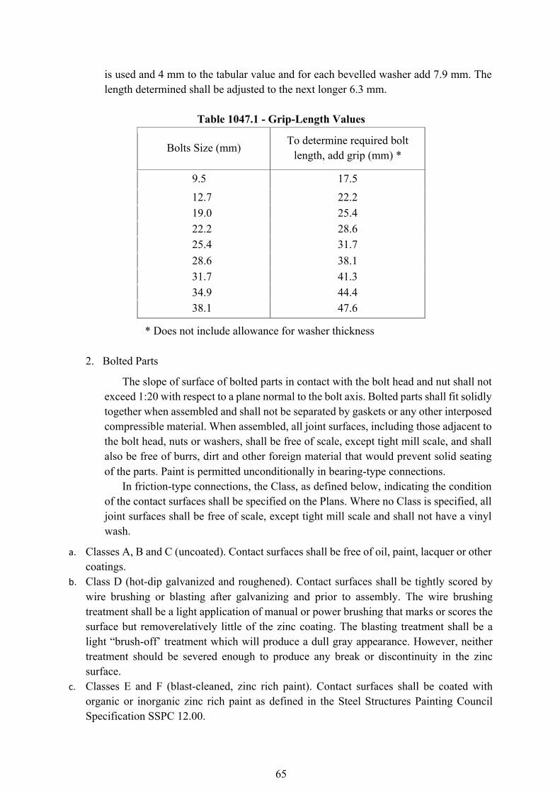
65
is used and 4 mm to the tabular value and for each bevelled washer add 7.9 mm. The length determined shall be adjusted to the next longer 6.3 mm.
Table 1047.1 - Grip-Length Values
Bolts Size (mm) To determine required bolt
length, add grip (mm) *
9.5 17.5 12.7 22.2 19.0 25.4 22.2 28.6 25.4 31.7 28.6 38.1 31.7 41.3 34.9 44.4 38.1 47.6
* Does not include allowance for washer thickness
2. Bolted Parts
The slope of surface of bolted parts in contact with the bolt head and nut shall not exceed 1:20 with respect to a plane normal to the bolt axis. Bolted parts shall fit solidly together when assembled and shall not be separated by gaskets or any other interposed compressible material. When assembled, all joint surfaces, including those adjacent to the bolt head, nuts or washers, shall be free of scale, except tight mill scale, and shall also be free of burrs, dirt and other foreign material that would prevent solid seating of the parts. Paint is permitted unconditionally in bearing-type connections.
In friction-type connections, the Class, as defined below, indicating the condition of the contact surfaces shall be specified on the Plans. Where no Class is specified, all joint surfaces shall be free of scale, except tight mill scale and shall not have a vinyl wash.
a. Classes A, B and C (uncoated). Contact surfaces shall be free of oil, paint, lacquer or other coatings.
b. Class D (hot-dip galvanized and roughened). Contact surfaces shall be tightly scored by wire brushing or blasting after galvanizing and prior to assembly. The wire brushing treatment shall be a light application of manual or power brushing that marks or scores the surface but removerelatively little of the zinc coating. The blasting treatment shall be a light “brush-off’ treatment which will produce a dull gray appearance. However, neither treatment should be severed enough to produce any break or discontinuity in the zinc surface.
c. Classes E and F (blast-cleaned, zinc rich paint). Contact surfaces shall be coated with organic or inorganic zinc rich paint as defined in the Steel Structures Painting Council Specification SSPC 12.00.
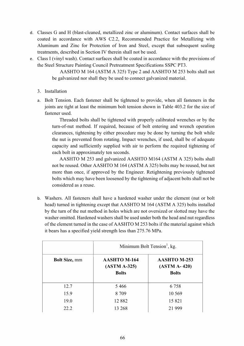
66
d. Classes G and H (blast-cleaned, metallized zinc or aluminum). Contact surfaces shall be coated in accordance with AWS C2.2, Recommended Practice for Metallizing with Aluminum and Zinc for Protection of Iron and Steel, except that subsequent sealing treatments, described in Section IV therein shall not be used.
e. Class I (vinyl wash). Contact surfaces shall be coated in accordance with the provisions of the Steel Structure Painting Council Pretreatment Specifications SSPC PT3.
AASHTO M 164 (ASTM A 325) Type 2 and AASHTO M 253 bolts shall not be galvanized nor shall they be used to connect galvanized material.
3. Installation
a. Bolt Tension. Each fastener shall be tightened to provide, when all fasteners in the joints are tight at least the minimum bolt tension shown in Table 403.2 for the size of fastener used.
Threaded bolts shall be tightened with properly calibrated wrenches or by the turn-of-nut method. If required, because of bolt entering and wrench operation clearances, tightening by either procedure may be done by turning the bolt while the nut is prevented from rotating. Impact wrenches, if used, shall be of adequate capacity and sufficiently supplied with air to perform the required tightening of each bolt in approximately ten seconds.
AASHTO M 253 and galvanized AASHTO M164 (ASTM A 325) bolts shall not be reused. Other AASHTO M 164 (ASTM A 325) bolts may be reused, but not more than once, if approved by the Engineer. Retightening previously tightened bolts which may have been loosened by the tightening of adjacent bolts shall not be considered as a reuse.
b. Washers. All fasteners shall have a hardened washer under the element (nut or bolt
head) turned in tightening except that AASHTO M 164 (ASTM A 325) bolts installed by the turn of the nut method in holes which are not oversized or slotted may have the washer omitted. Hardened washers shall be used under both the head and nut regardless of the element turned in the case of AASHTO M 253 bolts if the material against which it bears has a specified yield strength less than 275.76 MPa.
Minimum Bolt Tension1, kg.
Bolt Size, mm AASHTO M-164 (ASTM A-325)
Bolts
AASHTO M-253 (ASTM A- 420)
Bolts
12.7 5 466 6 758 15.9 8 709 10 569 19.0 12 882 15 821 22.2 13 268 21 999
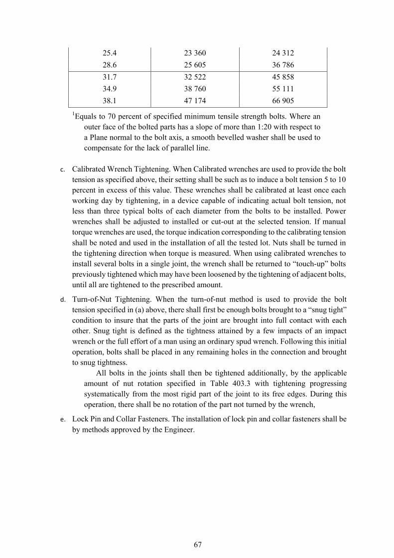
67
25.4 23 360 24 312 28.6 25 605 36 786 31.7 32 522 45 858 34.9 38 760 55 111 38.1 47 174 66 905
1Equals to 70 percent of specified minimum tensile strength bolts. Where an outer face of the bolted parts has a slope of more than 1:20 with respect to a Plane normal to the bolt axis, a smooth bevelled washer shall be used to compensate for the lack of parallel line.
c. Calibrated Wrench Tightening. When Calibrated wrenches are used to provide the bolt
tension as specified above, their setting shall be such as to induce a bolt tension 5 to 10 percent in excess of this value. These wrenches shall be calibrated at least once each working day by tightening, in a device capable of indicating actual bolt tension, not less than three typical bolts of each diameter from the bolts to be installed. Power wrenches shall be adjusted to installed or cut-out at the selected tension. If manual torque wrenches are used, the torque indication corresponding to the calibrating tension shall be noted and used in the installation of all the tested lot. Nuts shall be turned in the tightening direction when torque is measured. When using calibrated wrenches to install several bolts in a single joint, the wrench shall be returned to “touch-up” bolts previously tightened which may have been loosened by the tightening of adjacent bolts, until all are tightened to the prescribed amount.
d. Turn-of-Nut Tightening. When the turn-of-nut method is used to provide the bolt tension specified in (a) above, there shall first be enough bolts brought to a “snug tight” condition to insure that the parts of the joint are brought into full contact with each other. Snug tight is defined as the tightness attained by a few impacts of an impact wrench or the full effort of a man using an ordinary spud wrench. Following this initial operation, bolts shall be placed in any remaining holes in the connection and brought to snug tightness.
All bolts in the joints shall then be tightened additionally, by the applicable amount of nut rotation specified in Table 403.3 with tightening progressing systematically from the most rigid part of the joint to its free edges. During this operation, there shall be no rotation of the part not turned by the wrench,
e. Lock Pin and Collar Fasteners. The installation of lock pin and collar fasteners shall be by methods approved by the Engineer.

68
Table 1047.3 – Nut Rotation from Snug Tight Condition1
Disposition of Outer Faces of Bolted Parts
Bolt Length measured from underside of head to extreme end of point
Both faces normal to faces normal to bolt axis
One face normal to bolt axis and other face sloped not more 1:20 (bevel washer not used)
Both faces sloped not more than 1:20 from normal to bolt axis (bevel washers not used)
Up to and including diameters
0.33 turn 0.5 turn 0.66 turn
Over 4 diameters but not exceeding 8 diameters
0.5 turn 0.66 turn 0.625 turn
Over 8 diameters but not exceeding 12 diameters2
0.66 turn 0.83 turn 1 turn
1Nut rotation is relative to bolt, regardless of the element (nut or bolt) being turned. For bolts installed by 'A turn and less the tolerance should be plus or minus 30°, for bolts installed by 2/3 turn and more, the tolerance should be plus or minus 45°.
2No research work has been performed by the Research Council on Riveted and Bolted Structural joints to establish the turn-of-nut procedure when bolt lengths exceed 12 diameters. Therefore, the required rotation must be determined by actual tests in a suitable tension device simulating the actual conditions.
4. Inspection
The Engineer will determine that the requirements of these Specifications are not in the work. When the calibrated wrench method of tightening is used, the Engineer shall have full opportunity to witness the calibration tests.
The Engineer will observe the installation and tightening of the bolts to determine that the selected tightening procedure is properly used and will determine that all bolts are tightened. The following inspection shall be used unless a more extensive or different procedure is specified:
a. The Contractor shall use an inspecting wrench which may either be a torque
wrench or a power wrench that can be accurately adjusted in accordance with the requirements of Subsection 403.3.10(3) (c) above, in the presence of the Engineer.
69
b. Three bolts of the same grade, size and condition as those under inspection shall be placed individually in a calibration device capable of indicating bolt tension. Length may be any length representative of bolts used in the structure. There shall be a washer under the part turned in tightening each bolt.
c. When the inspecting wrench is a torque wrench, each of the three bolts specified above shall be tightened in the calibration device by any convenient means to the minimum tension specified for its size in Table 403.2. The inspecting wrench shall then be applied to the tightened bolt and the torque necessary to run the nut or head 5 degrees (approximately 25.4 mm at 304.8 mm radius) in the tightening direction shall be determined. The average torque measured in the tests of three bolts shall be taken as the job inspection torque to be used in the manner specified below.
d. When the inspecting wrench is a power wrench, it shall be adjusted so that it will tighten each of the three bolts specified to a tension at least 5 but not more than 10 percent greater than the minimum tension specified for its size in Table 403.2. This setting of wrench shall be taken as the job inspecting torque to be used in the manner specified below.
e. Bolts, represented by the three samples bolts prescribed above, which have been tightening in the structure shall be inspected by applying, in the tightening direction, the inspecting wrench and its job inspecting torque to 10 percent of the bolts, but not less than two bolts selected at random in each connection. If no nut or bolt head is turned by this application of the job inspecting torque, the connection shall be accepted as properly tightened. If any nut or bolt head is turned by the application of the job inspecting torque, this torque shall be applied to all bolts in the connection, and all bolts whose nut or head is turned by the job inspecting torque shall be tightened and re-inspected, or alternatively, the fabricator or erector, at his option may re-tighten all the bolts in the connection and then resubmit the connection for the specified inspection.
1047.3.11 Welding
Welding shall be done in accordance with the best modern practice and the applicable requirements at AWS D1.1 except as modified by AASHTO “Standard Specifications for Welding of Structural Steel Highway Bridges”.
1047.3.12 Erection
1. General
The Contractor shall provide the falsework and all tools, machinery and appliances, including driftpins and fitting-up bolts, necessary for the expeditious handling of the work and shall erect the metal work, remove the temporary construction, and do all work necessary to complete the structure as required by the Contract and in accordance with the Plans and these
70
Specifications. If shown on the Plans or in the Special Provisions, the Contractor shall dismantle the old
structure on the bridge site in accordance with Item 101, Removal of Structures and Obstructions.
1047.3.13 Handling and Storing Materials
Materials to be stored shall be placed on skids above the ground. It shall be kept clean and properly drained. Girders and beams shall be placed upright and shored. Long members, such as columns and chords, shall be supported on skids placed near enough together to prevent injury from deflection. If the Contract is for erection only, the Contractor shall check the material turned over to him against the shipping lists and report promptly in writing any shortage or damage discovered. He shall be responsible for the loss of any material while in his care, or for any damage caused to it after being received by him.
1047.3.14 Falsework
The false work shall be properly designed and substantially constructed and maintained for the loads which will come upon it. The Contractor shall prepare and submit to the Engineer working drawings for falsework and working drawings for changes in any existing structure for maintaining traffic, in accordance with Clause 45 of Part G, Div. II, Vol. I.
1047.3.15 Method and Equipment
Before starting the work of erection, the Contractor shall inform the Engineer fully as to the method of erection he proposes to follow, and the amount and character of equipment he proposes to use, which shall be subject to the approval of the Engineer. The approval of the Engineer shall not be considered as relieving the Contractor of the responsibility for the safety of his method or equipment or from carrying out the work in full accordance with the Plans and Specifications. No work shall be done until such approval by the Engineer has been obtained.
1047.3.16 Straightening Bent Materials
The strengthening of plates, angles, other shapes and built-up members, when permitted by the Engineer, shall be done by methods that will not produce fracture or other injury. Distorted members shall be straightened by mechanical means or, if approved by the Engineer, by the carefully planned and supervised application of a limited amount of localized heat, except that heat straightening of AASHTO M 244 (ASTM A 514) or ASTM A 517 steel members shall be done only under rigidly controlled procedures, each application subject to the approval of the Engineer. In no case shall the maximum temperature of the AASHTO M 244 (ASTM A 514) or ASTM A 517 steels exceed 607.2°C, nor shall the temperature exceed 510°C at the weld metal or within 152.4 mm of weld metal. Heat shall not be applied directly on weld metal. In all other steels, the temperature of the heated area shall not exceed 648.9°C (a dull red) as controlled by temperature indicating crayons, liquids or bimetal thermometers.
Parts to be heat-straightened shall be substantially free of stress and from external forces, except stresses resulting from mechanical means used in conjunction with the application of heat.
71
Following the straightening of a bend or buckle, the surface of the metal shall be carefully inspected for evidence of fracture.
1047.3.17 Assembling Steel
The parts shall be accurately assembled as shown on the working drawings and any matchmarks shall be followed. The material shall be carefully handled so that no parts will be bent, broken or otherwise damaged. Hammering which will injure or distort the members shall not be done. Bearing surfaces and surfaces to be in permanent contact shall be cleaned before the members are assembled. Unless erected by the cantilever methods, truss spans shall be erected on blocking so placed as to give the trusses proper camber. The blocking shall be left in place until the tension chord splices are fully connected with permanent fasteners and all other truss connections pinned and erection bolted. Splices of butt joints of compression members, that are milled to bear and of railing shall not be permanently fastened until the spans have been swung, except that such permanent fastening may be accomplished for the truss members at any time that joint holes are fair. Splices and field connections shall have one-half of the holes filled with erection bolts and cylindrical erection pins (half bolts and half pins) before placing permanent fasteners. Splices and connections carrying traffic during erection shall have three-fourths of the holes so filled, unless otherwise permitted by the Engineer.
Fitting-up bolts shall be of the same nominal diameter as the permanent fasteners and cylindrical erection pins will be 1.6 mm larger. 1047.3.18 Riveting
Pneumatic hammers shall be used for field riveting except when the use of hand tools is permitted by the Engineer. Rivets larger than mm in diameter shall not be driven by hand. Cup-faced dollies, fitting the head closely to insure good bearing, shall be used. Connections shall be accurately and securely fitted up before the rivets are driven.
Drifting shall be only such as to draw the parts into position and not sufficient to enlarge the holes or distort the metal. Unfair holes shall be reamed or drilled. Rivets shall be heated uniformly to a “light cherry red” color and shall be driven while hot. They shall not be overheated or burned. Rivet heads shall be full and symmetrical, concentric with the shank, and shall have full bearing all around. They shall not be smaller than the heads of the shop rivets. Rivets shall be tight and shall grip the connected parts securely together. Caulking or recupping will not be permitted. In removing rivets, the surrounding metal shall not be injured. If necessary, they shall be drilled out.
1047.3.19 Pin Connections
Pilot and driving nuts shall be used in driving pins. They shall be furnished by the Contractor without charge. Pins shall be so driven that the members will take full bearing on them. Pin nuts shall be screwed up tight and the threads burred at the face of the nut with a pointed tool.
72
1047.3.20 Setting Shoes and Bearings Shoes and bearing shall not be placed on bridge seat bearing areas that are improperly
finished, deformed, or irregular. They shall be set level in exact position and shall have full and even bearing. The shoes and bearing plates may be set by either of the following methods:
1. Method 1
The bridge seat bearing area shall be heavily coated with red lead paint and then covered with three layers of 405 to 472 g/m2 duck, each layer being coated thoroughly on its top surface with red lead paint. The shoes and bearing plates shall be placed in position while the paint is plastic. As alternatives to canvas and red lead, and when so noted on the Plans or upon written permission by the Engineer, the following may be used:
a. Sheet lead of the designated thickness b. Preformed fabric pad composed of multiple layers of 270 g/m2 duck impregnated
and bound with high quality natural rubber or of equivalent and equally suitable materials compressed into resilient pads of uniform thickness. The number of plies shall be such as to produce the specified thickness, after compression and vulcanizing. The finished pads shall withstand compression loads perpendicular to the plane of the laminations of not less than 7 kg/mm2 without detrimental reduction in thickness or extension.
c. Elastomeric bearing pads
2. Method 2
The shoes and bearing plates shall be properly supported and fixed with grout. No load shall be placed on them until the grout has set for at least 96 hours, adequate provision being made to keep the grout well moistened during this period. The grout shall consist of one part Portland Cement to one part of fine-grained sand.
The location of the anchor bolts in relation to the slotted holes in expansion shoes shall correspond with the temperature at the time of erection. The nuts on anchor bolts at the expansion ends shall be adjusted to permit the free movement of the span.
1047.3.21 Preparing Metal Surfaces for Painting
All surfaces of new structural steel which are to be painted shall be blast cleaned unless otherwise specified in the Special Provisions or approved in writing by the Engineer.
In repainting existing structures where partial cleaning is required, the method of cleaning will be specified in the Special Provision.
The steel surfaces to be painted shall be prepared as outlined in the “Steel Structures Painting Council Specifications" (SSPC) meeting one of the following classes of surface preparation.
a. SSPC - SP - 5 White Metal Blast Cleaning b. SSPC - SP - 6 Commercial Blast Cleaning
73
c. SSPC-SP-8 Pickling d. SSPC-SP-10 Near White Blast Cleaning
Blast cleaning shall leave all surfaces with a dense and uniform anchor pattern of not
less than one and one-half mills as measured with an approved surface profile comparator.
Blast cleaned surfaces shall be primed or treated the same day blast cleaning is done. If cleaned surface rust or are contaminated with foreign material before painting is accomplished, they shall be recleaned by the Contractor at his expense.
When paint systems No. 1 or 3 are specified, the steel surfaces shall be blast cleaned in accordance with SSPC - SP - 10. When paint systems No. 2, 4 or 5 are specified, the steel surface shall be blast cleaned in accordance with SSPC - SP - 6. 1047.3.22 System of Paint
The paint system to be applied shall consist of one as set forth in Table 403.4 and as modified in the Special Provisions.
1047.3.23 Painting Metal Surfaces
1. Time of Application
The prime coat of paint or pretreatment when specified, shall be applied as soon as possible after the surface has been cleaned and before deterioration of the surface occurs. Any oil, grease, soil, dust or foreign matter deposited on the surface after the surface preparation is completed shall be removed prior to painting. In the event the rusting occurs after completion of the surface preparation, the surfaces shall be again cleaned.
Particular care shall be taken to prevent the contamination of cleaned surfaces with salts, acids, alkali, or other corrosive chemicals before the prime coat is applied and between applications of the remaining coats of paint. Such contaminants shall be removed from the surface. Under these circumstances, the pretreatments or, in the absence of a pretreatment, the prime coat of paint shall be applied immediately after the surface has been cleaned.
2. Storage of Paint and Thinner
All paint and thinner should preferably be stored in a separate building or room that is well ventilated and free from excessive heat, sparks, flame or the direct ray of the sun.
All containers of paint should remain unopened until required for use. Containers which have been opened shall be used first.
Paint which has livered, gelled, or otherwise deteriorated during storage shall not be used. Thixotropic materials which may be stirred to attain normal consistency are satisfactory.
3. Mixing and Thinning
74
All ingredients in any container of paint shall be thoroughly mixed before use and shall be agitated often enough during application to keep the pigment in suspension.
Paint mixed in the original container shall not be transferred until all settled pigment is incorporated into the vehicle. This does not imply that part of the vehicle cannot be poured off temporarily to simplify the mixing.
Mixing shall be by mechanical methods, except that hard mixing will be permitted for container up to 19 litres in size. Mixing in open containers shall be done in a well ventilated area away from sparks or
flames. Paint shall not be mixed or kept in suspension by means of an air stream bubbling
under the paint surface. When a skin has formed in the container, the skin shall be cut loose from the sides
of the container, removed, and discarded. If such skins are thick enough to have a practical effect on the composition and quality of the paint, the paint shall not be used.
The paint shall be mixed in manner which will insure breaking up of all lumps, complete dispersion of settled pigment, and a uniform composition. If mixing is done by hand, most of the vehicle shall be poured off into a clean container. The pigment in the paint shall be lifted from the bottom of the container with a broad, flat paddle, lumps shall be broken up, and the pigment thoroughly mixed with the vehicle. The poured off vehicle shall be returned to the paint with simultaneous stirring, or pouring repeatedly from one container to another until the composition is uniform. The bottom of the container shall be inspected for unmixed pigment. Tinting pastes or colors shall be wetted with a small amount of thinner, vehicle, or paint and thoroughly mixed. The thinned mixture shall be added to the large container of paint and mixed until the color is uniform.
Paint which does not have a limited pot life, or does not deteriorate on standing, may be mixed at any time before using, but if settling has occurred, it must be remixed immediately before using. Paint shall not remain in spray pots, painter’s buckets, etc., overnight, but shall be gathered into a container and remixed before use.
No thinner shall be added to the paint unless necessary for proper application. In no case shall more than 0.5 litres of thinner be added per 3.8 litres unless the paint is intentionally formulated for greater thinning.
The type of thinner shall comply with the paint specification. When the use of thinner is permissible, thinner shall be added to paint during the
mixing process. Painters shall not When the use of thinner is permissible, thinner shall be added to paint during the mixing process. Painters shall not add thinner to paint after it has been thinned to the correct consistency.
All thinning shall be done under supervision of one acquainted with the correct amount and type of thinner to be added to the paint.
75
Table 1047.4 - Paint System Paint System
High Pollution or Coastal Mild
1 2 3 4 5
X X X
Climate X X Note:
1. Paint system shown for severe areas are satisfactorily in less severe areas. 2. Coastal - within 304.8 m of ocean or tidal water. High pollution-air pollution environment such as industrial areas. Mild-other than coastal areas not in air pollution environment All structural steel shall
be painted by one of the following systems. The required system or choice of systems will be shown in the Contract.
System 4 is intended for use in mild climates or to repaint existing structures where the other systems are not compatible.
Coating Thickness Specifications Min. Dry Film
System 1 - Vinyl Paint System Wash Prime Intermediate Coat 3rd Coat 4th Coat Finish Coat
708.3 (b) 708.3 (b)
708.3 (b) 708.3 (b)
708.3 (b) 708.4 Total thickness
12.7 38.10- 50.80
38.10- 50.80 38.10- 50.80
38.10- 50.80 165.10 -203.20
System 2 - Epoxy-Polymide System
Prime Coat Intermediate Coat 3rd Coat Finish Coat Total thickness
708.3 (c) 708.3 (c) 708.3 (c)
708.3 (c) 190.50 -279.40
50.80 - 76.20
50.80 - 76.20 50.80 - 76.20 38.10-50.80
* The third coat may be eliminated in mild climates
All structural steel shall be painted by one of the following systems. The required
system or choice of systems will be shown in the Contract. System 4 is intended for use in mild climates or to repaint existing structures where the
other systems are not compatible.
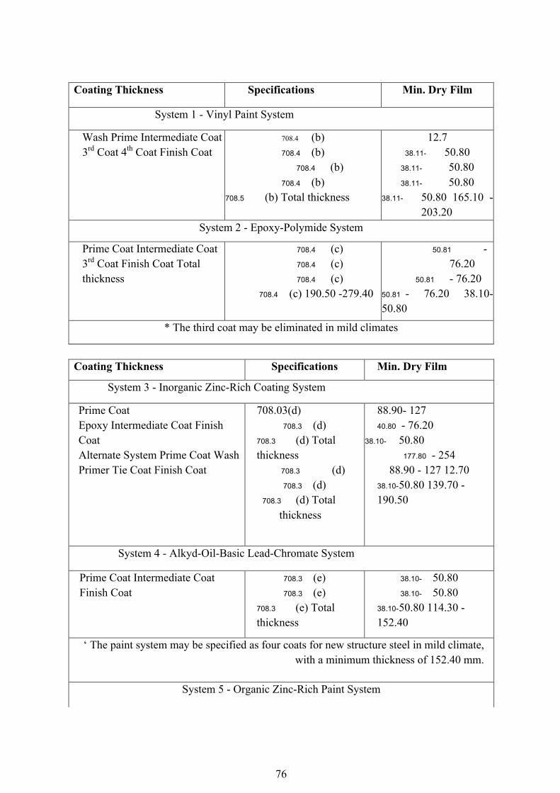
76
Coating Thickness Specifications Min. Dry Film
System 1 - Vinyl Paint System
Wash Prime Intermediate Coat 3rd Coat 4th Coat Finish Coat
708.4 (b) 708.4 (b)
708.4 (b) 708.4 (b)
708.5 (b) Total thickness
12.7 38.11- 50.80
38.11- 50.80 38.11- 50.80
38.11- 50.80 165.10 -203.20
System 2 - Epoxy-Polymide System
Prime Coat Intermediate Coat 3rd Coat Finish Coat Total thickness
708.4 (c) 708.4 (c) 708.4 (c)
708.4 (c) 190.50 -279.40
50.81 - 76.20
50.81 - 76.20 50.81 - 76.20 38.10-50.80
* The third coat may be eliminated in mild climates
Coating Thickness Specifications Min. Dry Film
System 3 - Inorganic Zinc-Rich Coating System
Prime Coat Epoxy Intermediate Coat Finish Coat Alternate System Prime Coat Wash Primer Tie Coat Finish Coat
708.03(d) 708.3 (d)
708.3 (d) Total thickness
708.3 (d) 708.3 (d)
708.3 (d) Total thickness
88.90- 127 40.80 - 76.20
38.10- 50.80 177.80 - 254
88.90 - 127 12.70 38.10- 50.80 139.70 - 190.50
System 4 - Alkyd-Oil-Basic Lead-Chromate System
Prime Coat Intermediate Coat Finish Coat
708.3 (e) 708.3 (e)
708.3 (e) Total thickness
38.10- 50.80 38.10- 50.80
38.10- 50.80 114.30 - 152.40
‘ The paint system may be specified as four coats for new structure steel in mild climate, with a minimum thickness of 152.40 mm.
System 5 - Organic Zinc-Rich Paint System
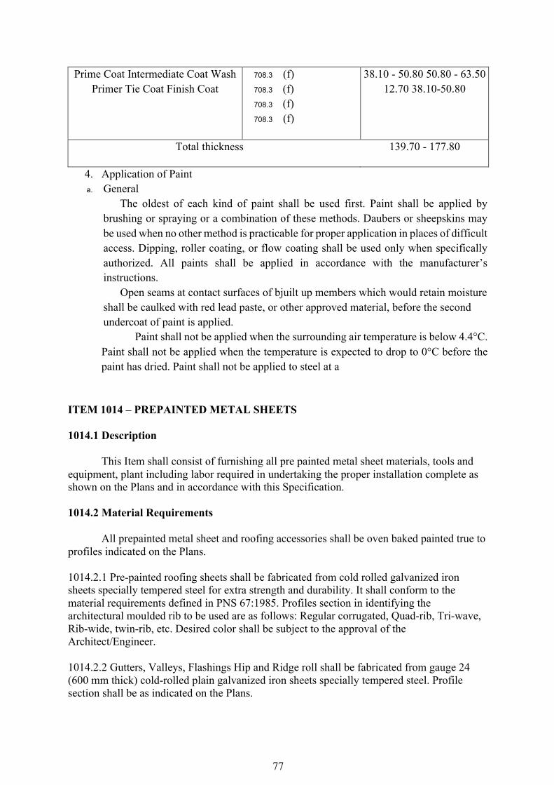
77
Prime Coat Intermediate Coat Wash Primer Tie Coat Finish Coat
708.3 (f) 708.3 (f) 708.3 (f) 708.3 (f)
38.10 - 50.80 50.80 - 63.50 12.70 38.10-50.80
Total thickness 139.70 - 177.80
4. Application of Paint a. General
The oldest of each kind of paint shall be used first. Paint shall be applied by brushing or spraying or a combination of these methods. Daubers or sheepskins may be used when no other method is practicable for proper application in places of difficult access. Dipping, roller coating, or flow coating shall be used only when specifically authorized. All paints shall be applied in accordance with the manufacturer’s instructions.
Open seams at contact surfaces of bjuilt up members which would retain moisture shall be caulked with red lead paste, or other approved material, before the second undercoat of paint is applied. Paint shall not be applied when the surrounding air temperature is below 4.4°C. Paint shall not be applied when the temperature is expected to drop to 0°C before the paint has dried. Paint shall not be applied to steel at a
ITEM 1014 – PREPAINTED METAL SHEETS 1014.1 Description This Item shall consist of furnishing all pre painted metal sheet materials, tools and equipment, plant including labor required in undertaking the proper installation complete as shown on the Plans and in accordance with this Specification. 1014.2 Material Requirements All prepainted metal sheet and roofing accessories shall be oven baked painted true to profiles indicated on the Plans. 1014.2.1 Pre-painted roofing sheets shall be fabricated from cold rolled galvanized iron sheets specially tempered steel for extra strength and durability. It shall conform to the material requirements defined in PNS 67:1985. Profiles section in identifying the architectural moulded rib to be used are as follows: Regular corrugated, Quad-rib, Tri-wave, Rib-wide, twin-rib, etc. Desired color shall be subject to the approval of the Architect/Engineer. 1014.2.2 Gutters, Valleys, Flashings Hip and Ridge roll shall be fabricated from gauge 24 (600 mm thick) cold-rolled plain galvanized iron sheets specially tempered steel. Profile section shall be as indicated on the Plans.
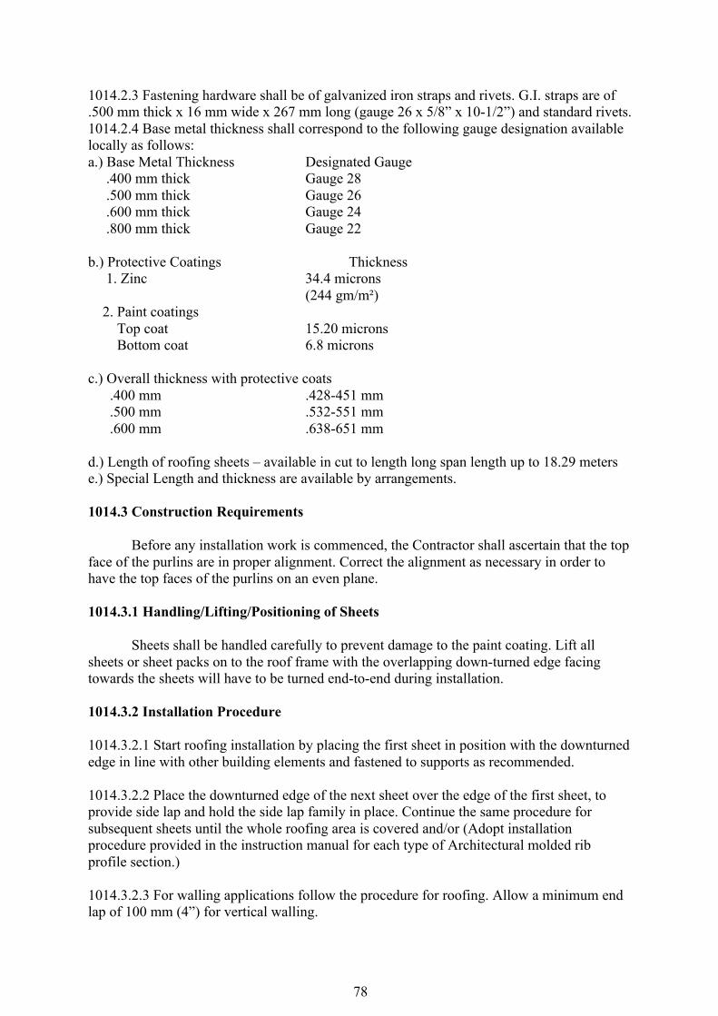
78
1014.2.3 Fastening hardware shall be of galvanized iron straps and rivets. G.I. straps are of .500 mm thick x 16 mm wide x 267 mm long (gauge 26 x 5/8” x 10-1/2”) and standard rivets. 1014.2.4 Base metal thickness shall correspond to the following gauge designation available locally as follows: a.) Base Metal Thickness Designated Gauge .400 mm thick Gauge 28 .500 mm thick Gauge 26 .600 mm thick Gauge 24 .800 mm thick Gauge 22 b.) Protective Coatings Thickness 1. Zinc 34.4 microns (244 gm/m²) 2. Paint coatings Top coat 15.20 microns Bottom coat 6.8 microns c.) Overall thickness with protective coats .400 mm .428-451 mm .500 mm .532-551 mm .600 mm .638-651 mm d.) Length of roofing sheets – available in cut to length long span length up to 18.29 meters e.) Special Length and thickness are available by arrangements. 1014.3 Construction Requirements Before any installation work is commenced, the Contractor shall ascertain that the top face of the purlins are in proper alignment. Correct the alignment as necessary in order to have the top faces of the purlins on an even plane. 1014.3.1 Handling/Lifting/Positioning of Sheets Sheets shall be handled carefully to prevent damage to the paint coating. Lift all sheets or sheet packs on to the roof frame with the overlapping down-turned edge facing towards the sheets will have to be turned end-to-end during installation. 1014.3.2 Installation Procedure 1014.3.2.1 Start roofing installation by placing the first sheet in position with the downturned edge in line with other building elements and fastened to supports as recommended. 1014.3.2.2 Place the downturned edge of the next sheet over the edge of the first sheet, to provide side lap and hold the side lap family in place. Continue the same procedure for subsequent sheets until the whole roofing area is covered and/or (Adopt installation procedure provided in the instruction manual for each type of Architectural molded rib profile section.) 1014.3.2.3 For walling applications follow the procedure for roofing. Allow a minimum end lap of 100 mm (4”) for vertical walling.
79
1014.3.3 Gutters, Valleys, Flashing ridge and Hip rolls Gutters, valleys, flashing ridge and hip rolls shall be fastened where indicated on the Plans by self-tapping screws or galvanized iron straps and rivets. 1014.3.4 End Laps In case handling or transport consideration requires to use two or more end lapped sheets to provide full length coverage for the roof run, install each line of sheets from bottom to top or from eave line to apex of roof framing. Provide 150 mm minimum end lap. 1014.3.5 Anchorage/Fastening 1014.3.5.1 Prepainted steel roofing sheets shall be fastened to the wood purlins with standard length G.I. straps and rivets. 1014.3.5.2 For steel frame up to 4.5 mm thick use self-drilling screw No.12 by 35 mm long hexagonal head with neoprene washer. 1014.3.5.3 For steel support up to 5 mm thick or more use thread cutting screw No. 12 by 40 mm long hexagonal head with neoprene washer. 1014.3.5.4 Side lap fastener use self drilling screw No. 10 by 16 mm long hexagonal head with neoprene washer. 1014.3.5.5 Valley fastened to lumber and for walling use self-drilling wood screw No. 12 by 25 mm long hexagonal head with neoprene washer. 10143.5.6 Valley fastened to steel supports use selfdrilling wood screw, hexagonal head with neoprene washer. Drill size is 5 mm diameter. 1014.3.6 Cutting of Sheets 1014.3.6.1 In cutting prepainted steel roofing sheets and accessories to place the exposed color side down. Cutting shall be carried out on the ground and not over the top of other painted roofing product. 1014.3.6.2 Power cutting or drilling to be done or carried out on prepainted products already installed or laid in position, the area around holes or cuts shall be masked to shield the paint from hot fillings. 1014.3.7 Storage and Protection Prepainted steel roofing, walling products and accessories should be delivered to the jobsite in strapped bundles. Sheets and/or bundles shall be neatly stacked in the ground and it left in the open it shall be protected by covering the stack materials with loose tarpauline. 1014.4 Method of Measurement The work done under this item shall be measured by actual area covered or installed with prepainted steel roofing and/or walling in square meters and accepted to the satisfaction of the Engineer/Architect.

80
1014.5 Basis of Payment The area of prepainted steel roofing and/or walling in square meters as provided in section 1014 shall be paid for at the unit bid or contract unit price which payment shall constitute full compensation including labor, materials, tools and incidents necessary to complete this item. Payment shall be made under: Pay Item Number Description Unit of Measurement 1014(a) Prepainted metal sheet m² ITEM 1100 – CONDUITS, BOXES & FITTINGS 1100.1 Description This Item shall consist of the furnishing and installation of the compete conduit work consisting of electrical conduits; conduits boxes such as junction boxes, pull boxes, utility boxes, octagonal and square boxes; conduit fittings such as couplings, locknuts and bushings and other electrical materials needed to complete the conduit roughing-in work of this project. 1100.2 Materials Requirements All materials shall be brand new and shall be of the approved type meeting all the requirements of the Philippine Electrical Code and bearing the Philippine Standard Agency (PSA) mark. Conduits Conduits shall be standard rigid steel, zinc coated or galvanized. Intermediate metal conduit may be used if shown or specified on the approved Plans. PVC conduits if required shall be Schedule 40. Enamel coated steel conduits and conduits with rough inner surface are not acceptable. Conduits Boxes All conduit boxes shall be Code gauge steel and galvanized. Outlet boxes shall be galvanized pressed steel of standard make. In general, outlet boxes shall be at least 100mm square or octagonal, 53 mm deep and 16 mm minimum gauge. Conduit Fittings All conduit fittings such as locknuts and bushing shall be galvanized of standard make. 1100.3 Construction Requirements All works thoroughly shall be executed in the best practice in a workmanlike manner by qualified and experienced electricians under the immediate supervision of duly licensed Electrical Engineer. Conduits Conduits should be cut square with a hacksaw and reamed. Bends shall be made with the required radius. In making bends only conduit bending apparatus will be used. The use of a pipe tee or vise for bending conduits shall not be permitted. Conduits which have been crushed, deformed or flattened shall not be installed. No running thread shall be allowed.
81
Conduit runs crossing construction joints of the building shall be provided with standard expansion fittings of the approved type. No conduits shall be used in any system smaller than 12 mm diameter electric trade size nor shall have more than four (4) 90-degree bends in any one run and where necessary, pull boxes shall be provided. All ends of conduits which are left empty in cabinets and conduit boxes shall be plugged with lead or approved pipe caps so as to prevent the entrance of white ants and dirt within the conduit system. Pull wires shall be inserted in the empty ducts before they are closed with lead or pipe caps and shall be left therein for future use. On expose work, all pipes and outlet boxes shall be secured by means of galvanized metal clamps which shall be held in place by means of machine screws. When running over concrete surfaces, the screws shall be held in place by means of expansion sleeves for big pipes and rolled lead sheet for small pipes. All pipes shall be run at right angles to and parallel with the surrounding walls. No diagonal run shall be allowed and all bends and offsets shall be avoided as much as possible. Conduits shall be supported at 1,500 mm intervals maximum. Conduits Boxes & Fittings Provide conduit boxes for pulling and splicing wires and outlet boxes for installation of wiring devices. As a rule, provide junction boxes or pull boxes in all runs greater than 30 meters in length, for horizontal runs. For other lengths, provide boxes as required for splices or pulling. Pull boxes shall be installed in inconspicuous but accessible locations. Support boxes independently of conduits entering by means of bolts, red hangers or other suitable means. Conduits boxes shall be installed plump and securely fastened. They shall be set flush with the surface of the structure in which they are installed where conduits are run concealed. All convenience and wall switch outlet boxes for concealed conduit work shall be deep, rectangular flush type boxes; four-inch octagonal flush type boxes shall be used of all ceiling light outlets and shall be of the deep type where three or more conduits connect to a single box. Floor mounted outlet boxes required shall be waterproof type with flush brass floor plate and brass bell nozzle. All boxes shall be painted with antirust red lead paint after installation. All conduits shall be fitted with approved standard galvanized bushing and locknuts where they enter cabinets and conduits boxes. Junction and pull boxes of code gauge steel shall be provided as indicated or as required to facilitate the pulling of wires and cables. 1100.4 Method of Measurement The work under this Item shall be measured either by lengths, pieces, pairs, lot and set actually placed and installed as shown on the approved plans. 1100.5 Basis of Payment
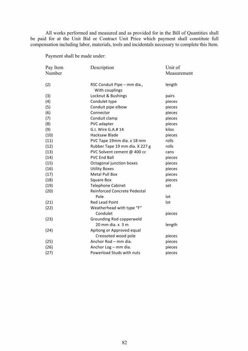
82
All works performed and measured and as provided for in the Bill of Quantities shall be paid for at the Unit Bid or Contract Unit Price which payment shall constitute full compensation including labor, materials, tools and incidentals necessary to complete this Item. Payment shall be made under: Pay Item Description Unit of Number Measurement
(2) RSCConduitPipe–mmdia., length Withcouplings(3) Locknut&Bushings pairs(4) Condulettype pieces(5) Conduitpipeelbow pieces(6) Connector pieces(7) Conduitclamp pieces(8) PVCadapter pieces(9) G.I.WireG.A.#14 kilos(10) HacksawBlade pieces(11) PVCTape19mmdia.x18mm rolls(12) RubberTape19mmdia.X227g rolls(13) PVCSolventcement@400cc cans(14) PVCEndBall pieces(15) Octagonaljunctionboxes pieces(16) UtilityBoxes pieces(17) MetalPullBox pieces(18) SquareBox pieces(19) TelephoneCabinet set(20) ReinforcedConcretePedestal Pole lot(21) RedLeadPoint lot(22) Weatherheadwithtype“F”
Condulet pieces(23) GroundingRodcopperweld
20mmdia.x3m length(24) ApitongorApprovedequal
Creosotedwoodpole pieces(25) AnchorRod–mmdia. pieces(26) AnchorLog–mmdia. pieces(27) PowerloadStudswithnuts pieces
83
ITEM 1101 – WIRING AND WIRING DEVICES 1101.1 Description This Item shall consist of the furnishing and installation of all wires and wiring devices consisting of electric wires and cables, wall switches, convenience receptacles, heavy duty receptacles and other devices shown on the approved Plans but not mentioned in these specifications. 1101.2 Material Requirements Wires and cables shall be of the approved type meeting all the requirements of the Philippine Electrical Code and bearing the PSA mark. Unless specified or indicated otherwise, all power and lighting conductors shall be insulated for 600 volts. All wires shall be copper, soft drawn and annealed, smooth and of cylindrical form and shall be centrally located inside the insulation. All wiring devices shall be standard products of reputable electrical manufacturers. Wall switches shall be rated at least 10A. 250 volts and shall be spring operated, flush, tumbler type. Duplex convenience receptacles shall be rated at least 15A, 250 volts, flush, parallel slots. Single heavy duty receptacles shall be rated at least 20A, 250 volts. 3 -wire, flush, polarized type. 1101.3 Construction Requirements Conductors or wires shall not be drawn in conduits until after the cement plaster is dry and the conduits are thoroughly cleaned and free from dirt and moisture. In drawing wires into conduits, sufficient slack shall be allowed to permit easy connections for fixtures, switches, receptacles and other wiring devices without the use of additional splices. All conductors of convenience outlets and lighting branch circuit homeruns shall be wired with a minimum of 3.5 mm in size. Circuit homeruns to panel-boards shall not be smaller than 3.5 mm but all homeruns to panel-board more than 30 meters shall not be smaller than 5.5 mm. No conductor shall be less than 2 mm in size. All wires of 14mm and larger in size shall be connected to panels and apparatus by means of approved type lugs or connectors of the solderless type, sufficiently large enough to enclose all strands of the conductors and securely fastened. They shall not loosen under vibration or normal strain. All joints, tap and splices on wires larger than 14 mm shall be made of suitable solderless connectors of the approved type and size. They shall be tapped with rubber and PVC tapes providing insulation not less than that of the conductors. No splices or joints shall be permitted in either feeder or branch conductors except within outlet boxes or accessible junction boxes or pull boxes. All joints in branch circuit wiring shall be made mechanically and electrically secured by approved splicing devices and taped with rubber and PVC tapes in a manner which will make their insulation as that of the conductor. All wall switches and receptacles shall be fitted with standard Bakelite face plate covers. Device plates for flush mounting shall be installed with all four edges in continuous contact with finished wall surfaces without the use of coiled wire or similar devices. Plaster fillings will not be permitted. Plates installed in wet locations shall be gasketed. When more than one switched or device is indicated in a single location, gang plate shall be used.
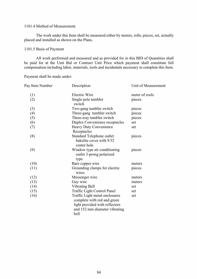
84
1101.4 Method of Measurement The work under this Item shall be measured either by meters, rolls, pieces, set, actually placed and installed as shown on the Plans. 1101.5 Basis of Payment All work performed and measured and as provided for in this BID of Quantities shall be paid for at the Unit Bid or Contract Unit Price which payment shall constitute full compensation including labor, materials, tools and incidentals necessary to complete this Item. Payment shall be made under: Pay Item Number Description Unit of Measurement
(1) Electric Wire meter of rools (2) Single pole tumbler pieces
switch (3) Two-gang tumbler switch pieces (4) Three-gang tumbler switch pieces (5) Three-way tumbler switch pieces (6) Duplex Convenience receptacles set (7) Heavy Duty Convenience set
Receptacles (8) Standard Telephone outlet pieces
bakelite cover with 9.52 center hole
(9) Window type air conditioning pieces outlet 3-prong polarized type
(10) Bare copper wire meters (11) Grounding clamps for electric pieces
wires (12) Messenger wire meters (13) Guy wire meters (14) Vibrating Bell set (15) Traffic Light Control Panel set (16) Traffic Light metal enclosures set
complete with red and green light provided with reflectors and 152 mm diameter vibrating bell
85
ITEM 1102 – POWER LOAD CENTER, SWITCHGEAR AND PANEL BOARDS 1102.1 Description This Item shall consist of the furnishing and installation of the power load center unit substation or low voltage switchgear and distribution panelboards at the location shown or the approved Plans complete with transformer, circuit breakers, cabinets and all accessories, completely wired and ready for service. 1102.2 Material Requirements All materials shall be brand new and shall be of the approved type. It shall conform with the requirements of the Philippine Electrical Code and shall bear the Philippine e Standard Agency (PSA) mark. Power Load Center Unit Substation The Contractor shall furnish and install an indoor-type Power Load Center Unit Substation at the location shown on the approved Plans if required. It shall be totally metal-enclosed, dead front and shall consist of the following coordinated component parts: High Voltage Primary Section: High voltage primary incoming line section consisting of the following parts and related accessories:
(a) One (1) Air-filled Interrupter Switch, 2-position (open-close) installed in a suitable air filled metal enclosure and shall have sufficient interrupting capacity to carry the electrical load. It shall be provided with key interlock with the cubicle for the power fuses to prevent access to the fuses unless the switch is open.
(b) Three (3)-power fuses mounted in separate compartments within the switch housing and accessible by a hinged door.
(c) One (1) set of high voltage potheads or 3-conductor cables or three single conductor cables.
(d) Lightning arresters shall be installed at the high voltage cubicle if required. Items (a) and (b) above could be substituted with a power circuit breaker with the correct rating and capacity. Transformer Section The transformer section shall consist of a power transformer with ratings and capacities as shown on the plans. It shall be oil liquid-filled non-flammable type and designed in accordance with the latest applicable standards. The transformer shall be provided with four (4 approximately 2 ½ % rated KVA taps on the primary winding in most cases one (1) above and three (3) below rated primary voltage and shall be changed by means of externally gang-operated manual tap changer only when the transformer is de-energized. Tap changing under load is acceptable if transformer has been so designed. The following accessories shall be provided with the transformer, namely: drain valve, sampling device, filling connection, oil liquid level gauge, ground pad, top filter press connection, lifting lugs, diagrammatic nameplate, relief valve, thermometer and other necessary related accessories.
86
The high-voltage and low-voltage bushings and transition flange shall be properly coordinated for field connection to the incoming line section and low voltage switchboard section, respectively. Low-Voltage Switchboard Section The low-voltage switchboard shall be standard modular-unitized units, metal-built, dead front, safety type construction and shall consist of the following:
(a) Switchboard Housing The housing shall be heavy gauge steel sheet, dead front type, gray enamel finish complete with frame supports, steel bracing, steel sheet panelboards, removable rear plates, copper busbars, and all other necessary accessories to insure sufficient mechanical strength and safety. It shall be provided with grounding bolts and clamps.
(b) Secondary Metering Section The secondary metering section shall consist of one (1) ammeter, AC, indicating type; one(1) voltmeter transfer switch for 3-phase; and current transformers of suitable rating and capacity. The above-mentioned instruments shall be installed in one compartment above the main breaker and shall be complete with all necessary accessories completely wired, ready for use.
(c) Main Circuit Breaker The main circuit breaker shall be draw-out type, manually or electrically operated as required with ratings and capacity as shown on the approved Plans. The main breaker shall include insulated control switch if electrically operated, manual trip button, magnetic tripping devices, adjustable time overcurrent protection and instantaneous short circuit trip and all necessary accessories to insure safe and efficient operation.
(d) Feeder Circuit Breakers There shall be as many feeder breakers as are shown on the single line diagram or schematic riser diagram and schedule of loads and computations on the Plans. The circuit breakers shall be drawout or molded case as required. The circuit breakers shall each have sufficient interrupting capacity and shall be manually operated complete with trip devices and all necessary accessories to insure safe and efficient operation. The number, ratings, capacities of the feeder branch circuit breakers shall be as shown on the approved Plans. Circuit breakers shall each be of the indicating type, providing “ON” – “OFF” and “TRIP” positions of the operating handles and shall each be provided with nameplate for the branch circuit designation. The circuit breaker shall be so designed that an overload or short on one pole automatically causes all poles to open. Low-Voltage Switchgear (For projects requiring low-voltage switchgear only) The Contractor shall furnish and install a low-voltage switchgear at the location shown on the plans. It shall be metal-clad, dead front, free standing, safety type construction and shall have copper busbars of sufficient size, braced to resist allowable root mean square (RMS) symmetrical short circuit stresses, and all necessary accessories.
87
The low-voltage switchgear shall consist of the switchgear housing, secondary metering, main breaker and feeder branch circuit breakers and all necessary accessories, completely wired, ready for service. Grounding System: All non-current carrying metallic parts like conduits, cabinets and equipment frames shall be properly grounded in accordance with the Philippine Electrical Code, latest edition. The size of the ground rods and ground wires shall be as shown on the approved Plans. The ground resistance shall not be more than 5 ohms. Panelboards and Cabinets Panelboards shall conform to the schedule of panelboards as shown on the approved Plans with respect to supply characteristics, rating of main lugs or main circuit breaker, number and ratings and capacities of branch circuit breakers. Panelboards shall consist of a factory completed dead front assembly mounted in an enclosing flush type cabinet consisting of code gauge galvanized sheet steel box with trim and door. Each door shall be provided with catch lock and two (2) keys. Panelboards shall be provided with directories and shall be printed to indicate load served by each circuit. Panelboard cabinets and trims shall be suitable for the type of mounting shown on the approved Plans. The inside and outside of panelboard cabinets and trims shall be factory painted with one rustproofing primer coat and two finish shop coat of pearl gray enamel paint. Main and branch circuit breaker for panelboards shall have the rating, capacity and number of poles as shown on the approved Plans. Breakers shall be thermal magnetic type. Multiple breaker shall be of the common trip type having a single operating handle. For 50 – ampere breaker or less, it may consist of single-pole breaker permanently assembled at the factory into a multi-pole unit. 1102.3 Construction Requirement The contractor shall install the Power Load Center Unit Substation or Low-Voltage Swithgear and Panelboards at the locations shown on the approved Plans. Standard panels and cabinets shall be used and assembled on the job. All panels shall be of dead front construction furnished with trims for flush or surface mounting as required. 1102.4 Method of Measurement The work under this Item shall be measured either by set and pieces actually placed and installed as shown on the approved Plans. 1102.5 Basis of Payment All works performed and measured and as provided for in the Bill of Quantities shall be paid for at the Unit Bid or Contract Unit Price which payment shall constitute full compensation including labor, materials, tools and incidentals necessary to complete this Item. Payment shall be made under :
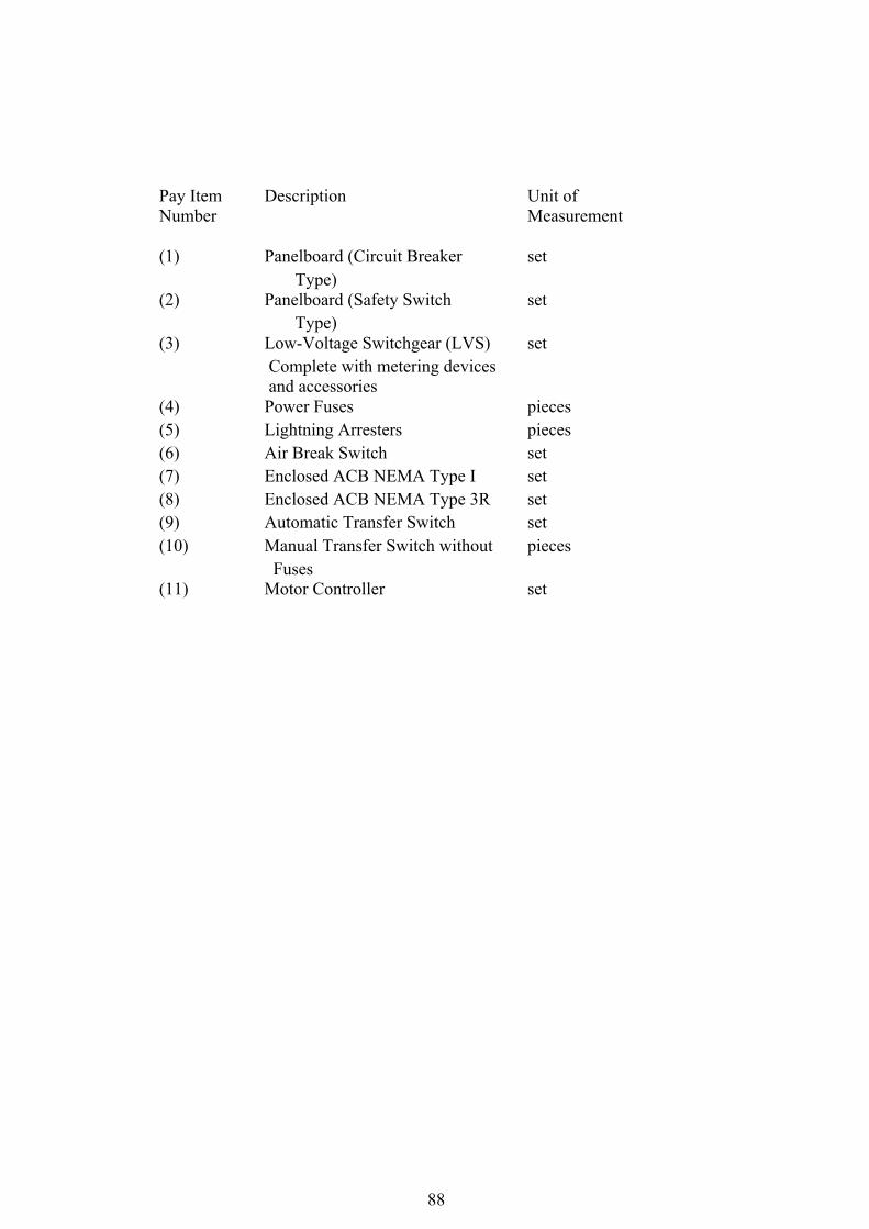
88
Pay Item Description Unit of Number Measurement (1) Panelboard (Circuit Breaker set
Type) (2) Panelboard (Safety Switch set
Type) (3) Low-Voltage Switchgear (LVS) set
Complete with metering devices and accessories
(4) Power Fuses pieces (5) Lightning Arresters pieces (6) Air Break Switch set (7) Enclosed ACB NEMA Type I set (8) Enclosed ACB NEMA Type 3R set (9) Automatic Transfer Switch set (10) Manual Transfer Switch without pieces
Fuses (11) Motor Controller set