performance technical specifications - swdakotah.com
TRANSCRIPT
PART FOUR -
Performance Technical Specifications
Unaccompanied Housing Conversion P-599 FY15
Port Hueneme
Naval Base Ventura County
CA
January 2015

TABLE OF CONTENTS
COVER PAGE...........................................................#
TABLE OF CONTENTS..............................................#
A10 Foundations................................................ Not used A20 Basement Construction............................... Not used B10 Superstructure............................................ Not used B20 Exterior Closure.......................................... B30 Roofing...................................................... C10 Interior Construction................................... C20 Stairs........................................................ C30 Interior Finishes......................................... D10 Conveying Systems.................................... Not used D20 Plumbing................................................... D30 HVAC........................................................ D40 Fire Protection Systems............................... D50 Electrical Power and Lighting....................... E10 Equipment.................................................... Not used E20 Furnishings................................................... Not used F10 Special Construction..................................... Not used F20 Selective Building Demolition........................ G10 Site Preparations........................................ G20 Site Improvements..................................... G30 Site Mechanical Utilities............................... G40 Site Electrical Utilities................................. Z10 General Performance Technical Specification.................. Part 4 identifies design criteria, verification requirements, and performance and quality requirements of products. See "Order of Precedence" paragraph in Part 2 for relationships between all parts of this RFP.
PART 4 - SECTION B20 - Page 1
SECTION B20
EXTERIOR ENCLOSURE
05/14
B20 GENERAL
RFP Part 3 including the Engineering System Requirements (ESR) provide project
specific requirements. The RFP Part 4, Performance Technical Sections (PTS)
provide generalized technical requirements that apply to multiple facility types
and include more requirements than are applicable to any one project. Therefore,
only the RFP Part 4 requirements that apply to the project and further define the
RFP Part 3 project specific requirements are required.
B20 1.1 DESIGN GUIDANCE
Provide the design and installation in accordance with the following
references. This Performance Technical Specification (PTS) adds
clarification to the fundamental requirements contained in the following
Government Standards. The general requirements of this PTS section are
located in PTS Section Z10, General Performance Technical Specification.
Industry standards, codes, and Government standards referenced in the
section text that are not found in the Unified Master Reference List (UMRL)
in the Construction Criteria Base (CCB) at the Whole Building Design Guide
Website , are listed below for basic designation identification. Comply
with the required and advisory portions of the current edition of the
referenced standard at the time of contract award.
B20 1.1.1 Industry Standards and Codes
NATIONAL LUMBER GRADES AUTHORITY (NLGA)
B20 1.1.2 Government Standards
Military Handbook 1013/1A, Design Guidance for Physical Security of
Facilities
UNIFIED FACILITIES CRITERIA (UFC)
UFC 1-200-01
General Building Requirements(A
reference in this PTS section to UFC
1-200-01 requires compliance with the
Tri-Service Core UFCs that are listed
in UFGS Section 01 33 10.05 20, which
includes the following significant
UFC(s): UFC 3-101-01, Architecture)
UFC 1-200-02
High Performance and Sustainable
Buildings
P599 NBVC UH Housing Conversion
Page 1 of 324
PART 4 - SECTION B20 - Page 2
B20 1.2 PERFORMANCE VERIFICATION AND ACCEPTANCE TESTING
Verification of satisfactory exterior enclosure system performance must be
via Performance Verification Testing, and by field inspection as detailed
in this section of the RFP. Provide special tests and special inspections
in accordance with UFGS Section 01 45 00.05 20, Design and Construction
Quality Control. The Contractor must pay the cost of all testing.
B20 1.2.1 Required Brick Masonry Testing and Field Samples
a. Where field testing is required, masonry strength must be
determined in accordance with ACI 530.1.
b. Field Samples: Masonry Panel Requirements - At the job site
submit for approval by the Designer of Record, a sample masonry
panel minimum 8 feet (2.4 meters) long by a minimum of 4 feet
(1.2 meters) high. Actual Sample size will be determined by
number of components in the sample wall but provide a span of
at least 4 feet (1.2 meters) of uninterrupted brickwork and 2
feet (.6 meters) above wall openings. The approved sample must
exhibit the standard for workmanship and materials for the
project. The sample panel must include brick coursing, bond,
weep holes, flashing, thickness, anchors, joint reinforcing,
wall ties, rigid-board insulation, intersection of walls, bond
beams, expansion and control joints, and tooling of joints,
range of color, texture of masonry, and mortar color; or
cold-formed steel framing, insulation, fiberglass-faced gypsum
sheathing, air barrier, moisture barrier/vapor retarders,
exterior enclosure barrier connections to adjoining
construction, sealing of exterior enclosure barrier
penetrations, sealant, masonry ties and anchors, and tooling
of joints, the range of color and texture of brick veneer, and
the color of mortar. The sample panel must be protected from
damage and must remain at the site until masonry work is complete
and approved, at which time the panel must be removed from the
site. If there are windows or curtain walls in the project
which interface with the masonry, a cut-away sample window or
curtain wall mock-up must be installed in the masonry field
panel, with all accessories, finishes, and trim (see B20 1.2.4
and 1.2.5). Masonry work must match the approved sample.
B20 1.2.2 Air Barrier Field Sample
Designate a portion of the project that reveals the various edge, seam,
transition, and penetration conditions that the air barrier is exposed
to. Determine this location with the Contracting Officer and obtain
approval of the sealing methods employed on the project from the air
barrier Manufacturer. Leave sample area exposed to view as long as
practical to serve as a construction standard and comparison of future
air barrier construction on the project. Before construction covers
the sample area, provide detailed photographs of the air barrier
details for future reference.
B20 1.2.3 Air Barrier Performance
P599 NBVC UH Housing Conversion
Page 2 of 324
PART 4 - SECTION B20 - Page 3
Provide air barrier inspection on all projects and air barrier
performance testing when required in RFP Part 3, section B20.
B20 1.2.3.1 Air Barrier Inspection
Coordinate all subcontractors that provide part of the air
barrier construction to provide an air tight barrier. Review
the air barrier prior to being covered by subsequent
construction to confirm that the air barrier complies with the
following requirements;
a. Prior to applying an air barrier, confirm that the
substrate complies with conditions required by the
applied air barrier material manufacturer.
b. Air barrier must create a continuous barrier, without
gaps, "fish mouths", holes, unsealed seams, or unsealed
penetrations.
c. Air barrier components are compatible and capable of
being permanently connected to form an air tight barrier.
d. Construction of the air barrier complies with air barrier
design as indicated in the Design Analysis and exterior
enclosure barrier drawings.
e. Air barrier is installed in accordance with
manufacturer's standard details available on the Air
Barrier Association of America (ABAA) website named "Air
Barrier Materials, Components, Assemblies & Systems" and
found at the following web link;
http://www.airbarrier.org/materials/assemblies_e.php
B20 1.2.3.2 Air Barrier Performance Testing
Provide air barrier testing and repair as follows (coordinate
with infrared thermal testing):
a. Provide a testing plan as a part of the Commissioning Plan
and notify the Contracting Officer 7 working days before
the testing will take place. Do not test the building
until verifying that the continuous air barrier is in
place and installed without failures in accordance with
installation instructions so that repairs to the
continuous air barrier, if needed to comply with the
required air leakage rate, can be done in a timely manner.
Also coordinate building access during the test with the
Contracting Officer. Perform pretest inspection with
all parties involved in the test and possible repairs of
the building enclosure. Record pretest conditions and
utilize pictures to assist in the documentation.
b. Perform testing as described in "U.S. Army Corps of
Engineers Air Leakage Test Protocol for Building
Envelopes Version3, May 11,2012." The air leak flow rate
must not exceed 0.25 CFM at 75 Pa per square foot (0.076
cmm 75 Pa per square meter) of building enclosure area
including roof or ceiling, walls and floor as provided
P599 NBVC UH Housing Conversion
Page 3 of 324
PART 4 - SECTION B20 - Page 4
by the DOR.
Method 1: This test consists of measuring the flow rates
required to establish 12 positive and 12 negative
building pressures from at least 25 Pa to at least 50 Pa.
At least 12 bias pressure readings must be taken across
the building enclosure and averaged over 5 seconds each
before and after the test. None of these readings must
exceed 30% of the minimum test pressure.
Method 2: this test consists of measuring the flow rates
required to establish 12 positive building pressures from
at least 50 Pa to at least 75 Pa. At least 12 bias pressure
readings must be taken across the building enclosure and
averaged over 5 seconds each before and after the test.
None of these readings must exceed 20% of the minimum test
pressure.
The test results must be either pass or fail. Provide
the theoretical size of the opening that leaks the same
amount as the building enclosure at 75 Pa, to facilitate
the search for leaks and repair of the exterior enclosure.
c. Provide infrared thermography to determine air leakage
paths if facility fails to retain the required air
pressure in the test above. Utilize infrared cameras
with a resolution of 0.1 degree C or better.
Prerform infrared thermography in accordance with ISO
6781:1983 and ASTM C1060-90(1997). Determine air
leakage pathways in accordance with ASTM E1186-03
Standard Practices for Air Leakage Site Detection in
Building Envelopes and Air Barrier Systems, and perform
corrective work as necessary to achieve the whole
building air leakage rate specified.
Modify construction to stop identified air leakage until
target 0.25 cfm/ft2 is reached. Correct air path leaks
at the source of the leak, do not use sealant to close
air leakage paths that are required to be opened for
maintenance of the facility such as fixtures, switches
covers, receptacle covers, access doors,...etc.
d. Air leaks must be sealed in the following
order of priority: 1. Top of the
building. These include attics, roof/wall
intersections, penthouse doors and walls,
HVAC equipment.
2. Bottom of the building. These include
ground floor access doors and inspection
hatches, exhaust and air intake vents,
service penetrations of enclosure, crawl
spaces.
3. Vertical shafts. These include gasket
stairwell fire doors, fire hose cabinets and
recessed toilet accessories connected to
P599 NBVC UH Housing Conversion
Page 4 of 324
PART 4 - SECTION B20 - Page 5
vertical shaft, vertical and horizontal
utility penetrations in service rooms,
elevator rooms and shafts.
4. Exterior walls. These include weather
strip doors and windows, exhaust fans and
ducts, service penetrations, electrical
receptacles, wall base.
B20 1.2.4 Thermal Envelope Performance Testing (Infrared Thermography)
Where required in RFP Part 3, provide infrared thermal testing and
repair as follows (coordinate with air barrier testing):
a. Test the building envelope using Infrared Thermography
technology. The thermography testing must be completed in
accordance with the requirements of ASTM C1060 (latest edition)
and ISO 6781. The Contracting Officer will witness the
testing. Testing must occur just before the building air
tightness test. Testing must also occur during the air tightness
test so that areas of building air leaks are detected. If the
building air tightness test is failed, thermographic testing
must be repeated just before and during subsequent air tightness
tests until the air tightness test is successful.
b. Thermography Test Procedures: Submit detailed test procedures
indicating the test apparatus, the test methods and procedures,
and the analysis methods to be employed not later than 60 days
after Notice to Proceed.
c. Thermography Test Report: Provide a report. The report must
include thermographs in color and a color temperature scale to
define the temperature indicated by the various colors. The
report must identify the high temperature reading, the outdoor
air temperature, the building indoor air temperature, and the
wind speed and direction. The report must note any areas of
compromise in the building envelope, and must note all actions
required and taken to correct those areas.
d. Final Test: Final thermography test report must demonstrate
the problem areas have been corrected. Submit the complete
test and analysis for review and approval.
B20 1.2.5 Required Records for Concrete Wall Panels
a. Cast-in-place - Submit to DOR mandatory batch ticket
information as ASTM C 94 for each load of ready-mixed concrete.
b. Submit to DOR commercial testing results in accordance with PCI
MNL-117 and as required in paragraph entitled "Sampling and
Testing for Precast"
B20 1.2.6 Precast Concrete Wall Panel Surface Finish Sample
Submit to DOR a concrete wall panel sample 12 inches (300 mm) by 12
inches (300 mm) by approximately 1 1/2 inches (38 mm) in thickness,
to illustrate quality, color, and texture of both exposed-to-view
P599 NBVC UH Housing Conversion
Page 5 of 324
PART 4 - SECTION B20 - Page 6
surface finish and finish of panel surfaces that will be concealed
by other construction. Obtain initial approval of color and texture
from DOR prior to submission of sample panels.
B20 1.2.6.1 Manufacturing Plant Sampling And Testing for Precast
Plant Quality Control - PCI MNL-117 for PCI enrolled plants.
Where panels are manufactured by specialists in plants not
currently enrolled in the PCI "Quality Control Program,"
provide a product quality control system in accordance with PCI
MNL-117 and perform concrete and aggregate quality control
testing using an approved, independent commercial testing
laboratory. Submit test results to the Contracting Officer.
a. Aggregate Tests: ASTM C 33. Perform one test for each
aggregate size, including determination of the specific
gravity.
b. Strength Tests: ASTM C 172. Provide ASTM C 39 and ASTM
C 31/C 31M compression tests. Perform ASTM C 143 slump
tests. Mold six cylinders each day or for every 20 cubic
yards (15 cubic meters) of concrete placed, whichever is
greater. Perform strength tests using two cylinders at
7 days and two at 28 days. Cure four cylinders in the
same manner as the panels and place at the point where
the poorest curing conditions are offered. Moist cure
two cylinders and test at 28 days.
c. Changes in Proportions: If, the compressive strength
falls below that specified, adjust the mix proportions
and water content and make necessary changes in the
temperature, moisture, and curing procedures to secure
the specified strength. Notify the Contracting Officer
of all changes.
d. Strength Test Results: Evaluate compression test results
at 28 days in accordance with ACI 214 using a coefficient
of variation of 20 percent. Evaluate the strength of
concrete by averaging the test results (two specimens)
of standard cylinders tested at 28 days. Not more than
20 percent of the individual tests must have an average
compressive strength less than the specified ultimate
compressive strength.
B20 1.2.6.2 Acceptable Appearance
Refer to Architectural Precast Concreteby the Prestressed
Concrete Institute, in the "Acceptability of Appearance"
paragraph for reasons to reject precast panels. Panels in
place may be rejected for any one of the product defects or
installation deficiencies remaining after repairs and cleaning
have been accomplished. "Visible" means visible to a person
with normal eyesight when viewed from a distance of 20 feet (6
meters) in broad daylight.
B20 1.2.7 Window Sample Mock-Up
P599 NBVC UH Housing Conversion
Page 6 of 324
PART 4 - SECTION B20 - Page 7
a. Provide mock-up of one (1) typical combination window unit to
be used within the project and conduct a field mock-up test in
strict compliance with AAMA 502 method A and method B. Each
opening will be tested to achieve performance of ASCE 7-02
calculated requirements (PSF or Kg/m2) for water resistance,
which must not exceed .667 % of the products capable water based
on AAMA 101/I.S.2. Allowable rates of air leakage for field
testing must be 1.5 times applicable AAMA 101/I.S.2 rate for
the Product Type and Performance Class.
b. Opening is to be tested under "Quality Control" testing by a
designated independent testing agency.
1) Schedule mock-up installation sufficiently in advance of
need to allow adequate time for cure of sealants, testing and
reconstruction, if needed, without delaying the project.
2) Build mock-up in building enclosure wall in location selected
by Owner and Architect.
3) Modify mock-up construction and perform additional tests as
required to achieve specified minimum acceptable results. If
corrections are not adequate, construct new mock-up, at written
direction of Owner and Architect. Co-ordinate construction of
mock-up with other involved trades.
4) Approved mock-ups may become part of completed Work if
undisturbed at time of Substantial Completion.
5) Flood test Mock-up window subsill and obtain approval of DOR
prior to installing window unit.
B20 1.2.8 Curtain Wall Systems Field Sample and Testing
a. At the job site submit for approval by the Designer of Record,
a sample curtain wall installation which may be a cut-away
portion of a curtain wall, if appropriate, to show the
construction, the workmanship, tie-in to building,
infiltration and moisture barriers, wrap, flashing, head,
window unit installation where required, sill, lintel if
required, interior and exterior trim, anchors and reinforcing,
and sealants.
b. Provide mock-up of (1) designated Curtain Wall System unit to
be used in conducting a field mock-up test in strict compliance
with AAMA 503 method A and method B. Each opening will be tested
to achieve performance of ASCE 7-05 calculated requirements
(PSF or Kg/m2) for water resistance, which must not exceed the
derived water expectation of 0 infiltration at the calculated
Design Pressure. Allowable rates of air leakage for field
testing must be .30 CFM/Ft2 of wall area test specimen.
Performance test at 6.24 PSF (30.3 Kg/m2) allows .30 cfm/ft2.
Opening is to be tested under "Quality Control" testing by a
designated independent testing agency.
1) Schedule mock-up installation sufficiently in advance of
P599 NBVC UH Housing Conversion
Page 7 of 324
PART 4 - SECTION B20 - Page 8
need to allow adequate time for cure of sealants, testing and
reconstruction, if needed, without delaying the project.
2) Build mock-up in building enclosure wall in location
selected by DOR.
3) Modify mock-up construction and perform additional tests
as required to achieve specified minimum acceptable results.
If corrections are not adequate, construct new mock-up, at
written direction of DOR. Co-ordinate construction of mock-up
with other involved trades.
4) Approved mock-ups may become part of completed Work if
undisturbed at time of Substantial Completion.
The sample curtain wall must be protected from damage and must remain
at the site until curtain wall construction work is complete and
approved, at which time the panel must be removed from the site. On
projects where the curtain wall interfaces with masonry walls, a
cut-away sample curtain wall must be installed with the masonry sample
panel. Curtain wall installations must match the approved sample.
Water Penetration: No water penetration must occur when the wall is
tested in accordance with ASTM E 331 at a differential static test
pressure of 20 percent of the inward acting design wind pressure as
specified, but not less than 15 psf (80 Kg/m2). Make provision in
the wall construction for adequate drainage to the outside of water
leakage or condensation that occurs within the outer face of the wall.
Leave drainage and weep openings in members and wall open during test.
B20 1.3 DESIGN SUBMITTALS
Design submittals must be in accordance with Z10, General Performance
Technical Specifications, UFGS section 01 33 10.05 20, Design Submittal
Procedures, UFC 1-300-09N, Design Procedures, UFC 3-101-01, Architectureand
UFC 3-301-01, Structural Engineering.
In addition, UFGS sections listed below or in the body of the PTS text are
to be used by the Designer of Record (DOR) as a part of the design submittal.
If the UFGS products or systems are applicable to the project, the DOR must
edit these referenced UFGS sections and submit them as a part of the design
submittal specification. Edit the specification sections in accordance
with the limitations stated in PTS section Z10, General Performance
Technical Specifications.
UFGS 08 34 16.10, Steel Sliding Hangar Door
UFGS 08 34 16.20, Vertical Lift Fabric Door
B20 1.4 CONSTRUCTION SUBMITTALS
Submit construction submittals in accordance with PTS Section Z10, General
P599 NBVC UH Housing Conversion
Page 8 of 324
PART 4 - SECTION B20 - Page 9
Performance Technical Specifications. In addition to the Z10 requirements,
the Designer of Record (DOR) must approve the following submittals as a
minimum;
Shop drawings for reinforcing steel in masonry walls, doors, door
hardware, windows, storefront, curtainwall, glazing, paint, exterior
enclosure barrier systems, and visible exterior materials.
All structural elements necessary for construction.
B20 1.4.1 Manufacturer's Verification Inspection Documentation for
Galvanized Steel
Manufacturer's verification inspection documentation must be
submitted for all galvanized steel in accordance with ASTM A123, ASTM
A 153, and ASTM A 653.
B20 1.4.2 Field Inspection of Field-erected Concrete Panels
a. Perform field inspection of panel welded connections. Furnish
the services of AWS-certified welding inspector for erection
inspections. Welding inspector must visually inspect all
welds and identify all defective welds.
b. The DOR must be notified in writing of defective welds, bolts,
nuts and washers within 7 working days of the date of inspection.
All defective connections or welds must be removed and re-welded
or repaired as required by the DOR.
B20 1.4.3 Sustainable Construction Submittals
Submit sustainable construction submittals in accordance with UFGS
01 33 29.05 20 Sustainability Requirements for Design-Build.
B2010 EXTERIOR WALLS
Provide exterior wall construction that consists of exterior skin system of
non-structural outside face elements with rain-screen back-up wall systems that
include; flashing (embedded, exposed, and thru-wall), a water resistive barrier,
moisture barrier/ vapor retarder (if required), air barrier, and insulation
systems with interior skin system materials to provide a protective finish on the
inside face of exterior walls. Provide all components necessary to for a shingled
water resistive barrier to direct water that would penetrate the wall to be directed
to the outside of the wall. Provide exterior enclosure components and barriers
in accordance with UFC 3-101-01, Architecture.
Design all work to comply with UFC 3-101-01, Architecture, and UFC 3-301-01,
Structural Engineering, and the following requirements:
a. Vapor Pressure and Hygrothermal Analysis - Perform a job specific vapor
pressure and hygrothermal analysis in accordance with UFC 3-101-01,
Architecture. The conclusion of the analysis must indicate if a moisture
barrier/ vapor retarder is required, the appropriate locations of needed
moisture barrier/ vapor retarder, and anticipated dew-point locations in
P599 NBVC UH Housing Conversion
Page 9 of 324

PART 4 - SECTION B20 - Page 10
the exterior enclosure during different critical times of the year.
b. Wind Loads - Provide wind load calculations for exterior cladding in
accordance with UFC 1-200-01 and UFC 3-301-01 with comparative analysis of
the cladding system to be provided.
c. Water Penetration - No water penetration must occur at a pressure of 8 psf
(39 Kg/m2) of fixed area when tested in accordance with ASTM E 331.
d. Insulating Value – Comply with UFC 3-101-01, Architecture for the ASHRAE
requirements defining the minimum insulating value of the complete wall
system.
B201001 EXTERIOR CLOSURE
B201001 1.1 MASONRY VENEER EXTERIOR WALL CLOSURE COMPONENTS
B201001 1.1.1 General Requirements
a. The masonry veneer includes the non-load bearing exterior walls
of the structure, and also includes colored mortar, special
shapes such as sills, headers, trim units and copings of brick
masonry, precast concrete, concrete masonry units, or other
approved materials. The veneer must be tied to the backup wall
system with a system that allows the veneer to move
independently of the backup wall system, while being
structurally supported. Allow for expansion and contraction
of the veneer without cracking the exterior material.
b. Use running bond, tooled concave joints and full head joint
weeps at 24 inches (610 mm) o.k. in the course immediately above
the base flashing. Where rowlocks are permitted, slope
rowlocks and project not less than 1/2 inch (13 mm) beyond the
face of the wall to form a wash and drip. Where required,
provide colored mortar conforming to ASTM C270. Provide
special shapes where required.
c. Locate expansion/control joints and seal with proper backing
material and ASTM C 920 polyurethane sealant, or preformed foam
or rubberized expansion joint closure. Conform to UFC 3-101-01
and BIA Technotes 18, 18A. Match joint color of the brick,
unless DOR directs otherwise.
d. Conform to ACI 530.1 for masonry veneer installation, including
cold weather construction. Antifreeze admixtures are not to
be used.
e. Clean the masonry in accordance with manufacturer's
instructions and BIA Technote 20.
f. Utilize BIA Technical Notes to design, detail, and construct
brick masonry walls. This PTS section amends the BIA documents
and takes precedence over similar BIA requirements.
Substitute directive language in the place of BIA suggestive
language as required in PTS Section Z10, General Performance
Technical Specifications. The results of these wording
substitutions change this document to required procedures.
B201001 1.1.2 Face Brick
a. Brick Masonry Appearance - Do not change source or supply of
materials after brick manufacturing work has started. Blend
P599 NBVC UH Housing Conversion
Page 10 of 324

PART 4 - SECTION B20 - Page 11
all brick to produce a uniform appearance when installed. An
observable "banding" or "layering" of colors or textures caused
by improperly mixed brick is unacceptable.
b. Brick Type – Provide brick in accordance with ASTM C216, Grade
SW, type FBX. Test rating of ASTM C67 must be "Not
effloresced".
B201001 1.1.3 Split Faced or Ground Faced Masonry
ASTM C 90. If required, provide split faced or ground faced units,
or split-ribbed units or scored-faced units.
B201001 1.1.4 Cast Stone Trim Units
a. Cast stone must be the product of a manufacturer regularly
engaged in the manufacture of architectural cast stone (precast
concrete building unit) products. Meet or exceed the
requirements of ASTM C 1364.
b. Trim units of cast stone must include sills, fascia, header
units, copings and other trim units as required by the approved
design
B201001 1.1.5 The Wall Cavity
Comply with UFC 3-101-01 and BIA Technical Notes 21A, 21B, 21C, 28B.
B201001 1.1.6 Through-Wall Flashing Components
Provide through-wall flashing over all openings, spandrels, shelf
angles, lintels, and built-in structural steel members. Provide
through-wall flashing below all openings, parapets copings, sills,
and at the base of the wall. Provide a method of weeping water
collected by the through-wall flashing to the outside of the wall.
a. Incorporate weep holes to align with through-wall flashing in
cavity wall construction as required by UFC 3-101-01 and BIA
Technotes. Install flashing according to BIA Technotes 7, 7A,
7B, 21A, 21B, 21C, 28B, and SMACNA figures 4-1A and 4-1B. Extend
metal drip edge flashing beyond the wall plane using a 1/4 inch
(6 mm) preformed 45 degree angle turn down.
b. Flashing material must be as required by UFC 3-101-01 and the
following: Provide flashing of 7 ounce copper flashing with a
3 ounce bituminous coating on each side or a fiberglass fabric
bonded on each side of the copper sheet. Sixteen (16) ounce
uncoated copper, 28 gauge Type 302 or 304 stainless steel is
also acceptable. 'Flexible membrane flashing, plastic or
PVC-based membrane flashing is prohibited. Lap and seal
turndown solid metal drip edge flashing to through- wall
flashing. Refer to "Flashing" in this section to find
requirements for non-through-wall flashing.
c. Incorporate the through-wall flashing in the water resistive
barrier and seal joints to flashing to form a shingled effect
and direct water to the exterior to the exterior enclosure and
away from back-up wall assembly.
P599 NBVC UH Housing Conversion
Page 11 of 324
PART 4 - SECTION B20 - Page 12
d. Where flashing is not continuous, such as at masonry wall
opening heads and sills, extend flashing four inches beyond each
side of the opening and turn up ends to form a pan and prevent
water from reentering the wall cavity.
B201001 1.1.7 Reinforcing in Veneer Layer
Reinforcing in the veneer layer must be galvanized in accordance with
ASTM A 123/A123M, ASTM A153/A153M, or ASTM A653/A653M, Z275 (G90)
coating, and be of sufficient size to eliminate damage to the veneer
layer from wind and other live and dead loads imposed on the veneer
layer.
B201001 1.2 METAL WALL PANEL EXTERIOR CLOSURE
B201001 1.2.1 General Wall Panel Requirements
a. Factory Color Finish – Provide panels with a factory applied,
baked coating to the exterior and interior of metal wall panels
and metal accessories. Exterior finish topcoat must be of 70
percent polyvinylidene fluoride (PVDF) resin with not less than
0.8 mil dry film thickness (DFT). Provide exterior primer that
is standard with panel manufacturer but not less than 0.8 mil
dry film thickness (DFT). Provide factory applied 70 percent
PVDF clear coating of 0.8 mil DFT over the color topcoat and
edge coating for projects within 300 feet (91 meters) of a water
shoreline or industrial environment. Field apply 70 percent
PVDF clear coat to unfinished panel edges or field cut panels.
Interior finish exposed to sun or rain must be the same coating
and DFT as the exterior coating.
b. Wall system and attachments must resist wind loads as determined
by ASCE 7, with a factor of safety appropriate for the material
holding the anchor. Maximum deflection due to wind on aluminum
wall panels must be 1/60. Limit maximum deflection due to wind
on steel wall panels and girts behind aluminum or steel wall
panels to 1/120 of their respective spans, except that when
interior finishes are used limit the maximum allowable
deflection to 1/180 of their respective spans. The structural
performance test methods and requirements of the wall system
and attachments must be in accordance with ASTM E 1592.
c. Conformations - Non-insulated steel or aluminum wall panels
must have configurations for overlapping adjacent sheets or
interlocking ribs for securing adjacent sheets and fastened to
framework using exposed or concealed fasteners, as specified.
Provide sheets of sufficient length to cover the entire height
of any unbroken wall surface when the length of run is 30 feet
(9 meters) or less. Design wall systems with provisions for
expansion and contraction. Where required, provide series 305
stainless steel fasteners factory finished to match panels.
d. Shape - Standard V-beam or boxed beam type having 5 to 8 inch
(125 mm to 200 mm) pitch for steel panels or 4 to 8 inch (100
mm to 200 mm) pitch for aluminum panels, and 1.5 inch (38 mm)
overall depth, exclusive of coating. Other shapes may be
considered if approved by the DOR.
P599 NBVC UH Housing Conversion
Page 12 of 324

PART 4 - SECTION B20 - Page 13
B201001 1.2.2 Steel Wall Panels
a. Material and Coating - Form sheets from steel conforming to ASTM
A 653/A 653M, Structural Grade 40, galvanized coating
conforming to ASTM A 924/A 924M, Class G-90; aluminum-coated
steel conforming to SAE AMS 5036; or steel-coated with
aluminum-zinc alloy conforming to ASTM A 792/A 792M, except that
coating chemical composition must be approximately 55 percent
aluminum, 1.6 percent silicon, and 43.4 percent zinc with
minimum coating weight of 0.5 ounce per square foot.
b. Gage - Minimum 22 U.S. Standard Gage for wall panels, but in
no case lighter than required to meet maximum deflection
requirements specified.
B201001 1.2.3 Aluminum Wall Panels
a. Material and Coating - Form sheets of Alloy 3004 or Alclad 3004
conforming to ASTM B 209 having proper temper to suit respective
forming operations.
b. Thickness - Minimum 0.032 inch (0.81 mm) nominal, but in no case
thinner than that required to meet maximum deflection
requirements specified.
B201001 1.2.4 Insulated Aluminum or Steel Wall Panels
Insulated wall panels must be steel or aluminum factory-fabricated
units with insulating core between metal face sheets securely fastened
together and uniformly separated with rigid spacers. Provide factory
color finish on panels. Insulation must be compatible with adjoining
materials and capable of retaining its R-value for the life of the
metal facing sheets; and unaffected by extremes of temperature and
humidity. The assembly must have a flame spread rating not higher
than 25, and smoke developed rating not higher than 50 when tested
in accordance with ASTM E 84. Panels must be not less than 8 inches
(200 mm) wide and must be in one piece for unbroken wall heights.
Provide wall panel edge configurations with interlocking ribs for
securing adjacent panels. Utilize factory fabricated corners and
trim pieces at intersections with other materials. Fasten wall
panels to framework using concealed fasteners. Install in accordance
with DOR-approved shop drawings and manufacturer's recommendations.
a. Insulated Steel Panels - Zinc-coated steel conforming to ASTM
A 653/A 653M; or Aluminum-zinc alloy coated steel conforming
to ASTM A 792/A 792M, AZ 55 coating. Uncoated wall panels must
be 0.024 inch (0.61 mm) thick minimum.
b. Insulated Aluminum Panels - Alloy conforming to ASTM B209,
temper as required for the forming operation, minimum 0.032 inch
(0.81 mm) thick.
B201001 1.3 STUCCO EXTERIOR WALL CLOSURE
B201001 1.3.1 Portland Cement Plaster
P599 NBVC UH Housing Conversion
Page 13 of 324
PART 4 - SECTION B20 - Page 14
ASTM C150, gray Portland cement Type II with 1/2 inch (13 mm) maximum
chopped alkali resistant fiberglass strands, minimum 1.5 percent by
weight to cement; 1 1/2 pounds (.68 kg) per sack of cement. Lime must
conform to ASTM C206, Type S. Utilize stainless steel or zinc corner
beads, J-beads and other accessories for the system.
a. Unless specifically deleted, utilize an acrylic admixture or
coating to give additional moisture suppression to control
fungus growth for the system.
b. Sand aggregate for job-mixed base coat and job-mixed finish coat
stucco must conform to ASTM C897.
c. Sand for Finish Coats: Natural color and graded within the
limits shown above for basecoats, except that the sand must pass
the No. 8 sieve, and for smooth finish the sand must pass the
No. 30 sieve.
d. Mix scratch coat in proportion of one part by volume Portland
cement, 3/4 to 1 1/2 parts by volume hydrated lime and 2 1/2
to 4 parts sand (volume of sand per sum of cement and lime).
Mix brown coat in proportion of one part by volume Portland
cement, 3/4 to 1 1/2 parts by volume hydrated lime and 3 to 5
parts sand (volume of sand per sum of cement and lime). Mix
proportions can vary depending on climate and application
variations, with the approval of the DOR.
e. Portland Cement Stucco Finish Coat 3 to 5 parts sand (volume
of sand per sum of cement and lime).
f. Portland cement plaster application must be in accordance with
ASTM C 926. Furring and lath application must be in accordance
with ASTM C 1063.
g. Bonding Agents: ASTM C 932. Provide for exterior applications
to masonry or concrete substrates.
h. Provide water resistive barrier under stucco in accordance with
manufacturer’s recommendations and code requirements.
B201001 1.4 EXTERIOR INSULATION AND FINISH SYSTEM (EIFS)
EIMA TM 101 and 01 EIMA TM 101.86. Refer to the RFP Part 3 Project Program
to determine if EIFS is used as the non-primary or the primary exterior finish
material for the project. Job-fabricate the exterior insulation and finish
system (EIFS) covering consisting of sheathing, water resistive barrier,
moisture drainable insulation board system, reinforcing fabric, base coat,
finish coat, adhesive, primer, accessories, flashing, sealant, and
mechanical fasteners. The system components must be compatible with each
other and with the substrate as recommended or approved by, and the products
of, a single manufacturer regularly engaged in furnishing Exterior
Insulation and Finish Systems. Install all materials using an applicator
trained and approved by the system manufacturer in accordance with
DOR-approved shop drawings and manufacturer's recommendations. Provide
EIFS Class PB or Class PM. Do not use Class PB EIFS in first floor, high
traffic areas, or in areas where pedestrians congregate without at least
one layer of 20 ounce (567 grams) reinforcing fabric mesh. Use 1/8 inch
(4 mm) minimum thickness for PB finish system. Color of the EIFS finish
must be consistent, with no variation noticeable to the DOR. Seal all joints
in EIFS in accordance with ASTM C 1481 and as recommended by the manufacturer.
P599 NBVC UH Housing Conversion
Page 14 of 324

PART 4 - SECTION B20 - Page 15
Furnish manufacturer's standard warranty for the EIFS. Provide warranty
directly to Government and cover a period of not less than 5 years from date
Government accepted the work.
B201001 1.4.1 EIFS System Components
a. Glass Mat Gypsum Sheathing Board - Conform to ASTM C 1177/C
1177M. Nail Pull Resistance: No less than 120 lb (54.4 Kg) when
tested in accordance with ASTM C 473.
b. Mechanical Fasteners - Corrosion resistant and as approved by
EIFS manufacturer. Select fastener type and pattern based on
applicable wind loads and substrate into which fastener will
be attached, to provide the necessary pull-out, tensile, and
shear strengths.
c. Thermal Insulation - Drainable type. Do not use any layer of
insulation less than 3/4 in (19 mm) thick. The maximum
thickness of all layers mustl not exceed 4 in (101 mm).
Insulation Board must be certified as aged, in block form, prior
to cutting and shipping, a minimum of 6 weeks by air-drying,
or equivalent. Insulating material must conform to ASTM C 578,
Type I or IV, as recommended by the EIFS manufacturer and treated
to be compatible with other EIFS components.
d. Reinforcing Fabric - Reinforcing fabric mesh must be
alkali-resistant, balanced, open weave, glass fiber fabric made
from twisted multi-end strands specifically treated for
compatibility with the other system materials, and comply with
EIMA TM 105.01 and as recommended by EIFS manufacturer.
B201001 1.5 CONCRETE EXTERIOR WALL CLOSURE
B201001 1.5.1 Precast Concrete Wall Panels:
ACI 211.1 and ACI 301. PCI MNL-116 or PCI MNL-117. Concrete must have
a minimum 28-day compressive strength of 4000 psi (281 Kg/cm2). Air
content of plastic concrete must be between 4 and 6 percent air by
volume. Provide a dosage of air entraining agent, which will produce
19 plus or minus 3 percent air in a 1 to 4 by weight standard sand
mortar in accordance ASTM C 185. Provide aggregate in accordance with
ASTM C 33. Seal the panel joints with fully loaded and tooled sealant
joints that are properly sized, shaped, and placed against
manufacturer approved backing material. Sealant material thickness
must not be less than 1/4 inch (6mm).
For rain screen precast panel wall systems with back-up wall
construction, provide sealed face joints that allow moisture to be
drained from the wall cavity behind the precast panels via weeps.
Provide flashing and water/ moisture resistant barriers to direct
water from the wall cavity to the outside of the building. Locate
weeps where cavity is obstructed such as above through-wall flashing,
at head and sill flashing above and below windows, above door
flashings, and wall base flashing.
For barrier wall precast panel wall systems without back-up wall
construction, provide a two stage drained joint system on all precast
P599 NBVC UH Housing Conversion
Page 15 of 324
PART 4 - SECTION B20 - Page 16
panels joints. Design the two staged drained joint system to provide
the following;
a. Locate all sealant beads on the exterior side of the backer rod.
Align placement of the exterior sealant bead with the exterior
surface of the precast panel and space the placement of the
interior sealant bead as required below but no less than 3 inches
(75 mm) from the face of the panel to the face of the interior
tooled sealant bead.
b. Space sealant beads as far apart as possible but provide no less
than 1 inch (25mm) clear air space between the exterior seal
backer rod and the tooled interior sealant bead.
c. Form minimum of 1/2 inch (12mm) weep holes to facilitate
drainage in the vertical sealant joints. Attach a bead of
sealant to the interior vertical sealant bead with an outward
slope and a drop in height of at least 4 inches (100mm) to form
the drainage plane for the weep opening.
d. Locate weeps as necessary to allow complete drainage of water
from the two stage air/ vent space. Provide weeps at
obstructions in the air/ vent space such as through wall
flashing, horizontal panel joints, head and sill flashing above
and below windows, above door flashing, and wall base flashing.
Minimize cracking potential of precast concrete elements by
implementing expansion and control joints in the precast assembly.
Comply with the following;
a. Exposed Aggregates - In addition to the above aggregate, facing
mixture aggregate, and aggregate for homogeneous panels with
exposed aggregate finish, must be crushed stone.
b. Cement - ASTM C 150.
c. Admixtures - ASTM C 260 for air-entraining admixtures. Other
admixtures: ASTM C 494. Certify that admixtures are free of
chlorides.
d. Reinforcement - ACI 301.
e. Inserts - ASTM A 47, Grade 32510 or 35018, or may be medium
strength cast steel conforming to ASTM A 27/A 27M, Grade
U-60-30. Where exposed to moisture, provide inserts hot-dip
galvanized after fabrication in accordance with ASTM A 153/A
153M.
f. Embedded Plates - ASTM A 36/A 36.
g. Flashing Reglets - Fabricate of sheet metal, open-type with
continuous groove 1-1/8 inches (28 mm) deep minimum by 3/16 inch
(5 mm) wide at opening and sloped upward at 45 degrees. Top
surface must have toothed lip section to anchor upturned edge
of metal snap-lock counter flashing when inserted. Provide
stainless steel sheet metal, 0.011 inch (0.28 mm) minimum
thickness, ASTM A 167, Type 302 or Type 304, Number 2D finish,
soft temper.
h. Clip Angles - ASTM A 36/A 36M steel, galvanized after
fabrication in accordance with ASTM A 153/A 153M.
i. Ferrous Casting Clamps - ASTM A 47, Grade 32510 or Grade 35018
malleable iron or cast steel, or ASTM A 27/A 27M, Grade U-60-30,
cast steel casting, hot-dip galvanized in accordance with ASTM
P599 NBVC UH Housing Conversion
Page 16 of 324
PART 4 - SECTION B20 - Page 17
A 153/A 153M.
j. Threaded Fasteners – Provide galvanized machine bolts, washers
and, when required, nuts.
1) Bolts: ASTM A 449, 3/4 inch (19 mm) diameter machine bolts
with hexagon head.
2) Washers: ANSI B18.21.1, medium or heavy lock-spring
washers.
3) Nuts: ASTM A 563, Grade C, heavy, hexagon-type nuts.
4) Square Nuts: ASTM A 563, Grade A, plain.
B201001 1.6 CONCRETE WALL PANEL RESTORATION
Materials, physical and chemical properties, and composition of new concrete
must match that of existing concrete to be repaired, unless samples and
testing determine that existing mixtures and materials are faulty or
non-performing.
B201001 1.6.1 Existing Concrete Testing
Take representative samples of existing concrete from areas of the
structure to be repaired at indicated locations. The samples must
be taken in accordance with ASTM C 42 and ASTM C 823 and tested in
accordance with ASTM C 39, ASTM C 42, ASTM C 295, ASTM C 457, ASTM
C 856, ASTM C 1218/C 1218M, and ASTM C 642, ASTM C 114, and ASTM C
1084. Evaluate aggregates in the existing concrete in accordance
with ASTM C 136 and ASTM C 295. Determine the air content of the
existing concrete in accordance with ASTM C 457 and ASTM C 642.
B201001 1.6.2 Admixtures
Air entraining admixtures must conform to ASTM C 260, water-reducing
or -retarding admixtures must conform to ASTM C 494, and pigments for
integrally colored concrete must conform to ASTM C 979 and ASTM C 1017.
Admixtures must not contain added chlorides.
B201001 1.6.3 Aggregates
Aggregates must conform to ASTM C 33.
B201001 1.6.4 Cement
Match cement composition of cement used in existing concrete to be
repaired as determined by samples and testing and conforms to the basic
requirements of ASTM C 150, Type I or II. Provide cement with
non-shrink (shrinkage compensating) properties and conforms to ASTM
C 1107, Class B or C, expansive cement type.
B201001 1.6.5 Pozzolan
Provide pozzolan to conform with ASTM C 618, Class F, including limit
P599 NBVC UH Housing Conversion
Page 17 of 324
PART 4 - SECTION B20 - Page 18
on available alkalis, "Table 2 - Supplementary Optional Chemical
Requirements," and uniformity requirements, "Table 4 - Supplementary
Optional Physical Requirements."
B201001 1.6.6 Epoxy Anchor Adhesives
Use epoxy-resin grout to bond steel anchors to concrete with a 100
percent solids, moisture insensitive, low creep, structural adhesive.
The epoxy must conform to ASTM C 881, type IV; grade and class selected
to conform to the manufacturer's recommendations for the application.
The epoxy adhesive must be conditioned, proportioned, mixed, and
applied in accordance with the manufacturer's recommendations, except
as otherwise specified herein.
a. Epoxy-resin grout - Provide a two-component material, 100
percent solids by weight, formulated to meet the requirements
of ASTM C 881, Type I or II. Use type I material when materials
or atmospheric temperatures are 70 degrees F (21 degrees C) or
above. Use type II material when materials or atmospheric
temperatures are below 70 degrees F (21 degrees C). Provide
epoxy-resin grout with the ability to structurally rebond
cracks, delaminations, and hollow plane conditions in concrete;
must be insensitive to the presence of water; and must have the
capability to penetrate cracks down to 5 mils in width.
Materials must have been successfully used in similar
conditions for a period of at least five years.
b. Epoxy Injection Ports – Design injection ports for epoxy-resin
grout for the intended use as required in this section and made
according to the recommendation of the epoxy manufacturer.
B201001 1.7 WOOD SIDING SYSTEM
B201001 1.7.1 Horizontal Wood Siding
Horizontal Wood Siding: DOC PS 20, exterior, lap type, 6 inches wide,
maximum practicable lengths, 7/16 inch (11 mm) thick, smooth face.
Shop coat all surfaces of wood siding and trim with an alkyd primer.
a. Species and Grades
Utilize species and grades listed:
1) Grade 1 Common spruce-pine-fir; NELMA, NLGA, WCLIB, or
WWPA.
2) Grade Prime or D finish, pressure-preservative-treated
hem-fir; NLGA, WCLIB, or WWPA.
3) Grade D Select (Quality) eastern white pine, eastern
hemlock-balsam fir-tamarack, eastern spruce, or white woods;
NELMA, NLGA, WCLIB, or WWPA.
4) Grade D Select northern white cedar; NELMA or NLGA.
P599 NBVC UH Housing Conversion
Page 18 of 324
PART 4 - SECTION B20 - Page 19
5) Grade B & B, pressure-preservative-treated southern pine;
SPIB.
b. Water resistive barrier – Install to protect back-up wall
assembly.
B201001 1.8 VINYL SIDING SYSTEM
Integrally colored, vinyl siding complying with ASTM D 3679. Horizontal or
vertical pattern with exposure and shape to be compatible with overall design
concept. Provide a water resistive barrier to protect back-up wall assembly
and install in accordance with manufacturer's recommendations.
B201001 1.8.1 Texture, Thickness, Finish and Color
Wood grain texture. Minimum Nominal Thickness: 0.044 inch (1.1 mm).
Minimum Profile Depth (Butt Thickness): 5/8 inch (16 mm) or 3/4 inch
(19 mm). Nailing Hem: Double thickness. Comply with
manufacturer's requirements for fastener types and nailing process.
B201001 1.8.2 Accessories
Provide integrally colored, premanufactured accessories to match
siding. Use accessories at terminations with other materials.
B201001 1.9 MANUFACTURED FACED PANELS SYSTEMS EXTERIOR WALL SIDING
B201001 1.9.1 Glass Fiber Reinforced Cementitious Panels System
Siding made from fiber-cement board that does not contain asbestos
fibers; complies with ASTM C 1186, Type A, Grade II; is classified
as noncombustible when tested according to ASTM E 136; and has a
flame-spread index of 25 or less when tested according to ASTM E 84.
Provide a water resistive barrier under panel systems and install in
accordance with manufacturers recommendations. Panel system must be
a horizontal siding pattern in plain or beaded-edge style, unless
vertical sheet panels are allowed by the RFP Part 3. Texture: Rough
sawn or smooth, factory primed.
B201001 1.10 OTHER EXTERIOR WALL CLOSURE
B201001 1.10.1 Glass Block
a. Provide clear colorless glass block. Units to have polyvinyl
butyral edge coating. Units to have 75 percent light
transmission allowance. Utilize ventilators and accessories
recommended by glass block manufacturer. Glass block
specified is manufactured by Pittsburgh Corning Corporation.
The manufacturer's name and catalog identification are provided
to describe physical characteristics and functional
requirements of the product desired. Other manufacturers'
products that are considered to be the functional equivalent
will be acceptable.
b. Provide DECORA, VUE, or ARGUS pattern for the exterior glass
block units. Units designated as "reflective glass block"
P599 NBVC UH Housing Conversion
Page 19 of 324
PART 4 - SECTION B20 - Page 20
must have a highly reflective oxide surface coating of a gray
color.
B201001 1.10.2 Concrete Unit Masonry
Masonry walls must comply with ACI 530.1. Load-bearing units: ASTM
C90, Non-load bearing- units: ASTM C129, Type I or II. Provide ground
face units, split-faced units, ground-faced units, or split-ribbed
units for exposed exterior walls. Provide water repellent admixture
to masonry units where the exterior face of the units will not receive
a waterproof coating such as paint. Mortar must conform to ASTM C
270, Type S. Test mortar in accordance with ASTM C 780. Provide
water repellent admixture and color additive in mortar for masonry
walls that will not receive a waterproof coating such as paint. Do
not use admixtures containing chlorides. Provide air entrainment,
not to exceed 12 percent, in mortar.
a. Adjustable Anchors for Structural Members - Use adjustable
anchors to anchor masonry structural steel columns or beams.
Weld the fixed portion of the anchors (steel anchor rods) to
the structural steel member. Provide adjustable anchors 3/16
inch (5 mm) diameter steel wire, triangular-shaped. Anchors
attached to steel must be 5/16 inch (8 mm) diameter steel bars
placed to provide 1/16 inch (1.6 mm) play between flexible
anchors and structural steel members.
b. Deformed Bars - ASTM A 615/A 615M, ASTM A 616/A 616M, ASTM A
617/A 617M, or ASTM A 706/A 706M.
B201002 EXTERIOR WALL BACKUP CONSTRUCTION
B201002 1.1 CONCRETE UNIT MASONRY
Provide concrete unit masonry as described in B201001 1.10.2
Provide water resistive barrier on the cavity-facing wythe of the backup
masonry. Coordinate water resistant barrier materials and methods to
provide water control and vapor transmission control for the lifetime of
the structure. Seal all holes and penetrations in the water resistive
barrier and repair any material damaged by other construction operations.
B201002 1.2 LOAD-BEARING METAL FRAMING SYSTEM
Exterior Studs:
Max. Deflection Criteria Exterior Finish
L/360 Cement Plaster, Wood Veneer, Synthetic
Plaster, Metal Panels
L/600 Brick Veneer, Stone Panels
Compute wall deflections on the basis that studs withstand all lateral forces
independent of any composite action from sheathing materials. Design studs
abutting windows or louvers not to exceed 1/4-inch maximum deflection and
P599 NBVC UH Housing Conversion
Page 20 of 324
PART 4 - SECTION B20 - Page 21
as required in UFC 4-010-01.
a. Studs - ASTM A 1003/ASTM A 1003M, Structural Grade 50, Type H minimum;
provide Z180 (G60) galvanized coating in accordance with ASTM A
653/ASTM A 653M. Do not expose studs to direct moisture contact.
Clearly stamp studs with manufacturer's name, initials, or logo, an
ICBO number, material thickness and yield strength. Choose size and
gage as required to meet the loading requirements specified.
b. Bracing - Provide horizontal bracing in accordance with design
calculations and AISI SG-673, consisting of, as a minimum, runner
channel cut to fit between and welded to the studs or hot- or
cold-rolled steel channels inserted through cutouts in the web of each
stud and secured to studs with welded clip angles. Provide bracing,
as a minimum, at 5 feet (1.52 meters) o.c. for wind load only, and
3"-4"(1.0 meters) o.c. for axial loads.
c. Sheathing - Provide sheathing to withstand structural loads imposed
on the wall structure. Cover sheathing with either a 15 pound
asphalt-impregnated building paper, or air barrier as required by the
wall moisture analysis. Provide one of the following sheathings:
(1) Plywood: C-D Grade, Exposure 1, with an Identification Index
of not less than 24/0.
(2) Structural-Use and OSB Panels: Sheathing grade with durability
equivalent to Exposure 1, Span Rating of 24/0 or greater.
(3) Gypsum: ASTM C 79/C 79M and ASTM C 1177/C 1177M, 1/2 inch (13
mm) thick fire retardant (Type X) 5/8 inch (15 mm) thick; 4 feet (1.2
meters) wide with square edge for supports 16 inches (400 mm) o.c.
with or without corner bracing of framing. Face gypsum sheathing with
materials capable of resisting six months of weathering exposure
without degradation of the covering or the gypsum material. Seal all
joints as recommended by the manufacturer.
d. Water resistive barrier – Install to protect back-up wall assembly.
B201002 1.3 WOOD FRAMING SYSTEM
Kiln-dry all lumber materials to comply with DOC PS 20. Installation must
be in accordance with AF&PA T11. Use preservative pressure treated lumber
at sill plates and other members in contact with concrete and masonry
surfaces.
a. Species and Grades - Provide species and grades listed:
(1) Grade 2 Common spruce-pine-fir; NELMA, NLGA, WCLIB, or WWPA.
(2) Grade 2 Common, hem-fir; Douglas-fir; NLGA, WCLIB, or WWPA.
(3) Grade 2 Common, southern pine; SPIB.
b. Sheathing - Sheathing must withstand structural loads imposed on the
wall structure. Cover sheathing with a water resistive barrier and
other barriers as required by the vapor pressure and hygrothermal
analysis. Provide one of the following sheathings:
P599 NBVC UH Housing Conversion
Page 21 of 324
PART 4 - SECTION B20 - Page 22
(1) Plywood: C-D Grade, Exposure 1, with an Identification Index
of not less than 24/0.
(2) Structural-Use and OSB Panels: Sheathing grade with durability
equivalent to Exposure 1, Span Rating of 24/0 or greater.
(3) Gypsum: ASTM D 3273 for mold resistance, ASTM C 1177/C1177M,
fire retardant (Type X) 5/8 inch (15 mm) thick; 4 feet (1.2 meters)
wide with square edge for supports 16 inches (400 mm) o.c. with or
without corner bracing of framing. Face gypsum sheathing with
materials capable of resisting six months of weathering exposure
without degradation or the covering or the gypsum material. Seal all
joints as recommended by the manufacturer.
c. Water resistive barrier – Install to protect back-up wall assembly.
B201002 1.4 CAST-IN-PLACE CONCRETE SYSTEM
a. Unless otherwise noted herein, all concrete design and construction
must be in accordance with UFC 1-200-01.
b. Concrete construction must be in accordance with ACI 301.
c. Refer to Performance Verification Testing for Cast-in-place field
quality control.
d. Concrete construction tolerances must be in accordance with ACI 117.
e. Design for watertight joints, or weeping joints having back-up water
penetration protection in precast elements. Minimize cracking
potential of precast concrete elements by implementing expansion and
control joints in the precast assembly.
f. Joints must include properly sized and placed backing material and
fully loaded and tooled sealant joint of no less than 1/4 inch sealant
material thickness.
g. Provide a water resistive barrier to protect back-up wall assembly.
B201003 INSULATION AND EXTERIOR ENCLOSURE BARRIERS
Provide insulation, air barriers, water resistive barriers, and moisture barrier/
vapor retarders (if required) in the exterior enclosure to control heat loss/gain,
air infiltration/diffusion, moisture infiltration/diffusion, and water
infiltration. These barriers can be accomplished by insulation, liquid
application, applied sheet materials, or applied membranes.
Provide insulation, air barrier and water resistive barrier on all conditioned
facilities and moisture barrier/ vapor retarders when required by the exterior
enclosure vapor pressure and hygrothermal analysis. These barrier materials may
be installed separately or combined if different air barrier, moisture barrier/
vapor retarder, and water resistive barrier functions can be consolidated in one
material.
Provide exterior enclosure barriers that are durable and designed to last the life
of the facility. Seal the continuous air and water resistive barrier in a flexible
manner to allow for relative movement of adjacent building enclosure components.
Support exterior enclosure barriers to withstand maximum positive and negative
air pressure to be placed on the building without displacement or damage and
transfer the load to the structure. Permanently seal penetrations, joints, holes,
and transitions to adjoining construction in air and water resistive barriers as
P599 NBVC UH Housing Conversion
Page 22 of 324
PART 4 - SECTION B20 - Page 23
recommended by the material manufacturer. Do not compromise exterior enclosure
barrier integrity at electrical boxes, fixture supports, and fasteners with holes
through the exterior enclosure barriers that allow air or water leakage. Do not
expose exterior enclosure barriers or retarders to environment conditions longer
than is recommended by the manufacturer.
B201003 1.1 INSULATION SYSTEMS
Vertical and horizontal polystyrene insulation conforming to ASTM C578 or
rigid polyisocyanurate board wall insulating products conforming to ASTM
C591 or mineral-fiber blanket insulation conforming to ASTM C 665 must be
provided. Wall insulating product must have a minimum R-value to meet UFC
3-101-01 Architecture and the energy design of the facility. Seal the joints
in rigid insulation within cavity/veneer walls for additional moisture and
air infiltration protection.
B201003 1.2 AIR BARRIER
The building air barrier is a combination of various construction materials/
components that form a continuous air barrier seal on all six sides of a
building. Materials designated as a part of the air barrier must use methods
recommended by the manufacture to seal joints and intersections for
air-tightness. Individual materials used in the continuous air barrier
must have an air permeance not to exceed 0.004 cfm/ft2 at a pressure
differential of 0.3 inches water (1.56lb/ft2), (0.02 L/s. m2 at 75 Pa) when
tested in accordance with ASTM E 2178. If the air barrier is to be field
tested, refer to the requirements in the paragraph entitled "Air Barrier
Performance Testing" of this section for entire building minimum air
permeance. Air barrier installation at windows must be in accordance with
ASTM E 2112.
B201003 1.2.1 Exterior Enclosure Air Barrier Materials
Refer to Air Barrier Association of America (ABAA) to identify
qualified materials with the appropriate performance for the air
barrier. Utilize materials from the "ABAA Evaluated Air Barrier
Materials" found at the following web link;
http://www.airbarrier.org/materials/index_e.php
B201003 1.3 WATER RESISTIVE BARRIER
Provide a water resistant barrier to resist bulk water penetration and
wind-driven rain that passes the exterior cladding of the facility. Provide
vapor permeable water resistant barrier if the water resistive barrier
function is combined with other exterior enclosure barrier functions.
Integrate water resistive barriers with wall flashing to form a shingled
effect and direct water down the outside surface of the water resistive
barrier, away from the back-up wall assembly, and out of the wall. Comply
with the requirements of ASTM E2256 for mechanical fastened building wrap
materials or ICC-ES Acceptance Criteria AC38 for other materials.
B201003 1.3.1 Exterior Enclosure Water Resistive Barrier Materials
Refer to Air Barrier Association of America (ABAA) to identify
P599 NBVC UH Housing Conversion
Page 23 of 324
PART 4 - SECTION B20 - Page 24
qualified materials with the appropriate performance for the water
resistive barrier. Utilize materials from the "ABAA Evaluated Air
Barrier Materials" found at the following web link;
http://www.airbarrier.org/resistive/index_e.php
B201003 1.4 MOISTURE BARRIER/ VAPOR RETARDER
Provide a moisture barrier/ vapor retarder to slow or reduce the unintended
movement of water vapor in and out of conditioned space, if required by
exterior enclosure vapor pressure and hygrothermal analysis. Perform the
analysis and provide a moisture barrier/ vapor retarders in accordance with
UFC 3-101-01, Architecture. Choose the moisture barrier/ vapor retarder
permeability as a function of climate, the characteristics of the materials
that comprise the assembly, and the interior conditions. If required,
install moisture barrier/ vapor retarder materials on the warm side of the
building assembly insulation (in the predominate season for the facility
climate). Select moisture barrier/ vapor retarders in accordance with ASTM
C755.
B201004 PARAPETS
Avoid parapets when possible, but when necessary, provide parapets with the same
materials as the exterior wall construction, including framing members, anchors,
flashings, cants, and accessories. Parapets must be designed to withstand the
lateral loads prevailing at the project site and be provided with thruwall flashing
below the parapet cap, at structural members, at penetrations, and at the roof
level. Provide flashing and scuppers in accordance with SMACNA.
B201005 EXTERIOR LOUVERS & SCREENS
If required, provide louvers, which are not an integral part of the mechanical
equipment, exterior closures, grilles and screens, storm shutters, and other
materials used for a variety of purposes including screening of equipment or as
louvers for exterior doors.
Louvers, screens, grilles in must be selected in a color and design that is
compatible with the fabric of the exterior architectural character as described
below. For frame construction, install in accordance with ASTM E 2112.
B201005 1.1 WALL LOUVERS
Wall louvers must be drainable blade type louver with blade slopes of 45
degrees minimum, but provide wind driven rain rated louvers for wall louvered
rooms without a floor drain within the room. Louvers must be made to
withstand a wind load of not less than 30 psf (146 Kg/m2), .08 inch (2 mm)
thick 6063-T5 or T52 extruded aluminum in a factory-finished color in
accordance with AAMA 2605 with a minimum coating thickness of 1.2 mil to
match the building facade. Wall louvers must bear the AMCA certified ratings
program seal for air performance and water penetration in accordance with
AMCA 500 , 500L (wind driven rain), and AMCA 511. Provide sill flashing
with sloped drain pan at base of louver to collect moisture that migrates
down the interior face of the louver. This sill flashing must drain water
to the outside of the building. Louvers must have bird screens.
P599 NBVC UH Housing Conversion
Page 24 of 324
PART 4 - SECTION B20 - Page 25
B201005 1.2 SCREENED EQUIPMENT ENCLOSURE
Design and fabricate support frames to withstand wind loads. Anchor frames
securely in place. Provide secondary horizontal steel or aluminum framing
for attachment of screen materials. Screen material must be factory finished
coating in accordance with AAMA 2605 with a minimum coating thickness of
1.2 mils. Formed metal panels from galvanized steel sheet per ASTM A 653
or aluminum sheet per ASTM B 209.
B201005 1.3 STORM SHUTTERS
B201005 1.3.1 Roll Shutters
Roll shutters must have factory finished 0.050 inch (1.27 mm),
6063-T5/T6 aluminum slats with continuous over-head housing, frame
and tracks. Roll shutter must be capable of being locked in a closed
position by a non-key device.
B201005 1.3.2 Accordion Shutters
Accordion shutters must have factory-finished aluminum alloy
6063-T5/T6 slats and tracks. Accordion shutter must have stainless
steel wheel carriers, nylon wheels and guides with stainless steel
fasteners and be capable of being locked in a closed position by a
non-key device.
B201005 1.3.3 Hinged Louvered Shutters
Hinged louvered shutters must have factory finished 0.50 inch (13 mm),
6063-T5/T6 aluminum louvered blades and frames with stainless steel
hinges, holders, and fasteners. Allow minimum space between
horizontal louver blades. Provide storm bar where required due to
the lateral loads imposed on the shutter.
B201005 1.3.4 Removable Shutters
Removable shutters must have formed factory finished 0.050 inch (1.27
mm), 3003-H16 aluminum panels and continuous 6063-T5/T6 header and
base frame with stainless steel fasteners or spring tempered stainless
steel clips.
B201005 1.3.5 Exterior Door Louvers
If allowed by UFC 4-010-01, louvers for exterior doors must be inverted
"Y" type with minimum of 30 percent net-free opening. Weld or tenon
louver blades to continuous channel frame and weld assembly to door
to form watertight assembly. Form louvers of hot-dip galvanized
steel of same gage as door facings. Louvers must have steel-framed
insect screens secured to room side and readily removable. Louvers
must have aluminum wire cloth, 18 by 18 or 18 by 16 inch mesh, for
insect screens. Net-free louver area to be before screening.
B201006 BALCONY WALLS & HANDRAILS
P599 NBVC UH Housing Conversion
Page 25 of 324
PART 4 - SECTION B20 - Page 26
B201006 1.1 PRECAST CONCRETE BALCONY WALLS
Precast concrete balcony walls must be in accordance with section B201001
EXTERIOR CLOSURE paragraph titled, "Precast Concrete Wall Panels."
B201006 1.2 UNIT MASONRY BALCONY WALLS
B201006 1.2.1 Clay Masonry Units
Clay masonry balcony walls must be in accordance with section B201001
EXTERIOR CLOSURE, paragraph titled, "Face Brick."
B201006 1.2.2 Concrete Masonry Units
Concrete masonry balcony walls must be in accordance with section
B201001 EXTERIOR CLOSURE, paragraph titled, "Unit Masonry."
B201006 1.3 METAL FRAMED ASSEMBLY BALCONY WALLS
Metal framed assembly balcony walls must be in accordance with section
B201001 EXTERIOR CLOSURE, paragraph titled, "Load Bearing Metal Framing
System."
B201006 1.4 WOOD FRAMED ASSEMBLY BALCONY
Wood framed assembly balcony walls must be in accordance with section B201001
EXTERIOR CLOSURE, paragraph titled, "Wood Framing System."
B201006 1.5 HANDRAILS
Design handrails and anchorage connections to resist loads in accordance
with IBC. Provide materials in accordance with NAAMM PR, with the same size
handrail and vertical post. Provide series 300 stainless steel pipe
collars. Factory coat all metal railings, except ornamental metals such
as brass, bronze, and nickel-silver, with a high performance coating in
accordance with AAMA 2605 with a minimum coating thickness of 1.2 mils unless
otherwise noted.
B201006 1.5.1 Steel Handrails
Steel handrails, including inserts in concrete, steel pipe conforming
to ASTM A 53 or structural tubing conforming to ASTM A 500, Grade A
or B of equivalent strength must be provided. Steel railings must
be of 1 1/2 inches (38 mm) nominal size. Railings must be hot-dip
galvanized, shop primed shop painted for exterior applications.
B201006 1.5.2 Aluminum Handrails
Aluminum railing must be of 1-1/2 inch (38 mm) nominal schedule 40
pipe conforming to ASTM B 429 or 1-3/4 inch (44 mm) square aluminum
semi-hollow tube with rounded corners conforming to ASTM B 221.
Railings must be coated with a high performance coating or anodized
in accordance with AAMA 611, Class I. All fasteners must be Series
300 stainless steel.
P599 NBVC UH Housing Conversion
Page 26 of 324
PART 4 - SECTION B20 - Page 27
B201006 1.5.3 Wood Handrails
Wood handrails must be of pre-finished natural hardwood in oak,
walnut, or ash. Wood must be coated with hard acrylic finish to
withstand indentations.
B201007 EXTERIOR SOFFITS
Exterior soffit system assemblies must include trim and necessary accessories
including high performance coatings, if required. Installation must be crisp,
fit and trim with tight joinery to back-up framing. Soffits must be designed to
be field assembled by lapping side edges of adjacent panels and mechanically
attaching through panels to galvanized, non-load bearing framing conforming to
ASTM A 653 (G60) and ASTM C 645, using concealed fasteners. Provide trim
accessories of the same material and finish as the soffit material where soffit
abuts other materials.
Use adequate backing material to assure snug joints and even face planes. Where
soffits ventilate an attic space, or an otherwise unventilated space, provide a
soffit/ridge/louver/ventilator ventilation system with air quantities complying
to the IBC. For spaces intentionally not vented, provide sealed soffits to
maintain the integrity of the air barrier and insulation barrier.
B201007 1.1 METAL SOFFIT PANELS
Metal soffit panels must be factory-formed and factory-finished. Use
factory-applied sealant in side laps
B201007 1.2 VINYL SOFFIT SYSTEM
If required, provide integrally colored vinyl soffit complying with ASTM
D 4477.
B201007 1.3 EXTERIOR GYPSUM BOARD SYSTEM
Exterior gypsum wall board soffit system must be tapered edge 5/8 inch (16
mm) thick, 48 inch (1.2 meter) wide exterior gypsum board panels conforming
to ASTM C 931 and ASTM C 840, mechanically attached to galvanized non-load
bearing framing conforming to ASTM A 653, G60 and ASTM C 754. Tape and finish
gypsum board joints in accordance with ASTM C840. Soffit design must assure
that the gypsum soffit material does not have direct water contact.
B201008 WALL FLASHING
Flashing must be aluminum or stainless steel or copper. Aluminum must conform
to ASTM B 209/B 209M, 0.040 inches (1.27 mm) thick and must be coated to match
the item flashed. Stainless steel must conform to ASTM A 167, type 302 or 304,
2D finish, fully annealed, dead soft temper. Thickness must be a minimum of 0.018
inches (0.4572 mm). Copper must conform to ASTM B 370, cold rolled temper.
Thickness of copper must be 20 ounces per square foot (6.125 Kg/m2). Incorporate
the flashing in the water resistive barrier and seal joints to flashing to form
a shingled effect and direct liquid water to the exterior of the exterior enclosure
and away from back-up wall assembly.
P599 NBVC UH Housing Conversion
Page 27 of 324
PART 4 - SECTION B20 - Page 28
B201009 EXTERIOR PAINTING AND SPECIAL COATINGS
Apply coatings directly to all non-prefinished surfaces of the exterior
construction. Comply with Master Painters Institute requirements for surface
degradation analysis, surface preparation, paint and coating selection, paint
application restrictions for substrate materials, and paint application.
B201009 1.1 GENERAL REQUIREMENTS
Painting practices must comply with applicable federal, state and local laws
enacted to insure compliance with Federal Clean Air Standards. Apply
coating materials in accordance with SSPC PA 1. SSPC PA 1 methods are
applicable to all substrates.
All paint must be in accordance with the Master Painter Institute (MPI)
standards for the exterior architectural surface being finished. The
current MPI, "Approved Product List" which lists paint by brand, label,
product name and product code as of the date of contract award, will be used
to determine compliance with the submittal requirements of this
specification. The Contractor may choose to use a more current MPI
"Approved Product List"; however, only one list may be used for the entire
contract. All coats on a particular substrate, or a paint system, must be
from a single manufacturer. No variation from the MPI Approved Products
List is acceptable.
Select paint systems for the project in accordance with the MPI Architectural
Painting Decision Tree available on the Whole Building Design Guide. Use
this interactive MPI Decision Tree website to identify applicable paint
system(s) for the project. The MPI Decision Tree identifies paint systems
for each interior or exterior coated surface in "Normal" or "Aggressive"
environmental conditions and generally lists the applicable paint systems
in descending order of performance. The paint system at the top of each
substrate list generally indicates the highest performing acceptable
coating system.
Choose the "Aggressive" environmental conditions in the MPI Decision Tree
for exterior systems that are used in moist humid conditions, abrasive
conditions, chemical exposure conditions, or within five miles proximity
of the ocean or a body of water. Also use "Aggressive " environmental
conditions in interior spaces that are exposed to in moist humid conditions,
abrasive conditions, chemical exposure conditions, such as bathrooms,
shower rooms, kitchens, chemical storage area, swimming pools, laundry,
sanitary areas, commercial kitchens, industrial production areas, and
hospital operating rooms provide paint systems that comply with the MPI
Decision Tree "Aggressive" environmental conditions.
Comply with the following requirements when determining the appropriate
paint or coating system from the MPI Decision Tree:
a. Some of these paint systems are identified with a "NAVFAC Anchor".
This "NAVFAC Anchor" indicates the minimum performing system that NAVFAC
will accept for that substrate and environmental conditions.
b. When multiple "NAVFAC Anchors" are indicated on a certain substrate
P599 NBVC UH Housing Conversion
Page 28 of 324
PART 4 - SECTION B20 - Page 29
and environmental condition, provide the "NAVFAC Anchor" paint or coating
system that is most appropriate for the facility use.
c. If only one MPI Decision Tree choice is available for a certain
substrate and environmental condition with no indicated NAVFAC preference,
provide that sole option for NAVFAC projects.
d. If the MPI Decision Tree provides multiple choices and no NAVFAC
preference is denoted, refer to the Additional RFP Requirements below to
determine level of performance.
e. If the MPI Decision Tree does not identify all paint system applicable
to the facility, utilize the MPI Architectural Painting, Exterior Systems
Manual to identify other appropriate paint systems for the project. Utilize
the "Premium Grade" systems and comply with all limitations stated in the
MPI "Approved Product List" for each paint product. Products having an MPI
VOC Range E3 must be given preferential consideration over lower VOC Ranges.
Use higher performing paint systems unless the lower performing paint system
can be justified based on a lifecycle cost to include surface preparation,
application, disposal, environmental impact, and required recoating cycles.
Only use paint products that have been tested for MPI'S "DETAILED
PERFORMANCE" or "EVALUATED PERFORMANCE ". Do not use products that have only
been tested for "INTENDED USE".
f. If an "Aggressive" environmental condition option is not available
in the MPI Decision Tree for a certain substrate, use the "Normal"
environmental condition option.
g. Refer to the Additional Exterior Paint and Coating System Requirements
below for further system requirements.
Paints and coatings must comply with Master Painters Institute Green
Performance Standard GPS-1-12 which is available at the following website;
http://www.specifygreen.com/EvrPerf/EnvironmentalPerformance.html .
Choose paints that provide performance, are environmentally friendly, and
that conform to EPA or local environmental regulations, whichever requires
the lowest VOC content.
B201009 1.1.1 MPI Gloss Levels
Gloss levels must comply with the MPI system of determining gloss as
defined in the Evaluation sections of the MPI Manuals. Utilize the
performance characteristics of the paint gloss and sheen to categorize
paint rather than manufacturers’ description of the product. The MPI
Gloss Levels are indicated by the notation G1, G2, G3, G4, G5, G6,
or G7. Navy only uses MPI Gloss Levels G2, G3, G5, G6.
The MPI Decision Tree indicates a default gloss level for each paint
system, however consider the appearance, anticipated conditions, and
need for cleaning when establishing the final gloss level for each
coated surface of the project. Comply with the following guidance in
choosing the appropriate gloss level.
a. Use G2 "Velvet-like" Flat for ceilings, residential walls away
P599 NBVC UH Housing Conversion
Page 29 of 324

PART 4 - SECTION B20 - Page 30
from human contact and low traffic areas.
b. Use G3 "Eggshell-like" in high traffic areas for ceilings and
walls, when human contact with the wall is limited, and for dark accent
colors.
c. Use G5 Semigloss for walls, doors and trim for high durability
and clean ability and when a surface is expected to have routine human
contact.
d. Use G6 Gloss only in special situations such as for piping
identification or special effects.
The MPI gloss and sheen standard values are per ASTM D523, and are
as follows:
Gloss Level Number Gloss@60 Degrees
Sheen@85 Degrees
Gloss Level 1(G1)–Matte or Flat Max.5 units Max.10
units
Gloss Level 2(G2)–"Velvet-like" Flat Max. 10 units 10-35
units
Gloss Level 3(G3)–"Eggshell-like" Max. 10-25 units 10-35
units
Gloss Level 4(G4)-"Satin-like Max. 20-35 units Min. 35
units
Gloss Level 5(G5)-Semi-Gloss 35-70 units
Gloss Level 6(G6)–Gloss 70-85 units
Gloss Level 7(G7)–High Gloss More than 85 units
B201009 1.1.2 MPI System Designations and Table Abbreviations
The MPI coating system number description is found in either the MPI
Architectural Painting Specification Manualor the Maintenance
Repainting Manualand defined as an exterior system
a. EXT - MPI short-term designation for an exterior coating system
on a new surface.
b. REX - the MPI short term designation for an exterior coating
system used in repainting projects or over existing coating
systems.
c. DSD - the MPI short-term designation for Degree of Surface
Degradation as defined in the Assessment sections in the MPI
Maintenance Repainting Manual. Degree of Surface Degradation
designates the MPI Standard for description and appearance of
existing condition of surfaces to be painted. This DSD
classification is used to determine the proper surface
preparation necessary for painting.
B201009 1.1.3 Surface Preparation
Comply with the "Exterior Surface Preparation" section of the MPI
Architectural Painting Specification Manualor the Exterior Surface
Preparation” section of the MPI Maintenance Repainting Manual. All
P599 NBVC UH Housing Conversion
Page 30 of 324

PART 4 - SECTION B20 - Page 31
suggestive language such as "may" or "should" are deleted from the
standard and "must" inserted in its place. Suggestive language such
as "recommended" or "advisable" is deleted from the standard and
"require" or "required" inserted in its place. The results of these
wording substitutions change this document to required procedures.
For surface preparation, determine a MPI DSD Assessment of each
surface and comply with the MPI Surface Preparation Requirements
relating to the assessments. Not withstanding MPI requirements,
clean exterior ferrous metal that is exposed to weather conditions
(wind, precipitation, solar degradation, and humidity) to a SSPC SP
10 level (near white).
Remove dirt, splinters, loose particles, grease, oil, and other
foreign matter and substances deleterious to coating performance as
specified for each substrate before application of paint or surface
treatments. For existing buildings, use MPI Maintenance Repainting
Manual to determine the coatings that need to be removed. Remove
deteriorated or loose coatings before repainting begins. Oil and
grease must be removed prior to mechanical cleaning. Cleaning must
be programmed so that dust and other contaminants will not fall on
wet, newly painted surfaces. Exposed ferrous metals such as nail
heads on or in contact with surfaces to be painted with water-thinned
paints, must be spot-primed with a suitable corrosion-inhibitive
primer capable of preventing flash rusting and compatible with the
coating specified for the adjacent areas.
B201009 1.2 ADDITIONAL EXTERIOR PAINT AND COATING SYSTEM REQUIREMENTS
In addition to the MPI Decision Tree, comply with the following paint system
requirements:
B201009 1.2.1 Pavement Coatings
a. EXT 3.2 Concrete Horizontal Surfaces
Normal/ Aggressive Condition; Pigmented;
Provide road and parking lot pavement marking in accordance with UFGS 32
17 23.00 20, Pavement Markings.
b. EXT 10.2 Bituminous Coated Surfaces
Normal/ Aggressive Condition; Pigmented;
Provide road and parking lot pavement marking in accordance with UFGS 32
17 23.00 20, Pavement Markings.
B201009 1.2.2 Hot Metal Surfaces (including smokestacks),
P599 NBVC UH Housing Conversion
Page 31 of 324

PART 4 - SECTION B20 - Page 32
a. EXT 5.2 Hot Metal, Up to 205 degrees C 400 degrees F
Normal/ Aggressive Condition; Pigmanted
(1) EXT 5.2A - Heat Resistant Enamel
Primer: Intermediate/ Topcoat:
MPI 21 Surface Preparation and numbers of coats per manufacturers'
instructions.
b. EXT 5.2 Hot Metal (Ferrous), Up to 400 degree C, 750 degree F
Normal/ Aggressive Condition; Pigmented;
(1) 5.2C - Heat resistant - inorganic zinc coating
Primer: Intermediate/ Topcoat:
MPI 19 Surface Preparation and numbers of coats per manufacturers'
instructions.
(2) 5.2B - Heat resistant - aluminum finish enamel
Primer: Intermediate/ Topcoat:
MPI 2 Surface Preparation and numbers of coats per manufacturers'
instructions.
c. EXT 5.2 Hot Metal (Non-Ferrous), Up to 593 degree C, 1100 degree F
Normal/ Aggressive Condition; Pigmented
(1) 5.2D - Heat Resistant Coating
New and existing surfaces cleaned bare to SSPC SP 10/NACE No. 2
Primer: Intermediate/ Topcoat:
MPI 22 Surface Preparation and numbers of coats per manufacturers'
instructions.
B201010 EXTERIOR JOINT SEALANT
Sealant joint design, priming, tooling, masking, cleaning and application must
be in accordance with the general requirements of Sealants: A Professionals'
Guidefrom the Sealant, Waterproofing & Restoration Institute (SWRI). All sealant
must conform to ASTM C 920.
P599 NBVC UH Housing Conversion
Page 32 of 324
PART 4 - SECTION B20 - Page 33
Joints must include proper backing material for sealant support during
application, control of sealant depth, and to act as a bond breaker. Use filler
boards, backer rods and bond breaker tapes. Provide priming unless specifically
not recommended by the sealant manufacturer. Applied sealant must be tooled.
Tooling must not compact sealant too less than the minimum sealant thickness
required. Mask adjacent surfaces to control sealant boundaries during sealant
application.
B201011 SUN CONTROL DEVICES (EXTERIOR)
Sun control devices must be manufactured devices to provide sun control on exterior
windows and storefronts. Sun control devices must be designed and installed to
withstand the wind loads prevailing at the project site.
B201011 1.1 EXTERIOR SUN SCREENS
Exterior sun screens must be of aluminum with 6063-T5/T6 aluminum
demountable frame attachment. Screen material must be formed factory
finished metal from aluminum sheet per ASTM B 209. Screen material must be
factory finished coating in accordance with AAMA 2605 with a minimum coating
thickness of 1.2 mils. Sunscreen must be awning, fin or other type
appropriate to the installation.
B201012 SCREEN WALL
Screen walls include attached or unattached walls adjacent to the main building.
Screen walls must conform to the applicable portions of Section B201001 EXTERIOR
CLOSURE.
B201090 OTHER EXTERIOR WALLS
B2020 EXTERIOR WINDOWS
Standard windows must be in compliance with ANSI/AAMA/WDMA 101, SWI SWS, UFC
4-010-01, and the design criteria of ASCE 7 for glazed windows to meet the Building
Code.
If required, provide windows that meet the requirements of AAMA/WDMA 101/I.S.2.
Residential construction must utilize windows that comply with AAMA LC-25
designation unless the wind pressure on the building exceeds 38 psf (185 Kg/m2).
Commercial (non-residential) construction must utilize windows that comply with
AAMA designation HC-40 (60 psf - 293 Kg/m2) for windows that do not have to meet
anti-terrorism requirements, and HC-60 (90 psf - 439 Kg/m2) for commercial windows
that are required to meet anti-terrorism requirements, unless the wind pressure
or blast pressure on the building exceeds the design pressure for these minimum
windows. Determine the wind pressure on the building by converting the ASCE-7
basic wind speed to wind pressure and find the corresponding structural test
pressure in the AAMA specific requirements or optional performance tables. If the
residential window wind pressure exceeds of 38 psf (185 Kg/m2) or the commercial
(non-residential) window wind pressure exceeds 60 psf (293 Kg/m2) or exceeds 90
psf (439 Kg/m2), utilize a higher AAMA designated window complying with the
calculated wind pressure. Anti- Terrorism window systems (including connections)
must meet the testing requirements of UFC 4-010-01 when tested in accordance with
ASTM F1642.
P599 NBVC UH Housing Conversion
Page 33 of 324
PART 4 - SECTION B20 - Page 34
Comply with ASTM E 2112 and with flashing and weather-resistive barrier
manufacturers’ recommendations to install windows in framed wall construction.
Comply with window flashing details from BIA for masonry back-up and veneer walls.
Engineer and install window cleaning access and anchorage to the exterior wall
for facilities over three stories tall without interior window cleaning access
from pivoting or tilting sash. Provide anchors in accordance with OSHA standard
29 CFR Section 1910.66.
Windows must be provided with sills on the exterior and stools on the interior
of the opening. Sills must be special shape or cut unit masonry or precast concrete
in masonry exterior construction and extruded aluminum or aluminum-wrapped wood
framing or formed metal in other construction. Positively slope sills away from
windows. Window stools must be slate or solid polymer for commercial construction
and painted wood for residential construction.
B202001 WINDOWS
Exterior windows must consist of fixed and operable sash used singly and in
multiples. Provide operable sash in spaces occupied by people as a minimum.
Include operating hardware, non-corroding framed metal screens for operable sash,
integrated blinds set between glass panels and security grilles. Provide jamb
support for larger windows where recommended by manufacturer. Metal windows with
insulating glass must have thermally broken frames and sash. Provide thermally
broken windows and window assemblies where separating conditioned and
unconditioned spaces. Provide windows and window assemblies that bear an NFRC
energy performance label and meet or exceed current EnergyStar requirements.
Provide glazing in exterior windows in accordance with section B202004 EXTERIOR
GLAZING.
B202001 1.1 STANDARD WINDOW SYSTEMS
B202001 1.1.1 Steel Windows
Conform to SWI SWS. Solid hot-rolled steel shape welded frames and
mullions. Provide chemically cleaned and primed galvanized frames
with polysteel powder coat finish. Provide glazing beads, steel frame
screens with aluminum mesh at operable sashes, hardware and locks,
and tinted glazing. Aluminum screens must comply with ANSI/SMA 1004.
B202001 1.1.2 Aluminum Windows
Conform to ANSI/AAMA/WDMA 101. Factory finish aluminum windows and
provide with aluminum frame screens with aluminum mesh at operable
sash, hardware and locks, and tinted glazing. Aluminum screens must
comply with ANSI/SMA 1004.
Exposed aluminum surfaces must be factory finished with an AA 45 anodic
coating or an AAMA organic coating. Provide a minimum of
architectural Class II anodized coating or a baked enamel finish
conforming to AAMA 2604 for residential construction. Provide a
minimum of architectural Class I anodized coating or a
high-performance organic coating conforming to AAMA 2605 for
non-residential (commercial) construction. AAMA coatings must have
P599 NBVC UH Housing Conversion
Page 34 of 324
PART 4 - SECTION B20 - Page 35
a total dry film thickness of 1.2 mils.
B202001 1.1.3 Security Windows
Security windows delay forced entry into the building through the
windows. In addition to meeting the requirements of AAMA 101, windows
designated "resistance to forced entry" must conform to the
requirements of AAMA 1302.
B202001 1.1.4 Plastic Windows, Factory Finish
Provide integral colored or co-extruded color PVC, welded and
reinforced corners, reinforcing members, fasteners, hardware,
weatherstripping, welded sill, and anchors conforming to
ANSI/AAMA/WDMA 101 or ASTM D 4099. The exterior grade polyvinyl
chloride extrusion must comply with AAMA 303 and ASTM 4726.
B202001 1.1.5 Wood Windows
Wood windows must consist of complete units including sash, glass,
frame, weatherstripping, insect screen, and hardware. Window units
must meet the requirements of AAMA 101, except maximum air
infiltration must not exceed 0.30 CFM per linear foot of sash crack
when tested under uniform static air pressure difference of 1.57 psf
(7.66 Kg/m2). Glass and glazing materials must conform to section
B202004, EXTERIOR GLAZING. Insect screen must meet ASTM D 3656, Class
2, 18 by 14 mesh, color charcoal. Aluminum screen frames must meet
SMA 1004.
a. Finish
1) Vinyl (PVC) Cladding: Preservative treat all basic wood
frame and sash members in accordance with WDMA I.S.4, except
do not use pentachlorophenol. Clad all exterior surfaces with
rigid polyvinyl sheathing, complying with ASTM D 1784, class
14344-C, not less than 35 mil average thickness.
2) Aluminum Cladding: Preservative treat all basic wood frame
and sash members in accordance with WDMA I.S.4, except do not
use pentachlorophenol. Clad all exterior surfaces with roll
formed aluminum with joints sealed during assembly. Aluminum
clad frames and sash must meet performance requirements of AAMA
101. Aluminum finish must be an organic coating of an AAMA 2604
coating for residential construction and AAMA 2605 for
non-residential (commercial) construction with a minimum dry
film thickness of 1.2 mils.
B202002 STOREFRONTS
Provide one-story storefront system fabricated from formed and extruded aluminum
and glass components for exterior use.
B202002 1.1 ALUMINUM-FRAMED STOREFRONTS
P599 NBVC UH Housing Conversion
Page 35 of 324
PART 4 - SECTION B20 - Page 36
B202002 1.1.1 Performance Requirements
a. Structural Requirements, as measured in accordance with ANSI/ASTM
E330: Wind loads for exterior assemblies must meet or exceed 25 psf
(122 Kg/m2) acting inward and 25 psf (122 Kg/m2) acting outward.
Design system to withstand this as a minimum and comply with design
pressure established within the required ASCE 7-05 Wind Speed
Calculations determined by the overall average opening within the
project.
b. Deflection: Maximum calculated deflection of any framing member
in direction normal to plane of wall when subjected to specified design
pressures for spans up to and including 13’-6" must be limited to 1/175
of its clear span and for spans greater than 13’-6" deflection must
be limited to 1/240 + 1/4" of its clear span, except that maximum
deflection of members supporting plaster surfaces must not exceed
1/360 of its span.
c. Air Infiltration - Air leakage through fixed light areas of
storefront must not exceed 0.06 cfm per square foot of surface area
when tested in accordance with ASTM E283 at differential static
pressure of 6.24 psf (33.84 Kg/m2).
d. Water Penetration - When tested in accordance with ASTM E 331, there
must be no water penetration at a pressure of 15 psf (73 Kg/m2) of
fixed area.
e. Water infiltration No uncontrolled leakage when tested in
accordance with ASTM E331 at test pressure of 10 psf (48 Kg/m2) for
system standard and capable of performing within the Design Pressure
requirements derived from the ASCE 7-05 requirements.
f. Provide storefront framing and glazing assembly with an overall
thermal transmittance value of not more than 0.40 BTU/hr x ft2 x deg
F as determined according to NFRC 100.
B202002 1.1.2 Doors And Frames
Provide doors complete with frames, framing members, subframes,
transoms, adjoining sidelights, adjoining window wall, trim, and
accessories, as required for a complete installation. Anchors must
be stainless steel. Weatherstripping must be Continuous wool pile,
silicone treated, or type recommended by door manufacturer. See
B203008, EXTERIOR DOOR HARDWARE for hardware requirements.
B202002 1.1.3 Aluminum Alloy for Doors and Frames
ASTM B 221, Alloy 6063-T6 for extrusions. ASTM B 209, alloy and temper
best suited for aluminum sheets and strips.
B202002 1.1.4 Fabrication
a. Aluminum Frames: Provide removable glass stops and glazing
beads for frames accommodating fixed glass. Use countersunk
P599 NBVC UH Housing Conversion
Page 36 of 324
PART 4 - SECTION B20 - Page 37
stainless steel Phillips screws for exposed fastenings, and
space not more than 12 inches (300 mm) o.c.. Mill joints in
frame members to a hairline fit, reinforce, and secure
mechanically.
b. Aluminum Doors: Doors must be medium or wide stile. Doors must
be not less than 1-3/4 inches (44 mm) thick. Minimum wall
thickness, 0.125 inch (3.175 mm), except beads and trim, 0.050
inch (1.27 mm). Bevel single-acting doors at lock, hinge, and
meeting stile edges. Double-acting doors must have rounded
edges at hinge stile, lock stile, and meeting stile edges.
c. Finishes: Provide exposed aluminum surfaces with factory finish
of anodic coating conforming to AA45, Architectural Class I or
an organic coating conforming to AAMA 2605 with a total dry film
thickness of not less than 1.2 mils.
B202003 CURTAIN WALLS
B202003 1.1 GLAZED CURTAIN WALL SYSTEM REQUIREMENTS
Provide system complete with framing, mullions, trim, panels, windows,
glass, glazing, sealants, insulation, fasteners, anchors, accessories,
concealed auxiliary members, and attachment devices for securing the wall
to the structure as specified.
Fully coordinate system accessories directly incorporated and adjacent to
related work and insure materials compatibility, deflection limitations,
thermal movements, and clearances and tolerances as specified. Design and
test in accordance with AAMA Curtain Wall Manual.
Provide thermally broken curtain wall framing and infill glazing and panels
where separating conditioned and unconditioned spaces.
B202003 1.1.1 Source
Curtain wall system components must be furnished by one manufacturer
or fabricator; however, all components need not be products of the
same manufacturer.
B202003 1.1.2 Cleaning Provisions
For curtain wall systems over two stories in height reinforce curtain
wall members and provide support for cleaning rigs. The support for
cleaning rigs may be provided by other elements of the facility.
B202003 1.1.3 Warranty
a. System Warranty – Manufacturer of the curtain wall system must
be warrant that the design, construction, and materials
installed in the system must be free of manufacturer's defects
for the life of the installation. The manufacturer must
provide a similar warranty for the individual components of the
system that are provided by other, outside manufacturers.
Execute the warranty for the system directly to the Government.
b. Additional Glass Warranty – Insulating glass units must be
P599 NBVC UH Housing Conversion
Page 37 of 324
PART 4 - SECTION B20 - Page 38
guaranteed not to develop material obstruction of vision as a
result of dust or film formation on the inner glass surface
caused by failure of the seal, other than through glass
breakage, within a period of 5 years from date of acceptance
of work by the Government. Units failing to comply with the terms
of this guarantee must be replaced with new units without
additional cost to the Government. The Contractor must require
the manufacturer to execute their warranties in writing
directly to the Government.
B202003 1.1.4 Design
a. Structural Requirements, as measured in accordance with
ANSI/ASTM E330:
1) Wind loads for exterior assemblies: Provide systems capable
of performing at a minimum C acting inward and 25 psf (122 Kg/m2)
acting outward. Design system to withstand this as a minimum
and comply with design pressure established within the required
ASCE 7-05 Wind Speed Calculations determined by the overall
average opening within the project.
2) Deflection: Maximum calculated deflection of any framing
member in direction normal to plane of wall when subjected to
specified design pressures for spans up to and including 13'-6"
must be limited to 1/175 of its clear span and for spans greater
than 13'-6" deflection must be limited to 1/240 + 1/4" of its
clear span, except that maximum deflection of members
supporting plaster surfaces must not exceed 1/360 of its span.
3) Water Penetration/Water infiltration - No uncontrolled
leakage when tested in accordance with ASTM E331 at test
pressure of 10 psf (48.6 Kg/m2) for system standard and capable
of performing within the Design Pressure requirements derived
from the ASCE 7-05 requirements.
4) Air Infiltration - Air leakage through fixed light areas
of storefront must not exceed 0.06 cfm per square foot of surface
area when tested in accordance with ASTM E283 at differential
static pressure of 26.24 psf (30.32 Kg/m2).
b. Delamination: Adhesively bonded metal-faced or glass faced
panels must show no evidence of delamination, warpage or other
deterioration or damage when subjected to the six "Accelerated
Aging Cycles" specified in ASTM D 1037.
c. Thermal Conductance: The thermal transmittance of opaque panels
must not exceed the specified U-value, when tested in accordance
with ASTM C 236. The average calculated thermal transmittance
of the complete wall assembly including panels, windows, and
all other components must not exceed a U-value necessary to meet
the energy budget of the facility. Determine U-values of
components in accordance with ASTM C 236.
d. Window Tests: Windows must meet the requirements specified
herein. Windows must meet the same requirements for deflection
and structural adequacy as specified for framing members when
P599 NBVC UH Housing Conversion
Page 38 of 324
PART 4 - SECTION B20 - Page 39
tested in accordance with ASTM E 330 except permanent
deformation must not exceed 0.4 percent; there must be no glass
breakage, and no permanent damage to fasteners, anchors,
hardware, or operating devices. Windows must have no water
penetration when tested in accordance with ASTM E 331.
e. Fire Resistance Tests: Insulation provided in the curtain wall
system or field applied in conjunction with the curtain wall
system must have a flame spread rating not exceeding 75 and a
smoke developed rating not exceeding 150 when tested in
accordance with ASTM E 84, except as specified otherwise herein.
1) Insulation: Insulation contained entirely within panel
assemblies which meet the flame spread and smoke developed
ratings of 75 and 150 respectively. Insulation isolated from
the building interior by masonry walls, masonry cavity walls,
or encased in masonry cores is not required to comply with the
flame spread and smoke developed ratings specified.
2) Curtain Wall Systems: Material for firestopping the
opening between the edge of the floor slab and back of the
curtain wall system, must have not less than the flame spread
and smoke developed ratings specified for insulation which is
neither isolated from the building interior nor encased in
masonry cores.
3) Curtain Wall Panels: Panels for fire resistive curtain
walls must have the required fire resistive rating when tested
in accordance with ASTM E 119.
4) Firestopping Materials and Devices: Firestopping
material and attachment devices must be an effective barrier
against the spread of fire, smoke, and gases for the required
period of when exposed to the conditions of the standard ASTM
E 119 time-temperature curve for a period equivalent to the fire
rating of the floor system and must also be rated noncombustible
when tested in accordance with ASTM E 136.
B202003 1.1.5 Tolerances
Design and erect wall system to accommodate tolerances in building
frame and other contiguous work. Provide with the following
tolerances:
a. Maximum variation from plane or location shown on DOR-approved
shop drawings: 1/8 inch (3 mm) per 12 feet (3.7 meters) of length
up to not more than 1/2 inch (13 mm) in any total length.
b. Maximum offset from true alignment between two identical
members abutting end to end in line: 1/16 inch (1.6 mm).
B202003 1.1.6 Structural Requirements
Deflection and Structural Tests: No curtain wall framing member must
deflect, in a direction normal to the plane of the wall, more than
P599 NBVC UH Housing Conversion
Page 39 of 324
PART 4 - SECTION B20 - Page 40
1/175 of its clear span or 3/4 inch (20 mm), whichever is less, when
tested in accordance with ASTM E 330, except that when a plastered
or gypsum board surface will be affected the deflection must not exceed
1/360 of the span. No framing member must have a permanent
deformation in excess of 0.2 percent of its clear span when tested
in accordance with ASTM E 330 for a minimum test period of 10 seconds
at 1.5 times the design wind pressures specified.
B202003 1.1.7 Thermal Movement
Fabricate, assemble, and erect system with adequate allowances for
expansion and contraction of components and fastenings to prevent
buckling damage, joint seal failure, glass breakage, undue stress on
fastenings or other detrimental effects.
B202003 1.1.8 Curtain Wall Components
The curtain wall and the components listed below must be designed to
meet the performance requirements below.
a. Framing Members in Curtain Wall Main Frames and Sash or
Ventilator Members: extrusion strength must meet or exceed the
physical properties required for minimum ultimate tensile yield
strength of 16,000 psi (110 MPa) when tested under AA ASDI, ASTM
E34, and ASTM B221M (or ASTM B221).
b. Joint and Glazing Sealants: Perform tests as required by ASTM
C 920.
c. Preformed Compression Gaskets and Seals: ASTM C 864.
d. Preformed Lock-strip Gaskets: ASTM C 542, modified as follows:
Heat age specimens seven days at 158 degrees F (70 degrees C),
in zipped or locked position under full design compression.
Unzip, cool for one hour, re-zip, and test lip seal pressure,
which must be minimum 2.5 pounds per linear inch on any extruded
or corner specimen.
e. Spandrel Glass: Fallout resistance test, ASTM C 1048.
f. Porcelain Enamel: Acid resistance, color retention, and spall
resistance tests, PEI 1001.
g. Anodized Finishes: Aluminum used for framing must have a color
anodized NAAMM MFM finish designation AA-MIO-C22-A34 and
AA-MIO-C22-A44, meeting the requirements of AAMA 611.
h. Glass and Glazing:
1) Conform to paragraph B202004, GLAZING.
2) Insulating Glass must meet ASTM E 546 or ASTM E 576 at minus
20 degrees F (minus 29 degrees C), no frost or dew point.
i. Firestopping Material - Mineral fiber manufactured from
asbestos-free materials, and conforming to ASTM C 612 or ASTM
C 665, meeting fire resistance requirements specified.
j. Screens - ASTM D 3656, Class 2, 18 by 14 mesh, color charcoal.
k. Panels - Unless otherwise indicated, design for installation
from outside the building. Provide moisture/ vapor retarder
on interior face of insulation. Seal edges of panels with cores
of absorptive material to prevent entrance of water and allow
P599 NBVC UH Housing Conversion
Page 40 of 324
PART 4 - SECTION B20 - Page 41
venting of the core space to outside air.
1) Metal Facing Panels, Single Thickness - Metal facing panels
must be single thickness. Panel facing must be flat sheet or
textured type, made of porcelain enamel, aluminum, bronze,
stainless steel and, with backside stiffeners or edge flanges
spaced as required to meet flatness specified.
2) Adhesively Bonded Panels - Adhesively bonded panels must
be sandwich type, metal faced both sides, and bonded to form
stable and composite unit. Nonexposed face must be galvanized
steel. Exposed face must be porcelain enamel, aluminum,
bronze, or stainless steel, with continuous laminated backing
or internal stiffening ribs or breaks spaced as required to meet
flatness specified.
3) Nonmetallic Panels
a) Panels must be glass-faced on the side that will be
exposed to view. Glass must be spandrel glass with ceramic
coating on its non-weathering surface and smooth finish on the
exposed surface; backing must be adhesively bonded to
non-weathering surface.
b) Adhesively bonded insulated panels must be
nonmetallic faced, sandwich type, tempered hardboard on exposed
face and on non-exposed face. Apply coating of epoxy or
polyester followed by application of inert aggregate to exposed
face in the factory. Inert aggregate must be natural stone
chips.
l. Metal Windows – Conform to ANSI/AAMA/WDMA 101. Provide inside
glazing with removable metal glazing beads except for windows
with structural glazing. Factory finish aluminum windows and
provide with aluminum frame screens with aluminum mesh at
operable sash, hardware and locks, and tinted glazing. Aluminum
screens must comply with ANSISMA 1004.
Exposed aluminum surfaces must be factory finished with an AA
45 anodic coating or an AAMA organic coating. Provide a minimum
of architectural Class II anodized coating or a baked enamel
finish conforming to AAMA 2604 for residential construction.
Provide a minimum of architectural Class I anodized coating or
a high-performance organic coating conforming to AAMA 2605 for
non-residential (commercial) construction. AAMA coatings
must have a total dry film thickness of 1.23 mils.
m. Metal Accessories - Provide gravel stops and fascias,
flashings, metal sills, metal stools, louvers, venetian blind
pockets, and closures. Fabricate accessories of sizes and
shapes indicated from similar materials and finish as specified
for the wall system.
B202004 EXTERIOR GLAZING
Provide setting and sealing materials, stops and gaskets as recommended by the
P599 NBVC UH Housing Conversion
Page 41 of 324
PART 4 - SECTION B20 - Page 42
glass or acrylic sheet manufacturer.
Provide warranty for insulating glass units for a period of 10 years against
development of material obstruction to vision (such as dust or film formation on
the inner glass surfaces) caused by failure of the hermetic seal, other than through
glass breakage. The Contractor must require the glazing warranty for curtain wall
glazing to be written directly to the Government.
Provide warranty for polycarbonate sheet glazing for a period of 5-years against
breakage, coating delamination, and yellowing.
Glazing thickness indicated in the following paragraphs is the minimum acceptable
thickness. Provide thicker glazing if required by the manufacturer for the given
application.
B202004 1.1 GLASS
B202004 1.1.1 Clear Glass
Type I, Class 1 (clear), Quality q4 (A).
B202004 1.1.2 Heat-Absorbing Glass
ASTM 1036, Type I, Class 2 (heat absorbing and light reducing), Quality
q3 (select), 1/4 inch (6 mm) thick, with a light transmittance of
approximately 45 percent and total solar transmittance of not more
than 50 percent for 1/4 inch (6 mm) thickness. Use warm color tint
for warm color frames and cool color tints for white and gray frames.
B202004 1.1.3 Wire Glass
Type II, Class 1, Form 1, Quality q8 Mesh m1 or Form 2, Quality q7,
Finish f1, Mesh m1, 1/4 inch (6 mm) thick. Conform to NFPA 80. Glass
for fire-rated windows muat be UL listed and must be rated when tested
in accordance with ASTM E 163.
B202004 1.1.4 Laminated Glass
ASTM 1172, fabricated from two pieces of Type I, Class 1, Quality q3
glass laminated together with a clear 0.030 inch (0.75 mm) thick
polyvinyl butyral interlayer. The total thickness must be nominally
1/4 inch (6 mm). Laminated glass used for anti-terrorism window
assemblies must be a minimum of 1/4 inch (6 mm) thickness.
B202004 1.1.5 Insulating Glass Units
Provide insulated glass using a combination of the interior and
exterior glazing materials listed below filled with a thermal
resistive gas. The air space must be sized to meet the thermal
requirements below but not less than one half inch(12 mm) for
non-residential construction and one quarter inch(6 mm) minimum for
residential construction.
Provide active solar control glazing by using tinting, maximum thermal
P599 NBVC UH Housing Conversion
Page 42 of 324
PART 4 - SECTION B20 - Page 43
resistance, special coatings to meet Energy Star climate zone and
window type requirements(including frames), and comply with the
performance characteristics below. Provide an active low-emissivity
coating on glass surface number 2 (the inside surface of the exterior
glass pane).
If the building is located in a heat dominated climate zone, the
facility is designed to utilize solar heat gain to augment the HVAC
system, and the window overhang design prohibits excessive solar gain;
a passive low-emissivity coating may be used to accommodate the
design. Occupied spaces adjoining passive low-emissivity coated glass
must be designed for comfortable use of the space.
Provide two panes of glass separated by a dehydrated airspace and
hermetically sealed. Dimensional tolerances must be as specified in
IGMA TR-1200. The units must conform to ASTM E 773 and ASTM E 774,
Class A. Provide primary seal, secondary seal, and spacers to
eliminate moisture and hydrocarbon vapor transmission into airspace.
Warranty insulating glass units against development of material
obstruction to vision (such as dust, fogging, or film formation on
the inner glass surfaces) caused by failure of the hermetic seal for
a 10-year period following acceptance of the work.
The interior glass pane must be one of the following:
1. Typically ASTM C 1036, Type I, Class 1, Quality q4, minimum 1/4
inch (6 mm) thick;
2. ASTM C 1048, Grade B (fully tempered), Style I (uncoated), Type
I, Class 1 (transparent), Quality q4, minimum 1/4 inch (6 mm)
thick when required by ANSI Z97.1 or possible human impact is
anticipated;
3. ASTM C 1172, laminated glass as specified above, when required
by antiterrorism requirements.
The exterior glass pane must be one of the following:
1. Typically ASTM C 1036, Type I, Class 2 (tinted heat absorbing
or reflective), Quality q4, minimum 1/4 inch (6 mm) thick;
2. ASTM C 1048, Grade B (fully tempered), Style I (uncoated), Type
I, Class 2 (tinted heat absorbing or reflective), Quality q4,
minimum 1/4 inch (6 mm) thick when required by ANSI Z97.1 or
possible human impact is anticipated.
Insulating glass performance for active solar control using
low-emissivity coatings:
1. Visible Light Transmission, 66% or lower
2. Outdoor Light Reflectance, 11% or greater
3. Solar Heat Gain Coefficient, .36 or lower
4. Winter U-Value, .35 Btu/square foot x hr x degree F or lower for
residential construction and .29 Btu/square foot x hr x degree F or
P599 NBVC UH Housing Conversion
Page 43 of 324

PART 4 - SECTION B20 - Page 44
lower for all other types of construction.
B202004 1.1.6 Tempered Glass
ASTM C 1048, Kind FT (fully tempered), Condition A (uncoated), Type
I, Class 1 (transparent) or 2 (tinted heat absorbing, Quality q3, 1/4
inch (6 mm) thick.
B202004 1.1.7 Bullet-Resisting Glass
ASTM 1172 and UL 752, fabricated from Type I, Class 1, Quality q3 glass
with polyvinyl butyral plastic interlayers between the layers of glass
and listed by UL ABPMED as bullet resisting, with a power rating of
Medium—Small Arms, High—Small Arms, Super—Small Arms, High—Rifle, or
as required by the building program in accordance with UL 752.
B202004 1.1.8 Patterned Glass
ASTM 1036, Type II, Class 1 (translucent), Form 3 (patterned), Quality
q7 (decorative), Finish f1 (patterned one side), Pattern p2
(geometric) 7/32 inch (5.55 mm) thick.
B202004 1.1.9 Spandrel Glass
ASTM C 1048, Kind HS or FT, Condition B (ceramic coated), Type I,
Quality q5, 1/4 inch (6 mm) thick.
B202004 1.1.10 Spandrel Glass with Adhered Backing
ASTM C 1048, Kind HS or FT, Condition B (ceramic coated), Type I,
Quality q5, 1/4 inch (6 mm) thick and must pass the fallout resistance
test specified in ASTM C 1048.
B202004 1.2 PLASTIC GLAZING
All plastic glazing exposed to the interior or exterior environment must
have an applied hardcoat.
B202004 1.2.1 Bullet-Resistant Plastic Sheet
Provide cast acrylic sheet or mar-resistant polycarbonate sheet
laminated with a special interlayer, and listed in UL 752 as bullet
resisting, Class I, II, III, clear, or in color.
B202004 1.2.2 Acrylic Sheet Glazing
ASTM D 4802, Type I, regular, Type II, heat resistant, in various
thicknesses, clear or colored.
B202004 1.2.3 Polycarbonate Sheet Glazing
ASTM D 3595, ANSI Z97.1, Mar-resistant, Clear and smooth both sides
when used for vision glazing; Translucent, textured both sides when
used for obscure glazing, tint to match frame, ultraviolet stabilized,
P599 NBVC UH Housing Conversion
Page 44 of 324

PART 4 - SECTION B20 - Page 45
thickness to be specified in mm and inches, and listed in UL ABPMED
as burglar resisting. Mar-resistant sheet must have a change in haze
of between 5 and 8 percent under silica carbide test, 56.44 ounces
(1600 grams), ASTM D 673.
B202004 1.3 FRAGMENT RETENTION FILM FOR GLAZING
Existing windows that will not be replaced in the project must have fragment
retention film if they require antiterrorism protection. The film must be
polyester, polyethylene terephthalate, or a composite. Fragment retention
film must be optically clear and free of waves, distortions, impurities,
and adhesive lines. The film may be a single layer or laminated.
Lamination of the film must only occur at the factory of the fragment
retention film manufacturer. The film must include an abrasion resistant
coating on the surface that does not receive the film adhesive. Fragment
retention film must be a minimum thickness of 0.004 inch (0.1016 mm), or
0.007 inch (0.1778 mm), or 0.010 inch (0.254 mm). The film must be supplied
with an optically clear weatherable pressure sensitive adhesive. The
adhesive must contain ultraviolet inhibitors to protect the film for its
required life and must limit ultraviolet transmission to not more than 8
percent of the radiation between 300 and 380 nanometers. The adhesive must
not be water activated. A water-soluble detackifier or release liner may
be incorporated over the adhesive to facilitate film application. The
adhesive must be 90 percent cured within 30 days of installation. Adhesives
on film thicknesses of 0.010 inch (0.254 mm) and greater must be a minimum
of 0.0008 inch (0.02032 mm) thick.
B202090 OTHER EXTERIOR WINDOWS
B202090 1.1 OPERABLE TRAY PASS WINDOWS
Frames and glass channels must be of heavy type 6063-TS aluminum extrusions
with reinforcing as required. Include bullet-resistant glazing and
heavy-duty operable pass tray. Unit must have a minimum of architectural
Class I anodized coating or a high-performance organic coating conforming
to AAMA 2605. AAMA coatings must have a total dry film thickness of 1.2
mils.
B2030 EXTERIOR DOORS
Exterior doors must be heavy duty insulated steel doors and frames for service
access. Door frames must be welded. Corner knockdown door frames are not
permitted.
Use heavy-duty overhead holder and closer to protect doors from wind damage.
Provide kickplates on the inside face of all exterior doors.
Weather-protect all exterior doors and related construction with low infiltration
weatherstripping and sealants. Provide threshold with offset to stop water
penetration while maintaining accessibility compliance.
Conform to the design criteria of ASCE 7.
See section B203008, EXTERIOR DOOR HARDWARE, for door hardware requirements. For
P599 NBVC UH Housing Conversion
Page 45 of 324

PART 4 - SECTION B20 - Page 46
all installations, provide a recessed key box (Knox Box) approximately 7 inches
x 7 inches (175 mm x 175 mm) with 4-3/4 inches (120 mm) solid steel door at primary
exterior entry for storage of keys and access cards accessible by the fire
department.
B203001 SOLID DOORS
B203001 1.1 STEEL DOORS
Hardware preparation must be in accordance with ANSI A250.6. Doors must
be hung in accordance with ANSI A115.16.
B203001 1.1.1 Steel Doors
Steel doors must be ANSI A250.8, Level 4, exterior, main entry doors,
with a physical performance level of, Model 1 or 2.
Doors may be specified to be insulated. Door selection must be
specified in the project program according to the following:
a. Standard Duty Doors - Level 1, physical performance Level C,
Model [1] [2]
b. Heavy Duty Doors - physical performance Level B, Model [1] [2]
c. Extra Heavy Duty Doors – ANSI A250.8, Level 3, physical
performance Level A, Model [1] [2] [3]
d. Maximum Duty Doors – ANSI A250.8, Level 4, physical performance
Level A, Model [1] [2]
B203001 1.1.2 Residential Insulated Steel Entry Door Systems
Insulated steel doors and frames must be provided for residential
construction with a core of polyurethane foam and an R factor of 10.0
or more (based on a k value of 0.16). Face sheets, edges, and frames
of galvanized steel not lighter than 23 gage thick (0.7 mm) for paneled
door faces, or 16 gage thick (1.5 mm) for solid doors, with vinyl door
bottom flashing. Frames must be a minimum 16 gage thick (1.5 mm)
respectively; with magnetic weatherstripping; nonremovable-pin
hinges; thermal-break aluminum threshold. Doors and frames must
receive phosphate treatment, rust-inhibitive primer, and baked
acrylic enamel finish. Doors must have been tested in accordance with
ANSI A250.4 and must have met the requirements for Level C. Prepare
doors to receive specified hardware. Doors must be 1-3/4 inch (44.5
mm) thick.
B203001 1.1.3 Insulation Cores
Insulated cores must be of type specified, and provide an apparent
U-factor of .48 in accordance with SDI 113 and must conform to:
a. Rigid Polyurethane Foam: ASTM C591, Type 1 or 2,
foamed-in-place or in board form, with oxygen index of not less
than 22 percent when tested in accordance with ASTM D2863; or
b. Rigid Polystyrene Foam Board: ASTM C578, Type I or II; or
c. Mineral board: ASTM C612, Type I.
P599 NBVC UH Housing Conversion
Page 46 of 324
PART 4 - SECTION B20 - Page 47
B203001 1.1.4 Accessories
a. Louvers must comply with SDI 111-C, must be stationary,
sight-proof type. Use lightproof louvers if function of room
requires darkness. Louver frames must be 20-gage steel with
louver blades minimum 24 gage.
b. Astragals: For pairs of exterior steel doors that will not have
aluminum astragals or removable mullions, provide overlapping
steel astragals with the doors.
c. Moldings: Provide moldings around glass of exterior doors and
louvers. Provide non-removable moldings on outside of
exterior doors. Secure inside moldings to stationary moldings,
or provide snap-on moldings. Muntins must interlock at
intersections and must be fitted and welded to stationary
moldings.
B203001 1.1.5 Standard Steel Frames
ANSI A 250.8. Form frames with welded corners for installation in
exterior walls. Form stops and beads of 20 gage steel. Frames must
be set in accordance with ASTM A250.11.
B203001 1.1.6 Anchors
Anchor all frames with a minimum of three jamb anchors and base steel
anchors per frame, zinc-coated or painted with rust-inhibitive paint,
not lighter than 18 gage. Mortar infill frames in masonry walls, and
infill with gypsum board compound at each jamb anchor in metal frame
walls. Only use surface exposed bolted anchors in concrete walls.
B203001 1.1.7 Finishes
a. Exterior Doors, Factory-Primed and Field Painted Finish – Doors
and frames must be factory primed with a rust inhibitive coating
as specified in ANSI A250.8. Factory prime doors on six sides
of the door. Manufacturer's primer and field painting must be
compatible with finish system in the paragraph "EXTERIOR
PAINTING AND SPECIAL COATINGS".
b. Exterior Doors Galvanized Finish – Must be Commercial Quality,
Coating Class A, zinc coating in accordance with ASTM A 591 when
facility is located further than 300 feet (91 meters) from the
ocean. When facility is located within 300 feet (91 meters)
of the ocean, provide G60 galvanized coating in accordance with
ASTM A 924/A 924M and ASTM A 653/A 653M.
B203001 1.2 WOOD DOORS
Solid wood or particleboard core with solid wood edge bands and reinforced
at all hardware attachments to door with sound grade hardwood. Exterior
wood doors are only allowed in residential construction where facility
design, overhangs and porches eliminate direct rain/moisture contact from
wind driven rain.
P599 NBVC UH Housing Conversion
Page 47 of 324

PART 4 - SECTION B20 - Page 48
B203001 1.2.1 Stile and Rail Doors
Stile and rail doors must be premium or custom grade Ponderosa pine
stile and rail doors conforming to WDMA I.S.6A-01, heavy duty.
B203001 1.2.2 Flush Doors
Flush doors must conform to WDMA I.S.1-A.
Exterior Flush Doors - Solid wood core, Type I conforming to WDMA I.S.
1-A.
B203001 1.2.3 Wood Door Louvers
Door louvers must be of the manufacturer's standard design and must
transmit a minimum of 35 percent free air. Louver must be a galvanized
coated louvers with insect screens and comply with SDI 111-C, must
be stationary, sight-proof type. Use lightproof louvers if function
of room requires darkness.
B203001 1.2.4 Door Light Openings
Where glazed openings are required, use the manufacturer's standard
wood moldings. Moldings for doors to receive a natural finish must
be of the same species and color of the face veneer.
B203001 1.2.5 Fabrication
a. Marking - Each door must bear a stamp, brand or other identifying
mark indicating quality and construction of the door.
b. Adhesives and Bonds - WDMA I.S. 1-A. Use Type I bond for
exterior doors. Adhesive for doors to receive a natural finish
must be non-staining.
B203002 GLAZED DOORS
B203002 1.1 ALUMINUM GLAZED DOORS
See B202002 STOREFRONTS, paragraph titled, "Doors and Frames."
B203004 OVERHEAD ROLL-UP AND OVERHEAD SECTIONAL DOORS
Refer to RFP PART 3, Chapter 6 for project specific exterior overhead sectional
and roll-up doors system requirements. Do not use exterior roll-up doors as an
entrance into conditioned spaces.
B203004 1.1 OVERHEAD ROLL-UP DOORS
Provide overhead doors in accordance with Door and Access Systems
Association International (DASMA) requirements. Overhead roll-up doors
must conform to ANSI/ DASMA 207. Provide overhead roll-up doors with
minimum 22 gage thermal insulated slats, however use door weight, pressure,
and width to determine if a heavier gauge slat is required. Electric
operators must have protected 3-button switches conforming to NEMA MG 1,
P599 NBVC UH Housing Conversion
Page 48 of 324
PART 4 - SECTION B20 - Page 49
NEMA ICS 1, and NEMA ICS 2. Galvanize door and sheet metal components in
accordance with ASTM A653. Apply painted coat required in RFP Part 3,
Chapter 6, over the galvanizing to all components directly exposed to the
weather.
B203004 1.2 OVERHEAD SECTIONAL DOORS
Provide overhead doors in accordance with Door and Access Systems
Association International (DASMA) requirements. Overhead sectional doors
must conform to ANSI/DASMA 102 Completely close the door opening in the
closed position and make the full width and height of the door opening
available for use in the open position. Provide a 3 inch (75 mm) track when
required by manufacturers standards, or design pressure and forces on the
door, or if the door is equal to or greater than 16 feet (4877 mm) high or
wide. Design door storage to allow full use of the space around the door
for the activities required in the space. Provide a minimum of 16 inches
(400 mm) of headroom for 2 inch (50 mm) tracks, 21 inches (525 mm) of headroom
for 3 inch (75 mm) tracks, or a high lift type or vertical lift type. If
motorized, provide limit switches to automatically stop doors at the fully
open and closed positions. Provide readily adjustable limit switch
positions..
Doors must remain operable and undamaged after conclusion of tests conducted
in accordance with ASTM E 330 using the design wind load. Form steel door
sections of hot-dipped galvanized steel not lighter than 16 gage using a
flush surface without ribs or grooves. Sections must be not less than 1
3/4 inches (44.50 mm) minimum panel thickness. Provide maximum insulation
value to insulate doors as required to meet energy requirements. Cover
interior of door sections with steel sheets of not lighter than 24 gauge
to completely enclose the insulating material. Provide galvanized steel
tracks not lighter than 14 gauge for 2 inch (50 mm) tracks and not lighter
than 12 gauge for 3 inch (75 mm) track. Provide a positive locking device
and cylinder lock with two keys on manually operated doors. Form aluminum
door panels of 0.050 inch (1.3 mm) sheet aluminum and styles and rails of
6063-T6 aluminum. Galvanize door and steel sheet metal components in
accordance with ASTM A653.
B203004 1.3 OVERHEAD DOOR FINISH
Finish steel door and components with hot dipped galvanized coating and apply
a baked-on primer and topcoat painted finish. If powder coat finish is
required in RFP Part 3, Chapter 6, painted system must conform to the
following requirements;
a. Outgas Forgiving Primer
b. Film Thickness per ISO 2360 - 2.5-3.5 mils (60-80 μm)
c. Mandrel Bending Test per ASTM D522 - 1/8 inches (3mm)
d. Impact Test per ASTM D2794 - Up to 80 in/lb. Cracking at the perimeter
of the concave area
but no cracking pick off
P599 NBVC UH Housing Conversion
Page 49 of 324

PART 4 - SECTION B20 - Page 50
e. Pencil Hardness per ASTM D3363 - 2H minimum.
f. Color Change per ASTM D2244 - ≤Δε 5.0 (Hunter)
g. Gloss Retention per ASTM D523 - >80%
h. Salt Spray Test per ASTM B117 - 3000 hours
B203005 HANGAR DOORS
DOR utilize UFGS Specification Section 08 34 16.10, Steel Sliding Hangar Doors,
or Specification Section 08 34 16.20, Vertical Lift Fabric Doors, for the project
specification submittal for the project. Refer to the Project Program for which
type of hanger door is used on this project.
B203008 EXTERIOR DOOR HARDWARE
Provide the services of an Architectural Hardware Consultant (AHC), Certified Door
Consultant (CDC), or an Electrified Hardware Consultant (EHC) to assist the
Designer of Record in preparation of the door hardware schedule and product
selection. The hardware consultant must sign and seal the door hardware
construction submittal. Provide, as far as possible, door hardware of one
manufacturer’s make. All hardware must be clearly and permanently marked by the
manufacturer where it will be visible after installation.
B203008 1.1 HINGES
BHMA A156.1, size to match door size, but in no case less than 4-1/2 x 4-1/2
inches (114 mm x 114 mm), with non-removable pin and anti-friction bearing
hinges. Use two hinges for doors 60 inches (1500 mm) or less in height and
one additional hinge for each additional 30 inches (750 mm), or fraction
thereof, in door height.
B203008 1.2 PIVOTS
BHMA A156.4.
B203008 1.3 LOCKS AND LATCHES
Commercial (all construction except family housing) buildings locks and
latches must be BHMA A 156.13, Series 1000, Operational Grade 1, Security
Grade 2 for exterior building entrances and other high-use doors not
requiring exit devices. Use BHMA A 156.2, Series 4000, Grade 1 for all
Commercial buildings locks and latches not using Series 1000 hardware.
For Residential (family housing) projects, use Series 4000, Grade 2
hardware.
B203008 1.3.1 Combination Locks for Sensitive Areas and Vault Doors
If required for exterior use, see C102007 1.1.6 "Combination Locks"
for the specification. This installation may require special weather
protection.
P599 NBVC UH Housing Conversion
Page 50 of 324

PART 4 - SECTION B20 - Page 51
B203008 1.3.2 Pushbutton Combination Locks
Where required, provide a heavy-duty, mechanical combination lockset
with 5 pushbuttons, standard-sized knob or lever, 3/4 inch (19 mm)
deadlocking latch with 2-3/4 inch (70 mm) back-set. Provide deadbolt
key override option. Safelock, Simplex, and Venn are acceptable
manufacturers. Provide a hardware grade equivalent to Grade 1,
series 4000. Include a 5-year parts and labor warranty.
B203008 1.4 CARD KEY SYSTEM
Where required, provide card key type access units. Provide lithium battery
powered, magnetic stripe keycard locksets that are ANSI/BHMA A156.13, Series
1000, Grade 1, mortise or ANSI/BHMA A156.2, Series 4000, Grade 1, cylindrical
locks, tamper resistant, UL listed with 1 inch (25 mm) throw deadbolt,
3/4-inch (19 mm) throw latch bolt, auxiliary deadlocking latch, and 2-3/4
inch (68.75 mm) backset. The latch bolt and the dead bolt must be operated
simultaneously by rotating inside lever. Locks with mechanical override
lock cylinders are not acceptable. Locks must be operated only by a
correctly encoded keycard. Use of a newly issued keycard automatically
re-keys the lock and voids the previous keycard. The lock must re-lock
immediately after outside lever is turned and latch retracted. Locks must
have memory that is capable of recording up to 140 entries into each room,
identification of the keycard used to access the room, the date and time
of entry. Entry information of the lock must be retrievable by a data key
that can be inserted into the lock and then taken to the front desk printer
to display information. Other components that are required for this system
at the front desk are a personal or laptop computer, printer and encoder
to program each key.
For exit device locks with card key access, provide mortise type, narrow
stile exit devices with 24 volt DC, solenoid option for card key exterior
access at aluminum storefront doors. Provide mortise type exit devices with
24 volt DC, solenoid option with alarm and remote exterior access for card
key access at insulated hollow metal doors. The alarmed exit device must
sound when exiting only.
System must be capable of accepting a minimum of 12 keycard access levels,
security auditing and computer interfacing with existing installations
management system. Provide a single point of contact customer service
representative accessible by telephone with a 10-digit telephone number
without additional dialing hierarchies except that a maximum 4-digit
extension is permissible. On-site service must be provided within 3 hours
from request within the first 12 months of occupancy. Provide a 5-year parts
and labor warranty.
B203008 1.5 EXIT DEVICES
BHMA A 156.3, Grade 1. Provide on exit doors if it is anticipated that more
than 50 people may use a particular door in an emergency exit situation.
Touch bars must be provided in lieu of conventional crossbars and arms. Use
manufacturer's integral touch bars in aluminum storefront doors.
B203008 1.6 EXIT LOCKS WITH ALARM
P599 NBVC UH Housing Conversion
Page 51 of 324

PART 4 - SECTION B20 - Page 52
BHMA A 156.5.
B203008 1.7 CYLINDERS AND CORES
If required, provide cylinders and cores for new locks, including locks
provided under other sections of this specification. Cylinders and cores
must have seven pin tumblers. Cylinders must be products of one
manufacturer, and cores must be the products of one manufacturer. Rim
cylinders, mortise cylinders, and knobs of bored locksets must have
interchangeable cores, which are removable by special control keys. Stamp
each interchangeable core with a key control symbol in a concealed place
on the core.
B203008 1.8 KEYING SYSTEM
Keying system must be a master key system for the facility, unless more than
one tenant/tenant command must reside in a facility, or a grand master keying
system, or great, grand master keying system if multiple tenants or buildings
are required. The keying system must be an extension of the existing keying
system for additions to existing facilities. The keying system must allow
for construction interchangeable cores when subcontractors require keys
during construction. If required, provide a key cabinet.
The Contractor must coordinate a keying system meeting. The Contractor's
Project Manager, Superintendent, Hardware Subcontractor, Electrical
Subcontractor (if keying hardware is electric), Designer of Record,
Contracting Officer, Public Works Base Hardware Specialist, and the Using
Activity must attend this meeting to establish the keying system for the
project. This meeting is intended to identify base limitations, the
necessary security, and access control within the facility. The meeting
must produce a marked up copy of the floor plan indicating the doors to
receive locks and the doors to be keyed together, and any master keying or
grand master keying.
B203008 1.9 KEYS
Furnish one file key, one duplicate key and one working key for each key
exchange and for each master and grand master keying system.
B203008 1.10 LOCK TRIM
Cast, forged or heavy wrought construction and commercial plain in design.
B203008 1.10.1 Knobs and Roses
Knobs and roses must meet test requirements of BHMA A 156.2 and BHMA
A 156.13.
B203008 1.10.2 Lever Handles
Provide lever handles in lieu of knobs as required by DoD ABAAS. Lever
handles must meet the test requirements of BHMA A 156.13 for mortise
locks. All lever handles (mortise or cylinder) must be the
P599 NBVC UH Housing Conversion
Page 52 of 324

PART 4 - SECTION B20 - Page 53
freewheeling type.
B203008 1.11 DOOR BOLTS
BHMA A 156.16, Grade 1. Provide two flush bolts for each inactive leaf of
a pair of doors.
B203008 1.12 CLOSERS
BHMA A 156.4, Series C02000, Grade 1, with PT 4C, 1-1/2 inch piston, heavy
duty forged arm, full size case. Provide closers for all exterior doors,
fire-rated doors, corridor doors, stairway doors, and secure area doors,
for non-residential (commercial) construction, as a minimum.
B203008 1.13 OVERHEAD HOLDERS
BHMA A 156.8, Grade 1. Provide for exterior doors for non-residential
(commercial) construction.
B203008 1.14 DOOR PROTECTION PLATES
Kick plates must conform to BHMA A 156.6. Provide kick plates on all doors
with closers and all doors leading to corridors or circulation spaces.
Provide armor plates on all doors to receive cart traffic. Provide mop
plates on all doors in rooms with a mopable floor finish that do not have
kick plates.
B203008 1.15 DOOR STOPS AND SILENCERS
BHMA A 156.16. Provide silencers, Type L03011, three per single door and
four per double door, for doors in hollow metal frames.
B203008 1.16 THRESHOLDS
BHMA A 156.21. Provide thresholds with offset to stop water infiltration,
while maintaining accessibility requirements.
B203008 1.17 WEATHERSTRIPPING
BHMA A 156.22. Air leakage of weatherstripped doors must not exceed 0.5
CFM of air per square foot of door for residential doors, and 1.25 CFM for
non-residential doors (unless a more restrictive infiltration level is
specified).
B203008 1.18 RAIN DRIPS
For all exterior doors that open to the outside, where the door swing area
is not covered by an overhang, provide top and bottom rain drips complying
with ANSI R3Y535 as a minimum. Greater weathersealing may be required by
the geographic location of the project.
B203008 1.19 FINISHES
One of the following hardware finish systems must be provided, and match
P599 NBVC UH Housing Conversion
Page 53 of 324

PART 4 - SECTION B20 - Page 54
the interior door hardware:
a. BHMA A156.18. Hardware must have BHMA 630 finish (satin stainless
steel), unless specified otherwise. Provide items not manufactured
in stainless steel in BHMA 626 finish (satin chromium plated) over
brass or bronze, except surface door closers which must have aluminum
paint finish, and except steel hinges which must have BHMA 652 finish
(satin chromium plated). Hinges for exterior doors must be stainless
steel with BHMA 630 finish or chromium plated brass or bronze with
BHMA 626 finish. Exit devices may be provided in BHMA 626 finish in
lieu of BHMA 630 finish. Exposed parts of concealed closers must have
finish to match lock and door trim. Hardware for aluminum doors must
be finished to match the doors.
b. BHMA A156.18. Hardware must have BHMA 612 finish (satin bronze),
unless specified otherwise. Surface door closers must have bronze
paint finish. Steel hinges must have BHMA 639 finish (satin bronze
plated). Exposed parts of concealed closers must have finish to match
lock and door trim. Hardware for aluminum doors must be finished to
match the doors. Hardware showing on interior of bathrooms, shower
rooms, toilet rooms, washrooms, laundry rooms, and kitchens must have
BHMA 629 finish (bright stainless steel) or BHMA 625 finish (bright
chromium plated).
B203090 OTHER EXTERIOR SPECIALTY DOORS
Where required, provide special function exterior doors and gates and assemblies
required for the proper operation and functioning of the facility. Exterior doors
system may include factory-finished or painted doors and frames.
B203090 1.1 AUTOMATIC ENTRANCE DOORS
B203090 1.1.1 Automatic Swinging Entrance Door Controller
Automatic swinging entrance doors must be glazed aluminum doors and
frames as specified in this section. Controller must be a dual
function safety device that utilizes planar K-band microwave motion
detectors and active infrared presence sensors at each door to protect
individuals in the path of the swinging door. The planar K-band
motion detector must be capable of sensing an individual moving as
slow as 2.2 inches (55.8 mm) per foot. The infrared sensors must
employ both diffused presence sensors that see through the plane of
the door, and distance measuring sensors. The infrared sensors must
constantly remain in operation. The safety device must call for
reactivation or creep closing function, depending on the location of
the sensor. If the sensor is located on the swing side, it will call
for reactivation; if it is located on the pull side, it will call for
creep closing function. Sensing system must be fully adjustable with
a universal remote control, and meet or exceed the requirements of
ANSI A156.10. System must include aluminum guard rails and signage
for additional personnel safety.
B203090 1.1.2 Automatic Sliding Entrance Door Controller
Automatic sliding entrance doors must be glazed aluminum doors and
P599 NBVC UH Housing Conversion
Page 54 of 324
PART 4 - SECTION B20 - Page 55
frames as specified in this section. Controller must be a dual
function safety device that utilizes planar K-band microwave motion
detectors and focused active infrared presence sensors at each door
to protect individuals in the path of the sliding door. The planar
K-band motion detector must be capable of sensing an individual moving
as slow as 2.2 inches (55.8 mm) per foot. The focused active infrared
sensors must overlap their patterns for full coverage of the motion
pattern and extend its range all the way to the floor surface. The
infrared sensors must constantly remain in operation even when the
door is in the closing cycle. Door and frame must have a "break-away"
feature that allows the door to be pushed open in an emergency exit
situation.
-- End of Section --
P599 NBVC UH Housing Conversion
Page 55 of 324
PART 4 - SECTION B30 - Page 1
SECTION B30
ROOFING
05/14
B30 GENERAL
RFP Part 3 including the Engineering System Requirements (ESR) provide project
specific requirements. The RFP Part 4, Performance Technical Sections (PTS)
provide generalized technical requirements that apply to multiple facility types
and include more requirements than are applicable to any one project. Therefore,
only the RFP Part 4 requirements that apply to the project and further define the
RFP Part 3 project specific requirements are required.
B30 1.1 DESIGN GUIDANCE
Provide the design and installation in accordance with the following
references. This Performance Technical Specification (PTS) adds
clarification to the fundamental requirements contained in the following
Government Standards. The general requirements of this PTS section are
located in PTS Section Z10, General Performance Technical Specification.
Industry standards, codes, and Government standards that are referenced in
the section text that are not found in the Unified Master Reference List
(UMRL) in the Construction Criteria Base (CCB) at the Whole Building Design
Guide Website are listed below for basic designation identification.
Comply with the required and advisory portions of the current edition of
the standard at the time of contract award.
B30 1.1.1 Government Standards
UNIFIED FACILITIES CRITERIA (UFC)
UFC 1-200-01
General Building Requirements(A
reference in this PTS section to UFC
1-200-01 requires compliance with the
Tri-Service Core UFCs that are listed
in UFGS Section 01 33 10.05 20, which
includes the following significant
UFC(s):UFC 3-101-01 ArchitectureUFC
3-110-03 Roofing)
UFC 1-200-02
High Performance and Sustainable
Buildings
B30 1.1.2 Design Requirements
Wind Uplift Resistance: Determine the required wind uplift
resistance based on ASCE 7 wind loading calculations or applicable
building code requirements and UFC 3-301-01 Architectureand UFC
3-110-03 Roofing. The specified FM rating incorporates a safety
P599 NBVC UH Housing Conversion
Page 56 of 324
PART 4 - SECTION B30 - Page 2
factor of 2 over the maximum calculated uplift pressure. Therefore,
a FM rating of 1-90 correlates to a maximum uplift calculation of 2.2
kPa, 45 psf. When a rated system is specified, ensure the specified
roof system is capable of meeting the wind uplift resistance
specified. Where non-rated systems may be allowed and used,
delineate calculated values in the roof specification or drawings.
Utilize independently tested and rated roof systems, such as Factory
Mutual (FM), Underwriters Laboratory (UL), and Single Ply Roofing
Industry (SPRI).
The complete roof system assembly shall be rated and installed to
resist wind loads calculated in accordance with ASCE 7 and validated
by uplift resistance testing in accordance with Factory Mutual (FM)
test procedures. Non-rated systems must not be installed, except as
approved by the Contracting Officer. Submit licensed engineer's wind
uplift calculations and substantiating data to validate any non-rated
roof system.
B30 1.2 PERFORMANCE VERIFICATION AND ACCEPTANCE TESTING
Verification of satisfactory roofing system performance shall be via
Performance Verification Testing, and by field inspection as detailed in
this section of the RFP. All performance and acceptance testing including
final/warranty inspections shall be witnessed by the Contracting Officer
on all significant roof projects.
A significant roof is defined as a single or group of buildings with greater
than 15,000 square feet (1,400 m2) of roof area; or a roof with area that
is allocated to energy generating equipment such as solar hot water panels
or photovoltaic panels; or where building equipment (excluding HVAC), use,
or safety causes multiple roof penetrations.
B30 1.2.1 Pre-Roofing Design Conference
If the project roof meets the defination of a significant roof above,
provide a Pre-Roofing Design Conference. Schedule this conference
prior to the roof design and roof layout of the facility. Attendee's
shall include the DOR, DQC Manager, Roof Design Assurance Consultant
(if applicable), Commissioning Authority, and Subcontractors
directly responsible for installing the roof and equipment that will
be mounted on the roof. Discuss and coordinate the following as a
minimum:
a. Renewable energy systems to be mounted on the roof and interface
with building systems and utilities,
b. Allocation of space on the roof for different functions,
c. Impact of renewable energy systems and building orientation to
the suns path,
d. Waterproofing, flashing, and future reroofing considerations
of the facility resulting from renewable energy systems
inclusion on the roof,
e. Measures taken to eliminate penetration of the roof membrane.
NRCA roof details proposed for each necessary penetration,
f. Structural requirements to support roof mounted equipment,
P599 NBVC UH Housing Conversion
Page 57 of 324
PART 4 - SECTION B30 - Page 3
g. Aesthetic impact of roof mounted equipment on the facility and
measures taken to mitigate negative appearances of equipment.
h. Maintenance and Commissioning requirements of the roof and roof
mounted equipment to facilitate final testing and provide
proper access and roof membrane protection.
B30 1.2.2 Pre-Roofing Conference
Prior to beginning roofing work, the Contractor shall hold a
Pre-Roofing Conference with the Contracting Officer. Attendees'
shall include personnel directly responsible for the roofing systems
design and construction, DQC Manager, Commissioning Authority, as
well as the roofing manufacturer's technical representative, and Roof
Design Consultant (if applicable). At this time the Contractor will
address any conflicts between the proposed roofing system, the design
documents, and the scheduling of work / workers (trades) to assure
a watertight roofing installation. Resolutions will be obtained and
documented in writing prior to the start of roofing work. A quality
assurance/quality control plan shall also be established at this time,
inclusive of the roofing manufacturer's recommended testing and
inspections procedures, and in accordance with industry standard
guidelines.
Contractor shall provide the following additional information at the
pre-roofing conference: Procedure for the roof manufacturer’s
technical representative's onsite inspection and acceptance of the
roofing substrate, roof insulation, and installation of the roofing
in accordance with the roof system warranty, the name of the
manufacturer's technical representatives, the frequency of the onsite
visits, copies of the roof status reports from the technical
representatives to the roof manufacturer, and pertinent structural
details to the roofing system.
B30 1.2.3 Roof Design Assurance
If the project roof meets the defination of a significant roof above,
the Contractor must utilize the services of a Registered Roof
Consultant (RRC) certified by the Roof Consultant Institute, or a
Registered Professional Architect or Engineer who specializes in
roofing, to approve the roof design. The roof consultant must derives
his or her principal income from roofing design on the quality control
staff of the Design or Design-Build team. The roof consultant must
verify in writing that the design for the project is in accordance
with the current edition of NRCA Roofing and Waterproofing Manual,
UFC 3-110-03, the RFP, and standard industry practices and building
codes.
B30 1.2.4 Low Slope Roof Drain Test
Plug roof drains and fill with water to the edge of the drain sump
for 24 hours. Not all drains shall be tested at one time. Measure
water at the beginning and end of the 24 hour time period to ensure
there is no leakage. Repeat testing until all leaks have been located,
corrected, and no leaks found.
P599 NBVC UH Housing Conversion
Page 58 of 324
PART 4 - SECTION B30 - Page 4
B30 1.2.5 Tests for Surface Dryness
Prior to application of roofing materials, perform surface dryness
tests in presence of DOR. Asphalt of 350 to 400 degrees F (177 to
204 degrees C) shall not foam upon contact with substrate. After
foaming test is performed, test for strippability (adherence).
B30 1.2.6 Quality Control Program
Contractor shall establish a quality control program to assure
adherence to NRCA recommended Quality Control Guidelines for the
Application of Roofing Systems and other specified application
requirements. Compliance with UFGS Section 01 45 00.05 20, Design
and Construction Quality Control, is required.
B30 1.3 DESIGN SUBMITTALS
Design submittals shall be in accordance with Z10, General Performance
Technical Specifications, UFGS section 01 33 10.05 20, Design Submittal
Procedures, UFC 1-300-09N, Design Proceduresand UFC 3-101-01, Architecture.
B30 1.4 CONSTRUCTION SUBMITTALS
Submit construction submittals in accordance with PTS Section Z10, General
Performance Technical Specifications. In addition to the Z10 requirements,
the Designer of Record (DOR) shall approve the following submittals as a
minimum:
Test reports, color samples, certificates of conformance, warranties, close
out documentation, and manufacturer's instructions for application and
installation on all products used on the roof. Products used on the roof
consist of but are not limited to structural deck, insulation, membrane or
panels, Standing Seam Metal Roofing (SSMR), flashing, fasteners, nailers,
accessories and equipment support curbs or equipment support stands for
solar equipment, equipment roof plan, maintenance access and paths.
B3010 ROOF COVERINGS
Roof coverings shall comply with the requirements of UFC 3-110-03, Roofing, and
NRCA, Roofing and Waterproofing Manualfound at
http://www.nrca.net/rp/technical/manual/manual.aspx as the primary NAVFAC
roofing criteria. Roof selection shall comply with UFC 3-330-02A, Design:
Commentary on Roof Systems. Determine wind uplift using wind speed in accordance
with ASCE-7.
Submit the INFORMATION CARD (see "Form 1" at the end of this section) Provide a
typewritten card, laminated in plastic and framed in a weather-tight frame, or
a photoengraved 0.032-inch (0.81 mm) thick aluminum card for the roof. This card
shall be a minimum size of 8 1/2 x 11 inch (216 x 280 mm) and contain information
listed in the attached Form 1. Install the card where directed. Furnish framed
card and a duplicate card to the Designer of Record.
B301001 STEEP SLOPE ROOF SYSTEMS
P599 NBVC UH Housing Conversion
Page 59 of 324
PART 4 - SECTION B30 - Page 5
Slope conversions from low slope to steep slope roofing systems must specifically
address temporary waterproofing protection where new framing connections
penetrate the existing low slope system.
B301001 1.1 SLATE ROOFING
Slate roofing systems shall be installed in accordance with NRCA Standards.
B301001 1.1.1 Warranty
Contractor shall supply manufacturer's standard warranty against
defects in product workmanship and materials, including related metal
flashing for a period of 30 years from the date of FINAL acceptance
of the work.
B301001 1.1.2 Materials
a. Slate - Slate materials shall meet the grading standards of the
National Slate Association. Field punching of slate shall be
from the back of the slate.
b. Underlayment Membrane - For standard slate roofs, roofing felts
shall be un-perforated asphalt-saturated felts, No. 30 or
heavier. For graduated slate roofs, two layers of felts shall
be applied with joints and laps staggered. When roof slopes
are less than 4:12, a double layer of felt shall be applied in
mastic or hot asphalt shall be applied. At the roofing
perimeter, eaves, rakes, sidewalls, head walls, valleys and all
penetrations, install self-adhering membrane (3 foot band
minimum) (900 mm band minimum).
c. Fastening - Nails shall be stainless steel or copper ring shank
nails. Nails shall be long enough to penetrate the roof
sheathing with heads of sufficient diameter to prevent pullover
of slate. Slate shall hang on the shaft of the fastener, and
drawn to, but not tight against the slate surface. Exposed
nails on the top courses shall be sealed. In high wind areas,
provide mechanical fastening plus sealant adhesive attachment.
Provide screws, wire ties, hook nails, tile locks and storm
clips of brass, copper or stainless steel as recommended by the
manufacturer for the project.
d. Flashing - Flashings for slate roofing shall be 16 oz. (454 g)
copper or 24 gage stainless steel, and 16 oz. (454 g) lead-coated
copper, and shall be protected to prevent the potential for
galvanic action by having contact with dissimilar metals.
e. Snow Guards - Provide snow guards of type compatible with roof
system specified, and designed to meet design loads for the
project location.
B301001 1.2 ASPHALT SHINGLES
The shingle roofing system shall be installed in accordance with NRCA Roofing
and Waterproofing Manual(Latest Edition), "Steep Roofing", closed cut
valley flashing shall not be allowed and per ASTM D 3462.
B301001 1.2.1 Warranties
P599 NBVC UH Housing Conversion
Page 60 of 324
PART 4 - SECTION B30 - Page 6
The contractor shall furnish to the Government the manufacturer's
standard 30-year warranty for the asphalt shingles. The Contractor
shall also warrant that the asphalt shingle roofing system, as
installed, is free from defects in workmanship. Provide a minimum
10-year fungus resistance warranty in southern climate and areas
susceptible to fungus growth on shingles.
B301001 1.2.2 Materials
a. Shingles - Shingles shall meet ASTM D 3018, Type I, and ASTM
D 3462, and shall weigh not less than 210 pounds per 100 square
feet (95 kg per 9.3 square meters). Shingles shall meet the
fire resistance requirements of UL 790 for Class 'A' and resist
winds in accordance with ASCE-7 when tested in accordance with
UL 997.
b. Shingle Underlayment - Asphalt-saturated felt conforming to
ASTM D 226, Type I.
c. Self-Adhering Membrane - Self-adhering rubberized asphaltic
membrane, a minimum of 40 mils thick. Provide at all ridges,
valleys, sidewalls and starter strips.
d. Nails - 11 or 12 gauge hot-dipped galvanized steel, corrosion
resistant roofing nails, with sharp points and flat heads 3/8
inch to 7/16 inch (9.5 mm to 11 mm) diameter. Shank diameter
shall be a minimum of 0.105 inch (2.7 mm) to a maximum of 0.135
inch (3.4 mm). Nails shall be long enough to penetrate through
all layers of roofing materials and achieve secure anchorage
into a roof deck. A minimum of 4 nails shall be used on a full
width shingle, and six nails in high wind areas. Location of
nails shall be as shown in manufacturers printed installation
instructions. Staples are not permitted as a means of
attachment.
e. Asphalt Roof Cement - ASTM D 4586, Type II
f. Asphalt Primer - ASTM D 41
B301001 1.3 ROOF TILES
B301001 1.3.1 Warranty
The contractor shall warrant for 30 years that the tile roofing system,
as installed, is free from defects in workmanship.
B301001 1.3.2 Materials
a. Clay Tile - ASTM C 1167, machine-formed natural clay tiles,
kiln-fired to vitrification and free from surface
imperfections. Provide specially shaped units as required to
provide watertight installation and closure. Form fastening
holes prior to firing.
b. Concrete Tile - ASTM C 1492, molded or extruded, interlocking
concrete roofing tile units, and specially shaped as required
to provide a watertight installation and closure. Provide with
cast-in anchor lugs, transverse weather checks and fastening
P599 NBVC UH Housing Conversion
Page 61 of 324
PART 4 - SECTION B30 - Page 7
holes.
B301001 1.3.3 Underlayment
Underlayment type shall be determined by slope as follows:
10:12 slope and above shall have a minimum of one layer of number
30 felt, laid in shingle fashion with a minimum of a 2 inch (50
mm) lap.
4:12 to 10:12 slopes shall have a minimum of 2 layers of number
30 felt or one layer of a modified bitumen underlayment for use
with standard size tile as long as tile is laid with a minimum
of a 3 inch (75 mm) headlap. Underlayment shall be laid shingle
fashion with a 19-inch (480 mm) lap.
Tiles shall not be laid on slopes less than 4:12.
a. Felt Underlayment - Asphalt saturated felt
conforming to ASTM D 226, Type I.
b. Flexible Hip, Starter and Ridge Flashing - Provide
SBS Modified rubberized asphalt adhesive on a
linear, low-density polyethylene membrane with a
60 mil total thickness, or 40 mil thick
self-adhered membrane underlayment in accordance
with ASTM D 1970. At the roofing perimeter, eaves,
rakes, sidewalls, head walls, valleys and all
penetrations, install self-adhering membrane (3
foot (900 mm) band minimum).
B301001 1.3.4 Substrate Panels for Application Over Metal Deck
a. Glass Mesh Mortar Units - ASTM E 84, exterior type panels of
Portland cement.
b. Fiberglass-Faced Gypsum Roof Board - ASTM 1177/C 1177M
B301001 1.3.5 Fasteners
a. Nails for Applying Felt Underlayment - Hot dip galvanized steel,
11 gage, of sufficient length to penetrate through substrate
panels.
b. Materials for Installation of Tile - Nails shall be round-head,
sharp point, 11 or 12 gauge, copper or stainless steel ring
shank roofing nails. Nail heads shall be low profile, smooth
and flat. Shanks may be smooth, barbed or otherwise deformed
for added pull out resistance. Nails should be of sufficient
length to penetrate one inch (25 mm) into wood ridge and hip
boards, or battens, with heads of sufficient size to prevent
pullover of the tile.
P599 NBVC UH Housing Conversion
Page 62 of 324

PART 4 - SECTION B30 - Page 8
1) Wind Locks shall be of 10 gage copper or brass, 12 gage
galvanized steel, or 0.084 inch (2.1 mm) stainless steel formed
wire clips.
2) Provide hurricane clips with two nail holes in the
horizontal leg for anchorage to deck or substrate.
3) Provide dual means of attachment of tile as follows, or as
recommended by the tile manufacturer: Mechanical fastening
plus hurricane clips, mechanical fastening plus foam setting,
mechanical fastening plus sealant adhesive attachment of tile
to tile in headlap areas.
B301001 1.3.6 Preservative-Treated Lumber - AWPA C1
B301001 1.3.7 Sheet Metal Flashing and Trim
Fabricate sheet metal flashing and trim of 20 oz. Copper, lead-coated
copper or stainless steel to comply with SMACNA Architectural Sheet
Metal Manual.
B301001 1.3.8 Bird-stop for Concrete Tile
Provide 20 oz.(567 g) copper, lead or stainless steel "L" section with
3-inch (75 mm) wide horizontal leg and vertical leg cut to conform
to bottom profile of tile, or provide mortar formed bird-stops with
weep holes, molded plastic bird-stops, or prefabricated tiles as
recommended by roofing tile manufacturer.
B301001 1.3.9 Mortar
ASTM C 270, Type M mortar mix. Mortar set tile shall not be used in
high-wind areas.
B301001 1.3.10 Asphaltic Plastic Cement
ASTM D 4586.
B301001 1.3.11 Foam-set Tile
Provide foam plastic adhesive designed to meet the concrete and clay
tile roofing industries requirements for adhering roofing tile to
specified roof underlayment assemblies. Foam adhesive shall meet
ASTM E 84, with a flame spread of less than 75. When tested in
accordance with ASTM E 108, the roof covering system shall qualify
as a Class 'A' roof covering system.
B301001 1.4 METAL ROOF PANELS (ARCHITECTURAL STANDING SEAM METAL ROOFS ON
SUPPORTED SUBSTRATE)
B301001 1.4.1 Manufactured Sheet Metal Roofing
Provide galvanized steel or aluminum-zinc coated steel or aluminum
P599 NBVC UH Housing Conversion
Page 63 of 324

PART 4 - SECTION B30 - Page 9
panels formed at the manufacturing plant and conditioned for flatness.
Panel thickness shall be determined by the requirements of NRCA,
Roofing and Waterproofing Manual, but not less than 24 gauge for panels
less than 16 inches wide (400 mm), and 22 gauge for panels 16 inches
(400 mm) wide or greater. All panels greater than 12 inches (300 mm)
wide shall have preformed reinforcing ribs or embossed for stiffening.
The minimum gauge for aluminum panels shall be 20-gauge, .032 inch
thick (.8 mm thick) or greater. Roofing design shall meet deflection
and wind load requirements per building code.
The SSMR system covered under this specification shall include the
entire roofing system; the standing seam metal roof panels, fasteners,
connectors, roof securement components, and assemblies tested and
approved in accordance with ASTM E 1592. In addition, the system
shall consist of panel finishes, slip sheet, insulation, vapor
retarder, all accessories, components, and trim and all connections
with roof panels. This includes roof penetration items such as vents,
curbs, skylights; interior or exterior gutters and downspouts; eaves,
ridge, hip, valley, rake, gable, wall, or other roof system flashings
installed and any other components specified within this contract to
provide a weathertight roof system.
a. Provide inverted "L" Standing Seam shape roofing panels.
b. Panel Protection - Treat exposed cut edges with compatible
coating comparable to the factory applied coating system for
corrosion protection.
c. Sealants - Provide non-curing, non-skinning butyl based
sealants and tapes for concealed locations such as within laps
and under eaves. Provide polyurethane and curing butyl
elastomeric sealants for exposed locations such as along top
edge of surface mounted counter flashings.
d. Factory Color Finish - Provide factory applied, baked coating
to the exterior and interior of metal wall panels and metal
accessories. Provide exterior finish top coat of 70 percent
polyvinylidene fluoride resin with not less than 0.8 mil dry
film thickness. Provide exterior primer standard with panel
manufacturer with not less than 0.8 mil dry film thickness.
Interior finish shall consist of 0.5 mil dry film thick backer
coat if permanently concealed from view by construction or the
same coating and dry film thickness as the exterior coating if
the panel interior side will be exposed. Provide
factory-applied clear 70 percent PVF, 0.8 mil top coat and edge
coating on all factory-cut or unfinished panel edges for
projects within 300 feet (91 meters) of the ocean or industrial
environments.
e. Warranty - Furnish manufacturer's no dollar limit materials and
workmanship warranty for the roofing system. The warranty
period shall be not less than 20 years from the date of
Government acceptance of the work. The warranty shall be
issued directly to the Government. The warranty shall provide
that if within the warranty period the metal roofing system
becomes non-watertight or shows evidence of corrosion,
perforation, peeling paint, rupture or excess weathering due
to deterioration of the roofing system resulting from defective
P599 NBVC UH Housing Conversion
Page 64 of 324
PART 4 - SECTION B30 - Page 10
materials or workmanship the repair or replacement of the
defective materials and correction of the defective workmanship
shall be the responsibility of the roofing system manufacturer.
Repairs that become necessary because of defective materials
and workmanship while roofing is under warranty shall be
performed within 7 days after notification, unless additional
time is approved by the Contracting Officer. Failure to
perform repairs within the specified period of time will
constitute grounds for having the repairs performed by others
and the cost billed to the manufacturer. The Contractor shall
also provide a 2 year contractor installation warranty.
Coating shall not show a color change greater than 5 NBS color
units per ASTM D2244, and not show chalking in excess of 10 per
ASTM D4214.
f. Wind Uplift - Metal roofing systems shall be designed and
attached to resist wind uplift pressures calculated in
accordance with ASCE 7. Uplift resistance shall be validated
by applicable Factory Mutual (FM), Underwriters Laboratories
(UL), or ASTM uplift resistance test procedures.
B301001 1.4.2 Metal Roof Design Requirements
The design of the SSMR system shall be provided by the Contractor as
a complete system. Roof panels, components, transitions,
accessories, and assemblies shall be supplied by the same roofing
system manufacturer. Provide to the DOR a design analysis signed by
a Registered Professional Engineer employed by the SSSMR
manufacturer. The design analysis shall include a list of the design
loads, and complete calculations for the roofing system and its
components; valley designs, gutter/downspout calculations, screw
pullout test results, and shall indicate how expected thermal
movements are accommodated.
B301001 1.4.3 Accessories
Provide other sheet metal flashings, trim moldings, closure strips,
caps and other preformed metal panel accessories, of the same
material, thickness and finish as panels, except accessories that are
concealed after installation, and are aluminum or zinc-coated steel
may be provided unfinished. Provide molded closure strips of
closed-cell or solid-cell synthetic rubber, neoprene, or polyvinyl
chloride premolded to match configurations of preformed metal panels.
All accessories shall be manufactured or approved by the roof panel
manufacturer.
B301001 1.4.4 Fasteners
Provide concealed fasteners for attaching panels to structural
supports and to adjoining panels as approved and in accordance with
printed manufacturer's recommendations.
B301001 1.4.5 Field Quality Control
Install in accordance with the approved manufacturer's erection
P599 NBVC UH Housing Conversion
Page 65 of 324
PART 4 - SECTION B30 - Page 11
instructions, shop drawings, and diagrams. Panels shall be in full
and firm contact with attachment clips. Where prefinished panels are
cut in the field, or where any of the factory applied coverings or
coatings are abraded or damaged in handling or installation, they
shall, after necessary repairs have been made with material of the
same color as the weather coating, be approved before being installed.
Seal openings through panels. Correct defects or errors in the
materials. Replace materials which cannot be corrected in an
approved manner with nondefective materials. Provide molded closure
strips where necessary to provide weathertight construction. Use
shims as required to ensure attachment clip line is true. Use a
spacing gage at each row of panels to ensure that panel width is not
stretched or shortened. Provide 30 pound layer of asphalt-saturated
felt placed perpendicular to roof slope, covered by a slip sheet.
Overlap side and end laps 75 mm 3 inches, offset seams in building
paper with seams in felt.
Apply roofing panels with the standing seams parallel to the slope
of the roof. Provide roofing panels in longest practical lengths from
ridge to eaves (top to eaves on shed roofs), with no transverse joints
except at the junction of ventilators, curbs, and similar openings.
Install flashing to assure positive water drainage away from roof
penetrations. Locate panel end laps such that fasteners do not engage
supports or otherwise restrain the longitudinal thermal movement of
panels. Attach panels to the structure with concealed clips
incorporated into panel seams. Clip attachment shall allow roof to
move independently of the structure, except at fixed points as
necessary.
B301001 1.5 STRUCTURAL METAL ROOFING SYSTEM
B301001 1.5.1 Structural Standing Seam Metal Roof (SSSMR) System
The SSSMR system covered under this specification shall include the
entire roofing system; the standing seam metal roof panels, fasteners,
connectors, roof securement components, and assemblies tested and
approved in accordance with ASTM E 1592. In addition, the system
shall consist of panel finishes, slip sheet, insulation, vapor
retarder, all accessories, components, and trim and all connections
with roof panels. This includes roof penetration items such as vents,
curbs, skylights; interior or exterior gutters and downspouts; eaves,
ridge, hip, valley, rake, gable, wall, or other roof system flashings
installed and any other components specified within this contract to
provide a weathertight roof system.
B301001 1.5.2 Design Requirements
The design of the SSSMR system shall be provided by the Contractor
as a complete system, in accordance with ASCE 7. Framing members and
connections not indicated on the drawings shall be designed by the
Contractor. Roof panels, components, transitions, accessories, and
assemblies shall be supplied by the same roofing system manufacturer.
Provide to the DOR a design analysis signed by a Registered
Professional Engineer employed by the SSSMR manufacturer. The design
P599 NBVC UH Housing Conversion
Page 66 of 324
PART 4 - SECTION B30 - Page 12
analysis shall include a list of the design loads, and complete
calculations for the support system (when provided by the Contractor),
roofing system and its components; valley designs, gutter/downspout
calculations, screw pullout test results, and shall indicate how
expected thermal movements are accommodated.
a. Dead Loads - The dead load shall be the weight of the SSSMR
system. Collateral loads such as sprinklers, mechanical and
electrical systems, and ceilings shall not be attached to the
panels.
b. Concentrated Loads - The panels and anchor clips shall be
capable of supporting a 300 pound concentrated load. The
concentrated load shall be applied at the panel mid-span and
will be resisted by a single standing seam metal roof panel
assumed to be acting as a beam. The un-deformed shape of the
panel shall be used to determine the section properties.
c. Uniform Loads - The panels and concealed anchor clips shall be
capable of supporting the minimum uniform live load specified
in the project program.
d. Roof Snow Loads - The design roof snow loads shall be shown on
the contract drawings.
e. Wind Loads - The design wind uplift pressure for the roof system
shall be shown on the contract drawings. The design uplift
force for each connection assembly shall be that pressure given
for the area under consideration, multiplied by the tributary
load area of the connection assembly. The safety factor listed
below shall be applied to the design force and compared against
the ultimate capacity. Prying shall be considered when
figuring fastener design loads.
1) Single fastener in each connection.............3.0
2) Two or more fasteners in each connection...2.25
f. Framing Members Supporting the SSSMR System - New or revised
framing members and their connections shall be designed in
accordance with AISC 335, AISI SG-973, or SJI Specs & Tables.
Maximum deflection under applied live load, snow, or wind load
shall not exceed 1/180 of the span length.
g. Roof Panels Design – Deflections shall be based on panels being
continuous across three or more supports. Deflection shall be
calculated and measured along the major ribs of the panels.
1) Steel panels shall be designed in accordance with AISI
SG-973.
2) Aluminum panels shall be designed in accordance with AA ADM.
The panel deflection from concentrated loads shall not exceed
1/180 of the span length. The panel deflection under applied
live load, snow, or wind load shall not exceed 1/180 times the
span length.
B301001 1.5.3 Performance Requirements
a. The SSSMR shall be tested for wind uplift resistance in
P599 NBVC UH Housing Conversion
Page 67 of 324

PART 4 - SECTION B30 - Page 13
accordance with ASTM E 1592; SSSMR systems previously tested
and approved may be acceptable.
b. SSSMRS Warranty Certificate -- At the completion of the project
the Contractor shall furnish signed copies of the 5-year
Warranty for Structural Standing Seam Metal Roof (SSSMR)
System, a sample copy of which is attached to this section, and
the 20-year Manufacturer's Material Warranties, and the
manufacturer's 20-year system weather-tightness warranty.
1) Contractor's Weather-tightness Warranty
The SSSMR system shall be warranted by the Contractor on a no
penal sum basis for a period of five years against material and
workmanship deficiencies; system deterioration caused by
exposure to the elements or inadequate resistance to specified
service design loads, water leaks, and wind uplift damage. The
SSSMR system covered under this warranty shall include the
entire roofing system including, but not limited to, the
standing seam metal roof panels, fasteners, connectors, roof
securement components, and assemblies tested and approved in
accordance with ASTM E 1592. In addition, the system shall
consist of panel finishes, slip sheet, insulation, vapor
retarder, all accessories, components, and trim and all
connections with roof panels. This includes roof penetration
items such as vents, curbs, and skylights; interior or exterior
gutters and downspouts; eaves, ridge, hip, valley, rake, gable,
wall, or other roof system flashings installed and any other
components specified within this contract to provide a
weathertight roof system; and items specified in other sections
of these specifications that are part of the SSSMR system. All
material and workmanship deficiencies, system deterioration
caused by exposure to the elements /or inadequate resistance
to specified design loads, water leaks and wind uplift damage
shall be repaired as approved by the DOR. See the attached
Contractor's required warranty for issue resolution of
warrantable defects. This warranty shall warrant and cover the
entire cost of repair or replacement, including all material,
labor, and related markups. The Contractor shall supplement
this warranty with written warranties from the installer and
system manufacturer, which shall be submitted along with
Contractor's warranty; however, the Contractor shall be
ultimately responsible for this warranty
2) Manufacturer's Material Warranties
The Contractor shall furnish, in writing, the following
manufacturer's material warranties which cover all SSSMR system
components such as roof panels, anchor clips and fasteners, flashing,
accessories, and trim, fabricated from coil material:
a) A manufacturer's 20 year material warranty warranting that
the aluminum, zinc-coated steel, aluminum-zinc alloy coated
steel or aluminum-coated steel as specified herein will not
rupture, structurally fail, fracture, deteriorate, or become
P599 NBVC UH Housing Conversion
Page 68 of 324
PART 4 - SECTION B30 - Page 14
perforated under normal design atmospheric conditions and
service design loads. Liability under this warranty shall be
limited exclusively to the cost of either repairing or replacing
nonconforming, ruptured, perforated, or structurally failed
coil material.
b) A manufacturer's 20 year exterior material finish warranty
on the factory colored finish warranting that the finish, under
normal atmospheric conditions at the site, will not crack, peel,
or delaminate; chalk in excess of a numerical rating of eight,
as determined by ASTM D 4214 test procedures; or change color
in excess of five CIE or Hunter Lab color difference (delta E)
units in accordance with ASTM D 2244. Liability under this
warranty is exclusively limited to refinishing with an
air-drying version of the specified finish or replacing the
defective coated material.
c) A roofing system manufacturer's 20 year, non-prorated,
system weathertightness warranty.
B301001 1.5.4 Roof Panels
Panels shall be steel or aluminum and shall have a factory color or
mill finish. Length of sheets shall be sufficient to cover the entire
length of any unbroken roof slope for slope lengths that do not exceed
30 feet. When length of run exceeds 30 feet and panel laps are provided,
each sheet in the run shall extend over three or more supports. Sheets
longer than 100 feet may be furnished if approved by the DOR. Width
of sheets shall provide not more than 24 inches of coverage in place.
SSSMR system with roofing panels greater than 12 inches in width shall
have standing seams rolled during installation by an electrically
driven seaming machine.
a. Steel panels
1) Steel panels shall be zinc-coated steel conforming to ASTM
A 653/A 653M; aluminum-zinc alloy coated steel conforming to
ASTM A 792/A 792M, AZ 55 or 50 coating; or aluminum-coated steel
conforming to ASTM A 463/A 463M,Type 2, coating designation T2
65. Zinc, zinc-aluminum alloy or aluminum coated panels shall
be 0.023 inch (0.584 mm) thick minimum. Panels shall be within
95 percent of reported tested thickness as noted in wind uplift
resistance testing required in paragraph "PERFORMANCE
REQUIREMENTS".
2) Prior to shipment, if the panels are not specified with a
factory color finish, mill finish panels shall be treated with
a passivating chemical to inhibit the formation of oxide
corrosion products. Panels that have become wet during shipment
and have started to oxidize shall be rejected.
b. Aluminum Panels - Alloy conforming to ASTM B 209, temper as
required for the forming operation, minimum 0.032 inch thick.
P599 NBVC UH Housing Conversion
Page 69 of 324
PART 4 - SECTION B30 - Page 15
B301001 1.5.5 Concealed Anchor Clips
Concealed anchor clips shall be the same as the tested roofing system.
B301001 1.5.6 Accessories
Flashing, trim, metal closure strips, caps and similar metal
accessories shall be the manufacturer's standard products. Exposed
metal accessories shall be finished to match the panels furnished.
B301001 1.5.7 Fasteners
Fasteners for steel roof panels shall be zinc-coated steel, aluminum,
corrosion resisting steel, or nylon capped steel, type and size
specified below or as otherwise approved for the applicable
requirements. Fasteners for aluminum roof panels shall be aluminum
or corrosion resisting steel. Fasteners for structural connections
shall provide both tensile and shear ultimate strengths of not less
than 750 pounds per fastener. Exposed roof fasteners shall be sealed
or have sealed washers on the exterior side of the roof to waterproof
the fastener penetration. Washer material shall be compatible with
the roofing; have a minimum diameter of 3/8 inch for structural
connections; and gasketed portion of fasteners or washers shall be
neoprene or other equally durable elastomeric material approximately
1/8 inch thick. Exposed fasteners for factory color finished panels
shall be factory finished to match the color of the panels.
a. Screws - Screws for attaching anchor devices shall be not less
than No. 14
b. Bolts - Bolts shall be not less than 1/4 inch diameter,
shouldered or plain shank as required, with locking washers and
nuts.
c. Structural Blind Fasteners - Blind screw-type expandable
fasteners shall be not less than 1/4 inch diameter. Blind (pop)
rivets shall be not less than 9/32 inch minimum diameter.
B301001 1.5.8 Sub-purlins
Cold formed supporting structural members/sub-purlins shall have a
minimum thickness of 0.059 inches and a minimum tensile yield strength
of 50000 psi. Hot rolled structural members shall have a minimum
thickness of 0.25 inches and a minimum tensile yield strength of 36000
psi. Sub-purlins shall be galvanized or shop painted, as required
by the project program.
B301001 1.5.9 Factory Color Finish
Panels shall have a factory applied polyvinylidene fluoride finish
on the exposed side. The exterior finish shall consist of a baked-on
topcoat with an appropriate prime coat. The exterior coating shall
be a nominal 2 mil thickness consisting of a topcoat of not less than
0.7 mil dry film thickness and the paint manufacturer's recommended
primer of not less than 1.0 mil thickness. The interior color finish
P599 NBVC UH Housing Conversion
Page 70 of 324
PART 4 - SECTION B30 - Page 16
shall consist of the same coating and dry film thickness as the
exterior. The exterior color finish shall meet the test requirements
specified below.
a. Salt Spray test - A sample of the sheets shall withstand a cyclic
corrosion test for a minimum of 2016 hours in accordance with
ASTM D 5894, including the scribe requirement in the test.
Immediately upon removal of the panel from the test, the coating
shall receive a rating of not less than 10, no blistering, as
determined by ASTM D 714; 10, no rusting, as determined by ASTM
D 610; and a rating of 6, over 21/16 to 1/8 inch failure at
scribe, as determined by ASTM D 1654.
b. Formability Test - When subjected to testing in accordance with
ASTM D 522 Method B, 1/8 inch diameter mandrel, the coating film
shall show no evidence of cracking to the naked eye.
c. Humidity Test - When subjected to a humidity cabinet test in
accordance with ASTM D 2247 for 1000 hours, a scored panel shall
show no signs of blistering, cracking, creepage or corrosion.
d. Impact Resistance - Factory-painted sheet shall withstand
direct and reverse impact in accordance with ASTM D 2794 0.500
inch diameter hemispherical head indenter, equal to 1.5 times
the metal thickness in mils, expressed in inch-pounds, with no
cracking.
e. Abrasion Resistance Test - When subjected to the falling sand
test in accordance with ASTM D 968, Method A, the coating system
shall withstand a minimum of 2.83 cubic feet (80 liters) of sand
before the appearance of the base metal. The term "appearance
of base metal" refers to the metallic coating on steel or the
aluminum base metal.
f. Specular Gloss - Where considerations for flight line
visibility (or other considerations) mandate, finished roof
surfaces shall have a specular gloss value of 10 or less at
an angle of 85 degrees or 30 plus or minus the value specified
in the project program at 60 degrees when measured in accordance
with ASTM D 523.
g. Pollution Resistance - Coating shall show no visual effects when
covered spot tested in a 10 percent hydrochloric acid solution
for 24 hours in accordance with ASTM D 1308.
B301001 1.5.10 Insulation
Thermal resistance of insulation shall be not less than the R-values
shown on the contract drawings. R-values shall be determined at a
mean temperature of 75 degrees F in accordance with ASTM C 518.
a. Polyisocyanurate Rigid Board Insulation for Use Above a Roof
Deck - Polyisocyanurate insulation shall conform to ASTM C 1289,
Type II.
b. Blanket Insulation - Blanket insulation shall conform to ASTM
C 991.
c. Glass Mat Gypsum Roof Board - Glass mat gypsum roof board for
use above the deck or insulation for thermal protection shall
have a flame spread - 0, smoke developed - 0, shall be water
resistant and have a compressive strength of 500 psi. Glass
P599 NBVC UH Housing Conversion
Page 71 of 324
PART 4 - SECTION B30 - Page 17
mat gypsum roof board shall conform to ASTM C 1177/C 1177M.
B301001 1.5.11 Sealant
Sealants shall be elastomeric type containing no oil or asphalt.
Exposed sealant shall be colored to match the applicable building
color or clear and shall cure to a rubber like consistency. Sealant
placed in the roof panel standing seam ribs shall be provided in
accordance with the manufacturer's recommendations.
B301001 1.5.12 Vapor Retarder
a. Vapor Retarders as Integral Facing - Alloy conforming to ASTM
B 209, temper as required for the forming operation, minimum
0.032 inch thick. Insulation facing shall have a permeability
of 0.02 perm or less when tested in accordance with ASTM E 96.
b. Vapor Retarders Separate from Insulation - Vapor retarder
material shall be polyethylene sheeting conforming to ASTM D
4397. A single ply of 10 mil polyethylene sheet; or, at the
Contractor's option, a double ply of 6 mil polyethylene sheet
shall be used. A fully compatible polyethylene tape with equal
or better water vapor control characteristics than the vapor
retarder material shall be provided. A cloth industrial duct
tape in a utility grade shall also be provided to use as needed
to protect the vapor retarder from puncturing.
c. Slip Sheet for Use With Vapor Retarder - Slip sheet for use with
vapor retarder shall be a 5 lb. per 100 square feet rosin-sized,
unsaturated building paper.
B301001 1.5.13 EPDM Rubber Boots
Flashing devices around pipe penetrations shall be flexible,
one-piece devices molded from weather-resistant EPDM rubber. Rubber
boot material shall be as recommended by the manufacturer. The boots
shall have base rings made of aluminum or corrosion resisting steel
that conform to the contours of the roof panel to form a weather-tight
seal.
B301001 1.5.14 Prefabricated Curbs and Equipment Support
Prefabricated curbs and equipment supports shall be of structural
quality, hot-dipped galvanized or galvanized sheet steel, factory
primed and prepared for painting with mitered and welded joints.
Integral base plates and water diverter crickets shall be provided.
Minimum height of curb shall be 8 inches above finish roof. Curbs
shall be constructed to match roof slope and to provide a level top
surface for mounting of equipment. Curb flange shall be constructed
to match configuration of roof panels. Curb size shall be
coordinated, prior to curb fabrication, with the mechanical equipment
to be supported. Strength requirements for equipment supports shall
be coordinated to include all anticipated loads. Flashings shall not
be rigidly attached to underline structure.
B301002 LOW SLOPE ROOF SYSTEMS
P599 NBVC UH Housing Conversion
Page 72 of 324
PART 4 - SECTION B30 - Page 18
B301002 1.1 GENERAL REQUIREMENTS
a. Warranty (Except SSSMRS) - Furnish the roofing system manufacturer's
materials and workmanship warranty for the roofing system. The
warranty period shall not be less than 20 years from the date the
Government acceptance of the work. The warranty shall be issued
directly to the Government and shall not be limited in dollar value.
The system warranty shall include roofing membrane, insulation,
flashings, accessories and attachments.
b. Wind Uplift - The complete roof covering assembly shall be rated in
accordance with FM P7825, capable of withstanding an uplift pressure
as determined by ASCE-7, and FM I-49 for perimeter and flashing
attachment.
c. Fire Safety - The complete roof covering assembly shall meet ASTM E
108, Class 1A or UL 790, Class A; and be listed as Fire-Classified
roof deck construction in the UL RMSD, or Class I roof deck
construction in FM P7825. All components of the system shall be UL
labeled. Complete roof covering assembly shall:1) Be Class A or B rated in accordance with ASTM E 108 , FM 4470, or UL 790; and2) Be listed as part of Fire-Classified roof deck construction in UL RMSD, or Class I roof deck construction in FM P7825c.
d. Traffic Pads - Provide on roof system to protect roof from foot
traffic. Provide traffic pads from roof access to and around roof
mounted mechanical equipment and underneath removable mechanical
equipment access panels. Traffic pads shall be of compatible
material to roof.
e. Cool Roof - If required in RFP Part 2 or Part 3 comply with UFC 3-110-03,
Roofing Chapter 1, Cool Roofs. Cool roof design must follow the
requirements in UFC 3-110-03 "Roofing" Chapter 1, Cool Roofs.
B301002 1.2 BUILT-UP ASPHALT ROOFING (AGGREGATE SURFACED)
This paragraph covers the requirements for aggregate surfaced bituminous
built-up roofing made up of glass felt, asphalt bitumen, and aggregate
surfaced or modified bitumen cap sheet.
B301002 1.2.1 Materials
a. Asphalt - ASTM D 312, Type II, III or IV
b. Felts - Base Sheet (GB) – ASTM D 4601, Type II without
perforations
1) Ply Felt (GA) – ASTM D 2178, Type IV or VI
2) Ventilating Base Sheet VB) – ASTM D 4897
3) Flashing Felt (SBS Modified Base Sheet - MB) per ASTM D 6162
(with combined polyester and glass fiber reinforcing), Type II,
Grade G (weighing 4.3(90 lbs./100sf), and a thickness of 130
mils) or Grade S (weighing 58 lbs./100sf and a thickness of 85
mils), ASTM D 6163 (with glass fiber reinforcing), Type II,
Grade G (weighing 90 lbs./100sf, and a thickness of 130 mils)
P599 NBVC UH Housing Conversion
Page 73 of 324

PART 4 - SECTION B30 - Page 19
or S (weighing 58 lbs./100sf and a thickness of 85 mils), ASTM
D 6164 (with polyester reinforcing), Type II, Grade G (weighing
90 lbs./100sf, and a thickness of 130 mils) or S (weighing 70
lbs./100sf and a thickness of 115 mils).
4) SBS Bitumen Cap Sheet (RSS) – ASTM D 6162 (with combined
polyester and glass fiber reinforcing), Type II, Grade G
(weighing 90 lbs./100sf, and a thickness of 130 mils), ASTM D
6163 (with glass fiber reinforcing), Type II, Grade G (weighing
90 lbs./100sf, and a thickness of 130 mils), ASTM D 6164 (with
polyester reinforcing),
c. Primer - ASTM D 41
d. Asphalt Roof Cement - ASTM D 4586, Type II for vertical surfaces
and Type I for horizontal surfaces.
e. Aggregate for Surfacing Built-up Roofing - ASTM D 1863
f. Fasteners - Provide metal fasteners of copper, aluminum or
stainless steel, compatible with materials to be penetrated.
Fasteners shall be of sufficient length to achieve appropriate
embedment or penetration into the substrate below.
g. Metal Discs - Flat discs or caps of zinc-coated steel not less
than 28 gage and not less than 1-3/8 inches (35 mm) in diameter.
h. Traffic Pads - Preformed reprocessed rubber, compatible with
the roof membrane, 1/4-inch (6.35 mm) minimum thickness,
weighing not less than 1-1/2 pounds per square foot, to protect
roof from foot traffic. Provide traffic pads around roof
access and around roof mounted equipment and underneath
removable mechanical equipment access panels.
B301002 1.2.2 FIELD QUALITY CONTROL
a. Tests for Surface Dryness - see paragraph B301002 1.2 for
Performance Verification and Acceptance Testing requirements.
B301002 1.3 ETHYLENE PROPYLENE DIENE MONOMER (EPDM)
B301002 1.3.1 Materials
a. EPDM Sheet - ASTM D 4637. Ethylene Propylene Diene Monomer
(EPDM), reinforced, 0.06 inch (1.5 mm) thick for fully adhered
application. Seams shall be sealed with seam tape versus liquid
adhesive, unless previously approved by DOR.
b. Flashing and Flashing Accessories - Flashing, including
perimeter flashing, flashing around roof penetrations, and
prefabricated pipe seals, shall be 0.06 inch (1.5 mm) minimum
thick uncured EPDM sheet or 0.045 inch (1.1 mm) minimum thick
cured EPDM.
c. Fasteners - Provide fasteners warranted by the roofing
manufacturer for the EPDM sheet installation.
d. Roof Insulation - Provide rigid board insulation beneath the
EPDM sheet as part of the warranted roof system, and compatible
with the adhesive used in the installation.
P599 NBVC UH Housing Conversion
Page 74 of 324
PART 4 - SECTION B30 - Page 20
B301002 1.4 MODIFIED BITUMINOUS MEMBRANE ROOFING
This paragraph covers the requirements for modified bituminous membrane
sheet roofing, SBS modified for hot mopping or cold applied, with a minimum
slope of 1/2 inch per foot. Contractor shall provide a complete modified
bitumen roofing system, to include insulation, flashings, felts, primers
and adhesives as recommended for the installation either on a nailable
(plywood or metal deck) or non-nailable (concrete) substrate, from the
materials below. All work must follow the NRCA RoofMan guidelines and
standards stated within this Section.
B301002 1.4.1 Materials
a. Asphalt - ASTM D 312, Type III or IV.
b. Ply Materials -
1) Ventilating Base Sheet (VB) – ASTM D 4897, Type II
2) Base Sheet (GB) – ASTM D 4601, Type II without perforations
3) SBS Modified Base Sheet (MB) – ASTM D 6162 (with combined
polyester and glass fiber reinforcing), Type II, Grade S
weighing 58 lbs./100sf and a thickness of 85 mils), ASTM D 6163
with glass fiber reinforcing), Type II, Grade S (weighing 58
lbs./100sf and a thickness of 85 mils), ASTM D 6164 (with
polyester reinforcing), Type II, Grade S (weighing 70
lbs./100sf and a thickness of 115 mils).
4) SBS Interply Sheet: ASTM D 6162, ASTM D 6164, ASTM D 6163,
Type I or II, Grade S, minimum 80 mils (2.0 mm) thick.
5) SBS Bitumen Cap Sheet (RSS) – ASTM D 6162 (with combined
polyester and glass fiber reinforcing), Type II, Grade G
(weighing 90 lbs./100sf, and a thickness of 130 mils), ASTM D
6163 (with glass fiber reinforcing), Type II, Grade G (weighing
90 lbs./100sf, and a thickness of 130 mils), ASTM D 6164 (with
polyester reinforcing), Type II, Grade G (weighing 90
lbs./100sf, and a thickness of 130 mils). Provide polyester
reinforced cap sheet on roofs expected to experience high levels
of traffic, on roofs with congested equipment, where equipment
is expected to receive regular service or high maintenance, and
where other service conditions warrant.
c. Mineral Roofing Granules - Factory applied, requiring no
further coating.
d. Primer - ASTM D 41
e. Asphalt Roof Cement - ASTM D 4586, Type II for vertical surfaces,
Type I for horizontal surfaces.
f. Fasteners - Provide non-corrosive fasteners meeting the
requirements of FM A/S4470.
g. Asphalt Adhesive - ASTM D 4479, Type III.
h. Reflective Coating - 100% Acrylic Elastomeric with Energy Star
Rating exceeding the requirements of ASTM D-6083. Coating shall
be intended for use as a roof topcoat.
P599 NBVC UH Housing Conversion
Page 75 of 324
PART 4 - SECTION B30 - Page 21
B301002 1.5 STRUCTURAL STANDING SEAM METAL ROOFING
See B301001 1.5.1 "Structural Standing Seam Metal Roof System" for SSSMR
requirements.
B301003 ROOF INSULATION & FILL
The insulation system shall be coordinated with the mechanical design to suit the
energy requirements of the facility.
B301003 1.1 MINERAL FIBER BLANKET INSULATION
This paragraph covers the requirements for mineral fiber blanket thermal
insulation in attics and above ceilings.
B301003 1.1.1 Products
a. Blanket Insulation - ASTM C 665, Type I, II, or III, as
appropriate for the installation, Class A, membrane-faced
surface with a flame spread of 25 or less; and a smoke developed
rating of 150 or less when tested in accordance with ASTM E 84.
Indicate insulation R-values on the design drawings.
b. Blocking – Treated wood, metal, un-faced mineral fiber blankets
in accordance with ASTM C665, Type I. Blocking around chimneys
and other heat producing devices shall be non-combustible and
shall meet the requirements of ASTM E 136.
c. Vapor Retarder - 6 mil (minimum) thick polyethylene sheeting
conforming to ASTM D 4397, with a water permeance value of 1
perm or less when tested according with ASTM E 96.
B301003 1.2 ROOF AND DECK INSULATION
This paragraph covers the requirements for insulation materials used below
the roofing systems.
B301003 1.2.1 Insulation Types
Roof insulation shall have an R-value determined per ASHRAE Standard
90.1 (latest edition) and per project energy goals and be one or an
assembly of a maximum of three of the following materials and
compatible with attachment methods for the specified insulation and
roof system:
a. Expanded Perlite Board – ASTM C 728, minimum thickness of 3/4"
boards, and 4' by 4' board size.
b. Polyisocyanurate Board – ASTM C 1289, with a minimum compressive
strength of 138 kPa (20 psi), unless overlaid with another board
with a comparable or greater compressive strength. Use
insulation facer as recommended by the roofing material
manufacturer. Board size shall be restricted to 4' by 4' when
applied in direct contact with concrete deck.
c. Composite Boards – ASTM C 984 (Polyisocyanurate-perlite) or
ASTM C 1050 (Polystyrene-wood fiberboard), Type III, Grade 1,
P599 NBVC UH Housing Conversion
Page 76 of 324
PART 4 - SECTION B30 - Page 22
Class A, or ASTM C 1289, Type V, oriented strand board or
waferboard on one side and fibrous felt or glass fiber mat
membrane or aluminum foil on the other.
d. Wood Fiber (high density) – ASTM C 208
B301003 1.2.2 Tapered Roof Insulation
On portions of the roof where the sloping of structure does not allow
the minimum slopes, provide a factory tapered roof insulation system
to provide positive drainage of roof system, and to include drainage
around curbs, penetrations, and projections through the roof plane.
For new construction, provide one layer of the tapered roof insulation
assembly factory tapered to a slope not less than 1/2" per foot (13
mm per 300 mm). For re-roofing applications where slopes of 1/2" per
foot (13 mm per 300 mm) cannot be achieved, provide a minimum of 1/4"
per foot (6.35 mm per 300 mm) slope.
B301003 1.2.3 Protection Board
Provide for use as a thermal barrier (underlayment) or protection
board for hot-mopped applications.
B301003 1.2.4 Glass Mat Gypsum Roof Board
ASTM C 1177, with a 0 Flame Spread and 0 Smoke Developed when tested
in accordance with ASTM E 84.
B301003 1.2.5 Bitumens
a. Asphalt Primer - ASTM D 41
b. Asphalt - ASTM D 312, Type III or IV
c. Asphalt Roof Cement - ASTM D 4586, Type I for horizontal
surfaces, Type II for vertical and sloped surfaces. Roof
cement shall be compatible with membrane materials.
B301003 1.2.6 Underlayment
a. Asphalt-Saturated Felt Base Sheet for Single Layer Application
- ASTM D 4869, Type II or ASTM D 226, Type II (30 pounds).
b. Polymer-Modified Self-Adhering Bitumen Sheet, 40 mil (1.1 mm)
minimum thickness. Provide at roof perimeter, valley and roof
penetration locations as a minimum.
B301003 1.2.7 Seal at Penetrations
Provide pre-manufactured flashing components for use in single-ply
roofing applications. Seal laps and penetrations to prevent moisture
vapor penetration. Adhesives, sealants, prefabricated components
and spray foam products may be required.
B301003 1.2.8 Fasteners
P599 NBVC UH Housing Conversion
Page 77 of 324
PART 4 - SECTION B30 - Page 23
Fasteners shall be flat, round or hexagonal steel (not less than
1-3/8"(35 mm) diameter) and 28 gage, or plastic plates (not less than
3 inches (75 mm) in diameter).
Fasteners in lightweight cellular concrete decks shall penetrate at
least 1 inch (25 mm) but not more than 1-1/2 inches (32 mm) into the
deck. Withdrawal resistance from lightweight cellular concrete deck
shall be not less than 40 lbs.(18 kg) each, or 120 lbs. (54 kg) each
in metal deck.
Fasteners in steel decks shall be hardened fasteners or screws
conforming to FM A/S4470 and listed in FM P7825 for Class I roof deck
construction.
Fasteners shall be place to withstand an uplift pressure required by
the project program in the field of the roof and FM LPDS 1-49 for
perimeter component and flashing attachment.
Roofing Nails - Provide corrosion resistant ring shank nails of
sufficient length to penetrate a minimum of 1 inch (25 mm) into wood
nailers or so as to provide appropriate embedment in substrate below.
Fasteners shall conform to FM A/S4470, and be placed to withstand an
uplift pressure of 90 psf (4.3 kPa) conforming to FM P7825, and FM
1-49 for perimeter fasteners.
B301003 1.2.9 Wood Nailers
Wood nailers shall be pressure-preservative-treated in accordance
with AWPA M2 Standards, permanently marked or branded, and installed
flush with the top of the adjacent insulation board. Separate treated
wood nailers from roofing metals with underlayment.
B301003 1.2.9.1 Fasteners
Provide stainless steel, double hot-dipped galvanized or other
corrosion resistant fasteners recommended by the treatment
manufacturer for use with treated wood.
B301004 FLASHINGS & TRIM
B301004 1.1 FLASHING AND SHEET METAL
This paragraph covers the requirements for flashing and sheet metal work
including scuppers, splash pans, and sheet metal roofing. Flashing and
sheet metal shall be provided in accordance with roof manufacturer’s printed
installation instructions and in compliance with NRCA and SMACNA
recommendations.
B301004 1.1.1 Materials
Furnish sheet metal items in minimum 8 to 10 foot (2.44 to 3.05 meter)
lengths. Sheet metal items include the following: gutters, including
hangers; downspouts; counter-flashings; gravel stops and fascias;
cap, valley, stepped, base and eave flashings and related accessories.
P599 NBVC UH Housing Conversion
Page 78 of 324
PART 4 - SECTION B30 - Page 24
a. Copper, Sheet and Strip - ASTM B 370, cold-rolled temper.
b. Lead-Coated Copper Sheet - ASTM B 101
c. Lead Sheet - Minimum weight 4 pounds per square foot (.19 kPa).
d. Steel Sheet, Zinc-Coated (Galvanized) - ASTM A 653/ A 653M.
Galvanized steel items shall have a baked-on, factory applied
finish of polyvinylidene fluoride or an equivalent fluorocarbon
coating with a minimum thickness of 0.8 to 1.3 mils.
e. Stainless Steel - ASTM A 167, Type 302 or 304, 2D finish, fully
annealed, dead-soft temper.
f. Aluminum Alloy Sheet and Plate - ASTM B 209
g. Pre-Finished Aluminum - Provide trim, gravel stops and fascias
of Pre-finished aluminum. Finish shall be baked-on factory
applied color coating of polyvinylidene fluoride (PVF2) or
other equivalent fluorocarbon coating with a minimum thickness
of 0.8 to 1.3 mils.
h. Aluminum alloy, Extruded Bars, Rods, Shapes, and Tubes - ASTM
B 221
i. Solder - ASTM B 32
j. Polyvinyl Chloride Reglet - ASTM D 1784, Type II
k. Asphalt Primer - ASTM D 41
l. Fasteners - Fasteners shall be of the same or compatible metal
with the item being fastened. Stainless steel fasteners shall
be used to fasten dissimilar materials.
B301004 1.1.2 Field Quality Control
Fabrication and installation of sheet metal items shall be as follows:
a. Install work with watertight and hairline joints, without
waves, warps, buckles, fastening stresses, or distortion,
allowing for expansion and contraction.
b. Make surfaces to receive sheet metal plumb and true, clean,
even, smooth, dry and free of defects and projections that could
affect the application.
c. Provide sheet metal flashing in angles formed where roof decks
abut walls, curbs, ventilators, pipes, or other vertical
surfaces and wherever indicated and necessary to make the work
watertight.
d. Provide prefabricated inside and outside corners at all sheet
metal intersection pieces. Minimum leg length shall be 12
inches (300 mm), maximum length shall be 18 inches (450 mm).
e. Sheet metal shall be fabricated to conform to the contours of
surfaces to which applied.
f. All sheet metal cap flashings shall have waterproof membrane
underlayment installed behind or below the metal components.
g. Provide conforming sheet metal closures at all flashing
termination conditions.
h. Provide fastenings and accessories as required to provide a
securely attached, watertight construction. Cleats shall be
a minimum of one gage heavier than the component to be attached.
i. Where sheet metal components are to be embedded in the roofing
system, prime both sides of all metal flanges prior to
installation.
P599 NBVC UH Housing Conversion
Page 79 of 324
PART 4 - SECTION B30 - Page 25
B301005 GUTTERS AND DOWNSPOUTS
Provide gutters and downspouts compatible with roofing material and finish.
Concealed (interior) gutters and downspouts are prohibited. The primary and
secondary drainage systems shall be sized per applicable Plumbing and Building
Codes. Finish shall be baked-on factory applied color coating of polyvinylidene
fluoride (PVF2) or other equivalent fluorocarbon coating with a minimum thickness
of 0.8 to 1.3 mils.
B301006 ROOF OPENINGS AND SUPPORTS
B301006 1.1 GENERAL REQUIREMENTS
Provide flashings for roof openings and supports as recommended by the NRCA
and as specified below:
When existing pitch pans cannot be avoided and must be utilized, insure pitch
pan is a preformed pan with minimum 4-inch (100 mm) height and 2-inch (50
mm) flange with 2-inch (50 mm) clearance on all sides of the penetration.
Fill bottom 1/3 with non-shrink grout. Fill remainder with pourable
elastomeric sealer sloped to drain. For round penetrations, provide a
metal umbrella cap clamped to the penetration.
Assure all penetration flashings extend minimum 8 inches (200 mm) above the
finished roof surface. Use round shapes to construct equipment supports.
Equipment supports should be raised on a continuous curb a minimum of 14
inches (350 mm), but not less than as required by the NRCA.
B301006 1.2 ROOF HATCHES
Construct using NRCA approved techniques and details. Provide roof hatch
where required by OSHA, or as access to roof when roof mounted equipment
is used or other routine roof maintenance is required.
B301006 1.2.1 Construction
Provide insulated roof hatches of 14 gage galvanized steel with 22
gage galvanized steel liner or 18 gage aluminum liner, and have
integral curb, flange and flashings for securing to roof deck. Hinge
shall be heavy-duty zinc plated steel with non-removable pins.
Latching mechanism shall be zinc-coated steel slam latch with inside
and outside levers. Springs shall be greased compression springs in
telescopic tubes. Provide interior locking of roof hatch. Provide
a safety rail or ladder extension. Size roof hatch to allow access
of routine maintenance equipment, but not less than 2'-6" x 3'-0" (750
mm x 900 mm). Hatch and access ladders shall conform to OSHA and other
applicable safety standards.
B301006 1.3 GLAZED ROOF OPENINGS
This paragraph covers the requirements for skylights manufactured from
glass-fiber or thermoplastic carbonate.
P599 NBVC UH Housing Conversion
Page 80 of 324

PART 4 - SECTION B30 - Page 26
Skylights and other glazed roof openings shall be used only to supplement
interior lighting levels (generally in steep slope or vertical
applications), and otherwise, are discouraged from use. Proper detailing
is critical, and shall be scrutinized closely to minimize the likelihood
of future leaks at these locations.
B301006 1.3.1 Warranty
The contractor shall furnish to the Government the manufacturer's
complete warranty for materials, workmanship and installation. The
warranty is for 10 years from the time of project completion. The
warranty shall guarantee, but shall not be limited to, the following:
a. Light transmission and color of the panels shall not change
after exposure to heat of 300 degrees F (149 degrees C) for 25
minutes.
b. There is no delamination of the panel affecting appearance,
performance, weatherability or structural integrity of the
panels or the completed system.
c. There is no fiberbloom on the panel face.
d. Change in light transmission of no more than 6% per ASTM D 1003,
and in color (yellowing index) no more than 10 points in
comparison to the original specified value over a 10 year
period.
B301006 1.3.2 Skylight Panels
Skylight panels shall be constructed of glass-fiber reinforced
polyester or extruded cellular thermoplastic polycarbonate
materials. Glass-fiber reinforced panels shall conform to ASTM D
3841 and to the requirements of AAMA 1600/I.S.7.
a. Non-Combustible Grid Core - The aluminum I-beams shall be
6063-T6 with provisions for mechanical interlocking of
muntin-mullion and perimeter to provide full bonding surface
to contact the face material. Panels shall withstand 1200
degrees F (650 degrees C) for a minimum of one hour without
collapse or exterior flaming.
b. Adhesive - The laminate adhesive shall meet the following
requirements:1) Tensile strength of 750 psi-in. in accordance
with ASTM C 297.2) Shear strength shall meet or exceed the
following per ASTM D 1002:a) 540 psi (3723 kPa) at 50% relative
humidity and 73 degrees F (23 degrees C).b) 800 psi (5516 kPa)
under accelerated aging per ASTM D 1037 at room temperature.c)
250 psi (1724 kPa) under accelerated aging per ASTM D 1037 at
182 degrees F (83 degrees C).d) 1400 psi (9653 kPa) after 500
hour Oxygen Bomb per ASTM D 572.e) 100 psi (690 kPa) at 182
degrees F (83 degrees C).
c. Panel Construction - Panels shall consist of fiberglass faces
laminated to an aluminum I-beam grid core and shall not deflect
more than 1.9 inches (48 mm) at 30 psf (1.44 kPa) in 10 feet
(3.048 meters) per ASTM E 72, without a supporting frame.
P599 NBVC UH Housing Conversion
Page 81 of 324
PART 4 - SECTION B30 - Page 27
B301006 1.3.3 Thermoplastic Polycarbonate Panels
The glazing panels shall meet the following requirements:
a. The interior flame spread classification shall be Class I in
accordance with ASTM E 84, with a smoke developed rating no
greater than 70 in accordance with ASTM D 2843.
b. The exterior and interior faces shall be an approved light
transmitting panel with a CC1 fire rating classification in
accordance with ASTM D 635.
c. Self-ignition shall be greater than 1058 degrees F (570 degrees
C) in accordance with ASTM D 1929.
d. Fire rated roof assembly translucent panels shall be
successfully evaluated for fire from exterior exposure per ASTM
E 108 to meet Class 'A' rating, and be listed by an independent
recognized listing laboratory.
B301006 1.4 GUARDS
Provide rails or guards as required by the OSHA, the International Building
Code or other applicable safety standards.
B301090 OTHER ROOFING
B301090 1.1 LIGHTNING PROTECTION
Lightning protection component penetrations and attachments shall be sealed
and flashed and anchored in a permanent manner and in a manner to avoid the
degradation of the watertight integrity of the roof system. Do not cut or
otherwise disturb the roof membrane. Mastic seals in the plane of the roof
are unacceptable. Anchor plates set in mastic shall be set on roof surface
cleaned of aggregate and loose material prior to mastic application.
B301090 1.2 ROOF DRAINS (EXISTING)
Where existing roof drains are to be reused in roof replacement construction,
the contractor shall provide new, compatible flashing materials, a new drain
clamping ring and new bolts for anchorage. Reuse of existing clamping ring
and bolts is unacceptable.
B301090 1.3 VEGETATED ROOFS
Where vegetated roofs are specified, provide additional technical
specification for Government approval. Refer to UFC 3-110-03 and Whole
Building Design Guide section titled "Vegetated Roof Covering ".
-- End of Section --
P599 NBVC UH Housing Conversion
Page 82 of 324
PART 4 - SECTION C10 - Page 1
SECTION C10
INTERIOR CONSTRUCTION
05/14
C10 GENERAL
RFP Part 3 including the Engineering System Requirements (ESR) provide project
specific requirements. The RFP Part 4, Performance Technical Sections (PTS)
provide generalized technical requirements that apply to multiple facility types
and include more requirements than are applicable to any one project. Therefore,
only the RFP Part 4 requirements that apply to the project and further define the
RFP Part 3 project specific requirements are required.
C10 1.1 DESIGN GUIDANCE
Provide the design and installation in accordance with the following
references. This Performance Technical Specification (PTS) adds
clarification to the fundamental requirements contained in the following
Government Standards. The general requirements of this PTS section are
located in PTS Section Z10, General Performance Technical Specification.
Industry standards, codes, and Government standards that are referenced in
the section text that are not found in the Unified Master Reference List
(UMRL) in the Construction Criteria Base (CCB) at the Whole Building Design
Guide Website , are listed below for basic designation identification.
Comply with the required and advisory portions of the current edition of
the standard at the time of contract award.
C10 1.1.1 Industry Standards and Codes
Sealant, Waterproofing & Restoration Institute
C10 1.1.2 Government Standards
UNIFIED FACILITIES CRITERIA (UFC)
UFC 1-200-01
General Building Requirements(A
reference in this PTS section to UFC
1-200-01 requires compliance with the
Tri-Service Core UFCs that are listed
in UFGS Section 01 33 10.05 20, which
includes the following significant
UFC(s):UFC 3-101-01, ArchitectureUFC
3-120-10, Interior Design)
UFC 1-200-02
High Performance and Sustainable
Buildings
C10 1.2 PERFORMANCE VERIFICATION AND ACCEPTANCE TESTING
P599 NBVC UH Housing Conversion
Page 83 of 324
PART 4 - SECTION C10 - Page 2
Verification of satisfactory interior construction assemblies' performance
shall be via Performance Verification Testing, as detailed in this section
of the RFP. Provide special tests and special inspections in accordance
with UFGS Section 01 45 00.05 20, Design and Construction Quality Control.
The Contractor shall pay the cost of all testing.
C10 1.2.1 Slump and Compressive Strength Tests for Grout
Slump between 8 and 11 inches (200 and 275 mm). Provide minimum grout
strength of 2000 PSI in 28 days, as tested per ASTM C 1019.
C10 1.2.2 Door Closure Field Test for Demountable Partitions, Retractable
Partitions, Operable Panels, and Accordion Partitions
Perform a flashlight test of all joints in partitions and partition
to wall, floor, and ceiling. No light from a flashlight shall be
visible from the opposite side of the partition. Adjust partition
at locations where light is visible, and re-test.
C10 1.2.3 Field Test for Sprayed Fire-Resistive Materials
A qualified testing and inspection agency shall be engaged to prepare
testing and adhesion reports to test for bond strength. Bond strength
shall be tested per ASTM E 736 and be found to meet the requirements
in UL's Fire Resistance Directoryfor coating materials.
C10 1.3 DESIGN SUBMITTALS
Design submittals shall be in accordance with Z10, General Performance
Technical Specifications, UFGS section 01 33 10.05 20, Design Submittal
Procedures, UFC 1-300-09N, Design Procedures, UFC 3-101-01, Architecture,
and UFC 3-301-01, Structural Engineering.
C10 1.4 CONSTRUCTION SUBMITTALS
Submit construction submittals in accordance with PTS Section Z10, General
Performance Technical Specifications. In addition to the Z10 requirements,
the Designer of Record (DOR) shall approve the following submittals as a
minimum:
Doors, door hardware, windows and glazing, cabinets and countertops,
casework, and fireproofing/firestopping.
All structural elements necessary for construction
C10 1.5 SUSTAINABILITY
Provide products and systems in accordance with UFGS 01 33 29.05 20
Sustainability Requirements for Design Build.
C1010 PARTITIONS
For general use, metal studs and standard grade GWB, CMU with prime filler coat,
or CMU/cast-in-place concrete with GWB or skim coat plaster are acceptable unless
P599 NBVC UH Housing Conversion
Page 84 of 324
PART 4 - SECTION C10 - Page 3
shown otherwise in the Project Program. Reinforce points where doorknobs can
strike a wall and anchorage points for wall mounted equipment.
Provide control joints and installation techniques as recommended by the
manufacturer. See PTS Section C30, Interior Finishes, for additional
information.
Provide painted GWB with access panels at surfaces furred for HVAC, plumbing and
other utility services and controls behind wall surfaces.
Acceptable systems where "IMPACT RESISTANCE" (areas subject to physical abuse or
wear) is designated in the project program requirements for impact resistance
systems include:
a. CMU/cast-in-place concrete with or without plaster or furred impact
resistant GWB or surface applied impact resistant textured acrylic
architectural coating system.
b. GWB/metal stud system reinforced for impact resistance with a double layer
of gypsum board using at least one layer of impact resistant gypsum board
to resist denting and puncturing on the impact surface. If wall is subjected
to impact on both sides, both sides of the stud require a double layer of
gypsum board. Structural, mechanical, and acoustical design requirements
effect the metal stud/gypsum support configuration.
C101001 FIXED PARTITIONS
Provide fixed partitions, except where demountable or retractable partitions are
specifically required by the "Room Requirements", to include wood or metal studs,
GWB, plaster, masonry and cast-in-place concrete walls. Sound-rated partition
assemblies shall have a minimum Sound Transmission Coefficient (STC) as required
by the project program. Construct sound-rated bulkheads above partition
assemblies for continuity to the deck above.
C101001 1.1 CAST-IN-PLACE INTERIOR CONCRETE WALLS
Accomplish work in accordance with UFC 1-200-01, ACI 117 and 301/301M.
Concrete Mix Design shall be suitable for the job conditions.
C101001 1.2 MASONRY PARTITIONS
Accomplish work in accordance with ACI 530.1/ASCE 6/TMS 602 and associated
ASTM Standards for concrete masonry wall construction.
C101001 1.2.1 Testing
Masonry strength shall be determined in accordance with ACI 530.1.
Where fire-rated assemblies are indicated, provide concrete masonry
units that have been tested in conformance with ASTM E 119. Provide
certificate of compliance to the Designer of Record (DOR) that the
materials and assemblies meet the fire ratings indicated on the
drawings.
C101001 1.2.2 Masonry Units Types
P599 NBVC UH Housing Conversion
Page 85 of 324

PART 4 - SECTION C10 - Page 4
C101001 1.2.2.1 Concrete Masonry Units
Units of modular dimensions and air, water or steam cured.
Surfaces of units to be plastered or stuccoed shall be
sufficiently rough to provide bond and exposed surfaces of units
shall be smooth and of uniform texture.
a. Hollow Load-Bearing Units: ASTM C 90, Type I or II, made
of lightweight or normal weight aggregate.
b. Hollow Non-Load-Bearing Units: ASTM C 129, Type I or II,
made with lightweight or normal weight aggregate.
c. Special Shapes: Provide special shapes as necessary to
complete the work.
d. Fire-Rated CMU: Products shall be tested and approved
by United Laboratories (UL) according to testing methods
described in ASTM E 119, and listed as 2, 3 or 4-hour
fire-rated.
C101001 1.2.2.2 Glazed Structural Clay Tile
Provide glazed tile of Grade S, Type I, conforming to ASTM C
126. Tile for fire-rated walls shall have the percent of solid
required for that rating.
C101001 1.2.2.3 Pre-Faced Concrete Masonry Units
Provide pre-faced concrete masonry units conforming to ASTM C
744, load-bearing or non-load-bearing, lightweight, Grade N,
Type I.
C101001 1.2.2.4 Glass Masonry Units
Provide glass block units made of clear colorless glass with
polyvinyl butyl edge coating. Provide all aggregates,
horizontal and vertical joint reinforcing, panel anchors, and
expansion strip as recommended by the glass block manufacturer.
C101001 1.2.3 Masonry Partition Materials
a. Mortar - Provide ASTM C 270, Type N or S for non-shear-wall
interior masonry. For Glass Block use Type S, White Portland
cement.
b. Portland Cement - ASTM C 150, Type I, II, or III.
c. Masonry Cement - ASTM C 91, Type N, S, or M.
d. Sand - ASTM C144.
e. Grout - ASTM C 476, Fine aggregate for grouting cells / spaces
3" (75 mm) or less, or coarse aggregate for grouting cells /
spaces greater than 3" (75 mm). Slump between 8 and 11 inches
(200 and 275 mm). Provide minimum grout strength of 2000 PSI
in 28 days, as tested per ASTM C 1019.
P599 NBVC UH Housing Conversion
Page 86 of 324
PART 4 - SECTION C10 - Page 5
C101001 1.2.4 Masonry Accessories
a. Horizontal Joint Reinforcement – Fabricate from cold drawn
steel wire, ASTM A 82. Wire shall be hot-dipped galvanized
after fabrication in accordance with ASTM A 153/ A 153M, Class
B-2, 1.5 ounces of zinc per square foot (42.52 g / 0.0929 sq.
meter ).
b. Anchors and Wall Ties – Provide of stainless steel, ASTM A 167,
Type 304, or zinc-coated steel.
c. Reinforcing Bars – ASTM A 615 / A 615M.
C101001 1.3 COLD-FORMED METAL FRAMING
Cold-Formed Metal Framing shall be designed and constructed in accordance
with the provisions of UFC 1-200-01 and the International Building Code.
C101001 1.3.1 Studs
Galvanized steel, ASTM A 653 / A 653M, SS Grade 50, G60
C101001 1.3.2 Framing Accessories
Fabricate steel-framing accessories of the same material and finish
used for framing members, with minimum yield strength of 33,000 psi
(230 Mpa). Accessories include, but are not limited to, the following:
bracing, bridging, blocking, web stiffeners, end and foundation
clips, gusset plates, stud kickers, knee braces, girts, joist hangers,
reinforcing and backer plates.
Provide permanent metal-to-metal contact separation from stud to
electrical conduits, plumbing pipes, and other internal wall system
components, such as electrical wires.
C101001 1.4 METAL SUPPORT ASSEMBLIES
Provide steel materials for metal support systems with galvanized coating
per ASTM A 653/ A 653M, G60; aluminum coating ASTM A 463/ A 463M, T1-25;
or a 55% aluminum-zinc coating ASTM A 792.
C101001 1.4.1 Suspended and Furred Ceiling Systems, and Wall Furring
ASTM C 841(for lath); ASTM C 645 (for GWB).
C101001 1.4.2 Non-load-Bearing Wall Framing / Furring
ML/SFA MLF (for lath); ASTM C 645, but not thinner than 0.0179 inch
(0.4547 mm) thickness. Provide 0.0329 inch (0.8357 mm) minimum
thickness for supporting wall hung items such as cabinetwork,
equipment and fixtures and for GWB.
C101001 1.5 ROUGH CARPENTRY
Unless otherwise noted, all rough carpentry shall be concealed from view.
P599 NBVC UH Housing Conversion
Page 87 of 324

PART 4 - SECTION C10 - Page 6
All framing and board lumber shall be graded and marked by a recognized
association or independent inspection agency. Certification of grade is
acceptable in lieu of grade markings. Framing lumber such as studs, plates,
caps, bucks and nailers shall be of the minimum grade for the application
in accordance with the grading rules for the local species of framing and
board lumber.
C101001 1.5.1 Moisture Content
Air-dry or kiln dry lumber as follows:
a. Framing lumber and boards – 19% maximum
b. Timbers 5" and thicker – 25% maximum
C101001 1.5.2 Fire-retardant Treatment
Comply with AWPA C20 or AWPA C27.
C101001 1.5.3 Preservative Treated Lumber
Preservative treated lumber shall be in accordance with AWPA
Standards.
C101001 1.5.4 Structural Lumber
Provide of species and grade as listed in AF&PA 101 that have the
following minimum allowable unit stresses: 1050 Fb, 700 Fc with
1,200,000 E (for engineered uses) but not less than required by
structural calculations.
C101001 1.5.5 Plywood, Structural
PS-1, PS-2.
a. Plywood (Concealed) - C-D grade, exposure 1 durability
classification, span rating of 24/16 or greater.
b. Plywood Shear Walls - Structural I, C-C or C-D grade, and a
minimum thickness of 1/2 inch (12.5 mm), but not less than
required by structural calculations.
C101002 DEMOUNTABLE PARTITIONS
This paragraph covers unitized/component based demountable walls/partitions and
associated work, including tracks and anchoring systems. Requirements and
configurations shall be in accordance with the project requirements. Majority
of the components and hardware shall be provided by a single manufacturer and on
the manufacturer's current GSA pricelist.
C101002 1.1 PERFORMANCE REQUIREMENTS
C101002 1.1.1 Product Construction
Panels and framework shall be unitized/component based(not stick
P599 NBVC UH Housing Conversion
Page 88 of 324
PART 4 - SECTION C10 - Page 7
built), and non-progressive. All panel components including frames,
glass frames, door frames, base trim, ceiling trim, and tracks shall
be cold-formed steel or extruded aluminum and powder coated. Panels
shall be a minimum of 2-1/4" thick, and shall have panels available
between 6"-48" with 1/16" minimum with nominal widths and filler
panels available. Panels shall have no more than a ¼" reveal between
adjacent panels or the use of connectors in the same finish of the
skin. Panels shall have integrated leveling devices and have a
minimum of ½" adjustability at the ceiling and 1" of adjustability
at the floor. Walls shall be capable of hanging any manufacturer's
systems furniture. Walls must meet seismic requirements when
applicable.
C101002 1.1.2 Surface Skin
Wall surfaces to be available including fabric, wood veneer, plastic
laminate, painted MDF, glass, plexi-glass, resin, dry erase board,
metal, and custom paint, with the option of being be segmented or
monolithic. Surfaces all be interchangeable with the ability to apply
a new skin/finish.
C101002 1.1.3 Door Assemblies
Doors shall be a minimum of 1-3/4" thick and available as a hinged
or pivot door with the option of being a single or double doors, and
with or without glass. All hardware to be included. Door and Frame
assemblies shall be aligned and fitted, and securely anchored to
partitions.
C101002 1.1.4 Glazing
Comply with the Federal Safety Standard for Architectural Glazing
Materials and shall be factory installed. Options shall include
clear, frosted, patterned, custom etched, back painted, and available
for use on panels and doors.
C101002 1.1.5 Burning Characteristics and Fire Endurance
The system shall have a Class 'A' (under 25) flame spread rating in
conformance with ASTM E 84.
Provide fabric and lining with a flame spread rating of 25 or less,
fuel contribution rating of 15 or less, and a smoke generation of 50
or less when tested in accordance with ASTM E 84.
C101002 1.1.6 Acoustical Performance
Sound-rated partition assemblies shall have a minimum Sound
Transmission Coefficient (STC) as required by the RFP Part 3, Project
Program. STC ratings must be laboratory test and documentation must
be provided.
C101002 1.1.7 Structural Performance
P599 NBVC UH Housing Conversion
Page 89 of 324

PART 4 - SECTION C10 - Page 8
Panel deflection shall not exceed 1/120th of the vertical span when
tested in accordance with ASTM E 72.
C101002 1.1.8 Electrical Requirements
Modular power options shall be available within solid wall cavities,
base areas and frames and shall have open accessibility before, during
and after installation. Power shall be accessible to power and data
cabling, disconnection, and reconnection to accommodate wall
disassembly and relocation. Power Supply to consist of an 8-wire
system with 3,3,2 circuits and 2+1 grounding or a 10-wire system with
4-4-2 circuits and 2+2 grounding with isolated grounding available.
UL Listed manufactured wiring system rated for 20amp 120V/208V or
120V/240V. The components shall have a permanent label listing
manufacturer, catalog number, CSA/UL listing. Component's wiring
shall not be "de populated" to impede future configurations.
Electrical system must be capable of working with other manufacturer's
products. Light switch and outlet devices shall be provided by the
mfr and be fully pre-wired and pre-installed at the factory. Cables
shall have a J-Box option for hardwiring any manufacturer's furniture
power feed cable. Receptacles to indicate which circuit within the
modular wiring zone to which they are connected. Receptacles
may/may-not be pre-dedicated but must be able to easily be switched
to suit the user circuit requirements. Additional power and/or data
modules & hardwired outlets (fire, safety, thermostats etc) shall have
the option of being installed on any panel.
C101002 1.1.9 Installation
To include all materials, labor, equipment, and additional seismic
bracing as necessary, needed for a turn-key installation. Existing
Walls, ceilings, ceiling suspension systems, or floors shall not be
altered or damaged to accomodate function of partitions. Manufacturer
or manufacturer's representative must take field measurements prior
to fabrication.
C101002 1.1.10 Field Test
Perform field tests as required in Paragraph C30 1.2 PERFORMANCE
VERIFICATION AND FIELD TESTING.
C101002 1.2 WIRE MESH PARTITIONS
Wire mesh partitions shall be complete with all items necessary for a
useable, and rigid installation. Provide pre-manufactured assemblies with
pre-bolted connections. Wire mesh partition doors require a means of
locking. Key and cylinder locks are required for partition doors used
daily.
C101002 1.2.1 Materials
a. Steel shapes, plates and bars – ASTM A 36/ A 36M.
b. Cold-formed steel – AISI SG-673.
c. Wire mesh – Provide carbon steel wire with woven diamond mesh
P599 NBVC UH Housing Conversion
Page 90 of 324
PART 4 - SECTION C10 - Page 9
and intermediate crimping. Wire shall be 10 gauge mesh for
seasonal storage, 6 gage mesh for protection of equipment and
tools.
C101003 RETRACTABLE PARTITIONS
This paragraph covers all retractable partitions and associated work, including
tracks and anchoring systems. Wall assemblies above retractable partitions shall
provide a sound barrier equal to, or greater than, the sound rating of the
partition.
C101003 1.1 PERFORMANCE REQUIREMENTS
The retractable partitions below shall meet the following performance
requirements.
C101003 1.1.1 Burning Characteristics
The system shall have a Class 'A' (under 25) flame spread rating in
conformance with ASTM E 84.
C101003 1.1.2 Fire Endurance
Provide fabric and lining with a flame spread rating of 25 or less,
fuel contribution rating of 15 or less, and a smoke generation of 50
or less when tested in accordance with ASTM E 84.
C101003 1.1.3 Acoustical Performance
Sound-rated partition assemblies shall have a minimum Sound
Transmission Coefficient (STC) as required by the project program.
Construct sound-rated bulkheads above partition assemblies for
continuity to the deck above.
C101003 1.1.4 Electrical Requirements
Electrically powered partitions shall be controlled by electrical
switches located in the room where the partitions are stored.
Electrical outlets shall be tied to the building electrical power
system through over-head or end-mount base feeds.
C101003 1.1.5 Door Closure Field Test
Perform field tests as required in Paragraph C30 1.2 PERFORMANCE
VERIFICATION AND FIELD TESTING.
C101003 1.2 PARTITION MATERIALS
a. Aluminum Extrusions - ASTM B221, Alloy 3003
b. Steel Sheets - ASTM A 653 / A653M
c. Fabric Coating - CFFA-W-101-B, Type II
P599 NBVC UH Housing Conversion
Page 91 of 324
PART 4 - SECTION C10 - Page 10
C101003 1.2.1 OPERABLE PANEL PARTITIONS
Operable panel partitions shall be factory finished, supported from
an overhead track without floor guides, and complete with hardware,
track, and accessories necessary for operation.
a. Suspension System - shall consist of steel or heavy duty
extruded aluminum track connected to the structural system by
threaded rods, and trolleys designed to support the weight of
the partition. Provide steel track of 16 gage minimum,
phosphate treated and finished, or zinc or cadmium coated, or
provide extruded aluminum track with minimum thickness of 1/8
inch (3.2 mm). Tracks shall have an integral ceiling guard.
Trolleys shall have at least two ball bearing nylon or steel
tired wheels spaced according to manufacturer's design criteria
and four at an end post.
C101003 1.2.2 ACCORDION PARTITIONS
Provide full accordion type partitions, factory finished, supported
from overhead track without floor guides, and complete with hardware,
track, and accessories necessary for operation.
Suspension System – shall consist of steel or aluminum track and
trolleys designed to support the weight of the partition. Provide
steel track of 16 gage minimum, phosphate treated and finished, or
zinc or cadmium coated, or provide extruded aluminum track with
minimum thickness of 1/8 inch (3.2 mm). Tracks shall have an integral
ceiling guard. Trolleys shall have at least two ball bearing nylon
or steel tired wheels spaced according to manufacturer's design
criteria and four at an end post.
C101003 1.2.3 CUBICLE TRACK AND HARDWARE
Provide heavy-duty ceiling surface mounted tracks except in ceiling
heights over nine feet, hanger mounted tracks may be used, with
stainless steel fasteners. Track bends shall be a minimum of 18
inches radius.
C101003 1.2.3.1 Materials
a. Extruded Aluminum Track - ASTM B 221 and ASTM B 456; alloy
6063-TS, channel shape minimum 1-1/4 inch (32 mm) wide
by 1-1/8 inch (29 mm) deep, 0.050 inch (1.27 mm) minimum
wall thickness.
b. Carrier Unit - Provide silent type with double canted
wheel carrier. Wheels shall have nylon on stainless
steel hooks with swivel to support curtain. Provide 2.2
carriers for every foot of track length plus one
additional carrier.
C101004 INTERIOR GUARDRAILS & SCREENS
P599 NBVC UH Housing Conversion
Page 92 of 324
PART 4 - SECTION C10 - Page 11
This paragraph covers assemblies to include interior guardrails associated with
open sides of floors, but not stairs' handrails. Also included are screens and
associated work to include tracks and anchoring systems.
C101004 1.1 MATERIALS
a. Structural Carbon Steel - ASTM A 36/ A 36M
b. Structural Tubing - ASTM A 500
c. Steel Pipe - ASTM A 53, Type E or S, Grade B
d. Aluminum Alloy products - Products shall conform to ASTM B 209 for
sheet plate, and ASTM B 221 for extrusions, and ASTM B 26/B 26M or
ASTM B 108 for castings, as applicable.
C101004 1.2 FABRICATION FINISHES
C101004 1.2.1 Galvanizing
Hot-dip galvanize steel items to be exposed to water contact.
Zinc-coat steel in the largest unit possible. Galvanize per ASTM A
123/ A 123M, ASTM A 153/ A 153M or ASTM A 653/ A 653M, G90, as
applicable.
C101004 1.2.2 Non-Ferrous Metal Surfaces
Protect by plating, Class I anodic coatings, or 70% polyvinylidene
fluoride organic coatings. See Section C30 for additional
coatings/finish information.
C101004 1.3 GUARDRAILS
Design guardrails in accordance with the IBC, except delete the handrail
design load reduction for code exceptions for residential, prisons,
industrial, high hazard, and storage facilities. Provide materials in
accordance with NAAMM PR, and provide the same size rail and post. Provide
pipe collars of the same material and finish as the handrail and posts.
C101005 INTERIOR WINDOWS
For fixed interior windows, assemblies include frames, glazing, caulking, and
other associated work. For other window types, see PTS Section B20, Exterior
Enclosure. Glazing for windows specified under this section is located in
C101007, "Interior Glazing."
C101005 1.1 ALUMINUM WINDOWS
Each window unit shall be a complete factory assembled unit with or without
glass installed. Fabrication of window units shall comply with AAMA 101.
a. Fixed Windows - Type F, LC25 for residential, or HC40 for
non-residential (commercial).
b. Sliding Glass Pass Windows - Frames and glass channels shall be of
heavy type 6063-TS aluminum extrusions. Provide 1/4-inch (6.35 mm)
P599 NBVC UH Housing Conversion
Page 93 of 324
PART 4 - SECTION C10 - Page 12
clear tempered glass.
c. Bullet-Resistant Pass Windows - Conform to UL classification (1
through 8) as required by the installation. Provide fixed,
bullet-resistant glazing with pass tray for installations requiring
high levels of security.
C101005 1.2 VISION PANELS
a. Wood Windows
Wood windows shall consist of complete units, including sash, glass,
frame and hardware. Window units shall meet the Grade 40 requirements
of AAMA 101. Wood members that will receive a transparent finish
shall be in one piece, not finger-jointed.
b. Plastic Windows
Provide PVC windows, reinforcing members, welded corners, fasteners,
hardware and anchors conforming to AAMA 101 or ASTM D 4099.
1) Windows shall be fixed or operable, as stated in the project
program.
2) Material and Color - Window (PVC) color shall be a consistent color
all the way through the material.
c. Hollow Metal Vision Panels – shall meet the requirements of hollow
metal frames, paragraph C102001.
C101005 1.3 BULLET RESISTANT WINDOWS
Windows shall meet U.L. Classification, Rating Level 1 through 8, as required
for the installation and stated in the project program. Each window shall
be a complete factory-assembled unit with glass factory or field installed.
C101005 1.3.1 Glazing
Provide as specified under this section, paragraph entitled "Interior
Glazing."
C101005 1.3.2 Setting Materials
Provide types required for the glazing applicable setting method
specified in the GANA Glazing Manual. If sealants are employed, use
elastomeric sealants, ASTM C 920, Type S or M, Grade NS, Class 12.5,
Use NT.
C101005 1.4 FINISHES
Finish exposed aluminum or steel window surfaces as follows:
a. Anodic Coating
Architectural Class I (0.7 mil or thicker), designation
AA-M10-C22-A41, clear (natural) or A42, integral color or A44,
P599 NBVC UH Housing Conversion
Page 94 of 324
PART 4 - SECTION C10 - Page 13
electrolytically deposited color anodized.
b. Organic Coating
Provide a high-performance coating in accordance with AAMA 2605 with
a total dry film thickness not less than 1.2 mils (0.03 mm).
C101006 GLAZED PARTITIONS & STOREFRONTS
This paragraph covers fixed interior glazed partitions, including interior
storefronts with doors. Assemblies include frames, glazing, caulking, and other
associated work. See Section B20, Exterior Enclosure, for aluminum storefront
framing components and performance requirements.
C101006 1.1 GLASS
Refer to "Interior Glazing".
C101006 1.2 SETTING AND SEALING MATERIALS
Provide as specified in the GANA Glazing Manual, SIGMA TM-3000 and SIGMA
TB-3001, and per manufacturers recommendations.
C101007 INTERIOR GLAZING
ASTM C 1036, unless specified otherwise. Provide patterned glass where required
to obscure view into bathrooms and dressing rooms.
Provide setting and sealing materials, stops and gaskets as recommended by the
glass or acrylic sheet manufacturer.
Glazing thickness indicated in the following paragraphs is the minimum acceptable
thickness. Provide thicker glazing if required by the code or the manufacturer
for the given application.
C101007 1.1 GLASS
C101007 1.1.1 Clear Glass
Type I, class I (clear), quality q4 or q5 for patterned glass.
C101007 1.1.2 Wire Glass
Provide glazing of Type II, Class I, Form I, Quality q8 mesh stainless
steel, diamond pattern, 1/4 inch (6.35 mm) thick. Glass shall comply
with ASTM E 163.
C101007 1.1.3 Patterned Glass
Type II, Class 1 (translucent), Form 3 (patterned), quality q7
(decorative), Finish f2 (patterned two sides), 1/8 inch (3.2 mm).
C101007 1.1.4 Laminated Glass
P599 NBVC UH Housing Conversion
Page 95 of 324
PART 4 - SECTION C10 - Page 14
Fabricate from two pieces of Type I, Class 1, quality q3 glass
laminated together with a clear, 0.030 inch (0.75 mm) thick polyvinyl
butyral interlayer. Total thickness shall be nominally 1/4 inch
(6.35 mm).
C101007 1.1.5 Bullet-Resistant Glass
Provide bullet resistant composite glazing panel listed by UL ABPMED
with a power rating corresponding to the installation prescribed, and
in accordance with UL 752.
C101007 1.1.6 Tempered Glass
ASTM C 1048, Kind FT (fully tempered), Condition A (uncoated), Type
I, Class 1 (clear), quality q3.
C101007 1.2 PLASTIC GLAZING
C101007 1.2.1 Bullet-Resistant Plastic Sheet
Bullet resistant rating in accordance with UL 752, Class I, clear in
color. Only use bullet-resistant plastic sheet on existing interior
windows that cannot be removed and replaced.
C101007 1.2.2 Polycarbonate Sheet
ANSI Z97.1, Mar-resistant, Clear and smooth both sides when used for
vision glazing; Translucent, textured both sides when used for obscure
glazing. Mar-resistant sheet shall have a change in haze of between
5 and 8 percent under silica carbide test, 1600 grams, ASTM D 673.
Provide warranty for polycarbonate sheet glazing for a period of
5-years that includes the following:
a. Warranty Type I, Class A (UV Stabilized) sheets against
breakage;
b. Warranty Type III (coated and mar-resistant) sheets against
breakage and coating delamination.
c. Warranty Type IV (coated sheet) against breakage and yellowing
C101008 INTERIOR JOINT SEALANT
Sealant joint design and application shall be in accordance with the general
requirements of Sealants: A Professionals’ Guidefrom the Sealant, Waterproofing
& Restoration Institute. Refer to manufacturers' recommendations for chemical
resistance.
C101008 1.1 JOINT SEALANT TYPES FOR INTERIOR WORK
Sealants shall be paintable, and shall match the color of adjacent surfaces.
a. Vertical Surfaces - ASTM C 920, Type M, Grade NS, Class 25, Use NT.
b. Horizontal Surfaces - ASTM C 920, ASTM D 1190 for traffic surfaces,
P599 NBVC UH Housing Conversion
Page 96 of 324
PART 4 - SECTION C10 - Page 15
Type M, Class 25, Use T.
c. Pools and pool decks – for vertical joints, Gun grade: ASTM C 920,
Type M, Grade NS, Class 25, NT; for horizontal deck traffic joints
pourable: ASTM C 920, Type M, Grade P, Class 25, T
d. Food Service – Use a Vinyl Acetate Homopolymer, or other low VOC,
non-toxic sealant approved for use in food preparation areas.
e. Chemical Resistance - Ensure that all sealants are chemically
compatible or resistant to adjacent materials, or materials that may
come into contact with the sealants in the course of the building life.
C1020 INTERIOR DOORS
Door hardware shall be as specified in "Interior Door Hardware" in this section.
C102001 STANDARD INTERIOR DOORS
This paragraph covers all standard interior wood or hollow metal doors with frames,
hardware, locks, and finish.
C102001 1.1 STEEL DOORS
Hardware preparation shall be in accordance with SDI 17, ANSI/DHI A115 and
ANSI/SDI 100. Doors shall be hung in accordance with ANSI/SDI 100.
C102001 1.1.1 Standard Steel Doors
ANSI A 250.8, Level 1, (occasional use, low abuse types such as closet
doors without locks); Level 2, (low use, moderate abuse types such
as office/storeroom doors); Level 3, (moderate use, high abuse types
such as BEQ sleeping room doors); Level 4, (high use, high abuse types
such as corridors, stairways, assembly spaces, and main entry doors),
with a physical performance level of 'A'. Maximum door undercut shall
not exceed 3/4 inch (19 mm).
C102001 1.1.2 Sound Insulated Doors and Frames
Provide sound insulated door and frame assemblies into rooms requiring
wall assemblies to be sound insulated with a Sound Transmission Class
(STC) rating as required.
C102001 1.1.3 Accessories
a. Shelves for Dutch doors shall comply with SDI 111-B, and be of
steel not lighter than 16 gage.
b. Louver shall comply with SDI 111-C, shall be stationary,
sight-proof type. Use lightproof louvers if function of room
requires darkness. Louver frames shall be 20-gage steel with
louver blades minimum 24 gage.
C102001 1.2 STANDARD STEEL FRAMES
ANSI A 250.8. Form frames with welded corners for installation in masonry
P599 NBVC UH Housing Conversion
Page 97 of 324
PART 4 - SECTION C10 - Page 16
partitions and knock-down field assembled corners for installation in metal
stud and GWB partitions. Frames shall be set in accordance with SDI 105.
Form stops and beads with 20 gauge steel.
Provide a minimum of three jamb anchors and base steel anchors per frame,
zinc-coated or painted with rust-inhibitive paint, not lighter the 18 gauge.
Secure frames to previously installed concrete or masonry with expansion
bolts in accordance with SDI 11-F. Provide mortar infill of frames in
masonry walls, and gypsum board compound infill at each jamb anchor in metal
frame walls.
C102001 1.3 FINISHES
a. Factory-Primed Finish. Doors and frames in non-humid, non-corrosive
environments shall be factory primed with a rust inhibitive coating
as specified in ANSI A 250.8. Factory prime doors on six sides of
the door.
b. Zinc-Iron Alloy Coating (Galvanealed) and Factory Primed Finish
c. Fabricate interior doors and frames (for installation in such rooms
as kitchens, laboratories, battery charging, utility rooms and humid
areas such as shower/drying areas, areas with frequent floor
mopping, or corrosive chemical atmospheres) from zinc coated steel,
alloyed type, complying with ASTM A 653/ A 653M. Factory prime doors
and frames as specified in ANSI A 250.8.
d. Manufacturer’s primer shall be compatible with door finish system in
C30, Interior Coatings.
C102001 1.4 WOOD DOORS
C102001 1.4.1 Wood Doors and Frames
Install wood doors and frames according to workmanship requirements
of the Architectural Woodwork Institute Quality Standard 900-T-4
Custom Grade. Wood door frames may only be used in residential
construction.
For non-residential buildings provide extra-heavy doors for
stairways, building entrances, corridors, assembly spaces, and other
high use interior doors. Provide heavy duty doors for other
non-residential locations and for residential buildings.
Wood doors shall be solid wood doors with wood core and solid wood
edge bands. Vertical edge bands shall be one piece or laminated
two-piece solid lumber to match face veneer species for natural finish
wood doors. Reinforce door at all hardware attachments to door with
sound grade hardwood. Horizontal edge bands shall be solid wood or
structural composite lumber.
a. Stile and Rail Doors Provide premium or select grade Ponderosa
pine, Douglas Fir, White Pine, or Yellow Poplar stile and rail
doors conforming to WDMA I.S.6A-01. Doors shall be premium
grade, heavy duty or as required by the project program.
b. Interior Flush Doors - Flush doors shall conform to WDMA
P599 NBVC UH Housing Conversion
Page 98 of 324
PART 4 - SECTION C10 - Page 17
I.S.6A-01. Doors shall be premium grade, heavy duty, or
otherwise as required by the project program.Provide WDMA I.S. 1A-04 SCLC-5 structural composite lumber core, or staved lumber core, or PC-5 particleboard core construction. Do not use particleboard cores where it is anticipated that hardware may be screw mounted to the doors. Provide hardwood or softwood veneers cut for the best presentation for natural finishing of doors. Set match veneers of all components of a door opening. Face veneers shall be 1/20" thick before sanding.
c. Closet Doors – Provide flush, paneled, or louvered doors of
premium or custom grade, conforming to WDMA I.S.1A-01, premium
or custom grade, heavy duty. Doors shall be hinged or sliding.
d. Acoustical Doors and Frames - WDMA I.S 1-A-2004 WDMA I.S.6A-01.
Doors shall be premium or custom grade, heavy duty as required
by the project program. Provide acoustical doors in solid core,
constructed for door, hardware, and frame to provide a Sound
Transmission Class (STC) rating of 39 (minimum) when tested in
accordance with ASTM E 90.
C102001 1.4.2 Wood Door Accessories
a. Door Louvers - Louver shall comply with SDI 111-C. Louver
frames shall be 20-gage steel with louver blades minimum 24
gage.
b. Door Light Openings - Provide glazed openings with the
manufacturer's standard wood moldings. Moldings for doors to
receive a natural finish shall be of the same species and color
of the face veneer.
C102001 1.4.3 Fabrication
a. Marking - Each door shall bear a stamp, brand or other
identifying mark indicating quality and construction of the
door.
b. Adhesives and Bonds - WDMA I.S. 1-A. Use Type I (water-proof)
adhesive for assembly of interior doors and for the fabrication
of stiles, rails, crossbands, and veneers. Adhesive for doors
to receive a natural finish shall be non-staining. Type II
(water resistant) is allowed for fabrication of core parts.
C102001 1.4.4 Finishes
Unless required otherwise by the project program, typically provide
natural finish wood doors. Factory prime and or seal on all six sides
of doors.
a. Factory Finish - Provide doors finished at the factory as
follows: AWI Quality Standards Section 1500, specification
for Conversion varnish, alkyd urea catalyzed polyurethane, or
P599 NBVC UH Housing Conversion
Page 99 of 324
PART 4 - SECTION C10 - Page 18
acrylated UV curable epoxy. The coating shall be AWI Quality
Standards premium, medium rubbed sheen, with an open or closed
grain effect. Poly-wrap prefinished wood doors at factory for
shipping.
b. Field Finish - Prepare doors in accordance with WDMA
I.S.1-A-2004. Factory prime or seal doors. Manufacturer's
primer or sealer shall be compatible with door finish system
in Section C30, Interior Finishes.
c. Plastic Laminate Finish - Factory applied, NEMA LD 3, 0.050 inch
(1.27 mm) minimum thickness.
C102002 GLAZED INTERIOR DOORS
This paragraph covers all glazed interior doors with glass, frames, hardware and
locking devices. See paragraph entitled "Interior Glazing" in this section for
glazing options.
C102002 1.1 ALUMINUM DOORS, FRAMES AND STOREFRONT
Provide swing-type aluminum doors and frames complete with framing members,
transoms, side-lites, and accessories. Fabricate of ASTM B 221, Alloy
6063-TS for extrusions.
C102002 1.2 FABRICATION
C102002 1.2.1 Aluminum Frames
Provide frames with removable glass stops and glazing beads to
accommodate fixed glazing. Countersink screws for exposed
fastenings. Jointing of framing members shall obtain hairline fit,
be reinforced, and mechanically secured.
C102002 1.2.2 Aluminum Doors
Doors shall be not less than 1-3/4 inches (44 mm) thick, with a minimum
wall thickness of 0.125 inch (3.2 mm), except beads and trim, 0.050
inch (1.27 mm). Full glazed stile and rail doors shall have medium
or wide stiles and rails. Maximum water leakage of the door and frame
shall be "no uncontrolled water penetrating systems or appearing on
systems' normally exposed interior surfaces from sources other than
condensation." Water controlled by flashing and gutters that is
drained to exterior and cannot damage adjacent materials or finishes
is not considered water leakage.
C102002 1.2.3 Welding and Fastening
Locate welds and fasteners on unexposed surfaces, where possible.
Exposed welds shall be dressed smoothly. Exposed fasteners shall
have counter-sunk heads. Weld concealed reinforcements for hardware
in place. Hardware reinforcements shall be of stainless steel or
steel with a hot-dipped galvanized finish, and shall be secured with
stainless steel screws.
P599 NBVC UH Housing Conversion
Page 100 of 324
PART 4 - SECTION C10 - Page 19
C102002 1.2.4 Finishes
Provide exposed aluminum surfaces with factory finish of anodic or
organic coating. Anodic coatings shall conform to AA 45, with an
Architectural Class I finish, 0.7 mil or thicker. Organic coatings
shall be a baked enamel finish in accordance with AAMA 2605 with a
total dry film thickness not less than 1.2 mil. Exposed fasteners
to match the door finish.
C102003 FIRE DOORS
This paragraph covers all interior fire doors, including all necessary frames,
hardware, closing devices, and alarms associated with the door.
C102003 1.1 FIRE AND SMOKE DOORS AND FRAMES
Provide in conformance with NFPA 80 an NFPA 105. Fire doors and frames shall
bear the label of UL, FM or WHI attesting to the rating required. Door and
frame assemblies shall be tested for conformance per NFPA 252 or UL 10C (for
positive pressure). Wood fire doors shall also comply with ASTM E 152.
Provide stainless steel astragals complying with NFPA 80 for fire-rated
assemblies and NFPA 105 for smoke control assemblies.
C102004 SLIDING AND FOLDING DOORS
Provide paneled or louvered closet doors of premium or custom grade, conforming
to WDMA I.S.6A-01, heavy duty. Doors shall be sliding or bi-folding, as required
by the program.
C102005 INTERIOR OVERHEAD DOORS
Refer to RFP PART 4, B20 Exterior Enclosure - "Overhead Roll-Up and Overhead
Sectional Doors" for interior overhead door requirements. Design for ASCE 7 wind
loading not required for interior overhead doors.
C102006 INTERIOR GATES
Any special type gate installed in the interior of a facility, including frames,
hardware, hoisting devices, finish, and other associated work.
C102007 INTERIOR DOOR HARDWARE
C102007 1.1 DOOR HARDWARE
Provide the services of an Architectural Hardware Consultant (AHC),
Certified Door Consultant (CDC), or an Electrified Hardware Consultant (EHC)
to assist the Designer of Record in preparation of the door hardware schedule
and product selection. The hardware consultant shall sign and seal the door
hardware construction submittal. Provide, as far as feasible, locks,
hinges, pivots, and closers from one lock, hinge, pivot, or closer
manufacturer's make. All door hardware shall be clearly and permanently
marked by the manufacturer, on a location to be visible after installation.
Modify hardware as necessary to provide features indicated or specified.
P599 NBVC UH Housing Conversion
Page 101 of 324
PART 4 - SECTION C10 - Page 20
For necessary hardware items not indicated in these specification sections,
provide ANSI/BHMA grade 1 rated hardware.
C102007 1.1.1 Hardware for Fire Doors
All hardware provided shall meet the requirements of NFPA 80 for Fire
Doors and NFPA 101 for exit doors. Hardware shall bear the label of
Underwriter's Laboratories, Inc., and be listed in UL BMD or labeled
and listed by another testing laboratory acceptable to the contracting
officer. Comply with NFPA 105 for smoke control assemblies.
C102007 1.1.2 Hinges
BHMA A156.1, Grade 1, 4-1/2 x 4-1/2 inches (108 x 108 mm) with
non-removable pin or anti-friction bearing hinges.
C102007 1.1.3 Locks and Latches
For non-residential buildings use Series 1000, Operational Grade 1,
Security Grade 2 for stairways, building entrances, corridors,
assembly spaces, and other high use interior doors. Use Series 4000,
Grade 1 for non-residential locations not using Series 1000 hardware.
For residential buildings use Series 4000, Grade 2 for interior doors.
a. Mortise Locks and Latches - BHMA A 156.13, Series 1000,
Operation Grade 1, Security Grade 2.
b. Bored Locks and Latches - BHMA A 156.2, Series 4000, Grade 1,
or Grade 2.
C102007 1.1.4 Combination Locks
BHMA A 156.2. Heavy-duty, mechanical combination lockset with 5
pushbuttons, standard-sized knob or lever, 3/4-inch (19 mm)
deadlocking latch, 2-3/4 inch (70 mm) back-set. Provide deadbolt key
override option. Safelock, Simplex, and Venn are acceptable
manufacturers. Provide a hardware grade equivalent to Grade 1,
series 4000. Provide a 5-year parts and labor warranty.
A door into a sensitive area shall be fitted with a FF-L-2740A X-09
Heavy-duty, combination Electromechanical Deadbolt lock for
pedestrian doors, with a drill resistant dial ring mounting plate,
2-3/4 inch (70 mm) back-set, with Automatic Lock Reset, High-Security
combination scramble, and resistant to all forms of external
manipulation and environmental attack. KABA-MAS is the acceptable
manufacturer. Three Modes of Operation: 1) The Single Combination Mode
allows access by dialing a six-digit combination. 2) The Dual
Combination Mode allows access only when two separate codes are
entered within 10 seconds of one another. 3) The
Supervisory/Subordinate Mode allows access by a subordinate only
after a supervisor code has been entered. Audit Feature: Lock shall
have a full compliment of auditing features, including non-resettable
openings log, and unsuccessful attempts log (audits after 3
unsuccessful attempts) that resets once the proper access code is
P599 NBVC UH Housing Conversion
Page 102 of 324
PART 4 - SECTION C10 - Page 21
entered. Lock shall generate its own electrical energy with each turn
of the dial, with no batteries or wires required. Lock shall be
designed to fit industry standard door mounting pattern.
C102007 1.1.5 Card Key System
Provide card key type access units for specialized entries as required
by the program. Provide lithium battery powered, magnetic stripe
keycard locksets that are ANSI/BHMA A156.13, Series 1000, Grade 1,
mortise or ANSI/BHMA A156.2, Series 4000, Grade 1, cylindrical locks,
tamper resistant, UL listed with 1 inch (25 mm) throw deadbolt,
3/4-inch (19 mm) throw latch bolt, auxiliary dead-locking latch, and
2-3/4 inch (68.75 mm) backset. The latch bolt and the dead bolt shall
be operated simultaneously by rotating inside lever. Locks with
mechanical override lock cylinders are not acceptable. Locks shall
be operated only by a correctly encoded keycard. Use of a newly issued
keycard automatically re-keys the lock and voids the previous keycard.
The lock shall re-lock immediately after outside lever is turned and
latch retracted. Locks shall have memory that is capable of recording
up to 140 entries into each room, identification of the keycard used
to access the room, the date and time of entry. Entry information
of the lock shall be retrievable by a data key that can be inserted
into the lock and then taken to the front desk printer to display
information. Other components that are required for this system at
the front desk are a personal or laptop computer, printer and encoder
to program each key.
For exit device locks with card key access, provide mortise type,
narrow stile exit devices with 24 volt DC, solenoid option for card
key exterior access at aluminum storefront doors. Provide mortise
type exit devices with 24 volt DC, solenoid option with alarm and
remote exterior access for card key access at insulated hollow metal
doors. The alarmed exit device shall sound when exiting only.
System shall be capable of accepting a minimum of 12 keycard access
levels, security auditing and computer interfacing with the existing
or new management system. Provide a single point of contact customer
service representative accessible by telephone with a 10-digit
telephone number without additional dialing hierarchies except that
a maximum 4-digit extension is permissible. On-site service shall be
provided within 3 hours from request within the first 12 months of
occupancy. Provide a 5-year parts and labor warranty.
C102007 1.1.6 Exit Devices
BHMA A 156.3, Grade 1. Touch bars shall be provided in lieu of
conventional crossbars and arms. Use manufacturer's integral touch
bars in aluminum storefront doors.
C102007 1.1.7 Cylinders and Cores
Provide cylinders and cores for new locks, including locks provided
under other sections of this specification. Cylinders and cores
shall have seven pin tumblers. Cylinders shall be products of one
P599 NBVC UH Housing Conversion
Page 103 of 324
PART 4 - SECTION C10 - Page 22
manufacturer, and cores shall be the products of one manufacturer.
Rim cylinders, mortise cylinders, and knobs of bored locksets shall
have interchangeable cores, which are removable by special control
keys. Stamp each interchangeable core with a key control symbol in
a concealed place on the core.
C102007 1.1.8 Keying System
Provide a master key system for the facility unless more than one
tenant/tenant command shall reside in a facility. Provide a grand
master keying system, or great, grand master keying system if multiple
tenants or multiple buildings are required. Provide an extension of
the existing keying system for existing facility additions. Name the
manufacturer of the existing locks, and indicate if they have
interchangeable cores. Provide construction interchangeable cores
when subcontractors require keys during construction.
The Contractor shall coordinate a keying system meeting. The
Contractor's Project Manager, Superintendent, Hardware
Subcontractor, Electrical Subcontractor (if keying hardware is
electric), Designer of Record, Contracting Officer, Public Works Base
Hardware Specialist, and the Using Activity shall attend this meeting
to establish the keying system for the project. This meeting is
intended to identify base limitations, the necessary security, and
access control within the facility. The meeting shall produce a
marked up copy of the floor plan indicating the doors to receive locks
and the doors to be keyed together, and any master keying or grand
master keying
C102007 1.1.9 Keys
Furnish one file key, one duplicate key and one working key for each
key exchange and for each master and grand master keying system.
C102007 1.1.10 Key Cabinet and Control System
BHMA A 156.5 Provide key cabinet with 25% more key hooks than required
for interior and exterior doors.
C102007 1.1.11 Lock Trim
Cast, forged or heavy wrought construction and commercial plain in
design.
a. Knobs and Roses - Knobs and roses shall meet test requirements
of BHMA A 156.2 and BHMA A 156.13.
b. Lever Handles - Provide lever handles in lieu of knobs, as
required by DoD ABAAS. All lever handles shall have the
freewheeling feature.
C102007 1.1.12 Door Bolts
BHMA A 156.16. Provide automatic latching flush bolts for double doors
with both door leafs active, BHMA A 156.3, Type 25.
P599 NBVC UH Housing Conversion
Page 104 of 324

PART 4 - SECTION C10 - Page 23
C102007 1.1.13 Closers
BHMA A 156.4, Series C02000, Grade 1, with PT 4C, 1-1/2 inch piston,
heavy duty forged arm, with full size cover.
C102007 1.1.14 Overhead Holders
BHMA A 156.8, Grade 1.
C102007 1.1.15 Closer Holder-Release Devices
BHMA A 156.15, Grade 1.
C102007 1.1.16 Door Protection Plates
Provide armor, mop, and kick plates conforming to BHMA A 156.6.
Provide door kick plates on all doors with closers and doors leading
to corridors or circulation spaces. Provide armor plates on all doors
that receive cart traffic. Provide mop plates on all doors in rooms
that have a mop-able floor finish.
C102007 1.1.17 Door Stops and Silencers
BHMA A 156.16, Type L03011, three per single door and four per double
door.
C102007 1.1.18 Thresholds
BHMA A 156.21.
C102007 1.1.19 Door Gasketing
BHMA A 156.22. Use light-proof gasketing for room functions that
require darkness and integral sound-proof gasketing on acoustically
rated doors.
C102007 1.1.20 Finishes
Provide one of the following hardware finish systems, matching the
exterior hardware finish system.
a. BHMA A156.18. Hardware shall have BHMA 630 finish (satin
stainless steel), unless specified otherwise. Provide items
not manufactured in stainless steel in BHMA 626 finish (satin
chromium plated) over brass or bronze, except surface door
closers which shall have aluminum paint finish, and except steel
hinges which shall have BHMA 652 finish (satin chromium plated).
Hinges for exterior doors shall be stainless steel with BHMA
630 finish or chromium plated brass or bronze with BHMA 626
finish. Exit devices may be provided in BHMA 626 finish in lieu
of BHMA 630 finish except where BHMA 630 is specified under
paragraph entitled "Hardware Sets". Exposed parts of
concealed closers shall have finish to match lock and door trim.
Hardware for aluminum doors shall be finished to match the
P599 NBVC UH Housing Conversion
Page 105 of 324
PART 4 - SECTION C10 - Page 24
doors.
b. BHMA A156.18. Hardware shall have BHMA 612 finish (satin
bronze), unless specified otherwise. Surface door closers
shall have bronze paint finish. Steel hinges shall have BHMA
639 finish (satin bronze plated). Exposed parts of concealed
closers shall have finish to match lock and door trim. Hardware
for aluminum doors shall be finished to match the doors.
Hardware showing on interior of bathrooms, shower rooms, toilet
rooms, washrooms, laundry rooms, and kitchens shall have BHMA
629 finish (bright stainless steel) or BHMA 625 finish (bright
chromium plated).
C102090 OTHER INTERIOR SPECIALTY DOORS
C102090 1.1 ACCESS DOORS
Provide manufactured access doors and frames of 16-gage steel minimum with
concealed pivots or a continuous piano hinge and flush stainless steel cam
latch. Finish with manufacturer's standard primer coat finish and paint to
match the wall or ceiling unless a stainless steel finish is required in
the Project Program. Provide UL Rated access doors in fire rated assemblies.
Access panels located in furred wall spaces shall have an inserted material
to match adjacent wall surface. Size access doors large enough to allow
convenient hand and tool access and operation of controls and equipment
beyond the door. If maintenance of controls or equipment beyond the door
requires removal, size access door to allow removal and reinstallation of
new equipment through the access door. Provide access panels capable of
receiving finish material inserts in visible wall locations of habitable
spaces.
C102091 OTHER INTERIOR PERSONNEL DOORS
Interior personnel doors not described by the assembly categories listed above.
C1030 SPECIALTIES
C103001 COMPARTMENTS, CUBICLES AND TOILET PARTITIONS
This paragraph covers assemblies for individual compartments, cubicles, toilet
partitions and urinal screens.
C103001 1.1 TOILET PARTITIONS
FS A-A-60003. Provide toilet compartments at multi-fixture toilet rooms
of Type I, Style B-Ceiling Hung, C-Overhead Braced, or F-Overhead
braced-alcove. Reinforce panels to receive partition-mounted accessories.
Steel and Plastic toilet partitions shall have a recovered materials content
of 20 to 30 percent.
C103001 1.2 URINAL SCREENS
FS A-A-60003. Type III, Style A, floor supported and wall hung or Style
D, wall hung. Wall hung urinal screens shall be secured with continuous
flanges to urinal screen and wall.
P599 NBVC UH Housing Conversion
Page 106 of 324

PART 4 - SECTION C10 - Page 25
C103001 1.3 HARDWARE AND FITTINGS
Chrome-plated or stainless steel door latches and coat hooks. Provide one
coat hook per compartment door. Latches and hinges for handicapped
compartments shall comply with DoD ABAAS.
C103001 1.4 FINISHES
Finishes shall comply with FS A-A-60003. Use only one type of partition
per building.
a. Metal toilet partitions and urinal screens shall be made of stainless
steel.
b. Solid plastic partitions shall be fabricated of polymer resins
(polyethylene) formed under high pressure forming a single component
section one inch thick. Color shall extend throughout the panel
thickness.
c. Phenolic core panels.
d. Laminated plastic partitions are acceptable in low or limited use
applications (one or two toilet stalls per toilet room).
C103002 TOILET AND BATH ACCESSORIES
This paragraph covers toilet and bath accessories including, but not limited to,
soap dispensers, paper holders, towel receptacles, grab bars, and bathroom
mirrors.
C103002 1.1 TOILET AND BATH ACCESSORIES
C103002 1.1.1 Toilet Tissue Dispensers
Provide surface or recessed mounted dispensers fabricated of
stainless steel. Provide one horizontally or vertically mounted
double-roll dispenser per toilet compartment, unless otherwise
indicated.
C103002 1.1.2 Paper Towel Dispensers
Provide one per pair of sinks in toilet rooms without electric hand
dryers, and one per room with electric hand dryers, unless otherwise
indicated. Provide surface or recessed mounted towel dispenser
constructed of a minimum 0.7mm 0.03 inch Type 304 stainless steel.
C103002 1.1.3 Combination Paper Towel Dispenser / Waste Receptacle
Provide a recessed or semi-recessed type with a capacity of 400 sheets
of C-fold, single-fold, or quarter-fold towel and be constructed of
22-gage stainless steel. Provide one per pair of sinks, unless
otherwise indicated. Provide the towel compartment door with a
tumbler key lock locking mechanism.
C103002 1.1.4 Sanitary Napkin Disposal Units
P599 NBVC UH Housing Conversion
Page 107 of 324
PART 4 - SECTION C10 - Page 26
Units shall be toilet partition or wall mounted of not less than 22
gage stainless steel, with top and bottom hinged access doors.
Provide one in each Woman's toilet stall, unless otherwise indicated.
Each unit shall have leak-proof receptacle for disposable liners.
Provide fifty disposable liners of the type standard with the
manufacturer.
C103002 1.1.5 Medicine Cabinets
Provide units with plate or float glass mirrors on doors. Provide
doors and frames of 16-gage steel with a continuous piano hinge and
flush magnetic latch.
C103002 1.1.6 Towel Bars
Provide stainless steel towel bars with a minimum thickness of 0.015
inch (0.4 mm).
C103002 1.1.7 Grab Bars
Provide stainless steel grab bars per DoD ABAAS.
C103002 1.1.8 Robe Hooks
Provide stainless steel two-hook shape with integral wall flange, with
a projection not less than 1-5/8 inches (41 mm).
C103002 1.1.9 Mirrors
Provide one manufactured framed electro-copper plated mirror per
sink, or one full-size mirror for all sinks, unless otherwise
indicated.
C103002 1.1.10 Soap Dispensers
Provide one soap dispenser per two sinks, with mechanical action
dispensing valve. Do not mount soap dispenser on mirror. Surface
mounted liquid type shall consist of a vertical Type 304 stainless
steel tank with holding capacity of 1.2L (40 fluid ounces) with a
corrosion-resistant all-purpose valve.
C103002 1.1.11 Electric Hand Dryer
Provide wall mount and electric hand dryer designed to operate at
110/125 volts, 60 cycles, single phase alternating current with a
heating element core rating of a maximum 2100 watts. Provide dryer
housing of single piece construction and of chrome plated steel.
Provide one unit per three sinks, unless otherwise indicated.
C103003 MARKER BOARDS AND TACK BOARDS
This paragraph covers all marker boards, tack boards and fastening devices.
C103003 1.1 MATERIALS
P599 NBVC UH Housing Conversion
Page 108 of 324
PART 4 - SECTION C10 - Page 27
a. Porcelain Enamel - Marker board writing surface shall be composed of
porcelain enamel fused to a nominal 28 gage thick steel sheet,
laminated to a 1/4-inch (6.35 mm) thick core material with a steel
or foil backing sheet.
b. Cork shall be a continuous resilient sheet made from soft, clean,
granulated cork, relatively free from hardback and dust and bonded
with a binder suitable for the intended purpose. The cork sheet shall
have a tensile strength of not less than 40 PSI (275.8 kPa) when tested
in accordance with ASTM F 152.
c. Tack-board Covers - Provide woven fabric or vinyl wall covering over
cork tack surface.
d. Aluminum - Aluminum frame extrusions shall be alloy 6063-T5 or
6063-T6, conform to ASTM B 221, and be a minimum of 0.06 inches (1.5
mm) thick.
e. Hardwood - Exposed hardwood for frames, cabinets and cases shall be
oak, walnut or mahogany, with a factory applied stain and lacquer
finish.
f. Glass - Provide tempered glass in accordance with ANSI Z97.1 and in
conformance with ASTM C 1048.
C103003 1.2 PRESENTATION BOARD
The presentation board shall be a laminate covered wall-hung cabinet with
lockable doors. Doors are to be attached to the cabinet with continuous
piano hinges, and have a catch or closure to keep doors closed when not in
use. The interior of the cabinet shall contain a porcelain enamel marker
board writing surface with chalk-tray, a flip chart that can be hung on an
interior door panel, and fabric covered tack surface on the interior door
panels.
a. Marker Board - Marker board shall be a factory assembled, one-piece
unit, and have a 28 gauge nominal steel porcelain enamel writing
surface and a chalk-tray with end closure. Frame shall be aluminum,
powder-coated steel, oak, walnut or mahogany.
b. Tack Board - Tack boards shall consist of a minimum 1/4-inch (6.35
mm) thick natural cork laminated to a minimum 1/4-inch (6.35 mm) thick
hardboard, shall have an oak or aluminum frame, and be vinyl or fabric
covered. Covers shall have a Class 'A' flame spread rating of 0-50,
and a smoke developed rating of 0-450 in accordance with ASTM E 84.
C103004 IDENTIFYING DEVICES
This paragraph covers all signs, plaques, and traffic markers.
C103004 1.1 ASSEMBLIES
The signage system assemblies shall consist of three primary elements; a
structural rail (with coordinating rail joiners to increase sign height in
the field), removable copy inserts, and interlocking end caps or frame, and
trim.
P599 NBVC UH Housing Conversion
Page 109 of 324
PART 4 - SECTION C10 - Page 28
C103004 1.1.1 Inserts
The signage rails shall be designed as to accept ABS plastic signage
inserts.
C103004 1.1.1.1 Insert Fabrication
The insert is the signage member to which message signage copy
in the form of letters, numbers, and symbols shall be applied,
and shall be interchangeable with similar sized rails of any
other sign of equal or greater width and height. The ends of
the rail and insert assembly shall be enclosed by end caps of
prefinished 6064T5 extruded aluminum. Inserts shall be
fabricated from 0.090 minimum ultra-violet resistant thickness
extruded ABS Acrylic sheet core with 20.003 polycarbonate
non-glare clear cap bonded to the core during the extrusion
texturing process.
C103004 1.1.2 End Caps
End caps shall be injection-molded ABS plastic with integral color.
The end caps shall be interchangeable to either end of each sign type,
and any other similar sign of equal height. The end caps shall be
interlocking mechanically with the inserts, and rail, requiring no
tools for assembly. End caps shall utilize straight corners (instead
of radius corners). Spring clips shall be steel. Plastic spring
clips are not acceptable.
C103004 1.1.3 Trim
Optional accessory top and bottom trim frames of prefinished (color
as indicated 6063T5 extruded aluminum shall be provided to the signage
types indicated.
C103004 1.1.4 Mounting
Mounting of the modular signage system shall include surface mounting
with screw-on applications for interior and exterior walls and on
selected doors as indicated, at the locations indicated, and other
mounting devices as indicated.
C103004 1.1.5 Graphics Application
a. Tactile Letters and Symbols
Chemically weld tactile letters and symbols to front surface
of signage inserts where indicated and where required by DoD
ABAAS. Tactile letters and symbols shall be sized as indicated.
b. Braille
Grade II Braille. Provide Grad II Braille inlaid strip as
indicated to match sign color.
C103004 1.2 ALUMINUM ALLOY PRODUCTS
P599 NBVC UH Housing Conversion
Page 110 of 324

PART 4 - SECTION C10 - Page 29
Provide ASTM B 209 for aluminum sheet or plate, ASTM B 221 for aluminum
extrusions and ASTM B 26/B 26M or ASTM B 108 for aluminum castings. Provide
aluminum extrusions at least 1/8-inch (3.2 mm) thick and aluminum plate or
sheet at least 16 gage thick. Provide aluminum castings of solid aluminum
cast certified by AA 46 alloy designation B443.0. Where anodic coatings
are specified, alloy shall conform to Aluminum Association’s alloy
designation 514.0 or A514.0.
C103004 1.2.1 Aluminum Finishes
Provide exposed aluminum finishes with either mill finish, factory
finished with anodic coating or organic coating. Anodized finishes
shall conform to AA 45, Architectural Class I or II, with a coating
thickness 0.7 mil or thicker. Organic coatings shall be a baked enamel
finish with a dry film thickness not less than 1.2 mils, conforming
to AAMA 605.2.
C103004 1.3 STEEL PRODUCTS
Provide ASTM A 36/A 36M for structural steel, ASTM A 167 for sheet and plates.
C103004 1.4 CAST METAL
a. Cast Aluminum, ASTM B 108
b. Cast Bronze, ASTM B 62
C103004 1.5 GLASS
ASTM C 1036, Type 1, Class 1, Quality q3
C103004 1.6 FIBER-REINFORCED POLYESTER (FRP)
ASTM D 3841, Type II, Grade 1
C103004 1.7 ACRYLIC SHEET
ASTM D 4802, Type III
C103004 1.8 POLYCARBONATE SHEET
SAE AMS 3611
C103004 1.9 EXTERIOR POST AND PANEL SIGNS
C103004 1.9.1 Posts and Panels
Provide one-piece extruded aluminum posts with not less than 0.125
inch (3.2 mm) wall thickness. Posts shall permit attachment of panel
framing system. Provide cap for each post. Panel framing system shall
consist of aluminum extrusions and interlocking track components
designed to interlock with concealed fasteners. Panels shall be
fabricated of rectangular extruded tubular aluminum with a minimum
wall thickness of 0.125 inches. Panels shall be removable and
P599 NBVC UH Housing Conversion
Page 111 of 324

PART 4 - SECTION C10 - Page 30
interchangeable. Posts shall be embedded in solid concrete
foundation.
C103004 1.9.2 Illumination
Provide concealed lighting within panel framing members. Provide
T-12 slim-line lamps,. Ballast shall be integrally mounted with high
power factor and rated for use in up to minus 20 degrees F (minus 29
degrees C) ambient starting temperature.
C103005 LOCKERS
C103005 1.1 STEEL CLOTHING LOCKERS
C103005 1.1.1 FS AA-L-00486 (Rev J), enameled steel.
Provide ventilated, Single Tier Units (unless multi-tier permitted
by Project Program), fully framed. Provide galvanized or galvaneal
shelves and bottoms for all lockers, and fully galvanized or galvaneal
lockers in locker spaces adjoining shower rooms. Provide full height
door stiffeners.
C103006 SHELVING
Assemblies include all types of shelving with brackets and all supporting materials
and finish, if required.
C103007 FIRE EXTINGUISHER CABINETS
Cabinet shall be constructed of 16 gauge cold-rolled steel door panel / front,
and a 22 gauge cold-rolled steel tub. Cabinet shall be fire-rated if located in
a fire rated wall assembly, and have a full-length piano hinge, and baked enamel
finish. Provide a stainless steel cabinet door if cabinet is exposed to the
environment. Size and locate fire extinguisher cabinets to encase extinguisher
as required by NFPA 10 & 101.
C103008 COUNTERS
C103008 1.1 LAMINATE COVERED COUNTER TOPS
Fabricate with lumber and a core of exterior grade plywood (A-C Grade) or
particleboard (ANSI A208.1, Grade 1-M-2 or better), glued and screwed to
form an integral unit. Bond laminated plastic under pressure to exposed
surfaces using manufacturer’s recommended glue.
a. Countertops shall be constructed to meet "Custom" quality grade as
defined in AWI Quality Standards.
b. Finish shall meet NEMA LD 3, Grade PF 42 for plastic laminate.
C103008 1.2 ACRYLIC COUNTER TOPS
Provide 100% acrylic counter tops for use in non-residential construction.
P599 NBVC UH Housing Conversion
Page 112 of 324

PART 4 - SECTION C10 - Page 31
Solid surfacing material shall consist of 100% pure acrylic polymer, mineral
fillers, and pigments. The material shall be homogenous, not coated or
laminated. Superficial damage to a depth of 0.010 inch (.254 mm) shall be
repairable by sanding or polishing. Install with factory recommended
fasteners/adhesives/sealant. Provide the following performance
characteristics:
a. Tensile strength, ASTM D 638: 5800 psi minimum
b. Hardness, ASTM D 2583: Barcol Impressor 55 minimum
c. Flammability, ASTM E 84: Class I/A, flame spread 25 maximum; smoke
developed 30 maximum
d. Thermal Expansion, ASTM D 696:.00002 in/in/F maximum
e. Boiling water resistance, NEMA LD 3: No effect
f. High temperature resistance, NEMA LD 3: No effect
g. Liquid absorption, ASTM D 570 (24 hours): 0.10 percent maximum
h. Mold and mildew growth, ASTM G 21: No growth, no effect
i. Bacteria growth, ASTM G 22: No growth, no effect
j. Sanitation, NSF 51: "Food Contact" approval for food area
applications
k. Impact resistance, NEMA LD 3 (1/2 lb. ball drop): 1/4 inch material,
36 inch drop, no failure 1/2 inch material, 120 inch drop, no failure
C103009 CABINETS
This paragraph includes casework items that are permanently fixed in-place.
Included are all cabinetry and millwork items with their associated accessories
and anchoring devices.
C103009 1.1 WALL AND BASE CABINETS
Wall and base cabinets shall be of the same construction and appearance,
with solid ends and frame fronts, or with frames all around. Frames shall
be not less than 3/4 inch by 1 1/2 inches (19 mm by 38 mm) hardwood. All
ends, bottoms, backs, and partitions shall be hardwood plywood. Cabinet
doors and drawer fronts shall be a minimum 3/4 inch (19 mm) of either plywood
or medium density fiberboard cores with solid edge bands.
C103009 1.1.1 Quality Standards
Wall and base cabinets shall be constructed to meet "Custom" quality
grade as defined in AWI Quality Standards, except where this
specification exceeds AWI Custom.
C103009 1.1.2 Hardware
Provide cabinet hardware including two self-closing hinges for each
door and two side-mounted metal drawer slides for each drawer and pulls
for all doors and drawers as follows. All cabinet hardware exposed
to view shall be ANSI/BHMA 156.9, Grade 1, and comply with the
following requirements:
a. Concealed Euro-Style, back mounted hinges with opening to 165
degrees and a self-closing feature at less than 90 degrees.
P599 NBVC UH Housing Conversion
Page 113 of 324
PART 4 - SECTION C10 - Page 32
b. Drawer slides shall have a static rating capacity of 100 lbs.
(444 N).
c. Provide adjustable shelving standards with shelf support
hardware for wall cabinets.
d. Provide heavy-duty magnetic latch and door and drawer catch
C103009 1.1.3 Finish
Provide plastic laminate (NEMA LD3) or transparent finish with sealer
and varnish as selected by Designer of Record.
C103010 CASEWORK
This paragraph includes all built-in premanufactured metal cabinetry for
specialized functions such as labs, libraries, medical and dental facilities. At
a minimum, all casework shall conform to the following chart:
Metals
Thickness and Material
Uprights (all)
Horizontal foot
4" x 2" tube, 14 ga. (.075") HRPO Steel
Vertical upright
6" x 2" tube, 11 ga. (.118") HRPO Steel
Leveler
Threaded steel with plastic foot and
rubber boot
Bridge Channels
Channel (halves)
14 ga. (.075") CQCR Steel
Utility Rails
Top and Bottom Channels
18 ga. (.047") CQCR Steel
Covers
18 ga. (.047") CQCR Steel
Dividers
16 ga. (.059") CQCR Steel
End Brackets
22 ga. (.030") CQCR Steel
Top Stretchers
Channel
14 ga. (.075") CQCR Steel
End Brackets
18 ga. (.047") CQCR Steel
Vertical Utility Chase
Chase Assembly
Upper Chase Cover
P599 NBVC UH Housing Conversion
Page 114 of 324
PART 4 - SECTION C10 - Page 33
Cover
16 ga. (.059") CQCR Steel
Middle Chase Cover
Cover
16 ga. (.059") CQCR Steel
Lower Chase Cover
Cover
16 ga. (.059") CQCR Steel
Attachment Bracket
11 ga. (.118") CQCR Steel
Chase Cover
Panel
18 ga. (.047") CQCR Steel
Bridge Cover Extension
Panel
18 ga. (.047") CQCR Steel
Chase Cabinet Filler
Panel
18 ga. (.047") CQCR Steel
Cantilever
Cantilever
11 ga. (.118") HRPO Steel
End Panel
Outer Cover
11 ga. (.118") HRPO Steel
Inner Cover
20 ga. (.036") CQCR Steel
Angle Bracket
16 ga. (.059") CQCR Steel
Shelves
Shelf (all)
16 ga. (.059") CQCR Steel
End Panels (all)
14 ga. (.075") CQCR Steel
Reinforcement Channel (Flat and
Seismic Flat Shelves)
16 ga. (.059") CQCR Steel
Seismic Shelf Support Lip
20 ga. (.036") CQCR Steel
Laminate Overhead Storage Cabinets
Hanger bracket
14 ga. (.075") CQCR Steel
Solid door pull
Steel, aluminum or zinc
Glass door pull Steel
P599 NBVC UH Housing Conversion
Page 115 of 324
PART 4 - SECTION C10 - Page 34
Glass door track
Aluminum
Reinforcing hat channel for
shelf
11 ga. (.118") HRPO Steel
Steel Overhead Storage Cabinets
Sides, Back and Door
20 ga. (.036") CQCR Steel
Top, Bottom and Shelf
18 ga. (.047") CQCR Steel
Hanger bracket
14 ga. (.075") CQCR Steel
Solid door pull
Steel, aluminum or zinc
Glass door pull
Steel
Glass door track
Aluminum
Reinforcing hat channel for
shelf
11 ga. (.118") HRPO Steel
Laminate Storage and Sink Cabinets
Drawer glides
Steel rails with ball bearings
Door hinges
Steel
Door and Drawer pulls
Steel, aluminum or zinc
Leveler bracket
11 ga. (.118") HRPO Steel
Leveler
Threaded steel with plastic foot and
rubber boot
Reinforcing hat channel for
shelf
11 ga. (.118") HRPO Steel
Steel Storage and Sink Cabinets
Sides, Back and Top
20 ga. (.036") CQCR Steel
Base, Bottom and Shelf
18 ga. (.047") CQCR Steel
Door (interior and exterior
panels)
20 ga. (.036") CQCR Steel
Drawer glides
Steel rails with ball bearings
Door hinges
Steel
Door and Drawer pulls
Steel, aluminum or zinc
Leveler bracket 11 ga. (.118") HRPO Steel
P599 NBVC UH Housing Conversion
Page 116 of 324
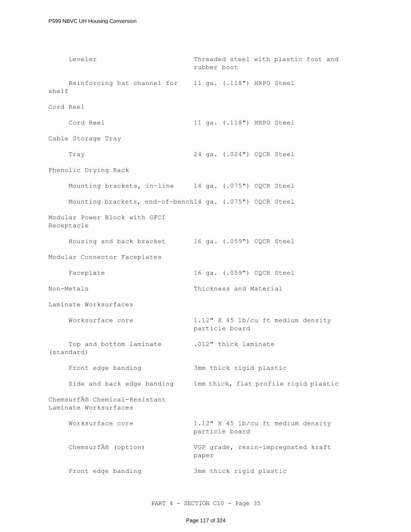
PART 4 - SECTION C10 - Page 35
Leveler
Threaded steel with plastic foot and
rubber boot
Reinforcing hat channel for
shelf
11 ga. (.118") HRPO Steel
Cord Reel
Cord Reel
11 ga. (.118") HRPO Steel
Cable Storage Tray
Tray
24 ga. (.024") CQCR Steel
Phenolic Drying Rack
Mounting brackets, in-line
14 ga. (.075") CQCR Steel
Mounting brackets, end-of-bench
14 ga. (.075") CQCR Steel
Modular Power Block with GFCI
Receptacle
Housing and back bracket
16 ga. (.059") CQCR Steel
Modular Connector Faceplates
Faceplate
16 ga. (.059") CQCR Steel
Non-Metals
Thickness and Material
Laminate Worksurfaces
Worksurface core
1.12" X 45 lb/cu ft medium density
particle board
Top and bottom laminate
(standard)
.012" thick laminate
Front edge banding
3mm thick rigid plastic
Side and back edge banding
1mm thick, flat profile rigid plastic
Chemsurf® Chemical-Resistant
Laminate Worksurfaces
Worksurface core
1.12" X 45 lb/cu ft medium density
particle board
Chemsurf® (option)
VGP grade, resin-impregnated kraft
paper
Front edge banding
3mm thick rigid plastic
P599 NBVC UH Housing Conversion
Page 117 of 324

PART 4 - SECTION C10 - Page 36
Side and back edge banding
1mm thick, flat profile rigid plastic
Phenolic Resin Worksurfaces
Worksurface core
.75" thick, phenolic
resin-impregnated kraft paper
Phenolic Drying Rack
Panel
1.00" thick, phenolic
resin-impregnated kraft paper
Pegs
.38" dia x 5" long polypropylene pegs
Phenolic Drip Trough
Trough
1.00" thick, phenolic
resin-impregnated kraft paper
Drain tube
.50" OD rigid phenolic tube
Drain flexible tube
.50" OD x 3' long flexible clear PVC
tubing
Laminate Overhead Storage Cabinets
Panel core (Top, Bottom, Ends,
Back, Door, Shelf)
.75" X 45 lb/cu ft industrial grade
particle board
Laminate
.012" thick laminate
Cabinet edge banding
1mm thick, flat profile rigid plastic
Door edge banding
2mm thick, flat profile rigid plastic
Glass door
.25" thick tempered safety glass
Steel Overhead Storage Cabinets
Glass door
.25" thick tempered safety glass
Laminate Storage and Sink Cabinets
Panel core (Top, Bottom, Base,
Ends, Back, Door, and Shelf)
.75" X 45 lb/cu ft industrial grade
particle board
Laminate
.012" thick laminate
Cabinet edge banding
1mm thick, flat profile rigid plastic
Drawer/Door edge banding
2mm thick, flat profile rigid plastic
Drawer/Door stop
Rubber
Steel Storage and Sink Cabinets
P599 NBVC UH Housing Conversion
Page 118 of 324
PART 4 - SECTION C10 - Page 37
Drawer/Door stop
Rubber
Power Block
Housing
Ultramid Nylon
Harness-to-Harness Connector
Housing
Ultramid Nylon
Duplex Receptacles
Housing
Ultramid Nylon
Modular Harnesses and Multipurpose
Power Infeeds
Connector housing
Ultramid Nylon
Wire Manager
Channel
Rigid plastic
C103011 CLOSETS This paragraph includes all built-in closets with associated work and finishes.
C103012 FIRESTOPPING PENETRATIONS
This paragraph covers fire-stopping assemblies to include sleeves, caulking and
flashing. See PTS Section D40, Fire Protection, for additional requirements.
C103012 1.1 FIRESTOPPING
Provide asbestos-free firestopping material capable of maintaining an
effective barrier against flame, gases and temperature. Provide
non-combustible firestopping that is non-toxic to human beings during
installation or during fire conditions. Devices and equipment for
firestopping service shall be UL FRD listed or FM P7825 approved for use
with applicable construction, and penetrating items.
C103012 1.1.1 Fire Hazard Classification
Material shall have a flame-spread of 25 or less, a smoke developed
rating of 50 or less when tested in accordance with UL 723 or UL listed
and accepted.
C103012 1.1.2 Firestopping Rating
Firestopping materials shall be UL FRD listed or FM P7825 approved
for "F" and "T" ratings at least equal to the fire-rating of the fire
P599 NBVC UH Housing Conversion
Page 119 of 324
PART 4 - SECTION C10 - Page 38
wall in which penetrated openings are to be protected.
C103013 SPRAYED FIRE-RESISTIVE MATERIALS
See PTS Section D40, Fire Protection, for additional requirements.
C103013 1.1 SPRAYED FIRE-RESISTIVE MATERIALS
C103013 1.1.1 Quality Assurance
A pre-installation conference shall be held with the manufacturer’s
approved installer prior to the application of the sprayed
fire-resistive materials. See Paragraph C10 1.2 for field testing
requirements for the fire-resistive material. Products provided shall
not contain asbestos per 40 CFR 763.
C103013 1.1.2 Warranty
Contractor shall provide manufacturer's standard materials and
workmanship warranty stating that the manufacturer agrees to repair
or replace materials that fail within 2 years, or as required by the
project program, from date of Substantial Completion.
C103013 1.1.3 Material Composition
Provide sprayed fire-resistive material consisting of factory-mixed,
dry formulation of gypsum or Portland cement binders and light-weight
mineral or synthetic aggregates mixed with water at the Project site,
or provide sprayed-fiber fire-resistive material consisting of
factory-mixed, dry formulation of inorganic binders, mineral fibers,
fillers, and additives conveyed in a dry state by pneumatic equipment
and mixed with water at a spray nozzle to form a damp, as-applied
product.
C103013 1.1.4 Physical Properties
a. Dry Density: 15 lb/cubic foot (240 kg/cubic meter) for
referenced fire-resistance design to attain the ratings
indicated, per ASTM E 605.
b. Thickness: Provide minimum average thickness required for
fire-resistance design indicated according to the following
criteria, but not less than 0.375 inch (9 mm), per ASTM E 605:
1) Where the referenced fire-resistance design lists a
thickness of 1 inch (25 mm) or greater, the minimum allowable
individual thickness of sprayed fire-restive material is the
design thickness minus 0.25 inch (6 mm).
2) Where the referenced fire-resistance design lists a
thickness of less than 1 inch (25 mm) but more than 0.375 inch
(9 mm), the minimum allowable individual thickness of sprayed
fire-resistive material is the greater of 0.375 inch (9 mm) or
75 percent of the design thickness.
P599 NBVC UH Housing Conversion
Page 120 of 324

PART 4 - SECTION C10 - Page 39
3) No reduction in design thickness is permitted for those
fire-resistance designs whose fire-resistance ratings were
established at densities of less than 15 lb/cubic foot (240
kg/cubic meter).
c. Bond Strength: 150 lb/sq. ft. (7.2 kPa) minimum per ASTM E 736.
d. Compressive Strength: 5.21 lb/sq. in. (35.9 kPa) as determined
per ASTM E 761. Minimum thickness of sprayed fire-resistive
material tested shall be 0.75 inch (19 mm) and minimum dry
density shall be as specified, but not less than 15 lb/cubic
foot (240 kg/cubic meter).
e. Corrosion Resistance: No evidence of corrosion per ASTM E 937.
f. Deflection: No cracking, spalling, or delaminating per ASTM E
759.
g. Effect of Impact on Bonding: No cracking, spalling, or
delaminating per ASTM E 759.
h. Air Erosion: Maximum weight loss of 0.025 g/sq. foot (0.270
g/sq. meter) in 24 hours per ASTM E 859.
i. Fire-Test-Response Characteristics: Provide sprayed
fire-resistive materials with the following surface-burning
characteristics per ASTM E 84 by United Laboratories:
flame-spread index of 10 or less and a smoke developed index
of 0.
j. Fungal Resistance: No observed growth on specimens per ASTM G
21.
C103014 ENTRANCE FLOOR GRILLES AND MATS
Provide entrance mats at all entrances to the facility. Provide recessed entrance
mats at building entrances with enclosed vestibule and or surface applied
entranceway mats or entranceway floor tiles at all other entrances. Entranceway
mats and entranceway floor tile require the use of a transition edge where he mat
adjoins other floor materials. Mat system shall meet ASTM D-2047 coefficient of
friction requirements for dry and wet surfaces. All portions of mat system shall
comply with ASTM E 648, Class I for flammability and ASTM E 662 for smoke development
of ≤ 450. Fasteners shall be non-corrosive screws and anchors for securing frames
together to floors. Provide continuous vinyl bottom cushion to quiet clatter at
recessed entrance mat systems. Hinges shall be flexible aluminum or thermoplastic
hinge retained in aluminum tread port, and allow debris and moisture to flow through
recessed mat. Provide ball and socket hinge for easy roll-up of recessed mat
inserts for cleaning. Recessed entrance mat systems shall use either an aluminum
or thermoplastic framework and shall have replaceable wearing surface inserts.
Provide inserts as follows:
a. Carpet Inserts - Carpet insert fiber shall be colorfast, solution dyed,
anti-static, anti-microbial, and waterproof. Fiber shall be 100% nylon or
polypropylene. Each carpet fiber shall be bonded to rigid ply backing to
prevent fraying and supplied in continuous splice-free lengths. Carpet shall
be minimum of 30-oz./yd².
b. Vinyl or Rubber Inserts - Vinyl or rubber inserts shall be removable and
be made from recycled materials wherever possible. Inserts shall have
serrated edges for scraping purposed or flexible abrasive grit tape, bonded
to a rigid vinyl tread insert.
P599 NBVC UH Housing Conversion
Page 121 of 324
PART 4 - SECTION C10 - Page 40
C103014 1.1 RECESSED MAT THERMOPLASTIC FRAME PROPERTIES
Thermoplastic frame shall be colorfast and UV-resistant. Tensile strength
of frame shall comply with ASTM D 638. Tensile impact of frame shall comply
with ASTM D 1822. Flexural strength of frame shall comply with ASTM D 790.
Shore D hardness of frame shall comply with ASTM D 2240. Rockwell R hardness
of frame shall comply with ASTM D 785. Coefficient of thermal expansion
of frame shall comply with ASTM D 696.
C103014 1.2 RECESSED MAT ALUMINUM FRAME REQUIREMENTS
Aluminum frame and rail shall comply with ASTM B 221, alloy 6063-T5. Frame
shall have butted corners and be factory coated with zinc chromate or
manufacturer's standard protective finish where surfaces are in contact with
concrete. Provide standard mill finish, color anodized finish complying
with AAMA 606.1, clear anodized finish complying with AAMA 607.1, or bronze
complying with ASTM B455, alloy 385.
C103014 1.3 SURFACE MOUNTED/LOOSE-LAY ENTRANCE MATS
Loose-lay mats shall have beveled vinyl or rubber transition edge and shall
have surface of carpet or vinyl/rubber surfaces. Edges shall conform to
ADA accessibility guideline 4.5.2, for loose-lay surface applications.
Mats shall be easily removed yet remain adhered to floor to prevent mat from
moving as pressure from walking is applied. Do not use carpet inserts unless
directed otherwise.
C103014 1.4 SURFACE APPLIED ENTRANCEWAY FLOOR TILE
Applied entranceway floor tiles shall be in the form of carpet tiles, carpet
tiles with vinyl or rubber scrubbing surfaces, or tiles of thermoplastic
scrubbing surfaces only. Tiles shall be installed in areas where permanent
mat is required but slab is not recessed to receive permanent recess mat.
Tiles shall be securely installed without obvious seams, cleanable,
dimensionally stable, and with maximum finished tile thickness of 1/2" above
finished floor line. Carpet fibers shall 100% nylon or polypropylene,
anti-static, anti-microbial, colorfast, solution dyed, mold and mildew
resistant, and waterproof with minimum face weight of 30 oz/yd2.
Thermoplastic only tiles shall be PVC free and UV-resistant.
C103015 ORNAMENTAL METALWORK
Building components made from ornamental metals. Ornamental stair handrails are
included in B1010 EXTERIOR STAIRS and PTS C20, Stairs.
C103090 OTHER INTERIOR SPECIALTIES
This paragraph covers other interior specialties not described by other assembly
categories listed previously.
C103090 1.1 PROJECTION SCREEN
Motorized projection screen shall be wall, ceiling, or above ceiling
mounting, and shall have a 120V motor that is lubricated for life, quick
P599 NBVC UH Housing Conversion
Page 122 of 324
PART 4 - SECTION C10 - Page 41
reversal type, has overload protector, integral gears, and preset accessible
limit switches. Screen shall be flame retardant, mildew resistant and have
black masked borders. Controls shall be wall mounted with wiring concealed
within the wall construction. Pull-down projection screens shall be
provided in lieu of motorized projection screens as approved by the Activity,
as specified in the project program.
C103090 1.2 OTHER INTERIOR SPECIALTIES
Also see PTS Sections C20 and C30 for additional interior specialties not
specified here.
-- End of Section --
P599 NBVC UH Housing Conversion
Page 123 of 324
PART 4 - SECTION C20 - Page 1
SECTION C20
STAIRS
05/14
C20 GENERAL
RFP Part 3 including the Engineering System Requirements (ESR) provide project
specific requirements. The RFP Part 4, Performance Technical Sections (PTS)
provide generalized technical requirements that apply to multiple facility types
and include more requirements than are applicable to any one project. Therefore,
only the RFP Part 4 requirements that apply to the project and further define the
RFP Part 3 project specific requirements are required.
C20 1.1 DESIGN GUIDANCE
Provide the design and installation in accordance with the following
references. This Performance Technical Specification (PTS) adds
clarification to the fundamental requirements contained in the following
Government Standards. The general requirements of this PTS section are
located in PTS Section Z10, General Performance Technical Specification.
Industry standards, codes, and government standards that are referenced in
the section text that are not found in the Unified Master Reference List
(UMRL) in the Construction Criteria Base (CCB) at the Whole Building Design
Guide Website , are listed below for basic designation identification.
Comply with the required and advisory portions of the current edition of
the standard at the time of contract award.
C20 1.1.1 Industry Standards and Codes
AISC American Institute of Steel Construction
C20 1.1.2 Government Standards
UNIFIED FACILITIES CRITERIA (UFC)
UFC 1-200-01
General Building Requirements(A
reference in this PTS section to UFC
1-200-01 requires compliance with the
Tri-Service Core UFCs that are listed
in UFGS Section 01 33 10.05 20, which
includes the following significant
UFC(s):UFC 3-101-01, Architecture)
UFC 1-200-02
High Performance and Sustainable
Buildings
C20 1.2 PERFORMANCE VERIFICATION AND ACCEPTANCE TESTING
Verification of satisfactory stair performance shall be via Performance
P599 NBVC UH Housing Conversion
Page 124 of 324

PART 4 - SECTION C20 - Page 2
Verification Testing, as detailed in this section of the RFP.
C20 1.2.1 Field Testing for Concrete
Field Quality Control Test Reports to be submitted to DOR shall comply
with ACI 301. If concrete is found to be below the strength required
in the tests, Contractor shall remove and replace that concrete and
all associated building components at his own expense.
C20 1.3 DESIGN SUBMITTALS
Design Submittals shall be in accordance with Z10, General Performance
Technical Specifications, UFGS section 01 33 10.05 20, Design Submittal
Procedures, UFC 1-300-09N, Design Proceduresand UFC 3-101-01, Architecture.
C20 1.4 CONSTRUCTION SUBMITTALS
Submit construction submittals in accordance with PTS Section Z10, General
Performance Technical Specification. In addition to the Z10 requirements
the Designer of Record (DOR) shall approve the following construction
submittals as a minimum:
Stairs, handrails.
C2010 STAIR CONSTRUCTION
C201001 INTERIOR AND EXTERIOR STAIRS
Provide primed and painted steel stairs with concrete filled pans or cast-in-place
concrete stairs for industrial and commercial construction. Design load shall not
be less than 100 PSF (4.8 kPa) for live load, and 300 pounds (136 kg) for
concentrated loads. Required means of egress stairs shall conform to NFPA 101.
Provide steel guard and handrails.
C201001 1.1 STEEL STAIRS
Design shall conform to AISC S335 or AISC S342L.
C201001 1.1.1 Materials
a. Structural Carbon Steel - ASTM A 36/A 36M
b. Structural Tubing - ASTM A 500
c. Steel Pipe - ASTM A 47
d. Gratings - Gray cast iron ASTM A 48, Class 40
e. Metal plank grating, non-slip requirement, FS RR-G-1602
aluminum ASTM B 209, 6061-T6; steel ASTM A 653/ A 653M, G90.
f. Floor Plates, Patterned - ASTM A 786/A 786M, 14 gage.
g. Anchor Bolts - ASTM A 307
h. Galvanized Structural Steel - All steel exposed to the
environment or direct water contact shall be galvanized in
accordance with ASTM A 123 /A123M, ASTM A153/A153M, and ASTM
A653/A653M, Z275 (G90) coating. Galvanize all components
after fabrication in accordance with ASTM A385. Fabricate all
steel components in the largest units practical using bolted
P599 NBVC UH Housing Conversion
Page 125 of 324
PART 4 - SECTION C20 - Page 3
connections for field assembly. Repair damage to, or voids in,
galvanizing in accordance with ASTM A780, Annex A1 or Annex A3.
C201001 1.2 ALUMINUM ALLOY PRODUCTS
Conform to ASTM B 209 for sheet plate, ASTM B 221 for extrusions and ASTM
B 26/B 26M or ASTM B 108 for castings. Aluminum extrusions shall be at least
1/8-inch (3.2 mm) thick and aluminum plate or sheet at least 0.050 inch (1.27
mm) thick.
C201001 1.3 FINISHES
C201001 1.3.1 Galvanizing
Hot-dip galvanizing: ASTM A 123/A123M, ASTM A 153/A 153M or ASTM A
653/A 653M, G90, as applicable.
C201001 1.3.2 Aluminum Finishes
Protect by plating, Class I anodic coatings, or 70% polyvinylidene
fluoride organic coatings. See PTS Section C30 for additional
coatings/finish information.
C201001 1.3.3 Safety Treads
NAAMM BG steel, Type W (welded).
C201001 1.3.4 Other Coatings
See PTS Section C30, Interior Finishes, for painted finishes.
C201001 1.4 CONCRETE STAIRS / STEPS
Provide interior or exterior concrete steps and stair with non-slip finish.
For interior stairs, provide rubber or other finish treads. For exterior
stairs, provide cast-in-place abrasive nosing. Provide steel guard and
handrails as necessary. Fire stairs shall comply to NFPA 101.
C201001 1.4.1 Materials
a. Concrete - ACI 211.1, ACI 301/301M, and ACI 318/318M, with a
compressive strength of 3,000 psi (20,680 kPa) or greater.
Concrete Mix Design shall be suitable for the job conditions.
b. Reinforcements - Bars, fabrics, connectors, and chairs shall
be galvanized.
c. Reinforcing Bars - ACI 301/301M
d. Welded Wire Fabric - ASTM A 185 or ASTM A 497
e. Cast Aluminum Safety Nosings – For exterior concrete stairs,
provide safety nosings of cast aluminum with abrasive surfaces
or with abrasive inserts.
C201001 1.5 WOOD STAIRS
Wood stairs may be used only for residential construction. Provide wood
P599 NBVC UH Housing Conversion
Page 126 of 324
PART 4 - SECTION C20 - Page 4
treads of minimum 1-1/4 inches thickness, of clear red or white oak. Risers
shall be nominal one-inch finish lumber. Provide natural finish equivalent
to one coat of sealer and two coats of varnish on all exposed surfaces.
C201002 FIRE ESCAPE STAIRS
Design fire escapes of the type and arrangement to conform to Fire Escape Stairs,
of NFPA 101, Life Safety Code. Escape stairs shall be of steel or aluminum,
conforming to the requirements of this specification section.
C201090 STAIR HANDRAILS, GUARDRAILS, AND ACCESSORIES
C201090 1.1 HANDRAILS
Design handrails in accordance with the IBC, except delete the handrail
design load reduction code exceptions for residential, prisons, industrial,
high hazard, and storage facilities. NAAMM PR, provide the same size rail
and post. Provide series 300 stainless steel pipe collars. Factory coat
all metal railings (except for ornamental metals such as brass, bronze,
stainless steel, and nickel-silver) with a high performance coating in
accordance with AAMA 2605, with a minimum coating thickness of 1.2 mils
unless otherwise noted.
C201090 1.1.1 Steel Handrails
Provide steel handrails, including inserts in concrete, steel pipe
conforming to ASTM A 53 or structural tubing conforming to ASTM A 500,
Grade A or B of equivalent strength. Railings shall be hot-dip
galvanized and shop painted for exterior applications and primed and
shop painted for interior applications. Railing may be unpainted
hot-dip galvanized in industrial areas.
C201090 1.1.2 Aluminum Handrails
Provide aluminum pipe railing conforming to ASTM B 429 or square
aluminum semi-hollow tube conforming to ASTM B 221. Railings shall
be coated with a high performance coating or anodized in accordance
with AAMA 611, Class I.
C201090 1.1.3 Ornamental Handrails
Provide ornamental railings. Provide anchorage and fasteners as
recommended by the product manufacturer. Railing system shall conform
to ASTM E 985, minimum concentrated test load requirement.
C201090 1.1.4 Glass Handrails
Provide glass railings consisting of continuous 1/2-inch (13 mm)
beveled tempered glass structural balusters with continuous railing
cap and bottom shoe molding. Railing cap and shoe molding shall be
6063-T52 aluminum, type 304 stainless steel, brass, or bronze.
C201090 1.1.5 Wood Handrails
P599 NBVC UH Housing Conversion
Page 127 of 324
PART 4 - SECTION C20 - Page 5
Wood handrails shall only be used for residential construction.
Provide wood handrails of pre-finished natural hardwood. Wood shall
be coated with hard acrylic finish to withstand indentations.
C201090 1.2 METAL LADDERS
C201090 1.2.1 Metal Ladders
Provide vertical ladders conforming to Section 7 of 29 CFR 1910.27.
C201090 1.2.2 Installation
Offset distance from the rungs to the finished wall surface not less
than 7 inches (175 mm). Provide heavy clip angles riveted or bolted
to the stringer and drilled for not less than two 1/2-inch (12 mm)
diameter expansion bolts as indicated. Provide intermediate clip
angles not over 48 inches (1200 mm) on center.
C201090 1.2.3 Ladder Cages
Where the height of the ladder is greater than 20 feet (6000 mm),
provide a cage to conform to 29 CFR 1910.27.
a. Cage fabrication – Provide attachments for fastening bands to
the side rails of ladders or directly to the structure.
-- End of Section --
P599 NBVC UH Housing Conversion
Page 128 of 324
PART 4 - SECTION C30 - Page 1
SECTION C30
INTERIOR FINISHES
05/14
C30 GENERAL
RFP Part 3 including the Engineering System Requirements (ESR) provide project
specific requirements. The RFP Part 4, Performance Technical Sections (PTS)
provide generalized technical requirements that apply to multiple facility types
and include more requirements than are applicable to any one project. Therefore,
only the RFP Part 4 requirements that apply to the project and further define the
RFP Part 3 project specific requirements are required.
All interior finish products shall be from manufacturers' standard running line
offerings. Custom fabrications shall not be allowed unless otherwise noted.
C30 1.1 DESIGN GUIDANCE
Provide the design and installation in accordance with the following
references. This Performance Technical Specification (PTS) adds
clarification to the fundamental requirements contained in the following
Government Standards. The general requirements of this PTS section are
located in PTS Section Z10, General Performance Technical Specification.
Industry standards, codes, and Government standards referenced in the
section text that are not found in the Unified Master Reference List (UMRL)
in the Construction Criteria Base (CCB) at the Whole Building Design Guide
Website , are listed below for basic designation identification. Comply
with the required and advisory portions of the current edition of the
referenced standard at the time of contract award.
C30 1.1.1 Industry Standards And Codes
FLOOR COVERING INSTALLATION CONTRACTOR'S ASSOCIATION (FCICA)
FLOOR COVERING INSTALLATION BOARD (FCIB)
TILE COUNCIL OF NORTH AMERICA (TCNA)
C30 1.1.2 Government Standards
UNIFIED FACILITIES CRITERIA (UFC)
UFC 1-200-01
General Building Requirements(A
reference in this PTS section to UFC
1-200-01 requires compliance with the
Tri-Service Core UFCs that are listed
in UFGS Section 01 33 10.05 20, which
includes the following significant
UFC(s):UFC 3-101-01, ArchitectureUFC
3-120-10, Interior Design)
P599 NBVC UH Housing Conversion
Page 129 of 324

PART 4 - SECTION C30 - Page 2
UFC 1-200-02
High Performance and Sustainable
Buildings
C30 1.2 QUALITY ASSURANCE
C30 1.2.1 Paint Applicator’s Qualifications
C30 1.2.1.1 SSPC QP 1 Certification
For the application of industrial coatings identified in the
Project Program, all contractors and subcontractors that
perform surface preparation or coating application shall be
certified by the Society for Protective Coatings (formerly
Steel Structures Painting Council) (SSPC) to the requirements
of SSPC QP 1 prior to contract award, and shall remain certified
while accomplishing any surface preparation or coating
application. The painting contractors and painting
subcontractors must remain so certified for the duration of the
project. If a contractor's or subcontractor's certification
expires, the firm will not be allowed to perform any work until
the certification is reissued. Requests for extension of time
for any delay to the completion of the project due to an inactive
certification will not be considered and liquidated damages
will apply. Notify the Contracting Officer of any change in
contractor certification status.
C30 1.2.2 Aircraft Maintenance Hangar and Vehicle Maintenance Flooring
Installer Qualifications
The Designer of Record shall utilize UFGS Specification Section 09
67 23.14, Fuel Resistive Resinous Flooring, 3-Coatto provide the
required installer qualifications for the floor coating system.
C30 1.3 PERFORMANCE VERIFICATION AND ACCEPTANCE TESTING
Verification of satisfactory interior finish assemblies' performance shall
be via Performance Verification Testing, as detailed in this section of the
RFP.
C30 1.3.1
Provide sample of textured ceiling application for DOR approval before
resuming work. Sample shall be used as a reference for remaining
application.
C30 1.3.2
Provide sample of multicolor paint application for DOR approval before
resuming work. Sample shall be used as a reference for remaining
application.
C30 1.3.3
P599 NBVC UH Housing Conversion
Page 130 of 324
PART 4 - SECTION C30 - Page 3
Provide sample of terrazzo and/ or architectural cast-in-place
concrete floor application for DOR approval before resuming work.
Sample shall be used as a reference for remaining application.
C30 1.4 DESIGN SUBMITTALS
Design Submittals shall be in accordance with Z10, General Performance
Technical Specifications, UFGS section 01 33 10.05 20, Design Submittal
Procedures, UFC 1-300-09N, Design Proceduresand UFC 3-101-01, Architecture.
In addition, UFGS sections listed below or in the body of the PTS text are
to be used by the Designer of Record (DOR) as a part of the design submittal.
If the UFGS products or systems are applicable to the project, the DOR shall
edit these referenced UFGS sections and submit them as a part of the design
submittal specification. Edit the specification sections in accordance
with the limitations stated in PTS section Z10, General Performance
Technical Specifications.
Changes shall not be made to the finishes that are submitted in the plans,
specifications, and Structural Interior Design submittals and approved by
the Government during the design phase unless changes are requested by the
Government. In the event that revisions may be required because of
unforeseen conditions such as discontinued product, the revisions must be
approved by the DOR and then submitted to the Government Interior Designer
for approval before substitutions can be made.
C30 1.5 CONSTRUCTION SUBMITTALS
Submit construction submittals in accordance with PTS section Z10, General
Performance Technical Specifications. In addition to the Z10 requirements,
the Designer of Record (DOR) and the NAVFAC Interior Designer shall approve
the following construction submittals as a minimum:
Paint, Finish materials, Finish colors
Installation drawings for floors with carpet, tile, stone,
architectural cast-in-place concrete or terrazzo to include locations
and details of seams, color and material transitions, details of
divider strips, control joints, and crack control solutions.
Changes shall not be made to the finishes that are submitted and approved
by the Government during the design phase. In the event that revisions may
be required because of unforeseen conditions such as discontinued product,
the revisions must be approved by the DOR and then submitted to the Government
Interior Designer for approval before substitutions can be made.
C3010 WALL FINISHES
Interior wall finishes shall be moisture and mildew resistant, easily maintained,
and suitable in accordance with industry standards for the architectural surface
being finished. For painted wall finishes, refer to C3040 "INTERIOR PAINTING AND
SPECIAL COATINGS".
P599 NBVC UH Housing Conversion
Page 131 of 324

PART 4 - SECTION C30 - Page 4
C301001 CONCRETE WALL FINISHES
C301001 1.1 SPECIAL OR ARCHITECTURAL FINISHES ON INTERIOR CONCRETE WALLS
Cast-in-place or pre-cast concrete wall finishes shall include, but are not
limited to, abrasive blasted surfaces, colored surfaces, exposed aggregate,
grooved surfaces, or tooled surfaces.
C301002 PLASTER WALL FINISHES
Veneer plaster shall be gypsum plaster veneer finish on gypsum base finishes, or
cement plaster veneer finish on concrete or masonry. Refer to Section C3040 for
paint system and gloss level.
C301002 1.1 GYPSUM PLASTER
Provide gypsum neat plaster or high strength gypsum plaster base coat
conforming to ASTM C28. High strength gypsum plaster shall have a compressive
strength of not less than 2,500 psi, when tested dry in accordance with ASTM
C472.
C301002 1.1.1
High strength gypsum gaging plaster finish coat shall have a
compressive strength of not less that 4,500 psi when tested dry in
accordance with ASTM C472.
C301002 1.1.2
Provide gypsum molding plaster for ornamental plaster in accordance
with ASTM C59.
C301002 1.1.3
Provide Keene's cement finish coat conforming to ASTM C61.
C301002 1.1.4
Provide acoustical gypsum plaster finish coat conforming to ASTM E1042
Type I or II Class A, noncombustible.
C301002 1.2 CEMENT PLASTER
C301002 1.2.1
Portland cement plaster base coat in accordance with ASTM C150, gray
Portland cement. Use Type I when no special characteristics are
required, Type II when plaster and stucco will be exposed to moderate
sulfate (alkali) action, Type III when early strength is needed as
in cold weather, and Type V when high resistance to sulfate is
required.
C301002 1.2.2
P599 NBVC UH Housing Conversion
Page 132 of 324

PART 4 - SECTION C30 - Page 5
Portland cement plaster finish coat in accordance with ASTM C150, gray
Portland cement Type I when no special characteristics are required,
Type II when plaster and stucco will be exposed to moderate sulfate
(alkali) action, Type III when early strength is needed as in cold
weather.
C301002 1.2.3
Factory-mixed finish coat according to the manufacturer's
instructions.
C301002 1.3 ACRYLIC PLASTER COATING
High Performance (impact resistant) seamless interior acrylic coating
system shall be used as an interior wall finish over CMU that has been joint
filled and smoothed with a water resistant manufactured recommended
compound. Coating system to be mold and mildew resistant, have a minimum
Barcoll Hardness Index of 38 and flame spread 15 or less per ASTM-E84 and
have a minimum final film thickness of higher than 10 mils. Coating system
must have been on the market and successfully used in commercial applications
for a minimum of 10 years. Coating system must be applied by a manufacturer's
factory trained applicator/installer.
C301003 GYPSUM WALLBOARD FINISHES
Conform to specifications, standards and requirements in accordance with Gypsum
Association GA 214, GA 216 and GA 224. Provide asbestos free materials only.
Provide Type X gypsum board in fire rated assemblies. Provide a foil back gypsum
board when a vapor retarder is required.
C301003 1.1 REGULAR GYPSUM BOARD
ASTM C36/C36M and ASTM C1396/C1396M 1/2 or 5/8 inch (12.7 mm or 15.9 mm)
thick in residential construction, and 5/8 inch (15.9 mm) thick in
non-residential construction, tapered edges for exposed layers, square
edges for concealed backer layers.
C301003 1.2 MOISTURE RESISTANT GYPSUM BOARD
ASTM C630/C630M, 1/2 or 5/8 inch (12.7 mm or 15.9 mm) thick in residential
construction, and 5/8 inch (15.9 mm) thick in non-residential construction.
Use in humid areas or spaces but not as a substrate in tiled areas where
wall tile is exposed to direct moisture contact or condensation
accumulation.
C301003 1.3 FOIL BACKED GYPSUM BOARD
ASTM C1396/C1396M 1/2 or 5/8 inch (12.7 mm or 15.9 mm) thick in residential
construction, and 5/8 inch (15.9 mm) thick in non-residential construction,
tapered edges for layers exposed to view, square edges for concealed layers.
Seal joints in foil backing to other panels and adjoining materials as
recommended by the panel manufacturer.
Alternative to foil backed gypsum board in Secured Areas: Field applied
P599 NBVC UH Housing Conversion
Page 133 of 324
PART 4 - SECTION C30 - Page 6
foil faced barrier material is an acceptable alternative for pre
manufactured foil backed gypsum board. Provide a continuous composite
multilayer barrier with a woven polyethylene sheet sandwiched between two
sheets of solid reflective aluminum surfaces. Shielding effectiveness
tested in accordance with IEEE 229/ ASTM D4935. Install barrier in
accordance with manufactures instructions.
C301003 1.4 CEMENTITIOUS BACKING UNITS
ANSI A108.11 and ANSI A118.9, 5/8 inch (15.9 mm) thick; use as a substrate
for ceramic tile in wet areas that are exposed to direct moisture contact
or condensation accumulation for areas including, but not limited to, tubs,
shower enclosures, saunas, steam rooms, gang shower rooms, and shower drying
rooms. Provide screws specifically designed for use with cement panels.
C301003 1.5 IMPACT RESISTANT GYPSUM BOARD
Reinforced gypsum panel with imbedded fiber mesh or polycarbonate resin
thermoplastic backing, 5/8 inch (15.9 mm) thick, tapered edges, in
accordance with Structural Failure Test; ASTM E695 or ASTM D2394 and
Indentation Test; ASTM D5420 or ASTM D1037. Provide metal framing of
20-gauge minimum. Provide fasteners that meet manufacturer requirements and
specifications. Impact resistant gypsum board shall have a flame spread
rating of 25 or less and a smoke developed rating of 50 or less, ASTM E84.
Finish with a high strength plaster veneer. Refer to PTS C10 for further
requirements on impact resistant wall construction.
C301003 1.6 JOINT TREATMENT
ASTM C475, Joint compound shall be specifically formulated and manufactured
for use with and compatible with tape, substrate and fasteners as recommended
by the manufacturer. Tape and finish gypsum board in accordance with ASTM
C840, GA 214 and GA 216. Provide premanufactured joints at all structural
expansion joints, crack control joints, and change of materials as
recommended by the manufacturer and in accordance with GA 216.
C301003 1.7 FASTENERS
ASTM C514. Fasteners shall be compatible with each type of gypsum board
material as recommended by the gypsum board manufacturer and in accordance
with GA 216 and GA 224.
C301003 1.8 ACCESSORIES
ASTM C1047. Fabricate from corrosion protected steel or plastic designed
for intended use. Accessories manufactured with paper flanges are not
acceptable. Flanges shall be free of dirt, grease, and other materials that
may adversely affect bond of joint treatment. Provide prefinished or job
decorated materials. For predecorated gypsum board provide prefinished
metal or plastic trim to match predecorated gypsum board. Install as
recommended by GA 214, GA 216 and GA 224.
C301003 1.9 LEVEL OF FINISH
P599 NBVC UH Housing Conversion
Page 134 of 324
PART 4 - SECTION C30 - Page 7
C301003 1.9.1
Tape and finish gypsum board in accordance with ASTM C840, GA 214 and
GA 216. Plenum areas above ceilings shall be finished to GA 214, Level
1. Water resistant gypsum backing board, ASTM C630/C630M, to receive
ceramic tile shall be finished to GA 214, Level 2. Walls to receive
a heavy-grade wall covering or have textured finish before painting
shall be finished to GA 214 Level 3. Walls without wall wash lighting
to receive paint (MPI Gloss Level 2), light textures, or wall coverings
shall be finished to GA 214 Level 4. Unless otherwise specified, all
gypsum board walls, partitions shall be finished to GA 214 Level 5.
Provide joint, fastener depression, and corner treatment. Do not use
fiberglass mesh tape with conventional drying type joint compounds;
use setting or hardening type compounds only. Provide treatment for
water-resistant gypsum board as recommended by the gypsum board
manufacturer.
C301003 1.9.2
Wherever gypsum board is to receive eggshell (MPI Gloss Level 3),
semigloss (MPI Gloss Level 5), or gloss (MPI Gloss Level 6) paint
finish, finish gypsum wall surface to GA 214 Level 5.
C301003 1.9.3
Where wall wash lighting will accent the flatness of the wall and
surface irregularities in gypsum board joints, provide feature edge
gypsum board and two coat joint compound fillers. Provide this
special joint treatment at up lighting, down lighting and horizontal
lighting at the end of a passageway wall.
C301004 TILE AND TERRAZZO WALL FINISHES
C301004 1.1 CERAMIC TILE WALL SYSTEM FINISHES
Provide ceramic tile wall systems as defined in the Tile Council of America
(TCA) handbook for ceramic tile installations suitable for the service
requirements listed. Install systems in accordance with ANSI A108/A118
series standards. Colored epoxy grout with sealer shall be provided.
Coordinate with ceramic bath accessories for modularity. Include all trim
pieces, caps, stops, and returns to complete installation.
C301004 1.1.1
Ceramic Mosaic Wall Tile shall be a minimum of 1/4 inch (6 mm) thick
and installed from floor to ceiling, unless otherwise noted.
C301004 1.1.2
Wall tile shall be glazed, matte glazed or unglazed finish. Refer to
project program for tile type, pattern, and surface texture.
C301004 1.1.3
P599 NBVC UH Housing Conversion
Page 135 of 324
PART 4 - SECTION C30 - Page 8
Porcelain wall tile shall be through color, polished or unpolished.
Refer to project program for tile type, pattern, and surface texture.
C301004 1.1.4
Provide wall tile color and style selections a minimum of one grade
above base grade.
C301004 1.1.5
Provide Designer accent tile, accent strips and accessory ceramic tile
shapes as an integral part of the ceramic wall tile system.
C301005 WALL COVERINGS
Wall coverings shall be material designed specifically for the specified use. The
wallcovering shall contain a non-mercury based anti-microbial. The wallcovering
shall be the type made without the use of cadmium-based stabilizers. Wallcovering
shall have a Class A flame spread rating of 0-25 and smoke development rating of
0-50 when tested in accordance with ASTM E84. The wall preparation, trimming,
adhesive and application shall be according to the manufacturer’s printed
directions. The manufacturer shall approve the installers in writing. The
material must be easily cleaned by traditional methods such as washing, wiping,
or vacuuming. Primer and adhesive shall be of a type recommended by the
wallcovering manufacturer and shall contain a non-mercury based anti-microbial.
Adhesive shall be strippable type. Do not apply wall coverings to the interior
surface of exterior walls.
C301005 1.1 VINYL WALL COVERING
C301005 1.1.1
Vinyl wallcovering shall be a vinyl coated woven or nonwoven fabric
with germicidal additives and shall conform to ASTM F793, Category
V Type II, 13.1 to 22 ounces (371 g to 624 g) total weight per square
yard and width of 54 inches (1370 mm). Provide ASTM F793, Category
VI, Type III, 22 ounces (624 g) and above to cover rough textured walls
such as masonry.
C301005 1.1.2
Provide a polyvinyl fluoride film, 0.0005 inch (0.012 mm) thick or
thicker shall be factory applied to the wall covering where additional
resistance to staining and soiling from exposure to staining reagents
or chemicals and resistance from abuse is required. The film shall
be transparent (clear), medium gloss.
C301005 1.2 FABRIC WALL COVERING
C301005 1.2.1
Fabric wallcovering shall be woven material of Polyester or
Polyolefin, or a combination of the two fibers with an acrylic backing.
The face shall be treated with a soil repellent finish. The material
P599 NBVC UH Housing Conversion
Page 136 of 324
PART 4 - SECTION C30 - Page 9
must be a minimum of 48 inches (1219 mm) wide. "Tackable" wall
covering shall be "self-healing" from tack penetration through the
covering into the substrate. The material must be a minimum of 12
ounces (340 g) per square yard exclusive of backing. A tackable wall
covering will not be required for smoother, less textured surface
appearance.
C301005 1.2.2
Acoustical wallcovering shall be textured, woven or non-woven
material of polyester or polyolefin, or a combination of the two fibers
with an acrylic backing. The material must be a minimum of 48 inches
(1219 mm) wide and a minimum of 16 ounces (454 g) per square yard.
The material shall have an NRC rating of .15 on gypsum board in
accordance with ASTM C423.
C301005 1.3 WALLCOVERING BORDER
Vinyl wallcovering border shall be a vinyl coated woven or nonwoven fabric
with germicidal additives and shall conform to ASTM F793, Type I, 7 to 13
ounces (198 g to 368 g) or Type II, 13.1 to 22 ounces (371 g to 624 g) total
weight per square yard.
C301005 1.4 SURFACE PREPARATION FOR UNEVEN WALLS
C301005 1.4.1
Wall liner shall be a non-woven polyester cellulose blend having a
minimum weight of 3.7 ounces (105 g) per square yard and a total
minimum thickness of 0.013 inches (0.33 mm). Wall liner shall have
a Class A flame spread rating of 0-25 and smoke development rating
of 0-50 when tested in accordance with ASTM E84. Use for masonry walls
or walls with uneven surfaces.
C301005 1.4.2
For masonry or rough textured walls, use a veneer plaster finish to
smooth the walls prior to wallcovering installation.
C301005 1.5 CORNER GUARDS
C301005 1.5.1
Corner guards shall be 3/32 inch (2.4 mm) thick and shall cover 1 inch
(25 mm) each side of corner at right angles. Corner guards shall be
clear polycarbonate. Use in executive areas, office areas, and
wall-covered areas subject to cart traffic as a minimum.
C301005 1.5.2
Corner guards shall be 3/32 inch thick and shall cover 2-1/2 inches
(64 mm) each side of corner at right angles. Corner guards shall be
through color polycarbonate or rubber. Use in corridors or other high
traffic areas.
P599 NBVC UH Housing Conversion
Page 137 of 324
PART 4 - SECTION C30 - Page 10
If protective wall components from paragraphs C301090 – 1.5 and 1.6
are provided, corner guards shall be from the same lot and color as
protective wall components.
C301005 1.6 WAINSCOT CAP
C301005 1.6.1
Wainscot cap shall be satin-finished extruded aluminum approximately
3/4 inch (19 mm) high, feathered at bottom edge, with an approximate
3/16 inch (5 mm) exposed face on top edge, and grooved to receive the
covering. Adhesive to install wainscot cap shall be of a type
recommended by the manufacturer of the cap.
C301005 1.6.2
Wood wainscot cap shall be 3-1/2 by 3/4 inch (89 mm by 19 mm) solid
hardwood, AWI Custom grade, with painted or stained finish. Profile
shall be a molded shape.
C301006 ACOUSTICAL PANELS ADHERED TO WALLS
Acoustical wall treatment shall be acoustical panels, sound absorbing wall units,
or acoustical wall systems. Acoustical panel system shall include manufacturer's
standard concealed fasteners, splines, tracks, and other components necessary to
complete the installation. Fire rating for the complete composite system shall
be Class A, 200 or less smoke density and flame spread less than 25, when tested
in accordance with ASTM E84.
C301006 1.1 ACOUSTICAL FABRIC COVERED WALL PANELS
C301006 1.1.1
Prefinished factory assembled wall panels shall consist of, seamless
fabric covered fiberglass or mineral fiber core system. Perimeter
edges shall be reinforced by an aluminum frame or a formulated resin
edge hardener. Fabric covering shall be stretched free of wrinkles
and then bonded to the edges and back or bonded directly to the panel
face, edges, and back of panel a minimum distance standard with the
manufacturer. Mounting shall be by manufacturer's standard concealed
spline, mechanical fasteners, magnetic fasteners, hook and loop or
adhesive mounting.
C301006 1.1.2
Stretched fabric wall panel system shall consist of continuous
perimeter and butt seam mounting extrusions, site-fabricated and
applied directly to the substrate. Facing fabric shall be stretched
over core materials and attached without adhesives, nails, tacks,
screws or tapes so that fabric may be removed and replaced with
framework in place.
C301006 1.1.3
P599 NBVC UH Housing Conversion
Page 138 of 324
PART 4 - SECTION C30 - Page 11
Fabric shall be seamless, 100% polyester or olefin or a blend of the
two. Light fastness (fadeometer) shall be approximately 40 hours in
accordance with AATCC 16.
C301006 1.1.3.1
Non-woven, embossed texture, or needle punched 100 percent
polyester, minimum 12 ounces (340 g) per linear yard. Tear
strength shall be minimum 25 pounds (11.25 kg) machine direction
and minimum 40 pounds (18 kg) cross-machine direction in
accordance with ASTM D1117. Tensile strength shall be minimum
50 pounds (22.5 kg) machine direction and minimum 75 pounds (34
kg) cross-machine direction in accordance with ASTM D5034.
C301006 1.1.3.2
Woven, minimum 2-ply 100 percent polyester or olefin, minimum
12 ounces (340 g) per linear yard. Tear strength shall be
minimum 29 pounds (13 kg). Tensile strength shall be 150 pounds
(68 kg) minimum in accordance with ASTM D5034.
C301006 1.1.3.3
Perforated vinyl covering with fabric backing, minimum 20
ounces (567 g) per linear yard total weight.
C301006 1.2 ACOUSTICAL WALL PANELS
Aspen wood fibers bonded together with an inorganic hydraulic cement binder,
formed in a continuous process under heat and pressure. Nominal overall panel
thickness shall be 1 inch (25 mm). Noise Reduction Coefficient shall be not
less than NRC 0.85 for Type C-40 and C-80 mounting.
C301090 OTHER WALL FINISHES
C301090 1.1 SOLID SURFACING WALL FINISHES
Solid surfacing material shall consist of 100% pure acrylic polymer, mineral
fillers, and pigments. The material shall be homogenous, not coated or
laminated, meeting ANSI Z124.3 and ANSI Z124.6 requirements. Superficial
damage to a depth of 0.010 inch (.254 mm) shall be repairable by sanding
or polishing. Provide manufacturer's full range of colors and patterns.
Flammability, ASTM E84: Class I/A, flame spread 25 maximum; smoke developed
30 maximum.
C301090 1.1.1
If used in a shower, solid surfacing wall finishes shall extend from
top of shower pan to a minimum of 84 inches (2130 mm) or to underside
of ceiling and shall surround the shower enclosure. Wall finish shall
extend from top of tub to 84 inches (2130 mm) and shall surround tub
shower. If used in a kitchen, solid surfacing wall finish shall extend
from top of kitchen countertop to underside of wall cabinet.
P599 NBVC UH Housing Conversion
Page 139 of 324

PART 4 - SECTION C30 - Page 12
C301090 1.1.2
Provide solid surfacing with factory recommended
fasteners/adhesives/caulk to complete the installation.
C301090 1.2 PLASTIC LAMINATE WALL FINISHES
Plastic laminate used for wall applications shall be commercial grade,
high-pressure laminate with a #60 finish, approved for vertical
applications. NEMA LD 3.
C301090 1.2.1
The kitchen wall area between the counter top backsplash and the bottom
of the wall cabinet shall be plastic laminate. Laminate wall finish
shall include factory recommended fasteners/adhesives/caulk to
complete the installation.
C301090 1.3 DECORATIVE PANELING SYSTEM
Architectural paneling system applied to interior walls shall include
associated furring, fastening, and trim to complete the installation. Wood
paneling system finish shall be factory or field applied.
C301090 1.4 WOOD TRIM AND DETAILING FINISHES
Decorative panels, chair rail, standing and running trim, shall be of AWI
custom grade hardwood with a painted or stained finish. Refer to C3040
"INTERIOR PAINTING AND SPECIAL FINISHES" for finish system. Chair rail shall
be a minimum of 3-1/2 inches (89 mm) high. Profile of chair rail shall be
a molded shape. Wood trim shall include associated furring, fastening,
adhesives and trim to complete the installation.
C301090 1.5 IMPACT RESISTANT PANEL OR WAINSCOT WALL FINISHES
The wall covering panel system, or wainscot, shall be an impact-resistant
acrylic PVC sheet of a minimum 0.060 inch (1.5 mm) thickness in 4 foot by
8 foot (1219 mm by 2438 mm) sheets. The system shall be Class A (ASTM E84),
UL listed, and chemical and stain resistant. It shall include all
accessories, such as top caps, joint covers, and inside and outside corners,
necessary for a complete installation. A full range of colors and textures
shall be included. The wall panel system shall have coordinating color and
pattern options for all components within the system. The wall panel system
shall offer a 21 ounce (595 g) fabric backed vinyl wallcovering laminated
to a 0.020 inch (.51 mm) rigid acrylic/PVC backing capped with 1 mil of
protective film.
C301090 1.5.1
Impact Resistant Trim Finishes - Impact resistant chair or handrail
system shall be a formed rigid PVC product. Chair or handrail shall
be a minimum of 3 inches (76 mm) high and be mounted with concealed
hardware. Chair or handrail system shall be chemical, stain, and
bacteria resistant. Chair rail shall be UL classified, conforming
P599 NBVC UH Housing Conversion
Page 140 of 324

PART 4 - SECTION C30 - Page 13
to NFPA Class A fire rating and ASTM D256-90b for impact strength of
30.2 ft-lbs/inch thick.
C301090 1.6 CORNER AND WALL GUARDS
Corner and wall guards shall be high-impact formed polyvinyl chloride a
minimum of 0.078 inch (2 mm) with concealed mounting hardware and end
closure. If used with an impact resistant panels system, the guards shall
be from the same manufacturer as the impact resistant wall panel system,
chair or hand rail system and shall include all accessories necessary for
a complete installation. A full range of styles, colors and textures shall
be included.
C3020 FLOOR FINISHES
Refer to C3040 "INTERIOR PAINTING AND SPECIAL FINISHES" for painted floor coatings.
C3020 1.1 RESILIENT SUBFLOOR PREPARATION
Have third party independent concrete slab testing agent verify that
concrete slabs comply with ASTM F710. Minimum values shall not be below the
following: Concrete floor flatness shall meet minimum flatness of FF 60 when
tested in accordance to ASTM E1155 - 96(2008). Concrete levelness on slab
on grade shall meet minimum levelness of FL 45 when tested in accordance
with ASTM E1155 - 96(2008). This requirement does not apply to elevated
concrete slabs.
C3020 1.1.1 Floor Preparation
Prior to installation of flooring materials the concrete sub-floors
are to be dry, free of curing compounds, sweeping compounds, sealers,
hardeners, and other materials which could interfere with bonding of
adhesive. If curing compounds, sweeping compounds, bond breakers or
sealers exist, they shall be completely removed by mechanical means
and methods, specifically grinding and shot blasting of concrete
surface as necessary. Determine adhesion and dryness characteristics
by performing bond and moisture tests. Prior to building being
conditioned, perform a preliminary moisture test using in situ probe
relative humidity testing as specified per ASTM F 2170.
C3020 1.1.2 Testing
All pre-installation moisture testing is to be performed by a
qualified independent testing agency. Perform the following test as
soon as building is enclosed, watertight, and conditioned, and a
minimum of two months prior to floor covering installation.
a. Moisture Testing: Perform moisture and pH tests as recommended by
the flooring and adhesive manufacturers. Perform test starting on the
deepest part of the concrete structure. Proceed with installation only
after concrete substrates meet or exceed floor covering
manufacturer's requirements. In the absence of specific guidance from
the flooring manufacturer the following shall be the required minimum:
P599 NBVC UH Housing Conversion
Page 141 of 324

PART 4 - SECTION C30 - Page 14
b. Perform concrete internal relative humidity testing using in situ
probes in accordance with ASTM F 2170. Proceed with installation only
after concrete reaches maximum 75 percent relative humidity level
measurement.
C3020 1.1.3 Additional Preparation
If tested moisture levels exceed the allowable limits, shot blast the
concrete subfloors to including grinding of areas not accessible to
shot blasting equipment and install a 100% solids VOC free epoxy
moisture and pH control system as recommended by the third party
testing agent.
a. Install cement based self-leveling underlayment over epoxy
moisture and pH control system to create a smooth substrate suitable
for floor covering and approved by floor covering manufacturer for
use with their products.
b. Correct conditions that will impair proper installation.
c. Fill cracks, joints and other irregularities in concrete with
leveling compound.
d. Do not use adhesive for filling or leveling purposes.
C3020 1.1.4 Final Cleaning Prior to Flooring Finish Installation
Clean floor of oil, paint, dust, and deleterious substances. Leave
floor dry and cured free of residue from existing curing or cleaning
agents.
C302001 TILE FLOOR FINISHES
Provide ceramic tile floor systems as defined in the Tile Council of North America
(TCNA) handbook for ceramic tile installation and materials for the service
requirements listed. Provide installation and materials in accordance with ANSI
A108/A118 series standards, except do not use organic adhesives. Provide
manufacturer’s full range of colors and styles. Tile shall be a minimum of two
grades above base grade.
Mortar shall be Portland cement, ANSI A108.1A/1B/1C/ A118.1, Latex-Portland
cement, ANSI A108.5/A118.4 or Epoxy ANSI A108.6/A118.3.
Grout shall be factory sanded Portland cement, ANSI A108.10/A118.6, Latex-Portland
cement, ANSI A108.10/A118.7 or Epoxy ANSI A108.6/A118.3. Provide tile joint grout
sealer on white, light colored areas that are routinely exposed to water and liquid
cleaning materials, entrance areas, and areas that require a high degree of stain
resistance, and as required by the manufacturer. Provide chemical resistant epoxy
resin for kitchens and other areas where high resistance to staining and absorption
are required, ANSI A118.3.
Slip resistant tile shall have a minimum Dynamic Coefficient of Friction (wet and
dry) of 0.42, ANSI A137.1-2012. Tile shall have smooth, non-slip or textured
surface and a glazed or unglazed finish. Non-slip or textured surface required
P599 NBVC UH Housing Conversion
Page 142 of 324
PART 4 - SECTION C30 - Page 15
for tile in areas where there is excessive water or grease and oils such as kitchens,
dining facilities, shower rooms, toilets, and in industrial and maintenance
facilities.
C302001 1.1 CERAMIC MOSAIC UNGLAZED FLOOR TILES
Ceramic Mosaic unglazed floor tiles shall be a minimum of 1/4 inch (6 mm)
thick with a maximum of 1/16 inch (1.6 mm) grout width with cushioned edge.
Tile shall have less than a 0.5 percent water absorption rate, ASTM C373.
C302001 1.2 PORCELAIN FLOOR TILE
Porcelain floor tiles shall be a minimum of 5/16 inch (8 mm) thick with a
maximum of 1/4 inch (6 mm) grout width with cushioned edge. Tile shall have
a minimum breaking strength of 300 pounds (202 kg), ASTM C648 and a maximum
absorption rate of 0.5%, ASTM C373. Tile shall be color through,
impervious, unglazed or glazed finish with an unpolished, semi-polished,
polished, or textured surface.
C302001 1.3 QUARRY FLOOR TILE
Quarry floor tiles shall be a minimum of 1/2 inch (12.7 mm) thick tiles with
a maximum of 1/4 inch (6 mm) grout width. Tile shall have a minimum breaking
strength of 350 pounds (158 kg), ASTM C648 and a maximum absorption rate
of 3%, ASTM C373. Use grout release for darker pigmented grout colors. Tile
shall have a maximum of 3.0 percent water absorption rate when tested in
accordance with ASTM C373. Non-slip, abrasive grain or textured surface
required for tile in areas where there is excessive water or grease and oils.
Tile shall consist of semi-vitreous, vitreous or clay material with smooth
or textured surface and unglazed finish.
C302002 TERRAZZO FLOOR FINISHES
Refer to Project Program for special design requirements.
C302002 1.1 BONDED TERRAZZO
Provide terrazzo, bonded to concrete, consisting of a terrazzo topping over
an underbed. Where structural movement is anticipated which may injure the
terrazzo, use the sand cushion (floating) method. Provide cementitious
terrazzo in accordance with the NTMA bonded terrazzo specification. Patterns
shall have three (3) colors with (18 gauge) minimum zinc "L" divider strips.
Applicator shall be approved by the NTMA and shall have a minimum of 5 years
experience in the application of the materials to be used and shall have
a completed 8 successful installations within the past 2 years.
C302002 1.2 RESINOUS TERRAZZO
The resinous terrazzo flooring shall be an epoxy terrazzo. All terrazzo,
auxiliary products and materials and application techniques used must be
approved by National Terrazzo and Mosaic Association (NTMA) and epoxy
terrazzo manufacturer, whichever is more stringent, prior to use. These
requirements shall include, but are not limited to the following;
P599 NBVC UH Housing Conversion
Page 143 of 324
PART 4 - SECTION C30 - Page 16
Epoxy Terrazzo Minimum Requirements:
The contractor must be a member of NTMA and shall have a minimum 10 years
application experience and have completed a minimum 5 successful
installations over the past five years of similar scope, complexity and
minimum of 75 percent of the square footage.
No products shall contain VOC's or formaldehydes. Thickness 3/8" cast in
place. Hardness: 60-85 per ASTM D-2240. Tensile Strength: 3,000 psi (min)
per ASTM D-638. Compressive Strength: 10,000 psi (min) per ASTM D-695.
Chemical Resistance: No deleterious effects per ASTM D-1308
Divider strips/control joints in the terrazzo shall be aluminum or brass
shall occur directly above control joints in the subfloor and be a minimum
18 gauge "L" shape. A flexible crack suppression membrane (elastomeric)
installed over entire floor slab surfaces, including all cracks in the
subfloor. Flatness tolerance of the slab must be less than 0.25-in flatness
variation over 10ft span. Fill areas with 100% epoxy solids with fine
aggregates per manufacturer's recommendations for areas which do not meet
the flatness tolerance mentioned above. The concrete surface shall use shot
blasting only (no alternate method to be used). The concrete slab is to
be tested for moisture transmission using ASTM F2170 Probe Test. Concrete
slabs shall be shot-blasted and cleaned to receive epoxy terrazzo moisture
vapor primer system as specified by manufacturer and NTMA, whichever is more
stringent.
Maintain the ambient room and floor temperature at 60°F or above for a period
extending 72 hours before, during and after floor installation. Concrete
to receive epoxy terrazzo shall have cured for at least 28 days and be free
of all curing compounds. Test concrete substrate to determine acceptable
moisture levels prior to installation. Testing should be conducted
according to ASTM F2170, Probe Test (determining relative humidity in
concrete slabs using in situ probes). Concrete slabs shall be shot-blasted
and cleaned to receive epoxy terrazzo moisture vapor primer system as
specified by manufacturer and NTMA, whichever is more stringent. The
building shall be enclosed and the HVAC system operational prior to and
during each day of installation, the terrazzo contractor shall verify that
the dew point is at least 5° F (-15° C) less than the slab and air
temperature.
Physical properties of the moisture migrating primer shall have a maximum
of 0.3 perms with 100% RH. Primer shall be a material recommended by the
resin manufacturer which will penetrate the pores of the substrate and bond
with the topping to form a permanent monolithic bond between the substrate
and the topping.
Five colors for various patterns and accents throughout the flooring area.
Marble chips shall not exceed #1 size. Provide a minimum of three 6" x 6"
samples for each color and type of terrazzo for review prior to purchase
and two 6" lengths of each type of divider strip. Use of post-industrial
recycled marble or granite terrazzo chips. When completed, the terrazzo
shall show a minimum of 70% decorative aggregate chips on the surface.
The finished floor will be rinsed clean, allowed to dry and non-yellowing,
P599 NBVC UH Housing Conversion
Page 144 of 324
PART 4 - SECTION C30 - Page 17
slip-resistant & durable water based acrylic sealer. Confirm with user if
high polish finish may be used in lieu of sealer. Coordinate with user sheen
of polished finish. Use 100% epoxy solids flexible resin, tinted to match
adjoining terrazzo matrix per manufacturer's specification.
For concrete slab requirements; See PTS A10-50 Slab on Grade, 1.1.1 Slab
on Grade where Resinous Terrazzo Floor Finish is scheduled.
C302003 WOOD FLOORING
C302003 1.1 WOOD FLOORING SYSTEM
Wood strip flooring shall be 3/4 inch (19 mm) thick by 2-1/4 inches (57 mm)
face width, kiln dried, continuous tongue and groove and of standard lengths.
Beech and birch shall be second grade in accordance with NOFMA Grading Rules.
Hard maple shall be second and better in accordance with MFMA-01. Red and
white oak shall be select grade in accordance with NOFMA Grading Rules.
Strip flooring shall be marked with the trademark of the grading agency.
The strip flooring shall be NOFMA certified and installed in accordance with
NOFMA publication Installing Hardwood Flooring. Nails shall be as
recommended by strip flooring manufacturer’s recommendations. Resilient
pads shall be pneumatic rubber, PVC, or polyurethane resilient mounts to
fit the floor system. Moisture barrier shall be 6 mil minimum thickness
polyethylene.
C302003 1.1.1
Rooms where wood flooring is to be installed shall have permanent
heating and air conditioning installed and working or adequate
arrangements for ventilation and temperature controls starting not
less than 3 days prior to beginning the installation of flooring and
continuing throughout the remainder of the contract period.
C302003 1.1.2
Concrete slab shall be level, steel troweled to a tolerance of 1/8
inch (3 mm) plus or minus in a 10 foot (3048mm) radius. Slab surface
shall be clean, dry, and approved by wood floor manufacturer prior
to start of installation.
C302003 1.1.3
Unless otherwise approved, flooring shall be laid parallel to the
length of the area to be floored. Strips shall be laid with close
joints, snugly driven up but providing for expansion in accordance
with humidity conditions expected during the life of the flooring.
End joints shall be so alternated that there will be at least two boards
between end joints in the same plane and at least 6 inches between
end joints in adjacent boards. Space for expansion shall be left
along perimeter walls and around fixed projections through the floor
surface.
C302003 1.1.4
P599 NBVC UH Housing Conversion
Page 145 of 324
PART 4 - SECTION C30 - Page 18
Flooring shall be sanded to a smooth, even, uniform finish without
burns in accordance with the flooring manufacturer’s recommendations.
The flooring shall be left clean and ready to receive the finishing
materials. Refer to C3040 "INTERIOR PAINTING AND SPECIAL FINISHES"
for floor finishes.
C302004 RESILIENT FLOOR FINISHES
All resilient flooring shall meet or exceed applicable ADA horizontal
requirements. Each type of flooring shall be installed with recommended adhesive
in accordance with the manufacturers' written instructions. Installers shall be
approved by the manufacturer in writing and shall have a minimum of 3 yrs experience
for each type of flooring to be installed. A minimum of 2% total quantity for
each type flooring, color and pattern shall be provided and stored within each
building for future replacement and patching. Provide manufacturers full line of
color and pattern selections, including multi-color patterns. Use the resilient
floor finishes as identified in the Project Program or as directed below.
C302004 1.1 RESILIENT SHEET FLOORING SYSTEMS
C302004 1.1.1
Resilient linoleum sheet flooring shall be made with natural raw
materials including linseed oil, flour, and rosin or resin binders
double calendared onto natural jute backing, ASTM F2034, Type I.
Pattern and color shall extend throughout thickness of material.
Gage shall be 0.10 inch (2.5 mm). Static load limit shall be 250 psi
per ASTM F970. Seal linoleum using manufacturer's recommended sealer
for commercial application. The manufacturer's technical
representative shall review and approve each typical sample
application on-site prior to resuming the installation and shall spot
check each 1,196 square yards (1000 square meters) for quality
control. Work shall not commence on any portion of work until the
manufacturer's technical representative renders approval on site. A
manufacturer's five year warranty is required.
C302004 1.1.2
Resilient rubber sheet flooring shall be commercial quality,
dimensionally stable, wear resistant, firm and slip resistant with
integral color. The rubber sheet flooring shall be a three-layer
construction consisting of a rubber wear layer, a cushioned layer,
and a polyester backing. All components of the construction shall
be thoroughly vulcanized to prevent delamination. The rubber sheet
flooring shall conform to ASTM F1860-98 and require no wax
maintenance.
C302004 1.1.3
Resilient homogeneous vinyl sheet flooring shall be commercial
quality, 0.080 inch (2.0 mm) overall nominal gauge with a minimum wear
layer thickness of 0.066 inch (1.6 mm) and a minimum of 6 feet (1.83
m) wide. It shall be non-layered, non-backed and include a protective
urethane finish for ease of maintenance and conform to ASTM F1303,
P599 NBVC UH Housing Conversion
Page 146 of 324

PART 4 - SECTION C30 - Page 19
Type II Grade 1 Class A. Seams shall be recess scribed and heat welded
with patterned or solid color weld rods depending on the contractor’s
design intent to camouflage, blend or accent the seam lines.
Resilient homogeneous vinyl sheet flooring shall require no wax
maintenance.
C302004 1.1.4
Resilient heterogeneous vinyl sheet flooring shall be commercial
quality, 0.080 inch (2.0 mm) overall nominal gauge with a minimum wear
layer thickness of 0.066 inch (1.6 mm) and a minimum of 6 feet (1.83
m) or 12 feet (3.6 m) wide. It shall include a protective urethane
finish for ease of maintenance and conform to ASTM F1303, Type I Grade
1 Class A. Seams shall be recess scribed and heat welded with
patterned or solid color weld rods depending on the contractor's
design intent to camouflage, blend or accent the seam lines.
Resilient heterogeneous vinyl sheet flooring shall require no wax
maintenance.
C302004 1.2 RESILIENT TILE FLOORING SYSTEM
C302004 1.2.1
Resilient vinyl composition tile (VCT) shall be commercial grade,
asbestos free, with a nominal overall gauge of 1/8 inch (3 mm) and
a wear layer thickness of 1/8 inch (3 mm) nominal. The tile shall be
manufactured in accordance with ASTM F 1066, Type II, Comp. 1, Class
2, through pattern. Tile shall be finished in accordance with
manufacturer’s written instructions.
C302004 1.2.2
Resilient static dissipative vinyl composition tile (SDT) shall be
of commercial grade, asbestos free, with a nominal overall gauge of
1/8-inch (3 mm) and a wear layer thickness of 1/8-inch (3 mm) nominal;
with an antistatic additive. The SDT tile shall conform to ASTM F1066,
Class 2 through pattern. The flooring shall be installed with
recommended adhesive and accessories; and finished in accordance with
the manufacturer's written instructions. Use SDT floors in computer
areas or areas with sensitive electronic where the Project Program
requires tile.
C302004 1.2.3
Resilient solid vinyl tile/plank shall be 0.1 inch (2.5 mm) thick,
with a vinyl wear layer of 0.040 inches (1.mm) and shall be planks
or square tiles. It shall include a protective urethane finish for
ease of maintenance and conform to ASTM E648, Type III, Class 1 and
ASTM F1700, Class III. Provide vinyl flooring that is easily cleaned
with off-the-shelf products. Surface finishes requiring
manufacturer supplied or special order cleaning solutions are not
acceptable. Vinyl flooring shall have a marble, granite, stone,
terrazzo or wood grain pattern. A manufacturer's 25-year min
warranty is required. Products must meet the Buy American Act and be
P599 NBVC UH Housing Conversion
Page 147 of 324
PART 4 - SECTION C30 - Page 20
manufactured in ISO 9001 and ISO 14001 compliant factories.
C302004 1.2.4
Resilient rubber tile shall be 100% synthetic rubber with color
through, slip resistance formulation, with a minimum base thickness
of 0.125 inch (3.2 mm) and a minimum stud height of 0.024 inch (0.6
mm). Rubber tile shall conform to ASTM F1344, Class I and ASTM E648,
Class 1. The product shall require no wax maintenance. A
manufacturer's 10-year warranty is required for a raised round or
square surface profile. A manufacturer's 5-year warranty is required
for other surface textures with slip resistant formulation.
C302004 1.2.5
Resilient athletic rubber tile shall be 100% synthetic heavy rubber
or recycled crumb rubber tile, 3/8 inch (9 mm) thick. Rubber tile shall
conform to ASTM F1344 for recycled crumb rubber tile. The product
shall require no wax maintenance. A manufacturer’s 2-year warranty
is required. Use rubber tile flooring in weight and exercise rooms.
C302004 1.2.6
Resilient linoleum tile shall be made with natural raw materials
including linseed oil, flour, and rosin or resin binders double
calendared onto synthetic jute backing, ASTM F2034, Type I. Pattern
and color shall extend throughout thickness of material. Gage shall
be 0.10 inch (2.5 mm). Static load limit shall be 250 psi per ASTM
F970. Seal linoleum using manufacturer's recommended sealer for
commercial application. The manufacturer's technical
representative shall review and approve each typical sample
application on-site prior to resuming the installation and shall spot
check each 1,196 square yards (1000 square meters) for quality
control. Work shall not commence on any portion of work until the
manufacturer's technical representative renders approval on site. A
manufacturer's 5-year warranty is required.
C302005 CARPETING
C302005 1.1 GENERAL
Installer(s) shall be approved by the manufacturer in writing. Carpet
manufacturer shall be established and in good standing with the industry.
A minimum of 5% total quantity for each color and pattern shall be provided
and stored within the building for future replacement patching.
C302005 1.2 CARPET PILE FIBER
Provide one of the following:
a. 100% premium branded, yarn-dyed, Type 6.6 continuous hollow filament
nylon
b. 100% premium branded, solution-dyed, Type 6 or Type 6.6 continuous
hollow filament nylon
P599 NBVC UH Housing Conversion
Page 148 of 324
PART 4 - SECTION C30 - Page 21
c. 100% premium branded, combination yarn dyed and solution-dyed, Type
6 or Type 6.6 continuous hollow filament nylon
C302005 1.3 CARPET BACKING REQUIREMENTS
a. Provide manufacturer's standard high performance carpet backing.
b. Moisture resistant carpet backing shall pass the 24 hour British Spill
Test.
c. Moisture proof carpet backing shall pass the 10,000 Impacts Test.
d. Provide moisture resistant carpet backing with an attached urethane
cushion, minimum 18 lb. density.
e. Provide moisture proof carpet backing with integral high density
cushion of thermoplastic, urethane, or PVC.
C302005 1.4 CARPET PERFORMANCE CHARACTERISTICS
a. Flammability: Carpet shall meet the Critical Radiant Flux
Classification of not less than 0.45 W/sq. cm. when tested in
accordance with ASTM E648. Carpet shall generate less than 450 rating
when tested in accordance with ASTM E662
b. Static Control: Carpet shall include a permanent static control
system to control static build-up to less than 3.0 KV in accordance
with AATCC-134.
c. Dimensional Stability: Carpet shall be permanently dimensionally
stable with no delamination of components or any edge raveling or
zippering. Edge Ravel: Minimum 1 lb. loop pile only - ASTM D-7267;
Delamination: Minimum 3.5 lb. per inch of width - ASTM D-3936; Tuft
Bind: Minimum 10 lb. average tuft bind for loop pile - ASTM D-1335;
Tuft Bind: Minimum 8 lb. average tuft bind for (Modular Tile) loop
pile - ASTM D-1335.
d. Colorfastness to Crocking: Not less than 4, wet and dry, per
AATCC-165.
e. Colorfastness to Light: Not less than 4 after 40 AFU (AATCC fading
units) per AATCC-16.
f. Antimicrobial Activity: Not less than 0.08-inch (2-mm) halo of
inhibition for gram-positive bacteria; not less than 0.04-inch (1-mm)
halo of inhibition for gram-negative bacteria; no fungal growth, per
AATCC-174.
g. Appearance Retention: Provide carpet with a medium scale (>3"
repeat) or large scale (>6" repeat), multi-color pattern for excellent
appearance retention and soil hiding characteristics. Heathered
yarn without a pattern is unacceptable unless approved by the NAVFAC
Interior Designer as an accent carpet.
h. Sustainability: Provide carpets with recycled fiber content, and
renewable material content in the attached cushion or backing
materials certified by an independent testing agency. Recycle Content
of the Total Product Weight: Must be either Pre-consumer or
Post-consumer content or a combination of these. Broadloom: minimum
of 10%; Modular Tile: minimum of 30%.
i. Product Sustainability Certification: To achieve superior
performance in multiple environmental attribute areas, carpet must
have third party certification in accordance with NSF/ANSI 140
Sustainable Carpet Assessment Standard at a "Gold" level minimum.
Carpet manufacturer must supply certificate as part of the procurement
P599 NBVC UH Housing Conversion
Page 149 of 324
PART 4 - SECTION C30 - Page 22
documentation.
j. Indoor Air Quality: Provide carpets that meet the criteria of the
CRI "Green Label Plus" Indoor Air Quality Testing Program. Carpet
adhesive VOC's shall be less than 50 g/L..
k. Reclamation of existing carpet to be determined with potential vendor.
When carpet is replaced, submit certification documentation from the
reclamation facility to the Contracting Officer.
l. Written Warranty: Lifetime commercial warranty for texture retention
and edge raveling, zippering, de-lamination is required. Seam
preparation and adhesives shall be recommended by the carpet
manufacturer in accordance with the warranty. Contractor shall
submit a copy of the manufacturer's standard warranty to the
Contracting Officer within 60 days of BOD. Government shall be a
beneficiary of the terms of this warranty.
m. Texture Appearance Retention Rating (TARR): The carpet should be
evaluated using ASTM D-5252, Hexapod Drum Test, as the commercial
carpet test procedure and TARR classification determined by ASTM
D-7330. Carpet must meet TARR ratings specified below:
Space Definition
Traffic Classification
TARR Classification
Private Offices
Moderate
> 3.0 TARR
Training,
Conference, etc.
Heavy
> 3.0 TARR
Open Office,
Corridors,
Lobbies, etc.
Severe
> 3.5 TARR
C302005 1.5 CARPET INSTALLATION
Install carpet by one of the following methods in accordance the
manufacturer's recommendations and in accordance with the Carpet and Rug
Institute, CRI-104, Standard for Installation Specification of Commercial
Carpet, compatible with the construction, backing, and pattern
characteristics of each carpet provided.
a. Direct Glue Down Carpet Installation
b. Double Glue Down Carpet and Pad Installation
c. Carpet with Attached-Cushion Installation
d. Preapplied releasable "dry" adhesive system installation.
e. Stretch-In Carpet Installation with tack strips and pad
C302006 MASONRY AND STONE FLOORING
C302006 1.1 UNIT MASONRY FLOORING SYSTEM
Unit masonry flooring system and coordinating base shall be fired red clay
brick, or chemical resistant brick unit masonry flooring. Provide unit
P599 NBVC UH Housing Conversion
Page 150 of 324
PART 4 - SECTION C30 - Page 23
masonry flooring systems in accordance with the Brick Industry Association
recommendations and the Tile Council of America Handbook for Ceramic Tile
Installation.
C302006 1.2 STONE FLOOR AND BASE FINISHES
C302006 1.2.1
Natural Stone Flooring and coordinating base shall be of marble,
granite, or travertine.
C302006 1.2.2
Aggregate Stone Tile and coordinating base shall be a composite of
marble or granite.
C302006 1.2.3
Install stone floor and base in accordance with the recommendations
of the Marble Institute of America, the Indiana Limestone Institute
of America, Inc. the National Building Granite Quarries Association,
Inc. in addition to the Tile Council of America Handbook for Ceramic
Tile Installationas applicable to the type of stone being installed.
C302007 WALL BASE FINISHES
Provide a wall base for transition between floor and wall finish. If no other
type of base is required, provide rubber or vinyl straight base at carpet
installations, rubber or vinyl cove base at exposed concrete or resilient tile
floors, and a base to match the floor material at hard surface tile floors, or
as required in the project program.
C302007 1.1 RESILIENT WALL BASE FINISHES
C302007 1.1.1
All rubber wall base shall be 4 inch (100 mm) high and 1/8 inch (3.2
mm) thick as required unless indicated otherwise. The wall base shall
include inside and outside corners and shall conform to ASTM F1861-98,
Type TS. Provide wall base in rolls and not 4 foot lengths.
C302007 1.1.2
Flash-coved integral resilient sheet wall bases shall be installed
in accordance with the manufacturers' printed instructions to include
a cove stick having a minimum radius of 3/4 inch (19 mm) and finished
with an approved cap strip.
C302007 1.2 CARPET WALL BASE FINISHES
Carpet wall base finishes shall consist of a strip of carpet matching or
contrasting adjacent carpet, 4 inch (100 mm) high, with the top edge finished
with an aluminum or vinyl edge profile; or an edge binding material matching
the carpet.
P599 NBVC UH Housing Conversion
Page 151 of 324
PART 4 - SECTION C30 - Page 24
C302007 1.3 WOOD BASE FINISHES
Wall base shall be a minimum of 3-1/2 inches (90 mm) high and AWI custom
grade hardwood molding with mitered inside and outside corners. Refer to
C302008 – 1.1.2 for wood finishes.
C302007 1.4 STONE AND MARBLE BASE FINISHES
Stone and marble wall base shall coordinate with the adjacent flooring and
shall be 4 inch (89 mm) and 3/4 inch (19 mm) thick.
C302007 1.5 TILE BASE FINISHES
Coordinate tile base with ceramic wall and floor tile for color, material
match and modularity. Include all pre-manufactured trim pieces, special
shapes, caps, stops, and returns to provide a complete installation. Provide
coordinating wall, base and floor tile for curb construction at showers.
C302008 STAIR FINISHES
C302008 1.1 RESILIENT STAIR TREADS, RISERS AND LANDINGS
Refer to C302004 for resilient landing finishes. Provide rubber risers to
match treads or one piece tread/risers. Provide treads with raised patterns
and visually impaired nosing inserts as required.
C302008 1.2 PORCELAIN AND STONE STAIR TREADS, RISERS AND LANDINGS
Refer to C302001 and C302006 for porcelain and stone stair finishes. Provide
treads with textured surfaces or raised patterns and visually impaired
nosing inserts as required.
C302008 1.3 CARPETED STAIR TREADS, RISERS AND LANDINGS
Refer to C302005 for carpeted stair finishes. Provide dense padding on treads
and nosings for increased appearance retention and durability.
C302009 FLOOR TOPPINGS AND TRAFFIC MEMBRANES
Assemblies include floor toppings and membrane systems.
C302009 1.1 REFLECTIVE, CHEMICAL AND SLIP RESISTANT FLOOR SYSTEMS
C302009 1.1.1 Thin Film Floor Coating
The Designer of Record shall utilize UFGS Specification Section 09
67 23.15, Fuel Resistive Resinous Flooring, 3-Coat System, for the
project specification submittal and for test patch, surface
preparation, and installation requirements. Use MPI Product #212
"Thin Film Flooring System for Aircraft Maintenance Facilities" for
product specifications.
C302009 1.1.2 Dry Shake Floor Topping
P599 NBVC UH Housing Conversion
Page 152 of 324
PART 4 - SECTION C30 - Page 25
System shall be a nonferrous, non-oxidizing metallic aggregate,
dry-shake surface hardener system consisting of specially processed
cementitious binder, plasticizer, and water-reducing admixtures,
formulated and processed under the stringent quality control of the
manufacturer. The hardener shall be proportioned and sealed in
standard moisture resistant bags. The manufacturer shall guarantee
their aggregate to be free of rust, corrosive materials, oil,
petroleum, or other water-base materials when delivered. The
manufacturer shall replace any material found to contain any such
materials, or any other material, which is deemed unsatisfactory.
The manufacturer shall provide a full-time technical representative,
qualified in designing and adjusting concrete mixes, to assist in the
application of the aggregate surface hardener system. A mono
molecular surface evaporation retardant film, as recommended by ACI
305R and ACI 308R, shall be provided for use under drying conditions,
due to high concrete or ambient temperatures, low humidity, high
winds, and so forth. This includes heated interiors during cold
weather, to aid in maintaining concrete moisture during the early
placement stages of the plastic concrete. Retarder shall be
certified by its manufacturer to be compatible with the surface
hardener and shall be used in accordance with the manufacturer's
recommendations. Curing and sealing materials and procedures shall
be as recommended by the manufacturer of the aggregate surface
hardener system and ASTM C309 or ASTM C1315. All installation shall
be in accordance with manufacturer’s instructions. Coordinate the
concrete mix design with the dry shake floor topping manufacturer to
optimize bond of floor finish to slab. Spread topping mix with a
mechanical spreader.
C302010 HARDENERS AND SEALERS
C302010 1.1 HARDENED AND SEALED CURE CONCRETE FLOORS
Harden and seal concrete floors in accordance with the finished floor
manufacture requirements. Utilize other methods of concrete curing if the
floor finish manufacturer does not recommend a chemical hardener or sealer.
Concrete floors that can utilize a hardener-sealer and will be exposed to
traffic shall receive a minimum of two coats of hardener-sealer curing agent
for dust protection. These hardener-sealer-cured floors shall be finished
with a curing agent that shall penetrate the concrete to permanently seal
the floor against moisture and the penetration of contaminants. The curing
agent shall be non-toxic, non-flammable, and non-combustible and shall be
installed in accordance with the manufacturer’s printed instructions. The
finished floor shall be dust-free.
C302010 1.2 COLORED CONCRETE FLOORS
Colored concrete floors shall include a colored pigment either applied as
a topical dye; or a concrete topping with integral color pigment; or a dry
shake pigment application, as required by the project program. Concrete
floor shall be trowel applied in a pattern, or shall include grit for slip
resistance.
C302011 RAISED ACCESS FLOORING
P599 NBVC UH Housing Conversion
Page 153 of 324

PART 4 - SECTION C30 - Page 26
C302011 1.1 FLOORING SUPPORT SYSTEM
Design support system to allow for 360 degree clearance in laying out cable
and cutouts for service to machines and so that panel and stringer together
take up maximum of 2 inches (50 mm).
C302011 1.1.1 Pedestals, Shafts, and Caps
Provide pedestals of steel or aluminum, each capable of carrying 4,960
pounds (2250 kg) axial load without permanent deformation. Provide
permanent factory applied corrosion resistant finish for pedestals
made of ferrous materials. Provide base plate not less than 4 inch
by 4 inch by 1/8 inches (100 mm by 100 mm by 3 mm) thick, welded to
shaft of pedestal. Approved die-formed bases of equivalent load
spreading capacity and bearing area may be provided in lieu of flat
base plates. Provide shafts to support design loads. Provide Pedestal
Caps designed to fit precisely over pedestal shafts and to interlock
with panels and stringers to prevent tilting, rocking, or vibrating
of panels when live load is applied. Provide pedestals with adjusting
threads or other devices that will permit leveling of floor system
with adjustment range of approximately 2 inches (50 mm). Provide lock
nuts, set screws, or other locking devices to positively lock final
pedestal vertical adjustments in place, independent of floor panels.
Do not use self-tapping screws, snap type connections, or
spring-action lock-nuts. All adhesives used shall be as recommended
by the manufacturer.
C302011 1.1.2 Stringers
Fabricate from rolled or formed galvanized steel conforming to ASTM
A591/A592M. Incorporate interlocking pedestal and stringers in
pedestal stringer system, providing positive seating of panels to
prevent tilting, rocking, or vibrating of panels when live load is
applied. Provide stringers that can be added or removed after floor
is in place. Fasten end of each stringer and mid-point of each four
foot stringer positively to pedestal heads, using manufacturer's
standard screws. Provide screws that are removable from top.
C302011 1.2 FLOOR PANELS
Provide interchangeable 24 inch by 24 inch (610 mm by 610 mm) square module
panels capable of supporting design loads. Panels shall be of weight that
can readily be removed and handled by one person using lifting tool furnished
by access floor manufacturer. Panel finish surface to be Grade HW 120 high
pressure plastic laminate conforming to NEMA LD. Use either factory
attached carpet tile, factory attached - static dissipative grounded carpet
tile or field installed carpet tile with seams overlapping the access floor
grid panels or to transition areas where only part of the space is recessed
for access floor.
a. Aluminum Panels - ASTM B85, SC84A, die-cast or extruded construction
for rooms with MRI equipment.
P599 NBVC UH Housing Conversion
Page 154 of 324

PART 4 - SECTION C30 - Page 27
b. Steel Panels - Die-formed construction. Weld flat steel top sheet to
one or more formed steel stiffener sheets. Provide zinc-coating conforming
to ASTM A591/A591M, Class C, with manufacturer's standard corrosive
resistant electrically conductive epoxy paint finish . Wood, plastic and
other combustible products are prohibited.
c. Cementitious or Concrete Filled Formed Steel Panels Entirely
non-combustible steel shell and cementitious or concrete fill, corrosive
resistant inside and out. Seal cut edges in accordance with manufacturer's
recommendations.
d. All panels to be manufactured in USA and individually labeled "Made
in USA"
C302011 1.2.1 Gravity Held Factory Finished Panels with Bolted Stringer
Understructure
Fasten end of each stringer and mid-point of each four foot stringer
positively to pedestal heads, using manufacturer's standard screws.
Provide corner lock system for all general office (bare for carpet
tile) applications with screws that are removable from top.
C302011 1.3 GROUNDING
Ground access floor system for safety hazard and static suppression.
Connection of access floor support system to building grounding electrodes
is specified in another section of this RFP. Provide positive contact
between components for safe, continuous electrical grounding of entire floor
system. Total system resistance from wearing surface of floor to building
grounding electrode shall be within the range of 0.5 megohms to 20,000
megohms for computer rooms, electronics offices, data centers and control
rooms, 0.2 megohms to 2.0 megohms for clean rooms and laboratories.
C302011 1.4 THRESHOLD(S)
Provide interior thresholds of nonferrous materials where flooring
materials or floor levels change.
C302011 1.5 RAMPS
Provide ramps of required slip resistance and slope conforming to ATBCB ADA
Title III.
C302011 1.6 INSTALLATION
Install access floor system and accessories under supervision of the access
flooring manufacturers authorized representative to insure rigid, firm
installation free of vibration, rocking, rattle, squeaks, and other
unacceptable performance. Install in accordance with the following;
a. Set pedestal in adhesive as recommended by the access flooring
manufacturer to provide full bearing of the pedestal base on the sub
floor.
b. Layout floor panel installation to keep the number of cut panels at
P599 NBVC UH Housing Conversion
Page 155 of 324
PART 4 - SECTION C30 - Page 28
the floor perimeter at a minimum. Scribe panel assemblies at the
perimeter to provide a close fir with no voids greater than 1/18" where
panels abut vertical surfaces. At spaces where access floor connects
to the walls provide connection detail that seals the access floor
to the wall to reduce air leakage.
c. Secure grid member to pedestal heads in accordance with access floor
manufacturers instructions.
d. Thoroughly clean up dust, dirt and construction debris caused by floor
installation.
e. Level installed access floor to within 0.060" of true level over the
entire area and within 0.10" in any 10" distance.
C3030 CEILING FINISHES
Refer to C3040 "INTERIOR PAINTING AND SPECIAL COATINGS" for painted ceiling
finishes.
C303001 ACOUSTICAL CEILING TILES AND PANELS
C303001 1.1 ACOUSTICAL CEILING PANELS
All acoustical ceiling panels shall be 24 inch by 24 inch (610 mm by 610
mm), with a minimum light reflectance of .75 (except as noted), Class A,
flame spread 25 or less and smoke development of 50 or less, ASTM E84. All
acoustical ceiling panels shall have minimum 60% recycled content except
as noted. Acoustical ceiling panels shall conform to ASTM E1264. Provide
square edge except as noted.
C303001 1.1.1
For typical open office areas, conference rooms, executive offices,
provide non-asbestos mineral composition acoustical ceiling panels
of Type III with factory-applied standard washable painted finish or
Type IV with factory-applied plastic membrane-faced vinyl, Form: 1,
2, or 3. Provide reveal edge tiles unless otherwise noted.
C303001 1.1.2
For typical humid areas such as toilets, kitchens, fitness and locker
rooms, provide non-asbestos mineral or glass composition acoustical
ceiling panels bonded with ceramic, moisture resistant thermo-setting
resin, or other moisture resistant material with factory-applied
standard washable painted finish; and recycled content: minimum of
40%.
C303001 1.1.3
For areas with very high humidity, heavy soiling, staining, impact
abrasion, or limited security concerns, such as bachelor's quarters,
laundry rooms, or maintenance shops, provide Type V, Steel or Type
VII, aluminum faces with white baked on enamel finish, and
non-asbestos mineral composition absorbent backing.
C303001 1.1.4
P599 NBVC UH Housing Conversion
Page 156 of 324
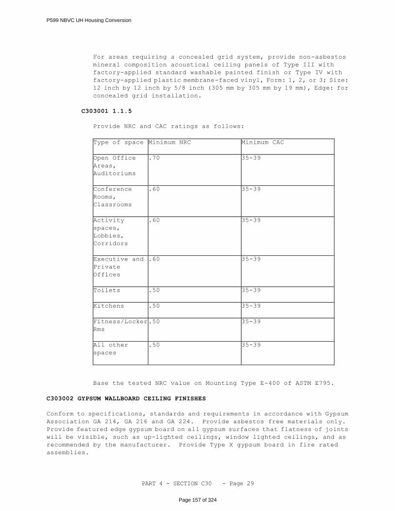
PART 4 - SECTION C30 - Page 29
For areas requiring a concealed grid system, provide non-asbestos
mineral composition acoustical ceiling panels of Type III with
factory-applied standard washable painted finish or Type IV with
factory-applied plastic membrane-faced vinyl, Form: 1, 2, or 3; Size:
12 inch by 12 inch by 5/8 inch (305 mm by 305 mm by 19 mm), Edge: for
concealed grid installation.
C303001 1.1.5
Provide NRC and CAC ratings as follows:
Type of space
Minimum NRC
Minimum CAC
Open Office
Areas,
Auditoriums
.70
35-39
Conference
Rooms,
Classrooms
.60
35-39
Activity
spaces,
Lobbies,
Corridors
.60
35-39
Executive and
Private
Offices
.60
35-39
Toilets
.50
35-39
Kitchens
.50
35-39
Fitness/Locker
Rms
.50
35-39
All other
spaces
.50
35-39
Base the tested NRC value on Mounting Type E-400 of ASTM E795.
C303002 GYPSUM WALLBOARD CEILING FINISHES
Conform to specifications, standards and requirements in accordance with Gypsum
Association GA 214, GA 216 and GA 224. Provide asbestos free materials only.
Provide featured edge gypsum board on all gypsum surfaces that flatness of joints
will be visible, such as up-lighted ceilings, window lighted ceilings, and as
recommended by the manufacturer. Provide Type X gypsum board in fire rated
assemblies.
P599 NBVC UH Housing Conversion
Page 157 of 324
PART 4 - SECTION C30 - Page 30
C303002 1.1 REGULAR GYPSUM BOARD
ASTM C36/C36M and ASTM C1396/C1396M, 1/2 or 5/8 inch(12.7 mm or 15.9 mm)
thick, tapered edge. Provide 5/8 inch (15.9 mm) for all projects except
for single family residential, which may utilize 1/2 inch (12.7 mm) if other
requirements, such as sound control, are met.
C303002 1.2 MOISTURE RESISTANT GYPSUM BOARD
ASTM C630/C630M, 1/2 or 5/8 inch (12.7 mm or 15.9 mm) thick, tapered edges.
Use for ceilings in humid areas. Do not use as a substrate in tiled areas
where tile will be exposed to direct moisture contact or condensation
accumulation. Support moisture resistant gypsum board at 12 inches (305 mm)
on center. Provide 1/2 inch (12.7 mm) for single-family residential
projects only. Provide 5/8 inch (15.9 mm) for all other projects.
C303002 1.3 FOIL BACKED GYPSUM BOARD
ASTM C1396/C1396M 1/2 or 5/8 inch (12.7 mm or 15.9 mm) thick in residential
construction, and 5/8 inch (15.9 mm) thick in non-residential construction,
tapered edges for layers exposed to view, square edges for concealed layers.
Seal joints in foil backing to other panels and adjoining materials as
recommended by the panel manufacturer.
Alternative to foil backed gypsum board in Secured Areas: Field applied
foil faced barrier material is an acceptable alternative for pre
manufactured foil backed gypsum board. Provide a continuous composite
multilayer barrier with a woven polyethylene sheet sandwiched between two
sheets of solid reflective aluminum surfaces. Shielding effectiveness
tested in accordance with IEEE 229/ ASTM D4935. Install barrier in
accordance with manufactures instructions
C303002 1.4 CEMENTITIOUS BACKING UNITS
ANSI A108.11 and ANSI A118.9, 1/2 or 5/8 inch (12.7 mm or 15.9 mm) thick;
use for adhesive applied ceramic tile in wet areas (tubs, shower enclosures,
saunas, steam rooms, gang shower rooms, or for shower areas with a veneer
plaster finish. Support cementitious backing units at 12 inches (305 mm)
on center. Provide screws specifically designed for use with cement panels.
C303002 1.5 IMPACT RESISTANT GYPSUM BOARD
Reinforced gypsum panel with imbedded fiber mesh or polycarbonate resin
thermoplastic backing, 5/8 inch (15.9mm) thick, tapered edges, in accordance
with Structural Failure Test; ASTM E695 or ASTM D2394 and Indentation Test;
ASTM D5420 or ASTM D1037. For use whenever gypsum board partitions are
allowed for barracks, training facilities, and industrial facilities.
Provide metal framing of 20-gauge minimum. Provide fasteners that meet
manufacturer requirements and specifications. Impact resistant gypsum
board shall have a flame spread rating of 25 or less and a smoke developed
rating of 50 or less, ASTM E84. Finish with a high strength veneer plaster.
C303002 1.6 TEXTURED CEILING FINISH SYSTEM
P599 NBVC UH Housing Conversion
Page 158 of 324

PART 4 - SECTION C30 - Page 31
Applied textured ceiling finish shall be plaster based. Refer to paragraph
"C301002 – 1.1 GYPSUM PLASTER" for finish requirements.
C303002 1.7 JOINT TREATMENT
ASTM C475, Joint compound shall be specifically formulated and manufactured
for use with and compatible with tape, substrate and fasteners as recommended
by the manufacturer. Tape and finish gypsum board in accordance with ASTM
C840, GA 214 and GA 216. Provide premanufactured joints at all structural
expansion joints, crack control joints, and change of materials as
recommended by the manufacturer and in accordance with GA 216.
C303002 1.8 FASTENERS
ASTM C514, Fasteners shall be compatible with each type of gypsum board
material as recommended by the gypsum board manufacturer and in accordance
with GA 216 and GA 224.
C303002 1.9 ACCESSORIES
ASTM C1047, Fabricate from corrosion protected steel or plastic designed
for intended use. Accessories manufactured with paper flanges are not
acceptable. Flanges shall be free of dirt, grease, and other materials that
may adversely affect bond of joint treatment. Provide prefinished or job
decorated materials. Install as recommended by GA 214, GA 216 and GA 224.
C303002 1.10 LEVEL OF FINISH
C303002 1.10.1
Tape and finish gypsum board in accordance with ASTM C840, GA 214 and
GA 216. Ceilings to receive a heavy-grade wall covering or heavy
textured finish before painting shall be finished to GA 214, Level
3. Ceilings without critical lighting to receive flat paints, light
textures, or wall coverings shall be finished to GA 214, Level 4.
Unless otherwise specified, all gypsum board walls, partitions and
ceilings shall be finished to GA 214, Level 5. Provide joint,
fastener depression, and corner treatment. Do not use fiberglass
mesh tape with conventional drying type joint compounds; use setting
or hardening type compounds only. Provide treatment for
water-resistant gypsum board as recommended by the gypsum board
manufacturer.
C303002 1.10.2
Wherever gypsum board is to receive eggshell, semigloss or gloss paint
finish, or where severe, up or down lighting conditions occur, finish
gypsum wall surface to GA 214 Level 5. In accordance with GA 214 Level
5, apply a thin skim coat of joint compound to the entire gypsum board
surface, after the two-coat joint and fastener treatment is complete
and dry.
C303003 PLASTER CEILING FINISHES
P599 NBVC UH Housing Conversion
Page 159 of 324
PART 4 - SECTION C30 - Page 32
C303003 1.1 VENEER PLASTER CEILING FINISHES SYSTEM
Veneer plaster ceilings shall be gypsum plaster veneer finish to gypsum base
finishes. Refer to Section C3040 for paint system and gloss level. Provide
gypsum neat plaster, gypsum ready-mixed plaster, or high strength gypsum
plaster base coat conforming to ASTM C28. High strength gypsum plaster shall
have a compressive strength of not less than 2,500 psi, when tested dry in
accordance with ASTM C472.
C303004 WOOD CEILINGS
Not Used.
C303005 SUSPENSION SYSTEMS
C303005 1.1 EXPOSED SUSPENDED ACOUSTICAL CEILING GRID
Provide 24 inch by 24 inch (610 mm by 610 mm) aluminum or steel non-corroding
intermediate-duty standard grid system for lay-in acoustical panels (ASTM
C635). Finish shall be factory applied white baked enamel. Provide
manufacturer's hold down clips for fire rated assemblies and wall or edge
molding. Hang grid system as recommended by manufacturer but with no less
than 0.106 inch (2.7 mm) diameter wires (ASTM A641A, A641M, Class 1), or
with one by 3/16 inch (4.76 mm) galvanized steel straps conforming to ASTM
A653A, A653M (for light commercial zinc coating) or ASTM A366A, A366M (with
an electrodeposited zinc coating, Type RS). Use ASTM A580/A580M, composition
302 or 304, condition annealed stainless steel, 0.106 inches (2.7 mm) in
diameter over high humidity areas such as commercial kitchens and pools.
Install suspended grid system with acoustical sealant (ASTM C843,
nonstaining and ASTM C636). Recycled content shall be a minimum of 25%.
C303005 1.2 CONCEALED SUSPENDED ACOUSTICAL CEILING GRID
Provide 12 inch by 12 inch (305 mm by 305 mm) aluminum or steel non-corroding
intermediate-duty concealed grid system for lay-in acoustical panels (ASTM
C635). Finish shall be factory applied white baked enamel. Provide
manufacturer’s wall or edge molding. Hang grid system as recommended by
manufacturer but no less than with 0.106 inch (2.7 mm) diameter wires (ASTM
A641A, A641M, Class 1), or with one by 3/16 inch (4.76mm) galvanized steel
straps conforming to ASTM A653A, A653M (for light commercial zinc coating)
or ASTM A366A, A366M (with an electrodeposited zinc coating, Type RS).
Install suspended grid system with acoustical sealant (ASTM C843,
nonstaining) and in accordance with ASTM C636. Recycled content shall be
a minimum of 25%.
C303005 1.3 SUSPENDED AND FURRED CEILING SYSTEMS
ASTM C841 (for lath); ASTM C645 (for GWB).
Provide steel materials for metal support systems with galvanized coating
per ASTM A653/A653M, G60; aluminum coating ASTM A463/A463M, T1-25; or a 55%
aluminum-zinc coating. Provide suspended ceiling framing in accordance
with ASTM C754, except framing members shall be 16 inches (400mm) unless
otherwise noted.
P599 NBVC UH Housing Conversion
Page 160 of 324
PART 4 - SECTION C30 - Page 33
C303006 METAL STRIP CEILINGS
Not Used.
C303090 OTHER CEILING AND CEILING FINISHES
C3040 INTERIOR COATINGS AND SPECIAL FINISHES
Apply coatings directly to all non-prefinished surfaces of the interior
construction. Comply with Master Painters Institute requirements for surface
degradation analysis, surface preparation, paint and coating selection, paint
application restrictions for substrate materials, and paint application.
C304001 GENERAL REQUIREMENTS
All paint shall be suitable in accordance with the Master Painter Institute (MPI)
standards for the interior architectural surface being finished. The current MPI,
"Approved Product List" as of the date of contract award, will be used to determine
compliance with the submittal requirements of this specification. The Contractor
may choose to use a more current MPI "Approved Product List"; however, only one
list may be used for the entire contract. All coats on a particular substrate,
or a paint system, must be from a single manufacturer. No variation from the MPI
Approved Products List is acceptable.
Select paint systems for the project in accordance with the MPI Architectural
Painting Decision Tree available on the Whole Building Design Guide. Use this
interactive MPI Decision Tree website to identify applicable paint system(s) for
the project. The MPI Decision Tree identifies paint systems for each interior or
exterior coated surface in "Normal" or "Aggressive" environmental conditions and
generally lists the applicable paint systems in descending order of performance.
The paint system at the top of each substrate list generally indicates the highest
performing acceptable coating system.
Choose the "Aggressive" environmental conditions in the MPI Decision Tree for
exterior systems that are used in moist humid conditions, abrasive conditions,
chemical exposure conditions, or within five miles proximity of the ocean or a
body of water. Also use "Aggressive " environmental conditions in interior spaces
that are exposed to in moist humid conditions, abrasive conditions, chemical
exposure conditions, such as bathrooms, shower rooms, kitchens, chemical storage
area, swimming pools, laundry, sanitary areas, commercial kitchens, industrial
production areas, and hospital operating rooms provide paint systems that comply
with the MPI Decision Tree "Aggressive" environmental conditions.
Comply with the following rules when determining the appropriate paint or coating
system from the MPI Decision Tree:
a. Some of these paint systems are identified with a "NAVFAC Anchor". This
"NAVFAC Anchor" indicates the minimum performing system that NAVFAC will accept
for that substrate and environmental conditions.
b. When multiple "NAVFAC Anchors" are indicated on a certain substrate and
environmental condition, provide the "NAVFAC Anchor" paint or coating system that
is most appropriate for the facility use.
P599 NBVC UH Housing Conversion
Page 161 of 324
PART 4 - SECTION C30 - Page 34
c. If only one MPI Decision Tree choice is available for a certain substrate
and environmental condition with no indicated NAVFAC preference, provide that sole
option for NAVFAC projects.
d. If the MPI Decision Tree provides multiple choices and no NAVFAC preference
is denoted, refer to the Additional RFP Requirements below to determine level of
performance.
e. If the MPI Decision Tree does not identify all paint system applicable to
the facility, utilize the MPI Architectural Painting, Exterior Systems Manual to
identify other appropriate paint systems for the project. Utilize the "Premium
Grade" systems and comply with all limitations stated in the MPI "Approved Product
List" for each paint product. Products having an MPI VOC Range E3 shall be given
preferential consideration over lower VOC Ranges. Use higher performing paint
systems unless the lower performing paint system can be justified based on a
lifecycle cost to include surface preparation, application, disposal,
environmental impact, and required recoating cycles. Only use paint products that
have been tested for MPI'S "DETAILED PERFORMANCE" or "EVALUATED PERFORMANCE ".
Do not use products that have only been tested for "INTENDED USE".
f. If an "Aggressive" environmental condition option is not available in the
MPI Decision Tree for a certain substrate, use the "Normal" environmental condition
option.
g. Refer to the Additional Exterior Paint and Coating System Requirements below
for further system requirements.
Paints and coatings shall comply with Master Painters Institute Green Performance
Standard GPS-1-12 which is available at the following website;
http://www.specifygreen.com/EvrPerf/EnvironmentalPerformance.html . Provide
Interior flat intermediate and topcoats of a maximum of 50 g/L VOC and interior
non-flat intermediate and topcoats of a maximum 150 g/L VOC. Choose paints that
provide performance and are environmentally friendly by using total VOC budgeting
to analyze the total impact of all flat, non-flat and special purpose coatings
on the project.
C304001 1.1 MPI GLOSS LEVELS
Gloss levels shall comply with the MPI system of determining gloss as defined
in the Evaluation sections of the MPI Manuals. Utilize the performance
characteristics of the paint gloss and sheen to categorize paint rather than
manufactures' description of his product. The MPI Gloss Levels are
indicated by the notation G1, G2, G3, G4, G5, G6, or G7. G1 is not used
by Navy.
The MPI Decision Tree indicates a default gloss level for each paint system,
however consider the appearance, anticipated conditions, and need for
cleaning when choosing the correct gloss level for each coated surface of
the project. Comply with the following guidance in choosing the appropriate
gloss level.
a. Use G2 "Velvet-like" Flat for ceilings, residential walls away from
human contact and low traffic areas.
P599 NBVC UH Housing Conversion
Page 162 of 324
PART 4 - SECTION C30 - Page 35
b. Use G3 "Eggshell-like" in high traffic areas for ceilings and walls,
when human contact with the wall is expected but limited, and for dark accent
colors.
c. Use G5 Semigloss for walls, doors and trim for high durability and clean
ability and when a surface is expected to have routine human contact.
d. Use G6 Gloss only in special situations such as piping identification
or special effects.
The MPI Gloss and Sheen Standard values are measured per ASTM D523, and are
as follows:
Gloss Level Number Gloss@ 60 Degrees Sheen@85
Degrees
Gloss Level 1(G1) – Matte or Flat Max.5 units Max.10 units
Gloss Level 2(G2) – "Velvet-like" Flat Max. 10 units 10-35 units
Gloss Level 3(G3) – "Eggshell-like" Max. 10-25 units 10-35 units
Gloss Level 4(G4) - "Satin-like" Max. 20-35 units Min. 35 units
Gloss Level 5(G5) - Semi-Gloss 35-70 units
Gloss Level 6(G6) – Gloss 70-85 units
Gloss Level 7(G7) – High Gloss More than 85 units
C304001 1.2 MPI SYSTEM DESIGNATIONS AND ABBREVIATIONS
The MPI coating system number in each Division is found in either the MPI
Architectural Painting Specification Manualor the Maintenance Repainting
Manualand defined as an interior system (INT/RIN).
a. INT designates an interior coating system for new surfaces.
b. RIN designates an interior coating system used in repainting projects
or over existing coating systems.
c. DSD – the MPI short-term designation for Degree of Surface Degradation
as defined in the Assessment sections in the MPI Maintenance
Repainting Manual. Degree of Surface Degradation designates the MPI
Standard for description and appearance of existing condition of
surfaces to be painted. This DSD classification is used to determine
the proper surface preparation necessary for painting.
C304001 1.3 SURFACE PREPARATION
Comply with the "Interior Surface Preparation" section of the MPI
Architectural Painting Specification Manualor the "Interior Surface
Preparation” section of the MPI Maintenance Repainting Manual. All
suggestive language such as "may" or "should" are deleted from the standard
and "must" or "shall" inserted in its place. Suggestive language such as
"recommended" or "advisable" is deleted from the standard and "require" or
'required" inserted in its place. The results of these wording substitutions
change this document to required procedures. For surface preparation,
determine a MPI DSD Assessment of each surface and comply with the MPI Surface
Preparation Requirements relating to the assessments. Notwithstanding MPI
requirements, clean interior ferrous metal to a SSPC SP 10 level (near white)
that have aggressive chemical environments (SSPC Zones 3A, 3B, 3C, 3D, and
3E) or waterfront exposure to open structures (SSPC Zones 2A or 2B).
P599 NBVC UH Housing Conversion
Page 163 of 324
PART 4 - SECTION C30 - Page 36
Examples of these types of facilities are indoor water training facilities,
indoor swimming pools, and open or mostly open waterfront maintenance
buildings/ waterfront warehouses/ canopies.
Remove dirt, splinters, loose particles, grease, oil, and other foreign
matter and substances deleterious to coating performance as specified for
each substrate before application of paint or surface treatments. For
existing buildings, use MPI Maintenance Repainting Manual to determine the
coatings that need to be removed. Remove deteriorated or loose coatings
before repainting begins. Oil and grease shall be removed prior to
mechanical cleaning. Cleaning shall be programmed so that dust and other
contaminants will not fall on wet, newly painted surfaces. Exposed ferrous
metals such as nail heads on or in contact with surfaces to be painted with
water-thinned paints, shall be spot-primed with a suitable
corrosion-inhibitive primer capable of preventing flash rusting and
compatible with the coating specified for the adjacent areas.
C304001 1.4 ADDITIONAL INTERIOR PAINT AND COATING SYSTEMS
In addition to the MPI Decision Tree, comply with the following paint system
requirements:
C304001 1.4.1 PAVEMENT COATINGS
(1) INT 3.2 Concrete Horizontal Surfaces
Normal Environmental Conditions; Pigmented
Provide road and parking lot pavement marking in accordance with UFGS
32 17 23.00 20, Pavement Markings.
C304001 1.4.2 DRESSED LUMBER
Provide Pigmented systems for Composite Wood Doors (Fiberboard) and
trim. Do not use Normal/ Aggressive; Clear and Normal/ Aggressive
Stain finishes.
C304007 SPECIAL COATINGS TO WALLS
C304007 1.1 HIGH PERFORMANCE ARCHITECTURAL COATING (HIPAC)
HIPAC shall be a durable, organic system applied to a continuous (seamless)
high-build film and cure to a hard glaze finish. They shall be resistant
to continuous heat and humidity, abrasion, staining, chemicals, and
biological growth. Coating shall be installed as a complete system, and
as recommended by the manufacturer and have a flame spread index of not more
than 25 and a smoke developed index of not more than 50 when tested in
accordance with ASTM E84.
C304007 1.1.1
Two-component, epoxy-polyamide shall be chemical and
corrosion-resistant, adhesive, alkali-resistant, and water-tolerant
for metal, wood, concrete, masonry surfaces, and painted surfaces
P599 NBVC UH Housing Conversion
Page 164 of 324
PART 4 - SECTION C30 - Page 37
where high gloss or glaze type finish, extreme workability and
resistance to abrasion and stains is required. Minimum dry film
thickness is 3 mils for each of two coats. Furnish Gloss or Semigloss
finish. Maximum volatile organic compounds (VOC) shall be 340
grams/liter.
C304007 1.1.2
Single Component, Moisture-Curing Urethane shall be a flexible,
abrasion- and impact-resistant, use for floors, walls, machinery,
equipment and other surfaces where good abrasion resistance, color
retention, gloss retention, graffiti resistance and good resistance
to acids, alkalis, solvents, strong cleaners and sanitizers, fuel and
chemicals are necessary. Can also be used on concrete floors, brick
and masonry surfaces (properly conditioned), metals (properly
primed), and wood (properly prepared and sealed.) Minimum dry film
thickness is 3 mils for each of 3 coats. Use Type I, Aliphatic, for
exterior use except for oily or resinous exterior wood surfaces. Use
Type II, Aromatic, for interior use.
C304007 1.2 IMPACT RESISTANT WALL FINISHES
Provide textured acrylic architectural coating system: a seamless textured
acrylic water-based coating system, having a thickness of at least 20 mils,
on surfaces scheduled to receive it. System shall be composed of pure
acrylic polymers, silica dioxide, ethylene dioxide and pigments. System
shall have a Barcoll Hardness Index of 38.0 or greater, smoke contribution
of 7.0 or less, and have water vapor permeability of 27.5 English Perms or
greater when tested in accordance with ASTM E96. (MPI 42) Coating system
must have been on the market and successfully used in commercial applications
for a minimum of 10 years.
C304007 1.2.1 CMU Application
High Performance seamless interior acrylic coating system shall be
used as an interior wall finish over CMU that has been joint-filled
and smoothed with a water resistant manufactured recommended
compound. Coating system to be mold and mildew resistant, flame spread
15 or less per ASTM-E84 and have a minimum final film thickness of
7 mils.
C304007 1.2.2 Gypsum Wallboard Application
High Performance seamless interior acrylic coating system shall be
used as an interior wall finish over gypsum wallboard. Do not prime
or seal the drywall except as specifically recommended by the texture
acrylic coating manufacturer. Coating system to be mold and mildew
resistant, flame spread 8.5 or less per ASTM-E84 and have a minimum
final film thickness of 20 mils.
C304007 1.2.3 Installation
Finish may only be installed by factory-qualified applicators in
accordance with the manufacturer's printed instructions and
P599 NBVC UH Housing Conversion
Page 165 of 324

PART 4 - SECTION C30 - Page 38
recommendations, to fulfill warranty requirements. All coating system
components shall be products of the same manufacturer.
A minimum of one sample wall application shall be provided. Edges
at door and window frames shall be feathered; hard edges are
unacceptable. Upon approval of the sample wall by the project
manager, the application shall serve as a standard for the remaining
work.
The manufacturer's certified representative shall provide an on-site
training demonstration of the application and care of the finish for
the end-user's facility manager or other representatives.
-- End of Section --
P599 NBVC UH Housing Conversion
Page 166 of 324
PART 4 - SECTION D20 - Page 1
SECTION D20
PLUMBING
05/14
D20 GENERAL
RFP Part 3 including the Engineering System Requirements (ESR) provide project
specific requirements. The RFP Part 4, Performance Technical Sections (PTS)
provide generalized technical requirements that apply to multiple facility types
and include more requirements than are applicable to any one project. Therefore,
only the RFP Part 4 requirements that apply to the project and further define the
RFP Part 3 project specific requirements are required.
D20 1.1 NARRATIVE
This section must be used in conjunction with all parts of the Design Build
(D/B) Request for Proposal (RFP) to determine the full requirements of this
solicitation.
This section includes the construction of interior plumbing systems. This
section covers installations inside the facility and out to the five foot
line. See Section G30, Site Mechanical Utilities, for continuation of
systems beyond the five foot line.
D20 1.2 PLUMBING DESIGN GUIDANCE
Provide the design and installation in accordance with the following
references. This Performance Technical Specification (PTS) adds
clarification to the fundamental requirements contained in the following
Government Standards. The general requirements of this PTS section are
located in PTS Section Z10, General Performance Technical Specification.
D20 1.2.1 Government Standards
Federal Energy Management Program (FEMP)
UNIFIED FACILITIES CRITERIA (UFC)
UFC 1-200-01
General Building Requirements(A
reference in this PTS section to UFC
1-200-01 requires compliance with the
Tri-Service Core UFCs that are listed
in UFGS Section 01 33 10.05 20, which
includes the following significant
UFC(s):UFC 3-401-01, Mechanical
EngineeringUFC 3-420-01, Design:
Plumbing Systems)
UFC 1-200-02
High Performance and Sustainable
Buildings
P599 NBVC UH Housing Conversion
Page 167 of 324
PART 4 - SECTION D20 - Page 2
D20 1.3 DESIGN SUBMITTALS
Design Submittals shall be in accordance with Z10, General Performance
Technical Specifications, UFGS section 01 33 10.05 20, Design Submittal
Procedures, UFC 1-300-09N, Design Proceduresand UFC 3-401-01, Mechanical
Engineering.
D20 1.4 CONSTRUCTION SUBMITTALS
Submit construction submittals in accordance with PTS section Z10, General
Performance Technical Specifications. In addition to the Z10 requirements,
the Designer of Record (DOR) shall approve the following construction
submittals as a minimum:
Fixtures, equipment, and OMSI information for all equipment and fixtures.
D2010 PLUMBING FIXTURES
Plumbing fixtures shall be provided in accordance with the IBC, IPC, and as
specified. Provide EPA's "WaterSense" labeled fixtures where available.
D201001 WATER CLOSETS
D201001 1.1 FLUSH VALVE WATER CLOSETS
ASME A112.19.2, white vitreous china, siphon jet. Provide ASME A112.19.5
trim. Provide self-closing metering type flush valve, unless electronic
flush control is specified in the ESR Section D20. Electronic flush control
shall conform to UL 1951 and ASSE 1037. Flush valve shall not exceed 1.28
GPF (4.8 LPF). Handicapped fixture mounting height and appurtenances shall
be in accordance with UFAS and ADAAG.
D201001 1.2 DUAL FUNCTION FLUSH VALVE WATER CLOSETS
ASME A112.19.2, white vitreous china, siphon jet. Provide ASME A112.19.5
trim. Provide self-closing metering type dual function flush valve, unless
electronic flush control is specified in the ESR Section D20. Electronic
flush control shall conform to UL 1951 and ASSE 1037. Dual function flush
valve shall provide a flush of 0.8 to 1.1 GPF (3.0 to 4.2 LPF) or 1.28 GPF
(4.8 LPF). Maximum flush volume shall not exceed 1.28 GPF (4.8 LPF).
Handicapped fixture mounting height and appurtenances shall be in accordance
with UFAS and ADAAG.
D201001 1.3 FLUSH TANK WATER CLOSETS
ASME A112.19.2, white vitreous china, siphon jet. EPA "WaterSense"
labeled. Provide ASME A112.19.5 trim. Water flushing volume of the water
closet shall not exceed 1.28 GPF (4.8 LPF). Handicapped fixture mounting
height and appurtenances shall be in accordance with UFAS and ADAAG.
D201001 1.4 DUAL FUNCTION FLUSH TANK WATER CLOSETS
ASME A112.19.2, white vitereous china, siphon jet. Provide ASME A112.19.5
P599 NBVC UH Housing Conversion
Page 168 of 324
PART 4 - SECTION D20 - Page 3
trim. Dual function flush tank water closet shall provide a dual flush that
allows a flush of 0.8 to 1.1 GPF (3.0 to 1.6 LPF) or 1.28 GPF (4.8 LPF).
Maximum flush tank volume per flush shall not exceed 1.28 GPF (4.8 LPF).
Handicapped fixture mounting height and appurtenances shall be in accordance
with UFAS and ADAAG.
D201002 URINALS
D201002 1.1 FLUSH VALVE URINALS
ASME A112.19.2, white vitreous china, wall-mounted, wall outlet, siphon jet,
integral trap, extended side shields. EPA "WaterSense" labeled. Provide
large diaphragm (not less than 2.625 inches (66 mm) upper chamber inside
diameter at the point where the diaphragm is sealed between the upper and
lower chambers) flush valve of chrome plated cast brass conforming to ASTM
B 584, including vacuum breaker and angle (control-stop) valve. Maximum
flush valve volume per flush shall not exceed 0.5 gallons per flush (1.9
lpf). Provide ASME A112.19.5 trim and ASME 112.6.1M concealed chair
carriers. Provide self-closing metering type flush valve, unless
electronic flush control is specified in the ESR Section D20. Electronic
flush control shall conform to UL 1951 and ASSE 1037.Handicapped fixture
mounting height and appurtenances shall be in accordance with UFAS and ADAAG.
D201002 1.2 NON WATER USE URINALS
ASME A112.19.2, white vitreous china, wall-mounted, wall outlet, non-water
using, integral drain line connection, with sealed replaceable cartridge
or integral liquid seal trap insert. The urinal and trap assembly shall
maintain a sufficient barrier of a biodegradable immiscible liquid to
provide the trap seal and inhibit the backflow of sewer gases. For urinals
that use a replaceable cartridge, provide four additional cartridges for
each urinal installed. Provide an additional quart of biodegradable liquid
for each urinal installed. Provide ASME A112.6.1M concealed chair
carriers. Installation and testing shall be in accordance with the
manufacturers’ recommendations. Drain lines that connect to the urinal
outlet shall not be made of copper tube or pipe. Urinal design and
installation shall be ADA compliant. Slope the sanitary sewer branch line
for non-water use urinals a minimum of 1/4-inch per foot. Manufacturer
shall provide an operating manual and on-site training for the proper care
and maintenance of the urinal.
D201003 LAVATORIES
D201003 1.1 COUNTERTOP LAVATORIES
Unless integral bowl is specified elsewhere, lavatories shall be white, ASME
A112.19.2 vitreous china lavatories with minimum dimensions of 20 inches
(508 mm) wide x 18 inches (457 mm) front to rear, and self-rimming type.
Provide ASME 112.18.1 copper alloy centerset faucets unless self closing
metering or electronic control is specified in ESR section D20. Faucets
shall be EPA "WaterSense" labeled. Provide with aerator, adjustable
P-traps, and perforated grid strainers, unless pop-up drain fittings are
specified in ESR section D20.
P599 NBVC UH Housing Conversion
Page 169 of 324

PART 4 - SECTION D20 - Page 4
D201003 1.2 WALL-MOUNTED LAVATORIES
ASME A112.19.1, white enameled cast-iron or ASME A112.19.2 white vitreous
china with ASME A112.6.1M concealed arm carrier support, with minimum
dimensions of 20 inches wide by 18 inches (508 mm wide by 457 mm) front to
rear. Provide ASME 112.18.1 copper alloy centerset faucets unless self
closing metering or electronic control is specified in ESR section D20.
Faucets shall be EPA "WaterSense" labeled. Provide with aerator,
adjustable P-traps, and perforated grid strainers, unless pop-up drain
fittings are specified in ESR section D20.
D201003 1.3 HANDICAPPED LAVATORIES
Same as Paragraphs 1.1 or 1.2, except height and appurtenances shall be in
accordance with UFAS and ADAAG.
D201004 SINKS
D201004 1.1 COUNTERTOP SINKS
ASME A112.19.3 sink, 20 gage stainless steel with integral mounting rim,
minimum dimensions of 33 inches (840 mm) wide for two compartment or 21 inches
(560 mm) wide for one compartment by 21 inches (560 mm) front to rear, with
ledge back and undersides coated with sound dampening material. Provide
top-mounted ASME A112.18.1 copper alloy faucets, swing spout with aerator,
and stainless steel drain outlets with cup strainers. Provide adjustable
P-trap with drain piping to vertical vent stack. If specified in ESR section
D20, provide UL 430 waste disposer unit in right compartment.
D201004 1.2 SERVICE SINKS
ASME A112.19.1, white enameled cast-iron or ASME A112.19.2 white vitreous
china, wall mounted and floor supported by wall outlet cast-iron P-trap,
minimum dimensions of 22 inches (560 mm) wide by 18 inches (457 mm) front
to rear with 9 inch (230 mm) splashback, and stainless steel rim guard.
Provide ASME A112.18.1 copper alloy back-mounted combination faucets with
vacuum breaker and 0.75 inch (20 mm) external hose threads.
D201004 1.3 MOP SINKS
Pre-cast terrazzo floor-mounted mop sink, 36 inches x 36 inches x 12 inches
(914 mm x 914 mm x 305 mm) shall be made of marble chips cast in white Portland
cement to a compressive strength of not less than 3625 PSI (25 mPa) 7 days
after casting. Provide brass body drains with nickel bronze strainers cast
integral with terrazzo. Provide stainless steel rim guard for mop sink.
Provide chrome-plated exposed hot and cold water faucets ASME A112.18.1
wall-mounted copper alloy faucets swing spout with 3/4 inch (20 mm) hose
connection, vacuum breaker, and pail hook. Provide mop hanger on wall above
sink suitable for four mops.
D201004 1.4 LAUNDRY SINKS
IAPMO Z124.6, plastic, two compartment, minimum dimensions of 40 inches wide
by 21 inches (1016 mm wide by 533 mm) front to rear, with floor-supported
P599 NBVC UH Housing Conversion
Page 170 of 324
PART 4 - SECTION D20 - Page 5
steel mounting frame secured to wall. Provide ASME A112.18.1 copper alloy
centerset faucets, swing spout with aerator, and stainless steel drain
outlets with cup strainers, and 1.5 inch (40 mm) adjustable P-trap with drain
piping to vertical vent stack.
D201005 SHOWERS/TUBS
D201005 1.1 ONE PIECE BATH AND SHOWER MODULES
IAPMO Z124.1.2, made of white fiberglass reinforced plastic (FRP) or acrylic
with slip-resistant bathing surfaces, integral grab bar, and three walls
integrally molded in one piece. Provide outlet at left or right as necessary
to suit module arrangement. Provide pop-up drain fittings and adjustable
P-trap. Bathtub and shower supply fittings shall be diverter type with body
mounted from behind the wall. Provide tub fill over-rim spout with
diverter.
D201005 1.2 SHOWER FLOORS
Precast terrazzo or Acrylic Shower Floors: Terrazzo shall be made of marble
chips cast in white Portland cement to produce a compressive strength of
not less than 3625 psi (25 MPa) 7 days after casting. Provide brass body
drains with nickel bronze strainers cast integral with terrazzo.
D201005 1.3 BATHTUBS
ASME A112.19.1 white enameled cast-iron or porcelain steel bathtubs,
recessed type, minimum dimensions of 56 inches (1424 mm) wide by 30 inches
(762 mm) front to rear by 16 inches (406 mm) high with drain outlet for
above-the-floor drain installation. Bathtub and shower supply fittings
shall be diverter type with body mounted from behind the wall. Provide tub
over fill rim spout with diverter.
D201005 1.4 SHOWER SUPPLY FITTINGS
ASME A112.18.1, ball joint, self-cleaning, adjustable spray pattern shower
heads, connected to concealed pipe connected to copper alloy pressure
balance single control type mixing valves with front access integral
screwdriver stops. Showerhead shall be EPA "WateSense" labeled. Anchor
the mixing valves and the pipe to each showerhead in wall to prevent movement.
D201005 1.5 HANDHELD SHOWER HEAD
ASSE 1014, adjustable spray hand-held shower head with swivel fitting, 60
inch (1524 mm) minimum flexible chrome plated copper alloy hose and in-line
vacuum breaker. Provide push button flow control if specified in ESR
section D20. Provide 25 inch (635 mm) grab bar with sliding spray holder
that locks at any height.
D201006 DRINKING FOUNTAINS AND COOLERS
D201006 1.1 DRINKING FOUNTAINS
Wall mounted drinking fountain shall be constructed of white enameled cast
P599 NBVC UH Housing Conversion
Page 171 of 324
PART 4 - SECTION D20 - Page 6
iron with bubbler and push button control. Handicapped fixture mounting
height and appurtenances shall be in accordance with UFAS and ADAAG.
D201006 1.2 ELECTRIC WATER COOLERS
AHRI 1010, wall-mounted, bubbler style, air-cooled condensing unit, 4.0 gph
(4.20 mL per second) minimum capacity, stainless steel splash receptor,
double wall heat exchanger, and all stainless steel cabinet. Provide ASME
A112.6.1M concealed wall hangers with thru-bolts and back plates.
Handicapped fixture mounting height and appurtenances shall be in accordance
with UFAS and ADAAG.
D201090 EMERGENCY FIXTURES
Pressure-compensated tempering valve is required for emergency fixtures, with
leaving water temperature setpoint adjustable throughout the range 60 to 95 degrees
F (15.5 and 35 degrees C) unless cold water supply meets temperature criteria.
Where indicated in ESR section D20, provide packaged, UL listed, alarm system;
including an amber strobe lamp, horn with externally adjustable loudness and horn
silencing switch, mounting hardware, and waterflow switch, assembled and prewired
for waterproof service within NEMA Type 3 or 4 enclosures or for explosion proof
service within NEMA Type 7 or 9 enclosures.
D201090 1.1 EMERGENCY SHOWER
ISEA Z358.1, wall-mounted self-cleaning, non-clogging 10 inch (250 mm)
diameter stainless steel deluge shower head with elbow, one inch (25 mm)
full-flow stay-open ball valve with pull rod and 8 inch (200 mm) diameter
ring or triangular handle, one inch (25 mm) interconnecting fittings.
D201090 1.2 EMERGENCY EYE & FACE WASH
ISEA Z358.1, wall-mounted self-cleaning, non-clogging eye and face wash with
quick opening, full-flow valves, stainless steel eye and face wash receptor.
Provide copper alloy control valves.
D201090 1.3 COMBINATION EMERGENCY SHOWER & EYEWASH
ISEA Z358.1, column mounted on a floor flange. Design combination unit so
components can be operated individually from a common fixture supply line.
Provide a self-cleaning, non-clogging 10 inch (250 mm) diameter stainless
steel deluge shower head with elbow, full flow stay-open ball valve with
pull rod and 8 inch (200 mm) diameter ring or triangular handle one inch
(25 mm) interconnecting fittings. Provide a self-cleaning, non-clogging
eye and face wash with quick opening, full-flow valves, stainless steel eye
and face wash receptor. Provide copper alloy control valves.
D2020 DOMESTIC WATER DISTRIBUTION
D202001 PIPES & FITTINGS
D202001 1.1 COPPER
P599 NBVC UH Housing Conversion
Page 172 of 324
PART 4 - SECTION D20 - Page 7
Use copper tubing and fittings for pipe sizes 4 inches (100 mm) or smaller.
Use type L tubing above ground with solder fittings. For buried piping,
use type K tubing with solder fittings.
D202001 1.2 CHLORINATED POLYVINYL CHLORIDE (CPVC)
When specified in ESR section D20, provide CPVC pipe, fittings, and solvent
cement per ASTM D 2846/D 2846M for sizes 4 inches (100 mm) and smaller.
Provide transition union connections or threaded gate valve between metallic
piping and CPVC piping.
D202002 VALVES & HYDRANTS
D202002 1.1 VALVES
Provide valves at water supplies to fixtures and to provide ease of
maintenance as required in the IPC.
D202002 1.2 HOSE BIBBS & HYDRANTS
Use non-freeze wall hydrants where the winter design temperature is at or
below freezing. Hose bibbs are acceptable for use elsewhere.
D202002 1.2.1 Hose bibbs
Angle type, copper alloy hose bibbs with vacuum breaker.
D202002 1.2.2 Wall Hydrants
Non-freeze, ASSE 1019, cast bronze, with vacuum breaker, locking
shield and tee-handle.
D202003 DOMESTIC WATER EQUIPMENT
D202003 1.1 BACKFLOW PREVENTERS
Furnish proof that each make, model/design, and size of backflow preventer
being furnished for the project is approved by and has a current "Certificate
of Approval" from the Foundation for Cross-Connection Control and Hydraulic
Research (FCCCHR)-USC. Listing of the particular make, model/design, and
size in the current FCCCHR-USC will be acceptable as the required proof.
Provide freeze protection for aboveground exterior applications in areas
where the winter design temperature is at or below freezing.
D202003 1.2 WATER HEATERS
D202003 1.2.1 Electric Water Heaters
Electric water heaters with double heating element per UL 174 for water
heaters with less than 120 gallons of storage and 200,000 btuh input.
Provide water heater per UL 1453 for commercial water heaters with
120 gallons of storage or more and 200,000 btuh input or more. Water
heaters shall be equipped with glass-lined steel tanks, high
efficiency type, insulated with polyurethane foam insulation,
P599 NBVC UH Housing Conversion
Page 173 of 324
PART 4 - SECTION D20 - Page 8
replaceable anodes, and adjustable range thermostat to allow hot water
settings between 110 and 160 degrees F (43 and 71 degrees C). Water
heater warranty shall be a minimum of 5 years.
D202003 1.2.2 Gas-Fired Water Heaters
High efficiency storage type water heaters per CSA/AM Z21.10.1 for
water heaters with less than 120 gallons of storage and input ratings
of 75,000 btuh or less. Provide water heater per CSA/AM Z21.10.3 for
commercial water heaters with 120 gallons of storage or more and input
ratings above 75,000 btuh. Water heaters shall meet AGA
requirements. Water heaters shall be equipped with glass-lined steel
tanks, polyurethane foam insulation, replaceable anodes, and
adjustable range thermostat to allow hot water settings between 110
and 160 degrees F (43 and 71 degrees C). Water heater warranty shall
be a minimum of 5years. Provide vent in accordance with NFPA 54.
D202003 1.2.3 Oil-Fired Water Heaters
UL 732 oil-fired water heaters with glass-lined steel tanks, high
efficiency type, insulated with polyurethane foam insulation,
replaceable anodes, with adjustable range thermostat to allow hot
water settings between 110 and 160 degrees F (43 and 71 degrees C).
Provide vent in accordance with NFPA 58. Oil-fired water heater
system design shall be in accordance with NFPA 31.
D202003 1.2.4 Instantaneous Water Heater (Electric)
UL 499, heater(s) shall be of the modulating, under the sink,
point-of-use type. Output temperature shall be adjustable from 40
degrees F to 160 degrees F. Heating elements shall be field
replaceable. Unit(s) shall have a 10-year warranty.
D202003 1.2.5 Steam Heat Exchangers
Double wall copper tube domestic water heating elements constructed
with air gap to atmosphere between the two walls using steam as the
heating medium exterior of the heating elements. Provide posted
operating instructions for water heaters.
D202003 1.2.6 Storage Tanks
AWWA D100, glass-lined vertical steel tanks, minimum of 125 psig (862
kPa) (gage) working pressure.
D202003 1.3 PUMPS
D202003 1.3.1 Inline Pumps
In-line circulator for service water distribution system. Factory
assembled and tested pumps constructed of materials suitable for hot
domestic water service.
D202003 1.3.2 Base Mounted Pumps
P599 NBVC UH Housing Conversion
Page 174 of 324

PART 4 - SECTION D20 - Page 9
Potable water service, base mounted, end suction pumps with mechanical
seals and drip-proof electric motors.
D202003 1.4 DOMESTIC WATER PRESSURE BOOSTER SYSTEM
Factory assembled, tested, and certified by a single manufacturer who
assumes undivided responsibility for the system to include providing
start-up services, two days instruction and furnishing related operations
and maintenance manuals. Each building shall be provided with its own
system. Each system will consist of a minimum of two pumps mounted on a
single, welded structural steel base. Provide bladder type low-flow
accumulator storage tank, lead-lag pump alternator selector switches and
all related controls and alarms required for safe and proper system
operation. Provide variable frequency drive pump operation.
D202003 1.5 EXPANSION TANKS
Steel expansion tank with potable water rated polypropylene or butyl lined
diaphragm at water heater.
D202003 1.6 WATER METERS
AWWA C701 turbine type, with register reading in liters and U.S. gallons.
D202004 INSULATION & IDENTIFICATION
D202004 1.1 PIPING INSULATION
Mineral fiber insulation on domestic hot water supply and recirculation
piping. Insulate domestic cold water piping with cellular glass insulation
(ASTM C 552, Type II, and Type III).
D202004 1.2 PIPING & EQUIPMENT IDENTIFICATION
In addition to the requirements in Section Z10, General Performance
Technical Specification, provide laminated plastic nameplates for valves.
Stop valves in supplies to fixtures will not require nameplates. Identify
above ground pipe with the type of service and direction of flow. Letter
size, lengths and colors shall be per ANSI A13.1.
D202005 SPECIALTIES
D202005 1.1 WASHING MACHINE CONNECTOR BOX
Recessed wall box fabricated of PVC plastic. Provide bronze dual washing
machine valve with single lever shut-off.
D202005 1.2 VALVE BOXES
For each buried valve provide cast-iron, ductile-iron box of a suitable size.
Provide cast-iron or ductile-iron cover for the box with the word "WATER"
cast on the cover.
P599 NBVC UH Housing Conversion
Page 175 of 324
PART 4 - SECTION D20 - Page 10
D202005 1.3 WATER HAMMER ARRESTORS
PDI WH 201, water hammer arrestors in lieu of air chambers.
D202005 1.4 ICEMAKER CONNECTOR BOX
Recessed wall box fabricated of PVC plastic. Provide bronze shut-off valve.
D202090 OTHER DOMESTIC WATER SUPPLY
D202090 1.1 SUPPORTS
Provide piping supports in accordance with the IPC.
D202090 1.2 INSPECTIONS
Prior to initial operation, inspect piping system for compliance with
drawings, specifications, and manufacturer's submittals.
D202090 1.3 DISINFECTION
Upon completion of the installation, disinfect all systems per the IPC.
D202090 1.4 PLUMBING SYSTEMS TESTING
Upon completion of the installation test all systems per the IPC.
D2030 SANITARY WASTE
D203001 WASTE PIPE & FITTINGS
D203001 1.1 PIPING AND FITTINGS
Cast iron hub and spigot pipe and fittings, rubber compression gasket joints
or cast-iron hubless pipe and fittings, CISPI 301 with CISPI 310 couplings.
Where indicated in ESR Section D20, plastic PVC or ABS piping, fittings,
and solvent cement per ASTM D 2665 or ASTM D 2661 may be provided. Plastic
piping shall be equipped with approved firestopping devices as required by
code.
D203001 1.2 CLEANOUTS
Provide cleanouts as required by the IPC. Material shall be consistent with
the piping system materials.
D203002 VENT PIPE & FITTINGS
Cast-iron hubless pipe and fittings, CISPI 301 with CISPI 310 couplings. Where
indicated in ESR Section D20, plastic PVC or ABS piping, fittings, and solvent
cement per ASTM D 2665 or ASTM D 2661. PVC piping shall be equipped with approved
firestopping devices as required by code. Single drainage/vent stack systems
(such as Philadelphia system) and mechanical air admittance valves are not
acceptable.
P599 NBVC UH Housing Conversion
Page 176 of 324

PART 4 - SECTION D20 - Page 11
D203003 FLOOR DRAINS
Floor drains shall be flush strainer or extended rim type as required by the IPC.
Provide in mechanical rooms, restrooms, fire pump room, laundry room, and plumbing
chase areas. Provide floor sinks in kitchens. Provide floor sinks where required
for interior air handling unit condensate drains.
D203004 SANITARY & VENT EQUIPMENT
D203004 1.1 PUMPS
D203004 1.1.1 Submersible Sump Pumps
Factory assembled and tested submersible type pumps for operation
under water.
D203004 1.1.2 Sewage Pumps
FS A-A-50555, single or duplex type to meet demand. Duplex types
shall be provided with automatic controls to alternate the operation
from one pump to the other.
D2040 RAIN WATER DRAINAGE
D204001 PIPE & FITTINGS
Cast iron hubless pipe and fittings, CISPI 301 with CISPI 310 couplings. Where
indicated in ESR Section D20, plastic PVC or ABS piping, fittings, and solvent
cement per ASTM D 2665 or ASTM D 2661 may be used. PVC piping shall be equipped
with approved firestopping devices as required by code. Size and install piping
in accordance with the IPC.
D204002 ROOF DRAINS
Roof drains shall conform to ASME A112.6.4, with dome and integral flange, and
shall have a device for making a watertight connection between roofing and
flashing.
D204003 RAIN WATER DRAINAGE EQUIPMENT
Where required by building design, provide expansion joint(s) of proper size to
receive the conductor pipe. The expansion joint shall consist of a heavy cast-iron
housing, brass or bronze sleeve.
D204004 INSULATION & IDENTIFICATION
Mineral fiber insulation on all drainage piping that may be subject to
condensation. Provide a vapor retarder. Identify aboveground pipe with the type
of service and direction of flow. Letter size, lengths and colors shall be per
ANSI A13.1.
D2090 OTHER PLUMBING SYSTEMS
D209001 SPECIAL PIPING SYSTEMS
P599 NBVC UH Housing Conversion
Page 177 of 324
PART 4 - SECTION D20 - Page 12
D209001 1.1 NATURAL GAS PIPING
Conform to requirements of the local natural gas utility and ASME B31.8,
Gas Transmission and Distribution Piping Systems, for exterior piping.
Conform to requirements of NFPA 54, National Fuel Gas Code, for interior
gas piping. Provide meter and pressure regulator in accordance with the
requirements of the local utility. Provide earthquake valve where required
by code.
D209002 ACID WASTE SYSTEMS
Acid-resistant DWV pipe, fittings, and couplings with mechanical, bell and spigot,
or fusion type joints. Material for buried piping and aboveground piping shall
be silicon-iron composition. Borosilicate glass pipe and fitting may be provided
for aboveground piping where acid composition dictates, except vent piping through
and above roofs shall be silicon-iron composition. Provide cleanouts and drains
as specified for DWV piping, except material shall be silicon-iron composition.
D209003 INTERCEPTORS
D209003 1.1 OIL/WATER SEPARATOR
Oil/water separator, where required, in accordance with the IPC and with
a minimum flow capacity to meet system demand.
D209003 1.2 GREASE INTERCEPTORS
Provide in accordance with the IPC and PDI G 101.
D209005 COMPRESSED AIR SYSTEM (NON-BREATHING)
D209005 1.1 AIR COMPRESSOR
Factory packaged electric motor driven, duplex air compressor including
manufacturer’s standard air filter, oil filter, and plug drain. Air
compressor, aftercooler, and receiver shall be factory packaged as a unit.
Receiver tank shall be per ASME PBVC Sec. VIII D1, labeled and rated for
125 PSI (862 kPa) gage, equipped with required valves and trimmings,
including gage and automatic drain valve and ASME BPVC pressure safety relief
valve. Air compressor and receiver shall be sized in accordance with the
Compressed Air and Gas Institute (CAGI) guidelines. Locate air compressor
away from noise sensitive areas.
D209005 1.2 REFRIGERATED AIR DRYER
Low-pressure compressed air dryer of the mechanical refrigeration type,
equipped with an automatic temperature shutdown switch to prevent freezing,
a regenerative air-to-air exchanger (as standard with the manufacturer),
and a main compressed air cooling exchanger. Refrigeration system shall
use non-CFC refrigerant and shall cool compressed air to dry the air. Dryer
operating pressure shall be not less than 125 PSI (862 kPa) gage. Dryer
size shall be based on system pressure, the entire system air flow, and
provide air with a dew point 5 degrees F (-15 degrees C) lower than the most
P599 NBVC UH Housing Conversion
Page 178 of 324
PART 4 - SECTION D20 - Page 13
stringent equipment or outlet requirement. The pressure drop of the dryer
shall not exceed 2 PSI (13.8 kPa) gage.
D209005 1.3 COMPRESSED AIR PIPING SYSTEM
Piping shall conform to the requirements of ASME B31.1 for materials,
assembly, and testing. Piping shall be steel, black seamless schedule 40
carbon steel per ASTM A 53/A 53M with threaded fittings or copper tubing
per ASTM B 88, Type K or Type L, hard drawn, Class 1, with wrought copper
or bronze fittings. Provide compressed air drops in locations to facilitate
work required with quick disconnects throughout the work areas to allow
connection of such as pneumatic tools and air guns. Each air drop shall
be equipped with a filter/moisture separator, pressure gauge, air pressure
regulator, and a quick-disconnect.
-- End of Section --
P599 NBVC UH Housing Conversion
Page 179 of 324
PART 4 - SECTION D30 - Page 1
SECTION D30
HVAC
05/14
D30 GENERAL
RFP Part 3 including the Engineering System Requirements (ESR) provide project
specific requirements. The RFP Part 4, Performance Technical Sections (PTS)
provide generalized technical requirements that apply to multiple facility types
and include more requirements than are applicable to any one project. Therefore,
only the RFP Part 4 requirements that apply to the project and further define the
RFP Part 3 project specific requirements are required.
D30 1.1 NARRATIVE
This section includes the construction of interior mechanical systems. This
section covers installations inside the facility and out to the five foot
line. See Section G30, Site Civil/Mechanical Utilities, for continuation
of systems beyond the five-foot line.
D30 1.2 MECHANICAL DESIGN GUIDANCE
Provide the design and installation in accordance with the following
references. This Performance Technical Specification (PTS) adds
clarification to the fundamental requirements contained in the following
Government Standards. The general requirements of this PTS section are
located in PTS Section Z10, General Performance Technical Specification.
D30 1.2.1 Government Standards
Federal Energy Management Program (FEMP)
UNIFIED FACILITIES CRITERIA (UFC)
UFC 1-200-01
General Building Requirements(A
reference in this PTS section to UFC
1-200-01 requires compliance with the
Tri-Service Core UFCs that are listed
in UFGS Section 01 33 10.05 20, which
includes the following significant
UFC(s):UFC 3-401-01, Mechanical
EngineeringUFC 3-420-01, Plumbing
Systems)
UFC 1-200-02
High Performance and Sustainable
Buildings
UFC 3-440-04N
Solar Heating of Buildings and
Domestic Hot Water
P599 NBVC UH Housing Conversion
Page 180 of 324
PART 4 - SECTION D30 - Page 2
UNIFIED FACILITIES GUIDE SPECIFICATIONS (UFGS)
UFGS 01 78 24.00 20
Electronic Facility Operation and
Maintenance Support Information
UFGS 23 05 93
Testing, Adjusting, and Balancing for
HVAC
UFGS 23 09 23.13 20
BACNET Direct Digital Control Systems
for HVAC
UFGS 23 81 23.00 20
Computer Room Air Conditioning Units
D30 1.3 PERFORMANCE VERIFICATION AND ACCEPTANCE TESTING
a. Verification of satisfactory HVAC system performance shall be via
Performance Verification Testing, as detailed in this section.
b. The Government reserves the right to witness all Acceptance Tests and
Inspections, review data, and request other such additional
inspections and repeat tests as necessary to ensure that the system
and provided services conform to the stated requirements.
c. The Qualified Testing Organization shall provide the Acceptance Tests
and Inspections test plan and perform the acceptance tests and
inspections. Test methods, procedures, and test values shall be
performed and evaluated in accordance with appropriate standards, and
the manufacturer's recommendations. Equipment shall be placed in
service only after completion of required tests and evaluation of the
test results have been completed. Contractor shall supply to the
testing organization complete sets of shop drawings, settings of
adjustable devices, and other information necessary for an accurate
test and inspection of the system prior to the performance of any final
testing. Perform acceptance tests and inspections on Computer Room
Air Conditioning Units, Direct Digital Control System, and HVAC
Testing/Adjusting/Balancing.
D30 1.4 HVAC COMMISSIONING
Commission the HVAC systems per the Commissioning Plan as required by UFGS
Specification Section 01 45 00.05 20, Design & Construction Quality Control.
HVAC system commissioning shall coordinate with and incorporate the testing,
reporting, training & O&M documentation requirements of UFGS 23 05 93,
Testing, Adjusting, and Balancing for HVACand UFGS 23 09 23.13 20, BACnet
Direct Digital Control Systems for HVAC.
D30 1.5 DESIGN SUBMITTALS
Design Submittals shall be in accordance with Z10, General Performance
Technical Specifications, UFGS section 01 33 10.05 20, Design Submittal
Procedures, UFC 1-300-09N, Design Procedures, and UFC 3-401-01, Mechanical
Engineering.
In addition, UFGS sections listed below or in the body of the PTS text are
P599 NBVC UH Housing Conversion
Page 181 of 324
PART 4 - SECTION D30 - Page 3
to be used by the Designer of Record (DOR) as a part of the design submittal.
If the UFGS products or systems are applicable to the project, the DOR shall
edit these referenced UFGS sections and submit them as a part of the design
submittal specification. Edit the specification sections in accordance
with the limitations stated in PTS section Z10, General Performance
Technical Specifications.
UFGS 01 78 24.00 20, ElectronicFacility Operation and Maintenance
Support Information
UFGS 23 09 23.13 20, BACnet Direct Digital Control Systems for HVAC
UFGS 23 05 93, Testing, Adjusting, and Balancing for HVAC
UFGS 48 14 13.00 20, Solar Liquid Flat Plate Collectors
D30 1.6 CONSTRUCTION SUBMITTALS
Submit construction submittals in accordance with PTS section Z10, General
Performance Technical Specifications. In addition to the Z10 requirements,
the Designer of Record (DOR) shall approve the following construction
submittals as a minimum:
Solar hot water heating system fixtures and equipment, and OMSI
information for all equipment and fixtures.
D30 1.7 MOTORS
Single-phase fractional-horsepower alternating-current motors shall be
high efficiency types corresponding to the applications listed in NEMA MG
11. Select polyphase motors based on high efficiency characteristics
relative to the applications as listed in NEMA MG 10. Additionally, all
polyphase squirrel-cage medium induction motors with continuous ratings
shall meet or exceed energy efficient ratings per Table 12-10 of NEMA MG
1. Provide controllers for 3-phase motors rated 1 hp (0.75 kW) and above
with phase voltage monitors designed to protect motors from phase loss and
over/under-voltage. Provide means to prevent automatic restart by a time
adjustable restart relay. For packaged equipment, the manufacturer shall
provide controllers including the required monitors and timed restart.
Provide reduced voltage starters for all motors 25 hp and larger.
D3010 ENERGY SUPPLY
D301001 OIL SUPPLY SYSTEM
Conform to requirements of International Mechanical Code for piping. Conform to
requirements of NFPA 31 for testing. Contractor is responsible for providing the
complete oil supply system to the facility, including any applications and permits.
D301001 1.1 OIL SUPPLY SYSTEM PIPING & EQUIPMENT
ASTM A 53/A 53M or ASTM A 106/A 106M piping with associated ASME fittings
P599 NBVC UH Housing Conversion
Page 182 of 324

PART 4 - SECTION D30 - Page 4
or ASTM B 88, type L or M copper tubing with ASME B16.26 flared fittings
or compression type fittings. Provide welded fittings on piping below
grade. Pumps that are not part of the burner assembly shall be positive
displacement type. Provide oil filter prior to oil entering appliance or
pump. Storage tanks shall meet the requirements of NFPA 31.
D301002 GAS SUPPLY SYSTEM
D301002 1.1 NATURAL GAS PIPING
Conform to requirements of the local natural gas utility and ASME B31.8,
Gas Transmission and Distribution Piping Systems, for exterior piping.
Conform to requirements of NFPA 54, National Fuel Gas Code, for interior
gas piping. Provide meter and pressure regulator in accordance with the
requirements of the local utility. Provide earthquake valve where required
by code. Contractor is responsible for providing the complete natural gas
system to the facility, including any applications and permits.
D301002 1.2 MATERIALS AND EQUIPMENT
D301002 1.2.1 Aboveground Within Buildings
Black steel per ASTM A 53/A 53M, Schedule 40, and associated ASME
fittings threaded ends for sizes 2 inches (50 mm) and smaller;
otherwise, plain end beveled for butt welding.
D301002 1.3 PRESSURE TESTS
Pressure test per NFPA 54 at 1.5 times maximum working pressure, but in no
case less than 50 PSI (350 kPa).
D301002 1.4 PROPANE PIPING
If required, provide the same as specified for natural gas and comply with
NFPA 58.
D301002 1.4.1 Underground
Polyethylene (PE) pipe conforming to ASTM D 2513 for 100 PSI (690 kPa)
(gage) working pressure. Standard Dimension Ratio shall be 11.5
maximum. Provide detectable aluminum plastic backed tape or
detectable magnetic plastic tape manufactured specifically for
warning and identification of direct buried piping. Tape shall be
detectable by an electronic detection instrument. Polyethylene
Fittings shall be ASTM D 2683 socket fittings or ASTM D 2513 molded
butt-fusion fittings.
D301002 1.5 PROPANE TANKS
If not provided by the propane provider, the tank material and installation
shall comply with NFPA 58.
D301003 STEAM SUPPLY SYSTEM (FROM CENTRAL PLANT)
P599 NBVC UH Housing Conversion
Page 183 of 324
PART 4 - SECTION D30 - Page 5
Refer to Section G30, Site Civil/Mechanical Utilities
D301004 HOT WATER SUPPLY SYSTEM (FROM CENTRAL PLANT)
Refer to Section G30, Site Civil/Mechanical Utilities
D301005 SOLAR ENERGY SUPPLY SYSTEM
Design and build each solar domestic hot water heating system meeting the
requirements of UFC 3-440-04N Solar Heating of Buildings and Domestic Hot Water.
Each system shall be fully integrated with the building DDC controls system.
Provide complete solar domestic hot water system designed and built by a single
contractor who specializes in solar heated water systems. System shall be
designed, built, and tested by this contractor who shall be responsible for the
provided system to operate as proposed. This design-build contractor must be
endorsed in writing, prior to system design, by the manufacturer of the solar plate
collectors provided for this solicitation.
The solar domestic hot water system designer shall work with the building designers
to optimize the roof area, slope and orientation available for solar domestic hot
water. Coordinate with other solar systems utilizing the roof area such as
photovoltaic systems.
Provide solar liquid flat plate collector systems to comply with the requirements
specified in UFGS Section 48 14 13.00 20, Solar Liquid Flat Plate Collectors.
D3020 HEAT GENERATING SYSTEMS
D302001 BOILERS
If required, provide Boiler(s) type for the load capacity of the building as
indicated in ESR Section D30.
D302001 1.1 REQUIREMENTS
Boiler shall be designed, tested, and installed per ASME CSD-1 (Controls
and Safety Devices) and ASME BPVC (Boiler and Pressure Vessel Code). The
boiler shall meet the requirements of the UL 795, ANSI Z83.3, and ASME CSD.
Oil-fired boiler system design shall be in accordance with NFPA 31.
D302001 1.2 BOILER BURNER
Burners provided shall be the make, model and type certified and approved
by the manufacturer of the boiler being provided. Burner controls and flame
safety equipment shall conform to either ASME CSD-1 or NFPA 58 as dictated
by the input.
D302001 1.3 BOILER TRIM AND CONTROL EQUIPMENT
D302001 1.3.1 Boiler Controls
Mount controls, including operating switches, indicating lights,
gages, alarms, motor starters, fuses, and circuit elements of the
P599 NBVC UH Housing Conversion
Page 184 of 324
PART 4 - SECTION D30 - Page 6
control systems, on a single control panel mounted on the burner or
separate from the burner. Location of the separate panel shall be
at the side of the boiler or in a freestanding control cabinet away
from the front of the boiler. When using BACnet communication
protocol, use the ASHRAE 135 protocol without gateways to interface
with the BACnet Direct Digital Control System in specification UFGS
23 09 23.13 20.
D302001 1.3.2 Boiler Trim
Comply with ASME BPVC SEC IV, ASME CSD-1, and additional appurtenances
as specified herein.
D302001 1.3.3 Pressure Gages
Provide pressure gages with a scale equivalent to 1.5 times the outlet
water pressure on supply water piping and return water piping.
D302001 1.3.4 Thermometers
Provide thermometers with a scale equivalent to 1.5 times the outlet
water temperature on supply water piping and return water piping.
D302001 1.3.5 Drain Trapping
Provide drain valve and piping to a floor drain.
D302001 1.3.6 Air Vent Valve
Provide with screwed connection, stainless steel disk, and stainless
steel seats to vent entrapped air.
D302001 1.4 STEAM BOILERS
Steam boilers shall meet the requirements of hot water boilers, except as
follows.
D302001 1.4.1 Pressure Gages
Provide pressure gages with a scale equivalent to 1.5 times the outlet
water pressure on boiler feedwater supply piping and condensate return
water piping. Provide boiler steam pressure gage with scale
equivalent to 1.5 times the boiler rated working pressure.
D302001 1.4.2 Thermometers
Provide thermometers with a scale equivalent to 1.5 times the outlet
water temperature on boiler feedwater piping and return water piping.
D302001 1.5 BOILER STACK AND ACCESSORIES
Provide pre-manufactured, multi-wall stacks complying with NFPA 54 or NFPA
58 and UL-listed. Provide flue gas thermometer and mount in flue gas outlet.
P599 NBVC UH Housing Conversion
Page 185 of 324
PART 4 - SECTION D30 - Page 7
D302001 1.6 BOILER STARTUP AND OPERATIONAL TESTS
D302001 1.6.1 Boiler Cleaning
Prior to startup, clean boiler(s) in accordance with ASME Boiler and
Pressure Vessel Codeand manufacturer's recommendations.
D302001 1.6.2 Operational Tests
Furnish the services of an engineer or technician approved by the
boiler manufacturer for installation, startup, operational and safety
testing. Demonstrate proper operability of combustion control, flame
safeguard control, and safety interlocks.
D302003 FUEL-FIRED UNIT HEATERS
D302003 1.1 GAS-FIRED UNIT HEATERS
ANSI Z83.8 and AGA label. Equip each heater with individually adjustable
package discharge louver. Provide with thermostat.
D302003 1.2 INFRARED HEATERS
ANSI Z83.8 and AGA label.
D302004 AUXILIARY EQUIPMENT
D302004 1.1 HEAT EXCHANGERS
Steam to hot water converter as required for the application. Provide
factory assembled, u-tube units constructed in accordance with ASME BPVC
for steam or hot water. Factory assembled, plate type heat exchangers may
be provided for hot water.
D302004 1.2 CONDENSATE RETURN UNITS
Floor-mounted receiver and duplex pump unit.
D302005 EQUIPMENT THERMAL INSULATION
Insulate hot water pumps and equipment as suitable for the temperature and service
in rigid block, semi-rigid board, or flexible unicellular insulation to fit as
closely as possible to equipment.
D3030 COOLING GENERATING SYSTEMS
If coatings are indicated in ESR Section D30, provide with copper tube/copper fin
construction or immersion applied, baked phenolic or other approved coating that
passes the 3000 hour salt spray resistance test using the ASTM B117 procedure.
Field applied coatings are not acceptable.
D303001 CHILLED WATER SYSTEMS
D303001 1.1 AIR-COOLED CHILLERS
P599 NBVC UH Housing Conversion
Page 186 of 324
PART 4 - SECTION D30 - Page 8
Air-cooled chillers shall be type indicated in Project Program and meet the
requirements of AHRI 550/590. Provide control panel with the
manufacturers' standard controls and protection circuits. If DDC system
is required in project, provide a control interface for remote monitoring
of the chiller's operating parameters, functions and alarms from the DDC
control system central workstation. When using BACnet communication
protocol, use the ASHRAE 135 protocol without gateways to interface with
the BACnet DDC system in specification UFGS 23 09 13.13 20.
D303001 1.1.1 Stages
Provide continuous variable speed compressor adjustment to match
actual load, or minimum of four stages of unloading at 25% per stage
minimum for reciprocating, centrifugal, and scroll chillers.
Provide reciprocating units with hot gas bypass.
D303001 1.1.2 Pressure Control
Provide head pressure control for cold temperature operation.
Provide freeze protection for chiller and piping.
D303001 1.1.3 Coil Construction
Provide copper tube, aluminum fins for condenser coils. Provide
manufacturer's optional louvered covers or hail guards for condenser
coils to provide protection against vandalism, debris, or hail.
D303001 1.2 WATER-COOLED CHILLERS
Self-contained chiller meeting the requirements of AHRI 550/590. Provide
control panel with the manufacturers' standard controls and protection
circuits. If DDC system is required in project, provide a control interface
for remote monitoring of the chiller's operating parameters, functions and
alarms from the DDC control system central workstation. Provide automatic
capacity-reduction system for stable operation from 100 to 10 percent of
full load capacity. When using BACnet protocol, use the ASHRAE 135 protocol
without gateways to interface with the BACnet DDC system in specification
23 09 23.13 20.
D303001 1.3 COOLING TOWERS
Factory assembled, conforming to NFPA 214. Fire hazard rating for plastic
impregnated materials shall not exceed 25. Provide Cooling Technology
Institute 201 certification of tower capability and performance. Cooling
Tower performance shall meet or exceed that listed in ASHRAE 90.1.
Construct as indicated in ESR Section D30 with fill material of PVC formed
sheets. Provide stainless steel hardware. Provide vibration cutout
switch interlocked with the fan motor. Provide 2-speed or adjustable
frequency drive fan motors. Provide work platform(s) at all locations in
the tower that require periodic maintenance. For multi-cell installations,
provide isolation valves on inlets and outlets of each cell.
D303001 1.4 CLOSED CIRCUIT COOLERS
P599 NBVC UH Housing Conversion
Page 187 of 324
PART 4 - SECTION D30 - Page 9
Factory assembled, conforming to NFPA 214. Fire hazard rating for plastic
impregnated materials shall not exceed 25. Provide Cooling Technology
Institute 201 certification of tower capability and performance. Cooler
performance shall meet or exceed that listed in ASHRAE 90.1. Provide
stainless steel hardware. Provide vibration cutout switch interlocked with
the fan motor. Provide 2-speed or adjustable frequency drive fan motors.
Meet OSHA safety requirements for stairs and handrails.
D303002 DIRECT EXPANSION SYSTEMS
If coatings are indicated in ESR Section D30, provide with copper tube/copper fin
construction or immersion applied, baked phenolic or other approved coating that
passes the 3000 hour salt spray resistance test using the ASTM B117 procedure.
Field applied coatings are not acceptable.
D303002 1.1 HEAT PUMPS
D303002 1.1.1 Air to Air
Air-cooled, split system heat pumps with ducted air distribution.
Provide units factory assembled, designed, tested, and rated in
accordance with AHRI 210/240 or AHRI 340/360. Provide manufacturer's
minimum recommended clearance around condensing units. Refrigerant
piping size shall be per the manufacturer's recommendations. Insulate
refrigerant piping suction lines and condensate drain.
D303002 1.1.2 Water Source
Factory assembled, designed, tested, and rated in accordance with
AHRI/ISO 13256-1 or AHRI/ISO 13256-2. Unit shall be AHRI/ISO 13256-1
or AHRI/ISO 13256-2 certified, or listed in the AHRI/ISO 13256-1 or
AHRI/ISO 13256-2 directory.
D303002 1.1.3 Ground-Coupled
Factory assembled, designed, tested, and rated in accordance with
AHRI/ISO 13256-1 or AHRI/ISO 13256-2. Unit shall be AHRI/ISO 13256-1
or AHRI/ISO 13256-2 certified, or listed in the AHRI/ISO 13256-1 or
AHRI/ISO 13256-2 directory. Ground-coupled heat pumps shall be
connected to the heat exchanger by a closed loop ground source vertical
well field. Design and installation of each well field shall comply
with IGSHPA and ASHRAE Standards.
D303002 1.2 CONDENSING UNITS
Air-cooled, split system air conditioner with ducted air distribution.
Provide units factory assembled, designed, tested, and rated in accordance
with AHRI 210/240 or AHRI 340/360. Provide manufacturer's minimum
recommended clearance around condensing units. Refrigerant piping size
shall be per the manufacturer's recommendations.
D303002 1.3 DX VARIABLE AIR VOLUME (VAV) UNITS
P599 NBVC UH Housing Conversion
Page 188 of 324

PART 4 - SECTION D30 - Page 10
Direct expansion equipment shall be specifically designed and manufactured
for VAV applications. The same manufacturer shall provide central air
handling units, VAV boxes/zone dampers and zone controls. Airflow through
the evaporator coils shall not be modulated. Provide duct mounted zone
control damper units with integral control box, designed for use with DX
VAV packaged systems. Self-modulating air diffusers will not be allowed.
D303002 1.4 DUCTLESS SPLIT SYSTEM
Air-cooled, ductless split system. Provide units factory assembled,
designed, tested, and rated in accordance with ARI 210/240. Provide
manufacturer's minimum recommended clearance around heat pump or condensing
units. Refrigerant piping size shall be per the manufacturer's
recommendations. Insulate refrigerant piping suction lines and condensate
drain.
D303002 1.5 VARIABLE REFRIGERANT FLOW SYSTEMS
The system shall consist of VRF heat pump units, branch circuit controllers,
VRF fan coil units, and associated controls. The heat pump units shall be
inverter driven and shall utilize R410A refrigerant. The branch circuit
controllers shall include multiple branch connections allowing for
simultaneous heating and cooling utilizing hot gas refrigerant or sub-cooled
liquid. The total capacity of the branch controllers shall be between 50%
and 150% of the rated capacity.
All refrigerant piping shall be sized and installed in strict compliance
with the manufacturer's requirements. Refrigerant piping shall be clean,
dry, and leak free. Prior to installation all refrigerant pipes shall
remain sealed. During installation and prior to filling, nitrogen shall
be used to maintain cleanliness and prevent oxidation and scaling while
brazing. Each system shall be installed to provide proper oil return.
Refrigerant piping shall be copper, ACR type, ASTM B280. All joints shall
be sil-brazed. All thicknesses of piping shall remain the same throughout
the system. Each refrigerant circuit shall be individually pressure tested
and commissioned. Pressure testing shall be performed using nitrogen at
1-1/2 times the system operating pressure. Each system shall be designed
to meet Refrigerant Piping and Heat Transfer Components ASME B31.9, Building
Services Piping Code and shall be designed to allow for expansion and
contraction.
D3040 DISTRIBUTION SYSTEMS
D304001 AIR DISTRIBUTION, HEATING & COOLING
D304001 1.1 DUCTWORK
Except as specified herein, provide ductwork constructed, braced,
reinforced, installed, supported, and sealed per SMACNA standards.
D304001 1.1.1 Flexible Ducts
Use insulated flexible duct only for connections to air distribution
devices to adapt to minor offsets. Flexible duct shall be UL 181
P599 NBVC UH Housing Conversion
Page 189 of 324
PART 4 - SECTION D30 - Page 11
listed and per SMACNA 1966 duct construction standards with a minimum
R value of 4. Maximum length of flexible ductwork shall be 6 feet
(2 meters).
D304001 1.1.2 Flexible Connections
Provide flexible connectors between fans and ducts.
D304001 1.1.3 Volume Dampers
Provide manual volume dampers in each branch take-off from the main
duct to control air quantity except for primary supply ductwork on
VAV systems. Dampers shall conform to SMACNA 1966 duct construction
standards and shall be seal class "A" construction.
D304001 1.1.4 Fire Dampers
Fire dampers shall be rated per UL 555. Fire dampers shall be dynamic
type rated for closure against a moving airstream. Provide fire
dampers that do not intrude into the air stream when in the open
position.
D304001 1.1.5 Smoke Dampers
Smoke dampers shall be rated per UL 555S.
D304001 1.1.6 Sound Attenuators
Fabricated attenuators that will reduce the rated sound pressure level
of the fan down to at least 65 decibels in the 250 Hz (third octave
band) center frequency by using a reference sound source calibrated
in decibels of sound power at 10 to 12 watts. Maximum permissible
pressure drop shall not exceed 0.63 inch of water (157 Pa).
D304001 1.2 LOUVERS & HOODS
D304001 1.2.1 Louvers
Louvers shall bear AMCA ratings seal for air performance and water
penetration in accordance with AMCA 500L and AMCA 511. Louvers shall
be constructed of anodized aluminum alloy or stainless steel.
Provide birdscreens.
D304001 1.2.2 Hoods
Hoods shall be constructed of anodized aluminum alloy or stainless
steel. Provide with birdscreens.
D304001 1.3 GRILLES, REGISTERS, & DIFFUSERS
Factory-finished grilles, registers, and diffusers. Exterior and exposed
edges shall be rolled, or otherwise stiffened and rounded.
D304001 1.4 INSULATION
P599 NBVC UH Housing Conversion
Page 190 of 324
PART 4 - SECTION D30 - Page 12
Provide external thermal insulation for all ductwork. Insulate ductwork
in concealed spaces with blanket flexible mineral fiber. Insulate ductwork
in Mechanical Rooms and exposed locations with rigid mineral fiber
insulation.
Provide insulation with factory applied all-purpose jacket with integral
vapor retarder. In exposed locations, provide a jacket with white surface
suitable for painting. Flame spread/smoke developed rating for all
insulation shall not exceed 25/50. Minimum insulation thickness shall be
the minimum thickness required by ASHRAE 90.1. Insulate the backs of all
supply air diffusers with blanket flexible mineral fiber insulation.
D304001 1.5 VAV BOXES
Pressure-independent type variable air volume units rated per AHRI 880.
Boxes shall not be allowed to fully shut-off. Provide each box with a heating
coil unless not required by space reheat or heating. Provide electronic
controls.
D304001 1.6 VARIABLE AIR VOLUME VAV FAN-POWERED UNITS
Pressure-independent, fan powered, VAV units rated per AHRI 880 and UL
listed. Provide each box with a heating coil. Provide electronic controls
with speed controller, discharge volume control damper(s), and
return/recirculation air frame and filter. If discharge dampers are not
provided with the unit, coordinate installation with the sheet metal
contractor. Insulate in accordance with ASHRAE 90.1.
D304002 STEAM DISTRIBUTION SYSTEMS
D304002 1.1 STEAM PIPING
Steam piping shall be ASTM A 106/A 106M or ASTM A 53/A 53M Grade B, Schedule
40, black steel, electric-resistance welded or seamless.
D304002 1.2 CONDENSATE RETURN PIPING
Condensate return piping shall be ASTM A 106/A 106M or ASTM A 53/A 53M, Grade
B, Schedule 80, black steel, electric-resistance welded or seamless.
D304002 1.3 STEEL PIPE FITTINGS
For piping 2 inch (50 mm) and smaller, provide ASME B16.3 malleable iron
screwed fittings or ASME B16.11 socket welding (Class 3000) or threaded type
(Class 2000). Provide ASME B16.9 butt-welding fittings or ASME B16.5
flanged type for piping 2-1/2 inch (63 mm) and larger.
D304002 1.4 INSULATION
Insulate steam and condensate return piping with mineral fiber or cellular
glass insulation with all-purpose jacket.
D304002 1.5 STEAM PRESSURE REDUCING STATION
P599 NBVC UH Housing Conversion
Page 191 of 324
PART 4 - SECTION D30 - Page 13
For each building, provide steam pressure reducing station(s).
D304002 1.6 STEAM TRAPS
Provide steam traps and accessories in accordance with UFC 3-401-01.
D304003 HOT WATER DISTRIBUTION SYSTEMS
D304003 1.1 HOT WATER PIPING
Hot water piping shall be electric resistance welded or seamless Schedule
40 black steel pipe conforming to ASTM A 53/A 53M. Piping 4 inch (100 mm)
and smaller may be ASTM B 88 Type K or L copper.
D304003 1.2 STEEL PIPE FITTINGS
For piping 2 inch (50 mm) and smaller, provide ASME B16.3 malleable iron
screwed fittings or ASME B16.11 socket welding (Class 3000) or threaded type
(Class 2000). Provide ASME B16.9 butt-welding fittings or ASME B16.5
flanged type for piping 2-1/2 inch (63 mm) and larger.
D304003 1.3 COPPER FITTINGS
ASME B16.18 cast bronze solder joint type or ASME B16.22 wrought copper
solder joint type.
D304003 1.4 ISOLATION VALVES
Provide isolation valves on supply and return lines at take-offs for service
to each building(s). Valves shall be located in valve boxes.
D304003 1.5 INSULATION
Insulate hot water piping with mineral fiber insulation with factory-applied
all-purpose jacket. Provide aluminum metal wrap over insulation for all
exterior piping.
D304003 1.6 VALVES
Provide shut off valves, appropriately sized relief valves, and
appropriately sized balancing valves as necessary to balance water flows,
protect components and isolate equipment for service and repairs.
D304003 1.7 APPURTENANCES
Provide appurtenances such as air separators, expansion tanks, suction
diffusers, strainers, and other required features to allow for proper
operation of hot water systems.
D304003 1.8 TEST PORTS
Provide test ports in piping at inlet and outlet of all major system
components including boilers, pumps, and other equipment as required.
P599 NBVC UH Housing Conversion
Page 192 of 324

PART 4 - SECTION D30 - Page 14
D304004 CHANGEOVER DISTRIBUTION SYSTEMS
Provide as specified for Hot Water Distribution Systems see D304003.
D304005 GLYCOL DISTRIBUTION SYSTEMS
Provide as specified for Chilled Water Distribution Systems see D304006.
D304006 CHILLED / CONDENSER WATER DISTRIBUTION SYSTEMS
D304006 1.1 ABOVEGROUND CHILLED AND CONDENSER WATER PIPING
Aboveground chilled water piping shall be electric resistance welded or
seamless Schedule 40 black steel pipe conforming to ASTM A 53/A 53M. Piping
4 inch (100 mm) and smaller may be ASTM B 88 Type K or L copper.
D304006 1.2 STEEL PIPE FITTINGS
For piping 2 inch (50 mm) and smaller, provide ASME B16.3 malleable iron
screwed fittings or ASME B16.11 socket welding (Class 3000) or threaded type
(Class 2000). Provide ASME B16.9 butt-welding fittings or ASME B16.5
flanged type for piping 2-1/2 inch (63 mm) and larger.
D304006 1.3 COPPER FITTINGS
ASME B16.18 cast bronze solder joint type or ASME B16.22 wrought copper
solder joint type.
D304006 1.4 ISOLATION VALVES
Provide isolation valves on supply and return lines at take-offs for service
to each building(s). Valves shall be located in valve boxes.
D304006 1.5 INSULATION
Insulate chilled water pumps and accessories for the temperature and service
in rigid block, semi-rigid board, or flexible unicellular insulation to fit
as closely as possible to equipment. Insulate above ground chilled water
piping with cellular glass insulation (ASTM C 552, Type II, and Type III).
Flexible unicellular insulation may be used on small piping runouts.
Insulate condenser water piping with mineral fiber insulation. Provide
all-purpose jacket with vapor retarder. Provide aluminum metal wrap over
insulation for all exterior piping.
D304006 1.6 VALVES
Provide shut off valves, appropriately sized relief valves, and
appropriately sized balancing valves as necessary to balance water flows,
protect components and isolate equipment for service and repairs.
D304006 1.7 TEST PORTS
Provide test ports in piping at inlet and outlet of all major system
components including chillers, pumps, and other equipment as required.
P599 NBVC UH Housing Conversion
Page 193 of 324

PART 4 - SECTION D30 - Page 15
D304007 EXHAUST SYSTEMS
D304007 1.1 FANS
Fans shall be AMCA 210 certified, with AMCA seal. Fan bearings shall have
a minimum average life of 200,000 hours at design operating conditions.
Provide bird screens for outdoor inlets and outlets. Provide direct-drive
type fans with means for verifying operation via the building DDC system
or with speed controllers
D304007 1.2 IN-LINE FANS
UL-Listed centrifugal fans.
D304007 1.3 WALL FANS
Propeller fans with fan guards. Provide centrifugal fans with backdraft
dampers and wall bracket.
D304007 1.4 ROOFTOP FANS
UL-Listed centrifugal fans with roof curb.
D304007 1.5 UTILITY SETS
AMCA 210 with AMCA seal.
D304007 1.6 BATHROOM FANS
UL 507 and UL-listed, Home Ventilating Institute (HVI) certified and with
AMCA seal for ceiling installation.
D304007 1.7 RANGE HOODS
UL 507 and UL-listed, with AMCA seal, range hood with light over stove.
Minimum fan capacity shall be 160 cfm with maximum sound level of 5.6 sones.
D304008 AIR HANDLING UNITS
AMCA 210 certified fans with AMCA seal. Fan bearings shall have a minimum average
life of 200,000 hours at design operating conditions. Provide bird screens for
outdoor inlets and outlets.
D304008 1.1 CENTRAL STATION AIR HANDLERS
Modular construction, double wall air handling units with minimum of 1 inch
(25 mm) casing insulation. Provide AHRI 430 certified fans and AHRI
certified coils. Provide stainless steel, positive draining condensate
drain pan. For 100% outside air units provide capability for cooling,
heating, dehumidification and reheat.
D304008 1.1.1 Ultraviolet Disinfection System
For central station air handling units provide an ultra violet c-band
P599 NBVC UH Housing Conversion
Page 194 of 324
PART 4 - SECTION D30 - Page 16
(UVC) disinfection system for mold, bacteria and odor control in each
air handler that has a chilled water or DX cooling coil.
Irradiation-emitters and fixtures are to be installed in sufficient
quantity and in such an arrangement so as to provide an equal
distribution of UVC energy on the coil and in the drain pan. To
maintain energy efficiency, the UVC energy produced shall be of the
lowest possible reflected and shadowed losses. Energy Efficiency -
Power supplies shall be of the high efficiency electronic type and
matched to the emitter. Intensity - The minimal UVC energy striking
the leading edge (if installed upstream) or trailing edge (if
installed downstream) of all the coil fins shall not be less than 820
µW/cm2 at the closest point and through placement, not less than 60%
of that value at the farthest point. Equal amounts are to strike the
drain pan, either directly or indirectly through reflection. The
foregoing sets the placement and minimum quantity of fixtures to be
installed. Installation - emitters and fixtures shall be installed
at right angles to the conforming lines of the coil fins, such that
through incident angle reflection, UVC energy bathes all surfaces of
the coil and drain pan as well as all of the available line of sight
airstream. One complete set of spare bulbs will be supplied.
D304090 OTHER DISTRIBUTION SYSTEMS
D304090 1.1 PUMPS
Centrifugal circulating pumps with motor, motor starter, and motor enclosure
conforming to the appropriate NEMA standards. Provide suction diffusers
on base-mounted pumps. Insulate pumps used for hot service and chilled
water service.
D304090 1.1.1 In-Line Pumps
Pumps constructed of manufacturer's standard materials suitable for
chilled, condenser, and hot water heating systems.
D304090 1.1.2 Base Mounted Pumps
Single stage end suction pumps suitable for chilled, condenser, and
hot water heating systems.
D304090 1.2 VARIABLE FREQUENCY DRIVES (VFD)
Factory-assembled variable frequency drive control systems for variable
speed control. All air handling unit and pump VFD's shall be from the same
manufacturer. Each VFD shall include motor starter, motor disconnects and
controls as required for a complete system. Units shall be UL-listed and
comply with the National Electric Code.
Provide the following accessories:
Disconnect switch
Control circuit transformer, with primary and secondary fuses
P599 NBVC UH Housing Conversion
Page 195 of 324
PART 4 - SECTION D30 - Page 17
Manual bypass
System hand-off-auto switch with provisions for remote start/stop of
the system.
System initialized light
Run light
Failure alarm
LCD digital display with numeric keypad
Provide a control interface for remote monitoring of VFD functions
and alarms from the DDC control system computer.
D304090 1.3 AIR SEPARATORS
ASME rated air separators with tangential inlet and outlet connections and
automatic air vent.
D304090 1.4 SOLIDS SEPARATORS
Provide centrifugal solids separator with automatic drain in open systems.
D304090 1.5 EXPANSION TANKS
ASME rated expansion tanks with polypropylene or butyl diaphragm or
compression tanks as indicated in UFC 3-401-01.
D304090 1.6 MAKE-UP WATER STATION
Station shall consist of a water pressure-reducing valve and a relief valve
in the make-up water line to the chilled and hot water systems to maintain
the operating pressure. Provide a 3/4 inch (20 mm) globe valve by-pass
around this pressure reducing station. Provide reduced pressure backflow
preventer upstream of the by-pass.
D304090 1.7 GLYCOL MAKE-UP STATION
If required, provide a glycol makeup system to maintain system proper
operating mixture.
D304090 1.8 CONDENSATE DRAIN PIPING
ASTM B 88, Type M or L, hard drawn copper.
D304090 1.9 CONDENSATE DRAIN INSULATION
Insulate condensate drain piping with flexible cellular insulation.
D304090 1.10 CHEMICAL TREATMENT
P599 NBVC UH Housing Conversion
Page 196 of 324

PART 4 - SECTION D30 - Page 18
If required, Provide chilled and hot water systems with automatic chemical
treatment system for the control of pH, scale formation, and corrosion
inhibition. Provide shot-type feeders for manual chemical feed. Feeders
shall be rated for use with pressures up to 130 PSI (900 kPa) (gage). Provide
condenser water systems with automatic chemical treatment systems that
monitor conductivity, and pH, and provide for water metering and bleed-off.
Provide chemicals in accordance with EPA and equipment manufacturer’s
recommendations.
D304090 1.11 PIPING IDENTIFICATION
Provide piping identification labels or Stencil names or code letters for
piping systems in clearly visible letters and symbols. Provide
arrow-shaped markings to indicate direction of flow.
D304090 1.12 PIPE SLEEVES
Provide pipe sleeves at each wall and floor penetration. The sleeve shall
be of a material suitable to protect the carrier pipe (two pipe sizes larger)
and sealed with an appropriate flexible material. Provide fire stopping
in fire rated walls in accordance with IBC.
D304090 1.13 SYSTEM FLUSHING
Thoroughly flush hydronic systems prior to system startup. Isolate coils
during initial flushing until water is clear.
D304090 1.14 HEAT TAPE
UL-Listed, self-regulating, heat tape on piping subject to freezing.
D3050 TERMINAL & PACKAGE UNITS
D305002 UNIT HEATERS
See D302004 for gas fired unit heaters.
D305002 1.1 STEAM
UL-Listed, factory assembled, unit heaters.
D305002 1.2 HOT WATER
UL-Listed, factory assembled, unit heaters.
D305002 1.3 CABINET UNIT HEATER
UL-Listed, factory assembled, heaters.
D305003 FAN COIL UNITS
UL-Listed, factory assembled and tested fan coils, AHRI 440 and AHRI certified.
D305004 FIN TUBE RADIATION
P599 NBVC UH Housing Conversion
Page 197 of 324
PART 4 - SECTION D30 - Page 19
D305004 1.1 FIN TUBE RADIATORS AND CONVECTORS
Fin tube radiators and Convectors shall be provided with copper tubes and
aluminum fins. Provide normally open, spring return control valves.
D305005 ELECTRIC HEATING
D305005 1.1 UNIT HEATERS
Factory assembled, UL-1025, unit heaters.
D305005 1.2 BASEBOARD HEATERS
Factory assembled, UL-1042, heaters.
D305005 1.3 WALL HEATERS
Factory assembled, UL-1025, cabinet heaters.
D305005 1.4 INFRARED HEATERS
Factory assembled, UL-Listed and labeled heaters.
D305006 PACKAGE UNITS
D305006 1.1 ROOFTOP AIR HANDLERS
Factory packaged units in accordance with AHRI 430 and suitable for outdoor
installation. Provide with manufacturer's roof curb.
D305006 1.2 DUCT HEATER
Factory assembled, UL-listed heaters. Provide control cabinet and heating
coil.
D3060 CONTROLS AND INSTRUMENTATION
D306001 HVAC CONTROLS
D306001 1.1 DIRECT DIGITAL CONTROLS
Provide one of the following as directed in ESR Section D30.
a. Provide Direct Digital Controls (DDC) to comply with the requirements
specified in UFGS Section 23 09 23.13 20, BACNET Direct Digital Control
Systems for HVAC.
b. Provide a partial direct digital control (DDC) system to that will
communicate with the existing DDC system. If using BACnet protocol,
comply with the requirements specified in UFGS Section 23 09 23.13
20, BACnet Direct Digital Control Systems for HVAC. Notwithstanding
any other provisions of this contract, no other product will be
acceptable other than that indicated in ESR Section D30. Provide a
distributed control system. Integrate all new DDC points on the
P599 NBVC UH Housing Conversion
Page 198 of 324
PART 4 - SECTION D30 - Page 20
existing server providing a seamless logical flow from the existing
facilities to the new integrated facility.
The Designer of Record shall use UFGS Section 23 09 23.13 20 if using BACnet
protocol, and submit the edited specification section as a part of the
project design submittal.
Design requirements shall be in accordance with all specification notes and
the BAS Owner shall be identified and designated early in the design
documentation.
The system shall have stand alone digital controllers, a communication
network, and a workstation computer with control software. Provide
stand-alone control routines that operate without connection to the network
during a loss of communication. Provide trending, scheduling and alarm
tables (may be included with the sequence of operation). Provide reset
routines (based on outdoor air temperature or zone demand) for hot water
loop temperature setpoints and supply air static pressure control. Use
alarming and trending services during performance testing or commissioning.
Alarm every sequence routine when out-of-limits or control/response failure
occurs. Display all graphic floor plans, equipment graphics, DDC ladder
diagrams, and sequence of operations graphic pages.
All 120-volt wiring shall comply with NFPA 70. All 24-volt wiring shall
comply with the IMC and terminal device manufacturer’s recommendations.
Provide training on the installed system according to the maximum training
days in UFGS 23 09 23.13 20. All operator workstation functions requiring
BACnet services, i.e., navigating through the graphic displays, trending,
alarming and monitoring of the new controls system must be demonstrated from
the existing operator workstation using only the existing application
software and without the need to launch other applications or logon to other
vendor applications.
D306001 1.2 ELECTRONIC CONTROLS
If required, provide programmable thermostats with built in keypads for
scheduling of day and night temperatures with two setback periods per day.
Provide independent summer and winter programs. Thermostats shall have
temporary and manual override of schedule and battery backup.
D3070 SYSTEMS TESTING AND BALANCING
D3070 1.1 HVAC SYSTEM
Provide HVAC systems testing and balancing that complies with the
requirements specified in UFGS Specification Section 23 05 93, Testing,
Adjusting, and Balancing for HVAC. The Designer of Record shall prepare
UFGS Specification Section 23 05 93, as a part of the project specification
and shall include the prepared specification section in the design submittal
for the project.
D3090 OTHER HVAC SYSTEMS AND EQUIPMENT
P599 NBVC UH Housing Conversion
Page 199 of 324

PART 4 - SECTION D30 - Page 21
D309001 GENERAL CONSTRUCTION ITEMS
D309001 1.1 SEISMIC DESIGN
Provide in accordance with UFC 3-401-01, Mechanical Engineering.
D309002 REFRIGERATION SYSTEMS
D309090 OTHER SPECIAL MECHANICAL SYSTEMS
D309090 1.1 ENERGY RECOVERY WHEELS
Total energy (enthalpy) type energy recovery wheels (heat wheels). Media
shall be aluminum or a lightweight polymer coated with a corrosion-resistant
finish. Etched or oxidized surfaces are not acceptable. Heat transfer
surfaces shall be coated with a non-migrating (permanently bonded) absorbent
specifically developed for the selective transfer of water vapor. Equal
sensible and latent recovery efficiencies shall be documented through a
certification program conducted per ASHRAE 84 and AHRI 1060. The energy
recovery wheel shall have an insulated housing of double wall construction,
rotor seals that are specifically designed to limit cross-contamination,
and a rotation detector. Should rotation stop, the rotation detector shall
alarm the HVAC control system. Filter sections shall be readily accessible
for maintenance.
D309090 1.2 HEAT PIPES
Factory fabricated, assembled and tested heat pipes with counter-flow
arrangement. Provide hermitically sealed, seamless aluminum tube cores
with extended surfaces. Heat exchanger frame shall be constructed of not
less than 16-gage galvanized steel and fitted with intermediate tube
supports, and flange connections. Provide tube end covers and a partition
of galvanized steel to separate exhaust and supply air streams without
cross-contamination. A refrigerant shall be used as the working fluid.
Type I refrigerants are not allowed.
-- End of Section --
P599 NBVC UH Housing Conversion
Page 200 of 324
PART 4 - SECTION D40 - Page 1
SECTION D40
FIRE PROTECTION
05/14
D40 GENERAL
RFP Part 3 including the Engineering System Requirements (ESR) provide project
specific requirements. The RFP Part 4, Performance Technical Sections (PTS)
provide generalized technical requirements that apply to multiple facility types
and include more requirements than are applicable to any one project. Therefore,
only the RFP Part 4 requirements that apply to the project and further define the
RFP Part 3 project specific requirements are required.
D40 1.1 DESIGN GUIDANCE
Provide the design and installation of fire protection systems in accordance
with the following references. This Performance Technical Specification
(PTS) adds clarification to the fundamental requirements contained in the
following Government Standards. The general requirements of this PTS
section are located in PTS Section Z10, General Performance Technical
Specification.
D40 1.1.1 Government Standards
UNIFIED FACILITIES CRITERIA (UFC)
UFC 1-200-01
General Building Requirements(A
reference in this PTS section to UFC
1-200-01 requires compliance with the
Tri-Service Core UFCs that are listed
in UFGS Section 01 33 10.05 20, which
includes the following significant
UFC(s):UFC 3-600-01, Fire Protection
Engineering for Facilities)
UFC 1-200-02
High Performance and Sustainable
Buildings
UFC 3-600-10N
Fire Protection Engineering
D40 1.2 QUALITY ASSURANCE
Materials and assemblies installed in the work shall be inspected and found
to be in compliance with industry standards and these specifications prior
to acceptance of the work. Items found not to be in compliance shall be
removed, or corrective measures taken, to assure compliance with the
referenced standard.
Qualifications, Training Plans, and Test Plans and Procedures indicated
herein, shall be submitted 45 calendar days prior to the expected date of
P599 NBVC UH Housing Conversion
Page 201 of 324
PART 4 - SECTION D40 - Page 2
execution. Notify the Contracting Officer 14 calendar days prior to all
testing. Submit test results within 7 calendar days of completion of testing.
D40 1.2.1 Qualified Workers
D40 1.2.1.1 Fire Protection Designer of Record
Services and qualifications of the FPDOR shall be as specified
in UFC 3-600-01 and UFC 3-600-10N. The FPDOR shall review and
approve all fire protection engineering submittals.
D40 1.2.1.2 Fire Protection Engineering Technicians
Workers required herein to be certified by the National
Institute for Certification in Engineering Technologies
(NICET) as an engineering technician in the Fire Protection
Engineering Technology program shall be thoroughly trained and
experienced, and completely familiar with the specified
requirements and the methods needed for proper performance of
the work in this section. All documentation required to be
submitted for record and/or approval shall include the NICET
engineering technician's signature, along with the
technician's current NICET certification number, certification
subfield, and level.
Installation drawings, shop drawings or working plans,
calculations, other required pre-construction documentation
and as-built drawings shall be prepared by, or under the direct
supervision of a NICET engineering technician as specified in
Section 6 D40 of Part 3.
D40 1.2.1.3 Qualified System Installers
Fire Suppression System and Fire Alarm System installers shall
be regularly engaged in the installation of the type and
complexity of system specified in the Contract documents, and
shall have served in a similar capacity for at least three
systems that have performed in the manner intended for a period
of not less than 6 months.
Installers of Chlorinated Poly Vinyl Chloride (CPVC) sprinkler
systems shall be certified by the manufacturer and maintain a
copy of their certification on hand at all times.
D40 1.2.1.4 Fire Protection QC Specialist
The Fire Protection (FP) QC Specialist shall be a U.S.
Registered Fire Protection Engineer (FPE) and shall be an
integral part of the Prime Contractor's Quality Control
Organization. This FPE shall have no business relationships
(owner, partner, operating officer, distributor, salesman, or
technical representative) with any fire protection equipment
device manufacturers, suppliers or installers for any such
equipment provided as part of this project. The Fire
P599 NBVC UH Housing Conversion
Page 202 of 324
PART 4 - SECTION D40 - Page 3
Protection Designer of Record (FPDOR) may serve as the FPQC
Specialist provided the following qualifications are met.
a. Qualifications/Experience: The FPQC Specialist shall
have obtained their professional registration by
successfully completing the Fire Protection Engineering
discipline examination. This FPE shall have a minimum
of 5 years full time and exclusive experience in every
aspect of facility design and construction as it relates
to fire protection, which includes, but is not limited
to, building code analysis, life safety code analysis,
design of automatic detection and suppression systems,
passive fire protection design, water supply analysis,
and a multi-discipline coordination reviews, and
construction surveillance.
b. Area of Responsibility: The FPQC Specialist is
responsible for assuring the proper construction and
installation of life safety and fire protection features
across all disciplines and trades. The FPQC Specialist
shall be responsible for assuring that life safety and
fire protection features are provided in accordance with
the design documents, approved construction submittals,
and manufacturer's requirements. Examples include, but
are not limited to, water distribution systems including
fire pumps and fire hydrants, fire resistive assemblies
such as spray-applied fire proofing of structural
components and fire rated walls/partitions, fire alarm
and detection systems, fire suppression and standpipe
systems, and emergency and exit lighting fixtures.
c. Construction Surveillance: The FPQC Specialist shall
visit the construction site as necessary to ensure life
safety and fire protection systems are being constructed,
applied, and installed in accordance with the approved
design documents, approved construction submittals, and
manufacturer's requirements. Frequency and duration of
the field visits are dependent upon particular system
components, system complexity, and phase of
construction. At a minimum, field visits shall occur
just prior to installation of suspended ceiling system
to inspect the integrity of passive fire protection
features and fire suppression system piping, preliminary
inspections of fire alarm/detection and suppression
systems, and final acceptance testing of fire
alarm/detection and suppression systems. The FPQC
Specialist shall prepare a written report detailing
compliance of any outstanding submittal review comments,
summarizing the results of all tests, detailing all
discrepancies discovered, corrective action taken, all
forms as required by the respective NFPA codes, and
recommendations/certifications for acceptance. Forward
one copy of the report with attachments to the Naval
Facilities Engineering Command Fire Protection Engineer.
D40 1.2.2 Performance Verification Testing
P599 NBVC UH Housing Conversion
Page 203 of 324
PART 4 - SECTION D40 - Page 4
All systems shall have operational tests to demonstrate compliance
with contract requirements and respective NFPA codes, International
Building Code and as noted below. Test procedures shall be in full
compliance with the respective NFPA codes, the equipment manufacturer
recommendations, and UFC 3-600-10N. Provide all personnel,
equipment, and materials for tests. Return trips to witness repeat
acceptance tests due to failure of previous tests will be at the
Contractor’s expense.
D40 1.2.2.1 Preliminary Inspections and Final Acceptance Testing
The FPQC Specialist shall personally witness all preliminary
inspections of fire alarm/detection and suppression systems.
Once preliminary inspections have been successfully completed,
the FPQC Specialist shall submit a signed certificate to the
QC Manager that systems are ready for final inspection and
testing. The Naval Facilities Engineering Command Fire
Protection Engineer will witness formal tests and approve all
systems before they are accepted. The QC Manager shall submit
the request for formal inspection at least 15 days prior to the
date the inspection is to take place. The QC manager shall
provide 10 days advance notice to the Contracting Officer and
the activity Fire Inspection Office of scheduled final
inspections.
D40 1.2.2.2 Final Life Safety/Fire Protection Certification
The FPQC Specialist shall provide certification that all life
safety and fire protection systems have been installed in
accordance with the contract documents, approved submittals,
and manufacturer's requirements. This certification shall
summarize all life safety and fire protection features, and
shall bear the professional seal of the FPQC Specialist.
D40 1.2.2.3 System Manufacturers Representatives
The systems manufacturer technical representative shall be
present for the final inspection and test for the following
systems: fire alarm and detection, fire pump, carbon dioxide,
foam generating and clean agent extinguishing.
D40 1.2.2.4 Fire Suppression Water Supply and Equipment
The fire hydrants shall be inspected prior to backfilling the
trench surrounding the fire hydrants. A report, including
pictures, shall be provided to the Contracting Officer.
Fire pump tests shall be conducted in the presence of the pump,
controller, and engine manufacturer technical representatives.
The fire pump manufacturer shall also be present for the
preliminary test of the fire pump system.
D40 1.2.2.5 Kitchen Hood Fire Extinguishing Systems
P599 NBVC UH Housing Conversion
Page 204 of 324
PART 4 - SECTION D40 - Page 5
The kitchen hood fire extinguishing system shall contain water
for the actual performance testing. The nozzles may be bagged
in order to minimize damage from water spray.
D40 1.2.2.6 Spray-Applied Fire Proofing and Fire Stopping
See Section C1030 for requirements.
D40 1.2.3 Training
The contractor shall provide training for the active systems within
6 weeks of final acceptance of the systems. The training shall be
scheduled at least 2 weeks in advance.
D40 1.3 DESIGN SUBMITTALS
Design Submittals shall be in accordance with Z10, General Performance
Technical Specifications, UFGS section 01 33 10.05 20, Design Submittal
Procedures, UFC 1-300-09N, Design Proceduresand UFC 3-600-10N, Fire
Protection Engineering.
D40 1.4 CONSTRUCTION SUBMITTALS
Submit construction submittals in accordance with PTS Section Z10, General
Performance Technical Specifications. In addition to the Z10 requirements,
the Designer of Record (DOR) shall approve the following construction
submittals as a minimum:
All fire protection engineering submittals including:
a. Shop Drawings. Provide shop drawings for all systems.
b. Product Data. Provide product data for all equipment.
c. Design Data. Provide design data for all system calculations.
d. Test Reports
e. Certificates
D4010 FIRE ALARM AND DETECTION SYSTEMS
D401001 FIRE ALARM DISTRIBUTION
D401001 1.1 REMOTE ANNUNCIATORS
Remote annunciators shall have a minimum 80 character alphanumeric display
with alarm acknowledge, alarm silence, and reset functions.
D401001 1.2 TRANSMITTED SIGNALS
Provide the following signals to be sent to the fire alarm receiving station:
a. Sprinkler Water Flow
b. Smoke Detector
c. Manual Pull Station
d. Supervisory (i.e., valve tamper switch, fire pump loss of power, fire
P599 NBVC UH Housing Conversion
Page 205 of 324
PART 4 - SECTION D40 - Page 6
pump phase reversal)
e. Duct Smoke Detector
f. Fire Pump Running
g. Sleeping Room Smoke Detector
D4020 FIRE SUPPRESSION WATER SUPPLY AND EQUIPMENT
D402001 FIRE PROTECTION WATER PIPING AND EQUIPMENT
The design point of connection to the existing water supply shall require the
approval of the Contracting Officer. The FP DOR shall conduct additional flow
tests after contract award prior to any design submissions. Tests shall be
conducted under the supervision of the Contracting Officer.
D4040 SPRINKLERS
D404001 SPRINKLERS & RELEASING DEVICES
D404001 1.1 DESCRIPTION
Areas subject to freezing shall be provided with a dry pipe system. Loading
docks may be protected with dry-type sidewall sprinklers supplied by the
wet-pipe system.
D404001 1.2 REQUIREMENTS
Utilize upright sprinklers with ordinary temperature rating and color to
match finish in normally occupied rooms without a finished ceiling (i.e.,
laboratories, and other spaces with exposed ceilings).
D4090 OTHER FIRE PROTECTION SYSTEMS
D409001 CARBON DIOXIDE SYSTEMS
Supply shall include storage cylinders, racks, manifolds, beam scales, and
associated equipment. Arrange the primary cylinders for automatic discharge upon
activation of the main control, and the secondary cylinders for discharge both
manually and upon no discharge from the primary cylinders.
D409002 FOAM GENERATING EQUIPMENT
D409002 1.1 SYSTEM CRITERIA
Foam fire protection systems shall incorporate the necessary elements for
foam storage, pumping, piping, proportioning, delivery, and detection,
activation and alarm systems.
D409002 1.2 SYSTEM OPERATION
Once activated, foam system(s) shall operate until shut down manually.
Provide separate circuits from the releasing control panel to each zone of
initiating devices. Transmission of signals from more than one zone over
a common circuit is prohibited.
P599 NBVC UH Housing Conversion
Page 206 of 324

PART 4 - SECTION D40 - Page 7
D409002 1.3 AFFF CONCENTRATE PUMPS
The foam concentrate pump shall be positive displacement, electric motor
driven, drip proof, 240/480 volts, 60 Hz AC. System operation shall be fully
automatic, with manual over-ride and manual shutdown.
D409002 1.4 FOAM CONCENTRATE STORAGE TANK
A gage or unbreakable sight glass shall permit visual determination of level
of tank contents, unless liquid level is clearly visible through shell of
tank.
D409002 1.5 LOW-LEVEL LOW-EXPANSION FOAM SYSTEM
D409002 1.5.1 Discharge Devices
Where used the low-level AFFF nozzle system shall utilize the Viking
Grate Nozzle TM, Model GN 200 (or equivalent that is acceptable to
the NAVFAC Chief Fire Protection Engineer for this use).
D409002 1.5.2 Test Header
Where used a foam system test header connection with integral gate
valves shall be located at each foam system riser. Sufficient 2-1/2
inch (65 mm) male National Standard hose threads, with cap and chain,
shall be installed to allow testing of the riser at the design flow
rate. A wall escutcheon plate with "FOAM TEST HEADER" in raised
letters cast in plate shall be installed.
D409002 1.6 AUTOMATIC WATER CONTROL VALVE ASSEMBLY (DELUGE VALVE)
Where used, the water control valve shall be an electrically actuated type.
Valve shall be resettable without opening the valve. Solenoid valve shall
be of the normally closed, de-energized type, which opens when energized
upon receipt of an electrical signal from the releasing control panel to
which it is connected. Solenoid valves used with diaphragm-type valves
shall be rated for a maximum pressure differential of 175 psi (1207 kPa).
Water control valves used for low-level foam systems shall be capable of
recycling to the closed position at an adjustable speed. Valves located
in hazardous locations shall be approved for the hazard classification of
the area where located.
D409002 1.7 FOAM SYSTEM RELEASING CONTROL SYSTEM
D409002 1.7.1 Manual Releasing Stations
Where used the units shall be dual-action type located inside a clear
plastic tamper cover that must be lifted prior to actuating the
station. Any lettering on the cover must be "FOAM"; the words "fire"
or "fire alarm" shall not appear on the cover. The station shall not
require the breaking of glass to actuate. Unit shall have operating
instructions clearly marked on the station cover. Unit shall be
compatible with the control panel to which it is connected. Operation
of a station shall result in immediate release of the foam system for
P599 NBVC UH Housing Conversion
Page 207 of 324
PART 4 - SECTION D40 - Page 8
that space.
D409002 1.7.2 Flame Detectors
Where used flame detectors shall operate on the infrared (IR)
principle. Detector shall employ three IR sensors to provide
multi-spectrum detection. Each detector shall have a manufacturer's
swivel mounting bracket. Locate a permanent engraved rigid plastic
or metal label at each detector with detector aiming information
(degrees horizontal and vertical) for the corresponding detector.
D409002 1.7.3 Abort Switch
Where used a foam release abort switch shall be installed adjacent
to each manual releasing station and at the releasing panel and be
properly labeled (Minimum 1½ inch high lettering stating:
"CONTINUOUS OPERATION OF SWITCH WILL ABORT FOAM FLOW UNTIL SYSTEM IS
RESET". Switch shall be deadman type which when depressed ceases flow
of foam solution (both water and foam concentrate). Upon release of
the switch, the system shall return to its previous operational state.
Switch and wiring shall be supervised.
D409003 CLEAN AGENT SYSTEMS
D409003 1.1 SYSTEM INSTALLATION
The system shall be supplied and installed by a factory-authorized
distributor. The distributor shall be trained by the manufacturer to
design, install, test, and maintain the system and shall be able to provide
proof of training upon request.
D409003 1.2 RELEASING CONTROL SYSTEM
Where provided manual release stations shall be dual-action type located
inside a clear plastic tamper cover that must be lifted prior to actuating
the station. The words "fire" or "fire alarm" shall not appear on the cover.
The station shall not require the breaking of glass to actuate. Unit shall
have operating instructions clearly marked on the station cover. Unit shall
be compatible with the control panel to which it is connected. Operation
of a station shall result in immediate release of the clean agent system
for that space.
D409004 HOOD & DUCT FIRE PROTECTION
Exhaust hoods with grease extractors listed by UL or FM are not required to have
protection downstream of the grease extractor.
-- End Of Section --
P599 NBVC UH Housing Conversion
Page 208 of 324

PART 4 - SECTION D50 - Page 1
SECTION D50
ELECTRICAL
05/14
D50 GENERAL
RFP Part 3, including the Engineering System Requirements (ESR) provides project
specific requirements. The RFP Part 4, Performance Technical Specifications
(PTS), provides generalized technical requirements that apply to multiple facility
types and include more requirements than are applicable to any one project.
Therefore, only the RFP Part 4 requirements that apply to the project and further
define the RFP Part 3 project specific requirements are required.
D50 1.1 NARRATIVE
This section covers installations inside the facility and out to the five
foot line. See PTS Section G40, Site Electrical, for continuation of systems
beyond the five foot line.
D50 1.2 ELECTRICAL DESIGN GUIDANCE
Provide the design and installation in accordance with the following
references. This Performance Technical Specification (PTS) adds
clarification to the fundamental requirements contained in the following
Government Standards. The general requirements of this PTS section are
located in PTS Section Z10, General Performance Technical Specification.
When all product Quality Control information is included in the Unified
Facility Criteria (UFC) and there are requirement options identified in the
ESR, then the Uniformat Level 4 titles (and possible subtitles) are included
without additional verbiage. One example of this is D501090, OTHER SERVICE
AND DISTRIBUTION.
D50 1.2.1 Government Publications
UNIFIED FACILITIES CRITERIA (UFC)
UFC 1-200-01
General Building Requirements(A
reference in this PTS section to UFC
1-200-01 requires compliance with the
Tri-Service Core UFCs that are listed
in UFGS Section 01 33 10.05 20, which
includes the following significant
UFC(s):UFC 3-501-01, Electrical
Engineering)
UFC 1-200-02
High Performance and Sustainable
Buildings
UFC 3-580-10
Navy and Marine Corps Intranet (NMCI)
Standard Construction Practices
P599 NBVC UH Housing Conversion
Page 209 of 324

PART 4 - SECTION D50 - Page 2
UNIFIED FACILITIES GUIDE SPECIFICATIONS (UFGS)
UFGS 26 08 00
Apparatus Inspection and Testing
UFGS 26 20 00
Interior Distribution System
UFGS 26 23 00
Switchboards and Switchgear
UFGS 26 29 23
Variable Frequency Drive Systems
Under 600 Volts
UFGS 26 32 13.00 20
Single Operation Generator Sets
UFGS 26 32 26
Motor Generator Sets, 400 Hertz
UFGS 26 33 53.00 20
Uninterruptible Power Supply (UPS)
UFGS 26 35 43
400 Hertz Solid State Frequency
Converters
UFGS 26 36 23.00 20
Automatic Transfer Switches
UFGS 26 41 00.00 20
Lightning Protection System
UFGS 26 51 00
Interior Lighting
UFGS 27 10 00
Building Telecommunications Cabling
Systems
UFGS 28 20 00.00 20
Electronic Security System (ESS),
Commercial
D50 1.3 QUALITY ASSURANCE
Qualifications, certifications, and Test Plans indicated herein shall be
submitted 45 calendar days prior to the expected date of execution. Notify
the Contracting Officer 14 calendar days prior to all testing. Submit test
results within 7 calendar days of completion of testing.
The Designer of Record is responsible for approving the submittals listed
below.
D50 1.3.1 Qualified Testing Organization
Contractor shall engage the services of a qualified testing
organization to provide inspection, testing, calibration, and
adjustment of the electrical distribution system and equipment listed
in paragraph entitled "Acceptance Tests and Inspections" herein.
Organization shall be independent of the supplier, manufacturer, and
installer of the equipment. The organization shall be a first tier
P599 NBVC UH Housing Conversion
Page 210 of 324

PART 4 - SECTION D50 - Page 3
subcontractor.
Submit name and qualifications of organization. Organization shall
have been regularly engaged in the testing of electrical materials,
devices, installations, and systems for a minimum of 5 years. The
organization shall have a calibration program, and test instruments
used shall be calibrated in accordance with NETA ATS.
Submit name and qualifications of the lead engineering technician
performing the required testing services. Include a list of three
comparable jobs performed by the technician with specific names and
telephone numbers for reference. Testing, inspection, calibration,
and adjustments shall be performed by an engineering technician,
certified by NETA or the National Institute for Certification in
Engineering Technologies (NICET) with a minimum of 5 years' experience
inspecting, testing, and calibrating electrical distribution and
generation equipment, systems, and devices.
D50 1.3.2 NEC Qualified Worker
Provide in accordance with NFPA 70. Qualified Workers shall be allowed
to be assisted by helpers on a 1 to 1 ratio, provided such helpers
are registered in recognized apprenticeship programs. Submit a
certification confirming NEC Qualified Worker requirements.
D50 1.3.3 Qualified PV Installer
Installation of photovoltaic systems shall be by experienced and
trained installers. At minimum the PV installation supervisor shall
hold a "PV Installer Certification" as issued by the North American
Board of Certified Energy Practitioners (NABCEP) and hold a Certified
Solar Roofing Professional (CSRP) credential issued by RISE "Roof
Intergrated Solar Energy Inc".
D50 1.3.4 Qualified Telecommunications Worker
All installers assigned to the installation of telecommunications
systems or any of its components shall be Building Industry Consulting
Services International (BICSI) Registered Cabling Installation
Technicians or have a minimum of 3 years experience in the installation
of the specified copper and fiber optic cable and components. Include
names and locations of two projects successfully completed using
optical fiber and copper communications cabling systems. Include
written certification from users that systems have performed
satisfactorily for not less than 18 months. Include specific
experience in installing and testing structured telecommunications
distribution systems using optical fiber and Category 5e cabling
systems.
D50 1.3.5 Material Standards
Ensure service support and provide manufacturer's nameplate in
accordance with PTS Section Z10, General Performance Technical
Specification.
P599 NBVC UH Housing Conversion
Page 211 of 324
PART 4 - SECTION D50 - Page 4
D50 1.3.5.1 Warning Labels
Provide arc flash warning labels.
D50 1.3.5.2 Field-Required Nameplates
Provide laminated plastic nameplates for each switchboard,
switchgear, panelboard, equipment enclosure, motor controller,
relay, and switch. Each nameplate must identify the function
and, when applicable, the position. Provide melamine plastic
nameplates, 0.125 inch (3 mm) thick, white with black center
core. Surface shall be matte finish. Corners shall be square.
Accurately align lettering and engrave into the core. Minimum
size of nameplates shall be 1-inch by 2-1/2 inches (25 mm by
65 mm). Lettering shall be a minimum of 0.25 inch (6.35 mm)
high normal block style.
D50 1.3.6 Factory Testing
The Government reserves the right to witness all factory testing. The
manufacturer shall have a calibration program that assures that all
applicable test instruments are maintained within rated accuracy.
D50 1.3.7 Electrical System Startup and Testing
Submit test plans for approval. The test plans shall be tailored to
the systems provided.
The test plan shall list make and model and provide functional
description of the test instruments and accessories and shall describe
the setup of the tests to be conducted. Test instruments shall be
capable of measuring and recording or displaying test data at a higher
resolution and greater accuracy than specified for the equipment's
performance.
D50 1.3.7.1 Factory Trained Engineer
Provide a factory trained engineer to supervise start-up and
testing as required in referenced specifications.
D50 1.3.7.2 Performance Verification Testing
The Contractor shall show by demonstration in service that all
circuits and devices are in operating condition. Tests shall
be such that each item of control equipment will function not
less than five times. The Contractor shall provide all necessary
test equipment, tools, fuel, load banks, labor, and materials
for testing. As a minimum, all systems shall be tested in
accordance with manufacturer's recommendations. Additional
testing requirements for the various systems are described with
those systems, hereinafter. The Contractor shall assure that
all applicable test instruments are maintained within rated
accuracy. Dated calibration labels shall be visible on all test
equipment.
P599 NBVC UH Housing Conversion
Page 212 of 324
PART 4 - SECTION D50 - Page 5
Submit a separate electrical field test plan in accordance with
manufacturer's recommendations and that conforms to NETA ATS
for each piece of Electrical Distribution Equipment and System
requiring Performance Verification Testing.
The following items identify specific test requirements.
Additional test requirements are contained in the applicable
UFGS.
a. Panelboards - Field test each GFI and AFI circuit breaker
with a UL 1436-certified outlet circuit tester to verify
correct operation.
b. Motor control centers – Test motor control centers and
motor starters in accordance with NETA ATS.
c. Surge Protective Devices (SPD) -
1) Inspect for physical damage and compare nameplate
data with the drawings and specifications, if applicable.
Verify from the nameplate data that the SPD equipment is
appropriate for the system voltage.
2) Verify lead length between the SPD equipment and the
circuit connection is less than one foot.
3) Verify wiring between the SPD equipment and the
circuit connection does not include high-inductance
coils or sharp bends.
4) Confirm circuit breaker used for SPD circuit
connection is sized in accordance with SPD manufacturer's
requirements.
5) Ensure SPD equipment is grounded in accordance with
SPD manufacturer's requirements. Check the ground lead
on each device for individual attachment to the ground
bus or electrode.
6) Check tightness of connections in accordance with
NETA ATS.
7) For SPD equipment with visual indications of proper
operation, verify that it displays normal operating
characteristics.
d. Busway – Conduct standard tests for busway in accordance
with NETA ATS.
e. Receptacles – Test GFI receptacles with a UL
1436-certified outlet circuit tester to verify correct
operation.
f. Lighting - Aim photocell switches and locate light level
sensors in accordance with the manufacturer's
recommendations. Verify that equipment operates in
accordance with user's requirements and in accordance
with manufacturer’s recommendations. Fluorescent lamps
on electronic dimming ballast control shall be burned in
P599 NBVC UH Housing Conversion
Page 213 of 324
PART 4 - SECTION D50 - Page 6
at full light output for 100 hours before dimming.
g. Telecommunication - Test telecommunications systems in
accordance with applicable EIA/TIA requirements.
h. Public address and intercommunications systems - Tests
shall include originating and accepting messages at each
station, at proper volume levels, without cross-talk or
noise from other links or non-designated units. Test
shall utilize the phonetically balanced monosyllabic
work intelligibility test in accordance with ANSI S3.2
(ASA 85). In order to be acceptable, a score of at least
75 percent must be obtained for each system test.
i. Community Antenna Television Systems - Confirm design and
installation is in compliance with NCTA-02, 47 CFR 76.605
and in accordance with FCC proof of performance
requirements. Test plan shall define tests required to
ensure that the system meets technical, operational, and
performance specifications. Test plan shall include plan
for testing for signal leakage.
j. Electronic security systems (ESS) – Test ESS in
accordance with UFGS requirements.
k. Grounding systems - Test the grounding system in
accordance with NETA ATS.
l. Lightning protection - Upon completion of the
installation, Contractor shall furnish the UL Lightning
Protection Inspection Certificate certified to UL 96A for
the system.
m. Emergency lighting - Test emergency lighting that is
intended for means of egress in accordance with NFPA 101,
Section 5-9. Confirm the emergency lighting system
operates for a minimum of 90 minutes and emergency
illumination satisfies NFPA 101, Section 5-9, specified
levels.
n. Photovoltaic Energy System - Provide test plan that meets
the requirements of IEC 62446. Test plan shall include
expected performance values. System performance shall
be compared to expected performance and shall include at
a minimum solar irradiance, DC energy, AC energy, ambient
air temperature and PV cell temperature. System
performance shall be measured and reported for at least
one full day. If the performance monitoring of the
installed array indicates the array is not meeting its
required performance predictions it shall be corrected
by the Contractor at the Contractor's expense.
Following correction, performance monitoring will again
be performed until the array meets required performance
predictions. Measurements made under actual
installation and temperature shall be normalized to
Standard Test Conditions (STC).
1) Verify that non-current carrying metal parts are
grounded.
2) Verify that all components are labeled.
P599 NBVC UH Housing Conversion
Page 214 of 324
PART 4 - SECTION D50 - Page 7
3) Verify mounting supports are installed properly and
all fasteners are installed correctly and torqued to
manufacturer's instructions.
4) Test open circuit voltage of each string in full
sunlight.
5) Submit startup and testing report.
D50 1.3.7.3 Acceptance Tests and Inspections
The Government reserves the right to witness all Acceptance
Tests and Inspections, review data, and request other such
additional inspections and repeat tests as necessary to ensure
that the system and provided services conform to the stated
requirements.
The Qualified Testing Organization shall provide the Acceptance
Tests and Inspections test plan and perform the acceptance tests
and inspections. Test methods, procedures, and test values
shall be performed and evaluated in accordance with NETA ATS,
the manufacturer's recommendations, and paragraph entitled
"Field Quality Control" of each applicable specification
section. Tests identified as optional in NETA ATS are not
required unless otherwise specified. Equipment shall be placed
in service only after completion of required tests and
evaluations of the test results have been completed. Contractor
shall supply to the testing organization complete sets of shop
drawings, settings of adjustable devices, and other information
necessary for an accurate test and inspection of the system
prior to the performance of any final testing. Perform
acceptance tests and inspections on Diesel-Electric
Generators, Uninterruptible Power Supply (UPS) Systems,
400-Hertz Motor Generator Sets, 400-Hertz Solid State Frequency
Converters, Automatic Transfer Switches, and Switchboards and
Switchgear.
D50 1.4 DESIGN SUBMITTALS
Design Submittals shall be in accordance with PTS Section Z10, General
Performance Technical Specifications, UFGS Section 01 33 10.05 20, Design
Submittal Procedures, UFC 1-300-09N, Design Procedures, and UFC 3-501-01,
Electrical Engineering.
Submit all PV submittals to the Contracting Officer for approval.
In addition, UFGS sections listed below or in the body of the PTS text are
to be used by the Designer of Record (DOR) as a part of the design submittal.
If the UFGS products or systems are applicable to the project, the DOR shall
edit these referenced UFGS sections and submit them as a part of the design
submittal specification. Edit the specification sections in accordance
with the limitations stated in PTS Section Z10, General Performance
Technical Specifications.
P599 NBVC UH Housing Conversion
Page 215 of 324
PART 4 - SECTION D50 - Page 8
UFGS 26 08 00, Apparatus Inspection and Testing
UFGS 26 20 00, Interior Distribution System
UFGS 26 23 00, Switchboards and Switchgear
UFGS 26 29 23, Variable Frequency Drives System Under 600 Volts
UFGS 26 32 13.00 20, Single Operation Generator Sets
UFGS 26 32 26, Motor Generator Sets, 400 Hertz
UFGS 26 33 53.00 20, Uninterruptible Power Supply (UPS)
UFGS 26 35 43, 400 Hertz Frequency Converters
UFGS 26 36 23.00 20, Automatic Transfer Switches
UFGS 26 41 00.00 20, Lightning Protection System
UFGS 26 51 00, Interior Lighting
UFGS 27 10 00, Building Telecommunications Cabling Systems
UFGS 28 20 00.00 20, Electronic Security System (ESS), Commercial
D50 1.4.1 Sustainable Design Submittal
Submit sustainable design submittals in accordance with UFGS 01 33
29.05 20, Sustainability Requirements for Design-Build.
D50 1.5 CONSTRUCTION SUBMITTALS
Submit construction submittals in accordance with PTS Section Z10, General
Performance Technical Specifications. In addition to the PTS Section Z10
requirements, the Designer of Record (DOR) shall approve the following
construction submittals as a minimum:
Electrical Equipment, OMSI information for equipment, and Quality
Assurance Submittals listed above.
Provide certification that all adjustable protective device settings have
been set in accordance with the coordination study for the as-built equipment
and configuration.
D50 1.5.1 Sustainable Construction Submittal
Submit sustainable construction submittals in accordance with UFGS
01 33 29.05 20, Sustainability Requirements for Design-Build.
D5010 ELECTRICAL SERVICE AND DISTRIBUTION
P599 NBVC UH Housing Conversion
Page 216 of 324
PART 4 - SECTION D50 - Page 9
D501001 MAIN TRANSFORMERS
Pad mounted distribution transformers shall be in accordance with PTS Section G40,
Site Electrical Utilities.
D501002 SERVICE ENTRANCE EQUIPMENT
When a switchboard or switchgear is required, the Designer of Record shall utilize
UFGS Section 26 23 00 for the project specification, and shall submit the edited
specification section as a part of the design submittal for the project.
D501003 INTERIOR DISTRIBUTION TRANSFORMERS
D501004 PANELBOARDS
Panelboards shall comply with UL 67 and UL 50. UL 869A shall apply if used as service
entrance equipment. Panelboards for non-linear loads shall be UL listed, including
heat rise tested, in accordance with UL 67, except with the neutral assembly
installed and carrying 200 percent of the phase bus current during testing.
Provide molded case circuit breakers in accordance with UL 489. Ground fault
circuit interrupting circuit breakers shall comply with UL 943. Arc fault circuit
breakers shall comply with UL 489 and UL 1699.
D501005 ENCLOSED CIRCUIT BREAKERS
Provide molded case circuit breakers in accordance with UL 489. UL 869A shall apply
if used as service entrance equipment. Provide with solid neutral when grounded
conductor is present.
D501006 MOTOR CONTROL CENTERS
Motor control centers shall comply with UL 845, NEMA ICS 2, and NEMA ICS 3. Motor
controllers shall comply with UL 508. Provide disconnecting means capable of being
locked out for machines and other equipment to prevent unexpected startup or
release of stored energy in accordance with 29 CFR 1910.147.
D501006 1.1 VARIABLE FREQUENCY DRIVES (VFD)
When Variable Frequency Drives are required, the Designer of Record shall
utilize UFGS Section 26 29 23 for the project specification, and shall submit
the edited specification section as a part of the design submittal for the
project.
D501090 OTHER SERVICE AND DISTRIBUTION
D501090 1.1 SURGE PROTECTIVE DEVICE (SPD)
D501090 1.2 BUSWAY
Busway shall comply with NEMA BU 1 and UL 857.
D5020 LIGHTING AND BRANCH WIRING
P599 NBVC UH Housing Conversion
Page 217 of 324
PART 4 - SECTION D50 - Page 10
D502001 BRANCH WIRING
Provide wiring and connections for special outlets where required.
All homerun circuits must contain no more than 3 phase conductors.
Switches shall comply with NEMA WD-1 and UL 20.
D502002 LIGHTING EQUIPMENT
Installation shall meet requirements of manufacturer's recommendations and the
additional requirements for "Severe Seismic Disturbance" contained in ASTM E 580.
Fixture support wires shall conform with ASTM A 641/A 641M, galvanized regular
coating, soft temper.
D502002 1.1 BALLASTS
Electronic ballasts shall include a 5-year warranty.
D5030 COMMUNICATIONS AND SECURITY
D503001 TELECOMMUNICATIONS SYSTEMS
D503002 PUBLIC ADDRESS SYSTEMS
D503003 INTERCOMMUNICATIONS SYSTEMS
D503004 TELEVISION SYSTEMS
D503004 1.1 CLOSED CIRCUIT TELEVISION (CCTV) FOR VIDEO TRAINING
D503004 1.2 COMMUNITY ANTENNA SYSTEM (CATV)
D503005 SECURITY SYSTEMS
D503005 1.1 ELECTRONIC SECTURITY SYSTEMS (ESS)
When an ESS system is required, the Designer of Record shall utilize UFGS
Section 28 20 00.00 20 for the project specification and shall submit the
edited specification section as a part of the design submittal for the
project.
D503005 1.2 PROTECTED DISTRIBUTION SYSTEMS (PDS)
Protected Distribution Systems shall be in accordance with UFC 3-580-10 and
IA PUB-5239-22, Information Assurance Protected Distribution System (PDS)
Guide Book.
D503005 1.3 SENSITIVE COMPARTMENTED INFORMATION FACILITIES (SCIF)
Electrical systems installed within SCIF spaces or facilities shall comply
with ICD 705, ICS 705-1, ICS 705-2, and with IC Tech Spec for ICD/ICS 705.
P599 NBVC UH Housing Conversion
Page 218 of 324

PART 4 - SECTION D50 - Page 11
D503090 OTHER COMMUNICATIONS AND ALARM SYSTEMS
D5090 OTHER ELECTRICAL SERVICES
D509001 GENERAL CONSTRUCTION ITEMS (ELECTRICAL)
D509002 EMERGENCY LIGHTING AND POWER
D509002 1.1 EMERGENCY LIGHTING
D509002 1.2 EMERGENCY GENERATORS
When an emergency generator is required, the Designer of Record shall utilize
UFGS Section 26 32 13.00 20 for the project specification, and shall submit
the edited specification section as a part of the design submittal for the
project.
D509002 1.3 AUTOMATIC TRANSFER AND BYPASS/ISOLATION SWITCHES
When an Automatic Transfer Switch is required, the Designer of Record shall
utilize UFGS Section 26 36 23.00 20 for the project specification, and shall
submit the edited specification section as a part of the design submittal
for the project.
D509002 1.4 UNINTERRUPTIBLE POWER SUPPLY (UPS) SYSTEM
When a UPS system is required, the Designer of Record shall utilize UFGS
Section 26 33 53.00 20 and shall submit the edited specification section
as a part of the design submittal for the project.
D509003 GROUNDING SYSTEMS
D509004 LIGHTNING PROTECTION
When a lightning protection system is required the designer of record shall utilize
UFGS section 26 41 00.00 20 and shall submit the edited specification section as
a part of the design submittal for the project.
D509005 ELECTRIC HEATING
D509006 ENERGY MANAGEMENT CONTROL SYSTEM
D509007 PHOTOVOLTAIC ENERGY SYSTEM
Provide a grid tied photovoltaic energy system including roof mounted crystalline
photovoltaic panels, combiner boxes, inverters, and support system.
Provide all labor, materials, equipment and supervision required to implement the
design and to provide a fully operational system.
Provide crystalline photovoltaic modules with a 20-year limited manufacturer
warranty that generates no less than 80% of the rated output under Standard Test
Conditions (STC). PV modules shall comply with IEC-61215 and UL-1703. Provide
with integrated bypass diodes, IP65, IP67 connectors.
P599 NBVC UH Housing Conversion
Page 219 of 324
PART 4 - SECTION D50 - Page 12
Provide inverters that comply with UL-1741 and IEEE-1547. Provide with output
THD 5% maximum, ambient operating temperature range of -25 degree C to 55 degree
C with a minimum efficiency of 95 percent at full load, grid tied.
Provide start-up and testing utilizing certified technician. Submit startup and
testing report.
D509007 1.1 CODES AND STANDARDS
The PV system hardware and services shall meet or exceed all applicable
local, State and utility requirements, conform to the applicable codes and
standards, and have passed the listing and qualification tests, listed
below. (Comply with the most recent version of each document).
a. IEEE 1262 "Recommended Practice for Qualification of Photovoltaic
Modules".
b. PowerMark certification for PV modules.
c. IEEE Standard 928-1986, Recommended Criteria for Terrestrial
Photovoltaic Power Systems (PV system performance criteria).
d. IEEE 1547 Standard for Interconnecting Distributed Resources with
Electric Power Systems.
e. Underwriters Laboratories 1741-2001 (UL Standard for Inverters and
Charge Controllers).
f. Underwriters Laboratories 1703 (UL Standard for Listing Photovoltaic
Modules).
g. Certification of PV Equipment: All PV modules, inverters, and
electrical components shall be required to be listed or recognized
by an appropriate and recognized United States Safety Laboratory (for
example: UL or ETL).
D509007 1.2 PHOTOVOLTAIC ROOFTOP APPLICATION ANALYSIS
Provide a comprehensive "Photovoltaic Application Analysis" with a detailed
description of system, application, site shading conditions and expected
kW output of the rooftop photovoltaic applications. The analysis shall
utilize the Solmetric Suneye or the Solar Pathfinder shading analyzers to
analyze the effects of the existing site shading conditions. Analysis shall
include estimated PV output in kWh per year. Coordinate rooftop application
analysis with other equipment that is required to be placed on the roof to
determine space available and proper solar orientation for photovoltaic
equipment.
D509007 1.3 TECHNICAL REQUIREMENTS
The contractor work responsibilities include at a minimum: system design,
equipment selection, and PV system installations. System shall be
individually capable of providing peak power output of at least proposed
PV system size, 208 or 480 volt, 3-phase, 4-wire power.
The final System configuration shall allow automatic operation without
operator intervention. System design and equipment specifications shall
minimize maintenance requirements. System shall include metering that must
be incorporated with current AMI network (Advanced Metering Infrastructure)
and planned energy metering projects.
P599 NBVC UH Housing Conversion
Page 220 of 324

PART 4 - SECTION D50 - Page 13
The inverter(s) disconnects and associated electrical equipment must be
located in an area that is accessible, weather-protected, and secure from
vandalism and personal injury.
Disconnects and over current devices shall be mounted in approved boxes,
enclosures, or panel boards. Disconnects and switches shall be DC rated
when used in DC applications. Metal enclosures and boxes shall be bonded
to the grounding conductor.
At a minimum, electrical meters shall capture the following data on
individual system performance (minimum solar irradiance, DC power, AC real
power, AC current, AC voltage, and power factor (recommend ION 8600 for AC);
ambient air temperature, PV cell temperature, kW, and kWh). This data shall
be captured at hourly intervals for a minimum one year. Units of
temperature, power, and current shall be in Fahrenheit, Watts, and Amps
respectively.
Transformers, if required, shall have a minimum efficiency based on factory
test results of not less than the efficiency indicated in 10 CFR 431, Subpart
K, paragraph 431.196(b). Transformers shall be housed in a NEMA 4X
enclosures.
Layout of modules on roof shall meet the requirements of NFPA-1 including
labeling, roof access, and roof pathways. Coordinate roof venting
requirements with fire protection engineer.
Mounting structures shall be corrosion resistant to marine environment.
Provide permanent plaque or directory at each building service and power
source identifying all other building services and power sources.
Refer to RFP Part 4, PTS B30 Roofingfor additional layout and installation
requirements.
D509007 1.4 OPERATORS MANUALS AND TRAINING
Operators manuals for each system component shall include detailed
instructions on how to operate the system, programming and installation
instructions, emergency operating procedures, default program values and
set points, listing of field programmed variables and set points, equipment
wiring diagrams, product model number, with Name, Address and Telephone
number of local representative, and starting, operating, and shut down
procedures. Include normal and emergency shut down procedures, schedule of
maintenance work, if any, recommended cleaning agents and methods,
replacement parts list, including internal fuses, and warranty information.
Provide a formal 2-hour on-site training session instructing operators in
the operation and maintenance of the new system, including operation and
maintenance of inverters, disconnects and other system components. Instruct
personnel in removal and installation of panels, including wiring and all
connections. At the time of training the Contractor shall furnish, for the
equipment specified, operation and maintenance manuals, record drawings and
recommended spare parts lists identifying components adequate for
competitive supply procurement for operation and maintenance of system.
P599 NBVC UH Housing Conversion
Page 221 of 324
PART 4 - SECTION D50 - Page 14
D509007 1.5 FIELD QUALITY CONTROL
Schedule connection of the photovoltaic system with the Contracting Officer
such that the Contracting Officer or his representative can be present when
the photovoltaic system is tied to the grid.
Provide test plan that meets the requirements of IEC 62446. Test plan shall
have expected values for testing. Provide test results.
Tests shall include the following:
a. Verify that non-current carrying metal parts are grounded.
b. Verify that all components are labeled.
c. Verify mounting supports are installed properly, and all fasteners
are installed correctly and torqued to manufacturer's instructions.
d. Test open circuit voltage of each string in full sunlight.
e. Test output of inverter. Measure solar irradiance. Perform
calculations to show inverter output is consistent with the expected
performance.
D509090 OTHER SPECIAL SYSTEMS AND DEVICES
D509090 1.1 400 HERTZ SYSTEMS
The Designer of Record shall utilize UFGS Section 26 32 26 or UFGS Section
26 35 43 for the project specification, and shall submit the edited
specification section as a part of the design submittal for the project.
--End Of Section--
P599 NBVC UH Housing Conversion
Page 222 of 324
PART 4 - SECTION F20 - Page 1
SECTION F20
SELECTIVE BUILDING DEMOLITION
05/14
F20 GENERAL
RFP Part 3 including the Engineering System Requirements (ESR) provide project
specific requirements. The RFP Part 4, Performance Technical Sections (PTS)
provide generalized technical requirements that apply to multiple facility types
and include more requirements than are applicable to any one project. Therefore,
only the RFP Part 4 requirements that apply to the project and further define the
RFP Part 3 project specific requirements are required.
F20 1.1 DESIGN GUIDANCE
Provide the design and installation in accordance with the following
references. This Performance Technical Specification (PTS) adds
clarification to the fundamental requirements contained in the following
Government Standards. The general requirements of this PTS section are
located in PTS Section Z10, General Performance Technical Specification.
Industry standards, codes, and government standards that are referenced in
the section text that are not found in the Unified Master Reference List
(UMRL) in the Construction Criteria Base (CCB) at the Whole Building Design
Guide Website , are listed below for basic designation identification.
Comply with the required and advisory portions of the current edition of
the standard at the time of contract award.
F20 1.1.1 Industry Standards
Refer to UMRL for reference designation identification.
F20 1.1.2 Government Standards
UNIFIED FACILITIES CRITERIA (UFC)
UFC 1-200-01
General Building Requirements(A
reference in this PTS section to UFC
1-200-01 requires compliance with the
Tri-Service Core UFCs that are listed
in UFGS Section 01 33 10.05 20, which
includes the following significant
UFC(s):UFC 3-101-01, Architecture)
UFC 1-200-02
High Performance and Sustainable
Buildings
UFC 3-800-10N
Environmental Engineering for
Facility Construction
P599 NBVC UH Housing Conversion
Page 223 of 324

PART 4 - SECTION F20 - Page 2
UNIFIED FACILITIES GUIDE SPECIFICATIONS (UFGS)
UFGS 01 57 19.00 20
Temporary Environmental Controls
UFGS 01 57 19.01 20
Supplementary Temporary
Environmental Controls
UFGS 02 82 14.00 10
Asbestos Hazard Control Activities
UFGS 02 82 16.00 20
Engineering Control of Asbestos
Containing Materials
UFGS 02 83 19.00 10
Lead Based Paint Hazard Abatement,
Target Housing and Child Occupied
Facilities
U.S. ARMY CORPS of ENGINEERS (USACE)
EM 385 -1-1
(2008) Safety -- Safety and Health
Requirements or latest edition
including changes
F20 1.2 QUALITY ASSURANCE
Materials and assemblies installed in the work shall be inspected and found
to be in compliance with industry standards prior to acceptance of the work.
Items found not to be in compliance shall be removed, or corrective measures
taken, to assure compliance with the referenced standard. Disposal of
materials shall be as specified and performed in a manner to protect workers
and existing structures to remain.
F20 1.3 PERFORMANCE VERIFICATION AND ACCEPTANCE CRITERIA
Compliance with the requirements will be determined by a review of the design
and construction submittals and by field inspection. See UFGS Section 01
33 10.05 20, Design Submittal Procedures, and UFGS Section 01 33 00.05 20,
Construction Submittal Procedures, for additional requirements.
F20 1.4 DESIGN SUBMITTALS
Design Submittals shall be in accordance with Z10, General Performance
Technical Specifications, UFGS section 01 33 10.05 20, Design Submittal
Procedures, UFC 1-300-09N, Design Procedures, and UFC 3-800-10N,
Environmental Engineering for Facility Construction.
F20 1.5 CONSTRUCTION SUBMITTALS
Submit construction submittals in accordance with PTS Section Z10, General
P599 NBVC UH Housing Conversion
Page 224 of 324

PART 4 - SECTION F20 - Page 3
Performance Technical Specifications. In addition to the Z10 requirements
and if applicable to this project, the Designer of Record (DOR) shall obtain
governing body approval for the construction submittals contained in the
following UFGS sections and USACE Safety Manual as a minimum:
UFGS 01 57 19.05 20, Temporary Environmental Controls for Design-Build
UFGS 01 57 19.01 20, Supplementary Temporary Environmental Controls
UFGS 02 82 14.00 10, Asbestos Hazard Control Activities
UFGS 02 82 14.00 20, Engineering Control of Asbestos Containing
Materials
EM 385-1-1, Safety and Health Requirements, latest edition including
changes
a. Engineering Safety Survey
b. Demolition Plan/ Deconstruction Plan
F2010 BUILDING ELEMENTS DEMOLITION
All demolition materials and appurtenances shall be properly disposed and in
accordance with all applicable regulations. Maximize the use of deconstruction
and recycling services. Before demolition can commence, any hazardous materials
shall be abated in accordance with the requirements of the ESR and other parts
of the RFP. Provide a Demolition Plan/ Deconstruction Plan that is based on a
Registered Engineers Survey in accordance with EM 385-1-1 and has been approved
by the DOR. The Contractor shall obtain approval from the Contracting Officer
for the proposed demolition plan and work/outage schedule prior to demolition
activities.
F2010 1.1 GENERAL DEMOLITION
The work includes demolition, salvage of identified items and materials and
removal of resulting rubbish and debris. Rubbish and debris shall be
removed from Government property daily, unless otherwise directed.
Materials that cannot be removed daily shall be stored in areas specified
in the approved Demolition Plan as described in UFGS 01 57 19.00 20.
F2010 1.2 UTILITIES
Remove existing utilities and terminate in a manner conforming to the
nationally recognized code covering the specific utility. Disturbance to
utilities can not cause a failure to utilities to remain operational, unless
a planned outage is approved by the FEAD/ROICC and coordinated with on-site
personnel.
F2010 1.3 DUST CONTROL
Perform dust control activities in accordance with approved Dirt and Dust
Control Plan as described in UFGS 01 57 19.00 20.
P599 NBVC UH Housing Conversion
Page 225 of 324

PART 4 - SECTION F20 - Page 4
F2010 1.4 TRAFFIC CONTROL
Where pedestrian, vehicle, aircraft safety is endangered, use traffic
barricades.
F2010 1.5 WEATHER PROTECTION
For portions of the building to remain, protect building interior,
materials, and equipment from weather at all times.
F2010 1.6 BURNING
Perform burning operations in accordance with the ESR.
F201001 SUBSTRUCTURE & SUPERSTRUCTURE
Perform substructure or superstructure demolition work in accordance with the ESR.
F201002 EXTERIOR CLOSURE
Perform exterior closure demolition work in accordance with the ESR.
For occupied buildings ensure openings to the exterior are secured by the end of
the work shift.
F201003 ROOFING
Perform roofing demolition work in accordance with the ESR.
For removal and re-roofing projects, remove only as much roofing as can be
re-covered by the end of the work shift.
F201004 INTERIOR CONSTRUCTION & FINISHES
Perform interior construction & finishes demolition in accordance with the ESR.
F201005 CONVEYING SYSTEMS
Perform conveying systems demolition in accordance with the ESR.
F201006 MECHANICAL SYSTEMS
Perform mechanical systems demolition in accordance with the ESR.
F201007 ELECTRICAL SYSTEMS
Perform electrical systems demolition in accordance with the ESR.
F201008 EQUIPMENT & FURNISHINGS
Perform special equipment and furnishing demolition in accordance with the ESR.
F201009 OTHER NON-HAZARDOUS SELECTIVE BUILDING DEMOLITION
P599 NBVC UH Housing Conversion
Page 226 of 324
PART 4 - SECTION F20 - Page 5
Perform non-hazardous selective building demolition in accordance with the ESR.
F2020 HAZARDOUS COMPONENTS ABATEMENT
Prior to starting work, conduct any additional testing that may be needed to provide
a final design and comply with all applicable Federal, regional, state and local
regulations. Refer to UFC 3-800-10N, Environmental Engineering for Facility
Construction, for restrictions and for additional requirements and criteria.
F2020 1.1 PRIVATE QUALIFIED PERSON (PQP)
The PQP must perform independent inspections, testing and verification of
the hazardous components work as indicated in the ESR and the approved work
plans as described in UFGS 01 57 19.00 20. The PQP shall be appropriately
licensed in the state in which the work will be performed.
F2020 1.2 FURNISHINGS
The government shall remove all uncontaminated furnishings and equipment
from the work area prior to the start of the work.
F2020 1.3 ASBESTOS
Perform asbestos related work as indicated in the RFP, in accordance with
the ESR, and the approved asbestos removal work plan as described in UFGS
01 57 19.00 20.
For asbestos work in DoD schools the Designer of Record shall edit UFGS 02
82 14.00 10, Asbestos Hazard Control Activities, as described in UFGS 01
57 19.00 20. The Designer of Record must be an EPA accredited Asbestos Project
Designer. Perform asbestos related work in DoD schools in accordance with
the approved edited UFGS 02 82 14.00 10.
F2020 1.4 LEAD BASED PAINT
Perform lead based paint related work as indicated in the RFP, in accordance
with the ESR and the approved lead based paint removal work plan as described
in UFGS 01 57 19.00 20.
All federal, state and local regulations regarding lead based paint within
a child occupied facility must be followed. For lead based paint work
performed in child occupied facilities the Designer of Record shall edit
UFGS 02 83 19.00 10, Lead Based Paint Hazard Abatement, Target Housing and
Child Occupied Facilities, as described in UFGS 01 57 19.00 20. The Designer
of Record must be an EPA accredited Lead Project Designer. Perform lead
based paint related work in child occupied facilities in accordance with
the approved edited UFGS 02 82 14.00 10.
F2020 1.5 PAINT RELATED WORK
Perform paint related work as indicated in the RFP, in accordance with the
ESR and the approved paint removal work plan as described in UFGS 01 57 19.00
20.
P599 NBVC UH Housing Conversion
Page 227 of 324

PART 4 - SECTION F20 - Page 6
F2020 1.6 MERCURY & LLR COMPONENTS
Perform work as indicated in the RFP, in accordance with the ESR and the
approved mercury & LLR components removal work plan as described in UFGS
01 57 19.00 20.
F2020 1.7 PCB'S
Perform PCB related work as indicated in the RFP, in accordance with the
ESR and the approved PCB removal work plan as described in UFGS 01 57 19.00
20. Notify the contracting officer immediately on discovery of any
equipment leaking PCB containing fluid. Take reasonable preventative
measures to contain the leak and prevent movement of the PCB containing
fluids.
F2020 1.8 ODS
Perform ODS related work as indicated in the RFP, in accordance with the
ESR and the approved ODS removal work plan as described in UFGS 01 57 19.00
20.
F2020 1.9 ANIMAL DROPPINGS
Perform animal droppings related work as indicated in the RFP, in accordance
with the ESR and the approved animal droppings removal work plan as
described in UFGS 01 57 19.00 20.
F2020 1.10 MOLDS AND SPORES
Perform mold and spore related work as indicated in the RFP, in accordance
with the ESR and the approved mold and spore work plan. The Designer of Record
shall prepare UFGS Specification 02 85 00.00 20 MOLD REMEDIATION as part
of the project specification and shall include the prepared specification
section in the design submittal for the project. UFGS sections shall be
edited in accordance with the limitations stated in PTS section Z10, General
Performance Technical Specifications.
F2020 1.11 DISPOSAL
All waste materials shall become the property of the Contractor and shall
be transported, disposed of and recycled in accordance with the approved
disposal plan as described in UFGS 01 57 19.00 20.
F202001 SUBSTRUCTURE & SUPERSTRUCTURE
F202002 EXTERIOR CLOSURE
F202003 ROOFING
F202004 INTERIOR CONSTRUCTION & FINISHES
F202005 CONVEYING SYSTEMS
F202006 MECHANICAL SYSTEMS
P599 NBVC UH Housing Conversion
Page 228 of 324
PART 4 - SECTION F20 - Page 7
F202007 ELECTRICAL SYSTEMS
F202008 EQUIPMENT & FURNISHINGS
F202009 OTHER HAZARDOUS SELECTIVE BUILDING DEMOLITION
Perform all other building components abatement work in accordance with the
ESR.
-- End of Section --
P599 NBVC UH Housing Conversion
Page 229 of 324
PART 4 - SECTION G10 - Page 1
SECTION G10
SITE PREPARATION
05/14
G10 GENERAL
RFP Part 3 including the Engineering System Requirements (ESR) provide project
specific requirements. The RFP Part 4, Performance Technical Sections (PTS)
provide generalized technical requirements that apply to multiple facility types
and include more requirements than are applicable to any one project. Therefore,
only the RFP Part 4 requirements that apply to the project and further define the
RFP Part 3 project specific requirements are required.
G10 1.1 DESIGN GUIDANCE
Provide the design and installation in accordance with the following
references. This Performance Technical Specification (PTS) adds
clarification to the fundamental requirements contained in the following
Government Standards. The general requirements of this PTS section are
located in PTS Section Z10, General Performance Technical Specification.
Industry standards, codes, and Government standards referenced in the
section text that are not found in the Unified Master Reference List (UMRL)
in the Construction Criteria Base (CCB) at the Whole Building Design Guide
Website, are listed below for basic designation identification. Comply
with the required and advisory portions of the current edition of the
referenced standard at the time of contract award.
G10 1.1.1 Industry Standards and Codes
AMERICAN NATIONAL STANDARDS INSTITUTE (ANSI)
Refer to UMRL for reference designation identification.
G10 1.1.2 Government Standards
CORPS OF ENGINEERS (COE)
COE EM 385-1-1
Safety and Health Requirements Manual
UNIFIED FACILITIES CRITERIA (UFC)
UFC 1-200-01
General Building Requirements(A
reference in this PTS section to UFC
1-200-01 requires compliance with the
Tri-Service Core UFCs that are listed
in UFGS Section 01 33 10.05 20, which
includes the following significant
UFC(s):UFC 3-201-01, Civil
EngineeringUFC 3-220-01,
P599 NBVC UH Housing Conversion
Page 230 of 324
PART 4 - SECTION G10 - Page 2
Geotechnical Engineering)
UFC 1-200-02
High Performance and Sustainable
Buildings
UFC 3-800-10N
Environmental Engineering for
Facility Construction
UNIFIED FACILITIES GUIDE SPECIFICATIONS (UFGS)
UFGS 31 23 00.00 20
Excavation and Fill
G10 1.2 PERFORMANCE VERIFICATION AND ACCEPTABLE TESTING
Compliance with the requirements will be determined by a review of the design
and construction submittals and by field inspection. See Section 01 33
10.05 20, Design Submittal Procedures, and Section 01 33 00.05 20,
Construction Submittal Procedures, for additional requirements. Verify
satisfactory earthwork performance via testing detailed in the paragraph,
"Field Quality Control", in UFGS Specification Section 31 23 00.00 20,
Excavation and Fill.
G10 1.3 DESIGN SUBMITTALS
Design Submittals must be in accordance with UFGS section 01 33 10.05 20,
Design Submittal Procedures, UFC 1-300-09N, Design Procedures, UFC
3-201-01, Civil Engineering, and UFC 3-220-01, Geotechnical Engineering.
In addition, UFGS sections listed below or in the body of the PTS text are
to be used by the Designer of Record (DOR) as a part of the design submittal.
If the UFGS products or systems are applicable to the project, the DOR is
required to edit these referenced UFGS sections and submit them as a part
of the design submittal specification. Edit the specification sections in
accordance with the limitations stated in PTS section Z10, General
Performance Technical Specifications.
UFGS 31 23 00.00 20, Excavation and Fill
Provide sustainability submittals in accordance with UFGS 01 33 29.05 20
Sustainability Requirements for Design Build.
G10 1.4 CONSTRUCTION SUBMITTALS
Submit construction submittals in accordance with PTS Section Z10, General
Performance Technical Specifications. In addition to the Z10 requirements,
the Designer of Record (DOR) is required to approve the following
construction submittals as a minimum:
Submittals in UFGS 01 57 19.00 20, Temporary Environmental Controls.
P599 NBVC UH Housing Conversion
Page 231 of 324
PART 4 - SECTION G10 - Page 3
Submittals in UFGS Specification Section 31 23 00.00 20, Excavation and Fill.
Demolition plan in accordance with Section 01 74 19.05 20, Construction and
Demolition Waste Management for Design-Build.
Provide sustainability submittals in accordance with UFGS 01 33 29.05 20
Sustainability Requirements for Design Build.
G10 1.5 GEOTECHNICAL REPORT
G10 1.5.1 Subsurface Soils Information
Any provided subsurface soil information is included for the
Contractor's information only, and is not guaranteed to fully
represent all subsurface conditions. The data included in this RFP
are intended for proposal preparation and preliminary design only.
Perform, at the Contractor's expense, such subsurface exploration,
investigation, testing, and analysis as the Designer of Record deems
necessary for the design and construction of the site improvements.
G10 1.5.2 Contractor-provided Geotechnical Engineer
The Contractor-provided Geotechnical Engineer is required to be
experienced with soil conditions in the region where the project site
is located. The Geotechnical Engineer is required to evaluate the
RFP data, obtain and evaluate all additional data as required to
support the design and construction, and prepare a Geotechnical
Report.
Coordinate all work, if required, by the Contractor-provided
Geotechnical Engineer at the project location with the Contracting
Officer so as not to interfere with normal base operations. A minimum
of two weeks prior to the Foundation Work Design submittal, provide
the Contractor's Geotechnical Report (an Adobe Acrobat PDF version
on CD and two printed copies) for review and record keeping purposes.
The report will become the property of the Government. Provide the
geotechnical reports generated during construction, such as pile
driving results and analysis, to the Contracting Officer. In
addition, provide an Adobe Acrobat PDF version and two printed copies
for record keeping purposes.
G10 1.5.3 Contractor-Provided Geotechnical Report
Submit a written Geotechnical report based upon Government-provided
subsurface investigation data and all additional field and laboratory
testing accomplished at the discretion of the Contractor's
Geotechnical Engineer. Include the following in the Geotechnical
Report:
a. The project site description, vicinity map and site map
indicating the location of borings and any other sampling locations.
Provide 24 hour groundwater observations for at least 20% of the
borings, minimum one boring. Provide notes explaining any
abbreviations or symbols used and describing any special site
P599 NBVC UH Housing Conversion
Page 232 of 324
PART 4 - SECTION G10 - Page 4
preparation requirements.
b. Results of all applicable field and laboratory testing, whether
Government or Contractor-provided. Address existing subsurface
conditions, selection and design of the foundation and floor slab,
all underground construction including utility installation and all
other site specific requirements (such as soil stabilization and slope
stability).
c. Engineering analysis, discussion and recommendations
Addressing:
1) Settlement analysis - Limit settlement as required in UFC 3-220-01
Geotechnical Engineeringand EM 1110-1-1904 "Settlement Analysis".
2) Bearing Capacity analysis
3) Foundation selection (shallow, deep, special) and construction
considerations; dimensions, and installation procedures.
4) Site preparation (earthwork procedures and equipment, compaction
requirements, building slab preparation (as applicable), soil
sensitivity to weather and equipment, groundwater influence on
construction, mitigation of expansive soils or liquefaction
potential, and dewatering requirements).
5) Sheeting and shoring considerations, as applicable.
6) Pavement design calculations with parameters defined, actual or
assumed, and recommended thicknesses and materials.
7) Stormwater management facility(ies) and permitting requirements,
as applicable.
8) Haul routes and stockpile locations for earthwork, as applicable.
9) Calculations to support conclusions and recommendations.
10) Present recommendations on a structure-by-structure basis.
A registered Geotechnical Engineer is required to sign the
Geotechnical Report.
Accompany the submitted report with a cover letter identifying any
report recommendations proposed to be adopted into the design which
are interpreted by the Contractor as a changed condition to the
Geotechnical or Pavement related requirements of the RFP.
G10 1.5.4 Geotechnical Site Data required in Design Drawings
The Contractor's final design drawings must include the
Government-provided subsurface data presented in the RFP, as well as
any additional borings and laboratory test result data performed by
the Contractor. The data provided is required to include:
P599 NBVC UH Housing Conversion
Page 233 of 324
PART 4 - SECTION G10 - Page 5
a. Logs of Borings and related summary of laboratory test results
and groundwater observations. Provide 24 hour groundwater
observations for at least 20% of the borings, minimum one boring.
Provide notes explaining any abbreviations or symbols used and
describing any special site preparation requirements.
b. Indicate the locations of all borings on the drawings. Revise
the applicable design drawings to reference the Contractor's
Geotechnical Report as being a basis for design.
G1010 SITE CLEARING
G1010 1.1 GENERAL
Clear and grub project site as required for project construction.
G1010 1.2 BURNING
Where burning is permitted, adhere to the applicable federal, state, and
local regulations.
G101001 CLEARING
G101001 1.1 CLEARING
Clear all trees, shrubs, brush and vegetation necessary for construction
of the project. Clearing includes the felling, trimming, and cutting of
trees into sections and the satisfactory disposal of the trees and other
vegetation designated for removal, including downed timber, snags, brush,
and rubbish occurring within the areas to be cleared.
G101001 1.2 PRESERVATION
Preserve and protect trees, shrubs and vegetation not directly impacted by
the construction in accordance with Section 01 57 19.00 20, Temporary
Environmental Controls, and PTS Section G205005, paragraph 1.1 Existing
Plant Material to Remain or be Transplanted.
G101002 TREE REMOVAL
Remove and dispose of trees to a depth of at least 18 inches (450 mm) below ground
surface. Fill depressions with satisfactory material and compact. Mound fill
2 inches (50 mm) above adjacent surface to allow for settling when not part of
a subbase.
G101003 STUMP REMOVAL
Remove stumps to a depth of at least 18 inches (450 mm) below ground surface and
grind stumps 18 to 30 inches (450 to 750 mm) below ground surface. Fill depressions
with satisfactory material and compact. Mound fill 2 inches (50 mm) above adjacent
surface to allow for settling when not part of a subbase.
G101004 GRUBBING
P599 NBVC UH Housing Conversion
Page 234 of 324
PART 4 - SECTION G10 - Page 6
Within the clearing limits, remove and dispose of all logs, shrubs, brush, matted
roots, roots larger than 3 inches (75 mm) in diameter, and other debris to a depth
of at least 18 inches (450 mm) below ground surface. Fill depressions made by
grubbing with satisfactory material and compact to make the new surface conform
to the adjacent surface of the ground.
G101005 SELECTIVE THINNING
G101005 1.1 TREE THINNING
Trim trees to remain of dead branches 1-1/2 inches (38 mm) or more in
diameter. Neatly cut limbs and branches in accordance with ANSI A300.
G101006 DEBRIS DISPOSAL
Prevent spillage on pavements, streets, or adjacent areas. Dispose of all surplus
and unsuitable material off of Government property.
G1020 SITE DEMOLITION & RELOCATIONS
G1020 1.1 GENERAL
Demolition work includes the demolition, removal and legal disposal of
existing construction debris as required to accommodate the new
construction. Take necessary precautions to prevent damages to existing
utilities, construction and materials not scheduled for demolition, repair
or replacement; repair damages to the construction and materials to the
satisfaction of the Contracting Officer and at no additional cost to the
Government.
G1020 1.2 AUTHORIZATION
Do not begin demolition until the Demolition Plan has been approved by and
authorization is received from the Contracting Officer.
G1020 1.3 TITLE TO MATERIALS
Whenever possible, salvage or recycle all features demolished in lieu of
being disposed of as waste in a landfill. Since existing features to be
demolished which are not salvageable or reused will become the property of
the Contractor, remove them from the project site. The Government will not
be responsible for the condition, loss of, or damage to, such property after
contract award. Materials and equipment cannot be viewed by prospective
purchasers or sold on the site.
G1020 1.4 REUSE OF MATERIALS AND EQUIPMENT
Remove and store materials and equipment to be reused or relocated to prevent
damage, and reinstall as the work progresses.
G1020 1.5 SALVAGED MATERIALS AND EQUIPMENT
Salvage materials and equipment that are to be removed by the Contractor
and that are to remain the property of the Government, and deliver to a
P599 NBVC UH Housing Conversion
Page 235 of 324

PART 4 - SECTION G10 - Page 7
storage site on the station in accordance with instructions of the
Contracting Officer.
G102001 BUILDING MASS DEMOLITION
Refer to Section F20 for additional information.
G102002 ABOVEGROUND SITE DEMOLITION
G102002 1.1 DUST AND DEBRIS CONTROL
Prevent the spread of dust and debris to occupied portions of a building
or on pavements and avoid the creation of a nuisance or hazard in the
surrounding area. Do not use water for dust control if it results in
hazardous or objectionable conditions such as, but not limited to, ice,
flooding, or pollution. Sweep pavements as often as necessary to control
the spread of debris that may result in foreign object damage potential to
aircraft.
G102002 1.2 PROTECTION
G102002 1.2.1 Traffic Control
Where pedestrian and driver safety is endangered in the area of removal
work, use traffic barricades with flashing lights.
G102002 1.2.2 Foreign Object Damage (FOD)
Remove potential FOD debris and waste materials on or adjacent to
operational airfield pavements due to the Contractor's operations.
If necessary, install a temporary barricade at the Contractor's
expense. The barricade is required to include a fence covered with
a fabric designed to stop the spread of debris. Anchor the fence and
fabric to prevent displacement by winds or jet/prop blasts. Remove
barricade when no longer required.
G102002 1.2.3 Existing Work
Protect existing work that is to remain in place, be reused, or remain
the property of the Government. At no additional expense to the
Government, repair all items that are damaged during performance of
the work to their original condition, or replace with new. Do not
overload pavements to remain.
G102002 1.3 PAVING AND SLABS
Remove concrete and asphaltic concrete paving and slabs as required for
construction of project. Remove the existing aggregate base in areas to
receive new pavement to the depth of the proposed pavement section below
new finish grade. Remove the existing aggregate base in areas not to
receive new pavement to a depth of 8 inches (200 mm) below existing adjacent
grade and break remaining pavement (if any) to allow drainage. Provide neat
P599 NBVC UH Housing Conversion
Page 236 of 324
PART 4 - SECTION G10 - Page 8
sawcuts at limits of pavement removal; protect sawcuts so that new pavement
will butt against the existing without feathering.
G102002 1.4 ABOVEGROUND STORAGE TANKS
Perform aboveground storage tank removal work as indicated in the RFP, in
accordance with the ESR and the approved aboveground storage tank removal
work plan as described in Section 01 57 19.00 20, Temporary Environmental
Controls.
G102003 UNDERGROUND SITE DEMOLITION
G102003 1.1 UTILITY TERMINATION
Terminate utilities in accordance with state and local rules and
regulations; the nationally recognized code; and the requirements of the
utility provider covering the specific utility; UFC 3-201-01, Civil
Engineering; and approved by the Contracting Officer.
G102003 1.2 PROTECTION OF EXISTING UTILITIES
Protect existing utilities to remain. Where removal of existing utilities
and pavement is required, provide approved barricades, temporary covering
of exposed areas, and temporary services or connections. Repair damage to
existing utilities to remain at no additional expense to the government.
G102003 1.3 UNDERGROUND STORAGE TANKS
Perform underground storage tank removal work as indicated in the RFP, in
accordance with the ESR and the approved underground storage tank removal
work plan as described in Section 01 57 19.00 20, Temporary Environmental
Controls.
G102004 BUILDING RELOCATION
Refer to applicable portions of Section F20 for additional information.
G102005 UTILITY RELOCATION
Repair relocated items that are damaged or replace damaged items with new undamaged
items as approved by the Contracting Officer and at no additional expense to the
government.
G102006 FENCING RELOCATION
Remove and replace post foundations. Repair relocated items that are damaged or
replace damaged items with new undamaged items as approved by the Contracting
Officer and at no additional expense to the government. Refer to Section G204001
for requirements for new fence systems, as applicable.
G102007 SITE CLEANUP
Remove rubbish and debris from the station daily; do not allow accumulations inside
or outside the building(s) or on pavements. Store materials that cannot be removed
P599 NBVC UH Housing Conversion
Page 237 of 324
PART 4 - SECTION G10 - Page 9
daily in areas specified by the Contracting Officer.
G1030 SITE EARTHWORK
G1030 1.1 GENERAL
This section includes the design and construction requirements for earthwork
and grading related to construction of the roadways, parking, paved areas
and other related sitework. Refer to Section A10 for earthwork related to
construction of structures, including building, footings, foundations,
retaining walls, slabs, tanks, and utility appurtenances.
The Designer of Record is required to utilize UFGS Specification Section
31 23 00.00 20, Excavation and Fill, for the project specification, and to
submit the edited specification section as a part of the design submittal
for the project.
G103001 GRADING
G103001 1.1 ELEVATIONS
Establish finish floor elevations as required by UFC 3-201-01, Civil
Engineering.
G103001 1.2 SITE GRADING
Preserve natural topographic features to minimize the impact on the existing
drainage patterns at and adjacent to the site. Provide site grading in
accordance with the requirements of the UFC 3-201-01, Civil Engineering.
G103001 1.3 FINISHED SURFACES
Provide finish grading with drainage towards new and existing drainage
features and with no resulting low spots that hold water or that direct runoff
towards new or existing facilities or site amenities. Provide finish
grading in accordance with the requirements of the UFC 3-201-01, Civil
Engineering.
G103002 COMMON EXCAVATION
Preserve natural topographic features to minimize cut and fill requirements.
Since all unsuitable material and surplus excavation will become the property of
the Contractor, dispose of it as indicated in the Project Program.
G103003 ROCK EXCAVATION
If blasting is allowed, conduct it in accordance with EM 385-1-1 and Federal, state,
and local safety regulations. Provide blasting mats and use non-electric blasting
caps. Notify the Contracting Officer 24 hours prior to blasting.
Do not make requests for additional compensation for degree of hardness or
difficulty encountered in removal of material. Since all unsuitable material and
surplus excavation will become the property of the Contractor, dispose of it as
indicated in the Project Program.
P599 NBVC UH Housing Conversion
Page 238 of 324
PART 4 - SECTION G10 - Page 10
G103004 FILL & BORROW
G103004 1.1 SOURCES
Where sufficient topsoil and satisfactory materials are not available on
the project site, provide suitable borrow materials.
G103004 1.2 UNSATISFACTORY SOIL MATERIALS
Remove unsatisfactory soil materials from the site in accordance with the
Project Program and replace with satisfactory soil materials in accordance
with UFGS Specification Section 31 23 00.00 20, Excavation and Fill.
G103004 1.3 TOPSOIL
Refer to Section G2050, "Landscaping". Remove unsatisfactory, existing
topsoil from the site in accordance with the Project Program.
G103005 COMPACTION
Provide compaction in accordance with UFGS Specification Section 31 23 00.00 20,
Excavation and Fill, and the recommendations of the Contractor's Geotechnical
Engineer, whichever is greater.
G103006 SOIL STABILIZATION
Provide soil stabilization designed to function as required by site conditions
in accordance with the State Highway specifications and standards in the state
where the project is located. Apply and install geosynthetics in accordance with
the manufacturer's written instructions.
G103007 SLOPE STABILIZATION
Provide slope stabilization methods in accordance with the State Highway
specifications and standards in the state where the project is located. Design
and install manufactured products, gabions, geogrids, rock anchors in accordance
with the manufacturer's written instructions.
G103008 SOIL TREATMENT
G103008 1.1 TERMITE CONTROL
Refer to Section A1010 1.2, "Termite Control".
G103009 SHORING
Provide sheeting, shoring, bracing, cribbing and underpinning in accordance with
the Army Corps of Engineer's Safety and Health Requirements Manual (COE EM
385-1-1), UFC 3-220-01, Geotechnical Engineering, UFC 3-301-01, Structural
Engineering, and all other applicable Federal, State and local codes and
requirements
Provide protection of existing structures.
P599 NBVC UH Housing Conversion
Page 239 of 324
PART 4 - SECTION G10 - Page 11
G103010 TEMPORARY DEWATERING
The design of the temporary dewatering system is required to account for soil
conditions, rainfall, fluctuations in the groundwater elevations and the potential
settlement impact on adjacent facilities due to dewatering. Provide dewatering
in accordance with UFGS Specification Section 31 23 00.00 20. While the excavation
is open, maintain the water level continuously, at least 1.0 foot (0.30 m) below
the working level.
French drains, sumps, ditches or trenches will not be permitted within 3 feet (0.9
m) of the foundation of any structure without written approval of the Government's
Civil/Geotechnical Reviewer.
G103011 TEMPORARY EROSION & SEDIMENT CONTROL
G103011 1.1 TEMPORARY EROSION & SEDIMENT CONTROL
Develop and implement temporary erosion and sediment control measures and
other Best Management Practices (BMPs) prior to or in conjunction with
commencement of earthwork in accordance with the state Erosion and Sediment
Control Laws and Regulations. Remove all non-permanent erosion control
measures after vegetation is fully established.
G103011 1.2 MAINTENANCE
Maintain temporary erosion control measures in accordance with state Erosion
and Sediment Control Laws and Regulations throughout the project until areas
are fully stabilized.
G103090 OTHER SITE EARTHWORK
G103090 1.1 HISTORIC AND ARCHAEOLOGIC ARTIFACTS
Refer to Section 01 50 00.05 20, Temporary Facilities and Controls for
Design-Build, in Part 2 of this RFP.
G103090 1.2 PIPELINE CASING UNDER RAILROADS OR PAVEMENTS
Where required by code or local practice provide casing for piping under
railroads or pavements. The Contractor is responsible for obtaining
permits from all government and nongovernment owners/agencies in designing
and providing the work.
G103090 1.3 TOPSOIL AND SEED
Provide topsoil and seed according to UFGS Specification Section 31 23 00.00
20, Excavation and Fill, except when landscaping is required.
G1040 HAZARDOUS WASTE REMEDIATION
G1040 1.1 EXCAVATION
Perform excavation of contaminated soil and groundwater as indicated in the
RFP, in accordance with the ESR and the approved contaminated soil and
P599 NBVC UH Housing Conversion
Page 240 of 324

PART 4 - SECTION G10 - Page 12
groundwater removal work plan as described in Section 01 57 19.00 20,
Temporary Environmental Controls. Excavate areas of contamination to the
depth noted elsewhere in the RFP. Select methods and equipment to minimize
disturbance to areas beyond the limits of the excavation area. Remove and
dispose of material that becomes contaminated as a result of the Contractor's
operations at no additional cost to the Government. Where excavation
extends into groundwater levels, employ dewatering methods on a localized
basis to facilitate excavation operations. Collect water generated by
dewatering during excavation and test in accordance with the ESR and the
approved work plan.
Dispose of water that contains contaminants above the levels indicated in
the ESR in accordance with the ESR and the approved work plan.
Non-contaminated water may be disposed of on-site.
G1040 1.2 STOCKPILED SOILS
Stockpile soils determined to be contaminated in accordance with the
criteria in the ESR in accordance with the contaminated soil and groundwater
removal work plan as described in Section 01 57 19.00 20, Temporary
Environmental Controls, and dispose of them in accordance with the
requirements of the ESR.
Soils that are determined to contain contaminants below the criteria listed
in the ESR may be used as clean fill.
G1040 1.3 CLEAN FILL
Backfill and compact soils that are determined as clean fill via testing
in accordance with the requirements listed in the ESR.
G1040 1.4 SPILLS
In the event of a spill or release of hazardous substances, pollutant,
contaminant or oil, notify the Contracting Officer immediately.
Containment actions must be taken immediately to minimize the effect of any
spill or leak. Perform clean up at the Contractor's expense in accordance
with the ESR and the approved spill work plan as described in Section 01
57 19.00 20, Temporary Environmental Controls.
G1040 1.5 DISPOSAL
Since all waste materials will become the property of the Contractor,
transport and dispose of it in accordance with the criteria listed in the
ESR and the approved disposal plan as described in Section 01 57 19.00 20,
Temporary Environmental Controls.
-- End of Section --
P599 NBVC UH Housing Conversion
Page 241 of 324

PART 4 - SECTION G20 - Page 1
SECTION G20
SITE IMPROVEMENTS
05/14
G20 GENERAL
RFP Part 3 including the Engineering System Requirements (ESR) provide project
specific requirements. The RFP Part 4, Performance Technical Sections (PTS)
provide generalized technical requirements that apply to multiple facility types
and include more requirements than are applicable to any one project. Therefore,
only the RFP Part 4 requirements that apply to the project and further define the
RFP Part 3 project specific requirements are required.
G20 1.1 DESIGN GUIDANCE
Provide the design and installation in accordance with the following
references. This Performance Technical Specification (PTS) adds
clarification to the fundamental requirements contained in the following
Government Standards. The general requirements of this PTS section are
located in PTS Section Z10, General Performance Technical Specification.
Industry standards, codes, and Government standards referenced in the
section text that are not found in the Unified Master Reference List (UMRL)
in the Construction Criteria Base (CCB) at the Whole Building Design Guide
Website, are listed below for basic designation identification. Comply
with the required and advisory portions of the current edition of the
referenced standard at the time of contract award.
G20 1.1.1 Industry Standards and Codes
AMERICAN NATIONAL STANDARDS INSTITUTE (ANSI)
AMERICAN SOD PRODUCERS ASSOCIATION (ASPA)
NATIONAL FEDERATION OF STATE HIGH SCHOOL ASSOCIATIONS (NF)
U.S CONSUMER PRODUCT SAFETY COMMISSION, PUBLICATION NO. 325
Refer to UMRL for reference designation identification.
G20 1.1.2 Government Standards
U.S. GENERAL SERVICES ADMINISTRATION (GSA)
FS RR-F-191
Fencing and Wire and Post Metal (and
Gates, Chain-link Fence Fabric, and
Accessories)
FACILITIES CRITERIA (UFC)
P599 NBVC UH Housing Conversion
Page 242 of 324
PART 4 - SECTION G20 - Page 2
UFC 1-200-01
General Building Requirements(A
reference in this PTS section to UFC
1-200-01 requires compliance with the
Tri-Service Core UFCs that are listed
in UFGS Section 01 33 10.05 20, which
includes the following significant
UFC(s):UFC 3-201-01, Civil
Engineering; UFC 3-201-02, Landscape
Architecture; UFC 3-220-01,
Geotechnical Engineering
UFC 1-200-02
High Performance and Sustainable
Buildings
UFC 3-250-01FA
Pavement Design for Roads, Streets,
Walks, and Open Storage Areas
UFC 3-270-01
Asphalt Maintenance and Repair
UFC 3-270-02
Asphalt Crack Repair
UFC 3-270-03
Concrete Crack and Partial Depth Spall
Repair
UFC 3-270-04
Concrete Crack Repair
UFC 3-800-10N
Environmental Engineering for
Facility Construction
UFC 4-022-02
Selection and Application of Vehicle
Barriers
G20 1.2 QUALITY ASSURANCE
G20 1.2.1 Qualifications of Tree Location Contractor
Contractor is required to be a professional tree moving company
holding landscape contractor's license in the state where the work
is to be performed and have a minimum ten years of tree relocation
experience. Contractor must be a Certified Arborist certified by the
International Society of Arboriculture. Arborist shall oversee all
tree moving operations during construction.
G20 1.2.2 Qualifications of New Landscape Contractor
Construction company must hold a landscape contractor's license in
the state where the work is to be performed and have a minimum five
years of landscape construction experience.
G20 1.3 PERFORMANCE VERIFICATION AND ACCEPTANCE TESTING
Compliance with the requirements will be determined by a review of the design
P599 NBVC UH Housing Conversion
Page 243 of 324

PART 4 - SECTION G20 - Page 3
and construction submittals and by field inspection. See Section 01 33
10.05 20, Design Submittal Procedures, and Section 01 33 00.05 20,
Construction Submittal Procedures, for additional requirements.
Verify satisfactory performance via Performance Verification, as detailed
in this section of the RFP. Verify satisfactory performance also via
testing as detailed in the paragraph, Field Quality Control, in applicable
UFGS Specification Sections utilized.
G20 1.3.1 Subgrade Preparation Performance Verification
Perform subgrade preparation in accordance with PTS Section G10. If
required by the Designer of Record, perform proof rolling. Perform
proof rolling in the presence of the Contracting Officer. Rutting
or pumping of material is required to be undercut as directed by the
Contracting Officer and replaced with satisfactory soil materials as
defined in Section G10, Site Preparation.
G20 1.3.2 Base Course Performance Verification
G20 1.3.2.1 Aggregate Base Course
a. Sampling: ASTM D75/D75M.
b. Gradation: ASTM C136.
c. Thickness: Confirm in-place compacted thickness.
Acceptable tolerances are plus or minus 0.5 inches (13
mm). One test for every 500 square yards (418 square
meters); minimum 2 tests.
d. Density: ASTM D1556 or ASTM D6938. One field test for
every 1000 square yards (836 square meters); minimum 2
tests. ASTM D1557, Method A, B or C; one laboratory test
for the project.
e. Visual: Surface must be smooth with no ruts.
G20 1.3.2.2 Other Types of Base Courses
For other types of base courses, provide field testing in
accordance with the SHS.
G20 1.3.3 Bituminous Concrete Pavement Performance Verification
a. Visual: Finished surface must be uniform in texture and
appearance and free of cracks and creases.
b. Sampling: ASTM D979.
c. Job Mix: Determine gradation and bitumen content. One
sample for every 400 tons (362,500 kilograms); minimum 1 test.
d. Thickness: ASTM D3549. Confirm in-place compacted
thickness. Acceptable tolerances are plus or minus 0.5 inches (13
mm) for bituminous base course and plus or minus 0.25 inches (6 mm)
for bituminous surface course. One test for every 500 square yards
(418 square meters); minimum 2 tests.
P599 NBVC UH Housing Conversion
Page 244 of 324
PART 4 - SECTION G20 - Page 4
e. Surface Smoothness: Test surface smoothness by using a 10
foot (3 meter) straightedge in transverse and longitudinal directions
to pavement. Acceptable tolerances are plus or minus 0.25 inches (6
mm) for bituminous base and surface courses.
f. Density: Conduct field density of in-place compacted
pavement in accordance with ASTM D2950 and correlated with ASTM D1188
or ASTM D2726. One field test for every 1000 square yards (836 square
meters); minimum 2 tests. One laboratory test for the project.
G20 1.3.4 Portland Cement Concrete Pavement Performance Verification
a. Visual: Finished surface must be uniform in texture and
appearance and free of cracks.
b. Sampling: ASTM C31/C31M.
c. Thickness: Acceptable tolerances are plus or minus 0.5 inches
(13 mm). One test for every 500 square feet (418 square meters);
minimum 2 tests.
d. Surface Smoothness: Test surface smoothness by using a 10 foot
(3 meter) straightedge in transverse and longitudinal directions to
pavement. The finished surfaces of the pavements must have no abrupt
change of 0.12 inch (3 mm) or more.
e. Strength: Samples for strength tests of each mix design of
concrete placed each day are required to be taken not less than once
a day, nor less than once for each 100 cubic yards (120 cubic meters)
of concrete, nor less than once for each 5000 square feet (500 square
meters).
1) Compressive Strength: ASTM C39/C39M. Make five test cylinders
for each set of tests. Test two cylinders at 7 days, two cylinders
at 28 days, and hold one cylinder in reserve. Determine each strength
test result by the average of two cylinders from the same concrete
sample tested at 28 days. If the average of any three consecutive
strength test results is less than f'c or if any strength test result
falls below f'c by more than 500 psi, take a minimum of three ASTM
C42/C42M core samples from the in-place work represented by the low
test cylinder results and test. Consider the concrete represented
by core test structurally adequate if the average of three cores is
equal to at least 85 percent of f'c and if no single core is less than
75 percent of f'c. Retest locations represented by erratic core
strengths.
2) Flexural Strength: ASTM C78/C78M. Make four test specimens for
each set of tests. Test two specimens at 28 days, and the other two
at 90 days. Concrete strength will be considered satisfactory when
the minimum of the 90-day test results equals or exceeds the specified
90-day flexural strength, and no individual strength test is less than
the design strength. If the ratio of the 28-day strength test to the
specified 90-day strength is less than 65 percent, make necessary
adjustments for conformance.
P599 NBVC UH Housing Conversion
Page 245 of 324
PART 4 - SECTION G20 - Page 5
f. Remove concrete not meeting strength criteria and provide new
acceptable concrete at no expense to the government. Repair core
holes with nonshrink grout. Match color and finish of adjacent
concrete.
G20 1.3.5 Concrete Joint Performance Verification
Install a test section of 500 linear feet (150 m) at start of sealing
operation for each type sealant to be used. Obtain approval of test
section by Contracting Officer prior to installing additional joint
seal. Reject joint sealer that fails to cure properly, or fails to
bond to joint walls, or reverts to uncured state or fails in cohesion,
or shows excessive air voids, blisters, or has surface defects,
swells, or other deficiencies, or is not recessed within indicated
tolerances. Remove rejected sealer and reclean and reseal joints.
G20 1.3.6 Topsoil Performance Verification
Prior to planting design, provide a commercial soil analysis. Amend
planting areas based on the soil test's interpretation, amendment
type, and quantity recommendations (including soil nutrients and
texture, with percentages shown). Use additional topsoil only in
areas where soil analysis shows that the existing soil is inadequate
for growth of plant materials.
G20 1.3.7 Final Inspection for Planting and Irrigation
Request the final inspection in writing at least 10 days prior to the
last day of the planting and irrigation Establishment Period. The
Landscape Contractor must attend the inspection with the Contracting
Officer and document the inspection. The Landscape
Architect-of-Record must also attend the inspection and provide the
Contracting Officer with a letter certifying that the planting and
irrigation is installed per the plans and irrigation coverage is
correct and appropriate for optimum plant survival. At the end of
the Establishment Period, remove all stakes and guy cables.
G20 1.3.8 Landscape and Irrigation Establishment Period and Guarantee
Guarantee all transplanted trees, newly planted vegetation and
irrigation systems for a period of one year after the Contracting
Officer's final acceptance. This acceptance, and the submittal of
irrigation as-builts and controller charts, begins the Establishment
Period. Replace all trees, shrubs, and ground covers that die or have
20 percent or more of their crowns that die during planting operations
or the guarantee period with healthy plants of the same species or
variety during the appropriate planting season. The Landscape
Architect-of-Record must, along with the Contracting Officer, attend,
approve and document the start of the Establishment Period and
document quarterly and final inspections. The Landscape Architect
of Record must document quarterly and final inspections by submitting
written reports with photographs to the Contracting Officer. During
this period, perform tasks including, but not limited to: watering,
mowing, overseeding, fertilizing, mulching, pruning, weeding,
P599 NBVC UH Housing Conversion
Page 246 of 324

PART 4 - SECTION G20 - Page 6
eradicating pests (rodents, rabbits, insects, mammals and fungus),
restaking, adjusting guy wires, adjusting irrigation systems,
maintaining erosion control materials, removing dead or broken
branches by pruning in accordance with ANSI A300 Part 1, maintaining
edging of planter beds, checking for girdling of trees, removal of
trash and debris, and replenishing mulch to assure all plant material
is in a healthy and thriving condition or replace plant material at
Contractor's expense. Reseed broadcast seeded or hydro-seeded areas
that do not achieve the 95-percent coverage by the end of the
Establishment Period by the same method and maintain an additional
120 days to ensure coverage requirements are met. Maintain turf in
a manner that promotes proper health, growth, rich natural green
color, and a neat, uniform, manicured appearance, free of bare areas,
ruts, holes, weeds, pests, dead vegetation, debris, and unwanted
vegetation that present an unsightly appearance. Mow weekly during
the growing season and remove excess clippings.
G20 1.4 DESIGN SUBMITTALS
Design Submittals must be in accordance with UFC 1-200-01, General Building
Requirements, UFGS section 01 33 10.05 20, Design Submittal Procedures, UFC
1-300-09N, Design Procedures, and UFC 3-201-01, Civil Engineering.
In addition, UFGS sections listed below or in the body of the PTS text are
to be used by the Designer of Record (DOR) as a part of the design submittal.
If the UFGS products or systems are applicable to the project, the DOR is
required to edit these referenced UFGS sections and submit them as a part
of the design submittal specification. Edit the specification sections in
accordance with the limitations stated in PTS section Z10, General
Performance Technical Specifications.
32 11 16.13, Sand-Clay [Base] [Subbase] Course
32 11 16.16, [Base Course for Rigid] [and Subbase Course for Flexible] Paving
32 11 24, Graded Crushed Aggregate Base Course for Flexible Pavement
32 11 26.16, Bituminous Concrete Base Course
32 11 33, Cement Stabilized [Base] [Subbase] Course at Airfields and Roads
32 11 36.13, Lean Concrete Base Course
32 12 17, Hot Mix Bituminous Pavement
32 13 13.16, Portland Cement Concrete Pavement for Roads and Site Facilities
32 13 43, Pervious Concrete Paving
32 16 15, Concrete Block Pavements
Provide sustainability submittals in accordance with UFGS 01 33 29.05 20
Sustainability Requirements for Design Build.
P599 NBVC UH Housing Conversion
Page 247 of 324

PART 4 - SECTION G20 - Page 7
G20 1.5 CONSTRUCTION SUBMITTALS
Submit a transplanting plan for all projects which include transplanting
trees. Submit the plan showing existing and proposed locations of
transplanted trees. Include in the plan delineate methods and times for
root pruning, digging, balling, removing, storing, transporting, planting,
watering, and maintenance to ensure survivability. Include also in the plan
equipment, anti-desiccant, and pesticides to be used. Provide a listing
of the plant material to be transplanted by common name and botanical name
as listed under "Nomenclature" in ANSI Z60.1; classification; caliper; and
height.
Provide sustainability submittals in accordance with UFGS 01 33 29.05 20
Sustainability Requirements for Design Build.
G20 1.5.1 Transplanting Plan
Submit a transplanting plan for all projects which include
transplanting trees. Submit the plan showing existing and proposed
locations of transplanted trees. Include in the plan delineate
methods and times for root pruning, digging, balling, removing,
storing, transporting, planting, watering, and maintenance to ensure
survivability. Include also in the plan equipment, anti-desiccant,
and pesticides to be used. Provide a listing of the plant material
to be transplanted by common name and botanical name as listed under
"Nomenclature" in ANSI Z60.1; classification; caliper; and height.
G20 1.5.2 As-Builts
Submit a complete set of irrigation as-builts to the Contracting
Officer, to include the recording of measurements onto a record set
of full-size project irrigation plans. Indicate measurements for
locating water meters, pressure supply lines at 100 foot (30 m)
intervals, backflow prevention devices, rain/freeze sensors, valves
(including quick couplers and hose bibbs), controllers (and control
wire, if routed separately from pressure supply line); all dimensioned
from two permanent points of reference, such as building corners,
sidewalks, and other permanent features.
G20 1.6 ANTITERRORISM (AT) STANDARDS
Incorporate the minimum AT standards indicated in UFC 4-010-01, DoD Minimum
Antiterrorism Standard for Buildings.
G20 1.7 PROJECT LIMITATIONS
Prior to the start of design, determine the exact limit-of-work line for
the project periphery, considering items such as, but not limited to, utility
work, landscape areas, and laydown areas. See PTS G2050 for limits of
landscape areas.
G2010 ROADWAYS
G2010 1.1 PAVEMENT DESIGN
P599 NBVC UH Housing Conversion
Page 248 of 324
PART 4 - SECTION G20 - Page 8
Provide geometric and pavement design, including minimum pavement sections,
in accordance with UFC 3-201-01, Civil Engineering, and the State Department
of Transportation. Provide pavement calculations in accordance with UFC
1-300-09N, Design Procedures. Provide any required additional pavement
design to provide a complete and useable facility.
For pavements subject to aircraft traffic or aircraft ground support
equipment traffic consult Government Civil Reviewer for design criteria and
requirements. State Department of Transportation standards are not
acceptable for airfield pavements.
G2010 1.2 PAVEMENT AESTHETICS
Provide surfaces consistent in color and finish.
G2010 1.3 LANDSCAPING
Include adequate space for trees and other landscape material in the design
for streets, roads, and parking lots in accordance with PTS G2050.
G2010 1.4 TRAFFIC CONTROL DEVICES
Provide and install new traffic control devices (i.e., signs and markings)
in accordance with the United States Department of Transportation Federal
Highway Administration's Manual on Uniform Traffic Control Devices and their
standard, "Rigid Sign Supports". Also provide new traffic control devices
along/in the existing streets adjacent to the project site as necessary to
provide complete traffic control to the new facilities.
G2010 1.5 EXISTING UTILITY STRUCTURES
Adjust existing utility structures to meet the new finished pavement grades
as required.
G201001 BASES & SUBBASES
Prepare subgrade in accordance with Section G10, Site Preparation. Geotextiles
may be used for separation or reinforcement in accordance with manufacturer's
instructions. Provide base course under paved areas in accordance with the State
Highway specifications (SHS) in the state where the project is located.
Place base course in accordance with the SHS for that particular base course and
in layers of equal thickness with no compacted layer more than 6 inches (150 mm)
thick. Compact base course at optimum moisture content to 100 percent ASTM D 1557
maximum dry density.
Where SHS are not available or applicable, the Designer of Record must utilize
the applicable UFGS Specification Sections referenced under paragraph 1.1.2
entitled "Government Standards" for the project specification. Submit these
specifications in edited form as a part of the design submittal for the project.
G201002 CURBS & GUTTERS
P599 NBVC UH Housing Conversion
Page 249 of 324
PART 4 - SECTION G20 - Page 9
Provide concrete curbs and gutters in accordance with the SHS and standards or
as specified in UFC 3-201-01, Civil Engineering, whichever is more stringent.
Where the SHS do not include concrete materials for curbs and gutters, provide
concrete in accordance with the applicable standard mix of the SHS for a minimum
compressive strength at 28 days of 3500 psi (25 MPa) concrete.
G201003 PAVED SURFACES
Where SHS are not available or applicable, the Designer of Record must utilize
the applicable UFGS Specification Sections referenced under paragraph 1.1.2
entitled "Government Standards" for the project specification. Submit these
specifications in edited form as a part of the design submittal for the project.
G201003 1.1 PAVEMENT MIX
G201003 1.1.1 Bituminous Concrete Pavement
Provide bituminous concrete pavement in accordance with the
applicable standard mix of the SHS based on the pavement design and
vehicle loading indicated in this RFP.
G201003 1.1.1.1 Bituminous Concrete Placement
Provide bituminous concrete placement, including minimum
temperature during placement, joints, and maximum lift
thickness in accordance with the SHS. Compact bituminous
concrete in accordance with the SHS, modified to 96 percent of
maximum laboratory density.
G201003 1.1.2 Portland Cement Concrete Pavement
If reinforced, the welded wire fabric shall conform to ASTM A 185.
Bar reinforcement shall conform to ASTM A 615/A 615M, Grade 400 (Grade
60).
Provide concrete in accordance with the applicable standard mix of
the SHS for the design strength plus any allowable deviations.
G201003 1.1.3 Portland Cement Concrete Pavement
If reinforced, provide the welded wire fabric in conformance to ASTM
A185. Provide bar reinforcement in conformance to ASTM A615/A615M,
Grade 400 (Grade 60).
Provide concrete in accordance with the applicable standard mix of
the SHS for the design strength required by UFC 3-201-01, Civil
Engineering, plus any allowable deviations. Unless noted otherwise
in Part 3 or Part 6, provide a minimum compressive strength at 28 days
of 3500 psi (25 MPa) concrete.
If required for applicable sustainability goal, provide Portland
cement concrete pavement with a Solar Reflectance Index (SRI) greater
than or equal to 29.
P599 NBVC UH Housing Conversion
Page 250 of 324

PART 4 - SECTION G20 - Page 10
G201003 1.2 JOINTS FOR PORTLAND CEMENT CONCRETE PAVEMENT
Provide joints in accordance with SHS and the applicable portions of UFC
3-250-01FA, Pavement Design for Roads, Streets, Walks, and Open Storage
Areas. Install joints in a manner and at such time to prevent random or
uncontrolled cracking. Joints must form a regular rectangular pattern.
Wherever curved pavement edges occur, make joints to intersect tangents to
curve at right angles.
G201003 1.2.1 Expansion Joints
Provide thickened edge expansion joints at the intersection of two
rigid pavements. Use preformed joint filler, ASTM D1751. Filler
must be compatible with joint sealer material. Securely hold preformed
joint filler in position during concreting operations.
G201003 1.2.2 Isolation Joints
Provide thickened edge isolation joints by placing a 1/2-inch (12 mm)
preformed joint filler (ASTM D 1751) around each structure that
extends into or through the pavement before concrete is placed at that
location.
G201003 1.2.3 Contraction Joints
Saw joint lines within specified tolerance, straight, and extend for
width of transverse joint, and for entire length of longitudinal
joint.
G201003 1.2.4 Construction Joints
If an emergency stop occurs remove the concrete back to location of
transverse joint and install a construction joint.
G201003 1.2.5 Joint Sealants
ASTM D5893/D5893M; provide single component cold-applied silicone.
Silicone sealant must be self-leveling and non-acid curing.
G201003 1.2.6 Preformed Compression Seals
Use preformed compression seals in areas where silicone joint sealant
does not perform, such as areas subject to water inundation, blasts,
or constant/repeated fuel spillage.
ASTM D 2628. ASTM D 2835, for lubricant.
G201003 1.3 PRIME COAT
Use prime coat in accordance with the SHS. Prime coat must be emulsified
asphalt materials.
G201003 1.4 TACK COAT
P599 NBVC UH Housing Conversion
Page 251 of 324
PART 4 - SECTION G20 - Page 11
Tack coat is required for bituminous pavement overlays and on vertical cut
faces of pavement patches. Provide tack coat in accordance with the SHS.
G201003 1.5 PAVEMENT PATCHES
Provide pavement patches for existing pavements where required for
installation of utility trenches. Sawcut 12 inches beyond edge of trench.
Provide thicknesses of pavement materials equal to or greater than the
existing pavement section.
For spalls or repairs of existing concrete pavement, perform repairs in
conformance with UFC 3-270-03, Concrete Crack and Partial Depth Spall
Repair, and UFC 3-270-04, Concrete Repair. Spall repair materials must be
either Rapid Setting Cementitious Concrete (RSCC), epoxy concrete, or
polymer-modified Portland Cement (non-sag mortar) products specially
formulated for spall repairs, with a proven record (in service at least three
years) of satisfactory use under loading and environmental conditions
similar to those at the location of intended use. Provide a manufacturer's
data sheet and certificate supporting the satisfactory use to the
Contracting Officer with the design. A product manufacturer's
representative is required to be present during the initial two days of
product application to verify that manufacturer's instructions for use are
adhered to by the contractor. Give the Contracting Officer 7 days notice
prior to the initial application in order to be present.
G201004 MARKING & SIGNAGE
G201004 1.1 MARKING
Provide pavement markings in accordance with the SHS. Design materials for
life expectancy of at least 3 years under an average daily traffic count
per lane of approximately 9000 vehicles. Water based paints must have
durability rating of at least 4 when determined in the wheel path area.
Provide a half-rate initial marking application on bituminous pavements.
Provide the remaining application at the end of the normal curing period.
G201004 1.2 SIGNAGE
Provide signage in accordance with the MUTCD.
G201005 GUARDRAILS & BARRIERS
G201005 1.1 GUARDRAILS
Provide guard (guide) rails in accordance with the SHS. Where the SHS do
not include materials for guardrails, provide guardrails in accordance with
the applicable portions of the AASHTO Roadside Design Guide.
G201005 1.2 BOLLARDS
For bollards to prevent damage, provide minimum 4 feet height, 4 inch
diameter steel pipe filled with concrete, painted, and embedded in a portland
cement concrete foundation.
P599 NBVC UH Housing Conversion
Page 252 of 324
PART 4 - SECTION G20 - Page 12
For bollards located at building entries or other high-visibility areas
provide decorative bollards matching the design of the facility or
consistent with the Base Exterior Architecture Plan (BEAP) and the
Installation Appearance Plan.
Bollards for security are specified in Section G204004, "Security
Structures".
G201006 RESURFACING
Adjust rims of existing utility structures to match proposed grades after
resurfacing.
G201006 1.1 SLURRY SEAL
ASTM D 3910 and in accordance with the SHS.
G201006 1.2 BITUMINOUS CONCRETE OVERLAY
Remove old pavement by cold milling to depths required to provide new surface
and leave underlying materials intact. Clean the pavement of excessive
dirt, clay or other foreign matter with power brooms and hand brooms
immediately prior to the milling operation.
Repair or replace damaged utility structures, valve boxes, or pavement that
is torn, cracked, gouged, rutted, broken or undercut at no addition expense
to the government.
Provide bituminous concrete overlay produced from hot or cold recycling of
the milled material or from virgin materials in accordance with the
applicable provisions of UFC 3-201-01, Civil Engineering, and the standard
mix of the SHS based on the pavement design and vehicle loading as indicated
in this RFP.
G201006 1.3 CRACK SEALING
Use fiber reinforced crack sealer for sealing cracks in asphalt pavement
after milling and prior to resurfacing. Provide crack sealing conforming
to the following requirements in UFC 3-270-01, Asphalt Maintenance and
Repair, and UFC 3-270-02, Asphalt Crack Repair.
G2020 PARKING LOTS
Refer to Section G2010.
G2020 1.1 PERMEABLE PAVEMENT
Provide permeable concrete pavers of solid interlocking paving units
complying with ASTM C936, resistant to freezing and thawing when tested
according to ASTM C67, and made from normal-weight aggregates. If required
for applicable sustainability goal, provide permeable concrete pavers with
a Solar Reflectance Index (SRI) greater than or equal to 29.
Provide pervious concrete in accordance with UFGS Specification Section 32
P599 NBVC UH Housing Conversion
Page 253 of 324
PART 4 - SECTION G20 - Page 13
13 43, Pervious Concrete Paving.
Do not use asphalt-surfaced porous pavement.
G202001 BASES & SUBBASES
Refer to Section G201001.
G202002 CURBS & GUTTERS
Refer to Section G201002.
G202003 PAVED SURFACES
Refer to Section G201003.
G202004 MARKING & SIGNAGE
Refer to Section G201004. Provide water-based paints only.
Mark neatly to denote traffic lanes and parking spaces; mark in accordance with
the requirements of UFC 3-201-01, Civil Engineering.
G202005 GUARDRAILS & BARRIERS
Refer to Section G201005.
G202005 1.1 WHEELSTOPS
Provide precast concrete wheelstops.
G202006 RESURFACING
Refer to Section G201006.
G2030 PEDESTRIAN PAVING
Locate new sidewalks such that they maintain continuity of pedestrian traffic to
and from the existing sidewalks adjacent to the site(s).
G203001 BASES & SUBBASES
Provide as required by local standards or geotechnical report; refer to Section
G201001.
G203003 PAVED SURFACES
G203003 1.1 SIDEWALKS
Provide sidewalks of Portland cement concrete pavement with 4 inches (100
mm) thick minimum or permeable pavement. Provide concrete and permeable
pavement in accordance with Section G201003 and G2020, respectively. For
PCC sidewalks, provide a broomed finish. Provide sidewalks of at least 5
feet (1.5 meters) wide, except that sidewalks connecting entry points of
P599 NBVC UH Housing Conversion
Page 254 of 324

PART 4 - SECTION G20 - Page 14
housing units to the housing unit's parking are required to be at least 36
inches (900 mm) wide. In housing areas, offset sidewalks paralleling
streets to maintain a minimum grassed separation of 5 feet (1.5 meters) from
the back face of the curb to the closest edge of the sidewalk.
Unless indicated otherwise, provide a transverse slope of 1/48. Limit
variation in cross section to 0.25 inch in 5 feet (6 mm in 1.50 m).
Submit samples boards per ESR G2050 and PTS G2050 and finish schedule on
final plans.
G203003 1.1.1 Joints for PCC Pavement Sidewalks
Provide contraction joints spaced at intervals equivalent to the width
of the sidewalk. Provide 0.5 inch (13 mm) thick transverse expansion
joints at changes in direction where sidewalk abuts curb, steps, rigid
pavement, or other similar structures; space expansion joints every
50 feet (15 m) maximum. Provide isolation joints by placing a
1/2-inch (12 mm) preformed expansion joint filler around each
structure that extends into or through the sidewalk before concrete
is placed at that location.
G203003 1.2 HANDICAPPED RAMPS
Provide handicapped ramps of PCC pavement with an exposed aggregate finish,
truncated domes, or as required by the SHS at roadway intersections.
G203004 GUARDRAILS & BARRIERS
Refer to Section G201005.
G2040 SITE DEVELOPMENT
G204001 FENCING & GATES
G204001 1.1 CHAIN LINK FENCE
Do not use aluminum fabric, posts or accessories.
Chain link fence fabric must be at least 9 gauge (3 mm) steel wire mesh
material (before any coating) with mesh openings not larger than 2 inches
(51 mm). Install fence in accordance with ASTM F567 and the manufacturer's
written installation instructions.
G204001 1.1.1 Tensions Wires and Top Rails
Provide rails in accordance with FS RR-F-191/3, Class 1, steel pipe,
Grade A.
G204001 1.1.2 Gates
Provide gates in accordance with FS RR-F-191/2 with posts and fabric
as specified for fence.
P599 NBVC UH Housing Conversion
Page 255 of 324

PART 4 - SECTION G20 - Page 15
G204001 1.1.3 Posts and Braces
Provide posts and braces in accordance with FS RR-F-191/3, Class 1,
steel pipe, Grade A. Each gate, terminal and end post will be braced
with truss rods.
G204001 1.1.4 Fencing Accessories
Provide fencing accessories in accordance with FS RR-F-191/4. If PVC
coating is required, provide accessories with PVC color coating
similar to that specified for chain-link fabric or framework.
G204001 1.2 ORNAMENTAL FENCE
G204001 1.3 SECURITY FENCE
Provide security fencing systems in accordance with UFC 3-201-01, Civil
Engineering, and this RFP.
G204001 1.3.1 Chain Link Security Fence
Provide chain link fence in accordance with paragraph G204001 - 1.1,
excepted as noted otherwise. Ensure that the fabric has twisted and
barbed selvage at the top and bottom. Do not provide top rails.
Locate all posts and structural supports on the inner side of the
fencing. Install outriggers facing outward except when the fence
must be mounted directly on the property line.
G204001 1.3.2 Signage
Provide signage at a minimum of 200 foot (61 m) intervals along the
entire perimeter.
G204001 1.3.3 Drainage Culverts and Utility Openings
Provide protective measures to prevent access through culverts, storm
drains, sewers, air intakes, exhaust tunnels and utility openings or
across drainage ditches or swales.
G204001 1.4 OPENINGS IN PERIMETER AND SECURITY FENCING
Do not cover, block or lace openings in perimeter fencing and security
fencing with material which would prevent a clear view of personnel, vehicles
or material in the outer or inner vicinity of the fence line.
G204001 1.5 FENCE GROUNDING
Ground fencing on either side of every gate and at other locations when the
fencing is near and parallel to high tension power lines. Grounding is also
required at intervals of 1000 feet (305 meters) to 1500 feet (457 meters)
when the fencing runs through isolated areas and at lesser distances
depending on the proximity of the fencing to public roads, highways and
buildings where the fencing is around or within any explosive storage,
production, operating or handling areas.
P599 NBVC UH Housing Conversion
Page 256 of 324

PART 4 - SECTION G20 - Page 16
G204001 1.6 ENCLOSURES FOR UTILITY EQUIPMENT
Where fencing is used to provide an enclosure for utility equipment, ensure
a minimum clearance is provided no less than 3 feet (900 mm) around the
equipment to permit maintenance access and ventilation. Provide stone,
gravel or concrete paving within the enclosure.
G204002 RETAINING WALLS AND FREESTANDING WALLS
Provide retaining walls to permanently resist soil pressures as well as live loads.
Provide wall drainage to minimize lateral loading and protect wall materials
against degradation.
G204003 EXTERIOR FURNISHINGS
Refer to ESR G20 and other portions of the RFP for exterior furnishings required
on this project. Permanently attach all site furnishings to concrete pads.
Provide site furnishings in conformance with the Base Exterior Architecture Plan
(BEAP) and or Installation Appearance Plan for each Activity. If no product
guidance is given, coordinate material, finish and color with architecture
(fiberglass and aluminum are not acceptable) and provide to the greatest extent
possible, materials with industrial recycled content, preferably from regionally
local manufacturers.
G204003 1.1 PICNIC AND PASSIVE RECREATION AREAS
Include tables, with attached benches, on concrete bases sloped to drain
and permanent barbecue grill(s) for picnic areas. Additionally, provide
separate receptacles for trash, recycling and barbecue ashes. Permanently
attach all site furnishings to concrete paving extending a minimum of 12
inches (300 mm) past the furnishing, with the exception of picnic tables
and benches, which require concrete paving extending 2 feet (600mm) minimum
on all sides. The elevation of the finished concrete must be plus 1 inch
(25 mm) above adjacent grade.
G204003 1.2 TRASH RECEPTACLES
Provide trash receptacles with drain hole and stationary or self-closing
lids with anchor chains secured to the receptacle to protect the contents
from weather. Design receptacles to hold heavy-duty plastic or galvanized
steel liners of the same manufacturer. Consider potential weight of full
containers when deciding on 'top loading' or 'side loading' receptacles.
Include a concrete pad 12 inches (300 mm) larger on all sides than the size
of the trash receptacle base.
G204003 1.3 BENCH
Minimum 6 feet (1.8 meter) length to match trash and recycling receptacle
material & color, installed a minimum of 18 inches (450 mm) above finish
grade, permanently installed with anchor bolts or in-ground. For benches
located in nonpaved areas, provide concrete pads extending a minimum 2 feet
(0.6 meters) beyond the edge of the seat portion of the bench (or both front
and back if accessible from either).
P599 NBVC UH Housing Conversion
Page 257 of 324
PART 4 - SECTION G20 - Page 17
G204003 1.4 RECYCLING RECEPTACLES
Provide recycling receptacles, single-piece with separate slots for cans,
bottles, newspaper. Match height, material, and style of the trash
receptacle.
G204003 1.5 BARBEQUE
Minimum 12 inches (300 mm) x 18 inches (450 mm) with heavy-duty grill and
hinged stainless steel lid, factory primed and painted with rust-resistant
paint. Install so coal height is a minimum of 36 inches (0.91 meter) above
finish grade.
G204003 1.6 HOT ASH RECEPTACLE
Minimum 28 square inches (181 square centimeters) x 42 inches (1.1 meter)
high pre-cast reinforced concrete with drain hole with steel ash grate and
cast in "Hot Coals Only" logos on each side with white letters on a red
background.
G204004 SECURITY STRUCTURES
Where identified for project elsewhere in this RFP, provide active and passive
vehicle barriers to effectively stop or detect penetration by explosive-laden
vehicles through the perimeter of a protected area in accordance with UFC 4-022-02,
Selection and Application of Vehicle Barriers.
G204005 SIGNAGE
Provide facility signage as required by local code, the Installation and Appearance
Guide, the Base Exterior Architectural Plan (BEAP) and this RFP.
Size messages and graphics on signs according to the functional viewing distance.
Typically, at least 1 inch (25 mm) of letter height per 25 feet (7.62 meters) of
viewing distance is required for readability.
Refer to Section G201004, "Marking & Signage" for traffic signage.
G204007 PLAYING FIELDS
G204007 1.1 PLAYGROUNDS
Design playgrounds and provide surfacing and equipment in accordance with
this RFP and U.S. Consumer Products Safety Commission Publication 325 and
ASTM F1487. Border tot-lots and play-lots with reinforced concrete curbing
to a depth appropriate to the type safety surfacing utilized. Provide shade
and wind protection where these elements may significantly limit the use
of the facilities. For tot-lots and play-lots provide separated areas with
appropriately sized equipment and materials to serve their developmental
levels. Separate areas by a buffer zone, which can be an area of shrubs,
hardscape or benches. Provide signage to give guidance to adults as to the
age appropriateness of the equipment.
G204007 1.1.1 Tot Lots
P599 NBVC UH Housing Conversion
Page 258 of 324

PART 4 - SECTION G20 - Page 18
Design each "tot lot" to accommodate children from ages 2 through 5
to provide a variety of play activities and motor skill development
opportunities which may include, as a minimum:
For multi-activity structures provide a minimum of two platforms and
two slides, one wheel chair accessible, swing set for young children,
paired spring mounted 'riders' or other similar types of apparatus.
Locate at least two benches with backs on concrete bases for
convenience to, and observation of, the tot-lot.
G204007 1.1.2 Play Lots
Design each "play lot" to accommodate children from ages 5 to 12 which
provide a wider range of activities and opportunities for greater
motor skills development and improvement. These may include, as a
minimum:
For a multi-activity structure, provide a minimum of three platforms
and two slides, one wheel chair accessible. A swing set, or other
similar types of apparatus. Locate at least two benches with backs
on concrete bases for convenience to, and observation of, the
play-lot.
G204007 1.1.3 Equipment
Tot lot and play lot equipment must be factory finished institutional
quality, in compliance with ASTM F1487, the United States Consumer
Products Safety Commission's Guidelines for Public Playgrounds, and
the UFC 3-201-01, Civil Engineering. Use only equipment that has been
approved by IPEMA and installed by a NPCA contractor.
Site tot lot and play lot equipment to provide use and no encroachment
zones in accordance with ASTM F1487. A use zone is a clear,
unobstructed area under and around play equipment where a child would
be expected to land when jumping or falling from a piece of play
equipment. Requirements for use zones vary for the age group and for
different pieces of equipment. Show all use zones for play equipment
on the site plan to ensure there is no conflict between play activities
on the ground and swinging or jumping from the equipment. The
No-encroachment zone is an additional area beyond the use zone where
children using the equipment can be expected to move about and should
have no encroaching obstacles. This area will vary according to the
types of adjacent equipment, and their orientation to one another.
G204007 1.1.4 CCA-Treated Lumber
Do not use CCA-treated lumber in recreational facilities for children.
G204007 1.1.5 Playground Safety Surface
Provide a playground safety surface, in accordance with ASTM F355 and
ASTM F1292, throughout all use zones and under all play equipment in
tot lots and play lots. Natural wood products and decomposed granite
P599 NBVC UH Housing Conversion
Page 259 of 324
PART 4 - SECTION G20 - Page 19
are not allowed for surfacing. Loose fill surfacing must be a minimum
of 4 inches (100 mm) below the top of edging. Consider local climate,
soil conditions, location and size of area, type of activity, age of
users, and intensity of use when choosing surfacing material.
Provide soil separator fabric between playground loose-fill material
and subgrade soil. Design play areas with permeable surface and
adequate drainage. Drain to sump a minimum of 20 feet out from the
playground curbing or to storm drain.
G204007 1.2 PLAYING FIELDS
Provide playing surfaces in accordance with this RFP. Use synthetic turf
systems approved by the reviewing Government Landscape Architect or Civil
Engineer.
G204090 OTHER SITE IMPROVEMENTS
Provide other site improvements in conformance to the BEAP or Installation
Appearance Plan and to the requirements of UFC 4-010-01.
G204090 1.1 DUMPSTER PADS AND ENCLOSURES
G2050 LANDSCAPING
Landscape area is defined as all permeable areas within the project boundaries
not covered by buildings, roads, parking lots, sidewalks, and other non-permeable
areas. All site areas disturbed by construction must receive landscape
improvements.
G2050 1.1 DESIGN
The design of landscaped areas must be in accordance with Presidential
Executive Order 13148 of April 2000, with a goal to reduce fertilizers,
pesticides, and water use. The intent is to achieve a base-wide ratio of
20 percent maximum non-native plants and 80 percent minimum locally or
regionally native plants. Do not use plants deemed invasive by the project
state or region's Exotic Pest Plant Council, State Department of Agriculture
or local chapter of the American Society of Landscape Architects as a threat
to ecosystems or agriculture. Select only plant species which require
little or no supplemental irrigation after the initial establishment period.
Only nursery-grown plants are acceptable. Cover all non-paved site areas
disturbed by construction operations with plant material or inorganic mulch.
Stabilized soil, decomposed granite, and organic mulch are not acceptable
as ground covers. Provide landscape architectural work in accordance with
UFC 3-201-02, Landscape Architecture. For all projects with planting and
or irrigation areas, utilize the design services of a Landscape Architect
licensed in the state of the project. The Landscape Architect of Record
must visit the site at least once prior to design, twice during construction,
and quarterly during the Establishment Period, including the Establishment
Period start and completion. The Landscape Architect of Record must attend
the kickoff partnering meeting and CDWs. Courtyards and plazas are to be
designed by the Landscape Architect. For the CDW, provide a Site Analysis
Plan to demonstrate the design thought process. It is the Contractor's
responsibility to coordinate between disciplines including architecture,
P599 NBVC UH Housing Conversion
Page 260 of 324
PART 4 - SECTION G20 - Page 20
civil engineering, electrical engineering, mechanical engineering, fire
protection, and landscape architecture. Coordinate location of utilities,
structures, and equipment. For projects in dry climates (arid and
semi-arid), eliminate or minimize the use of turf, except when needed for
active or passive recreation.
The Landscape Architect-of-Record is required to submit 5 sample boards of
landscape materials. Sample boards to include but not limited to colors,
finishes, textures of hardscape paving, walls, signs, monument piers,
inorganic mulches, organic mulches, and other site improvements. Include
cut sheets of all proposed plant material.
G205001 FINE GRADING AND SOIL PREPARATION
See Section G10, Site Preparation. Provide 4 inches (102 mm) of topsoil with
appropriate soil amendments, as recommended by a current soil composition test,
for all areas to be planted with turf grass.
G205002 EROSION CONTROL MEASURES
See Section G10, Site Preparation.
G205003 TOP SOIL AND PLANTING BEDS
See paragraph titled, G205005 PLANTINGS.
G205004 SEEDING, SPRIGGING, AND SODDING
Hydroseed areas that are to be seeded and are larger than 1,000 square feet (92.90
square meters). Hydroseed mix composition must be appropriate for surrounding
land use and compatible and consistent with local application rates, seed
availability and established practice in the project area. If project dates are
unknown, specify required planting dates or alternative species for different
seasons. Apply seed at a time best suited for germination of the selected species.
Seeded areas are required to achieve a 95-percent coverage of the selected species
and be weed free at the end of the Establishment Period.
G205005 PLANTINGS
G205005 1.1 EXISTING PLANT MATERIAL TO REMAIN OR BE TRANSPLANTED
Preserve existing trees to the greatest extent possible. Identify
preserved trees on the plans with tree species, caliper and dripline. Tag
trees to be saved with plastic or vinyl tape tied to the tree caliper.
Protect existing trees by fencing planting areas to remain from compaction
and any other damage with a barrier of metal poles a maximum 8 feet (2.4
meter) on center with plastic netting to a minimum of 10 feet (3.0 meter)
radius from outside of the tree's trunk. Where tree drip lines are greater
than 10 feet (3.0 meter) from the tree's trunk, locate barrier fencing at
the drip line of the tree. Install signs on each Tree Protection Zone fence
indicating that the barrier must not be taken down or moved without the
participation of a Certified Arborist. Ensure that the details and
specifications clearly state that none of the following activities occur
within the tree protection barricade: driving, parking, storing materials,
P599 NBVC UH Housing Conversion
Page 261 of 324
PART 4 - SECTION G20 - Page 21
dumping waste, concrete washout, adding fill soil, trenching, removing soil,
grubbing, or any other disturbance to the tree or the associated roots. Do
not allow debris from tree or stump removal operations to fall on or otherwise
damage plants that are not scheduled for removal. Do not remove plastic
tape and barrier fencing until planting operations are ready to begin and
or instructed by the Contracting Officer. Replace existing trees to remain
or to be transplanted that are unhealthy, that die, or have 20 percent or
more of their crowns that die during the establishment period with healthy
plants of the same species or variety during the appropriate planting season.
During the landscape establishment period, replace trees, turf, shrubs, and
ground cover that are damaged or destroyed during construction operations
by the Contractor at no additional cost to the Government. At the direction
of the Contracting Officer, remove the existing tree and stump and replace
it with trees of the same genus and species equal to the total caliper of
the existing tree. Minimum caliper of replacement trees must be 4 inch (100
mm). Replace shrubs with 5 gallon (18.9 liter) size container, ground cover
with flat containers planted at 8 inches (200 mm) on center, and turf with
sod, all of the same genus and species.
G205005 1.2 UTILITIES
Do not place trees within 10 feet (3 meter) of any above or below-grade
utility line or structure. Within roadway sightlines, mature shrubs must
not be greater than 3 feet (1 m) in height and trees must be limbed up a
minimum of 6 feet (2 m) so their mature growth will not obstruct views from
vehicle intersections or points of vehicle ingress or egress. Coordinate
utilities between the Landscape Architect and appropriate disciplines.
G205005 1.3 RECYCLING
Green waste: Contact the Public Works Department for potential green waste
collection and hauling by the Government. Separate green waste not
collected by the Government from construction debris and deliver to the
base's or local landfill's green waste recycling area. Quantify and report
diverted waste to the Contracting Officer.
G205005 1.4 PLANTING
G205005 1.4.1 Plant Quantities
Provide trees at the minimum rate of one (1) tree per 1,000 square
feet (92.9 square meters) of Landscape Area. Parking areas must
have a minimum of one (1) tree per every 5 parking spaces around the
parking perimeter and one (1) tree per every 10 parking spaces within
the parking area. Provide a minimum of one (1) tree in each end aisle
planter. Total minimum quantities may be reduced only by the reviewing
Government Landscape Architect. Tree quantities reduced by the
Government Landscape Architect will be included on the ADD/DEDUCT List
by the Contracting Officer. For bioretention areas, minimum
quantities of trees, shrubs, and ground covers must be as required
by State regulations. Provide a minimum tree size of 24 inch (600
mm) box/2 inch (50 mm) caliper, or if within an anti-terrorism zone
provide a minimum size of 36 inch (910 mm) box/3 inch (76 mm) caliper.
For trees within concrete or other non-permeable paved areas, allow
P599 NBVC UH Housing Conversion
Page 262 of 324
PART 4 - SECTION G20 - Page 22
a minimum non-paved planting area of 4 feet by 8 feet (1.2 m by 2.4
m) per tree.
For dry climates (arid and semi-arid) only: Plant a minimum of forty
percent (40%) of the landscaped areas with shrubs and groundcover so
that at 50 percent (50%) plant maturity, they will form mass plantings.
Utilize a minimum ratio of 60 percent (60%) 5 gallon (18.9 liter)
shrubs or groundcover and 40 percent (40%) 1 gallon (3.79 liter) shrubs
or groundcover. The remaining sixty percent (60%) of the landscape
area may be inorganic mulch, planted or a combination thereof. For
inorganic mulch, provide 3 inch (76 mm) depth of 3/4-inch (19 mm) and
smaller rock, and for larger than 3/4-inch (19 mm) size, assure
complete ground surface coverage. Provide plant material
calculation summary matrix on planting plan.
For all other climate zones: Plant the majority of shrubs at major
entrances to buildings and at other important planting zones that are
specific to each site. The overall design intent should be to plant
mostly trees and turf, with shrubs and ground covers used sparingly,
to reduce maintenance costs while still providing for functional
planting requirements (e.g., soil stabilization, energy
conservation, force protection, and aesthetics). Provide a minimum
size 3 gallon (11.4 liter) container for shrubs and 1 gallon (3.79
liter) container for ground covers.
G205005 1.4.2 Plant Quality
All plants must comply with ANSI Z60.1 and ANSI A300, Part 1, current
editions. All plants must be in a healthy, disease and pest free
condition. All seed, sod, and sprigs must be State Certified.
G205005 1.4.3 Plant Selection
The reviewing Government Landscape Architect has final approval
authority on all selected plant material. Species deemed unsuitable
for planting by the Government Landscape Architect will not be
allowed.
G205005 1.4.4 Plant Installation
Planting operations, including but not limited to planting soil mixes
and fertilization, must comply with local established practices and
agricultural extension service recommendations. Stake or guy new or
transplanted trees with three stakes [2 inch x 2 inch x 8 feet (50
mm x 50 mm x 2.4 m) hardwood], or three guy cables [five-strand, 3/16
inch (5 mm) diameter galvanized steel cable]. Install linear tree root
barriers at the edge of paving where trees are planted within 10 feet
(3 m) of sidewalks, curbs, walls, columns, and other hard surface
areas. Do not encircle tree root balls with root barriers.
G205005 1.4.5 Edging Materials and Mulching Materials
Provide 3/16 inch (5 mm) minimum thick by 5 inch (127 mm) minimum deep
aluminumedging or 6 inch (150 mm) by 6 inch (150 mm) minimum, concrete
P599 NBVC UH Housing Conversion
Page 263 of 324
PART 4 - SECTION G20 - Page 23
edging dividing all turf and planting beds and dividing all planted
and non-planted inorganic mulch areas. Provide stake type and
spacing for aluminum edging per manufacturer's recommendations.
Plastic edging is not allowed. Mulch planted areas not mulched with
inorganic mulch with a 3-inch (75 mm) depth of organic shredded
hardwood mulch. For inorganic mulch where rock cobble size is greater
than half of the profile depth, provide ¾ inch (19 mm) comparable
color and shape rock mulch in bottom half of profile. For dry climates
only, organic mulch must be shredded redwood bark unless approved
otherwise by the reviewing Government Landscape Architect. All
mulches (organic and inorganic) must not be subject to sloughing off
on sloped sites. Submit samples of mulches to the reviewing
Government Landscape Architect for approval prior to installation.
Decomposed granite must not be used. Provide a 3-inch (75 mm) depth
of organic shredded hardwood mulch between plants used to form a mass
(in dry climates, mulch in the remainder of planting beds with
inorganic mulch). Install mulching materials prior to the start of
the Establishment Period.
G205005 1.4.6 Fertilizer
Fertilize all transplanted trees, new trees, shrubs, ground covers,
turf, perennials and ornamental grasses as recommended by local
agricultural extension services.
G205005 1.4.7 Weed Fabric and Erosion Control Fabric
Provide a weed barrier fabric of sheet polypropylene or polyester
fabric specifically designed for weed control purposes beneath all
planted or mulched non-planted areas. Treat fabric for protection
against deterioration due to ultraviolet radiation. Fabric must be
a minimum 99 percent opaque to prevent photosynthesis and seed
germination from occurring, yet allowing air, water and nutrients to
pass through to the roots. Minimum weight must be 5 ounces per square
yard (0.11 kg per square meter) with a minimum thickness of 20 mils
(0.50 mm) with a 20 year minimum guarantee. Provide a biodegradable
product designed specifically for erosion control on all sloped areas
3 (horizontal):1 (vertical) and steeper in slope. Do not place weed
fabric over the root balls of trees.
G205005 1.4.8 Drainage
Provide for proper grading and drainage of turf and planting areas.
Provide sub-surface drainage where soil or other conditions do not
allow surface drainage. Do not drain roof gutters into planter areas.
G205007 IRRIGATION SYSTEMS
G205007 1.1 IRRIGATION
Where an irrigation system is required per other parts of this RFP, provide
a permanent, below-grade system. Provide 100 percent sprinkler head to head
coverage. Provide pop-up heads in turf and landscape zones when adjacent
to walks, roads, parking lots, or in sparsely planted landscape areas where
P599 NBVC UH Housing Conversion
Page 264 of 324
PART 4 - SECTION G20 - Page 24
pedestrians may circulate. Provide pop-up heads project-wide on
high-traffic sites such as, but not limited to, dining, housing,
entertainment, daycare, education and recreation facilities. For dry
climates, provide deep root watering systems for trees. Verify adequate
water pressure for irrigation purposes and provide booster pumps and or
pressure regulation as required. Provide minimum 18 inch (450 mm) cover
over pressurized (mainline) PVC irrigation pipe and 12 inch (300 mm) cover
over non-pressurized (lateral line) PVC irrigation pipe. 1/2-inch (13mm)
pipe is not allowed. Provide pressurized (mainline) pipe in conformance
with ASTM D1785, PVC 1120, Schedule 40. Provide non-pressurized (lateral)
pipe in conformance with ASTM D2241, PVC 1120 SDR 21, Class 200. The
Landscape Contractor must test the entire system in the presence of the
Contracting Officer and Landscape Architect-of-Record to ensure proper
performance. All irrigation components must be commercial or institutional
quality. Provide rain shut-off device and watertight splices. Provide
sprinkler heads, bodies and nozzles of the same manufacturer. All
irrigation heads on the same valve must have nozzles with matched
precipitation rates.
G205007 1.2 OPERATION AND CONTROL
Assure systems will automatically operate on an "irrigation window" between
2000-0530. Provide compatible and fully functional control if a central
control system exists on base. Otherwise, provide
evapotranspiration-measuring control with flow meter and master valve with
controller capable of indicating visible or auditory notification, such as
a blinking light or beeping sound, of system shut-off.
G205007 1.3 ZONING
Provide separate control valves for differing plant species coefficients,
landscape coefficients, and solar exposures, for areas with differing
irrigation head types or differing precipitation rates, and top and bottom
of slopes. Provide a separate irrigation backflow prevention device and
water meter. Turf, trees, and shrubs/groundcover are not allowed on the
same valve. Provide separate concrete valve box with cast iron lid and valve
ID for each valve and wire splice. Provide quick coupling valves at 100
feet (30 m) on center. Provide in-head check valves for sloped areas with
0.5 feet (150 mm) or more in elevation change.
G205007 1.4 TEMPORARY IRRIGATION
Provide ultra-violet resistant pipe and fittings for above-grade, temporary
irrigation. Only non-pressure pipe is allowed above grade. Install
irrigation systems intended to remain in place longer than one year below
grade.
G205007 1.5 NON-POTABLE IRRIGATION
Provide lavender-colored pipe, sprinkler head and quick coupler caps, valve
tags, signage, and associated filtration equipment.
G205007 1.5.1 Controller Charts
P599 NBVC UH Housing Conversion
Page 265 of 324
PART 4 - SECTION G20 - Page 25
Provide one chart for each new controller or existing re-sequenced
controller. The chart must be an actual plan reduced to fit inside
maximum dimensions of the controller housing. Use black line print
for chart and a different color to indicate each station area of
coverage. After chart is completed and approved for final
acceptance, seal chart between two 20 mil (0.5 mm) pieces of clear
plastic. Affix the chart to the inside of the controller cabinet door
using approved mastic or fastening system. Provide one additional
copy of the chart in electronic format. Additionally, the Landscape
Architect of Record must provide the Base with a maintenance plan and
schedule as part of the turn-over items.
-- End of Section --
P599 NBVC UH Housing Conversion
Page 266 of 324

PART 4 - SECTION G30 - Page 1
SECTION G30
SITE CIVIL/MECHANICAL UTILITIES
05/14
G30 GENERAL
RFP Part 3 including the Engineering System Requirements (ESR) provide project
specific requirements. The RFP Part 4, Performance Technical Sections (PTS)
provide generalized technical requirements that apply to multiple facility types
and include more requirements than are applicable to any one project. Therefore,
only the RFP Part 4 requirements that apply to the project and further define the
RFP Part 3 project specific requirements are required.
G30 1.1 DESIGN GUIDANCE
Provide the design and installation in accordance with the following
references. This Performance Technical Specification (PTS) adds
clarification to the fundamental requirements contained in the following
Government Standards. The general requirements of this PTS section are
located in PTS Section Z10, General Performance Technical Specification.
Industry standards, codes, and Government standards referenced in the
section text that are not found in the Unified Master Reference List (UMRL)
in the Construction Criteria Base (CCB) at the Whole Building Design Guide
Website, are listed below for basic designation identification. Comply
with the required and advisory portions of the current edition of the
referenced standard at the time of contract award.
G30 1.1.1 Industry Standards and Codes
AMERICAN SOCIETY OF MECHANICAL ENGINEERS (ASME)
G30 1.1.2 Government Standards
UNIFIED FACILITIES CRITERIA (UFC)
UFC 1-200-01
General Building Requirements(A
reference in this PTS section to UFC
1-200-01 requires compliance with the
Tri-Service Core UFCs that are listed
in UFGS Section 01 33 10.05 20, which
includes the following significant
UFC(s): UFC 3-201-01, Civil
Engineering UFC 3-401-01, Mechanical
Engineering)
UFC 1-200-02
High Performance and Sustainable
Buildings
UFC 3-600-01
Fire Protection Engineering
UFC 3-800-10N Environmental Engineering for
P599 NBVC UH Housing Conversion
Page 267 of 324
PART 4 - SECTION G30 - Page 2
Facility Construction
G30 1.2 QUALITY ASSURANCE
Materials and assemblies installed in the work must be inspected and found
to be in compliance with industry standards and these specifications prior
to acceptance of the work. Remove items found not to be in compliance, or
take corrective measures, to assure compliance with the referenced standard.
Perform field tests and provide labor, equipment and incidentals required
for testing.
G30 1.2.1 Materials
All materials must be new, and bear the label of the standardizing
agency whenever standards have been established and label service is
normally and regularly furnished by the agency. All equipment provided
must be listed and suitably labeled for the specified purpose,
environment, and application and installed in accordance with
manufacturer’s recommendations.
G30 1.2.2 Additional Work
Provide such other labor and materials as are required for a complete
and usable system in accordance with the requirements of the criteria
listed, regardless of whether such materials and associated labor are
called for elsewhere in this RFP.
G30 1.2.3 Qualifications of Well Drillers for Water Supply Wells
If required by the state waterworks' regulations, the well driller
must be certified by the state and remain certified while constructing
the well.
G30 1.2.4 Qualifications of Coating Contractors for Water Storage Tanks
All contractors and subcontractors that perform surface preparation
or coating application must be certified by the Society for Protective
Coatings (formerly Steel Structures Painting Council) (SSPC) to the
requirements of SSPC QP 5 for the inspection firm prior to contract
award, and remain certified while accomplishing any surface
preparation or coating application. The Coating Inspector must also
be certified to Level II for exterior and Level III for interior
coatings prior to and during the project.
G30 1.2.5 Qualifications of Oil/Water Separator Manufacturers
Manufacturers must have five years of experience producing packaged
oil/water separator units of similar size.
G30 1.3 PERFORMANCE VERIFICATION AND ACCEPTANCE TESTING
Compliance with the requirements will be determined by a review of the design
P599 NBVC UH Housing Conversion
Page 268 of 324
PART 4 - SECTION G30 - Page 3
and construction submittals and by field inspection. See Section 01 33
10.05 20, Design Submittal Procedures, and Section 01 33 00.05 20,
Construction Submittal Procedures, for additional requirements.
Verify satisfactory utility system performance via Performance Verification
Testing, as detailed in this section of the RFP. Verify satisfactory
performance also via testing as detailed in the paragraph, "Field Quality
Control", in applicable UFGS Specification Sections utilized.
G30 1.3.1 Water Supply Well Performance Verification
Upon completion of the permanent well, conduct performance testing
for well capacity, drawdown and pump equipment. Conduct water
quality testing in accordance with AWWA A100 and its appendices and
state regulations.
G30 1.3.2 Water Distribution System Verification Testing
Provide testing on water mains and service lines in accordance with
the state waterworks’ regulations and the following:
a. Ductile Iron and other materials: AWWA C600.
b. PVC: AWWA C605.
c. HDPE: ASTM F2164.
Do not begin testing on any section of a pipeline where concrete thrust
blocks have been provided until at least 5 days after placing of the
concrete.
G30 1.3.3 Water Booster Pump Station Verification Testing
Test the water booster pump station in accordance with state
regulations. Conduct testing on discharge and site piping in
accordance with tests for water distribution mains; see G30, paragraph
1.3.2. Test pumps, controls, and alarms, in operation, under design
conditions to ensure proper operation of all equipment.
G30 1.3.4 Sanitary Sewer Distribution System Verification Testing
Provide testing on sewer mains and laterals in accordance with state
regulations.
G30 1.3.4.1 Deflection Test
Deflection of pipe in the installed pipeline under external
loads must not exceed 4.5 percent of the average inside diameter
of pipe, in accordance with ASTM D 2412.
G30 1.3.4.2 Leakage Tests
Test lines for leakage by either infiltration tests or
exfiltration tests, or by low-pressure air tests in accordance
with the following:
P599 NBVC UH Housing Conversion
Page 269 of 324

PART 4 - SECTION G30 - Page 4
a. Exfiltration Tests:
ASTM C969 and perform calculations in accordance with its
Appendix.
b. Low-pressure Air Tests:
1) Pipelines: ASTM C924 and perform calculations in
accordance with its Appendix.
2) PVC plastic pipelines: UBPPA UNI-B-6 and ASTM
F1147.
G30 1.3.4.3 TV Inspection for Sanitary Sewer
Post-installation TV inspection will be performed on all
segments of the installed system when the total footage of
sanitary sewer mains installed in the contract is in excess of
300 feet.
Complete the post-installation TV inspection to confirm that
the completed lines are free of defects. For video recordings
include an audio track recorded by the inspection technician
during the actual inspection work describing the parameters of
the line being inspected. The minimum information to be
included is the pipe material, pipe size, starting and stopping
manholes and descriptions of any features as they occur. Video
recording playback must be at the same speed that it was
recorded. Permanently label CDs / DVDs according to their
contents; CDs / DVDs will become the property of the Government.
Provide all TV inspections of sanitary sewer mains in accordance
with the Pipeline Assessment and Certification Program as
sponsored by the National Association of Sewer Service
Companies (NASSCO). Prior to initiating CCTV inspection,
provide copies of PACP Certification of the operators that will
be performing the work.
Complete pipe segments and manhole work, including pipe
penetrations, manhole benches, main line and manhole visual
inspection, pressure testing, deflection and leakage tests on
a section of line (manhole to manhole) prior to performing TV.
Complete post-installation TV inspection in the presence of the
Contracting Officer or his designated representative.
The importance of accurate measurements is emphasized. The
meter device must be accurate to one tenth of a foot.
Utilize the full capabilities of the camera equipment to
document the completion and the conformance of the work to the
Contract Documents. Provide a full 360° view of the pipe,
joints and service connections. Move the camera through the
line in either direction at a moderate rate, stopping when
necessary to permit proper documentation of the sewer's
P599 NBVC UH Housing Conversion
Page 270 of 324
PART 4 - SECTION G30 - Page 5
condition. The maximum speed must be no greater than 30 feet
per minute. Use manual wenches, power winches, TV cable and
powered rewinds or other devices that do not obstruct the camera
view or interfere with the proper documentation of the sewer
conditions to move the camera through the sewer line.
Once video recording has commenced, the recording must be
continuous, without interruption, until the termination
manhole is reached.
Provide a color video showing the completed work. Prepare and
submit Television Inspection Logs providing location of service
connections along with the location of any discrepancies.
Keep computer printed location records (Television Inspection
Logs) and clearly show the location and orientation in relation
to an adjacent manhole for each point observed during the TV
inspection. Record features of significance such as locations
and orientations of service connections, pipe deflections,
leaks, rolled or dislodged gaskets, sags or bellies in the line,
or wide joints.
Document noted defects and lateral connections as color digital
files and color hard copy prints. Photo logs must accompany
each photo submitted.
Prior to submission of the TV inspection video, Television
Inspection Logs, and digital photographs to the Contracting
Officer, review the submittal items to ensure that they meet
the quality criteria set forth in this specification. A copy
of such video along with the Television Inspection Logs and
Digital photographs must be supplied to the Contracting Officer
within five (5) business days of completion of the
video-inspection. In the event that the video, Television
Inspection Logs or digital photographs are deemed of poor
quality or substandard by the Contracting Officer, the videos,
and / or Television Logs, or digital photographs will be
returned and a re-inspection provided by the Contractor, at no
additional cost to the Government.
G30 1.3.5 Sanitary Sewer Manholes Verification Testing
Provide a visual inspection of all manholes for proper grade and water
tightness. Provide testing on sanitary sewer manholes in accordance
with state regulations. At minimum, perform hydraulic testing in
accordance with ASTM C 969/C 969M.
G30 1.3.6 Wastewater Pump Station Verification Testing
Test the wastewater pump station in accordance with state regulations.
Conduct testing on discharge piping and force main in accordance with
tests for water distribution mains; see G30, paragraph 1.3.2. Test
pumps, controls, and alarms, in operation, under design conditions
to ensure proper operation of all equipment.
P599 NBVC UH Housing Conversion
Page 271 of 324

PART 4 - SECTION G30 - Page 6
G30 1.3.7 Storm Sewer System Verification Testing
G30 1.3.7.1 Deflection Test
Deflection of pipe in the installed pipeline under external
loads must not exceed 4.5 percent of the average inside diameter
of pipe, in accordance with ASTM D 2412.
G30 1.3.7.2 TV Inspection for Storm Sewer Under Pavements
Post-installation TV inspection will be performed on all
segments of the installed system when the total footage of storm
sewer lines installed in the contract is in excess of 300 feet.
Complete the post-installation TV inspection to confirm that
the completed lines are free of defects. For video recordings
include an audio track recorded by the inspection technician
during the actual inspection work describing the parameters of
the line being inspected. The minimum information to be
included is the pipe material, pipe size, starting and stopping
manholes and descriptions of any features as they occur. Video
recording playback must be at the same speed that it was
recorded. Permanently label CDs / DVDs according to their
contents; CDs / DVDs will become the property of the Government.
Provide all TV inspections of storm sewer lines in accordance
with the Pipeline Assessment and Certification Program as
sponsored by the National Association of Sewer Service
Companies (NASSCO). Prior to initiating CCTV inspection,
provide copies of PACP Certification of the operators that will
be performing the work.
Complete pipe segments and manhole work, including pipe
penetrations, manhole benches, main line and manhole visual
inspection, pressure testing, and deflection test on a section
of line (manhole to manhole) prior to performing TV.
Complete post-installation TV inspection in the presence of the
Contracting Officer or his designated representative.
The importance of accurate measurements is emphasized. The
meter device must be accurate to one tenth of a foot.
Utilize the full capabilities of the camera equipment to
document the completion and the conformance of the work to the
Contract Documents. Provide a full 360° view of the pipe,
joints and service connections. Move the camera through the
line in either direction at a moderate rate, stopping when
necessary to permit proper documentation of the sewer's
condition. The maximum speed must be no greater than 30 feet
per minute. Use manual wenches, power winches, TV cable and
powered rewinds or other devices that do not obstruct the camera
view or interfere with the proper documentation of the sewer
conditions to move the camera through the sewer line.
P599 NBVC UH Housing Conversion
Page 272 of 324

PART 4 - SECTION G30 - Page 7
Once video recording has commenced, the recording must be
continuous, without interruption, until the termination
manhole is reached.
Provide a color video showing the completed work. Prepare and
submit Television Inspection Logs providing location of service
connections along with the location of any discrepancies.
Keep computer printed location records (Television Inspection
Logs) and clearly show the location and orientation in relation
to an adjacent manhole for each point observed during the TV
inspection. Record features of significance such as locations
and orientations of service connections, pipe deflections,
leaks, rolled or dislodged gaskets, sags or bellies in the line,
or wide joints.
Document noted defects and lateral connections as color digital
files and color hard copy prints. Photo logs must accompany
each photo submitted.
Prior to submission of the TV inspection video, Television
Inspection Logs, and digital photographs to the Contracting
Officer, review the submittal items to insure that they meet
the quality criteria set forth in this specification. A copy
of such video along with the Television Inspection Logs and
Digital photographs must be supplied to the Contracting Officer
within five (5) business days of completion of the video
-inspection. In the event that the video, Television
Inspection Logs or digital photographs are deemed of poor
quality or substandard by the Contracting Officer, the videos,
and / or Television Logs, or digital photographs will be
returned and a re-inspection provided by the Contractor, at no
additional cost to the Government.
G30 1.4 DESIGN SUBMITTALS
Design Submittals must be in accordance with UFGS section 01 33 10.05 20,
Design Submittal Procedures, UFC 1-300-09N, Design Procedures, UFC
3-201-01, Civil Engineering, and UFC 3-401-01, Mechanical Engineering.
Provide sustainability submittals in accordance with UFGS 01 33 29.05 20
Sustainability Requirements for Design Build.
G30 1.5 CONSTRUCTION SUBMITTALS
Submit construction submittals in accordance with PTS Section Z10, General
Performance Technical Specifications. In addition to the Z10 requirements,
the Designer of Record (DOR) shall approve the following construction
submittals as a minimum:
All test reports.
Provide sustainability submittals in accordance with UFGS 01 33 29.05 20
Sustainability Requirements for Design Build.
P599 NBVC UH Housing Conversion
Page 273 of 324
PART 4 - SECTION G30 - Page 8
G30 1.6 COORDINATION
To the extent that site work is indicated on the RFP drawings, verify that
the locations and inverts of all site utility lines are coordinated with
building utility lines. If necessary, make adjustments to the locations
and inverts indicated on the RFP drawings in accordance with applicable codes
and standards.
G30 1.7 ANTITERRORISM (AT) STANDARDS
Incorporate the minimum AT standards indicated in UFC 4-010-01, DoD Minimum
Antiterrorism Standards for Buildings.
G30 1.8 BACKFLOW PREVENTION
Submit backflow prevention training certificates and backflow preventer
devices certification in accordance with Section 01 50 00.05 20, Temporary
Facilities and Controls for Design-Build.
G30 1.9 WATER STORAGE TANK
Submit a certificate signed by a registered professional engineer providing
a (1) description of the entire tank and foundation structural design loading
conditions; (2) description of structural design methods and codes used in
establishing allowable stresses and safety factors; (3) statement that the
structural design has been checked by experienced engineers specializing
in hydraulic structures to ensure that design calculations for member sizes,
dimensions and fabrication processes are as prescribed by ACI and AWWA
standards; and (4) certification that the completed work was inspected in
accordance with AWWA D100 or AWWA D103 as applicable.
G30 1.10 NACE CERTIFIED CATHODIC PROTECTION SPECIALIST QUALIFICATIONS
Submit qualifications of specialist prior to site welding. Submit
documentation of NACE certification. Certifications must not be more than
one year old.
G30 1.11 EXCAVATION, BACKFILLING AND COMPACTION OF UTILITIES
Refer to Section G10, Site Preparation.
G30 1.12 DELIVERY, STORAGE AND HANDLING OF MATERIALS
Inspect materials delivered to site for damage. Unload and store with
minimum handling. Store materials on site in enclosures or under protective
covering. Store plastic piping, jointing materials and rubber gaskets
under cover out of direct sunlight. Do not store materials directly on the
ground. Keep inside of pipes, fittings, valves, and hydrants free of dirt
and debris. Handle in a manner to ensure delivery to the trench in sound
undamaged condition. Take special care to avoid injury to coatings and
linings on pipe and fittings; make satisfactory repairs if coatings or
linings are damaged. Carry, do not drag pipe to the trench.
G3010 WATER SUPPLY
P599 NBVC UH Housing Conversion
Page 274 of 324
PART 4 - SECTION G30 - Page 9
G3010 1.1 WATER SYSTEM DESIGN
Determine domestic and fire demands for the facility and shall verify the
design of all components of the domestic and fire protection supply systems.
The water system design and construction must be in accordance with UFC
3-230-01, Water Supply: Storage, Distribution, and Transmission; the state
waterworks' regulations, and the utility provider's requirements. Design
the water supply systems to provide required flows and maintain residual
pressures based upon peak demands.
If the new water system is an extension of an existing water system, obtain
all necessary static pressure, residual pressure and flow characteristics
of the existing distribution system by actual field tests. Conduct flow
and pressure tests and provide design calculations that show the existing
lines are capable of handling the additional flows. Connect the new water
system to the nearest existing fitting or water line.
Design the connections to the water system including the necessary meter
assemblies and backflow-preventing devices in accordance with the
requirements of the Activity or utility provider and the state waterworks
regulations.
Wherever possible, locate valve boxes and all other utility access
structures out of paved areas.
G301001 WELL SYSTEMS
The potable water well system must be designed and constructed in accordance with
AWWA A100 and its appendices; the state waterworks' regulations, and the system
owner's preferences and requirements.
G301001 1.1 WATER METER
Provide a water meter on the well pump discharge piping aboveground in a
pump enclosure or in a meter vault underground. Provide type of water meter
and remote reading capability in accordance with system owner's preferences
and requirements: AWWA C700, displacement type; AWWA C701, turbine type;
or AWWA C702, compound type.
G301001 1.2 TEST HOLE
Drill test hole(s) at the well site before construction of the permanent
well to determine the existing site-specific geologic/hydrologic conditions
and groundwater-quality parameters. A test hole may be incorporated into
the finished construction provided it meets the requirements for a finished
well. Seal test holes not used in finished construction as recommended in
accordance with AWWA C654 and the state waterworks' regulations. Upon
completion of test hole, provide recommendations for permanent wells and
submit data obtained at each well site. Include with the recommendations
the appropriate depth, details of construction, length and location of
screens, screen openings, gravel size, grout, and an estimation of the
quantity of water that can be obtained from each water-bearing stratum and
from each completed well. Submit electric log, a drillers log drawn to scale
P599 NBVC UH Housing Conversion
Page 275 of 324
PART 4 - SECTION G30 - Page 10
with coarseness and fineness modulus of each strata, time penetration log
(time to drill through each formation), and sieve analysis to substantiate
recommendations.
G301001 1.3 WELL CONSTRUCTION
G301001 1.3.1 Well Development
Provide well development in accordance with AWWA A100 and the state
waterworks' regulations.
G301001 1.3.2 Disinfection
Disinfect well, equipment, and material in accordance with AWWA C654
and the state waterworks' regulations. Provide a sanitary seal for
the well to prevent contamination until the pump foundation and pump
are installed on the well.
G301001 1.4 ABANDONMENT OF EXISTING WELLS
Abandon and seal existing wells in accordance with AWWA A100 and the state
waterworks' regulations.
G301002 POTABLE WATER DISTRIBUTION
G301002 1.1 WATER SYSTEM DESIGN
Provide all materials, equipment, labor, testing, and miscellaneous related
items for water distribution mains and service lines to the facility and
connections to the existing water system in accordance with UFC 3-230-01,
Water Supply: Storage, Distribution, and Transmission; the utility
provider's requirements; and the state waterworks' regulations; whichever
is more stringent.
Determine available flow at the residual pressure at each point of connection
by conducting flow tests in accordance with AWWA M17 and NFPA 291.
Water main piping, service lines, fittings, valves, accessories and all
other materials must meet the American Water Works Association (AWWA)
standards for a minimum system working pressure of 150 psi (1050 kPa).
G301002 1.2 WATER DISTRIBUTION MAINS
For underground applications, water mains 12 inches (300 mm) in diameter
and less must be ductile iron, PVC, or high density polyethylene (HDPE).
Water mains deeper than 10 feet (3.0 m) or larger than 12 inches (300 mm)
in diameter must be ductile iron.
For aboveground applications, water mains shall be flanged ductile iron
pipe.
G301002 1.2.1 Materials
a. Ductile Iron Pressure Pipe
P599 NBVC UH Housing Conversion
Page 276 of 324
PART 4 - SECTION G30 - Page 11
1) Pipe: AWWA C151, Pressure Class 350.
2) Fittings: AWWA C110 or AWWA C153.
3) Interior Lining: AWWA C104.
4) Exterior Protection (if required): AWWA C105,
polyethylene encasement.
b. PVC Pressure Pipe
1) Pipe: AWWA C900, Pressure Class 150.
2) Fittings: Ductile Iron (AWWA C110 or AWWA C153).
c. HDPE Pressure Pipe: AWWA C906.
d. Flanged Ductile Iron Pipe
1) Pipe: AWWA C115 and its appendices.
2) Fittings: AWWA C110 or AWWA C153.
3) Lining: AWWA C104.
G301002 1.2.2 Installation
a. Ductile Iron: AWWA C600.
b. PVC: AWWA C605.
c. HDPE: AWWA M55.
Provide nondetectable warning tape and a continuous length of tracer
wire for the full length of each run of nonmetallic piping below grade.
Terminate tracer wire above grade at valve boxes and at exterior of
building.
G301002 1.2.3 Connections to Existing Water Lines
Make connections to existing water lines after approval from the
system owner is obtained and with a minimum interruption of service
on the existing line. Make connections to existing lines under
pressure in accordance with the recommended procedures of the
manufacturer of the pipe being tapped.
G301002 1.3 WATER SERVICE LINES
Water service lines less than 4 inches (100 mm) in diameter must be copper
tubing or PVC. Water service lines 4 inches (100 mm) and 6 inches (150 mm)
in diameter must be ductile iron pipe and PVC pressure pipe; see G301002,
paragraph 1.2, "Water Distribution Mains" for additional requirements for
ductile iron and PVC piping.
G301002 1.3.1 Materials
a. Copper Tubing
P599 NBVC UH Housing Conversion
Page 277 of 324
PART 4 - SECTION G30 - Page 12
1) Pipe: ASTM B 88/B 88M, Type K.
2) Fittings for Solder-Type Joint: ANSI B16.8 or ASME B16.22.
3) Fittings for Compression-Type Joint: ASME B16.26, flared
tube type.
b. PVC Pressure Pipe
1) Pipe: ASTM D1785, Schedule 40 or ASTM D 2241, with SDR
rating for 160 psi (1.1 MPa) pressure rating.
2) Fittings: ASTM D 2466.
3) Joints: Elastomeric gaskets for pressure rating; solvent
cement joints, ASTM D 2564.
G301002 1.3.2 Service Connections
Connect service lines 2-inch (50 mm) diameter or less to the main by
a corporation stop and install a gate valve on service line below the
frostline.
a. Ductile-iron water mains: AWWA C600.
b. PVC water mains: UBPPA UNI-B-8 and the recommendations of AWWA
M23, Chapter 9, "Service Connections."
G301002 1.3.3 Installation
Install pipe, fittings and accessories in accordance with
manufacturer's instructions.
a. Metallic Piping: applicable requirements of AWWA C600.
b. PVC: ASTM D 2774 and ASTM D 2855.
G301002 1.4 CORROSION PROTECTION
G301002 1.4.1 Insulating Joints
Provide insulating joints to prevent contact between dissimilar
metals at the joint between adjacent sections of piping in accordance
with the pipe manufacturer's recommendations. Ensure that there is
no metal-to-metal contact between dissimilar metals after the joint
has been assembled.
To prevent the possibility of bi-metallic corrosion, service lines
of dissimilar metal to the water mains and the attendant corporation
stops must be wrapped with polyethylene or suitable dielectric tape
for a minimum clear distance of 3 feet (900 mm) from the main.
G301002 1.5 VALVES
Install valves with the same diameter and have the same joint ends as the
mains to which they are installed. Each type of valve must be of one
manufacturer.
P599 NBVC UH Housing Conversion
Page 278 of 324
PART 4 - SECTION G30 - Page 13
G301002 1.5.1 Gate Valves
G301002 1.5.1.1 Location
Install valves at all new points of connection. At a minimum,
locate valves to ensure that no more than two fire hydrants will
be out of service in the event of a single break in a water main.
Locate valves outside of pavement and heavy traffic areas
whenever possible.
G301002 1.5.1.2 Gate Valves 3-inch (75 mm) and Larger in Diameter
a. Valves (20-inch and smaller in diameter): AWWA C509 or
AWWA C515, nonrising stem and of one manufacturer.
b. Valves (greater than 20-inch in diameter): AWWA C500.
c. Valves for Indicator Post: AWWA C509 or AWWA C500, as
indicated above, with indicator post flange in accordance
with applicable requirements of UL 262.
d. Interior Coating: AWWA C550.
G301002 1.5.1.3 Gate Valves Smaller than 3-inch (75 mm) in Diameter
MSS SP-80, Class 150, solid wedge. Provide valves with flanged
or threaded end connections, with unions on both sides of the
valve and a handwheel operator.
G301002 1.5.1.4 Valve Box
Provide a cast iron, adjustable, valve box for each gate valve
on buried piping. Provide valve boxes of a size suitable for
the valve on which it is to be used with a minimum diameter of
5-1/4 inches (130 mm). Provide a round head and cast the word
"WATER" on the lid.
G301002 1.5.2 Check Valves
Provide check valves sized 2-inches (50 mm) to 24-inches (600 mm) as
swing-check type (AWWA C508) and with a protective epoxy interior
coating conforming to AWWA C550. For underground applications,
provide check valve in a valve vault.
G301002 1.5.3 Air Release, Air/Vacuum, and Combination Air Valves
AWWA C512 and AWWA M51.
G301002 1.5.4 Corporation Stops
If service lines 2—inch diameter or less are tapping water mains,
provide corporation stops. The corporation stops must be ground key
type, bronze, ASTM B61 or ASTM B62.
G301002 1.5.5 Installation of Valves
Make and assemble joints to valves as specified for making and
P599 NBVC UH Housing Conversion
Page 279 of 324

PART 4 - SECTION G30 - Page 14
assembling the same type of joints between pipe and fittings.
G301002 1.6 WATER METERS
Provide water meter and remote reading as required by the utility provider
and in accordance with AWWA standards.
G301002 1.7 BACKFLOW PREVENTION
Provide backflow prevention and cross connection control in accordance with
AWWA M-14 and governing local/state plumbing codes and waterworks'
regulations.
G301002 1.8 FIRE HYDRANTS
Fire hydrants must be of one manufacturer and in accordance with UFC
3-600-01, Fire Protection Engineering. Coordinate with the project's fire
protection designer of record. Provide protection for fire hydrants
located in areas subject to vehicle damage. Fire hydrants must have
National Standard threads on hose and pumper connections. Provide a 6 inch
(150 mm) inlet, two 2.5 inch (62 mm) hose connections and one pumper
connection sized to accommodate local fire department equipment
requirements. Stencil hydrant number and main size on the hydrant barrel
using black stencil paint.
a. Dry Barrel Fire Hydrants: AWWA C502 with frangible sections.
b. Wet Barrel Fire Hydrants: AWWA C503 or UL 246, "Wet Barrel" design,
with breakable features.
c. Installation: Install hydrants with the pumper connection facing the
adjacent paved surface. If there are two, paved adjacent surfaces,
contact the Contracting Officer for further direction.
G301002 1.9 THRUST RESTRAINT
Provide thrust restraint for all piping, valves, fittings, and other
appurtenances of the water distribution system.
Provide thrust restraint using restrained joints in accordance with pipe
manufacturer's recommendations, AWWA C600 and if for fire service main, NFPA
24.
G301002 1.10 DISINFECTION
Disinfect new water piping and existing water piping affected by
Contractor's operations in accordance with the state waterworks'
regulations and AWWA C651.
G301003 POTABLE WATER STORAGE
G301003 1.1 POTABLE WATER STORAGE TANKS
Provide potable water storage facilities in accordance with UFC 3-230-01,
Water Supply: Storage, Distribution, and Transmission; and the state
waterworks' regulations.
P599 NBVC UH Housing Conversion
Page 280 of 324

PART 4 - SECTION G30 - Page 15
An elevated, steel water storage tank must be in accordance with AWWA D100.
A ground, steel water storage tank must be in accordance with AWWA D100 for
welded tanks and AWWA D103 for bolted tanks.
G301003 1.2 TANK ACCESSORIES
Provide piping and valves in accordance with G301002. Install an altitude
valve in a valve vault with appropriate shut off valves and check valve.
G301003 1.3 TANK COATINGS
All primer, intermediate coat and topcoat materials must be manufactured
by one manufacturer. Secondary materials, which are produced or are
specifically recommended by the coating system manufacturer, may be used.
Contrasting colors between coats are required.
G301003 1.3.1 Interior Coating System
Provide a commercially available interior coating system that is
certified in accordance with AWWA D102, ICS-No. 2 or ICS-No. 5, and
with NSF 61 and is in accordance with the state waterworks'
regulations.
The color of the final coat must be approved in writing by the
Contracting Officer before application begins.
Apply coatings at the following specified thickness:
Coat
Minimum DFT (mils)
Maximum DFT (mils)
Primer
3
5
Intermediate
3
5
Top
3
5
Total
Systems
9
15
G301003 1.3.2 Exterior Coating System
Provide a commercially available, zinc/epoxy/polyurethane exterior
coating system that is certified in accordance with AWWA D102, OCS-No.
6 and is in accordance with the state waterworks' regulations.
The color of the final coat must be approved in writing by the
Contracting Officer before application begins.
Apply coatings at the following specified thickness:
Coat
Minimum DFT (mils)
Maximum DFT (mils)
P599 NBVC UH Housing Conversion
Page 281 of 324

PART 4 - SECTION G30 - Page 16
Primer
3
5
Intermediate
3
5
Top
2
3
Total
Systems
8
13
G301004 FIRE PROTECTION WATER DISTRIBUTION
G301004 1.1 GENERAL REQUIREMENTS
Refer to applicable portions of Section G301002 and Section D40, Fire
Protection Systems. Water main piping, service lines, fittings, valves,
accessories and all other materials must meet the American Water Works
Association (AWWA) standards for a minimum system working pressure of 200
psi (1380 kPa).
G301004 1.2 DETECTOR CHECKS
UL 312; detector check includes bypass meter, piping, gate valves, check
valve and connections to detector check valve. Set valve to allow minimal
water flow through bypass meter when major water flow is required.
G301004 1.3 FIRE DEPARTMENT CONNECTIONS
UL 405.
G301004 1.4 INDICATOR POSTS
UL 789.
G301005 FIRE PROTECTION WATER STORAGE
Fire Protection Water Storage shall be in accordance with UFC 3-600-01 and NFPA
22.
G301006 NON-POTABLE WATER DISTRIBUTION
Refer to G301002; note that system disinfection is not required.
G301007 PUMPING STATIONS
If a pump station is allowed, provide a packaged booster pump station including
pumps, piping, valves, sensors, controls, and accessories to maintain the water
system pressure in accordance with UFC 3-230-01, Water Supply: Storage,
Distribution, and Transmission; and the state waterworks' regulations.
The packaged booster pump station must have an Underwriter’s Laboratories (UL)
label indicating compliance of the equipment under the packaged pumping systems
UL listing category. This label must be inclusive of the entire station with
P599 NBVC UH Housing Conversion
Page 282 of 324

PART 4 - SECTION G30 - Page 17
enclosure so as to demonstrate compliance with the National Electrical Code
requirements for working clearances and wiring procedures.
All interior coatings of pumps, piping, valves and other accessories must be a
National Standard Foundation (NSF) Standard 61 certified material for potable
water.
G301008 PACKAGED WATER TREATMENT PLANTS
Provide packaged water treatment plants in accordance with UFC 3-230-03, Water
Treatment; for pipeline materials and the state waterworks' regulations for
treatment plant requirements.
G3020 SANITARY SEWER
G3020 1.1 GENERAL REQUIREMENTS
The gravity sanitary sewage collection system must be designed and
constructed in accordance with UFC 3-240-01, Wastewater Collection;and the
state sewer collection and treatment regulations. Connect the new sanitary
sewage collection system to the nearest existing sanitary manholes or
sanitary line adjacent to the project site. Provide design calculations that
show the existing system is capable of handling the additional flows.
In areas where chemicals and other substances may be stored (including
mechanical and electrical rooms), eliminate floor drains or make provisions
to prevent spills from entering the sanitary sewer system. If there is
process flow from equipment, discharge can be hard piped, with air gap, to
the sanitary sewer.
Wherever possible, locate manholes and all other utility access structures
out of paved areas.
G302001 SANITARY SEWER PIPING
G302001 1.1 GENERAL REQUIREMENTS
Provide all materials, equipment, labor, testing, and miscellaneous related
items to provide sanitary sewage lines necessary for collection and services
from the buildings.
G302001 1.2 GRAVITY SEWER PIPING
Gravity sanitary sewer mains and laterals must be Ductile Iron, PVC or
Polypropylene sewer pipe and fittings, except under roadways or at depths
greater than 10 feet (3.0 m) where ductile iron pipe must be provided.
G302001 1.2.1 Materials
a. PVC Gravity Sewer Pipe
1) Piping and Fittings: ASTM D3034, SDR 35. For depths
greater than 10 feet (3.0 m), provide AWWA C900 and/or AWWA C905.
P599 NBVC UH Housing Conversion
Page 283 of 324
PART 4 - SECTION G30 - Page 18
2) Joints: ASTM D3212 and ASTM F477.
b. Ductile Iron Gravity Sewer Pipe (for depths greater than 10 feet
(3.0 m))
1) Piping: ASTM A746. Provide required Thickness Class based
on design information and methods in ASTM A746.
2) Fittings: AWWA C110 or AWWA C153.
3) Joints: AWWA C111.
4) Interior Coating: AWWA C104.
5) Exterior Protection (if required): AWWA C105,
polyethylene encasement.
c. Dual Wall and Triple Wall Polypropylene Sewer Pipe 12" to 60"
1) Piping and Fittings: ASTM F2736 and ASTMF2764/F2764M.
2) Joints: ASTM D3212 and ASTM F477.
G302001 1.2.2 Connections to Existing Lines
Obtain approval from the Contracting Officer before making a
connection to an existing line. Conduct work so that there is minimum
interruption of service on existing line and provide a new manhole
at the connection point.
G302001 1.2.3 Installation
Install pipe, fittings and accessories in accordance with
manufacturer's instructions.
a. PVC and Dual and Triple Wall Polypropylene: ASTM D2321. Do
not use ASTM D2321 Class IV or V materials for bedding, haunching
or initial backfill materials.
b. Ductile Iron: AWWA C600.
Provide nondetectable warning tape and a continuous length of tracer
wire for the full length of each run of nonmetallic piping below grade.
Terminate tracer wire above grade at valve boxes and at exterior of
building.
G302001 1.3 PIPING FOR CLEANOUTS
G302001 1.3.1 Materials
a. Cast-Iron Soil Pipe for Cleanouts
1) Pipe: ASTM A 74, service.
2) Joints: ASTM C 564 compression-type rubber gaskets.
3) Exterior Protection (if required): AWWA C105,
P599 NBVC UH Housing Conversion
Page 284 of 324
PART 4 - SECTION G30 - Page 19
polyethylene encasement.
G302001 1.3.2 Installation
Install cast iron pipe and fittings in accordance with the
recommendations of the pipe manufacturer.
G302002 SANITARY SEWER MANHOLES & CLEANOUTS
G302002 1.1 GENERAL REQUIREMENTS
Provide all materials, equipment, labor, testing, and miscellaneous related
items for the sanitary manholes in accordance with the following:
a. Set manhole rim elevations flush with finished surface of paved areas
or 1 inch (25 mm) above finished grade in unpaved areas.
b. Resilient connectors for making joints between manhole and pipes
entering manhole must conform to ASTM C 923/C 923M.
c. Provide drop manholes when a gravity sewer pipe enters a manhole at
an elevation of 24 inches (610 mm) or more above the manhole invert.
G302002 1.2 PRECAST CONCRETE MANHOLES
ASTM C 478/C 478M; base and first riser must be monolithic.
Precast manhole sections must have:
a. ASTM C 990/C 990M butyl gaskets;
b. ASTM C 443/C 443M rubber O-ring joints; or
c. AASHTO M 198, Type B preformed plastic gaskets.
G302002 1.3 CAST-IN-PLACE CONCRETE MANHOLES
Reinforced concrete; designed according to ASTM C 890 for A-16 (AASHTO
HS20-44), heavy-traffic, structural loading. Provide concrete work in
accordance with ACI 301/301M and ACI 350-01; provide a minimum compressive
strength of 4000 psi (28 MPa).
G302002 1.4 MANHOLE FRAMES AND COVERS
FS A-A-60005; cast iron or ductile iron; designed to accommodate the traffic
loadings. Stamp or cast the word "Sewer" into covers so that it is plainly
visible.
G302002 1.5 MANHOLE STEPS
a. Zinc-coated steel: 29 CFR 1910.27.
b. Plastic or rubber coating pressure molded to steel: ASTM D 4101,
copolymer polypropylene; or ASTM C 443/C 443M, except shore A
durometer hardness must be 70 plus or minus 5.
Aluminum steps or rungs will not be permitted.
Steps are not required in manholes less than 4 feet (1.2 m) deep.
P599 NBVC UH Housing Conversion
Page 285 of 324
PART 4 - SECTION G30 - Page 20
G302002 1.6 MANHOLE CONSTRUCTION
Where a new manhole is constructed on an existing line, remove existing pipe
as necessary to construct the manhole. Cut existing pipe so that pipe ends
are approximately flush with the interior face of manhole wall, but not
protruding into the manhole. For changes in direction of the sewer and
entering branches into the manhole, make a circular curve in the manhole
invert of as large a radius as manhole size will permit. For cast-in-place
concrete, no parging will be permitted on interior manhole walls.
G302002 1.7 CONNECTIONS TO EXISTING MANHOLES
Center pipe connections to existing manholes on the manhole. Holes for the
new pipe must be of sufficient diameter to allow packing cement mortar around
the entire periphery of the pipe but no larger than 1.5 times the diameter
of the pipe. Cut the manhole in a manner that will cause the least damage
to the walls.
G302002 1.8 CLEANOUTS
Construct cleanouts of cast iron soil pipe and fittings; see G302001,
paragraph 1.3.
G302003 LIFT STATIONS AND PUMPING STATIONS
G302003 1.1 GENERAL REQUIREMENTS
If a pump station is allowed, provide all materials, equipment, labor,
testing and miscellaneous related items for a packaged lift or pump station
system for the facility in compliance with the UFC 3-240-01, Wastewater
Collection; the state sewerage regulations; and the utility provider's
requirements.
G302003 1.2 SUBMERSIBLE PUMPS
Provide pumps cabable of handling raw wastewater and passing spheres of at
least 3 inches (75 mm) in diameter. The pump's suction and discharge
openings must be at least 4 inches (100 mm) in diameter.
Provide submersible type sewage pumps, with guide rail system. Include ASTM
A48/A48M, Class 25, nonclog, cast-iron impeller; and hermetically sealed
motor with moisture-sensing probe, mechanical seals, and waterproof power
cable. Construct the guide rail system of stainless steel. Provide a
stainless steel lifting chain for raising and lowering the pump in the basin.
G302003 1.3 GRINDER PUMPS
Provide grinder-type sewage pumps, with guide rail system. Include
stainless steel or bronze impeller and hermetically sealed motor with
moisture-sensing probe, mechanical seals, and waterproof power cable.
Construct the guide rail system of stainless steel. Provide a stainless
steel lifting chain for raising and lowering the pump in the basin.
G302003 1.4 SUCTION LIFT PUMPS
P599 NBVC UH Housing Conversion
Page 286 of 324

PART 4 - SECTION G30 - Page 21
Provide pumps capable of handling raw wastewater and passing spheres of at
least 3 inches (75 mm) in diameter. The pump's suction and discharge
openings must be at least 4 inches (100 mm) in diameter.
Provide dry-chamber-mounting, vacuum-primed, nonclog sewage pumps located
in dry compartment above wet pit. Include ASTM A48/A48M, Class 25, nonclog,
cast iron impeller; mechanical or stuffing box seals; pedestal mounted
motor; and suction piping extending to bottom of wet pit.
Provide suction-lift pumps capable of automatic rapid self priming and
re-priming at the "lead pump on" elevation. Suction piping must not exceed
25 feet (7.6 meters) in total length. Priming lift at the "lead pump on"
elevation must include a safety factor of at least 4 feet (1.2 meters) from
the maximum allowable priming lift for the specific equipment at design
operating conditions. The combined total of dynamic suction-lift at the
"pump off" elevation and the required net positive suction head at design
operating conditions must not exceed 22 feet (6.7 meters).
G302003 1.5 PUMP MOTOR
Provide pump motor sized to accommodate pump operation along the entire
impeller curve.
G302003 1.6 STATION PIPING WITHIN WET WELL AND VALVE VAULT
G302003 1.6.1 Piping Less than 4-Inch (100 mm) in Diameter
a. PVC Pressure Pipe
1) Pipe: ASTM D 1785, Schedule 80.
2) Fittings: Schedule 80 socket fittings, ASTM D 2467;
Schedule 80 threaded fittings, ASTM D 2464.
G302003 1.6.2 Piping 4 inch (100 mm) Diameter and Larger
a. Flanged Ductile Iron Pipe
1) Pipe: AWWA C115 and its appendices.
2) Fittings: AWWA C110 or AWWA C153.
3) Lining: AWWA C104.
G302003 1.7 FORCE MAINS
G302003 1.7.1 Force Mains for Submersible and Suction Lift Pumps
Force mains must be at least 4 inches (100 mm) in diameter and must
be either ductile iron or PVC pressure pipe.
a. Ductile Iron Pressure Pipe
P599 NBVC UH Housing Conversion
Page 287 of 324
PART 4 - SECTION G30 - Page 22
1) Pipe: AWWA C151, Pressure Class 350.
2) Fittings: AWWA C110 or AWWA C153.
3) Interior Lining: AWWA C104.
4) Exterior Protection (if required): AWWA C105,
polyethylene encasement.
b. PVC Pressure Pipe
1) Pipe: AWWA C900, Pressure Class 150. AWWA C905.
2) Fittings: Ductile Iron (AWWA C110 or AWWA C153).
G302003 1.7.2 Force Mains for Grinder Pumps
Force mains less than 4 inches (100 mm) in diameter must be PVC pressure
pipe:
a. PVC Pressure Pipe
1) Pipe: ASTM D 1785, Schedule 40 or ASTM D 2241, with SDR
rating for 160 psi (1.1 MPa) pressure rating.
2) Fittings: ASTM D 2466.
3) Joints: Elastomeric gaskets for pressure rating; solvent
cement joints, ASTM D 2564.
G302003 1.8 PIPING ACCESSORIES
G302003 1.8.1 Insulating Joints
Provide between pipes of dissimilar metals a rubber gasket or other
approved type of insulating joint or dielectric coupling to
effectively prevent metal-to-metal contact between adjacent sections
of piping.
G302003 1.8.2 Accessories
Provide flanges, connecting pieces, transition glands, transition
sleeves, and other adapters as required.
G302003 1.8.3 Flexible Flanged Coupling
Provide flexible flanged coupling applicable for sewage as indicated.
Use flexible flanged coupling designed for a working pressure of 350
psi (2400 kPa).
G302003 1.9 VALVES
Provide suitable shutoff and check valves on the discharge line of each pump.
Locate the check valve between the shutoff valve and the pump. Locate valves
in accordance with state sewerage regulations. Check valves must be
P599 NBVC UH Housing Conversion
Page 288 of 324

PART 4 - SECTION G30 - Page 23
suitable for the material being handled and placed on the horizontal portion
of the discharge piping except for ball check valves, which may be placed
in the vertical run. Provide valves capable of withstanding normal pressure
and water hammer. Use valves from one manufacturer.
G302003 1.9.1 Shut Off Valves
G302003 1.9.1.1 Shut Off Valves Less than 4 Inch (100 mm) in
Diameter
PVC ball valves.
G302003 1.9.1.2 Shut Off Valves 4 Inch (100 mm) and Larger in
Diameter
AWWA C509 or AWWA C515, nonrising stem, and flanged. Provide
valves with handwheels that open by counterclockwise rotation
of the valve stem. Provide epoxy coating in accordance with
AWWA C550.
G302003 1.9.2 Check Valves
G302003 1.9.2.1 Check Valves Less than 4-Inch (100 mm) in Diameter
Neoprene ball check valve with integral hydraulic sealing
flange, designed for a hydraulic working pressure of 175 psi
(1200 kPa).
G302003 1.9.2.2 Check Valves 4-Inch (100 mm) and Larger in Diameter
AWWA C508, flanged. Provide a nonclog, swing check valve rated
for not less than 175 psig (1200 kPa) working pressure capable
of passing 3-inch (75 mm) diameter solids.
G302003 1.9.3 Air Relief Valves
Provide air relief valves at high points in the force main to prevent
air locking in accordance with AWWA M51. Provide vacuum relief
valves, where required, to relieve negative pressures on force mains.
G302003 1.10 IDENTIFICATION TAGS AND PLATES
Provide valves with tags or plates numbered and stamped for their usage.
Use plates and tags of brass or nonferrous material and mounted or attached
to the valve.
G302003 1.11 THRUST RESTRAINT
Provide thrust restraint for force mains, valves and other features of the
wastewater distribution system.
Provide thrust restraint using restrained joints in accordance with pipe
manufacturer's recommendations, AWWA C600 and if for fire service main, NFPA
24.
P599 NBVC UH Housing Conversion
Page 289 of 324

PART 4 - SECTION G30 - Page 24
G302003 1.12 STATION CONTROL SYSTEM
G302003 1.12.1 Operating Controls
G302003 1.12.2 Alarm Controls
Provide alarms for all pumping and lift stations; at minimum provide
alarms for high level, power failure, pump failure, unauthorized entry
or any cause of station malfunction. Provide alarms as required by
the pump manufacturer to obtain warranty.
G302003 1.12.3 Telemetry
If required, provide a telemetry system in accordance with state sewer
collection and treatment regulations and system owner's requirements
to relay alarms to a facility that is manned 24 hours a day.
G302003 1.13 UNDERGROUND ENCLOSURES
G302003 1.14 STATION ACCESSORIES
G302003 1.14.1 Ventilation
Provide covered wet wells with provisions for air displacement venting
to the outside. Provide galvanized ASTM A 53/A 53M pipe with insect
screening.
Provide adequate ventilation for all pump stations.
G302003 1.14.2 Metering
Provide devices for measuring wastewater flow at all pumping stations.
Provide indicating, totalizing and recording flow measurement at
pumping stations with a 1200 gpm (76 l/s) or greater design peak hourly
flow. For smaller stations, provide elapsed time meters in
conjunction with pumping rate tests.
G302003 1.14.3 Pipe and Valve Supports
Use schedule 40 galvanized steel piping conforming to ASTM A 53/A 53M
for pipe and valve supports. Provide either ANSI B16.3 or ANSI B16.11
galvanized threaded fittings.
G302003 1.14.4 Miscellaneous Metals
Use stainless steel bolts, nuts, washers, anchors, and supports for
installation of equipment.
G302004 PACKAGED SANITARY SEWER TREATMENT PLANTS
Provide packaged wastewater treatment facilities in accordance with UFC 3-240-02,
Domestic Wastewater Treatment; for pipeline materials and the state sewer
collection and treatment regulations for treatment plant requirements.
P599 NBVC UH Housing Conversion
Page 290 of 324

PART 4 - SECTION G30 - Page 25
G302005 SEPTIC TANKS
Provide septic tanks in accordance with the state and treatment regulations and
the International Private Sewage Disposal Code 2000.
G302006 DRAIN FIELDS
Provide drain fields in accordance with the state and treatment regulations and
the International Private Sewage Disposal Code 2000.
G302090 OTHER SANITARY SEWER
G302090 1.1 OIL/WATER SEPARATOR
Refer to G303090.
G3030 STORM SEWER
Provide all materials, equipment, labor, testing, and miscellaneous related items
to provide storm drainage collection system necessary to drain the site. The storm
sewer collection system must be designed and constructed in accordance with UFC
3-201-01, Civil Engineering; the utility provider's requirements; and the state
stormwater management laws and regulations. Design project site to prevent
stormwater runoff in excess of the capacity of the existing utility system.
G303001 STORM SEWER PIPING
G303001 1.1 PIPING
Storm sewer piping 12 inches (300 mm) and larger in diameter shall be
reinforced concrete or corrugated steel; PVC, corrugated aluminum,
polyethylene and polypropylene pipe may only be used when written approval
is received by the Government's Civil Reviewer or indicated in another part
of the RFP.
Subsurface drainage piping shall be perforated PVC or HDPE.
G303001 1.1.1 Materials
a. PVC Pipe
1) Piping and Fittings: ASTM D3034, SDR 35.
2) Joints: ASTM D3212 and ASTM F477.
b. Ductile Iron Pipe
1) Piping: ASTM A746. Provide required Thickness Class based
on design information and methods in ASTM A746.
2) Fittings: AWWA C110 or AWWA C153.
3) Joints: AWWA C111.
4) Interior Coating: AWWA C104.
P599 NBVC UH Housing Conversion
Page 291 of 324
PART 4 - SECTION G30 - Page 26
5) Exterior Protection (if required): AWWA C105,
polyethylene encasement.
c. Reinforced Concrete Pipe
1) Circular Pipe: ASTM C76/C76M. Provide required Class
based on design information and methods in ASTM C76/C76M.
Class III minimum.
2) Elliptical Pipe: ASTM C507/C507M. Provide required
Class based on design information and methods in ASTM C76/C76M.
3) Joints:
a) ASTM C990/C990M butyl gaskets;
b) ASTM C 443/C 443M rubber O-ring joints; or
c) AASHTO M 198, Type B preformed plastic gaskets.
d. Corrugated Aluminum Pipe
1) Piping: ASTM B745/B745M.
2) Joints: Coupling bands conforming to ASTM B745/B745M.
3) Coating: Fully bituminous coated for all applications in
accordance with ASTM A849. For applications where piping is part
of a piped storm sewer system (not a culvert), provide pipe fully
bituminous coated, invert (half) paved with concrete lining in
accordance with ASTM A849.
e. Corrugated Steel Pipe
1) Piping: ASTM A760/A760M.
2) Joints: Coupling bands conforming to ASTM A760/A760M.
3) Coating: Fully bituminous coated for all applications in
accordance with ASTM A849. For applications where piping is part
of a piped storm sewer system (not a culvert), provide pipe fully
bituminous coated, invert (half) paved with concrete lining in
accordance with ASTM A849.
f. Polyetheylene (PE) Pipe
1) Piping 12" to 60" and Fittings: ASTM 2648/F2648M and AASHTO
M 294 Type S, corrugated.
2) Joints: ASTM F477 and ASTM D3212
g. Dual and Triple Wall Polypropylene (PP) Pipe
1) Piping 12" to 60" and Fittings: ASTM F2736, ASTM
F2764/F2764M, ASTM F2881 and AASHTO M 330 Type S or D
2) Joints: ASTM F477 and ASTM D3212
P599 NBVC UH Housing Conversion
Page 292 of 324
PART 4 - SECTION G30 - Page 27
h. Perforated PVC Pipe: ASTM D 2729.
i. Perforated PE Pipe
1) Piping and Fittings: AASHTO M 294, Type SP, corrugated.
2) Joints: AASHTO M 294, Soiltight.
G303001 1.1.2 Installation
Install piping in accordance with manufacturer's recommendations and
the following standards:
1. PVC, PE and Dual and Triple Wall PP: ASTM D 2321. Do not use
ASTM D 2321 Class IV or V materials for bedding, haunching or
initial backfill materials.
2. Ductile Iron: AWWA C600.
3. Reinforced Concrete: ACPA 01-102 and 01-103.
4. Corrugated Aluminum: ASTM B 788/B 788M.
5. Corrugated Steel: ASTM A 798/A 798M.
6. Perforated PVC and Perforated PE: ASTM D 2321. Do not use ASTM
D 2321 Class IV or V materials for bedding, haunching or initial
backfill materials.
Provide nondetectable warning tape and a continuous length of tracer
wire for the full length of each fun of nonmetallic piping below grade.
Terminate tracer wire above grade at valve boxes and at exterior of
building.
G303001 1.2 PIPING FOR CLEANOUTS
G303001 1.2.1 Materials
a. Cast-Iron Soil Pipe for Cleanouts
1) Pipe: ASTM A 74, service.
2) Joints: ASTM C 564 compression-type rubber gaskets.
3) Exterior Protection (if required): AWWA C105,
polyethylene encasement.
G303001 1.2.2 Installation
Install cast iron pipe and fittings in accordance with the
recommendations of the pipe manufacturer.
G303002 STORM SEWER STRUCTURES
G303002 1.1 GENERAL REQUIREMENTS
Provide all materials, equipment, labor, testing, and miscellaneous related
items for the drainage structures in accordance with the following:
a. Set structure rim elevations flush with finished surface of paved
P599 NBVC UH Housing Conversion
Page 293 of 324
PART 4 - SECTION G30 - Page 28
areas or 1 inch (25 mm) above finished grade in unpaved areas.
b. Provide resilient connectors for making joints between manhole and
pipes entering manhole in conformance with ASTM C 923/C 923M.
c. Provide precast or cast-in-place concrete drainage structures, except
cast-in-place concrete is required for airfield drainage structures,
headwalls and gutters.
G303002 1.2 PRECAST CONCRETE INLETS
Provide work and materials in accordance with applicable requirements of
the State Highway Specifications (SHS) and standards where the project is
located.
G303002 1.3 CAST-IN-PLACE CONCRETE DRAINAGE STRUCTURES
Provide work and materials in accordance with drainage structures indicated
in the State Highway Specifications (SHS) and standards where the project
is located.
For airfield drainage structures, provide work and materials in accordance
with FAA ACA 150/5370-10B.
G303002 1.4 DRAINAGE STRUCTURE FRAMES AND COVERS
FS A-A-60005; cast iron or ductile iron; designed to accommodate the traffic
loadings. Stamp or cast the word "Storm" into covers so that it is plainly
visible.
For airfield drainage structures, fabricate frames and covers of standard
commercial grade steel welded by qualified welders in accordance with AWS
D1.1/D1.1M. Provide covers of rolled steel floor plate having an approved
anti-slip surface. Steel frames and covers must be hot dipped galvanized
after fabrication. At the contractor's option, ductile iron covers and
frames may be used for airfield drainage structures if designed for a minimum
proof load of 100,000 pounds (45,000 kg) in lieu of the steel frames and
covers. Covers must be of the same material as the frames (i.e. ductile
iron frame with ductile iron cover, galvanized steel frame with galvanized
steel cover). Perform proof loading in accordance with FS A-A-60005 and
ASTM A 48/A 48M. Physically stamp proof loads into the cover. Provide the
Contracting Officer copies of previous proof load test results performed
on the same frames and covers as proposed for this contract. Modify the
top of the structure to accept the ductile iron structure in lieu of the
steel structure indicated. The finished structure must be level and
non-rocking, with the top flush with the surrounding pavement.
G303002 1.5 DRAINAGE STRUCTURE STEPS
a. Zinc-coated steel: 29 CFR 1910.27.
b. Plastic or rubber coating pressure molded to steel: ASTM D 4101,
copolymer polypropylene; or ASTM C 443/C 443M, except shore A
durometer hardness shall be 70 plus or minus 5.
Aluminum steps or rungs will not be permitted.
P599 NBVC UH Housing Conversion
Page 294 of 324

PART 4 - SECTION G30 - Page 29
Steps are not required in structures less than 4 feet (1.2 m) deep.
G303002 1.6 DRAINAGE STRUCTURE CONSTRUCTION
Where a new structure is constructed on an existing line, remove existing
pipe as necessary to construct the structure. Cut existing pipe so that
pipe ends are approximately flush with the interior face of structure wall,
but not protruding into the structure.
G303002 1.7 CONNECTIONS TO EXISTING STRUCTURES
Center pipe connections to existing structures on the structure. Holes for
the new pipe must be of sufficient diameter to allow packing cement mortar
around the entire periphery of the pipe but no larger than 1.5 times the
diameter of the pipe. Cut the structure in a manner that will cause the
least damage to the walls.
G303002 1.8 CLEANOUTS
Construct cleanouts of cast iron soil pipe and fittings; see G303001,
paragraph 1.2.
G303003 LIFT STATIONS
A stormwater pump station(s) will not be allowed.
G303004 CULVERTS
Culverts 12 inches (300 mm) and larger in diameter shall be reinforced concrete
or corrugated steel; PVC, corrugated aluminum, polyethylene and polypropylene pipe
may only be used when written approval is received by the Government's Civil
Reviewer or indicated in another part of the RFP. See G303001, paragraphs 1.1.1
and 1.1.2 for material and installation requirements.
Flared end sections must be the same material as pipe material.
Provide erosion control riprap or energy dissipaters in accordance with the State
Highway Specifications (SHS) and standards where the project is located.
G303005 HEADWALLS
Provide cast-in-place concrete headwalls in accordance with the State Highway
Specification (SHS) and standards where the project is located.
G303006 EROSION & SEDIMENT CONTROL MEASURES
Refer to Section G103011.
G303007 STORMWATER MANAGEMENT
G303007 1.1 STORMWATER COLLECTION AND STORAGE
Provide permanent detention/retention ponds and other drainage features to
regulate stormwater runoff and to prevent damage to the site and off-site.
P599 NBVC UH Housing Conversion
Page 295 of 324
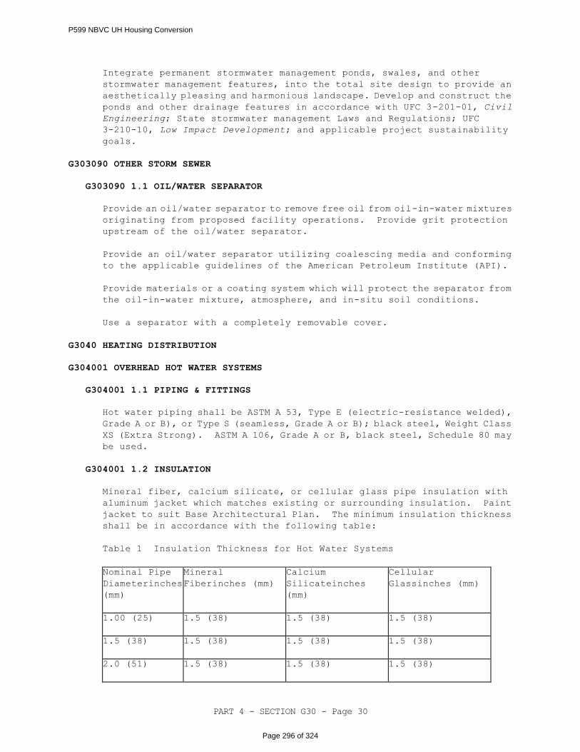
PART 4 - SECTION G30 - Page 30
Integrate permanent stormwater management ponds, swales, and other
stormwater management features, into the total site design to provide an
aesthetically pleasing and harmonious landscape. Develop and construct the
ponds and other drainage features in accordance with UFC 3-201-01, Civil
Engineering; State stormwater management Laws and Regulations; UFC
3-210-10, Low Impact Development; and applicable project sustainability
goals.
G303090 OTHER STORM SEWER
G303090 1.1 OIL/WATER SEPARATOR
Provide an oil/water separator to remove free oil from oil-in-water mixtures
originating from proposed facility operations. Provide grit protection
upstream of the oil/water separator.
Provide an oil/water separator utilizing coalescing media and conforming
to the applicable guidelines of the American Petroleum Institute (API).
Provide materials or a coating system which will protect the separator from
the oil-in-water mixture, atmosphere, and in-situ soil conditions.
Use a separator with a completely removable cover.
G3040 HEATING DISTRIBUTION
G304001 OVERHEAD HOT WATER SYSTEMS
G304001 1.1 PIPING & FITTINGS
Hot water piping shall be ASTM A 53, Type E (electric-resistance welded),
Grade A or B), or Type S (seamless, Grade A or B); black steel, Weight Class
XS (Extra Strong). ASTM A 106, Grade A or B, black steel, Schedule 80 may
be used.
G304001 1.2 INSULATION
Mineral fiber, calcium silicate, or cellular glass pipe insulation with
aluminum jacket which matches existing or surrounding insulation. Paint
jacket to suit Base Architectural Plan. The minimum insulation thickness
shall be in accordance with the following table:
Table 1 Insulation Thickness for Hot Water Systems
Nominal Pipe
Diameterinches
(mm)
Mineral
Fiberinches (mm)
Calcium
Silicateinches
(mm)
Cellular
Glassinches (mm)
1.00 (25)
1.5 (38)
1.5 (38)
1.5 (38)
1.5 (38)
1.5 (38)
1.5 (38)
1.5 (38)
2.0 (51)
1.5 (38)
1.5 (38)
1.5 (38)
P599 NBVC UH Housing Conversion
Page 296 of 324
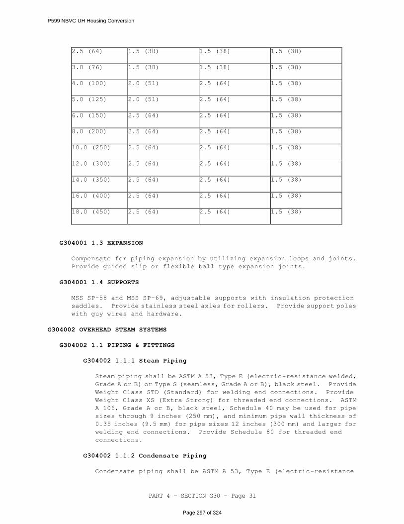
PART 4 - SECTION G30 - Page 31
2.5 (64)
1.5 (38)
1.5 (38)
1.5 (38)
3.0 (76)
1.5 (38)
1.5 (38)
1.5 (38)
4.0 (100)
2.0 (51)
2.5 (64)
1.5 (38)
5.0 (125)
2.0 (51)
2.5 (64)
1.5 (38)
6.0 (150)
2.5 (64)
2.5 (64)
1.5 (38)
8.0 (200)
2.5 (64)
2.5 (64)
1.5 (38)
10.0 (250)
2.5 (64)
2.5 (64)
1.5 (38)
12.0 (300)
2.5 (64)
2.5 (64)
1.5 (38)
14.0 (350)
2.5 (64)
2.5 (64)
1.5 (38)
16.0 (400)
2.5 (64)
2.5 (64)
1.5 (38)
18.0 (450)
2.5 (64)
2.5 (64)
1.5 (38)
G304001 1.3 EXPANSION
Compensate for piping expansion by utilizing expansion loops and joints.
Provide guided slip or flexible ball type expansion joints.
G304001 1.4 SUPPORTS
MSS SP-58 and MSS SP-69, adjustable supports with insulation protection
saddles. Provide stainless steel axles for rollers. Provide support poles
with guy wires and hardware.
G304002 OVERHEAD STEAM SYSTEMS
G304002 1.1 PIPING & FITTINGS
G304002 1.1.1 Steam Piping
Steam piping shall be ASTM A 53, Type E (electric-resistance welded,
Grade A or B) or Type S (seamless, Grade A or B), black steel. Provide
Weight Class STD (Standard) for welding end connections. Provide
Weight Class XS (Extra Strong) for threaded end connections. ASTM
A 106, Grade A or B, black steel, Schedule 40 may be used for pipe
sizes through 9 inches (250 mm), and minimum pipe wall thickness of
0.35 inches (9.5 mm) for pipe sizes 12 inches (300 mm) and larger for
welding end connections. Provide Schedule 80 for threaded end
connections.
G304002 1.1.2 Condensate Piping
Condensate piping shall be ASTM A 53, Type E (electric-resistance
P599 NBVC UH Housing Conversion
Page 297 of 324
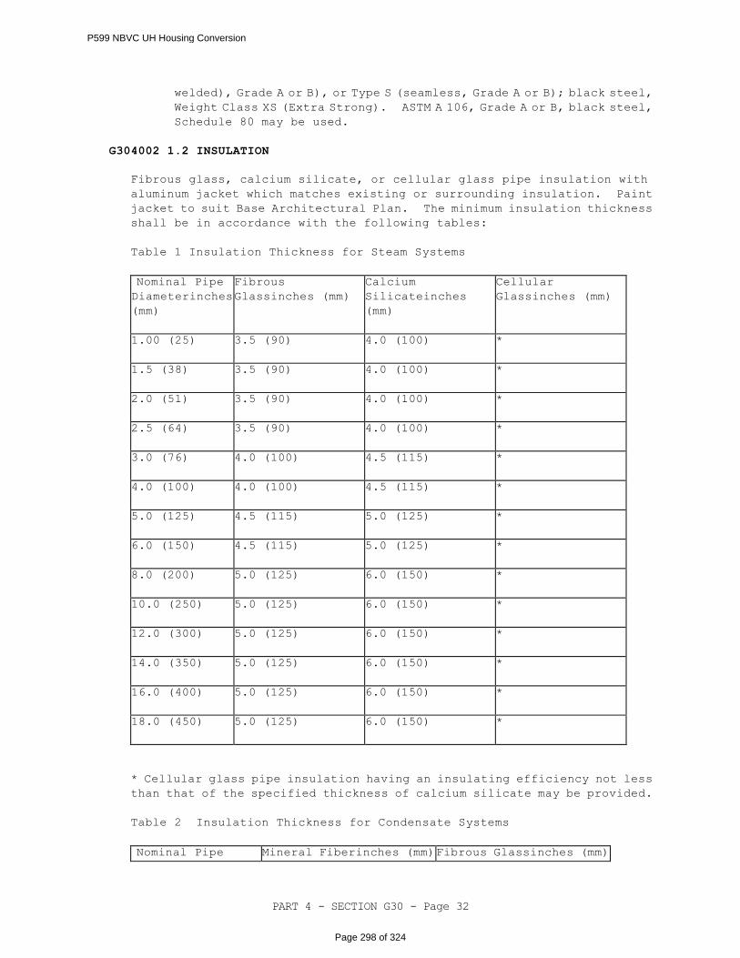
PART 4 - SECTION G30 - Page 32
welded), Grade A or B), or Type S (seamless, Grade A or B); black steel,
Weight Class XS (Extra Strong). ASTM A 106, Grade A or B, black steel,
Schedule 80 may be used.
G304002 1.2 INSULATION
Fibrous glass, calcium silicate, or cellular glass pipe insulation with
aluminum jacket which matches existing or surrounding insulation. Paint
jacket to suit Base Architectural Plan. The minimum insulation thickness
shall be in accordance with the following tables:
Table 1 Insulation Thickness for Steam Systems
Nominal Pipe Diameterinches
(mm)
Fibrous
Glassinches (mm)
Calcium
Silicateinches
(mm)
Cellular
Glassinches (mm)
1.00 (25)
3.5 (90)
4.0 (100)
*
1.5 (38)
3.5 (90)
4.0 (100)
*
2.0 (51)
3.5 (90)
4.0 (100)
*
2.5 (64)
3.5 (90)
4.0 (100)
*
3.0 (76)
4.0 (100)
4.5 (115)
*
4.0 (100)
4.0 (100)
4.5 (115)
*
5.0 (125)
4.5 (115)
5.0 (125)
*
6.0 (150)
4.5 (115)
5.0 (125)
*
8.0 (200)
5.0 (125)
6.0 (150)
*
10.0 (250)
5.0 (125)
6.0 (150)
*
12.0 (300)
5.0 (125)
6.0 (150)
*
14.0 (350)
5.0 (125)
6.0 (150)
*
16.0 (400)
5.0 (125)
6.0 (150)
*
18.0 (450)
5.0 (125)
6.0 (150)
*
* Cellular glass pipe insulation having an insulating efficiency not less
than that of the specified thickness of calcium silicate may be provided.
Table 2 Insulation Thickness for Condensate Systems
Nominal Pipe Mineral Fiberinches (mm) Fibrous Glassinches (mm)
P599 NBVC UH Housing Conversion
Page 298 of 324
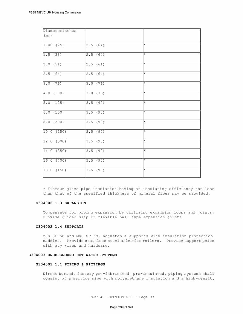
PART 4 - SECTION G30 - Page 33
Diameterinches
(mm)
1.00 (25)
2.5 (64)
*
1.5 (38)
2.5 (64)
*
2.0 (51)
2.5 (64)
*
2.5 (64)
2.5 (64)
*
3.0 (76)
3.0 (76)
*
4.0 (100)
3.0 (76)
*
5.0 (125)
3.5 (90)
*
6.0 (150)
3.5 (90)
*
8.0 (200)
3.5 (90)
*
10.0 (250)
3.5 (90)
*
12.0 (300)
3.5 (90)
*
14.0 (350)
3.5 (90)
*
16.0 (400)
3.5 (90)
*
18.0 (450)
3.5 (90)
*
* Fibrous glass pipe insulation having an insulating efficiency not less
than that of the specified thickness of mineral fiber may be provided.
G304002 1.3 EXPANSION
Compensate for piping expansion by utilizing expansion loops and joints.
Provide guided slip or flexible ball type expansion joints.
G304002 1.4 SUPPORTS
MSS SP-58 and MSS SP-69, adjustable supports with insulation protection
saddles. Provide stainless steel axles for rollers. Provide support poles
with guy wires and hardware.
G304003 UNDERGROUND HOT WATER SYSTEMS
G304003 1.1 PIPING & FITTINGS
Direct buried, factory pre-fabricated, pre-insulated, piping systems shall
consist of a service pipe with polyurethane insulation and a high-density
P599 NBVC UH Housing Conversion
Page 299 of 324
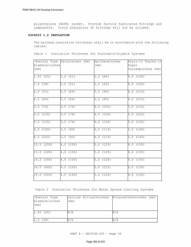
PART 4 - SECTION G30 - Page 34
polyethylene (HDPE) jacket. Provide factory fabricated fittings and
components. Field insulation of fittings will not be allowed.
G304003 1.2 INSULATION
The minimum insulation thickness shall be in accordance with the following
tables:
Table 1 Insulation Thickness for Drainable/Dryable Systems
Nominal Pipe Diameterinches
(mm)
Parocinches (mm)
Epitherminches
(mm)
Kaylo-10 Thermo-12
Super
Caltempinches (mm)
1.00 (25)
2.0 (51)
2.5 (64)
4.0 (100)
1.5 (38)
2.0 (51)
2.5 (64)
4.0 (100)
2.0 (51)
2.5 (64)
3.5 (90)
4.5 (115)
2.5 (64)
2.5 (64)
3.5 (90)
4.5 (115)
3.0 (76)
3.0 (76)
4.0 (100)
5.0 (125)
4.0 (100)
3.0 (76)
4.0 (100)
5.0 (125)
5.0 (125)
3.0 (76)
4.0 (100)
5.0 (125)
6.0 (150)
3.5 (90)
4.5 (115)
5.5 (140)
8.0 (200)
3.5 (90)
4.5 (115)
5.5 (140)
10.0 (250)
4.0 (100)
5.0 (125)
6.0 (150)
12.0 (300)
4.0 (100)
5.0 (125)
6.0 (150)
14.0 (350)
4.0 (100)
5.0 (125)
6.0 (150)
16.0 (400)
4.0 (100)
5.0 (125)
6.0 (150)
18.0 (450)
4.0 (100)
5.0 (125)
6.0 (150)
Table 2 Insulation Thickness for Water Spread Limiting Systems
Nominal Pipe Diameterinches
(mm)
Calcium Silicateinches
(mm)
Polyurethaneinches (mm)
1.00 (25)
N/A
N/A
1.5 (38) N/A N/A
P599 NBVC UH Housing Conversion
Page 300 of 324
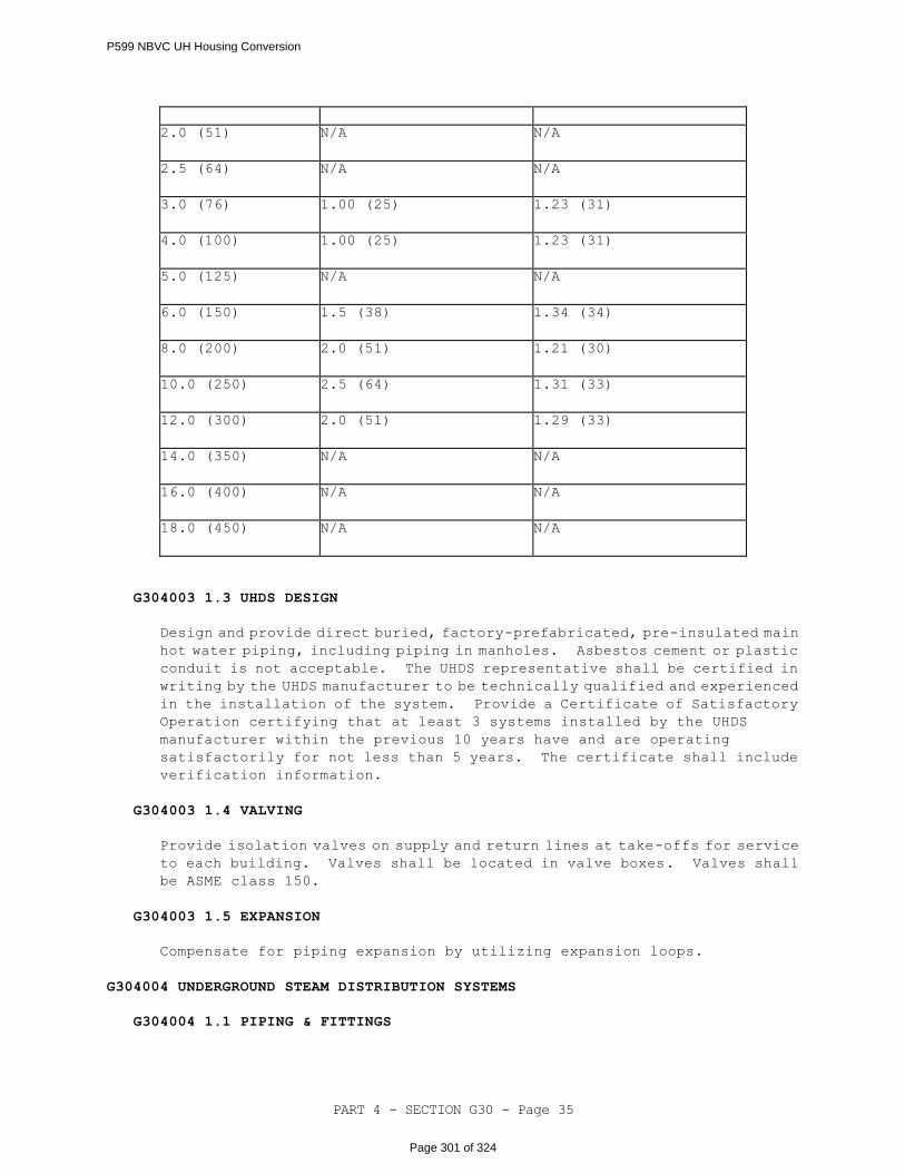
PART 4 - SECTION G30 - Page 35
2.0 (51)
N/A
N/A
2.5 (64)
N/A
N/A
3.0 (76)
1.00 (25)
1.23 (31)
4.0 (100)
1.00 (25)
1.23 (31)
5.0 (125)
N/A
N/A
6.0 (150)
1.5 (38)
1.34 (34)
8.0 (200)
2.0 (51)
1.21 (30)
10.0 (250)
2.5 (64)
1.31 (33)
12.0 (300)
2.0 (51)
1.29 (33)
14.0 (350)
N/A
N/A
16.0 (400)
N/A
N/A
18.0 (450)
N/A
N/A
G304003 1.3 UHDS DESIGN
Design and provide direct buried, factory-prefabricated, pre-insulated main
hot water piping, including piping in manholes. Asbestos cement or plastic
conduit is not acceptable. The UHDS representative shall be certified in
writing by the UHDS manufacturer to be technically qualified and experienced
in the installation of the system. Provide a Certificate of Satisfactory
Operation certifying that at least 3 systems installed by the UHDS
manufacturer within the previous 10 years have and are operating
satisfactorily for not less than 5 years. The certificate shall include
verification information.
G304003 1.4 VALVING
Provide isolation valves on supply and return lines at take-offs for service
to each building. Valves shall be located in valve boxes. Valves shall
be ASME class 150.
G304003 1.5 EXPANSION
Compensate for piping expansion by utilizing expansion loops.
G304004 UNDERGROUND STEAM DISTRIBUTION SYSTEMS
G304004 1.1 PIPING & FITTINGS
P599 NBVC UH Housing Conversion
Page 301 of 324
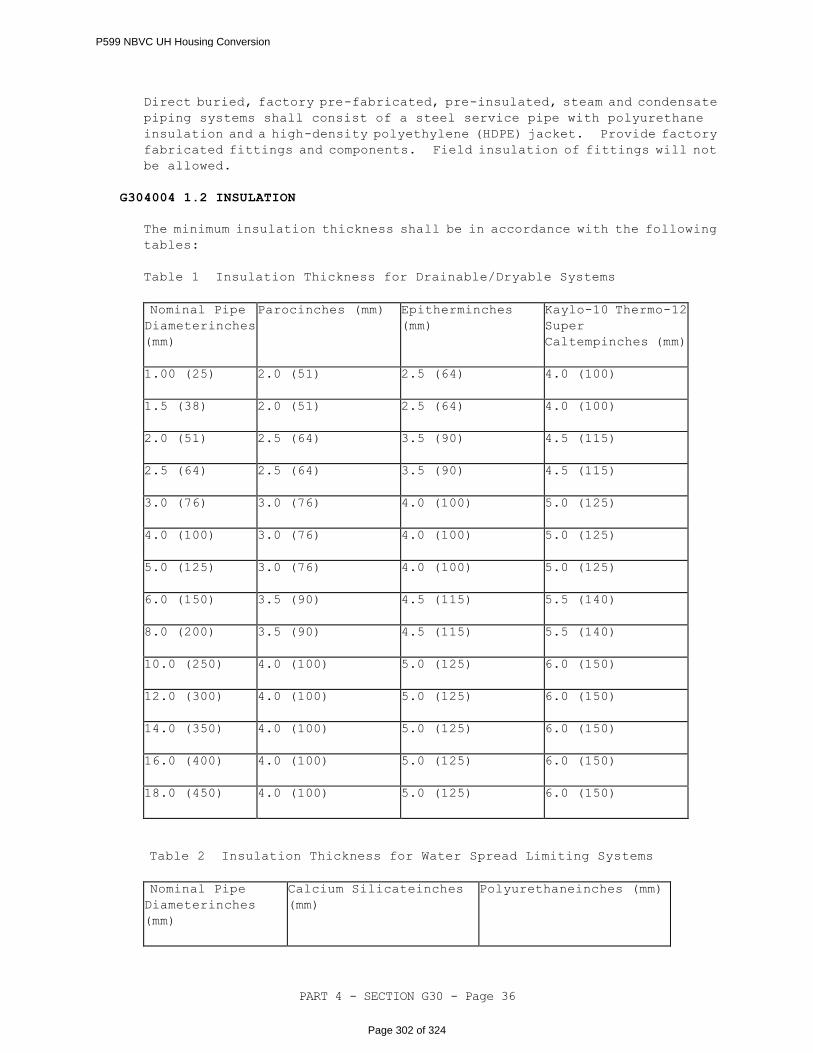
PART 4 - SECTION G30 - Page 36
Direct buried, factory pre-fabricated, pre-insulated, steam and condensate
piping systems shall consist of a steel service pipe with polyurethane
insulation and a high-density polyethylene (HDPE) jacket. Provide factory
fabricated fittings and components. Field insulation of fittings will not
be allowed.
G304004 1.2 INSULATION
The minimum insulation thickness shall be in accordance with the following
tables:
Table 1 Insulation Thickness for Drainable/Dryable Systems
Nominal Pipe Diameterinches
(mm)
Parocinches (mm)
Epitherminches
(mm)
Kaylo-10 Thermo-12
Super
Caltempinches (mm)
1.00 (25)
2.0 (51)
2.5 (64)
4.0 (100)
1.5 (38)
2.0 (51)
2.5 (64)
4.0 (100)
2.0 (51)
2.5 (64)
3.5 (90)
4.5 (115)
2.5 (64)
2.5 (64)
3.5 (90)
4.5 (115)
3.0 (76)
3.0 (76)
4.0 (100)
5.0 (125)
4.0 (100)
3.0 (76)
4.0 (100)
5.0 (125)
5.0 (125)
3.0 (76)
4.0 (100)
5.0 (125)
6.0 (150)
3.5 (90)
4.5 (115)
5.5 (140)
8.0 (200)
3.5 (90)
4.5 (115)
5.5 (140)
10.0 (250)
4.0 (100)
5.0 (125)
6.0 (150)
12.0 (300)
4.0 (100)
5.0 (125)
6.0 (150)
14.0 (350)
4.0 (100)
5.0 (125)
6.0 (150)
16.0 (400)
4.0 (100)
5.0 (125)
6.0 (150)
18.0 (450)
4.0 (100)
5.0 (125)
6.0 (150)
Table 2 Insulation Thickness for Water Spread Limiting Systems
Nominal Pipe Diameterinches
(mm)
Calcium Silicateinches
(mm)
Polyurethaneinches (mm)
P599 NBVC UH Housing Conversion
Page 302 of 324

PART 4 - SECTION G30 - Page 37
1.00 (25)
N/A
N/A
1.5 (38)
N/A
N/A
2.0 (51)
N/A
N/A
2.5 (64)
N/A
N/A
3.0 (76)
1.00 (25)
1.23 (31)
4.0 (100)
1.00 (25)
1.23 (31)
5.0 (125)
N/A
N/A
6.0 (150)
1.5 (38)
1.34 (34)
8.0 (200)
2.0 (51)
1.21 (30)
10.0 (250)
2.5 (64)
1.31 (33)
12.0 (300)
2.0 (51)
1.29 (33)
14.0 (350)
N/A
N/A
16.0 (400)
N/A
N/A
18.0 (450)
N/A
N/A
Table 3 Insulation Thickness for Condensate Return Systems
Nominal Pipe Diameterinches
(mm)
Parocinches (mm)
Epitherminches
(mm)
Kaylo-10 Thermo-12
Super
Caltempinches (mm)
1.00 (25)
2.0 (51)
2.5 (64)
4.0 (100)
1.5 (38)
2.0 (51)
2.5 (64)
4.0 (100)
2.0 (51)
2.5 (64)
3.5 (90)
4.5 (115)
2.5 (64)
2.5 (64)
3.5 (90)
4.5 (115)
3.0 (76)
3.0 (76)
4.0 (100)
5.0 (125)
4.0 (100)
3.0 (76)
4.0 (100)
5.0 (125)
5.0 (125)
3.0 (76)
4.0 (100)
5.0 (125)
6.0 (150)
3.5 (90)
4.5 (115)
5.5 (140)
8.0 (200) 3.5 (90) 4.5 (115) 5.5 (140)
P599 NBVC UH Housing Conversion
Page 303 of 324
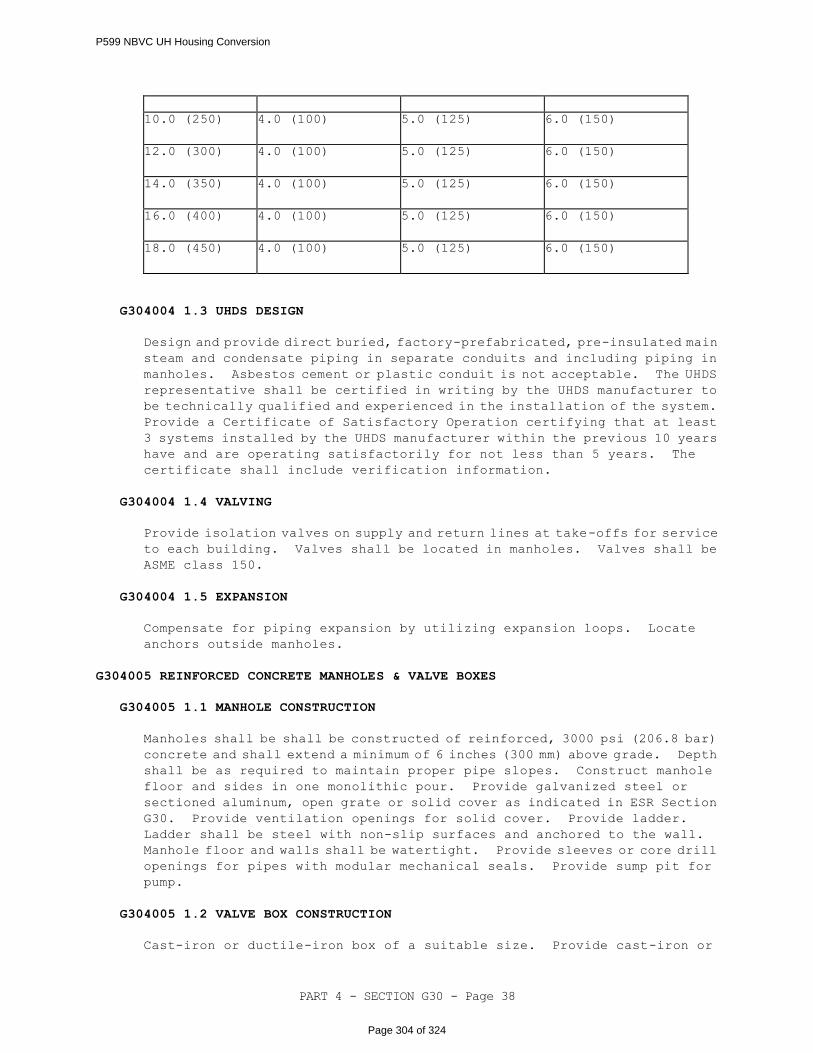
PART 4 - SECTION G30 - Page 38
10.0 (250)
4.0 (100)
5.0 (125)
6.0 (150)
12.0 (300)
4.0 (100)
5.0 (125)
6.0 (150)
14.0 (350)
4.0 (100)
5.0 (125)
6.0 (150)
16.0 (400)
4.0 (100)
5.0 (125)
6.0 (150)
18.0 (450)
4.0 (100)
5.0 (125)
6.0 (150)
G304004 1.3 UHDS DESIGN
Design and provide direct buried, factory-prefabricated, pre-insulated main
steam and condensate piping in separate conduits and including piping in
manholes. Asbestos cement or plastic conduit is not acceptable. The UHDS
representative shall be certified in writing by the UHDS manufacturer to
be technically qualified and experienced in the installation of the system.
Provide a Certificate of Satisfactory Operation certifying that at least
3 systems installed by the UHDS manufacturer within the previous 10 years
have and are operating satisfactorily for not less than 5 years. The
certificate shall include verification information.
G304004 1.4 VALVING
Provide isolation valves on supply and return lines at take-offs for service
to each building. Valves shall be located in manholes. Valves shall be
ASME class 150.
G304004 1.5 EXPANSION
Compensate for piping expansion by utilizing expansion loops. Locate
anchors outside manholes.
G304005 REINFORCED CONCRETE MANHOLES & VALVE BOXES
G304005 1.1 MANHOLE CONSTRUCTION
Manholes shall be shall be constructed of reinforced, 3000 psi (206.8 bar)
concrete and shall extend a minimum of 6 inches (300 mm) above grade. Depth
shall be as required to maintain proper pipe slopes. Construct manhole
floor and sides in one monolithic pour. Provide galvanized steel or
sectioned aluminum, open grate or solid cover as indicated in ESR Section
G30. Provide ventilation openings for solid cover. Provide ladder.
Ladder shall be steel with non-slip surfaces and anchored to the wall.
Manhole floor and walls shall be watertight. Provide sleeves or core drill
openings for pipes with modular mechanical seals. Provide sump pit for
pump.
G304005 1.2 VALVE BOX CONSTRUCTION
Cast-iron or ductile-iron box of a suitable size. Provide cast-iron or
P599 NBVC UH Housing Conversion
Page 304 of 324
PART 4 - SECTION G30 - Page 39
ductile-iron cover for the box with word(s) describing the utility cast on
the cover.
G304005 1.3 MANHOLE SUMP PUMPS
Vertical sump pump. Operating temperature design must be 195 degrees F (93
degrees C) minimum. Provide with 2-pole float control.
G304090 OTHER HEATING DISTRIBUTION
G304090 1.1 WARNING & IDENTIFICATION TAPE
Polyethylene plastic tape manufactured specifically for warning and
identifying buried utility lines.
G304090 1.2 CORROSION PROTECTION
Provide a cathodic protection system for the underground piping system.
System shall be designed by a National Association of Corrosion Engineers
(NACE) certified Cathodic Protection Engineer. The corrosion engineer
shall obtain soil data and existing system conditions. Corrosion engineer
shall supervise, inspect and test the installation and performance of the
cathodic protection system. Test stations shall be post mounted and placed
at the manhole or nearby building. Test stations shall be located at each
end of each cathodically protected section.
G3050 COOLING DISTRIBUTION
G305001 OVERHEAD COOLING SYSTEMS
G305001 1.1 PIPING & FITTINGS
G305001 1.1.1 Chilled and Condenser Water Piping
Chilled and condenser water piping shall be electric resistance welded
or seamless Schedule 40 black steel pipe conforming to ASTM A 53.
Piping 4 inch (100 mm) and smaller may be ASTM B 88 Type K or L copper.
G305001 1.1.2 Steel Pipe Fittings
For piping 2 inch (50 mm) and smaller, provide ANSI/ASME B16.3
malleable iron screwed fittings or ASME B16.11 socket welding (Class
3000) or threaded type (Class 2000). Provide ASME/ANSI B16.9
butt-welding fittings or ASME/ANSI B16.5 flanged type for piping 2-1/2
inch (63 mm) and larger. Grooved joint pipe coupling systems of
appropriate pressure rating are acceptable in lieu of welded or
screwed fittings.
G305001 1.1.3 Copper Fittings
Provide ANSI B16.18 cast bronze solder joint type or ASME/ANSI B16.22
wrought copper solder joint type.
G305001 1.2 INSULATION
P599 NBVC UH Housing Conversion
Page 305 of 324
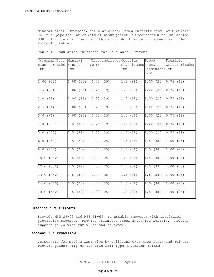
PART 4 - SECTION G30 - Page 40
Mineral fiber, Urethane, cellular glass, Faced Phenolic Foam, or Flexible
Cellular pipe insulation with aluminum jacket in accordance with ESR Section
G30. The minimum insulation thickness shall be in accordance with the
following table:
Table 1 Insulation Thickness for Cold Water Systems
Nominal Pipe Diameterinches
(mm)
Mineral
Fiberinches
(mm)
Urethaneinches
(mm)
Cellular
Glassinches
(mm)
Faced
Phenolic
Foaminches
(mm)
Flexible
Cellularinches
(mm)
1.00 (25)
1.00 (25)
0.75 (19)
1.5 (38)
1.00 (25)
0.75 (19)
1.5 (38)
1.00 (25)
0.75 (19)
1.5 (38)
1.00 (25)
0.75 (19)
2.0 (51)
1.00 (25)
0.75 (19)
1.5 (38)
1.00 (25)
0.75 (19)
2.5 (64)
1.00 (25)
0.75 (19)
1.5 (38)
1.00 (25)
0.75 (19)
3.0 (76)
1.00 (25)
0.75 (19)
1.5 (38)
1.00 (25)
0.75 (19)
4.0 (100)
1.5 (38)
0.75 (19)
1.5 (38)
1.00 (25)
0.75 (19)
5.0 (125)
1.5 (38)
0.75 (19)
1.5 (38)
1.00 (25)
0.75 (19)
6.0 (150)
1.5 (38)
1.00 (25)
1.5 (38)
1.5 (38)
1.00 (25)
8.0 (200)
1.5 (38)
1.00 (25)
1.5 (38)
1.5 (38)
1.00 (25)
10.0 (250)
1.5 (38)
1.00 (25)
1.5 (38)
1.5 (38)
1.00 (25)
12.0 (300)
1.5 (38)
1.00 (25)
1.5 (38)
1.5 (38)
1.00 (25)
14.0 (350)
1.5 (38)
1.00 (25)
1.5 (38)
1.5 (38)
1.00 (25)
16.0 (400)
1.5 (38)
1.00 (25)
1.5 (38)
1.5 (38)
1.00 (25)
18.0 (450)
1.5 (38)
1.00 (25)
1.5 (38)
1.5 (38)
1.00 (25)
G305001 1.3 SUPPORTS
Provide MSS SP-58 and MSS SP-69, adjustable supports with insulation
protection saddles. Provide stainless steel axles for rollers. Provide
support poles with guy wires and hardware.
G305001 1.4 EXPANSION
Compensate for piping expansion by utilizing expansion loops and joints.
Provide guided slip or flexible ball type expansion joints.
P599 NBVC UH Housing Conversion
Page 306 of 324
PART 4 - SECTION G30 - Page 41
G305002 UNDERGROUND COOLING SYSTEMS
G305002 1.1 PIPING & FITTINGS
Direct buried, factory-prefabricated, pre-insulated, chilled water piping
systems. All fittings and accessories shall be designed and
factory-fabricated to prevent moisture from entering into the system.
Backfill and overall installation shall meet the requirements of the piping
system manufacturer.
G305002 1.2 VALVES
Provide isolation valves on supply and return lines at take-offs for service
to each building. Valves shall be located in valve boxes.
G305090 OTHER COOLING DISTRIBUTION
G305090 1.1 EXPANSION
Compensate for piping expansion by utilizing expansion loops. Locate
anchors outside manholes.
G305090 1.2 WARNING & IDENTIFICATION TAPE
Polyethylene plastic tape manufactured specifically for warning and
identifying buried utility lines.
G305090 1.3 CORROSION PROTECTION
Provide a cathodic protection system for the underground chilled water and
condenser water piping system. System shall be designed by a National
Association of Corrosion Engineers (NACE) certified Cathodic Protection
Engineer. The corrosion engineer shall obtain soil data and existing system
conditions. Corrosion engineer shall supervise, inspect and test the
installation and performance of the cathodic protection system. Test
stations shall be post mounted and placed at the manhole or nearby building.
Test stations shall be located at each end of each cathodically protected
section.
G3060 FUEL DISTRIBUTION
G306001 LIQUID FUEL DISTRIBUTION PIPING
G306001 1.1 GASOLINE/DIESEL
Fuel piping shall be ASTM A 53, Type E (electric-resistance welded, Grade
A or B) or Type S (seamless, Grade A or B), black steel or API SPEC 5L,
seamless, submerged-arc weld or gas metal-arc weld, Grade B, black steel.
Provide Weight Class STD (Standard) for welding end connections. Provide
Weight Class XS (Extra Strong) for threaded end connections.
G306003 LIQUID FUEL STORAGE TANKS
G306003 1.1 STORAGE TANKS
P599 NBVC UH Housing Conversion
Page 307 of 324
PART 4 - SECTION G30 - Page 42
Aboveground, concrete encased or double wall in accordance with UL 142 and
UL 2085 with secondary containment and leak monitoring with a capacity to
meet the system requirements. Provide with overfill/spill containment,
overfill protection and vents.
G306003 1.2 FUEL PUMPS
Fuel pumps shall comply with NEMA MG 1, NFPA 70, and be designed for use
with hydrocarbon fuels and working pressure of 275 psig (1896 kilopascals)
at 100 degrees F (38 degrees C).
G306003 1.3 FUEL METERS
Continuous duty, positive displacement type, with electronic thermal
compensation capability, suitable for outdoor installation, and designed
for use with hydrocarbon fuels and working pressure of 275 psig (1896
kilopascals) at 100 degrees F (38 degrees C).
G306004 LIQUID FUEL DISPENSING TANKS
The same as storage tanks except, include tank mounted dispenser with filter,
vacuum breaker, safety breakaway, hose and nozzle.
G306006 GAS DISTRIBUTION PIPING (NATURAL & PROPANE)
G306006 1.1 STEEL PIPE
Gas piping shall be ASTM A 53, Type E (electric-resistance welded, Grade
A or B) or Type S (seamless, Grade A or B), black steel. Provide Weight Class
STD (Standard) for welding end connections. Provide Weight Class XS (Extra
Strong) for threaded end connections.
G306006 1.2 POLYETHYLENE (PE)
PE pipe and heat fusion fittings shall conform to ASTM D 2513, Grade PE2406
or PE3408.
G306007 GAS STORAGE TANKS
G306007 1.1 PROPANE STORAGE TANKS
ASME labeled tank in accordance with NFPA 58 with a capacity to meet the
system requirements.
G306009 OTHER GAS DISTRIBUTION
G306009 1.1 WARNING & IDENTIFICATION TAPE
Detectable aluminum foil, plastic backed tape or detectable magnetic plastic
tape manufactured specifically for warning and identifying buried piping.
-- End of Section --
P599 NBVC UH Housing Conversion
Page 308 of 324
PART 4 - SECTION G40 - Page 1
SECTION G40
SITE ELECTRICAL UTILITIES
05/14
G40 GENERAL
RFP Part 3 including the Engineering System Requirements (ESR) provide project
specific requirements. The RFP Part 4, Performance Technical Sections (PTS)
provide generalized technical requirements that apply to multiple facility types
and include more requirements than are applicable to any one project. Therefore,
only the RFP Part 4 requirements that apply to the project and further define the
RFP Part 3 project specific requirements are required.
G40 1.1 NARRATIVE
This section covers installations exterior to the facility up to the five
foot line. See PTS Section D50, Electrical, for continuation of systems into
the building.
G40 1.2 ELECTRICAL DESIGN GUIDANCE
Provide the design and installation in accordance with the following
references. This Performance Technical Specification (PTS) adds
clarification to the fundamental requirements contained in the following
Government Standards. The general requirements of this PTS section are
located in PTS Section Z10, General Performance Technical Specification.
When all product Quality Control information is included in the Unified
Facility Criteria (UFC) and there are requirement options identified in the
ESR, then the Uniformat Level 4 titles (and possible subtitles) are included
without additional verbiage. One example of this is G401008, GROUNDING
SYSTEMS.
G40 1.2.1 Government Standards
UNIFIED FACILITIES CRITERIA (UFC)
UFC 1-200-01
General Building Requirements(A
reference in this PTS section to UFC
1-200-01 requires compliance with the
Tri-Service Core UFCs that are listed
in UFGS Section 01 33 10.05 20, which
includes the following significant
UFC(s):UFC 3-501-01, Electrical
Engineering)
UFC 1-200-02
High Performance and Sustainable
Buildings
UFC 3-570-02N
Electrical Engineering Cathodic
Protection
P599 NBVC UH Housing Conversion
Page 309 of 324

PART 4 - SECTION G40 - Page 2
UNIFIED FACILITIES GUIDE SPECIFICATIONS (UFGS)
UFGS 26 11 13.00 20
Primary Unit Substation
UFGS 26 11 16
Secondary Unit Substations
UFGS 26 12 19.10
Three-Phase Pad-Mounted Transformers
UFGS 26 12 19.20
Single-Phase Pad-Mounted
Transformers
UFGS 26 13 00.00 20
SF6/High-Firepoint Fluids Insulated
Pad-Mounted Switchgear
UFGS 26 23 00
Switchboards and Switchgear
UFGS 26 27 14.00 20
Electricity Metering
UFGS 26 56 00
Exterior Lighting
UFGS 33 71 01
Overhead Transmission and
Distribution
UFGS 33 71 02.00 20
Underground Electrical Distribution
UFGS 33 82 00
Telecommunications Outside Plant
G40 1.3 QUALITY ASSURANCE
Qualifications, certifications, and Test Plans indicated herein shall be
submitted 45 calendar days prior to the expected date of execution. Notify
the Contracting Officer 14 calendar days prior to all testing. Submit test
results within 7 calendar days of completion of testing.
The Designer of Record is responsible for approving the submittals listed
below.
G40 1.3.1 Qualified Testing Organization
Contractor shall engage the services of a qualified testing
organization to provide inspection, testing, calibration, and
adjustment of the electrical distribution system and equipment listed
in paragraph entitled "Acceptance Tests and Inspections" herein.
Organization shall be independent of the supplier, manufacturer, and
installer of the equipment. The organization shall be a first tier
subcontractor.
P599 NBVC UH Housing Conversion
Page 310 of 324
PART 4 - SECTION G40 - Page 3
a. Submit name and qualifications of organization. Organization
shall have been regularly engaged in the testing of electrical
materials, devices, installations, and systems for a minimum
of 5 years. The organization shall have a calibration program,
and test instruments used shall be calibrated in accordance with
NETA ATS.
b. Submit name and qualifications of the lead engineering
technician performing the required testing services. Include
a list of three comparable jobs performed by the technician with
specific names and telephone numbers for reference. Testing,
inspection, calibration, and adjustments shall be performed by
an engineering technician, certified by NETA or the National
Institute for Certification in Engineering Technologies
(NICET) with a minimum of 5 years' experience inspecting,
testing, and calibrating electrical distribution and
generation equipment, systems, and devices.
G40 1.3.2 NEC Qualified Worker
Provide in accordance with NFPA 70. Qualified Workers shall be allowed
to be assisted by helpers on a 1 to 1 ratio, provided such helpers
are registered in recognized apprenticeship programs. Submit a
certification confirming NEC Qualified Worker requirements.
G40 1.3.3 Qualified Medium Voltage Electrician
All workers on medium voltage electrical crews shall have 5 years
experience working medium voltage systems on similar projects
involving the same or higher voltage.
G40 1.3.4 Qualified Cable Splicer (Medium Voltage Cable)
The cable splicer/terminator must have a certification from the
National Cable Splicing Certification Board (NCSCB) in the field of
splicing and terminating shielded medium voltage (5 kV to 35 kV) power
cable using pre-manufactured kits (pre-molded, heat-shrink,
cold-shrink). Proof of certification for the individuals that will
be performing cable splicer and termination work shall be submitted
30 days before splices or terminations are to be made.
G40 1.3.5 Qualified PV Installer
Installation of photovoltaic systems shall be by experienced and
trained installers. At minimum the PV installation supervisor shall
hold a "PV Installer Certification" as issued by the North American
Board of Certified Energy Practitioners or hold a Certified Solar
Roofing Professional (CSRP) credential issued by RISE "Roof
Intergrated Solar Energy Inc".
G40 1.3.6 Qualified Cable Splicer (Telecommunications)
Certification shall include the training, and experience of the
individual on specific type and classification of telecommunications
cable to be provided under this contract.
P599 NBVC UH Housing Conversion
Page 311 of 324
PART 4 - SECTION G40 - Page 4
G40 1.3.7 Qualified Cable Installer and Splicer (Fiber Optic Cable)
Certification shall include the training, and experience of the
individual on specific type and classification of Fiber Optic media
to be provided under this contract.
G40 1.3.8 Qualified Fiber Optic (FO) Cable Manufacturer
The FO media manufacturer shall have a minimum of 3 years experience
in the manufacturing, assembly, and factory testing of FO media that
complies with RUS REA Bull 1753F-601 (PE-90). Manufacturer shall
provide a list of customers with 3 years of maintenance logs
documenting experience with government customers.
G40 1.3.9 Material Standards
Ensure service support and provide manufacturer's nameplate in
accordance with PTS Section Z10, General Performance Technical
Specification.
G40 1.3.9.1 Warning Labels
Each enclosure of electrical equipment, including substations,
pad-mounted transformers, pad-mounted switches, pad-mounted
sectionalizing termination cabinets, and switchgear, shall
have a warning label identifying the enclosure as 1) containing
energized electrical equipment and 2) an arc flash hazard.
G40 1.3.10 Factory Testing
The Government reserves the right to witness all factory testing. The
manufacturer shall have a calibration program that assures that all
applicable test instruments are maintained within rated accuracy.
G40 1.3.11 Electrical System Startup and Testing
Submit test plans for approval. The test plans shall be tailored to
the systems provided.
The test plan shall list make and model and provide functional
description of the test instruments and accessories and shall describe
the setup of the tests to be conducted. Test instruments shall be
capable of measuring and recording or displaying test data at a higher
resolution and greater accuracy than specified for the equipment's
performance.
G40 1.3.11.1 Factory Trained Engineer
Provide a factory trained engineer to supervise start-up and
testing as required in referenced specifications.
G40 1.3.11.2 Performance Verification Testing
The Contractor shall show by demonstration in service that all
P599 NBVC UH Housing Conversion
Page 312 of 324
PART 4 - SECTION G40 - Page 5
circuits and devices are in operating condition. Tests shall
be such that each item of control equipment will function not
less than five times. The Contractor shall provide all necessary
test equipment, tools, fuel, load banks, labor, and materials
for testing. As a minimum, all systems shall be tested in
accordance with manufacturer's recommendations. Additional
testing requirements for the various systems are described with
those systems, hereinafter. The Contractor shall assure that
all applicable test instruments are maintained within rated
accuracy. Dated calibration labels shall be visible on all test
equipment.
Submit a separate electrical field test plan in accordance with
manufacturer's recommendations and that conforms to NETA ATS
for each piece of Electrical Distribution Equipment and System
requiring Performance Verification Testing.
The following items identify specific test requirements.
Additional test requirements are contained in the applicable
UFGS.
a. Cable – Test cable in accordance with the manufacturer's
recommendations and NETA ATS. Adhere to precautions and
limits as specified in the applicable NEMA/ICEA Standard
for the specific cable.
b. Grounding - Test ground systems in accordance with the
manufacturer's recommendations and NETA ATS.
c. Site Lighting - Contractor's Quality Control (CQC)
representative shall perform a field survey of site
lighting systems in accordance with IESNA for acceptance.
Show that the lighting system operates in accordance with
the user’s requirements and is in accordance with
designed levels. Provide certification that the measured
lighting levels conform to the design requirements.
d. Telecommunications wiring - Test all cables in accordance
with industry standards.
G40 1.3.11.3 Acceptance Tests and Inspections
The Qualified Testing Organization shall provide the Acceptance
Tests and Inspections test plan and procedures and perform the
acceptance tests and inspections. Test methods, procedures, and
test values shall be performed and evaluated in accordance with
NETA ATS, the manufacturer's recommendations, and paragraph
entitled "Field Quality Control" of each applicable
specification section. Tests identified as optional in NETA ATS
are not required unless otherwise specified. Equipment shall
be placed in service only after completion of required tests
and evaluation of the test results have been completed.
Contractor shall supply to the testing organization complete
sets of shop drawings, settings of adjustable devices, and other
information necessary for an accurate test and inspection of
the system prior to the performance of any final testing.
P599 NBVC UH Housing Conversion
Page 313 of 324
PART 4 - SECTION G40 - Page 6
Specific test requirements are contained in the UFGS for
equipment.
G40 1.4 DESIGN SUBMITTALS
Design Submittals shall be in accordance with PTS Section Z10, General
Performance Technical Specifications, UFGS Section 01 33 10.05 20, Design
Submittal Procedures, UFC 1-300-09N, Design Procedures, and UFC 3-501-01,
Electrical Engineering.
In addition, UFGS sections listed below or in the body of the PTS text are
to be used by the Designer of Record (DOR) as a part of the design submittal.
If the UFGS products or systems are applicable to the project, the DOR shall
edit these referenced UFGS sections and submit them as a part of the design
submittal specification. Edit the specification sections in accordance
with the limitations stated in PTS Section Z10, General Performance
Technical Specifications.
UFGS 26 11 13.00 20, Primary Unit Substation
UFGS 26 11 16, Secondary Unit Substations
UFGS 26 12 19.10, Three-Phase Pad-Mounted Transformers
UFGS 26 12 19.20, Single-Phase Pad-Mounted Transformers
UFGS 26 13 00.00 20, SF6/High-Firepoint Fluids Insulated Pad-Mounted
Switch Gear
UFGS 26 23 00, Switchboards and Switchgear
UFGS 26 27 14.00 20, Electricity Metering
UFGS 33 71 01.00 20, Overhead Transmission and Distribution
UFGS 33 71 02.00 20, Underground Electrical Distribution
UFGS 33 82 00, Telecommunications Outside Plant
G40 1.4.1 Sustainable Design Submittal
Submit sustainable design submittals in accordance with UFGS 01 33
29.05 20, Sustainability Requirements for Design-Build.
G40 1.5 CONSTRUCTION SUBMITTALS
Submit construction submittals in accordance with PTS Section Z10, General
Performance Technical Specifications. In addition to the PTS Section Z10
requirements, the Designer of Record (DOR) shall approve the following
construction submittals as a minimum:
OMSI Information for Electrical Equipment (if OMSI Manual for the
entire project is not already required); all "G" item submittals
P599 NBVC UH Housing Conversion
Page 314 of 324
PART 4 - SECTION G40 - Page 7
listed in the submittals of the specifications sections identified
in the Design Submittals paragraph above; and all "G" item submittals
listed in Government Surveillance UFGS Section 01 33 00.05 20,
Construction Submittal Procedures.
Provide certification that all adjustable protective device settings have
been set in accordance with the coordination study for the as-built equipment
and configuration.
G40 1.5.1 Sustainable Construction Submittal
Submit sustainable construction submittals in accordance with UFGS
01 33 29.05 20, Sustainability Requirements for Design-Build.
G4010 ELECTRICAL DISTRIBUTION
G401001 SUBSTATIONS
When secondary unit substations are required, the Designer of Record shall utilize
UFGS Section 26 11 16, Secondary Unit Substation, and UFGS Section 26 23 00,
Switchboards and Switchgear, for the project specification, and shall submit the
edited specification section as a part of the design submittal for the project.
G401002 TRANSFORMERS
When transformers are required, the Designer of Record shall utilize UFGS Section
26 12 19.10, Three-Phase Pad Mounted Transformers, UFGS Section 26 12 19.20,
Single-Phase Pad Mounted Transformers, or UFGS Section 33 71 01.00 20, Overhead
Transmission and Distribution, for the project specification, and shall submit
the edited specification section as a part of the design submittal for the project.
G401003 SWITCHES, CONTROLS AND DEVICES
When switches or control devices are required, the Designer of Record shall utilize
UFGS Section 26 13 00.00 20, SF6/High-Firepoint Fluids Insulated Pad Mounted
Switchgear, or UFGS Section 33 71 01.00 20, Overhead Transmission and Distribution,
for the project specification, and shall submit the edited specification section
as a part of the design submittal for the project.
G401004 OVERHEAD ELECTRIC CONDUCTORS
Power line conductors shall be strung in accordance with manufacturer's standard
sag and tension recommendations.
G401005 TOWERS, POLES, CROSSARMS AND INSULATORS
Wood poles shall comply with ANSI 05.1 and RUS 1728F-700. Pressure treat poles
in accordance with AWPA C1 and AWPA C4 as referenced in RUS 1728F-700. The quality
of each pole shall be ensured with "WQC" (wood quality control) brand on each piece
or by an approved inspection agency report. Do not use creosote treated poles,
lodgepole pine, and western larch pine poles.
Concrete poles shall comply with ANSI loadings for distribution poles.
P599 NBVC UH Housing Conversion
Page 315 of 324
PART 4 - SECTION G40 - Page 8
The size of poles required, class, height and other data, shall be determined by
the designer of record to meet requirements of the pole line. Crossarms shall be
wood, steel or fiberglass in accordance with industry and local standards.
Insulators, cutouts and associated equipment shall be determined by the Designer
of Record to meet system requirements.
G401006 UNDERGROUND ELECTRIC CONDUCTORS
Route underground cables to minimize splices. Cable pulling tensions shall not
exceed the maximum pulling tension recommended by the cable manufacturer. Medium
voltage cable termination shall be suitable for the location installed and meet
IEEE Std. 48 Class 1 requirements.
G401007 DUCTBANKS, MANHOLES, HANDHOLES AND RACEWAYS
Concrete manholes and handholes shall be standard type pre-cast concrete.
Composite/Fiberglass handholes shall be polymer concrete reinforced with a heavy
weave fiberglass reinforcing as indicated. Load ratings of manholes and handholes
shall be suitable for the location installed.
G401008 GROUNDING SYSTEMS
G401009 METERING
When metering is required the Designer of Record shall utilize UFGS section 26
27 14.00 20 for the project specification and shall submit the edited specification
section as part of the design submittal for the project.
G401010 CATHODIC PROTECTION SYSTEMS
Cathodic protection systems shall be in accordance with UFC 3-570-02N.
G401011 EQUIPMENT REQUIREMENTS FOR COASTAL AND HIGH HUMIDITY AREAS
G4020 SITE LIGHTING
G402001 EXTERIOR LIGHTING FIXTURES AND CONTROLS
Utilize SSL lighting sources for exterior lighting, except where lighting is
required to match an existing source.
Comply with ANSI/ASHRAE/IES 90.1 for all exterior lighting applications and
controls. Comply with UFC 3-530-01 for reduction of light pollution.
Provide SPD at panelboards that include circuits feeding exterior lighting
systems.
Coordinate the design and luminaire selection with the landscape designer. Such
coordination should include the location of poles which may conflict with tree
locations.
When exterior lighting is required the Designer of Record shall utilize UFGS
section 26 56 00 for the project specification and shall submit the edited
specification section as part of the design submittal for the project.
P599 NBVC UH Housing Conversion
Page 316 of 324

PART 4 - SECTION G40 - Page 9
G402002 SPECIAL SECURITY LIGHTING SYSTEM
G402003 OTHER AREA LIGHTING
G402004 LIGHTING POLES
Poles shall meet Uniform Building Code for street lighting poles, and AASHTO
loadings for highway and sports lighting poles taking into account the effective
projected areas of the luminaries provided. Poles shall be direct set or
anchor-base type designed for use with underground supply conductors.
G402005 UNDERGROUND ELECTRIC CONDUCTORS
Provide in accordance with Paragraph G401006.
G402006 DUCTBANKS, MANHOLES AND HANDHOLES
Handholes and underground conduits for site lighting shall be in accordance with
Paragraph G401007.
G402007 GROUNDING SYSTEMS
G4030 SITE COMMUNICATION AND SECURITY
G403001 TELECOMMUNICATIONS SYSTEMS
G403002 CABLE TV SYSTEMS (CATV)
G403003 CABLES AND WIRING
Provide underground copper cable pair in accordance with RUS 345-67. Provide aerial
cable in accordance with RUS 345-67 except that it shall be suitable for aerial
installation and shall be Figure 8 distribution wire with 6,000 pound (26,700 N)
Class A galvanized steel or 6,000 pound (26,700 N) aluminum-clad steel strand.
Screen-compartmental core cable shall be filled cable meeting the requirements
of RUS 345-67. Fiber optic media shall meet all performance requirements of
EIA/TIA-568-A and the physical requirements of ICEA S 87-640 and EIA/TIA-598-A.
G403004 DUCTBANKS, MANHOLES AND HANDHOLES
Provide in accordance with paragraph G401007.
G403005 TOWERS, POLES AND STANDS
Provide in accordance with paragraph G401005.
G403006 TV CAMERAS AND MONITORS
G403007 ELECTRONIC SECURITY SYSTEM (ESS)
G403008 OTHER COMMUNICATION AND ALARM
G403009 GROUNDING SYSTEMS
P599 NBVC UH Housing Conversion
Page 317 of 324

PART 4 - SECTION G40 - Page 10
G4090 OTHER ELECTRICAL UTILITIES
G409007 PHOTOVOLTAIC ENERGY SYSTEM
Provide a grid tied, photovoltaic system, including structural support
system, crystalline photovoltaic panels, combiner boxes, and inverters.
Provide all labor, materials, equipment and supervision required to
implement the design and to provide a fully operational system.
Provide crystalline photovoltaic modules with a 20-year limited
manufacturer warranty that generates no less than 80% of the rated output
under Standard Test Conditions (STC). PV modules shall comply with
IEC-61215 and UL-1703.
Provide inverters that comply with UL-1741 and IEEE-1547. Inverters shall
operate over an ambient temperature range of -25 degree C to 55 degree C
with a minimum efficiency of 95 percent at full load.
Provide start-up and testing utilizing manufacturer certified technician.
Submit startup and testing report.
G409007 1.1 CODES AND STANDARDS
The PV system hardware and services shall meet or exceed all applicable
local, State and utility requirements, conform to the applicable codes
and standards, and have passed the listing and qualification tests,
listed below. (Comply with the most recent version of each document).
a. IEEE 1262 "Recommended Practice for Qualification of
Photovoltaic Modules".
b. PowerMark certification for PV modules.
c. IEEE Standard 928-1986, Recommended Criteria for Terrestrial
Photovoltaic Power Systems (PV system performance criteria).
d. IEEE 1547 Standard for Interconnecting Distributed Resources
with Electric Power Systems.
e. Underwriters Laboratories 1741-2001 (UL Standard for Inverters
and Charge Controllers).
f. Underwriters Laboratories 1703 (UL Standard for Listing
Photovoltaic Modules).
g. Certification of PV Equipment: All PV modules, inverters, and
electrical components shall be required to be listed or
recognized by an appropriate and recognized United States
Safety Laboratory (for example: UL or ETL).
G409007 1.2 PHOTOVOLTAIC APPLICATION ANALYSIS
Provide a comprehensive "Photovoltaic Application Analysis" with a
detailed description of system, application, site shading conditions
and expected kW output of the photovoltaic application. The analysis
shall utilize the Solmetric Suneye or the Solar Pathfinder shading
analyzers to analyze the effects of the existing site shading
conditions. Analysis shall include estimated PV output in kWh per
year.
P599 NBVC UH Housing Conversion
Page 318 of 324
PART 4 - SECTION G40 - Page 11
G409007 1.3 TECHNICAL REQUIREMENTS
The contractor work responsibilities include at a minimum: system
design, equipment selection, and PV system installations. System
shall be individually capable of providing peak power output of at
least proposed PV system size, 208 or 480 volt, 3-phase, 4-wire
power./p>
The final System configuration shall allow automatic operation
without operator intervention. System design and equipment
specifications shall minimize maintenance requirements. System
shall include metering that must be incorporated with current AMI
network (Advanced Metering Infrastructure) and planned energy
metering projects.
The inverter(s) disconnects and associated electrical equipment must
be located in an area that is accessible, weather-protected, and
secure from vandalism and personal injury.
Disconnects and over current devices shall be mounted in approved
boxes, enclosures, or panel boards. Disconnects and switches shall
be DC rated when used in DC applications. Metal enclosures and boxes
shall be bonded to the grounding conductor.
At a minimum, electrical meters shall capture the following data on
individual system performance (minimum solar irradiance, DC power,
AC real power, AC current, AC voltage, and power factor (recommend
ION 8600 for AC); ambient air temperature, PV cell temperature, kW,
and kWh). This data shall be captured at hourly intervals for a
minimum one year. Units of temperature, power, and current shall be
in Fahrenheit, Watts, and Amps respectively.
Transformers, if required, shall have a minimum efficiency based on
factory test results of not less than the efficiency indicated in 10
CFR 431, Subpart K, paragraph 431.196(b). Transformers shall be
housed in a NEMA 4X enclosures.
Mounting structures shall be corrosion resistant to marine
environment.
Provide permanent plaque or directory at each building service and
power source identifying all other building services and power
sources.
-- End of Section --
P599 NBVC UH Housing Conversion
Page 319 of 324
PART 4 - SECTION Z10 - Page 1
SECTION Z10
GENERAL PERFORMANCE TECHNICAL SPECIFICATION
05/14
Z10 GENERAL
RFP Part 3 including the Engineering System Requirements (ESR) provide project
specific requirements. The RFP Part 4, Performance Technical Sections (PTS)
provide generalized technical requirements that apply to multiple facility types
and include more requirements than are applicable to any one project. Therefore,
only the RFP Part 4 requirements that apply to the project and further define the
RFP Part 3 project specific requirements are required.
Z10 1.1 NARRATIVE
All Performance Technical Specification (PTS) sections must be used in
conjunction with all parts of the Design Build (D/B) Request for Proposal
(RFP) to determine the full requirements of this solicitation. This PTS
section provides general requirements for the other PTS sections of this
RFP and is used in conjunction with the other PTS sections.
Refer to UFGS section 01 33 10.05 20, Design Submittal Proceduresfor the
Order of Precedence of the RFP Parts. Requirements listed in the Project
Program take precedence over the PTS sections requirements; therefore,
requirements identified in the Project Program eliminate options related
to that requirement in the PTS sections.
Z10 1.2 DESIGN GUIDANCE
Provide work in compliance with the following design standards and codes,
as a minimum. Government standards listed in this RFP take precedence over
industry standards.
The PTS Sections reference published standards, the titles of which can be
found in the Unified Master Reference List (UMRL)on the Whole Building Design
Guide at the Unified Facilities Guide Specification (UFGS) Website . The
publications referenced form a part of this specification to the extent
referenced. The publications are referred to in the section text by the
basic designation only. Industry standards, codes, and Government standards
referenced in the section text, and not found in the UMRL, are listed at
the beginning of the PTS sections.
The advisory provisions of all referenced codes, standards, and
specifications shall be mandatory; substitute words such as "shall", "must",
or "required" for words such as "should", "may", or "recommended," wherever
they appear. The results of these wording substitutions incorporate these
code and standard statements as requirements. Reference to the "authority
having jurisdiction" for variance from criteria shall be interpreted to mean
the "Chief Engineer, NAVFAC" and for contractural obligations on this
project shall be interpreted to mean the "Contracting Officer". Comply with
the required and advisory portions of the current edition of the standard
P599 NBVC UH Housing Conversion
Page 320 of 324
PART 4 - SECTION Z10 - Page 2
at the time of contract award.
The following list of codes and standards is not comprehensive and is
augmented by other codes and standards referenced and cross-referenced in
the RFP.
Z10 1.2.1 INDUSTRY CODES
INTERNATIONAL BUILDING CODE (IBC) as modified by UFC 1-200-01. UFC
1-200-01 applies the IBC to the project and references other
commercial standards and UFC criteria that become part of the
contract.
Z10 1.2.2 INDUSTRY REQUIREMENTS
WHOLE BUILDING DESIGN GUIDE (WBDG)
WHOLE BUILDING DESIGN GUIDE, Ensure Occupant Safety and Health
(Systems Safety Engineering) at
http://www.wbdg.org/design/ensure_health.php
Z10 1.2.3 GOVERNMENT STANDARDS
Z10 1.2.3.1 UNIFIED FACILITIES CRITERIA (UFC)
UFC 1-200-01
General Building Requirements(UFC
1-200-01 is a hub document that
provides general building
requirements and references other
critical UFCs. A reference to UFC
1-200-01 requires compliance with the
Tri-Service Core UFCs. A complete
list of these Tri-Service Core UFCs is
located in UFGS section 01 33 10.05 20)
UFC 1-200-02
High Performance and Sustainable
Buildings
UFC 1-300-09N
Design Procedures
Z10 1.2.3.2 FEDERAL STANDARDS
DoD Architectural Barriers Act Accessibility Standard with
DEPSECDEF Memorandum
Occupational Safety and Health Association (OSHA)
Z10 1.3 MATERIALS AND EQUIPMENT REQUIREMENTS IDENTIFICATION
Z10 1.3.1 MATERIALS STANDARD
Refer to the Project Program for identification of Government
P599 NBVC UH Housing Conversion
Page 321 of 324
PART 4 - SECTION Z10 - Page 3
Furnished Equipment.
The equipment items shall be supported by service organizations that
are convenient to the equipment installation in order to render
satisfactory service to the equipment on a regular and emergency basis
during the warranty period of the contract.
Materials, equipment, fixtures, and other appurtenances shall comply
with applicable Underwriters Laboratories, (UL) Inc., American
National Standards Institute, Inc., and National Electrical
Manufacturer's Association standards or applicable standards of a
similar independent testing organization. All materials shall be new,
and shall bear the label of Underwriters Laboratories whenever
standards have been established and label service is normally and
regularly furnished by the agency. All equipment provided shall be
listed and labeled suitable for the specified purpose, environment,
and application and installed in accordance with manufacturer’s
recommendations. Insulation shall be asbestos free.
Z10 1.3.2 EQUIPMENT NAMEPLATE IDENTIFICATION
Each item of equipment shall have a nameplate bearing the
manufacturer's name, address, model number, and serial number
securely affixed in a conspicuous place. The nameplate of the
distributing agent will not be acceptable.
Z10 1.3.3 FIELD-APPLIED NAMEPLATES
Provide laminated plastic nameplates for each piece of equipment. Each
nameplate must identify the function and, when applicable, the number
designation of that piece of equipment as used in the design documents.
Provide melamine plastic nameplates, 0.125 inch (3 mm) thick, white
with black center core.
Z10 1.4 COMMISSIONING
Commission the building systems identified in the Project Program paragraph
2.2.3. Refer to UFGS section 01 45 00.05 20, Design and Construction Quality
Controlfor commissioning requirements. Test reports must be certified by
the Commissioning Authority (CA), that work is in compliance with
requirements of the RFP.
Z10 1.5 PERFORMANCE VERIFICATION AND ACCEPTANCE TESTS
Verification of satisfactory construction and system performance shall be
via Performance Verification Testing, Acceptance Tests, and submittal of
test reports certified by the Designer of Record (DOR), that work is in
compliance with requirements of the RFP. The Government reserves the right
to witness all Performance Verification and Acceptance Tests, review data,
and request other such additional inspections and repeat tests as necessary
to ensure that the work and provided services conform to the stated
requirements. Contractor shall pay the cost of all testing.
Refer to each PTS section to identify Performance Verification and
P599 NBVC UH Housing Conversion
Page 322 of 324
PART 4 - SECTION Z10 - Page 4
Acceptance Testing required by the work specified in that PTS section.
Z10 1.6 SUBMITTALS
Contractor's design submittals that combines design and construction
submittals, must jointly comply with UFGS sections 01 33 00.05 20,
Construction Submittal Proceduresand 01 33 10.05 20, Design Submittal
Procedures. Contractor's construction submittals that submitted separate
from the design submittals must comply with UFGS 01 33 00.05 20, Construction
Submittal Procedures.
Refer to “"Construction Quality Control" in UFGS 01 33 00.05 20, Construction
Submittal Proceduresand 01 45 00.05 20, Design and Construction Quality
Controlto define reviewing and approving Authority of design and
construction submittals.
Utilize the same materials and equipment that are approved and provided for
an initial facility design, on all follow-on facilities that use the same
design with-in this contract. Once the initial facility design is approved
by the Government, the Contractor must obtain Government approval to change
materials and equipment when designing and constructing follow-on
facilities utilizing the same design.
Z10 1.6.1 DESIGN SUBMITTALS
Design submittals shall be in accordance with Unified Facility Guide
Specification (UFGS) section 01 33 10.05 20, Design Submittal
Procedures, UFC 1-300-09N, Design Procedures, and other
discipline-specific guidelines listed in the applicable PTS sections.
UFGS Section 01 33 10.05 20, Design Submittal Proceduresand some PTS
sections requires the use of UFGS sections in the development on the
contractor originated specification. The Designer of Record (DOR)
shall edit the UFGS sections for the project and submit the edited
specification as a part of the design submittal. The DOR shall edit
the UFGS as follows:
(1) Prepare UFGS Specifications as part of the project specification,
(2) Delete only portions of the UFGS specification that are not
applicable to the project,
(3) Edit only the bracketed choices that are within the UFGS
specification text,
(4) Edit blank bracketed options to include requirements that exercise
prudence and adherence to acceptable industry standards,
(5) Comply with the directions, directives, and requirements of all
UFGS Criteria Notes. The UFGS Criteria Notes are typically bordered
on the top and bottom by a line of asterisks to highlight their
location.
(6) If proprietary information is provided or required to streamline
P599 NBVC UH Housing Conversion
Page 323 of 324

PART 4 - SECTION Z10 - Page 5
the construction submittal process, include proprietary information
in the edited UFGS sections and added to the end of each UFGS section.
Confirm that the proprietary products, materials, and systems listed
in the specifications are in compliance with the requirements of the
RFP.
Z10 1.6.2 CONSTRUCTION SUBMITTALS
Submit for approval to the Designer of Record (DOR), construction
submittals, product data, manufacturer's information, shop drawings,
and test reports on all materials and systems installed in the project,
unless the DOR designates submittal for QC approval. Refer to each
PTS section for further construction submittal requirements relating
to the work identified in that particular PTS section. Some PTS
sections reference UFGS sections that will require more construction
submittals for DOR approval than is stated above. Refer to Section
01 33 00.05 20 for the list of construction submittals reserved for
Government Approval and Government Surveillance.
--End of Section--
P599 NBVC UH Housing Conversion
Page 324 of 324