technical specifications part- i - nalanda university
TRANSCRIPT
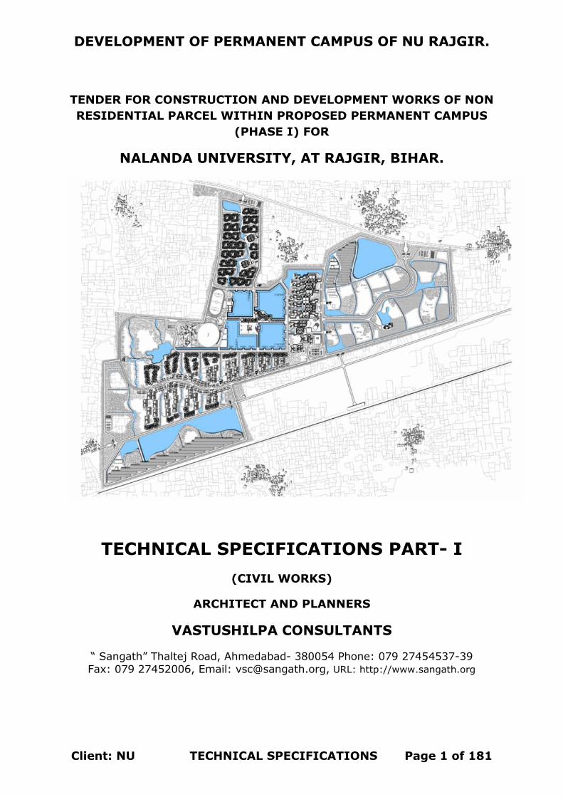
DEVELOPMENT OF PERMANENT CAMPUS OF NU RAJGIR.
Client: NU TECHNICAL SPECIFICATIONS Page 1 of 181
TENDER FOR CONSTRUCTION AND DEVELOPMENT WORKS OF NON RESIDENTIAL PARCEL WITHIN PROPOSED PERMANENT CAMPUS
(PHASE I) FOR
NALANDA UNIVERSITY, AT RAJGIR, BIHAR.
TECHNICAL SPECIFICATIONS PART- I (CIVIL WORKS)
ARCHITECT AND PLANNERS
VASTUSHILPA CONSULTANTS
“ Sangath” Thaltej Road, Ahmedabad- 380054 Phone: 079 27454537-39 Fax: 079 27452006, Email: [email protected], URL: http://www.sangath.org
DEVELOPMENT OF PERMANENT CAMPUS OF NU RAJGIR.
Client: NU TECHNICAL SPECIFICATIONS Page 2 of 181
TECHNICAL
SPECIFICATIONS PART-I
DEVELOPMENT OF PERMANENT CAMPUS OF NU RAJGIR.
Client: NU TECHNICAL SPECIFICATIONS Page 3 of 181
CONTENTS
SH. No. Name of Sub-Head
0.0 GENERAL
0.1 CARRIAGE OF MATERIALS
0.2 MORTARS 1.0 PILE WORK
2.0 EARTH WORK
3.0 CONCRETE WORK
4.0 REINFORCED CEMENT CONCRETE WORK
5.0 BRICK WORK
6.0 STONE WORK
7.0 MARBLE & GRANITE WORK
8.0 WOOD AND PVC WORK
9.0 STEEL WORK 10.0 FLOORING WORK
11.0 ROOFING 12.0 FINISHING WORK
13.0 WATER PROOFING WORK 14.0 MARKET RATE ITEMS
DEVELOPMENT OF PERMANENT CAMPUS OF NU RAJGIR.
Client: NU TECHNICAL SPECIFICATIONS Page 4 of 181
SUB HEAD: 0.0
GENERAL

DEVELOPMENT OF PERMANENT CAMPUS OF NU RAJGIR.
Client: NU TECHNICAL SPECIFICATIONS Page 5 of 181
GENERAL
0.1 Reference mentioned herein shall be applicable to all sections to the extent the context permits and are intended to supplement the provisions in the particular section. In case of any discrepancy/ deviation, the provisions in the particular section shall take precedence. 0.2 The rates for all items of work unless clearly specified otherwise shall include cost of all labour, materials and other inputs involved in the execution of the items. 0.3 INTERPRETATIONS 0.3.1 The Tender authority shall be the sole deciding authority as to the meaning, interpretation and implications for various provisions of the specifications. His decision in writing shall be final. 0.3.2 Wherever any reference is made to any Indian Standard, it shall be taken as reference to the latest edition with all amendments issued thereto. In the event of any variation between the detailed specifications and the Indian Standard, the former shall take precedence over the latter. 0.3.3 General Notes: All the works are to be carried out as per latest specifications of CPWD/MES/Indian Railways/State PWD, and relevant IS Codes unless otherwise specified in BOQ. Measurements of all the items of work will be done as per IS 1200 with its latest revisions, unless otherwise specified in BOQ or detailed specifications. In the absence of all the above three general engineering practice followed in construction industry or the local customs will be followed. Unless otherwise specified the rates of various items will be for all heights, leads and lifts. 0.4 DEFINITIONS The following terms and expressions in the specifications shall have the meaning or implication hereby assigned to them unless otherwise specified elsewhere. 0.4.1 Contractor: The Contractor shall mean the individual or firm or company whether incorporated or not, undertaking the works and shall include the legal personal representatives of such individual or the persons composing such firm or company, or the successors of such individual or firm or company and the permitted assignees of such individual or firm of company. 0.4.2 Engineer-in-Charge: The ‘Engineer-in-Charge’ means the person appointed by NU who shall supervise and be in-charge of the work.

DEVELOPMENT OF PERMANENT CAMPUS OF NU RAJGIR.
Client: NU TECHNICAL SPECIFICATIONS Page 6 of 181
0.4.3 Site: The ‘site’ shall mean the land/ or other places on, in, into or through which the work is to be executed under the contract or any adjacent land, path or street through which the work is to be executed under the contract, or any adjacent land, path or street which may be allotted or used for the purpose of carrying out the contract. 0.4.4 Store: The ‘store’ shall mean the place of issue of materials. 0.4.5 IS: The standards, specification and code of practices issued by the Bureau of Indian Standards. 0.4.6 Best: The word ‘best’ when used shall mean that in the opinion of the Tender Authority, there is no superior material/ article and workmanship obtainable in the market and trade respectively. As far as possible the standard required shall be specified in preference to the word ‘best’. 0.5 FLOOR AND LEVELS 0.5.1 Building 0.5.1.1 Floor 1 shall mean plinth level of respective area of individual building. The floors above floor 1 shall be numbered in sequence as floor 2, floor 3 and so on. The number shall increase upwards. 0.5.1.2 Floor level: For floor 1, top level of finished floor shall be the floor level and for all other floors above floor 1, top level of the structural slabs shall be the floor level.
0.5.1.3 Plinth level: Floor 1 level
0.5.2 Special Structures 0.5.2.1 For structures like retaining walls, wing walls, chimneys, overhead reservoirs/ tanks and other elevated structures, where elevations/ heights above a defined datum level have not been specified and identification of floors cannot be done as in case of building. Level, at 1.2 m above the ground level shall be the floor 1 level as well as plinth level. Level at a height of 3.5 m above floor 1 level will be reckoned as floor 2 level and level at a height of 3.5 m above the floor 2 level will be floor 3 level and so on, where the total height above floor 1 level is not a whole number multiple of 3.5 meter. Top most floor level shall be the next in sequence to the floor level below even if the difference in height between the two upper most floor levels is less than 3.5 meters 0.6 FOUNDATION AND PLINTH The work in foundation and plinth shall include: shall mean plinth level of respective area of individual building
(a) For buildings and basements: All works up to respective plinth level or up
DEVELOPMENT OF PERMANENT CAMPUS OF NU RAJGIR.
Client: NU TECHNICAL SPECIFICATIONS Page 7 of 181
to floor 1 level. (b) For abutments, piers and well staining: all works up to 1.2 m above
the bed level: (c) For retaining wall, wing walls, compound walls, chimneys, overhead
reservoirs/ tanks and other elevated structures: All works up to 1.2 meter above the formation ground level
(d) For reservoirs/ tanks (other than overhead reservoirs/ tanks): All works up to 1.2 meter above the formation ground level:
0.7 MEASUREMENTS 0.7.1 in booking dimensions, the order shall be consistent and in the sequence of length, width and height or depth or thickness. 0.7.2 Rounding off: Rounding off where required shall be done in accordance with IS: 2-1960. The number of significant places rounded in the rounded off value should be as specified. 0.8 MATERIALS 0.8.1 Samples of all materials to be used on the work shall be got approved by the contractor from the Engineer-in-Charge/Design consultant/Client well in time. The approved samples duly authenticated and sealed shall be kept in the custody of the Engineer-in-Charge till the completion of the work. All materials to be provided by the contractor shall be brand new and as per the samples approved by the Engineer-in-Charge. 0.8.2 Materials obtained by the contractor from the sources approved by the Client shall be subjected to the Mandatory tests. Where such materials do not conform to the relevant specifications, the matter shall be taken up by the Engineer-in-Charge for appropriate action against the defaulters. In all such cases, necessary documents in original and proof of payment relating to the procurement of materials shall be made available by the contractor to the Engineer-in-Charge. 0.8.3 Samples, whether submitted for approval to govern bulk supplies or required for testing before use and also the sample of materials bearing ‘Standard mark,’ if required for testing, shall be provided free of cost by the contractor. All other incidental expenditure to be incurred for testing of samples e.g. packaging, sealing transportation, loading, unloading etc. except testing charges shall be borne by the contractor. 0.8.4 The materials, supplied by the Client shall be deemed to be complying with the specifications. 0.8.5 Materials stored at site, depending upon the individual characteristics, sha l l be protected from atmospheric effects due to rain, sun, wind and
DEVELOPMENT OF PERMANENT CAMPUS OF NU RAJGIR.
Client: NU TECHNICAL SPECIFICATIONS Page 8 of 181
moisture to avoid deterioration. 0.8.6 Materials like timber, paints etc. shall be stored in such a way that there may not be any possibility of fire hazards. Inflammable materials and explosives shall be stored in accordance with the relevant rules and regulations or as approved by Engineer-in-Charge in writing so as to ensure desired safety during storage. 0.8.7 The unit weight of materials unless otherwise specified shall be reckoned as given in IS: 1911-1967. 0.9 SAFETY IN CONSTRUCTION 0.9.1 The contractor shall employ only such methods of construction, tools and plant as are appropriate for the type of work or as approved by Engineer-in-Charge in writing. 0.9.2 The contractor shall take all precautions and measures to ensure safety of works and workman and shall be fully responsible for the same. Safety pertaining to construction works such as excavation, centering and shuttering, trenching, blasting, demolition, electric connections, scaffolds, ladders, working platforms, gangway, mixing of bituminous materials, electric and gas welding, use of hoisting and construction machinery shall be governed by relevant safety codes and the direction of Engineer-in-Charge 0.10 ABBREVIATIONS The following abbreviations wherever they appear in the specifications, shall have the meaning or implication hereby assigned to them: Mm Millimeter Cm Centimeter M Meter Km Kilometer
Mm2/sqmm Square
Millimeter Cm2/sqcm Square
centimeter Dm2/sqdm Square
decimeter M2/sqm Square meter
Cm3/ cubic cm Cubic centimeter
Dm3/ cubic dm Cubic decimeter
M3/cum Cubic meter Ml Milliliter Kl Kiloliter
DEVELOPMENT OF PERMANENT CAMPUS OF NU RAJGIR.
Client: NU TECHNICAL SPECIFICATIONS Page 9 of 181
Gm Gram Kg Kilogram Q Quintal T Tonne Fps system Foot pound second system °C Degree Celsius temperature Fig Figure Re/Rs Rupee/ Rupees No Number Dia Diameter AC Asbestos cement CI Cast Iron GC Galvanized corrugated GP Galvanized plain GI Galvanized iron PVC Polyvinyl chloride RCC Reinforced cement concrete SW Stone ware SWG Standard wire Gauge
DEVELOPMENT OF PERMANENT CAMPUS OF NU RAJGIR.
Client: NU TECHNICAL SPECIFICATIONS Page 10 of
181
SUB HEAD: 0.1 CARRIAGE OF MATERIALS
Please refer to CPWD Specifications Volume I – 2009 Page No. 9 to 24
(with its latest corrections slips up to the date of submission of the tender).

DEVELOPMENT OF PERMANENT CAMPUS OF NU RAJGIR.
Client: NU TECHNICAL SPECIFICATIONS Page 11 of 181
SUB HEAD: 0.2 MORTARS
Please refer to CPWD Specifications Volume I – 2009 Page No.61 to 82 (with its latest corrections slips up to the date of submission of the Tender. Contractor shall strictly follow the procedure laid down in the above specifications for quality of Materials, Mixing of mortar and use of the same in various work heads like, Masonry, Flooring, and Plastering etc. Contractor shall also be responsible for ascertaining the quality of mortar through testing as specified in these specifications and as per relevant Indian Standards at specified frequency.
DEVELOPMENT OF PERMANENT CAMPUS OF NU RAJGIR.
Client: NU TECHNICAL SPECIFICATIONS Page 12 of 181
SUB HEAD: 1.0 PILE WORK
Please refer to Relevant Paras for Cast In Situ Bored Piles of CPWD Specifications Volume II – 2009 Page No.905 to 948 (with its latest corrections slips up to the date of submission of the Tender. Contractor shall strictly follow the procedure laid down in the above specifications for quality of Materials, Boring of Piles, Equipment to be used and Testing of Piles. Contractor shall also be responsible for ascertaining the Load Carrying capacities through Relevant Pile testing as specified in these specifications and as per relevant Indian Standards at specified frequency.
DEVELOPMENT OF PERMANENT CAMPUS OF NU RAJGIR.
Client: NU TECHNICAL SPECIFICATIONS Page 13 of 181
TERMINOLOGY Allowable Load: It is load which is applied to a pile after taking into account its ultimate load capacity, pile spacing, Overall bearing capacity of the ground, the allowable settlement, negative skin friction including reversal of loads.
Bearing Pile: A pile formed in the ground for transmitting load of a structure to the soil by the resistance developed at its tips and or along its surface. It is either vertical or batter pile. It may be ‘End bearing pile’ or friction pile if it supports the load primarily along the surface.
Board Compaction Pile: It is bored cast-in-situ with or without bulb. In this compaction of surrounding ground and freshly filled concrete in pile, bore is simultaneously achieved by suitable method. A pile with a bulb is called an “under-reamed bored compaction pile”. Under-reamed pile with more than one bulb is called Multi-under-reamed pile.
Constant Rate of Penetration (CRP) Test: The ultimate bearing capacity of preliminary piles and piles which are not used as working piles.
Constant Rate of Uplift (CRU) Test: The ultimate capacity in tension of preliminary piles and piles which are not used as working piles.
Cut of Level: It is the level where the installed pile is cut off to support the pile caps or beams.
Datum Bar: A rigid bar placed on immovable supports.
Draft Bolt: A metal rod driven into hole bored in timber, the hole being
smaller in diameter than the rod. Drop of Stroke: The distance through which
the driving weight is allowed to fall for driving the piles. Factor of Safety: It
is the ratio of the ultimate load capacity of a pile to the safe load of a pile.
Follower Tube: A tube which is used following the main casing tube and it requires to be extended further. The inner diameter of the follower tube should be the same as the inner diameter of casing. The follower tube shall preferably be an outside guide and should be water tight when driven in water- bearing strata or soft clays.
Initial Test: This test is carried out with a view to determine ultimate load capacity and safe load capacity.
Raker or Batter Pile: The pile which is installed at an angle to the vertical. Raker piles are normally provided where vertical piles cannot resist the required applied horizontal forces. The maximum rake to be permitted in piles shall not exceed –
1 in 8 for cast-in-situ piles of large diameter viz. 750 mm dia,. and above.
DEVELOPMENT OF PERMANENT CAMPUS OF NU RAJGIR.
Client: NU TECHNICAL SPECIFICATIONS Page 14 of 181
1 in 5 for smaller dia. cast-on-situ piles.
1 in 4 pre-cast piles. Routine Test: It is carried out with a view to check whether pile is capable of taking the working load assigned to it.
Safe Load: It is the load arrived at by applying a factor of safety to the ultimate load capacity of the pile.
Set: The net distance by which the pile penetrates in the ground due to stated number of blows of the hammer.
Spliced Pile: A pile composed of two or more lengths secured together, end to end to form one pile.
Test Pile: A pile which is selected for load testing and which is subsequently loaded for that purpose. This pile may form working pile itself if subjected to a routine load test with up to one and half time the safe load.
Total displacement (Gross): The total movement of the pile under a given load.
Total Elastic Displacement: This is the magnitude of the displacement of the pile due to rebound caused at the top after removal of given test load. This comprises two components as follows:
(a) Elastic displacement of the soil participating in load transfer; and (b) Elastic displacement of the pile shaft.
Trial Piles: These are installed initially to assess the load carrying capacity, it is either tested to ultimate bearing capacity or twice the estimated safe load.
Ultimate Load Capacity: The maximum load which a pile can carry before failure of ground (when the soil fails by shear) or failure of pile materials.
Working Load: It is a load assigned to a pile as per design.
Working Pile: It is a pile forming part of foundation of a structural system.
DEVELOPMENT OF PERMANENT CAMPUS OF NU RAJGIR.
Client: NU TECHNICAL SPECIFICATIONS Page 15 of 181
ITEM WISE SPECIFICATIONS OF PILE WORK
DSR Item No. 20.2.3 : Boring, providing and installing bored cast-in-situ reinforced cement concrete piles of grade M-25 of specified diameter and length below the pile cap, to carry a safe working load not less than specified, excluding the cost of steel reinforcement but including the cost of boring, with bentonite solution and temporary casing of appropriate length for setting out and removal of same and the length of the pile to be embedded in the pile cap etc. by percussion drilling using direct mud circulation (DMC) or Bailer and chisel technique by tripod and mechanical winch machine all complete, including removal of excavated earth with all lifts and leads (Length of pile for payment shall be measured up to bottom of pile cap). (a) : 450 mm dia piles DSR Item No. 20.2.4 : (b) 500 mm dia piles DSR Item No. 20.2.5 : (c) : 600 mm dia piles
Please refer to Para 20.2 BORED CAST-IN-SITU REINFORCED CONCRETE PILES from page no. 919 to page no. 926 of CPWD Specifications Volume II – 2009. DSR Item No. 20.2A.1 : Boring, providing and installation bored cast-in-situ reinforced cement concrete piles of grade M-25 of specified diameter and length below pile cap, to carry a safe working load not less than specified, excluding the cost of steel reinforcement but including the cost of boring with bentonite solution and temporary casing of appropriate length for setting out and removal of same and the length of the pile to be embedded in the pile cap etc. by Crawler mounted, telescopic boom hydraulic pilling Rig all complete, including removal of excavated earth with all its lifts and leads (length of pile for payment shall be measured up to bottom of pile cap).
Please refer to Para 20.2 BORED CAST-IN-SITU REINFORCED CONCRETE PILES from page no. 919 to page no. 926 of CPWD Specifications Volume II – 2009.
DSR Item No. 20.6.1.1 : Vertical load testing of piles in accordance with IS 2911 (Part IV) including installation of loading platform by Kentledge method and preparation of pile head or construction of test cap and dismantling of test cap after test etc. complete as per specification & the direction of Engineer in-charge. Note: 1. Initial and Routine Load Test shall not be carried out by Dynamic method of testing. Note: 2. Testing agency shall submit the design of loading platform for the approval of Engineer-in-charge.

DEVELOPMENT OF PERMANENT CAMPUS OF NU RAJGIR.
Client: NU TECHNICAL SPECIFICATIONS Page 16 of 181
(a) : Initial test (Test Load 2.5 times the safe capacity)
DSR Item No. 20.6.1.2 : (b) :Routine test (Test Load 1.5 times the safe capacity) DSR Item No. 20.6.2.1 : Single pile above 50 tonne and up to 100 tonne capacity
(a.1) : Initial test (Test Load 2.5 times the safe capacity)
DSR Item No. 20.6.2.2 : (b.1) :Routine test (Test Load 1.5 times the safe capacity)
DSR Item no. 20.8.1 : Lateral load testing of single pile in accordance with IS Code of practice IS : 2911 (Part IV) for determining safe allowable lateral load on pile : (a) :Up to 50 tonne capacity pile DSR Item no. 20.8.2 : (b) : Above 50 tonne and up to 100 tonne capacity pile DSR Item no. 20.9 : Integrity testing of Pile using Low Strain/ Sonic Integrity Test/ Sonic Echo Test method in accordance with IS 14893 including surface preparation of pile top by removing soil, mud, dust & chipping lean concrete lumps etc. and use of computerized equipment and high skill trained personal for conducting the test & submission of results, all complete as per direction of Engineer-in-charge. Please refer to Para 20.2 LOAD TEST ON PILES from page no. 935 to page no. 937 of CPWD Specifications Volume II – 2009.
DEVELOPMENT OF PERMANENT CAMPUS OF NU RAJGIR.
Client: NU TECHNICAL SPECIFICATIONS Page 17 of 181
SUB HEAD: 2.0 EARTH WORK
Please refer to CPWD Specifications Volume I – 2009 Page No.25 to 60 (with its latest corrections slips up to the date of submission of the Tender. Contractor shall strictly follow the procedure laid down in the above specifications for Classification of soils, equipment used for earth work in excavation and banking/trench or plinth fillings, transportation of earth and compaction of earth etc. The Earth shall be carried out following relevant safety codes. Before starting the work at site, the contractor shall take spot levels of entire area of site of work at the interval as directed by Engineer – in – Charge and record the same jointly with the representative of the Engineer – in – Charge. These records of levels will be used for all measurements of Earth work and deciding the various formation levels etc. The rates quoted also include for construction of temporary benchmarks, which shall be retained till the completion of the entire works. Whenever dewatering is required to be carried out because of rain water accumulated in excavated pits or because of ingress of any sub soil water or from any underground pipes etc. in to the pits, the contractor shall employ necessary pumping to bail out the water and to keep the pits free of water till the activities in that area is complete, without any extra cost. Earth filled in Trenches, Plinth or in Embankments shall be compacted and compacted manually, or with earth rammers, or with earth compactors or with vibratory rollers, so as to achieve minimum 95% proctor Density of compacted earth at OMC, within the quoted rates of relevant items. Contractor shall also produce Test results for compaction as per frequency specified in relevant Indian standards and as directed by Engineer – in – charge. Anti-termite treatment carried out for various buildings shall be guaranteed as specified in BOQ or NIT.
DEVELOPMENT OF PERMANENT CAMPUS OF NU RAJGIR.
Client: NU TECHNICAL SPECIFICATIONS Page 18 of 181
ITEM WISE SPECIFICATIONS OF EARTHWORK
DSR Item No. 2.1.1 : Earth work in surface excavation not exceeding 30 cm in depth but exceeding 1.5 m in width as well as 10 sqm on plan including disposal of excavated earth up to 50 m and lift up to 1.5 m, disposed soil to be levelled and neatly dressed : All kinds of soil 1SURFACE EXCAVATION Excavations exceeding 1.5 m in width and 10 sqm. on plan but not exceeding 30 cm. in depth in all types of soils and rocks shall be described as surface excavation and shall be done as specified in general specification of earthwork.
2Measurements The length and breadth shall be measured with a steel tape correct to the nearest cm. and the area worked out to the nearest two places of decimal in square meters. 3Rate Rate shall be as specified in general specification of earthwork.
DSR Item No. 2.6.1 : Earth work in excavation by mechanical means (Hydraulic excavator) / manual means over areas (exceeding 30 cm in depth, 1.5 m in width as well as 10 Sqm on plan) including disposal of excavated earth lead up to 50m and lift up to 1.5m, disposed soil to be levelled and neatly dressed : All kinds of soil EXCAVATION OVER AREA (ALL KINDS OF SOIL) 1 This shall comprise: (a) Excavation exceeding 1.5 m in width and 10 sum on plan and exceeding 30 cm in depth. (b) Excavation for basements, water tanks etc. (c) Excavation in trenches exceeding 1.5 m in width and 10 sqm on plan. 2 Excavation shall be done as specified in general specifications of earthwork. 3 Measurements shall be as specified in general specifications of earthwork. 4 Rates shall be as specified in general specifications of earthwork. DSR Item No. 2.8.1 : Earth work in excavation by mechanical means (Hydraulic excavator) / manual means in foundation trenches or drains
DEVELOPMENT OF PERMANENT CAMPUS OF NU RAJGIR.
Client: NU TECHNICAL SPECIFICATIONS Page 19 of 181
(not exceeding 1.5 m in width or 10 Sqm on plan) including dressing of sides and ramming of bottoms, lift up to 1.5m, including getting out the excavated soil and disposal surplus excavated soil as directed, within a lead of 50 m. All kinds of soil. 1 This shall comprise: (a) Excavation no t exceeding 1.5 m in width and 10 sqm on plan. (b) Excavation for foundation trenches. Etc. (c) Excavation in trenches not exceeding 1.5 m in width and 10 sqm on plan. 2 Excavation shall be done as specified in general specifications of earthwork. 3 Measurements shall be as specified in general specifications of earthwork. 4 Rates shall be as specified in general specifications of earthwork. DSR Item No. 2.3.1. : Banking excavated earth in layers not exceeding 20 cm in depth, breaking clods, watering, rolling each layer with 1⁄2 tonne roller, or wooden or steel rammers, and rolling every 3rd and top-most layer with power roller of minimum 8 tonnes and dressing up, in embankments for roads, flood banks, marginal banks, and guide banks etc., lead up to 50 m and lift up to 1.5 m : All kinds of soil. 1 Banking Excavated earth shall be done as specified in general specifications of earthwork. 2 Measurements shall be as specified in general specifications of earthwork and measurements of compacted earth compacted to proctor density of 95% at optimum moisture content will be considered for payment. 3 Rates shall be as specified in general specifications of earthwork except that banking excavated earth includes all lead & lift. DSR Item No. 2.4 : Deduct for not rolling with power roller of minimum 8 tonnes for banking excavated earth in layers not exceeding 20 cm in depth. The Item shall be operated for small areas only where it is not practically possible to do the compaction of earth by Power Roller. However the contractor shall do necessary compaction of earth through Manual Rammer, or Portable earth compactor. DSR Item No. 2.25 : Filling available excavated earth (excluding rock) in trenches, plinth, sides of foundations etc. in layers not exceeding 20cm in depth, compacting each deposited layer by ramming and watering, including all lead and lift.

DEVELOPMENT OF PERMANENT CAMPUS OF NU RAJGIR.
Client: NU TECHNICAL SPECIFICATIONS Page 20 of 181
FILLING IN TRENCHES, PLINTH, UNDER FLOOR ETC. 1.0 Earth Normally excavated earth from same area shall be used for filling. Earth used for filling shall be free from shrubs, rank, vegetation, grass, brushwood, stone shingle and boulders (larger than 75mm in any direction), organic or any other foreign matter. Earth containing deleterious materials, salt peter earth etc. shall not be used for filling. All clods and lumps of earth exceeding 8 cm in any direction shall be broken or removed before the earth is used for filling. 2.0 Filling The space around the foundations and drains in trenches shall be cleared of all debris, brick bats etc. The filling shall be done in layers not exceeding 20 cm in depth. Each layer shall be watered, rammed and compacted. Ramming shall be done with iron rammers where possible and with blunt end of crow bars where rammers cannot be used. Special care shall be taken to ensure that no damage is caused to the pipes, drains, masonry or concrete in the trenches. In case of filling under floor, the finished level of filling shall be kept to the slope intended to be given to the floor. 3.0 Measurements 3.0.1 Filling Side of Foundations: The cubical contents of bed concrete levelling course and masonry/ concrete in foundations up to the ground level shall be worked out and the same deducted from the cubical contents of earthwork in excavation for foundations already measured under the respective item of earth work to arrive at the quantity for filling sides of foundation. Quantity of Compacted earth shall be measured and paid for. The quantity shall be calculated correct to two places of decimal. 3.0.2 Filling in Plinth and under Floors: Depth of filling shall be the compacted depth. The dimensions of filling shall be on the basis of pre-measurement correct to the nearest cm and cubical content worked out in cubic meters correct to two places of decimal. 4.0 Rates The rates include cost of all the operations described above. DSR Item No. 2.26.1 : Extra for every additional lift of 1.5 m or part thereof in excavation / banking excavated or stacked materials. All kinds of soil. The excavation deeper than a depth of 1.5 and in every lift of 1.5 meter or part there of shall be measured under this item. The rates shall be extra over the item of Excavation under Item 2.002 and 2.003.
DEVELOPMENT OF PERMANENT CAMPUS OF NU RAJGIR.
Client: NU TECHNICAL SPECIFICATIONS Page 21 of 181
DSR Item No. 2.27 : Supplying and filling in plinth with Clean Coarse sand under floors, including watering, ramming, compacting and dressing complete, , including all lead and lift. SAND FILLING IN PLINTH 1.0 Sand Clean Coarse Sand as approved by Engineer –in – Charge and available in the area shall be free from dust organic and foreign matter and its grading shall be within the limits of grading zone IV or V. 2.0 Filling Sand filling shall be done in a manner similar to earth filling in plinth specified above except that compaction shall be done by flooding with water. The surface of the compacted sand filling shall be dressed to the required level or slope and shall not be covered till the Engineer-in-Charge has inspected and approved the sand filling. 3.0 Measurements The length, breadth and depth of compacted sand shall be measured with steel tape correct to the nearest cm and cubical contents after compact ion shal l be worked out in cubic meters correct to two places of decimal. 4.0 Rates The rates include the cost of material and labour involved in all the operations described above in general specifications of earthwork. DSR Item No. 2.36 : Deduct for disposed soil not levelled and neatly dressed. DSR Item No. 1.1.2 : Carriage of Earth (a) up to 1 km By Mechanical means including loading, unloading and stacking DSR Item No. 1.1.2 : Carriage of Earth (b) beyond 1 Km. and up to 2 km By Mechanical means including loading, unloading and stacking This item will operated for disposal of Earth up to 1 km. or part thereof or between 1.0 km. to 2.0 Km. as the case may be, beyond the initial lead mentioned in relevant items of Excavation. The Place of disposal shall be approved beforehand by the Engineer – in – Charge. The carriage and stacking of materials shall be done as directed by the Engineer-in-Charge. Any tools and plants, required for the work shall be arranged by the Contractor. 01.2 MODE OF CARRIAGE Depending upon the feasibility and economy, the Engineer-in-Charge shall
DEVELOPMENT OF PERMANENT CAMPUS OF NU RAJGIR.
Client: NU TECHNICAL SPECIFICATIONS Page 22 of 181
determine the mode of carriage viz. whether by mechanical or animal transport or manual labor. 01.3 LEAD 01.3.1 All distances shall be measured over the shortest practical route and not necessarily the route actually taken. Route other than shortest practical route may be considered in cases of unavoidable circumstances and as approved by Engineer-in-Charge along with reasons in writing. 01.3.3 Carriage by animal and mechanical transport shall be reckoned in one km unit. Distances of 0.5 km or more shall be taken as 1 km and distance of less than 0.5 km shall be ignored. However, when the total lead is less than 0.5 km, it will not be ignored but paid for separately in successive stages of 50 meters subject to the condition that the rate worked on this basis does not exceed the rate for initial lead of 1 km by mechanical/ animal transport. DSR Item No. 2.31 : Clearing jungle including uprooting of rank vegetation, grass, brush wood, trees and saplings of girth up to 30 cm measured at a height of 1m above ground level and removal of rubbish anywhere within the premises but outside the periphery of the area cleared, as directed by Engineer In Charge. JUNGLE CLEARANCE Jungle clearance shall comprise uprooting of rank vegetation, grass, brushwood, shrubs, stumps, trees and saplings of girth up to 30 cm measured at a height of one meter above the ground level. Where only clearance of grass is involved it shall be measured and paid for separately. 1 Uprooting of Vegetation The roots of trees and saplings shall be removed to a depth of 60 cm below ground level or 30 cm below formation level or 15 cm below sub-grade level, whichever is lower. All holes or hollows formed due to removal of roots shall be filled up with earth rammed and levelled. Trees, shrubs, poles, fences, signs, monuments, pipe lines, cable etc., within or adjacent to the area which are not required to be disturbed during jungle clearance shall be properly protected by the contractor at his own cost and nothing extra shall be payable. 2 Stacking and Disposal All useful materials obtained from clearing and grubbing operation shall be stacked in the manner as directed by the Engineer-in-Charge. Trunks and branches of trees shall be cleared of limbs and tops and stacked neatly at places indicated by the Engineer-in-Charge. The materials shall be the property of the Government. All unserviceable materials which in the opinion of the Engineer-in-Charge cannot be used or auctioned shall be removed up to any distance

DEVELOPMENT OF PERMANENT CAMPUS OF NU RAJGIR.
Client: NU TECHNICAL SPECIFICATIONS Page 23 of 181
outside the periphery of the area under clearance. It shall be ensured by the contractor that unserviceable materials are disposed of in such a manner that there is no likelihood of getting mixed up with the materials meant for construction. 3 Clearance of Grass Clearing and grubbing operation involving only the clearance of grass shall be measured and paid for separately and shall include removal of rubbish up to any distance outside the periphery of the area under clearance. 4 Measurements The length and breadth shall be measured correct to the nearest cm and area worked out in square meters correct to two places of decimal. 5 Rates The rate includes cost of all the operation described above. DSR Item No. 2.33.1 : Felling trees of the girth (measured at a height of 1 m above ground level), including cutting of trunks and branches, removing the roots and stacking of serviceable material and disposal of unserviceable material. (a) : Beyond 30 cm girth up to and including 60 cm girth DSR Item No. 2.33.2: (b) : Beyond 60 cm girth up to and including 120 cm girth DSR Item No. 2.33.3 : (c) : Beyond 120 cm girth up to and including 240 cm girth DSR Item No. 2.33.4 : (d) : Above 240 cm girth 1 Felling While clearing jungle, growth trees above 30 cm girth (measured at a height of one meter above ground level) to be cut, shall be approved by the Engineer-in-Charge and then marked at site. Felling trees shall include taking out roots up to 60 cm below ground level or 30 cm below formation level or 15 cm below sub-grade level, whichever is lower. All excavation below general ground level arising out of the removal of trees, stumps etc. shall be filled with suitable material in 20 cm layers and compacted thoroughly so that the surfaces at these points conform to the surrounding area. The trunks and branches of trees shall be cleared of limbs and tops and cut into suitable pieces as directed by the Engineer-in-Charge. 2 Stacking and Disposal Wood, branches, twigs of trees and other useful material shall be the property of the Government. The serviceable materials shall be stacked in the manner as directed by the Engineer-in-Charge up to any distance.
DEVELOPMENT OF PERMANENT CAMPUS OF NU RAJGIR.
Client: NU TECHNICAL SPECIFICATIONS Page 24 of 181
All unserviceable material, which in the opinion of Engineer-in-Charge cannot be used or auctioned shall be removed from the area and disposed of as per the directions of the Engineer-in-Charge. Care shall be taken to see that unsuitable waste materials are disposed of in such a manner that there is no likelihood of these getting mixed up with the materials meant for construction. 3 Measurements Cutting of trees above 30 cm in girth (measured at a height of one meter above level) shall be measured in numbers according to the sizes given below:
(a) Beyond 30 cm girth, up to and including 60cm girth.
(b) Beyond 60 cm girth, up to and including 120 cm girth. (c) Beyond 120 cm girth, up to and including 240 cm girth. (d) Above 240 cm girth.
DEVELOPMENT OF PERMANENT CAMPUS OF NU RAJGIR.
Client: NU TECHNICAL SPECIFICATIONS Page 25 of 181
SUB HEAD: 3.0 CONCRETE WORK
Please refer to Relevant Paras for Concrete Work of CPWD Specifications Volume I – 2009 Page No.83 to 112 (with its latest corrections slips up to the date of submission of the Tender. Contractor shall strictly follow the procedure laid down in the above specifications for quality of Materials like cement, aggregates, sand, water and concrete admixtures if any, Equipment to be used, procedures for Mixing and Placing of Concrete, curing of concrete etc. and Testing of Fresh concrete and concrete after it has set. Contractor shall establish full-fledged testing laboratory equipped with all necessary testing instruments, at site as directed by Engineer – in – Charge. Contractor shall also be responsible to produce the results of testing as specified in these specifications and as per relevant Indian Standards at specified frequency.
DEVELOPMENT OF PERMANENT CAMPUS OF NU RAJGIR.
Client: NU TECHNICAL SPECIFICATIONS Page 26 of 181
ITEM WISE SPECIFICATIONS OF CONCRETE WORK
DSR Item No. 4.1.10 : Providing and laying in position cement concrete of specified grade excluding the cost of centering and shuttering where payable as per general notes - All work up to plinth level : (a) : 1:5:10 (1 Cement : 5 coarse sand : 10 graded stone aggregate 20 mm nominal size) DSR Item No. 4.1.5 : (c ) :1:3:6 (1 Cement : 3 coarse sand : 6 graded stone aggregate 20 mm nominal size) (for encasing of pipe for road crossing and others) DSR Item No. 4.1.8 : (d) : 1:4:8 (1 Cement : 4 coarse sand : 8 graded stone aggregate 40 mm nominal size) 1.0 MATERIAL Water, cement, fine aggregate or sand, surkhi, and fly ash, coarse aggregates s h a l l be as specified in de ta i l e d spec i f i c a t i ons o f Conc re te works . 2.0 Proportions : Concrete shall be classified by different proportions of Cement : Fine aggregate : Coarse Aggregate. 3.0 The measurements shall be in Cum. 4.0 The rates shall include all the cost of all materials, labour for all operations of mixing, placing, finishing and curing of concrete and all the equipment required for the work.
DEVELOPMENT OF PERMANENT CAMPUS OF NU RAJGIR.
Client: NU TECHNICAL SPECIFICATIONS Page 27 of 181
SUB HEAD: 4.0 REINFORCED CEMENT CONCRETE
WORK
Please refer to Relevant Paras for Reinforced Cement Concrete Work of CPWD Specifications Volume I – 2009 Page No.113 to 200 (with its latest corrections slips up to the date of submission of the Tender. Contractor shall strictly follow the procedure laid down in the above specifications for quality of Materials like cement, aggregates, sand, water and concrete admixtures if any, Equipment to be used, procedures for Mixing, transporting and Placing of Concrete at desired location, curing of concrete etc. and Testing of Fresh concrete and concrete after it has set. All Concrete to be used for Reinforced Cement concrete will be of Designed mix only. The rates include for using minimum quantity of cement as specified for relevant design mix and use of Concrete admixture to achieve desired workability for the concrete. Contractor shall establish full-fledged testing laboratory equipped with all necessary testing instruments, at site as directed by Engineer – in – Charge. Contractor shall also be responsible to produce the results of testing as specified in these specifications and as per relevant Indian Standards at specified frequency. Contractor shall provide necessary scaffolding, Centering and Form work of approved quality as required as per detailed drawings and as directed by Engineer – in – Charge. The rates include for designing of form work required for special shapes as detailed and making all necessary safety arrangements as per relevant safety codes. The Reinforcement work includes, cutting, bending, placing and binding of reinforcement of approved quality as per detailed drawings and as directed by the Engineer – in – Charge. Necessary testing of Reinforcement as per relevant Indian Standards will have to be carried out at specified frequency within the quoted rates.

DEVELOPMENT OF PERMANENT CAMPUS OF NU RAJGIR.
Client: NU TECHNICAL SPECIFICATIONS Page 28 of 181
ITEM WISE SPECIFICATIONS FOR REINFORCED CEMENT CONCRETE WORK
DSR Item No. 5.9.1 : Centering and shuttering including strutting, propping etc. and removal of form for (a) : Foundations, footings, bases of columns, etc. for mass concrete as per drawing and as directed by engineer in charge. DSR Item No. 5.9.2 : (b) : Walls (any thickness) including attached pilasters, buttresses, plinth and string courses & kerb etc. DSR Item No. 5.9.3 : (c) : Suspended floors, roofs, landings, balconies and access platform including edges DSR Item No. 5.9.4 : (d) : Shelves (Cast in situ) DSR Item No. 5.9.5 : (e) : Lintels, beams, plinth beams, girders, bressumers and cantilevers DSR Item No. 5.9.6 : (f) : Columns, Pillars, Piers, Abutments, Posts and Struts DSR Item no. 5.9.7 : (g) : Stairs, (excluding landings) DSR Item No. 5.9.9 : (h) : Arches, domes, vaults up to 6 m span. DSR Item no. 5.9.10 : (i) : Extra for arches, domes, vaults exceeding 6 m span DSR Item No. 5.9.14 : (j) : Extra for shuttering in circular work DSR Item No.5.9.15 : (k) : Small lintels not exceeding 1.5 m clear span, moulding as in cornices, window sills, string courses, bands, copings, bed plates, anchor blocks and the like 1 Form Work The form work should be as per mentioned in 5.2.1 of CPWD specifications of Reinforced Cement Concrete work. 2 Design & Tolerance in Construction The form work should be as per mentioned in 5.2.2 of CPWD specifications of Reinforced Cement Concrete work. 3 General Requirement The form work should be as per mentioned in 5.2.3 of CPWD specifications of Reinforced Cement Concrete work. 4 Surface Treatment The form work should be as per mentioned in 5.2.4 of CPWD specifications of Reinforced Cement Concrete work. 5 Inspection of Form Work The form work should be as per mentioned in 5.2.5 of CPWD specifications of Reinforced Cement Concrete work.
DEVELOPMENT OF PERMANENT CAMPUS OF NU RAJGIR.
Client: NU TECHNICAL SPECIFICATIONS Page 29 of 181
6Measurements The form work should be as per mentioned in 5.2.6 of CPWD specifications of Reinforced Cement Concrete work. 7 Rate The form work should be as per mentioned in 5.2.7 of CPWD specifications of Reinforced Cement Concrete work. DSR Item No. 5.22.6 : Steel reinforcement for R.C.C. work including straightening, cutting, bending, placing in position and binding all complete up to plinth level. Thermo-Mechanically Treated bars TMT 500 D 1 General Requirements The general requirements of Item No. 5.22 should be as mentioned above in 5.3.1 of general specifications of Reinforced Cement Concrete Works. 2 Welding of Bars The Welding of bars should be as mentioned above in 5.3.2 of general specifications of Reinforced Cement Concrete Works. 3 Placing in Position The Positioning of steel should be as mentioned above in 5.3.3 of general specifications of Reinforced Cement Concrete Works.
4 Measurement The measurements should be as mentioned above in 5.3.4 of general specifications of Reinforced Cement Concrete Works. 5 Rate The rates should be as mentioned above in 5.3.5 of general specifications of Reinforced Cement Concrete Works. DSR Item No. 5.22A.6 : Steel reinforcement for R.C.C. work including straightening, cutting, bending, placing in position and binding all complete above plinth level. Thermo-Mechanically Treated bars TMT 500 D The relevant specifications should be as per mentioned in above Item except that the rate shall be paid separately for work above plinth level.
DEVELOPMENT OF PERMANENT CAMPUS OF NU RAJGIR.
Client: NU TECHNICAL SPECIFICATIONS Page 30 of 181
DSR Item No. 5.33.1 : Providing and laying in position concrete manufactured in fully automatic batching plant and transported to site of work in transit mixer for all leads, having continuous agitated mixer, or machine batched and machine mixed at site, design mix M-25 grade cement concrete for reinforced cement concrete work, using cement content as per approved design mix, including pumping of concrete to site of laying but excluding the cost of centering, shuttering, finishing and reinforcement, including admixtures in recommended proportions as per IS: 9103 to accelerate, retard setting of concrete, improve workability without impairing strength and durability as per direction of Engineer-in-charge. (Note :- Cement content considered in this item is @ 330 kg/cum. (a) : All works up to plinth level DSR Item No. 5.33.2 : (b) : All works above plinth level up to Floor V level. Refer following section - Para 5.4 Page 135 to 144 for Nominal Mix, Para 5.8 on Page 147 to 149 for Design Mix concrete, Para 5.9 on Page 149 to Page 157 for Ready Mix Concrete and Para 5.10 on Page 157 for Placing of concrete of CPWD Specifications for Reinforced Cement Concrete work . A CONCRETING 1 Consistency 2 Placing of Concrete 3 Compaction 4 Construction joints 5 Expansion Joints 6 Curing 7 Finishing 8 Strength of Concrete 9 Testing of Concrete 10 Standard of Acceptance – for Nominal Mix 11 Measurements 12 Tolerances 13 Rate Para 5.8 DESIGN MIX Definition 1 Mix Design and Proportioning 2 Standard Deviation 3 Acceptance Criteria 4 Cement Content of Concrete 5 Water cement Ratio and slump 6 Approval of Design Mix
DEVELOPMENT OF PERMANENT CAMPUS OF NU RAJGIR.
Client: NU TECHNICAL SPECIFICATIONS Page 31 of 181
C READY MIXED CONCRETE (as per IS 4926) 1 Materials 2 General Requirements 3 Sampling and Testing of Ready-Mixed Concrete 4 Information to be supplied by the Purchaser 5 Information to be supplied by the Producer
6 Production and Delivery 7 Quality Control 8 Order Processing 9 Records D PLACING CONCRETE BY PUMPING 1 General 2 Pumping Equipment’s DSR Item No. 5.34.1 : Extra for providing richer mixes M-30 grade concrete instead of M-25 grade BMC/ RMC at all floor levels. (Note:- Cement content considered in M-30 is @ 340 kg/cum) Relevant specifications of concreting described above shall be followed except that for M-30 grade concreting extra rate over M-25 grade concreting shall be measured and paid for separately. DSR Item No. 5.34.2 : Providing M-35 grade concrete instead of M-25 grade BMC /RMC. (Note : Cement content considered in M-35 is @ 350 kg/cum) Relevant specifications of concreting described above shall be followed except that for M-35 grade concreting extra rate over M-25 grade concreting shall be measured and paid for separately. DSR Item No. 5.34.3 : Providing M-40 grade concrete instead of M-25 grade BMC /RMC.(Note : Cement content considered in M-40 is @ 360 kg/cum) Relevant specifications of concreting described above shall be followed except that for M-40 grade concreting extra rate over M-25 grade concreting shall be measured and paid for separately. DSR Item No. 5.35 : Add for using extra cement in the items of design mix over and above the specified cement content therein.

DEVELOPMENT OF PERMANENT CAMPUS OF NU RAJGIR.
Client: NU TECHNICAL SPECIFICATIONS Page 32 of 181
DSR Item No. 5.38 : Extra for R.C.C./ B.M.C/ R.M.C. work above floor V level for each four floors or part thereof. DSR Item No. 5.42.1 : Providing and fixing tapered / parallel threaded couplers conforming to IS code on “Reinforcement Couplers for Mechanical Splices of Bars for Concrete Reinforcement - Specification”, to reinforcement bars including threading, enlargement at connection by forging, protecting the prepared reinforcement bars and related operations as required to complete the works per direction of Engineer-in-Charge. (The length of the bars in which coupler is to be provided should not be less than 4 meter, no deduction for labour and binding wire saved for not providing lap length shall be made). (a) : Coupler for 16 mm diameter reinforcement bar DSR Item No. 5.42.2 : (b) :Coupler for 20 mm diameter reinforcement bar DSR Item No. 5.42.3 : (c) :Coupler for 25 mm diameter reinforcement bar DSR Item No. 5.42.4 : (d) :Coupler for 28 mm diameter reinforcement bar DSR Item No. 5.42.5 : (e) :Coupler for 32 mm diameter reinforcement bar
1. Material
This item comprising of Providing and fixing tapered / parallel threaded couplers conforming to IS code on “Reinforcement Couplers for Mechanical Splices of Bars for Concrete Reinforcement - Specification”, to reinforcement bars including threading, enlargement at connection by forging, protecting the prepared reinforcement bars and related operations as required to complete the works per direction of Engineer-in-Charge. (The length of the bars in which coupler is to be provided should not be less than 4 meter, no deduction for labour and binding wire saved for not providing lap length shall be made).
2. Measurements: Couplers shall be measured in unit of Numbers.
3.Rate The rate shall include the cost of material supply of labour, tools, adhesive material fixing and equipment required for placing. DSR Item N. 4.43.2 : Providing and fixing in position Stainless steel Grade 304 plate-1.0 mm thick as per design for expansion joints. (a) : 300 mm wide. Above item comprising of Providing and fixing in position Stainless steel Grade 304 plate-1.0 mm thick & 200 mm or 300 mm wide as per design for expansion joints. Method of Application
DEVELOPMENT OF PERMANENT CAMPUS OF NU RAJGIR.
Client: NU TECHNICAL SPECIFICATIONS Page 33 of 181
200mm wide SS 304 grade plate 1 mm thick shall be fixed after levelling as per surrounding flooring area and plate to be fixed with adhesive as per directed by engineer - in – charge. The expansion joint shall be cleaned and made dry completely. All loose materials shall also be removed.
Disturbed edges of R.C.C. members near expansion joints shall be finished with rich mortar without any extra work includes providing required width of expansion board in the joints and measurement of expansion board only shall be taken.
Measurements All work shall be measured correct to a cm. The length of the Stainless steel Grade 304 plate shall be measured in running meters corrected up to a cm. Rate The rate shall include the cost of material and labor involved in all the operations described above. DSR Item No. 5.44.1 : Providing and fixing of expansion joint system related with floor location as per drawings and direction of Engineer-In-Charge. The joints system will be of extruded aluminum base members, self-aligning / self centering arrangement and support plates etc. as per ASTM B221-02. The system shall be such that it provides floor to floor /floor to wall expansion control system for various vertical location in load application areas that accommodates multi directional seismic movement without stress to its components. System shall consist of metal profiles with a universal aluminum base member designed to accommodate various project conditions and finish floor treatments. The cover plate shall be designed of width and thickness required to satisfy projects movement and loading requirements and secured to base members by utilizing manufacturer’s pre-engineered self-centering arrangement that freely rotates / moves in all directions. The Self – centering arrangement shall exhibit circular sphere ends that lock and slide inside the corresponding aluminum extrusion cavity to allow freedom of movement and flexure in all directions including vertical displacement. Provision of Moisture Barrier Membrane in the Joint System to have watertight joint is mandatory requirement all as per the manufactures design and as approved by Engineer -in- Charge. (Material shall confirm to ASTM 6063.) (a) Floor Joint 100 mm Gap (Horizontal) DSR Item No. 5.44.2 : (b) Floor Joint 150 mm Gap (Horizontal)
MATERIAL The joints system will be of extruded aluminum base members, self-aligning / self centering arrangement and support plates etc. as per ASTM B221-02. The system shall be such that it provides floor to floor /floor to wall expansion control system for various vertical location in load application areas that accommodates multi
DEVELOPMENT OF PERMANENT CAMPUS OF NU RAJGIR.
Client: NU TECHNICAL SPECIFICATIONS Page 34 of 181
directional seismic movement without stress to its components. System shall consist of metal profiles with a universal aluminum base member designed to accommodate various project conditions and finish floor treatments. The cover plate shall be designed of width and thickness required to satisfy projects movement and loading requirements and secured to base members by utilizing manufacturer’s pre-engineered self-centering arrangement that freely rotates / moves in all directions. The Self – centering arrangement shall exhibit circular sphere ends that lock and slide inside the corresponding aluminum extrusion cavity to allow freedom of movement and flexure in all directions including vertical displacement. Provision of Moisture Barrier Membrane in the Joint System to have watertight joint is mandatory requirement all as per the manufactures design and as approved by Engineer -in- Charge. (Material shall confirm to ASTM 6063.)" MEASUREMENTS All work shall be measured correct to a cm. The length of the Non-asbestos fiber cement board shall be measured in running meters corrected up to a cm. RATE The rate shall include the cost of material and labour involved in all the operations described above.
DSR Item No. 5.45.1 : Providing and fixing of expansion joint system related with wall joint (internal/external) location as per drawings and direction of Engineer-In- Charge. The joints shall be of extruded aluminum base members, self-aligning / centering arrangement and support plates as per ASTM B221- 02. The material shall be such that it provides an Expansion Joints System suitable for vertical wall to wall/ wall to corner application, both new and existing construction in office Buildings & complexes with no slipping down tendency amongst the components of the Joint System. The Joint System shall utilize lightweight aluminum profiles exhibiting minimal exposed aluminum surfaces mechanically snap locking the multicellular to facilitate movement. (Material shall confirm to ASTM 6063.) (a) Wall Joint 100 mm Gap (Vertical) DSR Item No. 5.45.2 : (b) Wall Joint 150 mm Gap (Vertical) MATERIAL The joints shall be of extruded aluminum base members, self-aligning / centering arrangement and support plates as per ASTM B221- 02. The material shall be such that it provides an Expansion Joints System suitable for vertical wall to wall/ wall to corner application, both new and existing construction in office Buildings & complexes with no slipping down tendency amongst the components of the Joint System. The Joint System shall utilize lightweight aluminum profiles exhibiting minimal exposed aluminum surfaces mechanically snap locking the multicellular to facilitate movement. (Material shall confirm to ASTM 6063.)"
MEASUREMENTS All work shall be measured correct to a cm.
DEVELOPMENT OF PERMANENT CAMPUS OF NU RAJGIR.
Client: NU TECHNICAL SPECIFICATIONS Page 35 of 181
The length of the 250 mm expansion joint shall be measured in running meters corrected up to a cm. RATE The rate shall include the cost of material and labor involved in all the operations described
DEVELOPMENT OF PERMANENT CAMPUS OF NU RAJGIR.
Client: NU TECHNICAL SPECIFICATIONS Page 36 of 181
SUB HEAD: 5.0 BRICK WORK
Please refer to Relevant Paras for Brick Work of CPWD Specifications Volume I – 2009 Page No.201 to 236 (with its latest corrections slips up to the date of submission of the Tender. Contractor shall strictly follow the procedure laid down in the above specifications for quality of Materials like cement, sand, Bricks, water etc., scaffolding, Brick Masonry bonds, curing of works etc. and Testing of Materials etc.

DEVELOPMENT OF PERMANENT CAMPUS OF NU RAJGIR.
Client: NU TECHNICAL SPECIFICATIONS Page 37 of 181
ITEM WISE SPECIFICATIONS FOR BRICK WORK
DSR Item No. 6.1.2 : Brick work with common burnt clay F.P.S. (non modular) bricks of 230 mm x 110 mm x 75 mm class designation 7.5 in foundation and plinth in: Cement mortar 1:6 (1 cement : 6 coarse sand) Refer following sections - List of Mandatory tests Page 205, Para 6.1 Page 214, Para 6.2 on Page 219 of CPWD Specifications for Brick work . Refer BRICKS/BRICK TILES/BRICK BATS/MECHANIZED AUTOCLAVE FLY ASH LIME BRICK 1.0 Material Bricks used in the masonry may be of the following type. (a) The Common Burnt Clay 1.1 Dimensions
1.2 Classification 1.3 Sampling and Tests 1.5 Burnt Clay Perforated Building Bricks 1.5.1 General Quality: 1.5.2 Dimensions and Tolerances: 1.5.3 Perforations 1.5.4 Compressive Strength: 1.5.5 Water Absorption: 1.5.6 Efflorescence 1.5.7 Warpage: 2 BRICK WORK 2.1 Classification 2.2 Mortar 2.3 Soaking of Bricks 2.4 Laying 2.5 Joints 2.6 Curing 2.7 Scaffolding 2.8 Measurements 2.9 Rate
DEVELOPMENT OF PERMANENT CAMPUS OF NU RAJGIR.
Client: NU TECHNICAL SPECIFICATIONS Page 38 of 181
DSR Item No. 6.4.2 : Brick work with common burnt clay F.P.S. (non modular) bricks of class designation 7.5 in superstructure above plinth level up to floor V level in all shapes and sizes in : Cement mortar 1:6 (1 cement : 6 coarse sand) The relevant specification shall be as per the above item of brickwork except that the work is to be done in superstructure above plinth level for all levels in all shapes and sizes.
DSR Item No. 6.13.2 : Half brick masonry with common burnt clay F.P.S. (non modular) bricks of class designation 7.5 in superstructure above plinth level up to floor V level in Cement mortar 1:4 (1 cement :4 coarse sand)
HALF BRICK WORK
Brick work in half brick walls shall be done in the same manner as described above in brickwork except that the bricks shall be laid in stretcher bond. The mortar interposed between the reinforcement bars and the brick shall not be less than 5 mm. The mortar covering in the direction of joints shall not be less than 15 mm. 1 Measurements The length and height of the wall shall be measured correct to a cm. The area shall be calculated in sq.m. where half brick wall is joined to the main walls of one brick or greater thickness and measurements for half brick wall shall be taken for its clear length from the face of the thicker wall. 2 Rate The rate includes the cost of the materials and labour involved in all the operations described above. DSR Item No. 6.23 : Honey-comb brick work 10 / 11.4 cm thick with common burnt clay bricks of class designation 7.5 in super structure above plinth level up to floor V level in cement mortar 1:4 (1 cement : 4 coarse sand).
The honeycomb brick work shall be done with specified class of brick, laid in specified mortar. All joints and edges shall be struck flush to give an even surface. The thickness of the brick honeycomb work shall be as specified in drawing. Openings shall be as specified in drawing.
DEVELOPMENT OF PERMANENT CAMPUS OF NU RAJGIR.
Client: NU TECHNICAL SPECIFICATIONS Page 39 of 181
The length and height shall be measured correct to a cm. Area shall be calculated in square meters correct to two places of decimal. Honeycomb openings shall not be deducted. The rate includes the cost of all materials, equipment, labour, carting, loading & unloading, removal of debris to local specified within the site, involved in all the operations described above.
DSR Item No. 6.44 : Brick edging 7cm wide 11.4 cm deep to plinth protection with common burnt clay F.P.S. (non modular) bricks of class designation 7.5 including grouting with cement mortar 1:4 (1 cement : 4 fine sand).
Refer following sections - Para 6.13 Page 225, of CPWD Specifications for Brick work.
1 Bricks 2 Mortar 3 Base Concrete 4 Soaking of Bricks 5 Laying 6 Joints
7 Curing 8 Dry Brick Flooring 9 Measurements 10 Rate DSR Item No. 6.38 : Providing and laying autoclaved aerated cement blocks masonry with 100 mm thick AAC blocks in super structure above plinth level up to floor V level in cement mortar 1:4 (1 cement : 4 coarse sand ). The rate includes providing and placing in position 2 Nos 6 mm dia M.S. bars at every third course of masonry work.
DSR Item No. 6.5 : Extra for brick work / AAC block masonry / Tile brick masonry in superstructure above floor V level, for each four floors or part thereof by mechanical means.
DSR Item No. 6.14 : Extra for half brick masonry in superstructure, above floor V level for every four floors or part thereof by mechanical means.
DEVELOPMENT OF PERMANENT CAMPUS OF NU RAJGIR.
Client: NU TECHNICAL SPECIFICATIONS Page 40 of 181
SUB HEAD: 6.0 STONE WORK
Please refer to Relevant Paras for Stone Work of CPWD Specifications Volume I – 2009 Page No.237 to 272 (with its latest corrections slips up to the date of submission of the Tender. Contractor shall strictly follow the procedure laid down in the above specifications for quality of Materials like cement, sand, various types of stones, water etc., scaffolding, laying of stone in Masonry, flooring , cladding etc., curing of works and Testing of Materials etc.
DEVELOPMENT OF PERMANENT CAMPUS OF NU RAJGIR.
Client: NU TECHNICAL SPECIFICATIONS Page 41 of 181
ITEM WISE SPECIFICATIONS FOR STONE WORK
DSR Item No. 7.1. : Random rubble masonry with hard stone in foundation and plinth including levelling up with cement concrete 1:6:12 (1 cement: 6 coarse sand : 12 graded stone aggregate 20 mm nominal size) up to plinth level with : Cement mortar 1:6 (1 cement : 6 coarse sand) DSR Item No. 7.8.1 : Coursed rubble masonry with hard stone (first or second sort) in superstructure above plinth level and upto floor five level. Masonry work (first sort) , in cement mortar 1:6 (1 cement : 6 coarse sand) DSR Item No. 7.32.1: Stone work, plain in copings, cornices, string courses and plinth courses, upto 75 mm thick in Cement mortar 1:6 (1 cement : 6 coarse sand), including pointing with white cement mortar 1:2 (1 white cement : 2 stone dust) with an admixture of pigment matching the stone shade. - Red Sandstone DSR Item No. 7.33.1 : Providing and fixing stone jali 40 mm thick throughout in cement mortar 1:3 (1 cement : 3 coarse sand), including pointing in white cement mortar 1:2 (1 white cement : 2 stone dust) with an admixture of pigment, matching the stone shade, jali slab without any chamfers etc. Red sand stone
DEVELOPMENT OF PERMANENT CAMPUS OF NU RAJGIR.
Client: NU TECHNICAL SPECIFICATIONS Page 42 of 181
SUB HEAD: 7.0 MARBLE & GRANITE WORK
Please refer to Relevant Paras for Stone Work of CPWD Specifications Volume I – 2009 Page No.273 to 290 (with its latest corrections slips up to the date of submission of the Tender. Contractor shall strictly follow the procedure laid down in the above specifications for quality of Materials like cement, sand, Granite stones, water etc., scaffolding, laying of Granite stone in flooring, Skirting, platforms cladding etc., curing of works and Testing of Materials etc.

DEVELOPMENT OF PERMANENT CAMPUS OF NU RAJGIR.
Client: NU TECHNICAL SPECIFICATIONS Page 43 of 181
ITEM WISE SPECIFICATIONS FOR GRANITE WORK DSR Item No. 8.2.2.2 : Providing and fixing 18 mm thick gang saw cut, mirror polished, premoulded and prepolished, machine cut for kitchen platforms, vanity counters, window sills , facias and similar locations of required size, approved shade, colour and texture laid over 20 mm thick base cement mortar 1:4 (1 cement : 4 coarse sand), joints treated with white cement, mixed with matching pigment epoxy touch ups, including rubbing, curing, moulding and polishing to edges to give high gloss finish etc. complete at all levels. (a) : Granite of any colour and shade Area of slab over 0.50 Sqm DSR Item No. 8.3.2 : Providing edge moulding to 18 mm thick marble stone counters, Vanities etc., including machine polishing to edge to give high gloss finish etc. complete as per design approved by engineer in charge. (a) : Granite work
DSR Item No. 8.5 : Extra for providing opening of required size & shape for wash basin/ kitchen sink in kitchen platform, vanity counter and similar location in marble/Granite/stone work, including necessary holes for pillar taps etc. including moulding, rubbing and polishing of cut edges etc. complete. DSR Item No. 8.12 : Providing and laying flamed finish Granite stone flooring in required design and patterns, in linear as well as curvilinear portions of the building all complete as per the architectural drawings with 18 mm thick stone slab over 20 mm (average) thick base of cement mortar 1:4 (1 cement : 4 coarse sand) laid and jointed with cement slurry and pointing with white cement slurry admixed with pigment of matching shade including rubbing, curing and polishing etc. all complete as specified and as directed by the Engineerin-Charge :
(a) Flamed finish granite stone slab Jet Black, Cherry Red, Elite Brown, Cat Eye or equivalent.
Please refer to Para 8.0, 8.1, 8.2, 8.7, etc. of CPWD Civil Works Specifications 2009 Volume I, for relevant items of work.
DEVELOPMENT OF PERMANENT CAMPUS OF NU RAJGIR.
Client: NU TECHNICAL SPECIFICATIONS Page 44 of 181
SUB HEAD: 8.0 WOOD AND PVC WORK
Please refer to Relevant Paras for Stone Work of CPWD Specifications Volume I – 2009 Page No.291 to 392 (with its latest corrections slips up to the date of submission of the Tender. Contractor shall strictly follow the procedure laid down in the above specifications for quality of Materials like wood, glass, ply wood, laminates, veneers, non-asbestos cement boards, wire mesh, hardware, gules and adhesives etc. to be used for doors, windows, partitions, and other related works and Testing of Materials etc. Wood to be used in the work shall be well seasoned timber having minimum of moisture content as required as per relevant Indian Standards, and the quality of wood shall be as specified in the BOQ. The joinery for various components shall be as per detailed drawings and as directed by the Engineer – in – Charge.

DEVELOPMENT OF PERMANENT CAMPUS OF NU RAJGIR.
Client: NU TECHNICAL SPECIFICATIONS Page 45 of 181
ITEM WISE SPECIFICATIONS FOR WOOD WORK
DSR Item No. 9.1.1 : Providing wood work in frames of doors, windows, clerestory windows and other frames, wrought framed and fixed in position with hold fast lugs or with dash fasteners of required dia & length ( hold fast lugs or dash fastener shall be paid for separately).
(a) : Second class teak wood
The relevant specification as per Para 9.3 along with its sub para, of CPWD Civil works specifications 2009 Vol.1, shall be followed for frames of doors, windows, ventilators etc. The frames shall be measured in volume of teak wood used in the making of frames and shall be paid in the unit of Cum. DSR Item no. 9.7.1 : Providing and fixing paneling or paneling and glazing in paneled or paneled and glazed shutters for doors, windows and clerestory windows (Area of opening for panel inserts excluding portion inside grooves or rebates to be measured). Paneling for paneled or paneled and glazed shutters 25 mm to 40 mm thick:
(a) : Second class teak wood panels- 25 mm thick
DSR Item No. 9.7.7.2 : (b) : Float glass panes 5.0 mm thick glass panes DSR Item No.: 9.7.8 (c) : Fly proof stainless steel grade 304 wire gauge with 0.5 mm dia. wire and 1.4 mm wide aperture with matching wood beading The relevant specification as per Para 9.2 along with its sub para, of CPWD Civil works specifications 2009 Vol.1, shall be followed for the Paneling Materials viz, Teak wood panels, Marin ply panels, Gloat glass panels, wire mesh (Wire Gauze) etc. Para 9.6.4 along with its sub paras refers to the fixing of Panels in shutter frames.
Measurements For paneling of each type or for glazed panel length and width of opening for panels inserts or glazed panels shall be measured correct to a cm before fixing the beading and the area shall be calculated to the nearest 0.01 sq.m. The portions of the panel inserts or glazed panel inside the grooves or rebates shall not be measured for payment.
Rates
Panels shall be measured in square meters and rates shall include all operations involved in the work.
DEVELOPMENT OF PERMANENT CAMPUS OF NU RAJGIR.
Client: NU TECHNICAL SPECIFICATIONS Page 46 of 181
DSR Item No. 9.21.1+9.23-9.15.1.1: Providing and fixing ISI marked flush door shutters conforming to IS : 2202 (Part I) non-decorative type, core of block board construction with frame of 1st class hard wood and well matched commercial 3 ply veneering with vertical grains or cross bands and face veneers on both faces of shutters, lipping with 2nd class teakwood battens 25 mm minimum depth on all edges of flush door shutters :
(a) : 35 mm thick excluding ISI marked Stainless Steel butt hinges with necessary screws
DSR Item No. 9.21.2+9.23-9.15.1.1: (b) : 30 mm thick excluding ISI marked Stainless Steel butt hinges with necessary screws
The relevant specification as per Para 9.7 along with its sub para, of CPWD Civil works specifications 2009 Vol.1 shall be followed for the Flush door shutters. Testing of Flush door shutters shall be carried out as per para 9.7.10.
DSR Item No. 9.22.1 : Extra for Providing and fixing flush doors with decorative veneering instead of non-decorative ISI marked flush door shutters conforming to IS: 2202 (Part I) (a) : On one side only Decorative face veneers shall conform to type I decorative plywood in IS 1328. Combined Thickness of Face veneer and cross bands shall be 3.0 mm. Decorative veneer shall be fixed to Flush shutters by gluing under hot press with suitable BWP adhesive. Decorative Veneers shall be measured in square meters and rates shall include all operations including cost of materials and labour components.
DSR Item No. 9.127 : Providing & Fixing decorative high pressure laminated sheet of plain / wood grain in gloss / matt / suede finish with high density protective surface layer and reverse side of adhesive bonding quality conforming to IS : 2046 Type S, including cost of adhesive of approved quality.
(a) :1.0 mm thick on one side only
Decorative high pressure laminates shall conform to thermosetting synthetic resin bonded laminated sheets as per IS 2046. Decorative laminate shall be fixed to Flush shutters by gluing under hot press with suitable BWP adhesive. Decorative Laminates shall be measured in square and rates shall include all operations including cost of materials and labour components
DSR Item No. 9.84 : Providing and fixing aluminium extruded section body tubular type universal hydraulic door closer (having brand logo with

DEVELOPMENT OF PERMANENT CAMPUS OF NU RAJGIR.
Client: NU TECHNICAL SPECIFICATIONS Page 47 of 181
ISI, IS : 3564, embossed on the body, door weight upto 36 kg to 80 kg and door width from 701 mm to 1000 mm), with double speed adjustment with necessary accessories and screws etc. complete.
Please refer General Specifications for door closers as per Para 9.15.22 of the CPWD Civil works specifications 2009 Volume 1.
DSR Item No. 21.4.1 : Providing and fixing double action hydraulic floor spring of approved brand and manufacture conforming to IS : 6315, having brand logo embossed on the body / plate with double spring mechanism and door weight upto 125 kg, for doors, including cost of cutting floors, embedding in floors as required and making good the same matching to the existing floor finishing and cover plates with brass pivot and single piece M.S. sheet outer box with slide plate etc. complete as per the direction of Engineer-in-charge. With stainless steel cover plate minimum 1.25 mm thickness
The hydraulic floor spring shall be heavy duty double action floor spring of make approved by the Engineer-in-Charge suitable for door leaf of weight minimum 100 kg. The top cover plate shall be of stainless steel, flushing with floor finish level. The contractor shall cut the floor properly with stone cutting machine to exact size & shape. The spindle of suitable length to accommodate the floor finish shall be used. The contractor shall give the guarantee duly supported by the company for proper functioning of floor spring at least for 10 years. Measurement: The hydraulic floor spring as describe in item shall be measured in numbers. Rate:
DEVELOPMENT OF PERMANENT CAMPUS OF NU RAJGIR.
Client: NU TECHNICAL SPECIFICATIONS Page 48 of 181
The rate shall include the cost of all materials and labour involved in all the operations described above.
DSR Item No. 21.8.1. : Filling the gap in between aluminium frame & adjacent RCC/ Brick/ Stone work by providing weather silicon sealant over backer rod of approved quality as per architectural drawings and direction of Engineer-in-charge complete.
Upto 5mm depth and 5 mm width
DEVELOPMENT OF PERMANENT CAMPUS OF NU RAJGIR.
Client: NU TECHNICAL SPECIFICATIONS Page 49 of 181
SUB HEAD: 9.0 STEEL WORK
Please refer to Relevant Paras for Steel Work of CPWD Specifications Volume I – 2009 Page No.393 to 442 (with its latest corrections slips up to the date of submission of the Tender. Contractor shall strictly follow the procedure laid down in the above specifications for quality of Materials like Structural Steel sections and M.S. pipes, M.S. Tubular sections, Nuts, Bolts, Rivets, Welding Electrodes, Rolling shutters, Bearings, Springs, Stainless steel pipes and sections, Glass, Primer etc. and Testing of Materials etc. Strength parameters of various materials shall be as per relevant Indian Standards, and the quality of materials shall be as specified in the BOQ. The joinery for various components shall be as per detailed drawings and as directed by the Engineer – in – Charge.
DEVELOPMENT OF PERMANENT CAMPUS OF NU RAJGIR.
Client: NU TECHNICAL SPECIFICATIONS Page 50 of 181
ITEM WISE SPECIFICATIONS FOR STEEL WORK DSR Item no. 10.6.1 : Supplying and fixing rolling shutters of approved make, made of required size M.S. laths, interlocked together through their entire length and jointed together at the end by end locks, mounted on specially designed pipe shaft with brackets, side guides and arrangements for inside and outside locking with push and pull operation complete, including the cost of providing and fixing necessary 27.5 cm long wire springs manufactured from high tensile steel wire of adequate strength conforming to IS: 4454 - part 1 and M.S. top cover of required thickness for rolling shutters. (a) : 80x1.25 mm M.S. laths with 1.25 mm thick top cover DSR Item No. 10.7 : Providing and fixing ball bearing for rolling shutters. DSR Item No. 10.8.1 : Extra over DSR item No. 10.6.1 for providing mechanical device chain and crank operation for operating rolling shutters.
(a) : Exceeding 10.00 sqm and up to 16.8 sqm in the area
DSR Item no. 10.9 : Extra over DSR item No. 10.6.1 for providing grilled rolling shutters manufactured out of 8 mm dia M.S. bar instead of laths as per design approved by Engineer-in- charge,(area of grill to be measured). Please refer to Para 10.8, 10.9, of CPWD Civil works specifications 2009 Volume 1 for detailed specifications of rolling shutters. DSR Item No. 10.16.1 : Steel work in built up tubular ( round, square or rectangular hollow tubes etc.) trusses etc., including cutting, hoisting, fixing in position and applying a priming coat of approved steel primer, including welding and bolted with special shaped washers etc. complete. Hot finished welded type tube. Please refer to Para 10.13, of CPWD Civil works specifications 2009 Volume 1 for detailed specifications of rolling shutters DSR Item No. 10.25.1 : Steel work welded in built up sections/ framed work including cutting, hoisting, fixing in position and applying a priming coat of approved steel primer using structural steel etc. as required.
(a) : In stringers, treads, landings etc. of stair cases, including use of chequered plate wherever required, all complete
DSR Item No. 10.25.2 : (b) : In gratings, frames, guard bar, ladder, railings, brackets, gates, and similar works.
DEVELOPMENT OF PERMANENT CAMPUS OF NU RAJGIR.
Client: NU TECHNICAL SPECIFICATIONS Page 51 of 181
Please refer to Para 10.17, of CPWD Civil works specifications 2009 Volume 1 for detailed specifications of Stringers, landings, staircase railings, grating, guard bars, safety grills, ladders, gates and similar works. DSR Item No. 10.19 : Providing and fixing mild steel round holding down bolts with nuts and washer plates complete. Holding down bolts and foundation bolts shall be made out of Mild steel round bars and shall have standard threads in minimum 100 mm length at exposed end. The other end of the holding down bolt shall be bent in a hook or “L” as shown on the drawings. Holding down bolts shall be firmly anchored and fixed in concrete foundation/ Colum heads/beam heads over which the equipment/ truss/ structural steel beams/columns are to be erected. Anchorage length of the holding down bolt/foundation bolts shall be as required for development of bond between the bolt and concrete foundations. Necessary washers and Nuts of required thickness and sizes shall be used to fix the structural members with the foundation bolts. Weight of the foundation bolts only, without considering the weight of nuts and washers shall be measured and paid for. Rates include for all materials and labour for all operations of fixing the bolts using M.S. template of suitable size and with bolt holes in true alignment and level as per detailed drawings and as directed by Engineer – in – Charge. DSR Item No. 10.26.1 : Providing and fixing hand rail of approved size by welding etc. to steel ladder railing, balcony railing, staircase railing and similar works, including applying priming coat of approved steel primer.
(a) : M.S. tube
Please refer to Para 10.18, of CPWD Civil works specifications 2009 Volume 1 for detailed specifications of handrails of staircase and balcony railings etc. DSR Item No. 10.27.2 : Providing and fixing carbon steel galvanized ( minimum coating 5 micron) dash fastener of 10 mm dia double threaded 6.8 grade (yield strength 480 N/mm2), counter sunk head, comprising of 10 m dia polyamide PA 6 grade sleeve, including drilling of hole in frame , concrete/ masonry, etc. as per direction of Engineer-in-charge.
(a) :10 x 120 mm DSR Item No. 10.27.2 : (b) :10 x 80 mm
Use light duty universal door/window fixing anchors HRD HR2 or equivalent of 10 mm dia. (120 mm long or 80 mm long as the case may be). The anchor should be made of polyamide sleeve PA6 grade and stainless steel A2 Grade.
Measurements

DEVELOPMENT OF PERMANENT CAMPUS OF NU RAJGIR.
Client: NU TECHNICAL SPECIFICATIONS Page 52 of 181
Measurements for the dash fastener shall be in number.
Rate
The rate shall include the cost of all materials and labor involved in all the operation described above.
DSR Item No. 10.28 : Providing and fixing stainless steel ( Grade 304) railing made of Hollow tubes, channels, plates etc., including welding, grinding, buffing, polishing and making curvature (wherever required) and fitting the same with necessary stainless steel nuts and bolts complete, i/c fixing the railing with necessary accessories & stainless steel dash fasteners , stainless steel bolts etc., of required size, on the top of the floor or the side of waist slab with suitable arrangement as per approval of Engineer-in-charge, ( for payment purpose only weight of stainless steel members shall be considered excluding fixing accessories such as nuts, bolts, fasteners etc.). Stailess Steel Fabrication Work This specification covers all stainless steel work of grade 304 and steel based composite items like pergola, gazebo, hand-rails, fencing, columns, frames, louvers, etc. All stainless steel work shall conform to relevant Indian Standards. Stainless Steel Components All stainless steel items shall be conforming to Indian Standards. Stainless steel items shall be supplied with a brushed hairline finish. All stainless steel fixings and fittings shall conform to relevant Indian Standards or equivalent International Standards. Stainless steel supplied shall be of minimum 304 grade. Regular Cutting Cutting shall be carried out via mechanical or heat powered tools. Maximum permissible variation shall be 5 millimeters for all cuts. All cut areas shall be ground to a smooth surface using mechanical grinder. CNC Precision Cutting and Engraving Computerized numerical controlled precision cutting and engraving shall be carried out on areas shown in contract drawings or as directed by EIC. This process shall be carried out by entering computerized drawings into a computer controlled laser based CNC cutting and engraving machine. Samples shall be approved by EIC before entire process is carried out. Maximum permissible variation shall be one millimeter. All cut areas shall be ground to a smooth surface using precision mechanical grinders only if required. Welding Joints
DEVELOPMENT OF PERMANENT CAMPUS OF NU RAJGIR.
Client: NU TECHNICAL SPECIFICATIONS Page 53 of 181
Welding joints shall be to relevant Indian Standards for material, processes and workmanship. All welds are required to be ground smooth to the approval of the EIC. All sharp edges shall be ground smooth as per directions of EIC. Bending Bending of Stainless steel sections shall be undertaken to provide smooth and true curves. Tightly curved and bent sections shall be free from all distortions and rippling. All sharp edges shall be ground smooth. Fixings and Fastenings Generally, the Contractor shall provide a sample of all fixings and fastenings to the EIC for approval. These shall include but not be limited to beams, columns, hinges, locks, nuts and bolts, nails and screws, cables, wire and tensioners. Surface Finishes on Stainless Steel Stainless steel work shall be finished matt or glossy as specified in contract drawings using mechanical finishing and grinding tools. Finish should be level and smooth with an even pattern as directed and approved by EIC. Measurement Stainless steel items shall be measured in kilograms of finished items (excluding all wastage), accurate to the nearest 100 grams. Rates shall include cutting, welding and workmanship, as well as nuts, bolts, fasteners, etc. accessories required for installing the item.

DEVELOPMENT OF PERMANENT CAMPUS OF NU RAJGIR.
Client: NU TECHNICAL SPECIFICATIONS Page 54 of 181
SUB HEAD: 10.0 FLOORING WORK
Please refer to Relevant Paras for Flooring Work of CPWD Specifications Volume I – 2009 Page No.443 to 480 (with its latest corrections slips up to the date of submission of the Tender. Contractor shall strictly follow the procedure laid down in the above specifications for quality of Materials like Bricks for flooring, Concrete, Kotah stones, Red Mandana stones, Rough kotah stone, sand stones, Bundi stone, Dholpur stone, Ceramic Glazed tiles, Rectified Ceramic tiles, Vitrified tiles, Endura Vitrified tiles, Terracotta tiles, Glazed terracotta tiles, Terracotta pavers, Red Mandana stone pavers and cobbles, concrete pavers etc. vinyl flooring, and Testing of Materials etc. Quality of materials and the polishing, texture etc. for various stones, tiles and pavers/cobbles shall be the best as specified in the BOQ and as approved by Engineer – in – Charge. Contractor shall submit the samples of all the flooring materials well in advance and get approval from Engineer – in – Charge before actually procuring the materials. Sizes of various stones and tiles shall be as required for the flooring to be laid to the pattern as per the detailed drawings and as directed. The flooring laid shall be Finished/polished smooth or otherwise as per the texture required according to relevant items of BOQ and as directed by the Engineer – in – Charge. There shall be no undulations and offsets between adjoining stones/tiles, what so ever in any kind variety of flooring.
DEVELOPMENT OF PERMANENT CAMPUS OF NU RAJGIR.
Client: NU TECHNICAL SPECIFICATIONS Page 55 of 181
ITEM WISE SPECIFICATIONS FOR FLOORING WORK
DSR Item No. 11.1.2 : Brick on edge flooring with bricks of class designation 7.5 on a bed of 12 mm cement mortar, including filling the joints with same mortar, with common burnt clay non modular bricks: 1:6 (1cement : 6 coarse sand). Please refer para 11.1 – Brick on Edge Flooring of CPWD specifications for Civil works 2009 Volume 1. DSR Item No. 11.3.1 : Cement concrete flooring 1:2:4 (1 cement : 2 coarse sand : 4 graded stone aggregate) finished with a floating coat of neat cement, including cement slurry, but excluding the cost of nosing of steps etc. complete 40 mm thick with 20 mm nominal size stone aggregate Please refer para 11.2 Cement Concrete Flooring of CPWD specifications for Civil works 2009 Volume 1. DSR Item No. 11.26.1 : Kota stone slab over 20 mm (average) thick base laid over and jointed with grey cement slurry mixed with pigment to match the shade of the slab, including rubbing and polishing complete with base of cement mortar 1 : 4 (1 cement : 4 coarse sand)
(a) 25 mm thick
Please refer para 11.2 Cement Concrete Flooring of CPWD specifications for Civil works 2009 Volume 1. DSR item No. 11.27 : Kota stone slabs 20 mm thick in risers of steps, skirting, dado and pillars laid on 12 mm (average) thick cement mortar 1:3 (1 cement: 3 coarse sand) and jointed with grey cement slurry mixed with pigment to match the shade of the slabs, including rubbing and polishing complete. Please refer para 11.21 Kota stone flooring of CPWD specifications for Civil works 2009 Volume 1. DSR Item no. 8.6 : Extra for Mirror polishing over normal polishing of marble work/Granite work/stone work where ever required to give high gloss finish complete. Polishing
DEVELOPMENT OF PERMANENT CAMPUS OF NU RAJGIR.
Client: NU TECHNICAL SPECIFICATIONS Page 56 of 181
After completion of the simple polishing the grinding shall be carried out using carborundum stone grade 500 to 2000 in successive order and final finishing with emery of grade 2000
Measurements Length shall be measured along the finished face of skirting or dado correct to a cm. This shall be measured correct to a mm in the case of skirting and correct to a cm in the case of dado. The area shall be calculated in square meter correct to two places of decimal. DSR Item No. 11.31 : Extra for pre finished nosing in treads of steps of Kota stone/ sand stone slab.
DSR Item No. 11.32 : Extra for Kota stone/ sand stone in treads of steps and risers using single length up to 1.05 metre.
DSR Item No. 11.36 : Providing and fixing Ist quality ceramic glazed wall tiles conforming to IS: 15622 (thickness to be specified by the manufacturer), of approved make, in all colours, shades except burgundy, bottle green, black of any size as approved by Engineer-in-Charge, in skirting, risers of steps and dados, over 12 mm thick bed of cement mortar 1:3 (1 cement : 3 coarse sand) and jointing with grey cement slurry @ 3.3kg per sqm, including pointing in white cement mixed with pigment of matching shade complete.
Please refer para 11.18 Pressed Ceramic tiles in skirting and dado of CPWD specifications for Civil works 2009 Volume 1. DSR Item no. 11.37 : Providing and laying Ceramic glazed floor tiles of size 300x300 mm (thickness to be specified by the manufacturer) of 1st quality conforming to IS : 15622 of approved make in colours such as White, Ivory, Grey, Fume Red Brown, laid on 20 mm thick cement mortar 1:4 (1 Cement : 4 Coarse sand), including pointing the joints with white cement and matching pigment etc., complete.
Please refer para 11.18 Pressed Ceramic tiles in skirting and dado of CPWD specifications for Civil works 2009 Volume 1.
DSR Item 11.53 : Providing and fixing Glass mosaic tiles at finished plain wall surface of size 20 mm x 20 mm x 4 mm in all colour, design , fixing in customize design as per direction of Engineer-in- Charge. The Glass mosaic tiles to be fixed on the wall surface with the help of approved adhesive applied at the rate of 2.5 kg per Sqm and grouting of the same. The rate is inclusive of all operation, material and required pattern approved by Engineer-in-Charge:
DEVELOPMENT OF PERMANENT CAMPUS OF NU RAJGIR.
Client: NU TECHNICAL SPECIFICATIONS Page 57 of 181
The tiles shall be of best quality and approved make. They shall be flat, and true to shape and free from blisters crazing, chips, welts, crawling or other imperfections detracting from their appearance. The tiles shall be square or rectangular of nominal size 20mmx 20mm & Thickness shall be 4 mm specified by the manufacturer. It includes the profiles on the visible face and on the rear side.
Preparation of Surface and Laying
Base plaster on which the tiles are to be fixed shall be cleaned, wetted and mopped.
Dado to be laid with adhesive. The plaster or flooring work shall be thoroughly cleaned and checked for undulations, if any, shall be rectified with cement mortar 1:3 (1 cement: 3 coarse sand).
High polymer modified quick set tile adhesive (conforming to IS 15477) shall be thoroughly mixed with water and a paste of zero slump shall be prepared so that it can be used within 1.5 to 2 hours. It shall be spread over an area not more than one sqm at one time. Average thickness of adhesive shall be 3 mm the adhesive so spreaded shall be combed using suitable trowel. Tiles shall be pressed firmly in to the position with slight twisting action checking it simultaneously to ensure good contact gently being tapped with wooden mallet till it is properly backed with adjoining tiles.
316mmX 316mm sheet size with the joint gap of 1.0 mm (approx.) pasted on a plastic adhesive film of 1st class quality confirming of approved make shall be fixed within 20 minutes of application of adhesive. The surplus adhesive from the joints, surface of the tiles shall be immediately cleaned.
The surface of the flooring or dado shall be frequently checked during laying with straight edge of above 2m long so as to attain a true surface with required slope.
Where full size tile cannot be fixed these shall be cut (sawn) to the required size and edges rubbed smooth to ensure straight and true joints.
Curing and Finishing
The day after the tiles are laid, plastic adhesive film shall be removed and all joints shall be cleaned of the grey cement grout with a wire brush or trowel to a depth of 2 mm and all dust and loose mortar removed and cleaned. Joints shall then be grouted with epoxy grout grey or white with or without pigment to match the shape of the topping of the wearing layer of the tiles.
Testing required:
i) Water Absorption
ii) Thermal Shock Resistance
iii) Scratch Hardness of Surface on Mohs scale
DEVELOPMENT OF PERMANENT CAMPUS OF NU RAJGIR.
Client: NU TECHNICAL SPECIFICATIONS Page 58 of 181
Measurements Length and breadth shall be measured correct to a cm before fixing skirting, dado or wall plaster and the area calculated in square meter correct to two places of decimal. Where coves are used at the junctions, the length and breadth shall be measured between the lower edges of the coves.
No deduction shall be made for voids not exceeding 0.20 square meter. Rate The rate for flooring or dado shall include the cost of all materials and labour involved in all the operations described above DSR Item 11.41.2 : Providing and laying vitrified floor tiles in different sizes (thickness to be specified by the manufacturer) with water absorption less than 0.08% and conforming to IS : 15622, of approved make, in all colours and shades, laid on 20mm thick cement mortar 1:4 (1 cement : 4 coarse sand), including grouting the joints with white cement and matching pigments etc., complete.
(a) : Size of Tile 600x600 mm
DSR Item No. 11.41.3 : (b) : Size of Tile 800x800 mm
1 Operations as described in above ceramic flooring tiles shall be followed except the vitrified tiles shall conform to Table 12 of IS 15622 (Tiles with water absorption E ≤ 0.08 per cent Group BIa) and the joint thickness in flooring shall not be more than 1mm. 2 Rate The rate for flooring shall include the cost of all materials and labour involved in all the operations described above. Nothing extra shall be paid for the use of cut (sawn) tiles in the work. DSR item No. 11.46.2 : Providing and laying Vitrified tiles in different sizes (thickness to be specified by manufacturer), with water absorption less than 0.08 % and conforming to I.S. 15622, of approved make, in all colours & shade, in skirting, riser of steps, over 12 mm thick bed of cement mortar 1:3 (1 cement: 3 coarse sand), including grouting the joint with white cement & matching pigments etc. complete.
(a) : Size of Tile 600x600 mm
DSR Item No. 11.46.3 : (b) : Size of Tile 800x800 mm
1 Operations as described above in flooring and skirting shall be followed except the tiles shall conform to Table 12 of IS 15622 (Tiles with water absorption E ≤
DEVELOPMENT OF PERMANENT CAMPUS OF NU RAJGIR.
Client: NU TECHNICAL SPECIFICATIONS Page 59 of 181
0.08 per cent Group BIa) and the joint thickness in flooring shall not be more than 1mm. 2 Rate The rate for skirting, riser of steps shall include the cost of all materials and labour involved in all the operations described above. Nothing extra shall be paid for the use of cut (sawn) tiles in the work. DSR no. 11.33.1 : Providing and fixing 25 mm wooden planking, tongued and grooved in flooring, including fixing with iron screws complete. (a) Second class teak wood Please refer para 11.25 Wooden flooring of CPWD specifications for Civil works 2009 Volume 1. DSR Item No. 11.45 : Providing and laying 500x500x40 mm thick Turf paver (Turfpave XD) on 150 mm thick sub grade of compacted bed of 20 mm thick nominal size stone aggregate and base course and filling with 150 mm thick sand, including spreading, well ramming, compacting and finishing smooth etc. all complete as per direction of Engineer-in-charge.
Turf pavers shall be 40 mm thick as per approved design. Turf pavers shall be laid over a bed of 150 mm thick well compacted subgrade of 20 mm thick stone aggregates. The sub grade shall be laid over a bed of sand of thickness of 150 mm.
The measurements shall in square meter of area of paver laid. Rate shall include the cost for all materials and the cost of labour for all operations described above.
DSR Item No. 16.68 : Providing and laying 60mm thick factory made cement concrete interlocking paver block of M -30 grade made by block making machine with strong vibratory compaction, of approved size, design & shape, laid in required colour and pattern over and including 50mm thick compacted bed of coarse sand, filling the joints with fine sand etc. all complete as per the direction of Engineer-in-charge.
Material
Concrete Pavers For pedestrian areas, concrete pavers should be Precast and cured paver blocks of 60mm thickness, ±2mm tolerance in dimensions and flatness, min. compressive strength 300 kg/sq cm, made from materials conforming to IS standards.
Sand Bedding

DEVELOPMENT OF PERMANENT CAMPUS OF NU RAJGIR.
Client: NU TECHNICAL SPECIFICATIONS Page 60 of 181
Sand bedding shall be done on 150 mm thick sub grade of compacted bed of 20 mm thick nominal size stone aggregate The paving blocks are indicated in the Contract Drawings to be bedded on sand (flexible paving). This material shall be naturally occurring sand or shall consist of crushed rock or gravel or a combination thereof with naturally occurring sand, hard, clean, free from all adherent coatings. It shall comply in all respects with relevant Indian Standards or MORTH code and be well graded down from 5mm. The moisture content of the laying course should be as uniform as possible and at or about its optimum. Where material is to be stockpiled it should be covered. The laying course should be such that, after compaction, it forms a nominally uniform layer, 50mm thick, below the pavers. It shall be laid in accordance with either of the following alternative methods:- The material should be spread loose in a uniform layer and screeded to a thickness required to give nominal 50mm layer after completion of the paving. OR The material should be spread in a loose, uncompacted layer to approximately 2/3 of the required final thickness. This layer should be lightly compacted by means of a vibrating plated compactor. A further layer of loose material should be spread and screeded to create a loose surface on to which the units can be placed. Care should be taken to avoid localized disturbance of the prepared laying course sand by pedestrian or wheeled traffic prior to placing units. The area of laying course prepared should be such that the position of its boundary is not more than one meter from the position of the laying face at the end of the working period wherever practicable.
Joints in Flexible Paving Joints are to be 2mm when placed hand-tight. Pavers shall be laid working from an existing laying face edge or edge restraint. Full pavers should be laid first; closure units should then be laid. The area to be laid should be completed as far as is possible in entire paver units. Wherever possible, infilling to boundaries and obstructions should proceed as the laying of the surface course proceeds and infilling should be completed before compaction commences. Mechanical force shall not be used to obtain tight joints. For flexible paving sand shall be brushed into the joints until they are filled to the top surface of the paving blocks. Sand for joint filling should be dry with a minimum particle size no greater than 1.18mm containing about 10% by weight passing a 0.75mm sieve. Sand color shall be agreed with EIC prior to brushing into joints. The Contractor shall allow for cutting units to achieve laying to curves (without opening up joints).
Laying Pavers
The units shall be laid to the patterns shown in the drawings. Special paver shapes designed to assist with the formation of boundaries and with changes in direction may be incorporated with the approval of the EIC.
Cutting Pavers
Paving blocks requiring cutting shall be cut using a diamond blade bench saw to give an acceptable quality edge to the satisfaction of the EIC and prior to general cutting taking place on site. Pavers shall be cut to form, neat junctions/boundaries
DEVELOPMENT OF PERMANENT CAMPUS OF NU RAJGIR.
Client: NU TECHNICAL SPECIFICATIONS Page 61 of 181
with other paving materials/kerbs, street furniture, etc. Fillets of colour matched mortar in lieu of small pieces of unit paving shall be avoided where possible and only be used with the approval of the EIC. Paving blocks showing a jagged or irregular edge will be rejected by the EIC and must be replaced to the satisfaction of the EIC all at the Contractors expense. Care shall be taken to avoid placing more than one cut kerb and/or paver unit in close proximity to another cut unit at junctions/changes of direction of paving. The Contractor must allow for the periodic replacement of blades in cutting equipment to ensure clean cut edges to paving units.
Mixing Pavers Where there is a colour variation between batches of pavers the Contractor is to ensure that pavers are mixed to avoid patterning in paved areas and this shall be to the approval of the EIC. Where patterning occurs the Contractor shall lift, mix and relay the pavers to the EIC's approval.
Compaction of Flexible Paving Pavers on sand bed shall be subjected to passes of a steel-faced vibrating-plate compactor to adequately compact the laying course and to bed and regulate the paving blocks. The vibrating-plate compactor shall have a centrifugal force of 16-20KN, a plate area of 0.35-0.5 sq m and a frequency of 75-100Hz. Enough passes shall be made to compact the paving course and produce an even surface. All trimming should be completed before the area is compacted. Compaction should follow laying as soon as possible but should not be carried out within 1m of the laying edge. Apart from this edge strip no area of paving should be left without being compacted at the completion of the days' work. The EIC's approval must be obtained if compaction is not to be completed at the end of the day's work.
Finished Levels Finished levels of the paving units shall not deviate by more than 2mm against adjacent units whilst the deviation from the design profile measured under a 3m straight edge should not exceed 10mm. The units shall form neat junctions with and prevent damage to adjacent work.
Cleaning on Completion of Work On completion the face of the units must be clear of all dust, rust and other stains, adhering mortar and other droppings. Any units from which stains cannot be removed shall be replaced at the Contractors expense and be to the approval of the EIC. Flexible paving surfaces are to be brushed down with a soft bristle brush with joints refilled with sand where required. The paved areas must be left in a neat and tidy condition to the satisfaction of the EIC.
Additional technical specifications for precast concrete paver blocks
Raw Materials - Cement
The cement used in the manufacture of high quality precast concrete paving block shall be conforming to IS 12269 (53 grade) ordinary Portland cement or IS 8112 (43 grade ordinary Portland cement). The minimum cement content in concrete used for making paver blocks should be 380 kg/cu.m.
DEVELOPMENT OF PERMANENT CAMPUS OF NU RAJGIR.
Client: NU TECHNICAL SPECIFICATIONS Page 62 of 181
Raw Materials - Aggregates
The fine and coarse aggregates shall consist of naturally occurring crushed or uncrushed materials which apart from the grading requirements comply with IS 383-1970. The fine aggregates used shall contain a minimum of 25 % natural silicon sand. Lime stone aggregates shall not be used. Aggregates shall contain no more than 3 % by weight of clay and shall be free from deleterious salts and contaminants.
Raw Materials - Water
The water shall be clean and free from any deleterious matter. It shall meet the requirements stipulated in IS: 456-2000.
Other materials
Any other material/ingredients used in the concrete shall conform to latest IS specifications.
Paver blocks characteristics
•The concrete pavers should have perpendicularities after release from the mould and the same should be retained until the laying.
•The surface should be of anti-skid and anti-glare type.
•The paver should have uniform chamfers to facilitate easy drainage of surface run off.
•The pavers should have uniform interlocking space of 2 mm to 3 mm to ensure compacted sand filling after vibration on the paver surface.
•The concrete mix design should be followed for each batch of materials separately and automatic batching plant is to be used to achieve uniformity in strength and quality.
•The pavers shall be manufactured in single layer only.
•Skilled labour should be employed for laying blocks to ensure line and level for laying, desired shape of the surface and adequate compaction of the sand in the joints.
•The pavers are to be skirted all round with kerbing using solid concrete or stone kerbs or as directed by the EIC. The kerbing should be embedded for minimum 100 mm depth.
Laying - Priming
It will be the responsibilities of the contractors to ensure that the manhole/pipeline cable trenches/circular drainage system etc. raised / lowered to finish paving level using the requisite materials as per instruction of Engineer. The areas of

DEVELOPMENT OF PERMANENT CAMPUS OF NU RAJGIR.
Client: NU TECHNICAL SPECIFICATIONS Page 63 of 181
potholes/deep depressions at the isolated locations also have to be filled up before laying the paver blocks. No extra pavements will be made for this purpose.
It will be the responsibility of the contractor to ensure that undulations on the paver’s blocks are eliminated after the traffic is allowed on it. Proper slope for drainage of water needs to be ensured by the Contractor. All necessary materials, tools, tackles are required to be arranged by the Contractor.
Laying - Bedding sand course
The bedding sand shall consist of clean well graded sand passing through 4.75 mm sieve and suitable for concrete. The bedding should be from either a single source or blended to achieve the following grading;
Sieve size% Passing
9.5 mm100
4.75 mm95-100
2.36 mm80-100
1.18 mm60-100
600 microns25-60
300 microns10-30
150 microns5-15
75 microns0-10
Contractor shall be responsible to ensure that single-sized, gap-graded sands or sands containing an excessive amount of fines or plastic fines are not used. The sand particles should preferably be sharp (not rounded) as sharp sand possess higher strength and resist the migration of sand from under the block to less frequency areas even though sharp sands are relatively more difficult to compact than rounded sands, the use of sharp sands is preferred for the more heavily trafficked driveways. The sand used for bedding shall be free of any deleterious soluble salts or other contaminants likely to cause efflorescence.
The sand shall be of uniform moisture content and within 4 % - 8 % when spread and shall be protected against rain when stock piled prior to spreading. Saturated sand shall not be used. The bedding sand shall be spread loose in a uniform layer as per drawing. The compacted uniform thickness shall be of 45 mm and within +/- 5 mm. Thickness variation shall not be used to correct irregularities in the base course surface.
The spread sand shall be carefully maintained in a loose dry condition and protected against pre-compaction both prior to and following screeding. Any pre-
DEVELOPMENT OF PERMANENT CAMPUS OF NU RAJGIR.
Client: NU TECHNICAL SPECIFICATIONS Page 64 of 181
compacted sand or screeded sand left overnight shall be loosened before further laying of paving blocks take place.
Sand shall be slightly screeded in a loose condition to the predetermined depth only slightly ahead of the laying of paving unit.
Any depressions in the screeded sand exceeding 5 mm shall be loosened, raked and rescreeded before laying of paving blocks.
Laying of interlocking paver blocks
Paver blocks shall be laid in pattern specified in drawing throughout the pavement. Once the laying pattern has been established, it shall continue without interruption over the entire pavement surface. Cutting of blocks, the use of infill concrete or discontinuities in laying pattern is not to be permitted in other than approved locations.
Paver blocks shall be placed on the uncompacted screeded sand bed to the nominated laying pattern, care being taken to maintain the specified bond throughout the job. The first row shall be located next to an edge restraint. Specially manufactured edge paving blocks are permitted or edge blocks may be cut using a power saw, a mechanical or hydraulic guillotine, bolster or other approved cutting machine.
Paver blocks shall be placed to achieve gaps nominally 2 to 3 wide between adjacent paving joints. No joint shall be less than 1.5 mm not more than 4 mm. Frequent use of string lines shall be used to check alignment. In this regard the “laying face” shall be checked at least every two meters as the face proceeds. Should the face become out of alignment, it must be corrected prior to initial compaction and before further laying job is proceeded with.
In each row, all full blocked shall be laid first. Closure blocks shall be cut and fitted subsequently. Such closer blocks shall consist of not less than 25 % of full blocks.
To infill spaces between 25 mm and 50 mm wide concrete having screened sand, coarse aggregate mix and strength of 45 N/sq.mm shall be used. Within such mix the nominal aggregate size shall not exceed one third the smallest dimension of the infill space. For smaller spaces dry packed mortar shall be used.
Except where it is necessary to correct any minor variations occurring in the laying bond, the paver blocks shall not be hammered into position. Where adjustment of paver blocks, necessary care shall be taken to avoid the premature compaction of the sand bedding.
Initial Compaction: After laying the paver blocks, they shall be compacted to achieve consolidation of the sand bedding and brought to design levels and profiles by not less than two (2) passes of a suitable plate compactor.
DEVELOPMENT OF PERMANENT CAMPUS OF NU RAJGIR.
Client: NU TECHNICAL SPECIFICATIONS Page 65 of 181
The compactor shall be a high-frequency, low amplitude mechanical flat plate vibrator having plate area sufficient to cover a minimum of twelve paving blocks. Prior to compaction all debris shall be removed from the surface.
Compaction shall proceed as closely as possible following laying and prior to any traffic. Compaction shall not, however, be attempted within one meter of the laying face. Compaction shall continue until lipping has been eliminated between adjoining blocks. Joints shall then be filled and re-compacted as described in relevant Clause.
All work further than one meter from the laying face shall be left fully compacted at the completion of each day’s laying.
Any blocks that are structurally damaged prior to or during compaction shall be immediately removed and replaced.
Sufficient plate compactors shall be maintained at the paving site for both bedding compaction and joint filling.
Joint filling and final compaction:
As soon as possible after compaction and in any case prior to the termination of work on that day and prior to the acceptance of vehicular traffic, sand for joint filling shall be spread over the pavement.
Joint sand shall pass a 2.36 mm (No. 8) sieve and shall be free of soluble salts or contaminants likely to cause efflorescence. The same shall comply with the following grading limits
Sieve size% Passing
2.36 mm100
1.18 mm90-100
600 microns60-90
300 microns30-60
150 microns15-30
75 microns10-20
The Contractor shall supply a sample of the jointing sand to be used in the contract prior to delivery and such materials to site for incorporation into the works. Certificates of test results issued by a recognized testing laboratory confirming that the samples conform to the requirements of this specifications shall accompany the sample.
The jointing sand shall be boomed to fill the joints. Excess sand shall then be removed from the pavement surface and the jointing sand shall be compacted
DEVELOPMENT OF PERMANENT CAMPUS OF NU RAJGIR.
Client: NU TECHNICAL SPECIFICATIONS Page 66 of 181
with not less than one (1) Pass by the plate vibrator and joints refilled with sand to full depth. This procedure shall be repeated until all joints are completely filled with sand. No traffic shall be permitted to use the pavement until all joints have been completely filled with sand and compacted.
Both the sand and paver blocks shall be dry when sand is spread and boomed into the joints to prevent premature setting of the sand.
The difference in level (lipping) between adjacent blocks shall not exceed 3 mm with not more than 1 % in any 3 m x 3 mm area exceeding 2 mm. Pavement which is deformed beyond above limits after final compaction shall be taken out and reconstructed to the satisfaction of the Engineer.
Edge Restraint
Edge restrains need to be sufficiently robust to withstand override by the anticipated traffic to withstand thermal expansion and to prevent loss of the laying course material from beneath the surface course. The edge restraint should present a vertical face down the level of the underside on the laying course.
The surface course should not be vibrated until the edge restraint together with any bedding or concrete hunching has gained sufficient strength. It is essential that edge restraints are adequately secured.
Concrete Block Making Machine
The block making machine should ensure the following:
High degree of dimensional accuracy (± 3 mm)
Precast blocks with spacer nibs (23 mm to ensure uniform joints)
High compaction energy (to produce blocks with high compressive strength)
The above can be generally achieve by machine with following feature –
Block making machine should have simultaneously application of high intense vibration to moulds at 3000 V.P.M. and hydraulic pressure 800 psi
Concrete Batching & Mixing Plant
The concrete Mix design should be followed for each batch of materials. The concrete ingredient should be mixed in concrete Batching & Mixing plant with suitable capacity. The plant should be equipped with automatic control panel for maintaining water cement ratio from batch to batch to obtain concrete of uniform quality and strength. The plant should be equipped with adequate mechanism for mechanized loading on raw materials into mixer and conveyor belt for transportation of concrete from mixer to concrete block making machine.
Sampling and testing procedures for paver blocks
DEVELOPMENT OF PERMANENT CAMPUS OF NU RAJGIR.
Client: NU TECHNICAL SPECIFICATIONS Page 67 of 181
Sample size
Average of minimum 3 samples per 5000 blocks shall be provided for testing.
Sampling for testing:
Sampling for testing of paver blocks shall be done in accordance with relevant Clause.
Compressive Strength:
Testing for compressive strength shall be undertaken in accordance with Appendix-B. The average compressive strength of the 80 mm. thick paver blocks tested shall be 50 N/Sq.mm and average compressive strength of the 60 mm. thick paver blocks tested shall be 45 N/Sq.mm.
Water Absorption:
Testing for water absorption shall be in accordance with IS: 2185: 1979: Part-(Specifications for Concrete Masonry Blocks) Appendix C.
Sampling of Paver Blocks
Method of sampling:
Before laying paver blocks, each designated section comprising not more than 50,000 blocks shall be divided into ten approximately equal groups. Nine blocks shall be drawn from each group.
Marking and Identification:
All samples shall be clearly marked at the time of sampling in such a way that the designated section of part thereof and the consignment represented by the sample are clearly defined.
The sample shall be dispatched to the approved test laboratory taking precaution to avoid damage to the paving in transit. Protect the paving from damage and contamination until they have been tested. The samples shall be stored in water at 20 ºC + 5 ºC for 24 hours prior to testing.
Procedure for testing of compressive strength for paver blocks
Testing machine:
The testing machines shall be of suitable capacity for the test and capable of applying the load at the rate specified. It shall comply as regards repeatability and accuracy with the requirements of relevant IS Specification.
Procedure: The sample specimens shall be tested in wet condition after being stored for at least 24 hours in water maintained at a temperature of 20 ºC + 5 ºC
DEVELOPMENT OF PERMANENT CAMPUS OF NU RAJGIR.
Client: NU TECHNICAL SPECIFICATIONS Page 68 of 181
before the specimens are submerged in water, the necessary area shall be determined.
The plates of the testing machine shall be wiped clean and any loose girt or other material removed from the contact faces of the specimen. Plywood normally 4 mm. thick shall be used as packing between the upper and lower faces of the specimen and the machine plates and these boards shall be larger than the specimen by a margin of at least 5 mm at all points. Fresh packing shall be used for each specimen tested. The specimen shall be placed in the machine with the wearing surface in a horizontal plane and in such a way that the axes of the specimen are aligned with those of the machine plates. The load shall be applied without shock and increased continuously at the rate of Approximately 15 N/sq.mm per minute until no greater load can be sustained. The maximum load applied to the specimen shall be recorded.
Calculation of corrected strength:
The compressive strength of each block specimen shall be calculated by dividing the maximum load by full cross section area and multiplying by appropriate factors.
Thickness and chamfer correction factors for compressive strength
Work size thickness (mm)Correction Factors
Plain blockChamfered block
601.001.06
801.121.18
1001.181.24
Compressive strength calculation
The average corrected compressive strength for the designed block section shall be calculated.
Method for the determination of water absorption
The test specimens shall be completely immersed in water at room temperature for 24 hours.
The specimens shall then be weighed, while suspended by a metal wire and completely submerged in water.
They shall be removed from the water and allowed to drain for one minute.
Visible surface water should be removed with a damp cloth and immediately weighed.

DEVELOPMENT OF PERMANENT CAMPUS OF NU RAJGIR.
Client: NU TECHNICAL SPECIFICATIONS Page 69 of 181
Subsequent to saturation, all specimens shall be dried in a ventilated oven at 100 to 115 ºC for not less than 24 hours and until two successive weightings at intervals of 2 hours show an increment of loss not greater than 0.2 percent of the last previously determined mass of the specimen.
Calculate the absorption as follows -
Absorption, kg/cum = A – B x 1000
A – C
Absorption, percent = A – B x 100
B Where;
A = Wet mass of unit in Kg.
B = Dry mass of unit in Kg and
C = Suspended immersed mass of unit in Kg
Measurement
Precast concrete paving shall be measured in square meters of finished paved area, accurate to the nearest centimeter in each direction.
Rate The rate shall include the cost of all materials and labour involved in all the operations described above.
DEVELOPMENT OF PERMANENT CAMPUS OF NU RAJGIR.
Client: NU TECHNICAL SPECIFICATIONS Page 70 of 181
SUB HEAD: 11.0 Roofing
Please refer to Relevant Paras for Roofing of CPWD Specifications Volume I – 2009 Page No.481 to 532 (with its latest corrections slips up to the date of submission of the Tender.
DEVELOPMENT OF PERMANENT CAMPUS OF NU RAJGIR.
Client: NU TECHNICAL SPECIFICATIONS Page 71 of 181
ITEM WISE SPECIFICATIONS OF ROOFING DSR Item No. 12.21.1 : Providing gola 75x75 mm in cement concrete 1:2:4 (1 cement : 2 coarse sand : 4 stone aggregate 10 mm and down gauge), including finishing with cement mortar 1:3 (1 cement : 3 fine sand) as per standard design : In 75x75 mm deep chase
Please refer para 12.13 Cement Concrete Gola of CPWD specifications for Civil works 2009 Volume 1. DSR Item No. 12.22 : Making khurras 45x45 cm with average minimum thickness of 5 cm cement concrete 1:2:4 (1 cement : 2 coarse sand : 4 graded stone aggregate of 20 mm nominal size) over P.V.C. sheet 1 m x1 m x 400 micron, finished with 12 mm cement plaster 1:3 (1 cement : 3 coarse sand) and a coat of neat cement, rounding the edges and making and finishing the outlet complete.
Please refer para 12.14 Khurras of CPWD specifications for Civil works 2009 Volume 1. DSR Item No. 12.7.1 providing and fixing 15 Cm wide, 45 cm overall semi-circular plain G.S. sheet gutter with iron brackets 40 x 3 mm Size, bolts, nuts and washers etc., including making necessary connections with rain Water pipes complete.
0.80 mm thick with zinc coating not less than 275 gm/m²
Please refer para 12.4 Gutter made out of Plain Galvanized steel sheet of CPWD specifications for Civil works 2009 Volume 1.
DEVELOPMENT OF PERMANENT CAMPUS OF NU RAJGIR.
Client: NU TECHNICAL SPECIFICATIONS Page 72 of 181
SUB HEAD: 12.0 Finishing
Please refer to Relevant Paras for Finishing Work of CPWD Specifications Volume II – 2009 Page No.533 to 578 (with its latest corrections slips up to the date of submission of the Tender.
DEVELOPMENT OF PERMANENT CAMPUS OF NU RAJGIR.
Client: NU TECHNICAL SPECIFICATIONS Page 73 of 181
ITEM WISE SPECIFICATIONS OF FINISHING
DSR Item No. 13.4.1 : Providing and laying plaster at all levels in any shape neat finish to line and level including providing necessary bands, drip molds, grooves including raking the joints or roughening the RCC surfaces, necessary curing, scaffolding etc. complete as per drawing and as directed by engineer in charge.( no separate payment for small qty. in rmt )
(a) : 12 mm cement plaster of mix : 1:4 (1 cement: 4 coarse sand)
DSR item No. 13.4.2 : (b) : 15 mm cement plaster on rough side of single or half brick wall of mix : 1:4 (1 cement: 4 coarse sand) Please refer para 13.1 Cement Plaster 12 mm, 15 mm or 20 mm of CPWD specifications for Civil works 2009 Volume II
DSR Item No. 13.12 : (C) : 18 mm cement plaster in two coats under layer 12 mm thick cement plaster 1:5 (1 cement: 5 coarse sand) and a top layer 6 mm thick cement plaster 1:3 (1 cement : 3 coarse sand) finished rough with sponge.
Please refer para 13.3 18 mm Cement Plaster (two coat work) of CPWD specifications for Civil works 2009 Volume II
DSR Item No 13.79 : Extra for addition of synthetic Polyester triangular fiber of length 6 mm, effective diameter 10-40 microns and specific gravity of 1.34 to 1.40 in cement plaster/mortar by using 125 gms. of synthetic Polyester triangular fiber for 50 Kgs. cement used in cement mortar as per directions of Engineer-in-Charge.
1Material The Recron 3-S polyester fiber of Reliance or its equivalent make @ 125 gm/bag shall be used or Duramesh Concrete Fibrillated Polypropylene Fiber or Monofilament Polypropylene Fiber for Guniting or precasting shall be used.
100% Virgin polypropylene Fibrillated Fiber containing no reprocessed Olefin materials. The fibers shall be used for non – structural, temperature and shrinkage crack reinforcement in hardened concrete. The application rate shall be the minimum recommended dosage rate of 0.1% by volume (.5 lbs per cubic yard / 0.9 kg per cubic meter). The fibers shall be used for the control of cracking due to drying shrinkage and thermal version expansion and contraction, lowered permeability, increased impact capacity, shatter resistance, abrasion resistance and residual strength.
Chemical and Physical Properties
Material-Polypropylene
DEVELOPMENT OF PERMANENT CAMPUS OF NU RAJGIR.
Client: NU TECHNICAL SPECIFICATIONS Page 74 of 181
Specific Gravity-0.91
Fiber Type-Collated Fibrillated
Fiber length-¼”, ½”, 1” - ½”
Modulus-0.5 (3.5 KN/mm3)2
Absorption-Nil
Melt Point-160-170 degree centigrade
Ignition Point-590 degree centigrade
Alkali Resistance-100% Alkali Proof
Thermal Conductivity-Low
Electrical Conductivity-Low
Acid and Salt Resistance-High
2 Application The synthetic Polyester triangular fiber shall be continuously stirred in the water so that its consistency is kept uniform throughout, use of this water for preparing mortar mix.
Other details shall be as specified in plastering as they are applicable. 3Measurement It shall be measured correct to no 12.5 gm pouch Per Bag of 50 Kg of cement bag.
4Rate The rate shall include all material and labour involved in all the operations described above with tools and scaffolding. DSR Item no. 13.31.1 : Pointing on brick work or brick flooring on non Modular bricks with cement mortar 1:3 (1 cement : 3 fine sand)
(a) : Flush / Ruled/ Struck or weathered pointing on bricks of size 230 mm x 110 mm x 75mm
DSR Item no. 13.31.1 : (b) : Raised and cut pointing
DSR no. 13.33.1 : Pointing on stone work with cement mortar 1:3 (1 cement : 3 fine sand):
(a) : Flush/ Ruled pointing
DEVELOPMENT OF PERMANENT CAMPUS OF NU RAJGIR.
Client: NU TECHNICAL SPECIFICATIONS Page 75 of 181
DSR Item no. 13.33.2 : (b) : Raised and cut pointing Please refer para 13.13 18 mm Cement Plaster (two coat work) of CPWD specifications for Civil works 2009 Volume II DSR item no. 13.37.1: White washing with lime to give an even shade : New work (three or more coats) Please refer para 13.14 18 mm White washing with lime of CPWD specifications for Civil works 2009 Volume II DSR Item no. 13.80 : Providing and applying white cement based putty of average thickness 1 mm, of approved brand and manufacturer, over the plastered wall surface to prepare the surface even and smooth complete.
1 Materials Cement based putty of approved brand and manufacture shall be used. Only ready mixed putty as received from the manufacturer without any admixture shall be used. 2 Commencing Work Cement based putty shall not be started until the Engineer-in-Charge has inspected the items of work to be painted, satisfied himself about their proper quality and given his approval to commence the painting work. Cement based putty shall generally be taken in hand after practically finishing all other building work. The rooms should be thoroughly swept out and the entire building cleaned up, at least one day in advance of the Putty work being started. 3 Preparation of Surface The surface shall be thoroughly cleaned and dusted off. All rust, dirt, scales, smoke splashes, mortar droppings and grease shall be thoroughly removed before painting is started. The prepared surface shall have received the approval of the Engineer-in-Charge after inspection, before painting is commenced. 4 Application
Before starting painting work order to achieve a superior finished surface, putty/ paste fillers shall be used on, all surfaces to be painted to fill pores, dents etc. The putty/paste fillers shall be approved quality and manufacture and shall be applied to the surface with a knife or other sharp edged tool after the priming coat as well after each under coat. The surface, after filling with putty/paste filler, shall be rubbed down with fine paper and dusted off before the application of the subsequent coat. Paste wood filler when set shall be wiped across the grain of the wood and then with the grain to secure a clean surface. Surface to be stained shall be covered with a uniform coat of stain wiped off if required. Each coat shall be
DEVELOPMENT OF PERMANENT CAMPUS OF NU RAJGIR.
Client: NU TECHNICAL SPECIFICATIONS Page 76 of 181
allowed to dry completely and lightly rubbed with fine grade pumice stone sand paper before next coat is applied. Each coat shall vary in shade and well approved to Engineer in charge.
5 The specifications in respect of scaffolding, protective measures, measurements and rate shall be as described in painting.
DSR Item no. 13.41.1 : Distempering with oil bound washable distemper of approved brand and manufacture to give an even shade : New work (two or more coats) over and including water thin able priming coat with cement primer Please refer para 13.19 18 mm Oil Emulsion (Oil Bound) Washable Distempering of CPWD specifications for Civil works 2009 Volume II DSR Item no. 13.44.1 : Finishing walls with water proofing cement paint of required shade : New work (Two or more coats applied @ 3.84 kg/10 sqm) Please refer para 13.21 18 mm Cement Primer of CPWD specifications for Civil works 2009 Volume II DSR Item no. 13.83.2 : Wall painting with premium acrylic emulsion paint of interior grade, having VOC (Volatile Organic Compound) content less than 50 grams/ liter of approved brand and manufacture, including applying additional coats wherever required to achieve even shade and colour. Two coats Please refer para 13.31 Plastic Emulsion Paint of CPWD specifications for Civil works 2009 Volume II. All specifications shall be same as for Plastic Emulsion paint except that Premium Acrylic Emulsion paint shall be used in place of Plastic Emulsion paint. DSR item no. 84.2 : Painting with synthetic enamel paint, having VOC (Volatile Organic Compound) content less than 150 grams/ liter, of approved brand and manufacture, including applying additional coats wherever required to achieve even shade and colour. Two coats Please refer para 13.32 Painting with Synthetic enamel Paint of CPWD specifications for Civil works 2009 Volume II. DSR item no. 13.46.1: Finishing walls with Acrylic Smooth exterior paint of required shade: New work (Two or more coat applied @ 1.67 ltr/10 sqm over and including priming coat of exterior primer applied @ 2.20 kg/ 10 sqm)
DEVELOPMENT OF PERMANENT CAMPUS OF NU RAJGIR.
Client: NU TECHNICAL SPECIFICATIONS Page 77 of 181
Please refer para 13.22 Exterior Painting on wall of CPWD specifications for Civil works 2009 Volume II. All the specifications shall be same per para 13.22 and Acrylic smooth exterior paint shall be used. DSR item no. 13.52.1 : Finishing with Epoxy paint (two or more coats) at all locations prepared and applied as per manufacturer's specifications including appropriate priming coat, preparation of surface, etc. complete. On steel work
1Material Epoxy Paint shall be (conforming to IS 2339) of approved brand and manufacture. The Paint comes in compact dual container with the paste and the medium separately. The two shall be mixed together to proper consistency before use. 2Preparation of Surface All rust and scales shall be removed by scraping or brushing with steel wire brushes and then smoothened with sand paper. The surface shall be thoroughly cleaned of dust. 3Application The number of coats to be applied shall be as given in the item. Each coat shall be allowed to dry for 24 hours and lightly rubbed down with fine grade sand paper and dusted off before the next coat is applied. The finished surface shall present an even and uniform appearance. As paste is likely to settle in the container, care shall be taken to frequently stir the Paint during used. Also the Paint shall be applied and laid off quickly, as surface is otherwise not easily finished. Other details, measurements and rates shall be as specified in painting. DSR item no. 13.58 : Providing and applying two coats of fire retardant paint on cleaned wood / ply surface / steel surface @ 3.5 sqm per liter per coat including preparation of base surface as per recommendations of manufacturer to make the surface fire retardant.
1Material Fire retardant Paint shall be of approved brand and manufacture. The Paint comes in compact dual container with the paste and the medium separately. The two shall be mixed together to proper consistency before use.
DEVELOPMENT OF PERMANENT CAMPUS OF NU RAJGIR.
Client: NU TECHNICAL SPECIFICATIONS Page 78 of 181
2Preparation of Surface All rust and scales shall be removed by scraping or brushing with steel wire brushes and then smoothened with sand paper. The surface shall be thoroughly cleaned of dust. 3Application The number of coats to be applied shall be as given in the item. Each coat shall be allowed to dry for 24 hours and lightly rubbed down with fine grade sand paper and dusted off before the next coat is applied. The finished surface shall present an even and uniform appearance. As paste is likely to settle in the container, care shall be taken to frequently stir the Paint during use. Also the Paint shall be applied and laid off quickly, as surface is otherwise not easily finished. Other details, measurements and rates shall be as specified in painting DSR item No. 14.61 : Painting (one or more coats) with black Japan paint of approved brand and manufacture to give an even shade.
The relevant specification shall be same as painting mentioned above except that Painting (one or more coats) with black Japan paint of approved brand and manufacture to give an even shade shall be measured & paid for separately.
DEVELOPMENT OF PERMANENT CAMPUS OF NU RAJGIR.
Client: NU TECHNICAL SPECIFICATIONS Page 79 of 181
SUBHEAD: 13.0 WATERPROOFING WORK
Please refer to Relevant Paras for Water proofing Work of CPWD Specifications Volume II – 2009 Page No.983 to 1020 (with its latest corrections slips up to the date of submission of the Tender.

DEVELOPMENT OF PERMANENT CAMPUS OF NU RAJGIR.
Client: NU TECHNICAL SPECIFICATIONS Page 80 of 181
ITEM WISE SPECIFICATIONS OF WATERPROOFFINISHING
DSR Item No. 22.4.1 : Providing and Placing in position suitable PVC water stops conforming to IS:12200 for construction/ expansion joints between two RCC members and fixed to the reinforcement with binding wire before pouring concrete etc. complete :
(a) : Serrated with central bulb (225 mm wide, 8-11 mm thick) Please refer para 22.4 Providing Water Stops of CPWD specifications for Civil works 2009 Volume II.
DSR Item no. 22.6 : Providing and laying water proofing treatment on roofs of slabs by applying cement slurry mixed with water proofing cement compound consisting of applying: a) after surface preparation, first layer of slurry of cement @ 0.488 Kg/Sqm mixed with water proofing cement compound @ 0.253 Kg/Sqm. b) laying second layer of Fiber glass cloth when the first layer is still green. Overlaps of joints of fiber cloth should not be less than 10 cm. c) third layer of 1.5 mm thickness consisting of slurry of cement @ 1.289 Kg/Sqm mixed with water proofing cement compound @ 0.670 Kg/Sqm and coarse sand @ 1.289 Kg/Sqm. This will be allowed to air cure for 4 hours followed by water curing for 48 hours. The entire treatment will be taken up to 30 cm on parapet wall and tucked into groove in parapet all around. d) fourth and final layer of brick tiling with cement mortar (which will be paid for separately. For the purpose of measurement the entire treated surface will be measured.
Please refer para 22.1, 22.2, 22.3 and 22.5 Integral water proofing treatment to UG Tanks, and Water proofing treatment to sunken portion of WC, Bath etc. of CPWD specifications for Civil works 2009 Volume II. This Item shall be operated for water proofing of sunken slab horizontal and vertical surfaces, water proofing of UG and Overhead tanks and the sloping roofs etc. Water proofing shall be guaranteed against leakage for a period of 10 years from the date of final completion of the project.
MR Based on DSR Item No. 22.7.1 : Providing and laying integral cement based water proofing treatment including preparation of surface as required for treatment of roofs, balconies, terraces etc. consisting of following operations: a) Applying a slurry coat of neat cement using 2.75 kg/sqm of cement admixed with water proofing compound conforming to IS. 2645 and approved by Engineer-in-charge over the RCC slab including adjoining walls up to 300 mm height including cleaning the surface before treatment. b) Laying brick bats with mortar using broken bricks/brick bats 25 mm to 115 mm size with 50% of cement mortar 1:5 (1 cement :

DEVELOPMENT OF PERMANENT CAMPUS OF NU RAJGIR.
Client: NU TECHNICAL SPECIFICATIONS Page 81 of 181
5 coarse sand) admixed with water proofing compound conforming to IS : 2645 and approved by Engineer-in-charge over 20 mm thick layer of cement mortar of mix 1:5 (1 cement :5 coarse sand ) admixed with water proofing compound conforming to IS : 2645 and approved by Engineer-in-charge to required slope and treating similarly the adjoining walls up to 300 mm height including rounding of junctions of walls and slabs c) After two days of proper curing applying a second coat of cement slurry using 2.75 kg/ sqm of cement admixed with water proofing compound conforming to IS : 2645 and approved by Engineer-in-charge. d)Finishing the surface with joint less cement mortar of mix 1:4 (1cement :4 coarse sand) admixed with water proofing compound confirming to IS 2645 and approved by Engineer - in - Charge including finishing the top surface with boom finish to receive subsequent finishing layer complete. The whole terrace so finished shall be flooded with water for a minimum period of two weeks for curing and for final test. All above operations to be done in order and as directed and specified by the Engineer - in-Charge :
With average thickness of 120 mm and minimum thickness at khurra as 65 mm.
Please refer para 22.6 and 22.7 Integral water proofing treatment of roof slabs of CPWD specifications for Civil works 2009 Volume II. This Item shall be operated for water proofing of sunken slab horizontal and vertical surfaces, water proofing of UG and Overhead tanks and the sloping roofs etc. horizontal surfaces of roof slab. Rate includes for providing slope in the treatment as per details drawings and as directed by the Enginner - in- Charge. Water proofing shall be guaranteed against leakage for a period of 10 years from the date of final completion of the project.
DSR Item No. 22.14.1: Grading roof for water proofing treatment with Cement concrete 1:2:4 (1 cement : 2 coarse sand : 4 graded stone aggregate 20 mm nominal size)
Please refer para 22.9 Grading roof with Cement Concrete 1:2:4 of CPWD specifications for Civil works 2009 Volume II.
DSR Item No. 22.20.1: Providing and laying APP (Atactic Polypropylene Polymer) modified prefabricated five layer 3 mm thick water proofing membrane, black finished reinforced with non-woven polyester matt consisting of a coat of bitumen primer for bitumen membrane @ 0.40 litre/sqm by the same membrane manufacture of density at 25°C, 0.87-0.89 kg/ liter and viscosity 70-160 cps. Over the primer coat the layer of membrane shall be laid using Butane Torch and sealing all joints etc., and preparing the surface complete. The vital physical and chemical parameters of the membrane shall be as under: Joint strength in longitudinal and transverse direction at 23°C as 650/450N/5cm. Tear
DEVELOPMENT OF PERMANENT CAMPUS OF NU RAJGIR.
Client: NU TECHNICAL SPECIFICATIONS Page 82 of 181
strength in longitudinal and transverse direction as 300/250N. Softening point of membrane not less than 150°C. Cold flexibility shall be up to -2°C when tested in accordance with ASTM,D - 5147. The laying of membrane shall be got done through the authorized applicator of the manufacturer of membrane: 3 mm thick
Please refer para 22.11 Water Proofing treatment with APP (Atactic Polypropylene Polymeric) Membrane of CPWD specifications for Civil works 2009 Volume II.
DSR Item no. 22.21 : Extra for covering top of membrane with Geotextile, 120 gsm non-woven, 100% polyester of thickness 1 to 1.25 mm bonded to the membrane with intermittent touch by heating the membrane by Butane Torch as per manufactures recommendation.
Please refer para 22.13 Extra for covering top of Atactic Polypropylene Polymer modified prefabricated membrane with Geotextile of CPWD specifications for Civil works 2009 Volume II.
DEVELOPMENT OF PERMANENT CAMPUS OF NU RAJGIR.
Client: NU TECHNICAL SPECIFICATIONS Page 83 of 181
ITEM WISE SPECIFICATIONS FOR MARKET RATE ITEMS
SUB HEAD: 2.0 EARTH WORK
MR 2.001: Supplying and Filling the approved good quality earth brought from outside the premises in layers not exceeding 20 cm in depth, breaking clods, watering, rolling No layer with 1⁄2 tonne roller, or wooden or steel rammers, and rolling every 3rd and top-most layer with power roller of minimum 8 tonnes and dressing up including all lead and lift. Compaction of Earth to be achieved up to 95% proctor Density of Earth. The mode of measurement will be made on the compacted volume. This shall comprise o f Supp ly ing and F i l l ing approved earth brought from outside in trenches, plinth, sides of foundations etc. in layers not exceeding 20cm in depth, compacting each deposited layer by ramming and watering, Filling shall be done as specified in item no 1.10 of general specifications of earthwork. Measurements shall be done as specified in item no 1.11 of general specifications of earthwork. Rates shall be as specified in specifications of filling under earthwork head except the rate of supplying of approved earth shall be included.
MR 2.002 : Carriage of Lime, Murrum, Building rubbish By Mechanical Transport- Disposal up to 5 Km. lead outside campus premises Workmanship The surplus excavated earth shall be disposed of as and when directed by the
Engineer-in-charge or the Architect, within 5 km. lead. The site to which the excavated earth should be disposed off shall be specified by the Engineer-in-charge. The disposal of the stuff includes loading the earth in vehicle, conveyance to the specified site, unloading and spreading the same. The Contractor should contact the Engineer-in-charge before disposing the material, i.e. when the trucks are being loaded for disposal. Every time the truck is loaded, the Engineer-in-charge shall check whether it is loaded properly to the predefined level and then note its number in the register used to keep the record of the trips made by the same truck.
Measurements The work shall be measured as 75% of the quantity, in cum, loaded in a single
truck. The total no of trucks shall be taken from the register and the quantity shall thus be calculated. The total measurement shall be in cum.
DEVELOPMENT OF PERMANENT CAMPUS OF NU RAJGIR.
Client: NU TECHNICAL SPECIFICATIONS Page 84 of 181
Rate
The rate includes for spreading, dressing etc. complete, at the specified site and shall be for an unit of one cum.
MR 2.003 : Providing and Laying Separation Membrane of impermeable plastic sheeting 125 micron thick. Separation membranes shall be impermeable plastic sheeting 125 microns thick laid flat without creases. Where an overlap of plastic sheets is necessary, this shall be at least 300 mm. There shall be no standing water on or under the membrane when the concrete is placed upon it. Measurements The unit of measurements will be in Smt. of surface area over which the membrane is laid inclusive of overlaps. Nothing extra will be measured and paid for overlaps. MR 2.004 : Providing & Laying HDPE made empty cement bags and stitching these in periphery so as to make a flexible barricade up to an height of 4 Meter above ground level and erecting with 50 to 60 mm diameter bamboos in frame work of 2400 mm X 1330 mm size including embedding of 600 mm lower part of vertical bamboos in ground as per direction of Engineer in charge HDPE empty cement bags shall be stich together and make flexible barricade at locations wherever required and as directed by engineer in charge. Measurements: All dimensions shall be measured correct to a cm. The measurements shall be made in square meters. Rates The rate shall include the cost of labour and all other involved in all the operations described above. MR 2.005 : Providing & Laying HDPE made empty cement bags and filling with clod free available excavated earth and stitching the bags manually and placing these filled up bags in form of toe wall to protect the stacked earth as per direction of Engineer-in-charge.(Volume of filled up bags shall be measured for payment purposes) HDPE empty cement bags shall be filled with available earth as described above, stitching the bags and placing these bags in form of toe wall to protect the stacked earth at locations wherever required and as directed by engineer in charge. Measurements: All dimensions shall be measured correct to a cm. The measurements shall be made in cubic meters.

DEVELOPMENT OF PERMANENT CAMPUS OF NU RAJGIR.
Client: NU TECHNICAL SPECIFICATIONS Page 85 of 181
Rates The rate shall include the cost of labour and all other inputs involved in all the operations described. MR 2.006 : Providing & laying barricading with three rows of enamel painted G.I. Sheets of about 750 mm wide nailed or bolted with wooden poles 80 mm to 100 mm dia spaced 2.4 meter center to center. The poles will be embedded in mobile iron pedestal rings suitably framed for giving stable support as per direction of the Engineer-in-charge. All management (including watch and ward) of barricades shall be the full responsibility of the contractor. The barricades shall be removed only after completion of the work or part of the work. After completion of work barricading will be contractor's property The relevant specification shall be as specified in nomenclature. Measurements: All dimensions shall be measured correct to a cm. The measurements shall be made in square meters. Rates The rate shall include the cost of labour and all other inputs involved in all the operations described. MR 2.007 : Removing from one location, a tree of girth not more than 60 Cms. Including the roots by excavating earth around the root, lifting the tree along with earth around the roots by suitable equipment, transporting the tree from old location to the new location, making a pit of required diameter and depth in earth at new location, and replanting the tree in to the pit, back filling the soil around the roots of the tree, including necessary manure, watering the tree for required time till the roots gets hold in the earth at new location complete as directed by Engineer In charge. Tree transplantation is a complex process, and depends on numerous factors. The entire process of tree transplantation can be divided into the following stages:
I. Identification of tree species suitable for transplantation II. Identification of factors affecting tree transplantation III. Pre-transplantation process
IV. Manufacturing EM solution
V.Transplantation equipment list
VI.Transplantation process on existing host site
VII.Transplantation process on new host site
DEVELOPMENT OF PERMANENT CAMPUS OF NU RAJGIR.
Client: NU TECHNICAL SPECIFICATIONS Page 86 of 181
VIII.Post-transplantation care
Stage I: Identification of tree species suitable for transplantation
Different tree species have different suitability to adapt to transplantation. The following hierarchy may be followed for identifying trees suitable for transplantation:
1. Trees having aerial roots are best adapted to transplantation, as they can grow new roots easily after the old ones are cut-off. Trees of Ficus family fall under this category.
2. Palms and palm like trees, having collar root system, are next best suited for transplantation. One reason for this is that most palms brought from the nursery are in fact large sized plants that are transplanted from nursery to the site initially.
3. Trees having a hard bark have the 3rd order of preference for transplantation. A hard bark prevents drying up of the moisture retained in the trunk. In addition, the veins of trees having hard bark are located towards the center of the trunk, as compared to trees with softer barks, whose veins are located towards the outer part of the bark. Trees like Neem, Peepul, Cassias, Peltophorum, etc fall under this category.
4. The last preference for transplantation is given to trees having soft barks. Trees with soft barks have veins in the trunk towards the outer side & hence are prone to drying up easily during & after transplantation. Trees like Kapok fall in this category.
In addition to this, one must also look at the sizes of the trees that may be transplanted. A normal crane (up to 10 tonnes) can move a tree having trunk up to 45 cm in diameter. For larger trees, one needs to have either a heavy duty crane or two cranes, and the entire process becomes more complex. Further, the cost of transplanting larger trees is very high, and it may be found economical to cut the tree’s branches and re-plant each branch individually, thus obtaining more trees from one tree.
Stage II: Identification of factors affecting tree transplantation
Trees are immobile living organisms and hence form very specific relationships with their surrounding ecosystem (climate, animate & inanimate objects). The growth habit of each tree is dependent on factors such as climate, surrounding objects & trees, general activity in the area, orientation to the sun, wind directions on site, insolation period on site, etc. A brief description of major factors affecting the tree growth & sustenance are discussed below:
1. Insolation:The foliage of each tree is adapted to the daily & seasonal insolation on the site. Hence, if the site is surrounded by large buildings or trees, and the tree receives sunlight only during noon, it will have more leaves towards the top of the canopy. Similarly, if the tree receives sunlight only during afternoon, it will
DEVELOPMENT OF PERMANENT CAMPUS OF NU RAJGIR.
Client: NU TECHNICAL SPECIFICATIONS Page 87 of 181
have more density of leaves toward the west & south-west. This information is stored in the tree, and it reproduces leaves and grows keep the above factor in mind.
2. Wind:As the trees grow taller, they have to resist increasing force of wind. If the region generally receives strong winds from the south-west, the tree will have a root system developed in order to support it specifically from that direction. In addition the tree may also have a slight tilt in the direction opposite to the wind direction, due to continued force of wind over years. Further, local wind pattern is affected by surrounding buildings or trees, and the trees are adapted to the same.
3. Soil:Trees older than 3 years absorb not just water, but also humidity from the soil. While water may be available at greater depths, the top roots of the tree are adapted to absorb moisture from the soil. Similarly, roots in different parts are adapted to absorb moisture, water, and nutrients as available on the site. Thus, the entire root system development is very specific to the site, and the tree’s growth is dependent on the nutrients usually available to it.
4. Culture: Micro-organisms in the soil provide necessary nutrients to the tree directly or indirectly. This culture is very important for tree growth and dictates the growth strategy of the tree.
Selecting the right season for transplantation
In addition to the above process it is very necessary to choose the right season for transplantation. In tropical India, December to February is the best season for transplantation as there is no precipitation, low soil moisture (so that soil is light & easy to transplant), dry weather and most trees are in dormant state during winter, which reduces their interaction with the surroundings. It is also easier to dig soil & retain it during transportation during this season.
However, if site conditions require transplantation during other seasons, one should try to induce dormancy in the tree in order to reduce its relation with the surroundings before transplantation. This can be achieved by:
-Removing fruits & flowers by applying chemicals
-Digging a moat around the tree & filling it with water+urea or water+cactus milk solution forcing the tree to shed fruits and flowers and go into dormancy
After a few weeks the tree will become dormant & it will be able to bear the effect of transplantation easily
Stage III: Pre-transplantation process
Each tree selected for transplantation needs to be conditioned before the actual transplantation process. The conditioning process lasts between 17-19 days, depending on the equipment & material availability. Keeping the factors shortlisted in stage-II in mind, the following actions are taken:
DEVELOPMENT OF PERMANENT CAMPUS OF NU RAJGIR.
Client: NU TECHNICAL SPECIFICATIONS Page 88 of 181
1. The first step is to modify the soil pH. Soil pH is critical for tree growth. If the pH is acidic, the root development is accelerated. A slightly acidic pH (between 6.5 & 7.2) is favourable for the transplantation process. This is achieved by using SO2 (sulphur dioxide), distilled water or cactus milk, which are poured or sprinkled around the tree in definite quantities (which are decided by the horticultural expert based on tree species, age and size). The site is left untouched for 2 days to allow the pH to change gradually.
2. The next step is to change the bacterial culture of the soil. One can prepare an EM (effective micro-organisms) solution or buy the same in powder or liquid form from the market. This solution is poured around the tree and sprayed on its leaves & trunk. The solution is re-applied after a period of 7 days. After 15 days of first application of the EM solution, the tree is generally ready for the transplantation process.
3. , on advise of horticultural expert, one may start chopping off few branches every 3-4 days to allow the tree to recuperate from the loss of branches gradually. The aim is to chop off most of the larger branches of the tree before transplantation.
Stage IV: Manufacture of EM solution
While processed EM solution is available in market in powder & liquid form, it is always best to prepare a fresh solution from the native regions of the tree species. The following are the steps of production:
-Identify a natural habitat of the tree species to be replanted, and look out for healthy trees of the same species in that region, in locations that are not frequented by humans. Collect about one kg of soil, mulch, leaf and other natural matter from near the trees. If such an area cannot be identified, the soil & mulch around the Rayan (Manilkara hexandra) tree can be used, as it is excellent culture raw-material.
-Procure an industrial mixing drum (about 50-100lts) and put the soil & mulch mixture in it. Buy some desi jiggery (dark brown to black coloured – non processed) – essentially glucose, and put it in with the mixture. Pour water and stir the mixture for some time. Add cow-dung (from wandering cows, not from those in cowsheds) and dal (protein) and stir the mixture again.
-The culture has to be left for 15 days with occasional stirring. After 15 days, the culture is ready for use.
-The culture should be used in 1:10 proportion of culture: water, applied and sprayed around and on the tree.
Stage V: Transplantation equipment list
The following equipment and materials need to be procured before the start of the transplantation process:
DEVELOPMENT OF PERMANENT CAMPUS OF NU RAJGIR.
Client: NU TECHNICAL SPECIFICATIONS Page 89 of 181
-EM solution required before transplantation
-SO2, distilled water or cactus milk required before transplantation
-CuS solution as fungicide
-Heavy Crane for lifting the tree, based on tree height & weight (with operator experienced in tree transplantation process)
-Truck for transporting the tree
-10-15 labourers
-JCB lifting machine
-Diamond tipped road-breaker if tree is on an existing road
-Jet spray pump with 15’-20’ throw range
-1 process engineer or horticultural expert
-Tractor for balancing tree by providing push-pull force
-Steel or MS pipe or angle section for support at new host site
-1” thick rope and link-chain to hold tree onto the crane
-Cotton waste for buffer between tree and link chain
-Gunny bags or cotton / plastic tarpaulin for holding the tree’s bulb
-Axe and ladder for chopping off the branches
-Fungicide Diythen M-45
Stage VI: Transplantation process
Tree transplantation is a very sensitive process for the tree, and one needs to perform it patiently. Hurried transplantation may lead to death of the tree subsequently. The process is performed in two steps. The first step takes place on the existing host site, and the second step takes place on the new host site.
Part-I : existing host site
1. North direction is marked on the tree with marker or chalk, and the bent of tree to the ground along with direction of bent is noted
2.A sketch of surroundings is made, so that similar conditions may be reproduced on the new host site.
3. The original foliage of the tree is marked on the ground with chalk powder, and approximately half of that is marked for digging. If the tree is large (>4-5m), a square of 2mx2m is marked with the tree in center, for digging.
DEVELOPMENT OF PERMANENT CAMPUS OF NU RAJGIR.
Client: NU TECHNICAL SPECIFICATIONS Page 90 of 181
4. If there is road, it needs to be cut with diamond cutter, and then the marked area has to be dug manually up to 1m depth.
5. The process engineer or horticultural expert will observe the collar rooting of the tree at this depth and decide on the total depth of digging. The depth of the collar is about 2’-3’ below the first root. However, if the site has been filled after the tree has been planted; the collar may be much lower, at the original level of the site. The bulb of the tree is preserved within this collar.
6. The branches of the tree are now trimmed to half their size with an axe, and sand, soil and fungicide (CuS) is applied on the tip of the cut branch and up to 2’ from tip on the entire branch surface. Clay-dung mixture may also be applied in place of fungicide.
7. Step 6 may be performed over a period of 3-5 days for best results, starting a week before the transplantation day.
8. After identifying the depth of digging, the rest of digging is carried out with JCB.
9. After the JCB has cut roots from below desired depth, the trunk is buffered with cotton waste and the crane lifts the tree up in the same place.
10. At this time, the labourers cover the bulb and soil with gunny bag or tarpaulin, and it is tied to the trunk.
11. The tree may be balanced using a tractor if required, and it is set onto the truck.
12. The truck has a soil slope created on it in advance, sloping downwards from the driver cabin.
13. The tree is laid on this soil at 45 degrees to vertical and transported to new host site.
Step II: New host site
-Before the tree is brought on the new host site, a pit equal to the size of the tree’s bulb is dug on-site and kept ready to receive the tree.
-It is very important NOT to apply urea or any nitrogen based fertilizer to the pit at this stage.
-When the tree is brought on site, a crane lifts the tree from the truck and holds it over the pit, aligned with the north in the same manner as that on its original site.
-The labourers remove the tarpaulin or gunny bags and spray fungicide on the bulb. If gunny bags are used, they may be left on the tree bulb, as they disintegrate naturally.
DEVELOPMENT OF PERMANENT CAMPUS OF NU RAJGIR.
Client: NU TECHNICAL SPECIFICATIONS Page 91 of 181
-The tree is then lowered into the pit and surrounding pit is backfilled with soil taken out during digging.
-Light spraying of water should be done, but away from the bulb of original soil. The original bulb needs to be preserved for a few days with same levels of soil moisture & soil air without allowing soil to settle. If the soil bulb settles during this process, it must be filled with fine soil from original soil and some water should be sprinkled. Care should be taken that over-sprinkling should not destroy the soil bulb.
-Apply a coat of CuS wherever wear & tear has happened on the tree during the transplantation process, and cover these areas with cloth to avoid excess transpiration.
-Install the steel or MS pipe / angle support to align tree with vertical as it was on original site.
Stage VII: Post-transplantation care
-First watering should be done after 3 days of transplantation.
-Next watering should be done after 10 days of transplantation, and mulch should be added on the surface to maintain soil moisture.
-When possible one should try to recreate surrounding conditions similar to that of original host site around the new host site. Hence, if the tree was surrounded by tall buildings, it should be transplanted in a similar location or one should erect scaffolding with high shuttering for few weeks around the tree to simulate such conditions.
-Such simulations may be removed gradually over a few weeks to allow the tree to adapt to changing surroundings.
Measurement shall be per tree transplanted, irrespective of size. The rate includes the cost of all materials, equipment, labour, carting, loading & unloading, removal of debris to local specified within the site, involved in all the operations described above.
SUB HEAD: 3.0 CONCRETE WORK
MR 3.001 : Providing and laying in position Plum cement concrete of specified grade 1:5:10 (1 cement : 5 coarse sand : 10 graded stone aggregate 40 mm nominal size) using plums of 160 mm and more of reasonable size of hard stones up to a maximum of 20% by volume of Concrete excluding the cost of centering and shuttering. The Plums should be evenly distributed in concrete and minimum space between two
DEVELOPMENT OF PERMANENT CAMPUS OF NU RAJGIR.
Client: NU TECHNICAL SPECIFICATIONS Page 92 of 181
plums should be not less than 200 mm and the plums should not be closure than 150 mm from the surface. The relevant specifications of concrete work shall be followed except that plums of 160 mm and more of reasonable size of hard stones shall be used. The Plums should be evenly distributed in concrete and minimum space between two plums should be not less than 200 mm and the plums should not be closure than 150 mm from the surface.
SUB HEAD: 4.0 REINFORCED CEMENT CONCRETE
WORK MR 4.001 : Centering and shuttering including strutting, propping etc. and removal of form for (l) Waffle slabs with intermediate rib beams MR 4.002 : (m) Extra for Shuttering (over DSR items no. 5.9.3, 5.9.4, 5.9.6 & 5.9.7) in sloping slabs, beams, columns and walls for chantries, gopurams, etc. including the edge beams etc. at all levels. This item will be operated over and above the normal rates of form work for Slab, beam, walls etc. when the soffit of slab, beam wall etc. are inclined at an angle from horizontal plane. The area of concrete in contact of formwork for slab, beam or wall, which is sloping, will be measured and paid for under this item, over and above the item of formwork for slab/beam/wall in their relevant items. Sloping surfaces of slab, beam or wall shall be sufficiently propped and braced effectively to make the formwork rigid. Soffit of the sloping slab, wall, and beams shall not be removed till the tie/ring beam at the top of sloping slab is cast and attains its full strength or till 28 days after the concreting for sloping slab/beam/wall, whichever is later. Rate also includes for making necessary provisions for temporary scaffolds for the labour during form work erection, bar binding and concreting operations. The unit of measurement shall be Sqm. MR 4.003 : Extra for staging for additional height in centering, wherever required with adequate bracing, propping etc., including cost of decentering at all levels over a height of 3.6 m, for every additional height of 3.6 m or part thereof for Suspended roofs, sloping slabs, slabs in curved shape, landing, beams and balconies etc. ( only Plan area of staging to be measured and paid for. Staging for vertical walls, columns pardies etc. will not be paid for in any case.)
DEVELOPMENT OF PERMANENT CAMPUS OF NU RAJGIR.
Client: NU TECHNICAL SPECIFICATIONS Page 93 of 181
The items of staging will be operated when the total height of staging/centering for slab or beam soffit will be more that 3.6 m from the corresponding lower floor level from which the staging/centring is supported. Staging shall be designed with required extension pieces of props and bracings as approved by Engineer – in – Charge. All staging shall be either tubular steel structure with adequate bracings as approved or made out of built up steel structural sections made from rolled steel sections. The relevant specifications shall be followed as per the above mentioned item of centering and shuttering except that extra rate shall be paid for the additional heights of centrering more than 3.6 meter from corresponding support level mentioned in the item description. The rate shall include the cost of removal of staging after the specified time lapsed after the concrete is poured and the concrete has gained designed strength.
MR 4.004: Extra Labour for leaving hollow spaces in Burnts brick Masonry/CSE block masonry for RCC Vertical mullians & horizontal transoms (ties) of required size, providing reinforcement bar for mullians & transoms (ties) as per structural drawing corners bars and concreting the same with M25 concrete grade concrete including removal of mortar, dust, etc. from the hollow spaces before doing the concreting complete as per drawing & instruction of engineer- in- charge. Reinforcement concrete & Burnt brick Masonry/CSE block masonry will be paid separately in their respective items. Measurements The above mentioned item shall be measured in cum. Rate The rate shall include only labour for the above mentioned item. MR 4.005 : Providing & laying Non shrink, free flow, self levelling, cementations grout of Conbextra GP2 of Fosroc or equivalent approved make including making holes if necessary in concrete ,curing etc. complete as per the manufacture specifications as per approved drawings and as instructed by engineer in charge. Material and preparation of Grout: The grout shall be of approved make pre bagged single component cementations material in powder from. It shall be mixed with clean water to the required consistency. The mix should not bleed or segregate. The consistency of the wet grout should be such that it flows freely in the gap between the base surface and the base plate or inside the pockets for foundation bolts. A volumetric expansion of between 2 - 4 % in shall occur while the grout is in a plastic state. This expansion enables to overcome shrinkage. The compressive strength of the grout shall exceed 40 MPa at 7 days and 60 MPa at 28 days. The storage, handling and
DEVELOPMENT OF PERMANENT CAMPUS OF NU RAJGIR.
Client: NU TECHNICAL SPECIFICATIONS Page 94 of 181
placement of the grout must be in strict accordance with the manufacturer’s guidelines. Placing: Base plates of the Columns, beams, trusses made out of structural steel and Base plates of Equipment foundation are placed and fixed over the foundations with Foundation bolts. After leveling of the base plates, the erection gap between the base plate and the foundation shall be filled with non-shrinking grout of approved quality material as per manufacturer’s specifications. The substrate surface must be free from oil, grease or any loosely adherent material. If the concrete surface is defective or has laitance, it must be cut back to a sound base. Bolt holes and fixing pockets must be blown clean of any dirt or debris. The grout should be placed within 20 minutes of mixing with water to gain full benefit of the expansion process. The thickness of grout should be restricted to 75 mm. Measurements Measurements of the grout will be done in weight of dry grout powder in Kg. of Grout material used (without the water added to it) for the grouting work shall be recorded as per actual usage at site. Rates shall include all operations of mixing the grout as per manufacturer’s specification, placing the grout under base plates, Pockets of foundation bolts and curing. MR 4.006 : Providing & fixing premoulded compressible filler board of approved make conforming to as per manufacturer specification, including cost of primer in expansion joints as per drawing, specification and sample approved and as directed by engineer in charge. The relevant specification shall be as per Compressible filler board except that rate of compressible filler board of required thickness shall be paid for measured and paid for in cum. MR 4.007 : Providing and fixing expansion joint flexible strip with polyurethane sealant of approved make flush mounted expansion /seismic joint system with+/‐25mm joint movement design as per the joint manufacturer specification complete as per drawing, specification and sample approved and as directed by engineer in charge. SURFACE PREPARATION •Joints and surrounding surface should be sound, clean, dry and free from all loose particles by using mechanical means like wire brushing, vacuum cleaner etc.
DEVELOPMENT OF PERMANENT CAMPUS OF NU RAJGIR.
Client: NU TECHNICAL SPECIFICATIONS Page 95 of 181
•If any contamination such as oil, grease, dirt etc. then it should be removed by a mechanical means like scrubbing etc. Surface preparation is very important factor for doing the water proofing treatment. So proper care should be taken at the time of surface preparation. Packing: 12cm x 50mtrs Roll 20cm x 50mtr Roll Fixing of Flexible Strip Joint
•Pre-wet the treated surface. •Apply one coat of waterproofing material as per manufacturer’s specifications on the clean joint areas. •Then fix the Flexible joint-tape over the material. Care should be taken that the tape is bonded with the surface properly. •Again it is recoated with waterproofing material as per manufacturer’s specifications MEASUREMENTS All work shall be measured correct to a cm. The length of the 300 mm expansion joint shall be measured in running meters corrected up to a cm. RATE The rate shall include the cost of material and labor involved in all the operations described above. MR 4.008 : Making core cutting for fixing pipe 50 mm to 100 mm dia in RCC slab/wall/beam up to 350 mm wide (Length of Core cutting) for drainage line fittings as per detailed drawing and as directed by engineer in charge. The item comprising drilling core of 50 to 100 mm dial in RCC slab/wall/beam for drainage line fittings as per drawing and as directed by engineer in charge. Mode of Measurement The rate shall be for a unit of no.
Care shall be taken when cutting in RCC slab/wall/beam that any structure component shall not be damaged anywhere, if damaged then structure component shall be repaired as directed by engineer in charge and nothing extra shall be paid for the repairing work. Core Cutting will be paid for making the holes only other than the holes drilled for fixing of plumbing and drainage lines. For Core cutting holes made for fixing
DEVELOPMENT OF PERMANENT CAMPUS OF NU RAJGIR.
Client: NU TECHNICAL SPECIFICATIONS Page 96 of 181
Plumbing and drainage lines shall be deemed to be included in the respective items of providing, laying and fixing of Plumbing pipes. Rate The rate shall be include the cost of all the materials and labour involved in all the operations described above except otherwise stated. MR 4.009 : Making core cutting for fixing pipe 150 mm dia in RCC slab/wall/beam up to 350 mm wide (Length of Core cutting) for drainage line fittings as per detailed drawing and as directed by engineer in charge. The item comprising drilling core of 150 mm dia in RCC slab/wall/beam for drainage line fittings as per drawing and as directed by engineer in charge. Mode of Measurement The rate shall be for a unit of no.
Care shall be taken while making core cutting in RCC slab/wall/beam that any structural component shall not be damaged anywhere, if damaged then structure component shall be repaired as directed by engineer in charge and nothing extra shall be paid for the repairing work. Core Cutting will be paid for making the holes only other than the holes drilled for fixing of plumbing and drainage lines. For Core cutting holes made for fixing Plumbing and drainage lines shall be deemed to be included in the respective items of providing, laying and fixing of Plumbing pipes. Rate The rate shall be include the cost of all the materials and labour involved in all the operations described above except otherwise stated. MR 4.010 : Making core cutting for fixing pipe 230 mm dia in RCC slab/wall/beam up to 350 mm wide (Length of Core cutting) for drainage line fittings as per detailed drawing and as directed by engineer in charge. The item comprising drilling core of 230 mm dia in RCC slab/wall/beam for drainage line fittings as per drawing and as directed by engineer in charge. Mode of Measurement The rate shall be for a unit of no.
Care shall be taken while making core cutting in RCC slab/wall/beam that any structural component shall not be damaged anywhere, if damaged then structure component shall be repaired as directed by engineer in charge and nothing extra shall be paid for the repairing work.
DEVELOPMENT OF PERMANENT CAMPUS OF NU RAJGIR.
Client: NU TECHNICAL SPECIFICATIONS Page 97 of 181
Core Cutting will be paid for making the holes only other than the holes drilled for fixing of plumbing and drainage lines. For Core cutting holes made for fixing Plumbing and drainage lines shall be deemed to be included in the respective items of providing, laying and fixing of Plumbing pipes. Rate The rate shall be include the cost of all the materials and labour involved in all the operations described above except otherwise stated.
SUB HEAD: 5.0 BRICK WORK
MR 5.001 : Extra rate over DSR item no. 6.1.2 for Brick work with burnt clay (non modular) bricks of 230 mm x 110 mm x 50 mm size instead of size 230 mm x 110 mm x 70 mm of class designation 7.5 in foundation and plinth in: Cement mortar 1:6 (1 cement : 6 coarse sand) Extra rate over the item of “Brick Masonry in Foundation and plinth with non modular bricks of size 230 mm x 110 mm x 75 mm” for the use of brick of size 230 mm x 110 mm x 50 mm sized bricks, as specified. All other operations are as per Normal Brick masonry. MR 5.002: Extra rate over DSR item no. 6.4.2 for Brick work with burnt clay (non modular) bricks of 230 mm x 110 mm x 50 mm size instead of size 230 mm x 110 mm x 70 mm and class designation 7.5 in superstructure above plinth level for all levels in all shapes and sizes in: Cement mortar 1:6 (1 cement : 6 coarse sand) Extra rate over the item of “Brick Masonry in Super structure with non modular bricks of size 230 mm x 110 mm x 75 mm” for the use of brick of size 230 mm x 110 mm x 50 mm sized bricks, as specified. All other operations are as per Normal Brick masonry. MR 5.003 : Manufacturing the Compressed Stabilized Earth (CSE) Blocks of size 230 mm x 110 mm x 100 mm, from the selected soil available from excavation at site within premises including providing and installing, operating and maintaining necessary machinery by the contractor at his own cost for the production of CSE blocks. Rates includes required quantity of Selected soil for the production of CSE blocks will be excavated from the site from the Proposed Water bodies or any other place within the site and transported to the location of CSE blocks manufacturing facility by the contractor. The contractor shall provide necessary Cement,
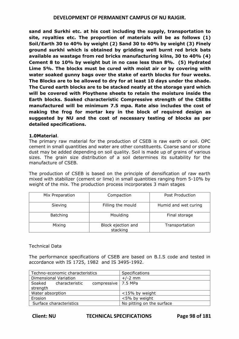
DEVELOPMENT OF PERMANENT CAMPUS OF NU RAJGIR.
Client: NU TECHNICAL SPECIFICATIONS Page 98 of 181
sand and Surkhi etc. at his cost including the supply, transportation to site, royalties etc. The proportion of materials will be as follows (1) Soil/Earth 30 to 40% by weight (2) Sand 30 to 40% by weight (3) Finely ground surkhi which is obtained by gridding well burnt red brick bats available as wastage from red bricks manufacturing kilns, 30 to 40% (4) Cement 8 to 10% by weight but in no case less than 8%. (5) Hydrated Lime 5%. The blocks must be cured with moist air or by covering with water soaked gunny bags over the stake of earth blocks for four weeks. The Blocks are to be allowed to dry for at least 10 days under the shade. The Cured earth blocks are to be stacked neatly at the storage yard which will be covered with Ploythene sheets to retain the moisture inside the Earth blocks. Soaked characteristic Compressive strength of the CSEBs manufactured will be minimum 7.5 mpa. Rate also includes the cost of making the frog for mortar key in the block of required design as suggested by NU and the cost of necessary testing of blocks as per detailed specifications. 1.0Material. The primary raw material for the production of CSEB is raw earth or soil. OPC cement in small quantities and water are other constituents. Coarse sand or stone dust may be added depending on soil quality. Soil is made up of grains of various sizes. The grain size distribution of a soil determines its suitability for the manufacture of CSEB. The production of CSEB is based on the principle of densification of raw earth mixed with stabilizer (cement or lime) in small quantities ranging from 5-10% by weight of the mix. The production process incorporates 3 main stages
Mix Preparation Compaction Post Production
Sieving Filling the mould Humid and wet curing
Batching Moulding Final storage
Mixing Block ejection and stacking
Transportation
Technical Data The performance specifications of CSEB are based on B.I.S code and tested in accordance with IS 1725, 1982 and IS 3495-1992. Techno-economic characteristics Specifications Dimensional Variation +/-2 mm Soaked characteristic compressive strength
7.5 MPa
Water absorption <15% by weight Erosion <5% by weight Surface characteristics No pitting on the surface
DEVELOPMENT OF PERMANENT CAMPUS OF NU RAJGIR.
Client: NU TECHNICAL SPECIFICATIONS Page 99 of 181
2.0Procedure for Manufacturing : Soil sand cement are to be taken as per above proportion and mixed thoroughly in a rotary pan mixer. Water to be added in the mixer in such proportion that the resultant moisture content of the mix is approximately 10 to 12%. The soil is then compressed and moulded in Earth Blocks of size 230 mm x 110 mm x 100 mm size on a Vibratory Hydro Mechanical press to achieve Compression pressure of 2.7 to 5 MPa to obtain the compression ratio of 1.7 to 1.8 in the blocks. The blocs must be cured with moist air or by covering with water soaked gunny bags over the stake of earth blocks for four weeks. The Blocks are allowed to dry for at least 10 days under the shade. The blocks are ready for use in the Masonry. Before the use of blocks in masonry, samples from each stake of Blocks must be tested for its compressive strength. If the Soaked characteristic Compressive strength of the blocks tested is equal to or more than 7.5 MPa then only the same should be used for masonry. The earth blocks not satisfying the strength criteria may be rejected and recycled.
The stages of the manufacturing process are as follows:
3.0 INGRADIENTS 3.1Earth
Clear earth available from excavation of water bodies, foundations for buildings, pipe trenches at the site shall be used. Soil shall be dumped at block making yard. Soil shall be collected from 50cm below natural ground at site to avoid high organic content in soil. While dumping the soil it is essential to make sure that one dump (heap) is from the single identified source of soil. The soil dump shall not have more than 150 m3 of soil for testing purpose. The representative sample from every dump shall be tested thoroughly for grain size distribution. (Including bifurcation of silt and clay), liquid limit, plastic limit and swelling index. Soil should be thoroughly soaked/submerged into water so that all lumps of soil dissolves. When soil settles down, excess water needs to be drain out. This wet soil should be used to prepare premix for the block making.
3.2 Sand
The sand to be used shall be coarse sand of Zone II or coarser procured from outside the site.
3.3 Cement
The cement to be used shall be ordinary Portland cement (OPC).
3.4 Lime
Lime to be used shall be hydrated lime of minimum 85% purity. The lime could be quick lime hydrated at site or hydrated lime procured to site in powder form.
3.5 Surkhi

DEVELOPMENT OF PERMANENT CAMPUS OF NU RAJGIR.
Client: NU TECHNICAL SPECIFICATIONS Page 100 of 181
It shall follow Indian Standard IS1344 – 1981 – (grade II) or latest.
4.0 PROPORTIONS To achieve the Soaked characteristic compressive strength of 7.50MPa and more of CSEB, following design mix are suggested based on preliminary test carried out. These proportions are only for guidance of the contractor for the Manufacturing of CSE Blocks. The Contractor has to fix proportion of the Mix of raw materials in such a way that desired Soaked characteristic compressive strength of 7.50 MPa and other quality parameters, which are listed in subsequent paragraphs of this specifications, are achieved at all times. To achieve the required soaked characteristic compressive strength of 7.50 MPa the mean soaked characteristic compressive strength is recommended as 9.5 MPa to take care of the Standard Deviation in manufacturing of CSE Blocks on site. The design mix shall be adjusted as per the test results of particular lot.
Design Mix:
Soil :30-40%
Sand:30-25%
Surkhi :25-20%
Stabilizer : 8- 10% Cement but in no case less than 8% and 5% Hydrated lime by weight of modified soil.
MANUFACTURING PROCESS
For making CSEB at site contractor shall set the required infrastructure at his cost at site like machinery, shed for machines, machine foundation, electric and water connection from given point, protection of raw material from weather etc.
5.1 Mixing
The mixing of ingredients shall be done using pan type Muller mixer with minimum capacity of 500kg per batch. First the soil shall be thoroughly mixed with sand (50% of total quantity) by adding sufficient water along with the required quantity of lime. The thoroughly mixed material shall be left for one day. Surkhi (available as waste from local Brick kilns), Ordinary Portland cement along with remaining sand shall be added to the previously prepared mix and thoroughly mixed again to achieve the required proportions. Potable water shall be added in required quantity to achieve the resultant moisture content of mix as 10 to 12%.
5.2 Molding
The mix prepared as above shall be molded in fully automatic hydro vibro/hydraulic press with hydraulic power pack of pressure of 2.7 to 5 MPa. Vibrator in the machine shall be equipped with variable frequency as well as vibration time setting. The filling height of the mold shall be designed such that
DEVELOPMENT OF PERMANENT CAMPUS OF NU RAJGIR.
Client: NU TECHNICAL SPECIFICATIONS Page 101 of 181
given compression ratio gives final density of freshly prepared block not less than 2.02 gm/cc and dry density of not less than 18.15 kN/m3
Following is the list of machines available in the market for the manufacture of compressed earth blocks / fly ash bricks. Contractor may choose any of them or the machine of similar kind for the manufacture of compressed earth blocks to get the desired quality of blocks, narrated in this section. List of Compressed earth Blocks/Bricks Manufacturing Press : This list is for guidance only. Contractor shall choose any suitable Machine to Manufacture the CSE Blocks to meet the requirements.
1. TARA Machines & Tech. Services Pvt.Ltd B-32, Tara Crescent, Qutab Institutional Area, New Delhi -110016.
2. Aurum Earth Block Press. Aureka, Aspirations, Auroville, Tamilnadu, 605101
3. HYDRAFORM (INDIA) PVT. LTD. 602-B, Ansal Majestic Tower, PVR Complex, Vikaspuri, New Delhi - 110018, India
4. Balaji Constructions Machines and Spares Pvt. Ltd. Plot No. L - 60, Additional MIDC, Satara - 415 004, Maharashtra, India.
5. Vishwakarma engineering works Behind sukhramnagar, PO Box. No. 5017, Rajpur – Gomtipur, Near Government G Colony, Rakhiyal, Ahmedabad.
6. ORBIT INTELLIGENT ENGINEERING Plot No.27, GIDC Estate, Phase-II, Modhera Road, Dediyasan,Mehsana-384002, Gujarat, India
7. AHP MACHINES Gat No. 1571 / 3, Chikhali - Talawade Road, Shelarwasti, Chikhali, Pune - 412114. Maharashtra INDIA .
5.3 Curing
Freshly made blocks shall be protected from immediate drying by covering with plastics. The block must be cured for 28 days either by fully covering it with plastics with water sprinkling as required or by soaked gunny bags over the stack of blocks. The blocks shall be allowed to dry for at least 10 days under the shade before using it for masonry.
5.4 Testing and Acceptance Criteria for CSE Blocks
1.4.1 Sampling shall be as per IS 5454-2010 for compressive strength, bulk density and water absorption. All the test shall be carried out for a lot to 15,000 units as per IS1725-1982 along with additional tests specified below.
1.4.2 The CSE Blocks shall be designed for mean soaked compressive strength of 9.5 MPa to achieve the required characteristic strength of 7.5 MPa.
DEVELOPMENT OF PERMANENT CAMPUS OF NU RAJGIR.
Client: NU TECHNICAL SPECIFICATIONS Page 102 of 181
1.4.3 Test results of Sample: The test results of the sample shall be average of the strength of the three specimens. The individual variation should not be more than +/- 15 per cent of the average. If variation in strength is more than +/- 15%, results of the samples are Invalid.
1.4.4 Acceptance criteria: 1.4.4.1 Compressive Strength : The CSE blocks shall be deemed to comply
with the strength requirements when both the following conditions are met
a The mean soaked compressive strength determined from any group of four consecutive test results shall be 9.5 MPa.
b The soaked compressive strength of any individual sample should fall below 7.5 MPa.
1.4.4.2Water Absorption: a The mean value of water absorption of four consecutive test results shall be 12 percent.
b Any individual sample shall not have water absorption more than 15 percent..
1.4.4.3Weathering Effect : a) The maximum loss of weight shall not exceed 5%. Minimum three blocks shall be tested for weathering effects as per IS 1725-1982 for a lot of 15000 units.
1.4.4.4 Loss of weight on alternate wetting and drying: The test for alternate wetting and drying shall be carried out. For wet compressive strength test before and after 12 wetting and drying cycle (here each cycle is of 24 hours), there shall be no loss of strength. In terms of loss of weight it shall not more than 2%.
1.2.4.5 Expansion in volume on saturation of CSE Blocks : The test of Expansion on saturation shall be carried out and in any case the expansion shall not be more than 0.15% measured after immersing the block in water for 48 hours.
1.4.5 Prism Test: Prism test for CSE Block Masonry should be carried out as
per following procedure.
1.4.5.1Select random samples for prism test from approved lot of 45,000 blocks. The same shall be tested for socked strength as described earlier.
1.4.5.2Use the mortar proportion same as specified for masonry. The same shall be tested for compressive strength and sand sieve analysis.
1.4.5.3Making of masonry prism: 1.4.5.3.1 Three masonry prism should be build and tested for every lot of 45,000
blocks.
DEVELOPMENT OF PERMANENT CAMPUS OF NU RAJGIR.
Client: NU TECHNICAL SPECIFICATIONS Page 103 of 181
1.4.5.3.2 Each test prism shall be one masonry unit in width and thickness. All specimens in the test shall be of the same size and shall have five courses of “English Bond”. The mortar joints shall be 10 mm in thickness. Spread a full bed of mortar on each solid masonry unit and allow no furrowing of the mortar bed. Strike mortar joints flush with the face of the masonry without tooling. The length of the prism shall be greater than its thickness.
1.4.5.3.3 The thickness of the prisms shall be the same as the thickness of the masonry part of the wall in the structure. The length of the prism shall be equal to or greater than the thickness of the prism. The height of the prism shall be at least twice the thickness, contain at least two mortar joints, and be a minimum of 380 mm
1.4.5.3.4 Cures all prisms for 28 days. Cure the prisms together with the corresponding mortar specimens in laboratory air maintained at a temperature of 24 ± 8 °C, with a relative humidity between 30 and 70 %, and free of drafts. These environmental conditions will not require, generally, special air-conditioning equipment. Make a continuous graphical record of temperatures and humidity to detect unusual dryness or excessive moisture together with unusual fluctuations of temperature. Prisms shall be fully submerged in water for 72 hours before 28 days testing.
1.4.5.3.5 Cap the ends of prism in the same manner as set forth for capping the units. 1.4.5.3.6 Determine the length and thickness of the prism to the nearest 0.3 mm by
averaging three measurements taken at the center and quarter points of the height of the specimen. Measure the height of the specimen including caps to the nearest 3 mm
1.4.5.3.7 Place the plain (lower) bearing block, with its hardened face up, on the table or platen of the testing machine directly under the spherically seated (upper) bearing block. Wipe clean the bearing faces of the upper and lower bearing blocks and of the test specimen and place the test specimen on the lower bearing block. Carefully align both centroid axes of the specimen with the center of thrust of the spherically seated block. As the spherically seated block is brought to bear on the specimen, rotate its movable portion gently by hand so that uniform seating is obtained.
1.4.5.3.8 Rate of Loading: Apply the load, up to one half of the expected maximum load, at any convenient rate, after which adjust the controls of the machine so that the remaining load is applied at a uniform rate in not less than 1 nor more than 2 min.
1.4.5.3.9 Compressive strength of each prism calculated to the nearest 0.1MPa after considering the strength factor of 0.85. The average strength is reported along with physical properties of unit, mortar and sieve analysis of sand. Acceptance Criteria: Mean soaked compressive strength of any prism shall not be less than 2.5 MPa.
MR 5.004 : Brick work with Compressed Stabilized Earth (CSE) Blocks of class designation 7.5 in superstructure above plinth level up to floor V level in all shapes and sizes in : Cement mortar 1:4 (1 cement : 4 coarse sand) Rates to include transportation of Compressed Earth blocks from storage yard to the site of work. (Supply of CSE block will be paid separately in relevant items)
DEVELOPMENT OF PERMANENT CAMPUS OF NU RAJGIR.
Client: NU TECHNICAL SPECIFICATIONS Page 104 of 181
Relevant specification for Brick Masonry with Non Modular bricks 230 mm x 110 mm x 75 mm shall be followed except that CSE Blocks of size 230 mm x 110 mm x 100 mm shall be used in place of Non Modular bricks of size 230 mm x 100 mm x 75 mm. Cement Mortar used shall be 1:4 (1 cement: 4 coarse sand). MR 5.005 : Half brick masonry with Compressed Stabilized Earth (CSE) Blocks of class designation 7.5 in superstructure above plinth level up to floor V level in: Cement mortar 1:4 (1 cement :4 coarse sand) Rates to include transportation of Compressed Earth blocks from storage yard to the site of work. (Supply of CSE block will be paid separately in relevant items)
Relevant specification shall be followed for Half Brick Masonry with Non Modular bricks 230 mm x 110 mm x 75 mm shall be followed except that CSE Blocks of size 230 mm x 110 mm x 100 mm shall be used in place of Non Modular bricks of size 230 mm x 100 mm x 75 mm. Cement Mortar used shall be 1:4 (1 cement : 4 coarse sand).
MR 5.006: Extra rates over DSR item no. 6.4.2 for providing exposed masonry with common burnt clay bricks of size 230 mm x 110 mm x 70 mm including raking horizontal and vertical joints 10 mm wide 12 mm deep to receive pointing complete. The Exposed surface area only of the Brick work will be measured for payment. The general specifications for Brick masonry shall be followed. Exposed Brick masonry work is to be carried out according to English bond for particular walls as per detailed drawings. The bricks used for exposed brick masonry shall be selected from the stakes of normal burnt clay bricks. The selected bricks shall have clean/sharp edges and the exposed face of the brick shall have even surface without any corner broken during handling. The facing bricks shall be free from cracks, flaws, nodules of free lime warpage and organic matter. The thickness of joints shall be maintained to give an architectural exposed brick work finish. Joints to be racked out with wooden patti upto uniform depth of 10 mm. Excessive Mortar from Surface of brick masonry should be cleaned with wire brush / good quality broom. Brick masonry to be cured with clean potable water as per clause no. 5.3 above. Measurements: Surface area of the exposed area of masonry will be measured and paid for. MR 5.007: Extra rates over MR item no. 5.002 for providing exposed masonry work for Brick masonry with common burnt clay bricks of size 230 mm x 110 mm x 50 mm instead of size 230 mm x 110 mm x 70 mm, including raking horizontal and vertical joints 10 mm wide 12 mm deep to receive pointing complete in cement mortar 1:4 (1 cement : 4 coarse
DEVELOPMENT OF PERMANENT CAMPUS OF NU RAJGIR.
Client: NU TECHNICAL SPECIFICATIONS Page 105 of 181
sand). The Exposed surface area only of the Brick work will be measured for payment. 1.1 Facing Bricks The general specifications for Brick masonry shall be followed. Exposed Brick masonry work is to be carried out according to English bond for particular walls as per detailed drawings. The bricks used for exposed brick masonry shall be selected from the stakes of normal burnt clay bricks. The selected bricks shall have clean edges and the exposed face of the brick shall have even surface without any corner broken during handling. The facing bricks shall be free from cracks, flaws, nodules of free lime warpage and organic matter. These shall be thoroughly burnt and shall have plane rectangular faces with parallel sides and sharp straight right angled edges. Facing bricks shall have uniform colour and even texture. The thickness of joints shall be maintained to give an architectural exposed brick work finish. Joints to be racked out with wooden Patti up to uniform depth of 10 mm. Excessive Mortar from Surface of brick masonry should be cleaned with wire brush / good quality broom. Brick masonry to be cured with clean potable water as per clause no. 5.3 above. Measurements: Surface area of the exposed area of masonry will be measured and paid for. MR 5.008: Extra rates over MR item no. 5.004 for providing exposed masonry with Compressed Stabilized Earth (CSE) Blocks including raking horizontal and vertical joints 10 mm wide 12 mm deep to receive pointing complete. The Exposed surface area only of the Brick work will be measured for payment. The general specifications for Brick masonry with CSE Blocks shall be followed. Exposed Brick masonry work with CSE Blocks is to be carried out according to English bond for particular walls as per detailed drawings. The bricks used for exposed brick masonry shall be selected from the stakes of normal CSE Block. The selected bricks shall have clean/sharp edges and the exposed face of the brick shall have even surface without any corner broken during handling. The facing bricks shall be free from cracks, flaws, nodules of free lime warpage and organic matter. The thickness of joints shall be maintained to give an architectural exposed brick work finish. Joints to be racked out with wooden patti up to uniform depth of 10 mm. Excessive Mortar from Surface of brick masonry should be cleaned with wire brush / good quality broom. Brick masonry to be cured with clean potable water as per clause no. 5.3 above. Measurements: Surface area of the exposed area of masonry will be measured and paid for.
SUB HEAD: 6.0
DEVELOPMENT OF PERMANENT CAMPUS OF NU RAJGIR.
Client: NU TECHNICAL SPECIFICATIONS Page 106 of 181
STONE WORK
MR 6.001 : Providing and fixing wet cladding in (wall lining) any shape at all heights with 18 to 20 mm thick gang saw cut stone with (machine cut edges) of uniform colour and size, backing filled with a grout of average 12 mm thick cement mortar 1:3 (1 cement : 3 coarse sand) mixed with adhesive in proportion as per manufacture's specification, including pointing in white cement mortar 1:2 (1 white cement : 2 stone dust) with an admixture of pigment matching the stone shade at all levels including cutting, making recesses in stone slab, drilling holes, rubbing, polishing, curing, and scaffolding etc complete in the required pattern as per drawing and as direct cted by engineer in charge. (a) Red Mandana stone MR 6.002 : (b) Granite stone Please refer to Para 7.0, 7.1, 7.2, 7.7, 7.10, 7.11 of CPWD Civil Works Specifications 2009 Volume I, for relevant items of work.
DEVELOPMENT OF PERMANENT CAMPUS OF NU RAJGIR.
Client: NU TECHNICAL SPECIFICATIONS Page 107 of 181
SUB HEAD: 7.0 MARBLE & GRANITE WORK
MR 7.001 : Providing and fixing 18mm thick gang saw cut, mirror polished, machine cut for flooring and skirting of required size, approved shade, colour and texture laid over 20mm thick base cement mortar 1:4 (1 cement : 4 coarse sand), joints treated with white cement, mixed with matching pigment, epoxy touch ups, including rubbing, curing, moulding and polishing edges give high gloss finish etc. complete at all levels as per detailed drawing and as directed by engineer in charge.
(a) : Granite Stone of approved shade
Materials Granite stone slabs shall be of any colour and size as shall be approved by Engineer – in – Charge. Before stating the work, the contractor shall get the samples of Granite stone approved by the Engineer – in – Charge. 18 mm thick slabs of Granite stone shall be plain machine cut in sizes as per pattern shown on the drawings and mirror polished, The stones shall be smooth and of even surface without holes or pits or any kind of natural flaws. Flooring and skirting work shall be fixed to floor over 20 mm thick base cement mortar 1:4 and finished with grout with pigment to match the colour of the stone as per drawing and as directed by engineer in charge. Measurements Granite stone flooring and skirting shall be measured in square meter correct to two places of decimal. Rate The rate shall include the cost of all materials and labor involved in all the operations described above.
MR 7.002 : Providing and fixing 18mm thick gang saw cut, mirror polished, pre moulded and pre polished, machine cut stone for tread and risers of steps, dado, jams, lintels, partition, seat, landing, parapet top , shelves, chajja , platform, sill, seat, divider, and similar locations of required size, machine cut edges ,approved shade, colour and texture laid over 20mm thick base cement mortar 1:3(1 cement : 3 coarse sand), joints treated with white cement, mixed with matching pigment, epoxy touch ups, including rubbing, curing, moulding and polishing edges give high gloss finish etc. complete at all levels as per detailed drawing and as directed by engineer in charge.
(a) : Granite Stone of approved shade

DEVELOPMENT OF PERMANENT CAMPUS OF NU RAJGIR.
Client: NU TECHNICAL SPECIFICATIONS Page 108 of 181
Materials Granite stone slabs shall be of any colour and size as shall be approved by Engineer – in – Charge. Before stating the work, the contractor shall get the samples of Granite stone approved by the Engineer – in – Charge.
Operations as described for the Platform work in granite shall be followed except that the stones shall be fixed for tread and risers of steps, seat, sill, and facia, and landing, parapet top and similar locations. Granite stone of 18 mm thickness shall be fixed to the wall/floor in cement mortar 1:3 and finished with grout with pigment to match the color of the stone/tile as per drawing and as directed by engineer in charge. The granite slabs shall be of uniform size and in full length unless otherwise specified as per drawing and as directed by engineer in charge.
Measurements Granite stone tread and risers of steps, seat, sill, and facia, and landing, parapet top and similar locations shall be measured in square meter correct to two places of decimal. Nothing extra shall be paid for edge rounded. Rate The rate shall include the cost of all materials and labor involved in all the operations described above.
SUB HEAD: 8.0 WOOD AND PVC WORK
MR 8.001 : Providing wood work in frames of paneled shutters for doors, window , clerestory windows and other similar frames, and fixed to the Existing wooden frames with approved make Hinges as per detailed drawings and as directed by the Engineer - in - Charge. The various components of Paneled shutter like vertical stiles, Top, Bottom & lock rails and intermediate transoms & mullions in the shutter shall be measured, only in volume of teakwood used and shall be paid for. The rates shall include all the required materials like, nails, screws, wooden nails, Adhesive Glue etc. and labour for preparation of shutter frame and fixing the same with Door frames complete. Approved quality Hinges, Wooden/ Glass/Ply wood panels including the necessary Teak wood beading, nails & screws etc. for fixing hinges/panels shall be paid under relevant items as the case may be.
(A) : Second class teak wood
Please refer para 9.0, 9.1 and 9.3 of CPWD Civil works specifications 2009 Volume 1 for this item. MR 8.002 : Providing wood work in frames of Partitions with Glass/Wooden panels/Plywood Panels. Wooden members are to be

DEVELOPMENT OF PERMANENT CAMPUS OF NU RAJGIR.
Client: NU TECHNICAL SPECIFICATIONS Page 109 of 181
fixed to cover the Rectangular/ Square M.S. Tube sections of the main partition frames from all sides as per the detailed drawings including fixing the wooden members with necessary screws, nuts, bolts etc. in such a way that the M.S. Sectiones are covered on all sides and is concealed behind the wooden members. Wooden members of Shutters frame if any and wooden beadings for fixing Glass panels, wooden panels, and plywood panels of the partition with wooden members of the frames will also be paid under this same item. The work to be carried out as per the detailed drawings and as directed by Engineer In charge. (Hold fast lugs or dash fastener shall be paid for separately)
(a) : Second class teak wood
The relevant specification as per Para 9.0, 9.1 and 9.4 along with their sub paras, of CPWD Civil works specifications 2009 Vol.1, shall be followed for the work in frames of Partitions with Glass/Wooden panels/Plywood Panels etc.
MR 8.003 : Providing and fixing 5.5 mm thick toughened glass fixed with wooden bedding including the cost of wooden beadings ,glass and necessary cutting finishing for Partitions, doors, windows etc. complete as per drawing and as directed by Engineer-in-charge. 1 The relevant specification shall be followed as per above mentioned item of glass.
2 Measurement The height and width of glass for partition/door/window units as fixed in place shall be measured correct to one centimeter and area calculated in sqm. correct to second place of decimal shall be taken for payment. 3 Rate The rate shall include the cost of all the materials, labours involved in all the operations as described in nomenclature of item and particular specification. MR 8.004 : Providing & fixing 4.0 mm thick glass vision panel not exceeding 0.2 sqmt fixed with teak wood beading of 5 mm thick both side in the opening and fixing the same in flush door at required location as per drawing and as directed by engineer-in-charge. 1 Glass Panels : Glass paneling (Glazing) shall be done with float sheet glass as per IS 14900. Glazing in the shutters of doors, windows and ventilators of bath, WC and Lavatories shall be provided with frosted glass the weight of which shall be not less than 10 kg/sqm. Frosted glass panes shall be fixed with frosted face on the inside. Glass panels shall be fixed by providing a thin layer of putty conforming to IS 419 applied between glass pane and all along the length of the rebate and also between glass panes and wooden beading.
DEVELOPMENT OF PERMANENT CAMPUS OF NU RAJGIR.
Client: NU TECHNICAL SPECIFICATIONS Page 110 of 181
2 Measurement The height and width of window unit as fixed in place shall be measured correct to one centimeter and area calculated in sqm. correct to second place of decimal shall be taken for payment. 3 Rate The rate shall include the cost of all the materials, labours MR 8.005 : Extra for providing frosted glass panes 5.5 mm thick instead of ordinary float glass panes 5.5 mm thick in doors, windows and clerestory window shutters. (Area of opening for glass panes excluding portion inside rebate shall be measured).
1 Relevant specifications of glazing shall be followed. Glazing in the shutters of doors, windows and ventilators of bath, WC and Lavatories shall be provided with frosted glass the weight of which shall be not less than 10 kg/sqm. Frosted glass panes shall be fixed with frosted face on the inside. Glass panels shall be fixed by providing a thin layer of putty conforming to IS 419 applied between glass pane and all along the length of the rebate and also between glass panes and wooden beading. 2 Measurements For paneling of each type or for glazed panel length and width of opening for panels inserts or glazed panels shall be measured correct to a cm before fixing the beading and the area shall be calculated to the nearest 0.01 sq.m. The portions of the panel inserts or glazed panel inside the grooves or rebates shall not be measured for payment. 3 Rate Rate includes the cost of materials and labour involved in all the operations described above. MR 8.006 : Extra rate over DSR item no 9.7.7.2 for for providing single glazing 5.0 mm thick clear cosmos (ET 125) of approved make (inplace of 5.0 mm thick clear float glass) having properties like light transmission 28%,external reflection 28%, internal reflection 9%, 28%, solar factor 0.3, shading coefficient 0.34, U value (W/Sqm-k) 3.9 Light instead of 5.0 mm thick sheet float glass as per drawing and as directed by Engineer-in-Charge. 1Materials
Glass shall be clear cosmos having properties mentioned in item description. Putty shall conform to I.S. 419-1967.
DEVELOPMENT OF PERMANENT CAMPUS OF NU RAJGIR.
Client: NU TECHNICAL SPECIFICATIONS Page 111 of 181
2Workmanship
The specifications of this item shall be followed as per above mentioned item of glass except that clear cosmos glass shall be used.
3Mode of measurements and payment The payment shall be made on sq. mt. basis extra over and above the payment for plain glass for using ground glass [Routed of obscured] involved in all the operations as described in nomenclature of item and particular specification. MR 8.007 : Providing and fixing 12 mm thick plane toughened glass fixed with wooden beading including the cost of wooden beadings ,glass and necessary cutting finishing for Partitions, doors, windows etc. complete as per drawing and as directed by Engineer-in-charge.
1 The relevant specification shall be followed as per general item of glass. The glass to be used shall be 12 mm thick toughened plain float glass.
2 Measurement The height and width of glass for partition/door/window units as fixed in place shall be measured correct to one centimeter and area calculated in sqm. correct to second place of decimal shall be taken for payment. 3 Rate The rate shall include the cost of all the materials, labours involved in all the operations as described in nomenclature of item and particular specification.
MR 8.008 : Providing and fixing in position frameless partition with 12 mm thick clear toughened float glass with appropriate stainless steel grade 304 patch fittings as per manufacturer's specifications and as per design and as directed by Engineer - in - Charge. All joints of the glass to glass and glass to wall/floor/ceiling shall be filled with RTV silicon sealant of structural grade and weathering grade of approved make, to make the partition leak proof, complete as per detailed drawings and approved shop drawings. Rates to include the cost of all installation charges and materials like glass, all SS patch fittings, wall Rails, hardware and RTV Silicon sealants etc. Installed glass are shall be measured and paid for. The contractor shall submit the detailed shop drawing showing all junction details and get the same approved from Engineer - in - Charge before executing this item. The item shall comprising of 12mm thick toughened plain float glass with fittings with Wall Connecting Profile SS Finish base rail Dorma or equivalent with fixing
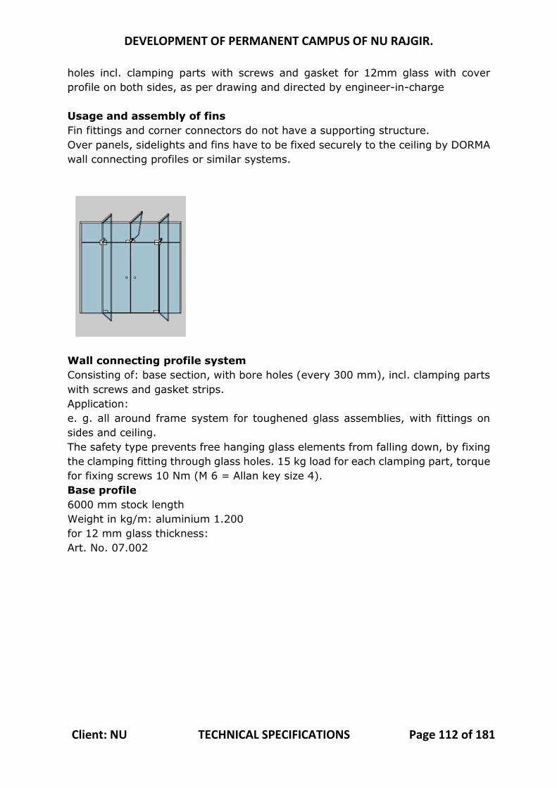
DEVELOPMENT OF PERMANENT CAMPUS OF NU RAJGIR.
Client: NU TECHNICAL SPECIFICATIONS Page 112 of 181
holes incl. clamping parts with screws and gasket for 12mm glass with cover profile on both sides, as per drawing and directed by engineer-in-charge Usage and assembly of fins Fin fittings and corner connectors do not have a supporting structure. Over panels, sidelights and fins have to be fixed securely to the ceiling by DORMA wall connecting profiles or similar systems.
Wall connecting profile system Consisting of: base section, with bore holes (every 300 mm), incl. clamping parts with screws and gasket strips. Application: e. g. all around frame system for toughened glass assemblies, with fittings on sides and ceiling. The safety type prevents free hanging glass elements from falling down, by fixing the clamping fitting through glass holes. 15 kg load for each clamping part, torque for fixing screws 10 Nm (M 6 = Allan key size 4). Base profile 6000 mm stock length Weight in kg/m: aluminium 1.200 for 12 mm glass thickness: Art. No. 07.002

DEVELOPMENT OF PERMANENT CAMPUS OF NU RAJGIR.
Client: NU TECHNICAL SPECIFICATIONS Page 113 of 181
Fixed length Weight in kg/m: aluminium 1.200 for 12 mm glass thickness: Clamping part 60 mm long with screw and gasket Weight in kg/m: aluminium 0.055 for 12 mm glass thickness: Art. No. 07.005
Clip on cover profile 6000 mm stock length, brass, stainless steel, satin and stainless steel polished door available Art. No. 07.003 fixed length Art. No. 07.053 Weight in kg/m: aluminium 0.203 brass 0.373
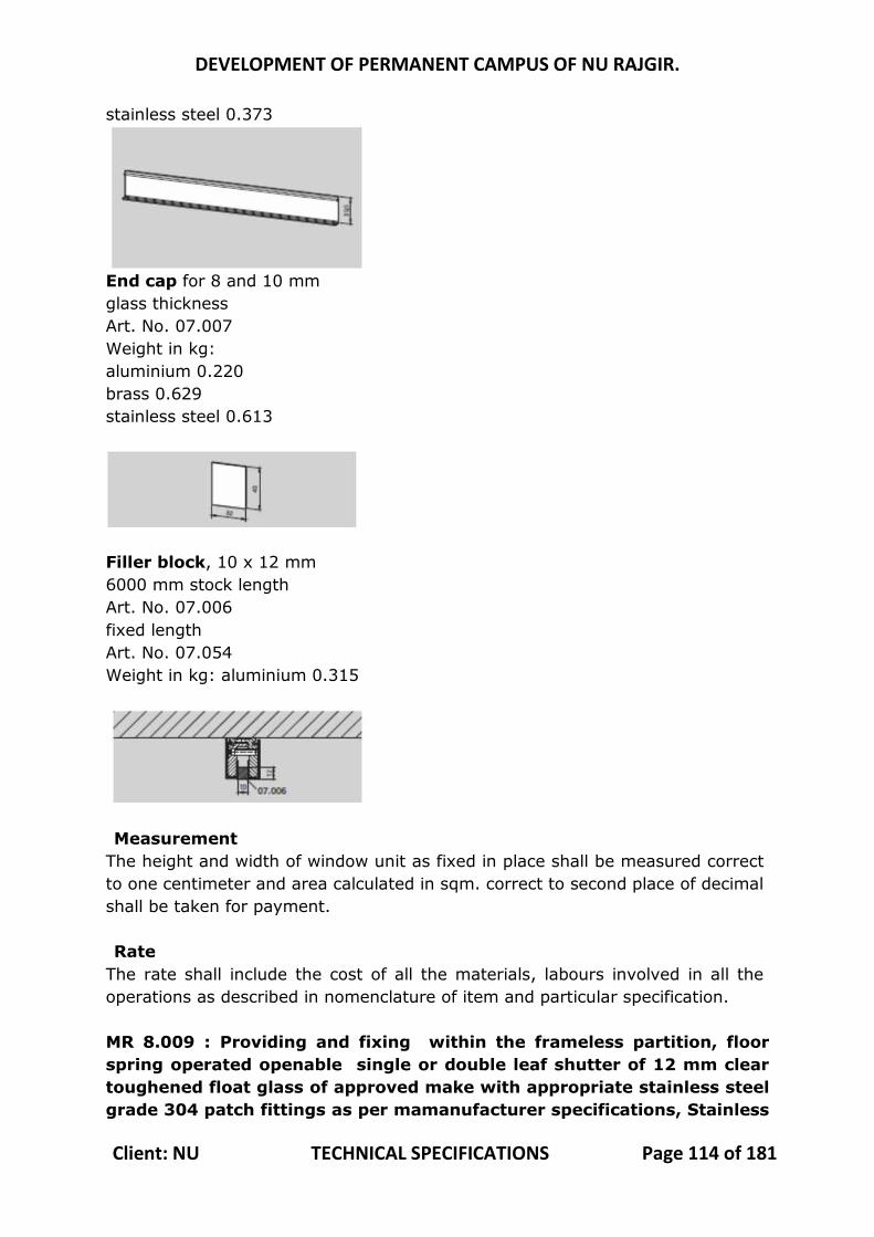
DEVELOPMENT OF PERMANENT CAMPUS OF NU RAJGIR.
Client: NU TECHNICAL SPECIFICATIONS Page 114 of 181
stainless steel 0.373
End cap for 8 and 10 mm glass thickness Art. No. 07.007 Weight in kg: aluminium 0.220 brass 0.629 stainless steel 0.613
Filler block, 10 x 12 mm 6000 mm stock length Art. No. 07.006 fixed length Art. No. 07.054 Weight in kg: aluminium 0.315
Measurement
The height and width of window unit as fixed in place shall be measured correct to one centimeter and area calculated in sqm. correct to second place of decimal shall be taken for payment. Rate
The rate shall include the cost of all the materials, labours involved in all the operations as described in nomenclature of item and particular specification. MR 8.009 : Providing and fixing within the frameless partition, floor spring operated openable single or double leaf shutter of 12 mm clear toughened float glass of approved make with appropriate stainless steel grade 304 patch fittings as per mamanufacturer specifications, Stainless
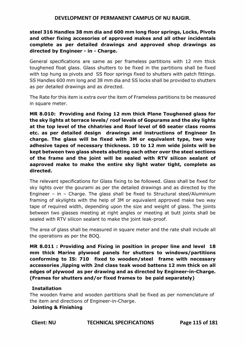
DEVELOPMENT OF PERMANENT CAMPUS OF NU RAJGIR.
Client: NU TECHNICAL SPECIFICATIONS Page 115 of 181
steel 316 Handles 38 mm dia and 600 mm long floor springs, Locks, Pivots and other fixing accesories of approved makes and all other incidentals complete as per detailed drawings and approved shop drawings as directed by Engineer - in - Charge.
General specifications are same as per frameless partitions with 12 mm thick toughened float glass. Glass shutters to be fixed in the partitions shall be fixed with top hung ss pivots and SS floor springs fixed to shutters with patch fittings. SS Handles 600 mm long and 38 mm dia and SS locks shall be provided to shutters as per detailed drawings and as directed.
The Rate for this item is extra over the item of Frameless partitions to be measured in square meter.
MR 8.010: Providing and fixing 12 mm thick Plane Toughened glass for the sky lights at terrace levels/ roof levels of Gopurams and the sky lights at the top level of the chhatries and Roof level of 60 seater class rooms etc. as per detailed design drawings and instructions of Engineer In charge. The glass will be fixed with 3M or equivalent type, two way adhesive tapes of necessary thickness. 10 to 12 mm wide joints will be kept between two glass sheets abutting each other over the steel sections of the frame and the joint will be sealed with RTV silicon sealant of aaproved make to make the entire sky light water tight, complete as directed.
The relevant specifications for Glass fixing to be followed. Glass shall be fixed for sky lights over the gourami as per the detailed drawings and as directed by the Engineer – in – Charge. The glass shall be fixed to Structural steel/Aluminium framing of skylights with the help of 3M or equivalent approved make two way tape of required width, depending upon the size and weight of glass. The joints between two glasses meeting at right angles or meeting at butt joints shall be sealed with RTV silicon sealant to make the joint leak-proof.
The area of glass shall be measured in square meter and the rate shall include all the operations as per the BOQ.
MR 8.011 : Providing and Fixing in position in proper line and level 18 mm thick Marine plywood panels for shutters to windows/partitions conforming to IS: 710 fixed to wooden/steel frame with necessary accessories ,lipping with 2nd class teak wood battens 12 mm thick on all edges of plywood as per drawing and as directed by Engineer-in-Charge. (Frames for shutters and/or fixed frames to be paid separately)
Installation The wooden frame and wooden partitions shall be fixed as per nomenclature of the item and directions of Engineer-in-Charge. Jointing & Finishing

DEVELOPMENT OF PERMANENT CAMPUS OF NU RAJGIR.
Client: NU TECHNICAL SPECIFICATIONS Page 116 of 181
Joints of the boards are finished with specially formulated Jointing compound and fiber tape to provide seamless finish. Board surface can be decorated with any type of paint, wall paper, wood veneer & hard laminates. Services should be incorporated before commencement of board fixing. Fitting and Fixtures
It is easy and simple to attach different fittings to wall panelling boards. Inclined nails can be fixed to the boards itself for light materials. For heavier materials the fastening should be centered on internal stud work or steel or wood frame behind the boards, fixed before boarding. Services should be incorporated before commencement of board fixing. Tolerance
Tolerance in dimensions shall be + 5 mm. Measurements
Length and breadth of superficial area of the finished work shall be measured correct to a cm. Area shall be calculated in square meter correct to two places of decimal. No deduction will be made of openings of areas up to 0.40 sqm nor shall extra payment be made either for any extra material or labour involved in forming such openings. For openings exceeding 0.40 sqm. in area, deduction in measurements shall be made but extra will be payable for any extra material or labour involved in making such openings. Rate
The rate shall include the cost of all materials and labour involved in all the operations described above.
MR 8.012: Providing, Fabricating and Fixing in position in proper line and level with 12 mm thick Marine plywood panels for shutters to windows/partitions conforming to IS: 710 fixed to wooden/steel frame with necessary accessories, lipping with 2nd class teak wood battens 12 mm thick on all edges of plywood as per drawing and as directed by Engineer-in-Charge. (Frames of shutter and/or fixed frames to be paid separately)
Specifications shall be followed as per above items.
MR 8.013 : Providing & fixing wooden patta 130 mm wide made from 18 mm thick marine plywood conforming to IS: 710 with eachside 5 mm thick teakwood beading and fixed to supporting second class teakwood patti 35X 35 mm which is fixed to wall as per drawing and as directed by engineer- in- charge
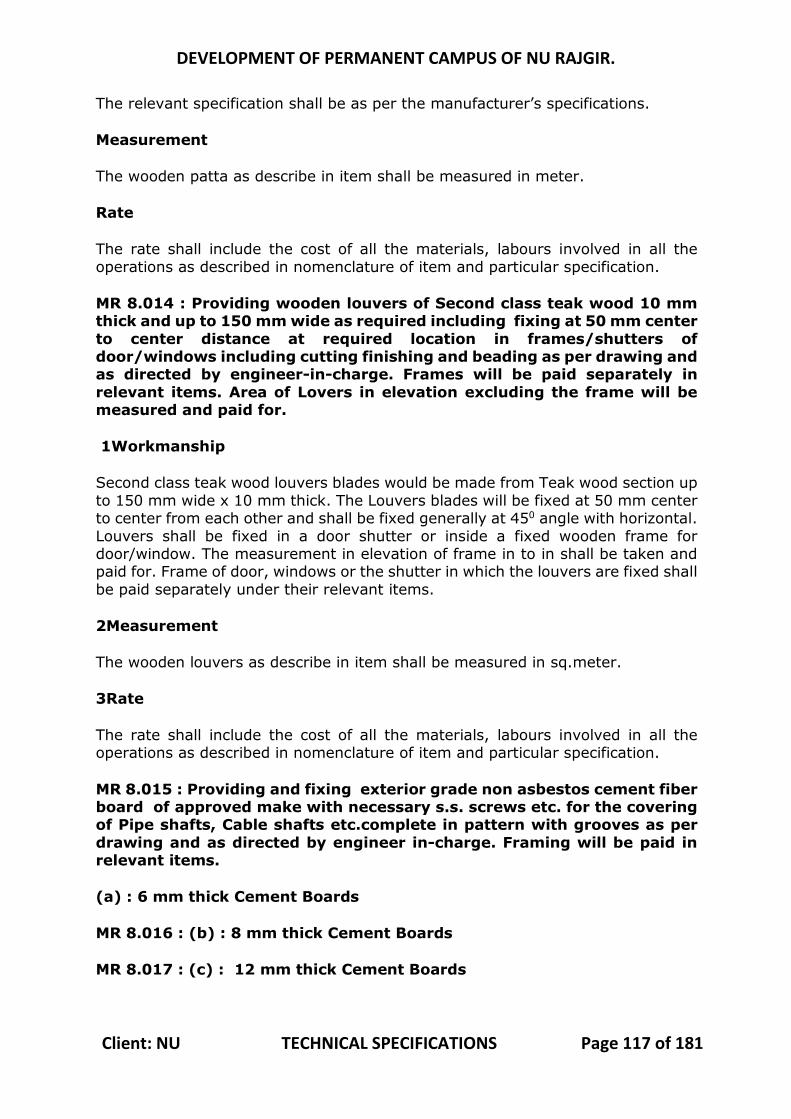
DEVELOPMENT OF PERMANENT CAMPUS OF NU RAJGIR.
Client: NU TECHNICAL SPECIFICATIONS Page 117 of 181
The relevant specification shall be as per the manufacturer’s specifications.
Measurement
The wooden patta as describe in item shall be measured in meter.
Rate
The rate shall include the cost of all the materials, labours involved in all the operations as described in nomenclature of item and particular specification.
MR 8.014 : Providing wooden louvers of Second class teak wood 10 mm thick and up to 150 mm wide as required including fixing at 50 mm center to center distance at required location in frames/shutters of door/windows including cutting finishing and beading as per drawing and as directed by engineer-in-charge. Frames will be paid separately in relevant items. Area of Lovers in elevation excluding the frame will be measured and paid for.
1Workmanship
Second class teak wood louvers blades would be made from Teak wood section up to 150 mm wide x 10 mm thick. The Louvers blades will be fixed at 50 mm center to center from each other and shall be fixed generally at 450 angle with horizontal. Louvers shall be fixed in a door shutter or inside a fixed wooden frame for door/window. The measurement in elevation of frame in to in shall be taken and paid for. Frame of door, windows or the shutter in which the louvers are fixed shall be paid separately under their relevant items.
2Measurement
The wooden louvers as describe in item shall be measured in sq.meter.
3Rate
The rate shall include the cost of all the materials, labours involved in all the operations as described in nomenclature of item and particular specification.
MR 8.015 : Providing and fixing exterior grade non asbestos cement fiber board of approved make with necessary s.s. screws etc. for the covering of Pipe shafts, Cable shafts etc.complete in pattern with grooves as per drawing and as directed by engineer in-charge. Framing will be paid in relevant items.
(a) : 6 mm thick Cement Boards
MR 8.016 : (b) : 8 mm thick Cement Boards
MR 8.017 : (c) : 12 mm thick Cement Boards
DEVELOPMENT OF PERMANENT CAMPUS OF NU RAJGIR.
Client: NU TECHNICAL SPECIFICATIONS Page 118 of 181
1 Fibre boards shall be of medium density cement board reinforced with wood fiber, produced by fiberizing steamed wood under pressure, blended with adhesive and wax and formed into solid panels under controlled conditions of heat and pressure as per IS 14862. 2 Adhesives: The adhesive used for bonding shall be BWP type synthetic resin conforming to IS 848. 3 Thickness : Fiber boards are available in thickness 6, 9, 12, 15, 18, 22, 25, 30, 35 & 40 mm. The tolerance in thickness shall be ± 0.3 mm. Thickness of fiber boards and adhesive used for bonding shall be as specified. Unless otherwise stated, exterior grade fiber boards bonded with BWP type synthetic resin adhesive shall be used. Relevant specifications of paneling shall be followed as specified and 6 mm thick non asbestos cement fiber board of Shera or equivalent fixed to m.s structure as per drawing and as directed by engineer in charge.
4 Measurement: The non asbestos cement fiber board as describe in item shall be measured in square meter. 5 Rate:
The rate shall include the cost of all materials and labour involved in all the operations described above.
MR 8.018 : Providing and fixing of Hollow metal fire rated doors of approved make as per IS 3614 part-1 & part-2 for stability and integrity. Pressed Galvanized steel confirming to IS 277 with the following specification. Recommended fire door shall have doors tested at CBRI or ARAI for maximum rating of 2hrs with vision panel. Door frame shall be double rebate profile of size 143 x 57 mm made out of 1.60mm (16gauge) minimum thick galvanized steel sheet. Frames should be provided with back plate bracket and anchor fasteners for installation on a finished wall opening. Door leaf shall be 46mm thick fully flush double skin door with vision lite. Door leaf shall be manufactured from 1.2mm (18guage) minimum thick galvanized steel sheet. The internal construction of the door should be rigid reinforcement pads for receiving appropriate hardware. The infill material shall be resin bonded honeycomb core. All doors shall be factory prepped for receiving appropriate hardware and provided with necessary reinforcement for hinges, locks, and door closers of approved make. The edges should be interlocked with a bending radius of 1.4mm. The glass should be 5.5 mm clear borosilicate fire rated glass of relavant rating of the door. All doors and frames shall be finished with etched primer coating, stove zinc phosphate primer and
DEVELOPMENT OF PERMANENT CAMPUS OF NU RAJGIR.
Client: NU TECHNICAL SPECIFICATIONS Page 119 of 181
thermosetting polyurethane aliphatic grade paint of approved colour complete as per drawing and as directed by Engineer-in-Charge. The door leaf and frame shall have passed minimum 250 hours of salt spray test. (a) : 2Hrs Fire Rated Door Single leaf of size : with vision panel & Standard Door Hardware Such as Hinges (CE 4330) , Dead Lock (CL 5302) , Handle (PH 1250), And Door Closer (TS 68 STD ARM) set or equivalent make 1Material
Fire resistant door frame of section 143 x 57 mm having built in rebate made out of 16 SWG G.I. sheet (zinc coating not less than 120 gm/sqm) duly filled with vermiculite based concrete mix, suitable for mounting 60 minutes fire rated door shutters. The frame is fitted with intumescent fire seal strip of size 10x4 mm (minimum) all round the frame and fixing with dash fastener of approved size and make, including applying a coat of approved brand fire resistant primer etc. complete
2Measurements
Fire resistant door frame shall be measured in running meter correct to two places of decimal. Nothing extra shall be paid.
3Rate
The rate shall include the cost of all materials and labour involved in all the operations described above.
8.019 : (b) 2Hrs Fire Rated Door Single leaf of size : with vision panel & Standard Door Hardware Such as Hinges (CE 4330), Panic (1211 + 1185) Bar And Door Closer (TS 68 STD ARM) set equivalent make 1Material
Fire resistant door frame of section 143 x 57 mm having built in rebate made out of 16 SWG G.I. sheet (zinc coating not less than 120 gm/sqm) duly filled with vermiculite based concrete mix, suitable for mounting 60 minutes fire rated door shutters. The frame is fitted with intumescent fire seal strip of size 10x4 mm (minimum) all round the frame and fixing with dash fastener of approved size and make, including applying a coat of approved brand fire resistant primer etc. complete
2Measurements
Fire resistant door frame shall be measured in running meter correct to two places of decimal. Nothing extra shall be paid.
3Rate The rate shall include the cost of all materials and labour involved in all the operations described above
DEVELOPMENT OF PERMANENT CAMPUS OF NU RAJGIR.
Client: NU TECHNICAL SPECIFICATIONS Page 120 of 181
8.020 : Providing and fixing sliding folding Top & Bottom Track set of approved make suitable for wooden sliding folding door of total weight up to 100 kg. with all hardwares as per architectural drawing and as directed by engineer in charge. ( Including Top Pivot , bottom Pivot ‐ wall Pivot‐ Hinges ‐100x32x3 min weight 300gm; Hinge Cum Handle ‐ min weight 768 gm; Top Roller ‐,Bottom Roller ‐,Heavy duty aluminium top track profile of suitable size for the door up to Rigid aluminium flush bottom track profile 25x19x3;conceled bottom guide 100x32x3;concealed intermediate hanger 100x32x3 with roller made of wood pile; end bottom guide 100x32x3;aluminium drop bolt 200x36x2 spindle dia 10 mm; end carrier set 100x32x3; etc
Ozone Wooden Sliding Folding System-(SL-WSFS-555 Series) or approved equivalent quality - Superior, High performance wooden Sliding and folding door system for internal and external use. These shall include necessary H/w, Hinges, Hanger, Roller, Handle and lock etc. 1. Sliding/ Folding Door Panels:-Solid Wooden / Wooden Framed Door with max size of 1m X 2.5m and weight of 120 kg. The min Thickness of panels would be 35mm.The min gap between the panels would be of 4mm. A Pivot Set to be provided in the opening end of the door system and all other panels to be interconnected using sets of offset hinges, intermediate carrier sets and Central Hinges. A pull handle to be provided between every two panels to make the opening operation smooth. A drop bolt made of Anodized Aluminum to be installed on the last panel to ensure that the door stays in location when closed. 1. Top Track:-An Aluminium Top track of 55X54mm and thickness of 3.6mm for
carrying and smooth sliding of the sliding door panels with help of Intermediate roller hanger and pivoted set at the end panels would be provided. The finish of track would be natural anodized i.e., oxide layer less than 0.5 micrometer.
3. Bottom Track/ Guide Channel:-An Aluminium bottom track of 25mm wide X19mm depth and thickness of 3mm would be flush fix at the floor to guide/ support smooth sliding of the sliding door panels with help of Concealed bottom guide and bottom pivoted set at the end panels. The finish of track would be natural anodized i.e., oxide layer less than 0.5 micrometer. 4. Concealed intermediate Hanger, Carrier Set and Top pivot set :-These accessories would be use at the top of sliding folding panels. A Concealed intermediate Hanger made up of combination stainless steel hinges (100 x 32 x3mm)-SS-304 would be fixed on intermediate door panels using relevant stainless steel screw and roller wheel made up of wool pile will be run in the top track. Left/Right End carrier set made up of combination stainless steel hinges (100 x 32 x3mm)-SS-304 would be fixed on the end panels using relevant
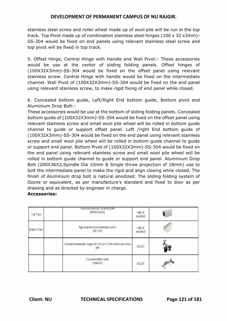
DEVELOPMENT OF PERMANENT CAMPUS OF NU RAJGIR.
Client: NU TECHNICAL SPECIFICATIONS Page 121 of 181
stainless steel screw and roller wheel made up of wool pile will be run in the top track. Top Pivot made up of combination stainless steel hinges (100 x 32 x3mm)-SS-304 would be fixed on end panels using relevant stainless steel screw and top pivot will be fixed in top track. 5. Offset Hinge, Central Hinge with Handle and Wall Pivot:- These accessories would be use at the center of sliding folding panels. Offset hinges of (100X32X3mm)-SS-304 would be fixed on the offset panel using relevant stainless screw. Central Hinge with handle would be fixed on the intermediate channel. Wall Pivot of (100X32X3mm)-SS-304 would be fixed on the end panel using relevant stainless screw, to make rigid fixing of end panel while closed. 6. Concealed bottom guide, Left/Right End bottom guide, Bottom pivot and Aluminium Drop Bolt:- These accessories would be use at the bottom of sliding folding panels. Concealed bottom guide of (100X32X3mm)-SS-304 would be fixed on the offset panel using relevant stainless screw and small wool pile wheel will be rolled in bottom guide channel to guide or support offset panel. Left /right End bottom guide of (100X32X3mm)-SS-304 would be fixed on the end panel using relevant stainless screw and small wool pile wheel will be rolled in bottom guide channel to guide or support end panel. Bottom Pivot of (100X32X3mm)-SS-304 would be fixed on the end panel using relevant stainless screw and small wool pile wheel will be rolled in bottom guide channel to guide or support end panel. Aluminium Drop Bolt (200X36X2,Spindle Dia 10mm & Single throw projection of 18mm) use to bolt the intermediate panel to make the rigid and align closing while closed. The finish of Aluminium drop bolt is natural anodized. The sliding folding system of Ozone or equivalent, as per manufacture’s standard and fixed to door as per drawing and as directed by engineer in charge. Accessories:
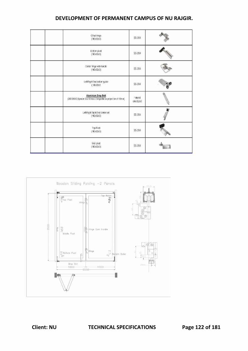
DEVELOPMENT OF PERMANENT CAMPUS OF NU RAJGIR.
Client: NU TECHNICAL SPECIFICATIONS Page 122 of 181
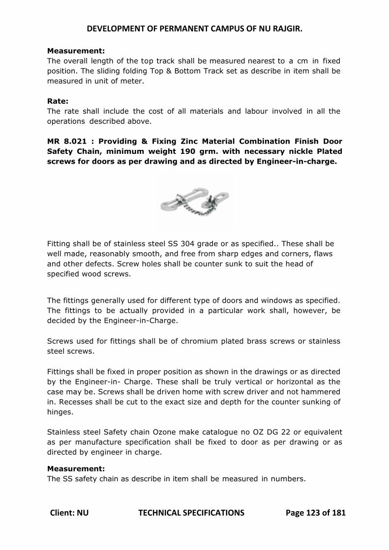
DEVELOPMENT OF PERMANENT CAMPUS OF NU RAJGIR.
Client: NU TECHNICAL SPECIFICATIONS Page 123 of 181
Measurement: The overall length of the top track shall be measured nearest to a cm in fixed position. The sliding folding Top & Bottom Track set as describe in item shall be measured in unit of meter. Rate: The rate shall include the cost of all materials and labour involved in all the operations described above. MR 8.021 : Providing & Fixing Zinc Material Combination Finish Door Safety Chain, minimum weight 190 grm. with necessary nickle Plated screws for doors as per drawing and as directed by Engineer-in-charge.
Fitting shall be of stainless steel SS 304 grade or as specified.. These shall be well made, reasonably smooth, and free from sharp edges and corners, flaws and other defects. Screw holes shall be counter sunk to suit the head of specified wood screws.
The fittings generally used for different type of doors and windows as specified. The fittings to be actually provided in a particular work shall, however, be decided by the Engineer-in-Charge. Screws used for fittings shall be of chromium plated brass screws or stainless steel screws. Fittings shall be fixed in proper position as shown in the drawings or as directed by the Engineer-in- Charge. These shall be truly vertical or horizontal as the case may be. Screws shall be driven home with screw driver and not hammered in. Recesses shall be cut to the exact size and depth for the counter sunking of hinges. Stainless steel Safety chain Ozone make catalogue no OZ DG 22 or equivalent as per manufacture specification shall be fixed to door as per drawing or as directed by engineer in charge.
Measurement: The SS safety chain as describe in item shall be measured in numbers.
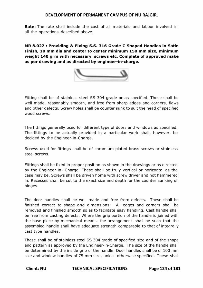
DEVELOPMENT OF PERMANENT CAMPUS OF NU RAJGIR.
Client: NU TECHNICAL SPECIFICATIONS Page 124 of 181
Rate: The rate shall include the cost of all materials and labour involved in all the operations described above.
MR 8.022 : Providing & Fixing S.S. 316 Grade C Shaped Handles in Satin Finish, 10 mm dia and center to center minimum 150 mm size, minimum weight 140 grm with necessary screws etc. Complete of approved make as per drawing and as directed by engineer-in-charge.
Fitting shall be of stainless steel SS 304 grade or as specified. These shall be well made, reasonably smooth, and free from sharp edges and corners, flaws and other defects. Screw holes shall be counter sunk to suit the head of specified wood screws.
The fittings generally used for different type of doors and windows as specified. The fittings to be actually provided in a particular work shall, however, be decided by the Engineer-in-Charge. Screws used for fittings shall be of chromium plated brass screws or stainless steel screws. Fittings shall be fixed in proper position as shown in the drawings or as directed by the Engineer-in- Charge. These shall be truly vertical or horizontal as the case may be. Screws shall be driven home with screw driver and not hammered in. Recesses shall be cut to the exact size and depth for the counter sunking of hinges.
The door handles shall be well made and free from defects. These shall be finished correct to shape and dimensions. All edges and corners shall be removed and finished smooth so as to facilitate easy handling. Cast handle shall be free from casting defects. Where the grip portion of the handle is joined with the base piece by mechanical means, the arrangement shall be such that the assembled handle shall have adequate strength comparable to that of integrally cast type handles.
These shall be of stainless steel SS 304 grade of specified size and of the shape and pattern as approved by the Engineer-in-Charge. The size of the handle shall be determined by the inside grip of the handle. Door handles shall be of 100 mm size and window handles of 75 mm size, unless otherwise specified. These shall
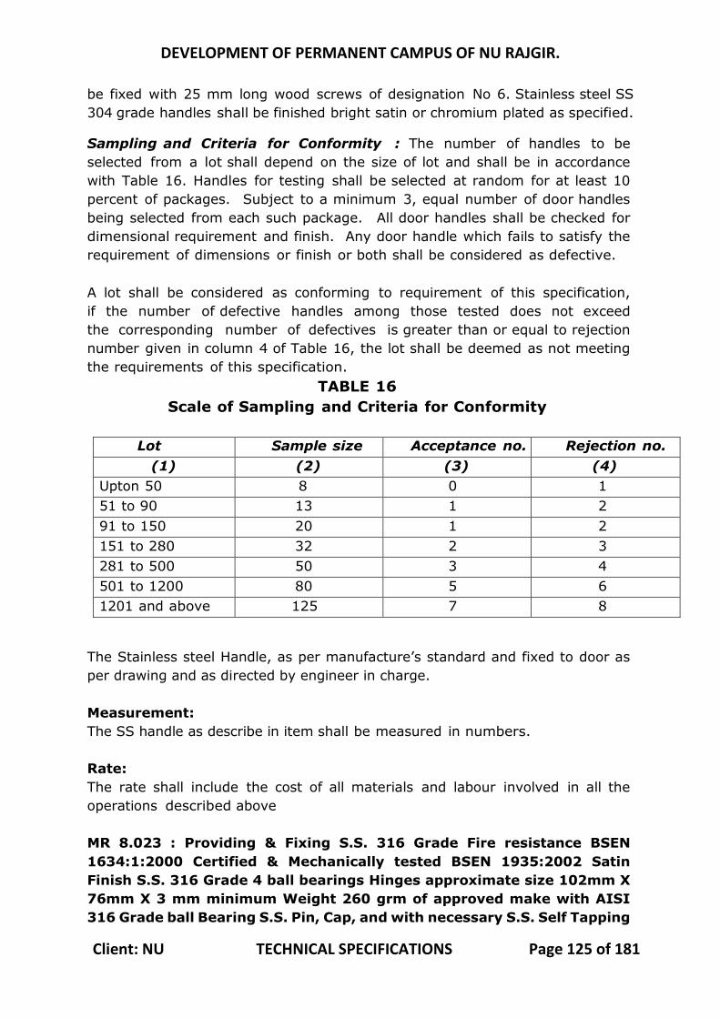
DEVELOPMENT OF PERMANENT CAMPUS OF NU RAJGIR.
Client: NU TECHNICAL SPECIFICATIONS Page 125 of 181
be fixed with 25 mm long wood screws of designation No 6. Stainless steel SS 304 grade handles shall be finished bright satin or chromium plated as specified.
Sampling and Criteria for Conformity : The number of handles to be selected from a lot shall depend on the size of lot and shall be in accordance with Table 16. Handles for testing shall be selected at random for at least 10 percent of packages. Subject to a minimum 3, equal number of door handles being selected from each such package. All door handles shall be checked for dimensional requirement and finish. Any door handle which fails to satisfy the requirement of dimensions or finish or both shall be considered as defective. A lot shall be considered as conforming to requirement of this specification, if the number of defective handles among those tested does not exceed the corresponding number of defectives is greater than or equal to rejection number given in column 4 of Table 16, the lot shall be deemed as not meeting the requirements of this specification.
TABLE 16 Scale of Sampling and Criteria for Conformity
Lot size
Sample size Acceptance no. Rejection no. (1) (2) (3) (4)
Upton 50 8 0 1 51 to 90 13 1 2 91 to 150 20 1 2 151 to 280 32 2 3 281 to 500 50 3 4 501 to 1200 80 5 6 1201 and above 125 7 8
The Stainless steel Handle, as per manufacture’s standard and fixed to door as per drawing and as directed by engineer in charge. Measurement: The SS handle as describe in item shall be measured in numbers. Rate: The rate shall include the cost of all materials and labour involved in all the operations described above MR 8.023 : Providing & Fixing S.S. 316 Grade Fire resistance BSEN 1634:1:2000 Certified & Mechanically tested BSEN 1935:2002 Satin Finish S.S. 316 Grade 4 ball bearings Hinges approximate size 102mm X 76mm X 3 mm minimum Weight 260 grm of approved make with AISI 316 Grade ball Bearing S.S. Pin, Cap, and with necessary S.S. Self Tapping
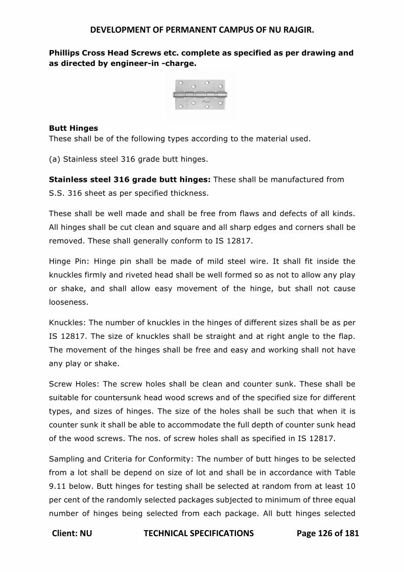
DEVELOPMENT OF PERMANENT CAMPUS OF NU RAJGIR.
Client: NU TECHNICAL SPECIFICATIONS Page 126 of 181
Phillips Cross Head Screws etc. complete as specified as per drawing and as directed by engineer-in -charge.
Butt Hinges These shall be of the following types according to the material used.
(a) Stainless steel 316 grade butt hinges.
Stainless steel 316 grade butt hinges: These shall be manufactured from
S.S. 316 sheet as per specified thickness.
These shall be well made and shall be free from flaws and defects of all kinds.
All hinges shall be cut clean and square and all sharp edges and corners shall be
removed. These shall generally conform to IS 12817.
Hinge Pin: Hinge pin shall be made of mild steel wire. It shall fit inside the
knuckles firmly and riveted head shall be well formed so as not to allow any play
or shake, and shall allow easy movement of the hinge, but shall not cause
looseness.
Knuckles: The number of knuckles in the hinges of different sizes shall be as per
IS 12817. The size of knuckles shall be straight and at right angle to the flap.
The movement of the hinges shall be free and easy and working shall not have
any play or shake.
Screw Holes: The screw holes shall be clean and counter sunk. These shall be
suitable for countersunk head wood screws and of the specified size for different
types, and sizes of hinges. The size of the holes shall be such that when it is
counter sunk it shall be able to accommodate the full depth of counter sunk head
of the wood screws. The nos. of screw holes shall as specified in IS 12817.
Sampling and Criteria for Conformity: The number of butt hinges to be selected
from a lot shall be depend on size of lot and shall be in accordance with Table
9.11 below. Butt hinges for testing shall be selected at random from at least 10
per cent of the randomly selected packages subjected to minimum of three equal
number of hinges being selected from each package. All butt hinges selected
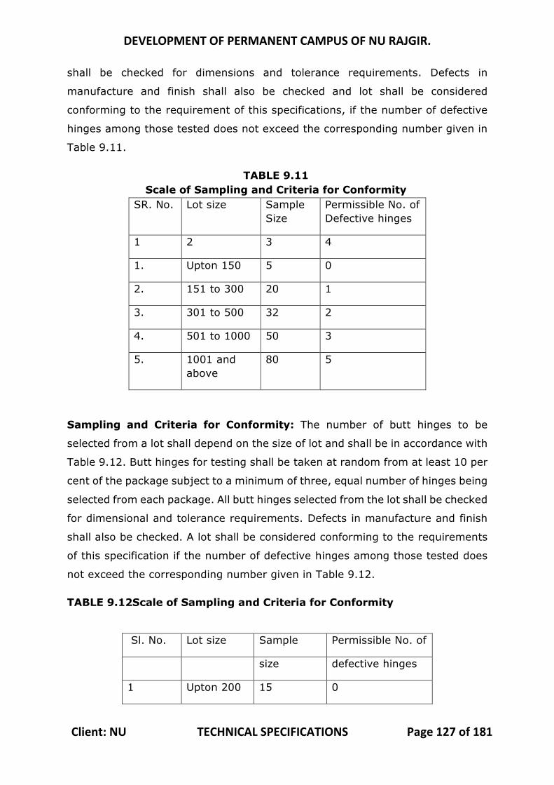
DEVELOPMENT OF PERMANENT CAMPUS OF NU RAJGIR.
Client: NU TECHNICAL SPECIFICATIONS Page 127 of 181
shall be checked for dimensions and tolerance requirements. Defects in
manufacture and finish shall also be checked and lot shall be considered
conforming to the requirement of this specifications, if the number of defective
hinges among those tested does not exceed the corresponding number given in
Table 9.11.
TABLE 9.11 Scale of Sampling and Criteria for Conformity
SR. No. Lot size Sample Size
Permissible No. of Defective hinges
1 2 3 4
1. Upton 150 5 0
2. 151 to 300 20 1
3. 301 to 500 32 2
4. 501 to 1000 50 3
5. 1001 and above
80 5
Sampling and Criteria for Conformity: The number of butt hinges to be
selected from a lot shall depend on the size of lot and shall be in accordance with
Table 9.12. Butt hinges for testing shall be taken at random from at least 10 per
cent of the package subject to a minimum of three, equal number of hinges being
selected from each package. All butt hinges selected from the lot shall be checked
for dimensional and tolerance requirements. Defects in manufacture and finish
shall also be checked. A lot shall be considered conforming to the requirements
of this specification if the number of defective hinges among those tested does
not exceed the corresponding number given in Table 9.12.
TABLE 9.12Scale of Sampling and Criteria for Conformity
Sl. No. Lot size Sample Permissible No. of
size defective hinges
1 Upton 200 15 0
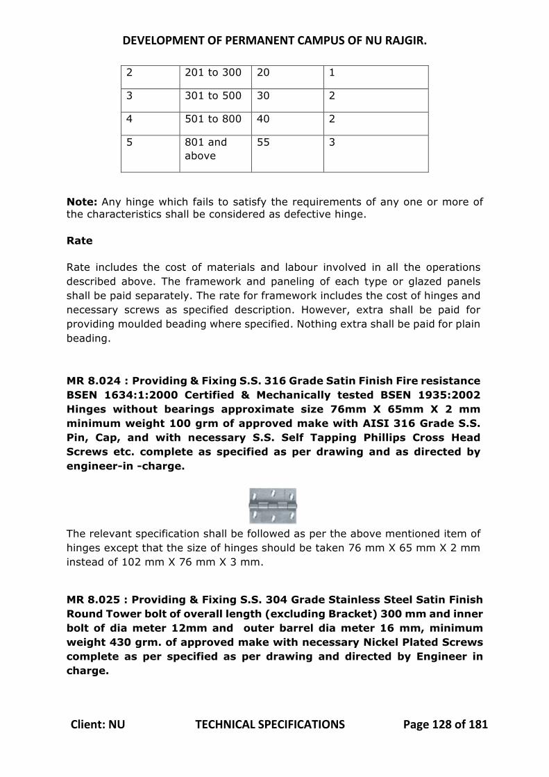
DEVELOPMENT OF PERMANENT CAMPUS OF NU RAJGIR.
Client: NU TECHNICAL SPECIFICATIONS Page 128 of 181
2 201 to 300 20 1
3 301 to 500 30 2
4 501 to 800 40 2
5 801 and above
55 3
Note: Any hinge which fails to satisfy the requirements of any one or more of the characteristics shall be considered as defective hinge. Rate Rate includes the cost of materials and labour involved in all the operations described above. The framework and paneling of each type or glazed panels shall be paid separately. The rate for framework includes the cost of hinges and necessary screws as specified description. However, extra shall be paid for providing moulded beading where specified. Nothing extra shall be paid for plain beading. MR 8.024 : Providing & Fixing S.S. 316 Grade Satin Finish Fire resistance BSEN 1634:1:2000 Certified & Mechanically tested BSEN 1935:2002 Hinges without bearings approximate size 76mm X 65mm X 2 mm minimum weight 100 grm of approved make with AISI 316 Grade S.S. Pin, Cap, and with necessary S.S. Self Tapping Phillips Cross Head Screws etc. complete as specified as per drawing and as directed by engineer-in -charge.
The relevant specification shall be followed as per the above mentioned item of hinges except that the size of hinges should be taken 76 mm X 65 mm X 2 mm instead of 102 mm X 76 mm X 3 mm.
MR 8.025 : Providing & Fixing S.S. 304 Grade Stainless Steel Satin Finish Round Tower bolt of overall length (excluding Bracket) 300 mm and inner bolt of dia meter 12mm and outer barrel dia meter 16 mm, minimum weight 430 grm. of approved make with necessary Nickel Plated Screws complete as per specified as per drawing and directed by Engineer in charge.
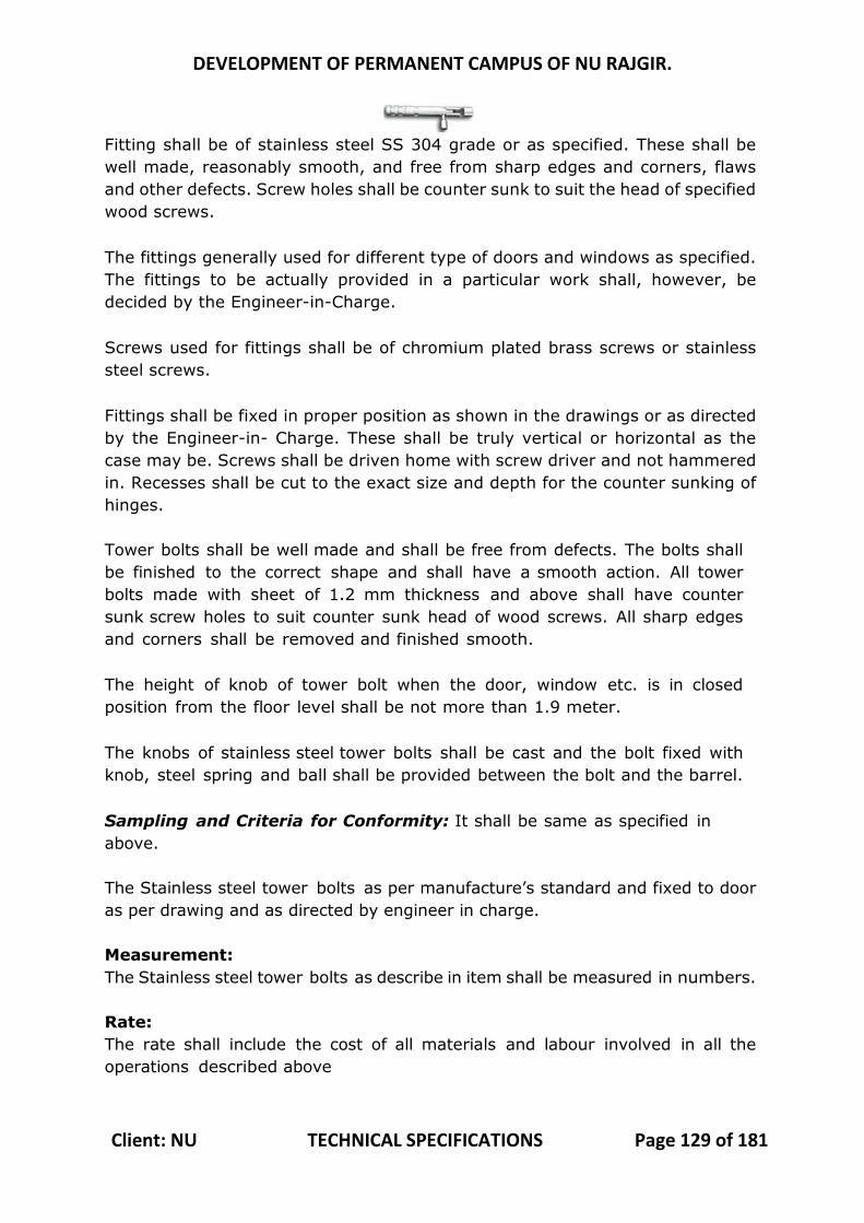
DEVELOPMENT OF PERMANENT CAMPUS OF NU RAJGIR.
Client: NU TECHNICAL SPECIFICATIONS Page 129 of 181
Fitting shall be of stainless steel SS 304 grade or as specified. These shall be well made, reasonably smooth, and free from sharp edges and corners, flaws and other defects. Screw holes shall be counter sunk to suit the head of specified wood screws. The fittings generally used for different type of doors and windows as specified. The fittings to be actually provided in a particular work shall, however, be decided by the Engineer-in-Charge. Screws used for fittings shall be of chromium plated brass screws or stainless steel screws. Fittings shall be fixed in proper position as shown in the drawings or as directed by the Engineer-in- Charge. These shall be truly vertical or horizontal as the case may be. Screws shall be driven home with screw driver and not hammered in. Recesses shall be cut to the exact size and depth for the counter sunking of hinges. Tower bolts shall be well made and shall be free from defects. The bolts shall be finished to the correct shape and shall have a smooth action. All tower bolts made with sheet of 1.2 mm thickness and above shall have counter sunk screw holes to suit counter sunk head of wood screws. All sharp edges and corners shall be removed and finished smooth. The height of knob of tower bolt when the door, window etc. is in closed position from the floor level shall be not more than 1.9 meter. The knobs of stainless steel tower bolts shall be cast and the bolt fixed with knob, steel spring and ball shall be provided between the bolt and the barrel. Sampling and Criteria for Conformity: It shall be same as specified in above. The Stainless steel tower bolts as per manufacture’s standard and fixed to door as per drawing and as directed by engineer in charge. Measurement: The Stainless steel tower bolts as describe in item shall be measured in numbers. Rate: The rate shall include the cost of all materials and labour involved in all the operations described above
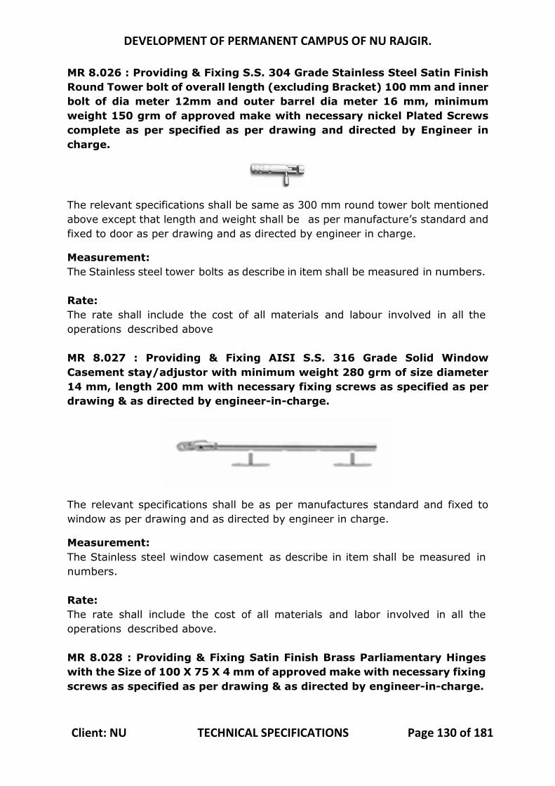
DEVELOPMENT OF PERMANENT CAMPUS OF NU RAJGIR.
Client: NU TECHNICAL SPECIFICATIONS Page 130 of 181
MR 8.026 : Providing & Fixing S.S. 304 Grade Stainless Steel Satin Finish Round Tower bolt of overall length (excluding Bracket) 100 mm and inner bolt of dia meter 12mm and outer barrel dia meter 16 mm, minimum weight 150 grm of approved make with necessary nickel Plated Screws complete as per specified as per drawing and directed by Engineer in charge.
The relevant specifications shall be same as 300 mm round tower bolt mentioned above except that length and weight shall be as per manufacture’s standard and fixed to door as per drawing and as directed by engineer in charge.
Measurement: The Stainless steel tower bolts as describe in item shall be measured in numbers. Rate: The rate shall include the cost of all materials and labour involved in all the operations described above MR 8.027 : Providing & Fixing AISI S.S. 316 Grade Solid Window Casement stay/adjustor with minimum weight 280 grm of size diameter 14 mm, length 200 mm with necessary fixing screws as specified as per drawing & as directed by engineer-in-charge.
The relevant specifications shall be as per manufactures standard and fixed to window as per drawing and as directed by engineer in charge.
Measurement: The Stainless steel window casement as describe in item shall be measured in numbers. Rate: The rate shall include the cost of all materials and labor involved in all the operations described above. MR 8.028 : Providing & Fixing Satin Finish Brass Parliamentary Hinges with the Size of 100 X 75 X 4 mm of approved make with necessary fixing screws as specified as per drawing & as directed by engineer-in-charge.

DEVELOPMENT OF PERMANENT CAMPUS OF NU RAJGIR.
Client: NU TECHNICAL SPECIFICATIONS Page 131 of 181
The relevant specifications shall be as per manufacture’s standard and fixed to door / window as per drawing and as directed by engineer in charge.
Measurement: The Parliamentary hinges a s describe in item shall be measured in numbers. Rate: The rate shall include the cost of all materials and labor involved in all the operations described above. MR 8.029 : Providing & Fixing Fire resistance BSEN 1634:1:2000 Certified & Mechanically tested BSEN 1906:2010 Pair of AISI S.S. 316 Grade Satin Finish hollow Pipe or solid design Mortise Handle with the minimum weight 620 grm key hole for Mortise Pin Cylinder, high grade brass bushing for extra fixing strength for intensive use of door with back to back fixing screws system of approved make with both side active mortise handle and spindle, High Quality Stainless Steel Wood Screws (8 PCS.) for minimum door thickness 30 mm as per drawing and as directed by engineer in charge. The Inner and Outer Rose of Mortise handle and Escutcheons must be of AISI 316 grade only.
Fitting shall be of stainless steel SS 304 grade or as specified. These shall be well made, reasonably smooth, and free from sharp edges and corners, flaws and other defects. Screw holes shall be counter sunk to suit the head of specified wood screws. The fittings generally used for different type of doors and windows as specified. The fittings to be actually provided in a particular work shall, however, be decided by the Engineer-in-Charge. Screws used for fittings shall be of chromium plated brass screws or stainless steel screws. Fittings shall be fixed in proper position as shown in the drawings or as directed by the Engineer-in- Charge. These shall be truly vertical or horizontal as the case may be. Screws shall be driven home with screw driver and not hammered in. Recesses shall be cut to the exact size and depth for the counter sunking of hinges. This is a mortise lock having a single spring bolt withdrawn from the outside by using the key and from inside by key and with an arrangement.
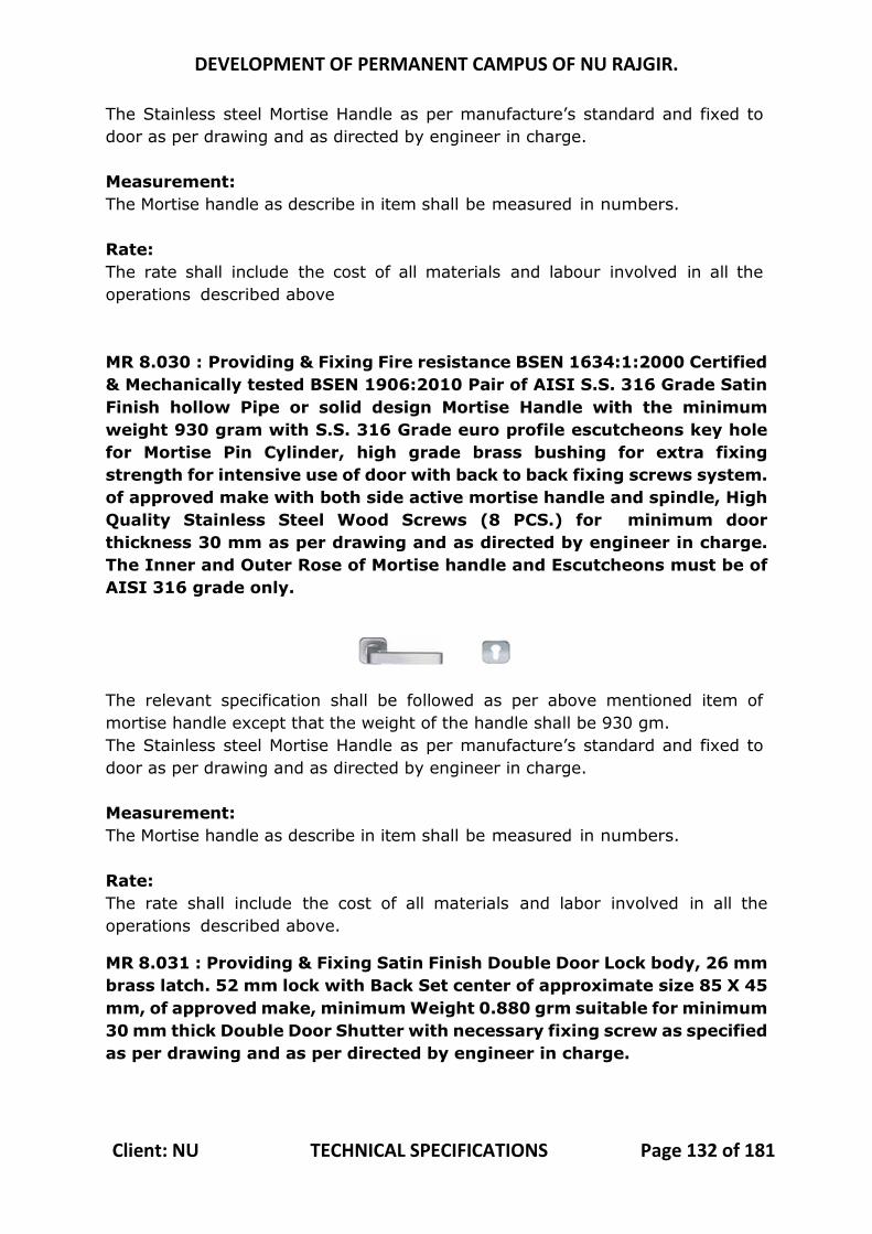
DEVELOPMENT OF PERMANENT CAMPUS OF NU RAJGIR.
Client: NU TECHNICAL SPECIFICATIONS Page 132 of 181
The Stainless steel Mortise Handle as per manufacture’s standard and fixed to door as per drawing and as directed by engineer in charge. Measurement: The Mortise handle as describe in item shall be measured in numbers. Rate: The rate shall include the cost of all materials and labour involved in all the operations described above MR 8.030 : Providing & Fixing Fire resistance BSEN 1634:1:2000 Certified & Mechanically tested BSEN 1906:2010 Pair of AISI S.S. 316 Grade Satin Finish hollow Pipe or solid design Mortise Handle with the minimum weight 930 gram with S.S. 316 Grade euro profile escutcheons key hole for Mortise Pin Cylinder, high grade brass bushing for extra fixing strength for intensive use of door with back to back fixing screws system. of approved make with both side active mortise handle and spindle, High Quality Stainless Steel Wood Screws (8 PCS.) for minimum door thickness 30 mm as per drawing and as directed by engineer in charge. The Inner and Outer Rose of Mortise handle and Escutcheons must be of AISI 316 grade only.
The relevant specification shall be followed as per above mentioned item of mortise handle except that the weight of the handle shall be 930 gm. The Stainless steel Mortise Handle as per manufacture’s standard and fixed to door as per drawing and as directed by engineer in charge. Measurement: The Mortise handle as describe in item shall be measured in numbers. Rate: The rate shall include the cost of all materials and labor involved in all the operations described above.
MR 8.031 : Providing & Fixing Satin Finish Double Door Lock body, 26 mm brass latch. 52 mm lock with Back Set center of approximate size 85 X 45 mm, of approved make, minimum Weight 0.880 grm suitable for minimum 30 mm thick Double Door Shutter with necessary fixing screw as specified as per drawing and as per directed by engineer in charge.
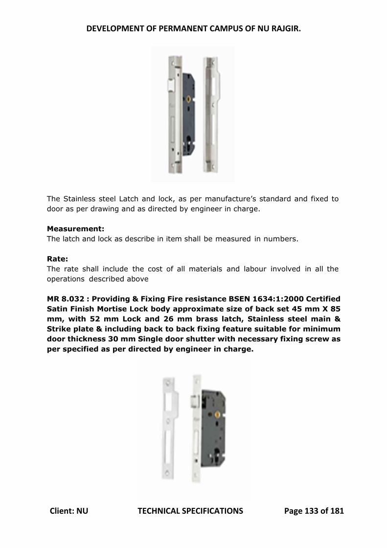
DEVELOPMENT OF PERMANENT CAMPUS OF NU RAJGIR.
Client: NU TECHNICAL SPECIFICATIONS Page 133 of 181
The Stainless steel Latch and lock, as per manufacture’s standard and fixed to door as per drawing and as directed by engineer in charge. Measurement: The latch and lock as describe in item shall be measured in numbers. Rate: The rate shall include the cost of all materials and labour involved in all the operations described above MR 8.032 : Providing & Fixing Fire resistance BSEN 1634:1:2000 Certified Satin Finish Mortise Lock body approximate size of back set 45 mm X 85 mm, with 52 mm Lock and 26 mm brass latch, Stainless steel main & Strike plate & including back to back fixing feature suitable for minimum door thickness 30 mm Single door shutter with necessary fixing screw as per specified as per directed by engineer in charge.
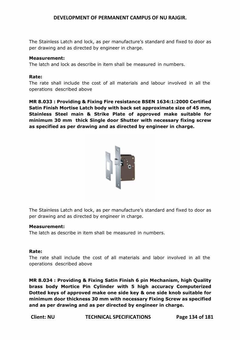
DEVELOPMENT OF PERMANENT CAMPUS OF NU RAJGIR.
Client: NU TECHNICAL SPECIFICATIONS Page 134 of 181
The Stainless Latch and lock, as per manufacture’s standard and fixed to door as per drawing and as directed by engineer in charge.
Measurement: The latch and lock as describe in item shall be measured in numbers. Rate: The rate shall include the cost of all materials and labour involved in all the operations described above MR 8.033 : Providing & Fixing Fire resistance BSEN 1634:1:2000 Certified Satin Finish Mortise Latch body with back set approximate size of 45 mm, Stainless Steel main & Strike Plate of approved make suitable for minimum 30 mm thick Single door Shutter with necessary fixing screw as specified as per drawing and as directed by engineer in charge.
The Stainless Latch and lock, as per manufacture’s standard and fixed to door as per drawing and as directed by engineer in charge.
Measurement: The latch as describe in item shall be measured in numbers. Rate: The rate shall include the cost of all materials and labor involved in all the operations described above
MR 8.034 : Providing & Fixing Satin Finish 6 pin Mechanism, high Quality brass body Mortice Pin Cylinder with 5 high accuracy Computerized Dotted keys of approved make one side key & one side knob suitable for minimum door thickness 30 mm with necessary Fixing Screw as specified and as per drawing and as per directed by engineer in charge.

DEVELOPMENT OF PERMANENT CAMPUS OF NU RAJGIR.
Client: NU TECHNICAL SPECIFICATIONS Page 135 of 181
The Cylinder lock, as per manufacture’s standard and fixed to door as per drawing and as directed by engineer in charge.
This is a Cylinder lock having a single spring bolt withdrawn from the outside by using the key and from inside by Knob with an arrangement. Measurement: The Cylinder lock as describe in item shall be measured in numbers. Rate: The rate shall include the cost of all materials and labour involved in all the operations described above MR 8.035 : Providing & Fixing Fire resistance BSEN 1634:1:2000 Certified Satin Finish Secure Standard 5 pin Mechanism Mortise Pin Cylinder with both Side Keys, high accuracy Brass keys of approved make suitable for minimum door thickness 30 mm with necessary fixing screw as per specified and as per drawing and as per directed by engineer in charge.
The Cylinder lock, as per manufacture’s standard and fixed to door as per drawing and as directed by engineer in charge.
This is a Cylinder lock having a single spring bolt withdrawn from the outside by using the key and from inside by Knob with an arrangement. Measurement: The Cylinder lock as describe in item shall be measured in numbers. Rate: The rate shall include the cost of all materials and labour involved in all the operations described above
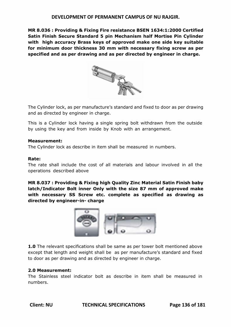
DEVELOPMENT OF PERMANENT CAMPUS OF NU RAJGIR.
Client: NU TECHNICAL SPECIFICATIONS Page 136 of 181
MR 8.036 : Providing & Fixing Fire resistance BSEN 1634:1:2000 Certified Satin Finish Secure Standard 5 pin Mechanism half Mortise Pin Cylinder with high accuracy Brass keys of approved make one side key suitable for minimum door thickness 30 mm with necessary fixing screw as per specified and as per drawing and as per directed by engineer in charge.
The Cylinder lock, as per manufacture’s standard and fixed to door as per drawing and as directed by engineer in charge.
This is a Cylinder lock having a single spring bolt withdrawn from the outside by using the key and from inside by Knob with an arrangement. Measurement: The Cylinder lock as describe in item shall be measured in numbers. Rate: The rate shall include the cost of all materials and labour involved in all the operations described above MR 8.037 : Providing & Fixing high Quality Zinc Material Satin Finish baby latch/Indicator Bolt inner Only with the size 87 mm of approved make with necessary SS Screw etc. complete as specified as drawing as directed by engineer-in- charge
1.0 The relevant specifications shall be same as per tower bolt mentioned above except that length and weight shall be as per manufacture’s standard and fixed to door as per drawing and as directed by engineer in charge. 2.0 Measurement: The Stainless steel indicator bolt as describe in item shall be measured in numbers.
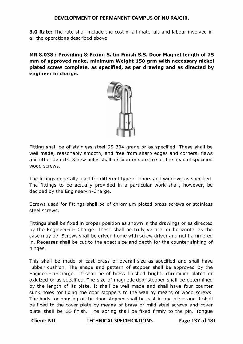
DEVELOPMENT OF PERMANENT CAMPUS OF NU RAJGIR.
Client: NU TECHNICAL SPECIFICATIONS Page 137 of 181
3.0 Rate: The rate shall include the cost of all materials and labour involved in all the operations described above
MR 8.038 : Providing & Fixing Satin Finish S.S. Door Magnet length of 75 mm of approved make, minimum Weight 150 grm with necessary nickel plated screw complete, as specified, as per drawing and as directed by engineer in charge.
Fitting shall be of stainless steel SS 304 grade or as specified. These shall be well made, reasonably smooth, and free from sharp edges and corners, flaws and other defects. Screw holes shall be counter sunk to suit the head of specified wood screws. The fittings generally used for different type of doors and windows as specified. The fittings to be actually provided in a particular work shall, however, be decided by the Engineer-in-Charge. Screws used for fittings shall be of chromium plated brass screws or stainless steel screws. Fittings shall be fixed in proper position as shown in the drawings or as directed by the Engineer-in- Charge. These shall be truly vertical or horizontal as the case may be. Screws shall be driven home with screw driver and not hammered in. Recesses shall be cut to the exact size and depth for the counter sinking of hinges. This shall be made of cast brass of overall size as specified and shall have rubber cushion. The shape and pattern of stopper shall be approved by the Engineer-in-Charge. It shall be of brass finished bright, chromium plated or oxidized or as specified. The size of magnetic door stopper shall be determined by the length of its plate. It shall be well made and shall have four counter sunk holes for fixing the door stoppers to the wall by means of wood screws. The body for housing of the door stopper shall be cast in one piece and it shall be fixed to the cover plate by means of brass or mild steel screws and cover plate shall be SS finish. The spring shall be fixed firmly to the pin. Tongue
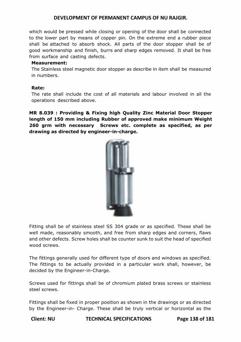
DEVELOPMENT OF PERMANENT CAMPUS OF NU RAJGIR.
Client: NU TECHNICAL SPECIFICATIONS Page 138 of 181
which would be pressed while closing or opening of the door shall be connected to the lower part by means of copper pin. On the extreme end a rubber piece shall be attached to absorb shock. All parts of the door stopper shall be of good workmanship and finish, burrs and sharp edges removed. It shall be free from surface and casting defects. Measurement: The Stainless steel magnetic door stopper as describe in item shall be measured in numbers. Rate: The rate shall include the cost of all materials and labour involved in all the operations described above.
MR 8.039 : Providing & Fixing high Quality Zinc Material Door Stopper length of 150 mm including Rubber of approved make minimum Weight 260 grm with necessary Screws etc. complete as specified, as per drawing as directed by engineer-in-charge.
Fitting shall be of stainless steel SS 304 grade or as specified. These shall be well made, reasonably smooth, and free from sharp edges and corners, flaws and other defects. Screw holes shall be counter sunk to suit the head of specified wood screws. The fittings generally used for different type of doors and windows as specified. The fittings to be actually provided in a particular work shall, however, be decided by the Engineer-in-Charge. Screws used for fittings shall be of chromium plated brass screws or stainless steel screws. Fittings shall be fixed in proper position as shown in the drawings or as directed by the Engineer-in- Charge. These shall be truly vertical or horizontal as the
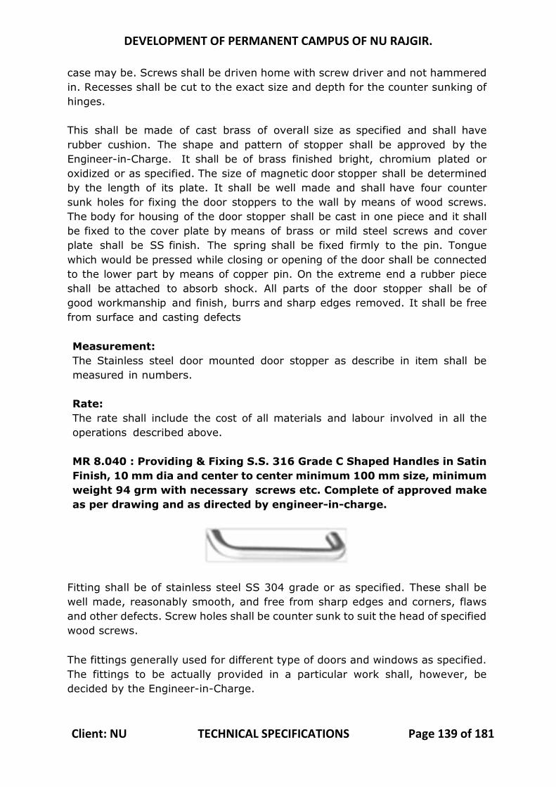
DEVELOPMENT OF PERMANENT CAMPUS OF NU RAJGIR.
Client: NU TECHNICAL SPECIFICATIONS Page 139 of 181
case may be. Screws shall be driven home with screw driver and not hammered in. Recesses shall be cut to the exact size and depth for the counter sunking of hinges. This shall be made of cast brass of overall size as specified and shall have rubber cushion. The shape and pattern of stopper shall be approved by the Engineer-in-Charge. It shall be of brass finished bright, chromium plated or oxidized or as specified. The size of magnetic door stopper shall be determined by the length of its plate. It shall be well made and shall have four counter sunk holes for fixing the door stoppers to the wall by means of wood screws. The body for housing of the door stopper shall be cast in one piece and it shall be fixed to the cover plate by means of brass or mild steel screws and cover plate shall be SS finish. The spring shall be fixed firmly to the pin. Tongue which would be pressed while closing or opening of the door shall be connected to the lower part by means of copper pin. On the extreme end a rubber piece shall be attached to absorb shock. All parts of the door stopper shall be of good workmanship and finish, burrs and sharp edges removed. It shall be free from surface and casting defects Measurement: The Stainless steel door mounted door stopper as describe in item shall be measured in numbers. Rate: The rate shall include the cost of all materials and labour involved in all the operations described above. MR 8.040 : Providing & Fixing S.S. 316 Grade C Shaped Handles in Satin Finish, 10 mm dia and center to center minimum 100 mm size, minimum weight 94 grm with necessary screws etc. Complete of approved make as per drawing and as directed by engineer-in-charge.
Fitting shall be of stainless steel SS 304 grade or as specified. These shall be well made, reasonably smooth, and free from sharp edges and corners, flaws and other defects. Screw holes shall be counter sunk to suit the head of specified wood screws. The fittings generally used for different type of doors and windows as specified. The fittings to be actually provided in a particular work shall, however, be decided by the Engineer-in-Charge.
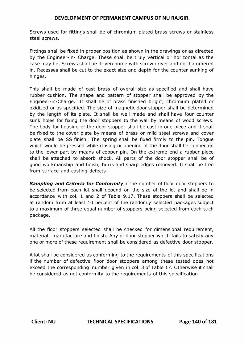
DEVELOPMENT OF PERMANENT CAMPUS OF NU RAJGIR.
Client: NU TECHNICAL SPECIFICATIONS Page 140 of 181
Screws used for fittings shall be of chromium plated brass screws or stainless steel screws. Fittings shall be fixed in proper position as shown in the drawings or as directed by the Engineer-in- Charge. These shall be truly vertical or horizontal as the case may be. Screws shall be driven home with screw driver and not hammered in. Recesses shall be cut to the exact size and depth for the counter sunking of hinges. This shall be made of cast brass of overall size as specified and shall have rubber cushion. The shape and pattern of stopper shall be approved by the Engineer-in-Charge. It shall be of brass finished bright, chromium plated or oxidized or as specified. The size of magnetic door stopper shall be determined by the length of its plate. It shall be well made and shall have four counter sunk holes for fixing the door stoppers to the wall by means of wood screws. The body for housing of the door stopper shall be cast in one piece and it shall be fixed to the cover plate by means of brass or mild steel screws and cover plate shall be SS finish. The spring shall be fixed firmly to the pin. Tongue which would be pressed while closing or opening of the door shall be connected to the lower part by means of copper pin. On the extreme end a rubber piece shall be attached to absorb shock. All parts of the door stopper shall be of good workmanship and finish, burrs and sharp edges removed. It shall be free from surface and casting defects Sampling and Criteria for Conformity : The number of floor door stoppers to be selected from each lot shall depend on the size of the lot and shall be in accordance with col. 1 and 2 of Table 9.17. These stoppers shall be selected at random from at least 10 percent of the randomly selected packages subject to a maximum of three equal number of stoppers being selected from each such package.
All the floor stoppers selected shall be checked for dimensional requirement, material, manufacture and finish. Any of door stopper which fails to satisfy any one or more of these requirement shall be considered as defective door stopper. A lot shall be considered as conforming to the requirements of this specifications if the number of defective floor door stoppers among these tested does not exceed the corresponding number given in col. 3 of Table 17. Otherwise it shall be considered as not conformity to the requirements of this specification.
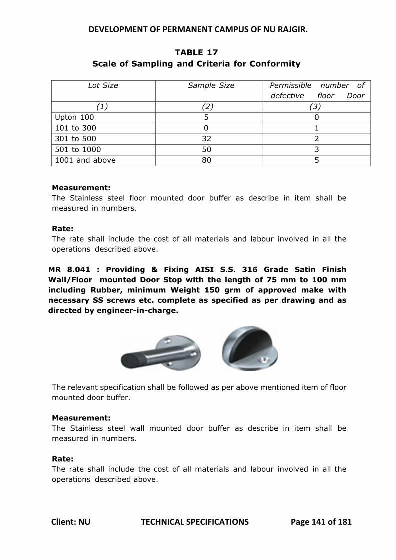
DEVELOPMENT OF PERMANENT CAMPUS OF NU RAJGIR.
Client: NU TECHNICAL SPECIFICATIONS Page 141 of 181
TABLE 17 Scale of Sampling and Criteria for Conformity
Lot Size Sample Size Permissible number of
defective floor Door stoppers (1) (2) (3)
Upton 100 5 0 101 to 300 0 1 301 to 500 32 2 501 to 1000 50 3 1001 and above 80 5
Measurement: The Stainless steel floor mounted door buffer as describe in item shall be measured in numbers. Rate: The rate shall include the cost of all materials and labour involved in all the operations described above.
MR 8.041 : Providing & Fixing AISI S.S. 316 Grade Satin Finish Wall/Floor mounted Door Stop with the length of 75 mm to 100 mm including Rubber, minimum Weight 150 grm of approved make with necessary SS screws etc. complete as specified as per drawing and as directed by engineer-in-charge.
The relevant specification shall be followed as per above mentioned item of floor mounted door buffer. Measurement: The Stainless steel wall mounted door buffer as describe in item shall be measured in numbers. Rate: The rate shall include the cost of all materials and labour involved in all the operations described above.
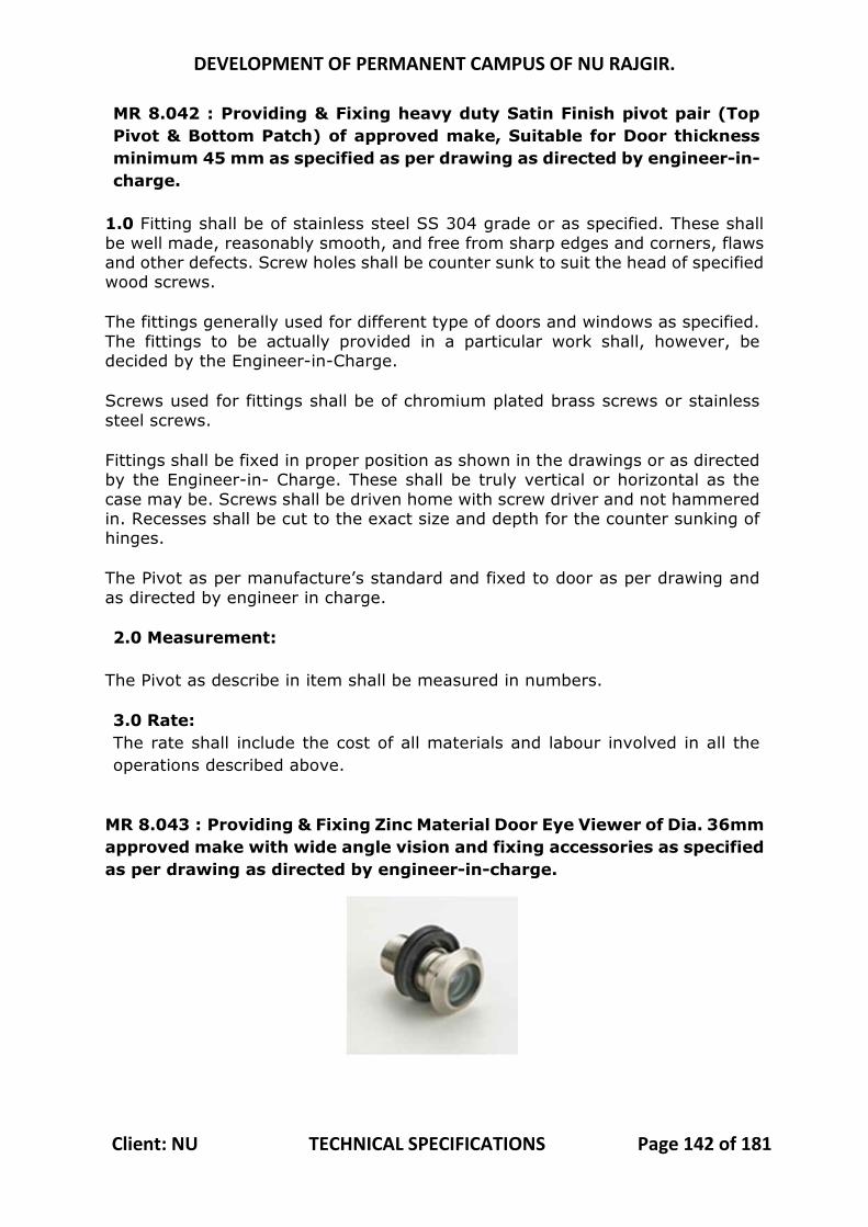
DEVELOPMENT OF PERMANENT CAMPUS OF NU RAJGIR.
Client: NU TECHNICAL SPECIFICATIONS Page 142 of 181
MR 8.042 : Providing & Fixing heavy duty Satin Finish pivot pair (Top Pivot & Bottom Patch) of approved make, Suitable for Door thickness minimum 45 mm as specified as per drawing as directed by engineer-in-charge.
1.0 Fitting shall be of stainless steel SS 304 grade or as specified. These shall be well made, reasonably smooth, and free from sharp edges and corners, flaws and other defects. Screw holes shall be counter sunk to suit the head of specified wood screws.
The fittings generally used for different type of doors and windows as specified. The fittings to be actually provided in a particular work shall, however, be decided by the Engineer-in-Charge.
Screws used for fittings shall be of chromium plated brass screws or stainless steel screws.
Fittings shall be fixed in proper position as shown in the drawings or as directed by the Engineer-in- Charge. These shall be truly vertical or horizontal as the case may be. Screws shall be driven home with screw driver and not hammered in. Recesses shall be cut to the exact size and depth for the counter sunking of hinges.
The Pivot as per manufacture’s standard and fixed to door as per drawing and as directed by engineer in charge.
2.0 Measurement:
The Pivot as describe in item shall be measured in numbers.
3.0 Rate: The rate shall include the cost of all materials and labour involved in all the operations described above.
MR 8.043 : Providing & Fixing Zinc Material Door Eye Viewer of Dia. 36mm approved make with wide angle vision and fixing accessories as specified as per drawing as directed by engineer-in-charge.
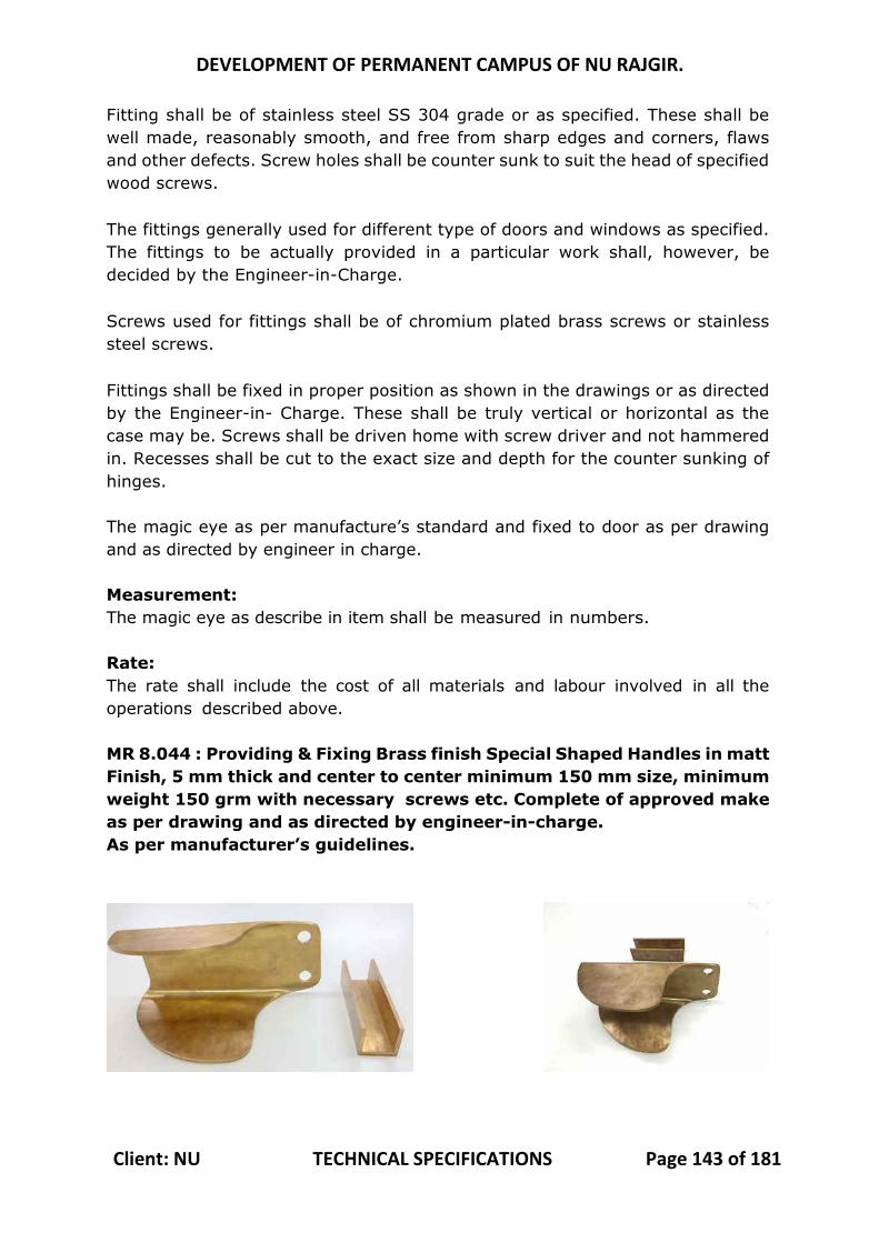
DEVELOPMENT OF PERMANENT CAMPUS OF NU RAJGIR.
Client: NU TECHNICAL SPECIFICATIONS Page 143 of 181
Fitting shall be of stainless steel SS 304 grade or as specified. These shall be well made, reasonably smooth, and free from sharp edges and corners, flaws and other defects. Screw holes shall be counter sunk to suit the head of specified wood screws. The fittings generally used for different type of doors and windows as specified. The fittings to be actually provided in a particular work shall, however, be decided by the Engineer-in-Charge. Screws used for fittings shall be of chromium plated brass screws or stainless steel screws. Fittings shall be fixed in proper position as shown in the drawings or as directed by the Engineer-in- Charge. These shall be truly vertical or horizontal as the case may be. Screws shall be driven home with screw driver and not hammered in. Recesses shall be cut to the exact size and depth for the counter sunking of hinges. The magic eye as per manufacture’s standard and fixed to door as per drawing and as directed by engineer in charge. Measurement: The magic eye as describe in item shall be measured in numbers. Rate: The rate shall include the cost of all materials and labour involved in all the operations described above. MR 8.044 : Providing & Fixing Brass finish Special Shaped Handles in matt Finish, 5 mm thick and center to center minimum 150 mm size, minimum weight 150 grm with necessary screws etc. Complete of approved make as per drawing and as directed by engineer-in-charge. As per manufacturer’s guidelines.
DEVELOPMENT OF PERMANENT CAMPUS OF NU RAJGIR.
Client: NU TECHNICAL SPECIFICATIONS Page 144 of 181
The Handel shall be made out of 5 mm thick brass plates. The plate shall be profile cut as per detailed drawings and shall be press bent on power press. Holes shall be drilled for fixing the handles to the door shutter and for locking arrangements as shown in the attached picture before the profile cut brass plate is press bent in the power press. The Prepared handle shall be fixed with door shutters with suitable brass screws/bolts of matching finish as directed by Engineer – in – Charge. The picture given here is for guidance and the design is subject to minor modifications. The weight of the handle shall be approximately 5Kg. The measurements shall be taken in numbers. Rates shall be for all materials and labour for all operations. MR 8.045 : Supply and carpentry of chemically seasoned 2nd class teak wood for creation of trellis & pergola rafters, columns, seat backs, railing tops, playground equipment parts like climbing wall steps, seats of see-saws, swings, etc. to be installed in exterior areas complete with all material, labour, equipment and accessories like screws, nuts, bolts, adhesive, etc. The relevant specification shall be followed as per the above mentioned item of wooden frame of doors, windows, clerestory windows and other frames. Measurements: Wood work wrought, framed and fixed shall be measured for finished dimension without any allowance for the wastage or for dimensions beyond specified dimension. However, in case of members having moldings, rounding’s or rebates and members of circular or varying sections, finished dimensions shall be taken as the sides of the smallest square or rectangle from which such a section can be cut. Length of each member shall be measured over all to the nearest cm so as to include projection for tenons. Width and thickness shall be measured to the nearest mm and the quantity shall be worked out in unit of up to three places of decimal.
Rate:
The rate shall include the cost of material and labour involved in all the operations described above except the hold fasts or metallic fasteners which will be paid for separately.
DEVELOPMENT OF PERMANENT CAMPUS OF NU RAJGIR.
Client: NU TECHNICAL SPECIFICATIONS Page 145 of 181
SUB HEAD: 9.0 STEEL WORK
MR 9.001 : Steel work in built up tubular (round, square or rectangular hollow hot finished welded type tubes etc.) for supporting frame work of Partitions with fixed glazing/fixed wooden/ plywood panels/ openable glazed doors/windows etc. all as per the detailed drawings and instructions of Engineer In charge, including cutting, hoisting, fixing in position and applying a priming coat of approved steel primer, including welding and bolted with special shaped washers etc. complete. Steel sections if required for Architectural aesthetic looks, may be covered with wooden members as per detailed design drawings. Weight of Steel sections only will be measured and paid for. Glazing, wooden/ply wood panels, shutters etc. will be paid separately under relevant items. General Specification of this Item shall be followed as per Para 10.13 of CPWD Civil works specifications 2009 volume 1. The Work pertains to Fabrication and erection of Tubular sections framing for Partitions instead of trusses as in para 10.13. The framing for partitions shall be erected in true line, level and plumb as per detailed drawings and as directed by Engineer – in – Charge. The joints between the various members shall be ground smooth and the partition frames shall be fixed firmly with wall and slabs with necessary holdfasts/anchor fasteners/by welding with pre-fixed insert plates as the case may be. Holdfasts/Anchor fasteners/insert plates shall be paid separately under relevant items. The weight of all sections used for partition frames shall be measured and paid for. Rates include cost all materials and cost of labour for all operations. MR 9.002: Steel work in single section or built up section or tubular (round, square or rectangular hollow tubes etc.)sections for frame work of sky lights at terrace levels/ roof levels of Gopurams / chhatries / class rooms etc. as per detailed drawings and direction of Engineer In charge , including cutting, hoisting, fixing in position and applying a priming coat of approved steel primer, including welding and bolted with special shaped washers etc. complete. Weight of Steel sections only will be measured and paid for. Glazing, Poly carbonate sheets or Fiberglass Plastic sheets of the skylight will be paid separately under relevant items. General Specification of this Item shall be followed as per Para 10.13 of CPWD Civil works specifications 2009 volume 1. The Work pertains to Fabrication and erection of Tubular sections framing for skylights instead of trusses as in para 10.13. The framing for partitions shall be erected in true line, level and plumb as per detailed drawings and as directed by Engineer – in – Charge. The joints between the various members shall be ground smooth and the skylight frames shall be fixed firmly with wall and slabs with necessary holdfasts/anchor
DEVELOPMENT OF PERMANENT CAMPUS OF NU RAJGIR.
Client: NU TECHNICAL SPECIFICATIONS Page 146 of 181
fasteners/by welding with pre-fixed insert plates as the case may be. Holdfasts/Anchor fasteners/insert plates shall be paid separately under relevant items. The weight of all sections used for skylight frames shall be measured and paid for. Rates include cost all materials and cost of labor for all operations. MR 9.003 : Providing and fixing stainless steel AISI 316 Grade Stainless Steel Knock Down railing system of approved make with satin finish and loading tested as per International load Testing Criteria with EXOVA Certification (Without any welding, Fabrication and Buffing on site) made of Hollow tubes, channels, plates , special glass holding fixtures etc., including welding, grinding, buffing, polishing and making curvature (wherever required) and fitting the same with necessary stainless steel nuts and bolts complete, on the top of the floor or the side of waist slab with suitable arrangement as per drawing and as directed by engineer in charge. The balustrade would be fixed onto floor/waist slab with casted base plate of S.S 316 with High Strength 2 NOS Anchor fasteners and whenever required, joints to be filled with bushings for extra strength. (For payment purpose only weight of stainless steel members shall be considered excluding fixing accessories such as nuts, bolts, fasteners etc.). Stainless Steel Fabrication Work This specification covers all Proprietary stainless steel railing work like D- Line or equivalent approved make. The Stainless steel sections shall be of AISI 316 Grade. Balusters shall be fixed with floor/steps with suitable anchor fasteners and the work shall be very nit and clear. All mild steel and stainless steel work shall conform to relevant Indian Standards. The Railing shall be supplied in factory finished Knocked down condition for all components. No site welding shall be allowed. Stainless Steel Components All stainless steel items shall be conforming to Indian Standards. Stainless steel items shall be supplied with a brushed hairline finish. All stainless steel fixings and fittings shall conform to relevant Indian Standards or equivalent International Standards. Stainless steel supplied shall be of minimum 316 grade. Regular Cutting Cutting shall be carried out via mechanical or heat powered tools. Maximum permissible variation shall be 5 millimeters for all cuts. All cut areas shall be ground to a smooth surface using mechanical grinder. CNC Precision Cutting and Engraving Computerized numerical controlled precision cutting and engraving shall be carried out on areas shown in contract drawings or as directed by EIC.
DEVELOPMENT OF PERMANENT CAMPUS OF NU RAJGIR.
Client: NU TECHNICAL SPECIFICATIONS Page 147 of 181
This process shall be carried out by entering computerized drawings into a computer controlled laser based CNC cutting and engraving machine. Samples shall be approved by EIC before entire process is carried out. Maximum permissible variation shall be one millimeter. All cut areas shall be ground to a smooth surface using precision mechanical grinders only if required. Welding Joints All Welding joints shall be factory finished and shall confirm to relevant Indian Standards or international standards for material, processes and workmanship. All welds are required to be ground smooth to the approval of the EIC. All sharp edges shall be ground smooth as per directions of EIC. Bending Bending of Stainless steel sections shall be undertaken to provide smooth and true curves. Tightly curved and bent sections shall be free from all distortions and rippling. All sharp edges shall be ground smooth. Fixings and Fastenings Generally, the Contractor shall provide a sample of all fixings and fastenings to the EIC for approval. These shall include but not be limited to beams, columns, hinges, locks, nuts and bolts, nails and screws, cables, wire and tensioners. Surface Finishes on Stainless Steel Stainless steel work shall be finished matt or glossy as specified in contract drawings using mechanical finishing and grinding tools. Finish should be level and smooth with an even pattern as directed and approved by EIC. Measurement Stainless steel items shall be measured in kilograms of finished items (excluding all wastage), accurate to the nearest 100 grams. Rates shall include cutting, welding and workmanship, as well as nuts, bolts, fasteners, etc accessories required for installing the item. MR no. 9.004: Providing and fixing 12 mm thick toughened glass with fixing of translucent polyester film on glass to give it a look of Frosted glass in the design as per detailed drawing to be fixed with Stainless steel railing in stairs/ passages etc. with necessary full length and designs stainless steel nuts etc. including making required size holes for bolts etc. for fixing the glass sheet with railing members complete. Sample of the railing will be prepared by the contractor and got approved by the Architect Before taking up the job at full scale. Stainless steel railing should be paid in relevant items.
DEVELOPMENT OF PERMANENT CAMPUS OF NU RAJGIR.
Client: NU TECHNICAL SPECIFICATIONS Page 148 of 181
The relevant specifications for Transparent float glass as per IS 14900 and specifications for safety glass IS 2553-1 shall be followed. Toughened glass shall be 12 mm thickness with providing and fixing of translucent polyester film on glass to give it a look of Frosted glass in the design as per detailed drawing. Necessary holes for fixing glass with Stainless steel railing in stairs, passages etc. shall be drilled before carrying out toughening process. MR 9.005 : Supplying and installing 4.3 m high 4mm GI Wire Chain Link Fencing PVC coated, of approved shade & colour on structure composed of 60.3 mm diametre MS CHS columns at 3 m center to center, & frame composed of 10mm MS bars, 40x25x5 ISA & 40x5 MS Flats, all MS items painted with approved paints, fixed in ground complete as per drawing and as directed by engineer in charge.(excluding cost of RCC Foundation) The relevant specifications shall be same as steel work mentioned in sub head 10.0 of CPWD Specifications for Civil works 2009 volume 1, except that Supplying and installing 4mm GI Wire Chain Link Fencing PVC coated, of approved shade & colour on structure composed of 60.3 mm diameter MS CHS columns, & frame composed of 10mm MS bars, 40x25x5 ISA & 40x5 MS Flats, all MS items painted with approved paints, fixed in ground complete (but excluding cost of RCC Foundation, which shall be paid separately under relevant items) will be measured and paid for in Rmt of length of the fencing. Rates includes cost of all materials and cost of labour for all operations for fabrication and fixing of fencing.
SUB HEAD: 10.0 FLOORING WORK
MR no. 10.001 : Extra rate over DSR item no. 11.26.1 in flooring for using Red Mandana stone slabs in place of Kota stone slabs
Operations as describe for kota stone flooring shall be followed except the stone shall be Red Mandana stone of same thickness.
Measurements
Red Mandana stone flooring shall be measured in square meter correct to two places of decimal. Nothing extra shall be paid for laying the patta or residue. Length and breadth shall be measured correct to a cm before laying skirting, dado or wall plaster. No deduction shall be made nor extra paid for voids not exceeding 0.20 square meter. Deductions for ends of dissimilar materials or other articles embedded shall not be made for areas not exceeding 0.10 square meter. Nothing extra shall be paid for laying the floor at different levels in the same room. Nosing shall not be measured and paid for extra. No separate

DEVELOPMENT OF PERMANENT CAMPUS OF NU RAJGIR.
Client: NU TECHNICAL SPECIFICATIONS Page 149 of 181
payment for groove in mortar at any junction of stone and wall/floor at any level. Rate The rate for flooring shall include the cost of all materials and labour involved in all the operations described above.
MR 10.002 : Extra rate over DSR item no. 11.26.1 in flooring for using Brown Bundi stone slabs in place of Kota stone slabs
1 Methodology
Operations as described for Kota stone flooring shall be followed except the stone shall be Brown bundi stone of same thickness.
2 Measurements
Brown bund stone flooring shall be measured in square meter correct to two places of decimal. Nothing extra shall be paid for laying the patta or residue. Length and breadth shall be measured correct to a cm before laying skirting, dado or wall plaster. No deduction shall be made nor extra paid for voids not exceeding 0.20 square metre. Deductions for ends of dissimilar materials or other articles embedded shall not be made for areas not exceeding 0.10 square meter. Nothing extra shall be paid for laying the floor at different levels in the same room. Nosing shall not be measured and paid for extra. No separate payment for groove in mortar at any junction of stone and wall/floor at any level. 3 Rate The rate for flooring shall include the cost of all materials and labour involved in all the operations described above. MR no. 10.003: Extra rate over DSR item no. 11.27 in tread & risers of steps, skirting, dado and pillars for using Red Mandana stone slabs in place of Kota stone slabs MR no. 10.004 : Extra rate over DSR item no. 11.27 in tread & risers of steps, skirting, dado and pillars for using Brown Bundi stone slabs in place of Kota stone slabs Operations as described for item no. 11.27 of kota stone skirting, dado and pillars shall be followed except the stone shall be Red Mandana stone or Brown Bundi stone of 20 mm thickness. Measurements
Length shall be measured along the finished face of skirting or dado correct to a cm. This shall be measured correct to a mm in the case of skirting and correct to a cm in the case of dado. The area shall be calculated in square meter
DEVELOPMENT OF PERMANENT CAMPUS OF NU RAJGIR.
Client: NU TECHNICAL SPECIFICATIONS Page 150 of 181
correct to two places of decimal. Lining of pillars etc. shall also be measured under this item. Nosing shall not be measured and paid for extra. No separate payment for groove in mortar at any junction of stone and wall/floor at any level. Rate The rate for skirting, dado and pillars shall include the cost of all materials and labor involved in all the operations described above. MR no. 10.005 : Kota stone slab 25 mm thick approved colour, shade & texture with machine cut edges in Kitchen platforms, vanity counters, facia, sills, jambs, lintels, partition, seat, landing, parapet top , shelves, chajja and similar locations of required size and in full length, over 20 mm (average) thick cement mortar 1:3 (1 cement 3 coarse sand) laid to line and level and jointed with grey cement slurry mixed with pigment to match the shade of the slabs, including rubbing and polishing complete as per drawing and as directed by engineer in charge. Material & Dressing Kota Stone Slabs and Dressing shall be as specified in kota stone flooring except that the thickness of the slabs shall be 25 mm. If required the slabs may be of uniform thickness or at least the visible edge of platform stone shall be made of uniform thickness and in full length or as specified otherwise as per drawing and as directed by engineer in charge. Relevant specifications of preparation of surface, Laying, Curing, Polishing, Finishing and measurements shall be as specified in kota stone flooring. Measurements
Length shall be measured along the finished face of tread and risers of steps, sill, facia, landing, parapet top correct to a cm. The area shall be calculated in square meter correct to two places of decimal. Nosing shall not be measured and paid for extra. No separate payment for groove in mortar at any junction of stone and wall/floor at any level. Rate The rate shall include the cost of all materials and labour involved in all the operations described above. MR 10.006 : Extra rate over MR item no. 10.005 in Kitchen platforms, vanity counters, facia, sills, jambs, lintels, partition, seat, landing, parapet top , shelves, chajja and similar locations for using Sand stone slabs in place of Kota stone slabs MR 10.007 : Extra rate over MR item no. 10.005 in Kitchen platforms, vanity counters, facia, sills, jambs, lintels, partition, seat, landing,

DEVELOPMENT OF PERMANENT CAMPUS OF NU RAJGIR.
Client: NU TECHNICAL SPECIFICATIONS Page 151 of 181
parapet top , shelves, chajja and similar locations for using Brown Bundi stone slabs in place of Kota stone slabs Methodology
Operations as described for kota stone tread and risers of steps, platform, sill, jam, lintel, facia, landing, parapet top and similar locations shall be followed except the stone shall be Red Mandana stone or Brown Bundi stone of 20 mm thickness. 2 Measurements
Length shall be measured along the finished face of tread and risers of steps, sill, facia, landing, parapet top correct to a cm. The area shall be calculated in square meter correct to two places of decimal. Nosing shall not be measured and paid for extra. No separate payment for groove in mortar at any junction of stone and wall/floor at any level. 3 Rate The rate for platform, vanity counters, sill, jambs, lintel, facia, partition, seat, landing, parapet top, shelves, chhajjah and similar locations shall include the cost of all materials and labour involved in all the operations described above. MR 10.008 : Rough Kota stone slab 25 mm thick approved color, shade & texture in flooring over 20 mm (average) thick over base of cement mortar 1 : 4 (1 cement : 4 coarse sand) laid to line and level and jointed with grey cement slurry mixed with pigment to match the shade of the slab including cleaning complete as directed by the Engineer-in-charge.
Methodology The relevant specifications shall be same as kota stone flooring mentioned above except that Rough kota stone slab 25 mm thick shall be used in place of kota stones. The flooring shall be measured in square meter correct to two places of decimal. Nothing extra shall be paid for laying the patta or residue. Length and breadth shall be measured correct to a cm before laying skirting, dado or wall plaster. No deduction shall be made nor extra paid for voids not exceeding 0.20 square meter. Deductions for ends of dissimilar materials or other articles embedded shall not be made for areas not exceeding 0.10 square meter. Nothing extra shall be paid for laying the floor at different levels in the same room. Nosing shall not be measured and paid for extra. No separate payment for groove in mortar at any junction of stone and wall/floor at any level. Rate The rate for flooring shall include the cost of all materials and labour involved in all the operations described above.
DEVELOPMENT OF PERMANENT CAMPUS OF NU RAJGIR.
Client: NU TECHNICAL SPECIFICATIONS Page 152 of 181
MR 10.009: Extra rate over DSR item no. 10.008 in Rough Red Mandana stone slab 25 mm thick approved colour, shade & texture in flooring over 20 mm (average) thick over base of cement mortar 1 : 4 (1 cement : 4 coarse sand) laid to line and level and jointed with grey cement slurry mixed with pigment to match the shade of the slab including cleaning complete as directed by the Engineer-in-charge.
Methodology The relevant specifications shall be same as kota stone flooring mentioned above except that Rough Red Manana stone slab 25 mm thick shall be used in place of kota stones. The flooring shall be measured in square metre correct to two places of decimal. Nothing extra shall be paid for laying the patta or residue. Length and breadth shall be measured correct to a cm before laying skirting, dado or wall plaster. No deduction shall be made nor extra paid for voids not exceeding 0.20 square meter. Deductions for ends of dissimilar materials or other articles embedded shall not be made for areas not exceeding 0.10 square meter. Nothing extra shall be paid for laying the floor at different levels in the same room. Nosing shall not be measured and paid for extra. No separate payment for groove in mortar at any junction of stone and wall/floor at any level. Rate The rate for flooring shall include the cost of all materials and labour involved in all the operations described above.
MR 10.010 : Rough Kota stone slabs 20 mm thick of approved color, shade & texture in tread & risers of steps, skirting, dado and pillars similar locations of required size with machine cut edges over 12 mm (average) thick cement mortar 1:3 (1 cement 3 coarse sand) laid to line and level and jointed with grey cement slurry mixed with pigment to match the shade of the slabs, including nosing, rubbing and polishing of Machine cut edges, cleaning complete as per drawing and as directed by engineer in charge.
Methodology The relevant specifications shall be same as kota stone for tread & risers of steps, skirting, dado and pillars similar locations of required size with machine cut edges mentioned above except that Rough kota stone slab 20 mm thick shall be used in place of kota stones.
Measurements
Length shall be measured along the finished face of skirting or dado correct to a cm. This shall be measured correct to a mm in the case of skirting and correct to a cm in the case of dado. The area shall be calculated in square meter correct to two places of decimal. Lining of pillars etc. shall also be measured
DEVELOPMENT OF PERMANENT CAMPUS OF NU RAJGIR.
Client: NU TECHNICAL SPECIFICATIONS Page 153 of 181
under this item. Nosing shall not be measured and paid for extra. No separate payment for groove in mortar at any junction of stone and wall/floor at any level. Rate The rate for flooring shall include the cost of all materials and labour involved in all the operations described above.
MR 10.011 : Rough Kota stone slab 25 mm thick approved color, shade & texture with machine cut edges in Kitchen platforms, vanity counters, facia, sills, jams, lintels, partition, seat, landing, parapet top , shelves, chajja and similar locations of required size and in full length, over 20 mm (average) thick cement mortar 1:3 (1 cement 3 coarse sand) laid to line and level and jointed with grey cement slurry mixed with pigment to match the shade of the slabs, including rubbing and polishing complete as per drawing and as directed by engineer in charge.
Material & Dressing Rough Kota Stone Slabs and Dressing shall be as specified in kota stone flooring except that the thickness of the slabs shall be 25 mm. If required the slabs may be of uniform thickness or at least the visible edge of platform stone shall be made of uniform thickness and in full length or as specified otherwise as per drawing and as directed by engineer in charge. Relevant specifications of preparation of surface, Laying, Curing, Polishing, Finishing and measurements shall be as specified in kota stone flooring. Measurements
Length shall be measured along the finished face of tread and risers of steps, sill, facia, landing, parapet top correct to a cm. The area shall be calculated in square meter correct to two places of decimal. Nosing shall not be measured and paid for extra. No separate payment for groove in mortar at any junction of stone and wall/floor at any level. Rate The rate shall include the cost of all materials and labour involved in all the operations described above. MR 10.012 : Extra for River-washed finish polishing in place of normal polishing on marble/ Granite/stone where ever required to give rough finish complete as per drawing and as directed by engineer in charge.
1. Polishing

DEVELOPMENT OF PERMANENT CAMPUS OF NU RAJGIR.
Client: NU TECHNICAL SPECIFICATIONS Page 154 of 181
After completion of the simple polishing the grinding shall be carried out using carborundum stone grade 500 to 2000 in successive order and final finishing with emery of grade 2000
2 Measurements Length shall be measured along the finished face of skirting or dado correct to a cm. This shall be measured correct to a mm in the case of skirting and correct to a cm in the case of dado. The area shall be calculated in square meter correct to two places of decimal. 3 Rate The rate shall include the cost of all materials and labour involved in all the operations described above. MR 10.013: Extra for Sand blasted finish/lather finish polishing in place of normal polishing on marble/Granite/stone where ever required to give rough finish complete as per drawing and as directed by engineer in charge.
This item comprising of sand blasted finish on marble/Granite/stone over polish marble/Granite/stone where ever required to give rough finish complete as directed by engineer-in-charge Measurements Length shall be measured along the finished face of skirting or dado correct to a cm. This shall be measured correct to a mm in the case of skirting and correct to a cm in the case of dado. The area shall be calculated in square meter correct to two places of decimal. Rate The rate shall include the cost of all materials and labour involved in all the operations described above. MR 10.014 : Extra for Kotah stone/Red Mandana stone in treads aand risewrs of steps for using single stone ogf length up to 1.50 meter.
MR 10.015 : Extra for providing 3 nos. grooves of size 5 mm x 5 mm in treads of steps as per detailed drawing to make the surface of tread non slippery.
MR 10.016 Extra over DSR Item No. 11.53 for providing and fixing 25 mm x 25 mm or 50 mm x 50 mm size Shone tiles (Glass Mosaic) in place of 20 mm x 20 mm x 4 mm Glass Mosaic tiles as per detailed architectural design, pattern and shade of tiles.
MR 10.017 : Providing and laying Terracotta Coloured vitrified floor tiles of Endura Make or equivalent in different sizes (having thickness 12 mm to 15 mm as specified by the manufacturer) with water absorption less than 0.08% and conforming to IS : 15622, of approved make, in all
DEVELOPMENT OF PERMANENT CAMPUS OF NU RAJGIR.
Client: NU TECHNICAL SPECIFICATIONS Page 155 of 181
colours and shades, laid on 20mm thick cement mortar 1:4 (1 cement : 4 coarse sand), including grouting the joints with white cement and matching pigments etc., complete.
(a) : 300x300 mm
1 Operations as described above in flooring and skirting shall be followed except the tiles shall conform to Table 12 of IS 15622 (Tiles with water absorption E ≤ 0.08 per cent Group BIa) and the joint thickness in flooring shall not be more than 1mm. 2 Rate The rate for skirting, riser of steps shall include the cost of all materials and labour involved in all the operations described above. Nothing extra shall be paid for the use of cut (sawn) tiles in the work. MR 10.018 : Providing and laying Terracotta coloured Vitrified tiles of Endura make or equivalent in different sizes ( having thickness 12 mm or 15 mm as specified by the manufacturer), with water absorption less than 0.08% and conforming to IS: 15622, of approved colours and shade, in skirting, riser of steps, laid over 12 mm thick bed of cement mortar 1:3 (1 cement: 3 coarse sand), including grouting of joints with white cement and matching pigment etc. complete as per drawing and as directed by Engineer in Charge (a) : 300x300 mm
1 Operations as described above in flooring and skirting shall be followed except the tiles shall conform to Table 12 of IS 15622 (Tiles with water absorption E ≤ 0.08 per cent Group BIa) and the joint thickness in flooring shall not be more than 1mm.
2 Rate The rate for skirting, riser of steps shall include the cost of all materials and labour involved in all the operations described above. Nothing extra shall be paid for the use of cut (sawn) tiles in the work. MR 10.019 : Providing and laying Glazed/Mat finished Terracotta clay tiles of approved make for flooring in different sizes (having thickness 12 mm to 15 mm as specified by the manufacturer) with water absorption less than 1%, in all colours and shades, laid on 20mm thick cement mortar 1:4 (1 cement : 4 coarse sand), including grouting the joints with white cement and matching pigments etc., complete.
(a) : 300x300 mm
DEVELOPMENT OF PERMANENT CAMPUS OF NU RAJGIR.
Client: NU TECHNICAL SPECIFICATIONS Page 156 of 181
(b) 200x200 mm Terracotta clay tiles shall be manufactured as per IS 1478. The flooring tiles shall be made from good soils of even texture and shall be uniformly well burnt. They shall be uniform in size and shape and shall be free from irregularities, such as twists, bends, cracks, flaws, laminations and imperfection which affects appearance or serviceability. The faces of tiles shall be plain as specified and the edges shall be square. The backs of the tile may have some type of either plain or engraved or embossed design. All other specification shall be generally as per glazed / vitrified tile flooring. MR 10.020 : Providing and laying Glazed/Mat finished Terracotta clay tiles of approved make for flooring in different sizes ( having thickness 12 mm to 15 mm as specified by the manufacturer), with water absorption less than 0.08%, of approved colours and shade, in skirting, tread & riser of steps, dado and pillar laid over 12 mm thick bed of cement mortar 1:3 (1 cement: 3 coarse sand), including grouting of joints with white cement and matching pigment etc. complete as per drawing and as directed by Engineer in Charge
(a) : 300x300 mm (b) : 200x200 mm
Relevant specification shall be followed as per above item All other specification shall be generally as per glazed / vitrified tile flooring. MR 10.021 : Providing and laying Terracotta clay tiles of approved make 200x200 mm or 300x300 mm in flooring laid on 20 mm thick cement mortar 1:4 (1 cement : 4 coarse sand), including grouting the joints with white cement and matching pigments etc. for terraces & exteriors areas complete. , as per architectural drawing as directed by engineer-in-charge. Relevant specification shall be followed as per above item All other specification shall be generally as per glazed / vitrified tile flooring. MR 10.022: Providing and laying 40 mm thick Terracotta clay pavers of approved size design and shape laid in required colour and pattern over and including 50 mm thick compact bed of coarse sand, filling the joints with fine sand etc. all complete as per the direction of Engineer – in – Charge. (a) : 200x200 mm MR 10.023 : (b) : 100x200 mm
DEVELOPMENT OF PERMANENT CAMPUS OF NU RAJGIR.
Client: NU TECHNICAL SPECIFICATIONS Page 157 of 181
MR 10.024 : (c) : 100x100 mm Terracotta clay pavers shall be manufactured as per IS 1478. The flooring tiles shall be made from good soils of even texture and shall be uniformly well burnt. They shall be uniform in size and shape and shall be free from irregularities, such as twists, bends, cracks, flaws, laminations and imperfection which affects appearance or serviceability. The faces of tiles shall be plain as specified and the edges shall be square. The backs of the tile may have some type of either plain or engraved or embossed design. Laying of Paver Blocks 1 Base
Terracotta paver block to be fixed on the bed 50 mm thick of coarse sand of approved specification and filling the joints with the sand of approved type and quality or as specified and as directed by Engineer-in-charge.
2 Terracotta Paver Block
Factory made Terracotta paver block of required strength or otherwise specified grade to be used. Paver blocks to be of approved brand and manufacturer and of approved quality. Minimum strength as prescribed by manufacturer and as per direction of Engineer-in-Charge.
3 Measurement & Rates
Area provided with paver block to be measured in sqm. correct up to two places of decimal. The rate include the cost of the material, labour, tools etc. required in all the operations described above. MR 10.025 : Providing and laying 50 mm thick sand blasted Red Mandana stone pavers of approved size, design and shape laid in required pattern over and including 50 mm thick compacted bed of coarse sand, filling the joint with fine sand etc. all complete as per drawing and as per direction of engineer in charge. (a) : 200x200 mm MR 10.026 : (b ) : 100x100 mm Laying of Paver Blocks
Red Mandana stone paver block 40 to 50 mm thick to be fixed on the bed 50 mm thick of coarse sand of approved specification and filling the joints with the sand of approved type and quality or as specified and as directed by Engineer-in-charge.
DEVELOPMENT OF PERMANENT CAMPUS OF NU RAJGIR.
Client: NU TECHNICAL SPECIFICATIONS Page 158 of 181
Measurement & Rates Area provided with paver block to be measured in sqm. correct up to two places of decimal. The rate include the cost of the material, labour, tools etc. required in all the operations described above. MR 10.027 : Providing and laying 60mm - 70mm thick Mandana cobble stone of 100mm x 100mm size, design & shape, laid in required pattern over and including 50mm thick compacted bed of coarse sand, filling the joints with Cement etc. all complete as per the direction of Engineer-in-charge.
Red Mandana stone paver Cobbles shall be 60 to 70 mm thick and 100 mm x 100 mm rough cut on the edges. The cobbles shal l be la id over the bed 50 mm thick of compacted coarse sand. The joints between the cobbles shall be filled with the sand of approved type and quality or as specified and as directed by Engineer-in-charge.
Measurement & Rates
Area provided with paver block to be measured in sqm. correct up to two places of decimal. The rate include the cost of the material, labour, tools etc. required in all the operations described above.
MR 10.028 : Extra Rates for leaving gap between two tiles in flooring, skirting and wall dado of size 3 mm width and depth up to 6 mm and Grouting the joints of flooring & wall tiles having joints of 3 mm width, using Cementatious grout mix of desired shade including filling /grouting and finishing complete as per drawing and as directed by Engineer-in-charge.
(a) : Size of Tile 300x300 mm
MR 10.029 : (b) : Size of Tile 300x600 mm
MR 10.030 : (c) : Size of Tile 600x600 mm
1 Material JOINT FILLER is a unique system of three components – water wipable, high bonding and high strength, 100 % epoxy joint filler. It is 100 % Dirt free, Water proof, Fungal & Bacteria proof, Acid & Chemical resistant ultimate durable epoxy joint filler. It is available in more than 136 attractive colours with Universal, Elegant & Glorious range. It compiles to BS 5385 2 Procedure
Mix hardener with resin in proportion of 1 : 2
Add filler (powder) in appropriate quantity (Approx. 600 to 700 gm)
DEVELOPMENT OF PERMANENT CAMPUS OF NU RAJGIR.
Client: NU TECHNICAL SPECIFICATIONS Page 159 of 181
Mix all 3 component (proportion ratio 1 : 2 : 7) thoroughly
Mix the component till it becomes a workable paste form
Apply the paste between tile joints
Clean the joints with the help of scrubber (scrotch bar)
Further clean the side of joints with sponge
Finally clean the joints with wet cloth
At last apply wet finger on joint for glossy finish
3 TECHNICAL SPECIFICATIONS
Mixing Ratio : 1 : 3 : 7 (Part 1 (Hardener): Part 2 (Resin) : Part 3 (Filler))
Wet Density : 1.6
Compressive Strength : 49 N/mm²
Tensile Strength : 12 N/mm²
Thermal Shock Resistance : 7. 5 N/mm²
Floor Traffic : 24 hours
Working Time : 40 to 50 minutes
4 RESISTANCE TO
Oxalic Acid : up to 10 %
Acetic Acid : up to 5 %
Phosphoric Acid : up to 50 %
Sulphuric Acid : up to 2 %
Lactic Acid : up to 5 %
Sodium Hydroxide : up to 50 %
5 Measurement
The measurement of epoxy grout shall be done in square meter as described in item description.
6 Rate The rate for wall and floor tiles grouting shall include the cost of all materials and labour involved in all the operations described above.
DEVELOPMENT OF PERMANENT CAMPUS OF NU RAJGIR.
Client: NU TECHNICAL SPECIFICATIONS Page 160 of 181
MT 10.031 : Extra over item no. MR 10.017, MR 10.018, MR 10.019, Mr 10.020 for providing and filling 5 mm x 5mm groove in flooring with cementations grout to match the shade of the slab, including rubbing and cleaning complete as per drawing as directed by engineer in charge.
Methodology Operations as described above in kota stone flooring shall be followed The 5 mm wide joints shall be cleaned off the grey cement with wire/coir brush or trowel to a depth of 5 mm and all dust and loose mortar removed. Joints shall be kept 3 mm below surrounding flooring by pointed with cementeceous grout added with pigments if required to match the colour of stone. Care shall be taken for all grooves are in line and level as directed by engineer in charge. Rate The rate for wall and floor tiles grouting shall include the cost of all materials and labour involved in all the operations described above.
MR 10.032 : Extra over item o. MR 10.010 for providing and filling 12 mm x 5 mm groove in flooring with cementations grout to match the shade of the slab, including rubbing and cleaning complete as per drawing as directed by engineer in charge.
Methodology Operations as described above in kota stone flooring shall be followed The 12 mm wide joints shall be cleaned off the grey cement with wire/coir brush or trowel to a depth of 6 mm and all dust and loose mortar removed. Joints shall be kept 3 mm below surrounding flooring by pointed with cementeceous grout added with pigments if required to match the colour of stone. Care shall be taken for all grooves are in line and level as directed by engineer in charge. Rate The rate for wall and floor tiles grouting shall include the cost of all materials and labour involved in all the operations described above.
MR 10.033 : Crazy pattern in terracotta clay tiles pieces for flooring for terraces & exteriors areas of approved shape & size 20 mm thick in flooring, including filling the gaps with light shade pigment with white cement marble powder mixture (3 parts of white cement : 1 part of marble powder) by weight in proportion of 4:7 (4 cement marble powder mix : 7 white, black, chocolate, grey, yellow or green marble chips of sizes from 1 mm to 4 mm nominal size by volume), with under layer 20 mm thick cement mortar 1:6 (1 cement : 6 course sand ), including
DEVELOPMENT OF PERMANENT CAMPUS OF NU RAJGIR.
Client: NU TECHNICAL SPECIFICATIONS Page 161 of 181
rubbing and polishing complete, as per architectural drawing as directed by engineer-in-charge.
(Use of wastage of terracotta clay tiles at site for crazy terracotta clay tiles flooring)
Material
The material shall be as per the above mentioned item of terracotta clay tiles.
1 Under Layer
The under layer of crazy Terracotta clay tiles flooring shall be of cement concrete of thickness 20 mm or as specified. The mix shall normally be 1:6 (1 cement: 6 coarse sand) by volume unless otherwise specified. 2 Top Layer The mix of crazy Terracotta clay tiles flooring shall consist of white cement with or without pigment, marble powder, marble chips of 00 Nos. and wastage of Terracotta clay tiles pieces and water. The Terracotta clay tiles pieces shall be hard, sound, dense, uniform in colour and free from stains, cracks, decay, weathering and minimum size of stone shall not be less than 100mm X 100mm. Before starting the work the contractor shall get the sample of Terracotta clay tiles approved by the Engineer-in-Charge. The Terracotta clay tiles pieces shall be of sizes as approved by the Engineer-in-Charge but the thickness shall be according to the overall thickness specified which could be achieved when laid over the under layer as specified. The white cement and marble powder shall be mixed in proportion of three parts of cement and one part of marble powder by weight, and the proportion of marble chips to binder mix by volume shall be 7 parts of marble chips to 4 parts of binder mix. The marble chips shall be as specified. It shall be hard, sound, dense and homogeneous in texture. It shall be uniform in colour and free from stains, cracks decay and weathering. 3 Laying A coat of cement slurry at the rate of 2 kg of cement per sqm of area shall be spread and then the Terracotta clay tiles pieces shall be set by hand in such a manner that the top surface of all the set Terracotta clay tiles shall be true to the required level and slopes. After fixing the stones, the cement marble chips mixture shall be filled in between the gaps of laid Terracotta clay tiles pieces. The filled surface then shall be trowelled over, pressed and brought to the level of the laid Terracotta clay tiles pieces. 4 Polishing Curing and Finishing shall be as described in kota stone flooring.
DEVELOPMENT OF PERMANENT CAMPUS OF NU RAJGIR.
Client: NU TECHNICAL SPECIFICATIONS Page 162 of 181
5 Precautions Flooring in terraces shall be laid after water proofing treatment. Khurras shall be plugged, while laying the floors and opened after the floors are cured and cleaned. 6 Measurements Length and breadth shall be measured correct to a cm before skirting, dado or wall plaster and it shall be calculated in sqm correct to two decimal places. No deduction shall be made nor extra paid for voids not exceeding 0.20 square meter. Deductions for ends of dissimilar materials or other articles embedded shall not be made for areas not exceeding 0.10 square meter. Nothing extra shall be paid for laying floor at different levels in the same room or courtyards. 7 Rate The rates shall include the cost of all materials and labour involved in all the operations described above. MR 10.034 : Crazy pattern in Red Mandana Sand stone pieces of approved shape & size 20 mm thick in flooring , including filling the gaps with light shade pigment with white cement marble powder mixture (3 parts of white cement : 1 part of marble powder) by weight in proportion of 4:7 (4 cement marble powder mix : 7 white, black, chocolate, grey, yellow or green marble chips of sizes from 1 mm to 4 mm nominal size by volume), with under layer 20 mm thick cement mortar 1:6 (1 cement : 6 course sand ), including rubbing and polishing complete, as per architectural drawing as directed by engineer-in-charge.
(Use of wastage of Red Mandana sand stone at site shall be used for crazy sand stone flooring)
The relevant specifications shall be same as crazy Terracotta clay tiles mentioned above except that sand stone slab 20 mm thick shall be measured and paid for separately.
MR 10.035 : Crazy pattern in Kota stone pieces of approved shape & size 20 mm thick in flooring, including filling the gaps with light shade pigment with white cement marble powder mixture (3 parts of white cement : 1 part of marble powder) by weight in proportion of 4:7 (4 cement marble powder mix : 7 white, black, chocolate, grey, yellow or green marble chips of sizes from 1 mm to 4 mm nominal size by volume), with under layer 20 mm thick cement mortar 1:6 (1 cement : 6 course sand ),. Including rubbing and polishing complete, as per architectural drawing as directed by engineer-in-charge.
(Use of wastage of kota stone at site for crazy kota stone flooring)

DEVELOPMENT OF PERMANENT CAMPUS OF NU RAJGIR.
Client: NU TECHNICAL SPECIFICATIONS Page 163 of 181
The relevant specifications shall be same as crazy Terracotta clay tiles mentioned above except that kota stone slab 20 mm thick shall be measured and paid for separately .
MR 10.036 : Providing and laying China Mosaic Top finish with all sides of vata using pieces of white glazed tiles of size (max) 4 to 8 sq.cm over 20 mm base of cement mortar 1:4 (1 cement: 4 Fine sand) with cement slurry @ 2.75 Kg of cement per Sqm, mixing of water proofing material including filling up the joints with grey cement rounding of edges and corners all complete as per the direction of Engineer in charge.
General:
The item refers to the provision of china mosaic surface (broken glazed tile pieces) set in cement mortar over waterproofing treatment well compacted and finished and laid in the required positions with white cement float as mentioned in the item.
Materials:
Broken glazed tile pieces: These shall be obtained from broken glazed tiles of approved shade and manufacture and conforming to I.S. 13753. The sizes of pieces should be suitable to obtain the correct pattern of flooring as shown on the drawings or as directed by the Engineer-in-charge.
Cement:
Cement in cement float shall be white cement or coloured as specified in the item.
Mortar Bedding:
20mm thick Cement mortar 1: 4 (1 cement : 4 coarse sand) with approved pure acrylic based water-proofing compound bedding shall be laid over the finished brick bat coba or other locations as directed by Engineer-in-charge to the required slopes as shown on the drawings or directed by the Engineer-in-charge.
Broken Glazed Tile Pieces:
These pieces shall be thoroughly wetted before fixing them. White cement grout as required of honey like consistency admixed with approved pure acrylic based water-proofing compound shall be spread over the mortar bedding when the mortar is still plastic. In this cement float glazed tile pieces shall be fixed piece by piece to the pattern as required. The fixing shall be done by keeping the joints between the pieces as thin as possible. The flooring shall be laid to correct level and slopes and compacted by striking the surface with hand thappies and straight screed tamper. The grout shall cream up to the surface. The junctions of the flooring and the parapet wall shall be rounded and the flooring shall be extended up the wall for 15cm or as specified. After the flooring has been laid or the day’s fixing work is completed, surplus cement grout that may have come out of the
DEVELOPMENT OF PERMANENT CAMPUS OF NU RAJGIR.
Client: NU TECHNICAL SPECIFICATIONS Page 164 of 181
joints on compacting shall be cleaned off. The flooring laid shall be kept moist and allowed to mature undisturbed for 10 days to allow the bedding and flooring to set properly.
Cleaning:
Once the floor has set, it shall be carefully washed clean and dried. When dry, the floor shall be covered with oil free dry saw dust which shall be removed only after the construction work is completed.
Curing:
The entire surface thus treated shall be flooded with water with wet gunny bags for a minimum period of one week.
Measurement:
The length and breadth shall be measured along the rounding up to the top of the edge of the flooring. Area shall be calculated in square meters correct to two place of decimal. Rate:
The rate shall include all labour, materials, testing, tools and equipment required for the following operations to carry out the item as specified above.
a) Fixing the broken glazed tile pieces in white cement float on the bedding to the required pattern and compacting
b) Curing
c) Cleaning the floor
MR 10.037: Providing and laying approved Light weight filler material wastage of AAC Blocks up to 100mm size in required thickness to level or in slope by using insulating material in 1:5:10 prop (1 cement: 5: Sand 10 wastage of AAC Block material) as per approved manufacturers specification including scaffolding, compacting, finishing, curing etc. complete as per drawing as directed by engineer in charge.
1 Material AAC Block wastage shall be used for light weight filling material.
2 Preparation of Surface and Laying 2.1 Base concrete or the RCC slab on which the filling are to be laid shall be cleaned, wetted and moped.
DEVELOPMENT OF PERMANENT CAMPUS OF NU RAJGIR.
Client: NU TECHNICAL SPECIFICATIONS Page 165 of 181
2.2 Mix the Cement mortar with wastage of AAC block in 1:5:10 prop (1 cement: 5: Sand: 10 wastage of AAC block) and filled it in level or slope as directed by engineer in charge. 3 Measurements Length and breadth and height shall be measured correct to a cm volume calculated in cubic meter correct to two places of decimal. 4 Rate The rate for filling shall include the cost of all materials and labour involved in all the operations described above. MR 10.038 : Providing and fixing of any colour Wonder floor PVC Cushioned BRAVO 4.0 mm thick Sports and multi utility flooring, roll manufactured with coating process , Glass fibre tissue impregnation for dimensional stability , 0.50 mm thick solid colour wear layer, unique TW anti-skid surface texture, total wt./sq. approx. 2930 gm./sq. Meter ,residual indentation 0.12, dimensional stability (%) 0.09 , tear strength 6.0 N/MM2 ,tensile strength 28 Kg/CM2,flammability IS 15061 , having abrasion resistance 0.16%, tensile stress 28Kg/CM2 & tear strength of 6.0N/mm2 according to IS:34 – 1 Method A. The flooring should have specially formulated abrasion resistant wear layer over a Glass fiber tissue reinforcement layer to have dimensional stability of the flooring. There should be a sufficient superior shock absorbing cushion base layer to provide foot comfort for the player. It should have acoustical property > 18DB. The flooring should have anti-bacterial property. The flooring roll be installed with rubber based adhesive Fevicol SR 505 on the clean & perfectly leveled floor & joints are to be treated & finished with PVC hot welding process to provide joint less flooring. Material shall be of any colour Wonder floor PVC Cushioned BRAVO 4.0 mm thick Sports and multi utility flooring, roll manufactured with coating process , Glass fiber tissue impregnation for dimensional stability , 0.50 mm thick solid colour wear layer, unique TW anti-skid surface texture, total wt./sq. approx. 2930 gm./sq. meter ,residual indentation 0.12, dimensional stability (%) 0.09 , tear strength 6.0 N/MM2 ,tensile strength 28 KG/CM2,flammability IS 15061 , having abrasion resistance 0.16%, tensile stress 28kg/CM2 & tear strength of 6.0N/mm2 according to IS:34 – 1 Method A. The flooring should have specially formulated abrasion resistant wear layer over a Glass fiber tissue reinforcement layer to have dimensional stability of the flooring. There should be a sufficient superior shock absorbing cushion base layer to provide foot comfort for the player. It should have acoustical property > 18DB. The flooring should have anti-bacterial property. The flooring roll be installed with rubber based adhesive Fevicol SR 505 on the clean
DEVELOPMENT OF PERMANENT CAMPUS OF NU RAJGIR.
Client: NU TECHNICAL SPECIFICATIONS Page 166 of 181
& perfectly leveled floor & joints are to be treated & finished with PVC hot welding process to provide joint less flooring
2. Measurements The length and height shall be measured correct to a cm. Area shall be calculated in square meters correct to two place of decimal. 3. Rate The rate shall include the cost of materials and labour involved in all the operations described above. MR 10.039 : Providing & laying of silento 3 mm thick vinyl flooring with 0.5 mm PU coating layer as per manufactures specification and the direction of Engineer in charge. There should be a sufficient superior shock absorbing cushion base layer to provide foot comfort for the player. It should have acoustical property > 18DB. The flooring should have anti-bacterial property. The flooring roll be installed with rubber based
1. Material:
Material shall be of silento 3 mm thick vinyl flooring with 0.5 mm PU coating layer as per manufactures specification and the direction of Engineer in charge. There should be a sufficient superior shock absorbing cushion base layer to provide foot comfort for the player. It should have acoustical property > 18DB. The flooring should have anti-bacterial property. The flooring roll be installed with rubber based
2. Measurements The length and height shall be measured correct to a cm. Area shall be calculated in square meters correct to two place of decimal. 3. Rate The rate shall include the cost of materials and labour involved in all the operations described above.
SUB HEAD:11.0
Roofing
MR 11.001 : Providing and fixing false ceiling grid made out of anodized aluminium (with 15 micron anodic coating) T-sections 35 x15x1.5 mm size main runners, cross runners 23.5x19x1.5 mm fixed to main runners

DEVELOPMENT OF PERMANENT CAMPUS OF NU RAJGIR.
Client: NU TECHNICAL SPECIFICATIONS Page 167 of 181
placed 600 mm center to center both ways so as to form a grid of 600 mm square. The frame work shall be suspended from ceiling by level adjusting hangers of 6 mm dia M.S rod fixed to roof slab by means of ceiling cleats and dash fastener. The suspenders shall be placed 600 x 1200 mm center to center including fixing to the frame with C.P brass screws and applying a priming coat of zinc chromate yellow primer (a) 12 mm thick plain/ semi perforated or with design ceiling tiles of BWP type phenol formaldehyde synthetic resin bonded pressed particle board conforming to IS:3087, finished with a coat of aluminum primer on both sides & edges
240(c) : 8mm thick non asbestos fiber cement board - moisture resistant board
1 Materials Non asbestos multi-purpose cement board conforming to IS 14862
False ceiling Grid of 600 mm x 600 mm shall be made out of Anodized Aluminium T sections 35 x 15 x 1.5 mm. Wall angles 15 mm x 15 mm x 1.5 mm. Minimum thickness of Anodic coating shall be 15 micron. False ceiling shall be suspended from ceiling with 6 mm dia MS rods fixed in a grid of 600 x 1200 mm.
2 Installation 8 mm thick Non asbestos boards shall be placed in the aluminum grid of 600 mm x 600 mm. 3 Tolerance Tolerance in dimensions shall be + 5 mm.
4Measurements 4.1 Length and breadth of superficial area of the finished work shall be measured correct to a cm. Area shall be calculated in square meter correct to two places of decimal. No deduction will be made of openings of areas up to 0.40 sqm nor shall extra payment be made either for any extra material or labour involved in forming such openings.
4.2 For openings exceeding 0.40 sqm. in area, deduction in measurements shall be made but extra will be payable for any extra material or labour involved in making such openings.
5 Rate The rate shall include the cost of all materials and labour involved in all the operations described above including all scaffolding, staging etc.
MR 11.002: Providing and fixing 75 mm diameter and 60 cm long rain water spout in cement mortar 1:4 (1 cement : 4 fine sand). PVC pipe 6 Kg/cm
Methodology
DEVELOPMENT OF PERMANENT CAMPUS OF NU RAJGIR.
Client: NU TECHNICAL SPECIFICATIONS Page 168 of 181
This item comprising of Providing and fixing 75 mm diameter and 60 cm long rain water spout of PVC pipe 6kg/cm in cement mortar 1:4 (1 cement : 4 fine sand)
Measurements Water spout shal l be counted in numbers. Rate The rate is for each water spout of specified size and is inclusive of the cost of all materials and labour. MR 11.003 : Providing and fixing extruded polystyrene insulation board of approved make having density 36kg/m3, K value 0.028 at 25 deg, green, pink or blue in colored by spot application over slab surfaces as per drawing and as directed by engineer-in-charge. 1 Material: Extruded polystyrene insulation board shall conform to ASTM C 578-08b-type VI requirements.
2 Dimensions: The size of the finished boards shall be 1.25 m × 0.6 m or as per manufacture specifications and having a thickness as required for the treatment. The tolerances on length, width and thickness of the finished board shall be ± 2 mm. 3 Sampling & Testing: In a single consignment all the items of the same type, shape and dimensions. Belonging to the same batch of manufacture shall be grouped together to constitute a lot. For the purpose of judging conformity to the requirements each lot shall be considered separately.
Any of the test date obtained on the samples tested fail to conform to the requirements given above, the material shall be rejected. 4 General Methodology: 4.1 Depending upon the span of the roof, a suitable slope should be provided to the roof surface towards a drain so that any rain water accumulation is prevented.
4.2 Waterproofing should be done to the roof prior to application of thermal insulation.
4.3 Surface preparation (level& clean surface) of the roof should be done before installation of XPS boards.
4.4 Ensure that the joints between the rows are staggered. All joints are sealed with a BOPP adhesive tape.
DEVELOPMENT OF PERMANENT CAMPUS OF NU RAJGIR.
Client: NU TECHNICAL SPECIFICATIONS Page 169 of 181
4.5 Covering top of membrane with Geotextile, 120 gsm non-woven, 100% polyester of thickness 1 to 1.25 mm bonded to the membrane with intermittent touch by heating the membrane by Butane Torch as per manufactures recommendation or as specified in item description.
4.6 Cement concrete screed or graded concrete is then applied on the geo textile to cover the surface with the required thickness and slope as directed by engineer in charge. 5 Measurements: Length, breadth and thickness of the roofing insulation shall be measured correct to a cm and the cubical volume of XPS boards shall be worked out in Cubic metre of the finished work. No deduction shall be made for openings of areas not more than 40 square decimetre. No extra payment will be made for any extra material or labour involved in forming such openings. For openings exceeding 40 square decimetre in area, deduction for the full opening will be made, but nothing extra will be paid for any extra material/labour involved in forming such openings.
6 Rate: The rate shall include the cost of material and labour in providing and fixing the extruded polystyrene insulation board (as described in general methodology). Geo textile and Screed or graded concrete shall be paid for separately. MR 11.004 : Providing and laying of 10 mm thick Polycarbonate Multiwall sheet as per drawing and as directed by engineer in charge having density of 1.2 g/m3 and 66 Mpa Yield stress. The sheet should have linear thermal expansion of 0.000065 /K & thermal conductivity 0.20 w (m-k). Sheet shall be remain stable between - 40C to 120C. Length & width of the sheet should be as per detailed drawings & design. Polycarbonate sheet should be available with co-extruded UV barrier applied on it. Poly carbonate sheet shall not remove any toxic fumes and hence pose no hazard to human life in case of fire. The sheet shall be fixed with 3mm thick Al. flat on the longitudinal joint & applied with a layer of EPDM rubber over the sheet. The joint between sheet & the Al. Joint shall be fully filled with RTV silicon sealant of approved make to avoid water leakage from the joint. The sheet shall be fixed to the structure with help of SDST screws.(Structural steel should be paid in relevant item).(Structural steel should be paid in relevant item)
1. Material:
Material shall be as specified in the nomenclature.
2. Measurements The length and height shall be measured correct to a cm. Area shall be calculated in square meters correct to two place of decimal.
DEVELOPMENT OF PERMANENT CAMPUS OF NU RAJGIR.
Client: NU TECHNICAL SPECIFICATIONS Page 170 of 181
3. Rate The rate shall include the cost of materials and labour involved in all the operations described above. MR 11.005 : Providing and fixing 3 mm thick, both side UV resistant Polycarbonate sheets easy to mould/bent to required shape and size for the sky lights at terrace levels/ roof levels of Gopurams and the sky lights at the top level of the chhatries and Roof level of 60 seater class rooms etc. as per detailed design drawings and instructions of Engineer In charge. The Polycarbonate sky light will be fixed with MS framing by necessary Galvanized steel bolts of self drilling type with crown head and necessary rubber washers etc. including minimum 100 mm of side overlap in the sheets. Overlapped joints will be sealed with RTV silicon sealant of approved make by the Design consultants to make the entire sky light water tight, complete as directed. Unit of Measurement - Sqm Polycarbonate sheet shall confirm IS 14443 : 1997
Poly carbonate sheets should be resistant to impact, should transmit high levels of light, and should have a good fire rating. It should be UV resilient.
Sheet shall be firmly fixed, true to the alignment as mentioned in drawing to the satisfaction of Architect or Engineering In charge
Measurement Measurement shall be in sq. m for the area of sky light covered, for completed work inclusive of the overlaps.
SUB HEAD:12.0
Finishing
MR 12.001 : Pointing on brick work or brick flooring on non Modular bricks with cement mortar 1:3 (1 cement : 3 fine sand) as per directions of Engineer-in-Charge. (a) : Flush / Ruled/ Struck or weathered pointing on bricks of size 230 mm x 110 mm x 100 mm Pointing shall be of the type shown in figure below: POINTINGS Raked
DEVELOPMENT OF PERMANENT CAMPUS OF NU RAJGIR.
Client: NU TECHNICAL SPECIFICATIONS Page 171 of 181
A. FLUSH B. RAISED & CUT Struck Weathered V. Joint Thumb Stripped Beaded Drawings not to Scale C. STRUCK AND WEATHERED D. RULED
1 Scaffolding For all exposed brick work, tile work or stone work independent double scaffolding having two sets of vertical supports shall be provided. The supports shall be sound and strong tied together with horizontal pieces over which scaffolding planks shall be fixed. For all other work in building, single scaffolding shall be permitted. In such cases, the inner end of the horizontal scaffolding pole shall rest in a hole provided only in the header course for the purpose. Only one header for each pole shall be left out. Such holes for scaffolding shall, however, not be allowed in pillars/columns less than one metre in width, or immediately near the skew backs of arches. The holes left in masonry works for scaffolding purposes shall be filled and made good before plastering. Note : In case of special type of work, scaffolding shall be got approved from Engineer-in-Charge in advance. 2 Preparation of surface The joints shall be raked out properly. Dust and loose mortar shall be brushed out. Efflorescence if any shall be removed by brushing and scraping. The surface shall then be thoroughly washed with water, cleaned and kept wet before pointing is commenced. In case of concrete surface if a chemical retarder has been applied to the form work, the surface shall be roughened by wire brushing and all the resulting dust and loose particles cleaned off and care shall be taken that none of the retarders is left on the surface. The joints shall be raked to such a depth that the minimum depth of the new mortar measured from either the sunk surface of the finished pointing or from the edge of the brick shall not be less than 12 mm. 3 Mortar Mortar of specified mix shall be used. It shall be as specified under Chapter 3.0. 4 Application and Finishing 4.1 The mortar shall be pressed into the raked out joints, with a pointing trowel, either flush, sunk or raised, according to the type of pointing required. The mortar shall not spread over the corner, edges or surface of the masonry. The pointing shall then be finished with the proper tool, in the manner described below: 4.2 Flush Pointing : The mortar shall be pressed into the joints and shall be finished off flush and level with the edges of the bricks, tiles or stones so as to give a smooth appearance. The edges shall be neatly trimmed with a trowel and straight edge. 4.3 Ruled Pointing : The joints shall be initially formed as for flush pointing and then while the mortar is still green, a groove of shape and size as shown in drawings or as instructed, shall be formed by running a forming tool, straight along the centre line of the joints. This operation shall be continued till a smooth

DEVELOPMENT OF PERMANENT CAMPUS OF NU RAJGIR.
Client: NU TECHNICAL SPECIFICATIONS Page 172 of 181
and hard surface is obtained. The vertical joints shall also be finished in a similar way. The vertical lines shall make true right angles at their junctions with the horizontal lines and shall not project beyond the same. 4.4 Cut or Weather Struck Pointing : The mortar shall first be pressed into the joints. The top of the horizontal joints shall then be neatly pressed back about 3 mm or as directed, with the pointing tool so that the joints are sloping from top to bottom.
The vertical joints shall be ruled pointed. The junctions of vertical joints with the horizontal joints shall be at true right angles. 4.5 Raised and Cut Pointing : Raised and cut pointing shall project from the wall facing with its edges cut parallel so as to have a uniformly raised band about 6 mm raised and width 10 mm more as directed. 4.6 The superfluous mortar shall then be cut off from the edges of the lines and the surface of the masonry shall also be cleaned off all mortar. The finish shall be such that the pointing is to the exact size and shape required and the edges are straight, neat and clean. 5 Curing The pointing shall be kept wet for seven days. During this period it shall be suitably protected from all damages. The pointing lines shall be truly horizontal and vertical except where the joints are slanting as in rubble random masonry. Lines of joints from different directions should meet neatly at the junctions instead of crossing beyond. 6 Measurements 6.1 Length and breadth shall be measured correct to a cm and its area shall be calculated in square metres up to two places of decimal. 6.2 The various types of pointing for example, struck, keyed, flush, tuck, etc. shall each be measured separately. 6.3 Pointing on different types of walls, floors, roofs etc. shall each be measured separately. The type and material of the surface to be pointed shall be described. 6.4 Pointing in a single detached joint as for flashing shall be given in running metres. 6.5 For jambs, soffits, sills etc. for opening not exceeding 0.5 sqm each in area, ends of joists, beams, posts, girders, steps etc. not exceeding 0.5 sqm each in area and opening not exceeding 3 sqm each deductions and additions shall be made in the following way, in case of pointing on external face only. (a) No deduction shall be made for ends of joists, beams, posts etc. and openings not exceeding 0.5 sqm each, and no addition shall be made for reveals, jambs, soffits, sills, etc. of these openings. (b) Deductions for openings exceeding 0.5 sqm but not exceeding 3 sqm each shall be made as follows and no additions shall be made for reveals, jambs, soffits, sills, etc. for these openings. (c) When both the faces of the wall are pointed with the same pointing deduction shall be made for one face only. (d) When two faces of wall are pointed with different pointings or if one face is plastered and other is pointed or plastered, deduction shall be made from the plaster or pointing on the side of frames for doors, windows, etc. on which the width of the reveal is less than that on the other side, but no deduction shall be made from the other side.
DEVELOPMENT OF PERMANENT CAMPUS OF NU RAJGIR.
Client: NU TECHNICAL SPECIFICATIONS Page 173 of 181
(e) Where width of reveals on both faces of wall are equal, deduction of 50% of area of opening on each face shall be made from area of pointing or plaster as the case may be.
(f) For opening having door frame equal to or projecting beyond thickness of wall, full deduction for opening shall be made from each pointed face of wall. 6.6 In case of openings of area above 3 sqm each, deduction shall be made for the openings, but jambs, soffits and sills shall be measured. 6.7 The following shall be measured separately. (a) Raking out joints for old work only shall be measured and given in square metres. (b) Raking out joints of old work built in mud mortar, lime mortar and cement mortar shall each be measured separately. (c) Raking out joints of different types of old walls, floors etc. shall each be measured separately. (d) Raking single detached joints as for flashing old work shall be given in running metres. 7 Rate The rate shall include the cost of all materials and labour involved in all the operations described above.
MR 12.002 : Extra rate over DSR item 13.31.1 for Pointing on brick work or brick flooring on non Moduler bricks with cement mortar 1:3 (1 cement : 3 fine sand) as per directions of Engineer-in-Charge.
(a) : Flush / Ruled/ Struck or weathered pointing on bricks of size 230 mm x 110 mm x 50 mm instead of size 230 mm x 110 mm x 75 mm
The relevant specification of the above mentioned item shall be followed except that the pointing is to be done on stone work instead of brick work. Rate The rate shall include the cost of all materials and labour involved in all the operations described above.
254(b) : Raised and cut pointing
The relevant specification of the above mentioned item shall be followed except that the pointing is to be done on stone work instead of brick work.
Rate The rate shall include the cost of all materials and labour involved in all the operations described above.
MR 12.003 : Providing and applying Melamine polishing with including preparation of surface and staining to the approved colour and shade as per the manufacturers specifications including scaffolding, curing, cleaning the surfaces and other incidental work to be done etc. complete at all floors for any height as directed by engineer in charge.
Material:
DEVELOPMENT OF PERMANENT CAMPUS OF NU RAJGIR.
Client: NU TECHNICAL SPECIFICATIONS Page 174 of 181
The melamine polish is two component acid catalyzed wood finish shall be of best quality and make such as Asian Paints, Nerolac, Burger or equivalent, as approved.
It shall give silken, smooth finish. It offers excellent non yellowing and stain resistant property. The Melamine polish shall have shade and shine, either Mat or glossy. It shall be two component polish consisting of a base and hardener. It shall be capable of protecting wood from moisture, heat, cold, scratches, stains, cigarette burns etc. It shall be applied using brush or spray gun. It shall require lesser time to dry and there shall be no cracks or pealing of the polish. There shall not be any undulation on the finished surface nor cracks at joints. It shall be durable and flexible to absorb cracks. It shall have resistant to scrubs, light rays, heat etc.
1. Preparation of Surface: The surface shall be cleaned. All unevenness shall be rubbed down smooth with sand and well dusted. Knots if visible shall be covered with a preparation of red lead and glue size laid on while hot. Holes and indentations on the surface shall be stopped with glazier’s putty. The surface shall then be given a coat of wood filler made by mixing whiting (ground chalk) in methylated spirit at the rate of 1.5 Kg of whiting per liter of spirit. The surface shall again be rubbed down perfectly smooth with glass paper and wiped clean. 2. Application: The number of coats of polish to be applied shall be as described in the item. A pad of woolen cloth covered by a fine cloth shall be used to apply the polish. The pad shall be moistened with the polish and rubbed hard on the wood, in a series of overlapping circles applying the mixture sparingly but uniformly over the entire area to give an even level surface. A trace of linseed oil on the face of the pad facilitates this operation. Sand the surface with the emery paper no 180, apply wood filler and allow it to dry for 2-3 hours. Again sand the surface with the emery paper no 180, apply melamine sealer and allow it to dry for 2-3 hours. Sand the surface with the emery paper no 320, wipe off the dust and dirt. Apply melamine polish mat or glossy as required two or three coat and finishing with spray coat. 2. Measurements, Rate and other details shall be as specified in painting
as they are applicable. MR 12.004 : Providing and applying low pigmented textured wall finish with marble chips and minerals aggregate, giving Natural plast/Random star effect of approved shade of approved make, finishing with i) 1st coat of Low VOC cement primer 0.80 Lt/10 Sqm ii) 2nd coat of stone finish highly dense smooth appearance with trowel @ 2.2 Kg/Sqm and

DEVELOPMENT OF PERMANENT CAMPUS OF NU RAJGIR.
Client: NU TECHNICAL SPECIFICATIONS Page 175 of 181
iii) 3rd coat of stone finish by gun spraying , coverage 1.1 Kg/Sqm, Overall minimum 1.50 mm thickness as per manufacturer's specification including scaffolding, curing, cleaning the surfaces and other incidental work to be done etc. complete at all levels as directed by engineer in charge. Materials Law pigmented texture paints of approved make shall be used. Only ready mixed Paint (Exterior grade) as received from the manufacturer without any admixture shall be used. If for any reason, thinning is necessary in case of ready mixed Texture Paint, the plain salt free water, as recommended by the manufacturer or as instructed by the Engineer-in-Charge shall be used. Approved Texture Paint shall be brought to the site of work by the contractor in their original containers in sealed condition. The material shall be brought in at a time in adequate quantities to suffice for the whole work or at least a fortnight’s work. The materials shall be kept in the joint custody of the contractor and the Engineer-in-Charge. The empties shall not be removed from the site of work, till the relevant item of work has been completed and permission obtained from the Engineer-in-Charge. 1.Commencing Work Painting shall not be started until the Engineer-in-Charge has inspected the items of work to be painted, satisfied himself about their proper quality and given his approval to commence the painting work. Painting of external surface should not be done in adverse weather condition like hail storm and dust storm. Painting, except the priming coat, shall generally be taken in hand after practically finishing all other building work. The rooms should be thoroughly swept out and the entire building cleaned up, at least one day in advance of the Paint work being started. 2.Preparation of Surface The surface shall be thoroughly cleaned and dusted off. All rust, dirt, scales, smoke splashes, mortar droppings and grease shall be thoroughly removed before painting is started. The broken edges, undulations etc. can be rectified by using a paste made of Spectrum Rectochem Surface Improver mixed with ordinary Portland cement at the ratio of 1:1. The prepared surface shall have received the approval of the Engineer-in-Charge after inspection, before painting is commenced. 3.Application
DEVELOPMENT OF PERMANENT CAMPUS OF NU RAJGIR.
Client: NU TECHNICAL SPECIFICATIONS Page 176 of 181
Before pouring into smaller containers for use, the Paint shall be stirred thoroughly in its Containers, A coat of is applied after cleaning the surface thoroughly. The primer is to be diluted with water at the rate of 1:4, i.e. one part of primer and four parts of water. It should be applied liberally so that the absorption becomes uniform. Thereafter the material (Law pigmented texture paints of Spectrum or approved equivalent) shall be applied with trowel onto the surface. The final painting shall be done by spraying, using Spray Plaster Gun. Spray machine used may be (at high pressure (small air aperture) type, or (b) at low pressure (large air gap) type, depending on the nature and location of work to be carried out. Skilled and experienced workmen shall be employed for this class of work. Spraying should be done only when dry condition prevails. Each coat shall be allowed to dry out thoroughly and rubbed smooth before the next coat is applied. This should be facilitated by thorough ventilation. Each coat except the last coat, shall be lightly rubbed down with sand paper or fine pumice stone and cleaned off dust before the next coat is laid. No left over Paint shall be put back into the stock tins. When not in use, the containers shall be kept properly closed. No hair marks from the brush or clogging of Paint puddles in the corners of panels, angles of mouldings etc. shall be left on the work. 4.Brushes and Containers After work, the brushes shall be completely cleaned of Paint and linseed oil by rinsing with turpentine. A brush in which Paint has dried up is ruined and shall on no account be used for painting work. The containers when not in use, shall be kept closed and free from air so that Paint does not thicken and also shall be kept safe from dust. When the Paint has been used, the containers shall be washed with water and wiped dry with soft clean cloth, so that they are clean, and can be used again. 5.Measurements The length and breadth shall be measured correct to a cm. The area shall be calculated in sqm (correct to two places of decimal), except otherwise stated. Small articles not exceeding 10 sq. decimetre (0.1 sqm) of painted surfaces where not in conjunction with similar painted work shall be enumerated. Measurements shall be taken for the work actually done with deductions for all openings and however, no deduction is to be made for the grooves provided as specified. 6.Rates The rates shall include the cost of all labour and materials involved in all the operations described above with tools and scaffolding.
DEVELOPMENT OF PERMANENT CAMPUS OF NU RAJGIR.
Client: NU TECHNICAL SPECIFICATIONS Page 177 of 181
MR 12.005 : Providing and applying breathable, non-reactive, antifungal, and water repellant Silane/ Siloxane chemical as approved by Engineer-in-charge, of approved brand and manufacture, diluted with solvent mineral Turpentine oil in the ratio of 1:12 (One part of approved chemical :12 Part of Turpentine oil), on the existing stone masonry surface or Stone cladding or RCC surfaces with two or more coats to give uniform application of chemical on the surface, including scaffolding, curing, cleaning the surfaces and other incidental work to be done etc. complete at all levels as directed by engineer in charge.
1.Material Water repellent is a premium water based or solvent based, high performance, long lasting exterior paint specially formulated for application on highly absorbent surfaces. The product is based on 100% Acrylic resin and hence it forms a tough and flexible protective film, with an excellent bonding to the substrate, which are released slowly over a long period of time. This actively helps not only to prevent the fungal and algae growth, but also ensures constant surface activity against these irritants for a long period. Excellent out-door durability. Excellent adhesion on absorbent surfaces. Very good color retention. Faster drying. Smooth with Sheen finish. Excellent resistance to fungal and algae growth.. Easy to apply and maintain. Superior washability & scrub resistance. Very wide range of beautiful colors. Very good coverage thus good value for money. 2. Preparation of Surface The surface to be painted must be free of all dust grease, traces of paint flakes, algae, fungus, etc. The surface previously coated with paint must be cleaned thoroughly with a stiff wire brush, to remove dust, dirt, chalking or any friable material & loose flakes. Wash thoroughly with water and allow to dry. This ensures proper adhesion of the new paint system. In case of fungus affected area apply a liberal coat of Fungicidal Solution. Allow it to react for minimum 6 - 8 hrs. Processing
Flooding, preferably not under pressure, is the best technique for applying water repellent, which is ready to use after dilution. Apply several coats, wet on wet, until the substrate is saturated. Generally, at least two applications suffice for all substrates. Do not leave long breaks between coats. Apply the next when the substrate has absorbed the previous one and is no longer shiny (wet-on-wet
DEVELOPMENT OF PERMANENT CAMPUS OF NU RAJGIR.
Client: NU TECHNICAL SPECIFICATIONS Page 178 of 181
working). The substrate must not have damp spots, i. e., it should look dry. The requisite quantity of water repellent depends on the absorbency of the substrate. The amount of impregnating agent required for a substrate and the effectiveness of the impregnation should be determined on site by testing a small area of the material to be treated. Before applying water repellent, be sure to cover windows and other non-absorbent surfaces properly because the product cures so quickly that it will be extremely difficult, if not impossible, to remove after a few hours. Wipe off any splashes on window panes immediately, using a solvent if necessary
3. Dilution
The solvents best suited for diluting water repellent are aliphatic hydrocarbons (e. g. White Spirit 130/175), aromatic hydrocarbons (solvent naphtha, e. g. Shellsol A) or low-odor isoparaffin hydrocarbons (e. g. Isopar H) or as per manufacturer specifications. The solvent used should have a boiling range of 140 – 190 °C and an evaporation number of 30 – 90. If the above-mentioned hydrocarbon solvents are used, water repellent should be diluted in a weight ratio of 1: 11 to 1: 15 or as per manufacturer specifications. Anhydrous alcohols, such as ethanol or 2-propanol, could also be used and are even indispensable whenever contact of the impregnating agent with solvent-sensitive materials (such as expanded polystyrene, bitumen, etc.) cannot be avoided. The alcohol must be completely anhydrous. If alcohol is used as a solvent, a dilution ratio of 1: 12 pbw is recommended or as per manufacturer specifications. When impregnating slightly damp substrates, water repellent will give better results if diluted with hydrocarbons than with alcohol. Stir vigorously when adding the diluent to water repellent. Since water repellent reacts with humidity, prolonged contact with air must be avoided. The containers must be hermetically sealed.
4. Storage
Water repellent has a shelf life of at least 12 months when stored between 0 °C and 30 °C in the tightly closed original container. The containers must be protected against direct sunlight. The 'Best use before end' date of each batch appears on the product label. Storage beyond the date specified on the label does not necessarily mean that the product is no longer usable. In this case however, the properties required for the intended use
5.The specifications in respect of scaffolding, protective measures, measurements and rate shall be as described in painting. MR 12.006 : Extra for expose shuttering over ordinary shuttering for exposed concrete elements using special sized of approved quality steel plates formwork / 12 mm waterproof plywood formwork / wood grain finish formwork with definite pattern as per approved drawing, Including providing and fixing necessary sleeves, grooves & Drip moulds for all shapes, at all levels and as directed by engineer in charge. Same kind of

DEVELOPMENT OF PERMANENT CAMPUS OF NU RAJGIR.
Client: NU TECHNICAL SPECIFICATIONS Page 179 of 181
shuttering material should be used for standard and residual sizes. (No separate payment for small qty. in Meter)
1.Material
Steel Sheeting and steel plates Steel sheeting and steel plates (black sheet) should be free from clinks, twists, offsets, warps, etc. Their surface should be neat, clean and smooth. The size of angles/tubes used for framing and bracing of steel plates should be sufficient to withstand the Weight of concrete without forming clinks, twists, offsets, warps, etc. in the steel plates. Also, the gauge of steel sheeting used should not be less than 16 G.
Minimum two bracing angles should be provided along with angle framing while making the steel plates. It should be welded at all four corners and at junction of angle framing and bracing.
If the plates are to be welded, steel sheet and angle framing/bracing should be welded from sides and at back. Welding on sides should be buffed to make the sides smooth. Also, intermittent welding should be done to keep steel sheet and angle framing/bracing in one plane.
It shall be made from strong and selected hard woods. It shall be bonded with high quality Phenol Formaldehyde synthetic resin adhesive, hot pressed and then shall be funkier treated with a permanent Type of preservative by vacuum cum pressure impregnation.
Waterproof plywood Marine Plywood of std. company (film faced waterproof) used for exposed formwork shall be minimum 12 mm thickness and as per requirement up to 25 mm thickness as directed by engineer in charge The quality plywood complying with IS :4990 and of make approved by the Engineer in charge. Due to the bonding with Phenol Formaldehyde, it shall be moisture and weatherproof. The use of selected hard woods renders hard and wear resistant faces (Film faces waterproof plywood) and thereby it shall be reusable several times. It shall be highly resistant to rot, termites and other wood inhabiting insects. Due to complete penetration of the preservative, it shall be exceedingly durable.
The shuttering shall be supported on wooden battens at distance as required as per thickness of plywood and as directed by engineer in charge.
It shall have high impact strength and therefore shall be used successfully in place of timber planks and steel sheets. It shall protect the concrete from rapid temperature changes and shall provide optimum conditions for setting of the concrete. As it shall possess remarkable design flexibility, it shall be ideal for curved formwork.
DEVELOPMENT OF PERMANENT CAMPUS OF NU RAJGIR.
Client: NU TECHNICAL SPECIFICATIONS Page 180 of 181
Fair finish with wood grain exposed finish surface wood grain planks of deodar, pine or equiv. Wood shall be used to give a pattern as per drawing by cutting it in size and finishing smooth on all faces. Wood grin planks thickness should not be less than 30 mm otherwise specified. Suitable stiffeners and walers shall be provided depending on the shuttering design. It shall be stable and not liable to warp when exposed to sun and rain or wetted during concrete
Precaution measures Before placing concrete, forms shall be thoroughly cleaned off of all rust, dust and loose materials. Colorless oil or grease or chemical of approved quality shall be applied of approved manufacture as directed by engineer in charge before placing steel.
The surface of timber shuttering that would come on contact with concrete shall be well wetted and coated with raw linseed oil or oil of approved manufacture as directed by engineer in charge. In case of steel shuttering, either raw linseed oil or oil of approved manufacture as directed by engineer in charge shall be applied after thoroughly cleaning the surface. Under no circumstances, black or burnt oil shall be permitted.
Fair finish with a uniform texture and definite pattern as per drawing for exposed concrete elements. The surface shall be neat and free from physical irregularities and imperfections. Since there will not be any plaster to cover concrete members formed under this finish, the work shall be more precise in terms of finish line, level & plumb.
The shuttering shall be supported on battens and beams and props properly cross braced together, so as to make the centering rigid. The shuttering shall have smooth and even surface and its joints shall not permit leakage of cement grout.
Double wedges shall further be provided between the sole Plate and the props so as to facilitate tightening and easing of shuttering without jerking the concrete.
The timber used in shuttering shall not be so dry as to absorb water from concrete and swell or bulge nor so green or wet as to shrink after erection. The timber shall be properly sawn and planned on the sides and surface coming in contact with concrete. Wooden form work with metal sheet lining or steel plates stiffened by steel angles shall be permitted.
As far as possible, clamps shall be used to hold the forms together and use of nails and spikes shall be avoided.
If at any stage of work, during or after placing concrete in the structure, the form work sags or bulges out beyond the required shape of the structure, the concrete shall be removed and work redone with fresh concrete and adequately rigid form work. The complete form work shall be got inspected by and got approved from the Engineer in charge, before the reinforcement bars are placed in position.
DEVELOPMENT OF PERMANENT CAMPUS OF NU RAJGIR.
Client: NU TECHNICAL SPECIFICATIONS Page 181 of 181
Patching or any other method of repair shall not be allowed on the concrete surface
3. The specifications in respect of scaffolding, surface preparation, application, measurements and rate shall be as described in shuttering.