nampower technical specifications part pt: power transformers
TRANSCRIPT

NAMPOWER TECHNICAL SPECIFICATIONS PART PT: POWER TRANSFORMERS
REVISION 02
REFERENCE NUMBER: 1/7/2/PTR
NamPower
15 Luther Street
PO Box 2864 Windhoek
Namibia
Tel : (+264 61) 205 4111
Fax : (+264 61) 205 2326

NamPower Technical Specifications Part PT: POWER TRANSFORMERS Revision 02
Page i
Document Title: Date Issued: Reference
Number:
Revision
Number:
NamPower Technical Specifications
Part PT: POWER TRANSFORMERS 26/05/2021 1/7/2/PTR 02
Authorized by: B Vermeulen
Executive (Acting):
Transmission
Subcommittee
Members:
D Hechter J Hough D Magongo D Pieters S Sheetekela
Approved by: C Viljoen
Senior Manager: Wires
Business
Recommended
by:
D Magongo
Head: Transmission
Capital Projects
Reviewed by: S Sheetekela
Senior Engineer:
Transmission Capital
Projects
Revision
Number: Date Issued: Scope of Change:
00 03 October 2017 First Issue
01 07 August 2018 First Revision
02 26 May 2021 Second Revision
Referenced Drawings
Drawing Number: Revision
Number: Title of Drawing:
12.44/15181 0 TRFR MOUNTED SA SUPPORT DETAIL
12.44/16222 0 Sample Rating and Diagram Plate for Auto Power
Transformers

NamPower Technical Specifications Part PT: POWER TRANSFORMERS Revision 02
Page ii
12.44/16278 0 Sample Rating and Diagram Plate for 2 Winding Power
Transformers

NamPower Technical Specifications Part PT: POWER TRANSFORMERS Revision 02
Page iii
Foreword
This Specification forms part of the NamPower Technical Specifications, a series of
Specifications specifying various aspects of NamPower’s substations, transmission lines and
general construction works. This family of Specifications, or parts thereof, is applicable to all
new NamPower infrastructure, equipment and assets and/or wherever it is referenced.
For a master list of all the parts of the series of Specifications, please refer to the document
entitled NamPower Technical Specifications Part AA: Master List, reference number
1/7/1/AAA.

NamPower Technical Specifications Part PT: POWER TRANSFORMERS Revision 02
Page iv
Table of Contents
Foreword ............................................................................................................................... iii
Table of Contents .................................................................................................................. iv
List of Tables ...................................................................................................................... xvi
List of Figures ................................................................................................................... xviii
1 Definitions and Abbreviations ......................................................................................... 1
2 Introduction and Scope .................................................................................................. 1
3 Standardised Specification ............................................................................................. 1
3.1 List of Standards and Reference Documents .......................................................... 1
4 Technical Specifications ................................................................................................. 3
4.1 Scope ..................................................................................................................... 3
4.2 Interchangeability .................................................................................................... 4
4.3 Transformer Ratings ............................................................................................... 4
4.3.1 Power .............................................................................................................. 4
4.3.2 Current............................................................................................................. 4
4.3.3 Voltage ............................................................................................................ 5
4.3.4 Network Frequency .......................................................................................... 6
4.3.5 Ability to Withstand Short Circuits .................................................................... 6
4.3.6 Impedance and Tolerances .............................................................................. 7
4.3.7 Standard Minimum Impedances ...................................................................... 8
4.3.8 Standard Tapping Ranges to be considered for Impedances ........................... 8
4.3.9 Fault Currents Limits for Tertiary Windings ...................................................... 9

NamPower Technical Specifications Part PT: POWER TRANSFORMERS Revision 02
Page v
4.3.10 Zero Sequence Impedance .............................................................................. 9
4.4 Clearances in Air .................................................................................................... 9
4.5 Oil ......................................................................................................................... 12
4.5.1 General .......................................................................................................... 12
4.5.2 Storage of Oil ................................................................................................. 12
4.5.3 Type and Quality ............................................................................................ 12
4.5.4 Dielectric Strength ......................................................................................... 13
4.5.5 Moisture Content ........................................................................................... 13
4.5.6 Oil-filling / Impregnation under Vacuum ......................................................... 13
4.5.7 Preparation for Storage .................................................................................. 14
4.5.8 Contact with Bare Copper .............................................................................. 14
4.5.9 Oil/Gas Sampling ........................................................................................... 14
4.6 Physical Arrangement ........................................................................................... 15
4.7 Transformer Cores ................................................................................................ 16
4.7.1 Core Steel ...................................................................................................... 16
4.7.2 Electrical Continuity ....................................................................................... 16
4.7.3 Insulation of the Core ..................................................................................... 16
4.7.4 Earthing ......................................................................................................... 17
4.7.5 Mechanical Construction ................................................................................ 17
4.7.6 No-load Losses and No Load Current ............................................................ 18
4.8 Windings ............................................................................................................... 18
4.8.1 Material .......................................................................................................... 18
4.8.2 Design ........................................................................................................... 19

NamPower Technical Specifications Part PT: POWER TRANSFORMERS Revision 02
Page vi
4.8.3 Winding Terminations onto Bushings ............................................................. 20
4.8.4 Insulation Tests, Fault and Creepage Levels ................................................. 21
4.9 Colour, corrosion proofing and finishing ................................................................ 23
4.9.1 Surfaces of oil filled compartments ................................................................ 23
4.9.2 Terminal boxes, marshalling boxes and control cubicles ................................ 23
4.9.3 External surfaces: Colour, corrosion proofing and finishing ............................ 23
4.9.4 Galvanising .................................................................................................... 23
4.10 Tanks .................................................................................................................... 24
4.10.1 Approval ........................................................................................................ 24
4.10.2 Materials and welding .................................................................................... 24
4.10.3 Tank construction .......................................................................................... 24
4.10.4 Tank strength and oil tightness ...................................................................... 25
4.10.5 Brackets for surge arresters ........................................................................... 26
4.10.6 Magnetic Flux Effects ..................................................................................... 26
4.10.7 Underbase ..................................................................................................... 26
4.10.8 Jacking pads .................................................................................................. 27
4.10.9 Wheels........................................................................................................... 28
4.10.10 Lifting lugs .................................................................................................. 28
4.10.11 Pressure Relief Devices ............................................................................. 29
4.10.12 Provisions for earthing ................................................................................ 30
4.10.13 Main tank covers ........................................................................................ 31
4.10.14 Welding of cover ........................................................................................ 33
4.10.15 Gaskets: Types, material, re-tightening and welding .................................. 33

NamPower Technical Specifications Part PT: POWER TRANSFORMERS Revision 02
Page vii
4.10.16 Attachments to the transformer tank ........................................................... 34
4.10.17 Pipe joints .................................................................................................. 34
4.10.18 Drilling of pipe flanges ................................................................................ 34
4.10.19 Access openings and covers ...................................................................... 35
4.11 Main Terminals ..................................................................................................... 35
4.11.1 Position of Open Terminals ............................................................................ 35
4.11.2 Terminal Markings ......................................................................................... 36
4.12 Bushings ............................................................................................................... 36
4.12.1 Terminals ....................................................................................................... 36
4.12.2 Continuous and Overload Currents ................................................................ 37
4.12.3 Bushing Types ............................................................................................... 38
4.12.4 Tertiary Bushings - Minimum Voltage Ratings, Stems and Spacing ............... 38
4.12.5 Minimum Insulation, Spacing and Terminals for Bushings on Transformers of 5
MVA and Above ........................................................................................................... 39
4.12.6 Gauge Glasses .............................................................................................. 39
4.12.7 Test Tap Points .............................................................................................. 39
4.12.8 Safe Mounting Height .................................................................................... 39
4.12.9 Mechanical Forces ......................................................................................... 40
4.12.10 Positioning.................................................................................................. 40
4.12.11 Oil Filling Plugs .......................................................................................... 40
4.12.12 Oil Sampling ............................................................................................... 40
4.12.13 Gaskets ...................................................................................................... 40
4.13 On Load Tap Changer Requirements ................................................................... 41

NamPower Technical Specifications Part PT: POWER TRANSFORMERS Revision 02
Page viii
4.13.1 General .......................................................................................................... 41
4.13.2 Design Limits ................................................................................................. 41
4.13.3 Mechanical Requirements.............................................................................. 41
4.13.4 Ratings .......................................................................................................... 42
4.13.5 Design of the Tap Changer ............................................................................ 43
4.13.6 Driving mechanism, control and indicating equipment .................................... 45
4.13.7 Mechanical tap position indicators ................................................................. 49
4.13.8 Maximum and minimum tap position indicators .............................................. 49
4.13.9 Operation counters ........................................................................................ 49
4.14 Current Transformers ............................................................................................ 50
4.14.1 Number and Location ..................................................................................... 50
4.14.2 Applicable Standard ....................................................................................... 50
4.14.3 Transformer Short-Circuits and Overload ....................................................... 50
4.14.4 Insulation Levels and Short Circuiting for Testing .......................................... 50
4.14.5 Connections ................................................................................................... 50
4.14.6 Protective Current Transformers .................................................................... 51
4.14.7 Current Transformers for Delta-connected Windings ..................................... 52
4.14.8 Winding Temperature Indication for Delta Windings....................................... 52
4.14.9 Type and Accessibility ................................................................................... 52
4.14.10 Data for Rating and Diagram Plates ........................................................... 52
4.14.11 Terminal Markings ...................................................................................... 53
4.14.12 Geomagnetic Induced Currents .................................................................. 63
4.15 SERGI Fire Protection .......................................................................................... 64

NamPower Technical Specifications Part PT: POWER TRANSFORMERS Revision 02
Page ix
4.15.1 General .......................................................................................................... 64
4.15.2 Installation Requirements .............................................................................. 64
4.16 Cable Sealing Boxes and Disconnecting Chambers ............................................. 66
4.16.1 General .......................................................................................................... 66
4.16.2 Construction of Cable Box Shells ................................................................... 67
4.16.3 Filling Orifice .................................................................................................. 67
4.16.4 Independent Mounting ................................................................................... 67
4.16.5 Cable-entry and Connections ......................................................................... 68
4.16.6 Armour Cable Clamps .................................................................................... 68
4.16.7 Single-core Cables and Cables with Insulated Sheaths ................................. 68
4.16.8 Oil Conservator, Level Gauge and Breather .................................................. 68
4.16.9 Interchangeability ........................................................................................... 68
4.16.10 Phase-isolated Cable Boxes ...................................................................... 69
4.16.11 Corrosion Proofing and Colour ................................................................... 69
4.16.12 Sealing during Transport and Storage ........................................................ 69
4.16.13 Filling, Draining and Venting of Disconnecting Chambers .......................... 69
4.16.14 Independent Sealing of Disconnecting Chambers and Cable Box .............. 70
4.16.15 Insulating Barriers between Cable Boxes and Disconnecting Chambers .... 70
4.17 Valves and Oil Sampling Devices ......................................................................... 70
4.17.1 Isolating valves .............................................................................................. 70
4.17.2 Filtering and drain valves ............................................................................... 71
4.17.3 Oil sampling devices ...................................................................................... 71
4.17.4 Transformer Monitoring System ..................................................................... 71

NamPower Technical Specifications Part PT: POWER TRANSFORMERS Revision 02
Page x
4.17.5 Strength and Oil Tightness............................................................................. 72
4.17.6 Valve stem seals ............................................................................................ 73
4.17.7 Padlocking ..................................................................................................... 73
4.17.8 Blanking plates .............................................................................................. 74
4.17.9 Valve function plate........................................................................................ 74
4.17.10 Valve position indication ............................................................................. 74
4.17.11 Labelling of oil sampling devices ................................................................ 74
4.18 Oil Conservator Tank and Connections ................................................................. 75
4.18.1 General .......................................................................................................... 75
4.18.2 Capacity ......................................................................................................... 75
4.18.3 Strength and colour........................................................................................ 75
4.18.4 Mounting ........................................................................................................ 75
4.18.5 Sump ............................................................................................................. 75
4.18.6 Removable end cover .................................................................................... 76
4.18.7 Filling aperture ............................................................................................... 76
4.18.8 Isolating/drain valves ..................................................................................... 76
4.18.9 Pipework connections .................................................................................... 76
4.18.10 Sealed oil preservation system ................................................................... 77
4.19 Gas and Oil Actuated Relays (BUCHHOLZ) ......................................................... 78
4.19.1 Relay stability................................................................................................. 79
4.19.2 Magnetic influence ......................................................................................... 79
4.19.3 Mounting and marking of relays ..................................................................... 79
4.19.4 Windows ........................................................................................................ 79

NamPower Technical Specifications Part PT: POWER TRANSFORMERS Revision 02
Page xi
4.19.5 Gas release and oil sampling cock ................................................................. 79
4.19.6 In-situ testing ................................................................................................. 80
4.19.7 Oil tightness and strength .............................................................................. 80
4.19.8 Electrical connections, terminals, and terminal box ........................................ 80
4.19.9 Devices for the protection of relay contacts .................................................... 80
4.19.10 Type and routine testing ............................................................................. 81
4.19.11 Assembly, operating and maintenance instructions. ................................... 81
4.19.12 Floats ......................................................................................................... 81
4.20 Dehydrating Breathers .......................................................................................... 83
4.20.1 General .......................................................................................................... 83
4.20.2 Type of breather ............................................................................................ 83
4.20.3 Diffusion of air through the desiccant ............................................................. 83
4.20.4 Air intake during starting of oil circulating pumps ........................................... 83
4.20.5 Containing of the silica gel charge ................................................................. 84
4.20.6 Visual inspection of the desiccant .................................................................. 84
4.20.7 Seals ............................................................................................................. 84
4.20.8 Castings ......................................................................................................... 84
4.20.9 Mounting and pipe work connections ............................................................. 84
4.21 Oil Level Indicators, Alarm and Signalling Devices................................................ 85
4.21.1 General .......................................................................................................... 85
4.21.2 Range of indication ........................................................................................ 85
4.21.3 Graduation of indicator ................................................................................... 85
4.21.4 Direct reading indicator .................................................................................. 86

NamPower Technical Specifications Part PT: POWER TRANSFORMERS Revision 02
Page xii
4.21.5 Dial-type indicator .......................................................................................... 86
4.21.6 Gaskets ......................................................................................................... 86
4.21.7 Mounting ........................................................................................................ 86
4.21.8 Low and high level alarms.............................................................................. 86
4.22 Cooling Arrangements .......................................................................................... 87
4.22.1 General .......................................................................................................... 87
4.22.2 Type of cooling required and ONAN rating ..................................................... 87
4.22.3 Hot oil connection point .................................................................................. 88
4.22.4 Electrostatic Charging Tendency (ECT) ......................................................... 88
4.22.5 Oil temperature measurement and settings ................................................... 88
4.22.6 Winding temperature measurement and settings ........................................... 89
4.22.7 Fibre Optic Temperature Probes .................................................................... 90
4.22.8 Remote Temperature Indications ................................................................... 90
4.22.9 Constructional details ..................................................................................... 90
4.22.10 Detachable radiators .................................................................................. 91
4.22.11 Galvanised radiators .................................................................................. 91
4.22.12 Separately mounted cooler banks .............................................................. 91
4.22.13 Forced cooling (OF, OD, AF) ...................................................................... 92
4.23 Surge Protection of Non-earthed HV Neutral of YNd1 Connected Transformers ... 97
4.23.1 Surge Arrester Bracket .................................................................................. 97
4.23.2 Arrester Rating and Rating Plate .................................................................... 97
4.24 Auxiliary Supplies, Terminal/ Marshalling Boxes, Wiring and Cables .................... 97
4.24.1 Auxiliary Supplies .......................................................................................... 97

NamPower Technical Specifications Part PT: POWER TRANSFORMERS Revision 02
Page xiii
4.24.2 Terminal boxes .............................................................................................. 98
4.24.3 Auxiliary cabling ........................................................................................... 100
4.24.4 Marshalling Box and Terminal Boxes ........................................................... 100
4.25 Quality and Design Review Requirements .......................................................... 101
4.25.1 Quality ......................................................................................................... 101
4.25.2 Design Review ............................................................................................. 102
4.26 Testing ................................................................................................................ 103
4.26.1 Testing Requirements .................................................................................. 103
4.26.2 Manufacturers' testing capabilities ............................................................... 104
4.26.3 Witnessing of tests ....................................................................................... 104
4.26.4 Test instruments and equipment .................................................................. 105
4.26.5 Test certificates ............................................................................................ 105
4.26.6 Temperature rise tests ................................................................................. 105
4.26.7 Mixed cooling ............................................................................................... 106
4.26.8 Tests below 1 800 m .................................................................................... 106
4.26.9 Short-circuit tests ......................................................................................... 106
4.26.10 Load loss measurement ........................................................................... 109
4.26.11 No-load loss and current measurements .................................................. 110
4.26.12 Core assembly dielectric and earthing continuity tests ............................. 111
4.26.13 Zero sequence impedance measurement ................................................ 111
4.26.14 Acoustic noise/sound level measurement ................................................. 112
4.26.15 Magnetising harmonic current measurement ............................................ 113
4.26.16 Power frequency voltage withstand tests .................................................. 113

NamPower Technical Specifications Part PT: POWER TRANSFORMERS Revision 02
Page xiv
4.26.17 Induced voltage withstand tests ................................................................ 113
4.26.18 Lightning and chopped impulse voltage withstand tests ........................... 114
4.26.19 Dielectric loss angle test ........................................................................... 117
4.26.20 Bushing tests ............................................................................................ 118
4.26.21 Testing of current transformers ................................................................. 119
4.26.22 On-load tap changer tests ........................................................................ 121
4.26.23 Transformer Tanks Tests ......................................................................... 124
4.26.24 Gas and oil actuated relay tests ............................................................... 125
4.26.25 Tests applied to devices with alarm and tripping contacts ........................ 127
4.26.26 Overload testing in short-circuit mode ...................................................... 128
4.26.27 Test records ............................................................................................. 130
4.27 Wiring ................................................................................................................. 133
4.27.1 Wiring shall be carried out strictly in accordance with the requirements of any of
the appropriate latest IEC or SANS 1507Standards and the following supplementary
rules.Type of conductor .............................................................................................. 133
4.27.2 All wiring shall have a minimum of 30 strands, flexible, 660/1000 V grade wire in
accordance with SANS 1507 or to NamPower's approval.Fixing of wiring .................. 133
4.28 All terminals and labels shall be easily accessible after wiring and cabling has been
completed. Transport ..................................................................................................... 133
4.28.1 General Conditions, Blanking Plates & Gas Filling ....................................... 133
4.28.2 Impact Recorders ........................................................................................ 134
4.28.3 Road Transport ............................................................................................ 135
4.28.4 Availability of Lifting Lugs and Jacking Pads ................................................ 135
4.28.5 Transport Support Brackets ......................................................................... 136

NamPower Technical Specifications Part PT: POWER TRANSFORMERS Revision 02
Page xv
4.29 Erection and Commissioning .............................................................................. 136
4.29.1 General ........................................................................................................ 136
4.29.2 Processing on Site ....................................................................................... 136
4.29.3 Testing on Site ............................................................................................. 136
4.30 Drawings ............................................................................................................. 137
4.31 Instruction manuals ............................................................................................. 138
4.32 Component Approvals ........................................................................................ 140
4.33 Rating and Diagram Plates ................................................................................. 140
4.33.1 General ........................................................................................................ 140
4.33.2 Materials and methods of marking ............................................................... 140
4.33.3 Mounting ...................................................................................................... 141
4.33.4 Information to be displayed .......................................................................... 141
4.34 Special Tools and Equipment ............................................................................. 142
4.35 Training of NamPower’s Staff ............................................................................. 142
4.36 Spares ................................................................................................................ 143
Appendix A: Revision History ................................................................................................ 1
Revision 00: New Issue ..................................................................................................... 2
Revision 01:....................................................................................................................... 2
Revision 02:....................................................................................................................... 3
Appendix B: Transformer Oil Requirements .......................................................................... 1

NamPower Technical Specifications Part PT: POWER TRANSFORMERS Revision 02
Page xvi
List of Tables
Table 1: Standard Minimum Percentage Impedances – Double Wound and Auto Transformers
Having Nominal Voltage Ratios of 2.5 and Above ................................................................. 8
Table 2: Standard Minimum Percentage Impedances – Auto Transformers Having Nominal
Voltage Ratios Below 2.5 ...................................................................................................... 8
Table 3: Standard Minimum Percentage Impedances – Limiting Factors for Impedance
Ranges ................................................................................................................................. 8
Table 4: Maximum Overall Dimensions for Transformers having a Highest Voltage Rating of
132kV and below and Ratings up to and including 160MVA................................................ 15
Table 5: Minimum Insulation, Fault and Creepage Levels for Power Transformers ............. 22
Table 6: Minimum Thickness of Transformer Tank Base Plates - Mild Steel ....................... 27
Table 7: Jacking Pads ......................................................................................................... 27
Table 8: Dimensions of Air-Side Bushing Terminals ............................................................ 37
Table 9: Built-in Current Transformers for (A) (auto-transformers above 20MVA) ............... 58
Table 10: Built-in Current Transformers for (C) (large star/star transformers) ...................... 59
Table 11: Built-in Current Transformers for (D) (large star/delta transformers up to 20MVA)
........................................................................................................................................... 60
Table 12: Built-in Current Transformers for (E) (large star/delta transformers above 20MVA)
........................................................................................................................................... 61
Table 13: Built-in Current Transformers for (F) (small star/delta transformers) .................... 61
Table 14: Built-in Current Transformers for (G) large delta/star transformers up to 10MVA . 61
Table 15: Built-in Current Transformers for (H) Star/ Zig - zag transformers ....................... 62
Table 16: Built-in Current Transformers (Class X/PX Specification Core Details) ................ 62
Table 17: Minimum Thickness of Mild Steel Plate for Cable Box Shells .............................. 67
Table 18: Gas and Oil Actuated Relays Oil Flow Rates for Closure of Surge Contacts ....... 78

NamPower Technical Specifications Part PT: POWER TRANSFORMERS Revision 02
Page xvii
Table 19: Maximum Cantilever Forces on Bushings ......................................................... 118
Table 20: Maximum Permanent Deflection of Steel Tank Panels Between Stiffeners........ 125
Table 21: Accepted Acceleration Values during Transport ................................................ 135

NamPower Technical Specifications Part PT: POWER TRANSFORMERS Revision 02
Page xviii
List of Figures
Figure 1: External Connections, Clearances from Lines of Approach .................................. 11
Figure 2: Arrangement of Jacking Pads .............................................................................. 28
Figure 3: Position of Terminals for System Transformers .................................................... 36
Figure 4: Current Transformer Terminal Markings ............................................................... 54
Figure 5: Current Transformer Terminal Markings for (G) large delta/star transformers up to
10MVA (H) Star/ Zig – zag transformers ............................................................................. 57
Figure 6: Oil Sampling Flange Interfaces ............................................................................ 73
Figure 7: Buchholz Relay Outline Drawing and Sizes.......................................................... 82
Figure 8: Cooler Stop Circuit ............................................................................................... 96

NamPower Technical Specifications Part PT: POWER TRANSFORMERS Revision 02
Page 1
1 Definitions and Abbreviations
For the purposes of this Specification the definitions in IEC 60076-1 apply
All defined terms are capitalised.
Specification
Refers to this specific document.
Supplier
Shall have the same meaning as "Contractor".
Technical Schedules
Refers to the Technical Schedules which comprise a separate document, but which form part
of these Specifications, and which contains project specific ratings and other particulars for the
equipment to be procured in terms of this Specification.

NamPower Technical Specifications Part PT: POWER TRANSFORMERS Revision 02
Page 1
2 Introduction and Scope
This Specification is a general specification to be used for the design and construction
equipment. It specifies different aspects of civil and mechanical works as well as some related
general design guidelines.
This Specification does not contain project specific specifications. It should therefore be
applied in conjunction with the project specific Scope of Works, Schedules of Finishes,
drawings and Particular Specifications. If there are conflicts between this Specification and the
before-mentioned documentation, the latter takes preference over this Specification. Where
certain aspects of the construction works of a project is not specified, these aspects are to be
clarified with the relevant project manager and not assumed. This specification shall be read
in conjunction with the requirements stipulated in the Technical Schedules. If there are any
conflicts between this Specification and the Technical Schedules, then the requirements
stipulated in the Technical Schedules shall take precedence.
This Specification uses the IEC 60076-1 series of standards as basis. These standards have
been adapted for use in this Specification in Section 2. Where conflict occurs between the IEC
standards and this Specification, this Specification shall take precedence.
3 Standardised Specification
3.1 List of Standards and Reference Documents
The following standards or part of the standards will be applicable or partly applicable to this
Specification:
• IEC 60028 Ed. 2.0 b:1925 International standard of resistance for copper
• IEC 60068-2: Environmental testing Package
• IEC60076-1: Power transformers - Part 1: General
• IEC60076-2: Power transformers - Part 2: Temperature rise
• IEC60076-3: Power transformers - Part 3: Insulation levels, dielectric tests
and external clearances in air IEC60076-5: Power transformers - Part 5:
Ability to withstand short circuit

NamPower Technical Specifications Part PT: POWER TRANSFORMERS Revision 02
Page 2
• IEC60076-7: Power transformers - Part 7: Loading guide for oil-immersed
power transformers
• IEC60076-8: Power transformers - Part 8: Application guide
• IEC60076-10: Part 10-1: Determination of sound levels IEC 60137 Ed. 6.0
b:2008: Insulated bushings for alternating voltages above 1 000 V
• IEC/TR 60616 Ed. 1.0 b:1978: Terminal and tapping markings for power
transformers
• IEC 60085: Thermal evaluation and classification of electric Isolation
• IEC 60214-1 Ed. 1.0 b:2003: Tap-changers - Part 1: Performance
requirements and test methods
• IEC 60214-2 Ed. 1.0 en:2004: Tap-changers - Part 2: Application guide
• IEC 60255: Electrical relays
• IEC 60269: Low-voltage fuses.
• IEC 60270: Partial discharge measurements
• IEC 60296 Ed. 3.0 b:2003: Fluids for electro technical applications - Unused
mineral insulating oils for transformers and switchgear
• IEC 60422: Mineral insulating oils in electrical equipment – Supervision and
maintenance guidance
• IEC 60297: Dimensions of panels and racks.
• IEC 60332: Test on electric cables under fire conditions
• IEC 60404-8-7 Ed. 3.0 b:2008: Magnetic materials - Part 8-7: Specifications
for individual materials - Cold-rolled grain-oriented electrical steel strip and
sheet delivered in the fully-processed state
• IEC 60439: Low-voltage switchgear and controlgear assemblies
• IEC 60529: Degrees of protection provided by enclosures (IP code)

NamPower Technical Specifications Part PT: POWER TRANSFORMERS Revision 02
Page 3
• IEC 60156 Ed. 2.0 b:1995: Insulating liquids - Determination of the breakdown
voltage at power frequency - Test method
• IEC 60688: Electrical measuring transducers for converting a.c. electrical
quantities to analogue and digital signals
• IEC 60694: Common clauses for high-voltage switchgear and controlgear
standards
• IEC 60947: Low voltage switchgear and controlgear
• SANS 1091: 2002: National Colour Standard
• ISO 1461:1999: Hot dip galvanized coatings on fabricated iron and steel
articles - Specifications and test methods
NAMPOWER STANDARDS
01-07-02-GLN NAMPOWER TECHNICAL SPECIFICATIONS PART GN: GENERAL
ORHVS NamPower Operating Rules for High Voltage Systems
Namibian Grid Code (www.ecb.org.na General Documents)
NamPower Corrosion Specifications
4 Technical Specifications
4.1 Scope
This Specification applies to NETWORK TRANSFORMERS having a rating of 2.5 MVA and
above and a winding rated 11kV and above, to be designed and supplied for ONAN and ONAF
operation.

NamPower Technical Specifications Part PT: POWER TRANSFORMERS Revision 02
Page 4
4.2 Interchangeability
All transformers of a specific rating and ratio ordered under the same contract shall be identical
and interchangeable with one another. No alteration to control circuits shall be permissible for
this purpose. All parts of the transformer shall be made accurately to dimensions so that any
corresponding parts will fit into place without the need for adjustments.
4.3 Transformer Ratings
4.3.1 Power
4.3.1.1 Rated Power
The values of rated power specified in the Technical Schedules are the continuous ratings in
MVA at which each of the windings of the transformer can operate at a voltage equal to the
appropriate nominal system voltage, Un, without exceeding the temperature rise limits
specified in this Specification.
Where mixed-cooled transformers are specified, the naturally-cooled rating (ONAN) of each of
the main windings shall be at least 0, 60 pu of the rated power of these windings.
If a tertiary winding is specified, this shall be capable of operating under the naturally-cooled
condition at any loading up to its rated power specified in the Technical Schedules, provided
the loading in the input winding does not exceed its naturally-cooled rating.
Equipment shall comply, as regards rating, temperature rise and overload, with the appropriate
requirements of IEC 60076 without any limitation by bushing, auxiliary equipment etc.
These loading capabilities shall be demonstrated by a temperature-rise test.
4.3.2 Current
4.3.2.1 Rated Power
The rated current corresponds to the rated power at rated voltage on the principle tap position.
4.3.2.2 Maximum Continuous Current on Any Tapping
It may be assumed that the transformer will be operated such that the maximum continuous
current in any winding on any tapping position will not exceed 1.05 times the rated current on
the principal tapping.

NamPower Technical Specifications Part PT: POWER TRANSFORMERS Revision 02
Page 5
4.3.2.3 Emergency Current
Power transformers shall have “long term” emergency cyclic overloading as per the provisions
of IEC 60076-7.
Auxiliary equipment such as bushings, tap changers, leads etc shall not limit the loading
capability of the transformer.
4.3.3 Voltage
4.3.3.1 Voltage Unbalance
The transformer must be capable of normal operation without any deleterious effects when
exposed to unbalanced voltages of 2% for the lifespan of the unit.
4.3.3.2 Rated Voltage on Principal Tapping
The rated voltage of each winding of the transformer on the principal tapping shall be as
specified in the Technical Schedules and, unless otherwise specified, shall correspond to the
system nominal voltage, Un.
For system nominal voltages (Un) up to and including 220 kV, the system highest voltages
(Um) will be 1, 1 Un. For nominal voltages of 330 kV and above, the system highest voltage
(Um) will be Um = 1,05 Un.
4.3.3.3 Maximum Continuous Voltage on Any Tapping (Overflux)
Regardless of the actual location of the tap positions in the HV winding, the rated voltage of
the HV winding on any tapping shall be assumed to be equal to the rated voltage on the MV
winding for three winding transformers (or LV for two winding transformers) multiplied by the
voltage ratio on that tapping.
On any tapping it may be assumed that the continuous voltages on the busbars to which the
various windings of the transformer are connected, will not exceed 1.1 times the rated voltage
of the particular winding on that tap position or Um, whichever is the lower, thus giving rise to
a maximum continuous overflux of 0.1 pu.
4.3.3.4 Maximum Temporary Overvoltage
Under switching conditions, the power frequency line voltage may exceed the maximum
system voltage (Um). The transformers shall be designed to withstand the following over
voltages without any harm caused to the unit:

NamPower Technical Specifications Part PT: POWER TRANSFORMERS Revision 02
Page 6
• 1.05 Um for 5 minutes;
• 1.25 Um for 5 seconds;
• 1.5 Um for 1 second; and
• 1.75 Um for 0.25 seconds.
Also see additional requirements to comply with IEC 60076-3
4.3.4 Network Frequency
The transformer shall be designed for a rated frequency of 50 Hz ± 2 Hz.
The under frequency condition may be sustained for 30 minutes and the over frequency for 5
minutes. Applicable at annual average ambient temperature.
4.3.5 Ability to Withstand Short Circuits
The transformer shall have the standard minimum percentage impedances given in Table 1 of
this Specification and shall be capable of withstanding the thermal-, mechanical- and other
effects of the following faults for 2 seconds duration per fault incident:
• A three-phase bolted fault on any set of terminals assuming the fault level(s) on
the remaining sets of terminals is(are) that given in the Technical Schedules. (For
three-winding auto-transformers assume no fault infeed from the LV). The
expected occurrence of such faults is once every five years; and
• A line-to-ground fault on any terminals assuming the fault level(s) on the
remaining terminals is (are) that given in the Technical Schedules. The earthed
neutral of the transformer and at least one more transformer in parallel with an
earthed neutral, are the earthed points in the system. The expected average
occurrence is once every year.
All information regarding calculations and the philosophy of dealing with the short circuit forces
shall be submitted to NamPower for acceptance.
For the purpose of guarantees, design and possible tests, the supply system must be
represented by voltage sources having the appropriate values of MAXIMUM system voltages,
Um, connected to the transformer through impedances having values such that the infeed in
kA from the voltage sources to a three-phase fault on any of the transformer terminals, is equal
to the fault current levels given in the Technical Schedules. Furthermore, it must be assumed

NamPower Technical Specifications Part PT: POWER TRANSFORMERS Revision 02
Page 7
that the unit will be on the tap position associated with the minimum impedance. For the
purpose of calculating the amplitude of the first peak of short circuit current, an X/R ratio of
>14 shall be used.
NamPower may require the Contractor, if stipulated in the Technical Schedules, to apply a
short circuit test to one transformer of any batch on site or elsewhere where convenient, before
taking over the batch, in order to prove the short circuit strength of the windings. Such tests
will follow the guidelines laid down in IEC 60076-5 and of this Specification.
In the absence of such tests the manufacturer shall demonstrate with design calculations,
acceptable to NamPower, that the transformer meets the requirements for short circuit
strength.
4.3.6 Impedance and Tolerances
4.3.6.1 Main Power Windings
Unless otherwise stated in the Technical Schedules, the leakage impedance of the transformer
on any tapping, at 75 ºC and 50 Hz, shall lie within the limits specified in Table 3.
The permissible range of impedance given in Table 3 includes all manufacturing tolerances.
All impedances and impedance ranges shall be referred to the nominal impedance of the
transformer. Therefore, the impedance on any tapping shall be the impedance in Ω as viewed
from the higher voltage terminals expressed as a percentage of where:
• Un is the nominal voltage of the higher voltage system in kV, and
• M is the MVA rating of the HV winding of the transformer.
NOTE: The impedance Z, in Ω, on any tap position can be expressed as:
Z =I
Vt
.3
where:
• I = is the rated line current in kA, appropriate to the higher voltage terminals, for
the principal tapping, and
• Vt = is the phase-to-phase voltage in kV required to circulate this current during
a short-circuit test. Thus the impedance, expressed as a percentage of Un²/M,
can be expressed as:-

NamPower Technical Specifications Part PT: POWER TRANSFORMERS Revision 02
Page 8
100
I
I
I
nU
tV =
100
nU
nU 1,732
1,732
tV =
100
nU
M
1,732
tV = Z%
2
2
4.3.7 Standard Minimum Impedances
Table 1: Standard Minimum Percentage Impedances – Double Wound and Auto Transformers Having Nominal Voltage Ratios of 2.5 and Above
NOMINAL VOLTAGE OF HV WINDING
(KV PHASE-TO-PHASE)
11 & 22
33 66 132 220 330 400
MINIMUM IMPEDANCE (%) 5 7 8 10 11 12 13
Table 2: Standard Minimum Percentage Impedances – Auto Transformers Having Nominal Voltage Ratios Below 2.5
NOMINAL VOLTAGE OF WINDINGS
( KV PHASE-TO-PHASE)
132 220 330 400
MINIMUM IMPEDANCE (%) 9 9 10 11
The actual measured values of impedance, on any tap position for the above-mentioned
transformers, shall lie within the limits obtained from applying to the impedance given above,
the following limiting factors:
Table 3: Standard Minimum Percentage Impedances – Limiting Factors for Impedance Ranges
IMPEDANCE RANGE (%)
Auto Transformers with Ratios Double-wound Transformers with Ratios
Up to 1,5 Between 1,5 and 2,5
2,5 and above
On Load Tap Changer
Off Circuit Tap Switch
Minimum
Maximum
1.00
1.35
1.00
1.30
1.00
1.25
1.00
1.25
1.00
1.40
4.3.8 Standard Tapping Ranges to be considered for Impedances
1) All transformers of 10 MVA and above shall have on-load taps from +5 % to -15
% of the HV voltage in 16 equal steps of 1, 25 % each, unless otherwise specified
in the in the Technical Schedules.

NamPower Technical Specifications Part PT: POWER TRANSFORMERS Revision 02
Page 9
2) In the case of Generation Station Transformers (GSU), the range shall be +10 %
to –10 % of the HV voltage in 16 steps of 1, 25 % each.
3) Transformers of 2,5 and 5 MVA that require on-load tap changers shall have a
range of +5 % to –15 % of the HV voltage in 16 steps of 1,25 % each. When an
off-circuit tap switch is specified, the range shall be +5 % to –5 % of the HV
voltage in 4 steps of 2, 5 % each and, in this case, the impedance ratio MAX/MIN
is 1.4, unless otherwise specified in the Technical Schedules.
4) The LV (tertiary) voltage of auto transformers rated 80 MVA and below may be
specified to suit local system requirements. (e.g. 11 kV or 6, 6 kV).
5) Impedance is that viewed from the HV terminals, expressed as a percentage of
V²/M where V = HV system nominal voltage and M = transformer rating in MVA,
and referred, for all tapings, to the rated (i.e. principal tapping) current and
voltage. The impedance limits for auto-transformers refer to HV/MV.
4.3.9 Fault Currents Limits for Tertiary Windings
HV/LV and MV/LV impedances may be selected to suit the design of the transformer. For all
transformers,, the symmetrical three-phase fault current of the LV terminals shall be limited to
31.5 kA.
LV WINDINGS SHALL BE SELF-PROTECTING AND THE INCLUSION OF LV CURRENT
LIMITING REACTORS IS NOT ACCEPTABLE.
4.3.10 Zero Sequence Impedance
If specified in the Technical Schedules, the zero sequence impedance of one unit of each
rating and type shall be measured as detailed in this Specification.
4.4 Clearances in Air
When assembled, electrical clearances in air shall be adequate to withstand the assigned
impulse withstand test voltages. This shall be demonstrated by the impulse voltage type tests
specified in the Technical Schedules during the performance of which all relevant fittings shall
be in position as for service conditions.
The low-voltage (up to and including 33kV) bushings shall have the maximum practicable
spacing between phases, phase-to-phase clearance of not less than 700 mm (centre to centre

NamPower Technical Specifications Part PT: POWER TRANSFORMERS Revision 02
Page 10
of the air terminals). Note that the metal to metal spacing between phases shall still be
maintained.
Care shall be taken to ensure that fittings are located so as not to interfere with the external
connection to the bushing terminals. The clearances to such connections shall not be less
than the appropriate minimum phase-to-earth clearance given in the latest revision of IEC
60076-3.
The lines of approach of these connections may lie anywhere within the limits indicated in
Figure 1. The required phase-to-earth clearance shall apply at all points along these lines, as
shown at the points marked 'L'. In addition, the minimum vertical working clearances from floor
level to live metal shall be as per IEC 60076-3.

NamPower Technical Specifications Part PT: POWER TRANSFORMERS Revision 02
Page 11
Figure 1: External Connections, Clearances from Lines of Approach

NamPower Technical Specifications Part PT: POWER TRANSFORMERS Revision 02
Page 12
4.5 Oil
4.5.1 General
The transformer oil shall conform to IEC 60296 without additives or unless otherwise specified
in the Technical Schedules.
The oil shall:
• contain no PCBs (zero ppm);
• be free of corrosive sulphur when tested in accordance with ASTM1275B, and
IEC62535;
• be checked for DBDS; and
• contain no furans.
The Supplier will be required to provide substantive information (certification) that the oil to be
supplied conforms to the specified requirements.
The Contractor is to ensure that the oil specified is compatible with the transformer design and
material used.
The oil (inhibited oil Type I) to be used in the transformers should meet the criteria defined in
Appendix B, Table 22 and should under-go the test required for QA prior to filling of new units
by an accredited laboratory as stipulated in Table 23.
4.5.2 Storage of Oil
Prior to the filling of the transformer, the storage of the oil shall remain the responsibility of the
Contractor.
Oil shall not be delivered or stored in drums or rubber bags.
4.5.3 Type and Quality
Only oil as specified in the Technical Schedules shall be used for impregnation, oil-filling and
topping-up.
Under no conditions shall poor quality oil be filled into the transformer and only thereafter be
brought up to specification by circulation within the transformer. If additives are recommended
for maximizing the life of the transformers, the supplier shall inform NamPower and obtain a
ruling in writing.

NamPower Technical Specifications Part PT: POWER TRANSFORMERS Revision 02
Page 13
4.5.4 Dielectric Strength
The power frequency dielectric breakdown strength of the oil in any part of the transformer
shall meet the transformer manufacturer's requirement, but shall in any case, not be less than
70 kV / 2,5 mm (sphere separation).
Dielectric strength shall be determined in accordance with the method prescribed in IEC 60156.
Only oil meeting this requirement may be filled into the transformer.
4.5.5 Moisture Content
The moisture of the oil before filling into the transformer shall not exceed 10 ppm at 20 °C.
The Piper oil/paper moisture equilibrium chart shall be applied to the moisture-in-oil results
obtained from a transformer oil sample taken at least 7 days after completing the oil and
impregnation treatment. It shall be demonstrated that the moisture content in the paper
insulation body of the transformer is less than 1%. Particle count in oil shall be less than
1000/10 ml for particles <2μm.
4.5.6 Oil-filling / Impregnation under Vacuum
When a transformer is designed to be oil-filled under vacuum, an instruction to this effect shall
feature prominently on the rating-and-diagram plate or on a separate plate mounted adjacent
to it.
All transformers installed in vacuum-proof tanks shall be oil impregnated and filled under
vacuum.
Oil impregnation or drying under vacuum shall be done with the transformer and oil at a
temperature of at least 60 °C.
The oil used during impregnation shall be Napthenic-based oil and shall be as specified in
IEC 60296, and shall be without additives.
The duration of the treatment shall be demonstrated as adequate by means of water
measurement with a cold trap.
Whenever the active insulation or any paper insulated HV connections, especially those from
the windings to the bushings, are exposed to atmosphere even for only a few minutes, these
shall be re-impregnated under vacuum.

NamPower Technical Specifications Part PT: POWER TRANSFORMERS Revision 02
Page 14
Procedures shall be submitted for approval and full instructions shall be included in the manual.
4.5.7 Preparation for Storage
NamPower will make use of one of the following storage methods:
a) Fully erected, oil filled with dehydrating breather;
b) Fully erected, oil filled with bagged conservator; or
c) Partially erected, oil filled with a bagged conservator;
The method of storage will be specified in the Technical Schedules.
Any special procedures for storage and commissioning after long term storage shall be
included in the manual.
All cabling ends that are not connected as for operation shall be sealed off from weather
influences by means of weatherproof, UV-resistant covers.
All site tests shall be done where units are fully erected.
For partially erected units those tests that are possible shall be done.
4.5.8 Contact with Bare Copper
Bare copper in contact with transformer oil shall be minimised by using appropriate paper
covering or painting.
4.5.9 Oil/Gas Sampling
Oil/gas sampling shall be made at least at the following stages:
• Dew point of shipping gas shall be checked prior to the release thereof, the
surface moisture shall be below 0.8%.
• Prior to filling of transformer to test for dielectric strength and water content.
• Approximately 1 week (7 days) after filling and filtration of transformer to test for
dielectric strength and water content, and at the same time a separate sample
from the on-load tap changer diverter switch for dielectric strength and water
content.

NamPower Technical Specifications Part PT: POWER TRANSFORMERS Revision 02
Page 15
• 48 hour after energisation to test for dielectric strength, water content and
dissolved gas analysis.
• After the 1st, 3rd, and 6th month from date of energising to test for dielectric
strength, water and dissolved gas analysis.
4.6 Physical Arrangement
Unless otherwise specified, the physical arrangement shall be such that:
a) The high-voltage bushings are approximately parallel to the major axis of the
transformer;
b) The intermediate-voltage bushings, or for two-winding transformers, the low-
voltage bushings are approximately parallel to the major axis of the transformer,
and symmetrical with the high-voltage bushings; for voltages of 22 kV and below,
the minimum phase to phase distance shall be 580 mm (metal to metal).
c) For three-winding transformers the low-voltage bushings are approximately
parallel to the minor axis of the transformer and on the right-hand end when
viewed from the HV side, and on the end opposite to the oil conservator;
d) Separately mounted cooler banks, if provided, shall be located so as to permit
free withdrawal of the transformer in the direction of the minor axis; and
e) The maximum overall dimensions (excluding surge arresters) for YNd1-
connected transformers having a highest voltage rating of 132 kV and below and
ratings up to and including 160 MVA shall be as detailed in Table 4.
f) The maximum overall dimensions for all other types of transformers shall be at
the discretion of the manufacturer, unless otherwise specified in the technical
schedules or drawings.
g) The distance from ground level to the base of any high-voltage (i.e. > 1000 V)
insulation shall not be less than 2 250 mm.
Table 4: Maximum Overall Dimensions for Transformers having a Highest Voltage Rating of 132kV and below and Ratings up to and including 160MVA
HV RATING, Un (kV)
HEIGHT (mm)
LENGTH (mm)
WIDTH (mm)

NamPower Technical Specifications Part PT: POWER TRANSFORMERS Revision 02
Page 16
132
66
33
22
11
5 500
5 500
5 500
5 500
5 500
7 800
6 800
6 400
6 400
6 400
5 000
5 000
5 000
5 000
5 000
1) The HV bushings should as far as possible be symmetrically arranged about the overall transverse
centre line of the transformer
2) The above dimensions exclude surge arresters and their mounting brackets
4.7 Transformer Cores
4.7.1 Core Steel
The core laminations material shall be “high permeability” or “domain refined material”,
complying with IEC 60404-8-7. Use of cold rolled grain-oriented steel, will not be accepted.
4.7.2 Electrical Continuity
Where the core laminations are divided into sections by insulating barriers or cooling ducts
parallel to the plane of the laminations, tinned copper bridging strips shall be inserted to
maintain electrical continuity between sections.
4.7.3 Insulation of the Core
The insulation between the core and the clamping structure, including bands and buckles and
between the clamping structure and earth shall withstand a test voltage of 2.5 kV dc for 60
seconds.
Preference shall be given to designs not requiring bolts through the core. Where through bolts
are required all reasonable steps shall be taken to ensure that they will remain correctly
insulated from the core and that they do not become loose throughout the life of the transformer
(also refer to section on mechanical construction).
All insulation used within the core and between the core and the core clamping structure shall
be class 155 (F).
Where reasonably possible all cores shall be without unwound limbs. All joints between limbs
and yokes shall be fully mitred. Plain overlap and semi-mitred joints are not acceptable to
NamPower, other than under exceptional circumstances. All joints for two limb single phase
and three limb three phase cores shall be step lap, with a minimum of four steps.

NamPower Technical Specifications Part PT: POWER TRANSFORMERS Revision 02
Page 17
4.7.4 Earthing
4.7.4.1 Core
The core shall be earthed to the core clamping structure at one point only, through a removable
external link suitably situated, and protected to allow testing after installation of the transformer.
4.7.4.2 Core Clamping Structure
The bottom core clamping structure shall be in electrical contact with the top core clamping
structure through the tie bars, by way of the tank, or by means of a connection placed on the
same side and end of the core as the removable core earthing link.
If a copper earthing connection is used between the core clamping structure and the tank, it
shall be flexible, (e.g. laminated, stranded or braided), tinned at the ends, and shall be located
on the same side and end of the core clamping structure as the removable core earthing link.
Care shall be taken to ensure that contact resistance between mechanical members which
form part of any intentional current paths, be it circulating or to earth, is not detrimentally
affected by any painting.
It shall be ensured that no sparking which may upset Dissolved Gas Analysis (DGA) monitoring
of the transformer occurs between bolted mechanical members during inrush or other transient
conditions.
The core clamping structures should be single point earthed. The earthing point should be
external and adjacent to the core earthing point.
4.7.4.3 Cross-Sectional Area of Earthing Connections
No core earthing connection shall be of smaller cross-sectional area than 80 mm², with
exception of the connections inserted between laminations which may be reduced to a cross-
sectional area of 20 mm², where they are clamped between the laminations.
4.7.5 Mechanical Construction
4.7.5.1 Lock Nuts
The core and core clamping structure shall be of adequate strength to withstand, without
damage, the stresses to which it may be subjected during handling, transportation, installation
and service.

NamPower Technical Specifications Part PT: POWER TRANSFORMERS Revision 02
Page 18
All nuts shall be effectively locked by means of locking plates, standard machined lock nuts or
other approved means. Peining of bolt-ends and/or threads alone or the use of tempered
pressed steel nuts will not be acceptable. Nuts and bolts of insulating material shall be fixed
by gluing or other approved means.
4.7.5.2 Mechanical Supports
Where the core and winding assembly is attached to the transformer cover plate, it shall
nevertheless be supported by the tank bottom. Handholes shall be provided in the attachment
to the cover plate, for regulation of the mechanical distances.
All tanks must be designed to withstand the vacuum, pressure test and transport without added
temporary supports.
4.7.5.3 Lifting Facilities
Lifting lugs or other means shall be provided for conveniently lifting the core and windings, and
when lifting, no undue stress shall be imposed on any core bolt or its insulation or on the tank
cover plate.
Unless otherwise approved in writing continuous (no joints) vertical tie rods or plates shall be
provided between the top and bottom core clamping structures.
4.7.6 No-load Losses and No Load Current
All core, shunts and construction parts shall be designed to withstand the fluxing conditions
resulting from the continuous and temporary overvoltage conditions as well as frequency
deviations, as specified.
The no-load losses and the no-load current of each transformer shall be measured as
stipulated in the Technical Schedules to demonstrate compliance with this specification.
4.8 Windings
4.8.1 Material
All windings and connections should be made from pure copper according to IEC60028.
Continuously transposed cable (CTC) shall be free from inter-strand shorts after the winding
has been completed.

NamPower Technical Specifications Part PT: POWER TRANSFORMERS Revision 02
Page 19
On all the windings for transformers rated equal to or greater than 10MVA, varnished or
enamelled conductor shall be used. Where the varnish is removed to make joints in the
conductor, special arrangements must be made to ensure no corrosive sulphur damage can
take place. The shear or tear strength of the bond and base enamel shall be no less than 40
% of the room temperature strength when heated to 125 °C after curing.
Each winding shall be well dried and sized using a minimum pressure of 7.5N/mm2 for helical
and disc windings. It is expected that the windings will be dried with the pressure maintained.
All windings shall be sized using a maximum tolerance of -0, + 2mm, or -2, +0 mm. The
pressure after final vapour phase drying shall not be less than 5N/mm2. The manufacturer will
be responsible for proposing methods for checking the pressure on the windings after the
assembly is completed. Winding clamping arrangements that require no adjustment of the
clamping structure in service are preferred.
4.8.2 Design
All designs shall be core form windings of the circular concentric type. All the conductor joints
within the winding are permissible at locations on the surface of the windings. Multiple strand
joints shall only be applied in areas of low stray flux density. Double concentric winding
arrangements are not permitted except in exceptional circumstances (e.g. matching
impedance of existing units).
Shell form windings are not permitted.
For windings exposed to radial inward stresses (compressive stress), self-supporting coil
design (free buckling) is required but windings must still be fully supported back to the core.
Regardless of the direction of short circuit forces (inward/outward), the copper yield strength
shall be at least 25% higher than the calculated average radial stress for the highest stressed
winding package.
Special attention has to be paid to the effects of axial short circuit forces as result of:
• Shifted ampere-turn gravity along the circumference of pitched windings, which
are extremely exposed, to the radial component of the stray flux.
• End thrust of windings due to unbalanced ampere-turn gravity
• Axial bending stress on the conductors at the axial end of the windings.

NamPower Technical Specifications Part PT: POWER TRANSFORMERS Revision 02
Page 20
4.8.2.1 Accepted Winding Designs
• Where radial inward compressed windings are constructed with epoxy bounded
conductors when applicable.
• Where main windings consist of parallel blocks( i.e. centre fed winding)
• Where extreme pitched windings can be avoided or arranged in an area of low
radial stray flux components
• Where the overall winding layout demonstrates a mechanical robust design.
• The free buckling should be limited to a maximum of 60% of the yield and bending
stresses to 80% of the yield.
The winding and main insulation design is subject to review and approval by NamPower,
including the short-circuit withstand, detailed thermal design, detailed insulation design and
main insulation design.
4.8.2.2 Winding Joints and Internal Connections
Copper conductor shall be used throughout for windings and leads. There shall be no soldered
joints or terminals in the transformer. All internal lead connections shall be brazed, welded, or
compression type. If compression type is used, then the method employed must be approved
by NamPower. No joints are permitted internal to the windings unless it involves a single
strand of a multiple strand (5 or more strands) conductor. Joints shall be permitted leads
external to the windings. The manufacturer shall have an established quality assurance
program to detect, prevent and repair nicks, dents, burrs and other imperfections in the
conductor material.
All internal connections shall be designed so that bushings can be removed or installed without
the complete removal of any nuts or bolts from either the bushing or the connector.
4.8.3 Winding Terminations onto Bushings
Winding termination interfaces with bushings shall be designed to allow for repeatable and
safe connection under site conditions without jeopardising the integrity of the transformer in
service.
The winding-end termination, insulation system and transport fixings shall be so designed that
the integrity of the insulation system is not easily compromised during repeated work in this
area.

NamPower Technical Specifications Part PT: POWER TRANSFORMERS Revision 02
Page 21
Allowances shall be made for accommodating up to 100 mm tolerances on bushing axial
dimensions and the fact that bushings may have to be rotated to get oil level inspection gauges
to face in a direction to allow easy inspection from ground level. In particular rotation or
straining of insulated connections shall be avoided during the fastening of conductor pads from
the winding onto the termination surfaces of the bushing.
Suitable inspection and access facilities into the tank shall be provided to minimise the
possibility of creating faults during the installation of bushings.
4.8.4 Insulation Tests, Fault and Creepage Levels
Table 5 specifies the insulation levels which apply for the various voltage levels. The rated
insulation levels offered shall be stated in Technical Schedule A. No additional altitude
correction factors need be applied for equipment installed up to 1800 m AMSL.

NamPower Technical Specifications Part PT: POWER TRANSFORMERS Revision 02
Page 22
Table 5: Minimum Insulation, Fault and Creepage Levels for Power Transformers
HIGHEST SYSTEM
VOLTAGE Um
(kV rms)
SYSTEM NOMINAL VOLTAGE
Un (kV rms)
SYSTEM FAULT LEVEL
(kA)
LIGHTNING IMPULSE
VOLTAGE AT SEA LEVEL
(kV peak)
BUSHINGS LIGHTNING IMPULSE VOLTAGE
AT SEA LEVEL
(kV peak)
SWITCHING IMPULSE
WITHSTAND AT SEA LEVEL
(Phase to Neutral)
(kV peak)
60S POWER FREQUENCY VOLTAGE WITHSTAND
LEVEL AT SEA LEVEL (60S 60HZ)
CREEPAGE OVER EXTERNAL INSULATION FOR LINE
TERMINALS ACCORDING TO IEC
(mm)
Line terminal
Neutral terminal
Line
terminal Separate Source Induced
Medium & light
pollution Heavy
pollution
Very heavy
pollution
3.6 3.3 20 0 0 40 10 6.6 72 90 112
7.2 6.6 20 60 60 75 20 13.2 144 180 223
12.0 11 40 95 95 170b 28 22 240 300 372
24 22 31.5 145 145 170b 50 44 480 600 744
36 33 20 170 170 170 70 66 720 900 1116
72 66 20 325 250x
350 95x 140 1440 1800 2232
145 132 40 550 110+
325x
650 95x 230 2900 3625 4495
245 220 40 950 110+ 1050 750 38+ 460 4900 6125 7595
362 330 50 1175 110+ 1425 950 38+ 510 7240 9050 11222
420 400 50 1425 110+ 1425 1050 38+ 630 8400 10500 13020

NamPower Technical Specifications Part PT: POWER TRANSFORMERS Revision 02
Page 23
4.9 Colour, corrosion proofing and finishing
4.9.1 Surfaces of oil filled compartments
After cleaning by an approved abrasive or pickling process, interior surfaces shall be protected
by a light coloured paint coat which is unaffected by transformer oil in the temperature range
of operation as defined in this Specification. The paint shall not influence the dissolved gas
analysis of the oil in any way.
4.9.2 Terminal boxes, marshalling boxes and control cubicles
Interior surfaces shall be given an approved corrosion proofing treatment, and finished in white
gloss enamel.
4.9.3 External surfaces: Colour, corrosion proofing and finishing
All external surfaces, with the exception of galvanised radiators shall be finished with an outer
coat of enamel of colour as specified in the Technical Schedules.
The conservators shall be finished with pure white enamel (RAL 9010) and the transformer
tank with an outer coat of light grey enamel (RAL 7035).
Coastal corrosion protection finishes shall have a dry film thickness of 0,125 mm and normal
corrosion protection shall have a dry film thickness of 0,075 mm. The protection requirement
is specified in the Technical Schedules.
Damage to paintwork sustained during transport and/or erection shall be made good by the
Contractor. If site re-spraying is necessary, labels and all other areas not to be painted shall
be carefully masked. Any overspray which occurs despite this masking shall be removed by
the Contractor. Damaged paint areas shall be cleaned. Rust spots and any other deleterious
matter shall be removed. Spot repairs shall be carried out such that the patch painting extends
at least 25 mm beyond the damaged areas. Spot repairs shall reinstate each of the previous
coats and shall commence directly after surface preparation.
4.9.4 Galvanising
All interior and exterior surfaces subject to corrosion, and which cannot be readily painted
shall be galvanised. Bolts and nuts associated with galvanised parts shall be galvanised.

NamPower Technical Specifications Part PT: POWER TRANSFORMERS Revision 02
Page 24
Exposed bolts, screws, nuts and washers up to and including 10 mm diameter, and spring
lock washers up to 25 mm diameter may be cadmium plated, however these shall be painted
after assembly on site.
Finned-tube oil/air heat exchangers and all types of detachable cooling radiators (whether
tank mounted or separate bank mounted) shall be galvanised, and not painted.
4.10 Tanks
4.10.1 Approval
The design of the tank is subject to approval
4.10.2 Materials and welding
Unless otherwise approved metal plate, bar and sections for fabrication shall comply with IEC
or EN. Welds exposed to the atmosphere shall be continuous. Dye-penetrant tests shall be
carried out on load bearing joints.
4.10.3 Tank construction
4.10.3.1 General
The transformer tank construction shall conform to the latest revision of IEC Standard. Tank
base shall be suitable for skidding or rolling in either direction, and designed so that the
transformer centre of gravity will not fall outside the base support members for a tilt of 15° or
less, with or without oil in the transformer. The jacking pads shall also have holes to provide
for attaching clevises so that the transformer may be skidded or rolled in either direction. All
metallic parts, exclusive of those energised, shall be grounded.
Jacking lugs and lifting hooks shall be provided so the transformer can be moved into place.
All equipment requiring frequent inspection shall be installed in easily accessible locations and
clear of all obstacles hindering access for inspection or removal, where necessary inspection
covers shall be provided.
All indicating thermometers, oil level gauges, etc., shall be located so they can be easily read
from the ground level with location subject to purchaser’s approval

NamPower Technical Specifications Part PT: POWER TRANSFORMERS Revision 02
Page 25
The shipping cover (if required) shall have an inspection port, at least 457mm (18”) in
diameter, on one end. A drawing of the shipping cover is required for approval.
The top permanent cover shall be welded (not bolted) to the main tank before final testing.
4.10.3.2 Shape
The shape of the transformer tank and fittings, including the under-base shall be such that no
water can be retained at any point on their external surfaces. The lid on the inside shall be
shaped to ensure that all free gas generated inside the transformer escapes to the conservator
by way of the gas and oil actuated relay.
4.10.3.3 Cooling Corrugations
Corrugated tanks will not be accepted.
4.10.3.4 Guides for core and winding assembly
Guides shall be provided inside the transformer tank to correctly locate the core and winding
assembly in the tank.
4.10.4 Tank strength and oil tightness
4.10.4.1 Rigidity
Transformer tanks and their associated components shall have adequate mechanical strength
and rigidity to permit the complete transformer, filled with oil, to be lifted, jacked and hauled in
any direction, and to be transported without structural damage or impairment of the oil
tightness of the transformer, and without the necessity for the special positioning of sliding
rails in relation to the tank. Tank stiffeners shall not cover welded seams, to enable the repair
of possible oil leaks. The tank and transformer as a whole shall be suitable for transport by
low-bed transport vehicle.
4.10.4.2 Internal pressure and vacuum
Transformer tanks, complete with all fittings and attachments normally in contact with the
transformer oil, and filled with oil of the specified viscosity, shall withstand the pressure and
the leakage tests prescribed. When empty of oil they shall withstand the vacuum test
prescribed.

NamPower Technical Specifications Part PT: POWER TRANSFORMERS Revision 02
Page 26
In the case of type tests for strength and oil tightness the fittings (e.g. pressure relief valves
and bushing stems) may be tested separately.
The ability of the tank to withstand overpressure shall be co-ordinated with the pressure relief
valves.
4.10.5 Brackets for surge arresters
For three winding auto transformers, the low voltage bushing protective surge arrester
brackets shall be provided by the Contractor. The brackets shall be spaced on the transformer
tank, in-line with and directly underneath the bushings. For earthing details, refer to section
4.10.12.
For all bushings having a voltage up to and including 132 kV, the surge arrester mounting
brackets shall be provided on the transformer to suit the dimensions of the surge arresters, as
per the drawings provided with the bid documents.
The outline and dimension drawings, provided in terms of the contract, shall show the surge
arresters mounted on the transformer, with all necessary clearances and sizes dimensioned.
Drawing 12.44/15181 can be used as reference.
4.10.6 Magnetic Flux Effects
Heating due to stray flux effects should not result in the top oil rise exceeding that specified in
IEC60076 part 3 and the surface temperature of the tank so affected to rise by more than 10K
compared to the surrounding surfaces.
Thermometer pockets shall be located so as to avoid errors in temperature indication due to
the heating effects resulting from stray flux.
4.10.7 Underbase
The underbase shall be suitable for the movement of the transformer in any direction, by
sliding on greased rails, and shall be provided with four hauling eyes not less than 50 mm in
diameter, as near as possible to the extremities of the length and width of the tank, and having
not less than 100 mm working clearance above them.
Unless otherwise approved, transformer underbases shall have a thickness not less than that
specified in Table 6. The position of the axial and transverse centre lines as shown on the
dimension and foundation drawings shall be accurately stamped onto the tank at the base

NamPower Technical Specifications Part PT: POWER TRANSFORMERS Revision 02
Page 27
level, on both sides and at both ends, and indicated by means of a red enamelled mark at
each point. Only flat base type shall be accepted by NamPower.
Foundations will be levelled to within a tolerance of ± 3 mm in 3 m in all directions.
Table 6: Minimum Thickness of Transformer Tank Base Plates - Mild Steel
LENGTH OF TANK (m)
MINIMUM PLATE THICKNESS (mm)
Flat bases,
not exceeding 2,5
over 2,5m but less than 5
over 5m but less than 7,5
exceeding 7,5
12
20
26
32
4.10.8 Jacking pads
Four suitably and symmetrically placed jacking pads shall be provided in positions which shall
be accessible when the transformer is loaded on to the transport vehicle, except where jacking
pads are utilised as transport pads on vehicles having built-in jacking.
Each jacking pad shall be designed to support, with an adequate factor of safety at least half
of the total mass of the transformer filled with oil, allowing maximum possible misalignment of
the jacking force in relation to the centre of the working surface.
Unless otherwise approved, the heights of the jacking pads above the bottom of the
transformer base, and the unimpeded working surface of the jacking pads shall be as in Figure
2.
Table 7: Jacking Pads
TRANSFORMER MASS
COMPLETE WITH OIL
(metric tons)
MIN/MAX HEIGHT OF
JACKING PAD ABOVE BASE
"A" (mm)
OVERHANG TO CENTRE
OF JACKING
PAD "B" (mm)
UNIMPEDED WORKING SURFACE OF PAD
"C" (mm)
WIDTH OF SYMMETRICAL
UNIMPEDED ACCESS TO
JACKING PAD "D" (mm)
60 and below
Above 60
460/530
650/700
115
150
170 x 170
210 x 210
230
300
Access in the direction 'E' shall be unrestricted.

NamPower Technical Specifications Part PT: POWER TRANSFORMERS Revision 02
Page 28
Figure 2: Arrangement of Jacking Pads
4.10.9 Wheels
Where wheels are fitted to the transformer, the distance between the jacking pad centres shall
be not less than 610 mm greater than the distance between the wheel centres.
4.10.10 Lifting lugs
Four symmetrically placed lifting lugs shall be provided so that it will be possible to lift the
complete transformer when filled with oil without structural damage to any part of the
transformer. The factor of safety at any one point shall not be less than 2.
The lifting lugs shall be so arranged and located as to be accessible for use when the
transformer is loaded on the transport vehicle, and so as not to cause fouling of any of the
transformer fittings and accessories.

NamPower Technical Specifications Part PT: POWER TRANSFORMERS Revision 02
Page 29
4.10.11 Pressure Relief Devices
Transformers rated below 100 MVA shall be equipped with one spring operated pressure relief
device. Transformers rated at 220 kV and above, or 100 MVA and above shall be equipped
with two of these devices at opposite corners of the main tank.
Each device shall:
a) Maintain its oil tightness under a static oil pressure equal to the static operating
head of oil plus 20 kPa;
b) Attain its full opening in not more than 2,5 ms when subjected to an internal
pressure impulse equal to the static operating head of oil plus 50 kPa;
c) Be capable of withstanding full internal vacuum at sea level;
d) Be fitted with a visual operation indicator plainly visible from ground level, and
arranged for manual resetting;
e) Be equipped with two normally open contacts which may be used to give
electrical indication that the device has operated; and
f) Have an opening diameter of at least 100 mm.
Pressure relief devices shall be mounted so as not to entrap gases which may be generated
or released inside the transformer. These devices shall be fitted directly to the side walls of
the transformer tank at a level such that in the event of operation the top of the windings are
not exposed to air and such that they may be replaced without exposing major insulated parts
or windings to air. Where one device is fitted it shall be positioned as close as possible to the
centre phase. Where there are two devices they shall be arranged on opposite sides of the
transformer, i.e. between 'A' and 'B' phases on one side and between 'b' and 'c' phases on the
other. Alternative mounting positions like on the tank cover may be considered if adequate
mechanical protection can be provided to avoid inadvertent damage by erecting personnel.
This shall be subject to approval by NamPower.
A combined weather guard and oil deflector shall be fitted to ensure free deflection of the oil
towards the ground. Pipes shall be fitted to deflect the oil towards the ground.
Despite any testing requirements in this Specification the overpressure device shall not be
influenced to generate invalid trip signals by tank vibrations and the magnetic fields generated
during normal operation and through faults.

NamPower Technical Specifications Part PT: POWER TRANSFORMERS Revision 02
Page 30
4.10.12 Provisions for earthing
Provision shall be made for earthing the transformer tank and associated apparatus as follows:
a) At a height not less than 300 mm from the base of the transformer tank, and near
each end of each of the two major sides of the tank (i.e. in four positions).
• These shall take the form of earthing pads integral with the tank walls;
where the pads are attached by welding, such welding shall be
continuous around the perimeter of the pads. The contact surfaces of the
pads shall be protected from corrosion by means of heavy duty
galvanising.
• Provision shall be made for connection to the stainless earthing pads of
tinned four copper earthing straps each 50 mm x 3 mm laid one upon
another, and clamped in position by means of a heavy clamping plate
fastened by means of not less than two M16 studs or set screws having
hexagonal heads and fitted with lock washers, spanning the width of the
copper straps.
• The conductivity of such connections shall be not less than that of the
connection provided at the neutral terminal of the transformer.
• At intervals not greater than 700 mm on a line from a point adjacent to the
neutral terminals of the transformer to the nearest earthing pad, cleats
shall be provided for securing two 50 mm x 3 mm copper earth straps laid
one upon the other, in such a manner as to eliminate vibration against the
tank wall. This line shall approach the earthing pad vertically. Cleats shall
also be provided on the tank for securing 50 mm x 3 mm copper straps to
the tertiary surge arresters.
b) All tank attached apparatus, including cable marshalling boxes, tap changer
operating gear and mechanism boxes, and fan and pump motors shall be bonded
to their supporting structures.
c) Earthing pads shall also be provided on either end of the supporting structures
for all separately mounted cooler banks and oil conservators, and on all free-
standing cubicles.
d) Where surge arrester mounting brackets are provided, suitably spaced cleats
shall be provided on the tank side for securing the copper earth leads between
the arresters and the nearest earthing pad.A 50 mm x 3 mm copper strap shall

NamPower Technical Specifications Part PT: POWER TRANSFORMERS Revision 02
Page 31
be provided connecting the neutral bushing to the transformer ground pad. An
approved fixing method shall be applied to connect the ground to the bushing.
Earthing of neutral must be separately connected and not earthed through the
tank.
e)
4.10.13 Main tank covers
4.10.13.1 Shape
The main cover of the transformer tank may be flat, domed or of the "bell type".
The top of the lid must be sloped, ridged or domed to prevent water from collecting.
Positive provision shall be made to guide any gas that may be developed toward the Buchholz
relay.
This provision shall take into account the possible slopes of the plinth on which the transformer
will be mounted.
The effectiveness of guiding gas in the transformer shall be tested by injection of a known
quantity of gas into bottom drain valve furthest away from the Buchholz relay.
In order to avoid the undesirable and possible dangerous entrapment of gas in the transformer,
this test shall be carried out prior to the final vacuum treatment of the transformer oil.
4.10.13.2 Lifting
Lifting lugs or eyes shall be provided, and the cover so arranged that it may be lifted and
handled without permanent distortion.
4.10.13.3 Support
The cover may be supported from, but shall not support the core and winding assembly.
4.10.13.4 Gas venting
The transformer cover, and generally the internal spaces of the transformer and all relevant
oil connections shall be designed so as to provide venting of any gas in any part of the
transformer to the gas and oil actuated relay.

NamPower Technical Specifications Part PT: POWER TRANSFORMERS Revision 02
Page 32
Covers shall be vented at least at both ends.
4.10.13.5 Manhole
There shall be more than one manhole in the transformer cover to facilitate the removal and
installation of bushings and current transformers, to provide access to the terminal board
without disturbing the leads, for untanking the transformer and removing its cover and for
internal inspections. If the manholes are round, the minimum diameter shall be 400mm (18”).
All manhole covers shall be placed on gaskets which shall be confined in recesses machined
in the tank flange or the lower side of the cover. The gaskets shall be at least 6mm (1/4”) thick
when compressed. All mounting bolts shall be external to the gaskets.
4.10.13.6 Vacuum connection
On all transformers a 150 mm nominal diameter pipe flange, with a flanged gate valve, shall
be fitted at the highest point of the transformer cover plate.
The position of the gate valve on the transformer cover plate shall provide easy access (e.g.
between the transformer bushings) for the flexible vacuum pump tube.
The face of the gate valve shall always be in the vertical plane, and shall be suitably finished
to provide an effective seal to an 'O'-ring housed in the mating flange.
4.10.13.7 Cover Identification
The main tank cover shall have indelibly stamped into its edge below the "C"-phase bushing,
the maker's serial number, which shall also similarly appear in the adjacent position on the
edge of the main tank flange.
4.10.13.8 Thermometer Pockets
In addition to the pockets required to house the detecting elements of the dial-type, top oil
temperature indicators specified, a similar thermometer pocket fitted with a captive flanged
screw plug shall be provided and suitably positioned for use with a mercury-in-glass type
check thermometer to verify top-oil temperatures.
Thermometer pockets shall be located so as to avoid errors in temperature indication due to
the heating effects resulting from stray flux.

NamPower Technical Specifications Part PT: POWER TRANSFORMERS Revision 02
Page 33
4.10.13.9 Currents flowing in tank cover and bushing turrets
To allow for the effect of induced loop currents and capacitive surge currents the main lid, all
turrets and any panels which are fitted with bushings that carry current in normal service or
under fault conditions must be fitted with earthing straps to ensure a continuous electrical
contact around the perimeter of the tank and turrets.
Special care shall be taken in the vicinity of high current terminals.
4.10.14 Welding of cover
Joints, other than those which may have to be separated during transport or for maintenance
in service, shall be welded.
The main tank/cover joint shall be welded before final test. A fire-proof gasket shall be
included to prevent foreign matter entering the transformer during welding or un-welding.
The welded joint shall be designed to permit removal of the weld with minimum damage to the
mating flanges, and to leave them suitable for re-welding.
4.10.15 Gaskets: Types, material, re-tightening and welding
4.10.15.1 General
All oil to air and gas to air seals shall utilise recessed groove joints. The gasketing material
shall be Nitrile (Buna N) and compression shall be between 15% and 33% for each location.
The cross sectional area of the gasket shall be 80% to 90% of the cross sectional area of the
groove. Groove thickness and inside and outside diameter and gasket thickness and inside
and outside diameter shall be detailed on a drawing for approval.
All gasketed joints shall be designed, manufactured and assembled to ensure long term leak
and maintenance free operation.
Gasketed joints that need not be removed for normal maintenance or transport shall be
welded.
Non O-ring approved gaskets requiring re-tightening in order to avoid oil leaks as a result of
shrinkage shall be retightened in the second 6 months of service by the Contractor at no extra
cost to NamPower. Gaskets and O-rings shall be replaced each time they are disturbed by
opening.

NamPower Technical Specifications Part PT: POWER TRANSFORMERS Revision 02
Page 34
All costs to maintain the system leak free shall be for the Contractor’s account for the duration
of the warranty period.
All gasketed joints except the ones specifically excluded below, shall be of the O-ring and
groove type.
The O-rings shall be of Nitrile rubber.
The joints that may be excluded from being O-ring types are:
• Bolt-on type tapchangers and selector tanks that have to be removed for
transport or maintenance may be equipped with non O-ring type gaskets. In these
applications rectangular cord and groove joints where the Nitrile rubber cord is
not joined but passed twice around the perimeter with the loose ends at the
bottom, are acceptable. Alternatively a flat Nitrile rubber gasket with stoppers to
prevent overcompression will be acceptable.
Details of all gasketed joints shall be submitted for approval.
4.10.16 Attachments to the transformer tank
Attachments to the transformer tank shall only be fixed by means of bolting to the prepared
flat surface of a flange facing, either integral with or welded to the tank and sealed by a gasket
or O-ring to the mating flange of the attachment. Joints dependent on the sealing of screw
threads and direct welding of fittings to the tank will not be accepted.
4.10.17 Pipe joints
Oil pipes above 15 mm bore shall have flanged, gasketed and bolted joints. Flexible
compression joints will not be accepted unless specifically approved. Joints dependent on the
sealing of screw threads will not be accepted.
4.10.18 Drilling of pipe flanges
Except where otherwise stated, the drilling and bolting of pipe flanges and the mating flanges
of fittings shall comply with latest IEC standards.

NamPower Technical Specifications Part PT: POWER TRANSFORMERS Revision 02
Page 35
4.10.19 Access openings and covers
An appropriate number of suitably proportioned handholes and manholes shall be provided
for easy access to the upper portions of the core and windings assembly, the lower ends of
bushings, internal current transformers and the oil side of their terminal boxes.
4.10.19.1 Handles
Manhole covers shall be provided with stout handles to facilitate their removal.
4.10.19.2 Lifting lugs
Covers with a mass above 25 kg shall be provided with symmetrically arranged lifting lugs.
4.11 Main Terminals
4.11.1 Position of Open Terminals
a) HV/MV Terminals
All terminal groups shall be arranged so that when viewed in the direction of power flow, the
neutral terminal appears on the left, followed by the line terminals in alphabetical order, as
shown in Figure 3.
The power shall always be assumed to flow from the winding having the highest voltage rating
towards all other windings.
b) Tertiary Terminals
Tertiary winding terminals shall appear on the right-hand end of the transformer when viewed
from the HV side.
In the case of delta-connected stabilising windings, the "T" - terminal shall occupy that position
(See Figure 3).

NamPower Technical Specifications Part PT: POWER TRANSFORMERS Revision 02
Page 36
Figure 3: Position of Terminals for System Transformers
4.11.2 Terminal Markings
The terminal markings on the diagram plate shall be as prescribed in appendix D of IEC/TR
60616.
Terminals shall be positioned as indicated in Figure 3.
Terminal markings characters shall be in relief adjacent to their appropriate terminals.
The characters may be of brass, steel or other acceptable metal and shall be permanently
fixed to the tank by means of brazing or welding.
4.12 Bushings
4.12.1 Terminals
Unless otherwise specified in the Technical Schedules, air-side bushing terminals shall be
solid copper or copper alloy cylinders having the diameter and length specified in Table 8.
They shall be electro-tinned to BS 1872, Classification Cu/z/Sn/10/b without subsequent heat
treatment or machining. Routine test certificates must be submitted for each bushing prior to
energising.

NamPower Technical Specifications Part PT: POWER TRANSFORMERS Revision 02
Page 37
Table 8: Dimensions of Air-Side Bushing Terminals
SYSTEM HIGHEST VOLTAGE UM (KV)
RATED LINE CURRENT OF TRANSFORMER WINDINGS (A)
AIR-SIDE BUSHING TERMINALS
DIAMETER (MM)
LENGTH (MM)
300 TO 800
UP TO 245
UP TO 245
NEUTRAL
UP TO 2 500
UP TO 800
801 TO 2 500
38
26
38
26
125
125
125
125
NOTE : Dimensional tolerances shall be as specified in BS 1433: Copper for electrical purposes - rod and bar: Tables 3 and 4. Neutral terminals shall be fitted with terminal connectors and bolted clamping plates, all tinned or plated, and suitable for connecting two undrilled 50 mm x 3 mm flat copper bars.
4.12.2 Continuous and Overload Currents
Bushing conductors shall be capable of safely carrying the currents implied by the short term
and emergency overloading requirements in 4.3.2 without exceeding the temperature rise and
hot spot limits specified in IEC 60137.
4.12.2.1 Short-time Current
Bushing conductors shall be capable of safely carrying, for 3 seconds, the short-circuit
currents resulting from the faults specified. This time factor allows for the possibility of having
repetitive system short circuits in quick succession.
4.12.2.2 Insulation Levels and Creepage Distances
All bushings shall comply with the latest IEC 60137 Standard and shall have an insulation
level as indicated in Table 5 of this specifications, unless otherwise specified in the Technical
Schedules. The type tests certificates shall be submitted to NamPower for approval. All
bushings must be approved by NamPower prior to purchasing. When a bushing during test
fails the partial discharge (PD) test limits it should be rejected and not used again. No
reprocessing will be accepted.
The creepage distances shall be as per Table 5, unless specified higher in the Technical
Schedules.
The creepage distances for the line terminals are based on 20/25/31 mm/kV (phase-to-phase)
highest system voltages.
In the interest of standardisation the creepage distances for light and medium polluted areas
are specified the same.

NamPower Technical Specifications Part PT: POWER TRANSFORMERS Revision 02
Page 38
Protected creepage distance asked for in the Technical Schedules is the value of creepage
distance in the rain shadow at an angle of precipitation of 90º to the bushing axis.
This value shall not exceed 50 % of the total creepage.
4.12.3 Bushing Types
4.12.3.1 Outdoor Immersed Bushings
Unless otherwise stated in the Technical Schedules, all open bushings shall be outdoor
immersed bushings with silicone rubber sheds.
4.12.3.2 Completely Immersed Bushings
Connections from winding leads into cable boxes or oil filled disconnecting chambers shall be
affected by means of completely immersed bushings.
4.12.3.3 Capacitance Graded Bushings
Only capacitance graded bushings, manufactured from resin impregnated synthetics, with
silicone rubber sheds shall be supplied for all applications with nominal voltages of 11 kV up
to and including 132 kV in this Specification.
4.12.3.4 Resin Impregnated Paper Bushings
Proven resin impregnated paper bushings with silicone rubber sheds shall be supplied for all
applications with nominal voltages greater than 132 kV in this Specification.
If available, proven resin impregnated synthetic bushings are preferred due their advantage
in reducing fire risks. Where resin impregnated synthetic bushings are not commercially
available, resin impregnated paper bushings may be offered.
4.12.3.5 Non-fluid Bushings
Non-fluid filled capacitance graded bushings will only be accepted with specific approval
4.12.4 Tertiary Bushings - Minimum Voltage Ratings, Stems and
Spacing
For three winding auto transformers the low-voltage (tertiary) bushings shall, despite their
actual operating voltage, have at least an insulation level corresponding to a nominal system

NamPower Technical Specifications Part PT: POWER TRANSFORMERS Revision 02
Page 39
voltage of 33 kV. These bushings shall be equipped with a terminal stem of 38 mm diameter
and 125 mm length, have a minimum metal-to-metal phase spacing of 580 mm and a centre-
to-centre spacing of not less than 700 mm.
4.12.5 Minimum Insulation, Spacing and Terminals for Bushings
on Transformers of 5 MVA and Above
For all transformers rated 5 MVA and above, with a secondary voltage of 33 kV and below,
shall have a minimum insulation level for the line-end bushings corresponding to a nominal
system voltage of 33 kV.
These bushings shall have the same terminals and spacing as specified above.
4.12.6 Gauge Glasses
Liquid filled capacitance graded bushings, if approved, shall be provided with liquid level
gauges, of the direct-reading prismatic or the magnetic type. The gauge glasses shall be
installed to be readable from ground level
4.12.7 Test Tap Points
All capacitive graded bushings shall have an easily accessible power factor test tap, which
faces inwards. Pressure contacts against the outer earth layer of the bushing are not
acceptable. Test tapings of approved design and materials shall be provided on all
capacitance graded bushings. Values of “C1” and “C2” and Tan Delta shall be stamped on
the bushing nameplate and shall be included in the test report.
The test tap contact and earthing system shall be adequately designed as not to be damaged
by repetitive fast transient currents during the lifetime of the bushing.
4.12.8 Safe Mounting Height
For compliance with safety regulations, open bushings shall be arranged and mounted on the
transformer in such a manner that the minimum vertical working clearances listed in IEC
60076-3 are provided from finished ground level to live metal.

NamPower Technical Specifications Part PT: POWER TRANSFORMERS Revision 02
Page 40
4.12.9 Mechanical Forces
The minimum cantilever load withstand values which may be applied to the external bushing
terminals of standard transformers is specified in IEC 60137.
4.12.10 Positioning
The installation of bushings shall be possible without exposing any insulation to atmosphere
and so necessitating lowering the oil below the top of the core and coils or any paper insulation
which may need to be impregnated under vacuum, including the bushing leads.
Particular attention shall be given to bushing and tank cover flange details to allow interchange
ability between the transformer bushings supplied and spare bushings.
4.12.11 Oil Filling Plugs
Filling plugs on liquid filled capacitance graded bushings, if approved, shall be located below
the oil level such that any leak will be visible. Plugs shall be of a type requiring special tools
for opening, filling and pressurising of the bushing. These filling plugs shall during operation
be under oil and not in any gas cushion space.
4.12.12 Oil Sampling
A description shall be provided in the transformer manual detailing the recommended method
and procedures with the necessary precautions for oil sampling.
4.12.13 Gaskets
Gaskets shall be made from Nitrile rubber. All gaskets or O-rings shall be replaced after they
have been disturbed.
No metal shall bear directly on porcelain.

NamPower Technical Specifications Part PT: POWER TRANSFORMERS Revision 02
Page 41
4.13 On Load Tap Changer Requirements
4.13.1 General
Only on load tap changers of either oil interrupting or vacuum type will be accepted, unless
otherwise stated in the Technical Schedules. On load tap changing equipment shall be
designed and constructed in accordance with the latest revision of IEC 60214.
NamPower may require that a tap change drive unit comes with pre-installed Automatic
Voltage Regulator (AVR) with integrated transformer condition monitoring functionality (refer
to the specific requirements in the Technical Schedules). The AVR shall be IEC 61850
compliant. Final part numbers and design details will be confirmed at design phase
It is required to provide all signals and Input/ Output to be wired in the MIB and enough space
for future IED and Automatic Voltage Regulators
4.13.2 Design Limits
All OLTC's should be located on the neutral end of the winding and all OLTC's mounted on
the line end (delta connections) should be of one voltage class higher than the class of the
terminal..
The design limits of the OLTC shall not be exceeded during the operation of the transformer
as specified. The rated current shall be 1.2 times the maximum rated current of the
transformer. In special cases where the overload design of the transformer is limited by the
OLTC the use of an additional margin must be considered after approval by NamPower.
The OLTC voltage ratings shall be as specified in the Technical Schedules of the Ordering
specification. The voltage withstand capability of the OLTC has to be selected by the
transformer manufacturer.
4.13.3 Mechanical Requirements
Where vacuum type tape changers are specified, the mechanism shall be capable of more
than 150 000 maintenance free operations, mechanically and electrically, before inspection is
required, unless otherwise specified in the Technical Schedules of which the provisions of
Technical Schedules shall take precedence.

NamPower Technical Specifications Part PT: POWER TRANSFORMERS Revision 02
Page 42
4.13.4 Ratings
4.13.4.1 Current ratings
The continuously rated through current of the tap changer, as defined in 4.17 of IEC 60214,
shall not be less than that resulting from the highest value of continuous maximum load in the
tapping winding of the transformer. (It shall be able to operate at the emergency and overload
ratings of the transformer without harm).
It is permissible that tap changing be inhibited during transformer overload conditions above
1, 5 pu.
4.13.4.2 Short-circuit currents
In addition to the requirements of 8.3 of IEC 60214 for on-load tap changers, tap changing
equipment shall be capable of carrying the same currents, due to external short-circuit, as the
transformer windings with which they are associated as specified in this specification.
4.13.4.3 Insulation level
Notwithstanding the requirements of 8.6 and table V of IEC 60214, on-load tap changing
equipment, including all insulating and barrier boards, shall withstand the impulse and
dielectric test voltages applicable to the part of the transformer windings with which they are
associated, as specified in this Specification.
If any specific critical phase to phase insulation situations exist in the transformer winding it
should be noted that NamPower’s surge arresters will only limit incoming surges on a phase
to ground basis and that phase to phase insulation will therefore be protected by two arresters
in series. This particularly applies to three-phase line end tap changers and their leads, as
well as the leads of single-phase tap changers. The Contractor must design for this situation.
4.13.4.4 Tie-In Resistors
The manufacturer shall do the necessary studies to decide according to the OEM
recommendations whether a tie-in resistor shall be provided. The presence of a tie-in resistor
shall be indicated on the transformer name plate.

NamPower Technical Specifications Part PT: POWER TRANSFORMERS Revision 02
Page 43
4.13.5 Design of the Tap Changer
4.13.5.1 Diverter and selector switch compartments
Drop-down tanks which necessitate the provision of pits in the foundations are unacceptable.
Each diverter and selector switch compartment shall be provided with an oil drain valve or
plug. Care shall be taken to close the drain valve or plug of the diverter compartment prior to
operating the tap changers on load in the factory or after installation. Failure to do so will
require full reprocessing of the oil in the transformer at the cost of the Contractor.
Current breaking switches (e.g. diverter and selector switches as distinct from tap selectors
and change-over selectors) shall not operate in the insulating oil of the transformer. The
insulating oil for these switches shall be completely segregated in a separate oil and gas-tight
compartment from that in the main transformer tank and the oil conservator for maintaining
the oil level in the compartments containing such switches, shall be separated from the main
transformer oil conservator. Where a common conservator tank construction is employed to
serve both the main tank and the tap changer switching compartment, the two bodies of oil
shall be segregated by an oil and gas tight steel partition. Each body shall have its own
separate dehydrating breather and oil level indicator, which shall be clearly labelled to relate
it to the corresponding oil body.
4.13.5.2 Protective devices for diverter and selector switch compartments
Protective functions to be provided for diverter switch and selector switch compartments shall
effect tripping of the circuit breakers controlling the transformer in the case of:
• Low oil level (may be omitted if a surge relay, which fulfils this function is
provided).
• A surge of oil produced by a fault inside the compartment, or a rise in pressure
or temperature resulting from such a fault, whichever one of these three is most
appropriate to the design of the apparatus.
Transformers having ratings below 100 MVA, shall be equipped with one protective device.
Transformers having a voltage rating of 220 kV and above or a rating of 100 MVA and above
shall be equipped with two approved protection devices, or alternatively one device with two
sets of contacts.

NamPower Technical Specifications Part PT: POWER TRANSFORMERS Revision 02
Page 44
Where a pressure sensitive device is provided, its contact shall close under steady increase
of pressure, at a value not less than 100 kPa, or as recommended by the manufacturer, taking
the head of oil into consideration.
4.13.5.3 Breather
The oil in diverter switch and selector compartments shall only be in contact with the
atmosphere via a dehydrating breather containing a silica gel charge of at least 2 kg.
4.13.5.4 Change-over contact
The selector change-over contact shall be maintenance-free (for vacuum tap change) or low
maintenance (oil tap change) for the life of the transformer and shall be so protected that it
does not build up carbon if not used for long periods, as well as it shall not be effected by
contamination from copper
4.13.5.5 Buchholz for Selector Compartment
Where tap selectors and change-over selectors are contained in compartments separate from
current breaking switches, these compartments shall be protected by the Buchholz relay
serving the main transformer tank, unless separate oil surge and low-oil level relays are
provided. Provisions shall be made for filtering and draining the oil in such compartments.
4.13.5.6 Alarm and Tripping Contacts for Protective Devices
Only reed or other alarm and tripping contacts approved by Transmission shall be used.
Mercury switches are not acceptable.
The alarm signalling and the tripping contacts shall be electrically separate and independent,
and shall be externally connected.
Contacts providing alarm output shall be rated as follows:
• Make and carry for 200 ms 5 A @ 250 Vdc
• Carry for 1 second 2 A @ 250 Vdc
• Carry continuously 1 A @ 250 Vdc
• Break (inductive L/R = 40 ms) 20 W @ 250 Vdc
Contacts providing trip outputs shall be rated as follows:

NamPower Technical Specifications Part PT: POWER TRANSFORMERS Revision 02
Page 45
• Make and Carry for 200 ms 5 A @ 250 Vdc
• Carry for 1s 2 A @ 250 Vdc
• Carry Continuously 1 A @ 250 Vdc
• Break (Inductive L/R = 40 ms) 20 W @ 250 Vdc
Where the Contractor deems it necessary to protect the relay contacts from the effects of
cable capacitance or electromagnetic relay inductance by means of inductors or diodes, he
shall provide and fit these items, preferably in the relay terminal box, or alternatively in the
marshalling box on the transformer. Such designs shall be for NamPower's approval.
4.13.5.7 Strength of Tap Changer Compartments and Insulating Barriers
Tap changer compartments and insulating barriers shall have adequate strength to resist,
without suffering significant permanent distortion or damage of any sort, the forces resulting
from the application of a full internal vacuum at sea level.
In the case of insulating barriers, the vacuum is unequalised (i.e. applied from one side only,
against atmospheric and oil pressure on the other side), and applied internally from either side.
4.13.5.8 Sealing of Tap Changer Parts for Transport
Where it is necessary to remove parts or the whole of the on-load tap changer for transport
purposes, it shall be possible, unless otherwise approved, to complete erection on site with
the transformer windings and terminal insulation covered with oil.
4.13.6 Driving mechanism, control and indicating equipment
4.13.6.1 Enclosures of Apparatus
The driving mechanism shall be enclosed in a ventilated, dust-proof, weather-proof and
vermin-proof cubicle provided with an a 240 Vac, separately fused, anti-condensation heater
and switch (with a solid withdrawable link in its neutral lead), and, at its lowest point, with a 25
mm diameter gauze covered drain hole.
Where a gland plate for cables is provided, ample space shall be allowed from the terminal
strip for arranging the entry of the cable cores.

NamPower Technical Specifications Part PT: POWER TRANSFORMERS Revision 02
Page 46
NOTE - Unless specified to the contrary, the automatic and remote-control panels and
equipment for the on-load tap changer will be supplied and installed by NamPower.
4.13.6.2 Design of Driving Mechanism: Synchronism and Limit Stops
The driving mechanism shall be so designed that once a tap changing operation has been
initiated, the diverter switch or selector switch contacts will not remain in an intermediate
position should the power supply for the driving unit fail.
The design shall include means to ensure that tap changers fitted to three single-phase units,
or units operating in parallel, remain in step. Mechanical stops shall be provided to prevent
the mechanism from overrunning its end position.
4.13.6.3 Manual Operation
For maintenance and emergency operation of the tap changing equipment, a readily
detachable handle shall be provided for manual operation. Adequate provision shall be made
to prevent the diverter switch or selector switch contacts being left in an intermediate position
when operated manually.
To prevent power operation with the handle in position, a normally closed contact in the control
or motor circuits (type 'm') shall be provided which opens when the handle is inserted.
4.13.6.4 Electrical Operation
The following are the minimum requirements which shall be mounted in the driving mechanism
enclosure or other suitable kiosk, mounted near the transformer. Control relays shall only
respond to control initiation pulses of 150 ms duration or longer.
All contactor operating coils and trip coils shall be rated for the voltage specified in the
Technical Schedules.
4.13.6.5 Tap Changer Drive Motor
A tap changer drive motor rated at:
• 400 Vac, three-phase, 50 Hz, or
• 230 Vac, single-phase, 50 Hz.
Only single-phase motors with continuously rated starting windings (and this without
centrifugal switches) will be acceptable.

NamPower Technical Specifications Part PT: POWER TRANSFORMERS Revision 02
Page 47
4.13.6.6 Tap-in-Progress Indication
In the case of a three-phase drive motor, a terminal shall be provided for the neutral of the
400/230 Vac supply and one terminal of the motor shall be connected to an external terminal
for a "tap-in-progress" lamp.
4.13.6.7 Circuit Breaker for Motor Protection
i) For a three-phase drive motor, a circuit-breaker fitted with three-phase thermal
overload protection and single-phasing protection and a separate DC shunt trip
coil shall be provided. The trip coil shall be provided with a contact to break its
own current if the coil rating exceeds 50 W. The trip coil rating in watts shall be
stated on the OLTC drive schematic diagram.
ii) For a single-phase drive motor, a circuit-breaker shall be provided, having similar
features to those in (i) above as relevant.
iii) Where in case (i) or case (ii), "raise" and "lower" contactors are fitted, both shall
be provided with the circuit-breaker and the DC shunt trip coil.
If the motor is continuously rated for the stalled condition, the thermal overload protection may
be omitted.
Where 'raise' and 'lower' contactors are not provided and the motor current does not exceed
5A when starting or running, the separate DC shunt trip coil may be omitted.
In the case of single-phase motors continuously rated for the stalled condition and having a
motor current not exceeding 5 A when starting or running, the circuit-breaker may be omitted
entirely, provided no 'raise' or 'lower' contactors are fitted.
4.13.6.8 Protection of Tap Changer during System Faults
A self-resetting contactor shall be provided in the motor circuit for overcurrent blocking of the
tap changer drive under system fault conditions. The contactor shall be fitted with a DC
operating coil, and normally closed contacts capable of interrupting motor starting currents.
Contactors having normally open contacts and requiring the coil to be continuously energised
are not acceptable.
NOTE — In the case of single-phase drive motors, having a starting or running current which
will not at any time exceed 5 A, this contactor is not required.

NamPower Technical Specifications Part PT: POWER TRANSFORMERS Revision 02
Page 48
4.13.6.9 Local Control
"Raise" and "Lower" push-buttons or a control switch for the local control, mechanically or
electrically interlocked, shall be provided. The raise/lower control devices shall be connected
to separate terminals for use in NamPower's control scheme. They shall not be connected for
direct control of the OLTC drive.
4.13.6.10 “Raise and Lower” Motor Operating Contactors
Direct-current operated "Raise" and "Lower" contactors for controlling motor direction shall be
provided. Interlocking shall be provided to ensure only one contactor can operate at a time.
4.13.6.11 Completion of Tap Change Operations
Auxiliary contacts shall be provided for sealing "Raise" and "Lower" contactors and
mechanism contact "A" for controlling the sealing of the "Raise" and "Lower" contactors.
4.13.6.12 Step-by-Step and Parallel Operation
For operation of step-by-step relays on NamPower control panel, two contacts shall be
provided. One contact shall close only when the drive moves in the "Raise" direction and the
other shall close only when the drive moves in the "Lower" direction.
These contacts may take the form of mechanism contacts or, alternatively, auxiliary contacts
on the "Raise" and "Lower" contactors may be used.
In the latter case an additional mechanism contact, similar to 'A' above shall be provided for
the step-by-step circuit if the 'A'-contact is of the normally open type, i.e. if the mechanism
contact through which the "Raise" and "Lower" contactors are sealed is of the type which is
open in the rest position and closed during operation.
The essential features of the contacts provided for the step-by-step circuit are that they shall
not operate the step-by-step relays before the "Raise" and "Lower" contactors have had time
to seal themselves in, and that they shall remain closed throughout a tap change operation,
and also throughout a transition step. If they do not remain closed throughout a transition
step, then a spare mechanism contact 'B' shall be provided and wired to separate terminals.
4.13.6.13 Tap Position Indication, Supervision and Monitoring
Two sets of coded, voltage free contacts shall be provided. This switch may take the form of
either a change-over switch which changes its position at the end of each tap change
NamPower Technical Specifications Part PT: POWER TRANSFORMERS Revision 02
Page 49
operation or a multi-position rotary switch having as many contacts as there are taps on the
transformer. These switches shall be of the break-before-make type.
4.13.6.14 Limit Switches
Limit switch contacts, to prevent the tap changer from overrunning the end positions, shall be
provided. These contacts shall be provided where indicated in the initiating circuits and shall
preferably be provided in the motor circuits as well if, in the case of single-phase motors, motor
contactors are provided.
NOTE — The preceding clauses list NamPower's minimum requirements, but if the Contractor
wishes to add further relays (e.g. for step-by-step control), this is acceptable though not
desirable.
4.13.6.15 Approval of Components
All contactors, switches, circuit-breakers, relays and contacts incorporated in the electrical
control of tap changers, shall be to NamPower's approval.
4.13.7 Mechanical tap position indicators
An externally visible mechanical tap position indicator shall be provided on the driving
mechanism.
4.13.8 Maximum and minimum tap position indicators
Maximum and minimum tap position indicators arranged for manual resetting shall be fitted to
the driving mechanism to register the operating range encountered in service.
4.13.9 Operation counters
Externally visible six digit, non-resettable electrical counters shall be provided to register the
number of tap change operations. These recorders shall have at least six digits, and shall
have no provision for resetting. . This shall be supported by a type test certificate.

NamPower Technical Specifications Part PT: POWER TRANSFORMERS Revision 02
Page 50
4.14 Current Transformers
4.14.1 Number and Location
For tendering purposes, the number, type and ratings of the built in current transformers shall
be as per the specification.
The final requirements for the CTs shall be finalised during the design phase and shall be
deemed as a hold point in the design phase.
4.14.2 Applicable Standard
Current transformers shall comply with the requirements of IEC 61869:2007 and BS 3938
(PX), except where otherwise stated in this Specification.
4.14.3 Transformer Short-Circuits and Overload
Current transformers shall be capable of withstanding mechanically and thermally the same
overcurrent and overload, for the same periods, as the associated windings of the transformer.
4.14.4 Insulation Levels and Short Circuiting for Testing
Current transformers shall withstand all dielectric tests applied to the transformer windings,
and shall be in position and in circuit during the transformer voltage withstand and impulse
tests.
Open circuits shall be avoided during testing of the transformer.
All current transformers shall be short circuited in the factory and so delivered to site.
4.14.5 Connections
4.14.5.1 Terminals and Lock Nuts
Current transformer secondary terminals, where applicable, shall comply with the
requirements of the specification and they shall be permanently marked for identification.
All current transformer terminals inside the transformer shall be of the stud type and all
connections shall be securely locked by means of lock nuts or locking plates. Steel lock
washers are not acceptable.

NamPower Technical Specifications Part PT: POWER TRANSFORMERS Revision 02
Page 51
4.14.5.2 Secondary Connection Wiring and Termination
The beginning and end of each secondary winding and all secondary tappings shall be wired
to terminals in a terminal box accessible from ground level and hence to be the free-standing
marshalling box, all as specified.
Termination of Leads
Particular attention shall be paid to the termination of leads inside the transformer tank with a
view to ensuring secure connection of current carrying lugs, and the elimination of all possible
tension in the leads.
Armour
Where a current transformer’s secondary leads are taken through armoured cables, all leads
from one winding shall be included in one particular armoured cable.
4.14.6 Protective Current Transformers
4.14.6.1 Type
Protective current transformers shall be of the low-reactance type on all ratios.
4.14.6.2 Ratio
The nominal ratios for protective current transformers are specified in Table 9 to
Table 15.
4.14.6.3 Turns Compensation
Protective current transformers shall not be turns compensated.
4.14.6.4 Required Data
The following information relating to protective current transformers shall be submitted for
approval:
a) Magnetization curve;
b) Secondary winding resistance; and
c) Secondary winding leakage reactance.

NamPower Technical Specifications Part PT: POWER TRANSFORMERS Revision 02
Page 52
4.14.6.5 Designation
Where more than one protective current transformer is provided in any one phase, the current
transformer designated "main protective current transformer" shall be located furthest from the
transformer windings. In addition, protective current transformers together with current
transformers in general, shall be given designations as indicated in Figure 4 of this
Specification.
4.14.7 Current Transformers for Delta-connected Windings
The arrangement of protective current transformers associated with delta-connected power
transformer windings, is indicated in Figure 4.
4.14.8 Winding Temperature Indication for Delta Windings
Where the current transformer for a winding temperature indicator is associated with a delta-
connected winding, it shall be located inside the delta so that it can detect all overcurrent
conditions of the delta winding, including those circulating current conditions resulting from
external earth faults on the associated power systems.
4.14.9 Type and Accessibility
Current transformers shall be of the bushing type. Separately mounted CTs shall be located
above core and winding assembly and be provided with adjacent hand holes in the tank side
or cover of a size adequate for their removal or replacement.
4.14.10 Data for Rating and Diagram Plates
Where current transformers are built into the transformer, the combined rating and diagram
plate shall provide full details of each current transformer's location, polarity, secondary
terminal markings and also all the information required by IEC 60044 as applicable, with the
provision that no information be duplicated.
The following symbols may be used on rating and diagram plates:
d) IL = Secondary insulation Level (3 kV dc)
e) Hz = Rated frequency
f) Ith = Rated short-time current and rated time kA-s;

NamPower Technical Specifications Part PT: POWER TRANSFORMERS Revision 02
Page 53
g) Rs = Secondary winding resistance at 75 ºC;
h) N = Turns ratio
i) Vk = Kneepoint voltage
j) Im = Magnetising current
k) Ip = Primary current
l) Is = Secondary current
m) VA = Output in (VA).
4.14.11 Terminal Markings
The system of marking for identifying the terminals for current transformers supplied with
transformers, shown in Figure 4 indicates:
a) The polarity of the primary and the secondary terminals, or, where no primary
terminals exist as such, the orientation of the current transformer; and
b) The current transformer designation, viz.
• The connection in which it appears (e.g. a phase or neutral connection);
• The sequence relative to other current transformers appearing in the same
connection.
The current transformer winding (primary and/or secondary) and its polarity shall be denoted
by the letter P and/or S and the figures 1 and 2 as specified in IEC 60044.
The convention to be used always places P1 (and/or S1) nearer the external terminal of the
transformer and P2 (and/or S2) nearer the winding.
The winding alpha-numerics and the polarity alpha-numerics shall be prefixed by letters
denoting the phase or neutral connection (see Figure 4) in which the current transformers
appear and these alpha-numerics shall be prefixed by numerals giving the sequence of the
current transformers relative to other current transformers in the particular phase or neutral
connection, as indicated in Figure 4. These numbers shall be counted in the case of star-
connected windings, from the transformer external terminal towards the neutral point

NamPower Technical Specifications Part PT: POWER TRANSFORMERS Revision 02
Page 54
connection, and in the case of delta-connected windings in a direction from the external
terminal through the particular phase winding towards the junction with another phase.
Figure 4: Current Transformer Terminal Markings

NamPower Technical Specifications Part PT: POWER TRANSFORMERS Revision 02
Page 55
Note to Figure 4:
1. Current transformers having a wound primary shall be shown on the
rating-and-diagram plate as exemplified by current transformers 1YN
and 2B.
2. Ring type current transformers with an integral bar primary shall be
shown in the same way as current transformers 1-3B and 1B.
3. Ring type current transformers mounted on bushings or positioned over
an independent connection shall be shown as exemplified by current
transformers “1a” and “1c”

NamPower Technical Specifications Part PT: POWER TRANSFORMERS Revision 02
Page 56
RE/F
1
2
O/C5
3
RE/F
1
2
3
44
2
4
RE/F
RE/F
5
1
4
3 RE/F
O/C
E/F
2 1
4
3 RE/F
O/C
E/F
2 1
7
3
RE/F
RE/F
2
5
1
E/F
6
E/F
4 O/C
A B
C D
E F
3
Figure 5: Current Transformer Terminal Markings

NamPower Technical Specifications Part PT: POWER TRANSFORMERS Revision 02
Page 57
G H
Figure 5: Current Transformer Terminal Markings for (G) large delta/star transformers up to 10MVA (H) Star/ Zig – zag transformers
O/C1
O/C2

NamPower Technical Specifications Part PT: POWER TRANSFORMERS Revision 02
Page 58
Table 9: Built-in Current Transformers for (A) (auto-transformers above 20MVA)
TRANSFORMER IN BUILT CURRENT TRANSFORMER RATIOS
KV MVA CT Position 1, 2, 3 CT Position 4
400/220 630/40
315/40
2400/1
1000/1
1600/1
1600/1
400/132 500/40
250/40
125/20
2400/1
1600/1
1000/1
1600/1
1600/1
800/1
330/220 315/10 1000/1 600/1
220/132 500/40
250/40
125/20
2400/1
1600/1
1000/1
1600/1
1600/1
800/1
220/66 160/20
80/10
40/10
2400/1
1600/1
400/1
800/1
400/1
200/1
132/66 80/10
40/10
*25/5
1600/1
1000/1
300/1
400/1
400/1
200/1
NOTE : For Class "X/PX" specification core details, see Table 16
• *New additions
• Protection CTs in all three phases

NamPower Technical Specifications Part PT: POWER TRANSFORMERS Revision 02
Page 59
Table 10: Built-in Current Transformers for (C) (large star/star transformers)
TRANSFORMER IN-BUILT CURRENT TRANSFORMERS RATIOS
KV MVA CT Position 1, 2, 3
CT Position 4 CT Position 5
TRANSFORMER IN-BUILT CURRENT TRANSFORMERS RATIOS
KV MVA CT Position 1, 2 CT Position 3 CT Position 4, 5
400/132 315/40
160/20
2400/1
1600/1
1600/1
800/1
800/1
400/1
400/66 160/20
80/10
2400/1
1000/1
800/1
400/1
400/1
200/1
330/66 160/20
80/10
2400/1
1000/1
800/1
400/1
400/1
200/1
220/66 160/20
90/10
40/10
2400/1
1000/1
400/1
800/1
400/1
400/1
800/1
400/1
200/1
NOTE : The above are non-standard ratings are used in certain limited applications.

NamPower Technical Specifications Part PT: POWER TRANSFORMERS Revision 02
Page 60
Table 11: Built-in Current Transformers for (D) (large star/delta transformers up to 20MVA)
TRANSFORMER IN-BUILT CURRENT TRANSFORMERS RATIOS
KV MVA CT Position 1 CT Position 2 & 3 CT Position 4
132/33 30
20
100/1
100/1
400/1
300/1
600/1
400/1
132/22 30
20
10
100/1
100/1
100/1
400/1
300/1
300/1
800/1
600/1
300/1
132/11 20
10
100/1
100/1
300/1
300/1
1200/1
600/1
66/33 20
10
5
100/1
100/1
100/1
300/1
300/1
300/1
600/1
300/1
100/1
66/22 20
10
5
100/1
100/1
100/1
300/1
300/1
300/1
600/1
300/1
200/1
66/11 *30
20
10
5
2,5
100/1
100/1
100/1
100/1
100/1
300/1
300/1
300/1
300/1
300/1
1600/1
1200/1
600/1
300/1
200/1
66/3.3 5
2,5
100/1
100/1
100/1
100/1
1000/1
600/1
NOTE : For these ratings the 100/1 ratio has been selected as the lowest ratio to avoid wound primary current transformers on the basis that modern low burden protection can be set with adequate sensitivity using these current transformers.
• * New addtions

NamPower Technical Specifications Part PT: POWER TRANSFORMERS Revision 02
Page 61
Table 12: Built-in Current Transformers for (E) (large star/delta transformers above 20MVA)
TRANSFORMER IN-BUILT CURRENT TRANSFORMERS RATIOS
KV MVA CT Position 1, 2 & 3 CT Position 4
132/33 80
40
30
500/1
300/1
300/1
1 600/1
800/1
600/1
132/22 40
30
300/1
300/1
1 200/1
1 000/1
132/11 40 300/1 2 400/1
66/33 40 500/1 800/1
66/22 40 500/1 1 200/1
66/11 40 500/1 2 400/1
66/33 30 300/1 800/1
66/11 30 300/1 1 600/1
Table 13: Built-in Current Transformers for (F) (small star/delta transformers)
TRANSFORMER IN-BUILT CURRENT TRANSFORMERS RATIOS
KV MVA CT
Position 1
CT Position
2 & 3
CT Position
4
CT Position
5 & 7
CT Position
6
33/11 20
10
5
2,5
1/400
1/200
1/100
1/100
1/800
1/400
1/200
1/200
1/1200
1/ 600
1/ 300
1/ 200
1/1600
1/ 800
1/ 400
1/ 200
1/1200
1/ 600
1/ 300
1/ 300
33/6,6 10
5
1,5
1/400
1/200
1/100
1/800
1/400
1/200
1/1200
1/ 600
1/ 300
1/1600
1/ 800
1/ 400
1/1200
1/ 600
1/ 300
22/11 20
10
5
2,5
1/400
1/200
1/100
1/100
1/800
1/400
1/200
1/200
1/1200
1/ 600
1/ 300
1/ 200
1/1600
1/ 800
1/ 400
1/ 200
1/1200
1/ 600
1/ 300
1/ 300
22/6,6 10
5
2,5
1/200
1/100
1/100
1/400
1/200
1/200
1/1000
1/ 500
1/ 300
1/1000
1/ 500
1/ 400
1/ 800
1/ 400
1/ 200
33/3,3 5
2,5
1/100
1/100
1/200
2/100
1/1000
1/ 500
1/1000
1/ 500
1/ 300
1/ 400
22/3,3 5
2,5
1/100
1/100
1/200
1/200
1/1000
1/ 500
500/1
500/1
1/ 400
1/ 400
Table 14: Built-in Current Transformers for (G) large delta/star transformers up to 10MVA
TRANSFORMER IN-BUILT CURRENT TRANSFORMERS RATIOS
KV MVA CT Position 1 CT Position 2 & 4 CT Position 3
132/33 10 200/1 300/1 200/1

NamPower Technical Specifications Part PT: POWER TRANSFORMERS Revision 02
Page 62
TRANSFORMER IN-BUILT CURRENT TRANSFORMERS RATIOS
KV MVA CT Position 1 CT Position 2 & 4 CT Position 3
132/22 10 200/1 300/1 200/1
132/11 5 200/1 300/1 200/1
66/33 10
5
2,5
100/1
100/1
100/1
300/1
300/1
300/1
100/1
100/1
100/1
66/22 10
5
2,5
100/1
100/1
100/1
300/1
300/1
300/1
100/1
100/1
100/1
66/11 10
5
100/1
100/1
300/1
300/1
100/1
100/1
NOTE : For these ratings the 100/1 ratio has been selected as the lowest ratio to avoid wound primary current transformers on the basis that modern low burden protection can be set with adequate sensitivity using these current transformers.
Table 15: Built-in Current Transformers for (H) Star/ Zig - zag transformers
TRANSFORMER IN-BUILT CURRENT TRANSFORMERS RATIOS CORE SPECIFICATIONS
KV MVA HV CT 1 HV CT 2 CLASS
132/33 5 200/5 100/1 10P10 10VA
Table 16: Built-in Current Transformers (Class X/PX Specification Core Details)
TURNS RATIO Np/Ns CLASS "X/PX" CORE SPECIFICATION
Im (mA) (MAX)
Vk (Volts) (MIN)
Rs (Ohms) (MAX)
1/ 100 500 150 0,4
1/ 200 500 200 0,8
1/ 300 330 300 1,2
1/ 400 250 400 1,6
1/ 500 200 500 2
1/ 600 170 600 2,4
1/ 800 125 600 3,2
1/1000 100 650 4
1/1200 83 650 4,8
1/1400 71 650 5,6
1/1600 63 700 5,6
1/2000 50 700 8
1/2400 42 750 9,6
1/3000 35 780 12
1/4000 25 860 16
Im = CT excitation current Vk = knee-point voltage

NamPower Technical Specifications Part PT: POWER TRANSFORMERS Revision 02
Page 63
TURNS RATIO Np/Ns CLASS "X/PX" CORE SPECIFICATION
Im (mA) (MAX)
Vk (Volts) (MIN)
Rs (Ohms) (MAX)
The knee-point of the excitation curve is the point where an increase of 10 % of the secondary emf results in a 50 % increase of excitation current.
4.14.12 Geomagnetic Induced Currents
This section is applicable to transformers where the Neutral of the transformer is solidly
earthed and if GIC compatibility is specified in the Technical Schedules.
For the reason of GIC compatibility of three phase transformers, three limb cores are the
requirement and where this is not possible, the return limbs must be optimized to achieve a
good design for GIC withstand. The Contractor shall in details, during a design review
demonstrate how he has taken care of the GIC effect on the design of the affected steel
components.
The transformer shall be able to withstand a GIC of 10A in the neutral terminal for 30 minutes
under the following operating conditions:
• Continuous Maximum System Voltage,
• Nominal System Frequency,
• Continuous Maximum Load,
• With a tap position such that the maximum number of turns are between the HV
terminals and Neutral.
Under these conditions, the transformer must not be damaged. Thermal excursion during GIC
phenomena must not shorten the transformers lifespan. For during the presence of the GIC
storms special consideration must be given to effects such as vibration increases, increased
magnetic forces, hot spot temperature rises, and localized heating due to stray flux changes.
The effect of GIC currents on the transformer design must be quantified and the mitigation
techniques used by the Contractor must be highlighted and submitted to NamPower as
stipulated in Technical Schedule. The Contractor includes a description of the intended design
to be applied in the tender documentation. During the high-level initial design review phase,
the Contractor presents the results of his studies of the GIC impact on his design and illustrates
that the transformer withstands the criteria specified in this document and Technical
Schedules to the Employer for his approval. In addition, he shall include the proposal for the

NamPower Technical Specifications Part PT: POWER TRANSFORMERS Revision 02
Page 64
testing the transformer during the FAT to demonstrate its response to GIC and that the thermal
excursions are not exceeded as per the design.
In the interest of being able to measure and monitor, the Contractor shall provide externally
on the neutral terminal connection a proper CT that will enable the Employer to both measure
and monitor the GIC level during service life. The proposal for this measurement shall be part
of the tender returns and shall form part of the design review.
4.15 SERGI Fire Protection
4.15.1 General
If called for in the Technical Schedules, transformers with a voltage rating of 220 kV and
above, all transformers rated at 40 MVA and above or transformers installed indoors shall be
fitted with a SERGI Transformer Protector System to SERGI specifications stated below. For
transformers rated below 220kV or lower than 40MVA, Sergi is not mandatory, unless
otherwise specified in the Technical Schedules.
4.15.2 Installation Requirements
SERGI Transformer Protector: Type TP (inclusive all material provided
as per SERGI scope of supply). Only
Vertical Depressurisation Set is to be
installed
SERGI On Load Tap Changer Protection
(for transformers with auxiliary winding):
-OLTC-, applicable for internal OLTCs,
with aluminium cover and for oil type ®
Type A (indicate quantity of Diverter
Switches). Transformers with
Internal/External On Load Tap
Changers, must be protected with the
TP
SERGI Oil Cable Box Protection OCB: Type B (indicate quantity of Bushing
Cable Boxes). Transformers with Oil
Cable Boxes/Oil Bushing Cable Box,
must be protected with the TP

NamPower Technical Specifications Part PT: POWER TRANSFORMERS Revision 02
Page 65
Oil Gas Separation Tank Sliced Oil Gas Separation Tank has to
be built as an isolated compartment of
the transformer conservator tank, being
a separated section of the conservator
itself. The minimum volume has to be of
0.5 m³. Configuration to be approved by
SERGI and NamPower
Mandatory Items - Type TL34 Conservator Shutter
Valve
- Control Boxes Rack Cabinet
- IP65 Stainless Steel
Transformer Protector Cabinet
for severe coastal conditions
- Stainless Steel Depressurisation
Set for severe coastal conditions
Electrical Drawings (installation, wiring): To be supplied by SERGI for approval
by NamPower
Site General Arrangement Drawings
(installation):
To be supplied by Contractor for
approval by NamPower and SERGI.
Drawings will indicate how the
Transformer Protector System will be
installed on the transformer. The
drawings will indicate each component,
supports for the piping and routing of
piping
Civil Drawings (installation): To be supplied by Contractor for
approval by NamPower
Adaptation Pieces (Trfr, OLTC, OCB): To be supplied by Contractor for
approval by NamPower and SERGI

NamPower Technical Specifications Part PT: POWER TRANSFORMERS Revision 02
Page 66
Transformer Protector Spares: Shall be determined as per specific
transformer requirement and will be
supplied by Contractor, for approval by
NamPower
Transformer Protector and accessories shall be procured, supplied, installed and
commissioned by Contractor. Inspection and final approval shall be by SERGI and
NamPower. The operating and maintenance instructions of the SERGI Transformer Protector
shall be included in the transformer manual.
The above general specification should be read together with the latest revision of the
following SERGI documentation which can be obtained either from NamPower or SERGI:
• n°FTPdb Customer Technical Specification
• n°FtTPpa Adaptation on New Transformers
• n°FtTPpb Adaptation on Existing Transformers
• n°FtTPpc On Site Erection, Commissioning and Testing
• noFtTPpd Operation, Maintenance and Periodical Tests
• FtTPds32 01.00e Shielded cables
• FtTPds35 02 Coating
• FtTPds25 01.00e Stainless Steel piping
4.16 Cable Sealing Boxes and Disconnecting Chambers
4.16.1 General
Cable boxes shall be supplied and fitted as specified in the Technical Schedules. Where
applicable, cable boxes shall comply with BS 2562-1 and 2.
Cable boxes shall be complete with all the fittings necessary for attaching and connecting the
cables specified in the Technical Schedules

NamPower Technical Specifications Part PT: POWER TRANSFORMERS Revision 02
Page 67
4.16.2 Construction of Cable Box Shells
Cable box shells shall be constructed so as to minimise the danger of fragmentation under
internal arcing fault conditions. Cast metal construction of the cable box shall are not
acceptable.
Where mild steel is used, the thickness of metal shall not be less than that specified in Table
17.
Table 17: Minimum Thickness of Mild Steel Plate for Cable Box Shells
PART THICKNESS (mm)
Shell
Gland plate
Cover plate
Bushing plate
3
3
5
8
4.16.3 Filling Orifice
Notwithstanding the requirements of 6a of BS 2562-2, the filling orifice shall not be smaller
than 80 mm in diameter, and shall have a bolted and gasketed cover, arranged to protect the
outer edges of the gasket from the weather.
The filling orifice shall be so placed as to permit the filling medium to fall directly to the bottom
of the cable box.
4.16.4 Independent Mounting
Where independent mounting of cable boxes is specified in the Technical Schedules, the cable
boxes shall be mounted on an independent floor-mounted supporting structure provided by
the Contractor. The foundation height for this structure shall be the same as that for the
transformer.
After making the necessary disconnections in the disconnecting chamber(s), it shall be
possible to remove the transformer from its operating position without disturbing the sealing
or position of the cable boxes.
All cable boxes shall be arranged on the same side of the transformer. If this cannot be done
it may be necessary to employ sectional construction of the disconnecting chambers in order
to facilitate their removal in order to provide access for the completely immersed bushings.

NamPower Technical Specifications Part PT: POWER TRANSFORMERS Revision 02
Page 68
4.16.5 Cable-entry and Connections
Unless otherwise specified, cables shall enter cable boxes from vertically below. Where cable
stands are provided, these shall be equipped with suitable cable saddles vertically aligned
with the cable gland positions on the cable boxes and spaced to suit the cable manufacturer's
recommendations, but in any case not more than 1 m apart.
Copper strip used for the laminae of flexible connections shall not exceed 0,5 mm in thickness.
4.16.6 Armour Cable Clamps
Cable boxes for armoured cables shall be provided with suitable armour clamps.
4.16.7 Single-core Cables and Cables with Insulated Sheaths
Suitable 10 mm earthing terminals fitted with all required washers, nuts, lock nuts and
removable copper earthing links shall be provided on the cable boxes and on the insulated
cable glands required for single-core cables, for the purpose of bridging the gland insulation.
The choice of material shall be subject to NamPower’s approval during the design review
stage.
Stud holes shall not break through the metal of the gland or cable box to the inside.
Where a higher insulation level is required for the glands for cables having anti-electrolysis
finish, the gland insulation shall withstand a test of 5 kVdc for 60 seconds.
4.16.8 Oil Conservator, Level Gauge and Breather
Where specified in the Technical Schedules, cable boxes shall be provided with oil
conservators fitted with magnetic type oil level gauges of the dial type and dehydrating
breathers. The active volume of the oil conservators shall be a minimum of 8% of the total oil
volume of the oil space served by it and in all cases not less than that required by the specified
temperature range of the transformer. The dehydrating breather shall have a minimum of 2
kg of silica gel.
4.16.9 Interchangeability
For identical transformers, the cable boxes and disconnecting chambers shall be jig drilled
and fabricated so as to permit interchangeability of the transformer.

NamPower Technical Specifications Part PT: POWER TRANSFORMERS Revision 02
Page 69
4.16.10 Phase-isolated Cable Boxes
Where phase-isolation is called for in the Technical Schedules, the appropriate transformer
windings shall be terminated in three separate cable boxes, each fitted with a suitable cable
gland.
Where disconnecting chambers are specified in the Technical Schedules, a disconnecting
chamber shall be provided for each cable box.
4.16.11 Corrosion Proofing and Colour
Surfaces of cable boxes and disconnecting chambers shall be cleaned of all oxide, scale and
grease by sand or shot blasting or other approved method.
Internal surfaces under oil shall be given a suitable white protective coat. Other internal
surfaces shall be given a suitable priming coat and surfaces above the level of the filling
medium shall be finished with air drying anti corrosion white paint.
External surfaces shall be treated and finished to correspond with the transformer in all
respects.
4.16.12 Sealing during Transport and Storage
All apertures giving access to the interior of cable boxes, disconnecting chambers and cable
glands shall be sealed during transport and storage, to exclude the ingress of water and
foreign matter.
4.16.13 Filling, Draining and Venting of Disconnecting Chambers
Where a disconnecting chamber is specified, this shall be fitted with easily removable, bolted
links to facilitate separate testing of the cable without disturbing its connections, and a suitable
and easily accessible earthing terminal for connection of the transformer windings to earth
during this process.
For paper-insulated cables, this chamber shall be oil-filled and shall be provided with a suitable
brass drain valve at its lowest point and with a vent plug at its highest point, and shall be oil-
filled from the transformer tank by a connecting pipe fitted with a suitable brass isolating valve
with a position indicator. This connecting pipe shall be arranged so as to vent all gas in the
chamber to the Buchholz type relay via the transformer tank, and shall not obstruct the access
covers provided for disconnecting the bolted links.

NamPower Technical Specifications Part PT: POWER TRANSFORMERS Revision 02
Page 70
The oil in the disconnecting chamber shall be sealed off from the cable box and shall only
communicate with that in the transformer tank by the aforementioned connecting pipe.
4.16.14 Independent Sealing of Disconnecting Chambers and
Cable Box
Where disconnecting chambers are specified, the cable box bushings shall be attached to the
back plate of the cable box (or a separate backing plate) to permit removal of the disconnecting
chamber from the cable box (and cables) without the necessity of draining oil or compound
from the cable box.
4.16.15 Insulating Barriers between Cable Boxes and
Disconnecting Chambers
If oil barriers or bushings of synthetic materials are used, the dielectric loss angle of each such
item shall be determined and recorded on the transformer test certificates.
These items shall withstand the temperature, vacuum, and kerosene of vapour phase
treatment.
The materials shall be thermally, chemically, and electrically stable under all operating
conditions for the life of the transformer.
These items shall withstand, without damage, the application to the transformer tank of a
complete vacuum against the normal operating head of oil or filling medium plus the
atmospheric pressure at sea level on the other side.
If the material is liable to be damaged by excessive pouring temperature of the filling medium,
a suitable, prominent and indelible warning notice shall be affixed adjacent to the filling orifice.
4.17 Valves and Oil Sampling Devices
4.17.1 Isolating valves
Suitably dimensioned isolating valves shall be provided at:
a) each point of connection to detachable cooling apparatus; and

NamPower Technical Specifications Part PT: POWER TRANSFORMERS Revision 02
Page 71
b) each point of connection to tap changer compartments cable disconnecting
chambers and cable sealing boxes supplied from the transformer tank.
4.17.2 Filtering and drain valves
Not less than two 50 mm double-flange valves shall be provided. Where only two filtering
valves are provided, one valve shall be located at the top of the tank adjacent to the oil
conservator, and another at the bottom of the tank on the opposite end to give a cross current
of oil during filtration. The lower valve shall be a combined drain and filtering valve and, as
such, shall be arranged so as to drain, as far as possible, all the oil from the transformer tank.
The tap changer diverter chambers shall be fitted with 25 mm drain valves for maintenance
purposes. If inaccessible from ground level, they shall be piped down to 1,5 m above ground
level.
4.17.3 Oil sampling devices
All transformers shall have oil sampling devices consisting of a flange and drain plug (see
Figure 6):
• At the bottom of the transformer tank bolted and gasketed to the free flange of
the 50 mm drain valve;
• At the bottom of each separate tap-changer selector compartment;
• In the pipe running between the transformer and the radiator to permit an oil
sample to be taken from the main oil flow path;
• At the free flange of the main and diverter conservator drain valve;
• On the free flange of the tap changer diverter chamber; and
• At the end of the main Buchholz relay sample pipe.
These points shall all be numbered on the sampling point with the number corresponding to
the same point on the valve function plate.
4.17.4 Transformer Monitoring System
Provisions for a transformer monitoring system by-pass loop shall be provided. Two valves
shall be mounted on the transformer sidewall tank, one near the tank bottom and one near the

NamPower Technical Specifications Part PT: POWER TRANSFORMERS Revision 02
Page 72
tank top, below the minimum oil level. The valves shall be 1-inch (25mm) full port flanged ball
valves. The valves must be vertically in line with no obstacles in direct line between. The
location should be near the Marshalling Interface Box; however, the location must be
positioned to provide adequate oil convection for circulation. Brass plugs or cover plates with
gaskets shall be provided to seal the outlet of the valves.
If called for in the Technical Schedules, all transformers shall be fitted with an online gas in oil
analyser, measuring the eight (8) critical fault gases and moisture in the oil with remote data
transfer/communications. The recommended system with detailed specification shall be
submitted for NamPower’s approval.
4.17.5 Strength and Oil Tightness
Valves and oil sampling devices shall be of adequate strength to withstand the hydraulic and
mechanical loads imposed upon them during testing, processing, and transporting of the
transformer and in service. Pewter and similar low strength materials will not be accepted.
Valve discs, wedges, wedge facing rings, seats and seat rings, stems and spindles shall be of
approved non-corrodable material. Valves and oil sampling devices shall withstand the tests
prescribed.

NamPower Technical Specifications Part PT: POWER TRANSFORMERS Revision 02
Page 73
Figure 6: Oil Sampling Flange Interfaces
4.17.6 Valve stem seals
Valve stem seals shall be capable of adjustment in service without draining the transformer
oil. In this connection, and generally, aluminium (or aluminium alloy) threads shall not mate
with threads of brass valve stems.
4.17.7 Padlocking
Suitable means for padlocking valves in both the open and closed positions will be required.

NamPower Technical Specifications Part PT: POWER TRANSFORMERS Revision 02
Page 74
4.17.8 Blanking plates
All valve entries communicating with the atmosphere shall be sealed by means of bolted and
blanking plates with gaskets, or captive screwed caps, or plugs as the case may be.
4.17.9 Valve function plate
A schematic diagram plate indicating all valves, vent plugs and sampling points shall be
provided in the same manner as the rating and diagram plate indicating the position of each,
the total number, the function, and the required position during operation.
4.17.10 Valve position indication
The position of each valve, i.e. either fully open or fully closed, shall be clearly and
unambiguously identified on inspection. Where this is not so, e.g. in the case of lever operated
valves, the “open” and “closed” positions of the lever in relation to a clearly recognisable part
of the transformer shall be depicted on the valve function plate.
4.17.11 Labelling of oil sampling devices
All the oil sampling points, shall be numbered the same as on the valve function plate with
exception of the two routine sampling points that shall also be labelled as follows:
SAMPLING POINT LABEL
Buchholz relay (Main 1) TRANSFORMER OIL
ROUTINE SAMPLING POINT
Diverter conservator drain valve TAPCHANGER DIVERTER OIL
ROUTINE SAMPLING POINT
When transformers without Buchholz relays are specified, the drain valve at the bottom of the
main tank will be considered the routine oil sampling point and shall be labelled
TRANSFORMER OIL ROUTINE SAMPLING POINT.
Transformers with a primary voltage of 40 kV and less are considered uneconomical to sample
routinely and do not require the routine sample points to be labelled as specified above, unless
specifically called for in the Technical Schedules.

NamPower Technical Specifications Part PT: POWER TRANSFORMERS Revision 02
Page 75
4.18 Oil Conservator Tank and Connections
4.18.1 General
A conservator tank design to preserve the insulation oil from atmospheric contaminants such
as moisture and oxygen shall be provided.
4.18.2 Capacity
The capacity of the oil conservator shall be such that the oil level will not fall below the top of
the feed pipe to the transformer for a top oil temperature of –10 °C and shall as a minimum
not overflow for a top oil temperature of 115 °C.
The transformer shall nevertheless also be able to carry the overloads specified by the IEC
loading guide without overflowing.
4.18.3 Strength and colour
The conservator shall be designed and tested to meet the requirements of section 4.10.4.
The finished colour of the conservator external plate shall be as stipulated in the Technical
Schedules.
4.18.4 Mounting
Oil conservators shall be mounted on the transformer tank. When designed to be mounted on
a separately mounted cooler bank, or separately on a floor mounted supporting structure,
which shall be provided by the Contractor. Such designs shall be submitted for NamPower’s
approval.
Tank mounted conservators shall be bolted on brackets to facilitate the complete removal of
the conservator for whatever purpose.
4.18.5 Sump
The connection to the transformer shall be so arranged that a level of oil of not less than 10
% of the internal vertical dimension of the conservator with a minimum of 50 mm in the case
of transformers having a rating of up to and including 20MVA and 75 mm for larger units,
remains in the conservator after it has been drained to the transformer.
NamPower Technical Specifications Part PT: POWER TRANSFORMERS Revision 02
Page 76
The conservator shall not contain pockets which are undrained by the drain valve.
4.18.6 Removable end cover
The end plate of the conservator adjacent to the drain valve shall be attached by means of a
bolted and external flange with gasket to facilitate internal cleaning of the conservator. In the
case of a conservator partitioned to also supply the tap changer switch compartment(s), both
ends shall be removable.
These covers shall be provided with integral lifting lugs. The removal of these covers when
the transformer is erected as in service shall not be obstructed by pipework or fittings.
4.18.7 Filling aperture
A filling aperture not less then 65 mm diameter, and fitted with an air tight gasketed cover shall
be provided at the top of each conservator.
4.18.8 Isolating/drain valves
A suitably dimensioned isolating valve shall be attached direct to the outlet of each oil
conservator by means of a bolted and flange with gasket.
A 50 mm double-flanged valve shall be provided to fully drain each main tank conservator.
This valve shall be mounted, on an extension pipe where necessary approximately 1,5 metres
above ground level.
A 25 mm double-flanged drain valve shall be provided to fully drain each tap changer oil
conservator.
Valves, flanges, and flange facings shall comply with the relevant requirements.
4.18.9 Pipework connections
Pipework connections shall be of ample size for their duty and as short and direct as possible.
Only radiused elbows shall be used. Pipework shall not obstruct the removal of tap changers
for maintenance.
The feed pipe to the transformer tank shall enter the transformer cover plate at its highest
point and shall be straight for a distance not less than five times its internal diameter on the
transformer side of the Buchholz relay, and straight for not less than three times that diameter

NamPower Technical Specifications Part PT: POWER TRANSFORMERS Revision 02
Page 77
on the conservator side of the relay. This pipe shall rise toward the oil conservator, through
the relay, at an angle of not less than five degrees.
For transformers containing up to 10 000 litres of oil, the feed pipe diameter shall be not less
than 50 mm, and for larger transformers, not less than 75 mm.
Gas-venting pipes, as referred to in 4.9.14, shall be connected to the final rising pipe to the
Buchholz relay as nearly as possible in an axial direction, and not less than five pipe diameters
from the relay, on the transformer side of the relay.
4.18.10 Sealed oil preservation system
When a bagged main conservator is specified in the Technical Schedules, the materials,
design, and construction are subject to approval by NamPower.
The expansion tank and piping shall be designed for complete vacuum filling of the main tank
and the expansion tank. Provision must be made for equalising the pressure in the expansion
tank and the rubber bag during vacuum filling operations to prevent rupture of the bag.
The vendor must furnish the leakage rate of the rubber bag. It is preferred that the rubber bag
be tested with high-pressure helium. The leakage rate must be a minimum such that the oil in
the transformer will not become saturated with air in less than 10 years.
The requirement is that only bags with well proven characteristics be installed. The design and
materials shall take the long-life expectancy of the transformer into account:
• High and low oil level alarm contacts shall be provided together with the oil level
indication.
• To prevent oil filling into the bag, the oil filling aperture shall be clearly marked.
• Dehydrating breathers shall be fitted even when bags are specified.
• A bag leak detector shall be fitted.
The bag shall allow expansion without increasing the pressure or creating a partial vacuum
over the full specified temperature range. The bag or system shall not prevent or restrict the
normal draining of the conservator or the flow of oil to the transformer.
The system shall be air tight.

NamPower Technical Specifications Part PT: POWER TRANSFORMERS Revision 02
Page 78
The transformer rating and diagram plate shall bear a warning statement that the conservator
is fitted with a bag. Also, the conservator tank shall be stencilled on its underside with the
words “Caution: Bag Fitted”. This lettering shall be in minimum 150mm high and be clearly
legible for a person at ground level when the transformer is fully dressed. The transformer
manual shall give full and clear instructions on the operation, maintenance, testing and
replacement of the bag. It shall also indicate the life expectancy of the bag that is the
recommended replacement intervals.
4.19 Gas and Oil Actuated Relays (BUCHHOLZ)
An approved gas and oil actuated relay suitable for operation in transformer oil over the
temperature range from 115 °C to –10 °C shall be interposed in the connecting pipe between
the oil conservator and the transformer tank in such a manner that all gas from the tank must
pass through the relay as it rises to the oil conservator.
For the purpose of redundant protection, transformers having a voltage rating of 220 kV and
above or a rating of 100 MVA and above, shall be provided with two Buchholz relays located
in series in the connecting pipe between the oil conservator and the transformer tank, with at
least a distance of five pipe diameters between them.
Alternatively, one device with dual contacts for both the alarm and tripping functions will be
accepted.
The following normally open contacts shall be provided to close as follows:
c) The gas alarm signalling contacts shall be closed by the falling of the oil level to
a predetermined point in the relay due, either to the deficiency of oil, or to the
presence of gas in the relay;
d) The gas tripping contacts shall close on a further lowering of the oil to a point
before the gas escapes to the conservator.
e) If this cannot be achieved the gas alarm signal shall be used for a gas trip signal
in which case this arrangement is subject to approval by NamPower; and
f) The surge tripping contact shall close when there is a surge of oil through the
relay towards the conservator with a rate of flow not less than that stated in Table
18.
Table 18: Gas and Oil Actuated Relays Oil Flow Rates for Closure of Surge Contacts

NamPower Technical Specifications Part PT: POWER TRANSFORMERS Revision 02
Page 79
TRANSFORMER TOTAL OIL CONTENT (l)
RELAY NOMINAL SIZE (mm)
LIMITS OF MINIMUM STEADY OIL FLOW RATE
(mm/s)
Up to 1 000
1 001 to 10 000
10 001 to 50 000
Above 50 000
25
50
75
75
Between 700 and 1 300
Between 750 and 1 400
Between 900 and 1 600
Between 1 500 and 2 500
4.19.1 Relay stability
In addition to the tests specified, the relay shall withstand the contact tests prescribed.
No mal operation of the relay shall result from starting or stopping of the transformer oil
circulating pumps under any oil temperature conditions. Stability, in this regard, shall not be
achieved using pipe or relay aperture baffles to the impairment of sensitivity to oil surges as
specified.
4.19.2 Magnetic influence
Despite the testing requirements below, the relay shall not operate for through fault conditions
or be influenced by the magnetic fields around the transformer under normal or external fault
conditions.
4.19.3 Mounting and marking of relays
Pipe mounting flanges and relay lengths between flange facings shall comply with Figure 6
and preference will be given to relays which are, in these respects, interchangeable. Each
relay shall bear clear indication as to which is the conservator end.
4.19.4 Windows
Unless otherwise approved, two graduated windows shall be provided in opposing sides of
the relay and so arranged that the oil level in the relay may be clearly gauged. The internal
surfaces of the relay shall be finished in glossy white, oil resistant enamel.
4.19.5 Gas release and oil sampling cock
An oil tight gas release cock, terminated in a threaded (6 mm) air connection fitted with a
captive screw cap, and communicating by a small-bore non-ferrous tube to the top of the relay
body, shall be located approximately 1,5 m above ground level. The tubing shall be protected
against physical damage by appropriate routing, fastening and or protective conduit.

NamPower Technical Specifications Part PT: POWER TRANSFORMERS Revision 02
Page 80
4.19.6 In-situ testing
Each Buchholz relay shall have an internal test nozzle for simulating the gas alarm, gas trip
and surge trip signals by injecting gas into this nozzle. The nozzle shall be piped down to a
height of 1,5 m above ground level in the same manner as the gas release cock specified
above.
Alternatively, an approved mechanical device that operates the float mechanism and not only
the switch contacts may be provided.
4.19.7 Oil tightness and strength
The relay shall withstand the internal pressure and vacuum conditions specified without
damage and without leakage of oil, either externally or into its terminal box, and, in the case
of the application of vacuum, without ingress of air.
4.19.8 Electrical connections, terminals, and terminal box
In general, these shall comply with the requirements of 4.24.2.
The gauze covered drain and vent hole in the terminal box on the relay is not required.
The terminal box cover gasket shall be confined to the perimeter of the cover where sealing
is required, i.e. the central area of gasket material over the terminals shall be removed.
A suitable water-tight and weather resistant electrical conduit threaded cable entry shall be
provided.
The alarm signalling and the tripping contacts shall be electrically separate and independent
and shall be externally connected.
4.19.9 Devices for the protection of relay contacts
Where the Contractor deems it necessary to protect the relay contacts from the effects of
cable capacitance or electromagnetic relay inductance by means of inductors or diodes, he
shall provide and fit these items, preferably in the relay terminal box, or alternatively in the
marshalling box on the transformer. Such designs shall be for NamPower's approval.

NamPower Technical Specifications Part PT: POWER TRANSFORMERS Revision 02
Page 81
4.19.10 Type and routine testing
The Buchholz relays shall meet the requirements of the tests prescribed.
A standard test card bearing the manufacturer's serial number of the relay shall be included
with each of the operating instruction manuals required for the transformer.
4.19.11 Assembly, operating and maintenance instructions.
Original and fully detailed instructions for assembly, operation and maintenance of the relay
shall be included with each of the operating instruction manuals for the transformer.
4.19.12 Floats
The buoyancy of the floating elements shall be due to their specific gravity and shall not
depend on the sealing of a hollow float. The materials shall not be affected by hot transformer
oil.

NamPower Technical Specifications Part PT: POWER TRANSFORMERS Revision 02
Page 82
Figure 7: Buchholz Relay Outline Drawing and Sizes

NamPower Technical Specifications Part PT: POWER TRANSFORMERS Revision 02
Page 83
4.20 Dehydrating Breathers
4.20.1 General
With the exception of oil-filled bushings and bushing mounted tap changer diverter switch
compartments operating at line or tapping potential, the oil in conservators and other oil-filled
compartments shall only be in communication with the atmosphere by a NamPower approved
dehydrating breather.
No single breather shall carry a silica gel charge in excess of 12,5 kg. Where the required
quantity exceeds this mass it shall be subdivided into a sufficient number of individual
compartments arranged in series. A single atmospheric oil seal shall be provided to serve the
entire breather group. The breather shall be carefully designed for easy and frequent
changing of the silica gel charge by non-specialist maintenance personnel.
4.20.2 Type of breather
A desiccating breather employing cobalt impregnated silica gel is required. The cobalt
impregnated silica gel shall comply with BS 3523 Standard.
4.20.3 Diffusion of air through the desiccant
The silica gel charge shall be so supported and arranged that the air passing through the
charge shall be diffused throughout the charge so as to contact all gel particles in the charge,
and in particular those observable from the outside or through the window provided for this
purpose.
4.20.4 Air intake during starting of oil circulating pumps
The arrangement and proportions of the dehydrating breather shall be such that air inhaled
during starting of the oil circulating pumps shall receive adequate dehydration, and also such
that the oil in the atmospheric seal shall not be drawn into the breather unit(s) during this
operation, nor blown out of the oil seal during the operation of stopping the oil circulating
pumps.

NamPower Technical Specifications Part PT: POWER TRANSFORMERS Revision 02
Page 84
4.20.5 Containing of the silica gel charge
The silica gel charge shall be contained in a transparent and independent container of
weatherproof, UV and heat resistant (up to 115 °C) material, which may be simply and easily
removed and replaced without the use of special tools.
In the case of multi-unit breathers each separate charge shall be independently retained upon
removal of the oil seal.
4.20.6 Visual inspection of the desiccant
Unless the container for the silica gel charge is of transparent material an inspection window,
at least 50 mm wide, shall be provided for inspection of the colour and condition of the silica
gel. The inspection window shall be positioned to make the desiccant visible at both ends and
for the full length of each cartridge.
Windows or containers of heat resistant glass or other fragile material shall be guarded by
means of metal grids.
4.20.7 Seals
The breather desiccant shall not be in contact with the atmosphere unless the transformer is
breathing, but shall be sealed by a device containing a quantity of transformer oil.
The designed oil level in this device shall be clearly marked. The seal shall be constructed of
heat-resistant glass.
All other seals on the breather shall be affected by oil proof and air tight gaskets that shall be
effectively retained on dismantling of the breather for the purpose of changing the desiccant
charge.
4.20.8 Castings
Where cast components are used they shall be of high quality and non-porous castings.
4.20.9 Mounting and pipe work connections
Dehydrating breathers shall be mounted approximately 1,5 m above ground level.

NamPower Technical Specifications Part PT: POWER TRANSFORMERS Revision 02
Page 85
Connection shall be made to a point in the oil conservator not less than 50 mm above the
maximum working oil level (i.e. top oil temperature 115 °C), by means of a pipe with a minimum
diameter of 20 mm in the case of breathers less than 10 kg in total mass, and a minimum
diameter of 25 mm for units of 10 kg and above.
Breathers having a mass less than 10 kg may be supported by the connecting pipe, whereas
units of 10 kg and above shall be supported independently of the connecting pipe.
Connecting pipes shall be securely cleated to the transformer, or other structure supplied by
the Contractor, in such a manner as to eliminate undesirable vibration and noise. In the case
where a breather of less than 10 kg is supported by the pipe, there shall be a cleat directly
above the breather flange.
Pipe connections shall comply with 4.18.16 unless otherwise approved.
4.21 Oil Level Indicators, Alarm and Signalling Devices
4.21.1 General
The oil level in conservators and oil-filled chambers having a free oil level, shall be clearly
indicated when viewed from ground level by approved weatherproof oil level indicators. The
indicators shall be suitable for the design, i.e. free breathing or bag type conservators.
4.21.2 Range of indication
The oil level indication shall be continuous over the range of top oil temperature from 10 °C to
+115 °C.
The level of oil in the conservator corresponding with the –10 °C index shall be not less than
25 mm above the transformer feed pipe entry.
4.21.3 Graduation of indicator
The oil level indicator on the oil conservator connected to the transformer tank shall bear the
following markings:
If the dial indicator type, the words “FULL” and “EMPTY”, appropriately placed. (Dial-type
indicator pointers shall move from empty to full in the clockwise direction).

NamPower Technical Specifications Part PT: POWER TRANSFORMERS Revision 02
Page 86
Graduations indicating the normal oil levels at 15°C, 25°C, 35°C, 60°C, 75°C and 90°C, or
alternatively, decade graduations between 0 and 1,0.
The actual temperature values should, not appear on the oil level indicator, which should bear
only clear index marks at the specified points.
A table or curve correlating the index marks with their corresponding temperature values shall
appear on the rating and diagram plate, or on a similar plate affixed adjacent to it.
4.21.4 Direct reading indicator
Direct reading type oil level indicators will only be accepted when approved by NamPower for
specific applications.
4.21.5 Dial-type indicator
These shall be of the magnetically operated type in which breaking of the glass will not expose
the oil to the atmosphere.
The buoyancy of the floating element shall be due to its specific gravity and shall not depend
on the sealing of a hollow float. The materials used shall be unaffected by the hot transformer
oil in the long term.
The vibration of the transformer shall not produce wear and damage to the mechanism of the
indicator.
4.21.6 Gaskets
Gaskets shall be as specified.
4.21.7 Mounting
Oil level indicators shall be arranged for front-end mounting without the necessity of access to
the inside of the oil conservator or chamber.
4.21.8 Low and high level alarms
A pair of circuit-closing, potential free low oil level alarm signalling contacts shall be provided
in each oil conservator. These contacts shall be set to close at the ±10 °C point.

NamPower Technical Specifications Part PT: POWER TRANSFORMERS Revision 02
Page 87
A pair of circuit-closing, potential free, high oil level alarm signalling contacts shall be provided
in each oil conservator. These contacts shall be set to close before the oil is pushed into the
breather pipe.
Contacts shall comply with the requirements of section 4.13.5.6.
4.22 Cooling Arrangements
4.22.1 General
In cooling systems where oil forced cooling (OD) is in combination with oil natural cooling
(ON), the core cooling has to be incorporated in the forced oil flow system.
When OD cooling is incorporated in the cooling system, low speed oil pumps (i.e. propeller
pumps with low hydraulic resistance) shall be applied to ensure the OD oil flow is less than 1
m/s.
Where only ONAF cooling is used, it must be capable of 100% of the capacity requirements.
ONAN cooling must be capable of at least 70% of the cooling capacity requirements.
If transformers intended for self-cooling are installed indoors, suitable large ventilation
openings must be provided above and below the transformers so that the heat losses can be
removed. If natural ventilation is not sufficient, forced flow ventilation must be provided.
4.22.2 Type of cooling required and ONAN rating
Cooling arrangements shall be provided for the transformers as follows:
• for transformers with a maximum rating of 20 MVA:
ONAN cooling;
• for auto transformers with a maximum rating of 40 MVA :
ONAN
ONAN/ONAF or
ONAN/OFAF cooling.
• for system and other transformers :

NamPower Technical Specifications Part PT: POWER TRANSFORMERS Revision 02
Page 88
ONAN/ONAF
ONAN/OFAF or
ONAN/ODAF cooling.
NOTE : For the latter two categories of transformers, the naturally-cooled ratings shall be 0,60
pu of the maximum rated power.
4.22.3 Hot oil connection point
Hot oil to the transformer oil cooling apparatus shall be drawn off, as far as practicable, from
the highest point in the transformer tank to eliminate stagnant oil volumes below the cover-
plate.
4.22.4 Electrostatic Charging Tendency (ECT)
The manufacturer shall guarantee that the transformer will be free of any deleterious
electrostatic charging tendency throughout its life, under all operating conditions and in
particular with all cooling and oil circulation systems simultaneously in operation. NamPower
will not accept any restrictions on the maximum number of cooling systems/pumps that may
be operated simultaneously, irrespective of the cooling demand.
The manufacturer shall submit evidence or tests to prove that there is no electrostatic charging
tendency in the design of his transformer.
4.22.5 Oil temperature measurement and settings
A dial-type thermometer, graduated in degrees Celsius over the specified temperature range,
fully compensated for the effects of ambient temperature, shall be provided for registering the
temperature of the transformer "top-oil".
The instrument shall be fitted with a maximum temperature indicator, arranged for manual
resetting, and with alarm signalling and tripping contacts, which can be manually set to close
at predetermined temperatures which, unless otherwise specified, shall be:
• Alarm - 95°C
• Trip - 105°C

NamPower Technical Specifications Part PT: POWER TRANSFORMERS Revision 02
Page 89
The instrument shall be mounted in a separate control cabinet, where this is provided, or
otherwise by means of an approved anti-vibration mounting on the transformer tank.
NamPower requires low maintenance, reliable instrumentation with fixed settings.
4.22.6 Winding temperature measurement and settings
Winding temperature thermometers shall be of the dial-type, fully compensated for changes
in ambient temperature, and shall have a load-temperature characteristic approximately the
same as the hottest part of the windings. The current transformers for operating the
thermometers shall be built into the main transformer tank and shall be located so as to reflect
the maximum hot-spot temperature of the respective windings. For delta-connected windings,
the current transformer shall be located electrically inside the delta connection.
For each loaded winding a separate winding temperature thermometer shall be provided,
except in the case of two-winding transformers which shall be provided with a single winding
temperature thermometer arranged to provide a thermal image of the maximum overall
winding hottest-spot.
Thermometers shall be provided with dials indicating the temperature in degrees Celsius and
fitted with a resettable maximum temperature indicator. A pair of adjustable alarm contacts,
which can be set to close at a predetermined temperature, shall be provided and, in addition,
a pair of contacts for tripping purposes. The alarm contact circuits of these indicators shall be
paralleled, and the trip contact circuits paralleled and each brought out to a pair of terminals.
Unless otherwise specified, the alarm and trip settings shall be:
• Alarm - 110°C
• Trip - 120°C
Unless otherwise approved, the operation of the winding temperature thermometer shall not
require any external electrical power supply.
The instrument shall be mounted in a separate control cabinet, where this is provided,
otherwise, by means of an approved anti-vibration mounting on the transformer tank.
Where supplementary forced cooling is provided, an additional pair of contacts, or an
additional thermal or auxiliary relay shall be provided to automatically start the oil pump and/or
fans for cooling the transformer. These contacts shall be self-resetting. Alternatively, the start

NamPower Technical Specifications Part PT: POWER TRANSFORMERS Revision 02
Page 90
signalling may be derived from a current relay with suitable hysteresis characteristics to avoid
hunting.
Terminals and links shall be provided in the marshalling box or, where provided, the cooler
controller cabinet for checking the output of the current transformer and/or the functioning of
the heater coil by means of an external supply.
4.22.7 Fibre Optic Temperature Probes
If indicated as a requirement in the Technical Schedules, all transformers with a voltage rating
of 220 kV and above, and on all transformers having a rating of 40 MVA and above, fibre optic
temperature probes shall be installed for indication of hot spot temperatures. Provision of at
least two probes per phase per primary, secondary and tertiary winding shall be provided. The
location of the probes shall be finalised during the design phase of the transformer. The
sensors will be installed permanently for future use with the connection points easily
accessible.
4.22.8 Remote Temperature Indications
The control of networks requires the remote indication of oil and winding temperatures. For
this purpose all temperature indications shall in addition to the above local indicators (which
must function without auxiliary supply), also be made available in the transformer control
cabinet in a format suitable for interfacing with remote modern SCADA systems. The
information shall be provided as 4-20 mA signals as well as (this requires emphasis as both
analogue and Ethernet interfaces are required) over a TCP/IP interface (for parameterization
and retrieval of data and may be in a Fibre Optic-based network architecture). The auxiliary
supply will be 110-220 V DC/ 230 V AC, 50 Hz. For this reason it is recommended that these
transducer-/communications units are supplied with Universal-/Wide Range Power Supplies
to facilitate being supplied from either DC- or AC-supplies within the ranges as specified
earlier. In all instances a Secure Supply is preferred.
4.22.9 Constructional details
The requirements of section 4.8.4shall, wherever they are relevant, apply equally to the
cooling apparatus provided for the transformer.

NamPower Technical Specifications Part PT: POWER TRANSFORMERS Revision 02
Page 91
Pipework and coolers shall be arranged to permit free access to oil conservators, tapping
mechanism boxes, terminal and marshalling boxes and any items requiring inspection or
maintenance in service.
In order to facilitate painting of non-detachable (non-galvanised) cooler tubes on site a
minimum of 80 mm shall be allowed between adjacent tubes, and between these and the
transformer tank.
For all tubular radiators the joints between tubes and header shall be welded outside and not
inside the header in order to reduce the possibility of corrosion in the seams.
4.22.10 Detachable radiators
Detachable radiators shall be provided with:
g) Lifting lugs;
h) Drain valves or plugs, at their lowest points;
i) Vent plugs, at their highest points;
j) Flanged and bolted isolating valves at both points of attachment to the
transformer tank or cooler bank; and
k) Individual serial numbers indelibly stamped on the mounting flanges for quality
control purposes.
l) At least one spare radiator shall be incorporated in the cooler group in such a
way that with one radiator out of service the transformer will supply its maximum
continuous rating without exceeding the specified temperature limits.
4.22.11 Galvanised radiators
Radiators shall be hot dipped galvanised as per NamPower corrosion section and ISO 1461
to a minimum thickness of 70µm. Painting of radiators shall not be accepted.
4.22.12 Separately mounted cooler banks
Drawings shall indicate the maximum overall dimensions of the transformer including separate
cooler banks.

NamPower Technical Specifications Part PT: POWER TRANSFORMERS Revision 02
Page 92
It shall be assumed that separately mounted cooler banks will be mounted on separate plinths
from the transformer tank and that the maximum relative movement between these plinths will
not exceed 10 mm.
Expansion couplings, used in connection pipework between transformers and separate cooler
banks, shall be for NamPower's approval.
The arrangement of the cooler banks shall comply with 4.6 and their earthing provisions as
specified.
A filtration valve shall be provided at the top and bottom of each separately mounted cooler
bank.
Thermometer pockets to take pencil-type mercury-in-glass check thermometers shall be
provided on the top and bottom headers of each cooler bank.
4.22.13 Forced cooling (OF, OD, AF)
4.22.13.1 Cooler control and settings
Forced cooling equipment shall be designed for automatic operation by means of winding
temperature thermometer or current level contacts set at predetermined
temperatures/currents. Generally the manufacturer’s standard settings for the starting of fans
and pumps shall be used, otherwise a setting of 65°C or 0,6 pu current shall apply. To avoid
hunting the fan off temperature shall be set lower than the fan on temperature.
The coolers shall be grouped in such a way that with one (standby) cooler group out of service
the transformer will supply its maximum continuous rating without exceeding the specified
temperature limits. The cooler groups shall be of equal rating.
All required coolers shall be started by a single external circuit closing contact supplied by
NamPower. Staggered time delayed starting is required under these conditions. If any one
group is out of service and isolated, this shall not affect the automatic starting of the remainder.
Similarly, all coolers shall be tripped by a single external circuit closing contact in NamPower's
protection system.
Cooler groups shall be capable of individual manual on/off control. In the event of the failure
of any component of a selected group of coolers, tripping of the defective group shall close a

NamPower Technical Specifications Part PT: POWER TRANSFORMERS Revision 02
Page 93
set of potential free contacts which NamPower will use to initiate suitable remote warning
alarms.
The cooler switches shall be suitably labelled.
4.22.13.2 Cooler Control Equipment
All the necessary automatic control, motor contactors, protective devices, and switches for the
forced cooling equipment shall be assembled in a rustproof, weatherproof and vermin-proof
cabinet. This cabinet shall be arranged either for separate floor mounting in the proximity of
the transformer or, alternatively, by means of approved anti-vibration mountings on the
transformer tank. Hinged door(s), handle(s), locking facilities, a separately fused 230 V single-
phase heater and switch, and a separately fused lamp with door switch shall be provided.
The heater shall be so rated and located that none of the apparatus in the cabinet will suffer
damage due to prolonged operation of the heater at high ambient temperatures.
Tap changer control equipment may also be housed in this cabinet.
The cooler control equipment shall include:
1) An isolating switch rated to carry and break full-load current for each group of fan
and pump motors;
2) A "manual"/"auto" change-over switch;
3) A magnetic contactor for each group of fan and pump motors. Contactor coil
leads shall be wired to the terminal board. A set of normally open contacts shall
be provided to initiate an alarm circuit if the contactor is tripped by its overload
element. All such contacts of the various groups shall be paralleled and wired to
a pair of terminals in the control cabinet.
Magnetic contactors shall maintain supply to motors at supply voltage down to
0,85 pu of the rated supply voltage at their terminals. Tripping shall only occur
on a controlled basis and automatic restarting in the staggered mode is
required if the voltage recovers while the transformer is in service; and
4) Provision for disconnection of all cooling pumps and fans on the closure of a pair
of contacts provided by NamPower on the master tripping relay controlling the
isolation of the transformer on the occurrence of a fault.
The ratings of these contacts will be:
NamPower Technical Specifications Part PT: POWER TRANSFORMERS Revision 02
Page 94
• Make and carry continuously : 1 250 W at maxima of 5 A and 660 V.
• Make and carry for 0,5 s : 7 500 W at maxima of 30 A and 660 V.
• Break : 100 W resistive
• 50 W inductive as defined in BS 142: Table 12, i.e. L/R = 40 ms.
The arrangement for disconnection of the oil pumps and fans shall not be self-resetting.
A change over relay shall be provided in the control scheme. A contact of the trip relay, on
NamPower protection panels will energise the operating coil of this change over relay which
in turn isolates the contactor control circuits. A reset push button shall be provided in the
marshalling kiosk for resetting the above change over relay. The operating coil of the relay
shall be continuously rated, or a make contact of it shall be wired in series with the operating
coil and a break contact in series with the reset coil (see Figure 8).
Where a contactor is supplied for this purpose, the operating coil shall be suitable for operation
by way of the above mentioned contacts and shall operate and reset correctly between 80 %
and 120 % of the DC auxiliary supply voltage specified in the Technical Schedules . The
contactor shall have two sets of normally closed contacts, one of which shall isolate the fan
and/or oil pump motor control circuit(s), and the other shall inhibit the fail alarm.
Contactors shall comply with IEC 60947:
• Provisions for staggering the starting times of oil pumps and fans or of individual
groups of fans as required;
• Overload and single-phasing relays;
• Winding temperature and oil-temperature indicators, which are to be visible
through a window in the door of the cabinet if installed in the same cabinet;
• Links for testing winding temperature relay, and interposing current transformer;
• Fuses, links and terminal boards to make a complete assembly; and
• Labelling of all apparatus, which shall be inscribed indelibly in black lettering on
a white background, which will not discolour in long term service.

NamPower Technical Specifications Part PT: POWER TRANSFORMERS Revision 02
Page 95
4.22.13.3 Oil pumps
Each oil pump and motor shall be completely enclosed so that both stator and rotor windings
and the bearings are immersed in oil. It shall be possible to remove the pump and motor for
maintenance without removing oil from the transformer or coolers.
Oil flow indicators with alarm contacts in accordance with 4.13.5.6shall be provided. Oil flow
indicators shall be able to withstand a reversal of the pumps without damage. In the event of
accidental reversal the flow indicators shall indicate "no flow".
Pumps and pump motors shall not require concrete foundations.
Provision shall be made to verify the direction of rotation by an approved method when the
pump is in normal service position. It shall be possible and allowed to operate all pumps
simultaneously without any restrictions.
4.22.13.4 Fans
All fans shall have their blades secured to the hub in such a manner that it will not come loose
due to the vibration or impact. Fixing impeller blades by use of epoxy or resin methods is not
acceptable.
Fan blades and fan ducting shall be of aluminium alloy, stainless steel, galvanised steel, or
other corrosion- resistant material and shall be designed to keep noise and vibration to a
minimum. All fans shall be provided with galvanised wire-mesh guards. The rotation and air
flow directions shall be clearly and indelibly indicated by appropriate arrows.
Fans shall not be located underneath the radiators. The brackets shall be designed in such a
way to prevent damage to the radiators. Fans mounted directly on the radiators shall be
subject to NamPower’s approval. Fans and fan-motors shall not require concrete foundations.
4.22.13.5 Motors
All motors shall be suitable for direct starting and continuous running from the supply voltage
specified in the Technical Schedules. Three-phase motors are preferred but single-phase
motors of 0,5 kW and less will be for NamPower’s approval.
All motors shall comply at least with IEC 60034, IEC 60072 and shall be IP55 of the totally
enclosed weather-proof type, with sealed ball bearings. Three-phase motors shall be of the

NamPower Technical Specifications Part PT: POWER TRANSFORMERS Revision 02
Page 96
single-cage squirrel cage type. Bearings of all motors shall be of the ball or roller bearing type.
With the exception of oil-pump motors, the bearings shall be grease lubricated.
Each motor shall be equipped with a terminal box arranged to accommodate incoming cable
provided by the Contractor. If necessary, a suitable cable box shall be provided to terminate
the cable.
Motors shall be provided with starters, overload protection (three-phase where applicable)
and, in the case of three-phase motors, single-phasing protection.
All motors shall be labelled indicating kW and A rating.
All motors shall be specified on the Technical Schedules and shall be for NamPower’s
approval.
4.22.13.6 Maintenance
Fans/pumps/motors shall be installed to facilitate easy removal in event of failure. Although
very low maintenance is desired, lubrication and servicing instructions, if required, shall be
brought out clearly in the transformer manual. If deemed necessary by NamPower, labelling
shall be provided at each pump or fan.
Figure 8: Cooler Stop Circuit

NamPower Technical Specifications Part PT: POWER TRANSFORMERS Revision 02
Page 97
4.23 Surge Protection of Non-earthed HV Neutral of YNd1
Connected Transformers
The neutral ends of the HV windings of all YNd1-connected transformers having partially
graded HV winding insulation (132 kV and 66 kV HV windings) require surge arrester
protection in cases where their neutral terminals are not earthed (see note below).
4.23.1 Surge Arrester Bracket
The transformer manufacturer shall provide a suitable bracket for the mounting of the surge
arrester which will be supplied and fitted by NamPower.
4.23.2 Arrester Rating and Rating Plate
A separate plate shall be attached to the transformer adjacent to the rating and diagram plate.
This plate shall bear the following cautionary instruction:
"HV winding insulation partially graded. HV neutral to be solidly earthed or
protected by a ......... kV RMS rated voltage (Ur) metal oxide surge arrester having
a .......... kV peak residual voltage (8/20µs 10 kA)".
The rated voltage (Ur) and residual voltage (8/20µs10 kA) of the required surge arrester shall
be inserted as indicated above.
4.24 Auxiliary Supplies, Terminal/ Marshalling Boxes, Wiring and
Cables
4.24.1 Auxiliary Supplies
The auxiliary power supply will be rated at 400/230 Vac, three-phase, 4-wire, 50 Hz.
The centre point earthed DC supply will be specified in the Technical Schedules.

NamPower Technical Specifications Part PT: POWER TRANSFORMERS Revision 02
Page 98
4.24.2 Terminal boxes
4.24.2.1 Terminal boxes and covers
Marshalling boxes and terminal boxes shall be vermin-, dust- and weather-proof and shall be
provided with easily removable covers fixed by not more than two screws.
Covers for terminal boxes may be of the slip-on type, and those for marshalling boxes shall
be hinged in a vertical plane.
Covers in a vertical plane shall, in addition to a gasketed seal, be provided with a double-
curved flange along the top edge and sides. The door opening in the box shall have a double-
curved flange around its entire perimeter, the outer face of which shall form the gasketed joint.
The top of the box shall be made to overhang the cover, except in the case of slip-on covers.
These shall be double-curved and fitted with drip ledges for internal corrosion proofing.
Where applicable, access to equipment shall be provided at the rear to NamPower's approval.
Hinged panels are acceptable.
4.24.2.2 Venting and Draining
Marshalling boxes and terminal boxes, arranged in a vertical plane, shall be provided with a
25 mm vent and drain hole covered by a fine mesh of non-corrodible wire, fitted at the lowest
point. This fitting shall be flush inside to permit total drainage.
4.24.2.3 Earthing Terminal
An earthing terminal of M16 or larger shall be provided in each terminal and marshalling box
with a stud on both the inside and outside.
4.24.2.4 Spare terminals
Each marshalling box shall be provided with not less than 10 % spare terminals with a
minimum number of twelve, unless otherwise agreed.
4.24.2.5 Incoming auxiliary circuits
To prevent entry of water, the auxiliary wiring from the gas- and oil-actuated relay, current
transformers and other auxiliary apparatus, shall be arranged for side or bottom entry into the

NamPower Technical Specifications Part PT: POWER TRANSFORMERS Revision 02
Page 99
marshalling box. If bottom entry is adopted, the gland plate used shall be independent of that
provided for NamPower's outgoing cables.
4.24.2.6 Provision for outgoing cables
The marshalling box shall be provided with a separate, removable, undrilled gland plate to
take NamPower's cable glands, mounted at least 100 mm below the bottom of the terminal
blocks, or other equipment, in such a manner as to facilitate the entry of NamPower's cables.
The gauze covered drain and vent hole may be fitted to this gland plate.
4.24.2.7 Contactors
Contactors shall not be mounted directly on the back plate of winding temperature or oil
temperature indicators, as vibration can cause these indicators to read incorrectly.
4.24.2.8 Termination of wiring
a) Termination of internal wiring and terminal boxes
All wiring connected to the terminals of auxiliary apparatus within the transformer tank shall
be terminated at the terminals of a terminal box on the tank wall or cover plate.
These terminals, or tags permanently attached to them, shall be indelibly marked with the
terminal marking of the corresponding terminal of the internal apparatus and also, it’s wiring
designation.
The terminal marking tags, where used, and the terminals themselves shall be so fixed to their
respective bushings or barrier board that there is no possibility of slackening of the internal
connection, or of the terminal, or of removal of the terminal marking tag during the process of
applying or removing the external connection.
b) Termination of external wiring
All wiring from alarm and tripping contacts, current transformer secondary terminal boxes or
any other apparatus on the transformer requiring connection to external circuits, shall be
terminated in a marshalling box situated on the transformer at a height of approximately 1,5
m above ground level.

NamPower Technical Specifications Part PT: POWER TRANSFORMERS Revision 02
Page 100
4.24.3 Auxiliary cabling
4.24.3.1 Cabling by the Contractor
Where a separately mounted outdoor control cubicle is provided near the transformer and
where the Contractor is responsible for erection, he shall provide and connect all cabling
between this control cubicle, the transformer marshalling box and the auxiliary apparatus on
the transformer together with all necessary cable fittings, attachments and identification of
cables and cable cores. Cabling for on-load tap changers may be terminated at the
appropriate mechanism box. All other cabling shall be terminated at one point, which shall be
the marshalling box or the separately mounted outdoor control cubicle, where the latter is
provided.
4.24.3.2 Cabling by NamPower
Multi-core cabling to the remote-control point will be provided by NamPower.
4.24.4 Marshalling Box and Terminal Boxes
The Marshalling box shall be mounted on the transformer main tank. It shall be mounted in a
position that it can remain fitted to the transformer tank during transport and installation. The
Marshalling box shall be mounted on vibration reducing mountings to prevent damage or
malfunction of internal accessories. The base of the Marshalling box shall not be lower than
300 mm form the base of the transformer but limited to 400 mm. All parts inside the marshalling
box must be accessible from ground level.
Marshalling boxes and terminal boxes shall be vermin-, dust- and weather-proof and shall be
provided with easily removable covers fixed by not more than two screws.
Covers for terminal boxes may be of the slip-on type, and those for Marshalling boxes shall
be hinged in a vertical plane. Marshalling kiosk access doors shall open to a minimum angle
of 120 degrees and shall be provided with a door open retainer. The door retainers must be
strong enough to hold the cover in the presence of wind stresses. Covers in a vertical plane
shall, in addition to a gasketed seal, be provided with a double-curved flange along the top
edge and sides. The door opening in the box shall have a double-curved flange around its
entire perimeter, the outer face of which shall form the gasketed joint. The top of the box shall

NamPower Technical Specifications Part PT: POWER TRANSFORMERS Revision 02
Page 101
be made to overhang the cover, except in the case of slip-on covers. These shall be double-
curved and fitted with drip ledges for internal corrosion proofing.
Marshalling boxes and terminal boxes, arranged in a vertical plane, shall be provided with a
25 mm vent and drain hole covered by a fine mesh of non-corrodible wire, fitted at the lowest
point. This fitting shall be flush inside to permit total drainage.
The Marshalling box shall be supplied equipped with a 3 pin plug, connected via an earth
leakage.
4.25 Quality and Design Review Requirements
The following steps shall be followed in the design and manufacturing process on dates as
agreed between NamPower and the Contractor.
1) Mechanical and electrical design reviews
2) Check for suitability of major accessories
3) Inspection during manufacture
4) Final test
4.25.1 Quality
NamPower reserves the right to inspect manufacturers’ and subcontractors’ works and
processes at any stage after receiving tenders in order to assess the manufacturer’s
capabilities and the quality of his products and processes. In addition, the overall quality
assurance requirements of ISO 9000 shall apply as appropriate.
The manufacturer shall submit a schedule within four weeks of the award of the contract which
shall show dates for:
• Engineering
• Submit preliminary outline and general arrangement drawing for approval
• Submit details of underbase and jacking points for approval to permit the design
of plinth and off-loading facilities
• Submit drawings for approval
• Supply of instruction manuals

NamPower Technical Specifications Part PT: POWER TRANSFORMERS Revision 02
Page 102
• Purchasing and delivery of components
• Quality plan/test and inspection plan
• Manufacturing and assembly
• Testing of transformer
• Shipment and delivery to site
• The schedule shall be updated monthly.
4.25.2 Design Review
Design reviews will be conducted by NamPower during the design phase of the transformers.
The design review shall be done following the guidelines for conducting design reviews for
transformers 5 MVA and 66 kV and above, April 2013 – Cigré WG A2.36.
The first design review will be done after award of Contract but prior to the procurement of any
materials or manufacturing. The information provided in the Technical Schedule will be
reviewed.
Visits to the manufacturers works to inspect design, manufacture and test facilities may also
take place. During this stage the Contractor has the opportunity to ensure that the
specification has been interpreted correctly.
The design review will take place before manufacture commences.
The Contractor shall conduct internal design reviews at all critical stages of the design, and
submit findings of these reviews to NamPower. These reviews will be more detailed and
related to the specific design of the transformer on order. For these reviews, the design control
requirements of ISO 9001 shall apply.
The scope of such a review shall include the following:
1. Core design
2. Winding and tapping design
3. Thermal design
4. Main insulation design
5. Tank, Cooling and Oil Preservation

NamPower Technical Specifications Part PT: POWER TRANSFORMERS Revision 02
Page 103
6. Accessories:
a. Bushings
b. Protective devices
c. Tap changers
7. Corrosion protection
8. Manufacturing and manufacturing facilities
9. Production Schedule
10. Transport
11. Testing
12. Installation
13. Short circuit withstand capability
14. Transient overvoltage withstand capability
15. Noise
16. Overload capability
4.26 Testing
4.26.1 Testing Requirements
The various tests for the Transformers are indicated in Annexure B (Schedule of Transformer
Test Requirements), except where specifically indicated in the respective Transformer
Technical schedules. Full type and routine tests in accordance with IEC60076 are required.
To this end type test documentation of tests carried out on similar transformers may be
submitted for evaluation in lieu of conducting type tests. These type test documents are for
approval by NamPower. Full routine tests will be required to be carried out together with any
additional tests herein specified or such further tests that are required by NamPower to prove
the acceptability of the units.

NamPower Technical Specifications Part PT: POWER TRANSFORMERS Revision 02
Page 104
4.26.2 Manufacturers' testing capabilities
The manufacturer shall be fully equipped to perform and is required to execute all the required
tests as specified in IEC 60076. Suppliers shall confirm the manufacturers' capabilities in this
regard when submitting tenders. Suppliers shall submit a full test plan at the tender stage,
stating which tests are to be performed and using what methods. Suppliers shall preferably
submit a type test certificate from a similar transformer with their bid as a demonstration of the
manufacturer’s test capability.
Any limitations shall be clearly stated. The manufacturer shall bear all costs related to tests
not done at his own works.
4.26.3 Witnessing of tests
NamPower or their appointed representatives may attend and witness any of the tests or hold
points specified at their own discretion.
The Supplier shall ascertain the sequence of tests required in each particular case and
whether witnessing of tests is required, and, after completion of all works preliminary tests,
shall then give NamPower not less than six (6) weeks’(for overseas manufacturers) and 14
days’ (SADC region) notice of the firm date when the transformers and associated apparatus
will be ready for the witnessing of testing. As many tests as possible shall be arranged to take
place on the same day.
No transformer shall be despatched from the manufacturer's works without NamPower
approval of its testing and overall quality.
Any costs incurred by the Supplier as a result of abortive or protracted visits by NamPower
representatives, due to poor organisation on the part of the manufacturer or test failures, shall
be for the Supplier’s account.
NamPower shall be notified as soon as possible of all test failures and corrective measures.
This shall take the form of abbreviated reports which shall, upon request, be supported by
more detailed reports. It is desirable that NamPower be notified of test failures to allow in situ
inspection if desired.

NamPower Technical Specifications Part PT: POWER TRANSFORMERS Revision 02
Page 105
4.26.4 Test instruments and equipment
The testing equipment shall be approved by NamPower. Where required, instruments shall
be re-calibrated by an agreed independent body at the Contractor's expense.
The valid equipment calibration certificate shall be presented during the witnessing of the
tests.
All equipment shall be arranged and operated with due regard to the safety of personnel and
to minimise damage to the test object in case of breakdown.
4.26.5 Test certificates
Four copies of test certificates in English shall be supplied to NamPower within 30 days of the
completion of the works tests.
A copy of the test certificate shall be incorporated into each maintenance/operating manual
provided for that transformer.
4.26.6 Temperature rise tests
The manufacturer should supply the full load losses. Deviation from this requirement should
be stated in the bid submission. For details, refer to IEC 60076.
4.26.6.1 Infrared Scanning
Infra-red scanning shall be done as specified in the Technical Schedules.
4.26.6.2 Test conditions
All tests shall be done on a fully assembled and wired transformer.
4.26.6.3 System and other transformers:
A temperature rise type test shall be carried out on all transformers, unless otherwise specified
in the Technical Schedules. The test shall be carried out with the transformer connected on
the principal tapping.
The top oil temperature rise shall be that resulting from the circulation under the specified test
conditions of sufficient current to produce the total losses, corresponding to those which would

NamPower Technical Specifications Part PT: POWER TRANSFORMERS Revision 02
Page 106
occur in service, when the transformer input winding carries rated power at rated voltage on
the principal tapping.
In the case of transformers with more than two windings, it shall be assumed that the remaining
windings will carry the specified loading combination which would result in maximum losses,
assuming that the loads on these windings have the same power factor as the power supplied
to the input winding.
4.26.6.4 Dissolved Gas Analysis Test
A dissolved gas analysis test shall be performed both before and after the heat run type test
in order to detect possible hot spots.
4.26.7 Mixed cooling
For mixed cooled transformers, tests shall be carried out to demonstrate both the forced-
cooled rating and the naturally cooled rating, the values of input power and current being
appropriately adjusted.
4.26.8 Tests below 1 800 m
Where tests are made at altitudes lower than 1 800 m, the limits of temperature rise specified
in the IEC standards (i.e. 50 °C for oil and 55 °C for windings) shall be reduced by the following
amounts for each 50 m by which the test altitude is below 1 800 m:
• Naturally air cooled /oil-immersed type transformers - 0,2 %
• Forced air cooled /oil-immersed type transformers - 0,3 %
In all other respects these tests shall be carried out in accordance with the recommendations
contained in IEC 60076.
4.26.9 Short-circuit tests
4.26.9.1 Transformers to be tested
One transformer of any batch may be selected by NamPower for short-circuit testing on site
to prove its ability to withstand the expected short-circuit currents, if specified in the Technical
Schedules and this fact, coupled with the serial number of the transformer, will be
communicated to the supplier by NamPower prior to carrying out any such tests.

NamPower Technical Specifications Part PT: POWER TRANSFORMERS Revision 02
Page 107
Unless otherwise specified in the Technical Schedulers, calculations must be submitted in lieu
of short circuit tests.
4.26.9.2 Reference data, diagnostic tests and inspection
Short-circuit tests shall generally be carried out as specified in IEC 60076-5.
The transformer shall be able to withstand a short-circuit with the source voltage at Um.
The details of all reference data and oscillograms to be recorded before the tests and used as
a basis of reference for the determination of the effects of the short-circuits on the transformer,
and the testing techniques and procedures to be used to diagnose such effects, shall be
subject to agreement.
Sweep frequency response analysis (SFRA) of the transformer impedance may be applied to
identify any damage.
4.26.9.3 Tests circuit arrangement and currents
The test circuit shall be arranged to apply the short-circuit currents to the transformer having
one winding previously short-circuited by means of bolted connections.
The transformer shall be disconnected from the supply by means of a circuit breaker. The
fault current and the minimum and maximum time settings shall be subject to agreement.
4.26.9.4 Application of currents
The short-circuit test shall consist of three applications, spaced at suitable intervals to avoid
excessive temperature in any part of the transformer.
The tapping and point-of-wave switching positions will be selected by NamPower.
4.26.9.5 Test results and conclusions
The transformer shall have passed the tests if the results is in accordance with the acceptance
criteria provisions indicated in IEC 60076-5.

NamPower Technical Specifications Part PT: POWER TRANSFORMERS Revision 02
Page 108
4.26.9.6 Assessment of short-circuit currents in service
The method, for expressing the percentage impedance of the transformer on tappings other
than the principal tapping, differs from the conventional method in that for all tapping positions
the impedance is referred to rated conditions applicable to the principle tap, i.e.:
a) The current to be circulated when measuring the impedance voltage, is the
rated current appropriate to the principal tapping;
b) The base on which the percentage is calculated is the system nominal
voltage, 𝑼𝒏.
In consequence of these differences, the following methods shall be used in order to assess
the fault currents against which the transformer shall be self-protecting:
Assuming, for example, a three-phase short-circuit on the LV side of a two-winding transformer
supplied from a high-voltage system, having a nominal system voltage 𝑼𝒏:
The fault level, 𝑴𝒔, in MVA, at the transformer HV terminals will be:
𝑴𝒔 = 𝑼𝒎 × 𝒌𝑨 × 𝟏. 𝟕𝟑𝟐
where: 𝑼𝒎 is the system maximum voltage of the HV system in kV, and kA is the fault current
capability in kA, of the HV circuit given in Table 5 unless specified in the Technical Schedules.
The HV system impedance, 𝒁𝒔, on the transformer MVA base, 𝑴𝑻, will be:
𝒁𝒔 = (𝑴𝑻
𝑴𝒔) × 𝟏𝟎𝟎 𝒂𝒔 𝒂 𝒑𝒆𝒓𝒄𝒆𝒏𝒕𝒂𝒈𝒆
The transformer impedance, 𝒁𝒕𝒎, on the minimum impedance tapping position tm, as a
percentage of the nominal base impedance in Ω, will be:
𝒁 =𝟐𝑼𝒏
𝑴𝑻
𝒁𝒕𝒎 =𝑽𝒕𝒎
𝑼𝒏× 𝟏𝟎𝟎
where: 𝑽𝒕𝒎 is the impedance voltage in kV, measured on the HV side of the transformer, set
on the minimum tapping position, with the LV terminals short-circuited and with Itm, the rated
current appropriate to the principal tapping, passing through the HV terminals.

NamPower Technical Specifications Part PT: POWER TRANSFORMERS Revision 02
Page 109
Then, the total impedance, 𝒁𝑻, as a percentage, from the HV source to the LV side of the
transformer will be:
𝒁𝑻 = 𝒁𝒔 + 𝒁𝒕𝒎
The HV fault current, 𝑰𝑯, for a fault on the LV side of the transformer, will be:
𝑰𝑯 =𝟏𝟎𝟎
𝒁𝑻 𝒑𝒖 of the rated HV current on the principal tapping
The current through the LV terminals will be:
𝑰𝑳 =𝟏𝟎𝟎
𝒁𝑻× 𝑹𝒕𝒎
where: 𝑹𝒕𝒎 is the HV/LV (or HV/MV) ratio provided by the tapping tm, in pu of the principal
tapping ratio.
4.26.10 Load loss measurement
4.26.10.1 Method
If the measured load loss value exceeds the guaranteed value, this will be regarded as a major
deviation. Deviations in the offered guaranteed losses and actual measured losses will be
subtracted from final payment as per the NamPower’s capitalised loss formula calculated over
a 10 year period.
The load losses on every transformer on the principal and the two extreme tapping positions,
and when referred to the rated current on the tapping, shall be measured and corrected to 75
°C. The load losses on one transformer on every tapping position, and when referred to the
rated current on the tapping, shall be measured and corrected to 75 °C.
Below is the NamPower transformer capitalization loss formula in Namibian dollars (N$): Cost of Losses = [PNL * FNL] + [PL * FL] Where: FNL = No Load Loss Factor (N$ 150 000 / kW) FL = Load Loss Factor (N$ 75 000 / kW) PNL = No-load loss in kW
PL = Load loss in kW

NamPower Technical Specifications Part PT: POWER TRANSFORMERS Revision 02
Page 110
4.26.10.2 Records required
In addition to the record details specified the following details shall be recorded under the
heading of load losses on the test certificate:
a) Voltage measured across the phases;
b) Currents measured in the phases;
c) Total losses measured;
d) Total losses corrected to 75 °C winding temperature.
4.26.11 No-load loss and current measurements
4.26.11.1 Method
The no-load losses and the no-load current of every transformer shall be measured as
specified in IEC 76, unless specified differently. The guaranteed value of no-load losses is
that incurred by the application of rated voltage to the principal tapping. Measurements shall
also be made on that tapping which produces maximum flux conditions in the magnetic circuit.
In each case the measurements shall be made at 0.90 Ut, 1.00 Ut and 1.10 Ut, where Ut is
the particular tapping voltage.
6.1.1 Records required
The following details shall be recorded and submitted with the test certificates:
a) The terminal markings of the terminals supplied with power;
b) The voltage readings taken on each voltmeter on each phase;
c) The mode of response and scaling of the voltmeters;
d) The current readings taken on each phase;
e) The power readings taken on each phase;
f) The frequency reading;
g) The instrument constants and corrections;
h) Corrections made to power and current results, due to non-sinusoidal wave forms
of voltage and current;

NamPower Technical Specifications Part PT: POWER TRANSFORMERS Revision 02
Page 111
i) The magnetization curve of the transformer.
4.26.12 Core assembly dielectric and earthing continuity tests
4.26.12.1 Method
The insulation of the magnetic circuit, and between the magnetic circuit and the core clamping
structure, including, bands and/or buckles shall withstand the application of a test voltage of
2.5 kV dc for 60 seconds. The core and the core clamping structure must be verifiably single
point earthed and the continuity shall be verified before despatch.
4.26.12.2 Records required
The results of the works tests shall be recorded on the test certificate, and shall include the
resistance reading obtained from a measurement made between the core and core clamping
structure by means of 2.5 kV dc. Where erection is included, the Contractor shall repeat this
measurement on arrival at site. The records of these tests shall be included in the site manual.
4.26.13 Zero sequence impedance measurement
4.26.13.1 Method
The zero sequence impedance called for in the Technical Schedules, shall be measured as
specified in IEC 60076. These impedances shall, however, be expressed as a percentage of
Un²/M, where Un is the nominal voltage of the HV system in kV, and M is the MVA rating of
the HV winding of the transformer.
The results of a minimum of three tests are required, as follows:
a) HV/MV
The three line terminals of the MV windings shall be connected together, and to
the transformer neutral terminal.
A rated frequency, single-phase voltage shall be applied between the three line
terminals of the HV winding connected together, and the transformer neutral
terminal, and the zero sequence impedance shall be measured.
All internal winding connections shall be made as in service. The three LV line
terminals shall not be connected externally.
b) HV/Neutral

NamPower Technical Specifications Part PT: POWER TRANSFORMERS Revision 02
Page 112
A rated frequency, single-phase voltage shall be applied between the three line
terminals of the HV winding connected together, and the transformer neutral
terminal, and the zero sequence impedance shall be measured.
All internal winding connections shall be made as in service. All MV and LV
terminals shall remain unconnected externally.
c) MV/Neutral
A rated frequency, single-phase voltage shall be applied between the three line
terminals of the MV winding connected together, and the transformer neutral
terminal, and the zero sequence impedance shall be measured.
All internal winding connections shall be made as in service. All HV and LV
terminals shall remain unconnected externally.
4.26.13.2 Records required
The Contractor shall provide a diagram showing the test circuits, the voltages and currents
measured during the tests and the exact points at which the test measurements were made.
The test results shall be analysed and the equivalent star three-terminal network zero
sequence impedance values stated as a percentage of Un²/M.
4.26.14 Acoustic noise/sound level measurement
4.26.14.1 Method
Where, in the Technical Schedules , measurement of the acoustic noise level produced by the
transformer is specified, the method to be used shall be in accordance with IEC 60076-10.
4.26.14.2 Records required
Full details of the arrangements and conditions of the tests and of the readings and corrections
made, shall be recorded on the test certificates. The pass criteria shall be as specified in IEC
60076-10..

NamPower Technical Specifications Part PT: POWER TRANSFORMERS Revision 02
Page 113
4.26.15 Magnetising harmonic current measurement
4.26.15.1 Transformers to be tested
All transformers without a delta-connected winding shall be subjected to a type test to
determine the combined harmonic content of the magnetising current. The test shall be done
at 0,9 Un, Un and 1,1 Un.
4.26.15.2 Records required
The magnitude of the harmonics, expressed as a percentage of the fundamental component,
shall be recorded on the test certificates for each of the test voltages.
4.26.16 Power frequency voltage withstand tests
4.26.16.1 Separate source voltage withstand tests
a) Test requirements
These tests shall be applied to each transformer winding as indicated below, but
otherwise as specified in IEC 60076.
b) Applied power frequency withstand voltages
The power frequency withstand voltages are given in the appropriate columns of
Table 5 and shall be applied as specified below.
For uniform insulated windings, the test voltages taken from the column headed "Line
Terminals", and for windings with non-uniform insulation the voltages from the column headed
"Neutral Terminal", shall be applied, unless otherwise stated in the Technical Schedules.
4.26.17 Induced voltage withstand tests
a) Transformers to be tested
These tests shall be applied to each transformer winding as indicated below, but
otherwise as specified in IEC 60076-3 (Method1/Method 2). Notwithstanding the
requirements of Method 2 of IEC 60076 for Um > 245 kV, measurements of the
internal partial discharges taking place at particular voltages according to Method
2 shall be made on all transformers having a winding rated for Um above 72.5
kV.

NamPower Technical Specifications Part PT: POWER TRANSFORMERS Revision 02
Page 114
To avoid damage to the core during the test, it is recommended to be carried out
at a frequency of at least 100Hz.
b) Voltage levels and duration
The overvoltage to be induced in the windings of the transformer shall be as
follows:
1) Twice the rated nominal voltage for Un up to and including 33 kV. (Uniform
insulation).
2) The power frequency voltages given in the column of Table 5 of this
Specification headed "Line Terminals" for a system nominal voltage, Un,
above 33 kV.
Withstand test levels are given in Table 5:
1) Pre-stress voltage (U1) shall be of maximum phase voltage applied for 5 s;
2) The test voltage (U2) shall be 1,5 pu of maximum phase voltage applied for
30 minutes.
c) Three phase testing
For three phase transformers, where the above tests are performed on a single
phase basis, the test conditions in 1) and 2) above shall be repeated with the
transformer energised on all three phases. The measurement shall be done on
the centre phase.
d) Acceptance criteria
The acceptance criteria will be as per the latest revision of IEC600-76.
4.26.18 Lightning and chopped impulse voltage withstand tests
4.26.18.1 Methods and procedures
These tests shall be carried out as recommended in IEC 60076-3, except where specified
differently.
The gas and oil actuated relay shall be in operation during the tests and shall be checked for
gas content before and after the tests.

NamPower Technical Specifications Part PT: POWER TRANSFORMERS Revision 02
Page 115
4.26.18.2 Tests required
Lightning impulse tests, comprising full wave tests, shall be carried out as a routine test on all
transformers having windings rated above 145 kV Um and as a type test on other transformers
as specified in the Technical Schedules.
The specified voltage impulses shall be applied to each terminal in turn, including, for
transformer windings having partially graded insulation, the neutral terminal, all other terminals
being earthed.
Alternatively, for partially graded insulation, the specified test voltage may be produced at the
neutral terminal by earthing this through a suitable resistor when applying an impulse voltage
through the line terminals.
Chopped wave impulse tests on neutral terminals are not required.
4.26.18.3 Test apparatus
The test apparatus and circuits, including all earthing and measuring arrangements and
circuits, shall be free of any cause of high-frequency or spurious oscillations, and shall be to
the approval of NamPower.
4.26.18.4 Choice of tapping position
The tapping position on which the transformer windings shall be connected for the purpose of
the impulse tests, shall be agreed upon by NamPower after examination of recurring low
voltage impulse measurements or other valid studies for all tap positions.
4.26.18.5 Impulse voltage levels
The minimum peak value of the applied impulse voltage for any test shall be that specified in
Table 5. NamPower require the chopped wave level to be 110% of the full wave level, as per
IEC60076-3 clause 14.1.
4.26.18.6 Application of voltage impulses
Apart from the voltage impulses required for calibration of apparatus, the normal sequence of
voltage impulses applied to the transformer shall be:
a) One full-wave at reduced voltage for the purpose of reference;
b) One full-wave at the specified test voltage;

NamPower Technical Specifications Part PT: POWER TRANSFORMERS Revision 02
Page 116
c) One chopped wave at reduced voltage*;
d) Two chopped waves at the specified test voltage; and
e) Two full-waves at the specified test voltage.
Accurate control of the chopping time is required.
4.26.18.7 Records required
The report of the test shall give full details of the test circuits, the measuring apparatus and its
calibration for determination of the crest values of the voltage impulses.
Oscillograms requiring comparison shall have the same amplitudes and sweep times and shall
be affixed to the same sheet and where possible, adjacent to one another. The details
necessary for the analysis of the oscillograms, including voltage amplitude and time
calibration, shall be given on the sheet to which they are affixed or on which they appear.
Each oscillogram shall be properly identified, and shall be of such size and so produced and
reproduced as to give throughout clear resolution of the traces, which shall be continuous and
free from spurious oscillations.
The oscillograms to be provided shall clearly show :
a) For recording the voltage wave shapes :
1) the wave front; and
2) the wave-tail down to at least half-value.
b) For recording test results :
1) the voltage wave trace from its inception back down to at least the half-value,
but in any case as far as may be required for fault location; and
2) in the case of chopped wave impulses, the voltage wave trace from its
inception to at least 10 μs after the instant of chopping, but in any case as far
as may be required for the location of faults occurring in the transformer after
chopping of the voltage wave.
c) For recording the current trace shapes and test results

NamPower Technical Specifications Part PT: POWER TRANSFORMERS Revision 02
Page 117
1) the oscillations of the neutral current trace, including the higher frequency
components near the front of the wave; and
2) enough of the current trace to permit detection of any discrepancies
occurring at the tail end.
These requirements may demand more than one current trace and the respective sweep times
shall be chosen so as to give clear identification of the later parts of the traces produced by
the shorter sweep times with the corresponding parts of the traces produced by the longer
sweep time(s).
4.26.19 Dielectric loss angle test
4.26.19.1 Measurement required
Measurement of the dielectric loss angle shall be made on all transformers having windings
rated at Um 132 kV and above. This measurement shall be made:
a) Between each set of windings which are electrically interconnected and all the
other windings connected to the core, frame and tank and earth; and
b) Between all windings connected together and the core, frame and tank
connected to earth.
4.26.19.2 Acceptance criteria
For a core form transformer which had been vapour phase dried an inter-winding power factor
greater than 0.25% shall constitute a test failure as specified. If the loss exceeds 0,6 % for
the winding-earth insulation, test failures as specified shall apply.
4.26.19.3 Records required
The test certificates shall record the details of the apparatus connections and parameters
used, the voltages at which the dielectric loss angle was measured and the corresponding
value of the angle as well as the transformer temperature.
The measurements shall also include a loss angle measurement made at a voltage of 10 kV
for each combination of connections.

NamPower Technical Specifications Part PT: POWER TRANSFORMERS Revision 02
Page 118
4.26.20 Bushing tests
4.26.20.1 Tests and records
Bushings shall be tested in accordance with the recommendations of IEC 60137, except where
specified differently.
The withstand voltage test levels for the transformer are given in Table 5 of this Specification.
For testing the bushings these test levels plus 10% shall be used.
Wherever any test is to be carried out to prove the efficiency of any bushing seal, that test
shall be preceded by the application of the cantilever load specified. Leakage tests shall, in
turn, precede the dielectric tests to be made on the particular bushing.
The bushing test certificates shall include adequate details of the conditions of the test,
bushing temperatures, the test methods, procedures, apparatus and connections, instrument
calibration, test readings and oscillograms, corrections and results, including plots of curves
where relevant.
4.26.20.2 Cantilever loads for leak tests
Immediately prior to the commencement of any test to prove the effectiveness of any bushing
seal, a steady cantilever load shall be applied to the external bushing terminal in any direction
normal to the axis of the bushing for 60 seconds.
The value of this cantilever force shall be not less than that given in Table 19 of this
Specification for the corresponding bushing voltage rating.
Table 19: Maximum Cantilever Forces on Bushings
HIGHEST SYSTEM
VOLTAGE
NOMINAL LINE CURRENT, In
(A)
Um In <800 Up to 1 600 Up to 2 500 In >2 500
(kV) CANTILEVER TEST LEVEL (N)
3,6 – 48
72 - 100
145 - 300
362
1 000
1 000
1 250
2 500
1 250
1 250
1 600
2 500
2 000
2 000
2 500
3 150
3 150
4 000
4 000
5 000

NamPower Technical Specifications Part PT: POWER TRANSFORMERS Revision 02
Page 119
4.26.20.3 Type tests
The type tests included in IEC 60137, and those listed below shall be carried out on one
bushing of each design, type and rating, which is fully representative of the bushings being
supplied to NamPower. The results of these tests shall be included in each transformer
manual.
a) The tests for the efficiency of the seals specified in 29 of IEC 60137.
b) A test for leakage under vacuum at the conductor seals of all bushings.
The bushings mounted on a test tank shall be subjected to a full vacuum drawn
on the empty tank. The tank shall then be sealed off from the means used to
evacuate it.
The bushing conductor shall be deemed to be effective if, after 15 minutes, the
original vacuum is maintained.
c) All other type tests prescribed by IEC 60137.
4.26.20.4 Routine tests
The required routine tests are those prescribed in IEC 60137.
a) A dielectric loss angle measurement is required to be made at 10 kV in addition
to that specified in the above mentioned document. The bushing temperature
shall be recorded.
b) Measurement of partial discharge, in accordance with the recommendations in
IEC 60270, shall be made at ambient temperature on all bushings for operation
at a dielectric stress above 1,5 kV/mm across major insulation of organic material.
The bushing temperature shall be recorded.
4.26.21 Testing of current transformers
4.26.21.1 General
The type and routine tests called for in IEC 60044 (BS 3938) shall be carried out as specified,
excepting where modified in this subsection.

NamPower Technical Specifications Part PT: POWER TRANSFORMERS Revision 02
Page 120
4.26.21.2 Insulation test levels
The power frequency and impulse withstand voltages to be applied shall be those applicable
to the transformer specified in the Technical Schedules and given in Table 5.
4.26.21.3 Type tests
a) Type tests previously performed
If evidence is available of type tests previously performed on identical current
transformers which meet NamPower's requirements, this may be accepted
instead of these tests.
b) Impulse tests on transformer
The current transformer shall be in position and connected as in service during
the impulse tests carried out on the power transformer with which they are
associated. All current transformers shall be short-circuited and earthed during
the test.
c) Additional type tests
The following are required as additional type tests for protection current
transformers:
1) a magnetization curve which should include the kneepoint of the curve;
2) the secondary winding resistance referred to 75 °C; and
3) the secondary leakage reactance in the case of high-reactance current
transformers. This shall be determined by the Berghahn or other approved
method, in which case details shall be submitted.
4.26.21.4 Routine tests
a) Secondary insulation and polarity tests
In addition to the specified tests, a final check on the secondary circuit insulation
and the polarity of each current transformer, in relation to the transformer
connections, is required before despatch.

NamPower Technical Specifications Part PT: POWER TRANSFORMERS Revision 02
Page 121
A test voltage of 2 kV r.m.s. shall be applied for 1 minute between the external
terminals of each secondary winding, or section thereof and earth; any other
winding, core, frame and case (if any) all being connected together and to earth.
b) Accuracy of protection current transformers
The following measurements shall be recorded:
1) In the case of Class X/PX current transformers, the exciting current shall be
measured with the secondary voltage specified in the Technical Schedules
applied to the secondary winding.
2) Secondary winding resistance referred to 75 °C.
All current transformers shall be short-circuited in the factory prior to dispatch.
4.26.21.5 Test certificates
The records of all tests and measurements required by IEC 60044 (BS 3938) including
previous type tests and the corresponding current transformer serial numbers, shall be
attached to the test records required for the transformer(s) with which the current transformers
are associated.
4.26.22 On-load tap changer tests
4.26.22.1 General
On-load tap changers shall successfully sustain the type and routine tests as specified in IEC
60214 or as modified in this subsection or the Technical Schedules, and the tests specified
for the transformers with which they are associated.
4.26.22.2 Type tests
a) Through-current
The current to be considered when making the tests specified below, shall be
that resulting from the emergency duty conditions specified:
1) 8.1 of IEC 60214, Temperature rise of contacts
2) 8.2 of IEC 60214, Switching tests
3) 8.4 of IEC 60214, Transition Resistors

NamPower Technical Specifications Part PT: POWER TRANSFORMERS Revision 02
Page 122
b) Short-circuit current
Notwithstanding the values given in Table III of IEC 60214, the short-circuit
currents applied in terms of 8.3 of that standard shall not be less than the currents
due to an external short-circuit, which the windings of the associated transformer
are designed to withstand.
c) Impulse voltage withstand
The on-load tap changer shall withstand the same impulse voltages as the
transformer winding with which it is associated and shall be in circuit when the
completed transformer is subjected to the specified type or routine impulse test.
Attention is drawn to the fact that three-phase tap changers and windings leading
to line end tap changers may be overstressed in service because of line-line
surges being limited by two line to earth surge arresters in series.
d) Vacuum
On-load tap changer compartments and insulating barriers shall be subjected to
full and unequalised vacuum as specified, without significant permanent
distortion, leakage or any sort of damage.
e) Timing sequence
The precise sequence and time of operation of all contacts and other relevant
parts of the on-load tap changer shall be recorded by approved apparatus having
adequate recording speed in relation to the velocity of the respective moving
parts. These records shall cover either one complete tapping step operation on
either side of and including the transition steps and changeover selector
operation, where applicable, first in one direction of tapping and then in the
reverse direction; or where there are neither changeover selector nor transition
steps, two complete consecutive tapping step operations in one direction
followed by two complete tapping step operations in the other direction of tapping.
f) Mechanical end stops
Tests shall be carried out to prove that, when the on-load tap changer is driven,
either manually or electrically (with the limit switches defeated), against the
mechanical end stops, these will completely and without damage arrest the
operation of the tap changer.

NamPower Technical Specifications Part PT: POWER TRANSFORMERS Revision 02
Page 123
4.26.22.3 Routine tests
In addition to the tests of the auxiliary circuits and the mechanical test specified in clause 9 of
IEC 60214, each tap changer shall successfully sustain the routine dielectric and other
relevant tests applied to the completed transformer, and also the following routine tests:
a) Operation of the on-load tap changer
The on-load tap changer fully assembled to the transformer it is to serve shall be
satisfactorily electrically operated without failure of any kind through the following
complete cycles of operation. For the tests requiring the transformer to be
energised all relevant protective devices shall be in service and connected to
signal their operation:
b) Un-energised operation test
Eight complete cycles of operation with the transformer un-energised.
c) Operation at reduced auxiliary supply voltage
Following the un-energised operation test and under the same conditions but with
the auxiliary supply voltage reduced to 0,85 pu of the rated voltage; one complete
cycle of operation.
d) Energised operation test
With the transformer energised at rated voltage on open circuit; one complete
cycle of operation.
e) Operation test on load
With the transformer carrying, as far as possible, its rated currents, with one
winding short circuited; one complete cycle of operation.
f) Manual operation interlock test
The effectiveness of the manual operation safety interlock shall be proved by
inserting the manual operating handle into its socket at not less than three
randomly chosen stages of an electrically driven operation cycle.
g) Limit switch check

NamPower Technical Specifications Part PT: POWER TRANSFORMERS Revision 02
Page 124
During the un-energised operation test, it shall be demonstrated that electrical
operation of the tap changer drive beyond the pre-set end positions of the limit
switches will not take place.
4.26.23 Transformer Tanks Tests
4.26.23.1 Routine oil leakage test
a) Tank and fittings
Each transformer tank complete with all the fittings and attachments normally in
contact with the transformer oil, and filled with oil with a viscosity not greater than
that specified in IEC 60296, shall withstand, for twenty four hours at room
temperature, without leakage, a hydraulic pressure which is not less than 35 kPa
above the maximum working pressure at every point in the transformer.
b) Pressure relief valve
One pressure relief valve of each make and type, and set to open at the specified
pressure, shall withstand, for twenty four hours, at room temperature, an internal
pressure of oil of 20 kPa above the maximum working pressure at the position of
the valve, without leakage.
4.26.23.2 Strength tests
a) Internal hydraulic pressure withstand
One tank and oil conservator of each type and size shall be subjected, for 1 min,
to an internal hydraulic pressure equal to 70 kPa or the maximum operating
pressure plus 35 kPa whichever is the greater, without suffering permanent
deflection, measured after a first application greater than the amounts specified
in Table 20 of this Specification.
After a second application no further permanent deflection shall be measurable.
b) Vacuum withstand
One tank and oil conservator of each type and size, both empty of oil, shall be
subjected, for 1 minute, to an absolute internal pressure of 1,5 kPa, against
atmospheric pressure at sea level on the outside, without suffering permanent
deflection, measured after a first application greater than the amounts specified

NamPower Technical Specifications Part PT: POWER TRANSFORMERS Revision 02
Page 125
in Table 20 of this Specification. After a second application no further permanent
deflection shall be measurable.
NOTE : The above two tests may, by agreement, be combined.
Table 20: Maximum Permanent Deflection of Steel Tank Panels Between Stiffeners
MAXIMUM PERMANENT DEFLECTION
(mm)
MAJOR DIMENSION OF FABRICATED
ASSEMBLY
(mm)
16
14
12
10
8
6
4
3
2
1
0
> 3 000
> 2 700 > 3 000
> 2 300 > 2 700
> 2 000 > 2 300
> 1 650 > 2 000
> 1 300 > 1 650
> 950 > 1 300
> 750 > 950
> 600 > 750
> 450 > 600
< 450
c) Dye-penetrant
To avoid leaks dye-penetrant testing shall be done prior to corrosion proofing of
the tank and other manufactured fittings after any welding.
4.26.24 Gas and oil actuated relay tests
4.26.24.1 Routine tests
These tests shall be carried out on each relay completely assembled as in service.
a) Oil tightness
The relay shall be subjected to an internal hydraulic pressure of oil of 70 kPa for
twenty four hours, at room temperature, without leakage.
b) Insulation
The relay circuits shall withstand for 60 seconds an applied voltage of 2kV r.m.s.
applied in turn between each electrically independent circuit and the casing of
the relay and between the separate and independent electrical circuits.

NamPower Technical Specifications Part PT: POWER TRANSFORMERS Revision 02
Page 126
c) Alarm signalling
Air shall be introduced into the relay mounted as specified, and at an minimum
angle of 5 degrees rising towards the oil conservator but at the same angle as it
would be in service, until the alarm signalling contacts close. This shall take
place before air escapes freely from the relay towards the oil conservator, but not
before a minimum quantity of air has been collected in the relay housing. This
minimum shall be, in the case of a 25 mm relay, approximately 0,2 l, and in case
of 50 mm and 75 mm relays 0,3 l and 0,4 l respectively.
The quantity of air in the relay at the point of closure of the alarm signalling
contacts shall be recorded on the relay test card specified.
d) Tripping
With the relay mounted as above, the tripping functions shall be verified by tests
to prove that the tripping contacts will close as follows:
1) With steady rates of oil flow through the relay within the limits given in Table
18 of Surge Contacts of this Specification, at room temperature;
2) With an oil surge through the relay, produced by the rapid opening of a lever
operated valve, also within the limits given in Table 18 of this Specification.
In both (1) and (2), the closure of the relay contacts shall be unaffected by the
presence in the relay of sufficient gas to escape freely through the oil conservator
pipe connection; and
3) With further accumulation of gas in the relay but before gas escapes to the
conservator.
The results of these tests, together with the flow rates producing contact closure
at a 5 degree rising angle shall be recorded on the standard relay test card.
The quantity of gas in the relay at the point of closure of the trip contacts shall be
recorded on the relay test card specified.
4.26.24.2 Type tests
One relay of each make, size and type shall, after routine testing, be subjected to the following
tests (unless acceptable certificates of previous tests on identical relays are available):
a) Vacuum

NamPower Technical Specifications Part PT: POWER TRANSFORMERS Revision 02
Page 127
The empty relay shall be subjected to an internal pressure of 1,5 kPa against
atmospheric pressure at sea level without damage.
b) Contact life, vibration and shock
The alarm signalling and tripping contacts shall be tested as specified.
After these tests the routine testing of the relay shall be repeated.
4.26.25 Tests applied to devices with alarm and tripping contacts
4.26.25.1 Routine tests
The manufacturer's routine tests shall be performed to confirm that individual protection
instruments or relays have been correctly manufactured and set up.
6.1.2 Type tests
The following type tests shall be carried out on one complete instrument or relay
of each design and rating and equipped with alarm and tripping contacts and
mounted as in service.
a) Contact life test
With the contacts loaded as in service and monitored by electrically operated
counters, the device shall be operated over 2 500 complete cycles during each
of which the making and breaking capabilities of the alarm and tripping contacts
shall be demonstrated without sign of distress or failure.
b) Power frequency (100 Hz) vibrations
A test shall be carried out on one complete device of each type and size, fitted
with alarm and tripping contacts, as follows:
The device, having its contacts electrically monitored by means of an instrument
capable of registering and recording a contact closure of 1 ms duration, shall be
subjected to a sinusoidal vibration having a frequency of 100 Hz and an amplitude
of 0,25 mm + 0,05 mm peak-to-peak and thus a maximum acceleration of 6 g in
the plane of movement of the contact making arrangement for a period of 1 000
hours, during which there shall be no maloperation of the contacts.
Upon examination after the test there shall be no evidence of undue wear of any
part of the movement, contact mechanism or connections of the device.

NamPower Technical Specifications Part PT: POWER TRANSFORMERS Revision 02
Page 128
c) Vibration, earth tremors and blasting
The equipment shall comply with IEC 60255-21-3.
d) Magnetic fields
It shall be demonstrated that the relay contacts are immune to magnetic fields
which may be present around the transformer during inrush or through-fault
conditions. Design features to achieve this shall be elaborated.
4.26.26 Overload testing in short-circuit mode
4.26.26.1 General
When specified in the Technical Schedules, System Power transformers shall be subjected to
overloads.
The test shall be carried out on the tapping position that will cause the highest current under
normal conditions.
Hot spot temperature measurement shall be done by using pre-placed temperature probes.
The transformer shall be fully erected as for service with all cooling equipment.
Oil samples shall be taken prior to the test and directly after the test for the purpose of
dissolved gas analysis in order to identify the existence of hot spots.
a) Testing option 1
Pre-load the unit with 100 % of full load current for a period long enough to
stabilise the top oil temperature with cooling as for service conditions.
b) Increase to the loading to full load current plus 20 %. Forced cooling shall be
activated as for service conditions. Infra-red scanning shall be done during the
increase period as well.
1) Hold the current at 120 % for a period of 4 hours.
2) Measure and record the hotspot temperature and do the infra-red scanning
from all four sides and from above. Record the infra-red scanning at a
minimum of 30 minute intervals.
c) Testing option 2

NamPower Technical Specifications Part PT: POWER TRANSFORMERS Revision 02
Page 129
Pre-load the unit with 100 % of full load current for a period long enough to
stabilise the top oil temperature with 100 % cooling as for service conditions.
d) Increase the loading to full load current plus 30 %. Infra-red scanning shall be
done during the increase of the loading and the results recorded.
e) Hold the current at 130 % for a period of 2 hours.
f) Measure and record the hotspot temperature and do the infra-red scanning from
all four sides and from above. Record the infra-red scanning at 30 minute
intervals.
4.26.26.2 Test records
Full details of the test arrangements, procedures and conditions shall be supplied with the test
certificates and shall include the following:
a) General
• NamPower’s reference number and site designation.
• The manufacturer’s name and transformer serial number.
• MVA rating and voltage ratio.
• Vector group
• Altitude of test bay.
• Designation of terminals supplied and terminals strapped.
Thermal imaging by infra-red is required. Colour photographs of the four sides
and top of the transformer together with the corresponding thermal images shall
be provided, taken at the end of the overloading time.
The dissolved gas analysis results.
b) Overload test
A log of the following quantities taken at 30 minute intervals:
• Time
• Volts between phases

NamPower Technical Specifications Part PT: POWER TRANSFORMERS Revision 02
Page 130
• Current in each phase
• Power in each phase and total power
• Ambient temperature
• Top oil temperature
• Cooler inlet and outlet temperatures
• Average winding temperatures
• Hot spot temperatures (make use of probes)
• Infra-red photographs/colour photographs and video.
Measurement methods for hot spots, their location and their number shall be
agreed with NamPower prior to the test.
The fibre optic probes shall be installed and left in place during normal service
provided the reliability and integrity of the unit will not be jeopardised.
Alternatively the removal procedure, reassembly and requirements for re-testing
dielectric and other non-thermal aspects of the unit shall be agreed with
NamPower at the Contract stage.
4.26.27 Test records
Full details of the test arrangements, procedures and conditions shall be supplied with the test
certificates and shall include the following:
c) General
• NamPower’s order number and transformer site designation.
• Manufacturer's name and transformer serial number.
• Ratings of transformer: MVA
• Voltages and tapping range:
• Number of phases:

NamPower Technical Specifications Part PT: POWER TRANSFORMERS Revision 02
Page 131
• Frequency:
• Rated currents for each winding:
• Vector Group.
• Class of cooling.
• Measured no-load losses and load losses at 75 °C.
• Altitude of test bay.
• Designation of terminals supplied and terminals strapped.
• Equipment calibration details (date and entity)
d) Top oil temperature rise test
A log of the following quantities taken at half-hourly intervals:
• Time;
• Volts between phases;
• Current in each phase;
• Power in each phase and total power;
• Ambient temperature, measured on not less than three thermometers (or
water inlet and outlet temperatures);
• Top oil temperature; and
• Cooler inlet and outlet oil temperatures.
e) Winding temperature rise test
Record the weight of conductor in each winding, and the losses in watts per
kilogram : the 'cold' resistance of each winding and the simultaneous top oil and
ambient air temperatures, together with the time required for the inductive effect
to disappear.
Record the thermal time constant of the winding.

NamPower Technical Specifications Part PT: POWER TRANSFORMERS Revision 02
Page 132
Log the half-hourly readings of the quantities as for the top oil temperature rise
test.
Provide a table of readings, after shut-down of power, giving the following
information:
• time after shut-down,
• time increment,
• winding resistance,
• resistance increment;
• x, where x is the time after shut-down divided by the thermal time constant of
the winding, and
• y, where y = 100 (1-e-x)
(Any graphical/computer method used to determine the temperature of a winding
by extrapolation to the instant of power shut-down shall produce a linear curve.)
Provide a record of all calculations, corrections and curves leading to the
determination of the winding temperatures at the instant of shut-down of power.
Record any action taken to remedy instability of the oil surge device during
initiation of the oil circulating pumps.
f) For all winding resistance tests, ratio, and short-circuit impedance, a print-out
directly from the machine shall be presented with the FAT report as opposed to
manually recorded values.

NamPower Technical Specifications Part PT: POWER TRANSFORMERS Revision 02
Page 133
4.27 Wiring
4.27.1 Wiring shall be carried out strictly in accordance with the
requirements of any of the appropriate latest IEC or SANS
1507Standards and the following supplementary rules.Type of
conductor
All secondary wiring used on the transformer for current transformer secondary and other
auxiliary equipment shall have a minimum cross-section of 2.5 mm² and
All cables and wiring shall be of approved types and sizes. Unless otherwise approved, the
minimum size of wire to be used internally in the control cubicles shall be multi-strand, 1.5 mm²
copper wire. The size of the wiring for current transformer secondary circuits shall be 2.5 mm².
Should the total circuit burden become excessive the size of the wiring for current transformer
secondary circuits shall be increased to 4 mm².
4.27.2 All wiring shall have a minimum of 30 strands, flexible,
660/1000 V grade wire in accordance with SANS 1507 or to
NamPower's approval.Fixing of wiring
All wiring shall present a neat appearance and shall be either braced, clipped and/or laced or
placed in rust-proof trunking or conduit. Armoured cables shall be supported away from the
transformer surfaces on cable rails.
4.28 All terminals and labels shall be easily accessible after wiring
and cabling has been completed. Transport
4.28.1 General Conditions, Blanking Plates & Gas Filling
It shall be the Contractor's responsibility to make all arrangements for transport with the
appropriate authorities.
It shall be the Contractor's responsibility to co-ordinate the arrangements for all stages of the
transport of the transformer from the manufacturer's works to site, including trans-shipping
where necessary.

NamPower Technical Specifications Part PT: POWER TRANSFORMERS Revision 02
Page 134
The dimensions of the transformer shall be such that when packed for transport, it will comply
with the requirements of the loading and clearance restrictions for the approved route.
All metal blanking plates and covers which are specifically required to transport the particular
transformer, shall be considered part of the transformer and be handed over to NamPower
after completion of erection. A listing of all these items and relevant drawings shall be included
in the manuals, to enable NamPower to have the plates manufactured if required. The
dimensions and quantity of each item required for transport shall be on the drawings.
Where the supply of oil is included in the Contract and where transport weight limitations
permit, the transformers shall be transported with sufficient oil to cover the core and windings
during all transport and storage conditions. The tank shall be sealed for transport to prevent
all breathing. Alternatively, where the above method is not applicable, the transformer shall
be maintained continuously under positive pressure of dry air of at least 10 kPa during
transport and storage until final installation. The pressure and the temperature at the time of
filling shall be documented as part of the quality system. A pressure gauge, suitably protected
shall be fitted to each transformer to facilitate checking of gas pressure during transit and on
site. If another gas like Nitrogen is used appropriate safety labelling shall be provided.
The total duration that the unit is filled with dry gas shall be limited to three months where after
the transformer must be appropriately processed and filled with oil as for service.
Every precaution shall be taken to ensure that the transformer arrives at site in a satisfactory
condition so that after proper oil processing and filling it may be put into service without the
necessity for extensive drying out.
Full details of the proposed method of transport and all other transport arrangements shall be
submitted to NamPower for approval.
The costs of any necessary extensions and/or improvements to existing facilities for
transporting to site and escort and permit fees shall be included in the Contractor’s prices.
4.28.2 Impact Recorders
The type of impact recorder shall be as specified in the Technical Schedules.
An impact recorder shall be attached externally as close as possible to the geometrical centre
of each transformer of rating more than 40 MVA respectively and/or primary voltage of above
132 kV for the duration of the transport process. The external impact recorder should be
positioned so as to be easily checked from ground level. Another impact recorder shall be

NamPower Technical Specifications Part PT: POWER TRANSFORMERS Revision 02
Page 135
mounted inside the tank on the active part. For cores with unwound limbs an impact recorder
shall be attached to each unwound limb. The impact recorder shall record continuously the
acceleration of the transformer in three directions perpendicular to each other and of which
the main direction must be in the direction of transport.
The recording shall continue until the unit is in its final position. The traces shall be inspected
as part of the quality process.
The magnitude of vibration and shocks is recorded in terms of “g” (Multiples of gravity
acceleration), according to Table 21. NamPower shall be notified if this limit is exceeded.
Table 21: Accepted Acceleration Values during Transport
DIRECTION TRANSPORT
By truck or By Sea By Railroad
Longitudinal 1,0g 4,0g
Transverse 1,0g 1,0g
Vertical 3,0g 3,0g
The manufacturer of the transformer shall specify the max gravitational forces that the
transformer is designed to withstand for in all directions during the design review meeting.
The impact recorder chart / downloads shall be made available at site. Under no
circumstances shall the unit be returned to the Contractor before the analysis of the data is
complete. No transformer shall be accepted before a report analysing the impact recorder
data has been submitted by the Contractor and approved by NamPower.
4.28.3 Road Transport
The transport arrangements shall include any necessary extensions and/or improvements to
road routes, bridges, and civil works, and also the assurance that any abnormal loads
comprising the transformers, their transporters, ancillary apparatus and plant and equipment
required for erection shall pass without obstruction throughout the selected route.
4.28.4 Availability of Lifting Lugs and Jacking Pads
The lifting lugs and jacking pads shall not be prevented from fulfilling their functions when the
transformer is arranged for transport on the transporter.

NamPower Technical Specifications Part PT: POWER TRANSFORMERS Revision 02
Page 136
4.28.5 Transport Support Brackets
The Contractor shall obtain the necessary approval from the Transport Contractor of the
design and spacing of transport support brackets to avoid overstressing of the relevant trailer
carrying beams.
4.29 Erection and Commissioning
4.29.1 General
Erection shall include off-loading, lifting, handling, positioning on foundations, oil filling and
installation of the transformer, together with the provision of all materials and ancillary
equipment necessary for completing the installation.
4.29.2 Processing on Site
Erection shall include filtering of oil and any drying-out and testing and checking procedures
which are necessary to ensure that the transformer is ready for operation before handing over,
together with the provision of the necessary materials, apparatus and instruments for these
processes.
4.29.3 Testing on Site
High-voltage tests at site shall be required as specified in the Technical Schedules.
The results of the all the site tests done during commissioning shall be documented and a
copy included in the site manual.
The testing and checking procedures shall include verification of:
g) Sweep frequency response analysis (SFRA) tests must be conducted on the
transformer as indicated in the technical schedules:
h) All voltage ratios on all phases;
i) Vector group;
j) Three-phase 380 V magnetising currents;
k) Winding and core megger test;

NamPower Technical Specifications Part PT: POWER TRANSFORMERS Revision 02
Page 137
l) Functional test for all alarm and trip contacts;
m) CT polarities, function and insulation;
n) Fan and oil pump directions and operation of starting and overload protection
relays;
o) Control/power cabling insulation (minimum 1 kV);
p) Correct operation and indication of tap changers;
q) Correct position of all valves in the oil circuits.
The results of the above tests shall be documented, signed off as part of the quality process
and included in the transformer manuals and
All equipment provided for erection shall be removed from site when erection is completed
and the site cleaned of any debris and oil spillage.
4.30 Drawings
Drawings shall comply with SANS 10111, and shall be submitted for approval.
Drawing sizes required are indicated in brackets below.
The following drawings shall be supplied:
r) Preliminary outline and general arrangement drawing, including foundation
details (A2);
s) Details of underbase and jacking points to permit the design of plinth and off-
loading facilities (A3);
t) Schematic and, if applicable, wiring diagrams for on-load tap changer circuits,
including a diagram of the complete timing cycle for the tap changer giving (A2):
1) Time in seconds for normal tap changer operation stepping in:
i) Raise direction after previous raise; and
ii) Lower direction after previous raise.
2) Time in seconds for tap changer operation where a transition step is involved when stepping in:
NamPower Technical Specifications Part PT: POWER TRANSFORMERS Revision 02
Page 138
i) Raise direction after previous raise; and
ii) Lower direction after previous raise.
3) The schematic drawings shall include:
i) Motor power and control circuits;
ii) Tap position indicator circuit: and
iii) Location of each item of equipment either by means of suitable terminal
marking or legend.
u) Schematic and, if applicable, wiring, drawings for cooler control circuits (A2);
v) Final outline and general arrangement (A2);
w) Shipping and transport drawings (A2);
x) Rating and diagram plates (A3);
y) Outline, mounting and constructional details of marshalling boxes and control
cubicles (A2);
z) Cabling drawings for fan motor, pump motor and on-load tap changer control
circuits (A2); and
aa) Manufacturing drawings for all transport blanking plates.
The same device references shall be used on schematic, wiring and cabling drawings.
A drawing detailing the specifics of the earthing design is required as part of the manuals.
4.31 Instruction manuals
The number of copies of approved instruction manuals for each transformer shall be as
specified in the Technical Schedules. The manuals shall be complete with all approved
drawings which shall be adequate to enable the equipment to be assembled, checked and
overhauled.
Only original documentation, especially from sub suppliers, shall be provided. Photocopies
are unacceptable due to the loss of colour information.
A complete set of all drawings submitted during the contracting stage shall also be included
in the manual.

NamPower Technical Specifications Part PT: POWER TRANSFORMERS Revision 02
Page 139
Each manual shall bear on the front cover the:
bb) Substation name;
cc) Order number;
dd) Manufacturer’s serial number; and
ee) Rating and ratio.
Information shall be included on the following:
a) A completed copy of NamPower’s Technical Schedules;
b) Checking and erection procedures at site;
c) Mechanical operation of tap changers and cooling apparatus;
d) Electrical control of tap changers, fan motors, pump motors etc.;
e) Assembly, adjustment and routine maintenance procedures for on-load tap
changers and cooling apparatus;
f) Drawings of tap changer circuit diagrams;
g) Drawings and outlines of HV, MV, LV and neutral bushings;
h) Details for the calibration of winding temperature thermometers;
i) A set of A-5 size colour photographs of the specific transformer completely
assembled showing all details, sides and top;
j) Setting and testing of winding temperature and oil temperature, thermometers
and gas and oil actuated relays;
k) Serial number of the transformer/reactor unit;
l) Details of permissible vacuum and site processing (drying-out procedures);
m) A copy of the certificates of all tests carried out by the manufacturer, including
the results of winding and core insulation resistance tests;
n) Internal arrangement of the core and windings, showing lead supports and
winding clamping arrangements;

NamPower Technical Specifications Part PT: POWER TRANSFORMERS Revision 02
Page 140
o) Details of core and core clamping;
p) Sectional arrangement drawing of the windings showing sufficient details of the
conductors and insulation for local maintenance purposes; and
q) Operating and maintenance instructions of the SERGI Transformer Protector.
The manual shall be designed from a user’s point of view. It shall be organised in a logical
sequence and all maintenance instructions shall additionally be collected from the relevant
subsections and presented in a simplified/summarised format for the transformer as a
complete unit, while maintaining reference to subsections which may contain more details.
These instructions shall refer to specific maintenance time periods, e.g. 3, 6, 12 months, 3
years, 6 years, etc., for the life of the unit. Specific attention shall be paid to bushing
installation, transport, tap changer maintenance, processing and site tests.
4.32 Component Approvals
The components and fittings associated with transformers covered by this Specification shall
be subject to NamPower's approval. Samples, technical literature, drawings, tests reports and
lists of the names of the principal users, with experience gained, shall be supplied on request.
The burden, however, is on the Contractor to submit components for approval to NamPower
after these have already been approved by the Contractor himself for use on the transformer.
4.33 Rating and Diagram Plates
4.33.1 General
Rating and diagram plates shall comply with the requirements of IEC 60076 except where
otherwise stated in this Specification.
4.33.2 Materials and methods of marking
Rating and diagram plates shall be of stainless steel not less than 1,2 mm in thickness.
The required information shall be engraved on the plate and the engraved filled with a glossy
black, baked enamel.

NamPower Technical Specifications Part PT: POWER TRANSFORMERS Revision 02
Page 141
Other arrangements must be specifically approved.
4.33.3 Mounting
The rating and diagram plates shall be mounted on a purpose made backing plate, situated in
an accessible position not more than 1,5 m above ground level, by means of stainless steel
screws.
4.33.4 Information to be displayed
The information to be displayed on the rating and diagram plate shall be in accordance with
the requirements of IEC 76 with addition of the following:
r) Tapping current values shall be shown for HV, MV and LV terminals for the
principal tapping positions, and for the extreme tapping positions. Tapping
values of current shall also be shown for those tapping position where the current
will not exceed 1,05 times the rated current on the principal tapping;
s) The capability of the transformer (including bushings and tap changers) to carry
overloads in accordance with the emergency duties detailed in IEC60076-7 shall
be shown.
t) The system fault levels in kA for which the transformer is designed (as specified
in the Technical Schedules );
u) Zero sequence impedances in the case of three-winding auto transformers;
v) The current transformer data;
w) A statement that the manufacturer deems it necessary for the transformer to be
oil-filled under vacuum shall appear;
x) A statement that the transformer will withstand full vacuum at sea level shall
appear;
y) NamPower’s Purchase Order Reference Number shall appear on the rating and
diagram plate;
z) A blank space for NamPower Asset Number shall be provided;
aa) Type, make and designation numbers of all bushings, to enable full identification
(relating to stock spares) while the transformer is energised;

NamPower Technical Specifications Part PT: POWER TRANSFORMERS Revision 02
Page 142
bb) Valve and oil sampling point functions and positions; and
cc) A warning statement that the conservator contains a bag or other sealing systems
if it is the case.
Whilst a single plate is preferred, separate plates mounted adjacent to the main plate are
acceptable for the information required by items (f), (g), (h), (j), (k), and (l).
4.34 Special Tools and Equipment
If indicated in the Technical Schedules, the Contractor shall provide as part of the contract
free of charge all the special tools and equipment which will be required for the normal
maintenance of the transformer. These include any special bushing tap adaptors. The
Contractor shall provide complete listing of such equipment and tools with their specific
characteristics, including type and manufacturer and purpose, at the tendering stage and shall
be handed over with the transformer. Tools and equipment may be used for the erection of
the transformer but shall essentially be in as good as new condition when handed over.
NamPower has the right to demand new equipment and tools of good quality if they are not in
satisfactory condition.
4.35 Training of NamPower’s Staff
If indicated in the Technical Schedules, the Contractor shall propose an appropriate training
program for the operating and engineering staff of NamPower. This shall include the
nomination of an appropriate venue and duration of the training period.
If the proposed training involves travelling and accommodation and subsistence away from
NamPower’s home country, NamPower shall be responsible for all the direct travelling and
subsistence expenses involved for a maximum number of four (4) of NamPower’s staff.
NamPower shall have the option at its own expense, to add further two (2) staff members.
The Contractor shall provide a complete and detailed breakdown schedule of the training
events, but is not expected that formal training should last less than 5 consecutive working
days nor more than 10 consecutive working days.
The Contractor shall advise NamPower of the minimum pre-requisite level of education
required for the employees to successfully participate in the training programme.

NamPower Technical Specifications Part PT: POWER TRANSFORMERS Revision 02
Page 143
Over and above any formal training, the program shall include as a minimum, an on-site
component covering:
• On site preparation for transportation;
• Loading and off-loading procedure and precautions
• Fitting of accessories like tapchargers, bushings and their testing;
• Sensors and protective devices and their testing;
• Vacuum treatment, drying filtering and impregnation; and
• All testing of the completed system to ensure that it is ready for service.
Special emphasis shall be placed on quality control processes and the maintenance of the oil
and insulation system in the best possible condition to ensure maximum life for the
transformer, as well the underlying theoretical aspects.
4.36 Spares
If indicated in the Technical Schedules, the Contractor shall provide NamPower with a
proposed spares list for normal maintenance activities of the transformer.

NamPower Technical Specifications Part PT: POWER TRANSFORMERS Revision 02
Page A1
Appendix A: Revision History

NamPower Technical Specifications Part PT: POWER TRANSFORMERS Revision 02
Page A2
Revision 00: New Issue
Page/Section number: Change: Notes/Reason:
Whole Document Adaptation of the old Transformer Specifications to align it with
the new NamPower Specifications
Align with new Technical Specifications.
Revision 01:
Page/Section number: Change: Notes/Reason:
Table 5/ page 22 Review the minimum insulation, fault and creepage levels for
power transformers
Removed the non-NamPower standard voltages and aligned
the “lightning impulse voltage at sea level (kV peak)” and
“applied voltage AC withstand (sixty second power frequency
withstand test at sea level)” to IEC 60076-3 levels
Align with IEC standards, and make it easy
for manufacturers to understand NamPower
standards.

NamPower Technical Specifications Part PT: POWER TRANSFORMERS Revision 02
Page A3
Revision 02:
Page/Section number: Change: Notes/Reason:
Page 1 Inserted “If there are any conflicts between this Specification
and the Technical Schedules, then the requirements stipulated
in the Technical Schedules shall take precedence”
To inform the Supplier/ Manufacturer that
Technical Schedules takes precedence in
case of conflict between schedule and
Technical Specification
Pages 2 & 3 Removed the BS and SABS standards BS and SABS standards no longer relevant
Page 5 Removed the original NamPower emergency cyclic overloading
requirement and replaced with the following statement “Power
transformers shall have “long term” emergency cyclic
overloading as per the provisions of IEC 60076-7.”
Align the long-term cyclic overloading to IEC
standards
Page 9 Changed the tapping range for the 400kV transformer from “0%
to -15%” to “+5% to-15%”
The plus tapping of 0% was incorrect.
Page 13 Added the following working to the 1st statement “or unless
specified in the Technical Schedules, of which the technical
schedules specifications should prevail”
In case of conflict between the IEC standard
and the Technical Schedule
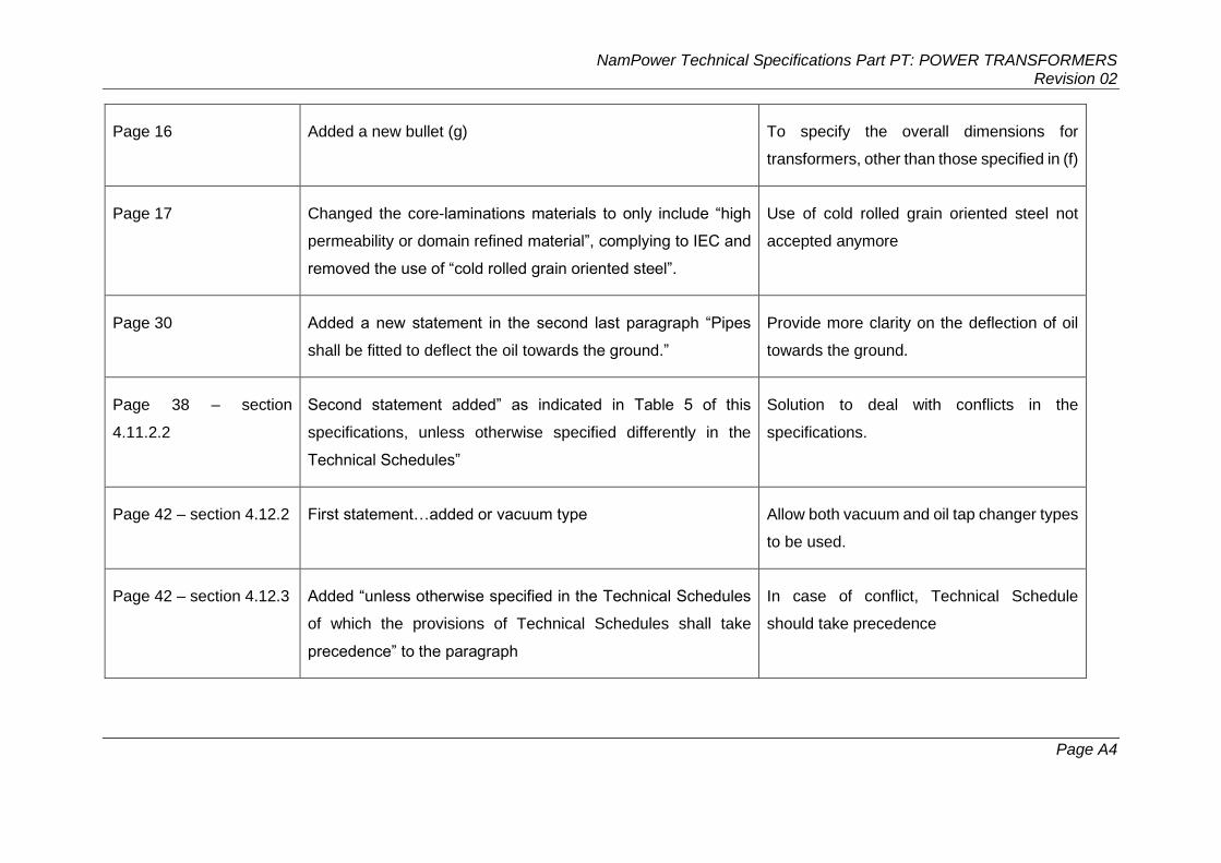
NamPower Technical Specifications Part PT: POWER TRANSFORMERS Revision 02
Page A4
Page 16 Added a new bullet (g) To specify the overall dimensions for
transformers, other than those specified in (f)
Page 17 Changed the core-laminations materials to only include “high
permeability or domain refined material”, complying to IEC and
removed the use of “cold rolled grain oriented steel”.
Use of cold rolled grain oriented steel not
accepted anymore
Page 30 Added a new statement in the second last paragraph “Pipes
shall be fitted to deflect the oil towards the ground.”
Provide more clarity on the deflection of oil
towards the ground.
Page 38 – section
4.11.2.2
Second statement added” as indicated in Table 5 of this
specifications, unless otherwise specified differently in the
Technical Schedules”
Solution to deal with conflicts in the
specifications.
Page 42 – section 4.12.2 First statement…added or vacuum type Allow both vacuum and oil tap changer types
to be used.
Page 42 – section 4.12.3 Added “unless otherwise specified in the Technical Schedules
of which the provisions of Technical Schedules shall take
precedence” to the paragraph
In case of conflict, Technical Schedule
should take precedence

NamPower Technical Specifications Part PT: POWER TRANSFORMERS Revision 02
Page A5
Page 58 to 60: Table 9 to
12
Removed the ratios that pertains to non-standard NamPower
voltages.
Align with NamPower voltages and remove
all other Eskom voltages which are not
relevant to NamPower.
Page 91 – section
4.22.11
Removed BS 729 and changed the minimum thickness of the
radiator paint from 85µm to 70 µm
BS standards no longer relevant; and
thickness to align with International
standards
Page 103 – section
4.25.1
Added statement “The testing shall be done in accordance with
the relevant IEC standards”
Align testing requirements with IEC
standards
Page 105 – section
4.25.10
Added statement at the end of the section “Note: The Altitude
of 1800m shall be applied to the design, but the testing shall be
done according to IEC standard.”
To ensure that the design is done for an
altitude of 1800m, even though the testing is
to be done in accordance to IEC standards
Page 105 – section
4.25.11.1
Statement amended “Unless otherwise specified in the
Technical Schedulers, calculations must be submitted in lieu of
short circuit tests”
Only calculations required for the short-
circuit tests. No actual tests to be done on
the transformer, due to the destructive
nature of it.
Page 131 – section 4.26 Removed the NRS, SABS and BS standards NRS, SABS and BS standards not
applicable any longer

NamPower Technical Specifications Part PT: POWER TRANSFORMERS Revision 02
Page A1
Appendix B: Transformer Oil Requirements
Table 22: Recommended limits for oil properties of new (virgin) inhibited oils (Type I)
1 2 3 4
Oil Unit Specification Reference and/or test method
Oil type
Naphthenic Type I (Type I) Inhibited
Colour ISO units 0.5 max. ASTM D1500
Inhibitor % Inhibited (see Anti-oxidant additives)
IEC 60666
Appearance
Clear, free of sediment and suspended matter
IEC 60422
Density @ 20 °C kg/dm3 0.895 max. ISO3675/ISO12185/ASTM D1298
Kinematic viscosity @ 40 °C mm2/s 12 max. ASTM D445/ISO 3104
Flash point ºC 140 min. ASTM D93/ISO 2719 (closed cup)
Pour point ºC –20 max. ASTM D97
Aromatic content % 6 to 14 max. ASTM D2140/IEC 60590
Total fufural and furans mg/kg 0.1 max IEC 61198
Polyaromatic hydrocarbons % 3.0 max. BS2000 / IP 346
Aniline point C 63 to 84 ASTM D611
Interfacial tension
@ 25 ºC
mN/m 40 min. ASTM D971
Neutralization value mg KOH/g 0.01 max. IEC 62021-1
Corrosive sulphur
Non-corrosive IEC 62535
Moisture mg/kg 10 max. (1)
20 max. (2)
10 max. (3)
IEC 60814 and ASTM D1533
Anti-oxidant additives % by mass 0.4 max IEC 60666
Oxidation stability RPVOT minutes 220 min ASTM D2112
Dielectric strength kV/2.5 mm 70 min. (1)
60 min. (2)
70 min. (3)
IEC 60156
Dissipation factor @ 90 ºC
NOTE: 0.005 max. NOTE: BS 5737 / IEC 61620 / IEC
60247 Gassing tendency mm3/min NOTE: +5 IEC 60628 (Method A)/ASTM
D2300 Maximum particulate
contamination per 100 ml Prior to filling –
these :
4000 particles > 6 m
500 particles > 14 m
or 12/9 (ISO rating) (4)
NOTE: ISO 4406 (1999)/IEC
60970/IEC 60422
On Delivery : 130 000 particles > 6 m
16 000 particles > 14 m
or 17/14 (ISO rating) (4)
Silicon/silicone Content ppm Not detectable ASTM D6595
Polychlorinated biphenyl mg/kg Not detectable IEC 60619/EPA 600/ASTM D4059
NOTE 1: Prior to transportation
NOTE 2: On delivery
NOTE 3: Prior to filling
NOTE 4: Due to the uncertainty of measurement the standard indicates an unacceptable level.

NamPower Technical Specifications Part PT: POWER TRANSFORMERS Revision 02
Page A2
Table 23: Test 4 – Quality Assurance
Analysis Test set Recommended method of analysis Sub-clause
Dielectric strength 4 IEC 60156 7.3.2
Moisture content 4 IEC 60814 and ASTM D1533 7.3.3
A
ci
d
it
y
4 IEC 62021-1 7.3.4
C
o
l
o
u
r
4 ASTM D1500 7.3.6
Appea
rance
4 IEC 60422 7.3.6
Dielectric dissipation factor (Tan
delta)
4 BS 5737 or IEC 61620 and
IEC
60247
7.3.7
Sediment and sludge 4 IEC 60422 7.3.8
Interfacial tension 4 ASTM D971 7.3.9
Particle quantification 4 ISO 4406 (1999)/IEC60970 7.3.10
Polychlorinated biphenyl
(PCB)
4 IEC 60619 or EPA 600 or ASTM D4059
7.3.11
Corrosive sulphur 4 IEC 62535 7.3.12
Silicon/silicone 4 ASTM D6595 7.3.20
Inhibitor content/FTIR
verification*
4 IEC 60666 7.3.14