vol.-5: technical specifications - hllhites
TRANSCRIPT
Vol.-5: Technical Specifications
HLL INFRA TECH SERVICES LTD. (HITES)
As Construction Agency of
National Health Mission, Govt. of U.P.
Invites e-Tender for
“Construction of District Drug Warehouse at Prayagraj&Kaushambi in the state of Uttar Pradesh on Design, Engineering, Procurement
and Construction (EPC) Basis”
Tender No. HITES/IDN/EPC/DWH-NHM/2021-22/PKG-1
Volume-5
Technical Specifications
(March, 2022)
CLIENT
NATIONAL HEALTH MISSION
Govt. of Uttar Pradesh
CONSTRUCTION AGENCY
B-14 A, SECTOR 62 NOIDA, UP 201 307
PH.: 0120 4071 500 FAX: 0120 4071 513 www.hllhites.com
CONSTRUCTION OF DISTRICT DRUG WAREHOUSE AT
PRAYAGRAJ &KAUSHAMBI (U.P.)
Tender No. HITES/IDN/EPC/DWH-NHM/2021-22/PKG-1 Page 1
“Construction of District Drug Warehouse at Prayagraj & Kaushambi in the state of Uttar Pradesh on Design, Engineering, Procurement and Construction (EPC) Basis”
Technical Specifications
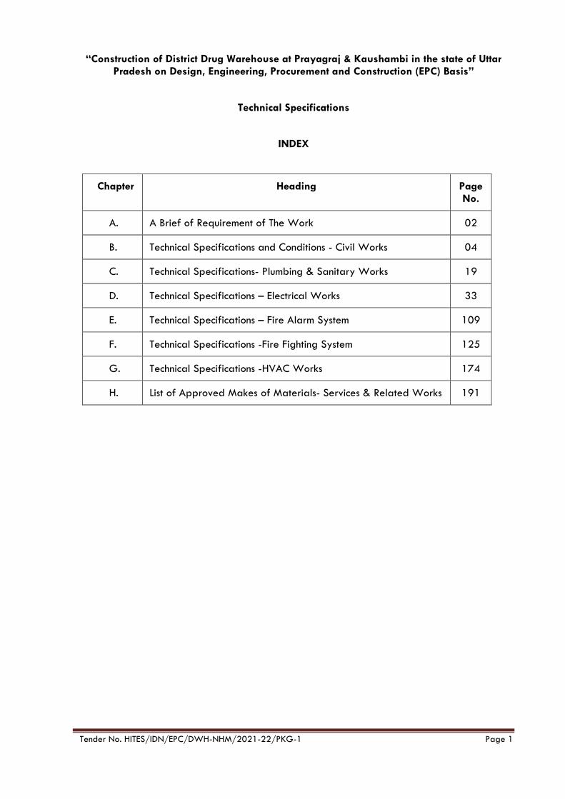
INDEX
Chapter Heading Page No.
A. A Brief of Requirement of The Work 02
B. Technical Specifications and Conditions - Civil Works 04
C. Technical Specifications- Plumbing & Sanitary Works 19
D. Technical Specifications – Electrical Works 33
E. Technical Specifications – Fire Alarm System 109
F. Technical Specifications -Fire Fighting System 125
G. Technical Specifications -HVAC Works 174
H. List of Approved Makes of Materials- Services & Related Works 191
Construction of District Drug Warehouse on Design, Engineering, Procurement and Construction (EPC) Basis Vol-5 Tech Specifications
Tender No. HITES/IDN/DWH-NHM/2021-22/Pkg-1 Page 2
CHAPTER -A
A Brief of Requirement of the Work
1. Introduction:
The scope of work relates to Construction of District Drug Warehouse in the various Districts of Uttar Pradesh. The buildings consist of Double height structures with infrastructure facilities including External Development Works.
The scope of work shall include Plumbing works, Electrical works, Firefighting works, LV works, etc. & preparation of all detailed shop drawings, obtaining approval from all local authorities, electrical inspector, water, sewer, drainage, electricity connection from local bodies, permission/ approval for tree re-plantation, etc. to be executed as integral part of the project. The following are the salient features of the Works:
a. Foundations & Other Works.
b. Super Structure.
c. Water Proofing Treatment Works.
d. Door and Windows.
e. Anti-Termite Chemical Treatment.
f. Internal and External Water Supply, Sewerage, Storm Water Drainage.
g. External Development Works i.e., Roads, Pathways, Etc.
h. Electrical Installation (Internal & External).
i. Fire Fighting System.
j. LT Panel Installation, DG Sets.
k. HVAC, Fire Alarm, PA, CCTV, EPABX/ Telephone, LAN Systems, Etc.
l. Landscape & Horticulture Works.
2. General
i. The work shall in general conform to the Latest CPWD /UPPWD Specifications (corrected up to the last date of submission/uploading of bid). Work under this Contract shall consist of furnishing all labour, materials, equipment, tools & plants and appliances necessary and required.
Regarding testing of civil & electrical & other materials, the testing of materials shall be conducted in Govt. Laboratory/ Govt. Engineering Colleges/ IITs/ NITs or from the laboratory approved by Engineer-in-charge. The charges of testing of materials in approved laboratory shall be borne by the Contractor.
ii. Contractor should spray curing water on concrete structure and shall not allow free flow of water. Concrete structures should be kept covered with thick cloth/gunny bags and water should be sprayed on them. Contractor shall do water ponding on all sunken slabs using cement and sand mortar.
iii. Specification/brands names of materials to be used as per the scope of work are listed in the bid documents. The efforts should be made by the contractor to use indigenous products. The contractor should also consider the availability of spares parts/ components for maintenance purposes while proposing any brand/ manufacturer. The materials of any other brand/manufacturer may be proposed for use by the contractor in case the brands specified below are not available in the market and/or contractor intends to use some other brand better than the brands mentioned in the document. The alternate brand can be used only after the approval of Engineer-in-Charge. The list of approved makes is appended to this document.
iv. Contractor shall submit credentials of the agencies proposed to be engaged by him/them for execution of specialized works to the HITES. Particular agency shall be
Construction of District Drug Warehouse on Design, Engineering, Procurement and Construction (EPC) Basis Vol-5 Tech Specifications
Tender No. HITES/IDN/DWH-NHM/2021-22/Pkg-1 Page 3
approved by HITES and only such agencies shall be allowed to execute the work on behalf of the Contractor.
v. CPWD /UPPWD Specifications for Civil, Electrical and all other works with up-to-date correction slips for all sub heads of work as applicable, and, Technical Specifications included in the tender documents, wherever applicable.
vi. The work shall, in general, conform to the CPWD /UPPWD Specifications for Civil, Electrical and all other works with up-to-date correction slips for all sub heads of work as applicable, and, Technical Specifications included in the tender documents, wherever applicable. Wherever any aspect of design / construction / material standards is not covered under the above-mentioned specification, relevant standards shall be referred to in the order of precedence mentioned in the Vol-5, GCC.
For items not covered by any of the above, the work shall be done, as per sound engineering practices and as directed by the Engineer-in-charge.
3. Setting Out
i. The contractor shall carry out survey of the whole work area, setting out the layout of building in consultation with the Engineer -in-Charge & proceed further. Any discrepancy between architectural drawings and actual layout at site shall be brought to the notice of the Engineer -in-charge. It shall be responsibility of the contractor to ensure correct setting out of alignment. Total station survey instruments only shall be used for layout, fixing boundaries, and centre lines, etc.
ii. The contractor shall establish, maintain and assume responsibility for grades, lines, levels and benchmarks. He shall report any errors or inconsistencies regarding grades, lines, levels, dimensions etc. to the Engineer -in-Charge before commencing work. Commencement of work shall be regarded as the contractor’s acceptance of such grades, lines, levels, and dimensions and no claim shall be entertained at a later date for any errors found.
iii. If at any time, any error appears due to grades, lines, levels and benchmarks during the progress of the work, the contractor shall, rectify such error, if so required, to the satisfaction of the Engineer -in-Charge.
iv. Though the site levels are indicated in the drawings, the contractor shall ascertain and confirm the site levels with respect to benchmark from the concerned authorities. The contractor shall protect and maintain temporary/ permanent benchmarks at the site of work throughout the execution of work. These benchmarks shall be got checked by the Engineer-in-Charge or his authorized representatives. The work at different stages shall be checked with reference to bench marks maintained for the said purpose.
v. The approval by the Engineer-in-Charge, of the setting out by the Contractor, shall not relieve the Contractor of any of his responsibilities and obligation to rectify the errors/ defects, if any, which may be found at any stage during the progress of the work or after the completion of the work.
vi. The Contractor shall be entirely and exclusively responsible for the horizontal, vertical and other alignments, the level and correctness of every part of the work and shall rectify effectively any errors or imperfections therein. Such rectifications shall be carried out by the contractor to the entire satisfaction of the Engineer - in-Charge.
vii. The Contractor (s) shall carry out soil/geotechnical investigation and should satisfy himself about complete characteristics of soil and other parameters at site. The intending contractor shall conduct soil investigations on their own, and shall be responsible for the adequacy of the design.

Construction of District Drug Warehouse on Design, Engineering, Procurement and Construction (EPC) Basis Vol-5 Tech Specifications
Tender No. HITES/IDN/DWH-NHM/2021-22/Pkg-1 Page 4
CHAPTER-B
Technical Specifications and Conditions - Civil Works
1. General
i. The work shall be carried out in accordance with the Architectural drawings and Structural drawings (proof checked/vetted by the approved Institute) and approved by the HITES. The Technical Specifications are to be read with and in general conforming to the Latest CPWD /UPPWD Specifications.
ii. The EPC Contractor(s) shall provide permanent bench marks, flag tops and other reference points for the proper execution of work and these shall be preserved till the end of the work. All such reference points shall be in relation to the levels and locations, given in the Architectural drawings. On completion of work, the Contractor (s) shall submit required number of prints of as built drawings to the Engineer-in-Charge.
iii. Before commencement of any item of work the, Contractor shall correlate all the relevant architectural and structural drawings and specifications etc. and satisfy him that the information available is complete and unambiguous. The Contractor alone shall be responsible for any loss or damage occurring by the commencement of work based on any erroneous and or incomplete information and no claim whatsoever shall be entertained on this account.
iv. The Contractor (s) should engage approved, licensed plumbers for the work and get the materials (fixtures/fittings) tested, by the municipal Body /Corporation authorities wherever required, at his own cost. The Contractor (s) shall submit for the approval of the Engineer-in-Charge, the name of the plumbing proposed to be engaged by him.
v. The contractor shall give performance test of the entire installation(s) as per the specifications in the presence of the Engineer-in-charge or his authorized representative before the work is finally accepted and nothing extra what-so-ever shall be payable to the for the test.
vi. The work of services will be executed simultaneously. The contractor shall minimize the scope of making recesses, holes, opening etc. as the same shall be planned in advance and necessary grooves/niches shall be provided in shuttering of RCC.
vii. Sample of building materials, fittings and other articles required for execution of work shall be got approved from the Engineer-in-Charge before use in the work. The quality of samples brought by the contractor shall be judged by standards laid down in the relevant CPWD/ U.P. PWD/ BIS specifications. All materials and articles brought by the contractor to the site for use shall conform to the samples approved by the Engineer-in-Charge which shall be preserved till the completion of the work.
viii. BIS marked materials except otherwise specified shall be subjected to quality test at the discretion of the Engineer-in-Charge besides testing of other materials as per the specifications described for the item/material. Wherever BIS marked materials are brought to the site of work, the contractor shall, if required, by the Engineer-in-Charge, furnish manufacturer’s test certificate or test certificate from approved testing laboratory to establish that the material/ procured by the for incorporation in the work satisfies the provisions of specifications/ BIS codes relevant to the material and/ or the work done.
ix. The Contractor shall procure the required materials in advance so that there is sufficient time to testing of the materials and clearance of the same before use in the work. The contractor shall provide at his own cost suitable weighing and measuring arrangements at site for checking the weight / dimensions as may be necessary for execution of work.
x. The Contractor shall submit minimum “Quality Assurance” plan which shall consist of:
Construction of District Drug Warehouse on Design, Engineering, Procurement and Construction (EPC) Basis Vol-5 Tech Specifications
Tender No. HITES/IDN/DWH-NHM/2021-22/Pkg-1 Page 5
a. Lot size, number of required tests and frequency of testing. While deciding these criteria CPWD /U.P.PWD Specifications & provisions of BIS Code and standard practices may be referred. The mandatory test shall be in conformity with the requirements details in the latest CPWD /UPPWD Specifications. For testing of other materials/work, the requirements as per provisions of BIS Code and standard practices shall be applicable.
b. It should clearly indicate the Machinery and other Tool & Plants required to be deployed at site by the Contractor. Entire Machinery and T&P may not be required at the start of work, therefore, a proper time schedule by which each Machinery & T&P is to be brought at site should also be indicated.
c. The Contractor shall maintain record of Receipt of Materials, testing of the same & Maintenance of Register of Tests.
d. All the registers of tests carried out at Construction Site or in outside laboratories shall be maintained by the Contractor, which may be inspected by Engineer-in-charge or his/her designee at any point of time.
e. The Contractor shall allow access to Third Party Quality Assurance Agency (TPQAA) engaged by HITES/ Client to have a control on quality and methodology of execution. Requisite number of Samples of materials including Cement Concrete Cubes shall be taken jointly by Contractor, TPQAA and Engineer-in-charge or their authorized representative. All arrangements for transporting and getting them tested shall be made by the Contractor.
f. All the test in field lab setup at Construction Site shall be carried out by the Quality control team to be engaged by the Contractor, which can be witnessed by Engineer-in-charge or his/her designee. A daily report of Tests to be conducted on a day shall be submitted to Engineer-in-charge or his authorized representative.
g. All the entries in the registers will be made by the designated Engineering Staff of the Contractor.
h. The Contractor shall be responsible for safe custody of all the test registers.
i. Submission of copy of all test registers, Material at Site Register and hindrance register along with each alternate Running Account Bill and Final Bill shall be mandatory.
j. All material received at site shall be entered in MAS Register and copy of Supply order, MTC & Bill-invoice shall be maintained in order. The MAS Registers including Cement and Steel Registers shall be maintained by a qualified staff of Contractor, which shall be inspected by Engineer-in-charge or his authorized representative at any time. The daily report of receipt of material shall be sent to Engineer-in-charge or his authorized representative.
xi. The Contractor shall ensure that no construction leach ate (e.g., cement slurry etc.), is allowed to percolate into the ground. Adequate precautions are to be taken to safeguard against this including, reduction of wasteful curing processes, collection, basic filtering and reuse. The Contractor shall follow requisite measures for collecting drainage water run-off from construction areas and material storage sites and diverting water flow away from such polluted areas. Temporary drainage channels, perimeter dike/swale, etc. shall be constructed to carry the pollutant-laden water directly to the treatment device or facility (municipal sewer line).
2. Pour Card, Check-List for Execution of Work
i. As and when any important item is taken up for execution, the Contractor shall submit the specifications and develop a checklist and Pour card. This sample checklist should be got approved from the Engineer-in-charge and should be used at site. This check list should be shown to the Engineer-in-charge or his authorized representative during inspection. This procedure is to be followed for all hidden items, CC/RCC work, Steel-
Construction of District Drug Warehouse on Design, Engineering, Procurement and Construction (EPC) Basis Vol-5 Tech Specifications
Tender No. HITES/IDN/DWH-NHM/2021-22/Pkg-1 Page 6
reinforcement, shuttering, flooring, doors & windows, plumbing, including water supply pipe lines, roof treatment, earth filling, etc.
ii. The contractor shall render all help and assistance in documenting the total sequence of this project by way of photography, slides, audio-video recording etc. nothing extra shall be payable to the on this account.
Note: - All Scheduled items shall be carried out as per the latest CPWD /U.P. PWD Specification with up-to-date correction slip.
3. Earth Work: As per relevant CPWD /U.P. PWD specifications.
i. Irrespective of the stipulations in the relevant CPWD /U.P. PWD Specifications or elsewhere in the Contract, the surplus excavated earth shall be disposed off by the contractor at his own cost to the place as directed by Engineer – in-charge and/or permitted by the local authority after obtaining written permission of the Engineer – in-charge and no payment will be made by the HITES for disposal of this excavated earth.
ii. The contractor shall, at his own expense and without extra charges, make provision for all shoring, pumping, dredging or bailing out water, encountered from any sources such as rains, floods, springs, subsoil water table being high or due to any other cause whatsoever. The foundation trenches shall be kept free from water while all the works below ground level are in progress without any extra payment.
iii. Filling in plinth shall be consolidated with water and compacted with pneumatic rammers, to achieve 90% relative density on testing. One test is to be carried out for 1000 Sqm of compacted area.
4. Plain Cement Concrete and Reinforced Cement Concrete Work
a. Stone Aggregate:
i. Stone aggregate used in the work shall be of hard broken stone to be obtained from approved source (Quarries to be approved by the Engineer in charge) and shall conform to relevant provision in the Latest CPWD /UPPWD Specifications for works.
b. Sand:
i. Sand to be used for the work shall be of as specified in CPWD /UPPWD Specifications. Sand shall be obtained from the source to be got approved by the Engineer in charge and washed if required, with appropriate equipment to bring down the chemical, inorganic and organic impurities within the permissible limits as per the direction of the Engineer in charge. The same shall consist of hard siliceous materials.
Note: Where only one variety of sand is available the sand will be sieved for use in finishing work as directed by the Engineer – in – charge in order to obtain smooth surface and nothing extra will be paid on this account.
i. Nothing extra shall be paid for screening or washing the sand as prescribed above.
c. Centering Shuttering and Scaffolding:
i. All Scaffolding centring for RCC shall be with properly designed system and brought to site well in advance so that the progress of the work is not hampered for non-availability of the same.
ii. All shuttering for RCC work except soffits of slab shall be in water proof shuttering Ply. Shuttering for slab and soffits shall be in water proof shuttering ply or in good quality mild steel plates free of dents, bends or warping and rusting as approved by the Engineer in charge.
Construction of District Drug Warehouse on Design, Engineering, Procurement and Construction (EPC) Basis Vol-5 Tech Specifications
Tender No. HITES/IDN/DWH-NHM/2021-22/Pkg-1 Page 7
iii. Contractorshould deploy complete one set of shuttering materials for minimum one complete floor and the shuttering material for beam bottom shall be minimum for two complete floors.
d. Reinforcement:
i. TMT reinforcement steel shall be used shall be as per design and conforming to IS: 1786 pertaining to Fe 500 OR Fe 550D grade of steel.
ii. TMT steel bars manufactured by main producers, as per list of makes, shall be allowed in the work. Contractor shall produce manufacturer Test Report for each dia and each lot Tests. Nothing extra will be paid for “straightening of bars” received from market in coils or with bends. All incidental charges of any kind whatsoever including cartage, storage, safe custody of materials, cutting and wastage etc. shall be borne by the Contractor.
iii. The actual average sectional weight for dia up to 10 mm shall be arrived at from one-meter-long samples (minimum 3 from each dia) taken from each lot of steel. The discretion of the Engineer – in – charge shall be final for the procedure to be followed for determining the average sectional weight of each lot. Quantity of each diameter of steel received at site of work each day will constitute the single lot for this purpose.
iv. The weight of each lot of a particular diameter of 10mm and below shall be reckoned as the weight as per actual issue multiplied by a factor equal to the standard sectional weight of the particular diameter divided by the average sectional weight of the particular dia in a particular lot worked out as per above para. Adjustment for the steel shall be effected on the basis of the weight as modified above for quantity payable.
v. Measurement of all diameters of steel be on linear basis and will be converted into weight on the basis of standard sectional weight coefficients given in relevant CPWD /UPPWD Specifications mentioned in schedule ‘F’ of General Conditions of Contract.
vi. Measurement of reinforcement shall be as per procedure described in the relevant CPWD /UPPWD Specifications mentioned in schedule ‘F’ of General Conditions of Contract.
e. Concrete Mix Design:
The concrete mix design shall be as specified in IS 456:2000 and CPWD /UPPWD Specifications.
f. Ready Mix Concrete:
i. The Contractor shall engage Ready Mix Concrete (RMC) producing plants (Distance of plant from site to be approved by Engineer in Charge) to supply RMC for the work. The RMC plant proposed to be engaged by the Contractor shall fulfil the following requirements.
a. It shall be fully computerized.
b. It should have supplied RMC for Govt. projects.
c. It should have facility for providing printed advice showing ingredients of concrete carried by each mixer.
d. The Ready-Mix Concrete (RMC) producing plants of the main Cement producers shall be preferred.
ii. The Contractor shall, within 15 days of award of the work submit list of at least three reputed RMC plant companies along with details of such plants Including details of transit mixer, pumps etc. to be deployed indicating name of Company, its location,
Construction of District Drug Warehouse on Design, Engineering, Procurement and Construction (EPC) Basis Vol-5 Tech Specifications
Tender No. HITES/IDN/DWH-NHM/2021-22/Pkg-1 Page 8
capacity, technical establishment, past experience for approval by Engineer-in-charge.
iii. The Engineer-in-Charge reserves the right to exercise check over the: -
a. Concrete including conducting of tests for checking quality of materials recordings of test results and declaring the material fit or unfit for use in production of mix.
b. Calibration check of the RMC.
c. Weight and quality check on the ingredient, water and admixture added for batch mixing.
d. Time of mixing of concrete.
e. Testing of fresh concrete, recordings of results and declaring the mix fit or unfit for use. This will include continuous control on the workability during production and taking corrective action.
For exercising such control, the Engineer shall periodically depute his authorized representative at the RMC plant. It shall be the responsibility of the Contractor to ensure that the necessary equipment manpower & facilities are made available to Engineer and/or his authorized representative at RMC plant.
iv. Ingredients, admixtures & water declared unfit for use in production of mix shall not be used. A batch mix found unfit for use shall not be loaded into the truck for transportation.
v. All required relevant records of RMC shall be made available to the Engineer or his authorized representative. Engineer shall, as required, specify guidelines & additional procedures for quality control & other parameters in respect of materials, production and transportation of concrete mix which shall be binding on the Contractor & the RMC plant.
vi. It shall be the responsibility of the Contractor to ensure that the RMC producer provides all necessary testing equipment and takes all necessary measures to ensure Quality control of ready -mixed concrete. In general the required measures shall be:-
a. Control of Purchased Material Quality
RMC producer shall ensure that the materials purchased and used in the production of concrete conform to the stipulation of the relevant agreed standards with the material Supplier and the requirement of the product mix design and quality control producer‘s. This shall be accomplished by visual checks, sampling and testing, certification from materials suppliers and information /data from material supplier. Necessary equipment for the testing of all material shall be provided and maintained in calibration condition at the plant by the RMC producer.
b. Control of Material Storage
Adequate and effective storage arrangement shall be provided by RMC producer at RMC plant for prevention of contamination, reliable transfer and feed system, drainage of aggregates, prevention of freeing or excessive solar heating of Aggregate etc.,
c. Record of Mix Design and Mix Design Modification
RMC producer shall ensure that record of mix design and mix design modification is available in his computer at RMC plant for inspection of Engineer or his representative at any time.

Construction of District Drug Warehouse on Design, Engineering, Procurement and Construction (EPC) Basis Vol-5 Tech Specifications
Tender No. HITES/IDN/DWH-NHM/2021-22/Pkg-1 Page 9
d. Computer Print outs of Each Truck Load
Each truckload / transit mixer dispatched to site shall carry computer printout of the ingredients of the concrete it is carrying. The printout shall be produced to Engineer or his representative at site before RMC issued in work.
e. Transfer and Weighing Equipment
RMC Producer shall ensure that a documented calibration is in place. Proper calibration records shall be made available indicating date of next calibration due, corrective action taken etc. RMC producer shall ensure additional calibration checks whenever required by the Engineer in writing to Contractor. RMC producer shall also maintain a daily production record including details of mixes supplied. Record shall be maintained of what materials were used for that day‘s production including water and admixtures.
f. Maintenance of Plant, Truck Mixers and Pumps
Plant, Truck Mixers and Pumps should be well maintained so that it does not hamper any operation of production, transportation and placement.
g. Production of Concrete
The following precautions shall be taken during the production of RMC at the plant:
i. Weighing (correct reading of batch data and accurate weighing):- For each load, written, printed or graphical records shall be made of the weights of the materials batched, the estimated slump, the total amount of water added to load the delivery tickets number for that load and the time of loading the concrete into the truck.
ii. Visual observation of concrete during production and delivery or during sampling and testing of fresh concrete assessment of uniformity, cohesion, workability adjustment to water content. The workability of the concrete shall be controlled on a continuous basis during production. The batch mix found unfit shall not be loaded into the truck for transportation. Necessary corrective action shall be taken in the production of mix as required for further batches.
iii. Use of adequate equipment at the plant to measure surface moisture content of aggregates, particularly fine aggregates or the workability of the concrete, cube tests etc. shall also be ensured.
iv. Making corresponding adjustment at the plant automatically or manually to batched quantities to allow for observed, measured or reported changes in materials or concrete qualities.
v. Sampling of concrete, testing monitoring of results.
vi. Diagnosis and correction of faults identified from observations / complaints.
vii. The RMC plant produced concrete shall be accepted by Engineer-in –Charge at site after receipt of the same after fulfilling all the requirements of mix mentioned in the tender documents.
viii. The Item of design mix cement concrete is inclusive of all the ingredients including admixtures, if required, labour, machinery T&P etc. required for a design mix concrete of required strength and workability, and, shall take into account change, if any, in quantities of concrete, ingredients like cement and aggregates and admixtures etc. as per the approved mix design.
ix. Ready mix concrete shall be arranged in quantity as required at site of work. The ready-mix concrete shall be supplied as per the pre-agreed schedule approved by Engineer.

Construction of District Drug Warehouse on Design, Engineering, Procurement and Construction (EPC) Basis Vol-5 Tech Specifications
Tender No. HITES/IDN/DWH-NHM/2021-22/Pkg-1 Page 10
x. Frequency of sampling and standards of acceptance shall be as per CPWD /UPPWD Specifications.
xi. No addition of water or other ingredients shall be permitted in the RMC at site or during transit.
xii. The RMC shall be placed by pump of suitable capacity and the arrangements shall be made to arrange sufficient length of pipe at site to place the RMC in the minimum required time.
xiii. Pre delivery tickets shall be produced with each truck load of RMC.
xiv. The representative of RMC supplier shall attend the site meetings as and when decided by the Engineer.
The Contractor shall assess the quantity of RMC requirement at site well in advance and order accordingly to the RMC supplier. It shall be the responsibility of the Contractor to arrange requisite quantity of RMC available at site, so that there is no hindrance to the work on this account.
5. Water Proof Treatment
a. Integral Cement Based Water Proofing Treatment for Roof / Sunken Floors of W.C`S etc.
i. The proprietary water proofing compound shall conform to I.S 2645 – 1975 in cement-based water proofing treatment; stone aggregate shall be used instead of brick aggregate without any extra cost wherever required by the Engineer in – charge.
ii. The finished surface after water proofing treatment shall have required slope.
iii. While treatment of sunken floors is done it shall be ensured that the ‗S‘or ‗P‘traps as the case may be have been fixed / eased and rounded off properly the work shall be carried out as per relevant CPWD /UPPWD Specifications.
iv. GUARANTEE: The above water proofing, treatment shall be covered by a 10 years guarantee by the main contractor against leakage, seepage and dampness etc. for which necessary performance shall be furnished by thecontractor.
b. Water Proofing Treatment Integral Crystalline waterproofing to be done as per CPWD Specifications for Underground/ Overhead RCC water tanks with 10 Years Guarantee.
c. Brick Coba Water Proofing Treatment at Terrace Slabs to be done as per CPWD Specifications with 10 Years Guarantee.
6. Brick Work
a. Bricks used in the work shall be obtained from kilns to be got approved from the Engineer in charge and shall be best quality well burnt ground moulded bricks as available in the vicinity of the grade specified in the DBR. They shall have an absorption percentage of not more than 15 (Fifteen) % of its dry weight when immersed in water for 24 hours. In all other respects they shall conform to the provision in Latest CPWD /UPPWD Specifications for works.
b. Both the face of wall of thickness more than 23cm shall be kept in the proper plane. Walls of half brick thickness or less shall be measured separately and paid in sqm.
c. Bricks wall beyond half brick thickness shall be measured in multiple of half brick (i.e., 115mm) which shall be deemed to be inclusive of mortar joints. In all other respects they shall conform to the provision in relevant specifications of the work.

Construction of District Drug Warehouse on Design, Engineering, Procurement and Construction (EPC) Basis Vol-5 Tech Specifications
Tender No. HITES/IDN/DWH-NHM/2021-22/Pkg-1 Page 11
7. Wood Work
a. Timber required for manufacture of chowkhats and shutters for doors, windows, ventilators, partitions etc shall be Forest Stewardship council (FSC) certified wood and it shall be seasoned and preservative treated.
b. The moisture contents of the wood used in the work shall not be more than that stipulated in the relevant clause of Latest CPWD /UPPWD Specifications for works. The rate quoted for various items shall be inclusive of kiln seasoning and preservative treatment of wood. In all other respects the wood used in the work shall conform to the provision in latest CPWD /U.P. PWD specification for works.
c. The sample of species to be used shall be deposited by the contractor with the Engineer-in – charge before commencement of the work. The contractor shall produce cash voucher and certificate from standard kiln seasoning plant operator about the timber section to be used on the work having been kiln seasoned by them failing which it would not be so accepted as kiln seasoned.
d. Shutters:
i. Factory made shutters, as specified shall be obtained from factories to be approved by the Engineer – in - charge and shall conform to IS 2202 (Part –I) 1977. The Contractor shall inform well in advance to the Engineer – in – charge the name address of the factory from where the contractor intends to get the shutters manufactured.
ii. The Contractor will place order for manufacture of shutters only after written approval of Engineer – in – charge in this regard is obtained. The Contractor is bound to abide by the decision of the Engineer – in-charge. In case the factory already proposed by the contractor is not found competent to manufacture quality shutters, the Engineer – in – charge will recommend the name of another factory from the approved list.
iii. The Contractor will also arrange stage wise inspection of the shutters at factory with the Engineer in charge or his subordinate authorized representatives. Contractor will have no claim, if the shutters brought at site are rejected by the Engineer in charge in part or in full lot due to bad workmanship / quality or damages caused during their shifting from factory to site. Such shutters will not be measured and paid and the contractor shall remove the same from the site of work within 7 days after the written instruction in this regard are issued by the Engineer in charge or his authorized representatives.
8. Steel Grill Work
a. All steel grills shall be according to the Architectural detailed drawings and obtained from approved suppliers. These shall conform to Latest CPWD /UPPWD Specifications for works.
b. In case of grills an approved quality priming coat of zinc chromate shall be applied over and above a shop coat of primer. Nothing extra shall be payable for providing shop coat primer, but the zinc chromate primer will be paid for separately.
c. The welded steel works shall be tested for quality of weld as laid in IS 822-1978 before actual erection.
9. Aluminium Work:
a. The scope of the work is the fabrication, supply and erection of Aluminium glazed doors, windows and ventilators in accordance with the tender drawings and CPWD/ UPPWD specifications.
b. The supply and erection will include all parts such as but not restricted to frames, tracks, guides, mullions, styles, rails, couplers, transoms, rails, plates glazing bars, glass, hinges, arrangement, spring catches, cord and pulley arrangements, spring catches, cord and
Construction of District Drug Warehouse on Design, Engineering, Procurement and Construction (EPC) Basis Vol-5 Tech Specifications
Tender No. HITES/IDN/DWH-NHM/2021-22/Pkg-1 Page 12
pulley arrangements door closers floor springs etc., required for the whole work whether the parts/ items are individually and specifically referred to in the schedules/ specifications/drawings or not provided that the supply and installation of such parts can be inferred there from and are necessary to make the work complete, unless separate provision is made in the bills of quantities for supply to such parts/items.
c. The doors, windows, ventilators, will be fabricated to suit the finished clear openings in the building/structure which the tenderer will himself measure.
d. Materials:
i. The members will be made out of aluminium alloy corresponding to IS:733 and will consist of extruded sections and of other shapes, and to sized gauges as shown in the drawings/ described in accordance with the relevant IS codes. The members shall be chosen to provide strength/ stability and maximum resistance to wear and tear.
ii. The Sections will be as per approved makes, extruded sections. As indicated in the drawings the tenderer should specifically mention which sections he is using.
iii. The weight of sections and the corresponding catalogue numbers are mentioned. The IS specifications are to be strictly adhered.
iv. The alloy of extruded aluminium should be BS or IS old HE9, Alcon 50 SWP to this effect test certificate has to be provided from the extruder.
e. Finishing:
i. The extruded aluminium section has to be mechanically finished to remove all scratches; extrusion marks etc and subsequently thoroughly cleared in all alkali baths prior to anodizing.
ii. The polyester powder coating, if required as per item of work, shall be of desired shade with minimum average thickness to 50 microns or other shades as required and to this effect the tenderer must have to produce test certificate from authorized institutions Bureau of Indian Standard.
iii. The polyester powder coated material should be properly wrapped in gummed tape before fabrication to avoid scratches during fabricated and erection shall be kept protected till handing over.
f. Fabrication:
i. Before commencing the fabrication, the contractorshall submit to the Engineer – in - charge for their approval detailed shop drawings, based on the Architectural drawings and corresponding specification showing junctions, fittings, accessories such as hinges flush bolts, locks, latches, latching arrangements, peg stays, rotor arms, anodize pivots gaskets rubber packing door felts, mastic, sealant etc., including fixing and sealing arrangements. Type and method of scaffolding he intends to use, Fabrication is to be taken up only after approval by the Engineer – in - charge and in accordance with the approved drawings. Sections for fabrication of door/ window/ventilators etc shall be as per architectural drawings or as approved by the Engineer – in - charge.
ii. A sample of finished door / windows/ ventilator railing etc. shall be fabricated as per the shop drawings approved by the Engineer – in - charge for final approval before under taking mass production/ fabrication,
iii. All materials shall conform to relevant IS. Codes and in the absence of IS code, they should correspond to the best engineering practice; decision of the Engineer – in - charge shall be final and binding on the Contractor.

Construction of District Drug Warehouse on Design, Engineering, Procurement and Construction (EPC) Basis Vol-5 Tech Specifications
Tender No. HITES/IDN/DWH-NHM/2021-22/Pkg-1 Page 13
iv. Fabrication shall be done true to the drawing/ sample approved and in correspondence to the finished openings at the site. All joints shall be mitered at the corners, true right angles, and joints to be finished neatly to hairlines, with concealed fasteners, wherever possible joints shall be made in concealed locations.
v. All fabricated/finished items shall be packed and carted properly to site to prevent any damage in transit. On receipt at site, they shall be carefully stacked in protected storage to avoid distortion/damage.
vi. Site installation shall be with concealed screws, self-tapping or other approved fasteners or may be by welding, due precautions shall be taken to avoid any distortion/ discoloration /damage to the finished items.
vii. Wood work faces /parts coming in contact with masonry shall before shifting to the site be given a heavy coat of alkali resistance bitumen paint. Steel items coming in contact with other incompatible materials shall be given a thick coat of zinc chromate primer.
g. Glazing: Glazing shall be done with flawless sheet glass of best approved quality without waviness, distortion, coloration / discoloration, of specified thickness in sizes as shown in the drawings, fixed as required with special glazing clips, putty, neoprene/PVC gaskets. All glass shall be cleaned thoroughly before they are fixed in position. Unless otherwise specified the minimum thickness shall be 5.5 mm thick.
10. UPVC Windows
The Factory made UPVC Windows in the building shall be provided and fixed as per Schedule given in the Tender drawings based on CPWD/ UPPWD Specifications with complete set of fittings and fixtures viz. SS friction hinges, Powder coated handles, EPDM gasket, stainless steel (SS 304 grade) friction hinges, zinc alloy (white powder coated) handles, G.I fasteners 100 x 8 mm size for fixing frame to finished wall, plastic packers, plastic caps and necessary stainless-steel screws etc. After fixing frame the gap between frame and adjacent finished wall shall be filled with weather proof silicon sealant over backer rod of required size and of approved quality, all complete as per approved drawing & direction of Engineer-in-Charge.
11. Flooring
a. The flooring in the building shall be provided / laid as per the approved finishing schedule/as specified in Vol-4, DBR and tender drawings and laid in such a way that limits in floor levels would not exceed the limits provided in the latest CPWD /UPPWD Specifications or manufactures specifications.
b. Wherever Vitrified Tile flooring is done, it shall be with multi grade/range 1st Quality tiles.
c. Slope in floors shall be provided as per architectural drawings, else the levels at any place when checked over a distance of one meter in any direction should not show variation in floor level more than 3 mm.
d. Items of flooring be inclusive of provision of sunken flooring and finishing edges (molding etc. complete) of the same in bath kitchen, toilets, platforms, treads/risers of staircase/ entrance steps cutting holes for traps/ pipes etc., and nothing extra shall be paid on this account unless otherwise specified.
12. False Ceiling: False ceiling items in general are to be carried out as per the description of the item in the
DBR/ Tender drawings and also as per the manufacturer’s specifications / CPWD /UPPWD Specifications and as directed by the Engineer – in – Charge.
Construction of District Drug Warehouse on Design, Engineering, Procurement and Construction (EPC) Basis Vol-5 Tech Specifications
Tender No. HITES/IDN/DWH-NHM/2021-22/Pkg-1 Page 14
13. Stainless Steel Railings:
a. The Stainless-Steel Railing work in general are to be carried out as per the description of the item in the DBR/ Tender drawings and also as per CPWD /UPPWD Specifications and as directed by the Engineer – in – Charge.
b. The scope of the work includes preparation of the shop drawings (based on the architectural drawings), fabrication, supply, installation and protection of the stainless-steel railing till completion and handing over of the work.
c. The stainless-steel work shall be got executed through specialized fabricator having experience of similar works. The contractor shall submit the credentials of the fabricator for the approval of the Engineer-in-Charge.
d. The contractor shall submit shop drawings, for approval of the Engineer-in-Charge, for fabricating stainless steel railing with detailing of M.S. stiffener frame work backing along with the fixing details of the M.S. frame work to the R.C.C columns. The details of the joints in the stainless-steel railing including location, etc. shall also be shown in the shop drawings.
e. The contractor shall procure and submit to the Engineer-in-Charge, samples of various materials for the railing work, for approval. After approval of samples, thecontractor shall prepare a mock up for approval of Engineer-in-Charge / Consultant. The material shall be procured and the mass work taken up only after the approval of the mock up by the Engineer-in-Charge / Consultant. The mock-up shall be dismantled and removed by the contractor as per the directions of the Engineer-in-Charge. Nothing extra shall be payable on this account.
f. The stainless steel shall be of grade 304 with brushed steel satin finish and procured from the approved manufacturer. It shall be without any dents, waviness, scratches, stains etc.
g. The required joints in the railing provided as per the architectural drawings, shall be welded in a workmanlike manner including grinding, polishing, buffing etc. all complete and compacted. The temporary clamps provided and fixed to hold the stainless-steel railing, in position shall be removed after the concrete has set properly. The junction of the flooring and the cladding shall be neatly filled with weather silicone sealant of approved colour and shade. Nothing extra shall be payable on this account.
h. One test (three specimens) for each lot shall be conducted for the stainless-steel pipe in the approved laboratory. Therefore, the material shall preferably be procured in one lot from one manufacturer.
i. The finished surface shall be free of any defects like dents, waviness, scratches, stains etc. and shall have uniform brushed steel satin finish. Any defective work shall be rejected and redone by the contractor at his own cost. The finished surface shall therefore be protected using protective tape which shall be removed at the time of completion of the work. The surface shall then be suitably cleaned using nonabrasive approved cleaner for the material. Nothing extra shall be payable on this account.
j. The item includes the cost of all inputs of labour, materials (including stainless steel pipes, welding, brazing, concrete, protective film, weather silicone sealant etc including cost of providing and fixing M.S. frames), T & P other incidental charges, wastages etc. The items also included providing and fixing stainless steel anchor fasteners for fixing railing.
k. The railing shall be fixed in position using stainless steel pipes, stainless steel posts of required diameters and thickness as shown on drawing and polished to satin finish including cutting, welding, grinding, bending to required profile and shape, hoisting, butting, polishing etc.
Construction of District Drug Warehouse on Design, Engineering, Procurement and Construction (EPC) Basis Vol-5 Tech Specifications
Tender No. HITES/IDN/DWH-NHM/2021-22/Pkg-1 Page 15
l. The item includes the cost of all inputs of labour, materials, T&P, other incidental charges, wastage etc. The entire work shall be carried out to the satisfaction of Engineer-In-Charge.
14. Glass
a. All glass and glazing material shall be verified and coordinate with the applicable Performance requirement as per CPWD/ UPPWD Specifications.
b. All glass shall be cut to require size and ready for glazing. All glass shall be accurate sizes with clear undamaged edges and surfaces which are not disfigured.
c. Glass shall be free from defect or impurities detrimental to its performance. Defects such as bubbles, waves, spots scratches, spalls, discoloration, visibly imperfect coating, chipping, and bubbles delaminating of opacifier film shall be limited in accordance with the Manufacturer’s / trade guidelines. The glass is to be produced in such a way that the rollers will be parallel to what will be the horizontal position of the glass. Glass should be consistent in colour.
d. All glass breakage caused by the contractor or his sub- contractor because of negligence or caused by the installation of faulty work by him shall be replaced by the contractor at his own expense without delay to the project completion.
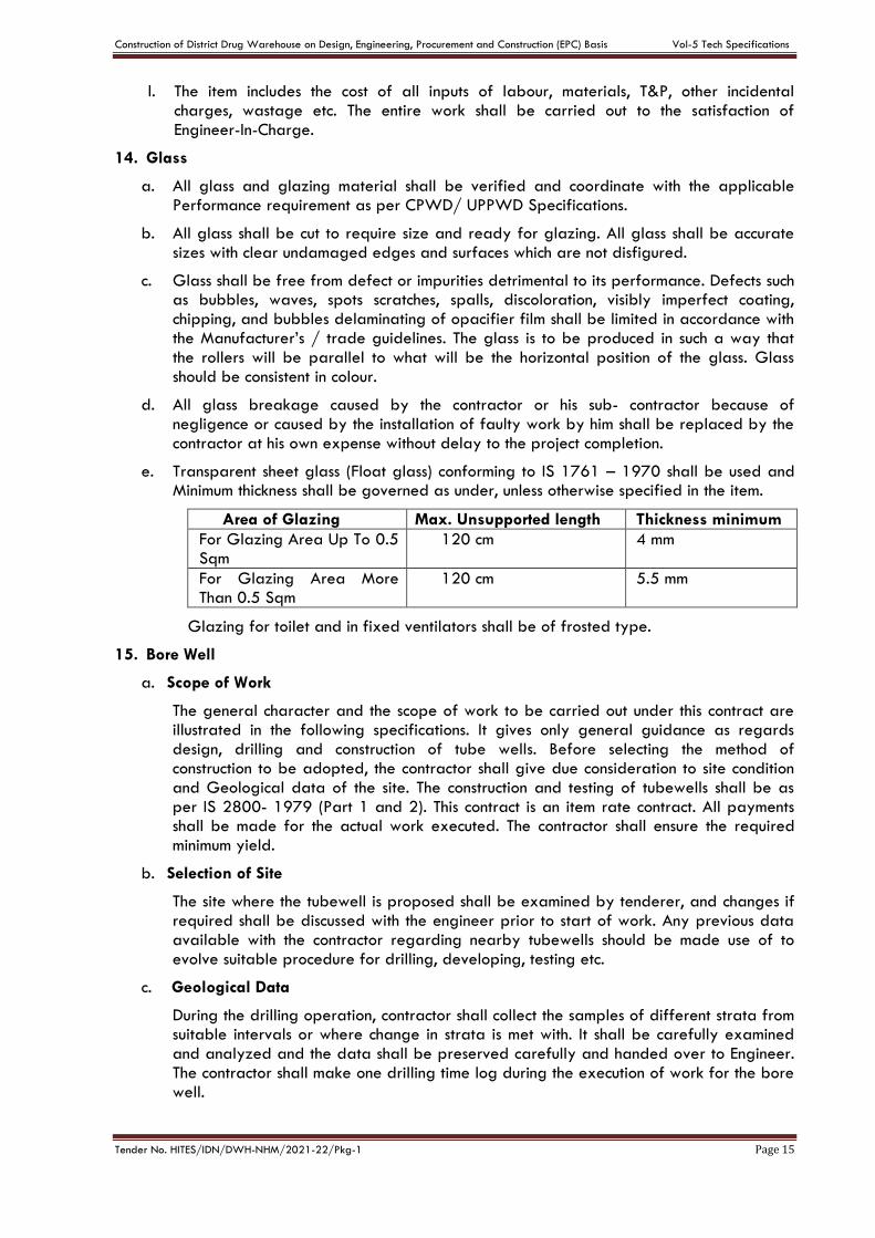
e. Transparent sheet glass (Float glass) conforming to IS 1761 – 1970 shall be used and Minimum thickness shall be governed as under, unless otherwise specified in the item.
Area of Glazing Max. Unsupported length Thickness minimum
For Glazing Area Up To 0.5 Sqm
120 cm 4 mm
For Glazing Area More Than 0.5 Sqm
120 cm 5.5 mm
Glazing for toilet and in fixed ventilators shall be of frosted type.
15. Bore Well
a. Scope of Work
The general character and the scope of work to be carried out under this contract are illustrated in the following specifications. It gives only general guidance as regards design, drilling and construction of tube wells. Before selecting the method of construction to be adopted, the contractor shall give due consideration to site condition and Geological data of the site. The construction and testing of tubewells shall be as per IS 2800- 1979 (Part 1 and 2). This contract is an item rate contract. All payments shall be made for the actual work executed. The contractor shall ensure the required minimum yield.
b. Selection of Site
The site where the tubewell is proposed shall be examined by tenderer, and changes if required shall be discussed with the engineer prior to start of work. Any previous data available with the contractor regarding nearby tubewells should be made use of to evolve suitable procedure for drilling, developing, testing etc.
c. Geological Data
During the drilling operation, contractor shall collect the samples of different strata from suitable intervals or where change in strata is met with. It shall be carefully examined and analyzed and the data shall be preserved carefully and handed over to Engineer. The contractor shall make one drilling time log during the execution of work for the bore well.
Construction of District Drug Warehouse on Design, Engineering, Procurement and Construction (EPC) Basis Vol-5 Tech Specifications
Tender No. HITES/IDN/DWH-NHM/2021-22/Pkg-1 Page 16
d. Design and lowering of pipe assembly
The length and diameter of the housing pipe shall be selected on the basis of static water level, the draw down and the discharge expected from the well and the size of the pump to be installed. The size and length of blind pipes and the slotted/ strainer pipes shall be selected according to the expected discharge and the depth of tubewell. The size and distribution of the slots shall be as per IS 8110. After completion of the bore hole the shall assemble the tube well assembly according to the water bearing strata met during boring, after getting the same approved from the Engineer and shall lower in to the drilled hole the same keeping the slotted strainer opposite to water bearing strata from which the water is to be extracted. The bail plug shall rest on firm ground. Before the bail plug is lowered, about one metre depth of the bore hole shall be packed with the gravel to avoid sinking of the assembly. In case part of a bore hole is not proposed to be utilized, it shall be filled with gravel before lowering the assembly. The slotted pipe and other pipes shall be provided with proper guides to keep them in the centre of the bore to ensure uniform gravel packing all around.
e. Gravel Packing
All gravel shall consist of hard rounded particles reasonably uniform in diameter and shall be of size, determined after analyzing the character of the water bearing formation tapped. The gravel shroud around the screen shall be uniform. It should be free from dust, dirt and other vegetable matters. Gravel packing once started shall be carried out continuously until it is completed. Pea gravel/Stone Chips shall be thoroughly washed.
f. Development of Bore well
The well shall be developed either by surging and agitating or by over pumping and back washing with an air lift and high velocity jetting. The tube well shall be developed as per IS 2800 -1979 or latest by air compressor to be arranged by the contractor as required and stipulated in BOQ to obtain the maximum discharge available from the completed tube well. Another acceptable method may also be adopted. This development process shall be continued until the stabilization of sand and gravel particles has taken place. The development shall continue until the gravel should stop sinking, discharge of depression ceases to improve and the sand content is not more than 20parts per million. A record of the hours of working of Air compressor shall be maintained by Employer Engineer which will be signed by the contractor or his authorized representative. Payment for development of tube well shall be made at the hourly rate indicated in the schedule of quantities for the actual period during which the Air-Condition has worked. A statement showing the quantity of gravel initially filled in the bore and the quantity added during development should be prepared by the contractor and got signed by the representative of the Engineer.
g. Disinfection
The well shall be disinfected after completion of test for yield. All the exterior parts of the pump coming in contact with the water shall be thoroughly cleaned and dusted with powdered chlorine compound. In fact it shall be disinfected every time a new pump is installed or the one installed is replaced after repairs.
The stock solution of chlorine may be prepared by dissolving fresh chlorinated lime. For obtaining an applied standard concentration of 50 PPM, 1 litre of the stock solution shall be used to treat 300 liters of water.
h. Grouting and sealing
Grouting and sealing of tube well may be done, if required depending upon the site conditions and the quality of the discharge of the strata encountered. To ensure that the grout shall be provided a satisfactory seal, it shall be applied in one continuous
Construction of District Drug Warehouse on Design, Engineering, Procurement and Construction (EPC) Basis Vol-5 Tech Specifications
Tender No. HITES/IDN/DWH-NHM/2021-22/Pkg-1 Page 17
operation. Sealing of the tube well may be done by grouting the annular space between bore and the housing pipe, with cement concrete 1:2:4 (1 cement: 2 coarse sand: 4: coarse aggregate 20 mm nominal size) to a depth of 5m below the grouted level.
i. Handing over of the bore well.
The tube well shall be handed over in complete shape. The housing pipe shall be closed by a well cap for the period between the completion of the tube well and the installation of the pump set.
The following information shall be furnished by the drilling agency on completion of the tube well:
i. Strata chart of the tube well indicating the different types of soils met with, at different depths.
ii. Samples of strata collected, neatly packed and correctly marked in sample bags.
iii. Chart of actual pipe assembly lowered indicating the size of pipes, depth ranges, where slotted/ strainer pipes have been used, depth and diameter of housing pipe, reduced level of the top of the housing pipe and the diameter and depth of the bore hole.
iv. Position of every joint in the well assembly.
v. Hours of development done by the compressed air, pump sets or by other means.
vi. Pumping water level at the developed discharge.
vii. Two copies of test certificates of the water samples results from approved testing agency.
viii. Results of development along with levels of static subsoil water and depth of draw for steady discharge.
ix. Results of mechanical (sieve) analysis of samples of aquifer materials wherever applicable.
x. Yield analysis and recommendation on the safe pumping yield, pump settings and specifications for suitable pumps etc.
xi. Verticality tests results to be recorded in accordance with IS:2800-1979
xii. TUBEWELL DATA: - Shall be decided by the Engineer-in-charge.
j. Water for drilling – Contractorshall make his own arrangement for water required for drilling purposes as well for development purposes.
k. The design for the tube well indicating the depth range of the aquifer zones to be tapped shall be given after a detailed study of the data collected during drilling operations.
l. The slotted pipes should have an effective open area of at least 15% and the slotted size should be 1.6 mm. All pipes shall be painted fresh before lowering. The pipes shall be welded thoroughly all round to prevent leakage and breakage. Centering guides may be used to maintain the verticality of the tube wells which shall be tested.
m. The annular space between the bore well and tube well assembly shall be packed with well-graded pea gravel of good quality, durability and high sphericity.
16. Samples of Materials
a. Sample of all materials/ fittings and fixture to be used in the work such as doors, windows, tiles, sanitary, water supply, drainage fittings and fixtures shall be submitted well in advance by the contractor for approval from the Engineer-in charge of work in writing before placing orders for the entire quantity required for completion of work. Samples approved by the EIC/ Client shall be kept in Sample Room under the charge of EIC and shall retain till completion of work.
Construction of District Drug Warehouse on Design, Engineering, Procurement and Construction (EPC) Basis Vol-5 Tech Specifications
Tender No. HITES/IDN/DWH-NHM/2021-22/Pkg-1 Page 18
b. Finished items in respect of typical portion of works of repetitive nature such as typical room, toilet, railing, door, window or any other work desired by the engineer-in- charge shall be prepared by the contractor to the satisfaction of Engineer-in – charge and got approved from him in writing before the commencement of these items for the entire work.
c. The requirements for preparation of samples shall be observed and fulfilled by the contractorwell in advance to avoid any detriment to the general progress of work. In other words, this will not be allowed to have any effects on the general progress of work or on any of the terms and conditions of the contract. No claims of any kind whatsoever including the claims of extension of time will be entertained due to the incorporation of this requirement.
17. Variation in Consumption of Materials
The variation in consumption of material shall be governed as per CPWD /UPPWD Specifications and clauses of the contract to the extent applicable.
18. Miscellanceous
Materials manufacture by reputed firms and approved by Engineer – in charge shall only be used. Only articles classified as “First Quality” by the manufactures shall be used unless otherwise specified. Preference shall be given to those articles which bear ISI certification marks. In case articles bearing ISI certification marks are not available the quality of sample brought by the contractor shall be judged by the standards laid down in the latest CPWD /UPPWD Specifications. For items not covered by the latest CPWD /UPPWD Specifications, relevant ISI standards shall apply.
19. Tests
a. Materials brought at site of work shall not be used in the work before getting satisfactory test results for Mandatory tests as per relevant provisions in Latest CPWD /UPPWD Specifications for works. Normally, part rate payment shall be allowed in the running account bills only if the materials are tested and test results are found to be satisfactory to by the Engineer-in-charge. These tests shall be got done from laboratories certified and approved by competent central/state Governments or the laboratory set up by the contractor at site as per directions of EIC/ Consultant.
b. The Engineer - in - charge of work shall check the test results and satisfy himself before allowing any payment in the running /final bill.
Construction of District Drug Warehouse on Design, Engineering, Procurement and Construction (EPC) Basis Vol-5 Tech Specifications
Tender No. HITES/IDN/DWH-NHM/2021-22/Pkg-1 Page 19
CHAPTER- C
Technical Specifications- Plumbing & Sanitary Works
SECTION 1 GENERAL REQUIREMENT
1. Scope of work
The work shall in general conform to the Latest CPWD /UPPWD Specifications for works as mentioned in Schedule ‘F’ of the GCC. Work under this Contract shall consist of Design of the System, Supply & installation of Pipes/Fixtures etc. furnishing all labour, materials, equipment and appliances necessary and required for execution of Plumbing Works for respective Drug ware house. The EPC Contractor is required to completely furnish all the plumbing and other specialized services as described hereinafter and as specified in the tender drawings and specified in the Vol 4, DBR.
SECTION 2 PLUMBING FIXTURES
1. General
a. Work under this Part shall consist of furnishing all materials & labour necessary and required to completely install all sanitary fixtures, chromium plated fittings and accessories as required by the tender drawings and specified in the Vol 4, DBR.
b. Without restricting to the generality of the foregoing the sanitary fixtures shall include the following: -
i. Sanitary fixtures
ii. Shower trays
iii. Chromium plated fittings
iv. Porcelain or stainless-steel sinks
v. Accessories e.g., towel rods, toilet paper holders, soap dish etc.
vi. Whether specifically mentioned or not, the work includes installation of the fixtures, appliances and accessories provided with all fixing devices, nuts, bolts, screws, hangers, fasteners as required.
vii. All exposed pipes within toilets and near fixtures shall be chromium plated brass or copper unless otherwise specified.
c. All sanitary fixtures, CP Fittings and CP/SS accessories shall be supplied at site of work as per manufacturers’ standard supply.
d. All fixtures and fittings shall be provided with all such accessories and fixing devices as are required to complete the item in working condition, even if the same is not specifically mentioned in the Design Basis Report or shown on the drawings. The item will include all devices for proper fixing arrangement, nuts, bolts, screws and required connection pieces etc.
e. Fixing screws shall be half round head stainless steel wood screws or bolts with Stainless Steel washers. Iron screws rust and will not be permitted.
f. All fittings and fixtures shall be fixed in a neat workmanike manner true to level and heights shown on the drawings and in accordance with the manufacturer’s recommendations. Care shall be taken to fix all inlet and outlet pipes at correct positions. Faulty locations shall be made good and any damage to the finished floor, tiling or terrace shall be made good at contractor's cost.
g. The contractor shall provide poly-sulphide sealant appropriate for its use for all fixtures fixed near wall, marble core seal and edges.
Construction of District Drug Warehouse on Design, Engineering, Procurement and Construction (EPC) Basis Vol-5 Tech Specifications
Tender No. HITES/IDN/DWH-NHM/2021-22/Pkg-1 Page 20
2. Water Closets
a. European W.C.
i. W.C. shall be single or double siphon type or
ii. Each W.C. set shall be provided with an approved type of plastic/wooden seat of approved finish compatible and fitting appropriately with the WC set with rubber buffers and hinges. The WC seat shall be those approved and accepted for fixing on a particular type of WC.
iii. The seat shall be so fixed that it remains absolutely stationary in vertical position without falling down on the W.C.
iv. The edge between the fixture and the wall shall be sealed with approved type of poly-sulphide sealant.
b. Health faucet/spray (Optional)
A chromium plated spray with integral hand control valve and connected to a flexible pipe and angle valve with wall flange and hook are fixed as shown on the drawings or directed by the Engineer-in-charge.
3. Wash Basins
a. Wash basins shall wall mounted type or for under over/counter installation as specified in the drawings.
b. Each basin shall be supported on MS galvanized and the basin securely fixed to wall or under/above counter installation. The design of the brackets shall suit the basin selected and as recommended by the manufacturer.
c. Each basin shall be provided with 32 mm dia. C.P. waste with overflow/ pop-up or standard waste with rubber plug and chain, 32 mm dia. C.P. brass bottle trap with CP pipe to wall and flange.
d. The edge between the fixture and the wall or the counter shall be sealed with approved type of poly-sulphide sealant
e. Washbasins shall be fixed at proper heights as shown on drawings. If height is not specified, the rim level shall be 79 cm or as directed by Engineer-in-charge.
f. Each washbasin connection (separately for hot and cold) shall be provided with angle valves with CP wall flange and CP connecting pipe and of required length.
4. Shower set
a. Shower set shall comprise of hot & cold-water mixer, C.P. shower arm with wall flange and shower head adjustable type.
b. Mixer shall be exposed type, single lever, concealed stop cocks with diverter and spout as selected by the Engineer-in-charge.
5. Accessories
a. SS Accessories shall be of any of the following types:
i. Towel rails
ii. Towel rings
iii. Coat hooks
iv. Soap dispensers & Soap dishes
b. Accessories shall be fixed with stainless steel half round head screws and cup washers in wall with rawl plugs or nylon sleeves and shall include cutting and making good.

Construction of District Drug Warehouse on Design, Engineering, Procurement and Construction (EPC) Basis Vol-5 Tech Specifications
Tender No. HITES/IDN/DWH-NHM/2021-22/Pkg-1 Page 21
SECTION 3 SOILS, WASTE, VENT & RAINWATER PIPES & FITTINGS
1. Scope of work
a. Work under this Part shall consist of furnishing all materials & labour necessary and required to completely install all sanitary fixtures, chromium plated fittings and accessories as required by the tender drawings and specified in the Vol 4, DBR.
b. Without restricting to the generality of the foregoing, the system shall include the following:
i. Vertical and horizontal soil, waste, vent and rain water pipes, and fittings, joints, clamps and connections to fixtures.
ii. C.I. Soil & uPVC rainwater pipes.
iii. Connection of all pipes to sewer lines as shown on the drawings at ground floor levels.
iv. Floor and urinal traps, cleanout plugs, inlet fittings and rainwater heads/ Khurras.
v. Testing of all pipe lines.
2. General requirements
a. All materials shall be new of the best quality conforming to specifications and subject to the approval of Engineer-in-charge.
b. Pipes and fittings shall be fixed truly vertical, horizontal or in slopes as required in a neat workmanlike manner.
c. Pipes shall be fixed in a manner as to provide easy accessibility for repair and maintenance and shall not cause obstruction in shafts, passages etc.
d. Pipes shall be securely fixed to walls and ceilings by suitable clamps intervals specified.
e. Access doors for fittings and cleanouts shall be so located that they are easily accessible for repair and maintenance.
3. Piping System
a. Soil, Waste & Vent Pipes
i. The Soil & Waste pipe system above ground has been planned as a "two pipe system" as defined in BIS: having separate pipes for waste for kitchen sinks, showers, washbasins, AHU's condensate drains and floor drains and is approved by Engineer-in-charge.
ii. Vertical soil & waste stacks shall be connected to a common horizontal drain pipe to an external manhole directly where feasible.
b. Rainwater Pipes
i. All terraces shall be drained by providing down-takes rainwater pipes.
ii. Rainwater pipes are separate and independent and connected to the storm water drainage system/ catch-basins and connected to storm water harvesting chambers.
c. Cast iron pipes & fittings (for Soil, waste, anti-siphon age pipes)
All pipes shall be straight and smooth and inside free from irregular bore, blow holes, cracks and other manufacturing defects. Pipes shall be Hubless Centrifugally cast (spun) iron pipes epoxy coated inside and outside as per IS : 15905
d. uPVC pipes & fittings (For Rain Water Pipes etc.)
Construction of District Drug Warehouse on Design, Engineering, Procurement and Construction (EPC) Basis Vol-5 Tech Specifications
Tender No. HITES/IDN/DWH-NHM/2021-22/Pkg-1 Page 22
i. Where specified, Polythene pipes shall be uPVC pipes confirming to I.S: 4985-2000. The details of the nominal outer diameter, weight and working pressure shall be as per the standards, for the respective pressure rating as specified Tender drawings.
ii. Polythene pipes may be cold bending to a radius of not less than eight times of their external diameter. Pipes bent for smaller radius may be made by hot bending.
iii. Fittings used for Polythene pipes shall be compression moulded fittings matching to the above specifications.
e. Jointing
i. All Polythene pipes shall be Drip seal/Sealant and jointed as per manufacturer’s specifications and relevant I.S codes.
ii. All pipes shall be tested after installation for a pressure equal to twice the maximum working pressure in the line as per manufacturer’s specifications.
f. Fittings
i. Fittings shall conform to the same Indian Standard as for pipes. Pipes and fittings must be of matching IS Specification. Interchange of pipes of one standard with fittings on the other standard will not be permitted.
ii. Fittings shall be of the required degree of curvature with or without access door.
iii. Access door shall be made up with 3 mm thick insertion rubber washer and white lead. The bolts shall be lubricated with grease or white lead for easy removal later. The fixing shall be air and water tight.
g. Fixing
i. All vertical pipes shall be fixed by structural support clamps truly vertical. Branch pipes shall be connected to the stack at the same angle as that of the fittings. No collars shall be used on vertical stacks. Each stack shall be terminated at top with a cowl (terminal guard).
ii. Horizontal pipes running along ceiling shall be fixed on structural adjustable clamps (Clevis clamps) of special design shown on the drawings or as directed. Horizontal pipes shall be laid to uniform slope and the clamps adjusted to the proper levels so that the pipes fully rest on them.
iii. The contractor shall provide all sleeves, openings, hangers, inserts during the construction.
4. Traps
a. Floor traps
Floor traps shall be siphon type full bore P or S type cast iron having a minimum 50 mm deep seal. The trap and waste pipes shall be set in cement concrete blocks firmly supported on the structural floor. The blocks shall be in 1:2:4 mix (1 cement :2 coarse sand : 4 stone aggregate 20 mm nominal size) and extended to 40 mm below finished floor level shall provide all necessary shuttering and centring for the blocks. Size of the block shall be 30x30 cm of the required depth.
b. Urinal traps
Urinal traps /horn shall be cast iron P or S traps with or without vent and set in cement concrete block specified for floor traps.
c. Floor trap inlet
Bath room traps and connections shall ensure free and silent flow of discharging water. Where specified, shall provide a special type inlet fitting fabricated from G.I. pipe
Construction of District Drug Warehouse on Design, Engineering, Procurement and Construction (EPC) Basis Vol-5 Tech Specifications
Tender No. HITES/IDN/DWH-NHM/2021-22/Pkg-1 Page 23
without, with one, two or three inlet sockets welded on side to connect the waste pipe. Joint between waste and hopper inlet socket shall be Drip Seal. Inlet shall be connected to a C.I. P or S trap. Floor trap inlet hoppers and the traps shall be set in cement concrete blocks.
d. Gratings for traps
Floor and urinal traps shall be provided with 100-150mm square or round C.P. / Stainless steel grating, with rim of approved design and shape as directed by Engineer-in Charge.
e. Jointing
Soil, waste, vent and anti-siphonage pipes shall be jointed with Lead joint/Drip seal joint as per requirement. The following minimum procedures shall be complied with while making the pipe joints:-
i. Ensure that the pipes are clean internally and undamaged.
ii. The pipes shall be cut square with sharp tools.
iii. The cut ends of the pipes shall be filed/ reamed and finished smooth.
iv. Any deformed ends shall be re-rounded.
v. It shall be ensured that the pipe ends shall enter the fittings and sockets to full depth of the jointing area.
vi. The pipe work shall be assembled in a manner such that it does not entail making of joints in restricted locations.
vii. Each metal pipe spigot shall be cantered with three lightly wedged pieces of hardwood or folded lead.
viii. The jointing surfaces shall be cleaned to remove any coatings or cutting oils, etc.
f. Floor Trap Inlet/GI Inlet Fitting:
Traps and connections shall ensure free and silent flow of discharging water. Where specified, contractor shall provide a special type cast iron or G.I. inlet hopper without or with one or two or three inlet sockets to receive the waste pipe. Joint between G.I. waste pipe and hopper inlet socket shall be Drip seal joint. Hopper shall be connected to a CI ‘P’ or ‘S’ trap with at least 50mm seal. Floor trap inlet hoppers and the traps shall be set in cement concrete blocks/and supports as required for Floor trap above shall be provided.
5. Cleanout Plugs
a. Cleanout Plug on soil pipes
Clean out plug for Soil, Waste or Rainwater pipes laid under floors shall be provided near pipe junctions bends, tees, “Ys” and on straight runs at such intervals as required as per site conditions. Cleanout plugs shall terminate flush with the floor levels. They shall be threaded and provided with key holes for opening. Cleanout plugs shall be Cast Brass suitable for the Pipe dia. With screwed to a G.I. socket. The socket shall be Drip seal caulked to the drain pipes.
b. Cleanout Plug on Drainage Pipes
i. Cleanout plugs shall be provided on starting point of each drain and in between at locations indicated on plans or directed by the Engineer-in-charge. Cleanout plugs shall be of size matching the full bore of the pipe but not exceeding 150 mm dia. Cleanout Plugs on drains of greater diameters shall be 150 mm dia. Fixed with a suitable reducing adapter.
Construction of District Drug Warehouse on Design, Engineering, Procurement and Construction (EPC) Basis Vol-5 Tech Specifications
Tender No. HITES/IDN/DWH-NHM/2021-22/Pkg-1 Page 24
ii. Cleanout Plug at Ceiling Pipes: - Cleanouts provided at ceiling level pipe shall be fixed to a CI flanged tail piece. The cleanout doors shall be specially fabricated from light weight galvanised sheets and angles with hinged type doors with fly nuts, gasket etc., as per drawing.
6. Waste pipe from appliances
a. General
i. Waste pipe from appliances e.g. washbasins, sinks and urinals shall be of heavy galvanized steel.
ii. All pipes shall be fixed in gradient towards the outfalls of drains. Pipes inside a toilet room shall be in chase. Where required pipes may be run at ceiling level in suitable gradient and supported on galvanized structural clamps. Spacing for clamps for such pipes shall be as per good engineering practice approved by the Engineer-In-Charge.
b. Galvanized pipes
Waste pipes from appliances shall be galvanized steel tubes conforming to I.S.1239 (Heavy class) and quality certificates shall be furnished. Pipes shall be provided with all required fittings e.g. tees, couplings, bends, elbows, unions, reducers, nipples, plugs. All G.I. waste pipes shall be terminated at the point of connection with the appliance with an outlet of suitable diameter. Pipes in chase shall be wrapped with bitumen tape and then painted with two coats of black bitumen paint. Exposed pipes with one coat of Zinc chromate with etch coating primer and two or more coats of synthetic enamel paint be as per the approved colour code.
7. Encasing pipe in Cement Concrete
Cast iron soil and waste pipes under floor in sunken slabs and in wall chases (when cut specially for the pipe) shall be encased in cement concrete 1:2:4 mix (1 cement : 2 coarse sand :4 stone aggregate 12 mm size) 75 mm in bed and all-round. When pipes are running well above the structural slab, the encased pipes shall be supported with suitable cement concrete pillars of required height at intervals of 1.8 m. Rate for concrete round pipes shall be inclusive of pillars, supports, shuttering and centring.
8. Painting
a. All cast iron, soil, waste vent, anti-siphon age and rainwater pipes in exposed location in shafts and pipe spaces shall be painted with two or more coats of synthetic enamel paint to over a priming coat to give an even shade.
b. Paint shall be of approved quality and shade. Where directed pipes shall be painted in accordance with approved pipe colour code.
c. G.I. waste pipes in chase shall be painted with two coats of bitumen paint, covered with polythene tape and a final coat of bitumen paint. Exposed pipes shall be painted with two or more coats of synthetic enamel paint over each priming coat.
d. C.I. soil and waste pipes below ground and covered in cement concrete or lead pipes shall not be painted.
9. Testing
a. Testing procedure specified below apply to all soil, waste and vent pipes above ground including C.I. LA pipes laid in basement ceiling.
b. Entire drainage system shall be tested for water tightness during and after completion of the installation. No portion of the system shall remain untested must have adequate number of expandable rubber/bellow plugs, manometers, smoke testing machines, pipe and fitting work test benches and any other equipment necessary and required to
Construction of District Drug Warehouse on Design, Engineering, Procurement and Construction (EPC) Basis Vol-5 Tech Specifications
Tender No. HITES/IDN/DWH-NHM/2021-22/Pkg-1 Page 25
conduct the tests. All testing shall be certified for its calibration by an approved laboratory.
c. All materials obtained and used on site must have manufacturer's hydraulic test certificate for each batch of materials used on the site. All testing equipment must be calibrated and shall carry certificate from an approved laboratory.
d. Testing soil, waste and rainwater pipes
i. Apart from factory test all pipes and fittings shall be hydraulically tested for a head of 3 m preferably on a specially set up work bench. After applying pressure, strike the pipe with a wooden pallet and inspect for blow holes and cracks. Pressure may be applied for about 2 minutes. Reject and remove all defective pipes.
ii. After installation all connections from fixtures, vertical stacks and horizontal drains including C.I. LA pipes shall be tested to a hydraulic pressure not exceeding 3 m. Such tests shall be conducted for each floor separately by suitable plugs.
iii. The entire installation shall be tested by smoke testing machine. The test can be conducted after the plumbing fixtures are installed and all traps have water seal or by plugging all inlets by bellow plugs. Apply dense smoke keeping the top of stack open an observe for leakages. Rectify or replace defective sections.
iv. After the installation is fully complete, it should be tested by flushing the toilets, running at least 20% of all taps simultaneously and ensuring that the entire system is self-draining, has no leakages, blockages etc. Rectify and replace where required.
e. The contractorshall maintain a test register identifying date and time of each area. All tests shall be conducted in presence of Engineer-in-charge and signed by both.
SECTION 4 WATER SUPPLY SYSTEMS
1. Scope of work
a. Work under this section consists of furnishing all labour, materials equipment and appliances necessary and required to completely install the water supply system as required by the tender drawings and specified in the Vol 4, DBR.
b. Without restricting to the generality of the foregoing, the water supply system shall include the following: -
i. Rising main from water supply pumps to all overhead tanks.
ii. Distribution system from overhead tank to all fixtures and appliances for cold & hot water.
iii. Insulation to hot water pipes within toilets.
iv. Connections to all plumbing fixtures, and appliances.
2. General requirements
a. All materials shall be new of the best quality conforming to specifications. All works executed shall be to the satisfaction of the Engineer-in-charge.
b. Pipes and fittings shall be fixed truly vertical, horizontal or in slopes as required in a neat workmanlike manner.
c. Short or long bends shall be used on all main pipe lines as far as possible. Use of elbows shall be restricted for short connections.
d. As far as possible all bends shall be formed by means of a hydraulic pipe bending machine for pipes up to 25 mm dia. Bends and elbows may be used for pipe dia. greater than 32 mm.
Construction of District Drug Warehouse on Design, Engineering, Procurement and Construction (EPC) Basis Vol-5 Tech Specifications
Tender No. HITES/IDN/DWH-NHM/2021-22/Pkg-1 Page 26
e. Pipes shall be fixed in a manner as to provide easy accessibility for repair and maintenance and shall not cause obstruction in shafts, passages etc.
f. Pipes shall be securely fixed to walls and ceilings by suitable clamps at intervals approved by the Engineer-In-Charge.
g. Valves and other appurtenances shall be so located as to provide easy accessibility for operations, maintenance and repairs.
3. Water Supply System
a. The contractor should study the site plan and water supply system diagram for overviews of the system.
b. Source
i. Water supply will be acquired from Municipal Main supply / Bore well.
ii. The rising mains will be connected to the main fire static tank and then overflow into the main domestic water tank.
c. Water supply piping for garden hydrant and sprinkler and irrigation system will be separate and independent connected to a different pumping system.
4. G.I./ CPVC Pipes & Fittings
a. All concealed pipe inside the building shall be CPVC and open/ buried G.I. Pipes conforming to specifications given in CPWD/UPPWD. When class is not specified, they shall be heavy class.
b. Fittings shall be malleable iron galvanized / CPVC of approved make. Each fitting shall have manufacturer’s trade mark stamped on it. Fittings for G.I. /CPCV pipe shall include couplings, bends tees, reducers, nipples, union and bushes. Fittings shall conform to I.S. 1879-(Section I to X).
c. Pipe and fittings shall be joined with screwed joints, after cutting a pipe with a hacksaw or a cutting machine care shall be taken to remove burr from the end of the pipe after reaming with a proper file.
d. Pipe threaded joints will be made by applying suitable grade of TEFLON tape used for drinking water supply. (Use of red and white lead sutli will not be permitted for screwed joints)
e. All pipes shall be fixed in accordance with layout and alignment shown on the drawings. Care shall be taken to avoid air pockets. G.I./CPCV pipes inside shall be fixed in wall chases well above the floor. No floor shall be run inside a sunken floor as far as possible. Pipes may be run under the ceiling or floors and other areas as shown on drawings.
f. Clamps
i. G.I / CPVC pipes in the shaft and other locations shall be supported by clamps of design approved by Engineer-In-Charge. Pipes in wall chases shall be anchored by hooks. Pipes at ceiling level shall be supported on structural clamps.
ii. Spacing of clamps, hooks etc. Shall be as per good engineering practice approved by the Engineer-in-charge
g. Unions
The contractorshall provide adequate number of unions on pipes 50mm and below to enable easy dismantling later when required. Unions shall be provided near each gunmetal valve, stop clock, or check valve and go on straight runs as necessary at appropriate locations as required and /or direct by Engineer-In-Charge.
h. Flanges
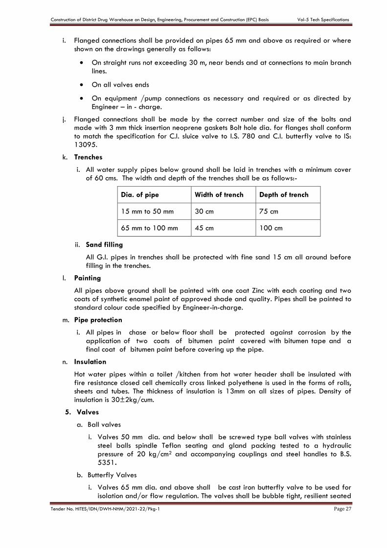
Construction of District Drug Warehouse on Design, Engineering, Procurement and Construction (EPC) Basis Vol-5 Tech Specifications
Tender No. HITES/IDN/DWH-NHM/2021-22/Pkg-1 Page 27
i. Flanged connections shall be provided on pipes 65 mm and above as required or where shown on the drawings generally as follows:
On straight runs not exceeding 30 m, near bends and at connections to main branch lines.
On all valves ends
On equipment /pump connections as necessary and required or as directed by Engineer – in - charge.
j. Flanged connections shall be made by the correct number and size of the bolts and made with 3 mm thick insertion neoprene gaskets Bolt hole dia. for flanges shall conform to match the specification for C.I. sluice valve to I.S. 780 and C.I. butterfly valve to IS: 13095.
k. Trenches
i. All water supply pipes below ground shall be laid in trenches with a minimum cover of 60 cms. The width and depth of the trenches shall be as follows:-
Dia. of pipe Width of trench Depth of trench
15 mm to 50 mm 30 cm 75 cm
65 mm to 100 mm 45 cm 100 cm
ii. Sand filling
All G.I. pipes in trenches shall be protected with fine sand 15 cm all around before filling in the trenches.
l. Painting
All pipes above ground shall be painted with one coat Zinc with each coating and two coats of synthetic enamel paint of approved shade and quality. Pipes shall be painted to standard colour code specified by Engineer-in-charge.
m. Pipe protection
i. All pipes in chase or below floor shall be protected against corrosion by the application of two coats of bitumen paint covered with bitumen tape and a final coat of bitumen paint before covering up the pipe.
n. Insulation
Hot water pipes within a toilet /kitchen from hot water header shall be insulated with fire resistance closed cell chemically cross linked polyethene is used in the forms of rolls, sheets and tubes. The thickness of insulation is 13mm on all sizes of pipes. Density of insulation is 30±2kg/cum.
5. Valves
a. Ball valves
i. Valves 50 mm dia. and below shall be screwed type ball valves with stainless steel balls spindle Teflon seating and gland packing tested to a hydraulic pressure of 20 kg/cm2 and accompanying couplings and steel handles to B.S. 5351.
b. Butterfly Valves
i. Valves 65 mm dia. and above shall be cast iron butterfly valve to be used for isolation and/or flow regulation. The valves shall be bubble tight, resilient seated
Construction of District Drug Warehouse on Design, Engineering, Procurement and Construction (EPC) Basis Vol-5 Tech Specifications
Tender No. HITES/IDN/DWH-NHM/2021-22/Pkg-1 Page 28
suitable for flow in either direction and seal in both direction. Valves shall be provided with matching flanges with neoprene insertion gasket 3 mm thick .P.N 1.6
ii. Butterfly valve shall be of best quality conforming to IS: 13095.
c. Non Return Valve
i. Where specified non return valve (swing check type) shall be provided through which flow can occur in one direction only, It shall be single door swing check type of best quality conforming to IS: 5312.P.N1.6
ii. Each butterfly and slim type swing check valves shall be provided with a pair of flanges screwed or welded to the main line and having the required number of galvanized nuts, bolts and double washers of correct length.
iii. Sluice valve shall be of approved makes conforming to I.S.:780 of class as specified.
6. Storage Tanks
a. Overhead Tanks
Overhead water storage tanks for water supply shall be reinforced cement concrete.
b. Tank connection and accessories
i. shall provide the following to each tank:
Inlet and outlet connections to pumps, equipment and main pipe lines.
Tank overflows with mosquito proof gratings
Scour drain and valve as per drawings
Water level gauge with approved type of brass gauges, plastic tube, a wooden board with level marking.
ii. Electronic level controllers, cabling, sequence controllers and all related equipment shall be provided by agency executing the pumping system work. Plumbing shall provide necessary G.I. sleeves and co-operate with to ensure that the work is successfully executed.
7. Testing
a. All pipes, fittings and valves, after fixing at site, shall be tested by hydrostatic pressure of 1.5 times the working pressure or 10 kg /cm2 whichever is more. Pressure shall be maintained for a period of at least 12 hours without any drop & withstand for 8 hrs.
b. A test register shall be maintained and all entries shall be counter-signed by Contractor (s) in the presence of Engineer-in-charge.
c. In addition to the sectional testing carried out during the construction, contractor shall test the entire installation after connections to the overhead tanks or pumping system or mains. He shall rectify all leakages and shall replace all defective materials in the system. Any damage done due to carelessness, open or burst pipes or failure of fittings, to the building, furniture and fixtures shall be made good by the contractor during the defects liability period without any cost.
d. After commissioning of the water supply system, shall test each valve by closing and opening it a number of times to observe if it is working efficiently. Valves which do not effectively operate shall be replaced by new ones at no extra cost and the same shall be tested as above.

Construction of District Drug Warehouse on Design, Engineering, Procurement and Construction (EPC) Basis Vol-5 Tech Specifications
Tender No. HITES/IDN/DWH-NHM/2021-22/Pkg-1 Page 29
SECTION – 5 WATER SUPPLY PUMPING SYSTEM & ALLIED SERVICES
1. Scope of work
a. Work under this section shall consist of furnishing all labour, materials, equipment and appliances necessary and required for the satisfactory supply, installation, completion and commissioning of water supply pumping system and allied works.
2. The System
a. The system described below is for the contractors bidding for the works to understand the extent and scope of work and the intent in the manner in which the water supply system is planned and shall be executed. This does not form a part of thecontractor’s scope of work with respect to the various elements that are described in this paragraph.
b. Sources of supply
Local water supply from the main road/ bore well to the underground water tank.
c. Underground water tanks
i. Static fire water storage tanks in compartments. Connections from the tube well water supply lines will be made into these tanks. Water will overflow into the Domestic Pure water tanks
Domestic Water Pumping Systems
ii. Water supply to the building will be made from a set of pumping sets to the overhead water and supplementary fire tanks located on the terrace of building.
3. Rising Mains & level control system
a. Water from the pumps described above will fill each tank by a rising main.
b. To control the level in each tank and enable it to fill as the water demand so requires, each tank will be provided with a ball cock to shut off the water supply when the tank is full.
c. A set of electronic level sensing probes will be installed in each tank. The probes installed in each pumping system will be wired to a central electronic panel which will activate the pump when any one of the tank probes signals low water conditions and top up all tanks. No excess flow will occur due to the ball cock in the tank.
4. Level Controllers
a. Level controllers shall be electronic magnetic type using required number of stainless-steel type probes, shrouded in PVC sheath or encapsulated in a stainless-steel pipe. The level controller will be used for following applications:-
i. Provide an audible high water alarm when water level in the sump reaches a pre-determined high level in the sump location at MCC panel installed in wall near sump location.
b. Overhead tank level controller cum indicators
i. Each OHT to be provided with required number of stainless steel electronically operated probes (housed in a stainless steel protective housing) and connected by a control cable to a central junction box connected to MCC panel located in the pump house at basement. A common multi-core cable from each group of buildings will be laid to the pump room in basement. The probes will function as follows:
ii. To cut off the water supply pumps when all the OHT is full and to start the pump if any OHT level reaches at pre-determined low level.

Construction of District Drug Warehouse on Design, Engineering, Procurement and Construction (EPC) Basis Vol-5 Tech Specifications
Tender No. HITES/IDN/DWH-NHM/2021-22/Pkg-1 Page 30
iii. Provision shall be made to enable the operation of the second duty pump in case the water level does not rise above a pre-determined level in the tank due to water demand which is higher than capacity of duty pump no.1 to meet.
iv. Indicate the water level in each OHT in the level indicating panel installed in the pump room
v. Each OHT are also provided with a float valve to stop the supply in individual OHT when level reaches a cut off high level.
c. Control & Indicating Panel (For overhead and underground water tanks)
i. A centralized indicating stand–alone wall mounted panel fabricated from 14 g. with seven tank process MS sheet and painted inside and outside with stove enamelled finish with clear vertical panels for each group of buildings & tanks shall indicate water level in each tank by means of digital display unit to indicate water level in each tank in four levels (¼th, ½, ¾ and full). The panel shall be installed on the control console panel located in the pump room or as directed by the Project Engineer. The panel shall have:
ii. Digital level indicator panel meter for each water tank.
iii. Etched plate identification plates.
iv. Control cabling from MCC to the panel installed in the control room as directed by the Engineer-In-Charge.
v. Cabling from PHT sensing probes to the panel
SECTION 6 PIPES & FITTINGS
1. Headers, piping and connections
a. All pipes within the plant room building in exposed locations and shafts including connections buried under floor and for suction and delivery headers shall be G.I. (Medium class) and thickness specified. Pipes up to 150 mm dia. shall conform to I.S. 1239.
b. Pipe 200 mm dia. and above shall be G.I. ERW tubes to IS 3589. If black pipes are available they shall be galvanized before use.
c. Fittings for G.I. pipes shall be approved type malleable iron or wrought iron screwed galvanized fittings for screwed joints. Fittings 200 mm dia. may be shop fabricated but shall be shop galvanized after fabrication.
d. All M.S. structural supports and clamps shall be galvanised. All the pipe work within plant room shall be adequately supported with G.I. structural supports from floor or ceiling as required and directed by Engineer-In-Charge.
2. Jointing
a. G.I. Pipes (Screwed joints)
Pipe shall be provided with metal-to-metal threaded joints. Teflon tape shall be used for lubrication and rust prevention. (USE OF LEAD /ZINC BASED JOINTING COMPOUND ARE NOT PERMITTED)
b. Flanged joints / Dead Joints
a. Flanges shall be provided on:
i. Straight runs not exceeding 12-15 m on pipe lines 80 mm dia and above.
ii. Both ends of any fabricated fittings e.g. bends, tees etc. of 50 mm dia or larger diameter. (When Permitted)

Construction of District Drug Warehouse on Design, Engineering, Procurement and Construction (EPC) Basis Vol-5 Tech Specifications
Tender No. HITES/IDN/DWH-NHM/2021-22/Pkg-1 Page 31
iii. Both end of all suction delivery and other headers.
iv. For jointing valves, appurtenances, pumps, connections with pipes, to water tanks and other places necessary and required as good for engineering practice.
v. Flanges shall be as per applicable I.S. with appropriate number of G.I. nuts and bolts, 3 mm insertion rubber gasket complete.
vi. The cost of flanges is included in the rates of pipes along with fittings.
c. Unions
Provide approved type of dismountable unions on pipes lines 50 mm and below near valves or inspector test/drain and assemblies and as required as per site conditions.
d. Vibration Eliminators
All suction and delivery lines and as shown on the drawings double flanged reinforced neoprene bellow type flexible pipe connectors shall be provided. Connectors should be suitable for a working pressure of each pump and tested to the test pressure given in the relevant head. Length of the connectors shall be as per site requirements in accordance with manufacturer’s details.
3. Valves
a. Sluice valves
i. Full way Sluice Valves shall be used on the suction connection to pumps and headers.
ii. Sluice valves (80 mm dia. and above) shall be C.I. double flanged sluice valves with rising stem. Each sluice valve shall be provided with wheel in exposed positions and cap top for underground valves. shall provide suitable operating keys for sluice valves with cap tops.
iii. Sluice valves shall be of approved makes conforming to I.S.780 PN1.6 class
b. Butterfly Valves (PN 1.6 rating)
i. Butterfly Valves shall be used in all other locations as required conforming to IS 13095.PN 1.6
ii. They shall have a cast iron body.
iii. Disc shall be CI heavy duty electrolyses nickel plated abrasion resistant.
iv. The shaft to be EN-8 Carbon Steel with low friction nylon bearings.
v. The seat shall be drop tight constructed by bonding resilient elastomer inside a rigid backing.
vi. Built in flanged rubber seals.
vii. Actuator to level operated for valves above ground and T Key operated for valves below Ground.
viii. Built in flanges for screwed on flanged connections. Manufacturer’s details on fixing and Installation will be followed.
c. Non Return Valves (NRV PN 1.6 rating))
i. Non return valves will be used at location to allow flow only in one direction and prevent flow in the opposite direction.
ii. NRV shall be cast iron slim type with cast iron body and gunmetal internal parts and accompanying flanges. Valves shall conform relevant IS or match the butterfly valves.PN 1.6
iii. Built in flanges for screwed on flanged connections.
Construction of District Drug Warehouse on Design, Engineering, Procurement and Construction (EPC) Basis Vol-5 Tech Specifications
Tender No. HITES/IDN/DWH-NHM/2021-22/Pkg-1 Page 32
d. Ball Valves
Ball Valves up to 40 mm dia. shall be screwed type ball valves with stainless steel balls, spindle, Teflon seating and gland packing tested to a hydraulic pressure of 20 kg/cm2 and accompanying coupling and steel handles (to B.S. 5351.
4. ‘Y’ Strainers (PN 1.6 rating)
Provide cast iron ‘Y’ type strainers with gunmetal internal strainers, CI screwed plug to be provided on all water tank suction connections to pumps.
SECTION 7: RAIN WATER HARVESTING PIT
i. The rain water harvesting pit shall be constructed in brick masonry chamber / cement concrete as per the standard design. The chamber shall have gravel, sand and boulders along with boring of suitable size as per the standard design, inlet and outlet fittings in UPVC, double seal C.I. covers complete as per standard design. The rain water harvesting pit shall be in rectangular shape, of appropriate capacity designed as per standards.
ii. Workmanship:
a. Bed Concrete shall be in 1:4:8 cement concrete 150 mm thick.
b. Brick work shall be with best quality bricks in 1:5 cement mortar. The walls of chamber shall be
plastered from inside with 12 mm thick cement plaster 1:3 and finished smooth with a floating
coat of neat cement & rough plaster on outside in cement mortar 1:3.
c. The pit shall have 400 mm thick coarse sand layer of 1.5 mm to 2.0 mm in size, 400 mm thick
layer of gravel of 5 mm to 10 mm in size, 400 mm thick layer of of boulder 50 to 200 mm in
size, fixing heavy duty pvc rungs @ 300 c/c; 250 mm dia. to 450 mm dia. inlet & outlet
points; boring of 400 mm dia. hole in all soil base depth 20 Rm; lowering 200 mm dia. pvc
Housing pipe base depth 10 RMT; lowering 200 mm dia. pvc Slotted pipe base depth 10
RMT; 8 '' dia. MS Clamp and MS CAP; packing of pea gravel at the sides of pipe as per
drawing.
d. Covers shall be of SRFC Manhole covers and shall be fixed on frame embedded in concrete.
C. I steps shall be provided at two corners of the chamber. All Cast Iron and MS items shall be
painted with two coats of bitumastic paint.
e. SRFC Manhole covers shall conforming to CPWD specifications.
Construction of District Drug Warehouse on Design, Engineering, Procurement and Construction (EPC) Basis Vol-5 Tech Specifications
Tender No. HITES/IDN/DWH-NHM/2021-22/Pkg-1 Page 33
CHAPTER-D
Technical Specifications – Electrical Works
1. GENERAL
Electrical works shall be provided in buildings/facilities as per scope of works and as specified in DBR as per directions of Engineer-In-Charge.
2. SCOPE OF WORK
The scope of work shall cover internal Electrical Installations, DG Set, Main LT Panels and external electrical Installation works complete as required for Electrification ofproposed buildings. It shall cover designing of complete Electrical System for the entire complex, preparation of shop drawings, supply of all equipment, material, electrical Fixtures & Accessories required, installation, testing and commissioning of all electrical installations for the project for the following, but not limited to, main items/systems:
2.1 ESS & External Electrical Installation
i. LT Panel with Synchronizing Relay for auto synchronizing and Auto-load management
ii. Capacitor Panels (APFC) with Harmonic filters to improve Power factor up to 0.97 (lagging).
iii. All Associated Equipment & accessories required
iv. DG Sets including Synchronizing relay and PLC panels for Auto Start/ Stop, Auto Load Management & Load sharing etc.
v. Lightening Protection System & Earthing Network
vi. 1.1 kV LT power cables
vii. Street Lighting System
viii. Electrical distribution comprising of feeder cables from LT Two Pole structure to respective Main LT panel/ Changeover Panel. Separate distribution shall be provided for Lighting load, AC Load, Power/Medical Equipment load through Rising Mains etc. UPS power shall be distributed through suitable cabling & LT panels in all buildings. Separate LT panels at each floor shall be provided for feeding HVAC load of AHUs, FCUs, Split ACs and Ventilation Fans.
The Electrical distribution should include - Emergency power supplying distribution system as per NBC 2016 for critical requirement for functioning of fire and life safety system and equipment, shall be planned for efficient and reliable power and control supply to the following systems and equipment where provided:
i. Fire Pumps
ii. Pressurization and smoke venting; including its ancillary systems such as dampers and actuators;
iii. Fireman's Lifts (including all lifts).
iv. Exit Signage Lighting;
v. Emergency Lighting;
vi. Fire Alarm System;
vii. Public Address (PA) System (relating to emergency voice evacuation and annunciation);
viii. Access Control System
Construction of District Drug Warehouse on Design, Engineering, Procurement and Construction (EPC) Basis Vol-5 Tech Specifications
Tender No. HITES/IDN/DWH-NHM/2021-22/Pkg-1 Page 34
ix. Lighting in fire command centre and security room.
x. Any other system as required
2.2 Internal Electrical Installations
It shall include the following items of work to be carried out simultaneously with the civil work within the buildings:
i. Wiring for 6A Light Points and socket Outlets
ii. Wiring for Call Bell, Fan & Exhaust Points.
iii. Wiring for 16A/20A Power socket outlets.
iv. Wiring for 3 Phase Power socket Outlets
v. 1.1 KV L.T. Cables and Sub main wiring.
vi. Rising Mains
vii. MV Panels/ Floor Panels and Double Door MCB Type Distribution Boards.
viii. Supply and Installation of LED Light fittings, fans, Exhaust Fans & fixtures
ix. Earthing & Lighting Arrestor
x. Wiring for Telephone
xi. Wiring for Cable TV
xii. Wiring for LAN Networking & Hospital Management Information System (HMIS)
xiii. Wiring for CCTV & Access Control System, Boom Barriers
xiv. Testing and commissioning of all electrical installations
The scope of work shall also include any other item or item of work, equipment, material or accessories not specifically mentioned above but are required for the satisfactory completion & trouble free operation & maintenance of electrical equipment/ work. This shall also include spares required for commissioning of the equipment/ work.
2.3 SPECIAL CONDITIONS FOR ELECTRICAL SERVICES:
a) GENERAL: The design and workmanship shall be in accordance with the best engineering practices, to ensure satisfactory performance and service life. The requirement offered by thecontractor shall be complete in all respects.
b) The contractor shall obtain all sanctions (electrical loads, approval of drawing/ ESS/ D.G.’s estimator/ approval of meter room etc. from the concerned authorities and permits required for the electrical installation work. The actual fee payable in this regard will be reimbursed against receipt/documentary evidence. On completion of work, the contractor shall obtain NOC from SEB & Director of Safety of the concerned state/Pollution Control Board; a copy of the same shall be delivered to HITES / Engineer In Charge.
The HITES shall have full power regarding the materials or work to be got tested through independent agency at the expenses in order to prove their soundness and adequacy. The contractor will rectify the defects/suggestions pointed out by HITES/ independent agency at his own expenses.
The installation shall comply in all respects with the requirements of Indian Electricity Act 1910, Indian Electricity Rules (IER) 1956 and other related Laws and Regulations as amended up to date, there under and special requirements, if any, of the State Electricity Boards etc. The bidder is liable to furnish the list of authorized licensed persons/ employed/deputed to carry
Construction of District Drug Warehouse on Design, Engineering, Procurement and Construction (EPC) Basis Vol-5 Tech Specifications
Tender No. HITES/IDN/DWH-NHM/2021-22/Pkg-1 Page 35
out the works/perform the assigned duties to fulfill the requirement of Rule No.3 of IER 1956 as amended up to date.
2.4 DRAWINGS
i. Tender Drawings:
The tender drawings are meant to give general idea to bidder regarding the nature of scope & works to be executed. Any information/data not shown in tender drawings shall not relieve the contractor of his responsibility to carry out the work as per the specifications & terms of the contract. Additional information required by the bidder/tenderer for successful completing the work shall be obtained at his end.
ii. Shop Drawings:
The shall prepare detailed coordinated electrical shop drawing indicating Light Points, Power Points, Cal Bell points, Ceiling Fan, Exhaust Fan Points, Switch Boards, Distribution Boards (Light, Power & UPS), Lighting Fixtures, Convenience outlets, Single Line Diagram for complete HT/ LT electrical scheme, DG Sets, HT Panel, Transformers, LT Panels, Capacitor Panels, RTCC Panels, PCC Panel, UPS Units, UPS Incoming/ Outgoing panels, Lift Panels, Rising Mains, HT/ LT Cable Schedules, Solar PV System, Earth Pit Layout, Earth Strip routes, HT/ LT Cable Routes, Street Light Layout & Street Cable routes, Schematic Diagrams & Floor wise Shop Drawings for all LV works namely, Telephone, LAN, Wifi, CCTV, Access Control, Fire Alarm, Public Adress System, Information Display System, Boom Barriers etc. with other relevant services and submit to the HITES for approval or the Engineer-in-Charge before commencing the work.
GA Drawings, SLD & Control wiring diagrams, Room trench details for all HT / LT Panels, Capacitor Panels, UPS panels, Floor Electrical Panels, Transformers, DG Sets, UPS Units, Rising Mains etc. shall be prepared & submitted. The shop drawings shall indicate all setting out details and physical dimensions of all equipment/items/ components with wiring and cable details, cable schedule and routes, manhole trap and fixing details as well as for conduit indicating run and size of wire/cables, outlet/pull/junction boxes etc. with fixing details etc. for the above mentioned work. All work shall be carried out on the approval of these drawings. However, approval of these drawings shall not relieve the contractor of his responsibility for providing maintenance free and fool proof system including any missing component/accessories to meet the intent of the specifications. will submit 2 prints for preliminary approval and finally six prints for distribution. The recommended location/ position of the all equipment as shown on the layout drawings will be adhered to unless stated otherwise.
iii. As-Built Drawings:
On completion of the work and before issue of certificate of virtual completion, the contractor shall submit to the HITES, required Sets of ‘As Built’ drawings (in AutoCAD & PDF format) along with soft copy of the executed works incorporating all such changes and modifications during engineering and execution along with Operation and Maintenance Manuals, Warranty & Guarantee Certificates from Original Equipment Manufacturers (OEM), authorized Suppliers & Vendors, as applicable.
These drawings must provide:
Run and size of conduit, inspection and pull boxes including routing and locations.
Construction of District Drug Warehouse on Design, Engineering, Procurement and Construction (EPC) Basis Vol-5 Tech Specifications
Tender No. HITES/IDN/DWH-NHM/2021-22/Pkg-1 Page 36
Number and size of conductor in each conduit.
Locations and rating of sockets and switches controlling the light and power outlet.
A complete wiring diagram as installed and schematic drawings showing all connections in the complete electrical system.
Location of outlets of various services, junction boxes, light fixtures.
Location of all earthing stations route and size of all earthing conductors.
Layout and particulars of all cables.
Location and details of Transformers, HT/ LT Panels, Feeder Pillars, capacitor control panels etc.
UPS Panel and relay panels with description detailed control wiring diagram.
Location of transformer and its details and control wiring diagram.
Location of Hume pipe and manhole including HT/LT cable layout and scheduling
Location of DG Sets, Exhaust and auxiliary equipment with schematic drawings.
Layout of cable trays with support and their fixing details.
Location of all earthing station, route and size of all earthing conductor.
Layout and particulars of rising mains with fixing details.
The contractor shall submit 2 sets of samples of each type of accessories and apparatus, proposed to be used in the installation at site for approval (drawings or samples) as required shall be submitted by contractor and the choice of selection out of the approved list lies with the HITES. For all non-specified items, approval of the HITES shall be obtained prior to procurement of the same. HITES shall in no way be liable for rejection of the any material due to poor quality, poor workmanship, poor material etc.
2.5 MANUFACTURER’S INSTRUCTIONS
Where manufacturers have furnished specific instructions, relating to the material/ equipment to be used on this job, covering points not specifically mentioned in this document, manufacturers’ instructions should be followed.
2.6 MATERIALS AND EQUIPMENT
All the materials and equipment shall be of the approved make and design. Unless otherwise called for any approval by HITES’s Engineer-in-Charge, only the best quality materials and equipment shall be used.
2.7 GENERAL DETAILS
a) Space Heaters & Lighting.
One of more adequately rated heaters thermostatically controlled with On-Off switch and fuse shall be provided to prevent condensation in any panel compartment. The heaters shall be installed in the lower portion of the compartment and electrical connections shall be made from below the heaters to minimize deterioration of supply wire insulation. The heaters shall be suitable to maintain the compartment temperature to prevent condensation. CFL lamp shall be provided in any panel compartment.
Construction of District Drug Warehouse on Design, Engineering, Procurement and Construction (EPC) Basis Vol-5 Tech Specifications
Tender No. HITES/IDN/DWH-NHM/2021-22/Pkg-1 Page 37
b) Fungistatic Varnish
Besides the space heaters, special moisture and fungus resistant varnish shall be applied on parts, which may be subjected or predisposed to the formation of fungi due to the presence or deposit of nutrient substances. The varnish shall not be applied to any surface of part where the treatment will interfere with the operation or performance of the equipment. Such surfaces or parts shall be protected against the application of the varnish.
c) Ventilation Opening
In order to ensure adequate ventilation, compartments shall have ventilation openings provided with fine wire mesh of brass to prevent the entry of insects and to reduce to a minimum the entry of dirt and dust. Outdoor compartment openings shall be provided with shutter type blinds.
d) Degree of Protection
The enclosures of the Control Cabinets, Junction Boxes and Marshalling Boxes, Panels etc. to be installed shall provide degree of protection as called for in specifications / General arrangement, whenever it is not mentioned it shall be as given below:
i. Installed out door: IP-55.
ii. Installed indoor in air-conditioned area: IP-52.
iii. Installed in covered area: IP-52.
iv. Installed indoor in non-air-conditioned area where possibility of entry of water is limited: IP-42.
v. For L.T. switchgear (AC and DC distribution boards): IP-52.
The degree of protection shall be in accordance with IS: 13947 (Part-I)/IEC-947 (Part-I). Type test report for degree of protection test, on each type of the box shall be submitted for approval.
2.8 Rating Plates, Name Plates and Labels
Rating Plates, Name Plates and Labels are to be provided & attached permanently in a conspicuous position to all equipment & items installed in various buildings. A rating plate of non-corrosive material engraved with manufacturer’s name, year of manufacture, equipment name, diagram, type or serial number etc. together with details of the loading conditions of equipment. The rating plate of each equipment shall be according to relevant BIS & IEC norms, as applicable.
All such nameplates, instruction plates, rating plates shall be bilingual with Hindi inscription first followed by English. Alternatively two separate plates one with Hindi and the other with English inscriptions may be provided.
2.9 First Fill of Consumables, Oil and Lubricants
All the first fill of consumables such as oils, lubricants, filling compounds, touch up paints, welding/ soldering/ brazing material for all copper/ G.I. earthing and essential chemicals etc. which will be required to put the equipment/ scheme covered under the scope of the specifications, into successful operation, shall be furnished by the contractor unless specifically excluded under the exclusions in these specifications and documents.
2.10 DESIGN IMPROVEMENTS / DEVIATIONS
The bidder shall note that the equipment offered by him in the bid only shall be accepted for supply. If for any reason, contractor wishes to deviate from
Construction of District Drug Warehouse on Design, Engineering, Procurement and Construction (EPC) Basis Vol-5 Tech Specifications
Tender No. HITES/IDN/DWH-NHM/2021-22/Pkg-1 Page 38
specification, prior permission from HITES will be sought.
If any such agreed upon change is such that it affects the price and schedule of completion, the parties shall agree in writing as to the extent of any change in the price and/or schedule of completion before the proceeds with the change. Following such agreement, the provision thereof, shall be deemed to have been amended accordingly in the specification.
3. QUALITY ASSURANCE PROGRAMME
To ensure that the equipment and services under the scope of this Contract whether manufactured or performed within thecontractor ’s works or at his sub-’s premises or at the Purchaser’s site or at any other place of work are in accordance with the specifications, the contractor shall adopt suitable quality assurance programme to control such activities at all points necessary. Such programme shall be outlined by the contractor and shall be finally accepted by the Purchaser after discussions before the award of Contract. A quality assurance programme of the contractor shall generally cover the following:
a) His organization structure for the management and implementation of the proposed quality assurance programme.
b) Documentation control system.
c) Qualification data for bidder’s key personnel.
d) The procedure for purchases of materials, parts components and selection of sub-contractor’s services including vendor analysis, source inspection, incoming raw material inspection, verification of material purchases etc.
e) System for shop manufacturing and site erection controls including process controls and fabrication and assembly control.
f) Control of non-conforming items and system for corrective actions.
g) Inspection and test procedure both for manufacture and field activities.
h) Control of calibration and testing of measuring instruments and field activities.
i) System for indication and appraisal of inspection status.
j) System for quality audits.
k) System for authorizing release of manufactured product to the Purchaser.
l) System for maintenance of records.
m) System for handling storage and delivery.
n) A quality plan-detailing out the specific quality control measures and procedures adopted for controlling the quality characteristics relevant to each item of equipment furnished and/or services rendered.
3.1. QUALITY ASSURANCE DOCUMENTS
The contractor shall be required to submit the following Quality Assurance Documents within three weeks after dispatch of the equipment:
a) All Non-Destructive Examination procedures, stress relief and weld repair procedure actually used during fabrication and reports including radiography interpretation reports.
b) Welder and welding operator qualification certificates.
c) Welder’s identification list, listing welders and welding operator’s qualification procedure and welding identification symbols.
Construction of District Drug Warehouse on Design, Engineering, Procurement and Construction (EPC) Basis Vol-5 Tech Specifications
Tender No. HITES/IDN/DWH-NHM/2021-22/Pkg-1 Page 39
d) Raw material test reports on components as specified by the specification and/or agreed to in the quality plan.
e) Stress relief time temperature charts/oil impregnation time temperature charts.
f) Factory test results for testing required as per applicable codes/ mutually agreed quality plan/ standards referred in the technical specification.
g) The quality plan with verification of various HITES inspection points as mutually and methods used to verify the inspection and testing points in the quality plan were performed satisfactorily.
4. INSPECTION, TESTING AND INSPECTION CERTIFICATE
a) The HITES or duly authorized representative shall have at all reasonable times free access to thecontractor ’s/ Manufacturer’s premises or works and shall have the power at all reasonable times to inspect and examine the materials and workmanship of the works during its manufacture or erection, if part of the works is being manufactured or assembled at other premises or works, thecontractor shall obtain permission to inspect as if the works were manufactured or assembled on the contractor’s own premises or works. Inspection may be made at any stage of manufacture, dispatch or at site at the option of the Purchaser and the equipment if found unsatisfactory due to bad workmanship or quality, material is liable to be rejected.
b) All equipment being supplied shall conform to type tests and shall be subject to routine tests in accordance with requirements stipulated under respective sections. Bidder shall submit the type tests reports for approval. The contractor shall intimate the HITES the detailed programme about the tests at least three (3) weeks in advance in case of domestic supplies.
c) The contractor shall give the HITES thirty (30) days written notice of any material being ready for testing. Such tests shall be to thecontractor’s account. The HITES, unless witnessing of the tests is virtually waived off, will attend such tests within thirty (30) days of the date of which the equipment is notified as being ready for test/ inspection, failing which the contractor may proceed with the test which shall be deemed to have been made in the presence of HITES and he shall forthwith forward to the HITES duly certified copies of tests in triplicate.
d) The HITES shall within fifteen (15) days from the date of inspection as defined shall inform in writing to the contractor of any objection to any drawings and all or any equipment and workmanship which in his opinion is not in accordance with the Contract. The contractor shall give due consideration to such objections and make the necessary modifications accordingly.
e) When the factory tests have been completed at the contractor’s or Sub- contractor’s works, the HITES shall issue a certificate to this effect within fifteen (15) days after completion of tests but if the tests are not witnessed by the HITES, the certificate shall be issued within fifteen (15) days of receipt of thecontractor’s Test certificate by the HITES. Failure of the issue of such a certificate shall not prevent the contractor from proceeding with the works. The completion of these tests or the issue of the certificate shall not bind the HITES to accept the equipment should, it, on further tests after erection, is found not to comply with the Specification. The equipment shall be dispatched to site only after approval of test reports and issuance of clearance by the HITES.
f) The contractor shall arrange all necessary tools and testing facilities for inspection purpose including arrangement of air travel (inland as well as abroad), conveyance, lodging, boarding and other miscellaneous expenses etc. HITES shall depute its inspection engineers (2 or more as decided by HITES) after receipt of inspection call
Construction of District Drug Warehouse on Design, Engineering, Procurement and Construction (EPC) Basis Vol-5 Tech Specifications
Tender No. HITES/IDN/DWH-NHM/2021-22/Pkg-1 Page 40
from the contractor. All such expenses incurred by the contractor towards inspection of equipment by HITES’ inspection engineers shall be borne by the contractor.
g) For tests whether at the premises or at the works of the contractor or of any Sub- contractor, the contractor shall provide free of charge such items as labour, materials, electricity, fuel, water, stores, apparatus and instruments as may be required by HITES or this authorized representative to carry out effectively such tests of the equipment in accordance with the Specification.
h) The inspection by HITES and issue of Inspection Certificate thereon shall in no way absolve the liabilities and responsibilities of the contractor in respect of the agreed quality assurance programme forming a part of the Contract.
i) The HITES will have the right of having at his own expenses any other tests(s) of reasonable nature carried out atcontractor ’s premises or at site or in any other place in addition of aforesaid type and routine tests to satisfy that the material complies with the specifications.
j) The HITES reserves the right for getting any field tests not specified in respective sections of the technical specification conducted on the completely assembled equipment at site. The testing equipment for these tests shall be provided by the contractor.
5. TESTS
5.1. Charging Tests
On completion of erection of the equipment and before charging, each item of the equipment shall be thoroughly cleaned and then inspected jointly by the HITES and the contractor for correctness and completeness of installation and acceptability for charging, leading to initial pre-commissioning tests at Site. The pre-commissioning tests to be performed as per relevant I.S. given and shall be included in the contractor ’s quality assurance programme.
5.2. Commissioning Tests
a) The available instrumentation and control equipment will be used during such tests and the contractor will calibrate all such measuring equipment and devices as far as practicable. However, unmeasurable parameters shall be taken into account in a reasonable manner by thecontractor for the requirement of these tests. The tests will be conducted at the specified load points and as near the specified cycle condition as practicable. The contractor will apply proper corrections in calculation, to take into account conditions, which do not correspond to the specified conditions.
b) All instruments, tools and tackles required for the successful completion of the Commissioning Tests shall be provided by the contractor, free of cost.
c) Pre-commissioning test shall be carried out as per relevant IS and/or as specified in the relevant clause.
d) The contractor shall be responsible for obtaining statutory clearances from the concerned authorities for commissioning of the equipment.
6. PACKAGING
All the equipment shall be suitably protected, coated, covered or boxed and crated to prevent damage or deterioration during transit, handling and storage at Site till the time of erection. While packing all the materials, the limitation from the point of view of availability of Railway wagon/truck/trailer sizes in India should be taken account of. Thecontractorshall be responsible for any loss or damage during transportation, handling and storage due to improper packing. Any demurrage, wharfage and other such
Construction of District Drug Warehouse on Design, Engineering, Procurement and Construction (EPC) Basis Vol-5 Tech Specifications
Tender No. HITES/IDN/DWH-NHM/2021-22/Pkg-1 Page 41
charges claimed by the transporters, railways etc. shall be to the account of the contractor. HITES takes no responsibility of the availability of any special packaging/transporting arrangement.
7. PROTECTION
All coated surfaces shall be protected against abrasion, impact, discoloration and any other damages. All exposed threaded portions shall be suitably protected with either a metallic or a non-metallic protecting device. All ends of all valves and pipings and conduit equipment connections shall be properly sealed with suitable devices to protect them from damage. The parts which are likely to get rusted, due to exposure to weather should also be properly treated and protected in a suitable manner.
8. FINISHING OF METAL SURFACES
8.1. General
All metal surfaces shall be subjected to treatment for anti-corrosion protection. All ferrous surfaces for external use unless otherwise stated elsewhere in the specification or specifically agreed, shall be hot-dip galvanized after fabrication. High tensile steel nuts and bolts and spring washers shall be electro galvanized. All steel conductors used for earthing/grounding (above ground level) shall be galvanized according to IS: 2629.
8.2. Hot Dip Galvanizing
a) The minimum weight of the zinc coating shall be 700 gm/sq.m and minimum thickness of coating shall be 85 microns.
b) The galvanized surfaces shall consist of a continuous and uniform thick coating of zinc, firmly adhering to the surface of steel. The finished surface shall be clean and smooth and shall be free from defects like discolored patches, bare spots, unevenness of coating, spelter which is loosely attached to the steel globules, spiky deposits, blistered surface, flaking or peeling off etc. The presence of any of these defects noticed on visual or microscopic inspection shall render the material liable to rejection.
c) After galvanizing drilling or welding shall be performed on the galvanized parts of the earthing materials. Sodium dichromate treatment shall be provided to avoid formation of white rust after hot dip galvanization.
d) The galvanized steel shall be subjected to six one minute dips in copper sulphate solution as per IS-2633.
e) Sharp edges with radii less than 2.5mm shall be able to withstand four immersions of the Standard Preece test. All other coatings shall withstand six immersions. The following galvanizing tests should essentially be performed as per relevant Indian Standards.
- Coating thickness,
- Uniformity of zinc,
- Adhesion test,
- Mass of zinc coating.
f) Galvanized material must be transported properly to ensure that galvanized surfaces are not damaged during transit. Application of zinc rich paint at site shall not be allowed.

Construction of District Drug Warehouse on Design, Engineering, Procurement and Construction (EPC) Basis Vol-5 Tech Specifications
Tender No. HITES/IDN/DWH-NHM/2021-22/Pkg-1 Page 42
8.3. Painting
a) All sheet steel work shall be degreased, pickled, phosphate in accordance with the IS-6005 “Code of practice for phosphating iron and sheet”. All surfaces which will not be easily accessible after shop assembly shall beforehand be treated and protected for the life of the equipment. The surfaces, which are to be finished painted after installation or require corrosion protection until installation, shall be shop painted with at least two coats of primer. Oil, grease, dirt and swaf shall be thoroughly removed by emulsion cleaning. Rust and scale shall be removed by pickling with dilute acid followed by washing with running water, rinsing with slightly alkaline hot water and drying.
b) After phosphating, thorough rinsing shall be carried out with clean water followed by final rinsing with dilute dichromate solution and oven drying. The phosphate coating shall be sealed with application of two coats of ready mixed, staving type zinc chromate primer. The first coat may be “flash dried” while the second coat shall be shoved.
c) Powder coating/electrostatic painting of approved shade shall be applied.
d) The exterior color of the paint shall be as per shade no. 697 of IS-5 or as approved by Engineer-in-charge and inside shall be white or as approved by Engineer-in-charge. A small quantity of finishing paint shall be supplied for minor touching up required at site after installation of the equipments, if required.
e) In case the Bidder proposes to follow his own standard surface finish and protection procedures or any other established painting procedures like electrostatic painting etc. the procedure shall be submitted along with the Bids for HITES’s review and approval.
9. HANDLING, STORING AND INSTALLATION
a) In accordance with the specific installation instructions as shown on manufacturer’s drawings or as directed by the Purchaser or his representative, the contractor shall unload, store, erect, install, wire, test and place into commercial use all the equipment included in the contract. Equipment shall be installed in a neat, workmanlike manner so that it is level, plumb, square and properly aligned and oriented.
b) Shall follow the unloading and transporting procedure at site, as well as storing, testing and commissioning of the various equipment being procured by him separately. The contractorshall unload, transport, store, erect, test and commission the equipment as per instructions of the manufacturer’s Engineer(s) and shall extend full co-operation to them.
c) In case of any doubt/ misunderstanding as to the correct interpretation of manufacturer’s drawings or instructions, necessary clarifications shall be obtained from the HITES. The contractor shall be held responsible for any damage to the equipment consequent for not following manufacturer’s drawings/instructions correctly.
d) Where assemblies are supplied in more than the one section, contractor shall make all necessary connections between sections. All components shall be protected against damage during unloading, transportation, storage, installation, testing and commissioning. Any equipment damaged due to negligence or carelessness or otherwise shall be replaced by the contractor at his own expense.
e) The contractor shall submit to the HITES every week, a report detailing all the receipts during the weeks. However, the contractor shall be solely responsible for any shortages or damages in transit, handling and/or in storage and erection of
Construction of District Drug Warehouse on Design, Engineering, Procurement and Construction (EPC) Basis Vol-5 Tech Specifications
Tender No. HITES/IDN/DWH-NHM/2021-22/Pkg-1 Page 43
the equipment at Site. Any demurrage, wharfage and other such charges claimed by the transporters, railways etc. shall be to the account of the contractor.
f) The contractor shall be fully responsible for the equipment/material until the same is handed over to the HITES in an operating condition after commissioning. The contractor shall be responsible for the maintenance of the equipment/material while in storage as well as after erection until taken over by HITES, as well as protection of the same against theft, element of nature, corrosion, damages etc.
g) The contractor shall be responsible for making suitable indoor storage facilities, to store all equipment, which require indoor storage.
h) The words ‘erection’ and ‘installation’ used in the specification are synonymous.
i) Exposed live parts shall be placed high enough above ground to meet the requirements of electrical and other statutory safety codes.
j) The minimum phase to earth, phase to phase and section clearance along with other technical parameters for the various voltage levels shall be maintained as per relevant IS.
10. PROTECTIVE GUARDS
Suitable guards shall be provided for protection of personnel on all exposed rotating and/or moving machine parts. All such guards with necessary spares and accessories shall be designed for easy installation and removal for maintenance purpose.
11. DESIGN CO-ORDINATION
The contractor shall be responsible for the selection and design of appropriate equipments to provide the best co-ordinated performance of the entire system. The basic design requirements are detailed out in this Specification. The design of various components, sub-assemblies and assemblies shall be so done that it facilitates easy field assembly and maintenance.
12. DESIGN COORDINATION MEETING
The contractor will be called upon to attend design co-ordination meetings with HITES/ Client during the period of Contract. The contractor shall attend such meetings at his own cost contractor at mutually agreed venue as and when required and fully co-operate with such persons and agencies involved during those discussions.
13. TOOLS AND TACKLES
Thecontractor shall supply with the equipment one complete set of all special tools and tackles for the erection, assembly, dis-assembly and maintenance of the equipments.
14. SAFETY CODES & PRECAUTIONS
The contractor at his own expenses shall arrange for safety provisions as required to comply with the statuary regulations, ISI recommendations and CPWD codes.
The contractor shall provide necessary barriers, warnings, signals and other safety measures to avoid accidents. He shall indemnify HITES against any claims arising out of negligence in this respect.
15. REGULATIONS AND STANDARDS
All equipments their installation, testing and commissioning shall conform latest CPWD/ IS specifications in all respects. Indian Standard Code of Practice for Electrical Wiring Installation IS:732-1989. It shall also be in conformity with Indian Electricity Rules and the Regulations, National Electric Code, National Building Code 2016, ECBC, latest CPWD specifications amended up to date and requirements of the Local Electric Supply Authority. In general, all materials equipment and workmanship shall conform to the
Construction of District Drug Warehouse on Design, Engineering, Procurement and Construction (EPC) Basis Vol-5 Tech Specifications
Tender No. HITES/IDN/DWH-NHM/2021-22/Pkg-1 Page 44
Indian Standards specifications and code. Some of the applicable codes/standards are as under:
a. CPWD General specifications for electrical works
Part-I (Internal) 2013
b. CPWD General specifications for electrical works
Part-II (External) 1994
c. CPWD General specifications for electrical works
Part-III (Lifts & Escalators) 2005
d. CPWD General specifications for electrical works
Part-IV (Substation) 2013
e. CPWD General specifications for electrical works
Part VII (DG Sets) 2013
f. CPWD Guidelines for Substation & Power Distribution Systems of Buildings
2019
g. Guide for uniform system of marking and identification of conductor and apparatus terminals.
IS 11353 -1985
h. Low voltage switchgear and control gear assemblies
IS/IEC 61439
i. Specification for low voltage switchgear and control gear assemblies
IS 8623 (Part -2-1993)
j. Code of practice for selection, Installation and maintenance of switchgear and control gear.
IS 10118 Part – 1 – 4
k. PVC insulated (heavy duty) electric cables IS 1554
l. PVC insulated cables for working voltages up to and including 1100V.
IS 694
m. Conduit for electrical installations IS 9537
n. Accessories for rigid steel conduits for electrical wiring
IS 3837
o. Boxes for the enclosure of electrical accessories
IS 14772
p. General and safety requirements for luminaries
IS 1913
q. Code of practice for earthing IS 3043
r. Electrical accessories – circuit breakers for over current protection for household and
IS 8828
Construction of District Drug Warehouse on Design, Engineering, Procurement and Construction (EPC) Basis Vol-5 Tech Specifications
Tender No. HITES/IDN/DWH-NHM/2021-22/Pkg-1 Page 45
similar installations.
s. Low Voltage switchgear and control gear IS 13947 Part 1 – 5
t. Residual current operated Circuit Beakers IS 12640
u. Current Transformers IS 2705
v. Voltage Transformers IS 3156
w. Direct acting indicating analogue electrical measuring instruments and their accessories
IS 1248 part – 1 to 9
x. Control Switches (switching device for control and auxiliary circuits including contactor relays) for voltages up to and including 1000V AC and 1200 V DC.
IS 13947 & IS 1336
In case of contradiction in specification the priority of the documents shall be CPWD/ IS Specifications, Drawings, and Technical Specifications.
16. 11/ 0.433 kV SUBSTATIONS
16.1. 11 kV VACUUM CIRCUIT BREAKER (VCB) PANEL BOARD
16.1.1. GENERAL:
Vacuum Circuit Breaker shall be incorporated in HT Panel boards in required combination of incoming panels, coupler panel, outgoing transformer panels & outgoing feeder panels. VCB’s shall conform to IEC 298 and 694, IS 3427, BS 5227 and VDE 0670, Part 6 as well as the regulations mentioned therein. VCB’s shall be indoor type & suitable for operation on 11 kV, 3-Phase, 50 Hz AC supply. Metering and protection in the panels as detailed herein after. 11KV Panel board in each Substation shall be comprising of 2 Incoming Panels, One Bus coupler & Outgoing Panels with provision of at least one no. spare Breaker panels on each side.
16.1.2. TYPE AND CONSTRUCTION:
i. The metal clad panel shall be fully extensible and compartmentalized to give.
a. Circuit Breaker Compartment
b. Busbar Compartment
c. CT and Cable Compartment
ii. The compartments shall be safe to touch and compartments thus formed shall be dust proof & vermin proof. A separate metering chamber for fixing the necessary instrumentation metering and protective equipment shall be provided panel on the front.
iii. The VCB shall consist of three air insulated poles incorporating mechanism of interrupters. The body of interrupters shall be made of nickel chromium steel supported on insulators made out of metalised aluminum oxide. The contacts shall be of chromium copper and butt shaped.
iv. Vacuum Circuit Breaker shall be mounted on truck or a carriage mechanism. In case of truck mechanism, the breaker shall be on a trolley while in a carriage mechanism, shall be separate door and it shall be possible to perform all operations with front door closed. The draw out carriage shall have two positions for the circuit breaker viz isolated/test & service position. Bus bars shall be
Construction of District Drug Warehouse on Design, Engineering, Procurement and Construction (EPC) Basis Vol-5 Tech Specifications
Tender No. HITES/IDN/DWH-NHM/2021-22/Pkg-1 Page 46
insulated type made of high conductivity copper supported on cast epoxy monobloc designed to withstand full short circuit currents and shall be provided all along the length of the HT Board.
v. It shall be horizontal isolation, horizontal draw out type, fully interlocked, with dust and vermin proof construction, suitable for indoor instillation. The panel shall be supplied with the manufacturer’s test certificates.
vi. The steel work should have undergone a rigorous rust proofing process comprising alkaline degreasing, descaling in dilute sulphuric acid and recognized phosphate process and shall then be given power coating (Electrostatic) paint of manufacturer’s standard shade.
vii. The switchgear constructions shall be such that breaker operation and internal explosions do not endanger the operating personnel, and the front of the panel shall be specially designed to withstand these. Pressure relief flaps shall be provided for safely venting out gases produced inside the high voltage compartment, bus bar compartment and termination compartment. These flaps shall be vented upwards and cannot be opened from outside. These relief flaps shall be of such construction as not to permit ingress of dust/water in harmful quantities under normal working conditions. Enclosure shall be constructed with sheet steel of at least 2.0 mm thickness. It shall have a rigid, smooth, leveled, flawless finish.
viii. Voltage transformer of burden not less than 100 VA and of proper ratio as specified shall be provided. The accuracy class for the VT shall be 0.5 as per is 3156 Part 1 to III for incomer and class I for outgoing panels. The PT shall be of cast epoxy resin construction. It shall be fixed/withdraw able type. HRC fuses circuit Breaker shall be provided on both HV and LV side. Adequate space at the rear of the panel shall be provided for the termination of power & control cables. The panel shall be provided with suitable terminating arrangement for the termination of cables. Burden of PT should match with the requirement of client.
ix. The making contact arms (upper & lower) of the circuit breaker shall be encased in polyprolene tubes. Penetration type bushings shall be provided in the busbars & cable compartment for the fixed contacts.
x. Safety shutters shall be provided to cover up the fixed high voltage contacts on busbar and cable sides when the carriage is moved to Isolated/Disconnected position. The shutters shall move automatically with the movement of the draw out carriage. It shall, however, be possible to open the shutters of busbars side and cable side individually.
xi. Mechanically operated circuit breaker auxiliary switches of minimum 5 NO + 5 NC ways, shall be provided for control and indication purposes. Control wiring shall be done by 1.5 sq. mm, 1.1 kV grade stranded copper PVC insulated wires. All control device shall be MCB type.
xii. Terminal blocks shall be clamp type suitable for connection of only 2 wires per terminal and shall be 650 V grade. The LT control circuit shall be routine tested to withstand 1.5 kV for one minute.
xiii. Busbar compartment shall be provided at the rear. Electrolytic copper busbars shall be of rectangular cross section and insulated. Busbars shall be supported properly by cast epoxy resin insulators so as to withstand thermal and dynamic stresses during system short circuits. Busbars shall be provided with necessary color coding for phases indication. The busbars shall be designed to withstand a temperature rise of 60 deg. C above and ambient temperature of 45 deg. C.
Construction of District Drug Warehouse on Design, Engineering, Procurement and Construction (EPC) Basis Vol-5 Tech Specifications
Tender No. HITES/IDN/DWH-NHM/2021-22/Pkg-1 Page 47
16.1.3. BUSBAR AND REGULATORS
i. All bus bars and jumper connections shall be of electrolytic copper conforming to relevant IS Standards. They shall be adequately supported on epoxy insulators to withstand electrical and mechanical stresses due to specified short circuit currents. Busbar cross section shall be uniform throughout the length of switch board.
ii. Contact surface at all joints shall be properly cleaned and No-oxide grease applied to ensure an efficient and trouble free connections. All bolted joints shall have necessary washers for maintaining adequate contact pressure. All connection hardware shall have high corrosion resistance.
iii. Bus bar insulators shall be of track-resistance, high strength, and non-hygroscopic, non-combustible type & shall be suitable to withstand stresses due to over voltages and short circuit current. Busbar shall be supported on the insulator such that the conductor expansion and contraction are allowed without straining the insulators. The temperatures of the busbars and all other equipments, when carrying the rated of relevant Indian Standards, duly considering the specified ambient temperature.
iv. EARTHING AND PROTECTIVE EARTHING
Copper earthing bus shall be provided. It shall be bolted/ welded to the framework of each panel. The earth bus shall have sufficient cross time fault currents to earth without exceeding the allowable temperature rise. Suitable arrangement shall be provided at each end of the earth for bolting. Earthing conductors and earth bus shall run inside at the back of the panel for entire length. Facilities shall be provided for integral earthing of busbars & feeder circuit. Earthing rod consisting of 16 Sq.mm. stranded/flexible copper cable 15 Mtr. long and connectors shall be supplied. Cost of this earthing rod is deemed to be included in the cost of VCB Panel.
v. METERING AND PROTECTION
The VCB Panel Board shall be provided with epoxy resin current transformers for metering and protection. The protection CT’s shall be of accuracy class 5P10 of 2705- Part –III- 1992. The metering CTs shall confirm to the metering ratio and accuracy class 0.5 of is 2705-1992 for the incomer and Class I for the outgoing panels. Ammeter and voltmeter to be installed on panel shall be digital type. Voltmeter transformer of burden not less than 100 VA shall be 0.5 as per IS 3156 Part-I to Part-III for incomer and class I for outgoing panels. The PT shall be fixed/withdraw able type. HRC fuses/ MCB shall be provided on both HV and LV side. All meters shall be 96mm squire pattern, flush mounting type necessary selector switches. Necessary lamps of low voltage type with built in resistors shall be provided (maximum wattage 2.5watt. Burden of CT should match with the requirement of the client.
vi. Metering and Protection to be provided in Panels shall be as detailed below:
INCOMING PANELS - 800 A, 11 kV VCB BREAKER PANEL
1 Set .-11KV/110Volts , 3 phase PT Class -0.5 accuracy and 100 VA burden with 1 No. Voltmeter (0-15KV), digital type with built-in selector switch and protection MCBs for HT metering up to 12 KV on Incomer (IS-3156)
1 Set- Ammeter Digital Type with built -in selector switch.
1 Set-Microprocessor based relay with O/L, S/C and E/F protection. Relay shall be communicable on modbus protocol of IBMS.
Construction of District Drug Warehouse on Design, Engineering, Procurement and Construction (EPC) Basis Vol-5 Tech Specifications
Tender No. HITES/IDN/DWH-NHM/2021-22/Pkg-1 Page 48
1 Set of dual core dual ratio 3 CTs of suitable ratio 15VA burden and accuracy Class-0.5 for metering and class 5P10 for protection. (IS-2705-1992)
1 Set calibrated intelligent multi function digital panel meter of class 0.5 accuracy with communication interface port RS 485 for giving output on MOD BUS protocol of IBMS for receiving V, A, KVA, KVAh, KW, KWH, Hz, KVAR , PF, MDI individual total harmonic distortion with suitable rating CTs etc complete with wiring connections etc.
1 Set R/Y/B phase LED indication lamp
1 Set Red - ON, Green - OFF, TRIP, TRIP CIRCUIT HEALTHY, SPRING CHARGE, DC ON. (6 Nos. Ind. Lamps (LED TYPE) for each set).
1 Set of Push button for Emergency Tripping with 1 NO + 1 NC contacts & inscription plates.
1 Set Trip / Neutral / Close Breaker Control Switch.
1 Lot - Master Trip Relays / Lockout Relays / Anti pumping / Aux. Relays/ Over current/ Earth Fault/ Phase Sequence Relay for Incoming VCB Feeders as required.
OUTGOING PANELS- 630 A, 11 KV VCB BREAKER PANEL
1 set Ammeter digital type with built-in selector switch.
1 set -Microprocessor based relay with O/L, S/C and E/F protection. Relay shall be communicable on modbus for protocol of IBMS.
1 Set of dual core 3 CTs of 15VA burden and accuracy Class-1.0 for metering and class 5P10 for protection.
1 set R/Y/B phase LED indication lamp
1 set Red - ON, Green - OFF, TRIP, TRIP CIRCUIT HEALTHY, SPRING CHARGE, DC ON and AC ON. Indication LED lamps (7 Nos. Ind. Lamps for each set)
1 set of Push button for Emergency Tripping with 1 NO + 1 NC contacts & inscription plates.
1 set Trip / Neutral / Close Breaker control switch.
1set calibrated intelligent multi function digital panel meter of class- 1.0 accuracy with communication inter face port RS 485 for giving output on BACNET / MOD BUS protocol of IBMS for receiving V, A, KVA, KVAh, KW, KWH,F, KVAR & PF etc. complete with wiring.
1 Set 8 window solid state audio/ Visual Annunciators with Test/ Accept/ Reset push buttons and Electronic Hooter.
1 Lot - Master Trip Relays / Lockout Relays / Anti pumping / Aux. Relays/ Over current/ Earth Fault for Outgoing VCB feeder as required.
The Incoming & Outgoing VCBs panels shall SCADA/BMS compatible.
16.1.4. OPERATING MECHANISM
i. Vacuum Circuit Breaker shall be equipped with motorized spring charge. These operating mechanisms shall be of the stored energy type. In the closed state of the breaker, the energy stored in the springs shall be suitable for O-C-O duty.
ii. Interlocking and Safety Arrangement- Vacuum Circuit Breaker shall be provided with the following safety and interlocking arrangements:
a). The draw out carriage cannot be moved from either test/disconnected to service position or vice versa, when the circuit breaker is ‘On’.
b). The circuit breaker cannot be switched ‘ON’ when the carriage is in any position between test & service position.
Construction of District Drug Warehouse on Design, Engineering, Procurement and Construction (EPC) Basis Vol-5 Tech Specifications
Tender No. HITES/IDN/DWH-NHM/2021-22/Pkg-1 Page 49
c). The front door of the panel cannot be opened when the breaker is in service position or in an intermediated position.
d). The low voltage plug & socket cannot be disconnected in any position except test/isolated position.
e). The door cannot be closed unless the LV plug has been fitted.
f). It shall be possible to mechanically close and trip the circuit breaker through push buttons with the circuit breaker in service position and the door closed.
g). Individual explosion vents shall be provided for breaker, busbar, cable chambers on the top of the panel to let out the gases under pressure generated during an unlikely event of a fault inside the panel.
h). Circuit Breaker & sheet metal enclosure shall be fully earthed.
i). Self locking shutters shall be provided which close automatically and shall be interlocked with the movement of the draw out carriage mechanism.
iii. Rating: The rating of the vacuum circuit breaker shall be as below
Rated current 800 A for I/C and 630 A for O/G Panels
Rated Voltage 11 KV
Rated Frequency 50 Hz
Rated Breaking capacity 18.37 kA (350 MVA)
Rated making capacity as per relevant standards.
iv. Accessories: Circuit Breakers shall be provided with the following accessories.
a). Auxiliary Switch with minimum 5 NO + 5 NC auxiliary contacts.
b). Tripping Coil
c). Mechanical Operation Counter
d). Spring Charging Handle
v. Mounting:-Vacuum Circuit Breakers shall be mounted as per manufacturer’s standard practice.
vi. Auxiliary Supply
a). The tripping shall be at 24 Volt D.C. through a power pack unit or Battery Charger
b). Space heater indication & other auxiliary supply requirement shall be at 230 V AC. Necessary termination arrangements complete with isolating switch, control fuse & link shall be provided at one place in the panel for receiving the purchaser’s cable.
16.1.5. TESTS
i. Factory Tests
The circuit breakers panel shall be subjected to routine tests at manufacturer’s works in accordance with the details specified in the relevant IS specifications. These shall however necessarily comprise of the following.
a. Power frequency voltage test on the main power circuit.
b. Verification of the correct wiring/Functional Test.
c. Dielectric test at 1.5kV on the control circuit. Apart form above, the shall submit the routine test certificates for the following equipment.
Construction of District Drug Warehouse on Design, Engineering, Procurement and Construction (EPC) Basis Vol-5 Tech Specifications
Tender No. HITES/IDN/DWH-NHM/2021-22/Pkg-1 Page 50
Circuit Breakers
Current Transformers
iii.Voltage Transformers
d. Temperature rise test.
e. Impulse & power frequency voltage test
f. Short time current test on circuit breaker.
ii. Site Test
General
a. Verification for completion of equipment, physical damage/deformities.
b. Alignment of panel, interconnection of busbars & tightness of bolts & connection etc.
c. Interconnection of panel earth busbar with plant earthing grid.
d. Inter panel wiring between transport sections.
e. Cleanliness of insulators and general Cleanliness of panel to remove traces of dust, water etc.
Circuit Breaker &Panel
a. Check for free movement of circuit breaker, lubrication of moving part & other parts as per manufacturers manual.
b. Manual/Electrical operations of the breaker and Functional test as per drawings.
c. Meggar before the Hi Pot test.
d. H.T. Test - Hi Pot test (Power frequency withstand test for one minute at 28kV RMS). At site Hi Pot test is carried out at 80% of 28kV RMS value.
e. Meggar after the Hi Pot test.
f. CT/PT ratio/polarity primary injection test.
g. Secondary injection test on relays to practical characteristics.
16.2. 11 KV HT CABLES
The size & runs of the HT cables shall be decided as per the Electrical Load requirements and rated short circuit capacity of Substations & HT cable Schedule shall be got approved from Engineer-In-Charge.
16.2.1. Construction
All HT cables shall be of 11 kV grade, armored, aluminum conductor, XLPE insulated, earthed & PVC sheathed. All HT cables shall be manufactured & tested in accordance with relevant IS Code Specifications.
16.2.2. 11KV CABLE JOINTS/ TERMINATIONS
Terminal joints shall be carried out as per IS specifications. Heat shrink cable termination kit shall be used for terminations & straight through joints.
16.2.3. INSTALLATION OF CABLES
Cable laying in ground, Cable trays, Ducts or fixing on Wall shall be carried out as per CPWD specifications for Electrical works Part II as amended up to date.Cable route
Construction of District Drug Warehouse on Design, Engineering, Procurement and Construction (EPC) Basis Vol-5 Tech Specifications
Tender No. HITES/IDN/DWH-NHM/2021-22/Pkg-1 Page 51
marker shall be provided at regular intervals as per CPWD specifications. Cost of cable route markers is deemed to be included in the cost of cables/cable laying.
16.3. LT PANELS
16.3.1. GENERAL
The scope of supply covers design, fabricate, integrate, pack, dispatch to site along with routine testing as per IEC of Low Voltage Switchgear &Controlgear Assemblies up-to 1000 V ( Will be termed as ‘ LT Panel ’ here forth ) . Main LT Panel, Distribution Boards & Sub Panels shall be factory fabricated by Original Equipment Manufacturer or their authorized system intergrators/ channel partners. All Main LT Panels shall comply with IEC-61439 codes & manufactured accordingly. The Panels shall be indoor type, metal clad, floor mounted, free standing, totally enclosed, extensible type, air insulated, cubicle type for use on 415 Volts, 3-phase, 50 cycles system. All LT Panels shall be designed to accommodate suitable ratings of Incoming Feeders, Outgoing Feeders, Bus Couplers etc. to cater to electrical load requirements of various buildings & facilities. All necessary wiring, cabling etc between LT Panels, Sub- Panels etc and BMS shall be carried out as per norms. Incoming Feeders from Transformers & DG Sets shall also be controlled through Sync Relay/ PLC for auto Load change over / load sharing.
Degree of protection shall be IP-42 for Indoor & IP-62 for Outdoor Panels. All Outdoor Panels shall be weather proof, Double Door with suitable canopy on top. The short circuit current rating of LT Switchgears shall be ≥ 50 kA.
All LT Panelsshall be provided with necessary instruments for Monitoring & Metering purpose to meet ECBC & GRIHA requirements.
All incoming feeders of LT panels shall have R, Y, B, ON, OFF & Trip LED Type indicationlamps. All outgoing feeders of LT panels shall have ON, OFF & Trip LED Type indication lamps.
Multifunction meters with BMS compatibility shall be provided in all incoming feeders of all LT Panels. Suitable digital energy meter with CTs, wiring etc. shall be provided for all outgoing feeders of Main LT Panels to be installed in various buildings.
Main LT Panels in ESS buildings shall have Multifunction meters with BMS compatibility in all Incoming Feeders & all Outgoing Feeders.
Site Conditions: The LT Panel will be located indoors and shall be designed to operate satisfactory at rated load under the service conditions. This equipment will be subject to the ambient temperature conditions at the site as specified in the Project Requirements.
a. Location - Indoor
b. Altitude above main sea level - < 2000 M above sea level.
c. Design Ambient Temperature - 40 Deg. C
d. Temperature Rise - As per IEC-61439
e. Relative Humidity Max - 95%
f. Relative Humidity Min - 10%
g. Pollution - Up to Degree of Pollution-3
h. Application - Indoor
16.3.2. CONSTRUCTION-
a) Standards:
The equipment covered under this specification shall conform to the latest revisions of relevant Indian and International Standards some of which are listed below:
Construction of District Drug Warehouse on Design, Engineering, Procurement and Construction (EPC) Basis Vol-5 Tech Specifications
Tender No. HITES/IDN/DWH-NHM/2021-22/Pkg-1 Page 52
IEC 61439 part 1 & 2 : Low voltage switchgear and control Gear assemblies
IS 13947 1993 : General requirements of Switchgear and Control Gear for Voltage not exceeding 1000 / 1200V AC
IS 11353 1985 : Guide for uniform system of marking Identification of Busbarand Terminals.
IS 13703 1993 : Low voltage fuses
IS 2705 1992 : Current transformers
IS 694 1990 : PVC insulated cables for voltages including 1100 V with Copper and Aluminum Conductor.
IS 1248 1983 : Direct Acting Electrical Indicating Analog
IS 8623 1993 : Low voltage Switch gear & control gear assemblies
IS 5082 : Electrolytic Aluminum Busbar, Trunking system, Rod tubes sections for Electrical Purposes.
IS 13779 1999 : AC Electric Meters / Static Meters.
b) Main/ Sub Panels shall be:
i. Of metal enclosed, indoor, floor mounted, free standing construction (unless otherwise specified) type.
ii. Ade up of the requisite vertical sections, which when coupled together shall form continuous dead front switchboards.
iii. Provide dust and damp protection.
iv. Be readily extensible on both sides by the addition of vertical sections after removal of the end covers in case of Main Panels.
v. All panels shall be front access type.
Main/ Sub Panels shall be constructed only of materials capable of withstanding the mechanical, electrical and thermal stresses, as the effects of humidity, which are likely to be encountered in normal service.
Each vertical section shall comprise of the following:
i. A front-framed structure of rolled/ folded sheet steel channel section, of minimum 2 mm thickness, rigidly bolted together. This structure shall house the components contributing to the major weight of the equipment, such as circuit breaker cassettes, moulded case circuit breaker, main horizontal busbars, vertical risers and other front mounted accessories. The structure shall be mounted on a rigid base frame of 100 mm height with folded sheet steel of minimum 2 mm thickness. The design shall ensure that the weight of the components is adequately supported without deformation or loss of alignment during transit or during operation.
ii. A cable chamber housing the cable end connections, and power/control cable terminations. The design shall ensure generous availability of space for ease of installation and maintenance of cabling, and adequate safety for working in one vertical section without coming into accidental contact with live parts in an adjacent section.
iii. A cover plate at the top of the vertical section, provided with a ventilating hood where necessary. Any aperture for ventilation shall be covered with a
Construction of District Drug Warehouse on Design, Engineering, Procurement and Construction (EPC) Basis Vol-5 Tech Specifications
Tender No. HITES/IDN/DWH-NHM/2021-22/Pkg-1 Page 53
perforated sheet having less than 1 mm diameter perforations to prevent entry of vermin.
iv. Front and rear doors fitted with dust excluding neoprene gaskets with fasteners designed to ensure proper compression of the gaskets. When covers are provided in place of doors, generous overlap shall be assured between sheet steel surfaces with closely spaced fasteners to preclude the entry of dust.
The height of the panels should not be more than 2400 mm for MV Panels. Operating handle of breaker in top most compartments shall not be higher than 1800 mm. The total depth of the panel should be adequate to cater to proper cabling space and should not be less than 350 mm.
Doors and covers shall be of minimum 2 mm thick sheet steel. Sheet steel shrouds and partitions shall be of minimum 1.6 mm thickness. All sheet panels shall be smoothly finished, leveled and free from flaws. The corners should be rounded. The apparatus and circuits in the power control centers (panels) shall be so arranged as to facilitate their operation and maintenance and at the same time to ensure the necessary degree of safety.
Apparatus forming part of the Main/ Sub Panels shall have the clearances more than as given below.
i. Between phases - 32 mm
ii. Between phases and neutral - 26 mm
iii. Between phases and earth - 26 mm
iv. Between neutral and earth - 26 mm
When, for any reason, the above clearances are not available, suitable insulation shall be provided. Clearances shall be maintained during normal service conditions.
Creepage distances shall comply with those specified in relevant standards.
All insulating material used in the construction of the equipment shall be of non-hygroscopic material, duly treated to withstand the effects of the high humidity, high temperature tropical ambient service conditions.
Functional units such as circuit breakers and moulded case circuit breakers shall be arranged in multi-tier formation, except that not more than two air circuit breakers shall be housed in a single vertical section. Cable entry for various feeders shall be from the rear. Panel shall be suitable for termination of bus duct for incoming breakers.
Metallic/insulated barriers shall be provided within vertical sections and between adjacent sections to ensure prevention of accidental contact with:
i. Main busbars and vertical risers during operation, inspection or maintenance of functional units and front mounted accessories.
ii. Cable termination of one functional unit, when working on those of adjacent unit /units.
All doors/ covers providing access to live power equipment/ circuits shall be provided with tool operated fasteners to prevent unauthorized access.
Provision shall also be made for permanently earthing the frames and other metal parts of the switchgear by two independent connections.
16.3.3. METAL TREATMENT & FINISH
All steel work used in the construction of the Main/Sub Panels should have undergone a rigorous metal treatment process as follows:-
Construction of District Drug Warehouse on Design, Engineering, Procurement and Construction (EPC) Basis Vol-5 Tech Specifications
Tender No. HITES/IDN/DWH-NHM/2021-22/Pkg-1 Page 54
i. Effective cleaning by hot alkaline degreasing solution followed by cold water rinsing to remove traces of alkaline solution.
ii. Pickling in dilute sulphuric acid to remove oxide scales & rust formation, if any, followed by cold water rinsing to remove traces of acidic solution.
iii. A recognized phosphating process to facilitate durable coating of the paint on the metal surfaces and also to prevent the spread of rusting in the event of the paint film being mechanically damaged. This again, shall be followed by hot water rinsing to remove traces of phosphate solution.
iv. Passivating in de-oxalite solution to retain and augment the effects of phosphating.
v. Drying with compressed air in a dust free atmosphere.
vi. Panel shall be powder coated with epoxy based powder paint after the above process so as to render the material suitable for corrosive environment.
vii. Paint shade shall be Pebble (light) grey, shade No RAL 7032 unless otherwise specified.
16.3.4. BUSBARS
The busbars shall be air insulated and made of high conductivity, high strength aluminum alloy complying with the requirement of IS-5082.
The busbars shall be suitable braced with non-hygroscopic SMC supports to provide a through fault withstand capacity of at least 50 kA RMS symmetrical for one second. The neutral as well as the earth bar should be capable of withstanding the above level. Ridges shall be provided on the SMC supports to prevent tracking between adjacent busbars. Large clearances and Creepage distances shall be provided on the busbar system to minimize possibilities of fault.
The Main/Sub Panels shall be designed that the cables are not directly terminated on the terminals of breaker etc. but on cable termination links. In general, Cross-section area/ size of aluminum busbars shall be designed considering current density as 0.8 Amp per sqmm. Likewise Cross-section area/ size of copper busbars shall be generally designed considering current density as 1.2 Amp per sqmm. However, in case of LT Panels complying to IEC-61439, main busbar size shall be provided as per regulations of IEC-61439 & OEM standards. The main busbars shall have continuous current rating throughout the length of Panels. The cross section of neutral busbars shall be same as that of phase busbar for busbars of capacity up to 200 Amp; for higher capacity the neutral busbar shall not be less than half (50%) the cross section of that the phase busbars. The busbar system shall consist of main horizontal busbar and auxillary vertical busbars run in busbar alley/chamber on either side in which the circuit could be arranged/connected with front access.
Connections from the main busbars to functional circuit shall be arranged and supported to withstand without any damage or deformation the thermal and dynamic stresses due to short circuit currents. Busbars to be colour coded with PVC sleeves.
All MCCBs & ACBs shall be provide with spreader links/terminals or Bus Bar extension pieces for easy termination of cables.
Clamp or screw type control terminal blocks shall be provided for outgoing control cables.
Minimum 20% spare terminals shall be provided for future use. Control terminal block shall be separated from power terminal blocks by means of an insulating barrier.
Construction of District Drug Warehouse on Design, Engineering, Procurement and Construction (EPC) Basis Vol-5 Tech Specifications
Tender No. HITES/IDN/DWH-NHM/2021-22/Pkg-1 Page 55
16.3.5. SWITCHGEARS
Refer 16.4 – LT switchgears
Protection Relays:
Provision of Relays like Under Voltage & Reverse Power shall be incorporated in incoming Feeders in addition to the relays already inbuilt in the ACBs as mentioned above.
16.3.6. CABLE TERMINATIONS
Cable entries and terminals shall be provided in the Main/Sub Distribution Panels to suit the number, type and size of aluminium conductor power cables and copper conductor control cable specified.
Provision shall be made for top or bottom entry of cables as required. A cable chamber 150 mm. high shall be provided at the bottom through out the length and depth of the MDB/SDB. Generous size of cabling chambers shall be provided, with the position of cable gland and terminals such that cables can be easily and safely terminated.
Barriers or shrouds shall be provided to permit safe working at the terminals of one circuit without accidentally touching that of another live circuit.
Cable risers shall be adequately supported to withstand the effects of rated short circuit currents without damage and without causing secondary faults.
16.3.7. Auxiliary wiring and terminals:
Wiring for all controls, protection, metering, signaling etc. inside the switchboard shall be done with 1100 V gray colour PVC insulated FRLS copper conductors. Minimum size of these conductors shall not be less than 1.5 mm2. However, CT circuit wiring shall be done with 2.5 mm2. Control wiring to components fixed on doors shall be flexible type.
10% spare terminals shall always be available in each terminal block. Control wiring up to these terminal blocks shall be done by supplier.
15% spare feeders of various ratings completely prewired shall be supplied in each MCC.
All conductors should be terminated using compression type cable sockets / lugs at both the ends.
Each control wiring termination shall be identified at both the ends by PVC ferrules. The identification termination numbers should match with those on drawings. Suitable size SP MCB shall be used for tapping power for control circuit wiring.
For all motor starter feeders, provision for control wiring to remote ON/OFF control is to be made. The auxiliary wiring for the same shall be brought up to terminal block in the feeder's cubicle.
16.3.8. LABELS
Labels shall be anodisedaluminium with white engraving on black background shall be provided for each incoming and outgoing feeder of Main/Sub Distribution and all Panels.
16.3.9. TEST AT MANUFACTURES WORK
All routine tests specified in IS: 8623-1977 shall be carried out and test certificates submitted.
Construction of District Drug Warehouse on Design, Engineering, Procurement and Construction (EPC) Basis Vol-5 Tech Specifications
Tender No. HITES/IDN/DWH-NHM/2021-22/Pkg-1 Page 56
16.3.10. INSTALLATION, TESTING AND COMMISSIONING
Installations of LT Panels shall be done as per CPWD norms/Specifications.
Commissioning checks and tests shall be included all wiring checks and checking up of connections. Primary/secondary injection tests for the relays adjustment/setting shall be done before commissioning in addition to routine Meggar test. Checks and tests shall include the following.
a. Operation checks and lubrication of all moving parts.
b. Interlocking function check.
c. Insulation Test:As per CPWD Specifications for Electrical Works Part-I (2013)
d. Trip tests & protection gear test.
16.4. LT SWITCHGEARS
16.4.1. AIR CIRCUIT BREAKERS
GENERAL
Air Circuit Breakers shall be incorporated in Main Distribution Panels wherever specified. ACBs shall conform to IS 13947 (Part 2) & IEC 60947 (2) in all respects. ACBs shall be suitable for operation on 415 volts, 3 phase, 50 Hz, AC supply. ACB shall be provided for feeder ratings 800A and above.
All electrical panels shall be provided with BMS compatibility.
TYPE AND CONSTRUCTION
Air Circuit Breakers shall be of enclosed pattern, dead front type with 'trip free' operating mechanism. It shall have microprocessor based electronic release. Air Circuit Breakers shall be EDO type (Electrically draw out type unless otherwise specified) with horizontal draw out carriage. The ACBs shall be strong and robust in construction with suitable arrangements for anchoring when in fully engaged or fully drawn-out positions. The carriage or cradle on which the breakers are mounted shall be robust design made of fabricated steel, supported on rollers. Cradle shall also comprise of main and secondary separable contacts and all draw out mechanism in a completely fig welded assembly. There shall be no dependence upon the switchboard frame for any critical alignment. The withdrawal arrangement shall be such as to allow smooth and easy movement.
All the current carrying parts of the circuit breakers shall be silver plated, suitable arcing contacts shall be provided to protect the main contacts. The contacts shall be of spring loaded design. The sequence of operation of the contacts shall be such that arcing contacts 'make before' and break after' the main contacts. Arcing contacts shall be provided with efficient arc chutes on each pole and these shall be such suitable for being lifted out for inspection of main as well as arcing contacts. The contact tips and arc chutes shall be suitable for ready replacement. Self aligning isolating contacts shall be provided. The design of the breaker shall be such that all the components are easily accessible to inspection, maintenance and replacement. Inter phase barriers shall be provided to prevent flashover between phases.
OPERATING MECHANISM
Air Circuit Breaker shall be provided with a quick-make, trip free operating mechanism, the operating mechanism shall be 'strain-free' spring operated. The operating handle shall be in front of the panel type. The design shall be such that the circuit breaker compartment door need not be opened while moving the
Construction of District Drug Warehouse on Design, Engineering, Procurement and Construction (EPC) Basis Vol-5 Tech Specifications
Tender No. HITES/IDN/DWH-NHM/2021-22/Pkg-1 Page 57
breaker from completely connected, through test, into the disconnected position. Electrical operated breakers shall have a motor wound spring charged closing mechanism. Breaker operation shall be independent of the motor, which shall be used solely for charging the closing spring. The operating mechanism shall be such that the breaker is at all times free to open immediately and the trip coil is energised. Mechanical operation indicator shall be provided to show open and closed position of breaker. Electrically operated breakers shall be additionally provided with mechanical indication to show charged and discharged condition of charging spring. 24 Volt DC supply through battery backup for closing and opening for tripping circuit.
Means shall be provided for slow closing and opening of the breaker for maintenance purposes and for manual charging and closing of electrically operating breakers during emergencies.
INTERLOCKING AND SAFETY ARRANGEMENT
Air Circuit Breakers shall be provided the following safety and interlocking arrangements:
i. It shall not be possible for breaker to be withdrawn when in "ON" position.
ii. It shall not be possible for the breaker to be switched on until it is either in fully inserted position or for testing purposes it is in fully isolated position.
iii. The breaker shall be capable of being racked into 'testing', 'isolated' and ‘maintenance’ positions and kept locked in any of these positions.
iv. A safety catch to ensure that the movement of the breaker, as it is withdrawn is checked before it is completely out of the cubicle.
v. The operating mechanism shall provide for racking the breaker into connected, test and disconnected positions without operating compartment door. When cubicle door shall be open position, the breaker can be pulled out to a fourth position, maintenance, where free access shall be possible to all parts of the breaker.
RATING
Rated service breaking capacity (Ics) of the breakers shall be 50 kA at 433 Volts unless otherwise specified. The rated making capacity shall be as per the relevant standard. Rated service, short Circuit Breaking capacity shall be equal to the Rated ultimate Short circuit breaking capacity (Icu) and short circuit withstand values (Icw) for 1 sec.
RELAYS & ACCESSORIES
All ACBs (except bus couplers) shall be provided with micro-controller based release to offer accurate and versatile protections with complete flexibility and in the following zones:
i. Overload (Phase & Neutral) protection with adjustable time delay.
ii. Short time protection with intentional delay.
iii. Instantaneous protection.
iv. Ground fault protection with intentional time delay.
The release should provide local LED indication for identification of type of fault, without requiring using external power supply. The release shall meet the EMI / EMC requirements.
Construction of District Drug Warehouse on Design, Engineering, Procurement and Construction (EPC) Basis Vol-5 Tech Specifications
Tender No. HITES/IDN/DWH-NHM/2021-22/Pkg-1 Page 58
Transformer & DG set Incomer ACB releases shall have LED/LCD display showing all Power & Energy Parameters (I, Imax, %loading, Iavg, V, Freq, PF, W, VAr, VA, Wh, VArh, Vah, MD-Active, MD-Reactive, MD-Apparent, Temperature in each Phase).
The release shall draw its power from the main breaker CTs and shall require no external power supply for its operation, release shall also be connected to aux. supply for display of parameters during off or lightly loaded conditions.
The ACB should have breaker control through Modbus Breaker control.
The breaker shall be fitted with following accessories for control, signal and interlocking.
i. Auxiliary contacts 6 NO + 6 NC, of rating 16Amp at 415 volts 50Hz.
ii. Shunt release for tripping the breaker remotely and shall be suitable for 240 Volt/415 Volt 50Hz with range of operation from 10% to 130% of rated voltage.
iii. Micro switches shall be mounted on the cradle of draw out breaker to indicate the position of the breaker on the cradle.
a) Kit for test/isolated indication.
b) Kit for service position indication.
c) Kit for shutter assembly.
iv. Accessories for following interlocking schemes shall be provided.
a) Accessory kit for locking the breaker in isolated position. This kit is useful for interlocking scheme as well as keeping personnel and equipment safe.
b) Door interlock kit: Panel or cubicle door cannot be opened with the ACB in Test or Service position.
c) Lockable trip push button.
MOUNTING
Circuit Breakers shall be mounted as per manufacturers’ standard practice.
TESTING
Testing of each circuit breaker shall be carried out at the works as per IS 2516 and the original test certificate shall be furnished in triplicate. The tests shall incorporate at least the following.
i. Impulse withstand test.
ii. Power frequency withstand test.
iii. Short circuit test.
iv. Temperature - rise test under rated conditions.
16.4.2. MOULDED CASE CIRCUIT BREAKERS.
GENERAL
Moulded Case Circuit Breaker shall be incorporated in the Main/Sub Distribution Boards wherever specified. MCCBs shall conform to IS 13947 (Part 2) & IEC 60947 (2) in all respects. MCCBs shall be suitable either for single-phase AC 230 volts or three phase 433Volts. All MCCBs shall have microprocessor based over
Construction of District Drug Warehouse on Design, Engineering, Procurement and Construction (EPC) Basis Vol-5 Tech Specifications
Tender No. HITES/IDN/DWH-NHM/2021-22/Pkg-1 Page 59
current and short circuit releases with adjustable current setting from 0.4In to 1.0 In.
Technical Specifications
The MCCB should be current limiting type with trip time of less than 10 milli sec under short circuit conditions. All MCCB should be 4 poles type unless stated otherwise.
MCCB shall comply with the requirements of the relevant standards IS13947 – Part 2 /IEC 60947-2 and should have test certificates for breaking capacities from independent test authorities CPRI / ERDA.
MCCB shall comprise of Quick Make-break switching mechanism, arc extinguishing device and the tripping unit shall be contained in a compact, high strength, heat resistant, flame retardant, insulating moulded case with high withstand capability against thermal and mechanical stresses.
The MCCBs shall be provided with following type of Relays for overload, short circuit & earth fault protection in the LT panels boards:
All incoming ACBs /MCCBs of LT Panel boards shall be with Microprocessor based release having inbuilt adjustable protections against Over Load (L), Short Circuit (S), instantaneous short-circuit protection (I) and Ground Faults (G)] with time delay (LSING).
The outgoing MCCBs shall be with Thermal Magnetic type release for with adjustable Overload and fixed short circuit protections. However, MCCBs of ratings 250A & above shall be provided with Microprocessor based release with LSING protection.
Microprocessor based Trip unit shall be suitable for 433 V voltage rating.
All MCCBs should be provided with the Rotary Operating Mechanism. The ROM should be with door interlock (with defeat feature) &padlock facility
MCCB should have Spreader links & Phase barriers as standard feature. Superior quality of engineering grade plastics confirming to glow wire Tests as Per IEC 60695-2-1 should be used for insulation purpose.
The handle position shall give positive indication of ‘ON’, ‘OFF’ or ‘Tripped’ thus qualifying to disconnection as per the IS/IEC indicating the true position of all the contacts.
For Motor application, motor duty type MCCBs shall be selected with reference to Type 2 coordination chart provided by the manufacturer.
CONSTRUCTIONS
The MCCB's cover and case shall be made of high strength heat treatment and flame- retardant thermo-setting insulating material. Operating handle shall be quick make/quick break, trip-free type. The operating handle shall have suitable "ON", "OFF" "and" "tripped" indicators. Three-phase MCCBs shall have common operating handle for simultaneous operation and tripping of all the three phases. MCCBs shall be provided with rotary handle.
Suitable extinguishing device shall be provided for each contact. Tripping unit shall be of thermal magnetic or static release type provided in each pole & connected by a common trip bar such that tripping of any pole operates all three poles to open simultaneously. MCCB shall be current limiting type.
Contact trips shall be made of suitable air resistant, silver alloy for long electrical life. Terminals shall be of liberal design with adequate clearance.
Construction of District Drug Warehouse on Design, Engineering, Procurement and Construction (EPC) Basis Vol-5 Tech Specifications
Tender No. HITES/IDN/DWH-NHM/2021-22/Pkg-1 Page 60
BREAKING CAPACITY
All MCCB shall be 4 pole type and shall have following short circuit current rating/breaking-
i. MCCB rating below 250 A – 25 kA
ii. MCCB rating 250 A and above upto 630 A – 36 kA
The ratedservice breaking capacity should be equal to rated ultimate breaking capacities (Ics=Icu).
TESTING
i. Original test certificate of the MCCB as per Indian Standards (IS) 315C- 8370 shall be furnished.
ii. Pre-commissioning tests on the Main Distribution/Sub Distribution Board incorporating the MCCB shall be done as per standard.
16.5. MEASURING INSTRUMENTS, METERING & PROTECTION
16.5.1. GENERAL
Direct reading electrical instruments shall be in conformity with IS 1248. The accuracy of direct reading shall be 0.5 for voltmeter and 0.5 for ammeters. Other type of instruments shall have accuracy of 1.5. The errors due to variations in temperature shall be limited to a minimum. The meter shall be suitable for continuous operation between-10 degree Centigrade to + 50 degree Centigrade. All meters shall be of flush mounting type of 96mm square or circular pattern. The meter shall be enclosed in a dust tight housing. The housing shall be of steel or phenolic mould. The design and manufacture of the meters shall ensure the prevention of fogging of instrument glass. Instruments meters shall be sealed in such a way that access to the measuring element and to the accessories within the case shall not be possible without removal of the seal. The meters shall be provided with white dials and black scale markings.
The pointer shall be black in colour and shall have zero position adjustment device which could be operated from outside. The direction of deflection shall be from left to right.
Suitable selector switches shall be provided for all ammeters and voltmeters intended to be used on three-phase supply.
The specifications herein after laid down shall also cover all the meters, instrument and protective devices required for the electrical work. The ratings type and quantity of meters, instruments and protective devices shall be as per DBR/Drawings.
16.5.2. DIGITAL AMMETERS
Ammeters shall be standard digital type. The ammeters shall be calibrated as per the latest edition of IS:1248. Ammeters shall be instrument transformer operated, and shall be suitable for 5A secondary of instrument transformer. The scales shall be calibrated to indicate primary current, unless otherwise specified. The ammeters shall be capable of carrying sustained overloads during fault conditions without damage or loss of accuracy.
16.5.3. DIGITAL VOLTMETERS
Voltmeters shall be standard digital type. The voltmeters shall be calibrated as per the latest edition of IS:1248. The range for 415 volts, 3 phase voltmeters shall be 0 to 500 volts. Suitable selector switch shall be provided for each voltmeter to read voltage between any two lines of the system. The voltmeter shall be provided with protection fuse of suitable capacity.
Construction of District Drug Warehouse on Design, Engineering, Procurement and Construction (EPC) Basis Vol-5 Tech Specifications
Tender No. HITES/IDN/DWH-NHM/2021-22/Pkg-1 Page 61
16.5.4. CURRENT TRANSFORMERS
Current transformers shall be in conformity with IS: 4201 - 1983 as amended up to date in all respects. All current transformers used for medium voltage applications shall be rated for 1kV. Current transformers shall have rated primary current, rated burden and class of accuracy as required. However, the rated acceptable minimum class of various applications shall be as given below:
Measuring : Class 0.5 to 1 Protection : Class 5P10.
Current transformers shall be capable of withstanding without damage, magnetic and thermal stresses due to short circuit fault of 50KA on medium voltage system. Terminals of the current transformers shall be marked permanently for easy identification of poles. Separate CT shall be provided for measuring instruments and protection relays. Each C.T. shall be provided with rating plate.
Current transformers shall be mounted such that they are easily accessible for inspection, maintenance and replacement. The wiring for CT's shall be copper conductor, PVC insulated wires with proper termination lugs and wiring shall be bunched with cable straps and fixed to the panel structure in a neat manner.
All Current Transformer shall be Cast resin type
16.6. MISCELLANEOUS
Control switches shall be of the heavy-duty rotary type with escutcheon plates clearly marked to show the operating position. They shall be semi-flush mounting with only the front plate and operating handle projecting.
Indicating lamps shall be of the filament type of low watt consumption, provided with series resistor where necessary, and with translucent lamp covers, bulbs & lenses shall be easily replaced from the front.
Push buttons shall be of the momentary contact, push to actuate type fitted with self-reset contacts & provided with integral escutcheon plates marked with its functions.
16.7. LT CABLES
16.7.1. GENERAL
LT Cables shall be supplied, inspected, laid tested and commissioned in accordance with drawings, specifications, relevant Indian Standards specifications as per given below. The cable shall be delivered at site in original drums with manufacturer's name clearly written on the drums.
Total number of runs and size of LT power cables shall be designed so that voltage drop does not exceed 2% as per latest ECBC norms.
CODES OF PRACTICE GUIDE
Sl. No. Reference Description
1 IS 694: 1990 IEC 60227-1 to 5: 1979
PVC insulated cables for working voltages up to and including 1100 V
2 IS 694 : 2010 Polyvinyl chloride insulated sheathed and unsheathed cables with rigid and flexible conductor for rated voltages up to and including 450/750 V: Part general requirements( fourth revision)
3 IS: 7098: 1988 (Part-I)
XLPE insulated (heavy duty) electric cables. For working Voltages up to and including 1100 V ( third revision)
4 IS 4288 : 1988 PVC insulated ( heavy duty) electric cables with solid aluminium conductors for voltages up to and 1100 V ( second revision)
Construction of District Drug Warehouse on Design, Engineering, Procurement and Construction (EPC) Basis Vol-5 Tech Specifications
Tender No. HITES/IDN/DWH-NHM/2021-22/Pkg-1 Page 62
16.7.2. CABLE CONDUCTOR MATERIAL
a) The LT Power cables shall be XLPE insulated, PVC sheathed, copper conductor armoured cable for sizes up to & including 16 sqmm, unless otherwise stated.
b) For LT Power cable sizes above 16 sqmm, cables shall be XLPE insulated, PVC sheathed, Aluminium conductor, armoured cables, unless otherwise stated.
c) LT Control cables shall be XLPE insulated, PVC sheathed type, copper conductor, armoured cables, unless otherwise stated.
d) All LT Power & Control cables shall conform to IS: 7098: 1988 (Part-I) with up to date amendments.
16.7.3. INSTALLATION OF CABLES
Cables shall be laid directly in ground, pipes, masonry ducts, on cable tray, surface of wall/ceiling etc. as indicated on drawings and/or as per the direction of Engineer in Charge. Cable laying shall be carried out strictly as per CPWD specifications.
16.7.4. INSPECTION
All cables shall be inspected at site and checked for any damage during transit.
16.7.5. JOINTS IN CABLES
The contractor shall take care to see that the cables received at site are apportioned to various locations in such a manner as to ensure maximum utilization and avoiding of cable joints. This apportioning shall be got approved from Engineer-in-Charge before the cables are cut to lengths.
16.7.6. LAYING CABLES IN GROUND
Cables shall be laid by skilled experienced workmen, using adequate rollers to minimize stretching of the cables. The cable drums shall be placed on jacks before unwinding the cable. With great care it shall be unrolled on over wooden rollers placed in trenches at intervals not exceeding 2 meter. Cables shall be laid at depth of 0.75 meters below ground level for LT Cables and 1.20 meter below ground level for HT cable. A cushion of sand total of 250 mm shall be provided both above and below the cable, joint boxes and other accessories. Cable shall not be laid in the same trench or alongside a water main.
The cable shall be laid in excavated trench over 80mm layer of sand cushion. The relative position of the cables, laid in the same trench shall preserve. At all changes in direction in horizontal and vertical planes, the cables shall be bent smooth with a radius of bent not less than 12 times the diameter of cables. Minimum 3 meter long loop shall be provided at both ends of cable.
Distinguishing marks may be made on the cable ends for identifications of phases. Insulation, tapes of appropriate voltage and in red, yellow and blue colours shall be wrapped just below the sockets for phase identifications.
16.7.7. CABLE ROUTE MARKERS:
Cable route marker shall be provided at regular intervals as per CPWD specifications. Cost of cable route markers is deemed to be included in the cost of cables/cable laying.
Construction of District Drug Warehouse on Design, Engineering, Procurement and Construction (EPC) Basis Vol-5 Tech Specifications
Tender No. HITES/IDN/DWH-NHM/2021-22/Pkg-1 Page 63
16.7.8. PROTECTION OF CABLES:
The cables shall be protected by bricks laid on the top layer of the sand for the full length of underground cable. Where more than one cable is laid in the same trench, the bricks shall cover all the cables and shall project a minimum of approximately 80mm on either side of the cables. Cable under road crossings and any other places subject to heavy traffic shall be protected by running them through Hume Pipes of suitable size. Hume Pipes for road crossing of the cables the shall be laid at a depth of 1000 mm.
16.7.9. EXCAVATION & BACK FILL
All excavation and back fill required for the installation of the cables shall be carried out by the contractor in accordance with the drawings and requirements laid down elsewhere. Trenches shall be dug true to line and grades. Back fill for trenches shall be filled in layer not exceeding 150mm. Each layer shall be properly rammed and consolidated before laying the next layer.
The contractor shall restore all surfaces, road ways, side walks, curbs, wall or the works cut by excavation to their original condition to the satisfaction of the Engineer-in -Charge.
16.7.10. LAYING OF CABLES ON CABLE TRAY/SURFACE OF WALL/ CEILING
Cable shall be laid on perforated M.S. Cable tray/ladders. Cables shall be properly dressed before cable ties/clamps are fixed. Wherever cable tray is not proposed, cables shall be fixed on surface of wall or ceiling slab by suitable MS clamps/saddles. Care shall be taken to avoid crossing of cable.
16.7.11. CABLES ON HANGERS OR RACKS
The contractor shall provide and install all iron hangers racks or racks with die cast cleats with all fixings, rag bolts or girder clamps or other specialist fixing as required. Where hangers or racks are to be fixed to wall sides, ceiling and other concrete structures, the contractor shall be responsible for cutting away, fixing and grouting in rag bolts and making good.
The hangers or racks shall be designed to leave at least 25mm clearance between the cables and the face to which it is fixed. Multiple hangers shall have two or more fixing holes. All cables shall be saddled at not more than 150mm centres. These shall be designed to keep provision of some spare capacity for future development.
16.7.12. CABLES TAGS
Cable tags shall be made out of 2mm thick aluminium sheets, each tag 1-1/2 inch in dia with one hole of 2.5mm dia, 6mm below the periphery. Cable designations are to be punched with letter/number punches and the tags are to be tied inside the panels beyond the glanding as well as below the glands at cable entries. Tray tags are to be tied at all bends. On straight lengths, tags shall be provided at every 5 metres.
16.7.13. TESTING OF CABLES
Prior to installation burying of cables, following tests shall be carried out. Insulation test between phases, phase & neutral, phase & earth for each length of cable.
i. Before laying.
ii. After laying.
iii. After jointing.

Construction of District Drug Warehouse on Design, Engineering, Procurement and Construction (EPC) Basis Vol-5 Tech Specifications
Tender No. HITES/IDN/DWH-NHM/2021-22/Pkg-1 Page 64
Along with the test as prescribed in IS Code, cross sectional area shall also be checked. On completion of cable laying work, the following tests shall be conducted in the presence of the Engineer in Charge.
i. Insulation Resistance Test (Sectional and overall).
ii. Continuity Resistance Test.
iii. Earth Test.
All tests shall be carried out in accordance with relevant Indian Standard code of practice and Indian Electricity Rules. The contractor shall provide necessary instruments, equipments and labour for conducting the above tests & shall bear all expenses of conducting such test
16.8. CABLE TRAY
16.8.1. Ladder Type Cable Tray
Ladder type cable tray shall be fabricated out of double bended channel section longitudinal members with single bended channel section rungs of cross members welded to the base of the longitudinal members at a centre to centre spacing of 250 mm. The channel sections shall be supplied in convenient lengths and assembled at site to the desired lengths. Ladder type cable trays shall be Hot Dip Galvanized as per IS-2629 latest as amended.
16.8.2. Perforated Type Cable Tray
i. The cable tray shall be fabricated out of slotted/perforated Hot Dip Galvanized (HDG), M.S. Sheet as channel section single or double bended. The channel section shall be supplied in convenient length and assembled at site to the desired lengths. All cable trays and its accessories, supporting structures, suspenders etc. shall be Hot Dipped Galvanized only as per relevant IS Codes.
ii. Typically, the dimensions, fabrication details etc. are shown in CPWD General Specification for Electrical Works - Part II -External, 1994 as amended up to date. The jointing between the sections shall be made with coupler plates of the same material and thickness as the channel section.
iii. Two coupler plates, each of minimum 200 mm length, shall be bolted on each of the two sides of the channel section with 8 mm dia round headed bolts, nuts and washers. In order to maintain proper earth continuity bond, the paint on the contact surfaces between the coupler plates and cable tray shall be scraped and removed before the installation.
iv. The maximum permissible uniformly distributed load for various sizes of cables trays and for different supported span are as per CPWD General Specification of Electrical Work Part II -1994. The sizes shall be specified considering the same.
v. The width of the cable tray shall be chosen so as to accommodate all the cable in one tier, plus 30 to 50% additional width for future expansion. This additional width shall be minimum 100 mm. The overall width of one cable tray shall be limited to 900 mm.
vi. Dimensions of Cable Trays shall be as following:
Sr Width Depth Thickness
1 100 mm to 300 mm 50 mm 2 mm
Construction of District Drug Warehouse on Design, Engineering, Procurement and Construction (EPC) Basis Vol-5 Tech Specifications
Tender No. HITES/IDN/DWH-NHM/2021-22/Pkg-1 Page 65
2 375 mm to 450 mm 62.5 mm 2 mm
3 600 mm to 900 mm 75 mm 2 mm
vii. Factory fabricated bends, reducers, tee/cross junctions, etc. shall be provided as per good engineering practice. (Details are typically shown in figure 3 of CPWD General Specification of Electrical Work Part II -1994) or as amended up to date. The radius of bend, junctions etc. shall not be less than the minimum permissible radius of bending of the largest size of cable to be carried by the cable tray.
viii. The cable tray shall be suspended from the ceiling slab with the help of 10mm dia, Hot Dip Galvanized (HDG), MS rounds or 25 mm X 5 mm (HDG) flats at specified spacing as per CPWD General Specification of Electrical Work Part II -1994 or as amended up to date. Flat type suspenders may be used for channels up to 450 mm width bolted to cable trays. Round suspenders shall be threaded and bolted to the cable trays or to independent support angles 50 mm x 50 mm x 5 mm at the bottom end as specified. These shall be grouted to the ceiling slab at the other end through an effective means, as approved by Client to take the weight of the cable tray with the cables.
ix. The entire cable trays including all accessories like bends, reducers, coupler plates etc and supporting structures like rods, suspenders, angle, channels etc shall be Hot Dip galvanized as per IS-2629 Code latest as amended.
x. The cable tray shall be bonded to the earth Terminal of the switch bonds at both ends.
xi. The cable trays shall be measured, in case of item rate contracts, on unit length basis, along the center line of the cable tray, including bends, reducers, tees, cross-joints, etc, and paid for accordingly.
16.9. SANDWICH BUS DUCTS/ TRUNKING, RISING MAINS
16.9.1. Scope :
These specifications are intended for design, manufacturing, Supply, Installation, testing & commissioning of 3 Phase 3 Wire / 3 Phase 4 Wire (100% Neutral ) / 3 Phase 5 Wire Sandwich type Aluminum Busbar Trunking System.
16.9.2. System details :
The Busbar Trunking System shall be suitable for operational Voltage of 415V / 690V / 1000 V with supply frequency of 50Hz, minimum insulation voltage of 1100 V & impulse withstand voltage of 12 kV.
16.9.3. Standards :
The Busbar Trunking System shall be designed to comply in accordance with the following international standards,
IEC 61439 – Part 1 : Low voltage switchgear &controlgear assembly- General rules
IEC 61439 – Part 6 : Busbar Trunking Systems (busways)
IEC 60529 : Degree of protection
IS 8623 – Part 2 : Specification for Low Voltage Switchgear &Controlgear Assemblies
IS 1893 – Part 1 : Criteria for Earthquake Resistant Design of Structures
Construction of District Drug Warehouse on Design, Engineering, Procurement and Construction (EPC) Basis Vol-5 Tech Specifications
Tender No. HITES/IDN/DWH-NHM/2021-22/Pkg-1 Page 66
IEEE 693:2005 : High Seismic Qualification Level
Wherever required and specified, the Busbar Trunking System shall conform to Fire Rating of 600 deg C for 2 Hours.
Busbar Trunking System should also have Seismic Zone-5, Flame Propagation and Fire Resistance certification.
16.9.4. Manufacturer :
The manufacturer must have an established track record in design and manufacture of sandwich busbar trunking system.
Design & Construction requirements:
General :
The Busbar Trunking System shall be of sandwich construction, non-ventilated and natural cooled design. It shall be possible to mount the Busbar Trunking System in any orientation without affecting the current rating.
Busbars :
o The busbars should be made of high conductivity electrical grade Aluminum with conductivity >60%
o Purity of Aluminum conductor should not be less than 99.6%
o Aluminum busbars should be Tin plated at the joint area
o Provision for mounting external earth strip to be provided on both side ofbusduct. 2 Nos. Copper earth strips of appropriate size shall be provided for the complete run of bus bars enclosure.
Insulation :
o Each bus bar shall be individually insulated by means of Multi-layer Class-F Insulation; each layer shall have with stand breakdown voltage of minimum 6 kV.
o The insulation material used shall be of minimum Class F (155 deg. C)
o Insulation must be Halogen free & RoHS compliance
Housing :
The housing shall be made of minimum 1.6 mm electro-galvanized sheet steel, epoxy powder coated with RAL7032 shade. Enclosure must be dust & vermin proof IP rating of indoor busduct must be IP-54 / IP-55 & Outdoor busduct should be IP-65 / IP-66 with canopy.
Joints :
o The joint design shall have inbuilt provision of absorbing expansion & contraction of 12mm per joint during operation.
o The joint insulation must be of single piece moulded design of thermoset material for longer life and higher temperature with stand & better insulation property.
o The joint construction must allow +/- 3mm adjustment at the time of installation, for ease of adjusting to site measurement variations.
o The joint bolt must be insulated with a bolt insulator. The bolt insulator must be of molded one piece.

Construction of District Drug Warehouse on Design, Engineering, Procurement and Construction (EPC) Basis Vol-5 Tech Specifications
Tender No. HITES/IDN/DWH-NHM/2021-22/Pkg-1 Page 67
o The joint design shall have inbuilt provision to prevent excessive insertion of busduct which can damage the bolt insulator.
o The busbar ends shall not have holes or slots at the joints to avoid reduction in cross section area which will lead to temperature increase. The electrical continuity shall be through pressure plates, achieving a high contact area of joint cross section and expansion capability.
o It shall be possible to install and remove the joints without disturbing the adjacent feeder section
o Joint set should have insulators with temperature withstand capacity of class-F
Plug-in Unit / Tap off units :
o Plug in boxes will be of draw out type. Contacts will be of silver plated copper and spring loaded. Earth connection will be the first to make and last to break during insertion and with drawl. Plug in boxes will be made from 1.6 mm CRCA sheet steel powder coated.
o Each section of Bus Bar enclosure plug in ports spread at interval of approximately 600 mm for the insertion of plug in boxes.
o Inside the plug in Boxes MCCB will be located as per requirements. The operating handle will be interlocked with plug in box cover so that MCCB can be operated only with the suitable cover in closed position. The plug in box will be interlocked with bus bar trunking so that it cannot be inserted or removed with the plug in box lid open. MCCB will be of 4 pole type.
o When the MCCB in the Plug-in unit is in ‘ON’ position, the operator should not be able to open the door.
o The design of plug-in units shall be such that, the PE conductor shall be of ‘First-Make’ ‘Last-Break’ type.
o The Plug-in unit will be suitable for accommodating MCCBs or other accessories, as required. The Plug-in unit should allow the flexibility of accommodating different reputed MCCB makes, to be mutually agreed depending on the tender requirements.
o Plug-in unit must achieve IP-54 protection.
o Plug-in units should be plug-in type up to 400A & Bolt-on Type from 630A.
Routine & Type Tests :
o The busduct shall be type tested at a reputed test laboratory (certified by ASTA or ERDA) for the tests as per IEC-61439 Part-1 (Low voltage switchgear &controlgear assembly- General rules) & Part 6 (Bus bar trunking systems & bus ways)
o Short circuit testing of busduct should be for duration of 1 Sec. Neutral & Earth conductor should also be tested for 60% short circuit rating of phase conductor
o Degree of ingress protection (IP rating) shall also be tested at any reputed independent laboratory as per IEC-60529
o Dielectric test.
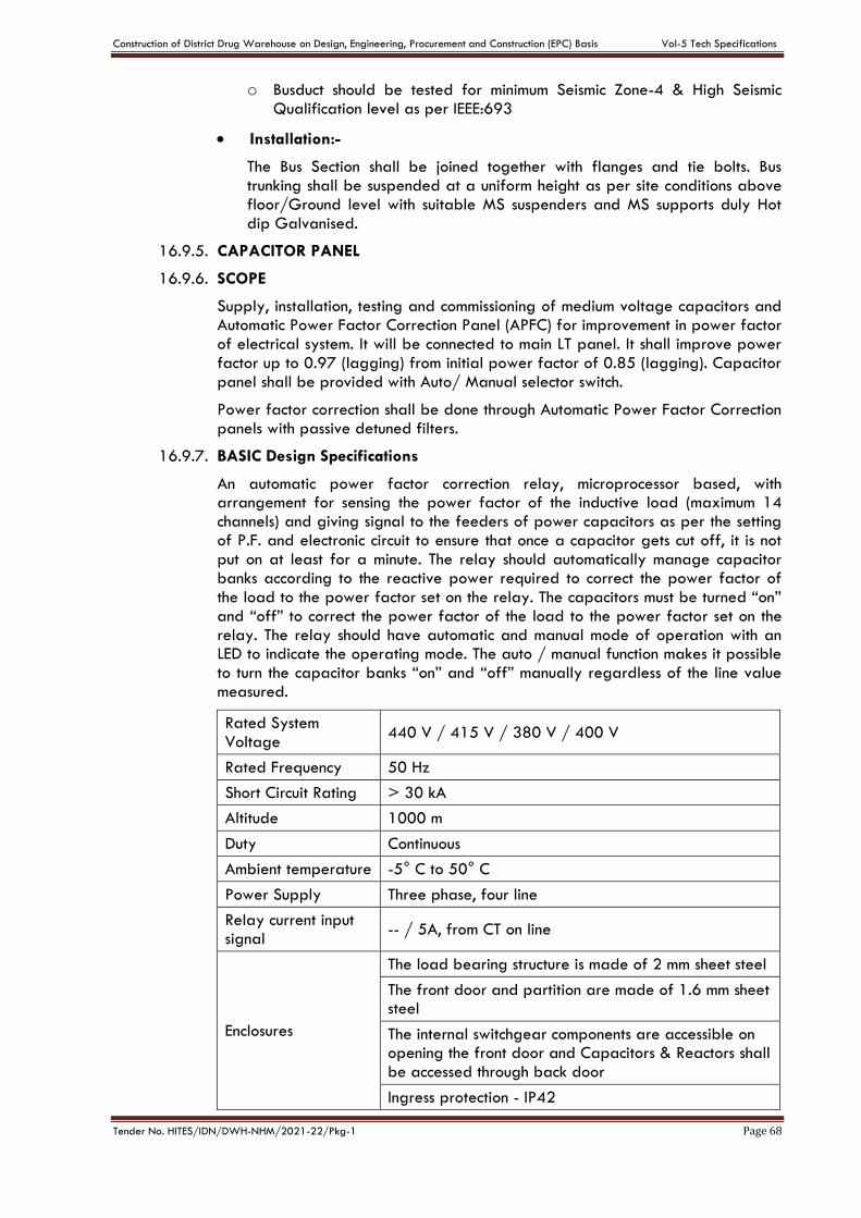
Construction of District Drug Warehouse on Design, Engineering, Procurement and Construction (EPC) Basis Vol-5 Tech Specifications
Tender No. HITES/IDN/DWH-NHM/2021-22/Pkg-1 Page 68
o Busduct should be tested for minimum Seismic Zone-4 & High Seismic Qualification level as per IEEE:693
Installation:-
The Bus Section shall be joined together with flanges and tie bolts. Bus trunking shall be suspended at a uniform height as per site conditions above floor/Ground level with suitable MS suspenders and MS supports duly Hot dip Galvanised.
16.9.5. CAPACITOR PANEL
16.9.6. SCOPE
Supply, installation, testing and commissioning of medium voltage capacitors and Automatic Power Factor Correction Panel (APFC) for improvement in power factor of electrical system. It will be connected to main LT panel. It shall improve power factor up to 0.97 (lagging) from initial power factor of 0.85 (lagging). Capacitor panel shall be provided with Auto/ Manual selector switch.
Power factor correction shall be done through Automatic Power Factor Correction panels with passive detuned filters.
16.9.7. BASIC Design Specifications
An automatic power factor correction relay, microprocessor based, with arrangement for sensing the power factor of the inductive load (maximum 14 channels) and giving signal to the feeders of power capacitors as per the setting of P.F. and electronic circuit to ensure that once a capacitor gets cut off, it is not put on at least for a minute. The relay should automatically manage capacitor banks according to the reactive power required to correct the power factor of the load to the power factor set on the relay. The capacitors must be turned “on” and “off” to correct the power factor of the load to the power factor set on the relay. The relay should have automatic and manual mode of operation with an LED to indicate the operating mode. The auto / manual function makes it possible to turn the capacitor banks “on” and “off” manually regardless of the line value measured.
Rated System Voltage
440 V / 415 V / 380 V / 400 V
Rated Frequency 50 Hz
Short Circuit Rating > 30 kA
Altitude 1000 m
Duty Continuous
Ambient temperature -5° C to 50° C
Power Supply Three phase, four line
Relay current input signal
-- / 5A, from CT on line
Enclosures
The load bearing structure is made of 2 mm sheet steel
The front door and partition are made of 1.6 mm sheet steel
The internal switchgear components are accessible on opening the front door and Capacitors & Reactors shall be accessed through back door
Ingress protection - IP42
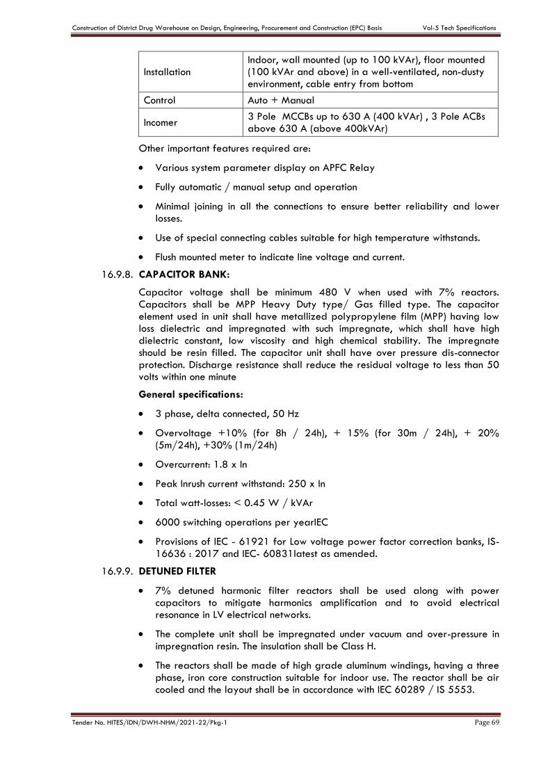
Construction of District Drug Warehouse on Design, Engineering, Procurement and Construction (EPC) Basis Vol-5 Tech Specifications
Tender No. HITES/IDN/DWH-NHM/2021-22/Pkg-1 Page 69
Installation Indoor, wall mounted (up to 100 kVAr), floor mounted (100 kVAr and above) in a well-ventilated, non-dusty environment, cable entry from bottom
Control Auto + Manual
Incomer 3 Pole MCCBs up to 630 A (400 kVAr) , 3 Pole ACBs above 630 A (above 400kVAr)
Other important features required are:
Various system parameter display on APFC Relay
Fully automatic / manual setup and operation
Minimal joining in all the connections to ensure better reliability and lower losses.
Use of special connecting cables suitable for high temperature withstands.
Flush mounted meter to indicate line voltage and current.
16.9.8. CAPACITOR BANK:
Capacitor voltage shall be minimum 480 V when used with 7% reactors. Capacitors shall be MPP Heavy Duty type/ Gas filled type. The capacitor element used in unit shall have metallized polypropylene film (MPP) having low loss dielectric and impregnated with such impregnate, which shall have high dielectric constant, low viscosity and high chemical stability. The impregnate should be resin filled. The capacitor unit shall have over pressure dis-connector protection. Discharge resistance shall reduce the residual voltage to less than 50 volts within one minute
General specifications:
3 phase, delta connected, 50 Hz
Overvoltage +10% (for 8h / 24h), + 15% (for 30m / 24h), + 20% (5m/24h), +30% (1m/24h)
Overcurrent: 1.8 x In
Peak Inrush current withstand: 250 x In
Total watt-losses: < 0.45 W / kVAr
6000 switching operations per yearIEC
Provisions of IEC - 61921 for Low voltage power factor correction banks, IS-16636 : 2017 and IEC- 60831latest as amended.
16.9.9. DETUNED FILTER
7% detuned harmonic filter reactors shall be used along with power capacitors to mitigate harmonics amplification and to avoid electrical resonance in LV electrical networks.
The complete unit shall be impregnated under vacuum and over-pressure in impregnation resin. The insulation shall be Class H.
The reactors shall be made of high grade aluminum windings, having a three phase, iron core construction suitable for indoor use. The reactor shall be air cooled and the layout shall be in accordance with IEC 60289 / IS 5553.
Construction of District Drug Warehouse on Design, Engineering, Procurement and Construction (EPC) Basis Vol-5 Tech Specifications
Tender No. HITES/IDN/DWH-NHM/2021-22/Pkg-1 Page 70
The permitted tolerance of inductance is ± 3% of rated inductance value.
Reactor tuning factor shall be 7 % (189 Hz) and the current rating of the reactor shall include the effects of harmonics and other possible over-currents.
The limit of linearity of inductance of the filter reactor is: 1.8*In with L=0.95*LN.
The reactor shall be fitted with a temperature sensitive micro-switch in the center coil (normally open) for connection to trip circuits in case of high operating temperatures.
Power loss in each reactor shall be less than 5 W/kVAr
Each reactor shall have routine test certificate for the above tests.
16.9.10. Thyristor switching
All capacitor banks shall be controlled with suitable rating thyristor switches.
16.9.11. APFC Controller
The APFC controller should be microprocessor based and should correct power factor with the help of contactors by switching the required no. capacitor banks
The controller should offer power factor correction without any need for manual intervention. The controllers should decide optimum configuration of capacitor banks in order to achieve desired power factor by taking into consideration the kVAr of each step, no of operations, total usage time, re-connection time of each step etc. Besides manual switching of capacitors should also be possible directly through the controller, The APFC controller should have the following basic features
Backlit LCD display with multiple parameters displayed at the same time
Auto step programmable
Capable of measuring VTHD and ITHD values at least up to 15th order
Automatic CT reversal sensing and correction
Should be 1A / 5A CT selectable.
Sensing shall be done at LT as well as HT side of the transformer
Display of average weekly power factor
Keypad lock feature to prevent operation by unauthorized persons
Alarms for under/over compensation, high VTHD/ITHD, over temperature, capacitor failure, capacitor over-current, over/under voltage
Individual capacitor’s ON/OFF status and capacitor failure indication
Temperature sensing feature with alarm in case of panel over heating
Should have RS485 communication protocol.
16.9.12. SWITCHGEAR & PROTECTION:
Suitable capacity duty contactor for each step shall be used and must be capable of capacitor switching duty. Busbars shall be suitably colour coded and must be mounted on appropriate insulator supports.
Construction of District Drug Warehouse on Design, Engineering, Procurement and Construction (EPC) Basis Vol-5 Tech Specifications
Tender No. HITES/IDN/DWH-NHM/2021-22/Pkg-1 Page 71
Power cable used shall have superior mechanical, electrical and thermal properties. Internal wiring between main bus bars, contactor, capacitor etc shall be made with 1100 volt grade PVC insulated FRLS copper conductor of appropriate size by using suitable copper crimping terminal ends etc suitable bus links for input supply cable termination shall be provided.
Control circuit shall be duly protected by using suitable rating MCB. An emergency stop push button shall be provided to trip the entire system (22.5 mm dia, mushroom type, press to stop and turn to reset). 440 Volt caution board shall be provided on the panel.
16.9.13. TESTS AT MANUFACTURER’S WORKS:
All routine and type tests as per IS:2834 relevant to capacitor banks as amended up to date shall be carried out at manufacturer’s works and test certificates to be submitted.
TEST AT SITE:
Insulation resistance with 500 V DC Meggar shall be carried out and test results should be recorded.
Residual voltage shall be measured after switching of the capacitors and the same shall not be more than 50 volts after one minute. Each discharge resister shall be tested for its working.
16.9.14. INSTALLATION:
Capacitor bank shall be installed at least 30 cm away from the walls on suitable frame work of welded construction. The earth terminals provided on the body of capacitor bank shall be bonded to main capacitor panel earth bus with 2 nos 8 SWG copper or 6 SWG GI earth wire.
Contractorshall also submit four sets of installation and maintenance manual.
17. Hybrid Power Factor Correction Panel
The contractor shall carry out Design, fabrication, assembling, wiring, supply, installation, testing and commissioning of HPFC (Hybrid power factor correction) panel having IGBTs, microprocessors, capacitors, reactors and other associated accessories, as explained below:
The HPFC panel shall be fabricated out of 14/16 gauge CRCA sheet steel in cubicle compartment, free-standing, floor-mounted, dust and vermin proof with reinforcement of suitable size, angle iron, channel, ‘T’ sections and/or flats wherever necessary. Pre-treatment of panel shall be carried out before epoxy powder coating with at least eight tank process. The HPFC panel shall adhere to IP 41 protection standard.
Cable gland plates shall be provided on top / bottom / both (as per client’s requirements) of the HPFC panel. Lifting hooks shall also be provided at least on all four corners of the panel.
The HPFC panel shall be suitable for 415V, 4 phase, 4 wire, 50 Hz supply system. The panel shall have a tolerance of 10% for the voltage and 5% for the frequency. Two numbers of earthing terminals shall be provided on either side of the panel.
The HPFC Panel shall, in its default configuration, shall implement the following:
Step-less Power Factor Correction (for both leading and lagging current)
Harmonics Compensation up to 51st order
Load Current Balancing in the three phases
Construction of District Drug Warehouse on Design, Engineering, Procurement and Construction (EPC) Basis Vol-5 Tech Specifications
Tender No. HITES/IDN/DWH-NHM/2021-22/Pkg-1 Page 72
Neutral current compensation in neutral phase
All capacitor banks shall be controlled with suitable rating thyristor switches.
17.1 HPFC Panel: The HPFC Panel shall comprise:
i. Incomer:
ACB four pole a having thermal magnetic based over-current and short-circuit protection and at least 50kA breaking capacity (Ics) as the incomer of the panel. 100% Icu breakers shall be used.
ii. Metering and Indication:
a. A HMI display meter showing voltage, current, frequency, PF, THD, kW, kVA, and other related parameters
b. Required number of CTs of suitable rating
c. Required number of three phase digital ammeter showing current of HPFC panel
iii. An active filter part and a passive filter part shall be provided. The ratio of the rating of active filter to that of the passive filter shall be at least 1:1.
17.2 Detuned capacitor bank unit:Each fixed detuned capacitor bank unit shallcomprise:
i. Incomer:
a. A three pole,thermal magnetic based MCCB having over-current and short-circuit protection and at least 36 kA breaking capacity as the incomer
b. 100% ICU breakers shall be used
c. Three pole capacitor duty contactor of suitable rating
ii. Power Circuit:
a. Three phase delta connected capacitors of suitable rating
b. The capacitor unit shall be heavy-duty MPP type and have an AC voltage rating of 525V
c. A series detuned reactor of suitable rating connected to the capacitor bank
d. The series detuned reactor shall be a 7% reactor having linearity of at least 180%
e. Heavy duty exhaust fans and suitably placed ventilation louvers for proper heat dissipation from the reactors and capacitors shall be provided.
iii. Control Circuit:
a. On and Off indication lights for each detuned capacitor bank
b. Start and Stop push buttons for each detuned capacitor bank
c. Auto/Manual selector switch for auto mode (through the HPFC Panel’s DSP microprocessor) or manual mode of operation of the capacitor banks
d. On delay timer for the detuned capacitor bank so that all the detuned banks don’t get switched on at the same time
Construction of District Drug Warehouse on Design, Engineering, Procurement and Construction (EPC) Basis Vol-5 Tech Specifications
Tender No. HITES/IDN/DWH-NHM/2021-22/Pkg-1 Page 73
17.3 Active Filter Unit:
Active filter unit shall provide the required reactive power in a step-less mode to meet the requirement for neutral compensation. Each Active filter unit shall comprise:
i. Incomer:
a. A four pole MCCB having thermal magnetic based over-current and short-circuit protection and at least 36kA breaking capacity (Ics) as the incomer of the 3-Ph HPFC Panel
b. 100% ICU breakers shall be used
ii. Metering and Indication:
a. On/Off selector switch for the Active filter
iii. Power Circuit:
a. Suitable rating four phase inverter stack.
b. The inverter stack shall be rated for the full rating of active filter and shall have sufficient margins for overloading the filter
c. Four single phase inductor chokes of suitable rating
d. Inductor chokes shall have overload margin of at least 150% for 1 minute
e. Suitable rating four pole AC1 duty power contactor
f. The contactor shall be connected to the input of the IGBT power stack
g. The inverter stack shall comprise suitable number and rating (with sufficient margin for overload) of IGBTs, DC Capacitors and IGBT driver circuits to meet the full power output of the inverter stack
h. Resistors, capacitors and other passive components of suitable rating (with sufficient margin) and quantity to continuously carry the full load of the filter
i. Cables, bus-bars and other associated hardware of suitable rating (with sufficient margin) to continuously carry the full load of the filter
j. Heavy duty exhaust fans and suitably placed ventilation louvers for proper heat dissipation from the inverter stacks and inductor choke shall be provided
k. Heavy duty PWM filter comprising capacitors, resistances and/or inductors to filter out the switching ripple from the filter output
iv. Control Circuit:
a. Control MCB of rating 6A, FP, 10 kA, C-Curve to provide power supply to the control circuit of the Active filter
b. Advanced DSP microprocessor controller which shall monitor the voltage and current in the three phases (Red, Yellow and Blue) to compute the exact power requirement in the three phases, and thus, implement the following features - step-less compensation of leading and lagging power factor, harmonics compensation and load balancing
c. Suitable number and rating of voltage and current sensing circuits
d. Necessary control and firing cards with proper wiring and lugs of required rating shall be provided
e. Suitable number and rating of any other items, e.g. relays, SMPS, etc.
Construction of District Drug Warehouse on Design, Engineering, Procurement and Construction (EPC) Basis Vol-5 Tech Specifications
Tender No. HITES/IDN/DWH-NHM/2021-22/Pkg-1 Page 74
17.4 HMI (Human Machine Interface): The HMI (Human Machine Interface) installed in the HPFC Panel shall have the following features:
a. A 7-inch, colored touch screen LCD/ LED interface
b. It must at-least have Ethernet port, USB port and SD card port
c. It must support MODBUS TCP communication protocol
d. Start, stop and trip status (with trip code) on the home screen
e. Internal CAN communication with the DSP controller
f. The HMI must display the following (minimum) numerical parameters:
Irms - All 3 phase currents + Neutral
Irms (Fundamental Current) - All 3 phase fundamental currents
iTHD (%) - All 3 phase current harmonic distortion
Iunb (%) - All 3 phase current unbalance
Vrms - All 3 phase voltages
Urms - All 3 line voltages
V1rms (Fundamental Voltage) - All 3 phase fundamental voltages
vTHD (%) - All 3 phases voltage harmonic distortion
Vunb (%) - All 3 phase voltage unbalance
Grid Frequency
Active Power (kW) - All 3 phases + Total
Reactive Power (kVAr) - All 3 phases + Total
Apparent Power (kVA) - All 3 phases + Total
Power Factor (PF) - All 3 phases + Total
Displacement Power Factor (dPF) - All 3 phases + Total
Ipk - Peak Current of 3 phases of power stack
Utilization (%) - Utilization percentage of 3 phases of power stack
Vdc - DC bus voltage of power stack
Stack Temperature - Temperature of 3 phase IGBTs of power stack
Control Card Temperature
System Running hours
Fan Running hours
Advanced logging capabilities
The HMI must save a minimum of 50,000 time stamped event logs
The logs view must be password protected
The logs should capture system events like system On/Off
Construction of District Drug Warehouse on Design, Engineering, Procurement and Construction (EPC) Basis Vol-5 Tech Specifications
Tender No. HITES/IDN/DWH-NHM/2021-22/Pkg-1 Page 75
System trip event should be logged with associated trip code and time stamp
User entry into settings should get logged
Any failed user login attempt (wrong password) should be logged
Changes in user settings must be logged
Logs must be accessible day-wise for ease of navigation
Logs must be arranged in First In - Last Out fashion to display the latest events on top
User must be able to export the logs to an external USB storage device
HMI must have provision for Ethernet communication or suitable communication bus
The HMI must provide graphical information for the following (minimum) data:
Individual harmonic bar chart of 3-phase currents - upto 51st order
Individual harmonic bar chart of 3-phase voltages - upto 51st order
Simultaneous graphical display of 3-phase currents and 3-phase voltages on single window with user select-able options
17.5 Additional Features in HPFC Panel: The HPFC Panel shall have the following features, in addition to those already mentioned above:
Panel shall be suitable for operation within an ambient temperature between 0ºC and 45ºC.
Panel shall have an audible noise level lesser than 70 db
Panel shall have a filtering efficiency of at least 98%
Panel shall have a reaction time of less than 200 micro-seconds
Selection between the features - PF compensation, harmonics compensation load balancing and neutral compensation of the filter shall be programmable using the HMI
In the default mode, harmonics compensation is set at 1st priority, PF compensation is set at 2nd priority and load balancing is set at 3rd priority
Panel shall also have provision for selection of individual harmonic orders for compensation in the harmonic compensation mode through the HMI
Panel shall only compensate the load balancing requirements arising from distributed loading in the three phases or due to two phase loads
Any compensation requirements arising due to the unbalanced current in the neutral shall be compensated
Auto fold-back of the HPFC Panel panel if total current requirement exceeds the rated
capacity of the filter
Bus-bars or cables shall be suitably color coded and mounted using appropriate insulator supports
Construction of District Drug Warehouse on Design, Engineering, Procurement and Construction (EPC) Basis Vol-5 Tech Specifications
Tender No. HITES/IDN/DWH-NHM/2021-22/Pkg-1 Page 76
Suitable clearances shall be provided for the bus-bars and other live parts of the system as per international standards
All live parts of the system shall be properly shrouded
Inspection terminal strip, number ferruling, and other labeling shall be suitably provided
Stickers marked with “DANGER” shall be provided wherever required
Detailed drawings and manuals shall be provided wherever required
17.6 Protections: Following protections shall be provided:
Over voltage (AC) protection
Over voltage (DC) protection
Phase sequence protection
Over current protection
One phase disconnection (double phasing) detection/protection
Over temperature protection
Temperature sensor abnormality detection
Protection circuits for the IGBT stack and its components
Temperature based de-rating to protect the system and longer operational life
The system will de rate its capacity by sensing the control card temperature
System will sense abnormally high stack temperature and trip itself to protect the converter with suitable error indication
The system will sense abnormality with stack temperature sensing circuit and generate a suitable error indication
All components and wiring used in the system shall adhere to the relevant ISI and IEC standards shall also submit four sets of installation and maintenance manual.
17.7 The HPFC Panel shall have the following settings options for the user:
Define priority between Harmonic, Reactive and Unbalance compensation e.g: User can easily choose to do only one of the three or a combination of the three. Filter will utilize its full capacity as per defined priority.
Individual harmonic selection
17.8 Tests at Manufacturer’s Works:
All routine and type tests as per IS:2834 relevant to capacitor banks as amended up to date shall be carried out at manufacturer’s works and test certificates to be submitted.
17.9 Tests at Site:
Insulation resistance with 500 V DC Meggar shall be carried out and test results should be recorded.

Construction of District Drug Warehouse on Design, Engineering, Procurement and Construction (EPC) Basis Vol-5 Tech Specifications
Tender No. HITES/IDN/DWH-NHM/2021-22/Pkg-1 Page 77
Residual voltage shall be measured after switching of the capacitors and the same shall not be more than 50 volts after one minute. Each discharge resister shall be tested for its working.
17.10 Installation:
Hybrid Power Factor Capacitor Panel shall be installed with adequate clearance from the adjacent walls on suitable frame work of welded construction. The earth terminals provided on the body of capacitor bank shall be bonded to main capacitor panel earth bus with 2 nos 8 SWG copper or 6 SWG GI earth wire.
18. EARTHING & LIGHTENING PROTECTION SYSTEM
Earthing system shall conform to CPWD General Specifications for Electrical Works (Part I-Internal), 2013. Earthing system shall comprise of suitable nos. of Earthpits with GI & Copper Plate electrodes as per IS-3043 & CPWD specifications.
Neutral Earthing with suitable size Copper strips and Copper plate earthpits for Transformer, DG Sets and other equipment as specified by OEMs shall be provided. earthing of all sus. The body earthing for transformers, DG, HV & MV panels shall be done separately (2 Nos. for Each equipment) and shall also made a common earth bus network.
Like for a single transformer, the total number of earth electrodes shall be 4 (2 for neutral and 2 for connection to a common earth bus for body earthing).
18.1 ELECTRODES
The earth electrodes shall be as per CPWD General Specifi cations for Electrical Works (Part I-Internal), 2013.
18.2 LOCATION OF EARTH ELECTRODES
Distance of earth electrode from any building and other earth electrode shall be as per CPWD specification & IS codes. Care shall be taken that the excavation of earth electrode may not affect the column footings or foundation of the building. In such cases electrodes may be farther away from the building. The location of the electrode earth will be a place where the soil has reasonable chance of remaining moist. As far as possible, entrances, pavements and road ways, are to be definitely avoided for locating the earth electrode.
18.3 WATERING ARRANGEMENT
Method of watering arrangement shall comply with CPWD general specifications.
18.4 SIZE OF EARTH LEAD
The recommended sizes of copper earth bus lead in case of Sub-stations shall be in accordance with General Specifications for Electrical Works (Part I-Internal), 2013 amended upto date. The minimum size of earth lead shall be 25 mm x 5 mm copper or equivalent GI strip.
18.5 INSTALLATION
All joints shall be riveted and sweated. Joints in the earth bar shall be bolted and the joints faces tinned. Where the diameter of the bolt for connecting earth bar to apparatus exceeds one quarter of the width of the earth bar, the connection to the bolt shall be made with a wider piece of flange of copper jointed to earth bar. These shall be tinned at the point of connection to equipment and special care taken to ensure a permanent low resistance contact to iron or steel. All steel bolts, nuts, washers etc. shall be cadmium plated, main earth bars shall be spaced sufficiently on the surface to which they are fi xed such as walls or the side trenches to allow for ease of connections. Copper earthing shall not be fi xed by ferrous fi ttings. The earthing shall suitably be protected from
Construction of District Drug Warehouse on Design, Engineering, Procurement and Construction (EPC) Basis Vol-5 Tech Specifications
Tender No. HITES/IDN/DWH-NHM/2021-22/Pkg-1 Page 78
mechanical injury by galvanized pipe wherever it passes through wall and floor. The portion within ground shall be buried at least 60 cm deep. The earthing lead shall be securely bolted and soldered to plate or pipe as the case may be. In the case of plate earthing the lead shall be connected by means of a cable socket with two bolts and nuts. All washers shall be of the same materials as the plate or pipe. All iron bolts, nuts and washers shall be galvanized.
18.6 TESTING
After installation, the tests as specifi ed in CPWD General Specifications for Electrical Work (Part I-Internal), 2013 shall be carried out and results recorded
18.7 LIGHTENING PROTECTION SYSTEM
Lightening Protection System shall be provided for all buildings, blocks and facilities constructed under this contract as per IS/IEC-62305:2010 amended up to date and NBC 2016. However, All earth pits shall be GI or copper Plate electrodes. Finial shall be of copper material and for earth grid/mes&downcomers, required size Copper strip/equivalent size G.I. strip shall be used.
19. SAFETY REQUIREMENTS
Safety provisions shall be generally in conformity with appendices (A) and (C) of CPWD General Specifi cations of Electrical Works (Part I-Internal), 2013. In particular following items shall be provided:
(i) Insulation Mats
Insulation mats conforming to IS 15652: 2006 shall be provided in front of of all HT & LT Panels as well as other control equipments as specified.
(ii) First Aid Charts and First Aid Box
Charts (one in English, one in Hindi, one in Regional language), displaying methods of giving artificial respiration to a recipient of electrical shock shall be prominently provided at appropriate place. Standard first aid boxes containing required materials should be provided in each sub-station.
(iii) Danger Plate
Danger Plates shall be provided on HV and MV equipments. MV danger notice plate shall be 200 mm x 150 mm made of mild steel at least 2 mm thick vitreous enameled white on both sides and with the descriptions in signal red colour on front side as required. Notice plates of other suitable materials such as stainless steel, brass or such other permanent nature material shall also be accepted with the description engraved in signal red colour.
(iv) Fire Extinguishers
Portable CO2 conforming to IS 2878: 1976/ chemical conforming to IS 2171: 1976 extinguishers, HCFC Blend A (P-IV) shall be installed in the sub-station at suitable places. Other extinguishers recommended for electric fires may also be used.
(v) Fire Buckets
Fire buckets conforming to IS 2546: 1974 shall be installed with the suitable stand for storage of water and sand.
(vi) Tool Box
A Standard tool box containing necessary tools required for operation and maintenance shall be provided in the sub-station.
Construction of District Drug Warehouse on Design, Engineering, Procurement and Construction (EPC) Basis Vol-5 Tech Specifications
Tender No. HITES/IDN/DWH-NHM/2021-22/Pkg-1 Page 79
(vii) Caution Board
Necessary number of caution boards such as “Man on Line” ‘Don’t Switch on’ etc. shall be available in the sub-station.
(viii) Key Board
A keyboard of required size shall be provided at a proper place containing castle keys, and all other keys of sub-station and allied areas.
20. 11/0.433 KV DRY TYPE TRANSFORMER (ON LOAD TAP CHANGER TYPE)
20.1. GENERAL
Power transformers shall be Cast Resin Dry Type for indoor use. The transformers shall be suitable for 11KV/ 433 Volts, 50 Hz and 3-phase. All the transformers shall be ON LOAD TAP CHANGER type with RTCC Panels.
The design manufacture and performance of transformer shall comply with all performance of equipment status, regulations and safety codes in the location where the transformers will be installed. Transformers shall conform to the latest applicable standards. Transformer losses at 50% & 100% loads & impedance shall be as per latest applicable ECBC Building norms. Transformers’ incoming feeders in the LT Panel would be equipped with metering class current transformers (CT’s) & potential transformers (PT’s) so that periodic loss monitoring can be carried out.
20.2. CODES AND STANDARD
Transformers shall comply with the latest edition of Indian Standards No. IS 2026 Part I to Part V (Power Transformer) and IS-11171 for Dry Type Transformer. In case the Provision of Indian Standards is not directly applicable to dry type Transformer, the provision of latest IEC-60726 and any other relevant IEC shall apply. Latest Stadards as applicable shall be followed the Insulating materials, Bushing, Installation and Maintenance of the Transformer.
20.3. SERVICE CONDITION
Altitude Less than 1000 meters.
Maximum Ambient Temperature 50 deg. C
Minimum Ambient Temperature -5 deg C
Relative Humidity 100 %
Installation Corrosive, dusty, humid and tropical.
20.4. RATING AND TYPE
The Transformer shall have core type construction, 3 phase and shall be suitable for indoor service under the climatic conditions prevailing at site. The Transformer shall be capable of withstanding thermal and mechanical effects of short circuit at terminals of any winding with full voltage maintained on other winding as per IS: 2026.
20.5. WINDING
The primary and secondary winding shall be of electrolyte copper conductors. The high and low voltage winding shall be totally encapsulated and should be cast under vaccum in moulds with fiber glass reinforce epoxy resin laminate. Both HV and LV winding of each phase shall be separately cast as arigid tubular coil with no mechanical and electrical connection between their co- axial arrangements. The Transformer shall be free of partial discharges at least up to 1.1 times the rated voltage.

Construction of District Drug Warehouse on Design, Engineering, Procurement and Construction (EPC) Basis Vol-5 Tech Specifications
Tender No. HITES/IDN/DWH-NHM/2021-22/Pkg-1 Page 80
The winding shall not absorb moisture under the worst tropical conditions. The collection of moisture and dust over the winding shall not in any way affect the insulation strength of the winding.
20.6. CORE
The transformer core shall be build up with high non-aging low and high permeability CRGO Silicon steel lamination. CRGO sheet shall be coated with inorganic material or equivalent insulation to reduce eddy current to minimum. After shearing, the laminations shall be treated to remove all burrs and shall be annealed to remove all the residual stresses.
Core frame work and clamps shall be arranged and tighted to securely hold lamination in order to prevent any settling or displacement in case of heavy shocks during transport, handling or short circuits. All the Iron parts except the core shall be galvanized and treated with high temperature resistance paint. Core Fastening shall be insulated to reduce losses and avoid spots. Transformer shall be designed to witstand 10 % over fluxing corresponding to rated voltage.
Suitable lugs shall be provided for lifting the complete core and coil assembly of the transformer.
20.7. INSULATION
Interturn and inter coil insulation shall be designed such that di - electric stress is uniformly distributed throughout the winding under all operating conditions. The winding shall be provided with Class ‘F’ Insulation.
20.8. TEMPERATURE RISE
The temperature rise of the winding shall not exceed 90 deg C on continuous full load above maximum ambient temperature of 50 Deg C and in no case shall reach value that may damage the core itself or other adjacent part.
20.9. TAP CHANGING:
"ON LOAD" circuit tap changing with AVR arrangement on H.V side is to be provided. The tapping is to be provided for variation on high voltage side from + 5% to - 15% steps of 1.25% each. Automatically operated STEPLESS "ON LOAD Tap Changing Switch" having a position indicating lights & Locking device and complete with Automatic Voltage regulator and its Control panel shall be provided separately.
In case of transformers having OFF Load Tap Changer, the tapping is to be provided for variation on high voltage side from + 5% to - 5% in steps of 2.5% each.
20.10. VECTOR GROUP:
Transformer shall have the vector group of Dyn 11.
20.11. IMPEDANCE
The desired impedance shall be as mentioned in the IS: 11171 and ECBC norms.
20.12. FLUX DENSITY
The maximum flux density at any point in the winding shall not exceed 1.6 Tesla on the normal rated tap voltage and frequency.
20.13. CURRENT DENSITY
The Maximum current density at any point in the winding shall not exceed 2.2 Amp. Per sq.mm at the rated full load, voltage and frequency.
Construction of District Drug Warehouse on Design, Engineering, Procurement and Construction (EPC) Basis Vol-5 Tech Specifications
Tender No. HITES/IDN/DWH-NHM/2021-22/Pkg-1 Page 81
20.14. COOLING
The Transformer shall be designed for natural cooling (AN) or forced cooling as required for smooth continuos functioning at site.
20.15. ENCLOSURE
Transformer shall be provided with a sheet steel enclosure with adequate provision for ventilation. The degree of protection of enclosure shall be IP 21 for indoor installation and IP 44 for outdoor installations. The sheet steel thickness of enclosure shall be minimum 2mm.
20.16. CABLE TERMINATION
The low voltage side of the transformer shall be suitable to receive Sandwich Aluminium Bus Duct of suitable capacities from the top of the Transformer. A suitable size of flange to be provided for connecting the suitable size overhead sandwich busducts in the LT Box.
H.T. sides of the transformers shall have cable end boxes to receive 3 C X 300 sq.mm size of 11KV HT cables with bottom entry provision.
All cable end boxes shall have bore holes to match the opening for each cable specified and shown in the single line diagram.
20.17. EARTHING
Two main earthing terminals shall be connected to the terminals provided for transformer.
20.18. FITTINGS AND ACCESSORIES
• Rating and Terminal Marking Plate of the Transformer including the details of OFF circuit changing voltage of the links.
• Earthing terminal with Lugs.
• Transformer Neutral Earthing terminal.
• Marshal Box with wiring and terminal and temperature scanner.
• PT 100 type temperature scanner and its connection with marshal box.
• Neutral CT 2000/1 Amp. And its connection with marshal box for 2000 KVA Transformer only.
• Limit Switch in all hinged door fix door and wiring till marshal box.
• HV cable end box at primary.
• LT Bus Trunking box at secondary.
• Nos. Plan bi- directional rollers.
• Inspection windows shall be provided in the cover.
• Lifting lugs for both the transformer and core shall be provided.
20.19. RTCC PANEL
RTCC Panel shall be provided to operate OLTC from control room located in substation. RTCC shall be provided with main switch, a sequence selector switch. RTCC shall be provided with lower push button & raise push button, tap change in progress & complete. A.C supply ON/OFF lamp indicator & AVR relay operated operation indication. Cubical panel shall be totally enclosed, floor mounting and fabricated with a
Construction of District Drug Warehouse on Design, Engineering, Procurement and Construction (EPC) Basis Vol-5 Tech Specifications
Tender No. HITES/IDN/DWH-NHM/2021-22/Pkg-1 Page 82
framed structure with rolled/folded sheet steel channel section of minimum 2mm thickness.
All the sheet steel work forming the exterior of RTCC panel shall be smoothly finished and all steel work used in construction of RTCC panel shall undergone a regrious metal treatment process consisting of effective cleaning by hot alkaline degreasing solution followed by the cold water rinsing, pickling in dilute sulphuric acid to remove scales and rust formation, a recognized phosphating process, passivating in deoxidize to retain & augment the effects of phosphating, drying with compressed air and dust free atmosphere, primer coating with two coats of highly corrosion resistant primer applied under strictly controlled conditions and finished coat of stoving. RTCC Panels shall be connected with respective transformers through suitable size multicore copper conductor armoured control cables.
20.20. INSTALLATION OF TRANSFORMER
Installation of transformer shall be carried out in accordance with manufacturer's instructions and/or as directed by purchaser.
All power/control connections and mechanical joints shall be completed, checked and adjusted to ensure safety and satisfactory operation of the transformer.
Transformer shall not be placed on bare ground during unloading but it shall be placed on wooden sleepers. After placing on foundation, alignment, leveling etc. shall be carried out in best workman like manner.
For the power/control cabled projecting above the ground, the termination to cable box shall be run in GI conduits of suitable cross section and the same shall be supported properly and pipe ends shall be sealed with bitumen compound.
The cable box of detachable type of the transformer shall be supported properly so as to facilitate taking out of the transformer for repair without disturbing the cables.
20.21. TEST CERTIFICATES.
Test certificate shall be furnished in required number of copies for approval. The routine, special and type test certificate of the transformer shall be furnished.
The routine and type test certificates of miscellaneous components shall be furnished or approval.
20.22. ROUTINE TESTS
During manufacture and on completion the transformer shall be subjected but not limited to the following Routine Tests as laid down in the latest revision of the IS 11171 IEC - 726
i. Applied voltage test
ii. Induced voltage test
iii. No-load loss and excitation current tests
iv. Impedance voltage and load loss tests
v. Resistance measurement
vi. Ratio tests
vii. Polarity and phase relation tests
viii. Insulation resistance tests
ix. Insulation power factor tests

Construction of District Drug Warehouse on Design, Engineering, Procurement and Construction (EPC) Basis Vol-5 Tech Specifications
Tender No. HITES/IDN/DWH-NHM/2021-22/Pkg-1 Page 83
20.23. TYPE TESTS
The type test certificates for the following type tests carried out on similar capacity rating shall be submitted along with the routine test certificates.
i. Heat run test
ii. Impulse test
20.24. FIELD TEST
After installation a site, the transformer shall be subjected to the following field test:
i. Construction inspection
ii. Ratio tests
iii. Polarity test
iv. Tap change operation test.
20.25. ELECTRICAL & PERFORMANCE REQUIREMENT :
i. Transformer shall operate without injurious heating at the rated KVA at any voltage within variation of +/- 10% of the rated voltage of that particular tap.
ii. Transformer shall be designed for 110% continuous over fluxing withstand capability.
iii. The neutral terminals of the winding with star connection shall be designed for the highest over current that can flow through the winding.
iv. Overloads shall be allowed within the conditions defined in the loading guide of the applicable standard. Under these conditions, no limitations by terminal bushings, tap changers or other auxiliary equipment shall apply.
v. Temperature Rise for continuous full load application shall be guided by Maximum temperature rise clause of IS 2026. The temperature rise shall not exceed 45 degree C by thermometer in oil or 50 degree C for winding over an ambient of 45 degree C.
(Please note maximum ambient temperature shall be considered 50 degree C).
20.26. DRAWINGS AND O&M MANUALS:
Four copies of manual of complete instructions for the installation, operation, maintenance and repairs circuit diagrams, foundation and trenching details shall be provided with the transformers. List of spare parts shall also be indicated.
i. GA drawing showing dimension, net weight and shipping weight, quantity of insulating oil etc.
ii. Crane requirements for assembly and dismantling of the transformer.
iii. Drawing indicating GA of cable box and its dimension for cable entry cut out requirements etc.
The drawings in (four sets) to be furnished by the supplier for approval after acceptance of his order shall include the following:
a) GA showing front and side elevations and plan of transformer and all accessories and external features, detailed dimensions, crane lift for untanking, H.T./L.T. clearances etc.
b) Drawings of Bus duct termination arrangement.
c) HV cable box arrangement & disconnecting chamber GA drawings.
Construction of District Drug Warehouse on Design, Engineering, Procurement and Construction (EPC) Basis Vol-5 Tech Specifications
Tender No. HITES/IDN/DWH-NHM/2021-22/Pkg-1 Page 84
d) Name plate and terminal making and connection diagram.
e) Assembly of OLTC gear mechanism & details of mechanism parts, limits, contours of wearing parts, timing gear adjustments etc.
21. DISTRIBUTION TRANSFORMER OIL FILLED
11/ 0.433 kV OIL TYPE DISTRIBUTION TRANSFORMER WITH ON LOAD TAP CHANGER MECHANISM WITH AUTOMATIC VOLTAGE REGULATOR
21.1. GENERAL
The step down double wound core type transformers shall be suitable for Outdoor mounting with a voltage ratio of 11000/433 Volts and naturally oil cooled with a Delta/Star configuration. The transformer shall comply with the regulations of IEC 76, B.S. 171, IS: 1180, Level -2 efficiency, as amended up to date.
21.2. TRANSFORMER OPERATION
The transformer shall be suitable for operation on 11 kV, 3 phase 50 cycle earthed system, connected Delta on H.V. side and star on the L.V. side with neutral brought out for independent Earthing (Vector Group DYN11). The transformer shall be suitable for continuous operation at the rated capacity under Site conditions.
21.3. TRANSFORMER MATERIAL
The material used in the manufacture of the transformer shall be of the best quality of their respective kind available as per standard specifications.
21.4. CORE
The core shall be built up with high grade non-aging, low loss and high permeability CRGO lamination special silicon steel suitable for transformers. After being sheared, the lamination shall be treated to remove all burs and shall be re-annealed to remove all residual stresses. Each lamination shall be coated with a durable, insulating coating. Core assembly shall be provided with lugs suitable for lifting the complete core and coil assembly of the transformers. Core and coil shall be so fixed that there is permanent displacement of windings on other parts when the transformer is moved or during short circuit. Core frame parts shall be galvanized.
21.5. WINDINGS
The HV and LV windings shall be of copper conductors using highly densified glass fiber reinforcement. Temperature rise of winding shall not exceed 50 deg C by resistance on continuous full load above ambient of 50 deg C and temperature rise of oil shall not exceed 45 deg C above ambient of 50 deg C. Flux density at any point in winding and core shall not exceed 1.7 T on normal rated voltage and frequency.
21.6. On Load Tap Changer (OLTC)
The transformer shall be provided with an Automatic On Load Tap Changer (OLTC) with Remote Tap Changer Control (RTCC) facility. The OLTC suitable for an incoming voltage variation from +5% to -15% in 17 steps on H.V side so as to give a near constant voltage of 433 Volt on the L.V. side. The OLTC shall be provided with automatic voltage sensing relay and shall be fully automatic in operation.
The OLTC shall be supplied with the first filling of the oil, oil surge relay, shut off valve for the OLTC oil surge relay, trip contracts, access windows for OLTC connection etc. The OLTC shall be provided with motorized / manual operation alongwith handle for operating manually. Mechanical tap position indicator shall be provided.
OLTC shall be provided with remote / local operation facility with selector switch for remote/local operation. The Remote Tap Changer Control Panel (RTCC) shall have remote
Construction of District Drug Warehouse on Design, Engineering, Procurement and Construction (EPC) Basis Vol-5 Tech Specifications
Tender No. HITES/IDN/DWH-NHM/2021-22/Pkg-1 Page 85
indicator for the position of the steps and automatic voltage regulating relays. The RTCC Panel shall have Push buttons for Raise and Lower. The RTCC shall have indicating lamps for :-
Tap in progress
Raise
Lower
Out of step indication
21.7. INSULATION CLASS
The insulation material shall be insulation class 'F'.
21.8. TRANSFORMER TAPPINGS
‘ON’ load tap changing links on HV side. The tappings to be provided for variation on HV side from + 5% to – 15% in steps of 1.25 % each.
In case of transformers having OFF Load Tap Changer, the tapping is to be provided for variation on high voltage side from + 5% to - 5% in steps of 2.5% each.
21.9. TRANSFORMER CHARACTERISTICS
The no load voltage ratio of the transformer shall be 11000/433 Volts and the percentage impedance be as per latest applicable ECBC building norms.
21.10. TRANSFORMER TERMINATIONS
The transformer shall have self-supporting cable boxes with suitable glands and cable sockets for receiving 11,000 Volt grade XLPE cables on the H.V. side as required.
On the LV side the transformer shall have a suitable self supporting terminal arrangement with extended busbars to receive 1100 Volt grade Aluminium Conductor Sandwich Busduct as specified.
21.11. TEMPERATURE RISE PARAMETERS
Thermistor sensors shall be embedded in the low voltage winding for warning and tripping, for temperature control. The temperature detectors shall be suitable for 24 volts D.C. The temperature rise when continuously operated of windings by resistance method shall not exceed 20 deg C over 50 deg C ambient for warning and 45 deg C over 50 deg C ambient for tripping.
21.12. TRANSFORMER FITTINGS
The transformer alongwith OLTC shall be manufactured in accordance with the requirements as specified in the Standards stated above and shall be fitted with:
i. Diagram and Rating plate
ii. Lifting Lugs.
iii. Two earthing terminals on either side of the tank.
iv. Four bidirectional rollers on the under carriage for movement.
v. Winding Temperature Indicator with alarm contacts for alarm and trip circuits.
vi. Externally operated tapping switch with position indicator & locking arrangement.
vii. Terminal marking plate.
viii. Jacking Lugs.
ix. H.V. cable box for 3 core XLPE cable as required.
Construction of District Drug Warehouse on Design, Engineering, Procurement and Construction (EPC) Basis Vol-5 Tech Specifications
Tender No. HITES/IDN/DWH-NHM/2021-22/Pkg-1 Page 86
x. L.V. cable box suitable for reception of XLPE armoured cables or chamber for receiving sandwich/ air insulated bus ducts as required.
xi. Oil conservator with drain plug.
xii. Oil filling hole and cap.
xiii. Filter valve with plug.
xiv. Drain valve with plug or cover plate.
xv. Oil level indicator with minimum marking.
xvi. Dehydrating breather (Silica gel breather)
xvii. Air release valve.
xviii. Explosion vent.
xix. Thermometer pocket with plug.
xx. 150 mm dial type contact thermometer with maximum temperature indicator and alarm and trip contacts for oil temperature.
xxi. Buchholz relay of double float type with alarm and trip contacts and M.S. box for terminating control cables of 4 x 2.5 sq. mm. size.
xxii. L. V. Neutral bushing
xxiii. Shut-off valve between Buchholz relay and conservator.
xxiv. The transformer shall be complete with the first filling of insulating oil as per IS 335 - 1983 including makeup fill at site.
21.13. TRANSFORMER GUARENTEED TECHNICAL PARTICULARS
The following guaranteed technical particulars of the transformer shall be furnished.
a). Core loss
b). Load loss
c). Percentage Impedance
21.14. TRANSFORMER TESTING
Prior to acceptance and dispatch of the transformer, the CLIENT/HITES reserves the right to witness the routine tests at manufacturer’s works. The transformer shall be subjected to the following routine tests as per relevant Standards at the manufacturers Works. The test certificates shall be submitted to the CLIENT/HITES/Engineer-in-charges for approval prior to dispatch.
a). Measurement of Winding Resistance
b). Ratio polarity and phase relationship
c). Losses in kW at No load, 50% Load, 75% Load and 100% Load
d). Impedance Voltage
e). No load and Full load current
f). Insulation resistance
g). Induced over voltage withstand
h). Separate source voltage withstand
In addition type test certificate for following parameters shall also be submitted to CLIENT/HITES/ Engineer-in-charges for record. Any type test if specifically asked for by
Construction of District Drug Warehouse on Design, Engineering, Procurement and Construction (EPC) Basis Vol-5 Tech Specifications
Tender No. HITES/IDN/DWH-NHM/2021-22/Pkg-1 Page 87
CLIENT/HITES, shall be carried out on the equipment covered by this contract shall be done at extra cost prior to dispatch.
a). Temperature Rise
b). Impulse Voltage withstands.
21.15. INSTALLATION
The transformer shall be installed as per the manufacturers’ instruction manual and shall conform to the requirements of IS 10028: 1981.
Transformer and all other accessories shall be handled carefully in its upright position as indicated on the packing cases. Lifting lugs and jacking pads shall be use for lifting the transformer. Utmost care shall be taken in proper application of jacks. Where transformer is dragged or pulled on sleeper or rollers, the traction eyes provided at the bottom frame shall be used with suitable wire ropes and shackles.
Transformer shall be mounded on concrete plinth/foundation prepared for the purpose. Rollers shall be checked and locket to prevent movement of the transformer after being positioned after on the plinth.
The transformer cable end boxes shall be sealed to prevent entry of moisture.
The transformer neutral and body earthing shall be as per the requirements of IS 3043-1966 and the Local Inspecting Authorities.
21.16. COMMISSIONING TESTS
The following tests shall be carried out prior to commissioning at site by third party
a). Insulation resistance of the winding between phases and phase and earth on the H.T. side.
b). Winding resistance of all the windings on all tap positions.
c). Voltage ratio test shall be carried out by applying low voltage on H.T. side and measuring the voltage between phases and phase and neutral on the L.T. side for every tap setting.
d). On commissioning of the transformer the following readings shall be taken:
- MV side voltages at all tap settings
- Temperature rise under no load conditions
e). Transformer Oil Test
f). If necessary, the transformer shall be heated by applying low voltage on the HT side and shorting the LT side. This shall be done for a period of 48 hours or till all the moisture has been removed from the transformer
22. INTERNAL ELECTRIFICATION OF BUILDING
22.1. SCOPE
The electrical Installation work shall be carried out in accordance with Indian Standard Code of Practice for Electrical Wiring Installation IS: 732-1989 and IS: 2274-1963. It shall also be in conformity with the current Indian Electricity rules and regulations and requirements of the Local Electricity Supply Authority and Fire Insurance regulations, so far as these become applicable to the installation. Electrical work in general shall be carried out as per following CPWD Specifications with up to date amendment.
Specifications for Electrical Works Part-I (Internal) by CPWD–2013 with latest revision.
Construction of District Drug Warehouse on Design, Engineering, Procurement and Construction (EPC) Basis Vol-5 Tech Specifications
Tender No. HITES/IDN/DWH-NHM/2021-22/Pkg-1 Page 88
Specifications for Electrical Works Part-II (External) by CPWD–1994 with latest revision
Wherever these specifications calls for a higher standard of material and or workmanship than those required by any of the above mentions regulations and specification then the specification here under shall take precedence over the said regulations and standards.
Following Light/power point Shall be provided as minimum or as per approved shop drawings in following areas and as directed by Engineer In-Charge
Consultation Room / Workstation -
6/16 A Raw Power points- 2 nos.
6/16 A UPS power points – 2 Nos.
Data points- 1 Nos.
Telephone Points – 1 Nos.
Light fittings as per required Lux level (NBC-2016, ECBC)
General Wards (with Each Bed)-
6/16 A UPS power points – 4 Nos.
Light fittings as per required Lux level (NBC- 2016, ECBC)
Foot Light
ICU/ICCU with Each Bed-
6/16 A UPS power points – 8 Nos.
Light fittings as per required Lux level (NBC-2016, ECBC)
Bed Head Light (Up & Down)
Confrence Room-
6/16 A Raw Power points- 4 nos.
6/16 A UPS power points – 2 Nos. shared in Two seats (in Pop up box)
HDMI Port – 1 Nos. shared between Two seats (in Pop up box)
Data points – 2 Nos. shared between Two seats or Wifi connectivity
Dimmer Lights as per requirement
Light fittings as per required Lux level (NBC-2016, ECBC)
Data & UPS Power points for Projector / Monitor/PC/Audio Visual system
22.2. DISTRIBUTION BOARDS
As a general practice MCB type double door DB shall be used. Provision of Vertical type MCB DBs is to be considered in areas where 3-phase outlets are also required:
Provisions in MCB DB:
i. Recess/ surface type with integral loose wire box.
Construction of District Drug Warehouse on Design, Engineering, Procurement and Construction (EPC) Basis Vol-5 Tech Specifications
Tender No. HITES/IDN/DWH-NHM/2021-22/Pkg-1 Page 89
ii. Phase/neutral/ earth terminal blocks for termination of incoming & outgoing wires.
iii. DIN channel for mounting MCBs.
iv. Arrangement for mounting incomer MCB/RCCB/RCBO/MCCB as required.
v. Copper Bus Bar.
vi. Earthing terminals.
vii. Interconnection between terminal block/ incoming switch/ bus bar/ neutral/ terminal block/ earth terminal connector with specified size of FRLS pre insulated copper conductor cable duly fitted with copper lugs/ thimbles.
viii. Termination block should be suitable for termination of conductor/ cable of required size but minimum rated cross section of the terminal blocks should be 6 sq. mm.
ix. Terminal block shall be made of flame retardant polyamide material.
x. Coloured terminal blocks and FRLS wires for easy identification of RYB phases, Neutral and Earth.
xi. DB shall be provided with a detachable cassette for safe removal of MCBs, RCCBs. Terminal connectors from the DB without loosening the internal cable connections of phase and neutral circuits.
xii. The DB shall have peel able poly layer on the cover for protection from cement, plaster, paints etc during the construction period.
xiii. Detachable plate with knock out holes shall be provided at the top/ bottom of board. Complete board shall be factory fabricated /pre-wired in factory, ready for installation at site. The box and cover shall be fabricated from 1.2 mm sheet steel, properly pretreated, phosphotized with powder coated finish.
xiv. DB shall be of double door construction provided with hinged cover in the front.
xv. DB doors shall be suitably earthed.
Distribution Board shall be standard type. Distribution boards shall contain miniature circuit breakers. Miniature circuit breakers shall be quick make and quick break type with trip free mechanism. MCB shall have thermal and magnetic short circuit protection. All miniature circuit breakers shall be of minimum 10 kA, ‘C’ curve rated rupturing capacity unless otherwise specified.
Neutral busbars shall be provided with the same number of terminals, as there are single ways on the board, in addition to the terminals for incoming mains. An earth bar of similar size as the neutral bar shall also be provided. All live parts shall be screened from the front. Ample clearance shall be provided between all live metal and the earth case and adequate space for all incoming and outgoing cables. A circuit identification card in clear plastic cover shall be provided for each distribution board.
MCB's shall be provided on the phase of each circuit. No isolator shall be used in distribution board & panels unless stated otherwise. The individual banks of MCB's shall be detachable. There shall be ample space behind the banks of MCB's to accommodate all the wiring. All the distribution boards shall be completely factory wired, ready for connections. All the terminals shall have adequate current rating and size to suit individual feeder requirements. Each circuit shall be clearly numbered from left to right to correspond with wiring diagram. All the switches and circuits shall be distinctly marked with a small description of the service installed.
Construction of District Drug Warehouse on Design, Engineering, Procurement and Construction (EPC) Basis Vol-5 Tech Specifications
Tender No. HITES/IDN/DWH-NHM/2021-22/Pkg-1 Page 90
Earth Leakage Circuit Breaker/Residual Current Circuit Breaker shall be provided in each Distribution Board as required. Earth Leakage Circuit Breaker shall be current operated type and of 30 mA sensitivity unless otherwise specified. It shall also provide over-current and short circuit protection i.e. it shall be MCB-cum-RCCB (Residual Current Circuit Breaker). In case ELCB doesn’t have inbuilt short circuit protection, same rating MCB have to be provided for short circuit protection along with ELCB. Cost of this MCB is deemed to be included in the cost of ELCB. ELCB shall be housed within the Distribution Board.
Distribution Boards shall be ready for connections and shall be inspected in the factory by Electrical Engineer- In charge before dispatch.
Before procurement of Distribution Boards, MCB’s, ELCB’s (incomer and outgoings) etc., the has to take approval of the DB Schedule/Drawings of each DB from the Electrical Engineer In Charge. The whole unit i.e. Distribution Board, MCB’s, ELCB’s etc. shall come from the manufactures premises/workshop. After inspection, if required, HITES representative shall provide dispatch clearance for installation at site.
22.3. METALLIC CONDUIT WIRING SYSTEM:
22.3.1. TYPE AND SIZE OF CONDUIT
All conduit pipes shall be of approved gauge (not less than 16 SWG for conduits of sizes up to 32 mm diameter and not less than 14 SWG for conduit of size above 32mm diameter) solid drawn or reamed by welding finished with black stove enameled surface. All conduit accessories shall be of threaded type and under no circumstances pin grip type accessories shall be used. The maximum number of PVC insulated 650/1100 volts grade copper conductor cable that can be drawn in conduit of various sizes shall be as per IS Code. No steel conduit less than 20 mm in diameter shall be used.
22.3.2. CONDUIT JOINTS.
Conduit pipes shall be joined by means of threaded couplers, and threaded accessories only. In long distance straight run of conduits, inspection type couplers at reasonable intervals shall be provided or running threads with couplers and jam nuts shall be provided. In the later case the bare threaded portion shall be treated with anti-corrosive preservative. Threads on conduit pipes in all cases shall be between 13 mm to 19 mm long sufficient to accommodate pipes to full threaded portion of couplers or accessories.
Cut ends of conduit pipe shall have neither sharp edges nor any burrs left to avoid damage to the insulation of conductor while pulling them through such pipes.
22.3.3. PROTECTION AGAINST CONDENSATION.
The layout of conduit should be such that any condensation or sweating inside the conduit is drained out. Suitable precaution should also be taken to prevent entry of insects inside the conduit.
22.3.4. PROTECTION OF CONDUIT AGAINST RUST.
The outer surface of conduit including all bends, unions, tees, junction boxes etc. forming part of conduit system shall be adequately protected against rust when such system is exposed to weather by being painted with two coats of oxide paint applied before they are fixed. In all cases, no bare threaded portion of conduit pipe shall be allowed. Unless such bare thread portion of conduit is treated with anticorrosive preservative or covered with approved plastic compound.
Construction of District Drug Warehouse on Design, Engineering, Procurement and Construction (EPC) Basis Vol-5 Tech Specifications
Tender No. HITES/IDN/DWH-NHM/2021-22/Pkg-1 Page 91
22.3.5. PAINTING OF CONDUIT AND ACCESSORIES.
After installation, all accessible surface (if any) of conduit pipes, fittings etc. shall be painted with two coats of approved enameled paint or aluminium paint as required to match the finish of surrounding wall, trusses etc.
22.3.6. SURFACE CONDUIT
Conduit pipes shall be fixed by saddles, secured to suitable approved plugs with screws in an approved manner at an interval of not more than one meter,but on either side of the couplers or bends or similar fi ttings, saddles shall be fixed at a distance of 30 cm from the center of such fittings.Where conduit pipes are to be laid along the trusses, steel joists etc. the same shall be secured by means of saddles or girder clips or clamps asrequired by the Engineer-in-charge.In long distance straight run of conduit, inspection type couplers at reasonable intervals shall be provided, or running threads with couplers and jam nuts shall be provided.Fixing Outlet Boxes Only portion of the switch box shall be sunk in the wall, the other portion beingprojected out for suitable entry of conduit pipes into the box.
22.3.7. RECESS CONDUIT
The chase in the wall shall be neatly made and of ample dimensions to permit the conduit to be fixed in the manner desired. In the case of building under construction, conduit shall be buried in the wall before plastering and shall be finished neatly after erection of conduit. In case of exposed brick/rubble masonry work, special care shall be taken to fix the conduit and accessories in position along with the building work. Entire work of chasing the wall, fixing the conduit in chases, and burring the conduit in mortar before plastering shall form part of point wiring work.
The conduit pipe shall be fixed by means of staples or by means of saddles not more than 60cm apart or by any other approved means of fixing. Fixing of standard bends and elbows shall be avoided as far as practicable and all curves maintained by bending the conduit pipe itself with the long radius, which shall permit easy drawing in of conductors. All threaded joints of conduit pipe shall be treated with some approved preservative compound to secure protection against rust. Suitable inspection boxes to the barest minimum requirements shall be provided to permit periodical inspection and of facilitate replacement of wires, if necessary. These shall be mounted flush with the wall. Suitable ventilating holes shall be provided in the inspection box covers. Wherever the length of conduit run is more than 10 meters, then circular junction box shall be provided.
22.3.8. METAL OUTLET BOXES & COVERS.
The switch box shall be made of modular metal boxes with suitable size modular cover plates. Modular metal box shall be made of mild steel on all sides except on the front. The metal box (other than modular type) shall be made of metal on all sides except on the front. Boxes shall be hot dip galvanized mild steel. Metal boxes up to 20 x 30 cm size M.S. box shall have wall thickness of 18 SWG and MS boxes above 20 x 30 cm size shall be of 16 SWG. The metallic boxes shall be painted with anticorrosive paint before erection. Clear depth of the box shall not be less than 60mm. All boxes shall be covered from top with Phenolic laminated sheet of approved shade. These shall be of 3 mm thick synthetic phenolic resin bonded laminated sheet as base material and conform to grade P-I of IS: 2036-1994.
22.3.9. ERECTION AND EARTHING OF CONDUITS.
The conduit of each circuit or section shall be completed before conductors are drawn in. The entire system of conduit after erection shall be tested in presence of Engineer In Charge for mechanical and electrical continuity throughout and permanently connected to earth conforming to the requirement by means of special
Construction of District Drug Warehouse on Design, Engineering, Procurement and Construction (EPC) Basis Vol-5 Tech Specifications
Tender No. HITES/IDN/DWH-NHM/2021-22/Pkg-1 Page 92
approved type of earthing clamp effectively fastened to conduit pipe in a workmen like manner for a perfect continuity between the earth and conduit.
22.4. NON-METALLIC CONDUIT WIRING SYSTEM
22.4.1. Scope
This chapter covers the detailed requirements for wiring work in non-metallic conduits.This chapter covers both surface and recessed types of wiring work.
22.4.2. Application
Recessed conduit work is generally suitable for all applications. Surface conduit work may be adopted in places like workshops etc. and where recessed work may not be possible to be done. The type of work shall be as specified in individual works.
Flexible non-metallic conduits shall be used only at terminations, wherever specified.
Special Precautions-
i. If the pipes are liable to mechanical damages, they should be adequately protected.
ii. Non-metallic conduit shall not be used for the following applications:-
iii. In concealed/inaccessible places of combustible construction where ambient temperature exceeds 60 degrees C.
iv. In places where ambient temperature is less than 5 degrees C.
v. For suspension of fluorescent fi ttings and other fi xtures.
vi. In areas exposed to sunlight.
22.4.3. Materials
a) Conduits
All non-metallic conduit pipes and accessories shall be of suitable material complying with IS 2509 : 1973 and IS 3419 : 1989 for rigid conduits and IS 9537 (Part 5) : 2000 for flexible conduits. The interior of the conduits shall be free from obstructions. The rigid conduit pipes shall be ISI marked.
The conduits shall be circular in cross-section. The conduits shall be designated by their nominal outside diameter. The dimensional details of rigid non-metallic
No non-metallic conduit less than 20 mm in diameter shall be used.
The maximum number of PVC insulated aluminium/copper conductor cables of 650/1100 V grade conforming to IS 694 : 1990 that can be drawn in one conduit of various sizes as per CPWD specification. Conduit sizes shall beselected accordingly.
b) Conduit Accessories
The conduit wiring system shall be complete in all respect including accessories.
Rigid conduit accessories shall be normally of grip type.
Flexible conduit accessories shall be of threaded type.
Construction of District Drug Warehouse on Design, Engineering, Procurement and Construction (EPC) Basis Vol-5 Tech Specifications
Tender No. HITES/IDN/DWH-NHM/2021-22/Pkg-1 Page 93
Bends, couplers etc. shall be solid type in recessed type of works, and may be solid or inspection type as required, in surface type of works.
Saddles for fi xing conduits shall be heavy gauge non-metallic type with base.
The minimum width and the thickness of the ordinary clips or girder clips shall be as per CPWD specification
For all sizes of conduit, the size of clamping rod shall be 4.5 mm (7 SWG) diameter.
c) Outlets
The switch box shall be made of either rigid PVC molding, or mild steel, or cast iron on all sides except at the front. The regulator boxes shall however be made only of mild steel or cast iron.
PVC boxes shall comply with the requirements laid down in IS 14772 : 2000. These boxes shall be free from burrs, fi ns and internal roughness.
The thickness of the walls and base of PVC boxes shall not be less than 2 mm.
The clear depth of PVC boxes shall not be less than 60 m.
3 mm thick phenolic laminated sheet covers for all types of boxes shall be as per requirements.
22.4.4. Installation
a) Common Aspects for Both Recessed and Surface Conduit Works
The erection of conduits of each circuit shall be completed before the cables are drawn in.
Conduit Joints
o All joints shall be sealed/cemented with approved cement. Damaged conduit pipes/fittings shall not be used in the work. Cut ends of conduit pipes shall have neither sharp edges nor any burrs left to avoid damage to the insulation of conductors while pulling them through such pipes.
o The Engineer-in-charge, with a view to ensuring that the above provision has been carried out, may require that the separate lengths of conduit etc.
Conduit joints after preparation shall be submitted for inspection before being fixed.
All bends in the system may be formed either by bending the pipes by an approved method of heating, or by inserting suitable accessories such as bends, elbows or similar fittings, or by fixing non-metallic inspection boxes, whichever is most suitable. Where necessary, solid type fittings shall be used.
o Radius of bends in conduit pipes shall not be less than 7.5 cm. No length of conduit shall have more than the equivalent of four quarter bends from outlet to outlet.
o Care shall be taken while bending the pipes to ensure that the conduit pipe is not injured, and that the internal diameter is not effectively reduced.
Construction of District Drug Warehouse on Design, Engineering, Procurement and Construction (EPC) Basis Vol-5 Tech Specifications
Tender No. HITES/IDN/DWH-NHM/2021-22/Pkg-1 Page 94
Outlets
o All switches, plugs, fan regulators etc. shall be fitted in flush pattern.
b) Additional Requirements for Surface Conduit Work
Conduit pipes shall be fixed by heavy gauge non-metallic saddles with base, secured to suitable approved plugs with screws in an approved manner, at an interval of not more than 60 cm, but on either side of couplers or bends or similar fi ttings, saddles shall be fi xed at a closer distance from the centre of such fi ttings.
Slotted PVC saddles may also be used where the PVC pipe can be pushed in through the slots.
Where the conduit pipes are to be laid along the trusses, steel joists etc. the same shall be secured by means of saddles or girder clips as required by the Engineer in-charge. Where it is not possible to use these for fi xing, suitable clamps with bolts and nuts shall be used.
If the conduit pipes are liable to mechanical damage, they shall be adequately protected.
22.4.5. Earthing Requirements
A protective (earth) conductor shall be drawn inside the conduit in all distribution circuits to provide for earthing of non-current carrying metallic parts of the installation. These shall be terminated on the earth terminal in the switch boxes and/or earth terminal blocks at the DBs.
Gas or water pipe shall not be used as protective conductors (earth medium).
22.5. SWITCHES.
All 6 and 16 Amp switches shall be modular type of 240 volts A.C. grade. All switches shall be fixed on modular metal boxes. All 6 Amp socket shall be 3 pin type and 16 Amp socket shall be 5/6 pin type (unless otherwise specified) suitable for 16/6 Amp. All modular switches, sockets, telephone outlets, TV outlet etc. shall be in off white finish unless otherwise specified. The switches controlling the lights or fans shall be connected to the phase wire of the circuit. Switch boards shall be located at 1200 mm above finished floor level unless otherwise indicated on drawings or directed by Engineer-In-Charge.
In case of computer power points, Data points, telephone points etc. to be fixed on laminated partition board (furniture), same shall be fixed on laminated board (portion of laminated board meant for fixing power points) with base plate/cover plate as applicable, duly fixed with screws.
One modular switch may control maximum one, two or three light points as per requirement and as directed by Engineer-In-Charge. One light point controlled by 2 switches shall be provided in the staircases as directed by Engineer-In-Charge. Depending on area of rooms, halls etc. one or more than one switchboards shall be provided as directed by Engineer-In-Charge. At least one number 6A Socket with Switch shall be provided in each switchboard as directed by Engineer-In-Charge. Suitable power points and light points shall be provided for urinal sensors and hand dryers in the toilets as directed by Engineer-In-Charge. At least 10% Light fixtures shall be provided and operated with UPS supply with switches fed from UPS Distribution Boards.
22.5.1. COVER PLATE
All modular switches, sockets, telephone outlets etc. shall be fixed on modular metal boxes with modular base plates and modular cover plates on top.
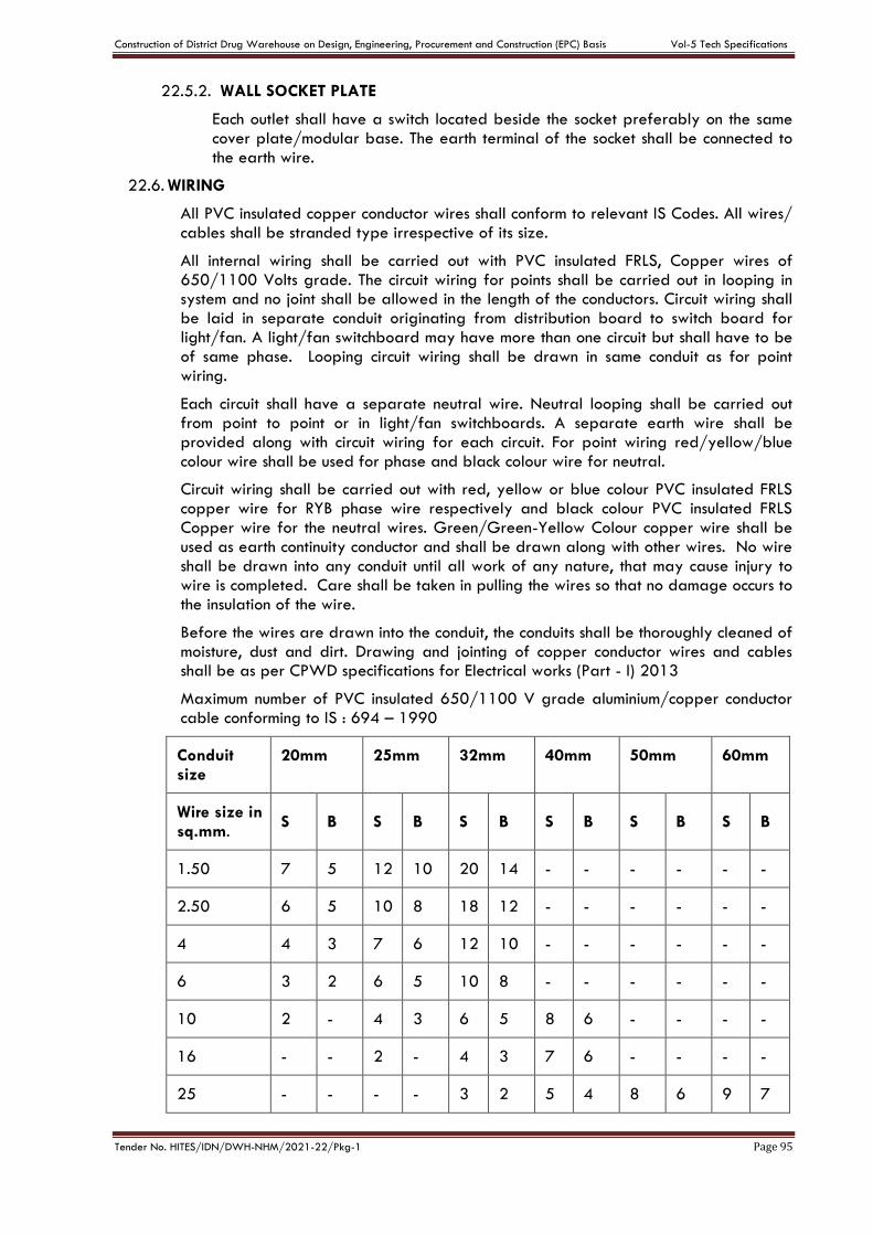
Construction of District Drug Warehouse on Design, Engineering, Procurement and Construction (EPC) Basis Vol-5 Tech Specifications
Tender No. HITES/IDN/DWH-NHM/2021-22/Pkg-1 Page 95
22.5.2. WALL SOCKET PLATE
Each outlet shall have a switch located beside the socket preferably on the same cover plate/modular base. The earth terminal of the socket shall be connected to the earth wire.
22.6. WIRING
All PVC insulated copper conductor wires shall conform to relevant IS Codes. All wires/ cables shall be stranded type irrespective of its size.
All internal wiring shall be carried out with PVC insulated FRLS, Copper wires of 650/1100 Volts grade. The circuit wiring for points shall be carried out in looping in system and no joint shall be allowed in the length of the conductors. Circuit wiring shall be laid in separate conduit originating from distribution board to switch board for light/fan. A light/fan switchboard may have more than one circuit but shall have to be of same phase. Looping circuit wiring shall be drawn in same conduit as for point wiring.
Each circuit shall have a separate neutral wire. Neutral looping shall be carried out from point to point or in light/fan switchboards. A separate earth wire shall be provided along with circuit wiring for each circuit. For point wiring red/yellow/blue colour wire shall be used for phase and black colour wire for neutral.
Circuit wiring shall be carried out with red, yellow or blue colour PVC insulated FRLS copper wire for RYB phase wire respectively and black colour PVC insulated FRLS Copper wire for the neutral wires. Green/Green-Yellow Colour copper wire shall be used as earth continuity conductor and shall be drawn along with other wires. No wire shall be drawn into any conduit until all work of any nature, that may cause injury to wire is completed. Care shall be taken in pulling the wires so that no damage occurs to the insulation of the wire.
Before the wires are drawn into the conduit, the conduits shall be thoroughly cleaned of moisture, dust and dirt. Drawing and jointing of copper conductor wires and cables shall be as per CPWD specifications for Electrical works (Part - I) 2013
Maximum number of PVC insulated 650/1100 V grade aluminium/copper conductor cable conforming to IS : 694 – 1990
Conduit size
20mm 25mm 32mm 40mm 50mm 60mm
Wire size in sq.mm.
S B S B S B S B S B S B
1.50 7 5 12 10 20 14 - - - - - -
2.50 6 5 10 8 18 12 - - - - - -
4 4 3 7 6 12 10 - - - - - -
6 3 2 6 5 10 8 - - - - - -
10 2 - 4 3 6 5 8 6 - - - -
16 - - 2 - 4 3 7 6 - - - -
25 - - - - 3 2 5 4 8 6 9 7
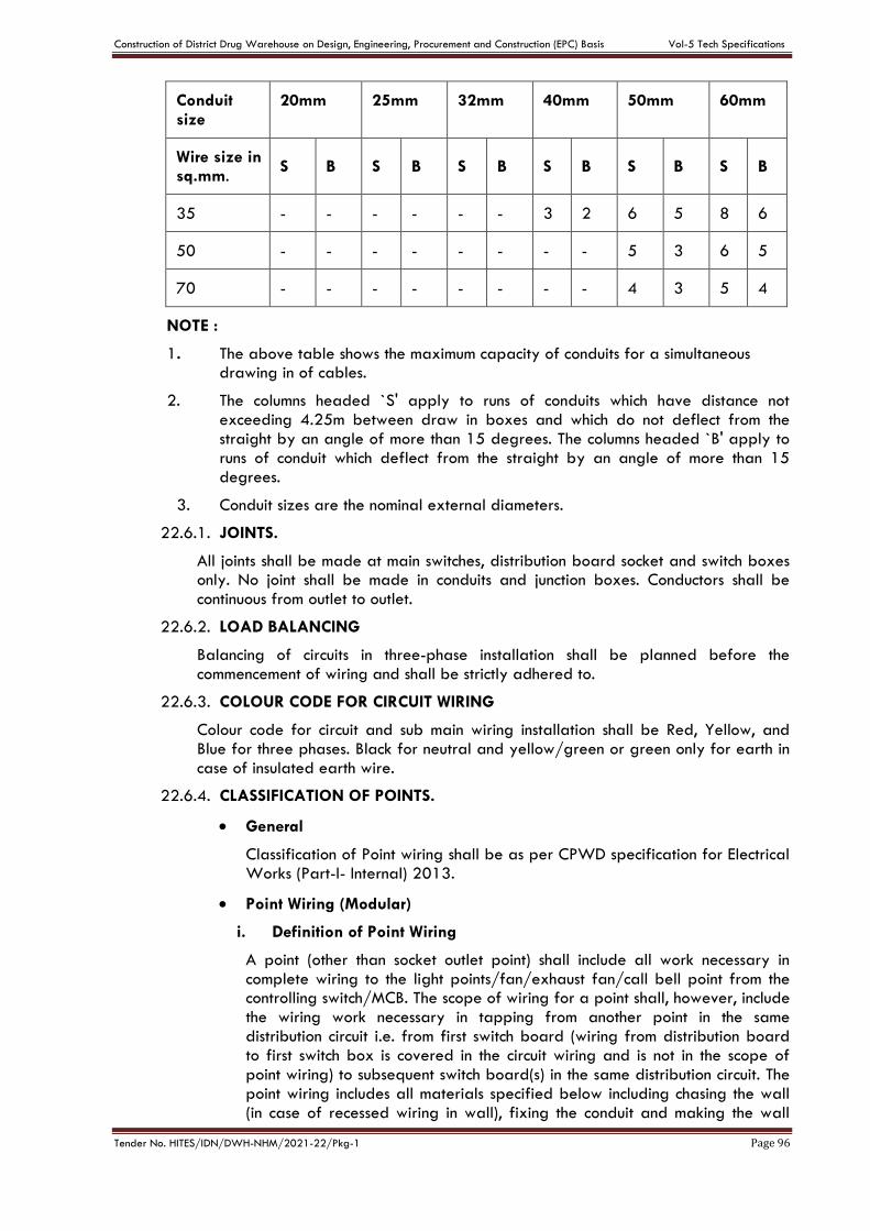
Construction of District Drug Warehouse on Design, Engineering, Procurement and Construction (EPC) Basis Vol-5 Tech Specifications
Tender No. HITES/IDN/DWH-NHM/2021-22/Pkg-1 Page 96
Conduit size
20mm 25mm 32mm 40mm 50mm 60mm
Wire size in sq.mm.
S B S B S B S B S B S B
35 - - - - - - 3 2 6 5 8 6
50 - - - - - - - - 5 3 6 5
70 - - - - - - - - 4 3 5 4
NOTE :
1. The above table shows the maximum capacity of conduits for a simultaneous drawing in of cables.
2. The columns headed `S' apply to runs of conduits which have distance not exceeding 4.25m between draw in boxes and which do not deflect from the straight by an angle of more than 15 degrees. The columns headed `B' apply to runs of conduit which deflect from the straight by an angle of more than 15 degrees.
3. Conduit sizes are the nominal external diameters.
22.6.1. JOINTS.
All joints shall be made at main switches, distribution board socket and switch boxes only. No joint shall be made in conduits and junction boxes. Conductors shall be continuous from outlet to outlet.
22.6.2. LOAD BALANCING
Balancing of circuits in three-phase installation shall be planned before the commencement of wiring and shall be strictly adhered to.
22.6.3. COLOUR CODE FOR CIRCUIT WIRING
Colour code for circuit and sub main wiring installation shall be Red, Yellow, and Blue for three phases. Black for neutral and yellow/green or green only for earth in case of insulated earth wire.
22.6.4. CLASSIFICATION OF POINTS.
General
Classification of Point wiring shall be as per CPWD specification for Electrical Works (Part-I- Internal) 2013.
Point Wiring (Modular)
i. Definition of Point Wiring
A point (other than socket outlet point) shall include all work necessary in complete wiring to the light points/fan/exhaust fan/call bell point from the controlling switch/MCB. The scope of wiring for a point shall, however, include the wiring work necessary in tapping from another point in the same distribution circuit i.e. from first switch board (wiring from distribution board to first switch box is covered in the circuit wiring and is not in the scope of point wiring) to subsequent switch board(s) in the same distribution circuit. The point wiring includes all materials specified below including chasing the wall (in case of recessed wiring in wall), fixing the conduit and making the wall
Construction of District Drug Warehouse on Design, Engineering, Procurement and Construction (EPC) Basis Vol-5 Tech Specifications
Tender No. HITES/IDN/DWH-NHM/2021-22/Pkg-1 Page 97
good as it originally was. It also includes supply, drawing, testing and commissioning of wires.
Scope of point wiring
Following shall be deemed to be included in point wiring.
(a) Supply & fixing conduit & conduit accessories for the same and wiring cables (including supplying and drawing wires) between the switch box and the point outlet.
(b) All fixing accessories such as clips, nails, screws, phil plug, rawl plug etc. as required.
(c) Modular switches, modular base plates and modular cover plates over the same. regulators, sockets with Metal boxes etc. in recessed or surface .
(d) Outlet boxes, junction boxes, pull-through boxes etc. but excluding modular metal boxes if any, provided the switchboards for loose wires/conduit terminations.
(e) In case of recessed wiring in wall the scope includes chasing of wall, fixing the conduit and making the wall good as it originally was.
(f) Control modular switch (5/6A) as specified.
(g) Ceiling rose or connector (in case of points for ceiling/exhaust fan point, prewired light fittings and call bells).
(h) Connections to ceiling rose, connector, socket outlet, lamp holder, switch etc.
(i) Interconnecting wiring between points on the same circuit, in the same switch box or from another. Interconnecting wiring from first switchboard to subsequent switch board(s).
(j) Protective (loop earthing) conductor as required from one metallic switch box to another in the distribution circuits, and from switchboard to each point (light/fan/exhaust fan/call bell etc).
(k) Bushed conduit where wiring cables pass through wall etc.
(l) Ceiling rose (in the case of pendants except stiff pendants).
(m) Lamp holder (in the case of goose neck type wall bracket, batten holder and fittings which are not pre-wired)..
(n) Back Plate (in the case of stiff pendants).
22.6.5. Circuit and Submain Wiring
a. Circuit Wiring
Circuit wiring shall mean the wiring from the distribution board up to the tapping point for the nearest first point of that distribution circuit i.e. up to the nearest first switch box.
b. Submain Wiring
Submain wiring shall mean the wiring from one main/distribution switchboard to another.
22.6.6. Power Plug Wiring
a. 6A Plug Wiring
Construction of District Drug Warehouse on Design, Engineering, Procurement and Construction (EPC) Basis Vol-5 Tech Specifications
Tender No. HITES/IDN/DWH-NHM/2021-22/Pkg-1 Page 98
Wiring for all 6 A Socket Outlets shall be done with 2 X 2.5 sqmm PVC insulated FRLS copper wire in suitable size MS Conduit (including supplying and fixing MS Conduit) along with the earth wire. Up to 3 points may be connected to one circuit.
b. 16A Power Plug Wiring
Wiring for all 16 A Socket Outlets/Geyser point shall be done with 2X4 sq mm PVC insulated FRLS copper wire in suitable size MS Conduit (including supplying and fixing MS Conduit) along with the earth wire, directly from the MCB- Distribution Board or from one power socket outlet to another in case of computer power points. Looping shall not be done in general 16A power points (other than computer power points).
c. Wiring for 20A Metal Clad Socket Outlets
Wiring for all 20A Metal Clad Socket Outlets shall be done with 2X6 sqmm PVC insulated FRLS copper wire in suitable size MS Conduit (including supplying and fixing MS Conduit) along with the earth wire directly from the MCB-Distribution Board. Wiring for 20A Metal Clad Socket outlet shall be done on linear basis i.e. complete wiring directly from MCB-Distribution Board to the socket outlet.
22.6.7. CONDUCTOR SIZE.
Wiring shall be carried out with following sizes of PVC insulated FRLS multiple stranded single core copper conductor wire/cable.
i. Light Point. - 1.5 sq.mm
ii. Ceiling /Cabin/Exhaust Fan Point - 1.5 sq.mm
iii. Call Bell Point - 1.5 sq.mm
iv. 6A Plug Point/ UPS Computer outlets (up to 3 outlets on one ckt.) - 2.5 sq.mm
v. Circuit Wiring - 2.5 sq.mm
vi. General Power Point – 4 sq.mm
vii. 20A Industrial Socket Outlet – 6 Sqmm
viii. Special Power Point – 6 Sqmm
ix. A/C Industrial Box/ Modular Socket with 25A Modular MCB- 6 sqmm
22.7. LIGHTING FIXTURE AND FANS
22.7.1. GENERAL
a. The Contractor shall supply and install all LED Lighting fixtures as per relevant IS Codes for all buildings.
b. All fixtures shall be delivered to the building complete with suspension accessories, canopies, hanging devices, sockets, holders, reflectors, ballasts, diffusing material, louvers, plaster frames, recessing boxes, etc. all wired and assembled as indicated.
c. Full size shop detail drawings of special fixture or lighting equipment, where called for in the fixtures, shall be submitted to the Engineer In Charge for approval.
d. Fixtures, housing, frame or canopy, shall provide a suitable cover for fixture outlet box or fixture opening.
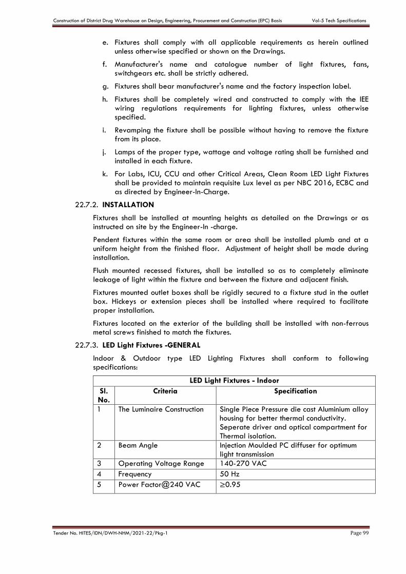
Construction of District Drug Warehouse on Design, Engineering, Procurement and Construction (EPC) Basis Vol-5 Tech Specifications
Tender No. HITES/IDN/DWH-NHM/2021-22/Pkg-1 Page 99
e. Fixtures shall comply with all applicable requirements as herein outlined unless otherwise specified or shown on the Drawings.
f. Manufacturer's name and catalogue number of light fixtures, fans, switchgears etc. shall be strictly adhered.
g. Fixtures shall bear manufacturer's name and the factory inspection label.
h. Fixtures shall be completely wired and constructed to comply with the IEE wiring regulations requirements for lighting fixtures, unless otherwise specified.
i. Revamping the fixture shall be possible without having to remove the fixture from its place.
j. Lamps of the proper type, wattage and voltage rating shall be furnished and installed in each fixture.
k. For Labs, ICU, CCU and other Critical Areas, Clean Room LED Light Fixtures shall be provided to maintain requisite Lux level as per NBC 2016, ECBC and as directed by Engineer-In-Charge.
22.7.2. INSTALLATION
Fixtures shall be installed at mounting heights as detailed on the Drawings or as instructed on site by the Engineer-In -charge.
Pendent fixtures within the same room or area shall be installed plumb and at a uniform height from the finished floor. Adjustment of height shall be made during installation.
Flush mounted recessed fixtures, shall be installed so as to completely eliminate leakage of light within the fixture and between the fixture and adjacent finish.
Fixtures mounted outlet boxes shall be rigidly secured to a fixture stud in the outlet box. Hickeys or extension pieces shall be installed where required to facilitate proper installation.
Fixtures located on the exterior of the building shall be installed with non-ferrous metal screws finished to match the fixtures.
22.7.3. LED Light Fixtures -GENERAL
Indoor & Outdoor type LED Lighting Fixtures shall conform to following specifications:
LED Light Fixtures - Indoor
Sl. No.
Criteria Specification
1 The Luminaire Construction Single Piece Pressure die cast Aluminium alloy housing for better thermal conductivity. Seperate driver and optical compartment for Thermal isolation.
2 Beam Angle Injection Moulded PC diffuser for optimum light transmission
3 Operating Voltage Range 140-270 VAC
4 Frequency 50 Hz
5 Power Factor@240 VAC ≥0.95

Construction of District Drug Warehouse on Design, Engineering, Procurement and Construction (EPC) Basis Vol-5 Tech Specifications
Tender No. HITES/IDN/DWH-NHM/2021-22/Pkg-1 Page 100
6 Driver Driver Efficiency ≥ 85% Driver inbuilt Surge Protection - 3 KV Silicon Potted IP-66 Over voltage Protection Short circuit Protection Thermal Protection
7 THD @ 240 VAC ≤ 10%
8 Ingress Protection IP-20
9 Colour Temperature 5300 K to 6000 K
10 Color Rendition Index (CRI) ≥80
11 System Efficacy ≥110 Lumens per Watt
12 Junction Temperature of LED ≤ 65°C
13 LED Make NICHIA/Philips Lumileds/ CREE/ OSRAM/ Samsung/ Bridge Lux
14 Operating Temperature Range
0°C to 35°C
15 Unified Glare Rating (UGR) ≤ 19
16 Average Operating Life 50,000 Hours @ L 70 B50
17 Humidity 10 to 80%
LED Light Fixtures – Outdoor
Sl. No.
Criteria Specification
1 The Luminaire Construction Single Piece Pressure die cast Aluminium alloy housing for better thermal conductivity. Seperate driver and optical compartment for Thermal isolation. Each LED should be covered with IP-66 or more protected lens. Luminaire with glass/PC/Acrylic cover/diffuser will not be accepted due to accumulation of insects/dust and decrease in light output.
2 Operating Voltage Range 140-270 VAC
3 Frequency 50 Hz
4 Power Factor@240 VAC ≥0.95
5 Driver Driver Efficiency ≥85% Driver inbuilt Surge Protection: 5 KV Silicon Potted: IP-66 Over voltage Protection Short circuit Protection Thermal Protection
6 THD @240 V AC ≤ 10 %
7 Ingress Protection IP-66
8 Impact Resistance IK-08
9 Colour Temperature 5300 K to 6000 K
10 Color Rendition Index (CRI) ≥ 70 %
11 System Efficacy ≥110 Lumens per Watt
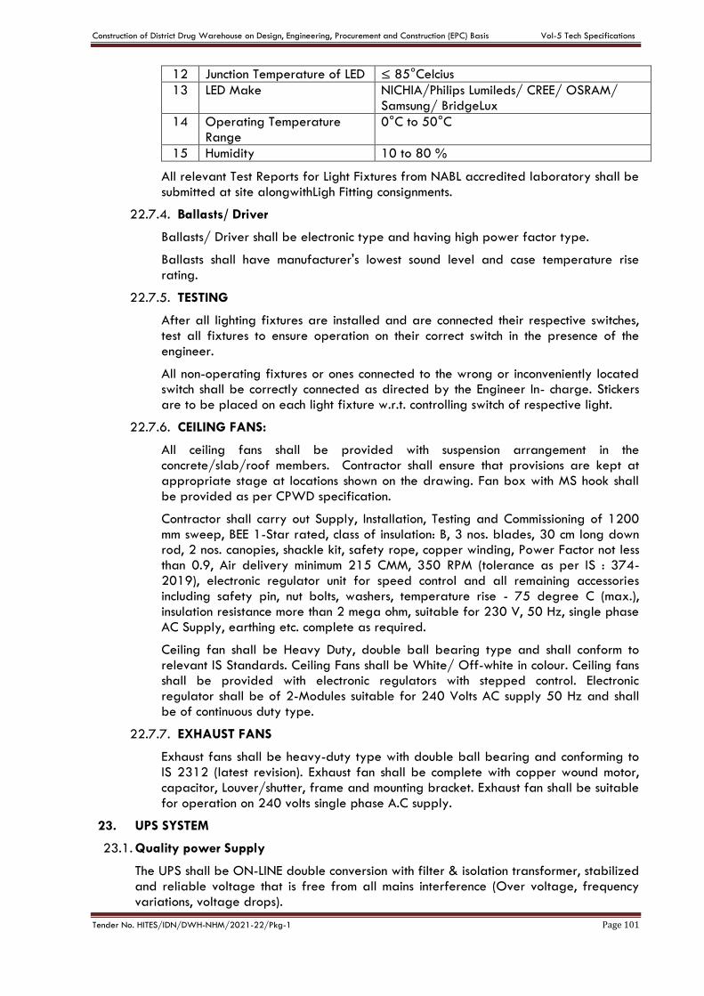
Construction of District Drug Warehouse on Design, Engineering, Procurement and Construction (EPC) Basis Vol-5 Tech Specifications
Tender No. HITES/IDN/DWH-NHM/2021-22/Pkg-1 Page 101
12 Junction Temperature of LED ≤ 85°Celcius
13 LED Make NICHIA/Philips Lumileds/ CREE/ OSRAM/ Samsung/ BridgeLux
14 Operating Temperature Range
0°C to 50°C
15 Humidity 10 to 80 %
All relevant Test Reports for Light Fixtures from NABL accredited laboratory shall be submitted at site alongwithLigh Fitting consignments.
22.7.4. Ballasts/ Driver
Ballasts/ Driver shall be electronic type and having high power factor type.
Ballasts shall have manufacturer's lowest sound level and case temperature rise rating.
22.7.5. TESTING
After all lighting fixtures are installed and are connected their respective switches, test all fixtures to ensure operation on their correct switch in the presence of the engineer.
All non-operating fixtures or ones connected to the wrong or inconveniently located switch shall be correctly connected as directed by the Engineer In- charge. Stickers are to be placed on each light fixture w.r.t. controlling switch of respective light.
22.7.6. CEILING FANS:
All ceiling fans shall be provided with suspension arrangement in the concrete/slab/roof members. Contractor shall ensure that provisions are kept at appropriate stage at locations shown on the drawing. Fan box with MS hook shall be provided as per CPWD specification.
Contractor shall carry out Supply, Installation, Testing and Commissioning of 1200 mm sweep, BEE 1-Star rated, class of insulation: B, 3 nos. blades, 30 cm long down rod, 2 nos. canopies, shackle kit, safety rope, copper winding, Power Factor not less than 0.9, Air delivery minimum 215 CMM, 350 RPM (tolerance as per IS : 374-2019), electronic regulator unit for speed control and all remaining accessories including safety pin, nut bolts, washers, temperature rise - 75 degree C (max.), insulation resistance more than 2 mega ohm, suitable for 230 V, 50 Hz, single phase AC Supply, earthing etc. complete as required.
Ceiling fan shall be Heavy Duty, double ball bearing type and shall conform to relevant IS Standards. Ceiling Fans shall be White/ Off-white in colour. Ceiling fans shall be provided with electronic regulators with stepped control. Electronic regulator shall be of 2-Modules suitable for 240 Volts AC supply 50 Hz and shall be of continuous duty type.
22.7.7. EXHAUST FANS
Exhaust fans shall be heavy-duty type with double ball bearing and conforming to IS 2312 (latest revision). Exhaust fan shall be complete with copper wound motor, capacitor, Louver/shutter, frame and mounting bracket. Exhaust fan shall be suitable for operation on 240 volts single phase A.C supply.
23. UPS SYSTEM
23.1. Quality power Supply
The UPS shall be ON-LINE double conversion with filter & isolation transformer, stabilized and reliable voltage that is free from all mains interference (Over voltage, frequency variations, voltage drops).
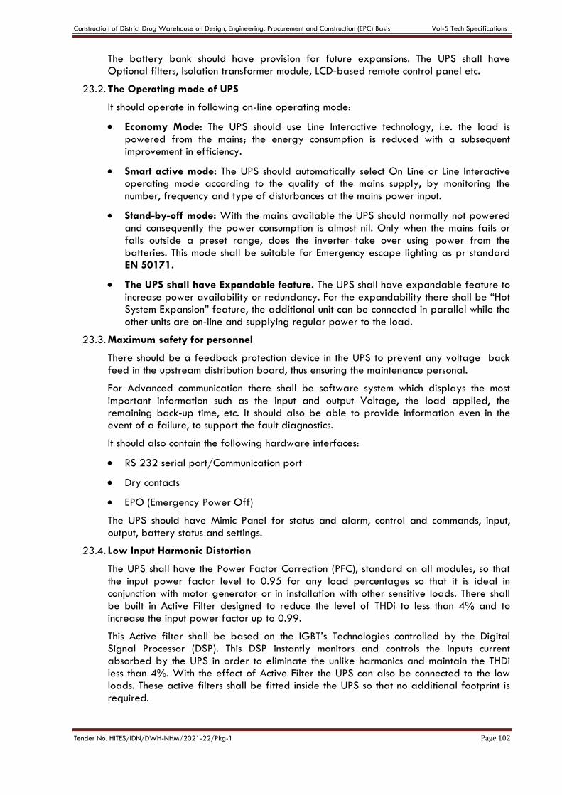
Construction of District Drug Warehouse on Design, Engineering, Procurement and Construction (EPC) Basis Vol-5 Tech Specifications
Tender No. HITES/IDN/DWH-NHM/2021-22/Pkg-1 Page 102
The battery bank should have provision for future expansions. The UPS shall have Optional filters, Isolation transformer module, LCD-based remote control panel etc.
23.2. The Operating mode of UPS
It should operate in following on-line operating mode:
Economy Mode: The UPS should use Line Interactive technology, i.e. the load is powered from the mains; the energy consumption is reduced with a subsequent improvement in efficiency.
Smart active mode: The UPS should automatically select On Line or Line Interactive operating mode according to the quality of the mains supply, by monitoring the number, frequency and type of disturbances at the mains power input.
Stand-by-off mode: With the mains available the UPS should normally not powered and consequently the power consumption is almost nil. Only when the mains fails or falls outside a preset range, does the inverter take over using power from the batteries. This mode shall be suitable for Emergency escape lighting as pr standard EN 50171.
The UPS shall have Expandable feature. The UPS shall have expandable feature to increase power availability or redundancy. For the expandability there shall be “Hot System Expansion” feature, the additional unit can be connected in parallel while the other units are on-line and supplying regular power to the load.
23.3. Maximum safety for personnel
There should be a feedback protection device in the UPS to prevent any voltage back feed in the upstream distribution board, thus ensuring the maintenance personal.
For Advanced communication there shall be software system which displays the most important information such as the input and output Voltage, the load applied, the remaining back-up time, etc. It should also be able to provide information even in the event of a failure, to support the fault diagnostics.
It should also contain the following hardware interfaces:
RS 232 serial port/Communication port
Dry contacts
EPO (Emergency Power Off)
The UPS should have Mimic Panel for status and alarm, control and commands, input, output, battery status and settings.
23.4. Low Input Harmonic Distortion
The UPS shall have the Power Factor Correction (PFC), standard on all modules, so that the input power factor level to 0.95 for any load percentages so that it is ideal in conjunction with motor generator or in installation with other sensitive loads. There shall be built in Active Filter designed to reduce the level of THDi to less than 4% and to increase the input power factor up to 0.99.
This Active filter shall be based on the IGBT’s Technologies controlled by the Digital Signal Processor (DSP). This DSP instantly monitors and controls the inputs current absorbed by the UPS in order to eliminate the unlike harmonics and maintain the THDi less than 4%. With the effect of Active Filter the UPS can also be connected to the low loads. These active filters shall be fitted inside the UPS so that no additional footprint is required.
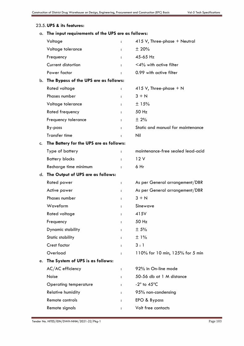
Construction of District Drug Warehouse on Design, Engineering, Procurement and Construction (EPC) Basis Vol-5 Tech Specifications
Tender No. HITES/IDN/DWH-NHM/2021-22/Pkg-1 Page 103
23.5. UPS & its features:
a. The input requirements of the UPS are as follows:
Voltage : 415 V, Three-phase + Neutral
Voltage tolerance : ± 20%
Frequency : 45-65 Hz
Current distortion : <4% with active filter
Power factor : 0.99 with active filter
b. The Bypass of the UPS are as follows:
Rated voltage : 415 V, Three-phase + N
Phases number : 3 + N
Voltage tolerance : ± 15%
Rated frequency : 50 Hz
Frequency tolerance : ± 2%
By-pass : Static and manual for maintenance
Transfer time : Nil
c. The Battery for the UPS are as follows:
Type of battery : maintenance-free sealed lead-acid
Battery blocks : 12 V
Recharge time minimum : 6 Hr
d. The Output of UPS are as follows:
Rated power : As per General arrangement/DBR
Active power : As per General arrangement/DBR
Phases number : 3 + N
Waveform : Sinewave
Rated voltage : 415V
Frequency : 50 Hz
Dynamic stability : ± 5%
Static stability : ± 1%
Crest factor : 3 : 1
Overload : 110% for 10 min, 125% for 5 min
e. The System of UPS is as follows:
AC/AC efficiency : 92% in On-line mode
Noise : 50-56 db at 1 M distance
Operating temperature : -2º to 45ºC
Relative humidity : 95% non-condensing
Remote controls : EPO & Bypass
Remote signals : Volt free contacts
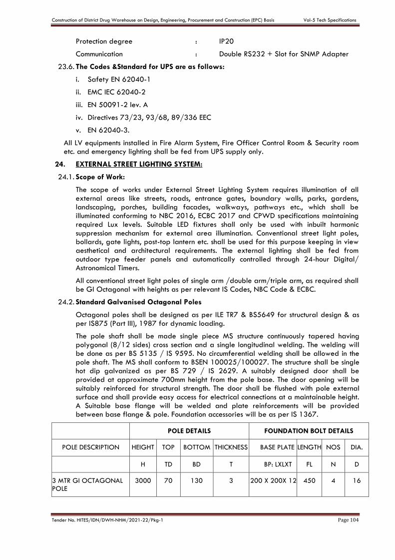
Construction of District Drug Warehouse on Design, Engineering, Procurement and Construction (EPC) Basis Vol-5 Tech Specifications
Tender No. HITES/IDN/DWH-NHM/2021-22/Pkg-1 Page 104
Protection degree : IP20
Communication : Double RS232 + Slot for SNMP Adapter
23.6. The Codes &Standard for UPS are as follows:
i. Safety EN 62040-1
ii. EMC IEC 62040-2
iii. EN 50091-2 lev. A
iv. Directives 73/23, 93/68, 89/336 EEC
v. EN 62040-3.
All LV equipments installed in Fire Alarm System, Fire Officer Control Room & Security room etc. and emergency lighting shall be fed from UPS supply only.
24. EXTERNAL STREET LIGHTING SYSTEM:
24.1. Scope of Work:
The scope of works under External Street Lighting System requires illumination of all external areas like streets, roads, entrance gates, boundary walls, parks, gardens, landscaping, porches, building facades, walkways, pathways etc., which shall be illuminated conforming to NBC 2016, ECBC 2017 and CPWD specifications maintaining required Lux levels. Suitable LED fixtures shall only be used with inbuilt harmonic suppression mechanism for external area illumination. Conventional street light poles, bollards, gate lights, post-top lantern etc. shall be used for this purpose keeping in view aesthetical and architectural requirements. The external lighting shall be fed from outdoor type feeder panels and automatically controlled through 24-hour Digital/ Astronomical Timers.
All conventional street light poles of single arm /double arm/triple arm, as required shall be GI Octagonal with heights as per relevant IS Codes, NBC Code & ECBC.
24.2. Standard Galvanised Octagonal Poles
Octagonal poles shall be designed as per ILE TR7 & BS5649 for structural design & as per IS875 (Part III), 1987 for dynamic loading.
The pole shaft shall be made single piece MS structure continuously tapered having polygonal (8/12 sides) cross section and a single longitudinal welding. The welding will be done as per BS 5135 / IS 9595. No circumferential welding shall be allowed in the pole shaft. The MS shall conform to BSEN 100025/100027. The structure shall be single hot dip galvanized as per BS 729 / IS 2629. A suitably designed door shall be provided at approximate 700mm height from the pole base. The door opening will be suitably reinforced for structural strength. The door shall be flushed with pole external surface and shall provide easy access for electrical connections at a maintainable height. A Suitable base flange will be welded and plate reinforcements will be provided between base flange & pole. Foundation accessories will be as per IS 1367.
POLE DETAILS FOUNDATION BOLT DETAILS
POLE DESCRIPTION HEIGHT TOP BOTTOM THICKNESS BASE PLATE LENGTH NOS DIA.
H TD BD T BP: LXLXT FL N D
3 MTR GI OCTAGONAL POLE
3000 70 130 3 200 X 200X 12 450 4 16
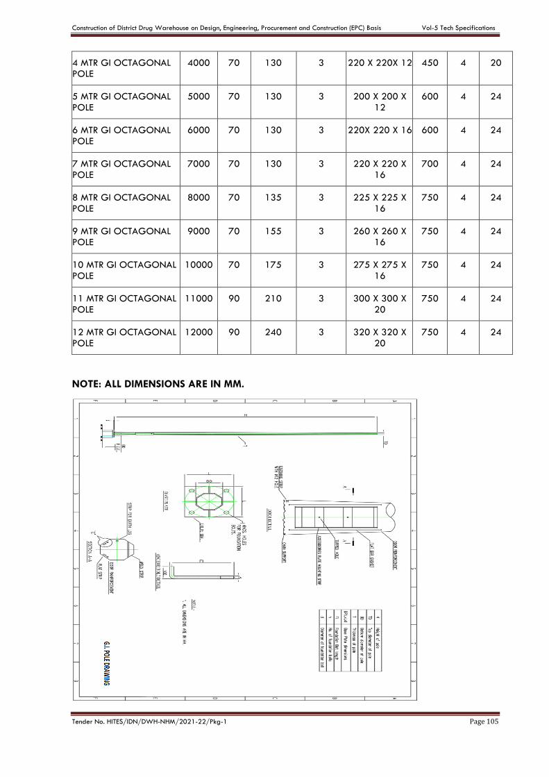
Construction of District Drug Warehouse on Design, Engineering, Procurement and Construction (EPC) Basis Vol-5 Tech Specifications
Tender No. HITES/IDN/DWH-NHM/2021-22/Pkg-1 Page 105
4 MTR GI OCTAGONAL POLE
4000 70 130 3 220 X 220X 12 450 4 20
5 MTR GI OCTAGONAL POLE
5000 70 130 3 200 X 200 X 12
600 4 24
6 MTR GI OCTAGONAL POLE
6000 70 130 3 220X 220 X 16 600 4 24
7 MTR GI OCTAGONAL POLE
7000 70 130 3 220 X 220 X 16
700 4 24
8 MTR GI OCTAGONAL POLE
8000 70 135 3 225 X 225 X 16
750 4 24
9 MTR GI OCTAGONAL POLE
9000 70 155 3 260 X 260 X 16
750 4 24
10 MTR GI OCTAGONAL POLE
10000 70 175 3 275 X 275 X 16
750 4 24
11 MTR GI OCTAGONAL POLE
11000 90 210 3 300 X 300 X 20
750 4 24
12 MTR GI OCTAGONAL POLE
12000 90 240 3 320 X 320 X 20
750 4 24
NOTE: ALL DIMENSIONS ARE IN MM.

Construction of District Drug Warehouse on Design, Engineering, Procurement and Construction (EPC) Basis Vol-5 Tech Specifications
Tender No. HITES/IDN/DWH-NHM/2021-22/Pkg-1 Page 106
25. Solar Street Lighting System
25.1. Scope of Work:
Solar Street Lighting System shall comprise of Solar Panel Module, LED Luminaires, Solar Charge Controller /LED driver in a single PCB, SMF Battery with 48 hours back up, Hybrid Charger etc. Mounting System shall include, panel frame, panel holder, Battery Box, Battery Box Stand, Luminaire arm, GI Octagonal Pole etc.
Maximum Power Point Tracking (MPPT) System shall be provided with charge controllers for extracting maximum available power from PV module under certain conditions. MPPT (18 W – 45W) Solar Charge Controller with maximum efficiency shall be provided as per Lux level requirements to maximise the generation of solar power.
25.2. Features of Solar Street Light Poles:
System Wattage
15Watts 18Watts 21Watts 24Watts 27Watts 30Watts
Total Lumen Output
1600 1900 2200 2600 2900 3150
Charge
Controller Type
MPPT (DIM ) MPPT (DIM ) MPPT (DIM ) MPPT (DIM ) MPPT (DIM ) MPPT (DIM )
Charge
controller efficiency
>96% >96% >96% >96% >96% >96%
LED Driver
efficiency >96% >96% >96% >96% >96%
>96%
No of Leds 8 8 8 12 12 12
No Load current from
battery <10mA <10mA <10mA <10mA <10mA <10mA
Housing LM6 PDC Housing
LM6 PDC Housing
LM6 PDC Housing
LM6 PDC Housing
LM6 PDC Housing
LM6 PDC Housing
Front Cover Toughened
Glass Toughened
Glass Toughened
Glass Toughened
Glass Toughened
Glass Toughened
Glass
Ingress Protection
IP66, Class I IP66, Class I IP66, Class I IP66, Class I IP66, Class I IP66, Class I
Life 50,000Hrs@
L70 50,000Hrs@
L70 50,000Hrs@
L70 50,000Hrs@
L70 50,000Hrs@
L70 50,000Hrs@
L70
CCT 5700K (+/-
5SDCM) 5700K (+/-
5SDCM) 5700K (+/-
5SDCM) 5700K (+/-
5SDCM) 5700K (+/-
5SDCM) 5700K (+/-
5SDCM)
CRI >70 >70 >70 >70 >70 >70
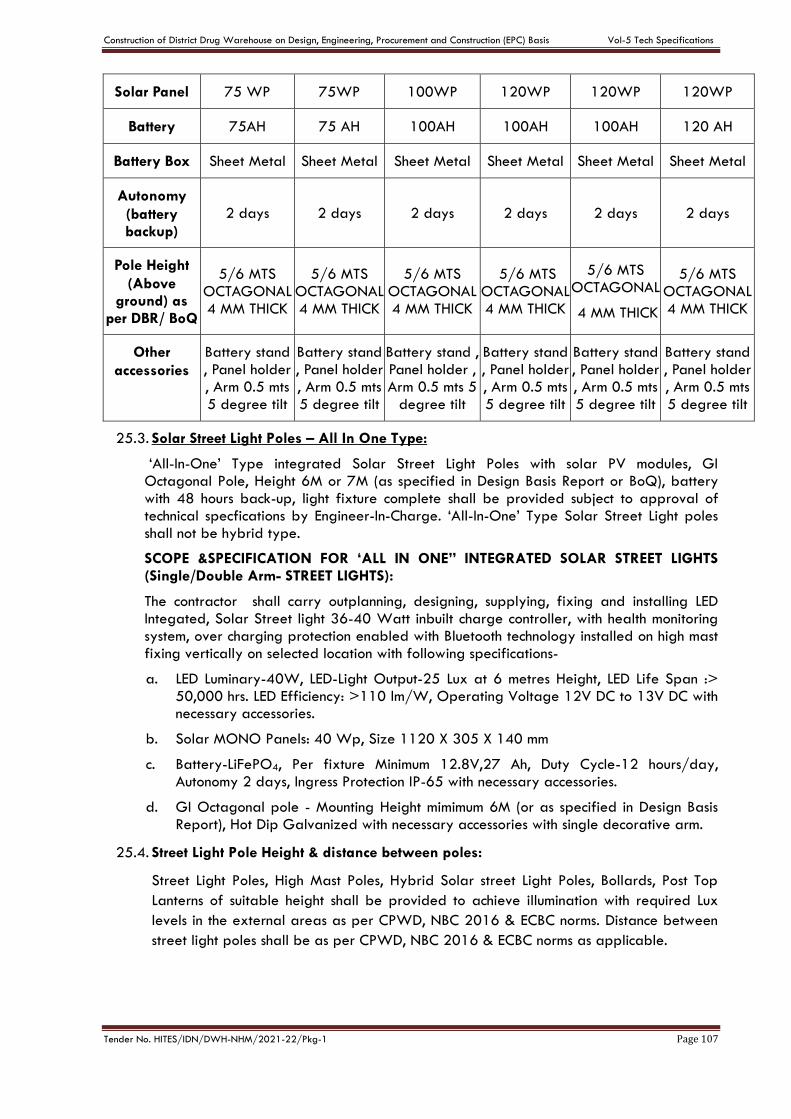
Construction of District Drug Warehouse on Design, Engineering, Procurement and Construction (EPC) Basis Vol-5 Tech Specifications
Tender No. HITES/IDN/DWH-NHM/2021-22/Pkg-1 Page 107
Solar Panel 75 WP 75WP 100WP 120WP 120WP 120WP
Battery 75AH 75 AH 100AH 100AH 100AH 120 AH
Battery Box Sheet Metal Sheet Metal Sheet Metal Sheet Metal Sheet Metal Sheet Metal
Autonomy
(battery backup)
2 days 2 days 2 days 2 days 2 days 2 days
Pole Height
(Above ground) as
per DBR/ BoQ
5/6 MTS OCTAGONAL 4 MM THICK
5/6 MTS OCTAGONAL 4 MM THICK
5/6 MTS OCTAGONAL 4 MM THICK
5/6 MTS OCTAGONAL 4 MM THICK
5/6 MTS OCTAGONAL
4 MM THICK
5/6 MTS OCTAGONAL 4 MM THICK
Other
accessories
Battery stand , Panel holder , Arm 0.5 mts 5 degree tilt
Battery stand , Panel holder , Arm 0.5 mts 5 degree tilt
Battery stand , Panel holder , Arm 0.5 mts 5
degree tilt
Battery stand , Panel holder , Arm 0.5 mts 5 degree tilt
Battery stand , Panel holder , Arm 0.5 mts 5 degree tilt
Battery stand , Panel holder , Arm 0.5 mts 5 degree tilt
25.3. Solar Street Light Poles – All In One Type:
‘All-In-One’ Type integrated Solar Street Light Poles with solar PV modules, GI Octagonal Pole, Height 6M or 7M (as specified in Design Basis Report or BoQ), battery with 48 hours back-up, light fixture complete shall be provided subject to approval of technical specfications by Engineer-In-Charge. ‘All-In-One’ Type Solar Street Light poles shall not be hybrid type.
SCOPE &SPECIFICATION FOR ‘ALL IN ONE” INTEGRATED SOLAR STREET LIGHTS (Single/Double Arm- STREET LIGHTS):
The contractor shall carry outplanning, designing, supplying, fixing and installing LED Integated, Solar Street light 36-40 Watt inbuilt charge controller, with health monitoring system, over charging protection enabled with Bluetooth technology installed on high mast fixing vertically on selected location with following specifications-
a. LED Luminary-40W, LED-Light Output-25 Lux at 6 metres Height, LED Life Span :> 50,000 hrs. LED Efficiency: >110 lm/W, Operating Voltage 12V DC to 13V DC with necessary accessories.
b. Solar MONO Panels: 40 Wp, Size 1120 X 305 X 140 mm
c. Battery-LiFePO4, Per fixture Minimum 12.8V,27 Ah, Duty Cycle-12 hours/day, Autonomy 2 days, Ingress Protection IP-65 with necessary accessories.
d. GI Octagonal pole - Mounting Height mimimum 6M (or as specified in Design Basis Report), Hot Dip Galvanized with necessary accessories with single decorative arm.
25.4. Street Light Pole Height & distance between poles:
Street Light Poles, High Mast Poles, Hybrid Solar street Light Poles, Bollards, Post Top
Lanterns of suitable height shall be provided to achieve illumination with required Lux
levels in the external areas as per CPWD, NBC 2016 & ECBC norms. Distance between
street light poles shall be as per CPWD, NBC 2016 & ECBC norms as applicable.
Construction of District Drug Warehouse on Design, Engineering, Procurement and Construction (EPC) Basis Vol-5 Tech Specifications
Tender No. HITES/IDN/DWH-NHM/2021-22/Pkg-1 Page 108
25.5. Inspection:
Street Light Poles, High Mast Poles, Hybrid Solar Street Light Poles etc shall be offered
for inspection by HITES Engineers at manufacturer’s works before final dispatch to site as
per terms of the contract.
25.6. Drawings:
Site Layout drawings and Single Line diagrams shall be prepared and submitted for
approval of Engineer-In–charge by the contractor for the Street Light Poles, High Mast
Poles, Hybrid Solar street Light Poles, Bollards, Post Top lanterns, Gate Lights, Façade
Lights, Walk Way lights etc. The drawings shall be got approved from Engineer-In–
charge before commencement of works at site.
25.7. Applicable IEC Standards:
i. IEC 61215 latest: Solar Panel
ii. IEC 61347-2-13 : LED driver safety
iii. IEC 62384 : LED driver performance
iv. CISPR 15 : Radio disturbance characteristics
v. IEC 61547 : EMC immunity requirements
vi. IEC 60598 : General requirements and tests
Construction of District Drug Warehouse on Design, Engineering, Procurement and Construction (EPC) Basis Vol-5 Tech Specifications
Tender No. HITES/IDN/DWH-NHM/2021-22/Pkg-1 Page 109
CHAPTER –E
TECHNICAL SPECIFICATIONS – FIRE ALARM SYSTEM
1. GENERAL
a. The specifications includes furnishing, installation, connection and testing of the microprocessor controlled, intelligent reporting fire alarm network equipment required to form a complete, operative, coordinated system. It shall include, but not be limited to, alarm initiating devices, alarm notification appliances, Network Fire Alarm Control Panels (FACP), Network Reporting Terminals (NRT), Network Liquid Crystal Display (NLCD), auxiliary control devices, annunciators, and wiring as specified herein.
b. The fire alarm system shall comply with requirements of IS:2189:1999 & 1996 NFPA Standard 72 for Protected Premises Signalling Systems except as modified and supplemented by this specification, or the stringent one of the two specification in case of any discrepancy. The system shall be electrically supervised and monitor the integrity of all conductors.
c. Fire Alarm System shall be integrated with P.A. system. A digitized pre-recorded voice message shall notify occupants that a fire condition has been reported. The message shall instruct the occupants with emergency instructions. Emergency manual voice override shall be provided.
d. The system and its components shall be Underwriters Laboratories, Inc. listed under the appropriate UL testing standard as listed herein for fire alarm applications and shall be in compliance with the UL listing for equivalent European standard EN54.
e. Each designated zone shall transmit separate and different alarm, supervisory and trouble signals to the Fire Alarm Control Room and designated personnel.
f. The FACPs shall be active/interrogative-type systems where each transponder is repetitively scanned, causing a signal to be transmitted to the fire alarm control panel node indicating that the transponder and its associated initiating device and notification appliance circuit wiring is functional. Loss of this signal at the FACP shall result in a trouble indication on both the FACP display and at the network display, as specified hereinafter for the particular input.
g. The system shall be arranged such that not less than 20 percent additional transponders may be inserted into any network communication loop.
h. The installing company shall employ technicians on site to guide the labours and to ensure the systems integrity.
1.1. SCOPE:
a. A new network intelligent reporting, microprocessor controlled fire detection and shall be compatible with PA system emergency voice alarm communication network shall be installed in accordance with the specifications and drawings.
b. Basic Performance:
i. Alarm and trouble signals from the FACP, NRT, and NLCD network nodes shall be digitally encoded by listed electronic devices onto a NFPA Style 9 looped multiplex communication system.
ii. Alarm, trouble and supervisory signals from all intelligent reporting devices shall be encoded onto NFPA Style 6 (Class A) Signaling Line Circuits (SLC).
iii. Initiation Device Circuits (IDC) shall be wired Class A (NFPA Style D). Connected by the SLC.
Construction of District Drug Warehouse on Design, Engineering, Procurement and Construction (EPC) Basis Vol-5 Tech Specifications
Tender No. HITES/IDN/DWH-NHM/2021-22/Pkg-1 Page 110
iv. Notification Appliance Circuits (NAC) shall be wired Class A (NFPA Style Z). Connected by the SLC.
v. Power for initiating devices and notification appliances must be from the main fire alarm control panel, the transponder to which they are connected or to a Field Charging Power Supply (FCPS).
vi. A single ground or open on any system signaling line circuit, initiating device circuit, or notification appliance circuit shall not cause system malfunction, loss of operating power or the ability to report an alarm.
vii. Alarm signals arriving at the main FACP shall not be lost following a power failure (or outage) until the alarm signal is processed and recorded.
viii. Digitized electronic signals shall employ check digits or multiple polling.
ix. Transponder devices are to consist of low current, solid-state integrated circuits, and shall be powered locally from a primary power and standby power source.
x. F.A. System shall be integrated with P.A system & Car Calling system so that it can be used for Emergency evacuation under fire condition.
1.2. SUBMITTALS
A. General:
All substitute equipment proposed as equal to the equipment specified herein, shall meet or exceed the following standards. For equipment other than that specified, the contractor shall supply proof that such substitute equipment does in fact equal or exceed the features, functions, performance, and quality of the specified equipment. Two copies of all submittals shall be submitted to the Engineer-in-charge/Engineer for review.
B. Shop Drawings:
i. Sufficient information, clearly presented, shall be included to determine compliance with drawings and specifications.
ii. Include manufacturer's name(s), model numbers, ratings, power requirements, equipment layout, device arrangement, complete wiring point-to-point diagrams, and conduit layouts.
iii. Show equipment layout and main control panel, module layout, configurations and terminations.
C. Manuals:
Submit simultaneously with the shop drawings, complete operating and maintenance manuals listing the manufacturer's name(s) including technical data sheets.
Wiring diagrams shall indicate internal wiring for each item of equipment and the interconnections between the items of equipment.
Provide a clear and concise description of operation, which gives the information required to properly operate the equipment and system.
Approvals will be based on complete submissions of manuals together with shop drawings.

Construction of District Drug Warehouse on Design, Engineering, Procurement and Construction (EPC) Basis Vol-5 Tech Specifications
Tender No. HITES/IDN/DWH-NHM/2021-22/Pkg-1 Page 111
D. Software Modifications
Provide the services of a factory trained and authorized technician to perform all system software modifications, upgrades or changes. Response time of the technician to the site shall not exceed 2 hours.
Provide all hardware, software, programming tools and documentation necessary to modify the fire alarm network on site. Modification includes addition and deletion of devices, circuits, zones and changes to system operation and custom label changes for devices or zones. The system structure and software shall place no limit on the type or extent of software modifications on-site. Modification of software shall not require power-down of the system or loss of system fire protection while modifications are being made.
E. Certifications:
Together with the shop drawing submittal, submit a certification from the major equipment manufacturer indicating that the proposed supervisor of installation and the proposed performer of contract maintenance is an authorized representative of the major equipment manufacturer and trained on network applications. Include names and addresses in the certification.
1.3. APPLICABLE PUBLICATIONS:
The publications listed below form a part of this specification. The publications are referenced in text by the basic designation only.
A. The fire alarm system shall comply with requirements of NFPA 72 for protected premises signaling systems except as modified and supplemented by this specification. The system field wiring shall be supervised either electrically or by software-directed polling of field devices.
B. Underwriters Laboratories Inc. (UL) - USA: / EN - 54
C. NBC - 2016 (Part-4)
D. All requirements of the Authority Having Jurisdiction (AHJ).
1.4. APPROVALS/ GOVERNING SPECIFICATIONS:
A. Detectors/ Devices:
a. Heat Detectors shall conform to IS-2175 - 1988 or BS-5445 ( EN 54) Part 5–1977 (VdS/LPCB approved) or NFPA72 (UL/ULC/FM approved) amended upto date.
b. Smoke Detectors shall conform to IS-11360-1985 or BS 5446 Part I-1977 & Part VII – 1985 (VdS/LPCB approved) or NFPA72 (UL/ULC/FM approved) amended upto date.
c. For other detectors/devices relevant IS or BS (EN 54) (VdS/LPCB approved) or NFPA 72 (UL/ULC/FM approved) amended upto date
B. Fire Alarm Control Panel: FACP shall meet the following requirements to assure the integrity and reliability of the system. The FACP shall have proper listing and / or approval from the following recognized agencies:
(I) National Fire Protection Association (NFPA)-USA: This will cover the following approval:
a. UL (Under writers Laboratories Inc.)
b. ULC (Under writers Laboratories Canada)
c. FM (Factory Mutual)
Construction of District Drug Warehouse on Design, Engineering, Procurement and Construction (EPC) Basis Vol-5 Tech Specifications
Tender No. HITES/IDN/DWH-NHM/2021-22/Pkg-1 Page 112
d. CSFM (California State Fire Marshal)
(II) EN 54 (European): This will cover the following approval:
a. LPCB (Loss Prevention Council Board)
b. VDS (VertauenDurchSicherheit)
c. BRE
FireAlarm Control Panel (FACP) shall be NFPA/EN listed independently and as per relevant IS Code and CPWD specifications.
The fire alarm control panel, network interface and all transponders shall meet the modular labeling requirements of Underwriters Laboratories, Inc. Each subassembly, including all printed circuits, shall include the appropriate UL modular label. Systems which do not include modular labels, which may require return to the manufacturer for system upgrades, and are not acceptable.
1.5. EQUIPMENT AND MATERIAL:
1.5.1. GENERAL
A. All equipment and components shall be new, and the manufacturer's current model. The materials, appliances, equipment and devices shall be tested and listed by a nationally recognized approvals agency for use as part of a protected premises protective signaling (fire alarm) system. The authorized representative of the manufacturer of the major equipment, such as control panels, shall be responsible for the satisfactory installation of the complete system.
B. All equipment and components shall be installed in strict compliance with each manufacturer's recommendations. Consult the manufacturer's installation manuals for all wiring diagrams, schematics, physical equipment sizes, etc. before beginning system installation. Refer to the riser/connection diagram for all specific system installation/termination/wiring data.
C. All equipment shall be attached to walls and ceiling/floor assemblies and shall be held firmly in place. (e.g., detectors shall not be supported solely by suspended ceilings). Fasteners and supports shall be adequate to support the required load.
1.5.2. Wire & Cable
Fire Survival Cable: For the detector and sounders proposed to fixed on false ceiling/surface, the wiring shall be done with Fire Survival Cable capable of withstanding temperature up to 950 degree C for 20 minutes and 650 degree C for the 180 minutes. The fire survival cable shall be laid on surface with proper saddle etc. ar per requirement & in cable tray above false ceiling. The cables may be armoured/unarmoured as per the location of use.
1.6. FIRE ALARM CONTROL PANELS AND FIRE CONTROL ROOM:
The Fire Alarm Control Panel shall be as per IS: 2189 (latest amended). Each network FACP shall contain a microprocessor-based central processing unit (CPU). The CPU shall communicate with and control the following types of equipment used to make up the system: intelligent addressable detectors, addressable modules, Panel modules including initiating circuit, control circuits, transponders, local and remote operator terminals, printers, annunciators, emergency voice communication systems, and other system controlled devices.
Construction of District Drug Warehouse on Design, Engineering, Procurement and Construction (EPC) Basis Vol-5 Tech Specifications
Tender No. HITES/IDN/DWH-NHM/2021-22/Pkg-1 Page 113
Each FACP on the network shall perform the following functions:
A. It shall Supervise and monitor all intelligent addressable detectors and monitor modules connected to the system for normal, trouble and alarm conditions.
B. It shall supervise all initiating signaling and notification circuits throughout the facility by way of connection to monitor and control modules.
C. It shall detect the activation of any initiating device and the location of the alarm condition. Operate all notification appliances and auxiliary devices as programmed. In the event of CPU failure, all SLC loop modules shall fallback to degrade mode. Such degrade mode shall treat the corresponding SLC loop control modules and associated detection as conventional two-wire operation. Any activation of a detector in this mode shall automatically activate associated Notification Appliance Circuits.
D. It shall visually and audibly annunciate any trouble, supervisory, security or alarm condition on operator’s terminals, panel display, and annunciators.
E. When a any of the following condition is detected and reported by one of the system initiating devices or appliances:
i. Fire Alarm Conduits
ii. Trouble Confirmation
iii. Supervisory Card
iv. Security Alarm
v. Pre Alarm
Then the following functions shall immediately occur:
a. The FACP alarm LED on the FACP shall flash.
b. A local piezo-electric indication for the event signal for the event in the FACP shall sound a distinctive Signal.
c. The 640-character LCD display on the local FACP node and on the network displays shall indicate all information associated with the fire alarm condition, including the type of alarm point, and its location within the protected premises. This information shall also be displayed on the network reporting terminal.
d. Printing and history storage equipment shall log the information associated with the fire alarm control panel condition, along with the time and date of occurrence.
e. All system output programs assigned via control-by-event interlock programming to be activated by the particular point in alarm shall be executed, and the associated system outputs (alarm notification appliances and/or relays) shall be activated on either local outputs or points located on other network nodes.
1.6.1. General FACP Configuration & Operation:
a. Each FACP node shall include a full featured operator interface control and annunciation panel which shall include a backlit 640-character / minimum 4 “ (inch) Liquid Crystal Display (LCD), individual, color coded system status LEDs, and an alpha-numeric keypad for field programming and control of the node.
b. All programming or editing of the existing programming in the system shall be achieved without special equipment or interrupting the alarm monitoring functions of the fire alarm control panel.

Construction of District Drug Warehouse on Design, Engineering, Procurement and Construction (EPC) Basis Vol-5 Tech Specifications
Tender No. HITES/IDN/DWH-NHM/2021-22/Pkg-1 Page 114
c. FACP nodes shall be designed so that it permits continued local operation of remote transponders under both normal and abnormal network communication loop conditions. This shall be obtained by having transponders operate as local control panels upon loss of network communication.
d. FACP nodes shall be modular in construction to allow ease of servicing. Each CPU and transponder shall be capable of being programmed on site without requiring the use of any external programming equipment. Systems which require use of external programmers or change of EPROMs are not acceptable.
e. The CPU and associated equipment are to be protected so that they will not be affected by voltage surges or line transients including RFI and EMI.
f. Each transponder and peripheral device connected to the FACP node CPU shall be continuously scanned for proper operation. Data transmissions between network nodes, FACP CPUs, transponders, and peripheral devices shall be reliable and error free. The transmission scheme used shall employ dual transmission or other equivalent error checking techniques. Failure of any transponder or peripheral device to respond to an interrogation shall be annunciated as a trouble condition.
1.6.2. FACP software and hardware features:
a. Pre- Signal and Positive Alarm Sequence: The system shall provide means to cause pre-alarm signals to only sound in specific areas with a delay of the alarm from 60 to up to 180 seconds after start of alarm processing. In addition, a Positive Alarm Sequence selection shall be available that allows a 15-Second time period for acknowledge an alarm signal from a fire detection/initiating device. If the alarm is not acknowledged within 15 seconds, all local remote outputs shall automatically immediately.
b. Smoke Detector Pre-Alarm indication at control panel: To obtain early warning of incipient or potential fire conditions, the system shall support a programmable option to determine system response to real-time detector sensing values abovethe programmed setting. Two levels of Pre-Alarm indication shall be available at the control.
i) Alert: It shall be possible to set individual smoke detectors for pre-programmed pre-alarm thresholds. If the individual threshold is reached, the pre-alarm condition shall be activated.
ii) Action: if programmed for action and the detector reaches a level exceeding the pre-programmed level, the control panel shall indicate an action condition, Sounder bases installed with either heart or smoke detectors shall automatically activate on action Pre-Alarm level, with general evacuation on alarm level.
c. The system shall be integrated with P.A. System Car Calling system for Emergency evacuation under fire.
d. Each FACP node shall be capable of providing the following features:
i) Block Acknowledge for Trouble Conditions.
ii) Rate Charger Control
iii) Control-By-Time (Delay, Pulse, time of day, etc.)
iv) Automatic Day/Night Sensitivity Adjust (high/low)
v) Device Blink Control (turn of detector LED strobe)
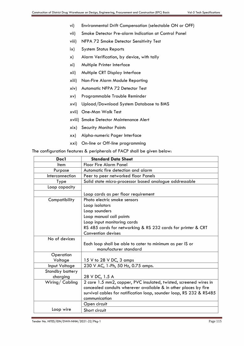
Construction of District Drug Warehouse on Design, Engineering, Procurement and Construction (EPC) Basis Vol-5 Tech Specifications
Tender No. HITES/IDN/DWH-NHM/2021-22/Pkg-1 Page 115
vi) Environmental Drift Compensation (selectable ON or OFF)
vii) Smoke Detector Pre-alarm Indication at Control Panel
viii) NFPA 72 Smoke Detector Sensitivity Test
ix) System Status Reports
x) Alarm Verification, by device, with tally
xi) Multiple Printer Interface
xii) Multiple CRT Display Interface
xiii) Non-Fire Alarm Module Reporting
xiv) Automatic NFPA 72 Detector Test
xv) Programmable Trouble Reminder
xvi) Upload/Download System Database to BMS
xvii) One-Man Walk Test
xviii) Smoke Detector Maintenance Alert
xix) Security Monitor Points
xx) Alpha-numeric Pager Interface
xxi) On-line or Off-line programming
The configuration features & peripherals of FACP shall be given below:
Doc1 Standard Data Sheet
Item Floor Fire Alarm Panel
Purpose Automatic fire detection and alarm
Interconnection Peer to peer networked floor Panels
Type Solid state micro-processor based analogue addressable
Loop capacity
Loop cards as per floor requirement
Compatibility Photo electric smoke sensors
Loop isolators
Loop sounders
Loop manual call points
Loop input monitoring cards
RS 485 cards for networking & RS 232 cards for printer & CRT
Convention devises
No of devices Each loop shall be able to cater to minimum as per IS or
manufacturer standard
Operation Voltage 15 V to 28 V DC, 3 amps
Input Voltage 230 V AC, 1-Ph, 50 Hz, 0.75 amps.
Standby battery charging 28 V DC, 1.5 A
Wiring/ Cabling 2 core 1.5 mm2, copper, PVC insulated, twisted, screened wires in concealed conduits wherever available & in other places by fire survival cables for notification loop, sounder loop, RS 232 & RS485 communication
Loop wire
Open circuit
Short circuit
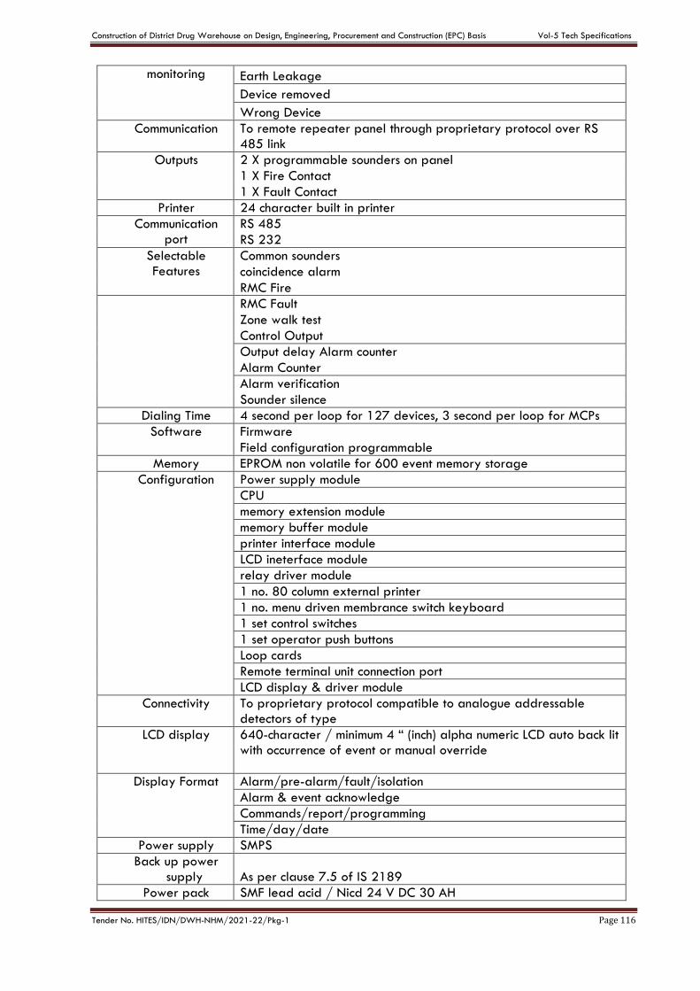
Construction of District Drug Warehouse on Design, Engineering, Procurement and Construction (EPC) Basis Vol-5 Tech Specifications
Tender No. HITES/IDN/DWH-NHM/2021-22/Pkg-1 Page 116
monitoring Earth Leakage
Device removed
Wrong Device
Communication To remote repeater panel through proprietary protocol over RS 485 link
Outputs 2 X programmable sounders on panel
1 X Fire Contact
1 X Fault Contact
Printer 24 character built in printer
Communication port
RS 485
RS 232
Selectable Features
Common sounders
coincidence alarm
RMC Fire
RMC Fault
Zone walk test
Control Output
Output delay Alarm counter
Alarm Counter
Alarm verification
Sounder silence
Dialing Time 4 second per loop for 127 devices, 3 second per loop for MCPs
Software Firmware
Field configuration programmable
Memory EPROM non volatile for 600 event memory storage
Configuration Power supply module
CPU
memory extension module
memory buffer module
printer interface module
LCD ineterface module
relay driver module
1 no. 80 column external printer
1 no. menu driven membrance switch keyboard
1 set control switches
1 set operator push buttons
Loop cards
Remote terminal unit connection port
LCD display & driver module
Connectivity To proprietary protocol compatible to analogue addressable detectors of type
LCD display 640-character / minimum 4 “ (inch) alpha numeric LCD auto back lit with occurrence of event or manual override
Display Format Alarm/pre-alarm/fault/isolation
Alarm & event acknowledge
Commands/report/programming
Time/day/date
Power supply SMPS
Back up power supply As per clause 7.5 of IS 2189
Power pack SMF lead acid / Nicd 24 V DC 30 AH
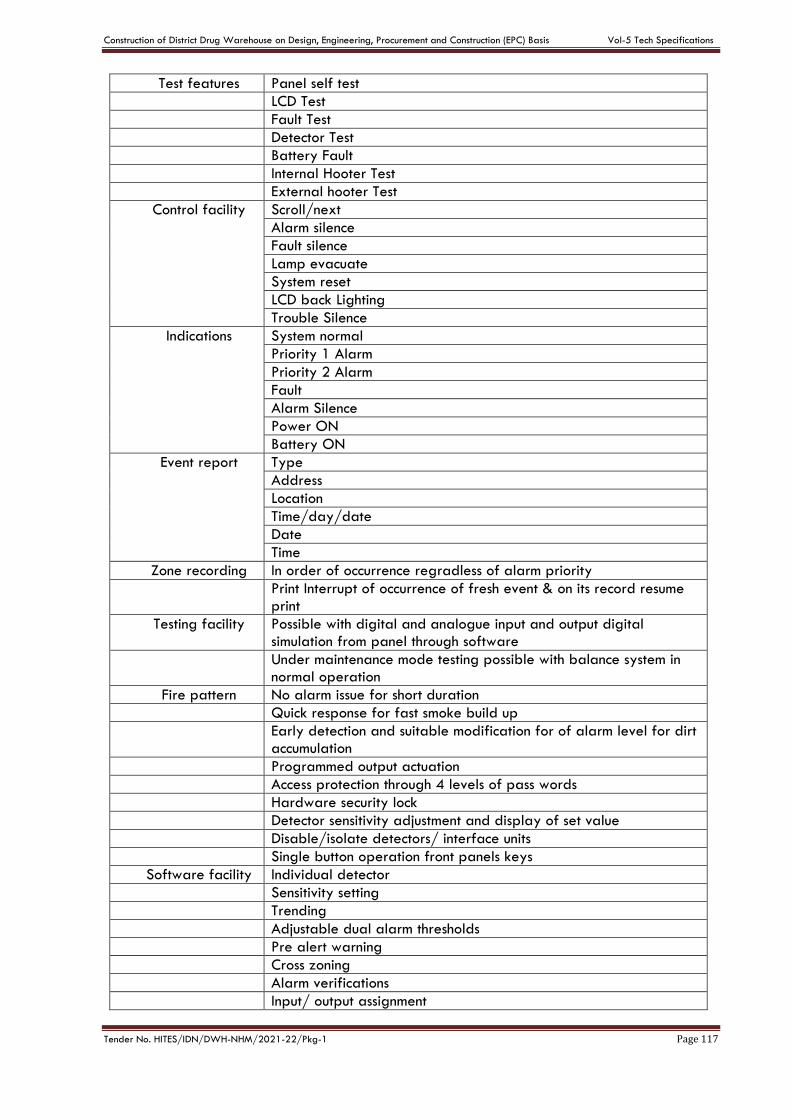
Construction of District Drug Warehouse on Design, Engineering, Procurement and Construction (EPC) Basis Vol-5 Tech Specifications
Tender No. HITES/IDN/DWH-NHM/2021-22/Pkg-1 Page 117
Test features Panel self test
LCD Test
Fault Test
Detector Test
Battery Fault
Internal Hooter Test
External hooter Test
Control facility Scroll/next
Alarm silence
Fault silence
Lamp evacuate
System reset
LCD back Lighting
Trouble Silence
Indications System normal
Priority 1 Alarm
Priority 2 Alarm
Fault
Alarm Silence
Power ON
Battery ON
Event report Type
Address
Location
Time/day/date
Date
Time
Zone recording In order of occurrence regradless of alarm priority
Print Interrupt of occurrence of fresh event & on its record resume print
Testing facility Possible with digital and analogue input and output digital simulation from panel through software
Under maintenance mode testing possible with balance system in normal operation
Fire pattern No alarm issue for short duration
Quick response for fast smoke build up
Early detection and suitable modification for of alarm level for dirt accumulation
Programmed output actuation
Access protection through 4 levels of pass words
Hardware security lock
Detector sensitivity adjustment and display of set value
Disable/isolate detectors/ interface units
Single button operation front panels keys
Software facility Individual detector
Sensitivity setting
Trending
Adjustable dual alarm thresholds
Pre alert warning
Cross zoning
Alarm verifications
Input/ output assignment
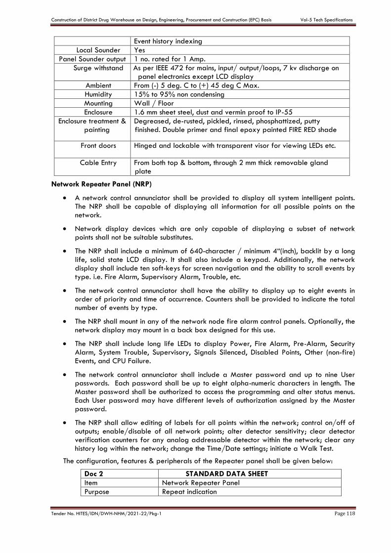
Construction of District Drug Warehouse on Design, Engineering, Procurement and Construction (EPC) Basis Vol-5 Tech Specifications
Tender No. HITES/IDN/DWH-NHM/2021-22/Pkg-1 Page 118
Event history indexing
Local Sounder Yes
Panel Sounder output 1 no. rated for 1 Amp.
Surge withstand As per IEEE 472 for mains, input/ output/loops, 7 kv discharge on panel electronics except LCD display
Ambient From (-) 5 deg. C to (+) 45 deg C Max.
Humidity 15% to 95% non condensing
Mounting Wall / Floor
Enclosure 1.6 mm sheet steel, dust and vermin proof to IP-55
Enclosure treatment & painting
Degreased, de-rusted, pickled, rinsed, phosphattized, putty finished. Double primer and final epoxy painted FIRE RED shade
Front doors Hinged and lockable with transparent visor for viewing LEDs etc.
Cable Entry From both top & bottom, through 2 mm thick removable gland plate
Network Repeater Panel (NRP)
A network control annunciator shall be provided to display all system intelligent points. The NRP shall be capable of displaying all information for all possible points on the network.
Network display devices which are only capable of displaying a subset of network points shall not be suitable substitutes.
The NRP shall include a minimum of 640-character / minimum 4“(inch), backlit by a long life, solid state LCD display. It shall also include a keypad. Additionally, the network display shall include ten soft-keys for screen navigation and the ability to scroll events by type. i.e. Fire Alarm, Supervisory Alarm, Trouble, etc.
The network control annunciator shall have the ability to display up to eight events in order of priority and time of occurrence. Counters shall be provided to indicate the total number of events by type.
The NRP shall mount in any of the network node fire alarm control panels. Optionally, the network display may mount in a back box designed for this use.
The NRP shall include long life LEDs to display Power, Fire Alarm, Pre-Alarm, Security Alarm, System Trouble, Supervisory, Signals Silenced, Disabled Points, Other (non-fire) Events, and CPU Failure.
The network control annunciator shall include a Master password and up to nine User passwords. Each password shall be up to eight alpha-numeric characters in length. The Master password shall be authorized to access the programming and alter status menus. Each User password may have different levels of authorization assigned by the Master password.
The NRP shall allow editing of labels for all points within the network; control on/off of outputs; enable/disable of all network points; alter detector sensitivity; clear detector verification counters for any analog addressable detector within the network; clear any history log within the network; change the Time/Date settings; initiate a Walk Test.
The configuration, features & peripherals of the Repeater panel shall be given below:
Doc 2 STANDARD DATA SHEET
Item Network Repeater Panel
Purpose Repeat indication
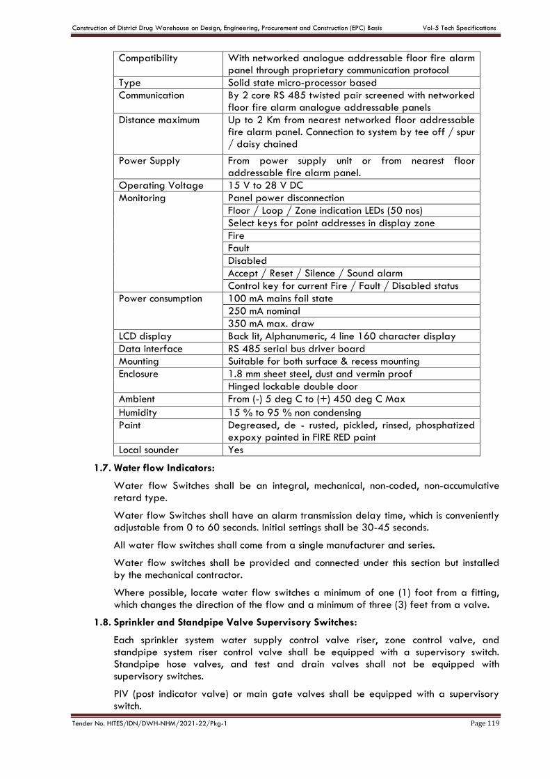
Construction of District Drug Warehouse on Design, Engineering, Procurement and Construction (EPC) Basis Vol-5 Tech Specifications
Tender No. HITES/IDN/DWH-NHM/2021-22/Pkg-1 Page 119
Compatibility With networked analogue addressable floor fire alarm panel through proprietary communication protocol
Type Solid state micro-processor based
Communication By 2 core RS 485 twisted pair screened with networked floor fire alarm analogue addressable panels
Distance maximum Up to 2 Km from nearest networked floor addressable fire alarm panel. Connection to system by tee off / spur / daisy chained
Power Supply From power supply unit or from nearest floor addressable fire alarm panel.
Operating Voltage 15 V to 28 V DC
Monitoring Panel power disconnection
Floor / Loop / Zone indication LEDs (50 nos)
Select keys for point addresses in display zone
Fire
Fault
Disabled
Accept / Reset / Silence / Sound alarm
Control key for current Fire / Fault / Disabled status
Power consumption 100 mA mains fail state
250 mA nominal
350 mA max. draw
LCD display Back lit, Alphanumeric, 4 line 160 character display
Data interface RS 485 serial bus driver board
Mounting Suitable for both surface & recess mounting
Enclosure 1.8 mm sheet steel, dust and vermin proof
Hinged lockable double door
Ambient From (-) 5 deg C to (+) 450 deg C Max
Humidity 15 % to 95 % non condensing
Paint Degreased, de - rusted, pickled, rinsed, phosphatized expoxy painted in FIRE RED paint
Local sounder Yes
1.7. Water flow Indicators:
Water flow Switches shall be an integral, mechanical, non-coded, non-accumulative retard type.
Water flow Switches shall have an alarm transmission delay time, which is conveniently adjustable from 0 to 60 seconds. Initial settings shall be 30-45 seconds.
All water flow switches shall come from a single manufacturer and series.
Water flow switches shall be provided and connected under this section but installed by the mechanical contractor.
Where possible, locate water flow switches a minimum of one (1) foot from a fitting, which changes the direction of the flow and a minimum of three (3) feet from a valve.
1.8. Sprinkler and Standpipe Valve Supervisory Switches:
Each sprinkler system water supply control valve riser, zone control valve, and standpipe system riser control valve shall be equipped with a supervisory switch. Standpipe hose valves, and test and drain valves shall not be equipped with supervisory switches.
PIV (post indicator valve) or main gate valves shall be equipped with a supervisory switch.
Construction of District Drug Warehouse on Design, Engineering, Procurement and Construction (EPC) Basis Vol-5 Tech Specifications
Tender No. HITES/IDN/DWH-NHM/2021-22/Pkg-1 Page 120
The switch shall be mounted so as not to interfere with the normal operation of the valve and adjusted to operate within two revolutions toward the closed position of the valve control, or when the stem has moved no more than one-fifth of the distance from its normal position.
The supervisory switch shall be contained in a weatherproof aluminum housing, which shall provide a 25 mm conduit entrance and incorporate the necessary facilities for attachment to the valves.
The switch housing shall be finished in red baked enamel.
The entire installed assembly shall be tamper proof and arranged to cause a switch operation if the housing cover is removed, or if the unit is removed from its mounting.
Valve supervisory switches shall be provided and connected under this section and installed by mechanical contractor.
1.9. Non-Alarm Input Operation
Any addressable initiating device in the system may be used as a non-alarm input to monitor normally open contact type devices. Non-alarm functions are a lower priority than fire alarm initiating devices.
Combo Zone: - A special type code shall be available to allow water flow and supervisory devices to share a common addressable module. Water flow devices shall be wired in parallel, supervisory devices in series.
1.10. SYSTEM COMPONENTS - ADDRESSABLE DEVICES
1.10.1. DETECTORS& ADDRESSABLE DEVICES
The addressable detector and devices shall comply to the below mentioned specifications. The addressing of detectors and devices shall be of rotary type electronic addressing shall not be acceptable.
I. Intelligent Laser Photo Smoke Detector
a) The intelligent laser photo smoke detector shall be a spot type detector that incorporates an extremely bright laser diode and an integral lens that focuses the light beam to a very small volume near a receiving photo sensor. The scattering of smoke particles shall activate the photo sensor.
b) The laser detector shall have conductive plastic so that dust accumulation is reduced significantly.
c) The intelligent laser photo detector shall have nine sensitivity levels and be sensitive to a minimum obscuration of 0.03 percent per foot.
d) The laser detector shall not require expensive conduit, special fittings or PVC pipe.
e) The intelligent laser photo detector shall support standard, relay, isolator and sounder detector bases.
f) The laser photo detector shall not require other cleaning requirements than those listed in NFPA 72. Replacement, refurbishment or specialized cleaning of the detector head shall not be required.
g) The laser photo detector shall include two bi-color LEDs that flash green in normal operation and turn on steady red in alarm.
II. Intelligent Multi Criteria Acclimating Detector
a) The intelligent multi criteria Acclimate detector shall be an addressable device that is designed to monitor a minimum of photoelectric and thermal
Construction of District Drug Warehouse on Design, Engineering, Procurement and Construction (EPC) Basis Vol-5 Tech Specifications
Tender No. HITES/IDN/DWH-NHM/2021-22/Pkg-1 Page 121
technologies in a single sensing device. The design shall include the ability to adapt to its environment by utilizing a built-in microprocessor to determine its environment and choose the appropriate sensing settings. The detector design shall allow a wide sensitivity window, no less than 1 to 4% per foot obscuration. This detector shall utilize advanced electronics that react to slow smoldering fires and thermal properties all within a single sensing device.
b) The microprocessor design shall be capable of selecting the appropriate sensitivity levels based on the environment type it is in (office, manufacturing, kitchen etc.) and then have the ability to automatically change the setting as the environment changes (as walls are moved or as the occupancy changes).
c) The intelligent multi criteria detection device shall include the ability to combine the signal of the thermal sensor with the signal of the photoelectric signal in an effort to react hastily in the event of a fire situation. It shall also include the inherent ability to distinguish between a fire condition and a false alarm condition by examining the characteristics of the thermal and smoke sensing chambers and comparing them to a database of actual fire and deceptive phenomena.
III. Intelligent Thermal Detectors
Thermal detectors shall be intelligent addressable devices rated at 135 degrees Fahrenheit (58 degrees Celsius) and have a rate-of-rise element rated at 15 degrees F (9.4 degrees C) per minute. It shall connect via two wires to the fire alarm control panel signaling line circuit.
IV. Intelligent Photoelectric Smoke Detector
The detectors shall use the photoelectric (light-scattering) principal to measure smoke density and shall, on command from the control panel, send data to the panel representing the analog level of smoke density.
V. Intelligent Multi Sensor Intelliquad Detector (CO, IR, Smoke & Heat)
a) The intelligent multi sensor Intelliquad detector shall be an addressable device that is designed to monitor a minimum of photoelectric, thermal technologies, carbon monoxide & infrared in a single sensing device. The design shall include the ability to adapt to its environment by utilizing a built-in microprocessor to determine its environment and choose the appropriate sensing settings. The detector design shall allow a wide sensitivity window, no less than 1 to 4% per foot obscuration. This detector shall utilize advanced electronics that react to slow smoldering fires and thermal properties all within a single sensing device.
b) The microprocessor design shall be capable of selecting the appropriate sensitivity levels based on the environment type it is in (office, manufacturing, parking etc.) and then have the ability to automatically change the setting as the environment changes (as walls are moved or as the occupancy changes).
c) The intelligent multi sensor detection device shall include the ability to combine the all of four signals in an effort to react hastily in the event of a fire situation. It shall also include the inherent ability to distinguish between a fire condition and a false alarm condition by examining the characteristics of the thermal and smoke sensing chambers and comparing them to a database of actual fire and deceptive phenomena.
Construction of District Drug Warehouse on Design, Engineering, Procurement and Construction (EPC) Basis Vol-5 Tech Specifications
Tender No. HITES/IDN/DWH-NHM/2021-22/Pkg-1 Page 122
VI. Intelligent Duct Smoke Detector
a) The smoke detector housing shall accommodate either an intelligent ionization detector or an intelligent photoelectric detector, of that provides continuous analog monitoring and alarm verification from the panel.
b) When sufficient smoke is sensed, an alarm signal is initiated at the FACP, and appropriate action taken to change over air handling systems to help prevent the rapid distribution of toxic smoke and fire gases throughout the areas served by the duct system.
c) Isolator modules shall be provided to automatically isolate wire-to-wire short circuits on an SLC Class A or Class B branch. The isolator module shall limit the number of modules or detectors that may be rendered inoperative by a short circuit fault on the SLC loop segment or branch. At least one isolator module shall be provided for each floor or protected zone of the building.
d) If a wire-to-wire short occurs, the isolator module shall automatically open-circuit (disconnect) the SLC. When the short circuit condition is corrected, the isolator module shall automatically reconnect the isolated section.
e) The isolator module shall not require address-setting, and its operations shall be totally automatic. It shall not be necessary to replace or reset an isolator module after its normal operation.
f) The isolator module shall provide a single LED that shall flash to indicate that the isolator is operational and shall illuminate steadily to indicate that a short circuit condition has been detected and isolated.
g) The isolator module shall not consume any detector or device address from the loop capacity.
VII. Addressable Control Relay Module
Addressable Relay Modules shall be available for HVAC control and other building functions. The relay shall be form C and rated for a minimum of 2.0 Amps resistive or 1.0 Amps inductive. The relay coil shall be magnetically latched to reduce wiring connection requirements, and to insure that 100% of all auxiliary relay or NACs may be energized at the same time on the same pair of wires.
VIII. Addressable Control Module
a) Addressable control modules shall be provided to supervise and control the operation of one conventional NACs of compatible, 24 VDC powered polarized audio/visual notification appliances.
b) The control module NAC may be wired for Style Z or Style Y (Class A/B) with up to 1 amp of inductive A/V signal, or 2 amps of resistive A/V signal operation.
c) Audio/visual power shall be provided by a separate supervised power circuit from the main fire alarm control panel or from a supervised UL listed remote power supply.
d) The control module shall be suitable for pilot duty applications and rated for a minimum of 0.6 amps at 30 VDC.
Construction of District Drug Warehouse on Design, Engineering, Procurement and Construction (EPC) Basis Vol-5 Tech Specifications
Tender No. HITES/IDN/DWH-NHM/2021-22/Pkg-1 Page 123
IX. Manual Pull Stations
The fire alarm station shall be of polycarbonate construction and incorporate an internal toggle switch. A locked test feature shall be provided. The station shall be finished in red with silver "PULL IN CASE OF FIRE" lettering.
X. Programmable Electronic Exit Point Sounders with Strobe Light
a) Shall follow NFPA 72 2007 edition recommendation.
b) Electronic sounders shall operate on 24 VDC nominal.
c) Electronic sounders shall be field programmable without the use of special tools, at a sound level of at least 90 dBA measured at 10 feet from the device.
d) Shall be capable to broadcast pre programmed Voice Message also
e) Shall be flush or surface mounted as shown on plans.
f) Shall produce broad band directional sound with 20 Hz to 20 Khz frequency band to guide occupants to safe exists even in complete darkness.
g) Strobe lights shall meet the requirements of the ADA, UL Standard 1971, be fully synchronized, and shall meet the following criteria:
h) The maximum pulse duration shall be 2/10 of one second.
i) Strobe intensity shall meet the requirements of UL 1971.
j) The flash rate shall meet the requirements of UL 1971.
k) Field Wiring Terminal Blocks
l) For ease of service all panel I/O wiring terminal blocks shall be removable, plug-in types and have sufficient capacity for #18 to #12 AWG wire. Terminal blocks that are permanently fixed are not acceptable.
1.11. TEST
The service of a competent, factory-trained engineer or technician authorized by the manufacturer of the fire alarm equipment shall be provided to technically supervise and participate during all of the adjustments and tests for the system.
a) Before energizing the cables and wires, check for correct connections and test for short circuits, ground faults, continuity, and insulation.
b) Close each sprinkler system flow valve and verify proper supervisory alarm at the FACP.
c) Verify activation of all flow switches.
d) Open initiating device circuits and verify that the trouble signal actuates.
e) Open signaling line circuits and verify that the trouble signal actuates.
f) Open and short notification appliance circuits and verify that trouble signal actuates.
g) Open and short (wire only) network communications and verify that trouble signals are received at network annunciators or reporting terminals.
h) Ground initiating device circuits and verify response of trouble signals.
i) Ground signaling line circuits and verify response of trouble signals.
Construction of District Drug Warehouse on Design, Engineering, Procurement and Construction (EPC) Basis Vol-5 Tech Specifications
Tender No. HITES/IDN/DWH-NHM/2021-22/Pkg-1 Page 124
j) Ground notification appliance circuits and verifies response of trouble signals.
k) Check alert tone and prerecorded voice message to all alarm notification devices.
l) Check installation, supervision & operation of all intelligent smoke detectors using walk test.
m) Each of the alarm conditions that the system is required to detect should be introduced on the system. Verify the proper receipt and the proper processing of the signal at the FACP and the correct activation of the control points.
n) When the system is equipped with optional features, the manufacturer's manual should be consulted to determine the proper testing procedures. This is intended to address such items as verifying controls performed by individually addressed or grouped devices, sensitivity monitoring, verification functionality and similar.
1.12. FINAL INSPECTION:
At the final inspection, a factory-trained representative of the manufacturer of the major equipment shall demonstrate that the system functions properly in every respect.
1.13. INSTRUCTION & SEQUENCE OF OPERATION:
Instruction shall be required for operating the system. Hands-on demonstrations of the operation of all system components and the entire system including program changes and functions shall be provided. The contractor and/or the systems manufacturer's representatives shall provide a typed written "Sequence of Operation."
Construction of District Drug Warehouse on Design, Engineering, Procurement and Construction (EPC) Basis Vol-5 Tech Specifications
Tender No. HITES/IDN/DWH-NHM/2021-22/Pkg-1 Page 125
CHAPTER- F
TECHNICAL SPECIFICATIONS -FIRE FIGHTING SYSTEM
1. FIRE FIGHTING WORKS- FIRE PROTECTIONS-GENERAL
Scope of work shall include design, engineering, supply, installation, testing & commissioning of complete fire fighting system for the buildings. All material shall be conforming to relevant IS specifications wherever existing and subject to approval of Engineer in charge.
The Fire Fighting System orks shall be designed and executed strictly as per prevalent norms of NBC-2016, CPWD General Specifications for Electrical Works, Part-V, Wet Riser & Sprinkler System: 2020, latest Indian Standards namely, IS:13039:2014 (External Hydrant Systems), IS: 15105 (Fixed Automatic Sprinkler Fire Extinguishing System), Local Bye-Laws, concerned Fire Inspector authorities as applicable.
The scope of work covers complete design, supply, installation, testing, commissioning & obtaining statutory approvals from various fire inspection authorities and obtaining No Objection Certificate (NOC) for occupation of various buildings.
1.1. TENDER DRAWINGS
For guidance of the bidder/ contractor, drawings (Schematic Fire Fighting Layout/External Fire Layout, Plant Room Layout etc.) are enclosed with these tender documents. These drawings are broadly indicative of the work to be carried out. The contractor on award of work will furnish detailed stage-wise working drawings as required in advance for approval of Engineer and get the same approved by Local Fire Authority/other statutory bodies. No claim whatsoever shall be admissible on account of changes that may be introduced by the Engineer/ Local Fire Authority.
1.2. SHOP DRAWINGS/TECHNICAL DATA SHEETS
The contractor shall prepare and furnish all shop drawings including floor plans & Terrace, Schematic Fire Fighting Layout/External Fire Layout showing sprinklers, Fire Hydrants/First Aid Hose, Zonal Control Valves, Extinguishers, Signages, Terrace layout with OHT & Terrace pump.
Plant Room Layout illustrating UG sump details, piping details, valves, pressure vessel, pressure switch, ICV, strainers, diesel tank with its piping & other accessories, foundation details, pump locations, sloping pattern inside pump room, drain/ sumps, fire panel, cable trays etc. at no extra cost for approval by the Engineer before commencing fabrication/ manufacture of the equipment. Such shop drawings shall be based on the Architectural drawings/Tender Drawings and requirements laid down in the specifications, BoQ/ Design Basis Report and as per site conditions. The manufacturing of equipment shall be commenced only after the shop drawings/GA Drawings/ technical data sheet along with pump curves are approved in writing by the Engineer. Such drawings shall be co-ordinated with other services work. These shop drawings will be approved by HITES which will be considered as base for execution of fire fighting work.
1.3. COMPLETION / AS BUILT DRAWINGS
On completion of the work and before issuance of certificate of virtual completion, the contractor shall submit to the Engineer –in-Charge, General layout drawings, drawn at approved scale indicating layout of pump house piping and its accessories “As installed”. As built drawings shall be prepared taking approved shop drawings as base & incorporating all changes/ modifications as per site conditions. These drawings shall include the following:-

Construction of District Drug Warehouse on Design, Engineering, Procurement and Construction (EPC) Basis Vol-5 Tech Specifications
Tender No. HITES/IDN/DWH-NHM/2021-22/Pkg-1 Page 126
a. General Layout of Pump House including all details mentioned in Clause 1.2.
b. Panels and other equipment/accessories location and their dimensions etc.
c. Fire fighting floor layout including terrace indicating internal hydrants, sprinklers
complete with pipe dia. , pipe spacing interval etc.
d. Complete schematic as installed.
e. UG Sumps, Location of External Hydrants, 2-way/4-way fire brigade inlet
connection, draw out connection, Earth pipes, route of earthling conductors etc.
f. Route of all cables and pipes run along with detail sizes and mode of installation.
1.4. DRAWINGS & DOCUMENTS
The contractor shall submit to the Engineer, the following documents on completion of the work and before issuance of virtual completion.
a. Warranty for all Fire Fighting Equipment installed like Pumps, Panels, Sprinklers,
Instruments etc.
b. As-Built Drawings
c. Material Test Certificates
d. Catalogues/Brochures
e. Operation and Maintenance Manuals
f. List of recommended spares and consumables
g. All approvals including technical approvals and sanctions
h. NOC from Fire authority before commencement of execution & after completion of
entire work.
1.5. SANCTION/ APPROVALS FROM STATUTORY AUTHORITIES/ LOCAL FIRE
AUTHORITY
The contractor shall be fully responsible and shall carry out following activities:-
a. Preparation & submission of working drawings
b. Obtaining the approval of drawings
c. Arranging inspection of site by officials of the Authority
d. Obtaining the final No objection/ completion certificate after submitting
required documents.
e. Any other statutory approvals required.
1.6. MANUFACTURING
The responsibility for ensuring the manufacture of the equipment as per the specifications shall be solely that of the contractor. The contractor shall be responsible for selection of materials as per agreed specifications.
1.7. MAKE OF MATRIALS/MANUFACTURER’S INSTRUCTION
Only approved makes as mentioned in our approved make list of tender documents of material shall be used. The Contrcator shall furnish Technical data sheets / GA
Construction of District Drug Warehouse on Design, Engineering, Procurement and Construction (EPC) Basis Vol-5 Tech Specifications
Tender No. HITES/IDN/DWH-NHM/2021-22/Pkg-1 Page 127
drawings of all items before placing P.O. The contractor shall get the samples of required items approved from the HITES as conveyed by E-I-C before commencing the supply. In case of any discrepancy/anomolieswrt specifications, prior intimation from Contractor to E-I-C to be given. Final decision lies with HITES for according approvals.
Any specific instruction furnished by manufacturer covering the points not mentioned in technical specifications of the tender shall be brought to the notice of E-I-C in writing for further instructions in this regard at appropriate time.
1.8. MATERIAL TESTING
The E-I-C shall have full power to get any material of work to be tested by an independent agency at contractor’s expense in order to prove the soundness and adequacy.
1.9. INSPECTION AND TESTING
a. All equipment shall be inspected and tested as per an agreed Quality Assurance
Plan before the same is packed and dispatched from the contractor’s works. The
contractor shall carry out tests as specified/ directed by engineer.
b. Contractor shall perform all such tests as may be necessary to meet requirements of
Local Authorities, Municipal or other statutory laws/ bye-laws in force. Nothing
extra shall be paid for these.
c. The E-I-C may, at his sole discretion, carry out inspection at different stages during
manufacturing and final testing after manufacturing.
d. Approvalsor passing of any inspection by the engineer or his authorized
representative shall not, however, prejudice the right of the engineer to reject the
plan if it does not comply with the specification when erected or give complete
satisfaction in service.
1.10. TRAINING OF DEPARTMENT PERSONNEL
a. The contractor shall train the CLIENT/ HITES’s personnel to become proficient in
operating the equipment installed. Training shall be arranged & imparted by
contractor before the expiry of the Defects Liability Period (one year after
completion & handing over).
b. The period of training shall be adequate and mutually agreed upon by the
Engineer and contractor.
c. The CLIENT/ HITES’s personnel shall also be trained for routine maintenance work
and lubrication, overhauling, adjustments, testing, minor repairs and replacement.
d. Nothing extra shall be paid to the contractor for training CLIENT/ HITES’s
personnel.
1.11. PERFORMANCE GUARANTEE
At the close of the work and before issue of final certificate of virtual completion by the engineer, the contractor shall furnish written guarantee indemnifying the CLIENT/ HITES against defective materials and workmanship for a period of one year after completion and handing over. The contractor shall be fully responsible for reinstallation or replace free of cost to the CLIENT/ HITES.
Construction of District Drug Warehouse on Design, Engineering, Procurement and Construction (EPC) Basis Vol-5 Tech Specifications
Tender No. HITES/IDN/DWH-NHM/2021-22/Pkg-1 Page 128
a. Any defective material or equipment supplied by the contractor.
b. Any material or equipment supplied by the CLIENT/ HITES which is proved to
be damaged or destroyed as a result of defective workmanship by the
contractor.
1.12. SYSTEM ENGINEERING:
1.12.1. Wet Riser & Down Comer
Pressure at hydraulically remote hydrant and at the highest hydrant shall not be less than 3.5 kgf/cm2. The pressure at hydrants shall however not exceed 7 kgf/cm2.
The pipeline shall be designed in such a way that it should be possible to get discharge at any location. Design parameters shall be as under:
Maximum Flow Velocity : 2.5 mps
Maximum Friction: 5 m per 100 m run
Main Fire Pumps (both electrical as well as diesel) shall be selected for:
Discharge : 1620 lpm/ 2280 lpm/ 2850 lpm (to be selected as per NBC
2016 norms)
Head: 35 m + Height of terrace level hydrant above pump level + 6%
of the maximum length of pipe from pump discharge to any hydrant at
terrace level
Terrace Pumpsshall be selected for:
Discharge : 450 lpm/ 900 lpm (to be selected as per NBC 2016 norms)
Head: 20 m + 6% of the maximum length of pipe from terrace pump to
any hydrant at terrace level
Pressurization Pumps (Jockey Pumps)shall be selected for:
Discharge : 180 lpm (as per NBC 2016 norms)
Head: 35 m + Height of terrace level hydrant above pump level
No of Risers:Number of Risers will be decided to fulfill following requirements:
No corner of the building is farther than 30 M from the nearest riser
Horizontal distance between two risers shall not be more than 50 M
One Riser shall be provided for every 1000 sqm of plinth area or part
thereof
However, number of Risers may be suitably increased to meet given situation as per
directions of Engineer-In-Charge. The quantity of Electrical Pumps - Sprinkler &
Hydrant, Diesel Pumps, Jockey Pumps, Terrace Pumps, Wet Risers etc. and all other
allied equipment shall be provided as per norms of NBC-2016 latest as amended.
All down comer pipes shall be inter connected at the terrace level. In case terraces
are not interconnected, all building will be treated as individual buildings. Fire
service inlet shall be provided with each Riser/down comer for facilitating pumping
of water from fire service tenders.
Construction of District Drug Warehouse on Design, Engineering, Procurement and Construction (EPC) Basis Vol-5 Tech Specifications
Tender No. HITES/IDN/DWH-NHM/2021-22/Pkg-1 Page 129
1.13. STATIC FIRE WATER STORAGE TANKS:
In order to ensure satisfactory supply of water for the pumps of firefighting, static
water storage tanks exclusively for the purpose of firefighting shall be provided. The
tank shall be provided both underground and/or at terrace. Reservoir for Wet Riser
System shall be lined. The effective capacities of the reservoir above the top of the
pump casing (flooded suction) for various types of occupancies shall be as per NBC
2016 norms. While deciding the capacities of underground and terrace tanks following
points shall also be taken into consideration:
i. In case common pump house and underground tank are to be provided for more
than one building in a campus, the capacity of UG tank shall be increased, if
required in consultation with local Fire Brigade.
ii. Arrangement shall be made for replenishment of water from alternative source
at the rate of 1000 lpm for underground tank. When this is not feasible the
capacities of storage tanks (both underground and terrace tanks) shall be
increased suitably in consultation with local Fire Brigade.
iii. Water for firefighting shall be stored in two or more interconnected
compartments of equal size to facilitate cleaning and maintenance of the tanks
without interrupting the water availability for firefighting.
iv. The underground fire water storage tank(s) shall not be more than 7 m in depth
from the level having fire brigade draw-out connection, while the draw-out
connection shall not be more than 5 m away from the tank wall.
Following factors shall be considered for deciding the location of underground
water storage tank:
i. The tank shall be by the side of road so that fire brigade personnel can draw
water from the tank or discharge water into the tank. Suitable manhole shall be
provided for this purpose.
ii. When the slab of the tank forms a part of pathway/drive way, it shall be
designed to withstand the vehicular load of 45 tonnes (or as applicable) equally
divided as a four-point load.
iii. Arrangement shall be made to replenish water by mains or alternative source.
iv. Suitable arrangement shall be made to prevent stagnation of water in the tank.
For this purpose, the tank of domestic or other water supply may be fed from
the over flow of static water storage tank to ensure water level there in.
v. The static water storage is meant for firefighting only and is not to be used for
any other purpose except when the tank is to be cleaned.
vi. There shall be no leakage in the tank.
Following factors shal be considered for deciding the location of terrace tank:
i. The terrace tank should be easily accessible.
ii. Connection to terrace pump shall be conveniently made.
iii. Factors mentioned in preceding para shall also be considered.

Construction of District Drug Warehouse on Design, Engineering, Procurement and Construction (EPC) Basis Vol-5 Tech Specifications
Tender No. HITES/IDN/DWH-NHM/2021-22/Pkg-1 Page 130
iv. The terrace tank may be of masonary, cement concrete, M.S. or plastic
depending upon relevant considerations.
1.14. Pump House:
For installation of firefighting pumps (Main Electrical Pump, Diesel Engine Driven and
Pressurization Pump) along with Electrical & Control Panel, valves, diesel tank etc.,
pump house is required. Following factors are to be considered:
i. In order to provide positive (flooded) suction to fire pumps, the pump house shall be
at a level below or equal to that of static water storage tank.
ii. The pump house at ground level shall be easily accessible for firefighting operations
and at least 6 meters away from all surrounding buildings and overhead structures.
In case, the 6m spacing of pump room from surrounding buildings is not feasible, the
provisions of IS 13039:2014 shall be followed.
iii. The pump house shall not be located in the building to be protected. However, the
pump house can be located in the basement subject to conditions of Clause 12.2.2 of
IS 15105.
iv. General water supply pumps can be installed in the same pump house.
v. Clear dimensions/ size of the pump house shall not be less than 6.0 m (W) x 8 m (L) x
3.5 m (H) . If two electrical pumps are to be provided, the length of the pump house
shall be not less than 12 m. If the water supply pumps are to be installed in the same
pump house, then either the width of pump house be increased by 1 m or length be
increased by 2 m or suitably as is necessary.
vi. Suitable ramp with proper slope and/or cutout in roof shall be provided for lowering
the equipment in to the pump house. Stair case with entry door at ground level and
locking arrangement shall be provided.
vii. Ventilators at least 500 mm height shall be provided on three sides for natural light.
Adequate ventilation for dissipation of heat due to operation of motors/engine shall
be provided.
viii. Proper water proofing shall be provided. A sump of size 0.6m x 0.6 m x 0.3 m with
1(Working)+1(Standby) dewatering pumps shall be provided in the pump house in
one corner adjacent with the tank wall. The floor slope will lead towards the sump so
that water leakage can be pumped out.
ix. In order to ensure that there is no leakage of water in the pump house, no pipe/
cable shall cross the pump house below ground level. Suitable opening in wall above
ground level shall be provided for crossing of pipes/cables.
x. Installation of negative suction arrangement and submersible pumps shall not be
allowed.
xi. There shall be no beam under the floor of pump house.
xii. The floor of the pump house shall be designed for loading of 1500 kgf/sq.m.
Foundation of pumps shall be raised over finished floor and in no case flooring or
RCC walls shall be damaged while installing equipment in the pump house.
Construction of District Drug Warehouse on Design, Engineering, Procurement and Construction (EPC) Basis Vol-5 Tech Specifications
Tender No. HITES/IDN/DWH-NHM/2021-22/Pkg-1 Page 131
xiii. Pump house shall be separated by fire walls all around and doors shall be protected
by fire doors (120 min rating).
xiv. The pump house shall be clearly marked by luminous sign.
xv. Typical layout of fire pump house as per CPWD norms shall be provided.
1.15. TERRACE PUMPS: Terrace pump shal be installed near terrace tank. The tank shall be
at higher level to provide positive suction to the pump. No separate pump house is
required for terrace pump. However suitable enclosure for protection of pump shall be
provided. The pump may be located in stair case mumty if suitable space is available.
The pump may be located near beam so that its load is not transferred to slab. A
minimum of two terrace pumps (eIectricaI) shall be provided. One pump shall be
provided as standby.
Control System: The starting of terrace pump shall be automatic i.e. with the opening of
any hydrant valve or hose reel on any floor, the pump will start automatically with fall
in line pressure. In addition start/stop push buttons shall be provided at ground floor
near internal hydrant for starting the pump manually. Where fire control room has been
provided, remote operation of terrace pump may be done from fire control room in
place of near internal hydrant. The control panel for terrace pumps shall be provided
near the pumps in a suitable enclosure to avoid unauthorized operation.
1.16. EXTERNAL YARD HYDRANTS
For fighting fire from outside the building, yard hydrants shall be provided around the
building and in the closed court yard. For connecting yard hydrants a ring of pipe shall
be laid underground around the building at a minimum distance of 2 m from the face of
the building. All internal risers shall be connected with this ring.
Yard hydrants shall be located at a minimum distance of 2 m but not more than 15 m
from the building face. The yard hydrants shall be easily accessible and should
normally be provided near boundary wall/along road. While locating yard hydrants it
should be ensured that same do not become hindrance in vehicular movement or
entrance to the building. Yard hydrants, should be located around the building in such a
way that it should be possible to fight fire on any face of the building from the nearest
hydrant. At least one hydrant post shall be provided for every 45 m.
External yard hydrants shall be of ‘Stand Post’ type conforming to IS: 908 and
comprise stand post for single or double outlet, duck foot bend, flange riser and single
headed brass/ gunmetal valve conforming type A/ type-B and conforming to IS:
5290. All Yard hydrant outlets shall be situated 1m above ground level. All hydrants
should be serially numbered.
The stand post column shall be of cast iron, cast in one piece, conforming to grade 20
of IS: 210 or M.S. pipe. The internal diameter at the top shall be at least 80 mm.
The outlet shall be angled towards ground, with instantaneous spring lock type
gunmetal female coupling of 63 mm dia. for connecting to hose pipe. It shall be with ISI
marked with Sl. No. clearly mentioned. The landing valve shall be of oblique pattern
shall be complete with GI twist release chain with cap. The manufacturer’s name &
trademark along with year of manufacture & other details like size & type shall, be
clearly mentioned. Valves shall be provided with one coat of primer & subsequently
Construction of District Drug Warehouse on Design, Engineering, Procurement and Construction (EPC) Basis Vol-5 Tech Specifications
Tender No. HITES/IDN/DWH-NHM/2021-22/Pkg-1 Page 132
painted with 2 coats of red paint with Shade No. 536 conforming to IS-5. The paint
shall conform to IS-2932. Hand Wheel shall be painted black. It shall be BIS approved.
Blank caps shall be made of gun metal. Hydrostatic pressure test shall be carried out at
21 kg/sqcm for 2.5 mins.
The flow test shall be at 7 kg/sqcm at 900 lpm. The water tightness seat test shall be
at 14 kg/sqcm. In case of any discrepencies between manufacturer’s standards &
above specified values, these parameters shall be in compliance with relevant IS codes.
RRL Hose pipe shall be controlled percolating (CP) type, ISI marked (IS:8423), 63 mm
dia x 15 m long (2 Nos.) complete with instantaneous type gunmetal 63 mm dia ISI
marked Male & Female couplings (IS:903) bound and riveted to hose pipe with copper
rivets and 1.5 mm copper wire.
Brusting pressure not less than 22 Kg/Sqcm. External Hydrant post shall also
include standard short size 63mm dia. gunmetal branch pipe with gun metal nozzle of
20 mm nominal bore outlet with instantaneous type 63 mm dia coupling complete &
confirming to IS:903. M.S. fire hose weather proof cabinet (750x600x250mm approx.)
made out of 16 gauge M.S. sheet capable of accommodating landing valve, hose
pipes, fittings & accessories. The box shall have a front glass door with lock and key
arrangement & shall be painted with one coat of primer & two coat of finished stove
enamelled post office red colour paint & "FIRE HOSE" written on front.
1.17. INTERNAL HYDRANTS
Internal Hydrants shall be provided at each floor at same location and connected with
risers. Hydrant for firefighting shall be located in the lobby in firefighting shaft. Those
hydrants planned to be provided near fire exit staircase on the floor shall be within 5
m from exit door in exit access. Numbers and location of risers shall be decided as per
norms mentioned in preceding Paras. Every wing of the building shall preferably be
provided with independent hydrants. Hydrant shall be located in the center of the
building so that one hydrant can cover area on both sides.
The landing valve shall be of oblique pattern shall be complete with GI twist release
chain with cap. The manufacturer’s name & trademark along with year of manufacture
& other details like size & type shall, be clearly mentioned. Valves shall be provided
with one coat of primer & subsequently painted with 2 coats of red paint with Shade
No. 536 conforming to IS-5. The paint shall conform to IS 2932. Hand Wheel shall be
painted black. It shall be BIS approved. Blank caps shall be made of gun metal.
Hydrostatic pressure test shall be carried out at 21 kg/sqcm for 2.5 mins. The flow test
shall be at 7 kg/sqcm at 900 lpm. The water tightness seat test shall be at 14 kg/sqcm.
In case of any discrepencies between manufacturer’s standards & above specified
values, these parameters shall be in compliance with relevant IS codes. RRL Hose pipe
shall be non percolating type, ISI marked (IS:8423), 63 mm dia x 15 m long (2 Nos.)
complete with instantaneous type gunmetal 63 mm dia ISI marked Male & Female
couplings (IS:903) bound and riveted to hose pipe with copper rivets and 1.5 mm
copper wire, brusting pressure not less than 22 Kg/Sqcm. External Hydrant post
shall also include standard short size 63mm dia. gunmetal branch pipe with gun metal
nozzle of 20 mm nominal bore outlet with instantaneous type 63 mm dia coupling
complete & confirming to IS:903. Internal hydrant shall be with firemans axe with heavy
rubber handle. Swing type First Aid hose reel in red colour with 36 mts long and 20 mm
Construction of District Drug Warehouse on Design, Engineering, Procurement and Construction (EPC) Basis Vol-5 Tech Specifications
Tender No. HITES/IDN/DWH-NHM/2021-22/Pkg-1 Page 133
dia heavy duty rubber water hose, 20 mm dia globe valve stop cock, terminating with
G.M. coupling & nozzle of 5 mm outlet with shut off valve confirming to IS:8090-1976
complete with drum and brackets for fixing on wall, bolts & nuts conforming to IS:884-
1969 complete as required to be provided. Mild Steel door made up of 16 gauge MS
Sheet capable of accommodating fire hose reel, landing valve, hose pipes, fittings, 1
No. CO2 & 1 No. Dry Powder type portable fire extinguishers & accessories. The door
shall have a 1250 mm high front glass with lock and key arrangement & shall be
painted with one coat of primer & two coat of finished stove enamelled post office red
colour paint.
Internal Hydrant shall be clearly marked on front with the inscription of "FIRE HOSE
CABINET" of letter size 75 mm height and 12 mm in width with luminous sign. The
location of such cabinets shall be shown on floor plan and duly displayed in the landing
of the respective exit fire staircase. Internal hydrants shall be easily accessible. A clear
space of at least 1.5 M should be available in front of the internal hydrant for
operation. Internal hydrant shall not be provided in a lockable room.
A masonary enclosure on three sides of size minimum 1200 mm wide, 800 mm deep
and 2100 mm height shall be provided. Cutout of size 200 mm X 200 mm shall be
provided in one corner in slab for wet riser/ down comer pipe. Additional cutout of
similar size shall be provided for sprinkler pipe & drain pipe.
1.18. BUILDING TO BE SPRINKLER PROTECTED
The sprinkler pipes shal be installed throughout the area to be protected. The structure
shall be designed to support sprinkler pipes and the contained water. Inbuilt drainage
with slope shall be provided throughout the area so that in the event of operation of
sprinkler, water is drained out without spreading to other parts of the building. Storage
racks/platforms shall be sufficiently raised above floor. It is essential to make provisions
for avoiding water from Sprinkler/hydrant operation entering lifts and electrical rooms.
1.19. FIRE CONTROL ROOM
For all buildings 15 m in height or above, and apartment buildings with height 30 m
and above, a fire control room (minimum size 4 m x 4 m approximately) shall be
provided on the entrance floor of the building. One store for keeping spares for
firefighting system shall also be provided adjacent with the fire control room.
1.20. FIRE BRIGADE INLET CONNECTIONS/ DRAW OFF CONNECTION
One set of 2/4 ways collector head Fire Brigade connection shall be provided at under
ground tank, Ring Main, Sprinkler system and individual wet risers as specified
conforming to IS 904.
The inlet to the wet riser sprinkler header shall be with 150 mm dia butterfly or sluice
valve and non-return valve. The scope shall include necessary reducers, tees bends and
special fittings as required.
It should be provided with M.S. enclosure fabricated from 1.5 mm thick M.S. sheet, front
glass locking arrangement supported on M.S. structural members, painting with two
coats of postal red enamel.
Fire brigade inlet connection (fire department connection) consisting of 4 Nos. 63 mm
dia instantaneous inlet arranged on a 50 mm dia header, 1 No. 150 mm diameter
Construction of District Drug Warehouse on Design, Engineering, Procurement and Construction (EPC) Basis Vol-5 Tech Specifications
Tender No. HITES/IDN/DWH-NHM/2021-22/Pkg-1 Page 134
sluice valve, with in built Non-return valve and wall mounted box of M.S. construction
made out of 16 gauge MS Sheet with glass door to house the above mentioned
components.
Fire brigade draw out connection (fire department connection) with suction pipe MS
class 'C' 100 mm dia. & 100 mm dia. foot valve & steel chain including wall mounted
box M.S. construction made out of 16 gauge MS Sheet with glass door to house the
above mentioned componenets.
Inlet breeching having C.I. body Two way gun metal 63 mm dia instantaneous inlets
conforming to IS 903 fitted with non return valves, 25 mm dia gun metal drain cock,
blank cap, brass chains and 150 mm dia flanges with all accessories suitable for
local fire tender complete as required.
1.21. ALARM FOR WET RISER SYSTEM:To indicate the flow of water in the system, turbine
type alarm shall be provided at a prominent place outside the pump house in the main
line before any connection is taken. The alarm will indicate the healthiness of the system
and shall not be silenced till the main fire pump is in operation.
1.22. CONTROL SYSTEM:
1.22.1. The system shall be designed for operation automatically so that as and when water is
drawn from the system through any hydrant, the pumps will operate automatically and
feed water in to the system. However once a fire pump starts working, it will be
stopped only manually (except jockey pump) or on account of any fault or non-
availability of power supply to electrical pumps or low water level in UG/Terrace tank.
Facility shall also be provided for manual operation. A selector switch for auto/manual
selection shall be provided for each pump.
1.22.2. The control system shall be designed to provide the following sequence of operation:
i. The Pressurization Pump shall maintain pressure in the system and shall operate only on
account of slow pressure loss. In case of sudden pressure loss the Pressurization Pump
shall not operate. The pump shall start when the water pressure in the system falls to a
pre-set value (about 0.35 kgf/cm2 below normal system pressure) and shut down when
the system pressure reaches the set value. Both limits shall be adjustable.
ii. Main Electric Fire Pump shall operate on account of sudden pressure loss. So long as
Main Electric Fire Pump is working, other Fire Pumps will not operate. The pump shall
start when the water pressure falls to a pre-set value in the system (about 1 kgf/cm2).
In case, Normal Electric Supply fails while the Main Electric Fire Pump is running, the DG
Set for essential supply will start within 5 seconds.
iii. The Diesel Fire Pump will start on sudden pressure loss, only in case supply to Main
Electric Fire Pump is not available or within a pre-set time the Main Electric Fire Pump
fails to start or fails during operation. No other pump will be working when Diesel
Engine Fire Pump is in operation. Audio-Visual Alarm shall be available to indicate
failure of Main Electric Fire Pump.
iv. A three attempts starting facility will be provided for diesel pump.
v. If within a pre-set time, the standby pump also fails to start or fails to develop pressure,
the standby pump shall also be shut down and locked out. An audio visual alarm
indication shall be given at the control panel.
Construction of District Drug Warehouse on Design, Engineering, Procurement and Construction (EPC) Basis Vol-5 Tech Specifications
Tender No. HITES/IDN/DWH-NHM/2021-22/Pkg-1 Page 135
vi. The Terrace Pumps will start on sudden loss of pressure only when both the Fire Pumps
have either failed to start or exhausted water.
vii. In case sprinkler pump is also provided:
viii. Sprinkler pump will start on pressure loss (about 1 kgf/cm2) in the sprinkler header.
ix. If sprinkler pump does not start in preset time or fails during operation, the main electric
fire pump shall start and feed water to sprinkler system.
x. Diesel pump will start and feed water only in case supply to main electric pump is not
available or within a preset time the main electric pump fails to start or fails during
operation. No other pump will be working when diesel pump is in operation. Audio-
visual alarm shall be available to indicate failure of both sprinkler and main electric
pump.
xi. Only one pump will be working at a time. In manual mode more than one pump can be
started.
xii. Water level in UG and terrace tanks shall be monitored and in case of low water level,
pumps connected with the tank shall not operate (even on manual mode) or stop
operation as the case may be. An audio-visual alarm shall be given at the control
panel.
xiii. The Terrace Fire Tank shall be provided with Baffles to ensure proper circulation of
water before overflow/discharge into domestic tank.
2. FIRE SPRINKLER/ HYDRANT& JOCKEY PUMPS- ELECTRIC DRIVEN AND DIESEL ENGINE
DRIVEN
This section covers the general requirements of water pumps for main fire pump, jockey pump and terrace pump. These shall comply with the IS codes as specified. These shall be delivered and stored in original packing.
2.1. PUMPING SETS
a. Pumps conforming to IS:12469 shall be exclusively used for fire fighting purposes.
The pumps shall be centrifugal type direct driven with a 3 phase, 415 V + 10%, 50
Hz, A.C. motor. The standby fire pump shall be driven by diesel engine. The pumps
may be either of horizontal split casing (HSC) type with operating speed not
exceeding 1500 rpm or solid casing with operating speed not exceeding 3000 rpm.
b. All pumps (main sprinkler & hydrant pumps, jockey pumps, diesel driven pump) of
suitable quantity, capacity, discharge & head shall be provided to meet the
requirements of NBC 2016 .
c. Pumping sets shall be multi stage horizontal split casing/end suction type centrifugal
Pump having single outlet with close grained cast iron body and dynamically
balanced impellers with mechanical seals. Connecting shaft shall be made of
stainless steel. The shaft sleeve and wearing ring etc. shall be of bronze, brass or
stainless steel with grease- lubricated bearings. The bearings shall be ball or roller
type suitable to meet the duty requirements.
d. The centrifugal pumps shall be conforming to IS:1520. The main fire pump and
terrace pump shall be suitable for continuous operation in the system. The jockey
pump shall be suitable for intermittent operation to build up pressure in the system

Construction of District Drug Warehouse on Design, Engineering, Procurement and Construction (EPC) Basis Vol-5 Tech Specifications
Tender No. HITES/IDN/DWH-NHM/2021-22/Pkg-1 Page 136
on account of leakage. The head and discharge requirements shall be as specified in
the tender documents. The head shall be suitable for the system and shall take into
consideration the pressure drops across the various components in the water circuit as
well as the frictional losses.
e. The impeller shall be made of broze, brass or stainless steel.
f. Pumps shall be connected to the drive by means of spacer type love joy couplings,
which shall be individually balanced.
g. The coupling joining the prime movers with the pump shall be provided with a sheet
metal guard. Pump and motor engine shall be mounted on a common base plate
fabricated from MS section.
h. Pumps shall be provided with approved type of mechanical seals. The shaft seal
shall be mechanical type, so as to allow minimum leakage. A drip well shall be
provided beneath the seal.
i. The pumps shall be directly coupled to the motor/diesel engine shaft through a
flexible coupling protected by a coupling guard.
j. The pump and motor/diesel engine shall be mounted on a common robust bed plate
fabricated from mild steel section. The bed plate shall have rigid, flat and true
surfaces to receive the pump and motor/diesel engine mounting feet. The pump will
be perfectly aligned with the motor/engine so as to avoid any vibration during
operation at all variations of load.
k. Pumps shall be capable of delivering not less than 150% of the rated capacity of
water at a head of not less than 65% of the rated head. The shut off head shall not
exceed 120% of the rated head.
l. The pump shall meet the requirements of NBC 2016 and NFPA and the unit shall be
design proven in fire protection services.
m. Operation & maintenance Manuals & hydraulic curve details for pumps shall be
provided
2.2. ELECTRIC DRIVE
a. Electrically driven pumps shall be provided with totally enclosed fan ventilated
induction motors of efficiency rating IE-3. For fire pumps the motors should be
rated not to draw starting current more than 3 times normal running current.
b. Motors for fire protection pumps shall be at least equivalent to the horse power
required to drive the pump at 150% of its rated discharge and shall be designed
for continuous full load duty and shall be design proven in similar service.
c. Motors shall be wound for Class F insulation and winding shall be vacuum
impregnated with heat and moisture resistant varnish glass fiber insulated.
d. Motors for fire pumps shall meet all requirements and specifications of NBC-2016
and NFPA.
e. Motors shall be suitable for 415 Volts, 3 phase 50 cycles A/c supply and shall be
designed for 38 deg. C ambient temperature. Motors shall conform to IS 325.
Construction of District Drug Warehouse on Design, Engineering, Procurement and Construction (EPC) Basis Vol-5 Tech Specifications
Tender No. HITES/IDN/DWH-NHM/2021-22/Pkg-1 Page 137
f. Motors shall be designed for two-start system.
g. Motors shall be capable of handling the required starting torque of the pumps.
h. Contractor shall provide inbuilt heating arrangements for the motors for main
pumps to ensure that motor windings shall remain dry.
i. Speed of the motors shall be compatible with the speed of the pump.
j. Suitable PCC/RCC foundation with plaster, Antivibration arrangement of cushy
foot mounting for all pumps needs to be provided.
k. The shaft seal shall be mechanical type, so as to allow minimum leakage. A drip
well shall be provided beneath the seal.
l. The pumps shall be directly coupled to the motor/diesel engine shaft through a
flexible coupling protected by a coupling guard.
m. The pump and motor/diesel engine shall be mounted on a common robust bed
plate fabricated from mild steel section. The bed plate shall have rigid, flat and
true surfaces to receive the pump and motor/diesel engine mounting feet. The
pump will be perfectly aligned with the motor/engine so as to avoid any vibration
during operation at all variations of load.
2.3. ACCESSORIES:Each pump shall be provided with the following accessories:
a. Sluice valves on suction and delivery.
b. Reducers, as may be required to match the sizes of the connected pipe work.
c. Non-return valve at the delivery.
d. Pressure gauge at delivery side between pump and the non-return valve.
e. Flexible coupling/connections shall be provided between Pump sets and Valves on suction and delivery sides of all the pump sets.
f. The size of the non-return valve and cut off (Sluice valve) shall not be less than the size of the initial delivery pipe.
2.4. INSTALLATION
a. The pump and motor/engine assembly shall be mounted and arranged for ease of maintenance and to prevent transmission of vibration and noise to the building structure or to the pipe work.
b. The pump and motor/engine assembly shall be installed on suitable RCC foundation.
c. The length and width of the foundation shall be such that 100 mm space is left all around the base frame. The height of foundation shall be so decided that the total weight of foundation block is 1.5 times the operating weight of the pump assembly. The foundation shall be isolated from the floor by vibration isolating pads. Angle iron frame of size 35 mm x 35 mm x 3 mm shall be provided on the top edges of the foundation.
d. More than one pump and motor assembly shall not be installed on a single base or cement concrete block.
e. The suction/discharge pipe shall be independently supported and their weight shall not be transferred to the pump. It should be possible to disconnect any pump for repairs without disturbing the connecting pipe line.
Construction of District Drug Warehouse on Design, Engineering, Procurement and Construction (EPC) Basis Vol-5 Tech Specifications
Tender No. HITES/IDN/DWH-NHM/2021-22/Pkg-1 Page 138
f. A minimum clearance of 1 m around the main pumps shall be provided. For jockey pump-clearance of 75 cm shall be adequate.
g. Sufficient space is to be left in front for the radiator of diesel engine for free discharge of hot air. Arrangement for discharging hot air to outside the pump house shall be provided so that hot air does not stagnate in the pump house.
h. Manufacturer’s instructions regarding installation, connections and commissioning shall be followed with respect to all pumps and accessories.
i. Contractor shall provide necessary test certificates and performance charts with NPSH requirement of the pumps from the manufacturer. The contractor shall provide facilities to the Engineer-in-charge or their authorized representative for inspection of equipment during manufacturing and also to witness various tests at the manufacturer’s works without any cost to the HITES/ Client. All expenses towards inspection shall be borne by the contractor.
j. Each pump shall be provided with a 150 mm dia pressure gauge, isolation cock and connecting piping, bleed and block valve.
2.5. VIBRATION ELIMINATORS
All individual suction and delivery lines shall be with double flanged reinforced neoprene flexible pipe connectors (double arch of min. PN 16 rating). Connectors should be suitable for a working pressure of each pump and tested to the test pressure given in the relevant head. Length of the connector shall be as per manufacturer’s details.
It shall be resilient rubber lined single arch vibration eliminators suitable for raw water up from (-) 10 deg. C to 150 degreecelcius temperature, working pressure 8.8 Kg/cm2 (approx.) and test pressure 24 bar (approx.). It shall be preferably without gaskets & it should compensate for any mis alignment/offset.
2.6. DIESEL ENGINE FIRE PUMP
2.6.1. Scope: The scope covers the details of requirements of a diesel engine for main fire
pump to act as standby.
2.6.2. Diesel Engine:
a. The diesel engine shall be suitable for automatic operation complete with necessary automatic starting gear, battery system and shall be complete with all accessories. Both engine and pump shall be assembled on a common bed plate, fabricated from mild steel channel.
b. The pump shall be only direct driven by means of a flexible coupling. The coupling between the engine and the pump shall allow each unit to be removed without disturbing the other. Coupling guard shall be provided. The speed shall be 1500 RPM. The engine shall be suitable to operate under the conditions of environment at site.
c. The engine shall be multi cylinder/vertical 4-stroke cycle, water cooled, developing suitable HP at the operating speed specified to drive the fire pump. Continuous capacity available for the load shall be exclusive of the power requirement of auxiliaries of the diesel engine, and after correction for altitude, ambient temperature and humidity for specified environment conditions. The engine rating shall be suitable to drive the pump at 150 percent of its rated discharge with at least 65 percent of rated head or 20% in excess of the maximum brake horsepower required to drive the pump at its duty point, whichever is higher. The engine shall have 10% overload capacity for one hour in any period of 12 hours continuous run.
Construction of District Drug Warehouse on Design, Engineering, Procurement and Construction (EPC) Basis Vol-5 Tech Specifications
Tender No. HITES/IDN/DWH-NHM/2021-22/Pkg-1 Page 139
d. The engine shall be:
i. Naturally aspirated, supercharged or turbo-charged and rather air or water-cooled.
ii. Provided with an in-built tachometer to indicate rpm of the engine.
iii. Suitable for cold starting for which suitable heaters shall be provided in lubricating oil.
iv. Able to develop full load within 15 seconds from the receipt of the signal to start.
v. The diesel engine shall conform to BS 649/ IS 1601/ IS 10002, amended up to date.
e. Engine Accessories:The engine shall be complete with following accessories:
i. Fly wheel dynamically balanced
ii. Direct coupling for pump and coupling guard
iii. Radiator with hoses, fan, water pump, drive arrangement and guard
iv. Air cleaner dry type
v. Fuel service tank with necessary pipe work
vi. Fuel filter
vii. Pump for lubricating oil and lub. oil filter
viii. Electric starting battery 12 V/24 V with 2 Nos. batteries
ix. Exhaust silencer with necessary pipe work
x. Governor
xi. Instrument panel housing all the gauges, including Tachometer, hour meter and starting switch with key (for manual starting)
xii. Necessary safety controls
xiii. Winterisation arrangement
xiv. Hand operated semi rotary pump for filling the service tank
xv. A standard kit of tools (this shall be kept on hand at all times)
f. Cooling System: The engine shall be radiator water cooled. The radiator assembly shall be mounted on the engine. The radiator fan shall be driven by the engine as its auxiliary with multiple fan belts. When half the belts are broken, the remaining belts shall be capable of driving the fan. Cooling water shall be circulated by means of an auxiliary pump of suitable capacity driven by the engine in a closed circuit.
g. Fuel System: Engine shall be suitable for running on high speed diesel oil. The fuel system shall be gravity fed from the fuel tank to the engine driven fuel pump. The engine fuel tank shall be mounted either adjacent to the engine or suitably wall mounted on brackets. The fuel filter shall be suitably located to permit easy servicing.
The fuel tank shall be of welded steel construction (3 mm thick) and of capacity sufficient to allow the engine to run on full load for at least 8 hours. The tank shall be complete with necessary floor mounted supports, level indicator (protected against mechanical injury) inlet, outlet, overflow connections and drain plug and piping to the engine fuel tank. The outlet should be so located as to avoid entry of any sediments into the fuel line to the engine.
Any valve in the fuel feed pipe between the fuel tank and the engine shall be placed adjacent to the tank and it shall be locked in the open position. All fuel tubing to the
Construction of District Drug Warehouse on Design, Engineering, Procurement and Construction (EPC) Basis Vol-5 Tech Specifications
Tender No. HITES/IDN/DWH-NHM/2021-22/Pkg-1 Page 140
engine shall be with MS 'C’ class pipe with flexible hose connections where required. Pipe joints shall not be soldered and plastic tubing shall not be used.
The following shall be provided:
i. A sludge and sediment trap shall be provided.
ii. An inspection and cleaning hole
iii. Means to enable the entire fuel system to be bled of air (Air relief cocks are not allowed; screwed plugs are permitted)
2.6.3. Lubricating Oil System- Forced feed lubricating Oil system shall be employed for positive lubrication. Necessary lubricating oil filters shall be provided, located suitably for convenient servicing.
2.6.4. Starting System- The starting system shall comprise of necessary batteries 12 Volts/ 24 Volts, starter motor of adequate capacity and axle type gear to match with the toothed ring on the fly wheel. Suitable protection to protect starting motor from excessively long cranking runs shall be suitably integrated with engine protection system. The capacity of the battery shall be suitable for meeting the needs of the starting system.
The battery capacity shall be adequate for 10 consecutive starts without recharging with cold engine under full compression. Three attempt starting facility shall be provided. If the engine fails to start after third attempt, the engine shall be locked out and suitable audio-visual alarm shall be given to indicate engine failure. The starter motor used for automatic starting may also be used for manual starting provided there are separate batteries for manual starting. The scope shall cover all cabling, terminals, initial charging etc.
2.6.5. Exhaust System: The exhaust system shall be complete with residential grade silencer suitable for outdoor installation and silencer piping shall be extended up to 1 m, outside pump house duly insulated with 50 mm thick glass wool and 1.0 mm thick aluminum sheet cladding.
Retrofitted emission-control equipment shall be used having a minimum specified PM-capturing efficiency of at least 70%, type approved by one of the five CPCB recognized labs. (Recommendations of National Clean Air Program 2019 launched by Ministry of Environment, Forest and Climate Change)
2.6.6. Engine shut down mechanism: This shall be manually operated and shall return automatically to the starting position after use.
2.6.7. Governing System- The engine shall be provided with an adjustable governor to control the engine speed within 5% of its rated speed under all conditions of load up to full load. The governor shall be set to maintain rated pump speed at maximum pump load.
2.6.8. Engine Instrumentation: The instrumentation panel shall be suitably mounted on the engine. Engine instrumentation shall include the folIowing:
i. Lub.oil pressure gauge
ii. Lub.oil temperature gauge
iii. Water temperature gauge
iv. Tachometer
v. Hour meter
2.6.9. Engine protection devices: Following engine protection and automatic shut down facilities shall be provided:
i. Low lub. oil pressure.
Construction of District Drug Warehouse on Design, Engineering, Procurement and Construction (EPC) Basis Vol-5 Tech Specifications
Tender No. HITES/IDN/DWH-NHM/2021-22/Pkg-1 Page 141
ii. High cooling water temperature.
iii. High lub. oil temperature.
iv. Over speed shut down
2.6.10. Pipe work- All pipe lines with fittings and accessories required shall be provided for fuel oil, lub.oil and exhaust systems.
2.6.11. Anti vibration mounting: Suitable vibration mounting duly approved by engineer-in-charge shall be employed for mounting the unit so as to minimize transmission of vibration to the structure.
2.6.12. Battery Charger: Battery of diesel engine operated fire pump shall have separate charger from emergency power supply circuit. Necessary float and boost charger shall be incorporated in the control section of power and control panel with manual selection of boost charge, to keep the battery under trim condition. Voltmeter to indicate the state of charge of the batteries shall be provided. Where separate batteries are provided for automatic and manual starting, the charging equipment shall be capable of trickle charging both the batteries simultaneously. Equipment shall be provided to enable the state of charge of the batteries to be determined.
2.6.13. The engine installation shall be approved by the representative of engine manufacturer.
2.6.14. The following spare parts shall be supplied with the engine and kept on hand:
i. Two sets of fuel filters, elements and seals;
ii. Two sets of lubricating oil filters, elements and seals;
iii. Two sets of belts(where used);
iv. One complete set of engine-joints, gaskets and hoses;
v. Two injector nozzles;
vi. One complete set of piston rings for each cylinder; and
vii. One inlet valve and one exhaust valve.
3. ELECTRICAL WORKS:
This section covers the requirements for the electrical works associated with firefighting installations, namely, motors, switch boards, power cabling, control wiring, earthing and remote control-cum-indicating panels.
3.1. General:
i. Unless otherwise specified in the tender specifications, all equipment and materials for electrical works shall be suitable for operations on 415 V / 240 V + 10% (3 phase/single phase), 50 Hz AC system.
ii. All electrical works shall be carried out complying Central Electricity Authority (Measures Relating To Safety and Electric Supply) Regulations, 2010 and NEC 2011, as amended up to date.
iii. All parts of electrical works shall be carried out as per appropriate CPWD General Specifications for Electrical works, namely, Part I (Internal) 2013, Part II (External) 1994 work, Part IV (Sub-station)- 2013 and Part-VII (D G Sets)-2013, all as amended up to date.
iv. All materials and components used shall conform to the relevant IS specifications amended to date.

Construction of District Drug Warehouse on Design, Engineering, Procurement and Construction (EPC) Basis Vol-5 Tech Specifications
Tender No. HITES/IDN/DWH-NHM/2021-22/Pkg-1 Page 142
3.2. POWER SUPPLY
Power supply to following systems and equipment, where provided, shall be from normal and emergency (standby generator) power sources with change over facility:
i. Fire pumps
ii. Pressurization and smoke venting; including its ancillary systems such as dampers and actuators.
iii. Terrace pump
iv. Fireman's lifts (including all lifts).
v. Exit signage lighting.
vi. Emergency lighting.
vii. Fire alarm system.
viii. Public address (PA) system (relating to emergency voice evacuation and annunciation).
ix. Magnetic door hold open devices.
x. Lighting in fire command center and security room.
The generator shall be capable of taking starting current of all the fire and life safety systems and equipment as above. Where parallel HV/LV supply from a separate substation fed from different grid is provided with appropriate transformer for emergency, the provision of generator may be waived in consultation with the Authority.
The electric supply to the pumping set(s) shall be entirely independent of all other equipment in the premises that is even when the power throughout the entire premises is switched off, the supply to the pump shall continue to be available un-interrupted. This can be achieved by taking the connection for the pump(s) from the incoming side of the main L.T. breaker. In case, where parallel HV/LV supply from a separate substation fed from different grid is provided with appropriate transformer for emergency connected to a common bus bar, the connection may be taken through the bus bars.
The power supply to the panel/distribution board of these fire and life safety systems shall be through fire proof enclosures or circuit integrity cables or through alternate route in the adjoining fire compartment to ensure supply of power is reliable to these systems and equipment. It shall be ensured that the cabling from the adjoining fire compartment is protected within the compartment of vulnerability. The location of the panel/distribution board feeding the fire and life safety system shall be in fire safe zone ensuring supply of power to these systems.
Circuits of such emergency system shall be protected at origin by an automatic circuit breaker so set as to permit the motor to be overloaded during an emergency to the maximum limit permissible by the manufacturer. Further, the no volt coil/the under voltage release of that circuit breaker shall be removed. Master switches controlling essential service circuits shall be clearly labeled.
i. Independent supply shall be provided for water supply pumps if installed in the same pump house.
ii. If the fire pump house is away from the sub-station building, the route of the cable shall not pass under the building or permanent structure. Cable shall be laid along the route which is safe from fire.
iii. Sufficient spare power shall always be available to drive pumping sets at all times throughout the year. Suitable capacity ACBs/MCCBs shall be provided in the electrical panel for extending supplies to fire pumps. Such switches shall be suitably marked "FIRE
Construction of District Drug Warehouse on Design, Engineering, Procurement and Construction (EPC) Basis Vol-5 Tech Specifications
Tender No. HITES/IDN/DWH-NHM/2021-22/Pkg-1 Page 143
SWITCH" and shall not be switched-off without permission/intimation to appropriate authority. In case any maintenance/repair work is to be carried out on the electrical panel where from supplies to fire pumps have been extended, alternative arrangement shall be made to ensure that power supply to fire pumps continue to be available for operation any time.
3.3. MOTORS
The motors shall be squirrel cage AC induction type. The motors shall be suitable for continuous duty and rating necessary to drive the pump at 150 percent of its rated discharge with at least 65 percent rated head. The motor shall be totally enclosed fan cooled type confirming to protection Clause IP-21 of IS: 4691. The class of insulation shall be ‘F’. The synchronous speed shall be 1500/3000 rpm as per requirement of the pump. The motor shall conform to IS: 325.
3.4. MOTOR STARTER
i. The motor starter shall conform to IS: 1822 “Motor starters of voltage not exceeding 1000 Volts” and shall be air insulated and suitable for 415 V, + 10%, 50 Hz, 3 phase AC supply and shall be integrated in the panel.
ii. Starter for the motor shall be direct on line (D.O.L) for motors up to and including 7.5 HP rating and automatic Star-Delta type for motors of higher ratings unless otherwise specified in the tender specifications. However, for main Fire Pump & Sprinkler Pump Soft Starters may be used as per BoQ/ DBR and as per directions of Engineer-In-charge.
iii. Each starter shall be provided with the following protections:
(a) Thermal overload on all the three phases with adjustable settings,
(b) Independent single phase preventer (Current sensing type).
iv. Adequate number of extra NO/NC contacts for interlocks, indicating lamps, remote operation etc. shall be provided on the starter/ contactor.
v. Under voltage/No volt trip shall not be provided.
3.5. SWITCH BOARDS
i. The main switch board shall be floor mounted, free standing or wall mounted cubical type and shall be factory built fabricated by one of the approved switch board manufacturer. The board shall be fabricated from 2.0 mm thick CRCA sheet and powder coated after 7 tank treatment process. The board shall be fabricated with IP-42 degree of protection. It shall be suitable for termination of the incoming cable(s) from bottom.
ii. The fabrication of switchboard shall be taken up only after the drawings for the fabrication of the same are approved by the Engineer-in-charge. Switchboards shall be fabricated as per specifications indicated in sub-para above. Switch boards shall house starters for motors with independent current sensing type single phase preventor for each starter.
iii. Fire Pump Panel shall be fed with dual source power supply from two separate panels as per statutory norms. Suitable rating Automatic Transfer Switch (ATS), Four Pole, 415 V shall be provided at Incoming Feeder of fire pump panel to receive dual power supply. Automatic Transfer Switch (ATS) shall conform to the technical specifications as provided under the chaper on Electrical Works.
iv. Incoming Feeder shall also have suitable Multifunction Meter (MFM), RYB phase indication lamps and ON/OFF indication lamps with SP MCB. All outgoing feeders shall have ON/ OFF indication lamps, Start/ Stop push buttons, Auto/ Manual selector
Construction of District Drug Warehouse on Design, Engineering, Procurement and Construction (EPC) Basis Vol-5 Tech Specifications
Tender No. HITES/IDN/DWH-NHM/2021-22/Pkg-1 Page 144
switches, digital Ammeter with CTs as per requirements. All indication lamps shall be LED based controlled by 2A, SP MCB.
v. Digital Ammeter with CTs and selector switch shall be provided with each motor starter. Instruments shall be flush mounted with the panel and have a class index not higher than 1.0. The instruments and accessories shall be provided whether or not specifically indicated in the tender specifications.
vi. The capacity of switch gear shall be suitable for the requirements of motor fed/ controlled. Starting currents shall be duly considered. Switchgear components like MCB, MCCBs, Relays, Contactors, Timers, LED based Indication Lamps with 2A SP MCB, terminal block, push button, control and selector switches etc. for automatic operation shall be provided.
vii. MCB units shall be used up to and including 32 A. MCCB units shall be used for 63 A and above. ACB shall be used for 630 A and above ratings.
viii. The layout shall be designed for convenient connections and inter-connections with the various switchgear. Connections from individual compartments to cable alleys shall be such as not to shut down healthy circuits in the event of maintenance work becoming necessary on a defective circuit.
ix. Care shall be taken to provide adequate clearances between phase bus bars as well as between phase bus bars, neutral and earth.
x. Where terminations are done on the bus bars by drilling holes therein, extra cross section shall be provided for the bus bars. Alternatively, terminations may be made by clamping.
xi. Provision shall be made for proper termination of cables at the switchboards such that there is no strain either on the cables, or on the terminators. Cables connected to the upper tiers shall be duly clamped within the switchboard.
xii. Identification labels shall be provided against each switchgear and starter compartment, using plastic/aluminum engraved labels.
xiii. Metallic danger board conforming to relevant IS shall be fixed on each electrical switchboard.
xiv. Engraved PVC labels shall be provided on all incoming and outgoing feeders switches. Circuit diagram showing the arrangements of the circuit inside the control panel shall be pasted on inside of the panel and covered with transparent plastic sheet. All cables terminations at panels and at equipments shall be provided with tags as approved by Engineer-In-Charge.
xv. The engine section shall incorporate the following facilities:
a. Control system components and equipment such as relays, contractors, and timers etc. for automatic operation.
b. Instruments, indicator lamps, fuses, terminal blocks, push buttons, control and selector switches etc. as are required.
c. Engine shut down and block out devices due to faults or abnormalities as specified.
d. Visual/ audio alarm indication and annunciator facility as specified.
e. Inter-connection control and power cable work, cable glands, lungs, all internal wiring and connection etc.
Construction of District Drug Warehouse on Design, Engineering, Procurement and Construction (EPC) Basis Vol-5 Tech Specifications
Tender No. HITES/IDN/DWH-NHM/2021-22/Pkg-1 Page 145
3.6. SYSTEM CONTROLLER
For controlling operation of pumps and indicating fault, system controller shall be provided. The system controller shall consist of relays, timer, contactors etc. and shall be designed to operate the fire pumps with interlocking and fault indication as described in relevant Paras. Annunciation window shall be provided to indicate following faults:
i. Low water level in UG tank
ii. Low water level in terrace tank.
iii. Main pump failed to start.
iv. Main pump failed during operation.
v. Diesel pump failed to start.
vi. Diesel pump failed during operation
vii. Supply to Main Pump failed
viii. Supply to Pressurization Pump failed
ix. Supply to Terrace Pump failed.
Suitable sensors, differential pressure switches, monitors shall be provided at respective locations. The control system shall be operational on 12 Volt/24 Volt DC starting batteries of engine. Battery chargers shall be provided to ensure that the batteries remain charged. Batteries shall be sealed maintenance free type.
3.7. REMOTE INDICATING PANEL
i. The remote indicating panel shall be provided in the fire control room. This panel shall have necessary status indication of all electric motors.
ii. Back indication to show the status of operation of all the motors, pressure in the system, water level in underground and overhead tank etc. shall be provided.
iii. Panel shall be fabricated from not less than 1.6 mm thick CRCA sheet and powder coated after 7 tank treatment process. The panel shall be dust, damp and vermin proof. This shall be of wall mounting type. This shall be complete with necessary termination arrangements, multicore cables, tag blocks, control transformer, designation plastic labels, double earth studs etc. as required.
3.8. POWER CABLING
i. Unless otherwise specified, the power cables shall be XLPE insulated, PVC outer sheathed aluminum conductor, armoured cables 1100 V grade. The power cables shall be of 2 core for single phase, 4 core for sizes up to and including 25 sq.mm for 3 phase and 3-1/2 core for sizes higher than 25 sq.mm for 3 phase.
ii. Alternatively, XLPE insulated copper cable (single core/multicore armoured/un-armoured) of grade 1100 V shall be used.
iii. For main power cable(s) from LT Room/ Substation to Fire Pumps Panel, if the cable(s) is taken in cable trench duly filled with sand & with proper distancing from other cables within the cable trench, or in fire rated shaft, then the cable(s) of above type be used. However, if the cable(s) is likely to be exposed to fire, then fire survival cable(s) shall be used.
iv. Power cables shall be of adequate sizes to meet the starting and running current of motors fed and shall be as approved by the Engineer-in-Charge, after taking into consideration the load, the length of cabling and allowable voltage drop of 2% as per prevalent norms.
Construction of District Drug Warehouse on Design, Engineering, Procurement and Construction (EPC) Basis Vol-5 Tech Specifications
Tender No. HITES/IDN/DWH-NHM/2021-22/Pkg-1 Page 146
v. Cables shall be laid in suitable size metallic hot dip galvanized perforated cable trays suspended from ceiling, or mounted on walls. Cable ducts shall not be provided in pump rooms. Cable trays shall be of perforated steel sheet with adequate structural strength and rigidity. Necessary supports and suspenders for cable trays shall be provided by the contractor as required.
3.9. CONTROL WIRING
i. Control wiring shall be done using ISI marked PVC insulated and PVC sheathed, 2.5 sq.mm, 250 V grade, armoured multi-core copper conductor cable. The control cable shall also be laid in the same manner as power cable.
ii. The number and size of the control cables shall be such as to suit the control system design adopted by the contractor.
iii. Runs of control wires within the-switchboard shall be neatly bunched and suitably supported/clamped. Means shall be provided for easy identification of the control wires.
iv. Control wiring shall correspond to the circuitry/sequence of operations and interlocks approved by Engineer-in-Charge.
3.10. EARTHING
i. Earth Pits (2 No) with GI plate electrodes and strips/ wires earthing shall be provided for all electrical equipment as per requirements of statutory authorities like Electrical Inspector, Fire Inspector etc. Prior approval from Engineer-In-Charge shall be obtained before carrying out earthing works.
ii. The earth work shall be carried out in conformity with CPWD Specifications for Electrical works (Part-I), Internal 2013 and IS: 3043.
iii. Metallic body of all motors, medium voltage equipment and switch boards shall be connected by two separate and distinct earth conductors to the earth stations of the installations. Looping of such body earth conductors is acceptable from one equipment, or switch board to another.
iv. The size of earth conductors for body earthing of equipment shall be 2 Nos. 6 mm dia copper wire/2 Nos. 25 X 3 mm G.I. strip.
v. Armoring of cables shall be connected to the body of the equipment/switch board at both the ends. Compression type glands shall be used for all such terminations in the case of PVC/XLPE cables.
3.11. CABLE LAYING:
Power & Control cable of various sizes shall be XLPE insulated & PVC sheathed conforming to IS: 7098. Cable shall be laid generally in accordance with CPWD Specifications ( Electrical) External & Internal amended upto date . Cables shall be laid on 14 gauge perforated Hot Dip Galvanized cable trays and cable drops/risers shall be fixed to ladder type cable trays fabricated out of steel angle. Access to all cables shall be provided to allow cable withdrawal/ replacement in the future. Where more than one cable is running, proper spacing shall be provided to minimize the loss in current carrying capacity. Cables shall be suitably supported with Galvanized saddles when run on walls/trays. When buried, they shall be laid in 350 mm wide and 750 mm deep trench and shall be covered with 250 mm thick layer of soft sifted sand & protected with bricks, tiles. Special care shall be taken to ensure that the cables are not damaged at bends. The radius of bend of the cables when installed shall not be less than 12 times the diameter of cable 1.1 KV cable shall be buried 600 mm below ground level. For additional details pertaining to Cable Laying, Refer the Electrical Works Specifications under the relevant Head.

Construction of District Drug Warehouse on Design, Engineering, Procurement and Construction (EPC) Basis Vol-5 Tech Specifications
Tender No. HITES/IDN/DWH-NHM/2021-22/Pkg-1 Page 147
Power cables of adequate size shall be for feeding power to Fire Fighting Panell & fire pumps/ motors. Power cable schedule shall be accordingly prepared and submitted by contractor for obtaining prior approval of Engineer-In-Charge before commencement of works.
3.12. PAINTING
All panels shall be supplied with the manufacturer’s standard finish painting or as indicated in the Schedule of Work. All sheet steel work shall undergo a process of degreasing, thorough cleaning and painting with a high corrosion resistant primer. All panels shall then be backed in an oven. The finishing treatment shall be by application of synthetic enamel paint of approved shade as per directions of Engineer-In-Charge.
3.13. DRAWINGS:
Shop drawings for control panels and wiring of equipment showing the route of conduit/ cable shall be submitted by the contractor for approval of Engineer-in-Charge before starting the fabrication of panel and starting the work. On completion, four sets of complete “As-Built/ As-installed" drawings incorporating all details like, conduits routes, number of wires in conduit, location of panels, switches, junction/pull boxes and cables route etc. shall be furnished by the Contractor.
3.14. TESTING:
Before commissioning of the equipment, the entire electrical installation shall be tested in accordance with relevant BIS Codes and test report furnished by a qualified and authorized person. The entire electrical installation shall be got approved by Electrical Inspector and a certificate from Electrical Inspector shall be submitted. All tests shall be carried out in the presence of Engineer-In-Charge.
4. GAS BASED FIRE SUPPRESSION SYSTEM:
4.1. For Low Voltage equipment /Laboratories & other Critical Areas:
The Total Room Flooding system of fire detection and quenching shall be provided in all Low Voltage Equipment Rooms where water sprinklers cannot be used. The Gas cylinder assembly should be UL/FM approved with seamless CCOE approved cylinder and will be connected to discharge nozzles through metal piping. The master cylinder kit fitted on gas cylinder will be operated through separate Fire Detection Panel and will release zero Ozone Depletion Potential Gas through the nozzles in case of fire.
4.2. For Electrical Panels:
Tube based Fire protection system shall be provided in the main Electrical Panels to be installed in substations and/or buildings as per directions of Engineer-In-Charge. UL listed fire detection Tube shall be installed throughout the compartment of panels. The location and spacing of tube shall be above the hazard to be protected. Cylinder equipped with brass valve, Pressure Gauge isolation valve will be fitted on the wall of the panel with suitable brackets and will be connected to the detection tube. In case of fire, the tube shall rupture at a point. The rupture Tube shall result in formation of discharge point and release Gas Agent in uniform pattern to extinguish the fire.
5. PORTABLE FIRE EXTINGUISHERS:
i. ABC Powder stored pressure type Fire Extinguishers of 6 kg capacity IS : 15683 & CO2 gas based Fire Extinguisher of 4.5 Kg capacity with IS : 15683 is proposed for all floors near internal hydrant locations.
ii. 4.5 kg Carbon Dioxide Extinguisher, IS marked shall be complete with high pressure discharge tube, horn, control valve & CCE approved cylinder. It shall be suitable for extinguishing Class B & C fires.It shall be provided with Wheel type /Squeeze grip type
Construction of District Drug Warehouse on Design, Engineering, Procurement and Construction (EPC) Basis Vol-5 Tech Specifications
Tender No. HITES/IDN/DWH-NHM/2021-22/Pkg-1 Page 148
with discharge hose & horn. It shall be suitable for operation within the temperature range of -20°C to 55°C. The test pressure shall be 250 Bar.The minimum effective discharge shall be 95 percent.
iii. 6 kg & 9 kg Mono Ammonium Phosphate (ABC) type cartridge operated extinguishers: The minimum effective discharge shall be 85% & the minimum jet length shall be between 2-3 meters. The discharge pressure time shall be between 8-13 seconds. The hydraulic test pressure shall be 35 kg/sqcm& the charge test pressure shall be 15 kg/sqcm& the operating range shall be within -5°C to 55°C. The operating valve shall be squeeze grip type with discharge hose & nozzle.
iv. Dry Chemical; Powder type Fire Extinguisher of capacity 25 kg, trolley mounted shall be provided conforming to IS:10658, bearing ISI mark, (Outside Cartridge). CO2 type Fire Extinguisher of capacity 22.5 kg filled with CO2 Gas as per IS:15222 with controll discharge mechanism fitted with Hose, Horn & Trolley conforming to IS 2878 bearing ISI mark. Co2 Cylinder as per IS 7285. The hydraulic test pressure shall be 250 Bar. The Operating range shall be between -30°C to 55°C. It shall be suitable for extinguishing fires of Class B & C.
v. 45 Lit. Trolley mounted Cartridge Type Fire Extinguisher (Foam): It shall be suitable for extinguishing fire of Class A & B. The minimum effective discharge shall be 90% & minimum jet length shall be 10 meters. The discharge pressure time shall be between 60-180 seconds. The hydraulic test pressure shall be 30 kg/sqcm. Type of extinguisher media shall be water & Aqueous Film forming Foam (AFFF) having 3 Liter of 6% concentrate.
vi. The ISI marked extinguishers and their installations shall be in accordance with acceptable standards of NBC 2016. These units shall be mounted at a convenient height & locations to enable quick access at all times. All requirement of fire extinguishers shall be fulfilled as per as per NBC 2016, Part-4, Table -7, other statutory norms and directions of Engineer-In-Charge.
6. FIRE SIGNAGES:
Various types of signage shall be provided in the buildings/ complex as per NBC-2016, Part -4. At every floor near Lift landing, diagram showing stairways shall be provided mentioning instructions - 'IN CASE OF FIRE USE STAIRS UNLESS INSTRUCTED OTHERWISE'. The signage shall be above call button in Lift Lobby. Floor Signage indicating Exit path will be provided in each floor within the staircase. The Numerical shall be Bold Type of minimum 75 mm height. Each corridor of every floor will have directional signage indicating Fire Escape route. All thes Fire Signage shall be LED lit with UPS power backup or of Photo Luminescent paint so that they will be visible in dark in case of power failure. Fire related signages shall be printed on Photoluminescent U1000 aluminium sheet of 1.0 mm (+-10%)/Acrylic Board containing Lumigen II as base chemical, covered under UV stablized coating and of appropriate size including fixing on wall, door, ceiling etc. with proper clamps, hangers, cleats, anchor fasteners etc. complete in all respects. Text shall be double sided or single sided as per requirements. Samples of all Fire Signages shall be submitted for prior approval of Engineer-In-charge.
7. CLEAN AGENT FIRE EXTINGUISHERS
Clean Agent Fire Extinguishers shall be provided in the designated areas as required for extinguishing fire of sensitive equipment. The HFC 236fa or equivalent Clean Agent Extinguisher is the most eco-friendly extinguisher. FE36 Clean Agent Extinguishers shall leave no residue, pack in mega power and shall be absolutely safe for use on any sensitive electronic equipment.
Construction of District Drug Warehouse on Design, Engineering, Procurement and Construction (EPC) Basis Vol-5 Tech Specifications
Tender No. HITES/IDN/DWH-NHM/2021-22/Pkg-1 Page 149
They should have zero ODP (Ozone Depletion Potential). They shall be extremely lightweight, yet packed with tremendous power and shall throw, to penetrate past even the finest grills and meshes.
It shall be Residue free: It shall leave no residue making it safe for use on sensitive equipment.
Valve Construction: Forging & Machining
Internal Coating of Can: Epoxy Powder coating
External Coating of Can: Epoxy Polyester Powder coating
Tests: Helium Leak Detection
Sheet metal thickness: 1.60 mm (approx.),
It shall be Lightweight: Extremely lightweight, yet packed with tremendous power and throw, to penetrate past even the finest grills and meshes.
It shall be Easy snap safety seal: A completely tamper proof safety seal that can be broken in seconds.
It shall be complete with pressure gauge, discharge mechanism with Easy Snap Lever Lock, EPDM rubber hose & shall Fight Class A, B and electrically started Fire, extinguisher has ISO 9001 and CE certifications, preferably UL listed & FM approved, and conforms to ISI standards & shall have preferably 5 years of warranty.
It shall be preferably of 4 kg (minimum) capacity with Discharge time: 8 Secs (approx.) & Range: 2 Meters (approx.)
8. PIPE WORK
8.1. SCOPE: This section covers the requirements of pipe work in firefighting installations.
8.2. PLUMBING DESIGN: Pipe sizes shown in tender documents are purely for contractor's guidance. The contractor shall be responsible for selection of sizes as per detailed engineering to be done by him. Plumbing design to be done by the contractor shall incorporate the following:
i. Sluice valves shall be provided at suction and delivery sides of pumps.
ii. External hydrant
iii. Fire service connection/inlet.
iv. Test valve.
v. Drain connections.
vi. For testing the system healthiness and automatic operation on daily basis, one test pipe with sluice valve shall be provided in common discharge header. For avoiding wastage of water, this pipe shall discharge water in the tank.
vii. Non-return valve shall be provided at the delivery of each pump and fire service inlet. This shall be of swing type.
viii. Air release valves with ball valve shall be provided in the piping system for venting trapped air with a size of 25 mm for pipes up to 100 mm and 40 mm for larger pipes.
ix. Plumbing drawings showing the sizes of pipe, valves, layout and other details shall be prepared and shall be got approved from the Engineer-in-Charge before the execution of the plumbing work.
Construction of District Drug Warehouse on Design, Engineering, Procurement and Construction (EPC) Basis Vol-5 Tech Specifications
Tender No. HITES/IDN/DWH-NHM/2021-22/Pkg-1 Page 150
8.3. PIPE MATERIALS: Pipes shall be of the following materials:
i. Mild steel heavy class (C-class) conforming to IS:1239 for sizes up to 150 mm.
ii. Welded black steel pipe, Class 2, conforming to IS: 3589, for sizes greater than 150 mm. These pipes shall be factory rolled and fabricated from minimum 6mm thick M.S. Sheet for pipes upto 350 mm diameter and from minimum 7 mm thick M.S. sheet for pipes of 400 mm diameter and above. MS pipes may be allowed for extension of existing systems which are laid with CI pipes.
iii. Cast Iron double flanged pipe, Class-A conforming to IS 1536 or IS: 1537 (to be provided only in underground application.
Note: For pipe work of Automatic Sprinkler System inside the building, Stainless Steel Pipes and fittings of grade AISI 304 as per JIS standard 3448 are also permitted particularly where replacement of pipes is not easy like areas above false ceiling etc., subject to the condition that these pipes with associated fittings are suitable to safely withstand the system test pressures.
iv. GI Pipe medium Class (B-class) conforming to IS:1239 (For Drain)
v. Cadmium plated steel nuts/bolts/washers shall be used.
vi. Flex drop of stainless steel metallic pipe with mounting accessories, frame for installation on false ceiling.
8.4. PIPE JOINTS
i. Electric welding joints shall be provided in the MS pipe work. Flanged joints shall be provided for connections to valves, pumps, air vessels etc. and also on straight lengths at suitable points to facilitate erection and subsequent maintenance.
ii. For connection of C.I. Pipe, fittings shall also be of C. I. heavy grade conforming to IS: 1538. The flanges shall be smooth faced and neoprene gasket shall be provided between joints. All bolt holes in flanges shall be drilled. The drilling of each flange shall be in accordance with the relevant Indian Standards. Where un-avoidable and to connect underground pipe with risers, MS pipe may be used in the form of distant pieces. The joint between C.I. and MS pipe shall be flanged type. MS pipe laid at such locations shall be provided anti-corrosive treatment as per Para 7.5.
iii. Mild steel flanges shall be in accordance with Table - 17 of IS : 6392 i.e. “Plate Flanges for Welding" and flange thickness shall be as under. Gasket thickness shall not be less than 3 mm.
Pipe diameter Flange Thickness
200 mm 24 mm
150 mm and 125 mm 22 mm
100 mm and 80 mm 20 mm
65 mm 18 mm
40 mm and below 16 mm
8.4.1. Fittings installed underground shall be of cast iron ‘heavy’ grade conforming to IS 1538 whereas those installed above ground shall normally be of medium grade wrought steel or mild steel conforming to IS 1239 (Part 2) or malleable iron fittings conforming to IS 1879.
8.4.2. All hardware items such as Nuts, Bolts, Washers shall be of appropriate size. Washers shall be used on both sides of the bolt.
Construction of District Drug Warehouse on Design, Engineering, Procurement and Construction (EPC) Basis Vol-5 Tech Specifications
Tender No. HITES/IDN/DWH-NHM/2021-22/Pkg-1 Page 151
8.5. JOINTING
8.5.1. Screwed (50 mm dia pipes and below)
Joint for black steel pipes and fittings shall be metal to metal thread joints. A small amount of red lead may be used for lubrication and rust prevention. Joints shall not be welded or caulked.
8.5.2. Welded (65 mm dia and above)
Joints between M.S. pipes and fittings shall be made with the pipes and fittings having "V" groove and welded with electrical resistance welding in an approved manner. Butt welded joints are not acceptable.
8.5.3. Flanged
Flanged joints shall be provided on:
a. Straight runs not exceeding 30 m on pipe lines 80 mm dia and above.
b. Both ends of any fabricated fittings e.g. bend tees etc. of 65 mm dia or larger diameter.
c. For jointing all types of valves, appurtenances, pumps, connections with other type of pipes, to water tanks and other places necessary and required as per good engineering practice.
d. Flanges shall be as per Table 17 of IS-6392. with appropriate number of G.I. nuts and bolts, 3 mm insertion neoprene gasket complete.
8.5.4. Unions
Approved type of dismountable unions on pipes lines 65 mm and below in similar places as specified for flanges. Joint for black steel pipes and fittings shall be metal to screw grid up to 50 mm dia and above 65 mm dia welded joints. A small amount of red lead may be used for lubrication and rust prevention in threaded joints. Hold tight will be use for threaded pipes joint.
All the welding shall be radiographic ally tested. Joints between MS pipes, valves and other appurtenances, pumps etc. shall be made with M.S. flanges with appropriate number of bolts. Flanged joints shall be made with 3mm thick insertion rubber gasket.
8.5.5. DIA OF FLANGE AND HOLE CONFORMING IS:
Size of pipe 80 mm 100 mm 150 mm 200 mm
Dia of flange 200 mm 220 mm 285 mm 340 mm
Flange thickness 20mm 20mm 22mm 24mm
Dia of bolt 16 mm 16 mm 16 mm 16 mm
No. of hole 4 mm 4 mm 8 mm 8 mm
8.6. ANTI-CORROSIVE PROTECTION ON UNDER GROUND MS PIPE
Corrosion protection tape shall be wrapped on MS pipes to be buried in ground. This corrosion protection tape shall comprise of coal tar/asphalt component supported on fabric of organic or inorganic fibre and minimum 4 mm thick and conform to requirement of IS : 10221-Code of practice for coating and wrapping of underground mild steel pipe line. Before application of corrosion protection tape all foreign matter on pipe shall be removed with the help of wire brush and suitable primer shall be applied over the pipe thereafter. The primer shall be allowed to dry until the solvent evaporates and the surface becomes tacky. Both primer and tape shall be furnished by the same
Construction of District Drug Warehouse on Design, Engineering, Procurement and Construction (EPC) Basis Vol-5 Tech Specifications
Tender No. HITES/IDN/DWH-NHM/2021-22/Pkg-1 Page 152
manufacturer. Corrosion protection tape shall then be wound around the pipe in spiral fashion and bounded completely to the pipe. There shall be no air pocket or bubble beneath the tape. The overlaps shall be 15 mm and 250 mm shall be left uncoated on either end of pipe to permit installation and welding. This area shall be coated insitu after the pipe line is installed. The tapes shall be wrapped in accordance with the manufacturer’s recommendations. If application is done in cold weather, the surface of the pipe shall be pre- heated until it is warm to touch and traces of moisture are removed and then primer shall be applied and allowed to dry.
Holiday Testing for wrapping and coating is essential. Holiday testing may preferably be carried by flexible and detachable ring probe, which will enable the entire 360º of the surface of the pipe to be scanned. At least 10 percent of all the welded joints shall be radio graphically tested and half of the joints radio graphed shall be the ‘field joints’.
8.7. VALVES
i. Each pump shall be provided with a non-return valve and a sluice valve on the delivery side, the sluice valve being installed on the upstream side of the non- return valve. A pressure gauge shall also be provided between the pump and the non-return valve. The size of the non-return valve and cut off (sluice) valve shall not be less than the size of the initial delivery pipe and, in no case, less than the delivery outlet of the pump. No butterfly valves shall be installed inside the pump room.
ii. Sluice valve shall conform to IS: 780. Sluice valve shall be of CI construction. The seat shall be of bronze. Hand Wheel shall be of cast iron. It should be of min. PN-16 rating.
iii. Butterfly valve, wherever used, shall conform to IS:13095. Butterfly valves of various dia. as per requirements shall be of wafer type, conforming to PN-16 rating with SS disc. It shall be lever operated. The rubber lining shall be integrally moulded with EPDM/Nitrile rubber. The O-ring sall be made of nitrile rubber. The lever shall be made preferably of carbon steel. The test pressure of Shell- 24 Bar, Seat:17.6 bar & maximum working pressure-16 bar,maximum working temperature :90 degree celcius. In case of any discrepencies between manufacturer’s standards & above specified values, these parameters shall be in compliance with relevant IS codes.
iv. All valves shall be suitable to with-stand the pressure in the system and rating shall be PN 16. All valves shall be right handed (i.e. handle or key shall be rotated clock wise to close the valve), the direction of opening and closing shall be marked and an open/ shunt indicator fitted.
v. Non return valves shall be swing check type in horizontal run and lift check type in vertical run of pipes. Air release valves shall be of gunmetal body. Non-return valves/ Dual plate check valve of various dia. as per requirements shall be of cast iron body. It should have Nitrile Rubber/EPDM Seal & Disc of stainless steel. They shall be swing check type/wafer type in horizontal runs and lift check type in vertical runs of piping. It should be of min. PN-16 rating. Test Pressure (Hydrostatic):Shell: 24.50 kg, Seat:16 kg/sqcm, maximum operating temperature- 80 degree C. In case of any discrepencies between manufacturer’s standards & above specified values, these parameters shall be in compliance with relevant IS codes.
vi. The ball valve of various dia. shall be of forged brass construction & shall have screwed female ends. It shall be lever operated with quarter turn & shall be provided with forged brass hard chrome plated ball. It shall be complete with premium quality PTFE gland packing & seating. The ball valve shall be with chrome finish wherever required. Test Pressure (Hydrostatic): Shell: 25 kg, Seat:16 kg/sqcm, maximum operating temperature- 220°C. In case of any discrepencies between manufacturer’s

Construction of District Drug Warehouse on Design, Engineering, Procurement and Construction (EPC) Basis Vol-5 Tech Specifications
Tender No. HITES/IDN/DWH-NHM/2021-22/Pkg-1 Page 153
standards & above specified values, these parameters shall be in compliance with relevant IS codes.
vii. Double flanged MS pot strainers of required dia. with M.S. body and SS 40-grade mesh strainer, PN 16 shall be provided either at tank suction line or at individual pump suction line.
viii. The material of valves shall be as under:
Body - Cast iron
Disc - Cast Bronze or Stainless Steel
Seat - Either integral or Nitrile rubber
O-ring - Nitrite/ Silicon
8.8. ISOLATION VALVES :
a. Isolation valves shall be provided in the network to enable isolation of any section of the network without affecting the flow in the rest. These valves are distributed according to the general layout of the installation. The isolation valves shall be normally located near the loop junctions. Additional valves shall be provided in the segments where the length of the segment exceeds 300 m.
b. Cut-off valves shall conform to IS 780 (PN 1.6 rating)/IS 14846, Class 3.
c. Butterfly valves can be accepted subject to the condition that the valves of diameter exceeding 150 mm shall necessary be of gear operated.
d. All Cut-off valves shall be of the right-hand type and enclosed in properly constructed surface boxes, at least 1 m2 in area so as to allow for broken joints being easily remade. The top of the surface box shall be 80 mm above ground level, except where it is located on a road. Valve wheels shall have an arrowhead engraved or cast thereon showing direction for turning open and close. It is recommended that the position of the surface box be indicated by an iron plate painted fire red with distinct lettering. Such plates shall also show the open and close direction as cast or indicated on the valves and the serial number of the sluice valve.
e. Locations where vehicles can pass shall be avoided for provision of valve below ground.
f. In case of installations in earthquake prone zones, flexible couplings shall be used for jointing purposes at required locations.
g. Valves in fixed firefighting installations shall have supervisory switch with its signalling to fire alarm panel or to have chain(s), pad lock(s), label and temper-proof security tag(s) with serial number to prevent tempering/unauthorized operation. These valves shall be kept in their intended ‘open’ position.
8.9. STRAINERS
Stainless steel strainers shall have minimum 1 mm thick screen with 3 mm perforations. Strainers shall be provided with flanges.
8.10. ORIFICE PLATE
Suitable pressure reducing devices shall be provided for yard as well as internal hydrants to control pressure to desired limit especially at lower level hydrants. Orifice plate shall be made of 6 mm thick stainless steel and shall have an identification tag projecting beyond any flange between which it is clamped. The orifice shall be plain central hole without burs and diameter not less than one-half of the internal diameter of the pipe to which it is fitted. The contractor shall furnish design for these orifice flanges.
Construction of District Drug Warehouse on Design, Engineering, Procurement and Construction (EPC) Basis Vol-5 Tech Specifications
Tender No. HITES/IDN/DWH-NHM/2021-22/Pkg-1 Page 154
8.11. INSTRUMENTS
i. Pressure gauge of appropriate range and 150 mm diameter size shall be provided.
ii. The pressure gauge shall be duly calibrated before installation and shall be complete with shut off valve.
iii. Pressure gauge (Bourdon Type) shall be of suitable range with SS 304/316 Construction, case of 150/100mm diameter. The gauges shall have brass cocks. The accuracy range of pressure guage shall be in the range of +- 0.5 % to 1%. It shall conform to IP 67 protection. The dial shall be Aluminium white background with black letters. The windows shall be made of plain &toughend glass. The suitability of pressure gauge shall be in the temperature range of (-) 20°C to 60°C. The gear mechanism shall be of SS 304 & the connection material shall be of SS-316 L. Pointer shall be of black aluminium. It shall be complete with all accessories such as siphon, gauge cock, snubber & needle valve etc. Pressure range shall be between 0 to 20 kg/sqcm.
8.12. AIR VESSEL
Air Vessel shall be provided on top of each riser and shall be fabricated out of 8 mm thick M.S. Sheet. The ends shall be dished. This shall be of 250 mm diameter&1.2 m high and installed vertically on suitable legs. The legs shall be provided with M.S. Plate of size 75 mm x 75 mm x 5 mm at the bottom so that the legs do not puncture the roof. The legs shall be grouted in CC foundation. Flange connection shall be provided for connection with wet riser pipe. Air release valve and pressure gauge with shut off valve shall be provided. The air vessel shall be tested at 25 kgf/cm2 pressure before installation.
8.13. INSTALLATION
i. The installation work shall be carried out in accordance with the detailed drawings prepared by the contractor and approved by the Engineer-in-charge.
ii. In pipe above ground level, expansion loops or joints shall be provided to take care of expansion or contraction of pipes due to temperature changes.
iii. Tee-off connections shall be through equal or reducing tees, otherwise ferrules welded to the main pipe shall be used. Drilling and tapping of the walls of the main pipe shall not be resorted to.
iv. Open ends of piping shall be blocked as soon as the pipe is installed to avoid entrance of foreign matter.
v. Piping installation shall be supported on or suspended from structure adequately. The contractor shall provide, clamps, hangers etc. Proper lines and levels shall be maintained while installing exposed pipes.
vi. Pipe supports in pump house shall be floor mounted and of mild steel/ G. I. Spacing of pipe supports shall not be more than that specified below:
Nominal Pipe Size (mm) Spacing (m)
20 and 25 2.00
32 to 125 2.50
150 and above 3.00
Extra supports shall be provided at the bends and at heavy fittings like valves to avoid undue stress on the pipes.
Construction of District Drug Warehouse on Design, Engineering, Procurement and Construction (EPC) Basis Vol-5 Tech Specifications
Tender No. HITES/IDN/DWH-NHM/2021-22/Pkg-1 Page 155
vii. Anti-vibration pads, springs or liners of resilient and non-deteriorating material shall be provided at each support, so as to prevent transmission of vibration through the supports.
viii. Pipe sleeves of diameter larger than the pipe by least 50 mm shall be provided wherever pipes pass through walls and the annular spaces shall be filled with felt and finished with retaining rings.
ix. (a) Vertical risers shall be parallel to walls and column lines and shall be straight and in plumb. Risers passing from floor to floor shall be supported at each floor by clamps.
(b) The space in the floor cut outs around the pipe work shall be closed using cement concrete (1:2:4 mix) or steel sheet, from the fire safety considerations, taking care to see that a small annular space is left around the pipes to prevent transmission of vibration to the structure.
(c) Riser shall have suitable supports at the lowest point.
x. Where mild steel pipes shall be buried under ground the same shall be treated in accordance with laid down procedure before laying. The top of the pipes shall be not less than 1m below the ground level. Where this is not practicable, permission of the Engineer-in-charge shall be obtained for burying the pipes at lesser depth. Masonry or C.C. blocks shall be provided for supporting the pipes at regular interval in accordance with relevant norms. After the pipes have been laid, the trench shall be refilled with the excavated soil in layers of 20 cm and rammed and any extra soil shall be removed from the site of work by the contractor.
xi. Underground pipe shall be laid at least 2 m away from the face of the building preferably along the roads and foot paths. As far as possible laying of pipes under road, pavement and large open spaces shall be avoided. Pipes shall not be laid under buildings and where unavoidable, these shall be laid in masonry trenches with removable covers and cut-off valves shall be provided at points of entry and exit.
xii. Pipe over ground shall be painted in red color as per relevant norms. Suitable identification shall be provided to indicate the run of underground pipe wherever the route of underground pipe cannot be ascertained from the location of yard hydrant/isolating valves.
xiii. It shall be made sure that proper noiseless circulation is achieved in the system. If proper circulation is not achieved due to air-bound connections, the contractor shall rectify the defective connections. He shall bear all the expenses for carrying out the above rectification, including the tearing up and refinishing of floors, walls, etc. as required.
8.14. FLUSHING ARRANGEMENT: Flushing connections with isolation valves should be provided at suitable locations in the firewater ring main.
8.15. PRESSURE TESTING
a. All piping shall be tested to hydrostatic test pressure of at least one and a half times the maximum operating pressure, but not less than 10 kgf/sq.cm for a period not less than 24 hours. While Hydro Testing, inclusion of cut-off valves in the mains to be tested can be avoided. All leaks and defects in joints revealed during the testing shall be rectified to the satisfaction of the Engineer-in-Charge.
b. Piping repaired subsequent to the above pressure test shall be re-tested in the same manner.
c. System may be tested in sections and such sections shall be securely capped.
d. Pressure gauges may be capped off during pressure testing of the installation.
Construction of District Drug Warehouse on Design, Engineering, Procurement and Construction (EPC) Basis Vol-5 Tech Specifications
Tender No. HITES/IDN/DWH-NHM/2021-22/Pkg-1 Page 156
8.16. PIPE SUPPORTS
For installing pipes vertically or horizontally inside the building standard modular type pipe supports of reputed make shall be used. Following supports shall be used:
i. All pipe clamps and supports shall be modular type and made of hot dip galvanized mild steel. When fabricated from M.S. steel sections, the supports shall be factory galvanized before use at site. Welding of galvanized clamps and supports will not be permitted.
ii. Split pipe support clamps with rubber lining for vertical, horizontal and roof hanging.
iii. Clevis Hangers for horizontal supports to adjust varying heights.
iv. Sprinkler Hangers for horizontal supports for pipes from 15 mm dia to 150 mm dia.
v. Fastners and fully threaded rods shall be used for installing the pipe supports. The sizes of pipe supports and installation shall be in accordance with manufacturer’s recommendations.
vi. For pipes of size 100 mm and above, with the prior approval of Engineer-in-Charge, 'U’ clamp with dash fastener may be used for supporting horizontal pipe from ceiling.
vii. Pipes shall be hung by means of expandable anchor fastener of approved make and design (Dash Fastners or equivalent). The hangers and clamps shall be fastened by means of galvanised nuts and bolts.
viii. The size/diameter of the anchor fastner and the clamp shall be suitable to carry the weight of water filled pipe and dead load normally encounted. For pipe spacing, the norms specified under relevant IS Code shall be followed. Pipe passing through structural members will be provided with suitable size MS pipes sleeves.
ix. Pipe cutouts/ openings shall be closed with suitable fire containment materials to prevent spread of fire through such cutouts/ openings.
8.17. MEASUREMENT
Measurements of plumbing work shall be on following basis for payment purpose for Item Rate contracts. In case of EPC contrcats, payment shall be dealt as per EPC contract provisions only.
a. Piping shall be measured along the centre line of installed pipes including all pipe fittings and accessories but excluding valves and other terms for which quantities are specifically indicated in the schedule of work. No separate payment shall be made for fittings and accessories.
The rates for piping work shall include all wastage allowances, flanges pipe supports, hangers, excavation, refilling, testing, nuts and check nuts, vibration isolators, suspension where specified or required, and any other item required to complete the piping installation. None of these items will be separately measured and paid.
9. FIREFIGHTING ACCESSORIES
9.1. SCOPE: This section covers landing valves, first aid hose reels, hose pipes, branch pipes etc., which are vital tools for firefighting.
9.2. LANDING VALVE
Landing valves are provided in the system for connection of hose pipes for discharging water for fighting fire by fire brigade or trained personnel. The landing valves shall be as per IS: 5290. The water discharge shall be not less than 900 lpm for single head valves at 7 kgf/cm2 pressure.
Construction of District Drug Warehouse on Design, Engineering, Procurement and Construction (EPC) Basis Vol-5 Tech Specifications
Tender No. HITES/IDN/DWH-NHM/2021-22/Pkg-1 Page 157
a. Material of Construction
i. Body, outlet and cap etc. : Bronze or Aluminum alloy or stainless steel
ii. Spindle: Brass for Bronze body, stainless steel for Aluminum alloy and stainless steel body.
iii. Hand wheel: Mild steel or cast iron.
b. Installation
The landing valve shall be fitted to a T-connection of the riser at the landing in such a way that the valve is in the center of the internal hydrant opening and at a height of 900 mm from floor level. The valve base shall be vertical and the valve facing outside. There should be no hindrance in operation of the handle.
9.3. FIRST AID HOSE REEL
First Aid Hose Reel is meant for delivering small quantity of water in early stage of fire and can be operated even by untrained personnel, and thus provides a most effective firefighting facility. It shall consist of 20 mm (nominal internal) diameter hose tubing length wrapped around a reel with water inlet pipe, stop valve and shut-off nozzle. The entire assembly is mounted on a wall bracket and can swing 180 degrees. The water inlet shall be connected directly to the riser/down-comer mains by means of 37 mm socket and valve. The hose tube can be pulled out easily for the purpose of discharge of water on fire. First aid hose reel shall be as per IS-884. The coupling, branch pipe and nozzle shall be as per IS:8090.
a. Material of Construction:
(i). Hub and sides: Aluminum Alloy / Mild steel / Aluminum sheets.
(ii). Wall Bracket: Cast iron / Mild steel.
(iii). Hose tube (20 mm) (nominal internal dia) :Thermoplastic (Textile Reinforced) Type-2 as per IS-12585
(iv). Nozzle with branch Pipe : Brass
(v). Stop Valve(Ball Valve): Gun metal
Normally M S construction is used. Other material may be used in areas having corrosive atmosphere. The water flow rate shall be not less than 24 lpm and the range of jet shall be not less than 6 m.
b. lnstallation
i. First aid hose reels are installed with internal hydrant space for which is provided as per specified norms. Where space is not provided, first aid hose reel shall be installed in suitable size MS cabinet made from 2 mm thick sheet with glass door. The cabinet shall be painted red as per norms. The size of the cabinet shall be such that there is no obstruction in swinging the hose reel. The location of cabinet shall be such that it does not form an obstruction in passage/escape route.
ii. The length of hose tube shall be such that the nozzle of the hose can be taken into every room and within a range of 6 m from any part of the room.
iii. There shall be no obstruction in swinging the hose reel and should be installed above landing valve where provided.
iv. The inlet valve shall be at 900 mm above floor level.
v. Hose reel bracket should be firmly grouted on the wall with the help of rawl bolts.
Construction of District Drug Warehouse on Design, Engineering, Procurement and Construction (EPC) Basis Vol-5 Tech Specifications
Tender No. HITES/IDN/DWH-NHM/2021-22/Pkg-1 Page 158
9.4. FIRE HOSE DELIVERY COUPLING, BRANCH PIPE AND NOZZLES: These are important accessories used for firefighting operations.
a. Material of Construction
i. Copper Alloy
ii. Aluminum alloy
iii. Stainless Steel
b. Delivery Hose Couplings
The delivery hose couplings consist of male half coupling and female half coupling. Grooves are provided on outer side on both coupling for binding hose pipes with wires. In female coupling spring loaded cam tooth is provided for holding male half coupling in position. Male half coupling and female half coupling are provided on both sides (i.e. on one side male and on other side female) of hose pipes. Two or more pipes can be joined together with the help of these couplings instantaneously.
Sizes: These are available in two sizes i.e. 63 mm and 70 mm. Normally size 63 mm will be used.
c. Branch Pipe and Nozzle: Branch Pipes with nozzle are mounted at the end of hose pipe. Branch pipe is properly finished and free from sharp edges. During operation, a fireman has to hold the branch pipe. One end of branch pipe is fixed with hose coupling and the other end is threaded to fit the nozzle.
Nozzle is tapered pipe with one end threaded internally which is fixed on branch pipe. The size of other end i.e. nozzle shall be 20 mm (nominal internal diameter). Spare Branch pipes and nozzles to the extent of 10 percent of the above requirements, with a minimum of two sets, shall always be kept readily available in fire control room/pump room.
9.5. FIRE SERVICE INLET AND FIRE SERVICE CONNECTION
These are provided for connection of fire service hose pipes for either directly pressurizing the system with their pumps or filling water in the tank from a distance. In the first case non- return valve with butterfly valve shall be provided for holding water pressure. Fire service inlet shall be provided with each wet riser/down comer and the ring main. The arrangement has been shown in Fig.5. These are fixed to 150 mm diameter pipe and located in MS Box made of 2 mm thick mild steel sheet with openable glass cover. These shall be as per IS: 904.
Material of Construction
i. Copper Alloy
ii. Aluminum Alloy
9.6. HOSE PIPES
i. Hose pipes shall be rubber lined woven jacketed and 63 mm in diameter. They shall conform to Type A (Re-inforced rubber lined) of IS: 636. They shall be flexible and capable of being rolled. Length of hose pipe will be 15 m.
ii. The hose pipe shall be complete with male and female coupling at the ends.
iii. Besides keeping hose pipe with internal hydrant and yard hydrant, spare hose pipes to the extent of 10 percent of the above requirements, with a minimum quantity of 30 m shall always be kept readily available in fire control room/pump room. Such spare hose shall be in 15 m lengths, readily attached to couplings.
Construction of District Drug Warehouse on Design, Engineering, Procurement and Construction (EPC) Basis Vol-5 Tech Specifications
Tender No. HITES/IDN/DWH-NHM/2021-22/Pkg-1 Page 159
10. AUTOMATIC SPRINKLER SYSTEM
10.1. SCOPE: This section covers the general requirement of selection, design, installation, testing, commissioning and maintenance of automatic sprinkler system for firefighting in buildings used for other than industrial, storage purpose, hotels and mercantile buildings.
10.2. References: For additional information regarding definitions, planning, design, hydraulic calculations, tables etc. following documents are to be referred to:
i. IS: 15105: Design and Installation and Maintenance of Fixed Automatic Sprinkler Fire Extinguishing Systems- Code of Practice (First Revision).
ii. IS: 9972: Specification for Automatic Sprinkler Heads for Fire Protection Service (First Revision).
10.3. INTRODUCTION
Firefighting installations for Wet Riser, Down Comer and Wet riser cum Down Comer are to be operated manually. Delay in undertaking manual operation due to late detection and or response, may result in spread of fire. In automatic sprinkler system, sprinkler heads are provided throughout the areas to be protected at specified locations such as roof or ceiling, walls, between racks, below obstructions and fitted with water supply lines permanently charged with water under specified pressure. The sprinklers operate at pre-determined temperature to discharge water over the affected area below and provide an adequate distribution of water to control or extinguish fire. Only those sprinklers which are in the vicinity of fire, that is those become sufficiently heated, operate. Operation of sprinkler results in flow of water which initiates fire alarm. Thus sprinklers perform two functions i.e. first to detect fire and then to provide an adequate distribution of water to control or extinguish it. Water distribution from ceiling level, cools down the hot gas which forms beneath the ceiling of enclosure in which fire is developing. This will prevent spread of fire to adjoining areas and contain damage to limited area.
It should not be assumed that the provision of sprinkler system entirely obviates the need for other means of fighting fire and it is important to consider the fire precaution in the premises as a whole. The system shall be installed only where there is no danger of freezing of water in the pipes at any time.
10.4. CLASSIFICATION OF OCCUPANCIES AND PROVISION OF AUTOMATIC SPRINKLER FIRE SYSTEM
Sprinklers are provided in industrial and non-industrial buildings. The design of sprinkler installation depends upon type of occupancy. For the purpose of designing and installation of automatic sprinkler system, buildings are categorized under the following classes in IS:15105.
(a) Light hazard class
(b) Moderate/Ordinary hazard class
(c) High hazard class
(d) Storage hazards
For details of classifications, IS:15105 is to be referred. Light Hazard Occupancies shall be understood as those with low fire loads and with materials within having low rates of heat release. Light Hazard Occupancies are of non-industrial type subject to the condition that “No single compartment greater than 210 m2 are allowable within light hazard occupancies and such compartments shall be fire separated by walls having 30 min rating and doors. Otherwise the sprinkler system shall be designed as per Ordinary Hazard Occupancy.”
Construction of District Drug Warehouse on Design, Engineering, Procurement and Construction (EPC) Basis Vol-5 Tech Specifications
Tender No. HITES/IDN/DWH-NHM/2021-22/Pkg-1 Page 160
Office buildings (excluding store rooms), education institutions, hospitals (excluding kitchens, stores, utilities), libraries, museums, nursing homes, prisons and residential apartments are classified under light hazard occupancies.
Airport terminal buildings, car parking areas within building or basement, departmental stores/retail shops are classified under ordinary hazard class.
In order to satisfy above conditions, all buildings classified under Light Hazard shall be designed under Ordinary Hazard class. Accordingly these specifications cover Ordinary Hazard class only.
10.5. PLANNING
Automatic sprinklers shall be installed wherever required in terms of Table 7 of Part-4, Vol-1 of NBC 2016 (amended up to date).
Automatic Sprinklers shall also be installed in false ceiling voids exceeding 800 mm in height. Ramps at all levels shall also be protected with sprinklers. Pressure in the sprinkler installation piping shall not exceed 7 bar and pressure at the most remote sprinkler at any level shall not be less than 0.5 bar and also not more than 5 bar.
10.5.1. Extent of Sprinkler Protection: Sprinklers shall be provided, but for following exceptions:
a. Areas, rooms or places where the water discharged from a sprinkler may pose a fire or explosion or toxic hazard. In such areas alternative arrangement shall be made.
b. Stairs, spaces below stair headings (but not rooms above a stair) and lift wells. Any part of the building not provided with sprinkler protection shall be fire separated by walls. Fire doors not less than 1 hour in fire resistance shall be provided in the opening of such walls.
c. Wash rooms, toilets and WCs (but not cloak rooms) of area less than 5 m2. If area of these rooms exceed 5 m2, these shall be provided with sprinkler protection unless fire separated by walls and all openings in the walls are protected.
d. Sprinklers shall not be required in electrical equipment rooms where all of the following conditions are met:
i. The room is dedicated to electrical equipment only.
ii. Only dry-type electrical equipment is used.
iii. Equipment is installed in a 120 minutes fire-rated enclosure including protection for penetration in walls.
iv. Cable coating is done in trays or trenches to prevent flame spread.
v. Storage is not permitted in the room.
In addition, for firefighting provisions to be provided for Substation/Transformers, Electrical MV main distribution panel and lift panel Clause 3.4.6.3 and 3.4.6.4, Page-22-23 of NBC 2016, Vol-1, Part-4 may be referred to.
e. Rooms like server room or electrical control room where alternate protection by other automatic extinguishing systems, (for example gas, powder and water spray).
f. In areas having height 17 m or above such as in atria, sprinkler installations may be rendered ineffective and hence may be avoided.
10.5.2. The area to be protected by sprinkler is divided in to various zones. For detecting operation of sprinkler in a zone, flow switches are provided which are wired to an annunciation panel installed in the Fire Control Room. In the event of operation of
Construction of District Drug Warehouse on Design, Engineering, Procurement and Construction (EPC) Basis Vol-5 Tech Specifications
Tender No. HITES/IDN/DWH-NHM/2021-22/Pkg-1 Page 161
sprinkler(s) in an affected area. The annunciation panel will give audio-visual alarm and indicate the affected zone. This arrangement will be independent of fire alarm system.
10.5.3. Design, Density and Assumed Maximum Area of Operation (AMAO):- This is different for different hazards classified in Para 13.4. For moderate hazard, water discharge shall be at least 5 litre/min/m2 over an assumed area of operation covering 360 m2.
10.5.4. Sprinkler Spacing, Arrangement, Distribution and Locations:- Sprinkler heads may be installed on ceiling and or side walls. For selection of number of sprinkler and their location in a given area, following factors shall be considered:
i. Maximum Area Coverage per Sprinkler
(a) Ceiling sprinkler: 12 m2
(b) Side Wall sprinkler:
Combustible ceiling: 7.5 m2
Non-Combustible ceiling: 9 m2
ii. Maximum Distance between Sprinklers
(a) Ceiling Sprinkler: 3.5 m
(b) Side wall sprinkler
Combustible ceiling 2.7 m
Non-combustible ceiling 3 m
iii. Minimum Distance between Sprinklers (for Ceiling as well as Sidewall sprinklers): 1.8m
In case of intermediate ceiling suspended sprinklers, protecting commodities in racks, distance lower than 1.8 m may be considered if necessary.
iv. Maximum distance of sprinklers from end walls (for ceiling & sidewall sprinklers) shall not exceed half of the allowable distance between sprinklers
Note: For ceiling sprinklers:
(a) Where the external walls are combustible or built with metallic or otherwise or open sided; and in case of open joisted ceilings or where the roof has the rafters exposed, the distance between the boundary and the sprinklers shall not exceed 1.5 m.
(b) Distance shall be measured perpendicular to the wall.
v. Sprinklers shall not be located at a distance less than 100 mm from the wall (for ceiling sprinklers). Sprinklers shall not be located at a distance less than 100 mm from the end wall (for sidewall sprinklers)
vi. While designing sprinklers installation, the recommendation of sprinkler manufacturer shall be considered. Typical layout of side wall sprinklers shall be shown in shop drawings.
10.5.5. Spacing below Sprinkler Heads: Clear minimum space of 0.5 m shall be maintained below the deflector of sprinkler head.
10.5.6. Ceiling Sprinkler deflector location and orientation in relation to building structure:
Roofs and ceilings: For conventional and spray type of sprinklers, the sprinklers shall be installed in such a way that the deflectors are at distances below ceilings as shown in Table below:
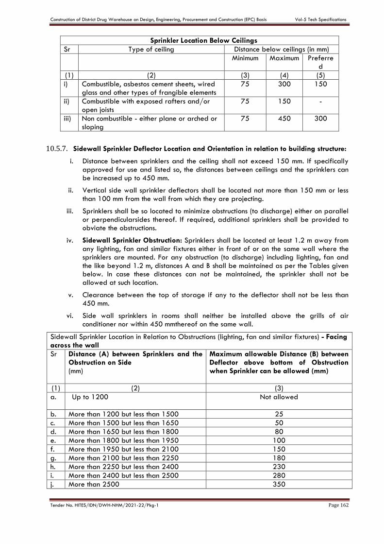
Construction of District Drug Warehouse on Design, Engineering, Procurement and Construction (EPC) Basis Vol-5 Tech Specifications
Tender No. HITES/IDN/DWH-NHM/2021-22/Pkg-1 Page 162
Sprinkler Location Below Ceilings
Sr Type of ceiling Distance below ceilings (in mm)
Minimum Maximum Preferred
(1) (2) (3) (4) (5)
i) Combustible, asbestos cement sheets, wired glass and other types of frangible elements
75 300 150
ii) Combustible with exposed rafters and/or open joists
75 150 -
iii) Non combustible - either plane or arched or sloping
75 450 300
10.5.7. Sidewall Sprinkler Deflector Location and Orientation in relation to building structure:
i. Distance between sprinklers and the ceiling shall not exceed 150 mm. If specifically approved for use and listed so, the distances between ceilings and the sprinklers can be increased up to 450 mm.
ii. Vertical side wall sprinkler deflectors shall be located not more than 150 mm or less than 100 mm from the wall from which they are projecting.
iii. Sprinklers shall be so located to minimize obstructions (to discharge) either on parallel or perpendicularsides thereof. If required, additional sprinklers shall be provided to obviate the obstructions.
iv. Sidewall Sprinkler Obstruction: Sprinklers shall be located at least 1.2 m away from any lighting, fan and similar fixtures either in front of or on the same wall where the sprinklers are mounted. For any obstruction (to discharge) including lighting, fan and the like beyond 1.2 m, distances A and B shall be maintained as per the Tables given below. In case these distances can not be maintained, the sprinkler shall not be allowed at such location.
v. Clearance between the top of storage if any to the deflector shall not be less than 450 mm.
vi. Side wall sprinklers in rooms shall neither be installed above the grills of air conditioner nor within 450 mmthereof on the same wall.
Sidewall Sprinkler Location in Relation to Obstructions (lighting, fan and similar fixtures) - Facing across the wall
Sr Distance (A) between Sprinklers and the Obstruction on Side (mm)
Maximum allowable Distance (B) between Deflector above bottom of Obstruction when Sprinkler can be allowed (mm)
(1) (2) (3)
a. Up to 1200
Not allowed
b. More than 1200 but less than 1500 25
c. More than 1500 but less than 1650 50
d. More than 1650 but less than 1800 80
e. More than 1800 but less than 1950 100
f. More than 1950 but less than 2100 150
g. More than 2100 but less than 2250 180
h. More than 2250 but less than 2400 230
i. More than 2400 but less than 2500 280
j. More than 2500 350
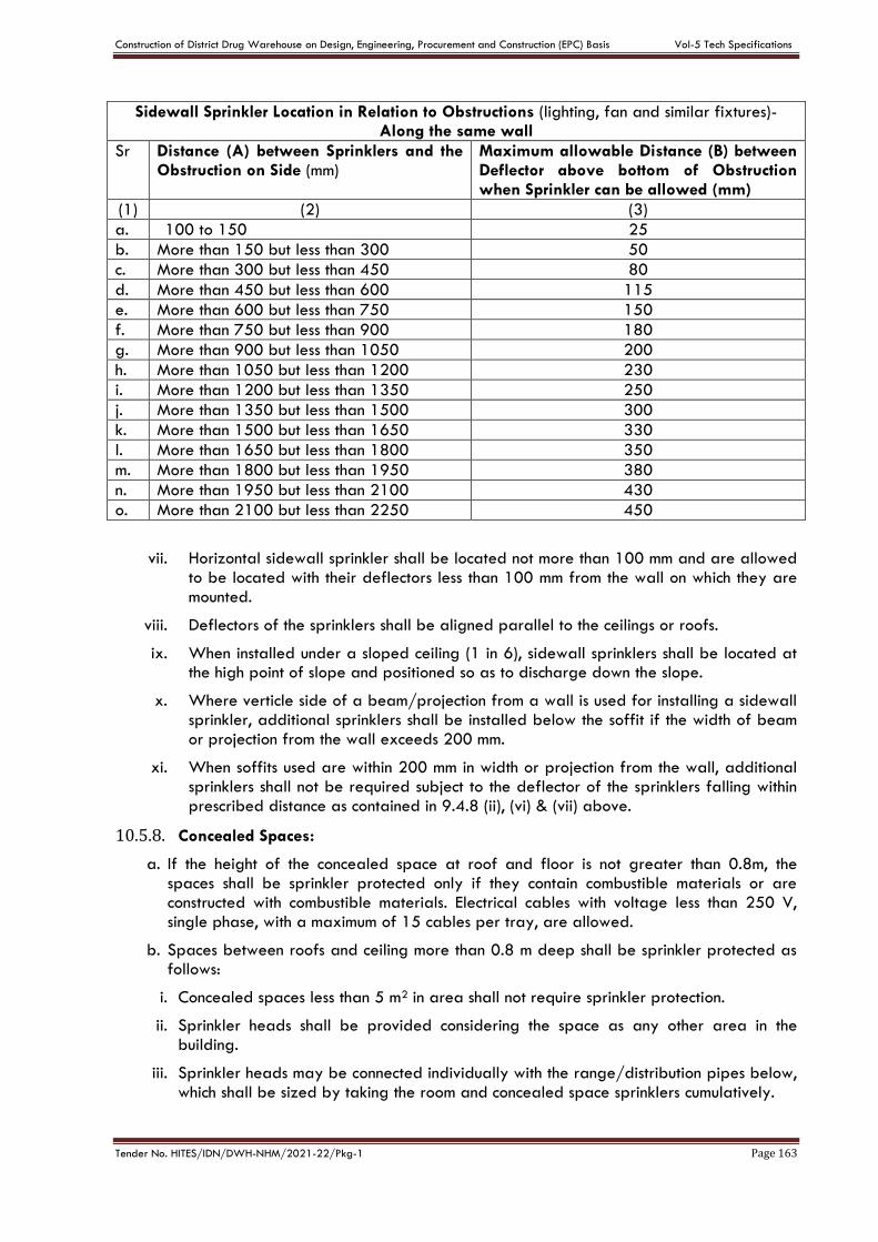
Construction of District Drug Warehouse on Design, Engineering, Procurement and Construction (EPC) Basis Vol-5 Tech Specifications
Tender No. HITES/IDN/DWH-NHM/2021-22/Pkg-1 Page 163
Sidewall Sprinkler Location in Relation to Obstructions (lighting, fan and similar fixtures)-Along the same wall
Sr Distance (A) between Sprinklers and the Obstruction on Side (mm)
Maximum allowable Distance (B) between Deflector above bottom of Obstruction when Sprinkler can be allowed (mm)
(1) (2) (3)
a. 100 to 150
25
b. More than 150 but less than 300 50
c. More than 300 but less than 450 80
d. More than 450 but less than 600 115
e. More than 600 but less than 750 150
f. More than 750 but less than 900 180
g. More than 900 but less than 1050 200
h. More than 1050 but less than 1200 230
i. More than 1200 but less than 1350 250
j. More than 1350 but less than 1500 300
k. More than 1500 but less than 1650 330
l. More than 1650 but less than 1800 350
m. More than 1800 but less than 1950 380
n. More than 1950 but less than 2100 430
o. More than 2100 but less than 2250 450
vii. Horizontal sidewall sprinkler shall be located not more than 100 mm and are allowed to be located with their deflectors less than 100 mm from the wall on which they are mounted.
viii. Deflectors of the sprinklers shall be aligned parallel to the ceilings or roofs.
ix. When installed under a sloped ceiling (1 in 6), sidewall sprinklers shall be located at the high point of slope and positioned so as to discharge down the slope.
x. Where verticle side of a beam/projection from a wall is used for installing a sidewall sprinkler, additional sprinklers shall be installed below the soffit if the width of beam or projection from the wall exceeds 200 mm.
xi. When soffits used are within 200 mm in width or projection from the wall, additional sprinklers shall not be required subject to the deflector of the sprinklers falling within prescribed distance as contained in 9.4.8 (ii), (vi) & (vii) above.
10.5.8. Concealed Spaces:
a. If the height of the concealed space at roof and floor is not greater than 0.8m, the spaces shall be sprinkler protected only if they contain combustible materials or are constructed with combustible materials. Electrical cables with voltage less than 250 V, single phase, with a maximum of 15 cables per tray, are allowed.
b. Spaces between roofs and ceiling more than 0.8 m deep shall be sprinkler protected as follows:
i. Concealed spaces less than 5 m2 in area shall not require sprinkler protection.
ii. Sprinkler heads shall be provided considering the space as any other area in the building.
iii. Sprinkler heads may be connected individually with the range/distribution pipes below, which shall be sized by taking the room and concealed space sprinklers cumulatively.
Construction of District Drug Warehouse on Design, Engineering, Procurement and Construction (EPC) Basis Vol-5 Tech Specifications
Tender No. HITES/IDN/DWH-NHM/2021-22/Pkg-1 Page 164
iv. Sprinkler heads for concealed space and for the room may be connected with separate range/distribution pipes connected, with common feed pipe. The common feed pipes shall be not less than 65 mm diameter.
10.5.9. Obstruction below Sprinklers: Sprinklers shall be fitted under the following types of obstruction which are either:
a. more than 0.8 m wide and less than 150 mm from the adjacent walls or partitions OR
b. More than 1 m wide.
10.5.10. Pipe Sizing and Design: Sprinkler heads located as per above norms shall be connected with pipe lines permanently charged with water. Depending upon location of sprinkler heads and site conditions, sprinkler heads may be connected with range and distribution pipes.
The pipes connecting the sprinkler heads are to be sized depending upon number of sprinkler heads and arrangement of their connection. The main elements of a sprinkler installation shall be provided as per norms. Various pipes connecting the sprinkler heads are termed as below:
a. Range Pipe
b. Distribution Pipe
c. Main Distribution Pipe
d. Riser
Sizes of pipes are to be calculated from various tables and hydraulic calculations given in IS: 15105.
Pipe sizes shall be determined using one of the following methods:
a. Pre-calculated system: applicable only where light and ordinary occupancies where the aggregate floor plate area (in one or more floors combined) is 5000 m2 or less (except where gridded or looped layouts are used). Pre-calculated pipework is applicable only to the extensions of old pre-calculated systems.
b. Fully calculated system: applicable for
i. Light and ordinary occupancies where the aggregate floor plate area (in one or more floors combined) exceeds 5000 m2.
ii. High hazard occupancies,
iii. Storage occupancies, and
iv. All occupancies where conventional and special sprinklers are used like ESFR, LD, EC, intermediate, etc.
Some guidelines relating to pre-calculated system are given below:
a. Pipe less than 25 mm diameter is not to be used.
b. There shall not be more than 6(Six) sprinklers in any range.
c. Range and distribution pipe nominal sizes shall be selected from Tables as given below:
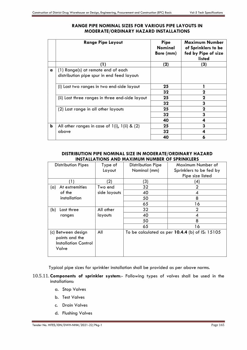
Construction of District Drug Warehouse on Design, Engineering, Procurement and Construction (EPC) Basis Vol-5 Tech Specifications
Tender No. HITES/IDN/DWH-NHM/2021-22/Pkg-1 Page 165
RANGE PIPE NOMINAL SIZES FOR VARIOUS PIPE LAYOUTS IN MODERATE/ORDINARY HAZARD INSTALLATIONS
Range Pipe Layout
Pipe Nominal
Bore (mm)
Maximum Number of Sprinklers to be fed by Pipe of size
listed
(1) (2) (3)
a (1) Range(s) at remote end of each distribution pipe spur in end feed layout:
(i) Last two ranges in two end-side layout
25 1
32 2
(ii) Last three ranges in three end-side layout
25 2
32 3
(2) Last range in all other layouts
25 2
32 3
40 4
b All other ranges in case of 1(i), 1(ii) & (2) above
25 3
32 4
40 6
DISTRIBUTION PIPE NOMINAL SIZE IN MODERATE/ORDINARY HAZARD INSTALLATIONS AND MAXIMUM NUMBER OF SPRINKLERS
Distribution Pipes
Type of Layout
Distribution Pipe Nominal (mm)
Maximum Number of Sprinklers to be fed by
Pipe size listed
(1) (2) (3) (4)
(a) At extremities of the installation
Two end side layouts
32 2
40 4
50 8
65 16
(b) Last three ranges
All other layouts
32 2
40 4
50 8
65 16
(c) Between design points and the Installation Control Valve
All To be calculated as per 10.4.4 (b) of IS: 15105
Typical pipe sizes for sprinkler installation shall be provided as per above norms.
10.5.11. Components of sprinkler system:- Following types of valves shall be used in the installations:
a. Stop Valves
b. Test Valves
c. Drain Valves
d. Flushing Valves
Construction of District Drug Warehouse on Design, Engineering, Procurement and Construction (EPC) Basis Vol-5 Tech Specifications
Tender No. HITES/IDN/DWH-NHM/2021-22/Pkg-1 Page 166
e. Check Valves
f. Installation Control Valves
g. Pre action valves
h. Subsidiary valves
The location of above valves shall be as under:
10.5.12. Test Valve: For testing hydraulic alarm or electric alarm by drawing water from downstream side, test valve shall be connected with downstream of the water flow alarm.
10.5.13. Drain Valve: For drainage of system, drain valve 50 mm diameter shall be provided down stream of Installation Control Valve or any subsidiary stop valve. A common valve can perform the functions of test and drain. The outlet shall be connected with a 50 mm diameter G.I. drain pipe along with riser pipes.
10.5.14. Flushing Valve:- If the water used for sprinkler is not potable, flushing valves shall be provided at the end of a distribution pipe. The valve size shall be same as distribution pipe. Valve outlet shall be fitted with a brass plug and extended to not more than 3 m above floor.
10.5.15. Check Valve: Check valve shall be provided where more than one water supply is available and same shall be fitted on each water supply pipe.
10.5.16. Subsidiary Stop Valve:- Subsidiary stop valve which shall be of the same diameter as the pipe line in which they are fitted shall be provided to control water supply to sprinklers of highly sensitive areas like computer rooms.
10.5.17. Installation Control Valve (ICV): A sprinkler installation shall be fitted with a suitable Installation Control Valve to control the water supply to the installation. The valve set shall comprise of:
a. A main stop valve.
b. An alarm valve.
c. A water motor alarm.
The alarm valve shall be fitted immediately downstream of the main stop valve of each building/block and before any connection is taken off to supply any part of the installation. The Installation Control Valve shall be placed externally in the vicinity of the main entrance of the building protected at an easily accessible place so that the alarm bell sound is heard by the inhabitants/passer-by. The valve shall be secured open by a pad locked or rivetted strap and protected against impact damage.
If there are genuine constraints in locating the Installation Control Valve outside the buildings, this may be located inside the building in the vicinity of main entrance (subject to approval of authorities concerned). Installation Control Valve in such cases, shall be located away from any exposure to damage and personnel shall be normally available in the vicinity of the location to get alerted by alarm operation. Also, electrically operated sirens interfaced with the opening of the alarm valve of ICV, shall be provided outside the building. In no case, Installation Control Valve shall be provided inside basement or inside pump room.
A plan of the risk with the position of Installation Control Valve shall be placed in a conspicuous location. A location plate shall be fixed near the Installation Control Valve bearing the following words SPRINKLER ALARM VALVE in raised letters.
10.5.18. Water Motor Alarm: Water motor alarm shall be provided very close to the alarm valve. Strainer shall be fitted between the alarm valve and the motor nozzle
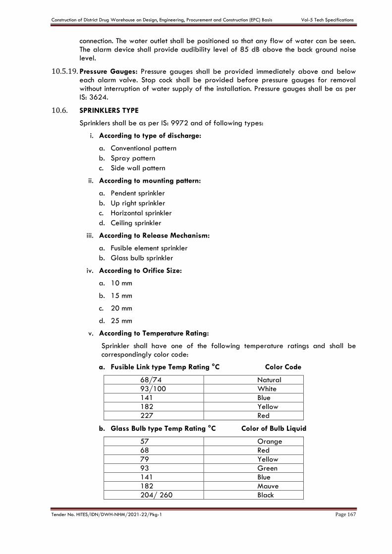
Construction of District Drug Warehouse on Design, Engineering, Procurement and Construction (EPC) Basis Vol-5 Tech Specifications
Tender No. HITES/IDN/DWH-NHM/2021-22/Pkg-1 Page 167
connection. The water outlet shall be positioned so that any flow of water can be seen. The alarm device shall provide audibility level of 85 dB above the back ground noise IeveI.
10.5.19. Pressure Gauges: Pressure gauges shall be provided immediately above and below each alarm valve. Stop cock shall be provided before pressure gauges for removal without interruption of water supply of the installation. Pressure gauges shall be as per IS: 3624.
10.6. SPRINKLERS TYPE
Sprinklers shall be as per IS: 9972 and of following types:
i. According to type of discharge:
a. Conventional pattern
b. Spray pattern
c. Side wall pattern
ii. According to mounting pattern:
a. Pendent sprinkler
b. Up right sprinkler
c. Horizontal sprinkler
d. Ceiling sprinkler
iii. According to Release Mechanism:
a. Fusible element sprinkler
b. Glass bulb sprinkler
iv. According to Orifice Size:
a. 10 mm
b. 15 mm
c. 20 mm
d. 25 mm
v. According to Temperature Rating:
Sprinkler shall have one of the following temperature ratings and shall be correspondingly color code:
a. Fusible Link type Temp Rating °C Color Code
68/74 Natural
93/100 White
141 Blue
182 Yellow
227 Red
b. Glass Bulb type Temp Rating °C Color of Bulb Liquid
57 Orange
68 Red
79 Yellow
93 Green
141 Blue
182 Mauve
204/ 260 Black
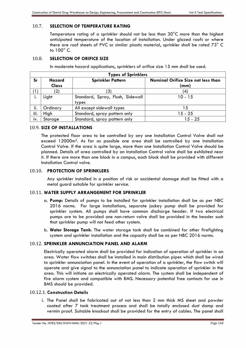
Construction of District Drug Warehouse on Design, Engineering, Procurement and Construction (EPC) Basis Vol-5 Tech Specifications
Tender No. HITES/IDN/DWH-NHM/2021-22/Pkg-1 Page 168
10.7. SELECTION OF TEMPERATURE RATING
Temperature rating of a sprinkler should not be less than 30°C more than the highest anticipated temperature of the location of installation. Under glazed roofs or where there are roof sheets of PVC or similar plastic material, sprinkler shall be rated 73° C to 100° C.
10.8. SELECTION OF ORIFICE SIZE
In moderate hazard applications, sprinklers of orifice size 15 mm shall be used.
Types of Sprinklers
Sr Hazard Class
Sprinkler Pattern Nominal Orifice Size not less than (mm)
(1) (2) (3) (4)
i. Light Standard, Spray, Flush, Sidewall types
10 - 15
ii. Ordinary All except sidewall types 15
iii. High Standard, spray pattern only 15 - 25
iv. Storage Standard, spray pattern only 15 - 25
10.9. SIZE OF INSTALLATIONS
The protected floor area to be controlled by any one Installation Control Valve shall not exceed 12000m2. As far as possible one area shall be controlled by one Installation Control Valve. If the area is quite large, more than one Installation Control Valve should be planned. Details of area controlled by an Installation Control valve shall be exhibited near it. If there are more than one block in a campus, each block shall be provided with different Installation Control valve.
10.10. PROTECTION OF SPRINKLERS
Any sprinkler installed in a position of risk or accidental damage shall be fitted with a metal guard suitable for sprinkler service.
10.11. WATER SUPPLY ARRANGEMENT FOR SPRINKLER
a. Pump: Details of pumps to be installed for sprinkler installation shall be as per NBC 2016 norms. For large installations, separate jockey pump shall be provided for sprinkler system. All pumps shall have common discharge header. If two electrical pumps are to be provided one non-return valve shall be provided in the header such that sprinkler pump will not feed other system.
b. Water Storage Tank: The water storage tank shall be combined for other firefighting system and sprinkler installation and the capacity shall be as per NBC 2016 norms.
10.12. SPRINKLER ANNUNCIATION PANEL AND ALARM
Electrically operated alarm shall be provided for indication of operation of sprinkler in an area. Water flow switches shall be installed in main distribution pipes which shall be wired to sprinkler annunciation panel. In the event of operation of a sprinkler, the flow switch will operate and give signal to the annunciation panel to indicate operation of sprinkler in the area. This will initiate an electrically operated alarm. The system shall be independent of fire alarm system and compatible with BMS. Necessary potential free contacts for use in BMS should be provided.
10.12.1. Construction Details
i. The Panel shall be fabricated out of not less than 2 mm thick MS sheet and powder coated after 7 tank treatment process and shall be totally enclosed dust damp and vermin proof. Suitable knockout shall be provided for the entry of cables. The panel shall
Construction of District Drug Warehouse on Design, Engineering, Procurement and Construction (EPC) Basis Vol-5 Tech Specifications
Tender No. HITES/IDN/DWH-NHM/2021-22/Pkg-1 Page 169
be designed such that the equipment for power supply, battery charging are housed in independent compartments. Sealed maintenance free batteries shall also be accommodated inside the panel.
ii. Indicating lamps control switches, buttons and fuses shall be suitably located in the front and properly labeled.
iii. The indicating lamps shall be LED type of following colors. The flow switch operation conditions shall be indicated by twin lamps.
a. Red to indicate flow switch operation.
b. Amber to indicate fault condition.
c. Green to indicate healthy condition.
iv. The test buttons to test the indication lamps shall be provided.
v. The panel control shall be microprocessor type.
vi. The primary function of the panel shall be to respond automatically to the operation of one or more flow switches to give alarm and to indicate area/areas where the device has activated. The operation of one or more flow switches shall result in simultaneous alarm given by the following:
a. External alarm hooter(s) (provided outside the building to be protected).
b. A visible indication on panel.
c. Audible alarm on panel itself (common for all zones)
vii. The panel shall indicate the fault within the system and immediate fault warning shall be given by an audible and visible signal on the panel in case of open circuit, short circuit and earth fault in cable between flow switch and annunciation panel.
viii. The panel shall be complete with mimic diagram for the areas covered by different flow switches. The layout of mimic diagram shall be got approved from Engineer- in-Charge.
ix. Battery backup with trickle cum boost charger shall be provided for operation of the system. Indication of mains failure and the state of charge of the batteries shall be provided. The batteries shall be sealed maintenance free. The capacity of the battery shall be 12 Volt, 2 Nos. 24 Ah each. All standard accessories shall be provided.
10.13. INSTALLATION:
The installation shall be carried out as per norms specified in relevant paras above. Following additional points are to be taken care for sprinkler installations:
a. For fixing sprinkler heads, 15 mm diameter M.S. Socket is to be welded to range pipes at the locations as per drawings. Dead plug shall be fixed in the socket.
b. If sprinkler head is to be provided away from range pipe, M.S. Pipe nipple of suitable size be used to extend the sprinkler head and socket is welded at desired location.
c. After completion of work in sections, pressure testing at 7.5 kgf/cm2 pressure shall be carried out for 24 hours.
d. After completion of the entire work, pressure testing of entire pipe work shall be carried out for 24 hours at a pressure of 7.5 kgf/cm2. The drop of pressure up to 0.5 kgf/cm2 shall be accepted.
e. The lines shall be flushed before completion of building work so that any foreign matter which might have entered the system is taken out. The pressurization pump (Jockey Pump) should be operated and valves opened at different locations.
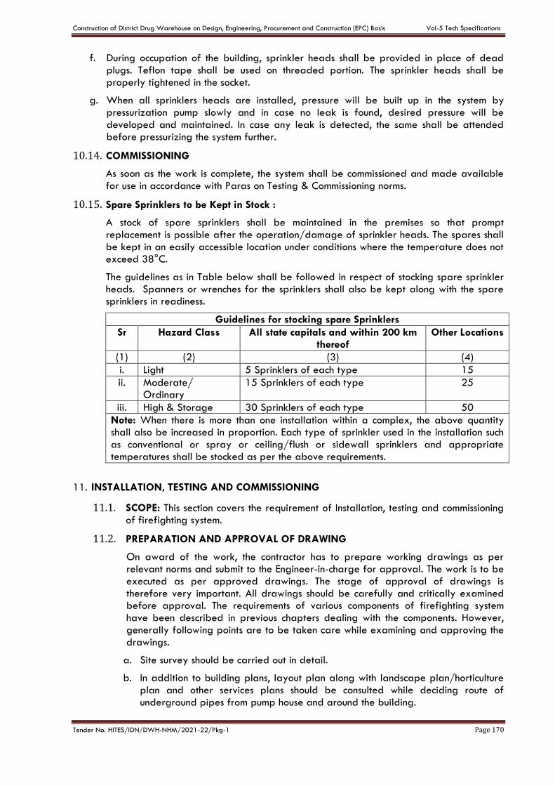
Construction of District Drug Warehouse on Design, Engineering, Procurement and Construction (EPC) Basis Vol-5 Tech Specifications
Tender No. HITES/IDN/DWH-NHM/2021-22/Pkg-1 Page 170
f. During occupation of the building, sprinkler heads shall be provided in place of dead plugs. Teflon tape shall be used on threaded portion. The sprinkler heads shall be properly tightened in the socket.
g. When all sprinklers heads are installed, pressure will be built up in the system by pressurization pump slowly and in case no leak is found, desired pressure will be developed and maintained. In case any leak is detected, the same shall be attended before pressurizing the system further.
10.14. COMMISSIONING
As soon as the work is complete, the system shall be commissioned and made available for use in accordance with Paras on Testing & Commissioning norms.
10.15. Spare Sprinklers to be Kept in Stock :
A stock of spare sprinklers shall be maintained in the premises so that prompt replacement is possible after the operation/damage of sprinkler heads. The spares shall be kept in an easily accessible location under conditions where the temperature does not exceed 38°C.
The guidelines as in Table below shall be followed in respect of stocking spare sprinkler heads. Spanners or wrenches for the sprinklers shall also be kept along with the spare sprinklers in readiness.
Guidelines for stocking spare Sprinklers
Sr Hazard Class All state capitals and within 200 km thereof
Other Locations
(1) (2) (3) (4)
i. Light 5 Sprinklers of each type 15
ii. Moderate/ Ordinary
15 Sprinklers of each type 25
iii. High & Storage 30 Sprinklers of each type 50
Note: When there is more than one installation within a complex, the above quantity shall also be increased in proportion. Each type of sprinkler used in the installation such as conventional or spray or ceiling/flush or sidewall sprinklers and appropriate temperatures shall be stocked as per the above requirements.
11. INSTALLATION, TESTING AND COMMISSIONING
11.1. SCOPE: This section covers the requirement of Installation, testing and commissioning of firefighting system.
11.2. PREPARATION AND APPROVAL OF DRAWING
On award of the work, the contractor has to prepare working drawings as per relevant norms and submit to the Engineer-in-charge for approval. The work is to be executed as per approved drawings. The stage of approval of drawings is therefore very important. All drawings should be carefully and critically examined before approval. The requirements of various components of firefighting system have been described in previous chapters dealing with the components. However, generally following points are to be taken care while examining and approving the drawings.
a. Site survey should be carried out in detail.
b. In addition to building plans, layout plan along with landscape plan/horticulture plan and other services plans should be consulted while deciding route of underground pipes from pump house and around the building.
Construction of District Drug Warehouse on Design, Engineering, Procurement and Construction (EPC) Basis Vol-5 Tech Specifications
Tender No. HITES/IDN/DWH-NHM/2021-22/Pkg-1 Page 171
c. As far as possible, underground pipe are not to be laid under road, pavement, building and long open spaces. The locations along road, foot path in earth may be preferred.
d. The location of yard hydrants, fire service inlet and fire service connection shall be decided based on consideration of norms in relevant Paras. However necessary adjustments are to be made so that these components do not become hindrance in vehicular movement and entrance to the building. Requirement of other building services are also to be given due consideration. Symmetry should be maintained for aesthetic considerations.
e. Pipe sizes shall be decided in accordance with provision of relevant Paras.
f. Pump House: The layout of equipment in pump house is very important from operation and maintenance considerations. The requirement of pumps and engine have been described in previous Paras. In case other equipment i.e. water supply pumps etc. are to be installed in the same pump house, sufficient space shall be left for them as well. The dimensioned foundation drawing of pumps should be available for marking in the pump room layout. The layout is to be prepared in such a way that it should be possible to maintain any equipment without disturbing the adjoining equipment. Electrical panels are to be installed at a location which is easily accessible near the entrance to the pump house and there should be no possibility of water dripping over or near the electrical panel. Layout Drawings of fire pump house shall be prepared & submitted for approval of Engineer-In-Charge.
g. Terrace Pumps: The location of pumps and terrace pipe may be decided keeping in view location of terrace tanks for firefighting and other services. The pipe line should not cause undue hindrance for movement of maintenance personnel at the terrace.
h. Electrical Panel: Complete wiring drawing, layout etc. will be examined to ensure that provisions of agreement are incorporated in the drawing. Sizes of various panel and mounting arrangement may be decided keeping in view ease of operation and aesthetic consideration as well.
11.3. INSTALLATION: The requirements of installation of various components have been described in previous chapters. However, following precautions are to be taken during execution of the work.
i. The pump and motor/engine are to be perfectly aligned on the base plate so that there is no vibration during operation. All nuts, bolts, washers shall be of adequate size and galvanized.
ii. The pipe supports should be decided in a way that the weight of pipes and valves are not transferred to the pumps and supports do not cause hindrance in movement inside the pump house. As far as possible, floor supports may be provided in pump house.
iii. All valves shall be installed at a height and in a position that their operation by right hand is conveniently possible.
iv. All pressure gauges should be installed so that the dial is vertical and is visible while entering the pump house.
v. Electrical panels should not be installed at floor level. The panels shall be sufficiently raised above ground level. If panels are to be mounted on wall, an angle iron frame shall be provided so that at least 75 mm space is left behind the panels. The panels shall be easily approachable.
Construction of District Drug Warehouse on Design, Engineering, Procurement and Construction (EPC) Basis Vol-5 Tech Specifications
Tender No. HITES/IDN/DWH-NHM/2021-22/Pkg-1 Page 172
vi. Cable trays are to be used for laying of power and control cable inside pump house. No cable is to be laid at floor level/in trench. Cable tray layout should give neat appearance. All cable tray shall be adequately supported from the ceiling/floor.
vii. Drain pump shall be installed in the sump provided as per norms in relevant Para. The pump shall operate automatically for which water level sensor shall be provided.
viii. In no case any structural member i.e. RCC wall, column, beam and floor are to be damaged during installation. Mechanical fasteners are to be used for grouting support. U.G. tank wall is not to be used for any support. No pipe/cable is to cross the pump house below ground level. Openings above ground level are only to be used for this purpose.
ix. The engine installation work shall be carried out in accordance with the requirement of engine manufacturer and be got approved by the manufacturer or their authorized service center. The exhaust pipe should be suitably extended outside the pump house so that smoke does not effect nearby structure. Fuel tank shall be properly supported and located in a way that the same does not cause hindrance in movement in the pump house.
x. While excavating for laying of external pipes, suitable sign board/ barricading shall be provided to ensure that no person falls in the trench.
xi. The width and depth of trench shall be adequate for laying the pipe 1m below ground level.
xii. No earth or any other matter is to be allowed to enter the pipes. The ends shall be kept closed always.
xiii. The anticorrosive treatment is to be applied on the entire length laid underground in accordance with norms in relevant Paras. The treatment is not to be damaged.
xiv. Pressure testing is to be carried out in sections before filling the earth back in the trench.
xv. The earth filling is to be done in layers of 20 cm each and properly rammed so as to avoid possibility of settlement. Surplus earth/malba shall be removed from the site by the contractor.
xvi. Where pipes crossing road likely to have heavy traffic, additional protection over pipe shall be provided to ensure that pipe is not damaged. However, semi-circular RCC Pipes shall be provided over cast iron pipes at road crossings.
xvii. External hydrants and fire service connection/ inlet shall be located parallel to the nearby road/ foot path so as to give proper appearance. Foundation shall be raised from below ground level and shall be properly plastered in plumb. The hydrants shall be facing the road/ approach. There shall be no obstruction in approaching the hydrants for operation.
xviii. Risers shall be parallel to the wall and in plumb. Adequate supports shall be provided from the wall. Opening around the pipe in slab shall be filled with CC and finished with plaster.
xix. Internal hydrant shall be provided in the center and facing outside for ease of operation. Sufficient space shall be provided around the handle for operation. There shall be no hindrance in moving the first aid hose reel.
xx. Terrace pipes shall be supported on CC pedestals of adequate height. The pipe route shall be such as no hindrance is created in movement at the terrace. Pipes
Construction of District Drug Warehouse on Design, Engineering, Procurement and Construction (EPC) Basis Vol-5 Tech Specifications
Tender No. HITES/IDN/DWH-NHM/2021-22/Pkg-1 Page 173
shall be sufficiently raised above terrace. It is to be ensured that water proofing is not damaged during laying of pipes.
11.4. TESTING
a. Initial Testing
i. During laying of pipes, the same shall be subjected to 10 kgf/cm2 hydraulic pressure for a period of 24 hours, in sections.
ii. After completion of the work, all vaIves/ fittings shall be installed in position and entire system shall be tested for 24 hours at a pressure of 10 kgf/cm2. The drop of pressure up to 0.5 kgf/cm2 shall be accepted.
b. Final Testing
i. After completion, all operation checks as per norms in relevant Para shall be carried out for automatic operation of the systems. For this purpose, landing valves may be opened at different locations. The exercise shall be repeated couple of times to ensure trouble free operation of the system.
ii. Flow Test: The design flow of pumps shall be checked. The pump shall be operated after opening a number of landing valves at different locations. Design pressure is to be maintained in the pump house. Water discharge is to be measured by drop in level in UG tank for a certain period. All pumps shall be tested one by one. The flow rate shall be not less than as specified while maintaining the design pressure in pump house.
11.5. INSPECTION BY LOCAL FIRE OFFICER
After completion of the work and testing to the entire satisfaction of Engineer-in- Charge, the installation shall be offered for inspection by Chief Fire Officer or his representative. Testing as desired by the Fire Officer shall be carried out. The contractor will extend all help including manpower during testing. The observations of Chief Fire Officer shall be part of the agreement. These shall be attended by the contractor. Nothing extra shall be paid for testing as above.
11.6. COMMISSIONING
i. Flushing the System: Before commissioning, the entire system shall be flushed to ensure that any earth/ foreign matters which might have entered during installation are taken out. For this, pump may be operated and valves opened at different locations.
ii. As soon as the work is complete, the system shall be commissioned and made available for use. Requirement of firefighting installations is equally important during occupation of the building. If the building is to be occupied in part, firefighting system of building completed shall be commissioned by isolating the system of under construction portion of the building.
iii. The firefighting system shall be maintained and manned from the very first day of its commissioning.
iv. Any defects noticed during the warranty period shall be promptly attended by the contractor and availability of the system at all time is to be ensured.
11.7. TRAINING TO CLIENT’S PERSONNEL
Contractor shall provide orientation and training on Fire Fighting System to Client’s personnel deployed for this purpose. Training on all aspects of operation, maintenance and trouble shooting shall be satisfactorily provided on mutually agreed dates as per directions of Engineer-In-Charge.
Construction of District Drug Warehouse on Design, Engineering, Procurement and Construction (EPC) Basis Vol-5 Tech Specifications
Tender No. HITES/IDN/DWH-NHM/2021-22/Pkg-1 Page 174
CHAPTER -G
TECHNICAL SPECIFICATIONS- HVAC WORKS
1. GENERAL
Scope of work shall include design, engineering, supply, installation, testing & commissioning of HVAC system. All material shall be of conforming to relevant IS specifications wherever exists and subject to approval of Engineer in charge. The HVAC sytem shall be carried out strictly as per NBC -2016/ASHRAE/ISHRAE/CPWD/ ECBC latest versions.
1.1. GOOD FOR CONDTRUCTION DRAWINGS/ TECHNICAL DATA SHEETS
The contractor shall prepare and furnish all shop drawings including floor plans & Terrace, Schematic HVAC Layout/External HVAC pipe routing etc.
The manufacturing of equipment shall be commenced only after the shop drawings/GA Drawings/ technical data sheet along with pump curves are approved in writing by the Engineer. Such drawings shall be co-ordinated with other services work. These shop drawings will be approved by HITES which will be considered as base for execution of fire fighting work.
1.2. DRAWINGS & DOCUMENTS
The contractor shall submit to the Engineer, the following documents on completion of the work and before issuance of virtual completion.
a. Warranty for required equipment installed like VRV/ VRF Equipment, Pumps, Panels,
Chillers, Cooling Tower, HWG, AHU, FCU etc.
b. As Built Drawings
c. Material Test Certificates
d. Catalogues/Brochures
e. Operation and Maintenance Manuals
f. List of recommended spares and consumables
g. All approvals including technical approvals and sanctions
h. NoC from Fire authority before commencement of execution & after completion of
entire work etc.
1.3. MANUFACTURING
The responsibility for ensuring the manufacture of the equipment as per the specifications shall be solely that of the contractor. The contractor shall be responsible for selection of materials as per agreed specifications.
1.4. MAKE OF MATRIALS/MANUFACTURER’S INSTRUCTION
Only approved makes as mentioned in our approved make list of tender documents of material shall be used. The Contrcator shall furnish Technical data sheets / GA drawings of all items before placing P.O. The contractor shall get the samples of required items approved from the HITES as conveyed by E-I-C before commencing the supply. In case of any discrepancy/anomolieswrt specifications, prior intimation from Contractor to E-I-C to be given. Final decision lies with HITES for according approvals.
Any specific instruction furnished by manufacturer covering the points not mentioned in technical specifications of the tender shall be brought to the notice of E-I-C in writing for further instructions in this regard at appropriate time.
1.5. MATERIAL TESTING
The E-I-C shall have full power to get any material of work to be tested by an independent agency at contractor’s expense in order to prove the soundness and adequacy.
Construction of District Drug Warehouse on Design, Engineering, Procurement and Construction (EPC) Basis Vol-5 Tech Specifications
Tender No. HITES/IDN/DWH-NHM/2021-22/Pkg-1 Page 175
1.6. INSPECTION AND TESTING
a. All equipment shall be inspected and tested as per an agreed Quality Assurance Plan
before the same is packed and dispatched from the contractor’s works. The
contractor shall carry out tests as specified/ directed by engineer.
b. The E-I-C may, at his sole discretion, carry out inspection at different stages during
manufacturing and final testing after manufacturing.
c. Approvals or passing of any inspection by the engineer or his authorized
representative shall not, however, prejudice the right of the engineer to reject the plan
if it does not comply with the specification when erected or give complete satisfaction
in service.
1.7. TRAINING OF DEPARTMENT PERSONNEL
a. The contractor shall train the CLIENT/ HITES’s personnel to become proficient in
operating the equipment installed. Training shall be done before the expiry of the
defects liability period (one year after completion & handing over).
b. The period of training shall be adequate and mutually agreed upon by the Engineer
and contractor.
c. The CLIENT/ HITES’s personnel shall also be trained for routine maintenance work and
lubrication, overhauling, adjustments, testing, minor repairs and replacement.
d. Nothing extra shall be paid to the contractor for training CLIENT/ HITES’s personnel.
1.8. PERFORMANCE GUARANTEE
At the close of the work and before issue of final certificate of virtual completion by the engineer, the contractor shall furnish written guarantee indemnifying the CLIENT/ HITES against defective materials and workmanship for a period of one year after completion and handing over. The contractor shall hold himself fully responsible for reinstallation or replace free of cost to the CLIENT/ HITES.
a. Any defective material or equipment supplied by the contractor.
b. Any material or equipment supplied by the CLIENT/ HITES which is proved to be
damaged or destroyed as a result of defective workmanship by the contractor.
1.9. AIR COOLED SPLIT AIR CONDITIONING UNITS (ENERGY SAVING INVERTER TYPE
COMPRESSORS)
i. SCOPE
The scope of this section comprise the supply, erection, testing and commissioning of Air Cooled Split Units with inverter driven compressors conforming to these specifications and in accordance with the requirements of Drawings and Design Basic Report. The proposed unit shall meet the highest possible star rating as per BEE standards.
ii. TYPE
The Split Units shall consist of hermetically sealed compressor, motor, air cooled condenser, strip heaters, integral refrigerant piping and wiring, all mounted on a steel frame.
Indoor unit to be installed for Split Unit within building, shall be housed in insulated cabinet consisting of cooling coil, blower with motor, filter & insulated drain pan. Split unit must deliver specified capacity after taking into account loses due to piping length & site conditions.
iii. CAPACITY
The refrigeration capacity of Packaged Unit and Room Air Conditioners, split unit shall be as shown on Drawings and as per requirements.
Construction of District Drug Warehouse on Design, Engineering, Procurement and Construction (EPC) Basis Vol-5 Tech Specifications
Tender No. HITES/IDN/DWH-NHM/2021-22/Pkg-1 Page 176
iv. COMPRESSOR AND MOTOR
Compressor shall be hermetically sealed, swing type, serviceable type and shall have dual pressure stat, and an operating oil charge. The motor shall be suction gas cooled and shall be sealed against dirt and moisture. The motor shall be suitable for 415±10% / volts or 230±6 % volts, 50 Hz, A.C. supply.
v. REFRIGERANT PIPING AND CONTROLS
Refrigerant piping and fittings interconnecting compressor condenser shall be all copper and valves shall be brass / gunmetal construction. The refrigerant used shall be ozone friendly HFC or any other CFC free refrigerant.
vi. CASING
The indoor & outdoor units shall be sectionalised / cabinet construction. Indoor units shall be consisting of fan section, coil section, filter section, and drain pan. Outdoor unit shall consist of condenser coil, fan & compressor. In case of package units, the compressor shall be mounted within the indoor units and in case of split unit, the compressor shall be mounted with the outdoor units. Each section shall be constructed of thick sheet steel all welded / bolted construction, adequately reinforced with structural members and provided with sufficient access panels for proper lubrication and maintenance. Base panel shall be constructed of fabricated steel structure provided with an under frame suitably braced. Each unit shall include one piece drain pan constructed of 20 gauge galvanised sheet steel plate or stainless steel. Drain pan shall extend under coil and fan sections with drain connections. Removable panels in fan and coil sections shall provide access to all internal parts. Panels shall be internally lined with 2.5 cm thick fibreglass as per section “Insulation” for the thermal insulation and acoustic lining.
vii. FAN MOTOR AND DRIVE
Fan motor shall be suitable for 415 ± 10% volts or 230±10% volts, 50 Hz, A.C.Supply, Single phase, motors shall be provided with permanent capacitor. Motors shall be especially designed for quite operation and motor speed shall not exceed 1440 rpm.
viii. FAN
Fan wheels and housing shall be fabricated from heavy gauge steel. Fan wheels shall be of double-width, double inlet forward-curve, multi-blade type enclosed in a housing and mounted on a common shaft. Fan housing shall be made of die-formed steel sheets with stream-lined inlets to ensure smooth air flow into the fans, fan shaft bearing shall be oil/grease lubricated. All rotating parts shall be dynamically balanced individually, and the complete assembly shall be statically and hydraulically balanced. Fan speed shall not exceed 1000 rpm and maximum fan outlet velocity shall be 550 meters per minute.
ix. COOLING COIL
Cooling coils shall be of fin and tube type having aluminium fins firmly bonded to copper tubes assembled in zinc coated steel frame. Face and surface areas shall be such as to ensure rated capacity from each unit and air velocity across each coil shall not exceed 100 meters per minute. The coil shall be pitched in the unit casing for proper drainage. Each coil shall be factory-tested at 21 Kg. per sq.cm air pressure under water. Tube shall be mechanically / hydraulically expanded for minimum thermal contract resistance with fins. The no.of fins per cm. shall be 4 to 5.
x. VIBRATION ISOLATORS
The indoor and outdoor units shall be provided with ribbed rubber pad vibration isolators.
xi. PAINTING
Split units shall be factory finished with durable alkyd spray enamel. Shop coats of paint that have become marred during shipment or erection shall be cleaned off with mineral spirits, then coated with enamel paint to match the finish over the adjoining shop-painted surface.
Construction of District Drug Warehouse on Design, Engineering, Procurement and Construction (EPC) Basis Vol-5 Tech Specifications
Tender No. HITES/IDN/DWH-NHM/2021-22/Pkg-1 Page 177
xii. PERFORMANCE RATING
The unit shall be selected for the lowest operating noise level. Capacity rating and power consumption with operating points clearly indicated shall be submitted with the tenders and verified at the time of testing and commissioning of the installation.
Refrigerant should be R-4R10A(R-410a) or any other CFC free refrigerant, Noise level should be less than 40Db, with wireless remote controller LCD typewith LED panel display, with sleep mode, auto restart, auto air swing(up-down), high EER Rotary, dual protection & 3M micro protection filters.
2. INLINE & PROPELLER FANS
1. SCOPE
The scope of this section comprises the supply, installation, testing and commissioning of centrifugal and inline fans conforming to these specifications and in accordance with the requirement of drawings and DBR.
2. TYPE
Centrifugal and inline fans shall be of type as indicated in drawings and in DBR.
3. INLINE FANS
Inline fan shall incorporate SISW direct driven centrifugal fan with TEFC (IP-44) motor. The fan assembly shall be enclosed in a sheet metal housing of 22 gauge GSS and with necessary inspection cover with proper gasket assembly. The fan material shall be galvanized sheet steel. Flanges shall be provided on both sides of inline fan to facilitate easy connection. Flexible anti-vibration joints shall be provided to arrest vibration being transferred to other equipments connected to inline fan. Motor shall be single phase/three phase as per duty conditions.
All single-phase fans shall be provided with speed regulators while all three phase fans shall be provided with opposed blade dampers in GSS construction at fan outlet for air balancing.
4. PROPELLER FANS
Propeller fans shall be direct driven, three or four blade type mounted on a steel mounting plate with orifice ring.
Mounting plate shall be of steel construction, square with streamlined venturi inlet coated with baked enamel paint. Mounting plate shall be of standard size, constructed of 12 to 16 gaugesteel sheet depending upon the fan size. Orifice ring shall be correctly formed by spinning or stamping to provide easy passage of air without turbulence and to direct the air stream.
Fan blades shall be constructed of aluminum or glass reinforced polypropylene. Fan hub shall be of heavy welded steel construction with blades bolted to the hub fan blades and assembly shall be statically and dynamically balanced
Shaft shall be of steel accurately ground and shall not pass through first critical speed through entire range of specified fan speed.
Motor shall be standard permanent split capacitor of shaded pole for small sizes, totally enclosed with pre-lubricated sleeve or ball bearings, designed for a quiet operation with a maximum speed of 1000 RPM for fans 60 cm dia. or larger and 1440 RPM for fans 45 cm dia. and smaller. Motors for larger fans shall be suitable for 415 ± 6% volts. 50 cycle 3-phase power supply and for smaller fans shall be suitable for 220 ± 6% volts, 50 cycles single-phase power supply. Motors shall be suitable for horizontal or vertical service as indicated in drawings and as per requirements.
Propeller fans shall be provided with following accessories: -
a. Wire guard and bird-screen
b. Gravity louvers at outlet
c. Regulator for controlling fan speed for single-phase fan motor.
Construction of District Drug Warehouse on Design, Engineering, Procurement and Construction (EPC) Basis Vol-5 Tech Specifications
Tender No. HITES/IDN/DWH-NHM/2021-22/Pkg-1 Page 178
d. Single-phase preventors for 3 phase fans.
e. Wiring between regulator and fan motor including termination at both ends.
5. PERFORMANCE DATA
All fans shall be selected for the lowest operating noise level. Capacity rating, power consumption with operating points clearly indicated shall be submitted and verified at the time of testing and commissioning of installation.
6. TESTING
Capacity of all fans shall be measured by an anemometer. Measured airflow capacities shall conform to the specified capacities and quoted ratings, power consumption shall be computed from measurements of incoming voltage and incoming current.
The Fans shall be preferably AMCA certified. Also, it should be UL & FM/EN approved.
3. FAN SECTIONS
1. SCOPE
The scope of this section comprises the supply, installation, testing and commissioning of ventilation fan sections conforming to these specifications and in accordance with the requirement of drawings and DBR. Fan Outlet velocity shall not exceed 610 meters per minute.
2. TYPE
Ventilation fan sections shall be complete with Centrifugal Fans, belt driven fans complete with motor drive and housing with weatherproof cowl.
3. UNIT CONSTRUCTION
i. Housing
The housing shall be fabricated out of 16 gauge steel sheet and shall have flange to be connected to duct. The discharge cowl shall be hinged along one edge for easy access to motor and drive, for inspection and maintenance. The entire assembly shall be weatherproof and provided with 18 gauge galvanized steel mesh bird screen of 6 mm size on all discharge cowls around the outlet areas. Shaft shall be constructed of steel, turned, ground & polished.
ii. Fan
Fan shall be forward / backward inclined wheel type designed for maximum efficiency, minimum turbulence and quiet operation. Fan shall be statically and dynamically balanced. Fan shall conform to specifications as given in specification No.SPC/CF – PF/01
iii. Motor
Motors shall be suitable for 415 +- 10% volts, 50 CPS, 3 Phase AC supply totally enclosed fan cooled motor provided with class ‘F’ insulation& IE-3 class efficiency. Motor shall be designed for quiet operation and motor speed shall not exceed 1440 RPM. Drive to fan shall be through belts.
iv. Back draft Damper
Where called for in DBR the ventilation fan section shall be provided with a rattle free back draft damper to prevent air from re-entering the fan when fan is not in operation, thus sealing completely in closed position. Damper shall be chatterproof under all conditions.
4. VIBRATION ISOLATION
The motor and fan assembly shall be isolated from base through Dunlop/Resistoflex vibration isolators.
Construction of District Drug Warehouse on Design, Engineering, Procurement and Construction (EPC) Basis Vol-5 Tech Specifications
Tender No. HITES/IDN/DWH-NHM/2021-22/Pkg-1 Page 179
5. PERFORMANCE DATA
All fans shall be selected for the lowest operating noise level. Capacity rating, power consumption with operating points clearly indicated shall be submitted and verified at the time of testing and commissioning of installation.
6. TESTING
Capacity of all fans shall be measured by an anemometer. Measured airflow capacities shall conform to the specified capacities and quoted ratings, power consumption shall be computed from measurements of incoming voltage and incoming current.
The Fans shall be AMCA certified. Also, it should be UL & FM/EN approved. Sound attenuators with/without baffles to reduce noise generated at source itself wherever feasible.
4. AXIAL FLOW FANS
1. SCOPE
This section covers the technical requirements for manufacture, testing at works, delivery at site, testing after installation, commissioning of axial flow fan equipments for ventilation and exhaust system. Their location shall be as given in DBR and drawings.
The fans shall be complete with all the accessories required for proper installation and performance consisting mainly of the following: -
a. Suction and discharge side flanges and counter flanges suitably drilled, complete with
bolts & nuts, direct driving electric motor, suspension hangers (for ceiling hung fans only)
for vibration isolation (rubber in shear type). Any structural steel and hardware required
for assembly, installation, supporting of fan or accessories. 2 mm thick flexible connectors,
fire resistant type at suction and discharge end, Foundation bolts and vibration isolators (in
case of floor mounting only).
b. Gravity louvers
2. APPLICABLE SPECIFICATIONS STANDARDS AND CODES.
Documents listed below should be read along with the technical data given in the DBR and shall be applicable to the material, manufacture, testing and installation of axial flow fans and accessories.
a. I.S.S.: 3588 – 1986; specifications for electric axial flow fans.
b. ANSI/ASHRAE: standard 51
c. ANSI/AMCA: standard 210 & 300 for preparing performance curves, charts and testing
of fans for air and sound performnace
d. IS-2312 – Propeller type A.C ventilation fans
e. BS – 848/ ACMA Tested – Methods of performance test for fans
3. DESIGN & MANUFACTURING:
i. Fan and Components
a. The fan shall be designed to handle the quantity of air against the static pressure and at
conditions indicated in the technical data. The fan shall have 70% efficiency at
operating conditions and shall have performance characteristics to match the approved
performance curves.
b. The unit shall be factory built to the highest standards to ensure rigidity, maximum
mechanical and electrical reliability, quite, stable and vibration free operation at the
prescribed conditions of flow, static and speed.
Construction of District Drug Warehouse on Design, Engineering, Procurement and Construction (EPC) Basis Vol-5 Tech Specifications
Tender No. HITES/IDN/DWH-NHM/2021-22/Pkg-1 Page 180
c. The casing shall be fabricated from heavy gauge sheet steel with suction and discharge
ends flanged and complete with counter flanges, G.I. nuts and bolts. The flanges and
counter flanges shall be matched and drilled suitably to receive flexible PVC connections.
An inspection door with handle and neoprene gaskets shall be provided. Support
brackets for ceiling suspension shall be bolted to the casing for connection to hanger
bolts.
ii. Impeller & Blades
The impeller shall be cast aluminum; aerofoil type with well-balanced blades made from cast aluminum alloy or cast steel construction.
4. DRIVE
The fan hub and blades shall be directly mounted on the shaft of a totally enclosed motor, rotor of fan motor shall be well balanced. The motor shall be TEFC, squirrel cage, IP 55 0– class H/F as per use, IE-3 class efficiency preferably and suitable for 415 +- 10% V, 50 HZ 3 phase AC power supply. The motor shall be dual speed wherever called for in DBR. The maximum motor speed shall be limited to 1450 RPM. Motor conduit box shall be mounted on exterior of fan casing and lead wires from motor to conduit box shall be protected from air stream by enclosing in a flexible metal conduit.
5. TECHNICAL SPECIFICATIONS
The firm shall submit the technical data and performance characteristics with operating points duly marked for approval prior to fabrication. The supplier shall supply the test certificates of all the fans.
6. GENERAL REQUIREMENTS
a. Static, dynamic balancing and vibration: the individual fan impeller, blades, motor shall
be statically and dynamically balanced independently. After assembly the entire fan
motor unit shall not give rise to any vibrations. The balancing shall be as per ISO: 1940
GR 6.3.
b. NOISE LEVEL: The tendered shall indicate the noise level generated by the fan/motor unit
in terms of decibel units to be measured at 3M from the unit. This shall fall in line with best
engineering standard and shall not be more than 80 db.
7. PAINTING
All fans and their accessories shall be painted with two coats of suitable enamel paint after one coat of Red Oxide primer.
8. PACKING
The fans shall be dispatched in packed condition to avoid damage during transportation to site. Transit insurance for the fans shall be included in this offer.
9. INSPECTION & TESTING
All fans shall be subjected to inspection and testing requirements as given below. The contactor shall be responsible for providing all inspection facilities and for conducting all tests at works and at site after erection. Test certificates for all fans shall be submitted, some fans at the discretion of CLIENT/ HITES may be tested at the factory in his presence.
The performance of the fan motor unit shall be tested by operating at design conditions. The following parameters will be tested vis-à-vis the approved performance curves.
a. Airflow capacity, Static head developed, BHP requirement, Vibration and noise level. The
Fans shall beAMCA certified. Also, it should be UL & FM/EN approved. Sound attenuators
with/without baffles to reduce noise generated at source itself wherever feasible.
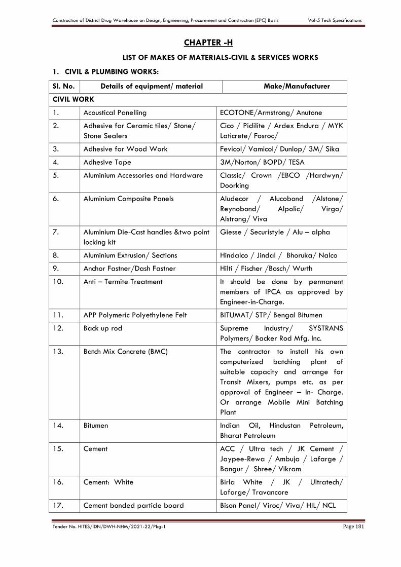
Construction of District Drug Warehouse on Design, Engineering, Procurement and Construction (EPC) Basis Vol-5 Tech Specifications
Tender No. HITES/IDN/DWH-NHM/2021-22/Pkg-1 Page 181
CHAPTER -H
LIST OF MAKES OF MATERIALS-CIVIL & SERVICES WORKS
1. CIVIL & PLUMBING WORKS:
Sl. No. Details of equipment/ material Make/Manufacturer
CIVIL WORK
1. Acoustical Panelling ECOTONE/Armstrong/ Anutone
2. Adhesive for Ceramic tiles/ Stone/
Stone Sealers
Cico / Pidilite / Ardex Endura / MYK
Laticrete/ Fosroc/
3. Adhesive for Wood Work Fevicol/ Vamicol/ Dunlop/ 3M/ Sika
4. Adhesive Tape 3M/Norton/ BOPD/ TESA
5. Aluminium Accessories and Hardware Classic/ Crown /EBCO /Hardwyn/
Doorking
6. Aluminium Composite Panels Aludecor / Alucobond /Alstone/
Reynobond/ Alpolic/ Virgo/
Alstrong/ Viva
7. Aluminium Die-Cast handles &two point
locking kit
Giesse / Securistyle / Alu – alpha
8. Aluminium Extrusion/ Sections Hindalco / Jindal / Bhoruka/ Nalco
9. Anchor Fastner/Dash Fastner Hilti / Fischer /Bosch/ Wurth
10. Anti – Termite Treatment It should be done by permanent
members of IPCA as approved by
Engineer-in-Charge.
11. APP Polymeric Polyethylene Felt BITUMAT/ STP/ Bengal Bitumen
12. Back up rod Supreme Industry/ SYSTRANS
Polymers/ Backer Rod Mfg. Inc.
13. Batch Mix Concrete (BMC) The contractor to install his own
computerized batching plant of
suitable capacity and arrange for
Transit Mixers, pumps etc. as per
approval of Engineer – In- Charge.
Or arrange Mobile Mini Batching
Plant
14. Bitumen Indian Oil, Hindustan Petroleum,
Bharat Petroleum
15. Cement ACC / Ultra tech / JK Cement /
Jaypee-Rewa / Ambuja / Lafarge /
Bangur / Shree/ Vikram
16. Cement: White Birla White / JK / Ultratech/
Lafarge/ Travancore
17. Cement bonded particle board Bison Panel/ Viroc/ Viva/ HIL/ NCL
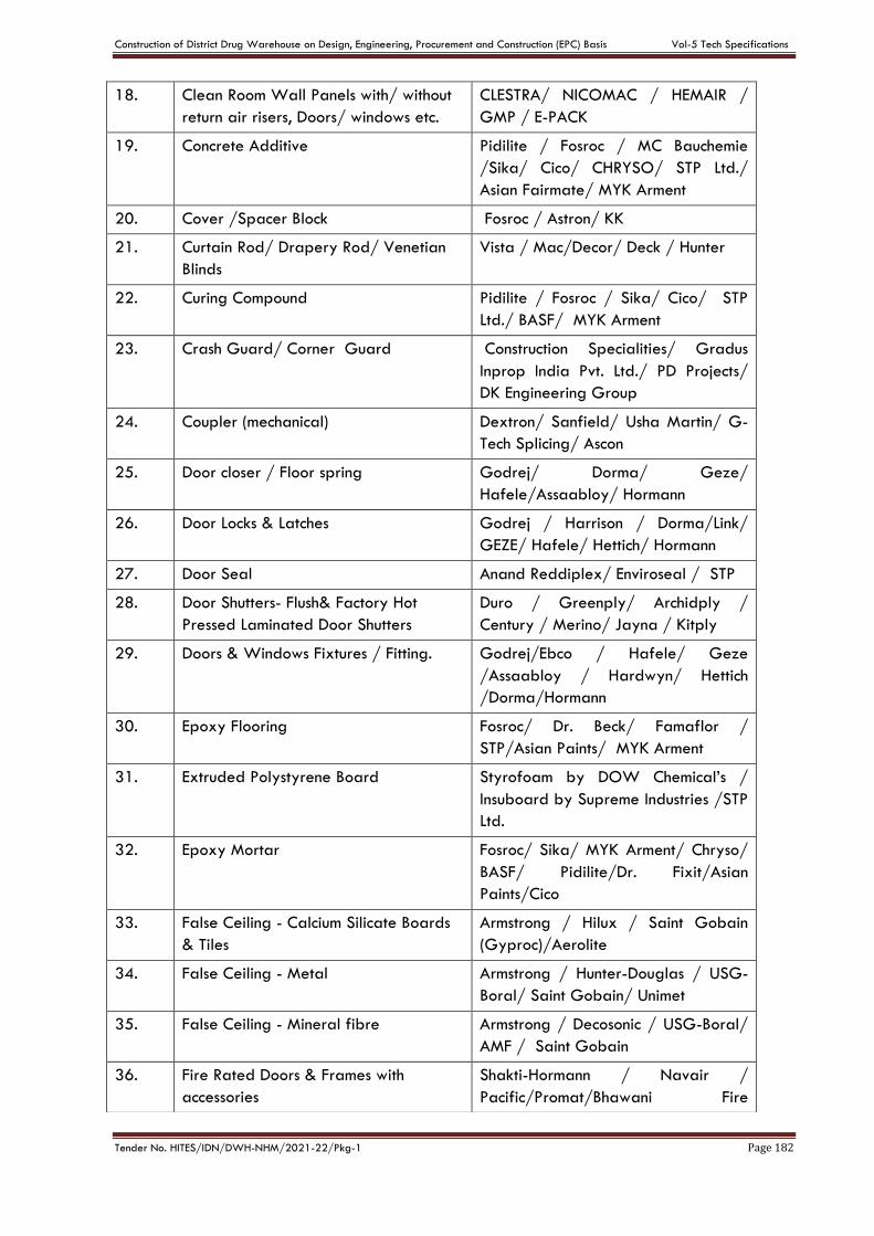
Construction of District Drug Warehouse on Design, Engineering, Procurement and Construction (EPC) Basis Vol-5 Tech Specifications
Tender No. HITES/IDN/DWH-NHM/2021-22/Pkg-1 Page 182
18. Clean Room Wall Panels with/ without
return air risers, Doors/ windows etc.
CLESTRA/ NICOMAC / HEMAIR /
GMP / E-PACK
19. Concrete Additive Pidilite / Fosroc / MC Bauchemie
/Sika/ Cico/ CHRYSO/ STP Ltd./
Asian Fairmate/ MYK Arment
20. Cover /Spacer Block Fosroc / Astron/ KK
21. Curtain Rod/ Drapery Rod/ Venetian
Blinds
Vista / Mac/Decor/ Deck / Hunter
22. Curing Compound Pidilite / Fosroc / Sika/ Cico/ STP
Ltd./ BASF/ MYK Arment
23. Crash Guard/ Corner Guard Construction Specialities/ Gradus
Inprop India Pvt. Ltd./ PD Projects/
DK Engineering Group
24. Coupler (mechanical) Dextron/ Sanfield/ Usha Martin/ G-
Tech Splicing/ Ascon
25. Door closer / Floor spring Godrej/ Dorma/ Geze/
Hafele/Assaabloy/ Hormann
26. Door Locks & Latches Godrej / Harrison / Dorma/Link/
GEZE/ Hafele/ Hettich/ Hormann
27. Door Seal Anand Reddiplex/ Enviroseal / STP
28. Door Shutters- Flush& Factory Hot
Pressed Laminated Door Shutters
Duro / Greenply/ Archidply /
Century / Merino/ Jayna / Kitply
29. Doors & Windows Fixtures / Fitting. Godrej/Ebco / Hafele/ Geze
/Assaabloy / Hardwyn/ Hettich
/Dorma/Hormann
30. Epoxy Flooring Fosroc/ Dr. Beck/ Famaflor /
STP/Asian Paints/ MYK Arment
31. Extruded Polystyrene Board Styrofoam by DOW Chemical’s /
Insuboard by Supreme Industries /STP
Ltd.
32. Epoxy Mortar Fosroc/ Sika/ MYK Arment/ Chryso/
BASF/ Pidilite/Dr. Fixit/Asian
Paints/Cico
33. False Ceiling - Calcium Silicate Boards
& Tiles
Armstrong / Hilux / Saint Gobain
(Gyproc)/Aerolite
34. False Ceiling - Metal Armstrong / Hunter-Douglas / USG-
Boral/ Saint Gobain/ Unimet
35. False Ceiling - Mineral fibre Armstrong / Decosonic / USG-Boral/
AMF / Saint Gobain
36. Fire Rated Doors & Frames with
accessories
Shakti-Hormann / Navair /
Pacific/Promat/Bhawani Fire
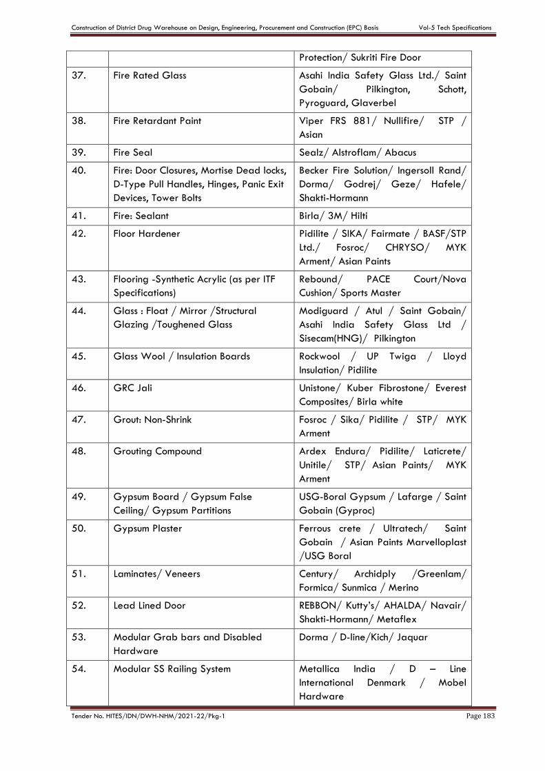
Construction of District Drug Warehouse on Design, Engineering, Procurement and Construction (EPC) Basis Vol-5 Tech Specifications
Tender No. HITES/IDN/DWH-NHM/2021-22/Pkg-1 Page 183
Protection/ Sukriti Fire Door
37. Fire Rated Glass Asahi India Safety Glass Ltd./ Saint
Gobain/ Pilkington, Schott,
Pyroguard, Glaverbel
38. Fire Retardant Paint Viper FRS 881/ Nullifire/ STP /
Asian
39. Fire Seal Sealz/ Alstroflam/ Abacus
40. Fire: Door Closures, Mortise Dead locks,
D-Type Pull Handles, Hinges, Panic Exit
Devices, Tower Bolts
Becker Fire Solution/ Ingersoll Rand/
Dorma/ Godrej/ Geze/ Hafele/
Shakti-Hormann
41. Fire: Sealant Birla/ 3M/ Hilti
42. Floor Hardener Pidilite / SIKA/ Fairmate / BASF/STP
Ltd./ Fosroc/ CHRYSO/ MYK
Arment/ Asian Paints
43. Flooring -Synthetic Acrylic (as per ITF
Specifications)
Rebound/ PACE Court/Nova
Cushion/ Sports Master
44. Glass : Float / Mirror /Structural
Glazing /Toughened Glass
Modiguard / Atul / Saint Gobain/
Asahi India Safety Glass Ltd /
Sisecam(HNG)/ Pilkington
45. Glass Wool / Insulation Boards Rockwool / UP Twiga / Lloyd
Insulation/ Pidilite
46. GRC Jali Unistone/ Kuber Fibrostone/ Everest
Composites/ Birla white
47. Grout: Non-Shrink Fosroc / Sika/ Pidilite / STP/ MYK
Arment
48. Grouting Compound Ardex Endura/ Pidilite/ Laticrete/
Unitile/ STP/ Asian Paints/ MYK
Arment
49. Gypsum Board / Gypsum False
Ceiling/ Gypsum Partitions
USG-Boral Gypsum / Lafarge / Saint
Gobain (Gyproc)
50. Gypsum Plaster Ferrous crete / Ultratech/ Saint
Gobain / Asian Paints Marvelloplast
/USG Boral
51. Laminates/ Veneers Century/ Archidply /Greenlam/
Formica/ Sunmica / Merino
52. Lead Lined Door REBBON/ Kutty’s/ AHALDA/ Navair/
Shakti-Hormann/ Metaflex
53. Modular Grab bars and Disabled
Hardware
Dorma / D-line/Kich/ Jaquar
54. Modular SS Railing System Metallica India / D – Line
International Denmark / Mobel
Hardware
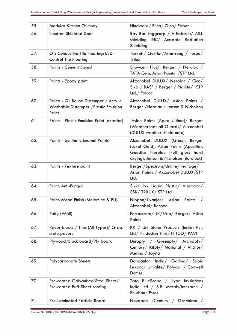
Construction of District Drug Warehouse on Design, Engineering, Procurement and Construction (EPC) Basis Vol-5 Tech Specifications
Tender No. HITES/IDN/DWH-NHM/2021-22/Pkg-1 Page 184
55. Modular Kitchen Chimney Hindware/ Elica/ Glen/ Faber
56. Neutron Shielded Door Ray-Bar Enggcorp / A-FabcoIn/ A&L
shielding INC/ Accurate Radiation
Shielding
57. OT: Conductive Tile Flooring: ESD-
Control Tile Flooring
Tarkett/ Gerflor/Armstrong / Forbo/
Trilux
58. Paints - Cement Based Snowcem Plus/, Berger / Nerolac /
TATA Cem, Asian Paints /STP Ltd.
59. Paints - Epoxy paint Akzonobel DULUX/ Nerolac / Cico/
Sika / BASF / Berger / Pidilite/ STP
Ltd./ Fosroc
60. Paints - Oil Bound Distemper / Acrylic
Washable Distemper /Plastic Emulsion
Paint
Akzonobel DULUX/ Asian Paints /
Berger /Nerolac / Jenson & Nicholson
61. Paints - Plastic Emulsion Paint (exterior) Asian Paints (Apex Ultima)/ Berger
(Weathercoat all Guard)/ Akzonobel
(DULUX weather shield max)
62. Paints - Synthetic Enamel Paints Akzonobel DULUX (Gloss), Berger
(Luxol Gold), Asian Paints (Apcolite),
Goodlas Nerolac (Full gloss hard
drying), Jenson & Nicholson (Borolock)
63. Paints - Texture paint Berger/Spectrum/Unilite/Heritage/
Asian Paints / Akzonobel DULUX/STP
Ltd.
64. Paint: Anti-Fungal Sikka by Liquid Plastic/ Viesmann/
SSK/ TRILUX/ STP Ltd.
65. Paint-Wood Finish (Melamine & PU) Nippon/Jivanjor/ Asian Paints /
Akzonobel/ Berger
66. Putty (Wall) Ferroscrete/ JK/Birla/ Berger/ Asian
Paints
67. Paver blocks / Tiles (All Types)/ Grass
crete pavers
KK / Uni Stone Products (India) Pvt.
Ltd/ Hindustan Tiles/ NITCO/ PAVIT
68. Plywood/Block board/Ply board Duroply / Greenply/ Archidply/
Century/ Kitply/ National / Anchor/
Merino / Jayna
69. Polycarbonate Sheets Danpanlon India/ Gallina/ Sabic
Lexanc/ Ultralite/ Polygal / Coxwell
Domes
70. Pre-coated Galvanised Steel Sheet/
Pre-coated Puff Sheet roofing
Tata BlueScope / Llyod Insulations
India Ltd / S.R. Metals/Interarch /
Bhushan/ Essar
71. Pre-Laminated Particle Board Novapan /Century / Greenlam /
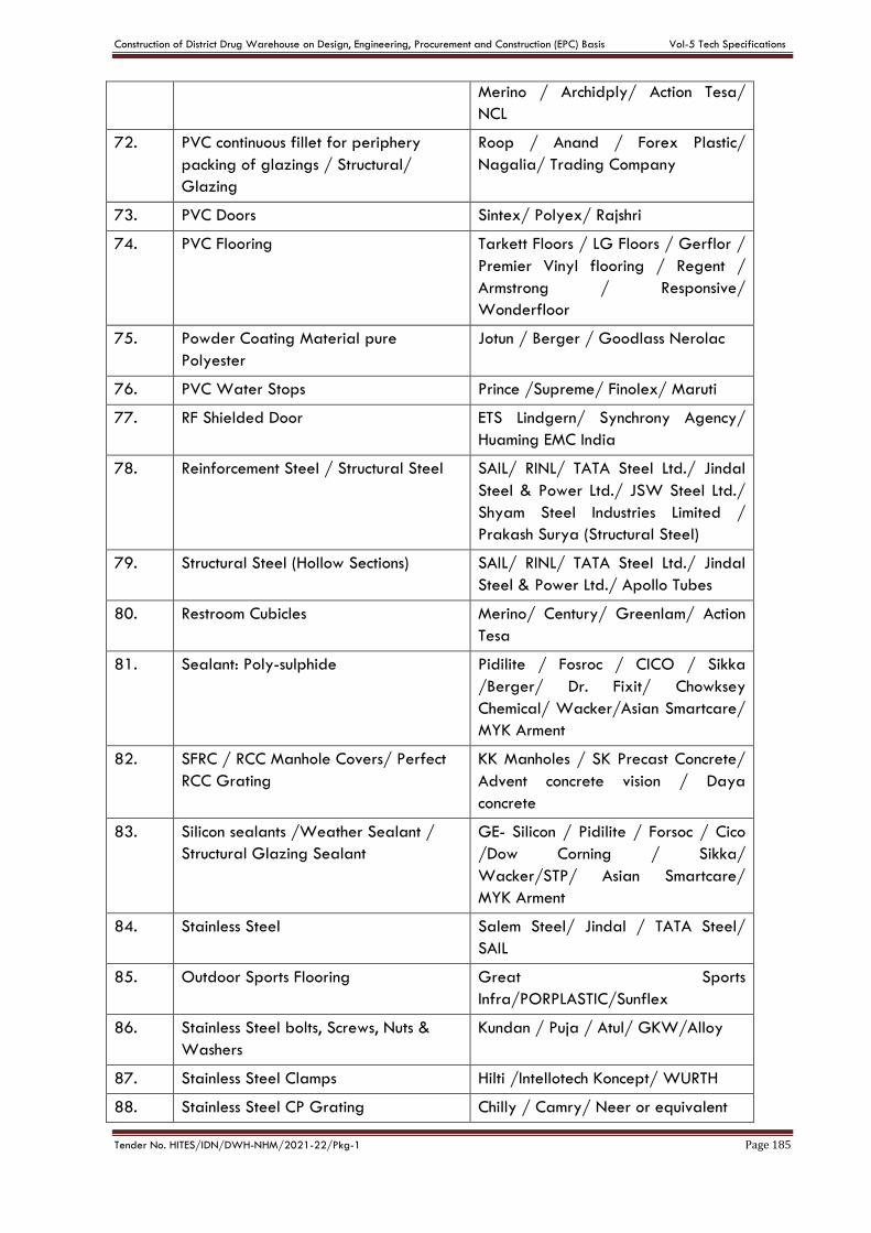
Construction of District Drug Warehouse on Design, Engineering, Procurement and Construction (EPC) Basis Vol-5 Tech Specifications
Tender No. HITES/IDN/DWH-NHM/2021-22/Pkg-1 Page 185
Merino / Archidply/ Action Tesa/
NCL
72. PVC continuous fillet for periphery
packing of glazings / Structural/
Glazing
Roop / Anand / Forex Plastic/
Nagalia/ Trading Company
73. PVC Doors Sintex/ Polyex/ Rajshri
74. PVC Flooring Tarkett Floors / LG Floors / Gerflor /
Premier Vinyl flooring / Regent /
Armstrong / Responsive/
Wonderfloor
75. Powder Coating Material pure
Polyester
Jotun / Berger / Goodlass Nerolac
76. PVC Water Stops Prince /Supreme/ Finolex/ Maruti
77. RF Shielded Door ETS Lindgern/ Synchrony Agency/
Huaming EMC India
78. Reinforcement Steel / Structural Steel SAIL/ RINL/ TATA Steel Ltd./ Jindal
Steel & Power Ltd./ JSW Steel Ltd./
Shyam Steel Industries Limited /
Prakash Surya (Structural Steel)
79. Structural Steel (Hollow Sections) SAIL/ RINL/ TATA Steel Ltd./ Jindal
Steel & Power Ltd./ Apollo Tubes
80. Restroom Cubicles Merino/ Century/ Greenlam/ Action
Tesa
81. Sealant: Poly-sulphide Pidilite / Fosroc / CICO / Sikka
/Berger/ Dr. Fixit/ Chowksey
Chemical/ Wacker/Asian Smartcare/
MYK Arment
82. SFRC / RCC Manhole Covers/ Perfect
RCC Grating
KK Manholes / SK Precast Concrete/
Advent concrete vision / Daya
concrete
83. Silicon sealants /Weather Sealant /
Structural Glazing Sealant
GE- Silicon / Pidilite / Forsoc / Cico
/Dow Corning / Sikka/
Wacker/STP/ Asian Smartcare/
MYK Arment
84. Stainless Steel Salem Steel/ Jindal / TATA Steel/
SAIL
85. Outdoor Sports Flooring Great Sports
Infra/PORPLASTIC/Sunflex
86. Stainless Steel bolts, Screws, Nuts &
Washers
Kundan / Puja / Atul/ GKW/Alloy
87. Stainless Steel Clamps Hilti /Intellotech Koncept/ WURTH
88. Stainless Steel CP Grating Chilly / Camry/ Neer or equivalent
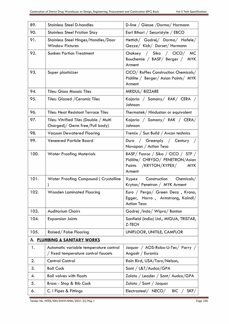
Construction of District Drug Warehouse on Design, Engineering, Procurement and Construction (EPC) Basis Vol-5 Tech Specifications
Tender No. HITES/IDN/DWH-NHM/2021-22/Pkg-1 Page 186
89. Stainless Steel D-handles D-line / Giesse /Dorma/ Hormann
90. Stainless Steel Friction Stay Earl Bihari / Securistyle / EBCO
91. Stainless Steel Hinges/Handles/Door
Window Fixtures
Hettich/ Godrej/ Dorma/ Hafele/
Gezze/ Kich/ Dorset/ Hormann
92. Sunken Portion Treatment Choksey / Sika / CICO/ MC
Bouchemie / BASF/ Berger / MYK
Arment
93. Super plasticizer CICO/ Roffes Construction Chemicals/
Pidilite / Berger/ Asian Paints/ MYK
Arment
94. Tiles: Glass Mosaic Tiles MRIDUL/ BIZZARE
95. Tiles: Glazed /Ceramic Tiles Kajaria / Somany/ RAK/ CERA /
Johnson
96. Tiles: Heat Resistant Terrace Tiles Thermatek/ Hindustan or equivalent
97. Tiles: Vitrified Tiles (Double / Multi
Charged)/ Germ free/Full body)
Kajaria / Somany/ RAK / CERA/
Johnson
98. Vacuum Dewatered Flooring Tremix / Sun Build / Avcon technics
99. Veneered Particle Board Duro / Greenply / Century /
Novapan / Action Tesa
100. Water Proofing Materials BASF/ Fosroc / Sika / CICO / STP /
Pidilite/ CHRYSO/ PENETRON/Asian
Paints /KRYTON/XYPEX/ MYK
Arment
101. Water Proofing Compound ( Crystalline
)
Xypex Construction Chemicals/
Kryton/ Penetron / MYK Arment
102. Wooden Laminated Flooring Euro / Pergo/ Green Deco , Krono,
Egger, Harro , Armstrong, Kaindl/
Action Tesa
103. Auditorium Chairs Godrej /Indo/ Wipro/ Bonton
104. Expansion Joints Sanfield (India) Ltd., MIGUA, TRISTAR,
Z-TECH
105. Raised/ False Flooring UNIFLOOR, UNITILE, CAMFLOR
A. PLUMBING & SANITARY WORKS
1. Automatic variable temperature control
/ fixed temperature control faucets
Jaquar / AOS-Robo-U-Tec/ Parry /
Angash / Euronics
2. Central Control Rain Bird, USA/Toro/Nelson,
3. Ball Cock Sant / L&T/Audco/GPA
4. Ball valves with floats Zoloto / Leader / Sant/ Audco/GPA
5. Brass - Stop & Bib Cock Zoloto / Sant / Jaquar
6. C. I Pipes & Fittings Electrosteel/ NECO/ BIC / SKF/
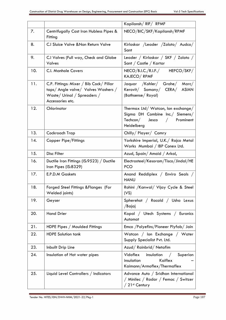
Construction of District Drug Warehouse on Design, Engineering, Procurement and Construction (EPC) Basis Vol-5 Tech Specifications
Tender No. HITES/IDN/DWH-NHM/2021-22/Pkg-1 Page 187
Kapilansh/ RIF/ RPMF
7. Centrifugally Cast Iron Hubless Pipes &
Fitting
NECO/BIC/SKF/Kapilansh/RPMF
8. C.I Sluice Valve &Non Return Valve Kirloskar /Leader /Zoloto/ Audco/
Sant
9. C.I Valves (Full way, Check and Globe
Valves
Leader / Kirloskar / SKF / Zoloto /
Sant / Castle / Kartar
10. C.I. Manhole Covers NECO/B.I.C./R.I.F./ HEPCO/SKF/
KAJECO/ RPMF
11. C.P. Fittings: Mixer / Bib Cock/ Pillar
taps/ Angle valve/ Valves Washers /
Waste/ Urinal / Spreaders /
Accessories etc.
Jaquar /Kohler/ Grohe/ Marc/
Kerovit/ Somany/ CERA/ ASIAN
(Bathsense/ Royal)
12. Chlorinator Thermax Ltd/ Watcon, lon exchange/
Sigma DH Combine Inc./ Siemens/
Techcon/ Jesco / Prominent
Heidelberg
13. Cockroach Trap Chilly/ Player/ Camry
14. Copper Pipe/Fittings Yorkshire Imperial, U.K./ Rajco Metal
Works Mumbai / IBP Conex Ltd.
15. Disc Filter Azud, Spain/ Amaid / Arkal,
16. Ductile Iron Fittings (IS:9523) / Ductile
Iron Pipes (IS:8329)
Electrosteel/Kesoram/Tisco/Jindal/HE
PCO
17. E.P.D.M Gaskets Anand Reddiplex / Enviro Seals /
HANU
18. Forged Steel Fittings &Flanges (For
Welded joints)
Rohini /Kanwal/ Vijay Cycle & Steel
(VS)
19. Geyser Spherehot / Racold / Usha Lexus
/Bajaj
20. Hand Drier Kopal / Utech Systems / Euronics
Automat
21. HDPE Pipes / Moulded Fittings Emco /Polyefins/Pioneer Plyfab/ Jain
22. HDPE Solution tank Watcon / Ion Exchange / Water
Supply Specialist Pvt. Ltd.
23. Inbuilt Drip Line Azud/ Rainbrid/ Netafim
24. Insulation of Hot water pipes Vidoflex insulation / Superion
insulation Kaiflex –
Kaimann/Armoflex/Thermaflex
25. Liquid Level Controllers / Indicators Advance Auto / Sridhan International
/ Minilec / Radar / Femac / Switzer
/ 21st Century
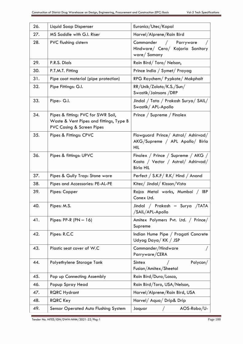
Construction of District Drug Warehouse on Design, Engineering, Procurement and Construction (EPC) Basis Vol-5 Tech Specifications
Tender No. HITES/IDN/DWH-NHM/2021-22/Pkg-1 Page 188
26. Liquid Soap Dispenser Euronics/Utec/Kopal
27. MS Saddle with G.I. Riser Harvel/Alprene/Rain Bird
28. PVC flushing cistern Commander / Parryware /
Hindware/ Cera/ Kajaria Sanitary
ware/ Somany
29. P.R.S. Dials Rain Bird/ Toro/ Nelson,
30. P.T.M.T. Fitting Prince India / Symet/ Prayag
31. Pipe coat material (pipe protection) RPG Raychem/ Pypkote/ Makphalt
32. Pipe Fittings: G.I. RR/Unik/Zoloto/K.S./Sun/
Swastik/Jainsons /DRP
33. Pipe:- G.I. Jindal / Tata / Prakash Surya/ SAIL/
Swastik/ APL-Apollo
34. Pipes & fitting: PVC for SWR Soil,
Waste & Vent Pipes and fittings, Type B
PVC Casing & Screen Pipes
Prince / Supreme / Finolex
35. Pipes & Fittings: CPVC Flowguard Prince/ Astral/ Ashirvad/
AKG/Supreme / APL Apollo/ Birla
HIL
36. Pipes & fittings: UPVC Finolex / Prince / Supreme / AKG /
Kasta / Vector / Astral/ Ashirvad/
Birla HIL
37. Pipes & Gully Trap: Stone ware Perfect / S.K.F/ R.K/ Hind / Anand
38. Pipes and Accessories: PE-AL-PE Kitec/ Jindal/ Kissan/Vista
39. Pipes: Copper Rajco Metal works, Mumbai / IBP
Conex Ltd.
40. Pipes: M.S. Jindal / Prakash – Surya /TATA
/SAIL/APL-Apollo
41. Pipes: PP-R (PN – 16) Amitex Polymers Pvt. Ltd. / Prince/
Supreme
42. Pipes: R.C.C Indian Hume Pipe / Pragati Concrete
Udyog Daya/ KK / JSP
43. Plastic seat cover of W.C Commander/Hindware /
Parryware/CERA
44. Polyethylene Storage Tank Sintex / Polycon/
Fusion/Amitex/Sheetal
45. Pop up Connecting Assembly Rain Bird/Dura/Lasco,
46. Popup Spray Head Rain Bird/Toro, USA/Nelson,
47. RQRC Hydrant Harvel/Alprene/Rain Bird, USA
48. RQRC Key Harvel/ Aqua/ Drip& Drip
49. Sensor Operated Auto Flushing System Jaquar / AOS-Robo/U-
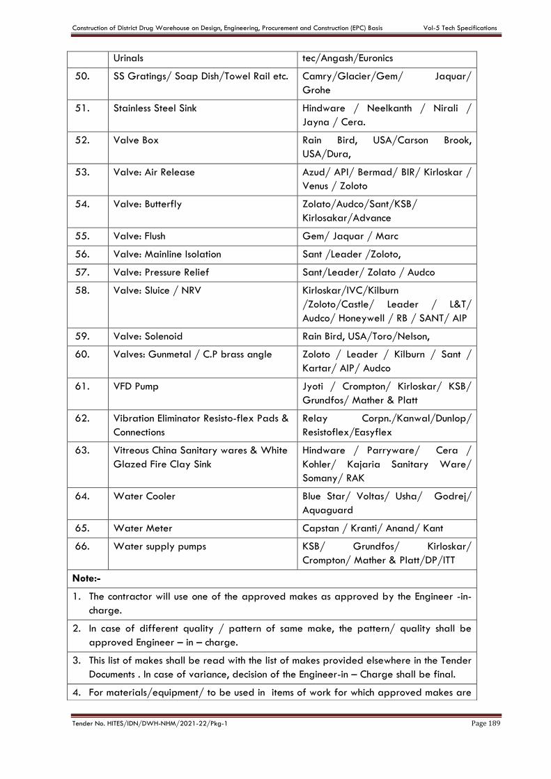
Construction of District Drug Warehouse on Design, Engineering, Procurement and Construction (EPC) Basis Vol-5 Tech Specifications
Tender No. HITES/IDN/DWH-NHM/2021-22/Pkg-1 Page 189
Urinals tec/Angash/Euronics
50. SS Gratings/ Soap Dish/Towel Rail etc. Camry/Glacier/Gem/ Jaquar/
Grohe
51. Stainless Steel Sink Hindware / Neelkanth / Nirali /
Jayna / Cera.
52. Valve Box Rain Bird, USA/Carson Brook,
USA/Dura,
53. Valve: Air Release Azud/ API/ Bermad/ BIR/ Kirloskar /
Venus / Zoloto
54. Valve: Butterfly Zolato/Audco/Sant/KSB/
Kirlosakar/Advance
55. Valve: Flush Gem/ Jaquar / Marc
56. Valve: Mainline Isolation Sant /Leader /Zoloto,
57. Valve: Pressure Relief Sant/Leader/ Zolato / Audco
58. Valve: Sluice / NRV Kirloskar/IVC/Kilburn
/Zoloto/Castle/ Leader / L&T/
Audco/ Honeywell / RB / SANT/ AIP
59. Valve: Solenoid Rain Bird, USA/Toro/Nelson,
60. Valves: Gunmetal / C.P brass angle Zoloto / Leader / Kilburn / Sant /
Kartar/ AIP/ Audco
61. VFD Pump Jyoti / Crompton/ Kirloskar/ KSB/
Grundfos/ Mather & Platt
62. Vibration Eliminator Resisto-flex Pads &
Connections
Relay Corpn./Kanwal/Dunlop/
Resistoflex/Easyflex
63. Vitreous China Sanitary wares & White
Glazed Fire Clay Sink
Hindware / Parryware/ Cera /
Kohler/ Kajaria Sanitary Ware/
Somany/ RAK
64. Water Cooler Blue Star/ Voltas/ Usha/ Godrej/
Aquaguard
65. Water Meter Capstan / Kranti/ Anand/ Kant
66. Water supply pumps KSB/ Grundfos/ Kirloskar/
Crompton/ Mather & Platt/DP/ITT
Note:-
1. The contractor will use one of the approved makes as approved by the Engineer -in-
charge.
2. In case of different quality / pattern of same make, the pattern/ quality shall be
approved Engineer – in – charge.
3. This list of makes shall be read with the list of makes provided elsewhere in the Tender
Documents . In case of variance, decision of the Engineer-in – Charge shall be final.
4. For materials/equipment/ to be used in items of work for which approved makes are
Construction of District Drug Warehouse on Design, Engineering, Procurement and Construction (EPC) Basis Vol-5 Tech Specifications
Tender No. HITES/IDN/DWH-NHM/2021-22/Pkg-1 Page 190
not given hereinor in the list of makes provided elsewhere inthe Tender Documents, the
makes of such materials /equipment shall be as decided by Engineer –in-charge.
5. If any major equipment is using a small component of make other than that given as a
standard component with the equipment, the same shall be accepted subject to
approval of Engineer –in-charge.
6. In case of non-availability of the brand specified in the contract, the contractor shall
be allowed to use alternate equivalent brand of the material subject to submission of
documentary evidence of non-availability of the specified brand. The necessary cost
adjustments on account of above change shall be made for the material.
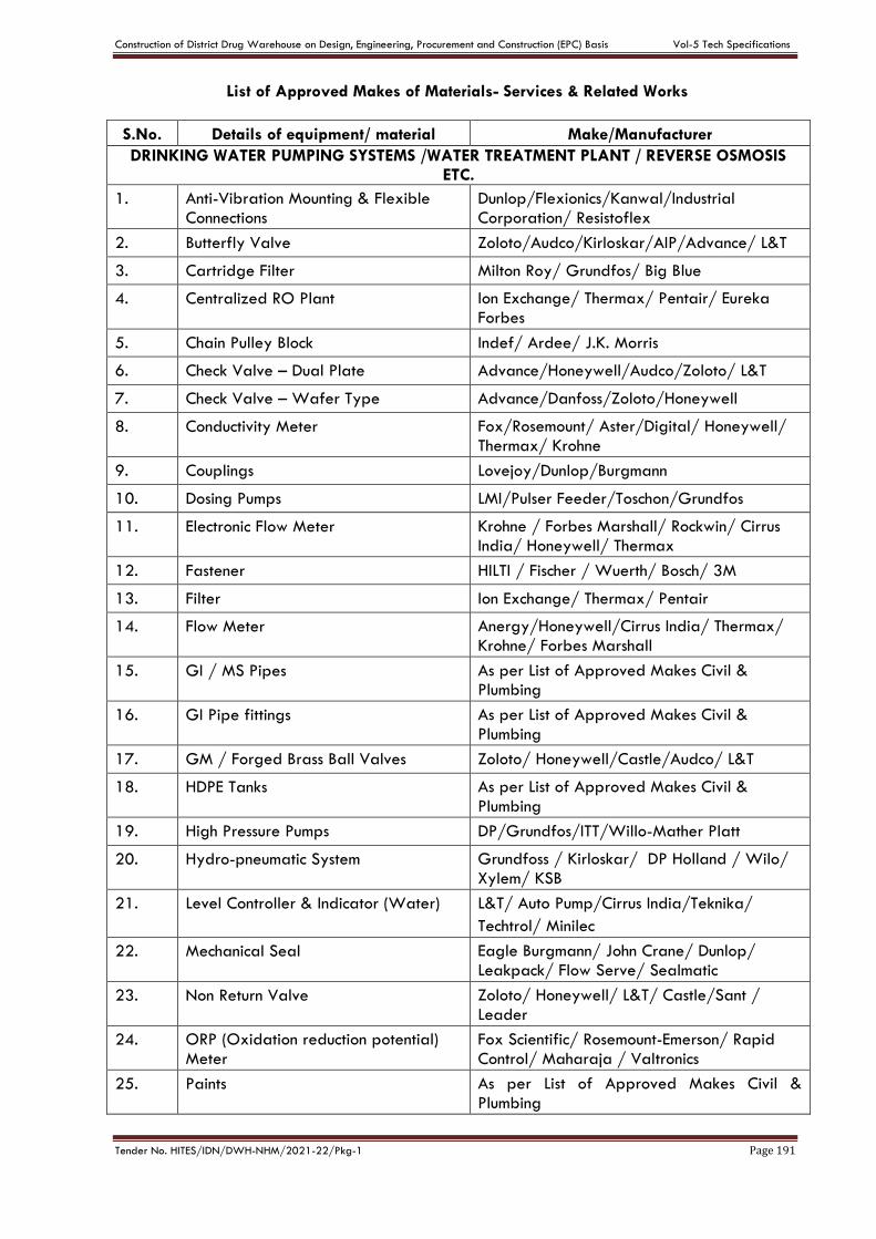
Construction of District Drug Warehouse on Design, Engineering, Procurement and Construction (EPC) Basis Vol-5 Tech Specifications
Tender No. HITES/IDN/DWH-NHM/2021-22/Pkg-1 Page 191
List of Approved Makes of Materials- Services & Related Works
S.No. Details of equipment/ material Make/Manufacturer
DRINKING WATER PUMPING SYSTEMS /WATER TREATMENT PLANT / REVERSE OSMOSIS ETC.
1. Anti-Vibration Mounting & Flexible
Connections
Dunlop/Flexionics/Kanwal/Industrial
Corporation/ Resistoflex
2. Butterfly Valve Zoloto/Audco/Kirloskar/AIP/Advance/ L&T
3. Cartridge Filter Milton Roy/ Grundfos/ Big Blue
4. Centralized RO Plant Ion Exchange/ Thermax/ Pentair/ Eureka
Forbes
5. Chain Pulley Block Indef/ Ardee/ J.K. Morris
6. Check Valve – Dual Plate Advance/Honeywell/Audco/Zoloto/ L&T
7. Check Valve – Wafer Type Advance/Danfoss/Zoloto/Honeywell
8. Conductivity Meter Fox/Rosemount/ Aster/Digital/ Honeywell/
Thermax/ Krohne
9. Couplings Lovejoy/Dunlop/Burgmann
10. Dosing Pumps LMI/Pulser Feeder/Toschon/Grundfos
11. Electronic Flow Meter Krohne / Forbes Marshall/ Rockwin/ Cirrus
India/ Honeywell/ Thermax
12. Fastener HILTI / Fischer / Wuerth/ Bosch/ 3M
13. Filter Ion Exchange/ Thermax/ Pentair
14. Flow Meter Anergy/Honeywell/Cirrus India/ Thermax/
Krohne/ Forbes Marshall
15. GI / MS Pipes As per List of Approved Makes Civil & Plumbing
16. GI Pipe fittings As per List of Approved Makes Civil &
Plumbing
17. GM / Forged Brass Ball Valves Zoloto/ Honeywell/Castle/Audco/ L&T
18. HDPE Tanks As per List of Approved Makes Civil &
Plumbing
19. High Pressure Pumps DP/Grundfos/ITT/Willo-Mather Platt
20. Hydro-pneumatic System Grundfoss / Kirloskar/ DP Holland / Wilo/
Xylem/ KSB
21. Level Controller & Indicator (Water) L&T/ Auto Pump/Cirrus India/Teknika/
Techtrol/ Minilec
22. Mechanical Seal Eagle Burgmann/ John Crane/ Dunlop/
Leakpack/ Flow Serve/ Sealmatic
23. Non Return Valve Zoloto/ Honeywell/ L&T/ Castle/Sant /
Leader
24. ORP (Oxidation reduction potential)
Meter
Fox Scientific/ Rosemount-Emerson/ Rapid
Control/ Maharaja / Valtronics
25. Paints As per List of Approved Makes Civil &
Plumbing
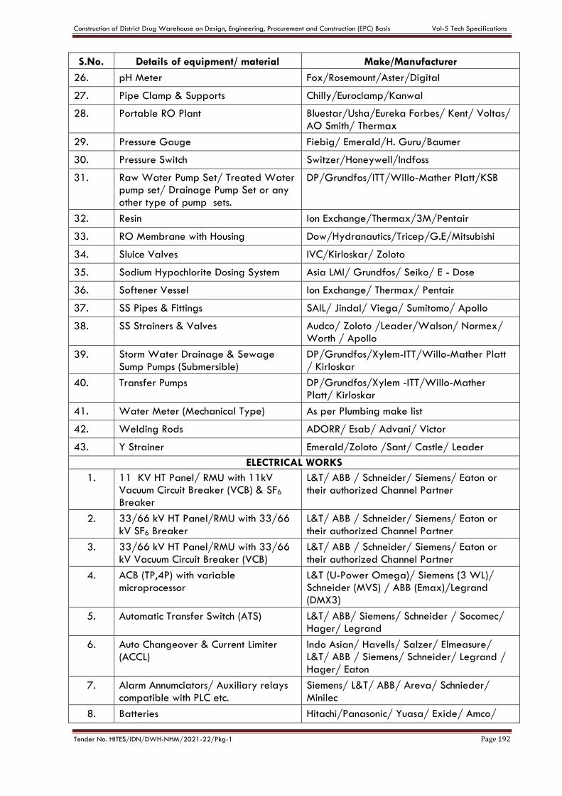
Construction of District Drug Warehouse on Design, Engineering, Procurement and Construction (EPC) Basis Vol-5 Tech Specifications
Tender No. HITES/IDN/DWH-NHM/2021-22/Pkg-1 Page 192
S.No. Details of equipment/ material Make/Manufacturer
26. pH Meter Fox/Rosemount/Aster/Digital
27. Pipe Clamp & Supports Chilly/Euroclamp/Kanwal
28. Portable RO Plant Bluestar/Usha/Eureka Forbes/ Kent/ Voltas/
AO Smith/ Thermax
29. Pressure Gauge Fiebig/ Emerald/H. Guru/Baumer
30. Pressure Switch Switzer/Honeywell/Indfoss
31. Raw Water Pump Set/ Treated Water pump set/ Drainage Pump Set or any
other type of pump sets.
DP/Grundfos/ITT/Willo-Mather Platt/KSB
32. Resin Ion Exchange/Thermax/3M/Pentair
33. RO Membrane with Housing Dow/Hydranautics/Tricep/G.E/Mitsubishi
34. Sluice Valves IVC/Kirloskar/ Zoloto
35. Sodium Hypochlorite Dosing System Asia LMI/ Grundfos/ Seiko/ E - Dose
36. Softener Vessel Ion Exchange/ Thermax/ Pentair
37. SS Pipes & Fittings SAIL/ Jindal/ Viega/ Sumitomo/ Apollo
38. SS Strainers & Valves Audco/ Zoloto /Leader/Walson/ Normex/
Worth / Apollo
39. Storm Water Drainage & Sewage
Sump Pumps (Submersible)
DP/Grundfos/Xylem-ITT/Willo-Mather Platt
/ Kirloskar
40. Transfer Pumps DP/Grundfos/Xylem -ITT/Willo-Mather
Platt/ Kirloskar
41. Water Meter (Mechanical Type) As per Plumbing make list
42. Welding Rods ADORR/ Esab/ Advani/ Victor
43. Y Strainer Emerald/Zoloto /Sant/ Castle/ Leader
ELECTRICAL WORKS
1. 11 KV HT Panel/ RMU with 11kV Vacuum Circuit Breaker (VCB) & SF6
Breaker
L&T/ ABB / Schneider/ Siemens/ Eaton or
their authorized Channel Partner
2. 33/66 kV HT Panel/RMU with 33/66
kV SF6 Breaker
L&T/ ABB / Schneider/ Siemens/ Eaton or
their authorized Channel Partner
3. 33/66 kV HT Panel/RMU with 33/66
kV Vacuum Circuit Breaker (VCB)
L&T/ ABB / Schneider/ Siemens/ Eaton or
their authorized Channel Partner
4. ACB (TP,4P) with variable
microprocessor
L&T (U-Power Omega)/ Siemens (3 WL)/ Schneider (MVS) / ABB (Emax)/Legrand
(DMX3)
5. Automatic Transfer Switch (ATS) L&T/ ABB/ Siemens/ Schneider / Socomec/ Hager/ Legrand
6. Auto Changeover & Current Limiter
(ACCL)
Indo Asian/ Havells/ Salzer/ Elmeasure/ L&T/ ABB / Siemens/ Schneider/ Legrand /
Hager/ Eaton
7. Alarm Annumciators/ Auxiliary relays
compatible with PLC etc.
Siemens/ L&T/ ABB/ Areva/ Schnieder/
Minilec
8. Batteries Hitachi/Panasonic/ Yuasa/ Exide/ Amco/

Construction of District Drug Warehouse on Design, Engineering, Procurement and Construction (EPC) Basis Vol-5 Tech Specifications
Tender No. HITES/IDN/DWH-NHM/2021-22/Pkg-1 Page 193
S.No. Details of equipment/ material Make/Manufacturer
Amaraja-Amaron/ Tata
9. Battery Charger Amaraja/ Volstat/Chloride Power System/
Expo-Fyn/HBL /Sabnife/ Statcon
10. Boom Barrier FAAC/ Godrej Vigiguard/ Somfy/Gunnebo
11. Bus bar Jindal/ Hindalco/ Sterlite
12. Bus Ducts & Rising Mains (Sandwich Type) Bus Trunking, End Feed Unit,
Tap-off box (plug-in type)
L&T/ Schneider/ C&S/ Godrej/ Legrand/
EAE
13. Cable Jointing/ Termination Kit Raychem/ Xicon/ 3M
14. Cable Trays/ Race ways / Floor
trunking / wall channels
MEM/ BEC/ OBO Bettermann/ Indiana/
Legrand/ RMCON/ Honeywell/ AKG
15. Call Bell / Door Bell switches & Buzzers Havells/ Anchor/ Schneider/ ABB/ Siemens/
Indo Asian/ Panasonic
16. Call Bell with Video Door Phone Honeywell/ Hikvision/ Godrej/ Panasonic/ Crabtree/ CP Plus/ Wipro
17. Capacitor Banks L&T/ Siemens / Schneider/ ABB/ Ducati/
Neptune/ Meher/ EPCOS
18. Ceiling /Exhaust/ Wall fans/ Air
Circulator Fans
Crompton/ Usha/Orient/ Bajaj / Havells/
Panasonic/ Almonard/ Marathon
19. Coaxial Wires Finolex/ Delton/ Skytone/ L&T/ KEI/ Bonton/
Gloster/ Polycab/ Belden/ Legrand/ Havells
20. Colour Monitor Samsung/ LG/ Sony/ Philips/ Panasonic
21. Current Transformer/ Potential
Transformer L&T/ Kappa/ AE / Meco/ Gilbert/ Maxwell
22. Cubicle Type Fuse Unit/ RMU Siemens/ L&T/ ABB/ Schneider/ Eaton
23. Data/Telephone/TV Socket Outlets Systemax/ Belden/ Simone/ Honeywell/ Legrand/ Havells/ Hager/ Panasonic/ ABB/
Schnieder/ Siemens
24. Distribution Boards (DB) Hager/ Havells/ Legrand/ L&T/ABB/ Indo-Asian/ Schneider / Siemens/ Eaton/
Panasonic/ Polycab
25. DG Set - Assembler Jakson & Company / Jakson Ltd/ Sterling Generators / Sudhir Gensets/ Powerica/ Kirloskar (KOEL authorized OEM) / TIPL
(Gainwell) / C&S Himoinsa/ Greaves Cotton
26. DG Set - Alternator Stamford/ Leroy Somer/ Toyo Denki/ AVK-SEG/ Kirloskar (KOEL Green)/ Crompton
Greaves
27. DG Set - Engine Cummins/ Mitsubishi/ Perkins/ Volvo/ Caterpiller/ Kirloskar (KOEL Green)/
Baudouin / Greaves Cotton
28. DG Synchronizing Controller Woodword/ Dief/ Deep sea
29. Door Frame Metal Detectors Metscan/ Trust Security System/ ID Tech
Solutions
30. DWC (Double Walled Corrugated) Duraline / Rex / Carlon/ Emtelle
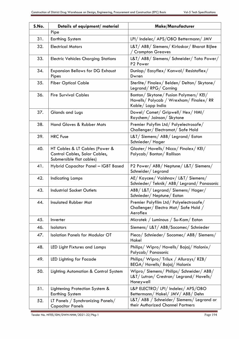
Construction of District Drug Warehouse on Design, Engineering, Procurement and Construction (EPC) Basis Vol-5 Tech Specifications
Tender No. HITES/IDN/DWH-NHM/2021-22/Pkg-1 Page 194
S.No. Details of equipment/ material Make/Manufacturer
Pipe
31. Earthing System LPI/ Indelec/ APS/OBO Bettermann/ JMV
32. Electrical Motors L&T/ ABB/ Siemens/ Kirloskar/ Bharat Bijlee
/ Crompton Greaves
33. Electric Vehicles Charging Stations L&T/ ABB/ Siemens/ Schneider/ Tata Power/
P2 Power
34. Expansion Bellows for DG Exhaust
Pipes
Dunlop/ Easyflex/ Kanwal/ Resistoflex/
Dwren
35. Fiber Optical Cable Sterlite/ Finolex/ Belden/ Delton/ Skytone/
Legrand/ RPG/ Corning
36. Fire Survival Cables Bonton/ Skytone/ Fusion Polymers/ KEI/ Havells/ Polycab / Wrexham/ Finolex/ RR
Kable/ Lapp India
37. Glands and Lugs Dowel/ Comet/ Gripwell/ Hex/ HMI/
Raychem/ Jainson/ Skytone
38. Hand Gloves & Rubber Mats Premier Polyfim Ltd/ Polyelectrosafe/
Challenger/ Electromat/ Safe Hold
39. HRC Fuse L&T/ Siemens/ ABB/ Legrand/ Eaton
Schnieder/ Hager
40. HT Cables & LT Cables (Power & Control Cables, Solar Cables,
Submersible flat cables)
Gloster/ Havells/ Nicco/ Finolex/ KEI/
Polycab/ Bonton/ Rallison
41. Hybrid Capacitor Panel – IGBT Based P2 Power/ ABB/ Neptune/ L&T/ Siemens/
Schneider/ Legrand
42. Indicating Lamps AE/ Kaycee/ Vaishnav/ L&T/ Siemens/
Schnieder/ Teknik/ ABB/ Legrand/ Panasonic
43. Industrial Socket Outlets ABB/ L&T/ Legrand/ Siemens/ Hager/
Schnieder/ Neptune/ Eaton
44. Insulated Rubber Mat Premier Polyfilm Ltd/ Polyelectrosafe/ Challenger/ Electro Mat/ Safe Hold /
Aeroflex
45. Inverter Microtek / Luminous / Su-Kam/ Eaton
46. Isolators Siemens/ L&T/ ABB/Socomec/ Schnieder
47. Isolation Panels for Modular OT Pieco/ Schnieder/ Socomec/ ABB/ Siemens/
Hakel
48. LED Light Fixtures and Lamps Philips/ Wipro/ Havells/ Bajaj/ Halonix/
Polycab/ Panasonic
49. LED Lighting for Facade Philips/ Wipro/ Trilux / Allurays/ RZB/
BEGA/ Havells/ Bajaj/ Halonix
50. Lighting Automation & Control System Wipro/ Siemens/ Philips/ Schneider/ ABB/ L&T/ Lutron/ Crestron/ Legrand/ Havells/ Honeywell
51. Lightening Protection System &
Earthing System
L&P ELECTRO/ LPI/ Indelec/ APS/OBO
Bettermann/ Hakel/ JMV/ ABB/ Dehn
52. LT Panels / Synchronizing Panels/
Capacitor Panels
L&T/ ABB / Schneider/ Siemens/ Legrand or their Authorized Channel Partners
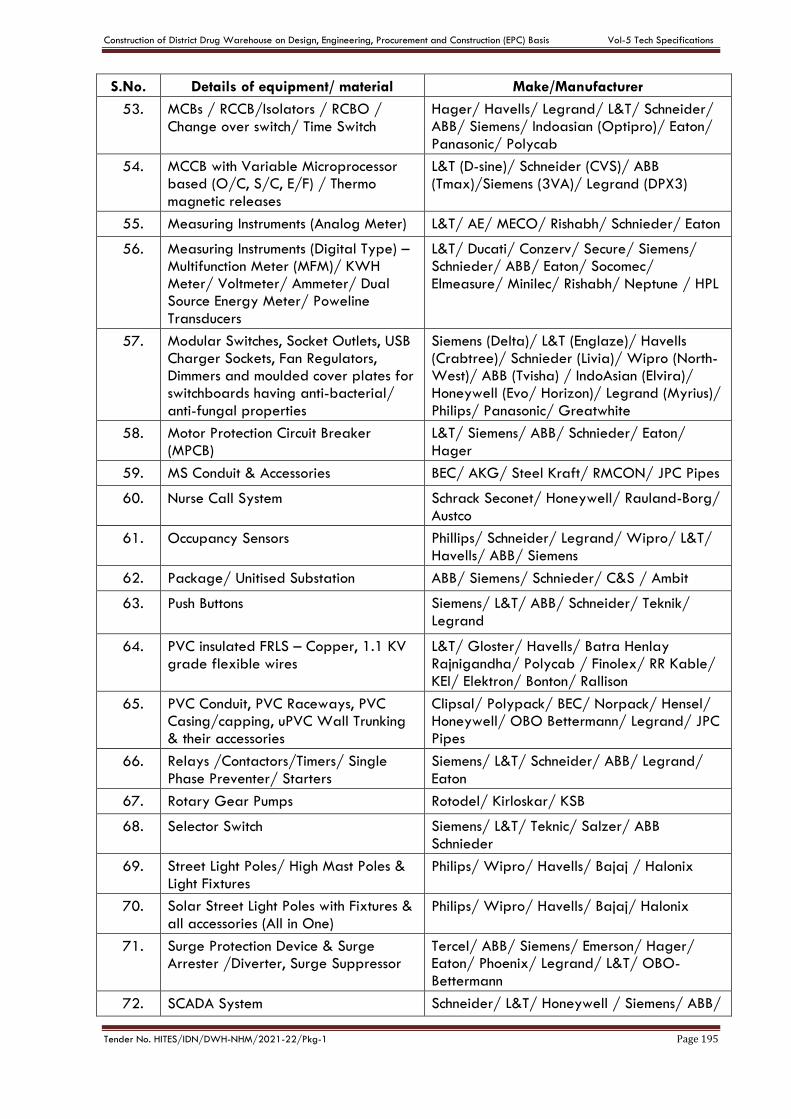
Construction of District Drug Warehouse on Design, Engineering, Procurement and Construction (EPC) Basis Vol-5 Tech Specifications
Tender No. HITES/IDN/DWH-NHM/2021-22/Pkg-1 Page 195
S.No. Details of equipment/ material Make/Manufacturer
53. MCBs / RCCB/Isolators / RCBO /
Change over switch/ Time Switch
Hager/ Havells/ Legrand/ L&T/ Schneider/ ABB/ Siemens/ Indoasian (Optipro)/ Eaton/
Panasonic/ Polycab
54. MCCB with Variable Microprocessor based (O/C, S/C, E/F) / Thermo
magnetic releases
L&T (D-sine)/ Schneider (CVS)/ ABB
(Tmax)/Siemens (3VA)/ Legrand (DPX3)
55. Measuring Instruments (Analog Meter) L&T/ AE/ MECO/ Rishabh/ Schnieder/ Eaton
56. Measuring Instruments (Digital Type) – Multifunction Meter (MFM)/ KWH Meter/ Voltmeter/ Ammeter/ Dual Source Energy Meter/ Poweline
Transducers
L&T/ Ducati/ Conzerv/ Secure/ Siemens/ Schnieder/ ABB/ Eaton/ Socomec/
Elmeasure/ Minilec/ Rishabh/ Neptune / HPL
57. Modular Switches, Socket Outlets, USB Charger Sockets, Fan Regulators, Dimmers and moulded cover plates for switchboards having anti-bacterial/
anti-fungal properties
Siemens (Delta)/ L&T (Englaze)/ Havells (Crabtree)/ Schnieder (Livia)/ Wipro (North-West)/ ABB (Tvisha) / IndoAsian (Elvira)/ Honeywell (Evo/ Horizon)/ Legrand (Myrius)/
Philips/ Panasonic/ Greatwhite
58. Motor Protection Circuit Breaker
(MPCB)
L&T/ Siemens/ ABB/ Schnieder/ Eaton/
Hager
59. MS Conduit & Accessories BEC/ AKG/ Steel Kraft/ RMCON/ JPC Pipes
60. Nurse Call System Schrack Seconet/ Honeywell/ Rauland-Borg/
Austco
61. Occupancy Sensors Phillips/ Schneider/ Legrand/ Wipro/ L&T/
Havells/ ABB/ Siemens
62. Package/ Unitised Substation ABB/ Siemens/ Schnieder/ C&S / Ambit
63. Push Buttons
Siemens/ L&T/ ABB/ Schneider/ Teknik/
Legrand
64. PVC insulated FRLS – Copper, 1.1 KV
grade flexible wires
L&T/ Gloster/ Havells/ Batra Henlay Rajnigandha/ Polycab / Finolex/ RR Kable/
KEI/ Elektron/ Bonton/ Rallison
65. PVC Conduit, PVC Raceways, PVC Casing/capping, uPVC Wall Trunking & their accessories
Clipsal/ Polypack/ BEC/ Norpack/ Hensel/ Honeywell/ OBO Bettermann/ Legrand/ JPC Pipes
66. Relays /Contactors/Timers/ Single
Phase Preventer/ Starters
Siemens/ L&T/ Schneider/ ABB/ Legrand/
Eaton
67. Rotary Gear Pumps Rotodel/ Kirloskar/ KSB
68. Selector Switch Siemens/ L&T/ Teknic/ Salzer/ ABB
Schnieder
69. Street Light Poles/ High Mast Poles &
Light Fixtures Philips/ Wipro/ Havells/ Bajaj / Halonix
70. Solar Street Light Poles with Fixtures &
all accessories (All in One) Philips/ Wipro/ Havells/ Bajaj/ Halonix
71. Surge Protection Device & Surge Arrester /Diverter, Surge Suppressor
Tercel/ ABB/ Siemens/ Emerson/ Hager/ Eaton/ Phoenix/ Legrand/ L&T/ OBO-
Bettermann
72. SCADA System Schneider/ L&T/ Honeywell / Siemens/ ABB/

Construction of District Drug Warehouse on Design, Engineering, Procurement and Construction (EPC) Basis Vol-5 Tech Specifications
Tender No. HITES/IDN/DWH-NHM/2021-22/Pkg-1 Page 196
S.No. Details of equipment/ material Make/Manufacturer
Legrand
73. TV Splitter Box/ Tap-off Zinwell/ Novatron/ Catvision
74. Terminal Block/ Connectors Dowells/ Elemex/ Wago/ Phoenix
Connectwell
75. Transformer (Oil Type/ Dry Type) ABB/ Siemens/ Kirloskar/ Voltamp/
Schneider/ Crompton
76. Trivector - Meter (Digital type) L&T/ Siemens/ Socomec/ Schnieder/ HPL/
ABB
77. Uninterruptible Power Supply (UPS) Emerson / Schnieder (APC)/ Eaton/ Socomec/ Numeric (Legrand)/ Best Power Equipment/
Luminous
78. Variable Frequency Drive (VFD) L&T/ Siemens/ Danfoss/ ABB/ Schneider
FIRE FIGHTING WORKS
1. Air Release Valve/Air Cushion Tank Zoloto/ Advance/ Leader/ Audco/ Castle
2. Alarm Valve & Hydraulic (Alarm motor
with coupling) HD fire protect/TYCO/VIKING/Newage
3. Alternator Stamford/ Leroy Somer/ Toyo Denki/ AVK-
SEG/ Kirloskar
4. Ammeter/ Voltmeter/ PF/ kW/ Hz/
Meter /Energy Meter/ Multimeter As per respective electrical make list
5. Anchor Fastener HILTI / Fischer / Wuerth/ Bosch/ 3M
6. Ball Valves
L&T/ Audco /Zoloto/ Advance/Emerald/
KSB/ Sant/ Castle
7. Battery As per respective electrical make list
8. Butt welded fitting (UL Listed) &
accessories
Bharat Forge/ VS Forge/True Forge / DRP-
M/ Metline Industries/ United Forge Industries
9. Butterfly Valves L&T/ Audco/ Zoloto / Advance/ KSB/ Castle
10. Cable lugs and glands As per electrical make list
11. Cables As per electrical make list
12. Check Valve/Foot Valve/Sluice Valve/ NRV
L&T/Audco / Zoloto/ Advance/KSB/ Sant/ Leader
13. Control / Potential / Current
Transformer As per respective electrical make list
14. Deluge valve/ Solenoid valve/ Spray
nozzle HD / Tyco/ Viking
15. Diesel Engine Ashok Leyland/ Cummins/ Perkins/ Kirloskar
16. ELCB As per electrical make list
17. Epoxy Paint As per Civil Works make list
18. Fire Buckets Safex / Minimax/ Cease Fire/ Peter Autokit/ AAAG/ ASES/ Agni
19. Fire Stopper/ Sealant Hilti/ 3M/ OBO-Bettermann
20. Fire Extinguishers Minimax / Newage/ Ceasefire/ Fyrex
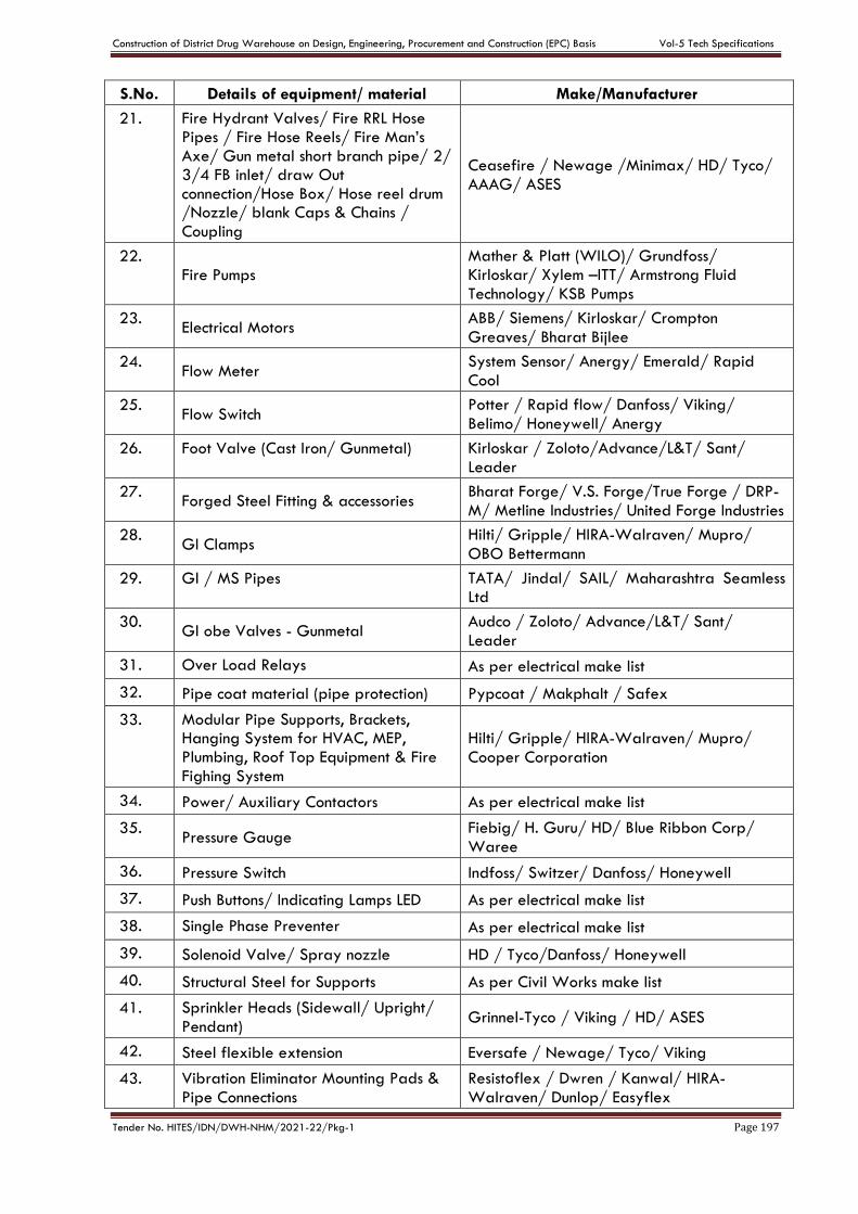
Construction of District Drug Warehouse on Design, Engineering, Procurement and Construction (EPC) Basis Vol-5 Tech Specifications
Tender No. HITES/IDN/DWH-NHM/2021-22/Pkg-1 Page 197
S.No. Details of equipment/ material Make/Manufacturer
21. Fire Hydrant Valves/ Fire RRL Hose Pipes / Fire Hose Reels/ Fire Man’s Axe/ Gun metal short branch pipe/ 2/ 3/4 FB inlet/ draw Out connection/Hose Box/ Hose reel drum /Nozzle/ blank Caps & Chains /
Coupling
Ceasefire / Newage /Minimax/ HD/ Tyco/
AAAG/ ASES
22. Fire Pumps
Mather & Platt (WILO)/ Grundfoss/ Kirloskar/ Xylem –ITT/ Armstrong Fluid
Technology/ KSB Pumps
23. Electrical Motors
ABB/ Siemens/ Kirloskar/ Crompton
Greaves/ Bharat Bijlee
24. Flow Meter
System Sensor/ Anergy/ Emerald/ Rapid
Cool
25. Flow Switch
Potter / Rapid flow/ Danfoss/ Viking/
Belimo/ Honeywell/ Anergy
26. Foot Valve (Cast Iron/ Gunmetal) Kirloskar / Zoloto/Advance/L&T/ Sant/
Leader
27. Forged Steel Fitting & accessories
Bharat Forge/ V.S. Forge/True Forge / DRP-
M/ Metline Industries/ United Forge Industries
28. GI Clamps
Hilti/ Gripple/ HIRA-Walraven/ Mupro/
OBO Bettermann
29. Gl / MS Pipes TATA/ Jindal/ SAIL/ Maharashtra Seamless Ltd
30. Gl obe Valves - Gunmetal
Audco / Zoloto/ Advance/L&T/ Sant/
Leader
31. Over Load Relays As per electrical make list
32. Pipe coat material (pipe protection) Pypcoat / Makphalt / Safex
33. Modular Pipe Supports, Brackets, Hanging System for HVAC, MEP, Plumbing, Roof Top Equipment & Fire
Fighing System
Hilti/ Gripple/ HIRA-Walraven/ Mupro/
Cooper Corporation
34. Power/ Auxiliary Contactors As per electrical make list
35. Pressure Gauge
Fiebig/ H. Guru/ HD/ Blue Ribbon Corp/
Waree
36. Pressure Switch Indfoss/ Switzer/ Danfoss/ Honeywell
37. Push Buttons/ Indicating Lamps LED As per electrical make list
38. Single Phase Preventer As per electrical make list
39. Solenoid Valve/ Spray nozzle HD / Tyco/Danfoss/ Honeywell
40. Structural Steel for Supports As per Civil Works make list
41. Sprinkler Heads (Sidewall/ Upright/
Pendant) Grinnel-Tyco / Viking / HD/ ASES
42. Steel flexible extension Eversafe / Newage/ Tyco/ Viking
43. Vibration Eliminator Mounting Pads &
Pipe Connections
Resistoflex / Dwren / Kanwal/ HIRA-
Walraven/ Dunlop/ Easyflex
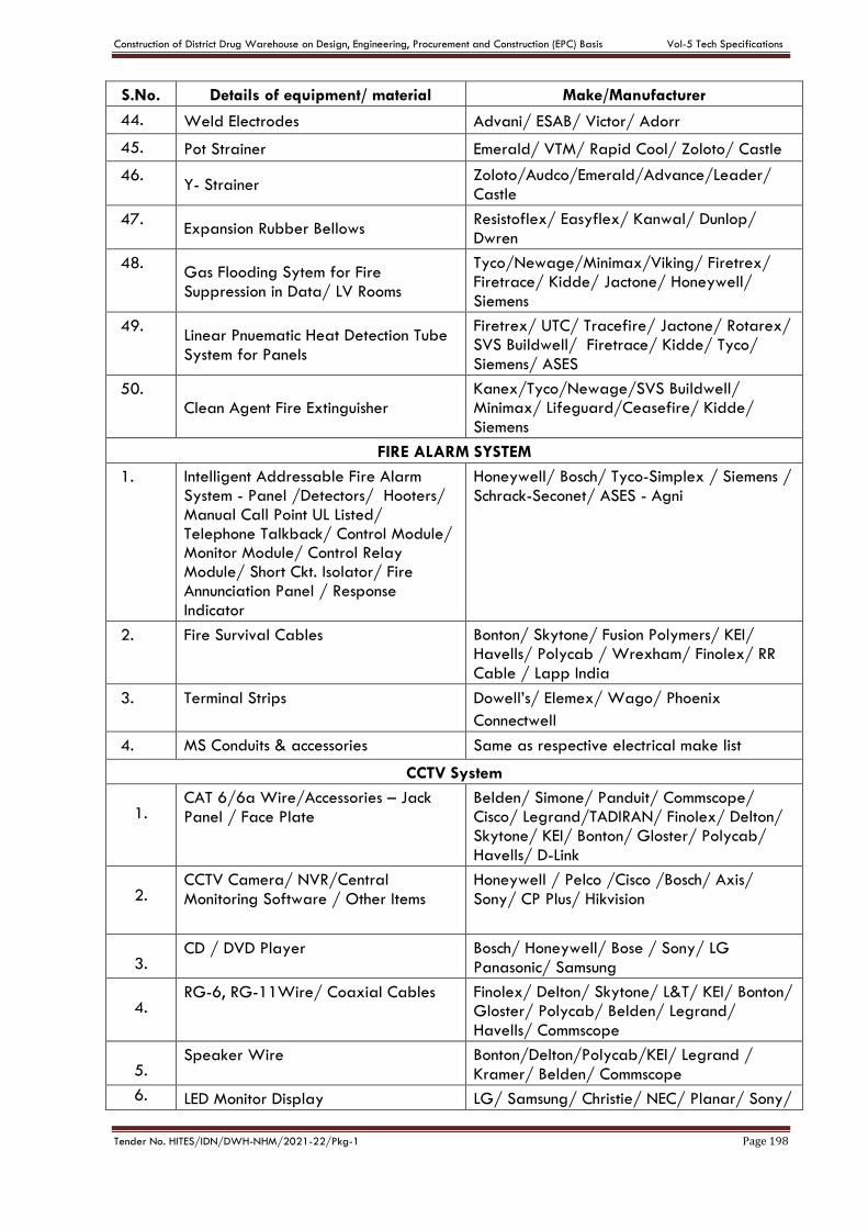
Construction of District Drug Warehouse on Design, Engineering, Procurement and Construction (EPC) Basis Vol-5 Tech Specifications
Tender No. HITES/IDN/DWH-NHM/2021-22/Pkg-1 Page 198
S.No. Details of equipment/ material Make/Manufacturer
44. Weld Electrodes Advani/ ESAB/ Victor/ Adorr
45. Pot Strainer Emerald/ VTM/ Rapid Cool/ Zoloto/ Castle
46. Y- Strainer
Zoloto/Audco/Emerald/Advance/Leader/
Castle
47. Expansion Rubber Bellows
Resistoflex/ Easyflex/ Kanwal/ Dunlop/
Dwren
48. Gas Flooding Sytem for Fire
Suppression in Data/ LV Rooms
Tyco/Newage/Minimax/Viking/ Firetrex/ Firetrace/ Kidde/ Jactone/ Honeywell/
Siemens
49. Linear Pnuematic Heat Detection Tube
System for Panels
Firetrex/ UTC/ Tracefire/ Jactone/ Rotarex/ SVS Buildwell/ Firetrace/ Kidde/ Tyco/
Siemens/ ASES
50. Clean Agent Fire Extinguisher
Kanex/Tyco/Newage/SVS Buildwell/ Minimax/ Lifeguard/Ceasefire/ Kidde/
Siemens
FIRE ALARM SYSTEM
1. Intelligent Addressable Fire Alarm System - Panel /Detectors/ Hooters/ Manual Call Point UL Listed/ Telephone Talkback/ Control Module/ Monitor Module/ Control Relay Module/ Short Ckt. Isolator/ Fire Annunciation Panel / Response
Indicator
Honeywell/ Bosch/ Tyco-Simplex / Siemens /
Schrack-Seconet/ ASES - Agni
2. Fire Survival Cables Bonton/ Skytone/ Fusion Polymers/ KEI/ Havells/ Polycab / Wrexham/ Finolex/ RR
Cable / Lapp India
3. Terminal Strips Dowell’s/ Elemex/ Wago/ Phoenix
Connectwell
4. MS Conduits & accessories Same as respective electrical make list
CCTV System
1.
CAT 6/6a Wire/Accessories – Jack
Panel / Face Plate
Belden/ Simone/ Panduit/ Commscope/ Cisco/ Legrand/TADIRAN/ Finolex/ Delton/ Skytone/ KEI/ Bonton/ Gloster/ Polycab/
Havells/ D-Link
2.
CCTV Camera/ NVR/Central
Monitoring Software / Other Items
Honeywell / Pelco /Cisco /Bosch/ Axis/
Sony/ CP Plus/ Hikvision
3.
CD / DVD Player Bosch/ Honeywell/ Bose / Sony/ LG
Panasonic/ Samsung
4.
RG-6, RG-11Wire/ Coaxial Cables Finolex/ Delton/ Skytone/ L&T/ KEI/ Bonton/ Gloster/ Polycab/ Belden/ Legrand/
Havells/ Commscope
5.
Speaker Wire Bonton/Delton/Polycab/KEI/ Legrand /
Kramer/ Belden/ Commscope
6. LED Monitor Display LG/ Samsung/ Christie/ NEC/ Planar/ Sony/
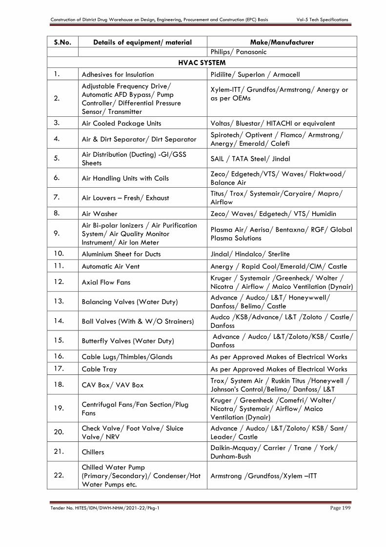
Construction of District Drug Warehouse on Design, Engineering, Procurement and Construction (EPC) Basis Vol-5 Tech Specifications
Tender No. HITES/IDN/DWH-NHM/2021-22/Pkg-1 Page 199
S.No. Details of equipment/ material Make/Manufacturer
Philips/ Panasonic
HVAC SYSTEM
1. Adhesives for Insulation Pidilite/ Superlon / Armacell
2.
Adjustable Frequency Drive/ Automatic AFD Bypass/ Pump Controller/ Differential Pressure
Sensor/ Transmitter
Xylem-ITT/ Grundfos/Armstrong/ Anergy or
as per OEMs
3. Air Cooled Package Units Voltas/ Bluestar/ HITACHI or equivalent
4. Air & Dirt Separator/ Dirt Separator Spirotech/ Optivent / Flamco/ Armstrong/
Anergy/ Emerald/ Calefi
5. Air Distribution (Ducting) -GI/GSS Sheets
SAIL / TATA Steel/ Jindal
6. Air Handling Units with Coils Zeco/ Edgetech/VTS/ Waves/ Flaktwood/
Balance Air
7. Air Louvers – Fresh/ Exhaust Titus/ Trox/ Systemair/Caryaire/ Mapro/
Airflow
8. Air Washer Zeco/ Waves/ Edgetech/ VTS/ Humidin
9. Air Bi-polar Ionizers / Air Purification System/ Air Quality Monitor
Instrument/ Air Ion Meter
Plasma Air/ Aerisa/ Bentaxna/ RGF/ Global Plasma Solutions
10. Aluminium Sheet for Ducts Jindal/ Hindalco/ Sterlite
11. Automatic Air Vent Anergy / Rapid Cool/Emerald/CIM/ Castle
12. Axial Flow Fans Kruger / Systemair /Greenheck/ Wolter /
Nicotra / Airflow / Maico Ventilation (Dynair)
13. Balancing Valves (Water Duty) Advance / Audco/ L&T/ Honeywwell/
Danfoss/ Belimo/ Castle
14. Ball Valves (With & W/O Strainers) Audco /KSB/Advance/ L&T /Zoloto / Castle/
Danfoss
15. Butterfly Valves (Water Duty) Advance / Audco/ L&T/Zoloto/KSB/ Castle/ Danfoss
16. Cable Lugs/Thimbles/Glands As per Approved Makes of Electrical Works
17. Cable Tray As per Approved Makes of Electrical Works
18. CAV Box/ VAV Box Trox/ System Air / Ruskin Titus /Honeywell /
Johnson’s Control/Belimo/ Danfoss/ L&T
19. Centrifugal Fans/Fan Section/Plug
Fans
Kruger / Greenheck /Comefri/ Wolter/ Nicotra/ Systemair/ Airflow/ Maico
Ventilation (Dynair)
20. Check Valve/ Foot Valve/ Sluice
Valve/ NRV
Advance / Audco/ L&T/Zoloto/ KSB/ Sant/
Leader/ Castle
21. Chillers Daikin-Mcquay/ Carrier / Trane / York/
Dunham-Bush
22. Chilled Water Pump (Primary/Secondary)/ Condenser/Hot
Water Pumps etc. Armstrong /Grundfoss/Xylem –ITT
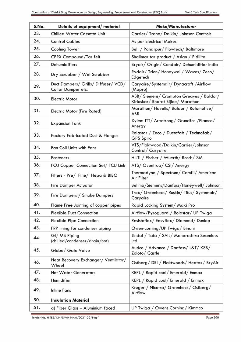
Construction of District Drug Warehouse on Design, Engineering, Procurement and Construction (EPC) Basis Vol-5 Tech Specifications
Tender No. HITES/IDN/DWH-NHM/2021-22/Pkg-1 Page 200
S.No. Details of equipment/ material Make/Manufacturer
23. Chilled Water Cassette Unit Carrier/ Trane/ Daikin/ Johnson Controls
24. Control Cables As per Electrical Makes
25. Cooling Tower Bell / Paharpur/ Flowtech/ Baltimore
26. CPRX Compound/Tar felt Shalimar tar product / Asian / Pidilite
27. Dehumidifiers Bryair/ Origin/ Condair/ Dehumidifier India
28. Dry Scrubber / Wet Scrubber Rydair/ Trion/ Honeywell/ Waves/ Zeco/
Edgetech
29. Duct Dampers/ Grills/ Diffuser/ VCD/
Collar Damper etc.
Caryaire/Systemair/ Dynacraft /Airflow
(Mapro)
30. Electric Motor ABB/ Siemens/ Crompton Greaves / Baldor/
Kirloskar/ Bharat Bijlee/ Marathon
31. Electric Motor (Fire Rated) Marathon/ Havells/ Baldor / Rotomotive/
ABB
32. Expansion Tank Xylem-ITT/ Armstrong/ Grundfos /Flamco/
Anergy
33. Factory Fabricated Duct & Flanges Rolastar / Zeco / Ductofab / Technofab/
GPS Spiro
34. Fan Coil Units with Fans VTS/Flaktwood/Daikin/Carrier/Johnson
Control/ Caryaire
35. Fasteners HILTI / Fischer / Wuerth/ Bosch/ 3M
36. FCU Copper Connection Set/ FCU Link ATS/ Oventrop/ CSI/ Anergy
37. Filters - Pre/ Fine/ Hepa & BIBO Thermadyne / Spectrum/ Camfil/ American
Air Filter
38. Fire Damper Actuator Belimo/Siemens/Danfoss/Honeywell/ Johnson
39. Fire Dampers / Smoke Dampers Trox/ Greenheck/ Ruskin/ Titus/ Systemair/
Caryaire
40. Flame Free Jointing of copper pipes Rapid Locking System/ Maxi Pro
41. Flexible Duct Connection Airflow/Pyroguard / Rolastar/ UP Twiga
42. Flexible Pipe Connection Resistoflex/ Easyflex/ Diamond/ Dunlop
43. FRP lining for condenser piping Owen-corning/UP Twiga/ Binani
44. GI/ MS Piping
(chilled/condenser/drain/hot)
Jindal / Tata / SAIL/ Maharashtra Seamless
Ltd
45. Globe/ Gate Valve Audco / Advance / Danfoss/ L&T/ KSB/
Zoloto/ Castle
46. Heat Recovery Exchanger/ Ventilator/
Wheel Ostberg/ DRI / Flaktwoods/ Heatex/ BryAir
47. Hot Water Generators KEPL / Rapid cool/ Emerald/ Enmax
48. Humidifier KEPL / Rapid cool/ Emerald / Enmax
49. Inline Fans Kruger / Nicotra/ Greenheck/ Ostberg/
Airflow
50. Insulation Material
51. a) Fiber Glass – Aluminium faced UP Twiga / Owens Corning/ Kimmco

Construction of District Drug Warehouse on Design, Engineering, Procurement and Construction (EPC) Basis Vol-5 Tech Specifications
Tender No. HITES/IDN/DWH-NHM/2021-22/Pkg-1 Page 201
S.No. Details of equipment/ material Make/Manufacturer
Insulation
52. b) Polyurethane Foam (PUF) Insulation Styrene Packaging & Insulations/Lloyd
Insulations/ Supreme
53. c) Nitrile Rubber/ EPDM Insulation with
antimicrobial
K-Flex/Superlon/Armacell/Supreme/
Aeroflex/ Aerocell
54. d) XLPE Insulation Supreme/ Vidoflex/ Trocellene
55. e) Expanded Polystyrene Insulation Styrene Packing/Mettur Beardsell/ Toshiba/
Trocellin/ Thermobreak
56. Laminar Flow HEPA Tent Systemair/TROX/American Air Filter/
Conaire/ Thermadyne/ Airtech
57. Magnehelic Gauges Mitbraus Instruments/ Dwyer / Omicron
58. Motorized Butterfly Valve Honeywell/Belimo/Danfoss/Siemens
59. Modular Pipe Supports, Brackets, Hanging System for HVAC, Roof Top Equipment
Hilti/ Gripple/ HIRA-Walraven/ Mupro
60. Paints As per Civil Works Makes
61. Pre insulated Ducts Pal/Zeco/ ALP/ Kingspan/ Spiro / UP Twiga
62. Pipe Clamps, Hangers, Suspension
Supports etc
Easyflex/Resistoflex/Diamond/ Hira-
Walraven
63. Pipe Supports-PUF Llyod insulation/ Melanpur/ Beardsell
64. Power & Control Cables As per Electrical Makes List
65. Pressure /Temperature Gauges H. Guru / Feibig / Warree/ H.D.
66. Propeller Fans
Crompton/ Khaitan/ Alstom/ Bajaj/GE/ Havells/ Maico Ventilation (Dynair)/ Marathon
67. Pressure Independent Balancing &
Control Valve – 2 Way
Siemens/ Danfoss/Oventrop /Belimo/ Castle/ Anergy/ Honeywell/ Johnson
Controls
68. Purge Valve/ Drain Valve Audco/ Advance / Anergy/ Zoloto
69. PVC /uPVC Pipes Polypack/ Supreme/ Astral/ Finolex/ AKG
70. Pot Strainer Emerald/ VTM/ Rapid Cool/ Castle
71. Red Oxide/ Zinc Chromate Primer As per Civil Works Makes
72. Refrigerant Copper Pipes Mandev Tubes/Rajco Metal/Mehta Tubes
(Max Flow)/ Kwality Tubes (Raj State)
73. Room Thermostat Honeywell/ Johnson/ Siemens/ Schneider/
Danfoss
74. RP Tissue UP Twiga/ Styrene Packing/ National
Industrial Co.
75. Split AC Units /Precision AC Toshiba/ Daikin/ Hitachi/ Carrier/ Voltas/
Blue Star/ Lloyd (Havells)
76.
Starters/ Change over switch/ Push Buttons/ Relays/ Indication Lamps/ Rotary switches/ 1-phase preventor/ Soft starter/ MCB/ MCCB/ ACB/
As per respective Electrical Makes
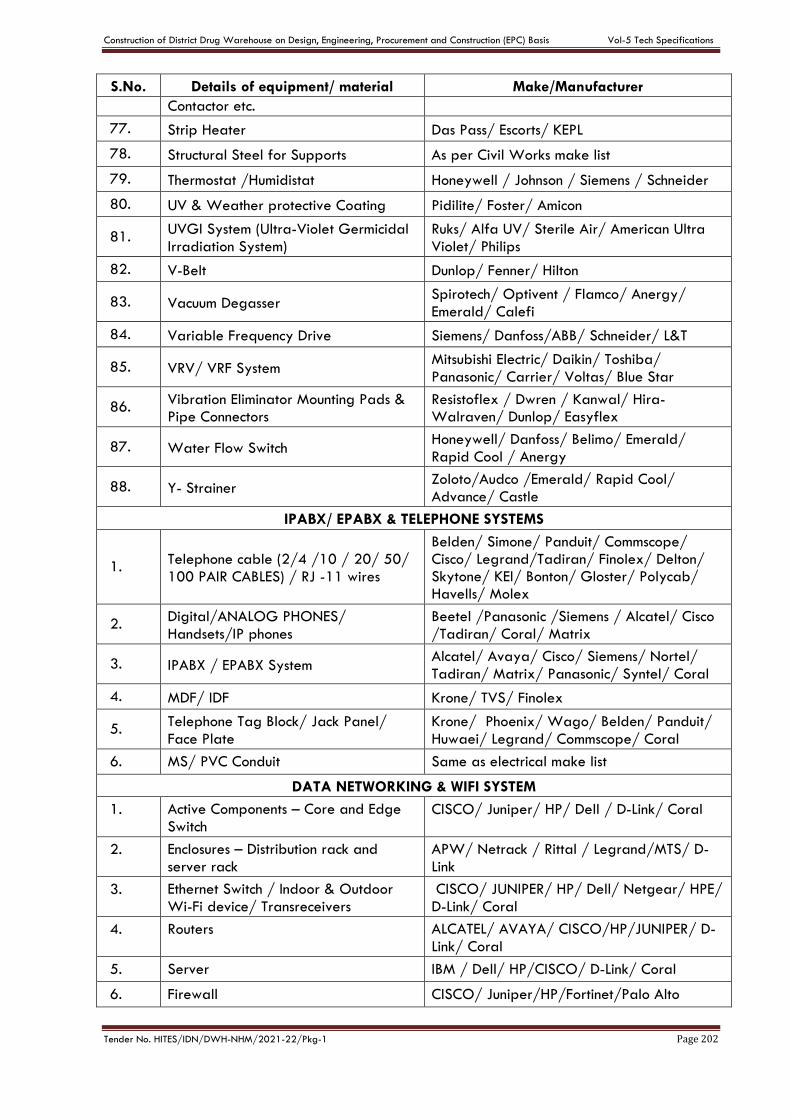
Construction of District Drug Warehouse on Design, Engineering, Procurement and Construction (EPC) Basis Vol-5 Tech Specifications
Tender No. HITES/IDN/DWH-NHM/2021-22/Pkg-1 Page 202
S.No. Details of equipment/ material Make/Manufacturer
Contactor etc.
77. Strip Heater Das Pass/ Escorts/ KEPL
78. Structural Steel for Supports As per Civil Works make list
79. Thermostat /Humidistat Honeywell / Johnson / Siemens / Schneider
80. UV & Weather protective Coating Pidilite/ Foster/ Amicon
81. UVGI System (Ultra-Violet Germicidal
Irradiation System)
Ruks/ Alfa UV/ Sterile Air/ American Ultra
Violet/ Philips
82. V-Belt Dunlop/ Fenner/ Hilton
83. Vacuum Degasser Spirotech/ Optivent / Flamco/ Anergy/
Emerald/ Calefi
84. Variable Frequency Drive Siemens/ Danfoss/ABB/ Schneider/ L&T
85. VRV/ VRF System Mitsubishi Electric/ Daikin/ Toshiba/
Panasonic/ Carrier/ Voltas/ Blue Star
86. Vibration Eliminator Mounting Pads & Pipe Connectors
Resistoflex / Dwren / Kanwal/ Hira- Walraven/ Dunlop/ Easyflex
87. Water Flow Switch Honeywell/ Danfoss/ Belimo/ Emerald/
Rapid Cool / Anergy
88. Y- Strainer Zoloto/Audco /Emerald/ Rapid Cool/
Advance/ Castle
IPABX/ EPABX & TELEPHONE SYSTEMS
1. Telephone cable (2/4 /10 / 20/ 50/
100 PAIR CABLES) / RJ -11 wires
Belden/ Simone/ Panduit/ Commscope/ Cisco/ Legrand/Tadiran/ Finolex/ Delton/ Skytone/ KEI/ Bonton/ Gloster/ Polycab/ Havells/ Molex
2. Digital/ANALOG PHONES/
Handsets/IP phones
Beetel /Panasonic /Siemens / Alcatel/ Cisco
/Tadiran/ Coral/ Matrix
3. IPABX / EPABX System Alcatel/ Avaya/ Cisco/ Siemens/ Nortel/
Tadiran/ Matrix/ Panasonic/ Syntel/ Coral
4. MDF/ IDF Krone/ TVS/ Finolex
5. Telephone Tag Block/ Jack Panel/
Face Plate
Krone/ Phoenix/ Wago/ Belden/ Panduit/
Huwaei/ Legrand/ Commscope/ Coral
6. MS/ PVC Conduit Same as electrical make list
DATA NETWORKING & WIFI SYSTEM
1. Active Components – Core and Edge
Switch CISCO/ Juniper/ HP/ Dell / D-Link/ Coral
2. Enclosures – Distribution rack and
server rack
APW/ Netrack / Rittal / Legrand/MTS/ D-
Link
3. Ethernet Switch / Indoor & Outdoor
Wi-Fi device/ Transreceivers
CISCO/ JUNIPER/ HP/ Dell/ Netgear/ HPE/
D-Link/ Coral
4. Routers ALCATEL/ AVAYA/ CISCO/HP/JUNIPER/ D-
Link/ Coral
5. Server IBM / Dell/ HP/CISCO/ D-Link/ Coral
6. Firewall CISCO/ Juniper/HP/Fortinet/Palo Alto
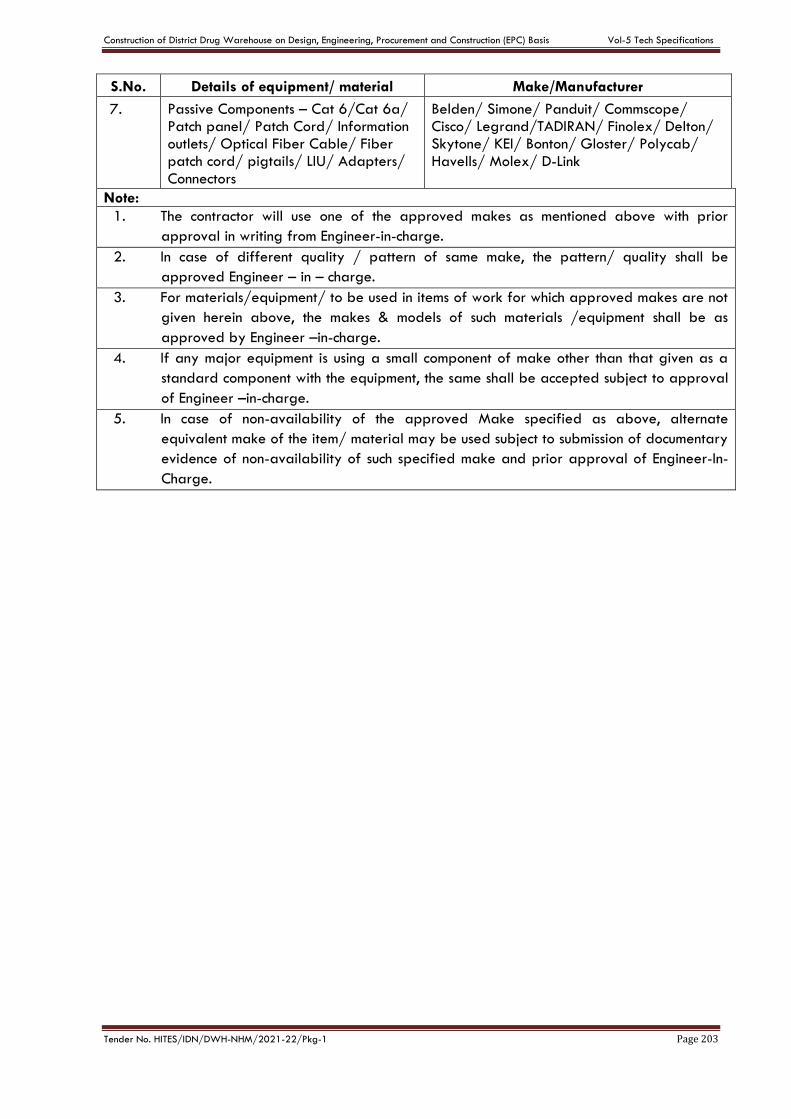
Construction of District Drug Warehouse on Design, Engineering, Procurement and Construction (EPC) Basis Vol-5 Tech Specifications
Tender No. HITES/IDN/DWH-NHM/2021-22/Pkg-1 Page 203
S.No. Details of equipment/ material Make/Manufacturer
7. Passive Components – Cat 6/Cat 6a/ Patch panel/ Patch Cord/ Information outlets/ Optical Fiber Cable/ Fiber patch cord/ pigtails/ LIU/ Adapters/
Connectors
Belden/ Simone/ Panduit/ Commscope/ Cisco/ Legrand/TADIRAN/ Finolex/ Delton/ Skytone/ KEI/ Bonton/ Gloster/ Polycab/
Havells/ Molex/ D-Link
Note:
1. The contractor will use one of the approved makes as mentioned above with prior
approval in writing from Engineer-in-charge.
2. In case of different quality / pattern of same make, the pattern/ quality shall be
approved Engineer – in – charge.
3. For materials/equipment/ to be used in items of work for which approved makes are not
given herein above, the makes & models of such materials /equipment shall be as
approved by Engineer –in-charge.
4. If any major equipment is using a small component of make other than that given as a
standard component with the equipment, the same shall be accepted subject to approval
of Engineer –in-charge.
5. In case of non-availability of the approved Make specified as above, alternate
equivalent make of the item/ material may be used subject to submission of documentary
evidence of non-availability of such specified make and prior approval of Engineer-In-
Charge.