technical specifications - african development bank
TRANSCRIPT
PROPOSED NEW OFFICES FOR AFRICAN
DEVELOPMENT BANK-RWANDA
TECHNICAL SPECIFICATIONS
CONTENTS:
SECTION I: ARCHITECTURAL WORKS
SECTION II: HVAC WORKS
SECTION III: PLUMBING & FIRE FIGHTING
WORKS
SECTION IV: IT EQUIPMENT
SECTION V: ELECTRICAL WORKS
1
- BID DOCUMENTS
ADB-RWANDA
AFRICAN DEVELOPMENT BANK- RWANDA
PROPOSED NEW OFFICES FOR ADB-
RWANDA
TECHNICAL SPECIFICATIONS
SECTION I
ARCHITECTURAL WORKS
2
- BID DOCUMENTS
ADB-RWANDA
TABLE OF CONTENTS
A. GENERAL SPECIFICATIONS .................................................................................................... 3
1.0 GENERAL NOTES ............................................................................................................... 4
2.0 GENERAL ITEMS ............................................................................................................... 6
3.0 DEMOLITIONS AND ALTERATIONS .............................................................................. 8
4.0 JOINERY ............................................................................................................................. 10
5.0 IRON MONGERY ............................................................................................................... 13
6.0 METAL WORK ................................................................................................................... 15
7.0 FLOOR, WALL AND CEILING FINISHES ...................................................................... 18
8.1.0 STANDARDS AND CODES OF PRACTICE ..................................................................... 19
9.0 GLAZING ............................................................................................................................ 22
9.0 PAINTING AND DECORATING ....................................................................................... 27
GENERAL SPECIFICATIONS 3
ADB-RWANDA
A. GENERAL SPECIFICATIONS
GENERAL NOTES 4
ADB-RWANDA
1.0 GENERAL NOTES
The Contractor is to allow in his rates for all expenses in connection with testing
of materials as specified including the supply and preparation of materials to be
tested, the cost of laboratory charges, etc. The standard measurement of
construction works for reference is the STANDARD METHOD OF MEASURING
BUILDING WORK FOR AFRICA 2015 FIST EDITION set by the Africa Association
of Quantity Surveyors (AAQS)
“Equivalent of Standards and Codes and Brand Names”
WHEREVER REFERENCE IS MADE IN THE CONTRACT TO SPECIFIC
STANDARDS AND CODES TO BE MET BY THE GOODS AND
MATERIALS TO BE FURNISHED, AND WORK PERFORMED OR
TESTED, THE PROVISIONS OF THE LATEST CURRENT EDITION OR
REVISION OF THE RELEVANT STANDARDS AND CODES IN EFFECT
SHALL APPLY, UNLESS OTHERWISE EXPRESSLY STATED IN THE
CONTRACT.
GENERAL NOTES 5
ADB-RWANDA
Where such standards and codes are national, or relate to a particular country or region,
other authoritative standards that ensure a substantially equal or higher quality than the
standards of codes specified will be accepted subject to the Engineer/Project Manager’s
prior review and written consent. Differences between the standards specified and the
proposed alternative standards shall be fully described in writing by the Contractor and
submitted to the Engineer/Project Manager at least 28 days prior to the date when the
Contractor desires the Engineer/Project Manager’s consent. In the event, the
Engineer/Project Manager determines that such proposed deviations do not ensure
substantially equal or higher quality, the Contractor shall comply with the standards
specified in the documents.
ALL MATERIALS USED IN THE WORKS FOR WHICH NO RWANDAN
NATIONAL BUREAU OF STANDARDS SPECIFICATION HAS BEEN
PUBLISHED SHALL CONFORM TO THE EURO STANDARD OR THE
BRITISH STANDARD SPECIFICATION FOR SUCH MATERIALS. IF THERE
IS NO PUBLISHED STANDARDS AS SPECIFIED FOR ANY MATERIALS,
THE QUALITY OF SUCH MATERIAL SHALL BE GENERALLY OF A
STANDARD EQUAL TO THOSE FOR WHICH THERE IS A RWANDA
STANDARDS OR EUROPEAN STANDARD OR BRITISH STANDARD
SPECIFICATION.
GENERAL ITEMS 6
ADB-RWANDA
2.0 GENERAL ITEMS
GENERAL ITEMS 7
ADB-RWANDA
2.0 GENERAL ITEMS
2.1 Materials generally
All materials shall be new and of the qualities and kinds specified herein and equal to
approve samples. Deliveries shall be made sufficiently in advance to enable samples to be
taken and tested if required. No materials shall be used until approved. Materials which are
damaged in any way shall be immediately removed from the site at the Contractor’s
expense.
2.2 Alternatives to proprietary brands or specified standards
Where materials are specified to a particular standard or by their proprietary names or
where fittings are specified by catalogues, numbers or descriptions, the Contractor may
offer alternatives which are of equal quality. In such event the tender must be qualified by
listing the various alternatives to be used. The successful tenderer must then subsequently
submit samples of the alternative materials to the Engineer as soon as practicable after the
award of the Contract, and must obtain his written approval before purchasing.
2.3 Measuring and testing equipment
The Contractor shall provide on the Site the following equipment for carrying out
measuring and control tests and maintain the same in full working order, if relevant to the
scope of the works:-
a) Straight edges 2 metres and 4 metres long for testing accuracy of finished surfaces
b) Two 30 metres steel tapes.
c) Two digital caliper.
2.4 Minor details of construction
Minor details of construction which are fairly and obviously intended and which may not
definitely be referred to in this Specification and/or Drawings, but which are usual in sound
building practice and are essential to the Works, shall be considered as included in the
Contract Sum.
2.5 Samples
The Contractor is to allow in his rates for all expenses in connection with testing of
materials as specified including the supply and preparation of materials to be tested, the
cost of laboratory charges, etc.
JOINERY 8
ADB-RWANDA
3.0 DEMOLITIONS AND ALTERATIONS
JOINERY 9
ADB-RWANDA
3.0 DEMOLITIONS AND ALTERATIONS
3.1 GENERALLY
The Contractor is required to visit the site of the existing building and ascertain for himself the
nature of the works and no claim arising from lack of knowledge in this respect will be entertained.
The dimensions and quantities given in this section are approximate and the Contractor is referred
to the site to ascertain the exact nature of the work. The items pulling down and alterations are to
include for both labour and materials and for any shoring, needling and temporary works in
connection therewith. The Contractor must allow in his pricing for making good all works
disturbed in all trades and carting away all debris.
The Contractor must give all the necessary notices and must exercise due care in the demolitions.
He must not collapse large sections of walls, floors, etc. and must provide all necessary shoring and
supports during the demolitions. During demolition the Contractor shall keep the debris constantly
watered to minimize the dust arising and this shall be included in his prices.
All materials arising from the demolitions, unless specifically stated otherwise, are to become the
property of the Contractor and any credit allowed for the value of such materials shall be shown in
the space provided, if any or valued and negotiated with the Project Manager. All materials,
including rubbish, shall be removed from the site as soon as possible.
3.2 INTERPRETATION OF TERMS
a) “Demolish” shall be deemed to mean cutting away, breaking up, demolishing, pulling
down, taking down, removing, etc., as the context requires and shall include in all cases temporarily
strutting and supporting and making good remaining works as necessary, and clearing away and
removing from site all debris, etc.
b) “Remove” shall be deemed to mean taking down, hacking up, breaking down, removing,
etc., and clearing away from site and all other expenses thereby entailed.
c) “Making good” shall be deemed to mean all making good, fitting, facing up, plastering,
repairing and repainting of match existing work.
d) “To match” shall mean to be equal to relevant existing work in design, workmanship and
all other respects.
e) “Re-fix” shall apply to existing materials arising from the works and shall mean take from
store and fix in new position, including making good, repairing and adjusting as necessary.
JOINERY 10
ADB-RWANDA
4.0 JOINERY
JOINERY 11
ADB-RWANDA
4.0 JOINERY
4.1.0 STANDARD AND CODES OF PRACTICE
The requirements of the following British Standards and codes of Practice
shall be observed:-
4.1.1 British Standards
a) B.S. 565 Glossary of terms relating to timber and woodwork.
b) B.S. 459 part 2 Flush doors
c) B.S. 1567 Wood door frame and linings
d) B.S. 1210 Wood screws
e) B.S. 1494 part 2 Fixing accessories for building purposes (bolts, screws,
staples, etc)
f) B.S. 4174 Felt tapping screws and metallic drive screws.
4.1.2 Codes of Practice
C.P. 151 Doors and windows including frames and linings
4.2.0 MATERIALS
4.2.1 Medium Density Fibreboard (MDF)
MDF shall be used wherever possible in place of blockboard or chipboard. The MDF used shall
be to the thickness specified, shall be flat, smooth, straight, without any imperfections, surface
distortion, broken or chipped edges. MDF used in damp locations (i.e. toilets) shall be
moisture resistant MDF.
4.2.2 Laminated Plastic Sheeting
Laminated plastic sheeting shall be 1.5mm “Formica” or other approved sheeting complying
with B.S.3794 Class 1, in colours to be selected by the Engineer.
Prior to fixing laminated sheeting, the Contractor shall obtain the Engineer’s written approval
to a sample.
5.3.0 GYPSUM PARTITIONS
Supply and installation of gypsum partitions 2.75 m high as per proposed layouts including
inner frame reinforcement for the installation of sanitary fittings, accessories, doors,
handrails etc. Gypsum boards shall be suitable for installation in wet areas.
JOINERY 12
ADB-RWANDA
IRONMONGERY 13 ADB-RWANDA
5.0 IRON MONGERY
IRONMONGERY 14 ADB-RWANDA
5.0 IRON MONGERY
5.1.0 STANDARDS AND CODES OF PRACTICE
5.1.1 British Standards
a) B.S. 1227 part 1 A Hinges
b) B.S. 2028 Performance test for locks
c) B.S. 2911 Letter plates
d) B.S. 4112 Performance requirements for hardware
for domestic furniture
5.2.0 MATERIALS AND WORKMANSHIP
All locks and ironmongery shall be fixed with screws, etc to match. Before woodwork or
steel work is painted, handles shall be removed, carefully stored and re-fixed after
completion of painting and locks oiled and left in perfect working order.
All keys shall be labelled with the door reference on labels before handing to the
Engineer on completion. All ironmongery shall be carefully protected until completion
of the work and any damage is to be made good at the contractor’s expense.
Rates shall allow for easing and adjusting all doors, etc and for lubricating all locks,
hinges, etc. and left in perfect working order.
Where descriptions fixing ironmongery include catalogue numbers, such items shall be
obtained from the specified manufacturers if at all possible.
Rates shall include for labelling all keys with door references as directed by the Engineer.
All keys shall be provided with two keys and no keys are to pass the ward of any but its
own.
METAL WORKS 15 ADB-RWANDA
6.0 METAL WORK
METAL WORKS 16 ADB-RWANDA
6.0 METALWORK
6.1.0 STANDARDS AND CODES OF PRACTICE
The requirements of the following British Standards and Codes of Practice
shall be observed:-
6.1.1 British Standards
a) B.S. 916 Black bolts screws and nuts.
b) B.S. 4174 Self tapping screws and metallic drive screws.
c) B.S. 405 Metal washers for general engineering purposes.
d) 1161 and addendum Aluminium and aluminium alloy sections for general engineering
purposes.
e) B.S. 938 Metal ore welding of structural steel tubes.
f) B.S. 1474 Wrot aluminium and aluminium alloy
6.1.2 Codes of Practice
a) C.P. 2008 Protection of iron and steel structures from
corrosion.
b) C.P. 3012 Cleaning and preparation of metal surfaces.
6.2.0 MATERIALS AND WORKMANSHIP
Iron and steel where galvanised shall comply with the requirements of
B.S. 729, part 1 entirely coated with fine fabrication by complete
immersion in a zinc bath in one operation and all excess carefully
removed.
The finished surfaces shall be clean and uniform.
METAL WORKS 17 ADB-RWANDA
All work in aluminium shall comply with the requirements of the
standard mentioned above. Aluminium frames should be not less than
1.5 mm thick
All smiting and bending shall be soundly and neatly executed, care being taken not to
overheat.
All strap bolts and similar work shall be forged neat and clean from the anvil.
All welded connections shall be ground to a smooth finish and rates shall be deemed to
allow for this.
Steel windows shall comply with the requirements of the standard mentioned above and
shall be fixed in accordance with the manufacturer’s instructions.
All mild steel except galvanised shall be cleaned of rust and scale, painted one coat red
lead priming paint before delivering to site and the rates shall include for this.
FLOOR, WALL AND CEILING FINISHES 18
ADB-RWANDA
7.0 FLOOR, WALL AND CEILING FINISHES
FLOOR, WALL AND CEILING FINISHES 19
ADB-RWANDA
7.0 FLOOR, WALL AND CEILING FINISHES
7.1.0 STANDARDS AND CODES OF PRACTICE
The requirements of the following British Standards and Codes of Practice shall
be observed.
British Standards
a) B.S. 1281 Glazed ceramic tiles and tile fittings
for internal walls.
b) C.P 202 Tile flooring and slab flooring
c) C.P. 212 part 1+2 Wall tiling
d) C.P. 209 Care and maintenance of floor surfaces
7.2.0 MATERIALS AND WORKMANSHIP
7.3.0 SCREEDS AND PAVINGS
All screeds and pavings shall be finished smooth, even and truly level,
unless otherwise specified and paving shall be steel trowel led.
7.4.0 FINISHING
Plastering shall be finished plumb, square, smooth, hard and even and junctions
between surfaces shall be perfectly true straight and square.
All work not found to be of satisfactory standard shall be hacked away and made good
at the Contractor’s expense.
7.5.0 GLAZED WALL TILES
Glazed wall tiles shall be cushion edged and satisfy the relevant Standard as
mentioned earlier. Tiles shall be well soaked in water laid with straight horizontal and
vertical joints painted in white cement and cleared down at completion.
FLOOR, WALL AND CEILING FINISHES 20
ADB-RWANDA
Tiles joints of 2mm width shall be formed and filled with the redding mix but using
very fine, well screened, care shall be taken that tiles are not over soaked and water
shall be avoided during fixing.
The fixed tiles shall be kept damp for 4 days. Tiles as slash backs to lavatory basins,
sinks and baths shall be fixed with necessary rounded-edge corner tiles.
Rates for linear items shall allow for all special fittings and cutting at angles and
intersections.
7.6.0 GENERAL
Rates for in-situ work shall allow for raking out joints walling or hacking of treating
with an approved bonding fluid. Hacking concrete form key, dubbing out irregular
surfaces of base to provide a finished surface in the same plane as the surrounding
surface, cutting out cracks, making good and leaving the whole of the work sound and
perfect on completion.
Rates shall also allow for fair edges, whether square, splayed or rounded, arises,
chamfered external angles not exceeding 25mm wide, rounded external angles not
exceeding 25mm radius coved internal angles not exceeding 25mm radius,
intersections to groins and the like, and for making good round pipe, brackets, floor
spring boxes and all other items of a like nature.
7.7.0 CERAMIC TILE PAVINGS AND ACCESSORIES
Ceramic tiles and accessories of the type described herein are to be
fixed with an adhesive to comply with BF Code of Practice 202 :
1972 (“ tile flooring and flab? Flooring”), tiles are to be laid with
close straight joints in each direction and upon completion grouted in
matching coloured cement and washed and cleaned down.
Tiles are to be cut with an electric tile cutting saw.
7.8.0 CEILING AND ACCESSORIES

FLOOR, WALL AND CEILING FINISHES 21
ADB-RWANDA
Providing and fixing tiled false ceiling of approved materials of size 595x595 mm in true
horizontal level suspended on inter locking metal grid of hot dipped galvanized steel
sections ( galvanized @ 120 gsm/sqm, both side inclusive) consisting of main "T" runner
with suitably spaced joints to get required length and of size 24x38mm made from 0.30mm
thick (minimum) sheet, spaced at 1200mm center to center and cross "T" of size 24x25mm
made of 0.30mm thick (minimum) sheet, 1200mm long spaced between main "T" at 600mm
center to center to form a grid of 1200x600 mm and secondary cross "T" of length 600mm
and size 24x25mm made of 0.30 mm thick (minimum) sheet to be interlocked at middle of
the 1200x600mm panel to form grids of 600x600mm and wall angle of size 24x24x0.3 mm
and laying false ceiling tiles of approved texture in the grid including, wherever, required,
cutting/making, opening for services like diffusers, grills, light fittings, fixtures, smoke
detectors etc. Main "T" runners to be suspended from ceiling using GI slotted cleats of size
27 x 37 x 25 x1.6 x mm fixed to ceiling with 12.5 mm dia and 50 mm long dash fasteners,
4mm GI adjustable rods with galvanised butterfly level clips of size 85 x 30 x 0.8 mm
spaced at 1200mm center to center along main T, bottom exposed width of 24 mm of all T-
sections shall be pre-painted with polyester paint, all complete at all heights as per
specifications drawings and as directed by Engineer in-charge.
12.5mm thick square edge PVC Laminated Gypsum Tile of size 595x595mm, made of
Gypsum plasterboard; manufactured from natural gypsum as per IS 2095 part I and
laminated with white 0.16mm thick fire retardant PVC film on the face side and 12micron
metalized polyester on the back side with all edges sealed with the face side PVC film which
goes around and wraps the edges and is bonded to the edges and the back side metalized
polyester film so as to make the tile a completely sealed unit.
The ceiling for replacement should be similar to the existing one
GLAZING 22
ADB-RWANDA
8.0 GLAZING
PAINTING AND DECORATING 23
ADB-RWANDA
GLAZING
8.1. 0 STANDARDS AND CODES OF PRACTICE
The requirements of the following British Standards and Codes of Practice shall
be observed.
British Standards
a) B.S 952 Glass for glazing.
b) NOTE: The Contractor’s attention is drawn to Section “T” of
the Standard Method of Measurements.
Codes of Practice
c) C.P. 152 Glazing and fixing glass for buildings.
8.2.0 MATERIALS AND WORKMANSHIP
The whole of the glass shall be of the best quality and be free from bubbles, specks,
wave’s flaws or any other defects and shall comply with the requirements of the
standard mentioned above.
All glass is to be accurately cut to fit easily into rebates. Glass shall be well puttied and
sprigged with copper springs.
Glazing to wood frames shall be secured with glazing beads fixed with brass caps and
screws and wash leather or approved “Neoprene” beading strips. Putty for lazing in
wood frames shall be composed of pure linseed oil and powdered whiting, free from
grittiness all in accordance with the standard mentioned above.
Glazing to metal frames shall be with clips, glass shall be properly back puttied and the
front putty finished neatly and cleanly.
Putty for glazing in metal frames shall be quick hard setting tropical putty specially
manufactured for use with steel windows.
PAINTING AND DECORATING 24
ADB-RWANDA
Rebates of metal frames receiving glass shall be prepared and treated with primer for putty
prior to glazing and putty shall be primed 10 days after glazing.
Rates for glazing Georgian wired glass shall include for aligning lines in adjoining panes both
ways.
Glass panes shall be cut to sizes to fit the opening with not more than 1.6mm play all round.
Clear sheet shall be ordinary glazing (OQ) quality and polished plate shall be (GG) quality.
Mirrors to be of selected glazing (S.G) quality plates glass of approved manufacture with
beveled edge and fixed at all corners to walls with raw plugs and brass screws with
removable chromium plated dome heads.
Cut out all cracked or broken glass re-glazed to match and leave perfect on completion. On
no account shall windows be cleaned by scraping with glass.
8.3.1 PARTICULAR SPECIFICATIONS
8.3.1 GLAZING
8.3.1.1 Definitions
8.3.1.1 Fixings
The provision of glazing compounds and putties and sprigs, clips and other sundry
fixings, shall be deemed to be included with all items of glazing.
10.3.1.2Materials
8.3.1.1.2.1 Glass Generally
All glass shall comply in all respect with the appropriate section of B.S.952. Plain
sheet clear glass shall be O.Q; plate glass shall be GG; all glass shall be as manufactured
by Pilkington Brothers Limited or another approved manufacturer.
8.3.1.2.2 Putty for Glazing to Metal
PAINTING AND DECORATING 25
ADB-RWANDA
Putty for glazing to metal shall be approved mastic manufactured for the purpose, used
in accordance with the manufacturer’s instructions.
8.3.1.2.3 Samples
Samples not less than 150mm square are to be submitted to the Engineer for approval
before any glass is cut.
8.3.1.2.4 Workmanship
8.3.1.2.4.1 Glass to be kept free from moisture
All glass surfaces shall be kept dry during transit and storage. Glass becoming moist from
condensation or other causes shall be thoroughly dried and aired.
8.3.1.2.4 Rebates and Beads
All rebates and beads in wood shall be primed, before glazing is commenced.
8.3.1.2.4.2 Edges of Glass
All glass shall have clean cut edges. All exposed edges (i.e. louvers) shall be rounded and
polished.
8.3.1.2.4.3 Bead Glazing
Glazing fixed by beads shall have both glass and beads bedded and back puttied, and the putty
trimmed off flush. Where sealing strip is used, it shall pass round both faces of the glass and
be trimmed off flush on both sides. Metal surfaces to receive sealing strip shall be treated
with mineral oil before glazing.
8.3.1.2.4.4 Putty Glazing
Glazing in putty shall be executed in proper bed and back putties, sprigs, clips and splayed
and mitred front putties. The back putties shall be trimmed off flush with the top of rebate
and the splayed front putties shall be finished 3 mm back from sight line to allow for
sealing between glass and putty with paint.
PAINTING AND DECORATING 26
ADB-RWANDA
8.3.1.2.4.5 Wired Glass
Wired glass shall in all cases be 6 mm Georgian wired, either polished or cast as specified.
The wire in wired glass shall extend to the edges and be free from rust, and be parallel to the
framing.
8.3.1.2.4.6 Mirrors
All mirrors shall be 6 mm polished plate, foil backed and with rounded polished edges.
Mirrors with chips, cracks, scratches on back or front will not be accepted.
8.3.1.2.4.7 Safety Glass
All glass fixed below 900mm above floor level shall be either 6mm clear toughened or
6.5mm clear laminated, unless specified otherwise.
All other glass to doors and internal partitions shall be 6mm clear float glass.
Glass to existing windows shall match the original or adjacent glass.
8.3.1.2.4.8 Glass to Partitions
Glass to internal aluminium partitions shall be fixed in accordance with the approved partition
system and as recommended by the supplier / manufacturer. The glass for patition should be
not les than 10 mm thick unless otherwise directed by the Engineer in charge
PAINTING AND DECORATING 27
ADB-RWANDA
Th
9.0 PAINTING AND DECORATING
PAINTING AND DECORATING 28
ADB-RWANDA
9.0 PAINTING AND DECORATING
9.1.0 STANDARD AND CODES OF PRACTICE
The requirements of the following British Standards and Codes of Practice shall
be observed:-
British Standards
a) B.S. 4756 Ready mixed aluminium priming paints for woodwork
b) B.S. 3842 Treatment of plywood with preservatives.
c) B.S. 4800 Paint colours for building purposes
d) B.S 2524 Red-Oxide-Linseed oil priming paint
e) B.S. 2525-7 Undercoating and finishing paints
Codes of Practice
f) C.P. 231 Paints for buildings
g) C.P. 3012 Cleaning and preparations of metal surfaces.
9.2.0 GENERAL
All work under this trade must be executed by an approved specialist unless otherwise
permitted.
The Contractor’s Programme in this area shall be so arranged that all others trades are
completed and away from the area to be painted prior to the commencement of painting.
Before painting the Contractor must remove all concrete and mortar droppings and the like
from all work to be decorated and remove all strains from and obtain uniform colour to
work to be oiled and polished.
9.3.0 MATERIALS AND WORKMANSHIP
All plaster, metal, wood or other surfaces which are to receive finishes of paint, stain, polish,
distemper or paint work of any description are to be carefully inspected by the Contractor
before he allows any of his painters to commence work. The Contractor will be held solely
responsible for all defective work as a result of his painter’s failure to insist on receiving from
the other trades surfaces in the proper condition to allow first class finishes to the various kinds
specified being applied to them.
PAINTING AND DECORATING 29
ADB-RWANDA
All painting and decorating schemes shall be carried out in colours selected by the Engineers.
Paints shall be ready mixed, oil based priming paint shall comply with the requirements of the
relevant standards mentioned earlier.
The oil shall comply with the requirements of B.S. 1215
All materials shall be of the best quality and shall be of an approved proprietary brand selected
from the latest Schedule of Approved paints issued by the Ministry of Works.
Materials to be applied externally shall be of external quality and/or recommended by the
manufacturers for external use.
Materials shall be delivered to site intact in the original sealed drums ortins and shall be mixed
and applied strictly in accordance with the manufacturer’s instructions and to the approval of
the Engineer.
Unless specifically instructed or approved by the Engineer, no paints, distemper etc. are to be
thinned or otherwise adulterated, but are to be used as supplied by the manufacturers and direct
from the tins.
If required by the Engineer the Contractor shall provide at his own expense samples of paints
etc. with containers and cases to be forwarded, carriage paid, by the Contractor for analyzing
to a laboratory.
The priming, undercoat and finishing coats shall each be of differing tints, and the priming and
undercoats shall be the correct brands and tints to suit the respective finishing coats, in
accordance with the manufacturer’s instructions. All finishing coats shall be of colours and
tints selected by the Engineer. Each coat must be approved by the Engineer before the next
coat is applied.
Each coat shall be properly dry and in the case of oil or enamel paints shall be well rubbed
down with fine glass paper before the next is applied. The paintwork shall be finished smooth
and free from brush marks.
Colour cards of all paints etc. shall be submitted to, and samples prepared for approval of the
Engineer before laying on, and such samples, when approved, shall become the standard for
the works.
PAINTING AND DECORATING 30
ADB-RWANDA
All paints, emulsion paints, and distempers shall be applied by means of a brush or spray gun
or rollers of an approved type, where so agreed by the Engineer.
No painting is to be done in wet weather or on surfaces which are not thoroughly dry.
Woodwork to be painted shall be rubbed down and all knots and resin pockets shall be
scorched back and coated with knotting. After priming all nail holes and other imperfections
shall be stopped and the whole surface be rubbed down and all dust brushed off. The surface
of woodwork shall be lightly sand prepared between the coats.
All work in contract with walling or plaster shall be treated after cutting and preparation but
before assembly or fixing with one coat of wood preservative. The solution is to be brushed on
all faces of all timbers, unless exposed to view and painted. The Contractor shall not that this
solution is poisonous and shall take all necessary precautions and instruct his workmen
accordingly.
Wax polish shall be furniture polish of an approved branch, and wood surfaces shall be clean
smooth free from oil or grease or any other blemishes. A minimum of two coats shall be
applied to approval.
Plaster surfaces shall be perfectly smooth free from defects and ready for decorations. All
such surfaces shall be allowed to dry a minimum period of six weeks, stopped with approved
plaster compound stopping and rubbed down flush as necessary, and then thoroughly,
immediately prior to decorating.
Plaster surfaces which are to be finished with emulsion, oil or enamel paint shall be primed
with an alkali resisting primer complying with the particular paint manufacturer’s
specifications and applied in accordance with their instructions.
Fibre board or similar surfaces shall be lightly brushed down to remove all dirt, dist or loose
particles and have all nail holes or other defects stopped with an approved plaster compound
stopping rubbed down flush and left with a texture so match surrounding materials and shall
receive one coat petrifying liquid at last or two coats polyurethane or clear laquar.
All metal surfaces shall be thoroughly brushed down with wire brushes and scrapped where
necessary to remove all scale, rust, etc. immediately prior to decorating.
PAINTING AND DECORATING 31
ADB-RWANDA
Where severe rust exists and if approved by the Engineer a proprietary de-rusting solution may
be used in accordance with the manufacturer’s instructions.
Hot primed and unprimed surfaces shall be given one coat of metal chromate primer.
Galvanized surfaces shall be treated before painting with an approved proprietary or de-
greasing solution before priming.
Coated surfaces already treated with bituminous solution shall be scrapped to remove soft parts
and then receive two isolating coats of aluminium primer or other approved anti-tar primer.
Existing painted and decorated surfaces shall be prepared as described above. Painted plaster,
metal or wood surfaces shall then be rubbed down to expose the material beneath and old paint
burnt off with blow torches if necessary in the Engineer’s opinion.
Emulsion paint on ceilings and all undercoats of emulsion paint and complete oil painting on
walls shall be completed before PVC flooring are laid. Final coat of emulsion paints on walls
shall be applied after such flooring has been laid complete.
Three coats of emulsion paints shall be applied to receiving surfaces using a thinning medium
or water only if and as recommended by the manufacturer. An approved plaster primer tinted
to match may be substituted for the first coat.
Enamel paint shall be applied in two undercoats and one finishing coat after preparation and
priming as specified above.
All ironmongery shall be removed from joinery steel windows and louver before painting is
commenced and shall be cleaned and renovated if necessary and re-fixed after completion of
painting.
Rates for painting shall be deemed to include for preparing and priming surfaces above
described.
Rates for paints, distemper etc. shall allow for covering up all floors, fittings, etc. with dust
sheets when executing the work and for removing, covering when no longer required and floor
cleaning off, touching up and leaving perfect at completion.
Technical specifications/HVAC
1
AFRICAN DEVELOPMENT BANK- RWANDA
PROPOSED NEW OFFICES FOR ADB-
RWANDA
TECHNICAL SPECIFICATIONS
SECTION II
HVAC WORKS
Technical specifications/HVAC
2
TECHNICAL SPECIFICATION FOR HVAC SYSTEM
INSTRUCTIONS TO TERMS AND CONDITIONS
1. General
T h e Intent of these specifications is to define the requirements for design,
supply, installation, testing & commissioning of HVAC System specifically Air condition VRF
system that shall embeds existing system and additional indoor units plus and Dual backup split
units system. The entire work shall be carried out in accordance with these terms and
conditions and generally as per the scope drawings as per the design. The liability of the
contractor shall not be limited to the scope of work mentioned below, but shall also extend t o
achievement of the inside conditions as well as complete, safe and satisfactory operation
of the system as approved by the Engineer In- Charge/client. Any alternations/additions,
equipment, apparatus, instruments, material and labour required in order to achieve the
completeness of the HVAC system as above shall be deemed to be included in the scope of
the contractor without any extra cost to the client, whether the same have been covered or not
in the specifications and drawings. However, any changes required in design and installation
shall be brought to notice of the Engineer In-Charge; and due approval shall be obtained
therefore.
2. Scope of Work:
The scope of work covered under this tender includes design, supply, installation,
testing & commissioning of the introduced cassettes in partitioned rooms and dual split units
for the server room the application mentioned, and shall be generally as per the schedule of
quantities and scope/tender drawings.
3. Tender Drawings:
The tender d r a w i n g s , which are enclosed herewith, shall serve as s c o p e drawings. They
indicate the general scheme of the HVAC system requirement. However, actual location,
distance, levels, etc. Will be governed by actual field conditions. The contractor shall check
architectural, structural, water sprinkling pipes, drainage, false ceiling, lighting and other
services plans to avoid possible installation conflicts.
Technical specifications/HVAC
3
Should drastic changes from original plan be necessary to resolve such conflicts, the
contractor shall notify the Engineer In-Charge and secure written approval before the
installation is started.
Discrepancies in different plans or between plans and actual field conditions or between plans
and specifications shall be promptly brought to attention of the Engineer In-Charge for a
decision.
4. Codes & Regulations:
The installation shall be in conformity with bye-laws and regulations of Rwanda Housing Authority
in so f a r as these become applicable to the installation. The installation shall also be in
conformity with t h e relevant codes of t h e British Standards, International Standards
o r g a n i z a t i o n and ASHRAE standards. Wherever a reference of Standard specification
is made in this document, it should imply the latest revision of that standard, including such
revisions/amendments as may be issued by the issuing authority, during the course of the
work contract. Compliance with all the applicable laws/rules pertaining to materials and
workers/personnel shall be the liability of contractor.
In case the drawings and/or specifications require something which violates the bye- laws
and regulations then the bye-laws and the regulations shall govern the requirement of this
installation and the fact shall be brought to the notice of the Engineer In-Charge.
5. Supervision by the contractor: The contractor shall have sufficient supervisory work force so that
one supervisor may be available on each job for day-to-day site work. The contractor shall have to
arrange day-to-day planning and execution of each j o b . All measuring tapes (of steel), scaffolding
and ladders which may be required for installation and taking measurements shall be
supplied the contractor.
6. Whole work must be carried out to RHA satisfaction and as per instruction of RHA
Engineer in charge.
7. Quality is essential part of the whole project and no compromise will be entertained as far as the
quality of the work is concern strictly in all respect of the work.
8. Materials & Workmanship:
The materials used by the contractor shall be new, free from defects and of the best quality and
workmanship and shall be in conformity with the latest and best engineering practice. The entire
installation work shall comply with the applicable standard specifications of:
(a) British Standards.
(b) The Air Conditioning and R e f r i g e r a t i o n Institute of America (ARI).
Technical specifications/HVAC
4
(c) American Society o f Heat ing , Refrigerating & Air Conditioning E n g i n e e r s (ASHRAE).
9. The contractor shall employ a qualified Erection Engineer at site who shall be assisted by
adequate number of skilled and experienced staff.
10. Any material supplied by the c o n t r a c t o r , if damaged in any way during cartage or
Execution of work or otherwise, shall be made good by the contractor at his own cost.
11. Working Drawings:
On award of the work, the contractor shall submit to t h e Engineer In-Charge detailed
Working Drawings
(as per reference list given at the end of this section) covering all items of equipment and
installation. Shop/working drawings shall show detailed dimensions of all
equipment, exact position of air/water intakes, outlets & exhaust, space requirements for
access, repair and maintenance for equipment, frame details, support details, foundation
drawings etc. The shop/working drawings shall also contain details of other services that are
r e q u i r e d for installation/completeness of HVAC system, cutouts, openings, framework,
foundations etc.- whether covered under HVAC scope or not. Soft copy and minimum 2 sets of
hard copies (paper copies) of all drawings shall be submitted to Engineer In-Charge for
a p p r o v a l /comments. After technical approval, soft copy and necessary sets of hard copies
shall be submitted for Engineer In – Charge and client.
12. Approval of Drawings:
No fabrication and installation should be put into execution until the relevant working
drawings are approved by the Engineer In-Charge.
The contractor shall initially submit in duplicate the drawings prepared by him for checking and
verification
By the Engineer In-Charge. The contractor shall submit adequate copies of final drawings as
required by Engineer In-Charge/client on approval. While it will be attempted to accord the
technical approval of the contractor's shop/working drawings on an expeditious basis, it will be
the responsibility of the contractor to secure from the other related agencies like the
Architect, Interior Designer, etc. their approval for the scheme of installation as far as the
building & interior layouts, aesthetics, etc. are concerned.
Approval of the drawing by the Engineer In-Charge shall in no way relieve the contractor from
the responsibility of providing a complete and satisfactory installation and achieving
& maintaining the stipulated design conditions. Any errors, omissions and shortfalls shall
be rectified, and made good free of cost to the client regardless of the fact that the
installation may in the first place have been carried out as per the approved drawings.
Technical specifications/HVAC
5
13. Schedule of Quantities:
(a) The quantities of ducting, insulation, piping, cabling, etc. mentioned in the tender
Documents are tentative and are given for tenderer's guidance and to have uniform basis for
tendering. The contractors should quote unit rates for variation in quantities.
(b) The accompanied tender drawings show the route of ducts, pipes, cutouts provided in slabs,
beams, etc. and the equipment layout. Should there be any ambiguity in plans and
specifications or obstructions, the same should be brought to the notice of the Engineer In-
Charge while submitting the tender documents.
(c) The contractor should carry out detailed calculations for estimating the quantities of variable
quantity items on approval of drawings. Increase or reduction in the quantities of variable items
shall be p a y a b l e or d e d u c t e d at the unit rate for that particular item. Any extra item not
covered under the schedule of quantities but needed for the completion of the work shall be
first approved by the Engineer In-Charge/client. The contractor shall submit a quotation for
such i t e m s before h e commences work or purchases material i n connection with such item(s).
The quotation shall show the rate analysis, namely the break-up of material, labour, profit,
overheads, etc. In case the estimated quantity exceeds the quantity mentioned in Schedule
of Quantities by over 5%, written approval from the client and the Engineer In-Charge
should be obtained before delivering the item/s, failing which, no claim for increase in final
Contract Value may be entertained on this account.
14. During progress of the work, completed portions of the building may be occupied and put to
use by the owner but the contractor will remain fully responsible for maintenance
of HVAC installations till the entire work covered under his contract is satisfactorily
completed by him and taken over by the owner.
15. Testing:
(a) All equipment and space conditions shall be tested to establish equipment ratings and
indoor space conditions. The test results shall be furnished to the Engineer In- Charge as
per the tender. Instruments required for testing shall be furnished by the contractor.
(b) After testing and commissioning, all equipment shall be painted in an approved manner. (c) All
equipment shall be guaranteed for the specified ratings with +/- 3% tolerance.
(d) After all the tests and adjustments have been made; the plant shall be put to run- test as per
frequency & duration specified by the Engineer In-Charge.
Technical specifications/HVAC
6
16. Training:
The contractor shall provide free training at site in operation of the System supplied by him to
the client. The duration of training shall be till the time client is completely conversant
with the operation of the System.
17. Submission by the Contractor on completion:
The contractor shall submit two complete sets of As Built drawings & documents to the
Engineer- in-charge after completion of the work. These drawings & documents must give
following information:
(a) Testing & Validation Results.
(b) Piping, cabling ODU and IDU layouts.
(c) Schematic & route drawings for piping installation
(d) Detailed operating instructions
(e) Detailed maintenance schedule for smooth running of the HVAC System.
(f) List of spare-parts required to maintain the System for two years of operation.
18. Guarantee/Defects Liability:
The contractor shall guarantee the installation for a period of 12 months from the date
of Taking Over by the client, and submission of stipulated documents, regardless of the
date of supply/erection of any equipment. Guarantee s h a l l cover all components
of t h e H V A C system, irrespective of the nature of item, any consumable items like refrigerant gas,
oil, etc. If the loss of the same is due to reasons attributed to contractor. Any damage or
defect that may arise or lie discovered or in any way be connected with the equipment or
fittings supplied by him or in the workmanship shall be rectified or replaced by the contractor
at his own expenses as deemed necessary by the Engineer-in-charge.
Bases of D e s i g n , throughout the Guarantee period s h a l l also be the r e s p o n s i b i l i t y of the
contractor. It is to be clearly understood that the specifications, drawings, schedule of quantities
and computed design, refrigeration, air conditioning and heating loads given under B a s e s of
Design of this specification is only for t h e tenderer’s guidance.
The tenderer shall carry out comprehensive load calculation and provide alternative /
additional equipment as required to achieve the specified inside conditions.
Technical specifications/HVAC
7
Complete set of architectural drawings are available at the office of the architect and
reference may be made to these drawings as required for load calculation Contractor shall also
provide routine preventive maintenance to the system/plant for the trouble free operation of the
system, and remove any faults that may arise during the guarantee period without any cost to
the client.
SPECIFICATIONS
AIR COOLED VARIABLE REFRIGERANT FLOW SYSTEM UNITS
0. General overview
A Variable Refrigerant Flow (VRF) system is a single refrigerant circuit that connects many indoor units
to one outdoor unit. VRF is a superior way to heat and cool any space, providing improved humidity
control, individual set points per indoor unit, and a very quiet comfort experience. In the heat recovery
configuration, VRF also allows for heating and cooling simultaneously in different zones, further
enhancing energy savings and increasing occupant comfort.
1 TYPE: Units shall be air cooled Heat pump type, variable refrigerant volume / flow air
conditioner consisting of outdoor unit and multiple indoor units. Each indoor unit shall have capability to
cool or heat. The indoor units on any circuit can be of different type and also controlled individually.
Compressor installed in each modular outdoor unit shall be equipped with Scroll / rotary compressors for
higher reliability, improved life, better backup and duty cycling purpose. Outdoor unit shall be suitable
for mix match connection of all type of indoor units.
The refrigerant piping between indoor units and outdoor unit shall be possible to extend up to 165m with
maximum 50m level difference without any oil traps.
Both indoor units and outdoor unit shall be factory assembled, tested and filled with first charge of
refrigerant before delivering at site. The capacity of indoor units that should be taken into consideration
to be 9000, 12000, 18000btus/hr. with the total number that has been provided in bills Each unit shall be
with wired LCD type remote controller. The remote controller shall memorize the latest malfunction code
for easy maintenance. The controller shall have self- diagnostic features for easy and quick maintenance
and service. The controller shall be able to change fan speed and angle of swing flap individually as per
requirement
Technical specifications/HVAC
8
CEILING MOUNTED CASSETTE TYPE UNIT (MULTI FLOW TYPE)
The unit shall be ceiling mounted type. The unit shall include pre-filter, fan section and DX-coil section.
The housing of the unit shall be powder coated galvanized steel. The body shall be light in weight and
shall be able to suspend from four corners. The fan shall be aerodynamically designed diffuser turbo fan
type. Unit shall have an external attractive panel for supply and return air. Unit shall have four way supply
air grilles on sides and return air grille in center. Each unit shall have high lift drain pump, fresh air intake
provision (if specified) Low gas detection system and very low operating sound. All the indoor units
regardless of their difference in capacity should have same decorative panel size for harmonious
aesthetic point of view. It should have provision of connecting branch duct.
SPECIFICATIONS FOR PIPING
1. Scope: All piping work shall conform to quality standards and shall be carried out as per
specifications and details given hereunder:
2. Piping:
2.1 Drain Piping: PVC Pipes
2.1.1 The drain piping shall be PVC heavy gauge grade and laid in continuous slope.
2.1.2 The fittings shall be of the same nature as provided pipework or equivalent.
2.1.3 Pipe crosses shall be provided at bends, to permit easy cleaning of drain line.
2.1.4 The drain line shall be provided up to the nearest drain trap and pitched towards the trap.
All sizes and additional information should be included in a detailed BOQ
2.3 Copper Piping:
2.3.1 Seamless soft copper tubing, type L shall be used to make connections to equipment,
wherever required or specified 1/4” and 3/8” are the size however should be changed as per site
conditions.
2.3.2 Flare fittings e.g. flare nuts, tees, elbows, reducers etc. shall all be of brass.
Technical specifications/HVAC
9
2.4 Refrigerant Piping:
All refrigerant piping for the air conditioning system shall be constructed from soft seamless up to
19.1mm and hard drawn copper refrigerant pipes for above 19.1mm with copper fittings and silver-
soldered joints. The refrigerant piping arrangements shall be in accordance with good practice within the
air conditioning industry, and are to include charging connections, suction line insulation and all other
items normally fo rm in g p a rt o f p ro p e r re fri ge ra n t c ir c u its .
All joints in copper piping shall be sweat joints using low temperature brazing and or silver solder. Before
joining any copper pipe or fittings, its interiors shall be thoroughly cleaned by passing a clean cloth via
wire or cable through its entire length. The piping shall be continuously kept clean of dirt etc. while
constructing the joints. S u b s eq uen tl y, it sh all be th o ro u gh l y b lo wn o u t u sin g n it ro g en.
After the refrigerant piping installation has been completed, the refrigerant piping system shall be
pressure tested using nitrogen at pressure of 20Kg per sq.cm and 10 Kg per sq.cm (low side). Pressure
shall be maintained in the system for 24 hours. The system shall then be evacuated to minimum vacuum
if 700mm hg and held for 24 hours. T h e a ir - co n d itio n in g system supplier shal l b e d e si gn si z e s an d
e re ct p ro p er in terc o n nection s o f th e co mp l et e re fri ge ra n t ci rc u it.
The thickness of copper piping shall not be less than mentioned below:
Pipe Size in mm (OD) Wall Thickness in mm
54.1 1.5
41.3 – 34.9 1.3 28.6 – 25.4 1.2 22.2 – 15.9 1.0 12.7 - 6.4 0.8
The suction line pipe size and the liquid line pipe size shall be selected according to the manufacturers
specified outside diameter. All refrigerant pipes shall be properly supported and anchored to the
building structure using steel hangers, anchors, brackets and supports which shall be fixed to the building
structure by means of inserts or expansion shields of adequate siz e an d number to support th e lo ad
imposed th er eon .
Pipework Insulation:
All chilled water and drain pipes Insulation shall be as follows. The material will be TF quality
Expanded polystyrene of 20kg/m3 density minimum.
10 to 40 mm pipe size -25 mm
Technical specifications/HVAC
10
50 to 100 mm pipe size -50 mm
Above 100 mm pipe size -75 mm
2.5 Sleeves
Where pipes pass through walls, provide galvanized steel pipe sleeves 50mm larger than outside
diameter of pipe without any extra cost. Where pipes are insulated, sleeves shall be large enough to have
ample clearance for insulation.
Where pipes pass through outside walls or floor slab the space between pipe and sleeve shall be packed
with lead wool and oakum.
The centre of pipes shall be in the centre of sleeves and sleeves shall be flush with the finished surface.
Floor sleeves shall project 50mm above finished floor level.
2.6 Arrangement and Alignment of Piping
All piping shall be arranged and aligned in accordance with the drawings as specified. Where special
conditions are encountered in the field, the arrangement and alignment of piping shall be as directed by the
Engineer-in-charge.
Unless otherwise specified, the piping shall be installed in a uniform manner, parallel to or perpendicular
to walls or ceilings, and all changes in directions shall be made with fittings. The horizontal piping shall be
run at right angles and shall not run diagonally across rooms or other piping. Wherever possible all piping
shall be arranged to provide a maximum head room.
All piping shall be installed as directly as possible between connecting points in so far as the work of other
trades permits. Where interference occurs with another trade whose work is more difficult to route, this
contractor shall reroute his pipes as required to avoid interference at the discretion of the Engineer-in-
Charge.
All piping shall be carefully installed to provide for proper alignment, slope and expansion.
The stresses in pipelines shall be guided and pipes shall be supported in such a manner that pipe lines shall
not creep, sag or buckle.
Anchors and supports shall be provided wherever necessary to prevent any misalignment of piping. Small
tubing, gauges, controls or other equipment installed on any apparatus, shall not be coiled or excessive in
length, but shall be installed neatly, carefully bent at all changes in direction, secured in place and properly
fastened to equipment at intervals to prevent sagging. The piping shall be grouped wherever practical and
shall be installed uniformly in straight parallel lines in either vertical or horizontal positions. All tubing /
capillaries shall be provided with PVC sleeves to save it against frictional cuts or damage due to vibration
Technical specifications/HVAC
11
ELECTRICAL CABLING AND WIRING SPECIFICATIONS
1 Wiring shall be carried out with PVC insulated, PVC sheathed and armored cables.
Wiring shall be suitable for a 3 phase, 50 Cycles, 4 wire supply with 415 volts between phases
and
230 volts between phase and neutral. The voltage and frequency of supply shall be subjected
to variations permissible under the Indian Electricity Act and Rules.
2 Cable Laying Cable shall be laid generally in accordance with Indian Standard Code of
Practice.
Cables shall be laid in trenches or buried or carried on walls as stated in the schedule,
indicated on the drawings. Where more than one cable is running, proper spacing shall be provided
to minimize the loss in current carrying capacity. Cable racks and trays shall be provided
wherever specified. Cables shall be suitably supported with angle iron clamps mounted on MS
supports when run on walls. The distance between supports shall not be more than 0.5 Meter.
Special care shall be taken to ensure that the cables are not damaged at bends. The radius of bends
of the cable when installed shall be sufficiently large to ensure that no undue stress is caused on the
insulation / conductor. Where cables pass through pipes, wooden / PVC bushes shall be provided at
the ends. When these pass through floors or walls the cable holes shall be sealed in a manner
approved by Owner.
3 Equipment Wiring Final connections to the equipment shall be through flexible wiring
particularly for equipment mounted on guide rails and which are liable to be moved.
4 Earthing shall be as per IS: 3043 - 1963 in all respects. The earth station shall consist of
GI pipe and accessories as per IS: 3043. The connection between earth plate and main earth bar
shall be by means of 3 Nos. 3/8" brass bolts and nuts. These bolts shall be fixed at least 4" apart.
The earthing station shall be preferably located in a grassy lawn/near flower beds near water
taps. These shall be kept at least 2 meter away from the foundation of the building or outer face
of the building. The distance between earth stations shall be at least 5 meters. No earth electrode
shall have greater ohmic resistance than 0.5 ohms as measured with approved earth testing
equipment. In case of rocky soil, it may be relaxed to 0.8 ohms.
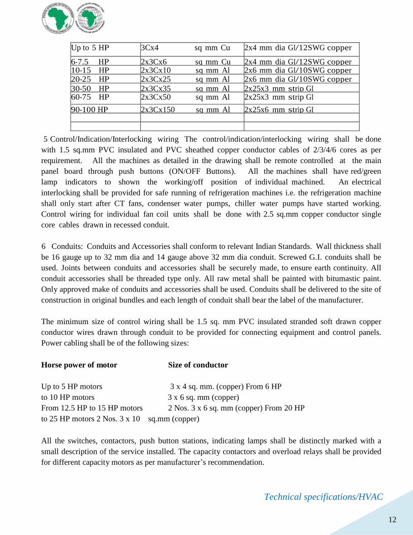
All switches/isolators shall be connected to the earth and size of earth conductor shall be
depending upon the size of the cable connected with the switch / isolator:
Cross sectional area of current carrying conductor
Motor Rating Power cable Earthing
Technical specifications/HVAC
12
Up to 5 HP 3Cx4 sq mm Cu 2x4 mm dia GI/12SWG copper
6-7.5 HP 2x3Cx6 sq mm Cu 2x4 mm dia GI/12SWG copper 10-15 HP 2x3Cx10 sq mm Al 2x6 mm dia GI/10SWG copper 20-25 HP 2x3Cx25 sq mm Al 2x6 mm dia GI/10SWG copper
30-50 HP 2x3Cx35 sq mm Al 2x25x3 mm strip GI 60-75 HP 2x3Cx50 sq mm Al 2x25x3 mm strip GI
90-100 HP 2x3Cx150 sq mm Al 2x25x6 mm strip GI
5 Control/Indication/Interlocking wiring The control/indication/interlocking wiring shall be done
with 1.5 sq.mm PVC insulated and PVC sheathed copper conductor cables of 2/3/4/6 cores as per
requirement. All the machines as detailed in the drawing shall be remote controlled at the main
panel board through push buttons (ON/OFF Buttons). All the machines shall have red/green
lamp indicators to shown the working/off position of individual machined. An electrical
interlocking shall be provided for safe running of refrigeration machines i.e. the refrigeration machine
shall only start after CT fans, condenser water pumps, chiller water pumps have started working.
Control wiring for individual fan coil units shall be done with 2.5 sq.mm copper conductor single
core cables drawn in recessed conduit.
6 Conduits: Conduits and Accessories shall conform to relevant Indian Standards. Wall thickness shall
be 16 gauge up to 32 mm dia and 14 gauge above 32 mm dia conduit. Screwed G.I. conduits shall be
used. Joints between conduits and accessories shall be securely made, to ensure earth continuity. All
conduit accessories shall be threaded type only. All raw metal shall be painted with bitumastic paint.
Only approved make of conduits and accessories shall be used. Conduits shall be delivered to the site of
construction in original bundles and each length of conduit shall bear the label of the manufacturer.
The minimum size of control wiring shall be 1.5 sq. mm PVC insulated stranded soft drawn copper
conductor wires drawn through conduit to be provided for connecting equipment and control panels.
Power cabling shall be of the following sizes:
Horse power of motor Size of conductor
Up to 5 HP motors 3 x 4 sq. mm. (copper) From 6 HP
to 10 HP motors 3 x 6 sq. mm (copper)
From 12.5 HP to 15 HP motors 2 Nos. 3 x 6 sq. mm (copper) From 20 HP
to 25 HP motors 2 Nos. 3 x 10 sq.mm (copper)
All the switches, contactors, push button stations, indicating lamps shall be distinctly marked with a
small description of the service installed. The capacity contactors and overload relays shall be provided
for different capacity motors as per manufacturer’s recommendation.
Technical specifications/HVAC
13
Two speed motors when specified, shall be provided with DOL starter irrespective of it rating.
7 Completion Drawings: Four sets of completion drawings giving single line diagram run of
cables location along with detail wiring panels, indication/interlocking circuits cable with sizes with
in the building/underground cables showing the location of straight through joint boxes, location of
main earthing stations shall be furnished within one month from the date of completion of the work.
8 Testing: Before the commissioning of the plant, the entire installation shall be tested in
accordance with Guide of practice IS: 732-1963 or relevant BSS and the test report furnished by the
qualified and authorized person. The electrical installation shall be got passed from local Electrical
Inspector. All tests shall be carried out in the presence of Engineer in charge.
9 Rubber Mat: Rubber mat shall be provided in front to cover the full length of all
p a n e l s . Where back space is provided for working from the rear of the panel, rubber mat shall also be
provided to cover the full length of panel.
INSPECTION AND TESTING PROCEDURES
All major equipments such as VRV/VRF, Air handling units, panels, fans shall be got inspected by
the engineer in charge / customer at works by the AC contractor, if he so desires. All routine and
Type tests shall be carried out and the test reports shall be submitted for approval before dispatch.
The engineer in charge is free to witness any or all tests. In any case the OEM test certificates shall
be submitted to the engineer in charge for verification of the same before the payments for the same can
be processed. The AC contractor shall inform the engineer in charge well in time about the date of
readiness of the equipment for inspection and testing. The inspection process shall be as under:
Final Inspection
After completion of entire installation as per specifications in all respects, the AC contractor shall
demonstrate trouble free operation of the entire installation simultaneously. The test readings shall be
recorded in a mutually acceptable format. All tests shall be carried out by the AC contractor at his
own expenses. However necessary utilities such as power and water shall be provided by the owner free
of cost. The tests shall include but will not be limited to the following:
To check satisfactory functioning of all equipment installed
Clean all equipment to remove foreign material and construction dirt and dust with Vacuum cleaner.
Verify that the equipment is secure on mounting and supporting devices and that connections for piping,
ductwork and electrical are complete.
Verify proper thermal overload protection is installed in motors, starters, and disconnects.
Technical specifications/HVAC
14
Check proper motor rotation direction and verify fan wheel / pump free rotation and smooth bearing
operations.
Reconnect drive system and align belts.
Lubricate bearings, pulleys, belts, and other moving parts with factory recommended lubricants. Set
outside-air / supply air dampers to minimum outside-air setting.
Install temporary throw away filters for initial run and finally install clean filters.
Verify manual and automatic volume control, and fire dampers in connected ductwork system are in the
full-open position.
Replace fan and motor pulleys as required to achieve design conditions. Measure and record motor
electrical values for voltage and amperage. Shut unit down and reconnect automatic temperature control
operators.
Cooling / heating capacity of various Indoor units shall be computed from the measurements of air
flow and dry and wet bulb temperatures of air entering and leaving the coil. Flow measurements shall be
by a calibrated rotating vane anemometer and temperature measurements by accurately calibrated
mercury-in-glass thermometers. Computed ratings shall conform to the specified capacities and quoted
ratings. Power consumption shall be computed from measurements of incoming voltage and input
current, whereas, noise level at various locations within the conditioned spaces shall be measured by a
sound pressure level meter
WALL MOUNT MULTI SPLIT UNITS SPCIFICATIONS
These type of AC shall serve the server room based on calculations there the need of
48000btus/hr.
General for indoor and outdoor units
The have a good range of power 5.3kW type up to 15.5 kW and they are electrically simple as they are
singe phase the number of Indoor units should vary in terms of combination from
3-9units and from 2.1kW-10.6kW.
Outdoor units: These encount for the grille shape design on the outdoor unit helps to disperse air more
efficiently which improves heat exchange and reduces noise level. The new axial fan has a thick front
edge and smooth rear edge, this provides a high efficiency, low noise, wide fan, as well as improving the
air flow rate.
Installation and Maintainance: MULTI split models are more compact and lighter models. The
reduction in weight makes it easier to carry and install.
The Multi split has a better design so that the piping cover is enclosed and the size reduced by
80mm and 25mm at the side and back respectively. As a result it is possible to install the unit close to a
wall. As well as the easily accessible service valve, it is possible to conveniently service the outdoor unit
when installed below a window.
Technical specifications/HVAC
15
Excellent monitor view that facilitate the accessibility, long and high evaluation piping they have also
the forced cooling operation that allows refrigerant to be recharged or pumped down, regardless of the
indoor temperature. More importantly this function can be used when indoor units are being repaired.
Energy saving: The BLDC motor is made up of powerful ND magnets providing high torque, resulting
in the ability to provide large air volume and high static pressure capability. This allows high speed
operation at reduced electrical and mechanical noise. The other characteristics is Wide Louver Plus fin
technology increases 11% of full load heating performance and 6% of COP compared to conventional
fin. It can slow down frosting of heat exchanger and postpone the start of defrosting operation.
Technical data
Contractor shall submit catalogues of the equipment offered by him:
Sr.No. Equipment description unit Condition of service
1. Cassette Units:
a. Manufacturer b. Casing
c. Coil
d. Blower e. Type
f. Overall Dimension g. Unit Weight
h Air Quantity i. Throw
j. Design capacity
k Cooling capacity h. Fan motor output
Technical specifications/HVAC
16
2. MULTI SPLIT UNITS:
a. Manufacturer b. Casing
c. Cooling capacity d. Type
e. Overall Dimension f. Unit Weight
g Air Quantit
e. Type of vibration isolators
3. DUAL UNITS DATA:
a. Manufacturer
b. Casing and accessories
c. Cooling capacity in CFM/BTU
d. Type
e. Dimension
f. Unit Weight
g Manual from manufacturer h. Refrigerants used
i. Mode of installation and maintainance
4 . Electrical Accessories :
Make of the following
a. Motor Control Centre (MCC)
b. Air Circuit Breaker c. MCCB
d. MCB
e. Rotary Switch f. Soft Starter
g. Auto-transformer starter h Direct on line starter
i. Contactor
j. Current transformer
k. Single phase preventor
l. Push botton/changeover switch m. Ammeter/Voltmeter
n Relays
o Indicating Lamps p. Cables/wires
Technical specifications/HVAC
17
5. Piping data;
a. Make of pipes/class of pipes
b. Pipe wall thickness
c) Pressure Gauge i) Material
ii) Model iii)Diameter
LIST OF STANDARDS
IS: 277-1992 - Galvanized steel Sheet (plain & corrugated) IS: 544-1985 -
Dimension for pipe Threads
(Reaffirmed 1996)
IS: 778 - Valves (gate/globe/check type) IS: 655-1963 - Metal Air
Ducts
IS: 13095-1991 - Butterfly Valves
IS: 659-1964 - Air-conditioning (safety codes) IS: 1239-1990/92 - Mild Steel
Pipes
IS: 325 - 3 phase induction motor
IS: 822 - Code of procedure for inspection of welds
IS: 900 - Code of practice for installation and maintenance of motors
IS: 6392 - Steel Pipe Flanges
IS: 1822 - Motor starters for voltage not exceeding 650 Volts
IEC - Relevant Sections
IS: 996 - Single phase small A.C. Motors
IS: 4894-1987 - Centrifugal Fans
IS: 1554(I) - PVC Insulated (heavy duty) electric cables for working
Voltage up to and including 1100 Volts
IS: 8623-1993 - Bus Bar Trucking System
IS: 8828-1996 - Miniature Circuit Breakers
& IEC898-1995
IS: 9537-1981 Part II - Rigid steel conduit for electrical wiring
IS: 10810-1989 - Method of Test of Cables
IS: 13947-1989 - Circuit Breakers
IS: 13947-1993 - Switches, disconnectors, fuse combination units
Technical specifications/HVAC
18
IS: 139-1993(Part IV) - Contactors & Motor Starters
Duct Fabrication standards -SMACNA ASHRAE Handbooks- Application 1995
System & equipment 1996- Fundamentals 1997
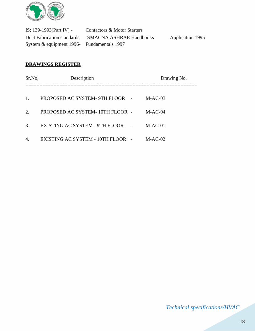
DRAWINGS REGISTER
Sr.No, Description Drawing No.
=============================================================
1. PROPOSED AC SYSTEM- 9TH FLOOR - M-AC-03
2. PROPOSED AC SYSTEM- 10TH FLOOR - M-AC-04
3. EXISTING AC SYSTEM - 9TH FLOOR - M-AC-01
4. EXISTING AC SYSTEM - 10TH FLOOR - M-AC-02
Technical Specifications/Plumbing works-ADB Rwanda
1
AFRICAN DEVELOPMENT BANK- RWANDA
PROPOSED NEW OFFICES FOR ADB-
RWANDA
TECHNICAL SPECIFICATIONS
SECTION III
PLUMBING &FIRE FIGHTING WORKS
Technical Specifications/Plumbing works-ADB Rwanda
2
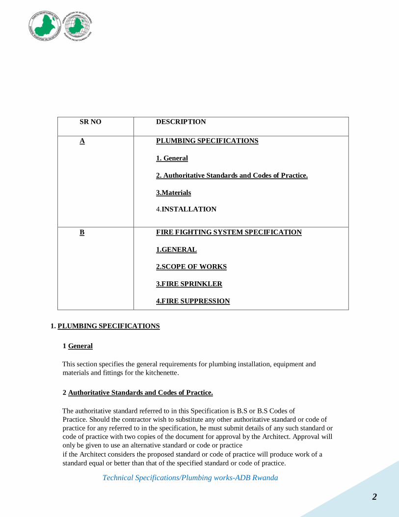
SR NO DESCRIPTION
A PLUMBING SPECIFICATIONS
1. General
2. Authoritative Standards and Codes of Practice.
3.Materials
4.INSTALLATION
B FIRE FIGHTING SYSTEM SPECIFICATION
1.GENERAL
2.SCOPE OF WORKS
3.FIRE SPRINKLER
4.FIRE SUPPRESSION
1. PLUMBING SPECIFICATIONS
1 General
This section specifies the general requirements for plumbing installation, equipment and
materials and fittings for the kitchenette.
2 Authoritative Standards and Codes of Practice.
The authoritative standard referred to in this Specification is B.S or B.S Codes of
Practice. Should the contractor wish to substitute any other authoritative standard or code of
practice for any referred to in the specification, he must submit details of any such standard or
code of practice with two copies of the document for approval by the Architect. Approval will
only be given to use an alternative standard or code or practice
if the Architect considers the proposed standard or code of practice will produce work of a
standard equal or better than that of the specified standard or code of practice.
Technical Specifications/Plumbing works-ADB Rwanda
3
The whole of the plumbing works is to be executed by a registered plumber and drain layer in
strict accordance with the Regulations of the Local Authorities and to the satisfaction of the
Architect.
3 Materials
3.1 Pipework
(a) PPR Pipe work
PPR pipes PN20 of 25 mm diameter should wistand the required task as per ISO 15874 a good
type of polypropylene plastic pipe, both grey and green color should be used otherwise advised
by architect the other equivalent pipes should be used.
(b) Galvanized Steel Pipework
Galvanized steel pipework shall be manufactured to comply in all respects with the
standards described for black steel pipework in paragraph (a) above.
Galvanizing shall be carried out in accordance with the requirements of B.S.1387 and
B.S. 143 respectively.
(c) P.V.C. (Head) Pressure Pipes and Fillings
All PVC pipes and fillings shall be manufactured in accordance with B.S.
3505: 1968.
3.2 Installation
Before any joint is made, the pipes shall be hung in their supports and adjusted to ensure that the
joining faces are parallel and any falls which be required are achieved without springing the
pipe.
All sanitary appliances associated with the Sub-Contractor works shall be installed in
accordance with the best standard of modern practice as described in C.P. 305 to the
approval of the Engineer.
i) Jointing
The method of jointing shall be fusion welding by the help of PPR machine otherwise
advised by the client or architect to use other types of pipework
ii) Anchoring
Technical Specifications/Plumbing works-ADB Rwanda
4
All bends, valves and hydrant tees etc., in the line of water main shall be adequately anchored to
resist thrust due to internal water pressure. A concrete block shall be cast under and around the
pipe and between it and sides of the trench. Well rammed material shall be used to support the
pipe and either side of the concrete in case of the necessity.
iii) Testing
Pipelines shall be tested in sections under the internal water pressure normal one and halftime
the maximum allowable working pressure for the class of pipe used. Testing shall be carried out
as soon as practicable after laying and when the pipeline is adequately anchored. Precautions
shall be taken to eliminate all air form the test section and to fill the pipeline slowly to avoid
risk of damage due to surge.
Pipes, traps and fittings shall be in accordance with the relevant British Standards,
including
B.S. 3943 and fixed generally in accordance with manufacturer‟s instructions, and B.S.
5572: 1978.
Jointing of pipes shall be carried out by means of solvent welding. The manufacturers
Recommended method of joint preparation and fixing shall be followed.
Standard brackets, as supplied for use with this system, shall be used wherever possible. Where
the building structure renders this impracticable the Sub-Contractor shall provide purpose made
supports, the centers of which shall both exceed one metre.
Expansion joints shall be provided as indicated. Supporting brackets and pipe clips shall
be fixed on each of these joints.
3.3 Drainage system
i) PVC Soil system
The Contractor shall supply and fix PVC PN10 soil pipe and fittings as indicated on
the drawings and BOQ.
Pipes and fittings shall be in accordance relevant B.S. including B.S. 4514, and fixed to
The manufacturer‟s instructions, and B.S. 5572.
3.4 VALVES
a) Ball Valves
All ball valves for use in connection with cold water services shall be of the ports mount type
in accordance with the requirements of B.S. 1212, constructed from bronze or other corrosion
resistant materials. These valves fall into three pressure classifications as follows:
Technical Specifications/Plumbing works-ADB Rwanda
5
(i) Low Pressure - 3.58 b maximum (ii)
Medium Pressure - 7.72 b maximum
(iii)High Pressure - 12.62 b maximum
The pressure classification required for each ball valve will be designated in the
description of its associated equipment contained in section IV of the specification.
3.5 PIPE SUPPORTS
(a) GI Pipes Tubes
Pipe runs shall be secured by pipe clips connected to pipe hangers, wall brackets, or trapeze type
supports. „U‟ bolts shall not be used as a substitute for pipe clips without the prior approval of the
Engineer. An approximate guide to the maximum permissible supports spacings in metres for
steel and copper pipe and tube is given in the following table for horizontal runs.
3.6 Cutting Pipes
GI pipes rounded throughout their length shall be used as cut pipes to form closures. The cutting shall
be done by an approved method and apparatus which provides a clean square cut, without separation
of the lining from the pipe wall. Minor damage to the lining may, if permitted be repaired on site in
accordance with the manufacturer‟s instructions. Where in the opinion of the Engineer the damage is
serious the pipe or special shall be returned to the manufacturer for reconditioning.
3.7 Pipes Built into Structures
The outside surface of all pipes and special casting to be built into structures shall be thoroughly cleaned
immediately before installation. Where ordered protective coatings to metal pipes shall be removed from
the sections to be built in, while the external surfaces of fireclay and concrete pipes shall be roughened to
form a key for concrete or mortar. Sheathing to steel pipes shall be cut away from the sections to be built-
in and after erection the protection shall be completed by applying approved bituminous material around
the barrels of pipes at the junctions with structures.
Pipes passing through water retaining walls and floors shall, where possible, be built into the
structure in-situ. Shuttering shall be formed closely to the outside of the pipes, and concrete shall be placed
and compacted thoroughly round pipe with puddle flange, if any.
Where fixing in the course of construction is not possible, temporary opening in structures, formed to the
dimensions shown by the Engineer shall be left where indicated or directed to accommodate the
subsequent erection of pipes and special castings. In water retaining structures, they shall taper to a smaller
dimension towards the external faces of structures and shall include where indicated a water stop.
In basements, dry chambers at pumping stations etc., temporary openings shall taper to smaller
dimensions towards the internal faces of structures and shall also include, where indicated a water shop.
Prior to in-filling, all surfaces against which fresh concrete is to be placed shall be prepared as specified,
while the external surfaces of pipework shall be prepared as described in this clause.
3.8 SANITARY AND
Technical Specifications/Plumbing works-ADB Rwanda
6
FIXTURE SINKS
They shall be Stainless steel of best quality and shall be supported on necessary
brackets.
Each sink shall be provided with 40 mm CP waste coupling, hot and cold single lever
sink
Mixer/wall mounted /table top mounted as specified in the BOQ. The complete set shall
comprise of the following. Single Stainless steel sink with drain board pillar cock with
swinging spout. Supporting bracket. 40mm CP Waste coupling. CP wall flanges Angle valves.
CP / copper / SS inlet connecting pipe with end nuts.
2. FIRE FIGHTING SYSTEM
1 GENERAL
This particular specification details the requirements for the supply, installation and
commissioning of Automatic fire suppression, in addition to commission, test and install
rearrange existing sprinklers. The Contractor shall include for all appurtenances and appliances
not necessarily called for in this specification or shown on the Contract Drawings, but which
are necessary for the successful completion and satisfactory functioning of the equipment.
2 SCOPE OF WORKS
The Contractor shall readjust existing sprinkler and introduce automatic sprinkler in a sever
room, deliver, erect, test and all indicated services that are called for in this specification
and shown on the Contract Drawings and listed in the Bills of Quantities.
3 FIRE
SPLINKLER
SYSTEM
3.0 SCOPE OF
WORKS
3.1 Sprinkler Installer’s
Responsibilities
Design, supply, install, set to work, test, commission, fully certify and handover a sprinkler system
in accordance with the function and performance requirements and as stated in the Rules for
Automatic Sprinkler Installations published by the Loss Prevention Council (LPC Rules)
incorporating BS EN
1284
5.
Provide pressure and flow requirements at each and every design point and flushing/test
connections on all the arrays that are required to meet the code requirements for the defined risk.
Confirm that the Installer‟s name appears in the current “List of Approved Products and
Services” Published by the LPC and the current list of “LPCB Quality Assessed Companies to
Technical Specifications/Plumbing works-ADB Rwanda
7
ISO 9001/ BS
57501” published by the Loss Prevention Certification Board (LPCB) and the contractor
has the suitable level of competency to carry out, without supervision, the design
and installation of the system(s)
3.1 Pipeline Ancillaries
General Install all pipe ancillaries fully in accordance with BSEN 12845.
Installation Control Valve Set(s)
Provide each sprinkler installation with a set of installation control valves as per existing
whichever modification shall be clearly included in tendering BOQ. Test Valve, Pipeline and
fittings. All necessary small bore piping (galvanized), pressure gauges and valves in accordance
with the requirement of the LPC Rules and Approvals.
All piping, valves, straps, padlocks and identification labels as required by the LPC
Sprinkler Test Valve
Provide a test valve adjacent to the highest sprinkler on the installation which is capable of
discharging a minimum flow rate equivalent to one sprinkler head operating.
Securing of Valves
Secure all stop valves (which are not electrically monitored) on the water supply mains with strap
and padlock. Secure the main stop valves and the installation control valves with leather straps and
padlocks. Secure all other valves with leather straps.
Sprinkler Heads
Verify the hazard classification, temperature rating and pattern of sprinkler heads required for
each area within the premises.
Locate sprinklers to provide coverage to conform to the hazard classification of each
area.
A pre-action sprinkler head device, namely Gemini (installed by approved installer) (available
through Project Fire Products Ltd), shall be installed in accordance with the project specifications and
drawings for areas where pre-action heads are required.
Addressable Sprinkler Monitoring & Testing
The activation of the sprinkler system (via signals from flow switches) shall be detected via the
Zonecheck Addressable Control Unit or equivalent and shall be integrated into fire strategy for the
building and be the primary fire detection loop. All monitored zone valves and flow-switches
(including flow switches on alarm valve) shall be connected via the IMMs back to the Zonecheck
Addressable Control Unit. Any alarm valves fitted with Bellcheck shall be connected via an IMM on
the same addressable loop. This unit shall be approved to UL346 and UL864 and installed and
Technical Specifications/Plumbing works-ADB Rwanda
8
commissioned via a suitably trained, competent approved and installer. This systems gives the ability
to test, record and monitor all key fire and fault signals for flow switches and alarm valves
3.2. IDENTIFICATION OF
MECHANICAL SERVICES General
In accordance with BS EN 12845.
Painting
Apply one coat of primer paint, one coat undercoat and two coats red gloss to all exposed piping
and, upon completion, touch-up to repair any damage caused to the finish by the installation work.
Apply ID banding to all piping in accordance with BS 1710.
Labelling and Signs
Supply and fit a „location plate‟ on the valve access route in a position to be agreed with the
Architect, bearing the following words: -
SPRINKLER STOP VALVE INSIDE
Arrange its letters to be at least 35mm in height and the word 'INSIDE' to be in letters of at least
25mm in height.
Fit all valves with engraved aluminium labels stating their number and purpose.
Individually identify all valves on a schedule (produced in resilient material) wall mounted in the Fire
Pump
Room. Include a copy of this schedule with the Operating and Maintenance Instruction Manual.
3.4. TESTING AND
COMMISSIONING
Particular Requirements
Carry out all tests and inspections to prove that the installation meets with the requirements of BS EN
12845. Carry out all tests required by the District Surveyor or/ Building Control Officer
giving adequate notice with regard to timing of tests, etc.
Inspect and test the installation at agreed stages to ensure that the piping is properly secured
and clear of obstructing debris and superfluous matter and that all work which is to be concealed
is free from defects before it is finally enclosed.
Carry out a low-pressure air test, to establish whether open ends are present, prior to carrying
out a hydraulic test on completion of the installation, or sections thereof.
All installation pipework shall be hydrostatically tested for no less than 2 hours, to a p pressure of no
less than
15 bar, or 1.5 times the maximum pressure to which the system shall be subjected, (both
Technical Specifications/Plumbing works-ADB Rwanda
9
measured at the installation control valves), whichever is the greater.
Dry pipe work shall be tested pneumatically to a pressure of no less th an 2.5bar for no less than 24
hours. Any leakage that results in a loss of pressure greater than 0.15 bar for the 24 hour period shall
be corrected.
Fully test all pumps through their full range of capabilities up to and including nominal ratings.
Ensure e that the duties are within the tolerances specified in LPC Rules.
All flow-switch testing shall be completed using a water flow detector tester in accordance with
FM1043. Test all alarms and alarm connections associated with the sprinkler installation a nd prove all
interlocks and links to other systems and remote locations.
Upon completion of the installation of the system carry out functional tests in the presence of all
interested parties to demonstrate to the satisfaction of all present that the installation conforms to the
required standards.
When these tests have been accepted by all parties as being satisfactory, issue a completion certificate
(as defined in Section 10 of the LPC Rules), issue an LPCB Certificate of Conformity (as required in
LPS 1048) and register the installation as a Certified Sprinkler System.
Keep a record of all pressure tests carried out to include the following: -
Date of test:
Location and identification of
pipeline: Drawing Reference:
Method of Test:
Test Pressure:
Result of
Test:
Signature of operative carrying out test and Company:
Signature of Witnessing Supervising Officer or his approved Representative:
Carry out two inspections, the first 6 months and the second 12 months after completion of the
installation. Include the following tasks in the inspection: -
Water Supplies
Carry out running and proving tests on both pump sets.
Check correct operation of float valves on water storage
tanks. Check rate of infill to water storage tanks.
Exercise and grease stop valves on incoming Mains Supply, pump suction and delivery piping
and ensure that they open and shut freely.
Check operation and seating of non-return valves/ alarm
valves. Check valve glands for leakage.
Check pump glands for leakage.
Check operating pressures on pressure switches.
Check operation of Jockey Pump.
Check operation of pressure relief valves on
pumps. Check operation of remote alarm
functions.
Technical Specifications/Plumbing works-ADB Rwanda
10
Installation Control Valves
Carry out flow and pressure tests.
Check satisfactory operation on Turbine Alarm Gong.
All alarm-valve testing shall be completed using Bellcheck in accordance with BS 12845 using
guidance from HB 223 (2008): Fire Protection System Testing – Water Conservation Handbook.
General
Exercise and grease all stop valves and ensure they open and shut easily.
Check valve glands for leakage.
Check seating of alarm valves.
Check all pressure gauges are registering correctly
.4. FIRE SUPPRESSION
SYSTEM SECTION 1 –
GENERAL
SPECIFICATIONS
I. SCOPE
This specification outlines the requirements for a “Total Flooding” FM-200 clean agent fire
extinguishing system. The work described in this specification includes all engineering,
labor, materials, equipment and services required to install and test the FM-200 fire extinguishing
system as indicated in BOQ.
II. APPLICABLE STANDARDS AND PUBLICATIONS
The design, equipment, installation, testing and maintenance of the Clean Agent Suppression
System shall be in accordance with the applicable requirements set forth in the latest edition of
the following codes and standards.
A. NFPA 2001 - Clean Agent Fire Extinguishing
Systems. B. NFPA 70 - National Electric Code.
C. NFPA 72 – National Fire Alarm and Signaling
Code. D. FM - Factory Mutual Approval Guide.
E. UL - Fire Protection Equipment
Directory.
F. NEMA - Enclosures for Industrial Controls and
Systems.
Technical Specifications/Plumbing works-ADB Rwanda
11
G. Department of Transportation (DOT) Title 49 Code of Federal
Regul
ations
H. All Requirements of Authority Having Jurisdiction
(AHJ)
The standards listed, as well as all other applicable codes, standards, and good engineering
practices shall be used as "minimum" design standards.
. III. REQUIREMENTS
The Suppression System installation shall be made in accordance with the drawings,
specifications and applicable standards. Should a conflict occur between the drawings and
specifications, the specifications shall prevail.
IV. EXCLUSIONS
The work listed below shall be provided by others, or under other sections
of this specification: A. System control panel and accessories.
B. Interlock wiring and conduit for shutdown of HVAC, dampers and/or electric power
supplies, relays or shunt trip breakers.
C. Connection to local/remote fire alarm systems or listed central
alarm station(s).
V. QUALITY ASSURANCE
A. MANUFACTURER
1) The manufacturer of the suppression system hardware and detection components shall
be ISO
9001 and 14001 registered.
2) The name of the manufacturer shall appear on all major components.
3) All devices, components and equipment shall be the products of the same manufacturer.
4) All devices, components and equipment shall be new, standard products of the
manufacturer‟s latest design and suitable to perform the functions intended.
5) All devices and equipment shall be UL Listed
Technical Specifications/Plumbing works-ADB Rwanda
12
and/or FM Approved. B. INSTALLER
1) The installing contractor shall be trained by the supplier to design, install, test and maintain fire
Suppression systems.
2) When possible, the installing contractor shall employ a NICET certified special
hazard designer, Level II or above, who will be responsible for this project.
3) The installing contractor shall be an experienced firm regularly engaged in the
installation of automatic Clean Agent, or similar, fire suppression systems in strict
accordance with all applicable codes and standards.
4) The installing contractor must have a minimum of five (5) years‟ experience in the
design, installation and testing of Clean Agent, or similar, fire suppression systems. A
list of systems of a similar nature and scope shall be provided on request.
5) The installing contractor shall maintain, or have access to, a Clean Agent recharging
station.
The installing contractor shall provide proof of this ability to recharge the largest
Clean Agent system within 24 hours after a discharge. Include the amount of bulk agent
storage available.
6) The installing contractor shall be an authorized stocking distributor of the Clean
Agent system equipment so that immediate replacement parts are available from
inventory.
7) The installing contractor shall show proof of emergency service available on a
twenty-four- hour-a- day, seven-day-a-week basis.
C. SUBMITTALS
1) The installing contractor shall submit the following design information and drawings
for approval prior to starting installation on this project.
a. Working plans indicating detailed layout of system, locating each component
(e.g. agent cylinder, control panel, electric/manual pull station, audible and visual
alarms). Include control diagrams, wiring diagrams, written sequence of operation or
cause to effect matrix along with battery calculations, and pipe locations including size
and length. Refer to NFPA 2001 Section
5.1.2.
b. Product data for each piece of equipment comprising the system including storage
cylinders, control valves and pilot controls, control panels, nozzles, push-button stations,
detectors, alarm bells or horns, switches, and annunciators.
Technical Specifications/Plumbing works-ADB Rwanda
13
c. Design calculations derived from the Janus Design Suite™ computer
program written specifically for FM-200 and verified by both Underwriters
Laboratories and Factory Mutual. Analysis shall include calculations to verify system
terminal pressures, nozzle flow rates, orifice code number, piping pressure losses,
component flow data, and pipe sizes considering actual and equivalent lengths of pipe
and elevation changes. Flow calculation shall also supply pressure venting estimates as
required by NFPA 2001. In addition, the flow calculation software shall print
specifications of all piping used in the design (mass, ID, etc). Designers using this
software shall be trained and certified by Janus Fire Systems.
d. Manufacturer's installation and operation manual.
2) Submit drawings, calculations and system component data sheets for approval to the
local fire prevention agency, owner‟s insurance underwriter, and all other authorities having
jurisdiction before starting installation. Submit approved plans to the architect/engineer
for record.
SECTION 2 – SYSTEM
REQUIREMENTS I. SYSTEM DESCRIPTION
AND OPERATION
A. The fire protection system shall be a Total Flooding System utilizing FM-200 clean agent or equivalent
System. System is a fixed installation where equipment is designed and installed to
provide fire extinguishing capability for hazards described
B. The system shall be designed to deliver an FM-200 minimum design concentration in
accordance with NFPA 2001, 2012 Edition, in all areas and/or protected spaces, at the
minimum anticipated temperature within the protected area. The system should be designed
to discharge its liquid contents in 10 seconds or less.
C. The system shall be complete in all ways. It shall include all mechanical and electrical
installation, all detection and control equipment, agent storage cylinders, FM-200 agent,
discharge nozzles, pipe and fittings, manual release and abort stations, audible and visual
alarm devices, auxiliary devices and controls, shutdowns, alarm interface, caution/advisory
signs, functional checkout and testing, training and all other operations necessary for a
functional, UL Listed and/or FM Approved FM-
200 Clean Agent Suppression
System.
D. The system(s) shall be actuated by photoelectric detectors installed for maximum area
coverage of
250 sq. ft. (23.2 m2) per detector, in both the room and above ceiling protected spaces.
Photoelectric detectors shall be installed in underfloor protected spaces. If the airflow is one air
Technical Specifications/Plumbing works-ADB Rwanda
14
change per minute, photoelectric detectors only shall be installed for maximum area coverage
of 125 sq. ft. (11.6 m2) per detector. (Ref. NFPA 72).
E. Detectors shall be Cross-Zoned detection requiring two detectors to be in alarm before release.
. II. MATERIALS AND EQUIPMENT
A. GENERAL REQUIREMENTS
1) The FM-200 Clean Agent System materials and equipment shall be standard
products of the supplier‟s latest design and suitable to perform the functions intended.
When one or more pieces of equipment must perform the same function(s), they shall be
duplicates produced by one manufacturer.
2) All devices and equipment shall be UL Listed and/or FM approved.
3) The fire suppression agent shall be FM-200 gas; clean dry, non-corrosive, non-
damaging, non- deteriorating, and meeting the requirements of NFPA 2001. The agent
shall be suitable for use in normally occupied spaces. Agent shall be listed as
“Acceptable” on the EPA‟s SNAP list.
B. FM-200 AGENT STORAGE AND DISTRIBUTION
1) Each system shall have its own supply of clean agent.
2) Each system can protect a single hazard or multiple hazards can be protected by a single
system with a common supply of clean agent through the use of selector or zone-type
valves.
3) The system design can be modular, central storage, or a combination of both design criteria.
4) Systems shall be designed in accordance with the manufacturer‟s guidelines.
5) Each supply shall be located within the hazard area, or as near as possible, to reduce the
amount of pipe and fittings required to install the system.
6) The clean agent shall be stored in Fire Systems Sv, Mv, or Lv Series Agent Storage Cylinder
Assemblies. Cylinders shall be super-pressurized with dry nitrogen to an operating pressure
of 360 psi @ 70°F (24.8 bar @ 20°C). Cylinders shall be of high -strength low alloy steel
construction and conform to NFPA 2001 and the regulations of the Department of
Transportation and/or CE.
7) Cylinders shall be fitted with a resilient pressure seat type forged brass valve and shall have a
threaded steel anti-recoil protective cap or grooved style anti-recoil protective plate for
handling and shipment.
Technical Specifications/Plumbing works-ADB Rwanda
15
8) The primary cylinder assembly(s) shall be actuated by a resettable electric actuator with
optional mechanical override located at each primary agent cylinder or connected bank of
cylinders. Non - resettable or explosive devices shall not be permitted
9) Each cylinder assembly shall have a pressure relief provision that automatically operates
before the internal pressure exceeds 850 psi (58.6 bar) to 1000 psi (68.9 bar).
10) When more than one cylinder is connected to a common manifold, a check valve shall be
provided with each cylinder.
11) Engineered discharge nozzles shall be provided within the manufacturer‟s guidelines
to distribute the FM-200 agent throughout the protected spaces. The nozzles shall be
designed to provide proper agent quantity and distribution.
a. Nozzles shall be available in 3/8 in (10 mm) through 2 in (50 mm) pipe sizes. Each
size shall be available in 90° Corner [Listed with a protection coverage area of 32‟
x 32‟ (9.753 m x 9.753 m)], 180° Sidewall [Listed with a protection coverage area of
64‟ x 32‟ (19.507 m x 9.753 m)], and 360° Center Room [Listed with a protection
coverage area of
64‟ x 64‟ (19.507 m x 19.507 m)] distribution patterns.
b. Nozzles shall be of corrosion resistant construction and shall be designed specifically for
FM-
200 application.
c. Nozzles shall be permanently marked as to part number and orifice diameter.
d. Nozzles shall be listed at a maximum 16‟ (4.876 m) elevation and listed at a maximum 4‟
(1.219
m) Distance below a ceiling while still achieving sufficient mixing.
e. Nozzles should be listed and/or approved to be used in the upright or pendant position.
f. Ceiling plates can be used with the nozzles to conceal pipe entry holes through ceiling
tiles.
12) Distribution piping, and fittings, shall be installed in accordance with the
manufacturer‟s requirements, NFPA 2001 and approved piping standards and
guidelines. All distribution piping shall be installed by qualified individuals using accepted
practices and quality procedures. All piping shall be adequately supported and anchored at
all directional changes and nozzle locations. The piping shall be laid out to give maximum
flow and to avoid possible mechanical, chemical or other damage. Installation shall follow
drawings as closely as possible. System designer must be consulted for anything other than
minor deviations in pipe routing.
a. Black or galvanized steel pipe shall be either ASTM A53 seamless or electric
welded, Grade A or B or ASTM A-106, Grade A, B, or C. ASTM A-120, ordinary cast-
Technical Specifications/Plumbing works-ADB Rwanda
16
iron pipe, aluminum pipe, or non-metallic pipe shall not be used. Stainless steel pipe
shall be 304,
316, 304L, or 316L for threaded connections or 304L or 316L for welded connections.
b. Threaded fittings must comply with NFPA 2001 and be at a minimum class 300
malleable iron, class 300 ductile iron, or have a minimum rated working pressure of
416 psi (28.7 bar) at 70°F (21.1°C). Cast iron and Class 150 pound fittings shall not be
used.
.c. Grooved fittings and couplings must comply with NFPA 2001 and have a
minimum rated working pressure of 416 psi (28.7 bar) at 70°F (21.1°C). Piping shall be
rolled or cut grooved in accordance with the fitting or coupling manufacturer's
guidelines.
d. Gaskets must be compatible with FM-200® agent (typically EPDM having a
temperature range of -30°F to 230°F [-34°C to 110°C]). Gasket lubricant must be in
accordance with manufacturer's specifications.
e. The minimum allowable working pressure at 70°F (21.1°C) for pipe and fittings
in closed sections of pipe must be greater than or equal to the maximum operating
pressure of the discharge pipe safety relief valve rated at 450 psi (31.02 bar).
f. All pipe and fittings shall be new and of recent manufacture.
g. Reductions in pipe sizes may be accomplished using threaded or grooved
concentric reducing fittings, steel or stainless steel concentric swage fittings, or steel or
stainless steel reducing bushings. All such fittings must comply with NFPA 2001 and
have a minimum rated working pressure of 416 psi (28.7 bar) at 70°F (21.1°C). Pipe
reductions can be made using machined or forged steel hex bushings. Malleable and/or
cast iron bushings are NOT to be used.
h. All piping shall be reamed, blown clear and swabbed with suitable solvents to
remove burrs, mill varnish and cutting oils before assembly.
i. All screwed pipe shall be coated with Teflon tape or an appropriate pipe joint
compound.
When tape or pipe joint compound is used, coating of the threads must start at least two
threads back from the pipe end. On small piping, care must be taken so as not to allow
sealant to enter valves or controls.
j. All pipe must be thoroughly cleaned before installation. A wire flue brush should
be pulled through the length several times, followed by clean cloth rags treated
with a noncombustible metal cleaner designed for the purpose. All foreign matter and
oil must be removed by this process.
k. All pipe and fittings installed out of doors or in corrosive areas must be galvanized
Technical Specifications/Plumbing works-ADB Rwanda
17
or treated with a proper protective coating.
l. Piping shall be pneumatically tested in a closed circuit for a period of 10 minutes at 40
psi (2.76 bar) per the latest edition of NFPA 2001. At the end of 10 minutes, the
pressure drop shall not exceed 20 percent of the test pressure. The pressure test shall
be permitted to be omitted if the total piping contains no more than one change in
direction fitting between the storage container and the discharge nozzle, and
where all piping is physically tested for tightness.
13) Pressure Switches
a. The system shall include a normally open contact on a pressure switch actuated by
the agent discharge to shut down equipment and sound alarm.
b. Switches shall be heavy duty, single pole,
double throw. c. Pressure switch shall require
manual reset.
d. Pressure switch is only required when a manual valve actuator is supplied on
the primary cylinder.
14) Pressure Operated Releases
a. The system shall include releases capable of holding maximum loads of 35 lbs
(15.9 kg) to release self-closing doors, dampers, windows, louvers, lids or valves
upon FM-200 discharge (Note to Specifier: All devices to be closed must be self-
closing and capable of being held open by a cable or chain hooked to the release.)
b. Piping to pressure releases shall be as specified above for discharge piping. All take -
offs for pressure release piping shall be from the top of the discharge piping
SECTION 3 – DOCUMENTATION AND
TESTING I. SYSTEM INSPECTION AND
CHECKOUT
After the system installation has been completed, the entire system shall be checked out, inspected and functionally tested by qualified, trained personnel, in accordance with the manufacturer‟s recommended procedures and NFPA standards. A. All containers and distribution piping shall be checked for proper mounting and installation. B. All electrical wiring shall be tested for proper connection, continuity and resistance to earth.
C. The complete system shall be functionally tested, in the presence of the owner or his
Technical Specifications/Plumbing works-ADB Rwanda
18
representative, and all functions, including system and equipment interlocks, must be ope
rational at least five (5) days prior to the final acceptance tests.
1) Each detector shall be tested in accordance with the manufacturer‟s recommended
procedures, and test values recorded.
2) All system and equipment interlocks, such as door release devices, audible and
visual devices, equipment shutdowns, local and remote alarms, etc. shall function as
required and designed.
3) Each control panel circuit shall be tested for trouble by inducing a trouble condition
into the system.
II. T R A I N I N G REQUIREMENTS
Prior to final acceptance, the installing contractor shall provide operational training to each shift
of the owner‟s personnel. Each training session shall include control panel operation, manual and
(optional) abort functions, trouble procedures, supervisory procedures, auxiliary functions and
emergency procedures.
III. OPERATION AND MAINTENANCE
Prior to final acceptance, the installing contractor shall provide complete operation and
maintenance instruction manuals, four (4) copies for each system, to the owner. All aspects of
system operation and maintenance shall be detailed, including piping isometrics, wiring diagrams
of all circuits, a written description of the system design, sequence of operation and drawing(s)
illustrating control logic and equipment used in the system. Checklists and procedures for
emergency situations, troubleshooting techniques, maintenance operations and procedures shall
be included in the manual.
IV. AS-BUILT DRAWINGS
Upon completion of each system, the installing contractor shall provide four (4) copies of system
“As- Built” drawings to the owner. The drawings shall show actual installation details including
all equipment locations (e.g. control panel(s), agent container(s), detectors, alarms, manuals
and aborts, etc.) as well as piping and conduit routing details. Show all room or facilities
modifications, including door and/or damper installations completed.
. V. ACCEPTANCE TESTS
A. At the time “As-Built” drawings and maintenance/operations manuals are submitted, the
installing contractor shall submit a “Test Plan” describing procedures to be used to test the
control system(s). The Test Plan shall include a step-by-step description of all tests to be
performed and shall indicate the type and location of test apparatus to be employed. The
tests shall demonstrate that the operational and installation requirements of this specification
have been met. All tests shall be conducted in the presence of the owner and shall not be
conducted until the Test Plan has been approved.
Technical Specifications/Plumbing works-ADB Rwanda
19
B. The tests shall demonstrate that the entire control system functions as designed and
intended. All circuits shall be tested: automatic actuation, solenoid and manual actuation,
HVAC and power shutdowns, audible and visual alarm devices and manual override of
abort functions. Supervision of all panel circuits, including AC power and battery power
supplies, shall be tested and qualified.
C. A room pressurization test shall be conducted, in each protected space, to determine the
presence of openings which would affect the agent concentration levels. The test(s) shall be
conducted using the Door Fan system with integrated computer program. All testing shall
be in accordance with NFPA 2001, Appendix B.
D. If room pressurization testing indicates that openings exist whi ch would result in leakage
and/or loss of the extinguishing agent, the installing contractor shall be responsible for
coordinating the proper sealing of the protected space(s) by the general contractor or his sub-
contractor or agent. The general contractor shall be responsible for adequately sealing all
protected space(s) against agent loss or leakage. The installing contractor shall inspect all
work to ascertain that the protected space(s) have been adequately and properly sealed.
THE SUPPRESSION SYSTEM INSTALLING CONTRACTOR SHALL BE
RESPONSIBLE FOR THE SUCCESS OF THE ROOM PRESSURIZATION TESTS. If
the first room pressurization test is not successful, in accordance with these
specifications, the installing contractor shall direct the general contractor to determine, and
correct, the cause of the test failure. The installing contractor shall conduct additional
room pressurization tests, at no additional cost to the owner, until a successful test is
obtained. Copies of successful test results shall be submitted to the owner for record.
Upon acceptance by the owner, the completed system(s) shall be placed into service.
VI. SYSTEM INSPECTIONS
A. The installing contractor shall provide two (2) inspections of each system, installed
under this contract, during the one-year warranty period. The first inspection shall be at the
six-month interval, and the second inspection at the 12-month interval, after system
acceptance. Inspections shall be conducted in accordance with the manufacturer‟s
guidelines and the recommendations of NFPA
2001.
B. Documents certifying satisfactory system(s) operation shall be submitted to the
owner upon completion of each inspection.
VII. WARRANTY
All Janus Fire Systems components furnished and installed under this contract sh all be
warranted against defects in design, materials and workmanship for the full warranty period
which is standard with the manufacturer, but in no case less than one (1) year from the date of
system acceptance. Training
Training on how to conduct regular testing regime and location and operation of all key components
Technical Specifications/Plumbing works-ADB Rwanda
20
shall be offered to client/building owner.
DRAWINGS REGISTER
Sr.No,
Description
Drawing No.
========================================== ========
1.
2.
PROPOSED SPLINKER SYSTEM-9TH
FPR
OOP
ROSED SPLINKER SYSTEM-10TH
-M-SP-03
- M-SP-04
FLOOR
3. EXISTING SPLINKER SYSTEM-9TH FLOOR - M-SP-01
4.
EXISTING SPLINKER SYSTEM-10TH FLOOR
-M-SP-02
5.
PROPOSED WATER SUPPLY
- M-WS-01
LAYOUT TYPICAL 9&10TH FLOOR
6.
PROPOSED DRAINAGE LAYOUT TYPICAL
- M-D-01
9&10TH FLOOR

Technical Specifications/ IT equipment ADB-RWANDA
1
AFRICAN DEVELOPMENT BANK- RWANDA
PROPOSED NEW OFFICES FOR ADB-
RWANDA
TECHNICAL SPECIFICATIONS
SECTION IV
IT EQUIPMENT WORKS
Technical Specifications/ IT equipment ADB-RWANDA
2
TECHNICAL SPECIFICATIONS FOR IT EQUIPMENT
1. Rack cabinet 42U
Width: 800mm, Depth: 600mm, Height:2050mm,
4 internal fans
2. Rack cabinet 27U
Width: 800mm, Depth: 600mm, Height: 1730mm
2 internal fans
3. Network cables,
SFTP Cat 6, as AICO or equivalent
4. Patch panels,
Cat6, 24 ports, as Legrand or equivalent
5. Data Sockets
Single complete with face plates, as Legrand or equivalent
6. Patch cord
1m
RJ-45
7. Patch cord
3m
RJ-45
8. Access point Antenna,
Ubiquiti UniFi 802.11ac PRO Outdoor 2.4/5GHz AP (3x3 MiMO) US
9. RJ-45
10. Power distribution unit (PDU)
8 ports, as Legrand or equivalent
11. Trunking
Technical Specifications/ IT equipment ADB-RWANDA
3
50x180 mm
With separators, as Legrand or equivalent
12. End cap
50x180mm, Legrand or equivalent
13. External bend
50x180mm, Legrand or equivalent
14. Internal bend
50x180mm, as Legrand or equivalent
15. Body joint
50x180mm, Legrand or equivalent
16. Cable managers/Organizers
48, 26 X 7.62 X 5.08 cm, Legrand or equivalent
17. Fiber up link
16 core, multimode
18. ODF (Optical Distribution Frame)
12 ports
19. Fiber media convertor
Converts 10/100/1000BASE-T to 1000BASE-X
One RJ45 twisted-pair jack, one fiber-optic connector and four LED indicators
PoE function
Standalone media converter
Power: Input: 100-240VAC;
Output: 48VDC, 1.5A, 72W
20. Fiber optic patch panel
12 ports
21. LCL-LC Jumper patch cord
3 meters for fiber
22. Cisco Optical GLC-T
(30-1410-03), SFP multi-mode, network module
Technical Specifications/ IT equipment ADB-RWANDA
4
23. IT Accessories
(scotches, Isolate ,
Screws:3.2 x 20 mm)
Dowel (Chevilles):4 x 20 mm
24. UPS
APC or equivalent
, VT30KVA,-24KW-30000VA, SUVTP30KHS
Output
Max Configurable Power (Watts)
24.0kWatts / 30.0kVA
Output Voltage Note
Configurable for 380: 400 or 415 V 3 Phase nominal output voltage
Efficiency at Full Load
95.8 %
Output Voltage Distortion
Less than 5% at full load
Output Frequency (sync to mains)
47 - 53 Hz for 50 Hz nominal
Output Frequency (not synced)
50Hz +/- 0.1% for 50Hz nominal
Other Output Voltages
380, 415
Load Crest Factor
3: 1
Topology
Double Conversion Online
Waveform type
Sine wave
Maximum Output Current
48
Bypass
Built-in Maintenance Bypass, Built-in Static Bypass
Input
Input frequency
47 - 70 Hz (auto sensing)
Input voltage range for main operations
304 - 477V
Technical Specifications/ IT equipment ADB-RWANDA
5
Efficiency at Full Load
95.8 %
Other Input Voltages
380, 415
Input Power Factor at Full Load
0.98
Batteries & Runtime
Battery type
No internal battery - uses external battery system
Efficiency
View Efficiency Graph
Communications & Management
Interface Port(s)
DB-9 RS-232, SmartSlot
Pre-Installed SmartSlot™ Cards
AP9631
Control panel
Multi-function LCD status and control console
Audible Alarm
Audible and visible alarms prioritized by severity
Emergency Power Off (EPO)
Yes
Physical
Maximum Height
823MM, 82.3CM
Maximum Width
523MM, 52.3CM
Maximum Depth
813MM, 81.3CM
Net Weight
182.5KG
Shipping weight
221.5KG
Shipping Height
1290MM, 129.0CM
Shipping Width
720MM, 72.0CM
Shipping Depth
1110MM, 111.0CM
Technical Specifications/ IT equipment ADB-RWANDA
6
Environmental
Operating Temperature
0 - 40 °C
Operating Relative Humidity
0 - 95 %
Operating Elevation
0-999.9meters
Storage Temperature
0 - 40 °C
Storage Relative Humidity
0 - 95 %
Storage Elevation
0-3000meters
Audible noise at 1 meter from surface of unit
55.0dBA
Protection Class
IP 20
Conformance
Approvals
C-tick, CE, EN 50091-2, EN/IEC 62040-3, IEC 61000-3-2, IEC 61000-3-3, ISO 14001, ISO
9001, RCM, VFI-SS-111
25.UPS
APC or equivalent
,SUVTP10KHS SMART-UPS VT 10KVA-400V
Output
Max Configurable Power (Watts)
8.0kWatts / 10.0kVA
Output Voltage Note
Configurable for 380 : 400 or 415 V 3 Phase nominal output voltage
Efficiency at Full Load
95.7 %
Output Voltage Distortion
Less than 5% at full load
Output Frequency (sync to mains)
47 - 53 Hz for 50 Hz nominal
Technical Specifications/ IT equipment ADB-RWANDA
7
Output Frequency (not synced)
50Hz +/- 0.1% for 50Hz nominal
Other Output Voltages
380, 415
Load Crest Factor
3 : 1
Topology
Double Conversion Online
Waveform type
Sine wave
Maximum Output Current
16
Bypass
Built-in Maintenance Bypass, Built-in Static Bypass
Input
Input frequency
47 - 70 Hz (auto sensing)
Input voltage range for main operations
304 - 477V
Efficiency at Full Load
95.7 %
Other Input Voltages
380, 415
Input Power Factor at Full Load
0.98
Batteries & Runtime
Battery type
No internal battery - uses external battery system
Extended Run Options
APC-Smart-UPS-VT-10kVA-400V-w-Start-Up-5X8-Internal-Maintenance-Bypass-Parallel-
Capability
Efficiency
View Efficiency Graph
Communications & Management
Interface Port(s)
DB-9 RS-232, Smart-Slot
Pre-Installed SmartSlot™ Cards
AP9631
Control panel
Technical Specifications/ IT equipment ADB-RWANDA
8
Multi-function LCD status and control console
Audible Alarm
Audible and visible alarms prioritized by severity
Emergency Power Off (EPO)
Yes
Physical
Maximum Height
823MM, 82.3CM
Maximum Width
352MM, 35.2CM
Maximum Depth
813MM, 81.3CM
Net Weight
134.0KG
Shipping weight
173.0KG
Shipping Height
1290MM, 129.0CM
Shipping Width
720MM, 72.0CM
Shipping Depth
1110MM, 111.0CM
Color
Black
Units per Pallet
1.0
Environmental
Operating Temperature
0 - 40 °C
Operating Relative Humidity
0 - 95 %
Operating Elevation
0-999.9meters
Storage Temperature
-50 - 40 °C
Storage Relative Humidity
0 - 95 %
Storage Elevation
0-15000meters
Technical Specifications/ IT equipment ADB-RWANDA
9
Audible noise at 1 meter from surface of unit
64.0dBA
Online thermal dissipation
1774.0BTU/hr
Protection Class
IP 20
Conformance
Approvals
C-tick, CE, EN 50091-2, EN/IEC 62040-3, IEC 61000-3-2, IEC 61000-3-3, ISO 14001, ISO
9001, RCM, VFI-SS-111
Technical specifications/Electrical-ADB-Rwanda
1
.
AFRICAN DEVELOPMENT BANK- RWANDA
PROPOSED NEW OFFICES FOR ADB-
RWANDA
TECHNICAL SPECIFICATIONS
SECTION V
ELECTRICAL WORKS
Technical specifications/Electrical-ADB-Rwanda
2
ELECTRICAL ENGINEERING SERVICES
TECHNICAL S P E C I F I C A T I O N S
SERVICES TO BE PRICED FOR BY ELECTRICAL SUB-CONTRACTOR:
5.1 Scope of Works
5.2 General Description
5.3 Electrical Services General Description
5.4 Electrical Supply
5.5 Standards Applicable to the Works
5.6 Distribution Boards
5. 7 Lighting Layout
5.8 Socket Outlets and Accessories
5.9 Conduiting and Trunking
5.10 Electrical Services Associated with Mechanical Services
5.11 Emergency Exit Lighting
5.12 Fire Alarm System Installation
5.13 Armoured Cables
5.14 First Fix Containment and Power Provision for Security System
5.15 Cable Trays
5.16 Quality Control
5.17 Earthing and Bonding
5.18 Testing and Commissioning
5.19 Schedule to Completed by the Electrical Contractor
5.20 Schedule of Luminaries (Light Fittings)
5.1 Scope of Works
The work generally comprises the Electrical Installation of the African Development
Bank Offices in KIGALI.
The Electrical Sub-Contractor shall price for the supply, delivery, installation testing and
commissioning of the following:
1. Distribution Boards
2. Lighting Layout
3. Socket Outlets and Accessories
4. Conduiting and Trunking
5. Electrical Services Associated with Mechanical Services
6. Emergency Exit Lighting
7. Wiring Fire Alarm System Installation
8. Armoured Cables
9. First Fix Containment and Power Provision for Security System
10. Cable Trays 11. Quality Control
Technical specifications/Electrical-ADB-Rwanda
3
12. Earthing and Bonding
13. Testing and Commissioning,
5.2 General Description
5.5.1 The development will entail the Electrical Installation of new Electrical
Materials.
5.5.2 Electrical Drawings
i) Lighting and Fire Alarm System Layouts ii)
Distribution Power Layout
iii) Electrical Reticulation Schematic
iv) Power Provision to Air Conditioning Equipment
5.5.3 The Electrical Installation shall be done in one Phase.
5.3 Electrical Services General Description
5.3.1 The existing Building Electrical Reticulation shall be remodeled to satisfy
Requirements of the new Offices for African Development Bank.
5.3.2 The Electrical Reticulation shall be priced in line with the provisions of the Bill of Quantities.
5.3.3 The Electrical sub-contractor shall install the additional distribution boards in the
9th and 10
th in line with quantities shown in the Bill of Quantities. The outgoing MCCB will be
installed in existing Main Distribution Board.
5.4 Electrical Supply
5.4.1 The Electrical Supply to the building shall be at 400 - 415V.
5.4.2 Throughout the course of the Installation the Electrical Contractor shall connect power analyzing
equipment to the power take off point and produce not less than
two reports as set out in the Preliminary and Generals.
Applicable t o the Works
5.5.1 The, IEE, BS and IEC regulations shall be applicable throughout the
Installation.
5.5.2 The Electrical Sub-Contractor shall regularly invite Landlord Maintenance inspectors so
that preliminary inspection can be done as the works progress.
5.6 Distribution Boards
Technical specifications/Electrical-ADB-Rwanda
4
5.6.1 All distribution boards shall conform to the standards set in section 5.5.
5.6.2 The Electrical Contractor shall price f o r disconnection of the existing main distribution
board.
5.6.3 The Electrical Contractor shall price for the new DBs in line with the MDB schedules herein
presented for the new Offices.
5.6.4 The Electrical Contractor shall provide new wiring for light fittings and all socket
outlets and termination shall be done safely from the new floor distribution boards.
5.6.4 Each distribution board shall have a danger 400v label on the outside.
5.6.6 Each distribution board shall have a designation chart.
5.6.5 Each distribution board shall have an earth bar with a separate connection point for each
outgoing circuit.
5.6.6 Each distribution board shall have a neutral bar with a separate connection point for each
outgoing circuit.
5.6.7 The Electrical Sub-Contractor shall submit to the Engineer for approval manufacturer's
drawings of all distribution boards prior to manufacture
5. 7 Lighting
5.7 .1 The lighting installation has been designed with energy efficiency in mind to achieve a long
life and economical running.
5.7.2 LED light fittings shall be utilized throughout the installations.
5.7.3 For specification of Luminaries refer to Schedule of Luminaries.
5.7.4 All luminaries shall be supplied, installed and tested by the Electrical
Sub-contractor.
5.7 .5 Recessed luminaries shall be supplied with a 2 meters flexible lead and a 5 amp plug.
5.7.6 The 5A plugs shall be inserted into 5A sockets mounted adjacent to the luminaries.
5.7.7 All metalwork on the luminaries shall be connected to an insulated earth protective
conductor.
5.7.8 Where luminaries are fixed to conduit boxes, the boxes shall be secured to the structure by
fixing screws.
5.7 .9 Luminaries shall prior to handover be cleaned and polished
Technical specifications/Electrical-ADB-Rwanda
5
5. 7.10 The Electrical Sub-Contractor shall submit for a p p r o v a l by the Architect, Engineer
and Client samples of all luminaries prior to manufacture.
5.7 .11 T he Light Fittings shall be of high quality.
5. 7.12 The Electrical Contractor shall price for the supply and installation three samples of
the Type A light fitting to enable the Project Team to approve color and light output
prior to placing full orders Lighting C o n t r o l S w i t c h e s
5.7.13 Lighting control switches shall comply with BS 3676. They shall be of the grid switch pattern
Matt Chrome Finish.
5.7.14 G r i d chrome high quality MK light switches shall have 10 or 20amp rating.
5.8 Socket Outlet and Accessories
5.8.1 The socket outlets on the work station shall be supplied by the Electrical
Contractor.
5.8.2 New socket outlets shall be installed on the Skirting Trunking in line with the allowances
made in the Bill of Quantities.
5.8.3 The Electrical Contractor shall be required to supply and install 13A Universal double
switched socket outlets with pilot lamps.
5.8.4 The Electrical Contractor shall be required to supply and install 13A Single
Standard Socket Outlets.
5.8.5 The samples of the all Electrical Accessories shall be submitted for approval by the Architect,
Engineer and Client prior to placing full orders.
5.9 Conduits and Trunking
5.9 .1 Conduit l a i d on the ceiling shall be of the heavy duty Pvc Type.
5.9.2 All conduit accessories shall be manufactured from the same materials as the conduit.
5.9.3 Every conduit shall contain a circuit earth conductor.
.
5.9.4 The standard flat bank three compartment ski r t ing trunking shall be installed throughout
the Offices in line with the contract drawings. 5.9.5 Various types of trunking are
specified throughout the building, generally the trunking shall be manufactured to Class 2,
and medium protection from folded mild steel, ZINTEC coated and stove enamel paint to
be advised by the Architect.
5.9.6 The Electrical Contractor shall price for 250 x 50mm three c o mp a r t me n t standard
bank skirting trunking supplied by contractor.
Technical specifications/Electrical-ADB-Rwanda
6
5.9.7 The Electrical Contractor shall price for a continuous cover with the following knock outs
punched on one sheet, lNo. 6 x 3 and 2No. 3x 3 for Power socket outlets, 2No. 3 x 3 for Data
Socket Outlets and 2No. 3 x 3 for Telephone Socket Outlets
5.9.8 The Electrical Contractor shall bring to Site the supplier o f the Skirting Trunking so that
they can take measurements of angles for the trunking accessories to be used for bends, tees,
offsets etc
5.9.9 W i t h i n the suspended ceilings, conduicts and trim shall be supported on common supports by
screwed rod or similar hangers. .
5.9.11 Horizontal trunking shall be fixed at centres not exceeding 1500mm.
5.9.12 C a b l e carrying capacities shall be in accordance with the l.E.E. wiring regulations. During
the installation should any trunking exceed the capacity the Engineer should be informed.
5.9.13 Each trunking shall have its own earth protective conductor connected through an earth
terminal on every length and fitting.
5.9.14 The Electrical Contractor shall submit s a mp l e s of the JVS 250 x 50mm
Skirting trunking for approval by the Engineer, Architect and Client
5.10 Electrical Services Associated with Mechanical Services
5.10.1 The electrical sub-contractor sha l l be responsible for the supply and installation of power
cables to the mechanical services installation.
5.10.2 The mechanical services control panels shall be supplied and fixed by the mechanical s e r v i c e s
sub-contractor. The mechanical s u b -contractor s h a l l carry out all electrical terminations.
5.10.3 T h e electrical sub-contractor shall ensure the electrical services installation associated
with the mechanical services complies with the electrical services specification for
materials and installation methods. 5.10.4 The electrical sub-contractor shall obtain
the free issue room temperature from the mechanical sub-contractor, to fix and connect
where applicable.
5.10.5.4 The electrical sub-contractor in addition to supplying and installing tray trunking and conduit,
shall supply and install all isolators, connection units, and spurs
DP switches to connect the complete mechanical services installation.
.10.6 The exact positioning for the termination of conduit box isolator for the termination to
plant shall be arranged to suit the equipment and for easy means of isolation.
5.10.7 Isolators and control switches shall be labelled with traffolite labels to indicate the items they
control.
5.10.8 The mechanical services sub-contractor shal l be responsible for testing and commissioning the
c o m p l e t e system. The m e c h a n i c a l sub-contractor shall employ a recognized
commissioning engineer to test and set to work the entire system.
Technical specifications/Electrical-ADB-Rwanda
7
5.11 Emergency Exit Lighting
5.11.1 The emergency exit lighting shall be installed at all exit points.
5.12 Addressable Fire Alarm System Installation
5.15.1 The Electrical Contractor shall be responsible for the installation of an addressable
Fire Alarm System.
5.15.2 The addressable Fire Alarm System shall consist of an Addressable Fire Alarm Control
Panel, Smoke Detectors, Heat Detectors, and Fire-Resistant W i r i n g .
5.15.3 Pvc conduits and ceiling trunking shall be installed to link the various Fire
Alarm System devices and the control point.
5.15.4 The exact routes of the Pvc Conduits a n d ceiling trunking shall be determined on site in
consultation with the Specialist Sub Contractors.
5.13.5 The first fix and power provisions shall be priced in line with the quantities stated in the
Bill of Quantities.
5.15.6 The Pvc Conduits arrangements shall be approved by Specialist Fire
Sub-Contractors.
5.13.7 The Fire Alarm System Control Panel shall have a capability to shut down the
Air-conditioning System
5.15 Armoured Cables
5.15 .1 The armoured cables shall be priced in line with the Bill of Quantities.
5.15.2 The cables shall be fixed on Cable Trays.
5.15.3 The Electrical Contractor shall price for glands and shrouds in line with the cables indicated
on the distribution board schedules and Electrical Reticulation Schematics.
5.15.4 The exact cable routes shall be determined on Site.
5.16 First Fix Containment and Power Provision for Securitv Svstem
5.16.1 Pvc conduits and ceiling trunking shall be installed to link the various security devices and
the control point.
5.16.2 The exact routes of the Pvc Conduits and ceiling trunking shall be determined
on site in consultation with the Specialist Sub Contractors.
5.16.3 The first fix and power provisions shall be priced in line with the quantities stated in the Bill of
Quantity.
Technical specifications/Electrical-ADB-Rwanda
8
5.16.4 Draw wires shall be put inside the Pvc conduits in which cables shall be installed by Specialist
Sub Contractors.
5.16.5 The Pvc Conduits arrangements shall be approved by Specialist Sub Contractors.
5.17 Cable Tra;ys
5.17.1 The cable trays shall be installed to provide supports for cable runs in the ceiling voids and on
wall risers to distribution boards.
5.17.2 The exact routes of the Cable Trays shall be determined on Site.
5.17.3 The Cable Trays shall be priced in line with the quantities stated in the Bill of
Quantities.
5.17.4 The Cable Trays shall be supported by brackets at 1500mmcentre
5.18 UPS
5 .18 .1 The installation of the UPS shall be done by others.
5.18.2 The UPS armored cables shall be installed by the Electrical Contractor.
5.19 Quality Control
5.19.1 The Electrical Contractor shall submit a list of Suppliers of Electrical Material to be used for
the Project together with their Tender.
5.19.2 The Electrical Contractor shall submit samples all Electrical Material to be used for
the Project before manufacture of full orders.
5.19.3 The Electrical Contractor shall price for the high-quality Exit
Signs and not the low-cost common box or suspended brass types.
5.19.4 The Electrical Contractor shall price for the modern high quality Hand Driers where
the two hands are inserted into the machine with drying of hands achieved by moving
the hands up and down.
5.20 Earthing and Bonding
5.20.1 The Electrical Sub-Contractor shall supply and install an electrical earth system linking the
neutral and equipment earth systems to be provided by the
Electricity
Supply Authority and that specified to be provided in connection with the
Standby Generator installation as indicated on the drawings and detailed below.
Technical specifications/Electrical-ADB-Rwanda
9
5.20.2 The earthing system shall comprise all necessary copper conductors, bonds and insulator
supports. The sizes of bonding cables and tapes shall be as indicated on the drawings.
5.20.3 Earthing conductors shall be fixed and dressed to the walls along the horizontal
route, not less than 600mm above floor level and held in position by brass saddles, raw
plugs and screws. 5.20.4 The Electrical Sub-Contractor shall also include for bonding all metal sinks, baths, tables etc.,
and all other extraneous metalwork to the electrical earth system as detailed on the
drawings. Metal sinks, baths and tables etc., are shown on the layout drawings by the use of
the international earth symbol.
5.20.5 Distribution boards shall be earthed to the main earth bar at the main or sub•
main
switchboard position, by bonding to the armouring of the services cable and main earth
bar by means of a separate bare stranded copper earth conductor run together with the service
cables.
5.20.6 Each socket outlet and spur outlet shall be earthed by means of a separate
5.5sq.mm (min) stranded bare copper conductor run together with the circuit conductors. Where
outlets are connected on a ring circuit the earth wires shall be connected on a ring circuit as
well.
5.21 Testing and Commissioning
5.21.1 The Electrical Sub-Contractor shall include for the Engineer to visit the
Suppliers of all materials and equipment in order to carry out Factory tests.
5.21.2 Final site commissioning shall also be witnessed by the Engineer but after satisfactory
preliminary tests and submission of results by the Electrical Sub-Contractor to the
Engineer.
5.21.3 The Electrical Sub-Contractor shall price for training of four users on the operation of
all equipment installed under this contract.
5.21.4 The Electrical Contractor shall price for submission of 3No. hard copies and a soft
copy of the as built drawings.
5.21.5 The Electrical Contractor shall price for submission of 3No. Leather book bound
Maintenance Manuals for the Electrical Installation.
5.23.1 MATERIAL BASIC PRICE LIST
The Tenderer must submit the Supplier's materials basic price quotations together with his/her
tender for all the materials to be used in this project. 2-14 Electrical specifications
5.23.2 SCHEDULE OF
Technical specifications/Electrical-ADB-Rwanda
10
TENDER LABOUR RATES
Project Manager $ /hr Foreman
Supervisor $ /hr Electrician Class 1
$ /hr Electrician Class 2 $
/hr Electrician Class 3 $ /hr Electrician
Class 4 $ /hr Skilled Worker Grade 1
$ /hr Skilled Worker Grade 2 $
/hr Assistant $ /hr Any Other (List
Below)
These rates will be used on labour increased costs and any extra works of similar nature.
Signature: Representing: Date:
5.23.3 SCHEDULE OF SUPERVISORY STAFF
Give names and experience of the key staff the Tenderer proposes to employ on the works.
NAME POSITION YEARS OF EXPERIENCE EXPERIENCE IN (GENERAL) PROPOSED
POSITION
Project Manager Site Foreman
Qualified Electrician Qualified
Electrician Qualified Electrician
Others (Specify)
1.
5.
3.
Technical specifications/Electrical-ADB-Rwanda
11
NATURE OF WORK VALUE OF YEAR WORKS COMPLETED US$
4.
5.
6.
We hereby certify that the information above is correct to best of our knowledge and that we
understand it is our responsibility to provide whatever staff is required to complete the works
in accordance with the Sub-Contract.
Tenderer Signed Date
Name Title
5.23.4 SCHEDULE OF WORKS OF A SIMILAR NATURE CARRIED OUT BY
TENDERER
Tenderers should complete the following schedule, listing work of a similar nature that
they have successfully carried out. Failure to complete this Schedule may prejudice the Tenderer,
the implication being that the Tenderer does not have meaningful experience in this field.
C:LIENT
We hereby certify that the information above is correct to the best of our knowledge. Tenderer
Signed Date Name
Title
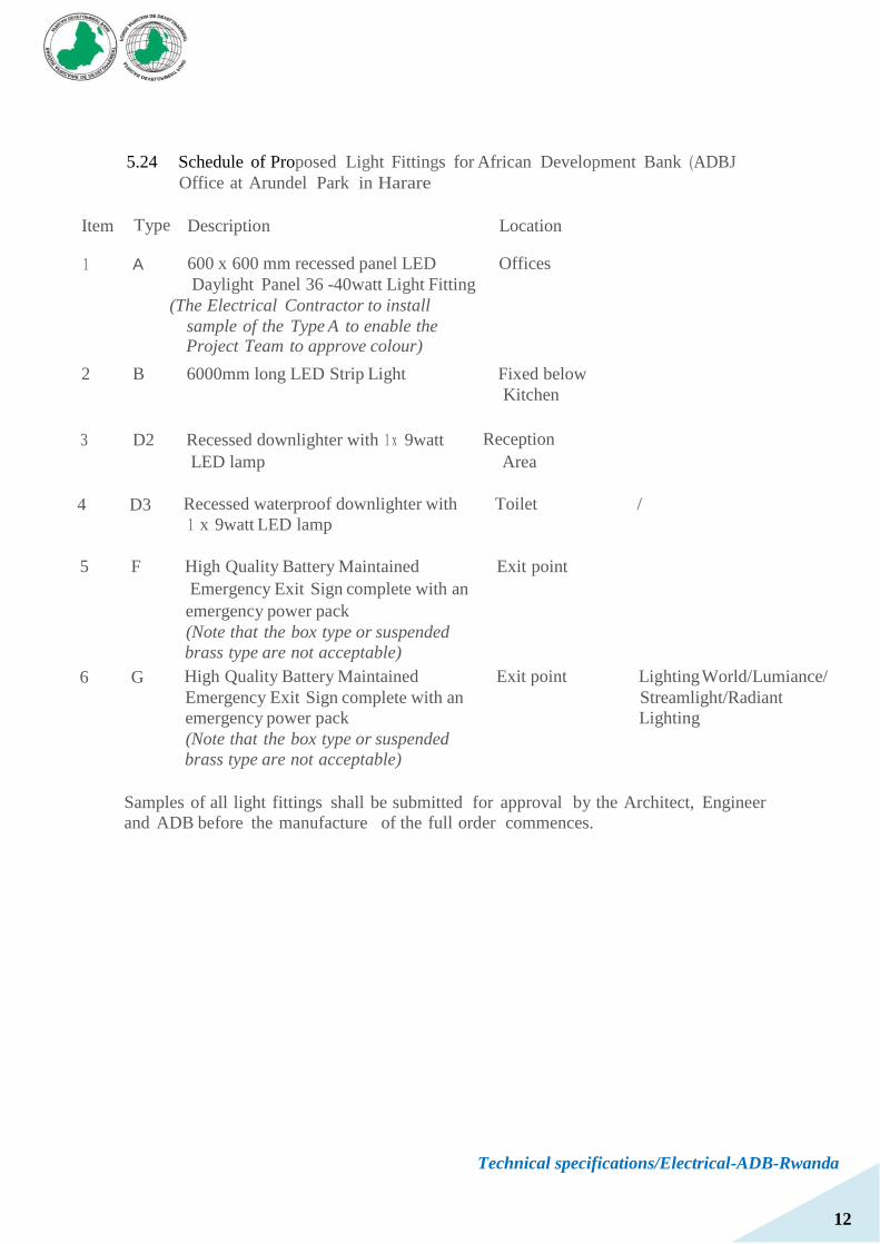
Technical specifications/Electrical-ADB-Rwanda
12
5.24 Schedule of Proposed Light Fittings for African Development Bank (ADBJ
Office at Arundel Park in Harare
Item Type Description Location
1 A 600 x 600 mm recessed panel LED Offices
Daylight Panel 36 -40watt Light Fitting
(The Electrical Contractor to install
sample of the Type A to enable the Project Team to approve colour)
2 B 6000mm long LED Strip Light Fixed below
Kitchen
.
3 D2 Recessed downlighter with 1 x 9watt Reception
LED lamp Area
4 D3 Recessed waterproof downlighter with Toilet / 1 x 9watt LED lamp
5 F High Quality Battery Maintained Exit point
Emergency Exit Sign complete with an
emergency power pack
(Note that the box type or suspended
brass type are not acceptable)
6 G High Quality Battery Maintained Exit point Lighting World/Lumiance/
Emergency Exit Sign complete with an Streamlight/Radiant
emergency power pack Lighting
(Note that the box type or suspended
brass type are not acceptable)
Samples of all light fittings shall be submitted for approval by the Architect, Engineer
and ADB before the manufacture of the full order commences.