sequoyah nuclear plants, units 1 and 2 technical specifications
TRANSCRIPT
Calculation No. MDN-000-000-2010-0200 Rev: 001 Plant: SQN Page: A-71 Subject:
PLANT PROBABILISTIC RISK ASSESSMENT – SUMMARY NOTEBOOK
F&ONumber F&O Details
4 13 The PRA model currently uses flag events indicate which standby component isrunning. It was noted that these flags could be set to zero or one (TRUE or FALSEduring quantification) as in the ERCW system, or could be set to an appropriate splitfraction to reflect the percentage of time each component was running as was donein the CCS system. (The base PRA model solution appears to assume a specific set ofcomponents are running or in standby, with the exception of CCS, which assumes a50%/50% likelihood of each train running.) The “mixing” of assumed configurationswith probabilistic configurations should be re examined. For CCS, the split fractionsare based on assumptions based on system design, but are reviewed by the systemengineers for accuracy. However, operational data is not reviewed to determine thespecific split fractions for each component. Therefore, the requirements of CategoryI for SR DA C8 are met.
(This F&O originated from SR DA C8)
Associated SR(s)
IE A6
IE C10
DA C8
Basis for Significance
This is considered to be a suggestion, as Category I of DA C8 is met and this shouldbe adequate for most applications. The determination of more precise split fractions(e.g., 54% and 46% vs. an assumed 50%/50% split) would not impact the overall PRAresults significantly.
Possible Resolution
To meet Category II, collect operating data to determine the actual standby/runningfractions for plant equipment. This data could be documented either in each systemnotebook or in the data notebook. Consideration should also be given to using aconsistent set of assumptions concerning system alignments (i.e., either all based onan assumed configuration or all based on probabilistic estimates for eachalignments).
Response
The values used in each fault tree were agreed upon by the system engineers fromthe site. No changes will be made to the split fraction values.
Calculation No. MDN-000-000-2010-0200 Rev: 001 Plant: SQN Page: A-72 Subject:
PLANT PROBABILISTIC RISK ASSESSMENT – SUMMARY NOTEBOOK
F&ONumber F&O Details
4 14 The Level 2 documentation as presented in MDN 000 000 2010 0206 providesdocumentation of each of the steps of the Level 2 analysis process. Thedocumentation is reasonably thorough; however, various documentationrecommendations have been noted in the various LE SRs that will further improvethe quality of the overall documentation package.
Also, there are a number of known changes to the Level 2 notebook that wasreviewed that need to be made (incorporation of Sequoyah specific containmentfailure evaluation results, updated CETs, updated LOSP recovery information,expanded discussion of systematic reviews that were performed, updated results,truncation studies, and sensitivity studies, etc.) This new/revised information needsto be incorporated as soon as possible in order to ensure that the notebook isconsistent with the actual Level 2 model and properly documents all of theinformation that is required by the Standard.
(This F&O originated from SR LE G1)
Associated SR(s)
LE B1
LE B2
LE C3
LE C9
LE C10
LE D1
LE D2
LE G1
Basis for Significance
This is considered a suggestion since it pertains to documentation enhancement.However, it is important that the Level 2 documentation reflect the current modeland results.
Possible Resolution
Update the notebook to reflect the comments in the referenced SRs and toincorporate the most recent information.
Response
Sequoyah specific containment failure results have been included in the document.The containment event trees have also been updated. The LOSP recoveries use level

Calculation No. MDN-000-000-2010-0200 Rev: 001 Plant: SQN Page: A-73 Subject:
PLANT PROBABILISTIC RISK ASSESSMENT – SUMMARY NOTEBOOK
one recovery factors, which should be conservative as discussed in Section 10.1.Updated results, truncation and sensitivity studies have been incorporated into thecurrent document.
Calculation No. MDN-000-000-2010-0200 Rev: 001 Plant: SQN Page: A-74 Subject:
PLANT PROBABILISTIC RISK ASSESSMENT – SUMMARY NOTEBOOK
F&ONumber F&O Details
4 15 The accident sequences are developed to a level of detail to account for the potentialcontributors identified in LE B1 and analyzed in LE B2. The containment structuralcapability and phenomena challenging containment are discussed in MDN 000 0002010 0206 Sections 5.11, 5.12, and 5.13. The description of the questionsconsidered in the Level 2 event trees are described in Section 6 and depicted inAppendix B.
However, for SBO sequences, Assumptions 10 and 11 state that if offsite power isrestored, that containment systems and injection systems will then operatesuccessfully and may arrest core melt in vessel and provide containment heatremoval. The possibility that these mitigating systems might not function should beconsidered following power restoration. This would affect the logic associated withquestions 10 and 16 of the SBO CET.
(This F&O originated from SR LE C1)
Associated SR(s)
LE C1
Basis for Significance
This is considered to be a suggestion since this modeling enhancement should haveonly a small impact on the Level 2 results (mostly for non LERF sequences).
Possible Resolution
Enhance the CET logic to consider the potential for failure of ECCS or CHR followingAC power recovery.
Response
This suggestion has not been incorporated into the current model but it will beconsidered for future model updates. Note that while not considering failure ofthese systems is a source of potential non conservative results, the current modeldoes not credit power recoveries beyond those considered in level 1 which is aconservative counter balance to this effect.
Calculation No. MDN-000-000-2010-0200 Rev: 001 Plant: SQN Page: A-75 Subject:
PLANT PROBABILISTIC RISK ASSESSMENT – SUMMARY NOTEBOOK
F&ONumber F&O Details
4 16 There are several issues identified with the use of the rule based recovery file and itsassociated documentation. Section 9.3 of the Level 2 Notebook says that variousrecovery rules were used to remove invalid combinations; these have now beenreplaced by a combination of fault tree logic changes and mutually exclusive rules.The LOSP recovery information described in section 10 is out of date. Specifically,the notebook says that the additional time between core damage and vessel failurewas included in the OSP recovery terms (as compared to the Level 1 analysis);however, the Level 1 OSP recovery factors were used in the level 2 (i.e., no credit forthe additional time). Also, the recovery factor data shown in the notebook pertainsto Watts Bar and is not the SQN specific data used in this PRA.
Recovery rules are also used to apply state of knowledge correlation adjustments tothe ISLOCA valve failure probabilities. Similar to the issues seen with HEPdependency analysis, cutsets containing combinations of multiple valve failures maybe truncated from the solution if the nominal values are used. So, an approachsimilar to HEP dependency rule application must be used (i.e. solve the fault treemodel with artificially high values for the ISLOCA valve failures, and then use therecovery file to either apply the SOK values as appropriate or to restore the valvefailure probabilities to their proper values.)
(This F&O originated from SR LE E4)
Associated SR(s)
LE E4
Basis for Significance
This is considered to be a suggestion since the items pertain either to documentationupdates or to relatively minor technical corrections. The proper treatment of theSOK adjustments may result in a small increase in ISLOCA probability. Theconsideration of the additional time available to restore OSP after core damage mayresult in a small reduction in LERF.
Possible Resolution
Address the issues identified with the recovery rules.
Response
The current level 2 analysis does not use level 2 specific recovery factors and thedocumentation has been updated to reflect this. The difference in results producedby increasing the default failure rates in the ISLOCA tree is deemed to be very small.ISLOCA contributes a small amount to the results for both level 1 and level 2, andutilizing a “seed value” approach similar to what was used for HEPS would notincrease ISLOCA contribution significantly.
Calculation No. MDN-000-000-2010-0200 Rev: 001 Plant: SQN Page: A-76 Subject:
PLANT PROBABILISTIC RISK ASSESSMENT – SUMMARY NOTEBOOK
F&ONumber F&O Details
4 17 HRA analysis was performed using the EPRI HRA Calculator for feasible operatoractions following the onset of core damage. The specific operator actions creditedand not credited are described in MDN 000 000 2010 0206 Section 7. The details ofthe analysis of each HFE is contained in the HRA Notebook (MDN 000 000 20100204).
The SQN level 2 analysis used the Watts bar PRA as a starting point. At Watts Bar,the SG PORVs will fail upon loss of power and are not credited after that time.However, at SQN, operators can use reach rods to operate the SG PORVs in SBOconditions. The Level 2 analysis should be updated to consider use of the SG PORVs,particularly since SBO is a key LERF contributor. Other conservative assumptions inthe model (as documented in Section 5 of the Level 2 notebook) should also be reevaluated.
(This F&O originated from SR LE C2)
Associated SR(s)
LE C2
Basis for Significance
This is a suggestion since it could be used to improve the PRA model through thereduction of conservatism
Possible Resolution
Re evaluate the manual operation of SG PORVs in a SBO, as well as otherconservative assumptions in the Level 2 analysis.
Response
The manual operation of SG PORVs in a SBO is covered in the level 1 analysis which isincorporated in the level 2 analysis.
Calculation No. MDN-000-000-2010-0200 Rev: 001 Plant: SQN Page: A-77 Subject:
PLANT PROBABILISTIC RISK ASSESSMENT – SUMMARY NOTEBOOK
F&ONumber F&O Details
5 1 Little description of the screening values is provided in the main text.
For example, two primary screening values are used for post initiator HEPs, 1.0E 8and 1.0. Even though Appendix E provides the basis for the screening value, themain HRA notebook should have a description on the approach taken to assign thescreening values.
In addition, Table 10 2 of the HRA notebook shows that some events in the table areset to a value of 1.0E 8. An asterisk follows this number. However, the meaning ofthe asterisk is not provided.
(This F&O originated from SR HR I2)
Associated SR(s)
HR I2
Basis for Significance
This is a suggestion because these are enhancements to the documentation.
Possible Resolution
1) Document the basis of the assigned screening values and the process used todetermine the appropriate values in the text of the HRA notebook.
2) Provide an explanation of the meaning of the asterisk for HEPs set to a value of1.0E 8 in Table 10 2.
Response
1) The screening values are appropriately documented in appendix E and no valuewould be added by moving this section to the main text of the document.
2) Table 10 2 was revised and no HEPs are set to 1.0E 8 or have an asterisk.
Calculation No. MDN-000-000-2010-0200 Rev: 001 Plant: SQN Page: A-78 Subject:
PLANT PROBABILISTIC RISK ASSESSMENT – SUMMARY NOTEBOOK
F&ONumber F&O Details
5 4 The basis of very short manipulation time (Tm) and median response time (T1/2)values for time critical HEPs such as HAOS1 and HASE2 needs to be more completelydocumented. The current documentation using the Appendix C operator interviewnotes as a basis is not considered sufficient.
(This F&O originated from SR HR G5)
Associated SR(s)
HR G5
Basis for Significance
This is a suggestion because this is primarily an issue with the completeness of thedocumentation.
Possible Resolution
Perform more time evaluation, such as simulator observations, for these kinds oftime critical HFEs.
Response
Various Tm and T1/2 timing values have been refined and further documentation hasbeen added to the HRA Calculator and the calculator reports in Appendix B.Simulator observations will be performed as they can be scheduled in the future, tofurther refine the HRA timing.
Calculation No. MDN-000-000-2010-0200 Rev: 001 Plant: SQN Page: A-79 Subject:
PLANT PROBABILISTIC RISK ASSESSMENT – SUMMARY NOTEBOOK
F&ONumber F&O Details
5 7 Even though MDN 000 000 2010 0201 identifies the key safety functions in general(see Section 6.2), the manner in which each key safety function is satisfied in theindividual event trees is not consistently documented. For example, the discussionof the LLOCA accident sequences contains a summary of the manner in which eachkey safety function is modeled. However, a similar discussion is not included in thediscussion of the General Transient accident sequences.
(This F&O originated from SR AS A2)
Associated SR(s)
AS A2
Basis for Significance
The information is available in the Success Criteria Notebook, but there should beconsistent discussion of the key safety functions in the various sections of theAccident Sequence Notebook.
Possible Resolution
Each accident sequence should describe the key safety functions, especially forgrouped initiating events like General Transients.
Response
The suggestion will be incorporated during the next revision of the notebook. Foreach event tree key safety functions will be explicitly detailed.
Calculation No. MDN-000-000-2010-0200 Rev: 001 Plant: SQN Page: A-80 Subject:
PLANT PROBABILISTIC RISK ASSESSMENT – SUMMARY NOTEBOOK
F&ONumber F&O Details
5 8 MDN 000 000 2010 0201 delineates all accident sequences. However thedescriptions do not have clear information regarding the top events.
(This F&O originated from SR AS C2)
Associated SR(s)
AS C2
Basis for Significance
The modeling appears to be correct, but the documentation could be improved.
Possible Resolution
The event sequence description should includes a combination of failed and succeedtop events. For example, the LLOCA 002 sequence description should have the eventsequence using top events, LLOCA*/ACC*/LPI3*/LPR3*LPH.
Response
The accident sequence top events are described in the Accident sequence notebook,all top events have their success criteria discussed under the appropriate event tree.
Calculation No. MDN-000-000-2010-0200 Rev: 001 Plant: SQN Page: A-81 Subject:
PLANT PROBABILISTIC RISK ASSESSMENT – SUMMARY NOTEBOOK
F&ONumber F&O Details
5 11 The graphical event trees and accident sequence descriptions delineate the transfersbetween event trees (e.g., transfers from GTRAN to SLOCA or from SLOCA to ATWS).However, the transferred sequence and boundary conditions are not discussed in theentry conditions for the event tree the sequence transfers to. The CAFTA single toplogic method preserves the existing conditions of the transferred sequences.
Associated SR(s)
AS A11
AS C2
Basis for Significance
The receiving event trees do not have any description about the transferredsequences from other event trees.
Possible Resolution
The transfer sequences should be discussed in the initiating event discussion of theaccident sequence the transfer is linked to, including the boundary conditionstransferred.
Response
The boundary conditions are supplied by the input decks and their associated outputfiles from MAAP. All transfer events from GTRAN to SLOCA are documented withinthe accident sequences.
Calculation No. MDN-000-000-2010-0200 Rev: 001 Plant: SQN Page: A-82 Subject:
PLANT PROBABILISTIC RISK ASSESSMENT – SUMMARY NOTEBOOK
F&ONumber F&O Details
5 15 Per Section 5.6 of MDN 000 000 2010 0208 and explanations provided by the TVAPRA analyst, the HRA event dependency in the cutset or sequence is properlyassessed during the quantification process. However improvement of thedocumentation is needed to better explain the process by which this is done.
For example, a special software tool, "HRASeedOptimizer 2.0.0.0," was used to avoida truncation stage from deleting necessary cutsets containing the HFE dependencycombination during the quantification process. However, MDN 000 000 2010 0208does not explain how this tool is used or how it ensures proper HEP values are usedduring the quantification to avoid truncation problems.
In addition, a two stage multiplication method is used in the recovery rules for somehigh order HFE dependency combination due to a limitation of QRecover. However,MDN 000 000 2010 0208 does not explain the Qrecover limitation or how theapplied process compensates for the limitation.
(This F&O originated from SR QU C2)
Associated SR(s)
QU C2
Basis for Significance
The process is technically acceptable, but the documentation of the process used isincomplete.
Possible Resolution
Revise the documentation to:
1) Describe the use of the HRASeedOptimizer and the manner in which it appliesthe selected HEP seed values.
2) Describe the Qrecover limitation requiring the use of the two stagemultiplication method and how the applied process compensates for thelimitation.
Response
Added description in the Quantification notebook to address resolution in section4.0.
Calculation No. MDN-000-000-2010-0200 Rev: 001 Plant: SQN Page: A-83 Subject:
PLANT PROBABILISTIC RISK ASSESSMENT – SUMMARY NOTEBOOK
F&ONumber F&O Details
6 1 Assessed as meeting category I. Site response to peer review team questionsregarding the performance of a precursor review indicated that a review wasperformed, but not documented. Documentation of the review would allow formeeting capability category II.
(This F&O originated from SR IE A9)
Associated SR(s)
IE A9
Basis for Significance
This is a suggestion for moving the categorization of this SR to Capability Category II.
Possible Resolution
Document an initiating event precursor review to meet category II.
Response
Added discussion to initiating event notebook to describe how precursor eventswere searched for and how events for intake blockage and loss of feedwater wereconsidered.
Calculation No. MDN-000-000-2010-0200 Rev: 001 Plant: SQN Page: A-84 Subject:
PLANT PROBABILISTIC RISK ASSESSMENT – SUMMARY NOTEBOOK
F&ONumber F&O Details
6 8 Overall, the documentation was well organized, and presented in a manner thatfacilitated review. There were some items that were noted that could enhance thedocumentation, however.
1) IE analysis, p. 17: Unit 1 results are considered applicable to Unit 2 due to“similarity.”
2) IE analysis, p. 17: Table A 2 of the Initiating Events Analysis refers the reader tothe Accident Sequence Analysis for discussion of Supporting Requirements (SRs)IE B2 through IE B5. However, Appendix A of the Accident Sequence analysislists AS SRs but not the IE SRs.
3) Uncertainty Analysis, section 6.4: Documentation describing how initiating eventfrequency 5th and 95th percentile values were calculated could not be identified.
4) IE analysis, Table 5 2: The table identifies NUREG/CR 1829 as the source forinitiator %LLOCACL. However, this should actually reference NUREG 1829.
(This F&O originated from SR IE D1)
Associated SR(s)
IE D1
Basis for Significance
Items noted are enhancements to the existing documentation.
Possible Resolution
Suggested resolutions to items as numbered in the description:
1) The statement on similarity could be expanded slightly to describe how the unitsare similar, e.g., they are similar in design, configuration and operation.
2) Provide a map to refer the reader to the documentation in which IE B2 throughIE B5 are addressed.
3) TVA personnel indicate that Crystal Ball ® was used to calculate the 5th and 95thpercentile values. To improve traceability of the analysis, provide a reference tothis supporting analysis.
4) Correct typo.
Response
Added discussion to IE notebook to address items 1, 2, and 4.
Item 3 should be addressed in uncertainty analysis notebook.
Calculation No. MDN-000-000-2010-0200 Rev: 001 Plant: SQN Page: A-85 Subject:
PLANT PROBABILISTIC RISK ASSESSMENT – SUMMARY NOTEBOOK
F&ONumber F&O Details
6 9 No requirements to compare results from similar plants for Capability Category I.
While a listing of CDF values from other 4 loop Westinghouse plants is provided, amore thorough comparison of the results with an explanation of the causes forsignificant differences is required to meet Category II/III.
(This F&O originated from SR QU D4)
Associated SR(s)
QU D4
Basis for Significance
Current documentation meets Capability Category I.
Possible Resolution
Provide a more thorough comparison of PRA results beyond CDF (e.g. majorsequence and initiating event contributors).
Response
A table showing the initiator distribution for similar plants has been added to theQuantification notebook.
Calculation No. MDN-000-000-2010-0200 Rev: 001 Plant: SQN Page: A-86 Subject:
PLANT PROBABILISTIC RISK ASSESSMENT – SUMMARY NOTEBOOK
F&ONumber F&O Details
6 11 Documentation of the model integration process in MDN 000 000 2010 0208 isadequate overall and contains sufficient detail to understand the process. Thedocumentation of quantification results is also satisfactory overall. The followingdocumentation issues were noted:
1) MDN 000 000 2010 0208, section 5.7 The recovery events included in theimportance tables do not include event descriptions.
2) MDN 000 000 2010 0208, section 5.1 references appendix F for a detailedreview of the top ten cutsets this documentation does not exist in appendix F.
3) MDN 000 000 2010 0208 Section 4.1 states 'Limitations that are known to havean impact on model development or quantification are addressed in Section 3.0which discusses the general methodology used to develop the SQN PRA Model.'No such discussion could be found in the referenced section.
4) MDN 000 000 2010 0208 Section 4.2 indicates that the sequence successes arecontained in the PRAQuant file when they are not actually contained in thePRAQuant file.
(This F&O originated from SR QU F2)
Associated SR(s)
QU A1
QU B1
QU B6
QU F2
Basis for Significance
The issues noted are minor issues that do not detract from the technical quality ofthe results.
Possible Resolution
1) As was done for other events in the section 5.7 importance tables, include eventdescriptions for the recovery events.
2) Provide the review or remove the reference.
3) Provide discussion in section 3 or delete reference.
4) Remove the referenced statement.
Response
References have been updated and all issues are resolved in the Quantification

Calculation No. MDN-000-000-2010-0200 Rev: 001 Plant: SQN Page: A-87 Subject:
PLANT PROBABILISTIC RISK ASSESSMENT – SUMMARY NOTEBOOK
notebook.
Calculation No. MDN-000-000-2010-0200 Rev: 001 Plant: SQN Page: A-88 Subject:
PLANT PROBABILISTIC RISK ASSESSMENT – SUMMARY NOTEBOOK
Best Practice F&Os
F&ONumber F&O Details
4 5 A thorough evaluation of the potential for human induced floods is documented insection 8.6 of the flooding notebook(MDN 000 000 2010 0203). Two types of floodsare considered: 'maintenance induced floods' which considered the potential for anisolation valve to fail during a maintenance event and 'human induced events' inwhich isolation is incorrectly performed, a tank is overfilled, etc. The calculatedfrequencies for these events are then added to the random failure frequencies forthe appropriate flood initiators.
(This F&O originated from SR IFEV A7)
Associated SR(s)
IFEV A7
Basis for Significance
This is considered a best practice, as the evaluation of human induced events wasquite comprehensive and considered different types of flooding mechanisms.
Possible Resolution
N/A
Response
No response required.
Calculation No. MDN-000-000-2010-0200 Rev: 001 Plant: SQN Page: A-89 Subject:
PLANT PROBABILISTIC RISK ASSESSMENT – SUMMARY NOTEBOOK
F&ONumber F&O Details
5 10 SQN PRA delineates not only accident sequences that result in core damage (MDN000 000 2010 0201), but also describes the success sequences (MDN 000 000 20100207).
(This F&O originated from SR AS A7)
Associated SR(s)
AS A7
Basis for Significance
This is considered a best practice, as the descriptions of the accident sequences werequite comprehensive and considered both core damage and success paths.
Possible Resolution
N/A
Response
No response required.
Calculation No. MDN-000-000-2010-0200 Rev: 001 Plant: SQN Page: A-90 Subject:
PLANT PROBABILISTIC RISK ASSESSMENT – SUMMARY NOTEBOOK
F&ONumber F&O Details
5 18 In addition to the general description to meet ASME standard, MDN 000 000 20100208 provides good information facilitating further update the model. Examplesinclude:
- Table 7.0 1: Summary of Modeling Changes,
- Comments in recovery rule file, and
- Appendix H: steps for creating a merged model
(This F&O originated from SR QU F2)
Associated SR(s)
QU F2
Basis for Significance
This is considered a best practice, as the documentation of the changes made to thefault tree model to address system reviewer’s comments, modeling logic corrections,and changes based upon cutset reviews is quite comprehensive. In addition, thedocumentation of the recovery rules, and model integration process is quitethorough and will facilitate the model maintenance and update process.
Possible Resolution
N/A
Response
No response required.
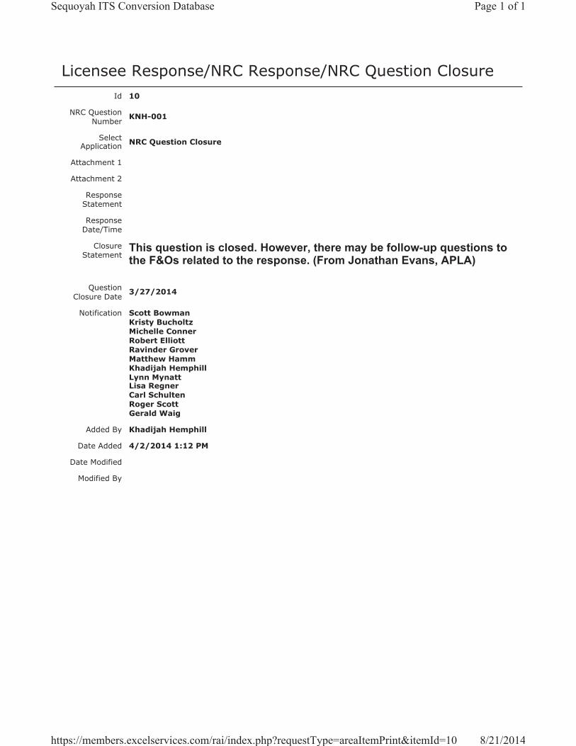
Licensee Response/NRC Response/NRC Question ClosureId 10
NRC Question Number KNH-001
Select Application NRC Question Closure
Attachment 1
Attachment 2
Response Statement
Response Date/Time
Closure Statement
This question is closed. However, there may be follow-up questions to the F&Os related to the response. (From Jonathan Evans, APLA)
Question Closure Date 3/27/2014
Notification Scott BowmanKristy BucholtzMichelle ConnerRobert ElliottRavinder GroverMatthew HammKhadijah HemphillLynn MynattLisa RegnerCarl SchultenRoger ScottGerald Waig
Added By Khadijah Hemphill
Date Added 4/2/2014 1:12 PM
Date Modified
Modified By
Page 1 of 1Sequoyah ITS Conversion Database
8/21/2014https://members.excelservices.com/rai/index.php?requestType=areaItemPrint&itemId=10
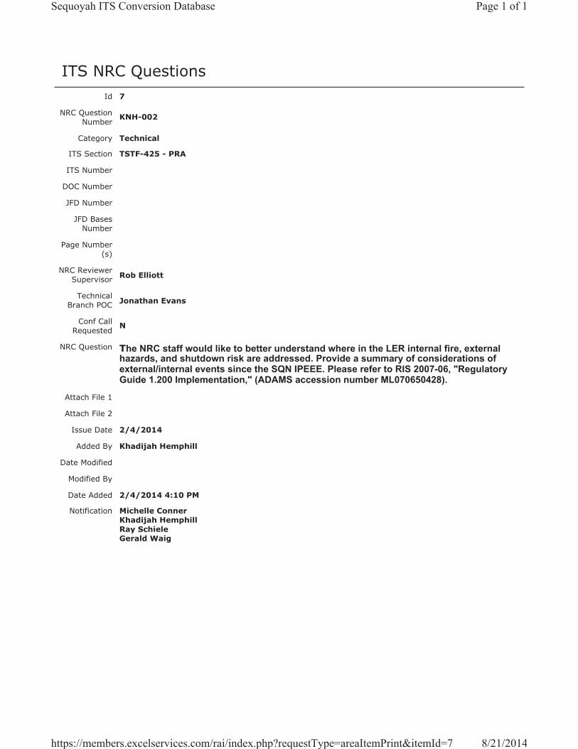
ITS NRC QuestionsId 7
NRC Question Number KNH-002
Category Technical
ITS Section TSTF-425 - PRA
ITS Number
DOC Number
JFD Number
JFD Bases Number
Page Number(s)
NRC Reviewer Supervisor Rob Elliott
Technical Branch POC Jonathan Evans
Conf Call Requested N
NRC Question The NRC staff would like to better understand where in the LER internal fire, external hazards, and shutdown risk are addressed. Provide a summary of considerations of external/internal events since the SQN IPEEE. Please refer to RIS 2007-06, "Regulatory Guide 1.200 Implementation," (ADAMS accession number ML070650428).
Attach File 1
Attach File 2
Issue Date 2/4/2014
Added By Khadijah Hemphill
Date Modified
Modified By
Date Added 2/4/2014 4:10 PM
Notification Michelle ConnerKhadijah HemphillRay SchieleGerald Waig
Page 1 of 1Sequoyah ITS Conversion Database
8/21/2014https://members.excelservices.com/rai/index.php?requestType=areaItemPrint&itemId=7
Licensee Response/NRC Response/NRC Question ClosureId 6
NRC Question Number
KNH-002
Select Application Licensee Response
Attachment 1
Attachment 2
Response Statement
Please refer to previously docketed correspondence, submitted as part of SQN's license renewal, for discussions concerning SQN's PRA. The ADAMS accession numbers are ML13024A010 (Attachment E.1, Evaluation of SQN PRA Model) and ML13227A003 (Response to NRC Request for Additional Information Regarding the Environmental Review of the Sequoyah Nuclear Plant, Units 1 and 2, License Renewal Application).
Response Date/Time 2/6/2014 3:00 PM
Closure Statement
Question Closure Date
Notification Scott BowmanMichelle ConnerKhadijah HemphillLynn MynattLisa RegnerRay SchieleGerald Waig
Added By Scott Bowman
Date Added 2/6/2014 1:57 PM
Date Modified
Modified By
Page 1 of 1Sequoyah ITS Conversion Database
8/21/2014https://members.excelservices.com/rai/index.php?requestType=areaItemPrint&itemId=6

Licensee Response/NRC Response/NRC Question ClosureId 32
NRC Question Number KNH-002
Select Application NRC Question Closure
Attachment 1
Attachment 2
Response Statement
Response Date/Time
Closure Statement
This question is closed and no further information is required at this time to draft the Safety Evaluation. Follow-up questions will be posted later.
Question Closure Date 5/20/2014
Notification Scott BowmanMichelle ConnerKhadijah HemphillAndrew HonLynn MynattRay SchieleRoger Scott
Added By Khadijah Hemphill
Date Added 5/20/2014 6:42 AM
Date Modified
Modified By
Page 1 of 1Sequoyah ITS Conversion Database
8/21/2014https://members.excelservices.com/rai/index.php?requestType=areaItemPrint&itemId=32
ITS NRC QuestionsId 93
NRC Question Number
KNH-003
Category Technical
ITS Section TSTF-425 PRA
ITS Number
DOC Number
JFD Number
JFD Bases Number
Page Number(s)
NRC Reviewer
Supervisor Hossein Hamzehee
Technical Branch POC Jonathan Evans
Conf Call Requested N
NRC Question
1) According to Regulatory Guide 1.200, Revision 2 “An Approach for Determining the Technical Adequacy of Probabilistic Risk Assessment Results for Risk-Informed Activities,” the Nuclear Regulatory Commission (NRC) staff needs additional information in support of this application that is related to the PRA technical adequacy. Please provide the following information.
A. The licensee’s submittal does not discuss the key area of uncertainty for this application, standby failure rate, and cyclic-demand failure rate, which should be utilized in the determination of STI extension impact. Regulatory Guide 1.177, Section 2.3.3 discusses stand by and cyclic-demand time-related component unavailability. Please identify assumptions regarding key sources of uncertainty, including discussion on the licensee’s handling of standby and cyclic-demand time-related component availability.
Attach File 1
Attach File 2
Issue Date 5/28/2014
Added By Khadijah Hemphill
Date Modified
Modified By
Page 1 of 2Sequoyah ITS Conversion Database
8/21/2014https://members.excelservices.com/rai/index.php?requestType=areaItemPrint&itemId=93
Date Added 5/28/2014 3:31 PM
Notification Scott BowmanMichelle ConnerKhadijah HemphillAndrew HonLynn MynattRay SchieleRoger Scott
Page 2 of 2Sequoyah ITS Conversion Database
8/21/2014https://members.excelservices.com/rai/index.php?requestType=areaItemPrint&itemId=93
Licensee Response/NRC Response/NRC Question ClosureId 160
NRC Question Number
KNH-003
Select Application Licensee Response
Attachment 1
Attachment 2
Response Statement
The SQN PRA model does not distinguish between time-related failure contribution and cyclic demand-related failure contribution. When the breakdown between time-related and demand-related contributions is unknown, all failures will be assumed to be time-related to obtain the maximum test-limited risk contribution. If a further breakdown of failure probability is required to remove conservatism from the risk impact calculation of a proposed surveillance frequency change, SQN will abide by the caution noted in NEI 04-10, Step 8, “…caution should be taken in dividing the failure probability into time-related and cyclic demand-related contributions because the test-limited risk can be underestimated when only part of the failure rate is considered as being time-related while this may not be the case”. When performing an assessment, Step 14 of NEI 04-10 advises that sensitivity studies be performed on those basic events whose probability is being impacted by the change in surveillance frequency, and this will also be followed.
[During a subsequent teleconference, TVA and NRC staff agreed that it was not necessary for TVA to specifically identify assumptions regarding key sources of uncertainty.]
Response Date/Time 6/27/2014 2:00 PM
Closure Statement
Question Closure
Date
Notification Scott BowmanMichelle ConnerKhadijah HemphillAndrew HonRay Schiele
Added By Scott Bowman
Date Added 6/27/2014 12:58 PM
Date Modified
Modified By
Page 1 of 1Sequoyah ITS Conversion Database
8/21/2014https://members.excelservices.com/rai/index.php?requestType=areaItemPrint&itemId=160

Licensee Response/NRC Response/NRC Question ClosureId 213
NRC Question Number KNH-003
Select Application NRC Question Closure
Attachment 1
Attachment 2
Response Statement
Response Date/Time
Closure Statement This question is closed and no further information is required at this time to draft the Safety Evaluation.
Question Closure Date 7/24/2014
Notification Scott BowmanMichelle ConnerKhadijah HemphillAndrew HonLynn MynattRay SchieleRoger Scott
Added By Khadijah Hemphill
Date Added 7/24/2014 7:49 AM
Date Modified
Modified By
Page 1 of 1Sequoyah ITS Conversion Database
8/21/2014https://members.excelservices.com/rai/index.php?requestType=areaItemPrint&itemId=213
ITS NRC QuestionsId 94
NRC Question Number
KNH-004
Category Technical
ITS Section TSTF-425 PRA
ITS Number
DOC Number
JFD Number
JFD Bases Number
Page Number(s)
NRC Reviewer
Supervisor Hossein Hamzehee
Technical Branch POC Jonathan Evans
Conf Call Requested N
NRC Question
According to Regulatory Guide 1.200, Revision 2 “An Approach for Determining the Technical Adequacy of Probabilistic Risk Assessment Results for Risk-Informed Activities,” the Nuclear Regulatory Commission (NRC) staff needs additional information in support of this application that is related to the PRA technical adequacy. Please provide the following information.A. The licensee does not discuss the considerations made regarding the evaluation of
external and shutdown events in their submittal. NEI 04-10 states that, “Plants implementing TSTF-425 shall evaluate their PRAs in accordance with [RG 1.200].”NRC Regulatory Issue Summary 2007-06 further states that, “If an implementation period for routine, limited scope risk-informed license applications is needed, the NRC would expect licensees to fully address all scope elements consistent with Revision 2 of RG 1.200 by the end of 2009.”
i. Please describe, in more detail, how external events will be assessed consistent with NEI 04-10 guidance. If a bounding method is to be used, please describe the method, how it is consistent with NEI 04-10 guidance (Step 10b), and how the bounding analysis considers the current plant configuration and operation.
Attach File 1
Attach File 2
Issue Date 5/28/2014
Added By Khadijah Hemphill
Date Modified
Modified By
Page 1 of 2Sequoyah ITS Conversion Database
8/21/2014https://members.excelservices.com/rai/index.php?requestType=areaItemPrint&itemId=94
Date Added 5/28/2014 3:32 PM
Notification Scott BowmanMichelle ConnerKhadijah HemphillAndrew HonLynn MynattRay SchieleRoger Scott
Page 2 of 2Sequoyah ITS Conversion Database
8/21/2014https://members.excelservices.com/rai/index.php?requestType=areaItemPrint&itemId=94
Licensee Response/NRC Response/NRC Question ClosureId 148
NRC Question Number
KNH-004
Select Application Licensee Response
Attachment 1
Attachment 2
Response Statement SQN is committed to evaluating surveillance test interval (STI) changes in
accordance with NEI 04-10, Rev. 1. The SQN process will be governed by procedure, based on NEI 04-10, Rev. 1 that provides the approach to be taken in addressing external events. STI risk assessments should be quantitative where practical, if not practical, a qualitative assessment and/or a bounding analysis will be performed.
For a given STI change the associated structures, systems, and components (SSCs) will be established and a determination will be made as to whether the SSC is modeled (either explicitly or implicitly) by the PRA. To determine if the SSC is implicitly modeled in the PRA, the following questions are considered:
1. Can its failure contribute to an initiating event in the PRA?2. Is it credited for prevention of core damage or large early release in
the PRA?3. Is it necessary for another (e.g., supported) system or structure
function evaluated in the PRA to prevent an event or mitigate an event?
The procedure states “If a particular hazard is not modeled either in an integrated PRA model or in an individual PRA (e.g., Fire PRA), the STI change impact on the hazard risk should be evaluated using a bounding or qualitative analysis…” STI changes will use the following sources of information with respect to external events until such time that the external hazard PRA is completed:
Fire Risk - IPEEE - Fire Induced Vulnerability Evaluation (FIVE)
Seismic Risk - IPEEE - Seismic Margins Analysis (SMA)Other External Events - Insights from the IPEEE
The following describes the processes as defined in the SQN procedure for consideration of external events which is consistent with NEI 04-10, Step 10.
Fire Risk
Page 1 of 3Sequoyah ITS Conversion Database
8/21/2014https://members.excelservices.com/rai/index.php?requestType=areaItemPrint&itemId=148
1. Either an application-specific evaluation or FIVE will be used for the analysis. If the STI SSC is explicitly evaluated in the fire analysis, then the analysis results may be used to determine the acceptability of the proposed change.
2. If the SSC is determined to be only implicitly modeled in the fire analysis, then either a bounding analysis, a refined analysis, or the fire analysis will be refined to adequately represent the SSC.
3. The risk increase values resulting from the FIVE evaluation, the bounding analysis, or the refined analysis are considered a single effect and will be included in the summation of all single effects to obtain the total effect.
4. If the SSC is not evaluated (either explicitly or implicitly) in the fire analysis, the STI change will be qualitatively screened out, and documented, as not having a fire risk impact on the core damage frequency (CDF) or large early release frequency (LERF) metrics.
Seismic Risk1. The SQN SMA will be used for the evaluation if the STI, associated
SSC is included (either explicitly or implicitly) in the seismic analysis. Qualitative information will be developed to determine if the STI change is acceptable with respect to the seismic risk.
2. If the STI SSC is not evaluated (either explicitly or implicitly) in the seismic analysis, the STI change may be qualitatively screened out as not having an impact on seismic risk.
Other External Events1. An external hazards screening evaluation, that was performed to
support the requirements of the IPEEE, may be used for the evaluation. If the STI SSC is evaluated in the external hazards analysis (either explicitly or implicitly), qualitative information will be developed to determine if the STI change is acceptable with respect to the external hazards risk.
2. If the SSC is not evaluated (either explicitly or implicitly) by the external hazards analysis, the STI change may be qualitatively screened out as not having an impact on external hazards risk.
Bounding Analysis – The bounding analysis methodology pertains to STI changes when the qualitative assessment alone is deemed insufficient to bring before the Integrated Decisionmaking Panel (IDP). The draft procedure developed by SQN follows the process described in NEI 04-10 Rev. 1. Consistent with Step 10b, the bounding analysis is performed for those SSCs that are not explicitly modeled in the PRA, but rather are implicitly included in the model at the initiating event, mitigating system, or functional level. In that case, the basic event(s) associated with the initiating event, mitigating system, or function can be identified to use as a surrogate for the SSC being investigated. Reasonable variations to the
Page 2 of 3Sequoyah ITS Conversion Database
8/21/2014https://members.excelservices.com/rai/index.php?requestType=areaItemPrint&itemId=148
basic event value(s) are then explored to determine the potential bounding impact of the STI change. The three approaches to be followed are:
1. Consistent with NEI 04-10 Rev. 1, Step 10b, manipulate the initiating events, mitigating system, or functions that are associated with the STI change in order to bound the impact of the change.
2. If the bounding analysis shows that the CDF and LERF values are below the 1.0E-07/yr CDF and 1.0E-08/yr LERF limits, then the PRA Engineer will further assess the impact of the STI change for Fire Risk, Seismic Risk and Other External Hazards in accordance with the steps described above which are consistent with NEI 04-10 Rev.1, Step 10.
3. If the bounding analysis cannot show that the STI change is below the 1.0E-07/yr CDF and 1.0E-08 LERF limits, a refined analysis will be performed consistent with NEI 04-10 Rev. 1, Step 10c.
The SQN PRA models are referred to as “living models” meaning they adequately represent the as-built, as-operated plant, and are updated periodically to ensure that changes to the design and operation of the plant are assessed. With respect to bounding analyses, surrogate basic events will be used as appropriate, which will represent the as-built, as-operated plant. Furthermore, as necessary, to best ascertain the impact of a proposed STI change, sensitivity analyses will be performed consistent with NEI 04-10 Rev. 1, Step 14. For those STIs impacted by external events, the event frequencies can be adjusted to determine how sensitive the STI change is to an increase in the likelihood of a given initiator.
Response Date/Time 6/27/2014 7:50 AM
Closure Statement
Question Closure
Date
Notification Scott BowmanMichelle ConnerKhadijah HemphillAndrew HonRay Schiele
Added By Scott Bowman
Date Added 6/27/2014 6:42 AM
Date Modified
Modified By
Page 3 of 3Sequoyah ITS Conversion Database
8/21/2014https://members.excelservices.com/rai/index.php?requestType=areaItemPrint&itemId=148

Licensee Response/NRC Response/NRC Question ClosureId 214
NRC Question Number KNH-004
Select Application NRC Question Closure
Attachment 1
Attachment 2
Response Statement
Response Date/Time
Closure Statement This question is closed and no further information is required at this time to draft the Safety Evaluation.
Question Closure Date 7/24/2014
Notification Scott BowmanMichelle ConnerKhadijah HemphillAndrew HonLynn MynattRay SchieleRoger Scott
Added By Khadijah Hemphill
Date Added 7/24/2014 7:50 AM
Date Modified
Modified By
Page 1 of 1Sequoyah ITS Conversion Database
8/21/2014https://members.excelservices.com/rai/index.php?requestType=areaItemPrint&itemId=214
ITS NRC QuestionsId 95
NRC Question Number
KNH-005
Category Technical
ITS Section TSTF-425 PRA
ITS Number
DOC Number
JFD Number
JFD Bases Number
Page Number(s)
NRC Reviewer
Supervisor Hossein Hamzehee
Technical Branch POC Jonathan Evans
Conf Call Requested N
NRC Question
According to Regulatory Guide 1.200, Revision 2 “An Approach for Determining the Technical Adequacy of Probabilistic Risk Assessment Results for Risk-Informed Activities,” the Nuclear Regulatory Commission (NRC) staff needs additional information in support of this application that is related to the PRA technical adequacy. Please provide the following information.
B. The licensee does not discuss the considerations made regarding the evaluation of external and shutdown events in their submittal. NEI 04-10 states that, “Plants implementing TSTF-425 shall evaluate their PRAs in accordance with [RG 1.200].”NRC Regulatory Issue Summary 2007-06 further states that, “If an implementation period for routine, limited scope risk-informed license applications is needed, the NRC would expect licensees to fully address all scope elements consistent with Revision 2 of RG 1.200 by the end of 2009.”
ii. Please provide the considerations made for shutdown events.
Attach File 1
Attach File 2
Issue Date 5/28/2014
Added By Khadijah Hemphill
Date Modified
Modified By
Page 1 of 2Sequoyah ITS Conversion Database
8/21/2014https://members.excelservices.com/rai/index.php?requestType=areaItemPrint&itemId=95
Date Added 5/28/2014 3:35 PM
Notification Scott BowmanMichelle ConnerAndrew HonLynn MynattRay SchieleRoger Scott
Page 2 of 2Sequoyah ITS Conversion Database
8/21/2014https://members.excelservices.com/rai/index.php?requestType=areaItemPrint&itemId=95
Licensee Response/NRC Response/NRC Question ClosureId 149
NRC Question Number
KNH-005
Select Application Licensee Response
Attachment 1
Attachment 2
Response Statement
The overall process for risk-informing surveillance test intervals (STIs) will be governed by procedure which defines the risk hazards that must be assessed. The TVA procedure will be developed using the methodology described in NEI 04-10, Rev. 1. The risk assessment is based on evaluation of internal events at full power, fire events, seismic events, other external hazards (e.g., tornados) and shutdown events. The SQN PRA does not explicitly model shutdown events; therefore, in accordance with NEI 04-10, Rev. 1 consideration for these events will be addressed through qualitative methods and to the extent possible, quantitative methods by use of surrogates, or in some cases, refined modeling, including application specific modeling, or bounding risk analysis. Note: This RAI addresses Shutdown Events, refer to RAI KNH-004 licensee response for External Events.
Shutdown Events - SQN has a Shutdown Risk Management Program (similar to Shutdown Safety Program) which was developed in accordance with NUMARC 91-06 that provides the process for assessing and managing risk during shutdown operations with focus on the key shutdown safety functions. NEI 04-10 states that the shutdown safety program can be used for the STI evaluation, or an application specific shutdown analysis may be performed. The SQN process uses a blended approach of high level fault trees and defense-in-depth to characterize risk associated with a given plant configuration during shutdown operations. Therefore, with respect to STIs determined to be credited in the NUMARC 91-06 analysis, qualitative information will be developed that supports the acceptability of the STI change with respect to shutdown risk for considerations defined in NEI 04-10, Step 10a, “Qualitative Analysis Sufficient for IDP.” This evaluation will be performed by personnel that are knowledgeable in the scope, level of detail and assumptions of NUMARC 91-06.
If the structure, system, and component (SSC) is not credited by the NUMARC 91-06 program, the SSC can be screened qualitatively and the information presented to the IDP (Integrated Decision-making Panel). This initial screening would be based on shutdown risk not having an impact on the CDF (core damage frequency) and LERF (large early release frequency) metrics.
Page 1 of 2Sequoyah ITS Conversion Database
8/21/2014https://members.excelservices.com/rai/index.php?requestType=areaItemPrint&itemId=149
Response Date/Time 6/27/2014 7:50 AM
Closure Statement
Question Closure
Date
Notification Scott BowmanMichelle ConnerKhadijah HemphillAndrew HonRay Schiele
Added By Scott Bowman
Date Added 6/27/2014 6:45 AM
Date Modified
Modified By
Page 2 of 2Sequoyah ITS Conversion Database
8/21/2014https://members.excelservices.com/rai/index.php?requestType=areaItemPrint&itemId=149

Licensee Response/NRC Response/NRC Question ClosureId 215
NRC Question Number KNH-005
Select Application NRC Question Closure
Attachment 1
Attachment 2
Response Statement
Response Date/Time
Closure Statement This question is closed and no further information is required at this time to draft the Safety Evaluation.
Question Closure Date 7/24/2014
Notification Scott BowmanMichelle ConnerKhadijah HemphillAndrew HonLynn MynattRay SchieleRoger Scott
Added By Khadijah Hemphill
Date Added 7/24/2014 7:53 AM
Date Modified
Modified By
Page 1 of 1Sequoyah ITS Conversion Database
8/21/2014https://members.excelservices.com/rai/index.php?requestType=areaItemPrint&itemId=215
ITS NRC QuestionsId 96
NRC Question Number
KNH-006
Category Technical
ITS Section TSTF-425 PRA
ITS Number
DOC Number
JFD Number
JFD Bases Number
Page Number(s)
NRC Reviewer
Supervisor Hossein Hamzehee
Technical Branch POC Jonathan Evans
Conf Call Requested N
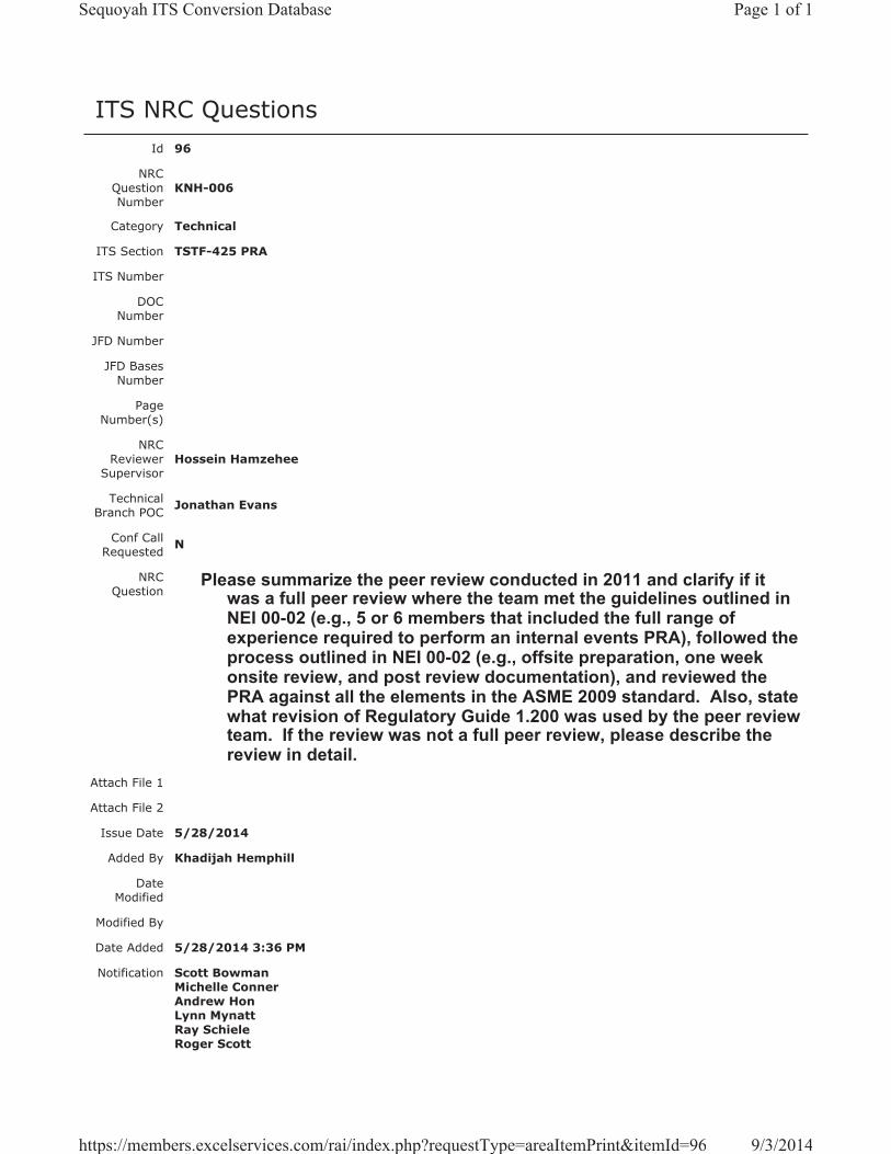
NRC Question
Please summarize the peer review conducted in 2011 and clarify if it was a full peer review where the team met the guidelines outlined in NEI 00-02 (e.g., 5 or 6 members that included the full range of experience required to perform an internal events PRA), followed the process outlined in NEI 00-02 (e.g., offsite preparation, one week onsite review, and post review documentation), and reviewed the PRA against all the elements in the ASME 2009 standard. Also, state what revision of Regulatory Guide 1.200 was used by the peer review team. If the review was not a full peer review, please describe the review in detail.
Attach File 1
Attach File 2
Issue Date 5/28/2014
Added By Khadijah Hemphill
Date Modified
Modified By
Date Added 5/28/2014 3:36 PM
Notification Scott BowmanMichelle ConnerAndrew HonLynn MynattRay SchieleRoger Scott
Page 1 of 1Sequoyah ITS Conversion Database
9/3/2014https://members.excelservices.com/rai/index.php?requestType=areaItemPrint&itemId=96
Licensee Response/NRC Response/NRC Question ClosureId 150
NRC Question Number
KNH-006
Select Application Licensee Response
Attachment 1
Attachment 2
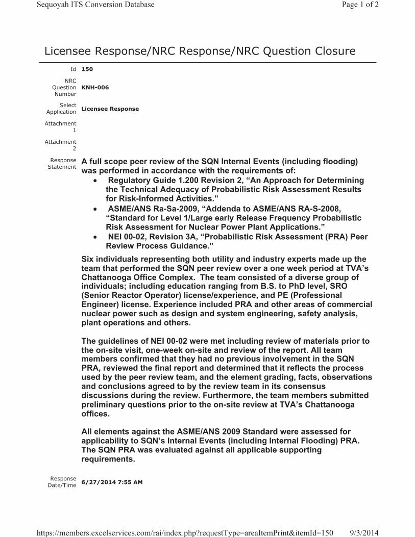
Response Statement
A full scope peer review of the SQN Internal Events (including flooding) was performed in accordance with the requirements of:
Regulatory Guide 1.200 Revision 2, “An Approach for Determining the Technical Adequacy of Probabilistic Risk Assessment Results for Risk-Informed Activities.”ASME/ANS Ra-Sa-2009, “Addenda to ASME/ANS RA-S-2008, “Standard for Level 1/Large early Release Frequency Probabilistic Risk Assessment for Nuclear Power Plant Applications.”NEI 00-02, Revision 3A, “Probabilistic Risk Assessment (PRA) Peer Review Process Guidance.”
Six individuals representing both utility and industry experts made up the team that performed the SQN peer review over a one week period at TVA’s Chattanooga Office Complex. The team consisted of a diverse group of individuals; including education ranging from B.S. to PhD level, SRO (Senior Reactor Operator) license/experience, and PE (Professional Engineer) license. Experience included PRA and other areas of commercial nuclear power such as design and system engineering, safety analysis, plant operations and others.
The guidelines of NEI 00-02 were met including review of materials prior to the on-site visit, one-week on-site and review of the report. All team members confirmed that they had no previous involvement in the SQN PRA, reviewed the final report and determined that it reflects the process used by the peer review team, and the element grading, facts, observations and conclusions agreed to by the review team in its consensus discussions during the review. Furthermore, the team members submitted preliminary questions prior to the on-site review at TVA’s Chattanooga offices.
All elements against the ASME/ANS 2009 Standard were assessed for applicability to SQN’s Internal Events (including Internal Flooding) PRA. The SQN PRA was evaluated against all applicable supporting requirements.
Response Date/Time 6/27/2014 7:55 AM
Page 1 of 2Sequoyah ITS Conversion Database
9/3/2014https://members.excelservices.com/rai/index.php?requestType=areaItemPrint&itemId=150
Closure Statement
Question Closure
Date
Notification Scott BowmanMichelle ConnerKhadijah HemphillAndrew HonRay Schiele
Added By Scott Bowman
Date Added 6/27/2014 6:51 AM
Date Modified
Modified By
Page 2 of 2Sequoyah ITS Conversion Database
9/3/2014https://members.excelservices.com/rai/index.php?requestType=areaItemPrint&itemId=150

Licensee Response/NRC Response/NRC Question ClosureId 311
NRC Question Number KNH-006
Select Application NRC Question Closure
Attachment 1
Attachment 2
Response Statement
Response Date/Time
Closure Statement This question is closed and no further information is required at this time to draft the Safety Evaluation.
Question Closure Date 9/3/2014
Notification Scott BowmanMichelle ConnerKhadijah HemphillAndrew HonLynn MynattRay SchieleRoger Scott
Added By Khadijah Hemphill
Date Added 9/3/2014 7:27 AM
Date Modified
Modified By
Page 1 of 1Sequoyah ITS Conversion Database
9/3/2014https://members.excelservices.com/rai/index.php?requestType=areaItemPrint&itemId=311
ITS NRC QuestionsId 97
NRC Question Number KNH-007
Category Technical
ITS Section TSTF-425 PRA
ITS Number
DOC Number
JFD Number
JFD Bases Number
Page Number(s)
NRC Reviewer Supervisor Hossein Hamzehee
Technical Branch POC Jonathan Evans
Conf Call Requested N
NRC Question Please identify any PRA upgrades made since the 2011 peer reviewed. If upgrades were made since then, discuss your plans to perform an appropriate focused scope peer review for the upgrades.
Attach File 1
Attach File 2
Issue Date 5/28/2014
Added By Khadijah Hemphill
Date Modified
Modified By
Date Added 5/28/2014 3:38 PM
Notification Scott BowmanMichelle ConnerKhadijah HemphillAndrew HonLynn MynattRay SchieleRoger Scott
Page 1 of 1Sequoyah ITS Conversion Database
9/3/2014https://members.excelservices.com/rai/index.php?requestType=areaItemPrint&itemId=97
Licensee Response/NRC Response/NRC Question ClosureId 151
NRC Question Number
KNH-007
Select Application Licensee Response
Attachment 1
Attachment 2
Response Statement
The ASME/ANS standard defines a PRA upgrade as the incorporation of new methodology or significant changes in scope or capability that impact the significant accident sequences. The standard defines PRA maintenance as updates to reflect plant changes such as modifications, procedure changes or plant performance (data). There have been no PRA upgrades, per the ASME/ANS definition, to the SQN PRA since the 2011 peer review. PRA maintenance has been performed to include known plant configuration changes due to completed modifications, identified modeling errors, and changes in plant procedures or practices.
Response Date/Time 6/27/2014 8:00 AM
Closure Statement
Question Closure
Date
Notification Scott BowmanMichelle ConnerKhadijah HemphillAndrew HonRay Schiele
Added By Scott Bowman
Date Added 6/27/2014 6:56 AM
Date Modified
Modified By
Page 1 of 1Sequoyah ITS Conversion Database
9/3/2014https://members.excelservices.com/rai/index.php?requestType=areaItemPrint&itemId=151

Licensee Response/NRC Response/NRC Question ClosureId 312
NRC Question Number KNH-007
Select Application NRC Question Closure
Attachment 1
Attachment 2
Response Statement
Response Date/Time
Closure Statement This question is closed and no further information is required at this time to draft the Safety Evaluation.
Question Closure Date 9/3/2014
Notification Scott BowmanMichelle ConnerKhadijah HemphillAndrew HonLynn MynattRay SchieleRoger Scott
Added By Khadijah Hemphill
Date Added 9/3/2014 7:27 AM
Date Modified
Modified By
Page 1 of 1Sequoyah ITS Conversion Database
9/3/2014https://members.excelservices.com/rai/index.php?requestType=areaItemPrint&itemId=312
ITS NRC QuestionsId 98
NRC Question Number
KNH-008
Category Technical
ITS Section TSTF-425 PRA
ITS Number
DOC Number
JFD Number
JFD Bases Number
Page Number(s)
NRC Reviewer
Supervisor Hossein Hamzehee
Technical Branch POC Jonathan Evans
Conf Call Requested N
NRC Question
Please provide the Facts and Observations (F&Os) mentioned in the LAR Enclosure 10, section 3, with their resolution to meet capability category II for the SR. Please note which SRs, if any, remained at capability category I after the F&O resolutions were completed. For those F&Os considered to be open for the PRA model of record used for the LAR, discuss their significance for the TSTF-425 application, and discuss if a sensitivity analysis would be applied in using the NEI 04-10 guidance.
Attach File 1
Attach File 2
Issue Date 5/28/2014
Added By Khadijah Hemphill
Date Modified
Modified By
Date Added 5/28/2014 3:39 PM
Notification Scott BowmanMichelle ConnerKhadijah HemphillAndrew HonLynn MynattRay SchieleRoger Scott
Page 1 of 1Sequoyah ITS Conversion Database
3/16/2015https://members.excelservices.com/rai/index.php?requestType=areaItemPrint&itemId=98
Licensee Response/NRC Response/NRC Question ClosureId 164
NRC Question Number
KNH-008
Select Application Licensee Response
Attachment 1
Attachment 2
Response Statement There were three Facts and Observations (F&Os) mentioned in the SQN
license amendment request (LAR) Enclosure 10, Section 3 as having supporting requirements (SRs) that remained at capability category (CC)-I (i.e., were not met) after the F&O resolutions were completed. They are F&O 1-15 (Finding), F&O 4-1 (Suggestion), and F&O 4-13 (Suggestion).Each F&O from the Peer Review Final Report is listed below followed by the SQN response or resolution.
F&O 1-15 (Finding)
The super initiator “super transient” may overlook certain differences among its contributors. For example, the impact of specific IEs [initiating events] like LOSP [loss of offsite power] and Loss of DC [direct current] that may prevent PORV [power operated relief valve] operation and challenge the Pressurizer Safeties do not appear to be captured. In addition, failure to provide a separate event tree for SBO [station blackout] may overestimate the success of power recovery by not addressing the operation of systems such as charging and AFW [auxiliary feedwater] following power recovery.(This F&O originated from SR AS-A10)
Associated SR(s)AS-A10AS-B1SC-B3
Basis for SignificanceThe accident sequences do not contain sufficient detail to capture important system requirements and required operator interactions for all initiating events.
Possible Resolution1) Subdivide the General Transients event tree to better represent the
unique challenges presented by specific initiating events (e.g.,
Page 1 of 5Sequoyah ITS Conversion Database
03/18/2015https://members.excelservices.com/rai/index.php?requestType=areaItemPrint&itemId=164
Transient with Loss of PCS [Power Conversion System], Transient with PCS Available, LOSP) or document how those challenges are addressed in the top logic model.
2) Modify the existing event sequence and/or linked fault tree to ensure that the challenge to the Pressurizer Safeties is captured for initiating events that would prevent the PORVs from opening.
3) Explicitly model the SBO sequences to ensure that the necessary mitigating systems are addressed following power recovery.
F&O 1-15 SQN Response/Resolution
The SQN PRA model was updated to meet CC-II or CC I – III for SRs AS-A10, AS-B1, and SC-B3. Recommended resolution #2 was incorporated into the General Transient event tree to ensure that the pressurizer safeties and PORVs opening and closing were addressed in the PRA model.Recommended resolutions #1 and #3 were not incorporated to meet CC-II or CC I – III. Rather, the model was updated via other means to meet the associated SRs with this F&O.
AS-A10: The PRA model was updated to improve the capture of the initiating event dependencies. The general Transient event tree models the plant response to all initiating events that are not loss of coolant accidents (LOCAs), secondary side line breaks, or anticipated transients without scram (ATWS) events. The plant response to these initiating events is the same; however, the equipment available is affected by the initiating event. To capture that dependency, the fault tree models for the systems credited in the General Transient event tree were updated and verified to have correctly modeled the effect of the initiating event.
AS-B1: The effect on systems was developed within the system notebook calculations so that the correct initiator impact was modeled for each of the accident sequences.
SC-B3: The success criteria developed for each of the event tree nodes was discussed in the Accident Sequence calculation as well as the Success Criteria calculation. The new nodes for the General Transient event tree and the required success criteria were added to these calculations.
To meet the requirements of CC-II or CC I – III, the system fault trees were revised. Proposed resolution #1 gives a choice of either subdividing the General Transient event tree or documenting how challenges are addressed in the top logic model. The Summary Notebook in section 3.2, Accident Sequence Analysis, lists the ten event trees developed for the SQN PRA. Table 2 from that section of the Summary Notebook provides the initiating event linking that was performed. The table includes the Transient with and without PCS, as well as, the loss of support initiating events that includes the loss of offsite power (LOOP).
Page 2 of 5Sequoyah ITS Conversion Database
03/18/2015https://members.excelservices.com/rai/index.php?requestType=areaItemPrint&itemId=164
Initiator General Transients was restructured to address proposed resolution #2 which was resolved by inclusion in the Revision 6 PRA model. The event tree was updated to explicitly ask demands for PORVs and Safeties.
Proposed resolution #3 was addressed in the response to NRC RAI 7.a.viii.4 (for the SQN severe accident mitigation alternative (SAMA)), reference ML13227A003. The TVA response was that to model the SBO event, there would not be appreciable enhancement to the PRA insights. An analysis was performed that included the SBO system failures post power recovery.The result was a negligible effect (e.g., E-8/yr) on the core damage frequency (CDF). Therefore, there would be insignificant effect on the calculations to risk-informed surveillance frequencies. In accordance with the NEI 04-10, Rev. 1 guidance (refer to Step 12-A4), given no significant effect on the PRA metrics, sensitivity analyses are not required in this case.
However, the TVA procedure being developed for implementation of NEI 04-10 will have provisions to invoke sensitivity studies based on the actual PRA metrics obtained during analysis and other factors such as assumptions and initiating frequency (e.g., LOOP, seismic) that could drive a sensitivity study to be performed.
F&O 4-1 (Suggestion)
Section 5.2 of the Internal Flooding Notebook (MDN-000-000-2010-0203 ) considers flood areas in the buildings of both units, and includes all common buildings. At the building level, the text discusses whether the building contains shared equipment; however, the text and tables do not indicate which specific flood areas can impact both units. It would be helpful to enhance the documentation to indicate which flood areas have multi-unit impacts.”(This F&O originated from SR IFPP-A3)
Associated SR(s)
IFPP-A3IFSO-A2
Basis for Significance
This is a suggestion since it pertains solely to enhancement of the documentation of the flood area partitioning and flood source identification process. The flood analysis itself correctly addresses multi-unit impacts.
Possible Resolution
Include (in the text of Section 5.2 or within the tables of the included areas) indication of what areas have multi-unit impacts. Include similar
Page 3 of 5Sequoyah ITS Conversion Database
03/18/2015https://members.excelservices.com/rai/index.php?requestType=areaItemPrint&itemId=164
documentation in Section 6.1 for flood sources.
F&O 4-1 SQN Response
F&O 4-1 proposes revising tables in the flooding analysis. This was not done because the flooding analysis already had the proposed information in tables and corresponding figures provided in Section 5.2 (Plant Partitioning) of the SQN Internal Flooding Analysis, MDQ-000-000-2010-0203. This recommendation would have added an unnecessary redundancy and the potential benefit to be achieved would not justify the effort to revise the Internal Flooding Analysis Notebook with the proposed resolution.
Furthermore, the SRs (IFPP-A3 & IFSO-A2) associated with F&O 4-1 were characterized by the peer review team as meeting CC I – III. This F&O is simply an administrative suggestion and does not have any quantifiable effect on the STI change application.
F&O 4-13 (Suggestion)
The PRA model currently uses flag events [to] indicate which standby component is running. It was noted that these flags could be set to zero or one (TRUE or FALSE during quantification) as in the ERCW [essential raw cooling water] system, or could be set to an appropriate split fraction to reflect the percentage of time each component was running as was done in the CCS [component cooling system] system. (The base PRA model solution appears to assume a specific set of components are running or in standby, with the exception of CCS, which assumes a 50%/50% likelihood of each train running.) The “mixing” of assumed configurations with probabilistic configurations should be re-examined. For CCS, the split fractions are based on assumptions based on system design, but are reviewed by the system engineers for accuracy. However, operational data is not reviewed to determine the specific split fractions for each component. Therefore, the requirements of Category I for SR DA-C8 are met.
(This F&O originated from SR DA-C8)
Associated SR(s)
IE-A6IE-C10DA-C8
Basis for Significance
This is considered to be a suggestion, as Category I of DA-C8 is met and this should be adequate for most applications. The determination of more precise split fractions (e.g., 54% and 46% vs. an assumed 50%/50% split
Page 4 of 5Sequoyah ITS Conversion Database
03/18/2015https://members.excelservices.com/rai/index.php?requestType=areaItemPrint&itemId=164
would not impact the overall RPA results significantly.
Possible Resolution
To meet category II, collect operating data to determine the actual standby/running fractions for plant equipment. This data could be documented either in each system notebook or the data notebook. Consideration should also be given to using a consistent set of assumptions concerning system alignments (i.e., either all based on an assumed configuration or all based on probabilistic estimates for each alignment).
F&O 4-13 SQN Response
F&O 4-13, with respect to SR DA-C8, suggests using plant-specific operational records to determine the time components are configured in their standby status. The change in risk associated with a change in the periodicity of surveillance frequencies is not expected to be affected significantly by the use of split-fractions for systems with a normally operating train/pump, and another in standby. SRs IE-A6 and IE-C10 associated with this Suggestion F&O were characterized by the review team to meet CC II and I – III, respectively. SR DA-C8 met CC-I. To meet CC II-III, plant-specific operational records must be referenced to ascertain the time components were configured in their standby configuration. The effect of an STI change is judged to have an insignificant effect on the risk metrics. However, the procedure for implementation of NEI 04-10 will require sensitivity analyses to be performed as required in NEI 04-10 to ensure that assumptions and/or uncertainties made in the PRA are not masking the importance of an SSC (this is discussed more fully in the response to RAI KNH-009).
Response Date/Time 7/2/2014 12:35 AM
Closure Statement
Question Closure
Date
Notification Scott BowmanMichelle ConnerKhadijah HemphillAndrew HonRay Schiele
Added By Scott Bowman
Date Added 7/2/2014 11:32 AM
Date Modified
Modified By
Page 5 of 5Sequoyah ITS Conversion Database
03/18/2015https://members.excelservices.com/rai/index.php?requestType=areaItemPrint&itemId=164

Licensee Response/NRC Response/NRC Question ClosureId 385
NRC Question Number KNH-008
Select Application NRC Question Closure
Attachment 1
Attachment 2
Response Statement
Response Date/Time
Closure Statement This question is closed and no further information is required at this time to draft the Safety Evaluation.
Question Closure Date 11/25/2014
Notification Scott BowmanMichelle ConnerKhadijah HemphillAndrew HonLynn MynattRay SchieleRoger Scott
Added By Khadijah Hemphill
Date Added 11/25/2014 7:33 AM
Date Modified
Modified By
Page 1 of 1Sequoyah ITS Conversion Database
3/16/2015https://members.excelservices.com/rai/index.php?requestType=areaItemPrint&itemId=385
ITS NRC QuestionsId 99
NRC Question Number
KNH-009
Category Technical
ITS Section TSTF-425 PRA
ITS Number
DOC Number
JFD Number
JFD Bases Number
Page Number(s)
NRC Reviewer
Supervisor Hossein Hamzehee
Technical Branch POC Jonathan Evans
Conf Call Requested N
NRC Question
According to the LAR Enclosure 10, section 3, F&O 4-13 is with respect to SR DA-C8 which suggests using plant-specific operational records to determine the time components are configured in their standby status. The disposition is that the change in risk associated with a change in the periodicity of surveillance frequencies is not expected to be impacted by the use of split-fractions for systems with normally operating train/pump, and another in standby. This disposition implies that systems which alternate standby components are modeled as being in a configuration where certain components are always running and certain components are always in standby. The TSTF-425 surveillance test interval evaluation applies to components which are in standby. If the Internal Events PRA model excludes standby components by modeling them as always operating and never in standby, provide justification for doing so for application of the TSTF-425 surveillance test interval program.
Attach File 1
Attach File 2
Issue Date 5/28/2014
Added By Khadijah Hemphill
Date Modified
Page 1 of 2Sequoyah ITS Conversion Database
9/3/2014https://members.excelservices.com/rai/index.php?requestType=areaItemPrint&itemId=99

Modified By
Date Added 5/28/2014 3:40 PM
Notification Scott BowmanMichelle ConnerKhadijah HemphillAndrew HonLynn MynattRay SchieleRoger Scott
Page 2 of 2Sequoyah ITS Conversion Database
9/3/2014https://members.excelservices.com/rai/index.php?requestType=areaItemPrint&itemId=99
Licensee Response/NRC Response/NRC Question ClosureId 152
NRC Question Number
KNH-009
Select Application Licensee Response
Attachment 1
Attachment 2
Response Statement
The SQN Internal Events PRA model does not exclude standby components by modeling them as always operating and never in standby. The SQN PRA model has the capability of modeling the standby components in either operation or standby alignment, or modeling those components with split-fractions between operating and standby. The SQN process for evaluating surveillance test interval changes will be governed by procedure based on NEI 04-10, Rev. 1. In applying TSTF-425 surveillance test interval program to alternating standby components, a refined analysis using plant data, a bounding analysis, or sensitivity studies, as applicable, may be conducted to evaluate the impact of the split fractions utilized or alignment of the standby components on the risk in terms of CDF (core damage frequency) and LERF (large early release frequency) as described in NEI 04-10.
Response Date/Time 6/27/2014 8:00 AM
Closure Statement
Question Closure
Date
Notification Scott BowmanMichelle ConnerKhadijah HemphillAndrew HonRay Schiele
Added By Scott Bowman
Date Added 6/27/2014 6:58 AM
Date Modified
Modified By
Page 1 of 1Sequoyah ITS Conversion Database
9/3/2014https://members.excelservices.com/rai/index.php?requestType=areaItemPrint&itemId=152

Licensee Response/NRC Response/NRC Question ClosureId 313
NRC Question Number KNH-009
Select Application NRC Question Closure
Attachment 1
Attachment 2
Response Statement
Response Date/Time
Closure Statement This question is closed and no further information is required at this time to draft the Safety Evaluation.
Question Closure Date 9/3/2014
Notification Scott BowmanMichelle ConnerKhadijah HemphillAndrew HonLynn MynattRay SchieleRoger Scott
Added By Khadijah Hemphill
Date Added 9/3/2014 7:28 AM
Date Modified
Modified By
Page 1 of 1Sequoyah ITS Conversion Database
9/3/2014https://members.excelservices.com/rai/index.php?requestType=areaItemPrint&itemId=313
ITS NRC QuestionsId 100
NRC Question Number
KNH-010
Category Technical
ITS Section TSTF-425 PRA
ITS Number
DOC Number
JFD Number
JFD Bases Number
Page Number(s)
NRC Reviewer
Supervisor Hossein Hamzehee
Technical Branch POC Jonathan Evans
Conf Call Requested N
NRC Question
According to the LAR Enclosure 10, section 3, F&O 1-15 (SRs AS-B1, AS-A10, and SC-B3) is related to not having explicit treatment of station blackout in the accident scenario analysis (e.g., event trees).The NRC staff considers that capability category II (CCII) is necessary for the Internal Events PRA model supporting a TSTF-425 application. Please describe how the disposition of this F&O meets CCII for the applicable Supporting Requirements. The discussion in the LAR on this F&O states that the inclusion of the SBO system failures post power recovery has a negligible effect on CDF. No mention is made of large early release frequency (LERF) associated with loss of offsite power (LOOP) or SBO due to the lack of SBO event trees in the PRA model. Please note that loss of offsite power and SBO sequences are typically significant contributors to both CDF and LERF. Therefore, in addition to addressing CCII SRs above, provide justification that the Internal Events PRA model is technically adequate for evaluating LERF for the TSTF-425 evaluations.
Attach File 1
Attach File 2
Issue Date 5/28/2014
Added By Khadijah Hemphill
Date Modified
Page 1 of 2Sequoyah ITS Conversion Database
05/18/2015https://members.excelservices.com/rai/index.php?requestType=areaItemPrint&itemId=100
Modified By
Date Added 5/28/2014 3:42 PM
Notification Scott BowmanMichelle ConnerKhadijah HemphillAndrew HonLynn MynattRay SchieleRoger Scott
Page 2 of 2Sequoyah ITS Conversion Database
05/18/2015https://members.excelservices.com/rai/index.php?requestType=areaItemPrint&itemId=100
Licensee Response/NRC Response/NRC Question ClosureId 165
NRC Question Number
KNH-010
Select Application Licensee Response
Attachment 1
Attachment 2
Response Statement The SQN PRA model was revised to address F&O 1-15 (SRs AS-B1, AS-A10,
and SC-B3). The resolutions to the SRs are as follows:
AS-A10: The PRA model was updated to improve the capture of the initiating event dependencies. The general transient event tree models the plant response to all initiating events that are not Loss of Coolant Accidents (LOCAs), Secondary Side Breaks, or Anticipated Transient Without SCRAM (ATWS) events. The plant response to these initiating events is the same; however the equipment available is affected by the initiating event. To capture that dependency the fault trees for the systems credited in the General Transient event tree were updated and verified to have correctly modeled the effect of the initiating event.AS-B1: The Systems Calculations for the PRA model discuss the phenomenological conditions encountered by the equipment credited in each of the event trees. The effect on the systems was developed within the systems calculations, so that the correct initiator impact (including AC power availability) was modeled for each of the accident sequences.SC-B3: The success criteria developed for each of the event tree nodes was discussed in the Accident Sequence calculation as well as the Success Criteria calculation. The new nodes for pressurizer safety valves and Power Operated Relief Valves (PORVs) were added to the general transient event tree and the required success criteria were added to these calculations. This change incorporated possible resolution number 2 of the F&O.
A response to F&O 1-15 was previously submitted to NRC via RAI 7.a.viii.4 (ML 13227A003). The conclusion of the analysis performed for that RAI response is that if SBO was modeled as proposed, the delta risk to core damage frequency (CDF) would be in the low E-08 range. A worst case for large early release frequency (LERF) would be equivalent to the increase in CDF, which would also be in the low E-08 range which can be characterized as a negligible increase.
For at power risk models, NUREG/CR-6595 suggests that core damage initiated by a Loss of Offsite Power (LOOP) (which includes initiating events %0LOSP-GR [Grid Related], %0LOSP-PC [Plant Centered], %0LOSP-
Page 1 of 2Sequoyah ITS Conversion Database
05/18/2015https://members.excelservices.com/rai/index.php?requestType=areaItemPrint&itemId=165
SC [Switchyard Centered], and %0LOSP-WI [Weather Induced]) can be mitigated by accounting for LOOP restoration prior to core damage. The current level 2 model uses the same recovery factors credited in the level 1 model and does not account for the additional time between core damage and vessel breach (no credit is taken for mitigating vessel breach), and core damage sequences are assumed to lead to either Low Pressure Melt Ejection (LPME) or High Pressure Melt Ejection (HPME)). As such, the SQN PRA is technically adequate to assess LERF for surveillance Test interval (STI) changes.
At SQN, the contribution of LOOP events is not as significant an event as at other comparable power plants. The contribution to CDF is less than 3%, in comparison with seven other stations representing twelve units, where the LOOP contribution to CDF (at the time of the benchmark) ranged from 13% to more than 60%. The likelihood of station blackout (SBO) at Sequoyah is lower than other nuclear plants due to a unique design feature called the utility bus. This bus allows for a cross-tie of the 6900 V shutdown boards from either unit. For example, when both diesel generators fail for Unit 1, one of the shutdown boards for Unit 2 can be de-energized and an operating diesel generator from Unit 2 can be aligned to provide power to one Unit 1 shutdown board. Procedures for performing this alignment are in place at SQN.
The TVA procedure being developed for implementation of NEI 04-10 will have provisions to invoke sensitivity studies based on the actual PRA Metrics obtained during the analysis and other factors such as assumptions and initiating event frequency (e.g., LOOP, Seismic). NEI and procedural guidance will be followed for STI changes associated with AC electrical power including the emergency diesel generators. Sensitivity studies will be performed as required.
Response Date/Time 7/2/2014 12:35 PM
Closure Statement
Question Closure
Date
Notification Scott BowmanMichelle ConnerKhadijah HemphillAndrew HonRay Schiele
Added By Scott Bowman
Date Added 7/2/2014 11:35 AM
Date Modified
Modified By
Page 2 of 2Sequoyah ITS Conversion Database
05/18/2015https://members.excelservices.com/rai/index.php?requestType=areaItemPrint&itemId=165
Licensee Response/NRC Response/NRC Question ClosureId 384
NRC Question Number
KNH-010
Select Application NRC Response
Attachment 1
Attachment 2
Response Statement Follow-up RAI (KNH-010):
The peer review F&O 1 15 finding included a possible resolution to explicitly model the SBO sequences to ensure that the necessary mitigation systems are addressed following power recovery. The NRC staff notes that these undeveloped SBO sequences may involve modeling TSTF 425 related equipment if they were to be developed. Furthermore, it is not clear whether their risk contribution for potential surveillance test interval (STI) increases is negligible.
a) Explain how the STI increase risk contribution, including CDF and LERF, from these undeveloped sequences will be considered for the TSTF 425 program, including the applicable guidance in NEI 04 10.
b) Explain whether the high pressure LERF sequences associated with these undeveloped sequences will be considered in the STI increase evaluation, and that the conditional LERP for these high pressure sequences is consistent with technical studies and guidance for ice condensers.
Please identify the technical document(s) that were used to evaluate the LERF high pressure sequences, or provide the rational for the approach used in the PRA model.
Response Date/Time 11/25/2014 6:00 PM
Closure Statement
Question Closure Date
Notification Michelle ConnerKhadijah HemphillAndrew Hon
Page 1 of 2Sequoyah ITS Conversion Database
05/18/2015https://members.excelservices.com/rai/index.php?requestType=areaItemPrint&itemId=384
Lynn MynattRay SchieleRoger Scott
Added By Khadijah Hemphill
Date Added 11/25/2014 7:09 AM
Date Modified
Modified By
Page 2 of 2Sequoyah ITS Conversion Database
05/18/2015https://members.excelservices.com/rai/index.php?requestType=areaItemPrint&itemId=384
Licensee Response/NRC Response/NRC Question ClosureId 424
NRC Question Number
KNH-010
Select Application Licensee Response
Attachment 1
Attachment 2
Response Statement NRC Question
The peer review F&O 1-15 finding included a possible resolution to explicitly model the SBO sequences to ensure that the necessary mitigation systems are addressed following power recovery. The NRC staff notes that these undeveloped SBO sequences may involve modeling TSTF-425 related equipment if they were to be developed. Furthermore, it is not clear whether their risk contribution for potential surveillance test interval (STI) increases is negligible.
a. Explain how the STI increase risk contribution, including CDF and LERF, from these undeveloped sequences will be considered for the TSTF-425 program, including the applicable guidance in NEI 04-10.
b. Explain whether the high pressure LERF sequences associated with these undeveloped sequences will be considered in the STI increase evaluation, and that the conditional LERP for these high pressure sequences is consistent with technical studies and guidance for ice condensers.
Please identify the technical document(s) that were used to evaluate the LERF high pressure sequences, or provide the rational for the approach used in the PRA model.
SQN Response
Page 1 of 3Sequoyah ITS Conversion Database
05/18/2015https://members.excelservices.com/rai/index.php?requestType=areaItemPrint&itemId=424
a. For the SQN PRA model, all sequences associated with a station blackout (SBO) are ended at the point of offsite power recovery (i.e., once power is recovered, it is assumed that the mitigation equipment is successful). The potential contribution associated with additional hardware failures following offsite power recovery will be directly calculated if a future version of the SQN PRA model supports the calculation; otherwise, the following bounding approach will be used for equipment that is credited in SBO sequences.
1) All station blackout cutsets, where a probability of non-recovery of offsite power occurs, are evaluated to determine what is the probability of successful recovery of offsite power by adjusting the non-recovery of offsite power probability to one minus the calculated probability. This value gives the total frequency of cutsets that represents the successful recovery of offsite power, without the subsequent failures that are assumed to not occur in the SQN PRA model.
2) To estimate the additional hardware failures, the Conditional Core Damage Probability (CCDP)/Conditional Large Early Release Probability (CLERP) was calculated for small loss of coolant accidents (LOCAs). This was done because all SBO events result in a small LOCA either through the seals of the reactor coolant pumps or from a stuck open pressurizer safety valve.
3) The probability of the recovery of offsite power (from Step 1, above) is then multiplied by the CCDP/CLERP for small LOCAs (from Step 2, above) to estimate the contribution of modeling the additional failures following offsite power recovery.
This sensitivity represents a bounding quantitative
Page 2 of 3Sequoyah ITS Conversion Database
05/18/2015https://members.excelservices.com/rai/index.php?requestType=areaItemPrint&itemId=424
analysis of the additional risk that is not modeled within the SQN PRA model. The results are bounding with respect to the potential outcomes because the calculation of a CCDP/CLERP for the additional hardware failures “double counts” potential failures that are already assessed in the calculation of the SBO core damage sequence.
b. In the process of calculating the CLERP values for small LOCAs, all sequences are assessed. This includes both high and low pressure core damage sequences. The development of this model was performed using the guidance outlined in numerous source documents such as NUREG-1150, NUREG/CR-4551, NUREG/CR-6213, NUREG/CR-6427, and NUREG/CR-6595.
Response Date/Time 2/5/2015 1:15 PM
Closure Statement
Question Closure
Date
Notification Scott BowmanMichelle ConnerKhadijah HemphillAndrew HonRay Schiele
Added By Scott Bowman
Date Added 2/5/2015 12:11 PM
Date Modified
Modified By
Page 3 of 3Sequoyah ITS Conversion Database
05/18/2015https://members.excelservices.com/rai/index.php?requestType=areaItemPrint&itemId=424
Licensee Response/NRC Response/NRC Question ClosureId 451
NRC Question Number
KNH-010
Select Application Licensee Response
Attachment 1
Attachment 2
Response Statement NRC Question
The peer review F&O 1-15 finding included a possible resolution to explicitly model the SBO sequences to ensure that the necessary mitigation systems are addressed following power recovery. The NRC staff notes that these undeveloped SBO sequences may involve modeling TSTF-425 related equipment if they were to be developed. Furthermore, it is not clear whether their risk contribution for potential surveillance test interval (STI) increases is negligible.
a. Explain how the STI increase risk contribution, including CDF and LERF, from these undeveloped sequences will be considered for the TSTF-425 program, including the applicable guidance in NEI 04-10.
b. Explain whether the high pressure LERF sequences associated with these undeveloped sequences will be considered in the STI increase evaluation, and that the conditional LERP for these high pressure sequences is consistent with technical studies and guidance for ice condensers.
Please identify the technical document(s) that were used to evaluate the LERF high pressure sequences, or provide the rational for the approach used in the PRA model.
SQN Response to Part a.
The STI increase risk contribution, including CDF and LERF, from undeveloped sequences (sequences involving SBO with successful recovery of offsite power prior to core damage) will be considered for the TSTF-425 program. The following approach will be employed.
For the SQN PRA model, all sequences associated with a station blackout (SBO) are ended at the point of offsite power recovery (i.e., once power is recovered prior to core damage, it is assumed that the mitigation equipment is successful). The potential contribution associated with additional hardware failures leading to core damage following offsite power recovery will be directly
Page 1 of 4Sequoyah ITS Conversion Database
05/18/2015https://members.excelservices.com/rai/index.php?requestType=areaItemPrint&itemId=451
calculated if a future version of the SQN PRA model supports the calculation; otherwise, the following bounding approach will be used for each surveillance frequency extension for equipment that is credited in SBO sequences.
1. Station blackout cutsets, where a probability of non-recovery of offsite power occurs, will be evaluated to determine what is the probability of successful recovery of offsite power by adjusting the non-recovery of offsite power probability to one minus the calculated probability. This value gives the total frequency of cutsets that represents the successful recovery of offsite power, without the subsequent failures that are assumed to not occur in the SQN PRA model.
2. To estimate the additional hardware failures, the Conditional Core Damage Probability (CCDP)/Conditional Large Early Release Probability (CLERP) will be calculated for small loss of coolant accidents (LOCAs). This was done because all SBO events result in a small LOCA either through the seals of the reactor coolant pumps or from a stuck open pressurizer safety valve.
3. The probability of the recovery of offsite power (from Step 1) will then be multiplied by the CCDP/CLERP for small LOCAs (from Step 2) to estimate the contribution of modeling the additional failures following offsite power recovery.
The results are conservative and bounding with respect to the potential outcomes because the calculation of a CCDP/CLERP for the additional hardware failures “double counts” potential failures that are already assessed in the calculation of the SBO core damage sequence.
SQN Response to Part b.
Yes, the high pressure LERF sequences associated with these undeveloped sequences will be considered in the STI increase evaluation via the same bounding approach described in part (a). The conditional LERP for these high pressure sequences is consistent with technical studies and guidance for ice condensers. In the process of calculating the CLERP values for small LOCAs, all sequences are assessed. The development of this model was performed using the guidance outlined in numerous source documents such as those identified below.
NUREG/CR-6595, section 1.4, “Scope and Limitations” indicates the following:
The simplified CETs [Containment Event Trees] presented in this
Page 2 of 4Sequoyah ITS Conversion Database
05/18/2015https://members.excelservices.com/rai/index.php?requestType=areaItemPrint&itemId=451
report use information provided in a Level-1 PRA to estimate LERF. The simplified CETs are based on results of severe accident research projects performed over the last several years. This research has been incorporated into Level-2 PRAs for numerous nuclear power plants… [T]he CETs are somewhat bounding in nature and should only be used as a first step scoping study to determine the proximity of LERF to the decision criteria established in [Reg. Guide 1.174]. If the estimated LERF is significantly below (about an order of magnitude or more) the acceptance guideline, then expenditure of additional resources to obtain a detailed Level-2 model and a more accurate estimate of LERF is not warranted. However, if the LERF estimated from this simplified approach is close to or larger than the acceptance guideline, further analysis may be necessary to obtain a more accurate LERF for the purpose of risk-informed decision making.
As suggested in the paragraph above from NUREG/CR-6595, a detailed Level-2 model has been developed for Sequoyah Nuclear Plant. This more detailed model will be used for further analysis to obtain a more accurate LERF instead ofusing the bounding NUREG/CR-6595 model to estimate the risk significance of proposed surveillance frequency changes (including risk associated with LERF high pressure sequences). This approach is not a deviation from NUREG/CR-6595 but is an implementation of its guidance. The Sequoyah Level-2 model is documented in calculationMDN-000-000-2010-0206, R3.
NUREG/CR-6595 provides a conservative and bounding approach to estimating LERF, including effects from hydrogen combustion before and after vessel failure which could lead to containment failure. Specific failure probabilities are provided in the NUREG but the NUREG indicates that alternative approaches are acceptable with justification. See Section 1.4 of NUREG/CR-6595, also Section 2.2, pg. 2-9. This is the approach taken in the Sequoyah Nuclear Plant PRA in developing the Level-2 analysis, and is documented in Sections 6.14 and 6.15 of the Sequoyah Level-2 calculation.
With respect to Direct Containment Heating (DCH) and potential concurrent hydrogen combustion, NUREG/CR-6595 indicates that for high pressure SBO sequences a screening containment failure probability of 1.0 could be used or alternately that a failure probability of 0.998 could be used. See Section 2.2, pg. 2-9 of NUREG/CR-6595 and Table 4.21 in NUREG/CR-6427. However NUREG/CR-6595 indicates that alternate split fractions are acceptable with justification. See Section 2.2, pg. 2-9 of NUREG/CR-6595.
For the Sequoyah PRA Level-2 analysis, this is the approach that was taken. In order to ensure that the PRA was realistic, plant-specific thermal hydraulic analyses were performed using the Modular Accident Analysis Program (MAAP)
Page 3 of 4Sequoyah ITS Conversion Database
05/18/2015https://members.excelservices.com/rai/index.php?requestType=areaItemPrint&itemId=451
code (which was developed by Fauske Associates for EPRI) to determine the hydrogen concentrations, steam concentrations and peak containment pressures expected under a variety of conditions. A containment capacity curve was developed using information from the report, “Containment Overpressure Capacity for the Sequoyah Nuclear Plant,” (EQE 1992). The realistically detailed calculated effects of DCH and H2 combustion were compared to the containment capacity curve to determine the likelihood of containment failure. As a result of those analyses, alternate split fractions were developed and incorporated into the Sequoyah Level-2 model. A limiting MAAP case with respect to peak containment pressure was identified, and then a value slightly higher than the calculated value was used for conservatism. This value was then used in conjunction with the containment capacity curve to determine the likelihood of containment failure for DCH failure in high pressure sequences which was utilized in the Sequoyah Level-2/ LERF model. This is documented in the SQN Level-2 calculation, MDN-000-000-2010-0206, R3, Sections 6.14 and 6.15. This methodology was reviewed as part of the SQN PRA Peer Review and there were no related findings.
Response Date/Time 5/13/2015 1:45 PM
Closure Statement
Question Closure
Date
Notification Scott BowmanMichelle ConnerRobert ElliottKhadijah HemphillAndrew HonLynn MynattRay Schiele
Added By Michelle Conner
Date Added 5/13/2015 12:44 PM
Date Modified
Modified By
Page 4 of 4Sequoyah ITS Conversion Database
05/18/2015https://members.excelservices.com/rai/index.php?requestType=areaItemPrint&itemId=451

Licensee Response/NRC Response/NRC Question ClosureId 455
NRC Question Number KNH-010
Select Application NRC Question Closure
Attachment 1
Attachment 2
Response Statement
Response Date/Time
Closure Statement This question is closed and no further information is required at this time to draft the Safety Evaluation.
Question Closure Date 5/15/2015
Notification Michelle ConnerKhadijah HemphillAndrew HonLynn MynattRay SchieleRoger Scott
Added By Khadijah Hemphill
Date Added 5/15/2015 1:04 PM
Date Modified
Modified By
Page 1 of 1Sequoyah ITS Conversion Database
05/18/2015https://members.excelservices.com/rai/index.php?requestType=areaItemPrint&itemId=455
ITS NRC QuestionsId 101
NRC Question Number
KNH-011
Category Technical
ITS Section TSTF-425 PRA
ITS Number
DOC Number
JFD Number
JFD Bases Number
Page Number(s)
NRC Reviewer
Supervisor Hossein Hamzehee
Technical Branch POC Jonathan Evans
Conf Call Requested N
NRC Question
In the F&O 1-14, the licensee includes credit for post-maintenance test events with the number of plant-specific demands on standby components. SR DA-C6 explicitly states that additional demands from post-maintenance testing shall not be counted. The licensee references “Table 15” where they document the tests that have been removed from the analysis. Please confirm that the credit for all post-maintenance tests has been removed from the analysis.
Attach File 1
Attach File 2
Issue Date 5/28/2014
Added By Khadijah Hemphill
Date Modified
Modified By
Date Added 5/28/2014 3:43 PM
Notification Scott BowmanMichelle ConnerKhadijah HemphillAndrew HonLynn MynattRay SchieleRoger Scott
Page 1 of 1Sequoyah ITS Conversion Database
9/3/2014https://members.excelservices.com/rai/index.php?requestType=areaItemPrint&itemId=101
Licensee Response/NRC Response/NRC Question ClosureId 153
NRC Question Number
KNH-011
Select Application Licensee Response
Attachment 1
Attachment 2
Response Statement
It has been confirmed that the post maintenance testing information has been removed from the success data credited as part of the data analysis calculation. The post maintenance testing totals were subtracted from the actual demand totals obtained from the plant process computer and documented per type code in the SQN Data Analysis calculation.
Response Date/Time 6/27/2014 8:00 AM
Closure Statement
Question Closure Date
Notification Scott BowmanMichelle ConnerKhadijah HemphillAndrew HonRay Schiele
Added By Scott Bowman
Date Added 6/27/2014 7:01 AM
Date Modified
Modified By
Page 1 of 1Sequoyah ITS Conversion Database
9/3/2014https://members.excelservices.com/rai/index.php?requestType=areaItemPrint&itemId=153

Licensee Response/NRC Response/NRC Question ClosureId 314
NRC Question Number KNH-011
Select Application NRC Question Closure
Attachment 1
Attachment 2
Response Statement
Response Date/Time
Closure Statement This question is closed and no further information is required at this time to draft the Safety Evaluation.
Question Closure Date 9/3/2014
Notification Scott BowmanMichelle ConnerKhadijah HemphillAndrew HonLynn MynattRay SchieleRoger Scott
Added By Khadijah Hemphill
Date Added 9/3/2014 7:29 AM
Date Modified
Modified By
Page 1 of 1Sequoyah ITS Conversion Database
9/3/2014https://members.excelservices.com/rai/index.php?requestType=areaItemPrint&itemId=314
ITS NRC QuestionsId 102
NRC Question Number
KNH-012
Category Technical
ITS Section TSTF-425 PRA
ITS Number
DOC Number
JFD Number
JFD Bases Number
Page Number(s)
NRC Reviewer
Supervisor Hossein Hamzehee
Technical Branch POC Jonathan Evans
Conf Call Requested N
NRC Question
In the F&O 4-3, the licensee excluded non-water flood sources from the identification of potential sources of flooding for each flood area on the basis of assumption 11. However, note 1 of the standard explicitly states that other fluid sources, not water, should also be considered. Please describe how the requirements of SR IFSO-A1 were addressed.
Attach File 1
Attach File 2
Issue Date 5/28/2014
Added By Khadijah Hemphill
Date Modified
Modified By
Date Added 5/28/2014 3:44 PM
Notification Scott BowmanMichelle ConnerKhadijah HemphillAndrew HonLynn MynattRay SchieleRoger Scott
Page 1 of 1Sequoyah ITS Conversion Database
9/3/2014https://members.excelservices.com/rai/index.php?requestType=areaItemPrint&itemId=102
Licensee Response/NRC Response/NRC Question ClosureId 172
NRC Question Number
KNH-012
Select Application Licensee Response
Attachment 1
Attachment 2
Response Statement
There were two non-water sources identified as being potentially relevant to the Internal Flooding analysis, glycol for the ice condenser and electrohydraulic control system (EHC) fluid for the turbine controls. Based on walkdown data, the EHC system’s only impact on the model is to cause a turbine trip initiating event. The glycol system however was retained in the internal flooding analysis.
Glycol only routed in flood areas 759.0-A01 and 759.0-A03 on the Auxiliary Building was considered. This system is of limited volume and will not cause any failures due to accumulation of glycol (submergence). However, flood areas 759.0-A01 and 759.0-A03 contain the control rod drive motor generator sets and related Solid State Protection System cabinets for each unit. These components have the potential to be spray impacted by the glycol system and cause a reactor trip. These flood areas were both screened from inclusion within the PRA model because the entire contribution of the flood areas have a CDF less than 10-9, which is the criteria for screening from IFQU-A3 of the ASME/ANS PRA Standard. Glycol located in other areas was screened due to insufficient volume to cause impact to PRA components.
Response Date/Time 7/7/2014 6:30 AM
Closure Statement
Question Closure
Date
Notification Scott BowmanMichelle ConnerKhadijah HemphillAndrew HonRay Schiele
Added By Scott Bowman
Date Added 7/7/2014 5:29 AM
Date Modified
Modified By
Page 1 of 1Sequoyah ITS Conversion Database
9/3/2014https://members.excelservices.com/rai/index.php?requestType=areaItemPrint&itemId=172
Licensee Response/NRC Response/NRC Question ClosureId 315
NRC Question Number KNH-012
Select Application NRC Question Closure
Attachment 1
Attachment 2
Response Statement
Response Date/Time
Closure Statement This question is closed and no further information is required at this time to draft the Safety Evaluation.
Question Closure Date 9/3/2014
Notification Scott BowmanMichelle ConnerKhadijah HemphillAndrew HonLynn MynattRay SchieleRoger Scott
Added By Khadijah Hemphill
Date Added 9/3/2014 7:30 AM
Date Modified
Modified By
Page 1 of 1Sequoyah ITS Conversion Database
9/3/2014https://members.excelservices.com/rai/index.php?requestType=areaItemPrint&itemId=315
ITS NRC QuestionsId 103
NRC Question Number KNH-013
Category Technical
ITS Section TSTF-425 PRA
ITS Number
DOC Number
JFD Number
JFD Bases Number
Page Number(s)
NRC Reviewer
Supervisor Hossein Hamzehee
Technical Branch POC Jonathan Evans
Conf Call Requested N
NRC Question According to the LAR Enclosure 10, section 5, the rare event approximation received a CCI/II/III in the quantification technical element. A rare event approximation may result in an overly conservative baseline risk. Please clarify if the minimal cutset upper bound is typically used and when the rare event approximation is used.
Attach File 1
Attach File 2
Issue Date 5/28/2014
Added By Khadijah Hemphill
Date Modified
Modified By
Date Added 5/28/2014 3:45 PM
Notification Scott BowmanMichelle ConnerKhadijah HemphillAndrew HonLynn MynattRay SchieleRoger Scott
Page 1 of 1Sequoyah ITS Conversion Database
9/3/2014https://members.excelservices.com/rai/index.php?requestType=areaItemPrint&itemId=103
Licensee Response/NRC Response/NRC Question ClosureId 154
NRC Question Number KNH-013
Select Application Licensee Response
Attachment 1 KNH-013 RAI Response.pdf (79KB)
Attachment 2
Response Statement See Attachment 1 for the response to RAI KNH-013.Response Date/Time 6/27/2014 8:05 AM
Closure Statement
Question Closure Date
Notification Scott BowmanMichelle ConnerKhadijah HemphillAndrew HonRay Schiele
Added By Scott Bowman
Date Added 6/27/2014 7:04 AM
Date Modified
Modified By
Page 1 of 1Sequoyah ITS Conversion Database
9/3/2014https://members.excelservices.com/rai/index.php?requestType=areaItemPrint&itemId=154
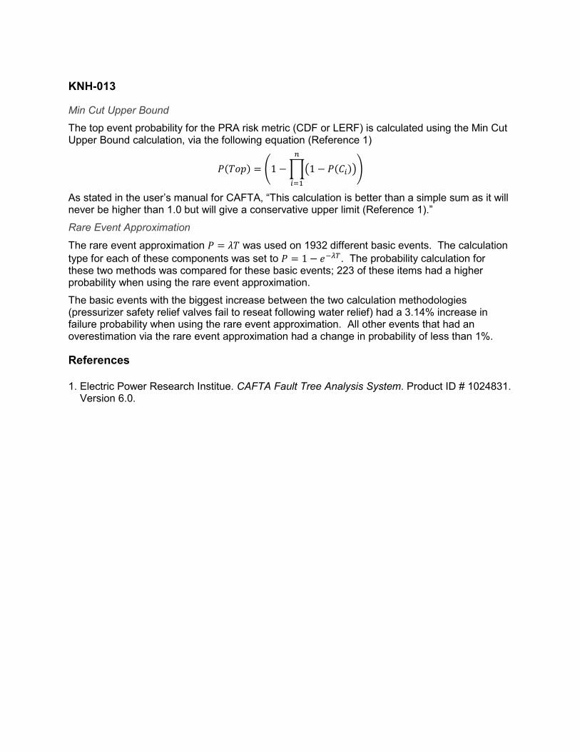
KNH-013
Min Cut Upper Bound
The top event probability for the PRA risk metric (CDF or LERF) is calculated using the Min Cut Upper Bound calculation, via the following equation (Reference 1) ( ) = 1 1 ( )
As stated in the user’s manual for CAFTA, “This calculation is better than a simple sum as it will never be higher than 1.0 but will give a conservative upper limit (Reference 1).”
Rare Event Approximation
The rare event approximation = was used on 1932 different basic events. The calculation type for each of these components was set to = 1 . The probability calculation for these two methods was compared for these basic events; 223 of these items had a higher probability when using the rare event approximation.
The basic events with the biggest increase between the two calculation methodologies (pressurizer safety relief valves fail to reseat following water relief) had a 3.14% increase in failure probability when using the rare event approximation. All other events that had an overestimation via the rare event approximation had a change in probability of less than 1%.
References
1. Electric Power Research Institue. CAFTA Fault Tree Analysis System. Product ID # 1024831. Version 6.0.

Licensee Response/NRC Response/NRC Question ClosureId 316
NRC Question Number KNH-013
Select Application NRC Question Closure
Attachment 1
Attachment 2
Response Statement
Response Date/Time
Closure Statement This question is closed and no further information is required at this time to draft the Safety Evaluation.
Question Closure Date 9/3/2014
Notification Scott BowmanMichelle ConnerKhadijah HemphillAndrew HonLynn MynattRay SchieleRoger Scott
Added By Khadijah Hemphill
Date Added 9/3/2014 7:30 AM
Date Modified
Modified By
Page 1 of 1Sequoyah ITS Conversion Database
9/3/2014https://members.excelservices.com/rai/index.php?requestType=areaItemPrint&itemId=316
ITS NRC QuestionsId 104
NRC Question Number
KNH-014
Category Technical
ITS Section TSTF-425 PRA
ITS Number
DOC Number
JFD Number
JFD Bases Number
Page Number(s)
NRC Reviewer
Supervisor Hossein Hamzehee
Technical Branch POC Jonathan Evans
Conf Call Requested N
NRC Question
Please clarify if the TSTF-425 portion of the LAR includes any deviations from TSTF-425 Program. For example, the definition of staggered test basis could be retained in the TS Section 1.1, "Definitions," because this term is used in an Administrative TS Section. It is an existing program and therefore, may not be proposed to be changed. This is considered an administrative deviation from TSTF-425 with no impact on the NRC's model safety evaluation dated July 6, 2009 (74 FR 31996). This is an example of an administrative deviation and there could be others.
Attach File 1
Attach File 2
Issue Date 5/28/2014
Added By Khadijah Hemphill
Date Modified
Modified By
Date Added 5/28/2014 3:47 PM
Notification Scott BowmanMichelle ConnerKhadijah HemphillAndrew HonLynn MynattRay SchieleRoger Scott
Page 1 of 1Sequoyah ITS Conversion Database
9/3/2014https://members.excelservices.com/rai/index.php?requestType=areaItemPrint&itemId=104
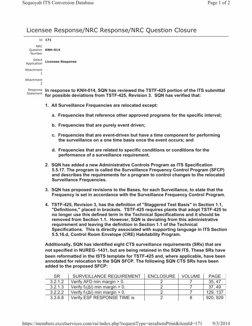
Licensee Response/NRC Response/NRC Question ClosureId 171
NRC Question Number
KNH-014
Select Application Licensee Response
Attachment 1
Attachment 2
Response Statement
In response to KNH-014, SQN has reviewed the TSTF-425 portion of the ITS submittal for possible deviations from TSTF-425, Revision 3. SQN has verified that:
1. All Surveillance Frequencies are relocated except:
a. Frequencies that reference other approved programs for the specific interval;
b. Frequencies that are purely event driven;
c. Frequencies that are event-driven but have a time component for performing the surveillance on a one time basis once the event occurs; and
d. Frequencies that are related to specific conditions or conditions for the performance of a surveillance requirement.
2. SQN has added a new Administrative Controls Program as ITS Specification 5.5.17. The program is called the Surveillance Frequency Control Program (SFCP) and describes the requirements for a program to control changes to the relocated Surveillance Frequencies.
3. SQN has proposed revisions to the Bases, for each Surveillance, to state that the Frequency is set in accordance with the Surveillance Frequency Control Program.
4. TSTF-425, Revision 3, has the definition of "Staggered Test Basis" in Section 1.1, "Definitions," placed in brackets. TSTF-425 requires plants that adopt TSTF-425 to no longer use this defined term in the Technical Specifications and it should be removed from Section 1.1. However, SQN is deviating from this administrative requirement and leaving the definition in Section 1.1 of the Technical Specifications. This is directly associated with supporting language in ITS Section 5.5.16.d, Control Room Envelope (CRE) Habitability Program.
Additionally, SQN has identified eight CTS surveillance requirements (SRs) that are not specified in NUREG-1431, but are being retained in the SQN ITS. These SRs have been reformatted in the ISTS template for TSTF-425 and, where applicable, have been annotated for relocation to the SQN SFCP. The following SQN CTS SRs have been added to the proposed SFCP:
SR SURVEILLANCE REQUIREMENT ENCLOSURE VOLUME PAGE3.2.1.2 Verify AFD min margin > 0. 2 7 35, 473.2.1.3 Verify f2( I) min margin > 0. 2 7 37, 493.2.2.2 Verify f1( I) min margin > 0. 2 7 129, 1373.3.6.8 Verify ESF RESPONSE TIME is 2 8 920, 929
Page 1 of 2Sequoyah ITS Conversion Database
9/3/2014https://members.excelservices.com/rai/index.php?requestType=areaItemPrint&itemId=171
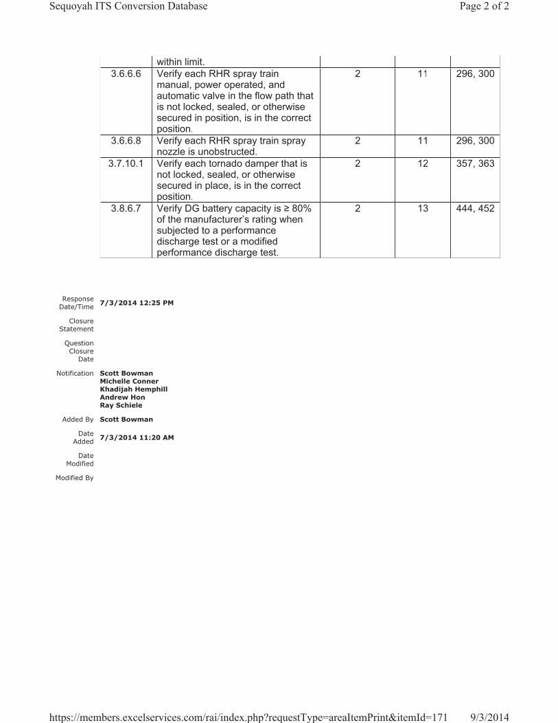
within limit.3.6.6.6 Verify each RHR spray train
manual, power operated, and automatic valve in the flow path that is not locked, sealed, or otherwise secured in position, is in the correct position.
2 11 296, 300
3.6.6.8 Verify each RHR spray train spray nozzle is unobstructed.
2 11 296, 300
3.7.10.1 Verify each tornado damper that is not locked, sealed, or otherwise secured in place, is in the correct position.
2 12 357, 363
3.8.6.7 Verify DG battery capacity is 80% of the manufacturer’s rating when subjected to a performance discharge test or a modified performance discharge test.
2 13 444, 452
Response Date/Time 7/3/2014 12:25 PM
Closure Statement
Question Closure
Date
Notification Scott BowmanMichelle ConnerKhadijah HemphillAndrew HonRay Schiele
Added By Scott Bowman
Date Added 7/3/2014 11:20 AM
Date Modified
Modified By
Page 2 of 2Sequoyah ITS Conversion Database
9/3/2014https://members.excelservices.com/rai/index.php?requestType=areaItemPrint&itemId=171

Licensee Response/NRC Response/NRC Question ClosureId 317
NRC Question Number KNH-014
Select Application NRC Question Closure
Attachment 1
Attachment 2
Response Statement
Response Date/Time
Closure Statement This question is closed and no further information is required at this time to draft the Safety Evaluation.
Question Closure Date 9/3/2014
Notification Scott BowmanMichelle ConnerKhadijah HemphillAndrew HonLynn MynattRay SchieleRoger Scott
Added By Khadijah Hemphill
Date Added 9/3/2014 7:31 AM
Date Modified 9/9/2014 2:21 PM
Modified By Ray Schiele
Page 1 of 1Sequoyah ITS Conversion Database
10/15/2014https://members.excelservices.com/rai/index.php?requestType=areaItemPrint&itemId=317
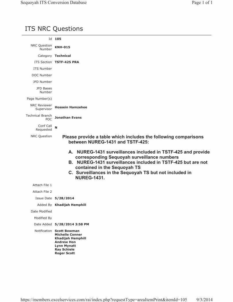
ITS NRC QuestionsId 105
NRC Question Number KNH-015
Category Technical
ITS Section TSTF-425 PRA
ITS Number
DOC Number
JFD Number
JFD Bases Number
Page Number(s)
NRC Reviewer Supervisor Hossein Hamzehee
Technical Branch POC Jonathan Evans
Conf Call Requested N
NRC Question Please provide a table which includes the following comparisons between NUREG-1431 and TSTF-425:
A. NUREG-1431 surveillances included in TSTF-425 and provide corresponding Sequoyah surveillance numbers
B. NUREG-1431 surveillances included in TSTF-425 but are not contained in the Sequoyah TS
C. Surveillances in the Sequoyah TS but not included in NUREG-1431.
Attach File 1
Attach File 2
Issue Date 5/28/2014
Added By Khadijah Hemphill
Date Modified
Modified By
Date Added 5/28/2014 3:58 PM
Notification Scott BowmanMichelle ConnerKhadijah HemphillAndrew HonLynn MynattRay SchieleRoger Scott
Page 1 of 1Sequoyah ITS Conversion Database
9/3/2014https://members.excelservices.com/rai/index.php?requestType=areaItemPrint&itemId=105
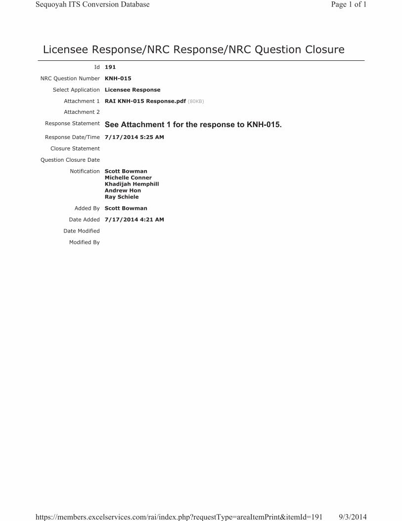
Licensee Response/NRC Response/NRC Question ClosureId 191
NRC Question Number KNH-015
Select Application Licensee Response
Attachment 1 RAI KNH-015 Response.pdf (80KB)
Attachment 2
Response Statement See Attachment 1 for the response to KNH-015.Response Date/Time 7/17/2014 5:25 AM
Closure Statement
Question Closure Date
Notification Scott BowmanMichelle ConnerKhadijah HemphillAndrew HonRay Schiele
Added By Scott Bowman
Date Added 7/17/2014 4:21 AM
Date Modified
Modified By
Page 1 of 1Sequoyah ITS Conversion Database
9/3/2014https://members.excelservices.com/rai/index.php?requestType=areaItemPrint&itemId=191
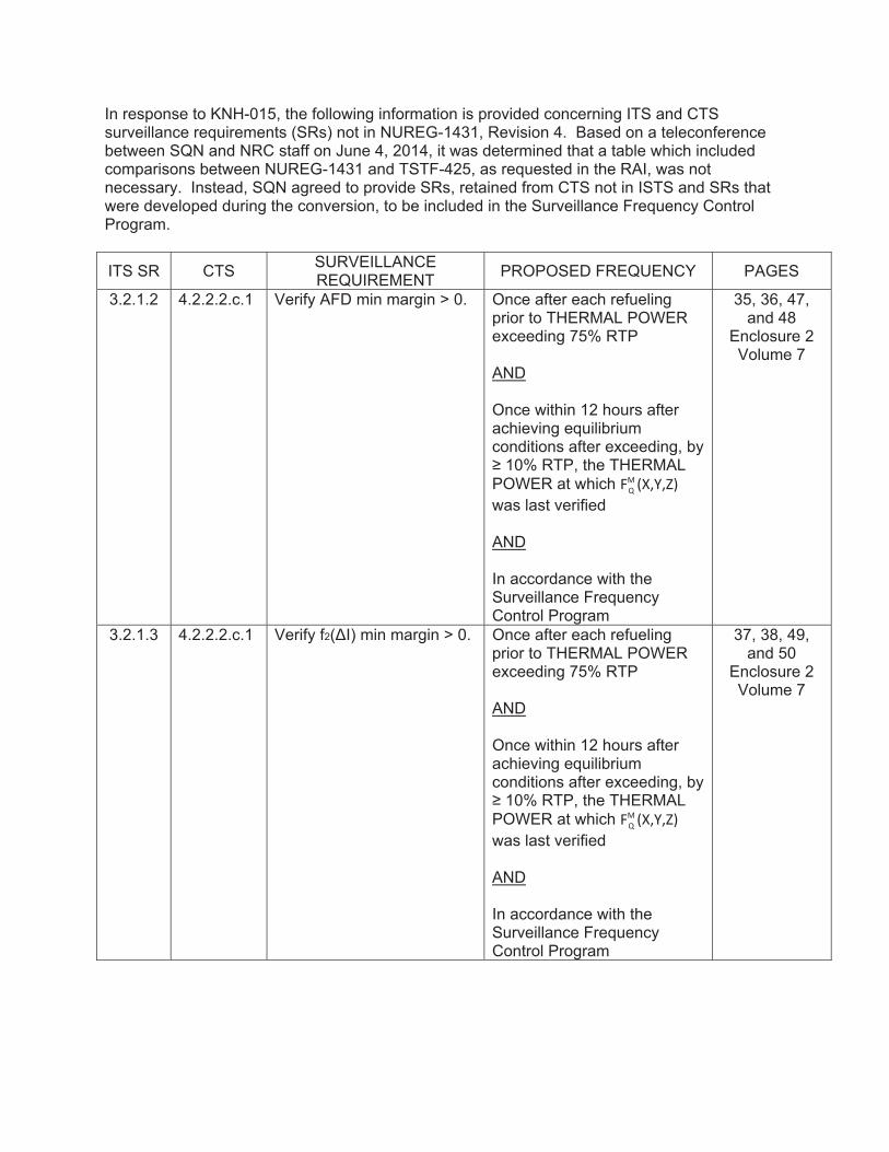
In response to KNH-015, the following information is provided concerning ITS and CTS surveillance requirements (SRs) not in NUREG-1431, Revision 4. Based on a teleconference between SQN and NRC staff on June 4, 2014, it was determined that a table which included comparisons between NUREG-1431 and TSTF-425, as requested in the RAI, was not necessary. Instead, SQN agreed to provide SRs, retained from CTS not in ISTS and SRs that were developed during the conversion, to be included in the Surveillance Frequency Control Program.
ITS SR CTS SURVEILLANCE REQUIREMENT PROPOSED FREQUENCY PAGES
3.2.1.2 4.2.2.2.c.1 Verify AFD min margin > 0. Once after each refueling prior to THERMAL POWER exceeding 75% RTP AND Once within 12 hours after achieving equilibrium conditions after exceeding, by 10% RTP, the THERMAL
POWER at which FMQ (X,Y,Z)was last verified AND In accordance with the Surveillance Frequency Control Program
35, 36, 47, and 48
Enclosure 2 Volume 7
3.2.1.3 4.2.2.2.c.1 Verify f2( I) min margin > 0. Once after each refueling prior to THERMAL POWER exceeding 75% RTP AND Once within 12 hours after achieving equilibrium conditions after exceeding, by 10% RTP, the THERMAL
POWER at which FMQ (X,Y,Z)was last verified AND In accordance with the Surveillance Frequency Control Program
37, 38, 49, and 50
Enclosure 2 Volume 7
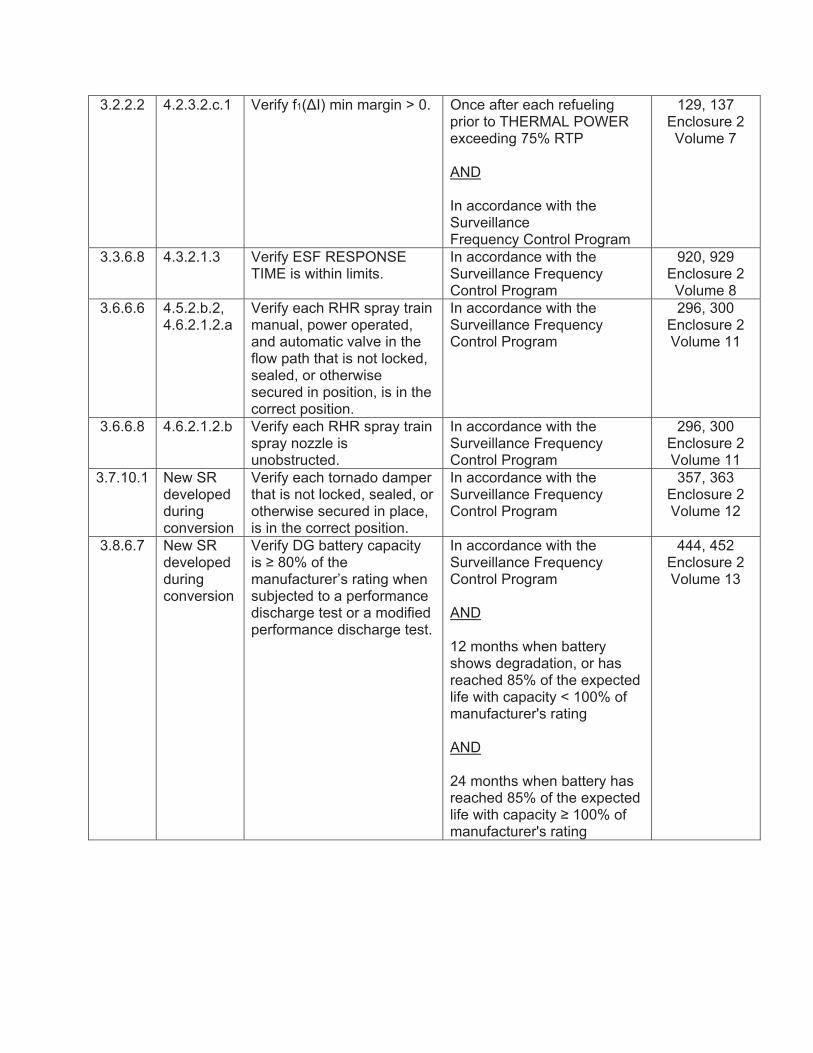
3.2.2.2 4.2.3.2.c.1 Verify f1( I) min margin > 0. Once after each refueling prior to THERMAL POWER exceeding 75% RTP AND In accordance with the Surveillance Frequency Control Program
129, 137 Enclosure 2 Volume 7
3.3.6.8 4.3.2.1.3 Verify ESF RESPONSE TIME is within limits.
In accordance with the Surveillance Frequency Control Program
920, 929 Enclosure 2 Volume 8
3.6.6.6 4.5.2.b.2, 4.6.2.1.2.a
Verify each RHR spray train manual, power operated, and automatic valve in the flow path that is not locked, sealed, or otherwise secured in position, is in the correct position.
In accordance with the Surveillance Frequency Control Program
296, 300 Enclosure 2 Volume 11
3.6.6.8 4.6.2.1.2.b Verify each RHR spray train spray nozzle is unobstructed.
In accordance with the Surveillance Frequency Control Program
296, 300 Enclosure 2 Volume 11
3.7.10.1 New SR developed during conversion
Verify each tornado damper that is not locked, sealed, or otherwise secured in place, is in the correct position.
In accordance with the Surveillance Frequency Control Program
357, 363 Enclosure 2 Volume 12
3.8.6.7 New SR developed during conversion
Verify DG battery capacity is 80% of the manufacturer’s rating when subjected to a performance discharge test or a modified performance discharge test.
In accordance with the Surveillance Frequency Control Program AND 12 months when battery shows degradation, or has reached 85% of the expected life with capacity < 100% of manufacturer's rating AND 24 months when battery has reached 85% of the expected life with capacity 100% of manufacturer's rating
444, 452 Enclosure 2 Volume 13

Licensee Response/NRC Response/NRC Question ClosureId 318
NRC Question Number KNH-015
Select Application NRC Question Closure
Attachment 1
Attachment 2
Response Statement
Response Date/Time
Closure Statement This question is closed and no further information is required at this time to draft the Safety Evaluation.
Question Closure Date 9/3/2014
Notification Scott BowmanMichelle ConnerKhadijah HemphillAndrew HonLynn MynattRay SchieleRoger Scott
Added By Khadijah Hemphill
Date Added 9/3/2014 7:32 AM
Date Modified
Modified By
Page 1 of 1Sequoyah ITS Conversion Database
9/3/2014https://members.excelservices.com/rai/index.php?requestType=areaItemPrint&itemId=318
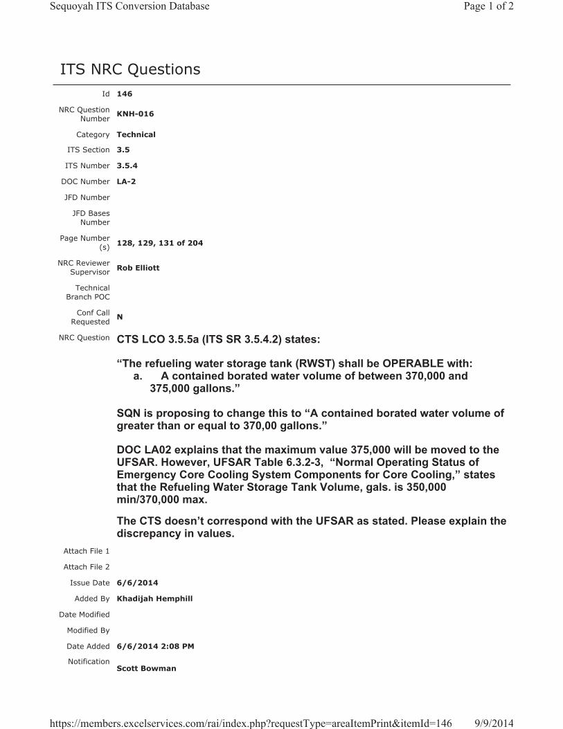
ITS NRC QuestionsId 146
NRC Question Number KNH-016
Category Technical
ITS Section 3.5
ITS Number 3.5.4
DOC Number LA-2
JFD Number
JFD Bases Number
Page Number(s) 128, 129, 131 of 204
NRC Reviewer Supervisor Rob Elliott
Technical Branch POC
Conf Call Requested N
NRC Question CTS LCO 3.5.5a (ITS SR 3.5.4.2) states:
“The refueling water storage tank (RWST) shall be OPERABLE with: a. A contained borated water volume of between 370,000 and
375,000 gallons.”
SQN is proposing to change this to “A contained borated water volume of greater than or equal to 370,00 gallons.”
DOC LA02 explains that the maximum value 375,000 will be moved to the UFSAR. However, UFSAR Table 6.3.2-3, “Normal Operating Status of Emergency Core Cooling System Components for Core Cooling,” states that the Refueling Water Storage Tank Volume, gals. is 350,000 min/370,000 max.
The CTS doesn’t correspond with the UFSAR as stated. Please explain the discrepancy in values.
Attach File 1
Attach File 2
Issue Date 6/6/2014
Added By Khadijah Hemphill
Date Modified
Modified By
Date Added 6/6/2014 2:08 PM
Notification Scott Bowman
Page 1 of 2Sequoyah ITS Conversion Database
9/9/2014https://members.excelservices.com/rai/index.php?requestType=areaItemPrint&itemId=146
Michelle ConnerKhadijah HemphillAndrew HonLynn MynattRay SchieleRoger Scott
Page 2 of 2Sequoyah ITS Conversion Database
9/9/2014https://members.excelservices.com/rai/index.php?requestType=areaItemPrint&itemId=146
Licensee Response/NRC Response/NRC Question ClosureId 279
NRC Question Number
KNH-016
Select Application Licensee Response
Attachment 1 Attachment 1 KNH-016.pdf (2MB)
Attachment 2
Response Statement
As a result of the transition from the CTS to ITS at SQN, there are a number of changes resulting in relocation to the SQN Updated Final Safety Analysis Report (UFSAR). These changes are being identified and incorporated during the Implementation Phase of the SQN ITS Project. Items identified in Enclosure 2 of the SQN ITS License Amendment Request as being relocated to the SQN UFSAR will be incorporated in the SQN UFSAR using the UFSAR update process; TVA’s Final Safety Analysis Report management procedure. This process includes developing UFSAR change packages that will include items relocated from the SQN CTS. In accordance with TVA procedures, these UFSAR change packages are processed and incorporated into the SQN UFSAR and transmitted to the NRC in accordance with the requirements of 10 CFR 50.4, “Written communications,” and in accordance with the schedule requirements set forth in 10 CFR 50.71(e)(4).
SQN UFSAR Table 6.3.2-3, “Normal Operating Status of Emergency Core Cooling System Components for Core Cooling,” states that the Refueling Water Storage Tank volume is 350,000 gallons, minimum and 370,000 gallons, maximum. The minimum value of 350,000 gallons was determined to be the minimum volume required for the RWST to be able to perform its design function during a large break loss of coolant accident. The maximum value of 370,000 gallons represents the minimum volume required by technical specifications for the RWST to be considered OPERABLE.
During the implementation process, SQN UFSAR Table 6.3.2-3 will be revised to state that the Refueling Water Storage Tank has a minimum volume of 370,000 gallons and a maximum volume of 375,000 gallons. Attachment 1 provides a draft markup of SQN UFSAR Table 6.3.2-3 to show the relocated and revised information.
Response Date/Time 8/21/2014 11:20 AM
Closure Statement
Question Closure
Date
Page 1 of 2Sequoyah ITS Conversion Database
9/9/2014https://members.excelservices.com/rai/index.php?requestType=areaItemPrint&itemId=279
Notification Scott BowmanMichelle ConnerKhadijah HemphillAndrew HonRay Schiele
Added By Scott Bowman
Date Added 8/21/2014 10:19 AM
Date Modified
Modified By
Page 2 of 2Sequoyah ITS Conversion Database
9/9/2014https://members.excelservices.com/rai/index.php?requestType=areaItemPrint&itemId=279
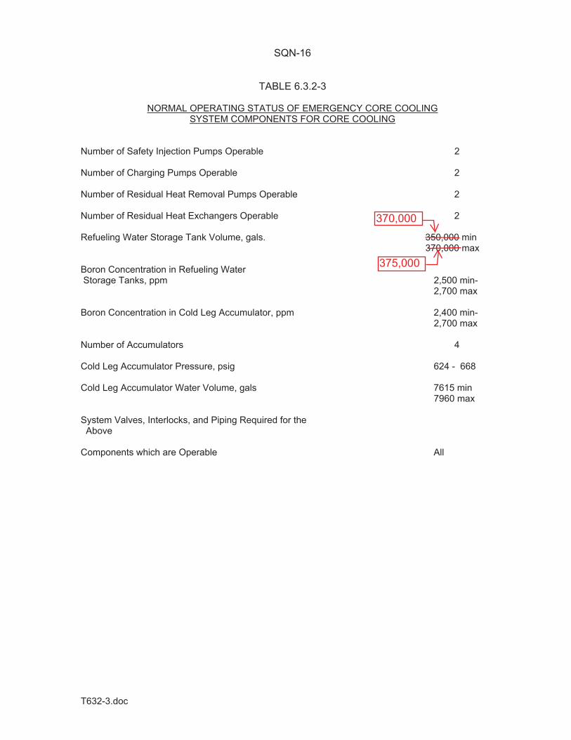
T632-3.doc
SQN-16
TABLE 6.3.2-3
NORMAL OPERATING STATUS OF EMERGENCY CORE COOLING SYSTEM COMPONENTS FOR CORE COOLING
Number of Safety Injection Pumps Operable 2 Number of Charging Pumps Operable 2 Number of Residual Heat Removal Pumps Operable 2 Number of Residual Heat Exchangers Operable 2 Refueling Water Storage Tank Volume, gals. 350,000 min 370,000 max Boron Concentration in Refueling Water Storage Tanks, ppm 2,500 min- 2,700 max Boron Concentration in Cold Leg Accumulator, ppm 2,400 min- 2,700 max Number of Accumulators 4 Cold Leg Accumulator Pressure, psig 624 - 668 Cold Leg Accumulator Water Volume, gals 7615 min 7960 max System Valves, Interlocks, and Piping Required for the Above Components which are Operable All
370,000
375,000

Licensee Response/NRC Response/NRC Question ClosureId 327
NRC Question Number KNH-016
Select Application NRC Question Closure
Attachment 1
Attachment 2
Response Statement
Response Date/Time
Closure Statement This question is closed and no further information is required at this time to draft the Safety Evaluation.
Question Closure Date 9/9/2014
Notification Scott BowmanMichelle ConnerKhadijah HemphillAndrew HonLynn MynattRay SchieleRoger Scott
Added By Khadijah Hemphill
Date Added 9/9/2014 8:34 AM
Date Modified
Modified By
Page 1 of 1Sequoyah ITS Conversion Database
9/9/2014https://members.excelservices.com/rai/index.php?requestType=areaItemPrint&itemId=327
ITS NRC QuestionsId 169
NRC Question Number
KNH-017
Category Technical
ITS Section 3.2
ITS Number 3.2.1
DOC Number LA-3
JFD Number
JFD Bases Number
Page Number(s) 6 of 249
NRC Reviewer
Supervisor Sam Miranda
Technical Branch POC Matt Hardgrove
Conf Call Requested N
NRC Question
ITS – 3.2.1 Heat Flux Hot Channel Factor
Page 6 of 249, Surveillance Requirements. According to Removed Detail Changes (LA03), the equations contained in the Surveillance Requirements for calculating % AFD Margin and % f2( I) Margin are to be removed to the Improved Standard Technical Specifications (ISTS) Bases. Please provide the context, informational or calculational, for how these equations are used in the Current Technical Specifications (CTS).
Attach File 1
Attach File 2
Issue Date 7/2/2014
Added By Khadijah Hemphill
Date Modified
Modified By
Date Added 7/2/2014 3:24 PM
Notification Scott BowmanMichelle ConnerKhadijah HemphillAndrew HonLynn MynattRay SchieleRoger ScottPete Snyder
Page 1 of 1Sequoyah ITS Conversion Database
9/3/2014https://members.excelservices.com/rai/index.php?requestType=areaItemPrint&itemId=169
Licensee Response/NRC Response/NRC Question ClosureId 257
NRC Question Number
KNH-017
Select Application Licensee Response
Attachment 1
Attachment 2
Response Statement In response to KNH-017, the following information is provided detailing the
use of CTS 3.2.2 (ITS 3.2.1) Heat Flux Hot Channel Factor %AFD Margin and % f2( I) Margin formulas used in CTS 4.2.2.2.c.1.
The moveable incore detector system is used to compare the measured power distribution with the designed power distribution at steady-state conditions. For each measured location, if the measured power is within the design, then the AFD limits for the design are applicable. For those locations that are outside the design, a margin calculation is performed to determine whether unacceptable margins exist. AFD and f2( I) limits are reduced when unacceptable margins are calculated as described below.
For %AFD Margin:
The FQ(X,Y,Z) margin supporting AFD operational limits (AFD margin) during transient operations is based on the relationship between FQ
M (X,Y,Z) and the limiting condition operational limit, BQDES (X,Y,Z).
BQDES(X,Y,Z) is the cycle dependent maximum allowable design peaking factor for fuel assembly X,Y at axial location Z. BQDES(X,Y,Z) ensures that the LOCA limit will be preserved for operation within the LCO limits, including allowances for calculational and measurement uncertainties.
If the reactor core is operating as designed (FQM(X,Y,Z) BQNOM(X,Y,Z)),
then FQM (X,Y,Z) is less than BQDES(X,Y,Z) and calculation of %AFD margin
is not required.
If the AFD margin is less than zero, then FQM(X,Y,Z) is greater than BQDES
(X,Y,Z) and the AFD limits may not be adequate to prevent exceeding the peaking criteria for a LOCA if a normal operational transient occurs.
If this occurs, then ITS 3.2.1 Required Actions B.1 and B.2 require reducing the AFD limit lines. The AFD limit reduction is from the full power AFD limits. The adjusted AFD limits must be used until a new measurement shows that a smaller adjustment can be made to the AFD limits, or that no
Page 1 of 3Sequoyah ITS Conversion Database
9/3/2014https://members.excelservices.com/rai/index.php?requestType=areaItemPrint&itemId=257
adjustment is necessary. Completing Required Actions B.1 and B.2 within the allowed Completion Time of 2 hours, restricts the axial flux distribution such that even if a transient occurred, core peaking factor limits are not exceeded.
For %f2( I) Margin:
The FQ(X,Y,Z) margin supporting the Overpower T f2( I) breakpoints (f2( I) margin) during transient operations is based on the relationship between FQ
M (X,Y,Z) and the limit, BCDES(X,Y,Z).
BCDES(X,Y,Z) is the cycle dependent maximum allowable design peaking factor for fuel assembly X,Y, at axial location Z. BCDES(X,Y,Z) ensures that the centerline fuel melt limit will be preserved for operation within the LCO limits, including allowances for calculational and measurement uncertainties.
If the reactor core is operating as designed (FQM(X,Y,Z) BQNOM(X,Y,Z)),
then FQM(X,Y,Z) is less than BCDES(X,Y,Z) and calculation of % f2( I) margin
is not required.
If the f2( I) margin is less than zero, then FQM (X,Y,Z) is greater than BCDES
(X,Y,Z) and there is a potential that the f2( I) limits are insufficient to preclude centerline fuel melt during certain transients.
If this occurs, then ITS 3.2.1, Required Actions C.1 and C.2 require reducing the f2( I) breakpoint limits. The f2( I) breakpoint limit reduction is always from the full power f2( I) breakpoint limits. The adjusted f2( I) breakpoint limits must be used until a new measurement shows that a smaller adjustment can be made to the f2( I) breakpoint limits, or that no adjustment is necessary. Completing Required Actions C.1 and C.2 is a conservative action for protection against the consequences of transients since this adjustment limits the peak transient power level which can be achieved during an anticipated operational occurrence. Completing Required Actions C.1and C.2 within the allowed Completion Time of 48 hours is sufficient considering the small likelihood of a limiting transient in this time period.
BQDES(X,Y,Z), and BCDES(X,Y,Z) data bases are provided for the plant power distribution analysis computer codes on a cycle specific basis and are determined using the methodology for core limit generation described in the references in the COLR.
Response Date/Time 8/11/2014 5:55 AM
Closure Statement
Page 2 of 3Sequoyah ITS Conversion Database
9/3/2014https://members.excelservices.com/rai/index.php?requestType=areaItemPrint&itemId=257
Question Closure
Date
Notification Scott BowmanMichelle ConnerKhadijah HemphillAndrew HonRay SchielePete Snyder
Added By Scott Bowman
Date Added 8/11/2014 4:54 AM
Date Modified
Modified By
Page 3 of 3Sequoyah ITS Conversion Database
9/3/2014https://members.excelservices.com/rai/index.php?requestType=areaItemPrint&itemId=257

Licensee Response/NRC Response/NRC Question ClosureId 319
NRC Question Number KNH-017
Select Application NRC Question Closure
Attachment 1
Attachment 2
Response Statement
Response Date/Time
Closure Statement This question is closed and no further information is required at this time to draft the Safety Evaluation.
Question Closure Date 9/3/2014
Notification Scott BowmanMichelle ConnerKhadijah HemphillAndrew HonLynn MynattRay SchieleRoger Scott
Added By Khadijah Hemphill
Date Added 9/3/2014 7:45 AM
Date Modified
Modified By
Page 1 of 1Sequoyah ITS Conversion Database
9/3/2014https://members.excelservices.com/rai/index.php?requestType=areaItemPrint&itemId=319
ITS NRC QuestionsId 170
NRC Question Number
KNH-018
Category Technical
ITS Section 3.2
ITS Number 3.2.2
DOC Number LA-4
JFD Number
JFD Bases Number
Page Number(s) 107 of 249
NRC Reviewer
Supervisor Sam Miranda
Technical Branch POC Matt Hardgrove
Conf Call Requested N
NRC Question
ITS – 3.2.2 Nuclear Enthalpy Rise Hot Channel Factor
Page 107 of 249, Surveillance Requirements. According to Removed Detail Changes (LA04), the equations contained in the Surveillance Requirements for calculating F HR
M(X, Y), % F H Margin, and % f1( I) Margin are to be removed to the Improved Standard Technical Specifications (ISTS) Bases. Please provide the context, informational or calculational, for how these equations are used in the CTS.
Attach File 1
Attach File 2
Issue Date 7/2/2014
Added By Khadijah Hemphill
Date Modified
Modified By
Date Added 7/2/2014 3:25 PM
Notification Scott BowmanMichelle ConnerKhadijah HemphillAndrew HonLynn MynattRay SchieleRoger ScottPete Snyder
Page 1 of 1Sequoyah ITS Conversion Database
9/3/2014https://members.excelservices.com/rai/index.php?requestType=areaItemPrint&itemId=170
Licensee Response/NRC Response/NRC Question ClosureId 258
NRC Question Number
KNH-018
Select Application Licensee Response
Attachment 1
Attachment 2
Response Statement In response to KNH-018, the following information is provided detailing the
use of CTS 3.2.3 (ITS 3.2.2) Nuclear Enthalpy Rise Hot Channel Factor F HRM(X,Y), %F H Margin and %f1( I) Margin formulas used in CTS 4.2.3.2.b and 4.2.3.2.c.1:
CTS LCO 3.2.3 requires that F H(X,Y) shall be less than the limits provided in the COLR. This relationship must be satisfied even if the core is operating at limiting conditions. This requires adjustment to the measured F H(X,Y) to account for limiting conditions and the differences between design and measured conditions. The adjustments are accounted for by comparing F HRM(X,Y) to the limits BHDES(X,Y) and BRDES(X,Y). Therefore, if the F H min margin is >0 and f1( I) min margin >0 the LCO is satisfied.
F HRM(X,Y)
An F H(X,Y) evaluation requires obtaining an incore flux map in MODE 1. The incore flux map results provide the measured value ( F H
M (X,Y) of F H(X,Y)) for each assembly location (X,Y).The F H ratio (FDHR) is used in order to determine the F H limit for the measured and design power distributions.
F HM(X,Y)The relationship F HRM(X,Y) = MAPM /AXIALM (X,Y) establishesMAPM as the maximum allowable peak from the COLR for the measured assembly power distribution at assembly location (X,Y) which accounts for calculational and measurement uncertainties, andAXIALM (X,Y) is the measured ratio of the peak-to-average axial power at assembly location (X,Y).
For % F H Margin:
The % F H margin is based on the relationship between F HRM(X,Y) and
Page 1 of 3Sequoyah ITS Conversion Database
9/3/2014https://members.excelservices.com/rai/index.php?requestType=areaItemPrint&itemId=258
the limit, BHDES (X,Y). BHDES (X,Y) is a cycle dependent design limit to preserve Departure from Nucleate Boiling (DNB) assumed for initial conditions at the time of limiting transients such as a Loss of Flow Accident (LOFA).
If the reactor core is operating as designed (F HRM(X,Y) BHNOM(X,Y)), then F HRM(X,Y) is less than BHDES (X,Y) and calculation of %F H margin is not required.
If the %F H margin is less than zero, then F HRM(X,Y) is greater than BHDES(X, Y) and the F H(X,Y) limits may not be adequate to prevent exceeding the initial DNB conditions assumed for transients such as a LOFA.
BHDES (X,Y) represents the maximum allowable design radial peaking factors which ensures that the initial conditions DNB will be preserved for operation within the LCO limits, and includes allowances for calculational and measurement uncertainties. The F H min margin is the minimum for all core locations examined.
For %f1( I) Margin:
The %f1( I) margin is based on the relationship between F HRM(X,Y) and the limit, BRDES (X,Y). BRDES (X,Y) is a cycle dependent design limit to preserve reactor protection system safety limits for DNB requirements.
If the reactor core is operating as designed (F HRM(X,Y) BHNOM(X,Y)), then F HRM(X,Y) is less than BRDES (X,Y) and calculation of %f1( I) margin is not required.
If the %f1( I) margin is less than zero, then F HRM(X,Y) is greater than BRDES (X, Y) and the OT T setpoint limits may not be adequate to prevent exceeding DNB requirements.
BRDES (X,Y) represents the maximum allowable design radial peaking factors which ensure that the steady state DNBR limit will be preserved for operation within the LCO limits, including allowances for calculational and measurement uncertainties. The f1( I) min margin is the minimum % of f1
( I) margin for all core locations examined.
Response Date/Time 8/11/2014 6:00 AM
Closure Statement
Question Closure
Date
Notification Scott Bowman
Page 2 of 3Sequoyah ITS Conversion Database
9/3/2014https://members.excelservices.com/rai/index.php?requestType=areaItemPrint&itemId=258

Michelle ConnerKhadijah HemphillAndrew HonRay SchielePete Snyder
Added By Scott Bowman
Date Added 8/11/2014 4:59 AM
Date Modified
Modified By
Page 3 of 3Sequoyah ITS Conversion Database
9/3/2014https://members.excelservices.com/rai/index.php?requestType=areaItemPrint&itemId=258

Licensee Response/NRC Response/NRC Question ClosureId 320
NRC Question Number KNH-018
Select Application NRC Question Closure
Attachment 1
Attachment 2
Response Statement
Response Date/Time
Closure Statement This question is closed and no further information is required at this time to draft the Safety Evaluation.
Question Closure Date 9/3/2014
Notification Scott BowmanKhadijah HemphillAndrew HonLynn MynattRay SchieleRoger Scott
Added By Khadijah Hemphill
Date Added 9/3/2014 7:46 AM
Date Modified
Modified By
Page 1 of 1Sequoyah ITS Conversion Database
9/3/2014https://members.excelservices.com/rai/index.php?requestType=areaItemPrint&itemId=320
ITS NRC QuestionsId 171
NRC Question Number
KNH-019
Category Technical
ITS Section 3.2
ITS Number 3.2.2
DOC Number
JFD Number
JFD Bases Number
Page Number(s) 152 of 249
NRC Reviewer
Supervisor Sam Miranda
Technical Branch POC Matt Hardgrove
Conf Call Requested N
NRC Question
ITS – 3.2.2 Nuclear Enthalpy Rise Hot Channel Factor
Page 152 of 249, References. The references listed in the Improved Standard Technical Specifications (ISTS) Bases for 3.2.2., Nuclear Enthalpy Hot Rise Hot Channel Factor, do not list NRC-approved topical report BAW-10163PA, “Core Operating Limit Methodology for Westinghouse-Designed PWRS,” June 1989. However, it is referenced in ISTS Bases 3.2.1, Heat Flux Hot Channel Factor. Please explain why this reference is not included in ISTS Bases 3.2.2, Nuclear Enthalpy Hot Rise Channel Factor.
Attach File 1
Attach File 2
Issue Date 7/2/2014
Added By Khadijah Hemphill
Date Modified
Modified By
Date Added 7/2/2014 3:27 PM
Notification Scott BowmanMichelle ConnerKhadijah HemphillAndrew HonLynn MynattRay SchieleRoger ScottPete Snyder
Page 1 of 1Sequoyah ITS Conversion Database
9/3/2014https://members.excelservices.com/rai/index.php?requestType=areaItemPrint&itemId=171
Licensee Response/NRC Response/NRC Question ClosureId 216
NRC Question Number
KNH-019
Select Application Licensee Response
Attachment 1 Attachment 1 KNH_019 STB.pdf (86KB)
Attachment 2
Response Statement
In response to KNH-019, the ISTS 3.2.2 Bases, Reference Section markup, on pages 152 and 167 of Enclosure 2, Volume 7, will be revised.Specifically, BAW-10163P-A, Revision 0, “Core Operating Limit Methodology for Westinghouse-Designed PWRs,” June 1989, will be added as Reference 4. Additionally, ITS 3.2.2 Bases Insert 1 (pages 141 and 156) will be revised to provide a reference to Reference 4.
See Attachment 1 for revised ITS 3.2.2 Bases pages for Units 1 and 2.Response
Date/Time 7/31/2014 12:00 PM
Closure Statement
Question Closure Date
Notification Scott BowmanMichelle ConnerKhadijah HemphillAndrew HonRay Schiele
Added By Scott Bowman
Date Added 7/31/2014 11:00 AM
Date Modified
Modified By
Page 1 of 1Sequoyah ITS Conversion Database
9/3/2014https://members.excelservices.com/rai/index.php?requestType=areaItemPrint&itemId=216

B 3.2.2
Insert Page B 3.2.2-1a
INSERT 1
An F H(X,Y) evaluation requires obtaining an incore flux map in MODE 1. The incore flux map results provide the measured value ( )Y,X(FM
HΔ of F H(X,Y) for each assembly location (X,Y). The F H ratio (FDHR) is used in order to determine the F H limit for the measured and design power distributions . Then,
F HRM(X,Y) = )Y,X(AXIAL/MAP
)Y,X(FMM
MHΔ
where MMAP is the maximum allowable peak from the COLR for the measured assembly power distribution at assembly location (X,Y) which accounts for calculational and measurement uncertainties, and
)Y,X(AXIALM is the measured ratio of the peak-to-average axial power at assembly location (X,Y).
BHDES(X,Y) is a cycle dependent design limit to preserve Departure from Nucleate Boiling(DNB) assumed for initial conditions at the time of limiting transients such as a Loss of Flow Accident (LOFA). BRDES(X,Y) is a cycle dependent design limit to preserve reactor protection system safety limits for DNB requirements .
The expression for BHDES(X,Y) is:
BHDES(X,Y) = F HRd(X,Y) * MH(X,Y)
where: F HRd(X,Y) = )Y,X(AXIAL/MAP
)Y,X(Fdd
dHΔ
• dMAP is the maximum allowable peak from the COLR for the designassembly power distribution at assembly location (X,Y) whichaccounts for calculational and measurement uncertainties,
• )Y,X(AXIALd is the design ratio of the peak-to-average axial powerat assembly location (X,Y),
• )Y,X(FdHΔ is the design F H assembly location (X, Y), and
• MH(X,Y) is the minimum available margin ratio for initial conditionDNB at the limiting conditions at assembly location (X,Y).
2
Enclosure 2, Volume 7, Rev. 0, Page 141 of 249
Enclosure 2, Volume 7, Rev. 0, Page 141 of 249
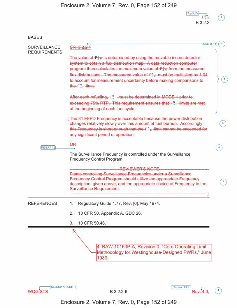
HNF Δ
B 3.2.2
WOG STS B 3.2.2-6 Rev. 4.0,
F H(X,Y)1
SEQUOYAH UNIT 1 Revision XXX 1
BASES SURVEILLANCE SR 3.2.2.1 REQUIREMENTS
The value of HNF Δ is determined by using the movable incore detector
system to obtain a flux distribution map. A data reduction computer program then calculates the maximum value of H
NF Δ from the measured flux distributions. The measured value of H
NF Δ must be multiplied by 1.04 to account for measurement uncertainty before making comparisons to the H
NF Δ limit. After each refueling, H
NF Δ must be determined in MODE 1 prior to exceeding 75% RTP. This requirement ensures that H
NF Δ limits are met at the beginning of each fuel cycle.
[ The 31 EFPD Frequency is acceptable because the power distribution changes relatively slowly over this amount of fuel burnup. Accordingly, this Frequency is short enough that the H
NF Δ limit cannot be exceeded for any significant period of operation. OR The Surveillance Frequency is controlled under the Surveillance Frequency Control Program. -----------------------------------REVIEWER’S NOTE----------------------------------- Plants controlling Surveillance Frequencies under a Surveillance Frequency Control Program should utilize the appropriate Frequency description, given above, and the appropriate choice of Frequency in the Surveillance Requirement. ------------------------------------------------------------------------------------------------ ]
REFERENCES 1. Regulatory Guide 1.77, Rev. [0], May 1974. 2. 10 CFR 50, Appendix A, GDC 26. 3. 10 CFR 50.46.
1
INSERT 12
4
4
6
7
INSERT 11
Enclosure 2, Volume 7, Rev. 0, Page 152 of 249
Enclosure 2, Volume 7, Rev. 0, Page 152 of 249
4. BAW-10163P-A, Revision 0, "Core Operating LimitMethodology for Westinghouse-Designed PWRs," June1989.
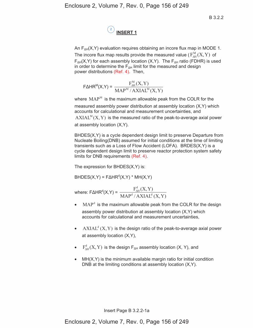
B 3.2.2
Insert Page B 3.2.2-1a
INSERT 1
An F H(X,Y) evaluation requires obtaining an incore flux map in MODE 1. The incore flux map results provide the measured value ( )Y,X(FM
HΔ of F H(X,Y) for each assembly location (X,Y). The F H ratio (FDHR) is used in order to determine the F H limit for the measured and design power distributions . Then,
F HRM(X,Y) = )Y,X(AXIAL/MAP
)Y,X(FMM
MHΔ
where MMAP is the maximum allowable peak from the COLR for the measured assembly power distribution at assembly location (X,Y) which accounts for calculational and measurement uncertainties, and
)Y,X(AXIALM is the measured ratio of the peak-to-average axial power at assembly location (X,Y).
BHDES(X,Y) is a cycle dependent design limit to preserve Departure from Nucleate Boiling(DNB) assumed for initial conditions at the time of limiting transients such as a Loss of Flow Accident (LOFA). BRDES(X,Y) is a cycle dependent design limit to preserve reactor protection system safety limits for DNB requirements .
The expression for BHDES(X,Y) is:
BHDES(X,Y) = F HRd(X,Y) * MH(X,Y)
where: F HRd(X,Y) = )Y,X(AXIAL/MAP
)Y,X(Fdd
dHΔ
• dMAP is the maximum allowable peak from the COLR for the designassembly power distribution at assembly location (X,Y) whichaccounts for calculational and measurement uncertainties,
• )Y,X(AXIALd is the design ratio of the peak-to-average axial powerat assembly location (X,Y),
• )Y,X(FdHΔ is the design F H assembly location (X, Y), and
• MH(X,Y) is the minimum available margin ratio for initial conditionDNB at the limiting conditions at assembly location (X,Y).
2
Enclosure 2, Volume 7, Rev. 0, Page 156 of 249
Enclosure 2, Volume 7, Rev. 0, Page 156 of 249
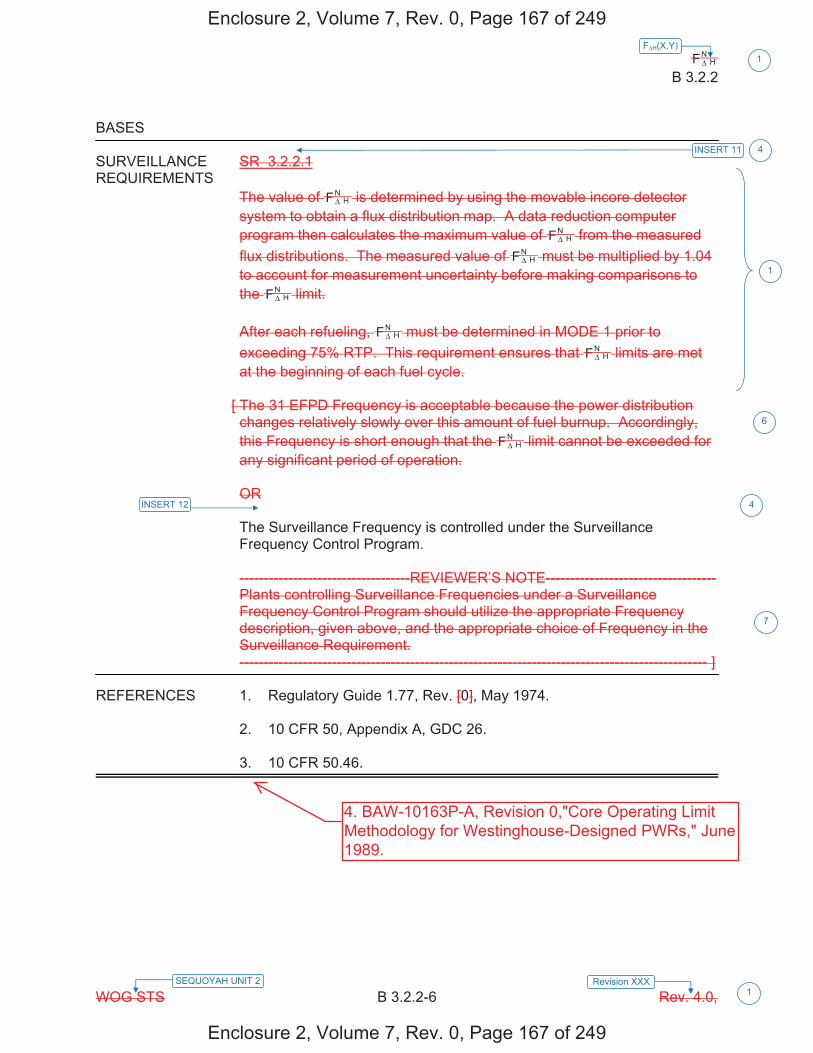
HNF Δ
B 3.2.2
WOG STS B 3.2.2-6 Rev. 4.0,
F H(X,Y)1
SEQUOYAH UNIT 2 Revision XXX 1
BASES SURVEILLANCE SR 3.2.2.1 REQUIREMENTS
The value of HNF Δ is determined by using the movable incore detector
system to obtain a flux distribution map. A data reduction computer program then calculates the maximum value of H
NF Δ from the measured flux distributions. The measured value of H
NF Δ must be multiplied by 1.04 to account for measurement uncertainty before making comparisons to the H
NF Δ limit. After each refueling, H
NF Δ must be determined in MODE 1 prior to exceeding 75% RTP. This requirement ensures that H
NF Δ limits are met at the beginning of each fuel cycle.
[ The 31 EFPD Frequency is acceptable because the power distribution changes relatively slowly over this amount of fuel burnup. Accordingly, this Frequency is short enough that the H
NF Δ limit cannot be exceeded for any significant period of operation. OR The Surveillance Frequency is controlled under the Surveillance Frequency Control Program. -----------------------------------REVIEWER’S NOTE----------------------------------- Plants controlling Surveillance Frequencies under a Surveillance Frequency Control Program should utilize the appropriate Frequency description, given above, and the appropriate choice of Frequency in the Surveillance Requirement. ------------------------------------------------------------------------------------------------ ]
REFERENCES 1. Regulatory Guide 1.77, Rev. [0], May 1974. 2. 10 CFR 50, Appendix A, GDC 26. 3. 10 CFR 50.46.
1
INSERT 12
4
4
6
7
INSERT 11
Enclosure 2, Volume 7, Rev. 0, Page 167 of 249
Enclosure 2, Volume 7, Rev. 0, Page 167 of 249
4. BAW-10163P-A, Revision 0,"Core Operating LimitMethodology for Westinghouse-Designed PWRs," June1989.

Licensee Response/NRC Response/NRC Question ClosureId 321
NRC Question Number KNH-019
Select Application NRC Question Closure
Attachment 1
Attachment 2
Response Statement
Response Date/Time
Closure Statement This question is closed and no further information is required at this time to draft the Safety Evaluation.
Question Closure Date 9/3/2014
Notification Scott BowmanMichelle ConnerKhadijah HemphillAndrew HonLynn MynattRay SchieleRoger Scott
Added By Khadijah Hemphill
Date Added 9/3/2014 7:46 AM
Date Modified
Modified By
Page 1 of 1Sequoyah ITS Conversion Database
9/3/2014https://members.excelservices.com/rai/index.php?requestType=areaItemPrint&itemId=321
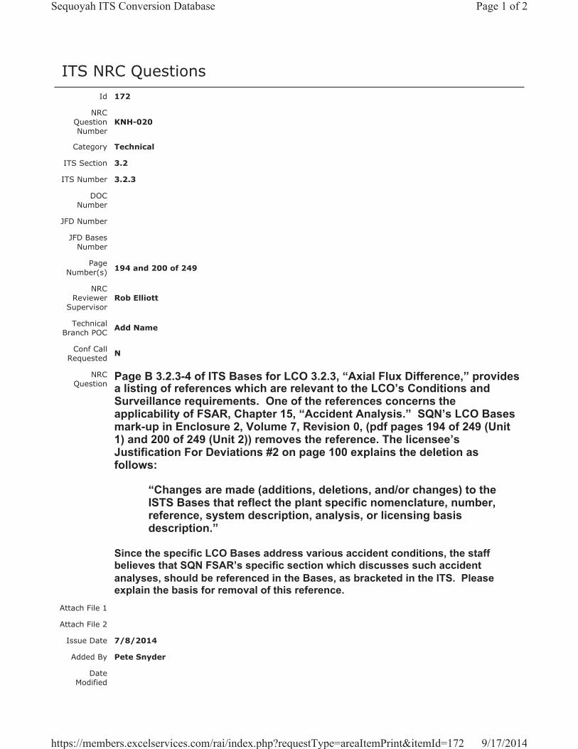
ITS NRC QuestionsId 172
NRC Question Number
KNH-020
Category Technical
ITS Section 3.2
ITS Number 3.2.3
DOC Number
JFD Number
JFD Bases Number
Page Number(s) 194 and 200 of 249
NRC Reviewer
Supervisor Rob Elliott
Technical Branch POC Add Name
Conf Call Requested N
NRC Question
Page B 3.2.3-4 of ITS Bases for LCO 3.2.3, “Axial Flux Difference,” provides a listing of references which are relevant to the LCO’s Conditions and Surveillance requirements. One of the references concerns the applicability of FSAR, Chapter 15, “Accident Analysis.” SQN’s LCO Bases mark-up in Enclosure 2, Volume 7, Revision 0, (pdf pages 194 of 249 (Unit 1) and 200 of 249 (Unit 2)) removes the reference. The licensee’s Justification For Deviations #2 on page 100 explains the deletion as follows:
“Changes are made (additions, deletions, and/or changes) to the ISTS Bases that reflect the plant specific nomenclature, number, reference, system description, analysis, or licensing basis description.”
Since the specific LCO Bases address various accident conditions, the staff believes that SQN FSAR’s specific section which discusses such accident analyses, should be referenced in the Bases, as bracketed in the ITS. Please explain the basis for removal of this reference.
Attach File 1
Attach File 2
Issue Date 7/8/2014
Added By Pete Snyder
Date Modified
Page 1 of 2Sequoyah ITS Conversion Database
9/17/2014https://members.excelservices.com/rai/index.php?requestType=areaItemPrint&itemId=172
Modified By
Date Added 7/8/2014 8:06 AM
Notification Scott BowmanMichelle ConnerRobert ElliottKhadijah HemphillAndrew HonRay SchieleRoger ScottPete Snyder
Page 2 of 2Sequoyah ITS Conversion Database
9/17/2014https://members.excelservices.com/rai/index.php?requestType=areaItemPrint&itemId=172
Licensee Response/NRC Response/NRC Question ClosureId 264
NRC Question Number
KNH-020
Select Application Licensee Response
Attachment 1 Attachment 1 KNH-020 STB.pdf (1008KB)
Attachment 2
Response Statement
In response to KNH-020, the ITS 3.2.3 Bases Reference Section, on pages 194 and 200 of Enclosure 2, Volume 7, will be revised to retain the reference to UFSAR, Chapter 15. Based on the response to RAI CSS-007, the ITS 3.2.3 Bases will be revised to include the Applicable Safety Analyses (ASA) discussion concerning Condition 4, 3, and 2 events. As a result of this RAI and the response to CSS-007, the following changes will be made to the ITS 3.2.3 Bases.
1. Following the discussion of the Condition 4, 3, and 2 events, an insert “(Ref. 1)” will be added in the ASA Section.
2. In the LCO section, where reference is made to “(Refs. 1 and 2)” the References will be renumbered as “(Refs. 1 and 3)”.
3. In the References section, the order of the References will be revised to coincide with the Reference number in previous Sections of the Bases.
4. Also, in the Reference section, BAW 10163P-A, Core Operating Limit Methodology for Westinghouse-Designed PWRs, June 1989, will be revised to BAW-10163P-A, Revision 0, “Core Operating Limit Methodology for Westinghouse-Designed PWRs,” June 1989. This change is consistent with the proposed Reference 4 insert for the ITS 3.2.2 Bases (See the response to RAI KNH-019 concerning this insert).
See Attachment 1 for the draft revised ITS 3.2.3 Bases.Response
Date/Time 8/14/2014 6:25 AM
Closure Statement
Question Closure Date
Notification Scott BowmanMichelle ConnerKhadijah HemphillAndrew HonRay SchielePete Snyder
Added By Scott Bowman
Page 1 of 2Sequoyah ITS Conversion Database
9/17/2014https://members.excelservices.com/rai/index.php?requestType=areaItemPrint&itemId=264
Date Added 8/14/2014 5:19 AM
Date Modified
Modified By
Page 2 of 2Sequoyah ITS Conversion Database
9/17/2014https://members.excelservices.com/rai/index.php?requestType=areaItemPrint&itemId=264
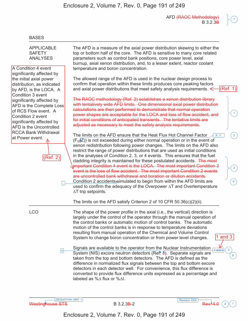
AFD (RAOC Methodology) B 3.2.3B
Westinghouse STS B 3.2.3B-2 Rev. 4.0 2 1
1
SEQUOYAH UNIT 1 Revision XXX
BASES APPLICABLE The AFD is a measure of the axial power distribution skewing to either the SAFETY top or bottom half of the core. The AFD is sensitive to many core related ANALYSES parameters such as control bank positions, core power level, axial
burnup, axial xenon distribution, and, to a lesser extent, reactor coolant temperature and boron concentration. The allowed range of the AFD is used in the nuclear design process to confirm that operation within these limits produces core peaking factors and axial power distributions that meet safety analysis requirements. The RAOC methodology (Ref. 2) establishes a xenon distribution library with tentatively wide AFD limits. One dimensional axial power distribution calculations are then performed to demonstrate that normal operation power shapes are acceptable for the LOCA and loss of flow accident, and for initial conditions of anticipated transients. The tentative limits are adjusted as necessary to meet the safety analysis requirements. The limits on the AFD ensure that the Heat Flux Hot Channel Factor (FQ(Z)) is not exceeded during either normal operation or in the event of xenon redistribution following power changes. The limits on the AFD also restrict the range of power distributions that are used as initial conditions in the analyses of Condition 2, 3, or 4 events. This ensures that the fuel cladding integrity is maintained for these postulated accidents. The most important Condition 4 event is the LOCA. The most important Condition 3 event is the loss of flow accident. The most important Condition 2 events are uncontrolled bank withdrawal and boration or dilution accidents. Condition 2 accidents simulated to begin from within the AFD limits are used to confirm the adequacy of the Overpower T and Overtemperature
T trip setpoints. The limits on the AFD satisfy Criterion 2 of 10 CFR 50.36(c)(2)(ii).
LCO The shape of the power profile in the axial (i.e., the vertical) direction is
largely under the control of the operator through the manual operation of the control banks or automatic motion of control banks. The automatic motion of the control banks is in response to temperature deviations resulting from manual operation of the Chemical and Volume Control System to change boron concentration or from power level changes. Signals are available to the operator from the Nuclear Instrumentation System (NIS) excore neutron detectors (Ref. 3). Separate signals are taken from the top and bottom detectors. The AFD is defined as the difference in normalized flux signals between the top and bottom excore detectors in each detector well. For convenience, this flux difference is converted to provide flux difference units expressed as a percentage and labeled as % flux or % I.
1 and 2
1
2
X, Y, 2
2
s
6
, 6
Enclosure 2, Volume 7, Rev. 0, Page 191 of 249
Enclosure 2, Volume 7, Rev. 0, Page 191 of 249
A Condition 4 event significantly affected by the initial axial power distribution, as indicated by AFD, is the LOCA. A Condition 3 event significantly affected by AFD is the Complete Loss of RCS Flow event. A Condition 2 event significantly affected by AFD is the Uncontrolled RCCA Bank Withdrawal at Power event.
(Ref. 2)
1 and 3
(Ref. 1)
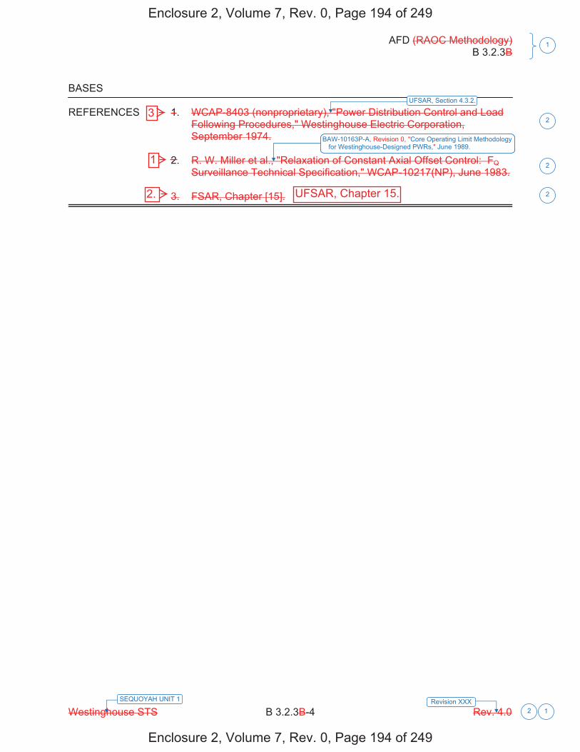
AFD (RAOC Methodology) B 3.2.3B
Westinghouse STS B 3.2.3B-4 Rev. 4.0
1
Revision XXX1
SEQUOYAH UNIT 1
2
BASES
REFERENCES 1. WCAP-8403 (nonproprietary), "Power Distribution Control and LoadFollowing Procedures," Westinghouse Electric Corporation,September 1974.
2. R. W. Miller et al., "Relaxation of Constant Axial Offset Control: FQSurveillance Technical Specification," WCAP-10217(NP), June 1983.
3. FSAR, Chapter [15].
UFSAR, Section 4.3.2.
BAW 10163P-A, Core Operating Limit Methodology for Westinghouse-Designed PWRs, June 1989.
2
2
2
Enclosure 2, Volume 7, Rev. 0, Page 194 of 249
Enclosure 2, Volume 7, Rev. 0, Page 194 of 249
3
2. UFSAR, Chapter 15.
1
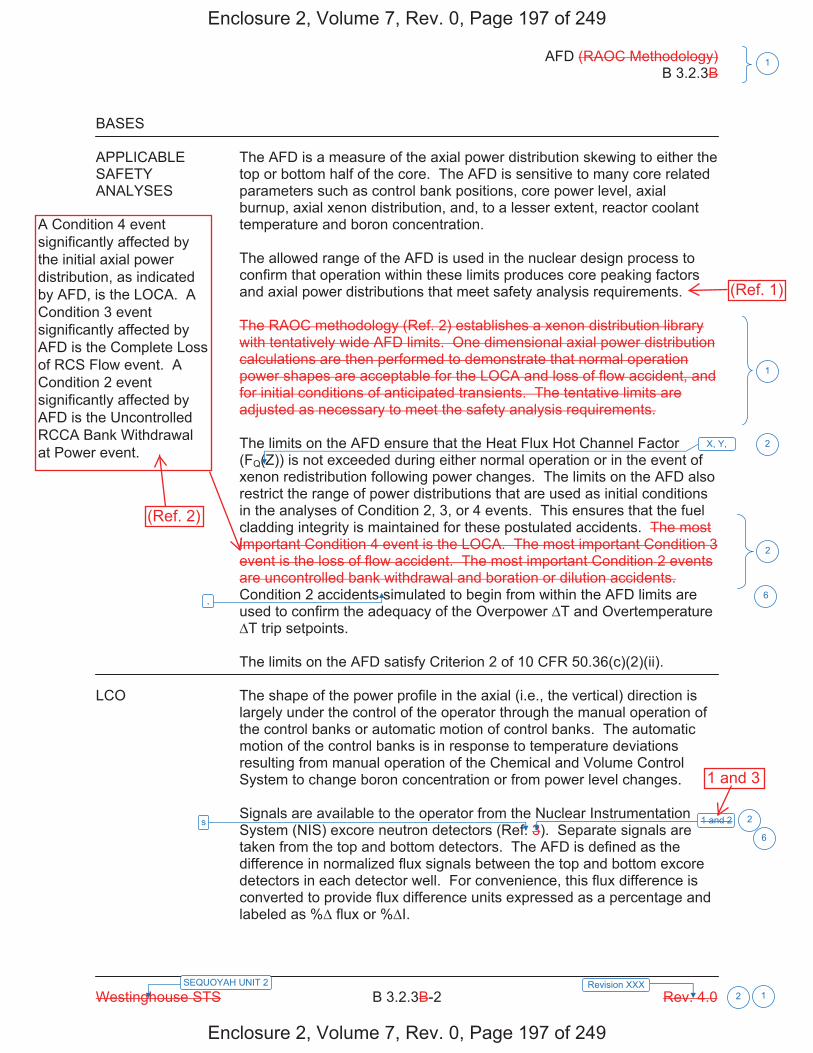
AFD (RAOC Methodology) B 3.2.3B
Westinghouse STS B 3.2.3B-2 Rev. 4.0 2 1
1
SEQUOYAH UNIT 2 Revision XXX
BASES APPLICABLE The AFD is a measure of the axial power distribution skewing to either the SAFETY top or bottom half of the core. The AFD is sensitive to many core related ANALYSES parameters such as control bank positions, core power level, axial
burnup, axial xenon distribution, and, to a lesser extent, reactor coolant temperature and boron concentration. The allowed range of the AFD is used in the nuclear design process to confirm that operation within these limits produces core peaking factors and axial power distributions that meet safety analysis requirements. The RAOC methodology (Ref. 2) establishes a xenon distribution library with tentatively wide AFD limits. One dimensional axial power distribution calculations are then performed to demonstrate that normal operation power shapes are acceptable for the LOCA and loss of flow accident, and for initial conditions of anticipated transients. The tentative limits are adjusted as necessary to meet the safety analysis requirements. The limits on the AFD ensure that the Heat Flux Hot Channel Factor (FQ(Z)) is not exceeded during either normal operation or in the event of xenon redistribution following power changes. The limits on the AFD also restrict the range of power distributions that are used as initial conditions in the analyses of Condition 2, 3, or 4 events. This ensures that the fuel cladding integrity is maintained for these postulated accidents. The most important Condition 4 event is the LOCA. The most important Condition 3 event is the loss of flow accident. The most important Condition 2 events are uncontrolled bank withdrawal and boration or dilution accidents. Condition 2 accidents simulated to begin from within the AFD limits are used to confirm the adequacy of the Overpower T and Overtemperature
T trip setpoints. The limits on the AFD satisfy Criterion 2 of 10 CFR 50.36(c)(2)(ii).
LCO The shape of the power profile in the axial (i.e., the vertical) direction is
largely under the control of the operator through the manual operation of the control banks or automatic motion of control banks. The automatic motion of the control banks is in response to temperature deviations resulting from manual operation of the Chemical and Volume Control System to change boron concentration or from power level changes. Signals are available to the operator from the Nuclear Instrumentation System (NIS) excore neutron detectors (Ref. 3). Separate signals are taken from the top and bottom detectors. The AFD is defined as the difference in normalized flux signals between the top and bottom excore detectors in each detector well. For convenience, this flux difference is converted to provide flux difference units expressed as a percentage and labeled as % flux or % I.
1 and 2
1
2
X, Y, 2
2
s
6
, 6
Enclosure 2, Volume 7, Rev. 0, Page 197 of 249
Enclosure 2, Volume 7, Rev. 0, Page 197 of 249
A Condition 4 event significantly affected by the initial axial power distribution, as indicated by AFD, is the LOCA. A Condition 3 event significantly affected by AFD is the Complete Loss of RCS Flow event. A Condition 2 event significantly affected by AFD is the Uncontrolled RCCA Bank Withdrawal at Power event.
(Ref. 2)
1 and 3
(Ref. 1)
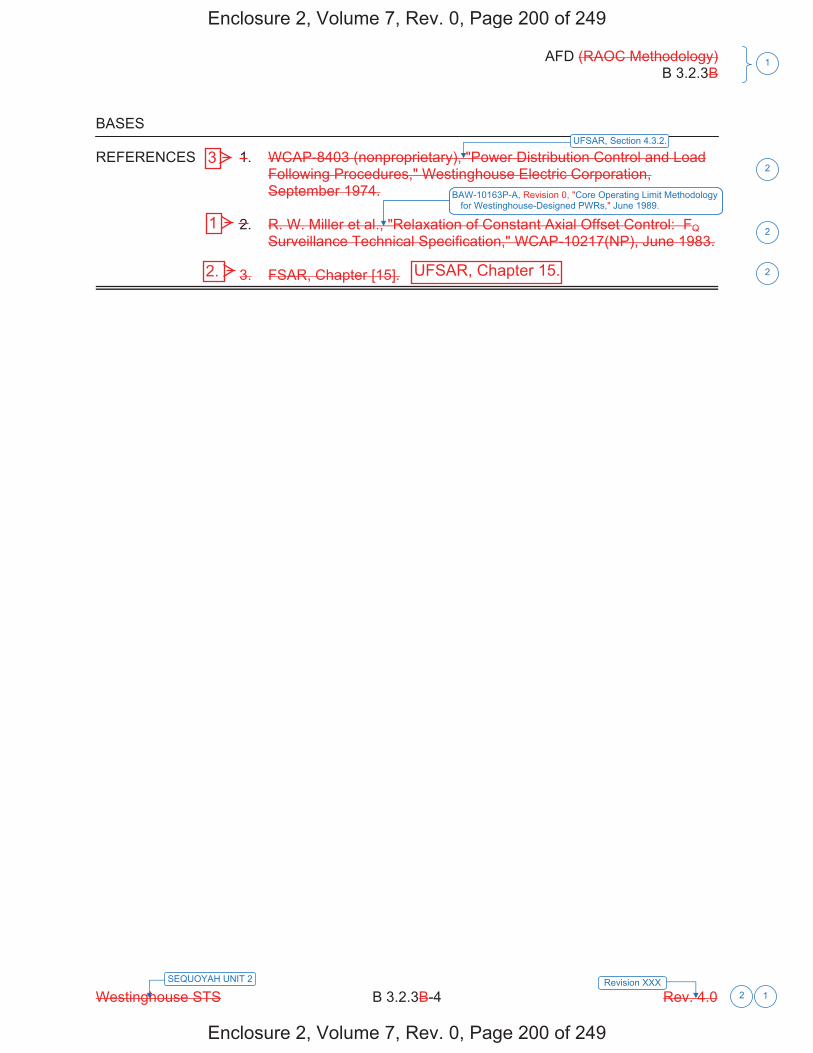
AFD (RAOC Methodology) B 3.2.3B
Westinghouse STS B 3.2.3B-4 Rev. 4.0
1
Revision XXX1
SEQUOYAH UNIT 2
2
BASES
REFERENCES 1. WCAP-8403 (nonproprietary), "Power Distribution Control and LoadFollowing Procedures," Westinghouse Electric Corporation,September 1974.
2. R. W. Miller et al., "Relaxation of Constant Axial Offset Control: FQSurveillance Technical Specification," WCAP-10217(NP), June 1983.
3. FSAR, Chapter [15].
UFSAR, Section 4.3.2.
BAW 10163P-A, Core Operating Limit Methodology for Westinghouse-Designed PWRs, June 1989.
2
2
2
Enclosure 2, Volume 7, Rev. 0, Page 200 of 249
Enclosure 2, Volume 7, Rev. 0, Page 200 of 249
3
1
2. UFSAR, Chapter 15.

Licensee Response/NRC Response/NRC Question ClosureId 326
NRC Question Number KNH-020
Select Application NRC Question Closure
Attachment 1
Attachment 2
Response Statement
Response Date/Time
Closure Statement This question is closed and no further information is required at this time to draft the Safety Evaluation.
Question Closure Date 9/9/2014
Notification Scott BowmanMichelle ConnerKhadijah HemphillAndrew HonLynn MynattRay SchieleRoger ScottPete Snyder
Added By Khadijah Hemphill
Date Added 9/9/2014 8:20 AM
Date Modified
Modified By
Page 1 of 1Sequoyah ITS Conversion Database
9/17/2014https://members.excelservices.com/rai/index.php?requestType=areaItemPrint&itemId=326
ITS NRC QuestionsId 173
NRC Question Number
KNH-021
Category Technical
ITS Section 3.5
ITS Number 3.5.2
DOC Number
JFD Number
JFD Bases Number
Page Number(s)
NRC Reviewer
Supervisor Sam Miranda
Technical Branch POC Matt Hardgrove
Conf Call Requested N
NRC Question
In Enclosure 2, Volume 10, Revision 0, regarding Limiting Condition for Operation (LCO) 3.5.2, “ECCS – OPERATING,” an edit for Note 1 is proposed as follows, “In MODE 3, both Emergency Core Cooling System (ECCS) pump flow paths may be isolated by closing the isolation valves for up to 2 hours to perform pressure isolation valves (PIVs) testing per ITS Surveillance Requirement (SR) 3.4.14.1.”Surveillance testing of the pressure isolation valves required the Safety Injection (SI) Pump and Residual Heat Removal (RHR) Pump flow paths to be isolated. ITS LCO 3.5.2 Note 1 will allow for isolating both SI pump paths and RHR pump flow paths for two hours allowing for required testing of the PIVs. TVA states that this change permits the isolation of the ECCS (SI pump and RHR pump) flow paths provided that the flow paths are readily restorable from the control room. TVA further states that the acceptability of this testing allowance is based, in part, on the operability of the centrifugal charging system and the cold leg injection accumulators and the low probability of an accident occurring during the isolation time to support PIV testing.
Please provide an analysis demonstrating acceptable ECCS performance in the event of a MODE 3 loss-of-coolant accident when only the accumulators and charging pumps are available for emergency core cooling.
Please provide justification that will ensure that simultaneous PIV surveillance on both RHR and ECCS will not be performed in the event of being in an action statement for failure to meet LCO 3.5.1, “Accumulators,” or in the event that the centrifugal charging system is not fully operable.
Attach File
Page 1 of 2Sequoyah ITS Conversion Database
9/25/2014https://members.excelservices.com/rai/index.php?requestType=areaItemPrint&itemId=173
1
Attach File 2
Issue Date 7/14/2014
Added By Khadijah Hemphill
Date Modified
Modified By
Date Added 7/14/2014 3:16 PM
Notification Scott BowmanMichelle ConnerKhadijah HemphillAndrew HonLynn MynattRay SchieleRoger Scott
Page 2 of 2Sequoyah ITS Conversion Database
9/25/2014https://members.excelservices.com/rai/index.php?requestType=areaItemPrint&itemId=173
Licensee Response/NRC Response/NRC Question ClosureId 338
NRC Question Number
KNH-021
Select Application Licensee Response
Attachment 1 Attachment 1 KNH-021 R1.pdf (1000KB)
Attachment 2
Response Statement mmm
In response to KNH-021, SQN is withdrawing the proposed change to ITS 3.5.2 ECCS- Operating. Specifically, SQN had proposed to change ITS LCO NOTE 1 to state “In MODE 3, both ECCS pump flow paths may be isolated by closing the isolation valves for up to 2 hours to perform pressure isolation valve testing per SR 3.4.14.1” and to change the ITS LCO NOTE 1 bases to state “As indicated in Note 1, the ECCS (SI Pump and RHR pump) flow paths may be isolated for 2 hours in MODE 3, under controlled conditions, to perform pressure isolation valve testing per SR 3.4.14.1. The flow path is readily restorable from the control room.” SQN will remove the associated changes from the ITS 3.5.2 Specification and Bases.
Additionally, during review for KNH-021, the following issue was identified.At the bottom of each page, where “Westinghouse STS” and “Rev. 4.0” are marked out and SQN specific information is inserted, the justification for deviation (JFD) indicator is incorrect. The JFD indicator will be revised to JFD 3 and JFD 3 will be revised to state, “Changes are made (additions, deletions, and/or changes) to the ISTS that reflect the plant specific nomenclature, number, reference, system description, analysis, or licensing basis description.” (Pages 57, 58, 60, 62, 63, 64, 66, 68, and 69)
See Attachment 1 for the related changes associated with Enclosure 2, Volume 10:
1. CTS markups removing the addition of “ECCS” to NOTE 1 and removing Discussion of Change (DOC) L01 pointers, pages 48 and 50;
2. DOC L01 deletion, pages 54 and 55;
3. ITS 3.5.2 Specification markups removing the addition of “ECCS” to NOTE 1 and removing the JFD 4 pointer, pages 57 and 63;
4. JFD 4 deletion, page 69;
5. ITS 3.5.2 Bases markups removing the addition of “ECCS (SI Pump and RHR Pump)” to LCO NOTE 1 and deleting JFD 7 pointers, pages 76 and page 88; and
Page 1 of 2Sequoyah ITS Conversion Database
9/25/2014https://members.excelservices.com/rai/index.php?requestType=areaItemPrint&itemId=338
6. JFD ITS 3.5.2 Bases, deleting JFD 7 page 95.Response
Date/Time 9/19/2014 9:50 AM
Closure Statement
Question Closure
Date
Notification Scott BowmanMichelle ConnerKhadijah HemphillAndrew HonRay Schiele
Added By Scott Bowman
Date Added 9/19/2014 8:49 AM
Date Modified
Modified By
Page 2 of 2Sequoyah ITS Conversion Database
9/25/2014https://members.excelservices.com/rai/index.php?requestType=areaItemPrint&itemId=338
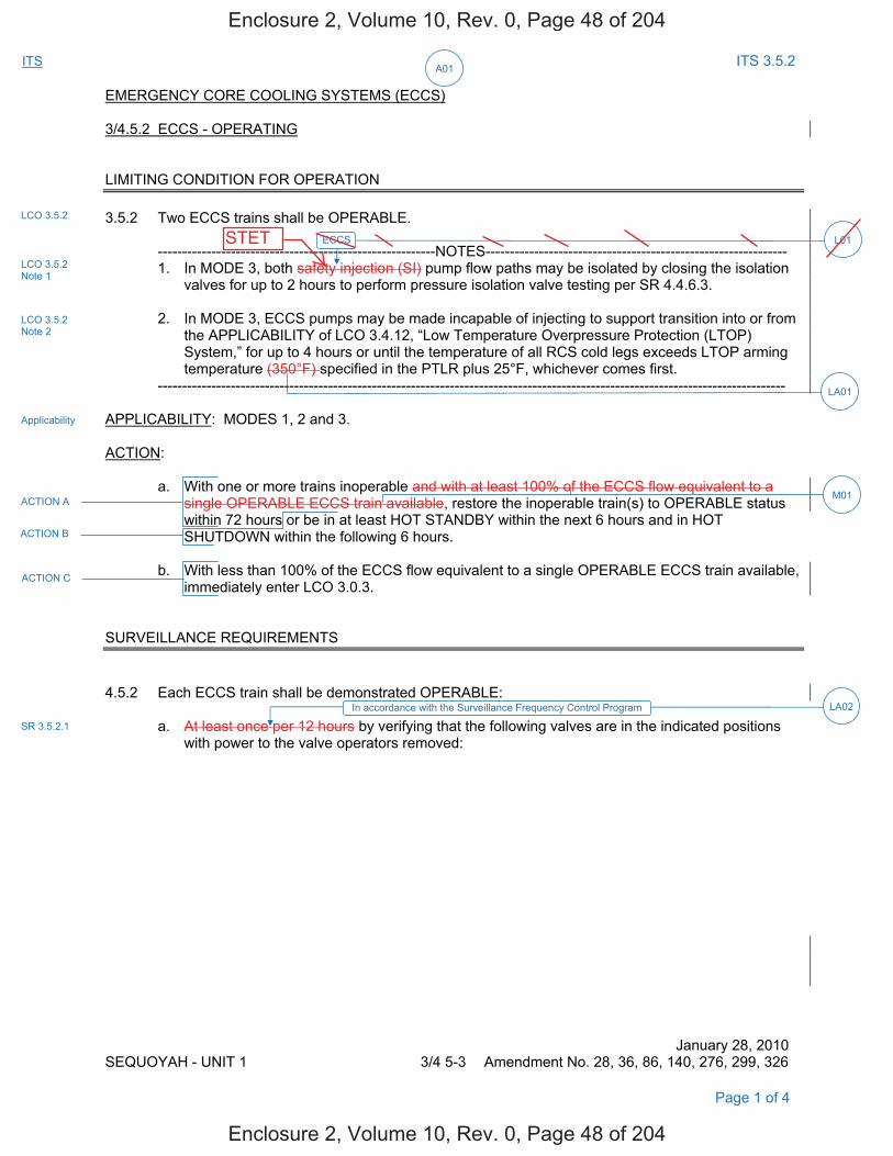
A01ITS ITS 3.5.2
EMERGENCY CORE COOLING SYSTEMS (ECCS) 3/4.5.2 ECCS - OPERATING LIMITING CONDITION FOR OPERATION 3.5.2 Two ECCS trains shall be OPERABLE.
---------------------------------------------------------NOTES-------------------------------------------------------------- 1. In MODE 3, both safety injection (SI) pump flow paths may be isolated by closing the isolation
valves for up to 2 hours to perform pressure isolation valve testing per SR 4.4.6.3.
2. In MODE 3, ECCS pumps may be made incapable of injecting to support transition into or from the APPLICABILITY of LCO 3.4.12, “Low Temperature Overpressure Protection (LTOP) System,” for up to 4 hours or until the temperature of all RCS cold legs exceeds LTOP arming temperature (350°F) specified in the PTLR plus 25°F, whichever comes first.
---------------------------------------------------------------------------------------------------------------------------------
APPLICABILITY: MODES 1, 2 and 3. ACTION:
a. With one or more trains inoperable and with at least 100% of the ECCS flow equivalent to a single OPERABLE ECCS train available, restore the inoperable train(s) to OPERABLE status within 72 hours or be in at least HOT STANDBY within the next 6 hours and in HOT SHUTDOWN within the following 6 hours.
b. With less than 100% of the ECCS flow equivalent to a single OPERABLE ECCS train available, immediately enter LCO 3.0.3.
SURVEILLANCE REQUIREMENTS 4.5.2 Each ECCS train shall be demonstrated OPERABLE:
a. At least once per 12 hours by verifying that the following valves are in the indicated positions with power to the valve operators removed:
January 28, 2010 SEQUOYAH - UNIT 1 3/4 5-3 Amendment No. 28, 36, 86, 140, 276, 299, 326
Page 1 of 4
LCO 3.5.2
LCO 3.5.2 Note 1
LCO 3.5.2 Note 2
Applicability
ACTION A
ACTION B
ACTION C
LA02In accordance with the Surveillance Frequency Control Program
SR 3.5.2.1
M01
LA01
L01ECCS
Enclosure 2, Volume 10, Rev. 0, Page 48 of 204
Enclosure 2, Volume 10, Rev. 0, Page 48 of 204
STET
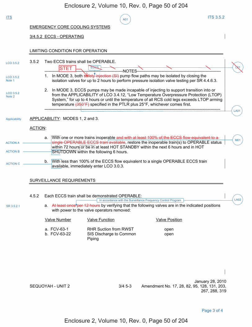
A01ITS ITS 3.5.2
EMERGENCY CORE COOLING SYSTEMS 3/4.5.2 ECCS - OPERATING LIMITING CONDITION FOR OPERATION 3.5.2 Two ECCS trains shall be OPERABLE.
---------------------------------------------------------NOTES------------------------------------------------------------- 1. In MODE 3, both safety injection (SI) pump flow paths may be isolated by closing the
isolation valves for up to 2 hours to perform pressure isolation valve testing per SR 4.4.6.3.
2. In MODE 3, ECCS pumps may be made incapable of injecting to support transition into or from the APPLICABILITY of LCO 3.4.12, “Low Temperature Overpressure Protection (LTOP) System,” for up to 4 hours or until the temperature of all RCS cold legs exceeds LTOP arming temperature (350°F) specified in the PTLR plus 25°F, whichever comes first.
--------------------------------------------------------------------------------------------------------------------------------
APPLICABILITY: MODES 1, 2 and 3. ACTION:
a. With one or more trains inoperable and with at least 100% of the ECCS flow equivalent to a single OPERABLE ECCS train available, restore the inoperable train(s) to OPERABLE status
within 72 hours or be in at least HOT STANDBY within the next 6 hours and in HOT SHUTDOWN within the following 6 hours. b. With less than 100% of the ECCS flow equivalent to a single OPERABLE ECCS train
available, immediately enter LCO 3.0.3. SURVEILLANCE REQUIREMENTS 4.5.2 Each ECCS train shall be demonstrated OPERABLE:
a. At least once per 12 hours by verifying that the following valves are in the indicated positions with power to the valve operators removed:
Valve Number Valve Function Valve Position a. FCV-63-1 RHR Suction from RWST open b. FCV-63-22 SIS Discharge to Common
Piping open
January 28, 2010 SEQUOYAH - UNIT 2 3/4 5-3 Amendment No. 17, 28, 82, 95, 128, 131, 203,
267, 288, 319
LCO 3.5.2
LCO 3.5.2 Note 1
LCO 3.5.2 Note 2
Applicability
ACTION A
ACTION B
ACTION C
SR 3.5.2.1
LA02In accordance with the Surveillance Frequency Control Program
Page 3 of 4
M01
LA01
L01ECCS
Enclosure 2, Volume 10, Rev. 0, Page 50 of 204
Enclosure 2, Volume 10, Rev. 0, Page 50 of 204
STET
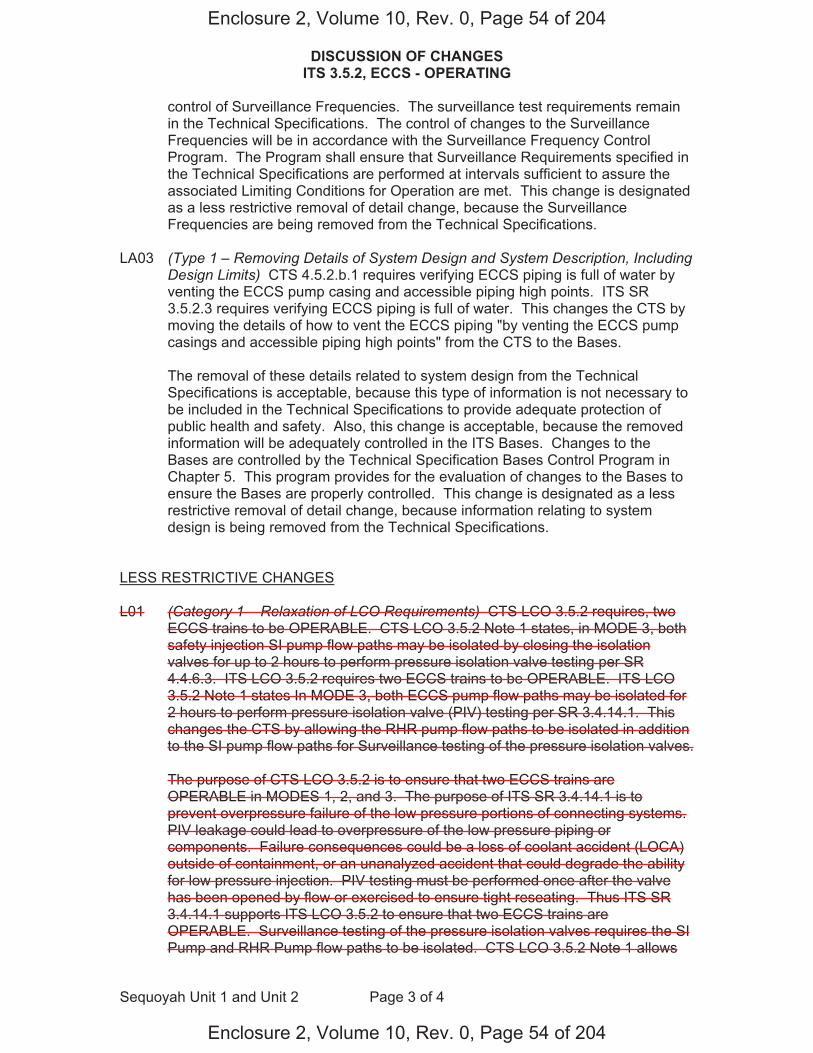
DISCUSSION OF CHANGES ITS 3.5.2, ECCS - OPERATING
Sequoyah Unit 1 and Unit 2 Page 3 of 4
control of Surveillance Frequencies. The surveillance test requirements remain in the Technical Specifications. The control of changes to the Surveillance Frequencies will be in accordance with the Surveillance Frequency Control Program. The Program shall ensure that Surveillance Requirements specified in the Technical Specifications are performed at intervals sufficient to assure the associated Limiting Conditions for Operation are met. This change is designated as a less restrictive removal of detail change, because the Surveillance Frequencies are being removed from the Technical Specifications.
LA03 (Type 1 – Removing Details of System Design and System Description, Including
Design Limits) CTS 4.5.2.b.1 requires verifying ECCS piping is full of water by venting the ECCS pump casing and accessible piping high points. ITS SR 3.5.2.3 requires verifying ECCS piping is full of water. This changes the CTS by moving the details of how to vent the ECCS piping "by venting the ECCS pump casings and accessible piping high points" from the CTS to the Bases.
The removal of these details related to system design from the Technical
Specifications is acceptable, because this type of information is not necessary to be included in the Technical Specifications to provide adequate protection of public health and safety. Also, this change is acceptable, because the removed information will be adequately controlled in the ITS Bases. Changes to the Bases are controlled by the Technical Specification Bases Control Program in Chapter 5. This program provides for the evaluation of changes to the Bases to ensure the Bases are properly controlled. This change is designated as a less restrictive removal of detail change, because information relating to system design is being removed from the Technical Specifications.
LESS RESTRICTIVE CHANGES L01 (Category 1 – Relaxation of LCO Requirements) CTS LCO 3.5.2 requires, two
ECCS trains to be OPERABLE. CTS LCO 3.5.2 Note 1 states, in MODE 3, both safety injection SI pump flow paths may be isolated by closing the isolation valves for up to 2 hours to perform pressure isolation valve testing per SR 4.4.6.3. ITS LCO 3.5.2 requires two ECCS trains to be OPERABLE. ITS LCO 3.5.2 Note 1 states In MODE 3, both ECCS pump flow paths may be isolated for 2 hours to perform pressure isolation valve (PIV) testing per SR 3.4.14.1. This changes the CTS by allowing the RHR pump flow paths to be isolated in addition to the SI pump flow paths for Surveillance testing of the pressure isolation valves.
The purpose of CTS LCO 3.5.2 is to ensure that two ECCS trains are
OPERABLE in MODES 1, 2, and 3. The purpose of ITS SR 3.4.14.1 is to prevent overpressure failure of the low pressure portions of connecting systems. PIV leakage could lead to overpressure of the low pressure piping or components. Failure consequences could be a loss of coolant accident (LOCA) outside of containment, or an unanalyzed accident that could degrade the ability for low pressure injection. PIV testing must be performed once after the valve has been opened by flow or exercised to ensure tight reseating. Thus ITS SR 3.4.14.1 supports ITS LCO 3.5.2 to ensure that two ECCS trains are OPERABLE. Surveillance testing of the pressure isolation valves requires the SI Pump and RHR Pump flow paths to be isolated. CTS LCO 3.5.2 Note 1 allows
Enclosure 2, Volume 10, Rev. 0, Page 54 of 204
Enclosure 2, Volume 10, Rev. 0, Page 54 of 204
DISCUSSION OF CHANGES ITS 3.5.2, ECCS - OPERATING
Sequoyah Unit 1 and Unit 2 Page 4 of 4
both SI pump flow paths to be isolated for two hours provided that the flow paths are readily restorable from the control room. In addition to isolating the SI pump flow paths, ITS LCO 3.5.2 Note 1 will allow both RHR pump flow paths to be isolated for two hours allowing for the required testing of the PIVs. This change permits the isolation of the ECCS (SI pump and RHR pump) flow paths provided that the flow paths are readily restorable from the control room. The acceptability of this testing allowance is based on the operability of the centrifugal charging system and the cold leg injection accumulators and the low probability of an accident occurring during the isolation time to support PIV testing. This change is acceptable because the LCO requirements continue to ensure that the system is maintained consistent with the safety analysis and licensing basis. This change is designated as less restrictive because the RHR pump flow path may be isolated to support testing of the PIVs.
Enclosure 2, Volume 10, Rev. 0, Page 55 of 204
Enclosure 2, Volume 10, Rev. 0, Page 55 of 204
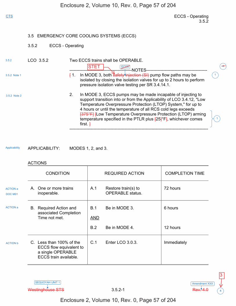
ECCS - Operating 3.5.2
Westinghouse STS 3.5.2-1 Rev. 4.0
CTS
Amendment XXXSEQUOYAH UNIT 1
4
3.5 EMERGENCY CORE COOLING SYSTEMS (ECCS) 3.5.2 ECCS - Operating LCO 3.5.2 Two ECCS trains shall be OPERABLE. --------------------------------------------NOTES------------------------------------------- [ 1. In MODE 3, both safety injection (SI) pump flow paths may be
isolated by closing the isolation valves for up to 2 hours to perform pressure isolation valve testing per SR 3.4.14.1.
2. In MODE 3, ECCS pumps may be made incapable of injecting to
support transition into or from the Applicability of LCO 3.4.12, "Low Temperature Overpressure Protection (LTOP) System," for up to 4 hours or until the temperature of all RCS cold legs exceeds [375°F] [Low Temperature Overpressure Protection (LTOP) arming temperature specified in the PTLR plus [25]°F], whichever comes first. ]
-------------------------------------------------------------------------------------------------- APPLICABILITY: MODES 1, 2, and 3. ACTIONS
CONDITION
REQUIRED ACTION
COMPLETION TIME
A. One or more trains
inoperable.
A.1 Restore train(s) to
OPERABLE status.
72 hours
B. Required Action and
associated Completion Time not met.
B.1 Be in MODE 3. AND B.2 Be in MODE 4.
6 hours 12 hours
C. Less than 100% of the
ECCS flow equivalent to a single OPERABLE ECCS train available.
C.1 Enter LCO 3.0.3.
Immediately
3.5.2
3.5.2 Note 1
3.5.2 Note 2
Applicability
ACTION a
ACTION a
ACTION b
1
1
DOC M01
ECCS 4
Enclosure 2, Volume 10, Rev. 0, Page 57 of 204
Enclosure 2, Volume 10, Rev. 0, Page 57 of 204
STET
3

ECCS - Operating 3.5.2
Westinghouse STS 3.5.2-2 Rev. 4.0
CTS
Amendment XXXSEQUOYAH UNIT 1
4
SURVEILLANCE REQUIREMENTS
SURVEILLANCE
FREQUENCY
SR 3.5.2.1 [ Verify the following valves are in the listed position
with power to the valve operator removed. Number Position Function [ ] [ ] [ ] [ ] [ ] [ ] [ ] [ ] [ ]
[ 12 hours OR In accordance with the Surveillance Frequency Control Program ]
SR 3.5.2.2 Verify each ECCS manual, power operated, and
automatic valve in the flow path, that is not locked, sealed, or otherwise secured in position, is in the correct position.
[ 31 days OR In accordance with the Surveillance Frequency Control Program ]
SR 3.5.2.3 [ Verify ECCS piping is full of water.
[ 31 days OR In accordance with the Surveillance Frequency Control Program ] ]
SR 3.5.2.4 Verify each ECCS pump's developed head at the
test flow point is greater than or equal to the required developed head.
In accordance with the Inservice Testing Program
4.5.2.a
4.5.2.b.2
4.5.2.b.1
4.5.2.f
2
2
2
2
2
2
INSERT 1 1
Enclosure 2, Volume 10, Rev. 0, Page 58 of 204
Enclosure 2, Volume 10, Rev. 0, Page 58 of 204
3

ECCS - Operating 3.5.2
Westinghouse STS 3.5.2-3 Rev. 4.0
CTS
Amendment XXXSEQUOYAH UNIT 1
4
SURVEILLANCE REQUIREMENTS (continued)
SURVEILLANCE
FREQUENCY
SR 3.5.2.5 Verify each ECCS automatic valve in the flow path
that is not locked, sealed, or otherwise secured in position, actuates to the correct position on an actual or simulated actuation signal.
[ [18] months OR In accordance with the Surveillance Frequency Control Program ]
SR 3.5.2.6 Verify each ECCS pump starts automatically on an
actual or simulated actuation signal.
[ [18] months OR In accordance with the Surveillance Frequency Control Program ]
SR 3.5.2.7 [ Verify, for each ECCS throttle valve listed below,
each position stop is in the correct position. Valve Number [ ] [ ] [ ]
[ [18] months OR In accordance with the Surveillance Frequency Control Program ] ]
4.5.2.e.1
4.5.2.e.2
4.5.2.g
2
2
2
2
2
2
INSERT 2
1
mechanical 1
Enclosure 2, Volume 10, Rev. 0, Page 60 of 204
Enclosure 2, Volume 10, Rev. 0, Page 60 of 204
3
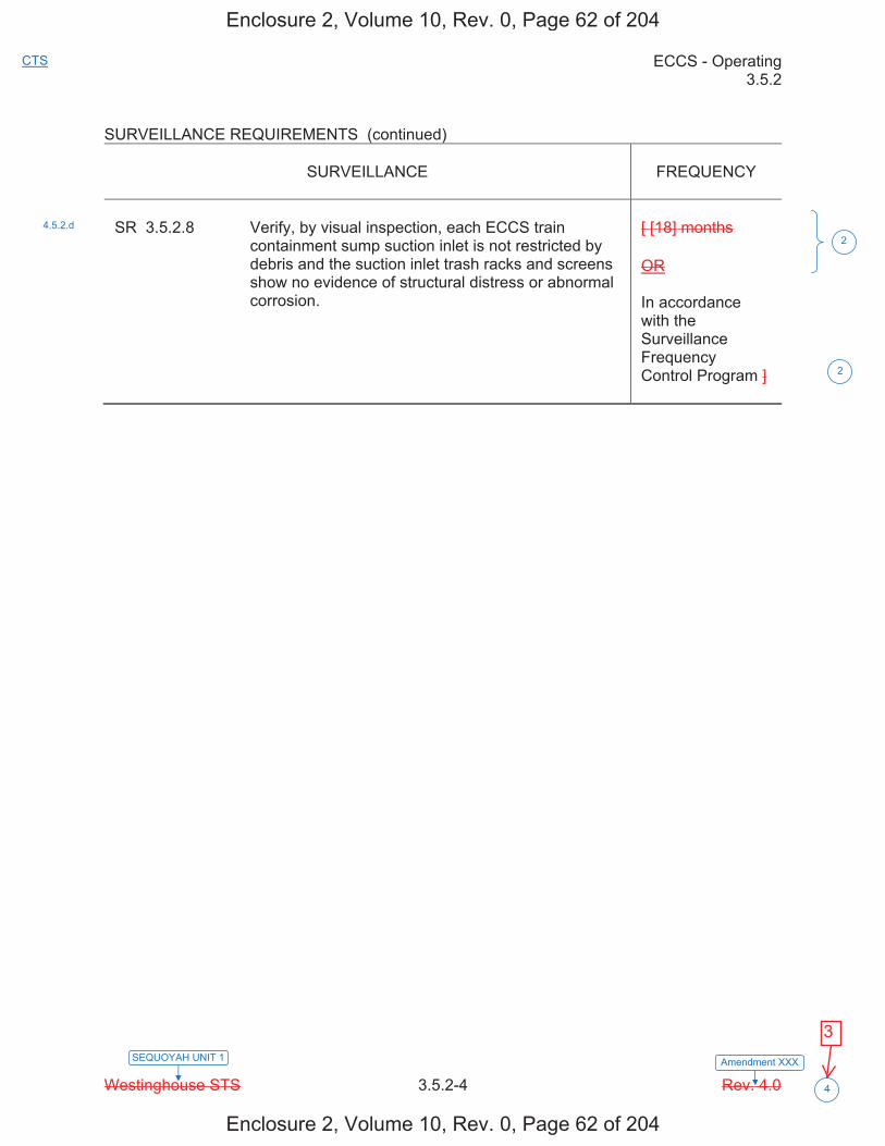
ECCS - Operating 3.5.2
Westinghouse STS 3.5.2-4 Rev. 4.0
CTS
Amendment XXXSEQUOYAH UNIT 1
4
SURVEILLANCE REQUIREMENTS (continued)
SURVEILLANCE
FREQUENCY
SR 3.5.2.8 Verify, by visual inspection, each ECCS train
containment sump suction inlet is not restricted by debris and the suction inlet trash racks and screens show no evidence of structural distress or abnormal corrosion.
[ [18] months OR In accordance with the Surveillance Frequency Control Program ]
4.5.2.d 2
2
Enclosure 2, Volume 10, Rev. 0, Page 62 of 204
Enclosure 2, Volume 10, Rev. 0, Page 62 of 204
3
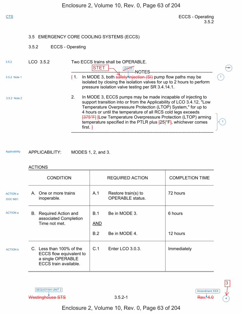
ECCS - Operating 3.5.2
Westinghouse STS 3.5.2-1 Rev. 4.0
CTS
Amendment XXXSEQUOYAH UNIT 2
4
3.5 EMERGENCY CORE COOLING SYSTEMS (ECCS) 3.5.2 ECCS - Operating LCO 3.5.2 Two ECCS trains shall be OPERABLE. --------------------------------------------NOTES------------------------------------------- [ 1. In MODE 3, both safety injection (SI) pump flow paths may be
isolated by closing the isolation valves for up to 2 hours to perform pressure isolation valve testing per SR 3.4.14.1.
2. In MODE 3, ECCS pumps may be made incapable of injecting to
support transition into or from the Applicability of LCO 3.4.12, "Low Temperature Overpressure Protection (LTOP) System," for up to 4 hours or until the temperature of all RCS cold legs exceeds [375°F] [Low Temperature Overpressure Protection (LTOP) arming temperature specified in the PTLR plus [25]°F], whichever comes first. ]
-------------------------------------------------------------------------------------------------- APPLICABILITY: MODES 1, 2, and 3. ACTIONS
CONDITION
REQUIRED ACTION
COMPLETION TIME
A. One or more trains
inoperable.
A.1 Restore train(s) to
OPERABLE status.
72 hours
B. Required Action and
associated Completion Time not met.
B.1 Be in MODE 3. AND B.2 Be in MODE 4.
6 hours 12 hours
C. Less than 100% of the
ECCS flow equivalent to a single OPERABLE ECCS train available.
C.1 Enter LCO 3.0.3.
Immediately
3.5.2
3.5.2 Note 1
3.5.2 Note 2
Applicability
ACTION a
ACTION a
ACTION b
1
1
DOC M01
ECCS 4
Enclosure 2, Volume 10, Rev. 0, Page 63 of 204
Enclosure 2, Volume 10, Rev. 0, Page 63 of 204
STET
3
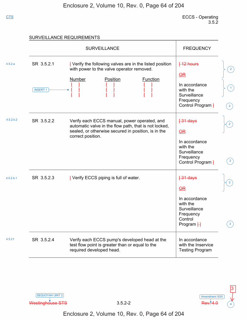
ECCS - Operating 3.5.2
Westinghouse STS 3.5.2-2 Rev. 4.0
CTS
Amendment XXXSEQUOYAH UNIT 2
4
SURVEILLANCE REQUIREMENTS
SURVEILLANCE
FREQUENCY
SR 3.5.2.1 [ Verify the following valves are in the listed position
with power to the valve operator removed. Number Position Function [ ] [ ] [ ] [ ] [ ] [ ] [ ] [ ] [ ]
[ 12 hours OR In accordance with the Surveillance Frequency Control Program ]
SR 3.5.2.2 Verify each ECCS manual, power operated, and
automatic valve in the flow path, that is not locked, sealed, or otherwise secured in position, is in the correct position.
[ 31 days OR In accordance with the Surveillance Frequency Control Program ]
SR 3.5.2.3 [ Verify ECCS piping is full of water.
[ 31 days OR In accordance with the Surveillance Frequency Control Program ] ]
SR 3.5.2.4 Verify each ECCS pump's developed head at the
test flow point is greater than or equal to the required developed head.
In accordance with the Inservice Testing Program
4.5.2.a
4.5.2.b.2
4.5.2.b.1
4.5.2.f
2
2
2
2
2
2
INSERT 1 1
Enclosure 2, Volume 10, Rev. 0, Page 64 of 204
Enclosure 2, Volume 10, Rev. 0, Page 64 of 204
3
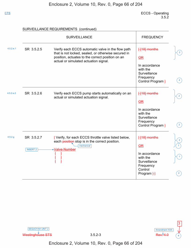
ECCS - Operating 3.5.2
Westinghouse STS 3.5.2-3 Rev. 4.0
CTS
Amendment XXXSEQUOYAH UNIT 2
4
SURVEILLANCE REQUIREMENTS (continued)
SURVEILLANCE
FREQUENCY
SR 3.5.2.5 Verify each ECCS automatic valve in the flow path
that is not locked, sealed, or otherwise secured in position, actuates to the correct position on an actual or simulated actuation signal.
[ [18] months OR In accordance with the Surveillance Frequency Control Program ]
SR 3.5.2.6 Verify each ECCS pump starts automatically on an
actual or simulated actuation signal.
[ [18] months OR In accordance with the Surveillance Frequency Control Program ]
SR 3.5.2.7 [ Verify, for each ECCS throttle valve listed below,
each position stop is in the correct position. Valve Number [ ] [ ] [ ]
[ [18] months OR In accordance with the Surveillance Frequency Control Program ] ]
4.5.2.e.1
4.5.2.e.2
4.5.2.g
2
2
2
2
2
2
INSERT 2
1
mechanical 1
Enclosure 2, Volume 10, Rev. 0, Page 66 of 204
Enclosure 2, Volume 10, Rev. 0, Page 66 of 204
3

ECCS - Operating 3.5.2
Westinghouse STS 3.5.2-4 Rev. 4.0
CTS
Amendment XXXSEQUOYAH UNIT 2
4
SURVEILLANCE REQUIREMENTS (continued)
SURVEILLANCE
FREQUENCY
SR 3.5.2.8 Verify, by visual inspection, each ECCS train
containment sump suction inlet is not restricted by debris and the suction inlet trash racks and screens show no evidence of structural distress or abnormal corrosion.
[ [18] months OR In accordance with the Surveillance Frequency Control Program ]
4.5.2.d 2
2
Enclosure 2, Volume 10, Rev. 0, Page 68 of 204
Enclosure 2, Volume 10, Rev. 0, Page 68 of 204
3
JUSTIFICATION FOR DEVIATIONS ITS 3.5.2, ECCS - OPERATING
Sequoyah Unit 1 and Unit 2 Page 1 of 1
1. The ISTS contains bracketed information and/or values that are generic to all Westinghouse vintage plants. The brackets are removed and the proper plant specific information/value is inserted to reflect the current licensing basis.
2. ISTS SR 3.5.2.1 (ITS SR 3.5.2.1), ISTS SR 3.5.2.2 (ITS SR 3.5.2.2),
ISTS SR 3.5.2.3 (ITS SR 3.5.2.3), ISTS SR 3.5.2.5 (ITS SR 3.5.2.5), ISTS SR 3.5.2.6 (ITS SR 3.5.2.6), ISTS SR 3.5.2.7 (ITS SR 3.5.2.7) and ISTS SR 3.5.2.8 (ITS SR 3.5.2.8) provide two options for controlling the Frequencies of Surveillance Requirements. SQN is proposing to control the Surveillance Frequencies for these SRs under the Surveillance Frequency Control Program.
3. Editorial correction made for clarity.
4. Changes made to reflect changes made to the Specification.
Enclosure 2, Volume 10, Rev. 0, Page 69 of 204
Enclosure 2, Volume 10, Rev. 0, Page 69 of 204
Changes are made (additions, deletions, and/or changes) to the ISTS that reflect the plant specific nomenclature, number, reference, system description, analysis, or licensing basis description.

ECCS - Operating B 3.5.2
Westinghouse STS B 3.5.2-5 Rev. 4.0
SEQUOYAH UNIT 1 Revision XXX
1
BASES LCO (continued)
In MODES 1, 2, and 3, an ECCS train consists of a centrifugal charging subsystem, an SI subsystem, and an RHR subsystem. Each train includes the piping, instruments, and controls to ensure an OPERABLE flow path capable of taking suction from the RWST upon an SI signal and automatically transferring suction to the containment sump. During an event requiring ECCS actuation, a flow path is required to provide an abundant supply of water from the RWST to the RCS via the ECCS pumps and their respective supply headers to each of the four cold leg injection nozzles. In the long term, this flow path may be switched to take its supply from the containment sump and to supply its flow to the RCS hot and cold legs. The flow path for each train must maintain its designed independence to ensure that no single failure can disable both ECCS trains. As indicated in Note 1, the SI flow paths may be isolated for 2 hours in MODE 3, under controlled conditions, to perform pressure isolation valve testing per SR 3.4.14.1. The flow path is readily restorable from the control room. As indicated in Note 2, operation in MODE 3 with ECCS trains made incapable of injecting in order to facilitate entry into or exit from the Applicability of LCO 3.4.12, "Low Temperature Overpressure Protection (LTOP) System," is necessary for plants with an LTOP arming temperature at or near the MODE 3 boundary temperature of 350°F. LCO 3.4.12 requires that certain pumps be rendered incapable of injecting at and below the LTOP arming temperature. When this temperature is at or near the MODE 3 boundary temperature, time is needed to make pumps incapable of injecting prior to entering the LTOP Applicability, and provide time to restore the inoperable pumps to OPERABLE status on exiting the LTOP Applicability.
APPLICABILITY In MODES 1, 2, and 3, the ECCS OPERABILITY requirements for the
limiting Design Basis Accident, a large break LOCA, are based on full power operation. Although reduced power would not require the same level of performance, the accident analysis does not provide for reduced cooling requirements in the lower MODES. The centrifugal charging pump performance is based on a small break LOCA, which establishes the pump performance curve and has less dependence on power. The SI pump performance requirements are based on a small break LOCA. MODE 2 and MODE 3 requirements are bounded by the MODE 1 analysis.
ECCS
ECCS1
1
RHR
1
ECCS (SI Pump and RHR Pump) 7
Enclosure 2, Volume 10, Rev. 0, Page 76 of 204
Enclosure 2, Volume 10, Rev. 0, Page 76 of 204
STET
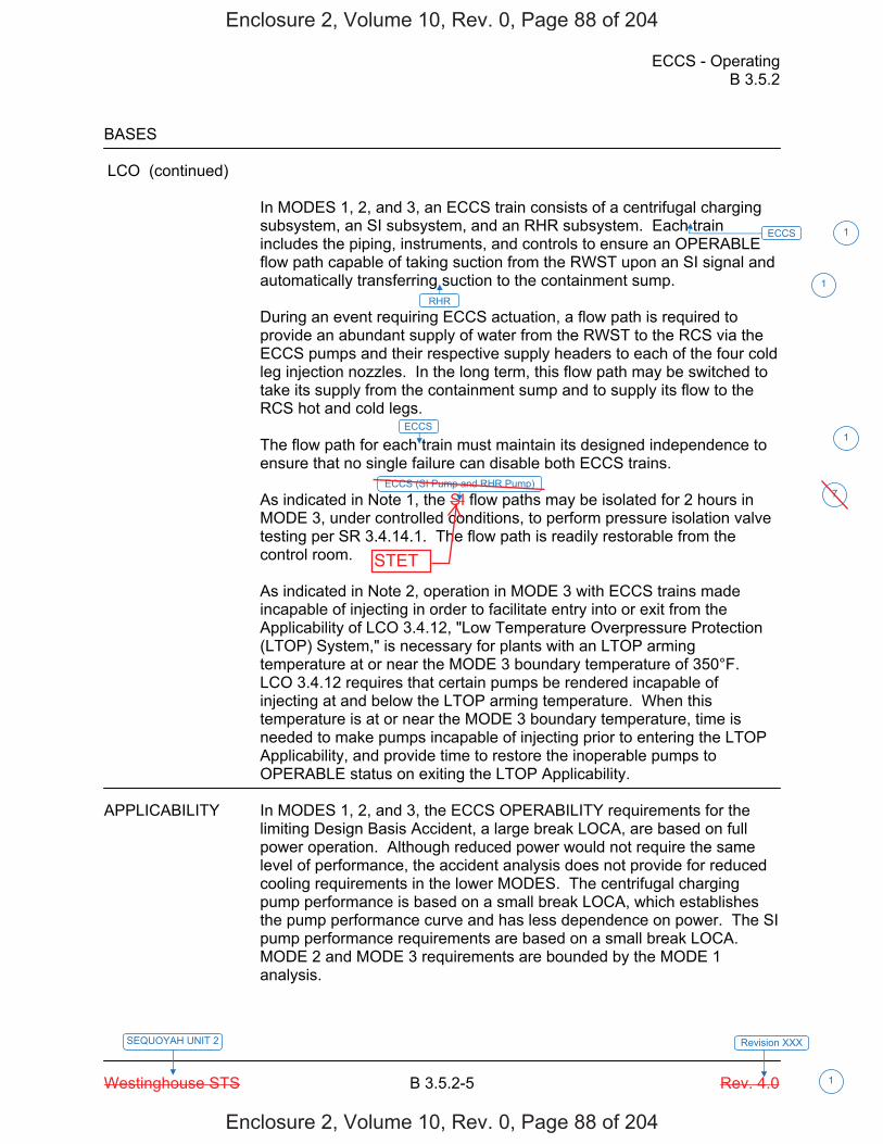
ECCS - Operating B 3.5.2
Westinghouse STS B 3.5.2-5 Rev. 4.0
SEQUOYAH UNIT 2 Revision XXX
1
BASES LCO (continued)
In MODES 1, 2, and 3, an ECCS train consists of a centrifugal charging subsystem, an SI subsystem, and an RHR subsystem. Each train includes the piping, instruments, and controls to ensure an OPERABLE flow path capable of taking suction from the RWST upon an SI signal and automatically transferring suction to the containment sump. During an event requiring ECCS actuation, a flow path is required to provide an abundant supply of water from the RWST to the RCS via the ECCS pumps and their respective supply headers to each of the four cold leg injection nozzles. In the long term, this flow path may be switched to take its supply from the containment sump and to supply its flow to the RCS hot and cold legs. The flow path for each train must maintain its designed independence to ensure that no single failure can disable both ECCS trains. As indicated in Note 1, the SI flow paths may be isolated for 2 hours in MODE 3, under controlled conditions, to perform pressure isolation valve testing per SR 3.4.14.1. The flow path is readily restorable from the control room. As indicated in Note 2, operation in MODE 3 with ECCS trains made incapable of injecting in order to facilitate entry into or exit from the Applicability of LCO 3.4.12, "Low Temperature Overpressure Protection (LTOP) System," is necessary for plants with an LTOP arming temperature at or near the MODE 3 boundary temperature of 350°F. LCO 3.4.12 requires that certain pumps be rendered incapable of injecting at and below the LTOP arming temperature. When this temperature is at or near the MODE 3 boundary temperature, time is needed to make pumps incapable of injecting prior to entering the LTOP Applicability, and provide time to restore the inoperable pumps to OPERABLE status on exiting the LTOP Applicability.
APPLICABILITY In MODES 1, 2, and 3, the ECCS OPERABILITY requirements for the
limiting Design Basis Accident, a large break LOCA, are based on full power operation. Although reduced power would not require the same level of performance, the accident analysis does not provide for reduced cooling requirements in the lower MODES. The centrifugal charging pump performance is based on a small break LOCA, which establishes the pump performance curve and has less dependence on power. The SI pump performance requirements are based on a small break LOCA. MODE 2 and MODE 3 requirements are bounded by the MODE 1 analysis.
ECCS
ECCS1
1
RHR
1
ECCS (SI Pump and RHR Pump) 7
Enclosure 2, Volume 10, Rev. 0, Page 88 of 204
Enclosure 2, Volume 10, Rev. 0, Page 88 of 204
STET
JUSTIFICATION FOR DEVIATIONS ITS 3.5.2 BASES, ECCS OPERATING
Sequoyah Unit 1 and Unit 2 Page 1 of 1
1. Changes are made (additions, deletions, and/or changes) to the ISTS Bases that reflect the plant-specific nomenclature, number, reference, system description, analysis, or licensing basis description.
2. The listed LCOs concern the shutdown cooling function of the RHR System, not the
ECCS function. The Applicability Section has adequately described why ECCS is not needed in MODES 5 and 6, and it is not necessary to describe why normal shutdown cooling is required. Therefore, this inappropriate information has been deleted.
3. ISTS SR 3.5.2.1, ISTS SR 3.5.2.2, ISTS SR 3.5.2.3, ISTS SR 3.5.2.5, ISTS SR 3.5.2.6, ISTS SR 3.5.2.7 and ISTS SR 3.5.2.8 provide two options for controlling the Frequencies of Surveillance Requirements. SQN is proposing to control the Surveillance Frequencies under the Surveillance Frequency Control Program. Therefore, the Frequency for ITS SR 3.5.2.1, SR 3.5.2.2, SR 3.5.2.3, SR 3.5.2.5, SR 3.5.2.6, SR 3.5.2.7 and SR 3.5.2.8 is "In accordance with the Surveillance Frequency Control Program."
4. The Reviewer's Note has been deleted. This information is for the NRC reviewer to be keyed into what is needed to meet this requirement. This Note is not meant to be retained in the final version of the plant specific submittal.
5. The ISTS contains bracketed information and/or values that are generic to Westinghouse vintage plants. The brackets are removed and the proper plant specific information/value is inserted to reflect the current licensing basis.
6. Editorial changes made to enhance clarity/consistency.
7. Changes are made to reflect changes made to the Specification.
Enclosure 2, Volume 10, Rev. 0, Page 95 of 204
Enclosure 2, Volume 10, Rev. 0, Page 95 of 204

Licensee Response/NRC Response/NRC Question ClosureId 340
NRC Question Number KNH-021
Select Application NRC Question Closure
Attachment 1
Attachment 2
Response Statement
Response Date/Time
Closure Statement This question is closed and no further information is required at this time to draft the Safety Evaluation.
Question Closure Date 9/22/2014
Notification Scott BowmanMichelle ConnerKhadijah HemphillAndrew HonLynn MynattRay SchieleRoger Scott
Added By Khadijah Hemphill
Date Added 9/22/2014 10:07 AM
Date Modified
Modified By
Page 1 of 1Sequoyah ITS Conversion Database
9/25/2014https://members.excelservices.com/rai/index.php?requestType=areaItemPrint&itemId=340
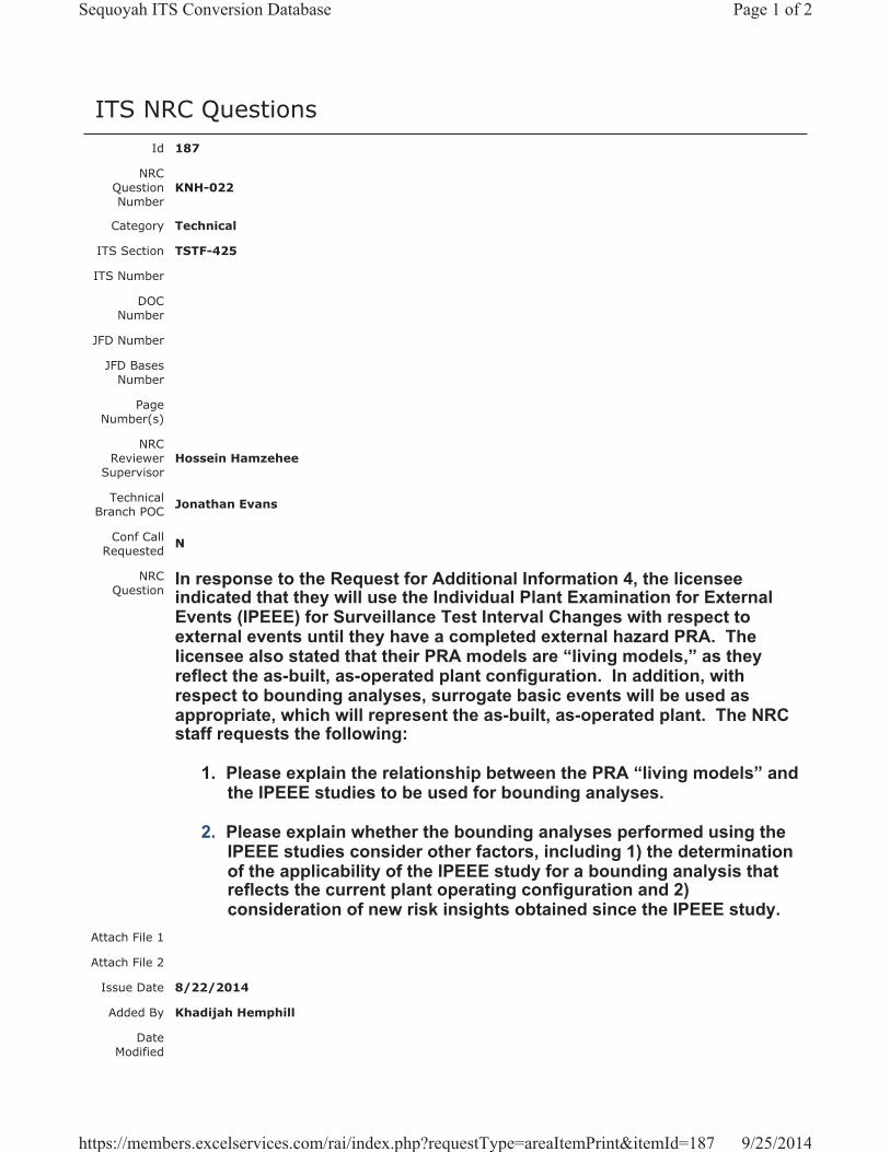
ITS NRC QuestionsId 187
NRC Question Number
KNH-022
Category Technical
ITS Section TSTF-425
ITS Number
DOC Number
JFD Number
JFD Bases Number
Page Number(s)
NRC Reviewer
Supervisor Hossein Hamzehee
Technical Branch POC Jonathan Evans
Conf Call Requested N
NRC Question
In response to the Request for Additional Information 4, the licensee indicated that they will use the Individual Plant Examination for External Events (IPEEE) for Surveillance Test Interval Changes with respect to external events until they have a completed external hazard PRA. The licensee also stated that their PRA models are “living models,” as they reflect the as-built, as-operated plant configuration. In addition, with respect to bounding analyses, surrogate basic events will be used as appropriate, which will represent the as-built, as-operated plant. The NRC staff requests the following:
1. Please explain the relationship between the PRA “living models” and the IPEEE studies to be used for bounding analyses.
2. Please explain whether the bounding analyses performed using the IPEEE studies consider other factors, including 1) the determination of the applicability of the IPEEE study for a bounding analysis that reflects the current plant operating configuration and 2) consideration of new risk insights obtained since the IPEEE study.
Attach File 1
Attach File 2
Issue Date 8/22/2014
Added By Khadijah Hemphill
Date Modified
Page 1 of 2Sequoyah ITS Conversion Database
9/25/2014https://members.excelservices.com/rai/index.php?requestType=areaItemPrint&itemId=187

Modified By
Date Added 8/22/2014 11:37 AM
Notification Scott BowmanMichelle ConnerKhadijah HemphillAndrew HonLynn MynattRay SchieleRoger Scott
Page 2 of 2Sequoyah ITS Conversion Database
9/25/2014https://members.excelservices.com/rai/index.php?requestType=areaItemPrint&itemId=187
Licensee Response/NRC Response/NRC Question ClosureId 339
NRC Question Number
KNH-022
Select Application Licensee Response
Attachment 1
Attachment 2
Response Statement 1. Please refer to previously docketed correspondence (ML13024A010,
Attachment E), “Evaluation of SQN PRA Model,” submitted as part of SQN’s license renewal for discussion on the relationship between the PRA “living model” and the IPEEE studies used for bounding analyses. Additionally, please refer to previously docketed correspondence (ML13227A003), “Response to NRC Request for Additional Information Regarding the Environmental Review of the Sequoyah Nuclear Plant, Units 1 and 2, License Renewal Application” for treatment and applicability of the IPEEE results.
The “external events multiplier” described in ML13024A010 will be used for the characterization of the external events contribution, where appropriate, when performing risk analyses associated with surveillance test interval calculations. An input to the multiplier is the Internal Events CDF of which the Model of Record value will be used and the multiplier recalculated as new revisions to the model are issued. The discussion on external events can be found in the applicable section of Attachment E as follows:
Seismic – §1.3.1Internal Fires – §1.3.2Other External Hazards §1.3.3
2. The SQN IPEEE is similar to other PRAs in the U.S. nuclear fleet with respect to treatment and analysis of external events contribution to plant risk in absence of PRA models for a given initiator. The methods employed in support of the IPEEE to assess seismic, fire and other external hazards were conservative and are judged to be applicable in support of bounding analyses for Risk-Informed Technical Specification Task Force Initiative 5b at SQN. Proposed surveillances for consideration of a risk-informed test interval will be assessed in accordance with the requirements of SQN’s owner controlled program which will contain language that requires a reassessment and documentation of risk-informed surveillance frequencies as new risk insights for external event initiators are available to industry. The Owner Controlled Program will also include language that requires a determination on the applicability of a bounding analysis for each
Page 1 of 3Sequoyah ITS Conversion Database
9/25/2014https://members.excelservices.com/rai/index.php?requestType=areaItemPrint&itemId=339
proposed surveillance frequency calculation. The documentation for the analysis will justify use of bounding analyses with respect to treatment of external events contribution to risk. The process described in NEI 04-10 Rev. 1, “Risk-Informed Method for Control of Surveillance Frequencies” Step 10 will be followed for bounding analyses and applicability. Figure 2 “Evaluation of Total and Cumulative Effect on CDF and LERF” is the process SQN will follow in evaluating proposed surveillance test interval (STI) changes. As can be seen in the diagram, there is a requirement to assess the contribution from each contributor (Seismic, Fire, Flood, etc.) as well as the metrics/criteria for bounding analyses. In accordance with the requirements of Section 10, a person knowledgeable in the scope, level of detail and assumptions used in the Fire Induced Vulnerability Evaluation (FIVE), the Seismic Margins Analysis (SMA), and screening of other hazards, etc., will make the determination of whether those evaluations are applicable to support the STI analysis.Seismic risk was considered in the IPEEE by development of a Seismic Margins Assessment (SMA). Risk insights identified post-IPEEE including the Fukushima Near-Term Task Force Report Recommendation 2.3: Seismic Response Report (refer to TVA’s response to NRC RAI 7.e.ii, ML13227A003) concluded that all components have a High Confidence, Low Probability of Failure (HCLPF) above the 0.3g requirement. As such, SQN is judged to be seismically robust based on the current state of knowledge. Refer to ML13024A010, §E.1.3.1 for additional information with respect to the SQN seismic analysis. The seismic design of SQN will be further evaluated by the ongoing Fukushima project requirements and any additional risk insights subsequent to the IPEEE submittal will be considered in the STI evaluations.Fire risk at SQN was determined by the successive screening methodology referred to as FIVE. The risk impact associated with this analysis is judged to be conservative as it was a screening process and given the fact that design modifications have since been performed; such as hot-short probability mitigation, Appendix R modifications (e.g., cable tray covers, fire wraps, and others) that mitigate the risk of damage due to internal fires. These additional modifications, as well as any other risk insights subsequent to the IPEEE submittal, will be considered a part of the STI evaluations. Refer to ML13024A010, §E.1.3.2 for additional information with respect to the SQN fire analysis.Other external hazards including, high winds, tornados, external flooding, transportation, and nearby industrial facilities were evaluated and documented in the IPEEE. These initiators were screened as less than the threshold of the Standard Review Plan (SRP), therefore, they are not significant contributors to external risk. Any risk insights subsequent to the IPEEE submittal with respect to other external hazards will be considered as part of the STI evaluation. Refer to ML13024A010, §E.1.3.3 for additional information with respect to other SQN external hazards analysis.
Page 2 of 3Sequoyah ITS Conversion Database
9/25/2014https://members.excelservices.com/rai/index.php?requestType=areaItemPrint&itemId=339
Date/Time 9/19/2014 12:05 AM
Closure Statement
Question Closure
Date
Notification Scott BowmanMichelle ConnerKhadijah HemphillAndrew HonRay Schiele
Added By Scott Bowman
Date Added 9/19/2014 11:03 AM
Date Modified
Modified By
Page 3 of 3Sequoyah ITS Conversion Database
9/25/2014https://members.excelservices.com/rai/index.php?requestType=areaItemPrint&itemId=339

Licensee Response/NRC Response/NRC Question ClosureId 341
NRC Question Number KNH-022
Select Application NRC Question Closure
Attachment 1
Attachment 2
Response Statement
Response Date/Time
Closure Statement This question is closed and no further information is required at this time to draft the Safety Evaluation.
Question Closure Date 9/22/2014
Notification Scott BowmanMichelle ConnerKhadijah HemphillAndrew HonLynn MynattRay SchieleRoger Scott
Added By Khadijah Hemphill
Date Added 9/22/2014 10:09 AM
Date Modified
Modified By
Page 1 of 1Sequoyah ITS Conversion Database
9/25/2014https://members.excelservices.com/rai/index.php?requestType=areaItemPrint&itemId=341
ITS NRC QuestionsId 198
NRC Question Number
KNH-023
Category Technical
ITS Section 3.6
ITS Number 3.6.3
DOC Number
JFD Number
JFD Bases Number
Page Number(s)
NRC Reviewer
Supervisor Hossein Hamzehee
Technical Branch POC Jonathan Evans
Conf Call Requested N
NRC Question For Changes related to TSTF-446:
1. In the submittal, the licensee states that they will use TVA procedure NPG-SPP-07.1, “On-Line Risk Management” to meet the Tier 2 requirement to avoid risk-significant plant configurations. However, the licensee does not indicate if this process confirms the conclusions of WCAP-15791. The purpose of Tier 2 evaluation is to ensure that appropriate restrictions will be in place to prevent the occurrence of high-risk configurations. Specifically, the licensee must provide reasonable assurance that risk-significant plant equipment outage configurations will not occur when specific plant equipment is out of service in accordance with the proposed extended CIV CT changes. The licensee would also need to confirm that the assumptions of the Topical Report (TR), addressed by the Tier 2 restrictions listed below, will be validated as part of their program:
Only one CIV will be in maintenance with an extended completion time at any given time, unless the licensee has proposed the additional ISTS LCO 3.6.3 Condition
Page 1 of 2Sequoyah ITS Conversion Database
1/13/2015https://members.excelservices.com/rai/index.php?requestType=areaItemPrint&itemId=198
D in its plant-specific application.
Other CIVs in the penetration flow path shall be checked for proper position before any maintenance or corrective action is performed.
Please explain whether the conclusions and assumptions of the Topical Report concerning Tier 2 requirements will be included the licensee’s plant-specific Tier 2 Requirements.
Attach File 1
Attach File 2
Issue Date 11/18/2014
Added By Khadijah Hemphill
Date Modified
Modified By
Date Added 11/18/2014 5:44 PM
Notification Scott BowmanMichelle ConnerKhadijah HemphillAndrew HonLynn MynattRay SchieleRoger ScottCaroline Tilton
Page 2 of 2Sequoyah ITS Conversion Database
1/13/2015https://members.excelservices.com/rai/index.php?requestType=areaItemPrint&itemId=198
Licensee Response/NRC Response/NRC Question ClosureId 401
NRC Question Number
KNH-023
Select Application Licensee Response
Attachment 1 RAI KNH-023 Attachment 1.pdf (21KB)
Attachment 2
Response Statement
In response to RAI KNH-023, regarding the conclusions and assumptions of the Tier 2 requirements in WCAP-15791, the following information is provided:
1. ISTS 3.6.3 Condition D has been retained in the SQN ITS submittal as ITS 3.6.3 Condition C. ITS 3.6.3 Condition C states, “Two or more penetration flow paths with one containment isolation valve inoperable for reasons other than Conditions E, F, and G.” ITS 3.6.3 Required Action C.1 requires isolating all but one penetration flow path by use of at least one closed and de-activated automatic valve, closed manual valve, or blind flange within 4 hours. (Pages 119 and 133 of Enclosure 2, Volume 11)
2. ITS 3.6.3, Containment Isolation Valves, Discussion of Change, L03 (page 106 of Enclosure 2, Volume 11) Item 3.2.2, Demonstration (Tier 2 Evaluation), states, “TVA has confirmed the conclusion in the TR that no Tier 2 requirements are needed other than a requirement to ensure that before maintenance or corrective maintenance (repair) is performed on a CIV, any other CIVs in the penetration flow path have been checked to ensure that they are in their proper position.
3. SQN ITS submittal, Enclosure 5, Section 4.7.2, Tier 2 Avoidance of Risk-Significant Plant Configurations, states in part, ”TVA procedure NPG-SPP-07.3, ‘Work Activity Risk Management Process’ provides an integrated process for assessing and reducing the likelihood and/or consequences of an adverse event. SQN employs a work management process that utilizes Functional Equipment Groups (FEGs). The grouping qualitatively assessed work activities and components and made logic ties that prevent certain risk-significant plant configurations for being scheduled simultaneously.”
Additionally, during review a typographical error was identified in Enclosure 5, Section 4.7.2. The reference to NPG-SPP-07.1, \"On-Line Risk Management.\" should be \"On-Line Work Management.\" See Attachment 1 for the correction of the title of NPG-SPP-07.1.
Response Date/Time 12/16/2014 3:00 PM
Closure Statement
Question Closure Date
Notification Scott BowmanMichelle ConnerKhadijah HemphillAndrew HonLynn MynattRay SchieleCaroline Tilton
Added By Scott Bowman
Date Added 12/16/2014 1:55 PM
Date Modified
Modified By
Page 1 of 1Sequoyah ITS Conversion Database
1/13/2015https://members.excelservices.com/rai/index.php?requestType=areaItemPrint&itemId=401
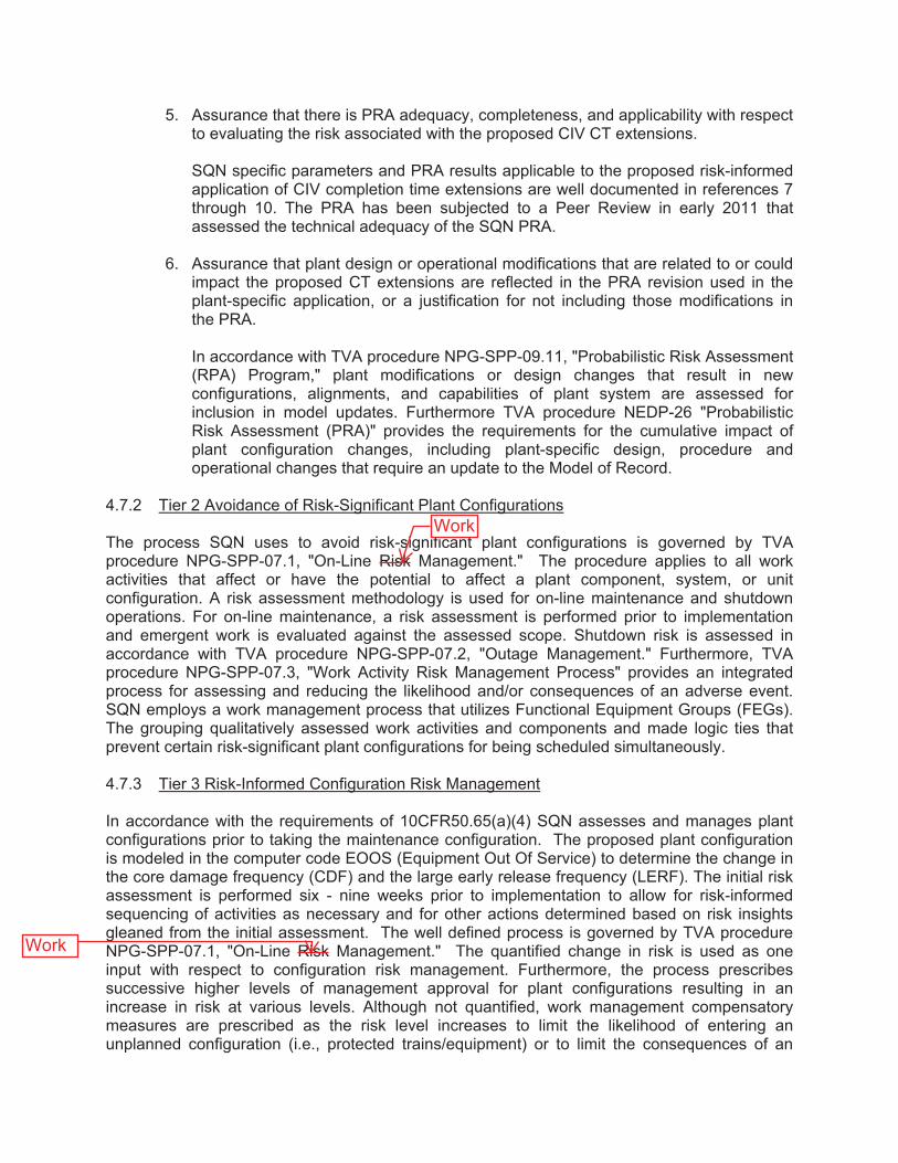
5. Assurance that there is PRA adequacy, completeness, and applicability with respect to evaluating the risk associated with the proposed CIV CT extensions. SQN specific parameters and PRA results applicable to the proposed risk-informed application of CIV completion time extensions are well documented in references 7 through 10. The PRA has been subjected to a Peer Review in early 2011 that assessed the technical adequacy of the SQN PRA.
6. Assurance that plant design or operational modifications that are related to or could impact the proposed CT extensions are reflected in the PRA revision used in the plant-specific application, or a justification for not including those modifications in the PRA. In accordance with TVA procedure NPG-SPP-09.11, "Probabilistic Risk Assessment (RPA) Program," plant modifications or design changes that result in new configurations, alignments, and capabilities of plant system are assessed for inclusion in model updates. Furthermore TVA procedure NEDP-26 "Probabilistic Risk Assessment (PRA)" provides the requirements for the cumulative impact of plant configuration changes, including plant-specific design, procedure and operational changes that require an update to the Model of Record.
4.7.2 Tier 2 Avoidance of Risk-Significant Plant Configurations The process SQN uses to avoid risk-significant plant configurations is governed by TVA procedure NPG-SPP-07.1, "On-Line Risk Management." The procedure applies to all work activities that affect or have the potential to affect a plant component, system, or unit configuration. A risk assessment methodology is used for on-line maintenance and shutdown operations. For on-line maintenance, a risk assessment is performed prior to implementation and emergent work is evaluated against the assessed scope. Shutdown risk is assessed in accordance with TVA procedure NPG-SPP-07.2, "Outage Management." Furthermore, TVA procedure NPG-SPP-07.3, "Work Activity Risk Management Process" provides an integrated process for assessing and reducing the likelihood and/or consequences of an adverse event. SQN employs a work management process that utilizes Functional Equipment Groups (FEGs). The grouping qualitatively assessed work activities and components and made logic ties that prevent certain risk-significant plant configurations for being scheduled simultaneously.
4.7.3 Tier 3 Risk-Informed Configuration Risk Management In accordance with the requirements of 10CFR50.65(a)(4) SQN assesses and manages plant configurations prior to taking the maintenance configuration. The proposed plant configuration is modeled in the computer code EOOS (Equipment Out Of Service) to determine the change in the core damage frequency (CDF) and the large early release frequency (LERF). The initial risk assessment is performed six - nine weeks prior to implementation to allow for risk-informed sequencing of activities as necessary and for other actions determined based on risk insights gleaned from the initial assessment. The well defined process is governed by TVA procedure NPG-SPP-07.1, "On-Line Risk Management." The quantified change in risk is used as one input with respect to configuration risk management. Furthermore, the process prescribes successive higher levels of management approval for plant configurations resulting in an increase in risk at various levels. Although not quantified, work management compensatory measures are prescribed as the risk level increases to limit the likelihood of entering an unplanned configuration (i.e., protected trains/equipment) or to limit the consequences of an
Work
Work

Licensee Response/NRC Response/NRC Question ClosureId 412
NRC Question Number KNH-023
Select Application NRC Question Closure
Attachment 1
Attachment 2
Response Statement
Response Date/Time
Closure Statement This question is closed and no further information is required at this time to draft the Safety Evaluation.
Question Closure Date 12/30/2014
Notification Scott BowmanMichelle ConnerKhadijah HemphillAndrew HonLynn MynattRay SchieleRoger Scott
Added By Khadijah Hemphill
Date Added 12/30/2014 10:58 AM
Date Modified
Modified By
Page 1 of 1Sequoyah ITS Conversion Database
1/13/2015https://members.excelservices.com/rai/index.php?requestType=areaItemPrint&itemId=412
ITS NRC QuestionsId 199
NRC Question Number
KNH-024
Category Technical
ITS Section 3.6
ITS Number 3.6.3
DOC Number
JFD Number
JFD Bases Number
Page Number(s)
NRC Reviewer
Supervisor Hossein Hamzehee
Technical Branch POC Jonathan Evans
Conf Call Requested N
NRC Question
For changes related to TSTF-446:
The submittal states that “Group/Calc # III-A-12BC, III-A-13, III-A-14, II-A-X17, II-B-X44, II-A-BOUNDING do not match generic configurations of the WCAP and have been analyzed and CT times determined using SQN specific configurations and SQN specific PRA values.” It is not clear how the plant-specific analysis was performed for the Group/Calc # that did not match generic configurations of the WCAP.
Please explain how the licensee performed plant-specific Completion Time calculations for the CIV configurations.
Attach File 1
Attach File 2
Issue Date 11/18/2014
Added By Khadijah Hemphill
Date Modified
Modified By
Date Added 11/18/2014 5:48 PM
Notification Scott BowmanMichelle ConnerKhadijah HemphillAndrew HonLynn MynattRay SchieleRoger ScottCaroline Tilton
Page 1 of 1Sequoyah ITS Conversion Database
3/16/2015https://members.excelservices.com/rai/index.php?requestType=areaItemPrint&itemId=199
Licensee Response/NRC Response/NRC Question ClosureId 418
NRC Question Number
KNH-024
Select Application Licensee Response
Attachment 1
Attachment 2
Response Statement RAI-KNH-024
The submittal states that “Group/Calc # III-A-12BC, III-A-13, III-A-14, II-A-X17, II-B-X44, II-A-BOUNDING do not match generic configurations of the WCAP and have been analyzed and CT times determined using SQN specific configurations and SQN specific PRA values.” It is not clear how the plant-specific analysis was performed for the Group/Calc # that did not match generic configurations of the WCAP.
Please explain how the licensee performed plant-specific Completion Time calculations for the CIV configurations.
TVA Response
SQN followed a similar process as the penetration classification methodology used for the generic analyses described by WCAP-15791, “Risk-Informed Evaluation of Extension to Containment Isolation Valve Completion Times,” that was endorsed by the NRC staff as documented in the Safety Evaluation of WCAP-15791-P-A, Revision 2 (ADAMS Accession No. ML080170680). The NRC Safety Evaluation concluded that the topical report provides guidance to assist licensees in evaluating changes to containment isolation valve (CIV) completion times (CTs) and includes methodologies for generic and plant-specific analyses.
The following explains the process employed for SQN:
SQN specific parameters and/or updated industry data were used for the valve types in consideration. The Tier 1 approach used in the generic analysis was conservative, and therefore, applicable to Westinghouse Owner’s Group plants, including SQN, Units 1 and 2. Where appropriate, the plant-specific
Page 1 of 5Sequoyah ITS Conversion Database
3/24/2015https://members.excelservices.com/rai/index.php?requestType=areaItemPrint&itemId=418
analysis removed over-conservatisms. The analysis of the penetrations listed in RAI KNH-024 followed the approach described in Sections 8.2 and 8.3 of WCAP-15791. The generic analysis data provided in WCAP-15791 was replaced by SQN specific data to potentionally justify an increase in the CT provided for the generic calculation similar to the lead plant analysis in Section 10.
The data used is documented in Enclosure 5 of the ITS license amendment request (LAR) in the following tables:
Table 4-1 Core Damage Frequencies Table 4-2 Valve Fail-to-Close and Valve Fail-to-Reseat ProbabilitiesTable 4-3 Generic and SQN Specific Beta, Gamma FactorsTable 4-4 Spurious Open and Beta Factor ValuesTable 4-5 Additional Inputs
The plant-specific approach is described in Section 4.5 of Enclosure 5 of the ITS LAR and is summarized as follows:
A determination is made with respect to the penetration class applicable to the given penetration.
Class I – flow paths connected to the containment atmosphereClass II – flow paths connected to the Reactor Coolant SystemClass III – flow paths connected to the steam generators
Secondly, the grouping for the system applicable to the penetration of interest is determined, e.g., standby or normally running.
Based on the class and grouping, the potential release paths considered in the analysis are determined, e.g., non-seismic, seismic, random pipe break, etc. Section 4.8.2, “Calculations/Inputs,” of Enclosure 5 to the ITS LAR describes the release types to consider and the inputs for each class and group. For each penetration, the type and number of valves are defined and a determination whether common cause failure (CCF) should be included. Characterization of whether the pressure boundary is maintained or not-maintained is considered. The pressure boundary “not-maintained”configuration bounds the pressure boundary “maintained”
Page 2 of 5Sequoyah ITS Conversion Database
3/24/2015https://members.excelservices.com/rai/index.php?requestType=areaItemPrint&itemId=418
configuration.
An incremental conditional large early release probability (ICLERP) is calculated for each of the release types associated with the penetration class. The generic core damage frequency (CDF) associated with each release type is multiplied by the probability of the event and the valve failure probability. The result for each release type is summed to obtain an overall probability. Initially, a 168-hour window of vulnerability is used and if the sum of the release types meets the ICLERP acceptance criterion of 5.0E-08 from Regulatory Guide (RG) 1.177, Revision 0, the 168-hour window is then used in the delta large early release frequency ( LERF) calculation. If 168 hours results in > 5.0E-08, the process is repeated using successively less hours, e.g., 72-hr, 48-hr, etc., until the acceptance criterion is met.
The LERF is calculated to determine the limiting CT for meeting the acceptance criteria from RG 1.174, Revision 0. For
LERF, the configuration is modeled using computer-aided fault tree analysis (CAFTA) to determine the probability that a penetration is not isolated based on the number of isolation valves, their type, position, etc. and given failure likelihoods taken from plant-specific data. CCF is included when applicable to the configuration. The model is solved for the CT of interest (based on the ICLERP) and the current licensing basis CT of 4 hours. The delta represents the increase in risk associated with the proposed CT over the current 4-hour CT.
The maximum CT to isolate a penetration is selected based on the more limiting of the ICLERP and the LERF.
The following explains the analyses of the penetrations listed in the RAI.
Penetrations III-A-X12BC and III-A-X13 are connected to the secondary side of the steam generator; therefore they are characterized as Class III. Also, these penetrations are connected to the outside environment thus are categorized as Group A. The balance of the penetration nomenclature represents the penetration numbers.
The Class III, Group A penetrations were analyzed for release types; seismic, random pipe break, and steam generator tube
Page 3 of 5Sequoyah ITS Conversion Database
3/24/2015https://members.excelservices.com/rai/index.php?requestType=areaItemPrint&itemId=418
rupture (SGTR). If an analysis does not take credit for isolation capability for a given release type, a bounding valve failure probability of 1.0 was used; otherwise, the probability associated with the specific valve type is used. A bounding calculation is represented by the sum of the three individual release types and based on the duration to obtain a ICLERP less than the RG 1.177 acceptance criterion of 5.0E-08. The result of the analysis for Class III Group A penetrations is 4.69E-08 and meets the acceptance criterion based on an 8 hour CT.
The change in risk ( LERF) for extending the CT from the current licensing basis of 4 hours to the proposed CT of 8 hours is determined by modeling the penetration configuration in CAFTA and solving the top gate for both durations. The delta is multiplied by the CDF associated with each release type and probability of the release. For Class III Group A, the seismic, random pipe break, and SGTR release types are calculated individually and then summed to obtain the overall LERF. The sum of the release types, based on an 8-hour CT for Class III Group A is 1.5E-10/yr, which meets the RG 1.174 acceptance criterion of < 1.0E-07/yr.
Penetrations II-A-X17, II-A-BOUNDING and II-B-X44 are connected to the Reactor Coolant System; therefore, they are characterized as Class II. Group A represents standby system CIVs and Group B represents CIVs for normally operating systems. The balance of the penetration nomenclature represents the penetration number.
Class II penetrations were analyzed for seismic, non-seismic, random pipe break, and Interfacing System Loss of Coolant Accident release paths. The same process as described for the Class III penetrations was used for determination of ICLERP and LERF.
The II-A-BOUNDING analysis differs only in that the valve failure probability is assumed as 1.0 to bound all possible valve types.
Note: At the time of the SQN ITS LAR submittal, more recent revisions of RGs 1.174 and 1.177 were approved for use; however, the RG revisions referenced in WCAP-15791-P-A were both Revision 0 of the guides. In terms of the metrics
Page 4 of 5Sequoyah ITS Conversion Database
3/24/2015https://members.excelservices.com/rai/index.php?requestType=areaItemPrint&itemId=418
used, the Revision 0 values are the same or more restrictive than the values in the currently approved revisions of these RGs; and therefore, the calculated ICLERP and LERF are bounded.
Response Date/Time 1/9/2015 12:30 PM
Closure Statement
Question Closure
Date
Notification Scott BowmanMichelle ConnerKhadijah HemphillAndrew HonLynn MynattRay SchieleCaroline Tilton
Added By Scott Bowman
Date Added 1/9/2015 11:31 AM
Date Modified
Modified By
Page 5 of 5Sequoyah ITS Conversion Database
3/24/2015https://members.excelservices.com/rai/index.php?requestType=areaItemPrint&itemId=418

Licensee Response/NRC Response/NRC Question ClosureId 420
NRC Question Number KNH-024
Select Application NRC Question Closure
Attachment 1
Attachment 2
Response Statement
Response Date/Time
Closure Statement This question is closed and no further information is required at this time to draft the Safety Evaluation.
Question Closure Date 1/20/2015
Notification Scott BowmanMichelle ConnerKhadijah HemphillAndrew HonLynn MynattRay SchieleRoger Scott
Added By Khadijah Hemphill
Date Added 1/20/2015 6:50 AM
Date Modified
Modified By
Page 1 of 1Sequoyah ITS Conversion Database
3/16/2015https://members.excelservices.com/rai/index.php?requestType=areaItemPrint&itemId=420
ITS NRC QuestionsId 200
NRC Question Number
KNH-025
Category Technical
ITS Section 3.6
ITS Number 3.6.3
DOC Number
JFD Number
JFD Bases Number
Page Number(s)
NRC Reviewer
Supervisor Hossein Hamzehee
Technical Branch POC Jonathan Evans
Conf Call Requested N
NRC Question
For changes related to TSTF-446:
In the submittal, the licensee did not fully describe the scope of the plant-specific PRA and its technical adequacy for performing a Tier 3 evaluation. In Regulatory Position 4.2 of RG 1.200, the NRC staff stated that it expects licensees to submit a discussion of the resolution of the peer review findings that are applicable to the parts of the PRA required for the application.
a. Please provide the Facts and Observations and their resolutions that are applicable to the generic analysis and associated completion times included in this submittal.
b. Explain whether the licensee has a PRA configuration control and updating process (including PRA quality assurance program, associated procedures, and PRA revision schedules).
Attach File 1
Attach File 2
Issue Date 11/18/2014
Page 1 of 2Sequoyah ITS Conversion Database
3/16/2015https://members.excelservices.com/rai/index.php?requestType=areaItemPrint&itemId=200
Added By Khadijah Hemphill
Date Modified
Modified By
Date Added 11/18/2014 5:50 PM
Notification Scott BowmanMichelle ConnerKhadijah HemphillAndrew HonLynn MynattRay SchieleRoger ScottCaroline Tilton
Page 2 of 2Sequoyah ITS Conversion Database
3/16/2015https://members.excelservices.com/rai/index.php?requestType=areaItemPrint&itemId=200
Licensee Response/NRC Response/NRC Question ClosureId 422
NRC Question Number
KNH-025
Select Application Licensee Response
Attachment 1
Attachment 2
Response Statement RAI KNH-025
In the submittal, the licensee did not fully describe the scope of the plant-specific PRA and its technical adequacy for performing a Tier 3 evaluation. In Regulatory Position 4.2 of RG 1.200, the NRC staff stated that it expects licensees to submit a discussion of the resolution of the peer review findings that are applicable to the parts of the PRA required for the application.
a. Please provide the Facts and Observations and their resolutions that are applicable to the generic analysis and associated completion times included in this submittal.
b. Explain whether the licensee has a PRA configuration control and updating process (including PRA quality assurance program, associated procedures, and PRA revision schedules).
TVA Response
a. The aspect of the PRA applicable to the generic analysis and associated completion times is the SQN data used in the analyses or used to bound the generic analysis. Facts and Observations (F&Os) associated with this aspect of the SQN PRA are 2-4, 2-5, 2-6, 2-7, 4-9, 4 10, 4-11, 4-12 and 4-13. Another attribute of the generic analysis is the selection of the
Page 1 of 17Sequoyah ITS Conversion Database
3/16/2015https://members.excelservices.com/rai/index.php?requestType=areaItemPrint&itemId=422
containment hole size with respect to characterizing postulated leakage, for this attribute, F&O 3-1 applies.
Following are the F&Os discussed above, as well as, their resolutions.
F&O 2-4 (Finding)Appendix F of the Data Analysis notebook provides graphs that show the prior and posterior distributions. Table 19 lists generic and Bayesian-updated mean values, along with a ratio of the posterior to prior mean value. However, there are no conclusions drawn about whether or not the posterior distributions are reasonable given the relative weight of evidence provided by the prior and the plant-specific data. (Note: the statement that "There are no significant differences between the industry data from NUREG/CR-6928 and the posterior distributions for the SQN failure rates" in section 11.0 is not judged to be sufficient. For example, the ratio of the posterior to prior mean for the AHUFR [air handling unit (standby) fails to run] type code in Table 19 is 10.6. For type code LSTFR [level sensor/level transmitter fails to operate], the ratio is 4.3. The significance of these differences should be discussed.)
(This F&O originated from SR [supporting requirement] DA-D4)
Associated SRs:DA-D4, DA-E2
Basis for SignificanceThe reasonableness check needs to assess whether the Bayesian updates yield expected results given the relative weight of evidence provided by the prior and the plant-specific data.
Possible Resolution
Page 2 of 17Sequoyah ITS Conversion Database
3/16/2015https://members.excelservices.com/rai/index.php?requestType=areaItemPrint&itemId=422
Discuss the observed differences in the prior and posterior distributions and draw conclusions on the significance associated with those differences.
F&O 2-4 SQN Response/ResolutionThe posterior distributions were validated using the following process. Using a Monte Carlo simulation, the posterior distributions were sample[d] to see the probability of having a recurrence in the number of events observed in the data window given the number of successes in the data window. If the mean value was within 0.05 to 0.95 the resultant distribution was used within the model.
Appendix F of the Data Analysis notebook was re-written to address this analysis as well as to present the prior, posterior, and plant specific distributions.
F&O 2-5 (Finding)The method from NUREG/CR-6823 is used to Bayesian-update a Jeffreys noninformative prior distribution with plant-specific experience. However, there is no comparison of the posterior means to plant-specific means. (See the last sentence in NUREG/CR-6823, section 6.7.1.2.).
(This F&O originated from SR DA-D4)
Associated SRs: DA-D4, DA-E2
Basis for SignificanceA reasonableness check should be performed to assure the Bayesian-updated maintenance unavailabilities yield expected results when compared to plant-specific mean values given the amount of plant-specific data.
Possible ResolutionCompare the Bayesian-updated maintenance
Page 3 of 17Sequoyah ITS Conversion Database
3/16/2015https://members.excelservices.com/rai/index.php?requestType=areaItemPrint&itemId=422
unavailabilities to plant-specific mean values, discuss the observed differences and draw conclusions on the significance associated with those differences.
F&O 2-5 SQN Response/ResolutionThe fundamental assumption used in the Bayesian update process described in the Data Analysis notebook for unavailability calculations is that there is no prior information from which to Bayesian update. Therefore, the methodology used a Jefferys non-informative prior (0.5) as the foundation for the update process. All of the available data that was used was from plant specific data collection, therefore the posterior mean and plant specific mean are directly correlated. The following assumption was added to Section 3.0 to address the non-informative prior.
"For unavailability calculations, a Jefferys non-informative prior was used as there was no informative prior information available."
F&O 2-6 (Suggestion)No modifications to plant design or operating practices were identified that lead to a condition where past data are no longer representative of current performance. Thus limiting the use of old data was not required. However, for completeness, it is suggested that the data analysis document the consideration of this supporting requirement.
(This F&O originated from SR DA-D8)
Associated SRs:DA-D8, DA-E2
Basis for SignificanceNo documentation addressing this supporting requirement was identified.
Page 4 of 17Sequoyah ITS Conversion Database
3/16/2015https://members.excelservices.com/rai/index.php?requestType=areaItemPrint&itemId=422
Possible ResolutionDocument a consideration of modifications to plant design or operating practices that could lead to a condition where past data are no longer representative of current performance in the Data Analysis notebook.
F&O 2-6 SQN Response/Resolution
Section 7.2.1 was added to the data analysis notebook to address plant design changes.
F&O 2-7 (Suggestion)The data analysis aligns well with the PRA Standard requirements and is generally well-documented.Adding a 'roadmap' to the PRA Standard data SRs - as was done elsewhere in the PRA documentation -would enhance the performance of PRA applications, upgrades, and peer review.
(This F&O originated from SR DA-E1)
Associated SR: DA-E1
Basis for SignificanceAdding a 'roadmap' to the PRA Standard data SRs would enhance the performance of PRA applications, upgrades, and peer review.
Possible ResolutionIn the Data Analysis notebook, add a 'roadmap' to the PRA Standard data SRs.
F&O 2-7 SQN Response/ResolutionAppendix K was added to the Data Analysis notebook to address the ASME/ANS standard sections.
F&O 3-1 (Finding)
Page 5 of 17Sequoyah ITS Conversion Database
3/16/2015https://members.excelservices.com/rai/index.php?requestType=areaItemPrint&itemId=422
Section 4.5, “The calculation above provides that the containment ‘hole’ size must lie between a 1 inch equivalent path and a 4 inch path. Therefore, it is acceptable to use the NRC value of 2 inches.” Based on the statement, the 1” equivalent hole should have been considered.
(This F&O originated from SR LE-D7)
Associated SRs:LE-D7
Basis for SignificanceIt is unknown what the applicable break size is between 1" and 4," therefore the conservative approach is to use 1."
Possible ResolutionPerform detailed analysis to ensure the use of the 2" equivalent hole is allowable or use 1" and include the additional penetrations in the containment isolation analysis.
F&O 3-1 SQN Response/ResolutionSection 4.4 of the Level 2 Analysis discusses the reasoning for concluding that the 2” hole size is acceptable for use in the Sequoyah level 2 analysis.The calculation shows that the release rate represented by a vent line diameter greater than 1”and slightly less than 2” corresponds to a pressure approximately half of the assumed severe containment challenge pressure that is slightly below the 2” contour line shown in the Severe Accident Management Guidelines (SAMG) Setpoints and Computational Aids calculation. There is conservatism built into both the assumed containment failure pressure and the assumed leak rates at that pressure; therefore, it is judged appropriate to use 2” as the bounding value for a large leak rate.
Page 6 of 17Sequoyah ITS Conversion Database
3/16/2015https://members.excelservices.com/rai/index.php?requestType=areaItemPrint&itemId=422
F&O 4-9 (Suggestion)Appropriate generic data sources appear to be used in the SN PRA, as documented in the data analysis notebook (MDN-000-000-2010-0202). Component failure rates are taken primarily from NUREG/CR-6928 (with other sources used in cases in which data for specific component types are not available).Common cause data is obtained from recent NRC (INEL) and PWROG [Pressurized Water Reactor Owners Group] data sources. Offsite power recovery data is obtained from NUREG/CR-6890. Component recovery is not used. Table 2 and Appendix A describe the boundaries assumed for each major component type.
The SQN PRA makes use of generic unavailability data from NUREG/CR-6928 for components for which plant-specific data is unavailable (as noted in Table 8). It is assumed (see Assumption 1 in the data notebook) that all generic data is applicable to SQN; however, since this SR requires that the consistency of the SQN practices and philosophies be checked against the generic data source assumptions, additional documentation needs to be provided to better meet the requirements of this SR. It is recognized that assumption 1 is listed as an important uncertainty and is discussed in the Uncertainties notebook (MDN-000-000-2010-0209). However, since the unique attributes concerning the use of generic unavailability data are not discussed, adding an additional assumption item for this issue may be appropriate.
(This F&O originated from SR DA-C1)
Associated SRs: DA-C1, DA-E2
Basis for SignificanceThis is considered to be a suggestion as it pertains primarily to a documentation enhancement. The use
Page 7 of 17Sequoyah ITS Conversion Database
3/16/2015https://members.excelservices.com/rai/index.php?requestType=areaItemPrint&itemId=422
of generic unavailability estimates for some plant components is probably acceptable; however documentation of the basis for accepting this data as appropriate to SQN is required.
Possible ResolutionEnhance the documentation in section 6.2 to better describe the acceptability of the generic estimates for SQN. Consideration should be given to specifically identifying this generic data use as an important assumption in the Uncertainties notebook (MDN-000-000-2010-0209) as well. That notebook has an overall item concerning the use of generic data; however, a specific item for the use of generic unavailability data could also be added.
F&O 4-9 SQN Response/ResolutionA discussion of the component boundaries was added to the Data Analysis notebook. Section 4.2 of the notebook defines system and component boundaries and lists them in Table 2. Generic component failure data and parametric estimations are discussed in Section 6.1 and presented in Table 7. The generic values were typically collected from NUREG/CR-6928. However, where data was not available, other
sources were used and listed in Table 7. Generic unavailabilities are discussed in Section 6.2. For components that have unavailability tracked by the system engineer or the maintenance rule program, the SQN specific data is used in the analysis; however, if not available, generic unavailability from NUREG/CR-6928 was used. Generic unavailability data is presented in Table 8.
F&O 4-10 (Suggestion)Failure data records are obtained from the plant's Cause Determination and Evaluation (CDE) records that are prepared by system engineers in response to failure events. The guidance for CDE development in plant procedure SPP-6.6 describes bases for failures,
Page 8 of 17Sequoyah ITS Conversion Database
3/16/2015https://members.excelservices.com/rai/index.php?requestType=areaItemPrint&itemId=422
discusses degraded conditions, and notes that Technical Specification failures or operability issues are not automatically Maintenance Rule functional failures (or PRA failures).
The CDE records are also then reviewed by the PRA staff to determine if a PRA failure has occurred. The CDEs that were used in the data analysis are included in Appendix D of the data notebook (MDN-000-000-2010-0202).
Because there are several DA-C SRs that specify requirements for the data collection and analysis process, it is suggested that the data analysis documentation be enhanced to specifically note these requirements and how they are met, especially since the other plant procedures do not specifically state these requirements (since the procedures are for system engineers and other non-PRA personnel). This F&O originated from SR DA-C4
Associated SRs: DA-C4, DA-C5, DA-C11, DA-C12, DA-C13, DA-E2
Basis for SignificanceThis is a suggestion since it pertains to enhancing the documentation to place all of the data analysis ground rules within the data notebook for clarity.
Possible ResolutionEnhance the data analysis notebook to specifically list the data collection requirements for DA-C4, C5, C6, C11, C12, and C13.
F&O 4-10 SQN Response/ResolutionDA-C4, Functional failures are determined based on the system engineer and maintenance rule expert panel. These determinations are outlined in NPG-SPP-03.4, Maintenance Rule Performance Indicator Monitoring, Trending and Reporting – 10 CFR 50.65,
Page 9 of 17Sequoyah ITS Conversion Database
3/16/2015https://members.excelservices.com/rai/index.php?requestType=areaItemPrint&itemId=422
and are only made by a qualified individual.
DA-C5, There was an identified event where multiple repeat failures occurred within the same time. Each of these events was assigned a specific CDE, however as noted in the documentation of CDE 1615 the three events were all assigned to one failure event in the PRA model.DA-C11, Unavailability is defined in the maintenance rule technical instruction TI-4. The definition presented states that unavailability is only counted while at power (mode 1), additionally, in the definition, unavailability is credited when the component would not be able to perform its designed function.
DA-C12, The definition of the component boundaries for tracking unavailability are documented in TI-4, Maintenance Rule Performance Indicator Monitoring, Trending, and Reporting – 10CFR50.65. For frontline systems only front line impacts are assigned to that system. If the ERCW header or other multi-system impact components are unavailable then the unavailability is tracked at that level.
DA-C13, For all significant unavailabilities, start and finish times are accurately documented in the maintenance rule spreadsheets.
F&O 4-11 (Finding)While the PRA model considers the possibility of two PORVs [power operated relief valves] being blocked at the same time, there does not appear to have been an investigation of whether coincident maintenance can occur in the various SQN systems (or if coincident inter-system maintenance can occur). Therefore this SR is not met.
It was also observed that the PORV blocking basis events noted above did not appear to be documented
Page 10 of 17Sequoyah ITS Conversion Database
3/16/2015https://members.excelservices.com/rai/index.php?requestType=areaItemPrint&itemId=422
in either the data notebook or the appropriate system notebook.
(This F&O originated from SQ DA-C14)
Associated SRs:DA-C14
Basis for SignificanceThis is a finding since the technical requirements of the SR are not met.
Possible ResolutionA study should be conducted to determine if coincident maintenance conditions can occur. If so, the system models may need to be modified and additional basic events to represent the coincident maintenance states would need to be added. If it is determined that no coincident maintenance can occur, then this should be documented in the data notebook or within the system notebooks.
Documentation for the calculation of the time that either one or both PORVs can be blocked should also be added to either the system notebook or the data notebook.
F&O 4-11 SQN Response/ResolutionThe following was added to the data analysis notebook to address coincident maintenance:
Coincident maintenance is scheduling maintenance where multiple SSCs [systems, structures, and components] are out of service at the same time. Specifically components on the same train, RHR [residual heat removal] train A and SI [safety injection] train A for example, being out of service for maintenance at the same time. The Outage and Site Scheduling Directive Manual 1.0 (Reference 28) dictates that:
Page 11 of 17Sequoyah ITS Conversion Database
3/16/2015https://members.excelservices.com/rai/index.php?requestType=areaItemPrint&itemId=422
Twelve (12) week schedule by FEG [functional equipment group] groups ensures that within a train week, no two (2) accident mitigating devices are removed from service at the same time [i.e., “A” train Residual Heat Removal (RHR) is not removed from service at the same time as “A” train Containment Spray.]
This requirement is further discussed in the Outage and Site Scheduling Directive Manual 4.7 (Reference 29) which states that any systems important to PRA that are unavailable at the same time must meet the requirements [SIC] of the plant risk matrix. Normally maintenance on any systems important to the PRA is not scheduled at the same time. If it is these instances are extremely rare and the current model does not exclude coincident maintenance events from appearing in a single cutset. Therefore the probability of having coincident maintenance events is extremely rare and accounted for during the normal cutset processing.
F&O 4-12 (Suggestion)Surveillance testing intervals are used for only a subset of the components for which operating data is calculated. For those using the surveillance testing intervals, the data notebook (MDN-000-000-2010-0202, section 7.3.4) does not indicate that a review of the surveillance test procedures was performed to determine if all sub-elements were tested on the same frequency. Therefore the Category I requirements are satisfied for this SR.
(This F&O originated from SR DA-C10)
Associated SR: DA-C10
Basis for SignificanceThis is considered a suggestion, since Category I is met and may be adequate for most applications. It is
Page 12 of 17Sequoyah ITS Conversion Database
3/16/2015https://members.excelservices.com/rai/index.php?requestType=areaItemPrint&itemId=422
unlikely that the data estimates will change as a result of fully meeting the Category II requirements.
Possible ResolutionTo meet category II requirements, the specific surveillance procedures that are credited in section 7.3.4 should be reviewed to confirm that the components for which demands or run time are being estimated are being properly exercised within each procedure. This review should be documented in the data notebook.
F&O 4-12 SQN Response/ResolutionFour procedures were used to derive success data. In order for these procedures to be valid tests, each was reviewed to ensure that the function of the surveillance or test procedure actually tested all portions of the component within the component boundary.
For ACPFR [auxiliary compressor (standby) fails to run] surveillance instruction 0-SI-SXV-032-200.A (Reference 25) and 0-SI-SXV-032-200.B (Reference 26) were used to estimate the number of hours in operation in the data window. Each of these procedures requires the compressor to be in full operation for an extended period of time to assure adequate cooling to the compressor. Therefore these procedures are acceptable for use in calculating the number of run hours for ACPFR.
For AOAFC [air operated valve (air system) fails to close] the surveillance instructions 1-SI-SXV-000-201.0 (Reference 27) and 2-SI-SXV-032-201.0 (Reference 28) were reviewed. These instructions require the valves to close within their acceptance criteria and require the complete valve to operate.Therefore these procedures are acceptable for use in calculating the number of demands for AOAFC.
Page 13 of 17Sequoyah ITS Conversion Database
3/16/2015https://members.excelservices.com/rai/index.php?requestType=areaItemPrint&itemId=422
F&O 4-13 (Suggestion)The PRA model currently uses flag events [to] indicate which standby component is running. It was noted that these flags could be set to zero or one (TRUE or FALSE during quantification) as in the ERCW [essential raw cooling water] system, or could be set to an appropriate split fraction to reflect the percentage of time each component was running as was done in the CCS [component cooling system] system. (The base PRA model solution appears to assume a specific set of components are running or in standby, with the exception of CCS, which assumes a 50%/50% likelihood of each train running.) The “mixing” of assumed configurations with probabilistic configurations should be re-examined. For CCS, the split fractions are based on assumptions based on system design, but are reviewed by the system engineers for accuracy. However, operational data is not reviewed to determine the specific split fractions for each component. Therefore, the requirements of Category I for SR DA-C8 are met.
(This F&O originated from SR DA-C8)
Associated SRs: IE-A6, IE-C10, DA-C8
Basis for SignificanceThis is considered to be a suggestion, as Category I of DA-C8 is met and this should be adequate for most applications. The determination of more precise split fractions (e.g., 54% and 46% vs. an assumed 50%/50% split) would not impact the overall PRA results significantly.
Possible ResolutionTo meet Category II, collect operating data to determine the actual standby/running fractions for plant equipment. This data could be documented either in each system notebook or in the data notebook. Consideration should also be given to
Page 14 of 17Sequoyah ITS Conversion Database
3/16/2015https://members.excelservices.com/rai/index.php?requestType=areaItemPrint&itemId=422
using a consistent set of assumptions concerning system alignments (i.e., either all based on an assumed configuration or all based on probabilistic estimates for each alignments).
F&O 4-13 SQN Response/ResolutionThe values used in each fault tree were agreed upon by the system engineers from the site. No changes will be made to the split fraction values.
b. The SQN PRA configuration is controlled by TVA procedure NEDP-26, Probabilistic Risk Assessment (PRA).
The PRA update process ensures that the PRA models adequately reflect the as-built, as-operated plant. The ASME/ANS PRA Standard (ASME/ANS RA-Sa-2009) defines the two types of updates to the PRA Model, PRA Maintenance or PRA Upgrade. The TVA process follows the Standard. The frequency for updates to the PRA Model of Record (MOR) is governed by NEDP-26. PRA MOR updates are expected to be completed at least once every other fuel cycle or sooner if estimated cumulative impact of plant configuration changes exceed a prescribed delta risk threshold for CDF and/or LERF. The overall decision to update the PRA MOR ahead of the normal PRA maintenance and upgrade schedule considers the impact on applications and programs that use the PRA results. PRA updates follow the guidelines established by the ASME/ANS RA-Sa-2009 Standard for PRA for a minimum of a Category II assessment.Furthermore, when updating the PRA MOR, NRC Regulatory Guide 1.200 is considered with respect to exceptions the NRC made to the Standard.
TVA procedure NPG-SPP-09.11 provides the general requirements for performing a PRA MOR update including initiation, data collection, and other
Page 15 of 17Sequoyah ITS Conversion Database
3/16/2015https://members.excelservices.com/rai/index.php?requestType=areaItemPrint&itemId=422
important aspects for updating the model. During the update process, a review is performed in accordance with procedure NEDP-5, Design Document Reviews, to ensure the responsibilities of the preparer, checker, verifier, and others are met for the PRA analyses documenting the PRA update. The PRA Summary Notebook is revised for every PRA MOR update which contains information relevant to the update.According to NEDP-26, PRA updates may be peer reviewed in part, or in whole; however, PRA upgrades receive a mandatory Peer Review commensurate with the aspect of the PRA MOR that was upgraded, or affected by the upgrade.
Another aspect to the SQN PRA model configuration control is performance of required periodic self-assessments.
In accordance with NEDP-26, PRA models and applications are documented in a manner that facilitates peer review as well as future updates and applications of the PRA. The documentation is required to be performed such that traceability and reproducibility is maintained. The procedure further states: “The purpose of the PRA MOR is to provide a prescriptive method for quality, configuration, and documentation control.”
Response Date/Time 1/22/2015 10:55 AM
Closure Statement
Question Closure
Date
Notification Scott BowmanMichelle ConnerKhadijah HemphillAndrew HonLynn MynattRay SchieleCaroline Tilton
Added By Scott Bowman
Date Added 1/22/2015 9:56 AM
Page 16 of 17Sequoyah ITS Conversion Database
3/16/2015https://members.excelservices.com/rai/index.php?requestType=areaItemPrint&itemId=422
Date Modified
Modified By
Page 17 of 17Sequoyah ITS Conversion Database
3/16/2015https://members.excelservices.com/rai/index.php?requestType=areaItemPrint&itemId=422

Licensee Response/NRC Response/NRC Question ClosureId 427
NRC Question Number KNH-025
Select Application NRC Question Closure
Attachment 1
Attachment 2
Response Statement
Response Date/Time
Closure Statement This question is closed and no further information is required at this time to draft the Safety Evaluation.
Question Closure Date 2/19/2015
Notification Scott BowmanMichelle ConnerKhadijah HemphillAndrew HonLynn MynattRay SchieleRoger Scott
Added By Khadijah Hemphill
Date Added 2/19/2015 10:21 AM
Date Modified
Modified By
Page 1 of 1Sequoyah ITS Conversion Database
3/16/2015https://members.excelservices.com/rai/index.php?requestType=areaItemPrint&itemId=427
ITS NRC QuestionsId 201
NRC Question Number
KNH-026
Category Technical
ITS Section 3.6
ITS Number 3.6.3
DOC Number
JFD Number
JFD Bases Number
Page Number(s)
NRC Reviewer
Supervisor Hossein Hamzehee
Technical Branch POC Jonathan Evans
Conf Call Requested N
NRC Question
For changes related to TSTF-446:
RG 1.174 states that “an implementation and monitoring plan should be developed to ensure that the engineering evaluation conducted to examine the impact of the proposed changes continues to reflect the actual reliability and availability of SSCs that have been evaluated. This will ensure that the conclusions that have been drawn from the evaluation remain valid.” Please describe how CIV availability will be monitored and assessed.
Attach File 1
Attach File 2
Issue Date 11/18/2014
Added By Khadijah Hemphill
Date Modified
Modified By
Date Added 11/18/2014 5:51 PM
Notification Scott BowmanMichelle ConnerKhadijah HemphillAndrew HonLynn MynattRay SchieleRoger ScottCaroline Tilton
Page 1 of 1Sequoyah ITS Conversion Database
3/17/2015https://members.excelservices.com/rai/index.php?requestType=areaItemPrint&itemId=201
Licensee Response/NRC Response/NRC Question ClosureId 423
NRC Question Number
KNH-026
Select Application Licensee Response
Attachment 1
Attachment 2
Response Statement RAI KNH-026
For changes related to TSTF-446:
RG 1.174 states that “an implementation and monitoring plan should be developed to ensure that the engineering evaluation conducted to examine the impact of the proposed changes continues to reflect the actual reliability and availability of SSCs that have been evaluated. This will ensure that the conclusions that have been drawn from the evaluation remain valid.”Please describe how CIV availability will be monitored and assessed.
TVA Response:
TVA Procedure NEDP-14 “Containment Leak Rate Programs” describes the process for SQN’s implementation of the containment isolation monitoring program. This program follows 10 CFR 50 Appendix J Option B requirements, Regulatory Guide 1.163 “Performance Based Containment Leak-Test Program”and NEI 94-01 “Industry Guideline for Implementing Performance-Based Option of 10 CFR Part 50, Appendix J.”
Containment Isolation System functional failures are reported to the Maintenance Rule Program in accordance with 10 CFR 50.65. In accordance with TVA’s SQN Technical Instruction TI-4, “Maintenance Rule
Page 1 of 2Sequoyah ITS Conversion Database
3/17/2015https://members.excelservices.com/rai/index.php?requestType=areaItemPrint&itemId=423
Performance Indicator Monitoring, Trending, and Reporting – 10CFR50.65,” containment isolation valves (CIVs) are included in the scope of Maintenance Rule (MR) monitored components. Therefore, CIV failures, and support components, are assessed by the Maintenance Rule Program in which performance deficiencies (i.e., failures) and unavailability are tracked. Furthermore, TVA procedure NPG-SPP-03.4 “Maintenance Rule Performance Indicator Monitoring, Trending and Reporting – 10CFR50.65,” describes the unavailability indicator for MR defined functions where a system, structure or component (SSC) is required to be available for service but is unable to perform it’s MR defined function due to planned or unplanned activities. In accordance with TVA Procedure NPG-SPP-09.11, “Probabilistic Risk Assessment (PRA) Program,” the Maintenance Rule Coordinator is required to provide the PRA update group all plant-specific unavailability and unreliability data for a specified update window.
The TVA PRA Program is governed by NEDP-26 “Probabilistic Risk Assessment (PRA).” It includes information sources such as the Maintenance Rule Program, when performing an update to the PRA model. Furthermore, NEDP-26 requires that when the PRA Model of Record is updated/upgraded, the effect of the change on programs and applications must be determined.
Response Date/Time 1/22/2015 11:15 AM
Closure Statement
Question Closure
Date
Notification Scott BowmanMichelle ConnerKhadijah HemphillAndrew HonLynn MynattRay SchieleCaroline Tilton
Added By Scott Bowman
Date Added 1/22/2015 10:12 AM
Date Modified
Modified By
Page 2 of 2Sequoyah ITS Conversion Database
3/17/2015https://members.excelservices.com/rai/index.php?requestType=areaItemPrint&itemId=423

Licensee Response/NRC Response/NRC Question ClosureId 428
NRC Question Number KNH-026
Select Application NRC Question Closure
Attachment 1
Attachment 2
Response Statement
Response Date/Time
Closure Statement This question is closed and no further information is required at this time to draft the Safety Evaluation.
Question Closure Date 2/19/2015
Notification Scott BowmanMichelle ConnerKhadijah HemphillAndrew HonLynn MynattRay SchieleRoger Scott
Added By Khadijah Hemphill
Date Added 2/19/2015 10:23 AM
Date Modified
Modified By
Page 1 of 1Sequoyah ITS Conversion Database
3/17/2015https://members.excelservices.com/rai/index.php?requestType=areaItemPrint&itemId=428
ITS NRC QuestionsId 202
NRC Question Number MHC001
Category Technical
ITS Section 3.9
ITS Number 3.9.3
DOC Number
JFD Number
JFD Bases Number
Page Number(s)
NRC Reviewer
Supervisor Chris Jackson
Technical Branch POC Matt Hardgrove
Conf Call Requested N
NRC Question The proposed TS 3.9.3 would allow movement of fuel and other core components while one Source Range Monitor is inoperable. This could have an adverse effect on core reactivity monitoring. Please provide justification for this proposed change, or propose a revision to TS 3.9.3 to prohibit movement of fuel and core components with one Source Range Monitor inoperable.
Attach File 1
Attach File 2
Issue Date 11/20/2014
Added By Khadijah Hemphill
Date Modified
Modified By
Date Added 11/20/2014 8:24 AM
Notification Scott BowmanMargaret ChernoffMichelle ConnerRavinder GroverMatthew HardgroveKhadijah HemphillAndrew HonLynn MynattAmrit PatelRay SchieleRoger Scott
Page 1 of 1Sequoyah ITS Conversion Database
3/16/2015https://members.excelservices.com/rai/index.php?requestType=areaItemPrint&itemId=202
Licensee Response/NRC Response/NRC Question ClosureId 411
NRC Question Number
MHC001
Select Application Licensee Response
Attachment 1 Attachment 1 MHC001 STB.pdf (1MB)
Attachment 2
Response Statement
Based on the November 18, 2014, public meeting with the NRC staff concerning the operability of the Source Range Monitors in MODE 6, SQN proposes to retain the CTS 3.9.2 Action to suspend CORE ALTERATIONS when one source range monitor is inoperable in MODE 6. Specifically, ISTS 3.9.3 Required Action A.1, which requires immediate suspension of positive reactivity additions will be revised in ITS 3.9.3 Required Action A.1 to state “suspend CORE ALTERATIONS.” The associated less restrictive Discussion of Change (DOC) L02 and DOC L02 indicators will be deleted. A new Justification for Deviation (JFD) 5, justifying the change to ISTS 3.9.3 Required Action A.1, will be added to the Justification for Deviations ITS 3.9.3, Nuclear Instrumentation.Associated JFD 5 indicators will be added, as well. The ITS 3.9.3 Bases Applicable Safety Analyses (ASA) Section will be revised to reflect that the source range neutron flux monitors are being retained in the technical specifications as a result of providing the primary on-scale monitoring of neutron flux levels during refueling. A new JFD 7, justifying the change to the ASA section, will be added to the Justifications for Deviations ITS 3.9.3 Bases, Nuclear Instrumentation. Associated JFD 7 indicators will be added, as well. The ITS 3.9.3 Bases for Actions A.1 and A.2 will be revised to be consistent with changes made to ITS Required Action A.1. JFD 4 indicators will be added to the ISTS markups to justify the proposed revision.
Below is a list of changes and associated pages:1. Retain CTS 3.9.2 Action a - pages 72 and 73 of Enclosure 2,
Volume 142. Delete DOC L02 and L02 indicators - pages 72, 73, and 77 of
Enclosure 2, Volume 143. Revise ITS 3.9.3 Required Action A.1 - pages 80 and 83 of
Enclosure 2, Volume 14
Page 1 of 2Sequoyah ITS Conversion Database
3/16/2015https://members.excelservices.com/rai/index.php?requestType=areaItemPrint&itemId=411

4. Add JFD 5 and JFD 5 indicators - pages 80, 83, and 86 of Enclosure 2, Volume 14
5. Revise ITS 3.9.3 Bases ASA section - pages 88-90, and 94-96 of Enclosure 2, Volume 14
6. Add JFD 7 and JFD 7 indicators - pages 89, 90, 95, 96, and 100 of Enclosure 2, Volume 14
7. Revise ITS 3.9.3 Bases Actions A.1 and A.2 to be consistent with changes made to ITS 3.9.3 Required Action A.1 - pages 90 and 96 of Enclosure 2, Volume 14
8. Add JFD 4 indicators to the ISTS 3.9.3 Bases - pages 90 and 96 of Enclosure 2, Volume 14
Related changes to retain the definition of CORE ALTERATIONS in ITS Section 1.0 will be addressed in the response to RAI KAB066.
See Attachment 1 for the draft revised DOCs, JFDs, and CTS and ISTS markups.
Response Date/Time 12/27/2014 9:50 PM
Closure Statement
Question Closure
Date
Notification Mark BlumbergScott BowmanKristy BucholtzMargaret ChernoffMichelle ConnerRobert ElliottRavinder GroverMatthew HardgroveKhadijah HemphillAndrew HonLynn MynattAmrit PatelRay Schiele
Added By Michelle Conner
Date Added 12/27/2014 8:51 PM
Date Modified
Modified By
Page 2 of 2Sequoyah ITS Conversion Database
3/16/2015https://members.excelservices.com/rai/index.php?requestType=areaItemPrint&itemId=411
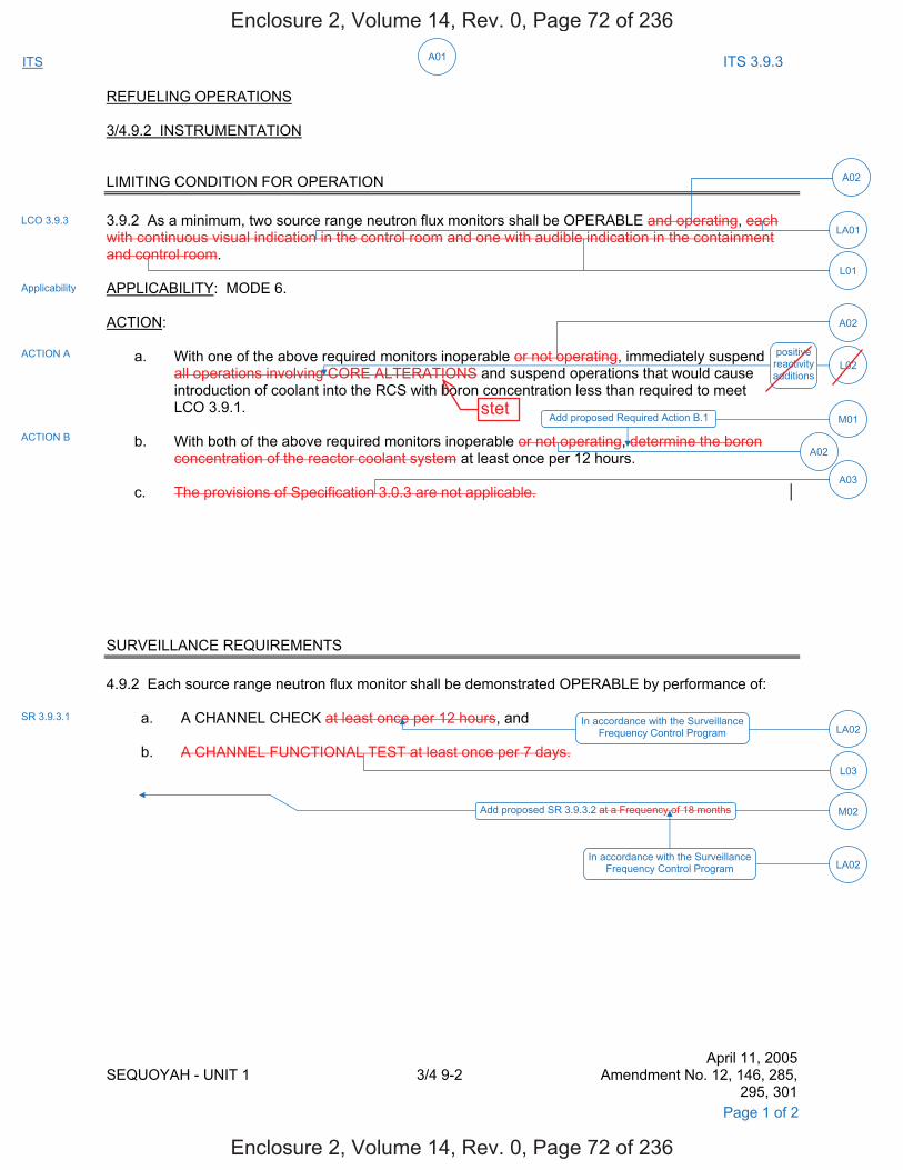
A01ITS ITS 3.9.3
REFUELING OPERATIONS 3/4.9.2 INSTRUMENTATION LIMITING CONDITION FOR OPERATION 3.9.2 As a minimum, two source range neutron flux monitors shall be OPERABLE and operating, each with continuous visual indication in the control room and one with audible indication in the containment and control room. APPLICABILITY: MODE 6. ACTION: a. With one of the above required monitors inoperable or not operating, immediately suspend all operations involving CORE ALTERATIONS and suspend operations that would cause
introduction of coolant into the RCS with boron concentration less than required to meet LCO 3.9.1.
b. With both of the above required monitors inoperable or not operating, determine the boron
concentration of the reactor coolant system at least once per 12 hours. c. The provisions of Specification 3.0.3 are not applicable. SURVEILLANCE REQUIREMENTS 4.9.2 Each source range neutron flux monitor shall be demonstrated OPERABLE by performance of: a. A CHANNEL CHECK at least once per 12 hours, and b. A CHANNEL FUNCTIONAL TEST at least once per 7 days.
April 11, 2005 SEQUOYAH - UNIT 1 3/4 9-2 Amendment No. 12, 146, 285,
295, 301
In accordance with the Surveillance Frequency Control Program LA02
L03
M02
LCO 3.9.3
Applicability
ACTION A
ACTION B
SR 3.9.3.1
L02
A03
positive reactivity additions
A02
M01Add proposed Required Action B.1
Page 1 of 2
A02
A02
Add proposed SR 3.9.3.2 at a Frequency of 18 months
In accordance with the Surveillance Frequency Control Program LA02
LA01
L01
Enclosure 2, Volume 14, Rev. 0, Page 72 of 236
Enclosure 2, Volume 14, Rev. 0, Page 72 of 236
stet
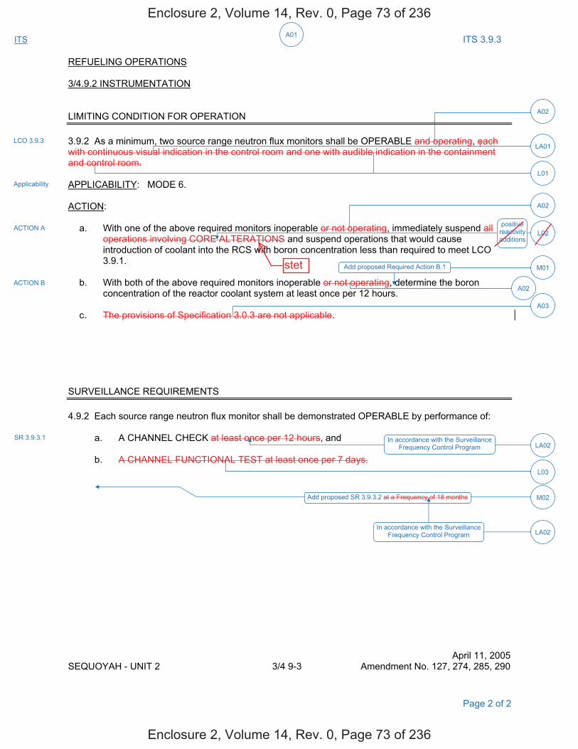
A01ITS ITS 3.9.3
REFUELING OPERATIONS 3/4.9.2 INSTRUMENTATION LIMITING CONDITION FOR OPERATION 3.9.2 As a minimum, two source range neutron flux monitors shall be OPERABLE and operating, each with continuous visual indication in the control room and one with audible indication in the containment and control room. APPLICABILITY: MODE 6. ACTION: a. With one of the above required monitors inoperable or not operating, immediately suspend all operations involving CORE ALTERATIONS and suspend operations that would cause
introduction of coolant into the RCS with boron concentration less than required to meet LCO 3.9.1.
b. With both of the above required monitors inoperable or not operating, determine the boron
concentration of the reactor coolant system at least once per 12 hours. c. The provisions of Specification 3.0.3 are not applicable. SURVEILLANCE REQUIREMENTS 4.9.2 Each source range neutron flux monitor shall be demonstrated OPERABLE by performance of:
a. A CHANNEL CHECK at least once per 12 hours, and b. A CHANNEL FUNCTIONAL TEST at least once per 7 days.
April 11, 2005 SEQUOYAH - UNIT 2 3/4 9-3 Amendment No. 127, 274, 285, 290
Page 2 of 2
Add proposed Required Action B.1
In accordance with the Surveillance Frequency Control Program
Add proposed SR 3.9.3.2 at a Frequency of 18 months
positive reactivity additions
LCO 3.9.3
Applicability
ACTION A
ACTION B
SR 3.9.3.1
A02
A02
L02
M01
A02
A03
LA02
L03
M02
LA01
In accordance with the Surveillance Frequency Control Program LA02
L01
Enclosure 2, Volume 14, Rev. 0, Page 73 of 236
Enclosure 2, Volume 14, Rev. 0, Page 73 of 236
stet
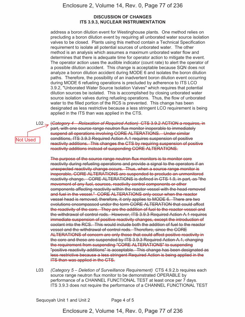
DISCUSSION OF CHANGES ITS 3.9.3, NUCLEAR INSTRUMENTATION
Sequoyah Unit 1 and Unit 2 Page 4 of 5
address a boron dilution event for Westinghouse plants. One method relies on precluding a boron dilution event by requiring all unborated water source isolation valves to be closed. Plants using this method contain a Technical Specification requirement to isolate all potential sources of unborated water. The other method is an analysis which assumes a maximum unborated water flow and determines that there is adequate time for operator action to mitigate the event. The operator action uses the audible indicator (count rate) to alert the operator of a possible dilution accident. This change is acceptable because SQN does not analyze a boron dilution accident during MODE 6 and isolates the boron dilution paths. Therefore, the possibility of an inadvertent boron dilution event occurring during MODE 6 refueling operations is precluded by adherence to ITS LCO 3.9.2, "Unborated Water Source Isolation Valves" which requires that potential dilution sources be isolated. This is accomplished by closing unborated water source isolation valves during refueling operations. Thus, the flow of unborated water to the filled portion of the RCS is prevented. This change has been designated as less restrictive because a less stringent LCO requirement is being applied in the ITS than was applied in the CTS.
L02 (Category 4 – Relaxation of Required Action) CTS 3.9.2 ACTION a requires, in
part, with one source range neutron flux monitor inoperable to immediately suspend all operations involving CORE ALTERATIONS. Under similar conditions, ITS 3.9.3 Required Action A.1 requires suspension of positive reactivity additions. This changes the CTS by requiring suspension of positive reactivity additions instead of suspending CORE ALTERATIONS.
The purpose of the source range neutron flux monitors is to monitor core
reactivity during refueling operations and provide a signal to the operators if an unexpected reactivity change occurs. Thus, when a source range monitor is inoperable, CORE ALTERATIONS are suspended to preclude an unmonitored reactivity change. CORE ALTERATIONS is defined in CTS 1.9, in part, as "the movement of any fuel, sources, reactivity control components or other components affecting reactivity within the reactor vessel with the head removed and fuel in the vessel." CORE ALTERATIONS only occur when the reactor vessel head is removed; therefore, it only applies to MODE 6. There are two evolutions encompassed under the term CORE ALTERATION that could affect the reactivity of the core. They are the addition of fuel to the reactor vessel and the withdrawal of control rods. However, ITS 3.9.3 Required Action A.1 requires immediate suspension of positive reactivity changes, except the introduction of coolant into the RCS. This would include both the addition of fuel to the reactor vessel and the withdrawal of control rods. Therefore, since the CORE ALTERATIONS of concern are only those that could affect positive reactivity in the core and these are suspended by ITS 3.9.3 Required Action A.1, changing the requirement from suspending "CORE ALTERATIONS" to suspending "positive reactivity additions" is acceptable. This change has been designated as less restrictive because a less stringent Required Action is being applied in the ITS than was applied in the CTS.
L03 (Category 5 – Deletion of Surveillance Requirement) CTS 4.9.2.b requires each
source range neutron flux monitor to be demonstrated OPERABLE by performance of a CHANNEL FUNCTIONAL TEST at least once per 7 days. ITS 3.9.3 does not require the performance of a CHANNEL FUNCTIONAL TEST
Enclosure 2, Volume 14, Rev. 0, Page 77 of 236
Enclosure 2, Volume 14, Rev. 0, Page 77 of 236
Not Used

Nuclear Instrumentation 3.9.3
Westinghouse STS 3.9.3-1 Rev. 4.0 2
SEQUOYAH UNIT 1 Amendment XXX
CTS
3.9 REFUELING OPERATIONS
3.9.3 Nuclear Instrumentation
LCO 3.9.3 Two source range neutron flux monitors shall be OPERABLE.
AND
[ One source range audible [alarm] [count rate] circuit shall be OPERABLE. ]
APPLICABILITY: MODE 6.
ACTIONS
CONDITION REQUIRED ACTION COMPLETION TIME
A. One [required] source range neutron flux monitor inoperable.
A.1 Suspend positive reactivity additions.
AND
A.2 Suspend operations that would cause introduction of coolant into the RCS with boron concentration less than required to meet the boron concentration of LCO 3.9.1.
Immediately
Immediately
B. Two [required] source range neutron flux monitors inoperable.
B.1 Initiate action to restore one source range neutron flux monitor to OPERABLE status.
AND
B.2 Perform SR 3.9.1.1.
Immediately
Once per 12 hours
1
3.9.2
Applicability
ACTION a
ACTION b
1
3
DOC M01
Enclosure 2, Volume 14, Rev. 0, Page 80 of 236
Enclosure 2, Volume 14, Rev. 0, Page 80 of 236
Suspend COREALTERATIONS.
5
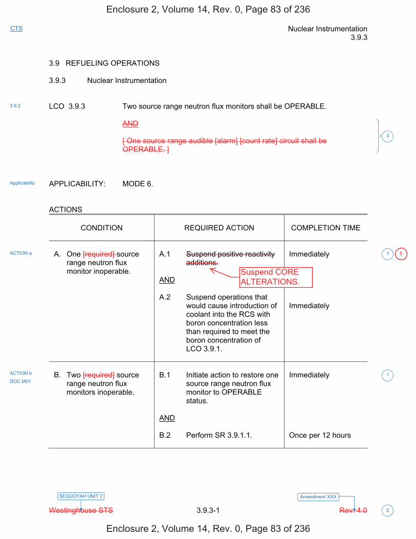
Nuclear Instrumentation 3.9.3
Westinghouse STS 3.9.3-1 Rev. 4.0 2
SEQUOYAH UNIT 2 Amendment XXX
CTS
3.9 REFUELING OPERATIONS 3.9.3 Nuclear Instrumentation LCO 3.9.3 Two source range neutron flux monitors shall be OPERABLE. AND [ One source range audible [alarm] [count rate] circuit shall be
OPERABLE. ] APPLICABILITY: MODE 6. ACTIONS
CONDITION
REQUIRED ACTION
COMPLETION TIME
A. One [required] source
range neutron flux monitor inoperable.
A.1 Suspend positive reactivity
additions. AND A.2 Suspend operations that
would cause introduction of coolant into the RCS with boron concentration less than required to meet the boron concentration of LCO 3.9.1.
Immediately Immediately
B. Two [required] source
range neutron flux monitors inoperable.
B.1 Initiate action to restore one
source range neutron flux monitor to OPERABLE status.
AND B.2 Perform SR 3.9.1.1.
Immediately Once per 12 hours
1
3.9.2
Applicability
ACTION a
ACTION b
1
3
DOC M01
Enclosure 2, Volume 14, Rev. 0, Page 83 of 236
Enclosure 2, Volume 14, Rev. 0, Page 83 of 236
Suspend COREALTERATIONS.
5
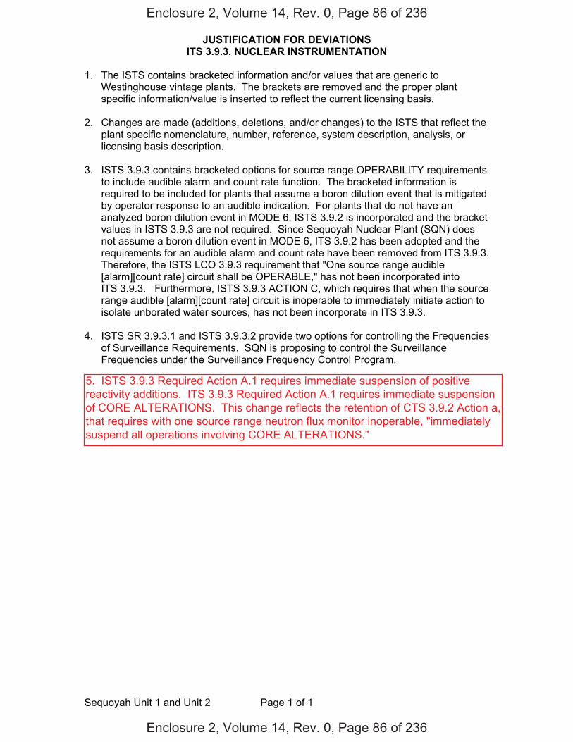
JUSTIFICATION FOR DEVIATIONS ITS 3.9.3, NUCLEAR INSTRUMENTATION
Sequoyah Unit 1 and Unit 2 Page 1 of 1
1. The ISTS contains bracketed information and/or values that are generic to Westinghouse vintage plants. The brackets are removed and the proper plant specific information/value is inserted to reflect the current licensing basis.
2. Changes are made (additions, deletions, and/or changes) to the ISTS that reflect the
plant specific nomenclature, number, reference, system description, analysis, or licensing basis description.
3. ISTS 3.9.3 contains bracketed options for source range OPERABILITY requirements
to include audible alarm and count rate function. The bracketed information is required to be included for plants that assume a boron dilution event that is mitigated by operator response to an audible indication. For plants that do not have an analyzed boron dilution event in MODE 6, ISTS 3.9.2 is incorporated and the bracket values in ISTS 3.9.3 are not required. Since Sequoyah Nuclear Plant (SQN) does not assume a boron dilution event in MODE 6, ITS 3.9.2 has been adopted and the requirements for an audible alarm and count rate have been removed from ITS 3.9.3. Therefore, the ISTS LCO 3.9.3 requirement that "One source range audible [alarm][count rate] circuit shall be OPERABLE," has not been incorporated into ITS 3.9.3. Furthermore, ISTS 3.9.3 ACTION C, which requires that when the source range audible [alarm][count rate] circuit is inoperable to immediately initiate action to isolate unborated water sources, has not been incorporate in ITS 3.9.3.
4. ISTS SR 3.9.3.1 and ISTS 3.9.3.2 provide two options for controlling the Frequencies
of Surveillance Requirements. SQN is proposing to control the Surveillance Frequencies under the Surveillance Frequency Control Program.
Enclosure 2, Volume 14, Rev. 0, Page 86 of 236
Enclosure 2, Volume 14, Rev. 0, Page 86 of 236
5. ISTS 3.9.3 Required Action A.1 requires immediate suspension of positivereactivity additions. ITS 3.9.3 Required Action A.1 requires immediate suspensionof CORE ALTERATIONS. This change reflects the retention of CTS 3.9.2 Action a,that requires with one source range neutron flux monitor inoperable, "immediatelysuspend all operations involving CORE ALTERATIONS."
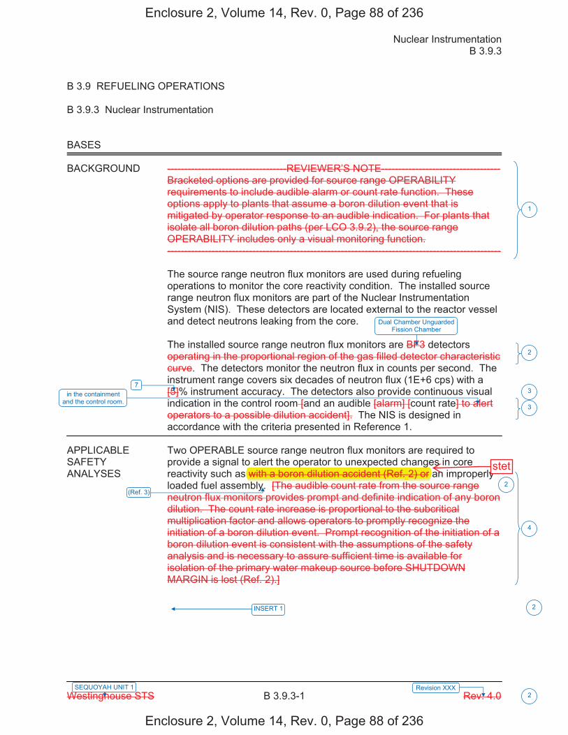
Nuclear Instrumentation B 3.9.3
Westinghouse STS B 3.9.3-1 Rev. 4.0 2
SEQUOYAH UNIT 1 Revision XXX
B 3.9 REFUELING OPERATIONS
B 3.9.3 Nuclear Instrumentation
BASES
BACKGROUND -----------------------------------REVIEWER’S NOTE----------------------------------- Bracketed options are provided for source range OPERABILITY requirements to include audible alarm or count rate function. These options apply to plants that assume a boron dilution event that is mitigated by operator response to an audible indication. For plants that isolate all boron dilution paths (per LCO 3.9.2), the source range OPERABILITY includes only a visual monitoring function. -------------------------------------------------------------------------------------------------- The source range neutron flux monitors are used during refueling operations to monitor the core reactivity condition. The installed source range neutron flux monitors are part of the Nuclear Instrumentation System (NIS). These detectors are located external to the reactor vessel and detect neutrons leaking from the core. The installed source range neutron flux monitors are BF3 detectors operating in the proportional region of the gas filled detector characteristic curve. The detectors monitor the neutron flux in counts per second. The instrument range covers six decades of neutron flux (1E+6 cps) with a [5]% instrument accuracy. The detectors also provide continuous visual indication in the control room [and an audible [alarm] [count rate] to alert operators to a possible dilution accident]. The NIS is designed in accordance with the criteria presented in Reference 1.
APPLICABLE Two OPERABLE source range neutron flux monitors are required to SAFETY provide a signal to alert the operator to unexpected changes in core ANALYSES reactivity such as with a boron dilution accident (Ref. 2) or an improperly
loaded fuel assembly. [The audible count rate from the source range neutron flux monitors provides prompt and definite indication of any boron dilution. The count rate increase is proportional to the subcritical multiplication factor and allows operators to promptly recognize the initiation of a boron dilution event. Prompt recognition of the initiation of a boron dilution event is consistent with the assumptions of the safety analysis and is necessary to assure sufficient time is available for isolation of the primary water makeup source before SHUTDOWN MARGIN is lost (Ref. 2).]
1
3
4
7 in the containment
and the control room.
Dual Chamber Unguarded Fission Chamber
2
3
(Ref. 3)
INSERT 1
2
2
Enclosure 2, Volume 14, Rev. 0, Page 88 of 236
Enclosure 2, Volume 14, Rev. 0, Page 88 of 236
p p gwith a boron dilution accident (Ref. 2) or r
stet
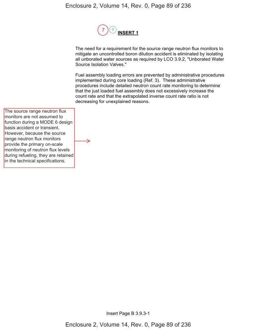
Insert Page B 3.9.3-1
INSERT 1
The need for a requirement for the source range neutron flux monitors to mitigate an uncontrolled boron dilution accident is eliminated by isolating all unborated water sources as required by LCO 3.9.2, "Unborated Water Source Isolation Valves."
Fuel assembly loading errors are prevented by administrative procedures implemented during core loading (Ref. 3). These administrative procedures include detailed neutron count rate monitoring to determine that the just loaded fuel assembly does not excessively increase the count rate and that the extrapolated inverse count rate ratio is not decreasing for unexplained reasons.
2
Enclosure 2, Volume 14, Rev. 0, Page 89 of 236
Enclosure 2, Volume 14, Rev. 0, Page 89 of 236
The source range neutron flux monitors are not assumed to function during a MODE 6 design basis accident or transient. However, because the source range neutron flux monitors provide the primary on-scale monitoring of neutron flux levels during refueling, they are retained in the technical specifications.
7
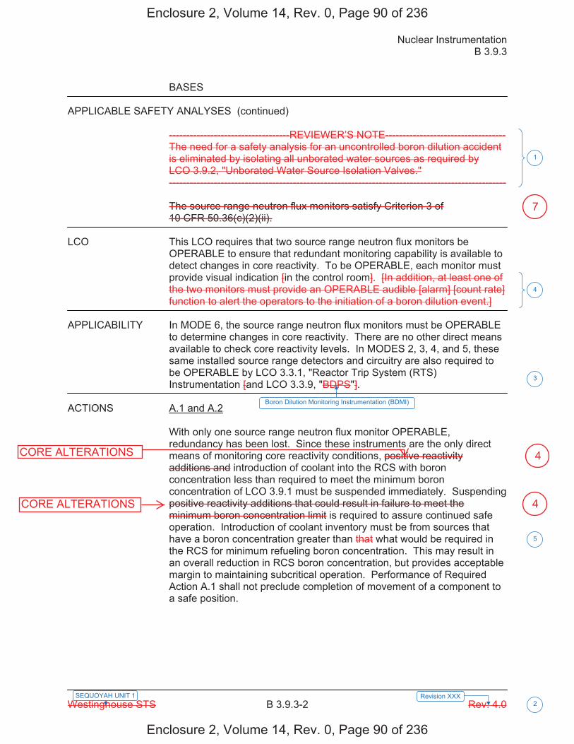
Nuclear Instrumentation B 3.9.3
Westinghouse STS B 3.9.3-2 Rev. 4.0 2
SEQUOYAH UNIT 1 Revision XXX
BASES APPLICABLE SAFETY ANALYSES (continued)
-----------------------------------REVIEWER’S NOTE----------------------------------- The need for a safety analysis for an uncontrolled boron dilution accident is eliminated by isolating all unborated water sources as required by LCO 3.9.2, "Unborated Water Source Isolation Valves." -------------------------------------------------------------------------------------------------- The source range neutron flux monitors satisfy Criterion 3 of 10 CFR 50.36(c)(2)(ii).
LCO This LCO requires that two source range neutron flux monitors be
OPERABLE to ensure that redundant monitoring capability is available to detect changes in core reactivity. To be OPERABLE, each monitor must provide visual indication [in the control room]. [In addition, at least one of the two monitors must provide an OPERABLE audible [alarm] [count rate] function to alert the operators to the initiation of a boron dilution event.]
APPLICABILITY In MODE 6, the source range neutron flux monitors must be OPERABLE
to determine changes in core reactivity. There are no other direct means available to check core reactivity levels. In MODES 2, 3, 4, and 5, these same installed source range detectors and circuitry are also required to be OPERABLE by LCO 3.3.1, "Reactor Trip System (RTS) Instrumentation [and LCO 3.3.9, "BDPS"].
ACTIONS A.1 and A.2
With only one source range neutron flux monitor OPERABLE, redundancy has been lost. Since these instruments are the only direct means of monitoring core reactivity conditions, positive reactivity additions and introduction of coolant into the RCS with boron concentration less than required to meet the minimum boron concentration of LCO 3.9.1 must be suspended immediately. Suspending positive reactivity additions that could result in failure to meet the minimum boron concentration limit is required to assure continued safe operation. Introduction of coolant inventory must be from sources that have a boron concentration greater than that what would be required in the RCS for minimum refueling boron concentration. This may result in an overall reduction in RCS boron concentration, but provides acceptable margin to maintaining subcritical operation. Performance of Required Action A.1 shall not preclude completion of movement of a component to a safe position.
1
4
3
Boron Dilution Monitoring Instrumentation (BDMI)
5
Enclosure 2, Volume 14, Rev. 0, Page 90 of 236
Enclosure 2, Volume 14, Rev. 0, Page 90 of 236
CORE ALTERATIONS
4
4
7
CORE ALTERATIONS
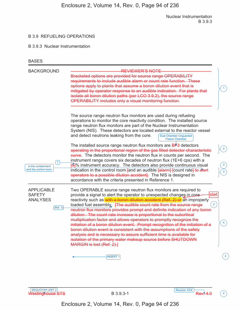
Nuclear Instrumentation B 3.9.3
Westinghouse STS B 3.9.3-1 Rev. 4.0 2
SEQUOYAH UNIT 2 Revision XXX
B 3.9 REFUELING OPERATIONS
B 3.9.3 Nuclear Instrumentation
BASES
BACKGROUND -----------------------------------REVIEWER’S NOTE----------------------------------- Bracketed options are provided for source range OPERABILITY requirements to include audible alarm or count rate function. These options apply to plants that assume a boron dilution event that is mitigated by operator response to an audible indication. For plants that isolate all boron dilution paths (per LCO 3.9.2), the source range OPERABILITY includes only a visual monitoring function. -------------------------------------------------------------------------------------------------- The source range neutron flux monitors are used during refueling operations to monitor the core reactivity condition. The installed source range neutron flux monitors are part of the Nuclear Instrumentation System (NIS). These detectors are located external to the reactor vessel and detect neutrons leaking from the core. The installed source range neutron flux monitors are BF3 detectors operating in the proportional region of the gas filled detector characteristic curve. The detectors monitor the neutron flux in counts per second. The instrument range covers six decades of neutron flux (1E+6 cps) with a [5]% instrument accuracy. The detectors also provide continuous visual indication in the control room [and an audible [alarm] [count rate] to alert operators to a possible dilution accident]. The NIS is designed in accordance with the criteria presented in Reference 1.
APPLICABLE Two OPERABLE source range neutron flux monitors are required to SAFETY provide a signal to alert the operator to unexpected changes in core ANALYSES reactivity such as with a boron dilution accident (Ref. 2) or an improperly
loaded fuel assembly. [The audible count rate from the source range neutron flux monitors provides prompt and definite indication of any boron dilution. The count rate increase is proportional to the subcritical multiplication factor and allows operators to promptly recognize the initiation of a boron dilution event. Prompt recognition of the initiation of a boron dilution event is consistent with the assumptions of the safety analysis and is necessary to assure sufficient time is available for isolation of the primary water makeup source before SHUTDOWN MARGIN is lost (Ref. 2).]
1
3
4
7 in the containment
and the control room.
Dual Chamber Unguarded Fission Chamber
2
3
(Ref. 3)
INSERT 1
2
2
Enclosure 2, Volume 14, Rev. 0, Page 94 of 236
Enclosure 2, Volume 14, Rev. 0, Page 94 of 236
p p gwith a boron dilution accident (Ref. 2) or r
stet
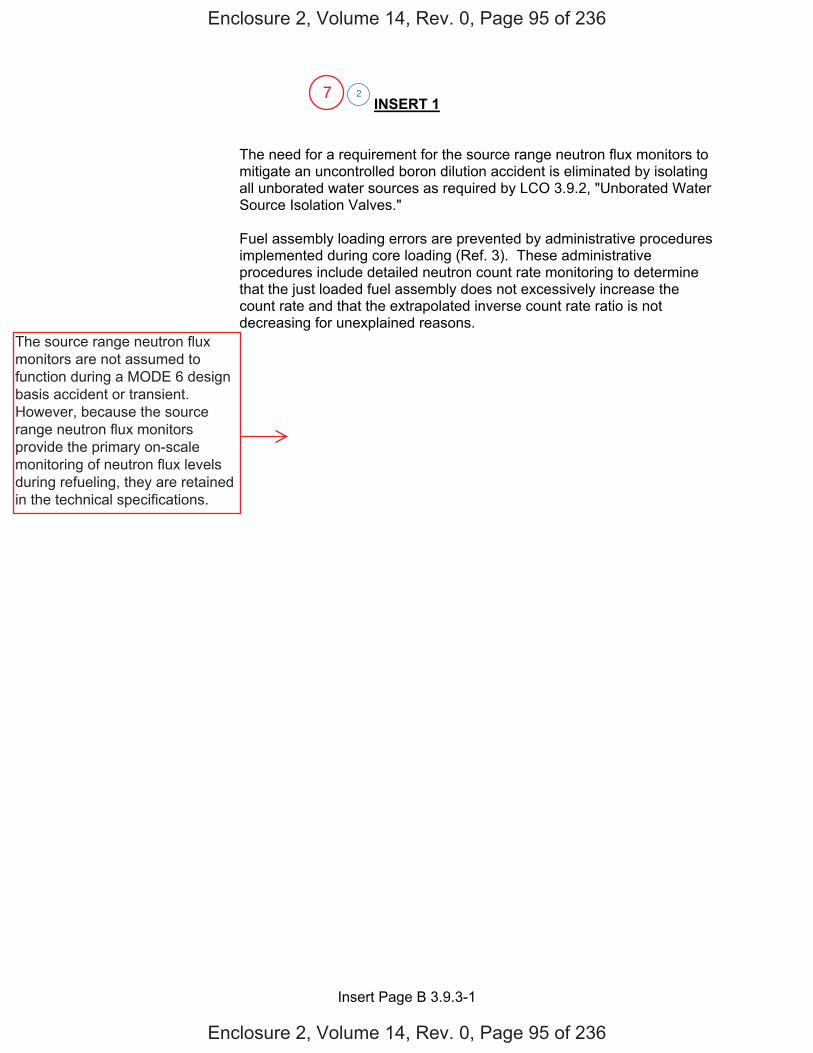
Insert Page B 3.9.3-1
INSERT 1
The need for a requirement for the source range neutron flux monitors to mitigate an uncontrolled boron dilution accident is eliminated by isolating all unborated water sources as required by LCO 3.9.2, "Unborated Water Source Isolation Valves."
Fuel assembly loading errors are prevented by administrative procedures implemented during core loading (Ref. 3). These administrative procedures include detailed neutron count rate monitoring to determine that the just loaded fuel assembly does not excessively increase the count rate and that the extrapolated inverse count rate ratio is not decreasing for unexplained reasons.
2
Enclosure 2, Volume 14, Rev. 0, Page 95 of 236
Enclosure 2, Volume 14, Rev. 0, Page 95 of 236
The source range neutron flux monitors are not assumed to function during a MODE 6 design basis accident or transient. However, because the source range neutron flux monitors provide the primary on-scale monitoring of neutron flux levels during refueling, they are retained in the technical specifications.
7
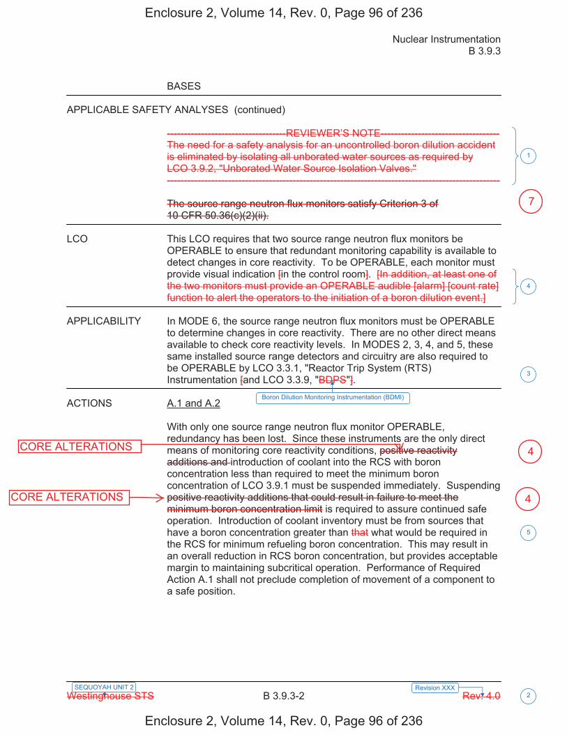
Nuclear Instrumentation B 3.9.3
Westinghouse STS B 3.9.3-2 Rev. 4.0 2
SEQUOYAH UNIT 2 Revision XXX
BASES APPLICABLE SAFETY ANALYSES (continued)
-----------------------------------REVIEWER’S NOTE----------------------------------- The need for a safety analysis for an uncontrolled boron dilution accident is eliminated by isolating all unborated water sources as required by LCO 3.9.2, "Unborated Water Source Isolation Valves." -------------------------------------------------------------------------------------------------- The source range neutron flux monitors satisfy Criterion 3 of 10 CFR 50.36(c)(2)(ii).
LCO This LCO requires that two source range neutron flux monitors be
OPERABLE to ensure that redundant monitoring capability is available to detect changes in core reactivity. To be OPERABLE, each monitor must provide visual indication [in the control room]. [In addition, at least one of the two monitors must provide an OPERABLE audible [alarm] [count rate] function to alert the operators to the initiation of a boron dilution event.]
APPLICABILITY In MODE 6, the source range neutron flux monitors must be OPERABLE
to determine changes in core reactivity. There are no other direct means available to check core reactivity levels. In MODES 2, 3, 4, and 5, these same installed source range detectors and circuitry are also required to be OPERABLE by LCO 3.3.1, "Reactor Trip System (RTS) Instrumentation [and LCO 3.3.9, "BDPS"].
ACTIONS A.1 and A.2
With only one source range neutron flux monitor OPERABLE, redundancy has been lost. Since these instruments are the only direct means of monitoring core reactivity conditions, positive reactivity additions and introduction of coolant into the RCS with boron concentration less than required to meet the minimum boron concentration of LCO 3.9.1 must be suspended immediately. Suspending positive reactivity additions that could result in failure to meet the minimum boron concentration limit is required to assure continued safe operation. Introduction of coolant inventory must be from sources that have a boron concentration greater than that what would be required in the RCS for minimum refueling boron concentration. This may result in an overall reduction in RCS boron concentration, but provides acceptable margin to maintaining subcritical operation. Performance of Required Action A.1 shall not preclude completion of movement of a component to a safe position.
1
4
3
Boron Dilution Monitoring Instrumentation (BDMI)
5
Enclosure 2, Volume 14, Rev. 0, Page 96 of 236
Enclosure 2, Volume 14, Rev. 0, Page 96 of 236
CORE ALTERATIONS
4
4
7
CORE ALTERATIONS
JUSTIFICATION FOR DEVIATIONS ITS 3.9.3 BASES, NUCLEAR INSTRUMENTATION
Sequoyah Unit 1 and Unit 2 Page 1 of 1
1. The Reviewer's Note has been deleted. This information is for the NRC reviewer to be keyed into what is needed to meet this requirement. This Note is not meant to be retained in the final version of the plant specific submittal.
2. Changes are made (additions, deletions, and/or changes) to the ISTS Bases that
reflect the plant specific nomenclature, number, reference, system description, analysis, or licensing basis description.
3. The ISTS contains bracketed information and/or values that are generic to
Westinghouse vintage plants. The brackets are removed and the proper plant specific information/value is inserted to reflect the current licensing basis.
4. Changes are made to be consistent with changes made to the Specification.
5. Editorial changes made for enhanced clarity.
6. ISTS SR 3.9.3.1 and SR 3.9.3.2 provide two options for controlling the Frequencies of Surveillance Requirements. SQN is proposing to control the Surveillance Frequencies under the Surveillance Frequency Control Program.
Enclosure 2, Volume 14, Rev. 0, Page 100 of 236
Enclosure 2, Volume 14, Rev. 0, Page 100 of 236
7. ISTS 3.9.3 Applicable Safety Analysis (ASA) section states, "the source rangeneutron flux monitors satisfy Criterion 3 of 10 CFR 50.36(c)(2)(ii)." SQN's sourcerange neutron flux monitors are not assumed to function during a MODE 6 designbasis accident or transient. Therefore, the statement has been deleted from theASA section. Furthermore, the ASA section is modified by the statement,"However, because the source range neutron flux monitors provide the primaryon-scale monitoring of neutron flux during refueling, they are retained in thetechnical specifications."

Licensee Response/NRC Response/NRC Question ClosureId 421
NRC Question Number MHC001
Select Application NRC Question Closure
Attachment 1
Attachment 2
Response Statement
Response Date/Time
Closure Statement This question is closed and no further information is required at this time to draft the Safety Evaluation.
Question Closure Date 1/20/2015
Notification Scott BowmanMargaret ChernoffMichelle ConnerMatthew HardgroveKhadijah HemphillAndrew HonLynn MynattAmrit PatelRay SchieleRoger Scott
Added By Khadijah Hemphill
Date Added 1/20/2015 6:53 AM
Date Modified
Modified By
Page 1 of 1Sequoyah ITS Conversion Database
3/16/2015https://members.excelservices.com/rai/index.php?requestType=areaItemPrint&itemId=421
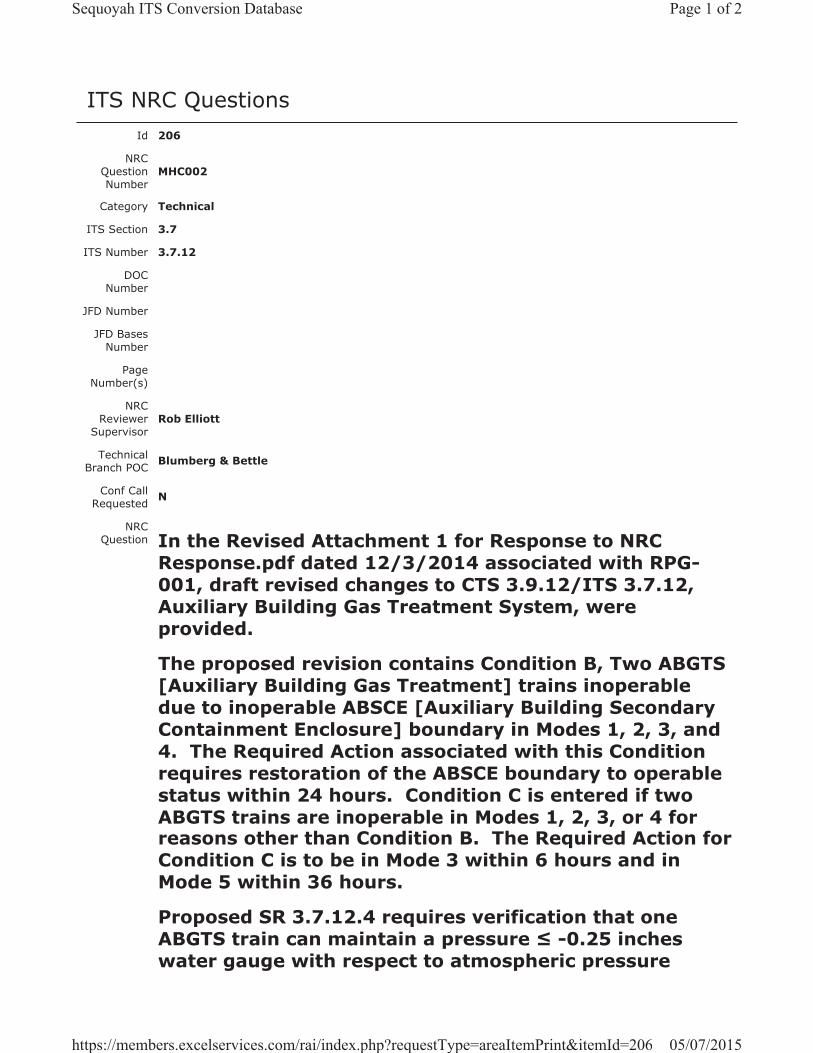
ITS NRC QuestionsId 206
NRC Question Number
MHC002
Category Technical
ITS Section 3.7
ITS Number 3.7.12
DOC Number
JFD Number
JFD Bases Number
Page Number(s)
NRC Reviewer
Supervisor Rob Elliott
Technical Branch POC Blumberg & Bettle
Conf Call Requested N
NRC Question In the Revised Attachment 1 for Response to NRC
Response.pdf dated 12/3/2014 associated with RPG-001, draft revised changes to CTS 3.9.12/ITS 3.7.12, Auxiliary Building Gas Treatment System, were provided.
The proposed revision contains Condition B, Two ABGTS [Auxiliary Building Gas Treatment] trains inoperable due to inoperable ABSCE [Auxiliary Building Secondary Containment Enclosure] boundary in Modes 1, 2, 3, and 4. The Required Action associated with this Condition requires restoration of the ABSCE boundary to operable status within 24 hours. Condition C is entered if two ABGTS trains are inoperable in Modes 1, 2, 3, or 4 for reasons other than Condition B. The Required Action for Condition C is to be in Mode 3 within 6 hours and in Mode 5 within 36 hours.
Proposed SR 3.7.12.4 requires verification that one ABGTS train can maintain a pressure -0.25 inches water gauge with respect to atmospheric pressure
Page 1 of 2Sequoyah ITS Conversion Database
05/07/2015https://members.excelservices.com/rai/index.php?requestType=areaItemPrint&itemId=206
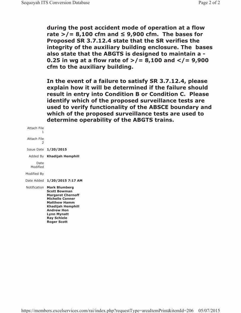
during the post accident mode of operation at a flow rate >/= 8,100 cfm and 9,900 cfm. The bases for Proposed SR 3.7.12.4 state that the SR verifies the integrity of the auxiliary building enclosure. The bases also state that the ABGTS is designed to maintain a -0.25 in wg at a flow rate of >/= 8,100 and </= 9,900 cfm to the auxiliary building.
In the event of a failure to satisfy SR 3.7.12.4, please explain how it will be determined if the failure should result in entry into Condition B or Condition C. Please identify which of the proposed surveillance tests are used to verify functionality of the ABSCE boundary and which of the proposed surveillance tests are used to determine operability of the ABGTS trains.
Attach File 1
Attach File 2
Issue Date 1/20/2015
Added By Khadijah Hemphill
Date Modified
Modified By
Date Added 1/20/2015 7:17 AM
Notification Mark BlumbergScott BowmanMargaret ChernoffMichelle ConnerMatthew HammKhadijah HemphillAndrew HonLynn MynattRay SchieleRoger Scott
Page 2 of 2Sequoyah ITS Conversion Database
05/07/2015https://members.excelservices.com/rai/index.php?requestType=areaItemPrint&itemId=206
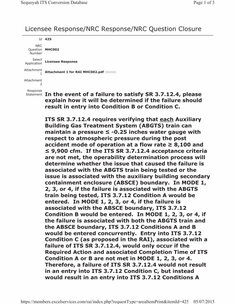
Licensee Response/NRC Response/NRC Question ClosureId 425
NRC Question Number
MHC002
Select Application Licensee Response
Attachment 1 Attachment 1 for RAI MHC002.pdf (942KB)
Attachment 2
Response Statement In the event of a failure to satisfy SR 3.7.12.4, please
explain how it will be determined if the failure should result in entry into Condition B or Condition C.
ITS SR 3.7.12.4 requires verifying that each Auxiliary Building Gas Treatment System (ABGTS) train can maintain a pressure -0.25 inches water gauge with respect to atmospheric pressure during the post accident mode of operation at a flow rate 8,100 and
9,900 cfm. If the ITS SR 3.7.12.4 acceptance criteria are not met, the operability determination process will determine whether the issue that caused the failure is associated with the ABGTS train being tested or the issue is associated with the auxiliary building secondary containment enclosure (ABSCE) boundary. In MODE 1, 2, 3, or 4, if the failure is associated with the ABGTS train being tested, ITS 3.7.12 Condition A would be entered. In MODE 1, 2, 3, or 4, if the failure is associated with the ABSCE boundary, ITS 3.7.12 Condition B would be entered. In MODE 1, 2, 3, or 4, if the failure is associated with both the ABGTS train and the ABSCE boundary, ITS 3.7.12 Conditions A and B would be entered concurrently. Entry into ITS 3.7.12 Condition C (as proposed in the RAI), associated with a failure of ITS SR 3.7.12.4, would only occur if the Required Action and associated Completion Time of ITS Condition A or B are not met in MODE 1, 2, 3, or 4.Therefore, a failure of ITS SR 3.7.12.4 would not result in an entry into ITS 3.7.12 Condition C, but instead would result in an entry into ITS 3.7.12 Conditions A
Page 1 of 3Sequoyah ITS Conversion Database
05/07/2015https://members.excelservices.com/rai/index.php?requestType=areaItemPrint&itemId=425
and/or B.
Please identify which of the proposed surveillance tests are used to verify functionality of the ABSCE boundary and which of the proposed surveillance tests are used to determine operability of the ABGTS trains.
ITS SRs 3.7.12.1, 3.7.12.2, 3.7.12.3 verify the OPERABILITY of the ABGTS train(s).
ITS SR 3.7.12.4 verifies the integrity of the ABSCE boundary. However, failure of ITS SR 3.7.12.4, could identify an inoperable ABGTS train if the failure is associated with an ABGTS train component and the failure is not related to the ABSCE boundary.
Additionally, during review it was discovered that the ITS 3.7.12 Bases discussion for ITS SR 3.7.12.4 is missing the word “pressure” from the following sentence, “The ABGTS is designed to maintain a -0.25 inches water gauge with respect to atmospheric pressure at a flow rate 8,100 and 9,900 cfm to the auxiliary building.” Therefore, the sentence will be revised to read, “The ABGTS is designed to maintain a pressure -0.25 inches water gauge with respect to atmospheric pressure at a flow rate 8,100 and
9,900 cfm to the auxiliary building.” A new Justification for Deviation (JFD) 7 will be written to discuss the addition of the word pressure and JFD indicators will be added to the ISTS markups.
See Attachment 1 for the draft revised ITS 3.7.12 Bases and JFD 7.
Response Date/Time 2/18/2015 1:40 PM
Closure Statement
Question Closure
Date
Notification Mark Blumberg
Page 2 of 3Sequoyah ITS Conversion Database
05/07/2015https://members.excelservices.com/rai/index.php?requestType=areaItemPrint&itemId=425
Scott BowmanMargaret ChernoffMichelle ConnerMatthew HammKhadijah HemphillAndrew HonLynn MynattRay Schiele
Added By Scott Bowman
Date Added 2/18/2015 12:37 PM
Date Modified
Modified By
Page 3 of 3Sequoyah ITS Conversion Database
05/07/2015https://members.excelservices.com/rai/index.php?requestType=areaItemPrint&itemId=425
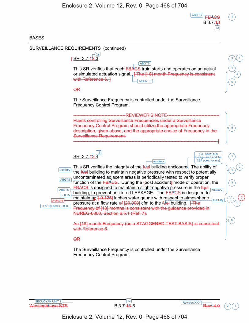
FBACS B 3.7.13
Westinghouse STS B 3.7.13-6 Rev. 4.0
ABGTS 1
12
12SEQUOYAH UNIT 1 Revision XXX 2 1
BASES SURVEILLANCE REQUIREMENTS (continued)
[ SR 3.7.13.3 This SR verifies that each FBACS train starts and operates on an actual or simulated actuation signal. [ The [18] month Frequency is consistent with Reference 6. ] OR The Surveillance Frequency is controlled under the Surveillance Frequency Control Program. -----------------------------------REVIEWER’S NOTE----------------------------------- Plants controlling Surveillance Frequencies under a Surveillance Frequency Control Program should utilize the appropriate Frequency description, given above, and the appropriate choice of Frequency in the Surveillance Requirement. ------------------------------------------------------------------------------------------------ ] SR 3.7.13.4 This SR verifies the integrity of the fuel building enclosure. The ability of the fuel building to maintain negative pressure with respect to potentially uncontaminated adjacent areas is periodically tested to verify proper function of the FBACS. During the [post accident] mode of operation, the FBACS is designed to maintain a slight negative pressure in the fuel building, to prevent unfiltered LEAKAGE. The FBACS is designed to maintain a [-0.125] inches water gauge with respect to atmospheric pressure at a flow rate of [20,000] cfm to the fuel building. [ The Frequency of [18] months is consistent with the guidance provided in NUREG-0800, Section 6.5.1 (Ref. 7). An [18] month Frequency (on a STAGGERED TEST BASIS) is consistent with Reference 6. OR The Surveillance Frequency is controlled under the Surveillance Frequency Control Program.
ABGTS
8,100 and 9,900
3
1
6
5
1
ABGTS
ABGTS
auxiliary
auxiliary- 0.25
3
31
6
auxiliary
auxiliary
112
112 (i.e., spent fuel
storage area and the ESF pump rooms)
2
INSERT 5
4
Enclosure 2, Volume 12, Rev. 0, Page 468 of 704
Enclosure 2, Volume 12, Rev. 0, Page 468 of 704
pressure7

FBACS B 3.7.13
Westinghouse STS B 3.7.13-6 Rev. 4.0
ABGTS 1
12
12SEQUOYAH UNIT 2 Revision XXX 2 1
BASES SURVEILLANCE REQUIREMENTS (continued)
[ SR 3.7.13.3 This SR verifies that each FBACS train starts and operates on an actual or simulated actuation signal. [ The [18] month Frequency is consistent with Reference 6. ] OR The Surveillance Frequency is controlled under the Surveillance Frequency Control Program. -----------------------------------REVIEWER’S NOTE----------------------------------- Plants controlling Surveillance Frequencies under a Surveillance Frequency Control Program should utilize the appropriate Frequency description, given above, and the appropriate choice of Frequency in the Surveillance Requirement. ------------------------------------------------------------------------------------------------ ] SR 3.7.13.4 This SR verifies the integrity of the fuel building enclosure. The ability of the fuel building to maintain negative pressure with respect to potentially uncontaminated adjacent areas is periodically tested to verify proper function of the FBACS. During the [post accident] mode of operation, the FBACS is designed to maintain a slight negative pressure in the fuel building, to prevent unfiltered LEAKAGE. The FBACS is designed to maintain a [-0.125] inches water gauge with respect to atmospheric pressure at a flow rate of [20,000] cfm to the fuel building. [ The Frequency of [18] months is consistent with the guidance provided in NUREG-0800, Section 6.5.1 (Ref. 7). An [18] month Frequency (on a STAGGERED TEST BASIS) is consistent with Reference 6. OR The Surveillance Frequency is controlled under the Surveillance Frequency Control Program.
ABGTS
8,100 and 9,900
3
1
6
5
1
ABGTS
ABGTS
auxiliary
auxiliary- 0.25
3
31
6
auxiliary
auxiliary
112
112 (i.e., spent fuel
storage area and the ESF pump rooms)
2
INSERT 5
4
Enclosure 2, Volume 12, Rev. 0, Page 479 of 704
Enclosure 2, Volume 12, Rev. 0, Page 479 of 704
pressure 7
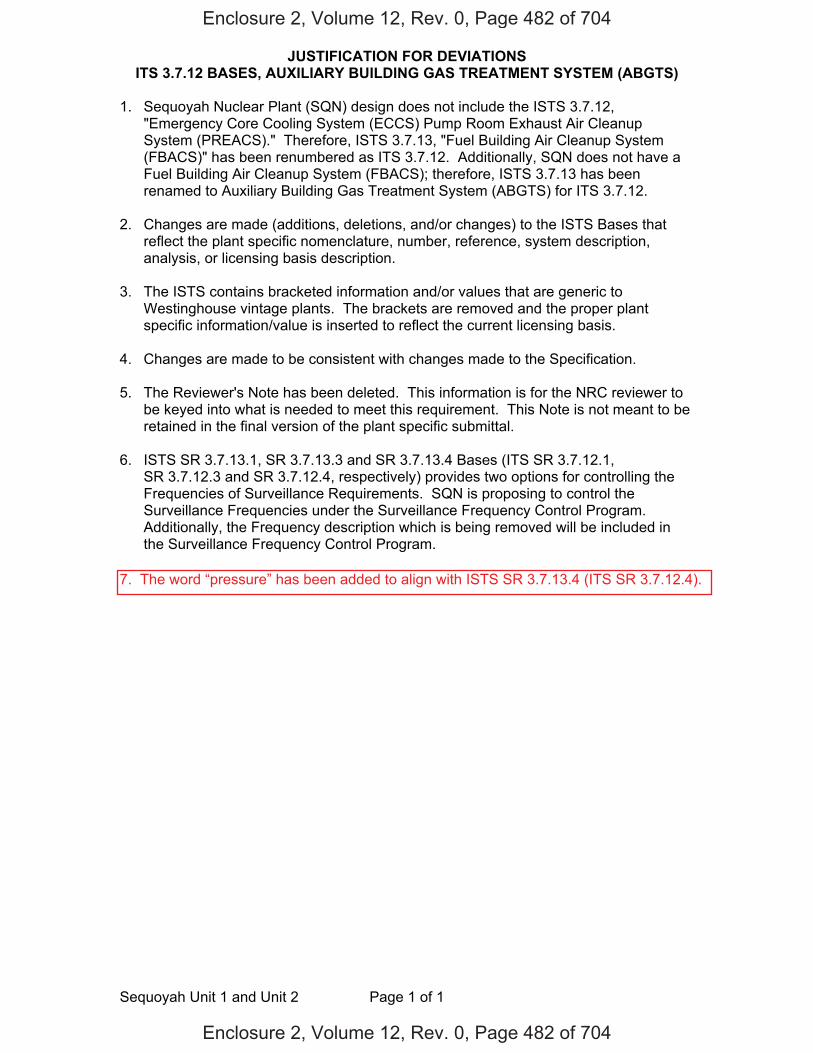
JUSTIFICATION FOR DEVIATIONS ITS 3.7.12 BASES, AUXILIARY BUILDING GAS TREATMENT SYSTEM (ABGTS)
Sequoyah Unit 1 and Unit 2 Page 1 of 1
1. Sequoyah Nuclear Plant (SQN) design does not include the ISTS 3.7.12, "Emergency Core Cooling System (ECCS) Pump Room Exhaust Air Cleanup System (PREACS)." Therefore, ISTS 3.7.13, "Fuel Building Air Cleanup System (FBACS)" has been renumbered as ITS 3.7.12. Additionally, SQN does not have a Fuel Building Air Cleanup System (FBACS); therefore, ISTS 3.7.13 has been renamed to Auxiliary Building Gas Treatment System (ABGTS) for ITS 3.7.12.
2. Changes are made (additions, deletions, and/or changes) to the ISTS Bases that
reflect the plant specific nomenclature, number, reference, system description, analysis, or licensing basis description.
3. The ISTS contains bracketed information and/or values that are generic to
Westinghouse vintage plants. The brackets are removed and the proper plant specific information/value is inserted to reflect the current licensing basis.
4. Changes are made to be consistent with changes made to the Specification.
5. The Reviewer's Note has been deleted. This information is for the NRC reviewer to be keyed into what is needed to meet this requirement. This Note is not meant to be retained in the final version of the plant specific submittal.
6. ISTS SR 3.7.13.1, SR 3.7.13.3 and SR 3.7.13.4 Bases (ITS SR 3.7.12.1,
SR 3.7.12.3 and SR 3.7.12.4, respectively) provides two options for controlling the Frequencies of Surveillance Requirements. SQN is proposing to control the Surveillance Frequencies under the Surveillance Frequency Control Program. Additionally, the Frequency description which is being removed will be included in the Surveillance Frequency Control Program.
Enclosure 2, Volume 12, Rev. 0, Page 482 of 704
Enclosure 2, Volume 12, Rev. 0, Page 482 of 704
7. The word “pressure” has been added to align with ISTS SR 3.7.13.4 (ITS SR 3.7.12.4).

Licensee Response/NRC Response/NRC Question ClosureId 441
NRC Question Number MHC002
Select Application NRC Question Closure
Attachment 1
Attachment 2
Response Statement
Response Date/Time
Closure Statement This question is closed and no further information is required at this time to draft the Safety Evaluation.
Question Closure Date 4/29/2015
Notification Kristy BucholtzMargaret ChernoffMichelle ConnerKhadijah HemphillAndrew HonLynn MynattRay SchieleRoger Scott
Added By Khadijah Hemphill
Date Added 4/29/2015 8:29 AM
Date Modified
Modified By
Page 1 of 1Sequoyah ITS Conversion Database
05/07/2015https://members.excelservices.com/rai/index.php?requestType=areaItemPrint&itemId=441
ITS NRC QuestionsId 208
NRC Question Number
MHC004
Category Technical
ITS Section 3.9
ITS Number
DOC Number
JFD Number
JFD Bases Number
Page Number(s)
NRC Reviewer
Supervisor Undine Shoop
Technical Branch POC Mark Blumberg
Conf Call Requested N
NRC Question Movement of irradiated fuel, movement of fresh fuel over irradiated fuel,
and loads other than fuel (i.e. tools and casks not covered by the heavy loads program) over irradiated fuel can create a source term if a fuel handling accident (FHA) occurs. Many of these potential scenarios are addressed by the proposed Technical Specifications credited for an FHA in containment (i.e. LCO 3.3.6, 3.3.7, 3.7.10, 3.7.12, 3.8.2, 3.8.8, 3.8.10, 3.9.4, 3.9.7 and 3.9.8), but not all proposed Technical Specifications seem to align with the mitigating systems credited for the FHA inside containment. For example, Limiting Condition for Operation (LCO) 3.9.8, "Decay Time" is consistent with the 100 hours assumed in the FHA inside containment, and addresses movement of fuel and some loads over the core. LCO 3.9.7, "Refueling Cavity Water Level," only applies during movement of irradiated fuel, but does not address the applicability covered by LCO 3.9.8.
These proposed Technical Specifications do not appear to align with the credited mitigation features in the FHA. Please either justify how the proposed Applicability and Required Actions align with the FHA in containment, or make the Applicability and Required Actions consistent with the systems and scenarios credited and analyzed in the FHA in containment.
Page 1 of 2Sequoyah ITS Conversion Database
05/07/2015https://members.excelservices.com/rai/index.php?requestType=areaItemPrint&itemId=208
Attach File 1
Attach File 2
Issue Date 4/7/2015
Added By Khadijah Hemphill
Date Modified
Modified By
Date Added 4/7/2015 3:45 PM
Notification Mark BlumbergScott BowmanMargaret ChernoffMichelle ConnerKhadijah HemphillAndrew HonLynn MynattRay SchieleRoger Scott
Page 2 of 2Sequoyah ITS Conversion Database
05/07/2015https://members.excelservices.com/rai/index.php?requestType=areaItemPrint&itemId=208
Licensee Response/NRC Response/NRC Question ClosureId 444
NRC Question Number MHC004
Select Application NRC Question Closure
Attachment 1
Attachment 2
Response Statement
Response Date/Time
Closure Statement This question is closed and will be addressed under MHC003 followup RAI.
Question Closure Date 5/4/2015
Notification Mark BlumbergScott BowmanMargaret ChernoffMichelle ConnerKhadijah HemphillAndrew HonLynn MynattRay SchieleRoger Scott
Added By Khadijah Hemphill
Date Added 5/4/2015 2:19 PM
Date Modified
Modified By
Page 1 of 1Sequoyah ITS Conversion Database
05/07/2015https://members.excelservices.com/rai/index.php?requestType=areaItemPrint&itemId=444
ITS NRC QuestionsId 209
NRC Question Number
MHC005
Category Technical
ITS Section 3.7
ITS Number 3.7.12
DOC Number
JFD Number
JFD Bases Number
Page Number(s) 446 and 452
NRC Reviewer
Supervisor Undine Shoop
Technical Branch POC Kristy Bucholtz
Conf Call Requested N
NRC Question On pages 446 and 452 of Enclosure 2, Volume 12, a note is applied
to Improved Technical Specifications (ITS) Limiting Condition of Operation (LCO) 3.7.12, “Auxiliary Building Gas Treatment System (ABGTS).” The Note states, “The Auxiliary Building Secondary Containment Enclosure (ABSCE) boundary may be opened intermittently under administrative control.” The current technical specifications Plant Systems LCO 3/4.7.8, “Auxiliary Building Gas Treatment System,” and Refueling Operations LCO 3/4.9.12, “Auxiliary Building Gas Treatment System,” do not have this noted allowance. 10 CFR 50.36 requires the technical specifications be derived from the analyses and evaluation included in the safety analysis report.
Section 15.5.3 of Sequoyah’s Updated Final Safety Analysis Report (UFSAR) contains the environmental consequences of a postulated Loss of Coolant Accident (LOCA). This analysis assumes that activity leaking to the Auxiliary Building is immediately released without filtration to the environment for the first 5 minutes after which it is held up for 0.3 hours and then released through the ABGTS filter system. This assumption is based on an initial delay of 4 minutes to establish the ABSCE and 1 minute to draw down the ABSCE to a negative 1/4-inch water
Page 1 of 2Sequoyah ITS Conversion Database
5/29/2015https://members.excelservices.com/rai/index.php?requestType=areaItemPrint&itemId=209
gauge.
The proposed LCO note to ITS 3.7.12 above is not consistent with the environmental consequences of a LOCA licensing basis for Sequoyah, which assumes the ABSCE boundary, is established in 4 minutes. The note allows the ABSCE boundary to be opened for an indefinite length of time, in addition to its unlimited use.Furthermore, the referenced administrative control is not defined in the operating license or proposed ITS for Sequoyah. The administrative control is discussed in the ITS Bases. The ITS Bases should describe or clarify the ITS; the ITS bases are not allowed to change the ITS. The proposed ITS 3.7.12 bases states requirements for ITS 3.7.12 and therefore the ITS 3.7.12 Bases are changing the ITS.
Therefore, the NRC staff requests one of the following:1. Submit for the NRC staff’s review a revised environmental consequences of
a LOCA analysis that supports the ABSCE boundary being opened and has dose results that meet 10 CFR 100. In addition, provide the inputs, assumptions, methodology and technical basis for the assumptions used.
2. Provide 1) a proposed change to ITS 3.7.12 that is consistent with the NRC-approved design basis as reflected in UFSAR Section 15.5.3, “Environmental Consequences of a LOCA” analysis, and 2) ITS 3.7.12 bases that is consistent with the proposed change to ITS 3.7.12.
Attach File 1
Attach File 2
Issue Date 4/7/2015
Added By Khadijah Hemphill
Date Modified
Modified By
Date Added 4/7/2015 3:47 PM
Notification Mark BlumbergScott BowmanKristy BucholtzMargaret ChernoffMichelle ConnerKhadijah HemphillAndrew HonLynn MynattRay SchieleRoger Scott
Page 2 of 2Sequoyah ITS Conversion Database
5/29/2015https://members.excelservices.com/rai/index.php?requestType=areaItemPrint&itemId=209
Licensee Response/NRC Response/NRC Question ClosureId 443
NRC Question Number
MHC005
Select Application Licensee Response
Attachment 1 Attachment 1 to RAI MHC005.pdf (953KB)
Attachment 2
Response Statement In response to RAI MHC005, the ITS 3.7.12 Bases, LCO
Section will be revised (Enclosure 2, Volume 12 - pages 462 and 473). Specifically, the Bases LCO Section will be revised to state, “Note 1 allows the Auxiliary Building Secondary Containment Enclosure (ABSCE) boundary to be opened intermittently under administrative controls.For entry and exit through doors the administrative control of the opening is performed by the person(s) entering or exiting the area. For other openings, these controls should be proceduralized and consist of stationing a dedicated individual at the opening who is in continuous communication with the control room.This individual will have a method to rapidly close the opening and to restore the ABSCE boundary to a condition equivalent to the design condition when a need for auxiliary building isolation is indicated.”Additionally, a new Justification for Deviation (JFD) 7 will be added to the ITS 3.7.12 Bases Justification for Deviations Section to justify the change (Enclosure 2, Volume 12 - page 482). JFD 7 indicators will be added to the ISTS markups, as well.
As stated in the RAI, 10 CFR 50.36 requires the technical specifications be derived from the analyses and evaluation included in the safety analysis report.The SQN Updated Final Safety Analysis Report (UFSAR), Section 15.5.3 provides the environmental consequences associated with a loss of coolant accident (LOCA). The analysis assumes that activity leaking to the auxiliary building is immediately released to the
Page 1 of 3Sequoyah ITS Conversion Database
5/29/2015https://members.excelservices.com/rai/index.php?requestType=areaItemPrint&itemId=443
environment without filtration for the first 5 minutes after which it is held up for 0.3 hours and then released through the Auxiliary Building Gas Treatment System (ABGTS) filter train. The assumption of 5 minutes of free release before filtration, is based on an initial delay of 4 minutes to establish the ABSCE and 1 minute to draw the ABSCE to a negative 1/4-inch water gauge.Therefore, the LCO allowance to open the ABSCE boundary intermittently under administrative controls provided the ABSCE boundary will be established within 4 minutes is consistent with the SQN UFSAR.
Based on the proposed change to the ITS 3.7.12 Bases to state that administrative controls for other openings (openings other than doors used for entry and exit) should be proceduralized, SQN procedures regarding the intermittent opening of the ABSCE boundary will require ABSCE breaches to be restored within 4 minutes such that the ABSCE can be drawn to a negative 1/4-inch water gauge within 5 minutes.
Additionally, the NRC staff states that, “the referenced administrative control is not defined in the operating license or proposed ITS for Sequoyah. The administrative control is discussed in the ITS Bases.The ITS Bases should describe or clarify the ITS; the ITS bases are not allowed to change the ITS. The proposed ITS 3.7.12 bases states requirements for ITS 3.7.12 and therefore the ITS Bases are changing the ITS.” The ITS LCO 3.7.12 Note states the Auxiliary Building Secondary Containment Enclosure (ABSCE) may be opened intermittently under administrative control. The technical specifications require administrative controls and the bases provide clarifying information.Furthermore, the use of the term administrative controls, regarding the allowance to open or unisolate a system, structure, or component, is used seven times (ISTS 3.6.2, 3.6.3, 3.7.10, 3.7.12, 3.7.13, 3.7.14, and 3.9.4) in NUREG-1431, Rev. 4, with no definition provided in the technical specifications. In some
Page 2 of 3Sequoyah ITS Conversion Database
5/29/2015https://members.excelservices.com/rai/index.php?requestType=areaItemPrint&itemId=443
instances the ISTS Bases describe or clarify what an administrative control is and in some instances the Bases provide no additional information. Therefore, the proposed note is consistent with NUREG-1431, Rev. 4 and does not require additional information in the technical specifications defining what constitutes an administrative control.
See Attachment 1 for the draft revised ISTS 3.7.12 markups and JFD 7.Response
Date/Time 5/1/2015 3:25 PM
Closure Statement
Question Closure
Date
Notification Mark BlumbergScott BowmanKristy BucholtzMargaret ChernoffMichelle ConnerKhadijah HemphillAndrew HonLynn MynattRay Schiele
Added By Scott Bowman
Date Added 5/1/2015 2:24 PM
Date Modified
Modified By
Page 3 of 3Sequoyah ITS Conversion Database
5/29/2015https://members.excelservices.com/rai/index.php?requestType=areaItemPrint&itemId=443
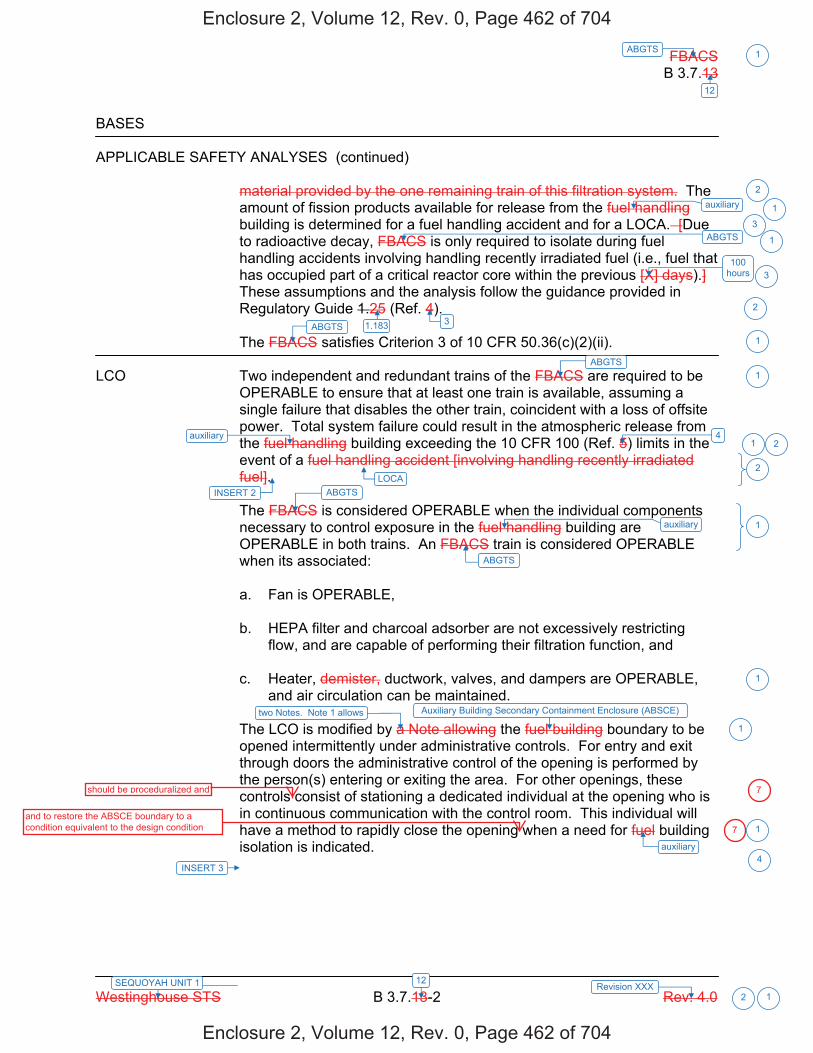
FBACS B 3.7.13
Westinghouse STS B 3.7.13-2 Rev. 4.0
ABGTS 1
12
12SEQUOYAH UNIT 1 Revision XXX 2 1
BASES APPLICABLE SAFETY ANALYSES (continued)
material provided by the one remaining train of this filtration system. The amount of fission products available for release from the fuel handling building is determined for a fuel handling accident and for a LOCA. [Due to radioactive decay, FBACS is only required to isolate during fuel handling accidents involving handling recently irradiated fuel (i.e., fuel that has occupied part of a critical reactor core within the previous [X] days).] These assumptions and the analysis follow the guidance provided in Regulatory Guide 1.25 (Ref. 4). The FBACS satisfies Criterion 3 of 10 CFR 50.36(c)(2)(ii).
LCO Two independent and redundant trains of the FBACS are required to be
OPERABLE to ensure that at least one train is available, assuming a single failure that disables the other train, coincident with a loss of offsite power. Total system failure could result in the atmospheric release from the fuel handling building exceeding the 10 CFR 100 (Ref. 5) limits in the event of a fuel handling accident [involving handling recently irradiated fuel]. The FBACS is considered OPERABLE when the individual components necessary to control exposure in the fuel handling building are OPERABLE in both trains. An FBACS train is considered OPERABLE when its associated: a. Fan is OPERABLE, b. HEPA filter and charcoal adsorber are not excessively restricting
flow, and are capable of performing their filtration function, and c. Heater, demister, ductwork, valves, and dampers are OPERABLE,
and air circulation can be maintained. The LCO is modified by a Note allowing the fuel building boundary to be opened intermittently under administrative controls. For entry and exit through doors the administrative control of the opening is performed by the person(s) entering or exiting the area. For other openings, these controls consist of stationing a dedicated individual at the opening who is in continuous communication with the control room. This individual will have a method to rapidly close the opening when a need for fuel building isolation is indicated.
ABGTS
100 hours
ABGTS 3
4
ABGTS
ABGTS
ABGTS
auxiliary
2
1
3
3
2
1
1
1
2
1
1
1
1auxiliary
auxiliary
1
auxiliary
1.183
Auxiliary Building Secondary Containment Enclosure (ABSCE)
2
LOCAINSERT 2
INSERT 3
two Notes. Note 1 allows
4
Enclosure 2, Volume 12, Rev. 0, Page 462 of 704
Enclosure 2, Volume 12, Rev. 0, Page 462 of 704
should be proceduralized and
and to restore the ABSCE boundary to a condition equivalent to the design condition
7
7

FBACS B 3.7.13
Westinghouse STS B 3.7.13-2 Rev. 4.0
ABGTS 1
12
12SEQUOYAH UNIT 2 Revision XXX 2 1
BASES APPLICABLE SAFETY ANALYSES (continued)
material provided by the one remaining train of this filtration system. The amount of fission products available for release from the fuel handling building is determined for a fuel handling accident and for a LOCA. [Due to radioactive decay, FBACS is only required to isolate during fuel handling accidents involving handling recently irradiated fuel (i.e., fuel that has occupied part of a critical reactor core within the previous [X] days).] These assumptions and the analysis follow the guidance provided in Regulatory Guide 1.25 (Ref. 4). The FBACS satisfies Criterion 3 of 10 CFR 50.36(c)(2)(ii).
LCO Two independent and redundant trains of the FBACS are required to be
OPERABLE to ensure that at least one train is available, assuming a single failure that disables the other train, coincident with a loss of offsite power. Total system failure could result in the atmospheric release from the fuel handling building exceeding the 10 CFR 100 (Ref. 5) limits in the event of a fuel handling accident [involving handling recently irradiated fuel]. The FBACS is considered OPERABLE when the individual components necessary to control exposure in the fuel handling building are OPERABLE in both trains. An FBACS train is considered OPERABLE when its associated: a. Fan is OPERABLE, b. HEPA filter and charcoal adsorber are not excessively restricting
flow, and are capable of performing their filtration function, and c. Heater, demister, ductwork, valves, and dampers are OPERABLE,
and air circulation can be maintained. The LCO is modified by a Note allowing the fuel building boundary to be opened intermittently under administrative controls. For entry and exit through doors the administrative control of the opening is performed by the person(s) entering or exiting the area. For other openings, these controls consist of stationing a dedicated individual at the opening who is in continuous communication with the control room. This individual will have a method to rapidly close the opening when a need for fuel building isolation is indicated.
ABGTS
100 hours
ABGTS 3
4
ABGTS
ABGTS
ABGTS
auxiliary
2
1
3
3
2
1
1
1
2
1
1
1
1auxiliary
auxiliary
1
auxiliary
1.183
Auxiliary Building Secondary Containment Enclosure (ABSCE)
2
LOCAINSERT 2
INSERT 3
two Notes. Note 1 allows
4
Enclosure 2, Volume 12, Rev. 0, Page 473 of 704
Enclosure 2, Volume 12, Rev. 0, Page 473 of 704
should be proceduralized and
and to restore the ABSCE boundary to a condition equivalent to the design condition 7
7
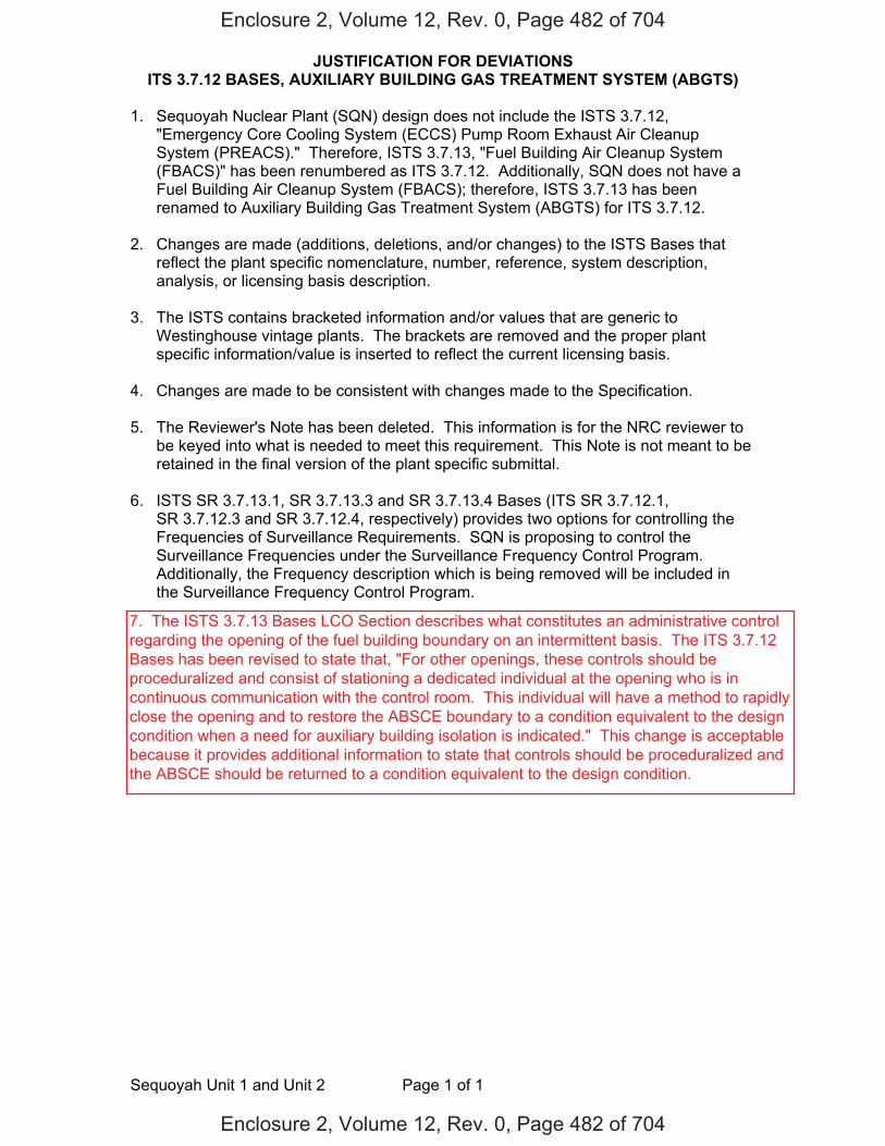
JUSTIFICATION FOR DEVIATIONS ITS 3.7.12 BASES, AUXILIARY BUILDING GAS TREATMENT SYSTEM (ABGTS)
Sequoyah Unit 1 and Unit 2 Page 1 of 1
1. Sequoyah Nuclear Plant (SQN) design does not include the ISTS 3.7.12,"Emergency Core Cooling System (ECCS) Pump Room Exhaust Air CleanupSystem (PREACS)." Therefore, ISTS 3.7.13, "Fuel Building Air Cleanup System(FBACS)" has been renumbered as ITS 3.7.12. Additionally, SQN does not have aFuel Building Air Cleanup System (FBACS); therefore, ISTS 3.7.13 has beenrenamed to Auxiliary Building Gas Treatment System (ABGTS) for ITS 3.7.12.
2. Changes are made (additions, deletions, and/or changes) to the ISTS Bases thatreflect the plant specific nomenclature, number, reference, system description,analysis, or licensing basis description.
3. The ISTS contains bracketed information and/or values that are generic toWestinghouse vintage plants. The brackets are removed and the proper plantspecific information/value is inserted to reflect the current licensing basis.
4. Changes are made to be consistent with changes made to the Specification.
5. The Reviewer's Note has been deleted. This information is for the NRC reviewer tobe keyed into what is needed to meet this requirement. This Note is not meant to beretained in the final version of the plant specific submittal.
6. ISTS SR 3.7.13.1, SR 3.7.13.3 and SR 3.7.13.4 Bases (ITS SR 3.7.12.1,SR 3.7.12.3 and SR 3.7.12.4, respectively) provides two options for controlling theFrequencies of Surveillance Requirements. SQN is proposing to control theSurveillance Frequencies under the Surveillance Frequency Control Program.Additionally, the Frequency description which is being removed will be included inthe Surveillance Frequency Control Program.
Enclosure 2, Volume 12, Rev. 0, Page 482 of 704
Enclosure 2, Volume 12, Rev. 0, Page 482 of 704
7. The ISTS 3.7.13 Bases LCO Section describes what constitutes an administrative control regarding the opening of the fuel building boundary on an intermittent basis. The ITS 3.7.12 Bases has been revised to state that, "For other openings, these controls should be proceduralized and consist of stationing a dedicated individual at the opening who is in continuous communication with the control room. This individual will have a method to rapidly close the opening and to restore the ABSCE boundary to a condition equivalent to the design condition when a need for auxiliary building isolation is indicated." This change is acceptable because it provides additional information to state that controls should be proceduralized and the ABSCE should be returned to a condition equivalent to the design condition.
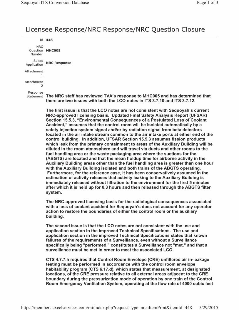
Licensee Response/NRC Response/NRC Question ClosureId 448
NRC Question Number
MHC005
Select Application NRC Response
Attachment 1
Attachment 2
Response Statement The NRC staff has reviewed TVA’s response to MHC005 and has determined that
there are two issues with both the LCO notes in ITS 3.7.10 and ITS 3.7.12.
The first issue is that the LCO notes are not consistent with Sequoyah’s current NRC-approved licensing basis. Updated Final Safety Analysis Report (UFSAR) Section 15.5.3, “Environmental Consequences of a Postulated Loss of Coolant Accident,” assumes that the control room will be isolated automatically by a safety injection system signal and/or by radiation signal from beta detectors located in the air intake stream common to the air intake ports at either end of the control building. In addition, UFSAR Section 15.5.3 assumes fission products which leak from the primary containment to areas of the Auxiliary Building will be diluted in the room atmosphere and will travel via ducts and other rooms to the fuel handling area or the waste packaging area where the suctions for the (ABGTS) are located and that the mean holdup time for airborne activity in the Auxiliary Building areas other than the fuel handling area is greater than one hour with the Auxiliary Building isolated and both trains of the ABGTS operating. Furthermore, for the reference case, it has been conservatively assumed in the
estimation of activity releases that activity leaking to the Auxiliary Building is immediately released without filtration to the environment for the first 5 minutes after which it is held up for 0.3 hours and then released through the ABGTS filter system.
The NRC-approved licensing basis for the radiological consequences associated with a loss of coolant accident for Sequoyah’s does not account for any operator action to restore the boundaries of either the control room or the auxiliary building.
The second issue is that the LCO notes are not consistent with the use and application section in the improved Technical Specifications. The use and application section in the improved Technical Specifications states that known failures of the requirements of a Surveillance, even without a Surveillance specifically being "performed," constitutes a Surveillance not "met," and that a surveillance must be met in order to meet the associated LCO.
CTS 4.7.7.h requires that Control Room Envelope (CRE) unfiltered air in-leakage testing must be performed in accordance with the control room envelope habitability program (CTS 6.17.d), which states that measurement, at designated locations, of the CRE pressure relative to all external areas adjacent to the CRE boundary during the pressurization mode of operation by one train of the Control Room Emergency Ventilation System, operating at the flow rate of 4000 cubic feet
Page 1 of 3Sequoyah ITS Conversion Database
5/29/2015https://members.excelservices.com/rai/index.php?requestType=areaItemPrint&itemId=448
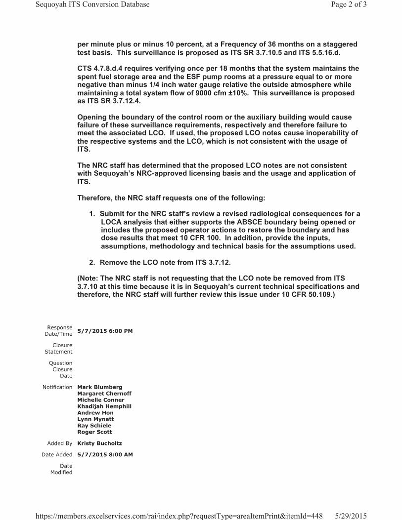
per minute plus or minus 10 percent, at a Frequency of 36 months on a staggered test basis. This surveillance is proposed as ITS SR 3.7.10.5 and ITS 5.5.16.d.
CTS 4.7.8.d.4 requires verifying once per 18 months that the system maintains the spent fuel storage area and the ESF pump rooms at a pressure equal to or more negative than minus 1/4 inch water gauge relative the outside atmosphere while maintaining a total system flow of 9000 cfm ±10%. This surveillance is proposed as ITS SR 3.7.12.4.
Opening the boundary of the control room or the auxiliary building would cause failure of these surveillance requirements, respectively and therefore failure to meet the associated LCO. If used, the proposed LCO notes cause inoperability of the respective systems and the LCO, which is not consistent with the usage of ITS.
The NRC staff has determined that the proposed LCO notes are not consistent with Sequoyah’s NRC-approved licensing basis and the usage and application of ITS.
Therefore, the NRC staff requests one of the following:
1. Submit for the NRC staff’s review a revised radiological consequences for a LOCA analysis that either supports the ABSCE boundary being opened or includes the proposed operator actions to restore the boundary and has dose results that meet 10 CFR 100. In addition, provide the inputs, assumptions, methodology and technical basis for the assumptions used.
2. Remove the LCO note from ITS 3.7.12.
(Note: The NRC staff is not requesting that the LCO note be removed from ITS 3.7.10 at this time because it is in Sequoyah’s current technical specifications and therefore, the NRC staff will further review this issue under 10 CFR 50.109.)
Response Date/Time 5/7/2015 6:00 PM
Closure Statement
Question Closure
Date
Notification Mark BlumbergMargaret ChernoffMichelle ConnerKhadijah HemphillAndrew HonLynn MynattRay SchieleRoger Scott
Added By Kristy Bucholtz
Date Added 5/7/2015 8:00 AM
Date Modified
Page 2 of 3Sequoyah ITS Conversion Database
5/29/2015https://members.excelservices.com/rai/index.php?requestType=areaItemPrint&itemId=448
Modified By
Page 3 of 3Sequoyah ITS Conversion Database
5/29/2015https://members.excelservices.com/rai/index.php?requestType=areaItemPrint&itemId=448
Licensee Response/NRC Response/NRC Question ClosureId 456
NRC Question Number
MHC005
Select Application Licensee Response
Attachment 1 Attachment 1 to NRC Response to RAI MHC005.pdf (1007KB)
Attachment 2
Response Statement Based on the Staff’s response to RAI MHC005, ITS
3.7.12 (ABGTS) LCO Note 1 will be deleted on pages 446 and 452 of Enclosure 2, Volume 12. Specifically, ITS 3.7.12 LCO Note 1 that states, “The Auxiliary Building Secondary Containment Enclosure (ABSCE) boundary may be opened intermittently under administrative control,” will be deleted. As a result of the deletion the following changes to the ITS submittal are required:
1. The CTS markups will be revised to delete the proposed addition of ITS 3.7.12 LCO Note 1, delete the associated Discussion of Change (DOC) L01 indicators, and the ITS cross reference for CTS LCO 3.9.12 will be revised to LCO 3.7.12 Note. (pages 427, 429, 431, and 433 of Enclosure 2, Volume 12)
2. DOC L01 will be revised to state, “Not Used,” in the ITS 3.7.12 Discussion of Changes Section. (pages 439 and 440 of Enclosure 2, Volume 12)
3. The ISTS markups will be revised to delete ITS LCO 3.7.12 Note 1, revise “NOTES” to “NOTE,” delete the associated CTS cross reference to DOC L01 3.9.12, revise the Justification for Deviation (JFD) indicator for the associated change to ITS LCO 3.7.12 Note 1, and delete the number 2 for ITS LCO 3.7.12 Note 2 (there is only one note). (pages 446, 447, 452, and 453 of Enclosure 2, Volume 12)
Page 1 of 2Sequoyah ITS Conversion Database
5/29/2015https://members.excelservices.com/rai/index.php?requestType=areaItemPrint&itemId=456
4. The ISTS Bases markups will be revised to correspond with changes made to the ITS 3.7.12 Specification. (pages 462, 463, 473, and 474 of Enclosure 2, Volume 12)
See Attachment 1 for the draft revised changes to the ITS submittal discussed above.
Response Date/Time 5/21/2015 2:40 PM
Closure Statement
Question Closure
Date
Notification Mark BlumbergScott BowmanKristy BucholtzMargaret ChernoffMichelle ConnerKhadijah HemphillAndrew HonLynn MynattRay Schiele
Added By Scott Bowman
Date Added 5/21/2015 1:40 PM
Date Modified
Modified By
Page 2 of 2Sequoyah ITS Conversion Database
5/29/2015https://members.excelservices.com/rai/index.php?requestType=areaItemPrint&itemId=456
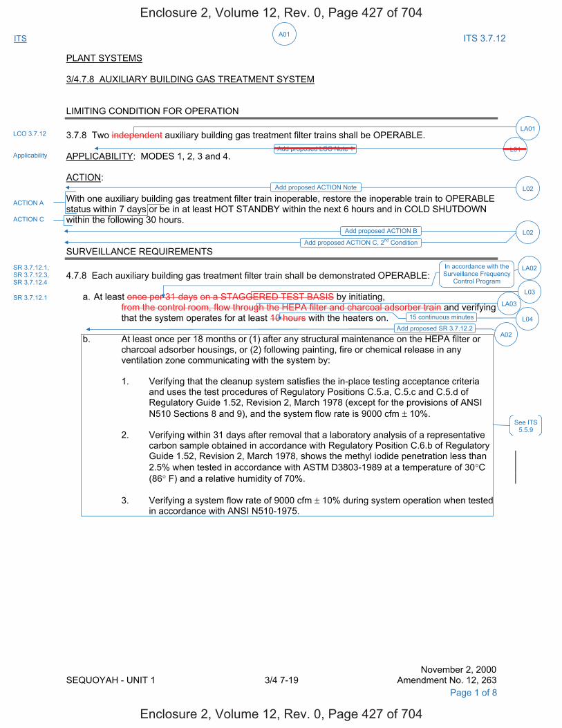
A01ITS ITS 3.7.12
PLANT SYSTEMS 3/4.7.8 AUXILIARY BUILDING GAS TREATMENT SYSTEM LIMITING CONDITION FOR OPERATION 3.7.8 Two independent auxiliary building gas treatment filter trains shall be OPERABLE. APPLICABILITY: MODES 1, 2, 3 and 4. ACTION: With one auxiliary building gas treatment filter train inoperable, restore the inoperable train to OPERABLE status within 7 days or be in at least HOT STANDBY within the next 6 hours and in COLD SHUTDOWN within the following 30 hours. SURVEILLANCE REQUIREMENTS 4.7.8 Each auxiliary building gas treatment filter train shall be demonstrated OPERABLE: a. At least once per 31 days on a STAGGERED TEST BASIS by initiating, from the control room, flow through the HEPA filter and charcoal adsorber train and verifying
that the system operates for at least 10 hours with the heaters on. b. At least once per 18 months or (1) after any structural maintenance on the HEPA filter or
charcoal adsorber housings, or (2) following painting, fire or chemical release in any ventilation zone communicating with the system by:
1. Verifying that the cleanup system satisfies the in-place testing acceptance criteria
and uses the test procedures of Regulatory Positions C.5.a, C.5.c and C.5.d of Regulatory Guide 1.52, Revision 2, March 1978 (except for the provisions of ANSI N510 Sections 8 and 9), and the system flow rate is 9000 cfm ± 10%.
2. Verifying within 31 days after removal that a laboratory analysis of a representative
carbon sample obtained in accordance with Regulatory Position C.6.b of Regulatory Guide 1.52, Revision 2, March 1978, shows the methyl iodide penetration less than 2.5% when tested in accordance with ASTM D3803-1989 at a temperature of 30°C (86° F) and a relative humidity of 70%. 3. Verifying a system flow rate of 9000 cfm ± 10% during system operation when tested
in accordance with ANSI N510-1975.
November 2, 2000 SEQUOYAH - UNIT 1 3/4 7-19 Amendment No. 12, 263
Page 1 of 8
LCO 3.7.12
Applicability
LA01
Add proposed LCO Note 1 L01
Add proposed ACTION Note L02
ACTION A
ACTION C
SR 3.7.12.1, SR 3.7.12.3, SR 3.7.12.4
SR 3.7.12.1 LA03
See ITS 5.5.9
Add proposed ACTION B L02Add proposed ACTION C, 2nd Condition
In accordance with the Surveillance Frequency
Control Program
LA02
L03
A02Add proposed SR 3.7.12.2
L0415 continuous minutes
Enclosure 2, Volume 12, Rev. 0, Page 427 of 704
Enclosure 2, Volume 12, Rev. 0, Page 427 of 704
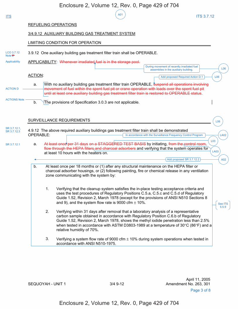
A01ITS ITS 3.7.12
REFUELING OPERATIONS 3/4.9.12 AUXILIARY BUILDING GAS TREATMENT SYSTEM LIMITING CONDITION FOR OPERATION 3.9.12 One auxiliary building gas treatment filter train shall be OPERABLE. APPLICABILITY: Whenever irradiated fuel is in the storage pool. ACTION: a. With no auxiliary building gas treatment filter train OPERABLE, suspend all operations involving
movement of fuel within the spent fuel pit or crane operation with loads over the spent fuel pit until at least one auxiliary building gas treatment filter train is restored to OPERABLE status.
b. The provisions of Specification 3.0.3 are not applicable. SURVEILLANCE REQUIREMENTS 4.9.12 The above required auxiliary buildings gas treatment filter train shall be demonstrated OPERABLE: a. At least once per 31 days on a STAGGERED TEST BASIS by initiating, from the control room,
flow through the HEPA filters and charcoal adsorbers and verifying that the system operates for at least 10 hours with the heaters on.
b. At least once per 18 months or (1) after any structural maintenance on the HEPA filter or
charcoal adsorber housings, or (2) following painting, fire or chemical release in any ventilation zone communicating with the system by:
1. Verifying that the cleanup system satisfies the in-place testing acceptance criteria and
uses the test procedures of Regulatory Positions C.5.a, C.5.c and C.5.d of Regulatory Guide 1.52, Revision 2, March 1978 (except for the provisions of ANSI N510 Sections 8 and 9), and the system flow rate is 9000 cfm ± 10%.
2. Verifying within 31 days after removal that a laboratory analysis of a representative
carbon sample obtained in accordance with Regulatory Position C.6.b of Regulatory Guide 1.52, Revision 2, March 1978, shows the methyl iodide penetration less than 2.5%
when tested in accordance with ASTM D3803-1989 at a temperature of 30°C (86°F) and a relative humidity of 70%.
3. Verifying a system flow rate of 9000 cfm ± 10% during system operations when tested in
accordance with ANSI N510-1975.
April 11, 2005 SEQUOYAH - UNIT 1 3/4 9-12 Amendment No. 263, 301
Page 3 of 8
LCO 3.7.12 Note 2
Applicability
During movement of recently irradiated fuel assemblies in the auxiliary building. L06
ACTION D
ACTIONS Note
L06
SR 3.7.12.1
SR 3.7.12.1, SR 3.7.12.3
Add proposed SR 3.7.12.2 A02
LA03
See ITS 5.5.9
In accordance with the Surveillance Frequency Control Program LA02
L03
Add proposed Required Action D.1 L06
Enclosure 2, Volume 12, Rev. 0, Page 429 of 704
Enclosure 2, Volume 12, Rev. 0, Page 429 of 704
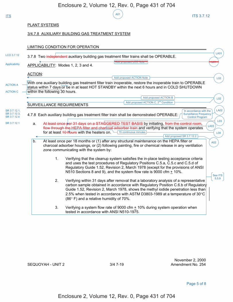
A01ITS ITS 3.7.12
PLANT SYSTEMS 3/4.7.8 AUXILIARY BUILDING GAS TREATMENT SYSTEM LIMITING CONDITION FOR OPERATION 3.7.8 Two independent auxiliary building gas treatment filter trains shall be OPERABLE. APPLICABILITY: Modes 1, 2, 3 and 4. ACTION: With one auxiliary building gas treatment filter train inoperable, restore the inoperable train to OPERABLE status within 7 days or be in at least HOT STANDBY within the next 6 hours and in COLD SHUTDOWN within the following 30 hours. SURVEILLANCE REQUIREMENTS 4.7.8 Each auxiliary building gas treatment filter train shall be demonstrated OPERABLE: a. At least once per 31 days on a STAGGERED TEST BASIS by initiating, from the control room, flow through the HEPA filter and charcoal adsorber train and verifying that the system operates
for at least 10 hours with the heaters on. b. At least once per 18 months or (1) after any structural maintenance on the HEPA filter or
charcoal adsorber housings, or (2) following painting, fire or chemical release in any ventilation zone communicating with the system by:
1. Verifying that the cleanup system satisfies the in-place testing acceptance criteria
and uses the test procedures of Regulatory Positions C.5.a, C.5.c and C.5.d of Regulatory Guide 1.52, Revision 2, March 1978 (except for the provisions of ANSI N510 Sections 8 and 9), and the system flow rate is 9000 cfm + 10%.
2. Verifying within 31 days after removal that a laboratory analysis of a representative
carbon sample obtained in accordance with Regulatory Position C.6.b of Regulatory Guide 1.52, Revision 2, March 1978, shows the methyl iodide penetration less than
2.5% when tested in accordance with ASTM D3803-1989 at a temperature of 30°C (86° F) and a relative humidity of 70%.
3. Verifying a system flow rate of 9000 cfm + 10% during system operation when
tested in accordance with ANSI N510-1975. November 2, 2000 SEQUOYAH - UNIT 2 3/4 7-19 Amendment No. 254
Page 5 of 8
LCO 3.7.12
Applicability
LA01
Add proposed LCO Note 1 L01
Add proposed ACTION Note L02
ACTION A
ACTION C
SR 3.7.12.1, SR 3.7.12.3, SR 3.7.12.4
SR 3.7.12.1 LA03
See ITS 5.5.9
Add proposed ACTION B L02Add proposed ACTION C, 2nd Condition
LA02
L03
In accordance with the Surveillance Frequency
Control Program
L0415 continuous minutesAdd proposed SR 3.7.12.2
A02
Enclosure 2, Volume 12, Rev. 0, Page 431 of 704
Enclosure 2, Volume 12, Rev. 0, Page 431 of 704
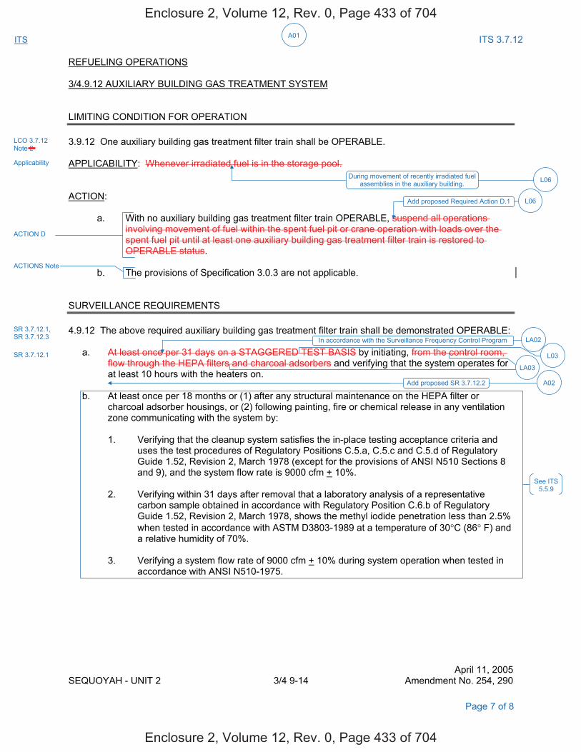
A01ITS ITS 3.7.12
REFUELING OPERATIONS 3/4.9.12 AUXILIARY BUILDING GAS TREATMENT SYSTEM LIMITING CONDITION FOR OPERATION 3.9.12 One auxiliary building gas treatment filter train shall be OPERABLE. APPLICABILITY: Whenever irradiated fuel is in the storage pool. ACTION: a. With no auxiliary building gas treatment filter train OPERABLE, suspend all operations
involving movement of fuel within the spent fuel pit or crane operation with loads over the spent fuel pit until at least one auxiliary building gas treatment filter train is restored to OPERABLE status.
b. The provisions of Specification 3.0.3 are not applicable. SURVEILLANCE REQUIREMENTS 4.9.12 The above required auxiliary building gas treatment filter train shall be demonstrated OPERABLE: a. At least once per 31 days on a STAGGERED TEST BASIS by initiating, from the control room,
flow through the HEPA filters and charcoal adsorbers and verifying that the system operates for at least 10 hours with the heaters on.
b. At least once per 18 months or (1) after any structural maintenance on the HEPA filter or
charcoal adsorber housings, or (2) following painting, fire or chemical release in any ventilation zone communicating with the system by:
1. Verifying that the cleanup system satisfies the in-place testing acceptance criteria and
uses the test procedures of Regulatory Positions C.5.a, C.5.c and C.5.d of Regulatory Guide 1.52, Revision 2, March 1978 (except for the provisions of ANSI N510 Sections 8 and 9), and the system flow rate is 9000 cfm + 10%.
2. Verifying within 31 days after removal that a laboratory analysis of a representative
carbon sample obtained in accordance with Regulatory Position C.6.b of Regulatory Guide 1.52, Revision 2, March 1978, shows the methyl iodide penetration less than 2.5%
when tested in accordance with ASTM D3803-1989 at a temperature of 30°C (86° F) and a relative humidity of 70%.
3. Verifying a system flow rate of 9000 cfm + 10% during system operation when tested in
accordance with ANSI N510-1975.
April 11, 2005 SEQUOYAH - UNIT 2 3/4 9-14 Amendment No. 254, 290
Page 7 of 8
LCO 3.7.12 Note 2
Applicability
During movement of recently irradiated fuel assemblies in the auxiliary building. L06
ACTION D
ACTIONS Note
SR 3.7.12.1
SR 3.7.12.1, SR 3.7.12.3
Add proposed SR 3.7.12.2 A02
LA03
See ITS 5.5.9
LA02In accordance with the Surveillance Frequency Control Program
L03
Add proposed Required Action D.1 L06
Enclosure 2, Volume 12, Rev. 0, Page 433 of 704
Enclosure 2, Volume 12, Rev. 0, Page 433 of 704
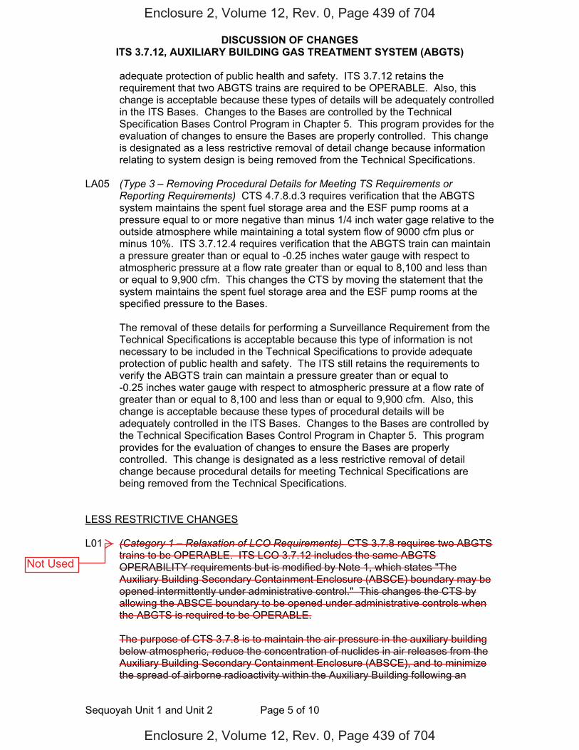
DISCUSSION OF CHANGES ITS 3.7.12, AUXILIARY BUILDING GAS TREATMENT SYSTEM (ABGTS)
Sequoyah Unit 1 and Unit 2 Page 5 of 10
adequate protection of public health and safety. ITS 3.7.12 retains the requirement that two ABGTS trains are required to be OPERABLE. Also, this change is acceptable because these types of details will be adequately controlled in the ITS Bases. Changes to the Bases are controlled by the Technical Specification Bases Control Program in Chapter 5. This program provides for the evaluation of changes to ensure the Bases are properly controlled. This change is designated as a less restrictive removal of detail change because information relating to system design is being removed from the Technical Specifications.
LA05 (Type 3 – Removing Procedural Details for Meeting TS Requirements or
Reporting Requirements) CTS 4.7.8.d.3 requires verification that the ABGTS system maintains the spent fuel storage area and the ESF pump rooms at a pressure equal to or more negative than minus 1/4 inch water gage relative to the outside atmosphere while maintaining a total system flow of 9000 cfm plus or minus 10%. ITS 3.7.12.4 requires verification that the ABGTS train can maintain a pressure greater than or equal to -0.25 inches water gauge with respect to atmospheric pressure at a flow rate greater than or equal to 8,100 and less than or equal to 9,900 cfm. This changes the CTS by moving the statement that the system maintains the spent fuel storage area and the ESF pump rooms at the specified pressure to the Bases.
The removal of these details for performing a Surveillance Requirement from the
Technical Specifications is acceptable because this type of information is not necessary to be included in the Technical Specifications to provide adequate protection of public health and safety. The ITS still retains the requirements to verify the ABGTS train can maintain a pressure greater than or equal to -0.25 inches water gauge with respect to atmospheric pressure at a flow rate of greater than or equal to 8,100 and less than or equal to 9,900 cfm. Also, this change is acceptable because these types of procedural details will be adequately controlled in the ITS Bases. Changes to the Bases are controlled by the Technical Specification Bases Control Program in Chapter 5. This program provides for the evaluation of changes to ensure the Bases are properly controlled. This change is designated as a less restrictive removal of detail change because procedural details for meeting Technical Specifications are being removed from the Technical Specifications.
LESS RESTRICTIVE CHANGES L01 (Category 1 – Relaxation of LCO Requirements) CTS 3.7.8 requires two ABGTS
trains to be OPERABLE. ITS LCO 3.7.12 includes the same ABGTS OPERABILITY requirements but is modified by Note 1, which states "The Auxiliary Building Secondary Containment Enclosure (ABSCE) boundary may be opened intermittently under administrative control." This changes the CTS by allowing the ABSCE boundary to be opened under administrative controls when the ABGTS is required to be OPERABLE.
The purpose of CTS 3.7.8 is to maintain the air pressure in the auxiliary building
below atmospheric, reduce the concentration of nuclides in air releases from the Auxiliary Building Secondary Containment Enclosure (ABSCE), and to minimize the spread of airborne radioactivity within the Auxiliary Building following an
Enclosure 2, Volume 12, Rev. 0, Page 439 of 704
Enclosure 2, Volume 12, Rev. 0, Page 439 of 704
Not Used
DISCUSSION OF CHANGES ITS 3.7.12, AUXILIARY BUILDING GAS TREATMENT SYSTEM (ABGTS)
Sequoyah Unit 1 and Unit 2 Page 6 of 10
accidental release in the fuel handling areas. ITS LCO 3.7.12 Note 1 will allow the ABSCE boundary to be opened under administrative controls when the ABGTS is required to be OPERABLE. This change is acceptable because the administrative controls are described in the Bases. For entry and exit through doors, the administrative control of the opening is performed by the person(s) entering or exiting the area. For other openings, these controls consist of stationing a dedicated individual at the opening who is in continuous communication with the control room. This individual will have a method to rapidly close the opening when a need for auxiliary building isolation is indicated. This change is designated as less restrictive because less stringent LCO requirements are being applied in the ITS than were applied in the CTS.
L02 (Category 4 – Relaxation of Required Action) CTS 3.7.8 ACTION contains
compensatory actions to take when one auxiliary building gas treatment filter train is inoperable in MODES 1, 2, 3 and 4. CTS 3.7.8 does not contain compensatory actions to take when both auxiliary building gas treatment filter trains are inoperable. Therefore, CTS 3.0.3 would be entered for two auxiliary building gas treatment filter trains inoperable. CTS 3.0.3 requires action to be initiated within one hour to be in HOT STANDBY (equivalent to ITS MODE 3) in the following 6 hours, to be in HOT SHUTDOWN (equivalent to ITS MODE 4) in the following 6 hours, and to be in COLD SHUTDOWN (equivalent to ITS MODE 5) in the subsequent 36 hours. ITS 3.7.12 ACTIONS contain a Note stating LCO 3.0.3 is not applicable. ITS 3.7.12 ACTION B states with two ABGTS trains inoperable due to an inoperable Auxiliary Building Secondary Containment Enclosure (ABSCE) boundary in MODE 1, 2, 3, or 4 to restore the auxiliary building boundary to OPERABLE status within 24 hours. Additionally, ITS 3.7.12 ACTION C states, in part, when two ABGTS trains are inoperable for reasons other than Condition B (i.e., an inoperable ABSCE boundary) or if the Required Action and associated Completion Time of Condition B is not met in MODE 1, 2, 3, or 4 to be in MODE 3 within 6 hours and to be in MODE 5 within 36 hours. This changes the CTS by not requiring entry into LCO 3.0.3 when two ABGTS trains are inoperable in MODE 1, 2, 3, or 4, and adds compensatory actions to take when two ABGTS trains are inoperable in MODE 1, 2, 3, or 4.
ITS 3.7.12 is applicable during movement of recently irradiated fuel assemblies in
addition to MODE 1, 2, 3, or 4. Since the movement of recently irradiated fuel assemblies can occur in MODES 1, 2, 3, and 4, it is necessary to add an ACTIONS Note stating that LCO 3.0.3 is not applicable because the movement of fuel is independent of reactor operations. This change is acceptable because ITS 3.7.12 ACTIONS B and C will provide compensatory measures to take when two trains of ABGTS are inoperable in MODE 1, 2, 3, or 4. ITS 3.7.12 ACTION B applies when two ABGTS trains are inoperable because of an inoperable ABSCE boundary in MODE 1, 2, 3, or 4 and provides 24 hours to restore the inoperable auxiliary building boundary to OPERABLE status. During these 24 hours, compensatory measures will be taken to protect plant personnel from potential hazards, and preplanned compensatory measures will be in place to address both the intentional and unintentional inoperability of the ABSCE boundary. Furthermore, the 24 hour Completion Time is based on the low probability of a DBA occurring during this time period and the compensatory measures that will be taken. ITS 3.7.12 ACTION C applies when the Required Action and associated Completion Time of Condition B is not met or when two ABGTS trains
Enclosure 2, Volume 12, Rev. 0, Page 440 of 704
Enclosure 2, Volume 12, Rev. 0, Page 440 of 704
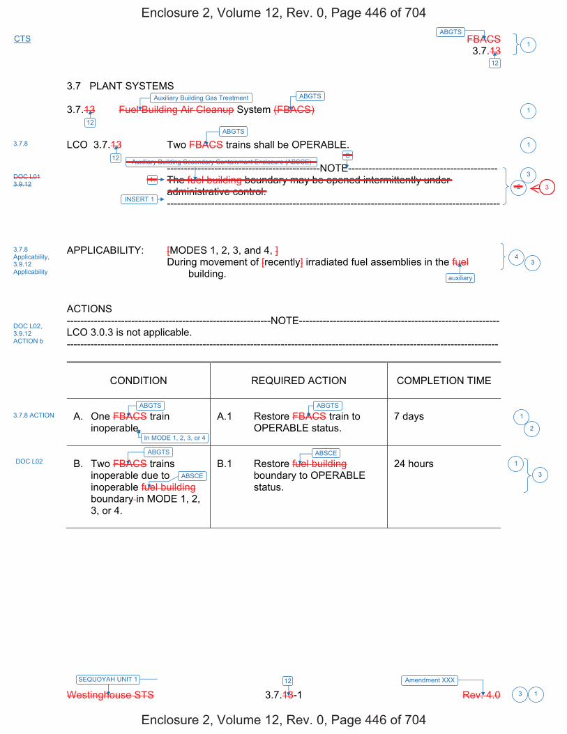
FBACS 3.7.13
Westinghouse STS 3.7.13-1 Rev. 4.0
ABGTSCTS
1
12
3
SEQUOYAH UNIT 1 Amendment XXX 12
1
3.7 PLANT SYSTEMS 3.7.13 Fuel Building Air Cleanup System (FBACS) LCO 3.7.13 Two FBACS trains shall be OPERABLE. ---------------------------------------------NOTE-------------------------------------------- The fuel building boundary may be opened intermittently under
administrative control. -------------------------------------------------------------------------------------------------- APPLICABILITY: [MODES 1, 2, 3, and 4, ] During movement of [recently] irradiated fuel assemblies in the fuel
building. ACTIONS ------------------------------------------------------------NOTE----------------------------------------------------------- LCO 3.0.3 is not applicable. -------------------------------------------------------------------------------------------------------------------------------
CONDITION
REQUIRED ACTION
COMPLETION TIME
A. One FBACS train
inoperable.
A.1 Restore FBACS train to
OPERABLE status.
7 days
B. Two FBACS trains
inoperable due to inoperable fuel building boundary in MODE 1, 2, 3, or 4.
B.1 Restore fuel building
boundary to OPERABLE status.
24 hours
ABGTSAuxiliary Building Gas Treatment
ABGTS
3.7.8
Auxiliary Building Secondary Containment Enclosure (ABSCE)
3.7.8 Applicability, 3.9.12 Applicability
1
1
2
4
3.7.8 ACTION
DOC L02, 3.9.12 ACTION b
ABGTS ABGTS
12
12
auxiliary
3
1
3
ABGTS
ABSCE
ABSCE DOC L02 1
1. DOC L01 3.9.12
S
INSERT 1
3
In MODE 1, 2, 3, or 4 2
Enclosure 2, Volume 12, Rev. 0, Page 446 of 704
Enclosure 2, Volume 12, Rev. 0, Page 446 of 704
3
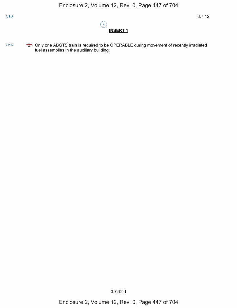
3.7.12
3.7.12-1
CTS
INSERT 1 2. Only one ABGTS train is required to be OPERABLE during movement of recently irradiated
fuel assemblies in the auxiliary building.
2
3.9.12
Enclosure 2, Volume 12, Rev. 0, Page 447 of 704
Enclosure 2, Volume 12, Rev. 0, Page 447 of 704

FBACS 3.7.13
Westinghouse STS 3.7.13-1 Rev. 4.0
ABGTSCTS
1
12
3
SEQUOYAH UNIT 2 Amendment XXX 12
1
3.7 PLANT SYSTEMS 3.7.13 Fuel Building Air Cleanup System (FBACS) LCO 3.7.13 Two FBACS trains shall be OPERABLE. ---------------------------------------------NOTE-------------------------------------------- The fuel building boundary may be opened intermittently under
administrative control. -------------------------------------------------------------------------------------------------- APPLICABILITY: [MODES 1, 2, 3, and 4, ] During movement of [recently] irradiated fuel assemblies in the fuel
building. ACTIONS ------------------------------------------------------------NOTE----------------------------------------------------------- LCO 3.0.3 is not applicable. -------------------------------------------------------------------------------------------------------------------------------
CONDITION
REQUIRED ACTION
COMPLETION TIME
A. One FBACS train
inoperable.
A.1 Restore FBACS train to
OPERABLE status.
7 days
B. Two FBACS trains
inoperable due to inoperable fuel building boundary in MODE 1, 2, 3, or 4.
B.1 Restore fuel building
boundary to OPERABLE status.
24 hours
ABGTSAuxiliary Building Gas Treatment
ABGTS
3.7.8
Auxiliary Building Secondary Containment Enclosure (ABSCE)
3.7.8 Applicability, 3.9.12 Applicability
1
1
2
4
3.7.8 ACTION
DOC L02, 3.9.12 ACTION b
ABGTS ABGTS
12
12
auxiliary
3
1
3
ABGTS
ABSCE
ABSCE DOC L02 1
1. DOC L01 3.9.12
S
INSERT 1
3
In MODE 1, 2, 3, or 4 2
Enclosure 2, Volume 12, Rev. 0, Page 452 of 704
Enclosure 2, Volume 12, Rev. 0, Page 452 of 704
3
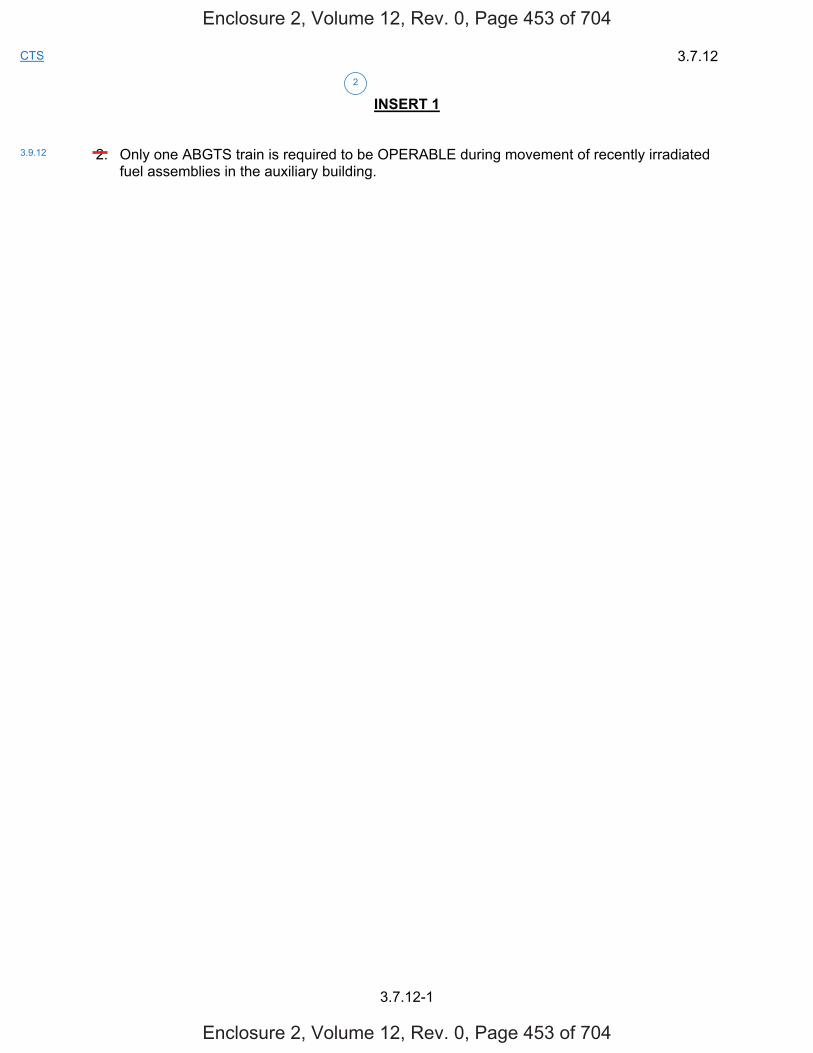
3.7.12
3.7.12-1
CTS
INSERT 1 2. Only one ABGTS train is required to be OPERABLE during movement of recently irradiated
fuel assemblies in the auxiliary building.
2
3.9.12
Enclosure 2, Volume 12, Rev. 0, Page 453 of 704
Enclosure 2, Volume 12, Rev. 0, Page 453 of 704
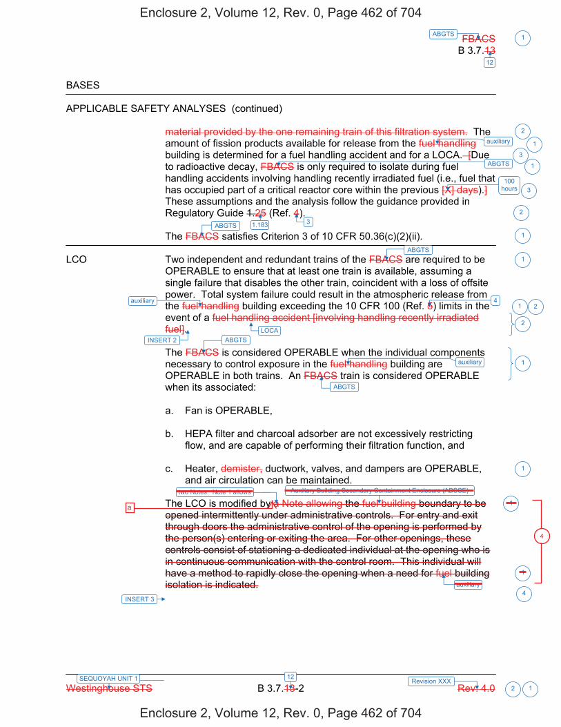
FBACS B 3.7.13
Westinghouse STS B 3.7.13-2 Rev. 4.0
ABGTS 1
12
12SEQUOYAH UNIT 1 Revision XXX 2 1
BASES
APPLICABLE SAFETY ANALYSES (continued)
material provided by the one remaining train of this filtration system. The amount of fission products available for release from the fuel handling building is determined for a fuel handling accident and for a LOCA. [Due to radioactive decay, FBACS is only required to isolate during fuel handling accidents involving handling recently irradiated fuel (i.e., fuel that has occupied part of a critical reactor core within the previous [X] days).] These assumptions and the analysis follow the guidance provided in Regulatory Guide 1.25 (Ref. 4).
The FBACS satisfies Criterion 3 of 10 CFR 50.36(c)(2)(ii).
LCO Two independent and redundant trains of the FBACS are required to be OPERABLE to ensure that at least one train is available, assuming a single failure that disables the other train, coincident with a loss of offsite power. Total system failure could result in the atmospheric release from the fuel handling building exceeding the 10 CFR 100 (Ref. 5) limits in the event of a fuel handling accident [involving handling recently irradiated fuel]. The FBACS is considered OPERABLE when the individual components necessary to control exposure in the fuel handling building are OPERABLE in both trains. An FBACS train is considered OPERABLE when its associated:
a. Fan is OPERABLE,
b. HEPA filter and charcoal adsorber are not excessively restrictingflow, and are capable of performing their filtration function, and
c. Heater, demister, ductwork, valves, and dampers are OPERABLE,and air circulation can be maintained.
The LCO is modified by a Note allowing the fuel building boundary to be opened intermittently under administrative controls. For entry and exit through doors the administrative control of the opening is performed by the person(s) entering or exiting the area. For other openings, these controls consist of stationing a dedicated individual at the opening who is in continuous communication with the control room. This individual will have a method to rapidly close the opening when a need for fuel building isolation is indicated.
ABGTS
100 hours
ABGTS 3
4
ABGTS
ABGTS
ABGTS
auxiliary
2
1
3
3
2
1
1
1
2
1
1
1
1auxiliary
auxiliary
1
auxiliary
1.183
Auxiliary Building Secondary Containment Enclosure (ABSCE)
2
LOCAINSERT 2
INSERT 3
two Notes. Note 1 allows
4
Enclosure 2, Volume 12, Rev. 0, Page 462 of 704
Enclosure 2, Volume 12, Rev. 0, Page 462 of 704
a
4
B 3.7.12
Insert Page B 3.7.12-2
INSERT 2 One train of the ABGTS is required to be OPERABLE to mitigate the consequences of a fuel handling accident involving handling recently irradiated fuel to limit releases to the environment to within the 10 CFR 50.67 limits.
INSERT 3 Note 2 specifies that only one ABGTS train is required to be OPERABLE during the movement of recently irradiated fuel assemblies in the auxiliary building.
2
4
Enclosure 2, Volume 12, Rev. 0, Page 463 of 704
Enclosure 2, Volume 12, Rev. 0, Page 463 of 704
that
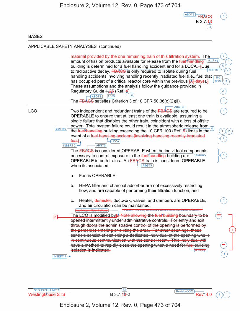
FBACS B 3.7.13
Westinghouse STS B 3.7.13-2 Rev. 4.0
ABGTS 1
12
12SEQUOYAH UNIT 2 Revision XXX 2 1
BASES APPLICABLE SAFETY ANALYSES (continued)
material provided by the one remaining train of this filtration system. The amount of fission products available for release from the fuel handling building is determined for a fuel handling accident and for a LOCA. [Due to radioactive decay, FBACS is only required to isolate during fuel handling accidents involving handling recently irradiated fuel (i.e., fuel that has occupied part of a critical reactor core within the previous [X] days).] These assumptions and the analysis follow the guidance provided in Regulatory Guide 1.25 (Ref. 4). The FBACS satisfies Criterion 3 of 10 CFR 50.36(c)(2)(ii).
LCO Two independent and redundant trains of the FBACS are required to be
OPERABLE to ensure that at least one train is available, assuming a single failure that disables the other train, coincident with a loss of offsite power. Total system failure could result in the atmospheric release from the fuel handling building exceeding the 10 CFR 100 (Ref. 5) limits in the event of a fuel handling accident [involving handling recently irradiated fuel]. The FBACS is considered OPERABLE when the individual components necessary to control exposure in the fuel handling building are OPERABLE in both trains. An FBACS train is considered OPERABLE when its associated: a. Fan is OPERABLE, b. HEPA filter and charcoal adsorber are not excessively restricting
flow, and are capable of performing their filtration function, and c. Heater, demister, ductwork, valves, and dampers are OPERABLE,
and air circulation can be maintained. The LCO is modified by a Note allowing the fuel building boundary to be opened intermittently under administrative controls. For entry and exit through doors the administrative control of the opening is performed by the person(s) entering or exiting the area. For other openings, these controls consist of stationing a dedicated individual at the opening who is in continuous communication with the control room. This individual will have a method to rapidly close the opening when a need for fuel building isolation is indicated.
ABGTS
100 hours
ABGTS 3
4
ABGTS
ABGTS
ABGTS
auxiliary
2
1
3
3
2
1
1
1
2
1
1
1
1auxiliary
auxiliary
1
auxiliary
1.183
Auxiliary Building Secondary Containment Enclosure (ABSCE)
2
LOCAINSERT 2
INSERT 3
two Notes. Note 1 allows
4
Enclosure 2, Volume 12, Rev. 0, Page 473 of 704
Enclosure 2, Volume 12, Rev. 0, Page 473 of 704
a
4
B 3.7.12
Insert Page B 3.7.12-2
INSERT 2 One train of the ABGTS is required to be OPERABLE to mitigate the consequences of a fuel handling accident involving handling recently irradiated fuel to limit releases to the environment to within the 10 CFR 50.67 limits.
INSERT 3 Note 2 specifies that only one ABGTS train is required to be OPERABLE during the movement of recently irradiated fuel assemblies in the auxiliary building.
2
4
Enclosure 2, Volume 12, Rev. 0, Page 474 of 704
Enclosure 2, Volume 12, Rev. 0, Page 474 of 704
that

Licensee Response/NRC Response/NRC Question ClosureId 458
NRC Question Number MHC005
Select Application NRC Question Closure
Attachment 1
Attachment 2
Response Statement
Response Date/Time
Closure Statement This question is closed and no further information is required at this time to draft the Safety Evaluation.
Question Closure Date 5/27/2015
Notification Mark BlumbergScott BowmanMichelle ConnerKhadijah HemphillAndrew HonLynn MynattRay SchieleRoger Scott
Added By Kristy Bucholtz
Date Added 5/27/2015 10:07 AM
Date Modified
Modified By
Page 1 of 1Sequoyah ITS Conversion Database
5/29/2015https://members.excelservices.com/rai/index.php?requestType=areaItemPrint&itemId=458
ITS NRC QuestionsId 211
NRC Question Number MHC007
Category Technical
ITS Section AST
ITS Number
DOC Number
JFD Number
JFD Bases Number
Page Number(s)
NRC Reviewer Supervisor Undine Shoop
Technical Branch POC Mark Blumberg
Conf Call Requested N
NRC Question Why are Tritium-Producing Burnable Absorber Rods (TPBARs) not included in the Fuel Handling Accident analysis source term?
Attach File 1
Attach File 2
Issue Date 4/14/2015
Added By Khadijah Hemphill
Date Modified
Modified By
Date Added 4/14/2015 1:33 PM
Notification Mark BlumbergScott BowmanMargaret ChernoffMichelle ConnerKhadijah HemphillAndrew HonLynn MynattRay SchieleRoger Scott
Page 1 of 1Sequoyah ITS Conversion Database
04/27/2015https://members.excelservices.com/rai/index.php?requestType=areaItemPrint&itemId=211
Licensee Response/NRC Response/NRC Question ClosureId 434
NRC Question Number
MHC007
Select Application Licensee Response
Attachment 1
Attachment 2
Response Statement Sequoyah Nuclear Plant (SQN), Units 1 and 2, both have license
conditions, provided with the issuance of Amendments 278 and 289 for Unit 1 and Amendments 269 and 279 for Unit 2, that state “This license amendment is effective as of the date of its issuance, and shall be implemented prior to starting up from the outage where TVA inserts tritium-producing burnable absorber rods in the core, provided there have been no changes to the facility that materially change the bases for approval of the [this] amendment.”Since the issuance of these amendments, changes have been made at SQN, Units 1 and 2, that materially change the bases for NRC approval of Amendments 278 and 289 for Unit 1 and Amendments 269 and 279 for Unit 2. A license amendment request was submitted on June 17, 2011, that requested an amendment of the licensing basis and the Technical Specifications (TS) to permit the use of AREVA Advanced W17 HTP fuel at SQN. The Safety Evaluation Report (SER) for the approval of this license amendment was issued on September 26, 2012. As a result, the bases for the TPBAR amendments have materially changed such that TVA would need to request and receive NRC approval prior to introducing any tritium-producing burnable absorber rods (TPBARs) into either SQN unit. At this time, SQN is not licensed to insert tritium-producing burnable absorber rods in the core. Therefore, SQN did not include TPBARS as part of the source term in the revised fuel handling accident dose consequences analysis submitted in Supplement 1 (ADAMS Accession No. ML 14350B364) to the SQN Unit 1 and 2 Technical Specifications conversion to NUREG-1431, Rev 4.
Response Date/Time 4/20/2015 3:20 PM
Closure Statement
Question Closure
Page 1 of 2Sequoyah ITS Conversion Database
04/27/2015https://members.excelservices.com/rai/index.php?requestType=areaItemPrint&itemId=434
Date
Notification Mark BlumbergScott BowmanKristy BucholtzMargaret ChernoffMichelle ConnerRobert ElliottKhadijah HemphillAndrew HonLynn MynattRay Schiele
Added By Lynn Mynatt
Date Added 4/20/2015 2:20 PM
Date Modified
Modified By
Page 2 of 2Sequoyah ITS Conversion Database
04/27/2015https://members.excelservices.com/rai/index.php?requestType=areaItemPrint&itemId=434

Licensee Response/NRC Response/NRC Question ClosureId 439
NRC Question Number MHC007
Select Application NRC Question Closure
Attachment 1
Attachment 2
Response Statement
Response Date/Time
Closure Statement This question is closed and no further information is required at this time to draft the Safety Evaluation.
Question Closure Date 4/23/2015
Notification Scott BowmanMichelle ConnerKhadijah HemphillAndrew HonLynn MynattRay SchieleRoger Scott
Added By Khadijah Hemphill
Date Added 4/23/2015 12:08 PM
Date Modified
Modified By
Page 1 of 1Sequoyah ITS Conversion Database
04/27/2015https://members.excelservices.com/rai/index.php?requestType=areaItemPrint&itemId=439
ITS NRC QuestionsId 30
NRC Question Number
MEH-001
Category Technical
ITS Section 3.7
ITS Number 3.7.4
DOC Number
JFD Number 6
JFD Bases Number
Page Number(s) 128 of 704
NRC Reviewer
Supervisor Rob Elliott
Technical Branch POC Add Name
Conf Call Requested N
NRC Question
The frequency for STS SR 3.7.4.1 is 18 months OR In accordance with the SFCP. The proposed frequency for proposed SR 3.7.4.1 is ”In accordance with the Inservice Testing Program.” Enclosure 2, Volume 12 Page 128 of 704 states that the ARVs are Code Class valves tested under the Sequoyah ASME Section XI Inservice Testing Program. Please provide an expanded justification for the proposed frequency which discusses why testing in accordance with the Inservice Testing Program is equivalent to or better than testing at a set frequency or in accordance with the surveillance frequency control program. Part of the expanded justification should discuss whether or not future revisions to the ASME Code could unintentionally change testing frequencies for the ARVs in TS.
Attach File 1
Attach File 2
Issue Date 5/7/2014
Added By Matthew Hamm
Date Modified
Modified By
Date Added 5/7/2014 2:05 PM
Notification Scott BowmanMichelle ConnerMatthew HammKhadijah HemphillAndrew HonLynn MynattRay SchieleRoger Scott
Page 1 of 1Sequoyah ITS Conversion Database
8/21/2014https://members.excelservices.com/rai/index.php?requestType=areaItemPrint&itemId=30
Licensee Response/NRC Response/NRC Question ClosureId 33
NRC Question Number
MEH-001
Select Application Licensee Response
Attachment 1 Attachment 1 draft revised ITS submittal pages.pdf (69KB)
Attachment 2
Response Statement
In response to RAI MEH-001, the Frequency for ITS SR 3.7.4.1 will be changed from, “In accordance with the Inservice Testing Program,” to “In accordance with the Surveillance Frequency Control Program.”Justification for deviation (JFD) 6 will be revised to indicate that for ISTS SR 3.7.4.1, SQN is proposing to control the ARV Surveillance Frequency under the Surveillance Frequency Control Program.
Additionally, the ITS Bases for SR 3.7.4.1 will be changed from, “The Surveillance Frequency is controlled under the Inservice Testing Program,”to, “The Surveillance Frequency is controlled under the Surveillance Frequency Control Program.” JFD 7, for the ITS 3.7.4 Bases, will be revised to indicate that for ISTS SR 3.7.4.1, SQN is proposing to control the ARV Surveillance Frequency under the Surveillance Frequency Control Program.
As discussed in DOC M01, SQN CTS do not contain a specification for ARVs. ITS 3.7.4 specifies the requirements for the ARVs, consistent with the requirements of ISTS 3.7.4, “Atmospheric Dump Valves.” As part of the adoption of ITS 3.7.4, a new surveillance, SR 3.7.4.1, will be added to verify one complete cycle of each ARV. ISTS SR 3.7.4.1 provides two options for controlling the Frequency of the Surveillance Requirement: (1) an 18 month Frequency, or (2) an 18 month Frequency relocated to the Surveillance Frequency Control Program. SQN currently tests the ARVs at an 18 month frequency. SQN is proposing to maintain the 18 month testing frequency and control the ARV Surveillance Frequency under the Surveillance Frequency Control Program.
See Attachment 1 for draft revised ITS submittal pages.Response
Date/Time 5/23/2014 9:15 AM
Closure Statement
Question Closure
Date
Notification Scott BowmanMichelle Conner
Page 1 of 2Sequoyah ITS Conversion Database
8/21/2014https://members.excelservices.com/rai/index.php?requestType=areaItemPrint&itemId=33

Matthew HammKhadijah HemphillAndrew HonLynn MynattRay Schiele
Added By Scott Bowman
Date Added 5/23/2014 8:12 AM
Date Modified
Modified By
Page 2 of 2Sequoyah ITS Conversion Database
8/21/2014https://members.excelservices.com/rai/index.php?requestType=areaItemPrint&itemId=33
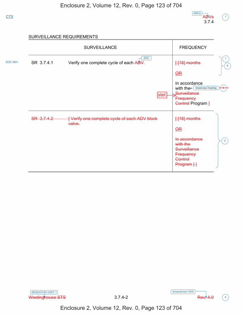
ADVs 3.7.4
Westinghouse STS 3.7.4-2 Rev. 4.0
1
5
SEQUOYAH UNIT 1 Amendment XXX
CTS ARVs
SURVEILLANCE REQUIREMENTS
SURVEILLANCE
FREQUENCY
SR 3.7.4.1 Verify one complete cycle of each ADV.
[ [18] months OR In accordance with the Surveillance Frequency Control Program ]
SR 3.7.4.2 [ Verify one complete cycle of each ADV block
valve.
[ [18] months OR In accordance with the Surveillance Frequency Control Program ] ]
1
6DOC M01
ARV
6
2
Inservice Testing
Enclosure 2, Volume 12, Rev. 0, Page 123 of 704
Enclosure 2, Volume 12, Rev. 0, Page 123 of 704
stet

ADVs 3.7.4
Westinghouse STS 3.7.4-2 Rev. 4.0
1
5
SEQUOYAH UNIT 2 Amendment XXX
CTS ARVs
SURVEILLANCE REQUIREMENTS
SURVEILLANCE
FREQUENCY
SR 3.7.4.1 Verify one complete cycle of each ADV.
[ [18] months OR In accordance with the Surveillance Frequency Control Program ]
SR 3.7.4.2 [ Verify one complete cycle of each ADV block
valve.
[ [18] months OR In accordance with the Surveillance Frequency Control Program ] ]
1
6DOC M01
ARV
6
2
Inservice Testing
Enclosure 2, Volume 12, Rev. 0, Page 126 of 704
Enclosure 2, Volume 12, Rev. 0, Page 126 of 704
stet
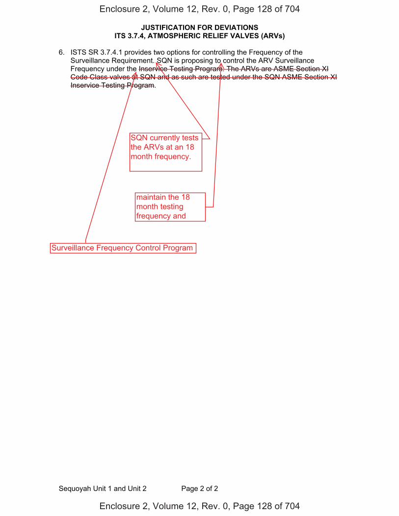
JUSTIFICATION FOR DEVIATIONS ITS 3.7.4, ATMOSPHERIC RELIEF VALVES (ARVs)
Sequoyah Unit 1 and Unit 2 Page 2 of 2
6. ISTS SR 3.7.4.1 provides two options for controlling the Frequency of the Surveillance Requirement. SQN is proposing to control the ARV Surveillance Frequency under the Inservice Testing Program. The ARVs are ASME Section XI Code Class valves at SQN and as such are tested under the SQN ASME Section XI Inservice Testing Program.
Enclosure 2, Volume 12, Rev. 0, Page 128 of 704
Enclosure 2, Volume 12, Rev. 0, Page 128 of 704
SQN currently teststhe ARVs at an 18month frequency.
maintain the 18month testingfrequency and
Surveillance Frequency Control Program
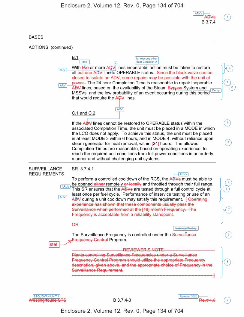
ADVs B 3.7.4
Westinghouse STS B 3.7.4-3 Rev. 4.0
1ARVs
2Revision XXXSEQUOYAH UNIT 1
BASES ACTIONS (continued)
B.1 With two or more ADV lines inoperable, action must be taken to restore all but one ADV line to OPERABLE status. Since the block valve can be closed to isolate an ADV, some repairs may be possible with the unit at power. The 24 hour Completion Time is reasonable to repair inoperable ADV lines, based on the availability of the Steam Bypass System and MSSVs, and the low probability of an event occurring during this period that would require the ADV lines. C.1 and C.2 If the ADV lines cannot be restored to OPERABLE status within the associated Completion Time, the unit must be placed in a MODE in which the LCO does not apply. To achieve this status, the unit must be placed in at least MODE 3 within 6 hours, and in MODE 4, without reliance upon steam generator for heat removal, within [24] hours. The allowed Completion Times are reasonable, based on operating experience, to reach the required unit conditions from full power conditions in an orderly manner and without challenging unit systems.
SURVEILLANCE SR 3.7.4.1 REQUIREMENTS
To perform a controlled cooldown of the RCS, the ADVs must be able to be opened either remotely or locally and throttled through their full range. This SR ensures that the ADVs are tested through a full control cycle at least once per fuel cycle. Performance of inservice testing or use of an ADV during a unit cooldown may satisfy this requirement. [ Operating experience has shown that these components usually pass the Surveillance when performed at the [18] month Frequency. The Frequency is acceptable from a reliability standpoint. OR The Surveillance Frequency is controlled under the Surveillance Frequency Control Program. -----------------------------------REVIEWER’S NOTE----------------------------------- Plants controlling Surveillance Frequencies under a Surveillance Frequency Control Program should utilize the appropriate Frequency description, given above, and the appropriate choice of Frequency in the Surveillance Requirement. ------------------------------------------------------------------------------------------------ ]
ARV
1
1
1
7
8
2
3
Dump
ARV
ARVs
ARV
ARVs
one s
6
2
for reasons other than Condition A
Inservice Testing
7
ARV
Enclosure 2, Volume 12, Rev. 0, Page 134 of 704
Enclosure 2, Volume 12, Rev. 0, Page 134 of 704
stet
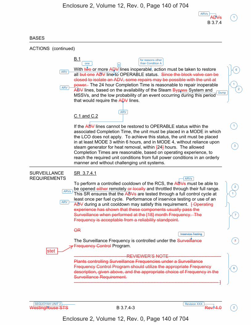
ADVs B 3.7.4
Westinghouse STS B 3.7.4-3 Rev. 4.0
1ARVs
2Revision XXXSEQUOYAH UNIT 2
BASES ACTIONS (continued)
B.1 With two or more ADV lines inoperable, action must be taken to restore all but one ADV line to OPERABLE status. Since the block valve can be closed to isolate an ADV, some repairs may be possible with the unit at power. The 24 hour Completion Time is reasonable to repair inoperable ADV lines, based on the availability of the Steam Bypass System and MSSVs, and the low probability of an event occurring during this period that would require the ADV lines. C.1 and C.2 If the ADV lines cannot be restored to OPERABLE status within the associated Completion Time, the unit must be placed in a MODE in which the LCO does not apply. To achieve this status, the unit must be placed in at least MODE 3 within 6 hours, and in MODE 4, without reliance upon steam generator for heat removal, within [24] hours. The allowed Completion Times are reasonable, based on operating experience, to reach the required unit conditions from full power conditions in an orderly manner and without challenging unit systems.
SURVEILLANCE SR 3.7.4.1 REQUIREMENTS
To perform a controlled cooldown of the RCS, the ADVs must be able to be opened either remotely or locally and throttled through their full range. This SR ensures that the ADVs are tested through a full control cycle at least once per fuel cycle. Performance of inservice testing or use of an ADV during a unit cooldown may satisfy this requirement. [ Operating experience has shown that these components usually pass the Surveillance when performed at the [18] month Frequency. The Frequency is acceptable from a reliability standpoint. OR The Surveillance Frequency is controlled under the Surveillance Frequency Control Program. -----------------------------------REVIEWER’S NOTE----------------------------------- Plants controlling Surveillance Frequencies under a Surveillance Frequency Control Program should utilize the appropriate Frequency description, given above, and the appropriate choice of Frequency in the Surveillance Requirement. ------------------------------------------------------------------------------------------------ ]
ARV
1
1
1
7
8
2
3
Dump
ARV
ARVs
ARV
ARVs
one s
6
2
for reasons other than Condition A
Inservice Testing
7
ARV
Enclosure 2, Volume 12, Rev. 0, Page 140 of 704
Enclosure 2, Volume 12, Rev. 0, Page 140 of 704
stet
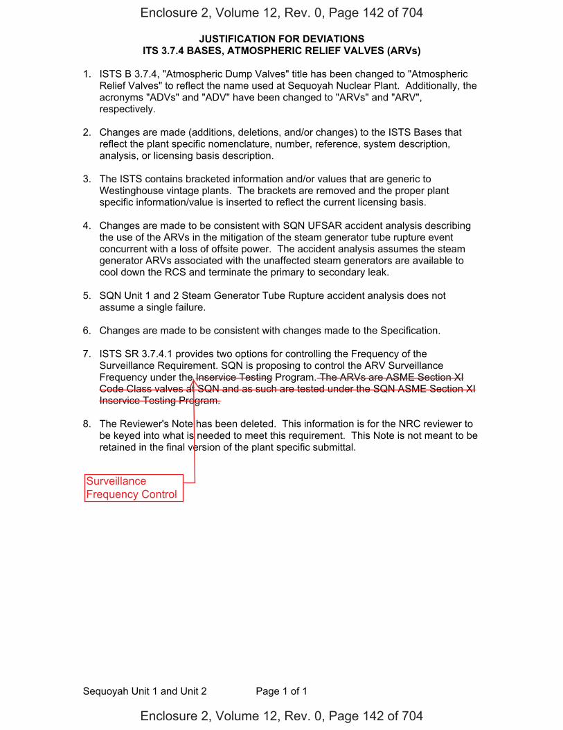
JUSTIFICATION FOR DEVIATIONS ITS 3.7.4 BASES, ATMOSPHERIC RELIEF VALVES (ARVs)
Sequoyah Unit 1 and Unit 2 Page 1 of 1
1. ISTS B 3.7.4, "Atmospheric Dump Valves" title has been changed to "Atmospheric Relief Valves" to reflect the name used at Sequoyah Nuclear Plant. Additionally, the acronyms "ADVs" and "ADV" have been changed to "ARVs" and "ARV", respectively.
2. Changes are made (additions, deletions, and/or changes) to the ISTS Bases that
reflect the plant specific nomenclature, number, reference, system description, analysis, or licensing basis description.
3. The ISTS contains bracketed information and/or values that are generic to
Westinghouse vintage plants. The brackets are removed and the proper plant specific information/value is inserted to reflect the current licensing basis.
4. Changes are made to be consistent with SQN UFSAR accident analysis describing
the use of the ARVs in the mitigation of the steam generator tube rupture event concurrent with a loss of offsite power. The accident analysis assumes the steam generator ARVs associated with the unaffected steam generators are available to cool down the RCS and terminate the primary to secondary leak.
5. SQN Unit 1 and 2 Steam Generator Tube Rupture accident analysis does not
assume a single failure.
6. Changes are made to be consistent with changes made to the Specification. 7. ISTS SR 3.7.4.1 provides two options for controlling the Frequency of the
Surveillance Requirement. SQN is proposing to control the ARV Surveillance Frequency under the Inservice Testing Program. The ARVs are ASME Section XI Code Class valves at SQN and as such are tested under the SQN ASME Section XI Inservice Testing Program.
8. The Reviewer's Note has been deleted. This information is for the NRC reviewer to
be keyed into what is needed to meet this requirement. This Note is not meant to be retained in the final version of the plant specific submittal.
Enclosure 2, Volume 12, Rev. 0, Page 142 of 704
Enclosure 2, Volume 12, Rev. 0, Page 142 of 704
SurveillanceFrequency Control

Licensee Response/NRC Response/NRC Question ClosureId 173
NRC Question Number MEH-001
Select Application NRC Question Closure
Attachment 1
Attachment 2
Response Statement
Response Date/Time
Closure Statement This question is closed and no further information is required at this time to draft the Safety Evaluation.
Question Closure Date 7/16/2014
Notification Scott BowmanMichelle ConnerMatthew HammKhadijah HemphillAndrew HonLynn MynattRay SchieleRoger Scott
Added By Matthew Hamm
Date Added 7/16/2014 11:50 AM
Date Modified
Modified By
Page 1 of 1Sequoyah ITS Conversion Database
8/21/2014https://members.excelservices.com/rai/index.php?requestType=areaItemPrint&itemId=173
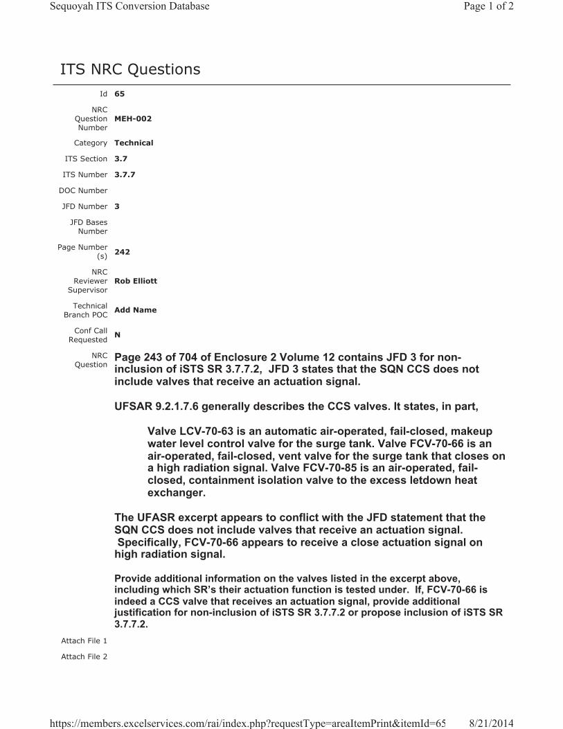
ITS NRC QuestionsId 65
NRC Question Number
MEH-002
Category Technical
ITS Section 3.7
ITS Number 3.7.7
DOC Number
JFD Number 3
JFD Bases Number
Page Number(s) 242
NRC Reviewer
Supervisor Rob Elliott
Technical Branch POC Add Name
Conf Call Requested N
NRC Question
Page 243 of 704 of Enclosure 2 Volume 12 contains JFD 3 for non-inclusion of iSTS SR 3.7.7.2, JFD 3 states that the SQN CCS does not include valves that receive an actuation signal.
UFSAR 9.2.1.7.6 generally describes the CCS valves. It states, in part,
Valve LCV-70-63 is an automatic air-operated, fail-closed, makeup water level control valve for the surge tank. Valve FCV-70-66 is an air-operated, fail-closed, vent valve for the surge tank that closes on a high radiation signal. Valve FCV-70-85 is an air-operated, fail-closed, containment isolation valve to the excess letdown heat exchanger.
The UFASR excerpt appears to conflict with the JFD statement that the SQN CCS does not include valves that receive an actuation signal. Specifically, FCV-70-66 appears to receive a close actuation signal on high radiation signal.
Provide additional information on the valves listed in the excerpt above, including which SR’s their actuation function is tested under. If, FCV-70-66 is indeed a CCS valve that receives an actuation signal, provide additional justification for non-inclusion of iSTS SR 3.7.7.2 or propose inclusion of iSTS SR 3.7.7.2.
Attach File 1
Attach File 2
Page 1 of 2Sequoyah ITS Conversion Database
8/21/2014https://members.excelservices.com/rai/index.php?requestType=areaItemPrint&itemId=65

Issue Date 5/16/2014
Added By Matthew Hamm
Date Modified
Modified By
Date Added 5/16/2014 12:35 PM
Notification Scott BowmanMichelle ConnerKhadijah HemphillAndrew HonLynn MynattRay SchieleRoger Scott
Page 2 of 2Sequoyah ITS Conversion Database
8/21/2014https://members.excelservices.com/rai/index.php?requestType=areaItemPrint&itemId=65
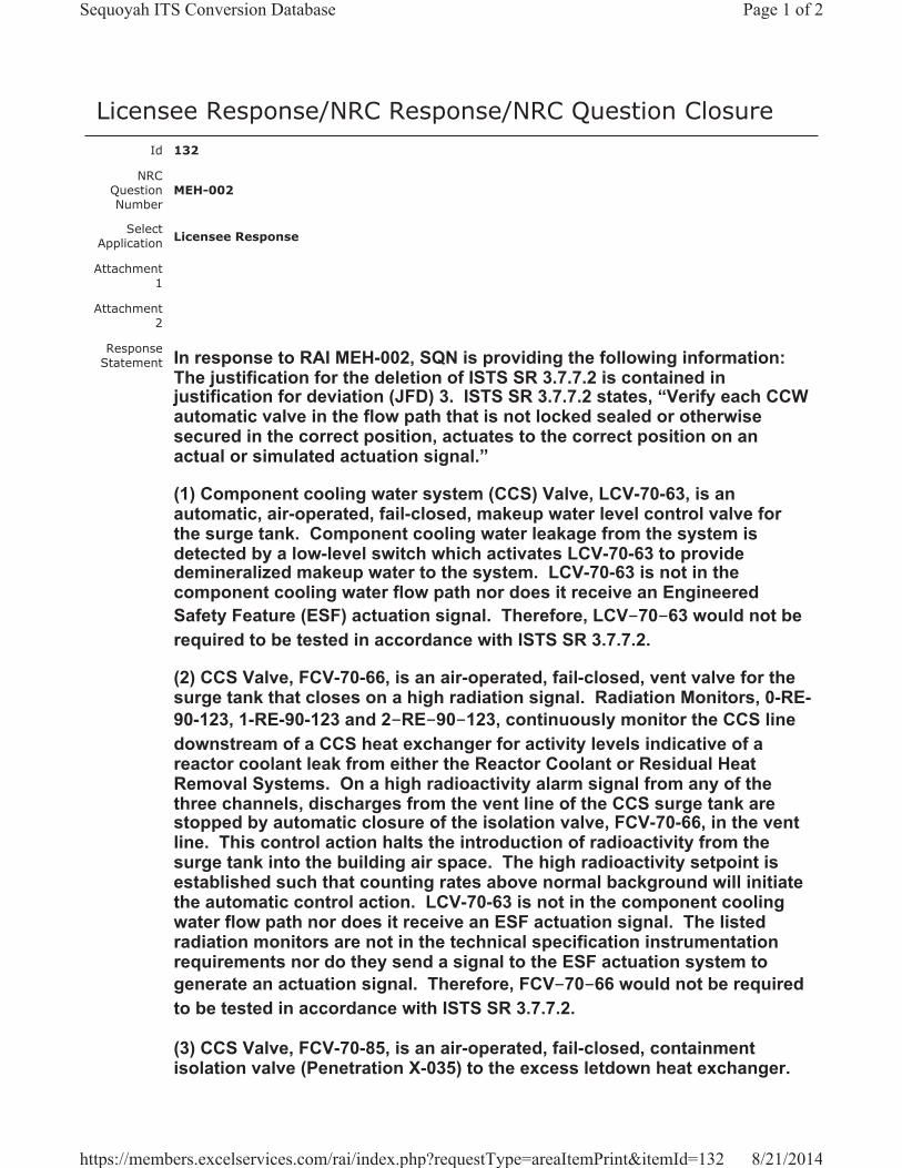
Licensee Response/NRC Response/NRC Question ClosureId 132
NRC Question Number
MEH-002
Select Application Licensee Response
Attachment 1
Attachment 2
Response Statement In response to RAI MEH-002, SQN is providing the following information:
The justification for the deletion of ISTS SR 3.7.7.2 is contained in justification for deviation (JFD) 3. ISTS SR 3.7.7.2 states, “Verify each CCW automatic valve in the flow path that is not locked sealed or otherwise secured in the correct position, actuates to the correct position on an actual or simulated actuation signal.”
(1) Component cooling water system (CCS) Valve, LCV-70-63, is an automatic, air-operated, fail-closed, makeup water level control valve for the surge tank. Component cooling water leakage from the system is detected by a low-level switch which activates LCV-70-63 to provide demineralized makeup water to the system. LCV-70-63 is not in the component cooling water flow path nor does it receive an Engineered Safety Feature (ESF) actuation signal. Therefore, LCV-70-63 would not be required to be tested in accordance with ISTS SR 3.7.7.2.
(2) CCS Valve, FCV-70-66, is an air-operated, fail-closed, vent valve for the surge tank that closes on a high radiation signal. Radiation Monitors, 0-RE-90-123, 1-RE-90-123 and 2-RE-90-123, continuously monitor the CCS line downstream of a CCS heat exchanger for activity levels indicative of a reactor coolant leak from either the Reactor Coolant or Residual Heat Removal Systems. On a high radioactivity alarm signal from any of the three channels, discharges from the vent line of the CCS surge tank are stopped by automatic closure of the isolation valve, FCV-70-66, in the vent line. This control action halts the introduction of radioactivity from the surge tank into the building air space. The high radioactivity setpoint is established such that counting rates above normal background will initiate the automatic control action. LCV-70-63 is not in the component cooling water flow path nor does it receive an ESF actuation signal. The listed radiation monitors are not in the technical specification instrumentation requirements nor do they send a signal to the ESF actuation system to generate an actuation signal. Therefore, FCV-70-66 would not be required to be tested in accordance with ISTS SR 3.7.7.2.
(3) CCS Valve, FCV-70-85, is an air-operated, fail-closed, containment isolation valve (Penetration X-035) to the excess letdown heat exchanger.
Page 1 of 2Sequoyah ITS Conversion Database
8/21/2014https://members.excelservices.com/rai/index.php?requestType=areaItemPrint&itemId=132
The valve will be tested as part of ITS SR 3.6.3.6, which states, “Verify each automatic containment isolation valve that is not locked, sealed or otherwise secured in position, actuates to the isolation position on an actual or simulated actuation signal.” LCV-70-85 is tested in accordance with ITS SR 3.6.3.6 to ensure safety function is preserved. Therefore, LCV-70-85 would not require additional testing in ISTS SR 3.7.7.2.
Therefore, the deletion of ISTS SR 3.7.7.2 is justified as being not needed, because the three valves discussed in UFSAR Section 9.2.1.7.6 are either not in the component cooling water flow path or are tested by a different surveillance requirement.
Response Date/Time 6/20/2014 5:05 AM
Closure Statement
Question Closure
Date
Notification Scott BowmanMichelle ConnerMatthew HammKhadijah HemphillAndrew HonRay Schiele
Added By Scott Bowman
Date Added 6/20/2014 4:03 AM
Date Modified
Modified By
Page 2 of 2Sequoyah ITS Conversion Database
8/21/2014https://members.excelservices.com/rai/index.php?requestType=areaItemPrint&itemId=132

Licensee Response/NRC Response/NRC Question ClosureId 255
NRC Question Number MEH-002
Select Application NRC Question Closure
Attachment 1
Attachment 2
Response Statement
Response Date/Time
Closure Statement This question is closed and no further information is required at this time to draft the Safety Evaluation.
Question Closure Date 8/8/2014
Notification Scott BowmanMichelle ConnerMatthew HammKhadijah HemphillAndrew HonLynn MynattRay SchieleRoger Scott
Added By Matthew Hamm
Date Added 8/8/2014 1:55 PM
Date Modified
Modified By
Page 1 of 1Sequoyah ITS Conversion Database
8/21/2014https://members.excelservices.com/rai/index.php?requestType=areaItemPrint&itemId=255
ITS NRC QuestionsId 107
NRC Question Number
MEH-003
Category Technical
ITS Section 3.7
ITS Number 3.7.9
DOC Number
JFD Number 5
JFD Bases Number
Page Number(s) 312
NRC Reviewer
Supervisor Rob Elliott
Technical Branch POC Add Name
Conf Call Requested N
NRC Question
The proposed SR 3.7.9.2 text is:
Verify average water temperature of UHS is:a) 81°F with any ERCW train aligned to support one pump per train operation,b) < 83°F with one ERCW supply strainer and two ERCW pumps OPERABLE on that train, andc) 87°F with two ERCW supply strainers and two ERCW pumps OPERABLE per train.
It appears the frequency of proposed SR 3.7.9.2 is a frequency that is related to specific conditions or conditions for the performance of a surveillance requirement. These types of frequencies were not permitted to be relocated to the Surveillance Frequency Control Program. However, JFD 5 on page 312 of 704 of Enclosure 2, Volume 12 states that the proposed frequency for SR 3.7.9.2 is “In Accordance with the Surveillance Frequency Control Program.” Please provide a more detailed explanation as to why the proposed frequency for SR 3.7.9.2 does not meet any of the 4 types of frequencies specifically not allowed to be relocated by TSTF-425.
Attach File 1
Attach File 2
Issue Date 5/29/2014
Added By Matthew Hamm
Page 1 of 2Sequoyah ITS Conversion Database
8/21/2014https://members.excelservices.com/rai/index.php?requestType=areaItemPrint&itemId=107
Date Modified
Modified By
Date Added 5/29/2014 3:05 PM
Notification Scott BowmanMichelle ConnerAndrew HonLynn MynattRay SchieleRoger Scott
Page 2 of 2Sequoyah ITS Conversion Database
8/21/2014https://members.excelservices.com/rai/index.php?requestType=areaItemPrint&itemId=107
Licensee Response/NRC Response/NRC Question ClosureId 142
NRC Question Number
MEH-003
Select Application Licensee Response
Attachment 1
Attachment 2
Response Statement
As indicated in Discussion of Change (DOC) LA01, the Frequency of proposed ITS SR 3.7.9.2 is 24 hours consistent with CTS 4.7.5.1. This CTS frequency of “at least once per 24 hours” is being relocated to the Surveillance Frequency Control Program. This frequency is time-based and is not related to specific conditions or conditions for performance of the surveillance. Proposed SR 3.7.9.2 must be performed every 24 hours regardless of the Essential Raw Cooling Water (ERCW) System configuration. The ERCW System configurations specified in a), b), and c) of proposed SR 3.7.9.2 are provided to differentiate when each specified average water temperature acceptance criteria must be met to satisfy SR 3.7.9.2 and does not alter when SR 3.7.9.2 must be performed.Therefore, the proposed relocated frequency of every 24 hours: 1) does not reference other approved programs; 2) is not purely event driven; 3) does not have a time component performing the surveillance on a one-time basis once the event occurs; and 4) is not related to a specific condition or conditions for the performance of a surveillance requirement (e.g., when the ERCW System configuration is altered).
Response Date/Time 6/20/2014 2:40 PM
Closure Statement
Question Closure
Date
Notification Scott BowmanMichelle ConnerMatthew HammKhadijah HemphillAndrew HonRay Schiele
Added By Scott Bowman
Date Added 6/20/2014 1:41 PM
Date Modified
Modified By
Page 1 of 1Sequoyah ITS Conversion Database
8/21/2014https://members.excelservices.com/rai/index.php?requestType=areaItemPrint&itemId=142

Licensee Response/NRC Response/NRC Question ClosureId 254
NRC Question Number MEH-003
Select Application NRC Question Closure
Attachment 1
Attachment 2
Response Statement
Response Date/Time
Closure Statement This question is closed and no further information is required at this time to draft the Safety Evaluation.
Question Closure Date 8/8/2014
Notification Scott BowmanMichelle ConnerMatthew HammKhadijah HemphillAndrew HonLynn MynattRay SchieleRoger Scott
Added By Matthew Hamm
Date Added 8/8/2014 1:55 PM
Date Modified
Modified By
Page 1 of 1Sequoyah ITS Conversion Database
8/21/2014https://members.excelservices.com/rai/index.php?requestType=areaItemPrint&itemId=254
ITS NRC QuestionsId 147
NRC Question Number
MEH-004
Category Technical
ITS Section 3.1
ITS Number 3.1.7
DOC Number
JFD Number 2
JFD Bases Number
Page Number(s)
NRC Reviewer
Supervisor Rob Elliott
Technical Branch POC Add Name
Conf Call Requested N
NRC Question
The proposed non adoption of STS 3.1.7 Condition C and addition of Completion Times for the described condition of STS 3.1.7 Condition C to Conditions A and B is not the STS format. The proposed additional CTs for Conditions A and B appear to have a negative impact on the human factors/readability improvement of having a specific and separate Condition C. JFD 2 on page 263 of 356 appears to lack sufficient justification for non adoption of STS format and degradation of the human factors/readability aspects of the proposed TS. Please provide further justification for the proposed change or change the proposal to adopt STS 3.1.7 Condition C.
Attach File 1
Attach File 2
Issue Date 6/9/2014
Added By Matthew Hamm
Date Modified
Modified By
Date Added 6/9/2014 12:10 PM
Notification Scott BowmanMatthew HammAndrew HonRay SchieleRoger Scott
Page 1 of 1Sequoyah ITS Conversion Database
1/13/2015https://members.excelservices.com/rai/index.php?requestType=areaItemPrint&itemId=147
Licensee Response/NRC Response/NRC Question ClosureId 364
NRC Question Number
MEH-004
Select Application Licensee Response
Attachment 1 RAI MEH 004 Attachment 1 R1.pdf (347KB)
Attachment 2
Response Statement In response to MEH-004, ISTS 3.1.7 Condition C, on pages 253 and 260 of
Enclosure 2, Volume 6, will be retained in the SQN ITS. The proposed additional Completion Times associated with verifying the position of the rods with inoperable position indicators immediately after a rod with an inoperable position indicator has been moved in excess of 24 steps in one direction since the last determination of the rod’s position for ITS 3.1.7 Conditions A and B, on pages 249, 250, 253, 254, 256, 257, 260, and 261, will be deleted (Inserts 2 and 4). Additionally, the following changes will be necessary:
1. CTS markups will be revised to indicate the cross reference to ITS Condition C. Subsequent cross references, as needed, will be revised based on the addition of ITS Condition C. (Pages 240, 241, 243, and 244)
2. Discussion of change (DOC) M03 will be added, as well as, DOC M03 indicators. CTS 3.1.3.2 Actions a and b require immediate verification of the non-indicating rod’s position if a rod with an inoperable position indicator has been moved in excess of 24 steps in one direction since the last determination of the rod’s position. ITS 3.1.7 Required Action C.1 requires verification of a rod’s position if a rod with an inoperable position indicator has been moved in excess of 24 steps in one direction since the last determination of the rod’s position and allows 4 hours for completion of the verification. DOC M03 provides the justification for changing the CTS 3.1.3.2 Action a and b Completion Time of immediately to the ITS 3.1.7 Required Action C.1 Completion Time of 4 hours. (Pages 240, 243, and 247)
3. DOC L02 will be added, as well as, DOC L02 indicators. CTS 3.1.3.2 Action b, for more than one rod position indicator per bank inoperable, requires immediate verification of the non-indicating rod’s position if a rod with an inoperable position indicator has been moved in excess of 24 steps in one direction since the last determination of the rod’s position. ITS 3.1.7 Required Action C.2 provides an option to reduce THERMAL POWER to < 50% RTP if one or more rods with an inoperable position indicator have been moved in excess of 24 steps in one direction since the last determination of the rod’s position. DOC L02 provides the justification for adopting ITS 3.1.7 Required Action C.2 for
Page 1 of 3Sequoyah ITS Conversion Database
1/13/2015https://members.excelservices.com/rai/index.php?requestType=areaItemPrint&itemId=364
CTS 3.1.3.2 Action b. (Pages 241, 244, and 248)
4. DOCs M01 and L01 will be revised to reflect changes made by the addition ITS 3.1.7 Condition C. (Pages 246 and 248)
5. The ISTS markups will be revised to correct the CTS cross references in the right hand margin. (Pages 253 and 260)
6. The ISTS markups will be revised to reflect the addition of ITS 3.1.7 Condition C (Previously proposed ITS Condition C will be become D and Condition D will become E.). (Pages 253, 255, 260, and 262)
7. Justification for deviation (JFD) 2 associated with the deletion of ISTS 3.1.7 Condition C will be deleted, as well as, JFD 2 indicators. (Pages 249, 250, 253 - 257, 260, 261, 262, and 263)
8. The ITS 3.1.7 Bases for Action A.1 and B.1, B.2, B.3, and B.4 will be revised to reflect the addition of ITS 3.1.7 Condition C. ITS 3.1.7 Bases Inserts 5 and 6 will be deleted. (Pages 271 - 274 and 283 - 286)
9. The ITS 3.1.7 Bases will be revised to retain ISTS Bases text associated with ITS 3.1.7 Action C. (Pages 271, 273, 275, 283, 285, and 287)
10. Bases JFD indicators will be revised to reflect the addition of ITS 3.1.7 Condition C. (Pages 271 - 275 and 283 - 287)
11. The ISTS 3.1.7 Bases markups will be revised to reflect the addition of ITS 3.1.7 Bases Actions C.1 and C.2 (Previously proposed ITS Bases Actions C.1.1 and C.1.2 will be become D.1.1 and D.1.2, C.2 will become D.2, and D.1 will become E.1.). (Pages 275 and 287
12. ISTS 3.1.7 Bases Action D.2 will be revised. Specifically, the ISTS phrase, “per Required Actions C.1.1 and C.1.2,” is being retained, however, the Required Actions will be revised to C.1 and C.2. A JFD 5 indicator will be added to the right hand margin to justify the change.(Pages 275 and 287)
See Attachment 1 for draft revised ISTS and CTS markups and associated changes.
Response Date/Time 9/30/2014 1:55 PM
Closure Statement
Question Closure
Date
Notification Scott BowmanMichelle ConnerMatthew HammKhadijah HemphillAndrew Hon
Page 2 of 3Sequoyah ITS Conversion Database
1/13/2015https://members.excelservices.com/rai/index.php?requestType=areaItemPrint&itemId=364
Ray Schiele
Added By Scott Bowman
Date Added 9/30/2014 12:49 PM
Date Modified
Modified By
Page 3 of 3Sequoyah ITS Conversion Database
1/13/2015https://members.excelservices.com/rai/index.php?requestType=areaItemPrint&itemId=364
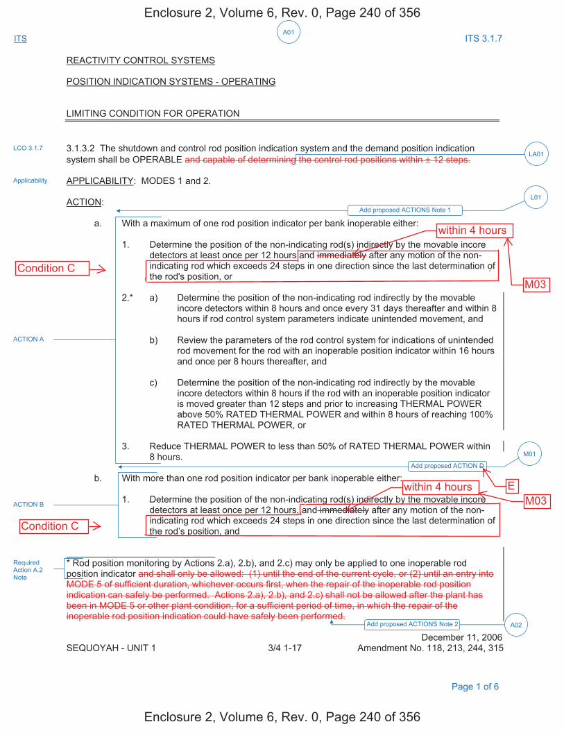
A01
ITS ITS 3.1.7
REACTIVITY CONTROL SYSTEMS POSITION INDICATION SYSTEMS - OPERATING LIMITING CONDITION FOR OPERATION 3.1.3.2 The shutdown and control rod position indication system and the demand position indication system shall be OPERABLE and capable of determining the control rod positions within ± 12 steps. APPLICABILITY: MODES 1 and 2. ACTION: a. With a maximum of one rod position indicator per bank inoperable either: 1. Determine the position of the non-indicating rod(s) indirectly by the movable incore
detectors at least once per 12 hours and immediately after any motion of the non-indicating rod which exceeds 24 steps in one direction since the last determination of the rod's position, or
2.* a) Determine the position of the non-indicating rod indirectly by the movable
incore detectors within 8 hours and once every 31 days thereafter and within 8 hours if rod control system parameters indicate unintended movement, and
b) Review the parameters of the rod control system for indications of unintended
rod movement for the rod with an inoperable position indicator within 16 hours and once per 8 hours thereafter, and
c) Determine the position of the non-indicating rod indirectly by the movable
incore detectors within 8 hours if the rod with an inoperable position indicator is moved greater than 12 steps and prior to increasing THERMAL POWER above 50% RATED THERMAL POWER and within 8 hours of reaching 100% RATED THERMAL POWER, or
3. Reduce THERMAL POWER to less than 50% of RATED THERMAL POWER within 8 hours. b. With more than one rod position indicator per bank inoperable either: 1. Determine the position of the non-indicating rod(s) indirectly by the movable incore
detectors at least once per 12 hours, and immediately after any motion of the non-indicating rod which exceeds 24 steps in one direction since the last determination of the rod’s position, and
_____________________________ * Rod position monitoring by Actions 2.a), 2.b), and 2.c) may only be applied to one inoperable rod position indicator and shall only be allowed: (1) until the end of the current cycle, or (2) until an entry into MODE 5 of sufficient duration, whichever occurs first, when the repair of the inoperable rod position indication can safely be performed. Actions 2.a), 2.b), and 2.c) shall not be allowed after the plant has been in MODE 5 or other plant condition, for a sufficient period of time, in which the repair of the inoperable rod position indication could have safely been performed.
December 11, 2006 SEQUOYAH - UNIT 1 3/4 1-17 Amendment No. 118, 213, 244, 315
LCO 3.1.7
Applicability
ACTION A
ACTION B
Add proposed ACTIONS Note 1
L01
Add proposed ACTION D
M01
LA01
Page 1 of 6
Required Action A.2 Note
Add proposed ACTIONS Note 2 A02
Enclosure 2, Volume 6, Rev. 0, Page 240 of 356
Enclosure 2, Volume 6, Rev. 0, Page 240 of 356
Condition C
Condition C
E
within 4 hours
within 4 hours
M03
M03
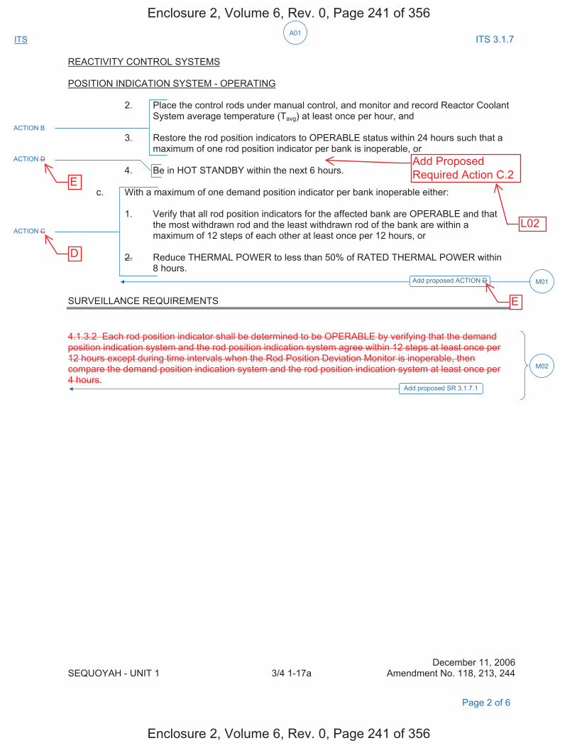
A01
ITS ITS 3.1.7
REACTIVITY CONTROL SYSTEMS POSITION INDICATION SYSTEM - OPERATING 2. Place the control rods under manual control, and monitor and record Reactor Coolant
System average temperature (Tavg) at least once per hour, and 3. Restore the rod position indicators to OPERABLE status within 24 hours such that a
maximum of one rod position indicator per bank is inoperable, or 4. Be in HOT STANDBY within the next 6 hours. c. With a maximum of one demand position indicator per bank inoperable either: 1. Verify that all rod position indicators for the affected bank are OPERABLE and that
the most withdrawn rod and the least withdrawn rod of the bank are within a maximum of 12 steps of each other at least once per 12 hours, or
2. Reduce THERMAL POWER to less than 50% of RATED THERMAL POWER within
8 hours. SURVEILLANCE REQUIREMENTS 4.1.3.2 Each rod position indicator shall be determined to be OPERABLE by verifying that the demand position indication system and the rod position indication system agree within 12 steps at least once per 12 hours except during time intervals when the Rod Position Deviation Monitor is inoperable, then compare the demand position indication system and the rod position indication system at least once per 4 hours. December 11, 2006 SEQUOYAH - UNIT 1 3/4 1-17a Amendment No. 118, 213, 244
ACTION B
ACTION C
ACTION D
Add proposed ACTION D M01
M02
Add proposed SR 3.1.7.1
Page 2 of 6
Enclosure 2, Volume 6, Rev. 0, Page 241 of 356
Enclosure 2, Volume 6, Rev. 0, Page 241 of 356
E
E
D
Add ProposedRequired Action C.2
L02
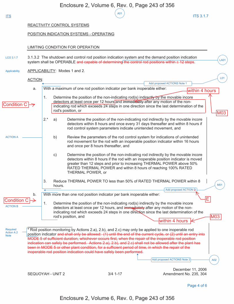
A01
ITS ITS 3.1.7
REACTIVITY CONTROL SYSTEMS POSITION INDICATION SYSTEMS - OPERATING LIMITING CONDITION FOR OPERATION 3.1.3.2 The shutdown and control rod position indication system and the demand position indication system shall be OPERABLE and capable of determining the control rod positions within ± 12 steps. APPLICABILITY: Modes 1 and 2. ACTION: a. With a maximum of one rod position indicator per bank inoperable either: 1. Determine the position of the non-indicating rod(s) indirectly by the movable incore
detectors at least once per 12 hours and immediately after any motion of the non-indicating rod which exceeds 24 steps in one direction since the last determination of the rod's position, or
2.* a) Determine the position of the non-indicating rod indirectly by the movable incore detectors within 8 hours and once every 31 days thereafter and within 8 hours if rod control system parameters indicate unintended movement, and
b) Review the parameters of the rod control system for indications of unintended
rod movement for the rod with an inoperable position indicator within 16 hours and once per 8 hours thereafter, and
c) Determine the position of the non-indicating rod indirectly by the movable incore
detectors within 8 hours if the rod with an inoperable position indicator is moved greater than 12 steps and prior to increasing THERMAL POWER above 50% RATED THERMAL POWER and within 8 hours of reaching 100% RATED THERMAL POWER, or
3. Reduce THERMAL POWER TO less than 50% of RATED THERMAL POWER within 8 hours. b. With more than one rod position indicator per bank inoperable either: 1. Determine the position of the non-indicating rod(s) indirectly by the movable incore
detectors at least once per 12 hours, and immediately after any motion of the non-indicating rod which exceeds 24 steps in one direction since the last determination of the rod’s position, and
* Rod position monitoring by Actions 2.a), 2.b), and 2.c) may only be applied to one inoperable rod position indicator and shall only be allowed: (1) until the end of the current cycle, or (2) until an entry into MODE 5 of sufficient duration, whichever occurs first, when the repair of the inoperable rod position indication can safely be performed. Actions 2.a), 2.b), and 2.c) shall not be allowed after the plant has been in MODE 5 or other plant condition, for a sufficient period of time, in which the repair of the inoperable rod position indication could have safely been performed. December 11, 2006 SEQUOYAH - UNIT 2 3/4 1-17 Amendment No. 235, 304
LCO 3.1.7
Applicability
Add proposed ACTIONS Note 1
L01
Add proposed ACTION D
M01
LA01
ACTION B
ACTION A
Page 4 of 6
Required Action A.2 Note
Add proposed ACTIONS Note 2 A02
Enclosure 2, Volume 6, Rev. 0, Page 243 of 356
Enclosure 2, Volume 6, Rev. 0, Page 243 of 356
ECondition C
Condition C
within 4 hours
within 4 hours
M03
M03
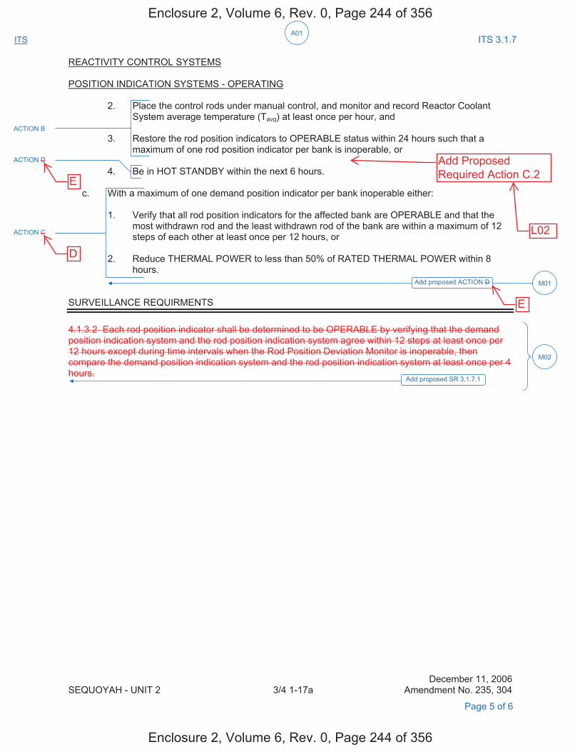
A01
ITS ITS 3.1.7
REACTIVITY CONTROL SYSTEMS POSITION INDICATION SYSTEMS - OPERATING 2. Place the control rods under manual control, and monitor and record Reactor Coolant
System average temperature (Tavg) at least once per hour, and 3. Restore the rod position indicators to OPERABLE status within 24 hours such that a
maximum of one rod position indicator per bank is inoperable, or 4. Be in HOT STANDBY within the next 6 hours. c. With a maximum of one demand position indicator per bank inoperable either: 1. Verify that all rod position indicators for the affected bank are OPERABLE and that the
most withdrawn rod and the least withdrawn rod of the bank are within a maximum of 12 steps of each other at least once per 12 hours, or
2. Reduce THERMAL POWER to less than 50% of RATED THERMAL POWER within 8
hours. SURVEILLANCE REQUIRMENTS 4.1.3.2 Each rod position indicator shall be determined to be OPERABLE by verifying that the demand position indication system and the rod position indication system agree within 12 steps at least once per 12 hours except during time intervals when the Rod Position Deviation Monitor is inoperable, then compare the demand position indication system and the rod position indication system at least once per 4 hours.
December 11, 2006 SEQUOYAH - UNIT 2 3/4 1-17a Amendment No. 235, 304
Add proposed ACTION D M01
M02
Add proposed SR 3.1.7.1
ACTION B
ACTION C
ACTION D
Page 5 of 6
Enclosure 2, Volume 6, Rev. 0, Page 244 of 356
Enclosure 2, Volume 6, Rev. 0, Page 244 of 356
E
E
D
Add ProposedRequired Action C.2
L02
DISCUSSION OF CHANGES ITS 3.1.7, ROD POSITION INDICATION
Sequoyah Unit 1 and Unit 2 Page 1 of 3
ADMINISTRATIVE CHANGES A01 In the conversion of the Sequoyah Nuclear Plant (SQN) Current Technical
Specifications (CTS) to the plant specific Improved Technical Specifications (ITS), certain changes (wording preferences, editorial changes, reformatting, revised numbering, etc.) are made to obtain consistency with NUREG - 1431, Rev. 4.0, "Standard Technical Specifications - Westinghouse Plants" (ISTS) and additional Technical Specification Task Force (TSTF) travelers included in this submittal.
These changes are designated as administrative changes and are acceptable
because they do not result in technical changes to the CTS. A02 CTS 3.1.3.2 Note * applies to Actions 2.a, 2.b, and 2.c and may be only applied
to one inoperable rod position indicator. In this condition, the inoperable rod position indicator shall only be allowed until either the end of the current cycle, or until an entry into MODE 5 of sufficient duration, whichever occurs first, when the repair of the inoperable rod position indication can safely be performed. Actions 2.a, 2.b, and 2.c shall not be allowed after the plant has been in MODE 5 or other plant condition, for a sufficient period of time, in which the repair of the inoperable rod position indication could have safely been performed. ITS 3.1.7 ACTIONS Note 2 states that LCO 3.0.4.a and b are not applicable for Required Actions A.2.1 and A.2.2 following startup from a refueling outage, or following entry into MODE 5 of sufficient duration to safely repair an inoperable rod position indication. This changes the CTS by rewording the allowance for one rod position indicator inoperable to be consistent with ITS terminology.
This change is designated as an administrative change since the change does
not result in a technical change to the CTS. MORE RESTRICTIVE CHANGES M01 CTS 3.1.3.2 ACTION a and c do not contain an ACTION to follow if the provided
ACTIONS cannot be met. Therefore, CTS 3.0.3 would be entered, which would allow 1 hour to initiate a shutdown and 7 hours to be in HOT STANDBY. ITS 3.1.7 ACTION D requires if the Required Actions and associated Completion Time of ACTION A or C are not met, to be in MODE 3 within 6 hours. This changes the CTS by eliminating the one hour to initiate a shutdown and consequently allows one hour less for the unit to be in MODE 3.
This change is acceptable because it provides an appropriate compensatory
measure for the described conditions. If any Required Action and associated Completion Time cannot be met, the unit must be placed in a MODE in which the LCO does not apply. The LCO is applicable in MODES 1 and 2. Requiring a shutdown to MODE 3 is appropriate in this condition. The one hour allowed by CTS 3.0.3 to prepare for a shutdown is not needed because the operators have had time to prepare for the shutdown while attempting to follow the Required Actions and associated Completion Times. This change is designated as more restrictive because it allows less time to shutdown than is allowed in the CTS.
Enclosure 2, Volume 6, Rev. 0, Page 246 of 356
Enclosure 2, Volume 6, Rev. 0, Page 246 of 356
E
s
DISCUSSION OF CHANGES ITS 3.1.7, ROD POSITION INDICATION
Sequoyah Unit 1 and Unit 2 Page 2 of 3
M02 CTS 4.1.3.2 requires that each rod position indicator shall be determined to be OPERABLE by verifying that the demand position indication system and the rod position indication system agree within 12 steps at least once per 12 hours except during time intervals when the Rod Position Deviation Monitor is inoperable, then compare the demand position indication system and the rod position indication system at least once per 4 hours. ITS 3.1.7 does not contain this requirement because it is duplicative of CTS 4.1.3.1.1 (ITS SR 3.1.4.1). A new Surveillance has been added (ITS SR 3.1.7.1) to verify each RPI agrees within 12 steps of the group demand position for the full indicated range of rod travel, once prior to criticality after each removal of the reactor head. This changes the CTS by adding a new Surveillance Requirement.
The purpose of ITS SR 3.1.7.1 is to provide additional assurance that the rod
position indication system is operating correctly. This change is acceptable because it provides additional assurance that the rod position indication channels are OPERABLE. This change is designated as more restrictive because it adds a new Surveillance Requirement to the CTS.
RELOCATED SPECIFICATIONS None REMOVED DETAIL CHANGES LA01 (Type 1 – Removing Details of System Design and System Description, Including
Design Limits) CTS LCO 3.1.3.2 requires the shutdown and control rod position indication system and the demand position indication system to be OPERABLE and capable of determining the control rod positions within ± 12 steps. ITS LCO 3.1.7 requires the analog Rod Position Indication System and the Demand Position Indication System to be OPERABLE but the details of what constitutes an OPERABLE system are moved to the Bases. This changes the CTS by removing the details of what constitutes an OPERABLE system to the Bases.
The removal of these details, which are related to system design, from the
Technical Specifications, is acceptable because this type of information is not necessary to be included in the Technical Specifications to provide adequate protection of public health and safety. The ITS retains the requirement that the Rod Position Indication System and Demand Position Indication System be OPERABLE. The details on the capability requirements of the systems do not need to appear in the specification in order for the requirement to apply. Additionally, this change is acceptable because the removed information will be adequately controlled in the ITS Bases. Changes to the Bases are controlled by the Technical Specification Bases Control Program in Chapter 5. This program provides for the evaluation of changes to ensure the Bases are properly controlled. This change is designated as a less restrictive removal of detail change because information relating to system design is being removed from the Technical Specifications.
Enclosure 2, Volume 6, Rev. 0, Page 247 of 356
Enclosure 2, Volume 6, Rev. 0, Page 247 of 356
M03
DOC M03 CTS LCO 3.1.3.2 states,” The shutdown and control rod position indication system and the demand position indication system shall be OPERABLE and capable of determining the control rod positions within ± 12 steps.” CTS 3.1.3.2 ACTION a.1 states, “With a maximum of one rod position indicator per bank inoperable either: Determine the position of the non-indicating rod(s) indirectly by the movable incore detectors at least once per 12 hours and immediately after any motion of the non-indicating rod which exceeds 24 steps in one direction since the last determination of the rod's position, or.” CTS 3.1.3.2 ACTION b.1 states, “With more than one rod position indicator per bank inoperable either: 1. Determine the position of the non-indicating rod(s) indirectly by the movable incore detectors at least once per 12 hours, and immediately after any motion of the non-indicating rod which exceeds 24 steps in one direction since the last determination of the rod’s position, and.” CTS 3.1.3.2 ACTION a.1 and b.1 both require identical compensatory measures to be performed “immediately.” ITS 3.1.7 CONDITION C. states, “One or more rods with inoperable position indicators have been moved in excess of 24 steps in one direction since the last determination of the rod's position.” ITS 3.1.7 Required Action C.1 states, “Verify the position of the rods with inoperable position indicators indirectly by using movable incore detectors,” and has a Completion Time of 4 hours. The CTS 3.1.3.2 and ITS 3.1.7 actions for verification of rod position are identical with different completion times. This changes the CTS by limiting the time to 4 hours to complete the verification of the position of the rods with inoperable position indicators. This change is acceptable because a time limit is placed on the length of time required to verify rod position after rod movement of 24 or more steps. If the rod position cannot be verified within the proposed Completion Time of 4 hours, the unit’s power will be reduced to < 50% RTP which will ensure undesirable power distributions will be minimized. This change is designated as more restrictive because it restricts the time allowed to complete the verification of the position of the rods with inoperable position indicators.

DISCUSSION OF CHANGES ITS 3.1.7, ROD POSITION INDICATION
Sequoyah Unit 1 and Unit 2 Page 3 of 3
LESS RESTRICTIVE CHANGES L01 (Category 4 – Relaxation of Required Action) CTS 3.1.3.2 ACTION a covers the
inoperability for a maximum of one rod position indicator per bank. CTS 3.1.3.2 ACTION b covers the inoperability for more than one rod position indicator per bank. CTS 3.1.3.2 ACTION c covers the inoperability for a maximum of one demand position indicator per bank. ITS 3.1.7 ACTIONS are modified by Note 1 that states "Separate Condition entry is allowed for each inoperable rod position indicator and each demand position indicator." ITS 3.1.7 ACTION A covers inoperability for one rod position indicator per bank. ITS 3.1.7 ACTION B covers inoperability for more than one rod position indicator per bank. ITS 3.1.7 ACTION C covers inoperability for one demand position indicator bank for one or more banks. This changes the CTS by allowing separate Condition entry for each inoperable rod position indicator and each demand position indicator.
The purpose of CTS 3.1.3.2 ACTION a is to provide compensatory actions for a
maximum of one rod position indicator per bank. The purpose of CTS 3.1.3.2 ACTION b is to provide compensatory actions for more than one rod position indicator per bank. The purpose of CTS 3.1.3.2 ACTION c is to provide compensatory actions for one demand position indicator per bank. This change is acceptable because the Required Actions are used to establish remedial measures that must be taken in response to the degraded conditions in order to minimize risk associated with continued operation while providing time to repair inoperable features. The Required Actions are consistent with safe operation under the specified Condition, considering the OPERABLE status of the redundant systems or features. This includes the capacity and capability of remaining features, a reasonable time for repairs or replacement of required features, and the low probability of a DBA occurring during the repair period. This change will allow separate Condition entry for each inoperable rod position indicator and each inoperable demand position indicator while the CTS does not. The ITS will allow each inoperable rod position indicator or each inoperable demand position indicator to be tracked separately. This change is acceptable because the Required Actions for each Condition provide appropriate compensatory actions for inoperable position indication. This change is designated as less restrictive because less stringent Required Actions are being applied in the ITS than were applied in the CTS.
Enclosure 2, Volume 6, Rev. 0, Page 248 of 356
Enclosure 2, Volume 6, Rev. 0, Page 248 of 356
D
L02
DOC L02
(Category 4 – Relaxation of Required Action) CTS LCO 3.1.3.2 states, ”The shutdown and control rod position indication system and the demand position indication system shall be OPERABLE and capable of determining the control rod positions within ± 12 steps.” The CTS 3.1.3.2 ACTION for, “a maximum of one rod position indicator per bank inoperable,” requires the performance of either ACTION a.1 or a.2 or a.3. CTS 3.1.3.2 ACTION a.3 requires the reduction of THERMAL POWER to less than 50% of RATED THERMAL POWER within 8 hours. The CTS 3.1.3.2 ACTION for, “more than one rod position indicator per bank inoperable” requires the performance of ACTION b.1 and b.2 and b.3 or b.4. CTS 3.1.3.2 ACTION b.4 requires the unit to be placed in HOT STANDBY within the next 6 hours. CTS 3.1.3.2 ACTION a. and ACTION b. do not have the same end state. ITS 3.1.7 CONDITION C. states, “One ormore rods with inoperable position indicators have been moved in excess of 24 steps in one direction since the last determination of the rod's position.” The ITS 3.1.7 CONDITION C entry point of “one or more rods” includes one rod or more than one rod and is identical to the entry points for both CTS 3.1.3.2 ACTION a.1 and b.1. ITS 3.1.7 CONDITION C requires the performance of either Required Action C.1 or Required Action C.2. ITS Required Action C.1 states, “Verify the position of the rods with inoperable position indicators indirectly by using movable incore detectors,” and is identical to CTS 3.1.3.2 ACTION a.1 and b.1. ITS Required Action C.2 states, “Reduce THERMAL POWER to < 50% RTP,” and is identical to CTS 3.1.3.2 ACTION a.3, but is not an option for CTS 3.1.3.2 ACTION b. This changes the CTS by allowing a reduction in RTP as an alternative to the verification of a rod’s position.
The purpose of the CTS ACTION to “verify the position of the rods with inoperable position indicators indirectly by using movable incore detectors” is to ensure a misaligned rod does not go undetected and cause a power imbalance in the core. This change is acceptable because, if within the required Completion Time of 4 hours, for ITS Required Action C.1, the rod positions have not been determined, THERMAL POWER must be reduced to < 50% RTP to avoid undesirable power distributions that could result from continued operation at > 50% RTP when one or more rods are misaligned by more than 24 steps. This change is designated as less restrictive because less stringent Required Actions are being applied in ITS than were applied in CTS.

Rod Position Indication 3.1.7
Westinghouse STS 3.1.7-1 Rev. 4.0 Amendment XXX SEQUOYAH UNIT 1
4
CTS
3.1 REACTIVITY CONTROL SYSTEMS
3.1.7 Rod Position Indication
LCO 3.1.7 The [Digital] Rod Position Indication ([D]RPI) System and the Demand Position Indication System shall be OPERABLE.
APPLICABILITY: MODES 1 and 2.
ACTIONS ------------------------------------------------------------NOTE----------------------------------------------------------- Separate Condition entry is allowed for each inoperable rod position indicator and each demand position indicator. -------------------------------------------------------------------------------------------------------------------------------
CONDITION REQUIRED ACTION COMPLETION TIME
A. One [D]RPI per group inoperable for one or more groups.
A.1 Verify the position of the rods with inoperable position indicators indirectly by using movable incore detectors.
OR
A.2 Reduce THERMAL POWER to 50% RTP.
Once per 8 hours
8 hours
B. More than one [D]RPI per group inoperable.
B.1 Place the control rods under manual control.
AND
B.2 Monitor and record Reactor Coolant System Tavg.
AND
Immediately
Once per 1 hour
INSERT 2
INSERT 3
3
3.1.3.2
Applicability
ACTION a
ACTION b
1
1
2
3
3
1
4<
12 4
bank
bank rod position
indicator
rod position indicator
4
INSERT 1
1.
S5
Enclosure 2, Volume 6, Rev. 0, Page 249 of 356
Enclosure 2, Volume 6, Rev. 0, Page 249 of 356

3.1.7
Insert Page 3.1.7-1a
INSERT 1
2. LCO 3.0.4.a and b are not applicable for Required Actions A.2.1 and A.2.2 following astartup from a refueling outage, or following entry into MODE 5 of sufficient duration to safelyrepair an inoperable rod position indication.
INSERT 2
AND
Immediately after a rod with an inoperable position indicator has been moved in excess of 24 steps in one direction since the last determination of the rod's position
2
4
3.1.3.2 Note*
Action a.1
Enclosure 2, Volume 6, Rev. 0, Page 250 of 356
Enclosure 2, Volume 6, Rev. 0, Page 250 of 356
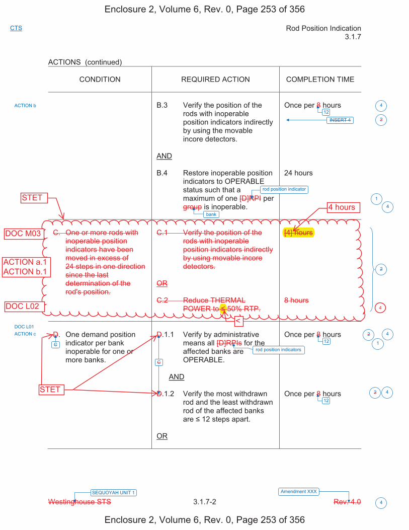
Rod Position Indication 3.1.7
Westinghouse STS 3.1.7-2 Rev. 4.0 Amendment XXX SEQUOYAH UNIT 1
4
CTS
ACTIONS (continued)
CONDITION REQUIRED ACTION COMPLETION TIME
B.3 Verify the position of the rods with inoperable position indicators indirectly by using the movable incore detectors.
AND
B.4 Restore inoperable position indicators to OPERABLE status such that a maximum of one [D]RPI per group is inoperable.
Once per 8 hours
24 hours
C. One or more rods with inoperable position indicators have been moved in excess of 24 steps in one direction since the last determination of the rod's position.
C.1 Verify the position of the rods with inoperable position indicators indirectly by using movable incore detectors.
OR
C.2 Reduce THERMAL POWER to 50% RTP.
[4] hours
8 hours
D. One demand position indicator per bank inoperable for one or more banks.
D.1.1 Verify by administrative means all [D]RPIs for the affected banks are OPERABLE.
AND
D.1.2 Verify the most withdrawn rod and the least withdrawn rod of the affected banks are 12 steps apart.
OR
Once per 8 hours
Once per 8 hours
INSERT 4
ACTION b
ACTION c
C
C
2
2
2
2
1
1
12 4
124
12
4
4
rod position indicator
rod position indicators
bank
DOC L01
Enclosure 2, Volume 6, Rev. 0, Page 253 of 356
Enclosure 2, Volume 6, Rev. 0, Page 253 of 356
4
STET
STET
ACTION a.1ACTION b.1
4 hours
[4] hours
<
DOC L02
DOC M03
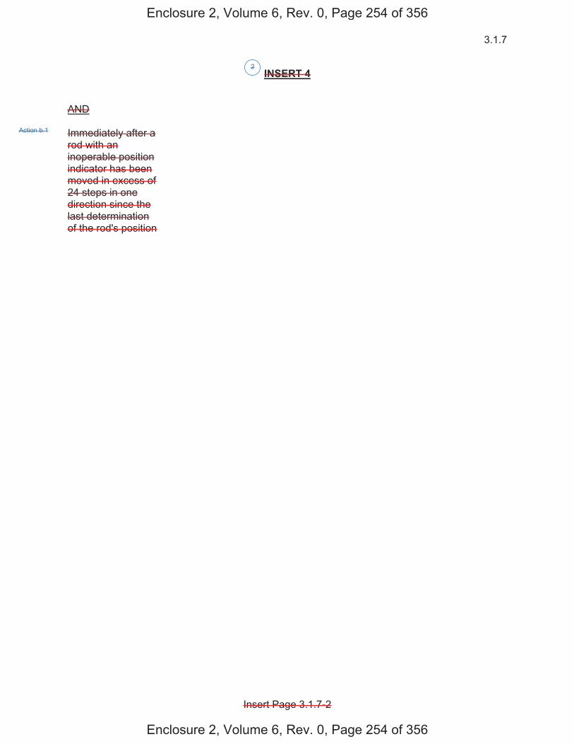
3.1.7
Insert Page 3.1.7-2
INSERT 4 AND Immediately after a rod with an inoperable position indicator has been moved in excess of 24 steps in one direction since the last determination of the rod's position
2
Action b.1
Enclosure 2, Volume 6, Rev. 0, Page 254 of 356
Enclosure 2, Volume 6, Rev. 0, Page 254 of 356
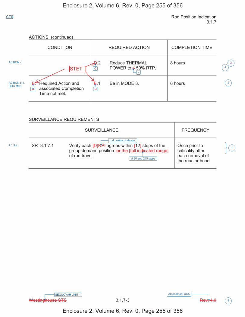
Rod Position Indication 3.1.7
Westinghouse STS 3.1.7-3 Rev. 4.0 Amendment XXX SEQUOYAH UNIT 1
4
CTS
ACTIONS (continued)
CONDITION
REQUIRED ACTION
COMPLETION TIME
D.2 Reduce THERMAL
POWER to 50% RTP.
8 hours
E. Required Action and
associated Completion Time not met.
E.1 Be in MODE 3.
6 hours
SURVEILLANCE REQUIREMENTS
SURVEILLANCE
FREQUENCY
SR 3.1.7.1 Verify each [D]RPI agrees within [12] steps of the
group demand position for the [full indicated range] of rod travel.
Once prior to criticality after each removal of the reactor head
ACTION c
ACTION b.4, DOC M02
C
D D
4.1.3.2
2
2
1
4
<
at 20 and 215 steps
rod position indicator
Enclosure 2, Volume 6, Rev. 0, Page 255 of 356
Enclosure 2, Volume 6, Rev. 0, Page 255 of 356
STET
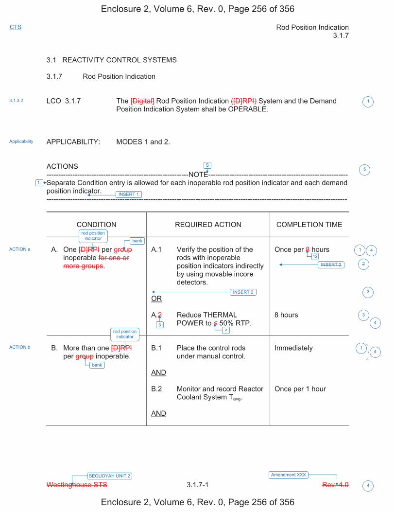
Rod Position Indication 3.1.7
Westinghouse STS 3.1.7-1 Rev. 4.0 Amendment XXX SEQUOYAH UNIT 2
4
CTS
3.1 REACTIVITY CONTROL SYSTEMS 3.1.7 Rod Position Indication LCO 3.1.7 The [Digital] Rod Position Indication ([D]RPI) System and the Demand
Position Indication System shall be OPERABLE. APPLICABILITY: MODES 1 and 2. ACTIONS ------------------------------------------------------------NOTE----------------------------------------------------------- Separate Condition entry is allowed for each inoperable rod position indicator and each demand position indicator. -------------------------------------------------------------------------------------------------------------------------------
CONDITION
REQUIRED ACTION
COMPLETION TIME
A. One [D]RPI per group
inoperable for one or more groups.
A.1 Verify the position of the
rods with inoperable position indicators indirectly by using movable incore detectors.
OR A.2 Reduce THERMAL
POWER to 50% RTP.
Once per 8 hours 8 hours
B. More than one [D]RPI
per group inoperable.
B.1 Place the control rods
under manual control. AND B.2 Monitor and record Reactor
Coolant System Tavg. AND
Immediately Once per 1 hour
INSERT 2
INSERT 3
3
3.1.3.2
Applicability
ACTION a
ACTION b
1
1
2
3
3
1
4<
12 4
bank
bank rod position
indicator
rod position indicator
4
INSERT 1
1.
S5
Enclosure 2, Volume 6, Rev. 0, Page 256 of 356
Enclosure 2, Volume 6, Rev. 0, Page 256 of 356
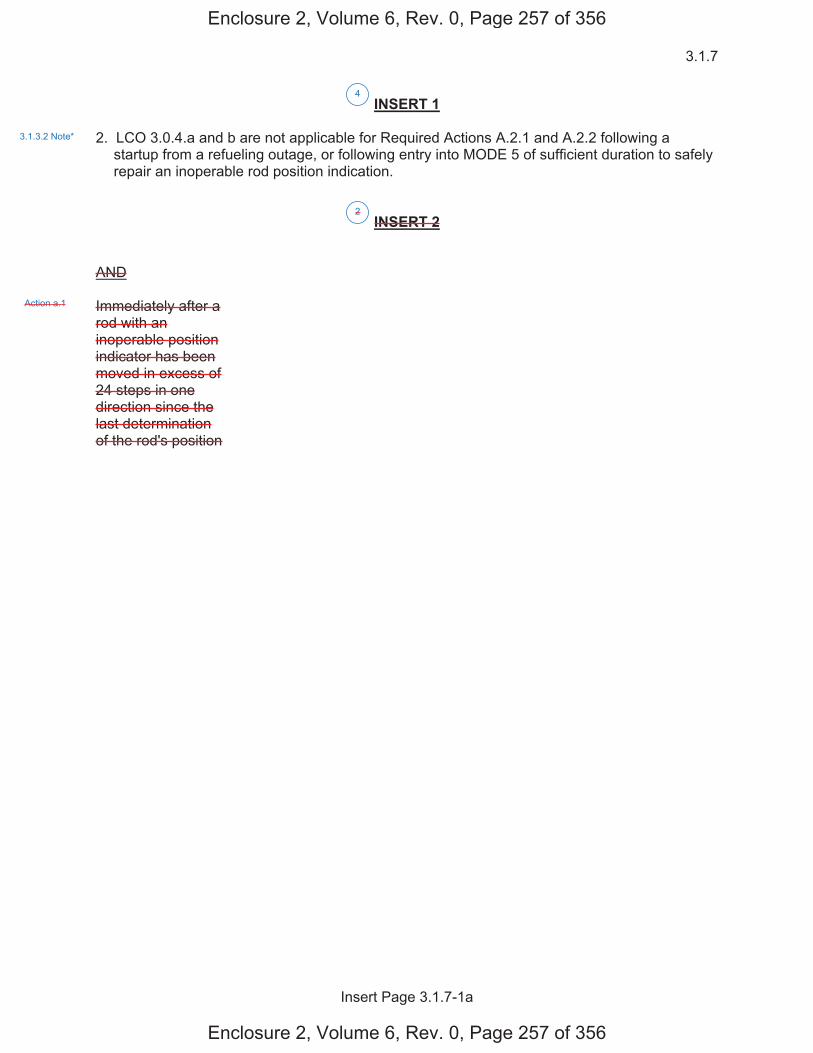
3.1.7
Insert Page 3.1.7-1a
INSERT 1 2. LCO 3.0.4.a and b are not applicable for Required Actions A.2.1 and A.2.2 following a
startup from a refueling outage, or following entry into MODE 5 of sufficient duration to safely repair an inoperable rod position indication.
INSERT 2 AND Immediately after a rod with an inoperable position indicator has been moved in excess of 24 steps in one direction since the last determination of the rod's position
2
4
3.1.3.2 Note*
Action a.1
Enclosure 2, Volume 6, Rev. 0, Page 257 of 356
Enclosure 2, Volume 6, Rev. 0, Page 257 of 356
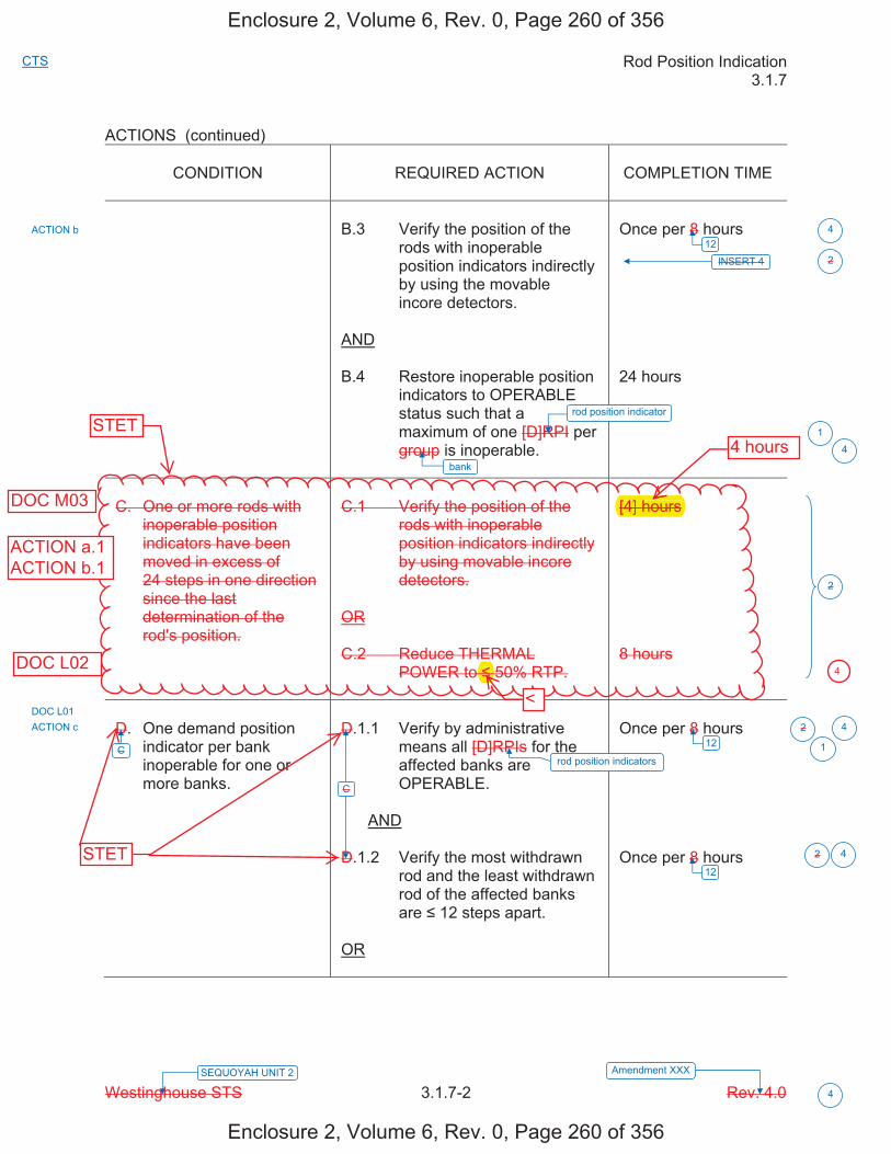
Rod Position Indication 3.1.7
Westinghouse STS 3.1.7-2 Rev. 4.0 Amendment XXX SEQUOYAH UNIT 2
4
CTS
ACTIONS (continued)
CONDITION REQUIRED ACTION COMPLETION TIME
B.3 Verify the position of the rods with inoperable position indicators indirectly by using the movable incore detectors.
AND
B.4 Restore inoperable position indicators to OPERABLE status such that a maximum of one [D]RPI per group is inoperable.
Once per 8 hours
24 hours
C. One or more rods with inoperable position indicators have been moved in excess of 24 steps in one direction since the last determination of the rod's position.
C.1 Verify the position of the rods with inoperable position indicators indirectly by using movable incore detectors.
OR
C.2 Reduce THERMAL POWER to 50% RTP.
[4] hours
8 hours
D. One demand position indicator per bank inoperable for one or more banks.
D.1.1 Verify by administrative means all [D]RPIs for the affected banks are OPERABLE.
AND
D.1.2 Verify the most withdrawn rod and the least withdrawn rod of the affected banks are 12 steps apart.
OR
Once per 8 hours
Once per 8 hours
INSERT 4
ACTION b
ACTION c
C
C
2
2
2
2
1
1
12 4
124
12
4
4
rod position indicator
rod position indicators
bank
DOC L01
Enclosure 2, Volume 6, Rev. 0, Page 260 of 356
Enclosure 2, Volume 6, Rev. 0, Page 260 of 356
4
STET
ACTION a.1ACTION b.1
STET
4 hours
<
[4] hours
DOC L02
DOC M03
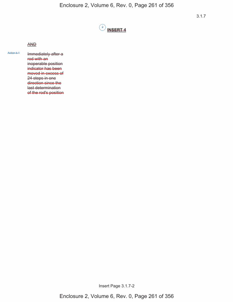
3.1.7
Insert Page 3.1.7-2
INSERT 4 AND Immediately after a rod with an inoperable position indicator has been moved in excess of 24 steps in one direction since the last determination of the rod's position
2
Action b.1
Enclosure 2, Volume 6, Rev. 0, Page 261 of 356
Enclosure 2, Volume 6, Rev. 0, Page 261 of 356
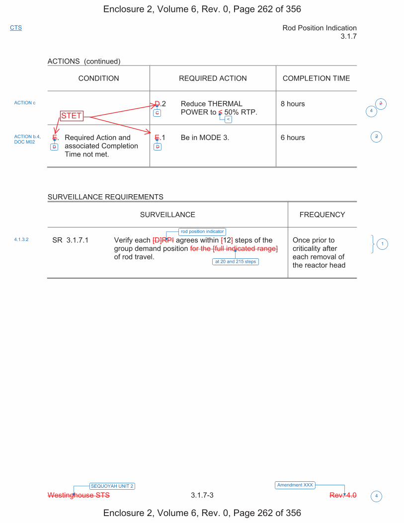
Rod Position Indication 3.1.7
Westinghouse STS 3.1.7-3 Rev. 4.0 Amendment XXX SEQUOYAH UNIT 2
4
CTS
ACTIONS (continued)
CONDITION
REQUIRED ACTION
COMPLETION TIME
D.2 Reduce THERMAL
POWER to 50% RTP.
8 hours
E. Required Action and
associated Completion Time not met.
E.1 Be in MODE 3.
6 hours
SURVEILLANCE REQUIREMENTS
SURVEILLANCE
FREQUENCY
SR 3.1.7.1 Verify each [D]RPI agrees within [12] steps of the
group demand position for the [full indicated range] of rod travel.
Once prior to criticality after each removal of the reactor head
ACTION c
ACTION b.4, DOC M02
C
D D
4.1.3.2
2
2
1
4
<
at 20 and 215 steps
rod position indicator
Enclosure 2, Volume 6, Rev. 0, Page 262 of 356
Enclosure 2, Volume 6, Rev. 0, Page 262 of 356
STET
JUSTIFICATION FOR DEVIATIONS ITS 3.1.7, ROD POSITION INDICATION
Sequoyah Unit 1 and Unit 2 Page 1 of 1
1. The ISTS contains bracketed information and/or values that are generic to Westinghouse vintage plants. The brackets are removed and the proper plant specific information/value is inserted to reflect the current licensing basis.
2. ISTS 3.1.7 ACTION C has been deleted and a new conditional Completion time has been added to Required Action A.1 and B.3. The new completion time ensures that SQN current licensing basis is maintained, in that a verification of the position indicator is still being performed immediately after a rod with an inoperable position indicator has been moved in excess of 24 steps in one direction since the last determination of the rod's position. Additionally, ISTS 3.1.7 ACTIONS D and E has been changed to ITS 3.1.7 ACTIONS C and D, respectively, because of this deletion.
3. ISTS 3.1.7 ACTION A provides compensatory actions for when one rod position
indicator is inoperable. ITS 3.1.7 provides an additional Required Action that can be taken when one rod position indicator is inoperable. The new Required Action allows the use of an alternate means other than the movable incore detectors to monitor the position of a control or shutdown rod when the analog rod position indication system is inoperable. This change reflects a current licensing basis that was approved by the NRC in Amendment 315 for Unit 1 and Amendment 304 for Unit 2 (ADAMS Accession No. ML063120575). Additionally ISTS 3.1.7 Required Action A.2 has been renumbered as ITS 3.1.7 Required Action A.3.
4. Changes are made (additions, deletions, and/or changes) to the ISTS that reflect the
plant specific nomenclature, number, reference, system description, analysis, or licensing basis description.
5. Editorial changes made for enhanced clarity/consistency.
Enclosure 2, Volume 6, Rev. 0, Page 263 of 356
Enclosure 2, Volume 6, Rev. 0, Page 263 of 356
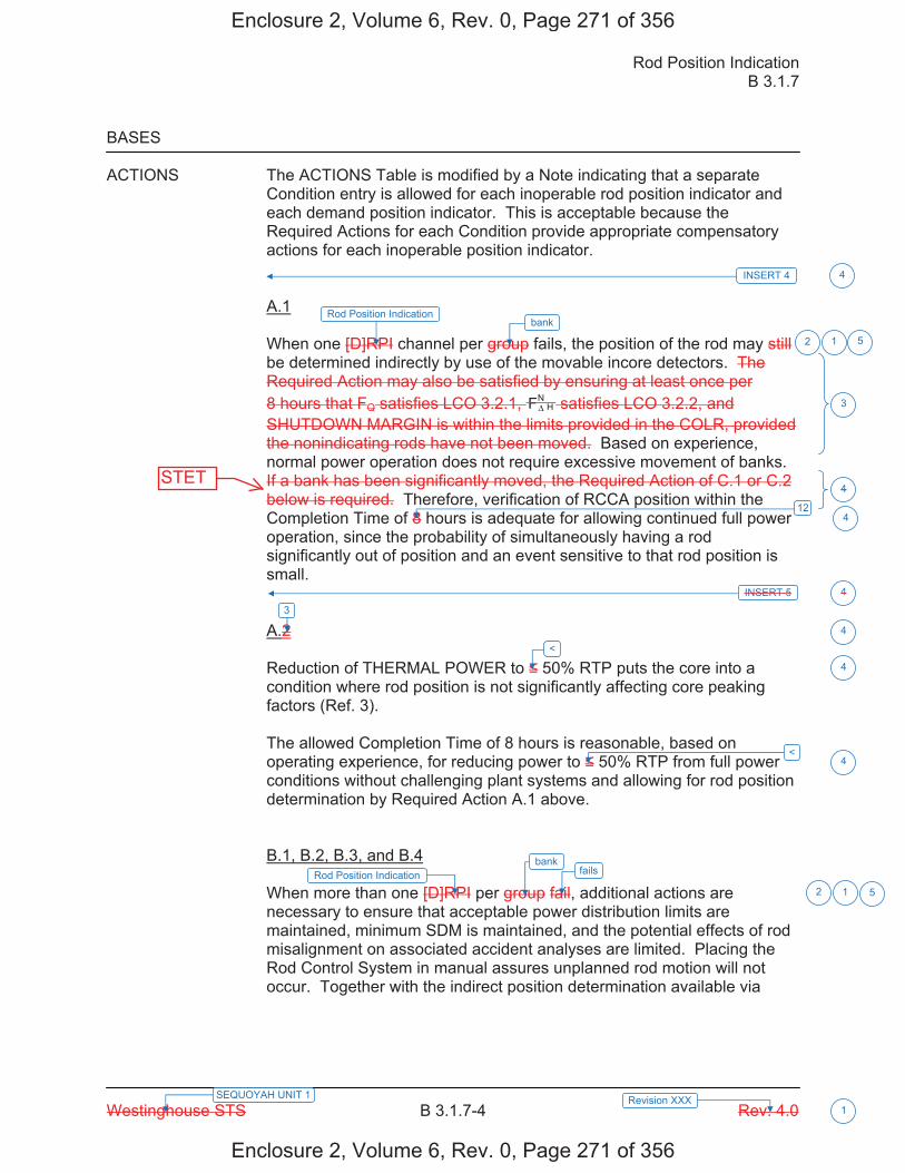
Rod Position Indication B 3.1.7
Westinghouse STS B 3.1.7-4 Rev. 4.0
SEQUOYAH UNIT 1 Revision XXX 1
BASES ACTIONS The ACTIONS Table is modified by a Note indicating that a separate
Condition entry is allowed for each inoperable rod position indicator and each demand position indicator. This is acceptable because the Required Actions for each Condition provide appropriate compensatory actions for each inoperable position indicator. A.1 When one [D]RPI channel per group fails, the position of the rod may still be determined indirectly by use of the movable incore detectors. The Required Action may also be satisfied by ensuring at least once per 8 hours that FQ satisfies LCO 3.2.1, H
NFΔ satisfies LCO 3.2.2, and SHUTDOWN MARGIN is within the limits provided in the COLR, provided the nonindicating rods have not been moved. Based on experience, normal power operation does not require excessive movement of banks. If a bank has been significantly moved, the Required Action of C.1 or C.2 below is required. Therefore, verification of RCCA position within the Completion Time of 8 hours is adequate for allowing continued full power operation, since the probability of simultaneously having a rod significantly out of position and an event sensitive to that rod position is small. A.2 Reduction of THERMAL POWER to 50% RTP puts the core into a condition where rod position is not significantly affecting core peaking factors (Ref. 3). The allowed Completion Time of 8 hours is reasonable, based on operating experience, for reducing power to 50% RTP from full power conditions without challenging plant systems and allowing for rod position determination by Required Action A.1 above. B.1, B.2, B.3, and B.4 When more than one [D]RPI per group fail, additional actions are necessary to ensure that acceptable power distribution limits are maintained, minimum SDM is maintained, and the potential effects of rod misalignment on associated accident analyses are limited. Placing the Rod Control System in manual assures unplanned rod motion will not occur. Together with the indirect position determination available via
2
3
4
4
INSERT 5 4
3
2
<
<
4
4
412
Rod Position Indicationbank
1 5
Rod Position Indication fails
1
bank
5
INSERT 4 4
Enclosure 2, Volume 6, Rev. 0, Page 271 of 356
Enclosure 2, Volume 6, Rev. 0, Page 271 of 356
STET

B 3.1.7
Insert Page B 3.1.7-4
INSERT 4 A second Note has been added to provide clarification that LCO 3.0.4.a and LCO 3.0.4.c are not applicable for Required Action A.2.1 and A.2.2 following startup from a refueling outage, or following entry into MODE 5 of sufficient duration to safely repair an inoperable rod position indication.
INSERT 5 If one or more rods have been significantly moved (in excess of 24 steps in one direction, since the position was last determined), Required Action A.1 is still appropriate, but actions must be initiated immediately to begin verifying that the rod is still properly positioned, relative to their group positions. In this Required Action, the Completion Time only begins on discovery that both: a. One rod position indication per bank is inoperable, and
b. A rod with an inoperable position indicator has been moved in excess of 24 steps in one
direction since the last determination of the rod's position.
If at any time during the existence of Condition A (one RPI per bank inoperable), a rod with an inoperable position indicator has been moved in excess of 24 steps in one direction since the last determination of the rod's position, this Completion Time begins to be tracked. A.2.1, and A.2.2 When one RPI channel per bank fails, the position of the rod may still be determined indirectly by use of the movable incore detectors and reviewing the parameters of the rod control system for indications of unintended rod movement for the rod with the inoperable position indication. Therefore, verification of RCCA position within 8 hours and every 31days thereafter is adequate for allowing continued full power operation as long as a review of the parameters of the rod control system for indications of unintended rod movement for the rod with the inoperable position indication is performed within 16 hours and every 8 hours thereafter. Furthermore, if the rod control system parameters indicate unintended movement or if the rod with an inoperable position indicator is moved greater than 12 steps, then the verification of the RCCA position must be performed within 8 hours. As long as these compensatory actions are met, reactor operation can then continue until the end of the current cycle or until an entry into MODE 5 of sufficient duration that the repair of the inoperable rod position indication can safely be performed. Required Actions A.2.1,and A.2.2 are modified by a Note directing that these Required Actions may only be applied to one inoperable rod position indicator.
4
4
Enclosure 2, Volume 6, Rev. 0, Page 272 of 356
Enclosure 2, Volume 6, Rev. 0, Page 272 of 356
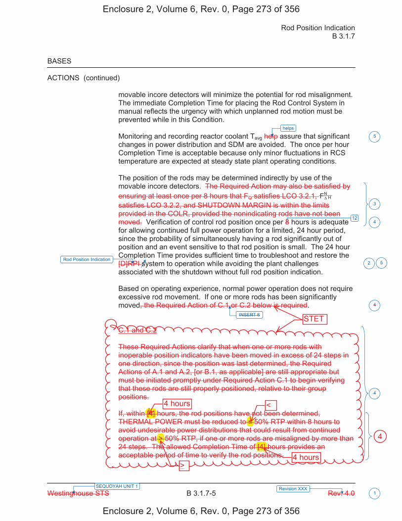
Rod Position Indication B 3.1.7
Westinghouse STS B 3.1.7-5 Rev. 4.0 SEQUOYAH UNIT 1 Revision XXX
1
BASES
ACTIONS (continued)
movable incore detectors will minimize the potential for rod misalignment. The immediate Completion Time for placing the Rod Control System in manual reflects the urgency with which unplanned rod motion must be prevented while in this Condition.
Monitoring and recording reactor coolant Tavg help assure that significant changes in power distribution and SDM are avoided. The once per hour Completion Time is acceptable because only minor fluctuations in RCS temperature are expected at steady state plant operating conditions.
The position of the rods may be determined indirectly by use of the movable incore detectors. The Required Action may also be satisfied by ensuring at least once per 8 hours that FQ satisfies LCO 3.2.1, H
NFΔ satisfies LCO 3.2.2, and SHUTDOWN MARGIN is within the limits provided in the COLR, provided the nonindicating rods have not been moved. Verification of control rod position once per 8 hours is adequate for allowing continued full power operation for a limited, 24 hour period, since the probability of simultaneously having a rod significantly out of position and an event sensitive to that rod position is small. The 24 hour Completion Time provides sufficient time to troubleshoot and restore the [D]RPI system to operation while avoiding the plant challenges associated with the shutdown without full rod position indication.
Based on operating experience, normal power operation does not require excessive rod movement. If one or more rods has been significantly moved, the Required Action of C.1 or C.2 below is required.
C.1 and C.2
These Required Actions clarify that when one or more rods with inoperable position indicators have been moved in excess of 24 steps in one direction, since the position was last determined, the Required Actions of A.1 and A.2, [or B.1, as applicable] are still appropriate but must be initiated promptly under Required Action C.1 to begin verifying that these rods are still properly positioned, relative to their group positions.
If, within [4] hours, the rod positions have not been determined, THERMAL POWER must be reduced to 50% RTP within 8 hours to avoid undesirable power distributions that could result from continued operation at > 50% RTP, if one or more rods are misaligned by more than 24 steps. The allowed Completion Time of [4] hours provides an acceptable period of time to verify the rod positions.
INSERT 6
3
2
4
4
412
Rod Position Indication
helps
5
5
Enclosure 2, Volume 6, Rev. 0, Page 273 of 356
Enclosure 2, Volume 6, Rev. 0, Page 273 of 356
STET
[4]
[4]
>
4 hours
4 hours
<
>
4

B 3.1.7
Insert Page B 3.1.7-5
INSERT 6 (in excess of 24 steps in one direction, since the position was last determined), Required Action B.3 is still appropriate, but action must be initiated immediately to begin verifying that the rod is properly positioned, relative to its bank position. In this Required Action, the Completion Time only begins on discovery that both: a. More than one RPI per bank is inoperable; and b. A rod with an inoperable position indicator has been moved in excess of 24 steps in one
direction since the last determination of the rod's position.
If at any time during the existence of Condition B (more than one RPI per bank inoperable), a rod with an inoperable position indicator has been moved in excess of 24 steps in one direction since the last determination of the rod's position, this Completion Time begins to be tracked.
4
Enclosure 2, Volume 6, Rev. 0, Page 274 of 356
Enclosure 2, Volume 6, Rev. 0, Page 274 of 356
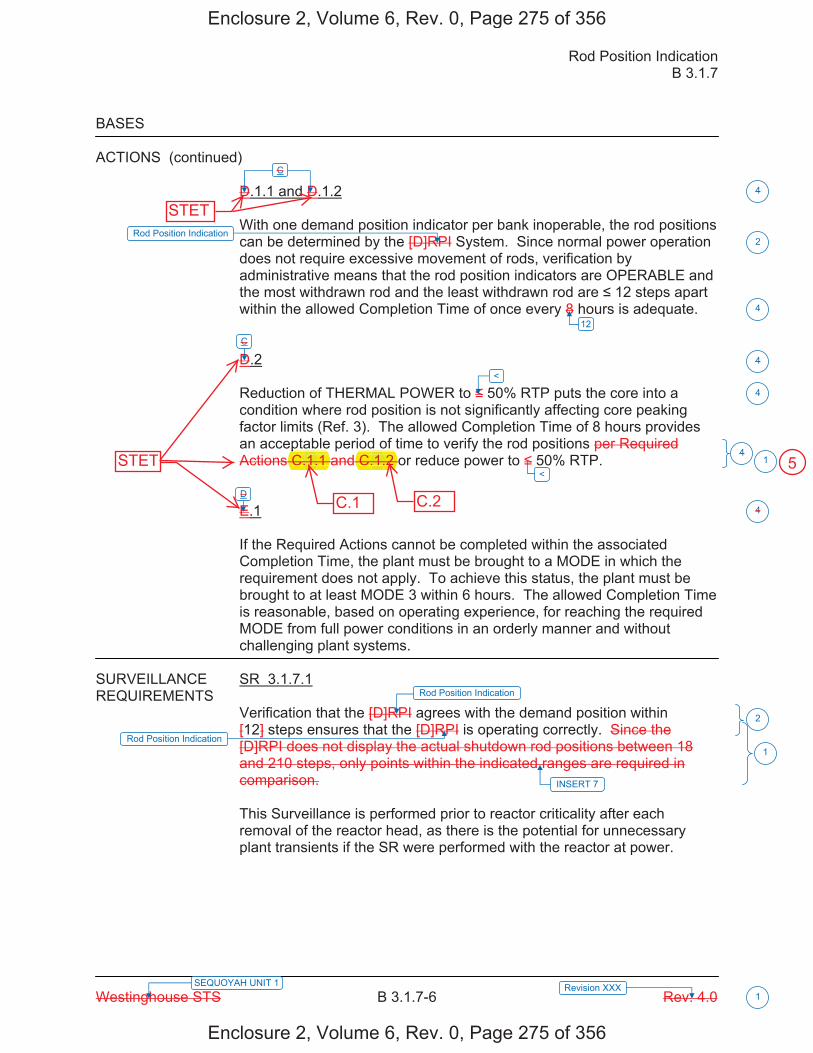
Rod Position Indication B 3.1.7
Westinghouse STS B 3.1.7-6 Rev. 4.0
SEQUOYAH UNIT 1 Revision XXX 1
BASES
ACTIONS (continued) D.1.1 and D.1.2 With one demand position indicator per bank inoperable, the rod positions can be determined by the [D]RPI System. Since normal power operation does not require excessive movement of rods, verification by administrative means that the rod position indicators are OPERABLE and the most withdrawn rod and the least withdrawn rod are 12 steps apart within the allowed Completion Time of once every 8 hours is adequate. D.2 Reduction of THERMAL POWER to 50% RTP puts the core into a condition where rod position is not significantly affecting core peaking factor limits (Ref. 3). The allowed Completion Time of 8 hours provides an acceptable period of time to verify the rod positions per Required Actions C.1.1 and C.1.2 or reduce power to 50% RTP. E.1 If the Required Actions cannot be completed within the associated Completion Time, the plant must be brought to a MODE in which the requirement does not apply. To achieve this status, the plant must be brought to at least MODE 3 within 6 hours. The allowed Completion Time is reasonable, based on operating experience, for reaching the required MODE from full power conditions in an orderly manner and without challenging plant systems.
SURVEILLANCE SR 3.1.7.1 REQUIREMENTS
Verification that the [D]RPI agrees with the demand position within [12] steps ensures that the [D]RPI is operating correctly. Since the [D]RPI does not display the actual shutdown rod positions between 18 and 210 steps, only points within the indicated ranges are required in comparison. This Surveillance is performed prior to reactor criticality after each removal of the reactor head, as there is the potential for unnecessary plant transients if the SR were performed with the reactor at power.
C
C
D
4
4
4
2
4
2
4
1
<
<
12
4
Rod Position Indication
Rod Position Indication
1Rod Position Indication
INSERT 7
Enclosure 2, Volume 6, Rev. 0, Page 275 of 356
Enclosure 2, Volume 6, Rev. 0, Page 275 of 356
STET
STET
pC. .1 .1. C.1.2.1.
C.1 C.2
5
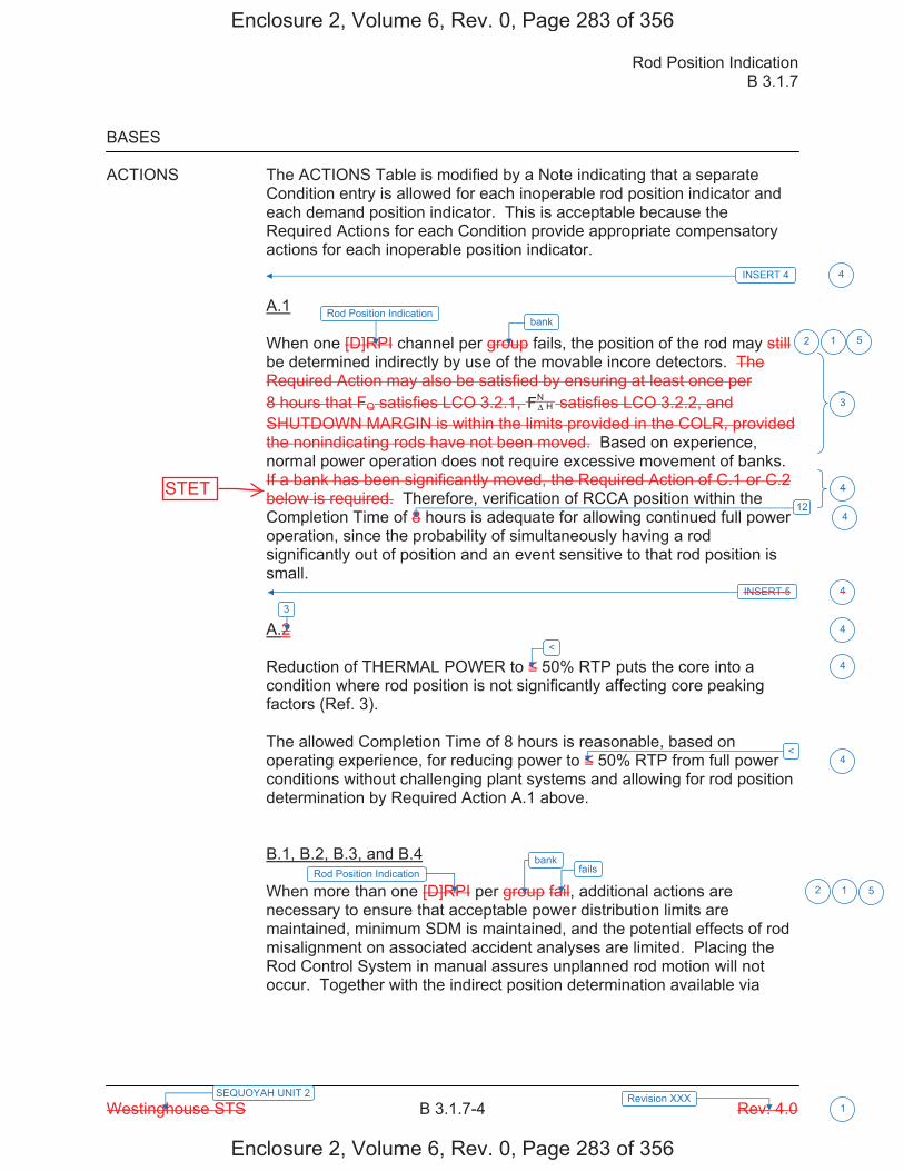
Rod Position Indication B 3.1.7
Westinghouse STS B 3.1.7-4 Rev. 4.0
SEQUOYAH UNIT 2 Revision XXX 1
BASES ACTIONS The ACTIONS Table is modified by a Note indicating that a separate
Condition entry is allowed for each inoperable rod position indicator and each demand position indicator. This is acceptable because the Required Actions for each Condition provide appropriate compensatory actions for each inoperable position indicator. A.1 When one [D]RPI channel per group fails, the position of the rod may still be determined indirectly by use of the movable incore detectors. The Required Action may also be satisfied by ensuring at least once per 8 hours that FQ satisfies LCO 3.2.1, H
NFΔ satisfies LCO 3.2.2, and SHUTDOWN MARGIN is within the limits provided in the COLR, provided the nonindicating rods have not been moved. Based on experience, normal power operation does not require excessive movement of banks. If a bank has been significantly moved, the Required Action of C.1 or C.2 below is required. Therefore, verification of RCCA position within the Completion Time of 8 hours is adequate for allowing continued full power operation, since the probability of simultaneously having a rod significantly out of position and an event sensitive to that rod position is small. A.2 Reduction of THERMAL POWER to 50% RTP puts the core into a condition where rod position is not significantly affecting core peaking factors (Ref. 3). The allowed Completion Time of 8 hours is reasonable, based on operating experience, for reducing power to 50% RTP from full power conditions without challenging plant systems and allowing for rod position determination by Required Action A.1 above. B.1, B.2, B.3, and B.4 When more than one [D]RPI per group fail, additional actions are necessary to ensure that acceptable power distribution limits are maintained, minimum SDM is maintained, and the potential effects of rod misalignment on associated accident analyses are limited. Placing the Rod Control System in manual assures unplanned rod motion will not occur. Together with the indirect position determination available via
2
3
4
4
INSERT 5 4
3
2
<
<
4
4
412
Rod Position Indicationbank
1 5
Rod Position Indication fails
1
bank
5
INSERT 4 4
Enclosure 2, Volume 6, Rev. 0, Page 283 of 356
Enclosure 2, Volume 6, Rev. 0, Page 283 of 356
STET
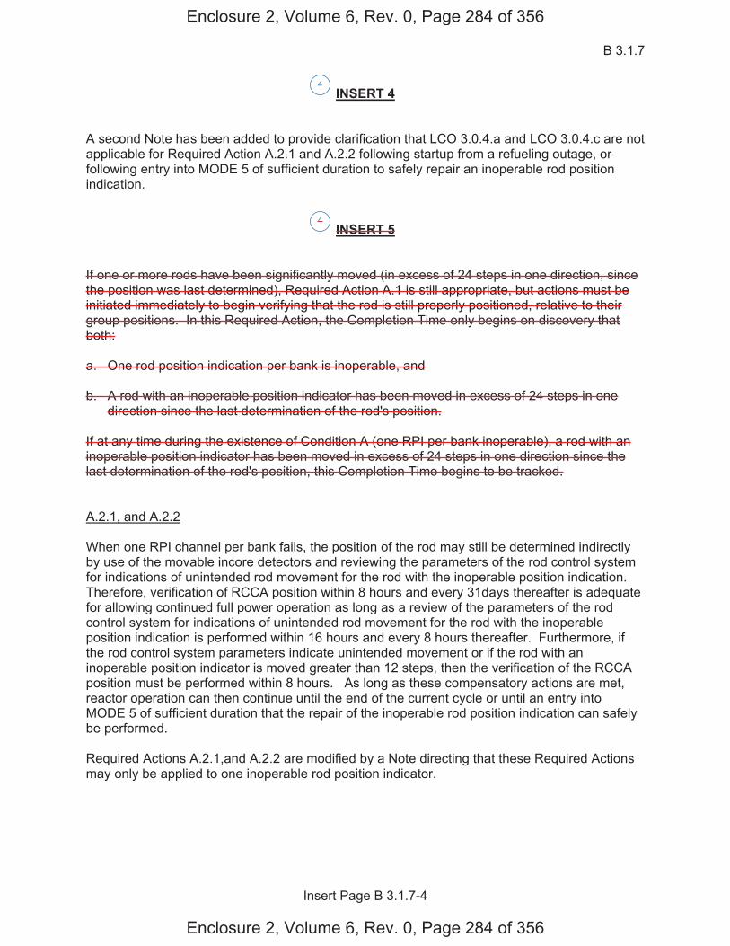
B 3.1.7
Insert Page B 3.1.7-4
INSERT 4 A second Note has been added to provide clarification that LCO 3.0.4.a and LCO 3.0.4.c are not applicable for Required Action A.2.1 and A.2.2 following startup from a refueling outage, or following entry into MODE 5 of sufficient duration to safely repair an inoperable rod position indication.
INSERT 5 If one or more rods have been significantly moved (in excess of 24 steps in one direction, since the position was last determined), Required Action A.1 is still appropriate, but actions must be initiated immediately to begin verifying that the rod is still properly positioned, relative to their group positions. In this Required Action, the Completion Time only begins on discovery that both: a. One rod position indication per bank is inoperable, and
b. A rod with an inoperable position indicator has been moved in excess of 24 steps in one
direction since the last determination of the rod's position.
If at any time during the existence of Condition A (one RPI per bank inoperable), a rod with an inoperable position indicator has been moved in excess of 24 steps in one direction since the last determination of the rod's position, this Completion Time begins to be tracked. A.2.1, and A.2.2 When one RPI channel per bank fails, the position of the rod may still be determined indirectly by use of the movable incore detectors and reviewing the parameters of the rod control system for indications of unintended rod movement for the rod with the inoperable position indication. Therefore, verification of RCCA position within 8 hours and every 31days thereafter is adequate for allowing continued full power operation as long as a review of the parameters of the rod control system for indications of unintended rod movement for the rod with the inoperable position indication is performed within 16 hours and every 8 hours thereafter. Furthermore, if the rod control system parameters indicate unintended movement or if the rod with an inoperable position indicator is moved greater than 12 steps, then the verification of the RCCA position must be performed within 8 hours. As long as these compensatory actions are met, reactor operation can then continue until the end of the current cycle or until an entry into MODE 5 of sufficient duration that the repair of the inoperable rod position indication can safely be performed. Required Actions A.2.1,and A.2.2 are modified by a Note directing that these Required Actions may only be applied to one inoperable rod position indicator.
4
4
Enclosure 2, Volume 6, Rev. 0, Page 284 of 356
Enclosure 2, Volume 6, Rev. 0, Page 284 of 356
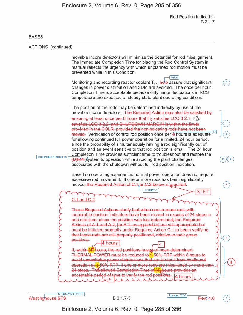
Rod Position Indication B 3.1.7
Westinghouse STS B 3.1.7-5 Rev. 4.0 SEQUOYAH UNIT 2 Revision XXX
1
BASES
ACTIONS (continued)
movable incore detectors will minimize the potential for rod misalignment. The immediate Completion Time for placing the Rod Control System in manual reflects the urgency with which unplanned rod motion must be prevented while in this Condition.
Monitoring and recording reactor coolant Tavg help assure that significant changes in power distribution and SDM are avoided. The once per hour Completion Time is acceptable because only minor fluctuations in RCS temperature are expected at steady state plant operating conditions.
The position of the rods may be determined indirectly by use of the movable incore detectors. The Required Action may also be satisfied by ensuring at least once per 8 hours that FQ satisfies LCO 3.2.1, H
NFΔ satisfies LCO 3.2.2, and SHUTDOWN MARGIN is within the limits provided in the COLR, provided the nonindicating rods have not been moved. Verification of control rod position once per 8 hours is adequate for allowing continued full power operation for a limited, 24 hour period, since the probability of simultaneously having a rod significantly out of position and an event sensitive to that rod position is small. The 24 hour Completion Time provides sufficient time to troubleshoot and restore the [D]RPI system to operation while avoiding the plant challenges associated with the shutdown without full rod position indication.
Based on operating experience, normal power operation does not require excessive rod movement. If one or more rods has been significantly moved, the Required Action of C.1 or C.2 below is required.
C.1 and C.2
These Required Actions clarify that when one or more rods with inoperable position indicators have been moved in excess of 24 steps in one direction, since the position was last determined, the Required Actions of A.1 and A.2, [or B.1, as applicable] are still appropriate but must be initiated promptly under Required Action C.1 to begin verifying that these rods are still properly positioned, relative to their group positions.
If, within [4] hours, the rod positions have not been determined, THERMAL POWER must be reduced to 50% RTP within 8 hours to avoid undesirable power distributions that could result from continued operation at > 50% RTP, if one or more rods are misaligned by more than 24 steps. The allowed Completion Time of [4] hours provides an acceptable period of time to verify the rod positions.
INSERT 6
3
2
4
4
412
Rod Position Indication
helps
5
5
Enclosure 2, Volume 6, Rev. 0, Page 285 of 356
Enclosure 2, Volume 6, Rev. 0, Page 285 of 356
STET
>f [4]
[4]4 hours
4 hours
<
>
4
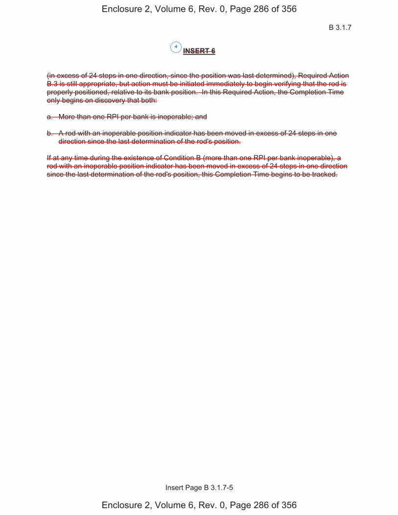
B 3.1.7
Insert Page B 3.1.7-5
INSERT 6 (in excess of 24 steps in one direction, since the position was last determined), Required Action B.3 is still appropriate, but action must be initiated immediately to begin verifying that the rod is properly positioned, relative to its bank position. In this Required Action, the Completion Time only begins on discovery that both: a. More than one RPI per bank is inoperable; and b. A rod with an inoperable position indicator has been moved in excess of 24 steps in one
direction since the last determination of the rod's position.
If at any time during the existence of Condition B (more than one RPI per bank inoperable), a rod with an inoperable position indicator has been moved in excess of 24 steps in one direction since the last determination of the rod's position, this Completion Time begins to be tracked.
4
Enclosure 2, Volume 6, Rev. 0, Page 286 of 356
Enclosure 2, Volume 6, Rev. 0, Page 286 of 356

Rod Position Indication B 3.1.7
Westinghouse STS B 3.1.7-6 Rev. 4.0
SEQUOYAH UNIT 2 Revision XXX 1
BASES
ACTIONS (continued) D.1.1 and D.1.2 With one demand position indicator per bank inoperable, the rod positions can be determined by the [D]RPI System. Since normal power operation does not require excessive movement of rods, verification by administrative means that the rod position indicators are OPERABLE and the most withdrawn rod and the least withdrawn rod are 12 steps apart within the allowed Completion Time of once every 8 hours is adequate. D.2 Reduction of THERMAL POWER to 50% RTP puts the core into a condition where rod position is not significantly affecting core peaking factor limits (Ref. 3). The allowed Completion Time of 8 hours provides an acceptable period of time to verify the rod positions per Required Actions C.1.1 and C.1.2 or reduce power to 50% RTP. E.1 If the Required Actions cannot be completed within the associated Completion Time, the plant must be brought to a MODE in which the requirement does not apply. To achieve this status, the plant must be brought to at least MODE 3 within 6 hours. The allowed Completion Time is reasonable, based on operating experience, for reaching the required MODE from full power conditions in an orderly manner and without challenging plant systems.
SURVEILLANCE SR 3.1.7.1 REQUIREMENTS
Verification that the [D]RPI agrees with the demand position within [12] steps ensures that the [D]RPI is operating correctly. Since the [D]RPI does not display the actual shutdown rod positions between 18 and 210 steps, only points within the indicated ranges are required in comparison. This Surveillance is performed prior to reactor criticality after each removal of the reactor head, as there is the potential for unnecessary plant transients if the SR were performed with the reactor at power.
C
C
D
4
4
4
2
4
2
4
1
<
<
12
4
Rod Position Indication
Rod Position Indication
1Rod Position Indication
INSERT 7
Enclosure 2, Volume 6, Rev. 0, Page 287 of 356
Enclosure 2, Volume 6, Rev. 0, Page 287 of 356
STE
STET
pC.1.1 C.1.2
C.1 C.2
5
JUSTIFICATION FOR DEVIATIONS ITS 3.1.7 BASES, ROD POSITION INDICATION
Sequoyah Unit 1 and Unit 2 Page 1 of 1
1. Changes are made (additions, deletions, and/or changes) to the ISTS Bases that reflect the plant specific nomenclature, number, reference, system description, analysis, or licensing basis description.
2. The ISTS contains bracketed information and/or values that are generic to
Westinghouse vintage plants. The brackets are removed and the proper plant specific information/value is inserted to reflect the current licensing basis.
3. ISTS 3.1.7 Required Action A.1 Bases contains a statement allowing an alternative
method of satisfying Required Action A.1 by verifying that FQ and HNFΔ are within the
limits provided in the COLR, provided the nonindicating rods have not been moved. Additionally, ISTS 3.1.7 Required Action B.3 Bases also contains this statement. ITS 3.1.7 Required Action A.1 Bases and Required Action B.3 Bases do not contain this statement. The statement has been deleted because it allows an alternative method for satisfying Required Actions A.1 and B.3 that are not addressed in the Specification. Since the Technical Specification Bases are not allowed to modify the Technical Specifications, this statement has been deleted.
4. Changes are made to be consistent with changes made to the Specification.
5. Editorial changes made for enhanced clarity/consistency.
Enclosure 2, Volume 6, Rev. 0, Page 290 of 356
Enclosure 2, Volume 6, Rev. 0, Page 290 of 356
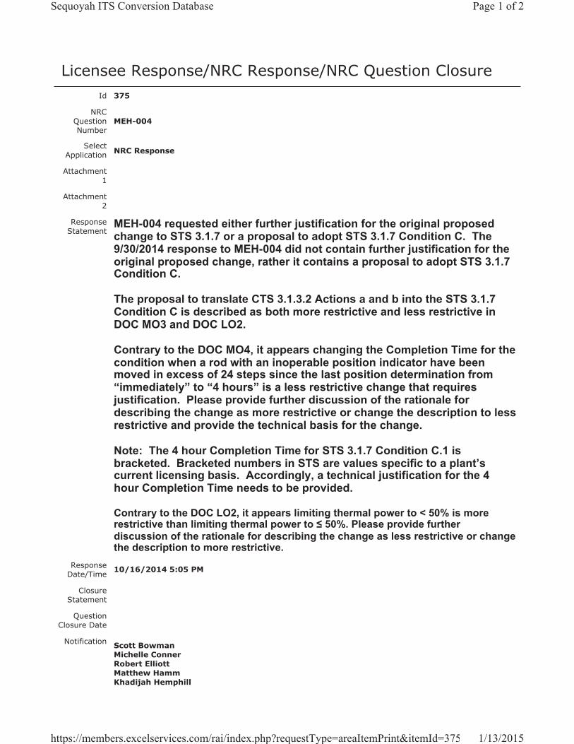
Licensee Response/NRC Response/NRC Question ClosureId 375
NRC Question Number
MEH-004
Select Application NRC Response
Attachment 1
Attachment 2
Response Statement
MEH-004 requested either further justification for the original proposed change to STS 3.1.7 or a proposal to adopt STS 3.1.7 Condition C. The 9/30/2014 response to MEH-004 did not contain further justification for the original proposed change, rather it contains a proposal to adopt STS 3.1.7 Condition C.
The proposal to translate CTS 3.1.3.2 Actions a and b into the STS 3.1.7 Condition C is described as both more restrictive and less restrictive in DOC MO3 and DOC LO2.
Contrary to the DOC MO4, it appears changing the Completion Time for the condition when a rod with an inoperable position indicator have been moved in excess of 24 steps since the last position determination from “immediately” to “4 hours” is a less restrictive change that requires justification. Please provide further discussion of the rationale for describing the change as more restrictive or change the description to less restrictive and provide the technical basis for the change.
Note: The 4 hour Completion Time for STS 3.1.7 Condition C.1 is bracketed. Bracketed numbers in STS are values specific to a plant’s current licensing basis. Accordingly, a technical justification for the 4 hour Completion Time needs to be provided.
Contrary to the DOC LO2, it appears limiting thermal power to < 50% is more restrictive than limiting thermal power to 50%. Please provide further discussion of the rationale for describing the change as less restrictive or change the description to more restrictive.
Response Date/Time 10/16/2014 5:05 PM
Closure Statement
Question Closure Date
Notification Scott BowmanMichelle ConnerRobert ElliottMatthew HammKhadijah Hemphill
Page 1 of 2Sequoyah ITS Conversion Database
1/13/2015https://members.excelservices.com/rai/index.php?requestType=areaItemPrint&itemId=375
Andrew HonRay Schiele
Added By Matthew Hamm
Date Added 10/16/2014 4:03 PM
Date Modified
Modified By
Page 2 of 2Sequoyah ITS Conversion Database
1/13/2015https://members.excelservices.com/rai/index.php?requestType=areaItemPrint&itemId=375
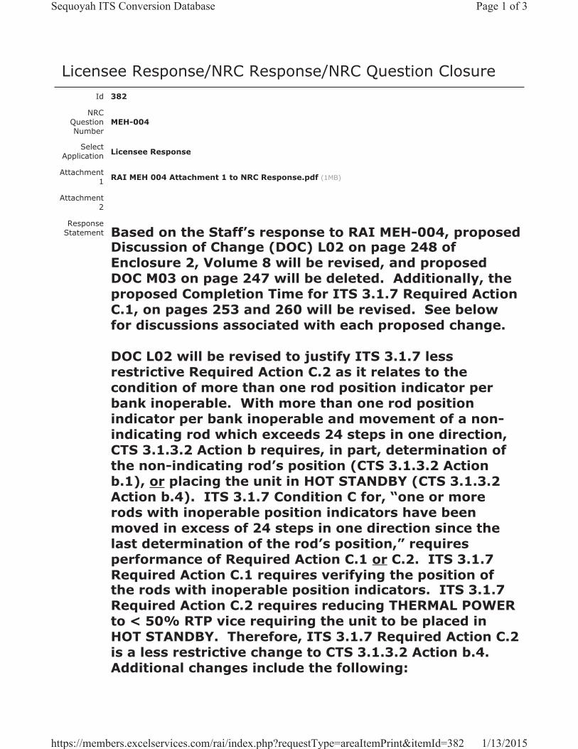
Licensee Response/NRC Response/NRC Question ClosureId 382
NRC Question Number
MEH-004
Select Application Licensee Response
Attachment 1 RAI MEH 004 Attachment 1 to NRC Response.pdf (1MB)
Attachment 2
Response Statement Based on the Staff’s response to RAI MEH-004, proposed
Discussion of Change (DOC) L02 on page 248 of Enclosure 2, Volume 8 will be revised, and proposed DOC M03 on page 247 will be deleted. Additionally, the proposed Completion Time for ITS 3.1.7 Required Action C.1, on pages 253 and 260 will be revised. See below for discussions associated with each proposed change.
DOC L02 will be revised to justify ITS 3.1.7 less restrictive Required Action C.2 as it relates to the condition of more than one rod position indicator per bank inoperable. With more than one rod position indicator per bank inoperable and movement of a non-indicating rod which exceeds 24 steps in one direction, CTS 3.1.3.2 Action b requires, in part, determination of the non-indicating rod’s position (CTS 3.1.3.2 Action b.1), or placing the unit in HOT STANDBY (CTS 3.1.3.2 Action b.4). ITS 3.1.7 Condition C for, “one or more rods with inoperable position indicators have been moved in excess of 24 steps in one direction since the last determination of the rod’s position,” requires performance of Required Action C.1 or C.2. ITS 3.1.7 Required Action C.1 requires verifying the position of the rods with inoperable position indicators. ITS 3.1.7 Required Action C.2 requires reducing THERMAL POWER to < 50% RTP vice requiring the unit to be placed in HOT STANDBY. Therefore, ITS 3.1.7 Required Action C.2 is a less restrictive change to CTS 3.1.3.2 Action b.4.Additional changes include the following:
Page 1 of 3Sequoyah ITS Conversion Database
1/13/2015https://members.excelservices.com/rai/index.php?requestType=areaItemPrint&itemId=382
1. An ITS cross-reference to Required Action C.2 will be added to the left-hand margin for CTS 3.1.3.2 Action a.3. (Pages 240 and 243 of Enclosure 2, Volume 6)
2. A CTS cross-reference to Action a.3 will be added to the left-hand margin for ITS 3.1.7 Required Action C.2. (Pages 253 and 260 of Enclosure 2, Volume 6)
In the initial response to RAI MEH-004, the Completion Time proposed for ITS 3.1.7 Required Action C.1 was 4 hours. Based on the Staff’s response concerning bracketed values in ISTS, the Completion Time for ITS 3.1.7 Required Action C.1 will be revised from the ISTS bracketed value of 4 hours to Immediately. With one or more rod position indicators per bank inoperable and after any motion of the non-indicating rod which exceeds 24 steps in one direction since the last determination of the rod’s position, CTS 3.1.3.2 Actions a.1 and b.1 require an immediate determination of the position of the non-indicating rod(s) indirectly by the movable incore detectors. This change aligns the Completion Time for ITS 3.1.7 Required Action C.1 with the Completion Time for CTS 3.1.3.2 Actions a.1 and b.1. Therefore, there is no longer a proposed more restrictive change, and DOC M03, that justified the change from Immediately to 4 hours, will be deleted.Additional changes include the following:
1. The CTS markups for CTS 3.1.3.2 Actions a.1 and b.1, initially provided as an attachment to the response for RAI MEH-004, will be revised to retain “immediately”, delete the insert for “within 4 hours”, and delete DOC M03 indicators. (Pages 240 and 243 of Enclosure 2, Volume 6)
2. The ISTS markups for ITS 3.1.7 Condition C, initially provided as an attachment to the response for RAI MEH-004, will be revised to delete the insert for “4 hours”, add an insert for “Immediately”, and add Justification for Deviations (JFD) 1 indicators. (Pages
Page 2 of 3Sequoyah ITS Conversion Database
1/13/2015https://members.excelservices.com/rai/index.php?requestType=areaItemPrint&itemId=382
253 and 260 of Enclosure 2, Volume 6)
3. The ISTS Bases markups for ITS 3.1.7 Actions C.1 and C.2, initially provided as an attachment to the response for RAI MEH-004, will be revised.Specifically, The final paragraph will read, “If the rod positions have not been determined, THERMAL POWER must be reduced to < 50% RTP within 8 hours to avoid undesirable power distributions that could result from continued operation at 50% RTP, if one or more rods are misaligned by more than 24 steps.”
See Attachment 1 for the draft revised changes to the ITS submittal. Attachment 1 is a rollup of changes based on the original RAI response and the proposed changes discussed above. Because the attachment is a reflection of changes to the submittal, originally proposed changes in the initial RAI response that have been deleted will not be reflected in the rollup.
Response Date/Time 11/24/2014 12:40 PM
Closure Statement
Question Closure
Date
Notification Scott BowmanMichelle ConnerMatthew HammKhadijah HemphillAndrew HonRay Schiele
Added By Scott Bowman
Date Added 11/24/2014 11:40 AM
Date Modified
Modified By
Page 3 of 3Sequoyah ITS Conversion Database
1/13/2015https://members.excelservices.com/rai/index.php?requestType=areaItemPrint&itemId=382
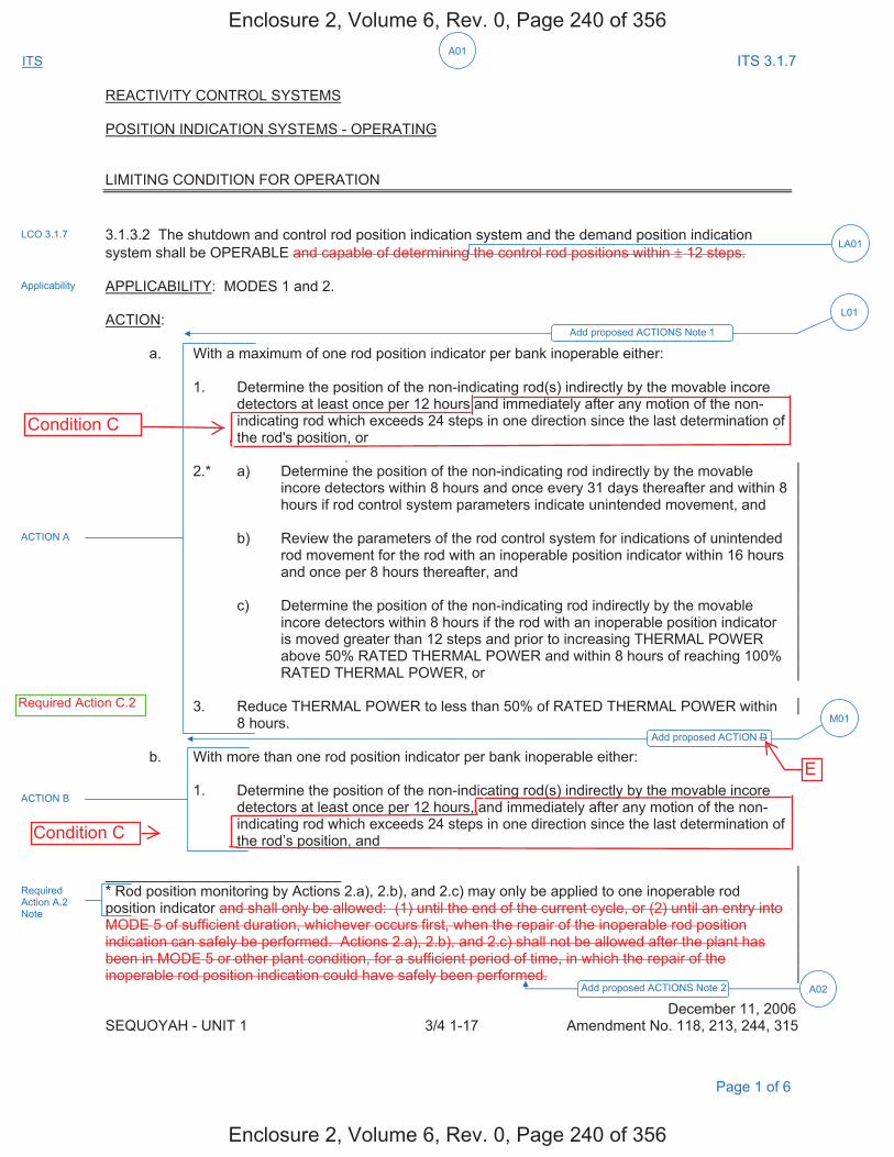
A01ITS ITS 3.1.7
REACTIVITY CONTROL SYSTEMS
POSITION INDICATION SYSTEMS - OPERATING
LIMITING CONDITION FOR OPERATION
3.1.3.2 The shutdown and control rod position indication system and the demand position indication system shall be OPERABLE and capable of determining the control rod positions within ± 12 steps.
APPLICABILITY: MODES 1 and 2.
ACTION:
a. With a maximum of one rod position indicator per bank inoperable either:
1. Determine the position of the non-indicating rod(s) indirectly by the movable incoredetectors at least once per 12 hours and immediately after any motion of the non-indicating rod which exceeds 24 steps in one direction since the last determination ofthe rod's position, or
2.* a) Determine the position of the non-indicating rod indirectly by the movable incore detectors within 8 hours and once every 31 days thereafter and within 8 hours if rod control system parameters indicate unintended movement, and
b) Review the parameters of the rod control system for indications of unintendedrod movement for the rod with an inoperable position indicator within 16 hoursand once per 8 hours thereafter, and
c) Determine the position of the non-indicating rod indirectly by the movableincore detectors within 8 hours if the rod with an inoperable position indicatoris moved greater than 12 steps and prior to increasing THERMAL POWERabove 50% RATED THERMAL POWER and within 8 hours of reaching 100%RATED THERMAL POWER, or
3. Reduce THERMAL POWER to less than 50% of RATED THERMAL POWER within8 hours.
b. With more than one rod position indicator per bank inoperable either:
1. Determine the position of the non-indicating rod(s) indirectly by the movable incoredetectors at least once per 12 hours, and immediately after any motion of the non-indicating rod which exceeds 24 steps in one direction since the last determination ofthe rod’s position, and
_____________________________ * Rod position monitoring by Actions 2.a), 2.b), and 2.c) may only be applied to one inoperable rodposition indicator and shall only be allowed: (1) until the end of the current cycle, or (2) until an entry into MODE 5 of sufficient duration, whichever occurs first, when the repair of the inoperable rod position indication can safely be performed. Actions 2.a), 2.b), and 2.c) shall not be allowed after the plant has been in MODE 5 or other plant condition, for a sufficient period of time, in which the repair of the inoperable rod position indication could have safely been performed.
December 11, 2006 SEQUOYAH - UNIT 1 3/4 1-17 Amendment No. 118, 213, 244, 315
LCO 3.1.7
Applicability
ACTION A
ACTION B
Add proposed ACTIONS Note 1
L01
Add proposed ACTION D
M01
LA01
Page 1 of 6
Required Action A.2 Note
Add proposed ACTIONS Note 2 A02
Enclosure 2, Volume 6, Rev. 0, Page 240 of 356
Enclosure 2, Volume 6, Rev. 0, Page 240 of 356
Condition C
Condition C
E
Required Action C.2

A01
ITS ITS 3.1.7
REACTIVITY CONTROL SYSTEMS POSITION INDICATION SYSTEM - OPERATING 2. Place the control rods under manual control, and monitor and record Reactor Coolant
System average temperature (Tavg) at least once per hour, and 3. Restore the rod position indicators to OPERABLE status within 24 hours such that a
maximum of one rod position indicator per bank is inoperable, or 4. Be in HOT STANDBY within the next 6 hours. c. With a maximum of one demand position indicator per bank inoperable either: 1. Verify that all rod position indicators for the affected bank are OPERABLE and that
the most withdrawn rod and the least withdrawn rod of the bank are within a maximum of 12 steps of each other at least once per 12 hours, or
2. Reduce THERMAL POWER to less than 50% of RATED THERMAL POWER within
8 hours. SURVEILLANCE REQUIREMENTS 4.1.3.2 Each rod position indicator shall be determined to be OPERABLE by verifying that the demand position indication system and the rod position indication system agree within 12 steps at least once per 12 hours except during time intervals when the Rod Position Deviation Monitor is inoperable, then compare the demand position indication system and the rod position indication system at least once per 4 hours. December 11, 2006 SEQUOYAH - UNIT 1 3/4 1-17a Amendment No. 118, 213, 244
ACTION B
ACTION C
ACTION D
Add proposed ACTION D M01
M02
Add proposed SR 3.1.7.1
Page 2 of 6
Enclosure 2, Volume 6, Rev. 0, Page 241 of 356
Enclosure 2, Volume 6, Rev. 0, Page 241 of 356
E
E
D
Add ProposedRequired Action C.2
L02
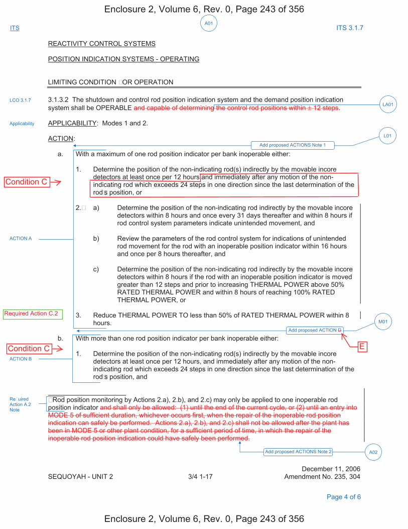
A01
ITS ITS 3.1.7
REACTIVITY CONTROL SYSTEMS POSITION INDICATION SYSTEMS - OPERATING LIMITING CONDITION FOR OPERATION 3.1.3.2 The shutdown and control rod position indication system and the demand position indication system shall be OPERABLE and capable of determining the control rod positions within ± 12 steps. APPLICABILITY: Modes 1 and 2. ACTION: a. With a maximum of one rod position indicator per bank inoperable either: 1. Determine the position of the non-indicating rod(s) indirectly by the movable incore
detectors at least once per 12 hours and immediately after any motion of the non-indicating rod which exceeds 24 steps in one direction since the last determination of the rodFs position, or
2.F a) Determine the position of the non-indicating rod indirectly by the movable incore detectors within 8 hours and once every 31 days thereafter and within 8 hours if rod control system parameters indicate unintended movement, and
b) Review the parameters of the rod control system for indications of unintended
rod movement for the rod with an inoperable position indicator within 16 hours and once per 8 hours thereafter, and
c) Determine the position of the non-indicating rod indirectly by the movable incore
detectors within 8 hours if the rod with an inoperable position indicator is moved greater than 12 steps and prior to increasing THERMAL POWER above 50% RATED THERMAL POWER and within 8 hours of reaching 100% RATED THERMAL POWER, or
3. Reduce THERMAL POWER TO less than 50% of RATED THERMAL POWER within 8 hours. b. With more than one rod position indicator per bank inoperable either: 1. Determine the position of the non-indicating rod(s) indirectly by the movable incore
detectors at least once per 12 hours, and immediately after any motion of the non-indicating rod which exceeds 24 steps in one direction since the last determination of the rodFs position, and
F Rod position monitoring by Actions 2.a), 2.b), and 2.c) may only be applied to one inoperable rod position indicator and shall only be allowed: (1) until the end of the current cycle, or (2) until an entry into MODE 5 of sufficient duration, whichever occurs first, when the repair of the inoperable rod position indication can safely be performed. Actions 2.a), 2.b), and 2.c) shall not be allowed after the plant has been in MODE 5 or other plant condition, for a sufficient period of time, in which the repair of the inoperable rod position indication could have safely been performed. December 11, 2006 SEQUOYAH - UNIT 2 3/4 1-17 Amendment No. 235, 304
LCO 3.1.7
Applicability
Add proposed ACTIONS Note 1
L01
Add proposed ACTION D
M01
LA01
ACTION B
ACTION A
Page 4 of 6
ReFuired Action A.2 Note
Add proposed ACTIONS Note 2 A02
Enclosure 2, Volume 6, Rev. 0, Page 243 of 356
Enclosure 2, Volume 6, Rev. 0, Page 243 of 356
ECondition C
Condition C
Required Action C.2

A01
ITS ITS 3.1.7
REACTIVITY CONTROL SYSTEMS POSITION INDICATION SYSTEMS - OPERATING 2. Place the control rods under manual control, and monitor and record Reactor Coolant
System average temperature (Tavg) at least once per hour, and 3. Restore the rod position indicators to OPERABLE status within 24 hours such that a
maximum of one rod position indicator per bank is inoperable, or 4. Be in HOT STANDBY within the next 6 hours. c. With a maximum of one demand position indicator per bank inoperable either: 1. Verify that all rod position indicators for the affected bank are OPERABLE and that the
most withdrawn rod and the least withdrawn rod of the bank are within a maximum of 12 steps of each other at least once per 12 hours, or
2. Reduce THERMAL POWER to less than 50% of RATED THERMAL POWER within 8
hours. SURVEILLANCE REQUIRMENTS 4.1.3.2 Each rod position indicator shall be determined to be OPERABLE by verifying that the demand position indication system and the rod position indication system agree within 12 steps at least once per 12 hours except during time intervals when the Rod Position Deviation Monitor is inoperable, then compare the demand position indication system and the rod position indication system at least once per 4 hours.
December 11, 2006 SEQUOYAH - UNIT 2 3/4 1-17a Amendment No. 235, 304
Add proposed ACTION D M01
M02
Add proposed SR 3.1.7.1
ACTION B
ACTION C
ACTION D
Page 5 of 6
Enclosure 2, Volume 6, Rev. 0, Page 244 of 356
Enclosure 2, Volume 6, Rev. 0, Page 244 of 356
E
E
D
Add ProposedRequired Action C.2
L02

DISCUSSION OF CHANGES ITS 3.1.7, ROD POSITION INDICATION
SeFuoyah Unit 1 and Unit 2 Page 1 of 3
ADMINISTRATIVE CHANGES A01 In the conversion of the SeFuoyah Nuclear Plant (SQN) Current Technical
Specifications (CTS) to the plant specific Improved Technical Specifications (ITS), certain changes (wording preferences, editorial changes, reformatting, revised numbering, etc.) are made to obtain consistency with NUREG - 1431, Rev. 4.0, FStandard Technical Specifications - Westinghouse PlantsF (ISTS) and additional Technical Specification Task Force (TSTF) travelers included in this submittal.
These changes are designated as administrative changes and are acceptable
because they do not result in technical changes to the CTS. A02 CTS 3.1.3.2 Note F applies to Actions 2.a, 2.b, and 2.c and may be only applied
to one inoperable rod position indicator. In this condition, the inoperable rod position indicator shall only be allowed until either the end of the current cycle, or until an entry into MODE 5 of sufficient duration, whichever occurs first, when the repair of the inoperable rod position indication can safely be performed. Actions 2.a, 2.b, and 2.c shall not be allowed after the plant has been in MODE 5 or other plant condition, for a sufficient period of time, in which the repair of the inoperable rod position indication could have safely been performed. ITS 3.1.7 ACTIONS Note 2 states that LCO 3.0.4.a and b are not applicable for ReFuired Actions A.2.1 and A.2.2 following startup from a refueling outage, or following entry into MODE 5 of sufficient duration to safely repair an inoperable rod position indication. This changes the CTS by rewording the allowance for one rod position indicator inoperable to be consistent with ITS terminology.
This change is designated as an administrative change since the change does
not result in a technical change to the CTS. MORE RESTRICTIVE CHANGES M01 CTS 3.1.3.2 ACTION a and c do not contain an ACTION to follow if the provided
ACTIONS cannot be met. Therefore, CTS 3.0.3 would be entered, which would allow 1 hour to initiate a shutdown and 7 hours to be in HOT STANDBY. ITS 3.1.7 ACTION D reFuires if the ReFuired Actions and associated Completion Time of ACTION A or C are not met, to be in MODE 3 within 6 hours. This changes the CTS by eliminating the one hour to initiate a shutdown and conseFuently allows one hour less for the unit to be in MODE 3.
This change is acceptable because it provides an appropriate compensatory
measure for the described conditions. If any ReFuired Action and associated Completion Time cannot be met, the unit must be placed in a MODE in which the LCO does not apply. The LCO is applicable in MODES 1 and 2. ReFuiring a shutdown to MODE 3 is appropriate in this condition. The one hour allowed by CTS 3.0.3 to prepare for a shutdown is not needed because the operators have had time to prepare for the shutdown while attempting to follow the ReFuired Actions and associated Completion Times. This change is designated as more restrictive because it allows less time to shutdown than is allowed in the CTS.
Enclosure 2, Volume 6, Rev. 0, Page 246 of 356
Enclosure 2, Volume 6, Rev. 0, Page 246 of 356
E
s
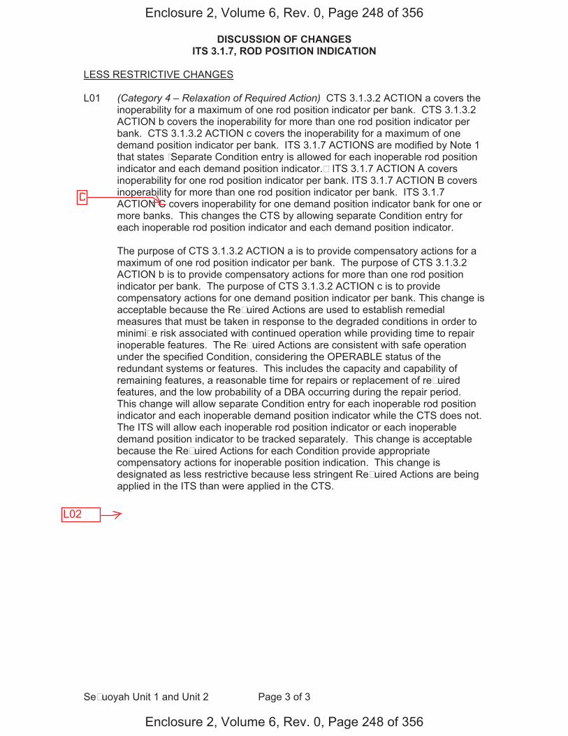
DISCUSSION OF CHANGES ITS 3.1.7, ROD POSITION INDICATION
SeFuoyah Unit 1 and Unit 2 Page 3 of 3
LESS RESTRICTIVE CHANGES L01 (Category 4 – Relaxation of Required Action) CTS 3.1.3.2 ACTION a covers the
inoperability for a maximum of one rod position indicator per bank. CTS 3.1.3.2 ACTION b covers the inoperability for more than one rod position indicator per bank. CTS 3.1.3.2 ACTION c covers the inoperability for a maximum of one demand position indicator per bank. ITS 3.1.7 ACTIONS are modified by Note 1 that states FSeparate Condition entry is allowed for each inoperable rod position indicator and each demand position indicator.F ITS 3.1.7 ACTION A covers inoperability for one rod position indicator per bank. ITS 3.1.7 ACTION B covers inoperability for more than one rod position indicator per bank. ITS 3.1.7 ACTION C covers inoperability for one demand position indicator bank for one or more banks. This changes the CTS by allowing separate Condition entry for each inoperable rod position indicator and each demand position indicator.
The purpose of CTS 3.1.3.2 ACTION a is to provide compensatory actions for a
maximum of one rod position indicator per bank. The purpose of CTS 3.1.3.2 ACTION b is to provide compensatory actions for more than one rod position indicator per bank. The purpose of CTS 3.1.3.2 ACTION c is to provide compensatory actions for one demand position indicator per bank. This change is acceptable because the ReFuired Actions are used to establish remedial measures that must be taken in response to the degraded conditions in order to minimiFe risk associated with continued operation while providing time to repair inoperable features. The ReFuired Actions are consistent with safe operation under the specified Condition, considering the OPERABLE status of the redundant systems or features. This includes the capacity and capability of remaining features, a reasonable time for repairs or replacement of reFuired features, and the low probability of a DBA occurring during the repair period. This change will allow separate Condition entry for each inoperable rod position indicator and each inoperable demand position indicator while the CTS does not. The ITS will allow each inoperable rod position indicator or each inoperable demand position indicator to be tracked separately. This change is acceptable because the ReFuired Actions for each Condition provide appropriate compensatory actions for inoperable position indication. This change is designated as less restrictive because less stringent ReFuired Actions are being applied in the ITS than were applied in the CTS.
Enclosure 2, Volume 6, Rev. 0, Page 248 of 356
Enclosure 2, Volume 6, Rev. 0, Page 248 of 356
D
L02
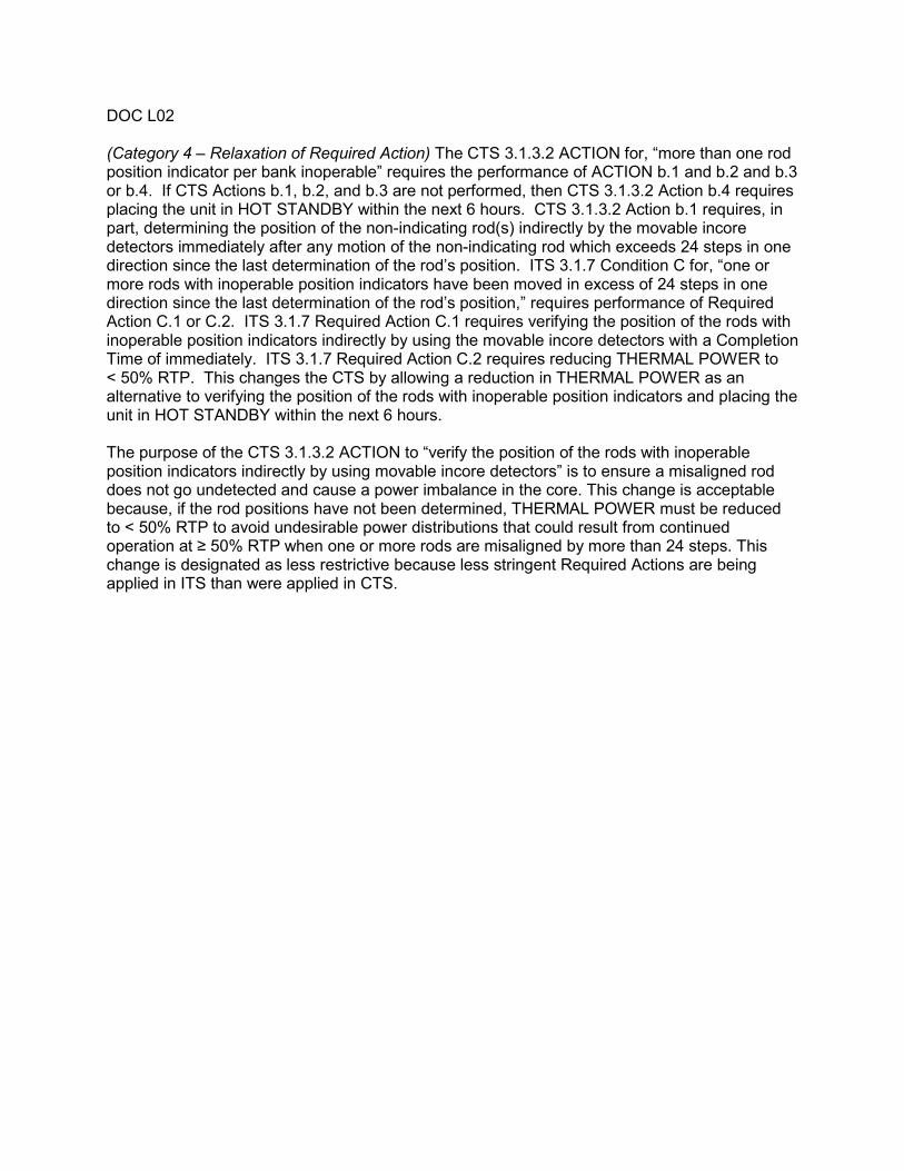
DOC L02 (Category 4 – Relaxation of Required Action) The CTS 3.1.3.2 ACTION for, “more than one rod position indicator per bank inoperable” requires the performance of ACTION b.1 and b.2 and b.3 or b.4. If CTS Actions b.1, b.2, and b.3 are not performed, then CTS 3.1.3.2 Action b.4 requires placing the unit in HOT STANDBY within the next 6 hours. CTS 3.1.3.2 Action b.1 requires, in part, determining the position of the non-indicating rod(s) indirectly by the movable incore detectors immediately after any motion of the non-indicating rod which exceeds 24 steps in one direction since the last determination of the rod’s position. ITS 3.1.7 Condition C for, “one or more rods with inoperable position indicators have been moved in excess of 24 steps in one direction since the last determination of the rod’s position,” requires performance of Required Action C.1 or C.2. ITS 3.1.7 Required Action C.1 requires verifying the position of the rods with inoperable position indicators indirectly by using the movable incore detectors with a Completion Time of immediately. ITS 3.1.7 Required Action C.2 requires reducing THERMAL POWER to < 50% RTP. This changes the CTS by allowing a reduction in THERMAL POWER as an alternative to verifying the position of the rods with inoperable position indicators and placing the unit in HOT STANDBY within the next 6 hours. The purpose of the CTS 3.1.3.2 ACTION to “verify the position of the rods with inoperable position indicators indirectly by using movable incore detectors” is to ensure a misaligned rod does not go undetected and cause a power imbalance in the core. This change is acceptable because, if the rod positions have not been determined, THERMAL POWER must be reduced to < 50% RTP to avoid undesirable power distributions that could result from continued operation at 50% RTP when one or more rods are misaligned by more than 24 steps. This change is designated as less restrictive because less stringent Required Actions are being applied in ITS than were applied in CTS.

Rod Position Indication 3.1.7
Westinghouse STS 3.1.7-1 Rev. 4.0 Amendment FFF SEQUOYAH UNIT 1
4
CTS
3.1 REACTIVITY CONTROL SYSTEMS
3.1.7 Rod Position Indication
LCO 3.1.7 The FDigitalF Rod Position Indication (FDFRPI) System and the Demand Position Indication System shall be OPERABLE.
APPLICABILITY: MODES 1 and 2.
ACTIONS ------------------------------------------------------------NOTE----------------------------------------------------------- Separate Condition entry is allowed for each inoperable rod position indicator and each demand position indicator. -------------------------------------------------------------------------------------------------------------------------------
CONDITION REQUIRED ACTION COMPLETION TIME
A. One FDFRPI per group inoperable for one or more groups.
A.1 Verify the position of the rods with inoperable position indicators indirectly by using movable incore detectors.
OR
A.2 Reduce THERMAL POWER to 50% RTP.
Once per 8 hours
8 hours
B. More than one FDFRPI per group inoperable.
B.1 Place the control rods under manual control.
AND
B.2 Monitor and record Reactor Coolant System Tavg.
AND
Immediately
Once per 1 hour
INSERT 2
INSERT 3
3
3.1.3.2
Applicability
ACTION a
ACTION b
1
1
2
3
3
1
4F
12 4
bank
bank rod position
indicator
rod position indicator
4
INSERT 1
1.
S5
Enclosure 2, Volume 6, Rev. 0, Page 24F of 356
Enclosure 2, Volume 6, Rev. 0, Page 24F of 356

3.1.7
Insert Page 3.1.7-1a
INSERT 1
2. LCO 3.0.4.a and b are not applicable for ReFuired Actions A.2.1 and A.2.2 following astartup from a refueling outage, or following entry into MODE 5 of sufficient duration to safelyrepair an inoperable rod position indication.
INSERT 2
AND
Immediately after a rod with an inoperable position indicator has been moved in excess of 24 steps in one direction since the last determination of the rodFs position
2
4
3.1.3.2 NoteF
Action a.1
Enclosure 2, Volume 6, Rev. 0, Page 250 of 356
Enclosure 2, Volume 6, Rev. 0, Page 250 of 356
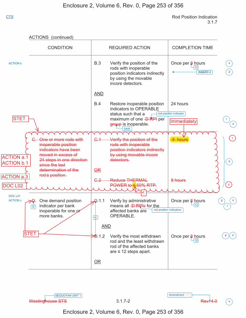
Rod Position Indication 3.1.7
Westinghouse STS 3.1.7-2 Rev. 4.0 Amendment FFF SEQUOYAH UNIT 1
4
CTS
ACTIONS (continued)
CONDITION REQUIRED ACTION COMPLETION TIME
B.3 Verify the position of the rods with inoperable position indicators indirectly by using the movable incore detectors.
AND
B.4 Restore inoperable position indicators to OPERABLE status such that a maximum of one FDFRPI per group is inoperable.
Once per 8 hours
24 hours
C. One or more rods with inoperable position indicators have been moved in excess of 24 steps in one direction since the last determination of the rodFs position.
C.1 Verify the position of the rods with inoperable position indicators indirectly by using movable incore detectors.
OR
C.2 Reduce THERMAL POWER to 50% RTP.
F4F hours
8 hours
D. One demand position indicator per bank inoperable for one or more banks.
D.1.1 Verify by administrative means all FDFRPIs for the affected banks are OPERABLE.
AND
D.1.2 Verify the most withdrawn rod and the least withdrawn rod of the affected banks are 12 steps apart.
OR
Once per 8 hours
Once per 8 hours
INSERT 4
ACTION b
ACTION c
C
C
2
2
2
2
1
1
12 4
124
12
4
4
rod position indicator
rod position indicators
bank
DOC L01
Enclosure 2, Volume 6, Rev. 0, Page 253 of 356
Enclosure 2, Volume 6, Rev. 0, Page 253 of 356
4
STET
STET
ACTION a.1ACTION b.1
F4Fhours
<DOC L02
ACTION a.3
Immediately
1

3.1.7
Insert Page 3.1.7-2
INSERT 4 AND Immediately after a rod with an inoperable position indicator has been moved in excess of 24 steps in one direction since the last determination of the rodFs position
2
Action b.1
Enclosure 2, Volume 6, Rev. 0, Page 254 of 356
Enclosure 2, Volume 6, Rev. 0, Page 254 of 356

Rod Position Indication 3.1.7
Westinghouse STS 3.1.7-3 Rev. 4.0 Amendment FFF SEQUOYAH UNIT 1
4
CTS
ACTIONS (continued)
CONDITION
REQUIRED ACTION
COMPLETION TIME
D.2 Reduce THERMAL
POWER to 50% RTP.
8 hours
E. ReFuired Action and
associated Completion Time not met.
E.1 Be in MODE 3.
6 hours
SURVEILLANCE REQUIREMENTS
SURVEILLANCE
FREQUENCY
SR 3.1.7.1 Verify each FDFRPI agrees within F12F steps of the
group demand position for the Ffull indicated rangeF of rod travel.
Once prior to criticality after each removal of the reactor head
ACTION c
ACTION b.4, DOC M02
C
D D
4.1.3.2
2
2
1
4
F
at 20 and 215 steps
rod position indicator
Enclosure 2, Volume 6, Rev. 0, Page 255 of 356
Enclosure 2, Volume 6, Rev. 0, Page 255 of 356
STET

Rod Position Indication 3.1.7
Westinghouse STS 3.1.7-1 Rev. 4.0 Amendment FFF SEQUOYAH UNIT 2
4
CTS
3.1 REACTIVITY CONTROL SYSTEMS 3.1.7 Rod Position Indication LCO 3.1.7 The FDigitalF Rod Position Indication (FDFRPI) System and the Demand
Position Indication System shall be OPERABLE. APPLICABILITY: MODES 1 and 2. ACTIONS ------------------------------------------------------------NOTE----------------------------------------------------------- Separate Condition entry is allowed for each inoperable rod position indicator and each demand position indicator. -------------------------------------------------------------------------------------------------------------------------------
CONDITION
REQUIRED ACTION
COMPLETION TIME
A. One FDFRPI per group
inoperable for one or more groups.
A.1 Verify the position of the
rods with inoperable position indicators indirectly by using movable incore detectors.
OR A.2 Reduce THERMAL
POWER to 50% RTP.
Once per 8 hours 8 hours
B. More than one FDFRPI
per group inoperable.
B.1 Place the control rods
under manual control. AND B.2 Monitor and record Reactor
Coolant System Tavg. AND
Immediately Once per 1 hour
INSERT 2
INSERT 3
3
3.1.3.2
Applicability
ACTION a
ACTION b
1
1
2
3
3
1
4F
12 4
bank
bank rod position
indicator
rod position indicator
4
INSERT 1
1.
S5
Enclosure 2, Volume 6, Rev. 0, Page 256 of 356
Enclosure 2, Volume 6, Rev. 0, Page 256 of 356

3.1.7
Insert Page 3.1.7-1a
INSERT 1 2. LCO 3.0.4.a and b are not applicable for ReFuired Actions A.2.1 and A.2.2 following a
startup from a refueling outage, or following entry into MODE 5 of sufficient duration to safely repair an inoperable rod position indication.
INSERT 2 AND Immediately after a rod with an inoperable position indicator has been moved in excess of 24 steps in one direction since the last determination of the rodFs position
2
4
3.1.3.2 NoteF
Action a.1
Enclosure 2, Volume 6, Rev. 0, Page 257 of 356
Enclosure 2, Volume 6, Rev. 0, Page 257 of 356
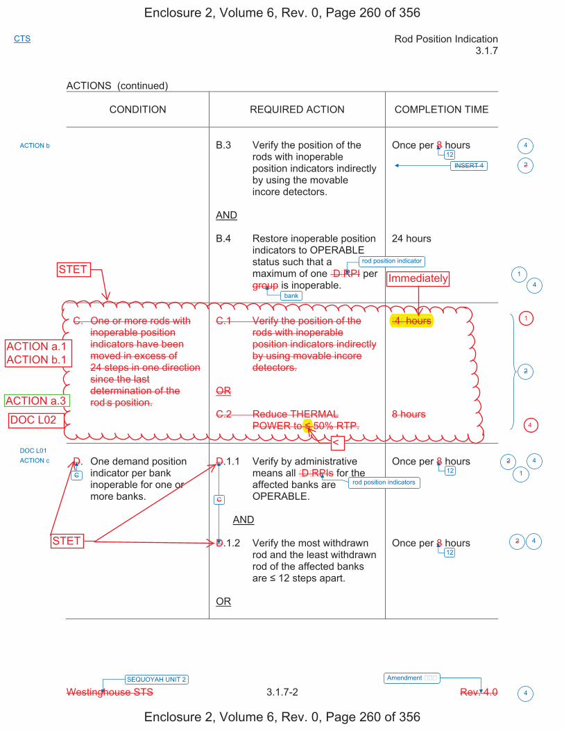
Rod Position Indication 3.1.7
Westinghouse STS 3.1.7-2 Rev. 4.0 Amendment FFF SEQUOYAH UNIT 2
4
CTS
ACTIONS (continued)
CONDITION REQUIRED ACTION COMPLETION TIME
B.3 Verify the position of the rods with inoperable position indicators indirectly by using the movable incore detectors.
AND
B.4 Restore inoperable position indicators to OPERABLE status such that a maximum of one FDFRPI per group is inoperable.
Once per 8 hours
24 hours
C. One or more rods with inoperable position indicators have been moved in excess of 24 steps in one direction since the last determination of the rodFs position.
C.1 Verify the position of the rods with inoperable position indicators indirectly by using movable incore detectors.
OR
C.2 Reduce THERMAL POWER to 50% RTP.
F4F hours
8 hours
D. One demand position indicator per bank inoperable for one or more banks.
D.1.1 Verify by administrative means all FDFRPIs for the affected banks are OPERABLE.
AND
D.1.2 Verify the most withdrawn rod and the least withdrawn rod of the affected banks are 12 steps apart.
OR
Once per 8 hours
Once per 8 hours
INSERT 4
ACTION b
ACTION c
C
C
2
2
2
2
1
1
12 4
124
12
4
4
rod position indicator
rod position indicators
bank
DOC L01
Enclosure 2, Volume 6, Rev. 0, Page 260 of 356
Enclosure 2, Volume 6, Rev. 0, Page 260 of 356
4
STET
ACTION a.1ACTION b.1
STET
<
F4Fhours
DOC L02
ACTION a.3
Immediately
1

3.1.7
Insert Page 3.1.7-2
INSERT 4 AND Immediately after a rod with an inoperable position indicator has been moved in excess of 24 steps in one direction since the last determination of the rodFs position
2
Action b.1
Enclosure 2, Volume 6, Rev. 0, Page 261 of 356
Enclosure 2, Volume 6, Rev. 0, Page 261 of 356
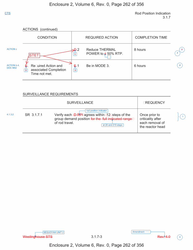
Rod Position Indication 3.1.7
Westinghouse STS 3.1.7-3 Rev. 4.0 Amendment FFF SEQUOYAH UNIT 2
4
CTS
ACTIONS (continued)
CONDITION
REQUIRED ACTION
COMPLETION TIME
D.2 Reduce THERMAL
POWER to 50% RTP.
8 hours
E. ReFuired Action and
associated Completion Time not met.
E.1 Be in MODE 3.
6 hours
SURVEILLANCE REQUIREMENTS
SURVEILLANCE
FREQUENCY
SR 3.1.7.1 Verify each FDFRPI agrees within F12F steps of the
group demand position for the Ffull indicated rangeF of rod travel.
Once prior to criticality after each removal of the reactor head
ACTION c
ACTION b.4, DOC M02
C
D D
4.1.3.2
2
2
1
4
F
at 20 and 215 steps
rod position indicator
Enclosure 2, Volume 6, Rev. 0, Page 262 of 356
Enclosure 2, Volume 6, Rev. 0, Page 262 of 356
STET
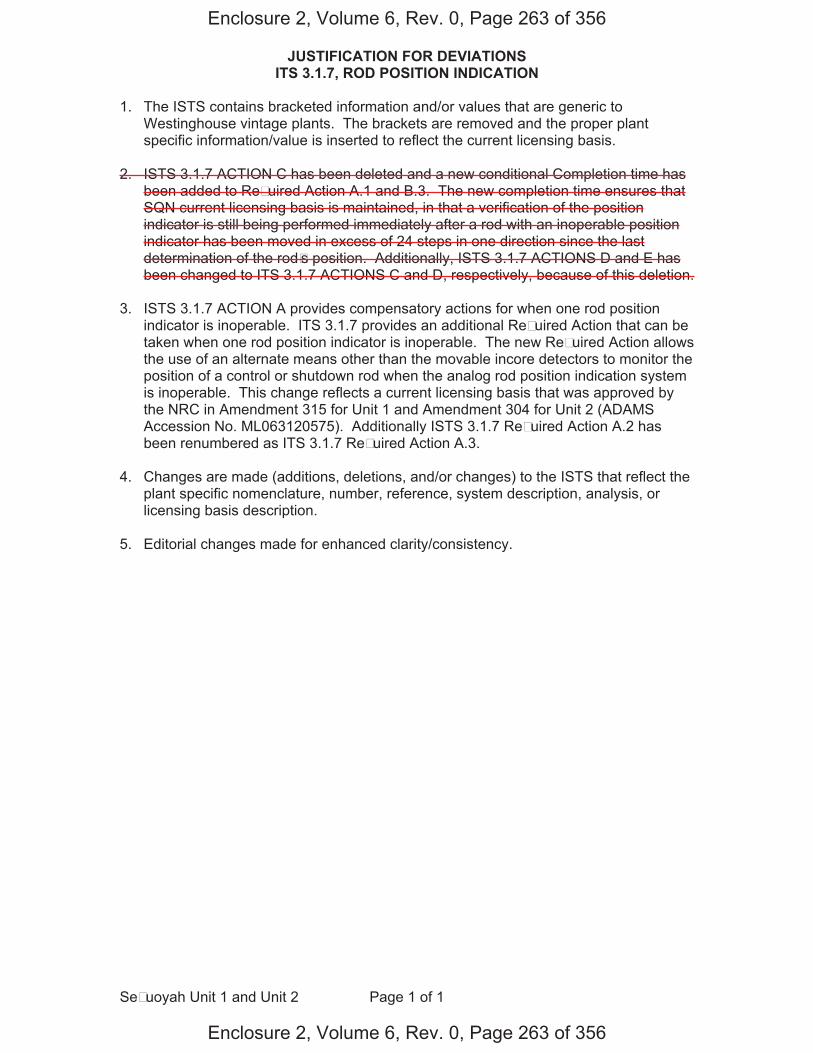
JUSTIFICATION FOR DEVIATIONS ITS 3.1.7, ROD POSITION INDICATION
SeFuoyah Unit 1 and Unit 2 Page 1 of 1
1. The ISTS contains bracketed information and/or values that are generic to Westinghouse vintage plants. The brackets are removed and the proper plant specific information/value is inserted to reflect the current licensing basis.
2. ISTS 3.1.7 ACTION C has been deleted and a new conditional Completion time has been added to ReFuired Action A.1 and B.3. The new completion time ensures that SQN current licensing basis is maintained, in that a verification of the position indicator is still being performed immediately after a rod with an inoperable position indicator has been moved in excess of 24 steps in one direction since the last determination of the rodFs position. Additionally, ISTS 3.1.7 ACTIONS D and E has been changed to ITS 3.1.7 ACTIONS C and D, respectively, because of this deletion.
3. ISTS 3.1.7 ACTION A provides compensatory actions for when one rod position
indicator is inoperable. ITS 3.1.7 provides an additional ReFuired Action that can be taken when one rod position indicator is inoperable. The new ReFuired Action allows the use of an alternate means other than the movable incore detectors to monitor the position of a control or shutdown rod when the analog rod position indication system is inoperable. This change reflects a current licensing basis that was approved by the NRC in Amendment 315 for Unit 1 and Amendment 304 for Unit 2 (ADAMS Accession No. ML063120575). Additionally ISTS 3.1.7 ReFuired Action A.2 has been renumbered as ITS 3.1.7 ReFuired Action A.3.
4. Changes are made (additions, deletions, and/or changes) to the ISTS that reflect the
plant specific nomenclature, number, reference, system description, analysis, or licensing basis description.
5. Editorial changes made for enhanced clarity/consistency.
Enclosure 2, Volume 6, Rev. 0, Page 263 of 356
Enclosure 2, Volume 6, Rev. 0, Page 263 of 356
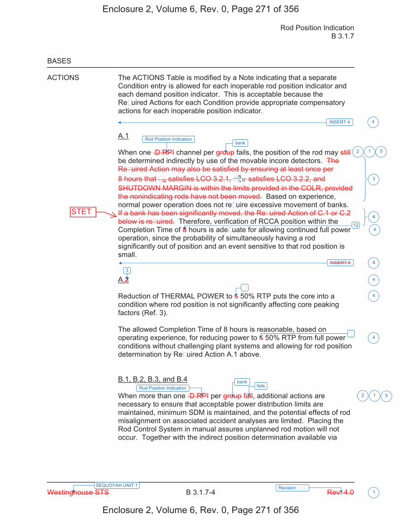
Rod Position Indication B 3.1.7
Westinghouse STS B 3.1.7-4 Rev. 4.0
SEQUOYAH UNIT 1 Revision FFF 1
BASES ACTIONS The ACTIONS Table is modified by a Note indicating that a separate
Condition entry is allowed for each inoperable rod position indicator and each demand position indicator. This is acceptable because the ReFuired Actions for each Condition provide appropriate compensatory actions for each inoperable position indicator. A.1 When one FDFRPI channel per group fails, the position of the rod may still be determined indirectly by use of the movable incore detectors. The ReFuired Action may also be satisfied by ensuring at least once per 8 hours that FQ satisfies LCO 3.2.1, H
NFΔ satisfies LCO 3.2.2, and SHUTDOWN MARGIN is within the limits provided in the COLR, provided the nonindicating rods have not been moved. Based on experience, normal power operation does not reFuire excessive movement of banks. If a bank has been significantly moved, the ReFuired Action of C.1 or C.2 below is reFuired. Therefore, verification of RCCA position within the Completion Time of 8 hours is adeFuate for allowing continued full power operation, since the probability of simultaneously having a rod significantly out of position and an event sensitive to that rod position is small. A.2 Reduction of THERMAL POWER to 50% RTP puts the core into a condition where rod position is not significantly affecting core peaking factors (Ref. 3). The allowed Completion Time of 8 hours is reasonable, based on operating experience, for reducing power to 50% RTP from full power conditions without challenging plant systems and allowing for rod position determination by ReFuired Action A.1 above. B.1, B.2, B.3, and B.4 When more than one FDFRPI per group fail, additional actions are necessary to ensure that acceptable power distribution limits are maintained, minimum SDM is maintained, and the potential effects of rod misalignment on associated accident analyses are limited. Placing the Rod Control System in manual assures unplanned rod motion will not occur. Together with the indirect position determination available via
2
3
4
4
INSERT 5 4
3
2
F
F
4
4
412
Rod Position Indicationbank
1 5
Rod Position Indication fails
1
bank
5
INSERT 4 4
Enclosure 2, Volume 6, Rev. 0, Page 271 of 356
Enclosure 2, Volume 6, Rev. 0, Page 271 of 356
STET

B 3.1.7
Insert Page B 3.1.7-4
INSERT 4 A second Note has been added to provide clarification that LCO 3.0.4.a and LCO 3.0.4.c are not applicable for ReFuired Action A.2.1 and A.2.2 following startup from a refueling outage, or following entry into MODE 5 of sufficient duration to safely repair an inoperable rod position indication.
INSERT 5 If one or more rods have been significantly moved (in excess of 24 steps in one direction, since the position was last determined), ReFuired Action A.1 is still appropriate, but actions must be initiated immediately to begin verifying that the rod is still properly positioned, relative to their group positions. In this ReFuired Action, the Completion Time only begins on discovery that both: a. One rod position indication per bank is inoperable, and
b. A rod with an inoperable position indicator has been moved in excess of 24 steps in one
direction since the last determination of the rodFs position.
If at any time during the existence of Condition A (one RPI per bank inoperable), a rod with an inoperable position indicator has been moved in excess of 24 steps in one direction since the last determination of the rodFs position, this Completion Time begins to be tracked. A.2.1, and A.2.2 When one RPI channel per bank fails, the position of the rod may still be determined indirectly by use of the movable incore detectors and reviewing the parameters of the rod control system for indications of unintended rod movement for the rod with the inoperable position indication. Therefore, verification of RCCA position within 8 hours and every 31days thereafter is adeFuate for allowing continued full power operation as long as a review of the parameters of the rod control system for indications of unintended rod movement for the rod with the inoperable position indication is performed within 16 hours and every 8 hours thereafter. Furthermore, if the rod control system parameters indicate unintended movement or if the rod with an inoperable position indicator is moved greater than 12 steps, then the verification of the RCCA position must be performed within 8 hours. As long as these compensatory actions are met, reactor operation can then continue until the end of the current cycle or until an entry into MODE 5 of sufficient duration that the repair of the inoperable rod position indication can safely be performed. ReFuired Actions A.2.1,and A.2.2 are modified by a Note directing that these ReFuired Actions may only be applied to one inoperable rod position indicator.
4
4
Enclosure 2, Volume 6, Rev. 0, Page 272 of 356
Enclosure 2, Volume 6, Rev. 0, Page 272 of 356
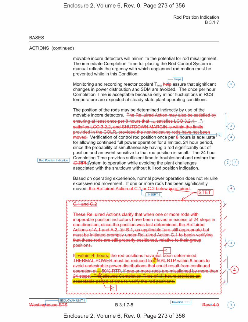
Rod Position Indication B 3.1.7
Westinghouse STS B 3.1.7-5 Rev. 4.0 SEQUOYAH UNIT 1 Revision FFF
1
BASES
ACTIONS (continued)
movable incore detectors will minimiFe the potential for rod misalignment. The immediate Completion Time for placing the Rod Control System in manual reflects the urgency with which unplanned rod motion must be prevented while in this Condition.
Monitoring and recording reactor coolant Tavg help assure that significant changes in power distribution and SDM are avoided. The once per hour Completion Time is acceptable because only minor fluctuations in RCS temperature are expected at steady state plant operating conditions.
The position of the rods may be determined indirectly by use of the movable incore detectors. The ReFuired Action may also be satisfied by ensuring at least once per 8 hours that FQ satisfies LCO 3.2.1, H
NFΔ satisfies LCO 3.2.2, and SHUTDOWN MARGIN is within the limits provided in the COLR, provided the nonindicating rods have not been moved. Verification of control rod position once per 8 hours is adeFuate for allowing continued full power operation for a limited, 24 hour period, since the probability of simultaneously having a rod significantly out of position and an event sensitive to that rod position is small. The 24 hour Completion Time provides sufficient time to troubleshoot and restore the FDFRPI system to operation while avoiding the plant challenges associated with the shutdown without full rod position indication.
Based on operating experience, normal power operation does not reFuire excessive rod movement. If one or more rods has been significantly moved, the ReFuired Action of C.1 or C.2 below is reFuired.
C.1 and C.2
These ReFuired Actions clarify that when one or more rods with inoperable position indicators have been moved in excess of 24 steps in one direction, since the position was last determined, the ReFuired Actions of A.1 and A.2, For B.1, as applicableF are still appropriate but must be initiated promptly under ReFuired Action C.1 to begin verifying that these rods are still properly positioned, relative to their group positions.
If, within F4F hours, the rod positions have not been determined, THERMAL POWER must be reduced to 50% RTP within 8 hours to avoid undesirable power distributions that could result from continued operation at F 50% RTP, if one or more rods are misaligned by more than 24 steps. The allowed Completion Time of F4F hours provides an acceptable period of time to verify the rod positions.
INSERT 6
3
2
4
4
412
Rod Position Indication
helps
5
5
Enclosure 2, Volume 6, Rev. 0, Page 273 of 356
Enclosure 2, Volume 6, Rev. 0, Page 273 of 356
STET
F
<
>
4
f within F4Fhours, f,
g y. The allowed Completion Time of hours provides anF4Fp p
acceptable period of time to verify the rod positions.
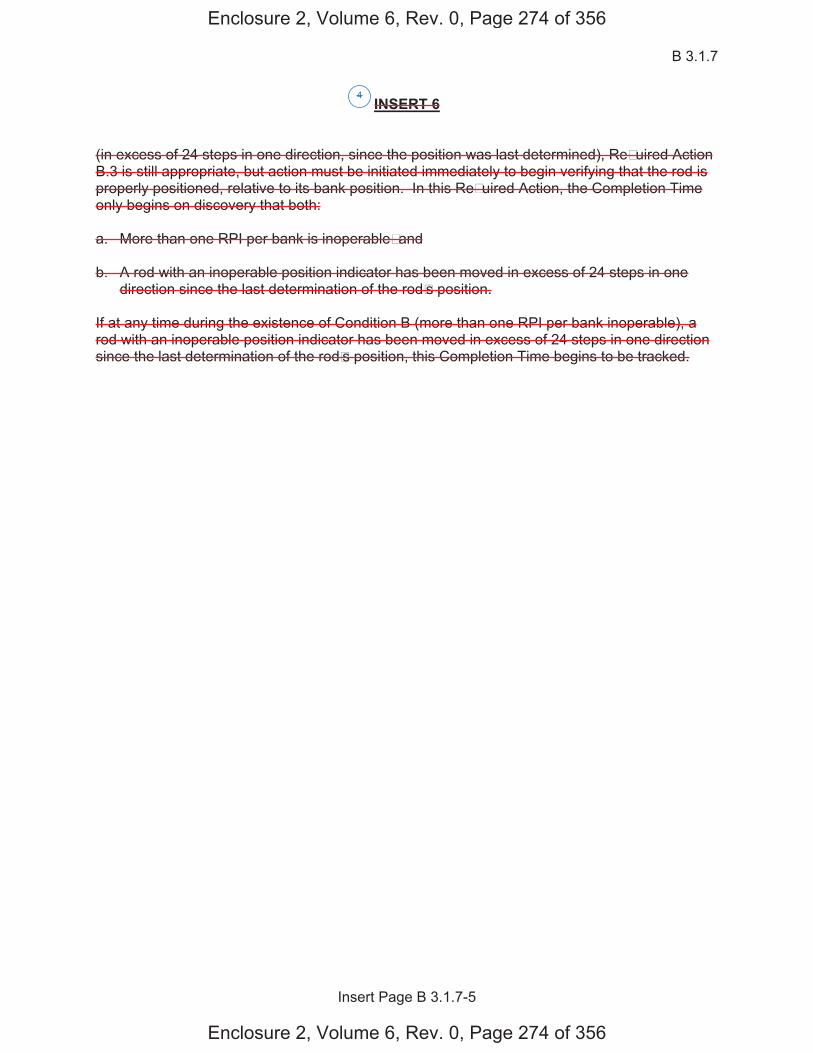
B 3.1.7
Insert Page B 3.1.7-5
INSERT 6 (in excess of 24 steps in one direction, since the position was last determined), ReFuired Action B.3 is still appropriate, but action must be initiated immediately to begin verifying that the rod is properly positioned, relative to its bank position. In this ReFuired Action, the Completion Time only begins on discovery that both: a. More than one RPI per bank is inoperableF and b. A rod with an inoperable position indicator has been moved in excess of 24 steps in one
direction since the last determination of the rodFs position.
If at any time during the existence of Condition B (more than one RPI per bank inoperable), a rod with an inoperable position indicator has been moved in excess of 24 steps in one direction since the last determination of the rodFs position, this Completion Time begins to be tracked.
4
Enclosure 2, Volume 6, Rev. 0, Page 274 of 356
Enclosure 2, Volume 6, Rev. 0, Page 274 of 356
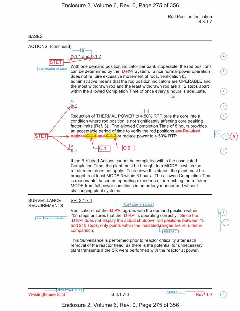
Rod Position Indication B 3.1.7
Westinghouse STS B 3.1.7-6 Rev. 4.0
SEQUOYAH UNIT 1 Revision FFF 1
BASES
ACTIONS (continued) D.1.1 and D.1.2 With one demand position indicator per bank inoperable, the rod positions can be determined by the FDFRPI System. Since normal power operation does not reFuire excessive movement of rods, verification by administrative means that the rod position indicators are OPERABLE and the most withdrawn rod and the least withdrawn rod are 12 steps apart within the allowed Completion Time of once every 8 hours is adeFuate. D.2 Reduction of THERMAL POWER to 50% RTP puts the core into a condition where rod position is not significantly affecting core peaking factor limits (Ref. 3). The allowed Completion Time of 8 hours provides an acceptable period of time to verify the rod positions per ReFuired Actions C.1.1 and C.1.2 or reduce power to 50% RTP. E.1 If the ReFuired Actions cannot be completed within the associated Completion Time, the plant must be brought to a MODE in which the reFuirement does not apply. To achieve this status, the plant must be brought to at least MODE 3 within 6 hours. The allowed Completion Time is reasonable, based on operating experience, for reaching the reFuired MODE from full power conditions in an orderly manner and without challenging plant systems.
SURVEILLANCE SR 3.1.7.1 REQUIREMENTS
Verification that the FDFRPI agrees with the demand position within F12F steps ensures that the FDFRPI is operating correctly. Since the FDFRPI does not display the actual shutdown rod positions between 18 and 210 steps, only points within the indicated ranges are reFuired in comparison. This Surveillance is performed prior to reactor criticality after each removal of the reactor head, as there is the potential for unnecessary plant transients if the SR were performed with the reactor at power.
C
C
D
4
4
4
2
4
2
4
1
F
F
12
4
Rod Position Indication
Rod Position Indication
1Rod Position Indication
INSERT 7
Enclosure 2, Volume 6, Rev. 0, Page 275 of 356
Enclosure 2, Volume 6, Rev. 0, Page 275 of 356
STET
STET
pC. .1 .1. C.1.2.1.
C.1 C.2
5

Rod Position Indication B 3.1.7
Westinghouse STS B 3.1.7-4 Rev. 4.0
SEQUOYAH UNIT 2 Revision FFF 1
BASES ACTIONS The ACTIONS Table is modified by a Note indicating that a separate
Condition entry is allowed for each inoperable rod position indicator and each demand position indicator. This is acceptable because the ReFuired Actions for each Condition provide appropriate compensatory actions for each inoperable position indicator. A.1 When one FDFRPI channel per group fails, the position of the rod may still be determined indirectly by use of the movable incore detectors. The ReFuired Action may also be satisfied by ensuring at least once per 8 hours that FQ satisfies LCO 3.2.1, H
NFΔ satisfies LCO 3.2.2, and SHUTDOWN MARGIN is within the limits provided in the COLR, provided the nonindicating rods have not been moved. Based on experience, normal power operation does not reFuire excessive movement of banks. If a bank has been significantly moved, the ReFuired Action of C.1 or C.2 below is reFuired. Therefore, verification of RCCA position within the Completion Time of 8 hours is adeFuate for allowing continued full power operation, since the probability of simultaneously having a rod significantly out of position and an event sensitive to that rod position is small. A.2 Reduction of THERMAL POWER to 50% RTP puts the core into a condition where rod position is not significantly affecting core peaking factors (Ref. 3). The allowed Completion Time of 8 hours is reasonable, based on operating experience, for reducing power to 50% RTP from full power conditions without challenging plant systems and allowing for rod position determination by ReFuired Action A.1 above. B.1, B.2, B.3, and B.4 When more than one FDFRPI per group fail, additional actions are necessary to ensure that acceptable power distribution limits are maintained, minimum SDM is maintained, and the potential effects of rod misalignment on associated accident analyses are limited. Placing the Rod Control System in manual assures unplanned rod motion will not occur. Together with the indirect position determination available via
2
3
4
4
INSERT 5 4
3
2
F
F
4
4
412
Rod Position Indicationbank
1 5
Rod Position Indication fails
1
bank
5
INSERT 4 4
Enclosure 2, Volume 6, Rev. 0, Page 283 of 356
Enclosure 2, Volume 6, Rev. 0, Page 283 of 356
STET

B 3.1.7
Insert Page B 3.1.7-4
INSERT 4 A second Note has been added to provide clarification that LCO 3.0.4.a and LCO 3.0.4.c are not applicable for ReFuired Action A.2.1 and A.2.2 following startup from a refueling outage, or following entry into MODE 5 of sufficient duration to safely repair an inoperable rod position indication.
INSERT 5 If one or more rods have been significantly moved (in excess of 24 steps in one direction, since the position was last determined), ReFuired Action A.1 is still appropriate, but actions must be initiated immediately to begin verifying that the rod is still properly positioned, relative to their group positions. In this ReFuired Action, the Completion Time only begins on discovery that both: a. One rod position indication per bank is inoperable, and
b. A rod with an inoperable position indicator has been moved in excess of 24 steps in one
direction since the last determination of the rodFs position.
If at any time during the existence of Condition A (one RPI per bank inoperable), a rod with an inoperable position indicator has been moved in excess of 24 steps in one direction since the last determination of the rodFs position, this Completion Time begins to be tracked. A.2.1, and A.2.2 When one RPI channel per bank fails, the position of the rod may still be determined indirectly by use of the movable incore detectors and reviewing the parameters of the rod control system for indications of unintended rod movement for the rod with the inoperable position indication. Therefore, verification of RCCA position within 8 hours and every 31days thereafter is adeFuate for allowing continued full power operation as long as a review of the parameters of the rod control system for indications of unintended rod movement for the rod with the inoperable position indication is performed within 16 hours and every 8 hours thereafter. Furthermore, if the rod control system parameters indicate unintended movement or if the rod with an inoperable position indicator is moved greater than 12 steps, then the verification of the RCCA position must be performed within 8 hours. As long as these compensatory actions are met, reactor operation can then continue until the end of the current cycle or until an entry into MODE 5 of sufficient duration that the repair of the inoperable rod position indication can safely be performed. ReFuired Actions A.2.1,and A.2.2 are modified by a Note directing that these ReFuired Actions may only be applied to one inoperable rod position indicator.
4
4
Enclosure 2, Volume 6, Rev. 0, Page 284 of 356
Enclosure 2, Volume 6, Rev. 0, Page 284 of 356

Rod Position Indication B 3.1.7
Westinghouse STS B 3.1.7-5 Rev. 4.0 SEQUOYAH UNIT 2 Revision FFF
1
BASES
ACTIONS (continued)
movable incore detectors will minimiFe the potential for rod misalignment. The immediate Completion Time for placing the Rod Control System in manual reflects the urgency with which unplanned rod motion must be prevented while in this Condition.
Monitoring and recording reactor coolant Tavg help assure that significant changes in power distribution and SDM are avoided. The once per hour Completion Time is acceptable because only minor fluctuations in RCS temperature are expected at steady state plant operating conditions.
The position of the rods may be determined indirectly by use of the movable incore detectors. The ReFuired Action may also be satisfied by ensuring at least once per 8 hours that FQ satisfies LCO 3.2.1, H
NFΔ satisfies LCO 3.2.2, and SHUTDOWN MARGIN is within the limits provided in the COLR, provided the nonindicating rods have not been moved. Verification of control rod position once per 8 hours is adeFuate for allowing continued full power operation for a limited, 24 hour period, since the probability of simultaneously having a rod significantly out of position and an event sensitive to that rod position is small. The 24 hour Completion Time provides sufficient time to troubleshoot and restore the FDFRPI system to operation while avoiding the plant challenges associated with the shutdown without full rod position indication.
Based on operating experience, normal power operation does not reFuire excessive rod movement. If one or more rods has been significantly moved, the ReFuired Action of C.1 or C.2 below is reFuired.
C.1 and C.2
These ReFuired Actions clarify that when one or more rods with inoperable position indicators have been moved in excess of 24 steps in one direction, since the position was last determined, the ReFuired Actions of A.1 and A.2, For B.1, as applicableF are still appropriate but must be initiated promptly under ReFuired Action C.1 to begin verifying that these rods are still properly positioned, relative to their group positions.
If, within F4F hours, the rod positions have not been determined, THERMAL POWER must be reduced to 50% RTP within 8 hours to avoid undesirable power distributions that could result from continued operation at F 50% RTP, if one or more rods are misaligned by more than 24 steps. The allowed Completion Time of F4F hours provides an acceptable period of time to verify the rod positions.
INSERT 6
3
2
4
4
412
Rod Position Indication
helps
5
5
Enclosure 2, Volume 6, Rev. 0, Page 285 of 356
Enclosure 2, Volume 6, Rev. 0, Page 285 of 356
STET
F
<
>
4
f, within hours, F4F
g ye allowed Completion Time of hours provides anf F4FThe The p
iod of time to verify the rod positions.p
acceptable perio>

B 3.1.7
Insert Page B 3.1.7-5
INSERT 6 (in excess of 24 steps in one direction, since the position was last determined), ReFuired Action B.3 is still appropriate, but action must be initiated immediately to begin verifying that the rod is properly positioned, relative to its bank position. In this ReFuired Action, the Completion Time only begins on discovery that both: a. More than one RPI per bank is inoperableF and b. A rod with an inoperable position indicator has been moved in excess of 24 steps in one
direction since the last determination of the rodFs position.
If at any time during the existence of Condition B (more than one RPI per bank inoperable), a rod with an inoperable position indicator has been moved in excess of 24 steps in one direction since the last determination of the rodFs position, this Completion Time begins to be tracked.
4
Enclosure 2, Volume 6, Rev. 0, Page 286 of 356
Enclosure 2, Volume 6, Rev. 0, Page 286 of 356
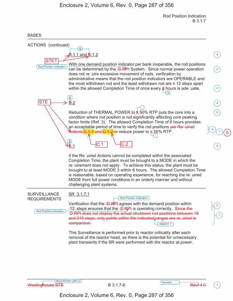
Rod Position Indication B 3.1.7
Westinghouse STS B 3.1.7-6 Rev. 4.0
SEQUOYAH UNIT 2 Revision FFF 1
BASES
ACTIONS (continued) D.1.1 and D.1.2 With one demand position indicator per bank inoperable, the rod positions can be determined by the FDFRPI System. Since normal power operation does not reFuire excessive movement of rods, verification by administrative means that the rod position indicators are OPERABLE and the most withdrawn rod and the least withdrawn rod are 12 steps apart within the allowed Completion Time of once every 8 hours is adeFuate. D.2 Reduction of THERMAL POWER to 50% RTP puts the core into a condition where rod position is not significantly affecting core peaking factor limits (Ref. 3). The allowed Completion Time of 8 hours provides an acceptable period of time to verify the rod positions per ReFuired Actions C.1.1 and C.1.2 or reduce power to 50% RTP. E.1 If the ReFuired Actions cannot be completed within the associated Completion Time, the plant must be brought to a MODE in which the reFuirement does not apply. To achieve this status, the plant must be brought to at least MODE 3 within 6 hours. The allowed Completion Time is reasonable, based on operating experience, for reaching the reFuired MODE from full power conditions in an orderly manner and without challenging plant systems.
SURVEILLANCE SR 3.1.7.1 REQUIREMENTS
Verification that the FDFRPI agrees with the demand position within F12F steps ensures that the FDFRPI is operating correctly. Since the FDFRPI does not display the actual shutdown rod positions between 18 and 210 steps, only points within the indicated ranges are reFuired in comparison. This Surveillance is performed prior to reactor criticality after each removal of the reactor head, as there is the potential for unnecessary plant transients if the SR were performed with the reactor at power.
C
C
D
4
4
4
2
4
2
4
1
F
F
12
4
Rod Position Indication
Rod Position Indication
1Rod Position Indication
INSERT 7
Enclosure 2, Volume 6, Rev. 0, Page 287 of 356
Enclosure 2, Volume 6, Rev. 0, Page 287 of 356
STE
STET
pC.1.1 C.1.2
C.1 C.2
5

Licensee Response/NRC Response/NRC Question ClosureId 408
NRC Question Number MEH-004
Select Application NRC Question Closure
Attachment 1
Attachment 2
Response Statement
Response Date/Time
Closure Statement This question is closed and no further information is required at this time to draft the Safety Evaluation.
Question Closure Date 12/19/2014
Notification Scott BowmanMichelle ConnerMatthew HammKhadijah HemphillAndrew HonRoger Scott
Added By Matthew Hamm
Date Added 12/19/2014 12:15 PM
Date Modified
Modified By
Page 1 of 1Sequoyah ITS Conversion Database
1/13/2015https://members.excelservices.com/rai/index.php?requestType=areaItemPrint&itemId=408

ITS NRC QuestionsId 186
NRC Question Number MEH-005
Category Technical
ITS Section 3.7
ITS Number
DOC Number
JFD Number
JFD Bases Number
Page Number(s)
NRC Reviewer Supervisor Rob Elliott
Technical Branch POC Add Name
Conf Call Requested N
NRC Question In a meeting between TVA and NRC on 8/12/2014, TVA stated that the following license amendment application, dated 10/2/2013, will be withdrawn from evaluation:
SEQUOYAH NUCLEAR PLANT (SQN), UNITS I AND 2 - PROPOSED TECHNICAL SPECIFICATION (TS) CHANGE, "ULTIMATE HEAT SINK (UHS) TEMPERATURE LIMITATIONS SUPPORTING ALTERNATE ESSENTIAL RAW COOLING WATER (ERCW) LOOP ALIGNMENTS (TS-SQN-13-01 AND 13-02)."
Please provide the marked-up CTS and ITS pages and revised Discussion of Changes with the current licensing basis that pertained license amendment request.
Attach File 1
Attach File 2
Issue Date 8/20/2014
Added By Khadijah Hemphill
Date Modified
Modified By
Date Added 8/20/2014 5:42 PM
Notification Scott BowmanRobert ElliottMatthew HammKhadijah HemphillAndrew HonLynn MynattRay SchieleRoger Scott
Page 1 of 1Sequoyah ITS Conversion Database
1/13/2015https://members.excelservices.com/rai/index.php?requestType=areaItemPrint&itemId=186
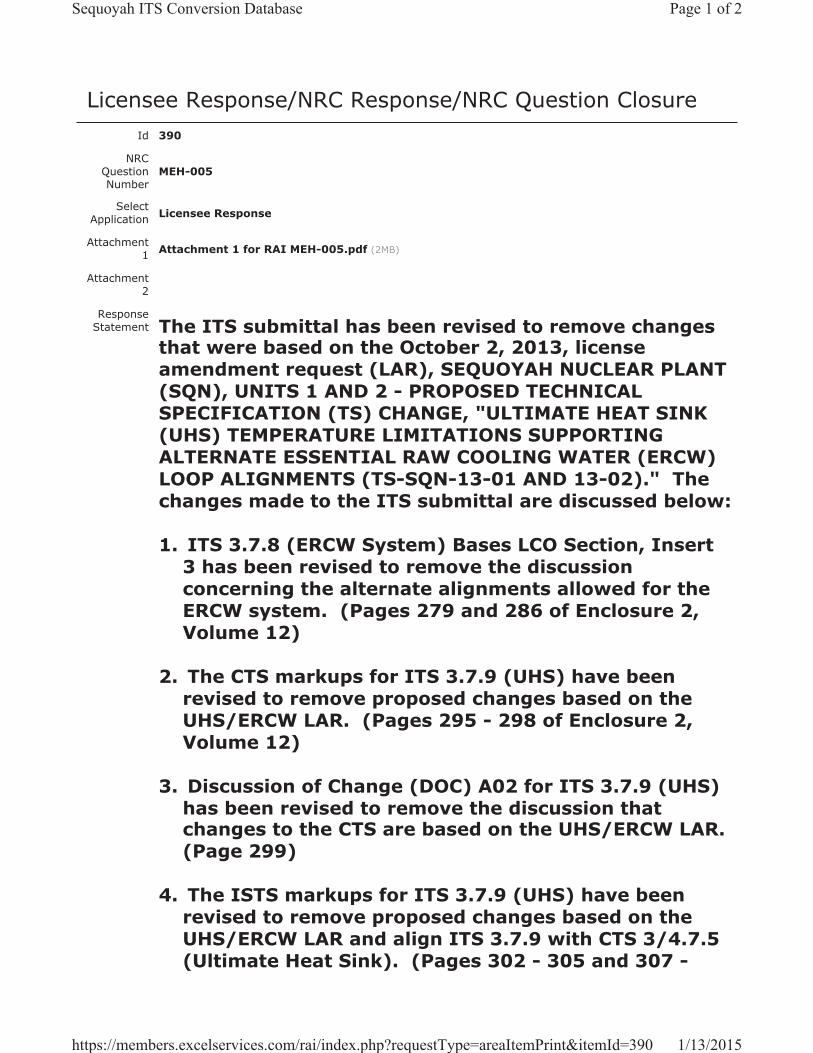
Licensee Response/NRC Response/NRC Question ClosureId 390
NRC Question Number
MEH-005
Select Application Licensee Response
Attachment 1 Attachment 1 for RAI MEH-005.pdf (2MB)
Attachment 2
Response Statement The ITS submittal has been revised to remove changes
that were based on the October 2, 2013, license amendment request (LAR), SEQUOYAH NUCLEAR PLANT (SQN), UNITS 1 AND 2 - PROPOSED TECHNICAL SPECIFICATION (TS) CHANGE, "ULTIMATE HEAT SINK (UHS) TEMPERATURE LIMITATIONS SUPPORTING ALTERNATE ESSENTIAL RAW COOLING WATER (ERCW) LOOP ALIGNMENTS (TS-SQN-13-01 AND 13-02)." The changes made to the ITS submittal are discussed below:
1. ITS 3.7.8 (ERCW System) Bases LCO Section, Insert 3 has been revised to remove the discussion concerning the alternate alignments allowed for the ERCW system. (Pages 279 and 286 of Enclosure 2, Volume 12)
2. The CTS markups for ITS 3.7.9 (UHS) have been revised to remove proposed changes based on the UHS/ERCW LAR. (Pages 295 - 298 of Enclosure 2, Volume 12)
3. Discussion of Change (DOC) A02 for ITS 3.7.9 (UHS) has been revised to remove the discussion that changes to the CTS are based on the UHS/ERCW LAR.(Page 299)
4. The ISTS markups for ITS 3.7.9 (UHS) have been revised to remove proposed changes based on the UHS/ERCW LAR and align ITS 3.7.9 with CTS 3/4.7.5 (Ultimate Heat Sink). (Pages 302 - 305 and 307 -
Page 1 of 2Sequoyah ITS Conversion Database
1/13/2015https://members.excelservices.com/rai/index.php?requestType=areaItemPrint&itemId=390
310)
5. Justification for Deviation (JFD) 1 for ITS 3.7.9 has been revised. JFD 6 has been added, as well as JFD 6 indicators, to justify the change made to ISTS SR 3.7.9.2. (Page 304, 309, and 312)
6. The ISTS 3.7.9 Bases have been revised to remove proposed changes based on the UHS/ERCW LAR and align the Bases with changes made to the Specification. JFD indicators have been added where necessary to justify changes made to the Bases.(Pages 316 - 325 and 328 - 337)
7. Enclosure 6, “Disposition of Existing License Amendment Requests,” has been revised to reflect the removal of the UHS/ERCW LAR from the ITS submittal. (Pages E6-1).
See Attachment 1 for the draft revised ITS submittal affected by the changes discussed above.
Response Date/Time 12/2/2014 2:10 AM
Closure Statement
Question Closure
Date
Notification Scott BowmanMichelle ConnerMatthew HammKhadijah HemphillAndrew HonLynn MynattRay Schiele
Added By Scott Bowman
Date Added 12/2/2014 1:09 PM
Date Modified
Modified By
Page 2 of 2Sequoyah ITS Conversion Database
1/13/2015https://members.excelservices.com/rai/index.php?requestType=areaItemPrint&itemId=390
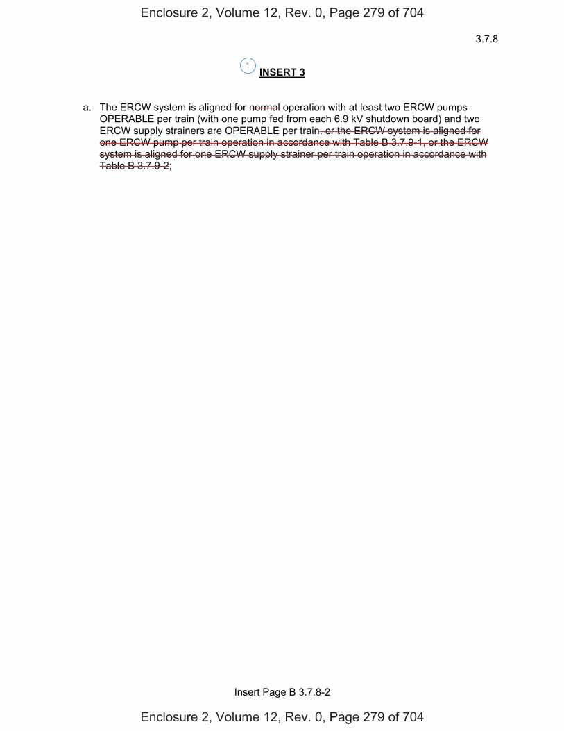
3.7.8
Insert Page B 3.7.8-2
INSERT 3
a. The ERCW system is aligned for normal operation with at least two ERCW pumps OPERABLE per train (with one pump fed from each 6.9 kV shutdown board) and two ERCW supply strainers are OPERABLE per train, or the ERCW system is aligned for one ERCW pump per train operation in accordance with Table B 3.7.9-1, or the ERCW system is aligned for one ERCW supply strainer per train operation in accordance with Table B 3.7.9-2;
1
Enclosure 2, Volume 12, Rev. 0, Page 279 of 704
Enclosure 2, Volume 12, Rev. 0, Page 279 of 704
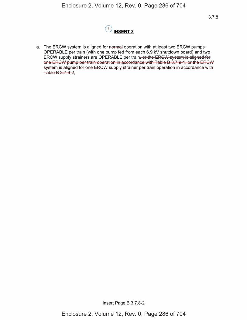
3.7.8
Insert Page B 3.7.8-2
INSERT 3
a. The ERCW system is aligned for normal operation with at least two ERCW pumps OPERABLE per train (with one pump fed from each 6.9 kV shutdown board) and two ERCW supply strainers are OPERABLE per train, or the ERCW system is aligned for one ERCW pump per train operation in accordance with Table B 3.7.9-1, or the ERCW system is aligned for one ERCW supply strainer per train operation in accordance with Table B 3.7.9-2;
1
Enclosure 2, Volume 12, Rev. 0, Page 286 of 704
Enclosure 2, Volume 12, Rev. 0, Page 286 of 704
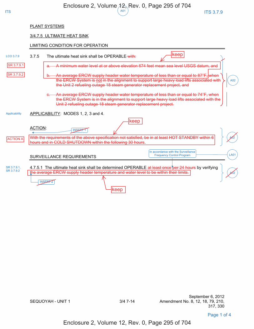
ITS 3.7.9A01ITS
PLANT SYSTEMS 3/4.7.5 ULTIMATE HEAT SINK LIMITING CONDITION FOR OPERATION 3.7.5 The ultimate heat sink shall be OPERABLE with:
a. A minimum water level at or above elevation 674 feet mean sea level USGS datum, and b. An average ERCW supply header water temperature of less than or equal to 87°F, when
the ERCW System is not in the alignment to support large heavy load lifts associated with the Unit 2 refueling outage 18 steam generator replacement project, and
c. An average ERCW supply header water temperature of less than or equal to 74°F, when
the ERCW System is in the alignment to support large heavy load lifts associated with the Unit 2 refueling outage 18 steam generator replacement project.
APPLICABILITY: MODES 1, 2, 3 and 4. ACTION: With the requirements of the above specification not satisfied, be in at least HOT STANDBY within 6 hours and in COLD SHUTDOWN within the following 30 hours. SURVEILLANCE REQUIREMENTS 4.7.5.1 The ultimate heat sink shall be determined OPERABLE at least once per 24 hours by verifying the average ERCW supply header temperature and water level to be within their limits. September 6, 2012 SEQUOYAH - UNIT 1 3/4 7-14 Amendment No. 8, 12, 18, 79, 210, 317, 330
LCO 3.7.9
Applicability
A02
Page 1 of 4
A02
INSERT 2
A02
INSERT 1
In accordance with the Surveillance Frequency Control Program LA01
SR 3.7.9.1, SR 3.7.9.2
Enclosure 2, Volume 12, Rev. 0, Page 295 of 704
Enclosure 2, Volume 12, Rev. 0, Page 295 of 704
ACTION A
keep
SR 3.7.9.1
SR 3.7.9.2
keep
keep
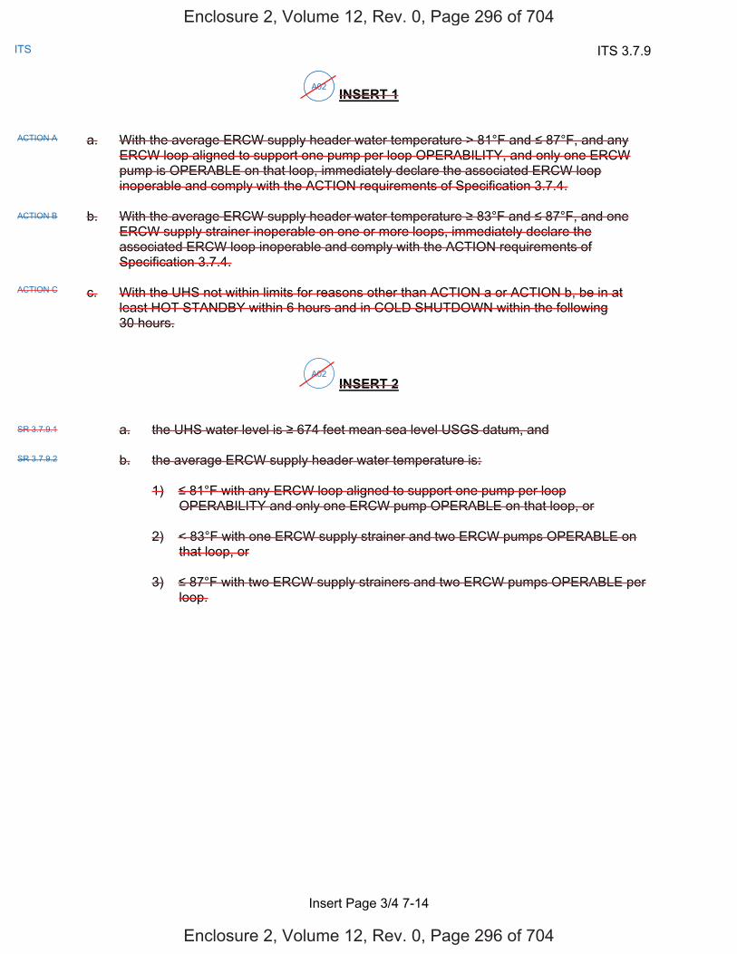
ITS 3.7.9
Insert Page 3/4 7-14
ITS
INSERT 1 a. With the average ERCW supply header water temperature > 81°F and 87°F, and any
ERCW loop aligned to support one pump per loop OPERABILITY, and only one ERCW pump is OPERABLE on that loop, immediately declare the associated ERCW loop inoperable and comply with the ACTION requirements of Specification 3.7.4.
b. With the average ERCW supply header water temperature 83°F and 87°F, and one
ERCW supply strainer inoperable on one or more loops, immediately declare the associated ERCW loop inoperable and comply with the ACTION requirements of Specification 3.7.4.
c. With the UHS not within limits for reasons other than ACTION a or ACTION b, be in at
least HOT STANDBY within 6 hours and in COLD SHUTDOWN within the following 30 hours.
INSERT 2
a. the UHS water level is 674 feet mean sea level USGS datum, and
b. the average ERCW supply header water temperature is:
1) 81°F with any ERCW loop aligned to support one pump per loop OPERABILITY and only one ERCW pump OPERABLE on that loop, or
2) < 83°F with one ERCW supply strainer and two ERCW pumps OPERABLE on
that loop, or 3) 87°F with two ERCW supply strainers and two ERCW pumps OPERABLE per
loop.
A02
ACTION A
ACTION B
ACTION C
A02
A02
SR 3.7.9.1
SR 3.7.9.2
Enclosure 2, Volume 12, Rev. 0, Page 296 of 704
Enclosure 2, Volume 12, Rev. 0, Page 296 of 704
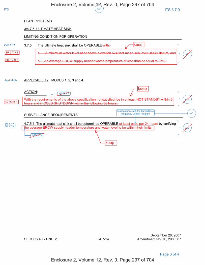
ITS 3.7.9 A01ITS
PLANT SYSTEMS 3/4.7.5 ULTIMATE HEAT SINK LIMITING CONDITION FOR OPERATION 3.7.5 The ultimate heat sink shall be OPERABLE with: a. A minimum water level at or above elevation 674 feet mean sea level USGS datum, and b. An average ERCW supply header water temperature of less than or equal to 87°F. APPLICABILITY: MODES 1, 2, 3 and 4. ACTION: With the requirements of the above specification not satisfied, be in at least HOT STANDBY within 6 hours and in COLD SHUTDOWN within the following 30 hours. SURVEILLANCE REQUIREMENTS 4.7.5.1 The ultimate heat sink shall be determined OPERABLE at least once per 24 hours by verifying the average ERCW supply header temperature and water level to be within their limits.
September 28, 2007 SEQUOYAH - UNIT 2 3/4 7-14 Amendment No. 70, 200, 307
LCO 3.7.9
Applicability
In accordance with the Surveillance Frequency Control Program LA01
Page 3 of 4
SR 3.7.9.1, SR 3.7.9.2
A02
A02
INSERT 4
A02
INSERT 3
Enclosure 2, Volume 12, Rev. 0, Page 297 of 704
Enclosure 2, Volume 12, Rev. 0, Page 297 of 704
keep
keep
keep
SR 3.7.9.1
SR 3.7.9.2
ACTION A

ITS 3.7.9
Insert Page 3/4 7-14
ITS
INSERT 3 a. With the average ERCW supply header water temperature > 79°F and 87°F, and any
ERCW loop aligned to support one pump per loop OPERABILITY, and only one ERCW pump is OPERABLE on that loop, immediately declare the associated ERCW loop inoperable and comply with the ACTION requirements of Specification 3.7.4.
b. With the average ERCW supply header water temperature 83°F and 87°F, and one
ERCW supply strainer inoperable on one or more loops, immediately declare the associated ERCW loop inoperable and comply with the ACTION requirements of Specification 3.7.4.
c. With the UHS not within limits for reasons other than ACTION a or ACTION b, be in at
least HOT STANDBY within 6 hours and in COLD SHUTDOWN within the following 30 hours.
INSERT 4
a. the UHS water level is 674 feet mean sea level USGS datum, and
b. the average ERCW supply header water temperature is:
1) 79°F with any ERCW loop aligned to support one pump per loop OPERABILITY and only one ERCW pump OPERABLE on that loop, or
2) < 83°F with one ERCW supply strainer and two ERCW pumps OPERABLE on
that loop, or 3) 87°F with two ERCW supply strainers and two ERCW pumps OPERABLE per
loop.
A02
ACTION A
ACTION B
ACTION C
A02
A02
SR 3.7.9.1
SR 3.7.9.2
Enclosure 2, Volume 12, Rev. 0, Page 298 of 704
Enclosure 2, Volume 12, Rev. 0, Page 298 of 704
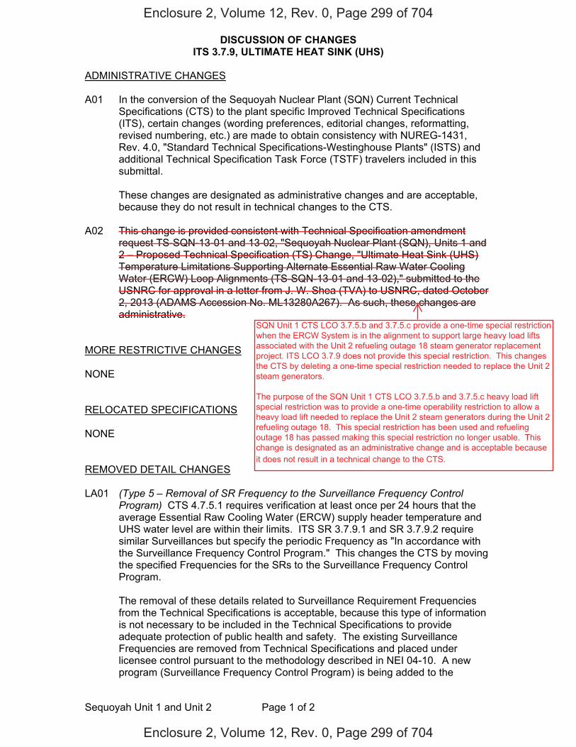
DISCUSSION OF CHANGES ITS 3.7.9, ULTIMATE HEAT SINK (UHS)
Sequoyah Unit 1 and Unit 2 Page 1 of 2
ADMINISTRATIVE CHANGES A01 In the conversion of the Sequoyah Nuclear Plant (SQN) Current Technical
Specifications (CTS) to the plant specific Improved Technical Specifications (ITS), certain changes (wording preferences, editorial changes, reformatting, revised numbering, etc.) are made to obtain consistency with NUREG-1431, Rev. 4.0, "Standard Technical Specifications-Westinghouse Plants" (ISTS) and additional Technical Specification Task Force (TSTF) travelers included in this submittal.
These changes are designated as administrative changes and are acceptable,
because they do not result in technical changes to the CTS. A02 This change is provided consistent with Technical Specification amendment
request TS-SQN-13-01 and 13-02, "Sequoyah Nuclear Plant (SQN), Units 1 and 2 – Proposed Technical Specification (TS) Change, "Ultimate Heat Sink (UHS) Temperature Limitations Supporting Alternate Essential Raw Water Cooling Water (ERCW) Loop Alignments (TS-SQN-13-01 and 13-02)," submitted to the USNRC for approval in a letter from J. W. Shea (TVA) to USNRC, dated October 2, 2013 (ADAMS Accession No. ML13280A267). As such, these changes are administrative.
MORE RESTRICTIVE CHANGES NONE RELOCATED SPECIFICATIONS NONE REMOVED DETAIL CHANGES LA01 (Type 5 – Removal of SR Frequency to the Surveillance Frequency Control
Program) CTS 4.7.5.1 requires verification at least once per 24 hours that the average Essential Raw Cooling Water (ERCW) supply header temperature and UHS water level are within their limits. ITS SR 3.7.9.1 and SR 3.7.9.2 require similar Surveillances but specify the periodic Frequency as "In accordance with the Surveillance Frequency Control Program." This changes the CTS by moving the specified Frequencies for the SRs to the Surveillance Frequency Control Program.
The removal of these details related to Surveillance Requirement Frequencies from the Technical Specifications is acceptable, because this type of information is not necessary to be included in the Technical Specifications to provide adequate protection of public health and safety. The existing Surveillance Frequencies are removed from Technical Specifications and placed under licensee control pursuant to the methodology described in NEI 04-10. A new program (Surveillance Frequency Control Program) is being added to the
Enclosure 2, Volume 12, Rev. 0, Page 299 of 704
Enclosure 2, Volume 12, Rev. 0, Page 299 of 704
SQN Unit 1 CTS LCO 3.7.5.b and 3.7.5.c provide a one-time special restriction when the ERCW System is in the alignment to support large heavy load lifts associated with the Unit 2 refueling outage 18 steam generator replacement project. ITS LCO 3.7.9 does not provide this special restriction. This changes the CTS by deleting a one-time special restriction needed to replace the Unit 2 steam generators. The purpose of the SQN Unit 1 CTS LCO 3.7.5.b and 3.7.5.c heavy load lift special restriction was to provide a one-time operability restriction to allow a heavy load lift needed to replace the Unit 2 steam generators during the Unit 2 refueling outage 18. This special restriction has been used and refueling outage 18 has passed making this special restriction no longer usable. This change is designated as an administrative change and is acceptable because it does not result in a technical change to the CTS.
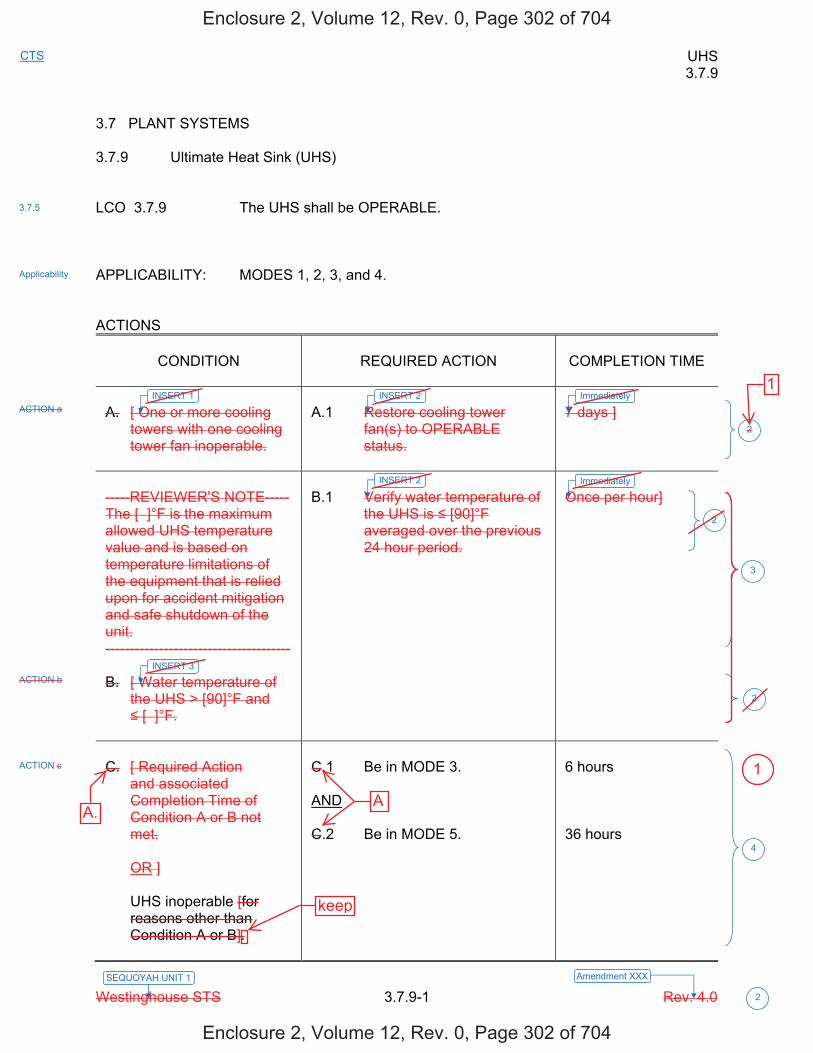
UHS 3.7.9
Westinghouse STS 3.7.9-1 Rev. 4.0 2
SEQUOYAH UNIT 1 Amendment XXX
CTS
3.7 PLANT SYSTEMS 3.7.9 Ultimate Heat Sink (UHS) LCO 3.7.9 The UHS shall be OPERABLE. APPLICABILITY: MODES 1, 2, 3, and 4. ACTIONS
CONDITION
REQUIRED ACTION
COMPLETION TIME
A. [ One or more cooling
towers with one cooling tower fan inoperable.
A.1 Restore cooling tower
fan(s) to OPERABLE status.
7 days ]
-----REVIEWER'S NOTE----- The [ ]°F is the maximum allowed UHS temperature value and is based on temperature limitations of the equipment that is relied upon for accident mitigation and safe shutdown of the unit. -------------------------------------- B. [ Water temperature of
the UHS > [90]°F and [ ]°F.
B.1 Verify water temperature of
the UHS is [90]°F averaged over the previous 24 hour period.
Once per hour]
C. [ Required Action
and associated Completion Time of Condition A or B not met.
OR ] UHS inoperable [for
reasons other than Condition A or B].
C.1 Be in MODE 3. AND C.2 Be in MODE 5.
6 hours 36 hours
3.7.5
Applicability
ACTION c
4
2
2
ACTION b
ACTION a
3
2
INSERT 1 INSERT 2 Immediately
Immediately
INSERT 3
INSERT 2
Enclosure 2, Volume 12, Rev. 0, Page 302 of 704
Enclosure 2, Volume 12, Rev. 0, Page 302 of 704
A.
1
A
keep
1
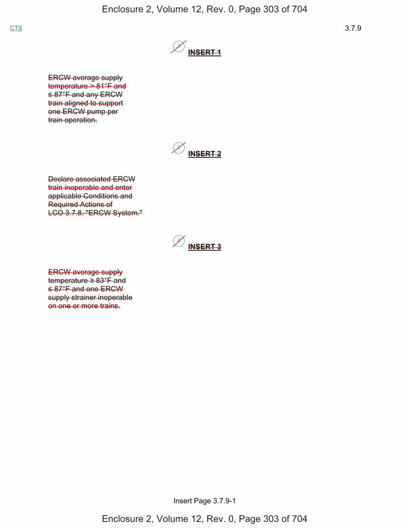
3.7.9
Insert Page 3.7.9-1
CTS
INSERT 1 ERCW average supply temperature > 81°F and 87°F and any ERCW
train aligned to support one ERCW pump per train operation.
INSERT 2
Declare associated ERCW train inoperable and enter applicable Conditions and Required Actions of LCO 3.7.8, "ERCW System."
INSERT 3
ERCW average supply temperature 83°F and 87°F and one ERCW
supply strainer inoperable on one or more trains.
2
2
2
Enclosure 2, Volume 12, Rev. 0, Page 303 of 704
Enclosure 2, Volume 12, Rev. 0, Page 303 of 704
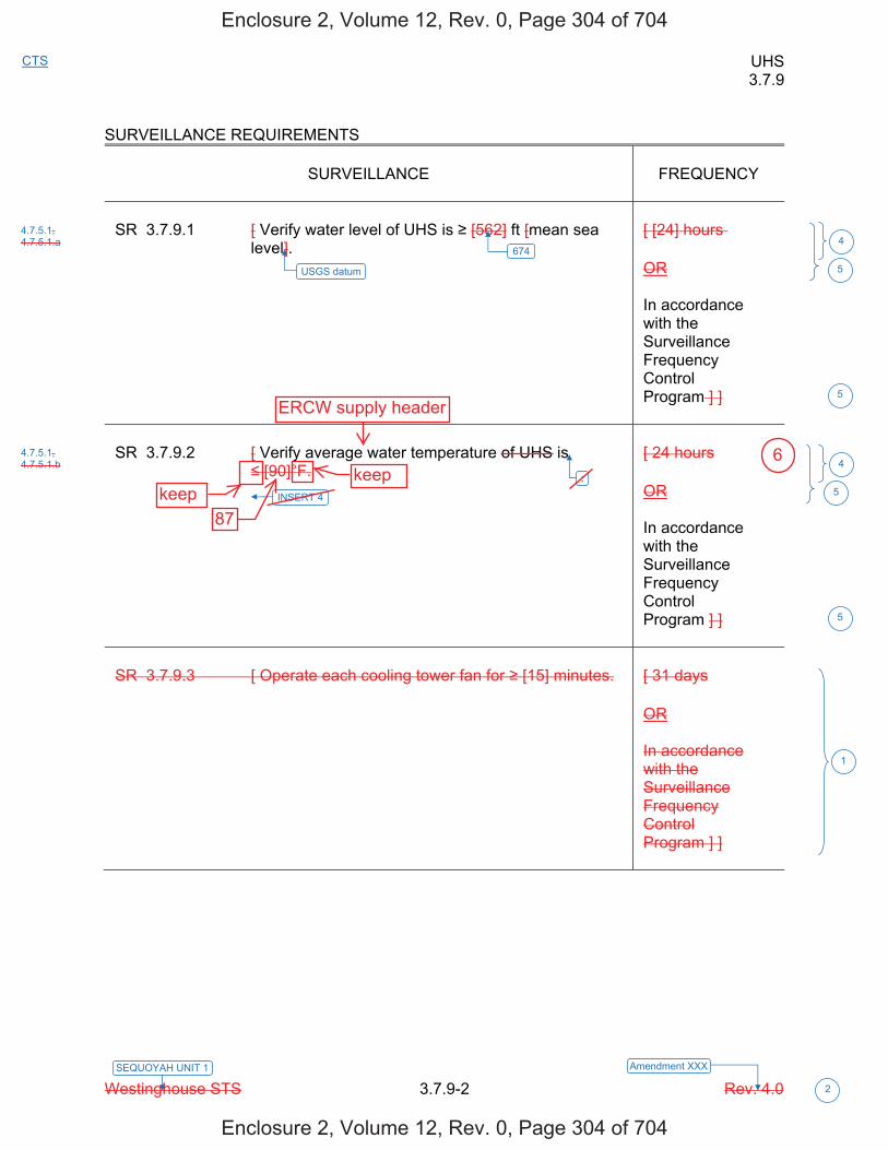
UHS 3.7.9
Westinghouse STS 3.7.9-2 Rev. 4.0 2
SEQUOYAH UNIT 1 Amendment XXX
CTS
SURVEILLANCE REQUIREMENTS
SURVEILLANCE
FREQUENCY
SR 3.7.9.1 [ Verify water level of UHS is [562] ft [mean sea
level].
[ [24] hours OR In accordance with the Surveillance Frequency Control Program ] ]
SR 3.7.9.2 [ Verify average water temperature of UHS is
[90]°F.
[ 24 hours OR In accordance with the Surveillance Frequency Control Program ] ]
SR 3.7.9.3 [ Operate each cooling tower fan for [15] minutes.
[ 31 days OR In accordance with the Surveillance Frequency Control Program ] ]
6744
5
1
4.7.5.1, 4.7.5.1.a
4.7.5.1, 4.7.5.1.b
5
4
5
5
USGS datum
INSERT 4
:
Enclosure 2, Volume 12, Rev. 0, Page 304 of 704
Enclosure 2, Volume 12, Rev. 0, Page 304 of 704
keepkeep
87
ERCW supply header
6

3.7.9
Insert Page 3.7.9-2
CTS
INSERT 4
a) 81°F with any ERCW train aligned to support one pump per train operation,
b) < 83°F with one ERCW supply strainer and two ERCW pumps OPERABLE on that train, and c) 87°F with two ERCW supply strainers and two ERCW pumps OPERABLE per train.
2
Enclosure 2, Volume 12, Rev. 0, Page 305 of 704
Enclosure 2, Volume 12, Rev. 0, Page 305 of 704

UHS 3.7.9
Westinghouse STS 3.7.9-1 Rev. 4.0 2
SEQUOYAH UNIT 2 Amendment XXX
CTS
3.7 PLANT SYSTEMS 3.7.9 Ultimate Heat Sink (UHS) LCO 3.7.9 The UHS shall be OPERABLE. APPLICABILITY: MODES 1, 2, 3, and 4. ACTIONS
CONDITION
REQUIRED ACTION
COMPLETION TIME
A. [ One or more cooling
towers with one cooling tower fan inoperable.
A.1 Restore cooling tower
fan(s) to OPERABLE status.
7 days ]
-----REVIEWER'S NOTE----- The [ ]°F is the maximum allowed UHS temperature value and is based on temperature limitations of the equipment that is relied upon for accident mitigation and safe shutdown of the unit. -------------------------------------- B. [ Water temperature of
the UHS > [90]°F and [ ]°F.
B.1 Verify water temperature of
the UHS is [90]°F averaged over the previous 24 hour period.
Once per hour]
C. [ Required Action
and associated Completion Time of Condition A or B not met.
OR ] UHS inoperable [for
reasons other than Condition A or B].
C.1 Be in MODE 3. AND C.2 Be in MODE 5.
6 hours 36 hours
3.7.5
Applicability
ACTION c
4
2
2
ACTION b
ACTION a
3
2
INSERT 1 INSERT 2 Immediately
Immediately
INSERT 3
INSERT 2
Enclosure 2, Volume 12, Rev. 0, Page 307 of 704
Enclosure 2, Volume 12, Rev. 0, Page 307 of 704
A.
1
A
keep
1

3.7.9
Insert Page 3.7.9-1
CTS
INSERT 1 ERCW average supply temperature > 79°F and 87°F and any ERCW
train aligned to support one ERCW pump per train operation.
INSERT 2
Declare associated ERCW train inoperable and enter applicable Conditions and Required Actions of LCO 3.7.8, "ERCW System."
INSERT 3
ERCW average supply temperature 83°F and 87°F and one ERCW
supply strainer inoperable on one or more trains.
2
2
2
Enclosure 2, Volume 12, Rev. 0, Page 308 of 704
Enclosure 2, Volume 12, Rev. 0, Page 308 of 704
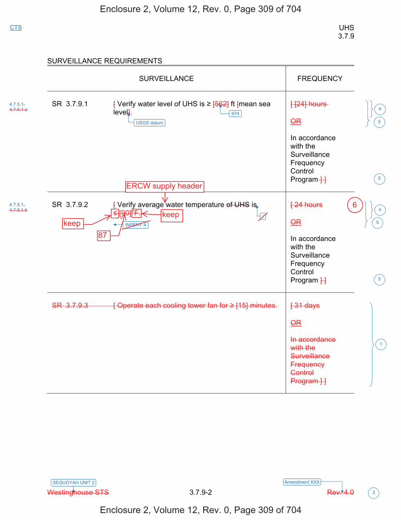
UHS 3.7.9
Westinghouse STS 3.7.9-2 Rev. 4.0 2
SEQUOYAH UNIT 2 Amendment XXX
CTS
SURVEILLANCE REQUIREMENTS
SURVEILLANCE
FREQUENCY
SR 3.7.9.1 [ Verify water level of UHS is [562] ft [mean sea
level].
[ [24] hours OR In accordance with the Surveillance Frequency Control Program ] ]
SR 3.7.9.2 [ Verify average water temperature of UHS is
[90]°F.
[ 24 hours OR In accordance with the Surveillance Frequency Control Program ] ]
SR 3.7.9.3 [ Operate each cooling tower fan for [15] minutes.
[ 31 days OR In accordance with the Surveillance Frequency Control Program ] ]
6744
5
1
4.7.5.1, 4.7.5.1.a
4.7.5.1, 4.7.5.1.b
5
4
5
5
USGS datum
INSERT 4
:
Enclosure 2, Volume 12, Rev. 0, Page 309 of 704
Enclosure 2, Volume 12, Rev. 0, Page 309 of 704
keepkeep
87
ERCW supply header
6
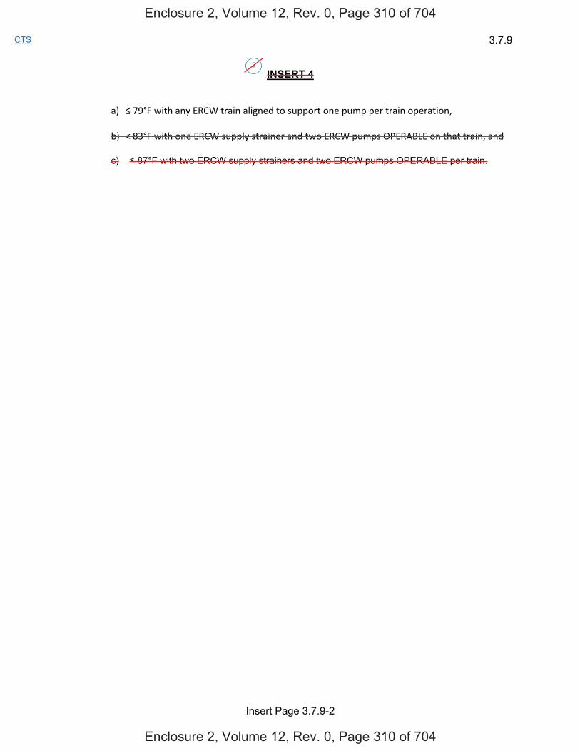
3.7.9
Insert Page 3.7.9-2
CTS
INSERT 4
a) 79°F with any ERCW train aligned to support one pump per train operation,
b) < 83°F with one ERCW supply strainer and two ERCW pumps OPERABLE on that train, and c) 87°F with two ERCW supply strainers and two ERCW pumps OPERABLE per train.
2
Enclosure 2, Volume 12, Rev. 0, Page 310 of 704
Enclosure 2, Volume 12, Rev. 0, Page 310 of 704
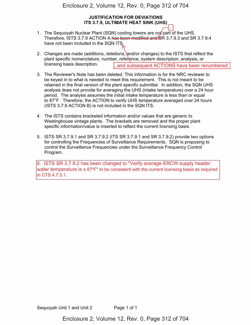
JUSTIFICATION FOR DEVIATIONS ITS 3.7.9, ULTIMATE HEAT SINK (UHS)
Sequoyah Unit 1 and Unit 2 Page 1 of 1
1. The Sequoyah Nuclear Plant (SQN) cooling towers are not part of the UHS. Therefore, ISTS 3.7.9 ACTION A has been modified and SR 3.7.9.3 and SR 3.7.9.4 have not been included in the SQN ITS.
2. Changes are made (additions, deletions, and/or changes) to the ISTS that reflect the plant specific nomenclature, number, reference, system description, analysis, or licensing basis description.
3. The Reviewer's Note has been deleted. This information is for the NRC reviewer to be keyed in to what is needed to meet this requirement. This is not meant to be retained in the final version of the plant specific submittal. In addition, the SQN UHS analysis does not provide for averaging the UHS (intake temperature) over a 24 hour period. The analysis assumes the initial intake temperature is less than or equal to 87°F. Therefore, the ACTION to verify UHS temperature averaged over 24 hours (ISTS 3.7.9 ACTION B) is not included in the SQN ITS.
4. The ISTS contains bracketed information and/or values that are generic to
Westinghouse vintage plants. The brackets are removed and the proper plant specific information/value is inserted to reflect the current licensing basis.
5. ISTS SR 3.7.9.1 and SR 3.7.9.2 (ITS SR 3.7.9.1 and SR 3.7.9.2) provide two options
for controlling the Frequencies of Surveillance Requirements. SQN is proposing to control the Surveillance Frequencies under the Surveillance Frequency Control Program.
Enclosure 2, Volume 12, Rev. 0, Page 312 of 704
Enclosure 2, Volume 12, Rev. 0, Page 312 of 704
,
6. ISTS SR 3.7.9.2 has been changed to "Verify average ERCW supply headerwater temperature is 87ºF" to be consistent with the current licensing basis as required in CTS 4.7.5.1.
, and subsequent ACTIONS have been renumbered
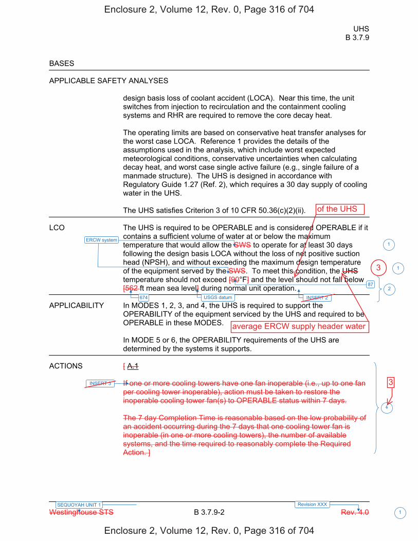
UHS B 3.7.9
Westinghouse STS B 3.7.9-2 Rev. 4.0
SEQUOYAH UNIT 1 Revision XXX 1
BASES APPLICABLE SAFETY ANALYSES
design basis loss of coolant accident (LOCA). Near this time, the unit switches from injection to recirculation and the containment cooling systems and RHR are required to remove the core decay heat. The operating limits are based on conservative heat transfer analyses for the worst case LOCA. Reference 1 provides the details of the assumptions used in the analysis, which include worst expected meteorological conditions, conservative uncertainties when calculating decay heat, and worst case single active failure (e.g., single failure of a manmade structure). The UHS is designed in accordance with Regulatory Guide 1.27 (Ref. 2), which requires a 30 day supply of cooling water in the UHS. The UHS satisfies Criterion 3 of 10 CFR 50.36(c)(2)(ii).
LCO The UHS is required to be OPERABLE and is considered OPERABLE if it
contains a sufficient volume of water at or below the maximum temperature that would allow the SWS to operate for at least 30 days following the design basis LOCA without the loss of net positive suction head (NPSH), and without exceeding the maximum design temperature of the equipment served by the SWS. To meet this condition, the UHS temperature should not exceed [90°F] and the level should not fall below [562 ft mean sea level] during normal unit operation.
APPLICABILITY In MODES 1, 2, 3, and 4, the UHS is required to support the
OPERABILITY of the equipment serviced by the UHS and required to be OPERABLE in these MODES.
In MODE 5 or 6, the OPERABILITY requirements of the UHS are determined by the systems it supports.
ACTIONS [ A.1
If one or more cooling towers have one fan inoperable (i.e., up to one fan per cooling tower inoperable), action must be taken to restore the inoperable cooling tower fan(s) to OPERABLE status within 7 days. The 7 day Completion Time is reasonable based on the low probability of an accident occurring during the 7 days that one cooling tower fan is inoperable (in one or more cooling towers), the number of available systems, and the time required to reasonably complete the Required Action. ]
87
674
2
1
1
1
USGS datum
ERCW system
INSERT 2
INSERT 3
Enclosure 2, Volume 12, Rev. 0, Page 316 of 704
Enclosure 2, Volume 12, Rev. 0, Page 316 of 704
3
average ERCW supply header water
3
of the UHS
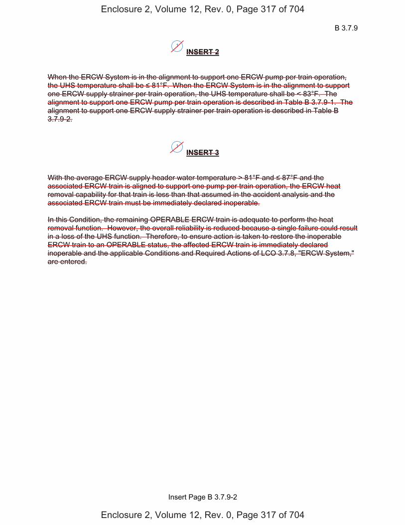
B 3.7.9
Insert Page B 3.7.9-2
INSERT 2 When the ERCW System is in the alignment to support one ERCW pump per train operation, the UHS temperature shall be 81°F. When the ERCW System is in the alignment to support one ERCW supply strainer per train operation, the UHS temperature shall be < 83°F. The alignment to support one ERCW pump per train operation is described in Table B 3.7.9-1. The alignment to support one ERCW supply strainer per train operation is described in Table B 3.7.9-2.
INSERT 3 With the average ERCW supply header water temperature > 81°F and 87°F and the associated ERCW train is aligned to support one pump per train operation, the ERCW heat removal capability for that train is less than that assumed in the accident analysis and the associated ERCW train must be immediately declared inoperable. In this Condition, the remaining OPERABLE ERCW train is adequate to perform the heat removal function. However, the overall reliability is reduced because a single failure could result in a loss of the UHS function. Therefore, to ensure action is taken to restore the inoperable ERCW train to an OPERABLE status, the affected ERCW train is immediately declared inoperable and the applicable Conditions and Required Actions of LCO 3.7.8, "ERCW System," are entered.
1
1
Enclosure 2, Volume 12, Rev. 0, Page 317 of 704
Enclosure 2, Volume 12, Rev. 0, Page 317 of 704
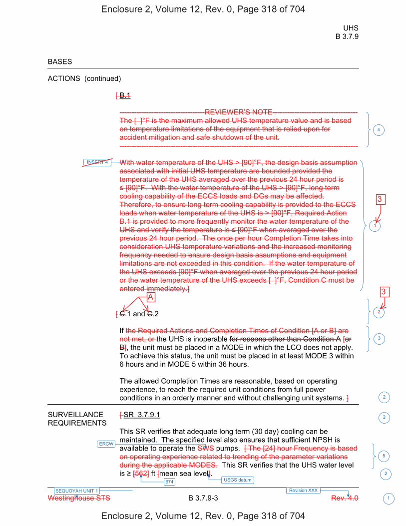
UHS B 3.7.9
Westinghouse STS B 3.7.9-3 Rev. 4.0
SEQUOYAH UNIT 1 Revision XXX 1
BASES ACTIONS (continued)
[ B.1
-----------------------------------REVIEWER’S NOTE----------------------------------- The [ ]°F is the maximum allowed UHS temperature value and is based on temperature limitations of the equipment that is relied upon for accident mitigation and safe shutdown of the unit. -------------------------------------------------------------------------------------------------- With water temperature of the UHS > [90]°F, the design basis assumption associated with initial UHS temperature are bounded provided the temperature of the UHS averaged over the previous 24 hour period is [90]°F. With the water temperature of the UHS > [90]°F, long term
cooling capability of the ECCS loads and DGs may be affected. Therefore, to ensure long term cooling capability is provided to the ECCS loads when water temperature of the UHS is > [90]°F, Required Action B.1 is provided to more frequently monitor the water temperature of the UHS and verify the temperature is [90]°F when averaged over the previous 24 hour period. The once per hour Completion Time takes into consideration UHS temperature variations and the increased monitoring frequency needed to ensure design basis assumptions and equipment limitations are not exceeded in this condition. If the water temperature of the UHS exceeds [90]°F when averaged over the previous 24 hour period or the water temperature of the UHS exceeds [ ]°F, Condition C must be entered immediately.]
[ C.1 and C.2 If the Required Actions and Completion Times of Condition [A or B] are not met, or the UHS is inoperable for reasons other than Condition A [or B], the unit must be placed in a MODE in which the LCO does not apply. To achieve this status, the unit must be placed in at least MODE 3 within 6 hours and in MODE 5 within 36 hours. The allowed Completion Times are reasonable, based on operating experience, to reach the required unit conditions from full power conditions in an orderly manner and without challenging unit systems. ]
SURVEILLANCE [ SR 3.7.9.1 REQUIREMENTS
This SR verifies that adequate long term (30 day) cooling can be maintained. The specified level also ensures that sufficient NPSH is available to operate the SWS pumps. [ The [24] hour Frequency is based on operating experience related to trending of the parameter variations during the applicable MODES. This SR verifies that the UHS water level is [562] ft [mean sea level]. 2
5
674
1
2
2
3
2
USGS datum
ERCW
INSERT 4
4
Enclosure 2, Volume 12, Rev. 0, Page 318 of 704
Enclosure 2, Volume 12, Rev. 0, Page 318 of 704
3
3A
B 3.7.9
Insert Page B 3.7.9-3
INSERT 4 With the average ERCW supply header water temperature 83°F and 87°F and the associated ERCW train(s) is aligned to support one inoperable ERCW supply strainer per train, the ERCW heat removal capability for each affected train is less than that assumed in the accident analysis and the associated ERCW train must be immediately declared inoperable. In this Condition, any remaining OPERABLE ERCW train is adequate to perform the heat removal function. However, the overall reliability is reduced because a single failure could result in a loss of the UHS function. Therefore, to ensure action is taken to restore the inoperable ERCW train(s) to an OPERABLE status, the associated ERCW train(s) is immediately declared inoperable and the applicable Conditions and Required Actions of LCO 3.7.8, "ERCW System," are entered.
1
Enclosure 2, Volume 12, Rev. 0, Page 319 of 704
Enclosure 2, Volume 12, Rev. 0, Page 319 of 704
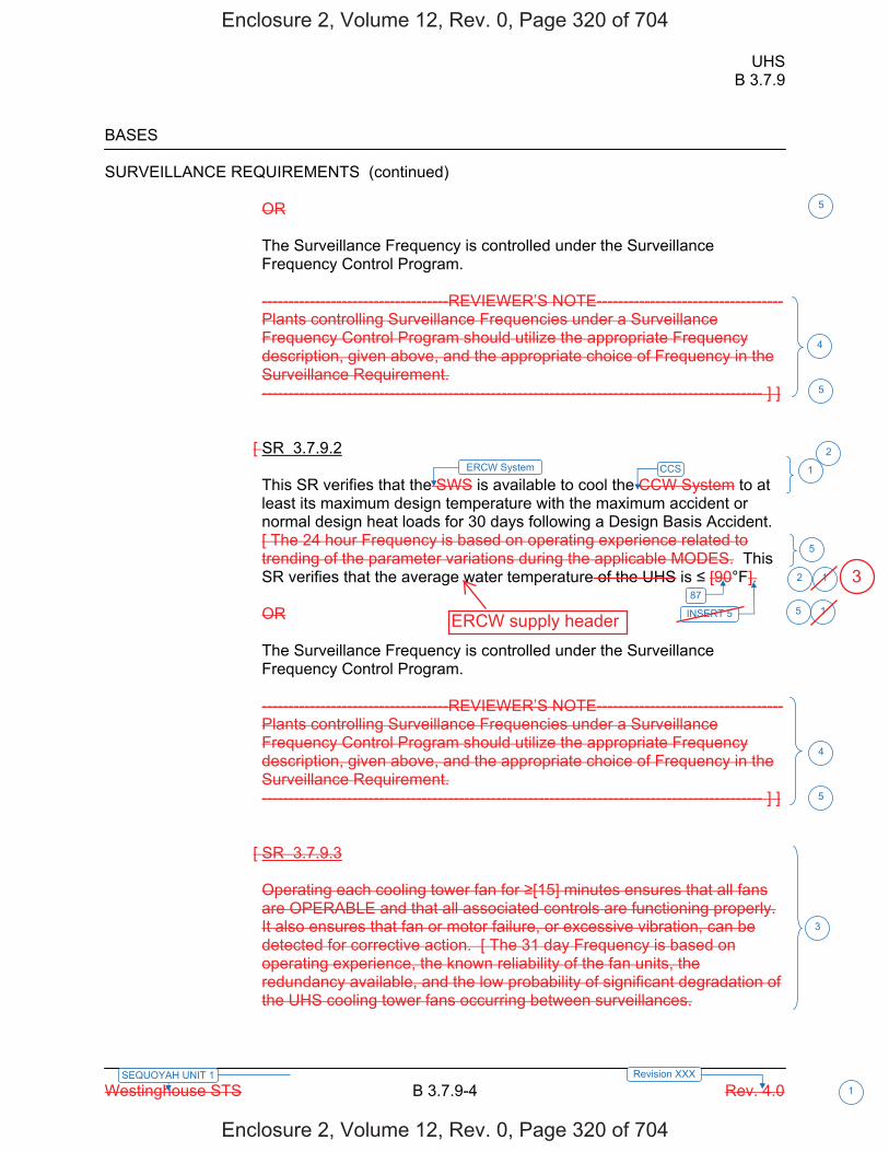
UHS B 3.7.9
Westinghouse STS B 3.7.9-4 Rev. 4.0
SEQUOYAH UNIT 1 Revision XXX 1
BASES SURVEILLANCE REQUIREMENTS (continued)
OR The Surveillance Frequency is controlled under the Surveillance Frequency Control Program. -----------------------------------REVIEWER’S NOTE----------------------------------- Plants controlling Surveillance Frequencies under a Surveillance Frequency Control Program should utilize the appropriate Frequency description, given above, and the appropriate choice of Frequency in the Surveillance Requirement. ---------------------------------------------------------------------------------------------- ] ]
[ SR 3.7.9.2 This SR verifies that the SWS is available to cool the CCW System to at least its maximum design temperature with the maximum accident or normal design heat loads for 30 days following a Design Basis Accident. [ The 24 hour Frequency is based on operating experience related to trending of the parameter variations during the applicable MODES. This SR verifies that the average water temperature of the UHS is [90°F]. OR The Surveillance Frequency is controlled under the Surveillance Frequency Control Program. -----------------------------------REVIEWER’S NOTE----------------------------------- Plants controlling Surveillance Frequencies under a Surveillance Frequency Control Program should utilize the appropriate Frequency description, given above, and the appropriate choice of Frequency in the Surveillance Requirement. ---------------------------------------------------------------------------------------------- ] ]
[ SR 3.7.9.3 Operating each cooling tower fan for [15] minutes ensures that all fans are OPERABLE and that all associated controls are functioning properly. It also ensures that fan or motor failure, or excessive vibration, can be detected for corrective action. [ The 31 day Frequency is based on operating experience, the known reliability of the fan units, the redundancy available, and the low probability of significant degradation of the UHS cooling tower fans occurring between surveillances.
87
4
3
4
5
1
1
5
ERCW System CCS 2
5
1
5
INSERT 5 5
2
Enclosure 2, Volume 12, Rev. 0, Page 320 of 704
Enclosure 2, Volume 12, Rev. 0, Page 320 of 704
ERCW supply header
3
B 3.7.9
Insert Page B 3.7.9-4
INSERT 5 when the ERCW System is aligned in its normal configuration. In addition, this SR provides temperature limitations for alternate ERCW train alignments. When an ERCW train is aligned in accordance with Table B 3.7.9-1 for one OPERABLE ERCW pump per train operation, this SR verifies that the average water temperature of the UHS is 81°F. When one or more ERCW train(s) is aligned in accordance with Table B 3.7.9-2 for one
OPERABLE ERCW supply strainer per train operation, this SR verifies that the average water temperature of the UHS is < 83°F. These actions verify that the ERCW is available to cool the CCS to at least its maximum design temperature with the maximum accident or normal design heat loads for 30 days following a Design Basis Accident when aligned in either the Table B 3.7.9-1 or Table B 3.7.9-2 alternate configuration.
1
Enclosure 2, Volume 12, Rev. 0, Page 321 of 704
Enclosure 2, Volume 12, Rev. 0, Page 321 of 704
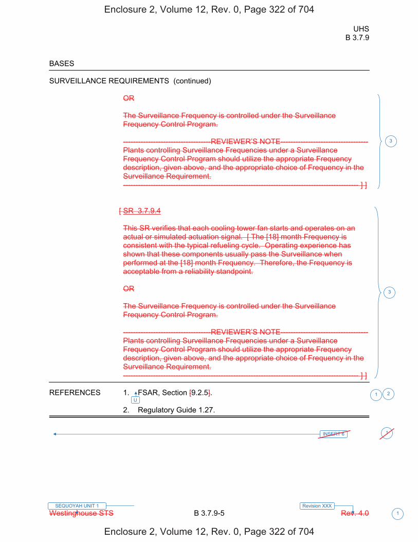
UHS B 3.7.9
Westinghouse STS B 3.7.9-5 Rev. 4.0
SEQUOYAH UNIT 1 Revision XXX 1
BASES SURVEILLANCE REQUIREMENTS (continued)
OR The Surveillance Frequency is controlled under the Surveillance Frequency Control Program. -----------------------------------REVIEWER’S NOTE----------------------------------- Plants controlling Surveillance Frequencies under a Surveillance Frequency Control Program should utilize the appropriate Frequency description, given above, and the appropriate choice of Frequency in the Surveillance Requirement. ---------------------------------------------------------------------------------------------- ] ]
[ SR 3.7.9.4 This SR verifies that each cooling tower fan starts and operates on an actual or simulated actuation signal. [ The [18] month Frequency is consistent with the typical refueling cycle. Operating experience has shown that these components usually pass the Surveillance when performed at the [18] month Frequency. Therefore, the Frequency is acceptable from a reliability standpoint. OR The Surveillance Frequency is controlled under the Surveillance Frequency Control Program. -----------------------------------REVIEWER’S NOTE----------------------------------- Plants controlling Surveillance Frequencies under a Surveillance Frequency Control Program should utilize the appropriate Frequency description, given above, and the appropriate choice of Frequency in the Surveillance Requirement. ---------------------------------------------------------------------------------------------- ] ]
REFERENCES 1. FSAR, Section [9.2.5]. 2. Regulatory Guide 1.27.
3
3
2U
1
1INSERT 6
Enclosure 2, Volume 12, Rev. 0, Page 322 of 704
Enclosure 2, Volume 12, Rev. 0, Page 322 of 704
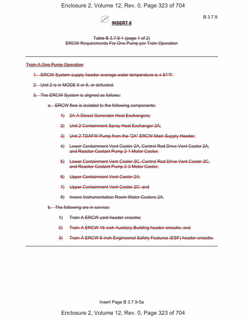
B 3.7.9
Insert Page B 3.7.9-5a
INSERT 6
Table B 3.7.9-1 (page 1 of 2) ERCW Requirements For One Pump per Train Operation
Train A One Pump Operation
1. ERCW System supply header average water temperature is 81°F. 2. Unit 2 is in MODE 5 or 6, or defueled.
3. The ERCW System is aligned as follows:
a. ERCW flow is isolated to the following components:
1) 2A-A Diesel Generator Heat Exchangers; 2) Unit 2 Containment Spray Heat Exchanger 2A; 3) Unit 2 TDAFW Pump from the "2A" ERCW Main Supply Header; 4) Lower Containment Vent Cooler 2A, Control Rod Drive Vent Cooler 2A,
and Reactor Coolant Pump 2-1 Motor Cooler; 5) Lower Containment Vent Cooler 2C, Control Rod Drive Vent Cooler 2C,
and Reactor Coolant Pump 2-3 Motor Cooler; 6) Upper Containment Vent Cooler 2A; 7) Upper Containment Vent Cooler 2C; and 8) Incore Instrumentation Room Water Coolers 2A.
b. The following are in service:
1) Train A ERCW yard header crosstie; 2) Train A ERCW 16-inch Auxiliary Building header crosstie; and 3) Train A ERCW 6-inch Engineered Safety Features (ESF) header crosstie.
1
Enclosure 2, Volume 12, Rev. 0, Page 323 of 704
Enclosure 2, Volume 12, Rev. 0, Page 323 of 704
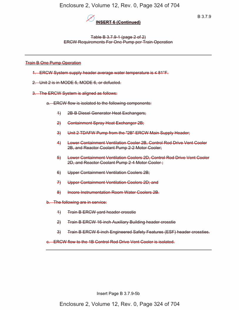
B 3.7.9
Insert Page B 3.7.9-5b
INSERT 6 (Continued)
Table B 3.7.9-1 (page 2 of 2) ERCW Requirements For One Pump per Train Operation
Train B One Pump Operation
1. ERCW System supply header average water temperature is 81°F. 2. Unit 2 is in MODE 5, MODE 6, or defueled.
3. The ERCW System is aligned as follows:
a. ERCW flow is isolated to the following components:
1) 2B-B Diesel Generator Heat Exchangers;
2) Containment Spray Heat Exchanger 2B;
3) Unit 2 TDAFW Pump from the "2B" ERCW Main Supply Header;
4) Lower Containment Ventilation Cooler 2B, Control Rod Drive Vent Cooler
2B, and Reactor Coolant Pump 2-2 Motor Cooler;
5) Lower Containment Ventilation Coolers 2D, Control Rod Drive Vent Cooler 2D, and Reactor Coolant Pump 2-4 Motor Cooler ;
6) Upper Containment Ventilation Coolers 2B;
7) Upper Containment Ventilation Coolers 2D; and
8) Incore Instrumentation Room Water Coolers 2B.
b. The following are in service:
1) Train B ERCW yard header crosstie 2) Train B ERCW 16-inch Auxiliary Building header crosstie 3) Train B ERCW 6-inch Engineered Safety Features (ESF) header crossties.
c. ERCW flow to the 1B Control Rod Drive Vent Cooler is isolated.
1
Enclosure 2, Volume 12, Rev. 0, Page 324 of 704
Enclosure 2, Volume 12, Rev. 0, Page 324 of 704

B 3.7.9
Insert Page B 3.7.9-5c
INSERT 6 (Continued)
Table B 3.7.9-2 (page 1 of 1) ERCW Requirements For One Supply Strainer per Train Operation
FEATURE Condition
Average ERCW System supply header water temperature < 83°F
ERCW Yard header crosstie (associated loop) In service
ERCW 16-Inch Auxiliary Building header crossties In service or isolated
ERCW 6-Inch ESF header crossties In service or isolated
1
Enclosure 2, Volume 12, Rev. 0, Page 325 of 704
Enclosure 2, Volume 12, Rev. 0, Page 325 of 704
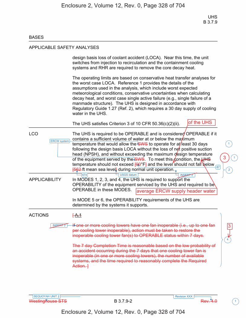
UHS B 3.7.9
Westinghouse STS B 3.7.9-2 Rev. 4.0
SEQUOYAH UNIT 2 Revision XXX 1
BASES APPLICABLE SAFETY ANALYSES
design basis loss of coolant accident (LOCA). Near this time, the unit switches from injection to recirculation and the containment cooling systems and RHR are required to remove the core decay heat. The operating limits are based on conservative heat transfer analyses for the worst case LOCA. Reference 1 provides the details of the assumptions used in the analysis, which include worst expected meteorological conditions, conservative uncertainties when calculating decay heat, and worst case single active failure (e.g., single failure of a manmade structure). The UHS is designed in accordance with Regulatory Guide 1.27 (Ref. 2), which requires a 30 day supply of cooling water in the UHS. The UHS satisfies Criterion 3 of 10 CFR 50.36(c)(2)(ii).
LCO The UHS is required to be OPERABLE and is considered OPERABLE if it
contains a sufficient volume of water at or below the maximum temperature that would allow the SWS to operate for at least 30 days following the design basis LOCA without the loss of net positive suction head (NPSH), and without exceeding the maximum design temperature of the equipment served by the SWS. To meet this condition, the UHS temperature should not exceed [90°F] and the level should not fall below [562 ft mean sea level] during normal unit operation.
APPLICABILITY In MODES 1, 2, 3, and 4, the UHS is required to support the
OPERABILITY of the equipment serviced by the UHS and required to be OPERABLE in these MODES.
In MODE 5 or 6, the OPERABILITY requirements of the UHS are determined by the systems it supports.
ACTIONS [ A.1
If one or more cooling towers have one fan inoperable (i.e., up to one fan per cooling tower inoperable), action must be taken to restore the inoperable cooling tower fan(s) to OPERABLE status within 7 days. The 7 day Completion Time is reasonable based on the low probability of an accident occurring during the 7 days that one cooling tower fan is inoperable (in one or more cooling towers), the number of available systems, and the time required to reasonably complete the Required Action. ]
87
674
2
1
1
1
USGS datum
ERCW system
INSERT 2
INSERT 3
Enclosure 2, Volume 12, Rev. 0, Page 328 of 704
Enclosure 2, Volume 12, Rev. 0, Page 328 of 704
3
3
average ERCW supply header water
of the UHS
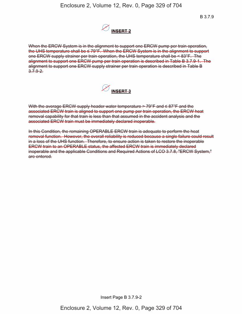
B 3.7.9
Insert Page B 3.7.9-2
INSERT 2 When the ERCW System is in the alignment to support one ERCW pump per train operation, the UHS temperature shall be 79°F. When the ERCW System is in the alignment to support one ERCW supply strainer per train operation, the UHS temperature shall be < 83°F. The alignment to support one ERCW pump per train operation is described in Table B 3.7.9-1. The alignment to support one ERCW supply strainer per train operation is described in Table B 3.7.9-2.
INSERT 3 With the average ERCW supply header water temperature > 79°F and 87°F and the associated ERCW train is aligned to support one pump per train operation, the ERCW heat removal capability for that train is less than that assumed in the accident analysis and the associated ERCW train must be immediately declared inoperable. In this Condition, the remaining OPERABLE ERCW train is adequate to perform the heat removal function. However, the overall reliability is reduced because a single failure could result in a loss of the UHS function. Therefore, to ensure action is taken to restore the inoperable ERCW train to an OPERABLE status, the affected ERCW train is immediately declared inoperable and the applicable Conditions and Required Actions of LCO 3.7.8, "ERCW System," are entered.
1
1
Enclosure 2, Volume 12, Rev. 0, Page 329 of 704
Enclosure 2, Volume 12, Rev. 0, Page 329 of 704

UHS B 3.7.9
Westinghouse STS B 3.7.9-3 Rev. 4.0
SEQUOYAH UNIT 2 Revision XXX 1
BASES ACTIONS (continued)
[ B.1
-----------------------------------REVIEWER’S NOTE----------------------------------- The [ ]°F is the maximum allowed UHS temperature value and is based on temperature limitations of the equipment that is relied upon for accident mitigation and safe shutdown of the unit. -------------------------------------------------------------------------------------------------- With water temperature of the UHS > [90]°F, the design basis assumption associated with initial UHS temperature are bounded provided the temperature of the UHS averaged over the previous 24 hour period is [90]°F. With the water temperature of the UHS > [90]°F, long term
cooling capability of the ECCS loads and DGs may be affected. Therefore, to ensure long term cooling capability is provided to the ECCS loads when water temperature of the UHS is > [90]°F, Required Action B.1 is provided to more frequently monitor the water temperature of the UHS and verify the temperature is [90]°F when averaged over the previous 24 hour period. The once per hour Completion Time takes into consideration UHS temperature variations and the increased monitoring frequency needed to ensure design basis assumptions and equipment limitations are not exceeded in this condition. If the water temperature of the UHS exceeds [90]°F when averaged over the previous 24 hour period or the water temperature of the UHS exceeds [ ]°F, Condition C must be entered immediately.]
[ C.1 and C.2 If the Required Actions and Completion Times of Condition [A or B] are not met, or the UHS is inoperable for reasons other than Condition A [or B], the unit must be placed in a MODE in which the LCO does not apply. To achieve this status, the unit must be placed in at least MODE 3 within 6 hours and in MODE 5 within 36 hours. The allowed Completion Times are reasonable, based on operating experience, to reach the required unit conditions from full power conditions in an orderly manner and without challenging unit systems. ]
SURVEILLANCE [ SR 3.7.9.1 REQUIREMENTS
This SR verifies that adequate long term (30 day) cooling can be maintained. The specified level also ensures that sufficient NPSH is available to operate the SWS pumps. [ The [24] hour Frequency is based on operating experience related to trending of the parameter variations during the applicable MODES. This SR verifies that the UHS water level is [562] ft [mean sea level]. 2
5
674
1
2
2
3
2
USGS datum
ERCW
INSERT 4
4
Enclosure 2, Volume 12, Rev. 0, Page 330 of 704
Enclosure 2, Volume 12, Rev. 0, Page 330 of 704
3
3A

B 3.7.9
Insert Page B 3.7.9-3
INSERT 4 With the average ERCW supply header water temperature 83°F and 87°F and the associated ERCW train(s) is aligned to support one inoperable ERCW supply strainer per train, the ERCW heat removal capability for each affected train is less than that assumed in the accident analysis and the associated ERCW train must be immediately declared inoperable. In this Condition, any remaining OPERABLE ERCW train is adequate to perform the heat removal function. However, the overall reliability is reduced because a single failure could result in a loss of the UHS function. Therefore, to ensure action is taken to restore the inoperable ERCW train(s) to an OPERABLE status, the associated ERCW train(s) is immediately declared inoperable and the applicable Conditions and Required Actions of LCO 3.7.8, "ERCW System," are entered.
1
Enclosure 2, Volume 12, Rev. 0, Page 331 of 704
Enclosure 2, Volume 12, Rev. 0, Page 331 of 704
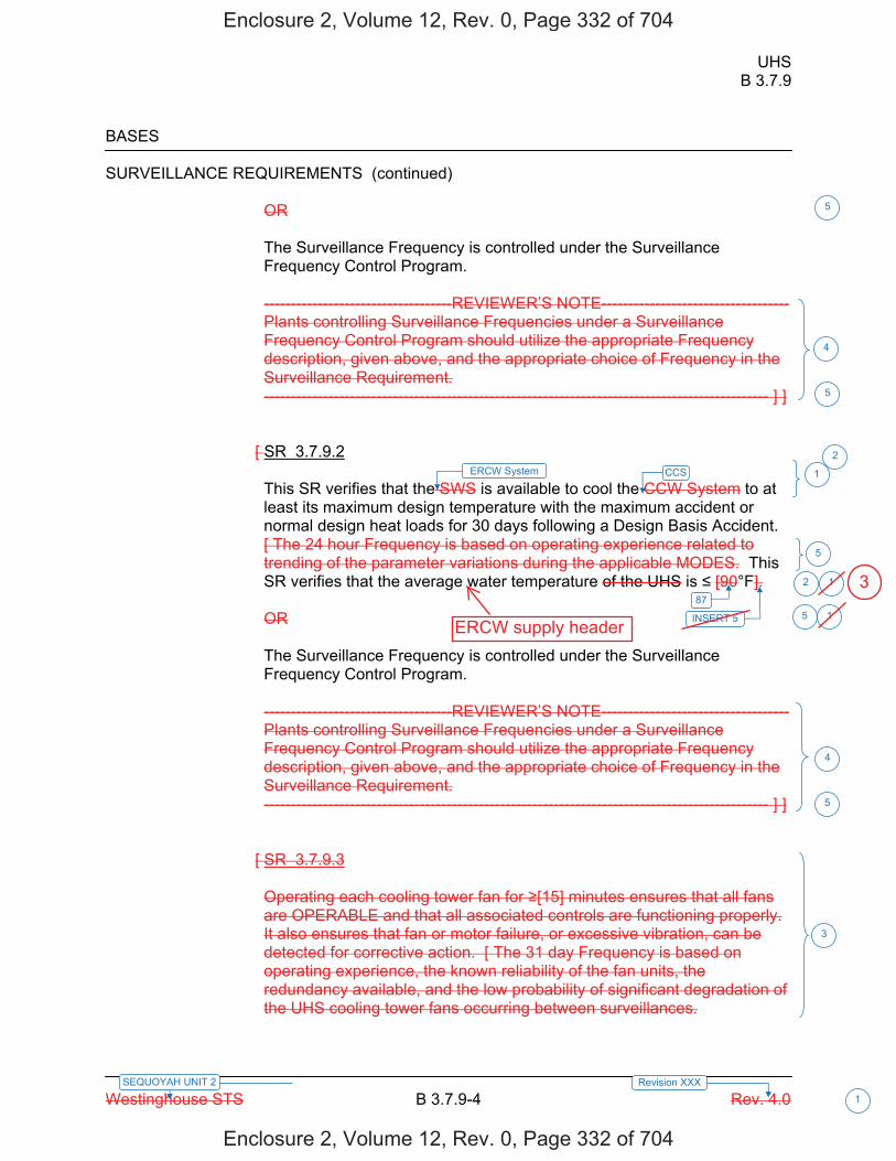
UHS B 3.7.9
Westinghouse STS B 3.7.9-4 Rev. 4.0
SEQUOYAH UNIT 2 Revision XXX 1
BASES SURVEILLANCE REQUIREMENTS (continued)
OR The Surveillance Frequency is controlled under the Surveillance Frequency Control Program. -----------------------------------REVIEWER’S NOTE----------------------------------- Plants controlling Surveillance Frequencies under a Surveillance Frequency Control Program should utilize the appropriate Frequency description, given above, and the appropriate choice of Frequency in the Surveillance Requirement. ---------------------------------------------------------------------------------------------- ] ]
[ SR 3.7.9.2 This SR verifies that the SWS is available to cool the CCW System to at least its maximum design temperature with the maximum accident or normal design heat loads for 30 days following a Design Basis Accident. [ The 24 hour Frequency is based on operating experience related to trending of the parameter variations during the applicable MODES. This SR verifies that the average water temperature of the UHS is [90°F]. OR The Surveillance Frequency is controlled under the Surveillance Frequency Control Program. -----------------------------------REVIEWER’S NOTE----------------------------------- Plants controlling Surveillance Frequencies under a Surveillance Frequency Control Program should utilize the appropriate Frequency description, given above, and the appropriate choice of Frequency in the Surveillance Requirement. ---------------------------------------------------------------------------------------------- ] ]
[ SR 3.7.9.3 Operating each cooling tower fan for [15] minutes ensures that all fans are OPERABLE and that all associated controls are functioning properly. It also ensures that fan or motor failure, or excessive vibration, can be detected for corrective action. [ The 31 day Frequency is based on operating experience, the known reliability of the fan units, the redundancy available, and the low probability of significant degradation of the UHS cooling tower fans occurring between surveillances.
87
4
3
4
5
1
1
5
ERCW System CCS 2
5
1
5
INSERT 5 5
2
Enclosure 2, Volume 12, Rev. 0, Page 332 of 704
Enclosure 2, Volume 12, Rev. 0, Page 332 of 704
3
ERCW supply header
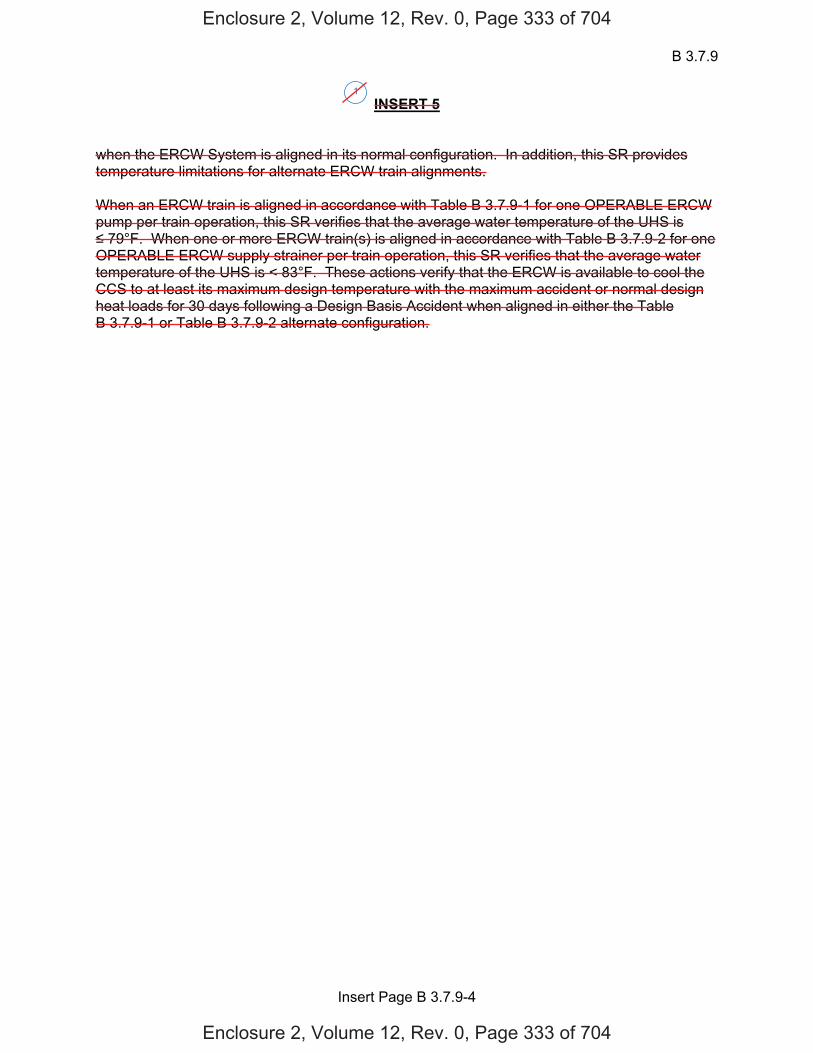
B 3.7.9
Insert Page B 3.7.9-4
INSERT 5 when the ERCW System is aligned in its normal configuration. In addition, this SR provides temperature limitations for alternate ERCW train alignments. When an ERCW train is aligned in accordance with Table B 3.7.9-1 for one OPERABLE ERCW pump per train operation, this SR verifies that the average water temperature of the UHS is 79°F. When one or more ERCW train(s) is aligned in accordance with Table B 3.7.9-2 for one
OPERABLE ERCW supply strainer per train operation, this SR verifies that the average water temperature of the UHS is < 83°F. These actions verify that the ERCW is available to cool the CCS to at least its maximum design temperature with the maximum accident or normal design heat loads for 30 days following a Design Basis Accident when aligned in either the Table B 3.7.9-1 or Table B 3.7.9-2 alternate configuration.
1
Enclosure 2, Volume 12, Rev. 0, Page 333 of 704
Enclosure 2, Volume 12, Rev. 0, Page 333 of 704

UHS B 3.7.9
Westinghouse STS B 3.7.9-5 Rev. 4.0
SEQUOYAH UNIT 2 Revision XXX 1
BASES SURVEILLANCE REQUIREMENTS (continued)
OR The Surveillance Frequency is controlled under the Surveillance Frequency Control Program. -----------------------------------REVIEWER’S NOTE----------------------------------- Plants controlling Surveillance Frequencies under a Surveillance Frequency Control Program should utilize the appropriate Frequency description, given above, and the appropriate choice of Frequency in the Surveillance Requirement. ---------------------------------------------------------------------------------------------- ] ]
[ SR 3.7.9.4 This SR verifies that each cooling tower fan starts and operates on an actual or simulated actuation signal. [ The [18] month Frequency is consistent with the typical refueling cycle. Operating experience has shown that these components usually pass the Surveillance when performed at the [18] month Frequency. Therefore, the Frequency is acceptable from a reliability standpoint. OR The Surveillance Frequency is controlled under the Surveillance Frequency Control Program. -----------------------------------REVIEWER’S NOTE----------------------------------- Plants controlling Surveillance Frequencies under a Surveillance Frequency Control Program should utilize the appropriate Frequency description, given above, and the appropriate choice of Frequency in the Surveillance Requirement. ---------------------------------------------------------------------------------------------- ] ]
REFERENCES 1. FSAR, Section [9.2.5]. 2. Regulatory Guide 1.27.
3
3
2U
1
1INSERT 6
Enclosure 2, Volume 12, Rev. 0, Page 334 of 704
Enclosure 2, Volume 12, Rev. 0, Page 334 of 704
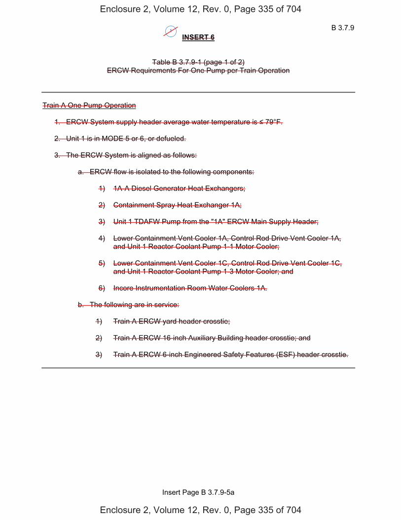
B 3.7.9
Insert Page B 3.7.9-5a
INSERT 6
Table B 3.7.9-1 (page 1 of 2) ERCW Requirements For One Pump per Train Operation
Train A One Pump Operation
1. ERCW System supply header average water temperature is 79°F. 2. Unit 1 is in MODE 5 or 6, or defueled.
3. The ERCW System is aligned as follows:
a. ERCW flow is isolated to the following components:
1) 1A-A Diesel Generator Heat Exchangers; 2) Containment Spray Heat Exchanger 1A; 3) Unit 1 TDAFW Pump from the "1A" ERCW Main Supply Header; 4) Lower Containment Vent Cooler 1A, Control Rod Drive Vent Cooler 1A,
and Unit 1 Reactor Coolant Pump 1-1 Motor Cooler; 5) Lower Containment Vent Cooler 1C, Control Rod Drive Vent Cooler 1C,
and Unit 1 Reactor Coolant Pump 1-3 Motor Cooler; and
6) Incore Instrumentation Room Water Coolers 1A.
b. The following are in service:
1) Train A ERCW yard header crosstie; 2) Train A ERCW 16-inch Auxiliary Building header crosstie; and 3) Train A ERCW 6-inch Engineered Safety Features (ESF) header crosstie.
1
Enclosure 2, Volume 12, Rev. 0, Page 335 of 704
Enclosure 2, Volume 12, Rev. 0, Page 335 of 704
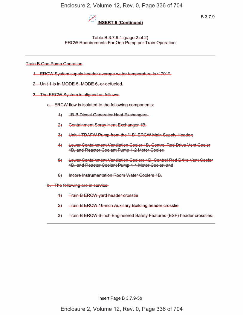
B 3.7.9
Insert Page B 3.7.9-5b
INSERT 6 (Continued)
Table B 3.7.9-1 (page 2 of 2) ERCW Requirements For One Pump per Train Operation
Train B One Pump Operation
1. ERCW System supply header average water temperature is 79°F. 2. Unit 1 is in MODE 5, MODE 6, or defueled.
3. The ERCW System is aligned as follows:
a. ERCW flow is isolated to the following components:
1) 1B-B Diesel Generator Heat Exchangers;
2) Containment Spray Heat Exchanger 1B;
3) Unit 1 TDAFW Pump from the "1B" ERCW Main Supply Header;
4) Lower Containment Ventilation Cooler 1B, Control Rod Drive Vent Cooler
1B, and Reactor Coolant Pump 1-2 Motor Cooler;
5) Lower Containment Ventilation Coolers 1D, Control Rod Drive Vent Cooler 1D, and Reactor Coolant Pump 1-4 Motor Cooler; and
6) Incore Instrumentation Room Water Coolers 1B.
b. The following are in service:
1) Train B ERCW yard header crosstie 2) Train B ERCW 16-inch Auxiliary Building header crosstie 3) Train B ERCW 6-inch Engineered Safety Features (ESF) header crossties.
1
Enclosure 2, Volume 12, Rev. 0, Page 336 of 704
Enclosure 2, Volume 12, Rev. 0, Page 336 of 704
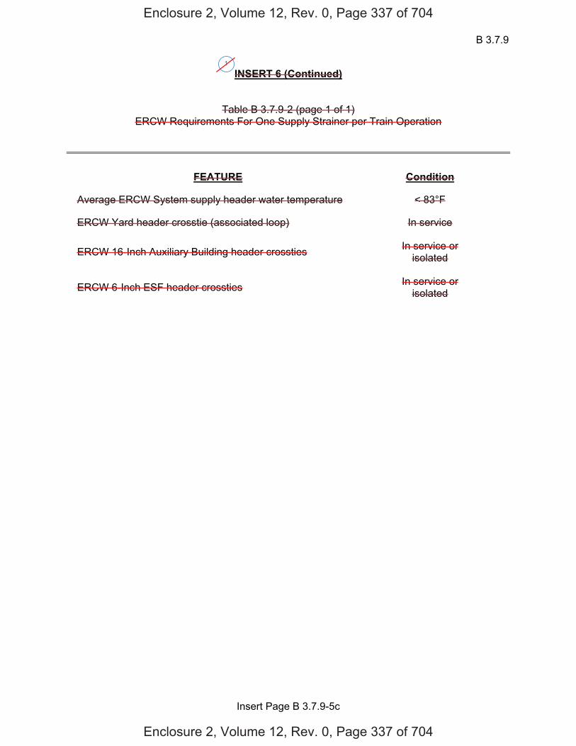
B 3.7.9
Insert Page B 3.7.9-5c
INSERT 6 (Continued)
Table B 3.7.9-2 (page 1 of 1) ERCW Requirements For One Supply Strainer per Train Operation
FEATURE Condition
Average ERCW System supply header water temperature < 83°F
ERCW Yard header crosstie (associated loop) In service
ERCW 16-Inch Auxiliary Building header crossties In service or isolated
ERCW 6-Inch ESF header crossties In service or isolated
1
Enclosure 2, Volume 12, Rev. 0, Page 337 of 704
Enclosure 2, Volume 12, Rev. 0, Page 337 of 704
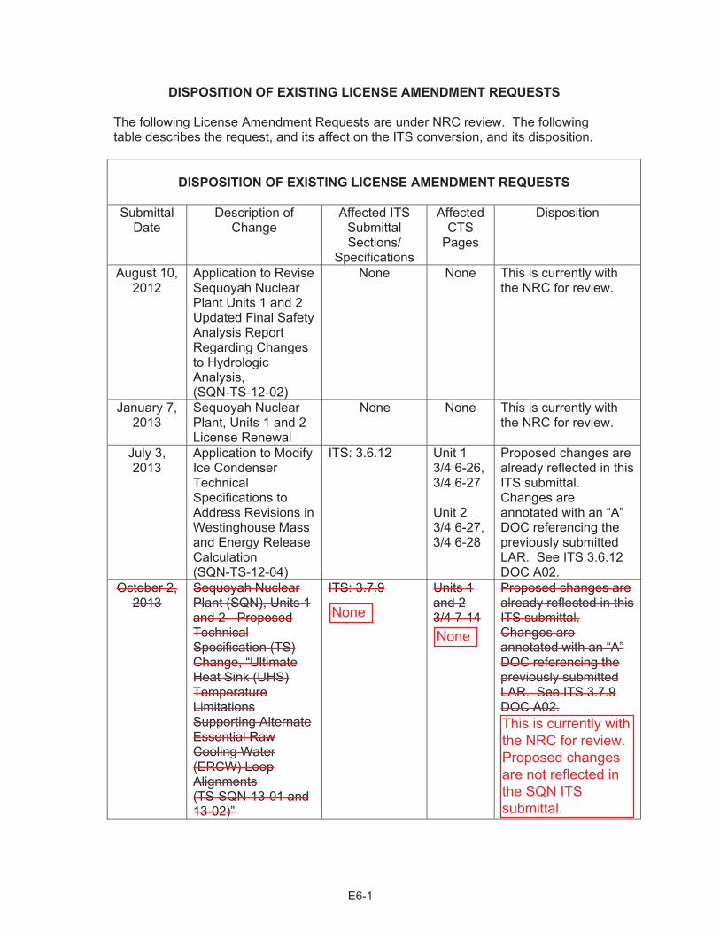
DISPOSITION OF EXISTING LICENSE AMENDMENT REQUESTS The following License Amendment Requests are under NRC review. The following table describes the request, and its affect on the ITS conversion, and its disposition.
DISPOSITION OF EXISTING LICENSE AMENDMENT REQUESTS Submittal
Date Description of
Change Affected ITS
Submittal Sections/
Specifications
Affected CTS
Pages
Disposition
August 10, 2012
Application to Revise Sequoyah Nuclear Plant Units 1 and 2 Updated Final Safety Analysis Report Regarding Changes to Hydrologic Analysis, (SQN-TS-12-02)
None None This is currently with the NRC for review.
January 7, 2013
Sequoyah Nuclear Plant, Units 1 and 2 License Renewal
None None This is currently with the NRC for review.
July 3, 2013
Application to Modify Ice Condenser Technical Specifications to Address Revisions in Westinghouse Mass and Energy Release Calculation (SQN-TS-12-04)
ITS: 3.6.12 Unit 1 3/4 6-26, 3/4 6-27 Unit 2 3/4 6-27,3/4 6-28
Proposed changes are already reflected in this ITS submittal. Changes are annotated with an “A” DOC referencing the previously submitted LAR. See ITS 3.6.12 DOC A02.
October 2, 2013
Sequoyah Nuclear Plant (SQN), Units 1 and 2 - Proposed Technical Specification (TS) Change, “Ultimate Heat Sink (UHS) Temperature Limitations Supporting Alternate Essential Raw Cooling Water (ERCW) Loop Alignments (TS-SQN-13-01 and 13-02)”
ITS: 3.7.9 Units 1 and 2 3/4 7-14
Proposed changes are already reflected in this ITS submittal. Changes are annotated with an “A” DOC referencing the previously submitted LAR. See ITS 3.7.9 DOC A02.
E6-1
None
None
This is currently withthe NRC for review.Proposed changesare not reflected inthe SQN ITSsubmittal.
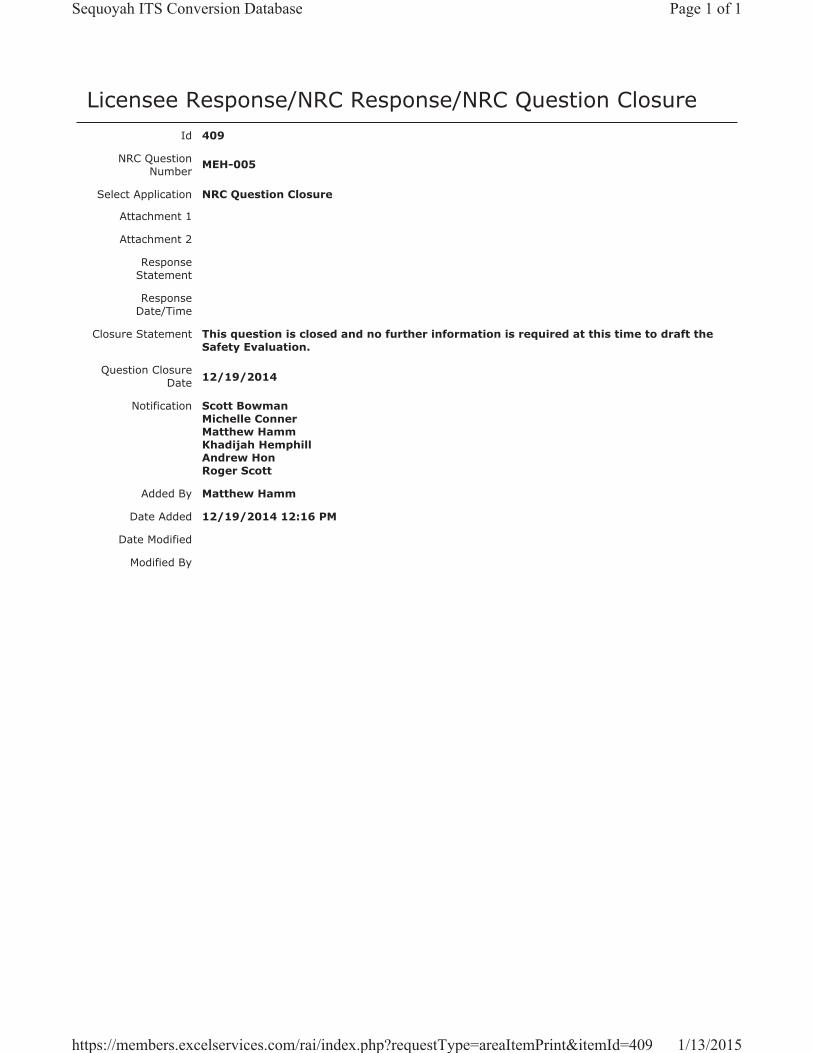
Licensee Response/NRC Response/NRC Question ClosureId 409
NRC Question Number MEH-005
Select Application NRC Question Closure
Attachment 1
Attachment 2
Response Statement
Response Date/Time
Closure Statement This question is closed and no further information is required at this time to draft the Safety Evaluation.
Question Closure Date 12/19/2014
Notification Scott BowmanMichelle ConnerMatthew HammKhadijah HemphillAndrew HonRoger Scott
Added By Matthew Hamm
Date Added 12/19/2014 12:16 PM
Date Modified
Modified By
Page 1 of 1Sequoyah ITS Conversion Database
1/13/2015https://members.excelservices.com/rai/index.php?requestType=areaItemPrint&itemId=409
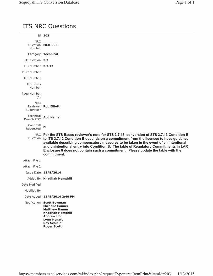
ITS NRC QuestionsId 203
NRC Question Number
MEH-006
Category Technical
ITS Section 3.7
ITS Number 3.7.12
DOC Number
JFD Number
JFD Bases Number
Page Number(s)
NRC Reviewer
Supervisor Rob Elliott
Technical Branch POC Add Name
Conf Call Requested N
NRC Question
Per the STS Bases reviewer’s note for STS 3.7.13, conversion of STS 3.7.13 Condition B to ITS 3.7.12 Condition B depends on a commitment from the licensee to have guidance available describing compensatory measures to be taken in the event of an intentional and unintentional entry into Condition B. The table of Regulatory Commitments in LAR Enclosure 8 does not contain such a commitment. Please update the table with the commitment.
Attach File 1
Attach File 2
Issue Date 12/8/2014
Added By Khadijah Hemphill
Date Modified
Modified By
Date Added 12/8/2014 2:40 PM
Notification Scott BowmanMichelle ConnerMatthew HammKhadijah HemphillAndrew HonLynn MynattRay SchieleRoger Scott
Page 1 of 1Sequoyah ITS Conversion Database
1/13/2015https://members.excelservices.com/rai/index.php?requestType=areaItemPrint&itemId=203
Licensee Response/NRC Response/NRC Question ClosureId 397
NRC Question Number
MEH-006
Select Application Licensee Response
Attachment 1 Attachment 1 for RAI MEH-006.pdf (941KB)
Attachment 2
Response Statement In response to RAI MEH-006, SQN will revise the table
of commitments in Enclosure 8 of the ITS submittal.The commitment will state, “Sequoyah will have guidance available describing compensatory measures to be taken in the event of an intentional or unintentional entry into ITS 3.7.12 Condition B.”Additionally, the paragraph detailing the number of commitments associated with the ITS conversion license amendment request will be revised to state that the table identifies 12 commitments by TVA for the SQN ITS conversion.
See Attachment 1 for the draft revised Enclosure 8.Response
Date/Time 12/16/2014 8:45 AM
Closure Statement
Question Closure
Date
Notification Scott BowmanMichelle ConnerMatthew HammKhadijah HemphillAndrew HonRay Schiele
Added By Scott Bowman
Date Added 12/16/2014 7:46 AM
Date Modified
Modified By
Page 1 of 1Sequoyah ITS Conversion Database
1/13/2015https://members.excelservices.com/rai/index.php?requestType=areaItemPrint&itemId=397
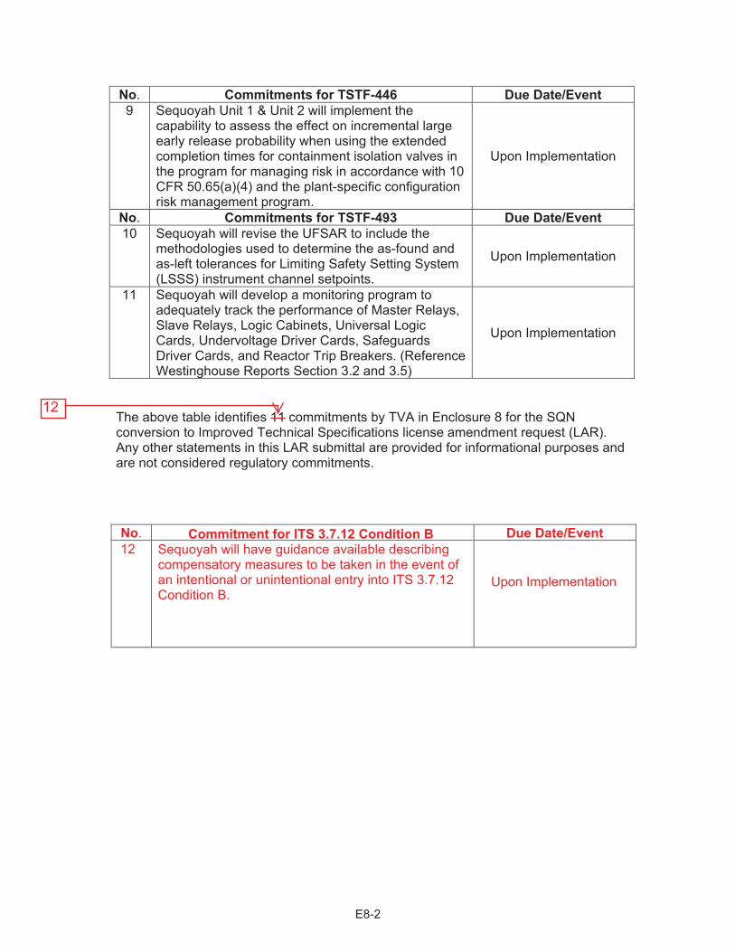
No. Commitments for TSTF-446 Due Date/Event 9 Sequoyah Unit 1 & Unit 2 will implement the
capability to assess the effect on incremental large early release probability when using the extended completion times for containment isolation valves in the program for managing risk in accordance with 10 CFR 50.65(a)(4) and the plant-specific configuration risk management program.
Upon Implementation
No. Commitments for TSTF-493 Due Date/Event10 Sequoyah will revise the UFSAR to include the
methodologies used to determine the as-found and as-left tolerances for Limiting Safety Setting System (LSSS) instrument channel setpoints.
Upon Implementation
11 Sequoyah will develop a monitoring program to adequately track the performance of Master Relays, Slave Relays, Logic Cabinets, Universal Logic Cards, Undervoltage Driver Cards, Safeguards Driver Cards, and Reactor Trip Breakers. (Reference Westinghouse Reports Section 3.2 and 3.5)
Upon Implementation
The above table identifies 11 commitments by TVA in Enclosure 8 for the SQN conversion to Improved Technical Specifications license amendment request (LAR). Any other statements in this LAR submittal are provided for informational purposes and are not considered regulatory commitments.
E8-2
No. Commitment for Due Date/Event
Upon Implementation
12

Licensee Response/NRC Response/NRC Question ClosureId 410
NRC Question Number MEH-006
Select Application NRC Question Closure
Attachment 1
Attachment 2
Response Statement
Response Date/Time
Closure Statement This question is closed and no further information is required at this time to draft the Safety Evaluation.
Question Closure Date 12/19/2014
Notification Scott BowmanMichelle ConnerMatthew HammKhadijah HemphillAndrew HonRoger Scott
Added By Matthew Hamm
Date Added 12/19/2014 12:17 PM
Date Modified
Modified By
Page 1 of 1Sequoyah ITS Conversion Database
1/13/2015https://members.excelservices.com/rai/index.php?requestType=areaItemPrint&itemId=410
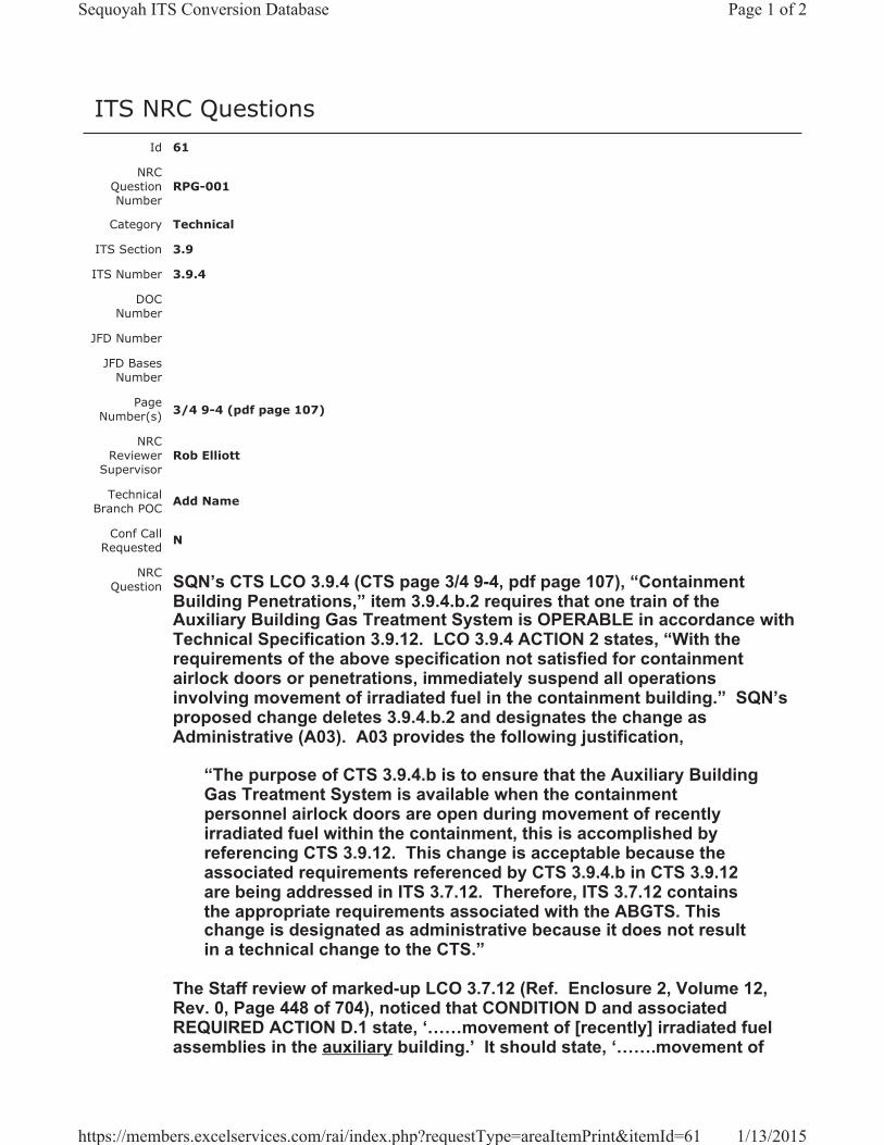
ITS NRC QuestionsId 61
NRC Question Number
RPG-001
Category Technical
ITS Section 3.9
ITS Number 3.9.4
DOC Number
JFD Number
JFD Bases Number
Page Number(s) 3/4 9-4 (pdf page 107)
NRC Reviewer
Supervisor Rob Elliott
Technical Branch POC Add Name
Conf Call Requested N
NRC Question SQN’s CTS LCO 3.9.4 (CTS page 3/4 9-4, pdf page 107), “Containment
Building Penetrations,” item 3.9.4.b.2 requires that one train of the Auxiliary Building Gas Treatment System is OPERABLE in accordance with Technical Specification 3.9.12. LCO 3.9.4 ACTION 2 states, “With the requirements of the above specification not satisfied for containment airlock doors or penetrations, immediately suspend all operations involving movement of irradiated fuel in the containment building.” SQN’s proposed change deletes 3.9.4.b.2 and designates the change as Administrative (A03). A03 provides the following justification,
“The purpose of CTS 3.9.4.b is to ensure that the Auxiliary Building Gas Treatment System is available when the containment personnel airlock doors are open during movement of recently irradiated fuel within the containment, this is accomplished by referencing CTS 3.9.12. This change is acceptable because the associated requirements referenced by CTS 3.9.4.b in CTS 3.9.12 are being addressed in ITS 3.7.12. Therefore, ITS 3.7.12 contains the appropriate requirements associated with the ABGTS. This change is designated as administrative because it does not result in a technical change to the CTS.”
The Staff review of marked-up LCO 3.7.12 (Ref. Enclosure 2, Volume 12, Rev. 0, Page 448 of 704), noticed that CONDITION D and associated REQUIRED ACTION D.1 state, ‘……movement of [recently] irradiated fuel assemblies in the auxiliary building.’ It should state, ‘…….movement of
Page 1 of 2Sequoyah ITS Conversion Database
1/13/2015https://members.excelservices.com/rai/index.php?requestType=areaItemPrint&itemId=61
[recently] irradiated fuel assemblies in the containment building,’ as stated in CTS 3.9.4 above. Please correct the discrepancy or explain.
Attach File 1
Attach File 2
Issue Date 5/13/2014
Added By Ravinder Grover
Date Modified
Modified By
Date Added 5/13/2014 3:15 PM
Notification Scott BowmanMichelle ConnerRobert ElliottRavinder GroverMatthew HammKhadijah HemphillAndrew HonRay Schiele
Page 2 of 2Sequoyah ITS Conversion Database
1/13/2015https://members.excelservices.com/rai/index.php?requestType=areaItemPrint&itemId=61
Licensee Response/NRC Response/NRC Question ClosureId 131
NRC Question Number
RPG-001
Select Application Licensee Response
Attachment 1 RAI RPG-001 Draft Response Attachment 1, Rev 4.pdf (2MB)
Attachment 2
Response Statement In response to RPG-001, the CTS 3.9.4 markup will be revised to reflect that
CTS 3.9.4.b.2 is dispositioned in ITS 3.7.12 and the ITS 3.9.4 discussion of change (DOC) A03 will be deleted.
For clarity, ITS 3.9.4 DOC A02 will be revised with the addition of a note that references ITS 3.7.12 DOC L08 for the discussion of relaxing the OPERABILITY requirements for ABGTS. The ITS 3.9.4 Bases will be revised by the deletion of Insert 3, because it pertained to the LCO requirements associated with the mitigation capabilities of ABGTS for a fuel handling accident in the containment with both doors of an airlock open. Subsequent ITS 3.9.4 Bases inserts will be renumbered accordingly.
During the process of including the disposition of CTS 3.9.4.b.2 in the ITS 3.7.12 markups, it became apparent that ISTS 3.7.12 (and therefore ITS 3.3.8) was incorrectly adopted. The SQN fuel handling analysis assumes, in part, that the accident occurs 100 hours after shutdown, no credit is takenfor natural decay due to holdup in the auxiliary building, and the activity released from the spent fuel pool is released to the environment over a 2-hour period with no credit for filtration through ABGTS. Therefore, a fuel handling accident involving recently irradiated fuel requires mitigation by a redundant ABGTS train. To reflect this requirement, ITS 3.3.8 and ITS 3.7.12 are being revised to require two ABGTS trains to be OPERABLE during the movement of recently irradiated fuel assemblies in the auxiliary building.
The changes to ITS 3.3.8 entail revising CTS Table3.3-6 to require two Spent Fuel Pool Area Radiation Monitor channels to be OPERABLE during the movement of recently irradiated fuel assemblies in the auxiliary building,the removal of the note specifying that the required radiation monitor channel shall be associated with the ABGTS train required to be OPERABLE per LCO 3.7.12, the addition of ISTS 3.3.8 ACTION A as it applies to an inoperable radiation monitor channel and associated changes to the DOCs (deletion of M04, and modification of M06, and M07), and including more detail in DOC L01 for the discussion of applying the Applicability associated with the movement of recently irradiated fuel assemblies in the auxiliary building. Changes to the ISTS markups and associated changes to justification for deviation (JFD) 7 are also made to
Page 1 of 2Sequoyah ITS Conversion Database
1/13/2015https://members.excelservices.com/rai/index.php?requestType=areaItemPrint&itemId=131
reflect the changes made to the CTS.
The changes to ITS 3.7.12 entail deletion of the proposed LCO Note 2, removal of the Applicability modifier proposed to be added to ACTION A, adoption of ISTS 3.7.12, ACTION D (with changes to reflect plant nomenclature), removal of changes to ISTS 3.7.12 ACTION E (with the exception of changes that reflect plant nomenclature) and associated changes to the DOCs (A03, LA04, L01, L02, and L06). These changes will also result in the deletion of JFD 2 and associated changes to the Bases markup. Changes to the CTS 3.9.12 markups will be made to reflect the requirement for two ABGTS trains to be OPERABLE during the movement of recently irradiated fuel assemblies in the auxiliary building and the adoption of ISTS 3.7.12 ACTIONS A and D. In addition, a correction will be made to reflect that the CTS 4.9.12.a requirement to operate the ABGTS trains for 10 hours with the heaters on is proposed to be changed to 15 minutes with the heaters on, consistent with the adoption of TSTF-522 and similar to the proposed change to CTS 4.7.8.a. This change will also be discussed in DOC L04.
An error was also identified within ITS 3.7.12 DOC LA05, whereby the ITS SR 3.7.12.4 requirement for verification that the ABGTS train can maintain a pressure with respect to atmospheric pressure was incorrectly stated as "greater than or equal to -0.25 inches water gauge." This statement will be corrected to state, "...less than or equal to -0.25 inches water gauge."
See Attachment 1 for the draft ITS 3.3.8, ITS 3.7.12, and ITS 3.9.4 changes discussed above.
Response Date/Time 6/20/2014 4:50 AM
Closure Statement
Question Closure
Date
Notification Scott BowmanKristy BucholtzMichelle ConnerRavinder GroverMatthew HammKhadijah HemphillAndrew HonRay SchieleRoger Scott
Added By Scott Bowman
Date Added 6/20/2014 3:49 AM
Date Modified 6/20/2014 8:39 AM
Modified By Scott Bowman
Page 2 of 2Sequoyah ITS Conversion Database
1/13/2015https://members.excelservices.com/rai/index.php?requestType=areaItemPrint&itemId=131

ITS A01 ITS 3.9.4
REFUELING OPERATIONS 3/4.9.4 CONTAINMENT BUILDING PENETRATIONS LIMITING CONDITION FOR OPERATION 3.9.4 The containment building penetrations shall be in the following status: a. The equipment door closed and held in place by a minimum of four bolts,
b. A minimum of one door in each airlock is closed, and both doors of both containment personnel
airlocks may be open if: 1. One personnel airlock door in each airlock is capable of closure, and 2. One train of the Auxiliary Building Gas Treatment System is OPERABLE in accordance
with Technical Specification 3.9.12, and c. Each penetration* providing direct access from the containment atmosphere to the outside
atmosphere shall be either: 1. Closed by an isolation valve, blind flange, manual valve, or equivalent, or 2. Be capable of being closed by an OPERABLE automatic Containment Ventilation isolation
valve. APPLICABILTY: 3.9.4.a. Containment Building Equipment Door - During movement of recently irradiated fuel within the containment. 3.9.4.b. and c. Containment Building Airlock Doors and Penetrations - During movement of irradiated fuel within the containment. ACTION: 1. With the requirements of the above specification not satisfied for the containment building
equipment door, immediately suspend all operations involving movement of recently irradiated fuel in the containment building. The provisions of Specification 3.0.3 are not applicable.
2. With the requirements of the above specification not satisfied for containment airlock doors or
penetrations, immediately suspend all operations involving movement of irradiated fuel in the containment building. The provisions of Specification 3.0.3 are not applicable.
SURVEILLANCE REQUIREMENTS 4.9.4 Each of the above required containment building penetrations shall be determined to be either in its required condition or capable of being closed by an OPERABLE automatic Containment Ventilation isolation valve once per 7 days during movement of irradiated fuel in the containment building by: a. Verifying the penetrations are in their required condition, or b. Verifying the Containment Ventilation isolation valves not locked, sealed, or otherwise secured
in position, actuate to the isolation position on an actual or simulated actuation signal. * Penetration flow path(s) providing direct access from the containment atmosphere that transverse
and terminate in the Auxiliary Building Secondary Containment Enclosure may be unisolated under administrative controls.
April 13, 2009 SEQUOYAH - UNIT 1 3/4 9-4 Amendment No. 12, 209, 249, 260, 288, 323
LCO 3.9.4
LCO 3.9.4.a
LCO 3.9.4.b
LCO 3.9.4.c
Applicability
ACTION A
ACTION A
SR 3.9.4.1, SR 3.9.4.2
SR 3.9.4.1
SR 3.9.4.2
recently L01
A04
A04
A02
Applicability
Page 1 of 4
Add proposed SR 3.9.4.2 Note
LCO 3.9.4.c.1
LCO 3.9.4.c.2
recently L01
L02
18 months
LA01In accordance with the Surveillance
Frequency Control Program
A01 once per 7 days LA01In accordance with the Surveillance
Frequency Control Program
LCO 3.9.4 Note
recently L01
A03
Enclosure 2, Volume 14, Rev. 0, Page 105 of 236
Enclosure 2, Volume 14, Rev. 0, Page 105 of 236
(See ITS3.7.12)
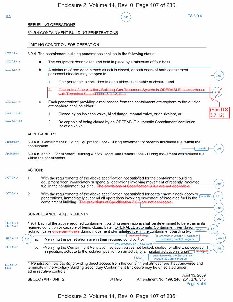
ITS A01 ITS 3.9.4
REFUELING OPERATIONS 3/4.9.4 CONTAINMENT BUILDING PENETRATIONS LIMITING CONDITION FOR OPERATION 3.9.4 The containment building penetrations shall be in the following status: a. The equipment door closed and held in place by a minimum of four bolts, b. A minimum of one door in each airlock is closed, or both doors of both containment
personnel airlocks may be open if: 1. One personnel airlock door in each airlock is capable of closure, and 2. One train of the Auxiliary Building Gas Treatment System is OPERABLE in accordance
with Technical Specification 3.9.12, and c. Each penetration* providing direct access from the containment atmosphere to the outside
atmosphere shall be either: 1. Closed by an isolation valve, blind flange, manual valve, or equivalent, or 2. Be capable of being closed by an OPERABLE automatic Containment Ventilation
isolation valve. APPLICABILITY: 3.9.4.a. Containment Building Equipment Door - During movement of recently irradiated fuel within the containment. 3.9.4.b. and c. Containment Building Airlock Doors and Penetrations - During movement of irradiated fuel within the containment. ACTION: 1. With the requirements of the above specification not satisfied for the containment building
equipment door, immediately suspend all operations involving movement of recently irradiated fuel in the containment building. The provisions of Specification 3.0.3 are not applicable.
2. With the requirements of the above specification not satisfied for containment airlock doors or
penetrations, immediately suspend all operations involving movement of irradiated fuel in the containment building. The provisions of Specification 3.0.3 are not applicable.
SURVEILLANCE REQUIREMENTS 4.9.4 Each of the above required containment building penetrations shall be determined to be either in its required condition or capable of being closed by an OPERABLE automatic Containment Ventilation isolation valve once per 7 days during movement of irradiated fuel in the containment building by: a. Verifying the penetrations are in their required condition, or b. Verifying the Containment Ventilation isolation valves not locked, sealed, or otherwise secured
in position, actuate to the isolation position on an actual or simulated actuation signal. * Penetration flow path(s) providing direct access from the containment atmosphere that transverse and terminate in the Auxiliary Building Secondary Containment Enclosure may be unisolated under administrative controls.
April 13, 2009 SEQUOYAH - UNIT 2 3/4 9-5 Amendment No. 199, 240, 251, 278, 315
LCO 3.9.4
LCO 3.9.4.a
LCO 3.9.4.b
LCO 3.9.4.c
Applicability
ACTION A
ACTION A
SR 3.9.4.1, SR 3.9.4.2
SR 3.9.4.1
SR 3.9.4.2
recently
Applicability
Add proposed SR 3.9.4.2 Note
A02
L01
A04
A04
Page 3 of 4
LCO 3.9.4.c.1
LCO 3.9.4.c.2
recently L01
L02
once per 7 days A01
In accordance with the Surveillance Frequency Control Program LA01
L0218 months
In accordance with the Surveillance Frequency Control Program LA01
LCO 3.9.4 Note
recently L01
A03
Enclosure 2, Volume 14, Rev. 0, Page 107 of 236
Enclosure 2, Volume 14, Rev. 0, Page 107 of 236
(See ITS3.7.12)
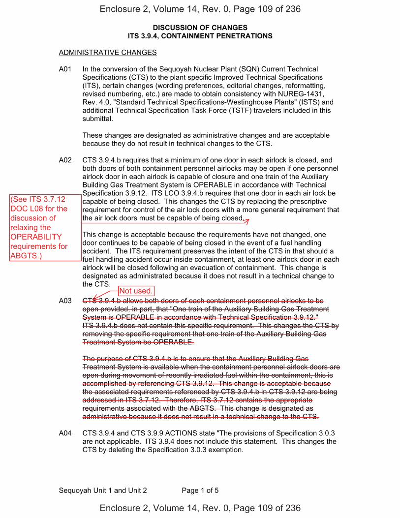
DISCUSSION OF CHANGES ITS 3.9.4, CONTAINMENT PENETRATIONS
Sequoyah Unit 1 and Unit 2 Page 1 of 5
ADMINISTRATIVE CHANGES A01 In the conversion of the Sequoyah Nuclear Plant (SQN) Current Technical
Specifications (CTS) to the plant specific Improved Technical Specifications (ITS), certain changes (wording preferences, editorial changes, reformatting, revised numbering, etc.) are made to obtain consistency with NUREG-1431, Rev. 4.0, "Standard Technical Specifications-Westinghouse Plants" (ISTS) and additional Technical Specification Task Force (TSTF) travelers included in this submittal.
These changes are designated as administrative changes and are acceptable
because they do not result in technical changes to the CTS. A02 CTS 3.9.4.b requires that a minimum of one door in each airlock is closed, and
both doors of both containment personnel airlocks may be open if one personnel airlock door in each airlock is capable of closure and one train of the Auxiliary Building Gas Treatment System is OPERABLE in accordance with Technical Specification 3.9.12. ITS LCO 3.9.4.b requires that one door in each air lock be capable of being closed. This changes the CTS by replacing the prescriptive requirement for control of the air lock doors with a more general requirement that the air lock doors must be capable of being closed.
This change is acceptable because the requirements have not changed, one
door continues to be capable of being closed in the event of a fuel handling accident. The ITS requirement preserves the intent of the CTS in that should a fuel handling accident occur inside containment, at least one airlock door in each airlock will be closed following an evacuation of containment. This change is designated as administrated because it does not result in a technical change to the CTS.
A03 CTS 3.9.4.b allows both doors of each containment personnel airlocks to be
open provided, in part, that "One train of the Auxiliary Building Gas Treatment System is OPERABLE in accordance with Technical Specification 3.9.12." ITS 3.9.4.b does not contain this specific requirement. This changes the CTS by removing the specific requirement that one train of the Auxiliary Building Gas Treatment System be OPERABLE.
The purpose of CTS 3.9.4.b is to ensure that the Auxiliary Building Gas
Treatment System is available when the containment personnel airlock doors are open during movement of recently irradiated fuel within the containment, this is accomplished by referencing CTS 3.9.12. This change is acceptable because the associated requirements referenced by CTS 3.9.4.b in CTS 3.9.12 are being addressed in ITS 3.7.12. Therefore, ITS 3.7.12 contains the appropriate requirements associated with the ABGTS. This change is designated as administrative because it does not result in a technical change to the CTS.
A04 CTS 3.9.4 and CTS 3.9.9 ACTIONS state "The provisions of Specification 3.0.3
are not applicable. ITS 3.9.4 does not include this statement. This changes the CTS by deleting the Specification 3.0.3 exemption.
Enclosure 2, Volume 14, Rev. 0, Page 109 of 236
Enclosure 2, Volume 14, Rev. 0, Page 109 of 236
Not used.
(See ITS 3.7.12DOC L08 for thediscussion ofrelaxing theOPERABILITYrequirements forABGTS.)
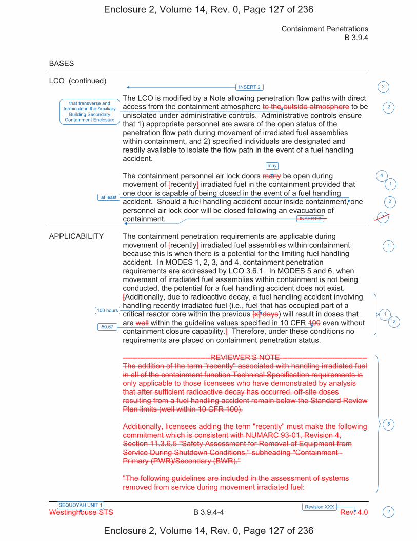
Containment Penetrations B 3.9.4
Westinghouse STS B 3.9.4-4 Rev. 4.0
SEQUOYAH UNIT 1 Revision XXX 2
BASES LCO (continued)
The LCO is modified by a Note allowing penetration flow paths with direct access from the containment atmosphere to the outside atmosphere to be unisolated under administrative controls. Administrative controls ensure that 1) appropriate personnel are aware of the open status of the penetration flow path during movement of irradiated fuel assemblies within containment, and 2) specified individuals are designated and readily available to isolate the flow path in the event of a fuel handling accident. The containment personnel air lock doors many be open during movement of [recently] irradiated fuel in the containment provided that one door is capable of being closed in the event of a fuel handling accident. Should a fuel handling accident occur inside containment, one personnel air lock door will be closed following an evacuation of containment.
APPLICABILITY The containment penetration requirements are applicable during
movement of [recently] irradiated fuel assemblies within containment because this is when there is a potential for the limiting fuel handling accident. In MODES 1, 2, 3, and 4, containment penetration requirements are addressed by LCO 3.6.1. In MODES 5 and 6, when movement of irradiated fuel assemblies within containment is not being conducted, the potential for a fuel handling accident does not exist. [Additionally, due to radioactive decay, a fuel handling accident involving handling recently irradiated fuel (i.e., fuel that has occupied part of a critical reactor core within the previous [x] days) will result in doses that are well within the guideline values specified in 10 CFR 100 even without containment closure capability.] Therefore, under these conditions no requirements are placed on containment penetration status. -----------------------------------REVIEWER’S NOTE----------------------------------- The addition of the term "recently" associated with handling irradiated fuel in all of the containment function Technical Specification requirements is only applicable to those licensees who have demonstrated by analysis that after sufficient radioactive decay has occurred, off-site doses resulting from a fuel handling accident remain below the Standard Review Plan limits (well within 10 CFR 100). Additionally, licensees adding the term "recently" must make the following commitment which is consistent with NUMARC 93-01, Revision 4, Section 11.3.6.5 "Safety Assessment for Removal of Equipment from Service During Shutdown Conditions," subheading "Containment - Primary (PWR)/Secondary (BWR)." "The following guidelines are included in the assessment of systems removed from service during movement irradiated fuel:
100 hours
2
1
1
1
5
may
4
at least
INSERT 2
2
2
INSERT 3
that transverse and terminate in the Auxiliary
Building Secondary Containment Enclosure
50.67
2
2
Enclosure 2, Volume 14, Rev. 0, Page 127 of 236
Enclosure 2, Volume 14, Rev. 0, Page 127 of 236

Insert Page B 3.9.4-4
INSERT 2 During movement of recently irradiated fuel assemblies within containment, the equipment hatch is required to be held in place by at least four bolts.
INSERT 3 The containment design is such that even though the primary and secondary containments are connected together when the personnel air lock doors are open, the normal auxiliary building ventilation system and Auxiliary Building Gas Treatment System (ABGTS) continue to provide the same fuel handling accident mitigation capability. With the personnel air lock doors open, the consequences of a fuel handling accident in the containment will be mitigated by the design of the ventilation systems (maintenance of a negative pressure during normal and applicable abnormal conditions, automatic isolation on high radiation in the auxiliary building, and automatic startup of emergency ventilation systems) and the leak-tight design of the auxiliary building. Both sets of the containment personnel airlock doors may be open during movement of recently irradiated fuel in containment provided one train of ABGTS is available for operation (LCO 3.7.12, "Auxiliary Building Gas Treatment System (AGBTS)"). The fuel handling accident is analyzed to occur in either the containment or the auxiliary building; however, an ABGTS start may be necessary for a containment fuel handling accident. The requirement for an airlock door to be capable of closure is provided to allow for long-term recovery from a fuel handling accident in containment.
4
2
Enclosure 2, Volume 14, Rev. 0, Page 128 of 236
Enclosure 2, Volume 14, Rev. 0, Page 128 of 236

Containment Penetrations B 3.9.4
Westinghouse STS B 3.9.4-5 Rev. 4.0
SEQUOYAH UNIT 1 Revision XXX 2
BASES APPLICABILITY (continued)
- During fuel handling/core alterations, ventilation system and radiation monitor availability (as defined in NUMARC 91-06) should be assessed, with respect to filtration and monitoring of releases from the fuel. Following shutdown, radioactivity in the fuel decays away fairly rapidly. The basis of the Technical Specification OPERABILITY amendment is the reduction in doses due to such decay. The goal of maintaining ventilation system and radiation monitor availability is to reduce doses even further below that provided by the natural decay. - A single normal or contingency method to promptly close primary or secondary containment penetrations should be developed. Such prompt methods need not completely block the penetration or be capable of resisting pressure.
The purpose of the "prompt methods" mentioned above are to enable ventilation systems to draw the release from a postulated fuel handling accident in the proper direction such that it can be treated and monitored." --------------------------------------------------------------------------------------------------
ACTIONS A.1
If the containment equipment hatch, air locks, or any containment penetration that provides direct access from the containment atmosphere to the outside atmosphere is not in the required status, including the Containment Purge and Exhaust Isolation System not capable of automatic actuation when the purge and exhaust valves are open, the unit must be placed in a condition where the isolation function is not needed. This is accomplished by immediately suspending movement of [recently] irradiated fuel assemblies within containment. Performance of these actions shall not preclude completion of movement of a component to a safe position.
SURVEILLANCE SR 3.9.4.1 REQUIREMENTS
This Surveillance demonstrates that each of the containment penetrations required to be in its closed position is in that position. The Surveillance on the open purge and exhaust valves will demonstrate that the valves are not blocked from closing. Also the Surveillance will demonstrate that each valve operator has motive power, which will ensure that each valve is capable of being closed by an OPERABLE automatic containment purge and exhaust isolation signal.
Ventilation
5
6
INSERT 4
is in its
1
Containment Ventilation isolation
2
automatic
valve(s)
Enclosure 2, Volume 14, Rev. 0, Page 129 of 236
Enclosure 2, Volume 14, Rev. 0, Page 129 of 236
3
Insert Page B 3.9.4-5
INSERT 4 status. The requirement that penetrations are capable of being closed by an OPERABLE automatic containment ventilation isolation valve, can be verified by ensuring that each required containment ventilation isolation
6
Enclosure 2, Volume 14, Rev. 0, Page 130 of 236
Enclosure 2, Volume 14, Rev. 0, Page 130 of 236
3

Containment Penetrations B 3.9.4
Westinghouse STS B 3.9.4-6 Rev. 4.0
SEQUOYAH UNIT 1 Revision XXX 2
BASES SURVEILLANCE REQUIREMENTS (continued)
[ The Surveillance is performed every 7 days during movement of [recently] irradiated fuel assemblies within containment. The Surveillance interval is selected to be commensurate with the normal duration of time to complete fuel handling operations. A surveillance before the start of refueling operations will provide two or three surveillance verifications during the applicable period for this LCO. As such, this Surveillance ensures that a postulated fuel handling accident [involving handling recently irradiated fuel] that releases fission product radioactivity within the containment will not result in a release of significant fission product radioactivity to the environment in excess of those recommended by Standard Review Plan Section 15.7.4 (Reference 3). OR The Surveillance Frequency is controlled under the Surveillance Frequency Control Program. -----------------------------------REVIEWER’S NOTE----------------------------------- Plants controlling Surveillance Frequencies under a Surveillance Frequency Control Program should utilize the appropriate Frequency description, given above, and the appropriate choice of Frequency in the Surveillance Requirement. ------------------------------------------------------------------------------------------------ ] SR 3.9.4.2 This Surveillance demonstrates that each containment purge and exhaust valve actuates to its isolation position on manual initiation or on an actual or simulated high radiation signal. [ The 18 month Frequency maintains consistency with other similar ESFAS instrumentation and valve testing requirements. In LCO 3.3.6, the Containment Purge and Exhaust Isolation instrumentation requires a CHANNEL CHECK every 12 hours and a COT every 92 days to ensure the channel OPERABILITY during refueling operations. Every 18 months a CHANNEL CALIBRATION is performed. The system actuation response time is demonstrated every 18 months, during refueling, on a STAGGERED TEST BASIS. SR 3.6.3.5 demonstrates that the isolation time of each valve is in accordance with the Inservice Testing Program requirements. These Surveillances performed during MODE 6 will ensure that the valves are capable of closing after a postulated fuel handling accident [involving handling recently irradiated fuel] to limit a release of fission product radioactivity from the containment.
ventilation isolation
7
8
2
7
INSERT 5 9
actuation 10
Enclosure 2, Volume 14, Rev. 0, Page 131 of 236
Enclosure 2, Volume 14, Rev. 0, Page 131 of 236
4

Insert Page B 3.9.4-6
INSERT 5 , that is not locked, sealed, or otherwise secured in position,
9
Enclosure 2, Volume 14, Rev. 0, Page 132 of 236
Enclosure 2, Volume 14, Rev. 0, Page 132 of 236
4

Containment Penetrations B 3.9.4
Westinghouse STS B 3.9.4-4 Rev. 4.0
SEQUOYAH UNIT 2 Revision XXX 2
BASES LCO (continued)
The LCO is modified by a Note allowing penetration flow paths with direct access from the containment atmosphere to the outside atmosphere to be unisolated under administrative controls. Administrative controls ensure that 1) appropriate personnel are aware of the open status of the penetration flow path during movement of irradiated fuel assemblies within containment, and 2) specified individuals are designated and readily available to isolate the flow path in the event of a fuel handling accident. The containment personnel air lock doors many be open during movement of [recently] irradiated fuel in the containment provided that one door is capable of being closed in the event of a fuel handling accident. Should a fuel handling accident occur inside containment, one personnel air lock door will be closed following an evacuation of containment.
APPLICABILITY The containment penetration requirements are applicable during
movement of [recently] irradiated fuel assemblies within containment because this is when there is a potential for the limiting fuel handling accident. In MODES 1, 2, 3, and 4, containment penetration requirements are addressed by LCO 3.6.1. In MODES 5 and 6, when movement of irradiated fuel assemblies within containment is not being conducted, the potential for a fuel handling accident does not exist. [Additionally, due to radioactive decay, a fuel handling accident involving handling recently irradiated fuel (i.e., fuel that has occupied part of a critical reactor core within the previous [x] days) will result in doses that are well within the guideline values specified in 10 CFR 100 even without containment closure capability.] Therefore, under these conditions no requirements are placed on containment penetration status. -----------------------------------REVIEWER’S NOTE----------------------------------- The addition of the term "recently" associated with handling irradiated fuel in all of the containment function Technical Specification requirements is only applicable to those licensees who have demonstrated by analysis that after sufficient radioactive decay has occurred, off-site doses resulting from a fuel handling accident remain below the Standard Review Plan limits (well within 10 CFR 100). Additionally, licensees adding the term "recently" must make the following commitment which is consistent with NUMARC 93-01, Revision 4, Section 11.3.6.5 "Safety Assessment for Removal of Equipment from Service During Shutdown Conditions," subheading "Containment - Primary (PWR)/Secondary (BWR)." "The following guidelines are included in the assessment of systems removed from service during movement irradiated fuel:
100 hours
2
1
1
1
5
may
4
at least
INSERT 2
2
2
INSERT 3
that transverse and terminate in the Auxiliary
Building Secondary Containment Enclosure
50.67
2
2
Enclosure 2, Volume 14, Rev. 0, Page 138 of 236
Enclosure 2, Volume 14, Rev. 0, Page 138 of 236
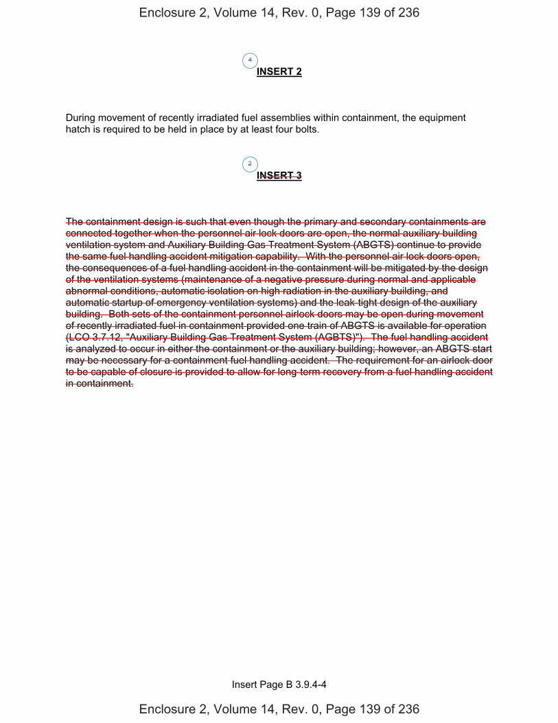
Insert Page B 3.9.4-4
INSERT 2 During movement of recently irradiated fuel assemblies within containment, the equipment hatch is required to be held in place by at least four bolts.
INSERT 3 The containment design is such that even though the primary and secondary containments are connected together when the personnel air lock doors are open, the normal auxiliary building ventilation system and Auxiliary Building Gas Treatment System (ABGTS) continue to provide the same fuel handling accident mitigation capability. With the personnel air lock doors open, the consequences of a fuel handling accident in the containment will be mitigated by the design of the ventilation systems (maintenance of a negative pressure during normal and applicable abnormal conditions, automatic isolation on high radiation in the auxiliary building, and automatic startup of emergency ventilation systems) and the leak-tight design of the auxiliary building. Both sets of the containment personnel airlock doors may be open during movement of recently irradiated fuel in containment provided one train of ABGTS is available for operation (LCO 3.7.12, "Auxiliary Building Gas Treatment System (AGBTS)"). The fuel handling accident is analyzed to occur in either the containment or the auxiliary building; however, an ABGTS start may be necessary for a containment fuel handling accident. The requirement for an airlock door to be capable of closure is provided to allow for long-term recovery from a fuel handling accident in containment.
4
2
Enclosure 2, Volume 14, Rev. 0, Page 139 of 236
Enclosure 2, Volume 14, Rev. 0, Page 139 of 236
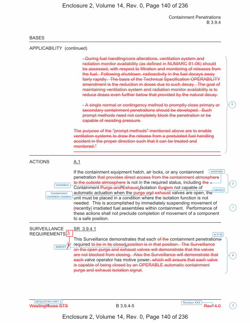
Containment Penetrations B 3.9.4
Westinghouse STS B 3.9.4-5 Rev. 4.0
SEQUOYAH UNIT 2 Revision XXX 2
BASES APPLICABILITY (continued)
- During fuel handling/core alterations, ventilation system and radiation monitor availability (as defined in NUMARC 91-06) should be assessed, with respect to filtration and monitoring of releases from the fuel. Following shutdown, radioactivity in the fuel decays away fairly rapidly. The basis of the Technical Specification OPERABILITY amendment is the reduction in doses due to such decay. The goal of maintaining ventilation system and radiation monitor availability is to reduce doses even further below that provided by the natural decay. - A single normal or contingency method to promptly close primary or secondary containment penetrations should be developed. Such prompt methods need not completely block the penetration or be capable of resisting pressure.
The purpose of the "prompt methods" mentioned above are to enable ventilation systems to draw the release from a postulated fuel handling accident in the proper direction such that it can be treated and monitored." --------------------------------------------------------------------------------------------------
ACTIONS A.1
If the containment equipment hatch, air locks, or any containment penetration that provides direct access from the containment atmosphere to the outside atmosphere is not in the required status, including the Containment Purge and Exhaust Isolation System not capable of automatic actuation when the purge and exhaust valves are open, the unit must be placed in a condition where the isolation function is not needed. This is accomplished by immediately suspending movement of [recently] irradiated fuel assemblies within containment. Performance of these actions shall not preclude completion of movement of a component to a safe position.
SURVEILLANCE SR 3.9.4.1 REQUIREMENTS
This Surveillance demonstrates that each of the containment penetrations required to be in its closed position is in that position. The Surveillance on the open purge and exhaust valves will demonstrate that the valves are not blocked from closing. Also the Surveillance will demonstrate that each valve operator has motive power, which will ensure that each valve is capable of being closed by an OPERABLE automatic containment purge and exhaust isolation signal.
Ventilation
5
6
INSERT 4
is in its
1
Containment Ventilation isolation
2
automatic
valve(s)
Enclosure 2, Volume 14, Rev. 0, Page 140 of 236
Enclosure 2, Volume 14, Rev. 0, Page 140 of 236
3

Insert Page B 3.9.4-5
INSERT 4 status. The requirement that penetrations are capable of being closed by an OPERABLE automatic containment ventilation isolation valve, can be verified by ensuring that each required containment ventilation isolation
6
Enclosure 2, Volume 14, Rev. 0, Page 141 of 236
Enclosure 2, Volume 14, Rev. 0, Page 141 of 236
3

Containment Penetrations B 3.9.4
Westinghouse STS B 3.9.4-6 Rev. 4.0
SEQUOYAH UNIT 2 Revision XXX 2
BASES SURVEILLANCE REQUIREMENTS (continued)
[ The Surveillance is performed every 7 days during movement of [recently] irradiated fuel assemblies within containment. The Surveillance interval is selected to be commensurate with the normal duration of time to complete fuel handling operations. A surveillance before the start of refueling operations will provide two or three surveillance verifications during the applicable period for this LCO. As such, this Surveillance ensures that a postulated fuel handling accident [involving handling recently irradiated fuel] that releases fission product radioactivity within the containment will not result in a release of significant fission product radioactivity to the environment in excess of those recommended by Standard Review Plan Section 15.7.4 (Reference 3). OR The Surveillance Frequency is controlled under the Surveillance Frequency Control Program. -----------------------------------REVIEWER’S NOTE----------------------------------- Plants controlling Surveillance Frequencies under a Surveillance Frequency Control Program should utilize the appropriate Frequency description, given above, and the appropriate choice of Frequency in the Surveillance Requirement. ------------------------------------------------------------------------------------------------ ] SR 3.9.4.2 This Surveillance demonstrates that each containment purge and exhaust valve actuates to its isolation position on manual initiation or on an actual or simulated high radiation signal. [ The 18 month Frequency maintains consistency with other similar ESFAS instrumentation and valve testing requirements. In LCO 3.3.6, the Containment Purge and Exhaust Isolation instrumentation requires a CHANNEL CHECK every 12 hours and a COT every 92 days to ensure the channel OPERABILITY during refueling operations. Every 18 months a CHANNEL CALIBRATION is performed. The system actuation response time is demonstrated every 18 months, during refueling, on a STAGGERED TEST BASIS. SR 3.6.3.5 demonstrates that the isolation time of each valve is in accordance with the Inservice Testing Program requirements. These Surveillances performed during MODE 6 will ensure that the valves are capable of closing after a postulated fuel handling accident [involving handling recently irradiated fuel] to limit a release of fission product radioactivity from the containment.
ventilation isolation
7
8
2
7
INSERT 5 9
actuation 10
Enclosure 2, Volume 14, Rev. 0, Page 142 of 236
Enclosure 2, Volume 14, Rev. 0, Page 142 of 236
4

Insert Page B 3.9.4-6
INSERT 5 , that is not locked, sealed, or otherwise secured in position,
9
Enclosure 2, Volume 14, Rev. 0, Page 143 of 236
Enclosure 2, Volume 14, Rev. 0, Page 143 of 236
4

A01ITS ITS 3.3.8
TABLE 3.3-6
RADIATION MONITORING INSTRUMENTATION
INSTRUMENT
MINIMUM CHANNELS OPERABLE
APPLICABLE
MODES
ALARM/TRIP SETPOINT
MEASUREMENT
RANGE
ACTION 1. AREA MONITOR
a. Fuel Storage Pool Area
1 * ≤ 151 mR/hr 10-1 - 104 mR/hr 26
2. PROCESS MONITORS
a. Containment Purge
Air
1
1, 2, 3, 4 & 6
≤ 8.5x 10⁻³μCi/cc
10 - 107 cpm
28
b. Containment
i. Deleted
ii. Particulate Activity RCS Leakage
Detection
1
1, 2, 3 & 4
N/A
10 - 107 cpm
27
c. Control Room
Isolation
2
ALL MODES and during movement of irradiated fuel assemblies
≤ 400 cpm**
10 - 107 cpm
29
_______________________________ * With fuel in the storage pool or building
** Equivalent to 1.0 x 10⁻⁵ μCi/cc.
December 04, 2008 SEQUOYAH - UNIT 1 3/4 3-40 Amendment Nos. 12, 60, 112, 168, 256,
310, 322
Page 2 of 8
Function 2
See ITS 3.3.6
See ITS 3.4.15
See ITS 3.3.7
During movement of recently irradiated fuel assemblies in the auxiliary building L01
Applicability
See ITS 3.3.7
Table 3.3.8-1
Auxiliary Building Gas Treatment System (ABGTS) A02
LA01
LA01
Add proposed Table 3.3.8-1 Function 1 M03
Add proposed Table 3.3.8-1 Function 3 M05
Spent A01(b)
M04
Add proposed Table 3.3.8-1 Footnote (b) M04
Enclosure 2, Volume 8, Rev. 0, Page 1031 of 1148
Enclosure 2, Volume 8, Rev. 0, Page 1031 of 1148
2 L01

A01ITS ITS 3.3.8
TABLE 3.3-6 (Continued)
ACTION STATEMENTS ACTION 26 - With the number of OPERABLE channels less than required by the Minimum
Channels OPERABLE requirement, perform area surveys of the monitored area with portable monitoring instrumentation at least once per 24 hours.
ACTION 27 - With the number of OPERABLE channels less than required by the Minimum
Channels OPERABLE requirement, comply with the ACTION requirements of Specification 3.4.6.1.
ACTION 28 - With the number of OPERABLE channels less than required by the Minimum
Channels OPERABLE requirement, comply with the ACTION requirements of Specification 3.9.9 (MODE 6) and 3.3.2.1 (MODES 1, 2, 3, and 4).
ACTION 29 - a. With one channel inoperable, place the associated control room emergency
ventilation system (CREVS) train in recirculation mode of operation within 7 days or be at least HOT STANDBY within the next 6 hours and in COLD SHUTDOWN within the following 30 hours.
b. With two channels inoperable, within 1 hour initiate and maintain operation of one
CREVS train in the recirculation mode of operation and enter the required Actions for one CREVS train made inoperable by inoperable CREVS actuation instrumentation.
Or place both trains in the recirculation mode of operation within one hour. If the completion time of Action 29b cannot be met in Modes 1, 2, 3, and 4, be in
at least HOT STANDBY within the next 6 hours and in COLD SHUTDOWN within the following 30 hours.
If the completion time of Action 29b cannot be met during the movement of
irradiated fuel assemblies, suspend core alterations and suspend movement of irradiated fuel assemblies.
If the completion time of Action 29b cannot be met in Modes 5 and 6, initiate
action to restore one CREVS train.
May 31, 2000 SEQUOYAH - UNIT 1 3/4 3-41 Amendment No. 12, 112, 168, 256
Page 3 of 8
See ITS 3.3.6
See ITS 3.4.15
See ITS 3.3.7
Add proposed ACTION Note 2 A03
Add proposed ACTION B M06
Add proposed ACTION C for Function 2 M07
ACTION B
Add proposed ACTIONS A, B, C, and D for Function 1 M03
Enclosure 2, Volume 8, Rev. 0, Page 1032 of 1148
Enclosure 2, Volume 8, Rev. 0, Page 1032 of 1148
Add proposed ACTION A L01
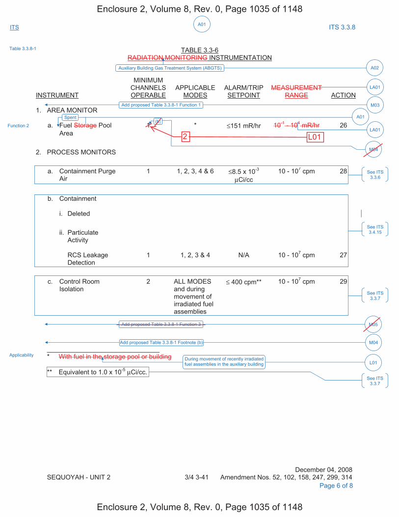
A01ITS ITS 3.3.8
TABLE 3.3-6
RADIATION MONITORING INSTRUMENTATION
INSTRUMENT
MINIMUM CHANNELS OPERABLE
APPLICABLE
MODES
ALARM/TRIP SETPOINT
MEASUREMENT
RANGE
ACTION 1. AREA MONITOR
a. Fuel Storage Pool 1 * ≤151 mR/hr 10-1 - 104 mR/hr 26 Area
2. PROCESS MONITORS
a. Containment Purge Air
1 1, 2, 3, 4 & 6 ≤8.5 x 10⁻³
μCi/cc 10 - 107 cpm 28
b. Containment i. Deleted
ii. Particulate Activity RCS Leakage Detection
1
1, 2, 3 & 4
N/A
10 - 107 cpm
27
c. Control Room Isolation
2 ALL MODES and during movement of irradiated fuel assemblies
≤ 400 cpm** 10 - 107 cpm 29
_______________________________ * With fuel in the storage pool or building ** Equivalent to 1.0 x 10⁻⁵ μCi/cc.
December 04, 2008 SEQUOYAH - UNIT 2 3/4 3-41 Amendment Nos. 52, 102, 158, 247, 299, 314 Page 6 of 8
Function 2
Applicability During movement of recently irradiated fuel assemblies in the auxiliary building L01
See ITS 3.3.6
See ITS 3.4.15
See ITS 3.3.7
See ITS 3.3.7
Table 3.3.8-1
Auxiliary Building Gas Treatment System (ABGTS) A02
LA01
Add proposed Table 3.3.8-1 Function 1 M03
LA01
Add proposed Table 3.3.8-1 Function 3 M05
Spent A01(b)
M04
Add proposed Table 3.3.8-1 Footnote (b) M04
Enclosure 2, Volume 8, Rev. 0, Page 1035 of 1148
Enclosure 2, Volume 8, Rev. 0, Page 1035 of 1148
2 L01

A01ITS ITS 3.3.8
TABLE 3.3-6 (Continued)
ACTION STATEMENTS ACTION 26 - With the number of OPERABLE channels less than required by the Minimum
Channels OPERABLE requirement, perform area surveys of the monitored area with portable monitoring instrumentation at least once per 24 hours.
ACTION 27 - With the number of OPERABLE channels less than required by the Minimum
Channels OPERABLE requirement, comply with the ACTION requirements of Specification 3.4.6.1.
ACTION 28 - With the number of OPERABLE channels less than required by the Minimum
Channels OPERABLE requirement, comply with the ACTION requirements of Specification 3.9.9 (MODE 6) and 3.3.2 (MODES 1, 2, 3, and 4).
ACTION 29 - a. With one channel inoperable, place the associated control room emergency
ventilation system (CREVS) train in recirculation mode of operation within 7 days or be at least HOT STANDBY within the next 6 hours and in COLD SHUTDOWN within the following 30 hours.
b. With two channels inoperable, within 1 hour initiate and maintain operation of one
CREVS train in the recirculation mode of operation and enter the required Actions for one CREVS train made inoperable by inoperable CREVS actuation instrumentation.
Or place both trains in the recirculation mode of operation within one hour. If the completion time of Action 29b cannot be met in Modes 1, 2, 3, and 4, be in
at least HOT STANDBY within the next 6 hours and in COLD SHUTDOWN within the following 30 hours.
If the completion time of Action 29b cannot be met during the movement of
irradiated fuel assemblies, suspend core alterations and suspend movement of irradiated fuel assemblies.
If the completion time of Action 29b cannot be met in Modes 5 and 6, initiate
action to restore one CREVS train.
May 31, 2000 SEQUOYAH - UNIT 2 3/4 3-42 Amendment Nos. 102, 158, 247
Page 7 of 8
See ITS 3.4.15
See ITS 3.3.6
See ITS 3.3.7
ACTION B
Add proposed ACTION Note 2 Add proposed ACTION B
Add proposed ACTION C for Function 2
M06
A03
M07
Add proposed ACTIONS A, B, C, and D for Function 1 M03
Enclosure 2, Volume 8, Rev. 0, Page 1036 of 1148
Enclosure 2, Volume 8, Rev. 0, Page 1036 of 1148
L01Add proposed ACTION A

DISCUSSION OF CHANGES ITS 3.3.8, AUXILIARY BUILDING GAS TREATMENT SYSTEM (ABGTS) ACTUATION
INSTRUMENTATION
Sequoyah Unit 1 and Unit 2 Page 3 of 7
M03 CTS 3.3.3.1 does not contain a requirement for the manual initiation of ABGTS.
ITS Table 3.3.8-1 Function 1 requires two channels of manual initiation for ABGTS to be OPERABLE in MODES 1, 2, 3, and 4 and during movement of recently irradiated fuel assemblies in the auxiliary building. ITS Table 3.3.8-1 Function 1 also requires performance of SR 3.3.8.3. ITS SR 3.3.8.3 requires performance of a TADOT every 18 months. (See DOC LA02 for the discussion related to moving the Surveillance Frequency to the Surveillance Frequency Control Program.) Additionally, ITS SR 3.3.8.3 contains a Note stating that verification of the setpoint is not required. Furthermore, ITS 3.3.8 contains compensatory actions to take if one or both ABGTS manual initiation channels are inoperable. ITS 3.3.8 ACTION A requires, in part, that with one manual initiation channel inoperable, to place one ABGTS train in operation. ITS 3.3.8 ACTION B requires, in part, that with two manual initiation channels inoperable, to place one train of ABGTS in operation immediately and to immediately enter the applicable Conditions and Required Actions of LCO 3.7.12. ITS 3.3.8 ACTION C requires that when the Required Action and associated Completion Time for Condition A or B are not met during movement of recently irradiated fuel assemblies in the auxiliary building, to immediately suspend movement of recently irradiated fuel assemblies in the auxiliary building. ITS 3.3.8 ACTION D requires that when the Required Action and associated Completion Time for Condition A or B are not met in MODE 1, 2, 3, or 4, to be in MODE 3 in 6 hours and in MODE 5 in 36 hours. This changes the CTS by requiring a new Function, Applicability, ACTIONS and Surveillance Requirement for the manual initiation of ABGTS.
The purpose the ABGTS manual initiation is to allow the operator to initiate
ABGTS at any time. This change is acceptable because the addition of ABGTS manual initiation requirements will ensure that proper redundancy is maintained. This change is designated as more restrictive because additional requirements are being added to the ITS that were not required in the CTS.
M04 CTS Table 3.3-6 Minimum Channels OPERABLE column requires one channel
for Functional Unit 1.a (Area Monitor, Fuel Storage Pool Area). ITS Table 3.3.8-1 Required Channels column requires one channel OPERABLE for Function 2 (Spent Fuel Pool Area Radiation Monitor) modified by footnote (b) that states the Required Channel shall be associated with the ABGTS train required OPERABLE by LCO 3.7.12. This changes the CTS by specifying that the required Spent Fuel Pool Area Radiation Monitor shall be associated with the OPERABLE ABGTS train.
The purpose of CTS Table 3.3-6 Functional Unit 1.a (Area Monitor, Fuel Storage
Pool Area) is to provide an indication of abnormal radiation levels and actuate ABGTS if necessary. This change is acceptable because it ensures the required radiation monitoring channel is associated with the OPERABLE ABGTS train. Thus if the radiation monitor's setpoint is exceeded a train of ABGTS will be available to start to mitigate any potential release. This change is designated as more restrictive because additional limitations are placed on what constitutes a required channel.
Enclosure 2, Volume 8, Rev. 0, Page 1040 of 1148
Enclosure 2, Volume 8, Rev. 0, Page 1040 of 1148
Not used.
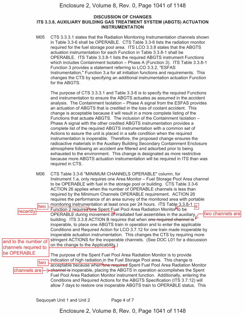
DISCUSSION OF CHANGES ITS 3.3.8, AUXILIARY BUILDING GAS TREATMENT SYSTEM (ABGTS) ACTUATION
INSTRUMENTATION
Sequoyah Unit 1 and Unit 2 Page 4 of 7
M05 CTS 3.3.3.1 states that the Radiation Monitoring Instrumentation channels shown in Table 3.3-6 shall be OPERABLE. CTS Table 3.3-6 lists the radiation monitor required for the fuel storage pool area. ITS LCO 3.3.8 states that the ABGTS actuation instrumentation for each Function in Table 3.3.8-1 shall be OPERABLE. ITS Table 3.3.8-1 lists the required ABGTS instrument Functions which includes Containment Isolation – Phase A (Function 3). ITS Table 3.3.8-1 Function 3 provides a statement referring to LCO 3.3.2, "ESFAS Instrumentation," Function 3.a for all initiation functions and requirements. This changes the CTS by specifying an additional instrumentation actuation Function for the ABGTS.
The purpose of CTS 3.3.3.1 and Table 3.3-6 is to specify the required Functions
and instrumentation to ensure the ABGTS actuates as assumed in the accident analysis. The Containment Isolation – Phase A signal from the ESFAS provides an actuation of ABGTS that is credited in the loss of coolant accident. This change is acceptable because it will result in a more complete listing of the Functions that actuate ABGTS. The inclusion of the Containment Isolation – Phase A signal with the other credited ABGTS instrumentation provides a complete list of the required ABGTS instrumentation with a common set of Actions to assure the unit is placed in a safe condition when the required instrumentation is inoperable. Therefore, the proposed change ensures the radioactive materials in the Auxiliary Building Secondary Containment Enclosure atmosphere following an accident are filtered and adsorbed prior to being exhausted to the environment. This change is designated as more restrictive because more ABGTS actuation instrumentation will be required in ITS than was required in CTS.
M06 CTS Table 3.3-6 "MINIMUM CHANNELS OPERABLE" column, for
Instrument 1.a, only requires one Area Monitor – Fuel Storage Pool Area channel to be OPERABLE with fuel in the storage pool or building. CTS Table 3.3-6 ACTION 26 applies when the number of OPERABLE channels is less than required by the Minimum Channels OPERABLE requirement. ACTION 26 requires the performance of an area survey of the monitored area with portable monitoring instrumentation at least once per 24 hours. ITS Table 3.3.8-1 Function 2 requires one Spent Fuel Pool Area Radiation Monitor to be OPERABLE during movement of irradiated fuel assemblies in the auxiliary building. ITS 3.3.8 ACTION B requires that when one required channel is inoperable, to place one ABGTS train in operation and to enter the applicable Conditions and Required Action for LCO 3.7.12 for one train made inoperable by inoperable actuation instrumentation. This changes the CTS by requiring more stringent ACTIONS for the inoperable channels. (See DOC L01 for a discussion on the change to the Applicability.)
The purpose of the Spent Fuel Pool Area Radiation Monitor is to provide
indication of high radiation in the Fuel Storage Pool area. This change is acceptable because when one required Spent Fuel Pool Area Radiation Monitor channel is inoperable, placing the ABGTS in operation accomplishes the Spent Fuel Pool Area Radiation Monitor instrument function. Additionally, entering the Conditions and Required Actions for the ABGTS Specification (ITS 3.7.12) will allow 7 days to restore one inoperable ABGTS train to OPERABLE status. This
Enclosure 2, Volume 8, Rev. 0, Page 1041 of 1148
Enclosure 2, Volume 8, Rev. 0, Page 1041 of 1148
two stwo channels are
and to the number ofchannels required tobe OPERABLE
twochannels are
recently
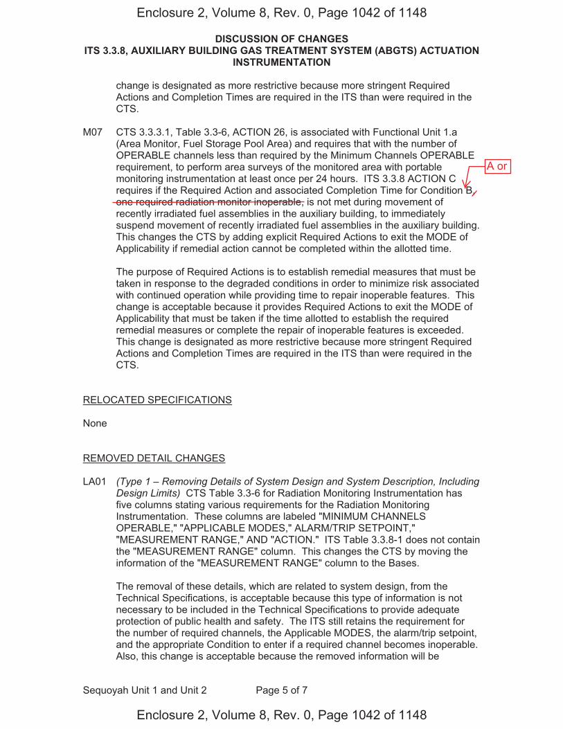
DISCUSSION OF CHANGES ITS 3.3.8, AUXILIARY BUILDING GAS TREATMENT SYSTEM (ABGTS) ACTUATION
INSTRUMENTATION
Sequoyah Unit 1 and Unit 2 Page 5 of 7
change is designated as more restrictive because more stringent Required Actions and Completion Times are required in the ITS than were required in the CTS.
M07 CTS 3.3.3.1, Table 3.3-6, ACTION 26, is associated with Functional Unit 1.a
(Area Monitor, Fuel Storage Pool Area) and requires that with the number of OPERABLE channels less than required by the Minimum Channels OPERABLE requirement, to perform area surveys of the monitored area with portable monitoring instrumentation at least once per 24 hours. ITS 3.3.8 ACTION C requires if the Required Action and associated Completion Time for Condition B, one required radiation monitor inoperable, is not met during movement of recently irradiated fuel assemblies in the auxiliary building, to immediately suspend movement of recently irradiated fuel assemblies in the auxiliary building. This changes the CTS by adding explicit Required Actions to exit the MODE of Applicability if remedial action cannot be completed within the allotted time.
The purpose of Required Actions is to establish remedial measures that must be
taken in response to the degraded conditions in order to minimize risk associated with continued operation while providing time to repair inoperable features. This change is acceptable because it provides Required Actions to exit the MODE of Applicability that must be taken if the time allotted to establish the required remedial measures or complete the repair of inoperable features is exceeded. This change is designated as more restrictive because more stringent Required Actions and Completion Times are required in the ITS than were required in the CTS.
RELOCATED SPECIFICATIONS None REMOVED DETAIL CHANGES LA01 (Type 1 – Removing Details of System Design and System Description, Including
Design Limits) CTS Table 3.3-6 for Radiation Monitoring Instrumentation has five columns stating various requirements for the Radiation Monitoring Instrumentation. These columns are labeled "MINIMUM CHANNELS OPERABLE," "APPLICABLE MODES," ALARM/TRIP SETPOINT," "MEASUREMENT RANGE," AND "ACTION." ITS Table 3.3.8-1 does not contain the "MEASUREMENT RANGE" column. This changes the CTS by moving the information of the "MEASUREMENT RANGE" column to the Bases.
The removal of these details, which are related to system design, from the
Technical Specifications, is acceptable because this type of information is not necessary to be included in the Technical Specifications to provide adequate protection of public health and safety. The ITS still retains the requirement for the number of required channels, the Applicable MODES, the alarm/trip setpoint, and the appropriate Condition to enter if a required channel becomes inoperable. Also, this change is acceptable because the removed information will be
Enclosure 2, Volume 8, Rev. 0, Page 1042 of 1148
Enclosure 2, Volume 8, Rev. 0, Page 1042 of 1148
A or

DISCUSSION OF CHANGES ITS 3.3.8, AUXILIARY BUILDING GAS TREATMENT SYSTEM (ABGTS) ACTUATION
INSTRUMENTATION
Sequoyah Unit 1 and Unit 2 Page 6 of 7
adequately controlled in the ITS Bases. Changes to the Bases are controlled by the Technical Specification Bases Control Program in Chapter 5. This program provides for the evaluation of changes to ensure the Bases are properly controlled. This change is designated as a less restrictive removal of detail change because information relating to system design is being removed from the Technical Specifications.
LA02 (Type 5 – Removal of SR Frequency to the Surveillance Frequency Control
Program) CTS Table 4.3-3 Instrument 1.a requires a CHANNEL CHECK every shift (12 hours), a CHANNEL FUNCTIONAL TEST every quarter (92 days), and a CHANNEL CALIBRATION every refueling cycle (18 months). In addition, SR 3.3.8.3 has been added for ITS Table 3.3.8-1 Function 1 with a Frequency of 18 months as discussed in DOC M03. ITS SR 3.3.8.1, SR 3.3.8.2, SR 3.3.8.3, and SR 3.3.8.4 require similar Surveillances and specify the periodic Frequency as, "In accordance with the Surveillance Frequency Control Program." This changes the CTS by moving the specified Frequencies for these SRs and associated Bases to the Surveillance Frequency Control Program.
The removal of these details related to Surveillance Requirement Frequencies
from the Technical Specifications is acceptable, because this type of information is not necessary to be included in the Technical Specifications to provide adequate protection of public health and safety. The existing Surveillance Frequencies are removed from Technical Specifications and placed under licensee control pursuant to the methodology described in NEI 04-10. A new program (Surveillance Frequency Control Program) is being added to the Administrative Controls section of the Technical Specifications describing the control of Surveillance Frequencies. The surveillance test requirements remain in the Technical Specifications. The control of changes to the Surveillance Frequencies will be in accordance with the Surveillance Frequency Control Program. The Program shall ensure that Surveillance Requirements specified in the Technical Specifications are performed at intervals sufficient to assure the associated Limiting Conditions for Operation are met. This change is designated as a less restrictive removal of detail change, because the Surveillance Frequencies are being removed from the Technical Specifications.
LESS RESTRICTIVE CHANGES L01 (Category 2 – Relaxation of Applicability) CTS Table 3.3-6 Instrument 1.a (Area
Monitor – Fuel Storage Pool Area) and CTS Table 4.3-3 Instrument 1.a (Area Monitor – Fuel Storage Pool Area) state that the requirements of the Fuel Storage Pool Area Monitors are applicable when there is fuel in the storage pool or building. ITS Table 3.3.8-1 Function 2 states that the Applicable MODE is during movement of recently irradiated fuel assemblies in the auxiliary building. This changes the CTS by only requiring the Spent Fuel Pool Monitors to be OPERABLE when there is a potential for a fuel handling accident in the auxiliary building (i.e., during movement of recently irradiated fuel assemblies in the auxiliary building).
Enclosure 2, Volume 8, Rev. 0, Page 1043 of 1148
Enclosure 2, Volume 8, Rev. 0, Page 1043 of 1148
Replace with"New" L01.
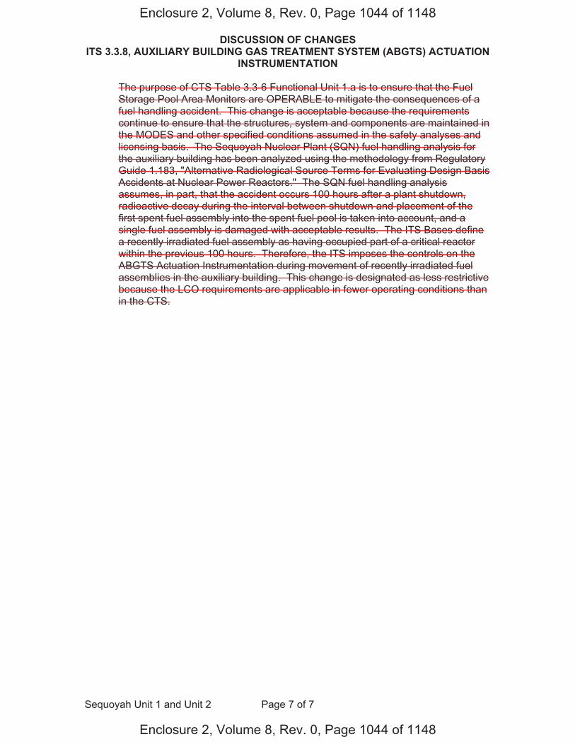
DISCUSSION OF CHANGES ITS 3.3.8, AUXILIARY BUILDING GAS TREATMENT SYSTEM (ABGTS) ACTUATION
INSTRUMENTATION
Sequoyah Unit 1 and Unit 2 Page 7 of 7
The purpose of CTS Table 3.3-6 Functional Unit 1.a is to ensure that the Fuel Storage Pool Area Monitors are OPERABLE to mitigate the consequences of a fuel handling accident. This change is acceptable because the requirements continue to ensure that the structures, system and components are maintained in the MODES and other specified conditions assumed in the safety analyses and licensing basis. The Sequoyah Nuclear Plant (SQN) fuel handling analysis for the auxiliary building has been analyzed using the methodology from Regulatory Guide 1.183, "Alternative Radiological Source Terms for Evaluating Design Basis Accidents at Nuclear Power Reactors." The SQN fuel handling analysis assumes, in part, that the accident occurs 100 hours after a plant shutdown, radioactive decay during the interval between shutdown and placement of the first spent fuel assembly into the spent fuel pool is taken into account, and a single fuel assembly is damaged with acceptable results. The ITS Bases define a recently irradiated fuel assembly as having occupied part of a critical reactor within the previous 100 hours. Therefore, the ITS imposes the controls on the ABGTS Actuation Instrumentation during movement of recently irradiated fuel assemblies in the auxiliary building. This change is designated as less restrictive because the LCO requirements are applicable in fewer operating conditions than in the CTS.
Enclosure 2, Volume 8, Rev. 0, Page 1044 of 1148
Enclosure 2, Volume 8, Rev. 0, Page 1044 of 1148
"New" DOC L01
(Category 2 – Relaxation of Applicability) CTS Table 3.3-6 Instrument 1.a (Area Monitor – Fuel Storage Pool Area) requires one channel to be OPERABLE when there is fuel in the storage pool or building. ITS Table 3.3.8-1 Function 2 requires two Spent Fuel Pool Area Radiation Monitor channels to be OPERABLE during movement of recently irradiated fuel assemblies in the auxiliary building. ITS 3.7.12 ACTION A requires with one inoperable Spent Fuel Pool Area Radiation Monitor channel that one train of ABGTS be placed in operation in 7 days. This changes the CTS increasing the number of Spent Fuel Pool Area Radiation Monitor channels required to be OPERABLE, but only when ABGTS is required to mitigate a fuel handling accident (i.e., during movement of recently irradiated fuel assemblies in the auxiliary building).
The purpose of CTS 3.3.3.1 and Tables 3.3-6 and 4.3-3 is to ensure that ABGTS actuates when required to mitigate the consequences of a fuel handling accident in the auxiliary building. This change is acceptable because the requirements continue to ensure that the structures, system and components are maintained in the MODES and other specified conditions assumed in the safety analyses and licensing basis. The Sequoyah Nuclear Plant (SQN) fuel handling analysis for the auxiliary building has been analyzed using the methodology from Regulatory Guide 1.183, "Alternative Radiological Source Terms for Evaluating Design Basis Accidents at Nuclear Power Reactors." The SQN fuel handling analysis inside the auxiliary building assumes, in part, that the accident occurs 100 hours after a plant shutdown, radioactive decay during the interval between shutdown and placement of the first spent fuel assembly into the spent fuel pool is taken into account, and a single fuel assembly is damaged. The damaged fuel assembly is assumed to be the highest powered assembly in the core region to be discharged with a radial peaking factor of 1.70. All of the gap activity in the damaged rods is released to the spent fuel pool and consists of 5% of the total noble gases other than Kr-85, 10% of the Kr-85, 5% of the to al radioactive iodine other than I-131, and 8% of the I-131 in the rods at the time of the accident. Noble gases released to the spent fuel pool do not experience retention in the water pool. The iodine gap inventory is composed of 99.85% inorganic species, and 0.15% organic species. The spent fuel pool decontamination factor is 200. No credit is taken for natural decay due to holdup in the auxiliary building or after the activity has been released to the atmosphere. The activity released from the spent fuel pool is all assumed to be released to the environment over a 2-hour period. Doses were determined at the EAB and LPZ for the 2-hour interval over which the releases are assumed to take place, and in the control room for an extended period of time after termination of releases in order to address the continual presence of activity in the control room atmosphere. The accident doses were calculated using the dose model consistent with the use of the alternate source term methodology (RG 1.183). T e doses are within the dose acceptance limits of 6.3 rem TEDE for offsite doses and 5.0 rem TEDE for control room doses. Because ABGTS is not credited in the mitigation of a fuel handling accident in the auxiliary building involving fuel that has at least 100 hours of decay time, it not required to be OPERABLE during that evolution. However, fuel movement could still proceed prior to a decay time of 100 hours. Therefore, to mitigate the consequences of a fuel handling accident involving the movement of recently irradiated fuel, ITS imposes the controls on the ABGTS during movement of recently irradiated fuel assemblies in the auxiliary building. Consistent with NUMARC 93-01, "Safety Assessment for Removal of Equipment from Service During Shutdown Conditions," TVA will implement procedural requirements for a single normal or contingency method to promptly close primary or secondary containment penetrations. Additionally, TVA will implement procedural requirements for one train of ABGTS to be OPERABLE during movement of irradiated fuel assemblies (whether in the auxiliary building or within the containment). This change is designated as less restrictive because the LCO requirements are applicable in fewer operating conditions than in the CTS.

FBACS Actuation Instrumentation (Without Setpoint Control Program) 3.3.8A
Westinghouse STS 3.3.8A-1 Rev. 4.0
1ABGTS
SEQUOYAH UNIT 1 Amendment XXX
2
CTS
3.3 INSTRUMENTATION 3.3.8A Fuel Building Air Cleanup System (FBACS) Actuation Instrumentation (Without
Setpoint Control Program) LCO 3.3.8 The FBACS actuation instrumentation for each Function in Table 3.3.8-1
shall be OPERABLE. APPLICABILITY: According to Table 3.3.8-1. ACTIONS -----------------------------------------------------------NOTES---------------------------------------------------------- 1. LCO 3.0.3 is not applicable. 2. Separate Condition entry is allowed for each Function. -------------------------------------------------------------------------------------------------------------------------------
CONDITION
REQUIRED ACTION
COMPLETION TIME
A. One or more Functions
with one channel or train inoperable.
A.1 Place one FBACS train in
operation.
7 days
B. One or more Functions
with two channels or two trains inoperable.
B.1.1 Place one FBACS train in
operation. AND B.1.2 Enter applicable Conditions
and Required Actions of LCO 3.7.13, "Fuel Building Air Cleanup System (FBACS)," for one train made inoperable by inoperable actuation instrumentation.
OR B.2 Place both trains in
emergency [radiation protection] mode.
Immediately Immediately Immediately
1
ABGTSAuxiliary Building Gas Treatment
ABGTS
Auxiliary Building Gas Treatment
ABGTS
ABGTS
ABGTS
12
3.3.3.1 Applicability
3.3.3.1
DOC A03
DOC M03
DOC M03
1
1
13
4
3
3
3.3.3.1 ACTION c
2
2
manual initiation
Two manual initiation
OR
One required radiation
monitoring channel
inoperable.
3.3.3.1 ACTION b Table 3.3-6 ACTION 26
1
2
Enclosure 2, Volume 8, Rev. 0, Page 1046 of 1148
Enclosure 2, Volume 8, Rev. 0, Page 1046 of 1148
or more Functionswith one
One or moreFunctions with two
DOC L01

FBACS Actuation Instrumentation (Without Setpoint Control Program) 3.3.8A
Westinghouse STS 3.3.8A-5 Rev. 4.0
1ABGTS
SEQUOYAH UNIT 1 Amendment XXX
2
CTS
Table 3.3.8-1 (page 1 of 1) FBACS Actuation Instrumentation
FUNCTION
APPLICABLE MODES OR SPECIFIED
CONDITIONS
REQUIRED CHANNELS
SURVEILLANCE REQUIREMENTS
TRIP SETPOINT
1. Manual Initiation
[1,2,3,4], (a)
2
SR 3.3.8.4
NA
2. [ Automatic Actuation Logic
and Actuation Relays
1,2,3,4, (a)
2 trains
SR 3.3.8.3
NA ]
3. Fuel Building Radiation
a. Gaseous
[1,2,3,4], (a)
[2]
SR 3.3.8.1 SR 3.3.8.2 SR 3.3.8.5
[2] mR/hr
b. Particulate
[1,2,3,4], (a)
[2]
SR 3.3.8.1 SR 3.3.8.2 SR 3.3.8.5
[2] mR/hr
(a) During movement of [recently] irradiated fuel assemblies in the fuel building.
Pool Area Monitor
151
ABGTS
DOC M03
Table 3.3-6 Instrument 1.a
1
5
5
5
7
5
DOC M05 3. Containment Isolation - Refer to LCO 3.3.2, "ESFAS Instrumentation," Function 3.a for all Phase A initiation functions and requirements.
8
auxiliary
4
3
2
5 4
4
Spent
1 (b)
(b) Required Channel shall be associated with the ABGTS train required OPERABLE per LCO 3.7.12DOC M04 2
Enclosure 2, Volume 8, Rev. 0, Page 1050 of 1148
Enclosure 2, Volume 8, Rev. 0, Page 1050 of 1148
2

FBACS Actuation Instrumentation (Without Setpoint Control Program) 3.3.8A
Westinghouse STS 3.3.8A-1 Rev. 4.0
1ABGTS
SEQUOYAH UNIT 2 Amendment XXX
2
CTS
3.3 INSTRUMENTATION 3.3.8A Fuel Building Air Cleanup System (FBACS) Actuation Instrumentation (Without
Setpoint Control Program) LCO 3.3.8 The FBACS actuation instrumentation for each Function in Table 3.3.8-1
shall be OPERABLE. APPLICABILITY: According to Table 3.3.8-1. ACTIONS -----------------------------------------------------------NOTES---------------------------------------------------------- 1. LCO 3.0.3 is not applicable. 2. Separate Condition entry is allowed for each Function. -------------------------------------------------------------------------------------------------------------------------------
CONDITION
REQUIRED ACTION
COMPLETION TIME
A. One or more Functions
with one channel or train inoperable.
A.1 Place one FBACS train in
operation.
7 days
B. One or more Functions
with two channels or two trains inoperable.
B.1.1 Place one FBACS train in
operation. AND B.1.2 Enter applicable Conditions
and Required Actions of LCO 3.7.13, "Fuel Building Air Cleanup System (FBACS)," for one train made inoperable by inoperable actuation instrumentation.
OR B.2 Place both trains in
emergency [radiation protection] mode.
Immediately Immediately Immediately
1
ABGTSAuxiliary Building Gas Treatment
ABGTS
Auxiliary Building Gas Treatment
ABGTS
ABGTS
ABGTS
12
3.3.3.1 Applicability
3.3.3.1
DOC A03
DOC M03
DOC M03
1
1
13
4
3
3
3.3.3.1 ACTION c
2
2
manual initiation
Two manual initiation
OR
One required radiation
monitoring channel
inoperable.
3.3.3.1 ACTION b Table 3.3-6 ACTION 26
1
2
Enclosure 2, Volume 8, Rev. 0, Page 1051 of 1148
Enclosure 2, Volume 8, Rev. 0, Page 1051 of 1148
One or moreFunctions with two
DOC L01
or more Functionswith one
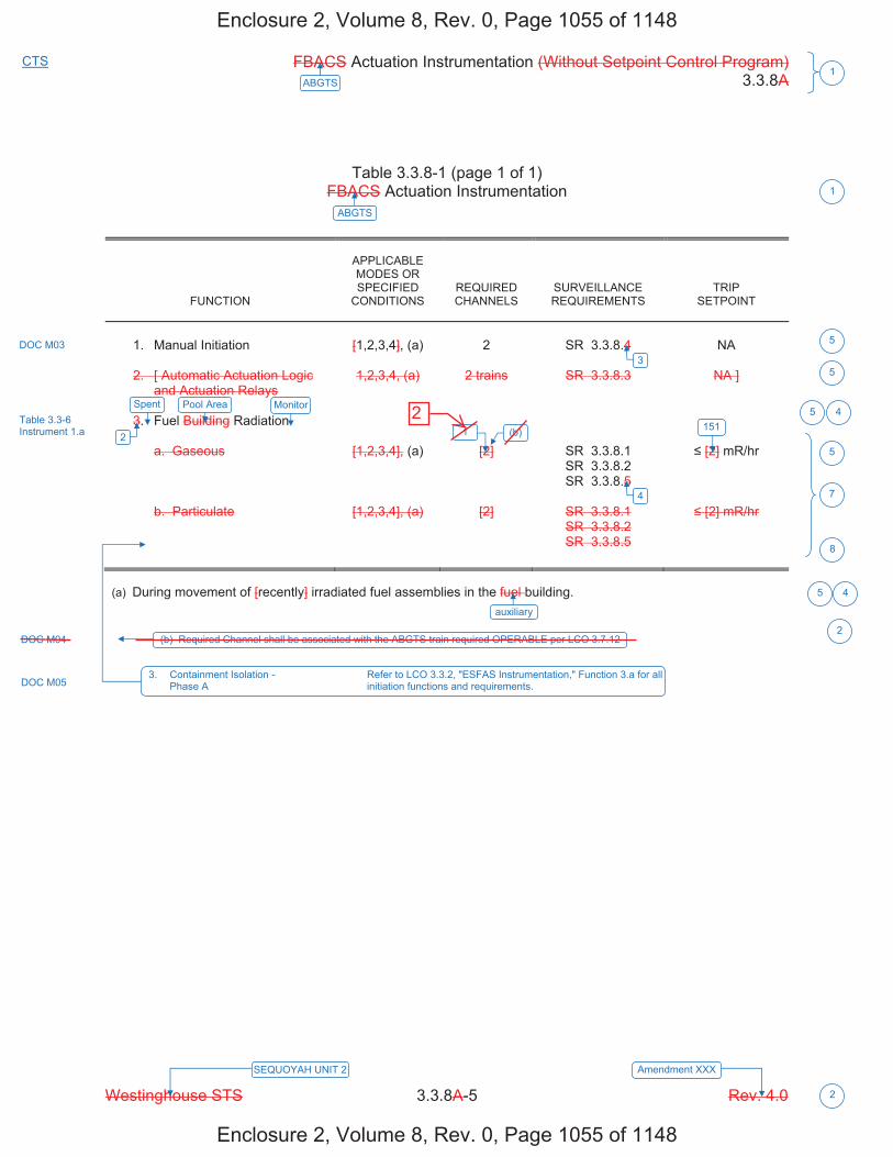
FBACS Actuation Instrumentation (Without Setpoint Control Program) 3.3.8A
Westinghouse STS 3.3.8A-5 Rev. 4.0
1ABGTS
SEQUOYAH UNIT 2 Amendment XXX
2
CTS
Table 3.3.8-1 (page 1 of 1) FBACS Actuation Instrumentation
FUNCTION
APPLICABLE MODES OR SPECIFIED
CONDITIONS
REQUIRED CHANNELS
SURVEILLANCE REQUIREMENTS
TRIP SETPOINT
1. Manual Initiation
[1,2,3,4], (a)
2
SR 3.3.8.4
NA
2. [ Automatic Actuation Logic
and Actuation Relays
1,2,3,4, (a)
2 trains
SR 3.3.8.3
NA ]
3. Fuel Building Radiation
a. Gaseous
[1,2,3,4], (a)
[2]
SR 3.3.8.1 SR 3.3.8.2 SR 3.3.8.5
[2] mR/hr
b. Particulate
[1,2,3,4], (a)
[2]
SR 3.3.8.1 SR 3.3.8.2 SR 3.3.8.5
[2] mR/hr
(a) During movement of [recently] irradiated fuel assemblies in the fuel building.
Pool Area Monitor
151
ABGTS
DOC M03
Table 3.3-6 Instrument 1.a
1
5
5
5
7
5
DOC M05 3. Containment Isolation - Refer to LCO 3.3.2, "ESFAS Instrumentation," Function 3.a for all Phase A initiation functions and requirements.
8
auxiliary
4
3
2
5 4
4
Spent
1 (b)
(b) Required Channel shall be associated with the ABGTS train required OPERABLE per LCO 3.7.12DOC M04 2
Enclosure 2, Volume 8, Rev. 0, Page 1055 of 1148
Enclosure 2, Volume 8, Rev. 0, Page 1055 of 1148
2
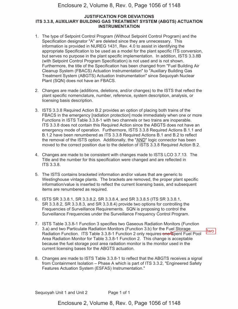
JUSTIFICATION FOR DEVIATIONS ITS 3.3.8, AUXILIARY BUILDING GAS TREATMENT SYSTEM (ABGTS) ACTUATION
INSTRUMENTATION
Sequoyah Unit 1 and Unit 2 Page 1 of 1
1. The type of Setpoint Control Program (Without Setpoint Control Program) and the Specification designator "A" are deleted since they are unnecessary. This information is provided in NUREG 1431, Rev. 4.0 to assist in identifying the appropriate Specification to be used as a model for the plant specific ITS conversion, but serves no purpose in the plant specific implementation. In addition, ISTS 3.3.8B (with Setpoint Control Program Specification) is not used and is not shown. Furthermore, the title of the Specification has been changed from "Fuel Building Air Cleanup System (FBACS) Actuation Instrumentation" to "Auxiliary Building Gas Treatment System (ABGTS) Actuation Instrumentation" since Sequoyah Nuclear Plant (SQN) does not have an FBACS.
2. Changes are made (additions, deletions, and/or changes) to the ISTS that reflect the
plant specific nomenclature, number, reference, system description, analysis, or licensing basis description.
3. ISTS 3.3.8 Required Action B.2 provides an option of placing both trains of the
FBACS in the emergency [radiation protection] mode immediately when one or more Functions in ISTS Table 3.3.8-1 with two channels or two trains are inoperable. ITS 3.3.8 does not contain this Required Action since the ABGTS does not have an emergency mode of operation. Furthermore, ISTS 3.3.8 Required Actions B.1.1 and B.1.2 have been renumbered as ITS 3.3.8 Required Actions B.1 and B.2 to reflect the removal of the ISTS option. Additionally, the "AND" logic connector has been moved to the correct position due to the deletion of ISTS 3.3.8 Required Action B.2.
4. Changes are made to be consistent with changes made to ISTS LCO 3.7.13. The
Title and the number for this specification were changed and are reflected in ITS 3.3.8.
5. The ISTS contains bracketed information and/or values that are generic to
Westinghouse vintage plants. The brackets are removed, the proper plant specific information/value is inserted to reflect the current licensing basis, and subsequent items are renumbered as required.
6. ISTS SR 3.3.8.1, SR 3.3.8.2, SR 3.3.8.4, and SR 3.3.8.5 (ITS SR 3.3.8.1,
SR 3.3.8.2, SR 3.3.8.3, and SR 3.3.8.4) provide two options for controlling the Frequencies of Surveillance Requirements. SQN is proposing to control the Surveillance Frequencies under the Surveillance Frequency Control Program.
7. ISTS Table 3.3.8-1 Function 3 specifies two Gaseous Radiation Monitors (Function
3.a) and two Particulate Radiation Monitors (Function 3.b) for the Fuel Storage Radiation Function. ITS Table 3.3.8-1 Function 2 only requires one Spent Fuel Pool Area Radiation Monitor for Table 3.3.8-1 Function 2. This change is acceptable because the fuel storage pool area radiation monitor is the monitor used in the current licensing bases for the ABGTS actuation.
8. Changes are made to ISTS Table 3.3.8-1 to reflect that the ABGTS receives a signal
from Containment Isolation – Phase A which is part of ITS 3.3.2, "Engineered Safety Features Actuation System (ESFAS) Instrumentation."
Enclosure 2, Volume 8, Rev. 0, Page 1056 of 1148
Enclosure 2, Volume 8, Rev. 0, Page 1056 of 1148
two

FBACS Actuation Instrumentation (Without Setpoint Control Program) B 3.3.8A
Westinghouse STS B 3.3.8A-1 Rev. 4.0
1ABGTS
Revision XXX SEQUOYAH UNIT 1 4 1
B 3.3 INSTRUMENTATION B 3.3.8A Fuel Building Air Cleanup System (FBACS) Actuation Instrumentation (Without
Setpoint Control Program) BASES BACKGROUND The FBACS ensures that radioactive materials in the fuel building
atmosphere following a fuel handling accident [involving handling recently irradiated fuel] or a loss of coolant accident (LOCA) are filtered and adsorbed prior to exhausting to the environment. The system is described in the Bases for LCO 3.7.13, "Fuel Building Air Cleanup System." The system initiates filtered ventilation of the fuel building automatically following receipt of a high radiation signal (gaseous or particulate) or a safety injection (SI) signal. Initiation may also be performed manually as needed from the main control room. High gaseous and particulate radiation, each monitored by either of two monitors, provides FBACS initiation. Each FBACS train is initiated by high radiation detected by a channel dedicated to that train. There are a total of two channels, one for each train. Each channel contains a gaseous and particulate monitor. High radiation detected by any monitor or an SI signal from the Engineered Safety Features Actuation System (ESFAS) initiates fuel building isolation and starts the FBACS. These actions function to prevent exfiltration of contaminated air by initiating filtered ventilation, which imposes a negative pressure on the fuel building. Since the radiation monitors include an air sampling system, various components such as sample line valves, sample line heaters, sample pumps, and filter motors are required to support monitor OPERABILITY.
APPLICABLE The FBACS ensures that radioactive materials in the fuel building SAFETY atmosphere following a fuel handling accident [involving handling ANALYSES recently irradiated fuel] or a LOCA are filtered and adsorbed prior to being
exhausted to the environment. This action reduces the radioactive content in the fuel building exhaust following a LOCA or fuel handling accident so that offsite doses remain within the limits specified in 10 CFR 100 (Ref. 1).
The FBACS actuation instrumentation satisfies Criterion 3 of 10 CFR 50.36(c)(2)(ii).
LCO The LCO requirements ensure that instrumentation necessary to initiate
the FBACS is OPERABLE.
1
ABGTSAuxiliary Building Gas Treatment
ABGTS
12
(ABGTS)
Auxiliary Building Gas Treatment
INSERT 1
spent fuel pool area
Containment Phase A Isolation
area
ABGTS
Auxiliary Building Secondary Containment Enclosure (ABSCE)
auxiliary
ABGTS
ABGTS
1
2
3
4
4
1
1
4
4
41
2
4
1
1
Containment Phase A Isolation
ABGTS
ABGTS
ABGTS ABSCE
for LOCA or 10 CFR 50.67 (Ref. 2) for fuel handling accident 4
auxiliary
auxiliary
the required
Enclosure 2, Volume 8, Rev. 0, Page 1058 of 1148
Enclosure 2, Volume 8, Rev. 0, Page 1058 of 1148
a
Keep
Keep
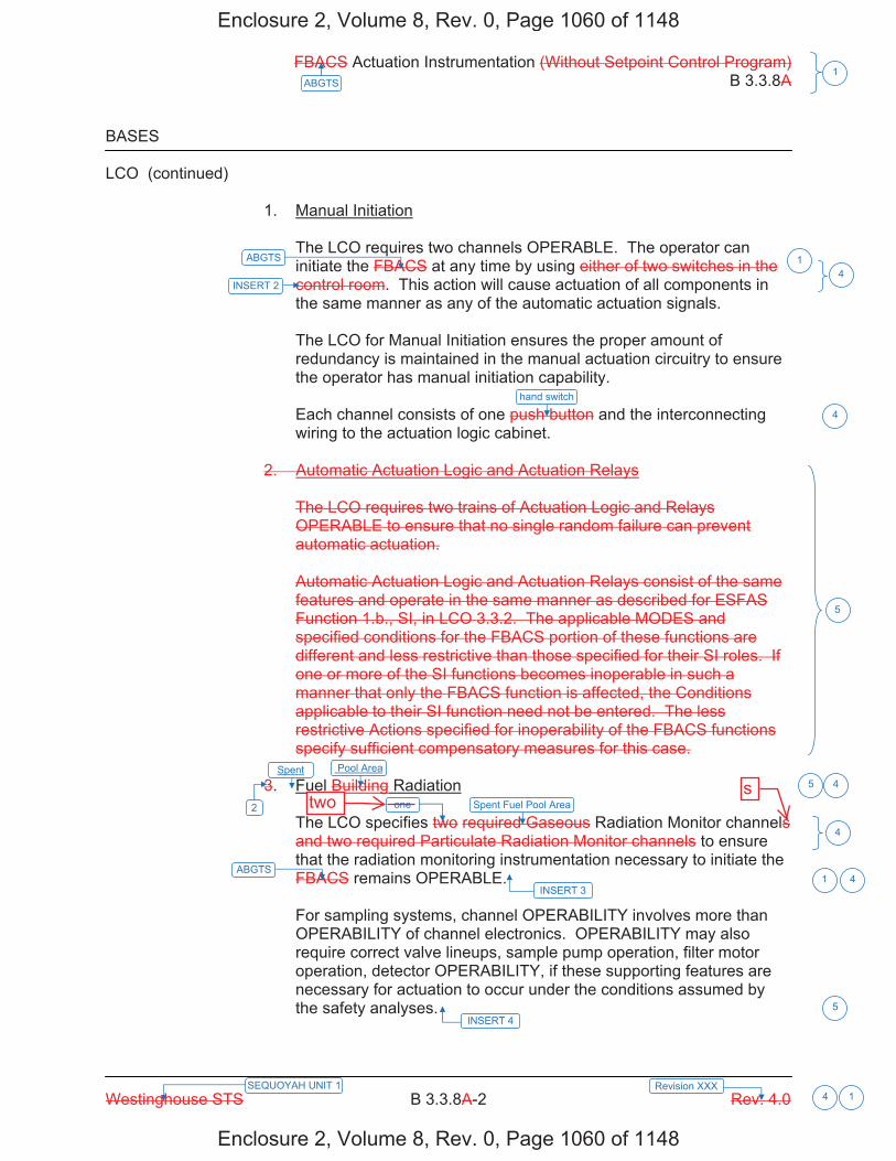
FBACS Actuation Instrumentation (Without Setpoint Control Program) B 3.3.8A
Westinghouse STS B 3.3.8A-2 Rev. 4.0
1ABGTS
Revision XXX SEQUOYAH UNIT 1 4 1
BASES LCO (continued) 1. Manual Initiation
The LCO requires two channels OPERABLE. The operator can initiate the FBACS at any time by using either of two switches in the control room. This action will cause actuation of all components in the same manner as any of the automatic actuation signals. The LCO for Manual Initiation ensures the proper amount of redundancy is maintained in the manual actuation circuitry to ensure the operator has manual initiation capability. Each channel consists of one push button and the interconnecting wiring to the actuation logic cabinet.
2. Automatic Actuation Logic and Actuation Relays
The LCO requires two trains of Actuation Logic and Relays OPERABLE to ensure that no single random failure can prevent automatic actuation. Automatic Actuation Logic and Actuation Relays consist of the same features and operate in the same manner as described for ESFAS Function 1.b., SI, in LCO 3.3.2. The applicable MODES and specified conditions for the FBACS portion of these functions are different and less restrictive than those specified for their SI roles. If one or more of the SI functions becomes inoperable in such a manner that only the FBACS function is affected, the Conditions applicable to their SI function need not be entered. The less restrictive Actions specified for inoperability of the FBACS functions specify sufficient compensatory measures for this case.
3. Fuel Building Radiation
The LCO specifies two required Gaseous Radiation Monitor channels and two required Particulate Radiation Monitor channels to ensure that the radiation monitoring instrumentation necessary to initiate the FBACS remains OPERABLE. For sampling systems, channel OPERABILITY involves more than OPERABILITY of channel electronics. OPERABILITY may also require correct valve lineups, sample pump operation, filter motor operation, detector OPERABILITY, if these supporting features are necessary for actuation to occur under the conditions assumed by the safety analyses.
INSERT 4
ABGTS
hand switch
Spent Fuel Pool Area
ABGTS
INSERT 3
1
4
5
4
1 4
Pool Area4
5
INSERT 2 4
2
5Spent
one
Enclosure 2, Volume 8, Rev. 0, Page 1060 of 1148
Enclosure 2, Volume 8, Rev. 0, Page 1060 of 1148
twos
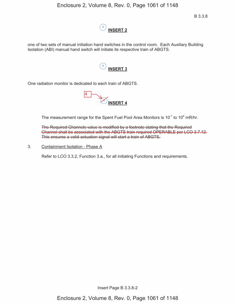
B 3.3.8
Insert Page B 3.3.8-2
INSERT 2 one of two sets of manual initiation hand switches in the control room. Each Auxiliary Building Isolation (ABI) manual hand switch will initiate its respective train of ABGTS.
INSERT 3 One radiation monitor is dedicated to each train of ABGTS.
INSERT 4
The measurement range for the Spent Fuel Pool Area Monitors is 10-1 to 104 mR/hr. The Required Channels value is modified by a footnote stating that the Required Channel shall be associated with the ABGTS train required OPERABLE per LCO 3.7.12. This ensures a valid actuation signal will start a train of ABGTS.
3. Containment Isolation - Phase A
Refer to LCO 3.3.2, Function 3.a., for all initiating Functions and requirements.
4
5
4
Enclosure 2, Volume 8, Rev. 0, Page 1061 of 1148
Enclosure 2, Volume 8, Rev. 0, Page 1061 of 1148
4
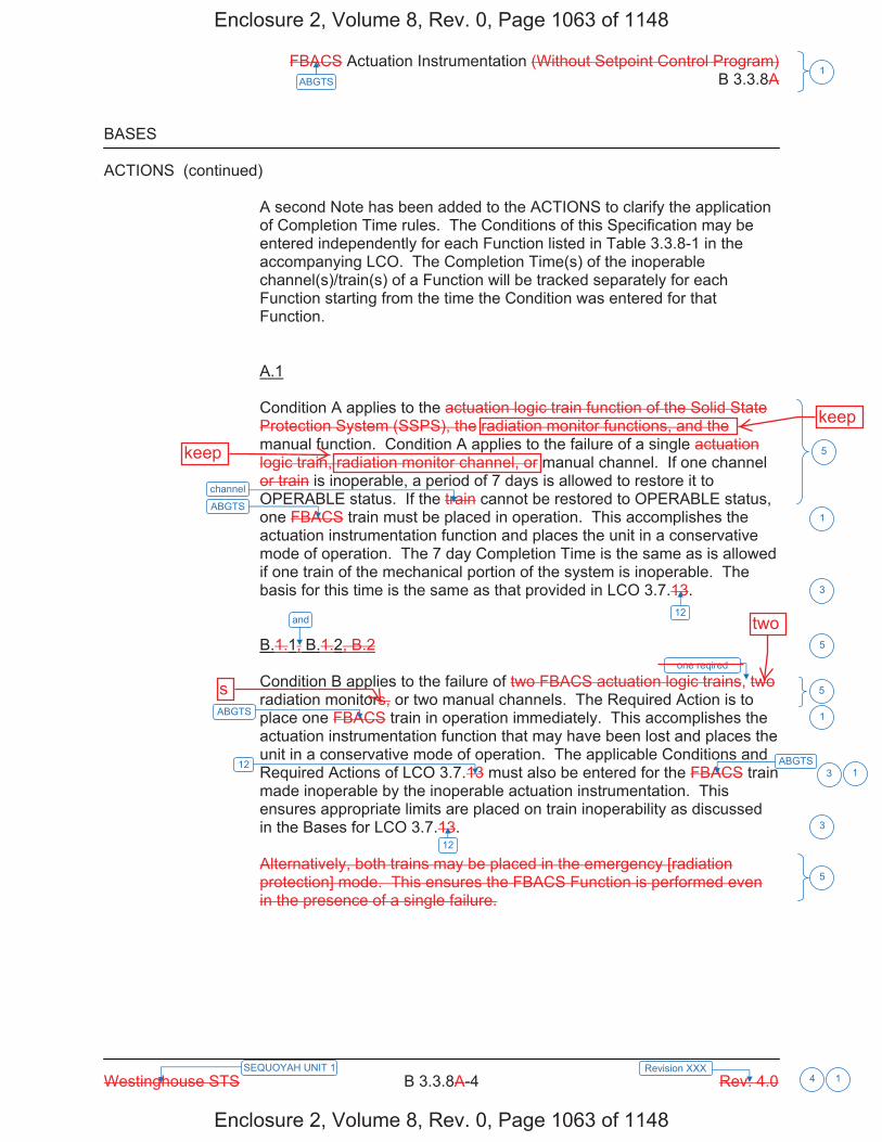
FBACS Actuation Instrumentation (Without Setpoint Control Program) B 3.3.8A
Westinghouse STS B 3.3.8A-4 Rev. 4.0
1ABGTS
Revision XXX SEQUOYAH UNIT 1 4 1
BASES ACTIONS (continued)
A second Note has been added to the ACTIONS to clarify the application of Completion Time rules. The Conditions of this Specification may be entered independently for each Function listed in Table 3.3.8-1 in the accompanying LCO. The Completion Time(s) of the inoperable channel(s)/train(s) of a Function will be tracked separately for each Function starting from the time the Condition was entered for that Function. A.1 Condition A applies to the actuation logic train function of the Solid State Protection System (SSPS), the radiation monitor functions, and the manual function. Condition A applies to the failure of a single actuation logic train, radiation monitor channel, or manual channel. If one channel or train is inoperable, a period of 7 days is allowed to restore it to OPERABLE status. If the train cannot be restored to OPERABLE status, one FBACS train must be placed in operation. This accomplishes the actuation instrumentation function and places the unit in a conservative mode of operation. The 7 day Completion Time is the same as is allowed if one train of the mechanical portion of the system is inoperable. The basis for this time is the same as that provided in LCO 3.7.13. B.1.1, B.1.2, B.2 Condition B applies to the failure of two FBACS actuation logic trains, two radiation monitors, or two manual channels. The Required Action is to place one FBACS train in operation immediately. This accomplishes the actuation instrumentation function that may have been lost and places the unit in a conservative mode of operation. The applicable Conditions and Required Actions of LCO 3.7.13 must also be entered for the FBACS train made inoperable by the inoperable actuation instrumentation. This ensures appropriate limits are placed on train inoperability as discussed in the Bases for LCO 3.7.13. Alternatively, both trains may be placed in the emergency [radiation protection] mode. This ensures the FBACS Function is performed even in the presence of a single failure.
ABGTS
12
ABGTS
ABGTS
12
12
1
3
5
1
13
3
5
and
5
5
channel
one reqired
Enclosure 2, Volume 8, Rev. 0, Page 1063 of 1148
Enclosure 2, Volume 8, Rev. 0, Page 1063 of 1148
keep
keep
two
s
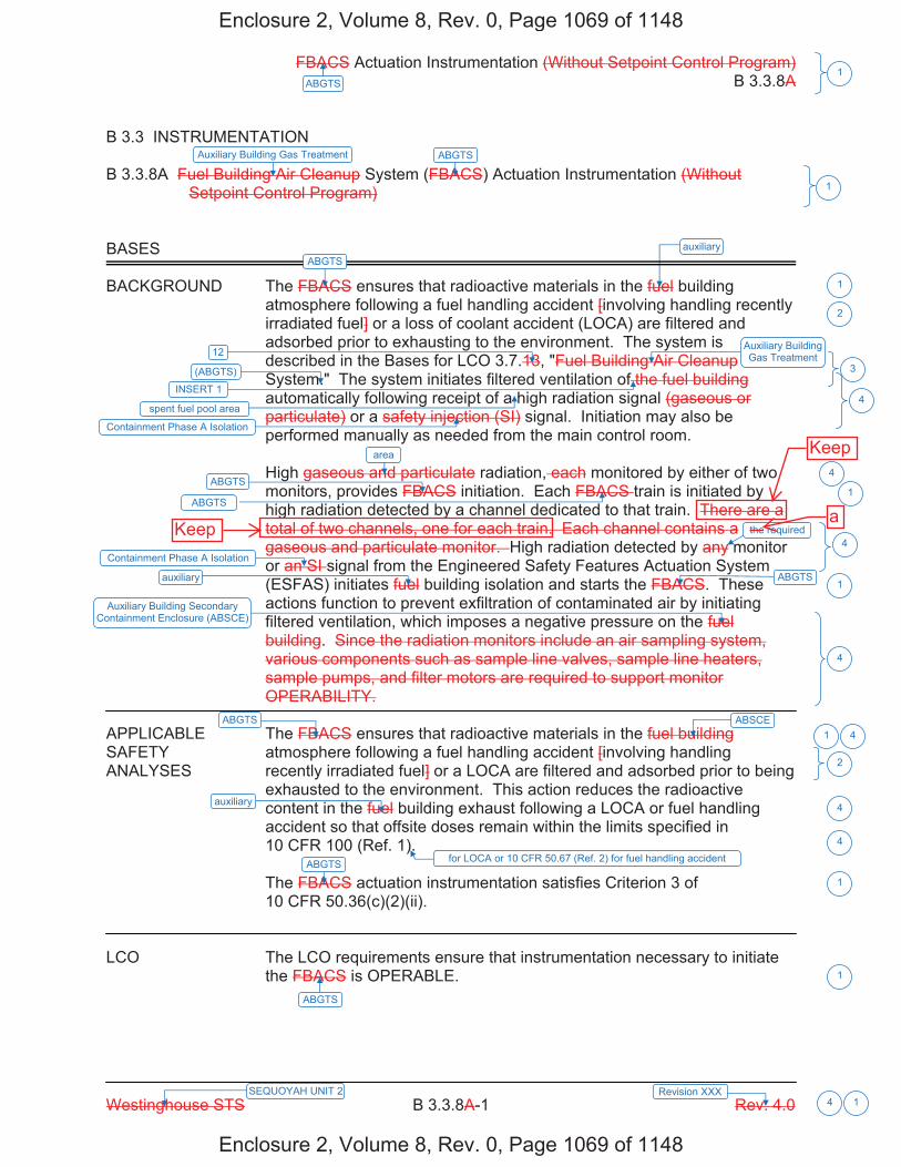
FBACS Actuation Instrumentation (Without Setpoint Control Program) B 3.3.8A
Westinghouse STS B 3.3.8A-1 Rev. 4.0
1ABGTS
Revision XXX SEQUOYAH UNIT 2 4 1
B 3.3 INSTRUMENTATION B 3.3.8A Fuel Building Air Cleanup System (FBACS) Actuation Instrumentation (Without
Setpoint Control Program) BASES BACKGROUND The FBACS ensures that radioactive materials in the fuel building
atmosphere following a fuel handling accident [involving handling recently irradiated fuel] or a loss of coolant accident (LOCA) are filtered and adsorbed prior to exhausting to the environment. The system is described in the Bases for LCO 3.7.13, "Fuel Building Air Cleanup System." The system initiates filtered ventilation of the fuel building automatically following receipt of a high radiation signal (gaseous or particulate) or a safety injection (SI) signal. Initiation may also be performed manually as needed from the main control room. High gaseous and particulate radiation, each monitored by either of two monitors, provides FBACS initiation. Each FBACS train is initiated by high radiation detected by a channel dedicated to that train. There are a total of two channels, one for each train. Each channel contains a gaseous and particulate monitor. High radiation detected by any monitor or an SI signal from the Engineered Safety Features Actuation System (ESFAS) initiates fuel building isolation and starts the FBACS. These actions function to prevent exfiltration of contaminated air by initiating filtered ventilation, which imposes a negative pressure on the fuel building. Since the radiation monitors include an air sampling system, various components such as sample line valves, sample line heaters, sample pumps, and filter motors are required to support monitor OPERABILITY.
APPLICABLE The FBACS ensures that radioactive materials in the fuel building SAFETY atmosphere following a fuel handling accident [involving handling ANALYSES recently irradiated fuel] or a LOCA are filtered and adsorbed prior to being
exhausted to the environment. This action reduces the radioactive content in the fuel building exhaust following a LOCA or fuel handling accident so that offsite doses remain within the limits specified in 10 CFR 100 (Ref. 1).
The FBACS actuation instrumentation satisfies Criterion 3 of 10 CFR 50.36(c)(2)(ii).
LCO The LCO requirements ensure that instrumentation necessary to initiate
the FBACS is OPERABLE.
1
ABGTSAuxiliary Building Gas Treatment
ABGTS
12
(ABGTS)
Auxiliary Building Gas Treatment
INSERT 1
spent fuel pool area
Containment Phase A Isolation
area
ABGTS
Auxiliary Building Secondary Containment Enclosure (ABSCE)
auxiliary
ABGTS
ABGTS
1
2
3
4
4
1
1
4
4
41
2
4
1
1
Containment Phase A Isolation
ABGTS
ABGTS
ABGTS ABSCE
for LOCA or 10 CFR 50.67 (Ref. 2) for fuel handling accident 4
auxiliary
auxiliary
the required
Enclosure 2, Volume 8, Rev. 0, Page 1069 of 1148
Enclosure 2, Volume 8, Rev. 0, Page 1069 of 1148
aKeep
Keep
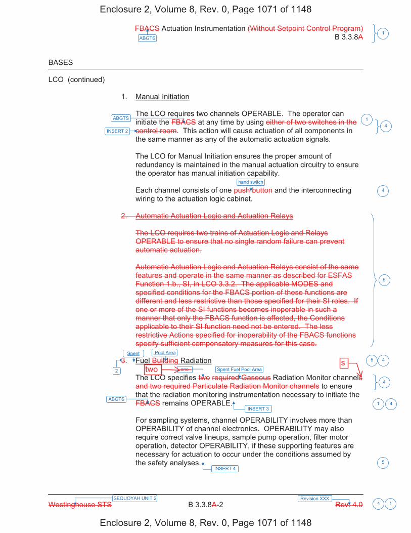
FBACS Actuation Instrumentation (Without Setpoint Control Program) B 3.3.8A
Westinghouse STS B 3.3.8A-2 Rev. 4.0
1ABGTS
Revision XXX SEQUOYAH UNIT 2 4 1
BASES LCO (continued) 1. Manual Initiation
The LCO requires two channels OPERABLE. The operator can initiate the FBACS at any time by using either of two switches in the control room. This action will cause actuation of all components in the same manner as any of the automatic actuation signals. The LCO for Manual Initiation ensures the proper amount of redundancy is maintained in the manual actuation circuitry to ensure the operator has manual initiation capability. Each channel consists of one push button and the interconnecting wiring to the actuation logic cabinet.
2. Automatic Actuation Logic and Actuation Relays
The LCO requires two trains of Actuation Logic and Relays OPERABLE to ensure that no single random failure can prevent automatic actuation. Automatic Actuation Logic and Actuation Relays consist of the same features and operate in the same manner as described for ESFAS Function 1.b., SI, in LCO 3.3.2. The applicable MODES and specified conditions for the FBACS portion of these functions are different and less restrictive than those specified for their SI roles. If one or more of the SI functions becomes inoperable in such a manner that only the FBACS function is affected, the Conditions applicable to their SI function need not be entered. The less restrictive Actions specified for inoperability of the FBACS functions specify sufficient compensatory measures for this case.
3. Fuel Building Radiation
The LCO specifies two required Gaseous Radiation Monitor channels and two required Particulate Radiation Monitor channels to ensure that the radiation monitoring instrumentation necessary to initiate the FBACS remains OPERABLE. For sampling systems, channel OPERABILITY involves more than OPERABILITY of channel electronics. OPERABILITY may also require correct valve lineups, sample pump operation, filter motor operation, detector OPERABILITY, if these supporting features are necessary for actuation to occur under the conditions assumed by the safety analyses.
INSERT 4
ABGTS
hand switch
Spent Fuel Pool Area
ABGTS
INSERT 3
1
4
5
4
1 4
Pool Area4
5
INSERT 2 4
2
5Spent
one
Enclosure 2, Volume 8, Rev. 0, Page 1071 of 1148
Enclosure 2, Volume 8, Rev. 0, Page 1071 of 1148
twos

B 3.3.8
Insert Page B 3.3.8-2
INSERT 2 one of two sets of manual initiation hand switches in the control room. Each Auxiliary Building Isolation (ABI) manual hand switch will initiate its respective train of ABGTS.
INSERT 3 One radiation monitor is dedicated to each train of ABGTS.
INSERT 4
The measurement range for the Spent Fuel Pool Area Monitors is 10-1 to 104 mR/hr. The Required Channels value is modified by a footnote stating that the Required Channel shall be associated with the ABGTS train required OPERABLE per LCO 3.7.12. This ensures a valid actuation signal will start a train of ABGTS.
3. Containment Isolation - Phase A
Refer to LCO 3.3.2, Function 3.a., for all initiating Functions and requirements.
4
5
4
Enclosure 2, Volume 8, Rev. 0, Page 1072 of 1148
Enclosure 2, Volume 8, Rev. 0, Page 1072 of 1148
4

FBACS Actuation Instrumentation (Without Setpoint Control Program) B 3.3.8A
Westinghouse STS B 3.3.8A-4 Rev. 4.0
1ABGTS
Revision XXX SEQUOYAH UNIT 2 4 1
BASES ACTIONS (continued)
A second Note has been added to the ACTIONS to clarify the application of Completion Time rules. The Conditions of this Specification may be entered independently for each Function listed in Table 3.3.8-1 in the accompanying LCO. The Completion Time(s) of the inoperable channel(s)/train(s) of a Function will be tracked separately for each Function starting from the time the Condition was entered for that Function. A.1 Condition A applies to the actuation logic train function of the Solid State Protection System (SSPS), the radiation monitor functions, and the manual function. Condition A applies to the failure of a single actuation logic train, radiation monitor channel, or manual channel. If one channel or train is inoperable, a period of 7 days is allowed to restore it to OPERABLE status. If the train cannot be restored to OPERABLE status, one FBACS train must be placed in operation. This accomplishes the actuation instrumentation function and places the unit in a conservative mode of operation. The 7 day Completion Time is the same as is allowed if one train of the mechanical portion of the system is inoperable. The basis for this time is the same as that provided in LCO 3.7.13. B.1.1, B.1.2, B.2 Condition B applies to the failure of two FBACS actuation logic trains, two radiation monitors, or two manual channels. The Required Action is to place one FBACS train in operation immediately. This accomplishes the actuation instrumentation function that may have been lost and places the unit in a conservative mode of operation. The applicable Conditions and Required Actions of LCO 3.7.13 must also be entered for the FBACS train made inoperable by the inoperable actuation instrumentation. This ensures appropriate limits are placed on train inoperability as discussed in the Bases for LCO 3.7.13. Alternatively, both trains may be placed in the emergency [radiation protection] mode. This ensures the FBACS Function is performed even in the presence of a single failure.
ABGTS
12
ABGTS
ABGTS
12
12
1
3
5
1
13
3
5
and
5
5
channel
one reqired
Enclosure 2, Volume 8, Rev. 0, Page 1074 of 1148
Enclosure 2, Volume 8, Rev. 0, Page 1074 of 1148
keep
keep
two
s

A01ITS ITS 3.7.12
REFUELING OPERATIONS 3/4.9.12 AUXILIARY BUILDING GAS TREATMENT SYSTEM LIMITING CONDITION FOR OPERATION 3.9.12 One auxiliary building gas treatment filter train shall be OPERABLE. APPLICABILITY: Whenever irradiated fuel is in the storage pool. ACTION: a. With no auxiliary building gas treatment filter train OPERABLE, suspend all operations involving
movement of fuel within the spent fuel pit or crane operation with loads over the spent fuel pit until at least one auxiliary building gas treatment filter train is restored to OPERABLE status.
b. The provisions of Specification 3.0.3 are not applicable. SURVEILLANCE REQUIREMENTS 4.9.12 The above required auxiliary buildings gas treatment filter train shall be demonstrated OPERABLE: a. At least once per 31 days on a STAGGERED TEST BASIS by initiating, from the control room,
flow through the HEPA filters and charcoal adsorbers and verifying that the system operates for at least 10 hours with the heaters on.
b. At least once per 18 months or (1) after any structural maintenance on the HEPA filter or
charcoal adsorber housings, or (2) following painting, fire or chemical release in any ventilation zone communicating with the system by:
1. Verifying that the cleanup system satisfies the in-place testing acceptance criteria and
uses the test procedures of Regulatory Positions C.5.a, C.5.c and C.5.d of Regulatory Guide 1.52, Revision 2, March 1978 (except for the provisions of ANSI N510 Sections 8 and 9), and the system flow rate is 9000 cfm ± 10%.
2. Verifying within 31 days after removal that a laboratory analysis of a representative
carbon sample obtained in accordance with Regulatory Position C.6.b of Regulatory Guide 1.52, Revision 2, March 1978, shows the methyl iodide penetration less than 2.5%
when tested in accordance with ASTM D3803-1989 at a temperature of 30°C (86°F) and a relative humidity of 70%.
3. Verifying a system flow rate of 9000 cfm ± 10% during system operations when tested in
accordance with ANSI N510-1975.
April 11, 2005 SEQUOYAH - UNIT 1 3/4 9-12 Amendment No. 263, 301
Page 3 of 8
LCO 3.7.12 Note 2
Applicability
During movement of recently irradiated fuel assemblies in the auxiliary building. L06
ACTION D
ACTIONS Note
L06
SR 3.7.12.1
SR 3.7.12.1, SR 3.7.12.3
Add proposed SR 3.7.12.2 A02
LA03
See ITS 5.5.9
In accordance with the Surveillance Frequency Control Program LA02
L03
Add proposed Required Action D.1 L06
Enclosure 2, Volume 12, Rev. 0, Page 429 of 704
Enclosure 2, Volume 12, Rev. 0, Page 429 of 704
Two L06
EE
Add proposed ACTION A L06
Add proposed ACTION D L06
15 continuous minutesL04
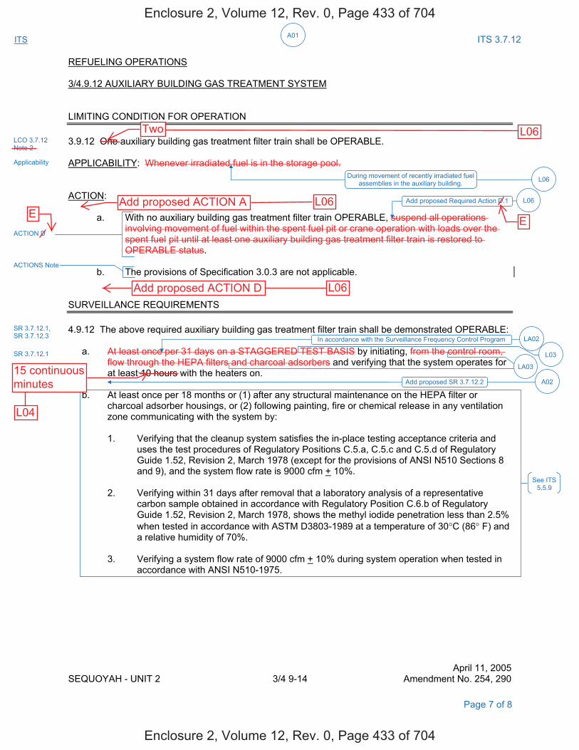
A01ITS ITS 3.7.12
REFUELING OPERATIONS 3/4.9.12 AUXILIARY BUILDING GAS TREATMENT SYSTEM LIMITING CONDITION FOR OPERATION 3.9.12 One auxiliary building gas treatment filter train shall be OPERABLE. APPLICABILITY: Whenever irradiated fuel is in the storage pool. ACTION: a. With no auxiliary building gas treatment filter train OPERABLE, suspend all operations
involving movement of fuel within the spent fuel pit or crane operation with loads over the spent fuel pit until at least one auxiliary building gas treatment filter train is restored to OPERABLE status.
b. The provisions of Specification 3.0.3 are not applicable. SURVEILLANCE REQUIREMENTS 4.9.12 The above required auxiliary building gas treatment filter train shall be demonstrated OPERABLE: a. At least once per 31 days on a STAGGERED TEST BASIS by initiating, from the control room,
flow through the HEPA filters and charcoal adsorbers and verifying that the system operates for at least 10 hours with the heaters on.
b. At least once per 18 months or (1) after any structural maintenance on the HEPA filter or
charcoal adsorber housings, or (2) following painting, fire or chemical release in any ventilation zone communicating with the system by:
1. Verifying that the cleanup system satisfies the in-place testing acceptance criteria and
uses the test procedures of Regulatory Positions C.5.a, C.5.c and C.5.d of Regulatory Guide 1.52, Revision 2, March 1978 (except for the provisions of ANSI N510 Sections 8 and 9), and the system flow rate is 9000 cfm + 10%.
2. Verifying within 31 days after removal that a laboratory analysis of a representative
carbon sample obtained in accordance with Regulatory Position C.6.b of Regulatory Guide 1.52, Revision 2, March 1978, shows the methyl iodide penetration less than 2.5%
when tested in accordance with ASTM D3803-1989 at a temperature of 30°C (86° F) and a relative humidity of 70%.
3. Verifying a system flow rate of 9000 cfm + 10% during system operation when tested in
accordance with ANSI N510-1975.
April 11, 2005 SEQUOYAH - UNIT 2 3/4 9-14 Amendment No. 254, 290
Page 7 of 8
LCO 3.7.12 Note 2
Applicability
During movement of recently irradiated fuel assemblies in the auxiliary building. L06
ACTION D
ACTIONS Note
SR 3.7.12.1
SR 3.7.12.1, SR 3.7.12.3
Add proposed SR 3.7.12.2 A02
LA03
See ITS 5.5.9
LA02In accordance with the Surveillance Frequency Control Program
L03
Add proposed Required Action D.1 L06
Enclosure 2, Volume 12, Rev. 0, Page 433 of 704
Enclosure 2, Volume 12, Rev. 0, Page 433 of 704
Two L06
E
L06Add proposed ACTION AE
Add proposed ACTION D L06
L04
15 continuousminutes

REFUELING OPERATIONS 3/4.9.4 CONTAINMENT BUILDING PENETRATIONS LIMITING CONDITION FOR OPERATION 3.9.4 The containment building penetrations shall be in the following status: a. The equipment door closed and held in place by a minimum of four bolts,
b. A minimum of one door in each airlock is closed, and both doors of both containment personnel
airlocks may be open if: 1. One personnel airlock door in each airlock is capable of closure, and 2. One train of the Auxiliary Building Gas Treatment System is OPERABLE in accordance
with Technical Specification 3.9.12, and c. Each penetration* providing direct access from the containment atmosphere to the outside
atmosphere shall be either: 1. Closed by an isolation valve, blind flange, manual valve, or equivalent, or 2. Be capable of being closed by an OPERABLE automatic Containment Ventilation isolation
valve. APPLICABILTY: 3.9.4.a. Containment Building Equipment Door - During movement of recently irradiated fuel within the containment. 3.9.4.b. and c. Containment Building Airlock Doors and Penetrations - During movement of irradiated fuel within the containment. ACTION: 1. With the requirements of the above specification not satisfied for the containment building
equipment door, immediately suspend all operations involving movement of recently irradiated fuel in the containment building. The provisions of Specification 3.0.3 are not applicable.
2. With the requirements of the above specification not satisfied for containment airlock doors or
penetrations, immediately suspend all operations involving movement of irradiated fuel in the containment building. The provisions of Specification 3.0.3 are not applicable.
SURVEILLANCE REQUIREMENTS 4.9.4 Each of the above required containment building penetrations shall be determined to be either in its required condition or capable of being closed by an OPERABLE automatic Containment Ventilation isolation valve once per 7 days during movement of irradiated fuel in the containment building by: a. Verifying the penetrations are in their required condition, or b. Verifying the Containment Ventilation isolation valves not locked, sealed, or otherwise secured
in position, actuate to the isolation position on an actual or simulated actuation signal. * Penetration flow path(s) providing direct access from the containment atmosphere that transverse
and terminate in the Auxiliary Building Secondary Containment Enclosure may be unisolated under administrative controls.
April 13, 2009 SEQUOYAH - UNIT 1 3/4 9-4 Amendment No. 12, 209, 249, 260, 288, 323
ITS 3.7.12ITS
(See ITS3.9.4)
(See ITS3.9.4)
A01
L08
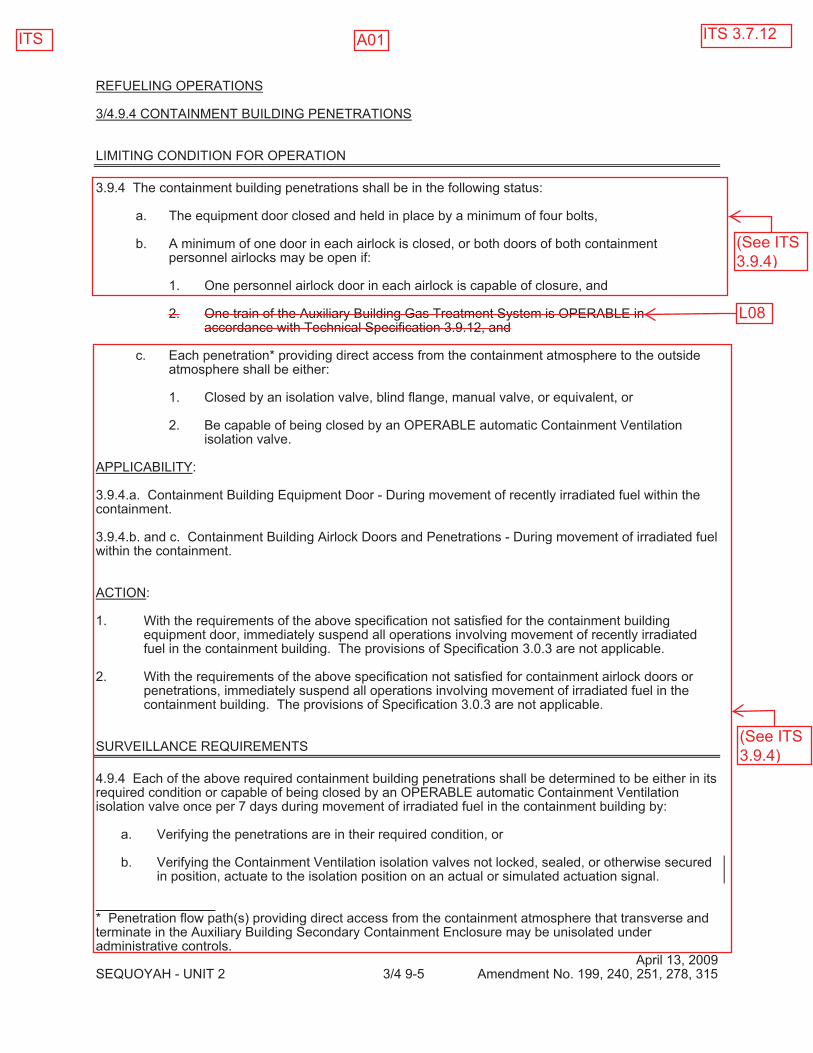
REFUELING OPERATIONS 3/4.9.4 CONTAINMENT BUILDING PENETRATIONS LIMITING CONDITION FOR OPERATION 3.9.4 The containment building penetrations shall be in the following status: a. The equipment door closed and held in place by a minimum of four bolts, b. A minimum of one door in each airlock is closed, or both doors of both containment
personnel airlocks may be open if: 1. One personnel airlock door in each airlock is capable of closure, and 2. One train of the Auxiliary Building Gas Treatment System is OPERABLE in
accordance with Technical Specification 3.9.12, and c. Each penetration* providing direct access from the containment atmosphere to the outside
atmosphere shall be either: 1. Closed by an isolation valve, blind flange, manual valve, or equivalent, or 2. Be capable of being closed by an OPERABLE automatic Containment Ventilation
isolation valve. APPLICABILITY: 3.9.4.a. Containment Building Equipment Door - During movement of recently irradiated fuel within the containment. 3.9.4.b. and c. Containment Building Airlock Doors and Penetrations - During movement of irradiated fuel within the containment. ACTION: 1. With the requirements of the above specification not satisfied for the containment building
equipment door, immediately suspend all operations involving movement of recently irradiated fuel in the containment building. The provisions of Specification 3.0.3 are not applicable.
2. With the requirements of the above specification not satisfied for containment airlock doors or
penetrations, immediately suspend all operations involving movement of irradiated fuel in the containment building. The provisions of Specification 3.0.3 are not applicable.
SURVEILLANCE REQUIREMENTS 4.9.4 Each of the above required containment building penetrations shall be determined to be either in its required condition or capable of being closed by an OPERABLE automatic Containment Ventilation isolation valve once per 7 days during movement of irradiated fuel in the containment building by: a. Verifying the penetrations are in their required condition, or b. Verifying the Containment Ventilation isolation valves not locked, sealed, or otherwise secured
in position, actuate to the isolation position on an actual or simulated actuation signal. * Penetration flow path(s) providing direct access from the containment atmosphere that transverse and terminate in the Auxiliary Building Secondary Containment Enclosure may be unisolated under administrative controls.
April 13, 2009 SEQUOYAH - UNIT 2 3/4 9-5 Amendment No. 199, 240, 251, 278, 315
ITS ITS 3.7.12
(See ITS3.9.4)
L08
(See ITS3.9.4)
A01

DISCUSSION OF CHANGES ITS 3.7.12, AUXILIARY BUILDING GAS TREATMENT SYSTEM (ABGTS)
Sequoyah Unit 1 and Unit 2 Page 2 of 10
DOC L07 for a discussion of specifying that the actuation signal may be either actual or simulated. See DOC L06 for a discussion on limiting the Applicability to the conditions during which a fuel handling accident is postulated to occur.)
The purpose of CTS 3.7.8 is to ensure the ABGTS trains are OPERABLE during
the plant conditions that a loss of coolant accident is postulated to occur (MODES 1, 2, 3 and 4). The purpose of CTS 3.9.12 is to ensure that radioactive material that is released from an irradiated fuel assembly during a fuel handling accident is processed through filtration prior to release to the atmosphere (during the movement of recently irradiated fuel assemblies in the auxiliary building). ITS 3.7.12 combines CTS 3.7.8 and 3.9.12 into one Specification with an Applicability of MODES 1, 2, 3 and 4 and during the movement of recently irradiated fuel assemblies in the auxiliary building. This results in the need to specify the plant conditions in which each actuation signal is required to actuate ABGTS to mitigate the associated accident. The plant conditions under which each ABGTS actuation signal is required to be OPERABLE remains unchanged between CTS and ITS. This change is designated as administrative because it does not result in a technical change to the CTS.
MORE RESTRICTIVE CHANGES M01 CTS 4.7.8.d.3 requires verification that each ABGTS system can maintain the
spent fuel storage area and the ESF pump rooms at a pressure equal to or less than - 0.25 inches water gauge relative to the outside atmosphere while maintaining a total system flow of 9,000 cfm plus or minus 10% every 18 months in MODES 1, 2, 3 and 4. ITS SR 3.7.12.4 requires the same verification every 18 months on a STAGGERED TEST BASIS in MODES 1, 2, 3 and 4 and during movement of recently irradiated fuel assemblies in the auxiliary building. This changes the CTS by adding a Surveillance Requirement to verify the ABGTS can maintain a negative pressure at the required flow rate during movement of recently irradiated fuel assemblies in the auxiliary building. (See DOC L05 for the discussion regarding the change of the testing Frequency to "on a STAGGERED TEST BASIS." See DOC LA02 for the discussion regarding movement of the Surveillance Frequency to the Surveillance Frequency Control Program.)
This change is acceptable because the ABGTS is required to be OPERABLE
during movement of recently irradiated fuel assemblies in the auxiliary building. The Surveillance Requirement is required to verify that the ABGTS can perform its required safety function during this Applicability. This change is designated as more restrictive because an additional Surveillance Requirement is being required that was not in the CTS.
RELOCATED SPECIFICATIONS None
Enclosure 2, Volume 12, Rev. 0, Page 436 of 704
Enclosure 2, Volume 12, Rev. 0, Page 436 of 704
of the ABGTSit is required to mitigate
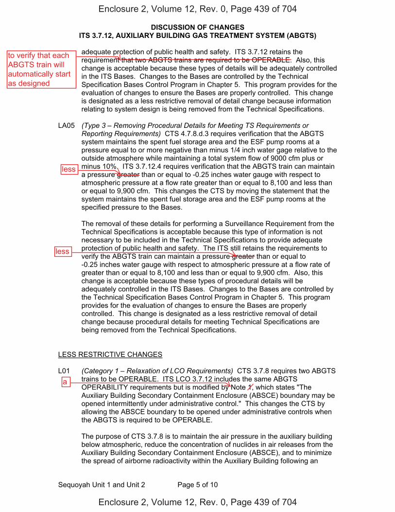
DISCUSSION OF CHANGES ITS 3.7.12, AUXILIARY BUILDING GAS TREATMENT SYSTEM (ABGTS)
Sequoyah Unit 1 and Unit 2 Page 5 of 10
adequate protection of public health and safety. ITS 3.7.12 retains the requirement that two ABGTS trains are required to be OPERABLE. Also, this change is acceptable because these types of details will be adequately controlled in the ITS Bases. Changes to the Bases are controlled by the Technical Specification Bases Control Program in Chapter 5. This program provides for the evaluation of changes to ensure the Bases are properly controlled. This change is designated as a less restrictive removal of detail change because information relating to system design is being removed from the Technical Specifications.
LA05 (Type 3 – Removing Procedural Details for Meeting TS Requirements or
Reporting Requirements) CTS 4.7.8.d.3 requires verification that the ABGTS system maintains the spent fuel storage area and the ESF pump rooms at a pressure equal to or more negative than minus 1/4 inch water gage relative to the outside atmosphere while maintaining a total system flow of 9000 cfm plus or minus 10%. ITS 3.7.12.4 requires verification that the ABGTS train can maintain a pressure greater than or equal to -0.25 inches water gauge with respect to atmospheric pressure at a flow rate greater than or equal to 8,100 and less than or equal to 9,900 cfm. This changes the CTS by moving the statement that the system maintains the spent fuel storage area and the ESF pump rooms at the specified pressure to the Bases.
The removal of these details for performing a Surveillance Requirement from the
Technical Specifications is acceptable because this type of information is not necessary to be included in the Technical Specifications to provide adequate protection of public health and safety. The ITS still retains the requirements to verify the ABGTS train can maintain a pressure greater than or equal to -0.25 inches water gauge with respect to atmospheric pressure at a flow rate of greater than or equal to 8,100 and less than or equal to 9,900 cfm. Also, this change is acceptable because these types of procedural details will be adequately controlled in the ITS Bases. Changes to the Bases are controlled by the Technical Specification Bases Control Program in Chapter 5. This program provides for the evaluation of changes to ensure the Bases are properly controlled. This change is designated as a less restrictive removal of detail change because procedural details for meeting Technical Specifications are being removed from the Technical Specifications.
LESS RESTRICTIVE CHANGES L01 (Category 1 – Relaxation of LCO Requirements) CTS 3.7.8 requires two ABGTS
trains to be OPERABLE. ITS LCO 3.7.12 includes the same ABGTS OPERABILITY requirements but is modified by Note 1, which states "The Auxiliary Building Secondary Containment Enclosure (ABSCE) boundary may be opened intermittently under administrative control." This changes the CTS by allowing the ABSCE boundary to be opened under administrative controls when the ABGTS is required to be OPERABLE.
The purpose of CTS 3.7.8 is to maintain the air pressure in the auxiliary building
below atmospheric, reduce the concentration of nuclides in air releases from the Auxiliary Building Secondary Containment Enclosure (ABSCE), and to minimize the spread of airborne radioactivity within the Auxiliary Building following an
Enclosure 2, Volume 12, Rev. 0, Page 439 of 704
Enclosure 2, Volume 12, Rev. 0, Page 439 of 704
to verify that eachABGTS train willautomatically startas designed
less
less
a

DISCUSSION OF CHANGES ITS 3.7.12, AUXILIARY BUILDING GAS TREATMENT SYSTEM (ABGTS)
Sequoyah Unit 1 and Unit 2 Page 6 of 10
accidental release in the fuel handling areas. ITS LCO 3.7.12 Note 1 will allow the ABSCE boundary to be opened under administrative controls when the ABGTS is required to be OPERABLE. This change is acceptable because the administrative controls are described in the Bases. For entry and exit through doors, the administrative control of the opening is performed by the person(s) entering or exiting the area. For other openings, these controls consist of stationing a dedicated individual at the opening who is in continuous communication with the control room. This individual will have a method to rapidly close the opening when a need for auxiliary building isolation is indicated. This change is designated as less restrictive because less stringent LCO requirements are being applied in the ITS than were applied in the CTS.
L02 (Category 4 – Relaxation of Required Action) CTS 3.7.8 ACTION contains
compensatory actions to take when one auxiliary building gas treatment filter train is inoperable in MODES 1, 2, 3 and 4. CTS 3.7.8 does not contain compensatory actions to take when both auxiliary building gas treatment filter trains are inoperable. Therefore, CTS 3.0.3 would be entered for two auxiliary building gas treatment filter trains inoperable. CTS 3.0.3 requires action to be initiated within one hour to be in HOT STANDBY (equivalent to ITS MODE 3) in the following 6 hours, to be in HOT SHUTDOWN (equivalent to ITS MODE 4) in the following 6 hours, and to be in COLD SHUTDOWN (equivalent to ITS MODE 5) in the subsequent 36 hours. ITS 3.7.12 ACTIONS contain a Note stating LCO 3.0.3 is not applicable. ITS 3.7.12 ACTION B states with two ABGTS trains inoperable due to an inoperable Auxiliary Building Secondary Containment Enclosure (ABSCE) boundary in MODE 1, 2, 3, or 4 to restore the auxiliary building boundary to OPERABLE status within 24 hours. Additionally, ITS 3.7.12 ACTION C states, in part, when two ABGTS trains are inoperable for reasons other than Condition B (i.e., an inoperable ABSCE boundary) or if the Required Action and associated Completion Time of Condition B is not met in MODE 1, 2, 3, or 4 to be in MODE 3 within 6 hours and to be in MODE 5 within 36 hours. This changes the CTS by not requiring entry into LCO 3.0.3 when two ABGTS trains are inoperable in MODE 1, 2, 3, or 4, and adds compensatory actions to take when two ABGTS trains are inoperable in MODE 1, 2, 3, or 4.
ITS 3.7.12 is applicable during movement of recently irradiated fuel assemblies in
addition to MODE 1, 2, 3, or 4. Since the movement of recently irradiated fuel assemblies can occur in MODES 1, 2, 3, and 4, it is necessary to add an ACTIONS Note stating that LCO 3.0.3 is not applicable because the movement of fuel is independent of reactor operations. This change is acceptable because ITS 3.7.12 ACTIONS B and C will provide compensatory measures to take when two trains of ABGTS are inoperable in MODE 1, 2, 3, or 4. ITS 3.7.12 ACTION B applies when two ABGTS trains are inoperable because of an inoperable ABSCE boundary in MODE 1, 2, 3, or 4 and provides 24 hours to restore the inoperable auxiliary building boundary to OPERABLE status. During these 24 hours, compensatory measures will be taken to protect plant personnel from potential hazards, and preplanned compensatory measures will be in place to address both the intentional and unintentional inoperability of the ABSCE boundary. Furthermore, the 24 hour Completion Time is based on the low probability of a DBA occurring during this time period and the compensatory measures that will be taken. ITS 3.7.12 ACTION C applies when the Required Action and associated Completion Time of Condition B is not met or when two ABGTS trains
Enclosure 2, Volume 12, Rev. 0, Page 440 of 704
Enclosure 2, Volume 12, Rev. 0, Page 440 of 704
in theauxiliarybuilding

DISCUSSION OF CHANGES ITS 3.7.12, AUXILIARY BUILDING GAS TREATMENT SYSTEM (ABGTS)
Sequoyah Unit 1 and Unit 2 Page 7 of 10
are in operable for reasons other than Condition B in MODE 1, 2, 3, or 4. ITS 3.7.12 ACTION C provides 6 hours to be in MODE 3 and 36 hours to be in MODE 5. This change is acceptable because ITS continues to require the unit to be placed outside of the MODE of Applicability when two ABGTS trains are inoperable in MODE 1, 2, 3, or 4, for reasons other than an inoperable ABSCE boundary, or if one ABGTS train is not restored to an OPERABLE status within 24 hours. This change is designated as less restrictive because the less stringent requirements are being applied in the ITS than were applied in the CTS.
L03 (Category 7 – Relaxation of Surveillance Frequency) CTS 4.7.8.a and 4.9.12.a
require the operation of each ABGTS train every 31 days on a STAGGERED TEST BASIS. ITS SR 3.7.12.1 requires the operation of each ABGTS train every 31 days. This changes the CTS by deleting the requirement to perform the verification on a STAGGERED TEST BASIS. (See DOC LA02 for the discussion on moving the 31 day Frequency to the Surveillance Frequency Control Program.)
The purpose of CTS 4.7.8.b and 4.9.12.a is to ensure that ABGTS is
OPERABLE. The CTS 1.35 STAGGERED TEST BASIS definition, defines a testing schedule for n systems, subsystems, or trains by dividing the specified test interval into n equal subintervals, with the testing of one system, subsystem, or train occurring at the beginning of each subinterval. In other words, a Surveillance Requirement to verify the OPERABILITY of each train in a two train system at a Frequency of 31 days on a STAGGERED TEST BASIS would result in each train being verified OPERABLE every 31 days, with one train being verified in alternating 15.5 day subintervals. Removal of the STAGGERED TEST BASIS scheduling requirement does not change the requirement to verify the OPERABILITY of each train every 31 days, but rather removes the requirement to schedule testing every 15.5 days. The new Surveillance Frequency will not change the testing Frequency of each train. The intent of the CTS staggered testing requirement is to evenly distribute testing of each ABGTS train across the system. However, as each ABGTS train is independent, no increase in reliability or safety is achieved by evenly staggering the testing subintervals. This change is acceptable, because removal of the staggered testing requirement will increase operational and scheduling flexibility without decreasing safety or system reliability. This change is designated as less restrictive, because the intervals between performances of the Surveillances for the ABGTS trains can be larger or smaller under the ITS than under the CTS.
L04 (Category 6 – Relaxation of Surveillance Requirement Acceptance Criteria)
CTS 4.7.8.a requires the periodic operation of each ABGTS train for at least 10 hours with the heaters on. ITS SR 3.7.12.1 requires the periodic operation of each ABGTS train for at least 15 continuous minutes with the heaters on. This changes the CTS by reducing the amount of time each ABGTS train is required to be operated.
The purpose of CTS 4.7.8.b is to periodically verify that each train of ABGTS can operate properly. The requirement to operate each train for at least 10 hours per month with the heaters on in order to reduce the buildup of moisture on the adsorbers and HEPA filters was derived from the guidance provided in Regulatory Guide (RG) 1.52, "Design, Testing, and Maintenance Criteria for Post
Enclosure 2, Volume 12, Rev. 0, Page 441 of 704
Enclosure 2, Volume 12, Rev. 0, Page 441 of 704
and CTS 4.9.12.a
and CTS 4.9.12.a
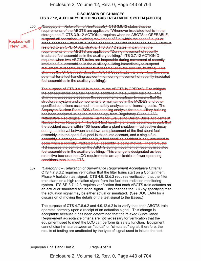
DISCUSSION OF CHANGES ITS 3.7.12, AUXILIARY BUILDING GAS TREATMENT SYSTEM (ABGTS)
Sequoyah Unit 1 and Unit 2 Page 9 of 10
L06 (Category 2 – Relaxation of Applicability) CTS 3.9.12 states that the requirements of the ABGTS are applicable "Whenever irradiated fuel is in the storage pool." CTS 3.9.12 ACTION a requires when no ABGTS is OPERABLE, suspend all operations involving movement of fuel within the spent fuel pit or crane operation with loads over the spent fuel pit until at least one ABGTS train is restored to an OPERABLE stratus. ITS 3.7.12 states, in part, that the requirements of the ABGTS are applicable "During movement of recently irradiated fuel assemblies in the auxiliary building." ITS 3.7.12 ACTION D requires when two ABGTS trains are inoperable during movement of recently irradiated fuel assemblies in the auxiliary building immediately to suspend movement of recently irradiated fuel assemblies in the auxiliary building. This changes the CTS by restricting the ABGTS Specification to only when there is a potential for a fuel handling accident (i.e., during movement of recently irradiated fuel assemblies in the auxiliary building).
The purpose of CTS 3.9.12 is to ensure the ABGTS is OPERABLE to mitigate
the consequences of a fuel handling accident in the auxiliary building. This change is acceptable because the requirements continue to ensure that the structures, system and components are maintained in the MODES and other specified conditions assumed in the safety analyses and licensing basis. The Sequoyah Nuclear Plant (SQN) fuel handling analysis for the auxiliary building has been analyzed using the methodology from Regulatory Guide 1.183, "Alternative Radiological Source Terms for Evaluating Design Basis Accidents at Nuclear Power Reactors." The SQN fuel handling analysis assumes, in part, that the accident occurs within 100 hours after a plant shutdown, radioactive decay during the interval between shutdown and placement of the first spent fuel assembly into the spent fuel pool is taken into account, and a single fuel assembly is damaged. Additionally, a fuel handling accident is only assumed to occur when a recently irradiated fuel assembly is being moved. Therefore, the ITS imposes the controls on the ABGTS during movement of recently irradiated fuel assemblies in the auxiliary building. This change is designated as less restrictive because the LCO requirements are applicable in fewer operating conditions than in the CTS.
L07 (Category 6 – Relaxation of Surveillance Requirement Acceptance Criteria)
CTS 4.7.8.d.2 requires verification that the filter trains start on a Containment Phase A Isolation test signal. CTS 4.9.12.d.2 requires verification that the filter train starts on a high radiation signal from the fuel pool radiation monitoring system. ITS SR 3.7.12.3 requires verification that each ABGTS train actuates on an actual or simulated actuation signal. This changes the CTS by specifying that the actuation signal may be either actual or simulated. (See DOC LA04 for a discussion of moving the details of the test signal to the Bases.)
The purpose of CTS 4.7.8.d.2 and 4.9.12.d.2 is to verify that each ABGTS train
operates correctly upon a receipt of an actuation signal. This change is acceptable because it has been determined that the relaxed Surveillance Requirement acceptance criteria are not necessary for verification that the equipment used to meet the LCO can perform its safety function. Equipment cannot discriminate between an "actual" or "simulated" signal; therefore, the results of testing are unaffected by the type of signal used to initiate the test.
Enclosure 2, Volume 12, Rev. 0, Page 443 of 704
Enclosure 2, Volume 12, Rev. 0, Page 443 of 704
Replace with"New" L06.
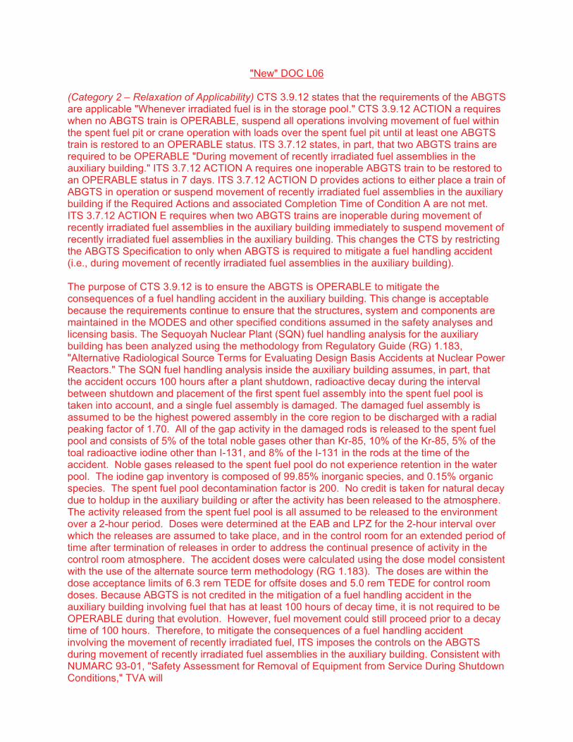
"New" DOC L06
(Category 2 – Relaxation of Applicability) CTS 3.9.12 states that the requirements of the ABGTS are applicable "Whenever irradiated fuel is in the storage pool." CTS 3.9.12 ACTION a requires when no ABGTS is OPERABLE, suspend all operations involving movement of fuel within the spent fuel pit or crane operation with loads over the spent fuel pit until at least one ABGTS train is restored to an OPERABLE status. ITS 3.7.12 states, in part, that two ABGTS trains are required to be OPERABLE "During movement of recently irradiated fuel assemblies in the auxiliary building." ITS 3.7.12 ACTION A requires one inoperable ABGTS train to be restored to an OPERABLE status in 7 days. ITS 3.7.12 ACTION D provides actions to either place a train of ABGTS in operation or suspend movement of recently irradiated fuel assemblies in the auxiliary building if the Required Actions and Completion Time of Condition A are not met. ITS 3.7.12 ACTION E requires when two ABGTS trains are inoperable during movement of recently irradiated fuel assemblies in the auxiliary building immediately to suspend movement of recently irradiated fuel assemblies in the auxiliary building. This changes the CTS by restricting the ABGTS Specification to only when ABGTS is required to mitigate a fuel handling accident (i.e., during movement of recently irradiated fuel assemblies in the auxiliary building).
The purpose of CTS 3.9.12 is to ensure the ABGTS is OPERABLE to mitigate the consequences of a fuel handling accident in the auxiliary building. This change is acceptable because the requirements continue to ensure that the structures, system and components are maintained in the MODES and other specified conditions assumed in the safety analyses and licensing basis. The Sequoyah Nuclear Plant (SQN) fuel handling analysis for the auxiliary building has been analyzed using the methodology from Regulatory Guide 1.183, "Alternative Radiological Source Terms for Evaluating Design Basis Accidents at Nuclear Power Reactors." The SQN fuel handling analysis inside the auxiliary building assumes, in part, that the accident occurs 100 hours after a plant shutdown, radioactive decay during the interval between shutdown and placement of the first spent fuel assembly into the spent fuel pool is taken into account, and a single fuel assembly is damaged. The damaged fuel assembly is assumed to be the highest powered assembly in the core region to be discharged with a radial peaking factor of 1.70. All of the gap activity in the damaged rods is released to the spent fuel pool and consists of 5% of the total noble gases other than Kr-85, 10% of the Kr-85, 5% of the toal radioactive iodine other than I-131, and 8% of the I-131 in the rods at the time of the accident. Noble gases released to the spent fuel pool do not experience retention in the water pool. The iodine gap inventory is composed of 99.85% inorganic species, and 0.15% organic species. The spent fuel pool decontamination factor is 200. No credit is taken for natural decay due to holdup in the auxiliary building or after the activity has been released to the atmosphere. The activity released from the spent fuel pool is all assumed to be released to the environment over a 2-hour period. Doses were determined at the EAB and LPZ for the 2-hour interval over which the releases are assumed to take place, and in the control room for an extended period of time after termination of releases in order to address the continual presence of activity in the control room atmosphere. The accident doses were calculated using the dose model consistent with the use of the alternate source term methodology (RG 1.183). T e doses are within the dose acceptance limits of 6.3 rem TEDE for offsite doses and 5.0 rem TEDE for control room doses. Because ABGTS is not credited in the mitigation of a fuel handling accident in the auxiliary building involving fuel that has at least 100 hours of decay time, it not required to be OPERABLE during that evolution. However, fuel movement could still proceed prior to a decay time of 100 hours. Therefore, to mitigate the consequences of a fuel handling accident involving the movement of recently irradiated fuel, ITS imposes the controls on the ABGTS during movement of recently irradiated fuel assemblies in the auxiliary building. Consistent with NUMARC 93-01, "Safety Assessment for Removal of Equipment from Service During Shutdown Conditions," TVA will
implement procedural requirements for a single normal or contingency method to promptly close primary or secondary containment penetrations. Additionally, TVA will implement procedural requirements for one train of ABGTS to be OPERABLE during movement of irradiated fuel assemblies (whether in the auxiliary building or within the containment). This change is designated as less restrictive because the LCO requirements are applicable in fewer operating conditions than in the CTS.

DISCUSSION OF CHANGES ITS 3.7.12, AUXILIARY BUILDING GAS TREATMENT SYSTEM (ABGTS)
Sequoyah Unit 1 and Unit 2 Page 10 of 10
This change is designated as less restrictive because less stringent Surveillance Requirements are being applied in the ITS than were applied in the CTS.
Enclosure 2, Volume 12, Rev. 0, Page 444 of 704
Enclosure 2, Volume 12, Rev. 0, Page 444 of 704
L08
The purpose of CTS 3.9.4 is to ensure the ABGTS is OPERABLE to mitigate a FHA in the auxiliary building. Although ABGTS is not credited in the mitigation of a FHA within the containment, the requirement for one train of ABGTS to be OPERABLE was added to the CTS with Amendments 209 and 199 for Units 1 and 2, respectively (ADAMS Accession number ML013320204). The amendments allowed both doors in one or both containment personnel airlock(s) to be open during core alterations and during the movement of irradiated fuel within the containment, provided one door in each airlock is capable of closure and one train of ABGTS remains OPERABLE. The change to restrict the ABGTS requirement to only when the system is required to mitigate a design basis FHA is acceptable because the requirements continue to ensure that the structures, system and components are maintained in the MODES and other specified conditions assumed in the safety analyses and licensing basis. The Sequoyah Nuclear Plant (SQN) fuel handling accident has been analyzed using the methodology from Regulatory Guide 1.183, "Alternative Radiological Source Terms for Evaluating Design Basis Accidents at Nuclear Power Reactors." For the FHA within the containment, the time after shutdown is assumed to be 100 hours. The containment equipment hatch and personnel air locks may be open during fuel handling operations, and although the purge line would be quickly isolated, activity release is assumed to continue through these open penetrations. The accident postulates that a spent fuel assembly is dropped after refueling. All of the fuel rods in the assembly are assumed to rupture, releasing the radionuclides within the reactor cavity water. Fission products released from the damaged fuel are decontaminated by passage through the reactor cavity water. The fission products released are exhausted by the building purge system. On detection of increased radiation levels in the containment, the purge system automatically isolates (assumed 300 seconds following accident). After purge is isolated, the remaining fission products in the containment are assumed to leak to the environment through containment penetrations within 2 hours with no credit for holdup, dilution, or filtration of the release. The accident doses are within the acceptable dose limits of 6.3 rem TEDE for offsite doses (RG 1.183) and 5.0 rem TEDE for control room dose (GDC 19). Therefore, the removal of the requirement for one train of ABGTS to be OPERABLE with both doors of one or both personnel airlocks open during movement of irradiated fuel assemblies in the containment is justified. Consistent with NUMARC 93-01, "Safety Assessment for Removal of Equipment from Service During Shutdown Conditions," TVA will implement procedural requirements for a single normal or contingency method to promptly close primary or secondary containment penetrations. Additionally, TVA will implement procedural requirements for one train of ABGTS to be OPERABLE during movement of irradiated fuel assemblies (whether in the auxiliary building or within the containment). This change is designated as less restrictive because the LCO requirements are applicable in fewer operating conditions than in the CTS.
(Category 1 - Relaxation of LCO Requirements) CTS 3.9.4 states that one train of ABGTS is required to be OPERABLE with both doors of one or both containment personnel airlock(s) open "During movement of irradiated fuel within the containment." ITS 3.7.12 states, in part, that two trains of ABGTS are required to be OPERABLE "During movement of recently irradiated fuel assemblies in the auxiliary building." This changes the CTS by restricting the ABGTS requirement to only when ABGTS is required to mitigate a design basis fuel handling accident (FHA) (i.e., during movement of recently irradiated fuel assemblies in the auxiliary building).

FBACS 3.7.13
Westinghouse STS 3.7.13-1 Rev. 4.0
ABGTSCTS
1
12
3
SEQUOYAH UNIT 1 Amendment XXX 12
1
3.7 PLANT SYSTEMS
3.7.13 Fuel Building Air Cleanup System (FBACS)
LCO 3.7.13 Two FBACS trains shall be OPERABLE.
---------------------------------------------NOTE--------------------------------------------The fuel building boundary may be opened intermittently under administrative control.
--------------------------------------------------------------------------------------------------
APPLICABILITY: [MODES 1, 2, 3, and 4, ] During movement of [recently] irradiated fuel assemblies in the fuel
building.
ACTIONS ------------------------------------------------------------NOTE----------------------------------------------------------- LCO 3.0.3 is not applicable. -------------------------------------------------------------------------------------------------------------------------------
CONDITION REQUIRED ACTION COMPLETION TIME
A. One FBACS train inoperable.
A.1 Restore FBACS train to OPERABLE status.
7 days
B. Two FBACS trains inoperable due to inoperable fuel building boundary in MODE 1, 2, 3, or 4.
B.1 Restore fuel building boundary to OPERABLE status.
24 hours
ABGTSAuxiliary Building Gas Treatment
ABGTS
3.7.8
Auxiliary Building Secondary Containment Enclosure (ABSCE)
3.7.8 Applicability, 3.9.12 Applicability
1
1
2
4
3.7.8 ACTION
DOC L02, 3.9.12 ACTION b
ABGTS ABGTS
12
12
auxiliary
3
1
3
ABGTS
ABSCE
ABSCE DOC L02 1
1. DOC L01 3.9.12
S
INSERT 1
3
In MODE 1, 2, 3, or 4 2
Enclosure 2, Volume 12, Rev. 0, Page 446 of 704
Enclosure 2, Volume 12, Rev. 0, Page 446 of 704
3.9.12
DOC L06
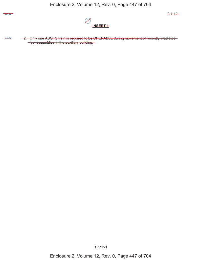
3.7.12
3.7.12-1
CTS
INSERT 1
2. Only one ABGTS train is required to be OPERABLE during movement of recently irradiatedfuel assemblies in the auxiliary building.
2
3.9.12
Enclosure 2, Volume 12, Rev. 0, Page 447 of 704
Enclosure 2, Volume 12, Rev. 0, Page 447 of 704

FBACS 3.7.13
Westinghouse STS 3.7.13-2 Rev. 4.0
ABGTSCTS
1
12
3
SEQUOYAH UNIT 1 Amendment XXX 12
1
ACTIONS (continued)
CONDITION
REQUIRED ACTION
COMPLETION TIME
C. [ Required Action and associated Completion Time of Condition A or B not met in MODE 1, 2, 3, or 4.
OR Two FBACS trains
inoperable in MODE 1, 2, 3, or 4 for reasons other than Condition B.
C.1 Be in MODE 3. AND C.2 Be in MODE 5.
6 hours 36 hours ]
D. Required Action and
associated Completion Time [of Condition A] not met during movement of [recently] irradiated fuel assemblies in the fuel building.
D.1 Place OPERABLE FBACS
train in operation. OR D.2 Suspend movement of
[recently] irradiated fuel assemblies in the fuel building.
Immediately Immediately
E. Two FBACS trains
inoperable during movement of [recently] irradiated fuel assemblies in the fuel building.
E.1 Suspend movement of
[recently] irradiated fuel assemblies in the fuel building.
Immediately
3.7.8 ACTION
3.9.12 ACTION a
ABGTS
ABGTS
auxiliary
auxiliary
4
4
1
2
1
3
4 3
4
DOC L02
D D2
One required
Enclosure 2, Volume 12, Rev. 0, Page 448 of 704
Enclosure 2, Volume 12, Rev. 0, Page 448 of 704
Etwo s
E
Keep, with changesindicated in black.
auxiliary auxiliary
ABGTS
DOC L06 1
4
4 3
3 4

FBACS 3.7.13
Westinghouse STS 3.7.13-1 Rev. 4.0
ABGTSCTS
1
12
3
SEQUOYAH UNIT 2 Amendment XXX 12
1
3.7 PLANT SYSTEMS
3.7.13 Fuel Building Air Cleanup System (FBACS)
LCO 3.7.13 Two FBACS trains shall be OPERABLE.
---------------------------------------------NOTE--------------------------------------------The fuel building boundary may be opened intermittently under administrative control.
--------------------------------------------------------------------------------------------------
APPLICABILITY: [MODES 1, 2, 3, and 4, ] During movement of [recently] irradiated fuel assemblies in the fuel
building.
ACTIONS ------------------------------------------------------------NOTE----------------------------------------------------------- LCO 3.0.3 is not applicable. -------------------------------------------------------------------------------------------------------------------------------
CONDITION REQUIRED ACTION COMPLETION TIME
A. One FBACS train inoperable.
A.1 Restore FBACS train to OPERABLE status.
7 days
B. Two FBACS trains inoperable due to inoperable fuel building boundary in MODE 1, 2, 3, or 4.
B.1 Restore fuel building boundary to OPERABLE status.
24 hours
ABGTSAuxiliary Building Gas Treatment
ABGTS
3.7.8
Auxiliary Building Secondary Containment Enclosure (ABSCE)
3.7.8 Applicability, 3.9.12 Applicability
1
1
2
4
3.7.8 ACTION
DOC L02, 3.9.12 ACTION b
ABGTS ABGTS
12
12
auxiliary
3
1
3
ABGTS
ABSCE
ABSCE DOC L02 1
1. DOC L01 3.9.12
S
INSERT 1
3
In MODE 1, 2, 3, or 4 2
Enclosure 2, Volume 12, Rev. 0, Page 452 of 704
Enclosure 2, Volume 12, Rev. 0, Page 452 of 704
3.9.12
DOC L06

3.7.12
3.7.12-1
CTS
INSERT 1
2. Only one ABGTS train is required to be OPERABLE during movement of recently irradiatedfuel assemblies in the auxiliary building.
2
3.9.12
Enclosure 2, Volume 12, Rev. 0, Page 453 of 704
Enclosure 2, Volume 12, Rev. 0, Page 453 of 704

FBACS 3.7.13
Westinghouse STS 3.7.13-2 Rev. 4.0
ABGTSCTS
1
12
3
SEQUOYAH UNIT 2 Amendment XXX 12
1
ACTIONS (continued)
CONDITION REQUIRED ACTION COMPLETION TIME
C. [ Required Action and associated Completion Time of Condition A or B not met in MODE 1, 2, 3, or 4.
OR
Two FBACS trains inoperable in MODE 1, 2, 3, or 4 for reasons other than Condition B.
C.1 Be in MODE 3.
AND
C.2 Be in MODE 5.
6 hours
36 hours ]
D. Required Action and associated Completion Time [of Condition A] not met during movement of [recently] irradiated fuel assemblies in the fuel building.
D.1 Place OPERABLE FBACS train in operation.
OR
D.2 Suspend movement of [recently] irradiated fuel assemblies in the fuel building.
Immediately
Immediately
E. Two FBACS trains inoperable during movement of [recently] irradiated fuel assemblies in the fuel building.
E.1 Suspend movement of [recently] irradiated fuel assemblies in the fuel building.
Immediately
3.7.8 ACTION
3.9.12 ACTION a
ABGTS
ABGTS
auxiliary
auxiliary
4
4
1
2
1
3
4 3
4
DOC L02
D D2
One required
Enclosure 2, Volume 12, Rev. 0, Page 454 of 704
Enclosure 2, Volume 12, Rev. 0, Page 454 of 704
DOC L06
Keep, with changesindicated in black.
1
4
4 3
4 3
ABGTS
auxiliary auxiliary
Etwo s E

JUSTIFICATION FOR DEVIATIONS ITS 3.7.12, AUXILIARY BUILDING GAS TREATMENT SYSTEM (ABGTS)
Sequoyah Unit 1 and Unit 2 Page 1 of 1
1. Sequoyah Nuclear Plant (SQN) design does not include the ISTS 3.7.12,"Emergency Core Cooling System (ECCS) Pump Room Exhaust Air CleanupSystem (PREACS)." Therefore, ISTS 3.7.13, "Fuel Building Air Cleanup System(FBACS)" has been renumbered as ITS 3.7.12. Additionally, SQN refers to the FuelBuilding Air Cleanup System (FBACS) as the Auxiliary Building Gas TreatmentSystem (ABGTS).
2. ISTS 3.7.13 ACTION A has been revised to only apply in MODES 1, 2, 3, or 4 andACTION D has been deleted, as the SQN current licensing basis only credits onetrain of ABGTS to mitigate a fuel handling accident involving the movement ofrecently irradiated fuel assemblies in the auxiliary building. Therefore, the onlyapplicable ACTION for the required ABGTS train being inoperable during themovement of recently irradiated fuel assemblies in the auxiliary building isISTS 3.7.13 ACTION E (ITS 3.7.12 ACTION D).
3. Changes are made (additions, deletions, and/or changes) to the ISTS that reflect theplant specific nomenclature, number, reference, system description, analysis, orlicensing basis description.
4. The ISTS contains bracketed information and/or values that are generic toWestinghouse vintage plants. The brackets are removed and the proper plantspecific information/value is inserted to reflect the current licensing basis.
5. ISTS SR 3.7.13.1, SR 3.7.13.3 and SR 3.7.13.4 (ITS SR 3.7.12.1, SR 3.7.12.3 andSR 3.7.12.4, respectively) provides two options for controlling the Frequencies ofSurveillance Requirements. SQN is proposing to control the SurveillanceFrequencies under the Surveillance Frequency Control Program.
6. Changes made for consistency with the Applicability of the ABGTS actuationfunctions provided in ITS 3.3.8.
Enclosure 2, Volume 12, Rev. 0, Page 458 of 704
Enclosure 2, Volume 12, Rev. 0, Page 458 of 704
Not used.

FBACS B 3.7.13
Westinghouse STS B 3.7.13-2 Rev. 4.0
ABGTS 1
12
12SEQUOYAH UNIT 1 Revision XXX 2 1
BASES
APPLICABLE SAFETY ANALYSES (continued)
material provided by the one remaining train of this filtration system. The amount of fission products available for release from the fuel handling building is determined for a fuel handling accident and for a LOCA. [Due to radioactive decay, FBACS is only required to isolate during fuel handling accidents involving handling recently irradiated fuel (i.e., fuel that has occupied part of a critical reactor core within the previous [X] days).] These assumptions and the analysis follow the guidance provided in Regulatory Guide 1.25 (Ref. 4).
The FBACS satisfies Criterion 3 of 10 CFR 50.36(c)(2)(ii).
LCO Two independent and redundant trains of the FBACS are required to be OPERABLE to ensure that at least one train is available, assuming a single failure that disables the other train, coincident with a loss of offsite power. Total system failure could result in the atmospheric release from the fuel handling building exceeding the 10 CFR 100 (Ref. 5) limits in the event of a fuel handling accident [involving handling recently irradiated fuel]. The FBACS is considered OPERABLE when the individual components necessary to control exposure in the fuel handling building are OPERABLE in both trains. An FBACS train is considered OPERABLE when its associated:
a. Fan is OPERABLE,
b. HEPA filter and charcoal adsorber are not excessively restrictingflow, and are capable of performing their filtration function, and
c. Heater, demister, ductwork, valves, and dampers are OPERABLE,and air circulation can be maintained.
The LCO is modified by a Note allowing the fuel building boundary to be opened intermittently under administrative controls. For entry and exit through doors the administrative control of the opening is performed by the person(s) entering or exiting the area. For other openings, these controls consist of stationing a dedicated individual at the opening who is in continuous communication with the control room. This individual will have a method to rapidly close the opening when a need for fuel building isolation is indicated.
ABGTS
100 hours
ABGTS 3
4
ABGTS
ABGTS
ABGTS
auxiliary
2
1
3
3
2
1
1
1
2
1
1
1
1auxiliary
auxiliary
1
auxiliary
1.183
Auxiliary Building Secondary Containment Enclosure (ABSCE)
2
LOCAINSERT 2
INSERT 3
two Notes. Note 1 allows
4
Enclosure 2, Volume 12, Rev. 0, Page 462 of 704
Enclosure 2, Volume 12, Rev. 0, Page 462 of 704
a Note allowing
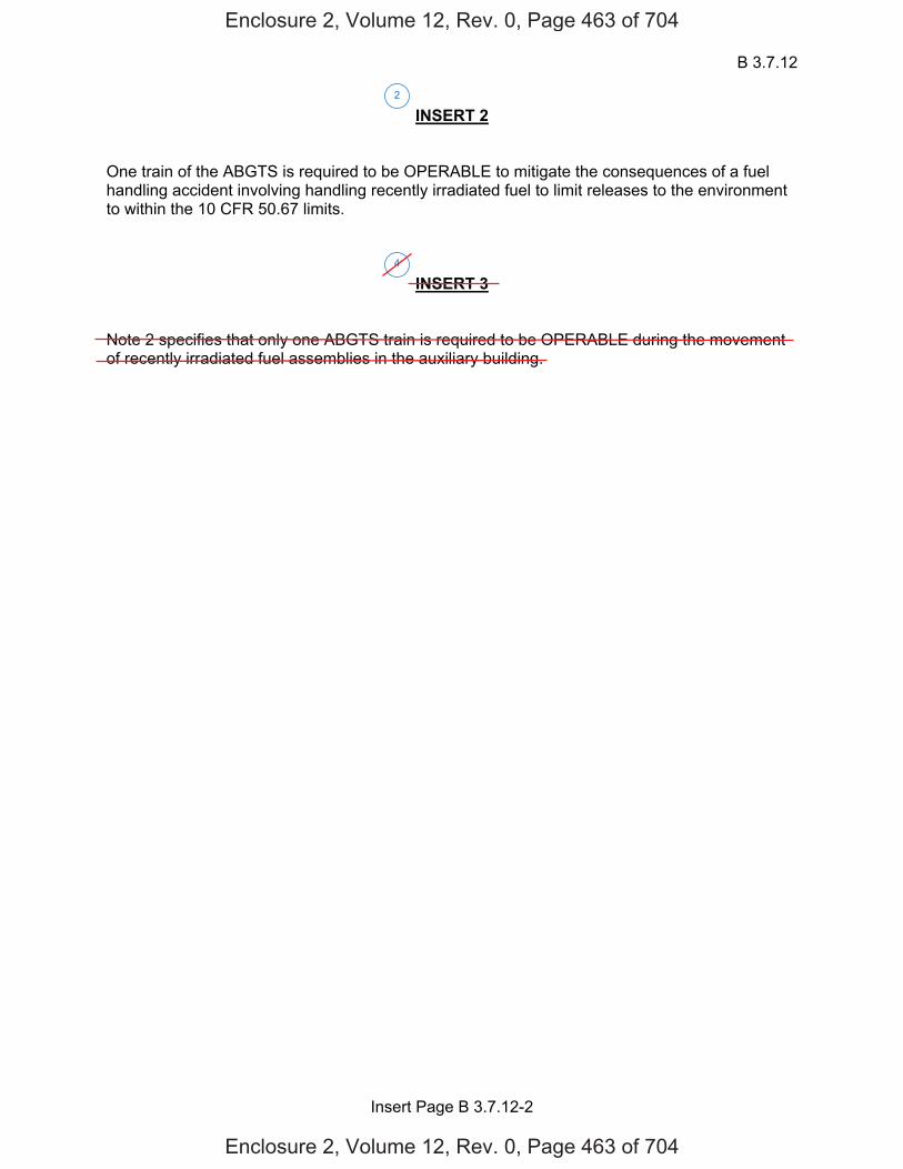
B 3.7.12
Insert Page B 3.7.12-2
INSERT 2
One train of the ABGTS is required to be OPERABLE to mitigate the consequences of a fuel handling accident involving handling recently irradiated fuel to limit releases to the environment to within the 10 CFR 50.67 limits.
INSERT 3
Note 2 specifies that only one ABGTS train is required to be OPERABLE during the movement of recently irradiated fuel assemblies in the auxiliary building.
2
4
Enclosure 2, Volume 12, Rev. 0, Page 463 of 704
Enclosure 2, Volume 12, Rev. 0, Page 463 of 704

FBACS B 3.7.13
Westinghouse STS B 3.7.13-3 Rev. 4.0
ABGTS 1
12
12SEQUOYAH UNIT 1 Revision XXX 2 1
BASES
APPLICABILITY In MODE 1, 2, 3, or 4, the FBACS is required to be OPERABLE to provide fission product removal associated with ECCS leaks due to a LOCA and leakage from containment and annulus.
In MODE 5 or 6, the FBACS is not required to be OPERABLE since the ECCS is not required to be OPERABLE.
During movement of [recently] irradiated fuel in the fuel handling area, the FBACS is required to be OPERABLE to alleviate the consequences of a fuel handling accident.
ACTIONS LCO 3.0.3 is not applicable while in MODE 5 or 6. However, since irradiated fuel assembly movement can occur in MODE 1, 2, 3, or 4, the ACTIONS have been modified by a Note stating that LCO 3.0.3 is not applicable. If moving irradiated fuel assemblies while in MODE 5 or 6, LCO 3.0.3 would not specify any action. If moving irradiated fuel assemblies while in MODE 1, 2, 3, or 4, the fuel movement is independent of reactor operations. Entering LCO 3.0.3, while in MODE 1, 2, 3, or 4 would require the unit to be shutdown unnecessarily.
A.1
With one FBACS train inoperable, action must be taken to restore OPERABLE status within 7 days. During this period, the remaining OPERABLE train is adequate to perform the FBACS function. The 7 day Completion Time is based on the risk from an event occurring requiring the inoperable FBACS train, and the remaining FBACS train providing the required protection.
B.1
-----------------------------------REVIEWER’S NOTE------------------------- Adoption of Condition B is dependent on a commitment from the licensee to have guidance available describing compensatory measures to be taken in the event of an intentional and unintentional entry into Condition B. --------------------------------------------------------------------------------------------------
If the fuel building boundary is inoperable in MODE 1, 2, 3, or 4, the FBACS trains cannot perform their intended functions. Actions must be taken to restore an OPERABLE fuel building boundary within 24 hours. During the period that the fuel building boundary is inoperable, appropriate compensatory measures [consistent with the intent, as
ABGTS
ABGTS
ABGTS
ABGTS
ABGTS
ABGTS
1
1
31
1
5
ABGTS 1
ABSCE
ABSCE
3
auxiliary building
2
in MODE 1, 2, 3, or 44
Enclosure 2, Volume 12, Rev. 0, Page 464 of 704
Enclosure 2, Volume 12, Rev. 0, Page 464 of 704

FBACS B 3.7.13
Westinghouse STS B 3.7.13-4 Rev. 4.0
ABGTS 1
12
12SEQUOYAH UNIT 1 Revision XXX 2 1
BASES ACTIONS (continued)
applicable, of GDC 19, 60, 61, 63, 64 and 10 CFR Part 100] should be utilized to protect plant personnel from potential hazards such as radioactive contamination, toxic chemicals, smoke, temperature and relative humidity, and physical security. Preplanned measures should be available to address these concerns for intentional and unintentional entry into the condition. The 24 hour Completion Time is reasonable based on the low probability of a DBA occurring during this time period, and the use of compensatory measures. The 24 hour Completion Time is a typically reasonable time to diagnose, plan and possibly repair, and test most problems with the fuel building boundary.
[ C.1 and C.2 In MODE 1, 2, 3, or 4, when Required Action A.1 or B.1 cannot be completed within the associated Completion Time, or when both FBACS trains are inoperable for reasons other than an inoperable fuel building boundary (i.e., Condition B), the unit must be placed in a MODE in which the LCO does not apply. To achieve this status, the unit must be placed in MODE 3 within 6 hours, and in MODE 5 within 36 hours. The Completion Times are reasonable, based on operating experience, to reach the required unit conditions from full power conditions in an orderly manner and without challenging unit systems. ] D.1 and D.2 When Required Action A.1 cannot be completed within the required Completion Time, during movement of [recently] irradiated fuel assemblies in the fuel building, the OPERABLE FBACS train must be started immediately or [recently] irradiated fuel movement suspended. This action ensures that the remaining train is OPERABLE, that no undetected failures preventing system operation will occur, and that any active failure will be readily detected. If the system is not placed in operation, this action requires suspension of [recently] irradiated fuel movement, which precludes a fuel handling accident [involving handling recently irradiated fuel]. This does not preclude the movement of fuel assemblies to a safe position.
ABGTS
1
3
3
4
1
ABSCE
ABSCE
3
Enclosure 2, Volume 12, Rev. 0, Page 465 of 704
Enclosure 2, Volume 12, Rev. 0, Page 465 of 704
Keep with changesmarked in black.
auxiliary
ABGTS
1
3 3
3
3

FBACS B 3.7.13
Westinghouse STS B 3.7.13-5 Rev. 4.0
ABGTS 1
12
12SEQUOYAH UNIT 1 Revision XXX 2 1
BASES ACTIONS (continued)
E.1 When two trains of the FBACS are inoperable during movement of [recently] irradiated fuel assemblies in the fuel building, action must be taken to place the unit in a condition in which the LCO does not apply. Action must be taken immediately to suspend movement of [recently] irradiated fuel assemblies in the fuel building. This does not preclude the movement of fuel to a safe position.
SURVEILLANCE SR 3.7.13.1 REQUIREMENTS
Standby systems should be checked periodically to ensure that they function properly. As the environmental and normal operating conditions on this system are not severe, testing each train once every month provides an adequate check on this system. Monthly heater operation dries out any moisture accumulated in the charcoal from humidity in the ambient air. [Systems with heaters must be operated for 10 continuous hours with the heaters energized. Systems without heaters need only be operated for 15 minutes to demonstrate the function of the system.] [ The 31 day Frequency is based on the known reliability of the equipment and the two train redundancy available. OR The Surveillance Frequency is controlled under the Surveillance Frequency Control Program. -----------------------------------REVIEWER’S NOTE----------------------------------- Plants controlling Surveillance Frequencies under a Surveillance Frequency Control Program should utilize the appropriate Frequency description, given above, and the appropriate choice of Frequency in the Surveillance Requirement. ------------------------------------------------------------------------------------------------ ]
[ SR 3.7.13.2 This SR verifies that the required FBACS testing is performed in accordance with the [Ventilation Filter Testing Program (VFTP)]. The [VFTP] includes testing HEPA filter performance, charcoal adsorber efficiency, minimum system flow rate, and the physical properties of the activated charcoal (general use and following specific operations). Specific test frequencies and additional information are discussed in detail in the [VFTP]. ]
ABGTS is
ABGTS
3
2
3
6
5
3
2
3
3
1auxiliary
1auxiliary
121
12
INSERT 4
TSTF-522
D
the required
4
4
Enclosure 2, Volume 12, Rev. 0, Page 466 of 704
Enclosure 2, Volume 12, Rev. 0, Page 466 of 704
E two
sare
3
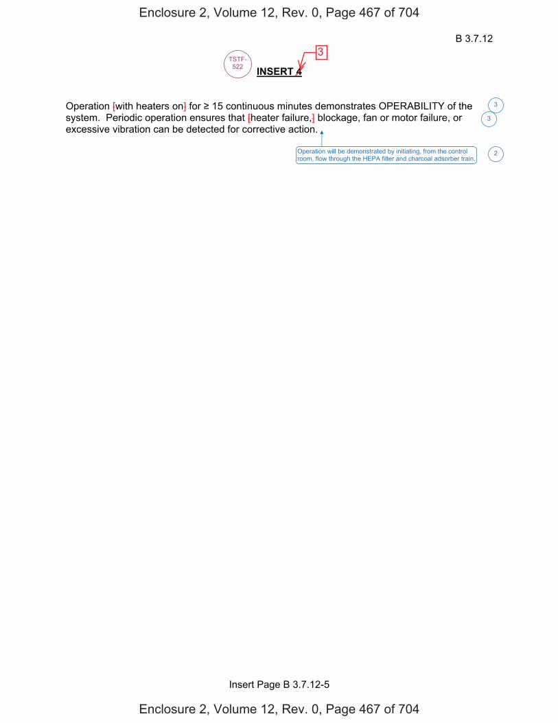
B 3.7.12
Insert Page B 3.7.12-5
INSERT 4 Operation [with heaters on] for 15 continuous minutes demonstrates OPERABILITY of the system. Periodic operation ensures that [heater failure,] blockage, fan or motor failure, or excessive vibration can be detected for corrective action.
TSTF-522
Operation will be demonstrated by initiating, from the control room, flow through the HEPA filter and charcoal adsorber train.
3
2
3
Enclosure 2, Volume 12, Rev. 0, Page 467 of 704
Enclosure 2, Volume 12, Rev. 0, Page 467 of 704
3

FBACS B 3.7.13
Westinghouse STS B 3.7.13-6 Rev. 4.0
ABGTS 1
12
12SEQUOYAH UNIT 1 Revision XXX 2 1
BASES SURVEILLANCE REQUIREMENTS (continued)
[ SR 3.7.13.3 This SR verifies that each FBACS train starts and operates on an actual or simulated actuation signal. [ The [18] month Frequency is consistent with Reference 6. ] OR The Surveillance Frequency is controlled under the Surveillance Frequency Control Program. -----------------------------------REVIEWER’S NOTE----------------------------------- Plants controlling Surveillance Frequencies under a Surveillance Frequency Control Program should utilize the appropriate Frequency description, given above, and the appropriate choice of Frequency in the Surveillance Requirement. ------------------------------------------------------------------------------------------------ ] SR 3.7.13.4 This SR verifies the integrity of the fuel building enclosure. The ability of the fuel building to maintain negative pressure with respect to potentially uncontaminated adjacent areas is periodically tested to verify proper function of the FBACS. During the [post accident] mode of operation, the FBACS is designed to maintain a slight negative pressure in the fuel building, to prevent unfiltered LEAKAGE. The FBACS is designed to maintain a [-0.125] inches water gauge with respect to atmospheric pressure at a flow rate of [20,000] cfm to the fuel building. [ The Frequency of [18] months is consistent with the guidance provided in NUREG-0800, Section 6.5.1 (Ref. 7). An [18] month Frequency (on a STAGGERED TEST BASIS) is consistent with Reference 6. OR The Surveillance Frequency is controlled under the Surveillance Frequency Control Program.
ABGTS
8,100 and 9,900
3
1
6
5
1
ABGTS
ABGTS
auxiliary
auxiliary
- 0.25
3
31
6
auxiliary
auxiliary
112
112 (i.e., spent fuel
storage area and the ESF pump rooms)
2
INSERT 5
4
Enclosure 2, Volume 12, Rev. 0, Page 468 of 704
Enclosure 2, Volume 12, Rev. 0, Page 468 of 704
4

B 3.7.12
Insert Page B 3.7.12-6
INSERT 5 The SR is modified by two Notes that specify when verification of ABGTS actuation for each actuation signal is required to be met. ABGTS actuation on a Containment Phase A isolation signal is required to be met in MODES 1, 2, 3 and 4. ABGTS actuation on fuel storage pool area high radiation signal is required to be met during movement of recently irradiated fuel assemblies in the auxiliary building.
6
Enclosure 2, Volume 12, Rev. 0, Page 469 of 704
Enclosure 2, Volume 12, Rev. 0, Page 469 of 704
4
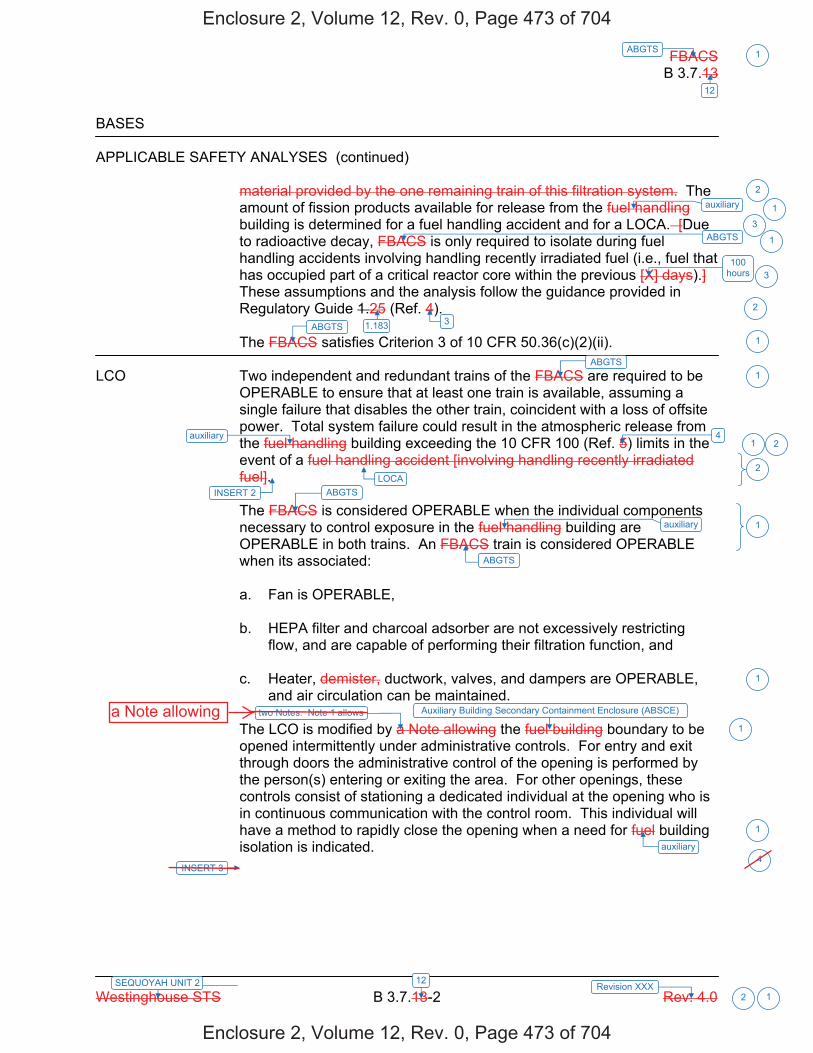
FBACS B 3.7.13
Westinghouse STS B 3.7.13-2 Rev. 4.0
ABGTS 1
12
12SEQUOYAH UNIT 2 Revision XXX 2 1
BASES APPLICABLE SAFETY ANALYSES (continued)
material provided by the one remaining train of this filtration system. The amount of fission products available for release from the fuel handling building is determined for a fuel handling accident and for a LOCA. [Due to radioactive decay, FBACS is only required to isolate during fuel handling accidents involving handling recently irradiated fuel (i.e., fuel that has occupied part of a critical reactor core within the previous [X] days).] These assumptions and the analysis follow the guidance provided in Regulatory Guide 1.25 (Ref. 4). The FBACS satisfies Criterion 3 of 10 CFR 50.36(c)(2)(ii).
LCO Two independent and redundant trains of the FBACS are required to be
OPERABLE to ensure that at least one train is available, assuming a single failure that disables the other train, coincident with a loss of offsite power. Total system failure could result in the atmospheric release from the fuel handling building exceeding the 10 CFR 100 (Ref. 5) limits in the event of a fuel handling accident [involving handling recently irradiated fuel]. The FBACS is considered OPERABLE when the individual components necessary to control exposure in the fuel handling building are OPERABLE in both trains. An FBACS train is considered OPERABLE when its associated: a. Fan is OPERABLE, b. HEPA filter and charcoal adsorber are not excessively restricting
flow, and are capable of performing their filtration function, and c. Heater, demister, ductwork, valves, and dampers are OPERABLE,
and air circulation can be maintained. The LCO is modified by a Note allowing the fuel building boundary to be opened intermittently under administrative controls. For entry and exit through doors the administrative control of the opening is performed by the person(s) entering or exiting the area. For other openings, these controls consist of stationing a dedicated individual at the opening who is in continuous communication with the control room. This individual will have a method to rapidly close the opening when a need for fuel building isolation is indicated.
ABGTS
100 hours
ABGTS 3
4
ABGTS
ABGTS
ABGTS
auxiliary
2
1
3
3
2
1
1
1
2
1
1
1
1auxiliary
auxiliary
1
auxiliary
1.183
Auxiliary Building Secondary Containment Enclosure (ABSCE)
2
LOCAINSERT 2
INSERT 3
two Notes. Note 1 allows
4
Enclosure 2, Volume 12, Rev. 0, Page 473 of 704
Enclosure 2, Volume 12, Rev. 0, Page 473 of 704
a Note allowing

B 3.7.12
Insert Page B 3.7.12-2
INSERT 2 One train of the ABGTS is required to be OPERABLE to mitigate the consequences of a fuel handling accident involving handling recently irradiated fuel to limit releases to the environment to within the 10 CFR 50.67 limits.
INSERT 3 Note 2 specifies that only one ABGTS train is required to be OPERABLE during the movement of recently irradiated fuel assemblies in the auxiliary building.
2
4
Enclosure 2, Volume 12, Rev. 0, Page 474 of 704
Enclosure 2, Volume 12, Rev. 0, Page 474 of 704
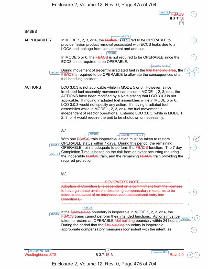
FBACS B 3.7.13
Westinghouse STS B 3.7.13-3 Rev. 4.0
ABGTS 1
12
12SEQUOYAH UNIT 2 Revision XXX 2 1
BASES APPLICABILITY In MODE 1, 2, 3, or 4, the FBACS is required to be OPERABLE to
provide fission product removal associated with ECCS leaks due to a LOCA and leakage from containment and annulus.
In MODE 5 or 6, the FBACS is not required to be OPERABLE since the ECCS is not required to be OPERABLE. During movement of [recently] irradiated fuel in the fuel handling area, the FBACS is required to be OPERABLE to alleviate the consequences of a fuel handling accident.
ACTIONS LCO 3.0.3 is not applicable while in MODE 5 or 6. However, since
irradiated fuel assembly movement can occur in MODE 1, 2, 3, or 4, the ACTIONS have been modified by a Note stating that LCO 3.0.3 is not applicable. If moving irradiated fuel assemblies while in MODE 5 or 6, LCO 3.0.3 would not specify any action. If moving irradiated fuel assemblies while in MODE 1, 2, 3, or 4, the fuel movement is independent of reactor operations. Entering LCO 3.0.3, while in MODE 1, 2, 3, or 4 would require the unit to be shutdown unnecessarily.
A.1 With one FBACS train inoperable, action must be taken to restore OPERABLE status within 7 days. During this period, the remaining OPERABLE train is adequate to perform the FBACS function. The 7 day Completion Time is based on the risk from an event occurring requiring the inoperable FBACS train, and the remaining FBACS train providing the required protection. B.1 -----------------------------------REVIEWER’S NOTE------------------------- Adoption of Condition B is dependent on a commitment from the licensee to have guidance available describing compensatory measures to be taken in the event of an intentional and unintentional entry into Condition B. -------------------------------------------------------------------------------------------------- If the fuel building boundary is inoperable in MODE 1, 2, 3, or 4, the FBACS trains cannot perform their intended functions. Actions must be taken to restore an OPERABLE fuel building boundary within 24 hours. During the period that the fuel building boundary is inoperable, appropriate compensatory measures [consistent with the intent, as
ABGTS
ABGTS
ABGTS
ABGTS
ABGTS
ABGTS
1
1
31
1
5
ABGTS 1
ABSCE
ABSCE
3
auxiliary building
2
in MODE 1, 2, 3, or 44
Enclosure 2, Volume 12, Rev. 0, Page 475 of 704
Enclosure 2, Volume 12, Rev. 0, Page 475 of 704

FBACS B 3.7.13
Westinghouse STS B 3.7.13-4 Rev. 4.0
ABGTS 1
12
12SEQUOYAH UNIT 2 Revision XXX 2 1
BASES ACTIONS (continued)
applicable, of GDC 19, 60, 61, 63, 64 and 10 CFR Part 100] should be utilized to protect plant personnel from potential hazards such as radioactive contamination, toxic chemicals, smoke, temperature and relative humidity, and physical security. Preplanned measures should be available to address these concerns for intentional and unintentional entry into the condition. The 24 hour Completion Time is reasonable based on the low probability of a DBA occurring during this time period, and the use of compensatory measures. The 24 hour Completion Time is a typically reasonable time to diagnose, plan and possibly repair, and test most problems with the fuel building boundary.
[ C.1 and C.2 In MODE 1, 2, 3, or 4, when Required Action A.1 or B.1 cannot be completed within the associated Completion Time, or when both FBACS trains are inoperable for reasons other than an inoperable fuel building boundary (i.e., Condition B), the unit must be placed in a MODE in which the LCO does not apply. To achieve this status, the unit must be placed in MODE 3 within 6 hours, and in MODE 5 within 36 hours. The Completion Times are reasonable, based on operating experience, to reach the required unit conditions from full power conditions in an orderly manner and without challenging unit systems. ] D.1 and D.2 When Required Action A.1 cannot be completed within the required Completion Time, during movement of [recently] irradiated fuel assemblies in the fuel building, the OPERABLE FBACS train must be started immediately or [recently] irradiated fuel movement suspended. This action ensures that the remaining train is OPERABLE, that no undetected failures preventing system operation will occur, and that any active failure will be readily detected. If the system is not placed in operation, this action requires suspension of [recently] irradiated fuel movement, which precludes a fuel handling accident [involving handling recently irradiated fuel]. This does not preclude the movement of fuel assemblies to a safe position.
ABGTS
1
3
3
4
1
ABSCE
ABSCE
3
Enclosure 2, Volume 12, Rev. 0, Page 476 of 704
Enclosure 2, Volume 12, Rev. 0, Page 476 of 704
Keep with changesmarked in black.
ABGTS
auxiliary 3 1
3
3 3

FBACS B 3.7.13
Westinghouse STS B 3.7.13-5 Rev. 4.0
ABGTS 1
12
12SEQUOYAH UNIT 2 Revision XXX 2 1
BASES ACTIONS (continued)
E.1 When two trains of the FBACS are inoperable during movement of [recently] irradiated fuel assemblies in the fuel building, action must be taken to place the unit in a condition in which the LCO does not apply. Action must be taken immediately to suspend movement of [recently] irradiated fuel assemblies in the fuel building. This does not preclude the movement of fuel to a safe position.
SURVEILLANCE SR 3.7.13.1 REQUIREMENTS
Standby systems should be checked periodically to ensure that they function properly. As the environmental and normal operating conditions on this system are not severe, testing each train once every month provides an adequate check on this system. Monthly heater operation dries out any moisture accumulated in the charcoal from humidity in the ambient air. [Systems with heaters must be operated for 10 continuous hours with the heaters energized. Systems without heaters need only be operated for 15 minutes to demonstrate the function of the system.] [ The 31 day Frequency is based on the known reliability of the equipment and the two train redundancy available. OR The Surveillance Frequency is controlled under the Surveillance Frequency Control Program. -----------------------------------REVIEWER’S NOTE----------------------------------- Plants controlling Surveillance Frequencies under a Surveillance Frequency Control Program should utilize the appropriate Frequency description, given above, and the appropriate choice of Frequency in the Surveillance Requirement. ------------------------------------------------------------------------------------------------ ]
[ SR 3.7.13.2 This SR verifies that the required FBACS testing is performed in accordance with the [Ventilation Filter Testing Program (VFTP)]. The [VFTP] includes testing HEPA filter performance, charcoal adsorber efficiency, minimum system flow rate, and the physical properties of the activated charcoal (general use and following specific operations). Specific test frequencies and additional information are discussed in detail in the [VFTP]. ]
ABGTS is
ABGTS
3
2
3
6
5
3
2
3
3
1auxiliary
1auxiliary
121
12
INSERT 4
TSTF-522
D
the required
4
4
Enclosure 2, Volume 12, Rev. 0, Page 477 of 704
Enclosure 2, Volume 12, Rev. 0, Page 477 of 704
3
ares
twoE

B 3.7.12
Insert Page B 3.7.12-5
INSERT 4 Operation [with heaters on] for 15 continuous minutes demonstrates OPERABILITY of the system. Periodic operation ensures that [heater failure,] blockage, fan or motor failure, or excessive vibration can be detected for corrective action.
TSTF-522
Operation will be demonstrated by initiating, from the control room, flow through the HEPA filter and charcoal adsorber train.
3
2
3
Enclosure 2, Volume 12, Rev. 0, Page 478 of 704
Enclosure 2, Volume 12, Rev. 0, Page 478 of 704
3
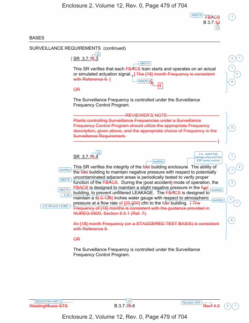
FBACS B 3.7.13
Westinghouse STS B 3.7.13-6 Rev. 4.0
ABGTS 1
12
12SEQUOYAH UNIT 2 Revision XXX 2 1
BASES SURVEILLANCE REQUIREMENTS (continued)
[ SR 3.7.13.3 This SR verifies that each FBACS train starts and operates on an actual or simulated actuation signal. [ The [18] month Frequency is consistent with Reference 6. ] OR The Surveillance Frequency is controlled under the Surveillance Frequency Control Program. -----------------------------------REVIEWER’S NOTE----------------------------------- Plants controlling Surveillance Frequencies under a Surveillance Frequency Control Program should utilize the appropriate Frequency description, given above, and the appropriate choice of Frequency in the Surveillance Requirement. ------------------------------------------------------------------------------------------------ ] SR 3.7.13.4 This SR verifies the integrity of the fuel building enclosure. The ability of the fuel building to maintain negative pressure with respect to potentially uncontaminated adjacent areas is periodically tested to verify proper function of the FBACS. During the [post accident] mode of operation, the FBACS is designed to maintain a slight negative pressure in the fuel building, to prevent unfiltered LEAKAGE. The FBACS is designed to maintain a [-0.125] inches water gauge with respect to atmospheric pressure at a flow rate of [20,000] cfm to the fuel building. [ The Frequency of [18] months is consistent with the guidance provided in NUREG-0800, Section 6.5.1 (Ref. 7). An [18] month Frequency (on a STAGGERED TEST BASIS) is consistent with Reference 6. OR The Surveillance Frequency is controlled under the Surveillance Frequency Control Program.
ABGTS
8,100 and 9,900
3
1
6
5
1
ABGTS
ABGTS
auxiliary
auxiliary
- 0.25
3
31
6
auxiliary
auxiliary
112
112 (i.e., spent fuel
storage area and the ESF pump rooms)
2
INSERT 5
4
Enclosure 2, Volume 12, Rev. 0, Page 479 of 704
Enclosure 2, Volume 12, Rev. 0, Page 479 of 704
4
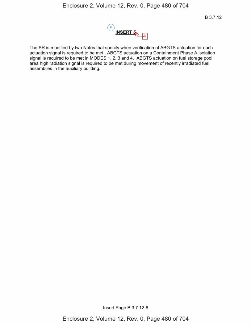
B 3.7.12
Insert Page B 3.7.12-6
INSERT 5 The SR is modified by two Notes that specify when verification of ABGTS actuation for each actuation signal is required to be met. ABGTS actuation on a Containment Phase A isolation signal is required to be met in MODES 1, 2, 3 and 4. ABGTS actuation on fuel storage pool area high radiation signal is required to be met during movement of recently irradiated fuel assemblies in the auxiliary building.
6
Enclosure 2, Volume 12, Rev. 0, Page 480 of 704
Enclosure 2, Volume 12, Rev. 0, Page 480 of 704
4
Licensee Response/NRC Response/NRC Question ClosureId 303
NRC Question Number
RPG-001
Select Application Licensee Response
Attachment 1 RAI RPG-001 Supplemental Response Attachment.pdf (466KB)
Attachment 2
Response Statement
This response supplements the response to RAI RPG-001. During review, it was identified that Attachment 1 to the response for RAI RPG-001 contained an error associated with the SQN Unit 2 ISTS markups for ITS 3.7.12. Specifically, for SQN Unit 2, ITS 3.7.12 Mode of Applicability should be, “MODES 1, 2, 3, and 4, During movement of recently irradiated fuel assemblies in the auxiliary building.” vice “MODES 1, 2, 3, and 4, During movement of recently irradiated fuel assemblies.”
See Attachment 1 for the draft revised SQN Unit 2, ITS 3.7.12 Mode of Applicability.
Response Date/Time 8/28/2014 6:15 AM
Closure Statement
Question Closure Date
Notification Scott BowmanMichelle ConnerRavinder GroverKhadijah HemphillAndrew HonRay Schiele
Added By Scott Bowman
Date Added 8/28/2014 5:16 AM
Date Modified
Modified By
Page 1 of 1Sequoyah ITS Conversion Database
3/24/2015https://members.excelservices.com/rai/index.php?requestType=areaItemPrint&itemId=303
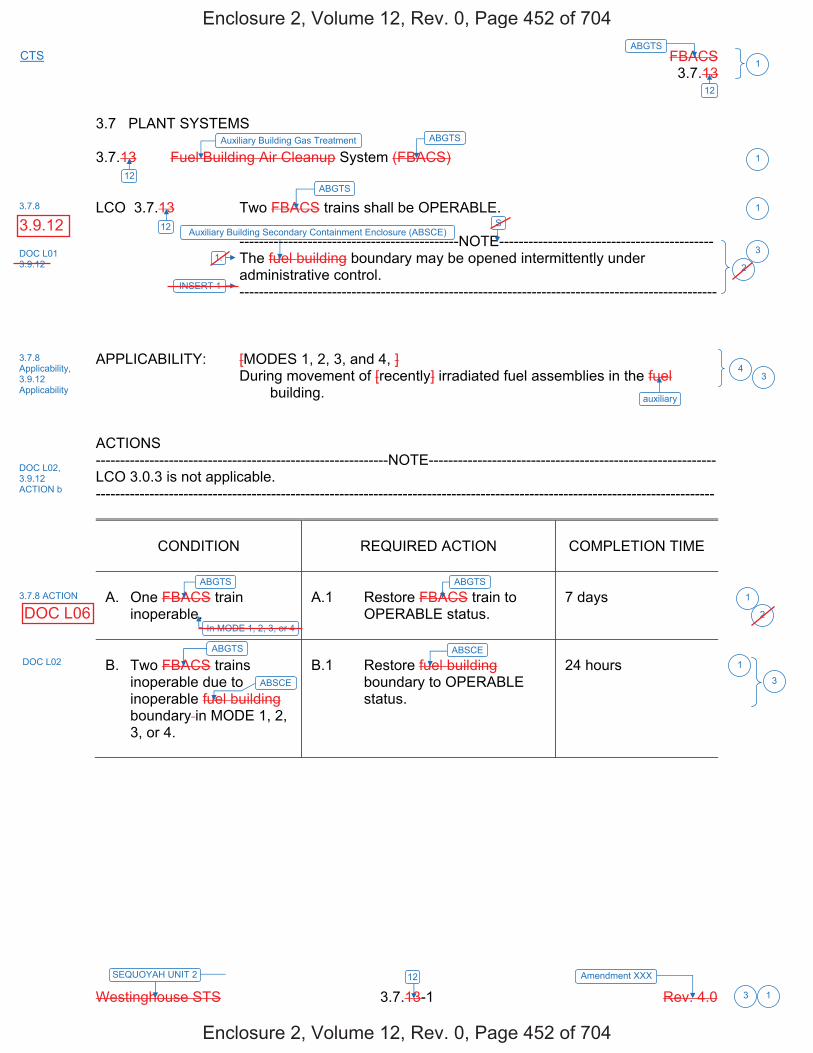
FBACS 3.7.13
Westinghouse STS 3.7.13-1 Rev. 4.0
ABGTSCTS
1
12
3
SEQUOYAH UNIT 2 Amendment XXX 12
1
3.7 PLANT SYSTEMS
3.7.13 Fuel Building Air Cleanup System (FBACS)
LCO 3.7.13 Two FBACS trains shall be OPERABLE.
---------------------------------------------NOTE--------------------------------------------The fuel building boundary may be opened intermittently under administrative control.
--------------------------------------------------------------------------------------------------
APPLICABILITY: [MODES 1, 2, 3, and 4, ] During movement of [recently] irradiated fuel assemblies in the fuel
building.
ACTIONS ------------------------------------------------------------NOTE----------------------------------------------------------- LCO 3.0.3 is not applicable. -------------------------------------------------------------------------------------------------------------------------------
CONDITION REQUIRED ACTION COMPLETION TIME
A. One FBACS train inoperable.
A.1 Restore FBACS train to OPERABLE status.
7 days
B. Two FBACS trains inoperable due to inoperable fuel building boundary in MODE 1, 2, 3, or 4.
B.1 Restore fuel building boundary to OPERABLE status.
24 hours
ABGTSAuxiliary Building Gas Treatment
ABGTS
3.7.8
Auxiliary Building Secondary Containment Enclosure (ABSCE)
3.7.8 Applicability, 3.9.12 Applicability
1
1
2
4
3.7.8 ACTION
DOC L02, 3.9.12 ACTION b
ABGTS ABGTS
12
12
auxiliary
3
1
3
ABGTS
ABSCE
ABSCE DOC L02 1
1. DOC L01 3.9.12
S
INSERT 1
3
In MODE 1, 2, 3, or 4 2
Enclosure 2, Volume 12, Rev. 0, Page 452 of 704
Enclosure 2, Volume 12, Rev. 0, Page 452 of 704
3.9.12
DOC L06
Licensee Response/NRC Response/NRC Question ClosureId 386
NRC Question Number
RPG-001
Select Application NRC Response
Attachment 1
Attachment 2
Response Statement The Staff’s follow-up response to RPG-001:
Ref. ITS TABLE 3.3.8-1 (CTS TABLE 3.3-6, “RADIATION MONITORING ISTRUMENTATION”) (ENCLOSURE 2, VOLUME 8, Rev 0)
1. The proposed change on TS page 3/4 3-41 for Sequoyah unit 2 (page 1035 of 1148 of Enclosure 2 Volume 8), in the attachment to the licensee’s 6/20/14 response to RPG-001, shows deletion of a wrong note. The change deletes the note, “ADD proposed Table 3.3.8-1 Function 3,” associated with M05, instead of deleting the note, “Add proposed Table 3.3.8-1 Footnote (b),” associated with M04.
2. New DOC L01 (Text added after page 1044) incorrectly references ITS 3.7.12 Action A in the first paragraph. It should have referenced ITS 3.3.8 Action A.
Please correct these discrepancies or provide justification for the proposed changes.
Please note, since the ITS 3.9.4 related proposed changes are dependent on the Staff’s approval of the FHA, the Staff believes that RPG-001 should remain open, If the FHA is not approved by the Staff, Sequoyah will have to remove the applicability of ‘recently’ irradiated fuel and return the applicability to irradiated fuel.
Response Date/Time 11/25/2014 6:00 PM
Closure Statement
Question Closure Date
Notification Mark Blumberg
Page 1 of 2Sequoyah ITS Conversion Database
1/13/2015https://members.excelservices.com/rai/index.php?requestType=areaItemPrint&itemId=386
Scott BowmanKristy BucholtzMichelle ConnerRobert ElliottRavinder GroverMatthew HammKhadijah HemphillAndrew HonLynn MynattRay SchieleRoger Scott
Added By Ravinder Grover
Date Added 11/25/2014 4:43 PM
Date Modified
Modified By
Page 2 of 2Sequoyah ITS Conversion Database
1/13/2015https://members.excelservices.com/rai/index.php?requestType=areaItemPrint&itemId=386
Licensee Response/NRC Response/NRC Question ClosureId 392
NRC Question Number
RPG-001
Select Application Licensee Response
Attachment 1 RAI RPG-001 Revised Attachment 1 for Response to NRC Response.pdf (2MB)
Attachment 2
Response Statement Based on the Staff’s response to RAI RPG-001,
Attachment 1, provided with the initial RAI response and supplemented by a subsequent licensee response, will be revised. Specifically, Attachment 1 (page 1035 of 1148 of Enclosure 2, Volume 8) will be revised to retain the proposed insert and indicator associated with Discussion of Change (DOC) M05, and delete the proposed insert and indicator associated with DOC M04. Additionally, new DOC L01 (insert page following page 1044 of 1148) will be revised to reference ITS 3.3.8 ACTION A vice ITS 3.7.12 ACTION A in the first paragraph.
See Attachment 1 for the draft revised changes to the ITS submittal. Attachment 1 is a rollup of changes based on the original RAI response, the supplemental RAI response, and the proposed changes discussed above. Because the revised Attachment 1 is a reflection of changes to the ITS submittal, originally proposed changes in the initial RAI response that were incorrect will not be reflected in the rollup.
Response Date/Time 12/3/2014 6:00 AM
Closure Statement
Question Closure
Date
Notification Mark BlumbergScott BowmanKristy BucholtzMichelle Conner
Page 1 of 2Sequoyah ITS Conversion Database
1/13/2015https://members.excelservices.com/rai/index.php?requestType=areaItemPrint&itemId=392
Ravinder GroverMatthew HammKhadijah HemphillAndrew HonRay Schiele
Added By Scott Bowman
Date Added 12/3/2014 5:02 AM
Date Modified
Modified By
Page 2 of 2Sequoyah ITS Conversion Database
1/13/2015https://members.excelservices.com/rai/index.php?requestType=areaItemPrint&itemId=392
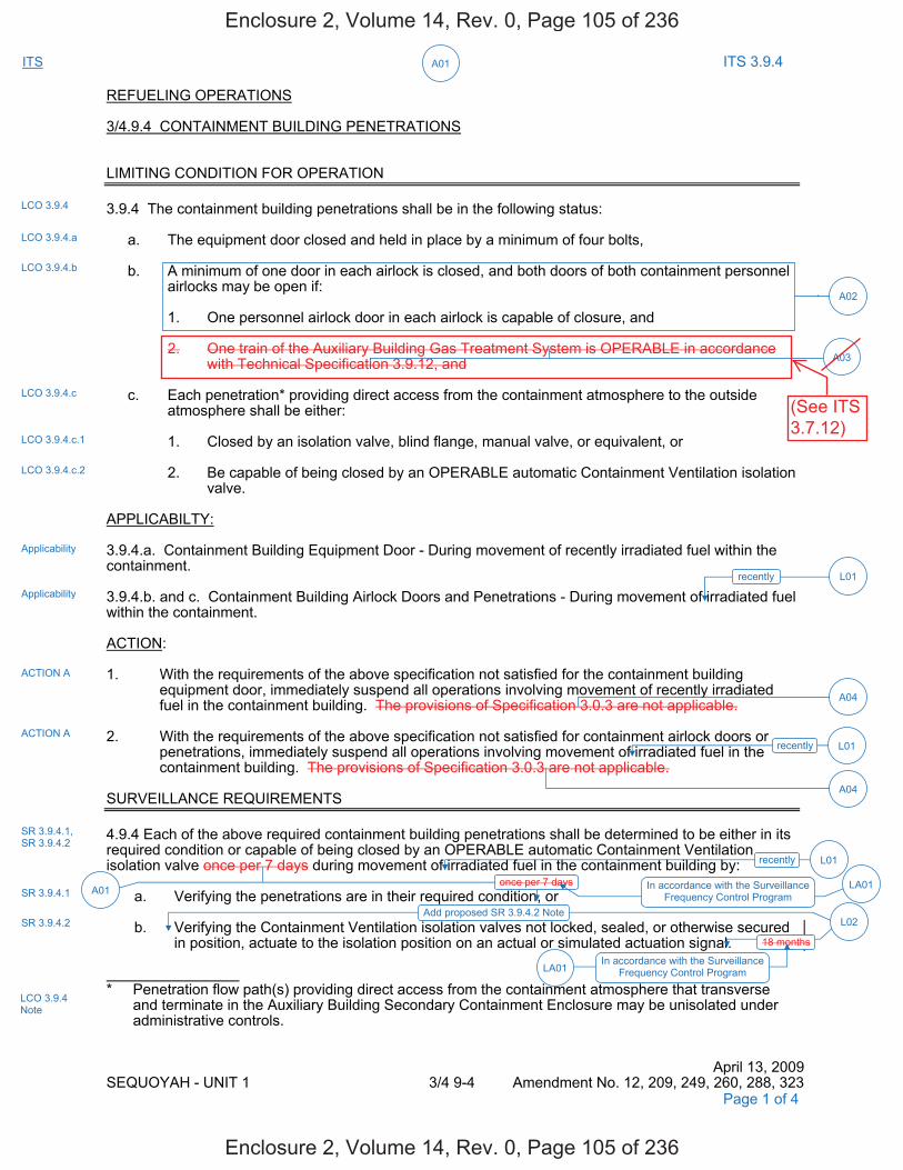
ITS A01 ITS 3.9.4
REFUELING OPERATIONS 3/4.9.4 CONTAINMENT BUILDING PENETRATIONS LIMITING CONDITION FOR OPERATION 3.9.4 The containment building penetrations shall be in the following status: a. The equipment door closed and held in place by a minimum of four bolts,
b. A minimum of one door in each airlock is closed, and both doors of both containment personnel
airlocks may be open if: 1. One personnel airlock door in each airlock is capable of closure, and 2. One train of the Auxiliary Building Gas Treatment System is OPERABLE in accordance
with Technical Specification 3.9.12, and c. Each penetration* providing direct access from the containment atmosphere to the outside
atmosphere shall be either: 1. Closed by an isolation valve, blind flange, manual valve, or equivalent, or 2. Be capable of being closed by an OPERABLE automatic Containment Ventilation isolation
valve. APPLICABILTY: 3.9.4.a. Containment Building Equipment Door - During movement of recently irradiated fuel within the containment. 3.9.4.b. and c. Containment Building Airlock Doors and Penetrations - During movement of irradiated fuel within the containment. ACTION: 1. With the requirements of the above specification not satisfied for the containment building
equipment door, immediately suspend all operations involving movement of recently irradiated fuel in the containment building. The provisions of Specification 3.0.3 are not applicable.
2. With the requirements of the above specification not satisfied for containment airlock doors or
penetrations, immediately suspend all operations involving movement of irradiated fuel in the containment building. The provisions of Specification 3.0.3 are not applicable.
SURVEILLANCE REQUIREMENTS 4.9.4 Each of the above required containment building penetrations shall be determined to be either in its required condition or capable of being closed by an OPERABLE automatic Containment Ventilation isolation valve once per 7 days during movement of irradiated fuel in the containment building by: a. Verifying the penetrations are in their required condition, or b. Verifying the Containment Ventilation isolation valves not locked, sealed, or otherwise secured
in position, actuate to the isolation position on an actual or simulated actuation signal. * Penetration flow path(s) providing direct access from the containment atmosphere that transverse
and terminate in the Auxiliary Building Secondary Containment Enclosure may be unisolated under administrative controls.
April 13, 2009 SEQUOYAH - UNIT 1 3/4 9-4 Amendment No. 12, 209, 249, 260, 288, 323
LCO 3.9.4
LCO 3.9.4.a
LCO 3.9.4.b
LCO 3.9.4.c
Applicability
ACTION A
ACTION A
SR 3.9.4.1, SR 3.9.4.2
SR 3.9.4.1
SR 3.9.4.2
recently L01
A04
A04
A02
Applicability
Page 1 of 4
Add proposed SR 3.9.4.2 Note
LCO 3.9.4.c.1
LCO 3.9.4.c.2
recently L01
L02
18 months
LA01In accordance with the Surveillance
Frequency Control Program
A01 once per 7 days LA01In accordance with the Surveillance
Frequency Control Program
LCO 3.9.4 Note
recently L01
A03
Enclosure 2, Volume 14, Rev. 0, Page 105 of 236
Enclosure 2, Volume 14, Rev. 0, Page 105 of 236
(See ITS3.7.12)

ITS A01 ITS 3.9.4
REFUELING OPERATIONS 3/4.9.4 CONTAINMENT BUILDING PENETRATIONS LIMITING CONDITION FOR OPERATION 3.9.4 The containment building penetrations shall be in the following status: a. The equipment door closed and held in place by a minimum of four bolts, b. A minimum of one door in each airlock is closed, or both doors of both containment
personnel airlocks may be open if: 1. One personnel airlock door in each airlock is capable of closure, and 2. One train of the Auxiliary Building Gas Treatment System is OPERABLE in accordance
with Technical Specification 3.9.12, and c. Each penetration* providing direct access from the containment atmosphere to the outside
atmosphere shall be either: 1. Closed by an isolation valve, blind flange, manual valve, or equivalent, or 2. Be capable of being closed by an OPERABLE automatic Containment Ventilation
isolation valve. APPLICABILITY: 3.9.4.a. Containment Building Equipment Door - During movement of recently irradiated fuel within the containment. 3.9.4.b. and c. Containment Building Airlock Doors and Penetrations - During movement of irradiated fuel within the containment. ACTION: 1. With the requirements of the above specification not satisfied for the containment building
equipment door, immediately suspend all operations involving movement of recently irradiated fuel in the containment building. The provisions of Specification 3.0.3 are not applicable.
2. With the requirements of the above specification not satisfied for containment airlock doors or
penetrations, immediately suspend all operations involving movement of irradiated fuel in the containment building. The provisions of Specification 3.0.3 are not applicable.
SURVEILLANCE REQUIREMENTS 4.9.4 Each of the above required containment building penetrations shall be determined to be either in its required condition or capable of being closed by an OPERABLE automatic Containment Ventilation isolation valve once per 7 days during movement of irradiated fuel in the containment building by: a. Verifying the penetrations are in their required condition, or b. Verifying the Containment Ventilation isolation valves not locked, sealed, or otherwise secured
in position, actuate to the isolation position on an actual or simulated actuation signal. * Penetration flow path(s) providing direct access from the containment atmosphere that transverse and terminate in the Auxiliary Building Secondary Containment Enclosure may be unisolated under administrative controls.
April 13, 2009 SEQUOYAH - UNIT 2 3/4 9-5 Amendment No. 199, 240, 251, 278, 315
LCO 3.9.4
LCO 3.9.4.a
LCO 3.9.4.b
LCO 3.9.4.c
Applicability
ACTION A
ACTION A
SR 3.9.4.1, SR 3.9.4.2
SR 3.9.4.1
SR 3.9.4.2
recently
Applicability
Add proposed SR 3.9.4.2 Note
A02
L01
A04
A04
Page 3 of 4
LCO 3.9.4.c.1
LCO 3.9.4.c.2
recently L01
L02
once per 7 days A01
In accordance with the Surveillance Frequency Control Program LA01
L0218 months
In accordance with the Surveillance Frequency Control Program LA01
LCO 3.9.4 Note
recently L01
A03
Enclosure 2, Volume 14, Rev. 0, Page 107 of 236
Enclosure 2, Volume 14, Rev. 0, Page 107 of 236
(See ITS3.7.12)

DISCUSSION OF CHANGES ITS 3.9.4, CONTAINMENT PENETRATIONS
Sequoyah Unit 1 and Unit 2 Page 1 of 5
ADMINISTRATIVE CHANGES A01 In the conversion of the Sequoyah Nuclear Plant (SQN) Current Technical
Specifications (CTS) to the plant specific Improved Technical Specifications (ITS), certain changes (wording preferences, editorial changes, reformatting, revised numbering, etc.) are made to obtain consistency with NUREG-1431, Rev. 4.0, "Standard Technical Specifications-Westinghouse Plants" (ISTS) and additional Technical Specification Task Force (TSTF) travelers included in this submittal.
These changes are designated as administrative changes and are acceptable
because they do not result in technical changes to the CTS. A02 CTS 3.9.4.b requires that a minimum of one door in each airlock is closed, and
both doors of both containment personnel airlocks may be open if one personnel airlock door in each airlock is capable of closure and one train of the Auxiliary Building Gas Treatment System is OPERABLE in accordance with Technical Specification 3.9.12. ITS LCO 3.9.4.b requires that one door in each air lock be capable of being closed. This changes the CTS by replacing the prescriptive requirement for control of the air lock doors with a more general requirement that the air lock doors must be capable of being closed.
This change is acceptable because the requirements have not changed, one
door continues to be capable of being closed in the event of a fuel handling accident. The ITS requirement preserves the intent of the CTS in that should a fuel handling accident occur inside containment, at least one airlock door in each airlock will be closed following an evacuation of containment. This change is designated as administrated because it does not result in a technical change to the CTS.
A03 CTS 3.9.4.b allows both doors of each containment personnel airlocks to be
open provided, in part, that "One train of the Auxiliary Building Gas Treatment System is OPERABLE in accordance with Technical Specification 3.9.12." ITS 3.9.4.b does not contain this specific requirement. This changes the CTS by removing the specific requirement that one train of the Auxiliary Building Gas Treatment System be OPERABLE.
The purpose of CTS 3.9.4.b is to ensure that the Auxiliary Building Gas
Treatment System is available when the containment personnel airlock doors are open during movement of recently irradiated fuel within the containment, this is accomplished by referencing CTS 3.9.12. This change is acceptable because the associated requirements referenced by CTS 3.9.4.b in CTS 3.9.12 are being addressed in ITS 3.7.12. Therefore, ITS 3.7.12 contains the appropriate requirements associated with the ABGTS. This change is designated as administrative because it does not result in a technical change to the CTS.
A04 CTS 3.9.4 and CTS 3.9.9 ACTIONS state "The provisions of Specification 3.0.3
are not applicable. ITS 3.9.4 does not include this statement. This changes the CTS by deleting the Specification 3.0.3 exemption.
Enclosure 2, Volume 14, Rev. 0, Page 109 of 236
Enclosure 2, Volume 14, Rev. 0, Page 109 of 236
Not used.
(See ITS 3.7.12DOC L08 for thediscussion ofrelaxing theOPERABILITYrequirements forABGTS.)

Containment Penetrations B 3.9.4
Westinghouse STS B 3.9.4-4 Rev. 4.0
SEQUOYAH UNIT 1 Revision XXX 2
BASES LCO (continued)
The LCO is modified by a Note allowing penetration flow paths with direct access from the containment atmosphere to the outside atmosphere to be unisolated under administrative controls. Administrative controls ensure that 1) appropriate personnel are aware of the open status of the penetration flow path during movement of irradiated fuel assemblies within containment, and 2) specified individuals are designated and readily available to isolate the flow path in the event of a fuel handling accident. The containment personnel air lock doors many be open during movement of [recently] irradiated fuel in the containment provided that one door is capable of being closed in the event of a fuel handling accident. Should a fuel handling accident occur inside containment, one personnel air lock door will be closed following an evacuation of containment.
APPLICABILITY The containment penetration requirements are applicable during
movement of [recently] irradiated fuel assemblies within containment because this is when there is a potential for the limiting fuel handling accident. In MODES 1, 2, 3, and 4, containment penetration requirements are addressed by LCO 3.6.1. In MODES 5 and 6, when movement of irradiated fuel assemblies within containment is not being conducted, the potential for a fuel handling accident does not exist. [Additionally, due to radioactive decay, a fuel handling accident involving handling recently irradiated fuel (i.e., fuel that has occupied part of a critical reactor core within the previous [x] days) will result in doses that are well within the guideline values specified in 10 CFR 100 even without containment closure capability.] Therefore, under these conditions no requirements are placed on containment penetration status. -----------------------------------REVIEWER’S NOTE----------------------------------- The addition of the term "recently" associated with handling irradiated fuel in all of the containment function Technical Specification requirements is only applicable to those licensees who have demonstrated by analysis that after sufficient radioactive decay has occurred, off-site doses resulting from a fuel handling accident remain below the Standard Review Plan limits (well within 10 CFR 100). Additionally, licensees adding the term "recently" must make the following commitment which is consistent with NUMARC 93-01, Revision 4, Section 11.3.6.5 "Safety Assessment for Removal of Equipment from Service During Shutdown Conditions," subheading "Containment - Primary (PWR)/Secondary (BWR)." "The following guidelines are included in the assessment of systems removed from service during movement irradiated fuel:
100 hours
2
1
1
1
5
may
4
at least
INSERT 2
2
2
INSERT 3
that transverse and terminate in the Auxiliary
Building Secondary Containment Enclosure
50.67
2
2
Enclosure 2, Volume 14, Rev. 0, Page 127 of 236
Enclosure 2, Volume 14, Rev. 0, Page 127 of 236
Insert Page B 3.9.4-4
INSERT 2 During movement of recently irradiated fuel assemblies within containment, the equipment hatch is required to be held in place by at least four bolts.
INSERT 3 The containment design is such that even though the primary and secondary containments are connected together when the personnel air lock doors are open, the normal auxiliary building ventilation system and Auxiliary Building Gas Treatment System (ABGTS) continue to provide the same fuel handling accident mitigation capability. With the personnel air lock doors open, the consequences of a fuel handling accident in the containment will be mitigated by the design of the ventilation systems (maintenance of a negative pressure during normal and applicable abnormal conditions, automatic isolation on high radiation in the auxiliary building, and automatic startup of emergency ventilation systems) and the leak-tight design of the auxiliary building. Both sets of the containment personnel airlock doors may be open during movement of recently irradiated fuel in containment provided one train of ABGTS is available for operation (LCO 3.7.12, "Auxiliary Building Gas Treatment System (AGBTS)"). The fuel handling accident is analyzed to occur in either the containment or the auxiliary building; however, an ABGTS start may be necessary for a containment fuel handling accident. The requirement for an airlock door to be capable of closure is provided to allow for long-term recovery from a fuel handling accident in containment.
4
2
Enclosure 2, Volume 14, Rev. 0, Page 128 of 236
Enclosure 2, Volume 14, Rev. 0, Page 128 of 236
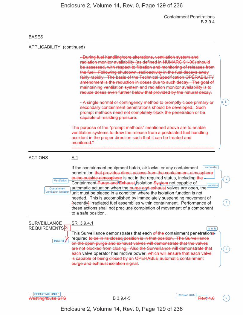
Containment Penetrations B 3.9.4
Westinghouse STS B 3.9.4-5 Rev. 4.0
SEQUOYAH UNIT 1 Revision XXX 2
BASES APPLICABILITY (continued)
- During fuel handling/core alterations, ventilation system and radiation monitor availability (as defined in NUMARC 91-06) should be assessed, with respect to filtration and monitoring of releases from the fuel. Following shutdown, radioactivity in the fuel decays away fairly rapidly. The basis of the Technical Specification OPERABILITY amendment is the reduction in doses due to such decay. The goal of maintaining ventilation system and radiation monitor availability is to reduce doses even further below that provided by the natural decay. - A single normal or contingency method to promptly close primary or secondary containment penetrations should be developed. Such prompt methods need not completely block the penetration or be capable of resisting pressure.
The purpose of the "prompt methods" mentioned above are to enable ventilation systems to draw the release from a postulated fuel handling accident in the proper direction such that it can be treated and monitored." --------------------------------------------------------------------------------------------------
ACTIONS A.1
If the containment equipment hatch, air locks, or any containment penetration that provides direct access from the containment atmosphere to the outside atmosphere is not in the required status, including the Containment Purge and Exhaust Isolation System not capable of automatic actuation when the purge and exhaust valves are open, the unit must be placed in a condition where the isolation function is not needed. This is accomplished by immediately suspending movement of [recently] irradiated fuel assemblies within containment. Performance of these actions shall not preclude completion of movement of a component to a safe position.
SURVEILLANCE SR 3.9.4.1 REQUIREMENTS
This Surveillance demonstrates that each of the containment penetrations required to be in its closed position is in that position. The Surveillance on the open purge and exhaust valves will demonstrate that the valves are not blocked from closing. Also the Surveillance will demonstrate that each valve operator has motive power, which will ensure that each valve is capable of being closed by an OPERABLE automatic containment purge and exhaust isolation signal.
Ventilation
5
6
INSERT 4
is in its
1
Containment Ventilation isolation
2
automatic
valve(s)
Enclosure 2, Volume 14, Rev. 0, Page 129 of 236
Enclosure 2, Volume 14, Rev. 0, Page 129 of 236
3

Insert Page B 3.9.4-5
INSERT 4 status. The requirement that penetrations are capable of being closed by an OPERABLE automatic containment ventilation isolation valve, can be verified by ensuring that each required containment ventilation isolation
6
Enclosure 2, Volume 14, Rev. 0, Page 130 of 236
Enclosure 2, Volume 14, Rev. 0, Page 130 of 236
3

Containment Penetrations B 3.9.4
Westinghouse STS B 3.9.4-6 Rev. 4.0
SEQUOYAH UNIT 1 Revision XXX 2
BASES SURVEILLANCE REQUIREMENTS (continued)
[ The Surveillance is performed every 7 days during movement of [recently] irradiated fuel assemblies within containment. The Surveillance interval is selected to be commensurate with the normal duration of time to complete fuel handling operations. A surveillance before the start of refueling operations will provide two or three surveillance verifications during the applicable period for this LCO. As such, this Surveillance ensures that a postulated fuel handling accident [involving handling recently irradiated fuel] that releases fission product radioactivity within the containment will not result in a release of significant fission product radioactivity to the environment in excess of those recommended by Standard Review Plan Section 15.7.4 (Reference 3). OR The Surveillance Frequency is controlled under the Surveillance Frequency Control Program. -----------------------------------REVIEWER’S NOTE----------------------------------- Plants controlling Surveillance Frequencies under a Surveillance Frequency Control Program should utilize the appropriate Frequency description, given above, and the appropriate choice of Frequency in the Surveillance Requirement. ------------------------------------------------------------------------------------------------ ] SR 3.9.4.2 This Surveillance demonstrates that each containment purge and exhaust valve actuates to its isolation position on manual initiation or on an actual or simulated high radiation signal. [ The 18 month Frequency maintains consistency with other similar ESFAS instrumentation and valve testing requirements. In LCO 3.3.6, the Containment Purge and Exhaust Isolation instrumentation requires a CHANNEL CHECK every 12 hours and a COT every 92 days to ensure the channel OPERABILITY during refueling operations. Every 18 months a CHANNEL CALIBRATION is performed. The system actuation response time is demonstrated every 18 months, during refueling, on a STAGGERED TEST BASIS. SR 3.6.3.5 demonstrates that the isolation time of each valve is in accordance with the Inservice Testing Program requirements. These Surveillances performed during MODE 6 will ensure that the valves are capable of closing after a postulated fuel handling accident [involving handling recently irradiated fuel] to limit a release of fission product radioactivity from the containment.
ventilation isolation
7
8
2
7
INSERT 5 9
actuation 10
Enclosure 2, Volume 14, Rev. 0, Page 131 of 236
Enclosure 2, Volume 14, Rev. 0, Page 131 of 236
4
Insert Page B 3.9.4-6
INSERT 5 , that is not locked, sealed, or otherwise secured in position,
9
Enclosure 2, Volume 14, Rev. 0, Page 132 of 236
Enclosure 2, Volume 14, Rev. 0, Page 132 of 236
4
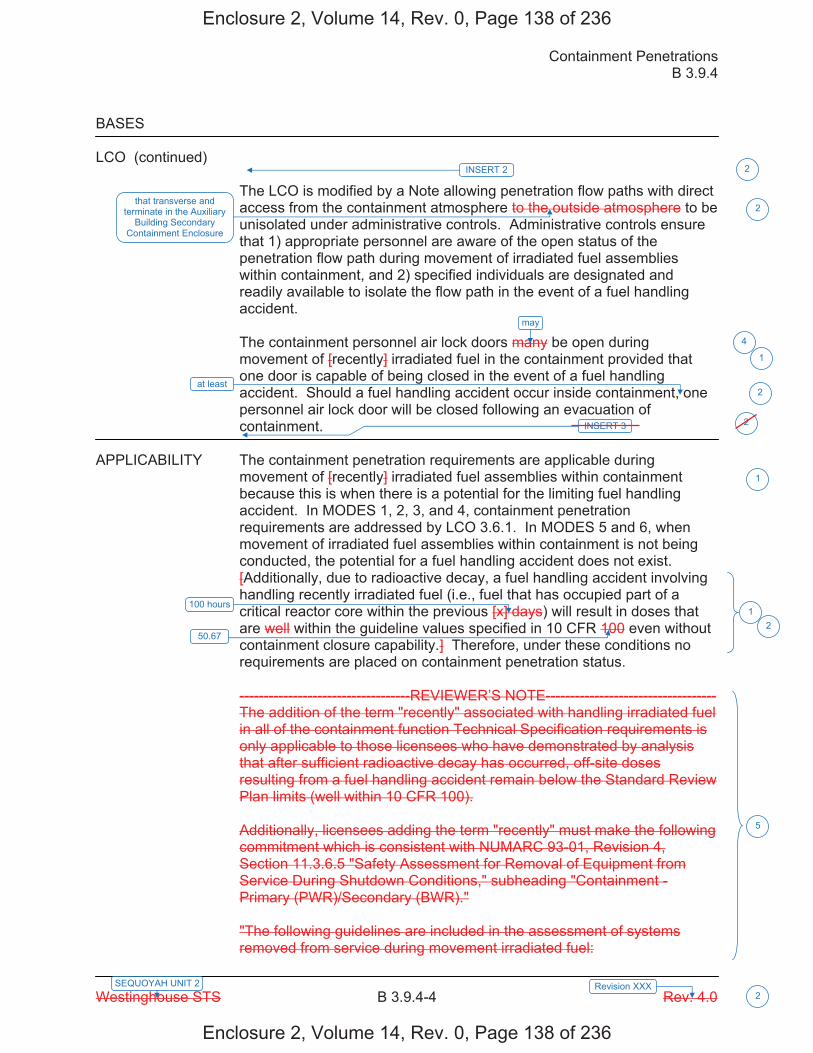
Containment Penetrations B 3.9.4
Westinghouse STS B 3.9.4-4 Rev. 4.0
SEQUOYAH UNIT 2 Revision XXX 2
BASES LCO (continued)
The LCO is modified by a Note allowing penetration flow paths with direct access from the containment atmosphere to the outside atmosphere to be unisolated under administrative controls. Administrative controls ensure that 1) appropriate personnel are aware of the open status of the penetration flow path during movement of irradiated fuel assemblies within containment, and 2) specified individuals are designated and readily available to isolate the flow path in the event of a fuel handling accident. The containment personnel air lock doors many be open during movement of [recently] irradiated fuel in the containment provided that one door is capable of being closed in the event of a fuel handling accident. Should a fuel handling accident occur inside containment, one personnel air lock door will be closed following an evacuation of containment.
APPLICABILITY The containment penetration requirements are applicable during
movement of [recently] irradiated fuel assemblies within containment because this is when there is a potential for the limiting fuel handling accident. In MODES 1, 2, 3, and 4, containment penetration requirements are addressed by LCO 3.6.1. In MODES 5 and 6, when movement of irradiated fuel assemblies within containment is not being conducted, the potential for a fuel handling accident does not exist. [Additionally, due to radioactive decay, a fuel handling accident involving handling recently irradiated fuel (i.e., fuel that has occupied part of a critical reactor core within the previous [x] days) will result in doses that are well within the guideline values specified in 10 CFR 100 even without containment closure capability.] Therefore, under these conditions no requirements are placed on containment penetration status. -----------------------------------REVIEWER’S NOTE----------------------------------- The addition of the term "recently" associated with handling irradiated fuel in all of the containment function Technical Specification requirements is only applicable to those licensees who have demonstrated by analysis that after sufficient radioactive decay has occurred, off-site doses resulting from a fuel handling accident remain below the Standard Review Plan limits (well within 10 CFR 100). Additionally, licensees adding the term "recently" must make the following commitment which is consistent with NUMARC 93-01, Revision 4, Section 11.3.6.5 "Safety Assessment for Removal of Equipment from Service During Shutdown Conditions," subheading "Containment - Primary (PWR)/Secondary (BWR)." "The following guidelines are included in the assessment of systems removed from service during movement irradiated fuel:
100 hours
2
1
1
1
5
may
4
at least
INSERT 2
2
2
INSERT 3
that transverse and terminate in the Auxiliary
Building Secondary Containment Enclosure
50.67
2
2
Enclosure 2, Volume 14, Rev. 0, Page 138 of 236
Enclosure 2, Volume 14, Rev. 0, Page 138 of 236

Insert Page B 3.9.4-4
INSERT 2 During movement of recently irradiated fuel assemblies within containment, the equipment hatch is required to be held in place by at least four bolts.
INSERT 3 The containment design is such that even though the primary and secondary containments are connected together when the personnel air lock doors are open, the normal auxiliary building ventilation system and Auxiliary Building Gas Treatment System (ABGTS) continue to provide the same fuel handling accident mitigation capability. With the personnel air lock doors open, the consequences of a fuel handling accident in the containment will be mitigated by the design of the ventilation systems (maintenance of a negative pressure during normal and applicable abnormal conditions, automatic isolation on high radiation in the auxiliary building, and automatic startup of emergency ventilation systems) and the leak-tight design of the auxiliary building. Both sets of the containment personnel airlock doors may be open during movement of recently irradiated fuel in containment provided one train of ABGTS is available for operation (LCO 3.7.12, "Auxiliary Building Gas Treatment System (AGBTS)"). The fuel handling accident is analyzed to occur in either the containment or the auxiliary building; however, an ABGTS start may be necessary for a containment fuel handling accident. The requirement for an airlock door to be capable of closure is provided to allow for long-term recovery from a fuel handling accident in containment.
4
2
Enclosure 2, Volume 14, Rev. 0, Page 139 of 236
Enclosure 2, Volume 14, Rev. 0, Page 139 of 236

Containment Penetrations B 3.9.4
Westinghouse STS B 3.9.4-5 Rev. 4.0
SEQUOYAH UNIT 2 Revision XXX 2
BASES APPLICABILITY (continued)
- During fuel handling/core alterations, ventilation system and radiation monitor availability (as defined in NUMARC 91-06) should be assessed, with respect to filtration and monitoring of releases from the fuel. Following shutdown, radioactivity in the fuel decays away fairly rapidly. The basis of the Technical Specification OPERABILITY amendment is the reduction in doses due to such decay. The goal of maintaining ventilation system and radiation monitor availability is to reduce doses even further below that provided by the natural decay. - A single normal or contingency method to promptly close primary or secondary containment penetrations should be developed. Such prompt methods need not completely block the penetration or be capable of resisting pressure.
The purpose of the "prompt methods" mentioned above are to enable ventilation systems to draw the release from a postulated fuel handling accident in the proper direction such that it can be treated and monitored." --------------------------------------------------------------------------------------------------
ACTIONS A.1
If the containment equipment hatch, air locks, or any containment penetration that provides direct access from the containment atmosphere to the outside atmosphere is not in the required status, including the Containment Purge and Exhaust Isolation System not capable of automatic actuation when the purge and exhaust valves are open, the unit must be placed in a condition where the isolation function is not needed. This is accomplished by immediately suspending movement of [recently] irradiated fuel assemblies within containment. Performance of these actions shall not preclude completion of movement of a component to a safe position.
SURVEILLANCE SR 3.9.4.1 REQUIREMENTS
This Surveillance demonstrates that each of the containment penetrations required to be in its closed position is in that position. The Surveillance on the open purge and exhaust valves will demonstrate that the valves are not blocked from closing. Also the Surveillance will demonstrate that each valve operator has motive power, which will ensure that each valve is capable of being closed by an OPERABLE automatic containment purge and exhaust isolation signal.
Ventilation
5
6
INSERT 4
is in its
1
Containment Ventilation isolation
2
automatic
valve(s)
Enclosure 2, Volume 14, Rev. 0, Page 140 of 236
Enclosure 2, Volume 14, Rev. 0, Page 140 of 236
3
Insert Page B 3.9.4-5
INSERT 4 status. The requirement that penetrations are capable of being closed by an OPERABLE automatic containment ventilation isolation valve, can be verified by ensuring that each required containment ventilation isolation
6
Enclosure 2, Volume 14, Rev. 0, Page 141 of 236
Enclosure 2, Volume 14, Rev. 0, Page 141 of 236
3
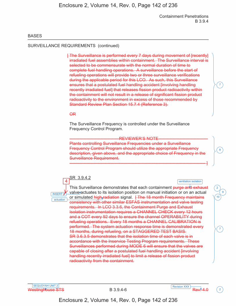
Containment Penetrations B 3.9.4
Westinghouse STS B 3.9.4-6 Rev. 4.0 SEQUOYAH UNIT 2 Revision XXX
2
BASES
SURVEILLANCE REQUIREMENTS (continued)
[ The Surveillance is performed every 7 days during movement of [recently] irradiated fuel assemblies within containment. The Surveillance interval is selected to be commensurate with the normal duration of time to complete fuel handling operations. A surveillance before the start of refueling operations will provide two or three surveillance verifications during the applicable period for this LCO. As such, this Surveillance ensures that a postulated fuel handling accident [involving handling recently irradiated fuel] that releases fission product radioactivity within the containment will not result in a release of significant fission product radioactivity to the environment in excess of those recommended by Standard Review Plan Section 15.7.4 (Reference 3).
OR
The Surveillance Frequency is controlled under the Surveillance Frequency Control Program.
-----------------------------------REVIEWER’S NOTE----------------------------------- Plants controlling Surveillance Frequencies under a Surveillance Frequency Control Program should utilize the appropriate Frequency description, given above, and the appropriate choice of Frequency in the Surveillance Requirement. ------------------------------------------------------------------------------------------------ ]
SR 3.9.4.2
This Surveillance demonstrates that each containment purge and exhaust valve actuates to its isolation position on manual initiation or on an actual or simulated high radiation signal. [ The 18 month Frequency maintains consistency with other similar ESFAS instrumentation and valve testing requirements. In LCO 3.3.6, the Containment Purge and Exhaust Isolation instrumentation requires a CHANNEL CHECK every 12 hours and a COT every 92 days to ensure the channel OPERABILITY during refueling operations. Every 18 months a CHANNEL CALIBRATION is performed. The system actuation response time is demonstrated every 18 months, during refueling, on a STAGGERED TEST BASIS. SR 3.6.3.5 demonstrates that the isolation time of each valve is in accordance with the Inservice Testing Program requirements. These Surveillances performed during MODE 6 will ensure that the valves are capable of closing after a postulated fuel handling accident [involving handling recently irradiated fuel] to limit a release of fission product radioactivity from the containment.
ventilation isolation
7
8
2
7
INSERT 5 9
actuation 10
Enclosure 2, Volume 14, Rev. 0, Page 142 of 236
Enclosure 2, Volume 14, Rev. 0, Page 142 of 236
4

Insert Page B 3.9.4-6
INSERT 5
, that is not locked, sealed, or otherwise secured in position,
9
Enclosure 2, Volume 14, Rev. 0, Page 143 of 236
Enclosure 2, Volume 14, Rev. 0, Page 143 of 236
4
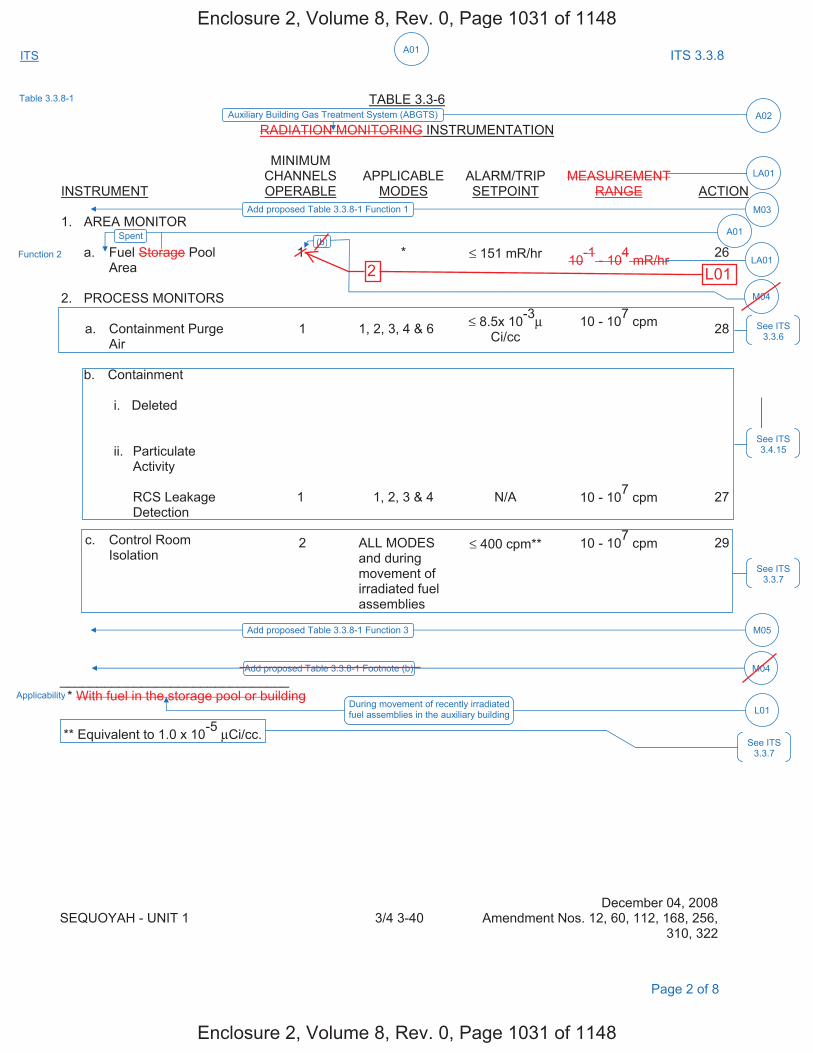
A01ITS ITS 3.3.8
TABLE 3.3-6
RADIATION MONITORING INSTRUMENTATION
INSTRUMENT
MINIMUM CHANNELS OPERABLE
APPLICABLE MODES
ALARM/TRIP SETPOINT
MEASUREMENT RANGE ACTION
1. AREA MONITOR
a. Fuel Storage Pool Area
1 * ≤ 151 mR/hr 10-1 - 104 mR/hr 26
2. PROCESS MONITORS
a. Containment PurgeAir
1 1, 2, 3, 4 & 6 ≤ 8.5x 10⁻³μCi/cc
10 - 107 cpm 28
b. Containment
i. Deleted
ii. ParticulateActivity
RCS LeakageDetection
1 1, 2, 3 & 4 N/A 10 - 107 cpm 27
c. Control RoomIsolation
2 ALL MODES and during movement of irradiated fuel assemblies
≤ 400 cpm** 10 - 107 cpm 29
_______________________________ * With fuel in the storage pool or building
** Equivalent to 1.0 x 10⁻⁵ μCi/cc.
December 04, 2008 SEQUOYAH - UNIT 1 3/4 3-40 Amendment Nos. 12, 60, 112, 168, 256,
310, 322
Page 2 of 8
Function 2
See ITS 3.3.6
See ITS 3.4.15
See ITS 3.3.7
During movement of recently irradiated fuel assemblies in the auxiliary building L01
Applicability
See ITS 3.3.7
Table 3.3.8-1
Auxiliary Building Gas Treatment System (ABGTS) A02
LA01
LA01
Add proposed Table 3.3.8-1 Function 1 M03
Add proposed Table 3.3.8-1 Function 3 M05
Spent A01(b)
M04
Add proposed Table 3.3.8-1 Footnote (b) M04
Enclosure 2, Volume 8, Rev. 0, Page 1031 of 1148
Enclosure 2, Volume 8, Rev. 0, Page 1031 of 1148
2 L01
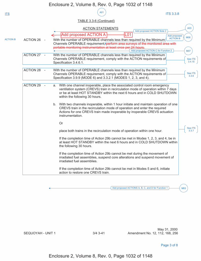
A01ITS ITS 3.3.8
TABLE 3.3-6 (Continued)
ACTION STATEMENTS
ACTION 26 - With the number of OPERABLE channels less than required by the Minimum Channels OPERABLE requirement, perform area surveys of the monitored area with portable monitoring instrumentation at least once per 24 hours.
ACTION 27 - With the number of OPERABLE channels less than required by the Minimum Channels OPERABLE requirement, comply with the ACTION requirements of Specification 3.4.6.1.
ACTION 28 - With the number of OPERABLE channels less than required by the Minimum Channels OPERABLE requirement, comply with the ACTION requirements of Specification 3.9.9 (MODE 6) and 3.3.2.1 (MODES 1, 2, 3, and 4).
ACTION 29 - a. With one channel inoperable, place the associated control room emergencyventilation system (CREVS) train in recirculation mode of operation within 7 daysor be at least HOT STANDBY within the next 6 hours and in COLD SHUTDOWNwithin the following 30 hours.
b. With two channels inoperable, within 1 hour initiate and maintain operation of oneCREVS train in the recirculation mode of operation and enter the requiredActions for one CREVS train made inoperable by inoperable CREVS actuationinstrumentation.
Or
place both trains in the recirculation mode of operation within one hour.
If the completion time of Action 29b cannot be met in Modes 1, 2, 3, and 4, be inat least HOT STANDBY within the next 6 hours and in COLD SHUTDOWN withinthe following 30 hours.
If the completion time of Action 29b cannot be met during the movement ofirradiated fuel assemblies, suspend core alterations and suspend movement ofirradiated fuel assemblies.
If the completion time of Action 29b cannot be met in Modes 5 and 6, initiateaction to restore one CREVS train.
May 31, 2000 SEQUOYAH - UNIT 1 3/4 3-41 Amendment No. 12, 112, 168, 256
Page 3 of 8
See ITS 3.3.6
See ITS 3.4.15
See ITS 3.3.7
Add proposed ACTION Note 2 A03
Add proposed ACTION B M06
Add proposed ACTION C for Function 2 M07
ACTION B
Add proposed ACTIONS A, B, C, and D for Function 1 M03
Enclosure 2, Volume 8, Rev. 0, Page 1032 of 1148
Enclosure 2, Volume 8, Rev. 0, Page 1032 of 1148
Add proposed ACTION A L01
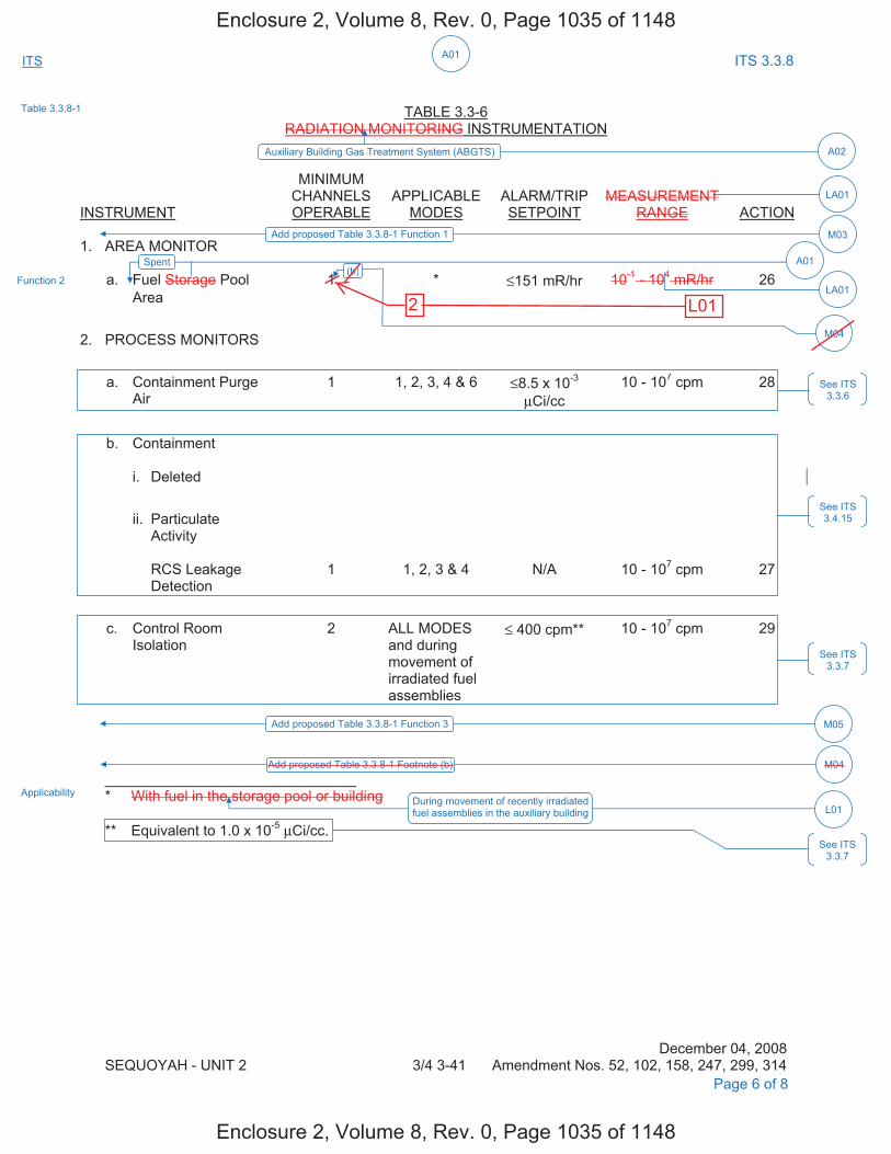
A01ITS ITS 3.3.8
TABLE 3.3-6 RADIATION MONITORING INSTRUMENTATION
INSTRUMENT
MINIMUM CHANNELS OPERABLE
APPLICABLE MODES
ALARM/TRIP SETPOINT
MEASUREMENT RANGE ACTION
1. AREA MONITOR
a. Fuel Storage Pool 1 * ≤151 mR/hr 10-1 - 104 mR/hr 26 Area
2. PROCESS MONITORS
a. Containment PurgeAir
1 1, 2, 3, 4 & 6 ≤8.5 x 10⁻³
μCi/cc 10 - 107 cpm 28
b. Containment
i. Deleted
ii. ParticulateActivity
RCS LeakageDetection
1 1, 2, 3 & 4 N/A 10 - 107 cpm 27
c. Control RoomIsolation
2 ALL MODES and during movement of irradiated fuel assemblies
≤ 400 cpm** 10 - 107 cpm 29
_______________________________ * With fuel in the storage pool or building
** Equivalent to 1.0 x 10⁻⁵ μCi/cc.
December 04, 2008 SEQUOYAH - UNIT 2 3/4 3-41 Amendment Nos. 52, 102, 158, 247, 299, 314
Page 6 of 8
Function 2
Applicability During movement of recently irradiated fuel assemblies in the auxiliary building L01
See ITS 3.3.6
See ITS 3.4.15
See ITS 3.3.7
See ITS 3.3.7
Table 3.3.8-1
Auxiliary Building Gas Treatment System (ABGTS) A02
LA01
Add proposed Table 3.3.8-1 Function 1 M03
LA01
Add proposed Table 3.3.8-1 Function 3 M05
Spent A01(b)
M04
Add proposed Table 3.3.8-1 Footnote (b) M04
Enclosure 2, Volume 8, Rev. 0, Page 1035 of 1148
Enclosure 2, Volume 8, Rev. 0, Page 1035 of 1148
2 L01
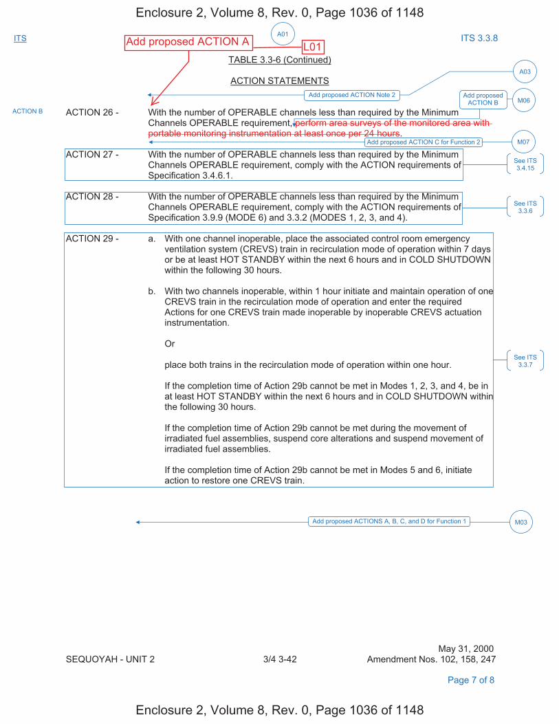
A01ITS ITS 3.3.8
TABLE 3.3-6 (Continued)
ACTION STATEMENTS
ACTION 26 - With the number of OPERABLE channels less than required by the Minimum Channels OPERABLE requirement, perform area surveys of the monitored area with portable monitoring instrumentation at least once per 24 hours.
ACTION 27 - With the number of OPERABLE channels less than required by the Minimum Channels OPERABLE requirement, comply with the ACTION requirements of Specification 3.4.6.1.
ACTION 28 - With the number of OPERABLE channels less than required by the Minimum Channels OPERABLE requirement, comply with the ACTION requirements of Specification 3.9.9 (MODE 6) and 3.3.2 (MODES 1, 2, 3, and 4).
ACTION 29 - a. With one channel inoperable, place the associated control room emergencyventilation system (CREVS) train in recirculation mode of operation within 7 daysor be at least HOT STANDBY within the next 6 hours and in COLD SHUTDOWNwithin the following 30 hours.
b. With two channels inoperable, within 1 hour initiate and maintain operation of oneCREVS train in the recirculation mode of operation and enter the requiredActions for one CREVS train made inoperable by inoperable CREVS actuationinstrumentation.
Or
place both trains in the recirculation mode of operation within one hour.
If the completion time of Action 29b cannot be met in Modes 1, 2, 3, and 4, be inat least HOT STANDBY within the next 6 hours and in COLD SHUTDOWN withinthe following 30 hours.
If the completion time of Action 29b cannot be met during the movement ofirradiated fuel assemblies, suspend core alterations and suspend movement ofirradiated fuel assemblies.
If the completion time of Action 29b cannot be met in Modes 5 and 6, initiateaction to restore one CREVS train.
May 31, 2000 SEQUOYAH - UNIT 2 3/4 3-42 Amendment Nos. 102, 158, 247
Page 7 of 8
See ITS 3.4.15
See ITS 3.3.6
See ITS 3.3.7
ACTION B
Add proposed ACTION Note 2 Add proposed ACTION B
Add proposed ACTION C for Function 2
M06
A03
M07
Add proposed ACTIONS A, B, C, and D for Function 1 M03
Enclosure 2, Volume 8, Rev. 0, Page 1036 of 1148
Enclosure 2, Volume 8, Rev. 0, Page 1036 of 1148
L01Add proposed ACTION A
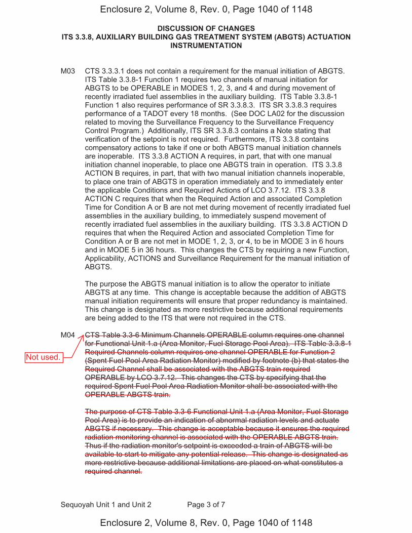
DISCUSSION OF CHANGES ITS 3.3.8, AUXILIARY BUILDING GAS TREATMENT SYSTEM (ABGTS) ACTUATION
INSTRUMENTATION
Sequoyah Unit 1 and Unit 2 Page 3 of 7
M03 CTS 3.3.3.1 does not contain a requirement for the manual initiation of ABGTS. ITS Table 3.3.8-1 Function 1 requires two channels of manual initiation for ABGTS to be OPERABLE in MODES 1, 2, 3, and 4 and during movement of recently irradiated fuel assemblies in the auxiliary building. ITS Table 3.3.8-1 Function 1 also requires performance of SR 3.3.8.3. ITS SR 3.3.8.3 requires performance of a TADOT every 18 months. (See DOC LA02 for the discussion related to moving the Surveillance Frequency to the Surveillance Frequency Control Program.) Additionally, ITS SR 3.3.8.3 contains a Note stating that verification of the setpoint is not required. Furthermore, ITS 3.3.8 contains compensatory actions to take if one or both ABGTS manual initiation channels are inoperable. ITS 3.3.8 ACTION A requires, in part, that with one manual initiation channel inoperable, to place one ABGTS train in operation. ITS 3.3.8 ACTION B requires, in part, that with two manual initiation channels inoperable, to place one train of ABGTS in operation immediately and to immediately enter the applicable Conditions and Required Actions of LCO 3.7.12. ITS 3.3.8 ACTION C requires that when the Required Action and associated Completion Time for Condition A or B are not met during movement of recently irradiated fuel assemblies in the auxiliary building, to immediately suspend movement of recently irradiated fuel assemblies in the auxiliary building. ITS 3.3.8 ACTION D requires that when the Required Action and associated Completion Time for Condition A or B are not met in MODE 1, 2, 3, or 4, to be in MODE 3 in 6 hours and in MODE 5 in 36 hours. This changes the CTS by requiring a new Function, Applicability, ACTIONS and Surveillance Requirement for the manual initiation of ABGTS.
The purpose the ABGTS manual initiation is to allow the operator to initiate ABGTS at any time. This change is acceptable because the addition of ABGTS manual initiation requirements will ensure that proper redundancy is maintained. This change is designated as more restrictive because additional requirements are being added to the ITS that were not required in the CTS.
M04 CTS Table 3.3-6 Minimum Channels OPERABLE column requires one channel for Functional Unit 1.a (Area Monitor, Fuel Storage Pool Area). ITS Table 3.3.8-1 Required Channels column requires one channel OPERABLE for Function 2 (Spent Fuel Pool Area Radiation Monitor) modified by footnote (b) that states the Required Channel shall be associated with the ABGTS train required OPERABLE by LCO 3.7.12. This changes the CTS by specifying that the required Spent Fuel Pool Area Radiation Monitor shall be associated with the OPERABLE ABGTS train.
The purpose of CTS Table 3.3-6 Functional Unit 1.a (Area Monitor, Fuel Storage Pool Area) is to provide an indication of abnormal radiation levels and actuate ABGTS if necessary. This change is acceptable because it ensures the required radiation monitoring channel is associated with the OPERABLE ABGTS train. Thus if the radiation monitor's setpoint is exceeded a train of ABGTS will be available to start to mitigate any potential release. This change is designated as more restrictive because additional limitations are placed on what constitutes a required channel.
Enclosure 2, Volume 8, Rev. 0, Page 1040 of 1148
Enclosure 2, Volume 8, Rev. 0, Page 1040 of 1148
Not used.

DISCUSSION OF CHANGES ITS 3.3.8, AUXILIARY BUILDING GAS TREATMENT SYSTEM (ABGTS) ACTUATION
INSTRUMENTATION
Sequoyah Unit 1 and Unit 2 Page 4 of 7
M05 CTS 3.3.3.1 states that the Radiation Monitoring Instrumentation channels shown in Table 3.3-6 shall be OPERABLE. CTS Table 3.3-6 lists the radiation monitor required for the fuel storage pool area. ITS LCO 3.3.8 states that the ABGTS actuation instrumentation for each Function in Table 3.3.8-1 shall be OPERABLE. ITS Table 3.3.8-1 lists the required ABGTS instrument Functions which includes Containment Isolation – Phase A (Function 3). ITS Table 3.3.8-1 Function 3 provides a statement referring to LCO 3.3.2, "ESFAS Instrumentation," Function 3.a for all initiation functions and requirements. This changes the CTS by specifying an additional instrumentation actuation Function for the ABGTS.
The purpose of CTS 3.3.3.1 and Table 3.3-6 is to specify the required Functions and instrumentation to ensure the ABGTS actuates as assumed in the accident analysis. The Containment Isolation – Phase A signal from the ESFAS provides an actuation of ABGTS that is credited in the loss of coolant accident. This change is acceptable because it will result in a more complete listing of the Functions that actuate ABGTS. The inclusion of the Containment Isolation – Phase A signal with the other credited ABGTS instrumentation provides a complete list of the required ABGTS instrumentation with a common set of Actions to assure the unit is placed in a safe condition when the required instrumentation is inoperable. Therefore, the proposed change ensures the radioactive materials in the Auxiliary Building Secondary Containment Enclosure atmosphere following an accident are filtered and adsorbed prior to being exhausted to the environment. This change is designated as more restrictive because more ABGTS actuation instrumentation will be required in ITS than was required in CTS.
M06 CTS Table 3.3-6 "MINIMUM CHANNELS OPERABLE" column, for Instrument 1.a, only requires one Area Monitor – Fuel Storage Pool Area channel to be OPERABLE with fuel in the storage pool or building. CTS Table 3.3-6 ACTION 26 applies when the number of OPERABLE channels is less than required by the Minimum Channels OPERABLE requirement. ACTION 26 requires the performance of an area survey of the monitored area with portable monitoring instrumentation at least once per 24 hours. ITS Table 3.3.8-1 Function 2 requires one Spent Fuel Pool Area Radiation Monitor to be OPERABLE during movement of irradiated fuel assemblies in the auxiliary building. ITS 3.3.8 ACTION B requires that when one required channel is inoperable, to place one ABGTS train in operation and to enter the applicable Conditions and Required Action for LCO 3.7.12 for one train made inoperable by inoperable actuation instrumentation. This changes the CTS by requiring more stringent ACTIONS for the inoperable channels. (See DOC L01 for a discussion on the change to the Applicability.)
The purpose of the Spent Fuel Pool Area Radiation Monitor is to provide indication of high radiation in the Fuel Storage Pool area. This change is acceptable because when one required Spent Fuel Pool Area Radiation Monitor channel is inoperable, placing the ABGTS in operation accomplishes the Spent Fuel Pool Area Radiation Monitor instrument function. Additionally, entering the Conditions and Required Actions for the ABGTS Specification (ITS 3.7.12) will allow 7 days to restore one inoperable ABGTS train to OPERABLE status. This
Enclosure 2, Volume 8, Rev. 0, Page 1041 of 1148
Enclosure 2, Volume 8, Rev. 0, Page 1041 of 1148
two stwo channels are
and to the number ofchannels required tobe OPERABLE
twochannels are
recently
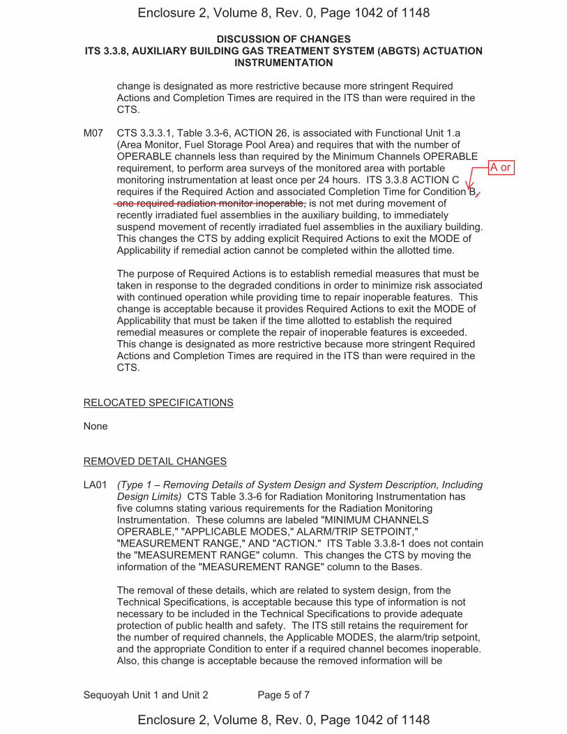
DISCUSSION OF CHANGES ITS 3.3.8, AUXILIARY BUILDING GAS TREATMENT SYSTEM (ABGTS) ACTUATION
INSTRUMENTATION
Sequoyah Unit 1 and Unit 2 Page 5 of 7
change is designated as more restrictive because more stringent Required Actions and Completion Times are required in the ITS than were required in the CTS.
M07 CTS 3.3.3.1, Table 3.3-6, ACTION 26, is associated with Functional Unit 1.a (Area Monitor, Fuel Storage Pool Area) and requires that with the number of OPERABLE channels less than required by the Minimum Channels OPERABLE requirement, to perform area surveys of the monitored area with portable monitoring instrumentation at least once per 24 hours. ITS 3.3.8 ACTION C requires if the Required Action and associated Completion Time for Condition B, one required radiation monitor inoperable, is not met during movement of recently irradiated fuel assemblies in the auxiliary building, to immediately suspend movement of recently irradiated fuel assemblies in the auxiliary building. This changes the CTS by adding explicit Required Actions to exit the MODE of Applicability if remedial action cannot be completed within the allotted time.
The purpose of Required Actions is to establish remedial measures that must be taken in response to the degraded conditions in order to minimize risk associated with continued operation while providing time to repair inoperable features. This change is acceptable because it provides Required Actions to exit the MODE of Applicability that must be taken if the time allotted to establish the required remedial measures or complete the repair of inoperable features is exceeded. This change is designated as more restrictive because more stringent Required Actions and Completion Times are required in the ITS than were required in the CTS.
RELOCATED SPECIFICATIONS
None
REMOVED DETAIL CHANGES
LA01 (Type 1 – Removing Details of System Design and System Description, Including Design Limits) CTS Table 3.3-6 for Radiation Monitoring Instrumentation has five columns stating various requirements for the Radiation Monitoring Instrumentation. These columns are labeled "MINIMUM CHANNELS OPERABLE," "APPLICABLE MODES," ALARM/TRIP SETPOINT," "MEASUREMENT RANGE," AND "ACTION." ITS Table 3.3.8-1 does not contain the "MEASUREMENT RANGE" column. This changes the CTS by moving the information of the "MEASUREMENT RANGE" column to the Bases.
The removal of these details, which are related to system design, from the Technical Specifications, is acceptable because this type of information is not necessary to be included in the Technical Specifications to provide adequate protection of public health and safety. The ITS still retains the requirement for the number of required channels, the Applicable MODES, the alarm/trip setpoint, and the appropriate Condition to enter if a required channel becomes inoperable. Also, this change is acceptable because the removed information will be
Enclosure 2, Volume 8, Rev. 0, Page 1042 of 1148
Enclosure 2, Volume 8, Rev. 0, Page 1042 of 1148
A or
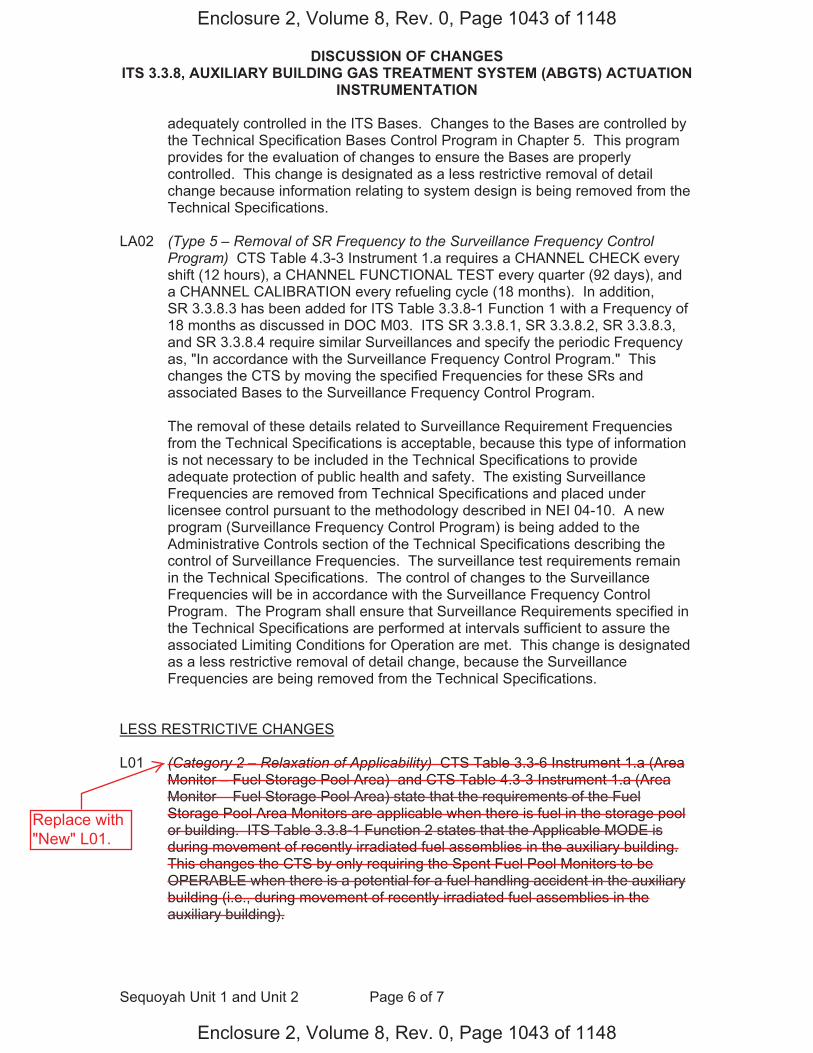
DISCUSSION OF CHANGES ITS 3.3.8, AUXILIARY BUILDING GAS TREATMENT SYSTEM (ABGTS) ACTUATION
INSTRUMENTATION
Sequoyah Unit 1 and Unit 2 Page 6 of 7
adequately controlled in the ITS Bases. Changes to the Bases are controlled by the Technical Specification Bases Control Program in Chapter 5. This program provides for the evaluation of changes to ensure the Bases are properly controlled. This change is designated as a less restrictive removal of detail change because information relating to system design is being removed from the Technical Specifications.
LA02 (Type 5 – Removal of SR Frequency to the Surveillance Frequency Control Program) CTS Table 4.3-3 Instrument 1.a requires a CHANNEL CHECK every shift (12 hours), a CHANNEL FUNCTIONAL TEST every quarter (92 days), and a CHANNEL CALIBRATION every refueling cycle (18 months). In addition, SR 3.3.8.3 has been added for ITS Table 3.3.8-1 Function 1 with a Frequency of 18 months as discussed in DOC M03. ITS SR 3.3.8.1, SR 3.3.8.2, SR 3.3.8.3, and SR 3.3.8.4 require similar Surveillances and specify the periodic Frequency as, "In accordance with the Surveillance Frequency Control Program." This changes the CTS by moving the specified Frequencies for these SRs and associated Bases to the Surveillance Frequency Control Program.
The removal of these details related to Surveillance Requirement Frequencies from the Technical Specifications is acceptable, because this type of information is not necessary to be included in the Technical Specifications to provide adequate protection of public health and safety. The existing Surveillance Frequencies are removed from Technical Specifications and placed under licensee control pursuant to the methodology described in NEI 04-10. A new program (Surveillance Frequency Control Program) is being added to the Administrative Controls section of the Technical Specifications describing the control of Surveillance Frequencies. The surveillance test requirements remain in the Technical Specifications. The control of changes to the Surveillance Frequencies will be in accordance with the Surveillance Frequency Control Program. The Program shall ensure that Surveillance Requirements specified in the Technical Specifications are performed at intervals sufficient to assure the associated Limiting Conditions for Operation are met. This change is designated as a less restrictive removal of detail change, because the Surveillance Frequencies are being removed from the Technical Specifications.
LESS RESTRICTIVE CHANGES
L01 (Category 2 – Relaxation of Applicability) CTS Table 3.3-6 Instrument 1.a (Area Monitor – Fuel Storage Pool Area) and CTS Table 4.3-3 Instrument 1.a (Area Monitor – Fuel Storage Pool Area) state that the requirements of the Fuel Storage Pool Area Monitors are applicable when there is fuel in the storage pool or building. ITS Table 3.3.8-1 Function 2 states that the Applicable MODE is during movement of recently irradiated fuel assemblies in the auxiliary building. This changes the CTS by only requiring the Spent Fuel Pool Monitors to be OPERABLE when there is a potential for a fuel handling accident in the auxiliary building (i.e., during movement of recently irradiated fuel assemblies in the auxiliary building).
Enclosure 2, Volume 8, Rev. 0, Page 1043 of 1148
Enclosure 2, Volume 8, Rev. 0, Page 1043 of 1148
Replace with"New" L01.
DISCUSSION OF CHANGES ITS 3.3.8, AUXILIARY BUILDING GAS TREATMENT SYSTEM (ABGTS) ACTUATION
INSTRUMENTATION
Sequoyah Unit 1 and Unit 2 Page 7 of 7
The purpose of CTS Table 3.3-6 Functional Unit 1.a is to ensure that the Fuel Storage Pool Area Monitors are OPERABLE to mitigate the consequences of a fuel handling accident. This change is acceptable because the requirements continue to ensure that the structures, system and components are maintained in the MODES and other specified conditions assumed in the safety analyses and licensing basis. The Sequoyah Nuclear Plant (SQN) fuel handling analysis for the auxiliary building has been analyzed using the methodology from Regulatory Guide 1.183, "Alternative Radiological Source Terms for Evaluating Design Basis Accidents at Nuclear Power Reactors." The SQN fuel handling analysis assumes, in part, that the accident occurs 100 hours after a plant shutdown, radioactive decay during the interval between shutdown and placement of the first spent fuel assembly into the spent fuel pool is taken into account, and a single fuel assembly is damaged with acceptable results. The ITS Bases define a recently irradiated fuel assembly as having occupied part of a critical reactor within the previous 100 hours. Therefore, the ITS imposes the controls on the ABGTS Actuation Instrumentation during movement of recently irradiated fuel assemblies in the auxiliary building. This change is designated as less restrictive because the LCO requirements are applicable in fewer operating conditions than in the CTS.
Enclosure 2, Volume 8, Rev. 0, Page 1044 of 1148
Enclosure 2, Volume 8, Rev. 0, Page 1044 of 1148

"New" DOC L01
(Category 2 – Relaxation of Applicability) CTS Table 3.3-6 Instrument 1.a (Area Monitor – Fuel Storage Pool Area) requires one channel to be OPERABLE when there is fuel in the storage pool or building. ITS Table 3.3.8-1 Function 2 requires two Spent Fuel Pool Area Radiation Monitor channels to be OPERABLE during movement of recently irradiated fuel assemblies in the auxiliary building. ITS 3. ACTION A requires with one inoperable Spent Fuel Pool Area Radiation Monitor channel that one train of ABGTS be placed in operation in 7 days. This changes the CTS increasing the number of Spent Fuel Pool Area Radiation Monitor channels required to be OPERABLE, but only when ABGTS is required to mitigate a fuel handling accident (i.e., during movement of recently irradiated fuel assemblies in the auxiliary building).
The purpose of CTS 3.3.3.1 and Tables 3.3-6 and 4.3-3 is to ensure that ABGTS actuates when required to mitigate the consequences of a fuel handling accident in the auxiliary building. This change is acceptable because the requirements continue to ensure that the structures, system and components are maintained in the MODES and other specified conditions assumed in the safety analyses and licensing basis. The Sequoyah Nuclear Plant (SQN) fuel handling analysis for the auxiliary building has been analyzed using the methodology from Regulatory Guide 1.183, "Alternative Radiological Source Terms for Evaluating Design Basis Accidents at Nuclear Power Reactors." The SQN fuel handling analysis inside the auxiliary building assumes, in part, that the accident occurs 100 hours after a plant shutdown, radioactive decay during the interval between shutdown and placement of the first spent fuel assembly into the spent fuel pool is taken into account, and a single fuel assembly is damaged. The damaged fuel assembly is assumed to be the highest powered assembly in the core region to be discharged with a radial peaking factor of 1.70. All of the gap activity in the damaged rods is released to the spent fuel pool and consists of 5% of the total noble gases other than Kr-85, 10% of the Kr-85, 5% of the to al radioactive iodine other than I-131, and 8% of the I-131 in the rods at the time of the accident. Noble gases released to the spent fuel pool do not experience retention in the water pool. The iodine gap inventory is composed of 99.85% inorganic species, and 0.15% organic species. The spent fuel pool decontamination factor is 200. No credit is taken for natural decay due to holdup in the auxiliary building or after the activity has been released to the atmosphere. The activity released from the spent fuel pool is all assumed to be released to the environment over a 2-hour period. Doses were determined at the EAB and LPZ for the 2-hour interval over which the releases are assumed to take place, and in the control room for an extended period of time after termination of releases in order to address the continual presence of activity in the control room atmosphere. The accident doses were calculated using the dose model consistent with the use of the alternate source term methodology (RG 1.183). T e doses are within the dose acceptance limits of 6.3 rem TEDE for offsite doses and 5.0 rem TEDE for control room doses. Because ABGTS is not credited in the mitigation of a fuel handling accident in the auxiliary building involving fuel that has at least 100 hours of decay time, it not required to be OPERABLE during that evolution. However, fuel movement could still proceed prior to a decay time of 100 hours. Therefore, to mitigate the consequences of a fuel handling accident involving the movement of recently irradiated fuel, ITS imposes the controls on the ABGTS during movement of recently irradiated fuel assemblies in the auxiliary building. Consistent with NUMARC 93-01, "Safety Assessment for Removal of Equipment from Service During Shutdown Conditions," TVA will implement procedural requirements for a single normal or contingency method to promptly close primary or secondary containment penetrations. Additionally, TVA will implement procedural requirements for one train of ABGTS to be OPERABLE during movement of irradiated fuel assemblies (whether in the auxiliary building or within the containment). This change is designated as less restrictive because the LCO requirements are applicable in fewer operating conditions than in the CTS.
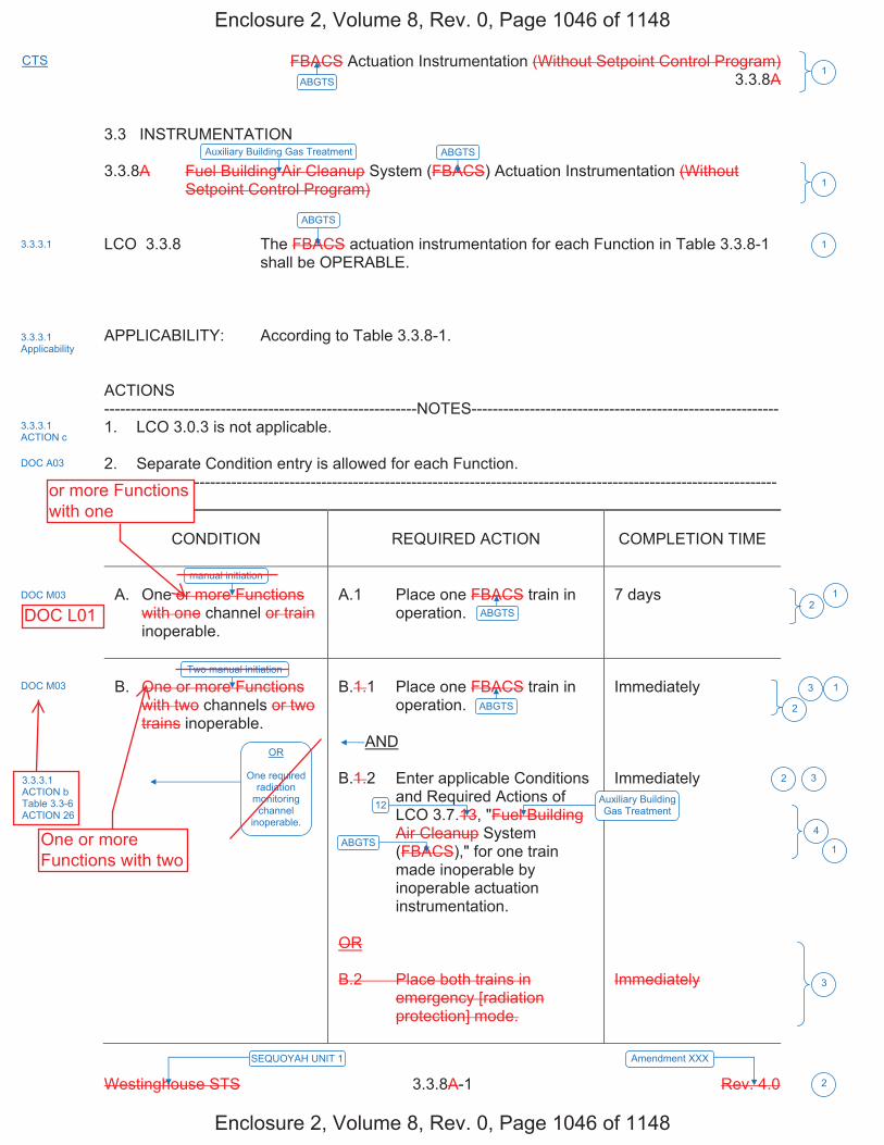
FBACS Actuation Instrumentation (Without Setpoint Control Program) 3.3.8A
Westinghouse STS 3.3.8A-1 Rev. 4.0
1ABGTS
SEQUOYAH UNIT 1 Amendment XXX
2
CTS
3.3 INSTRUMENTATION 3.3.8A Fuel Building Air Cleanup System (FBACS) Actuation Instrumentation (Without
Setpoint Control Program) LCO 3.3.8 The FBACS actuation instrumentation for each Function in Table 3.3.8-1
shall be OPERABLE. APPLICABILITY: According to Table 3.3.8-1. ACTIONS -----------------------------------------------------------NOTES---------------------------------------------------------- 1. LCO 3.0.3 is not applicable. 2. Separate Condition entry is allowed for each Function. -------------------------------------------------------------------------------------------------------------------------------
CONDITION
REQUIRED ACTION
COMPLETION TIME
A. One or more Functions
with one channel or train inoperable.
A.1 Place one FBACS train in
operation.
7 days
B. One or more Functions
with two channels or two trains inoperable.
B.1.1 Place one FBACS train in
operation. AND B.1.2 Enter applicable Conditions
and Required Actions of LCO 3.7.13, "Fuel Building Air Cleanup System (FBACS)," for one train made inoperable by inoperable actuation instrumentation.
OR B.2 Place both trains in
emergency [radiation protection] mode.
Immediately Immediately Immediately
1
ABGTSAuxiliary Building Gas Treatment
ABGTS
Auxiliary Building Gas Treatment
ABGTS
ABGTS
ABGTS
12
3.3.3.1 Applicability
3.3.3.1
DOC A03
DOC M03
DOC M03
1
1
13
4
3
3
3.3.3.1 ACTION c
2
2
manual initiation
Two manual initiation
OR
One required radiation
monitoring channel
inoperable.
3.3.3.1 ACTION b Table 3.3-6 ACTION 26
1
2
Enclosure 2, Volume 8, Rev. 0, Page 1046 of 1148
Enclosure 2, Volume 8, Rev. 0, Page 1046 of 1148
or more Functionswith one
One or moreFunctions with two
DOC L01
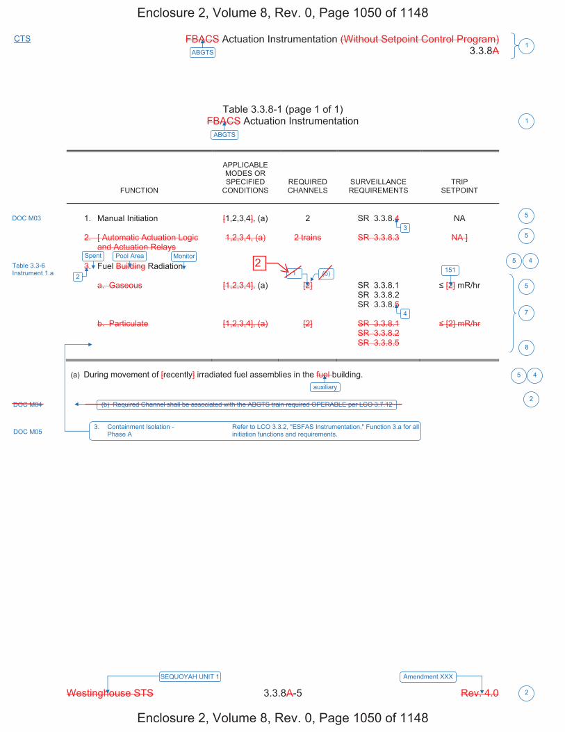
FBACS Actuation Instrumentation (Without Setpoint Control Program) 3.3.8A
Westinghouse STS 3.3.8A-5 Rev. 4.0
1ABGTS
SEQUOYAH UNIT 1 Amendment XXX
2
CTS
Table 3.3.8-1 (page 1 of 1) FBACS Actuation Instrumentation
FUNCTION
APPLICABLE MODES OR SPECIFIED
CONDITIONS
REQUIRED CHANNELS
SURVEILLANCE REQUIREMENTS
TRIP SETPOINT
1. Manual Initiation
[1,2,3,4], (a)
2
SR 3.3.8.4
NA
2. [ Automatic Actuation Logic
and Actuation Relays
1,2,3,4, (a)
2 trains
SR 3.3.8.3
NA ]
3. Fuel Building Radiation
a. Gaseous
[1,2,3,4], (a)
[2]
SR 3.3.8.1 SR 3.3.8.2 SR 3.3.8.5
[2] mR/hr
b. Particulate
[1,2,3,4], (a)
[2]
SR 3.3.8.1 SR 3.3.8.2 SR 3.3.8.5
[2] mR/hr
(a) During movement of [recently] irradiated fuel assemblies in the fuel building.
Pool Area Monitor
151
ABGTS
DOC M03
Table 3.3-6 Instrument 1.a
1
5
5
5
7
5
DOC M05 3. Containment Isolation - Refer to LCO 3.3.2, "ESFAS Instrumentation," Function 3.a for all Phase A initiation functions and requirements.
8
auxiliary
4
3
2
5 4
4
Spent
1 (b)
(b) Required Channel shall be associated with the ABGTS train required OPERABLE per LCO 3.7.12DOC M04 2
Enclosure 2, Volume 8, Rev. 0, Page 1050 of 1148
Enclosure 2, Volume 8, Rev. 0, Page 1050 of 1148
2
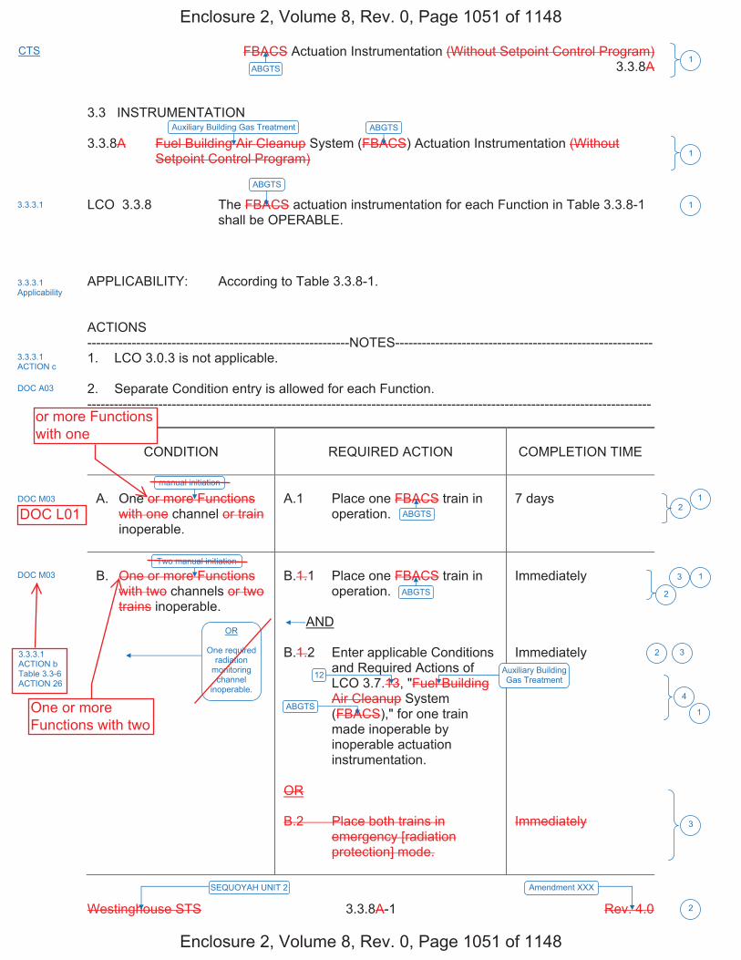
FBACS Actuation Instrumentation (Without Setpoint Control Program) 3.3.8A
Westinghouse STS 3.3.8A-1 Rev. 4.0
1ABGTS
SEQUOYAH UNIT 2 Amendment XXX
2
CTS
3.3 INSTRUMENTATION 3.3.8A Fuel Building Air Cleanup System (FBACS) Actuation Instrumentation (Without
Setpoint Control Program) LCO 3.3.8 The FBACS actuation instrumentation for each Function in Table 3.3.8-1
shall be OPERABLE. APPLICABILITY: According to Table 3.3.8-1. ACTIONS -----------------------------------------------------------NOTES---------------------------------------------------------- 1. LCO 3.0.3 is not applicable. 2. Separate Condition entry is allowed for each Function. -------------------------------------------------------------------------------------------------------------------------------
CONDITION
REQUIRED ACTION
COMPLETION TIME
A. One or more Functions
with one channel or train inoperable.
A.1 Place one FBACS train in
operation.
7 days
B. One or more Functions
with two channels or two trains inoperable.
B.1.1 Place one FBACS train in
operation. AND B.1.2 Enter applicable Conditions
and Required Actions of LCO 3.7.13, "Fuel Building Air Cleanup System (FBACS)," for one train made inoperable by inoperable actuation instrumentation.
OR B.2 Place both trains in
emergency [radiation protection] mode.
Immediately Immediately Immediately
1
ABGTSAuxiliary Building Gas Treatment
ABGTS
Auxiliary Building Gas Treatment
ABGTS
ABGTS
ABGTS
12
3.3.3.1 Applicability
3.3.3.1
DOC A03
DOC M03
DOC M03
1
1
13
4
3
3
3.3.3.1 ACTION c
2
2
manual initiation
Two manual initiation
OR
One required radiation
monitoring channel
inoperable.
3.3.3.1 ACTION b Table 3.3-6 ACTION 26
1
2
Enclosure 2, Volume 8, Rev. 0, Page 1051 of 1148
Enclosure 2, Volume 8, Rev. 0, Page 1051 of 1148
One or moreFunctions with two
DOC L01
or more Functionswith one

FBACS Actuation Instrumentation (Without Setpoint Control Program) 3.3.8A
Westinghouse STS 3.3.8A-5 Rev. 4.0
1ABGTS
SEQUOYAH UNIT 2 Amendment XXX
2
CTS
Table 3.3.8-1 (page 1 of 1) FBACS Actuation Instrumentation
FUNCTION
APPLICABLE MODES OR SPECIFIED
CONDITIONS
REQUIRED CHANNELS
SURVEILLANCE REQUIREMENTS
TRIP SETPOINT
1. Manual Initiation
[1,2,3,4], (a)
2
SR 3.3.8.4
NA
2. [ Automatic Actuation Logic
and Actuation Relays
1,2,3,4, (a)
2 trains
SR 3.3.8.3
NA ]
3. Fuel Building Radiation
a. Gaseous
[1,2,3,4], (a)
[2]
SR 3.3.8.1 SR 3.3.8.2 SR 3.3.8.5
[2] mR/hr
b. Particulate
[1,2,3,4], (a)
[2]
SR 3.3.8.1 SR 3.3.8.2 SR 3.3.8.5
[2] mR/hr
(a) During movement of [recently] irradiated fuel assemblies in the fuel building.
Pool Area Monitor
151
ABGTS
DOC M03
Table 3.3-6 Instrument 1.a
1
5
5
5
7
5
DOC M05 3. Containment Isolation - Refer to LCO 3.3.2, "ESFAS Instrumentation," Function 3.a for all Phase A initiation functions and requirements.
8
auxiliary
4
3
2
5 4
4
Spent
1 (b)
(b) Required Channel shall be associated with the ABGTS train required OPERABLE per LCO 3.7.12DOC M04 2
Enclosure 2, Volume 8, Rev. 0, Page 1055 of 1148
Enclosure 2, Volume 8, Rev. 0, Page 1055 of 1148
2

JUSTIFICATION FOR DEVIATIONS ITS 3.3.8, AUXILIARY BUILDING GAS TREATMENT SYSTEM (ABGTS) ACTUATION
INSTRUMENTATION
Sequoyah Unit 1 and Unit 2 Page 1 of 1
1. The type of Setpoint Control Program (Without Setpoint Control Program) and the Specification designator "A" are deleted since they are unnecessary. This information is provided in NUREG 1431, Rev. 4.0 to assist in identifying the appropriate Specification to be used as a model for the plant specific ITS conversion, but serves no purpose in the plant specific implementation. In addition, ISTS 3.3.8B (with Setpoint Control Program Specification) is not used and is not shown. Furthermore, the title of the Specification has been changed from "Fuel Building Air Cleanup System (FBACS) Actuation Instrumentation" to "Auxiliary Building Gas Treatment System (ABGTS) Actuation Instrumentation" since Sequoyah Nuclear Plant (SQN) does not have an FBACS.
2. Changes are made (additions, deletions, and/or changes) to the ISTS that reflect the
plant specific nomenclature, number, reference, system description, analysis, or licensing basis description.
3. ISTS 3.3.8 Required Action B.2 provides an option of placing both trains of the
FBACS in the emergency [radiation protection] mode immediately when one or more Functions in ISTS Table 3.3.8-1 with two channels or two trains are inoperable. ITS 3.3.8 does not contain this Required Action since the ABGTS does not have an emergency mode of operation. Furthermore, ISTS 3.3.8 Required Actions B.1.1 and B.1.2 have been renumbered as ITS 3.3.8 Required Actions B.1 and B.2 to reflect the removal of the ISTS option. Additionally, the "AND" logic connector has been moved to the correct position due to the deletion of ISTS 3.3.8 Required Action B.2.
4. Changes are made to be consistent with changes made to ISTS LCO 3.7.13. The
Title and the number for this specification were changed and are reflected in ITS 3.3.8.
5. The ISTS contains bracketed information and/or values that are generic to
Westinghouse vintage plants. The brackets are removed, the proper plant specific information/value is inserted to reflect the current licensing basis, and subsequent items are renumbered as required.
6. ISTS SR 3.3.8.1, SR 3.3.8.2, SR 3.3.8.4, and SR 3.3.8.5 (ITS SR 3.3.8.1,
SR 3.3.8.2, SR 3.3.8.3, and SR 3.3.8.4) provide two options for controlling the Frequencies of Surveillance Requirements. SQN is proposing to control the Surveillance Frequencies under the Surveillance Frequency Control Program.
7. ISTS Table 3.3.8-1 Function 3 specifies two Gaseous Radiation Monitors (Function
3.a) and two Particulate Radiation Monitors (Function 3.b) for the Fuel Storage Radiation Function. ITS Table 3.3.8-1 Function 2 only requires one Spent Fuel Pool Area Radiation Monitor for Table 3.3.8-1 Function 2. This change is acceptable because the fuel storage pool area radiation monitor is the monitor used in the current licensing bases for the ABGTS actuation.
8. Changes are made to ISTS Table 3.3.8-1 to reflect that the ABGTS receives a signal
from Containment Isolation – Phase A which is part of ITS 3.3.2, "Engineered Safety Features Actuation System (ESFAS) Instrumentation."
Enclosure 2, Volume 8, Rev. 0, Page 1056 of 1148
Enclosure 2, Volume 8, Rev. 0, Page 1056 of 1148
two

FBACS Actuation Instrumentation (Without Setpoint Control Program) B 3.3.8A
Westinghouse STS B 3.3.8A-1 Rev. 4.0
1ABGTS
Revision XXX SEQUOYAH UNIT 1 4 1
B 3.3 INSTRUMENTATION B 3.3.8A Fuel Building Air Cleanup System (FBACS) Actuation Instrumentation (Without
Setpoint Control Program) BASES BACKGROUND The FBACS ensures that radioactive materials in the fuel building
atmosphere following a fuel handling accident [involving handling recently irradiated fuel] or a loss of coolant accident (LOCA) are filtered and adsorbed prior to exhausting to the environment. The system is described in the Bases for LCO 3.7.13, "Fuel Building Air Cleanup System." The system initiates filtered ventilation of the fuel building automatically following receipt of a high radiation signal (gaseous or particulate) or a safety injection (SI) signal. Initiation may also be performed manually as needed from the main control room. High gaseous and particulate radiation, each monitored by either of two monitors, provides FBACS initiation. Each FBACS train is initiated by high radiation detected by a channel dedicated to that train. There are a total of two channels, one for each train. Each channel contains a gaseous and particulate monitor. High radiation detected by any monitor or an SI signal from the Engineered Safety Features Actuation System (ESFAS) initiates fuel building isolation and starts the FBACS. These actions function to prevent exfiltration of contaminated air by initiating filtered ventilation, which imposes a negative pressure on the fuel building. Since the radiation monitors include an air sampling system, various components such as sample line valves, sample line heaters, sample pumps, and filter motors are required to support monitor OPERABILITY.
APPLICABLE The FBACS ensures that radioactive materials in the fuel building SAFETY atmosphere following a fuel handling accident [involving handling ANALYSES recently irradiated fuel] or a LOCA are filtered and adsorbed prior to being
exhausted to the environment. This action reduces the radioactive content in the fuel building exhaust following a LOCA or fuel handling accident so that offsite doses remain within the limits specified in 10 CFR 100 (Ref. 1).
The FBACS actuation instrumentation satisfies Criterion 3 of 10 CFR 50.36(c)(2)(ii).
LCO The LCO requirements ensure that instrumentation necessary to initiate
the FBACS is OPERABLE.
1
ABGTSAuxiliary Building Gas Treatment
ABGTS
12
(ABGTS)
Auxiliary Building Gas Treatment
INSERT 1
spent fuel pool area
Containment Phase A Isolation
area
ABGTS
Auxiliary Building Secondary Containment Enclosure (ABSCE)
auxiliary
ABGTS
ABGTS
1
2
3
4
4
1
1
4
4
41
2
4
1
1
Containment Phase A Isolation
ABGTS
ABGTS
ABGTS ABSCE
for LOCA or 10 CFR 50.67 (Ref. 2) for fuel handling accident 4
auxiliary
auxiliary
the required
Enclosure 2, Volume 8, Rev. 0, Page 1058 of 1148
Enclosure 2, Volume 8, Rev. 0, Page 1058 of 1148
a
Keep
Keep

FBACS Actuation Instrumentation (Without Setpoint Control Program) B 3.3.8A
Westinghouse STS B 3.3.8A-2 Rev. 4.0
1ABGTS
Revision XXX SEQUOYAH UNIT 1 4 1
BASES LCO (continued) 1. Manual Initiation
The LCO requires two channels OPERABLE. The operator can initiate the FBACS at any time by using either of two switches in the control room. This action will cause actuation of all components in the same manner as any of the automatic actuation signals. The LCO for Manual Initiation ensures the proper amount of redundancy is maintained in the manual actuation circuitry to ensure the operator has manual initiation capability. Each channel consists of one push button and the interconnecting wiring to the actuation logic cabinet.
2. Automatic Actuation Logic and Actuation Relays
The LCO requires two trains of Actuation Logic and Relays OPERABLE to ensure that no single random failure can prevent automatic actuation. Automatic Actuation Logic and Actuation Relays consist of the same features and operate in the same manner as described for ESFAS Function 1.b., SI, in LCO 3.3.2. The applicable MODES and specified conditions for the FBACS portion of these functions are different and less restrictive than those specified for their SI roles. If one or more of the SI functions becomes inoperable in such a manner that only the FBACS function is affected, the Conditions applicable to their SI function need not be entered. The less restrictive Actions specified for inoperability of the FBACS functions specify sufficient compensatory measures for this case.
3. Fuel Building Radiation
The LCO specifies two required Gaseous Radiation Monitor channels and two required Particulate Radiation Monitor channels to ensure that the radiation monitoring instrumentation necessary to initiate the FBACS remains OPERABLE. For sampling systems, channel OPERABILITY involves more than OPERABILITY of channel electronics. OPERABILITY may also require correct valve lineups, sample pump operation, filter motor operation, detector OPERABILITY, if these supporting features are necessary for actuation to occur under the conditions assumed by the safety analyses.
INSERT 4
ABGTS
hand switch
Spent Fuel Pool Area
ABGTS
INSERT 3
1
4
5
4
1 4
Pool Area4
5
INSERT 2 4
2
5Spent
one
Enclosure 2, Volume 8, Rev. 0, Page 1060 of 1148
Enclosure 2, Volume 8, Rev. 0, Page 1060 of 1148
twos

B 3.3.8
Insert Page B 3.3.8-2
INSERT 2 one of two sets of manual initiation hand switches in the control room. Each Auxiliary Building Isolation (ABI) manual hand switch will initiate its respective train of ABGTS.
INSERT 3 One radiation monitor is dedicated to each train of ABGTS.
INSERT 4
The measurement range for the Spent Fuel Pool Area Monitors is 10-1 to 104 mR/hr. The Required Channels value is modified by a footnote stating that the Required Channel shall be associated with the ABGTS train required OPERABLE per LCO 3.7.12. This ensures a valid actuation signal will start a train of ABGTS.
3. Containment Isolation - Phase A
Refer to LCO 3.3.2, Function 3.a., for all initiating Functions and requirements.
4
5
4
Enclosure 2, Volume 8, Rev. 0, Page 1061 of 1148
Enclosure 2, Volume 8, Rev. 0, Page 1061 of 1148
4

FBACS Actuation Instrumentation (Without Setpoint Control Program) B 3.3.8A
Westinghouse STS B 3.3.8A-4 Rev. 4.0
1ABGTS
Revision XXX SEQUOYAH UNIT 1 4 1
BASES ACTIONS (continued)
A second Note has been added to the ACTIONS to clarify the application of Completion Time rules. The Conditions of this Specification may be entered independently for each Function listed in Table 3.3.8-1 in the accompanying LCO. The Completion Time(s) of the inoperable channel(s)/train(s) of a Function will be tracked separately for each Function starting from the time the Condition was entered for that Function. A.1 Condition A applies to the actuation logic train function of the Solid State Protection System (SSPS), the radiation monitor functions, and the manual function. Condition A applies to the failure of a single actuation logic train, radiation monitor channel, or manual channel. If one channel or train is inoperable, a period of 7 days is allowed to restore it to OPERABLE status. If the train cannot be restored to OPERABLE status, one FBACS train must be placed in operation. This accomplishes the actuation instrumentation function and places the unit in a conservative mode of operation. The 7 day Completion Time is the same as is allowed if one train of the mechanical portion of the system is inoperable. The basis for this time is the same as that provided in LCO 3.7.13. B.1.1, B.1.2, B.2 Condition B applies to the failure of two FBACS actuation logic trains, two radiation monitors, or two manual channels. The Required Action is to place one FBACS train in operation immediately. This accomplishes the actuation instrumentation function that may have been lost and places the unit in a conservative mode of operation. The applicable Conditions and Required Actions of LCO 3.7.13 must also be entered for the FBACS train made inoperable by the inoperable actuation instrumentation. This ensures appropriate limits are placed on train inoperability as discussed in the Bases for LCO 3.7.13. Alternatively, both trains may be placed in the emergency [radiation protection] mode. This ensures the FBACS Function is performed even in the presence of a single failure.
ABGTS
12
ABGTS
ABGTS
12
12
1
3
5
1
13
3
5
and
5
5
channel
one reqired
Enclosure 2, Volume 8, Rev. 0, Page 1063 of 1148
Enclosure 2, Volume 8, Rev. 0, Page 1063 of 1148
keep
keep
two
s

FBACS Actuation Instrumentation (Without Setpoint Control Program) B 3.3.8A
Westinghouse STS B 3.3.8A-1 Rev. 4.0
1ABGTS
Revision XXX SEQUOYAH UNIT 2 4 1
B 3.3 INSTRUMENTATION B 3.3.8A Fuel Building Air Cleanup System (FBACS) Actuation Instrumentation (Without
Setpoint Control Program) BASES BACKGROUND The FBACS ensures that radioactive materials in the fuel building
atmosphere following a fuel handling accident [involving handling recently irradiated fuel] or a loss of coolant accident (LOCA) are filtered and adsorbed prior to exhausting to the environment. The system is described in the Bases for LCO 3.7.13, "Fuel Building Air Cleanup System." The system initiates filtered ventilation of the fuel building automatically following receipt of a high radiation signal (gaseous or particulate) or a safety injection (SI) signal. Initiation may also be performed manually as needed from the main control room. High gaseous and particulate radiation, each monitored by either of two monitors, provides FBACS initiation. Each FBACS train is initiated by high radiation detected by a channel dedicated to that train. There are a total of two channels, one for each train. Each channel contains a gaseous and particulate monitor. High radiation detected by any monitor or an SI signal from the Engineered Safety Features Actuation System (ESFAS) initiates fuel building isolation and starts the FBACS. These actions function to prevent exfiltration of contaminated air by initiating filtered ventilation, which imposes a negative pressure on the fuel building. Since the radiation monitors include an air sampling system, various components such as sample line valves, sample line heaters, sample pumps, and filter motors are required to support monitor OPERABILITY.
APPLICABLE The FBACS ensures that radioactive materials in the fuel building SAFETY atmosphere following a fuel handling accident [involving handling ANALYSES recently irradiated fuel] or a LOCA are filtered and adsorbed prior to being
exhausted to the environment. This action reduces the radioactive content in the fuel building exhaust following a LOCA or fuel handling accident so that offsite doses remain within the limits specified in 10 CFR 100 (Ref. 1).
The FBACS actuation instrumentation satisfies Criterion 3 of 10 CFR 50.36(c)(2)(ii).
LCO The LCO requirements ensure that instrumentation necessary to initiate
the FBACS is OPERABLE.
1
ABGTSAuxiliary Building Gas Treatment
ABGTS
12
(ABGTS)
Auxiliary Building Gas Treatment
INSERT 1
spent fuel pool area
Containment Phase A Isolation
area
ABGTS
Auxiliary Building Secondary Containment Enclosure (ABSCE)
auxiliary
ABGTS
ABGTS
1
2
3
4
4
1
1
4
4
41
2
4
1
1
Containment Phase A Isolation
ABGTS
ABGTS
ABGTS ABSCE
for LOCA or 10 CFR 50.67 (Ref. 2) for fuel handling accident 4
auxiliary
auxiliary
the required
Enclosure 2, Volume 8, Rev. 0, Page 1069 of 1148
Enclosure 2, Volume 8, Rev. 0, Page 1069 of 1148
aKeep
Keep

FBACS Actuation Instrumentation (Without Setpoint Control Program) B 3.3.8A
Westinghouse STS B 3.3.8A-2 Rev. 4.0
1ABGTS
Revision XXX SEQUOYAH UNIT 2 4 1
BASES LCO (continued) 1. Manual Initiation
The LCO requires two channels OPERABLE. The operator can initiate the FBACS at any time by using either of two switches in the control room. This action will cause actuation of all components in the same manner as any of the automatic actuation signals. The LCO for Manual Initiation ensures the proper amount of redundancy is maintained in the manual actuation circuitry to ensure the operator has manual initiation capability. Each channel consists of one push button and the interconnecting wiring to the actuation logic cabinet.
2. Automatic Actuation Logic and Actuation Relays
The LCO requires two trains of Actuation Logic and Relays OPERABLE to ensure that no single random failure can prevent automatic actuation. Automatic Actuation Logic and Actuation Relays consist of the same features and operate in the same manner as described for ESFAS Function 1.b., SI, in LCO 3.3.2. The applicable MODES and specified conditions for the FBACS portion of these functions are different and less restrictive than those specified for their SI roles. If one or more of the SI functions becomes inoperable in such a manner that only the FBACS function is affected, the Conditions applicable to their SI function need not be entered. The less restrictive Actions specified for inoperability of the FBACS functions specify sufficient compensatory measures for this case.
3. Fuel Building Radiation
The LCO specifies two required Gaseous Radiation Monitor channels and two required Particulate Radiation Monitor channels to ensure that the radiation monitoring instrumentation necessary to initiate the FBACS remains OPERABLE. For sampling systems, channel OPERABILITY involves more than OPERABILITY of channel electronics. OPERABILITY may also require correct valve lineups, sample pump operation, filter motor operation, detector OPERABILITY, if these supporting features are necessary for actuation to occur under the conditions assumed by the safety analyses.
INSERT 4
ABGTS
hand switch
Spent Fuel Pool Area
ABGTS
INSERT 3
1
4
5
4
1 4
Pool Area4
5
INSERT 2 4
2
5Spent
one
Enclosure 2, Volume 8, Rev. 0, Page 1071 of 1148
Enclosure 2, Volume 8, Rev. 0, Page 1071 of 1148
twos

B 3.3.8
Insert Page B 3.3.8-2
INSERT 2 one of two sets of manual initiation hand switches in the control room. Each Auxiliary Building Isolation (ABI) manual hand switch will initiate its respective train of ABGTS.
INSERT 3 One radiation monitor is dedicated to each train of ABGTS.
INSERT 4
The measurement range for the Spent Fuel Pool Area Monitors is 10-1 to 104 mR/hr. The Required Channels value is modified by a footnote stating that the Required Channel shall be associated with the ABGTS train required OPERABLE per LCO 3.7.12. This ensures a valid actuation signal will start a train of ABGTS.
3. Containment Isolation - Phase A
Refer to LCO 3.3.2, Function 3.a., for all initiating Functions and requirements.
4
5
4
Enclosure 2, Volume 8, Rev. 0, Page 1072 of 1148
Enclosure 2, Volume 8, Rev. 0, Page 1072 of 1148
4

FBACS Actuation Instrumentation (Without Setpoint Control Program) B 3.3.8A
Westinghouse STS B 3.3.8A-4 Rev. 4.0
1ABGTS
Revision XXX SEQUOYAH UNIT 2 4 1
BASES ACTIONS (continued)
A second Note has been added to the ACTIONS to clarify the application of Completion Time rules. The Conditions of this Specification may be entered independently for each Function listed in Table 3.3.8-1 in the accompanying LCO. The Completion Time(s) of the inoperable channel(s)/train(s) of a Function will be tracked separately for each Function starting from the time the Condition was entered for that Function. A.1 Condition A applies to the actuation logic train function of the Solid State Protection System (SSPS), the radiation monitor functions, and the manual function. Condition A applies to the failure of a single actuation logic train, radiation monitor channel, or manual channel. If one channel or train is inoperable, a period of 7 days is allowed to restore it to OPERABLE status. If the train cannot be restored to OPERABLE status, one FBACS train must be placed in operation. This accomplishes the actuation instrumentation function and places the unit in a conservative mode of operation. The 7 day Completion Time is the same as is allowed if one train of the mechanical portion of the system is inoperable. The basis for this time is the same as that provided in LCO 3.7.13. B.1.1, B.1.2, B.2 Condition B applies to the failure of two FBACS actuation logic trains, two radiation monitors, or two manual channels. The Required Action is to place one FBACS train in operation immediately. This accomplishes the actuation instrumentation function that may have been lost and places the unit in a conservative mode of operation. The applicable Conditions and Required Actions of LCO 3.7.13 must also be entered for the FBACS train made inoperable by the inoperable actuation instrumentation. This ensures appropriate limits are placed on train inoperability as discussed in the Bases for LCO 3.7.13. Alternatively, both trains may be placed in the emergency [radiation protection] mode. This ensures the FBACS Function is performed even in the presence of a single failure.
ABGTS
12
ABGTS
ABGTS
12
12
1
3
5
1
13
3
5
and
5
5
channel
one reqired
Enclosure 2, Volume 8, Rev. 0, Page 1074 of 1148
Enclosure 2, Volume 8, Rev. 0, Page 1074 of 1148
keep
keep
two
s
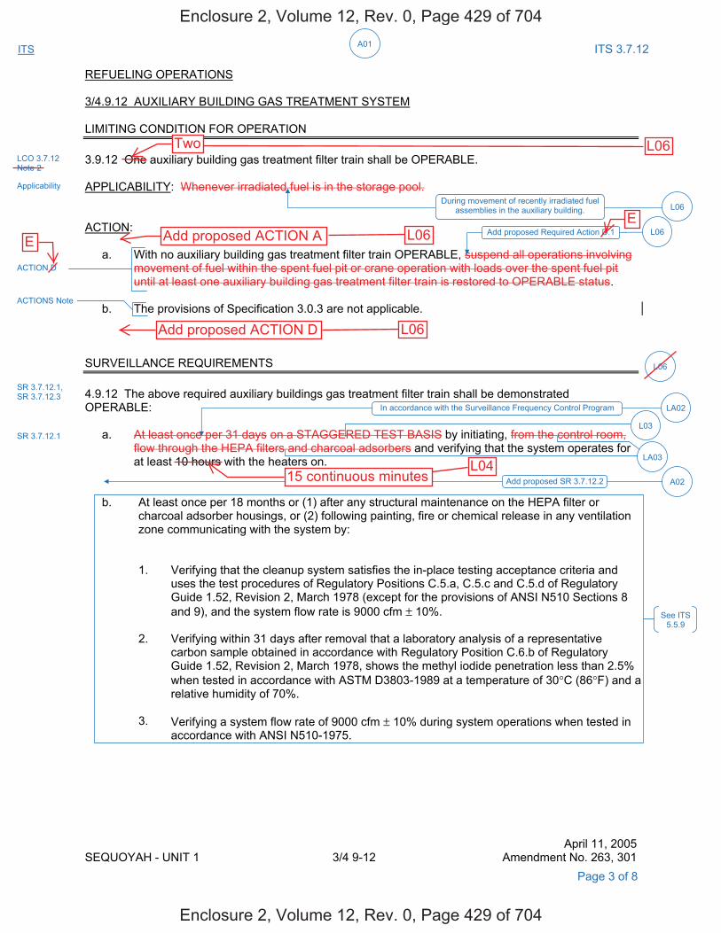
A01ITS ITS 3.7.12
REFUELING OPERATIONS 3/4.9.12 AUXILIARY BUILDING GAS TREATMENT SYSTEM LIMITING CONDITION FOR OPERATION 3.9.12 One auxiliary building gas treatment filter train shall be OPERABLE. APPLICABILITY: Whenever irradiated fuel is in the storage pool. ACTION: a. With no auxiliary building gas treatment filter train OPERABLE, suspend all operations involving
movement of fuel within the spent fuel pit or crane operation with loads over the spent fuel pit until at least one auxiliary building gas treatment filter train is restored to OPERABLE status.
b. The provisions of Specification 3.0.3 are not applicable. SURVEILLANCE REQUIREMENTS 4.9.12 The above required auxiliary buildings gas treatment filter train shall be demonstrated OPERABLE: a. At least once per 31 days on a STAGGERED TEST BASIS by initiating, from the control room,
flow through the HEPA filters and charcoal adsorbers and verifying that the system operates for at least 10 hours with the heaters on.
b. At least once per 18 months or (1) after any structural maintenance on the HEPA filter or
charcoal adsorber housings, or (2) following painting, fire or chemical release in any ventilation zone communicating with the system by:
1. Verifying that the cleanup system satisfies the in-place testing acceptance criteria and
uses the test procedures of Regulatory Positions C.5.a, C.5.c and C.5.d of Regulatory Guide 1.52, Revision 2, March 1978 (except for the provisions of ANSI N510 Sections 8 and 9), and the system flow rate is 9000 cfm ± 10%.
2. Verifying within 31 days after removal that a laboratory analysis of a representative
carbon sample obtained in accordance with Regulatory Position C.6.b of Regulatory Guide 1.52, Revision 2, March 1978, shows the methyl iodide penetration less than 2.5%
when tested in accordance with ASTM D3803-1989 at a temperature of 30°C (86°F) and a relative humidity of 70%.
3. Verifying a system flow rate of 9000 cfm ± 10% during system operations when tested in
accordance with ANSI N510-1975.
April 11, 2005 SEQUOYAH - UNIT 1 3/4 9-12 Amendment No. 263, 301
Page 3 of 8
LCO 3.7.12 Note 2
Applicability
During movement of recently irradiated fuel assemblies in the auxiliary building. L06
ACTION D
ACTIONS Note
L06
SR 3.7.12.1
SR 3.7.12.1, SR 3.7.12.3
Add proposed SR 3.7.12.2 A02
LA03
See ITS 5.5.9
In accordance with the Surveillance Frequency Control Program LA02
L03
Add proposed Required Action D.1 L06
Enclosure 2, Volume 12, Rev. 0, Page 429 of 704
Enclosure 2, Volume 12, Rev. 0, Page 429 of 704
Two L06
EE
Add proposed ACTION A L06
Add proposed ACTION D L06
15 continuous minutesL04

A01ITS ITS 3.7.12
REFUELING OPERATIONS 3/4.9.12 AUXILIARY BUILDING GAS TREATMENT SYSTEM LIMITING CONDITION FOR OPERATION 3.9.12 One auxiliary building gas treatment filter train shall be OPERABLE. APPLICABILITY: Whenever irradiated fuel is in the storage pool. ACTION: a. With no auxiliary building gas treatment filter train OPERABLE, suspend all operations
involving movement of fuel within the spent fuel pit or crane operation with loads over the spent fuel pit until at least one auxiliary building gas treatment filter train is restored to OPERABLE status.
b. The provisions of Specification 3.0.3 are not applicable. SURVEILLANCE REQUIREMENTS 4.9.12 The above required auxiliary building gas treatment filter train shall be demonstrated OPERABLE: a. At least once per 31 days on a STAGGERED TEST BASIS by initiating, from the control room,
flow through the HEPA filters and charcoal adsorbers and verifying that the system operates for at least 10 hours with the heaters on.
b. At least once per 18 months or (1) after any structural maintenance on the HEPA filter or
charcoal adsorber housings, or (2) following painting, fire or chemical release in any ventilation zone communicating with the system by:
1. Verifying that the cleanup system satisfies the in-place testing acceptance criteria and
uses the test procedures of Regulatory Positions C.5.a, C.5.c and C.5.d of Regulatory Guide 1.52, Revision 2, March 1978 (except for the provisions of ANSI N510 Sections 8 and 9), and the system flow rate is 9000 cfm + 10%.
2. Verifying within 31 days after removal that a laboratory analysis of a representative
carbon sample obtained in accordance with Regulatory Position C.6.b of Regulatory Guide 1.52, Revision 2, March 1978, shows the methyl iodide penetration less than 2.5%
when tested in accordance with ASTM D3803-1989 at a temperature of 30°C (86° F) and a relative humidity of 70%.
3. Verifying a system flow rate of 9000 cfm + 10% during system operation when tested in
accordance with ANSI N510-1975.
April 11, 2005 SEQUOYAH - UNIT 2 3/4 9-14 Amendment No. 254, 290
Page 7 of 8
LCO 3.7.12 Note 2
Applicability
During movement of recently irradiated fuel assemblies in the auxiliary building. L06
ACTION D
ACTIONS Note
SR 3.7.12.1
SR 3.7.12.1, SR 3.7.12.3
Add proposed SR 3.7.12.2 A02
LA03
See ITS 5.5.9
LA02In accordance with the Surveillance Frequency Control Program
L03
Add proposed Required Action D.1 L06
Enclosure 2, Volume 12, Rev. 0, Page 433 of 704
Enclosure 2, Volume 12, Rev. 0, Page 433 of 704
Two L06
E
L06Add proposed ACTION AE
Add proposed ACTION D L06
L04
15 continuousminutes
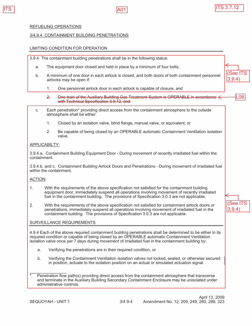
REFUELING OPERATIONS 3/4.9.4 CONTAINMENT BUILDING PENETRATIONS LIMITING CONDITION FOR OPERATION 3.9.4 The containment building penetrations shall be in the following status: a. The equipment door closed and held in place by a minimum of four bolts,
b. A minimum of one door in each airlock is closed, and both doors of both containment personnel
airlocks may be open if: 1. One personnel airlock door in each airlock is capable of closure, and 2. One train of the Auxiliary Building Gas Treatment System is OPERABLE in accordance
with Technical Specification 3.9.12, and c. Each penetration* providing direct access from the containment atmosphere to the outside
atmosphere shall be either: 1. Closed by an isolation valve, blind flange, manual valve, or equivalent, or 2. Be capable of being closed by an OPERABLE automatic Containment Ventilation isolation
valve. APPLICABILTY: 3.9.4.a. Containment Building Equipment Door - During movement of recently irradiated fuel within the containment. 3.9.4.b. and c. Containment Building Airlock Doors and Penetrations - During movement of irradiated fuel within the containment. ACTION: 1. With the requirements of the above specification not satisfied for the containment building
equipment door, immediately suspend all operations involving movement of recently irradiated fuel in the containment building. The provisions of Specification 3.0.3 are not applicable.
2. With the requirements of the above specification not satisfied for containment airlock doors or
penetrations, immediately suspend all operations involving movement of irradiated fuel in the containment building. The provisions of Specification 3.0.3 are not applicable.
SURVEILLANCE REQUIREMENTS 4.9.4 Each of the above required containment building penetrations shall be determined to be either in its required condition or capable of being closed by an OPERABLE automatic Containment Ventilation isolation valve once per 7 days during movement of irradiated fuel in the containment building by: a. Verifying the penetrations are in their required condition, or b. Verifying the Containment Ventilation isolation valves not locked, sealed, or otherwise secured
in position, actuate to the isolation position on an actual or simulated actuation signal. * Penetration flow path(s) providing direct access from the containment atmosphere that transverse
and terminate in the Auxiliary Building Secondary Containment Enclosure may be unisolated under administrative controls.
April 13, 2009 SEQUOYAH - UNIT 1 3/4 9-4 Amendment No. 12, 209, 249, 260, 288, 323
ITS 3.7.12ITS
(See ITS3.9.4)
(See ITS3.9.4)
A01
L08

REFUELING OPERATIONS 3/4.9.4 CONTAINMENT BUILDING PENETRATIONS LIMITING CONDITION FOR OPERATION 3.9.4 The containment building penetrations shall be in the following status: a. The equipment door closed and held in place by a minimum of four bolts, b. A minimum of one door in each airlock is closed, or both doors of both containment
personnel airlocks may be open if: 1. One personnel airlock door in each airlock is capable of closure, and 2. One train of the Auxiliary Building Gas Treatment System is OPERABLE in
accordance with Technical Specification 3.9.12, and c. Each penetration* providing direct access from the containment atmosphere to the outside
atmosphere shall be either: 1. Closed by an isolation valve, blind flange, manual valve, or equivalent, or 2. Be capable of being closed by an OPERABLE automatic Containment Ventilation
isolation valve. APPLICABILITY: 3.9.4.a. Containment Building Equipment Door - During movement of recently irradiated fuel within the containment. 3.9.4.b. and c. Containment Building Airlock Doors and Penetrations - During movement of irradiated fuel within the containment. ACTION: 1. With the requirements of the above specification not satisfied for the containment building
equipment door, immediately suspend all operations involving movement of recently irradiated fuel in the containment building. The provisions of Specification 3.0.3 are not applicable.
2. With the requirements of the above specification not satisfied for containment airlock doors or
penetrations, immediately suspend all operations involving movement of irradiated fuel in the containment building. The provisions of Specification 3.0.3 are not applicable.
SURVEILLANCE REQUIREMENTS 4.9.4 Each of the above required containment building penetrations shall be determined to be either in its required condition or capable of being closed by an OPERABLE automatic Containment Ventilation isolation valve once per 7 days during movement of irradiated fuel in the containment building by: a. Verifying the penetrations are in their required condition, or b. Verifying the Containment Ventilation isolation valves not locked, sealed, or otherwise secured
in position, actuate to the isolation position on an actual or simulated actuation signal. * Penetration flow path(s) providing direct access from the containment atmosphere that transverse and terminate in the Auxiliary Building Secondary Containment Enclosure may be unisolated under administrative controls.
April 13, 2009 SEQUOYAH - UNIT 2 3/4 9-5 Amendment No. 199, 240, 251, 278, 315
ITS ITS 3.7.12
(See ITS3.9.4)
L08
(See ITS3.9.4)
A01
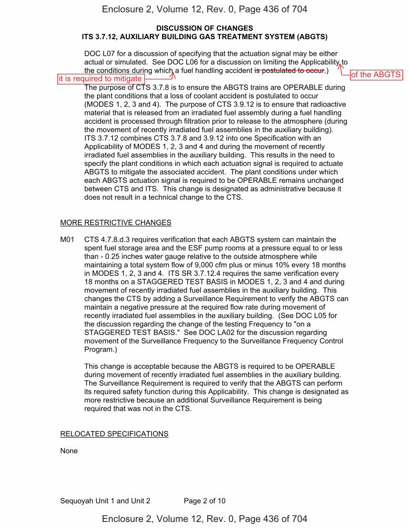
DISCUSSION OF CHANGES ITS 3.7.12, AUXILIARY BUILDING GAS TREATMENT SYSTEM (ABGTS)
Sequoyah Unit 1 and Unit 2 Page 2 of 10
DOC L07 for a discussion of specifying that the actuation signal may be either actual or simulated. See DOC L06 for a discussion on limiting the Applicability to the conditions during which a fuel handling accident is postulated to occur.)
The purpose of CTS 3.7.8 is to ensure the ABGTS trains are OPERABLE during
the plant conditions that a loss of coolant accident is postulated to occur (MODES 1, 2, 3 and 4). The purpose of CTS 3.9.12 is to ensure that radioactive material that is released from an irradiated fuel assembly during a fuel handling accident is processed through filtration prior to release to the atmosphere (during the movement of recently irradiated fuel assemblies in the auxiliary building). ITS 3.7.12 combines CTS 3.7.8 and 3.9.12 into one Specification with an Applicability of MODES 1, 2, 3 and 4 and during the movement of recently irradiated fuel assemblies in the auxiliary building. This results in the need to specify the plant conditions in which each actuation signal is required to actuate ABGTS to mitigate the associated accident. The plant conditions under which each ABGTS actuation signal is required to be OPERABLE remains unchanged between CTS and ITS. This change is designated as administrative because it does not result in a technical change to the CTS.
MORE RESTRICTIVE CHANGES M01 CTS 4.7.8.d.3 requires verification that each ABGTS system can maintain the
spent fuel storage area and the ESF pump rooms at a pressure equal to or less than - 0.25 inches water gauge relative to the outside atmosphere while maintaining a total system flow of 9,000 cfm plus or minus 10% every 18 months in MODES 1, 2, 3 and 4. ITS SR 3.7.12.4 requires the same verification every 18 months on a STAGGERED TEST BASIS in MODES 1, 2, 3 and 4 and during movement of recently irradiated fuel assemblies in the auxiliary building. This changes the CTS by adding a Surveillance Requirement to verify the ABGTS can maintain a negative pressure at the required flow rate during movement of recently irradiated fuel assemblies in the auxiliary building. (See DOC L05 for the discussion regarding the change of the testing Frequency to "on a STAGGERED TEST BASIS." See DOC LA02 for the discussion regarding movement of the Surveillance Frequency to the Surveillance Frequency Control Program.)
This change is acceptable because the ABGTS is required to be OPERABLE
during movement of recently irradiated fuel assemblies in the auxiliary building. The Surveillance Requirement is required to verify that the ABGTS can perform its required safety function during this Applicability. This change is designated as more restrictive because an additional Surveillance Requirement is being required that was not in the CTS.
RELOCATED SPECIFICATIONS None
Enclosure 2, Volume 12, Rev. 0, Page 436 of 704
Enclosure 2, Volume 12, Rev. 0, Page 436 of 704
of the ABGTSit is required to mitigate

DISCUSSION OF CHANGES ITS 3.7.12, AUXILIARY BUILDING GAS TREATMENT SYSTEM (ABGTS)
Sequoyah Unit 1 and Unit 2 Page 5 of 10
adequate protection of public health and safety. ITS 3.7.12 retains the requirement that two ABGTS trains are required to be OPERABLE. Also, this change is acceptable because these types of details will be adequately controlled in the ITS Bases. Changes to the Bases are controlled by the Technical Specification Bases Control Program in Chapter 5. This program provides for the evaluation of changes to ensure the Bases are properly controlled. This change is designated as a less restrictive removal of detail change because information relating to system design is being removed from the Technical Specifications.
LA05 (Type 3 – Removing Procedural Details for Meeting TS Requirements or
Reporting Requirements) CTS 4.7.8.d.3 requires verification that the ABGTS system maintains the spent fuel storage area and the ESF pump rooms at a pressure equal to or more negative than minus 1/4 inch water gage relative to the outside atmosphere while maintaining a total system flow of 9000 cfm plus or minus 10%. ITS 3.7.12.4 requires verification that the ABGTS train can maintain a pressure greater than or equal to -0.25 inches water gauge with respect to atmospheric pressure at a flow rate greater than or equal to 8,100 and less than or equal to 9,900 cfm. This changes the CTS by moving the statement that the system maintains the spent fuel storage area and the ESF pump rooms at the specified pressure to the Bases.
The removal of these details for performing a Surveillance Requirement from the
Technical Specifications is acceptable because this type of information is not necessary to be included in the Technical Specifications to provide adequate protection of public health and safety. The ITS still retains the requirements to verify the ABGTS train can maintain a pressure greater than or equal to -0.25 inches water gauge with respect to atmospheric pressure at a flow rate of greater than or equal to 8,100 and less than or equal to 9,900 cfm. Also, this change is acceptable because these types of procedural details will be adequately controlled in the ITS Bases. Changes to the Bases are controlled by the Technical Specification Bases Control Program in Chapter 5. This program provides for the evaluation of changes to ensure the Bases are properly controlled. This change is designated as a less restrictive removal of detail change because procedural details for meeting Technical Specifications are being removed from the Technical Specifications.
LESS RESTRICTIVE CHANGES L01 (Category 1 – Relaxation of LCO Requirements) CTS 3.7.8 requires two ABGTS
trains to be OPERABLE. ITS LCO 3.7.12 includes the same ABGTS OPERABILITY requirements but is modified by Note 1, which states "The Auxiliary Building Secondary Containment Enclosure (ABSCE) boundary may be opened intermittently under administrative control." This changes the CTS by allowing the ABSCE boundary to be opened under administrative controls when the ABGTS is required to be OPERABLE.
The purpose of CTS 3.7.8 is to maintain the air pressure in the auxiliary building
below atmospheric, reduce the concentration of nuclides in air releases from the Auxiliary Building Secondary Containment Enclosure (ABSCE), and to minimize the spread of airborne radioactivity within the Auxiliary Building following an
Enclosure 2, Volume 12, Rev. 0, Page 439 of 704
Enclosure 2, Volume 12, Rev. 0, Page 439 of 704
to verify that eachABGTS train willautomatically startas designed
less
less
a
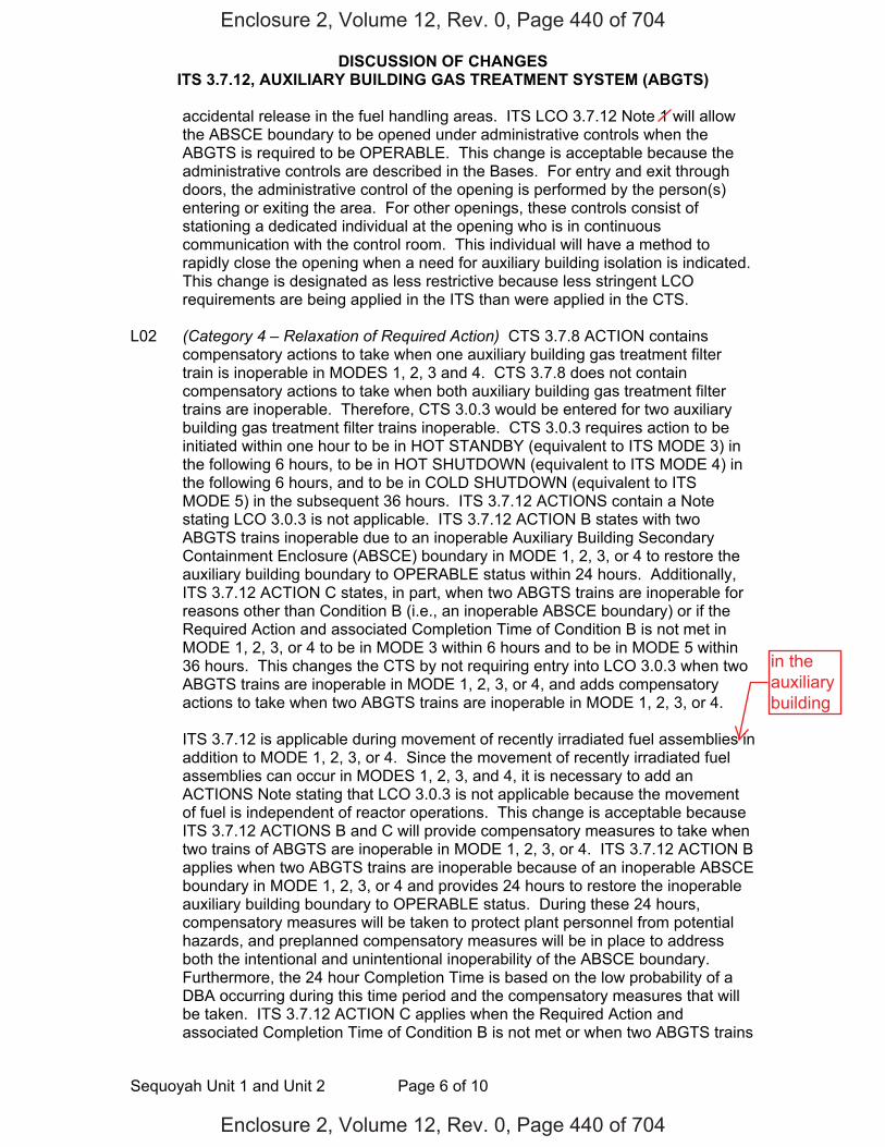
DISCUSSION OF CHANGES ITS 3.7.12, AUXILIARY BUILDING GAS TREATMENT SYSTEM (ABGTS)
Sequoyah Unit 1 and Unit 2 Page 6 of 10
accidental release in the fuel handling areas. ITS LCO 3.7.12 Note 1 will allow the ABSCE boundary to be opened under administrative controls when the ABGTS is required to be OPERABLE. This change is acceptable because the administrative controls are described in the Bases. For entry and exit through doors, the administrative control of the opening is performed by the person(s) entering or exiting the area. For other openings, these controls consist of stationing a dedicated individual at the opening who is in continuous communication with the control room. This individual will have a method to rapidly close the opening when a need for auxiliary building isolation is indicated. This change is designated as less restrictive because less stringent LCO requirements are being applied in the ITS than were applied in the CTS.
L02 (Category 4 – Relaxation of Required Action) CTS 3.7.8 ACTION contains
compensatory actions to take when one auxiliary building gas treatment filter train is inoperable in MODES 1, 2, 3 and 4. CTS 3.7.8 does not contain compensatory actions to take when both auxiliary building gas treatment filter trains are inoperable. Therefore, CTS 3.0.3 would be entered for two auxiliary building gas treatment filter trains inoperable. CTS 3.0.3 requires action to be initiated within one hour to be in HOT STANDBY (equivalent to ITS MODE 3) in the following 6 hours, to be in HOT SHUTDOWN (equivalent to ITS MODE 4) in the following 6 hours, and to be in COLD SHUTDOWN (equivalent to ITS MODE 5) in the subsequent 36 hours. ITS 3.7.12 ACTIONS contain a Note stating LCO 3.0.3 is not applicable. ITS 3.7.12 ACTION B states with two ABGTS trains inoperable due to an inoperable Auxiliary Building Secondary Containment Enclosure (ABSCE) boundary in MODE 1, 2, 3, or 4 to restore the auxiliary building boundary to OPERABLE status within 24 hours. Additionally, ITS 3.7.12 ACTION C states, in part, when two ABGTS trains are inoperable for reasons other than Condition B (i.e., an inoperable ABSCE boundary) or if the Required Action and associated Completion Time of Condition B is not met in MODE 1, 2, 3, or 4 to be in MODE 3 within 6 hours and to be in MODE 5 within 36 hours. This changes the CTS by not requiring entry into LCO 3.0.3 when two ABGTS trains are inoperable in MODE 1, 2, 3, or 4, and adds compensatory actions to take when two ABGTS trains are inoperable in MODE 1, 2, 3, or 4.
ITS 3.7.12 is applicable during movement of recently irradiated fuel assemblies in
addition to MODE 1, 2, 3, or 4. Since the movement of recently irradiated fuel assemblies can occur in MODES 1, 2, 3, and 4, it is necessary to add an ACTIONS Note stating that LCO 3.0.3 is not applicable because the movement of fuel is independent of reactor operations. This change is acceptable because ITS 3.7.12 ACTIONS B and C will provide compensatory measures to take when two trains of ABGTS are inoperable in MODE 1, 2, 3, or 4. ITS 3.7.12 ACTION B applies when two ABGTS trains are inoperable because of an inoperable ABSCE boundary in MODE 1, 2, 3, or 4 and provides 24 hours to restore the inoperable auxiliary building boundary to OPERABLE status. During these 24 hours, compensatory measures will be taken to protect plant personnel from potential hazards, and preplanned compensatory measures will be in place to address both the intentional and unintentional inoperability of the ABSCE boundary. Furthermore, the 24 hour Completion Time is based on the low probability of a DBA occurring during this time period and the compensatory measures that will be taken. ITS 3.7.12 ACTION C applies when the Required Action and associated Completion Time of Condition B is not met or when two ABGTS trains
Enclosure 2, Volume 12, Rev. 0, Page 440 of 704
Enclosure 2, Volume 12, Rev. 0, Page 440 of 704
in theauxiliarybuilding
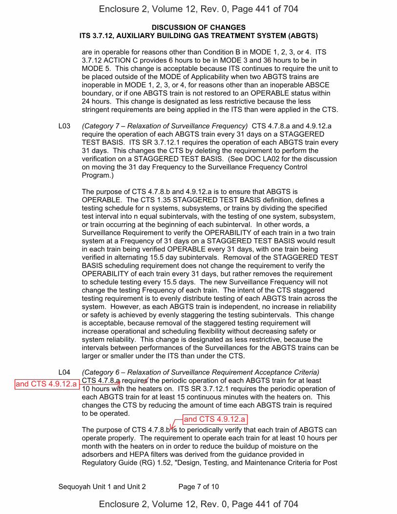
DISCUSSION OF CHANGES ITS 3.7.12, AUXILIARY BUILDING GAS TREATMENT SYSTEM (ABGTS)
Sequoyah Unit 1 and Unit 2 Page 7 of 10
are in operable for reasons other than Condition B in MODE 1, 2, 3, or 4. ITS 3.7.12 ACTION C provides 6 hours to be in MODE 3 and 36 hours to be in MODE 5. This change is acceptable because ITS continues to require the unit to be placed outside of the MODE of Applicability when two ABGTS trains are inoperable in MODE 1, 2, 3, or 4, for reasons other than an inoperable ABSCE boundary, or if one ABGTS train is not restored to an OPERABLE status within 24 hours. This change is designated as less restrictive because the less stringent requirements are being applied in the ITS than were applied in the CTS.
L03 (Category 7 – Relaxation of Surveillance Frequency) CTS 4.7.8.a and 4.9.12.a
require the operation of each ABGTS train every 31 days on a STAGGERED TEST BASIS. ITS SR 3.7.12.1 requires the operation of each ABGTS train every 31 days. This changes the CTS by deleting the requirement to perform the verification on a STAGGERED TEST BASIS. (See DOC LA02 for the discussion on moving the 31 day Frequency to the Surveillance Frequency Control Program.)
The purpose of CTS 4.7.8.b and 4.9.12.a is to ensure that ABGTS is
OPERABLE. The CTS 1.35 STAGGERED TEST BASIS definition, defines a testing schedule for n systems, subsystems, or trains by dividing the specified test interval into n equal subintervals, with the testing of one system, subsystem, or train occurring at the beginning of each subinterval. In other words, a Surveillance Requirement to verify the OPERABILITY of each train in a two train system at a Frequency of 31 days on a STAGGERED TEST BASIS would result in each train being verified OPERABLE every 31 days, with one train being verified in alternating 15.5 day subintervals. Removal of the STAGGERED TEST BASIS scheduling requirement does not change the requirement to verify the OPERABILITY of each train every 31 days, but rather removes the requirement to schedule testing every 15.5 days. The new Surveillance Frequency will not change the testing Frequency of each train. The intent of the CTS staggered testing requirement is to evenly distribute testing of each ABGTS train across the system. However, as each ABGTS train is independent, no increase in reliability or safety is achieved by evenly staggering the testing subintervals. This change is acceptable, because removal of the staggered testing requirement will increase operational and scheduling flexibility without decreasing safety or system reliability. This change is designated as less restrictive, because the intervals between performances of the Surveillances for the ABGTS trains can be larger or smaller under the ITS than under the CTS.
L04 (Category 6 – Relaxation of Surveillance Requirement Acceptance Criteria)
CTS 4.7.8.a requires the periodic operation of each ABGTS train for at least 10 hours with the heaters on. ITS SR 3.7.12.1 requires the periodic operation of each ABGTS train for at least 15 continuous minutes with the heaters on. This changes the CTS by reducing the amount of time each ABGTS train is required to be operated.
The purpose of CTS 4.7.8.b is to periodically verify that each train of ABGTS can operate properly. The requirement to operate each train for at least 10 hours per month with the heaters on in order to reduce the buildup of moisture on the adsorbers and HEPA filters was derived from the guidance provided in Regulatory Guide (RG) 1.52, "Design, Testing, and Maintenance Criteria for Post
Enclosure 2, Volume 12, Rev. 0, Page 441 of 704
Enclosure 2, Volume 12, Rev. 0, Page 441 of 704
and CTS 4.9.12.a
and CTS 4.9.12.a

DISCUSSION OF CHANGES ITS 3.7.12, AUXILIARY BUILDING GAS TREATMENT SYSTEM (ABGTS)
Sequoyah Unit 1 and Unit 2 Page 9 of 10
L06 (Category 2 – Relaxation of Applicability) CTS 3.9.12 states that the requirements of the ABGTS are applicable "Whenever irradiated fuel is in the storage pool." CTS 3.9.12 ACTION a requires when no ABGTS is OPERABLE, suspend all operations involving movement of fuel within the spent fuel pit or crane operation with loads over the spent fuel pit until at least one ABGTS train is restored to an OPERABLE stratus. ITS 3.7.12 states, in part, that the requirements of the ABGTS are applicable "During movement of recently irradiated fuel assemblies in the auxiliary building." ITS 3.7.12 ACTION D requires when two ABGTS trains are inoperable during movement of recently irradiated fuel assemblies in the auxiliary building immediately to suspend movement of recently irradiated fuel assemblies in the auxiliary building. This changes the CTS by restricting the ABGTS Specification to only when there is a potential for a fuel handling accident (i.e., during movement of recently irradiated fuel assemblies in the auxiliary building).
The purpose of CTS 3.9.12 is to ensure the ABGTS is OPERABLE to mitigate
the consequences of a fuel handling accident in the auxiliary building. This change is acceptable because the requirements continue to ensure that the structures, system and components are maintained in the MODES and other specified conditions assumed in the safety analyses and licensing basis. The Sequoyah Nuclear Plant (SQN) fuel handling analysis for the auxiliary building has been analyzed using the methodology from Regulatory Guide 1.183, "Alternative Radiological Source Terms for Evaluating Design Basis Accidents at Nuclear Power Reactors." The SQN fuel handling analysis assumes, in part, that the accident occurs within 100 hours after a plant shutdown, radioactive decay during the interval between shutdown and placement of the first spent fuel assembly into the spent fuel pool is taken into account, and a single fuel assembly is damaged. Additionally, a fuel handling accident is only assumed to occur when a recently irradiated fuel assembly is being moved. Therefore, the ITS imposes the controls on the ABGTS during movement of recently irradiated fuel assemblies in the auxiliary building. This change is designated as less restrictive because the LCO requirements are applicable in fewer operating conditions than in the CTS.
L07 (Category 6 – Relaxation of Surveillance Requirement Acceptance Criteria)
CTS 4.7.8.d.2 requires verification that the filter trains start on a Containment Phase A Isolation test signal. CTS 4.9.12.d.2 requires verification that the filter train starts on a high radiation signal from the fuel pool radiation monitoring system. ITS SR 3.7.12.3 requires verification that each ABGTS train actuates on an actual or simulated actuation signal. This changes the CTS by specifying that the actuation signal may be either actual or simulated. (See DOC LA04 for a discussion of moving the details of the test signal to the Bases.)
The purpose of CTS 4.7.8.d.2 and 4.9.12.d.2 is to verify that each ABGTS train
operates correctly upon a receipt of an actuation signal. This change is acceptable because it has been determined that the relaxed Surveillance Requirement acceptance criteria are not necessary for verification that the equipment used to meet the LCO can perform its safety function. Equipment cannot discriminate between an "actual" or "simulated" signal; therefore, the results of testing are unaffected by the type of signal used to initiate the test.
Enclosure 2, Volume 12, Rev. 0, Page 443 of 704
Enclosure 2, Volume 12, Rev. 0, Page 443 of 704
Replace with"New" L06.

"New" DOC L06
(Category 2 – Relaxation of Applicability) CTS 3.9.12 states that the requirements of the ABGTS are applicable "Whenever irradiated fuel is in the storage pool." CTS 3.9.12 ACTION a requires when no ABGTS is OPERABLE, suspend all operations involving movement of fuel within the spent fuel pit or crane operation with loads over the spent fuel pit until at least one ABGTS train is restored to an OPERABLE status. ITS 3.7.12 states, in part, that two ABGTS trains are required to be OPERABLE "During movement of recently irradiated fuel assemblies in the auxiliary building." ITS 3.7.12 ACTION A requires one inoperable ABGTS train to be restored to an OPERABLE status in 7 days. ITS 3.7.12 ACTION D provides actions to either place a train of ABGTS in operation or suspend movement of recently irradiated fuel assemblies in the auxiliary building if the Required Actions and Completion Time of Condition A are not met. ITS 3.7.12 ACTION E requires when two ABGTS trains are inoperable during movement of recently irradiated fuel assemblies in the auxiliary building immediately to suspend movement of recently irradiated fuel assemblies in the auxiliary building. This changes the CTS by restricting the ABGTS Specification to only when ABGTS is required to mitigate a fuel handling accident (i.e., during movement of recently irradiated fuel assemblies in the auxiliary building).
The purpose of CTS 3.9.12 is to ensure the ABGTS is OPERABLE to mitigate the consequences of a fuel handling accident in the auxiliary building. This change is acceptable because the requirements continue to ensure that the structures, system and components are maintained in the MODES and other specified conditions assumed in the safety analyses and licensing basis. The Sequoyah Nuclear Plant (SQN) fuel handling analysis for the auxiliary building has been analyzed using the methodology from Regulatory Guide 1.183, "Alternative Radiological Source Terms for Evaluating Design Basis Accidents at Nuclear Power Reactors." The SQN fuel handling analysis inside the auxiliary building assumes, in part, that the accident occurs 100 hours after a plant shutdown, radioactive decay during the interval between shutdown and placement of the first spent fuel assembly into the spent fuel pool is taken into account, and a single fuel assembly is damaged. The damaged fuel assembly is assumed to be the highest powered assembly in the core region to be discharged with a radial peaking factor of 1.70. All of the gap activity in the damaged rods is released to the spent fuel pool and consists of 5% of the total noble gases other than Kr-85, 10% of the Kr-85, 5% of the toal radioactive iodine other than I-131, and 8% of the I-131 in the rods at the time of the accident. Noble gases released to the spent fuel pool do not experience retention in the water pool. The iodine gap inventory is composed of 99.85% inorganic species, and 0.15% organic species. The spent fuel pool decontamination factor is 200. No credit is taken for natural decay due to holdup in the auxiliary building or after the activity has been released to the atmosphere. The activity released from the spent fuel pool is all assumed to be released to the environment over a 2-hour period. Doses were determined at the EAB and LPZ for the 2-hour interval over which the releases are assumed to take place, and in the control room for an extended period of time after termination of releases in order to address the continual presence of activity in the control room atmosphere. The accident doses were calculated using the dose model consistent with the use of the alternate source term methodology (RG 1.183). T e doses are within the dose acceptance limits of 6.3 rem TEDE for offsite doses and 5.0 rem TEDE for control room doses. Because ABGTS is not credited in the mitigation of a fuel handling accident in the auxiliary building involving fuel that has at least 100 hours of decay time, it not required to be OPERABLE during that evolution. However, fuel movement could still proceed prior to a decay time of 100 hours. Therefore, to mitigate the consequences of a fuel handling accident involving the movement of recently irradiated fuel, ITS imposes the controls on the ABGTS during movement of recently irradiated fuel assemblies in the auxiliary building. Consistent with NUMARC 93-01, "Safety Assessment for Removal of Equipment from Service During Shutdown Conditions," TVA will

implement procedural requirements for a single normal or contingency method to promptly close primary or secondary containment penetrations. Additionally, TVA will implement procedural requirements for one train of ABGTS to be OPERABLE during movement of irradiated fuel assemblies (whether in the auxiliary building or within the containment). This change is designated as less restrictive because the LCO requirements are applicable in fewer operating conditions than in the CTS.
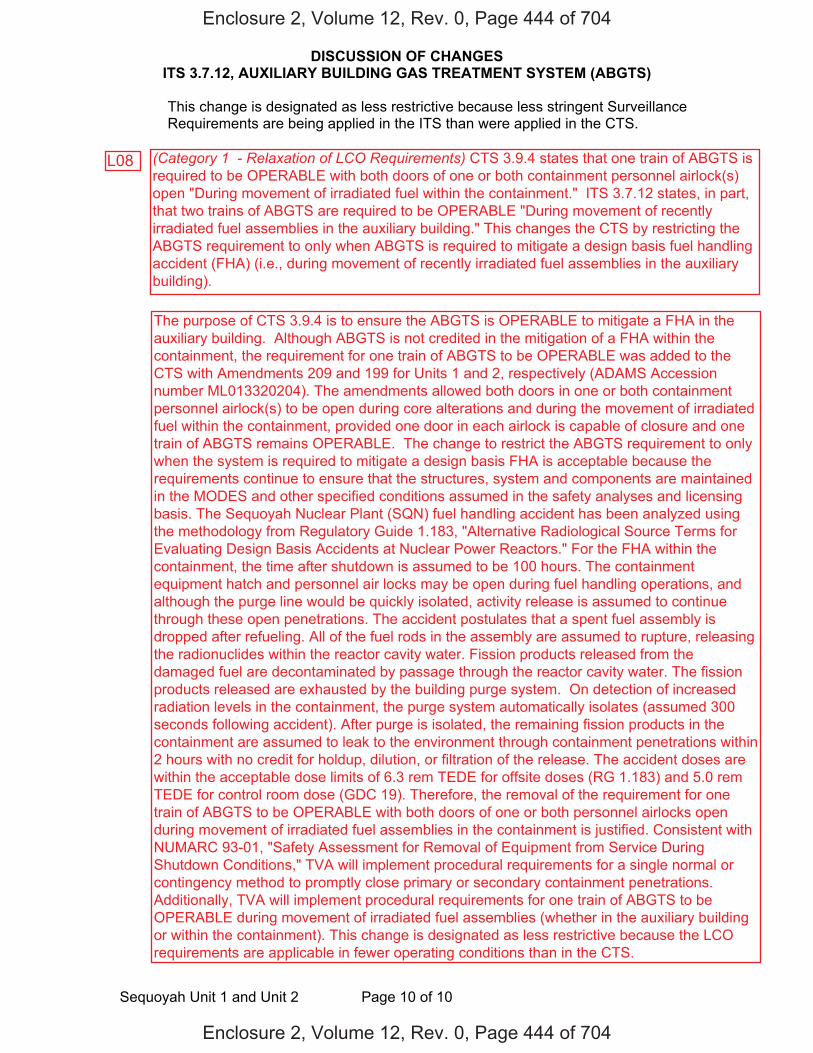
DISCUSSION OF CHANGES ITS 3.7.12, AUXILIARY BUILDING GAS TREATMENT SYSTEM (ABGTS)
Sequoyah Unit 1 and Unit 2 Page 10 of 10
This change is designated as less restrictive because less stringent Surveillance Requirements are being applied in the ITS than were applied in the CTS.
Enclosure 2, Volume 12, Rev. 0, Page 444 of 704
Enclosure 2, Volume 12, Rev. 0, Page 444 of 704
L08
The purpose of CTS 3.9.4 is to ensure the ABGTS is OPERABLE to mitigate a FHA in the auxiliary building. Although ABGTS is not credited in the mitigation of a FHA within the containment, the requirement for one train of ABGTS to be OPERABLE was added to the CTS with Amendments 209 and 199 for Units 1 and 2, respectively (ADAMS Accession number ML013320204). The amendments allowed both doors in one or both containment personnel airlock(s) to be open during core alterations and during the movement of irradiated fuel within the containment, provided one door in each airlock is capable of closure and one train of ABGTS remains OPERABLE. The change to restrict the ABGTS requirement to only when the system is required to mitigate a design basis FHA is acceptable because the requirements continue to ensure that the structures, system and components are maintained in the MODES and other specified conditions assumed in the safety analyses and licensing basis. The Sequoyah Nuclear Plant (SQN) fuel handling accident has been analyzed using the methodology from Regulatory Guide 1.183, "Alternative Radiological Source Terms for Evaluating Design Basis Accidents at Nuclear Power Reactors." For the FHA within the containment, the time after shutdown is assumed to be 100 hours. The containment equipment hatch and personnel air locks may be open during fuel handling operations, and although the purge line would be quickly isolated, activity release is assumed to continue through these open penetrations. The accident postulates that a spent fuel assembly is dropped after refueling. All of the fuel rods in the assembly are assumed to rupture, releasing the radionuclides within the reactor cavity water. Fission products released from the damaged fuel are decontaminated by passage through the reactor cavity water. The fission products released are exhausted by the building purge system. On detection of increased radiation levels in the containment, the purge system automatically isolates (assumed 300 seconds following accident). After purge is isolated, the remaining fission products in the containment are assumed to leak to the environment through containment penetrations within 2 hours with no credit for holdup, dilution, or filtration of the release. The accident doses are within the acceptable dose limits of 6.3 rem TEDE for offsite doses (RG 1.183) and 5.0 rem TEDE for control room dose (GDC 19). Therefore, the removal of the requirement for one train of ABGTS to be OPERABLE with both doors of one or both personnel airlocks open during movement of irradiated fuel assemblies in the containment is justified. Consistent with NUMARC 93-01, "Safety Assessment for Removal of Equipment from Service During Shutdown Conditions," TVA will implement procedural requirements for a single normal or contingency method to promptly close primary or secondary containment penetrations. Additionally, TVA will implement procedural requirements for one train of ABGTS to be OPERABLE during movement of irradiated fuel assemblies (whether in the auxiliary building or within the containment). This change is designated as less restrictive because the LCO requirements are applicable in fewer operating conditions than in the CTS.
(Category 1 - Relaxation of LCO Requirements) CTS 3.9.4 states that one train of ABGTS is required to be OPERABLE with both doors of one or both containment personnel airlock(s) open "During movement of irradiated fuel within the containment." ITS 3.7.12 states, in part, that two trains of ABGTS are required to be OPERABLE "During movement of recently irradiated fuel assemblies in the auxiliary building." This changes the CTS by restricting the ABGTS requirement to only when ABGTS is required to mitigate a design basis fuel handling accident (FHA) (i.e., during movement of recently irradiated fuel assemblies in the auxiliary building).

FBACS 3.7.13
Westinghouse STS 3.7.13-1 Rev. 4.0
ABGTSCTS
1
12
3
SEQUOYAH UNIT 1 Amendment XXX 12
1
3.7 PLANT SYSTEMS
3.7.13 Fuel Building Air Cleanup System (FBACS)
LCO 3.7.13 Two FBACS trains shall be OPERABLE.
---------------------------------------------NOTE--------------------------------------------The fuel building boundary may be opened intermittently under administrative control.
--------------------------------------------------------------------------------------------------
APPLICABILITY: [MODES 1, 2, 3, and 4, ] During movement of [recently] irradiated fuel assemblies in the fuel
building.
ACTIONS ------------------------------------------------------------NOTE----------------------------------------------------------- LCO 3.0.3 is not applicable. -------------------------------------------------------------------------------------------------------------------------------
CONDITION REQUIRED ACTION COMPLETION TIME
A. One FBACS train inoperable.
A.1 Restore FBACS train to OPERABLE status.
7 days
B. Two FBACS trains inoperable due to inoperable fuel building boundary in MODE 1, 2, 3, or 4.
B.1 Restore fuel building boundary to OPERABLE status.
24 hours
ABGTSAuxiliary Building Gas Treatment
ABGTS
3.7.8
Auxiliary Building Secondary Containment Enclosure (ABSCE)
3.7.8 Applicability, 3.9.12 Applicability
1
1
2
4
3.7.8 ACTION
DOC L02, 3.9.12 ACTION b
ABGTS ABGTS
12
12
auxiliary
3
1
3
ABGTS
ABSCE
ABSCE DOC L02 1
1. DOC L01 3.9.12
S
INSERT 1
3
In MODE 1, 2, 3, or 4 2
Enclosure 2, Volume 12, Rev. 0, Page 446 of 704
Enclosure 2, Volume 12, Rev. 0, Page 446 of 704
3.9.12
DOC L06

3.7.12
3.7.12-1
CTS
INSERT 1
2. Only one ABGTS train is required to be OPERABLE during movement of recently irradiatedfuel assemblies in the auxiliary building.
2
3.9.12
Enclosure 2, Volume 12, Rev. 0, Page 447 of 704
Enclosure 2, Volume 12, Rev. 0, Page 447 of 704
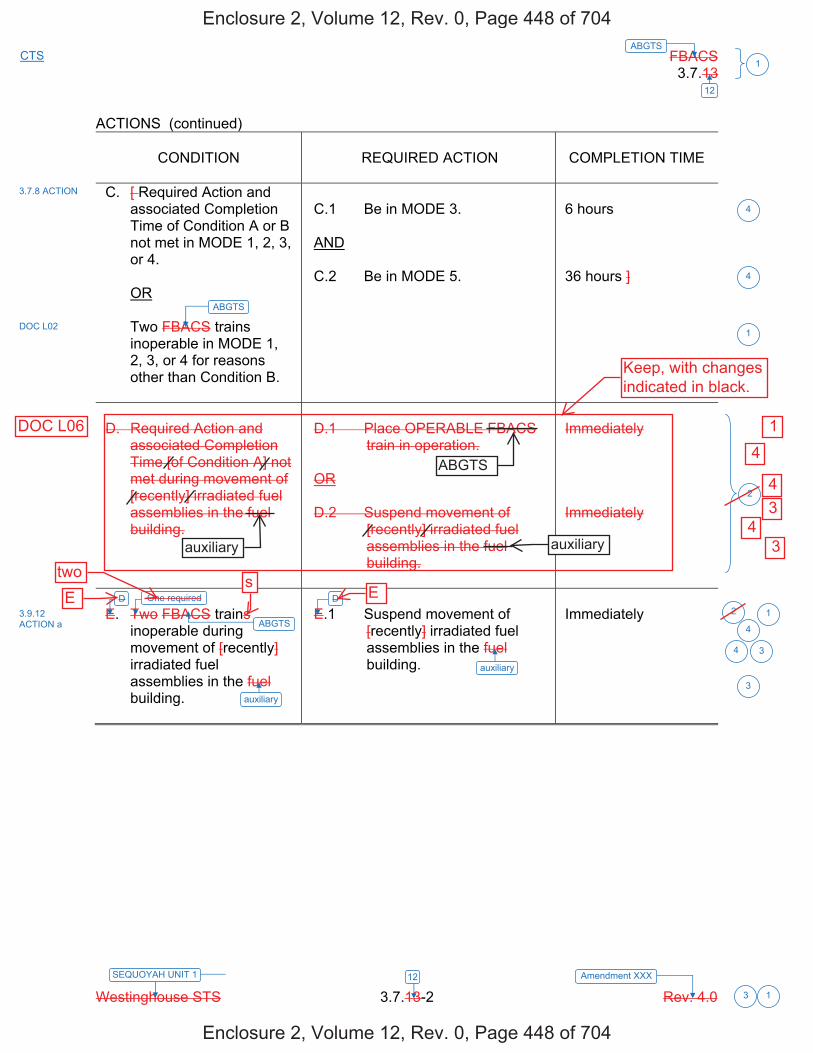
FBACS 3.7.13
Westinghouse STS 3.7.13-2 Rev. 4.0
ABGTSCTS
1
12
3
SEQUOYAH UNIT 1 Amendment XXX 12
1
ACTIONS (continued)
CONDITION
REQUIRED ACTION
COMPLETION TIME
C. [ Required Action and associated Completion Time of Condition A or B not met in MODE 1, 2, 3, or 4.
OR Two FBACS trains
inoperable in MODE 1, 2, 3, or 4 for reasons other than Condition B.
C.1 Be in MODE 3. AND C.2 Be in MODE 5.
6 hours 36 hours ]
D. Required Action and
associated Completion Time [of Condition A] not met during movement of [recently] irradiated fuel assemblies in the fuel building.
D.1 Place OPERABLE FBACS
train in operation. OR D.2 Suspend movement of
[recently] irradiated fuel assemblies in the fuel building.
Immediately Immediately
E. Two FBACS trains
inoperable during movement of [recently] irradiated fuel assemblies in the fuel building.
E.1 Suspend movement of
[recently] irradiated fuel assemblies in the fuel building.
Immediately
3.7.8 ACTION
3.9.12 ACTION a
ABGTS
ABGTS
auxiliary
auxiliary
4
4
1
2
1
3
4 3
4
DOC L02
D D2
One required
Enclosure 2, Volume 12, Rev. 0, Page 448 of 704
Enclosure 2, Volume 12, Rev. 0, Page 448 of 704
Etwo s
E
Keep, with changesindicated in black.
auxiliary auxiliary
ABGTS
DOC L06 1
4
4 3
3 4

FBACS 3.7.13
Westinghouse STS 3.7.13-1 Rev. 4.0
ABGTSCTS
1
12
3
SEQUOYAH UNIT 2 Amendment XXX 12
1
3.7 PLANT SYSTEMS
3.7.13 Fuel Building Air Cleanup System (FBACS)
LCO 3.7.13 Two FBACS trains shall be OPERABLE.
---------------------------------------------NOTE--------------------------------------------The fuel building boundary may be opened intermittently under administrative control.
--------------------------------------------------------------------------------------------------
APPLICABILITY: [MODES 1, 2, 3, and 4, ] During movement of [recently] irradiated fuel assemblies in the fuel
building.
ACTIONS ------------------------------------------------------------NOTE----------------------------------------------------------- LCO 3.0.3 is not applicable. -------------------------------------------------------------------------------------------------------------------------------
CONDITION REQUIRED ACTION COMPLETION TIME
A. One FBACS train inoperable.
A.1 Restore FBACS train to OPERABLE status.
7 days
B. Two FBACS trains inoperable due to inoperable fuel building boundary in MODE 1, 2, 3, or 4.
B.1 Restore fuel building boundary to OPERABLE status.
24 hours
ABGTSAuxiliary Building Gas Treatment
ABGTS
3.7.8
Auxiliary Building Secondary Containment Enclosure (ABSCE)
3.7.8 Applicability, 3.9.12 Applicability
1
1
2
4
3.7.8 ACTION
DOC L02, 3.9.12 ACTION b
ABGTS ABGTS
12
12
auxiliary
3
1
3
ABGTS
ABSCE
ABSCE DOC L02 1
1. DOC L01 3.9.12
S
INSERT 1
3
In MODE 1, 2, 3, or 4 2
Enclosure 2, Volume 12, Rev. 0, Page 452 of 704
Enclosure 2, Volume 12, Rev. 0, Page 452 of 704
3.9.12
DOC L06
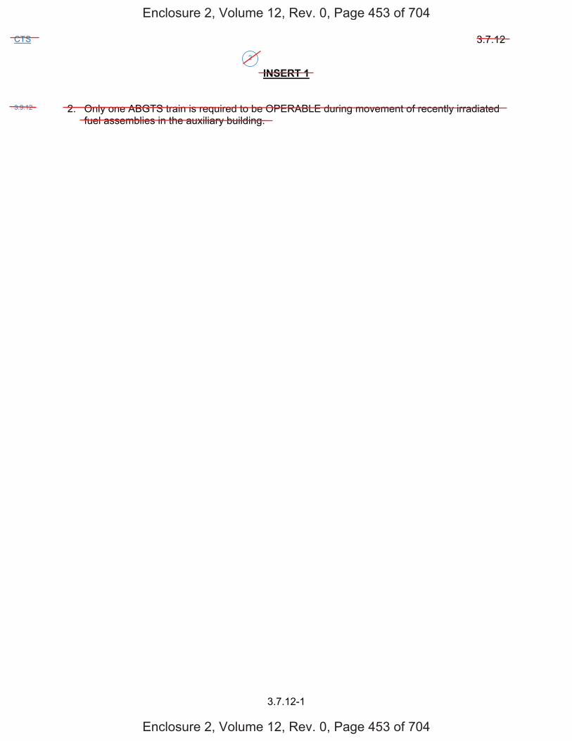
3.7.12
3.7.12-1
CTS
INSERT 1
2. Only one ABGTS train is required to be OPERABLE during movement of recently irradiatedfuel assemblies in the auxiliary building.
2
3.9.12
Enclosure 2, Volume 12, Rev. 0, Page 453 of 704
Enclosure 2, Volume 12, Rev. 0, Page 453 of 704
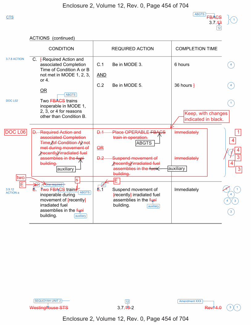
FBACS 3.7.13
Westinghouse STS 3.7.13-2 Rev. 4.0
ABGTSCTS
1
12
3
SEQUOYAH UNIT 2 Amendment XXX 12
1
ACTIONS (continued)
CONDITION REQUIRED ACTION COMPLETION TIME
C. [ Required Action and associated Completion Time of Condition A or B not met in MODE 1, 2, 3, or 4.
OR
Two FBACS trains inoperable in MODE 1, 2, 3, or 4 for reasons other than Condition B.
C.1 Be in MODE 3.
AND
C.2 Be in MODE 5.
6 hours
36 hours ]
D. Required Action and associated Completion Time [of Condition A] not met during movement of [recently] irradiated fuel assemblies in the fuel building.
D.1 Place OPERABLE FBACS train in operation.
OR
D.2 Suspend movement of [recently] irradiated fuel assemblies in the fuel building.
Immediately
Immediately
E. Two FBACS trains inoperable during movement of [recently] irradiated fuel assemblies in the fuel building.
E.1 Suspend movement of [recently] irradiated fuel assemblies in the fuel building.
Immediately
3.7.8 ACTION
3.9.12 ACTION a
ABGTS
ABGTS
auxiliary
auxiliary
4
4
1
2
1
3
4 3
4
DOC L02
D D2
One required
Enclosure 2, Volume 12, Rev. 0, Page 454 of 704
Enclosure 2, Volume 12, Rev. 0, Page 454 of 704
DOC L06
Keep, with changesindicated in black.
1
4
4 3
4 3
ABGTS
auxiliary auxiliary
Etwo s E
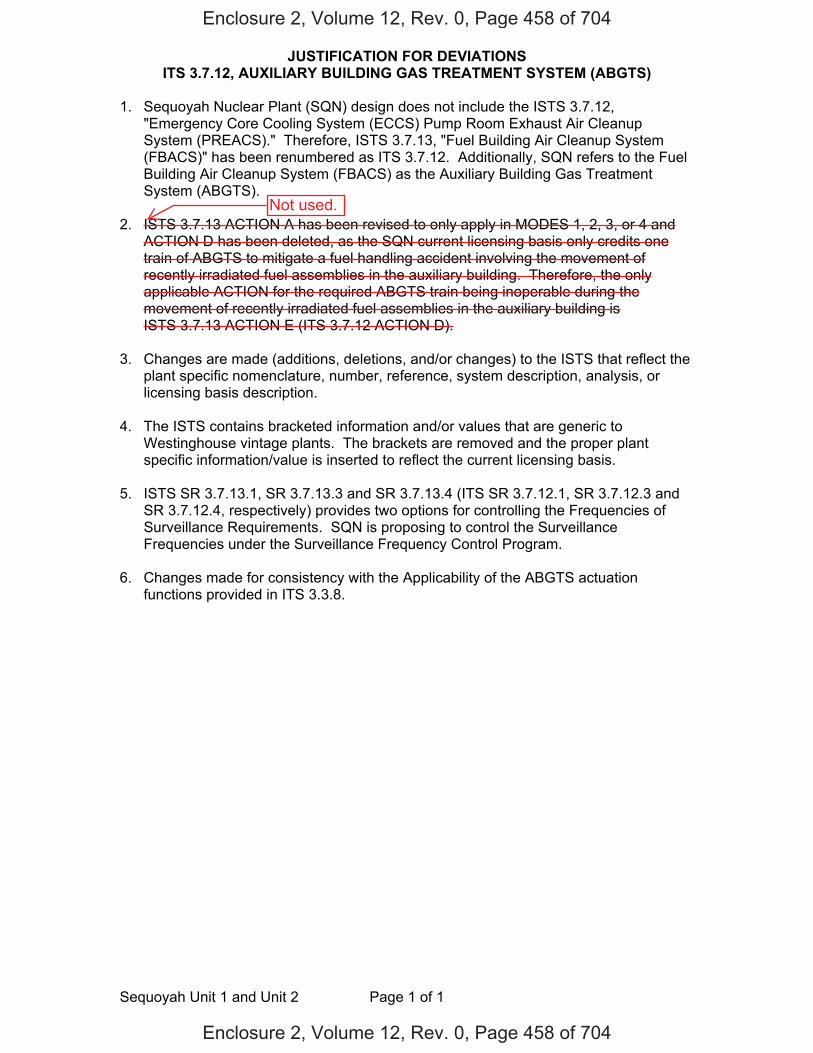
JUSTIFICATION FOR DEVIATIONS ITS 3.7.12, AUXILIARY BUILDING GAS TREATMENT SYSTEM (ABGTS)
Sequoyah Unit 1 and Unit 2 Page 1 of 1
1. Sequoyah Nuclear Plant (SQN) design does not include the ISTS 3.7.12,"Emergency Core Cooling System (ECCS) Pump Room Exhaust Air CleanupSystem (PREACS)." Therefore, ISTS 3.7.13, "Fuel Building Air Cleanup System(FBACS)" has been renumbered as ITS 3.7.12. Additionally, SQN refers to the FuelBuilding Air Cleanup System (FBACS) as the Auxiliary Building Gas TreatmentSystem (ABGTS).
2. ISTS 3.7.13 ACTION A has been revised to only apply in MODES 1, 2, 3, or 4 andACTION D has been deleted, as the SQN current licensing basis only credits onetrain of ABGTS to mitigate a fuel handling accident involving the movement ofrecently irradiated fuel assemblies in the auxiliary building. Therefore, the onlyapplicable ACTION for the required ABGTS train being inoperable during themovement of recently irradiated fuel assemblies in the auxiliary building isISTS 3.7.13 ACTION E (ITS 3.7.12 ACTION D).
3. Changes are made (additions, deletions, and/or changes) to the ISTS that reflect theplant specific nomenclature, number, reference, system description, analysis, orlicensing basis description.
4. The ISTS contains bracketed information and/or values that are generic toWestinghouse vintage plants. The brackets are removed and the proper plantspecific information/value is inserted to reflect the current licensing basis.
5. ISTS SR 3.7.13.1, SR 3.7.13.3 and SR 3.7.13.4 (ITS SR 3.7.12.1, SR 3.7.12.3 andSR 3.7.12.4, respectively) provides two options for controlling the Frequencies ofSurveillance Requirements. SQN is proposing to control the SurveillanceFrequencies under the Surveillance Frequency Control Program.
6. Changes made for consistency with the Applicability of the ABGTS actuationfunctions provided in ITS 3.3.8.
Enclosure 2, Volume 12, Rev. 0, Page 458 of 704
Enclosure 2, Volume 12, Rev. 0, Page 458 of 704
Not used.
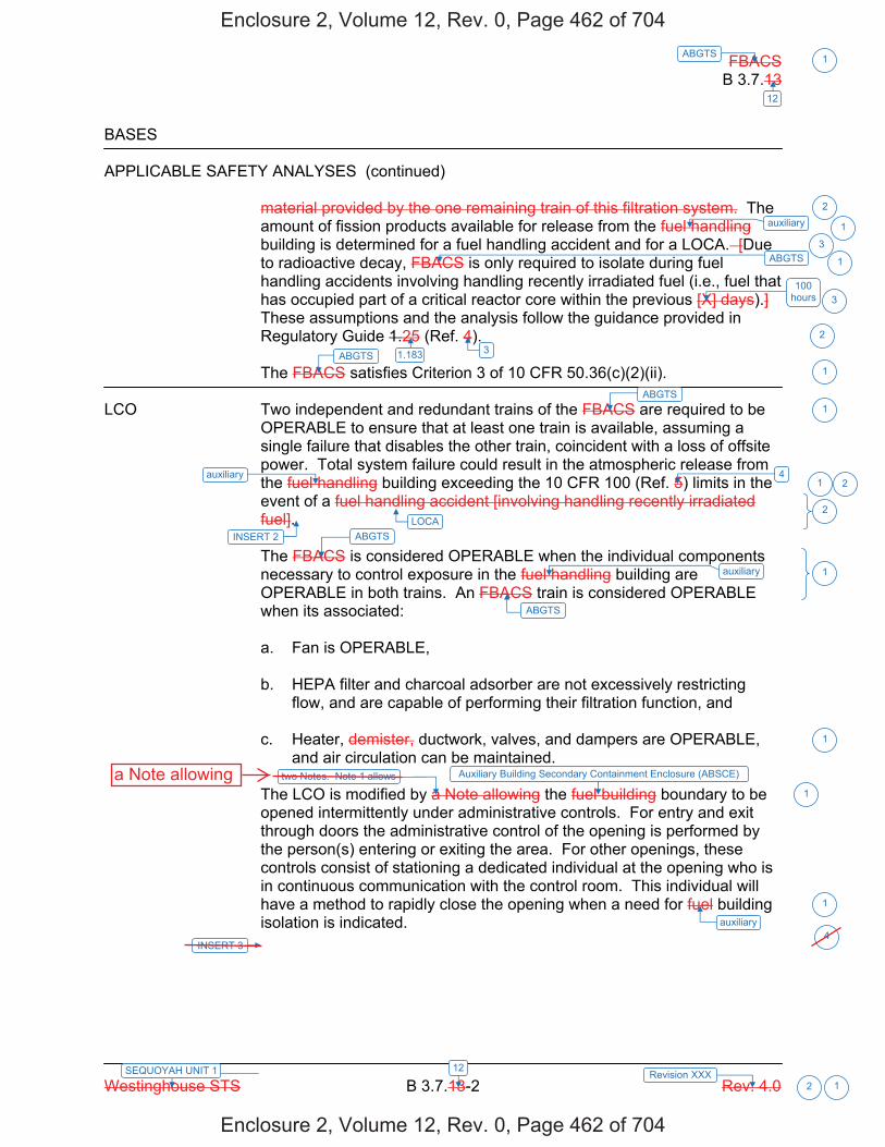
FBACS B 3.7.13
Westinghouse STS B 3.7.13-2 Rev. 4.0
ABGTS 1
12
12SEQUOYAH UNIT 1 Revision XXX 2 1
BASES
APPLICABLE SAFETY ANALYSES (continued)
material provided by the one remaining train of this filtration system. The amount of fission products available for release from the fuel handling building is determined for a fuel handling accident and for a LOCA. [Due to radioactive decay, FBACS is only required to isolate during fuel handling accidents involving handling recently irradiated fuel (i.e., fuel that has occupied part of a critical reactor core within the previous [X] days).] These assumptions and the analysis follow the guidance provided in Regulatory Guide 1.25 (Ref. 4).
The FBACS satisfies Criterion 3 of 10 CFR 50.36(c)(2)(ii).
LCO Two independent and redundant trains of the FBACS are required to be OPERABLE to ensure that at least one train is available, assuming a single failure that disables the other train, coincident with a loss of offsite power. Total system failure could result in the atmospheric release from the fuel handling building exceeding the 10 CFR 100 (Ref. 5) limits in the event of a fuel handling accident [involving handling recently irradiated fuel]. The FBACS is considered OPERABLE when the individual components necessary to control exposure in the fuel handling building are OPERABLE in both trains. An FBACS train is considered OPERABLE when its associated:
a. Fan is OPERABLE,
b. HEPA filter and charcoal adsorber are not excessively restrictingflow, and are capable of performing their filtration function, and
c. Heater, demister, ductwork, valves, and dampers are OPERABLE,and air circulation can be maintained.
The LCO is modified by a Note allowing the fuel building boundary to be opened intermittently under administrative controls. For entry and exit through doors the administrative control of the opening is performed by the person(s) entering or exiting the area. For other openings, these controls consist of stationing a dedicated individual at the opening who is in continuous communication with the control room. This individual will have a method to rapidly close the opening when a need for fuel building isolation is indicated.
ABGTS
100 hours
ABGTS 3
4
ABGTS
ABGTS
ABGTS
auxiliary
2
1
3
3
2
1
1
1
2
1
1
1
1auxiliary
auxiliary
1
auxiliary
1.183
Auxiliary Building Secondary Containment Enclosure (ABSCE)
2
LOCAINSERT 2
INSERT 3
two Notes. Note 1 allows
4
Enclosure 2, Volume 12, Rev. 0, Page 462 of 704
Enclosure 2, Volume 12, Rev. 0, Page 462 of 704
a Note allowing

B 3.7.12
Insert Page B 3.7.12-2
INSERT 2
One train of the ABGTS is required to be OPERABLE to mitigate the consequences of a fuel handling accident involving handling recently irradiated fuel to limit releases to the environment to within the 10 CFR 50.67 limits.
INSERT 3
Note 2 specifies that only one ABGTS train is required to be OPERABLE during the movement of recently irradiated fuel assemblies in the auxiliary building.
2
4
Enclosure 2, Volume 12, Rev. 0, Page 463 of 704
Enclosure 2, Volume 12, Rev. 0, Page 463 of 704

FBACS B 3.7.13
Westinghouse STS B 3.7.13-3 Rev. 4.0
ABGTS 1
12
12SEQUOYAH UNIT 1 Revision XXX 2 1
BASES
APPLICABILITY In MODE 1, 2, 3, or 4, the FBACS is required to be OPERABLE to provide fission product removal associated with ECCS leaks due to a LOCA and leakage from containment and annulus.
In MODE 5 or 6, the FBACS is not required to be OPERABLE since the ECCS is not required to be OPERABLE.
During movement of [recently] irradiated fuel in the fuel handling area, the FBACS is required to be OPERABLE to alleviate the consequences of a fuel handling accident.
ACTIONS LCO 3.0.3 is not applicable while in MODE 5 or 6. However, since irradiated fuel assembly movement can occur in MODE 1, 2, 3, or 4, the ACTIONS have been modified by a Note stating that LCO 3.0.3 is not applicable. If moving irradiated fuel assemblies while in MODE 5 or 6, LCO 3.0.3 would not specify any action. If moving irradiated fuel assemblies while in MODE 1, 2, 3, or 4, the fuel movement is independent of reactor operations. Entering LCO 3.0.3, while in MODE 1, 2, 3, or 4 would require the unit to be shutdown unnecessarily.
A.1
With one FBACS train inoperable, action must be taken to restore OPERABLE status within 7 days. During this period, the remaining OPERABLE train is adequate to perform the FBACS function. The 7 day Completion Time is based on the risk from an event occurring requiring the inoperable FBACS train, and the remaining FBACS train providing the required protection.
B.1
-----------------------------------REVIEWER’S NOTE------------------------- Adoption of Condition B is dependent on a commitment from the licensee to have guidance available describing compensatory measures to be taken in the event of an intentional and unintentional entry into Condition B. --------------------------------------------------------------------------------------------------
If the fuel building boundary is inoperable in MODE 1, 2, 3, or 4, the FBACS trains cannot perform their intended functions. Actions must be taken to restore an OPERABLE fuel building boundary within 24 hours. During the period that the fuel building boundary is inoperable, appropriate compensatory measures [consistent with the intent, as
ABGTS
ABGTS
ABGTS
ABGTS
ABGTS
ABGTS
1
1
31
1
5
ABGTS 1
ABSCE
ABSCE
3
auxiliary building
2
in MODE 1, 2, 3, or 44
Enclosure 2, Volume 12, Rev. 0, Page 464 of 704
Enclosure 2, Volume 12, Rev. 0, Page 464 of 704

FBACS B 3.7.13
Westinghouse STS B 3.7.13-4 Rev. 4.0
ABGTS 1
12
12SEQUOYAH UNIT 1 Revision XXX 2 1
BASES ACTIONS (continued)
applicable, of GDC 19, 60, 61, 63, 64 and 10 CFR Part 100] should be utilized to protect plant personnel from potential hazards such as radioactive contamination, toxic chemicals, smoke, temperature and relative humidity, and physical security. Preplanned measures should be available to address these concerns for intentional and unintentional entry into the condition. The 24 hour Completion Time is reasonable based on the low probability of a DBA occurring during this time period, and the use of compensatory measures. The 24 hour Completion Time is a typically reasonable time to diagnose, plan and possibly repair, and test most problems with the fuel building boundary.
[ C.1 and C.2 In MODE 1, 2, 3, or 4, when Required Action A.1 or B.1 cannot be completed within the associated Completion Time, or when both FBACS trains are inoperable for reasons other than an inoperable fuel building boundary (i.e., Condition B), the unit must be placed in a MODE in which the LCO does not apply. To achieve this status, the unit must be placed in MODE 3 within 6 hours, and in MODE 5 within 36 hours. The Completion Times are reasonable, based on operating experience, to reach the required unit conditions from full power conditions in an orderly manner and without challenging unit systems. ] D.1 and D.2 When Required Action A.1 cannot be completed within the required Completion Time, during movement of [recently] irradiated fuel assemblies in the fuel building, the OPERABLE FBACS train must be started immediately or [recently] irradiated fuel movement suspended. This action ensures that the remaining train is OPERABLE, that no undetected failures preventing system operation will occur, and that any active failure will be readily detected. If the system is not placed in operation, this action requires suspension of [recently] irradiated fuel movement, which precludes a fuel handling accident [involving handling recently irradiated fuel]. This does not preclude the movement of fuel assemblies to a safe position.
ABGTS
1
3
3
4
1
ABSCE
ABSCE
3
Enclosure 2, Volume 12, Rev. 0, Page 465 of 704
Enclosure 2, Volume 12, Rev. 0, Page 465 of 704
Keep with changesmarked in black.
auxiliary
ABGTS
1
3 3
3
3
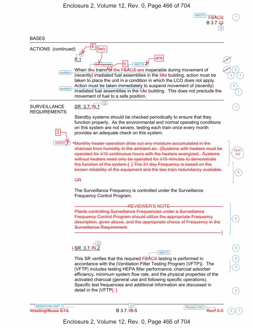
FBACS B 3.7.13
Westinghouse STS B 3.7.13-5 Rev. 4.0
ABGTS 1
12
12SEQUOYAH UNIT 1 Revision XXX 2 1
BASES ACTIONS (continued)
E.1 When two trains of the FBACS are inoperable during movement of [recently] irradiated fuel assemblies in the fuel building, action must be taken to place the unit in a condition in which the LCO does not apply. Action must be taken immediately to suspend movement of [recently] irradiated fuel assemblies in the fuel building. This does not preclude the movement of fuel to a safe position.
SURVEILLANCE SR 3.7.13.1 REQUIREMENTS
Standby systems should be checked periodically to ensure that they function properly. As the environmental and normal operating conditions on this system are not severe, testing each train once every month provides an adequate check on this system. Monthly heater operation dries out any moisture accumulated in the charcoal from humidity in the ambient air. [Systems with heaters must be operated for 10 continuous hours with the heaters energized. Systems without heaters need only be operated for 15 minutes to demonstrate the function of the system.] [ The 31 day Frequency is based on the known reliability of the equipment and the two train redundancy available. OR The Surveillance Frequency is controlled under the Surveillance Frequency Control Program. -----------------------------------REVIEWER’S NOTE----------------------------------- Plants controlling Surveillance Frequencies under a Surveillance Frequency Control Program should utilize the appropriate Frequency description, given above, and the appropriate choice of Frequency in the Surveillance Requirement. ------------------------------------------------------------------------------------------------ ]
[ SR 3.7.13.2 This SR verifies that the required FBACS testing is performed in accordance with the [Ventilation Filter Testing Program (VFTP)]. The [VFTP] includes testing HEPA filter performance, charcoal adsorber efficiency, minimum system flow rate, and the physical properties of the activated charcoal (general use and following specific operations). Specific test frequencies and additional information are discussed in detail in the [VFTP]. ]
ABGTS is
ABGTS
3
2
3
6
5
3
2
3
3
1auxiliary
1auxiliary
121
12
INSERT 4
TSTF-522
D
the required
4
4
Enclosure 2, Volume 12, Rev. 0, Page 466 of 704
Enclosure 2, Volume 12, Rev. 0, Page 466 of 704
E two
sare
3

B 3.7.12
Insert Page B 3.7.12-5
INSERT 4 Operation [with heaters on] for 15 continuous minutes demonstrates OPERABILITY of the system. Periodic operation ensures that [heater failure,] blockage, fan or motor failure, or excessive vibration can be detected for corrective action.
TSTF-522
Operation will be demonstrated by initiating, from the control room, flow through the HEPA filter and charcoal adsorber train.
3
2
3
Enclosure 2, Volume 12, Rev. 0, Page 467 of 704
Enclosure 2, Volume 12, Rev. 0, Page 467 of 704
3

FBACS B 3.7.13
Westinghouse STS B 3.7.13-6 Rev. 4.0
ABGTS 1
12
12SEQUOYAH UNIT 1 Revision XXX 2 1
BASES SURVEILLANCE REQUIREMENTS (continued)
[ SR 3.7.13.3 This SR verifies that each FBACS train starts and operates on an actual or simulated actuation signal. [ The [18] month Frequency is consistent with Reference 6. ] OR The Surveillance Frequency is controlled under the Surveillance Frequency Control Program. -----------------------------------REVIEWER’S NOTE----------------------------------- Plants controlling Surveillance Frequencies under a Surveillance Frequency Control Program should utilize the appropriate Frequency description, given above, and the appropriate choice of Frequency in the Surveillance Requirement. ------------------------------------------------------------------------------------------------ ] SR 3.7.13.4 This SR verifies the integrity of the fuel building enclosure. The ability of the fuel building to maintain negative pressure with respect to potentially uncontaminated adjacent areas is periodically tested to verify proper function of the FBACS. During the [post accident] mode of operation, the FBACS is designed to maintain a slight negative pressure in the fuel building, to prevent unfiltered LEAKAGE. The FBACS is designed to maintain a [-0.125] inches water gauge with respect to atmospheric pressure at a flow rate of [20,000] cfm to the fuel building. [ The Frequency of [18] months is consistent with the guidance provided in NUREG-0800, Section 6.5.1 (Ref. 7). An [18] month Frequency (on a STAGGERED TEST BASIS) is consistent with Reference 6. OR The Surveillance Frequency is controlled under the Surveillance Frequency Control Program.
ABGTS
8,100 and 9,900
3
1
6
5
1
ABGTS
ABGTS
auxiliary
auxiliary
- 0.25
3
31
6
auxiliary
auxiliary
112
112 (i.e., spent fuel
storage area and the ESF pump rooms)
2
INSERT 5
4
Enclosure 2, Volume 12, Rev. 0, Page 468 of 704
Enclosure 2, Volume 12, Rev. 0, Page 468 of 704
4

B 3.7.12
Insert Page B 3.7.12-6
INSERT 5 The SR is modified by two Notes that specify when verification of ABGTS actuation for each actuation signal is required to be met. ABGTS actuation on a Containment Phase A isolation signal is required to be met in MODES 1, 2, 3 and 4. ABGTS actuation on fuel storage pool area high radiation signal is required to be met during movement of recently irradiated fuel assemblies in the auxiliary building.
6
Enclosure 2, Volume 12, Rev. 0, Page 469 of 704
Enclosure 2, Volume 12, Rev. 0, Page 469 of 704
4

FBACS B 3.7.13
Westinghouse STS B 3.7.13-2 Rev. 4.0
ABGTS 1
12
12SEQUOYAH UNIT 2 Revision XXX 2 1
BASES APPLICABLE SAFETY ANALYSES (continued)
material provided by the one remaining train of this filtration system. The amount of fission products available for release from the fuel handling building is determined for a fuel handling accident and for a LOCA. [Due to radioactive decay, FBACS is only required to isolate during fuel handling accidents involving handling recently irradiated fuel (i.e., fuel that has occupied part of a critical reactor core within the previous [X] days).] These assumptions and the analysis follow the guidance provided in Regulatory Guide 1.25 (Ref. 4). The FBACS satisfies Criterion 3 of 10 CFR 50.36(c)(2)(ii).
LCO Two independent and redundant trains of the FBACS are required to be
OPERABLE to ensure that at least one train is available, assuming a single failure that disables the other train, coincident with a loss of offsite power. Total system failure could result in the atmospheric release from the fuel handling building exceeding the 10 CFR 100 (Ref. 5) limits in the event of a fuel handling accident [involving handling recently irradiated fuel]. The FBACS is considered OPERABLE when the individual components necessary to control exposure in the fuel handling building are OPERABLE in both trains. An FBACS train is considered OPERABLE when its associated: a. Fan is OPERABLE, b. HEPA filter and charcoal adsorber are not excessively restricting
flow, and are capable of performing their filtration function, and c. Heater, demister, ductwork, valves, and dampers are OPERABLE,
and air circulation can be maintained. The LCO is modified by a Note allowing the fuel building boundary to be opened intermittently under administrative controls. For entry and exit through doors the administrative control of the opening is performed by the person(s) entering or exiting the area. For other openings, these controls consist of stationing a dedicated individual at the opening who is in continuous communication with the control room. This individual will have a method to rapidly close the opening when a need for fuel building isolation is indicated.
ABGTS
100 hours
ABGTS 3
4
ABGTS
ABGTS
ABGTS
auxiliary
2
1
3
3
2
1
1
1
2
1
1
1
1auxiliary
auxiliary
1
auxiliary
1.183
Auxiliary Building Secondary Containment Enclosure (ABSCE)
2
LOCAINSERT 2
INSERT 3
two Notes. Note 1 allows
4
Enclosure 2, Volume 12, Rev. 0, Page 473 of 704
Enclosure 2, Volume 12, Rev. 0, Page 473 of 704
a Note allowing
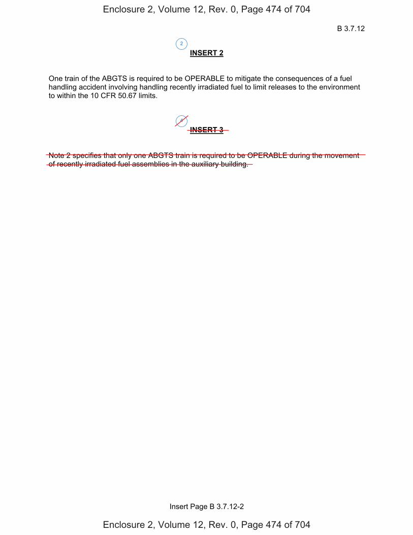
B 3.7.12
Insert Page B 3.7.12-2
INSERT 2 One train of the ABGTS is required to be OPERABLE to mitigate the consequences of a fuel handling accident involving handling recently irradiated fuel to limit releases to the environment to within the 10 CFR 50.67 limits.
INSERT 3 Note 2 specifies that only one ABGTS train is required to be OPERABLE during the movement of recently irradiated fuel assemblies in the auxiliary building.
2
4
Enclosure 2, Volume 12, Rev. 0, Page 474 of 704
Enclosure 2, Volume 12, Rev. 0, Page 474 of 704

FBACS B 3.7.13
Westinghouse STS B 3.7.13-3 Rev. 4.0
ABGTS 1
12
12SEQUOYAH UNIT 2 Revision XXX 2 1
BASES APPLICABILITY In MODE 1, 2, 3, or 4, the FBACS is required to be OPERABLE to
provide fission product removal associated with ECCS leaks due to a LOCA and leakage from containment and annulus.
In MODE 5 or 6, the FBACS is not required to be OPERABLE since the ECCS is not required to be OPERABLE. During movement of [recently] irradiated fuel in the fuel handling area, the FBACS is required to be OPERABLE to alleviate the consequences of a fuel handling accident.
ACTIONS LCO 3.0.3 is not applicable while in MODE 5 or 6. However, since
irradiated fuel assembly movement can occur in MODE 1, 2, 3, or 4, the ACTIONS have been modified by a Note stating that LCO 3.0.3 is not applicable. If moving irradiated fuel assemblies while in MODE 5 or 6, LCO 3.0.3 would not specify any action. If moving irradiated fuel assemblies while in MODE 1, 2, 3, or 4, the fuel movement is independent of reactor operations. Entering LCO 3.0.3, while in MODE 1, 2, 3, or 4 would require the unit to be shutdown unnecessarily.
A.1 With one FBACS train inoperable, action must be taken to restore OPERABLE status within 7 days. During this period, the remaining OPERABLE train is adequate to perform the FBACS function. The 7 day Completion Time is based on the risk from an event occurring requiring the inoperable FBACS train, and the remaining FBACS train providing the required protection. B.1 -----------------------------------REVIEWER’S NOTE------------------------- Adoption of Condition B is dependent on a commitment from the licensee to have guidance available describing compensatory measures to be taken in the event of an intentional and unintentional entry into Condition B. -------------------------------------------------------------------------------------------------- If the fuel building boundary is inoperable in MODE 1, 2, 3, or 4, the FBACS trains cannot perform their intended functions. Actions must be taken to restore an OPERABLE fuel building boundary within 24 hours. During the period that the fuel building boundary is inoperable, appropriate compensatory measures [consistent with the intent, as
ABGTS
ABGTS
ABGTS
ABGTS
ABGTS
ABGTS
1
1
31
1
5
ABGTS 1
ABSCE
ABSCE
3
auxiliary building
2
in MODE 1, 2, 3, or 44
Enclosure 2, Volume 12, Rev. 0, Page 475 of 704
Enclosure 2, Volume 12, Rev. 0, Page 475 of 704
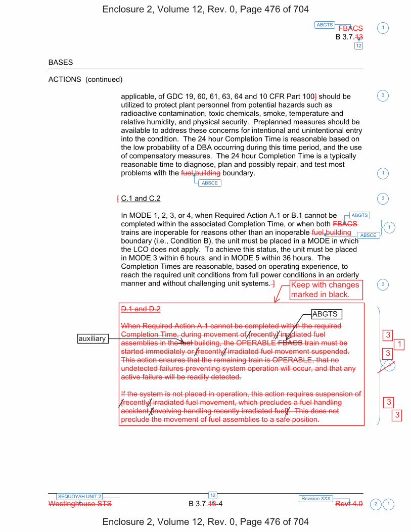
FBACS B 3.7.13
Westinghouse STS B 3.7.13-4 Rev. 4.0
ABGTS 1
12
12SEQUOYAH UNIT 2 Revision XXX 2 1
BASES ACTIONS (continued)
applicable, of GDC 19, 60, 61, 63, 64 and 10 CFR Part 100] should be utilized to protect plant personnel from potential hazards such as radioactive contamination, toxic chemicals, smoke, temperature and relative humidity, and physical security. Preplanned measures should be available to address these concerns for intentional and unintentional entry into the condition. The 24 hour Completion Time is reasonable based on the low probability of a DBA occurring during this time period, and the use of compensatory measures. The 24 hour Completion Time is a typically reasonable time to diagnose, plan and possibly repair, and test most problems with the fuel building boundary.
[ C.1 and C.2 In MODE 1, 2, 3, or 4, when Required Action A.1 or B.1 cannot be completed within the associated Completion Time, or when both FBACS trains are inoperable for reasons other than an inoperable fuel building boundary (i.e., Condition B), the unit must be placed in a MODE in which the LCO does not apply. To achieve this status, the unit must be placed in MODE 3 within 6 hours, and in MODE 5 within 36 hours. The Completion Times are reasonable, based on operating experience, to reach the required unit conditions from full power conditions in an orderly manner and without challenging unit systems. ] D.1 and D.2 When Required Action A.1 cannot be completed within the required Completion Time, during movement of [recently] irradiated fuel assemblies in the fuel building, the OPERABLE FBACS train must be started immediately or [recently] irradiated fuel movement suspended. This action ensures that the remaining train is OPERABLE, that no undetected failures preventing system operation will occur, and that any active failure will be readily detected. If the system is not placed in operation, this action requires suspension of [recently] irradiated fuel movement, which precludes a fuel handling accident [involving handling recently irradiated fuel]. This does not preclude the movement of fuel assemblies to a safe position.
ABGTS
1
3
3
4
1
ABSCE
ABSCE
3
Enclosure 2, Volume 12, Rev. 0, Page 476 of 704
Enclosure 2, Volume 12, Rev. 0, Page 476 of 704
Keep with changesmarked in black.
ABGTS
auxiliary 3 1
3
3 3

FBACS B 3.7.13
Westinghouse STS B 3.7.13-5 Rev. 4.0
ABGTS 1
12
12SEQUOYAH UNIT 2 Revision XXX 2 1
BASES ACTIONS (continued)
E.1 When two trains of the FBACS are inoperable during movement of [recently] irradiated fuel assemblies in the fuel building, action must be taken to place the unit in a condition in which the LCO does not apply. Action must be taken immediately to suspend movement of [recently] irradiated fuel assemblies in the fuel building. This does not preclude the movement of fuel to a safe position.
SURVEILLANCE SR 3.7.13.1 REQUIREMENTS
Standby systems should be checked periodically to ensure that they function properly. As the environmental and normal operating conditions on this system are not severe, testing each train once every month provides an adequate check on this system. Monthly heater operation dries out any moisture accumulated in the charcoal from humidity in the ambient air. [Systems with heaters must be operated for 10 continuous hours with the heaters energized. Systems without heaters need only be operated for 15 minutes to demonstrate the function of the system.] [ The 31 day Frequency is based on the known reliability of the equipment and the two train redundancy available. OR The Surveillance Frequency is controlled under the Surveillance Frequency Control Program. -----------------------------------REVIEWER’S NOTE----------------------------------- Plants controlling Surveillance Frequencies under a Surveillance Frequency Control Program should utilize the appropriate Frequency description, given above, and the appropriate choice of Frequency in the Surveillance Requirement. ------------------------------------------------------------------------------------------------ ]
[ SR 3.7.13.2 This SR verifies that the required FBACS testing is performed in accordance with the [Ventilation Filter Testing Program (VFTP)]. The [VFTP] includes testing HEPA filter performance, charcoal adsorber efficiency, minimum system flow rate, and the physical properties of the activated charcoal (general use and following specific operations). Specific test frequencies and additional information are discussed in detail in the [VFTP]. ]
ABGTS is
ABGTS
3
2
3
6
5
3
2
3
3
1auxiliary
1auxiliary
121
12
INSERT 4
TSTF-522
D
the required
4
4
Enclosure 2, Volume 12, Rev. 0, Page 477 of 704
Enclosure 2, Volume 12, Rev. 0, Page 477 of 704
3
ares
twoE
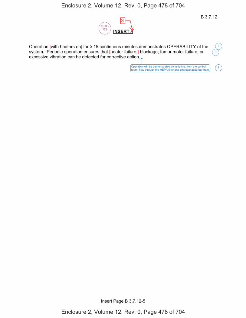
B 3.7.12
Insert Page B 3.7.12-5
INSERT 4 Operation [with heaters on] for 15 continuous minutes demonstrates OPERABILITY of the system. Periodic operation ensures that [heater failure,] blockage, fan or motor failure, or excessive vibration can be detected for corrective action.
TSTF-522
Operation will be demonstrated by initiating, from the control room, flow through the HEPA filter and charcoal adsorber train.
3
2
3
Enclosure 2, Volume 12, Rev. 0, Page 478 of 704
Enclosure 2, Volume 12, Rev. 0, Page 478 of 704
3

FBACS B 3.7.13
Westinghouse STS B 3.7.13-6 Rev. 4.0
ABGTS 1
12
12SEQUOYAH UNIT 2 Revision XXX 2 1
BASES SURVEILLANCE REQUIREMENTS (continued)
[ SR 3.7.13.3 This SR verifies that each FBACS train starts and operates on an actual or simulated actuation signal. [ The [18] month Frequency is consistent with Reference 6. ] OR The Surveillance Frequency is controlled under the Surveillance Frequency Control Program. -----------------------------------REVIEWER’S NOTE----------------------------------- Plants controlling Surveillance Frequencies under a Surveillance Frequency Control Program should utilize the appropriate Frequency description, given above, and the appropriate choice of Frequency in the Surveillance Requirement. ------------------------------------------------------------------------------------------------ ] SR 3.7.13.4 This SR verifies the integrity of the fuel building enclosure. The ability of the fuel building to maintain negative pressure with respect to potentially uncontaminated adjacent areas is periodically tested to verify proper function of the FBACS. During the [post accident] mode of operation, the FBACS is designed to maintain a slight negative pressure in the fuel building, to prevent unfiltered LEAKAGE. The FBACS is designed to maintain a [-0.125] inches water gauge with respect to atmospheric pressure at a flow rate of [20,000] cfm to the fuel building. [ The Frequency of [18] months is consistent with the guidance provided in NUREG-0800, Section 6.5.1 (Ref. 7). An [18] month Frequency (on a STAGGERED TEST BASIS) is consistent with Reference 6. OR The Surveillance Frequency is controlled under the Surveillance Frequency Control Program.
ABGTS
8,100 and 9,900
3
1
6
5
1
ABGTS
ABGTS
auxiliary
auxiliary
- 0.25
3
31
6
auxiliary
auxiliary
112
112 (i.e., spent fuel
storage area and the ESF pump rooms)
2
INSERT 5
4
Enclosure 2, Volume 12, Rev. 0, Page 479 of 704
Enclosure 2, Volume 12, Rev. 0, Page 479 of 704
4

B 3.7.12
Insert Page B 3.7.12-6
INSERT 5 The SR is modified by two Notes that specify when verification of ABGTS actuation for each actuation signal is required to be met. ABGTS actuation on a Containment Phase A isolation signal is required to be met in MODES 1, 2, 3 and 4. ABGTS actuation on fuel storage pool area high radiation signal is required to be met during movement of recently irradiated fuel assemblies in the auxiliary building.
6
Enclosure 2, Volume 12, Rev. 0, Page 480 of 704
Enclosure 2, Volume 12, Rev. 0, Page 480 of 704
4
Licensee Response/NRC Response/NRC Question ClosureId 399
NRC Question Number RPG-001
Select Application NRC Question Closure
Attachment 1
Attachment 2
Response Statement
Response Date/Time
Closure Statement
This question is closed and no further information is required at this time to draft the Safety Evaluation. The change to recently irradiated fuel will be addressed under the AST review, and further questions on this will be included in the AST RAIs
Question Closure Date 12/16/2014
Notification Mark BlumbergScott BowmanKristy BucholtzMichelle ConnerRobert ElliottRavinder GroverKhadijah HemphillAndrew HonLynn MynattRay SchieleRoger Scott
Added By Ravinder Grover
Date Added 12/16/2014 12:56 PM
Date Modified
Modified By
Page 1 of 1Sequoyah ITS Conversion Database
1/13/2015https://members.excelservices.com/rai/index.php?requestType=areaItemPrint&itemId=399
ITS NRC QuestionsId 62
NRC Question Number RPG-002
Category Technical
ITS Section 3.9
ITS Number
DOC Number
JFD Number
JFD Bases Number
Page Number(s)
NRC Reviewer
Supervisor Rob Elliott
Technical Branch POC Add Name
Conf Call Requested N
NRC Question SQN’s Current Technical Specifications specify requirements for LCOs 3/4.9.11 “Spent Fuel Pit Water Level,’ and 3/4.9.12 ‘Auxiliary Building Gas Treatment System.’ The Staff’s review of Enclosure 2, Volume 14 (Revision 0), ITS Section 3.9, ‘Refueling Operations,’ in SQN’s conversion application found no discussion of these LCOs. Please explain.
Attach File 1
Attach File 2
Issue Date 5/13/2014
Added By Ravinder Grover
Date Modified
Modified By
Date Added 5/13/2014 3:18 PM
Notification Scott BowmanMichelle ConnerRobert ElliottRavinder GroverKhadijah HemphillAndrew HonRay Schiele
Page 1 of 1Sequoyah ITS Conversion Database
8/21/2014https://members.excelservices.com/rai/index.php?requestType=areaItemPrint&itemId=62
Licensee Response/NRC Response/NRC Question ClosureId 92
NRC Question Number
RPG-002
Select Application Licensee Response
Attachment 1
Attachment 2
Response Statement
In response to RPG-002, with respect to the disposition of CTS 3/4.9.11, "Spent Fuel Pit Water Level," the requirements of CTS 3/4.9.11 (with an Applicability of "Whenever irradiated fuel assemblies are in the spent fuel pit") have been included in ITS 3.7.13, "Spent Fuel Pool Water Level," (with an Applicability of "During movement of irradiated fuel assemblies in the spent fuel pool"). The change in Applicability from "Whenever irradiated fuel assemblies are in the spent fuel pit," to "During movement of irradiated fuel assemblies in the spent fuel pool," is discussed in ITS 3.7.13 discussion of change (DOC) L01.
With respect to the disposition of CTS 3/4.9.12, "Auxiliary Building Gas Treatment System," the requirements of CTS 3/4.9.12 (with an Applicability of "Whenever irradiated fuel is in the storage pool") have been included with the requirements of CTS 3/4.7.8, "Auxiliary Building Gas Treatment System," (with an Applicability of "MODES 1, 2, 3, and 4") to form ITS 3.7.12, "Auxiliary Building Gas Treatment System," (with an Applicability of "MODES 1, 2, 3, and 4, and During movement of recently irradiated fuel assemblies in the auxiliary building"). The change in Applicability from "Whenever irradiated fuel is in the storage pool," to "During movement of recently irradiated fuel assemblies in the auxiliary building," is discussed in ITS 3.7.12 DOC L06.
Response Date/Time 6/4/2014 10:40 AM
Closure Statement
Question Closure
Date
Notification Scott BowmanMichelle ConnerRavinder GroverKhadijah HemphillAndrew HonRay Schiele
Added By Scott Bowman
Date Added 6/4/2014 9:37 AM
Date Modified
Modified By
Page 1 of 1Sequoyah ITS Conversion Database
8/21/2014https://members.excelservices.com/rai/index.php?requestType=areaItemPrint&itemId=92

Licensee Response/NRC Response/NRC Question ClosureId 271
NRC Question Number RPG-002
Select Application NRC Question Closure
Attachment 1
Attachment 2
Response Statement
Response Date/Time
Closure Statement This question is closed and no further information is required at this time to draft the Safety Evaluation.
Question Closure Date 8/20/2014
Notification Scott BowmanMichelle ConnerRobert ElliottRavinder GroverKhadijah HemphillAndrew HonLynn MynattRay SchieleRoger Scott
Added By Ravinder Grover
Date Added 8/20/2014 1:03 PM
Date Modified
Modified By
Page 1 of 1Sequoyah ITS Conversion Database
8/21/2014https://members.excelservices.com/rai/index.php?requestType=areaItemPrint&itemId=271
ITS NRC QuestionsId 63
NRC Question Number
RPG-003
Category Technical
ITS Section 3.9
ITS Number 3.9.1
DOC Number
JFD Number
JFD Bases Number
Page Number(s)
NRC Reviewer
Supervisor Rob Elliott
Technical Branch POC Add Name
Conf Call Requested N
NRC Question SQN Units 1 and 2 Current Technical Specifications (CTS) LCOs
3/4.9.1,“Boron Concentration,” 3/4.9.2, “Instrumentation,” and 3/4.9.8, “Residual Heat Removal And Coolant Circulation,” address limiting conditions for refueling operations. When a requirement of any of these LCOs is not satisfied, one of the REQUIRED ACTIONS is to immediately suspend all operations involving CORE ALTERATIONS or positive reactivity changes.
SQN’s proposed changes to these LCOs delete REQUIRED ACTION for CORE ALTERATIONS operations in accordance with Standard Technical Specifications (STS, NUREG-1431, Revision 4). STS incorporated the Staff approved Technical Specification Task Force (TSTF) traveler TSTF-471 Revision 1, “Eliminate Use Of Term Core Alterations In Actions And Notes,”which deleted reference to the term Core Alteration from the Specifications.
During a review of certain plant-specific license amendments requesting adoption of TSTF-471 and other related TSTFs, (such as, TSTFs-51 and 286), the Staff identified certain concerns with these TSTF’s changes. The NRC staff’s concerns relate to core monitoring instrumentation and dose consequences. Specifically, during core alterations (i.e., movement of fuel), there is the potential for operable neutron detectors to become effectively decoupled from the fuel assemblies being monitored. The NRC staff is concerned that the removal of the words CORE ALTERATIONS from
Page 1 of 2Sequoyah ITS Conversion Database
1/13/2015https://members.excelservices.com/rai/index.php?requestType=areaItemPrint&itemId=63
the TS LCO for source range monitors may create a situation where a boron dilution accident, misloaded fuel assembly, or an increase in neutron flux might go undetected. Secondly, the Staff is concerned that a dropped source, fuel assembly, or component (or any other item allowed to be moved by CORE ALTERATIONS) could damage a fuel assembly or break creating a radioactive source term. Additionally, a dropped source, component, or fuel assembly could add reactivity if it is dropped over or in the vicinity of other fuel.
The Staff is currently pursuing with the industry for a resolution to these concerns (for details, please refer to the Staff’s letter, dated October 7, 2013, (Agencywide Documents Access and Management System (ADAMS) Accession No ML13246A358). The letter suggested to the industry that licensees should not submit amendments to adopt these three Travelers until a final resolution is achieved.
Therefore, the Staff requests the SQN licensee to withdraw the requested changes associated with TSTFs-51and 471, 'core alterations,' related changes from its conversion since at this time, there is no definite timeframe by which the concerns will be resolved.
Attach File 1
Attach File 2
Issue Date 5/13/2014
Added By Ravinder Grover
Date Modified
Modified By
Date Added 5/13/2014 3:30 PM
Notification Scott BowmanKristy BucholtzRobert ElliottRavinder GroverMatthew HammKhadijah HemphillAndrew HonRay SchieleCarl Schulten
Page 2 of 2Sequoyah ITS Conversion Database
1/13/2015https://members.excelservices.com/rai/index.php?requestType=areaItemPrint&itemId=63
Licensee Response/NRC Response/NRC Question ClosureId 102
NRC Question Number
RPG-003
Select Application Licensee Response
Attachment 1
Attachment 2
Response Statement In response to RPG-003, the following information is provided to address the
staff's concerns related to removal of the Required Action to suspend CORE ALTERATIONS with an inoperable source range neutron flux monitor:
TSTF-51 removed the Technical Specifications (TS) requirements for certain systems to be OPERABLE from the Improved Standard Technical Specifications (ISTS) after sufficient radioactive decay has occurred to ensure the projected offsite dose from a fuel handling accident will be less than a small fraction of the 10 CFR 100 limit. To support this change in requirements during the handling of irradiated fuel, the OPERABILITY requirements during CORE ALTERATIONS were deleted. TSTF-51 eliminated all uses of the defined term CORE ALTERATIONS from Applicability statements and most uses of CORE ALTERATIONS in Required Actions in the ISTS. However, TSTF-51 did not make changes to NUREG-1431, LCO 3.9.3, "Nuclear Instrumentation."
TSTF-286 replaced the TS Required Action to suspend positive reactivity additions with one inoperable source range neutron flux monitor inoperable with a Required Action to suspend operations that would cause an introduction of coolant into the RCS with boron concentration less than required to meet the boron concentration of LCO 3.9.1. This change was necessary to address the fact that during conditions in which these Required Actions may be required, various unit operations such as maintaining RCS inventory and controlling RCS temperature must be continued. These activities necessarily involve additions to the RCS of cooler water (a positive reactivity effect in most cases) and may involve inventory makeup from sources that are at boron concentrations less than RCS concentration. These activities should not be precluded if the worst-case overall effect on the core would still assure SHUTDOWN MARGIN (SDM) (or the required refueling boron concentration) is maintained. Therefore, the proposed changes provide the flexibility necessary to provide for continued safe reactor operations, while also limiting any potential for excess positive reactivity addition. However, TSTF-286 did not remove the NUREG-1431, LCO 3.9.3 Required Action to suspend CORE ALTERATIONS with one inoperable source range neutron flux monitor inoperable.
TSTF-471 replaced the TS 3.9.3 Required Action to suspend CORE ALTERATIONS with one inoperable source range neutron flux monitor inoperable with a Required Action to suspend positive reactivity additions. Since CORE ALTERATIONS only occur when the reactor vessel head is removed, it only applies in MODE 6. For SQN, the only credible accident during MODE 6 is a fuel handling accident (FHA). A FHA is initiated by the dropping of an irradiated fuel assembly, either in the
Page 1 of 3Sequoyah ITS Conversion Database
1/13/2015https://members.excelservices.com/rai/index.php?requestType=areaItemPrint&itemId=102
containment or in the auxiliary building. The suspension of CORE ALTERATIONS, except for the suspension of movement of irradiated fuel, will not prevent or impair the mitigation of a fuel handling accident.
Per UFSAR Section 15.2.4.2, an uncontrolled boron dilution accident is not credible during refueling. ITS 3.9.2, "Unborated Water Source Isolation Valves," requires that while in MODE 6, all isolation valves in a specified combination for reactor makeup water sources containing unborated water that are connected to the RCS must be closed to prevent unplanned boron dilution of the reactor coolant. These valves will block the significant dilution flow paths which could allow unborated makeup to reach the RCS. Therefore, the possibility of an inadvertent boron dilution event occurring in MODE 6 refueling operations is precluded by adherence to LCO 3.9.2 and the availability of source range neutron flux monitors to alert operators to a possible boron dilution event is irrelevant.
With regard to misloaded fuel assemblies, fuel assembly loading errors are prevented by administrative procedures implemented during core loading. To reduce the probability of core loading errors, each fuel assembly is marked with an identification number and loaded in accordance with a core loading diagram. During core loading the identification number will be checked before each assembly is moved into the core. Serial numbers read during fuel movement are subsequently recorded on the loading diagram as a further check on proper placing after the loading is completed. The power distortion due to any combination of misplaced fuel assemblies would significantly raise peaking factors and would be readily observable with in-core flux monitors. In addition to the flux monitors, thermocouples are located at the outlet of about one third of the fuel assemblies in the core. There is a high probability that these thermocouples would also indicate any abnormally high coolant enthalpy rise. In-core flux measurements are taken during the startup subsequent to every refueling operation. To address the possibility of a misloaded fuel assembly, ITS 3.9.3, Required Action A.1 suspends positive reactivity additions if one source range neutron flux monitor is inoperable. This precludes movement of fuel assemblies which could add reactivity to the core.
Lastly, as stated in 10 CFR 50.36(b), "The technical specifications will be derived from the analyses and evaluation included in the safety analysis report, and amendments thereto, submitted pursuant to § 50.34." As discussed above, the suspension of CORE ALTERATIONS with an inoperable source range neutron flux monitor is not based on the analyses in the safety analysis report. Therefore, removal of this Required Action is justified.
Response Date/Time 6/6/2014 6:40 AM
Closure Statement
Question Closure
Date
Notification Scott BowmanMichelle ConnerRavinder GroverKhadijah HemphillAndrew HonRay Schiele
Added By Scott Bowman
Page 2 of 3Sequoyah ITS Conversion Database
1/13/2015https://members.excelservices.com/rai/index.php?requestType=areaItemPrint&itemId=102

Date Added 6/6/2014 5:36 AM
Date Modified
Modified By
Page 3 of 3Sequoyah ITS Conversion Database
1/13/2015https://members.excelservices.com/rai/index.php?requestType=areaItemPrint&itemId=102
Licensee Response/NRC Response/NRC Question ClosureId 272
NRC Question Number RPG-003
Select Application NRC Response
Attachment 1
Attachment 2
Response Statement
Regarding TVA's proposed changes related to the adoption of TSTFs-51, -286 and -471, in a 8/12/14 meeting between the NRC and TVA at the NRC HQ followed by 8/19/14 phone call between the NRC and TVA, the NRC was informed of the TVA's decision for rescinding all changes associated with the subject TSTFs as currently specified in its TS conversion amendment.
Please submit the revised pages for the NRC's review.
Response Date/Time 8/20/2014 6:00 PM
Closure Statement
Question Closure Date
Notification Scott BowmanKristy BucholtzMichelle ConnerRobert ElliottRavinder GroverMatthew HammKhadijah HemphillAndrew HonLynn MynattRay SchieleRoger ScottPete SnyderCaroline Tilton
Added By Ravinder Grover
Date Added 8/20/2014 2:10 PM
Date Modified
Modified By
Page 1 of 1Sequoyah ITS Conversion Database
1/13/2015https://members.excelservices.com/rai/index.php?requestType=areaItemPrint&itemId=272
Licensee Response/NRC Response/NRC Question ClosureId 325
NRC Question Number
RPG-003
Select Application NRC Response
Attachment 1
Attachment 2
Response Statement
Staff’s follow-up response to RPG-003:
On 8/20/2014, the Staff provided the following in response to the licensee’s explanation provided in its 6/6/14 response to RAI RPG-003 regarding its proposed deletion of core alteration requirements from its Current Licensing Basis.
“Regarding TVA's proposed changes related to the adoption of TSTFs-51, -286 and -471, in a 8/12/14 meeting between the NRC and TVA at the NRC HQ followed by 8/19/14 phone call between the NRC and TVA, the NRC was informed of the TVA's decision for rescinding all changes associated with the subject TSTFs as currently specified in its TS conversion amendment.
Please submit the revised pages for the NRC's review.”
As stated in the Staff’s RAI-003, the Staff is currently pursuing with the industry for a resolution to these concerns (for details, please refer to the Staff’s letter, dated November 7, 2013, (Agencywide Documents Access and Management System (ADAMS) Accession No. ML13246A358)). The letter suggested to the industry that licensees should not submit amendments to adopt these three Travelers until a final resolution is achieved.
On 8/25/2014, during a follow-up phone call between the Staff and the licensee, the licensee requested the Staff for additional information on its 6/6/2014 response to RPG-003. Specifically, the licensee asked for feedback as to why their previous response to RPG-003 was not acceptable and therefore, the Staff was requesting that the licensee to remove proposed changes related to TSTFs-51, 286 and 471.
Below please find, the Staff‘s feedback:
The licensee’s assertion that a fuel assembly misloading during refueling is not credible lacks sufficient justification. Fuel assembly misloadings have occurred in the past and absent evidence to the contrary would be expected to occur in the future. The licensee’s citing of Startup Physics Testing as a means to detect a core fuel assembly misloading in Mode 6 does not address the Staff’s concerns, since that testing isn’t done until
Page 1 of 3Kewaunee ITS Conversion Database
9/5/2014https://members.excelservices.com/rai/index.php?requestType=areaItemPrint&itemId=325
Mode 2. Additionally, the licensee’s citing of Core Exit Thermal couples as a means to detect a core fuel assembly misloading in Mode 6 doesn’t address the Staff’s concerns, since they are not operable in Mode 6 and could not be relied upon to detect a misloading in that Mode.
The use of one source range monitor being inoperable and removal of CORE ALTERATIONS by the licensee is of concern in regards to positive reactivity insertions. When one source range monitor is inoperable, and certain, strategically located fuel assemblies are removed; then the other, operable neutron source monitor may no longer be capable of monitoring some fuel assemblies that are located in the far half of the core and detect a positive reactivity insertion. Fuel movement occurs in MODE 6 and can lead to misloading of fuel assemblies. As noted above, the in-core detectors will not be able to detect misloading of fuel assemblies in the reactor core when in MODE 6. The in-core detectors will not detect core misloading until MODE 2 for Startup Physics Testing.
In addition to the misloaded fuel assembly concerns discussed above, the Staff’s November 7, 2013, letter (ADAMS Accession No. ML13246A358, referenced in RPG-003) stated that the Staff is concerned that a dropped source, fuel assembly, or component (or any other item allowed to be moved by CORE ALTERATIONS) could damage or break a fuel assembly creating a radioactive source term. If so, the NRC Staff may require an analysis to show that the dose consequences of these scenarios are less limiting than the current fuel handling accident. The licensee’s response to RPG-003 does not address such concern.
These generic issues with the TSTFs coupled with the licensee RAI responses regarding one inoperable source range monitor and removal of CORE ALTERATIONS do not address NRC Staff concerns. The licensee has not provided a plant specific basis with analysis to justify the adoption of these TSTFs that would address the generic NRC Staff issues.Therefore, the NRC Staff is concerned that the removal of the words CORE ALTERATIONS from the TS LCO for source range monitors may create a situation where a misloaded fuel assembly or an increase in neutron flux might go undetected. The NRC Staff’s preliminary review of this issue indicates that the removal of the words CORE ALTERATIONS may create a situation not consistent with the SRP guidance related to ‘redundant alarms,’ described in SRP Section 15.4.6.
Therefore, the Staff requests that the amendment should be revised to reflect your current licensing basis for those TS sections affected by your proposed adoption of TSTFs in question. Please submit revised pages for the Staff’s review.
Response Date/Time 9/5/2014 6:00 PM
Closure Statement
Page 2 of 3Kewaunee ITS Conversion Database
9/5/2014https://members.excelservices.com/rai/index.php?requestType=areaItemPrint&itemId=325
Question Closure
Date
Notification Mark BlumbergScott BowmanKristy BucholtzMichelle ConnerRobert ElliottRavinder GroverKhadijah HemphillAndrew HonLynn MynattRay SchieleRoger Scott
Added By Ravinder Grover
Date Added 9/5/2014 1:20 PM
Date Modified
Modified By
Page 3 of 3Kewaunee ITS Conversion Database
9/5/2014https://members.excelservices.com/rai/index.php?requestType=areaItemPrint&itemId=325
Licensee Response/NRC Response/NRC Question ClosureId 372
NRC Question Number
RPG-003
Select Application Licensee Response
Attachment 1
Attachment 2
Response Statement
Per discussion, on October 7, 2014, between SQN and NRC staff, SQN proposes that changes incorporated in NUREG-1431, Revision 4, associated with TSTFs-51, -286, and -471 be reviewed as submitted in the SQN ITS conversion submittal.SQN understands, that during staff review, there may be additional requests for information related to the changes made to NUREG-1431, Revision 4.
Response Date/Time 10/16/2014 2:10 AM
Closure Statement
Question Closure Date
Notification Mark BlumbergScott BowmanKristy BucholtzMichelle ConnerRavinder GroverKhadijah HemphillAndrew HonLynn MynattRay Schiele
Added By Scott Bowman
Date Added 10/16/2014 1:11 PM
Date Modified
Modified By
Page 1 of 1Sequoyah ITS Conversion Database
1/13/2015https://members.excelservices.com/rai/index.php?requestType=areaItemPrint&itemId=372

Licensee Response/NRC Response/NRC Question ClosureId 374
NRC Question Number RPG-003
Select Application NRC Question Closure
Attachment 1
Attachment 2
Response Statement
Response Date/Time
Closure Statement This question is closed and no further information is required at this time to draft the Safety Evaluation.
Question Closure Date 10/16/2014
Notification Scott BowmanMichelle ConnerRavinder GroverKhadijah HemphillAndrew HonLynn MynattRoger Scott
Added By Khadijah Hemphill
Date Added 10/16/2014 1:24 PM
Date Modified
Modified By
Page 1 of 1Sequoyah ITS Conversion Database
1/13/2015https://members.excelservices.com/rai/index.php?requestType=areaItemPrint&itemId=374
ITS NRC QuestionsId 106
NRC Question Number RPG-004
Category Technical
ITS Section 3.4
ITS Number 3.4.5
DOC Number
JFD Number
JFD Bases Number
Page Number(s) CTS page 3/4 4-1a; pdf page 137
NRC Reviewer
Supervisor Select
Technical Branch POC Add Name
Conf Call Requested N
NRC Question CTS (page 3/4 4-1a; pdf page 137) LCO 3.4.1.2, “Hot Standby,’ states, “At least two of the reactor coolant loops listed below shall be OPERABLE with at least two reactor coolant loops in operation when the Reactor Trip System breakers are closed and at least one reactor coolant loop in operation when the Reactor Trip System breakers are open.”
ITS LCO 3.4.5 states, “[Two] RCS loops shall be OPERABLE and either:
a. [Two] RCS loops shall be in operation when the Rod Control System is capable of rod withdrawal or
b. One RCS loop shall be in operation when the Rod Control System is not capable of rod withdrawal.
Please explain differentiation between the ‘and,’ ‘or,’ (as shown in bold) Action statements.
Attach File 1
Attach File 2
Issue Date 5/29/2014
Added By Ravinder Grover
Date Modified
Modified By
Page 1 of 2Sequoyah ITS Conversion Database
8/21/2014https://members.excelservices.com/rai/index.php?requestType=areaItemPrint&itemId=106
Date Added 5/29/2014 11:56 AM
Notification Scott BowmanMichelle ConnerRobert ElliottRavinder GroverKhadijah HemphillAndrew HonLynn MynattRay SchieleRoger Scott
Page 2 of 2Sequoyah ITS Conversion Database
8/21/2014https://members.excelservices.com/rai/index.php?requestType=areaItemPrint&itemId=106
Licensee Response/NRC Response/NRC Question ClosureId 141
NRC Question Number
RPG-004
Select Application Licensee Response
Attachment 1
Attachment 2
Response Statement
The choice of the use of “either… or” versus “and” in ITS LCO 3.4.5, as it relates to Rod Control System capability (e.g., Reactor Trip System (RTS) breaker position), does not technically alter the SQN CTS requirements since the plant condition of RTS breakers closed is mutually exclusive from the plant condition of RTS breakers open. Likewise, the plant condition when the Rod Control System is capable of rod withdrawal is mutually exclusive from the plant condition when the Rod Control System is not capable of rod withdrawal. As such, both the CTS and ITS require at least two reactor coolant loops in operation with the RTS breakers closed and both the CTS and the ITS require at least one reactor coolant loop in operation with the RTS breakers open. As indicated in Discussion of Change A01 (page 139 of Enclosure 2, Volume 9), in the conversion of the SQN CTS to the plant specific ITS, certain changes, including wording preferences, editorial changes, and formatting, are made to obtain consistency with NUREG-1431.
Specifically, CTS LCO 3.4.12 requires two reactor coolant loops to be OPERABLE and includes the preposition “with” followed by a prepositional phrase requiring: a) at least two reactor coolant loops in operation when the RTS breakers are closed; and b) at least one reactor coolant loop in operation when the RTS breakers are open. The conjunction “and” in the CTS case correctly connects the subjects in the prepositional phrase. ITS LCO 3.4.5 also requires two Reactor Coolant System (RCS) loops to be OPERABLE and uses the correlative “either-or” to correctly connect the two parallel sentences. Thus, either: a) Two RCS loops shall be in operation when the Rod Control System is capable of rod withdrawal; or b) One RCS loop shall be in operation when the Rod Control System is not capable of rod withdrawal.
Response Date/Time 6/20/2014 2:40 PM
Closure Statement
Question Closure
Date
Notification Scott Bowman
Page 1 of 2Sequoyah ITS Conversion Database
8/21/2014https://members.excelservices.com/rai/index.php?requestType=areaItemPrint&itemId=141

Michelle ConnerRavinder GroverKhadijah HemphillAndrew HonRay Schiele
Added By Scott Bowman
Date Added 6/20/2014 1:37 PM
Date Modified
Modified By
Page 2 of 2Sequoyah ITS Conversion Database
8/21/2014https://members.excelservices.com/rai/index.php?requestType=areaItemPrint&itemId=141
Licensee Response/NRC Response/NRC Question ClosureId 274
NRC Question Number RPG-004
Select Application NRC Question Closure
Attachment 1
Attachment 2
Response Statement
Response Date/Time
Closure Statement This question is closed and no further information is required at this time to draft the Safety Evaluation.
Question Closure Date 8/20/2014
Notification Scott BowmanMichelle ConnerRobert ElliottRavinder GroverKhadijah HemphillAndrew HonLynn MynattRay SchieleRoger Scott
Added By Ravinder Grover
Date Added 8/20/2014 2:27 PM
Date Modified
Modified By
Page 1 of 1Sequoyah ITS Conversion Database
8/21/2014https://members.excelservices.com/rai/index.php?requestType=areaItemPrint&itemId=274
ITS NRC QuestionsId 108
NRC Question Number
RPG-005
Category Technical
ITS Section 3.4
ITS Number 3.4.9
DOC Number
JFD Number
JFD Bases Number
Page Number(s) page 3/4 4-9, pdf page 272
NRC Reviewer
Supervisor Rob Elliott
Technical Branch POC Add Name
Conf Call Requested N
NRC Question CTS SR 4.4.4.3 (page 3/4 4-9, pdf page 272) requires that the emergency
power supply for the pressurizer heaters shall be demonstrated OPERABLE at least once per 18 months by transferring power from the normal to the emergency power supply and energizing the heaters. SQN proposes to delete the SR and explains the deletion as follows:
"L01: (Category 5 – Deletion of Surveillance Requirement) CTS 4.4.4.3 requires verification that the emergency power supply for the pressurizer heaters be demonstrated OPERABLE at least once per 18 months by transferring power from the normal to the emergency power supply and energizing the heaters. ISTS SR 3.4.9.3 requires a similar test but does not require the surveillance if pressurizer heater are supplied from a Class 1E power supply. Electrical power to the SQN pressurizer heaters can only be supplied from Class 1E power. This changes the CTS by deleting the Surveillance Requirement to demonstrate OPERABILITY of the pressurizer heater emergency power supply.
The purpose of CTS 4.4.4.3 is to verify OPERABILITY of the pressurizer heater emergency power supply. This change is acceptable because the deleted Surveillance Requirement is not necessary to verify the pressurizer heaters used to meet the LCO can perform its required functions. The pressurizer heaters continue to be tested in a manner and at a frequency necessary to give confidence that the pressurizer can perform its assumed safety
Page 1 of 2Sequoyah ITS Conversion Database
9/25/2014https://members.excelservices.com/rai/index.php?requestType=areaItemPrint&itemId=108
function. Electrical power to the pressurizer heaters is only provided by Class 1E power sources. Therefore, there is no requirement to verify the transfer from a non- Class 1E power supply to a Class 1E power supply. This change is designated as less restrictive because a Surveillance required in CTS will not be required in ITS."
The staff is requesting the licensee to provide the following information:
1. A single line diagram and description showing the Class 1E power circuits feeding the pressurizer heaters, switchgear numbers, breakers, and emergency diesel generators.
2. Are pressurizer heaters credited in Chapter 6 or Chapter 15 events or conditions? Are pressurizer heaters automatically sequenced or manually connected? If it is manually connected, briefly describe how the power supplies are connected to the heater banks. Is there any need for power supply transfer?
Attach File 1
Attach File 2
Issue Date 5/30/2014
Added By Ravinder Grover
Date Modified
Modified By
Date Added 5/30/2014 7:25 AM
Notification Scott BowmanMichelle ConnerRobert ElliottRavinder GroverKhadijah HemphillAndrew HonLynn MynattRay SchieleRoger Scott
Page 2 of 2Sequoyah ITS Conversion Database
9/25/2014https://members.excelservices.com/rai/index.php?requestType=areaItemPrint&itemId=108
Licensee Response/NRC Response/NRC Question ClosureId 145
NRC Question Number
RPG-005
Select Application Licensee Response
Attachment 1 Attachment 1 schematics for PZR HTRS.pdf (2MB)
Attachment 2
Response Statement For each unit, there are four groups of pressurizer heaters. All four groups
(A, B, C and D) are powered from the Class 1E Safety Related Shutdown Boards. For SQN, Unit 1, groups A and D are supplied by the 1A-A 6.9 kV Shutdown Board and groups B and C are supplied by the 1B-B 6.9 kV Shutdown Board (Unit 2 is similar, groups A and D on 2A-A and groups B and C on 2B-B). Pressurizer heater groups A and B are the only two groups that are considered safety related. During a loss of offsite power event (blackout), the A and B group pressurizer heaters are prevented from being energized by a load sequencing timer until after the emergency diesel generator (DG) has reestablished power to the shutdown board.Pressurizer heater groups C and D will be automatically load shed on the blackout and locked out, preventing them from being reenergized as long as the DG is supplying power to the shutdown board. If a safety injection signal has been initiated, all four groups of pressurizer heaters are automatically de-energized and prevented from being reenergized until the safety injection signal has been manually reset by the operator from the main control room.
There is no credit taken in the transient or accident analysis for the pressurizer heaters unless it would make the transient or accident more severe. The transients discussed in UFSAR Section 15.2.7, Loss of External Electrical Load and/or Turbine Trip, assume that the pressurizer heaters function because heater operation on a high pressurizer water level would potentially increase the maximum surge rate through the pressurizer safety valves. In all other transient or accident scenarios, it is assumed that the pressurizer heaters do not function.
CTS 4.4.4.3 requires the emergency power supply for the pressurizer heaters to be demonstrated OPERABLE by transferring power from the normal to the emergency power supply and energizing the heaters.Therefore, because the heaters are only supplied power by the Class 1E power supply, there is no need to perform and retain CTS 4.4.4.3 (ISTS SR 3.4.9.3).
Attachment 1 contains the single line and schematic drawings showing the power feed and operation of the pressurizer heaters.
Page 1 of 2Sequoyah ITS Conversion Database
9/25/2014https://members.excelservices.com/rai/index.php?requestType=areaItemPrint&itemId=145
Response Date/Time 6/23/2014 1:25 PM
Closure Statement
Question Closure
Date
Notification Scott BowmanMichelle ConnerRavinder GroverKhadijah HemphillAndrew HonLynn MynattRay Schiele
Added By Scott Bowman
Date Added 6/23/2014 12:25 PM
Date Modified
Modified By
Page 2 of 2Sequoyah ITS Conversion Database
9/25/2014https://members.excelservices.com/rai/index.php?requestType=areaItemPrint&itemId=145
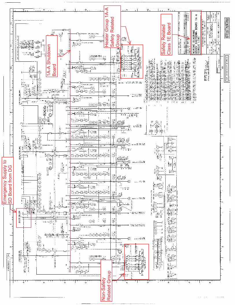
Saf
ety
Rel
ated
Cla
ss1E
Boa
rd
Hea
terG
roup
1A-A
Saf
ety
Rel
ated
Gro
up
Non
-Saf
ety
Rel
ated
Gro
up
Em
erge
ncy
Sup
ply
toS
DB
oard
from
DG
1A-A
Shu
tdow
nB
oard
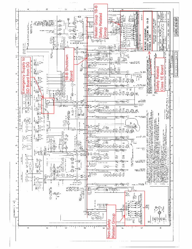
Saf
ety
Rel
ated
Cla
ss1E
Boa
rd
Hea
terG
roup
1B-B
Saf
ety
Rel
ated
Gro
upN
on-S
afet
yR
elat
edG
roup
1B-B
Shu
tdow
nB
oard
Em
erge
ncy
Sup
ply
toS
DB
oard
from
DG
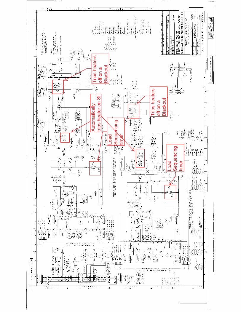
Load
Seq
uenc
ing
timer
Load
Seq
uenc
ing
timer
Trip
she
ater
sof
fon
aB
lack
out
Trip
she
ater
sof
fon
aB
lack
out
Aut
omat
ical
lytri
pshe
ater
onS
I
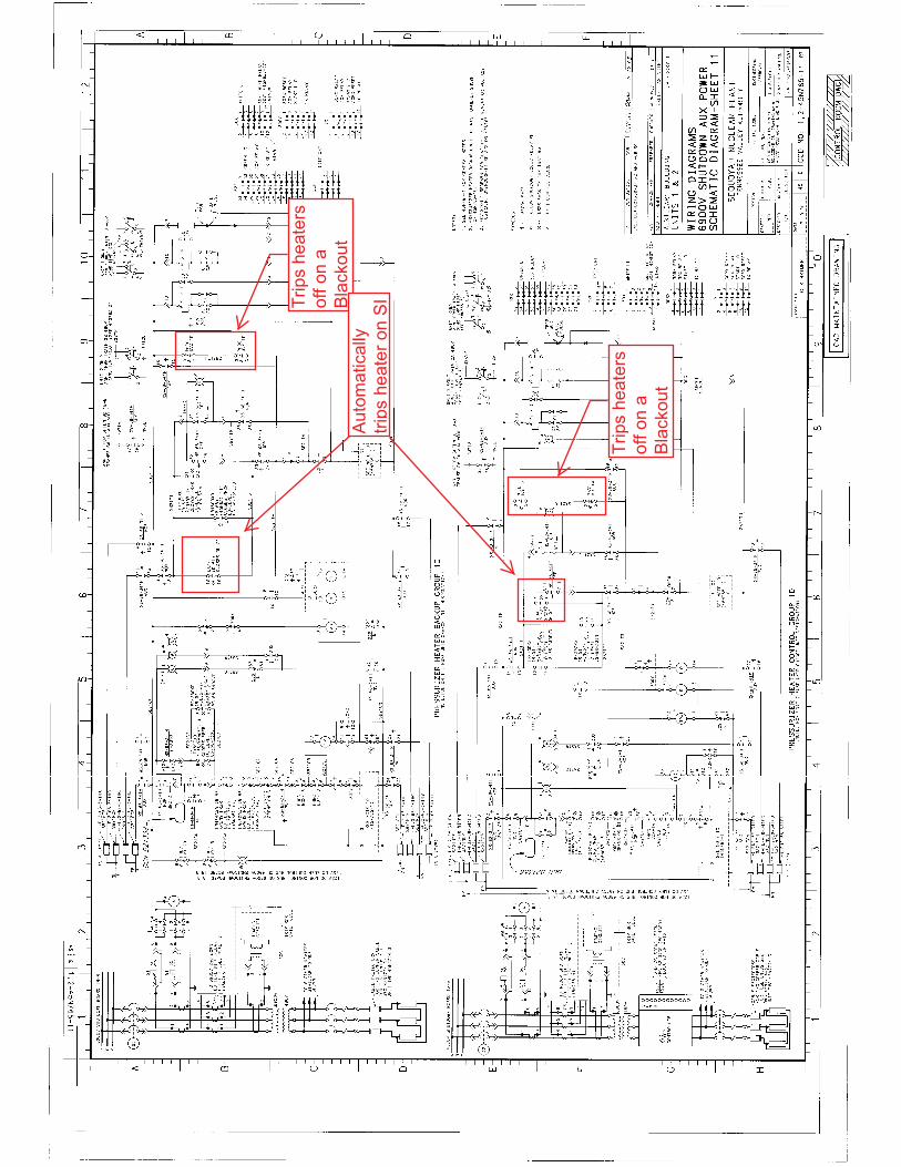
Trip
she
ater
sof
fon
aB
lack
out
Trip
she
ater
sof
fon
aB
lack
out
Aut
omat
ical
lytri
pshe
ater
onS
I

Licensee Response/NRC Response/NRC Question ClosureId 347
NRC Question Number RPG-005
Select Application NRC Question Closure
Attachment 1
Attachment 2
Response Statement
Response Date/Time
Closure Statement This question is closed and no further information is required at this time to draft the Safety Evaluation.
Question Closure Date 9/25/2014
Notification Scott BowmanMichelle ConnerRobert ElliottRavinder GroverKhadijah HemphillAndrew HonLynn MynattRay SchieleRoger Scott
Added By Ravinder Grover
Date Added 9/25/2014 7:14 AM
Date Modified
Modified By
Page 1 of 1Sequoyah ITS Conversion Database
9/25/2014https://members.excelservices.com/rai/index.php?requestType=areaItemPrint&itemId=347

ITS NRC QuestionsId 111
NRC Question Number
RPG-006
Category Technical
ITS Section 3.4
ITS Number 3.4.12
DOC Number
JFD Number
JFD Bases Number
Page Number(s) page 3/4 4-30; pdf page 375
NRC Reviewer
Supervisor Rob Elliott
Technical Branch POC Add Name
Conf Call Requested N
NRC Question
ITS SR 3.4.12.1 states, “Verify a maximum of one HPSI pump is capable of injecting into the RCS. CTS SR 4.4.12.2 states, “Verify no safety injection pumps are capable of injecting into the RCS within 4 hours after entering MODE 4 from MODE 3 and prior to the temperature of one or more RCS cold legs decreasing below 325°F.”CTS marked-up SR 4.4.12.2 (page 3/4 4-30; pdf page 375) shows both surveillances as ‘similar/equivalent’. Similarly, on the same page, CTS marked-up changes for CTS SRs 4.4.12.1.a and 4.4.12.1.c refer to ITS SRs 3.4.12.6 and 3.4.12.5, respectively. These surveillances are not identical. Please explain the basis for concluding that the CTS SRs are similar or identical to the ITS SRs.
Attach File 1
Attach File 2
Issue Date 5/30/2014
Added By Ravinder Grover
Date Modified
Modified By
Date Added 5/30/2014 10:18 AM
Notification Scott BowmanMichelle ConnerRobert ElliottRavinder GroverKhadijah HemphillAndrew HonLynn MynattRay SchieleRoger Scott
Page 1 of 1Sequoyah ITS Conversion Database
9/25/2014https://members.excelservices.com/rai/index.php?requestType=areaItemPrint&itemId=111
Licensee Response/NRC Response/NRC Question ClosureId 143
NRC Question Number
RPG-006
Select Application Licensee Response
Attachment 1
Attachment 2
Response Statement
SQN ITS SR 3.4.12.1 and SR 3.4.12.5 are equivalent to CTS 4.4.12.2 and 4.4.12.1.c, respectively. ITS SR 3.4.12.6 is similar to CTS 4.4.12.1.a, as modified by discussion of change (DOC) M01.
ISTS SR 3.4.12.1 states, “Verify a maximum of [one] [HPI] pump is capable of injecting into the RCS.” ISTS SR 3.4.12.1 was modified to ITS SR 3.4.12.1 to state, “Verify no safety injection pumps are capable of injecting into the RCS.” (ISTS justification for deviation 4 provides the discussion for the change to ISTS SR 3.4.12.1.) The first Frequency for ITS SR 3.4.12.1 is, “within 4 hours after entering MODE 4 from MODE 3 prior to the temperature of one or more RCS cold legs decreasing below 325°F.” This is equivalent to CTS 4.4.12.2, which states in part, “Verify no safety injection pumps are capable of injecting into the RCS within 4 hours after entering MODE 4 from MODE 3 prior to the temperature of one or more RCS cold legs decreasing below 325°F…” Following the initial performance of the SR, both surveillances are required to be performed at a 12 hour Frequency.
ITS SR 3.4.12.5 states, “Verify PORV block valve is open for each required PORV.” This is equivalent to CTS 4.4.12.1.c, which states in part, “Verifying the PORV block valve is open for each required PORV…” The Surveillance Frequency for CTS 4.4.12.1.c and ITS SR 3.4.12.5 is 72 hours.
ITS SR 3.4.12.6 states, “Perform a COT on each required PORV, excluding actuation.” This is similar to CTS 4.4.12.1.a as modified by DOC M01.CTS 4.4.12.1.a states, in part, “Performance of a CHANNEL FUNCTIONAL TEST*, but excluding valve operation...” DOC M01 discusses the change from a CHANNEL FUNCTIONAL TEST to a CHANNEL OPERATIONAL TEST (COT). Also, the * Note associated with CTS 4.4.12.1.a is equivalent to the Note in ITS SR 3.4.12.6, which states, “Not required to be performed until 12 hours after decreasing RCS cold leg temperatures to the LTOP arming temperature in the PTLR.”
Response Date/Time 6/20/2014 2:50 PM
Closure Statement
Page 1 of 2Sequoyah ITS Conversion Database
9/25/2014https://members.excelservices.com/rai/index.php?requestType=areaItemPrint&itemId=143

Question Closure
Date
Notification Scott BowmanMichelle ConnerRavinder GroverKhadijah HemphillAndrew HonRay Schiele
Added By Scott Bowman
Date Added 6/20/2014 1:47 PM
Date Modified
Modified By
Page 2 of 2Sequoyah ITS Conversion Database
9/25/2014https://members.excelservices.com/rai/index.php?requestType=areaItemPrint&itemId=143

Licensee Response/NRC Response/NRC Question ClosureId 342
NRC Question Number RPG-006
Select Application NRC Question Closure
Attachment 1
Attachment 2
Response Statement
Response Date/Time
Closure Statement This question is closed and no further information is required at this time to draft the Safety Evaluation.
Question Closure Date 9/22/2014
Notification Scott BowmanMichelle ConnerRobert ElliottRavinder GroverKhadijah HemphillAndrew HonLynn MynattRay SchieleRoger Scott
Added By Ravinder Grover
Date Added 9/22/2014 1:43 PM
Date Modified
Modified By
Page 1 of 1Sequoyah ITS Conversion Database
9/25/2014https://members.excelservices.com/rai/index.php?requestType=areaItemPrint&itemId=342
ITS NRC QuestionsId 134
NRC Question Number
RPG-007
Category Technical
ITS Section 3.4
ITS Number 3.4.1
DOC Number
JFD Number
JFD Bases Number
Page Number(s) pdf page 23
NRC Reviewer
Supervisor Select
Technical Branch POC Add Name
Conf Call Requested N
NRC Question
ITS SECTION 3.4, “REACTOR COOLANT SYSTEM (RCS),” RAIs (Ref.ENCLOSURE 2, VOLUME 9
ITS Surveillance Requirement (SR) 3.4.1.4 states, “Verify by precision heat balance that RCS total flow rate is [284,000] gpm and greater than or equal to the limit specified in the COLR. ITS explains the precision heat balance measurement as follows,
“Measurement of RCS total flow rate by performance of a precision calorimetric heat balance allows the installed RCS flow instrumentation to be calibrated and verifies the actual RCS flow rate is greater than or equal to the minimum required RCS flow rate.”
SQN’s proposed change on Page 23 in above reference states, “Verify by measurement that RCS total flow rate is [284,000] gpm and greater than or equal to the limit specified in the COLR. SQN’s Justification For Deviation # 6 on page 24 states,
“ISTS SR 3.4.1.4 has been changed to reflect current licensing basis. SQN used heat balance RCS flow measurements until the RTD Bypass manifolds were removed, after which problems were experienced due to hot leg streaming. SQN changed licensing basis to allow the measurement of RCS total flow using elbow tap flow differential pressure method.”
Page 1 of 2Sequoyah ITS Conversion Database
8/21/2014https://members.excelservices.com/rai/index.php?requestType=areaItemPrint&itemId=134
The Staff’s review of TS amendments 138 and 130 referenced in SQN units 1 and 2 TSs for LCO 3/4.2.5 respectively, did not find the Staff’s approval for SQN’s licensing basis to allow the measurement of RCS total flow using elbow tap flow differential pressure method.
Please provide additional information regarding the Staff’s approval of SQN’s licensing basis (e.g., date of issuance and amendment number) for the use of the elbow tap flow differential pressure method.
Attach File 1
Attach File 2
Issue Date 6/3/2014
Added By Ravinder Grover
Date Modified
Modified By
Date Added 6/3/2014 3:44 PM
Notification Scott BowmanMichelle ConnerRobert ElliottRavinder GroverKhadijah HemphillAndrew HonLynn MynattRay SchieleRoger Scott
Page 2 of 2Sequoyah ITS Conversion Database
8/21/2014https://members.excelservices.com/rai/index.php?requestType=areaItemPrint&itemId=134
Licensee Response/NRC Response/NRC Question ClosureId 196
NRC Question Number
RPG-007
Select Application Licensee Response
Attachment 1 Attachment 1 TS 92-07 from TVA 8-21-92 AccNo. 9208310198.pdf (2MB)
Attachment 2 Attachment 2 NRC issued Amendments 221 and 212.pdf (523KB)
Response Statement
In response to RAI RPG-007, the following information is being provided regarding the Staff’s approval of SQN’s licensing basis to allow the use of the elbow tap flow differential pressure method for measuring the reactor coolant system (RCS) total flow.
By letter dated August 21, 1992 (Accession Number 9208310198), SQN requested a license amendment to increase the allowable value for the RCS loss of coolant reactor trip setpoint. The change was necessary to update the SQN TSs to the latest revision of the Westinghouse Electric Corporation setpoint methodology for SQN (WCAP 11239, Revision 6). The WCAP revised the allowable value based on evaluation of SQN’s use of RCS elbow tap differential pressures to determine RCS flow because temperature streaming invalidated the use of primary to secondary calorimetrics. Supplemental letters were sent on September 3, 1993 (Accession Number 9309080173), and March 28, 1996 (Accession Number 9604080368). By letter dated April 26, 1996 (Accession Number 9605010304), the Commission issued Amendments 221 and 212 for SQN, Units 1 and 2, respectively. The Safety Evaluation related to Amendments 221 and 212 acknowledged that, “Flow is measured in each loop by three differential pressure measurements at an elbow tap in each of the four coolant loops.”
Attachment 1 is the initial SQN license amendment request dated August 21, 1992.
Attachment 2 is the Commission’s issuance of Amendments 221 and 212 for SQN, Units 1 and 2.
Response Date/Time 7/21/2014 12:05 PM
Closure Statement
Question Closure
Date
Notification Scott BowmanMichelle ConnerRavinder GroverKhadijah Hemphill
Page 1 of 2Sequoyah ITS Conversion Database
8/21/2014https://members.excelservices.com/rai/index.php?requestType=areaItemPrint&itemId=196
Andrew HonRay Schiele
Added By Scott Bowman
Date Added 7/21/2014 11:03 AM
Date Modified
Modified By
Page 2 of 2Sequoyah ITS Conversion Database
8/21/2014https://members.excelservices.com/rai/index.php?requestType=areaItemPrint&itemId=196
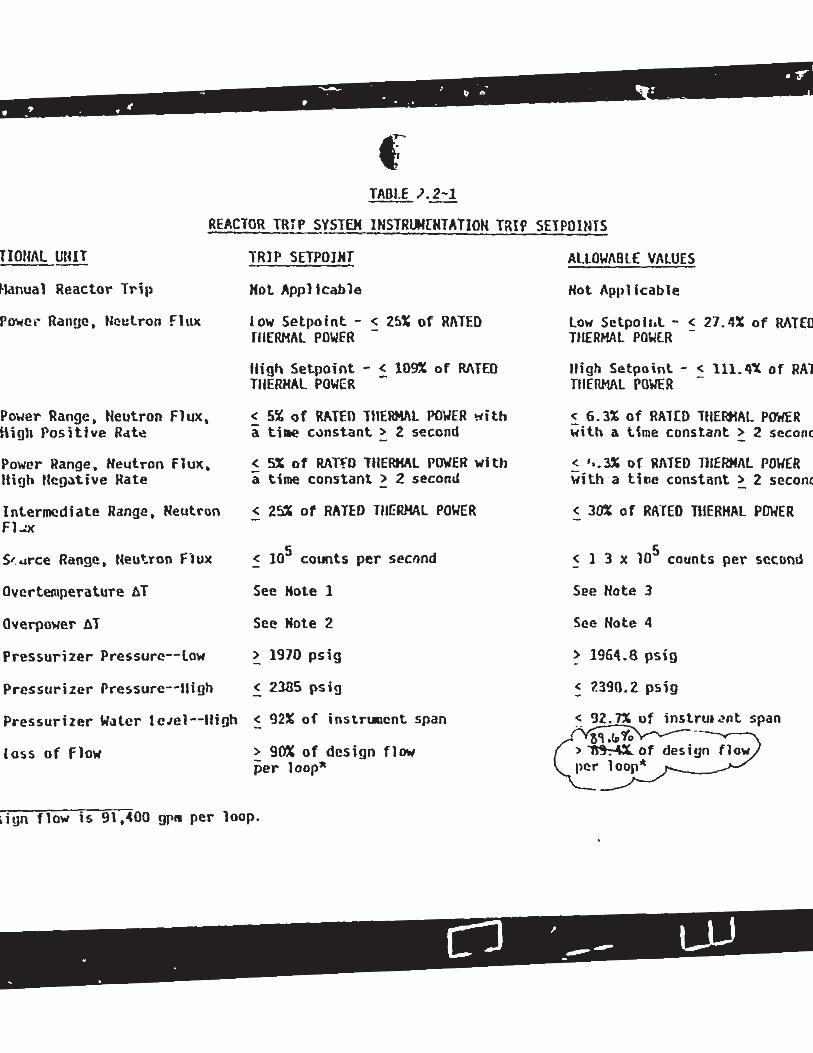
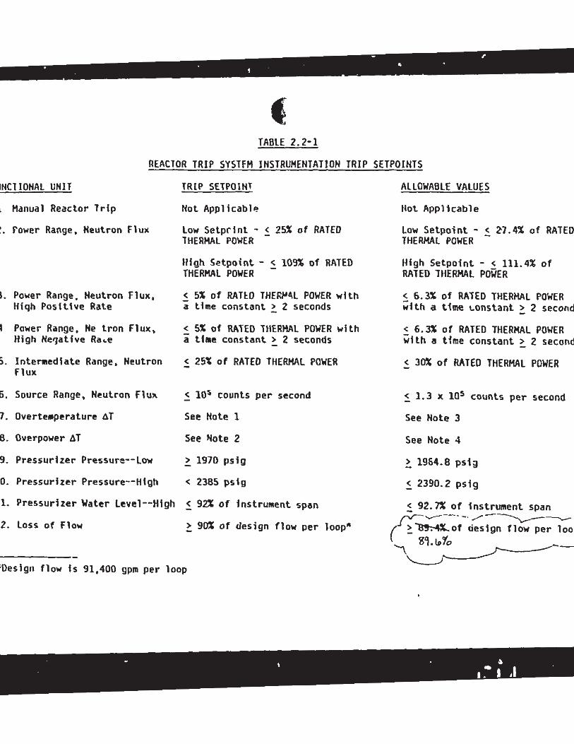
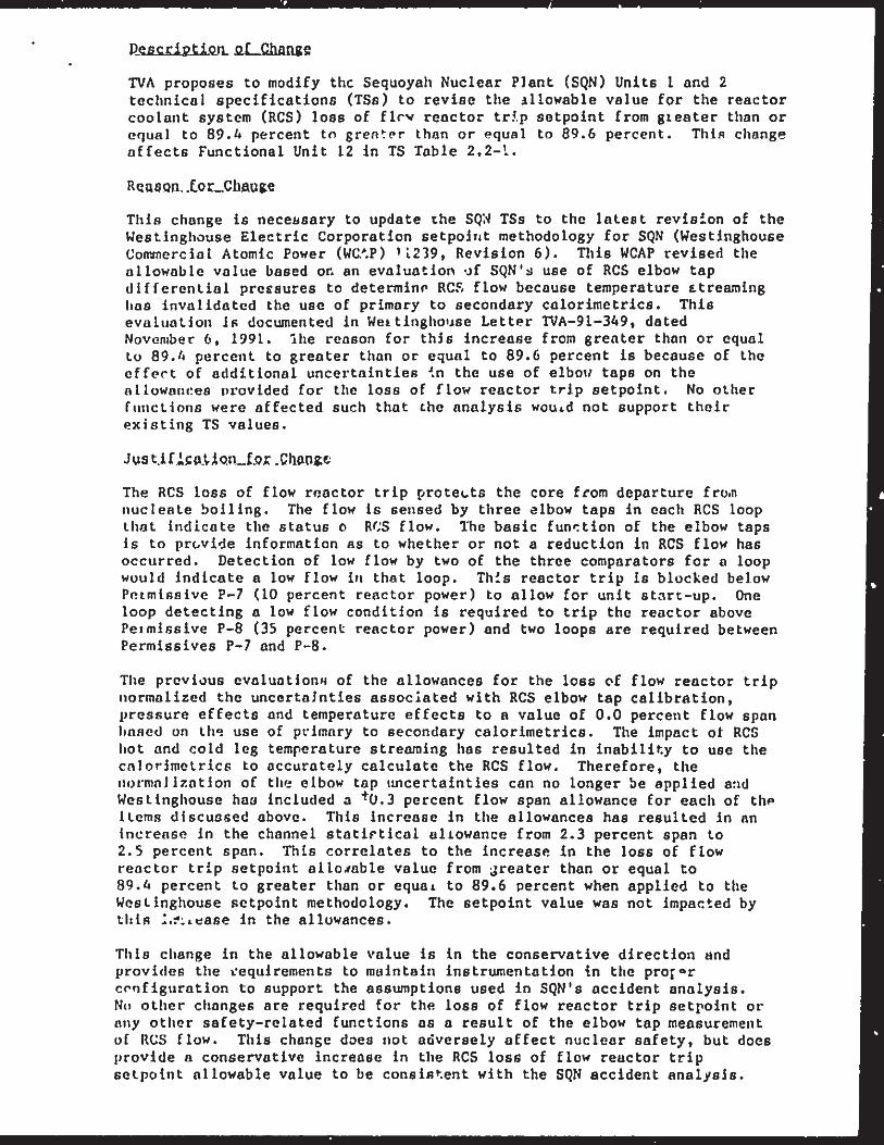
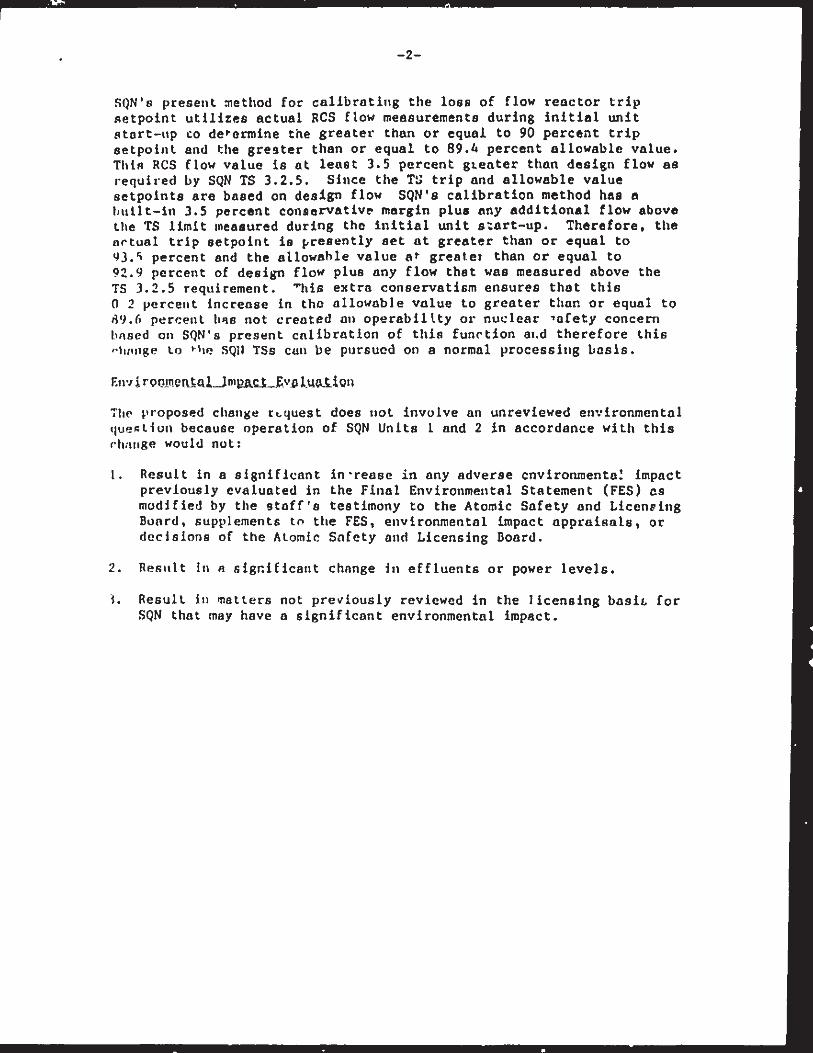
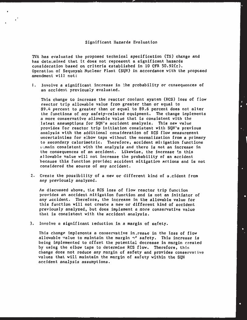
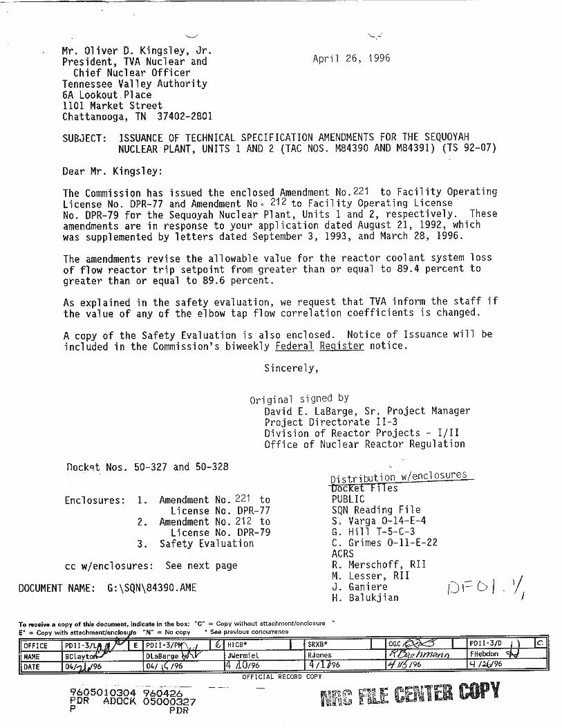
N- -
Mr. Oliver D. Kingsley, Jr.President, TVA Nuclear andChief Nuclear Officer
Tennessee Valley Authority6A LookoutPlace1101 Market StreetChattanooga, TN 37402-2801
April 26, 1996
SUBJECT: ISSUANCE OF TECHNICAL SPECIFICATION AMENDMENTS FOR THE SEQUOYAHNUCLEAR PLANT, UNITS I AND 2 (TAC NOS. M84390 AND M84391) (TS 92-07)
Dear Mr. Kingsley:
The Commission has issued the enclosed Amendment No.221 to Facility OperatingLicense No. DPR-77 and Amendment Noe 212 to Facility Operating LicenseNo. DPR-79 for the Sequoyah Nuclear Plant, Units I and 2, respectively. Theseamendments are in response to your application dated August 21, 1992, whichwas supplemented by letters dated September 3, 1993, and March 28, 1996.
The amendments revise the allowable value for the reactor coolant system lossof flow reactor trip setpoint from greater than or equal to 89.4 percent togreater than or equal to 89.6 percent.
As explained in the safety evaluation, we request that TVA inform the staff ifthe value of any of the elbow tap flow correlation coefficients is changed.
A copy of the Safety Evaluation is also enclosed. Notice of Issuance will beincluded in the Commission's biweekly Federal Register notice.
Sincerely,
Original signed byDavid E. LaBarge, Sr. Project ManagerProject Directorate 11-3Division of Reactor Projects - I/IlOffice of Nuclear Reactor Regulation
Docket Nos. 50-327 and 50-328
Enclosures: 1. Amendment No. 221 toLicense No. DPR-77
2. Amendment No. 212 toLicense No. DPR-79
3. Safety Evaluation
cc w/enclosures: See next page
DOCUMENT NAME: G:\SQN\84390.AME
Distribution w/enclosuresuocKet FilesPUBLICSQN Reading FileS. Varga O-14-E-4G. Hill T-5-C-3C. Grimes O-11-E-22ACRSR. Merschoff, RIIM. Lesser, RIIJ. GaniereH. Balukjian
To receive a copy of this document, Indicate In the box: "C" = Copy without attachment/enclosureE" = Copy with attachment/encloste "N" = No copy * See previous concurrence
OFFICE P01-3/I E PDIII3IP!"-f,,/ I •I HICB*l SRXB* I OGC I PDII-3/DjNAME BCtaytol/r- DiaBarge ,• JWermi e L RJones 1F'Y5UhMxnf)f ? FHebdonDATE 04/ /96 04/ /96 1 A1/96 4./1/96 f //11/96 / U-96
OFFICIAL RECORD COPY
9605010304 960426PDR ADOCK 05000327P PDR
NikL? ENEl W
.7;
UNITED STATES0 NUCLEAR REGULATORY COMMISSION
WASHINGTON, D.C. 2055-0001
TENNESSEE VALLEY AUTHORITY
DOCKET NO. 50-327
SEQUOYAH NUCLEAR PLANT, UNIT 1
AMENDMENT TO FACILITY OPERATING LICENSE
Amendment No. 221License No. DPR-77
1. The Nuclear Regulatory Commission (the Commission) has found that:
A. The application for amendment by Tennessee Valley Authority (thelicensee) dated August 21, 1992, which was supplemented September 3,1993, and March 28, 1996, complies with the standards andrequirements of the Atomic Energy Act of 1954, as amended (the Act),and the Commission's rules and regulations set forth in 10 CFRChapter I;
B. The facility will operate in conformity with the application, theprovisions of the Act, and the rules and regulations of theCommission;
C. There is reasonable assurance (i) that the activities authorized bythis amendment can be conducted without endangering the health andsafety of the public, and (ii) that such activities will beconducted in compliance with the Commission's regulations;
D. The issuance of this amendment will not be inimical to the commondefense and security or to the health and safety of the public; and
E. The issuance of this amendment is in accordance with 10 CFR Part 51of the Commission's regulations and all applicable requirements havebeen satisfied.
9605010306 960426PDR ADOCK 05000327P PDR

-2-
2. Accordingly, the license is amended by changes to the TechnicalSpecifications as indicated in the attachment to this license amendmentand paragraph 2.C.(2) of Facility Operating License No. DPR-77 is herebyamended to read as follows:
(2) Technical Specifications
The Technical Specifications contained in Appendices A and B, asrevised through Amendment No. 221 , are hereby incorporated in thelicense. The licensee shall operate the facility in accordance withthe Technical Specifications.
3. This license amendment is effective as of its date of issuance, to beimplemented within 30 days..
FOR THE NUCLEAR REGULATORY COMMISSION
Frederick J. Hebd n, DirectorProject Directorate 11-3Division of Reactor Projects - I/IIOffice of Nuclear Reactor Regulation
Attachment: Changes to the TechnicalSpecifications
Date of Issuance: April 26, 1996
Mr. Oliver D. Kingsley, Jr.Tennessee Valley Authority
cc:Mr. 0. J. Zeringue, Sr. Vice PresidentNuclear OperationsTennessee Valley Authority3B Lookout Place1101 Market StreetChattanooga, TN 37402-2801
Dr. Mark 0. Medford, Vice PresidentEngineering &Technical ServicesTennessee Valley Authority3B Lookout Place1101 Market StreetChattanooga, TN 37402-2801
Mr. D. E. Nunn, Vice PresidentNew Plant CompletionTennessee Valley Authority3B Lookout Place1101 Market StreetChattanooga, TN 37402-2801
Mr. R. J. Adney, Site ViceSequoyah Nuclear PlantTennessee Valley AuthorityP.O. Box 2000Soddy Daisy, TN 37379
General CounselTennessee Valley AuthorityET 11H400 West Summit Hill DriveKnoxville, TN 37902
President
SEQUOYAH NUCLEAR PLANT
TVA RepresentativeTennessee Valley Authority11921 Rockville PikeSuite 402Rockville, MD 20852
Regional AdministratorU.S. Nuclear Regulatory CommissionRegion II101 Marietta Street, NW., Suite 2900Atlanta, GA 30323
Mr. William E. HollandSenior Resident InspectorSequoyah Nuclear PlantU.S. Nuclear Regulatory Commission2600 Igou Ferry RoadSoddy Daisy, TN 37379
Mr. Michael H. Mobley, DirectorDivision of Radiological Health3rd Floor, L and C Annex401 Church StreetNashville, TN 37243-1532
County JudgeHamilton CountyChattanooga, TN
Courthouse37402-2801
Mr. P. P. Carier, ManagerCorporate LicensingTennessee Valley Authority4G Blue Ridge1101 Market StreetChattanooga, TN 37402-2801
Mr. Ralph H. ShellSite Licensing ManagerSequoyah Nuclear PlantTennessee Valley AuthorityP.O. Box 2000Soddy Daisy, TN 37379
ATTACHMENT TO LICENSE AMENDMENT NO.221
FACILITY OPERATING LICENSE NO. DPR-77
DOCKET NO. 50-327
Revise theidentifiedidentifiedindicating
Appendix A Technical Specifications by removing the pagesbelow and inserting the enclosed pages. The revised pages areby the captioned amendment number and contain marginal linesthe area of change.
REMOVE
2-5
INSERT
2-5
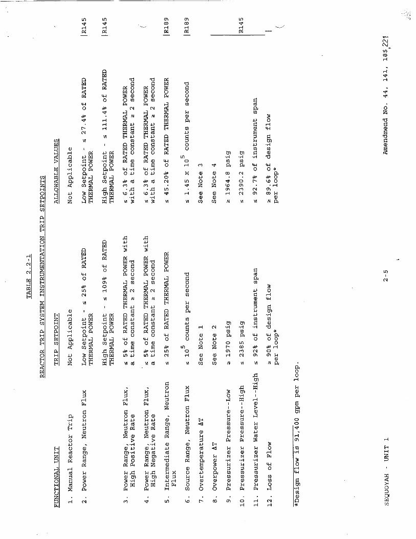
TABLE2.2-1
REAC~TORTRIP
BY•TF.M
TM•TRTTMEMTATIONTRIP
FUNCTIONALUNIT
1.ManualReactorTrip
2.PowerRange,NeutronFlux
3.PowerRange,NeutronFlux,
HighPositiveRate
4.PowerRange,NeutronFlux,
HighNegativeRate
5.IntermediateRange,Neutron
Flux
6.SourceRange,NeutronFlux
7.Overtemperature
AT
8.Overpower
AT
9.PressurizerPressure--Low
10.PressurizerPressure--High
11.PressurizerWaterLevel--High
12.LossofFlow
TRIP
SETPOINT
NotApplicable
LowSetpoint
-s25%ofRATED
THERMAL
POWER
HighSetpoint
-5109%ofRATED
THERMALPOWER
s5%ofRATED
THERMAL
POWERwith
atimeconstanta2second
r5%ofRATED
THERMALPOWERwith
atimeconstanta2second
s25%ofRATED
THERMAL
POWER
!105countspersecond
SeeNote1
SeeNote2
*1970psig
*2385psig
S92%ofinstrumentspan
S90%ofdesignflow
perloop*
ALLOWABLE
VALUES
NotApplicable
LowSetpoint
-s27.4%ofRATED
THERMALPOWER
HighSetpoint
-s111.4%ofRATED
THERMALPOWER
s6.3%ofRATED
THERMAL
POWER
withatimeconstant
a2second
•6.3%ofRATEDTHERMAL
POWER
withatimeconstant
a2second
r45.20%ofRATED
THERMAL
POWER
s1.45x105countspersecond
SeeNote3
SeeNote4
S1964.8psig
S2390.2psig
s92.7%ofinstrumentspan
S89.6%ofdesignflow
perloop*
*Designflow
is91,400gpmperloop.
AmendmendNo.
44,141,
185221
RETPC)TNTT•
JR145
JR145
JR189
R189
R145
REACTOR
TRIP
SYSTEM
INSTRUMENTATION
TRIP
SETPOINTS
SEQUOYAH
-UNIT
12-5
SAREG&
UNITED STATESNUCLEAR REGULATORY COMMISSION
) •llWASHINGTON, D.C. 20555-0001
TENNESSEE VALLEY AUTHORITY
DOCKET NO. 50-328
SEQUOYAH NUCLEAR PLANT, UNIT 2
AMENDMENT TO FACILITY OPERATING LICENSE
Amendment No.212
License No. DPR-79
1. The Nuclear Regulatory Commission (the Commission) has found that:
A. The application for amendment by Tennessee Valley Authority (thelicensee) dated August 21, 1992, which was supplemented September 3,1993, and March 28, 1996, complies with the standards andrequirements of the Atomic Energy Act of 1954, as amended (the Act),and the Commission's rules and regulations set forth in 10 CFRChapter I;
B. The facility will operate in conformity with the application, theprovisions of the Act, and the rules and regulations of theCommission;
C. There is reasonable assurance (i) that the activities authorized bythis amendment can be conducted without endangering the health andsafety of the public, and (ii) that such activities will beconducted in compliance with the Commission's regulations;
D. The issuance of this amendment will not be inimical to the commondefense and security or to the health and safety of the public; and
E. The issuance of this amendment is in accordance with 10 CFR Part 51of the Commission's regulations and all applicable requirements havebeen satisfied.
-2-
2. Accordingly, the license is amended by changes to the TechnicalSpecifications as indicated in the attachment to this license amendmentand paragraph 2.C.(2) of Facility Operating License No. DPR-79 is herebyamended to read as follows:
(2) Technical Specifications
The Technical Specifications contained in Appendices A and B, asrevised through Amendment No.212 , are hereby incorporated in thelicense. The licensee shall operate the facility in accordance withthe Technical Specifications.
3. This license amendment is effective as of its date of issuance, to beimplemented within 30 days.
FOR THE NUCLEAR REGULATORY COMMISSION
Frederick J. Hebdo1 , DirectorProject Directorate 11-3Division of Reactor Projects - I/IIOffice of Nuclear Reactor Regulation
Attachment: Changes to the TechnicalSpecifications
Date of Issuance: April 26, 1996
ATTACHMENT TO LICENSE AMENDMENT NO. 212
FACILITY OPERATING LICENSE NO. DPR-79
DOCKET NO. 50-328
Revise the Appendix A Technical Specifications by removing the pagesidentified below and inserting the enclosed pages. The revised pages areidentified by the captioned amendment number and contain marginal linesindicating the area of change.
REMOVE INSERT
2-5 2-5
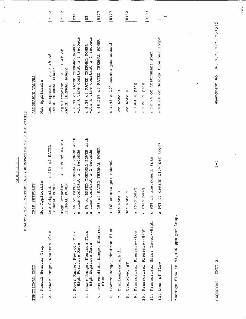
FUNCTIONALUNIT
1.ManualReactorTrip
2.PowerRange,NeutronFlux
3.PowerRange,NeutronFlux
HighPositiveRate
4.PowerRange,NeutronFlux
HighNegativeRate
5.Intermediate
Range,Neutr
Flux
6.SourceRange,NeutronFlu
7.Overtemperature
AT
8.Overpower
AT
9.PressurizerPressure--Low
10.PressurizerPressure--Hig
11.PressurizerWaterLevel-
12.LossofFlow
TABLE2.2-1
REACTORTRIP
SYSTEM
INSTRUMENTATIONTRIP
SETPOINTS
TRIP
SETPOINT
Al
NotApplicable
Nc
LowSetpoint
-s25%ofRATED
LTHERMALPOWER
Ri
HighSetpoint
-109%ofRATED
H:
THERMALPOWER
RI
,r5%ofRATED
THERMAL
POWERwith
atimeconstant
;2seconds
w:
55%ofRATED
THERMAL
POWERwith
atimeconstant
a2seconds
w:
on525%ofRATED
THERMAL
POWER
X25105countspersecond
SeeNote1
S
SeeNote2
SE
a1970psig
*h•2385
psig
High
•92%ofinstrumentspan
a90%ofdesignflowperloop*
LLOW
ABLE
VALUES
otApplicable
owSetpoint-s27.4%
ofATED
THERMAL
POWER
ighSetpoint-
!111.4%of
ATED
THERMALPOWER
6.3%ofRATED
THERMAL
POWER
Lthatimeconstant
Ž2seconds
6.3%ofRATED
THERMAL
POWER
Lthatimeconstant
a2seconds
45.20%ofRATED
THERMAL
POWER
1.45x10⁵countspersecond
eeNote3
eeNote4
1964.8psig
2390.2psig
92.7%ofinstrumentspan
89.6%ofdesignflowperloop*
*Designflow
is91,400gpmperloop.
AmendmentNo.
36,132,
177,
203212
JR132
JR132
R36
R177
JR177
R132
R203
SEQUOYAH
-UNIT
22-5
UNITED STATES0 )NUCLEAR REGULATORY COMMISSIONAt WASHINGTON, D.C. 20555-0001
***40 SAFETY EVALUATION BY THE OFFICE OF NUCLEAR REACTOR REGULATION
RELATED TO AMENDMENT NO.221 TO FACILITY OPERATING LICENSE NO. DPR-77
AND AMENDMENT NO. 212 TO FACILITY OPERATING LICENSE NO. DPR-79
TENNESSEE VALLEY AUTHORITY
SEQUOYAH NUCLEAR PLANT, UNITS 1 AND 2
DOCKET NOS. 50-327 AND 50-328
1.0 INTRODUCTION
By application dated August 21, 1992, which was supplemented by lettersdated September 3, 1993, and March 28, 1996, the Tennessee Valley Authority(the licensee) proposed amendments to the Technical Specifications (TS) forSequoyah Nuclear Plant (SQN) Units 1 and 2. The requested changes wouldrevise the allowable value for the reactor coolant system (RCS) loss of flowreactor trip setpoint from greater than or equal to 89.4 percent to greaterthan or equal to 89.6 percent. The proposed change would affect TSTable 2.2-1.The supplements supplied additional information that did not affect theprevious no significant hazards consideration.
2.0 EVALUATION
The function of the RCS loss of flow reactor trip is to protect the core fromdeparture from nucleate boiling should coolant flow be lost and to provideprotection against loss of flow conditions that affect only one reactorcoolant loop. Flow is measured in each loop by three differential pressuremeasurements at an elbow tap in each of the four coolant loops. A reactortrip signal would be generated should two of the three flow instruments (twoof-three coincidence circuit) in a loop detect a low flow condition in thatloop. This reactor trip signal is blocked below Permissive P-7 (10 percentpower) to allow for plant startup. Above this power level, up to PermissiveP-8 (35 percent power), two of the four loops detecting low flow would cause areactor trip. Above P-8, detection of low flow in any loop will cause areactor trip.
The minimum RCS low flow setpoint presently specified in the TS is89.4 percent of design flow. Therefore, if two out of the three coolant flowinstruments in any loop detect that flow has decreased from full flow to89.4 percent, a reactor trip will occur unless the trip is blocked.
9605o1o3o9 -96o2 - ENCLOSURE 3PDR ADOC26p D 05000327
PDR
-2
The TS require that the setpoint be equal to or greater than 89.4 percent ofdesign flow. The licensee has requested that this setpoint be changed to89.6 percent in order to update the TS to the latest revision of theWestinghouse Electric Corporation setpoint methodology. This methodologyincorporates the effects of additional uncertainties from using elbow taps onthe allowances used to determine the loss of flow setpoint. This evaluationis described in Westinghouse Letter TVA-91-349 dated November 6, 1991.Previously, the evaluation that determined the allowances for the loss of flowreactor trip setpoint normalized the uncertainties associated with RCS elbowtap sensor calibration accuracy, measurement and test equipment accuracy,sensor pressure effects, and sensor temperature effects, to a value of 0.0percent of flow instrument span, based on the use of primary to secondarycalorimetrics. However, hot and cold leg temperature streaming phenomena hasinvalidated the use of primary to secondary calorimetrics to accuratelycalculate RCS flow.
In their letter dated March 28, 1996, the licensee described the methodologycurrently being used to determine the RCS loss of flow reactor trip setpoint.The licensee indicated that flow correlation coefficients, or K values, areused to calculate the RCS flow rate from the equation Q=K(AP)°-. Thelicensee determined the K values for each elbow tap in each loop based on theinitial baseline Cycle 1 calorimetric flow rate. The K values for the threeelbows taps in each of the four loops for Units 1 and 2 are provided in TablesI and 2, respectively. These K values are used to determine the full scalespan of the flow instrument loop and, hence, the RCS loss of flow setpoint.It is requested that the licensee inform the staff if these elbow tapcoefficients are changed.
Since normalization of the elbow tap uncertainties can no longer be applied, a±0.3 percent flow span allowance is applied to each of the sensor effectsindicated above. The change to the individual allowances has resulted in anincrease in the channel statistical allowance from 2.3 percent to 2.5 percent,which correlates to an increase in the loss of flow reactor trip setpointallowable value from 89.4 percent to 89.6 percent.
This change in the allowable value would be in the conservative direction(i.e., the setpoint would be closer to actual RCS flow). Therefore, theproposed change does not adversely affect nuclear safety, but would result ina conservative increase in the RCS loss of flow reactor trip setpointallowable value that is consistent with the SQN accident analysis. Thelicensee has determined that no other changes are required for the setpointchange, nor are any other safety-related functions affected as a result of theelbow tap measurement of RCS flow. Based on this analysis, the staff hasdetermined that the proposed change is acceptable.
3.0 STATE CONSULTATION
In accordance with the Commission's regulations, the Tennessee State officialwas notified of the proposed issuance of the amendment. The State officialhad no comments.
- 3-
4.0 ENVIRONMENTAL CONSIDERATION
The amendment changes a requirement with respect to installation or use of afacility component located within the restricted area as defined in 10 CFRPart 20. The NRC staff has determined that the amendment involves nosignificant increase in the amounts, and no significant change in the types,of any effluents that may be released offsite, and that there is nosignificant increase in individual or cumulative occupational radiationexposure. The Commission has previously issued a proposed finding that theamendment involves no significant hazards consideration, and there has been nopublic comment on such finding (57 FR 45090). Accordingly, the amendmentmeets the eligibility criteria for categorical exclusion set forth in 10 CFR51.22(c)(9). Pursuant to 10 CFR 51.22(b) no environmental impact statement orenvironmental assessment need be prepared in connection with the issuance ofthe amendment.
5.0 CONCLUSION
The Commission has concluded, based on the considerations discussed above,that: (1) there is reasonable assurance that the health and safety of thepublic will not be endangered by operation in the proposed manner, (2) suchactivities will be conducted in compliance with the Commission's regulations,and (3) the issuance of the amendment will not be inimical to the commondefense and security or to the health and safety of the public.
Attachment: Tables I & 2
Principal Contributors: J. Ganiere, H. Balukjian, D. LaBarge
Dated: April 26, 1996
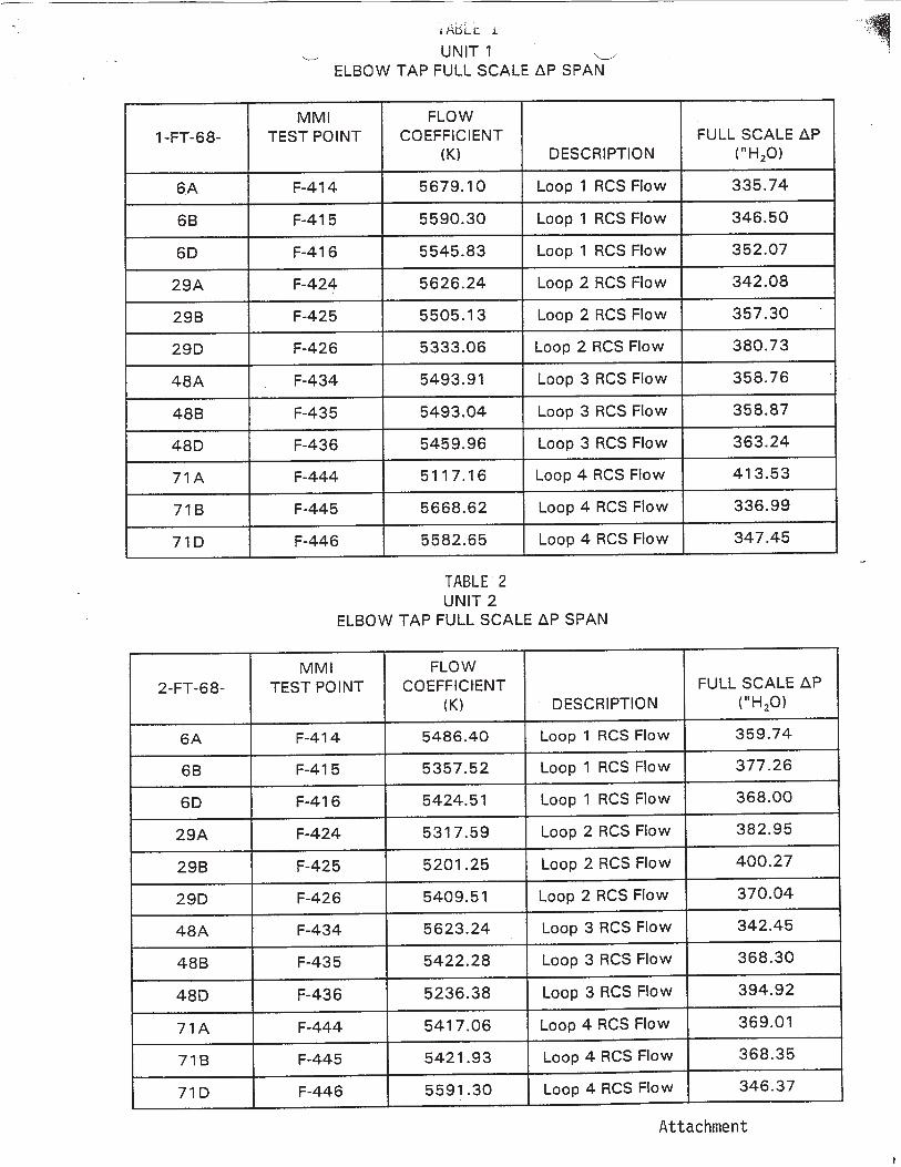
MMI FLOW1-FT-68- TEST POINT COEFFICIENT FULL SCALE AP
(K) DESCRIPTION ('H 20)
6A F-414 5679.10 Loop 1 RCS Flow 335.74
6B F-41 5 5590.30 Loop 1 RCS Flow 346.50
6D F-416 5545.83 Loop 1 RCS Flow 352.07
29A F-424 5626.24 Loop 2 RCS Flow 342.08
29B F-425 5505.13 Loop 2 RCS Flow 357.30
29D F-426 5333.06 Loop 2 RCS Flow 380.73
48A F-434 5493.91 Loop 3 RCS Flow 358.76
48B F-435 5493.04 Loop 3 RCS Flow 358.87
48D F-436 5459.96 Loop 3 RCS Flow 363.24
71 A F-444 5117.16 Loop 4 RCS Flow 413.53
71B F-445 5668.62 Loop 4 RCS Flow 336.99
71D F-446 5582.65 Loop 4 RCS Flow 347.45
TABLE 2UNIT 2
ELBOW TAP FULL SCALE AP SPAN
MMI FLOW2-FT-68- TEST POINT COEFFICIENT FULL SCALE AP
(K) DESCRIPTION ("H20)
6A F-414 5486.40 Loop 1 RCS Flow 359.74
6B F-415 5357.52 Loop 1 RCS Flow 377.26
6D F-416 5424.51 Loop 1 RCS Flow 368.00
29A F-424 5317.59 Loop 2 RCS Flow 382.95
29B F-425 5201.25 Loop 2 RCS Flow 400.27
29D F-426 5409.51 Loop 2 RCS Flow 370.04
48A F-434 5623.24 Loop 3 RCS Flow 342.45
48B F-435 5422.28 Loop 3 RCS Flow 368.30
48D F-436 5236.38 Loop 3 RCS Flow 394.92
71A F-444 5417.06 Loop 4 RCS Flow 369.01
71B F-445 5421.93 Loop 4 RCS Flow 368.35
71D F-446 5591.30 Loop 4 RCS Flow 346.37
Attachment
UNIT 1ELBOW TAP FULL SCALE AP SPAN

Licensee Response/NRC Response/NRC Question ClosureId 275
NRC Question Number RPG-007
Select Application NRC Question Closure
Attachment 1
Attachment 2
Response Statement
Response Date/Time
Closure Statement This question is closed and no further information is required at this time to draft the Safety Evaluation.
Question Closure Date 8/20/2014
Notification Scott BowmanMichelle ConnerRobert ElliottRavinder GroverKhadijah HemphillAndrew HonLynn MynattRay SchieleRoger Scott
Added By Ravinder Grover
Date Added 8/20/2014 3:27 PM
Date Modified
Modified By
Page 1 of 1Sequoyah ITS Conversion Database
8/21/2014https://members.excelservices.com/rai/index.php?requestType=areaItemPrint&itemId=275
ITS NRC QuestionsId 148
NRC Question Number
RPG-008
Category Technical
ITS Section 3.9
ITS Number 3.9.3
DOC Number
JFD Number
JFD Bases Number
Page Number(s) Enclosure 2, Volume 14, Revision 0, (pdf page 99 of 236)
NRC Reviewer
Supervisor Rob Elliott
Technical Branch POC Add Name
Conf Call Requested N
NRC Question Page B 3.9.3-5 of ITS Bases for LCO 3.9.3, “Nuclear Instrumentation,”
provides a listing of references which are relevant to the LCO’s Conditions and Surveillance requirements. One of the references concerns applicability of the 10 CFR 50, Appendix A, GDC 13, GDC 26, GDC 28, and GDC 29 requirements. SQN’s LCO Bases mark-up in Enclosure 2, Volume 14, Revision 0, (pdf page 99 of 236) replaces the reference to these specificGDCs with a reference to UFSAR Chapter 7.1.2, titled as, ‘Identification of Safety Criteria.’ The licensee’s Justification For Deviations #2 on page 100 explains the deletion as follows:
“Changes are made (additions, deletions, and/or changes) to the ISTS Bases that reflect the plant specific nomenclature, number, reference, system description, analysis, or licensing basis description.”
A Staff’s review of UFSAR Chapter 7.1.2 reveals that the Chapter contains a general listing of design criteria, which do not relate directly to the LCO‘s requirements, whereas a specific listing of GDCs referenced in the ITS LCO Bases, address certain requirements which are relevant to an explicit LCO‘s Conditions and Surveillance requirements. The NRC Staff as well as the Regions use such LCO-specific references as one of the tools to ensure that TS specified Systems, Structures and Components are operable per the stated requirements in the references.
The Staff‘s review has also found similar mark-ups in other TS Bases
Page 1 of 2Sequoyah ITS Conversion Database
8/21/2014https://members.excelservices.com/rai/index.php?requestType=areaItemPrint&itemId=148
sections. Please review the submittal whether the change(s) is consistent with CTS Bases or negate deletion of specific 10 CFR related references.
Attach File 1
Attach File 2
Issue Date 6/16/2014
Added By Ravinder Grover
Date Modified
Modified By
Date Added 6/16/2014 2:02 PM
Notification Scott BowmanMichelle ConnerRobert ElliottRavinder GroverMatthew HammKhadijah HemphillAndrew HonLynn MynattRay SchieleRoger Scott
Page 2 of 2Sequoyah ITS Conversion Database
8/21/2014https://members.excelservices.com/rai/index.php?requestType=areaItemPrint&itemId=148
Licensee Response/NRC Response/NRC Question ClosureId 240
NRC Question Number
RPG-008
Select Application Licensee Response
Attachment 1 Attachment 1 Draft Response to RAI RPG-008.pdf (2MB)
Attachment 2
Response Statement In response to RAI RPG-008, the References Section of ITS 3.9.3 Bases markup
will be revised from including UFSAR Section 7.1.2, to including 10 CFR 50, Appendix A, General Design Criteria (GDC) 13, 26, 28 and 29, as specified in the ISTS (pages 93 and 99 of Enclosure 2, Volume 14).
Additional instances of 10 CFR related references being deleted or replaced with other references in the ISTS Bases markups occur in the following Bases Sections:
- ISTS 3.4.14 Bases markup, Reference 8 (10 CFR 50.55a(g)) – The only place within the ISTS 3.4.14 Bases markup that this reference is used is in the discussion of the basis for the 18 month Frequency associated with the performance of SR 3.4.14.1. This discussion is being moved to the Surveillance Frequency Control Program as part of the adoption of TSTF-425, as discussed in JFD 6.
- ISTS 3.4.16 Bases markup, second Reference 1 of Insert 8 (TSTF-490) – As stated in the Reviewer’s Note of TSTF-490, Insert 8, the first listed References 1 and 2 are for plants that are licensed to 10 CFR 100.11. The second listed References 1 and 2 are for plants that are licensed to 10 CFR 50.67. The RCS specific activity limits are established to minimize the dose consequences in the event of a steam line break (SLB) or steam generator tube rupture (SGTR) event. SQN is licensed to 10 CFR 50.67 only for a fuel handling accident.Therefore, SQN has adopted the first listed References 1 and 2 to reflect the license basis use of the 10 CFR 100.11 dose limits for SLB and SGTR. This results in a deletion of the second listed References 1 and 2.
- ISTS 3.6.6C (ITS 3.6.6) Bases markup, Reference 1 – Reference 1 lists several GDCs to which the Containment Spray System is designed. ISTS 3.6.6C Bases assume that the Containment Spray System includes a Spray Additive System that injects sodium hydroxide solution into the spray to adjust the pH of the water to scavenge iodine fission products from the containment atmosphere and ensure their retention in the containment sump water. However, as discussed in JFD 3, SQN design does not include a Spray Additive System.Therefore, the GDCs (41, 42, and 43) that are associated with containment atmosphere cleanup have not been retained in Reference 1.
- ISTS 3.6.10 (ITS 3.6.8) Bases markup, Reference 2 – Reference 2 (10 CFR 50, Appendix A, GDC 41) appears in ISTS Bases 3.6.10 Background Section as a part of the discussion regarding the regulatory basis for requiring the
Page 1 of 2Sequoyah ITS Conversion Database
8/21/2014https://members.excelservices.com/rai/index.php?requestType=areaItemPrint&itemId=240
Hydrogen Ignition System (Hydrogen Mitigation System). However, as discussed in SQN UFSAR Section 3.1, regarding compliance with GDC 41, “Containment Atmosphere Cleanup,” the systems relied upon for compliance with GDC 41 are the Emergency Gas Treatment System, Auxiliary Building Gas Treatment System, and the Air Return Fan System. Therefore, the discussion of GDC 41 has been removed from the discussion in the Background Section of the Hydrogen Mitigation System Bases, as indicated in the ISTS 3.6.10 Bases markup.
- ISTS 3.7.15 (ITS 3.7.13) Bases markup, Reference 5 – Reference 5 (10 CFR 100.11) is provided in the ISTS 3.7.15 Bases Applicable Safety Analyses Section to indicate that doses at the exclusion area boundary, as the result of a fuel handling accident, are within the licensed dose limits. Because SQN has been approved for selective use of the alternate source term dose limits of 10 CFR 50.67 for a fuel handling accident, Reference 5 has been changed from 10 CFR 100.11 to 10 CFR 50.67.
- ISTS 3.9.7 Bases markup, Reference 4 (ITS 3.9.7 Reference 3) – Reference 4 (10 CFR 100.11) is provided in the ISTS 3.9.7 Bases Applicable Safety Analyses Section to indicate that offsite doses, as the result of a fuel handling accident, are within the licensed dose limits. Because SQN has been approved for selective use of the alternate source term dose limits of 10 CFR 50.67 for a fuel handling accident, Reference 4 has been changed from 10 CFR 100.11 to 10 CFR 50.67.
See Attachment 1 for the draft ITS 3.9.3 Bases changes discussed above.
Response Date/Time 8/5/2014 9:20 AM
Closure Statement
Question Closure
Date
Notification Scott BowmanMichelle ConnerRavinder GroverKhadijah HemphillAndrew HonRay Schiele
Added By Scott Bowman
Date Added 8/5/2014 8:18 AM
Date Modified
Modified By
Page 2 of 2Sequoyah ITS Conversion Database
8/21/2014https://members.excelservices.com/rai/index.php?requestType=areaItemPrint&itemId=240
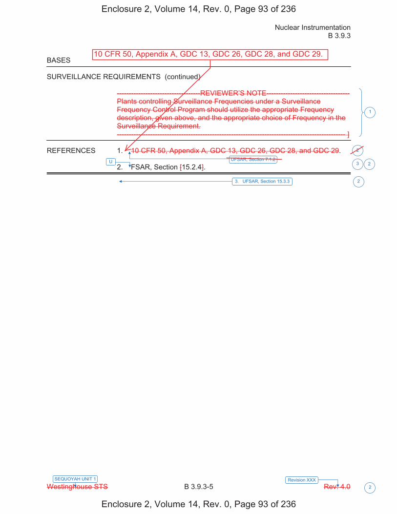
Nuclear Instrumentation B 3.9.3
Westinghouse STS B 3.9.3-5 Rev. 4.0 2
SEQUOYAH UNIT 1 Revision XXX
BASES SURVEILLANCE REQUIREMENTS (continued)
-----------------------------------REVIEWER’S NOTE----------------------------------- Plants controlling Surveillance Frequencies under a Surveillance Frequency Control Program should utilize the appropriate Frequency description, given above, and the appropriate choice of Frequency in the Surveillance Requirement. ------------------------------------------------------------------------------------------------ ]
REFERENCES 1. 10 CFR 50, Appendix A, GDC 13, GDC 26, GDC 28, and GDC 29. 2. FSAR, Section [15.2.4].
1
3UFSAR, Section 7.1.2
2
3. UFSAR, Section 15.3.3 2
U 2
Enclosure 2, Volume 14, Rev. 0, Page 93 of 236
Enclosure 2, Volume 14, Rev. 0, Page 93 of 236
10 CFR 50, Appendix A, GDC 13, GDC 26, GDC 28, and GDC 29.
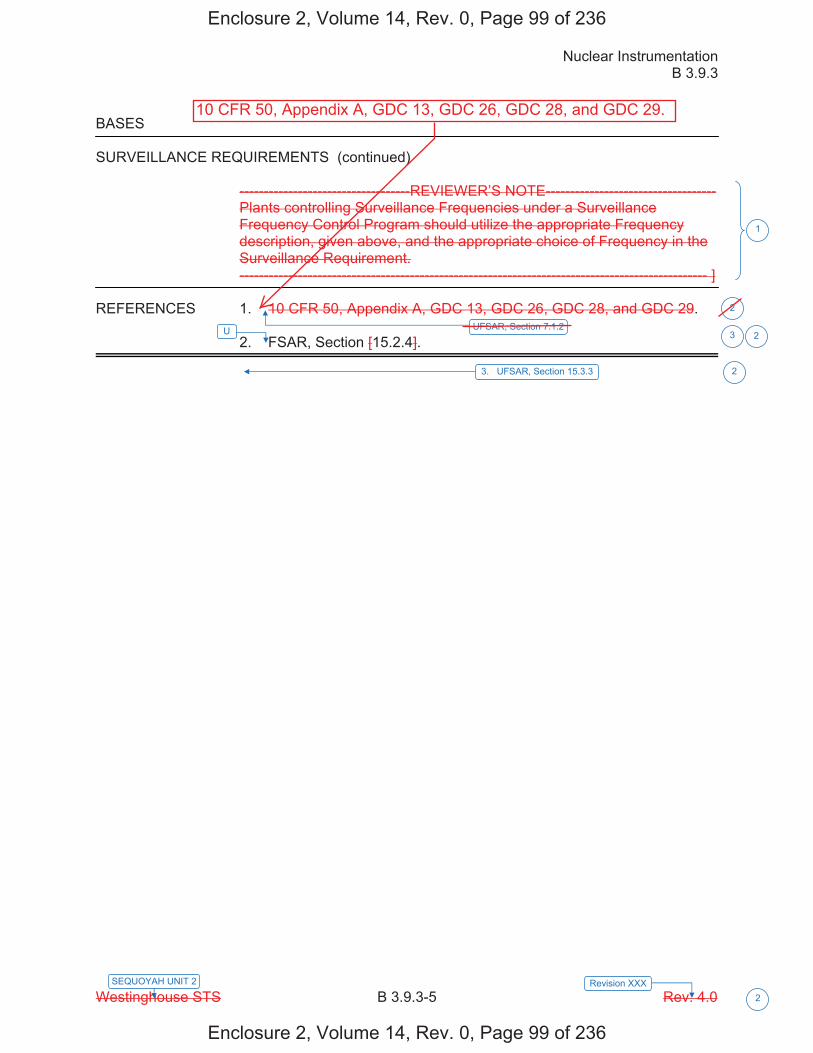
Nuclear Instrumentation B 3.9.3
Westinghouse STS B 3.9.3-5 Rev. 4.0 2
SEQUOYAH UNIT 2 Revision XXX
BASES SURVEILLANCE REQUIREMENTS (continued)
-----------------------------------REVIEWER’S NOTE----------------------------------- Plants controlling Surveillance Frequencies under a Surveillance Frequency Control Program should utilize the appropriate Frequency description, given above, and the appropriate choice of Frequency in the Surveillance Requirement. ------------------------------------------------------------------------------------------------ ]
REFERENCES 1. 10 CFR 50, Appendix A, GDC 13, GDC 26, GDC 28, and GDC 29. 2. FSAR, Section [15.2.4].
1
3UFSAR, Section 7.1.2
2
3. UFSAR, Section 15.3.3 2
U 2
Enclosure 2, Volume 14, Rev. 0, Page 99 of 236
Enclosure 2, Volume 14, Rev. 0, Page 99 of 236
10 CFR 50, Appendix A, GDC 13, GDC 26, GDC 28, and GDC 29.

Licensee Response/NRC Response/NRC Question ClosureId 280
NRC Question Number RPG-008
Select Application NRC Question Closure
Attachment 1
Attachment 2
Response Statement
Response Date/Time
Closure Statement This question is closed and no further information is required at this time to draft the Safety Evaluation.
Question Closure Date 8/21/2014
Notification Scott BowmanMichelle ConnerRobert ElliottRavinder GroverKhadijah HemphillAndrew HonLynn MynattRay SchieleRoger Scott
Added By Ravinder Grover
Date Added 8/21/2014 1:22 PM
Date Modified
Modified By
Page 1 of 1Sequoyah ITS Conversion Database
8/21/2014https://members.excelservices.com/rai/index.php?requestType=areaItemPrint&itemId=280
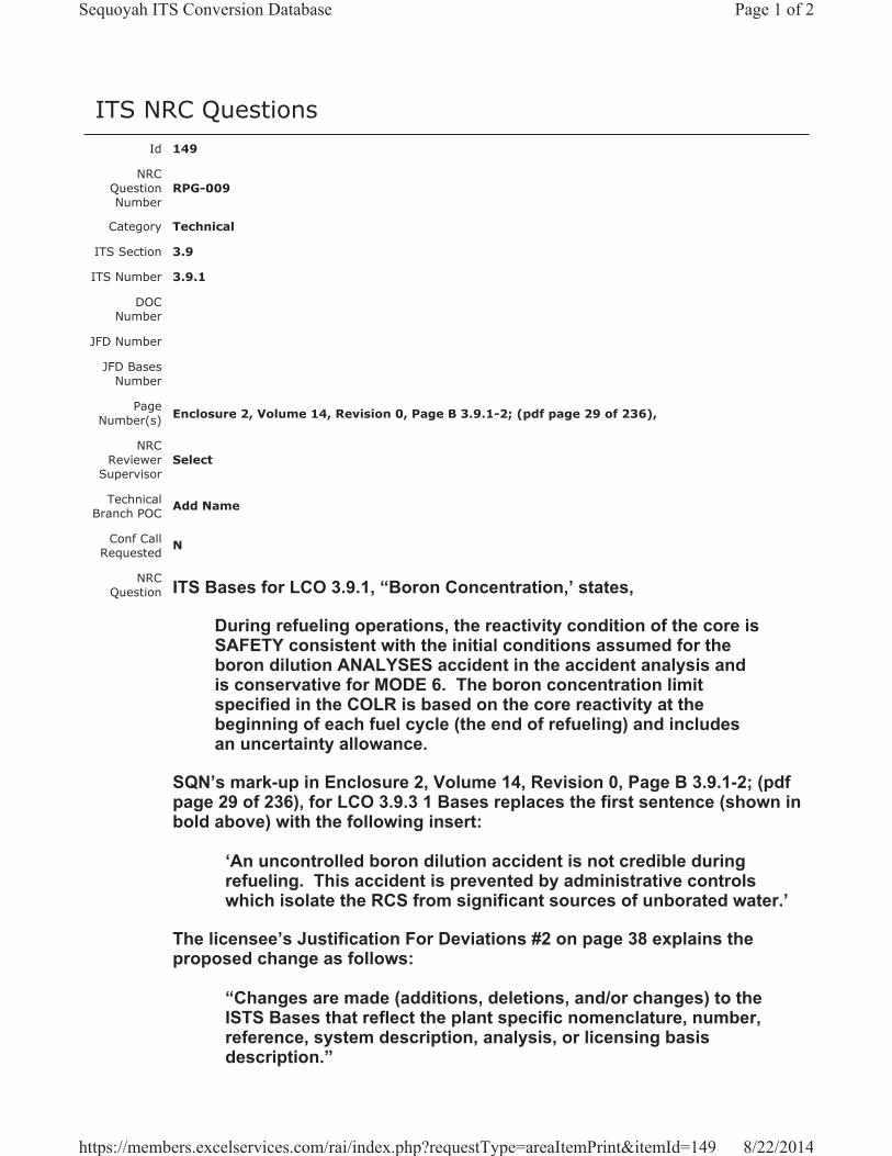
ITS NRC QuestionsId 149
NRC Question Number
RPG-009
Category Technical
ITS Section 3.9
ITS Number 3.9.1
DOC Number
JFD Number
JFD Bases Number
Page Number(s) Enclosure 2, Volume 14, Revision 0, Page B 3.9.1-2; (pdf page 29 of 236),
NRC Reviewer
Supervisor Select
Technical Branch POC Add Name
Conf Call Requested N
NRC Question ITS Bases for LCO 3.9.1, “Boron Concentration,’ states,
During refueling operations, the reactivity condition of the core is SAFETY consistent with the initial conditions assumed for the boron dilution ANALYSES accident in the accident analysis and is conservative for MODE 6. The boron concentration limit specified in the COLR is based on the core reactivity at the beginning of each fuel cycle (the end of refueling) and includes an uncertainty allowance.
SQN’s mark-up in Enclosure 2, Volume 14, Revision 0, Page B 3.9.1-2; (pdf page 29 of 236), for LCO 3.9.3 1 Bases replaces the first sentence (shown in bold above) with the following insert:
‘An uncontrolled boron dilution accident is not credible during refueling. This accident is prevented by administrative controls which isolate the RCS from significant sources of unborated water.’
The licensee’s Justification For Deviations #2 on page 38 explains the proposed change as follows:
“Changes are made (additions, deletions, and/or changes) to the ISTS Bases that reflect the plant specific nomenclature, number, reference, system description, analysis, or licensing basis description.”
Page 1 of 2Sequoyah ITS Conversion Database
8/22/2014https://members.excelservices.com/rai/index.php?requestType=areaItemPrint&itemId=149
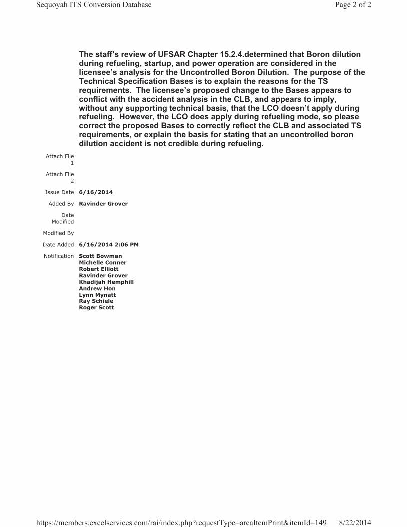
The staff’s review of UFSAR Chapter 15.2.4.determined that Boron dilution during refueling, startup, and power operation are considered in the licensee’s analysis for the Uncontrolled Boron Dilution. The purpose of the Technical Specification Bases is to explain the reasons for the TS requirements. The licensee’s proposed change to the Bases appears to conflict with the accident analysis in the CLB, and appears to imply, without any supporting technical basis, that the LCO doesn’t apply during refueling. However, the LCO does apply during refueling mode, so please correct the proposed Bases to correctly reflect the CLB and associated TS requirements, or explain the basis for stating that an uncontrolled boron dilution accident is not credible during refueling.
Attach File 1
Attach File 2
Issue Date 6/16/2014
Added By Ravinder Grover
Date Modified
Modified By
Date Added 6/16/2014 2:06 PM
Notification Scott BowmanMichelle ConnerRobert ElliottRavinder GroverKhadijah HemphillAndrew HonLynn MynattRay SchieleRoger Scott
Page 2 of 2Sequoyah ITS Conversion Database
8/22/2014https://members.excelservices.com/rai/index.php?requestType=areaItemPrint&itemId=149
Licensee Response/NRC Response/NRC Question ClosureId 197
NRC Question Number
RPG-009
Select Application Licensee Response
Attachment 1
Attachment 2
Response Statement
SQN UFSAR Section 15.2.4.2 states, “An uncontrolled boron dilution accident is not credible during refueling. This accident is prevented by administrative controls which isolate the RCS from significant sources of unborated water.” The requirements of ITS 3.9.1, “Boron Concentration,” are applicable during MODE 6 (Refueling) to ensure adequate boron concentration exists in the reactor coolant system (and the connected refueling canal and refueling cavity) in order to maintain an overall core reactivity of keff 0.95. The ISTS 3.9.1 Bases, as submitted in the ITS Conversion license amendment request, have been marked up to reflect that a boron dilution event is not credible during refueling, as stated in UFSAR Section 15.2.4.2.
Response Date/Time 7/21/2014 12:10 PM
Closure Statement
Question Closure
Date
Notification Scott BowmanMichelle ConnerRavinder GroverKhadijah HemphillAndrew HonRay Schiele
Added By Scott Bowman
Date Added 7/21/2014 11:08 AM
Date Modified
Modified By
Page 1 of 1Sequoyah ITS Conversion Database
8/22/2014https://members.excelservices.com/rai/index.php?requestType=areaItemPrint&itemId=197

Licensee Response/NRC Response/NRC Question ClosureId 281
NRC Question Number RPG-009
Select Application NRC Question Closure
Attachment 1
Attachment 2
Response Statement
Response Date/Time
Closure Statement This question is closed and no further information is required at this time to draft the Safety Evaluation.
Question Closure Date 8/21/2014
Notification Scott BowmanMichelle ConnerRobert ElliottRavinder GroverKhadijah HemphillAndrew HonLynn MynattRay SchieleRoger Scott
Added By Ravinder Grover
Date Added 8/21/2014 2:11 PM
Date Modified
Modified By
Page 1 of 1Sequoyah ITS Conversion Database
8/22/2014https://members.excelservices.com/rai/index.php?requestType=areaItemPrint&itemId=281
ITS NRC QuestionsId 150
NRC Question Number
RPG-010
Category Technical
ITS Section 3.9
ITS Number 3.9.1
DOC Number
JFD Number
JFD Bases Number
Page Number(s) Enclosure 2, Volume 14, Revision 0, Page B 3.9.1-2; (pdf page 29 of 236),
NRC Reviewer
Supervisor Rob Elliott
Technical Branch POC Add Name
Conf Call Requested N
NRC Question
Page B 3.9.1-2 of ITS Bases for LCO 3.9.1, “Boron Concentration,’ states,
‘The limiting boron dilution accident analyzed occurs in MODE 5 (Ref. 2). A detailed discussion of this event is provided in Bases B 3.1.1, "SHUTDOWN MARGIN (SDM)."’
SQN’s mark-up in Enclosure 2, Volume 14, Revision 0, Page B 3.9.1-2; (pdf page 29 of 236), for LCO 3.9.3 1 Bases replaces the word, ‘MODE 5,’ with ‘during startup,’ in the above sentence.
The licensee’s Justification For Deviations (JFD) #2 on pdf page 38 explains the deviation as follows:
“Changes are made (additions, deletions, and/or changes) to the ISTS Bases that reflect the plant specific nomenclature, number, reference, system description, analysis, or licensing basis description.”
The SQN’s UFSAR Section 15.2.4 discusses the Boron Dilution Accident analysis for the plant operational modes of refueling, startup, and power operations. LCO 3.9.1 mode of applicability is in Mode 6, ‘Refueling.’ Please provide basis for stating the limiting boron dilution accident analyzed occurs ‘during startup,’ as the JFD does not provide specific information for the change.
Attach File 1
Page 1 of 2Sequoyah ITS Conversion Database
9/25/2014https://members.excelservices.com/rai/index.php?requestType=areaItemPrint&itemId=150
Attach File 2
Issue Date 6/16/2014
Added By Ravinder Grover
Date Modified
Modified By
Date Added 6/16/2014 2:08 PM
Notification Scott BowmanMichelle ConnerRobert ElliottRavinder GroverKhadijah HemphillAndrew HonLynn MynattRay SchieleRoger Scott
Page 2 of 2Sequoyah ITS Conversion Database
9/25/2014https://members.excelservices.com/rai/index.php?requestType=areaItemPrint&itemId=150
Licensee Response/NRC Response/NRC Question ClosureId 302
NRC Question Number
RPG-010
Select Application Licensee Response
Attachment 1 Attachment 1 to RGP-010.pdf (35KB)
Attachment 2
Response Statement
In response to RPG-010, the Applicable Safety Analyses section for the Bases of ITS 3.9.1, on pages 29 and 34 of Enclosure 2, Volume 14, will be revised.Specifically, the following sentence, “The limiting boron dilution accident analyzed occurs during startup (Ref. 2).” will be revised to read, “The limiting boron dilution accident analyzed occurs in MODE 5 (Ref. 2).”
See Attachment 1 for the draft revised ITS 3.9.1 Bases change discussed above.
Response Date/Time 8/28/2014 6:15 AM
Closure Statement
Question Closure Date
Notification Scott BowmanMichelle ConnerRavinder GroverKhadijah HemphillAndrew HonRay Schiele
Added By Scott Bowman
Date Added 8/28/2014 5:11 AM
Date Modified
Modified By
Page 1 of 1Sequoyah ITS Conversion Database
9/25/2014https://members.excelservices.com/rai/index.php?requestType=areaItemPrint&itemId=302
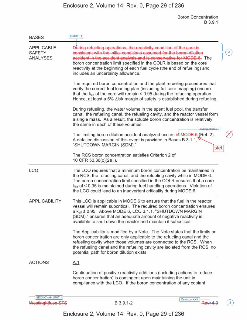
Boron Concentration B 3.9.1
Westinghouse STS B 3.9.1-2 Rev. 4.0 2
SEQUOYAH UNIT 1 Revision XXX
BASES APPLICABLE During refueling operations, the reactivity condition of the core is SAFETY consistent with the initial conditions assumed for the boron dilution ANALYSES accident in the accident analysis and is conservative for MODE 6. The
boron concentration limit specified in the COLR is based on the core reactivity at the beginning of each fuel cycle (the end of refueling) and includes an uncertainty allowance. The required boron concentration and the plant refueling procedures that verify the correct fuel loading plan (including full core mapping) ensure that the keff of the core will remain 0.95 during the refueling operation. Hence, at least a 5% k/k margin of safety is established during refueling. During refueling, the water volume in the spent fuel pool, the transfer canal, the refueling canal, the refueling cavity, and the reactor vessel form a single mass. As a result, the soluble boron concentration is relatively the same in each of these volumes. The limiting boron dilution accident analyzed occurs in MODE 5 (Ref. 2). A detailed discussion of this event is provided in Bases B 3.1.1, "SHUTDOWN MARGIN (SDM)." The RCS boron concentration satisfies Criterion 2 of 10 CFR 50.36(c)(2)(ii).
LCO The LCO requires that a minimum boron concentration be maintained in
the RCS, the refueling canal, and the refueling cavity while in MODE 6. The boron concentration limit specified in the COLR ensures that a core keff of 0.95 is maintained during fuel handling operations. Violation of the LCO could lead to an inadvertent criticality during MODE 6.
APPLICABILITY This LCO is applicable in MODE 6 to ensure that the fuel in the reactor
vessel will remain subcritical. The required boron concentration ensures a keff 0.95. Above MODE 6, LCO 3.1.1, "SHUTDOWN MARGIN (SDM)," ensures that an adequate amount of negative reactivity is available to shut down the reactor and maintain it subcritical.
The Applicability is modified by a Note. The Note states that the limits on boron concentration are only applicable to the refueling canal and the refueling cavity when those volumes are connected to the RCS. When the refueling canal and the refueling cavity are isolated from the RCS, no potential path for boron dilution exists.
ACTIONS A.1
Continuation of positive reactivity additions (including actions to reduce boron concentration) is contingent upon maintaining the unit in compliance with the LCO. If the boron concentration of any coolant
during startup
2
INSERT 1
2
Enclosure 2, Volume 14, Rev. 0, Page 29 of 236
Enclosure 2, Volume 14, Rev. 0, Page 29 of 236
stet
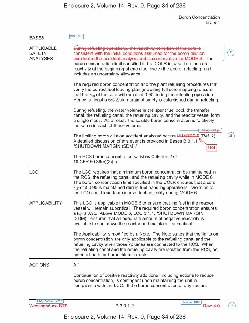
Boron Concentration B 3.9.1
Westinghouse STS B 3.9.1-2 Rev. 4.0 2
SEQUOYAH UNIT 2 Revision XXX
BASES APPLICABLE During refueling operations, the reactivity condition of the core is SAFETY consistent with the initial conditions assumed for the boron dilution ANALYSES accident in the accident analysis and is conservative for MODE 6. The
boron concentration limit specified in the COLR is based on the core reactivity at the beginning of each fuel cycle (the end of refueling) and includes an uncertainty allowance. The required boron concentration and the plant refueling procedures that verify the correct fuel loading plan (including full core mapping) ensure that the keff of the core will remain 0.95 during the refueling operation. Hence, at least a 5% k/k margin of safety is established during refueling. During refueling, the water volume in the spent fuel pool, the transfer canal, the refueling canal, the refueling cavity, and the reactor vessel form a single mass. As a result, the soluble boron concentration is relatively the same in each of these volumes. The limiting boron dilution accident analyzed occurs in MODE 5 (Ref. 2). A detailed discussion of this event is provided in Bases B 3.1.1, "SHUTDOWN MARGIN (SDM)." The RCS boron concentration satisfies Criterion 2 of 10 CFR 50.36(c)(2)(ii).
LCO The LCO requires that a minimum boron concentration be maintained in
the RCS, the refueling canal, and the refueling cavity while in MODE 6. The boron concentration limit specified in the COLR ensures that a core keff of 0.95 is maintained during fuel handling operations. Violation of the LCO could lead to an inadvertent criticality during MODE 6.
APPLICABILITY This LCO is applicable in MODE 6 to ensure that the fuel in the reactor
vessel will remain subcritical. The required boron concentration ensures a keff 0.95. Above MODE 6, LCO 3.1.1, "SHUTDOWN MARGIN (SDM)," ensures that an adequate amount of negative reactivity is available to shut down the reactor and maintain it subcritical.
The Applicability is modified by a Note. The Note states that the limits on boron concentration are only applicable to the refueling canal and the refueling cavity when those volumes are connected to the RCS. When the refueling canal and the refueling cavity are isolated from the RCS, no potential path for boron dilution exists.
ACTIONS A.1
Continuation of positive reactivity additions (including actions to reduce boron concentration) is contingent upon maintaining the unit in compliance with the LCO. If the boron concentration of any coolant
during startup
2
INSERT 1
2
Enclosure 2, Volume 14, Rev. 0, Page 34 of 236
Enclosure 2, Volume 14, Rev. 0, Page 34 of 236
stet

Licensee Response/NRC Response/NRC Question ClosureId 343
NRC Question Number RPG-010
Select Application NRC Question Closure
Attachment 1
Attachment 2
Response Statement
Response Date/Time
Closure Statement This question is closed and no further information is required at this time to draft the Safety Evaluation.
Question Closure Date 9/22/2014
Notification Scott BowmanMichelle ConnerRobert ElliottRavinder GroverKhadijah HemphillAndrew HonLynn MynattRay SchieleRoger Scott
Added By Ravinder Grover
Date Added 9/22/2014 1:48 PM
Date Modified
Modified By
Page 1 of 1Sequoyah ITS Conversion Database
9/25/2014https://members.excelservices.com/rai/index.php?requestType=areaItemPrint&itemId=343
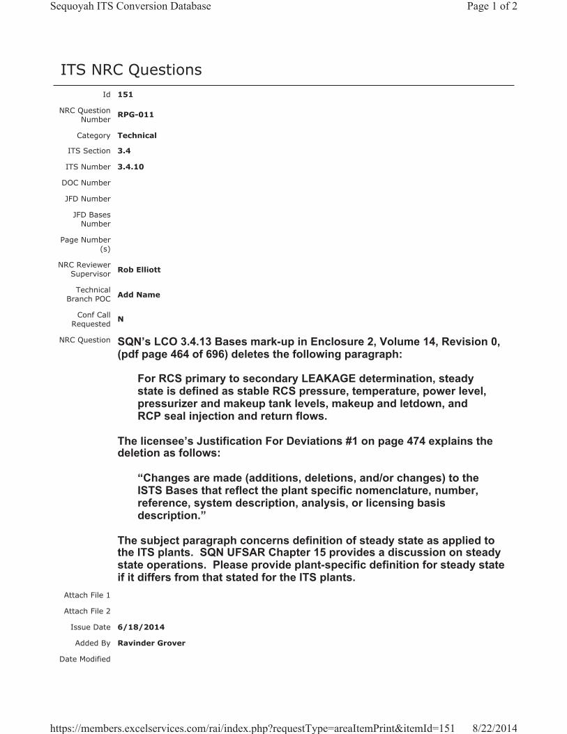
ITS NRC QuestionsId 151
NRC Question Number RPG-011
Category Technical
ITS Section 3.4
ITS Number 3.4.10
DOC Number
JFD Number
JFD Bases Number
Page Number(s)
NRC Reviewer Supervisor Rob Elliott
Technical Branch POC Add Name
Conf Call Requested N
NRC Question SQN’s LCO 3.4.13 Bases mark-up in Enclosure 2, Volume 14, Revision 0, (pdf page 464 of 696) deletes the following paragraph:
For RCS primary to secondary LEAKAGE determination, steady state is defined as stable RCS pressure, temperature, power level, pressurizer and makeup tank levels, makeup and letdown, and RCP seal injection and return flows.
The licensee’s Justification For Deviations #1 on page 474 explains the deletion as follows:
“Changes are made (additions, deletions, and/or changes) to the ISTS Bases that reflect the plant specific nomenclature, number, reference, system description, analysis, or licensing basis description.”
The subject paragraph concerns definition of steady state as applied to the ITS plants. SQN UFSAR Chapter 15 provides a discussion on steady state operations. Please provide plant-specific definition for steady state if it differs from that stated for the ITS plants.
Attach File 1
Attach File 2
Issue Date 6/18/2014
Added By Ravinder Grover
Date Modified
Page 1 of 2Sequoyah ITS Conversion Database
8/22/2014https://members.excelservices.com/rai/index.php?requestType=areaItemPrint&itemId=151
Modified By
Date Added 6/18/2014 2:12 PM
Notification Scott BowmanMichelle ConnerRobert ElliottRavinder GroverKhadijah HemphillAndrew HonLynn MynattRay SchieleRoger Scott
Page 2 of 2Sequoyah ITS Conversion Database
8/22/2014https://members.excelservices.com/rai/index.php?requestType=areaItemPrint&itemId=151
Licensee Response/NRC Response/NRC Question ClosureId 198
NRC Question Number RPG-011
Select Application Licensee Response
Attachment 1 Atachment 1 - RAI RPG-011 Response.PDF (2MB)
Attachment 2
Response Statement
In response to RAI RPG-011, the ITS 3.4.13 Bases markup for the definition of steady state, as it applies to the determination of RCS primary to secondary LEAKAGE, will be included in the discussion of SR 3.4.13.2 (pages 464 and 472 of Enclosure 2, Volume 9), as provided in NUREG-1431, Rev. 4.
See Attachment 1 for the draft ITS SR 3.4.13.2 Bases changes discussed above.Response
Date/Time 7/21/2014 12:55 PM
Closure Statement
Question Closure Date
Notification Scott BowmanMichelle ConnerRavinder GroverKhadijah HemphillAndrew HonRay Schiele
Added By Scott Bowman
Date Added 7/21/2014 11:55 AM
Date Modified
Modified By
Page 1 of 1Sequoyah ITS Conversion Database
8/26/2014https://members.excelservices.com/rai/index.php?requestType=areaItemPrint&itemId=198
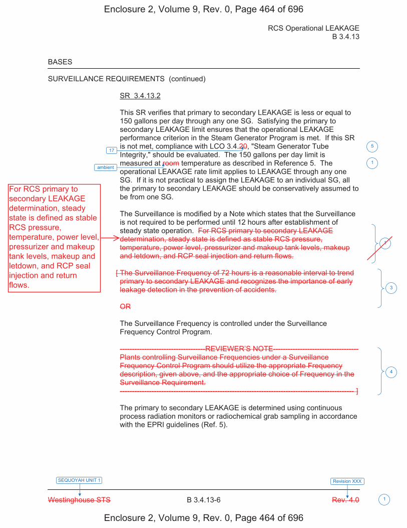
RCS Operational LEAKAGE B 3.4.13
Westinghouse STS B 3.4.13-6 Rev. 4.0
SEQUOYAH UNIT 1 Revision XXX
1
BASES SURVEILLANCE REQUIREMENTS (continued)
SR 3.4.13.2 This SR verifies that primary to secondary LEAKAGE is less or equal to 150 gallons per day through any one SG. Satisfying the primary to secondary LEAKAGE limit ensures that the operational LEAKAGE performance criterion in the Steam Generator Program is met. If this SR is not met, compliance with LCO 3.4.20, "Steam Generator Tube Integrity," should be evaluated. The 150 gallons per day limit is measured at room temperature as described in Reference 5. The operational LEAKAGE rate limit applies to LEAKAGE through any one SG. If it is not practical to assign the LEAKAGE to an individual SG, all the primary to secondary LEAKAGE should be conservatively assumed to be from one SG.
The Surveillance is modified by a Note which states that the Surveillance is not required to be performed until 12 hours after establishment of steady state operation. For RCS primary to secondary LEAKAGE determination, steady state is defined as stable RCS pressure, temperature, power level, pressurizer and makeup tank levels, makeup and letdown, and RCP seal injection and return flows.
[ The Surveillance Frequency of 72 hours is a reasonable interval to trend primary to secondary LEAKAGE and recognizes the importance of early leakage detection in the prevention of accidents. OR The Surveillance Frequency is controlled under the Surveillance Frequency Control Program. -----------------------------------REVIEWER’S NOTE----------------------------------- Plants controlling Surveillance Frequencies under a Surveillance Frequency Control Program should utilize the appropriate Frequency description, given above, and the appropriate choice of Frequency in the Surveillance Requirement. ------------------------------------------------------------------------------------------------ ] The primary to secondary LEAKAGE is determined using continuous process radiation monitors or radiochemical grab sampling in accordance with the EPRI guidelines (Ref. 5).
3
4
ambient 1
1
17 5
Enclosure 2, Volume 9, Rev. 0, Page 464 of 696
Enclosure 2, Volume 9, Rev. 0, Page 464 of 696
For RCS primary tosecondary LEAKAGEdetermination, steadystate is defined as stableRCS pressure,temperature, power level,pressurizer and makeuptank levels, makeup andletdown, and RCP sealinjection and returnflows.
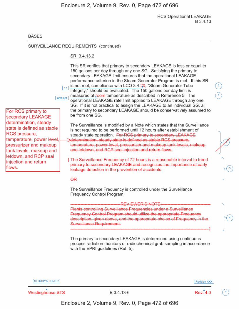
RCS Operational LEAKAGE B 3.4.13
Westinghouse STS B 3.4.13-6 Rev. 4.0
SEQUOYAH UNIT 2 Revision XXX
1
BASES SURVEILLANCE REQUIREMENTS (continued)
SR 3.4.13.2 This SR verifies that primary to secondary LEAKAGE is less or equal to 150 gallons per day through any one SG. Satisfying the primary to secondary LEAKAGE limit ensures that the operational LEAKAGE performance criterion in the Steam Generator Program is met. If this SR is not met, compliance with LCO 3.4.20, "Steam Generator Tube Integrity," should be evaluated. The 150 gallons per day limit is measured at room temperature as described in Reference 5. The operational LEAKAGE rate limit applies to LEAKAGE through any one SG. If it is not practical to assign the LEAKAGE to an individual SG, all the primary to secondary LEAKAGE should be conservatively assumed to be from one SG.
The Surveillance is modified by a Note which states that the Surveillance is not required to be performed until 12 hours after establishment of steady state operation. For RCS primary to secondary LEAKAGE determination, steady state is defined as stable RCS pressure, temperature, power level, pressurizer and makeup tank levels, makeup and letdown, and RCP seal injection and return flows.
[ The Surveillance Frequency of 72 hours is a reasonable interval to trend primary to secondary LEAKAGE and recognizes the importance of early leakage detection in the prevention of accidents. OR The Surveillance Frequency is controlled under the Surveillance Frequency Control Program. -----------------------------------REVIEWER’S NOTE----------------------------------- Plants controlling Surveillance Frequencies under a Surveillance Frequency Control Program should utilize the appropriate Frequency description, given above, and the appropriate choice of Frequency in the Surveillance Requirement. ------------------------------------------------------------------------------------------------ ] The primary to secondary LEAKAGE is determined using continuous process radiation monitors or radiochemical grab sampling in accordance with the EPRI guidelines (Ref. 5).
3
4
ambient 1
1
17 5
Enclosure 2, Volume 9, Rev. 0, Page 472 of 696
Enclosure 2, Volume 9, Rev. 0, Page 472 of 696
For RCS primary tosecondary LEAKAGEdetermination, steadystate is defined as stableRCS pressure,temperature, power level,pressurizer and makeuptank levels, makeup andletdown, and RCP sealinjection and returnflows.

Licensee Response/NRC Response/NRC Question ClosureId 283
NRC Question Number RPG-011
Select Application NRC Question Closure
Attachment 1
Attachment 2
Response Statement
Response Date/Time
Closure Statement This question is closed and no further information is required at this time to draft the Safety Evaluation.
Question Closure Date 8/21/2014
Notification Scott BowmanMichelle ConnerRobert ElliottRavinder GroverKhadijah HemphillAndrew HonLynn MynattRay SchieleRoger Scott
Added By Ravinder Grover
Date Added 8/21/2014 2:21 PM
Date Modified
Modified By
Page 1 of 1Sequoyah ITS Conversion Database
8/22/2014https://members.excelservices.com/rai/index.php?requestType=areaItemPrint&itemId=283
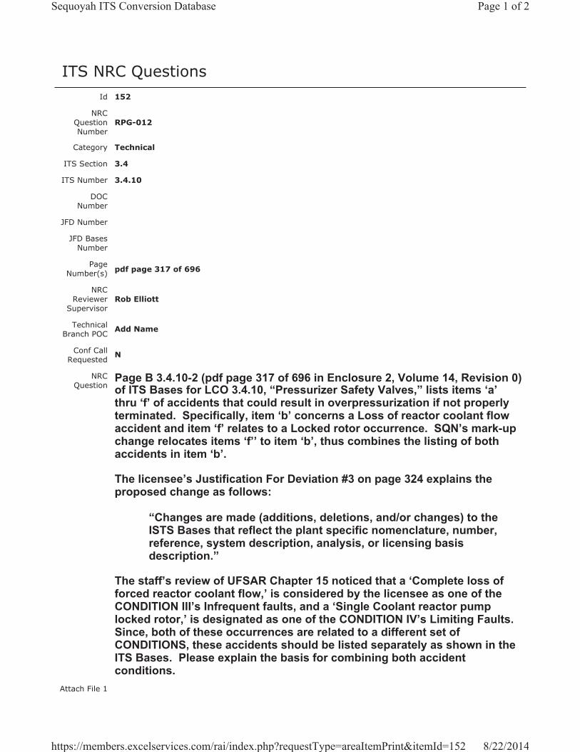
ITS NRC QuestionsId 152
NRC Question Number
RPG-012
Category Technical
ITS Section 3.4
ITS Number 3.4.10
DOC Number
JFD Number
JFD Bases Number
Page Number(s) pdf page 317 of 696
NRC Reviewer
Supervisor Rob Elliott
Technical Branch POC Add Name
Conf Call Requested N
NRC Question
Page B 3.4.10-2 (pdf page 317 of 696 in Enclosure 2, Volume 14, Revision 0) of ITS Bases for LCO 3.4.10, “Pressurizer Safety Valves,” lists items ‘a’thru ‘f’ of accidents that could result in overpressurization if not properly terminated. Specifically, item ‘b’ concerns a Loss of reactor coolant flow accident and item ‘f’ relates to a Locked rotor occurrence. SQN’s mark-up change relocates items ‘f’’ to item ‘b’, thus combines the listing of both accidents in item ‘b’.
The licensee’s Justification For Deviation #3 on page 324 explains the proposed change as follows:
“Changes are made (additions, deletions, and/or changes) to the ISTS Bases that reflect the plant specific nomenclature, number, reference, system description, analysis, or licensing basis description.”
The staff’s review of UFSAR Chapter 15 noticed that a ‘Complete loss of forced reactor coolant flow,’ is considered by the licensee as one of the CONDITION III’s Infrequent faults, and a ‘Single Coolant reactor pump locked rotor,’ is designated as one of the CONDITION IV’s Limiting Faults.Since, both of these occurrences are related to a different set of CONDITIONS, these accidents should be listed separately as shown in the ITS Bases. Please explain the basis for combining both accident conditions.
Attach File 1
Page 1 of 2Sequoyah ITS Conversion Database
8/22/2014https://members.excelservices.com/rai/index.php?requestType=areaItemPrint&itemId=152
Attach File 2
Issue Date 6/18/2014
Added By Ravinder Grover
Date Modified
Modified By
Date Added 6/18/2014 2:20 PM
Notification Scott BowmanMichelle ConnerRobert ElliottRavinder GroverKhadijah HemphillAndrew HonLynn MynattRay SchieleRoger Scott
Page 2 of 2Sequoyah ITS Conversion Database
8/22/2014https://members.excelservices.com/rai/index.php?requestType=areaItemPrint&itemId=152
Licensee Response/NRC Response/NRC Question ClosureId 199
NRC Question Number RPG-012
Select Application Licensee Response
Attachment 1 Atachment 1 - RAI RPG-012 Response.PDF (2MB)
Attachment 2
Response Statement
In response to RAI RPG-012, the ITS 3.4.10 Bases markup regarding the discussion of accidents that could result in overpressurization if not properly terminated, will be revised to reflect the standard wording for items a. through f. (pages 317 and 321 of Enclosure 2, Volume 9), as provided in NUREG-1431, Rev. 4.
See Attachment 1 for the draft ITS 3.4.10 Bases changes discussed above.Response
Date/Time 7/21/2014 1:00 PM
Closure Statement
Question Closure Date
Notification Scott BowmanMichelle ConnerRavinder GroverKhadijah HemphillAndrew HonRay Schiele
Added By Scott Bowman
Date Added 7/21/2014 11:58 AM
Date Modified
Modified By
Page 1 of 1Sequoyah ITS Conversion Database
8/22/2014https://members.excelservices.com/rai/index.php?requestType=areaItemPrint&itemId=199
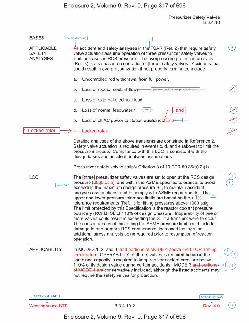
Pressurizer Safety Valves B 3.4.10
Westinghouse STS B 3.4.10-2 Rev. 4.0
SEQUOYAH UNIT 1 Amendment XXX
3
BASES APPLICABLE All accident and safety analyses in the FSAR (Ref. 2) that require safety SAFETY valve actuation assume operation of three pressurizer safety valves to ANALYSES limit increases in RCS pressure. The overpressure protection analysis
(Ref. 3) is also based on operation of [three] safety valves. Accidents that could result in overpressurization if not properly terminated include:
a. Uncontrolled rod withdrawal from full power, b. Loss of reactor coolant flow, c. Loss of external electrical load, d. Loss of normal feedwater, e. Loss of all AC power to station auxiliaries, and f. Locked rotor.
Detailed analyses of the above transients are contained in Reference 2. Safety valve actuation is required in events c, d, and e (above) to limit the pressure increase. Compliance with this LCO is consistent with the design bases and accident analyses assumptions. Pressurizer safety valves satisfy Criterion 3 of 10 CFR 50.36(c)(2)(ii).
LCO The [three] pressurizer safety valves are set to open at the RCS design
pressure (2500 psia), and within the ASME specified tolerance, to avoid exceeding the maximum design pressure SL, to maintain accident analyses assumptions, and to comply with ASME requirements. The upper and lower pressure tolerance limits are based on the ± 1% tolerance requirements (Ref. 1) for lifting pressures above 1000 psig. The limit protected by this Specification is the reactor coolant pressure boundary (RCPB) SL of 110% of design pressure. Inoperability of one or more valves could result in exceeding the SL if a transient were to occur. The consequences of exceeding the ASME pressure limit could include damage to one or more RCS components, increased leakage, or additional stress analysis being required prior to resumption of reactor operation.
APPLICABILITY In MODES 1, 2, and 3, and portions of MODE 4 above the LTOP arming
temperature, OPERABILITY of [three] valves is required because the combined capacity is required to keep reactor coolant pressure below 110% of its design value during certain accidents. MODE 3 and portions of MODE 4 are conservatively included, although the listed accidents may not require the safety valves for protection.
1
1
U
3
(reactor coolant pump locked rotor) 3
3
is
2
2
3
2485 psig 3
The most limiting
and
.
4
4
Enclosure 2, Volume 9, Rev. 0, Page 317 of 696
Enclosure 2, Volume 9, Rev. 0, Page 317 of 696
f. Locked rotor.
, and
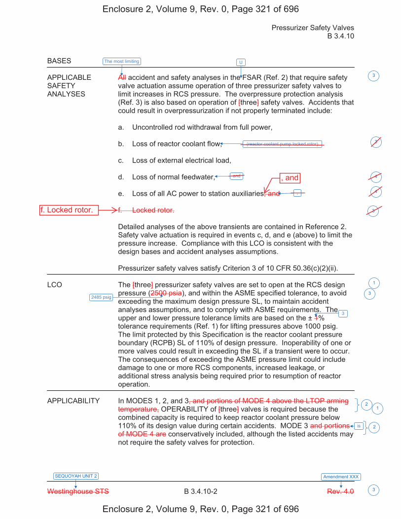
Pressurizer Safety Valves B 3.4.10
Westinghouse STS B 3.4.10-2 Rev. 4.0
SEQUOYAH UNIT 2 Amendment XXX
3
BASES APPLICABLE All accident and safety analyses in the FSAR (Ref. 2) that require safety SAFETY valve actuation assume operation of three pressurizer safety valves to ANALYSES limit increases in RCS pressure. The overpressure protection analysis
(Ref. 3) is also based on operation of [three] safety valves. Accidents that could result in overpressurization if not properly terminated include:
a. Uncontrolled rod withdrawal from full power, b. Loss of reactor coolant flow, c. Loss of external electrical load, d. Loss of normal feedwater, e. Loss of all AC power to station auxiliaries, and f. Locked rotor.
Detailed analyses of the above transients are contained in Reference 2. Safety valve actuation is required in events c, d, and e (above) to limit the pressure increase. Compliance with this LCO is consistent with the design bases and accident analyses assumptions. Pressurizer safety valves satisfy Criterion 3 of 10 CFR 50.36(c)(2)(ii).
LCO The [three] pressurizer safety valves are set to open at the RCS design
pressure (2500 psia), and within the ASME specified tolerance, to avoid exceeding the maximum design pressure SL, to maintain accident analyses assumptions, and to comply with ASME requirements. The upper and lower pressure tolerance limits are based on the ± 1% tolerance requirements (Ref. 1) for lifting pressures above 1000 psig. The limit protected by this Specification is the reactor coolant pressure boundary (RCPB) SL of 110% of design pressure. Inoperability of one or more valves could result in exceeding the SL if a transient were to occur. The consequences of exceeding the ASME pressure limit could include damage to one or more RCS components, increased leakage, or additional stress analysis being required prior to resumption of reactor operation.
APPLICABILITY In MODES 1, 2, and 3, and portions of MODE 4 above the LTOP arming
temperature, OPERABILITY of [three] valves is required because the combined capacity is required to keep reactor coolant pressure below 110% of its design value during certain accidents. MODE 3 and portions of MODE 4 are conservatively included, although the listed accidents may not require the safety valves for protection.
1
1
U
3
(reactor coolant pump locked rotor) 3
3
is
2
2
3
2485 psig 3
The most limiting
and
.
4
4
Enclosure 2, Volume 9, Rev. 0, Page 321 of 696
Enclosure 2, Volume 9, Rev. 0, Page 321 of 696
f. Locked rotor.
, and

Licensee Response/NRC Response/NRC Question ClosureId 285
NRC Question Number RPG-012
Select Application NRC Question Closure
Attachment 1
Attachment 2
Response Statement
Response Date/Time
Closure Statement This question is closed and no further information is required at this time to draft the Safety Evaluation.
Question Closure Date 8/21/2014
Notification Scott BowmanMichelle ConnerRobert ElliottRavinder GroverKhadijah HemphillAndrew HonLynn MynattRay SchieleRoger Scott
Added By Ravinder Grover
Date Added 8/21/2014 2:27 PM
Date Modified
Modified By
Page 1 of 1Sequoyah ITS Conversion Database
8/22/2014https://members.excelservices.com/rai/index.php?requestType=areaItemPrint&itemId=285
ITS NRC QuestionsId 168
NRC Question Number
RPG-013
Category Technical
ITS Section 3.4
ITS Number 3.4.16
DOC Number
JFD Number
JFD Bases Number
Page Number(s) Enclosure 2, Volume 9, Rev. 0 (several pages)
NRC Reviewer
Supervisor Rob Elliott
Technical Branch POC Mark Blumberg
Conf Call Requested N
NRC Question Question 1
In the subject license amendment request, the licensee proposed technical specification (TS) changes to revise LIMITING CONDITION FOR OPERATIONS (LCO) 3.4.16 (currently LCO 3.4.8), “RCS Specific Activity,”APPLICABILITY requirements to specify that the LCO is applicable in MODES 1, 2, 3, and 4. The proposed Bases entitled, “B 3.4.16 RCS Specific Activity,” states: “In MODES 1, 2, 3, and 4, operation within the LCO limits for DOSE EQUIVALENT I-131 (DEI) and DOSE EQUIAVALENT XE-133 (DEX) is necessary to limit the potential consequences of a SLB [Steam line break] or SGTR [steam generator tube rupture] to within the SRP [Standard Review Plan] acceptance criteria.” The licensee also proposed to revise SURVEILLANCE REQUIREMENT (SR) 3.4.16.1 and SR 3.4.16.2 to add the following NOTE, “Only required to be performed in MODE 1,” thus removing the APPLICABILITY of this SR to other MODES.
The NRC staff has a concern about the proposed addition of the NOTE to SR 3.4.16.1 and SR 3.4.16.2 and the proposed changes to the MODES ofAPPLICABILITY. The proposed change revises the conditions for sampling for SR 3.4.16.1 and SR 3.14.16.2, and may exclude sampling during the plant conditions where LCO 3.4.16 may be exceeded. After transient conditions (i.e. reactor trip, plant depressurization, shutdown or startup) that end in MODES 2, 3 or 4, the SR is not required to be performed.Isotopic spiking and fuel failures are more likely during transient conditions than during steady state plant operations.
Page 1 of 6Sequoyah ITS Conversion Database
03/18/2015https://members.excelservices.com/rai/index.php?requestType=areaItemPrint&itemId=168
Question 1a
Because LCO 3.4.16 could potentially be exceeded after plant transient or power changes, please justify why sampling is no longer needed in the plant MODES that are proposed to be eliminated and justify how the LCO3.4.16 remains consistent with the design bases analysis from which the LCO limits are derived (i.e. SLB, SGTR, etc.).
Page 2 of 6Sequoyah ITS Conversion Database
03/18/2015https://members.excelservices.com/rai/index.php?requestType=areaItemPrint&itemId=168
Question 1b
Please justify why there is an apparent disparity between the MODES of APPLICABILITY (MODES 1, 2, 3, and 4) and the limited mode (MODE 1) under which SR 3.4.16.1 and SR 3.14.16.2 are required.
Question 1c
Enclosure 2, Volume 9, Rev. 0 of the SQN, ITS Conversion, Section 3.4, “Reactor Coolant System (RCS)," (ADAMS Accession No. ML13330A928), page 606 states under the revision to the APPLICABILITY:
In MODES 5 and 6, the steam generators are not being used for decay heat removal, the RCS and steam generators are depressurized, and primary to secondary leakage is minimal. Therefore, the monitoring of RCS specific activity is not required.
The current TS 3.4.16 APPLICABILITY includes MODE 5.
The NRC staff is concerned that limiting the consideration of design basis accidents (DBAs) to only the SGTR and SLB has not been fully justified.Other accidents may be included in the licensing basis that uses the reactor coolant system (RCS) activity such as the small line break outside the containment or some anticipated operating occurrences. By limiting the review to only the SGTR and SLB, other accidents in the licensing basis (or previously not analyzed in the licensing basis because they were not limiting with the current LCO APPLICABILITY) do not appear to be considered by the proposed change.
For example, by only considering the SGTR and SLB, some Modes may no longer be considered in the APPLICABILITY for LCO 3.4.16. This may be equivalent to saying that in Mode 5, that any [emphasis added] DEI or DEXvalue would yield acceptable design basis accident doses. A justification for unlimited DEI and DEX in all possible MODES has not been provided.
Please justify why the LCO APPLICABILITY and SR should not consider MODE 5 accidents.
Question 2
Per the SQN Updated Final Safety Analysis Report (UFSAR), Appendix 15A, “Dose Models Used to Evaluate the Environmental Consequences of Accidents,” Section 15A.2, “Assumptions,” the dose conversion factors (DCFs) used for the dose models of postulated accidents, such as those provided in Section 15A.1 (SGTR, Main SLB [or SLB]), are provided in Table 15A-1. The DCFs in Table 15A-1, “Physical Data for Isotopes,” are taken from the Environmental Protection Agency (EPA), Federal Guidance Report Nos. 11 and 12.
Enclosure 2, Volume 3, Rev. 0 of the SQN, ITS Conversion, Chapter 1.0, Use and Application," (ADAMS Accession No. ML13329A790), page 26 provides
Page 3 of 6Sequoyah ITS Conversion Database
03/18/2015https://members.excelservices.com/rai/index.php?requestType=areaItemPrint&itemId=168
the proposed definition of DEI. Unlike the UFSAR analyses, DEI is derived using the DCFs from Technical Information Document [TID] -14844, Atomic Energy Commission (AEC), 1962, "Calculation of Distance Factors for Power and Test Reactor Sites.” The definition states:
DOSE EQUIVALENT I-131 shall be that concentration of I-131(microcuries per gram) that alone could produce the same thyroid dose when inhaled as the combined activities of iodine isotopes I-131, I-132, I-133, I-134, and I-135 actually present. The determination of DOSE EQUIVALENT I-131 shall be performed using thyroid dose conversion factors from Table III of TID-14844, AEC, 1962, "Calculation of Distance Factors for Power and Test Reactor Sites.”
The definition of DEX in Enclosure 2 uses the effective DCF for air submersion listed in Table III.1 of EPA, Federal Guidance Report No. 12, "External Exposure to Radionuclides in Air, Water, and Soil."
The purpose of the LCO for DEI and DEX is to satisfy Title 10 of the Code of Federal Regulations (10 CFR) Section 50.36, criterion 2, which establishes an operating restriction that is an initial condition of a design basis accident (DBA). When a surveillance of the reactor coolant system radionuclides is performed, each acceptable set of DCFs will yield a different DEI and DEX. As approved by the NRC staff, the intent of TSTF-490 was to allow the licensee to select, from the acceptable list, one DCF reference for the calculation of DEI, and one DCF reference for the calculation of DEX.
Question 2a
Please confirm that the site-specific limits for both DEI and DEX, and the DCFs used for the determination of DEI and DEX surveillances, are consistent with the SQN current design-basis radiological dose consequence analyses (i.e. SGTR, SLB, letdown line break, etc.) or justify why the use of different DCFs in the “dose equivalent” TS definitions from those in the DBA analyses yield conservative RCS radioisotopic concentrations and offsite consequence analyses for compliance with 10 CFR 100.
Question 2b
Please provide the information necessary (DCFs and RCS radioisotopic concentrations) for the NRC staff to verify the proposed value of 1612.6 μCi/gm (micro Curies per gram) in the surveillance requirement for DEX.
Question 3
The proposed change deletes the CONDITION requiring gross specific activity of the coolant less than or equal to 100/Ç μCi/gm and proposes to replace it with DEX not within limits. In the current LCO 3.4.16, when the gross specific activity of the coolant is greater than 100/Ç μCi/gm, the
Page 4 of 6Sequoyah ITS Conversion Database
03/18/2015https://members.excelservices.com/rai/index.php?requestType=areaItemPrint&itemId=168
REQUIRED ACTION is to take immediate action to begin shutdown of the reactor (be in HOT STANDBY with Tavg less than 500 °F within 6 hours [emphasis added]). SQN proposes 48 hours [emphasis added] to restore DEX within limits. TSTF-490, Revision 0 provided the following justification for this change:
The Completion Time for revised TS 3.4.16 Required Action B.1 will require restoration of Dose Equivalent Xe-133 to within limit in 48 hours. This is consistent with the Completion Time for current Required Action
A.2 for Dose Equivalent I-131. The Completion Time of 48 hours for revised Required Action B.1 is acceptable since it is expected that, if there were a noble gas spike, the normal coolant noble gas concentration would be restored within this time period. Also, there is a low probability of an accident occurring during this time period.
For the following reasons the staff needs additional justification for the proposed change:
While it is a correct statement that the proposed change makes the COMPLETION TIMEs of REQUIRED ACTION A.2 and B.1 consistent it is not clear to the NRC staff why the COMPLETION TIMEs should be consistent.The plant CONDITIONs for these REQUIRED ACTIONs are different.REQUIRED ACTION A.2 is required when the plant is in a CONDITION analyzed in the design basis accident analyses (RCS DEI is between 1 and 60 μCi/gm). Action B.1 is required when the plant is in a CONDITION not analyzed [emphasis added] in the design basis accident analyses (DEX is greater than 1612.61 μCi/gm). Typically, the REQUIRED ACTION for a CONDITION not analyzed requires the plant to take immediate actions to begin shutdown of the plant. The proposed change does not take immediate actions to begin shutdown of the plant, but allows 48 hours before the plant is required to begin shutting down.
Therefore, please provide additional justification for the proposed change to increase the COMPLETION TIME of REQUIRED ACTION B.1 to 48 hours and why it is acceptable to be in an unanalyzed CONDITION for 48 hours consistent with CONDITION A which is an analyzed CONDITION in the DBA analyses
Typo
Enclosure 2, Volume 9, Rev. 0, page 611, Insert 6 appears to have a typo.DOS EQUIVALENT should be DOSE EQUIVALENT.
Attach File 1
Attach File 2
Issue Date 6/23/2014
Page 5 of 6Sequoyah ITS Conversion Database
03/18/2015https://members.excelservices.com/rai/index.php?requestType=areaItemPrint&itemId=168
Added By Ravinder Grover
Date Modified
Modified By
Date Added 6/23/2014 8:55 AM
Notification Scott BowmanMichelle ConnerRobert ElliottRavinder GroverKhadijah HemphillAndrew HonLynn MynattRay SchieleRoger Scott
Page 6 of 6Sequoyah ITS Conversion Database
03/18/2015https://members.excelservices.com/rai/index.php?requestType=areaItemPrint&itemId=168
Licensee Response/NRC Response/NRC Question ClosureId 328
NRC Question Number
RPG-013
Select Application Licensee Response
Attachment 1 RAI RPG-013 Attachment 1 Posted Response.pdf (36KB)
Attachment 2 RAI RPG-013 Attachment 2 Posted Response.pdf (2MB)
Response Statement Attachment 1 contains the responses to Questions 1a, 1b, 1c, 2a, 2b, and 3
concerning RPG-013. Attachment 2 contains the revised CTS and ISTS markups, revised DOCs M01 and L01, and the addition of JFDs 4 and 6.
Changes to the ITS submittal associated with the response to RPG-013 are discussed below:
1. The ITS definition for DOSE EQUIVALENT XE-133 in ITS Section 1.1 will be revised to be consistent with the proposed definition in the CTS markups. Specifically, the phrase, “or the average gamma disintegration energies as provided in ICRP Publication 38, ‘Radionuclide Transformations or similar source,’ will be deleted. SQN uses the effective dose conversion factors for air submersion listed in Table III.1 of EPA Federal Guidance Report No. 12, 1993, “External Exposure to Radionuclides in Air, Water, and Soil” to determine DOSE EQUIVALENT XE-133. A Justification for deviation (JFD) 2 indicator will be added to the ITS markups associated with this change. (Pages 57 and 87 of Enclosure 2, Volume 3)
2. The CTS markups will be revised to indicate the deletion of proposed ITS 3.4.16 Condition B and the re-sequencing of Condition C to Condition B. The ITS cross references will be revised to align with changes made to ITS 3.4.16. (Pages 578 and 582 of Enclosure 2, Volume 9)
3. Discussion of changes (DOCs) M01 and L01 will be revised to align with the deletion of proposed ITS 3.4.16 Condition B and the re-sequencing of Condition C to Condition B. Additionally, DOC L01 will be revised to align with the proposed revision of ITS SR 3.4.16.1 Note. See No. 5 below concerning the revision to the Note. (Pages 587, 588 and 589 of Enclosure 2, Volume 9)
4. The ISTS markups will be revised to reflect the deletion of ITS 3.4.16 Condition B. ITS 3.4.16 Condition C will be re-sequenced as Condition B and revised to state, “Required Action and associated Completion Time of Condition A not met. OR DOSE EQUIVALENT I-131 > 21 μCi/gm.
Page 1 of 3Sequoyah ITS Conversion Database
03/18/2015https://members.excelservices.com/rai/index.php?requestType=areaItemPrint&itemId=328
OR DOSE EQUIVALENT XE-133 not within limit.” Justification for deviation (JFD) 4 indicators will be added to the ISTS markups associated with these changes. (Pages 591, 592, 596, and 597 of Enclosure 2, Volume 9)
5. The ISTS markups will be revised for ITS SR 3.4.16.1 Note and ITS SR 3.4.16.2 Note. Specifically, ITS SR 3.4.16.1 Note will be revised to state, “Only required to be performed in MODES 1, 2, and 3 with Tavg500ºF.” ITS SR 3.4.16.2 Note will be deleted. JFD 4 indicators will be added to the ISTS markups associated with these changes. (Pages 592, 593, 597, and 598)
6. JFD 4 will be added to the ITS 3.4.16 Justification for Deviations Section. JFD 4 will state, “Changes are made to ISTS 3.4.16 as a result of discussions between NRC staff and TVA during a public meeting held on August 12, 2014. ISTS 3.4.16 Condition B is deleted, ISTS 3.4.16 Condition C is re-sequenced to Condition B and revised to include a third Condition of ‘OR DOSE EQUIVALENT XE-133 not within limit,’ and ISTS SR 3.4.16.2 Note associated with DEI is deleted. Additionally, TSTF-490 proposed adding a Note to ISTS SR 3.4.16.1, ‘Only required to be performed in MODE 1.’ This Note is revised to state, ‘Only required to be performed in MODES 1, 2, and 3 with Tavg 500ºF.’" (Page 601 of Enclosure 2, Volume 9)
7. ITS 3.4.16 Bases Actions Section Insert 4 will be deleted. Insert 4 is associated with the originally proposed ITS 3.4.16 Condition B that is now being deleted. ITS 3.4.16 Bases Actions C.1 and C.2 will be re-sequenced to Actions B.1 and B.2 and revised to reflect the changes discussed in No. 4, above. JFD 6 indicators will be added to the markups associated with these changes. (Pages 610, 611, 623, and 624 of Enclosure 2, Volume 9)
8. ITS 3.4.16 Bases Surveillance Requirement Section Insert 6 for SR 3.4.16.1 will be revised to state, “A Note modifies the SR to only require the surveillance to be performed in MODES 1, 2, and 3 with Tavg 500ºF.” JFD 6 indicators will be added to the markups associated with this change. Additionally, the typographical error (DOS changed to DOSE) in Insert 6 will be corrected. (Pages 610, 611, 623, and 624 of Enclosure 2, Volume 9)
9. ITS 3.4.16 Bases Surveillance Requirement Section Insert 7 for SR 3.4.16.2 will be deleted. This deletion reflects proposed changes to ITS SR 3.4.16.2 discussed in No. 5, above. (Pages 612, 613, 625, and 626 of Enclosure 2, Volume 9)
10. JFD 6 will be added to the ITS 3.4.16 Bases Justification for Deviations Section. JFD 6 will state, “Changes are made to be consistent with changes made to the Specification.” (Page 629)
Response Date/Time 9/9/2014 4:35 PM
Page 2 of 3Sequoyah ITS Conversion Database
03/18/2015https://members.excelservices.com/rai/index.php?requestType=areaItemPrint&itemId=328
Closure Statement
Question Closure
Date
Notification Mark BlumbergScott BowmanMichelle ConnerRobert ElliottRavinder GroverKhadijah HemphillAndrew HonLynn MynattRay SchieleRoger Scott
Added By Lynn Mynatt
Date Added 9/9/2014 3:34 PM
Date Modified
Modified By
Page 3 of 3Sequoyah ITS Conversion Database
03/18/2015https://members.excelservices.com/rai/index.php?requestType=areaItemPrint&itemId=328
Attachment 1 to RPG-013
Question 1a Response: The proposed changes to ITS LCO 3.4.16 remain consistent with the design basis analysis from which the LCO limits are derived (i.e., SLB and SGTR). The SQN design basis SGTR and SLB analyses are based on power operating (MODE 1) conditions and assume RCS activity at TS limits (please refer to the response to question 2a). Therefore, these design basis analyses are bounding for the lower modes of operation. In addition, TVA is proposing to revise the Notes modifying ITS SR 3.4.16.1 and ITS SR 3.4.16.2 (please refer to the response to question 1b). Question 1b Response: In response to RAI RPG-013, Question 1b, TVA proposes to delete the ITS SR 3.4.16.2 Note associated with DEI. Sampling for DEI does not require a pressurized sample to maintain gases in solution. Therefore, the requirement to verify DEI within limits will be required to be performed in MODES 1, 2, 3, and 4. The proposed SR 3.4.16.1 Note restricting the sampling of DEX to MODES 1, 2, and 3 with RCS average temperature 500°F is needed since RCS pressure outside these modes may be insufficient to ensure collection of a representative, homogeneous sample for analysis of gaseous isotopes. Restricting the surveillance to MODES 1, 2, and 3 with Tavg 500°F ensures the necessary plant conditions have been established to produce sufficient pressure and sample flow. Therefore, TVA proposes to change the ITS SR 3.4.16.1 Note associated with DEX to state "Only required to be performed in MODES 1, 2, and 3 with Reactor Coolant System (RCS) average temperature (Tavg These changes reduce the apparent disparity between the LCO MODES of Applicability and MODES under which the surveillance requirements are required. These changes are a conservative and more restrictive deviation from TSTF-490, Revision 0. The deletion of SR 3.4.16.2 Note for DEI provides continued assessment of RCS activity for all Modes of Applicability. Given that iodine is the dominant contributor in the SQN Steam Generator Tube Rupture (SGTR) and Steam Line Break (SLB) dose analysis and that TVA is proposing to sample DEI in MODE 1 through MODE 4, the small disparity between the MODES of Applicability and the MODES that require sampling under SR 3.4.16.1 for DEX is acceptable. Question 1c Response: The revised LCO is applicable in MODES 1 through 4 to limit the potential radiological consequences of an SLB or SGTR that could occur during these Modes. In MODE 5 with the RCS loops filled, the steam generators are specified as a backup means of decay heat removal via natural circulation. In this Mode however, due to the reduced temperature of the RCS, the probability of a DBA involving the release of significant quantities of RCS inventory is greatly reduced. Therefore, monitoring of RCS specific activity is not required. In Mode 5 with the RCS loops not filled and in Mode 6, the steam generators are not used for decay heat removal, the RCS and steam generators are depressurized, and primary-to-secondary leakage is minimal. Therefore, the monitoring of RCS specific activity is not required. Question 2a Response: The Steam Generator Tube Rupture, Main Steam Line Break, and Loss of AC Power all utilize the RCS activity as a source term and scale it to the maximum allowed per Technical Specifications. The Dose Conversion Factors (DCFs) used to determine the Xe-133 equivalence were the Effective
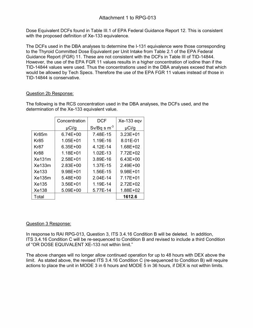
Attachment 1 to RPG-013
Dose Equivalent DCFs found in Table III.1 of EPA Federal Guidance Report 12. This is consistent with the proposed definition of Xe-133 equivalence. The DCFs used in the DBA analyses to determine the I-131 equivalence were those corresponding to the Thyroid Committed Dose Equivalent per Unit Intake from Table 2.1 of the EPA Federal Guidance Report (FGR) 11. These are not consistent with the DCFs in Table III of TID-14844. However, the use of the EPA FGR 11 values results in a higher concentration of iodine than if the TID-14844 values were used. Thus the concentrations used in the DBA analyses exceed that which would be allowed by Tech Specs. Therefore the use of the EPA FGR 11 values instead of those in TID-14844 is conservative. Question 2b Response: The following is the RCS concentration used in the DBA analyses, the DCFs used, and the determination of the Xe-133 equivalent value.
Concentration DCF Xe-133 eqv Sv/Bq s m-3
Kr85m 6.74E+00 7.48E-15 3.23E+01 Kr85 1.05E+01 1.19E-16 8.01E-01 Kr87 6.35E+00 4.12E-14 1.68E+02 Kr88 1.18E+01 1.02E-13 7.72E+02 Xe131m 2.58E+01 3.89E-16 6.43E+00 Xe133m 2.83E+00 1.37E-15 2.49E+00 Xe133 9.98E+01 1.56E-15 9.98E+01 Xe135m 5.48E+00 2.04E-14 7.17E+01 Xe135 3.56E+01 1.19E-14 2.72E+02 Xe138 5.09E+00 5.77E-14 1.88E+02 Total 1612.6
Question 3 Response: In response to RAI RPG-013, Question 3, ITS 3.4.16 Condition B will be deleted. In addition, ITS 3.4.16 Condition C will be re-sequenced to Condition B and revised to include a third Condition of “OR DOSE EQUIVALENT XE-133 not within limit.” The above changes will no longer allow continued operation for up to 48 hours with DEX above the limit. As stated above, the revised ITS 3.4.16 Condition C (re-sequenced to Condition B) will require actions to place the unit in MODE 3 in 6 hours and MODE 5 in 36 hours, if DEX is not within limits.
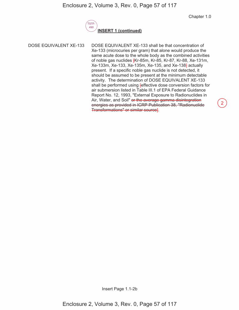
Chapter 1.0
Insert Page 1.1-2b
INSERT 1 (continued) DOSE EQUIVALENT XE-133 DOSE EQUIVALENT XE-133 shall be that concentration of
Xe-133 (microcuries per gram) that alone would produce the same acute dose to the whole body as the combined activities of noble gas nuclides [Kr-85m, Kr-85, Kr-87, Kr-88, Xe-131m, Xe-133m, Xe-133, Xe-135m, Xe-135, and Xe-138] actually present. If a specific noble gas nuclide is not detected, it should be assumed to be present at the minimum detectable activity. The determination of DOSE EQUIVALENT XE-133 shall be performed using [effective dose conversion factors for air submersion listed in Table III.1 of EPA Federal Guidance Report No. 12, 1993, "External Exposure to Radionuclides in Air, Water, and Soil" or the average gamma disintegration energies as provided in ICRP Publication 38, "Radionuclide Transformations" or similar source].
TSTF-490
Enclosure 2, Volume 3, Rev. 0, Page 57 of 117
Enclosure 2, Volume 3, Rev. 0, Page 57 of 117
2
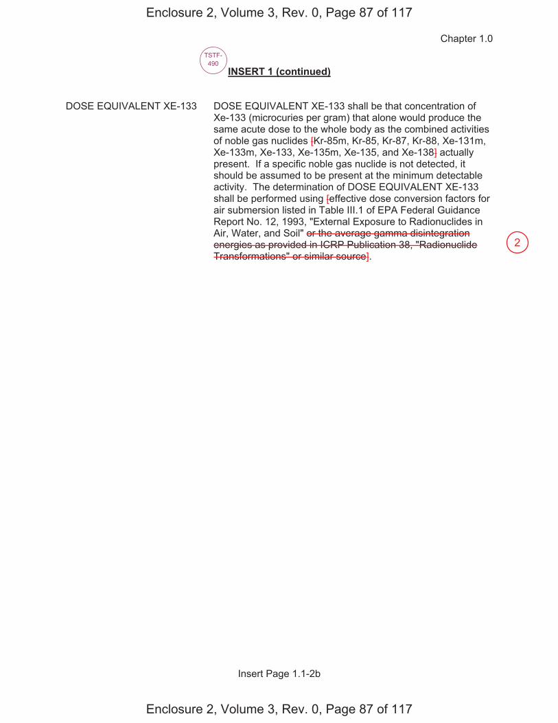
Chapter 1.0
Insert Page 1.1-2b
INSERT 1 (continued) DOSE EQUIVALENT XE-133 DOSE EQUIVALENT XE-133 shall be that concentration of
Xe-133 (microcuries per gram) that alone would produce the same acute dose to the whole body as the combined activities of noble gas nuclides [Kr-85m, Kr-85, Kr-87, Kr-88, Xe-131m, Xe-133m, Xe-133, Xe-135m, Xe-135, and Xe-138] actually present. If a specific noble gas nuclide is not detected, it should be assumed to be present at the minimum detectable activity. The determination of DOSE EQUIVALENT XE-133 shall be performed using [effective dose conversion factors for air submersion listed in Table III.1 of EPA Federal Guidance Report No. 12, 1993, "External Exposure to Radionuclides in Air, Water, and Soil" or the average gamma disintegration energies as provided in ICRP Publication 38, "Radionuclide Transformations" or similar source].
TSTF-490
Enclosure 2, Volume 3, Rev. 0, Page 87 of 117
Enclosure 2, Volume 3, Rev. 0, Page 87 of 117
2
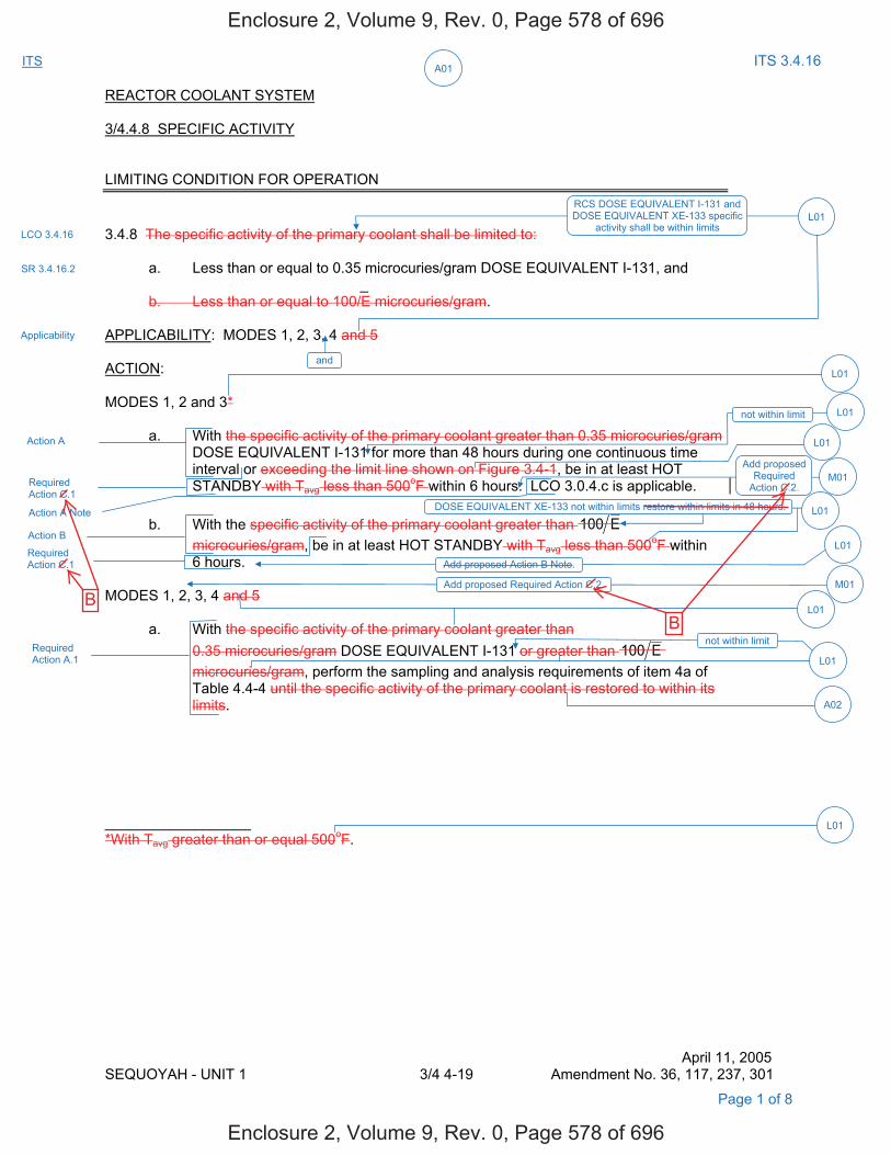
A01ITS ITS 3.4.16
REACTOR COOLANT SYSTEM 3/4.4.8 SPECIFIC ACTIVITY LIMITING CONDITION FOR OPERATION 3.4.8 The specific activity of the primary coolant shall be limited to: a. Less than or equal to 0.35 microcuries/gram DOSE EQUIVALENT I-131, and _ b. Less than or equal to 100/E microcuries/gram. APPLICABILITY: MODES 1, 2, 3, 4 and 5 ACTION: MODES 1, 2 and 3* a. With the specific activity of the primary coolant greater than 0.35 microcuries/gram
DOSE EQUIVALENT I-131 for more than 48 hours during one continuous time interval or exceeding the limit line shown on Figure 3.4-1, be in at least HOT
STANDBY with Tavg less than 500oF within 6 hours. LCO 3.0.4.c is applicable. b. With the specific activity of the primary coolant greater than 100 E
microcuries/gram, be in at least HOT STANDBY with Tavg less than 500oF within 6 hours.
MODES 1, 2, 3, 4 and 5 a. With the specific activity of the primary coolant greater than 0.35 microcuries/gram DOSE EQUIVALENT I-131 or greater than 100 E
microcuries/gram, perform the sampling and analysis requirements of item 4a of Table 4.4-4 until the specific activity of the primary coolant is restored to within its limits.
__________________ *With Tavg greater than or equal 500oF.
April 11, 2005 SEQUOYAH - UNIT 1 3/4 4-19 Amendment No. 36, 117, 237, 301
LCO 3.4.16
RCS DOSE EQUIVALENT I-131 and DOSE EQUIVALENT XE-133 specific
activity shall be within limits
Applicability
and
L01
M01
Required Action C.1
Add proposed Required Action C.2.
Action A
Required Action C.1
Action B
Add proposed Required
Action C.2.
Required Action A.1
Action A Note
L01
L01
A02
L01
L01
not within limit L01
not within limit
L01
Page 1 of 8
M01
SR 3.4.16.2
L01
DOSE EQUIVALENT XE-133 not within limits restore within limits in 48 hours.
Add proposed Action B Note.
L01
Enclosure 2, Volume 9, Rev. 0, Page 578 of 696
Enclosure 2, Volume 9, Rev. 0, Page 578 of 696
BB
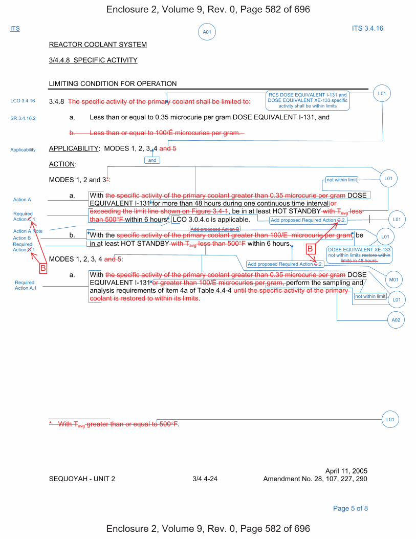
A01ITS ITS 3.4.16
REACTOR COOLANT SYSTEM 3/4.4.8 SPECIFIC ACTIVITY LIMITING CONDITION FOR OPERATION 3.4.8 The specific activity of the primary coolant shall be limited to: a. Less than or equal to 0.35 microcurie per gram DOSE EQUIVALENT I-131, and b. Less than or equal to 100/ microcuries per gram. APPLICABILITY: MODES 1, 2, 3, 4 and 5 ACTION: MODES 1, 2 and 3*: a. With the specific activity of the primary coolant greater than 0.35 microcurie per gram DOSE
EQUIVALENT I-131 for more than 48 hours during one continuous time interval or exceeding the limit line shown on Figure 3.4-1, be in at least HOT STANDBY with Tavg less
than 500°F within 6 hours. LCO 3.0.4.c is applicable. b. With the specific activity of the primary coolant greater than 100/E microcurie per gram, be
in at least HOT STANDBY with Tavg less than 500°F within 6 hours. MODES 1, 2, 3, 4 and 5: a. With the specific activity of the primary coolant greater than 0.35 microcurie per gram DOSE
EQUIVALENT I-131 or greater than 100/ microcuries per gram, perform the sampling and analysis requirements of item 4a of Table 4.4-4 until the specific activity of the primary coolant is restored to within its limits.
* With Tavg greater than or equal to 500°F.
April 11, 2005 SEQUOYAH - UNIT 2 3/4 4-24 Amendment No. 28, 107, 227, 290
LCO 3.4.16
Applicability
and
RCS DOSE EQUIVALENT I-131 and DOSE EQUIVALENT XE-133 specific
activity shall be within limits
L01
not within limit
Add proposed Required Action C.2. L01
Action A
Required Action C.1
Action A Note Add proposed Action B
DOSE EQUIVALENT XE-133 not within limits restore within
limits in 48 hours.
L01
Add proposed Required Action C.2.
Action B Required Action C.1
M01
not within limitL01
A02
L01
L01
Required Action A.1
Page 5 of 8
SR 3.4.16.2
Enclosure 2, Volume 9, Rev. 0, Page 582 of 696
Enclosure 2, Volume 9, Rev. 0, Page 582 of 696
B
B
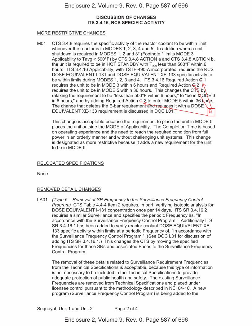
DISCUSSION OF CHANGES ITS 3.4.16, RCS SPECIFIC ACTIVITY
Sequoyah Unit 1 and Unit 2 Page 2 of 4
MORE RESTRICTIVE CHANGES M01 CTS 3.4.8 requires the specific activity of the reactor coolant to be within limit
whenever the reactor is in MODES 1, 2, 3, 4 and 5. In addition when a unit shutdown is required in MODES 1, 2 and 3* (Footnote * limits MODE 3 Applicability to Tavg 500°F) by CTS 3.4.8 ACTION a and CTS 3.4.8 ACTION b, the unit is required to be in HOT STANDBY with Tavg less than 500°F within 6 hours. ITS 3.4.16 Applicability, with TSTF-490-A incorporated, requires the RCS DOSE EQUIVALENT I-131 and DOSE EQUIVALENT XE-133 specific activity to be within limits during MODES 1, 2, 3 and 4. ITS 3.4.16 Required Action C.1 requires the unit to be in MODE 3 within 6 hours and Required Action C.2 requires the unit to be in MODE 5 within 36 hours. This changes the CTS by relaxing the requirement to be "less than 500°F within 6 hours," to "be in MODE 3 in 6 hours," and by adding Required Action C.2 to enter MODE 5 within 36 hours. The change that deletes the E-bar requirement and replaces it with a DOSE EQUIVALENT XE-133 requirement is discussed in DOC L01.
This change is acceptable because the requirement to place the unit in MODE 5
places the unit outside the MODE of Applicability. The Completion Time is based on operating experience and the need to reach the required condition from full power in an orderly manner and without challenging unit systems. This change is designated as more restrictive because it adds a new requirement for the unit to be in MODE 5.
RELOCATED SPECIFICATIONS None REMOVED DETAIL CHANGES LA01 (Type 5 – Removal of SR Frequency to the Surveillance Frequency Control
Program) CTS Table 4.4-4 Item 2 requires, in part, verifying isotopic analysis for DOSE EQUIVALENT I-131 concentration once per 14 days. ITS SR 3.4.16.2 requires a similar Surveillance and specifies the periodic Frequency as, "In accordance with the Surveillance Frequency Control Program." Additionally ITS SR 3.4.16.1 has been added to verify reactor coolant DOSE EQUIVALENT XE-133 specific activity within limits at a periodic Frequency of, "In accordance with the Surveillance Frequency Control Program." (See DOC L01 for discussion of adding ITS SR 3.4.16.1.) This changes the CTS by moving the specified Frequencies for these SRs and associated Bases to the Surveillance Frequency Control Program.
The removal of these details related to Surveillance Requirement Frequencies from the Technical Specifications is acceptable, because this type of information is not necessary to be included in the Technical Specifications to provide adequate protection of public health and safety. The existing Surveillance Frequencies are removed from Technical Specifications and placed under licensee control pursuant to the methodology described in NEI 04-10. A new program (Surveillance Frequency Control Program) is being added to the
Enclosure 2, Volume 9, Rev. 0, Page 587 of 696
Enclosure 2, Volume 9, Rev. 0, Page 587 of 696
B
DISCUSSION OF CHANGES ITS 3.4.16, RCS SPECIFIC ACTIVITY
Sequoyah Unit 1 and Unit 2 Page 3 of 4
Administrative Controls section of the Technical Specifications describing the control of Surveillance Frequencies. The surveillance test requirements remain in the Technical Specifications. The control of changes to the Surveillance Frequencies will be in accordance with the Surveillance Frequency Control Program. The Program shall ensure that Surveillance Requirements specified in the Technical Specifications are performed at intervals sufficient to assure the associated Limiting Conditions for Operation are met. This change is designated as a less restrictive removal of detail change, because the Surveillance Frequencies are being removed from the Technical Specifications.
LA02 (Type 3 – Removing Procedural Details for Meeting TS Requirements or
Reporting Requirements) CTS Table 4.4-4 Item 2 requires an isotopic analysis to determine whether DOSE EQUIVALENT I-131 concentration is within limit. CTS Table 4.4-4 Item 4 requires an isotopic analysis for iodine including I-131, I-133, and I-135. ITS SR 3.4.16.2 requires the verification that the reactor coolant DOSE EQUIVALENT I-131 specific activity is within limit. ITS 3.4.16 Required Action A.1 requires the verification that DOSE EQUIVALENT I-131 is 21.0 μCi/gm. This changes the CTS by moving the detail that an Isotopic Analysis or Isotopic Analysis for Iodine including I-131, I-133, and I-135 must be performed to satisfy the requirements of the Surveillance and Action to the ITS Bases.
The removal of these details for performing Surveillance Requirements from the Technical Specifications is acceptable because the type of information is not necessary to be included in the Technical Specifications to provide adequate protection to public health and safety. ITS SR 3.4.16.2 and ITS 3.4.16 Required Action A.1 still retain the requirements to verify the reactor coolant DOSE EQUIVALENT I-131 is within limit. Also, this change is acceptable because these types of procedural details will be adequately controlled in the ITS Bases. Changes to the Bases are controlled by the Technical Specification Bases Control Program in Chapter 5. This program provides for the evaluation of changes to ensure the Bases are properly controlled. This change is designated as a less restrictive removal of detail change because procedural details for meeting Technical Specification requirements are being removed from the Technical Specifications.
LESS RESTRICTIVE CHANGES L01 (Category 1 – Relaxation of LCO Requirements) CTS 3.4.8 requires the specific
activity of the primary coolant to be less than or equal to 100/ μCi/gram. CTS 3.4.8 ACTION b states that if the limit is not met, then the unit must be shut down to HOT STANDBY with Tavg less than 500°F within 6 hours – no restoration time prior to the shutdown is provided. Furthermore, if the limit is not met, ACTION a (MODES 1, 2, 3, 4 and 5) requires the sample and analysis requirements of Table TS 4.4-4, item 4.a (an isotopic analysis for iodine), to be performed every 4 hours. Table 4.4-4 Item 3, requires a "Radiochemical for E bar Determination" analysis performed every 6 months with a Footnote limitation (Footnote *) that a minimum of 2 EFPD and 20 days of POWER OPERATION have elapsed since the reactor was last subcritical for 48 hours or longer prior to performance of the analysis. ITS 3.4.16 does not include any requirements related to . ITS LCO 3.4.16 requires the DOSE EQUIVALENT XE-133 limit to be met. SR 3.4.16.1
Enclosure 2, Volume 9, Rev. 0, Page 588 of 696
Enclosure 2, Volume 9, Rev. 0, Page 588 of 696
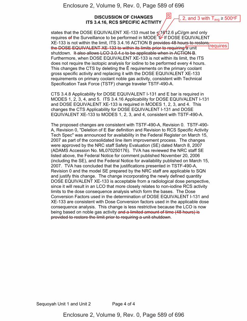
DISCUSSION OF CHANGES ITS 3.4.16, RCS SPECIFIC ACTIVITY
Sequoyah Unit 1 and Unit 2 Page 4 of 4
states that the DOSE EQUIVALENT XE-133 must be < 1612.6 μCi/gm and only requires of the Surveillance to be performed in MODE 1. If DOSE EQUIVALENT XE-133 is not within the limit, ITS 3.4.16 ACTION B provides 48 hours to restore the DOSE EQUIVALENT XE-133 to within its limits prior to requiring a unit shutdown. It also allows LCO 3.0.4.c to be applicable when in ACTION B. Furthermore, when DOSE EQUIVALENT XE-133 is not within its limit, the ITS does not require the isotopic analysis for iodine to be performed every 4 hours. This changes the CTS by deleting the requirements on the primary coolant gross specific activity and replacing it with the DOSE EQUIVALENT XE-133 requirements on primary coolant noble gas activity, consistent with Technical Specification Task Force (TSTF) change traveler TSTF-490-A.
CTS 3.4.8 Applicability for DOSE EQUIVALENT I-131 and E bar is required in
MODES 1, 2, 3, 4, and 5. ITS 3.4.16 Applicability for DOSE EQUIVALENT I-131 and DOSE EQUIVALENT XE-133 is required in MODES 1, 2, 3, and 4. This changes the CTS Applicability for DOSE EQUIVALENT I-131 and DOSE EQUIVALENT XE-133 to MODES 1, 2, 3, and 4, consistent with TSTF-490-A.
The proposed changes are consistent with TSTF-490-A, Revision 0. TSTF-490-
A, Revision 0, "Deletion of E Bar definition and Revision to RCS Specific Activity Tech Spec" was announced for availability in the Federal Register on March 15, 2007 as part of the consolidated line item improvement process. The changes were approved by the NRC staff Safety Evaluation (SE) dated March 8, 2007 (ADAMS Accession No. ML070250176). TVA has reviewed the NRC staff SE listed above, the Federal Notice for comment published November 20, 2006 (including the SE), and the Federal Notice for availability published on March 15, 2007. TVA has concluded that the justifications presented in TSTF-490-A, Revision 0 and the model SE prepared by the NRC staff are applicable to SQN and justify this change. The change incorporating the newly defined quantity DOSE EQUIVALENT XE-133 is acceptable from a radiological dose perspective, since it will result in an LCO that more closely relates to non-iodine RCS activity limits to the dose consequence analysis which form the bases. The Dose Conversion Factors used in the determination of DOSE EQUIVALENT I-131 and XE-133 are consistent with Dose Conversion factors used in the applicable dose consequence analysis. This change is less restrictive because the LCO is now being based on noble gas activity and a limited amount of time (48 hours) is provided to restore the limit prior to requiring a unit shutdown.
Enclosure 2, Volume 9, Rev. 0, Page 589 of 696
Enclosure 2, Volume 9, Rev. 0, Page 589 of 696
, 2, and 3 with Tavg 500oF
requires
S
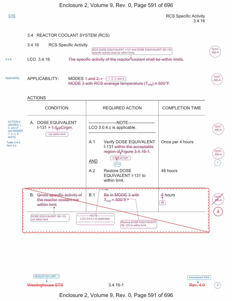
RCS Specific Activity 3.4.16
Westinghouse STS 3.4.16-1 Rev. 4.0
Amendment XXXSEQUOYAH UNIT 1
CTS
3
3.4 REACTOR COOLANT SYSTEM (RCS)
3.4.16 RCS Specific Activity
LCO 3.4.16 The specific activity of the reactor coolant shall be within limits.
APPLICABILITY: MODES 1 and 2, MODE 3 with RCS average temperature (Tavg) 500°F.
ACTIONS
CONDITION REQUIRED ACTION COMPLETION TIME
A. DOSE EQUIVALENT I-131 > 1.0 μCi/gm.
--------------------NOTE------------------- LCO 3.0.4.c is applicable. ------------------------------------------------
A.1 Verify DOSE EQUIVALENT I-131 within the acceptable region of Figure 3.4.16-1.
AND
A.2 Restore DOSE EQUIVALENT I-131 to within limit.
Once per 4 hours
48 hours
B. Gross specific activity of the reactor coolant not within limit.
B.1 Be in MODE 3 with Tavg < 500°F.
6 hours
TSTF-490-A
RCS DOSE EQUIVALENT I-131 and DOSE EQUIVALENT XE-133 specific activity shall be within limits
1, 2, 3, and 4
not within limit
[60] μCi/gm
DOSE EQUIVALENT XE-133 not within limit
---------------NOTE------------------LCO 3.0.4.c is applicable.
-----------------------------------------
48
Restore DOSE EQUIVALENT XE-133 to within limit.
3.4.8
Applicability
ACTION a (MODES 1, 2, and 3* and MODES 1, 2, 3, 4, and 5)
Table 4.4-4 Item 4.a
TSTF-490-A
TSTF-490-A
TSTF-490-A
TSTF-490-A
21.0 1
Enclosure 2, Volume 9, Rev. 0, Page 591 of 696
Enclosure 2, Volume 9, Rev. 0, Page 591 of 696
4

RCS Specific Activity 3.4.16
Westinghouse STS 3.4.16-2 Rev. 4.0
Amendment XXXSEQUOYAH UNIT 1
CTS
3
ACTIONS (continued)
CONDITION REQUIRED ACTION COMPLETION TIME
C. Required Action and associated Completion Time of Condition A not met.
OR
DOSE EQUIVALENT I-131 in the unacceptable region of Figure 3.4.16-1.
C.1 Be in MODE 3 with Tavg < 500°F.
6 hours
SURVEILLANCE REQUIREMENTS
SURVEILLANCE FREQUENCY
SR 3.4.16.1 Verify reactor coolant gross specific activity 100/ μCi/gm.
[ 7 days
OR
In accordance with the Surveillance Frequency Control Program ]
AND
C.2 Be in MODE 5 or B
> [60] μCi/gm
36 hours
----------------------NOTE---------------------------- Only required to be performed in MODE 1. ----------------------------------------------------------
Verify reactor coolant DOSE EQUIVALENT XE-133 specific activity [280] μCi/gm.
TSTF-490-A
TSTF-490-A
TSTF-490-A
2
2
ACTION a (MODES 1, 2, and 3*)
21.0 1
4.4.8 Table 4.4-4 Item 1
1612.6
Enclosure 2, Volume 9, Rev. 0, Page 592 of 696
Enclosure 2, Volume 9, Rev. 0, Page 592 of 696
ORDOSE EQUIVALENT XE-133 not within limit.
�n���e�ui�ed to �e�e��o��ed in ���ES1����nd ��it�T��� ����o�
BB
4
4
4
4
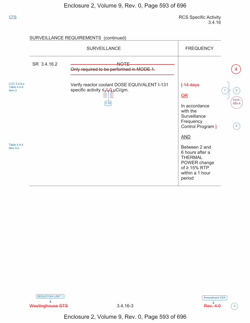
RCS Specific Activity 3.4.16
Westinghouse STS 3.4.16-3 Rev. 4.0
Amendment XXXSEQUOYAH UNIT 1
CTS
3
SURVEILLANCE REQUIREMENTS (continued)
SURVEILLANCE
FREQUENCY
SR 3.4.16.2 -------------------------------NOTE------------------------------ Only required to be performed in MODE 1. --------------------------------------------------------------------- Verify reactor coolant DOSE EQUIVALENT I-131
specific activity 1.0 μCi/gm.
[ 14 days OR In accordance with the Surveillance Frequency Control Program ] AND Between 2 and 6 hours after a THERMAL POWER change of 15% RTP within a 1 hour period
[ ]
2
2
TSTF-490-A
LCO 3.4.8.a Table 4.4-4 Item 2
Table 4.4-4 Item 4.b
0.35
1
Enclosure 2, Volume 9, Rev. 0, Page 593 of 696
Enclosure 2, Volume 9, Rev. 0, Page 593 of 696
4
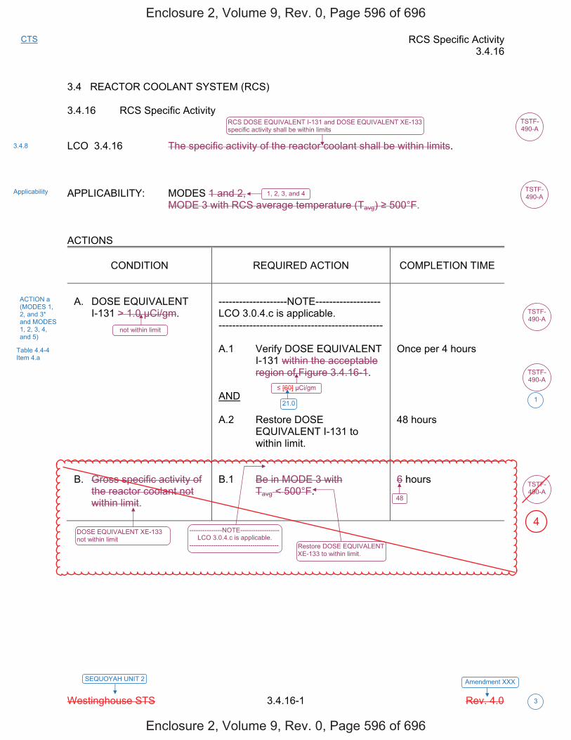
RCS Specific Activity 3.4.16
Westinghouse STS 3.4.16-1 Rev. 4.0
Amendment XXXSEQUOYAH UNIT 2
CTS
3
3.4 REACTOR COOLANT SYSTEM (RCS) 3.4.16 RCS Specific Activity LCO 3.4.16 The specific activity of the reactor coolant shall be within limits. APPLICABILITY: MODES 1 and 2, MODE 3 with RCS average temperature (Tavg) 500°F. ACTIONS
CONDITION
REQUIRED ACTION
COMPLETION TIME
A. DOSE EQUIVALENT
I-131 > 1.0 μCi/gm.
--------------------NOTE------------------- LCO 3.0.4.c is applicable. ------------------------------------------------ A.1 Verify DOSE EQUIVALENT
I-131 within the acceptable region of Figure 3.4.16-1.
AND A.2 Restore DOSE
EQUIVALENT I-131 to within limit.
Once per 4 hours 48 hours
B. Gross specific activity of
the reactor coolant not within limit.
B.1 Be in MODE 3 with
Tavg < 500°F.
6 hours
TSTF-490-A
RCS DOSE EQUIVALENT I-131 and DOSE EQUIVALENT XE-133 specific activity shall be within limits
1, 2, 3, and 4
not within limit
[60] μCi/gm
DOSE EQUIVALENT XE-133 not within limit
---------------NOTE------------------LCO 3.0.4.c is applicable.
-----------------------------------------
48
Restore DOSE EQUIVALENT XE-133 to within limit.
3.4.8
Applicability
ACTION a (MODES 1, 2, and 3* and MODES 1, 2, 3, 4, and 5)
Table 4.4-4 Item 4.a
TSTF-490-A
TSTF-490-A
TSTF-490-A
TSTF-490-A
21.0 1
Enclosure 2, Volume 9, Rev. 0, Page 596 of 696
Enclosure 2, Volume 9, Rev. 0, Page 596 of 696
4
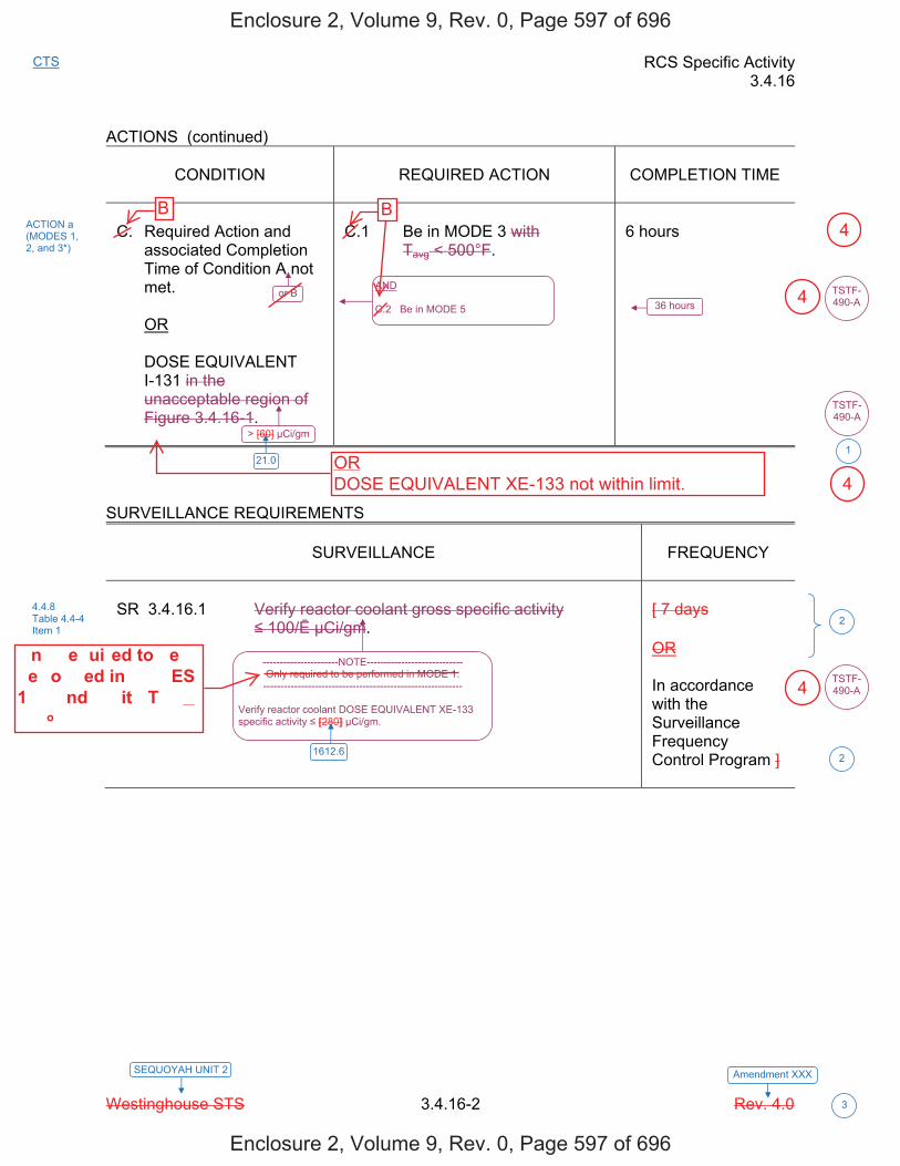
RCS Specific Activity 3.4.16
Westinghouse STS 3.4.16-2 Rev. 4.0
Amendment XXXSEQUOYAH UNIT 2
CTS
3
ACTIONS (continued)
CONDITION
REQUIRED ACTION
COMPLETION TIME
C. Required Action and
associated Completion Time of Condition A not met.
OR DOSE EQUIVALENT
I-131 in the unacceptable region of Figure 3.4.16-1.
C.1 Be in MODE 3 with
Tavg < 500°F.
6 hours
SURVEILLANCE REQUIREMENTS
SURVEILLANCE
FREQUENCY
SR 3.4.16.1 Verify reactor coolant gross specific activity
100/ μCi/gm.
[ 7 days OR In accordance with the Surveillance Frequency Control Program ]
AND C.2 Be in MODE 5
or B
> [60] μCi/gm
36 hours
----------------------NOTE---------------------------- Only required to be performed in MODE 1. ----------------------------------------------------------
Verify reactor coolant DOSE EQUIVALENT XE-133 specific activity [280] μCi/gm.
TSTF-490-A
TSTF-490-A
TSTF-490-A
2
2
ACTION a (MODES 1, 2, and 3*)
21.0 1
4.4.8 Table 4.4-4 Item 1
1612.6
Enclosure 2, Volume 9, Rev. 0, Page 597 of 696
Enclosure 2, Volume 9, Rev. 0, Page 597 of 696
�n���e�ui�ed to �e�e��o��ed in ���ES1����nd ��it�T��� ����o�
B B
ORDOSE EQUIVALENT XE-133 not within limit.
4
4
4
4
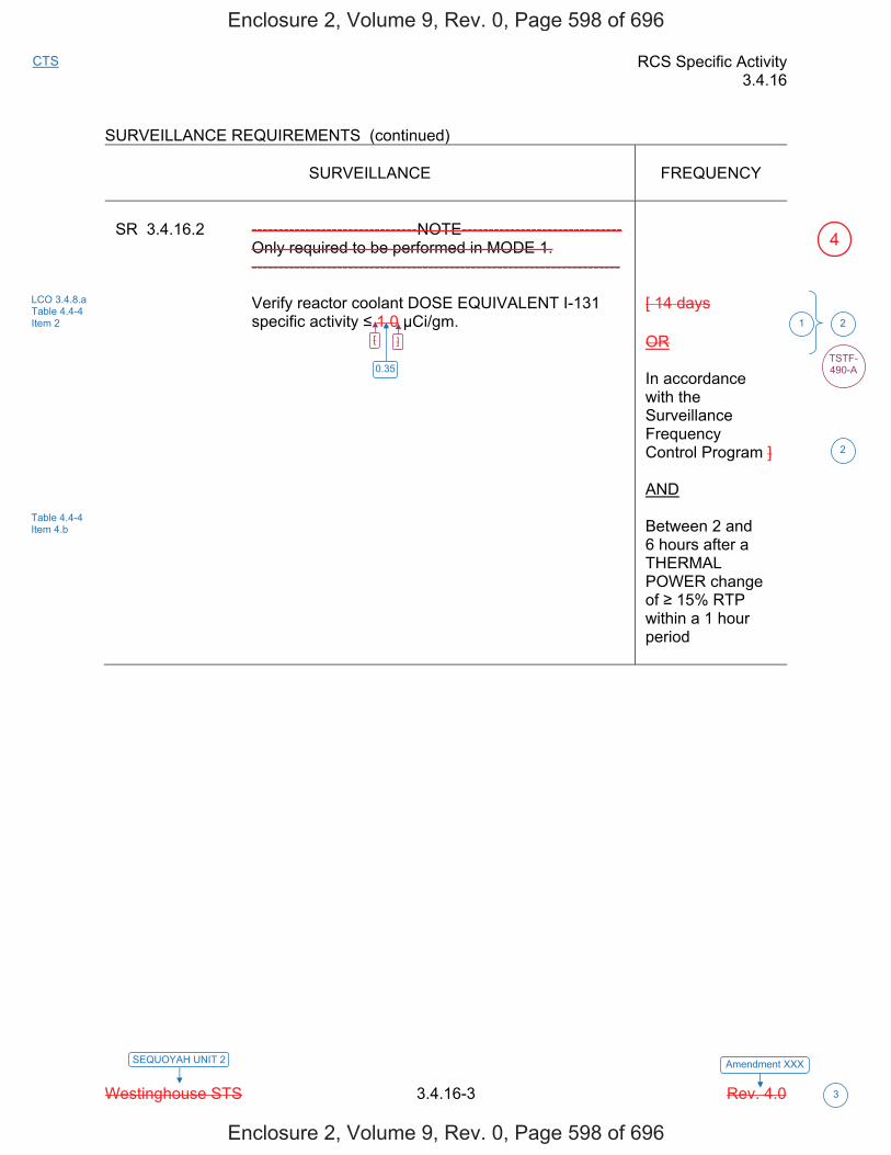
RCS Specific Activity 3.4.16
Westinghouse STS 3.4.16-3 Rev. 4.0
Amendment XXXSEQUOYAH UNIT 2
CTS
3
SURVEILLANCE REQUIREMENTS (continued)
SURVEILLANCE
FREQUENCY
SR 3.4.16.2 -------------------------------NOTE------------------------------ Only required to be performed in MODE 1. --------------------------------------------------------------------- Verify reactor coolant DOSE EQUIVALENT I-131
specific activity 1.0 μCi/gm.
[ 14 days OR In accordance with the Surveillance Frequency Control Program ] AND Between 2 and 6 hours after a THERMAL POWER change of 15% RTP within a 1 hour period
[ ]
2
2
TSTF-490-A
LCO 3.4.8.a Table 4.4-4 Item 2
Table 4.4-4 Item 4.b
0.35
1
Enclosure 2, Volume 9, Rev. 0, Page 598 of 696
Enclosure 2, Volume 9, Rev. 0, Page 598 of 696
4
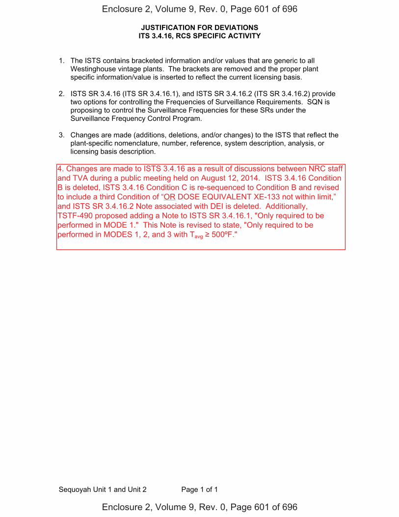
JUSTIFICATION FOR DEVIATIONS ITS 3.4.16, RCS SPECIFIC ACTIVITY
Sequoyah Unit 1 and Unit 2 Page 1 of 1
1. The ISTS contains bracketed information and/or values that are generic to all
Westinghouse vintage plants. The brackets are removed and the proper plant specific information/value is inserted to reflect the current licensing basis.
2. ISTS SR 3.4.16 (ITS SR 3.4.16.1), and ISTS SR 3.4.16.2 (ITS SR 3.4.16.2) provide two options for controlling the Frequencies of Surveillance Requirements. SQN is proposing to control the Surveillance Frequencies for these SRs under the Surveillance Frequency Control Program.
3. Changes are made (additions, deletions, and/or changes) to the ISTS that reflect the
plant-specific nomenclature, number, reference, system description, analysis, or licensing basis description.
Enclosure 2, Volume 9, Rev. 0, Page 601 of 696
Enclosure 2, Volume 9, Rev. 0, Page 601 of 696
4. Changes are made to ISTS 3.4.16 as a result of discussions between NRC staffand TVA during a public meeting held on August 12, 2014. ISTS 3.4.16 Condition B is deleted, ISTS 3.4.16 Condition C is re-sequenced to Condition B and revised to include a third Condition of “OR DOSE EQUIVALENT XE-133 not within limit,” and ISTS SR 3.4.16.2 Note associated with DEI is deleted. Additionally, TSTF-490 proposed adding a Note to ISTS SR 3.4.16.1, "Only required to be performed in MODE 1." This Note is revised to state, "Only required to be performed in MODES 1, 2, and 3 with Tavg 500ºF."
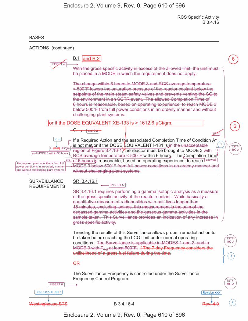
RCS Specific Activity B 3.4.16
Westinghouse STS B 3.4.16-4 Rev. 4.0
SEQUOYAH UNIT 1 Revision XXX
2
BASES ACTIONS (continued)
B.1 With the gross specific activity in excess of the allowed limit, the unit must be placed in a MODE in which the requirement does not apply. The change within 6 hours to MODE 3 and RCS average temperature < 500°F lowers the saturation pressure of the reactor coolant below the setpoints of the main steam safety valves and prevents venting the SG to the environment in an SGTR event. The allowed Completion Time of 6 hours is reasonable, based on operating experience, to reach MODE 3 below 500°F from full power conditions in an orderly manner and without challenging plant systems. C.1 If a Required Action and the associated Completion Time of Condition A is not met or if the DOSE EQUIVALENT I-131 is in the unacceptable region of Figure 3.4.16-1, the reactor must be brought to MODE 3 with RCS average temperature < 500°F within 6 hours. The Completion Time of 6 hours is reasonable, based on operating experience, to reach MODE 3 below 500°F from full power conditions in an orderly manner and without challenging plant systems.
SURVEILLANCE SR 3.4.16.1 REQUIREMENTS
SR 3.4.16.1 requires performing a gamma isotopic analysis as a measure of the gross specific activity of the reactor coolant. While basically a quantitative measure of radionuclides with half lives longer than 15 minutes, excluding iodines, this measurement is the sum of the degassed gamma activities and the gaseous gamma activities in the sample taken. This Surveillance provides an indication of any increase in gross specific activity. Trending the results of this Surveillance allows proper remedial action to be taken before reaching the LCO limit under normal operating conditions. The Surveillance is applicable in MODES 1 and 2, and in MODE 3 with Tavg at least 500°F. [ The 7 day Frequency considers the unlikelihood of a gross fuel failure during the time. OR The Surveillance Frequency is controlled under the Surveillance Frequency Control Program.
and C.2 or B
> [60.0] μCi/gm
and MODE 5 within 36 hours
allowedthe required plant conditions from full
power conditions in an orderly manner and without challenging plant systems
INSERT 6
TSTF-490-A
3
TSTF-490-A
INSERT 5
INSERT 4
, 1
s
are
TSTF-490-A
21.0
Enclosure 2, Volume 9, Rev. 0, Page 610 of 696
Enclosure 2, Volume 9, Rev. 0, Page 610 of 696
or if the DOSE EQUVALENT XE-133 is > 1612.6 μCi/gm,
and B.2 6
6
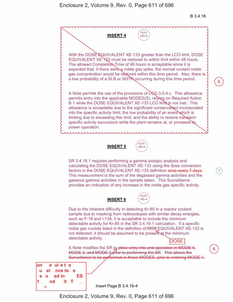
B 3.4.16
Insert Page B 3.4.16-4
INSERT 4
With the DOSE EQUIVALENT XE-133 greater than the LCO limit, DOSE EQUIVALENT XE-133 must be restored to within limit within 48 hours. The allowed Completion Time of 48 hours is acceptable since it is expected that, if there were a noble gas spike, the normal coolant noble gas concentration would be restored within this time period. Also, there is a low probability of a SLB or SGTR occurring during this time period.
A Note permits the use of the provisions of LCO 3.0.4.c. This allowance permits entry into the applicable MODES(S), relying on Required Action B.1 while the DOSE EQUIVALENT XE-133 LCO limit is not met. This allowance is acceptable due to the significant conservatism incorporated into the specific activity limit, the low probability of an event which is limiting due to exceeding this limit, and the ability to restore transient-specific activity excursions while the plant remains at, or proceeds to, power operation.
INSERT 5
SR 3.4.16.1 requires performing a gamma isotopic analysis and calculating the DOSE EQUIVALENT XE-133 using the dose conversion factors in the DOSE EQUIVALENT XE-133 definition once every 7 days. This measurement is the sum of the degassed gamma activities and the gaseous gamma activities in the sample taken. This Surveillance provides an indication of any increase in the noble gas specific activity.
INSERT 6
Due to the inherent difficulty in detecting Kr-85 in a reactor coolant sample due to masking from radioisotopes with similar decay energies, such as F-18 and I-134, it is acceptable to include the minimum detectable activity for Kr-85 in the SR 3.4.16.1 calculation. If a specific noble gas nuclide listed in the definition of DOS EQUIVALENT XE-133 is not detected, it should be assumed to be present at the minimum detectable activity.
A Note modifies the SR to allow entry into and operation in MODE 4, MODE 3, and MODE 2 prior to performing the SR. This allows the Surveillance to be performed in those MODES, prior to entering MODE 1.
TSTF-490-A
TSTF-490-A
TSTF-490-A
3
Enclosure 2, Volume 9, Rev. 0, Page 611 of 696
Enclosure 2, Volume 9, Rev. 0, Page 611 of 696
on���e�ui�e t�e�u��ei���nce to �e�e��o��ed in ���ES1����nd ��it�T��� ����o�
DOSE
6
6
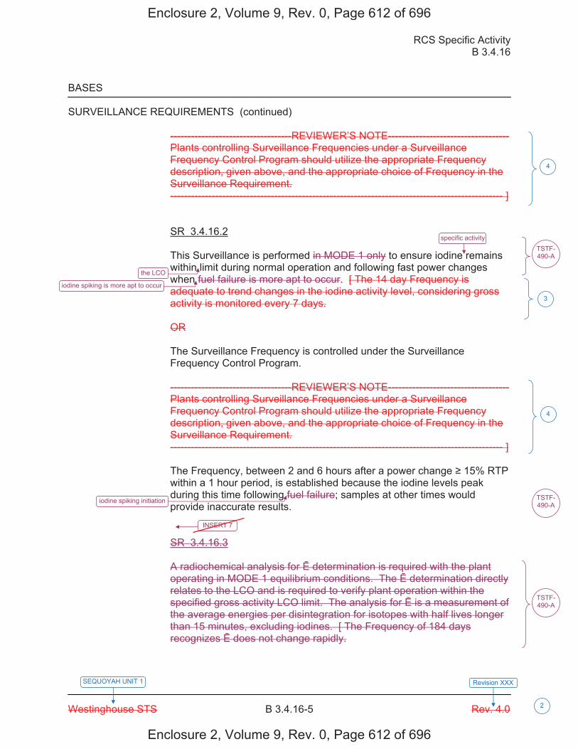
RCS Specific Activity B 3.4.16
Westinghouse STS B 3.4.16-5 Rev. 4.0
SEQUOYAH UNIT 1 Revision XXX
2
BASES SURVEILLANCE REQUIREMENTS (continued)
-----------------------------------REVIEWER’S NOTE----------------------------------- Plants controlling Surveillance Frequencies under a Surveillance Frequency Control Program should utilize the appropriate Frequency description, given above, and the appropriate choice of Frequency in the Surveillance Requirement. ------------------------------------------------------------------------------------------------ ] SR 3.4.16.2 This Surveillance is performed in MODE 1 only to ensure iodine remains within limit during normal operation and following fast power changes when fuel failure is more apt to occur. [ The 14 day Frequency is adequate to trend changes in the iodine activity level, considering gross activity is monitored every 7 days. OR The Surveillance Frequency is controlled under the Surveillance Frequency Control Program. -----------------------------------REVIEWER’S NOTE----------------------------------- Plants controlling Surveillance Frequencies under a Surveillance Frequency Control Program should utilize the appropriate Frequency description, given above, and the appropriate choice of Frequency in the Surveillance Requirement. ------------------------------------------------------------------------------------------------ ] The Frequency, between 2 and 6 hours after a power change 15% RTP within a 1 hour period, is established because the iodine levels peak during this time following fuel failure; samples at other times would provide inaccurate results. SR 3.4.16.3 A radiochemical analysis for determination is required with the plant operating in MODE 1 equilibrium conditions. The determination directly relates to the LCO and is required to verify plant operation within the specified gross activity LCO limit. The analysis for is a measurement of the average energies per disintegration for isotopes with half lives longer than 15 minutes, excluding iodines. [ The Frequency of 184 days recognizes does not change rapidly.
specific activity
the LCO
iodine spiking is more apt to occur
iodine spiking initiation
INSERT 7
4
4
TSTF-490-A
3
TSTF-490-A
TSTF-490-A
Enclosure 2, Volume 9, Rev. 0, Page 612 of 696
Enclosure 2, Volume 9, Rev. 0, Page 612 of 696
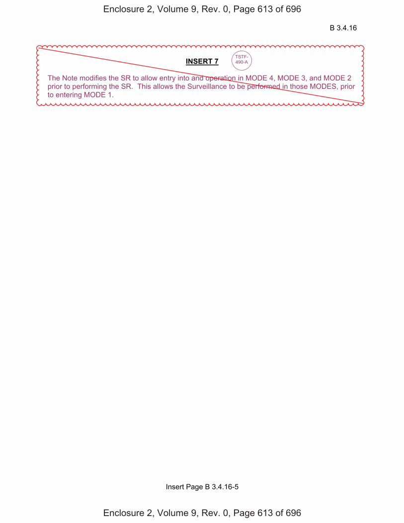
B 3.4.16
Insert Page B 3.4.16-5
INSERT 7 The Note modifies the SR to allow entry into and operation in MODE 4, MODE 3, and MODE 2 prior to performing the SR. This allows the Surveillance to be performed in those MODES, prior to entering MODE 1.
TSTF-490-A
Enclosure 2, Volume 9, Rev. 0, Page 613 of 696
Enclosure 2, Volume 9, Rev. 0, Page 613 of 696
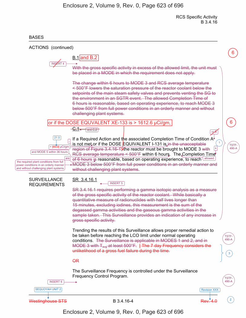
RCS Specific Activity B 3.4.16
Westinghouse STS B 3.4.16-4 Rev. 4.0
SEQUOYAH UNIT 2 Revision XXX
2
BASES ACTIONS (continued)
B.1 With the gross specific activity in excess of the allowed limit, the unit must be placed in a MODE in which the requirement does not apply. The change within 6 hours to MODE 3 and RCS average temperature < 500°F lowers the saturation pressure of the reactor coolant below the setpoints of the main steam safety valves and prevents venting the SG to the environment in an SGTR event. The allowed Completion Time of 6 hours is reasonable, based on operating experience, to reach MODE 3 below 500°F from full power conditions in an orderly manner and without challenging plant systems. C.1 If a Required Action and the associated Completion Time of Condition A is not met or if the DOSE EQUIVALENT I-131 is in the unacceptable region of Figure 3.4.16-1, the reactor must be brought to MODE 3 with RCS average temperature < 500°F within 6 hours. The Completion Time of 6 hours is reasonable, based on operating experience, to reach MODE 3 below 500°F from full power conditions in an orderly manner and without challenging plant systems.
SURVEILLANCE SR 3.4.16.1 REQUIREMENTS
SR 3.4.16.1 requires performing a gamma isotopic analysis as a measure of the gross specific activity of the reactor coolant. While basically a quantitative measure of radionuclides with half lives longer than 15 minutes, excluding iodines, this measurement is the sum of the degassed gamma activities and the gaseous gamma activities in the sample taken. This Surveillance provides an indication of any increase in gross specific activity. Trending the results of this Surveillance allows proper remedial action to be taken before reaching the LCO limit under normal operating conditions. The Surveillance is applicable in MODES 1 and 2, and in MODE 3 with Tavg at least 500°F. [ The 7 day Frequency considers the unlikelihood of a gross fuel failure during the time. OR The Surveillance Frequency is controlled under the Surveillance Frequency Control Program.
and C.2 or B
> [60.0] μCi/gm
and MODE 5 within 36 hours
allowedthe required plant conditions from full
power conditions in an orderly manner and without challenging plant systems
INSERT 6
TSTF-490-A
3
TSTF-490-A
INSERT 5
INSERT 4
, 1
s
are
TSTF-490-A
21.0
Enclosure 2, Volume 9, Rev. 0, Page 623 of 696
Enclosure 2, Volume 9, Rev. 0, Page 623 of 696
or if the DOSE EQUVALENT XE-133 is > 1612.6 μCi/gm,
and B.26
6
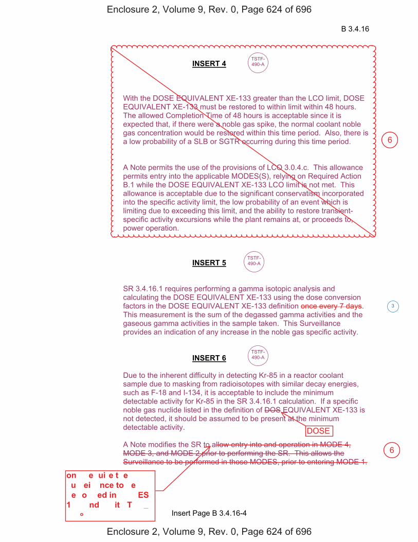
B 3.4.16
Insert Page B 3.4.16-4
INSERT 4
With the DOSE EQUIVALENT XE-133 greater than the LCO limit, DOSE EQUIVALENT XE-133 must be restored to within limit within 48 hours. The allowed Completion Time of 48 hours is acceptable since it is expected that, if there were a noble gas spike, the normal coolant noble gas concentration would be restored within this time period. Also, there is a low probability of a SLB or SGTR occurring during this time period.
A Note permits the use of the provisions of LCO 3.0.4.c. This allowance permits entry into the applicable MODES(S), relying on Required Action B.1 while the DOSE EQUIVALENT XE-133 LCO limit is not met. This allowance is acceptable due to the significant conservatism incorporated into the specific activity limit, the low probability of an event which is limiting due to exceeding this limit, and the ability to restore transient-specific activity excursions while the plant remains at, or proceeds to, power operation.
INSERT 5
SR 3.4.16.1 requires performing a gamma isotopic analysis and calculating the DOSE EQUIVALENT XE-133 using the dose conversion factors in the DOSE EQUIVALENT XE-133 definition once every 7 days. This measurement is the sum of the degassed gamma activities and the gaseous gamma activities in the sample taken. This Surveillance provides an indication of any increase in the noble gas specific activity.
INSERT 6
Due to the inherent difficulty in detecting Kr-85 in a reactor coolant sample due to masking from radioisotopes with similar decay energies, such as F-18 and I-134, it is acceptable to include the minimum detectable activity for Kr-85 in the SR 3.4.16.1 calculation. If a specific noble gas nuclide listed in the definition of DOS EQUIVALENT XE-133 is not detected, it should be assumed to be present at the minimum detectable activity.
A Note modifies the SR to allow entry into and operation in MODE 4, MODE 3, and MODE 2 prior to performing the SR. This allows the Surveillance to be performed in those MODES, prior to entering MODE 1.
TSTF-490-A
TSTF-490-A
TSTF-490-A
3
Enclosure 2, Volume 9, Rev. 0, Page 624 of 696
Enclosure 2, Volume 9, Rev. 0, Page 624 of 696
on���e�ui�e t�e�u��ei���nce to �e�e��o��ed in ���ES1����nd ��it�T��� ����o�
6
6
DOSE
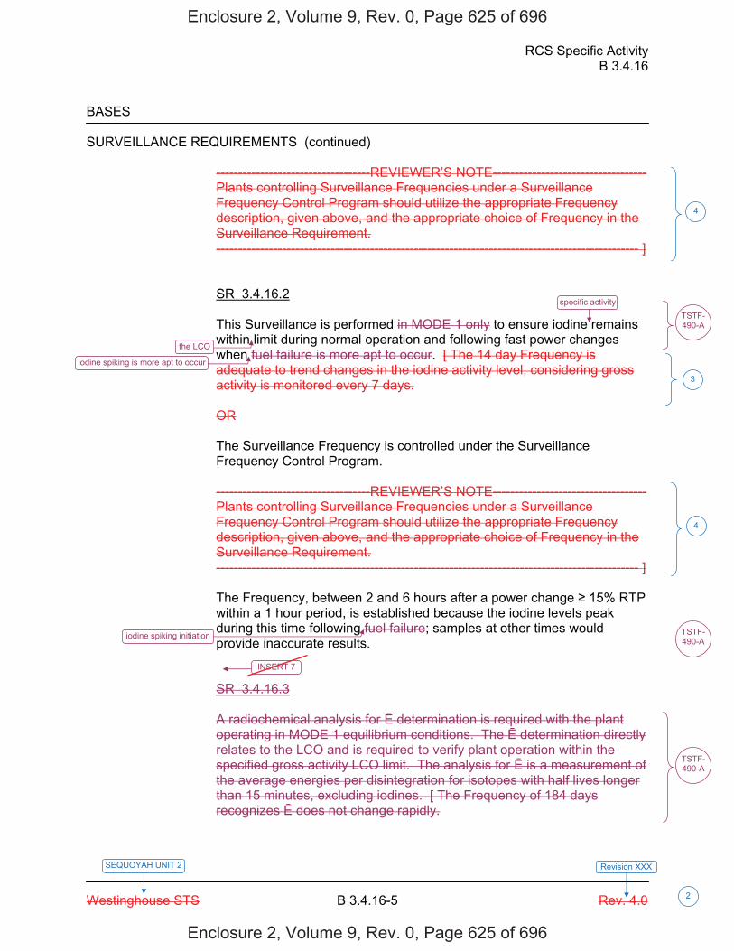
RCS Specific Activity B 3.4.16
Westinghouse STS B 3.4.16-5 Rev. 4.0
SEQUOYAH UNIT 2 Revision XXX
2
BASES SURVEILLANCE REQUIREMENTS (continued)
-----------------------------------REVIEWER’S NOTE----------------------------------- Plants controlling Surveillance Frequencies under a Surveillance Frequency Control Program should utilize the appropriate Frequency description, given above, and the appropriate choice of Frequency in the Surveillance Requirement. ------------------------------------------------------------------------------------------------ ] SR 3.4.16.2 This Surveillance is performed in MODE 1 only to ensure iodine remains within limit during normal operation and following fast power changes when fuel failure is more apt to occur. [ The 14 day Frequency is adequate to trend changes in the iodine activity level, considering gross activity is monitored every 7 days. OR The Surveillance Frequency is controlled under the Surveillance Frequency Control Program. -----------------------------------REVIEWER’S NOTE----------------------------------- Plants controlling Surveillance Frequencies under a Surveillance Frequency Control Program should utilize the appropriate Frequency description, given above, and the appropriate choice of Frequency in the Surveillance Requirement. ------------------------------------------------------------------------------------------------ ] The Frequency, between 2 and 6 hours after a power change 15% RTP within a 1 hour period, is established because the iodine levels peak during this time following fuel failure; samples at other times would provide inaccurate results. SR 3.4.16.3 A radiochemical analysis for determination is required with the plant operating in MODE 1 equilibrium conditions. The determination directly relates to the LCO and is required to verify plant operation within the specified gross activity LCO limit. The analysis for is a measurement of the average energies per disintegration for isotopes with half lives longer than 15 minutes, excluding iodines. [ The Frequency of 184 days recognizes does not change rapidly.
specific activity
the LCO
iodine spiking is more apt to occur
iodine spiking initiation
INSERT 7
4
4
TSTF-490-A
3
TSTF-490-A
TSTF-490-A
Enclosure 2, Volume 9, Rev. 0, Page 625 of 696
Enclosure 2, Volume 9, Rev. 0, Page 625 of 696
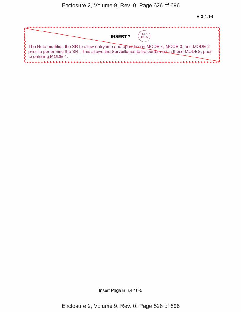
B 3.4.16
Insert Page B 3.4.16-5
INSERT 7 The Note modifies the SR to allow entry into and operation in MODE 4, MODE 3, and MODE 2 prior to performing the SR. This allows the Surveillance to be performed in those MODES, prior to entering MODE 1.
TSTF-490-A
Enclosure 2, Volume 9, Rev. 0, Page 626 of 696
Enclosure 2, Volume 9, Rev. 0, Page 626 of 696
JUSTIFICATION FOR DEVIATIONS ITS 3.4.16 BASES, RCS SPECIFIC ACTIVITY
Sequoyah Unit 1 and Unit 2 Page 1 of 1
1. The ISTS contains bracketed information and/or values that are generic to Westinghouse vintage plants. The brackets are removed and the proper plant specific information/value is inserted to reflect the current licensing basis.
2. Changes are made (additions, deletions, and/or changes) to the ISTS Bases that reflect the plant-specific nomenclature, number, reference, system description, analysis, or licensing basis description.
3. ISTS SR 3.4.16.1 and ISTS SR 3.4.16.2 provide two options for controlling the
Frequencies of Surveillance Requirements. SQN is proposing to control the Surveillance Frequencies under the Surveillance Frequency Control Program. Therefore, the Frequency for ITS SR 3.4.16.1 and SR 3.4.16.2 is "In accordance with the Surveillance Frequency Control Program."
4. The Reviewer's Note has been deleted. This information is for the NRC reviewer to be keyed into what is needed to meet this requirement. This Note is not meant to be retained in the final version of the plant specific submittal.
5. Editorial/grammatical changes to enhance clarity.
Enclosure 2, Volume 9, Rev. 0, Page 629 of 696
Enclosure 2, Volume 9, Rev. 0, Page 629 of 696
6. Changes are made to be consistent with changes made to the Specification.
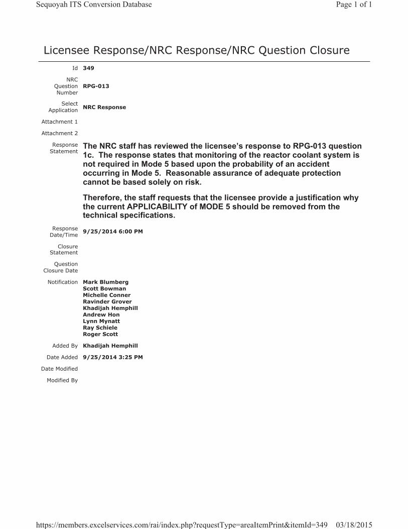
Licensee Response/NRC Response/NRC Question ClosureId 349
NRC Question Number
RPG-013
Select Application NRC Response
Attachment 1
Attachment 2
Response Statement
The NRC staff has reviewed the licensee’s response to RPG-013 question 1c. The response states that monitoring of the reactor coolant system is not required in Mode 5 based upon the probability of an accident occurring in Mode 5. Reasonable assurance of adequate protection cannot be based solely on risk.
Therefore, the staff requests that the licensee provide a justification why the current APPLICABILITY of MODE 5 should be removed from the technical specifications.
Response Date/Time 9/25/2014 6:00 PM
Closure Statement
Question Closure Date
Notification Mark BlumbergScott BowmanMichelle ConnerRavinder GroverKhadijah HemphillAndrew HonLynn MynattRay SchieleRoger Scott
Added By Khadijah Hemphill
Date Added 9/25/2014 3:25 PM
Date Modified
Modified By
Page 1 of 1Sequoyah ITS Conversion Database
03/18/2015https://members.excelservices.com/rai/index.php?requestType=areaItemPrint&itemId=349
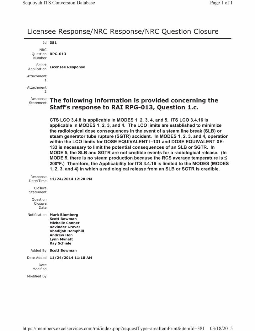
Licensee Response/NRC Response/NRC Question ClosureId 381
NRC Question Number
RPG-013
Select Application Licensee Response
Attachment 1
Attachment 2
Response Statement The following information is provided concerning the
Staff’s response to RAI RPG-013, Question 1.c.
CTS LCO 3.4.8 is applicable in MODES 1, 2, 3, 4, and 5. ITS LCO 3.4.16 is applicable in MODES 1, 2, 3, and 4. The LCO limits are established to minimize the radiological dose consequences in the event of a steam line break (SLB) or steam generator tube rupture (SGTR) accident. In MODES 1, 2, 3, and 4, operation within the LCO limits for DOSE EQUIVALENT I-131 and DOSE EQUIVALENT XE-133 is necessary to limit the potential consequences of an SLB or SGTR. In MODE 5, the SLB and SGTR are not credible events for a radiological release. (In MODE 5, there is no steam production because the RCS average temperature is 200ºF.) Therefore, the Applicability for ITS 3.4.16 is limited to the MODES (MODES 1, 2, 3, and 4) in which a radiological release from an SLB or SGTR is credible.
Response Date/Time 11/24/2014 12:20 PM
Closure Statement
Question Closure
Date
Notification Mark BlumbergScott BowmanMichelle ConnerRavinder GroverKhadijah HemphillAndrew HonLynn MynattRay Schiele
Added By Scott Bowman
Date Added 11/24/2014 11:18 AM
Date Modified
Modified By
Page 1 of 1Sequoyah ITS Conversion Database
03/18/2015https://members.excelservices.com/rai/index.php?requestType=areaItemPrint&itemId=381

Licensee Response/NRC Response/NRC Question ClosureId 398
NRC Question Number RPG-013
Select Application NRC Question Closure
Attachment 1
Attachment 2
Response Statement
Response Date/Time
Closure Statement This question is closed and no further information is required at this time to draft the Safety Evaluation.
Question Closure Date 12/16/2014
Notification Mark BlumbergScott BowmanMichelle ConnerRobert ElliottRavinder GroverKhadijah HemphillAndrew HonLynn MynattRay SchieleRoger Scott
Added By Ravinder Grover
Date Added 12/16/2014 8:21 AM
Date Modified
Modified By
Page 1 of 1Sequoyah ITS Conversion Database
03/18/2015https://members.excelservices.com/rai/index.php?requestType=areaItemPrint&itemId=398
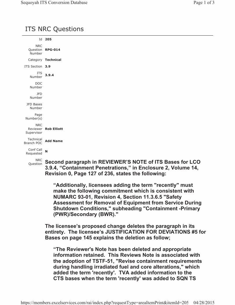
ITS NRC QuestionsId 205
NRC Question Number
RPG-014
Category Technical
ITS Section 3.9
ITS Number 3.9.4
DOC Number
JFD Number
JFD Bases Number
Page Number(s)
NRC Reviewer
Supervisor Rob Elliott
Technical Branch POC Add Name
Conf Call Requested N
NRC Question Second paragraph in REVIEWER’S NOTE of ITS Bases for LCO
3.9.4, “Containment Penetrations,” in Enclosure 2, Volume 14, Revision 0, Page 127 of 236, states the following:
“Additionally, licensees adding the term "recently" must make the following commitment which is consistent with NUMARC 93-01, Revision 4, Section 11.3.6.5 "Safety Assessment for Removal of Equipment from Service During Shutdown Conditions," subheading "Containment -Primary (PWR)/Secondary (BWR)."
The licensee’s proposed change deletes the paragraph in its entirety. The licensee’s JUSTIFICATION FOR DEVIATIONS #5 for Bases on page 145 explains the deletion as follow;
“The Reviewer's Note has been deleted and appropriate information retained. This Reviews Note is associated with the adoption of TSTF-51, "Revise containment requirements during handling irradiated fuel and core alterations," which added the term 'recently'. TVA added information to the CTS bases when the term 'recently' was added to SQN TS
Page 1 of 3Sequoyah ITS Conversion Database
04/28/2015https://members.excelservices.com/rai/index.php?requestType=areaItemPrint&itemId=205
under License Amendments 288/278 (Unit 1/Unit 2) (ADAMS Accession Nos. ML033030206 and ML033070057). The Bases is changed to include the applicable information contained in TSTF-51 and NUMARC 91-06. This will allow TVA to have a method in place to promptly close the primary containment (i.e., the equipment hatch) or the secondary containment (i.e., auxiliary building secondary containment enclosure (ABSCE)) using the ABGTS to draw the release from a postulated fuel handling accident in the proper direction such that it can be treated and monitored.”
The Staff’s review finds concerns in two areas:
a) The justification does not address deletion of NUMARC 93-01. It references NUMARC 91-06, and
b) Is SQN committed to specific section 11.3.6.5 of NUMARC 93-01, Revision 4, as identified in the REVIEWERS NOTE?The Staff has noticed that Enclosure 8 provides a listing of SQN’s Regulatory Commitments. Item 7 on Page 121 lists commitment to NUMARC 93-01, Section 11 for TSTF-427.However, the NOTE states, “Additionally, licensees adding the term "recently" must make the following commitment which is consistent with NUMARC 93-01, Revision 4, Section 11.3.6.5.”
Please explain the above concerns.
Attach File 1
Attach File 2
Issue Date 1/16/2015
Added By Ravinder Grover
Date Modified
Modified By
Date Added 1/16/2015 1:03 PM
Notification Mark BlumbergScott BowmanMichelle ConnerRobert ElliottRavinder GroverKhadijah HemphillAndrew HonLynn MynattRay Schiele
Page 2 of 3Sequoyah ITS Conversion Database
04/28/2015https://members.excelservices.com/rai/index.php?requestType=areaItemPrint&itemId=205
Roger Scott
Page 3 of 3Sequoyah ITS Conversion Database
04/28/2015https://members.excelservices.com/rai/index.php?requestType=areaItemPrint&itemId=205
Licensee Response/NRC Response/NRC Question ClosureId 430
NRC Question Number
RPG-014
Select Application Licensee Response
Attachment 1 Attachment 1 for RAI RPG-014.pdf (1MB)
Attachment 2
Response Statement In response to RPG-014, Justification for Deviation 5
(page 145 of Enclosure 2, Volume 14) will be revised to state, “The Reviewer’s Note has been deleted. This information is for the NRC reviewer to be keyed into what is needed to meet this requirement. This Note is not to be retained in the final version of the plant specific submittal. See Enclosure 8 for SQN’s commitment associated with the Reviewer’s Note.”There will no longer be a reference in JFD 5 to NUMARC 91-06.
Additionally, Enclosure 8, Regulatory Commitments, will be revised to include the commitment required by the Reviewer’s Note in ISTS 3.9.4, Applicability Section.The commitment is consistent with NUMARC 93-01, Revision 4, Section 11.3.6.5 “Safety Assessment for Removal of Equipment from Service During Shutdown Conditions,” subheading “Containment - Primary (PWR)/Secondary (BWR).” The commitment will state:
“The following guidelines are included in the assessment of systems removed from service during movement [of] irradiated fuel:
- During fuel handling/core alterations, ventilation system and radiation monitor availability (as defined in NUMARC 91-06) should be assessed, with respect to filtration and monitoring of releases from the fuel. Following shutdown, radioactivity in the fuel decays away fairly rapidly. The basis of the Technical
Page 1 of 2Sequoyah ITS Conversion Database
04/28/2015https://members.excelservices.com/rai/index.php?requestType=areaItemPrint&itemId=430
Specification OPERABILITY amendment is the reduction in doses due to such decay. The goal of maintaining ventilation system and radiation monitor availability is to reduce doses even further below that provided by the natural decay.
- A single normal or contingency method to promptly close primary or secondary containment penetrations should be developed. Such prompt methods need not completely block the penetration or be capable of resisting pressure.
The purpose of the "prompt methods" mentioned above are to enable ventilation systems to draw the release from a postulated fuel handling accident in the proper direction such that it can be treated and monitored."
See Attachment 1 for the draft revised ITS 3.9.4 Bases JFD 5 and Enclosure 8.Response
Date/Time 3/4/2015 6:00 AM
Closure Statement
Question Closure
Date
Notification Mark BlumbergScott BowmanMichelle ConnerRavinder GroverKhadijah HemphillAndrew HonRay Schiele
Added By Scott Bowman
Date Added 3/4/2015 5:01 AM
Date Modified
Modified By
Page 2 of 2Sequoyah ITS Conversion Database
04/28/2015https://members.excelservices.com/rai/index.php?requestType=areaItemPrint&itemId=430
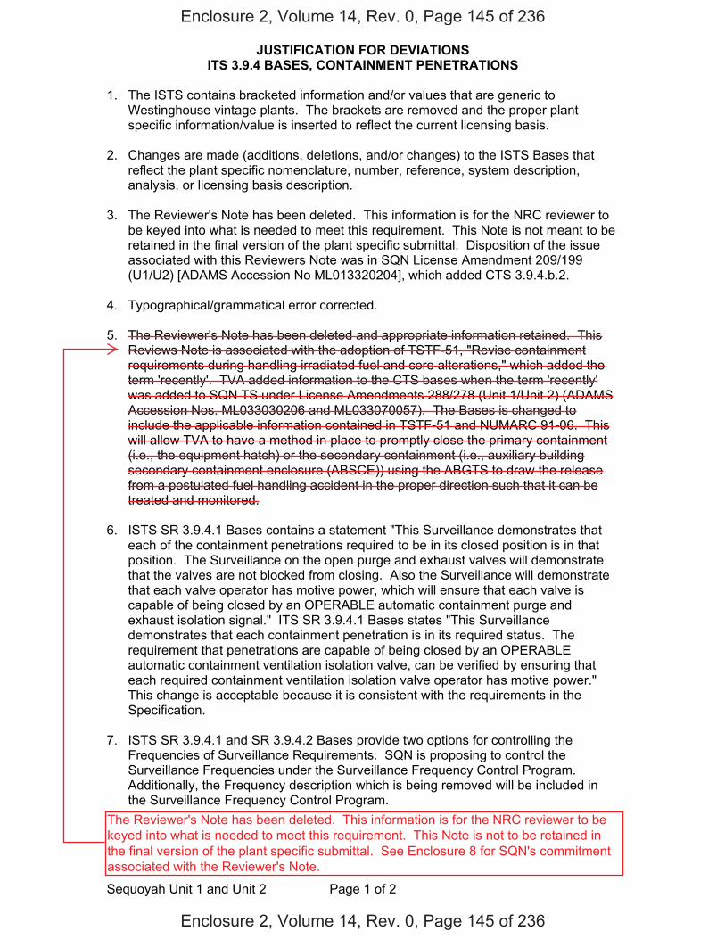
JUSTIFICATION FOR DEVIATIONS ITS 3.9.4 BASES, CONTAINMENT PENETRATIONS
Sequoyah Unit 1 and Unit 2 Page 1 of 2
1. The ISTS contains bracketed information and/or values that are generic to Westinghouse vintage plants. The brackets are removed and the proper plant specific information/value is inserted to reflect the current licensing basis.
2. Changes are made (additions, deletions, and/or changes) to the ISTS Bases that
reflect the plant specific nomenclature, number, reference, system description, analysis, or licensing basis description.
3. The Reviewer's Note has been deleted. This information is for the NRC reviewer to
be keyed into what is needed to meet this requirement. This Note is not meant to be retained in the final version of the plant specific submittal. Disposition of the issue associated with this Reviewers Note was in SQN License Amendment 209/199 (U1/U2) [ADAMS Accession No ML013320204], which added CTS 3.9.4.b.2.
4. Typographical/grammatical error corrected.
5. The Reviewer's Note has been deleted and appropriate information retained. This Reviews Note is associated with the adoption of TSTF-51, "Revise containment requirements during handling irradiated fuel and core alterations," which added the term 'recently'. TVA added information to the CTS bases when the term 'recently' was added to SQN TS under License Amendments 288/278 (Unit 1/Unit 2) (ADAMS Accession Nos. ML033030206 and ML033070057). The Bases is changed to include the applicable information contained in TSTF-51 and NUMARC 91-06. This will allow TVA to have a method in place to promptly close the primary containment (i.e., the equipment hatch) or the secondary containment (i.e., auxiliary building secondary containment enclosure (ABSCE)) using the ABGTS to draw the release from a postulated fuel handling accident in the proper direction such that it can be treated and monitored.
6. ISTS SR 3.9.4.1 Bases contains a statement "This Surveillance demonstrates that
each of the containment penetrations required to be in its closed position is in that position. The Surveillance on the open purge and exhaust valves will demonstrate that the valves are not blocked from closing. Also the Surveillance will demonstrate that each valve operator has motive power, which will ensure that each valve is capable of being closed by an OPERABLE automatic containment purge and exhaust isolation signal." ITS SR 3.9.4.1 Bases states "This Surveillance demonstrates that each containment penetration is in its required status. The requirement that penetrations are capable of being closed by an OPERABLE automatic containment ventilation isolation valve, can be verified by ensuring that each required containment ventilation isolation valve operator has motive power." This change is acceptable because it is consistent with the requirements in the Specification.
7. ISTS SR 3.9.4.1 and SR 3.9.4.2 Bases provide two options for controlling the
Frequencies of Surveillance Requirements. SQN is proposing to control the Surveillance Frequencies under the Surveillance Frequency Control Program. Additionally, the Frequency description which is being removed will be included in the Surveillance Frequency Control Program.
Enclosure 2, Volume 14, Rev. 0, Page 145 of 236
Enclosure 2, Volume 14, Rev. 0, Page 145 of 236
The Reviewer's Note has been deleted. This information is for the NRC reviewer to be keyed into what is needed to meet this requirement. This Note is not to be retained in the final version of the plant specific submittal. See Enclosure 8 for SQN's commitment associated with the Reviewer's Note.
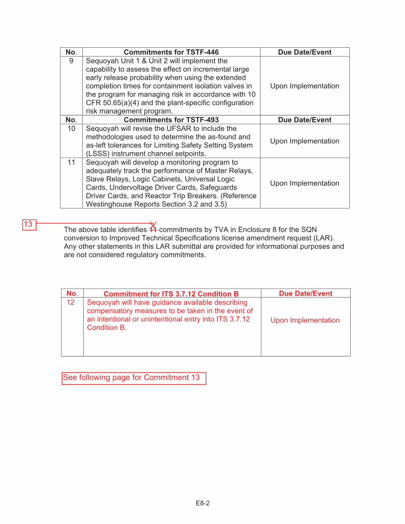
No. Commitments for TSTF-446 Due Date/Event 9 Sequoyah Unit 1 & Unit 2 will implement the
capability to assess the effect on incremental large early release probability when using the extended completion times for containment isolation valves in the program for managing risk in accordance with 10 CFR 50.65(a)(4) and the plant-specific configuration risk management program.
Upon Implementation
No. Commitments for TSTF-493 Due Date/Event10 Sequoyah will revise the UFSAR to include the
methodologies used to determine the as-found and as-left tolerances for Limiting Safety Setting System (LSSS) instrument channel setpoints.
Upon Implementation
11 Sequoyah will develop a monitoring program to adequately track the performance of Master Relays, Slave Relays, Logic Cabinets, Universal Logic Cards, Undervoltage Driver Cards, Safeguards Driver Cards, and Reactor Trip Breakers. (Reference Westinghouse Reports Section 3.2 and 3.5)
Upon Implementation
The above table identifies 11 commitments by TVA in Enclosure 8 for the SQN conversion to Improved Technical Specifications license amendment request (LAR). Any other statements in this LAR submittal are provided for informational purposes and are not considered regulatory commitments.
E8-2
No. Commitment for Due Date/Event
Upon Implementation
13
See following page for Commitment 13
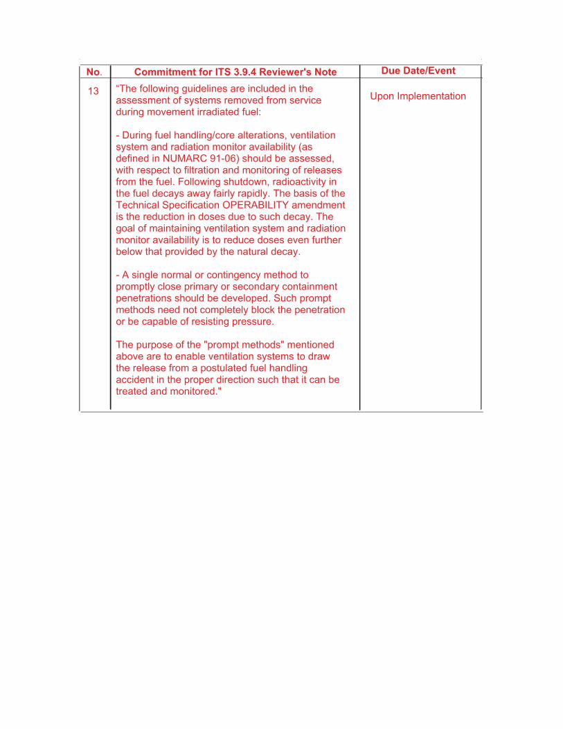
Commitment for No. Due Date/Event
Upon Implementation

Licensee Response/NRC Response/NRC Question ClosureId 435
NRC Question Number RPG-014
Select Application NRC Question Closure
Attachment 1
Attachment 2
Response Statement
Response Date/Time
Closure Statement This question is closed and no further information is required at this time to draft the Safety Evaluation.
Question Closure Date 4/21/2015
Notification Mark BlumbergScott BowmanMichelle ConnerRobert ElliottRavinder GroverKhadijah HemphillAndrew HonLynn MynattRay SchieleRoger Scott
Added By Ravinder Grover
Date Added 4/21/2015 4:06 PM
Date Modified
Modified By
Page 1 of 1Sequoyah ITS Conversion Database
04/28/2015https://members.excelservices.com/rai/index.php?requestType=areaItemPrint&itemId=435
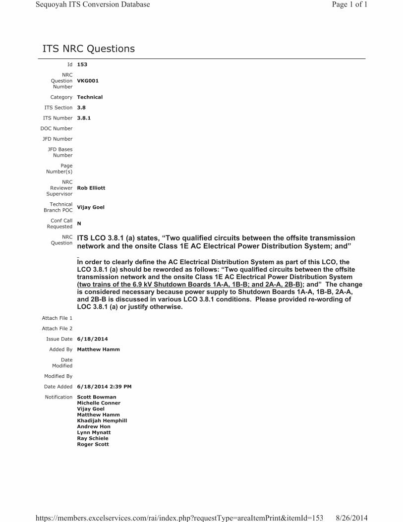
ITS NRC QuestionsId 153
NRC Question Number
VKG001
Category Technical
ITS Section 3.8
ITS Number 3.8.1
DOC Number
JFD Number
JFD Bases Number
Page Number(s)
NRC Reviewer
Supervisor Rob Elliott
Technical Branch POC Vijay Goel
Conf Call Requested N
NRC Question
ITS LCO 3.8.1 (a) states, “Two qualified circuits between the offsite transmission network and the onsite Class 1E AC Electrical Power Distribution System; and”
In order to clearly define the AC Electrical Distribution System as part of this LCO, the LCO 3.8.1 (a) should be reworded as follows: “Two qualified circuits between the offsite transmission network and the onsite Class 1E AC Electrical Power Distribution System (two trains of the 6.9 kV Shutdown Boards 1A-A, 1B-B; and 2A-A, 2B-B); and” The change is considered necessary because power supply to Shutdown Boards 1A-A, 1B-B, 2A-A, and 2B-B is discussed in various LCO 3.8.1 conditions. Please provided re-wording of LOC 3.8.1 (a) or justify otherwise.
Attach File 1
Attach File 2
Issue Date 6/18/2014
Added By Matthew Hamm
Date Modified
Modified By
Date Added 6/18/2014 2:39 PM
Notification Scott BowmanMichelle ConnerVijay GoelMatthew HammKhadijah HemphillAndrew HonLynn MynattRay SchieleRoger Scott
Page 1 of 1Sequoyah ITS Conversion Database
8/26/2014https://members.excelservices.com/rai/index.php?requestType=areaItemPrint&itemId=153
Licensee Response/NRC Response/NRC Question ClosureId 175
NRC Question Number
VKG001
Select Application Licensee Response
Attachment 1
Attachment 2
Response Statement
In response to RAI VKG-001, the following information is provided to justify not including details of the Class 1E electrical distribution system within ITS LCO 3.8.1.
The Sequoyah Nuclear Plant (SQN) Class 1E electrical distribution system is adequately described in ITS 3.8.1 Bases, Background Section. Within ISTS 3.8.1 Bases markup, on page B 3.8.1-1, Insert 1(pages 99 and 149 of Enclosure 2, Volume 13), the onsite Class 1E electrical distribution system includes a description of the 6.9 kV Shutdown Board arrangement. On page B 3.8.1-3, Insert 8 (pages 104-106 and 154-156), a detailed description of the offsite circuits is provided. The description provides several examples of offsite circuit configurations, including various offsite “power source” combinations available to meet the GDC 17 requirements for an OPERABLE offsite circuit.
The descriptions of the Class 1E electrical distribution system and offsite circuits provided in the ITS 3.8.1 Bases are details of system design that are not necessary to be included in the Technical Specifications to provide adequate protection of public health and safety.
Response Date/Time 7/16/2014 2:30 AM
Closure Statement
Question Closure
Date
Notification Scott BowmanMichelle ConnerKhadijah HemphillAndrew HonRay Schiele
Added By Scott Bowman
Date Added 7/16/2014 1:28 PM
Date Modified
Modified By
Page 1 of 1Sequoyah ITS Conversion Database
8/21/2014https://members.excelservices.com/rai/index.php?requestType=areaItemPrint&itemId=175

Licensee Response/NRC Response/NRC Question ClosureId 227
NRC Question Number VKG001
Select Application NRC Question Closure
Attachment 1
Attachment 2
Response Statement
Response Date/Time
Closure Statement This question is closed and no further information is required at this time to draft the Safety Evaluation.
Question Closure Date 8/4/2014
Notification Scott BowmanMichelle ConnerVijay GoelKhadijah HemphillAndrew HonLynn MynattRay SchieleRoger Scott
Added By Khadijah Hemphill
Date Added 8/4/2014 5:52 PM
Date Modified
Modified By
Page 1 of 1Sequoyah ITS Conversion Database
8/21/2014https://members.excelservices.com/rai/index.php?requestType=areaItemPrint&itemId=227
ITS NRC QuestionsId 154
NRC Question Number
VKG002
Category Technical
ITS Section 3.8
ITS Number 3.8.1
DOC Number
JFD Number
JFD Bases Number
Page Number(s)
NRC Reviewer
Supervisor Rob Elliott
Technical Branch POC Vijay Goel
Conf Call Requested N
NRC Question
ITS LCO 3.8.1, Condition A states, “One offsite circuit inoperable for reasons other than Condition C.” The Completion Time corresponding to Required Action A.2 states, “24 hours from discovery of no offsite power to 6.9 kV Shutdown Board 1A-A or 1B-B concurrent with inoperability of redundant required features”
It is not clear how the Condition A is related to Shutdown Board 1A-A or 1B-B indicated in Action A.2, and how it is related to Condition C. Because of the complexity of various alternate power feeds to the four 6 kV Shutdown Boards 1A-A, 2A-A, 1B-B, and 2B-B, the Condition A should clearly state the offsite circuit to which specific Shutdown Board(s) is considered inoperable as part of Condition A. Condition A should be revised (similar to the Condition A the licensee presented in the pre-submittal meeting dated June 4, 2013), as follows: “One offsite circuit to 6.9 kV Shutdown Board 1A-A inoperable OR One offsite circuit to 6.9 kV Shutdown Board 1B-B inoperable OR One offsite circuit to 6.9 kV Shutdown Boards 1A-A and 2A-A inoperable OR One offsite circuit to 6.9 kV Shutdown Boards 1B-B and 2B-B inoperable” with a NOTE: “Inoperable offsite circuits to Shutdown Board 2A-A or 2B-B are addressed in Condition C.” Please provide requisite re-wording of Condition A or justify otherwise.
Attach File 1
Attach File 2
Issue Date 6/18/2014
Added By Matthew Hamm
Page 1 of 2Sequoyah ITS Conversion Database
8/21/2014https://members.excelservices.com/rai/index.php?requestType=areaItemPrint&itemId=154
Date Modified
Modified By
Date Added 6/18/2014 2:40 PM
Notification Scott BowmanMichelle ConnerVijay GoelMatthew HammKhadijah HemphillAndrew HonRay SchieleRoger Scott
Page 2 of 2Sequoyah ITS Conversion Database
8/21/2014https://members.excelservices.com/rai/index.php?requestType=areaItemPrint&itemId=154
Licensee Response/NRC Response/NRC Question ClosureId 176
NRC Question Number
VKG002
Select Application Licensee Response
Attachment 1
Attachment 2
Response Statement Current Technical Specifications (CTS) 3.8.1.1, Action a, requires the restoration
of an inoperable offsite circuit to an operable status in 72 hours. This action applies to an offsite circuit that is inoperable for any reason.
As stated in ITS 3.8.1 Bases markup, Insert 2, there are several offsite power sources that can be combined to form an offsite circuit. In some cases, combinations of different transformers (i.e., unit station service transformers (USSTs) and/or common service station transformers (CSSTs)) are used. Insert 8 provides four common offsite power source alignments using different combinations of transformers to provide two qualified offsite circuits.
For example, Insert 8, offsite power configuration 2 provides the following combination (simplified):
2. Two offsite circuits consisting of a and b (Circuit 2 relies on automatic transfer to CSST A or CSST C on a loss of one or more USSTs):
a. Normal power source alignments (Circuit 1)
1) USST 1A to 6.9 kV Shutdown Board 1A-A;
2) USST 1B to 6.9 kV Shutdown Board 1B-B;
3) USST 2A to 6.9 kV Shutdown Board 2A-A; and
4) USST 2B to 6.9 kV Shutdown Board 2B-B.
b. Alternate power source alignments (b.1 or b.2) (Circuit 2)
1) From the 161 kV transmission network, through:
(a) CSST A (winding X) to 6.9 kV Shutdown Board 1B-B; and
(b) CSST A (winding Y) to 6.9 kV Shutdown Board 2B-B; or
2) From the 161 kV transmission network, through:
(a) CSST C (winding X) to 6.9 kV Shutdown Board 2A-A; and
(b) CSST C (winding Y) to 6.9 kV Shutdown Board 1A-A.
Page 1 of 2Sequoyah ITS Conversion Database
8/21/2014https://members.excelservices.com/index.php?requestType=areaItemPrint&itemId=176
In the above example, as it pertains to Unit 1 operation, if USST 2A becomes inoperable to 6.9 kV Shutdown Board 2A-A, the offsite circuit is inoperable solely due to an inoperable offsite power source to an opposite unit’s shutdown board.Therefore, ITS 3.8.1, Condition C, applies and is entered. If the offsite circuit is inoperable for any other reason, then ITS 3.8.1, Condition A, applies and is entered.
The Required Actions associated with ITS 3.8.1, Condition C, focus on the impact to the shared equipment that the associated unit is crediting that is powered from the opposite unit’s 6.9 kV Shutdown Board. The intent of ITS 3.8.1 Condition A is to address the instances of an offsite circuit inoperable for any reason other than the cases covered by Condition C. Therefore, ITS 3.8.1, Condition A is worded correctly to address all other reasons that an offsite circuit may be inoperable.
ITS 3.8.1, Required Action A.2, is provided to ensure that during the time that Condition A is entered, if a required feature becomes inoperable that is redundant to a required feature powered from an associated unit’s shutdown board (i.e., for Unit 1, 6.9 kV Shutdown Board 1A-A or 1B-B), then the required feature powered from the associated unit’s shutdown board is required to be declared inoperable in 24 hours. Required Action A.2 provides assurance that an event coincident with a single failure of the associated DG will not result in a complete loss of safety function of critical redundant required features.
Response Date/Time 7/16/2014 2:35 PM
Closure Statement
Question Closure
Date
Notification Scott BowmanMichelle ConnerVijay GoelKhadijah HemphillAndrew HonRay Schiele
Added By Scott Bowman
Date Added 7/16/2014 1:33 PM
Date Modified
Modified By
Page 2 of 2Sequoyah ITS Conversion Database
8/21/2014https://members.excelservices.com/index.php?requestType=areaItemPrint&itemId=176

Licensee Response/NRC Response/NRC Question ClosureId 228
NRC Question Number VKG002
Select Application NRC Question Closure
Attachment 1
Attachment 2
Response Statement
Response Date/Time
Closure Statement This question is closed and no further information is required at this time to draft the Safety Evaluation.
Question Closure Date 8/4/2014
Notification Scott BowmanMichelle ConnerVijay GoelKhadijah HemphillAndrew HonLynn MynattRay SchieleRoger Scott
Added By Khadijah Hemphill
Date Added 8/4/2014 5:52 PM
Date Modified
Modified By
Page 1 of 1Sequoyah ITS Conversion Database
8/21/2014https://members.excelservices.com/index.php?requestType=areaItemPrint&itemId=228
ITS NRC QuestionsId 155
NRC Question Number
VKG003
Category Technical
ITS Section 3.8
ITS Number 3.8.1
DOC Number
JFD Number
JFD Bases Number
Page Number(s)
NRC Reviewer
Supervisor Rob Elliott
Technical Branch POC Vijay Goel
Conf Call Requested N
NRC Question
ITS LCO 3.8.1, Condition C states, “One offsite circuit inoperable solely due to an offsite power source to 6.9 kV Shutdown Board 2A-A or 2B-B inoperable.”
It is not clear why in the Condition C, the “offsite circuit inoperable” is constrained to “solely due to an offsite power source inoperable” while no such constraint is considered in Condition A. Condition C should be revised (similar to the Condition C the licensee presented in the pre-submittal meeting dated June 4, 2013), as follows: “One offsite circuit to 6.9 kV Shutdown Board 2A-A or 2B-B inoperable” with a NOTE: “Only applicable when offsite circuits to 6.9 kV Shutdown Boards 1A-A and 1B-B are OPERABLE.” Please provide requisite re-wording of Condition C or justify otherwise. Also, please identify parameters and value/range of parameters which will render an offsite power source/circuit inoperable.
Attach File 1
Attach File 2
Issue Date 6/18/2014
Added By Matthew Hamm
Date Modified
Modified By
Date Added 6/18/2014 2:42 PM
Notification Scott BowmanMichelle ConnerVijay GoelMatthew HammKhadijah HemphillAndrew HonRay SchieleRoger Scott
Page 1 of 1Sequoyah ITS Conversion Database
9/17/2014https://members.excelservices.com/rai/index.php?requestType=areaItemPrint&itemId=155
Licensee Response/NRC Response/NRC Question ClosureId 177
NRC Question Number
VKG003
Select Application Licensee Response
Attachment 1
Attachment 2
Response Statement ITS 3.8.1 Condition C is applicable to the specific cases of an inoperable offsite
circuit due to an inoperable power source to an opposite unit’s 6.9 kV Shutdown Board. The Required Actions associated with Condition C focus on the impact to the shared equipment that the associated unit is crediting that is powered from the opposite unit’s 6.9 kV Shutdown Board. The Note that modified Condition C, as presented during the June 4, 2013 pre-submittal meeting, was later removed with the rewording of Condition C to refer to an offsite circuit inoperable solely due to an inoperable power source to an opposite unit’s 6.9 kV Shutdown Board.The reworded Condition meets the same intent of specifying that Condition C entry depends on the operability of offsite circuits to the associated unit’s 6.9 kV Shutdown Boards.
The intent of ITS 3.8.1 Condition A is to address the instances of an offsite circuit inoperable for any reason other than the cases covered by Condition C. ITS 3.8.1 Condition A addresses all instances of an inoperable offsite circuit that are currently addressed by CTS 3.8.1.1 Action a, with the exception of an offsite circuit inoperable due to an inoperable offsite power source to an opposite unit’s 6.9 kV Shutdown Board (ITS 3.8.1 Condition C). Therefore, the wording of ITS 3.8.1 Condition C is appropriate.
The operability of Sequoyah Nuclear Plant (SQN) offsite power sources is dependent on several factors which are under the control of and are the responsibility of the Transmission Operator. These include:
1. Total System Load
2. SQN Switchyard configuration (including Intertie Transformer and Capacitor Bank)
3. Configuration of 161kV and 500kV Transmission Lines outside SQN
The required minimum post-accident voltage for a normal SQN load alignment is 153kV at all times. SQN has alternate load alignments with higher minimum post-accident voltage requirements (159kV) which, therefore, require notification to the Transmission Operator:
1. Supplying more than one shutdown board from a single common station service transformer (CSST) winding (Start Bus).
2. Transferring any boards fed from the 6.9kV Common Boards to alternate or
Page 1 of 2Sequoyah ITS Conversion Database
9/17/2014https://members.excelservices.com/rai/index.php?requestType=areaItemPrint&itemId=177
transferring any 480V Unit Board, Turbine Building Motor Operated Valve or Vent Board to alternate.
3. Any CSST tap changer not in automatic for a CSST winding which is supplying a Start Bus.
The 500kV bus voltage should be maintained at a level of 520kV.
With a unit station service transformer (USST) load tap changer (LTC) in any position other than AUTO, if the transformer is supplying a Shutdown Board, then the offsite power source to the associated Shutdown Boards is inoperable.
Response Date/Time 7/16/2014 2:40 PM
Closure Statement
Question Closure
Date
Notification Scott BowmanMichelle ConnerVijay GoelKhadijah HemphillAndrew HonRay Schiele
Added By Scott Bowman
Date Added 7/16/2014 1:36 PM
Date Modified
Modified By
Page 2 of 2Sequoyah ITS Conversion Database
9/17/2014https://members.excelservices.com/rai/index.php?requestType=areaItemPrint&itemId=177
Licensee Response/NRC Response/NRC Question ClosureId 263
NRC Question Number
VKG003
Select Application NRC Response
Attachment 1
Attachment 2
Response Statement
In response to RAI # VKG003, the licensee stated:
“The required minimum post-accident voltage for a normal SQN load alignment is 153kV at all times. SQN has alternate load alignments with higher minimum post-accident voltage requirements (159kV) which, therefore, require notification to the Transmission Operator:
1. Supplying more than one shutdown board from a single common station service transformer (CSST) winding (Start Bus).
2. Transferring any boards fed from the 6.9kV Common Boards to alternate or transferring any 480V Unit Board, Turbine Building Motor Operated Valve or Vent Board to alternate.
3. Any CSST tap changer not in automatic for a CSST winding which is supplying a Start Bus.
The 500kV bus voltage should be maintained at a level of 520kV.”
Whereas the licensee provided minimum post-accident voltage required at 161 kV level, the minimum post-accident voltage required at 500 kV level is not provided. It is not clear whether 520 kV is the minimum bus voltage required corresponding to the post-accident at 500 kV level. Please provide necessary information and confirm that minimum post-accident voltage(s) are based upon appropriate supporting calculation(s)/documentation. Also, confirm the voltage level(s) of 161 kV and 500 kV sources below which these sources will be declared inoperable.
Response Date/Time 8/13/2014 6:00 PM
Closure Statement
Question Closure
Date
Notification Scott BowmanMichelle ConnerVijay Goel
Page 1 of 2Sequoyah ITS Conversion Database
9/17/2014https://members.excelservices.com/rai/index.php?requestType=areaItemPrint&itemId=263
Khadijah HemphillAndrew HonLynn MynattRay SchieleRoger Scott
Added By Khadijah Hemphill
Date Added 8/13/2014 9:39 AM
Date Modified
Modified By
Page 2 of 2Sequoyah ITS Conversion Database
9/17/2014https://members.excelservices.com/rai/index.php?requestType=areaItemPrint&itemId=263
Licensee Response/NRC Response/NRC Question ClosureId 332
NRC Question Number
VKG003
Select Application Licensee Response
Attachment 1
Attachment 2
Response Statement
The offsite transmission network supplies power to SQN onsite loads via the 161 kV and the 500 kV switchyard. In order to ensure that adequate power can be supplied to the onsite power loads for a Design Basis Event, a minimum worst case transient voltage has been established for each switchyard. The minimum voltage for the 161 kV and the 500 kV switchyard has been set at 153 kV and 480 kV, respectively. Voltage drops below these values would indicate inoperable offsite power sources. The TVA Transmission Group has established normal operational parameters for each switchyard that SQN monitors. Operators in the Main Control Room monitor the 161 kV switchyard for voltages between 165 kV and 170 kV. The 500 kV switchyard is monitored for voltages between 510 kV and 530 kV. If the switchyard voltages are outside these limits, the Transmission Operator is required to be notified within 30 minutes. The TVA Transmission Group then determines if the offsite power source has the necessary capacity and capability to be considered OPERABLE.
Response Date/Time 9/11/2014 4:30 PM
Closure Statement
Question Closure
Date
Notification Scott BowmanMichelle ConnerRobert ElliottVijay GoelKhadijah HemphillAndrew HonLynn MynattRay SchieleRoger Scott
Added By Lynn Mynatt
Date Added 9/11/2014 3:24 PM
Date Modified
Modified By
Page 1 of 1Sequoyah ITS Conversion Database
9/17/2014https://members.excelservices.com/rai/index.php?requestType=areaItemPrint&itemId=332

Licensee Response/NRC Response/NRC Question ClosureId 333
NRC Question Number VKG003
Select Application NRC Question Closure
Attachment 1
Attachment 2
Response Statement
Response Date/Time
Closure Statement This question is closed and no further information is required at this time to draft the Safety Evaluation.
Question Closure Date 9/15/2014
Notification Scott BowmanMichelle ConnerVijay GoelKhadijah HemphillAndrew HonLynn MynattRay SchieleRoger Scott
Added By Khadijah Hemphill
Date Added 9/15/2014 7:47 AM
Date Modified
Modified By
Page 1 of 1Sequoyah ITS Conversion Database
03/18/2015https://members.excelservices.com/rai/index.php?requestType=areaItemPrint&itemId=333
ITS NRC QuestionsId 156
NRC Question Number
VKG004
Category Technical
ITS Section 3.8
ITS Number 3.8.1
DOC Number
JFD Number
JFD Bases Number
Page Number(s)
NRC Reviewer
Supervisor Rob Elliott
Technical Branch POC Vijay Goel
Conf Call Requested N
NRC Question
ITS LCO 3.8.1, Condition C, Required Action C.3 states, “Declare associated required feature(s) inoperable.” Completion Time: 7 days
In the ITS Bases, Page B 3.8.1-8a (LAR, Enclosure 2, Volume 13, Page 114), for Action C.3, the licensee stated that, “The required offsite circuit must be returned to OPERABLE status within 7 days, or the support function for the associated required feature is considered inoperable.” To be consistent with ITS Bases, the Action C.3 of LCO 3.8.1 should be revised to state, “Return required offsite circuit to OPERABLE status OR Declare associated required feature(s) inoperable.” Please provide detailed justification why declaring only the associated required feature(s) is considered adequate.Also provide detailed justification for completion time of 7 days for Action C.3 comparing it to the corresponding Completion Time of 72 hours for Action A.3.
Attach File 1
Attach File 2
Issue Date 6/18/2014
Added By Matthew Hamm
Date Modified
Modified By
Date Added 6/18/2014 2:44 PM
Page 1 of 2Sequoyah ITS Conversion Database
8/21/2014https://members.excelservices.com/rai/index.php?requestType=areaItemPrint&itemId=156

Notification Scott BowmanMichelle ConnerVijay GoelMatthew HammKhadijah HemphillAndrew HonLynn MynattRay SchieleRoger Scott
Page 2 of 2Sequoyah ITS Conversion Database
8/21/2014https://members.excelservices.com/rai/index.php?requestType=areaItemPrint&itemId=156
Licensee Response/NRC Response/NRC Question ClosureId 178
NRC Question Number
VKG004
Select Application Licensee Response
Attachment 1
Attachment 2
Response Statement TSTF-GG-05-01, “Writer’s Guide for Plant-Specific Improved Technical
Specifications,” Section 4.1.6.g states, “A Required Action which requires restoration, such that the Condition is no longer met, is considered superfluous. It is only included if it would be the only Required Action for the Condition or it is needed for presentation clarity.” Therefore, it is unnecessary to include a Required Action to return a required DG to an operable status, as it is always an option to restore compliance with the LCO.
Proposed ITS 3.8.1 Condition C is entered when one offsite circuit is inoperable solely due to an inoperable offsite power source to an opposite unit’s shutdown board. Therefore, Required Action C.3 requires declaration that the associated required features are inoperable with a Completion Time of 7 days. This action is appropriate due to the limited amount of shared equipment that exists on an opposite unit’s shutdown board (see lists below). In addition, notwithstanding the inoperability of the power source, the current technical specifications (CTS 3.0.5) allow equipment to be considered operable for an indefinite amount of time with an inoperable normal or emergency power supply, as long as the redundant equipment remains operable.
Major shared equipment on an opposite unit’s shutdown board:
6.9 kV Shutdown Board 1A-A (and associated 480 V shutdown boards)ERCW Pump J-A (Note 1)ERCW Pump Q-A (Note 1)Control Room AHU A-A (Note 2)Control Room AC Compressor A-A (Note 2)CCS Pump 1A-A (Note 3)EGTS Fan A-A (Note 4)125 V Vital Battery Charger I (Note 5)
6.9 kV Shutdown Board 1B-B (and associated 480 V shutdown boards)ERCW Pump L-B (Note 1)ERCW Pump N-B (Note 1)Control Room AHU B-B (Note 2)Control Room AC Compressor B-B (Note 2)CCS Pump 1B-B (Note 3)EGTS Fan B-B (Note 4)125 V Vital Battery Charger II (Note 5)
6.9 kV Shutdown Board 2A-A (and associated 480 V shutdown boards)
Page 1 of 3Sequoyah ITS Conversion Database
8/21/2014https://members.excelservices.com/index.php?requestType=areaItemPrint&itemId=178
ERCW Pump R-A (Note 1)ERCW Pump K-A (Note 1)CCS Pump 2A-A (Note 3)ABGTS Fan A-A (Note 6)Auxiliary Control Air Compressor A-A (Note 7)125 V Vital Battery Charger III (Note 5)
6.9 kV Shutdown Board 2B-B (and associated 480 V shutdown boards)ERCW Pump P-B (Note 1)ERCW Pump M-B (Note 1)CCS Pump 2B-B (Note 3)CCS Pump C-S (Note 3)ABGTS Fan B-B (Note 6)Auxiliary Control Air Compressor B-B (Note 7)125 V Vital Battery Charger IV (Note 5)
NOTES:
1. The current requirement is for one operable ERCW pump per 6.9 kV Shutdown Board. Following implementation of an approved license amendment (TS-SQN-13-01 and TS-SQN-13-02, ML13280A267) an operable ERCW system train can require as few as one ERCW pump with consideration of the UHS temperature requirements. Until then, ITS 3.7.8, Condition A will require an inoperable ERCW system train to be restored in 72 hours.
2. Per ITS 3.7.10, Condition A, an inoperable train of CREVS is required to be restored in 7 days. Per ITS 3.7.11, Condition A, an inoperable CRACS train is required to be restored in 30 days.
3. CCS trains can be aligned and meet the requirements of ITS LCO 3.7.7 with the remaining operable pumps with one 6.9 kV Shutdown Board inoperable.
4. Per ITS 3.6.10, Condition A, an inoperable EGTS train is required to be restored in 7 days.
5. With the adoption of TSTF-500, ITS 3.8.4, Condition A requires an inoperable battery charger to be restored in 7 days, provided battery terminal voltage can be maintained greater than or equal to the minimum established float voltage and battery float current is maintained less than or equal to 2 amps.
6. Per ITS 3.7.12, Condition A, an inoperable ABGTS train is required to be restored in 7 days.
7. Following implementation of the proposed plant modification to install one or more auxiliary control air compressor(s), two trains of auxiliary control air can be maintained with either 6.9 kV Shutdown Board 2A-A or 2B-B inoperable. Until then, the most limiting components are the Atmospheric Relief Valves (ARVs) and the Auxiliary Feedwater (AFW) System level control valves. ITS 3.7.4, Condition A requires one or more ARV lines inoperable due to one train of Auxiliary Control Air nonfunctional to be restored in 72 hours. ITS 3.7.5, AFW, Condition B requires (in MODE 1, 2, or 3) one AFW train inoperable for reasons other than an inoperable steam supply to a turbine driven train to be restored in 72 hours.
Response Date/Time 7/16/2014 2:40 PM
Closure Statement
Question Closure
Date
Page 2 of 3Sequoyah ITS Conversion Database
8/21/2014https://members.excelservices.com/index.php?requestType=areaItemPrint&itemId=178

Notification Scott BowmanMichelle ConnerVijay GoelKhadijah HemphillAndrew HonRay Schiele
Added By Scott Bowman
Date Added 7/16/2014 1:39 PM
Date Modified
Modified By
Page 3 of 3Sequoyah ITS Conversion Database
8/21/2014https://members.excelservices.com/index.php?requestType=areaItemPrint&itemId=178

Licensee Response/NRC Response/NRC Question ClosureId 229
NRC Question Number VKG004
Select Application NRC Question Closure
Attachment 1
Attachment 2
Response Statement
Response Date/Time
Closure Statement This question is closed and no further information is required at this time to draft the Safety Evaluation.
Question Closure Date 8/4/2014
Notification Scott BowmanMichelle ConnerVijay GoelKhadijah HemphillAndrew HonLynn MynattRay SchieleRoger Scott
Added By Khadijah Hemphill
Date Added 8/4/2014 5:53 PM
Date Modified
Modified By
Page 1 of 1Sequoyah ITS Conversion Database
8/21/2014https://members.excelservices.com/index.php?requestType=areaItemPrint&itemId=229
ITS NRC QuestionsId 157
NRC Question Number VKG005
Category Technical
ITS Section 3.8
ITS Number
DOC Number
JFD Number
JFD Bases Number
Page Number(s)
NRC Reviewer
Supervisor Rob Elliott
Technical Branch POC Vijay Goel
Conf Call Requested N
NRC Question According to UFAR Section 8.1.4, the onsite (standby) power system is designed for postulated accident conditions in one unit and safe shutdown of the other unit, considering loss of offsite power and considering a single failure.
Please provide summary of worst case diesel generator (DG) loadings, considering loss of offsite power to both units; Unit 1 in accident condition; Unit 2 in safe shutdown condition; and single failure considered as follows (two separate scenarios): (1) One DG inoperable in Unit 1 (say DG 1A-A or DG 1B-B), and (2) One DG inoperable in Unit 2 (say DG 2A-A or DG 2B-B).
Attach File 1
Attach File 2
Issue Date 6/18/2014
Added By Matthew Hamm
Date Modified
Modified By
Date Added 6/18/2014 2:46 PM
Notification Scott BowmanMichelle ConnerVijay GoelMatthew HammKhadijah HemphillAndrew HonLynn MynattRay SchieleRoger Scott
Page 1 of 1Sequoyah ITS Conversion Database
8/21/2014https://members.excelservices.com/rai/index.php?requestType=areaItemPrint&itemId=157
Licensee Response/NRC Response/NRC Question ClosureId 179
NRC Question Number
VKG005
Select Application Licensee Response
Attachment 1 Attachment 1, RAI VKG-005 Draft Response.pdf (94KB)
Attachment 2
Response Statement
The diesel generator (DG) loading calculation evaluates the loading of each DG separately, in that all permanently connected and sequenced loads are considered to load onto each respective DG during any loss of offsite power (LOOP) event. The calculation contains analysis to support the safe shutdown during a LOOP, as well as a LOOP with a loss of coolant accident (LOCA). Because each DG is analyzed separately to its respective worst case loading, it is not necessary to differentiate which unit is in an accident condition or which DG is inoperable.
Attachment 1 contains excerpts from the DG loading calculation that reflect the calculated worst-case loading for each DG.
Response Date/Time 7/16/2014 2:45 PM
Closure Statement
Question Closure Date
Notification Scott BowmanMichelle ConnerVijay GoelKhadijah HemphillAndrew HonRay Schiele
Added By Scott Bowman
Date Added 7/16/2014 1:42 PM
Date Modified
Modified By
Page 1 of 1Sequoyah ITS Conversion Database
8/21/2014https://members.excelservices.com/index.php?requestType=areaItemPrint&itemId=179

Attachment 1 – SQN DG Loading
Page 1 of 3
DG Load Carrying Capability
The following tables show the maximum steady state (running) load of each DG during a loss of offsite power (LOOP), LOOP with safety injection and containment isolation Phase A (LOOP+SIA), and LOOP with safety injection and containment isolation Phase B (LOOP+SIB). Th s table represent the total steady-state running load of all sequenced loads plus the base continuous load on each DG plus random loads.
DG Loading, Load Carrying Capability
Maximum Steady-State Running Load, 0 hrs to 2 hrs
kW 1A-A 1B-B 2A-A 2B-B Short-Time Rating
Minimum Margin (%)
LOOP Time
3413.13 >120 sec
3589.95 >25 min
3594.86 >25 min
3687.63 >120 sec
4840 23.8
LOOP + SIA Time
3726.18 >720 sec
3868.80 >25 min
3901.45 >25 min
3975.06 >720 sec
4840 17.9
LOOP + SIB Time
4056.42 >720 sec
4197.20 >25 min
4272.39 >25 min
4344.83 >720 sec
4840 10.2
kVA 1A-A 1B-B 2A-A 2B-B Short-Time Rating
Minimum Margin (%)
LOOP Time
3775.66 >120 sec
3977.05 >25 min
3971.53 >25 min
4073.29 >120 sec
5500 25.9
LOOP + SIA Time
4207.34 >720 sec
4368.94 >25 min
4399.56 >25 min
4478.99 >720 sec
5500 18.6
LOOP + SIB Time
4550.78 >720 sec
4708.11 >25 min
4798.90 >25 min
4863.29 >720 sec
5500 11.6
Maximum Steady-State Running Load, 2 hrs to End
kW 1A-A 1B-B 2A-A 2B-B Continuous Rating
Minimum Margin
LOOP Time
3351.98 End
3514.35 End
3576.16 End
3615.91 End
4400 17.8
LOOP + SIA Time
3601.39 End
3731.80 End
3748.77 End
3842.54 End
4400 12.7
LOOP + SIB Time
3931.46 End
4060.05 End
4119.03 End
4154.04 End
4400 5.6
kVA 1A-A 1B-B 2A-A 2B-B Short-Time Rating
Minimum Margin (%)
LOOP Time
3706.21 End
3894.81End
3950.92End
3991.01End
5000 20.2
LOOP + SIA Time
4063.12 End
4213.80End
4225.24End
4323.80End
5000 13.5
LOOP + SIB Time
4407.27 End
4553.99End
4624.65End
4644.92End
5000 7.1
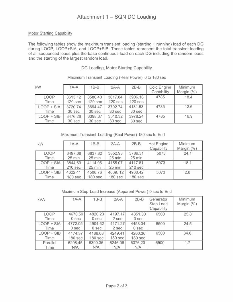
Attachment 1 – SQN DG Loading
Page 2 of 3
Motor Starting Capability
The following tables show the maximum transient loading (starting + running) load of each DG during LOOP, LOOP+SIA, and LOOP+SIB. These tables represent the total transient loading of all sequenced loads plus the base continuous load on each DG including the random loads and the starting of the largest random load.
DG Loading, Motor Starting Capability
Maximum Transient Loading (Real Power) 0 to 180 sec
kW 1A-A 1B-B 2A-A 2B-B Cold Engine Capability
Minimum Margin (%)
LOOP Time
3613.12 120 sec
3580.40 120 sec
3617.84 120 sec
3906.18 120 sec
4785 18.4
LOOP + SIA Time
3720.74 30 sec
3694.47 30 sec
3702.74 30 sec
4181.53 30 sec
4785 12.6
LOOP + SIB Time
3476.26 30 sec
3398.37 30 sec
3510.32 30 sec
3978.24 30 sec
4785 16.9
Maximum Transient Loading (Real Power) 180 sec to End
kW 1A-A 1B-B 2A-A 2B-B Hot Engine Capability
Minimum Margin (%)
LOOP Time
3497.08 25 min
3837.82 25 min
3852.93 25 min
3789.31 25 min
507 24.1
LOOP + SIA Time
3844.69 210 sec
4114.06 25 min
4155.07 25 min
4117.81 210 sec
5073 18.1
LOOP + SIB Time
4622.41 180 sec
4508.76 180 sec
4639. 12180 sec
4930.42 180 sec
5073 2.8
Maximum Step Load Increase (Apparent Power) 0 sec to End
kVA 1A-A 1B-B 2A-A 2B-B Generator Step Load Capability
Minimum Margin (%)
LOOP Time
4670.59 0 sec
4820.230 sec
4197.17 2 sec
4351.30 0 sec
6500 25.8
LOOP + SIA Time
4772.05 0 sec
4904.62 0 sec
4171.27 2 sec
4458.34 0 sec
6500 24.5
LOOP + SIB Time
4174.37 180 sec
4186.03 180 sec
4249.41 180 sec
4200.36 180 sec
6500 34.6
Parallel Time
6298.45 N/A
6390.36 N/A
6246.06 N/A
6376.23 N/A
6500 1.7
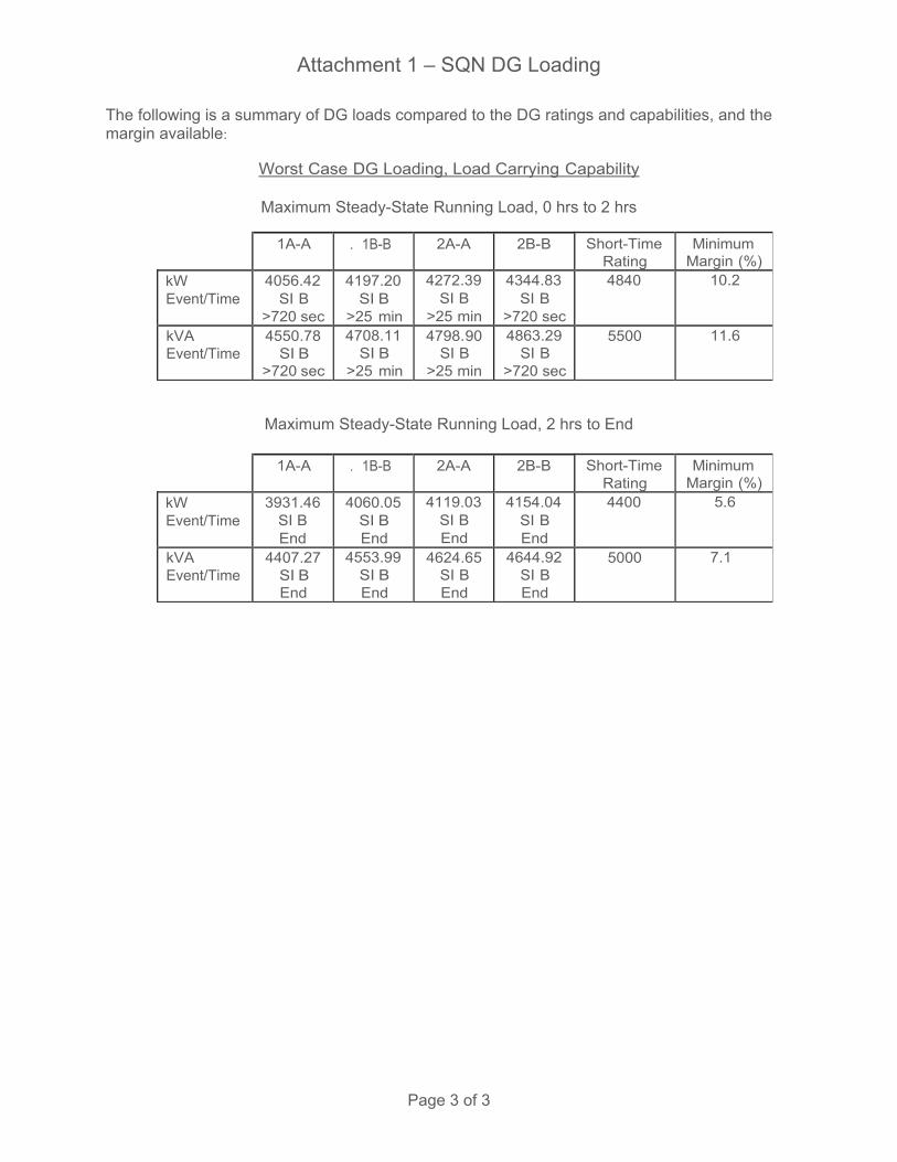
Attachment 1 – SQN DG Loading
Page 3 of 3
The following is a summary of DG loads compared to the DG ratings and capabilities, and the margin available:
Worst Case DG Loading, Load Carrying Capability
Maximum Steady-State Running Load, 0 hrs to 2 hrs
1A-A . 1B-B 2A-A 2B-B Short-Time Rating
Minimum Margin (%)
kW Event/Time
4056.42 SI B
>720 sec
4197.20 SI B
>25 min
4272.39 SI B
>25 min
4344.83 SI B
>720 sec
4840 10.2
kVA Event/Time
4550.78 SI B
>720 sec
4708.11 SI B
>25 min
4798.90 SI B
>25 min
4863.29 SI B
>720 sec
5500 11.6
Maximum Steady-State Running Load, 2 hrs to End
1A-A . 1B-B 2A-A 2B-B Short-Time Rating
Minimum Margin (%)
kW Event/Time
3931.46 SI B End
4060.05 SI B End
4119.03 SI B End
4154.04 SI B End
4400 5.6
kVA Event/Time
4407.27 SI B End
4553.99 SI B End
4624.65 SI B End
4644.92 SI B End
5000 7.1

Licensee Response/NRC Response/NRC Question ClosureId 230
NRC Question Number VKG005
Select Application NRC Question Closure
Attachment 1
Attachment 2
Response Statement
Response Date/Time
Closure Statement This question is closed and no further information is required at this time to draft the Safety Evaluation.
Question Closure Date 8/4/2014
Notification Scott BowmanMichelle ConnerAndrew HonLynn MynattRay SchieleRoger Scott
Added By Khadijah Hemphill
Date Added 8/4/2014 5:54 PM
Date Modified
Modified By
Page 1 of 1Sequoyah ITS Conversion Database
8/21/2014https://members.excelservices.com/index.php?requestType=areaItemPrint&itemId=230
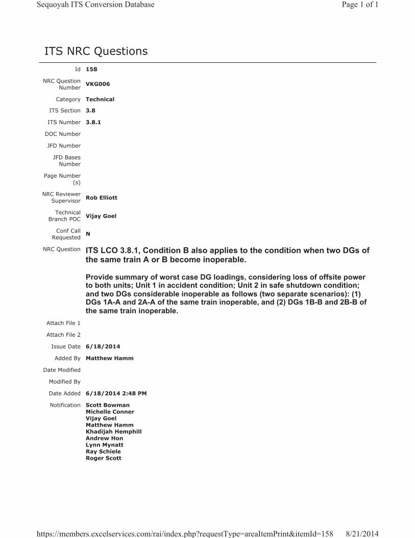
ITS NRC QuestionsId 158
NRC Question Number VKG006
Category Technical
ITS Section 3.8
ITS Number 3.8.1
DOC Number
JFD Number
JFD Bases Number
Page Number(s)
NRC Reviewer Supervisor Rob Elliott
Technical Branch POC Vijay Goel
Conf Call Requested N
NRC Question ITS LCO 3.8.1, Condition B also applies to the condition when two DGs of the same train A or B become inoperable.
Provide summary of worst case DG loadings, considering loss of offsite power to both units; Unit 1 in accident condition; Unit 2 in safe shutdown condition; and two DGs considerable inoperable as follows (two separate scenarios): (1) DGs 1A-A and 2A-A of the same train inoperable, and (2) DGs 1B-B and 2B-B of the same train inoperable.
Attach File 1
Attach File 2
Issue Date 6/18/2014
Added By Matthew Hamm
Date Modified
Modified By
Date Added 6/18/2014 2:48 PM
Notification Scott BowmanMichelle ConnerVijay GoelMatthew HammKhadijah HemphillAndrew HonLynn MynattRay SchieleRoger Scott
Page 1 of 1Sequoyah ITS Conversion Database
8/21/2014https://members.excelservices.com/rai/index.php?requestType=areaItemPrint&itemId=158

Licensee Response/NRC Response/NRC Question ClosureId 180
NRC Question Number
VKG006
Select Application Licensee Response
Attachment 1 Attachment 1, RAI VKG-006 Draft Response.pdf (94KB)
Attachment 2
Response Statement
The diesel generator (DG) loading calculation evaluates the loading of each DG separately, in that all permanently connected and sequenced loads are considered to load onto each respective DG during any loss of offsite power (LOOP) event. The calculation contains analysis to support the safe shutdown during a LOOP, as well as a LOOP with a loss of coolant accident (LOCA). Because each DG is analyzed separately to its respective worst case loading, it is not necessary to differentiate which unit is in an accident condition or which DG is inoperable.
Attachment 1 contains excerpts from the DG loading calculation that reflect the calculated worst-case loading for each DG.
Response Date/Time 7/16/2014 2:45 PM
Closure Statement
Question Closure Date
Notification Scott BowmanMichelle ConnerVijay GoelKhadijah HemphillAndrew HonRay Schiele
Added By Scott Bowman
Date Added 7/16/2014 1:44 PM
Date Modified
Modified By
Page 1 of 1Sequoyah ITS Conversion Database
8/21/2014https://members.excelservices.com/index.php?requestType=areaItemPrint&itemId=180
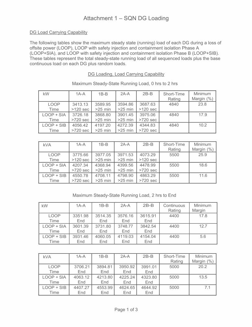
Attachment 1 – SQN DG Loading
Page 1 of 3
DG Load Carrying Capability
The following tables show the maximum steady state (running) load of each DG during a loss of offsite power (LOOP), LOOP with safety injection and containment isolation Phase A (LOOP+SIA), and LOOP with safety injection and containment isolation Phase B (LOOP+SIB). Th s table represent the total steady-state running load of all sequenced loads plus the base continuous load on each DG plus random loads.
DG Loading, Load Carrying Capability
Maximum Steady-State Running Load, 0 hrs to 2 hrs
kW 1A-A 1B-B 2A-A 2B-B Short-Time Rating
Minimum Margin (%)
LOOP Time
3413.13 >120 sec
3589.95 >25 min
3594.86 >25 min
3687.63 >120 sec
4840 23.8
LOOP + SIA Time
3726.18 >720 sec
3868.80 >25 min
3901.45 >25 min
3975.06 >720 sec
4840 17.9
LOOP + SIB Time
4056.42 >720 sec
4197.20 >25 min
4272.39 >25 min
4344.83 >720 sec
4840 10.2
kVA 1A-A 1B-B 2A-A 2B-B Short-Time Rating
Minimum Margin (%)
LOOP Time
3775.66 >120 sec
3977.05 >25 min
3971.53 >25 min
4073.29 >120 sec
5500 25.9
LOOP + SIA Time
4207.34 >720 sec
4368.94 >25 min
4399.56 >25 min
4478.99 >720 sec
5500 18.6
LOOP + SIB Time
4550.78 >720 sec
4708.11 >25 min
4798.90 >25 min
4863.29 >720 sec
5500 11.6
Maximum Steady-State Running Load, 2 hrs to End
kW 1A-A 1B-B 2A-A 2B-B Continuous Rating
Minimum Margin
LOOP Time
3351.98 End
3514.35 End
3576.16 End
3615.91 End
4400 17.8
LOOP + SIA Time
3601.39 End
3731.80 End
3748.77 End
3842.54 End
4400 12.7
LOOP + SIB Time
3931.46 End
4060.05 End
4119.03 End
4154.04 End
4400 5.6
kVA 1A-A 1B-B 2A-A 2B-B Short-Time Rating
Minimum Margin (%)
LOOP Time
3706.21 End
3894.81End
3950.92End
3991.01End
5000 20.2
LOOP + SIA Time
4063.12 End
4213.80End
4225.24End
4323.80End
5000 13.5
LOOP + SIB Time
4407.27 End
4553.99End
4624.65End
4644.92End
5000 7.1

Attachment 1 – SQN DG Loading
Page 2 of 3
Motor Starting Capability
The following tables show the maximum transient loading (starting + running) load of each DG during LOOP, LOOP+SIA, and LOOP+SIB. These tables represent the total transient loading of all sequenced loads plus the base continuous load on each DG including the random loads and the starting of the largest random load.
DG Loading, Motor Starting Capability
Maximum Transient Loading (Real Power) 0 to 180 sec
kW 1A-A 1B-B 2A-A 2B-B Cold Engine Capability
Minimum Margin (%)
LOOP Time
3613.12 120 sec
3580.40 120 sec
3617.84 120 sec
3906.18 120 sec
4785 18.4
LOOP + SIA Time
3720.74 30 sec
3694.47 30 sec
3702.74 30 sec
4181.53 30 sec
4785 12.6
LOOP + SIB Time
3476.26 30 sec
3398.37 30 sec
3510.32 30 sec
3978.24 30 sec
4785 16.9
Maximum Transient Loading (Real Power) 180 sec to End
kW 1A-A 1B-B 2A-A 2B-B Hot Engine Capability
Minimum Margin (%)
LOOP Time
3497.08 25 min
3837.82 25 min
3852.93 25 min
3789.31 25 min
507 24.1
LOOP + SIA Time
3844.69 210 sec
4114.06 25 min
4155.07 25 min
4117.81 210 sec
5073 18.1
LOOP + SIB Time
4622.41 180 sec
4508.76 180 sec
4639. 12180 sec
4930.42 180 sec
5073 2.8
Maximum Step Load Increase (Apparent Power) 0 sec to End
kVA 1A-A 1B-B 2A-A 2B-B Generator Step Load Capability
Minimum Margin (%)
LOOP Time
4670.59 0 sec
4820.230 sec
4197.17 2 sec
4351.30 0 sec
6500 25.8
LOOP + SIA Time
4772.05 0 sec
4904.62 0 sec
4171.27 2 sec
4458.34 0 sec
6500 24.5
LOOP + SIB Time
4174.37 180 sec
4186.03 180 sec
4249.41 180 sec
4200.36 180 sec
6500 34.6
Parallel Time
6298.45 N/A
6390.36 N/A
6246.06 N/A
6376.23 N/A
6500 1.7

Attachment 1 – SQN DG Loading
Page 3 of 3
The following is a summary of DG loads compared to the DG ratings and capabilities, and the margin available:
Worst Case DG Loading, Load Carrying Capability
Maximum Steady-State Running Load, 0 hrs to 2 hrs
1A-A . 1B-B 2A-A 2B-B Short-Time Rating
Minimum Margin (%)
kW Event/Time
4056.42 SI B
>720 sec
4197.20 SI B
>25 min
4272.39 SI B
>25 min
4344.83 SI B
>720 sec
4840 10.2
kVA Event/Time
4550.78 SI B
>720 sec
4708.11 SI B
>25 min
4798.90 SI B
>25 min
4863.29 SI B
>720 sec
5500 11.6
Maximum Steady-State Running Load, 2 hrs to End
1A-A . 1B-B 2A-A 2B-B Short-Time Rating
Minimum Margin (%)
kW Event/Time
3931.46 SI B End
4060.05 SI B End
4119.03 SI B End
4154.04 SI B End
4400 5.6
kVA Event/Time
4407.27 SI B End
4553.99 SI B End
4624.65 SI B End
4644.92 SI B End
5000 7.1

Licensee Response/NRC Response/NRC Question ClosureId 231
NRC Question Number VKG006
Select Application NRC Question Closure
Attachment 1
Attachment 2
Response Statement
Response Date/Time
Closure Statement This question is closed and no further information is required at this time to draft the Safety Evaluation.
Question Closure Date 8/4/2014
Notification Scott BowmanMichelle ConnerLynn MynattRay SchieleRoger Scott
Added By Khadijah Hemphill
Date Added 8/4/2014 5:54 PM
Date Modified
Modified By
Page 1 of 1Sequoyah ITS Conversion Database
8/26/2014https://members.excelservices.com/rai/index.php?requestType=areaItemPrint&itemId=231
ITS NRC QuestionsId 159
NRC Question Number
VKG007
Category Technical
ITS Section 3.8
ITS Number 3.8.1
DOC Number
JFD Number
JFD Bases Number
Page Number(s)
NRC Reviewer
Supervisor Rob Elliott
Technical Branch POC Vijay Goel
Conf Call Requested N
NRC Question
ITS LCO 3.8.1, Condition D, Required Action D.4 states, “Declare associated required feature(s) inoperable.” Completion Time: 7 days
In the ITS Bases, Page B 3.8.1-8c (LAR, Enclosure 2, Volume 13, Page 116), for Action D.4, the licensee stated that, “The required DG must be returned to OPERABLE status within 7 days, or the support function for the associated required feature is considered inoperable.” To be consistent with ITS Bases, the Action D.4 for LCO 3.8.1 should be revised to state, “Return required DG OPERABLE status OR Declare associated required feature(s) inoperable.” Please provide detailed justification why declaring only the associated required feature(s) is considered adequate.
Attach File 1
Attach File 2
Issue Date 6/18/2014
Added By Matthew Hamm
Date Modified
Modified By
Date Added 6/18/2014 2:49 PM
Notification Scott BowmanMichelle ConnerVijay GoelMatthew HammKhadijah HemphillAndrew HonLynn MynattRay SchieleRoger Scott
Page 1 of 1Sequoyah ITS Conversion Database
8/21/2014https://members.excelservices.com/rai/index.php?requestType=areaItemPrint&itemId=159
Licensee Response/NRC Response/NRC Question ClosureId 181
NRC Question Number
VKG007
Select Application Licensee Response
Attachment 1
Attachment 2
Response Statement TSTF-GG-05-01, “Writer’s Guide for Plant-Specific Improved Technical
Specifications,” Section 4.1.6.g states, “A Required Action which requires restoration, such that the Condition is no longer met, is considered superfluous. It is only included if it would be the only Required Action for the Condition or it is needed for presentation clarity.” Therefore, it is unnecessary to include a Required Action to return a required DG to an operable status, as it is always an option to restore compliance with the LCO.
Proposed ITS 3.8.1 Condition D is entered when one opposite unit’s DG is inoperable. Therefore, Required Action C.4 requires declaration that the associated required features are inoperable with a Completion Time of 7 days.This action is appropriate due to the limited amount of shared equipment that exists on an opposite unit’s shutdown board (see lists below). In addition, notwithstanding the inoperability of the power source, the current technical specifications (CTS 3.0.5) allow equipment to be considered operable for an indefinite amount of time with an inoperable normal or emergency power supply, as long as the redundant equipment remains operable.
Major shared equipment on an opposite unit’s shutdown board:
6.9 kV Shutdown Board 1A-A (and associated 480 V shutdown boards)ERCW Pump J-A (Note 1)ERCW Pump Q-A (Note 1)Control Room AHU A-A (Note 2)Control Room AC Compressor A-A (Note 2)CCS Pump 1A-A (Note 3)EGTS Fan A-A (Note 4)125 V Vital Battery Charger I (Note 5)
6.9 kV Shutdown Board 1B-B (and associated 480 V shutdown boards)ERCW Pump L-B (Note 1)ERCW Pump N-B (Note 1)Control Room AHU B-B (Note 2)Control Room AC Compressor B-B (Note 2)CCS Pump 1B-B (Note 3)EGTS Fan B-B (Note 4)125 V Vital Battery Charger II (Note 5)
6.9 kV Shutdown Board 2A-A (and associated 480 V shutdown boards)ERCW Pump R-A (Note 1)
Page 1 of 3Sequoyah ITS Conversion Database
8/21/2014https://members.excelservices.com/index.php?requestType=areaItemPrint&itemId=181
ERCW Pump K-A (Note 1)CCS Pump 2A-A (Note 3)ABGTS Fan A-A (Note 6)Auxiliary Control Air Compressor A-A (Note 7)125 V Vital Battery Charger III (Note 5)
6.9 kV Shutdown Board 2B-B (and associated 480 V shutdown boards)ERCW Pump P-B (Note 1)ERCW Pump M-B (Note 1)CCS Pump 2B-B (Note 3)CCS Pump C-S (Note 3)ABGTS Fan B-B (Note 6)Auxiliary Control Air Compressor B-B (Note 7)125 V Vital Battery Charger IV (Note 5)
NOTES:
1. The current requirement is for one operable ERCW pump per 6.9 kV Shutdown Board. Following implementation of an approved license amendment (TS-SQN-13-01 and TS-SQN-13-02, ML13280A267) an operable ERCW system train can require as few as one ERCW pump with consideration of the UHS temperature requirements. Until then, ITS 3.7.8, Condition A will require an inoperable ERCW system train to be restored in 72 hours.
2. Per ITS 3.7.10, Condition A, an inoperable train of CREVS is required to be restored in 7 days. Per ITS 3.7.11, Condition A, an inoperable CRACS train is required to be restored in 30 days.
3. CCS trains can be aligned and meet the requirements of ITS LCO 3.7.7 with the remaining operable pumps with one 6.9 kV Shutdown Board inoperable.
4. Per ITS 3.6.10, Condition A, an inoperable EGTS train is required to be restored in 7 days.
5. With the adoption of TSTF-500, ITS 3.8.4, Condition A requires an inoperable battery charger to be restored in 7 days, provided battery terminal voltage can be maintained greater than or equal to the minimum established float voltage and battery float current is maintained less than or equal to 2 amps.
6. Per ITS 3.7.12, Condition A, an inoperable ABGTS train is required to be restored in 7 days.
7. Following implementation of the proposed plant modification to install one or more additional auxiliary control air compressor(s), two trains of auxiliary control air can be maintained with either 6.9 kV Shutdown Board 2A-A or 2B-B inoperable. Until then, the most limiting components are the Atmospheric Relief Valves (ARVs) and the Auxiliary Feedwater System (AFW) level control valves. ITS 3.7.4, ARVs, Condition A requires one or more ARV lines inoperable due to one train of auxiliary control air nonfunctional to be restored in 72 hours. ITS 3.7.5, AFW, Condition B requires (in MODE 1, 2, or 3) one AFW train inoperable for reasons other than an inoperable steam supply valve to a turbine driven train to be restored in 72 hours.
Response Date/Time 7/16/2014 2:50 PM
Closure Statement
Question Closure
Date
Page 2 of 3Sequoyah ITS Conversion Database
8/21/2014https://members.excelservices.com/index.php?requestType=areaItemPrint&itemId=181

Notification Scott BowmanMichelle ConnerVijay GoelKhadijah HemphillAndrew HonRay Schiele
Added By Scott Bowman
Date Added 7/16/2014 1:47 PM
Date Modified
Modified By
Page 3 of 3Sequoyah ITS Conversion Database
8/21/2014https://members.excelservices.com/index.php?requestType=areaItemPrint&itemId=181

Licensee Response/NRC Response/NRC Question ClosureId 232
NRC Question Number VKG007
Select Application NRC Question Closure
Attachment 1
Attachment 2
Response Statement
Response Date/Time
Closure Statement This question is closed and no further information is required at this time to draft the Safety Evaluation.
Question Closure Date 8/4/2014
Notification Scott BowmanMichelle ConnerLynn MynattRay SchieleRoger Scott
Added By Khadijah Hemphill
Date Added 8/4/2014 5:55 PM
Date Modified
Modified By
Page 1 of 1Sequoyah ITS Conversion Database
8/21/2014https://members.excelservices.com/index.php?requestType=areaItemPrint&itemId=232
ITS NRC QuestionsId 160
NRC Question Number VKG008
Category Technical
ITS Section 3.8
ITS Number 3.8.1
DOC Number
JFD Number
JFD Bases Number
Page Number(s)
NRC Reviewer Supervisor Rob Elliott
Technical Branch POC Vijay Goel
Conf Call Requested N
NRC Question ITS 3.8.1, Condition E states, “Two offsite circuits inoperable.”
Condition E should be expanded to clarify the two circuits to which 6.9 kV switchboards are inoperable, such as: “Two offsite circuits to 6.9 kV Switchboards 1A-A and 1B-B inoperable.” Please provide rewording of Condition E or justify otherwise.
Attach File 1
Attach File 2
Issue Date 6/18/2014
Added By Matthew Hamm
Date Modified
Modified By
Date Added 6/18/2014 2:51 PM
Notification Scott BowmanMichelle ConnerVijay GoelMatthew HammKhadijah HemphillAndrew HonLynn MynattRay SchieleRoger Scott
Page 1 of 1Sequoyah ITS Conversion Database
8/21/2014https://members.excelservices.com/rai/index.php?requestType=areaItemPrint&itemId=160
Licensee Response/NRC Response/NRC Question ClosureId 182
NRC Question Number
VKG008
Select Application Licensee Response
Attachment 1
Attachment 2
Response Statement
ITS 3.8.1 Condition E is written to be similar to the wording of CTS 3.8.1.1 Action d, which states, “With two of the above required offsite circuits inoperable. . .”The intent of the CTS 3.8.1.1 Action d and ITS 3.8.1 Condition E wording is to enter the Action / Condition when two offsite circuits are inoperable for any offsite circuit configuration and regardless of the 6.9 kV Shutdown Boards that are affected. Therefore, ITS 3.8.1, Condition E is correct as written.
Response Date/Time 7/16/2014 2:50 PM
Closure Statement
Question Closure Date
Notification Scott BowmanMichelle ConnerVijay GoelKhadijah HemphillAndrew HonRay Schiele
Added By Scott Bowman
Date Added 7/16/2014 1:49 PM
Date Modified
Modified By
Page 1 of 1Sequoyah ITS Conversion Database
8/26/2014https://members.excelservices.com/rai/index.php?requestType=areaItemPrint&itemId=182

Licensee Response/NRC Response/NRC Question ClosureId 233
NRC Question Number VKG008
Select Application NRC Question Closure
Attachment 1
Attachment 2
Response Statement
Response Date/Time
Closure Statement This question is closed and no further information is required at this time to draft the Safety Evaluation.
Question Closure Date 8/4/2014
Notification Scott BowmanMichelle ConnerLynn MynattRay SchieleRoger Scott
Added By Khadijah Hemphill
Date Added 8/4/2014 5:55 PM
Date Modified
Modified By
Page 1 of 1Sequoyah ITS Conversion Database
8/21/2014https://members.excelservices.com/index.php?requestType=areaItemPrint&itemId=233

ITS NRC QuestionsId 161
NRC Question Number
VKG009
Category Technical
ITS Section 3.8
ITS Number 3.8.1
DOC Number
JFD Number
JFD Bases Number
Page Number(s)
NRC Reviewer
Supervisor Rob Elliott
Technical Branch POC Vijay Goel
Conf Call Requested N
NRC Question
ITS LCO 3.8.1, Condition F states, “One offsite circuit inoperable for reasons other than Condition C. AND DG 1A-A or DG 1B-B inoperable.”
It is not clear how the Condition F is related to Condition C. Since there are four 6 kV Shutdown Boards 1A-A, 2A-A, 1B-B, and 2B-B, the Condition F should clearly state the offsite circuit to which specific Shutdown Board(s) is considered inoperable as part of Condition F. Condition F should be revised (similar to the Condition F the licensee presented in the pre-submittal meeting dated June 4, 2013), as follows: “One offsite circuit to 6.9 kV Shutdown Board 1A-A or 1B-B inoperable. AND DG 1A-A or 1B-B inoperable.” Please provide requisite re-wording of Condition F or justify otherwise.
Attach File 1
Attach File 2
Issue Date 6/18/2014
Added By Matthew Hamm
Date Modified
Modified By
Date Added 6/18/2014 2:52 PM
Notification Scott BowmanMichelle ConnerVijay GoelMatthew HammKhadijah HemphillAndrew HonLynn MynattRay SchieleRoger Scott
Page 1 of 1Sequoyah ITS Conversion Database
8/21/2014https://members.excelservices.com/rai/index.php?requestType=areaItemPrint&itemId=161
Licensee Response/NRC Response/NRC Question ClosureId 183
NRC Question Number
VKG009
Select Application Licensee Response
Attachment 1 RAI VKG-009 Response Attachment 1, Rev 1.pdf (13KB)
Attachment 2
Response Statement
ITS 3.8.1 Condition C is applicable to the specific cases of an inoperable offsite circuit due to an inoperable power source to an opposite unit’s 6.9 kV Shutdown Board. ITS 3.8.1 Condition F addresses the combination of an inoperable offsite circuit for reasons other than Condition C (similar to Condition A) concurrent with an inoperable DG on the associated unit’s 6.9 kV Shutdown Board. ITS 3.8.1 Condition F addresses the instances of an inoperable offsite circuit concurrent with an inoperable DG that are currently addressed by CTS 3.8.1.1 Action c, with the exception of:
1. An offsite circuit inoperable due to an inoperable offsite power source to an opposite unit’s 6.9 kV Shutdown Board concurrent with an inoperable DB on the associated unit’s 6.9 kV Shutdown Board (ITS 3.8.1 Condition G),
2. An inoperable offsite circuit for reasons other than Condition C concurrent with an inoperable DG on the opposite unit’s 6.9 kV Shutdown Board (ITS 3.8.1 Condition H), and
3. An offsite circuit inoperable due to an inoperable offsite power source to an opposite unit’s 6.9 kV Shutdown Board concurrent with an inoperable DG on the opposite unit’s 6.9 kV Shutdown Board (ITS 3.8.1 Condition I).
Therefore ITS 3.8.1 Condition F is correct as written.
Attachment 1 provides a table that compares the CTS Actions and proposed ITS Actions for each combination of inoperable AC power sources. Proposed ITS Actions that differ from the CTS Actions are highlighted.
Response Date/Time 7/16/2014 3:00 PM
Closure Statement
Question Closure Date
Notification Scott BowmanMichelle ConnerVijay GoelKhadijah HemphillAndrew HonRay Schiele
Added By Scott Bowman
Page 1 of 2Sequoyah ITS Conversion Database
8/21/2014https://members.excelservices.com/index.php?requestType=areaItemPrint&itemId=183
Date Added 7/16/2014 1:56 PM
Date Modified
Modified By
Page 2 of 2Sequoyah ITS Conversion Database
8/21/2014https://members.excelservices.com/index.php?requestType=areaItemPrint&itemId=183
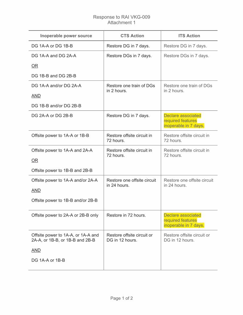
Response to RAI VKG-009 Attachment 1
Page 1 of 2
Inoperable power source CTS Action ITS Action
DG 1A-A or DG 1B-B Restore DG in 7 days. Restore DG in 7 days.
DG 1A-A and DG 2A-A OR DG 1B-B and DG 2B-B
Restore DGs in 7 days. Restore DGs in 7 days.
DG 1A-A and/or DG 2A-A AND DG 1B-B and/or DG 2B-B
Restore one train of DGs in 2 hours.
Restore one train of DGs in 2 hours.
DG 2A-A or DG 2B-B
Restore DG in 7 days. Declare associated required features inoperable in 7 days.
Offsite power to 1A-A or 1B-B Restore offsite circuit in 72 hours.
Restore offsite circuit in 72 hours.
Offsite power to 1A-A and 2A-A OR Offsite power to 1B-B and 2B-B
Restore offsite circuit in 72 hours.
Restore offsite circuit in 72 hours.
Offsite power to 1A-A and/or 2A-A AND Offsite power to 1B-B and/or 2B-B
Restore one offsite circuit in 24 hours.
Restore one offsite circuit in 24 hours.
Offsite power to 2A-A or 2B-B only
Restore in 72 hours. Declare associated required features inoperable in 7 days.
Offsite power to 1A-A, or 1A-A and 2A-A, or 1B-B, or 1B-B and 2B-B AND DG 1A-A or 1B-B
Restore offsite circuit or DG in 12 hours.
Restore offsite circuit or DG in 12 hours.
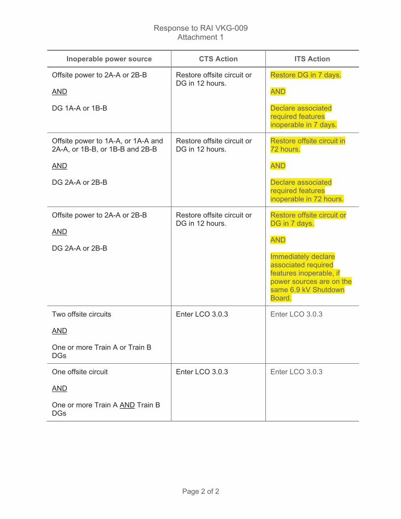
Response to RAI VKG-009 Attachment 1
Page 2 of 2
Inoperable power source CTS Action ITS Action
Offsite power to 2A-A or 2B-B AND DG 1A-A or 1B-B
Restore offsite circuit or DG in 12 hours.
Restore DG in 7 days. AND Declare associated required features inoperable in 7 days.
Offsite power to 1A-A, or 1A-A and 2A-A, or 1B-B, or 1B-B and 2B-B AND DG 2A-A or 2B-B
Restore offsite circuit or DG in 12 hours.
Restore offsite circuit in 72 hours. AND Declare associated required features inoperable in 72 hours.
Offsite power to 2A-A or 2B-B AND DG 2A-A or 2B-B
Restore offsite circuit or DG in 12 hours.
Restore offsite circuit or DG in 7 days. AND Immediately declare associated required features inoperable, if power sources are on the same 6.9 kV Shutdown Board.
Two offsite circuits AND One or more Train A or Train B DGs
Enter LCO 3.0.3 Enter LCO 3.0.3
One offsite circuit AND One or more Train A AND Train B DGs
Enter LCO 3.0.3 Enter LCO 3.0.3

Licensee Response/NRC Response/NRC Question ClosureId 234
NRC Question Number VKG009
Select Application NRC Question Closure
Attachment 1
Attachment 2
Response Statement
Response Date/Time
Closure Statement This question is closed and no further information is required at this time to draft the Safety Evaluation.
Question Closure Date 8/4/2014
Notification Scott BowmanMichelle ConnerLynn MynattRay SchieleRoger Scott
Added By Khadijah Hemphill
Date Added 8/4/2014 5:56 PM
Date Modified
Modified By
Page 1 of 1Sequoyah ITS Conversion Database
8/21/2014https://members.excelservices.com/index.php?requestType=areaItemPrint&itemId=234
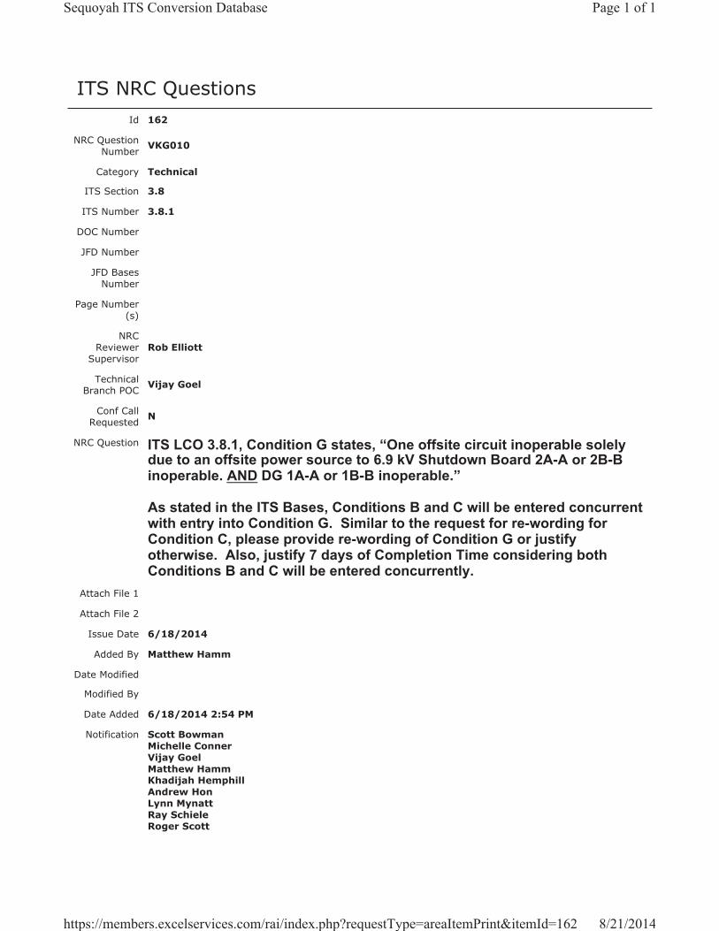
ITS NRC QuestionsId 162
NRC Question Number VKG010
Category Technical
ITS Section 3.8
ITS Number 3.8.1
DOC Number
JFD Number
JFD Bases Number
Page Number(s)
NRC Reviewer
Supervisor Rob Elliott
Technical Branch POC Vijay Goel
Conf Call Requested N
NRC Question ITS LCO 3.8.1, Condition G states, “One offsite circuit inoperable solely due to an offsite power source to 6.9 kV Shutdown Board 2A-A or 2B-B inoperable. AND DG 1A-A or 1B-B inoperable.”
As stated in the ITS Bases, Conditions B and C will be entered concurrent with entry into Condition G. Similar to the request for re-wording for Condition C, please provide re-wording of Condition G or justify otherwise. Also, justify 7 days of Completion Time considering both Conditions B and C will be entered concurrently.
Attach File 1
Attach File 2
Issue Date 6/18/2014
Added By Matthew Hamm
Date Modified
Modified By
Date Added 6/18/2014 2:54 PM
Notification Scott BowmanMichelle ConnerVijay GoelMatthew HammKhadijah HemphillAndrew HonLynn MynattRay SchieleRoger Scott
Page 1 of 1Sequoyah ITS Conversion Database
8/21/2014https://members.excelservices.com/rai/index.php?requestType=areaItemPrint&itemId=162
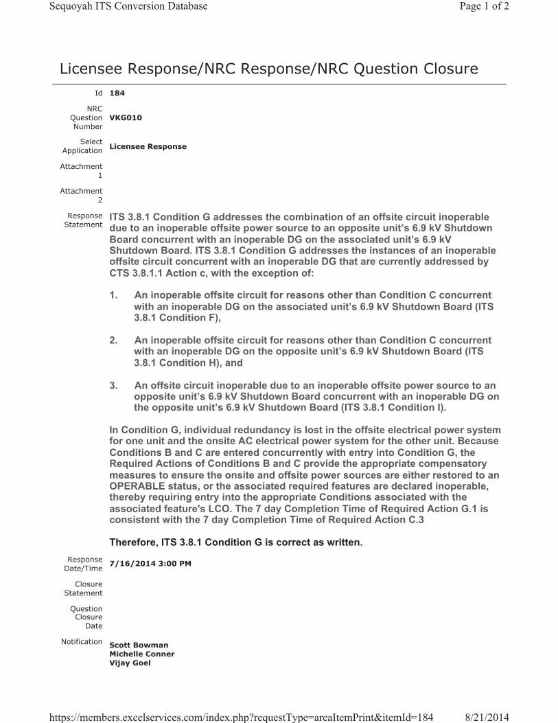
Licensee Response/NRC Response/NRC Question ClosureId 184
NRC Question Number
VKG010
Select Application Licensee Response
Attachment 1
Attachment 2
Response Statement
ITS 3.8.1 Condition G addresses the combination of an offsite circuit inoperable due to an inoperable offsite power source to an opposite unit’s 6.9 kV Shutdown Board concurrent with an inoperable DG on the associated unit’s 6.9 kV Shutdown Board. ITS 3.8.1 Condition G addresses the instances of an inoperable offsite circuit concurrent with an inoperable DG that are currently addressed by CTS 3.8.1.1 Action c, with the exception of:
1. An inoperable offsite circuit for reasons other than Condition C concurrent with an inoperable DG on the associated unit’s 6.9 kV Shutdown Board (ITS 3.8.1 Condition F),
2. An inoperable offsite circuit for reasons other than Condition C concurrent with an inoperable DG on the opposite unit’s 6.9 kV Shutdown Board (ITS 3.8.1 Condition H), and
3. An offsite circuit inoperable due to an inoperable offsite power source to an opposite unit’s 6.9 kV Shutdown Board concurrent with an inoperable DG on the opposite unit’s 6.9 kV Shutdown Board (ITS 3.8.1 Condition I).
In Condition G, individual redundancy is lost in the offsite electrical power system for one unit and the onsite AC electrical power system for the other unit. Because Conditions B and C are entered concurrently with entry into Condition G, the Required Actions of Conditions B and C provide the appropriate compensatory measures to ensure the onsite and offsite power sources are either restored to an OPERABLE status, or the associated required features are declared inoperable, thereby requiring entry into the appropriate Conditions associated with the associated feature's LCO. The 7 day Completion Time of Required Action G.1 is consistent with the 7 day Completion Time of Required Action C.3
Therefore, ITS 3.8.1 Condition G is correct as written.Response
Date/Time 7/16/2014 3:00 PM
Closure Statement
Question Closure
Date
Notification Scott BowmanMichelle ConnerVijay Goel
Page 1 of 2Sequoyah ITS Conversion Database
8/21/2014https://members.excelservices.com/index.php?requestType=areaItemPrint&itemId=184
Khadijah HemphillAndrew HonRay Schiele
Added By Scott Bowman
Date Added 7/16/2014 1:59 PM
Date Modified
Modified By
Page 2 of 2Sequoyah ITS Conversion Database
8/21/2014https://members.excelservices.com/index.php?requestType=areaItemPrint&itemId=184

Licensee Response/NRC Response/NRC Question ClosureId 235
NRC Question Number VKG010
Select Application NRC Question Closure
Attachment 1
Attachment 2
Response Statement
Response Date/Time
Closure Statement This question is closed and no further information is required at this time to draft the Safety Evaluation.
Question Closure Date 8/4/2014
Notification Scott BowmanMichelle ConnerLynn MynattRay SchieleRoger Scott
Added By Khadijah Hemphill
Date Added 8/4/2014 5:56 PM
Date Modified
Modified By
Page 1 of 1Sequoyah ITS Conversion Database
8/21/2014https://members.excelservices.com/index.php?requestType=areaItemPrint&itemId=235
ITS NRC QuestionsId 163
NRC Question Number VKG011
Category Technical
ITS Section 3.8
ITS Number 3.8.1
DOC Number
JFD Number
JFD Bases Number
Page Number(s)
NRC Reviewer
Supervisor Rob Elliott
Technical Branch POC Vijay Goel
Conf Call Requested N
NRC Question ITS LCO 3.8.1, Condition H states, “One offsite circuit inoperable for reasons other than Condition C. AND DG 2A-A or 2B-B inoperable.”
As stated in the ITS Bases, Conditions A and D will be entered concurrent with entry into Condition H. Similar to the request for re-wording for Condition A, please provide re-wording of Condition H or justify otherwise. Also, justify 7 days of Completion Time considering both Conditions A and D will be entered concurrently.
Attach File 1
Attach File 2
Issue Date 6/18/2014
Added By Matthew Hamm
Date Modified
Modified By
Date Added 6/18/2014 2:55 PM
Notification Scott BowmanMichelle ConnerVijay GoelMatthew HammKhadijah HemphillAndrew HonLynn MynattRay SchieleRoger Scott
Page 1 of 1Sequoyah ITS Conversion Database
8/21/2014https://members.excelservices.com/rai/index.php?requestType=areaItemPrint&itemId=163
Licensee Response/NRC Response/NRC Question ClosureId 185
NRC Question Number
VKG011
Select Application Licensee Response
Attachment 1 RAI VKG-011 Response Attachment 1, Rev 1.pdf (2MB)
Attachment 2
Response Statement
In response to RAI VKG-011, the Completion Time for ITS 3.8.1 Required Action H.1 (pages 52 and 76 of Enclosure 2, Volume 13) will be changed to 72 hours, consistent with the Completion Time for ITS 3.8.1 Required Action A.3. This change also results in a change to ITS 3.8.1 discussion of change (DOC) L01 (page 33) and to the ITS 3.8.1 Bases discussion of Required Action H.1 (pages 119 and 169).
See Attachment 1 for the draft ITS 3.8.1 changes discussed above.Response
Date/Time 7/16/2014 3:05 PM
Closure Statement
Question Closure Date
Notification Scott BowmanMichelle ConnerVijay GoelKhadijah HemphillAndrew HonRay Schiele
Added By Scott Bowman
Date Added 7/16/2014 2:03 PM
Date Modified
Modified By
Page 1 of 1Sequoyah ITS Conversion Database
8/21/2014https://members.excelservices.com/index.php?requestType=areaItemPrint&itemId=185
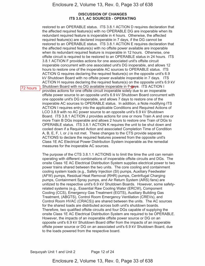
DISCUSSION OF CHANGES ITS 3.8.1, AC SOURCES - OPERATING
Sequoyah Unit 1 and Unit 2 Page 12 of 24
restored to an OPERABLE status. ITS 3.8.1 ACTION D requires declaration that the affected required feature(s) with no OPERABLE DG are inoperable when its redundant required feature is inoperable in 4 hours. Otherwise, the affected required feature(s) are declared inoperable in 7 days, if the DG cannot be restored to an OPERABLE status. ITS 3.8.1 ACTION E requires declaration that the affected required feature(s) with no offsite power available are inoperable when its redundant required feature is inoperable in 12 hours. Otherwise, one offsite circuit is required to be restored to an OPERABLE status in 24 hours. ITS 3.8.1 ACTION F provides actions for one associated unit's offsite circuit inoperable concurrent with one associated unit's DG inoperable, and allows 12 hours to restore one of the inoperable AC sources to OPERABLE status. ITS ACTION G requires declaring the required feature(s) on the opposite unit's 6.9 kV Shutdown Board with no offsite power available inoperable in 7 days. ITS ACTION H requires declaring the required feature(s) on the opposite unit's 6.9 kV Shutdown Board with no DG available inoperable in 7 days. ITS ACTION I provides actions for one offsite circuit inoperable solely due to an inoperable offsite power source to an opposite unit's 6.9 kV Shutdown Board concurrent with one opposite unit's DG inoperable, and allows 7 days to restore one of the inoperable AC sources to OPERABLE status. In addition, a Note modifying ITS ACTION I requires entry into the applicable Conditions and Required Actions of LCO 3.8.9 with no AC power source to an opposite unit's 6.9 kV Shutdown Board. ITS 3.8.1 ACTION J provides actions for one or more Train A and one or more Train B DGs inoperable and allows 2 hours to restore one Train of DGs to OPERABLE status. ITS 3.8.1 ACTION K requires the unit to be shut down and cooled down if a Required Action and associated Completion Time of Condition A, B, E, F, I, or J is not met. These changes to the CTS provide separate ACTIONS to declare the required features powered from the opposite unit's Class 1E AC Electrical Power Distribution System inoperable as the remedial measures for the inoperable AC sources.
The purpose of the CTS 3.8.1.1 ACTIONS is to limit the time the unit can remain operating with different combinations of inoperable offsite circuits and DGs. The onsite Class 1E AC Electrical Distribution System supplies electrical power to two power trains shared between the two units. The core cooling and containment cooling system loads (e.g., Safety Injection (SI) pumps, Auxiliary Feedwater (AFW) pumps, Residual Heat Removal (RHR) pumps, Centrifugal Charging pumps, Containment Spray pumps, and Air Return System (ARS) fans) are unitized to the respective unit's 6.9 kV Shutdown Boards. However, some safety-related systems (e.g., Essential Raw Cooling Water (ERCW), Component Cooling (CCS), Emergency Gas Treatment (EGTS), Auxiliary Building Gas Treatment, (ABGTS), Control Room Emergency Ventilation (CREVs), and Control Room HVAC (CRACS)) are shared between the units. The AC sources for the shared loads are distributed across both unit's shutdown boards. Therefore, two qualified offsite circuits and four DGs capable of supplying the onsite Class 1E AC Electrical Distribution System are required to be OPERABLE. However, the impacts of an inoperable offsite power source or DG on an opposite unit's 6.9 kV Shutdown Board differ from the impacts of an inoperable offsite power source or DG on an associated unit's 6.9 kV Shutdown Board, due to the loads powered from the respective board.
Enclosure 2, Volume 13, Rev. 0, Page 33 of 638
Enclosure 2, Volume 13, Rev. 0, Page 33 of 638
72 hours
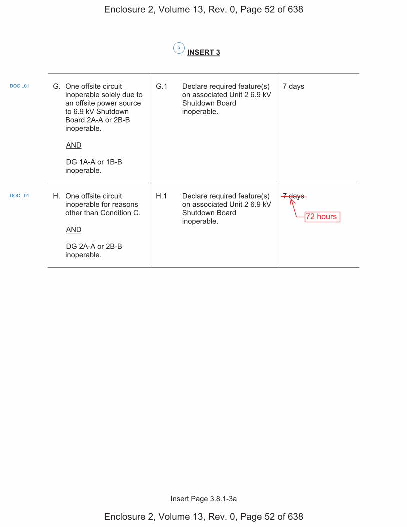
Insert Page 3.8.1-3a
INSERT 3
G. One offsite circuit
inoperable solely due to an offsite power source to 6.9 kV Shutdown Board 2A-A or 2B-B inoperable.
AND
DG 1A-A or 1B-B inoperable.
G.1 Declare required feature(s)
on associated Unit 2 6.9 kV Shutdown Board inoperable.
7 days
H. One offsite circuit
inoperable for reasons other than Condition C.
AND
DG 2A-A or 2B-B inoperable.
H.1 Declare required feature(s)
on associated Unit 2 6.9 kV Shutdown Board inoperable.
7 days
5
DOC L01
DOC L01
Enclosure 2, Volume 13, Rev. 0, Page 52 of 638
Enclosure 2, Volume 13, Rev. 0, Page 52 of 638
72 hours
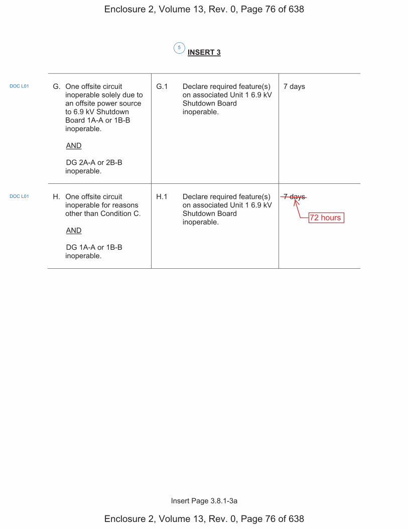
Insert Page 3.8.1-3a
INSERT 3
G. One offsite circuit
inoperable solely due to an offsite power source to 6.9 kV Shutdown Board 1A-A or 1B-B inoperable.
AND
DG 2A-A or 2B-B inoperable.
G.1 Declare required feature(s)
on associated Unit 1 6.9 kV Shutdown Board inoperable.
7 days
H. One offsite circuit
inoperable for reasons other than Condition C.
AND
DG 1A-A or 1B-B inoperable.
H.1 Declare required feature(s)
on associated Unit 1 6.9 kV Shutdown Board inoperable.
7 days
5
DOC L01
DOC L01
Enclosure 2, Volume 13, Rev. 0, Page 76 of 638
Enclosure 2, Volume 13, Rev. 0, Page 76 of 638
72 hours
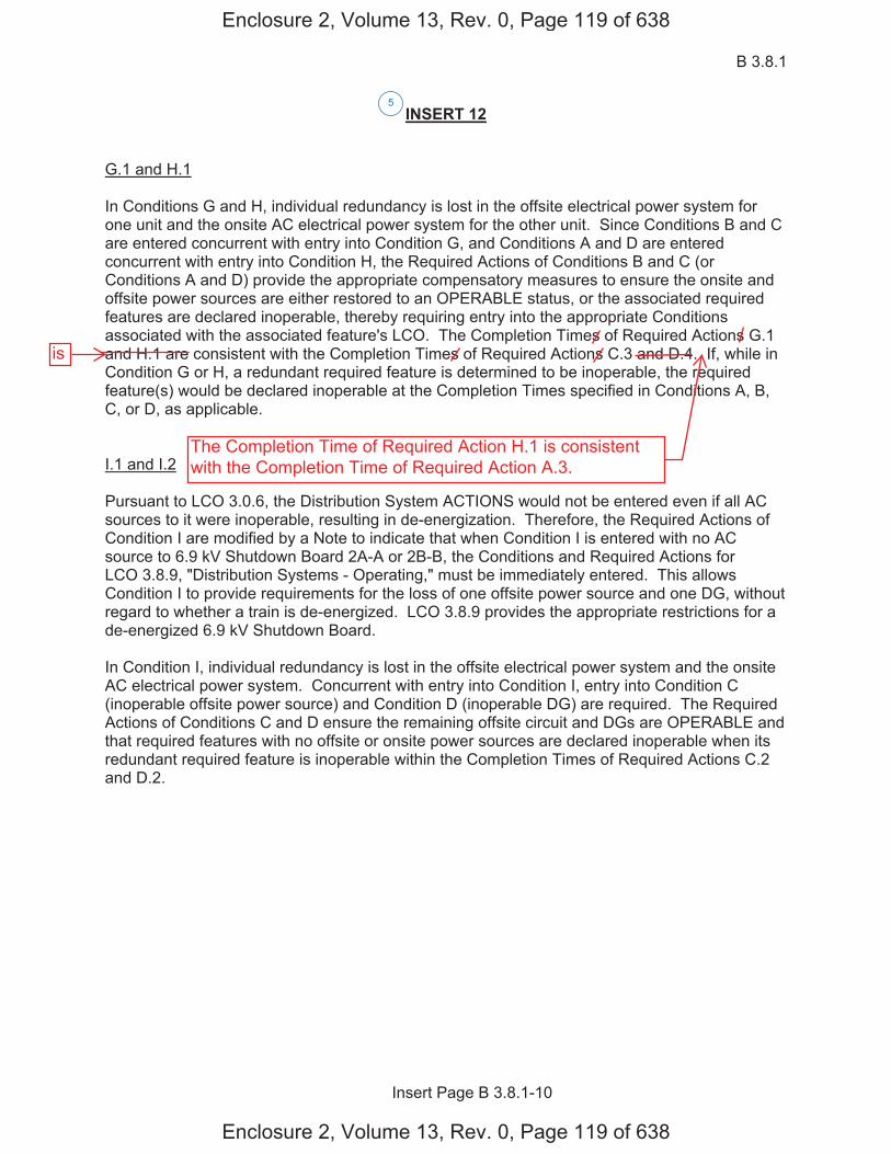
B 3.8.1
Insert Page B 3.8.1-10
INSERT 12 G.1 and H.1 In Conditions G and H, individual redundancy is lost in the offsite electrical power system for one unit and the onsite AC electrical power system for the other unit. Since Conditions B and C are entered concurrent with entry into Condition G, and Conditions A and D are entered concurrent with entry into Condition H, the Required Actions of Conditions B and C (or Conditions A and D) provide the appropriate compensatory measures to ensure the onsite and offsite power sources are either restored to an OPERABLE status, or the associated required features are declared inoperable, thereby requiring entry into the appropriate Conditions associated with the associated feature's LCO. The Completion Times of Required Actions G.1 and H.1 are consistent with the Completion Times of Required Actions C.3 and D.4. If, while in Condition G or H, a redundant required feature is determined to be inoperable, the required feature(s) would be declared inoperable at the Completion Times specified in Conditions A, B, C, or D, as applicable. I.1 and I.2 Pursuant to LCO 3.0.6, the Distribution System ACTIONS would not be entered even if all AC sources to it were inoperable, resulting in de-energization. Therefore, the Required Actions of Condition I are modified by a Note to indicate that when Condition I is entered with no AC source to 6.9 kV Shutdown Board 2A-A or 2B-B, the Conditions and Required Actions for LCO 3.8.9, "Distribution Systems - Operating," must be immediately entered. This allows Condition I to provide requirements for the loss of one offsite power source and one DG, without regard to whether a train is de-energized. LCO 3.8.9 provides the appropriate restrictions for a de-energized 6.9 kV Shutdown Board. In Condition I, individual redundancy is lost in the offsite electrical power system and the onsite AC electrical power system. Concurrent with entry into Condition I, entry into Condition C (inoperable offsite power source) and Condition D (inoperable DG) are required. The Required Actions of Conditions C and D ensure the remaining offsite circuit and DGs are OPERABLE and that required features with no offsite or onsite power sources are declared inoperable when its redundant required feature is inoperable within the Completion Times of Required Actions C.2 and D.2.
5
Enclosure 2, Volume 13, Rev. 0, Page 119 of 638
Enclosure 2, Volume 13, Rev. 0, Page 119 of 638
is
The Completion Time of Required Action H.1 is consistentwith the Completion Time of Required Action A.3.
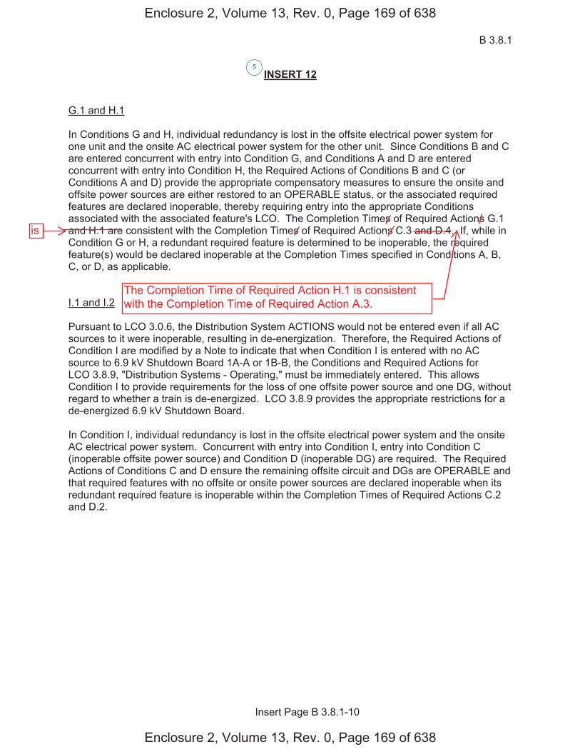
B 3.8.1
Insert Page B 3.8.1-10
INSERT 12 G.1 and H.1 In Conditions G and H, individual redundancy is lost in the offsite electrical power system for one unit and the onsite AC electrical power system for the other unit. Since Conditions B and C are entered concurrent with entry into Condition G, and Conditions A and D are entered concurrent with entry into Condition H, the Required Actions of Conditions B and C (or Conditions A and D) provide the appropriate compensatory measures to ensure the onsite and offsite power sources are either restored to an OPERABLE status, or the associated required features are declared inoperable, thereby requiring entry into the appropriate Conditions associated with the associated feature's LCO. The Completion Times of Required Actions G.1 and H.1 are consistent with the Completion Times of Required Actions C.3 and D.4. If, while in Condition G or H, a redundant required feature is determined to be inoperable, the required feature(s) would be declared inoperable at the Completion Times specified in Conditions A, B, C, or D, as applicable. I.1 and I.2 Pursuant to LCO 3.0.6, the Distribution System ACTIONS would not be entered even if all AC sources to it were inoperable, resulting in de-energization. Therefore, the Required Actions of Condition I are modified by a Note to indicate that when Condition I is entered with no AC source to 6.9 kV Shutdown Board 1A-A or 1B-B, the Conditions and Required Actions for LCO 3.8.9, "Distribution Systems - Operating," must be immediately entered. This allows Condition I to provide requirements for the loss of one offsite power source and one DG, without regard to whether a train is de-energized. LCO 3.8.9 provides the appropriate restrictions for a de-energized 6.9 kV Shutdown Board. In Condition I, individual redundancy is lost in the offsite electrical power system and the onsite AC electrical power system. Concurrent with entry into Condition I, entry into Condition C (inoperable offsite power source) and Condition D (inoperable DG) are required. The Required Actions of Conditions C and D ensure the remaining offsite circuit and DGs are OPERABLE and that required features with no offsite or onsite power sources are declared inoperable when its redundant required feature is inoperable within the Completion Times of Required Actions C.2 and D.2.
5
Enclosure 2, Volume 13, Rev. 0, Page 169 of 638
Enclosure 2, Volume 13, Rev. 0, Page 169 of 638
is
The Completion Time of Required Action H.1 is consistentwith the Completion Time of Required Action A.3.
Licensee Response/NRC Response/NRC Question ClosureId 236
NRC Question Number VKG011
Select Application NRC Question Closure
Attachment 1
Attachment 2
Response Statement
Response Date/Time
Closure Statement This question is closed and no further information is required at this time to draft the Safety Evaluation.
Question Closure Date 8/4/2014
Notification Scott BowmanMichelle ConnerLynn MynattRay SchieleRoger Scott
Added By Khadijah Hemphill
Date Added 8/4/2014 5:57 PM
Date Modified
Modified By
Page 1 of 1Sequoyah ITS Conversion Database
8/21/2014https://members.excelservices.com/index.php?requestType=areaItemPrint&itemId=236
ITS NRC QuestionsId 164
NRC Question Number
VKG012
Category Technical
ITS Section 3.8
ITS Number 3.8.1
DOC Number
JFD Number
JFD Bases Number
Page Number(s)
NRC Reviewer
Supervisor Rob Elliott
Technical Branch POC Vijay Goel
Conf Call Requested N
NRC Question
ITS LCO 3.8.1, Condition I states, “One offsite circuit inoperable solely due to an offsite power source to 6.9 kV Shutdown Board 2A-A or 2B-B inoperable. AND DG 2A-A or 2B-B inoperable.”
It is not clear why in the Condition I, the “offsite circuit inoperable” is constrained to “solely due to an offsite power source inoperable.” Condition I should be revised (similar to the Condition I the licensee presented in the pre-submittal meeting dated June 4, 2013), as follows: “One offsite circuit to 6.9 kV Shutdown Board 2A-A or 2B-B inoperable. AND DG 2A-A or 2B-B inoperable.” with a NOTE: “Only applicable when offsite circuits to 6.9 kV Shutdown Boards 1A-A and 1B-B are OPERABLE, and DGs 1A-A and 1B-B are OPERABLE.” Please provide requisite re-wording of Condition I or justify otherwise. Also, provide justification of Completion Time of 7 days for Action I.1 when compared to the Completion Time of 72 hours for Action A.3.
Attach File 1
Attach File 2
Issue Date 6/18/2014
Added By Matthew Hamm
Date Modified
Modified By
Date Added 6/18/2014 2:56 PM
Notification Scott BowmanMichelle Conner
Page 1 of 2Sequoyah ITS Conversion Database
8/21/2014https://members.excelservices.com/rai/index.php?requestType=areaItemPrint&itemId=164
Vijay GoelMatthew HammKhadijah HemphillAndrew HonLynn MynattRay SchieleRoger Scott
Page 2 of 2Sequoyah ITS Conversion Database
8/21/2014https://members.excelservices.com/rai/index.php?requestType=areaItemPrint&itemId=164
Licensee Response/NRC Response/NRC Question ClosureId 186
NRC Question Number
VKG012
Select Application Licensee Response
Attachment 1
Attachment 2
Response Statement Proposed ITS 3.8.1 Condition I is entered when one DG on an opposite unit’s 6.9
kV Shutdown Board is inoperable concurrent with one offsite circuit inoperable solely due to an inoperable offsite power source to an opposite unit’s 6.9 kV Shutdown Board. The assumption for the affected offsite circuit is that it is otherwise operable, i.e., capable of providing adequate power to the associated unit’s 6.9 kV Shutdown Board to power the required features on that board used to mitigate an accident on the associated unit. Therefore, the Condition focuses on the impact to the shared equipment that the associated unit is crediting that is powered from the opposite unit’s 6.9 kV Shutdown Board.
The Required Actions require restoration of either the offsite circuit or the DG in 7 days. In addition, if the inoperable AC sources result in an opposite unit’s 6.9 kV Shutdown Board having no AC power, the applicable Conditions and Required Actions of ITS 3.8.9 are entered. ITS 3.8.9 Condition D is entered when one or more opposite unit’s AC electrical power distribution subsystems are inoperable.ITS 3.8.9 Required Action D.1 requires the associated required features to be declared inoperable immediately.
The ITS 3.8.1 Required Action I.1 and I.2 Completion Times of 7 days are appropriate due to the limited amount of shared equipment that exists on an opposite unit’s shutdown board. In addition, notwithstanding the inoperability of the power source, the current technical specifications (CTS 3.0.5) allow equipment to be considered operable for an indefinite amount of time with an inoperable normal or emergency power supply, as long as the redundant equipment remains operable. If the inoperable offsite circuit and inoperable DG are on different 6.9 kV Shutdown Boards such that redundancy for one or more systems is lost, ITS 3.8.1 Required Actions C.2 and D.2 will direct the affected required features to be declared inoperable in 24 hours and 4 hours, respectively. Therefore, the Conditions and Required Actions of the associated LCOs provide adequate actions to address the inoperable required features.
Major shared equipment on an opposite unit’s shutdown board:
6.9 kV Shutdown Board 1A-A (and associated 480 V shutdown boards)ERCW Pump J-A (Note 1)ERCW Pump Q-A (Note 1)Control Room AHU A-A (Note 2)Control Room AC Compressor A-A (Note 2)CCS Pump 1A-A (Note 3)EGTS Fan A-A (Note 4)
Page 1 of 3Sequoyah ITS Conversion Database
8/21/2014https://members.excelservices.com/index.php?requestType=areaItemPrint&itemId=186
125 V Vital Battery Charger I (Note 5)
6.9 kV Shutdown Board 1B-B (and associated 480 V shutdown boards)ERCW Pump L-B (Note 1)ERCW Pump N-B (Note 1)Control Room AHU B-B (Note 2)Control Room AC Compressor B-B (Note 2)CCS Pump 1B-B (Note 3)EGTS Fan B-B (Note 4)125 V Vital Battery Charger II (Note 5)
6.9 kV Shutdown Board 2A-A (and associated 480 V shutdown boards)ERCW Pump R-A (Note 1)ERCW Pump K-A (Note 1)CCS Pump 2A-A (Note 3)ABGTS Fan A-A (Note 6)Auxiliary Control Air Compressor A-A (Note 7)125 V Vital Battery Charger III (Note 5)
6.9 kV Shutdown Board 2B-B (and associated 480 V shutdown boards)ERCW Pump P-B (Note 1)ERCW Pump M-B (Note 1)CCS Pump 2B-B (Note 3)CCS Pump C-S (Note 3)ABGTS Fan B-B (Note 6)Auxiliary Control Air Compressor B-B (Note 7)125 V Vital Battery Charger IV (Note 5)
NOTES:
1. The current requirement is for one operable ERCW pump per 6.9 kV Shutdown Board. Following implementation of an approved license amendment (TS-SQN-13-01 and TS-SQN-13-02, ML13280A267) an operable ERCW system train can require as few as one ERCW pump with consideration of the UHS temperature requirements. Until then, ITS 3.7.8, Condition A will require an inoperable ERCW system train to be restored in 72 hours.
2. Per ITS 3.7.10, Condition A, an inoperable train of CREVS is required to be restored in 7 days. Per ITS 3.7.11, Condition A, an inoperable CRACS train is required to be restored in 30 days.
3. CCS trains can be aligned and meet the requirements of ITS LCO 3.7.7 with the remaining operable pumps with one 6.9 kV Shutdown Board inoperable.
4. Per ITS 3.6.10, Condition A, an inoperable EGTS train is required to be restored in 7 days.
5. With the adoption of TSTF-500, ITS 3.8.4, Condition A requires an inoperable battery charger to be restored in 7 days, provided battery terminal voltage can be maintained greater than or equal to the minimum established float voltage and battery float current is maintained less than or equal to 2 amps.
6. Per ITS 3.7.12, Condition A, an inoperable ABGTS train is required to be restored in 7 days.
7. Following implementation of the proposed plant modification to install one or more additional auxiliary control air compressor(s), two trains of auxiliary control air can be maintained with either 6.9 kV Shutdown Board 2A-A or 2B-B inoperable. Until then, the most limiting components are the Atmospheric Relief Valves (ARVs) and the Auxiliary Feedwater System (AFW) level control valves. ITS
Page 2 of 3Sequoyah ITS Conversion Database
8/21/2014https://members.excelservices.com/index.php?requestType=areaItemPrint&itemId=186
3.7.4, ARVs, Condition A requires one or more ARV lines inoperable due to one train of auxiliary control air nonfunctional to be restored in 72 hours. ITS 3.7.5, AFW, Condition B requires (in MODE 1, 2, or 3) one AFW train inoperable for reasons other than an inoperable steam supply to a turbine driven train to be restored in 72 hours.
Response Date/Time 7/16/2014 3:05 AM
Closure Statement
Question Closure
Date
Notification Scott BowmanMichelle ConnerVijay GoelKhadijah HemphillAndrew HonRay Schiele
Added By Scott Bowman
Date Added 7/16/2014 2:06 PM
Date Modified
Modified By
Page 3 of 3Sequoyah ITS Conversion Database
8/21/2014https://members.excelservices.com/index.php?requestType=areaItemPrint&itemId=186

Licensee Response/NRC Response/NRC Question ClosureId 237
NRC Question Number VKG012
Select Application NRC Question Closure
Attachment 1
Attachment 2
Response Statement
Response Date/Time
Closure Statement This question is closed and no further information is required at this time to draft the Safety Evaluation.
Question Closure Date 8/4/2014
Notification Scott BowmanMichelle ConnerLynn MynattRay SchieleRoger Scott
Added By Khadijah Hemphill
Date Added 8/4/2014 5:57 PM
Date Modified
Modified By
Page 1 of 1Sequoyah ITS Conversion Database
8/21/2014https://members.excelservices.com/index.php?requestType=areaItemPrint&itemId=237
ITS NRC QuestionsId 165
NRC Question Number VKG013
Category Technical
ITS Section 3.8
ITS Number 3.8.1
DOC Number
JFD Number
JFD Bases Number
Page Number(s)
NRC Reviewer Supervisor Rob Elliott
Technical Branch POC Vijay Goel
Conf Call Requested N
NRC Question ITS LCO 3.8.1, Condition L states, “Two offsite circuits inoperable. AND…”
Condition L should be expanded to clarify the two circuits to which specific Shutdown Boards are inoperable, such as: “Two offsite circuits to 6.9 kV Shutdown Boards 1A-A and 1B-B inoperable. AND…” Please provide rewording of Condition L or justify otherwise.
Attach File 1
Attach File 2
Issue Date 6/18/2014
Added By Matthew Hamm
Date Modified
Modified By
Date Added 6/18/2014 2:57 PM
Notification Scott BowmanMichelle ConnerVijay GoelMatthew HammKhadijah HemphillAndrew HonLynn MynattRay SchieleRoger Scott
Page 1 of 1Sequoyah ITS Conversion Database
8/21/2014https://members.excelservices.com/rai/index.php?requestType=areaItemPrint&itemId=165
Licensee Response/NRC Response/NRC Question ClosureId 187
NRC Question Number
VKG013
Select Application Licensee Response
Attachment 1
Attachment 2
Response Statement
When ITS Condition L is entered, one or more DGs in either train are inoperable concurrent with two inoperable offsite circuits regardless of the 6.9kV Shutdown Boards that are affected. In this Condition, there are inadequate AC power sources available to power the required features needed to mitigate an accident.In this Condition, entry into LCO 3.0.3 is appropriate. Therefore, ITS 3.8.1, Condition L is correct as written.
Response Date/Time 7/16/2014 3:10 PM
Closure Statement
Question Closure Date
Notification Scott BowmanMichelle ConnerVijay GoelKhadijah HemphillAndrew HonRay Schiele
Added By Scott Bowman
Date Added 7/16/2014 2:10 PM
Date Modified
Modified By
Page 1 of 1Sequoyah ITS Conversion Database
8/21/2014https://members.excelservices.com/index.php?requestType=areaItemPrint&itemId=187

Licensee Response/NRC Response/NRC Question ClosureId 238
NRC Question Number VKG013
Select Application NRC Question Closure
Attachment 1
Attachment 2
Response Statement
Response Date/Time
Closure Statement This question is closed and no further information is required at this time to draft the Safety Evaluation.
Question Closure Date 8/4/2014
Notification Scott BowmanMichelle ConnerLynn MynattRay SchieleRoger Scott
Added By Khadijah Hemphill
Date Added 8/4/2014 5:58 PM
Date Modified
Modified By
Page 1 of 1Sequoyah ITS Conversion Database
8/21/2014https://members.excelservices.com/index.php?requestType=areaItemPrint&itemId=238
ITS NRC QuestionsId 166
NRC Question Number VKG014
Category Technical
ITS Section 3.8
ITS Number 3.8.1
DOC Number
JFD Number
JFD Bases Number
Page Number(s)
NRC Reviewer Supervisor Rob Elliott
Technical Branch POC Vijay Goel
Conf Call Requested N
NRC Question ITS LCO 3.8.1, Condition M states, “One offsite circuits inoperable. AND…”
Condition M should be expanded to clarify the circuit to which Shutdown Board is inoperable, such as: “One offsite circuits to 6.9 kV Shutdown Board 1A-A or 1B-B inoperable. AND…” Please provide rewording of Condition M or justify otherwise.
Attach File 1
Attach File 2
Issue Date 6/18/2014
Added By Matthew Hamm
Date Modified
Modified By
Date Added 6/18/2014 2:58 PM
Notification Scott BowmanMichelle ConnerVijay GoelMatthew HammKhadijah HemphillAndrew HonLynn MynattRay SchieleRoger Scott
Page 1 of 1Sequoyah ITS Conversion Database
8/21/2014https://members.excelservices.com/rai/index.php?requestType=areaItemPrint&itemId=166
Licensee Response/NRC Response/NRC Question ClosureId 188
NRC Question Number
VKG014
Select Application Licensee Response
Attachment 1
Attachment 2
Response Statement
When ITS 3.8.1 Condition M is entered, one or more DGs in both trains are inoperable concurrent with an inoperable offsite circuit. In this condition, there are inadequate AC power sources available to power the required features needed to mitigate an accident. Condition M is entered for any offsite circuit configuration regardless of the 6.9 kV Shutdown Boards that are affected. In this Condition, entry into LCO 3.0.3 is appropriate. Therefore, ITS 3.8.1, Condition M is correct as written.
Response Date/Time 7/16/2014 3:15 PM
Closure Statement
Question Closure Date
Notification Scott BowmanMichelle ConnerVijay GoelKhadijah HemphillAndrew HonRay Schiele
Added By Scott Bowman
Date Added 7/16/2014 2:12 PM
Date Modified
Modified By
Page 1 of 1Sequoyah ITS Conversion Database
8/21/2014https://members.excelservices.com/index.php?requestType=areaItemPrint&itemId=188

Licensee Response/NRC Response/NRC Question ClosureId 239
NRC Question Number VKG014
Select Application NRC Question Closure
Attachment 1
Attachment 2
Response Statement
Response Date/Time
Closure Statement This question is closed and no further information is required at this time to draft the Safety Evaluation.
Question Closure Date 8/4/2014
Notification Scott BowmanMichelle ConnerLynn MynattRay SchieleRoger Scott
Added By Khadijah Hemphill
Date Added 8/4/2014 5:59 PM
Date Modified
Modified By
Page 1 of 1Sequoyah ITS Conversion Database
8/21/2014https://members.excelservices.com/index.php?requestType=areaItemPrint&itemId=239
ITS NRC QuestionsId 175
NRC Question Number VKG015
Category Technical
ITS Section 3.8
ITS Number 3.8.1
DOC Number
JFD Number
JFD Bases Number
Page Number(s)
NRC Reviewer Supervisor Jake Zimmerman
Technical Branch POC Add Name
Conf Call Requested N
NRC Question Notes 2 of ITS SRs 3.8.1.9 and 3.8.1.10, and Note 3 of ITS SR 3.8.1.14 state: “If performed with the DG synchronized with offsite power, it shall be performed at a power factor 0.89.”
Please provide the basis (summary of calculation) for selecting the above limiting power factor value of 0.89.
Attach File 1
Attach File 2
Issue Date 7/24/2014
Added By Khadijah Hemphill
Date Modified
Modified By
Date Added 7/24/2014 8:07 AM
Notification Scott BowmanMichelle ConnerVijay GoelKhadijah HemphillAndrew HonLynn MynattRay SchieleRoger Scott
Page 1 of 1Sequoyah ITS Conversion Database
9/9/2014https://members.excelservices.com/rai/index.php?requestType=areaItemPrint&itemId=175
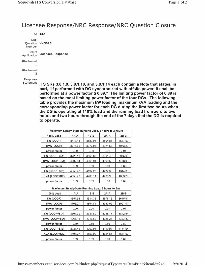
Licensee Response/NRC Response/NRC Question ClosureId 246
NRC Question Number
VKG015
Select Application Licensee Response
Attachment 1
Attachment 2
Response Statement ITS SRs 3.8.1.9, 3.8.1.10, and 3.8.1.14 each contain a Note that states, in
part, “If performed with DG synchronized with offsite power, it shall be performed at a power factor 0.89.” The limiting power factor of 0.89 is based on the most limiting power factor of the four DGs. The following table provides the maximum kW loading, maximum kVA loading and the corresponding power factor for each DG during the first two hours when the DG is operating at 110% load and the running load from zero to two hours and two hours through the end of the 7 days that the DG is required to operate.
Maximum Steady-State Running Load, 0 hours to 2 hours
110% Load 1A-A 1B-B 2A-A 2B-B
kW (LOOP) 3413.13 3589.95 3594.86 3687.63
KVA (LOOP) 3775.66 3977.05 3971.53 4073.29
power factor 0.90 0.90 0.91 0.91
kW (LOOP+SIA) 3726.18 3868.80 3901.45 3975.06
KVA (LOOP+SIA) 4207.34 4368.94 4399.56 4478.99
power factor 0.89 0.89 0.89 0.89
kW (LOOP+SIB) 4056.42 4197.20 4272.39 4344.83
KVA (LOOP+SIB 4550.78 4708.11 4798.90 4863.29
power factor 0.89 0.89 0.89 0.89
Maximum Steady-State Running Load, 2 hours to End
100% Load 1A-A 1B-B 2A-A 2B-B
kW (LOOP) 3351.98 3514.35 3576.16 3615.91
KVA (LOOP) 3706.21 3894.81 3950.92 3991.01
power factor 0.90 0.90 0.91 0.91
kW (LOOP+SIA) 3601.39 3731.80 3748.77 3842.54
KVA (LOOP+SIA) 4063.12 4213.80 4225.24 4323.80
power factor 0.89 0.89 0.89 0.89
kW (LOOP+SIB) 3931.46 4060.05 4119.03 4154.04
KVA (LOOP+SIB 4407.27 4553.99 4624.65 4644.92
power factor 0.89 0.89 0.89 0.89
Page 1 of 2Sequoyah ITS Conversion Database
9/9/2014https://members.excelservices.com/rai/index.php?requestType=areaItemPrint&itemId=246
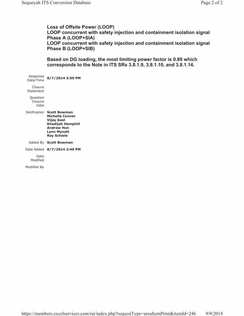
Loss of Offsite Power (LOOP)LOOP concurrent with safety injection and containment isolation signal Phase A (LOOP+SIA)LOOP concurrent with safety injection and containment isolation signal Phase B (LOOP+SIB)
Based on DG loading, the most limiting power factor is 0.89 which corresponds to the Note in ITS SRs 3.8.1.9, 3.8.1.10, and 3.8.1.14.
Response Date/Time 8/7/2014 3:50 PM
Closure Statement
Question Closure
Date
Notification Scott BowmanMichelle ConnerVijay GoelKhadijah HemphillAndrew HonLynn MynattRay Schiele
Added By Scott Bowman
Date Added 8/7/2014 2:49 PM
Date Modified
Modified By
Page 2 of 2Sequoyah ITS Conversion Database
9/9/2014https://members.excelservices.com/rai/index.php?requestType=areaItemPrint&itemId=246

Licensee Response/NRC Response/NRC Question ClosureId 304
NRC Question Number VKG015
Select Application NRC Question Closure
Attachment 1
Attachment 2
Response Statement
Response Date/Time
Closure Statement This question is closed and no further information is required at this time to draft the Safety Evaluation.
Question Closure Date 8/28/2014
Notification Scott BowmanMichelle ConnerVijay GoelKhadijah HemphillAndrew HonLynn MynattRay SchieleRoger Scott
Added By Khadijah Hemphill
Date Added 8/28/2014 3:54 PM
Date Modified
Modified By
Page 1 of 1Sequoyah ITS Conversion Database
9/9/2014https://members.excelservices.com/rai/index.php?requestType=areaItemPrint&itemId=304
ITS NRC QuestionsId 176
NRC Question Number VKG016
Category Technical
ITS Section 3.8
ITS Number 3.8.3
DOC Number
JFD Number
JFD Bases Number
Page Number(s)
NRC Reviewer Supervisor Jake Zimmerman
Technical Branch POC Add Name
Conf Call Requested N
NRC Question ITS LCO 3.8.3, Condition A, Action A.1 requires: “Restore fuel oil level to within limits” when the Condition “One or more DGs with fuel level less than a 7 day supply and greater than a 6 day supply in storage tank”occurs.
ITS LCO 3.8.3, Conditions A, Bases provide volume of fuel oil [53719 gallons] which is equivalent to 6 day supply.
Please provide summary of calculation which provides fuel consumption rate to verify that fuel oil volume of 53719 gallons is equivalent to 6 day supply, and 62,000 gallons (value provided in CTS) is equivalent to 7 day supply.
Attach File 1
Attach File 2
Issue Date 7/24/2014
Added By Khadijah Hemphill
Date Modified
Modified By
Date Added 7/24/2014 8:09 AM
Notification Scott BowmanMichelle ConnerVijay GoelAndrew HonLynn MynattRay SchieleRoger Scott
Page 1 of 1Sequoyah ITS Conversion Database
9/9/2014https://members.excelservices.com/rai/index.php?requestType=areaItemPrint&itemId=176
Licensee Response/NRC Response/NRC Question ClosureId 247
NRC Question Number
VKG016
Select Application Licensee Response
Attachment 1
Attachment 2
Response Statement
ITS LCO 3.8.3, Bases states that each diesel generator (DG) is provided with a 7 day storage tank, comprised of four inter-connected tanks, having a fuel oil capacity sufficient to operate that diesel for a period of 7 days while the DG is supplying maximum post loss of coolant accident load demand discussed in UFSAR, Section 9.5.4.3 and Regulatory Guide 1.137.LCO 3.8.3, Condition A, Required Action A.1, requires that the fuel oil level be restored to within limits if the fuel oil level is less than a 7 day supply and greater than a 6 day supply. The Bases states that the fuel oil level equivalent to a 6 day supply is 53,719 gallons and the 7 day supply is 62,000 gallons.
The fuel oil consumption rate for each DG is 337 gallons per hours (GPH) when supplying 100% load. The DG is also assumed to operate at 110% load during the first two hours of the design basis event, at 110% load, the fuel oil consumption rate is 395 GPH. A 6 day supply (144 hours) would require 2 hours at 395 GPH (790 gallons) and 142 hours at 337 GPH (47,854 gallons) for a total of 48,644 gallons. An additional 674 gallons of diesel fuel is added to account for periodic testing of the DG. The total required volume for 6 days would be 49,318 gallons which is less than stated in the Bases for ITS LCO 3.8.3, therefore, 53,719 gallons as stated in the Bases will ensure that the DG has sufficient fuel oil for 6 days.
The 7 day supply would require 168 hours of operation, 2 hours are at 395 GPH (790 gallons) and 166 hours at 337 GPH (55,942) for a total of 56,732 gallons. An additional 674 gallons is added to account for periodic testing of the DG. The total required volume for 7 days would be 57,406 gallons which is less than stated in the Bases for ITS LCO 3.8.3, therefore, 62,000 gallons as stated in the Bases will ensure that the DG has sufficient fuel oil for 7 days.
Response Date/Time 8/8/2014 7:50 AM
Closure Statement
Question Closure
Date
Notification Scott BowmanMichelle Conner
Page 1 of 2Sequoyah ITS Conversion Database
9/9/2014https://members.excelservices.com/rai/index.php?requestType=areaItemPrint&itemId=247

Vijay GoelKhadijah HemphillAndrew HonLynn MynattRay Schiele
Added By Scott Bowman
Date Added 8/8/2014 6:47 AM
Date Modified
Modified By
Page 2 of 2Sequoyah ITS Conversion Database
9/9/2014https://members.excelservices.com/rai/index.php?requestType=areaItemPrint&itemId=247

Licensee Response/NRC Response/NRC Question ClosureId 305
NRC Question Number VKG016
Select Application NRC Question Closure
Attachment 1
Attachment 2
Response Statement
Response Date/Time
Closure Statement This question is closed and no further information is required at this time to draft the Safety Evaluation.
Question Closure Date 8/28/2014
Notification Scott BowmanMichelle ConnerVijay GoelKhadijah HemphillAndrew HonLynn MynattRay SchieleRoger Scott
Added By Khadijah Hemphill
Date Added 8/28/2014 3:55 PM
Date Modified
Modified By
Page 1 of 1Sequoyah ITS Conversion Database
9/9/2014https://members.excelservices.com/rai/index.php?requestType=areaItemPrint&itemId=305
ITS NRC QuestionsId 177
NRC Question Number VKG017
Category Technical
ITS Section 3.8
ITS Number
DOC Number
JFD Number
JFD Bases Number
Page Number(s)
NRC Reviewer Supervisor Jake Zimmerman
Technical Branch POC Add Name
Conf Call Requested N
NRC Question ITS LCO 3.8.3, Condition B, Action B.1 requires: “Restore lube oil inventory to within limits” when the Condition “One or more DGs with lube oil inventory less than a 7 day supply and greater than a 6 day supply” occurs.
ITS LCO 3.8.3, Conditions B, Bases provide volume of lube oil [120 gallons] which is equivalent to 6 day supply. Please provide summary of calculation which provides lube oil consumption rate to verify that lube oil volume of 120 gallons is equivalent to 6 day supply.
Attach File 1
Attach File 2
Issue Date 7/24/2014
Added By Khadijah Hemphill
Date Modified
Modified By
Date Added 7/24/2014 8:10 AM
Notification Scott BowmanMichelle ConnerVijay GoelKhadijah HemphillAndrew HonLynn MynattRay SchieleRoger Scott
Page 1 of 1Sequoyah ITS Conversion Database
9/9/2014https://members.excelservices.com/rai/index.php?requestType=areaItemPrint&itemId=177
Licensee Response/NRC Response/NRC Question ClosureId 248
NRC Question Number
VKG017
Select Application Licensee Response
Attachment 1
Attachment 2
Response Statement
The ITS 3.8.3 Bases for ACTIONS B.1 states that the lube oil inventory equivalent to a 6 day supply is 120 gallons per diesel engine. The estimated lube oil consumption rate for each diesel engine is 0.83 gal/hr. At that consumption rate, 119.52 gallons of lube oil would be consumed. Therefore, 120 gallons of lube oil will adequately provide a 6 day supply for each diesel engine.
Response Date/Time 8/8/2014 8:00 AM
Closure Statement
Question Closure Date
Notification Scott BowmanMichelle ConnerVijay GoelKhadijah HemphillAndrew HonLynn MynattRay Schiele
Added By Scott Bowman
Date Added 8/8/2014 6:56 AM
Date Modified
Modified By
Page 1 of 1Sequoyah ITS Conversion Database
9/9/2014https://members.excelservices.com/rai/index.php?requestType=areaItemPrint&itemId=248

Licensee Response/NRC Response/NRC Question ClosureId 306
NRC Question Number VKG017
Select Application NRC Question Closure
Attachment 1
Attachment 2
Response Statement
Response Date/Time
Closure Statement This question is closed and no further information is required at this time to draft the Safety Evaluation.
Question Closure Date 8/28/2014
Notification Scott BowmanMichelle ConnerVijay GoelKhadijah HemphillAndrew HonLynn MynattRay SchieleRoger Scott
Added By Khadijah Hemphill
Date Added 8/28/2014 3:56 PM
Date Modified
Modified By
Page 1 of 1Sequoyah ITS Conversion Database
9/9/2014https://members.excelservices.com/rai/index.php?requestType=areaItemPrint&itemId=306
ITS NRC QuestionsId 178
NRC Question Number
VKG018
Category Technical
ITS Section 3.8
ITS Number 3.8.4
DOC Number
JFD Number
JFD Bases Number
Page Number(s)
NRC Reviewer
Supervisor Jake Zimmerman
Technical Branch POC Add Name
Conf Call Requested N
NRC Question
ITS LCO 3.8.4 Bases, Required Action A.2 contains the following statement: “The 2 amp value is based on returning the battery to 95% charge and assumes a 5% design margin for the battery.” Page E9-1 of the LAR contains the following statement: “Describes how a 5 percent design margin for the 125 V Vital batteries corresponds to a 2 amp float current value indicating that the battery is 98 percent charged.”
Please explain the relationship between the 95% charge value stated in ITS Bases and 98% charge value stated in the commitment made on Page E9-1 of the LAR.
Attach File 1
Attach File 2
Issue Date 7/24/2014
Added By Khadijah Hemphill
Date Modified
Modified By
Date Added 7/24/2014 8:11 AM
Notification Scott BowmanMichelle ConnerVijay GoelKhadijah HemphillAndrew HonLynn MynattRay SchieleRoger Scott
Page 1 of 1Sequoyah ITS Conversion Database
9/9/2014https://members.excelservices.com/rai/index.php?requestType=areaItemPrint&itemId=178
Licensee Response/NRC Response/NRC Question ClosureId 249
NRC Question Number
VKG018
Select Application Licensee Response
Attachment 1 Attachment 1 for VKG018.pdf (25KB)
Attachment 2
Response Statement
In response to VKG018, the ITS 3.8.4 Bases for ACTIONS A.1, A.2, and A.3, on pages 326 and 341 of Enclosure 2, Volume 13, will be revised.Specifically, the sentence, “The 2 amp value is based on returning the battery to 95% charge and assumes a 5% design margin for the battery,” in the fifth paragraph will be revised to state, “The 2 amp value is based on returning the battery to 98% charge and assumes a 5% design margin for the battery.”
This change aligns the statement provided on page E9-1 of Enclosure 9, which states Sequoyah will change or verify that the FSAR describes how a 5 percent design margin for the 125V Vital batteries corresponds to a 2 amp float current value indicating that the battery is 98 percent charged, and the letter provided by the battery manufacturer, C&D Technologies, Inc., provided in the response to RAI GMW-002, which states, “For the LCUN-33 batteries, after a discharge, when the float current drops to less than or equal to 2 amps, the battery should be at least 98% recharged,”with the ITS 3.8.4 Bases.
See Attachment 1 for the draft revised ITS 3.8.4 Bases.Response
Date/Time 8/8/2014 8:00 AM
Closure Statement
Question Closure
Date
Notification Scott BowmanMichelle ConnerVijay GoelKhadijah HemphillAndrew HonLynn MynattRay Schiele
Added By Scott Bowman
Date Added 8/8/2014 7:00 AM
Date Modified
Modified By
Page 1 of 1Sequoyah ITS Conversion Database
9/9/2014https://members.excelservices.com/rai/index.php?requestType=areaItemPrint&itemId=249

DC Sources - Operating B 3.8.4
Westinghouse STS B 3.8.4-5 Rev. 4.0
SEQUOYAH UNIT 1 Revision XXX
1
BASES ACTIONS (continued)
A discharged battery having terminal voltage of at least the minimum established float voltage indicates that the battery is on the exponential charging current portion (the second part) of its recharge cycle. The time to return a battery to its fully charged state under this condition is simply a function of the amount of the previous discharge and the recharge characteristic of the battery. Thus there is good assurance of fully recharging the battery within [12] hours, avoiding a premature shutdown with its own attendant risk. If established battery terminal float voltage cannot be restored to greater than or equal to the minimum established float voltage within [2] hours, and the charger is not operating in the current-limiting mode, a faulty charger is indicated. A faulty charger that is incapable of maintaining established battery terminal float voltage does not provide assurance that it can revert to and operate properly in the current limit mode that is necessary during the recovery period following a battery discharge event that the DC system is designed for. If the charger is operating in the current limit mode after 2 hours that is an indication that the battery is partially discharged and its capacity margins will be reduced. The time to return the battery to its fully charged condition in this case is a function of the battery charger capacity, the amount of loads on the associated DC system, the amount of the previous discharge, and the recharge characteristic of the battery. The charge time can be extensive, and there is not adequate assurance that it can be recharged within [12] hours (Required Action A.2). Required Action A.2 requires that the battery float current be verified as less than or equal to [2] amps. This indicates that, if the battery had been discharged as the result of the inoperable battery charger, it is now fully capable of supplying the maximum expected load requirement. The [2] amp value is based on returning the battery to [95]% charge and assumes a [5]% design margin for the battery. If at the expiration of the initial [12] hour period the battery float current is not less than or equal to [2] amps this indicates there may be additional battery problems and the battery must be declared inoperable.
-----------------------------------REVIEWER’S NOTE----------------------------------- Any licensee wishing to adopt Completion Time greater than 72 hours for Required Action A.3 will need to demonstrate that the longer Completion Time is appropriate for the plant in accordance with the guidance in Regulatory Guide (RG) 1.177, "An Approach for Plant-Specific, Risk-Informed Decisionmaking: Technical Specifications," and RG 1.174, "An Approach for Using Probabilistic Risk Assessment in Risk-Informed Decisions on Plant-Specific Changes to the Licensing Basis."
2
4
Enclosure 2, Volume 13, Rev. 0, Page 326 of 638
Enclosure 2, Volume 13, Rev. 0, Page 326 of 638
98
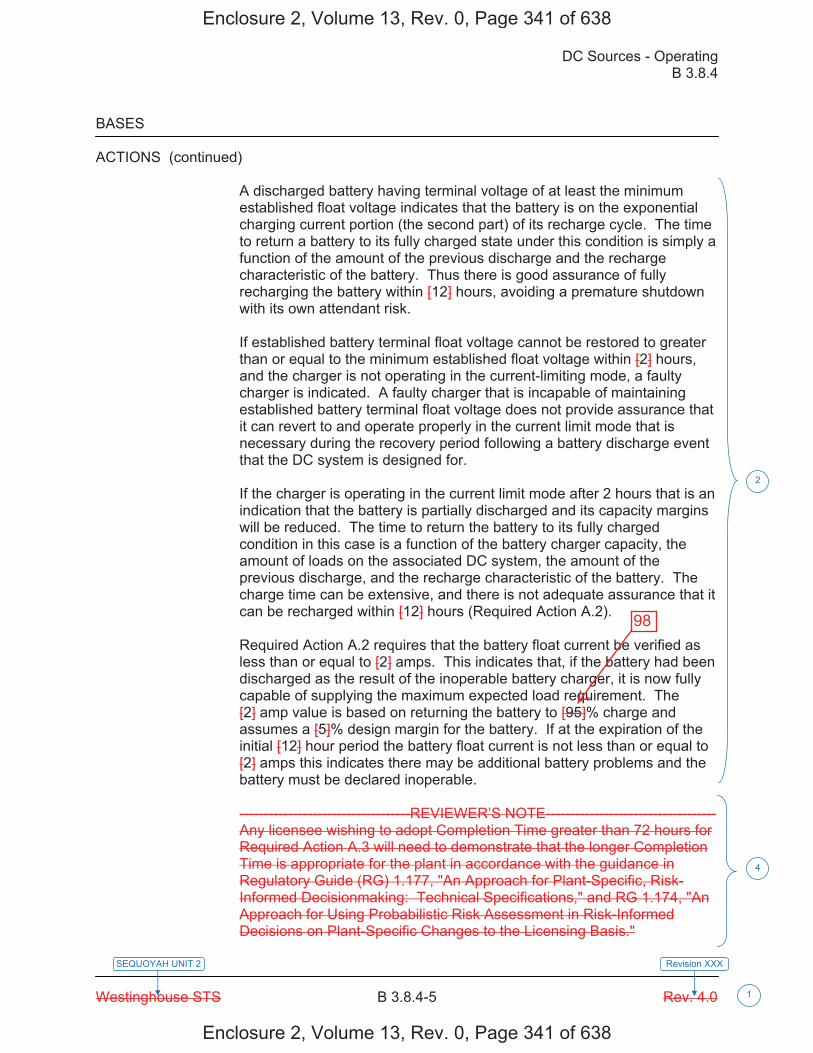
DC Sources - Operating B 3.8.4
Westinghouse STS B 3.8.4-5 Rev. 4.0
SEQUOYAH UNIT 2 Revision XXX
1
BASES ACTIONS (continued)
A discharged battery having terminal voltage of at least the minimum established float voltage indicates that the battery is on the exponential charging current portion (the second part) of its recharge cycle. The time to return a battery to its fully charged state under this condition is simply a function of the amount of the previous discharge and the recharge characteristic of the battery. Thus there is good assurance of fully recharging the battery within [12] hours, avoiding a premature shutdown with its own attendant risk. If established battery terminal float voltage cannot be restored to greater than or equal to the minimum established float voltage within [2] hours, and the charger is not operating in the current-limiting mode, a faulty charger is indicated. A faulty charger that is incapable of maintaining established battery terminal float voltage does not provide assurance that it can revert to and operate properly in the current limit mode that is necessary during the recovery period following a battery discharge event that the DC system is designed for. If the charger is operating in the current limit mode after 2 hours that is an indication that the battery is partially discharged and its capacity margins will be reduced. The time to return the battery to its fully charged condition in this case is a function of the battery charger capacity, the amount of loads on the associated DC system, the amount of the previous discharge, and the recharge characteristic of the battery. The charge time can be extensive, and there is not adequate assurance that it can be recharged within [12] hours (Required Action A.2). Required Action A.2 requires that the battery float current be verified as less than or equal to [2] amps. This indicates that, if the battery had been discharged as the result of the inoperable battery charger, it is now fully capable of supplying the maximum expected load requirement. The [2] amp value is based on returning the battery to [95]% charge and assumes a [5]% design margin for the battery. If at the expiration of the initial [12] hour period the battery float current is not less than or equal to [2] amps this indicates there may be additional battery problems and the battery must be declared inoperable.
-----------------------------------REVIEWER’S NOTE----------------------------------- Any licensee wishing to adopt Completion Time greater than 72 hours for Required Action A.3 will need to demonstrate that the longer Completion Time is appropriate for the plant in accordance with the guidance in Regulatory Guide (RG) 1.177, "An Approach for Plant-Specific, Risk-Informed Decisionmaking: Technical Specifications," and RG 1.174, "An Approach for Using Probabilistic Risk Assessment in Risk-Informed Decisions on Plant-Specific Changes to the Licensing Basis."
2
4
Enclosure 2, Volume 13, Rev. 0, Page 341 of 638
Enclosure 2, Volume 13, Rev. 0, Page 341 of 638
98

Licensee Response/NRC Response/NRC Question ClosureId 307
NRC Question Number VKG018
Select Application NRC Question Closure
Attachment 1
Attachment 2
Response Statement
Response Date/Time
Closure Statement This question is closed and no further information is required at this time to draft the Safety Evaluation.
Question Closure Date 8/28/2014
Notification Scott BowmanMichelle ConnerVijay GoelKhadijah HemphillAndrew HonLynn MynattRay SchieleRoger Scott
Added By Khadijah Hemphill
Date Added 8/28/2014 3:57 PM
Date Modified
Modified By
Page 1 of 1Sequoyah ITS Conversion Database
9/9/2014https://members.excelservices.com/rai/index.php?requestType=areaItemPrint&itemId=307
ITS NRC QuestionsId 179
NRC Question Number VKG019
Category Technical
ITS Section 3.8
ITS Number 3.8.4
DOC Number
JFD Number
JFD Bases Number
Page Number(s)
NRC Reviewer Supervisor Jake Zimmerman
Technical Branch POC Add Name
Conf Call Requested N
NRC Question ITS Bases SR 3.8.4.1 contains the following statement: “The voltage requirements are based on the nominal design voltage of the battery and are consistent with the minimum float voltage established by the manufacturer (129 V for the Vital batteries and 124 V for the DG batteries).”
Provide the basis for selecting 124 V minimum float voltage for DG batteries.
Attach File 1
Attach File 2
Issue Date 7/24/2014
Added By Khadijah Hemphill
Date Modified
Modified By
Date Added 7/24/2014 8:12 AM
Notification Scott BowmanMichelle ConnerVijay GoelKhadijah HemphillAndrew HonLynn MynattRay SchieleRoger Scott
Page 1 of 1Sequoyah ITS Conversion Database
10/15/2014https://members.excelservices.com/rai/index.php?requestType=areaItemPrint&itemId=179
Licensee Response/NRC Response/NRC Question ClosureId 351
NRC Question Number
VKG019
Select Application Licensee Response
Attachment 1 Attachment 1 for RAI VKG019.pdf (2MB)
Attachment 2 Attachment 2 for RAI VKG019.pdf (360KB)
Response Statement
In response to RAI VKG019, the following information is being provided regarding the basis for selecting 124 volts as the minimum float voltage for the DG batteries.
The minimum float voltage requirements for the DG batteries, as discussed in ITS 3.8.4 Bases Surveillance Requirements Section 3.8.4.1, reflects CTS 4.8.1.1.3.a.2 that requires verifying, “the total battery terminal voltage is greater than or equal to 124 volts on float charge,” for the DG batteries. By letter dated September 17, 1982 (Accession Number 8209220277), SQN requested a license amendment to change the minimum float voltage requirement specified in surveillance requirement 4.8.1.1.3.a.2 for the DG batteries from 129 volts to 124 volts. The change was necessary because SQN replaced the DG batteries with lead calcium batteries with 57 cells with a manufacturer’s recommended minimum float voltage of 2.17 volts/cell.The original minimum float voltage requirement of 129 volts exceeded the manufacturer’s recommended maximum of 128.25 volts and could contribute to shorter battery life. Therefore, 124 volts should be the minimum total float voltage requirement. By letter dated December 23, 1982 (Accession Number 8301060001), the Commission issued Amendments 17 and 8 for SQN, Units 1 and 2, respectively. The Safety Evaluation related to Amendments 17 and 8 stated that, “from this justification, the staff agrees that surveillance requirement 4.8.1.1.3.9.2 [sic] should be changed from 129 volts to 124 volts.”
Attachment 1 is the SQN license amendment request.
Attachment 2 is the Commission’s issuance of Amendments 17 and 8 for SQN, Units 1 and 2.
Response Date/Time 9/26/2014 6:55 AM
Closure Statement
Question Closure
Date
Notification Scott BowmanMichelle Conner
Page 1 of 2Sequoyah ITS Conversion Database
10/15/2014https://members.excelservices.com/rai/index.php?requestType=areaItemPrint&itemId=351
Vijay GoelKhadijah HemphillAndrew HonLynn MynattRay Schiele
Added By Scott Bowman
Date Added 9/26/2014 5:49 AM
Date Modified
Modified By
Page 2 of 2Sequoyah ITS Conversion Database
10/15/2014https://members.excelservices.com/rai/index.php?requestType=areaItemPrint&itemId=351
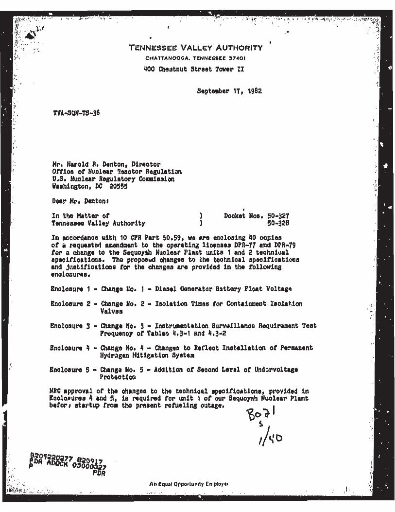
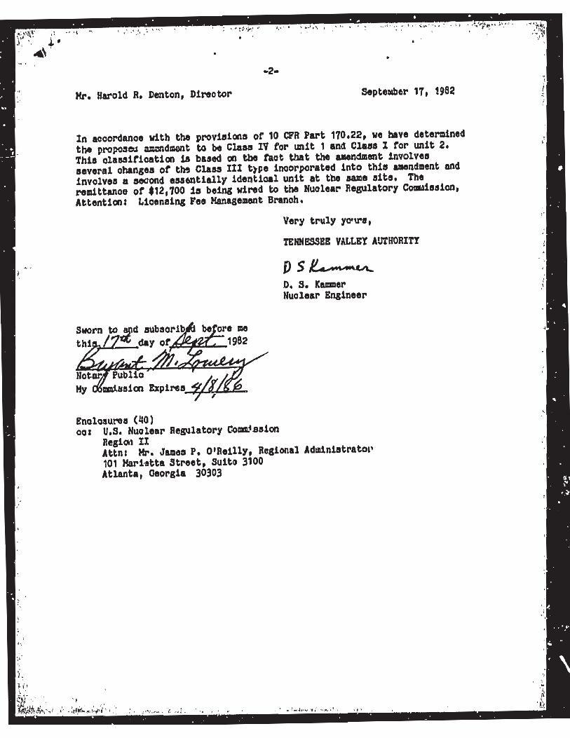
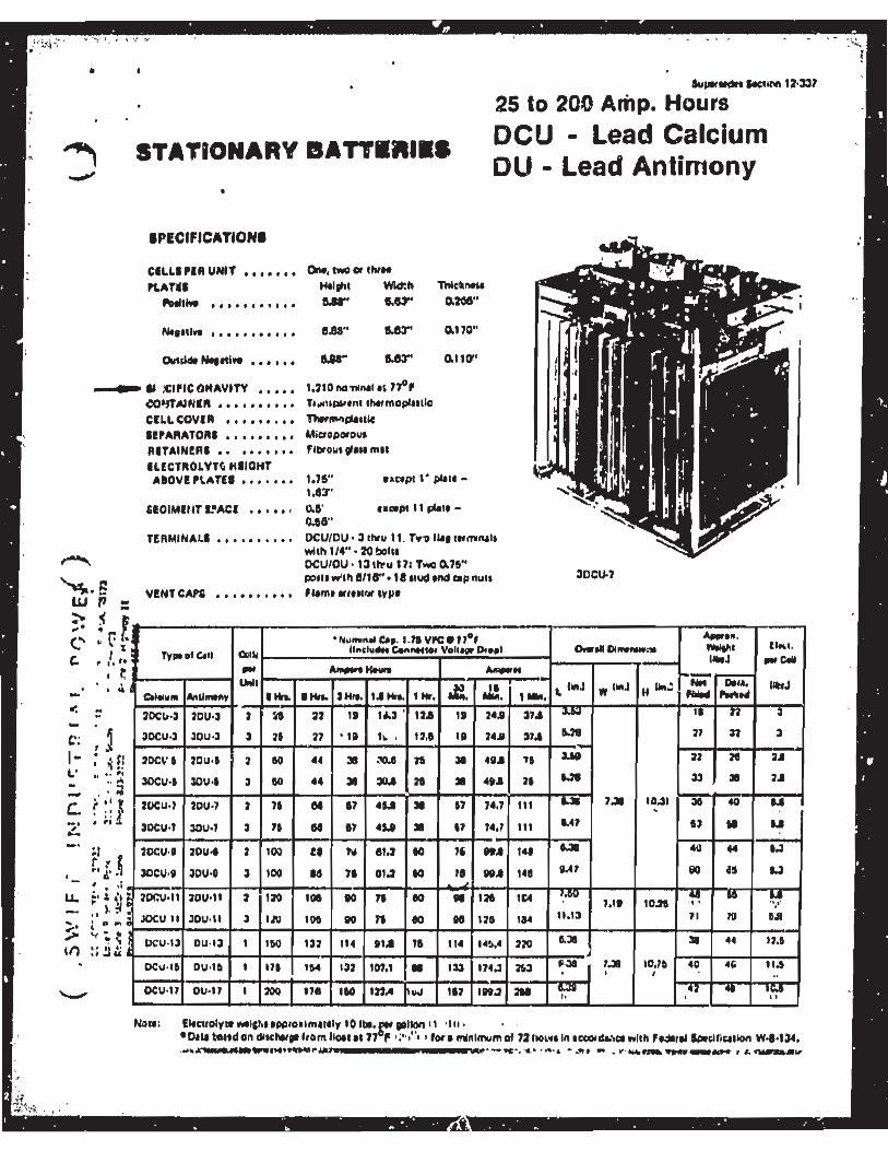
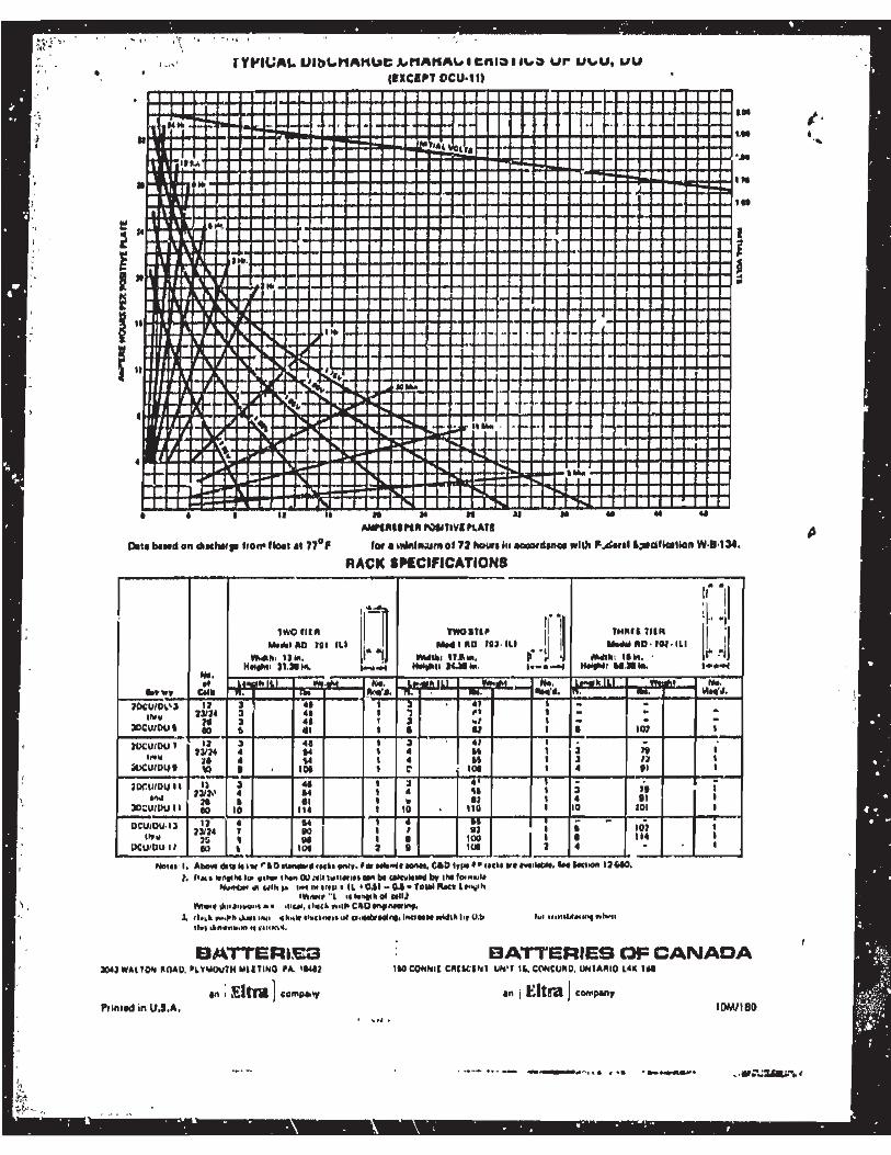
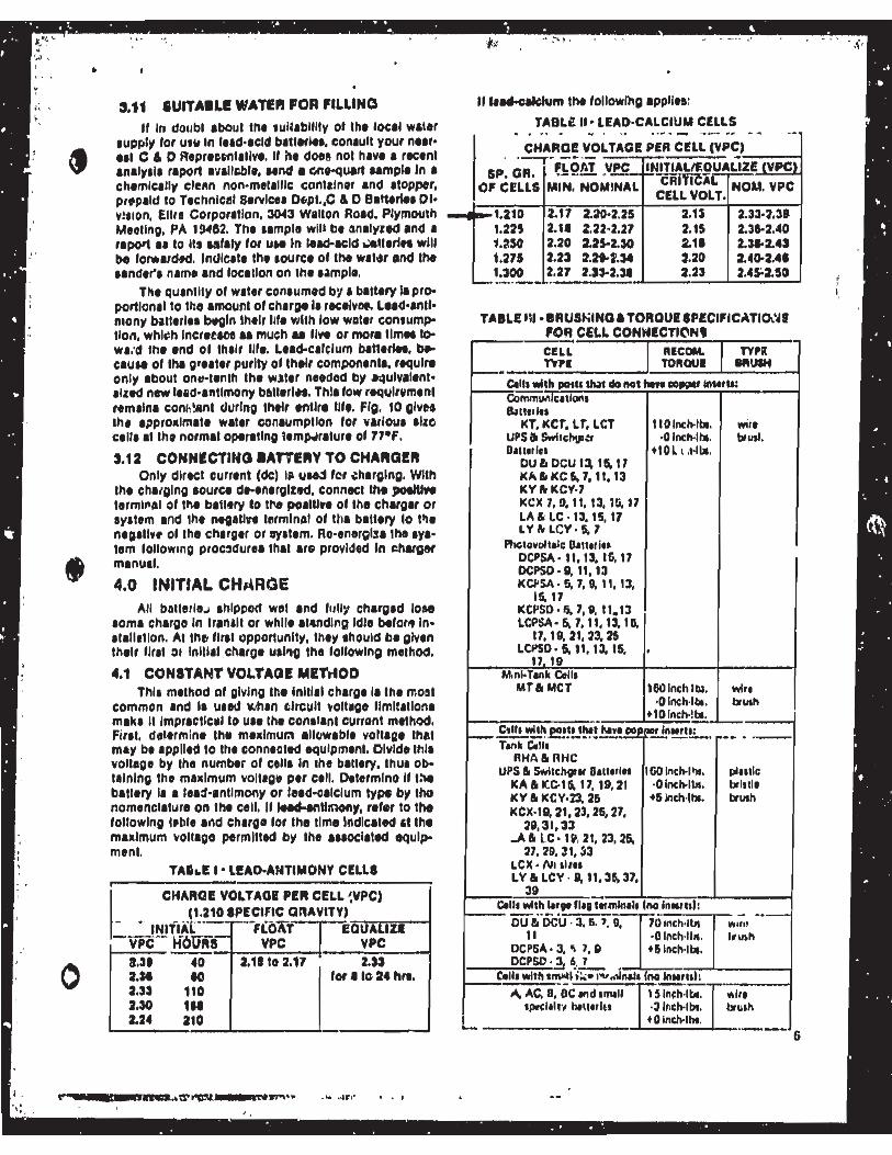
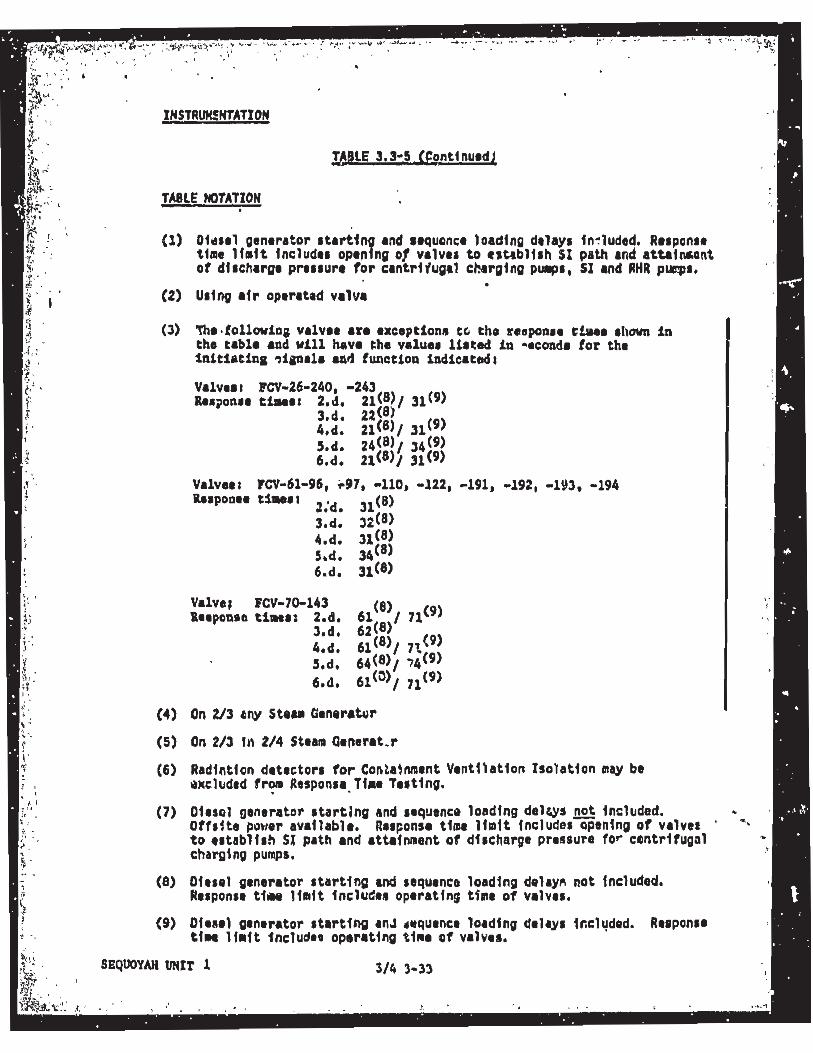
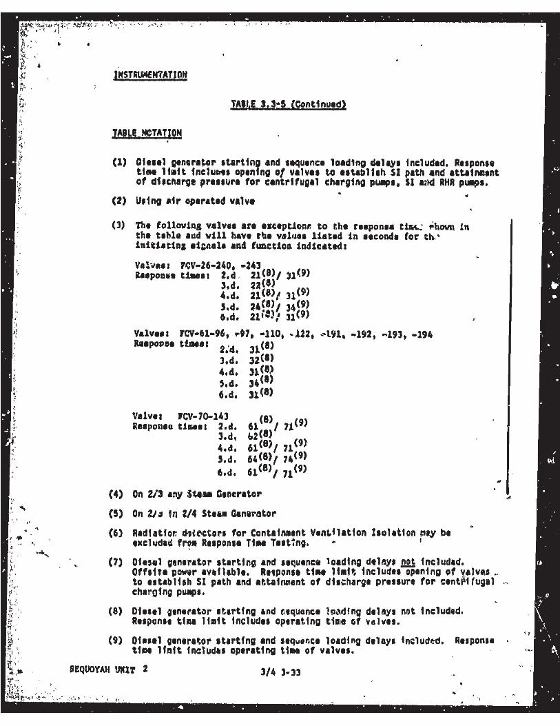
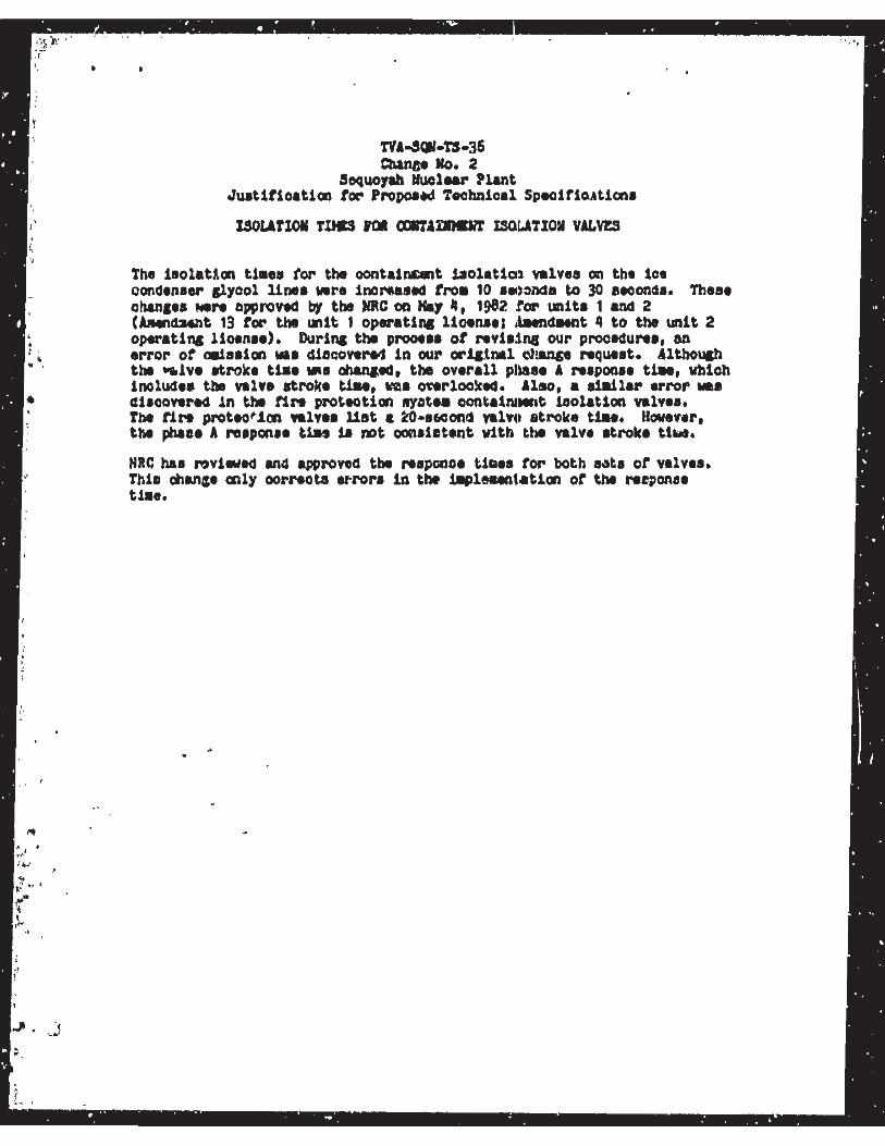
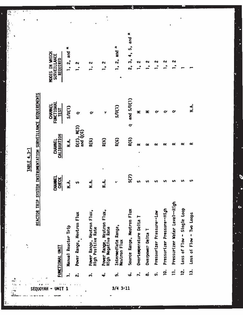
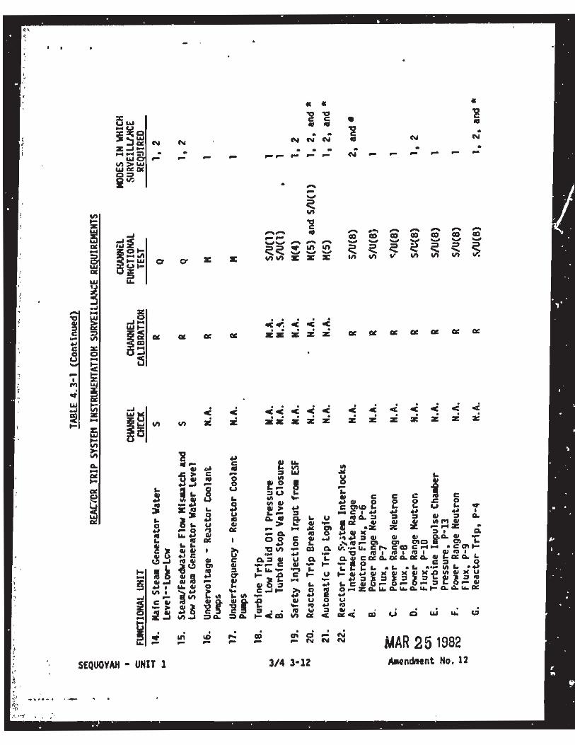
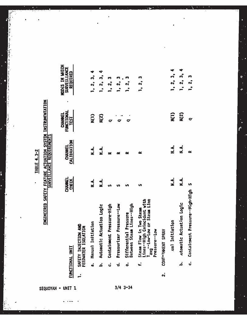
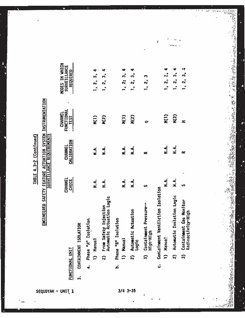
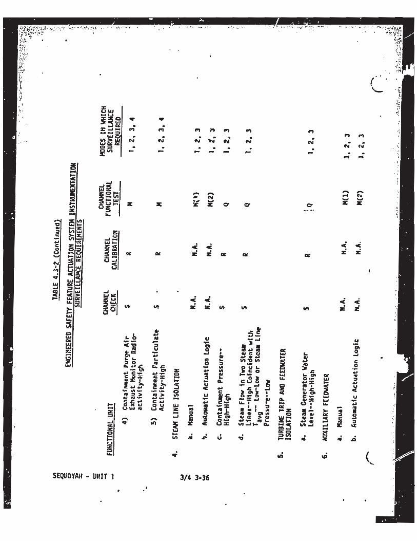
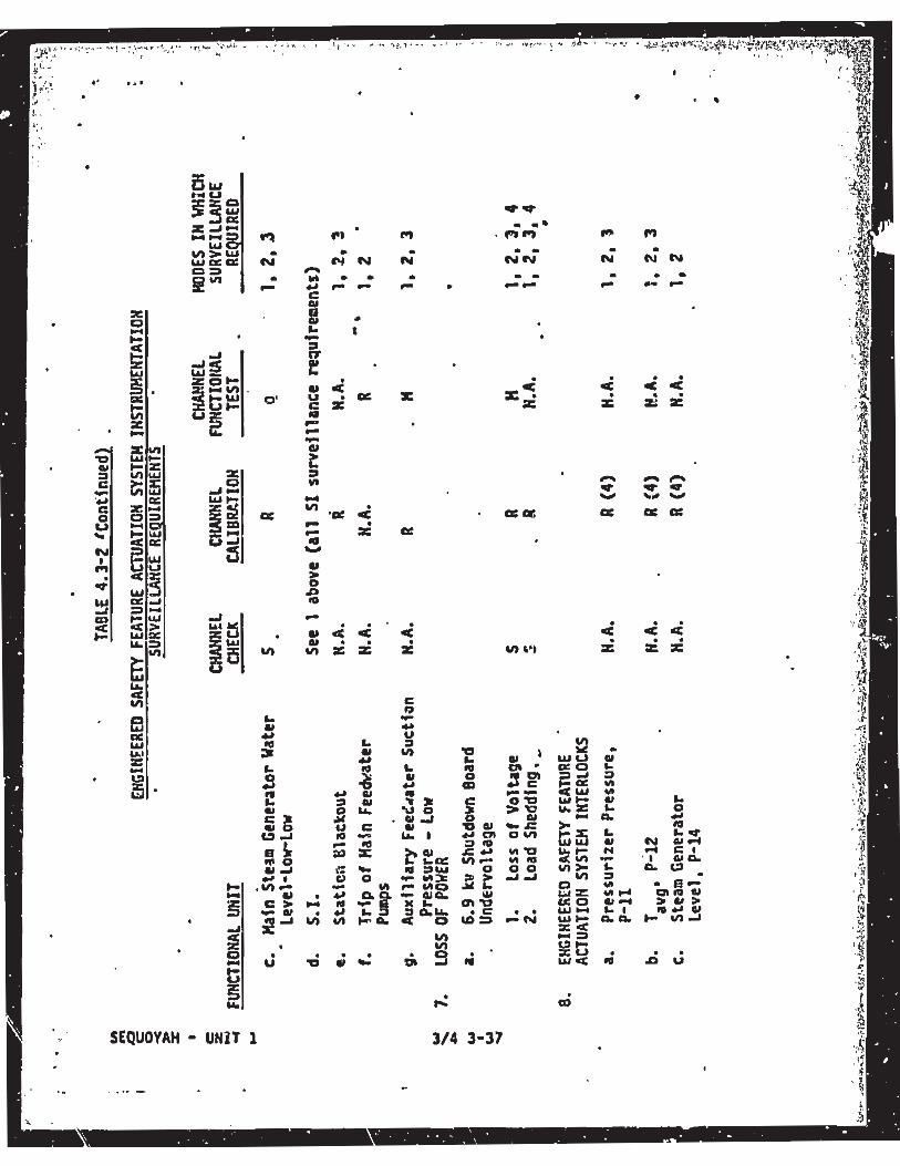
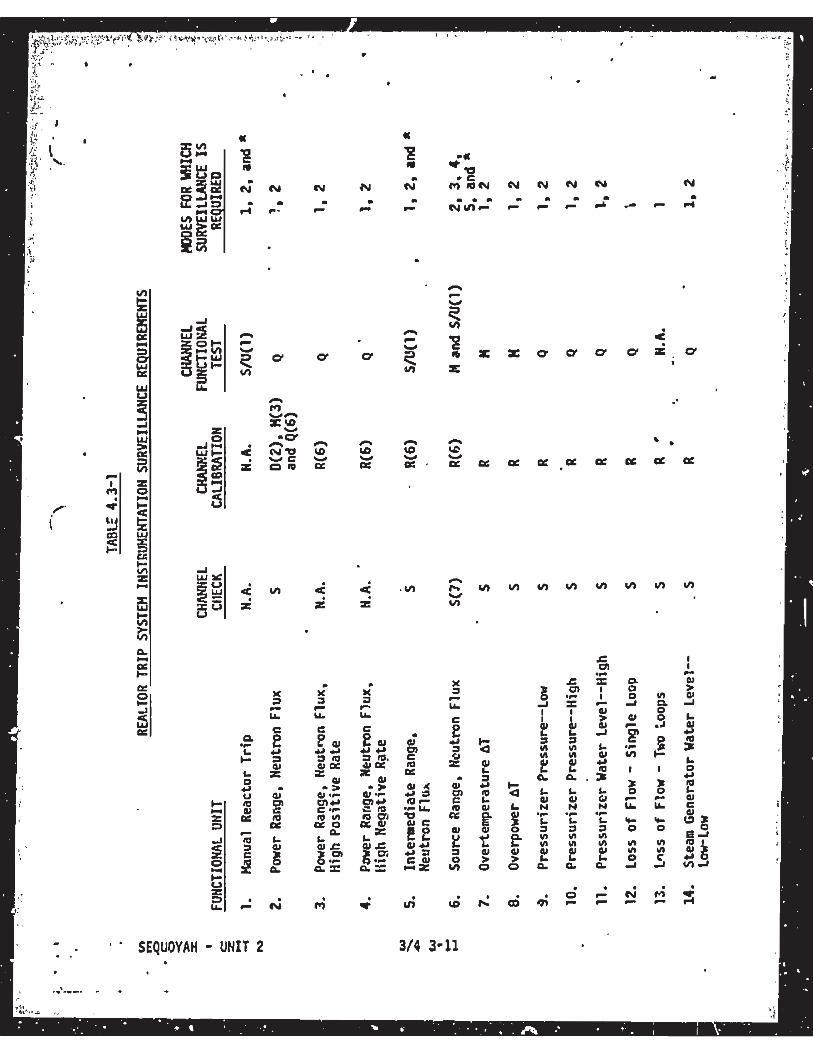
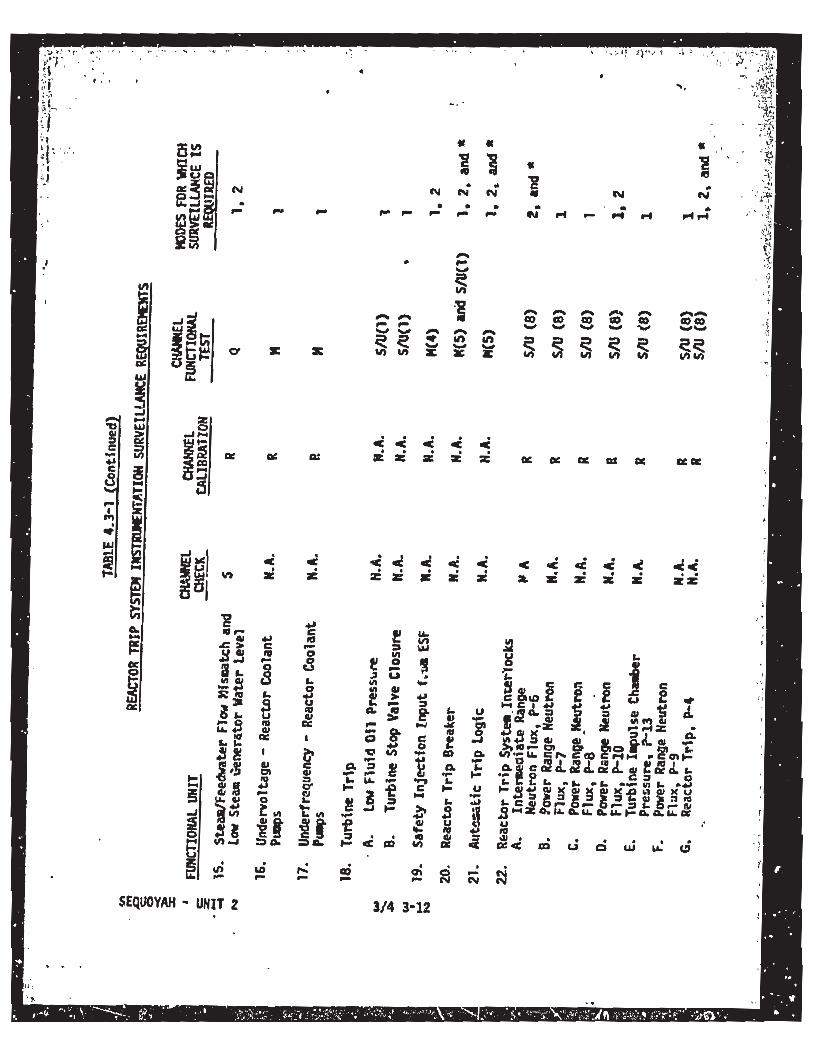
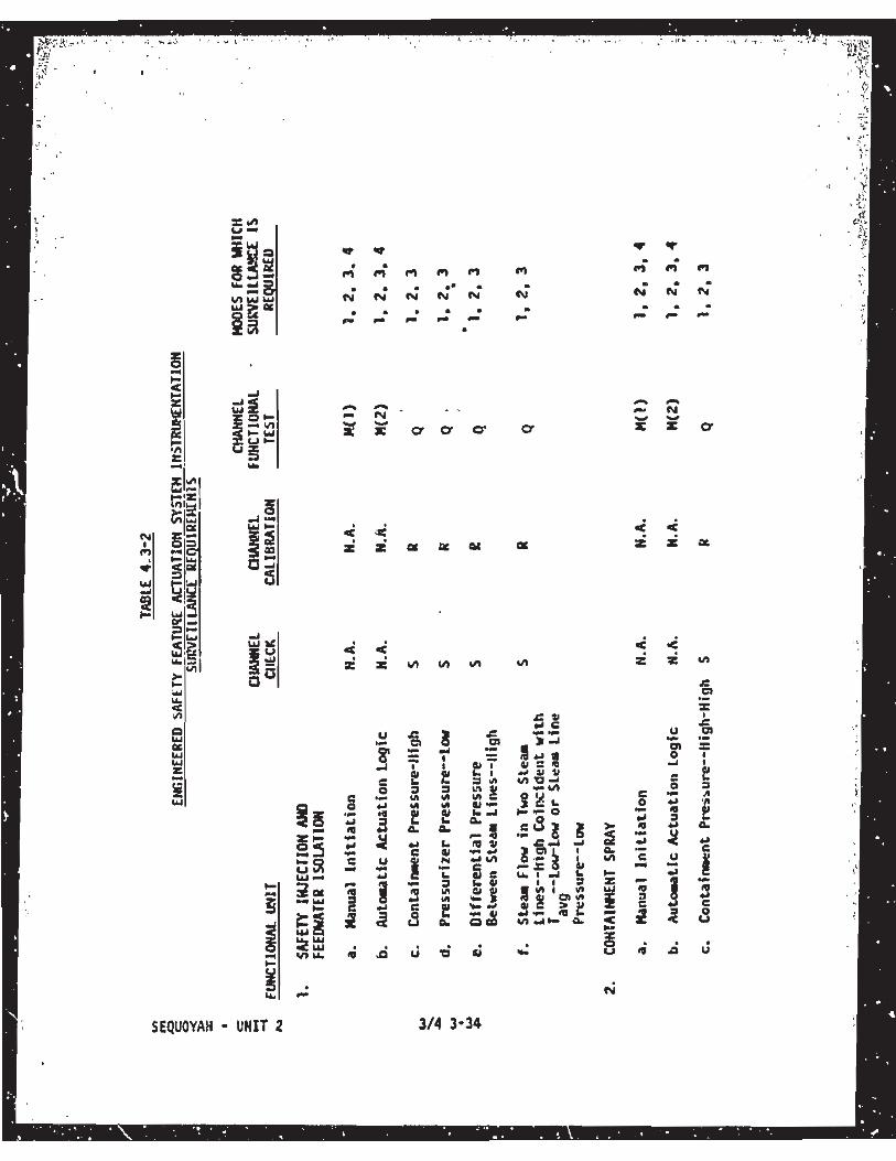
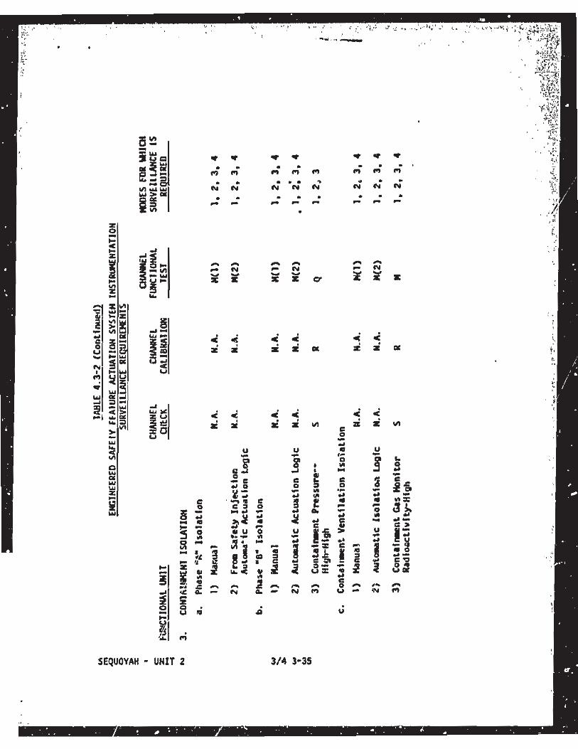
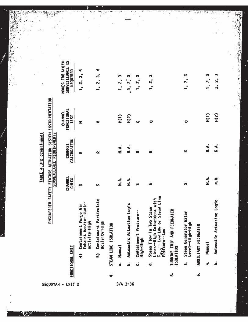
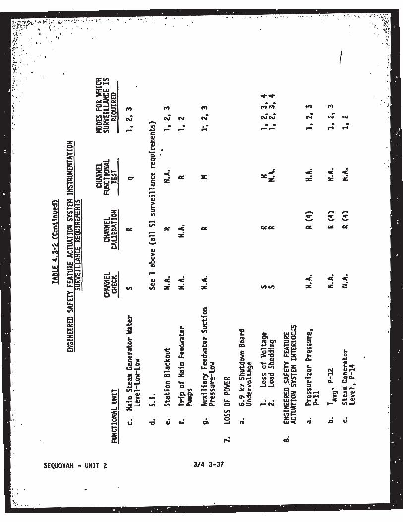
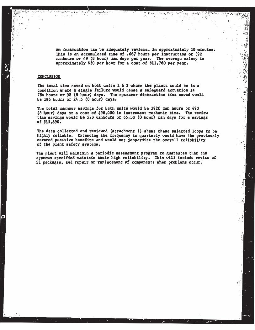
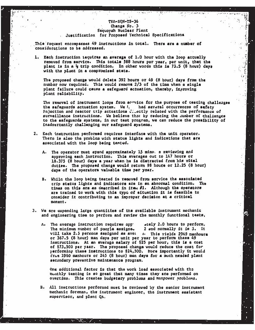
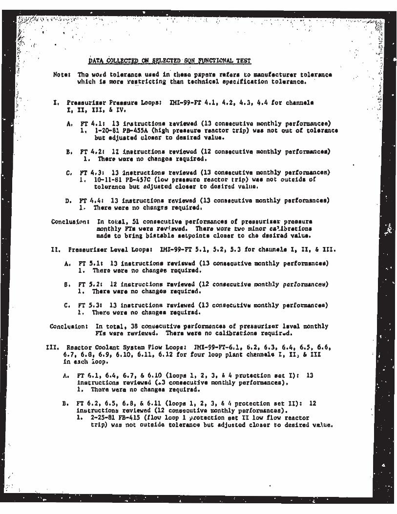
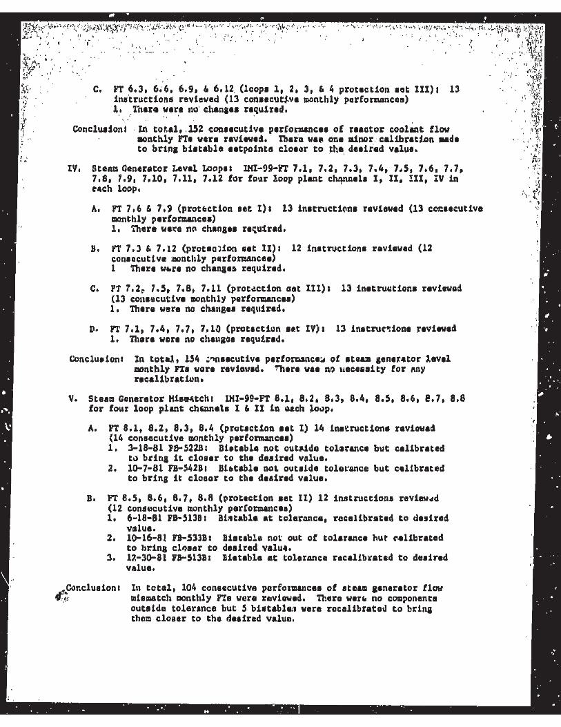
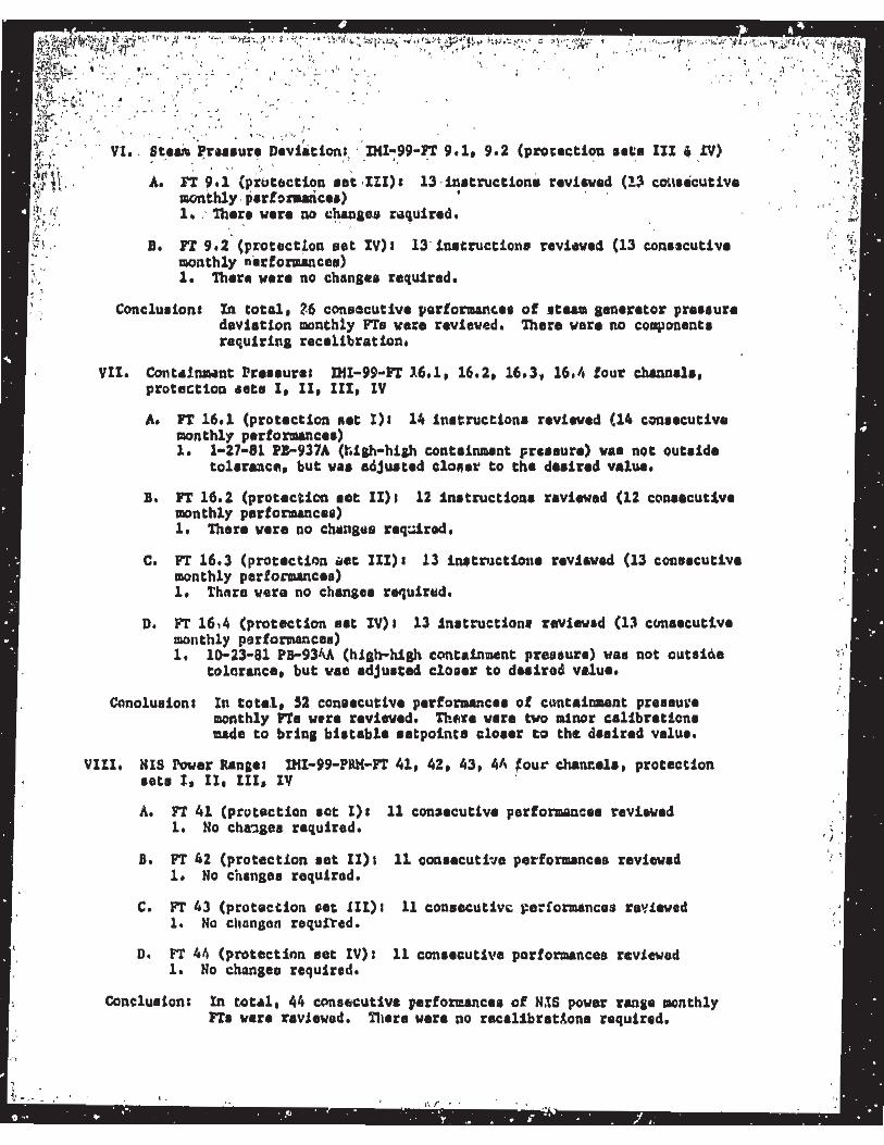
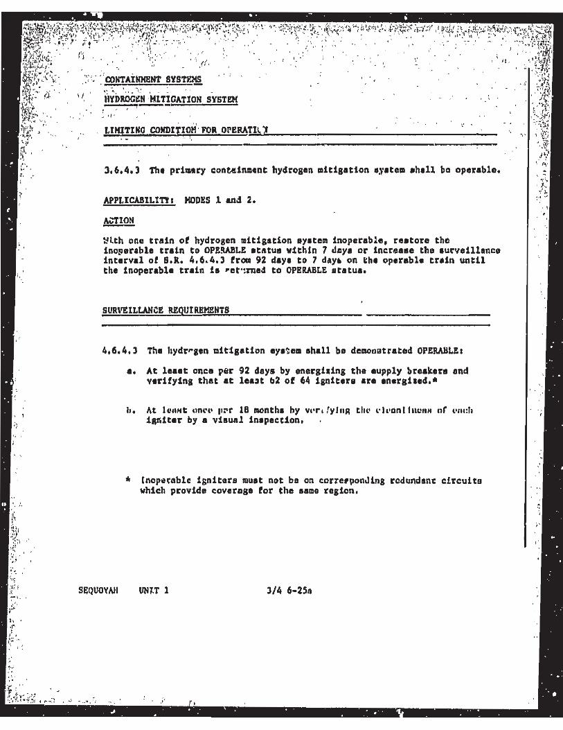
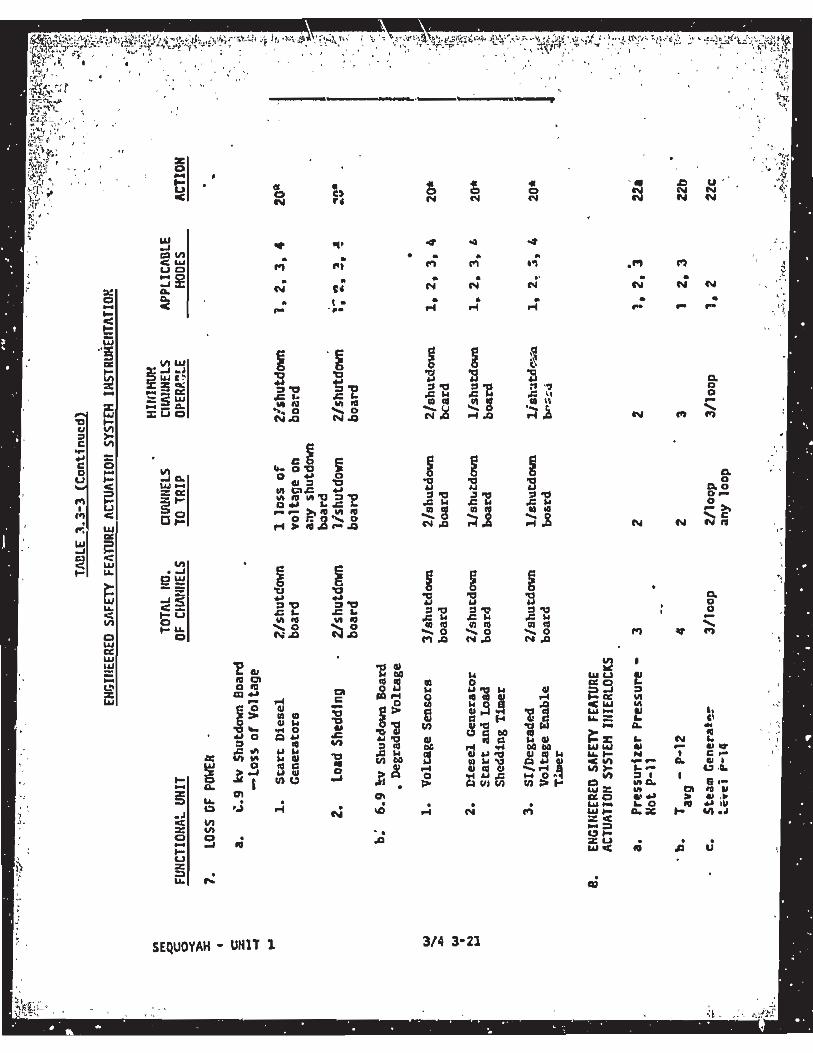
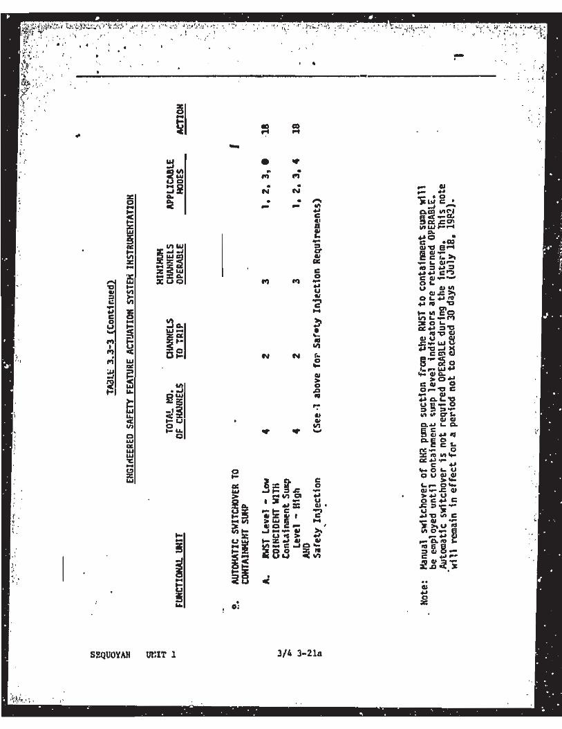
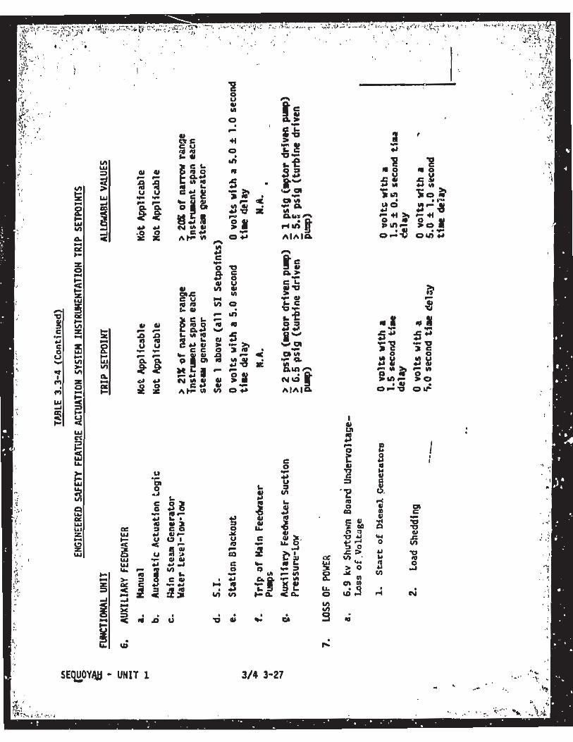
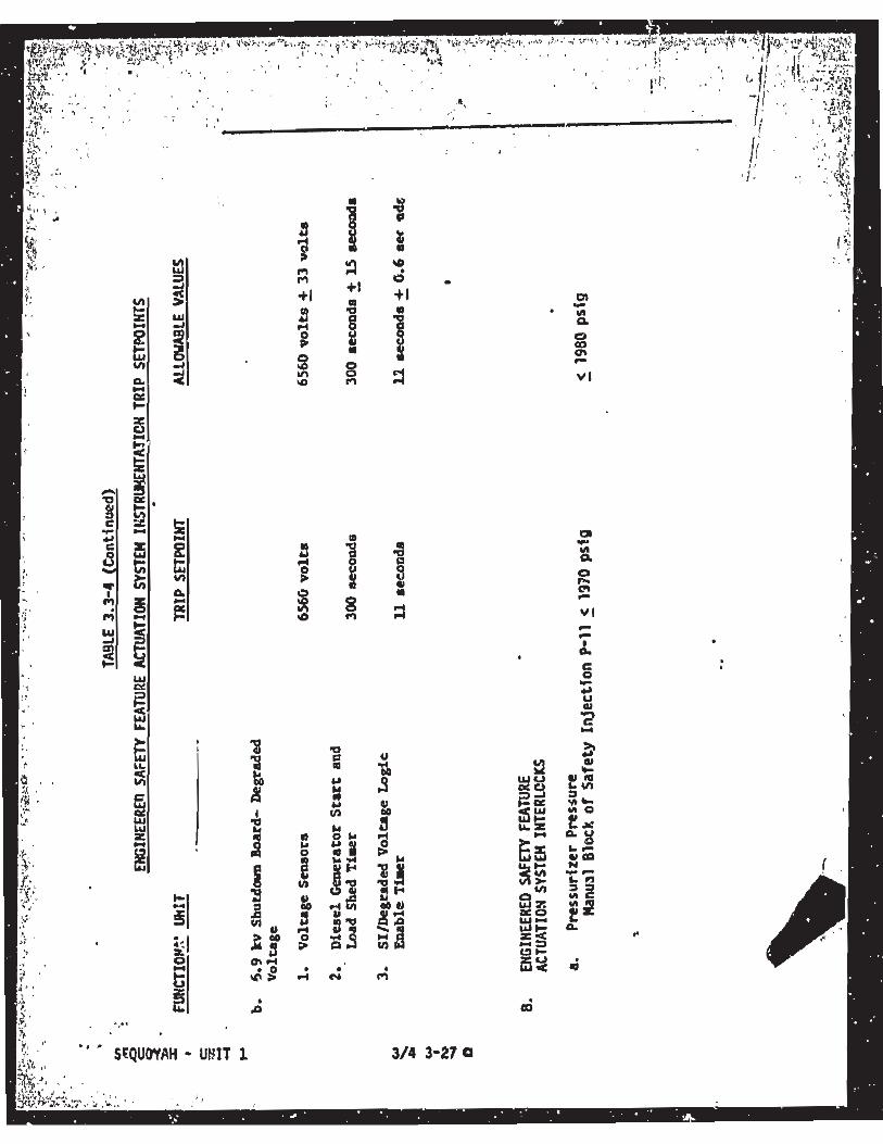
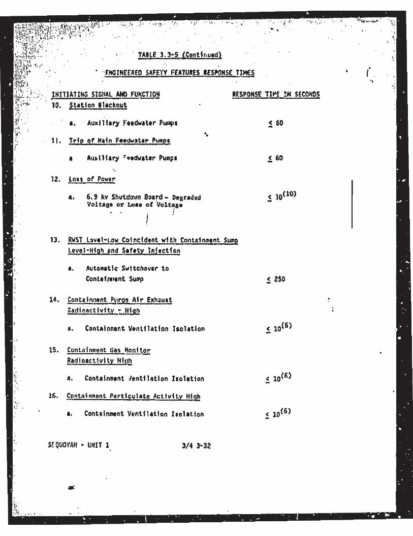
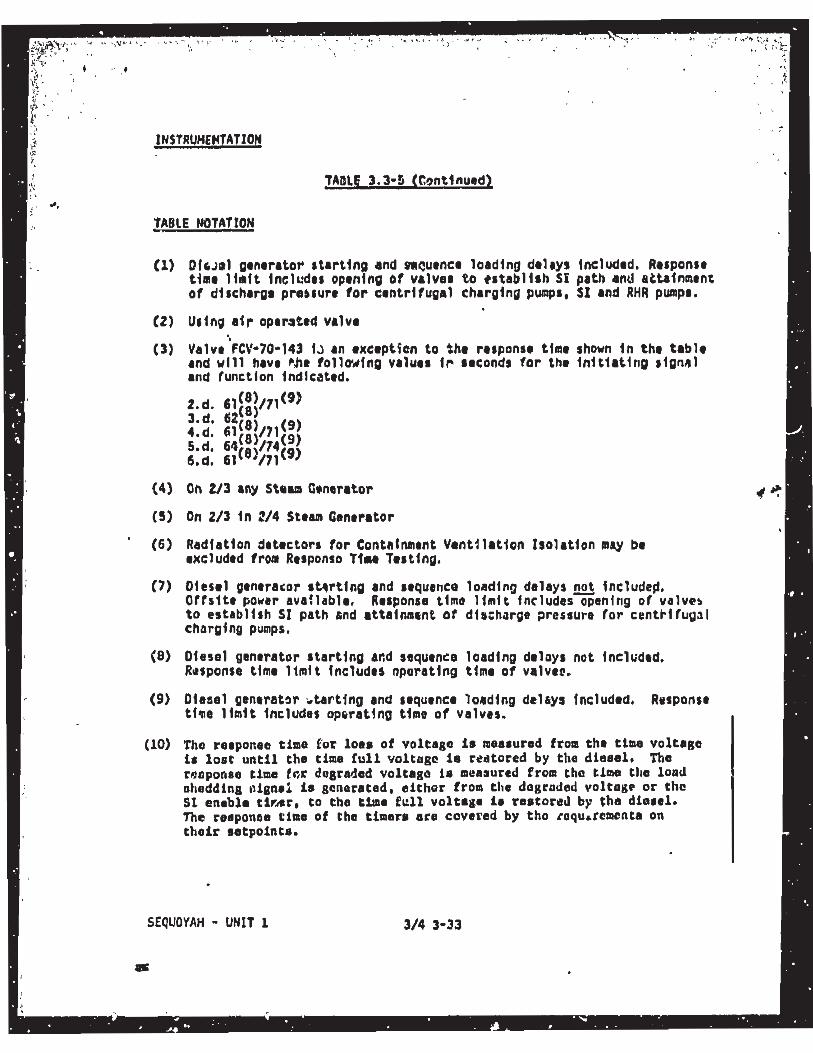
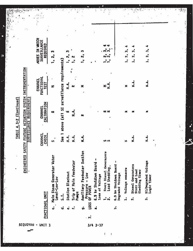
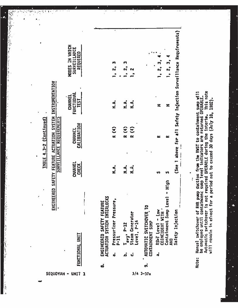
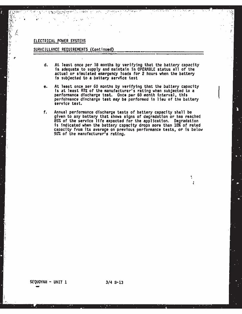
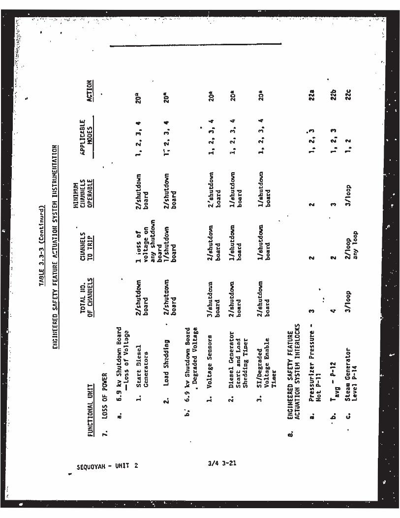
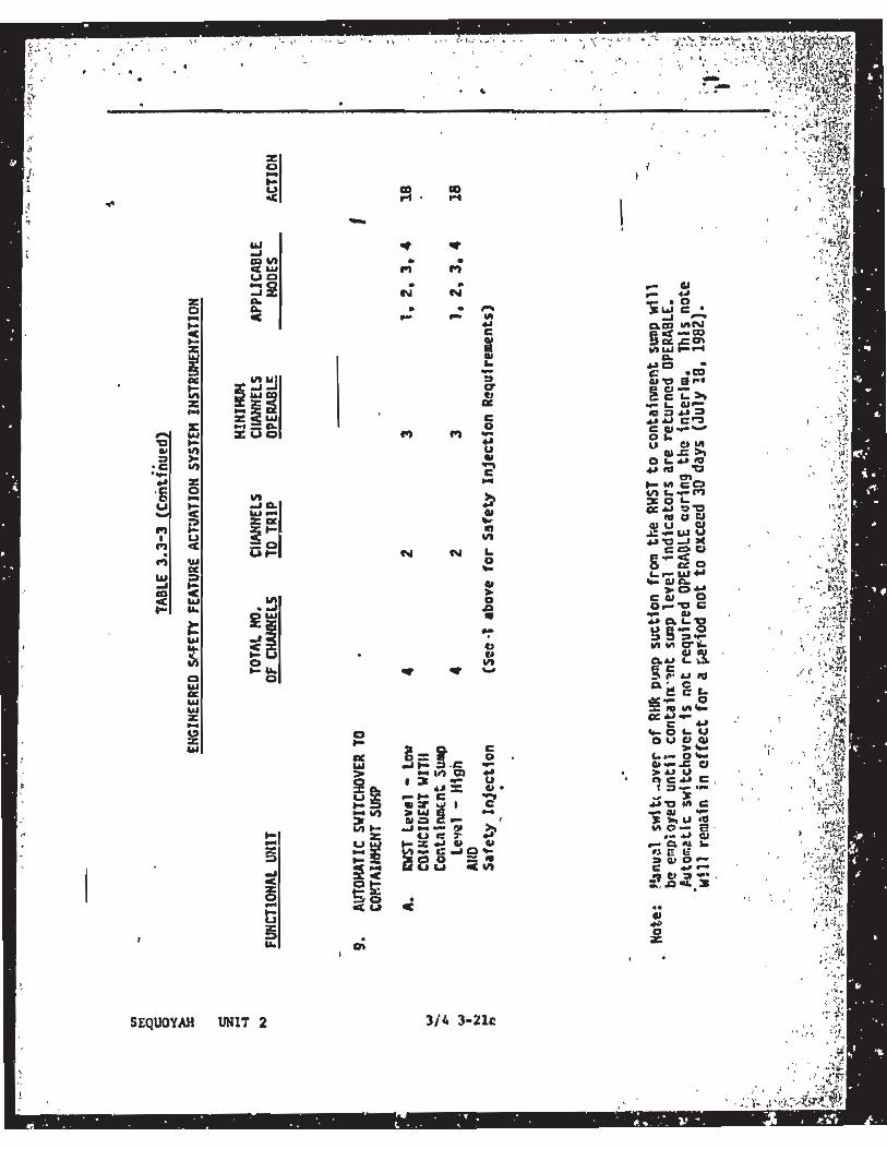
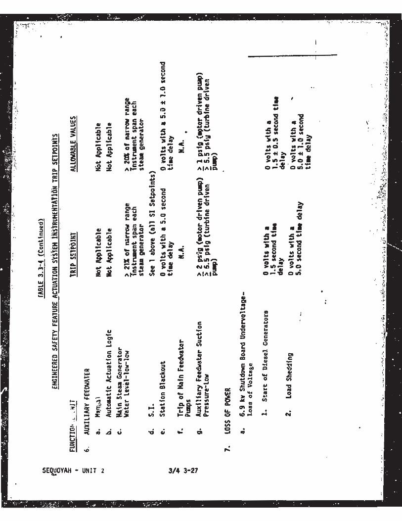
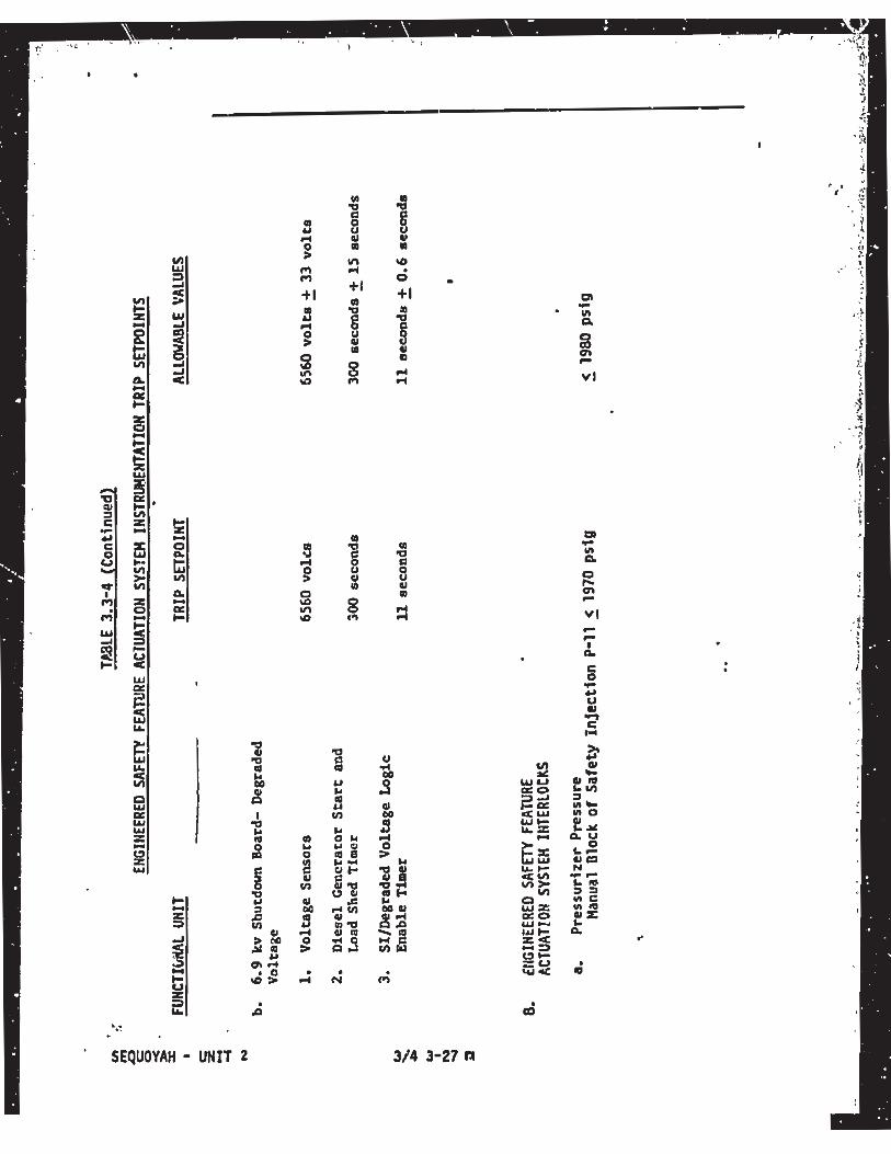
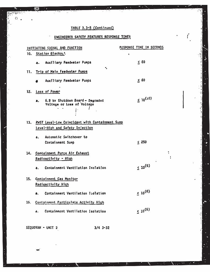
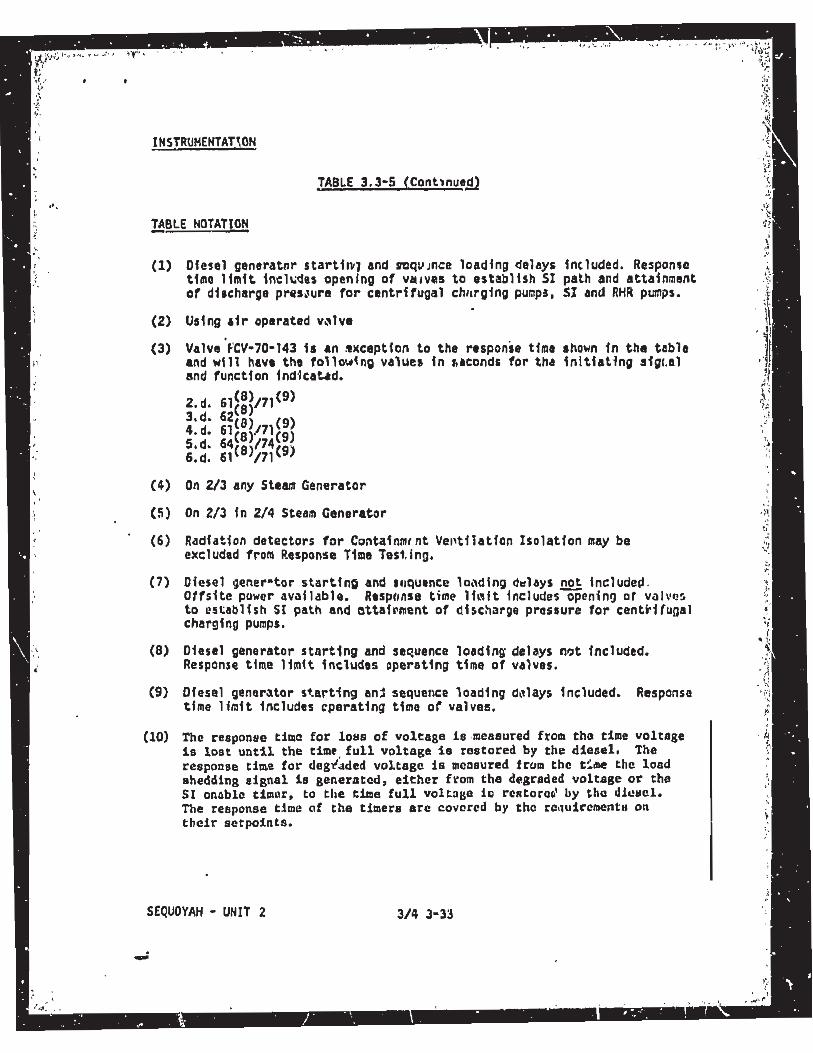
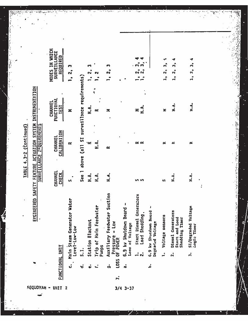
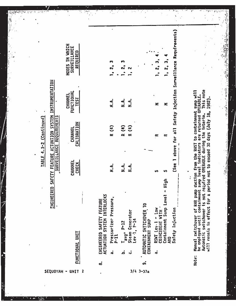
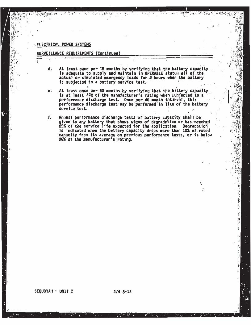
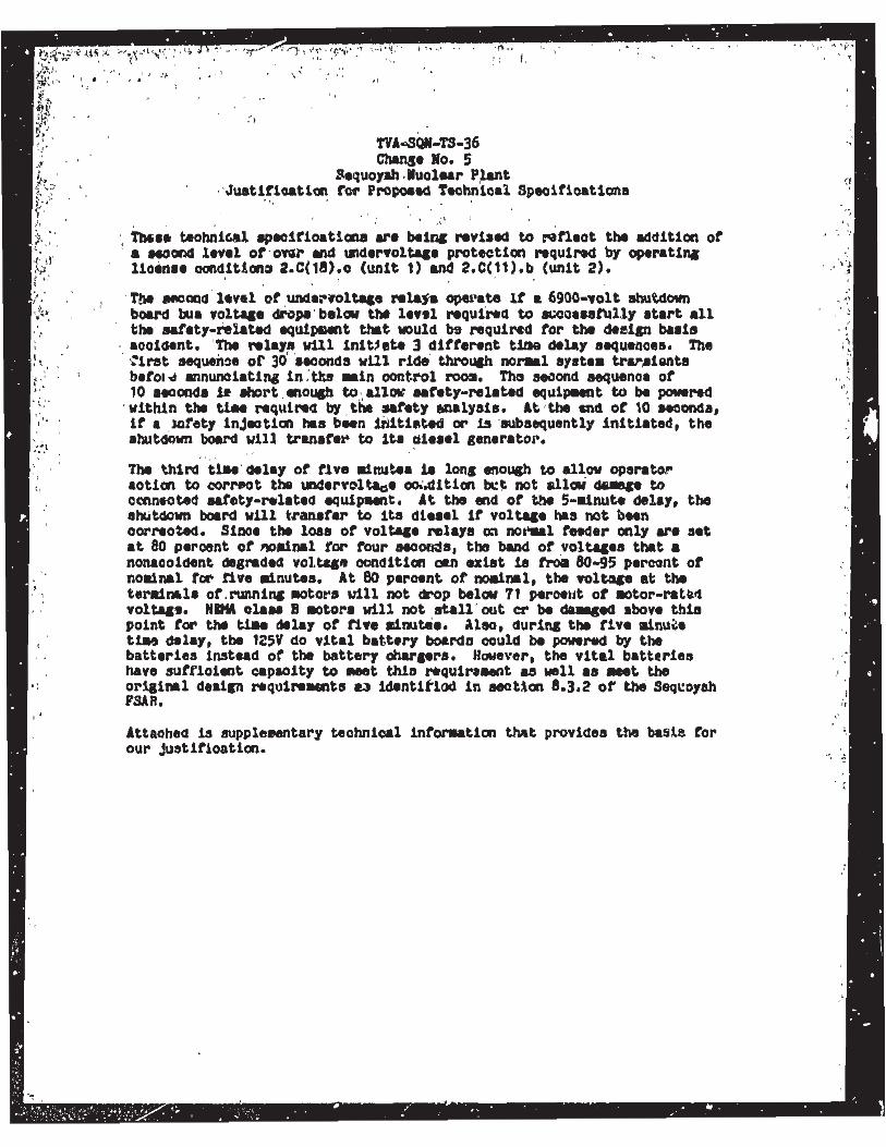
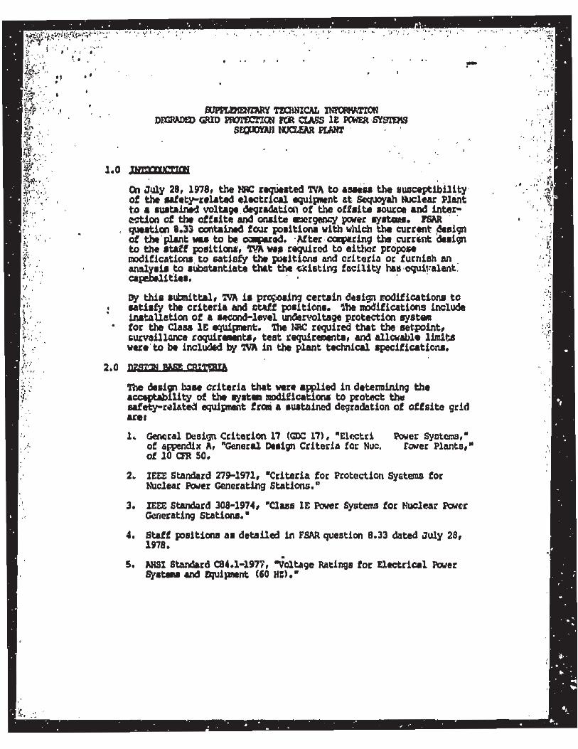
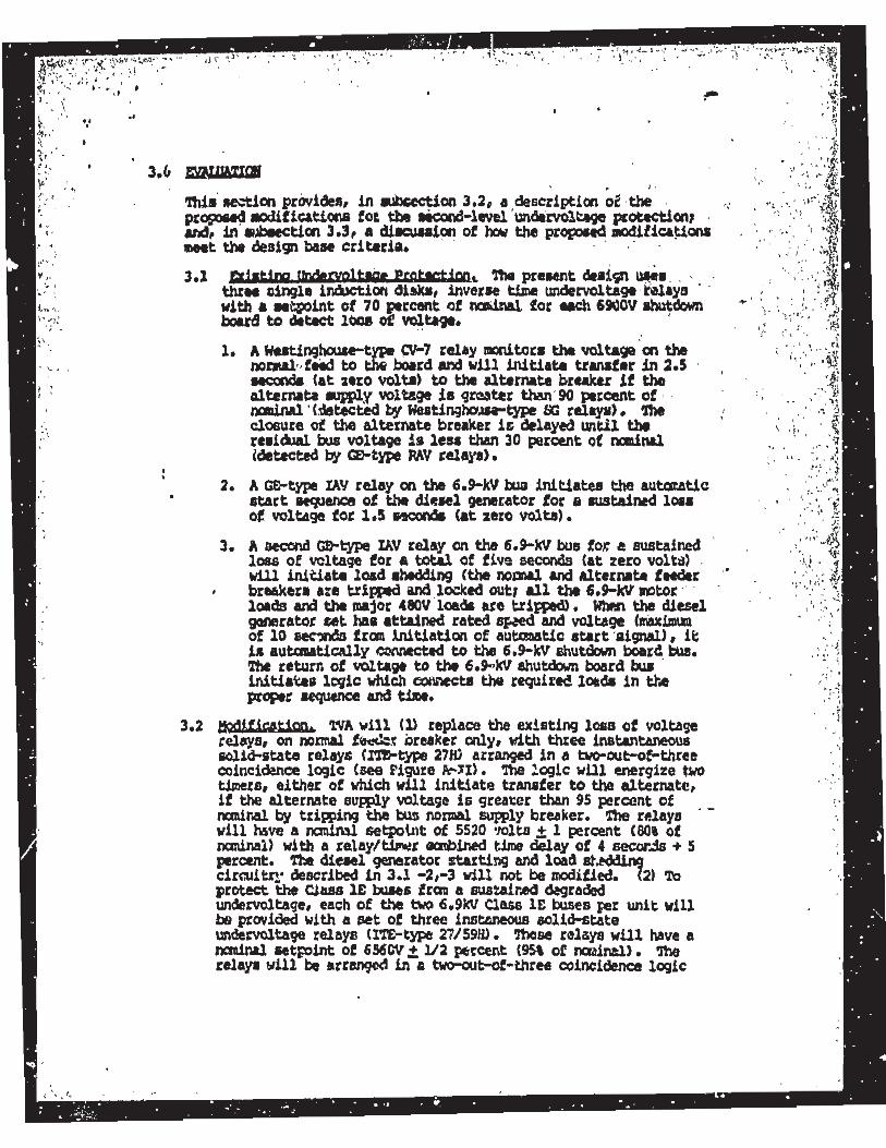
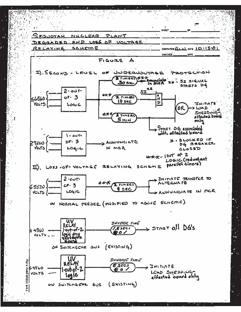
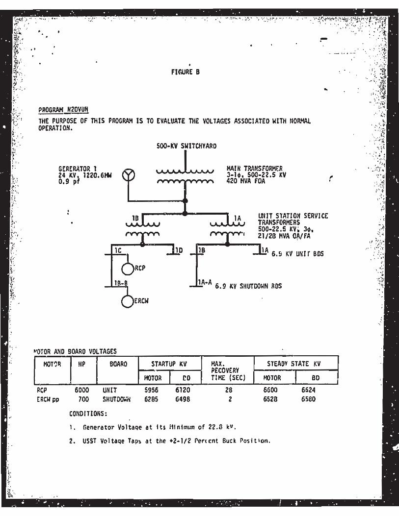
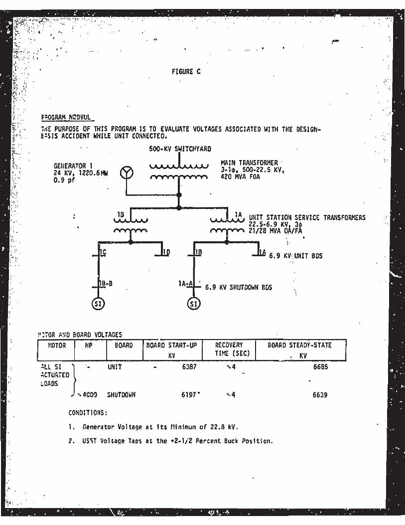
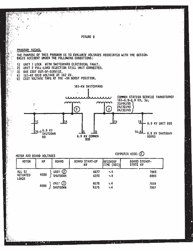
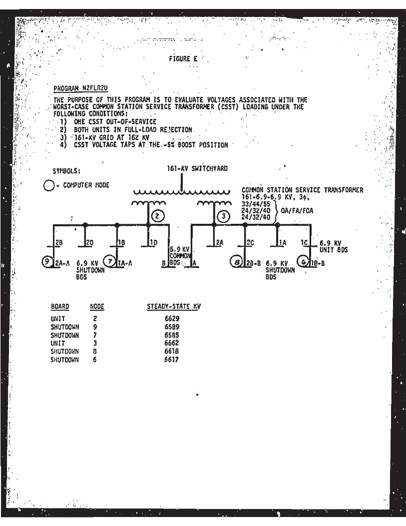
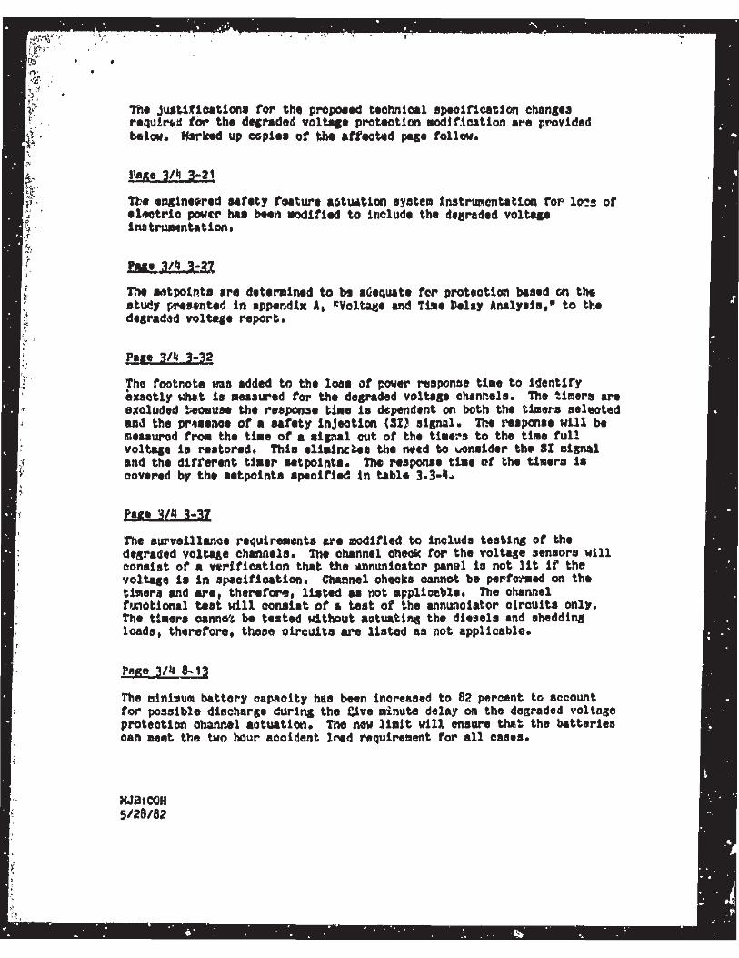
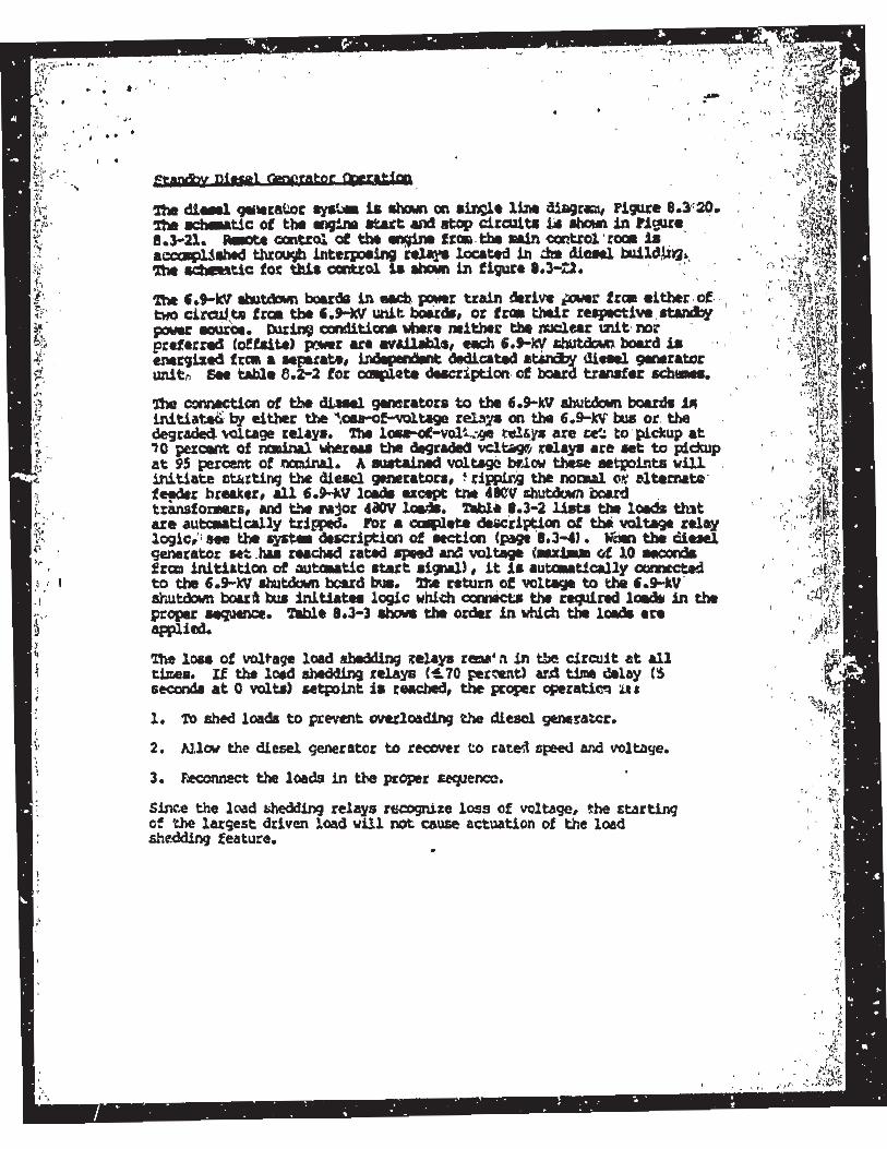
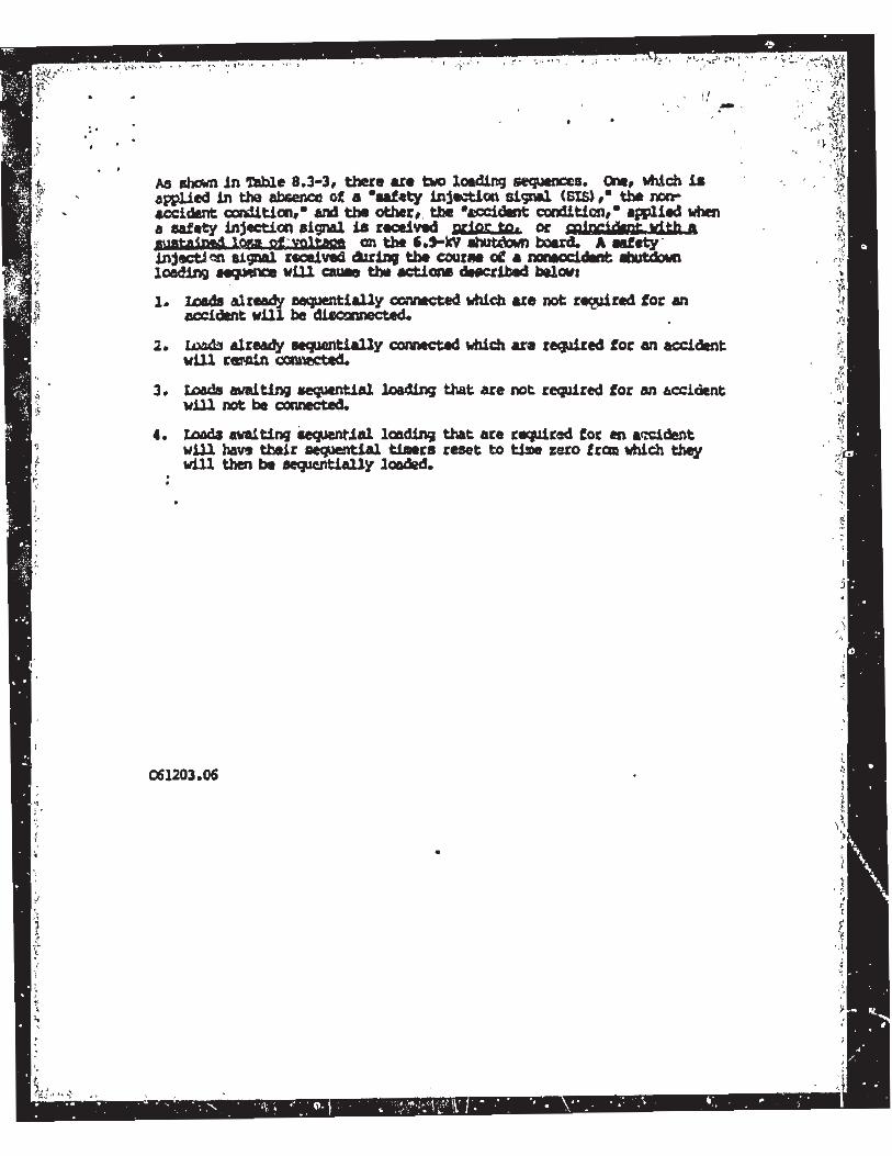
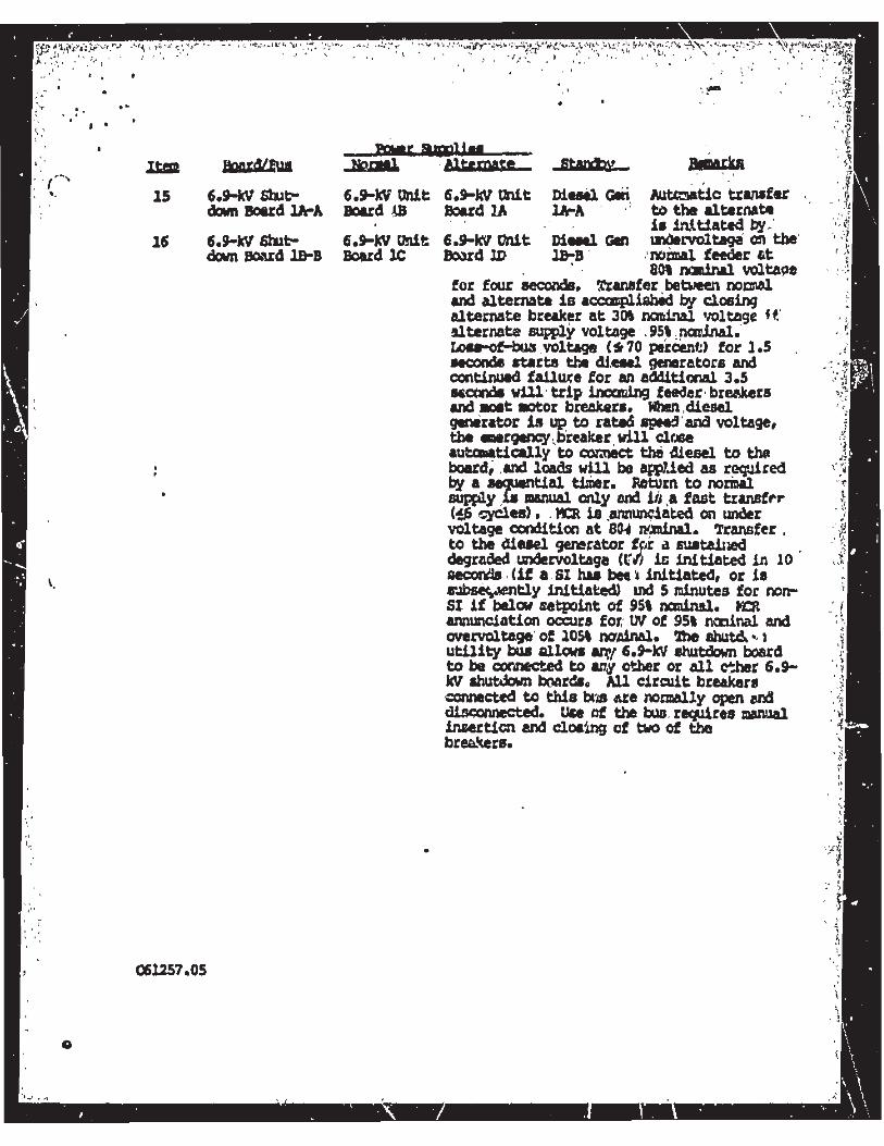
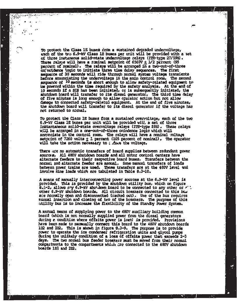
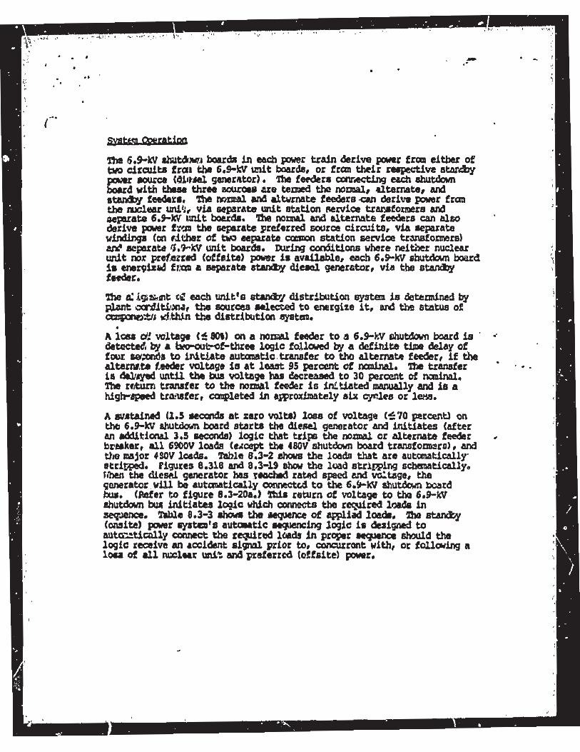
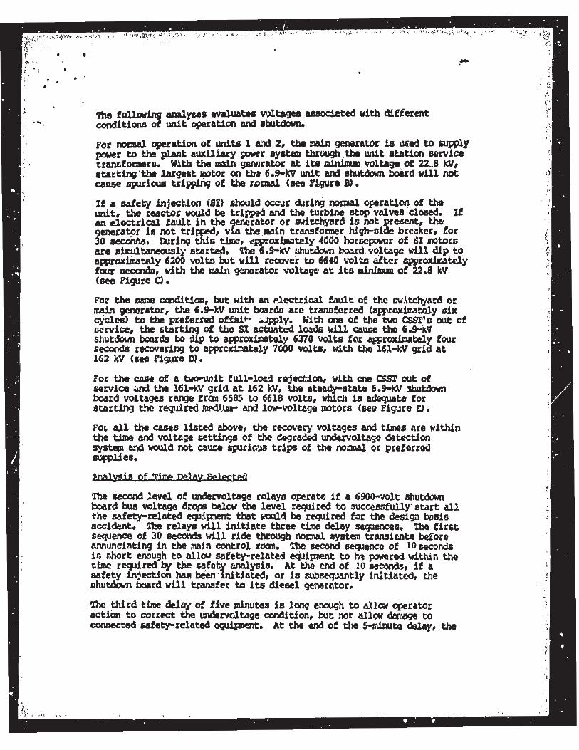
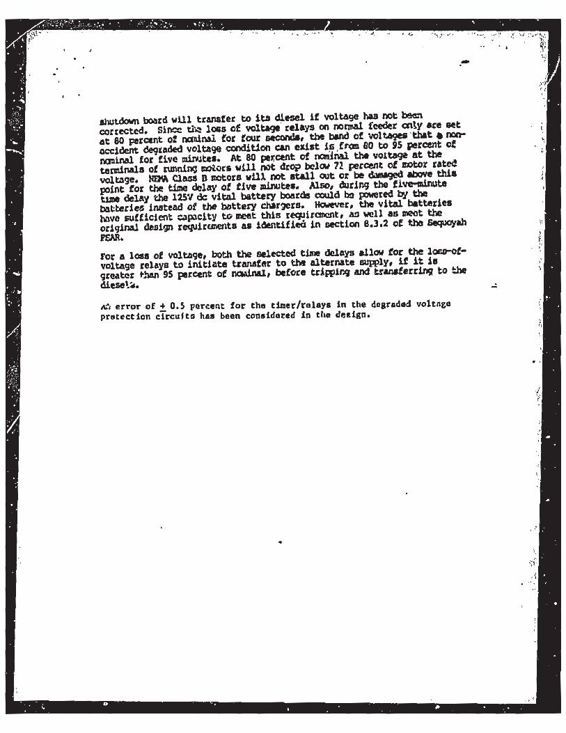
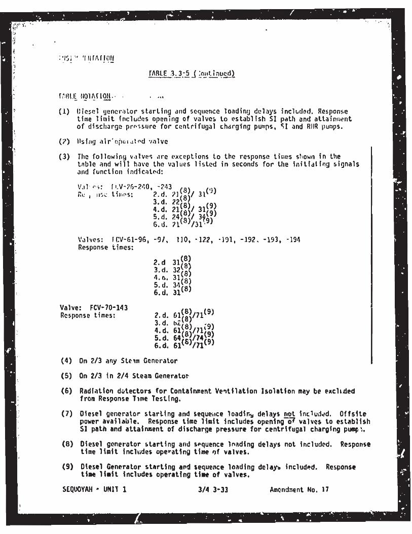
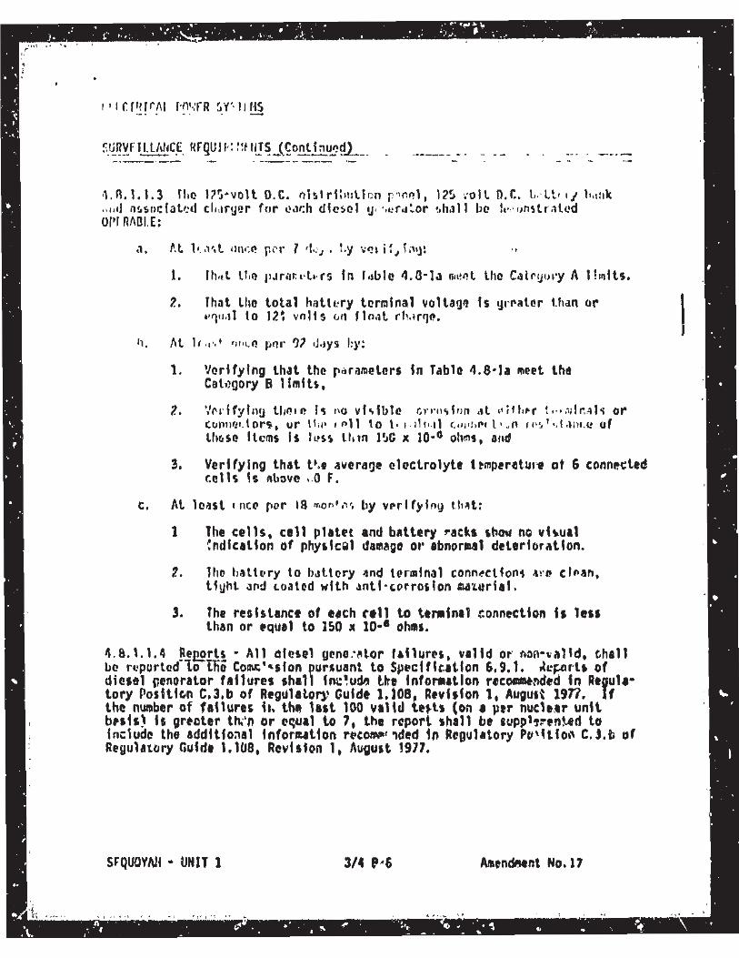
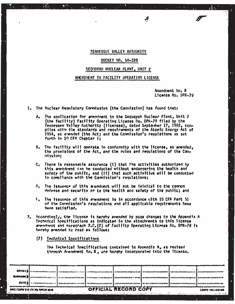
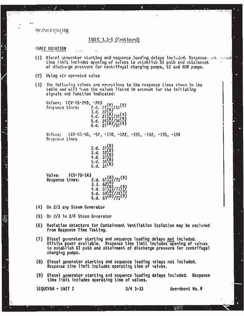
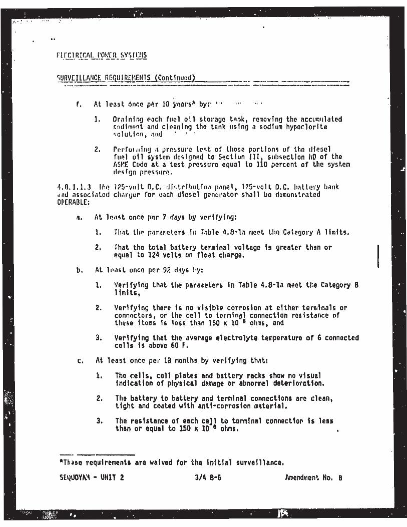
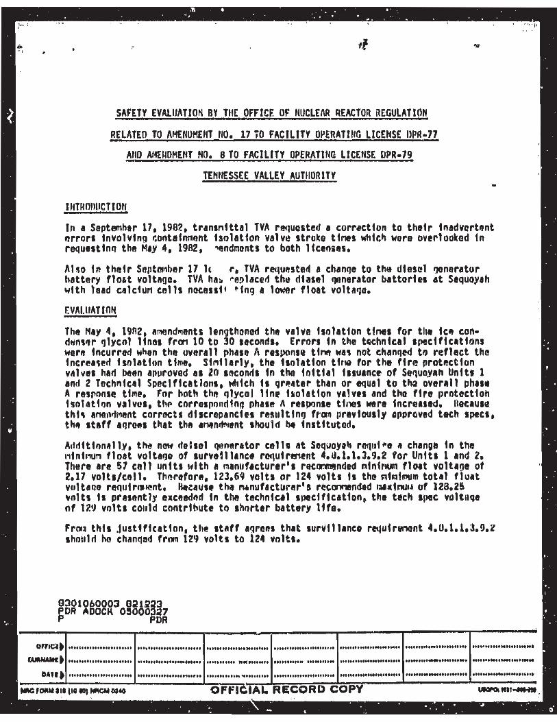
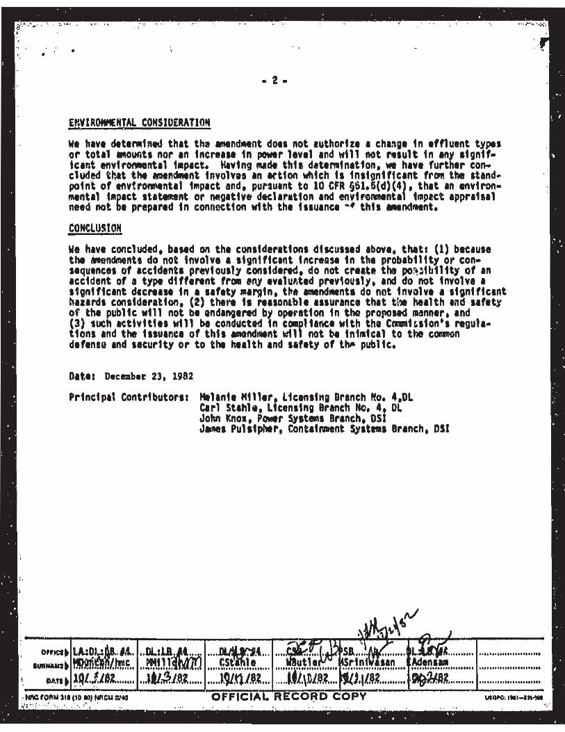
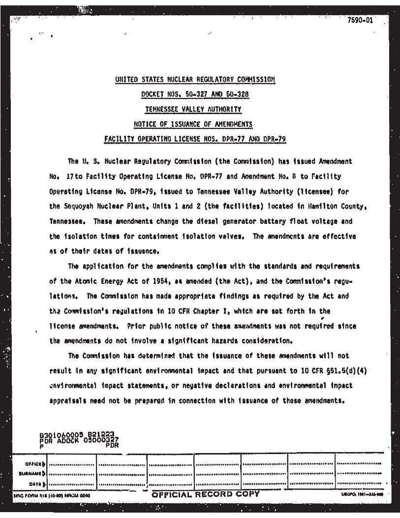
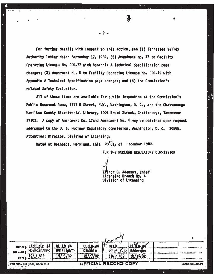

Licensee Response/NRC Response/NRC Question ClosureId 369
NRC Question Number VKG019
Select Application NRC Question Closure
Attachment 1
Attachment 2
Response Statement
Response Date/Time
Closure Statement This question is closed and no further information is required at this time to draft the Safety Evaluation.
Question Closure Date 10/8/2014
Notification Scott BowmanMichelle ConnerVijay GoelKhadijah HemphillAndrew HonLynn MynattRay SchieleRoger Scott
Added By Khadijah Hemphill
Date Added 10/8/2014 6:00 AM
Date Modified
Modified By
Page 1 of 1Sequoyah ITS Conversion Database
10/15/2014https://members.excelservices.com/rai/index.php?requestType=areaItemPrint&itemId=369
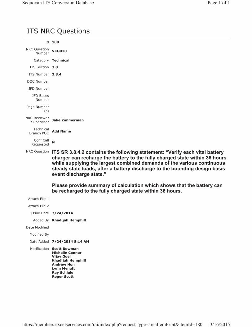
ITS NRC QuestionsId 180
NRC Question Number VKG020
Category Technical
ITS Section 3.8
ITS Number 3.8.4
DOC Number
JFD Number
JFD Bases Number
Page Number(s)
NRC Reviewer Supervisor Jake Zimmerman
Technical Branch POC Add Name
Conf Call Requested N
NRC Question ITS SR 3.8.4.2 contains the following statement: “Verify each vital battery charger can recharge the battery to the fully charged state within 36 hours while supplying the largest combined demands of the various continuous steady state loads, after a battery discharge to the bounding design basis event discharge state.”
Please provide summary of calculation which shows that the battery can be recharged to the fully charged state within 36 hours.
Attach File 1
Attach File 2
Issue Date 7/24/2014
Added By Khadijah Hemphill
Date Modified
Modified By
Date Added 7/24/2014 8:14 AM
Notification Scott BowmanMichelle ConnerVijay GoelKhadijah HemphillAndrew HonLynn MynattRay SchieleRoger Scott
Page 1 of 1Sequoyah ITS Conversion Database
3/16/2015https://members.excelservices.com/rai/index.php?requestType=areaItemPrint&itemId=180
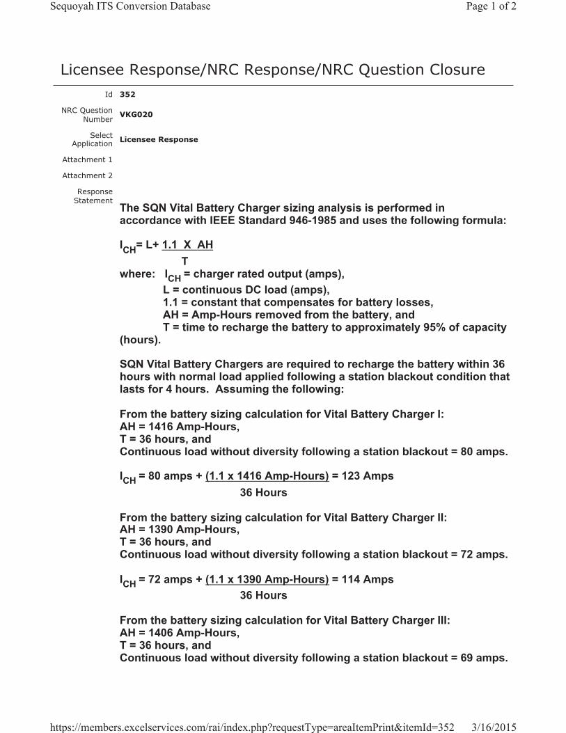
Licensee Response/NRC Response/NRC Question ClosureId 352
NRC Question Number VKG020
Select Application Licensee Response
Attachment 1
Attachment 2
Response Statement
The SQN Vital Battery Charger sizing analysis is performed in accordance with IEEE Standard 946-1985 and uses the following formula:
ICH= L+ 1.1 X AHT
where: ICH = charger rated output (amps), L = continuous DC load (amps),1.1 = constant that compensates for battery losses, AH = Amp-Hours removed from the battery, and T = time to recharge the battery to approximately 95% of capacity
(hours).
SQN Vital Battery Chargers are required to recharge the battery within 36 hours with normal load applied following a station blackout condition that lasts for 4 hours. Assuming the following:
From the battery sizing calculation for Vital Battery Charger I: AH = 1416 Amp-Hours,T = 36 hours, andContinuous load without diversity following a station blackout = 80 amps.
ICH = 80 amps + (1.1 x 1416 Amp-Hours) = 123 Amps36 Hours
From the battery sizing calculation for Vital Battery Charger II: AH = 1390 Amp-Hours,T = 36 hours, andContinuous load without diversity following a station blackout = 72 amps.
ICH = 72 amps + (1.1 x 1390 Amp-Hours) = 114 Amps36 Hours
From the battery sizing calculation for Vital Battery Charger III: AH = 1406 Amp-Hours,T = 36 hours, andContinuous load without diversity following a station blackout = 69 amps.
Page 1 of 2Sequoyah ITS Conversion Database
3/16/2015https://members.excelservices.com/rai/index.php?requestType=areaItemPrint&itemId=352
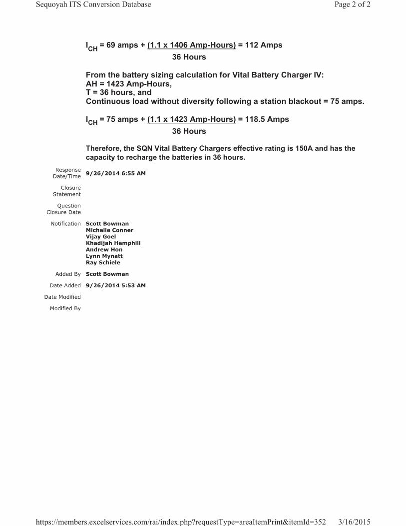
ICH = 69 amps + (1.1 x 1406 Amp-Hours) = 112 Amps36 Hours
From the battery sizing calculation for Vital Battery Charger IV: AH = 1423 Amp-Hours,T = 36 hours, andContinuous load without diversity following a station blackout = 75 amps.
ICH = 75 amps + (1.1 x 1423 Amp-Hours) = 118.5 Amps36 Hours
Therefore, the SQN Vital Battery Chargers effective rating is 150A and has the capacity to recharge the batteries in 36 hours.
Response Date/Time 9/26/2014 6:55 AM
Closure Statement
Question Closure Date
Notification Scott BowmanMichelle ConnerVijay GoelKhadijah HemphillAndrew HonLynn MynattRay Schiele
Added By Scott Bowman
Date Added 9/26/2014 5:53 AM
Date Modified
Modified By
Page 2 of 2Sequoyah ITS Conversion Database
3/16/2015https://members.excelservices.com/rai/index.php?requestType=areaItemPrint&itemId=352
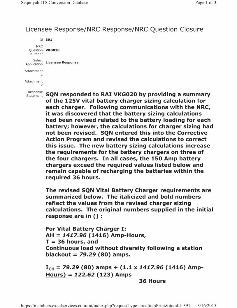
Licensee Response/NRC Response/NRC Question ClosureId 391
NRC Question Number
VKG020
Select Application Licensee Response
Attachment 1
Attachment 2
Response Statement SQN responded to RAI VKG020 by providing a summary
of the 125V vital battery charger sizing calculation for each charger. Following communications with the NRC, it was discovered that the battery sizing calculations had been revised related to the battery loading for each battery; however, the calculations for charger sizing had not been revised. SQN entered this into the Corrective Action Program and revised the calculations to correct this issue. The new battery sizing calculations increase the requirements for the battery chargers on three of the four chargers. In all cases, the 150 Amp battery chargers exceed the required values listed below and remain capable of recharging the batteries within the required 36 hours.
The revised SQN Vital Battery Charger requirements are summarized below. The italicized and bold numbers reflect the values from the revised charger sizing calculations. The original numbers supplied in the initial response are in () :
For Vital Battery Charger I:AH = 1417.96 (1416) Amp-Hours,T = 36 hours, andContinuous load without diversity following a station blackout = 79.29 (80) amps.
ICH = 79.29 (80) amps + (1.1 x 1417.96 (1416) Amp-Hours) = 122.62 (123) Amps
36 Hours
Page 1 of 3Sequoyah ITS Conversion Database
3/16/2015https://members.excelservices.com/rai/index.php?requestType=areaItemPrint&itemId=391
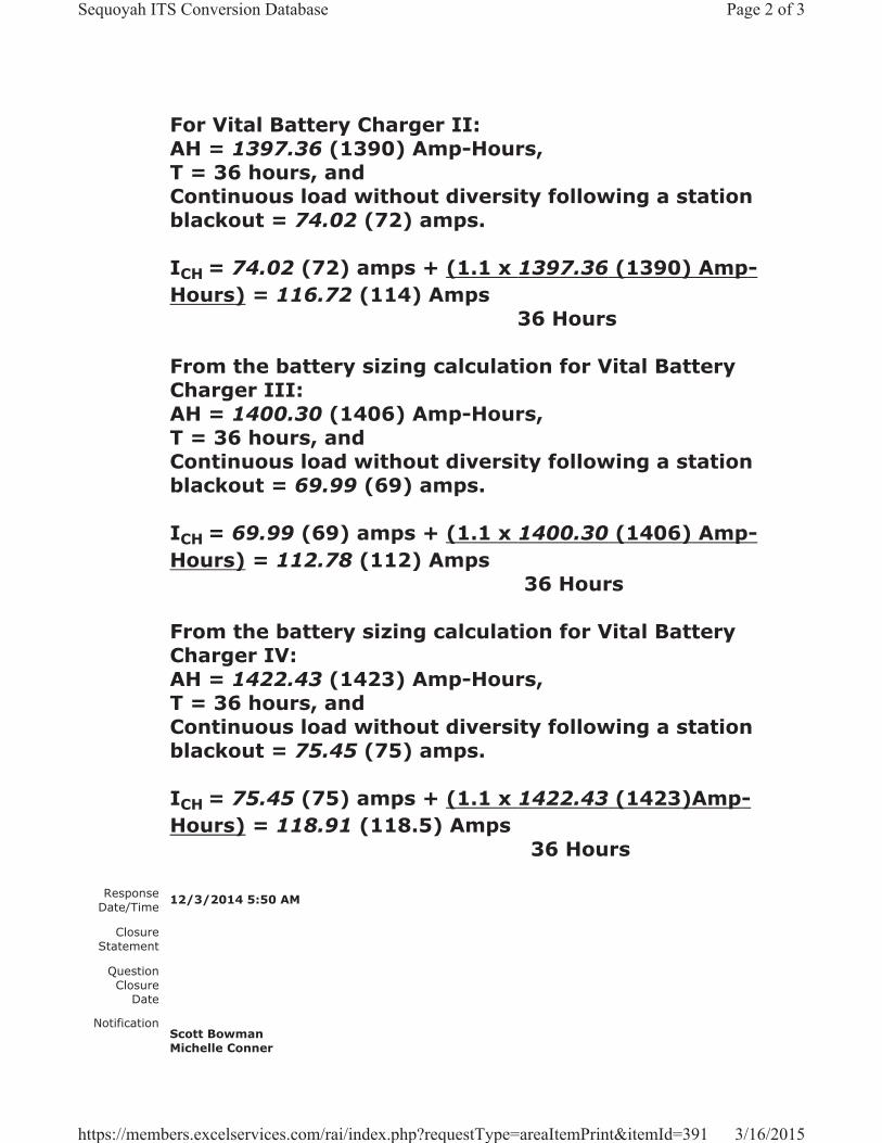
For Vital Battery Charger II:AH = 1397.36 (1390) Amp-Hours,T = 36 hours, andContinuous load without diversity following a station blackout = 74.02 (72) amps.
ICH = 74.02 (72) amps + (1.1 x 1397.36 (1390) Amp-Hours) = 116.72 (114) Amps
36 Hours
From the battery sizing calculation for Vital Battery Charger III:AH = 1400.30 (1406) Amp-Hours,T = 36 hours, andContinuous load without diversity following a station blackout = 69.99 (69) amps.
ICH = 69.99 (69) amps + (1.1 x 1400.30 (1406) Amp-Hours) = 112.78 (112) Amps
36 Hours
From the battery sizing calculation for Vital Battery Charger IV:AH = 1422.43 (1423) Amp-Hours,T = 36 hours, andContinuous load without diversity following a station blackout = 75.45 (75) amps.
ICH = 75.45 (75) amps + (1.1 x 1422.43 (1423)Amp-Hours) = 118.91 (118.5) Amps
36 Hours
Response Date/Time 12/3/2014 5:50 AM
Closure Statement
Question Closure
Date
Notification Scott BowmanMichelle Conner
Page 2 of 3Sequoyah ITS Conversion Database
3/16/2015https://members.excelservices.com/rai/index.php?requestType=areaItemPrint&itemId=391

Vijay GoelKhadijah HemphillAndrew HonLynn MynattRay Schiele
Added By Scott Bowman
Date Added 12/3/2014 4:51 AM
Date Modified
Modified By
Page 3 of 3Sequoyah ITS Conversion Database
3/16/2015https://members.excelservices.com/rai/index.php?requestType=areaItemPrint&itemId=391

Licensee Response/NRC Response/NRC Question ClosureId 393
NRC Question Number VKG020
Select Application NRC Question Closure
Attachment 1
Attachment 2
Response Statement
Response Date/Time
Closure Statement This question is closed and no further information is required at this time to draft the Safety Evaluation.
Question Closure Date 12/8/2014
Notification Scott BowmanMichelle ConnerVijay GoelKhadijah HemphillAndrew HonLynn MynattRay SchieleRoger Scott
Added By Khadijah Hemphill
Date Added 12/8/2014 2:09 PM
Date Modified
Modified By
Page 1 of 1Sequoyah ITS Conversion Database
3/16/2015https://members.excelservices.com/rai/index.php?requestType=areaItemPrint&itemId=393
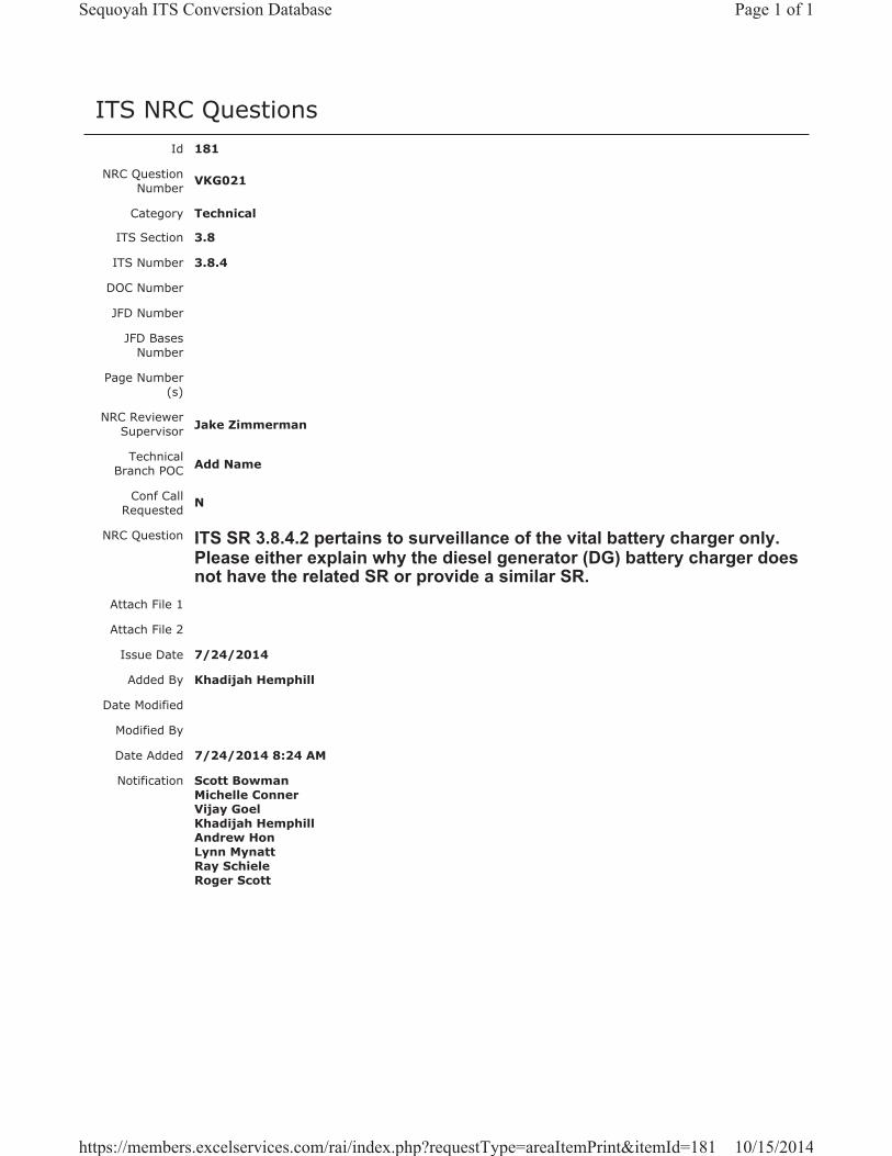
ITS NRC QuestionsId 181
NRC Question Number VKG021
Category Technical
ITS Section 3.8
ITS Number 3.8.4
DOC Number
JFD Number
JFD Bases Number
Page Number(s)
NRC Reviewer Supervisor Jake Zimmerman
Technical Branch POC Add Name
Conf Call Requested N
NRC Question ITS SR 3.8.4.2 pertains to surveillance of the vital battery charger only.Please either explain why the diesel generator (DG) battery charger does not have the related SR or provide a similar SR.
Attach File 1
Attach File 2
Issue Date 7/24/2014
Added By Khadijah Hemphill
Date Modified
Modified By
Date Added 7/24/2014 8:24 AM
Notification Scott BowmanMichelle ConnerVijay GoelKhadijah HemphillAndrew HonLynn MynattRay SchieleRoger Scott
Page 1 of 1Sequoyah ITS Conversion Database
10/15/2014https://members.excelservices.com/rai/index.php?requestType=areaItemPrint&itemId=181
Licensee Response/NRC Response/NRC Question ClosureId 353
NRC Question Number
VKG021
Select Application Licensee Response
Attachment 1
Attachment 2
Response Statement
ITS LCO 3.8.4 requires two vital DC electrical power trains and four diesel generator (DG) DC electrical power subsystems to be OPERABLE. ITS 3.8.4 does not have a DG battery charger testing requirement because the purpose of the DG batteries is to provide power to initially start the DG. Once the DG is running, the safety function is met and there is not a recharge time or extended load profile required to be tested.
Response Date/Time 9/26/2014 7:00 AM
Closure Statement
Question Closure Date
Notification Scott BowmanMichelle ConnerVijay GoelKhadijah HemphillAndrew HonLynn MynattRay Schiele
Added By Scott Bowman
Date Added 9/26/2014 5:55 AM
Date Modified
Modified By
Page 1 of 1Sequoyah ITS Conversion Database
10/15/2014https://members.excelservices.com/rai/index.php?requestType=areaItemPrint&itemId=353

Licensee Response/NRC Response/NRC Question ClosureId 370
NRC Question Number VKG021
Select Application NRC Question Closure
Attachment 1
Attachment 2
Response Statement
Response Date/Time
Closure Statement This question is closed and no further information is required at this time to draft the Safety Evaluation.
Question Closure Date 10/8/2014
Notification Scott BowmanMichelle ConnerVijay GoelKhadijah HemphillAndrew HonLynn MynattRay SchieleRoger Scott
Added By Khadijah Hemphill
Date Added 10/8/2014 6:01 AM
Date Modified
Modified By
Page 1 of 1Sequoyah ITS Conversion Database
10/15/2014https://members.excelservices.com/rai/index.php?requestType=areaItemPrint&itemId=370
ITS NRC QuestionsId 182
NRC Question Number
VKG022
Category Technical
ITS Section 3.8
ITS Number 3.8.6
DOC Number
JFD Number
JFD Bases Number
Page Number(s)
NRC Reviewer
Supervisor Ravi Grover (for RBE)
Technical Branch POC
Conf Call Requested N
NRC Question
In response to the NRC staff RAI GMW-002 #2, the licensee stated that SQN will incorporate the minimum float current measurement time into the Bases for SR 3.8.6.1. The following sentences will be added to the SR [Bases]: “The minimum required procedural time to measure battery float current will be 30 seconds or as recommended by the float current measurement instrument manufacturer. The minimum float current measurement time is required to provide a more accurate battery float current reading.”
Please provide markup of Bases for SR 3.8.6.1 with the above changes.Attach File 1
Attach File 2
Issue Date 8/5/2014
Added By Khadijah Hemphill
Date Modified
Modified By
Date Added 8/5/2014 10:33 AM
Notification Scott BowmanMichelle ConnerVijay GoelAndrew HonLynn MynattRay SchieleRoger Scott
Page 1 of 1Sequoyah ITS Conversion Database
9/9/2014https://members.excelservices.com/rai/index.php?requestType=areaItemPrint&itemId=182
Licensee Response/NRC Response/NRC Question ClosureId 250
NRC Question Number VKG022
Select Application Licensee Response
Attachment 1 Attachment 1 for VKG022.pdf (33KB)
Attachment 2
Response Statement
See Attachment 1 for the draft revised ITS SR 3.8.6.1 Bases insert on pages 459 and 473 of Enclosure 2, Volume 13.
Response Date/Time 8/8/2014 8:05 AM
Closure Statement
Question Closure Date
Notification Scott BowmanMichelle ConnerVijay GoelKhadijah HemphillAndrew HonRay Schiele
Added By Scott Bowman
Date Added 8/8/2014 7:04 AM
Date Modified
Modified By
Page 1 of 1Sequoyah ITS Conversion Database
9/9/2014https://members.excelservices.com/rai/index.php?requestType=areaItemPrint&itemId=250
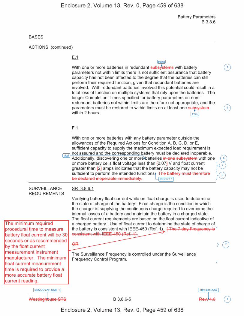
Battery Parameters B 3.8.6
Westinghouse STS B 3.8.6-5 Rev. 4.0
SEQUOYAH UNIT 1 Revision XXX
1
BASES ACTIONS (continued)
E.1 With one or more batteries in redundant subsystems with battery parameters not within limits there is not sufficient assurance that battery capacity has not been affected to the degree that the batteries can still perform their required function, given that redundant batteries are involved. With redundant batteries involved this potential could result in a total loss of function on multiple systems that rely upon the batteries. The longer Completion Times specified for battery parameters on non-redundant batteries not within limits are therefore not appropriate, and the parameters must be restored to within limits on at least one subsystem within 2 hours. F.1 With one or more batteries with any battery parameter outside the allowances of the Required Actions for Condition A, B, C, D, or E, sufficient capacity to supply the maximum expected load requirement is not assured and the corresponding battery must be declared inoperable. Additionally, discovering one or more batteries in one subsystem with one or more battery cells float voltage less than [2.07] V and float current greater than [2] amps indicates that the battery capacity may not be sufficient to perform the intended functions. The battery must therefore be declared inoperable immediately.
SURVEILLANCE SR 3.8.6.1 REQUIREMENTS
Verifying battery float current while on float charge is used to determine the state of charge of the battery. Float charge is the condition in which the charger is supplying the continuous charge required to overcome the internal losses of a battery and maintain the battery in a charged state. The float current requirements are based on the float current indicative of a charged battery. Use of float current to determine the state of charge of the battery is consistent with IEEE-450 (Ref. 1). [ The 7 day Frequency is consistent with IEEE-450 (Ref. 1). OR The Surveillance Frequency is controlled under the Surveillance Frequency Control Program.
trains
train
1
1
2
7
5vital
INSERT 1 5
Enclosure 2, Volume 13, Rev. 0, Page 459 of 638
Enclosure 2, Volume 13, Rev. 0, Page 459 of 638
The minimum requiredprocedural time to measurebattery float current will be 30seconds or as recommendedby the float currentmeasurement instrumentmanufacturer. The minimumfloat current measurementtime is required to provide amore accurate battery floatcurrent reading.

Battery Parameters B 3.8.6
Westinghouse STS B 3.8.6-5 Rev. 4.0
SEQUOYAH UNIT 2 Revision XXX
1
BASES ACTIONS (continued)
E.1 With one or more batteries in redundant subsystems with battery parameters not within limits there is not sufficient assurance that battery capacity has not been affected to the degree that the batteries can still perform their required function, given that redundant batteries are involved. With redundant batteries involved this potential could result in a total loss of function on multiple systems that rely upon the batteries. The longer Completion Times specified for battery parameters on non-redundant batteries not within limits are therefore not appropriate, and the parameters must be restored to within limits on at least one subsystem within 2 hours. F.1 With one or more batteries with any battery parameter outside the allowances of the Required Actions for Condition A, B, C, D, or E, sufficient capacity to supply the maximum expected load requirement is not assured and the corresponding battery must be declared inoperable. Additionally, discovering one or more batteries in one subsystem with one or more battery cells float voltage less than [2.07] V and float current greater than [2] amps indicates that the battery capacity may not be sufficient to perform the intended functions. The battery must therefore be declared inoperable immediately.
SURVEILLANCE SR 3.8.6.1 REQUIREMENTS
Verifying battery float current while on float charge is used to determine the state of charge of the battery. Float charge is the condition in which the charger is supplying the continuous charge required to overcome the internal losses of a battery and maintain the battery in a charged state. The float current requirements are based on the float current indicative of a charged battery. Use of float current to determine the state of charge of the battery is consistent with IEEE-450 (Ref. 1). [ The 7 day Frequency is consistent with IEEE-450 (Ref. 1). OR The Surveillance Frequency is controlled under the Surveillance Frequency Control Program.
trains
train
1
1
2
7
5vital
INSERT 1 5
Enclosure 2, Volume 13, Rev. 0, Page 473 of 638
Enclosure 2, Volume 13, Rev. 0, Page 473 of 638
The minimum requiredprocedural time to measurebattery float current will be 30seconds or as recommendedby the float currentmeasurement instrumentmanufacturer. The minimumfloat current measurementtime is required to provide amore accurate battery floatcurrent reading.

Licensee Response/NRC Response/NRC Question ClosureId 323
NRC Question Number VKG022
Select Application NRC Question Closure
Attachment 1
Attachment 2
Response Statement
Response Date/Time
Closure Statement This question is closed and no further information is required at this time to draft the Safety Evaluation.
Question Closure Date 9/4/2014
Notification Scott BowmanMichelle ConnerKhadijah HemphillAndrew HonLynn MynattRay SchieleRoger Scott
Added By Khadijah Hemphill
Date Added 9/4/2014 12:13 PM
Date Modified
Modified By
Page 1 of 1Sequoyah ITS Conversion Database
9/9/2014https://members.excelservices.com/rai/index.php?requestType=areaItemPrint&itemId=323
ITS NRC QuestionsId 183
NRC Question Number
VKG023
Category Technical
ITS Section 3.8
ITS Number 3.8.6
DOC Number
JFD Number
JFD Bases Number
Page Number(s)
NRC Reviewer
Supervisor Jake Zimmerman
Technical Branch POC Add Name
Conf Call Requested N
NRC Question
ITS 3.8.6, Bases, Background states: “The Vital battery cells are of flooded lead acid construction with a nominal specific gravity of 1.215. This specific gravity corresponds to an open circuit battery voltage of approximately 123.78 V for 60 cell battery (i.e., cell voltage of 2.063 volts per cell (Vpc))....This provides adequate over-potential which limits the formation of lead sulfate and self-discharge.”
The above discussion pertains to the Vital batteries. Please provide similar discussion for the DG batteries consisting of 58 cells.
Attach File 1
Attach File 2
Issue Date 8/13/2014
Added By Khadijah Hemphill
Date Modified
Modified By
Date Added 8/13/2014 9:36 AM
Notification Scott BowmanMichelle ConnerVijay GoelKhadijah HemphillAndrew HonLynn MynattRay SchieleRoger Scott
Page 1 of 1Sequoyah ITS Conversion Database
10/15/2014https://members.excelservices.com/rai/index.php?requestType=areaItemPrint&itemId=183
Licensee Response/NRC Response/NRC Question ClosureId 354
NRC Question Number
VKG023
Select Application Licensee Response
Attachment 1 Attachment 1 VKG-023 R1.pdf (558KB)
Attachment 2
Response Statement
In response to VKG023, the ITS 3.8.6 Bases Background Section, on pages 455 and 469 of Enclosure 2, Volume 13, will be modified to include a description of the DG batteries. Specifically, the ITS 3.8.6 Bases will be revised to add, “The DG battery cells are of flooded lead acid construction with a nominal specific gravity of 1.215. Each DG battery consists of 58 cells; however, a battery is considered OPERABLE with 57 cells if one is strapped out. Optimal long term performance is obtained by maintaining a float voltage of 2.20 to 2.25 Vpc. This provides adequate over-potential which limits the formation of lead sulfate and self-discharge.”
See Attachment 1 for the draft revised ITS 3.8.6 Bases.Response
Date/Time 9/26/2014 8:15 AM
Closure Statement
Question Closure
Date
Notification Scott BowmanMichelle ConnerVijay GoelKhadijah HemphillAndrew HonLynn MynattRay Schiele
Added By Scott Bowman
Date Added 9/26/2014 7:12 AM
Date Modified
Modified By
Page 1 of 1Sequoyah ITS Conversion Database
10/15/2014https://members.excelservices.com/rai/index.php?requestType=areaItemPrint&itemId=354
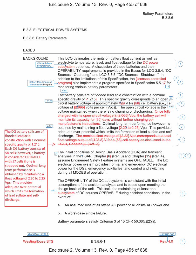
Battery Parameters B 3.8.6
Westinghouse STS B 3.8.6-1 Rev. 4.0
SEQUOYAH UNIT 1 Revision XXX
1
B 3.8 ELECTRICAL POWER SYSTEMS B 3.8.6 Battery Parameters BASES BACKGROUND This LCO delineates the limits on battery float current as well as
electrolyte temperature, level, and float voltage for the DC power subsystem batteries. A discussion of these batteries and their OPERABILITY requirements is provided in the Bases for LCO 3.8.4, "DC Sources - Operating," and LCO 3.8.5, "DC Sources - Shutdown." In addition to the limitations of this Specification, the [licensee controlled program] also implements a program specified in Specification 5.5.17 for monitoring various battery parameters.
The battery cells are of flooded lead acid construction with a nominal specific gravity of [1.215]. This specific gravity corresponds to an open circuit battery voltage of approximately 120 V for [58] cell battery (i.e., cell voltage of [2.065] volts per cell (Vpc)). The open circuit voltage is the voltage maintained when there is no charging or discharging. Once fully charged with its open circuit voltage [2.065] Vpc, the battery cell will maintain its capacity for [30] days without further charging per manufacturer's instructions. Optimal long term performance however, is obtained by maintaining a float voltage [2.20 to 2.25] Vpc. This provides adequate over-potential which limits the formation of lead sulfate and self discharge. The nominal float voltage of [2.22] Vpc corresponds to a total float voltage output of [128.8] V for a [58] cell battery as discussed in the FSAR, Chapter [8] (Ref. 2).
APPLICABLE The initial conditions of Design Basis Accident (DBA) and transient SAFETY analyses in the FSAR, Chapter [6] (Ref. 3) and Chapter [15] (Ref. 4), ANALYSES assume Engineered Safety Feature systems are OPERABLE. The DC
electrical power system provides normal and emergency DC electrical power for the DGs, emergency auxiliaries, and control and switching during all MODES of operation. The OPERABILITY of the DC subsystems is consistent with the initial assumptions of the accident analyses and is based upon meeting the design basis of the unit. This includes maintaining at least one subsystem of DC sources OPERABLE during accident conditions, in the event of: a. An assumed loss of all offsite AC power or all onsite AC power and b. A worst-case single failure. Battery parameters satisfy Criterion 3 of 10 CFR 50.36(c)(2)(ii).
Battery Monitoring and Maintenance Program
Vital and diesel generator (DG)
2.063
U
train
1
2
2
4
2
1
1 2
1
60123.78
15
Vital
3
1
2.17
Enclosure 2, Volume 13, Rev. 0, Page 455 of 638
Enclosure 2, Volume 13, Rev. 0, Page 455 of 638
The DG battery cells are of flooded lead acid construction with a nominal specific gravity of 1.215. Each DG battery consists of 58 cells; however, a battery is considered OPERABLE with 57 cells if one is strapped out. Optimal long term performance is obtained by maintaining a float voltage of 2.20 to 2.25 Vpc. This provides adequate over-potential which limits the formation of lead sulfate and self-discharge.
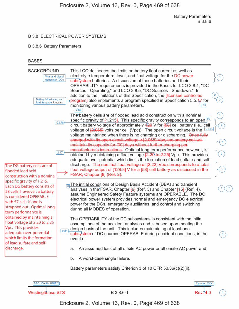
Battery Parameters B 3.8.6
Westinghouse STS B 3.8.6-1 Rev. 4.0
SEQUOYAH UNIT 2 Revision XXX
1
B 3.8 ELECTRICAL POWER SYSTEMS B 3.8.6 Battery Parameters BASES BACKGROUND This LCO delineates the limits on battery float current as well as
electrolyte temperature, level, and float voltage for the DC power subsystem batteries. A discussion of these batteries and their OPERABILITY requirements is provided in the Bases for LCO 3.8.4, "DC Sources - Operating," and LCO 3.8.5, "DC Sources - Shutdown." In addition to the limitations of this Specification, the [licensee controlled program] also implements a program specified in Specification 5.5.17 for monitoring various battery parameters.
The battery cells are of flooded lead acid construction with a nominal specific gravity of [1.215]. This specific gravity corresponds to an open circuit battery voltage of approximately 120 V for [58] cell battery (i.e., cell voltage of [2.065] volts per cell (Vpc)). The open circuit voltage is the voltage maintained when there is no charging or discharging. Once fully charged with its open circuit voltage [2.065] Vpc, the battery cell will maintain its capacity for [30] days without further charging per manufacturer's instructions. Optimal long term performance however, is obtained by maintaining a float voltage [2.20 to 2.25] Vpc. This provides adequate over-potential which limits the formation of lead sulfate and self discharge. The nominal float voltage of [2.22] Vpc corresponds to a total float voltage output of [128.8] V for a [58] cell battery as discussed in the FSAR, Chapter [8] (Ref. 2).
APPLICABLE The initial conditions of Design Basis Accident (DBA) and transient SAFETY analyses in the FSAR, Chapter [6] (Ref. 3) and Chapter [15] (Ref. 4), ANALYSES assume Engineered Safety Feature systems are OPERABLE. The DC
electrical power system provides normal and emergency DC electrical power for the DGs, emergency auxiliaries, and control and switching during all MODES of operation. The OPERABILITY of the DC subsystems is consistent with the initial assumptions of the accident analyses and is based upon meeting the design basis of the unit. This includes maintaining at least one subsystem of DC sources OPERABLE during accident conditions, in the event of: a. An assumed loss of all offsite AC power or all onsite AC power and b. A worst-case single failure. Battery parameters satisfy Criterion 3 of 10 CFR 50.36(c)(2)(ii).
Battery Monitoring and Maintenance Program
Vital and diesel generator (DG)
2.063
U
train
1
2
2
4
2
1
1 2
1
60123.78
15
Vital
3
1
2.17
Enclosure 2, Volume 13, Rev. 0, Page 469 of 638
Enclosure 2, Volume 13, Rev. 0, Page 469 of 638
The DG battery cells are of flooded lead acid construction with a nominal specific gravity of 1.215. Each DG battery consists of 58 cells; however, a battery is considered OPERABLE with 57 cells if one is strapped out. Optimal long term performance is obtained by maintaining a float voltage of 2.20 to 2.25 Vpc. This provides adequate over-potential which limits the formation of lead sulfate and self-discharge.

Licensee Response/NRC Response/NRC Question ClosureId 368
NRC Question Number VKG023
Select Application NRC Question Closure
Attachment 1
Attachment 2
Response Statement
Response Date/Time
Closure Statement This question is closed and no further information is required at this time to draft the Safety Evaluation.
Question Closure Date 10/8/2014
Notification Scott BowmanMichelle ConnerVijay GoelKhadijah HemphillAndrew HonLynn MynattRay SchieleRoger Scott
Added By Khadijah Hemphill
Date Added 10/8/2014 5:58 AM
Date Modified
Modified By
Page 1 of 1Sequoyah ITS Conversion Database
10/15/2014https://members.excelservices.com/rai/index.php?requestType=areaItemPrint&itemId=368
ITS NRC QuestionsId 184
NRC Question Number VKG024
Category Technical
ITS Section 3.8
ITS Number 3.8.7
DOC Number
JFD Number
JFD Bases Number
Page Number(s)
NRC Reviewer Supervisor Jake Zimmerman
Technical Branch POC Add Name
Conf Call Requested N
NRC Question ITS SR 3.8.7.1 states: “Verify correct inverter voltage, frequency, and alignment to required AC vital buses.” However, ITS SR 3.8.8.1 states: “Verify correct inverter voltage, frequency, and alignments to required AC vital boards.”
Please explain why the ITS 3.8.7 uses the term “AC vital buses,” and ITS 3.8.8 uses the term “AC vital boards.” Also, verify that the terms “boards” and “buses” are applied appropriately in any other instances in the ITS submittal.
Attach File 1
Attach File 2
Issue Date 8/13/2014
Added By Khadijah Hemphill
Date Modified
Modified By
Date Added 8/13/2014 9:36 AM
Notification Scott BowmanMichelle ConnerVijay GoelKhadijah HemphillAndrew HonLynn MynattRay SchieleRoger Scott
Page 1 of 1Sequoyah ITS Conversion Database
1/13/2015https://members.excelservices.com/rai/index.php?requestType=areaItemPrint&itemId=184
Licensee Response/NRC Response/NRC Question ClosureId 378
NRC Question Number
VKG024
Select Application Licensee Response
Attachment 1 Attachment 1 for RAI VKG024.pdf (1MB)
Attachment 2
Response Statement In response to VKG024, the ISTS Specifications and
ISTS Bases markups for 3.8.7, Inverters - Operating, and 3.8.8, Inverters - Shutdown, on pages 494-497, 500-503, 505-508, and 523-526 of Enclosure 2, Volume 13, will be revised to refer to AC vital instrument power boards vice AC vital buses and DC source vice DC bus. This revision aligns ITS with the CTS nomenclature for these components. Justification for deviation (JFD) 1 indicators will be added to address the revision.Additionally, the ITS submittal was reviewed to identify other locations where the term “bus(es)” was used, and where appropriate, the nomenclature will be revised to “board(s).” See the response to RAI VKG025 for changes in nomenclature associated with ITS Sections 3.8.9 and 3.8.10. See below for additional ITS Sections affected by the proposed revision:
1. The ITS 3.8.1 Bases Actions and Surveillance Requirements Sections will be revised to replace the term “bus(es)” with “board(s).” JFD 1 indicators will be added, as needed, to address the revision. (Pages 103, 124, 129-133, 139-141, 143, 153, 174, 179-183, 189-191, and 193 of Enclosure 2, Volume 13)
2. The ITS 3.8.1 Bases Surveillance Requirement Section for ITS SR 3.8.1.17 will be revised to change the last sentence in the first paragraph to read, “Reference 2 provides a summary of the automatic loading of Shutdown Boards.” (Pages 143 and 193 of Enclosure 2, Volume 13)
Page 1 of 2Sequoyah ITS Conversion Database
1/13/2015https://members.excelservices.com/rai/index.php?requestType=areaItemPrint&itemId=378
3. The ITS 3.8.2 Bases LCO Section will be revised to replace the term “bus” with “board.” Additionally, the following sentence will be revised to remove the word “buses,” “The DG must be capable of accepting required loads within the assumed loading sequence intervals, and continue to operate until offsite power can be restored to the 6.9 kV shutdown boards buses.” (Pages 225 and 232 of Enclosure 2, Volume 13)
4. The ITS 3.8.4 Bases Background Section will be revised to replace the term AC vital “bus” with AC vital “instrument power board.” ITS 3.8.4 Bases LCO Section will be revised to replace the term “bus” with “board.” JFD 1 indicators will be added, as needed, to address the revisions. (Pages 319, 323, 325, 334, 338 and 340 of Enclosure 2, Volume 13)
See Attachment 1 for draft revised ISTS markups for Units 1 and 2.
Response Date/Time 11/4/2014 8:40 AM
Closure Statement
Question Closure
Date
Notification Scott BowmanMichelle ConnerVijay GoelKhadijah HemphillAndrew HonLynn MynattRay Schiele
Added By Scott Bowman
Date Added 11/4/2014 7:39 AM
Date Modified
Modified By
Page 2 of 2Sequoyah ITS Conversion Database
1/13/2015https://members.excelservices.com/rai/index.php?requestType=areaItemPrint&itemId=378
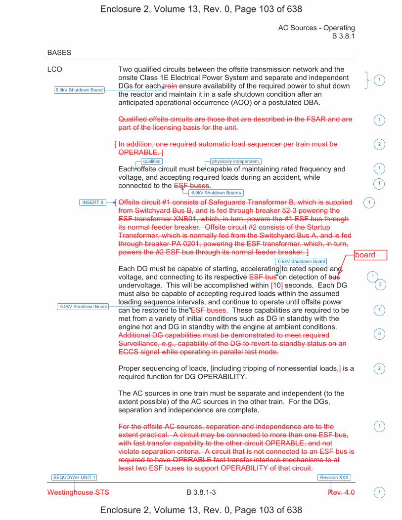
AC Sources - Operating B 3.8.1
Westinghouse STS B 3.8.1-3 Rev. 4.0
SEQUOYAH UNIT 1
1
Revision XXX
BASES LCO Two qualified circuits between the offsite transmission network and the
onsite Class 1E Electrical Power System and separate and independent DGs for each train ensure availability of the required power to shut down the reactor and maintain it in a safe shutdown condition after an anticipated operational occurrence (AOO) or a postulated DBA. Qualified offsite circuits are those that are described in the FSAR and are part of the licensing basis for the unit.
[ In addition, one required automatic load sequencer per train must be OPERABLE. ] Each offsite circuit must be capable of maintaining rated frequency and voltage, and accepting required loads during an accident, while connected to the ESF buses.
[ Offsite circuit #1 consists of Safeguards Transformer B, which is supplied from Switchyard Bus B, and is fed through breaker 52-3 powering the ESF transformer XNB01, which, in turn, powers the #1 ESF bus through its normal feeder breaker. Offsite circuit #2 consists of the Startup Transformer, which is normally fed from the Switchyard Bus A, and is fed through breaker PA 0201, powering the ESF transformer, which, in turn, powers the #2 ESF bus through its normal feeder breaker. ] Each DG must be capable of starting, accelerating to rated speed and voltage, and connecting to its respective ESF bus on detection of bus undervoltage. This will be accomplished within [10] seconds. Each DG must also be capable of accepting required loads within the assumed loading sequence intervals, and continue to operate until offsite power can be restored to the ESF buses. These capabilities are required to be met from a variety of initial conditions such as DG in standby with the engine hot and DG in standby with the engine at ambient conditions. Additional DG capabilities must be demonstrated to meet required Surveillance, e.g., capability of the DG to revert to standby status on an ECCS signal while operating in parallel test mode.
Proper sequencing of loads, [including tripping of nonessential loads,] is a required function for DG OPERABILITY. The AC sources in one train must be separate and independent (to the extent possible) of the AC sources in the other train. For the DGs, separation and independence are complete. For the offsite AC sources, separation and independence are to the extent practical. A circuit may be connected to more than one ESF bus, with fast transfer capability to the other circuit OPERABLE, and not violate separation criteria. A circuit that is not connected to an ESF bus is required to have OPERABLE fast transfer interlock mechanisms to at least two ESF buses to support OPERABILITY of that circuit.
6.9kV Shutdown Boards
INSERT 8
6.9kV Shutdown Board
6.9kV Shutdown Board
1
1
2
1
1
2
1
2
1
5
qualified physically independent,1
1
6.9kV Shutdown Board
Enclosure 2, Volume 13, Rev. 0, Page 103 of 638
Enclosure 2, Volume 13, Rev. 0, Page 103 of 638
board
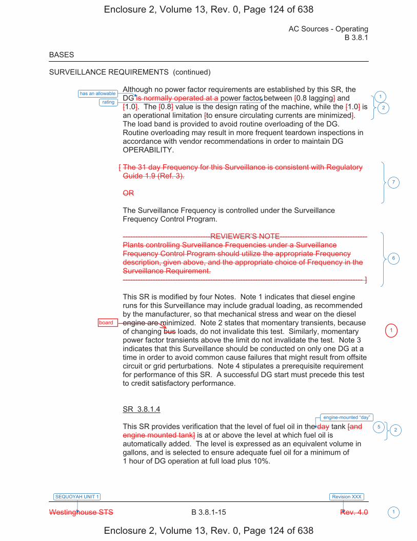
AC Sources - Operating B 3.8.1
Westinghouse STS B 3.8.1-15 Rev. 4.0
SEQUOYAH UNIT 1
1
Revision XXX
BASES SURVEILLANCE REQUIREMENTS (continued)
Although no power factor requirements are established by this SR, the DG is normally operated at a power factor between [0.8 lagging] and [1.0]. The [0.8] value is the design rating of the machine, while the [1.0] is an operational limitation [to ensure circulating currents are minimized]. The load band is provided to avoid routine overloading of the DG. Routine overloading may result in more frequent teardown inspections in accordance with vendor recommendations in order to maintain DG OPERABILITY.
[ The 31 day Frequency for this Surveillance is consistent with Regulatory Guide 1.9 (Ref. 3). OR The Surveillance Frequency is controlled under the Surveillance Frequency Control Program. -----------------------------------REVIEWER’S NOTE----------------------------------- Plants controlling Surveillance Frequencies under a Surveillance Frequency Control Program should utilize the appropriate Frequency description, given above, and the appropriate choice of Frequency in the Surveillance Requirement. ------------------------------------------------------------------------------------------------ ]
This SR is modified by four Notes. Note 1 indicates that diesel engine runs for this Surveillance may include gradual loading, as recommended by the manufacturer, so that mechanical stress and wear on the diesel engine are minimized. Note 2 states that momentary transients, because of changing bus loads, do not invalidate this test. Similarly, momentary power factor transients above the limit do not invalidate the test. Note 3 indicates that this Surveillance should be conducted on only one DG at a time in order to avoid common cause failures that might result from offsite circuit or grid perturbations. Note 4 stipulates a prerequisite requirement for performance of this SR. A successful DG start must precede this test to credit satisfactory performance. SR 3.8.1.4 This SR provides verification that the level of fuel oil in the day tank [and engine mounted tank] is at or above the level at which fuel oil is automatically added. The level is expressed as an equivalent volume in gallons, and is selected to ensure adequate fuel oil for a minimum of 1 hour of DG operation at full load plus 10%.
engine-mounted “day”
2
7
6
5 2
has an allowable
rating 1
Enclosure 2, Volume 13, Rev. 0, Page 124 of 638
Enclosure 2, Volume 13, Rev. 0, Page 124 of 638
board1
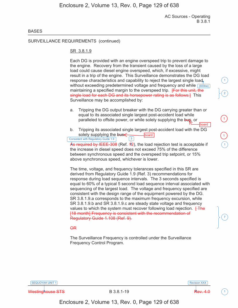
AC Sources - Operating B 3.8.1
Westinghouse STS B 3.8.1-19 Rev. 4.0
SEQUOYAH UNIT 1
1
Revision XXX
BASES SURVEILLANCE REQUIREMENTS (continued)
SR 3.8.1.9 Each DG is provided with an engine overspeed trip to prevent damage to the engine. Recovery from the transient caused by the loss of a large load could cause diesel engine overspeed, which, if excessive, might result in a trip of the engine. This Surveillance demonstrates the DG load response characteristics and capability to reject the largest single load without exceeding predetermined voltage and frequency and while maintaining a specified margin to the overspeed trip. [For this unit, the single load for each DG and its horsepower rating is as follows:] This Surveillance may be accomplished by: a. Tripping the DG output breaker with the DG carrying greater than or
equal to its associated single largest post-accident load while paralleled to offsite power, or while solely supplying the bus, or
b. Tripping its associated single largest post-accident load with the DG
solely supplying the bus. As required by IEEE-308 (Ref. 12), the load rejection test is acceptable if the increase in diesel speed does not exceed 75% of the difference between synchronous speed and the overspeed trip setpoint, or 15% above synchronous speed, whichever is lower. The time, voltage, and frequency tolerances specified in this SR are derived from Regulatory Guide 1.9 (Ref. 3) recommendations for response during load sequence intervals. The 3 seconds specified is equal to 60% of a typical 5 second load sequence interval associated with sequencing of the largest load. The voltage and frequency specified are consistent with the design range of the equipment powered by the DG. SR 3.8.1.9.a corresponds to the maximum frequency excursion, while SR 3.8.1.9.b and SR 3.8.1.9.c are steady state voltage and frequency values to which the system must recover following load rejection. [ The [18 month] Frequency is consistent with the recommendation of Regulatory Guide 1.108 (Ref. 9). OR The Surveillance Frequency is controlled under the Surveillance Frequency Control Program.
1
2
(600kw)
7
1
3Consistent with Regulatory Guide 1.9
Enclosure 2, Volume 13, Rev. 0, Page 129 of 638
Enclosure 2, Volume 13, Rev. 0, Page 129 of 638
board
board
1
1
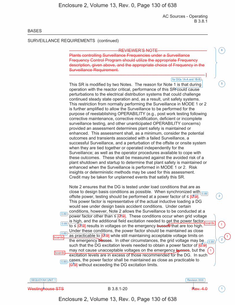
AC Sources - Operating B 3.8.1
Westinghouse STS B 3.8.1-20 Rev. 4.0
SEQUOYAH UNIT 1
1
Revision XXX
BASES SURVEILLANCE REQUIREMENTS (continued)
-----------------------------------REVIEWER’S NOTE----------------------------------- Plants controlling Surveillance Frequencies under a Surveillance Frequency Control Program should utilize the appropriate Frequency description, given above, and the appropriate choice of Frequency in the Surveillance Requirement. ------------------------------------------------------------------------------------------------ ]
This SR is modified by two Notes. The reason for Note 1 is that during operation with the reactor critical, performance of this SR could cause perturbations to the electrical distribution systems that could challenge continued steady state operation and, as a result, unit safety systems. This restriction from normally performing the Surveillance in MODE 1 or 2 is further amplified to allow the Surveillance to be performed for the purpose of reestablishing OPERABILITY (e.g., post work testing following corrective maintenance, corrective modification, deficient or incomplete surveillance testing, and other unanticipated OPERABILITY concerns) provided an assessment determines plant safety is maintained or enhanced. This assessment shall, as a minimum, consider the potential outcomes and transients associated with a failed Surveillance, a successful Surveillance, and a perturbation of the offsite or onsite system when they are tied together or operated independently for the Surveillance; as well as the operator procedures available to cope with these outcomes. These shall be measured against the avoided risk of a plant shutdown and startup to determine that plant safety is maintained or enhanced when the Surveillance is performed in MODE 1 or 2. Risk insights or deterministic methods may be used for this assessment. Credit may be taken for unplanned events that satisfy this SR. Note 2 ensures that the DG is tested under load conditions that are as close to design basis conditions as possible. When synchronized with offsite power, testing should be performed at a power factor of [0.9]. This power factor is representative of the actual inductive loading a DG would see under design basis accident conditions. Under certain conditions, however, Note 2 allows the Surveillance to be conducted at a power factor other than [0.9]. These conditions occur when grid voltage is high, and the additional field excitation needed to get the power factor to [0.9] results in voltages on the emergency busses that are too high. Under these conditions, the power factor should be maintained as close as practicable to [0.9] while still maintaining acceptable voltage limits on the emergency busses. In other circumstances, the grid voltage may be such that the DG excitation levels needed to obtain a power factor of [0.9] may not cause unacceptable voltages on the emergency busses, but the excitation levels are in excess of those recommended for the DG. In such cases, the power factor shall be maintained as close as practicable to [0.9] without exceeding the DG excitation limits.
6
for DGs 1A-A and 1B-B5
2
2
0.89
0.89
0.89
0.89
0.89
0.89
Enclosure 2, Volume 13, Rev. 0, Page 130 of 638
Enclosure 2, Volume 13, Rev. 0, Page 130 of 638
boards
boards
boards
1
1
1

AC Sources - Operating B 3.8.1
Westinghouse STS B 3.8.1-21 Rev. 4.0
SEQUOYAH UNIT 1
1
Revision XXX
BASES SURVEILLANCE REQUIREMENTS (continued)
-----------------------------------REVIEWER’S NOTE----------------------------------- The above MODE restrictions may be deleted if it can be demonstrated to the staff, on a plant specific basis, that performing the SR with the reactor in any of the restricted MODES can satisfy the following criteria, as applicable: a. Performance of the SR will not render any safety system or
component inoperable, b. Performance of the SR will not cause perturbations to any of the
electrical distribution systems that could result in a challenge to steady state operation or to plant safety systems, and
c. Performance of the SR, or failure of the SR, will not cause, or result
in, an AOO with attendant challenge to plant safety systems. -------------------------------------------------------------------------------------------------- SR 3.8.1.10 This Surveillance demonstrates the DG capability to reject a full load without overspeed tripping or exceeding the predetermined voltage limits. The DG full load rejection may occur because of a system fault or inadvertent breaker tripping. This Surveillance ensures proper engine generator load response under the simulated test conditions. This test simulates the loss of the total connected load that the DG experiences following a full load rejection and verifies that the DG does not trip upon loss of the load. These acceptance criteria provide for DG damage protection. While the DG is not expected to experience this transient during an event and continues to be available, this response ensures that the DG is not degraded for future application, including reconnection to the bus if the trip initiator can be corrected or isolated.
[ The [18 month] Frequency is consistent with the recommendation of Regulatory Guide 1.108 (Ref. 9) and is intended to be consistent with expected fuel cycle lengths. OR The Surveillance Frequency is controlled under the Surveillance Frequency Control Program.
6
7
Enclosure 2, Volume 13, Rev. 0, Page 131 of 638
Enclosure 2, Volume 13, Rev. 0, Page 131 of 638
board1
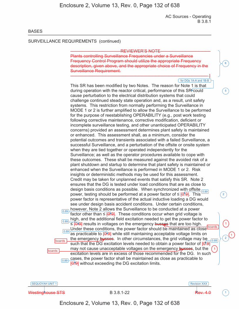
AC Sources - Operating B 3.8.1
Westinghouse STS B 3.8.1-22 Rev. 4.0
SEQUOYAH UNIT 1
1
Revision XXX
BASES SURVEILLANCE REQUIREMENTS (continued)
-----------------------------------REVIEWER’S NOTE----------------------------------- Plants controlling Surveillance Frequencies under a Surveillance Frequency Control Program should utilize the appropriate Frequency description, given above, and the appropriate choice of Frequency in the Surveillance Requirement. ------------------------------------------------------------------------------------------------ ] This SR has been modified by two Notes. The reason for Note 1 is that during operation with the reactor critical, performance of this SR could cause perturbation to the electrical distribution systems that could challenge continued steady state operation and, as a result, unit safety systems. This restriction from normally performing the Surveillance in MODE 1 or 2 is further amplified to allow the Surveillance to be performed for the purpose of reestablishing OPERABILITY (e.g., post work testing following corrective maintenance, corrective modification, deficient or incomplete surveillance testing, and other unanticipated OPERABILITY concerns) provided an assessment determines plant safety is maintained or enhanced. This assessment shall, as a minimum, consider the potential outcomes and transients associated with a failed Surveillance, a successful Surveillance, and a perturbation of the offsite or onsite system when they are tied together or operated independently for the Surveillance; as well as the operator procedures available to cope with these outcomes. These shall be measured against the avoided risk of a plant shutdown and startup to determine that plant safety is maintained or enhanced when the Surveillance is performed in MODE 1 or 2. Risk insights or deterministic methods may be used for this assessment. Credit may be taken for unplanned events that satisfy this SR. Note 2 ensures that the DG is tested under load conditions that are as close to design basis conditions as possible. When synchronized with offsite power, testing should be performed at a power factor of [0.9]. This power factor is representative of the actual inductive loading a DG would see under design basis accident conditions. Under certain conditions, however, Note 2 allows the Surveillance to be conducted at a power factor other than [0.9]. These conditions occur when grid voltage is high, and the additional field excitation needed to get the power factor to [0.9] results in voltages on the emergency busses that are too high.
Under these conditions, the power factor should be maintained as close as practicable to [0.9] while still maintaining acceptable voltage limits on the emergency busses. In other circumstances, the grid voltage may be such that the DG excitation levels needed to obtain a power factor of [0.9] may not cause unacceptable voltages on the emergency busses, but the excitation levels are in excess of those recommended for the DG. In such cases, the power factor shall be maintained as close as practicable to [0.9] without exceeding the DG excitation limits.
for DGs 1A-A and 1B-B
6
5
2
2
0.89
0.89
0.89
0.89
0.89
0.89
Enclosure 2, Volume 13, Rev. 0, Page 132 of 638
Enclosure 2, Volume 13, Rev. 0, Page 132 of 638
boards
boards
boards
1
1
1
AC Sources - Operating B 3.8.1
Westinghouse STS B 3.8.1-23 Rev. 4.0
SEQUOYAH UNIT 1
1
Revision XXX
BASES SURVEILLANCE REQUIREMENTS (continued)
-----------------------------------REVIEWER’S NOTE---------------------------- The above MODE restrictions may be deleted if it can be demonstrated to the staff, on a plant specific basis, that performing the SR with the reactor in any of the restricted MODES can satisfy the following criteria, as applicable: a. Performance of the SR will not render any safety system or
component inoperable, b. Performance of the SR will not cause perturbations to any of the
electrical distribution systems that could result in a challenge to steady state operation or to plant safety systems, and
c. Performance of the SR, or failure of the SR, will not cause, or result
in, an AOO with attendant challenge to plant safety systems. -------------------------------------------------------------------------------------------------- SR 3.8.1.11 As required by Regulatory Guide 1.108 (Ref. 9), paragraph 2.a.(1), this Surveillance demonstrates the as designed operation of the standby power sources during loss of the offsite source. This test verifies all actions encountered from the loss of offsite power, including shedding of the nonessential loads and energization of the emergency buses and respective loads from the DG. It further demonstrates the capability of the DG to automatically achieve the required voltage and frequency within the specified time. The DG autostart time of [10] seconds is derived from requirements of the accident analysis to respond to a design basis large break LOCA. The Surveillance should be continued for a minimum of 5 minutes in order to demonstrate that all starting transients have decayed and stability is achieved. The requirement to verify the connection and power supply of permanent and autoconnected loads is intended to satisfactorily show the relationship of these loads to the DG loading logic. In certain circumstances, many of these loads cannot actually be connected or loaded without undue hardship or potential for undesired operation. For instance, Emergency Core Cooling Systems (ECCS) injection valves are not desired to be stroked open, or high pressure injection systems are not capable of being operated at full flow, or residual heat removal (RHR) systems performing a decay heat removal function are not desired to be realigned to the ECCS mode of operation. In lieu of actual demonstration
6
2
Enclosure 2, Volume 13, Rev. 0, Page 133 of 638
Enclosure 2, Volume 13, Rev. 0, Page 133 of 638
boards1
AC Sources - Operating B 3.8.1
Westinghouse STS B 3.8.1-29 Rev. 4.0
SEQUOYAH UNIT 1
1
Revision XXX
BASES SURVEILLANCE REQUIREMENTS (continued)
-----------------------------------REVIEWER’S NOTE----------------------------------- Plants controlling Surveillance Frequencies under a Surveillance Frequency Control Program should utilize the appropriate Frequency description, given above, and the appropriate choice of Frequency in the Surveillance Requirement. ------------------------------------------------------------------------------------------------ ] This Surveillance is modified by three Notes. Note 1 states that momentary transients due to changing bus loads do not invalidate this test. Similarly, momentary power factor transients above the power factor limit will not invalidate the test. The reason for Note 2 is that during operation with the reactor critical, performance of this Surveillance could cause perturbations to the electrical distribution systems that could challenge continued steady state operation and, as a result, unit safety systems. This restriction from normally performing the Surveillance in MODE 1 or 2 is further amplified to allow the Surveillance to be performed for the purpose of reestablishing OPERABILITY (e.g., post work testing following corrective maintenance, corrective modification, deficient or incomplete surveillance testing, and other unanticipated OPERABILITY concerns) provided an assessment determines plant safety is maintained or enhanced. This assessment shall, as a minimum, consider the potential outcomes and transients associated with a failed Surveillance, a successful Surveillance, and a perturbation of the offsite or onsite system when they are tied together or operated independently for the Surveillance; as well as the operator procedures available to cope with these outcomes. These shall be measured against the avoided risk of a plant shutdown and startup to determine that plant safety is maintained or enhanced when the Surveillance is performed in MODE 1 or 2. Risk insights or deterministic methods may be used for this assessment. Credit may be taken for unplanned events that satisfy this SR. Note 3 ensures that the DG is tested under load conditions that are as close to design basis conditions as possible. When synchronized with offsite power, testing should be performed at a power factor of [0.9]. This power factor is representative of the actual inductive loading a DG would see under design basis accident conditions. Under certain conditions, however, Note 3 allows the Surveillance to be conducted as a power factor other than [0.9]. These conditions occur when grid voltage is high, and the additional field excitation needed to get the power factor to [0.9] results in voltages on the emergency busses that are too high.
Under these conditions, the power factor should be maintained as close as practicable to [0.9] while still maintaining acceptable voltage limits on the emergency busses. In other circumstances, the grid voltage may be such that the DG excitation levels needed to obtain a power factor of [0.9] may not cause unacceptable voltages on the emergency busses, but the excitation levels are in excess of those recommended for the DG. In such cases, the power factor shall be maintained close as practicable to [0.9] without exceeding the DG excitation limits.
for DGs 1A-A and 1B-B
6
5
2
2
0.89
0.89
0.89
0.89
0.89
0.89
Enclosure 2, Volume 13, Rev. 0, Page 139 of 638
Enclosure 2, Volume 13, Rev. 0, Page 139 of 638
board
boards
boards
boards
1
1
1
1
AC Sources - Operating B 3.8.1
Westinghouse STS B 3.8.1-30 Rev. 4.0
SEQUOYAH UNIT 1
1
Revision XXX
BASES SURVEILLANCE REQUIREMENTS (continued)
SR 3.8.1.15 This Surveillance demonstrates that the diesel engine can restart from a hot condition, such as subsequent to shutdown from normal Surveillances, and achieve the required voltage and frequency within [10] seconds. The [10] second time is derived from the requirements of the accident analysis to respond to a design basis large break LOCA.
[ The [18 month] Frequency is consistent with the recommendations of Regulatory Guide 1.108 (Ref. 9), paragraph 2.a.(5). OR The Surveillance Frequency is controlled under the Surveillance Frequency Control Program. -----------------------------------REVIEWER’S NOTE----------------------------------- Plants controlling Surveillance Frequencies under a Surveillance Frequency Control Program should utilize the appropriate Frequency description, given above, and the appropriate choice of Frequency in the Surveillance Requirement. ------------------------------------------------------------------------------------------------ ] This SR is modified by two Notes. Note 1 ensures that the test is performed with the diesel sufficiently hot. The load band is provided to avoid routine overloading of the DG. Routine overloads may result in more frequent teardown inspections in accordance with vendor recommendations in order to maintain DG OPERABILITY. The requirement that the diesel has operated for at least [2] hours at full load conditions prior to performance of this Surveillance is based on manufacturer recommendations for achieving hot conditions. Momentary transients due to changing bus loads do not invalidate this test. Note 2 allows all DG starts to be preceded by an engine prelube period to minimize wear and tear on the diesel during testing. SR 3.8.1.16 As required by Regulatory Guide 1.108 (Ref. 9), paragraph 2.a.(6), this Surveillance ensures that the manual synchronization and automatic load transfer from the DG to the offsite source can be made and the DG can be returned to ready to load status when offsite power is restored. It also ensures that the autostart logic is reset to allow the DG to reload if a
7
2
6
2
Enclosure 2, Volume 13, Rev. 0, Page 140 of 638
Enclosure 2, Volume 13, Rev. 0, Page 140 of 638
board1
AC Sources - Operating B 3.8.1
Westinghouse STS B 3.8.1-31 Rev. 4.0
SEQUOYAH UNIT 1
1
Revision XXX
BASES SURVEILLANCE REQUIREMENTS (continued)
subsequent loss of offsite power occurs. The DG is considered to be in ready to load status when the DG is at rated speed and voltage, the output breaker is open and can receive an autoclose signal on bus undervoltage, and the load sequence timers are reset.
[ The Frequency of [18 months] is consistent with the recommendations of Regulatory Guide 1.108 (Ref. 9), paragraph 2.a.(6), and takes into consideration unit conditions required to perform the Surveillance. OR The Surveillance Frequency is controlled under the Surveillance Frequency Control Program. -----------------------------------REVIEWER’S NOTE----------------------------------- Plants controlling Surveillance Frequencies under a Surveillance Frequency Control Program should utilize the appropriate Frequency description, given above, and the appropriate choice of Frequency in the Surveillance Requirement. ------------------------------------------------------------------------------------------------ ] This SR is modified by a Note. The reason for the Note is that performing the Surveillance would remove a required offsite circuit from service, perturb the electrical distribution system, and challenge safety systems. This restriction from normally performing the Surveillance in MODE 1 or 2 is further amplified to allow the Surveillance to be performed for the purpose of reestablishing OPERABILITY (e.g., post work testing following corrective maintenance, corrective modification, deficient or incomplete surveillance testing, and other unanticipated OPERABILITY concerns) provided an assessment determines plant safety is maintained or enhanced. This assessment shall, as a minimum, consider the potential outcomes and transients associated with a failed Surveillance, a successful Surveillance, and a perturbation of the offsite or onsite system when they are tied together or operated independently for the Surveillance; as well as the operator procedures available to cope with these outcomes. These shall be measured against the avoided risk of a plant shutdown and startup to determine that plant safety is maintained or enhanced when the Surveillance is performed in MODE 1 or 2. Risk insights or deterministic methods may be used for this assessment. Credit may be taken for unplanned events that satisfy this SR.
6
7
for DGs 1A-A and 1B-B
5
Enclosure 2, Volume 13, Rev. 0, Page 141 of 638
Enclosure 2, Volume 13, Rev. 0, Page 141 of 638
board1
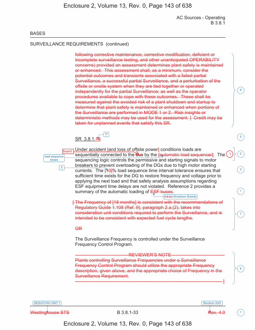
AC Sources - Operating B 3.8.1
Westinghouse STS B 3.8.1-33 Rev. 4.0
SEQUOYAH UNIT 1
1
Revision XXX
BASES SURVEILLANCE REQUIREMENTS (continued)
following corrective maintenance, corrective modification, deficient or incomplete surveillance testing, and other unanticipated OPERABILITY concerns) provided an assessment determines plant safety is maintained or enhanced. This assessment shall, as a minimum, consider the potential outcomes and transients associated with a failed partial Surveillance, a successful partial Surveillance, and a perturbation of the offsite or onsite system when they are tied together or operated independently for the partial Surveillance; as well as the operator procedures available to cope with these outcomes. These shall be measured against the avoided risk of a plant shutdown and startup to determine that plant safety is maintained or enhanced when portions of the Surveillance are performed in MODE 1 or 2. Risk insights or deterministic methods may be used for the assessment. ] Credit may be taken for unplanned events that satisfy this SR. SR 3.8.1.18 Under accident [and loss of offsite power] conditions loads are sequentially connected to the bus by the [automatic load sequencer]. The sequencing logic controls the permissive and starting signals to motor breakers to prevent overloading of the DGs due to high motor starting currents. The [10]% load sequence time interval tolerance ensures that sufficient time exists for the DG to restore frequency and voltage prior to applying the next load and that safety analysis assumptions regarding ESF equipment time delays are not violated. Reference 2 provides a summary of the automatic loading of ESF buses.
[ The Frequency of [18 months] is consistent with the recommendations of Regulatory Guide 1.108 (Ref. 9), paragraph 2.a.(2), takes into consideration unit conditions required to perform the Surveillance, and is intended to be consistent with expected fuel cycle lengths. OR The Surveillance Frequency is controlled under the Surveillance Frequency Control Program. -----------------------------------REVIEWER’S NOTE----------------------------------- Plants controlling Surveillance Frequencies under a Surveillance Frequency Control Program should utilize the appropriate Frequency description, given above, and the appropriate choice of Frequency in the Surveillance Requirement. ------------------------------------------------------------------------------------------------ ]
5
load sequence timers
2
5 2
7
6
175
6.9 kV Shutdown Boards
1
Enclosure 2, Volume 13, Rev. 0, Page 143 of 638
Enclosure 2, Volume 13, Rev. 0, Page 143 of 638
board1
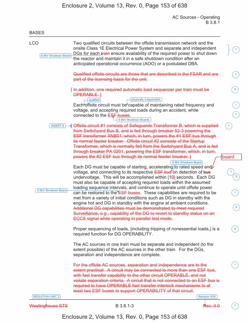
AC Sources - Operating B 3.8.1
Westinghouse STS B 3.8.1-3 Rev. 4.0
SEQUOYAH UNIT 2
1
Revision XXX
BASES LCO Two qualified circuits between the offsite transmission network and the
onsite Class 1E Electrical Power System and separate and independent DGs for each train ensure availability of the required power to shut down the reactor and maintain it in a safe shutdown condition after an anticipated operational occurrence (AOO) or a postulated DBA. Qualified offsite circuits are those that are described in the FSAR and are part of the licensing basis for the unit.
[ In addition, one required automatic load sequencer per train must be OPERABLE. ] Each offsite circuit must be capable of maintaining rated frequency and voltage, and accepting required loads during an accident, while connected to the ESF buses.
[ Offsite circuit #1 consists of Safeguards Transformer B, which is supplied from Switchyard Bus B, and is fed through breaker 52-3 powering the ESF transformer XNB01, which, in turn, powers the #1 ESF bus through its normal feeder breaker. Offsite circuit #2 consists of the Startup Transformer, which is normally fed from the Switchyard Bus A, and is fed through breaker PA 0201, powering the ESF transformer, which, in turn, powers the #2 ESF bus through its normal feeder breaker. ] Each DG must be capable of starting, accelerating to rated speed and voltage, and connecting to its respective ESF bus on detection of bus undervoltage. This will be accomplished within [10] seconds. Each DG must also be capable of accepting required loads within the assumed loading sequence intervals, and continue to operate until offsite power can be restored to the ESF buses. These capabilities are required to be met from a variety of initial conditions such as DG in standby with the engine hot and DG in standby with the engine at ambient conditions. Additional DG capabilities must be demonstrated to meet required Surveillance, e.g., capability of the DG to revert to standby status on an ECCS signal while operating in parallel test mode.
Proper sequencing of loads, [including tripping of nonessential loads,] is a required function for DG OPERABILITY. The AC sources in one train must be separate and independent (to the extent possible) of the AC sources in the other train. For the DGs, separation and independence are complete. For the offsite AC sources, separation and independence are to the extent practical. A circuit may be connected to more than one ESF bus, with fast transfer capability to the other circuit OPERABLE, and not violate separation criteria. A circuit that is not connected to an ESF bus is required to have OPERABLE fast transfer interlock mechanisms to at least two ESF buses to support OPERABILITY of that circuit.
6.9kV Shutdown Boards
INSERT 8
6.9kV Shutdown Board
6.9kV Shutdown Board
1
1
2
1
1
1
2
1
2
1
6.9kV Shutdown Board
1
qualified physically independent,
5
Enclosure 2, Volume 13, Rev. 0, Page 153 of 638
Enclosure 2, Volume 13, Rev. 0, Page 153 of 638
board

AC Sources - Operating B 3.8.1
Westinghouse STS B 3.8.1-15 Rev. 4.0
SEQUOYAH UNIT 2
1
Revision XXX
BASES SURVEILLANCE REQUIREMENTS (continued)
Although no power factor requirements are established by this SR, the DG is normally operated at a power factor between [0.8 lagging] and [1.0]. The [0.8] value is the design rating of the machine, while the [1.0] is an operational limitation [to ensure circulating currents are minimized]. The load band is provided to avoid routine overloading of the DG. Routine overloading may result in more frequent teardown inspections in accordance with vendor recommendations in order to maintain DG OPERABILITY.
[ The 31 day Frequency for this Surveillance is consistent with Regulatory Guide 1.9 (Ref. 3). OR The Surveillance Frequency is controlled under the Surveillance Frequency Control Program. -----------------------------------REVIEWER’S NOTE----------------------------------- Plants controlling Surveillance Frequencies under a Surveillance Frequency Control Program should utilize the appropriate Frequency description, given above, and the appropriate choice of Frequency in the Surveillance Requirement. ------------------------------------------------------------------------------------------------ ]
This SR is modified by four Notes. Note 1 indicates that diesel engine runs for this Surveillance may include gradual loading, as recommended by the manufacturer, so that mechanical stress and wear on the diesel engine are minimized. Note 2 states that momentary transients, because of changing bus loads, do not invalidate this test. Similarly, momentary power factor transients above the limit do not invalidate the test. Note 3 indicates that this Surveillance should be conducted on only one DG at a time in order to avoid common cause failures that might result from offsite circuit or grid perturbations. Note 4 stipulates a prerequisite requirement for performance of this SR. A successful DG start must precede this test to credit satisfactory performance. SR 3.8.1.4 This SR provides verification that the level of fuel oil in the day tank [and engine mounted tank] is at or above the level at which fuel oil is automatically added. The level is expressed as an equivalent volume in gallons, and is selected to ensure adequate fuel oil for a minimum of 1 hour of DG operation at full load plus 10%.
engine-mounted “day”
2
7
6
5 2
has an allowable 1rating
Enclosure 2, Volume 13, Rev. 0, Page 174 of 638
Enclosure 2, Volume 13, Rev. 0, Page 174 of 638
board1
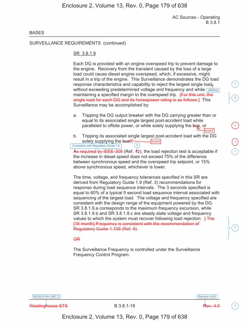
AC Sources - Operating B 3.8.1
Westinghouse STS B 3.8.1-19 Rev. 4.0
SEQUOYAH UNIT 2
1
Revision XXX
BASES SURVEILLANCE REQUIREMENTS (continued)
SR 3.8.1.9 Each DG is provided with an engine overspeed trip to prevent damage to the engine. Recovery from the transient caused by the loss of a large load could cause diesel engine overspeed, which, if excessive, might result in a trip of the engine. This Surveillance demonstrates the DG load response characteristics and capability to reject the largest single load without exceeding predetermined voltage and frequency and while maintaining a specified margin to the overspeed trip. [For this unit, the single load for each DG and its horsepower rating is as follows:] This Surveillance may be accomplished by: a. Tripping the DG output breaker with the DG carrying greater than or
equal to its associated single largest post-accident load while paralleled to offsite power, or while solely supplying the bus, or
b. Tripping its associated single largest post-accident load with the DG
solely supplying the bus. As required by IEEE-308 (Ref. 12), the load rejection test is acceptable if the increase in diesel speed does not exceed 75% of the difference between synchronous speed and the overspeed trip setpoint, or 15% above synchronous speed, whichever is lower. The time, voltage, and frequency tolerances specified in this SR are derived from Regulatory Guide 1.9 (Ref. 3) recommendations for response during load sequence intervals. The 3 seconds specified is equal to 60% of a typical 5 second load sequence interval associated with sequencing of the largest load. The voltage and frequency specified are consistent with the design range of the equipment powered by the DG. SR 3.8.1.9.a corresponds to the maximum frequency excursion, while SR 3.8.1.9.b and SR 3.8.1.9.c are steady state voltage and frequency values to which the system must recover following load rejection. [ The [18 month] Frequency is consistent with the recommendation of Regulatory Guide 1.108 (Ref. 9). OR The Surveillance Frequency is controlled under the Surveillance Frequency Control Program.
1
2
7
1
(600kw)
Consistent with Regulatory Guide 1.9 3
Enclosure 2, Volume 13, Rev. 0, Page 179 of 638
Enclosure 2, Volume 13, Rev. 0, Page 179 of 638
board
board
1
1
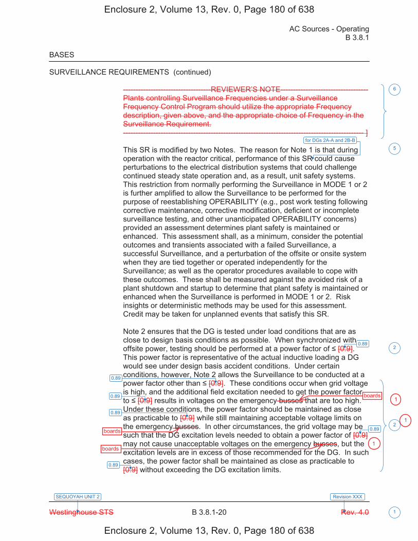
AC Sources - Operating B 3.8.1
Westinghouse STS B 3.8.1-20 Rev. 4.0
SEQUOYAH UNIT 2
1
Revision XXX
BASES SURVEILLANCE REQUIREMENTS (continued)
-----------------------------------REVIEWER’S NOTE----------------------------------- Plants controlling Surveillance Frequencies under a Surveillance Frequency Control Program should utilize the appropriate Frequency description, given above, and the appropriate choice of Frequency in the Surveillance Requirement. ------------------------------------------------------------------------------------------------ ]
This SR is modified by two Notes. The reason for Note 1 is that during operation with the reactor critical, performance of this SR could cause perturbations to the electrical distribution systems that could challenge continued steady state operation and, as a result, unit safety systems. This restriction from normally performing the Surveillance in MODE 1 or 2 is further amplified to allow the Surveillance to be performed for the purpose of reestablishing OPERABILITY (e.g., post work testing following corrective maintenance, corrective modification, deficient or incomplete surveillance testing, and other unanticipated OPERABILITY concerns) provided an assessment determines plant safety is maintained or enhanced. This assessment shall, as a minimum, consider the potential outcomes and transients associated with a failed Surveillance, a successful Surveillance, and a perturbation of the offsite or onsite system when they are tied together or operated independently for the Surveillance; as well as the operator procedures available to cope with these outcomes. These shall be measured against the avoided risk of a plant shutdown and startup to determine that plant safety is maintained or enhanced when the Surveillance is performed in MODE 1 or 2. Risk insights or deterministic methods may be used for this assessment. Credit may be taken for unplanned events that satisfy this SR. Note 2 ensures that the DG is tested under load conditions that are as close to design basis conditions as possible. When synchronized with offsite power, testing should be performed at a power factor of [0.9]. This power factor is representative of the actual inductive loading a DG would see under design basis accident conditions. Under certain conditions, however, Note 2 allows the Surveillance to be conducted at a power factor other than [0.9]. These conditions occur when grid voltage is high, and the additional field excitation needed to get the power factor to [0.9] results in voltages on the emergency busses that are too high. Under these conditions, the power factor should be maintained as close as practicable to [0.9] while still maintaining acceptable voltage limits on the emergency busses. In other circumstances, the grid voltage may be such that the DG excitation levels needed to obtain a power factor of [0.9] may not cause unacceptable voltages on the emergency busses, but the excitation levels are in excess of those recommended for the DG. In such cases, the power factor shall be maintained as close as practicable to [0.9] without exceeding the DG excitation limits.
6
5
2
2
for DGs 2A-A and 2B-B
0.89
0.89
0.89
0.89
0.89
0.89
Enclosure 2, Volume 13, Rev. 0, Page 180 of 638
Enclosure 2, Volume 13, Rev. 0, Page 180 of 638
boards
boards
boards
1
1
1
AC Sources - Operating B 3.8.1
Westinghouse STS B 3.8.1-21 Rev. 4.0
SEQUOYAH UNIT 2
1
Revision XXX
BASES SURVEILLANCE REQUIREMENTS (continued)
-----------------------------------REVIEWER’S NOTE----------------------------------- The above MODE restrictions may be deleted if it can be demonstrated to the staff, on a plant specific basis, that performing the SR with the reactor in any of the restricted MODES can satisfy the following criteria, as applicable: a. Performance of the SR will not render any safety system or
component inoperable, b. Performance of the SR will not cause perturbations to any of the
electrical distribution systems that could result in a challenge to steady state operation or to plant safety systems, and
c. Performance of the SR, or failure of the SR, will not cause, or result
in, an AOO with attendant challenge to plant safety systems. -------------------------------------------------------------------------------------------------- SR 3.8.1.10 This Surveillance demonstrates the DG capability to reject a full load without overspeed tripping or exceeding the predetermined voltage limits. The DG full load rejection may occur because of a system fault or inadvertent breaker tripping. This Surveillance ensures proper engine generator load response under the simulated test conditions. This test simulates the loss of the total connected load that the DG experiences following a full load rejection and verifies that the DG does not trip upon loss of the load. These acceptance criteria provide for DG damage protection. While the DG is not expected to experience this transient during an event and continues to be available, this response ensures that the DG is not degraded for future application, including reconnection to the bus if the trip initiator can be corrected or isolated.
[ The [18 month] Frequency is consistent with the recommendation of Regulatory Guide 1.108 (Ref. 9) and is intended to be consistent with expected fuel cycle lengths. OR The Surveillance Frequency is controlled under the Surveillance Frequency Control Program.
6
7
Enclosure 2, Volume 13, Rev. 0, Page 181 of 638
Enclosure 2, Volume 13, Rev. 0, Page 181 of 638
board1
AC Sources - Operating B 3.8.1
Westinghouse STS B 3.8.1-22 Rev. 4.0
SEQUOYAH UNIT 2
1
Revision XXX
BASES SURVEILLANCE REQUIREMENTS (continued)
-----------------------------------REVIEWER’S NOTE----------------------------------- Plants controlling Surveillance Frequencies under a Surveillance Frequency Control Program should utilize the appropriate Frequency description, given above, and the appropriate choice of Frequency in the Surveillance Requirement. ------------------------------------------------------------------------------------------------ ] This SR has been modified by two Notes. The reason for Note 1 is that during operation with the reactor critical, performance of this SR could cause perturbation to the electrical distribution systems that could challenge continued steady state operation and, as a result, unit safety systems. This restriction from normally performing the Surveillance in MODE 1 or 2 is further amplified to allow the Surveillance to be performed for the purpose of reestablishing OPERABILITY (e.g., post work testing following corrective maintenance, corrective modification, deficient or incomplete surveillance testing, and other unanticipated OPERABILITY concerns) provided an assessment determines plant safety is maintained or enhanced. This assessment shall, as a minimum, consider the potential outcomes and transients associated with a failed Surveillance, a successful Surveillance, and a perturbation of the offsite or onsite system when they are tied together or operated independently for the Surveillance; as well as the operator procedures available to cope with these outcomes. These shall be measured against the avoided risk of a plant shutdown and startup to determine that plant safety is maintained or enhanced when the Surveillance is performed in MODE 1 or 2. Risk insights or deterministic methods may be used for this assessment. Credit may be taken for unplanned events that satisfy this SR. Note 2 ensures that the DG is tested under load conditions that are as close to design basis conditions as possible. When synchronized with offsite power, testing should be performed at a power factor of [0.9]. This power factor is representative of the actual inductive loading a DG would see under design basis accident conditions. Under certain conditions, however, Note 2 allows the Surveillance to be conducted at a power factor other than [0.9]. These conditions occur when grid voltage is high, and the additional field excitation needed to get the power factor to [0.9] results in voltages on the emergency busses that are too high.
Under these conditions, the power factor should be maintained as close as practicable to [0.9] while still maintaining acceptable voltage limits on the emergency busses. In other circumstances, the grid voltage may be such that the DG excitation levels needed to obtain a power factor of [0.9] may not cause unacceptable voltages on the emergency busses, but the excitation levels are in excess of those recommended for the DG. In such cases, the power factor shall be maintained as close as practicable to [0.9] without exceeding the DG excitation limits.
6
5
2
2
for DGs 2A-A and 2B-B
0.89
0.89
0.89
0.89
0.89
0.89
Enclosure 2, Volume 13, Rev. 0, Page 182 of 638
Enclosure 2, Volume 13, Rev. 0, Page 182 of 638
boards
boards
boards
1
1
1
AC Sources - Operating B 3.8.1
Westinghouse STS B 3.8.1-23 Rev. 4.0
SEQUOYAH UNIT 2
1
Revision XXX
BASES SURVEILLANCE REQUIREMENTS (continued)
-----------------------------------REVIEWER’S NOTE---------------------------- The above MODE restrictions may be deleted if it can be demonstrated to the staff, on a plant specific basis, that performing the SR with the reactor in any of the restricted MODES can satisfy the following criteria, as applicable: a. Performance of the SR will not render any safety system or
component inoperable, b. Performance of the SR will not cause perturbations to any of the
electrical distribution systems that could result in a challenge to steady state operation or to plant safety systems, and
c. Performance of the SR, or failure of the SR, will not cause, or result
in, an AOO with attendant challenge to plant safety systems. -------------------------------------------------------------------------------------------------- SR 3.8.1.11 As required by Regulatory Guide 1.108 (Ref. 9), paragraph 2.a.(1), this Surveillance demonstrates the as designed operation of the standby power sources during loss of the offsite source. This test verifies all actions encountered from the loss of offsite power, including shedding of the nonessential loads and energization of the emergency buses and respective loads from the DG. It further demonstrates the capability of the DG to automatically achieve the required voltage and frequency within the specified time. The DG autostart time of [10] seconds is derived from requirements of the accident analysis to respond to a design basis large break LOCA. The Surveillance should be continued for a minimum of 5 minutes in order to demonstrate that all starting transients have decayed and stability is achieved. The requirement to verify the connection and power supply of permanent and autoconnected loads is intended to satisfactorily show the relationship of these loads to the DG loading logic. In certain circumstances, many of these loads cannot actually be connected or loaded without undue hardship or potential for undesired operation. For instance, Emergency Core Cooling Systems (ECCS) injection valves are not desired to be stroked open, or high pressure injection systems are not capable of being operated at full flow, or residual heat removal (RHR) systems performing a decay heat removal function are not desired to be realigned to the ECCS mode of operation. In lieu of actual demonstration
6
2
Enclosure 2, Volume 13, Rev. 0, Page 183 of 638
Enclosure 2, Volume 13, Rev. 0, Page 183 of 638
boards1
AC Sources - Operating B 3.8.1
Westinghouse STS B 3.8.1-29 Rev. 4.0
SEQUOYAH UNIT 2
1
Revision XXX
BASES SURVEILLANCE REQUIREMENTS (continued)
-----------------------------------REVIEWER’S NOTE----------------------------------- Plants controlling Surveillance Frequencies under a Surveillance Frequency Control Program should utilize the appropriate Frequency description, given above, and the appropriate choice of Frequency in the Surveillance Requirement. ------------------------------------------------------------------------------------------------ ] This Surveillance is modified by three Notes. Note 1 states that momentary transients due to changing bus loads do not invalidate this test. Similarly, momentary power factor transients above the power factor limit will not invalidate the test. The reason for Note 2 is that during operation with the reactor critical, performance of this Surveillance could cause perturbations to the electrical distribution systems that could challenge continued steady state operation and, as a result, unit safety systems. This restriction from normally performing the Surveillance in MODE 1 or 2 is further amplified to allow the Surveillance to be performed for the purpose of reestablishing OPERABILITY (e.g., post work testing following corrective maintenance, corrective modification, deficient or incomplete surveillance testing, and other unanticipated OPERABILITY concerns) provided an assessment determines plant safety is maintained or enhanced. This assessment shall, as a minimum, consider the potential outcomes and transients associated with a failed Surveillance, a successful Surveillance, and a perturbation of the offsite or onsite system when they are tied together or operated independently for the Surveillance; as well as the operator procedures available to cope with these outcomes. These shall be measured against the avoided risk of a plant shutdown and startup to determine that plant safety is maintained or enhanced when the Surveillance is performed in MODE 1 or 2. Risk insights or deterministic methods may be used for this assessment. Credit may be taken for unplanned events that satisfy this SR. Note 3 ensures that the DG is tested under load conditions that are as close to design basis conditions as possible. When synchronized with offsite power, testing should be performed at a power factor of [0.9]. This power factor is representative of the actual inductive loading a DG would see under design basis accident conditions. Under certain conditions, however, Note 3 allows the Surveillance to be conducted as a power factor other than [0.9]. These conditions occur when grid voltage is high, and the additional field excitation needed to get the power factor to [0.9] results in voltages on the emergency busses that are too high.
Under these conditions, the power factor should be maintained as close as practicable to [0.9] while still maintaining acceptable voltage limits on the emergency busses. In other circumstances, the grid voltage may be such that the DG excitation levels needed to obtain a power factor of [0.9] may not cause unacceptable voltages on the emergency busses, but the excitation levels are in excess of those recommended for the DG. In such cases, the power factor shall be maintained close as practicable to [0.9] without exceeding the DG excitation limits.
6
5
2
2
for DGs 2A-A and 2B-B
0.89
0.89
0.89
0.89
0.89
0.89
Enclosure 2, Volume 13, Rev. 0, Page 189 of 638
Enclosure 2, Volume 13, Rev. 0, Page 189 of 638
board
boards
boards
boards
1
1
1
1
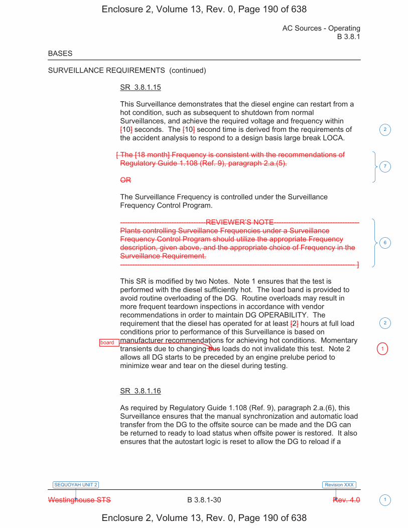
AC Sources - Operating B 3.8.1
Westinghouse STS B 3.8.1-30 Rev. 4.0
SEQUOYAH UNIT 2
1
Revision XXX
BASES SURVEILLANCE REQUIREMENTS (continued)
SR 3.8.1.15 This Surveillance demonstrates that the diesel engine can restart from a hot condition, such as subsequent to shutdown from normal Surveillances, and achieve the required voltage and frequency within [10] seconds. The [10] second time is derived from the requirements of the accident analysis to respond to a design basis large break LOCA.
[ The [18 month] Frequency is consistent with the recommendations of Regulatory Guide 1.108 (Ref. 9), paragraph 2.a.(5). OR The Surveillance Frequency is controlled under the Surveillance Frequency Control Program. -----------------------------------REVIEWER’S NOTE----------------------------------- Plants controlling Surveillance Frequencies under a Surveillance Frequency Control Program should utilize the appropriate Frequency description, given above, and the appropriate choice of Frequency in the Surveillance Requirement. ------------------------------------------------------------------------------------------------ ] This SR is modified by two Notes. Note 1 ensures that the test is performed with the diesel sufficiently hot. The load band is provided to avoid routine overloading of the DG. Routine overloads may result in more frequent teardown inspections in accordance with vendor recommendations in order to maintain DG OPERABILITY. The requirement that the diesel has operated for at least [2] hours at full load conditions prior to performance of this Surveillance is based on manufacturer recommendations for achieving hot conditions. Momentary transients due to changing bus loads do not invalidate this test. Note 2 allows all DG starts to be preceded by an engine prelube period to minimize wear and tear on the diesel during testing. SR 3.8.1.16 As required by Regulatory Guide 1.108 (Ref. 9), paragraph 2.a.(6), this Surveillance ensures that the manual synchronization and automatic load transfer from the DG to the offsite source can be made and the DG can be returned to ready to load status when offsite power is restored. It also ensures that the autostart logic is reset to allow the DG to reload if a
7
2
6
2
Enclosure 2, Volume 13, Rev. 0, Page 190 of 638
Enclosure 2, Volume 13, Rev. 0, Page 190 of 638
board1

AC Sources - Operating B 3.8.1
Westinghouse STS B 3.8.1-31 Rev. 4.0
SEQUOYAH UNIT 2
1
Revision XXX
BASES SURVEILLANCE REQUIREMENTS (continued)
subsequent loss of offsite power occurs. The DG is considered to be in ready to load status when the DG is at rated speed and voltage, the output breaker is open and can receive an autoclose signal on bus undervoltage, and the load sequence timers are reset.
[ The Frequency of [18 months] is consistent with the recommendations of Regulatory Guide 1.108 (Ref. 9), paragraph 2.a.(6), and takes into consideration unit conditions required to perform the Surveillance. OR The Surveillance Frequency is controlled under the Surveillance Frequency Control Program. -----------------------------------REVIEWER’S NOTE----------------------------------- Plants controlling Surveillance Frequencies under a Surveillance Frequency Control Program should utilize the appropriate Frequency description, given above, and the appropriate choice of Frequency in the Surveillance Requirement. ------------------------------------------------------------------------------------------------ ] This SR is modified by a Note. The reason for the Note is that performing the Surveillance would remove a required offsite circuit from service, perturb the electrical distribution system, and challenge safety systems. This restriction from normally performing the Surveillance in MODE 1 or 2 is further amplified to allow the Surveillance to be performed for the purpose of reestablishing OPERABILITY (e.g., post work testing following corrective maintenance, corrective modification, deficient or incomplete surveillance testing, and other unanticipated OPERABILITY concerns) provided an assessment determines plant safety is maintained or enhanced. This assessment shall, as a minimum, consider the potential outcomes and transients associated with a failed Surveillance, a successful Surveillance, and a perturbation of the offsite or onsite system when they are tied together or operated independently for the Surveillance; as well as the operator procedures available to cope with these outcomes. These shall be measured against the avoided risk of a plant shutdown and startup to determine that plant safety is maintained or enhanced when the Surveillance is performed in MODE 1 or 2. Risk insights or deterministic methods may be used for this assessment. Credit may be taken for unplanned events that satisfy this SR.
6
7
5for DGs 2A-A
and 2B-B
Enclosure 2, Volume 13, Rev. 0, Page 191 of 638
Enclosure 2, Volume 13, Rev. 0, Page 191 of 638
board
1

AC Sources - Operating B 3.8.1
Westinghouse STS B 3.8.1-33 Rev. 4.0
SEQUOYAH UNIT 2
1
Revision XXX
BASES SURVEILLANCE REQUIREMENTS (continued)
following corrective maintenance, corrective modification, deficient or incomplete surveillance testing, and other unanticipated OPERABILITY concerns) provided an assessment determines plant safety is maintained or enhanced. This assessment shall, as a minimum, consider the potential outcomes and transients associated with a failed partial Surveillance, a successful partial Surveillance, and a perturbation of the offsite or onsite system when they are tied together or operated independently for the partial Surveillance; as well as the operator procedures available to cope with these outcomes. These shall be measured against the avoided risk of a plant shutdown and startup to determine that plant safety is maintained or enhanced when portions of the Surveillance are performed in MODE 1 or 2. Risk insights or deterministic methods may be used for the assessment. ] Credit may be taken for unplanned events that satisfy this SR. SR 3.8.1.18 Under accident [and loss of offsite power] conditions loads are sequentially connected to the bus by the [automatic load sequencer]. The sequencing logic controls the permissive and starting signals to motor breakers to prevent overloading of the DGs due to high motor starting currents. The [10]% load sequence time interval tolerance ensures that sufficient time exists for the DG to restore frequency and voltage prior to applying the next load and that safety analysis assumptions regarding ESF equipment time delays are not violated. Reference 2 provides a summary of the automatic loading of ESF buses.
[ The Frequency of [18 months] is consistent with the recommendations of Regulatory Guide 1.108 (Ref. 9), paragraph 2.a.(2), takes into consideration unit conditions required to perform the Surveillance, and is intended to be consistent with expected fuel cycle lengths. OR The Surveillance Frequency is controlled under the Surveillance Frequency Control Program. -----------------------------------REVIEWER’S NOTE----------------------------------- Plants controlling Surveillance Frequencies under a Surveillance Frequency Control Program should utilize the appropriate Frequency description, given above, and the appropriate choice of Frequency in the Surveillance Requirement. ------------------------------------------------------------------------------------------------ ]
5
2
5 2
7
6
175
load sequence timers
6.9 kV Shutdown Boards
1
Enclosure 2, Volume 13, Rev. 0, Page 193 of 638
Enclosure 2, Volume 13, Rev. 0, Page 193 of 638
board1
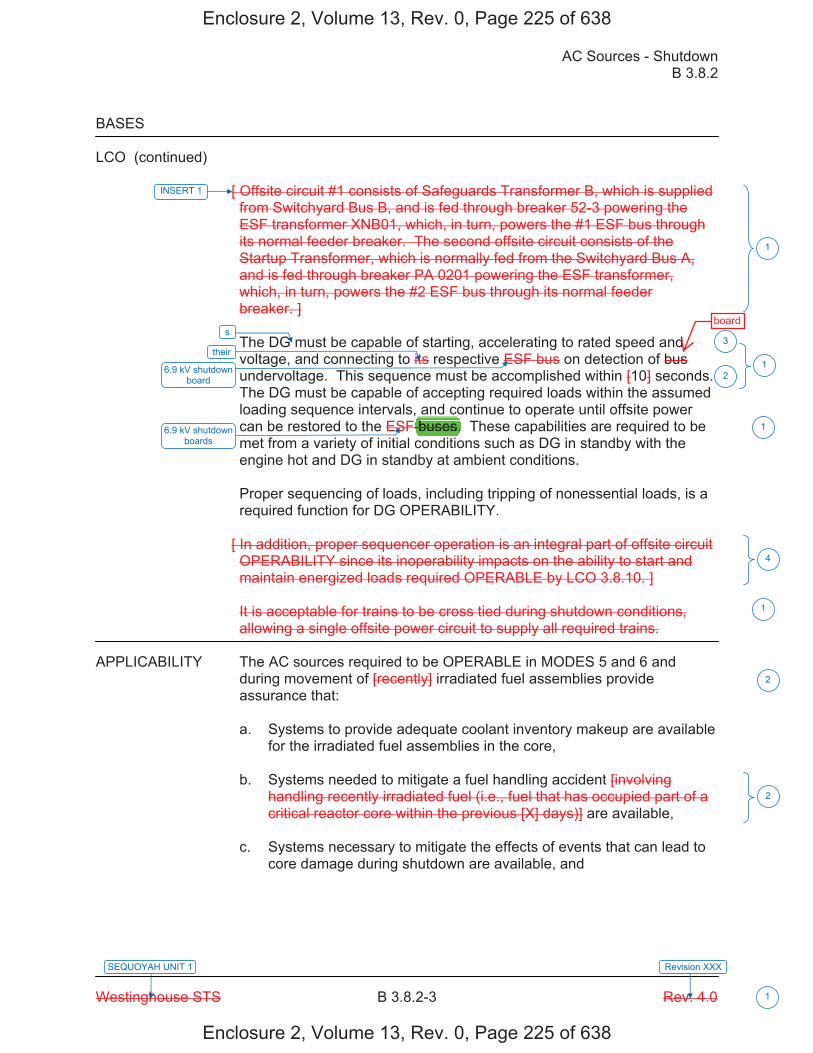
AC Sources - Shutdown B 3.8.2
Westinghouse STS B 3.8.2-3 Rev. 4.0 1
SEQUOYAH UNIT 1 Revision XXX
BASES
LCO (continued)
[ Offsite circuit #1 consists of Safeguards Transformer B, which is supplied from Switchyard Bus B, and is fed through breaker 52-3 powering the ESF transformer XNB01, which, in turn, powers the #1 ESF bus through its normal feeder breaker. The second offsite circuit consists of the Startup Transformer, which is normally fed from the Switchyard Bus A, and is fed through breaker PA 0201 powering the ESF transformer, which, in turn, powers the #2 ESF bus through its normal feeder breaker. ] The DG must be capable of starting, accelerating to rated speed and voltage, and connecting to its respective ESF bus on detection of bus undervoltage. This sequence must be accomplished within [10] seconds. The DG must be capable of accepting required loads within the assumed loading sequence intervals, and continue to operate until offsite power can be restored to the ESF buses. These capabilities are required to be met from a variety of initial conditions such as DG in standby with the engine hot and DG in standby at ambient conditions. Proper sequencing of loads, including tripping of nonessential loads, is a required function for DG OPERABILITY.
[ In addition, proper sequencer operation is an integral part of offsite circuit OPERABILITY since its inoperability impacts on the ability to start and maintain energized loads required OPERABLE by LCO 3.8.10. ] It is acceptable for trains to be cross tied during shutdown conditions, allowing a single offsite power circuit to supply all required trains.
APPLICABILITY The AC sources required to be OPERABLE in MODES 5 and 6 and
during movement of [recently] irradiated fuel assemblies provide assurance that: a. Systems to provide adequate coolant inventory makeup are available
for the irradiated fuel assemblies in the core, b. Systems needed to mitigate a fuel handling accident [involving
handling recently irradiated fuel (i.e., fuel that has occupied part of a critical reactor core within the previous [X] days)] are available,
c. Systems necessary to mitigate the effects of events that can lead to
core damage during shutdown are available, and
INSERT 1
1
s
1their
6.9 kV shutdown board
3
2
4
2
2
16.9 kV shutdown boards
1
Enclosure 2, Volume 13, Rev. 0, Page 225 of 638
Enclosure 2, Volume 13, Rev. 0, Page 225 of 638
board
buses.
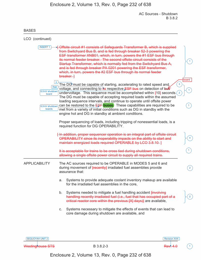
AC Sources - Shutdown B 3.8.2
Westinghouse STS B 3.8.2-3 Rev. 4.0 1
SEQUOYAH UNIT 2 Revision XXX
BASES
LCO (continued)
[ Offsite circuit #1 consists of Safeguards Transformer B, which is supplied from Switchyard Bus B, and is fed through breaker 52-3 powering the ESF transformer XNB01, which, in turn, powers the #1 ESF bus through its normal feeder breaker. The second offsite circuit consists of the Startup Transformer, which is normally fed from the Switchyard Bus A, and is fed through breaker PA 0201 powering the ESF transformer, which, in turn, powers the #2 ESF bus through its normal feeder breaker. ] The DG must be capable of starting, accelerating to rated speed and voltage, and connecting to its respective ESF bus on detection of bus undervoltage. This sequence must be accomplished within [10] seconds. The DG must be capable of accepting required loads within the assumed loading sequence intervals, and continue to operate until offsite power can be restored to the ESF buses. These capabilities are required to be met from a variety of initial conditions such as DG in standby with the engine hot and DG in standby at ambient conditions. Proper sequencing of loads, including tripping of nonessential loads, is a required function for DG OPERABILITY.
[ In addition, proper sequencer operation is an integral part of offsite circuit OPERABILITY since its inoperability impacts on the ability to start and maintain energized loads required OPERABLE by LCO 3.8.10. ] It is acceptable for trains to be cross tied during shutdown conditions, allowing a single offsite power circuit to supply all required trains.
APPLICABILITY The AC sources required to be OPERABLE in MODES 5 and 6 and
during movement of [recently] irradiated fuel assemblies provide assurance that: a. Systems to provide adequate coolant inventory makeup are available
for the irradiated fuel assemblies in the core, b. Systems needed to mitigate a fuel handling accident [involving
handling recently irradiated fuel (i.e., fuel that has occupied part of a critical reactor core within the previous [X] days)] are available,
c. Systems necessary to mitigate the effects of events that can lead to
core damage during shutdown are available, and
INSERT 1
1
s
1their
6.9 kV shutdown board
3
2
4
2
2
16.9 kV shutdown boards
1
Enclosure 2, Volume 13, Rev. 0, Page 232 of 638
Enclosure 2, Volume 13, Rev. 0, Page 232 of 638
board
buses.
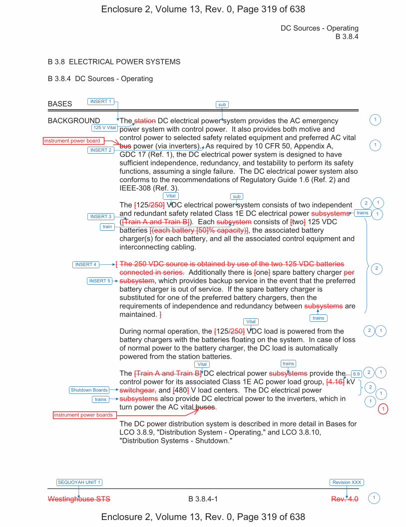
DC Sources - Operating B 3.8.4
Westinghouse STS B 3.8.4-1 Rev. 4.0
SEQUOYAH UNIT 1 Revision XXX
1
B 3.8 ELECTRICAL POWER SYSTEMS B 3.8.4 DC Sources - Operating BASES BACKGROUND The station DC electrical power system provides the AC emergency
power system with control power. It also provides both motive and control power to selected safety related equipment and preferred AC vital bus power (via inverters). As required by 10 CFR 50, Appendix A, GDC 17 (Ref. 1), the DC electrical power system is designed to have sufficient independence, redundancy, and testability to perform its safety functions, assuming a single failure. The DC electrical power system also conforms to the recommendations of Regulatory Guide 1.6 (Ref. 2) and IEEE-308 (Ref. 3).
The [125/250] VDC electrical power system consists of two independent and redundant safety related Class 1E DC electrical power subsystems ([Train A and Train B]). Each subsystem consists of [two] 125 VDC batteries [(each battery [50]% capacity)], the associated battery charger(s) for each battery, and all the associated control equipment and interconnecting cabling.
[ The 250 VDC source is obtained by use of the two 125 VDC batteries connected in series. Additionally there is [one] spare battery charger per subsystem, which provides backup service in the event that the preferred battery charger is out of service. If the spare battery charger is substituted for one of the preferred battery chargers, then the requirements of independence and redundancy between subsystems are maintained. ] During normal operation, the [125/250] VDC load is powered from the battery chargers with the batteries floating on the system. In case of loss of normal power to the battery charger, the DC load is automatically powered from the station batteries. The [Train A and Train B] DC electrical power subsystems provide the control power for its associated Class 1E AC power load group, [4.16] kV switchgear, and [480] V load centers. The DC electrical power subsystems also provide DC electrical power to the inverters, which in turn power the AC vital buses. The DC power distribution system is described in more detail in Bases for LCO 3.8.9, "Distribution System - Operating," and LCO 3.8.10, "Distribution Systems - Shutdown."
trainsINSERT 3
train
trains
6.9
INSERT 4
trains
2 1
1
2
2 1
2
1
2
125 V Vital
1
trains
Shutdown Boards
INSERT 5
1
INSERT 1
INSERT 2 1
Vital
Vital
sub
sub
Vital
1
Enclosure 2, Volume 13, Rev. 0, Page 319 of 638
Enclosure 2, Volume 13, Rev. 0, Page 319 of 638
instrument power board
instrument power boards1
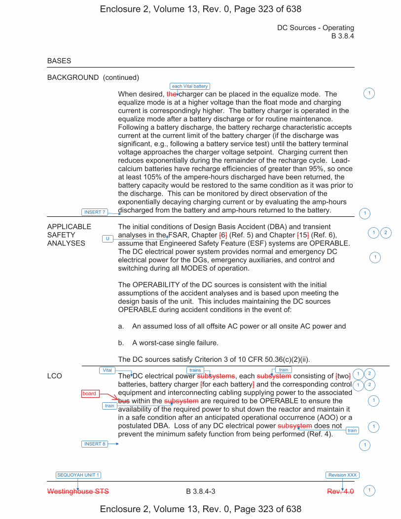
DC Sources - Operating B 3.8.4
Westinghouse STS B 3.8.4-3 Rev. 4.0
SEQUOYAH UNIT 1 Revision XXX
1
BASES BACKGROUND (continued)
When desired, the charger can be placed in the equalize mode. The equalize mode is at a higher voltage than the float mode and charging current is correspondingly higher. The battery charger is operated in the equalize mode after a battery discharge or for routine maintenance. Following a battery discharge, the battery recharge characteristic accepts current at the current limit of the battery charger (if the discharge was significant, e.g., following a battery service test) until the battery terminal voltage approaches the charger voltage setpoint. Charging current then reduces exponentially during the remainder of the recharge cycle. Lead-calcium batteries have recharge efficiencies of greater than 95%, so once at least 105% of the ampere-hours discharged have been returned, the battery capacity would be restored to the same condition as it was prior to the discharge. This can be monitored by direct observation of the exponentially decaying charging current or by evaluating the amp-hours discharged from the battery and amp-hours returned to the battery.
APPLICABLE The initial conditions of Design Basis Accident (DBA) and transient SAFETY analyses in the FSAR, Chapter [6] (Ref. 5) and Chapter [15] (Ref. 6), ANALYSES assume that Engineered Safety Feature (ESF) systems are OPERABLE.
The DC electrical power system provides normal and emergency DC electrical power for the DGs, emergency auxiliaries, and control and switching during all MODES of operation. The OPERABILITY of the DC sources is consistent with the initial assumptions of the accident analyses and is based upon meeting the design basis of the unit. This includes maintaining the DC sources OPERABLE during accident conditions in the event of: a. An assumed loss of all offsite AC power or all onsite AC power and b. A worst-case single failure. The DC sources satisfy Criterion 3 of 10 CFR 50.36(c)(2)(ii).
LCO The DC electrical power subsystems, each subsystem consisting of [two]
batteries, battery charger [for each battery] and the corresponding control equipment and interconnecting cabling supplying power to the associated bus within the subsystem are required to be OPERABLE to ensure the availability of the required power to shut down the reactor and maintain it in a safe condition after an anticipated operational occurrence (AOO) or a postulated DBA. Loss of any DC electrical power subsystem does not prevent the minimum safety function from being performed (Ref. 4).
train trains
train
train
U 1 2
1 2
1 2
1
1
1
INSERT 7 1
INSERT 8 1
Vital
1each Vital battery
Enclosure 2, Volume 13, Rev. 0, Page 323 of 638
Enclosure 2, Volume 13, Rev. 0, Page 323 of 638
board
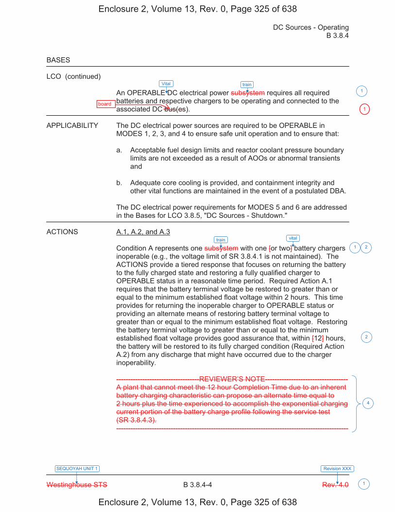
DC Sources - Operating B 3.8.4
Westinghouse STS B 3.8.4-4 Rev. 4.0
SEQUOYAH UNIT 1 Revision XXX
1
BASES LCO (continued)
An OPERABLE DC electrical power subsystem requires all required batteries and respective chargers to be operating and connected to the associated DC bus(es).
APPLICABILITY The DC electrical power sources are required to be OPERABLE in
MODES 1, 2, 3, and 4 to ensure safe unit operation and to ensure that: a. Acceptable fuel design limits and reactor coolant pressure boundary
limits are not exceeded as a result of AOOs or abnormal transients and
b. Adequate core cooling is provided, and containment integrity and
other vital functions are maintained in the event of a postulated DBA. The DC electrical power requirements for MODES 5 and 6 are addressed in the Bases for LCO 3.8.5, "DC Sources - Shutdown."
ACTIONS A.1, A.2, and A.3
Condition A represents one subsystem with one [or two] battery chargers inoperable (e.g., the voltage limit of SR 3.8.4.1 is not maintained). The ACTIONS provide a tiered response that focuses on returning the battery to the fully charged state and restoring a fully qualified charger to OPERABLE status in a reasonable time period. Required Action A.1 requires that the battery terminal voltage be restored to greater than or equal to the minimum established float voltage within 2 hours. This time provides for returning the inoperable charger to OPERABLE status or providing an alternate means of restoring battery terminal voltage to greater than or equal to the minimum established float voltage. Restoring the battery terminal voltage to greater than or equal to the minimum established float voltage provides good assurance that, within [12] hours, the battery will be restored to its fully charged condition (Required Action A.2) from any discharge that might have occurred due to the charger inoperability.
-----------------------------------REVIEWER’S NOTE----------------------------------- A plant that cannot meet the 12 hour Completion Time due to an inherent battery charging characteristic can propose an alternate time equal to 2 hours plus the time experienced to accomplish the exponential charging current portion of the battery charge profile following the service test (SR 3.8.4.3). --------------------------------------------------------------------------------------------------
train
train vital
1
21
4
2
Vital
Enclosure 2, Volume 13, Rev. 0, Page 325 of 638
Enclosure 2, Volume 13, Rev. 0, Page 325 of 638
board1
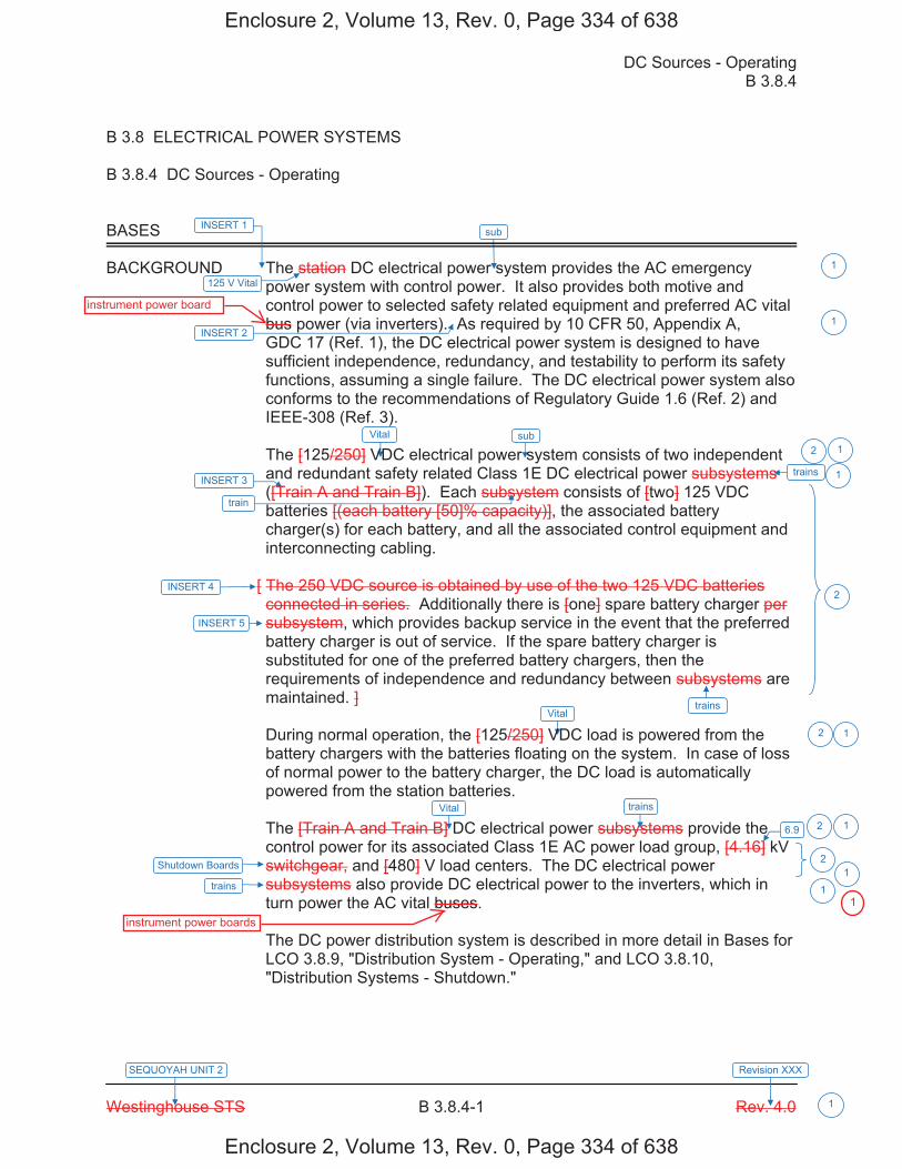
DC Sources - Operating B 3.8.4
Westinghouse STS B 3.8.4-1 Rev. 4.0
SEQUOYAH UNIT 2 Revision XXX
1
B 3.8 ELECTRICAL POWER SYSTEMS B 3.8.4 DC Sources - Operating BASES BACKGROUND The station DC electrical power system provides the AC emergency
power system with control power. It also provides both motive and control power to selected safety related equipment and preferred AC vital bus power (via inverters). As required by 10 CFR 50, Appendix A, GDC 17 (Ref. 1), the DC electrical power system is designed to have sufficient independence, redundancy, and testability to perform its safety functions, assuming a single failure. The DC electrical power system also conforms to the recommendations of Regulatory Guide 1.6 (Ref. 2) and IEEE-308 (Ref. 3).
The [125/250] VDC electrical power system consists of two independent and redundant safety related Class 1E DC electrical power subsystems ([Train A and Train B]). Each subsystem consists of [two] 125 VDC batteries [(each battery [50]% capacity)], the associated battery charger(s) for each battery, and all the associated control equipment and interconnecting cabling.
[ The 250 VDC source is obtained by use of the two 125 VDC batteries connected in series. Additionally there is [one] spare battery charger per subsystem, which provides backup service in the event that the preferred battery charger is out of service. If the spare battery charger is substituted for one of the preferred battery chargers, then the requirements of independence and redundancy between subsystems are maintained. ] During normal operation, the [125/250] VDC load is powered from the battery chargers with the batteries floating on the system. In case of loss of normal power to the battery charger, the DC load is automatically powered from the station batteries. The [Train A and Train B] DC electrical power subsystems provide the control power for its associated Class 1E AC power load group, [4.16] kV switchgear, and [480] V load centers. The DC electrical power subsystems also provide DC electrical power to the inverters, which in turn power the AC vital buses. The DC power distribution system is described in more detail in Bases for LCO 3.8.9, "Distribution System - Operating," and LCO 3.8.10, "Distribution Systems - Shutdown."
trainsINSERT 3
train
trains
6.9
INSERT 4
trains
2 1
1
2
2 1
2
1
2
125 V Vital
1
trains
Shutdown Boards
INSERT 5
1
INSERT 1
INSERT 2 1
Vital
Vital
sub
sub
Vital
1
Enclosure 2, Volume 13, Rev. 0, Page 334 of 638
Enclosure 2, Volume 13, Rev. 0, Page 334 of 638
instrument power board
instrument power boards
1

DC Sources - Operating B 3.8.4
Westinghouse STS B 3.8.4-3 Rev. 4.0
SEQUOYAH UNIT 2 Revision XXX
1
BASES BACKGROUND (continued)
When desired, the charger can be placed in the equalize mode. The equalize mode is at a higher voltage than the float mode and charging current is correspondingly higher. The battery charger is operated in the equalize mode after a battery discharge or for routine maintenance. Following a battery discharge, the battery recharge characteristic accepts current at the current limit of the battery charger (if the discharge was significant, e.g., following a battery service test) until the battery terminal voltage approaches the charger voltage setpoint. Charging current then reduces exponentially during the remainder of the recharge cycle. Lead-calcium batteries have recharge efficiencies of greater than 95%, so once at least 105% of the ampere-hours discharged have been returned, the battery capacity would be restored to the same condition as it was prior to the discharge. This can be monitored by direct observation of the exponentially decaying charging current or by evaluating the amp-hours discharged from the battery and amp-hours returned to the battery.
APPLICABLE The initial conditions of Design Basis Accident (DBA) and transient SAFETY analyses in the FSAR, Chapter [6] (Ref. 5) and Chapter [15] (Ref. 6), ANALYSES assume that Engineered Safety Feature (ESF) systems are OPERABLE.
The DC electrical power system provides normal and emergency DC electrical power for the DGs, emergency auxiliaries, and control and switching during all MODES of operation. The OPERABILITY of the DC sources is consistent with the initial assumptions of the accident analyses and is based upon meeting the design basis of the unit. This includes maintaining the DC sources OPERABLE during accident conditions in the event of: a. An assumed loss of all offsite AC power or all onsite AC power and b. A worst-case single failure. The DC sources satisfy Criterion 3 of 10 CFR 50.36(c)(2)(ii).
LCO The DC electrical power subsystems, each subsystem consisting of [two]
batteries, battery charger [for each battery] and the corresponding control equipment and interconnecting cabling supplying power to the associated bus within the subsystem are required to be OPERABLE to ensure the availability of the required power to shut down the reactor and maintain it in a safe condition after an anticipated operational occurrence (AOO) or a postulated DBA. Loss of any DC electrical power subsystem does not prevent the minimum safety function from being performed (Ref. 4).
train trains
train
train
U 1 2
1 2
1 2
1
1
1
INSERT 7 1
INSERT 8 1
Vital
1each Vital battery
Enclosure 2, Volume 13, Rev. 0, Page 338 of 638
Enclosure 2, Volume 13, Rev. 0, Page 338 of 638
board

DC Sources - Operating B 3.8.4
Westinghouse STS B 3.8.4-4 Rev. 4.0
SEQUOYAH UNIT 2 Revision XXX
1
BASES LCO (continued)
An OPERABLE DC electrical power subsystem requires all required batteries and respective chargers to be operating and connected to the associated DC bus(es).
APPLICABILITY The DC electrical power sources are required to be OPERABLE in
MODES 1, 2, 3, and 4 to ensure safe unit operation and to ensure that: a. Acceptable fuel design limits and reactor coolant pressure boundary
limits are not exceeded as a result of AOOs or abnormal transients and
b. Adequate core cooling is provided, and containment integrity and
other vital functions are maintained in the event of a postulated DBA. The DC electrical power requirements for MODES 5 and 6 are addressed in the Bases for LCO 3.8.5, "DC Sources - Shutdown."
ACTIONS A.1, A.2, and A.3
Condition A represents one subsystem with one [or two] battery chargers inoperable (e.g., the voltage limit of SR 3.8.4.1 is not maintained). The ACTIONS provide a tiered response that focuses on returning the battery to the fully charged state and restoring a fully qualified charger to OPERABLE status in a reasonable time period. Required Action A.1 requires that the battery terminal voltage be restored to greater than or equal to the minimum established float voltage within 2 hours. This time provides for returning the inoperable charger to OPERABLE status or providing an alternate means of restoring battery terminal voltage to greater than or equal to the minimum established float voltage. Restoring the battery terminal voltage to greater than or equal to the minimum established float voltage provides good assurance that, within [12] hours, the battery will be restored to its fully charged condition (Required Action A.2) from any discharge that might have occurred due to the charger inoperability.
-----------------------------------REVIEWER’S NOTE----------------------------------- A plant that cannot meet the 12 hour Completion Time due to an inherent battery charging characteristic can propose an alternate time equal to 2 hours plus the time experienced to accomplish the exponential charging current portion of the battery charge profile following the service test (SR 3.8.4.3). --------------------------------------------------------------------------------------------------
train
train vital
1
21
4
2
Vital
Enclosure 2, Volume 13, Rev. 0, Page 340 of 638
Enclosure 2, Volume 13, Rev. 0, Page 340 of 638
board1
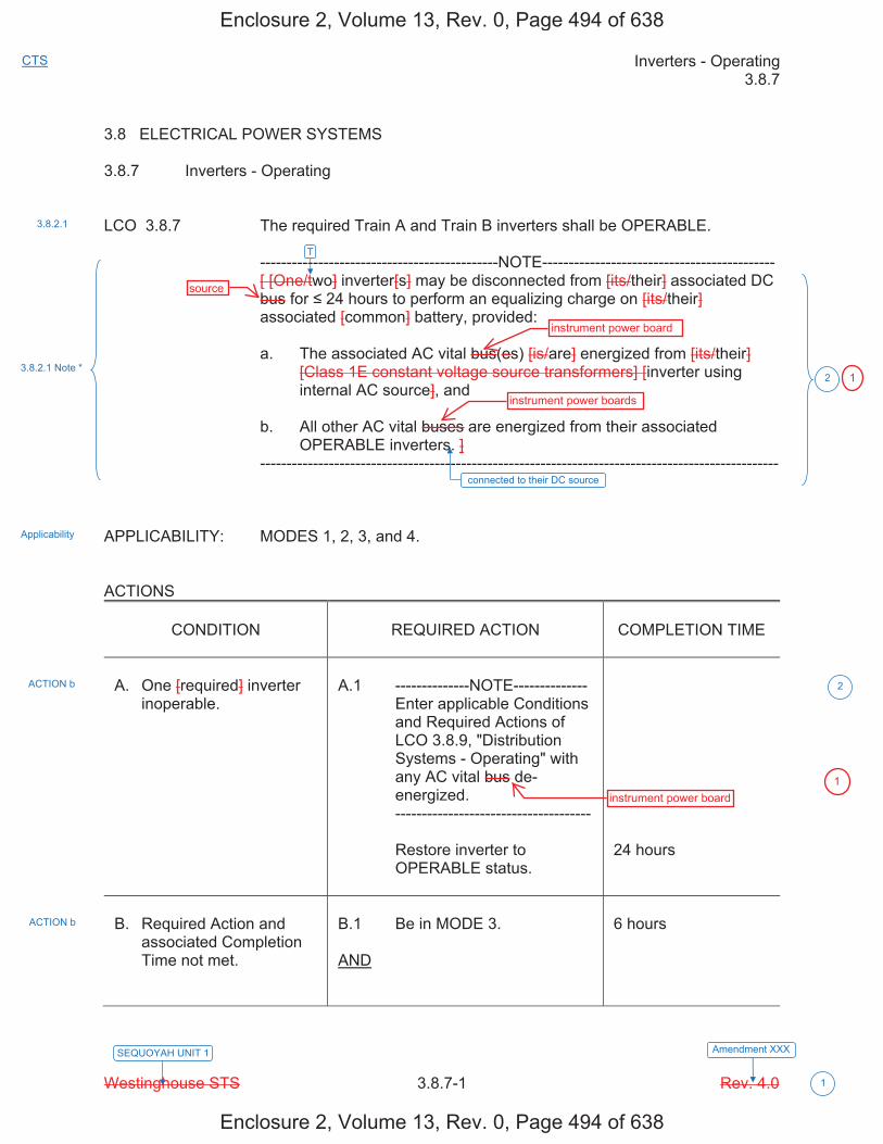
Inverters - Operating 3.8.7
Westinghouse STS 3.8.7-1 Rev. 4.0
CTS
Amendment XXX
1
SEQUOYAH UNIT 1
3.8 ELECTRICAL POWER SYSTEMS 3.8.7 Inverters - Operating LCO 3.8.7 The required Train A and Train B inverters shall be OPERABLE. ---------------------------------------------NOTE-------------------------------------------- [ [One/two] inverter[s] may be disconnected from [its/their] associated DC
bus for 24 hours to perform an equalizing charge on [its/their] associated [common] battery, provided:
a. The associated AC vital bus(es) [is/are] energized from [its/their]
[Class 1E constant voltage source transformers] [inverter using internal AC source], and
b. All other AC vital buses are energized from their associated
OPERABLE inverters. ] -------------------------------------------------------------------------------------------------- APPLICABILITY: MODES 1, 2, 3, and 4. ACTIONS
CONDITION
REQUIRED ACTION
COMPLETION TIME
A. One [required] inverter
inoperable.
A.1 --------------NOTE-------------- Enter applicable Conditions
and Required Actions of LCO 3.8.9, "Distribution Systems - Operating" with any AC vital bus de-energized.
------------------------------------- Restore inverter to
OPERABLE status.
24 hours
B. Required Action and
associated Completion Time not met.
B.1 Be in MODE 3. AND
6 hours
3.8.2.1
Applicability
3.8.2.1 Note *
ACTION b
ACTION b
2
2
T
connected to their DC source
Enclosure 2, Volume 13, Rev. 0, Page 494 of 638
Enclosure 2, Volume 13, Rev. 0, Page 494 of 638
source
instrument power board
instrument power boards
instrument power board
1
1

Inverters - Operating 3.8.7
Westinghouse STS 3.8.7-2 Rev. 4.0
CTS
Amendment XXX
1
SEQUOYAH UNIT 1
ACTIONS (continued)
CONDITION
REQUIRED ACTION
COMPLETION TIME
B.2 Be in MODE 5.
36 hours
SURVEILLANCE REQUIREMENTS
SURVEILLANCE
FREQUENCY
SR 3.8.7.1 Verify correct inverter voltage, [frequency], and
alignment to required AC vital buses.
[ 7 days OR In accordance with the Surveillance Frequency Control Program ]
4.8.2.1 2
3
Enclosure 2, Volume 13, Rev. 0, Page 495 of 638
Enclosure 2, Volume 13, Rev. 0, Page 495 of 638
instrument power boards
1
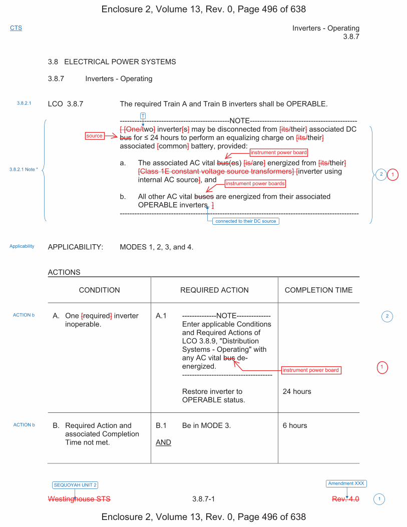
Inverters - Operating 3.8.7
Westinghouse STS 3.8.7-1 Rev. 4.0
CTS
Amendment XXX
1
SEQUOYAH UNIT 2
3.8 ELECTRICAL POWER SYSTEMS 3.8.7 Inverters - Operating LCO 3.8.7 The required Train A and Train B inverters shall be OPERABLE. ---------------------------------------------NOTE-------------------------------------------- [ [One/two] inverter[s] may be disconnected from [its/their] associated DC
bus for 24 hours to perform an equalizing charge on [its/their] associated [common] battery, provided:
a. The associated AC vital bus(es) [is/are] energized from [its/their]
[Class 1E constant voltage source transformers] [inverter using internal AC source], and
b. All other AC vital buses are energized from their associated
OPERABLE inverters. ] -------------------------------------------------------------------------------------------------- APPLICABILITY: MODES 1, 2, 3, and 4. ACTIONS
CONDITION
REQUIRED ACTION
COMPLETION TIME
A. One [required] inverter
inoperable.
A.1 --------------NOTE-------------- Enter applicable Conditions
and Required Actions of LCO 3.8.9, "Distribution Systems - Operating" with any AC vital bus de-energized.
------------------------------------- Restore inverter to
OPERABLE status.
24 hours
B. Required Action and
associated Completion Time not met.
B.1 Be in MODE 3. AND
6 hours
3.8.2.1
Applicability
3.8.2.1 Note *
ACTION b
ACTION b
2
2
T
connected to their DC source
Enclosure 2, Volume 13, Rev. 0, Page 496 of 638
Enclosure 2, Volume 13, Rev. 0, Page 496 of 638
source
instrument power board
instrument power boards
instrument power board
1
1
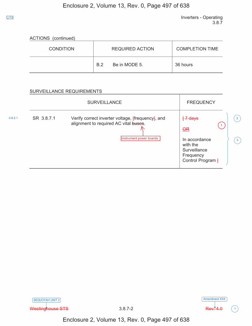
Inverters - Operating 3.8.7
Westinghouse STS 3.8.7-2 Rev. 4.0
CTS
Amendment XXX
1
SEQUOYAH UNIT 2
ACTIONS (continued)
CONDITION
REQUIRED ACTION
COMPLETION TIME
B.2 Be in MODE 5.
36 hours
SURVEILLANCE REQUIREMENTS
SURVEILLANCE
FREQUENCY
SR 3.8.7.1 Verify correct inverter voltage, [frequency], and
alignment to required AC vital buses.
[ 7 days OR In accordance with the Surveillance Frequency Control Program ]
4.8.2.1 2
3
Enclosure 2, Volume 13, Rev. 0, Page 497 of 638
Enclosure 2, Volume 13, Rev. 0, Page 497 of 638
instrument power boards
1
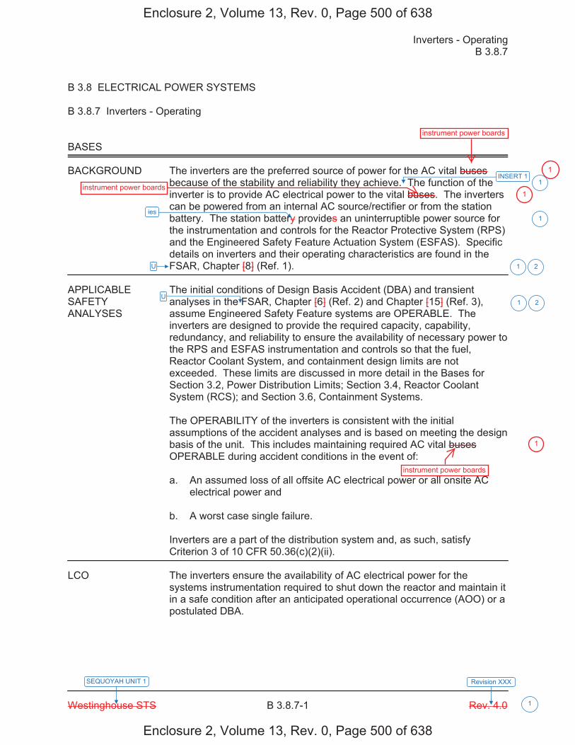
Inverters - Operating B 3.8.7
Westinghouse STS B 3.8.7-1 Rev. 4.0
SEQUOYAH UNIT 1 Revision XXX
1
B 3.8 ELECTRICAL POWER SYSTEMS B 3.8.7 Inverters - Operating BASES BACKGROUND The inverters are the preferred source of power for the AC vital buses
because of the stability and reliability they achieve. The function of the inverter is to provide AC electrical power to the vital buses. The inverters can be powered from an internal AC source/rectifier or from the station battery. The station battery provides an uninterruptible power source for the instrumentation and controls for the Reactor Protective System (RPS) and the Engineered Safety Feature Actuation System (ESFAS). Specific details on inverters and their operating characteristics are found in the FSAR, Chapter [8] (Ref. 1).
APPLICABLE The initial conditions of Design Basis Accident (DBA) and transient SAFETY analyses in the FSAR, Chapter [6] (Ref. 2) and Chapter [15] (Ref. 3), ANALYSES assume Engineered Safety Feature systems are OPERABLE. The
inverters are designed to provide the required capacity, capability, redundancy, and reliability to ensure the availability of necessary power to the RPS and ESFAS instrumentation and controls so that the fuel, Reactor Coolant System, and containment design limits are not exceeded. These limits are discussed in more detail in the Bases for Section 3.2, Power Distribution Limits; Section 3.4, Reactor Coolant System (RCS); and Section 3.6, Containment Systems. The OPERABILITY of the inverters is consistent with the initial assumptions of the accident analyses and is based on meeting the design basis of the unit. This includes maintaining required AC vital buses OPERABLE during accident conditions in the event of: a. An assumed loss of all offsite AC electrical power or all onsite AC
electrical power and b. A worst case single failure. Inverters are a part of the distribution system and, as such, satisfy Criterion 3 of 10 CFR 50.36(c)(2)(ii).
LCO The inverters ensure the availability of AC electrical power for the
systems instrumentation required to shut down the reactor and maintain it in a safe condition after an anticipated operational occurrence (AOO) or a postulated DBA.
INSERT 1
U
U 21
21
1
ies 1
Enclosure 2, Volume 13, Rev. 0, Page 500 of 638
Enclosure 2, Volume 13, Rev. 0, Page 500 of 638
instrument power boards
instrument power boards
instrument power boards
1
1
1
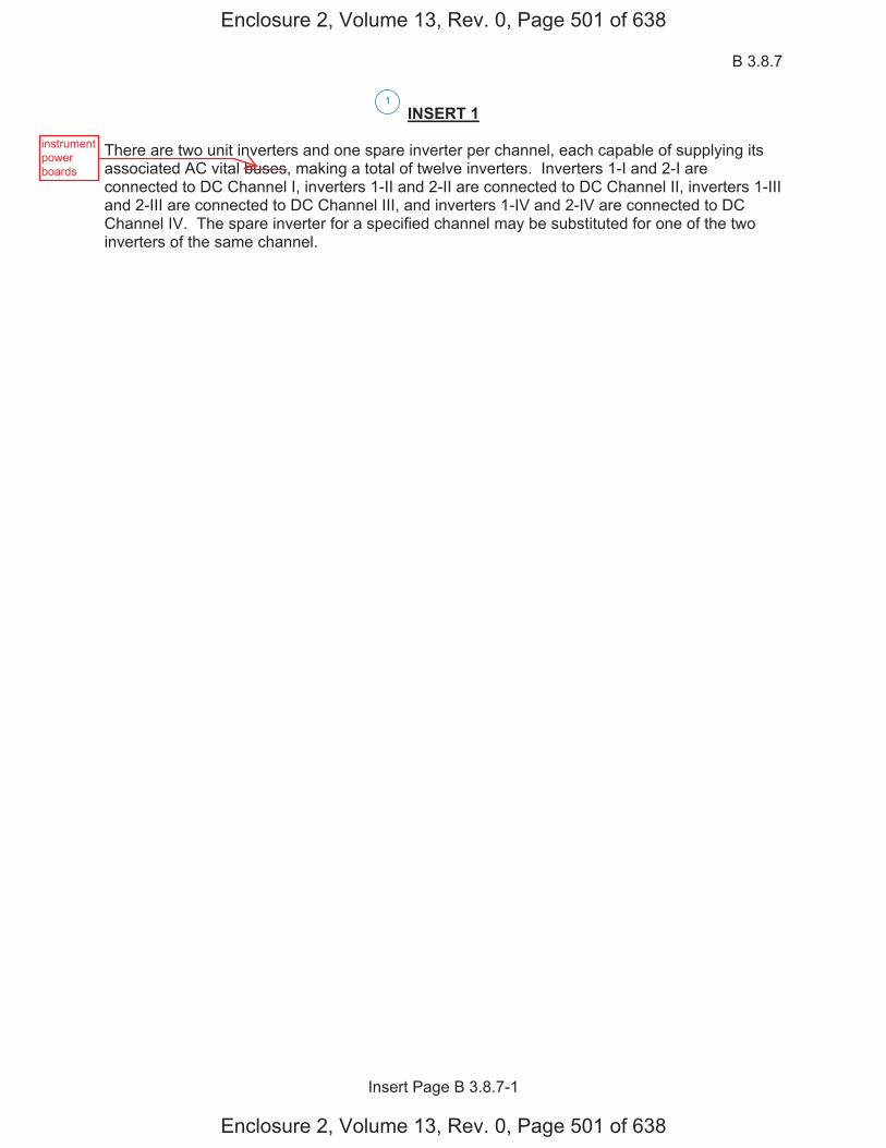
B 3.8.7
Insert Page B 3.8.7-1
INSERT 1 There are two unit inverters and one spare inverter per channel, each capable of supplying its associated AC vital buses, making a total of twelve inverters. Inverters 1-I and 2-I are connected to DC Channel I, inverters 1-II and 2-II are connected to DC Channel II, inverters 1-III and 2-III are connected to DC Channel III, and inverters 1-IV and 2-IV are connected to DC Channel IV. The spare inverter for a specified channel may be substituted for one of the two inverters of the same channel.
1
Enclosure 2, Volume 13, Rev. 0, Page 501 of 638
Enclosure 2, Volume 13, Rev. 0, Page 501 of 638
instrumentpowerboards
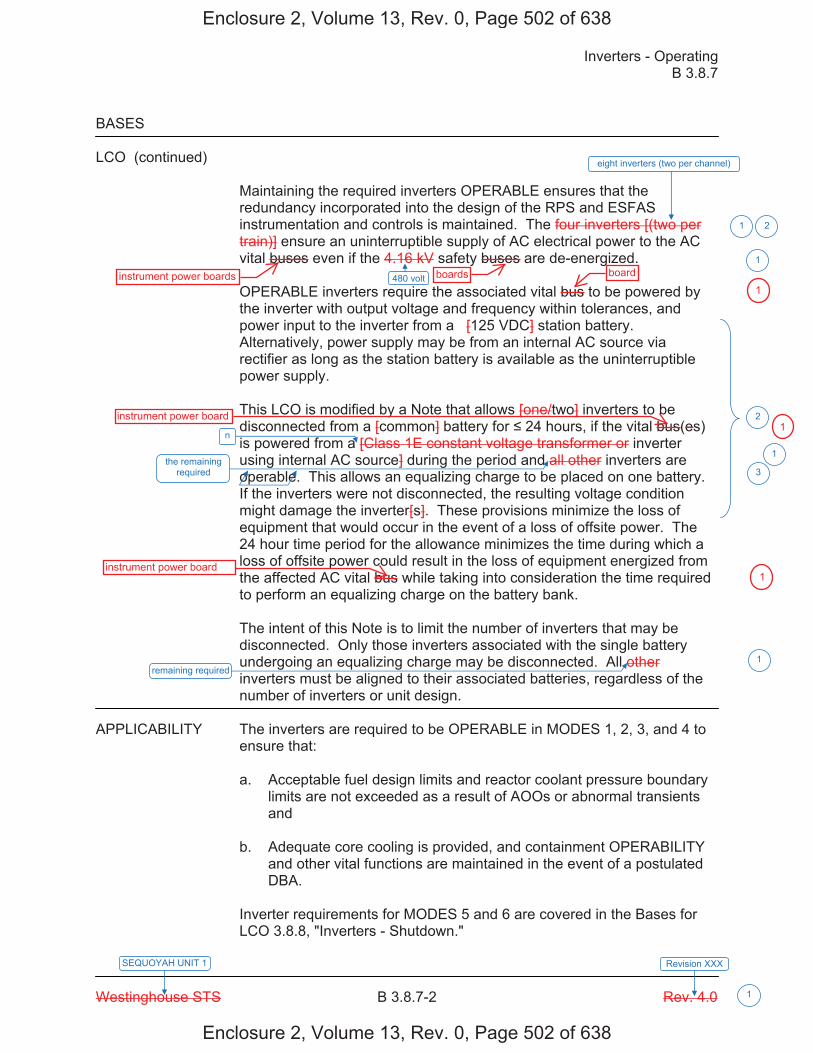
Inverters - Operating B 3.8.7
Westinghouse STS B 3.8.7-2 Rev. 4.0
SEQUOYAH UNIT 1 Revision XXX
1
BASES LCO (continued)
Maintaining the required inverters OPERABLE ensures that the redundancy incorporated into the design of the RPS and ESFAS instrumentation and controls is maintained. The four inverters [(two per train)] ensure an uninterruptible supply of AC electrical power to the AC vital buses even if the 4.16 kV safety buses are de-energized. OPERABLE inverters require the associated vital bus to be powered by the inverter with output voltage and frequency within tolerances, and power input to the inverter from a [125 VDC] station battery. Alternatively, power supply may be from an internal AC source via rectifier as long as the station battery is available as the uninterruptible power supply. This LCO is modified by a Note that allows [one/two] inverters to be disconnected from a [common] battery for 24 hours, if the vital bus(es) is powered from a [Class 1E constant voltage transformer or inverter using internal AC source] during the period and all other inverters are operable. This allows an equalizing charge to be placed on one battery. If the inverters were not disconnected, the resulting voltage condition might damage the inverter[s]. These provisions minimize the loss of equipment that would occur in the event of a loss of offsite power. The 24 hour time period for the allowance minimizes the time during which a loss of offsite power could result in the loss of equipment energized from the affected AC vital bus while taking into consideration the time required to perform an equalizing charge on the battery bank. The intent of this Note is to limit the number of inverters that may be disconnected. Only those inverters associated with the single battery undergoing an equalizing charge may be disconnected. All other inverters must be aligned to their associated batteries, regardless of the number of inverters or unit design.
APPLICABILITY The inverters are required to be OPERABLE in MODES 1, 2, 3, and 4 to
ensure that: a. Acceptable fuel design limits and reactor coolant pressure boundary
limits are not exceeded as a result of AOOs or abnormal transients and
b. Adequate core cooling is provided, and containment OPERABILITY
and other vital functions are maintained in the event of a postulated DBA.
Inverter requirements for MODES 5 and 6 are covered in the Bases for LCO 3.8.8, "Inverters - Shutdown."
eight inverters (two per channel)
480 volt
21
1
2
n
the remaining required
remaining required
1
1
3
Enclosure 2, Volume 13, Rev. 0, Page 502 of 638
Enclosure 2, Volume 13, Rev. 0, Page 502 of 638
instrument power boards boards board
instrument power board
instrument power board
1
1
1

Inverters - Operating B 3.8.7
Westinghouse STS B 3.8.7-3 Rev. 4.0
SEQUOYAH UNIT 1 Revision XXX
1
BASES ACTIONS A.1
With a required inverter inoperable, its associated AC vital bus becomes inoperable until it is [manually] re-energized from its [Class 1E constant voltage source transformer or inverter using internal AC source]. For this reason a Note has been included in Condition A requiring the entry into the Conditions and Required Actions of LCO 3.8.9, "Distribution Systems - Operating." This ensures that the vital bus is re-energized within 2 hours. Required Action A.1 allows 24 hours to fix the inoperable inverter and return it to service. The 24 hour limit is based upon engineering judgment, taking into consideration the time required to repair an inverter and the additional risk to which the unit is exposed because of the inverter inoperability. This has to be balanced against the risk of an immediate shutdown, along with the potential challenges to safety systems such a shutdown might entail. When the AC vital bus is powered from its constant voltage source, it is relying upon interruptible AC electrical power sources (offsite and onsite). The uninterruptible inverter source to the AC vital buses is the preferred source for powering instrumentation trip setpoint devices. B.1 and B.2 If the inoperable devices or components cannot be restored to OPERABLE status within the required Completion Time, the unit must be brought to a MODE in which the LCO does not apply. To achieve this status, the unit must be brought to at least MODE 3 within 6 hours and to MODE 5 within 36 hours. The allowed Completion Times are reasonable, based on operating experience, to reach the required unit conditions from full power conditions in an orderly manner and without challenging plant systems.
SURVEILLANCE SR 3.8.7.1 REQUIREMENTS
This Surveillance verifies that the inverters are functioning properly with all required circuit breakers closed and AC vital buses energized from the inverter. The verification of proper voltage and frequency output ensures that the required power is readily available for the instrumentation of the RPS and ESFAS connected to the AC vital buses. [ The 7 day Frequency takes into account the redundant capability of the inverters and other indications available in the control room that alert the operator to inverter malfunctions.
8
2
4
1
Enclosure 2, Volume 13, Rev. 0, Page 503 of 638
Enclosure 2, Volume 13, Rev. 0, Page 503 of 638
board
instrument power board
instrument power board
instrument power board
instrument power boards
instrument power boards
1
1
1
1
1
1
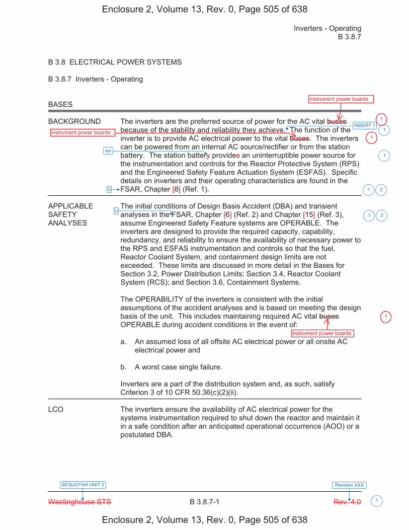
Inverters - Operating B 3.8.7
Westinghouse STS B 3.8.7-1 Rev. 4.0
SEQUOYAH UNIT 2 Revision XXX
1
B 3.8 ELECTRICAL POWER SYSTEMS B 3.8.7 Inverters - Operating BASES BACKGROUND The inverters are the preferred source of power for the AC vital buses
because of the stability and reliability they achieve. The function of the inverter is to provide AC electrical power to the vital buses. The inverters can be powered from an internal AC source/rectifier or from the station battery. The station battery provides an uninterruptible power source for the instrumentation and controls for the Reactor Protective System (RPS) and the Engineered Safety Feature Actuation System (ESFAS). Specific details on inverters and their operating characteristics are found in the FSAR, Chapter [8] (Ref. 1).
APPLICABLE The initial conditions of Design Basis Accident (DBA) and transient SAFETY analyses in the FSAR, Chapter [6] (Ref. 2) and Chapter [15] (Ref. 3), ANALYSES assume Engineered Safety Feature systems are OPERABLE. The
inverters are designed to provide the required capacity, capability, redundancy, and reliability to ensure the availability of necessary power to the RPS and ESFAS instrumentation and controls so that the fuel, Reactor Coolant System, and containment design limits are not exceeded. These limits are discussed in more detail in the Bases for Section 3.2, Power Distribution Limits; Section 3.4, Reactor Coolant System (RCS); and Section 3.6, Containment Systems. The OPERABILITY of the inverters is consistent with the initial assumptions of the accident analyses and is based on meeting the design basis of the unit. This includes maintaining required AC vital buses OPERABLE during accident conditions in the event of: a. An assumed loss of all offsite AC electrical power or all onsite AC
electrical power and b. A worst case single failure. Inverters are a part of the distribution system and, as such, satisfy Criterion 3 of 10 CFR 50.36(c)(2)(ii).
LCO The inverters ensure the availability of AC electrical power for the
systems instrumentation required to shut down the reactor and maintain it in a safe condition after an anticipated operational occurrence (AOO) or a postulated DBA.
INSERT 1
U
U 21
21
1
ies 1
Enclosure 2, Volume 13, Rev. 0, Page 505 of 638
Enclosure 2, Volume 13, Rev. 0, Page 505 of 638
instrument power boards
instrument power boards
instrument power boards
1
1
1
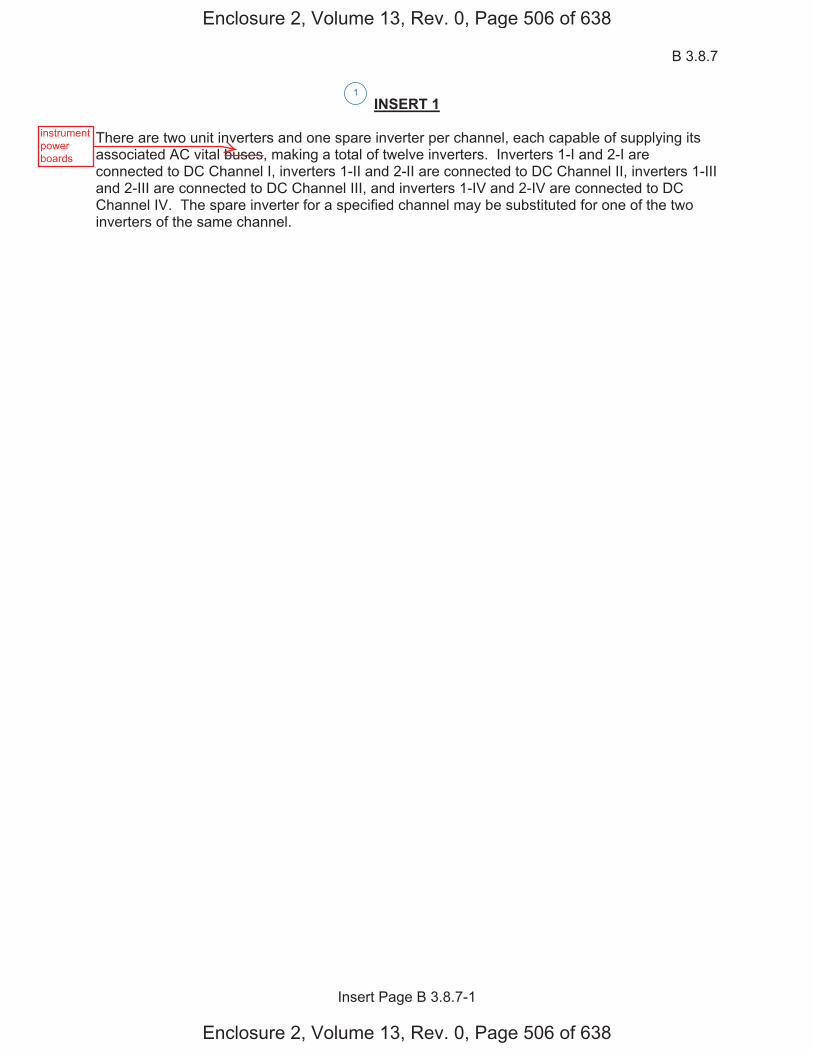
B 3.8.7
Insert Page B 3.8.7-1
INSERT 1 There are two unit inverters and one spare inverter per channel, each capable of supplying its associated AC vital buses, making a total of twelve inverters. Inverters 1-I and 2-I are connected to DC Channel I, inverters 1-II and 2-II are connected to DC Channel II, inverters 1-III and 2-III are connected to DC Channel III, and inverters 1-IV and 2-IV are connected to DC Channel IV. The spare inverter for a specified channel may be substituted for one of the two inverters of the same channel.
1
Enclosure 2, Volume 13, Rev. 0, Page 506 of 638
Enclosure 2, Volume 13, Rev. 0, Page 506 of 638
instrumentpowerboards
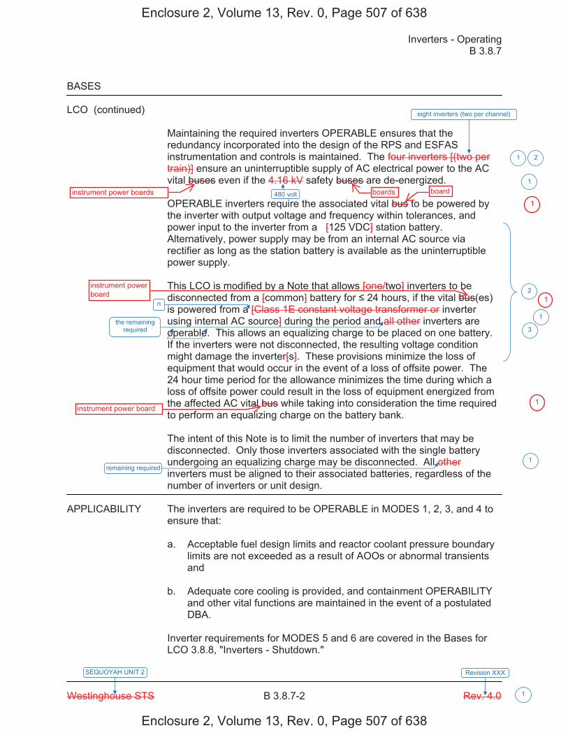
Inverters - Operating B 3.8.7
Westinghouse STS B 3.8.7-2 Rev. 4.0
SEQUOYAH UNIT 2 Revision XXX
1
BASES LCO (continued)
Maintaining the required inverters OPERABLE ensures that the redundancy incorporated into the design of the RPS and ESFAS instrumentation and controls is maintained. The four inverters [(two per train)] ensure an uninterruptible supply of AC electrical power to the AC vital buses even if the 4.16 kV safety buses are de-energized. OPERABLE inverters require the associated vital bus to be powered by the inverter with output voltage and frequency within tolerances, and power input to the inverter from a [125 VDC] station battery. Alternatively, power supply may be from an internal AC source via rectifier as long as the station battery is available as the uninterruptible power supply. This LCO is modified by a Note that allows [one/two] inverters to be disconnected from a [common] battery for 24 hours, if the vital bus(es) is powered from a [Class 1E constant voltage transformer or inverter using internal AC source] during the period and all other inverters are operable. This allows an equalizing charge to be placed on one battery. If the inverters were not disconnected, the resulting voltage condition might damage the inverter[s]. These provisions minimize the loss of equipment that would occur in the event of a loss of offsite power. The 24 hour time period for the allowance minimizes the time during which a loss of offsite power could result in the loss of equipment energized from the affected AC vital bus while taking into consideration the time required to perform an equalizing charge on the battery bank. The intent of this Note is to limit the number of inverters that may be disconnected. Only those inverters associated with the single battery undergoing an equalizing charge may be disconnected. All other inverters must be aligned to their associated batteries, regardless of the number of inverters or unit design.
APPLICABILITY The inverters are required to be OPERABLE in MODES 1, 2, 3, and 4 to
ensure that: a. Acceptable fuel design limits and reactor coolant pressure boundary
limits are not exceeded as a result of AOOs or abnormal transients and
b. Adequate core cooling is provided, and containment OPERABILITY
and other vital functions are maintained in the event of a postulated DBA.
Inverter requirements for MODES 5 and 6 are covered in the Bases for LCO 3.8.8, "Inverters - Shutdown."
eight inverters (two per channel)
480 volt
21
1
2
n
the remaining required
remaining required
1
1
3
Enclosure 2, Volume 13, Rev. 0, Page 507 of 638
Enclosure 2, Volume 13, Rev. 0, Page 507 of 638
boardsinstrument power boards board
instrument powerboard
instrument power board
1
1
1
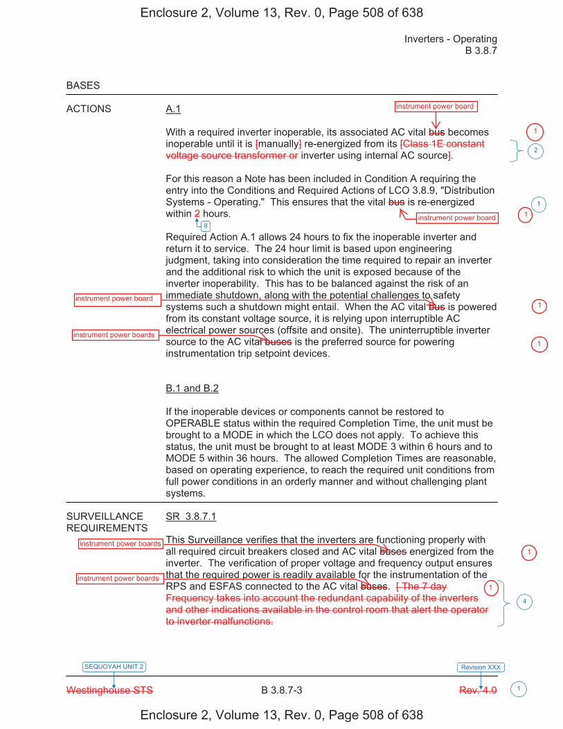
Inverters - Operating B 3.8.7
Westinghouse STS B 3.8.7-3 Rev. 4.0
SEQUOYAH UNIT 2 Revision XXX
1
BASES ACTIONS A.1
With a required inverter inoperable, its associated AC vital bus becomes inoperable until it is [manually] re-energized from its [Class 1E constant voltage source transformer or inverter using internal AC source]. For this reason a Note has been included in Condition A requiring the entry into the Conditions and Required Actions of LCO 3.8.9, "Distribution Systems - Operating." This ensures that the vital bus is re-energized within 2 hours. Required Action A.1 allows 24 hours to fix the inoperable inverter and return it to service. The 24 hour limit is based upon engineering judgment, taking into consideration the time required to repair an inverter and the additional risk to which the unit is exposed because of the inverter inoperability. This has to be balanced against the risk of an immediate shutdown, along with the potential challenges to safety systems such a shutdown might entail. When the AC vital bus is powered from its constant voltage source, it is relying upon interruptible AC electrical power sources (offsite and onsite). The uninterruptible inverter source to the AC vital buses is the preferred source for powering instrumentation trip setpoint devices. B.1 and B.2 If the inoperable devices or components cannot be restored to OPERABLE status within the required Completion Time, the unit must be brought to a MODE in which the LCO does not apply. To achieve this status, the unit must be brought to at least MODE 3 within 6 hours and to MODE 5 within 36 hours. The allowed Completion Times are reasonable, based on operating experience, to reach the required unit conditions from full power conditions in an orderly manner and without challenging plant systems.
SURVEILLANCE SR 3.8.7.1 REQUIREMENTS
This Surveillance verifies that the inverters are functioning properly with all required circuit breakers closed and AC vital buses energized from the inverter. The verification of proper voltage and frequency output ensures that the required power is readily available for the instrumentation of the RPS and ESFAS connected to the AC vital buses. [ The 7 day Frequency takes into account the redundant capability of the inverters and other indications available in the control room that alert the operator to inverter malfunctions.
8
2
4
1
Enclosure 2, Volume 13, Rev. 0, Page 508 of 638
Enclosure 2, Volume 13, Rev. 0, Page 508 of 638
instrument power board
instrument power board
instrument power board
instrument power boards
instrument power boards
instrument power boards
1
1
1
1
1
1
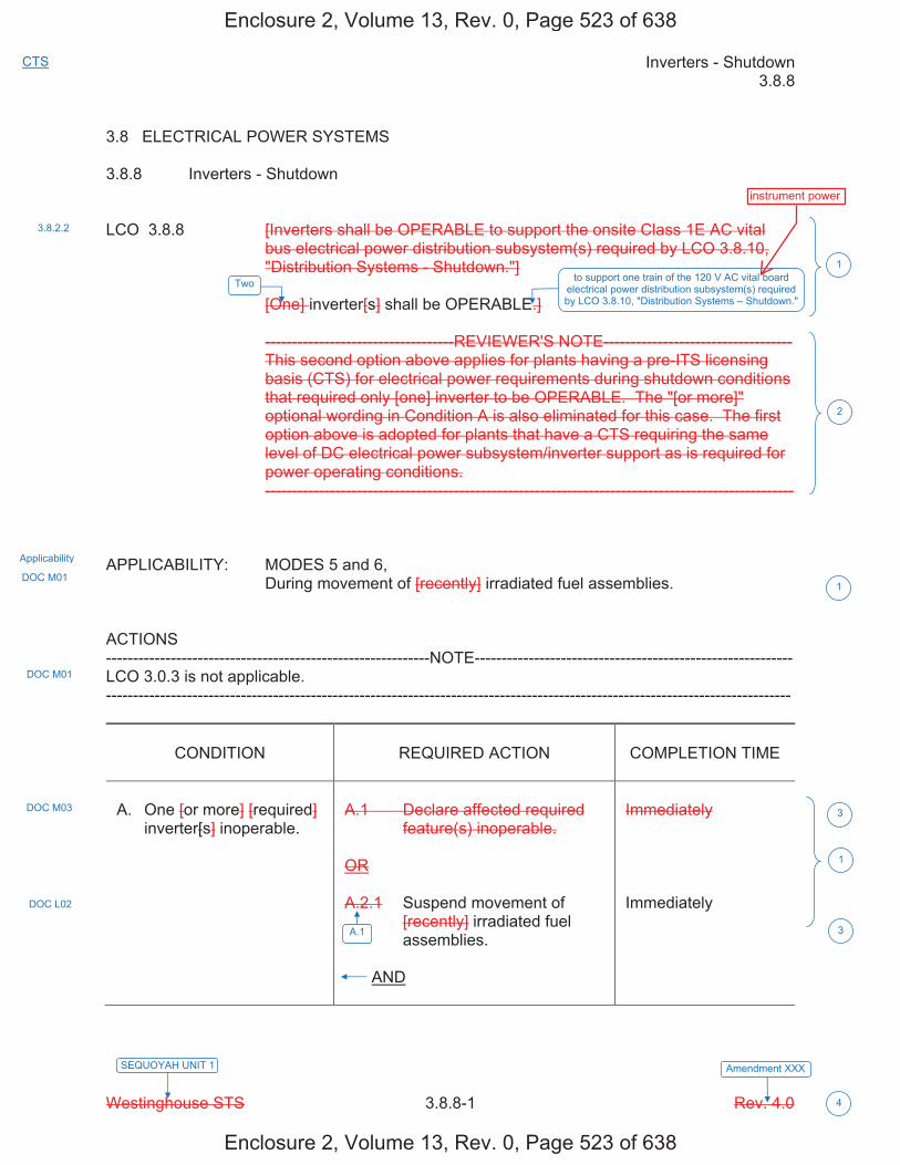
Inverters - Shutdown 3.8.8
Westinghouse STS 3.8.8-1 Rev. 4.0
CTS
SEQUOYAH UNIT 1 Amendment XXX
4
3.8 ELECTRICAL POWER SYSTEMS 3.8.8 Inverters - Shutdown LCO 3.8.8 [Inverters shall be OPERABLE to support the onsite Class 1E AC vital
bus electrical power distribution subsystem(s) required by LCO 3.8.10, "Distribution Systems - Shutdown."]
[One] inverter[s] shall be OPERABLE.] -----------------------------------REVIEWER'S NOTE----------------------------------- This second option above applies for plants having a pre-ITS licensing
basis (CTS) for electrical power requirements during shutdown conditions that required only [one] inverter to be OPERABLE. The "[or more]" optional wording in Condition A is also eliminated for this case. The first option above is adopted for plants that have a CTS requiring the same level of DC electrical power subsystem/inverter support as is required for power operating conditions.
-------------------------------------------------------------------------------------------------- APPLICABILITY: MODES 5 and 6, During movement of [recently] irradiated fuel assemblies. ACTIONS ------------------------------------------------------------NOTE----------------------------------------------------------- LCO 3.0.3 is not applicable. -------------------------------------------------------------------------------------------------------------------------------
CONDITION
REQUIRED ACTION
COMPLETION TIME
A. One [or more] [required]
inverter[s] inoperable.
A.1 Declare affected required
feature(s) inoperable. OR A.2.1 Suspend movement of
[recently] irradiated fuel assemblies.
AND
Immediately Immediately
3.8.2.2
1
2
1
1
Applicability
DOC M01
DOC M01
DOC L02
DOC M03
A.1
3
3
Two to support one train of the 120 V AC vital board electrical power distribution subsystem(s) required by LCO 3.8.10, "Distribution Systems – Shutdown."
Enclosure 2, Volume 13, Rev. 0, Page 523 of 638
Enclosure 2, Volume 13, Rev. 0, Page 523 of 638
instrument power
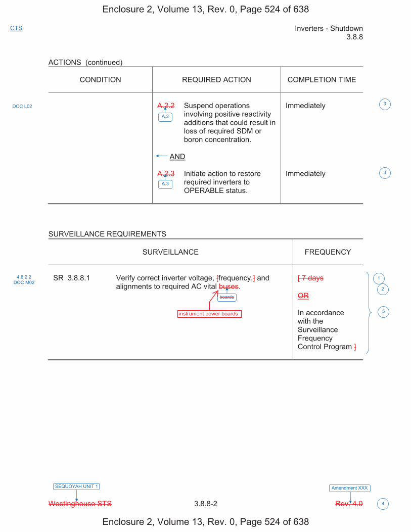
Inverters - Shutdown 3.8.8
Westinghouse STS 3.8.8-2 Rev. 4.0
CTS
SEQUOYAH UNIT 1 Amendment XXX
4
ACTIONS (continued)
CONDITION
REQUIRED ACTION
COMPLETION TIME
A.2.2 Suspend operations
involving positive reactivity additions that could result in loss of required SDM or boron concentration.
AND A.2.3 Initiate action to restore
required inverters to OPERABLE status.
Immediately Immediately
SURVEILLANCE REQUIREMENTS
SURVEILLANCE
FREQUENCY
SR 3.8.8.1 Verify correct inverter voltage, [frequency,] and
alignments to required AC vital buses.
[ 7 days OR In accordance with the Surveillance Frequency Control Program ]
4.8.2.2 DOC M02
1
5
DOC L02
A.2
A.3
3
3
boards
2
Enclosure 2, Volume 13, Rev. 0, Page 524 of 638
Enclosure 2, Volume 13, Rev. 0, Page 524 of 638
instrument power boards

Inverters - Shutdown 3.8.8
Westinghouse STS 3.8.8-1 Rev. 4.0
CTS
SEQUOYAH UNIT 2 Amendment XXX
4
3.8 ELECTRICAL POWER SYSTEMS 3.8.8 Inverters - Shutdown LCO 3.8.8 [Inverters shall be OPERABLE to support the onsite Class 1E AC vital
bus electrical power distribution subsystem(s) required by LCO 3.8.10, "Distribution Systems - Shutdown."]
[One] inverter[s] shall be OPERABLE.] -----------------------------------REVIEWER'S NOTE----------------------------------- This second option above applies for plants having a pre-ITS licensing
basis (CTS) for electrical power requirements during shutdown conditions that required only [one] inverter to be OPERABLE. The "[or more]" optional wording in Condition A is also eliminated for this case. The first option above is adopted for plants that have a CTS requiring the same level of DC electrical power subsystem/inverter support as is required for power operating conditions.
-------------------------------------------------------------------------------------------------- APPLICABILITY: MODES 5 and 6, During movement of [recently] irradiated fuel assemblies. ACTIONS ------------------------------------------------------------NOTE----------------------------------------------------------- LCO 3.0.3 is not applicable. -------------------------------------------------------------------------------------------------------------------------------
CONDITION
REQUIRED ACTION
COMPLETION TIME
A. One [or more] [required]
inverter[s] inoperable.
A.1 Declare affected required
feature(s) inoperable. OR A.2.1 Suspend movement of
[recently] irradiated fuel assemblies.
AND
Immediately Immediately
3.8.2.2
1
2
1
1
Applicability
DOC M01
DOC M01
DOC L02
DOC M03
A.1
3
3
Two to support one train of the 120 V AC vital board electrical power distribution subsystem(s) required by LCO 3.8.10, "Distribution Systems – Shutdown."
Enclosure 2, Volume 13, Rev. 0, Page 525 of 638
Enclosure 2, Volume 13, Rev. 0, Page 525 of 638
instrument power
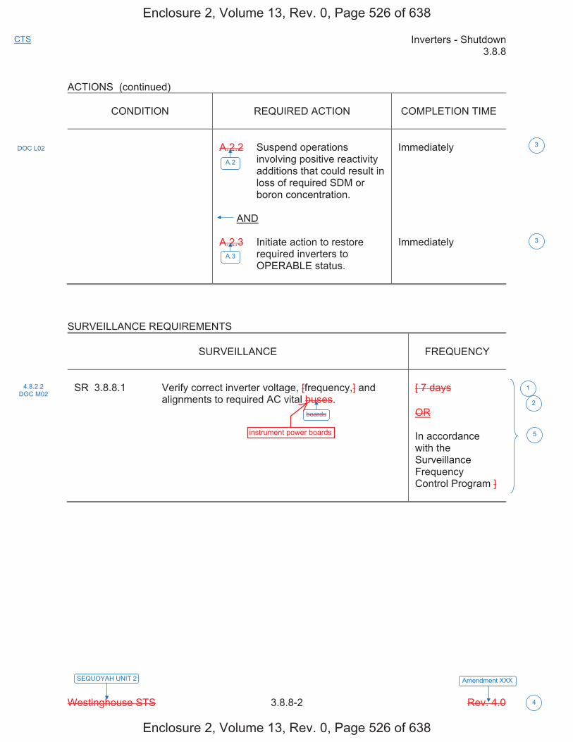
Inverters - Shutdown 3.8.8
Westinghouse STS 3.8.8-2 Rev. 4.0
CTS
SEQUOYAH UNIT 2 Amendment XXX
4
ACTIONS (continued)
CONDITION
REQUIRED ACTION
COMPLETION TIME
A.2.2 Suspend operations
involving positive reactivity additions that could result in loss of required SDM or boron concentration.
AND A.2.3 Initiate action to restore
required inverters to OPERABLE status.
Immediately Immediately
SURVEILLANCE REQUIREMENTS
SURVEILLANCE
FREQUENCY
SR 3.8.8.1 Verify correct inverter voltage, [frequency,] and
alignments to required AC vital buses.
[ 7 days OR In accordance with the Surveillance Frequency Control Program ]
4.8.2.2 DOC M02
1
5
DOC L02
A.2
A.3
3
3
boards
2
Enclosure 2, Volume 13, Rev. 0, Page 526 of 638
Enclosure 2, Volume 13, Rev. 0, Page 526 of 638
instrument power boards

Licensee Response/NRC Response/NRC Question ClosureId 387
NRC Question Number VKG024
Select Application NRC Question Closure
Attachment 1
Attachment 2
Response Statement
Response Date/Time
Closure Statement This question is closed and no further information is required at this time to draft the Safety Evaluation.
Question Closure Date 12/1/2014
Notification Scott BowmanMichelle ConnerVijay GoelKhadijah HemphillAndrew HonLynn MynattRay SchieleRoger Scott
Added By Khadijah Hemphill
Date Added 12/1/2014 8:20 AM
Date Modified
Modified By
Page 1 of 1Sequoyah ITS Conversion Database
1/13/2015https://members.excelservices.com/rai/index.php?requestType=areaItemPrint&itemId=387
ITS NRC QuestionsId 185
NRC Question Number VKG025
Category Technical
ITS Section 3.8
ITS Number 3.8.9
DOC Number
JFD Number
JFD Bases Number
Page Number(s)
NRC Reviewer Supervisor Jake Zimmerman
Technical Branch POC Add Name
Conf Call Requested N
NRC Question ITS 3.8.9, Condition A states: “One or more Unit 1 AC electrical power distribution subsystems inoperable.” ITS 3.8.9, Condition B states: “One or more AC vital subsystems inoperable.”
The ITS Bases Table B 3.8.9-1 provides a list of the AC electrical power distribution boards and AC vital boards of Train A and Train B, for Units 1 and 2.
The footnote of Table B 3.8.9-1 (*Each train of the AC and DC electrical power distribution systems is a subsystem) is not clear. The intent of Condition A and Condition B is that distribution subsystems or boards of only one train is inoperable.
Please revise as necessary the following: 1. Revise the footnote of Table B 3.8.9-1 to redefine/clarify distribution
subsystems.2. Revise Bases and ITS, as necessary, based on redefinition of
distribution subsystems3. Ensure Bases Table 3.8.9-1 reflects appropriate subsystems
Attach File 1
Attach File 2
Issue Date 8/13/2014
Added By Khadijah Hemphill
Date Modified
Modified By
Page 1 of 2Sequoyah ITS Conversion Database
05/15/2015https://members.excelservices.com/rai/index.php?requestType=areaItemPrint&itemId=185
Date Added 8/13/2014 9:37 AM
Notification Scott BowmanMichelle ConnerVijay GoelKhadijah HemphillAndrew HonLynn MynattRay SchieleRoger Scott
Page 2 of 2Sequoyah ITS Conversion Database
05/15/2015https://members.excelservices.com/rai/index.php?requestType=areaItemPrint&itemId=185
Licensee Response/NRC Response/NRC Question ClosureId 383
NRC Question Number
VKG025
Select Application Licensee Response
Attachment 1 RAI VKG025 Attachment 1 R1.pdf (4MB)
Attachment 2
Response Statement In response to VKG025, the ITS 3.8.9 Specifications and
Bases, on pages 561-566 and 569-590 of Enclosure 2, Volume 13, will be revised. Specifically, ITS 3.8.9 LCO will be revised to state, “Two electrical power distribution trains shall be OPERABLE.” ITS 3.8.9 Condition A will be revised to state, “One or more AC electrical power distribution subsystems inoperable due to one or more Unit 1 [Unit 2 for the Unit 2 technical specifications] AC shutdown boards inoperable.” ITS 3.8.9 Condition C will be revised to state, “One or more vital DC electrical power distribution subsystems inoperable.” ITS 3.8.9 Condition D will be revised to state, “One or more AC electrical power distribution subsystems inoperable due to one or more Unit 2 [Unit 1 for the Unit 2 technical specifications] AC shutdown boards inoperable.” ITS 3.8.9 Condition E will be revised to state, “One or more DG DC electrical power distribution panels inoperable.” ITS 3.8.9 Condition F will be revised to state, “Required Action and associated Completion Time not met.” As a result of the revision to ISTS LCO 3.8.9, a new Justification for Deviation (JFD) 5 will be added to the ITS 3.8.9 Justification for Deviations Section, on page 567. Additionally, JFD 5 indicators will be added to the ISTS markups.Additional changes to the ITS 3.8.9 Specification are associated with changes in nomenclature (i.e., changing AC vital subsystems to AC vital instrument power distribution subsystems). JFD indicators will be added, as needed, to the right hand margin of the ISTS markups to align with the Justification for Deviations
Page 1 of 5Sequoyah ITS Conversion Database
05/15/2015https://members.excelservices.com/rai/index.php?requestType=areaItemPrint&itemId=383
associated with each change.
The ITS 3.8.9 Bases Background Section will be revised to clarify what constitutes an electrical power distribution subsystem and explain the relationship between electrical power distribution subsystems and trains. An insert (Insert 6) will be added to explain the relationship and actions required if a board or motor control center (MCC) not reflected on ITS Table B 3.8.9-1 is out of service. A redundant paragraph following the description of the AC electrical power distribution subsystem will be deleted. As a result of the deletion, a new JFD 8 will be added to the ITS 3.8.9 Bases Justification for Deviations Section, on page 591 of Enclosure 2, Volume 13. JFD 8 indicators will be added, as well. The ITS 3.8.9 Bases LCO and Actions Section will be revised to align with changes made to ITS 3.8.9 Specifications. An insert (Insert 7) will be added to the LCO Section to clarify the electrical power distribution subsystems required to meet the LCO statement, Two electrical power distribution trains shall be OPERABLE.”Additionally, the ITS 3.8.9 Bases Action Section for
Action A.1 will be revised to remove the phrase “in one train” so that the first sentence reads, “With one or more Unit [Unit 2 for the Unit 2 technical specifications] required AC boards (except AC vital boards), inoperable and a loss of function has not occurred, the remaining AC electrical power distribution subsystems are capable of supporting the minimum safety functions necessary to shut down the reactor and maintain it in a safe condition, assuming no single failure.” As a result of the revision, a new JFD 9 will be added to the ITS 3.8.9 Bases Justification for Deviations Section, on page 591 of Enclosure 2, Volume 13. JFD 9 indicators will be added, as well. ITS Table B 3.8.9-1 will be revised (Revised Insert 5) to remove the footnote at the bottom of the table; reflect the appropriate electrical power distribution boards as required in CTS 3.8.1.1, CTS 3.8.2.1, and CTS 3.8.2.3; and reorder the subsystems to align with the order of their descriptions in the Bases
Page 2 of 5Sequoyah ITS Conversion Database
05/15/2015https://members.excelservices.com/rai/index.php?requestType=areaItemPrint&itemId=383
Background Section. Additional changes to the ITS 3.8.9 Bases are associated with changes in nomenclature (i.e., changing AC vital subsystems to AC vital instrument power distribution subsystems). JFD indicators will be added, as needed, to the right hand margin of the ISTS Bases markups to align with the Justification for Deviations associated with each change.
The ITS 3.8.9 Discussion of Changes, on pages 553-559 of Enclosure 2, Volume 13, were reviewed and revisions will be made to align with changes made to the Specification.
The ITS 3.8.10 Specifications and Bases, on pages 618-623 and 626-635 of Enclosure 2, Volume 13, will be revised to align with changes made to ITS 3.8.9 Specifications and Bases. Specifically, ITS 3.8.10 Condition B will be revised to state, “One or more required DG DC electrical power distribution panels inoperable,” (similar to the change to ITS 3.8.9 Condition E). Additionally, the phrase “AC vital” will be revised to “AC vital instrument.”
The ITS 3.8.10 Discussion of Changes, on pages 612-616 of Enclosure 2, Volume 13, were reviewed and revisions will be made to align with changes made to the Specification.
During review for RAI VKG025, it was discovered that the previously submitted ITS 3.8.9 Condition C allows more than one 125-volt DC board to be inoperable. CTS 3.8.2.3 Action a states, in part, “With one 125-volt D.C. board inoperable or not energized, restore the inoperable board to OPERABLE and energized status within 2 hours or be in at least HOT STANDBY within the next 6 hours.” This is a less restrictive change and is not justified in a corresponding DOC. As a result, the CTS markups, on pages 547 and 552 of Enclosure 2, Volume 13, will be revised to indicate that CTS 3.8.2.3 Action a is being changed in ITS 3.8.9 Condition C to
Page 3 of 5Sequoyah ITS Conversion Database
05/15/2015https://members.excelservices.com/rai/index.php?requestType=areaItemPrint&itemId=383
allow 2 hours to restore one or more inoperable 125-volt DC boards to OPERABLE status. Additionally, a new DOC L02 will be added to the ITS 3.8.9 Discussion of Changes Section, on page 559 of Enclosure 2, Volume 13, to justify the change to CTS 3.8.2.3 Action a. DOC L02 indicators will be added to the CTS markups.
Also during review, it was discovered that DOC LA04 stated that information contained in CTS 3.8.2.1 Footnote # would be relocated to the ITS 3.8.9 Bases.The Bases does not contain this information. Therefore, the paragraph describing a vital DC electrical power distribution subsystem in the ITS 3.8.9 Bases Background Section, on pages 569 and 580 of Enclosure 2, Volume 13, will be revised to include this information.
Additionally, RAI VKG025 states that, “The intent of Condition A and Condition B is that distribution subsystems or boards of only one train is inoperable.”The following information is provided concerning this statement. ISTS 3.8.9 Condition A states, “One or more AC electrical power distribution subsystems inoperable.” Condition A does not state that the inoperable subsystems are only in one train of the AC electrical power distribution subsystem. ISTS 3.8.9 Condition E states, “Two or more electrical power distribution subsystems inoperable that result in a loss of safety function.” Both Condition A and Condition E address a situation with more than one electrical power distribution subsystem inoperable. According to ITS Chapter 1.0, Use and Application, all applicable Conditions are required to be entered for an LCO. If it is discovered that the inoperability of more than one electrical power distribution subsystem results in a loss of safety function, then entry into Conditions A and E would be required. If it is discovered that the inoperability does not result in a loss of safety function, then entry into Condition A is all that is required regardless of the number of inoperable trains.
Page 4 of 5Sequoyah ITS Conversion Database
05/15/2015https://members.excelservices.com/rai/index.php?requestType=areaItemPrint&itemId=383
Therefore, ISTS Condition A provides Required Actions if one or more AC electrical power distribution subsystems are inoperable and a loss of safety function has not occurred. It is not the intent of ISTS Condition A to be applicable to only one inoperable train of AC electrical power distribution subsystems. The same logic is applicable to ISTS 3.8.9 Condition B.
See Attachment 1 for the draft revised CTS 3.8.2.3 markups, ITS 3.8.9 DOC L02, ISTS Specifications and Bases markups, ITS 3.8.9 Bases Inserts 6 and 7, and ITS 3.8.9 JFD 8. The changes to the ITS submittal have been annotated with red text for inserted letters or words and where deletions have occurred, the text has been lined through and highlighted.
Response Date/Time 11/24/2014 1:05 PM
Closure Statement
Question Closure
Date
Notification Scott BowmanMichelle ConnerVijay GoelKhadijah HemphillAndrew HonLynn MynattRay Schiele
Added By Scott Bowman
Date Added 11/24/2014 12:05 PM
Date Modified
Modified By
Page 5 of 5Sequoyah ITS Conversion Database
05/15/2015https://members.excelservices.com/rai/index.php?requestType=areaItemPrint&itemId=383
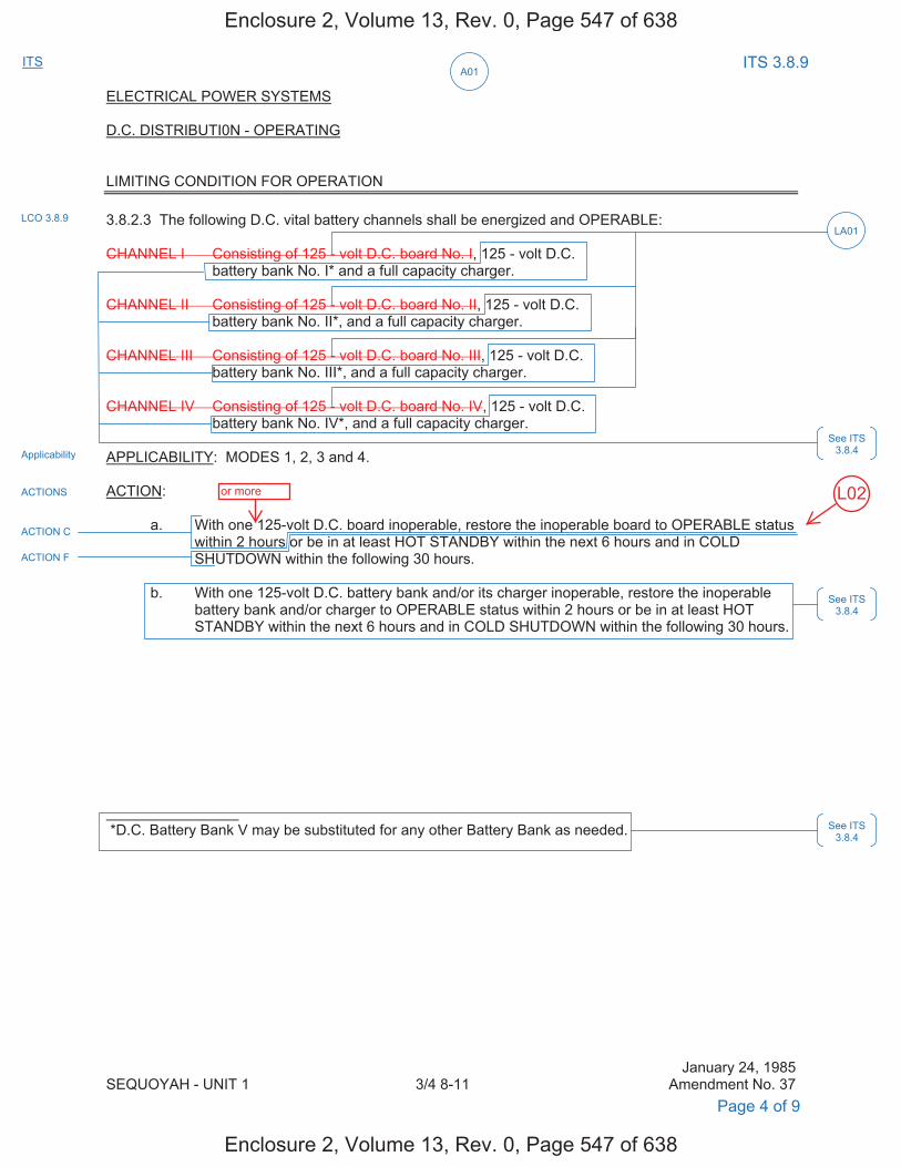
ITS A01
ITS 3.8.9
ELECTRICAL POWER SYSTEMS D.C. DISTRIBUTI0N - OPERATING LIMITING CONDITION FOR OPERATION 3.8.2.3 The following D.C. vital battery channels shall be energized and OPERABLE: CHANNEL I Consisting of 125 - volt D.C. board No. I, 125 - volt D.C. battery bank No. I* and a full capacity charger. CHANNEL II Consisting of 125 - volt D.C. board No. II, 125 - volt D.C. battery bank No. II*, and a full capacity charger. CHANNEL III Consisting of 125 - volt D.C. board No. III, 125 - volt D.C. battery bank No. III*, and a full capacity charger. CHANNEL IV Consisting of 125 - volt D.C. board No. IV, 125 - volt D.C. battery bank No. IV*, and a full capacity charger. APPLICABILITY: MODES 1, 2, 3 and 4. ACTION: a. With one 125-volt D.C. board inoperable, restore the inoperable board to OPERABLE status
within 2 hours or be in at least HOT STANDBY within the next 6 hours and in COLD SHUTDOWN within the following 30 hours.
b. With one 125-volt D.C. battery bank and/or its charger inoperable, restore the inoperable
battery bank and/or charger to OPERABLE status within 2 hours or be in at least HOT STANDBY within the next 6 hours and in COLD SHUTDOWN within the following 30 hours.
*D.C. Battery Bank V may be substituted for any other Battery Bank as needed.
January 24, 1985 SEQUOYAH - UNIT 1 3/4 8-11 Amendment No. 37
LCO 3.8.9
ACTIONS
Applicability
Page 4 of 9
LA01
ACTION C
ACTION F
See ITS 3.8.4
See ITS 3.8.4
See ITS 3.8.4
Enclosure 2, Volume 13, Rev. 0, Page 547 of 638
Enclosure 2, Volume 13, Rev. 0, Page 547 of 638
L02or more
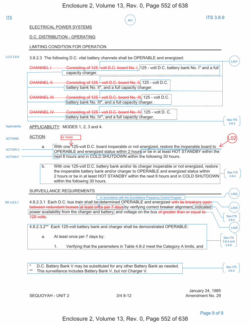
ITS A01
ITS 3.8.9
ELECTRICAL POWER SYSTEMS D.C. DISTRIBUTION - OPERATING LIMITING CONDITION FOR OPERATION 3.8.2.3 The following D.C. vital battery channels shall be OPERABLE and energized: CHANNEL I Consisting of 125 -volt D.C. board No. I, 125 - volt D.C. battery bank No. I* and a full
capacity charger. CHANNEL II Consisting of 125 - volt D.C. board No. II, 125 - volt D.C. battery bank No. II*, and a full capacity charger. CHANNEL III Consisting of 125 - volt D.C. board No. III, 125 - volt D.C. battery bank No. III*, and a full capacity charger. CHANNEL IV Consisting of 125 - volt D.C. board No. IV, 125 - volt D. C. battery bank No. IV*, and a full capacity charger. APPLICABILITY: MODES 1, 2, 3 and 4. ACTION: a. With one 125-volt D.C. board inoperable or not energized, restore the inoperable board to
OPERABLE and energized status within 2 hours or be in at least HOT STANDBY within the next 6 hours and in COLD SHUTDOWN within the following 30 hours.
b. With one 125-volt D.C. battery bank and/or its charger inoperable or not energized, restore
the inoperable battery bank and/or charger to OPERABLE and energized status within 2 hours or be in at least HOT STANDBY within the next 6 hours and in COLD SHUTDOWN within the following 30 hours.
SURVEILLANCE REQUIREMENTS 4.8.2.3.1 Each D.C. bus train shall be determined OPERABLE and energized with tie breakers open between redundant busses at least once per 7 days by verifying correct breaker alignment, indicated power availability from the charger and battery, and voltage on the bus of greater than or equal to 125 volts. 4.8.2.3.2** Each 125-volt battery bank and charger shall be demonstrated OPERABLE: a. At least once per 7 days by: 1. Verifying that the parameters in Table 4.8-2 meet the Category A limits, and * D.C. Battery Bank V may be substituted for any other Battery Bank as needed. ** This surveillance includes Battery Bank V, but not Charger V.
January 24, 1985 SEQUOYAH - UNIT 2 3/4 8-12 Amendment No. 29
Page 9 of 9
LCO 3.8.9
ACTIONS
Applicability
LA01
ACTION C
ACTION F
See ITS 3.8.4
See ITS 3.8.4
See ITS 3.8.4
See ITS 3.8.4 and
3.8.6
SR 3.8.9.1
See ITS 3.8.4
LA03
LA05
In accordance with the Surveillance Frequency Control Program LA02
Enclosure 2, Volume 13, Rev. 0, Page 552 of 638
Enclosure 2, Volume 13, Rev. 0, Page 552 of 638
L02or more
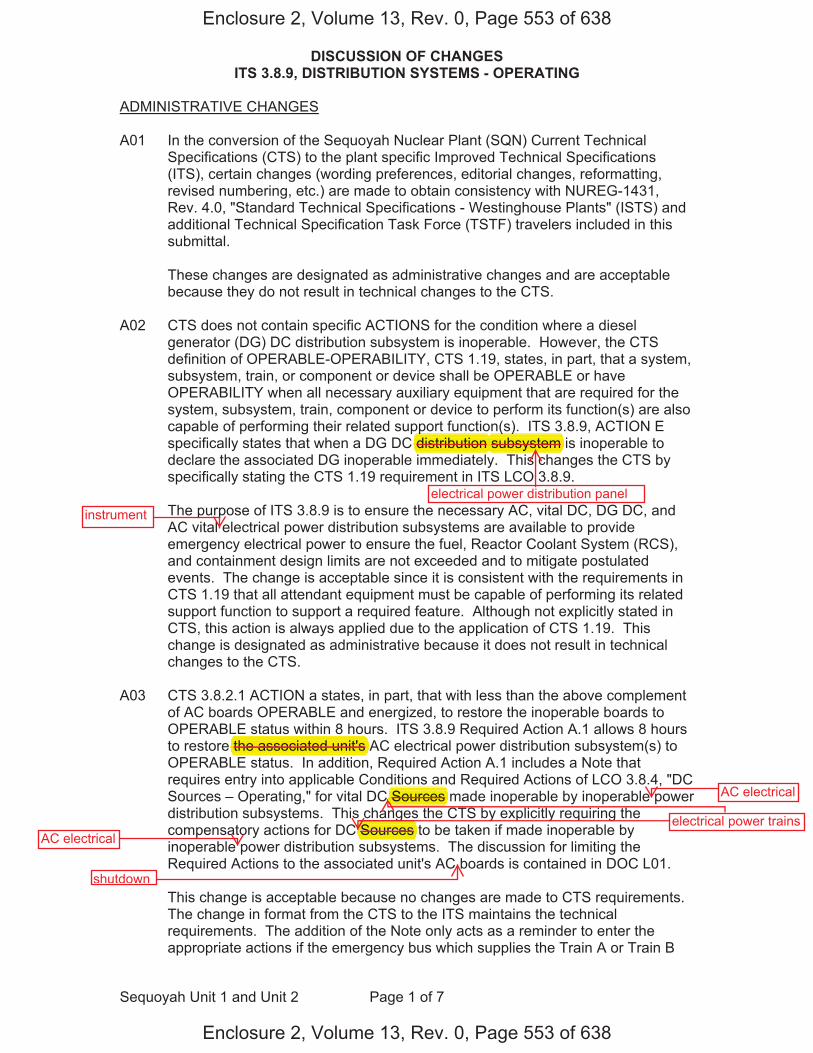
DISCUSSION OF CHANGES ITS 3.8.9, DISTRIBUTION SYSTEMS - OPERATING
Sequoyah Unit 1 and Unit 2 Page 1 of 7
ADMINISTRATIVE CHANGES A01 In the conversion of the Sequoyah Nuclear Plant (SQN) Current Technical
Specifications (CTS) to the plant specific Improved Technical Specifications (ITS), certain changes (wording preferences, editorial changes, reformatting, revised numbering, etc.) are made to obtain consistency with NUREG-1431, Rev. 4.0, "Standard Technical Specifications - Westinghouse Plants" (ISTS) and additional Technical Specification Task Force (TSTF) travelers included in this submittal.
These changes are designated as administrative changes and are acceptable
because they do not result in technical changes to the CTS. A02 CTS does not contain specific ACTIONS for the condition where a diesel
generator (DG) DC distribution subsystem is inoperable. However, the CTS definition of OPERABLE-OPERABILITY, CTS 1.19, states, in part, that a system, subsystem, train, or component or device shall be OPERABLE or have OPERABILITY when all necessary auxiliary equipment that are required for the system, subsystem, train, component or device to perform its function(s) are also capable of performing their related support function(s). ITS 3.8.9, ACTION E specifically states that when a DG DC distribution subsystem is inoperable to declare the associated DG inoperable immediately. This changes the CTS by specifically stating the CTS 1.19 requirement in ITS LCO 3.8.9.
The purpose of ITS 3.8.9 is to ensure the necessary AC, vital DC, DG DC, and
AC vital electrical power distribution subsystems are available to provide emergency electrical power to ensure the fuel, Reactor Coolant System (RCS), and containment design limits are not exceeded and to mitigate postulated events. The change is acceptable since it is consistent with the requirements in CTS 1.19 that all attendant equipment must be capable of performing its related support function to support a required feature. Although not explicitly stated in CTS, this action is always applied due to the application of CTS 1.19. This change is designated as administrative because it does not result in technical changes to the CTS.
A03 CTS 3.8.2.1 ACTION a states, in part, that with less than the above complement
of AC boards OPERABLE and energized, to restore the inoperable boards to OPERABLE status within 8 hours. ITS 3.8.9 Required Action A.1 allows 8 hours to restore the associated unit's AC electrical power distribution subsystem(s) to OPERABLE status. In addition, Required Action A.1 includes a Note that requires entry into applicable Conditions and Required Actions of LCO 3.8.4, "DC Sources – Operating," for vital DC Sources made inoperable by inoperable power distribution subsystems. This changes the CTS by explicitly requiring the compensatory actions for DC Sources to be taken if made inoperable by inoperable power distribution subsystems. The discussion for limiting the Required Actions to the associated unit's AC boards is contained in DOC L01.
This change is acceptable because no changes are made to CTS requirements.
The change in format from the CTS to the ITS maintains the technical requirements. The addition of the Note only acts as a reminder to enter the appropriate actions if the emergency bus which supplies the Train A or Train B
Enclosure 2, Volume 13, Rev. 0, Page 553 of 638
Enclosure 2, Volume 13, Rev. 0, Page 553 of 638
electrical power distribution panel
( )subsystem
electrical power trains
AC electrical
AC electrical
shutdown
the associated unit's
Sources
Sources
ppdistribution
instrument
DISCUSSION OF CHANGES ITS 3.8.9, DISTRIBUTION SYSTEMS - OPERATING
Sequoyah Unit 1 and Unit 2 Page 2 of 7
battery charger becomes de-energized. In the event an emergency board is inoperable such that a Train A or Train B battery charger were inoperable, ITS LCO 3.0.6 would allow taking only the Distribution System - Operating ACTIONS; taking exception to complying with the DC Sources - Operating ACTIONS. Since the Distribution System - Operating ACTIONS may not be sufficiently conservative in this event (i.e., a battery charger may be without power), specific direction to take appropriate ACTIONS for the DC Sources - Operating is added (ITS 3.8.9, Note to ACTION A) when there is no power to support the associated required battery charger. This change is designated as administrative because it does not result in a technical change to the CTS.
MORE RESTRICTIVE CHANGES M01 CTS 4.8.1.1.3 requires, in part, that the 125 volt DC distribution panel for each
DG be demonstrated OPERABLE. ITS SR 3.8.9.1 requires, in part, verifying correct breaker alignments and voltage to the 125 volt DC distribution subsystem for each DG. This changes the CTS by requiring correct breaker alignment verification and correct voltage for the DG DC bus electrical power distribution subsystem.
The purpose of CTS 4.8.1.1.3 is to provide assurance that necessary power to
required supported systems is available with sufficient capacity, capability, redundancy, and reliability to ensure the fuel, RCS, and containment design limits are not exceeded and postulated accidents are mitigated. This change is acceptable because it provides additional assurance that the panels associated with the DG DC bus electrical power distribution subsystem are OPERABLE. This change is designated as more restrictive because it adds a new Surveillance Requirement to the CTS for verification of correct breaker alignment and voltage.
M02 CTS 3.8.2.1 ACTION a states that with less than the above complement of AC
boards OPERABLE and energized, to restore the inoperable boards to OPERABLE status within 8 hours. CTS 3.8.2.3 ACTION a states that with one 125 volt DC board inoperable, to restore the inoperable boards to OPERABLE status within 2 hours. However, there are no limitations to preclude a loss of function due to numerous concurrently inoperable AC and DC boards. ITS 3.8.9 ACTION G has been added, requiring entry into ITS 3.0.3 if the loss of two or more required electrical power distribution subsystems result in a loss of safety function. This changes CTS by adding an explicit Action to enter LCO 3.0.3 for a loss of two or more electrical power distribution subsystems that result in a loss of safety function.
The purpose of the CTS ACTIONS is to limit the time the unit can operate under
these conditions. CTS 3.8.2.3 ACTION a specifies the compensatory actions for one inoperable DC board. With two inoperable DC boards, CTS 3.8.2.3 does not provide any actions and entry into LCO 3.0.3 would be required. CTS 3.8.2.1 ACTION a is applicable to all inoperable AC boards even if there is a loss of safety function. Certain combinations of inoperable AC and DC electrical power distribution subsystems result in a loss of safety function (e.g., an inoperable Train A AC electrical power distribution subsystem in combination with an
Enclosure 2, Volume 13, Rev. 0, Page 554 of 638
Enclosure 2, Volume 13, Rev. 0, Page 554 of 638
gbus
for each DG.
DISCUSSION OF CHANGES ITS 3.8.9, DISTRIBUTION SYSTEMS - OPERATING
Sequoyah Unit 1 and Unit 2 Page 3 of 7
inoperable Train B vital DC electrical power distribution subsystem). ITS 3.8.9 includes ACTION G, which requires immediate entry into LCO 3.0.3 if the loss of one or more required electrical power distribution subsystems boards results in a loss of safety function. ITS 3.8.9 Required Action G.1 preserves the intent of ITS LCO 3.0.3 and reflects an additional restriction on plant operation. This change is designated as more restrictive because an explicit action has been added which requires entry into LCO 3.0.3 with any combination of required AC and/or DC boards inoperable that results in a loss of safety function.
RELOCATED SPECIFICATIONS None REMOVED DETAIL CHANGES LA01 (Type 1 – Removing Details of System Design and System Description, Including
Design Limits) CTS 3.8.1.1.3.b.5 requires, in part, a separate 125 volt DC distribution panel to be OPERABLE for each DG. CTS 3.8.2.1 requires, in part, the AC electrical boards to be OPERABLE and lists the specific AC shutdown boards and AC vital instrument power board channels, including the applicable nominal voltage. CTS 3.8.2.3 requires, in part, vital DC boards to be OPERABLE and lists the specific boards and includes the nominal voltage. ITS LCO 3.8.9 requires the applicable electrical power distribution subsystems to be OPERABLE. This changes the CTS by moving the specific names of the buses and the associated nominal bus voltages (i.e., 6900 V, 480 V, 125 V, and 120 V) from the CTS to the ITS Bases.
The removal of these details, which are related to system design, from the
Technical Specifications, is acceptable because this type of information is not necessary to be included in the Technical Specifications to provide adequate protection of public health and safety. ITS 3.8.9 retains the requirement for the required distribution subsystems to be OPERABLE. In addition, this change is acceptable because the removed information will be adequately controlled in the ITS Bases. The Technical Specification Bases Control Program in Chapter 5 controls changes to the Bases, requiring an evaluation of changes to ensure the Bases are properly controlled. This change is designated as a less restrictive removal of detail change because information relating to system design is being removed from the Technical Specifications.
LA02 (Type 5 – Removal of SR Frequency to the Surveillance Frequency Control
Program) CTS 4.8.1.1.3 requires, in part, verification that the 125 volt DC distribution panel for each diesel generator is demonstrated OPERABLE. CTS 4.8.2.1 requires, in part, the specified AC boards to be determined OPERABLE and energized at least once per 7 days by verifying correct breaker alignment and indicated voltage on the busses. CTS 4.8.2.3.1 requires, in part, each DC bus train to be determined OPERABLE and energized at least once per 7 days by verifying correct breaker alignment, indicated power availability from the charger and battery, and voltage on the bus. DOC M01 discusses addition of a surveillance requirement to verify correct alignments and voltage for the DG
Enclosure 2, Volume 13, Rev. 0, Page 555 of 638
Enclosure 2, Volume 13, Rev. 0, Page 555 of 638
DISCUSSION OF CHANGES ITS 3.8.9, DISTRIBUTION SYSTEMS - OPERATING
Sequoyah Unit 1 and Unit 2 Page 4 of 7
DC distribution subsystem with a frequency of 7 days. ITS SR 3.8.9.1 requires a similar Surveillance and specifies the periodic Frequency as, "In accordance with the Surveillance Frequency Control Program." This changes the CTS by moving the specified Frequencies for these SRs and associated Bases to the Surveillance Frequency Control Program.
The removal of these details related to Surveillance Requirement Frequencies from the Technical Specifications is acceptable, because this type of information is not necessary to be included in the Technical Specifications to provide adequate protection of public health and safety. The existing Surveillance Frequencies are removed from Technical Specifications and placed under licensee control pursuant to the methodology described in NEI 04-10. A new program (Surveillance Frequency Control Program) is being added to the Administrative Controls section of the Technical Specifications describing the control of Surveillance Frequencies. The surveillance test requirements remain in the Technical Specifications. The control of changes to the Surveillance Frequencies will be in accordance with the Surveillance Frequency Control Program. The Program shall ensure that Surveillance Requirements specified in the Technical Specifications are performed at intervals sufficient to assure the associated Limiting Conditions for Operation are met. This change is designated as a less restrictive removal of detail change, because the Surveillance Frequencies are being removed from the Technical Specifications.
LA03 (Type 3 – Removing Procedural Details for Meeting TS Requirements or Reporting Requirements) CTS 3.8.2.1 requires the AC electrical boards to be OPERABLE and energized "with tie breakers open between redundant boards." CTS 4.8.2.1 also requires the AC boards to be determined OPERABLE and energized from AC sources "with tie breakers open between redundant busses" by verifying correct breaker alignment and indicated voltage on the buses. CTS 4.8.2.3.1 requires, in part, the DC bus trains to be determined OPERABLE and energized "with tie breakers open between redundant buses". ITS LCO 3.8.9 requires the applicable electrical power distribution subsystems to be OPERABLE and ITS SR 3.8.9.1 requires the verification of correct breaker alignments and voltage to required AC, vital DC, DG DC, and AC vital electrical power distribution subsystems. This changes the CTS by moving the procedural detail that the boards must have their tie breakers open between redundant boards from the CTS to the ITS Bases.
The removal of these details for meeting Technical Specification requirements
from the Technical Specifications is acceptable because this type of information is not necessary to be included in the Technical Specifications to provide adequate protection of public health and safety. The ITS still retains the requirement for the electrical power distribution subsystems to be OPERABLE and requires the verification of correct breaker alignments and voltage to required AC, vital DC, DG DC, and AC vital electrical power distribution subsystems. In addition, this change is acceptable because these types of procedural details will be adequately controlled in the ITS Bases. The Technical Specification Bases Control Program in Chapter 5 controls changes to the Bases. This program provides for the evaluation of changes to ensure the Bases are properly controlled. This change is designated as a less restrictive removal
Enclosure 2, Volume 13, Rev. 0, Page 556 of 638
Enclosure 2, Volume 13, Rev. 0, Page 556 of 638
instrument
instrument
DISCUSSION OF CHANGES ITS 3.8.9, DISTRIBUTION SYSTEMS - OPERATING
Sequoyah Unit 1 and Unit 2 Page 5 of 7
of detail change because procedural details for meeting Technical Specification requirements are being removed from the Technical Specifications.
LA04 (Type 1 – Removing Details of System Design and System Description, Including
Design Limits) CTS 4.8.2.1 states, in part, that the specified A.C. boards shall be determined OPERABLE by verifying correct breaker alignment. CTS 3.8.2.1 includes Note # that allows D.C. Channel V to be substituted for any one channel of channels I-IV, thus verification of correct breaker alignment is required when Channel V is substituted. ITS SR 3.8.9.1 does not contain this design information. This changes the CTS by moving the details that DC channel V can be substituted for any one of channels I-IV from the CTS to the ITS Bases.
The removal of these details, which are related to system design, from the
Technical Specifications, is acceptable because this type of information is not necessary to be included in the Technical Specifications to provide adequate protection of public health and safety. ITS 3.8.9 retains the requirement for the required distribution subsystems to be OPERABLE. In addition, this change is acceptable because the removed information will be adequately controlled in the ITS Bases. The Technical Specification Bases Control Program in Chapter 5 controls changes to the Bases, requiring an evaluation of changes to ensure the Bases are properly controlled. This change is designated as a less restrictive removal of detail change because information relating to system design is being removed from the Technical Specifications.
LA05 (Type 1 – Removing Details of System Design and System Description, Including Design Limits) CTS 4.8.2.3.1 requires, in part, each DC bus to be determined OPERABLE by verifying voltage of greater than or equal to 125 volt DC on the bus. ITS SR 3.8.9.1 requires, in part, verification of correct breaker alignment and voltage to the DG DC electrical power distribution subsystems. This changes the CTS by removing the specified voltage limit from the surveillance and placing it in the Bases.
The removal of these details, which are related to system design, from the
Technical Specifications, is acceptable because this type of information is not necessary to be included in the Technical Specifications to provide adequate protection of public health and safety. The ITS still retains the requirement to verify the correct voltage to each diesel generator 125 volt DC distribution panel and to each vital DC board. In addition, this change is acceptable because the removed information will be adequately controlled in the ITS Bases. The Technical Specification Bases Control Program in Chapter 5 controls changes to the Bases. This program provides for the evaluation of changes to ensure the Bases are properly controlled. This change is designated as a less restrictive removal of detail change because information relating to system design is being removed from the Technical Specifications.
LESS RESTRICTIVE CHANGES L01 CTS 3.8.2.1 ACTION a requires that with less than the listed AC electrical boards
OPERABLE and energized to restore the inoperable boards to OPERABLE status within 8 hours. ITS LCO 3.8.9 ACTION A requires that with one or more
Enclosure 2, Volume 13, Rev. 0, Page 557 of 638
Enclosure 2, Volume 13, Rev. 0, Page 557 of 638
DISCUSSION OF CHANGES ITS 3.8.9, DISTRIBUTION SYSTEMS - OPERATING
Sequoyah Unit 1 and Unit 2 Page 6 of 7
associated unit's AC electrical power distribution subsystems boards(s) inoperable to restore AC electrical power distribution subsystem(s) to OPERABLE status within 8 hours. ITS 3.8.9 ACTION D requires that when one or more opposite unit's AC boards are inoperable to declare the associated supported required feature(s) inoperable immediately. This changes the CTS by providing a separate ACTION to declare the required supported feature(s) inoperable and follow the applicable ACTIONS for the affected shared system LCOs when the opposite unit's required AC boards are inoperable.
The safety function of the Standby AC Power System is to supply power to support the functioning of components and systems required to assure that (1) fuel design limits and reactor coolant pressure boundary design conditions are not exceeded due to anticipated operational occurrences, and (2) the core is cooled and vital functions are maintained in the event of postulated accidents, subject to loss of the Preferred Power System and subject to any single failure in the Standby Power System. To accomplish its safety function, the onsite Class 1E AC distribution system supplies electrical power to two power trains for each unit. Each power train includes two Class 1E 6.9 kV shutdown boards powered from one of two separate and independent offsite power lines or a dedicated onsite DG. Two DGs in one train can provide the safety related functions to mitigate a loss-of-coolant accident (LOCA) in one unit and safely shut down the other unit. The core cooling and containment cooling system loads are unitized to the respective unit's 6.9 kV shutdown boards. Although the core cooling systems and containment systems credited in the mitigation of an anticipated operational occurrence (AOO) or postulated Design Basis Accident (DBA) are unitized (not shared with the opposite unit) and powered from the associated unit's shutdown boards, some safety-related systems (e.g., Essential Raw Cooling Water (ERCW), Component Cooling (CCS), Emergency Gas Treatment (EGTS), Auxiliary Building Gas Treatment, (ABGTS), Control Room Emergency Ventilation (CREVS), and Control Room HVAC (CRACS)) are shared between the units. The AC sources for these loads are distributed across both unit's shutdown boards. Therefore, in addition to requiring the associated unit's boards to be OPERABLE; the opposite unit's boards supplying power to a required shared system component is also required to be OPERABLE. The purpose of CTS 3.8.2.1 ACTION a is to limit the time AC boards can be inoperable. The proposed change maintains the CTS ACTIONS and allowed outage time for the associated unit's AC boards, and proposes a new ACTION that changes the allowed outage time for the opposite unit's AC boards. The Required Actions are consistent with safe operation under the specified Condition, considering the OPERABLE status of the redundant systems or features. This includes the capacity and capability of remaining systems or features, a reasonable time for repairs or replacement, and the low probability of a DBA occurring during the repair period. These changes are acceptable because the Required Actions associated with the required features are used to establish remedial measures that must be taken in response to the degraded conditions in order to minimize risk associated with continued operation, while providing time to repair the inoperable features. If the necessary repairs cannot be made within the established Completion Time, the applicable Conditions for the affected shared system LCOs establish the Required Actions to exit the MODE of Applicability for that inoperable required feature. This change is acceptable because the provided ACTIONS effect restoration of the opposite unit's AC boards
Enclosure 2, Volume 13, Rev. 0, Page 558 of 638
Enclosure 2, Volume 13, Rev. 0, Page 558 of 638
due to one or more of the associated unit's AC shutdown boards inoperable
electrical power distribution subsystems
due to one or more of the opposite unit's AC shutdown boards inoperable
shutdown
associated unit's
opposite unit's A boards
boards(s)
DISCUSSION OF CHANGES ITS 3.8.9, DISTRIBUTION SYSTEMS - OPERATING
Sequoyah Unit 1 and Unit 2 Page 7 of 7
commensurate with the importance of maintaining these AC boards capable of supporting the associated unit's required feature(s). This change is designated as less restrictive, because less stringent Required Actions are being applied in the ITS than were applied in the CTS.
Enclosure 2, Volume 13, Rev. 0, Page 559 of 638
Enclosure 2, Volume 13, Rev. 0, Page 559 of 638
L02 (Category 4 - Relaxation of Required Action) CTS 3.8.2.3 ACTION a. states, “With one 125-volt D.C. board inoperable, restore the inoperable board to OPERABLE status within 2 hours or be in at least HOT STANDBY within the next 6 hours and in COLD SHUTDOWN within the following 30 hours.” For more than one 125-volt DC board inoperable, CTS 3.8.2.3 does not contain a specific requirement; therefore, entry into LCO 3.0.3 is required. ITS 3.8.9 CONDITION C provides Required Actions for one or more vital DC electrical power distribution subsystems inoperable. ITS 3.8.9 Required Action C.1 requires restoration of vital DC electrical power distribution subsystem(s) to OPERABLE status within 2 hours. Additionally, ITS 3.8.9 ACTION G requires entry into LCO 3.0.3, immediately, if two or more inoperable electrical power distribution subsystems result in a loss of safety function. This changes the CTS by allowing more than one 125-volt DC board to be inoperable, provides an additional hour to restore inoperable 125-volt DC boards to OPERABLE status, and eliminates the requirement to enter LCO 3.0.3 if more than one 125-volt DC board is inoperable and a loss of safety function has not occurred. The purpose of CTS 3.8.2.3 is to ensure that two trains (subsystems) of the vital DC electrical power distribution system (four 125-volt DC boards, two per train) are capable of supplying the associated loads during a design bases accident (DBA). This change is acceptable because the Required Actions are used to establish remedial measures that must be taken in response to the degraded conditions in order to minimize risk associated with continued operation while providing time to repair inoperable features. The Required Actions are consistent with safe operation under the specified Condition, considering that only a small amount of time is provided to restore the required features, and the low probability of a DBA occurring during the repair period. Allowing an additional hour to restore one or more inoperable vital DC electrical power distribution subsystems (or more than one 125-volt DC board) is appropriate as it may avoid a shutdown, a unit transient, while the vital DC electrical power distribution subsystem is not in full working order. The ITS requires immediate entry into LCO 3.0.3 if the loss of more than one vital DC electrical power distribution system results in a loss of safety function, therefore, all safety analysis assumptions are being met. This change is designated as less restrictive because less stringent Required Actions are being applied in the ITS than were applied in the CTS.
shutdown
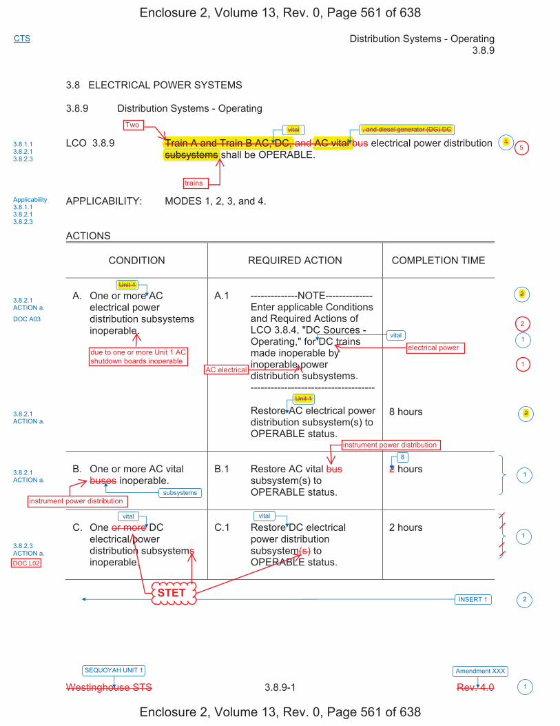
Distribution Systems - Operating 3.8.9
Westinghouse STS 3.8.9-1 Rev. 4.0
CTS
SEQUOYAH UNIT 1 Amendment XXX
1
3.8 ELECTRICAL POWER SYSTEMS
3.8.9 Distribution Systems - Operating
LCO 3.8.9 Train A and Train B AC, DC, and AC vital bus electrical power distribution subsystems shall be OPERABLE.
APPLICABILITY: MODES 1, 2, 3, and 4.
ACTIONS
CONDITION REQUIRED ACTION COMPLETION TIME
A. One or more AC electrical power distribution subsystems inoperable.
A.1 --------------NOTE-------------- Enter applicable Conditions and Required Actions of LCO 3.8.4, "DC Sources - Operating," for DC trains made inoperable by inoperable power distribution subsystems.
-------------------------------------
Restore AC electrical power distribution subsystem(s) to OPERABLE status.
8 hours
B. One or more AC vital buses inoperable.
B.1 Restore AC vital bus subsystem(s) to OPERABLE status.
2 hours
C. One or more DC electrical power distribution subsystems inoperable.
C.1 Restore DC electrical power distribution subsystem(s) to OPERABLE status.
2 hours
vital
vital
INSERT 1
Unit 1
vital
8
3.8.1.1 3.8.2.1 3.8.2.3
Applicability 3.8.1.1 3.8.2.1 3.8.2.3
3.8.2.1 ACTION a.
DOC A03
3.8.2.1 ACTION a.
3.8.2.3 ACTION a.
1
2
1
1
subsystems
vital
3.8.2.1 ACTION a.
1
2
Unit 1
2
, and diesel generator (DG) DC
Enclosure 2, Volume 13, Rev. 0, Page 561 of 638
Enclosure 2, Volume 13, Rev. 0, Page 561 of 638
Two
trains
instrument power distribution
instrument power distribution
electrical power
STET
DOC L02
Unit 1
Unit 1
AC electrical
due to one or more Unit 1 AC shutdown boards inoperable
AC vital bTrain A and Train B AC, DC, subsystems
vital , and diesel generator (DG) DC
2
2
5
2
1
1

3.8.9
Insert Page 3.8.9-1
INSERT 1
D. One or more Unit 2 AC
electrical power distribution subsystems inoperable.
D.1 Declare associated
required feature(s) inoperable.
Immediately
E. One or more required
DG DC subsystems inoperable.
E.1 Declare associated
supported DG inoperable.
Immediately
DOC L01
2
DOC A02
Enclosure 2, Volume 13, Rev. 0, Page 562 of 638
Enclosure 2, Volume 13, Rev. 0, Page 562 of 638
due to one or more Unit 2 AC shutdown boards inoperable
electrical power distribution panels
Unit 2
subsystems required q
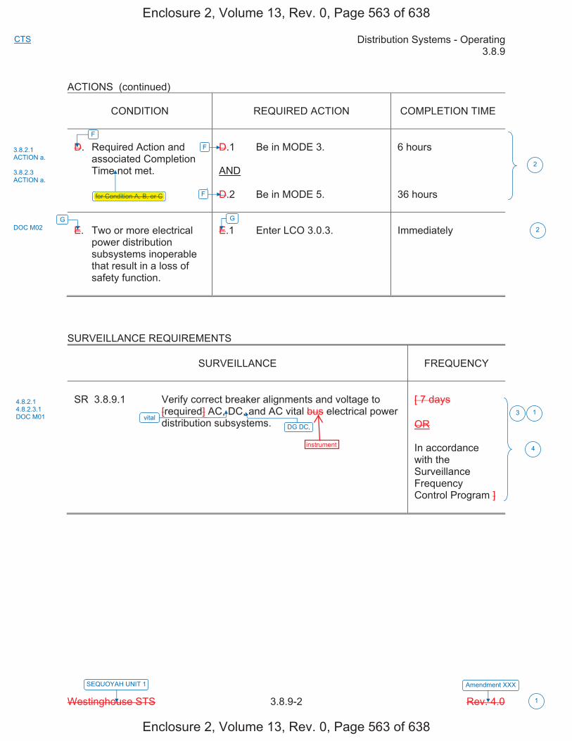
Distribution Systems - Operating 3.8.9
Westinghouse STS 3.8.9-2 Rev. 4.0
CTS
SEQUOYAH UNIT 1 Amendment XXX
1
ACTIONS (continued)
CONDITION REQUIRED ACTION COMPLETION TIME
D. Required Action and associated Completion Time not met.
D.1 Be in MODE 3.
AND
D.2 Be in MODE 5.
6 hours
36 hours
E. Two or more electrical power distribution subsystems inoperable that result in a loss of safety function.
E.1 Enter LCO 3.0.3. Immediately
SURVEILLANCE REQUIREMENTS
SURVEILLANCE FREQUENCY
SR 3.8.9.1 Verify correct breaker alignments and voltage to [required] AC, DC, and AC vital bus electrical power distribution subsystems.
[ 7 days
OR
In accordance with the Surveillance Frequency Control Program ]
F
for Condition A, B, or C
G
vital
F
F
G
3.8.2.1 ACTION a.
3.8.2.3 ACTION a.
DOC M02
4.8.2.1 4.8.2.3.1 DOC M01
2
3 1
4
2
DG DC,
Enclosure 2, Volume 13, Rev. 0, Page 563 of 638
Enclosure 2, Volume 13, Rev. 0, Page 563 of 638
instrument
for Condition A, B, or C

Distribution Systems - Operating 3.8.9
Westinghouse STS 3.8.9-1 Rev. 4.0
CTS
SEQUOYAH UNIT 2 Amendment XXX
1
3.8 ELECTRICAL POWER SYSTEMS
3.8.9 Distribution Systems - Operating
LCO 3.8.9 Train A and Train B AC, DC, and AC vital bus electrical power distribution subsystems shall be OPERABLE.
APPLICABILITY: MODES 1, 2, 3, and 4. ACTIONS
CONDITION
REQUIRED ACTION
COMPLETION TIME
A. One or more AC
electrical power distribution subsystems inoperable.
A.1 --------------NOTE-------------- Enter applicable Conditions
and Required Actions of LCO 3.8.4, "DC Sources - Operating," for DC trains made inoperable by inoperable power distribution subsystems.
------------------------------------- Restore AC electrical power
distribution subsystem(s) to OPERABLE status.
8 hours
B. One or more AC vital
buses inoperable.
B.1 Restore AC vital bus
subsystem(s) to OPERABLE status.
2 hours
C. One or more DC
electrical power distribution subsystems inoperable.
C.1 Restore DC electrical
power distribution subsystem(s) to OPERABLE status.
2 hours
vital
vital
INSERT 1
Unit 2
vital
8
3.8.1.1 3.8.2.1 3.8.2.3
Applicability 3.8.1.1 3.8.2.1 3.8.2.3
3.8.2.1 ACTION a.
DOC A03
3.8.2.1 ACTION a.
3.8.2.3 ACTION a.
2
1
1
subsystems
vital
3.8.2.1 ACTION a.
1
2
Unit 2
2
, and diesel generator (DG) DC
1
Enclosure 2, Volume 13, Rev. 0, Page 564 of 638
Enclosure 2, Volume 13, Rev. 0, Page 564 of 638
STET
DOC L02
Two
trains
, and diesel generator (DG) DCvital
AC vital Train A and Train B AC, DC,subsystems
Unit 2
Unit 2
due to one or more Unit 2 AC shutdown boards inoperable
AC electrical
electrical power
2
2
instrument power distribution
instrument power distribution
51
2
1
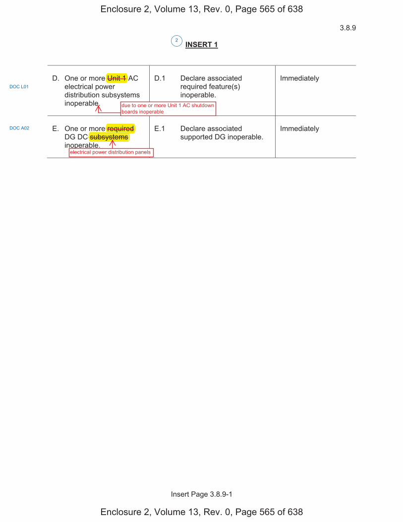
3.8.9
Insert Page 3.8.9-1
INSERT 1
D. One or more Unit 1 AC
electrical power distribution subsystems inoperable.
D.1 Declare associated
required feature(s) inoperable.
Immediately
E. One or more required
DG DC subsystems inoperable.
E.1 Declare associated
supported DG inoperable.
Immediately
DOC L01
2
DOC A02
Enclosure 2, Volume 13, Rev. 0, Page 565 of 638
Enclosure 2, Volume 13, Rev. 0, Page 565 of 638
due to one or more Unit 1 AC shutdown boards inoperable
electrical power distribution panels
Unit 1
subsystems required q

Distribution Systems - Operating 3.8.9
Westinghouse STS 3.8.9-2 Rev. 4.0
CTS
SEQUOYAH UNIT 2 Amendment XXX
1
ACTIONS (continued)
CONDITION
REQUIRED ACTION
COMPLETION TIME
D. Required Action and
associated Completion Time not met.
D.1 Be in MODE 3. AND D.2 Be in MODE 5.
6 hours 36 hours
E. Two or more electrical
power distribution subsystems inoperable that result in a loss of safety function.
E.1 Enter LCO 3.0.3.
Immediately
SURVEILLANCE REQUIREMENTS
SURVEILLANCE
FREQUENCY
SR 3.8.9.1 Verify correct breaker alignments and voltage to
[required] AC, DC, and AC vital bus electrical power distribution subsystems.
[ 7 days OR In accordance with the Surveillance Frequency Control Program ]
F
for Condition A, B, or C
G
vital
F
F
G
3.8.2.1 ACTION a. 3.8.2.3 ACTION a.
DOC M02
4.8.2.1 4.8.2.3.1 DOC M01 3 1
4
2
2
DG DC,
Enclosure 2, Volume 13, Rev. 0, Page 566 of 638
Enclosure 2, Volume 13, Rev. 0, Page 566 of 638
instrument
for Condition A, B, or C
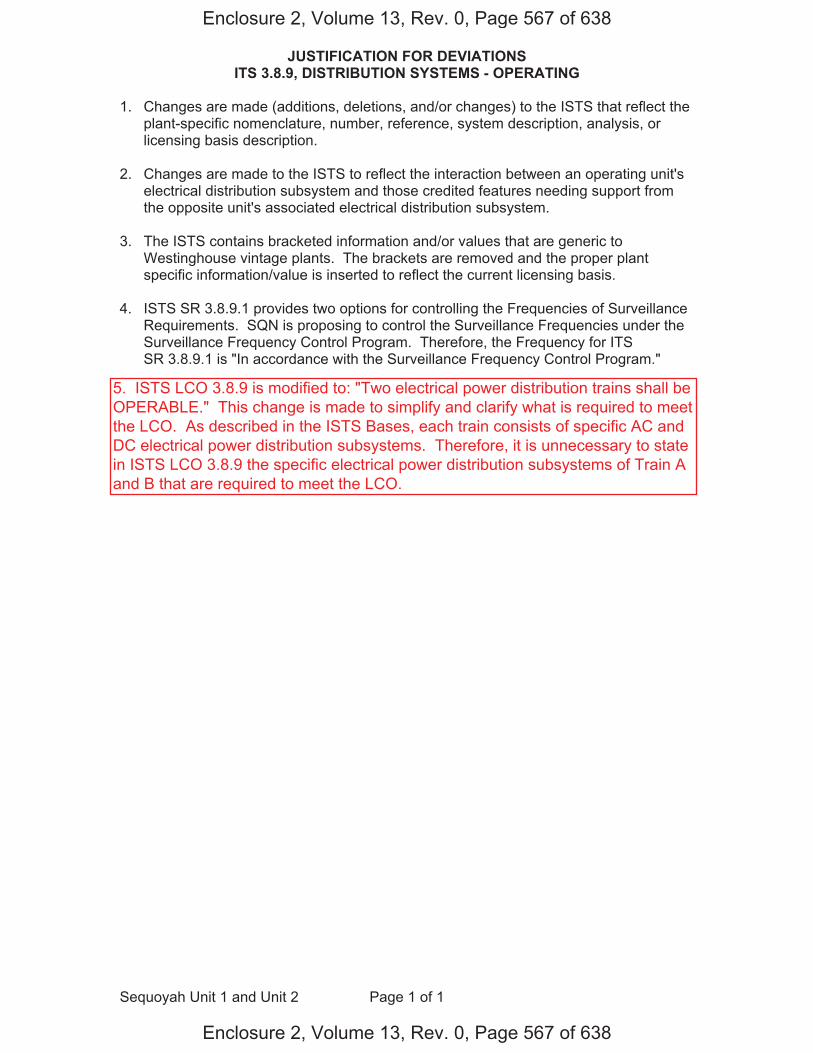
JUSTIFICATION FOR DEVIATIONS ITS 3.8.9, DISTRIBUTION SYSTEMS - OPERATING
Sequoyah Unit 1 and Unit 2 Page 1 of 1
1. Changes are made (additions, deletions, and/or changes) to the ISTS that reflect the plant-specific nomenclature, number, reference, system description, analysis, or licensing basis description.
2. Changes are made to the ISTS to reflect the interaction between an operating unit's electrical distribution subsystem and those credited features needing support from the opposite unit's associated electrical distribution subsystem.
3. The ISTS contains bracketed information and/or values that are generic to
Westinghouse vintage plants. The brackets are removed and the proper plant specific information/value is inserted to reflect the current licensing basis.
4. ISTS SR 3.8.9.1 provides two options for controlling the Frequencies of Surveillance
Requirements. SQN is proposing to control the Surveillance Frequencies under the Surveillance Frequency Control Program. Therefore, the Frequency for ITS SR 3.8.9.1 is "In accordance with the Surveillance Frequency Control Program."
Enclosure 2, Volume 13, Rev. 0, Page 567 of 638
Enclosure 2, Volume 13, Rev. 0, Page 567 of 638
5. ISTS LCO 3.8.9 is modified to: "Two electrical power distribution trains shall beOPERABLE." This change is made to simplify and clarify what is required to meetthe LCO. As described in the ISTS Bases, each train consists of specific AC andDC electrical power distribution subsystems. Therefore, it is unnecessary to statein ISTS LCO 3.8.9 the specific electrical power distribution subsystems of Train Aand B that are required to meet the LCO.
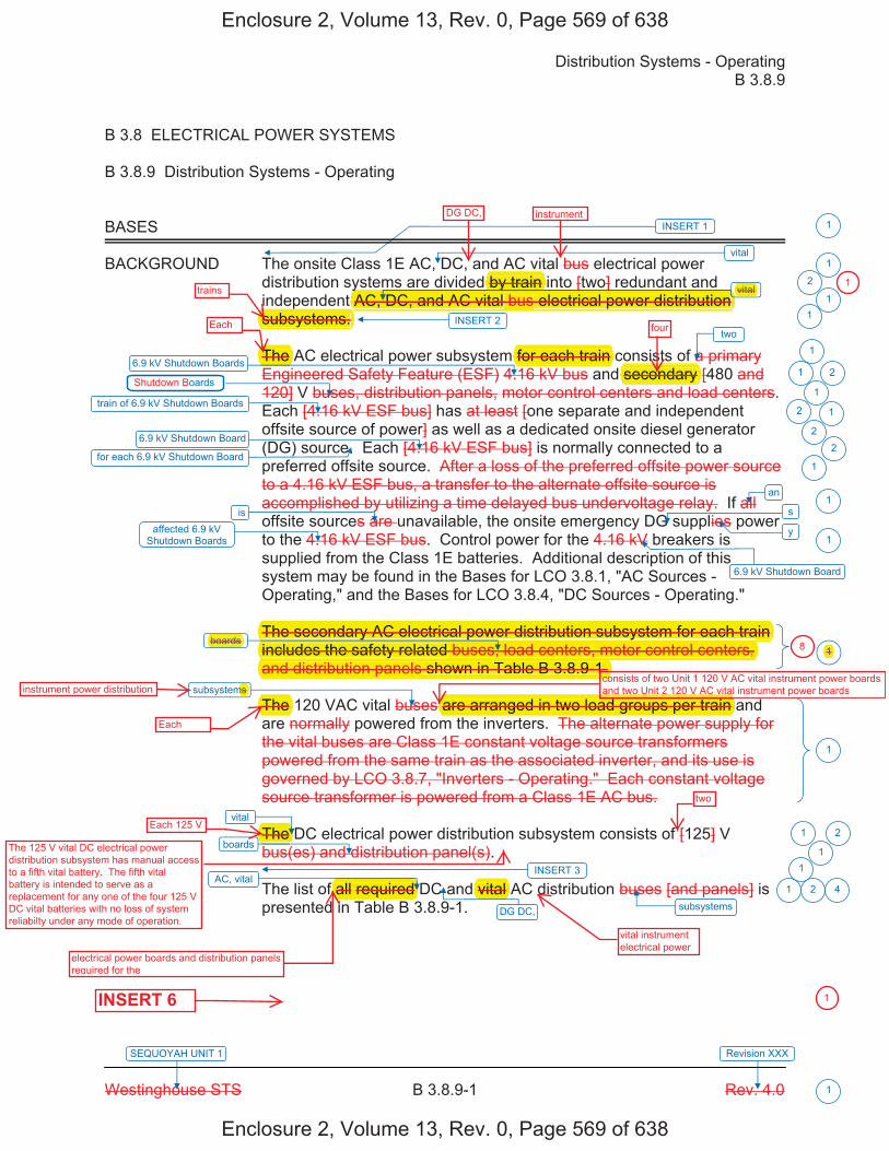
Distribution Systems - Operating B 3.8.9
Westinghouse STS B 3.8.9-1 Rev. 4.0
SEQUOYAH UNIT 1 Revision XXX
1
B 3.8 ELECTRICAL POWER SYSTEMS
B 3.8.9 Distribution Systems - Operating
BASES
BACKGROUND The onsite Class 1E AC, DC, and AC vital bus electrical power distribution systems are divided by train into [two] redundant and independent AC, DC, and AC vital bus electrical power distribution subsystems.
The AC electrical power subsystem for each train consists of a primary Engineered Safety Feature (ESF) 4.16 kV bus and secondary [480 and 120] V buses, distribution panels, motor control centers and load centers. Each [4.16 kV ESF bus] has at least [one separate and independent offsite source of power] as well as a dedicated onsite diesel generator (DG) source. Each [4.16 kV ESF bus] is normally connected to a preferred offsite source. After a loss of the preferred offsite power source to a 4.16 kV ESF bus, a transfer to the alternate offsite source is accomplished by utilizing a time delayed bus undervoltage relay. If all offsite sources are unavailable, the onsite emergency DG supplies power to the 4.16 kV ESF bus. Control power for the 4.16 kV breakers is supplied from the Class 1E batteries. Additional description of this system may be found in the Bases for LCO 3.8.1, "AC Sources - Operating," and the Bases for LCO 3.8.4, "DC Sources - Operating."
The secondary AC electrical power distribution subsystem for each train includes the safety related buses, load centers, motor control centers, and distribution panels shown in Table B 3.8.9-1.
The 120 VAC vital buses are arranged in two load groups per train and are normally powered from the inverters. The alternate power supply for the vital buses are Class 1E constant voltage source transformers powered from the same train as the associated inverter, and its use is governed by LCO 3.8.7, "Inverters - Operating." Each constant voltage source transformer is powered from a Class 1E AC bus.
The DC electrical power distribution subsystem consists of [125] V bus(es) and distribution panel(s).
The list of all required DC and vital AC distribution buses [and panels] is presented in Table B 3.8.9-1.
1
1
vital
vital
6.9 kV Shutdown Boards
train of 6.9 kV Shutdown Boards
two
6.9 kV Shutdown Board
affected 6.9 kV Shutdown Boards
boards
vital
AC, vital
INSERT 1
subsystems
boards
subsystems
oards
2
1
1 2
1
2
22
1
1
1
1
1 2
1
1 2
1
6.9 kV Shutdown Board
an1
is
for each 6.9 kV Shutdown Board
s
y
1
INSERT 2 1
INSERT 3 1
DG DC,
4
Enclosure 2, Volume 13, Rev. 0, Page 569 of 638
Enclosure 2, Volume 13, Rev. 0, Page 569 of 638
Each
Each
vital instrument electrical power
INSERT 6
trains
Each 125 V
two
four
consists of two Unit 1 120 V AC vital instrument power boards and two Unit 2 120 V AC vital instrument power boardsinstrument power distribution
electrical power boards and distribution panels required for the
DG DC, instrument
by train vital
The for each train secondary
The secondary AC electrical power distribution subsystem for each train y p yincludes the safety related buses, load centers, motor control centers,yand distribution panels shown in Table B 3.8.9-1.
co
boards
The ms
are arranged in two load groups per train
The
f all required vital
y y [ ]AC, DC, and AC vital bus electrical power distribution
yp
subsystems.
1
18
1
The 125 V vital DC electrical power distribution subsystem has manual access to a fifth vital battery. The fifth vital battery is intended to serve as a replacement for any one of the four 125 V DC vital batteries with no loss of system reliabilty under any mode of operation.

3.8.9
Insert Page B 3.8.9-1
INSERT 1
The two units share several structures and systems including the preferred and emergency (standby) electric power systems (UFSAR Chapter 8.0). The vital DC Power System is shared to the extent that a few loads (e.g., the vital inverters) in one nuclear unit are energized by the DC power channels assigned primarily to power loads of the other unit. In no case does the sharing inhibit the safe shutdown of one unit while the other unit is experiencing an accident. The Standby Power System serving each unit is divided into two redundant load groups (power trains). These power trains (Train A and Train B for each unit) supply power to safety-related equipment. Generally, the Engineered Safety Feature (ESF) loads assigned to a unit are supplied by the unit designated trains. For example, Safety Injection (SI) pump 1A-A (associated with Unit 1) is supplied by Shutdown Board 1A-A (also associated with Unit 1) while SI pump 2A-A (associated with Unit 2) is supplied by Shutdown Board 2A-A (also associated with Unit 2).
Separate and similar systems and equipment are provided for each unit when required. In certain instances, both units share systems or some components of a system. Shared systems are the exception to the unit/power system association. Because both units share the power system, one unit's power system(s) supports certain components required by the other unit (e.g., emergency gas treatment system). To show the unit, train, board, and panel association, Table B 3.8.9-1 lists these power system components by train and unit designation.
INSERT 2
In addition, each diesel generator (DG) has an associated DC electrical power distribution panel.
INSERT 3
The DG 125 Volt DC distribution subsystem includes a 125 V distribution panel for each DG. During normal operation, power is supplied to the distribution panel by a 480 VAC board through a battery charger. During emergency operation of the DG (loss of offsite power source), the distribution panel is supplied power from a 58 cell battery. This panel supplies power for DG control, protection, and the engine DC lube oil circulating pump.
1
1
1
Enclosure 2, Volume 13, Rev. 0, Page 570 of 638
Enclosure 2, Volume 13, Rev. 0, Page 570 of 638
Each consists of two
s that supply powerto the respectiveDG's auxiliary loads
electrical powerDC
dedicated
Each electrical power distribution train consists of: a. an AC electrical power distribution subsystem, b. an AC vital instrument power distribution subsystem, c. a vital DC electrical power distribution subsystem, and d. a diesel generator (DG) DC electrical power distribution subsystem.
qTo show they ( g , g y g y )
unit, train, board, and panel association, Table B 3.8.9-1 lists these power psystem components by train and unit designation.
In addition, each diesel generator (DG) has an associated DC electricalgpower distribution panel.
The 125 Volt includes a
p58 cell
for each DG.

�
�ss��i�te���it��e�������r���iste��in�����e������������re���num�er����s��et��si�ni�i��nt�e�e�tri��������s���� �en��ne��r�m�re����t�e����r�s�s�e�i�ie��in�����e������������e��mes�in��er���e��entr��int��t�e����r��ri�te����������������������is�re�uire������me����r�s���istri�uti�n���ne�s���n��m�t�r���ntr����enters�����s�����i����e�����m�rise�t�e�����n�����e�e�tri�������er��istri�uti�n�su�s�stems���re�n�t��iste��in�����e���������������e���ss����e�e�tri��������s��ss��i�te���it��t�ese����r�s����ne�s���r����s�m���n�t�resu�t�in�����m��ete���ss������s��et���un�ti�n�ne�ess�r��t��s�ut����n�t�e�re��t�r��n��m�int�in�it�in���s��e���n�iti�n�����ere��re��s��u����ne��r�m�re����t�ese����r�s����ne�s���r����s��e��me�in��er���e��ue�t������i�ure�n�t����e�tin��t�e���������������������r���iste��in�����e������������e��������re��er�su����in����sin��e��istri�uti�n���ne����i�s���en���t�e�in�i�i�u�������s��ss��i�te���it��t�e����r�����ne����r������re��e���re��in��er���e���n��t�e����r��ri�te���n�iti�ns��n���e�uire����ti�ns����t�e����s����ernin��t�e�in�i�i�u�������s��re�entere���
1
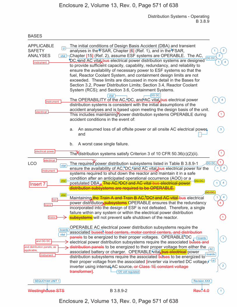
Distribution Systems - Operating B 3.8.9
Westinghouse STS B 3.8.9-2 Rev. 4.0
SEQUOYAH UNIT 1 Revision XXX
1
BASES
APPLICABLE The initial conditions of Design Basis Accident (DBA) and transient SAFETY analyses in the FSAR, Chapter [6] (Ref. 1), and in the FSAR, ANALYSES Chapter [15] (Ref. 2), assume ESF systems are OPERABLE. The AC,
DC, and AC vital bus electrical power distribution systems are designed to provide sufficient capacity, capability, redundancy, and reliability to ensure the availability of necessary power to ESF systems so that the fuel, Reactor Coolant System, and containment design limits are not exceeded. These limits are discussed in more detail in the Bases for Section 3.2, Power Distribution Limits; Section 3.4, Reactor Coolant System (RCS); and Section 3.6, Containment Systems. The OPERABILITY of the AC, DC, and AC vital bus electrical power distribution systems is consistent with the initial assumptions of the accident analyses and is based upon meeting the design basis of the unit. This includes maintaining power distribution systems OPERABLE during accident conditions in the event of: a. An assumed loss of all offsite power or all onsite AC electrical power
and b. A worst case single failure. The distribution systems satisfy Criterion 3 of 10 CFR 50.36(c)(2)(ii).
LCO The required power distribution subsystems listed in Table B 3.8.9-1
ensure the availability of AC, DC, and AC vital bus electrical power for the systems required to shut down the reactor and maintain it in a safe condition after an anticipated operational occurrence (AOO) or a postulated DBA. The AC, DC, and AC vital bus electrical power distribution subsystems are required to be OPERABLE. Maintaining the Train A and Train B AC, DC, and AC vital bus electrical power distribution subsystems OPERABLE ensures that the redundancy incorporated into the design of ESF is not defeated. Therefore, a single failure within any system or within the electrical power distribution subsystems will not prevent safe shutdown of the reactor. OPERABLE AC electrical power distribution subsystems require the associated buses, load centers, motor control centers, and distribution panels to be energized to their proper voltages. OPERABLE DC electrical power distribution subsystems require the associated buses and distribution panels to be energized to their proper voltage from either the associated battery or charger. OPERABLE vital bus electrical power distribution subsystems require the associated buses to be energized to their proper voltage from the associated [inverter via inverted DC voltage, inverter using internal AC source, or Class 1E constant voltage transformer].
vital
vital
vital
vital
vital
or
120 volt regulated
vital
;
U
boards
boards
boards
1 2
2
1
1
3
1
1
1
2
AC
DG DC,
DG DC,
DG DC,
DG DC,
DG DC,
4
4
4
4
1 4
Enclosure 2, Volume 13, Rev. 0, Page 571 of 638
Enclosure 2, Volume 13, Rev. 0, Page 571 of 638
instrument
instrument
electrical
electrical power
electrical
instrument
p p ( )The AC, DC, and AC vital bus electrical power p
distribution subsystems are required to be OPERABLE.Insert 7
vital
vital
DG DC,
two
trains
DG DC,
the Train A and Train B AC, DC, and AC vital subsystems O
subsystems trains
and DG DC
and distribution panels, as applicable,
gbus electrical
instrument
1
1
1
4
1

�
����e�e�tri�������er��istri�uti�n�tr�ins��re�re�uire��t���e����������������tr�in�in��u�es��
�� �n����e�e�tri�������er��istri�uti�n�su�s�stem��i�e����ne��nit����������s�ut���n����r����ne�nit����������s�ut���n����r����n���ss��i�te��������s�ut���n����r�s��
�� �n�����it���instrument����er��istri�uti�n�su�s�stem��i�e���t����nit�������� ���instrument���er����r�s��n��t����nit�������� ���instrument����er����r�s��
�� ���it������e�e�tri�������er��istri�uti�n�su�s�stem��i�e���t���������������r�s����n��� ��������e�e�tri�������er��istri�uti�n�su�s�stem��i�e���t��� ����istri�uti�n���ne�s��
1 4
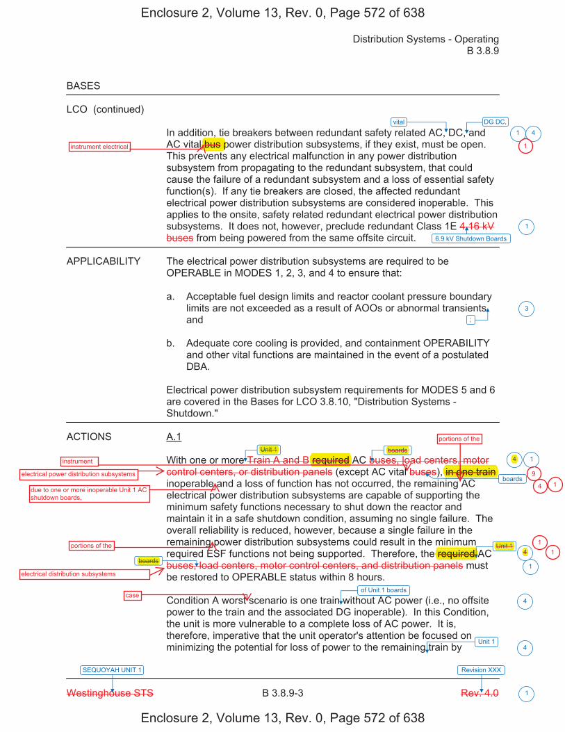
Distribution Systems - Operating B 3.8.9
Westinghouse STS B 3.8.9-3 Rev. 4.0
SEQUOYAH UNIT 1 Revision XXX
1
BASES
LCO (continued)
In addition, tie breakers between redundant safety related AC, DC, and AC vital bus power distribution subsystems, if they exist, must be open. This prevents any electrical malfunction in any power distribution subsystem from propagating to the redundant subsystem, that could cause the failure of a redundant subsystem and a loss of essential safety function(s). If any tie breakers are closed, the affected redundant electrical power distribution subsystems are considered inoperable. This applies to the onsite, safety related redundant electrical power distribution subsystems. It does not, however, preclude redundant Class 1E 4.16 kV buses from being powered from the same offsite circuit.
APPLICABILITY The electrical power distribution subsystems are required to be OPERABLE in MODES 1, 2, 3, and 4 to ensure that:
a. Acceptable fuel design limits and reactor coolant pressure boundarylimits are not exceeded as a result of AOOs or abnormal transientsand
b. Adequate core cooling is provided, and containment OPERABILITYand other vital functions are maintained in the event of a postulatedDBA.
Electrical power distribution subsystem requirements for MODES 5 and 6 are covered in the Bases for LCO 3.8.10, "Distribution Systems - Shutdown."
ACTIONS A.1
With one or more Train A and B required AC buses, load centers, motor control centers, or distribution panels (except AC vital buses), in one train inoperable and a loss of function has not occurred, the remaining AC electrical power distribution subsystems are capable of supporting the minimum safety functions necessary to shut down the reactor and maintain it in a safe shutdown condition, assuming no single failure. The overall reliability is reduced, however, because a single failure in the remaining power distribution subsystems could result in the minimum required ESF functions not being supported. Therefore, the required AC buses, load centers, motor control centers, and distribution panels must be restored to OPERABLE status within 8 hours.
Condition A worst scenario is one train without AC power (i.e., no offsite power to the train and the associated DG inoperable). In this Condition, the unit is more vulnerable to a complete loss of AC power. It is, therefore, imperative that the unit operator's attention be focused on minimizing the potential for loss of power to the remaining train by
vital
6.9 kV Shutdown Boards
;
boards
boards
1
1
1
3
1
Unit 1
boards
Unit 14
4
of Unit 1 boards
4
Unit 14
DG DC,
4
Enclosure 2, Volume 13, Rev. 0, Page 572 of 638
Enclosure 2, Volume 13, Rev. 0, Page 572 of 638
,bus pinstrument electrical
electrical power distribution subsystems
instrument
Unit 1 boards
due to one or more inoperable Unit 1 AC shutdown boards,
portions of the
required one trainonoin o
portions of the
electrical distribution subsystems
boards required
Unit 1
1
9
4
4 1
114
case
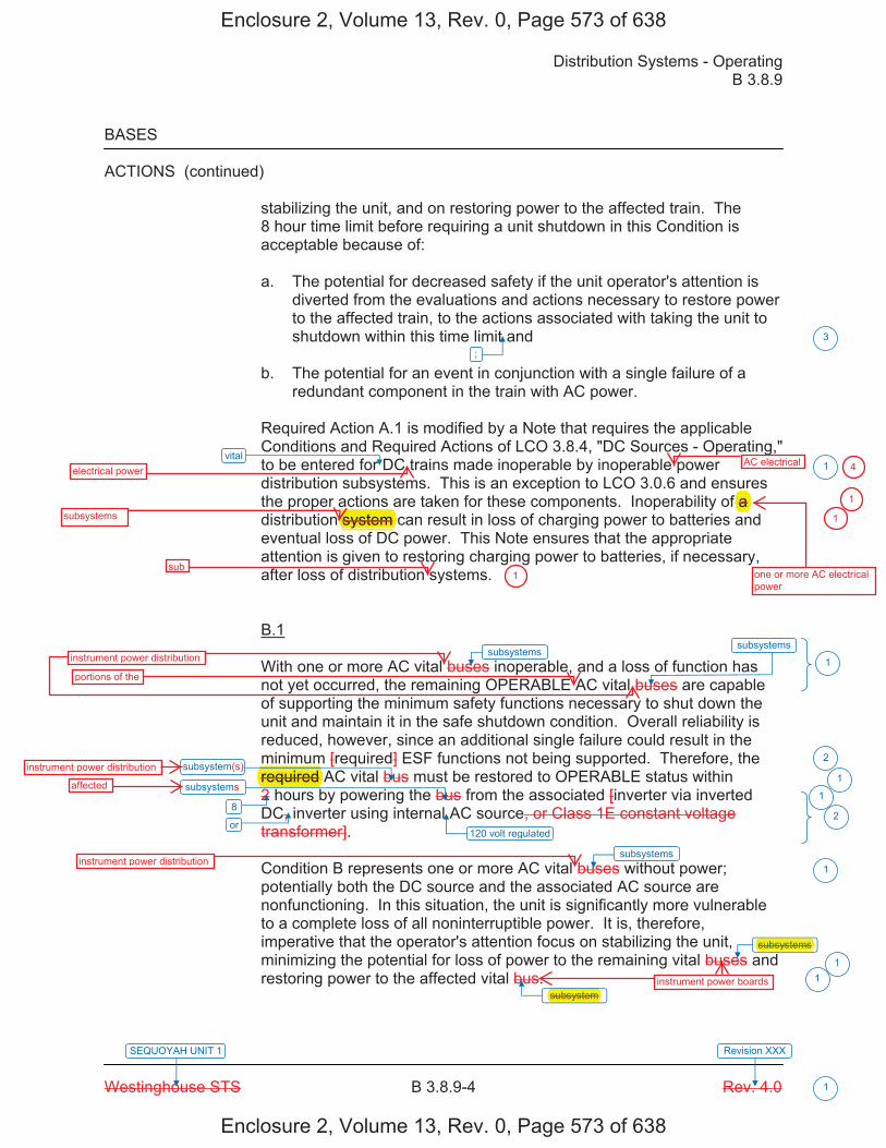
Distribution Systems - Operating B 3.8.9
Westinghouse STS B 3.8.9-4 Rev. 4.0
SEQUOYAH UNIT 1 Revision XXX
1
BASES
ACTIONS (continued)
stabilizing the unit, and on restoring power to the affected train. The 8 hour time limit before requiring a unit shutdown in this Condition is acceptable because of:
a. The potential for decreased safety if the unit operator's attention isdiverted from the evaluations and actions necessary to restore powerto the affected train, to the actions associated with taking the unit toshutdown within this time limit and
b. The potential for an event in conjunction with a single failure of aredundant component in the train with AC power.
Required Action A.1 is modified by a Note that requires the applicable Conditions and Required Actions of LCO 3.8.4, "DC Sources - Operating," to be entered for DC trains made inoperable by inoperable power distribution subsystems. This is an exception to LCO 3.0.6 and ensures the proper actions are taken for these components. Inoperability of a distribution system can result in loss of charging power to batteries and eventual loss of DC power. This Note ensures that the appropriate attention is given to restoring charging power to batteries, if necessary, after loss of distribution systems.
B.1
With one or more AC vital buses inoperable, and a loss of function has not yet occurred, the remaining OPERABLE AC vital buses are capable of supporting the minimum safety functions necessary to shut down the unit and maintain it in the safe shutdown condition. Overall reliability is reduced, however, since an additional single failure could result in the minimum [required] ESF functions not being supported. Therefore, the required AC vital bus must be restored to OPERABLE status within 2 hours by powering the bus from the associated [inverter via inverted DC, inverter using internal AC source, or Class 1E constant voltage transformer].
Condition B represents one or more AC vital buses without power; potentially both the DC source and the associated AC source are nonfunctioning. In this situation, the unit is significantly more vulnerable to a complete loss of all noninterruptible power. It is, therefore, imperative that the operator's attention focus on stabilizing the unit, minimizing the potential for loss of power to the remaining vital buses and restoring power to the affected vital bus.
vital
120 volt regulated
;
subsystems
3
1
1
2
1
1
2
1
11
8
subsystems
subsystem
subsystem
or
subsystems
subsystems
subsystem
Enclosure 2, Volume 13, Rev. 0, Page 573 of 638
Enclosure 2, Volume 13, Rev. 0, Page 573 of 638
electrical powerAC electrical
one or more AC electrical power
f a subsystems system
sub
instrument power distribution
portions of the
required instrument power distribution
affected
instrument power distribution
4
1
1
1
subsystems
subsystem instrument power boards
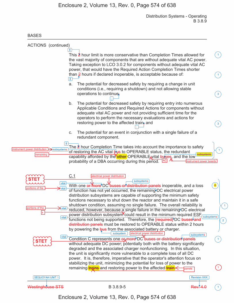
Distribution Systems - Operating B 3.8.9
Westinghouse STS B 3.8.9-5 Rev. 4.0
SEQUOYAH UNIT 1 Revision XXX
1
BASES
ACTIONS (continued) This 2 hour limit is more conservative than Completion Times allowed for the vast majority of components that are without adequate vital AC power. Taking exception to LCO 3.0.2 for components without adequate vital AC power, that would have the Required Action Completion Times shorter than 2 hours if declared inoperable, is acceptable because of:
a. The potential for decreased safety by requiring a change in unitconditions (i.e., requiring a shutdown) and not allowing stableoperations to continue,
b. The potential for decreased safety by requiring entry into numerousApplicable Conditions and Required Actions for components withoutadequate vital AC power and not providing sufficient time for theoperators to perform the necessary evaluations and actions forrestoring power to the affected train, and
c. The potential for an event in conjunction with a single failure of aredundant component.
The 2 hour Completion Time takes into account the importance to safety of restoring the AC vital bus to OPERABLE status, the redundant capability afforded by the other OPERABLE vital buses, and the low probability of a DBA occurring during this period.
C.1
With one or more DC buses or distribution panels inoperable, and a loss of function has not yet occurred, the remaining DC electrical power distribution subsystems are capable of supporting the minimum safety functions necessary to shut down the reactor and maintain it in a safe shutdown condition, assuming no single failure. The overall reliability is reduced, however, because a single failure in the remaining DC electrical power distribution subsystem could result in the minimum required ESF functions not being supported. Therefore, the [required] DC buses and distribution panels must be restored to OPERABLE status within 2 hours by powering the bus from the associated battery or charger.
Condition C represents one or more DC buses or distribution panels without adequate DC power; potentially both with the battery significantly degraded and the associated charger nonfunctioning. In this situation, the unit is significantly more vulnerable to a complete loss of all DC power. It is, therefore, imperative that the operator's attention focus on stabilizing the unit, minimizing the potential for loss of power to the remaining trains and restoring power to the affected train.
vital
vital
vital
vital
vital
;
;
subsystem
3
3
1
2
1
8
8
1
1
1
8
subsystems
subsystem
subsystem
subsystem subsystem
4
Enclosure 2, Volume 13, Rev. 0, Page 574 of 638
Enclosure 2, Volume 13, Rev. 0, Page 574 of 638
STET
STET
instrument power distribution
remaining other AC instrument power boards
subsystems
electrical power distribution
portions of the
portions of thes
electrical power distribution
4
panels
ptrain.trains 1

Distribution Systems - Operating B 3.8.9
Westinghouse STS B 3.8.9-6 Rev. 4.0
SEQUOYAH UNIT 1 Revision XXX
1
BASES
ACTIONS (continued) This 2 hour limit is more conservative than Completion Times allowed for the vast majority of components that would be without power. Taking exception to LCO 3.0.2 for components without adequate DC power, which would have Required Action Completion Times shorter than 2 hours, is acceptable because of: a. The potential for decreased safety by requiring a change in unit
conditions (i.e., requiring a shutdown) while allowing stable operations to continue,
b. The potential for decreased safety by requiring entry into numerous
applicable Conditions and Required Actions for components without DC power and not providing sufficient time for the operators to perform the necessary evaluations and actions for restoring power to the affected train, and
c. The potential for an event in conjunction with a single failure of a
redundant component. The 2 hour Completion Time for DC buses is consistent with Regulatory Guide 1.93 (Ref. 3). D.1 and D.2 If the inoperable distribution subsystem cannot be restored to OPERABLE status within the required Completion Time, the unit must be brought to a MODE in which the LCO does not apply. To achieve this status, the unit must be brought to at least MODE 3 within 6 hours and to MODE 5 within 36 hours. The allowed Completion Times are reasonable, based on operating experience, to reach the required unit conditions from full power conditions in an orderly manner and without challenging plant systems. E.1 Condition E corresponds to a level of degradation in the electrical power distribution system that causes a required safety function to be lost. When more than one inoperable electrical power distribution subsystem results in the loss of a required function, the plant is in a condition outside the accident analysis. Therefore, no additional time is justified for continued operation. LCO 3.0.3 must be entered immediately to commence a controlled shutdown.
vital
not
;
;
5
3
3
1
F F
G
4
4
INSERT 4
G 4
subsystems
Enclosure 2, Volume 13, Rev. 0, Page 575 of 638
Enclosure 2, Volume 13, Rev. 0, Page 575 of 638
electrical power distribution
an
f the electrical power
results inloss of
safety
causes g
required p
to be lost.p
required f
1
1
1
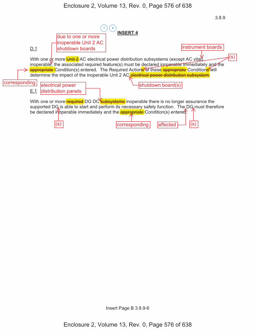
3.8.9
Insert Page B 3.8.9-6
INSERT 4
D.1
With one or more Unit 2 AC electrical power distribution subsystems (except AC vital) inoperable, the associated required feature(s) must be declared inoperable immediately and the appropriate Condition(s) entered. The Required Actions of these appropriate Conditions will determine the impact of the inoperable Unit 2 AC electrical power distribution subsystem.
E.1
With one or more required DG DC subsystems inoperable there is no longer assurance the supported DG is able to start and perform its necessary safety function. The DG must therefore be declared inoperable immediately and the appropriate Condition(s) entered.
41
Enclosure 2, Volume 13, Rev. 0, Page 576 of 638
Enclosure 2, Volume 13, Rev. 0, Page 576 of 638
due to one or moreinoperable Unit 2 ACshutdown boards
shutdown board(s)electrical powerdistribution panels
affected
instrument boards
Unit 2
pp pelectrical power distribution subsystem.
pe appropriate pp p
yns
(s)
corresponding
ns p
appropriate C
required subsystems
(s) (s)corresponding
yappropriate
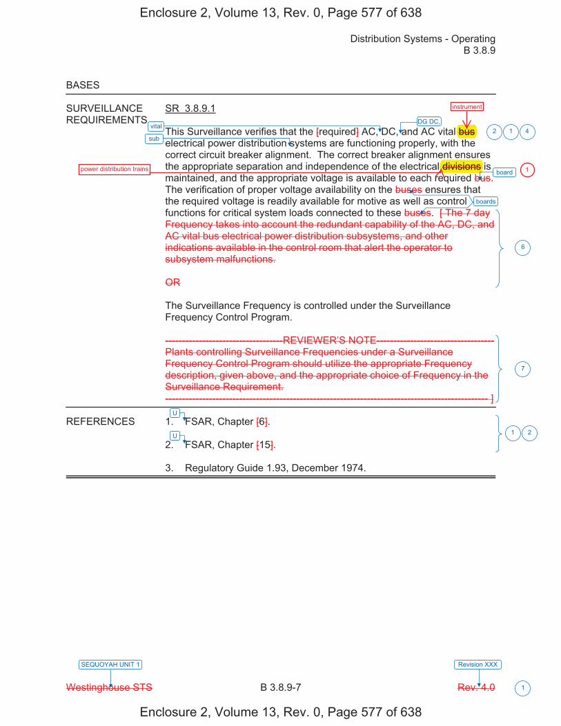
Distribution Systems - Operating B 3.8.9
Westinghouse STS B 3.8.9-7 Rev. 4.0
SEQUOYAH UNIT 1 Revision XXX
1
BASES
SURVEILLANCE SR 3.8.9.1 REQUIREMENTS
This Surveillance verifies that the [required] AC, DC, and AC vital bus electrical power distribution systems are functioning properly, with the correct circuit breaker alignment. The correct breaker alignment ensures the appropriate separation and independence of the electrical divisions is maintained, and the appropriate voltage is available to each required bus. The verification of proper voltage availability on the buses ensures that the required voltage is readily available for motive as well as control functions for critical system loads connected to these buses. [ The 7 day Frequency takes into account the redundant capability of the AC, DC, and AC vital bus electrical power distribution subsystems, and other indications available in the control room that alert the operator to subsystem malfunctions. OR The Surveillance Frequency is controlled under the Surveillance Frequency Control Program. -----------------------------------REVIEWER’S NOTE----------------------------------- Plants controlling Surveillance Frequencies under a Surveillance Frequency Control Program should utilize the appropriate Frequency description, given above, and the appropriate choice of Frequency in the Surveillance Requirement. ------------------------------------------------------------------------------------------------ ]
REFERENCES 1. FSAR, Chapter [6]. 2. FSAR, Chapter [15]. 3. Regulatory Guide 1.93, December 1974.
vital
U
sub 12
6
7
1 2
board
boards
U
DG DC, 4
Enclosure 2, Volume 13, Rev. 0, Page 577 of 638
Enclosure 2, Volume 13, Rev. 0, Page 577 of 638
bus
divisions
instrument
power distribution trains 1

Distribution Systems - Operating B 3.8.9
Westinghouse STS B 3.8.9-8 Rev. 4.0
SEQUOYAH UNIT 1 Revision XXX
1
Table B 3.8.9-1 (page 1 of 1) AC and DC Electrical Power Distribution Systems
TYPE
VOLTAGE
TRAIN A*
TRAIN B*
AC safety buses
[4160 V]
[ESF Bus] [NB01]
[ESF Bus] [NB02]
[480 V]
Load Centers [NG01, NG03]
Load Centers [NG02, NG04]
[480 V]
Motor Control
Centers [NG01A, NG01I, NG01B, NG03C, NG03I, NG03D]
Motor Control
Centers [NG02A, NG02I, NG02B, NG04C, NG04I, NG04D]
[120 V]
Distribution Panels
[NP01, NP03]
Distribution Panels
[NP02, NP04]
DC buses
[125 V]
Bus [NK01]
Bus [NK02]
Bus [NK03]
Bus [NK04]
Distribution Panels
[NK41, NK43, NK51]
Distribution Panels
[NK42, NK44, NK52]
AC vital buses
[120 V]
Bus [NN01]
Bus [NN02]
Bus [NN03]
Bus [NN04]
* Each train of the AC and DC electrical power distribution systems is a subsystem.
INSERT 5
1
Safety Related Onsite
Enclosure 2, Volume 13, Rev. 0, Page 578 of 638
Enclosure 2, Volume 13, Rev. 0, Page 578 of 638
Safety Related Onsite
* Each train of the AC and DC electrical power distribution systems is a subsystem. 1
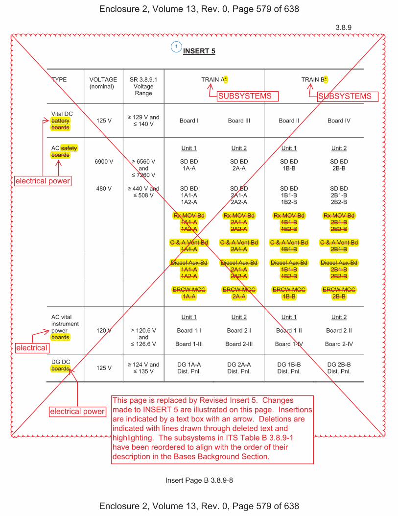
3.8.9
Insert Page B 3.8.9-8
INSERT 5
TYPE
VOLTAGE (nominal)
SR 3.8.9.1
Voltage Range
TRAIN A*
TRAIN B*
Vital DC battery boards
125 V 129 V and 140 V Board I Board III Board II
Board IV
AC safety boards
6900 V
6560 V and
7260 V
Unit 1
SD BD 1A-A
Unit 2
SD BD 2A-A
Unit 1
SD BD 1B-B
Unit 2
SD BD 2B-B
480 V
440 V and
508 V
SD BD 1A1-A 1A2-A
SD BD 2A1-A 2A2-A
SD BD 1B1-B 1B2-B
SD BD 2B1-B 2B2-B
Rx MOV Bd
1A1-A 1A2-A
Rx MOV Bd
2A1-A 2A2-A
Rx MOV Bd
1B1-B 1B2-B
Rx MOV Bd
2B1-B 2B2-B
C & A Vent Bd
1A1-A
C & A Vent Bd
2A1-A C & A Vent Bd
1B1-B
C & A Vent Bd
2B1-B
Diesel Aux Bd 1A1-A 1A2-A
Diesel Aux Bd
2A1-A 2A2-A
Diesel Aux Bd
1B1-B 1B2-B
Diesel Aux Bd
2B1-B 2B2-B
ERCW MCC
1A-A
ERCW MCC
2A-A
ERCW MCC
1B-B
ERCW MCC
2B-B
AC vital instrument power boards
120 V
120.6 V and
126.6 V
Unit 1
Board 1-I
Board 1-III
Unit 2
Board 2-I
Board 2-III
Unit 1
Board 1-II
Board 1-IV
Unit 2
Board 2-II
Board 2-IV
DG DC boards 125 V
124 V and
135 V
DG 1A-A Dist. Pnl.
DG 2A-A Dist. Pnl.
DG 1B-B Dist. Pnl.
DG 2B-B Dist. Pnl.
1
Enclosure 2, Volume 13, Rev. 0, Page 579 of 638
Enclosure 2, Volume 13, Rev. 0, Page 579 of 638
electrical power
electrical power
SUBSYSTEMS SUBSYSTEMS
B*A*
electrical
This page is replaced by Revised Insert 5. Changesmade to INSERT 5 are illustrated on this page. Insertionsare indicated by a text box with an arrow. Deletions areindicated with lines drawn through deleted text andhighlighting. The subsystems in ITS Table B 3.8.9-1have been reordered to align with the order of theirdescription in the Bases Background Section.
battery yboards
safety boards
pboards
boards
Rx MOV Bd Rx Rx MOV Bd Rx MOV Bd Rx MOV Bd A1-A1A 2A1-A 1B1-B 2B1-B
2-A1A2- 2A2-A 1B2-B 2B2-B
Vent BdC & A Ve Bd C & A Vent Bd C & A Vent Bd C & A Vent Bd A1-A1A 2A1-A 1B1-B 2B1-B
Diesel Aux Bd D Diesel Aux Bd D Diesel Aux Bd Diesel Aux Bd 1A1-A 2A1-A 1B1-B 2B1-B1A2-A 2A2-A2A 1B2-B 2B2-B
ERCW MCC MCCERCW MC ERCW MCC ERCW MCC1A-A 2A-A 1B-B 2B-B

������
�
����� ���������n�min����
��������������t��e���n�e�
��������
�����������
��������
�����������
���e�e�tri�������er� ������� ��������
�n����������
�nit���
�����������
�nit���
�����������
�nit���
�����������
�nit���
�����������
������ ��������n���������
������������������
������������������
������������������
������������������
����it���instrument�e�e�tri�������er�
������ ����������n��
���������
�nit���
���r������
���r��������
�nit���
���r������
���r��������
�nit���
���r�������
���r�������
�nit���
���r�������
���r�������
�it������e�e�tri�������er�
������ ��������n��������� ���r���� ���r������ ���r����� ���r�����
������e�e�tri�������er�
�������
����������ist���n���
���������ist���n���
���������ist���n���
���������ist���n���
1
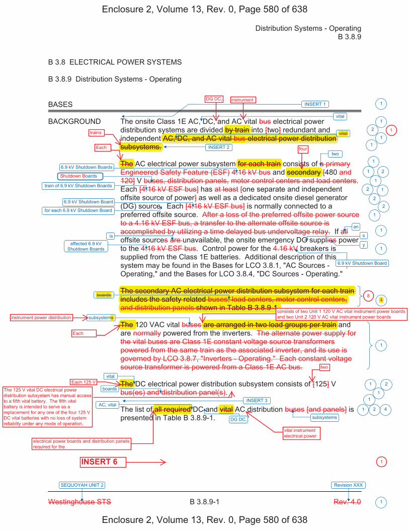
Distribution Systems - Operating B 3.8.9
Westinghouse STS B 3.8.9-1 Rev. 4.0
SEQUOYAH UNIT 2 Revision XXX
1
B 3.8 ELECTRICAL POWER SYSTEMS
B 3.8.9 Distribution Systems - Operating
BASES
BACKGROUND The onsite Class 1E AC, DC, and AC vital bus electrical power distribution systems are divided by train into [two] redundant and independent AC, DC, and AC vital bus electrical power distribution subsystems.
The AC electrical power subsystem for each train consists of a primary Engineered Safety Feature (ESF) 4.16 kV bus and secondary [480 and 120] V buses, distribution panels, motor control centers and load centers. Each [4.16 kV ESF bus] has at least [one separate and independent offsite source of power] as well as a dedicated onsite diesel generator (DG) source. Each [4.16 kV ESF bus] is normally connected to a preferred offsite source. After a loss of the preferred offsite power source to a 4.16 kV ESF bus, a transfer to the alternate offsite source is accomplished by utilizing a time delayed bus undervoltage relay. If all offsite sources are unavailable, the onsite emergency DG supplies power to the 4.16 kV ESF bus. Control power for the 4.16 kV breakers is supplied from the Class 1E batteries. Additional description of this system may be found in the Bases for LCO 3.8.1, "AC Sources - Operating," and the Bases for LCO 3.8.4, "DC Sources - Operating."
The secondary AC electrical power distribution subsystem for each train includes the safety related buses, load centers, motor control centers, and distribution panels shown in Table B 3.8.9-1.
The 120 VAC vital buses are arranged in two load groups per train and are normally powered from the inverters. The alternate power supply for the vital buses are Class 1E constant voltage source transformers powered from the same train as the associated inverter, and its use is governed by LCO 3.8.7, "Inverters - Operating." Each constant voltage source transformer is powered from a Class 1E AC bus.
The DC electrical power distribution subsystem consists of [125] V bus(es) and distribution panel(s).
The list of all required DC and vital AC distribution buses [and panels] is presented in Table B 3.8.9-1.
1
1
vital
vital
6.9 kV Shutdown Boards
train of 6.9 kV Shutdown Boards
two
6.9 kV Shutdown Board
affected 6.9 kV Shutdown Boards
boards
vital
AC, vital
INSERT 1
subsystems
boards
subsystems
oards
2
1
1 2
1
2
22
1
1
1
1
1 2
1
1 2
1
6.9 kV Shutdown Board
an1
is
for each 6.9 kV Shutdown Board
s
y
1
INSERT 2 1
1
DG DC,
INSERT 3
4
Enclosure 2, Volume 13, Rev. 0, Page 580 of 638
Enclosure 2, Volume 13, Rev. 0, Page 580 of 638
DG DC, instrument
trains
Each four
y y [ ]AC, DC, and AC vital bus electrical power distribution p
subsystems.
by train y vital
secondaryfor each train The
The secondary AC electrical power distribution subsystem for each train y p yincludes the safety related buses, load centers, motor control centers,yand distribution panels shown in Table B 3.8.9-1.
boards
instrument power distribution ms
EachThe 1 are arranged in two load groups per train
consists of two Unit 1 120 V AC vital instrument power boards and two Unit 2 120 V AC vital instrument power boards
Each 125 V The
two
f all required vital
electrical power boards and distribution panels required for the
INSERT 6
vital instrument electrical power
1
1
81
The 125 V vital DC electrical power distribution subsystem has manual access to a fifth vital battery. The fifth vital battery is intended to serve as a replacement for any one of the four 125 V DC vital batteries with no loss of system reliabilty under any mode of operation.
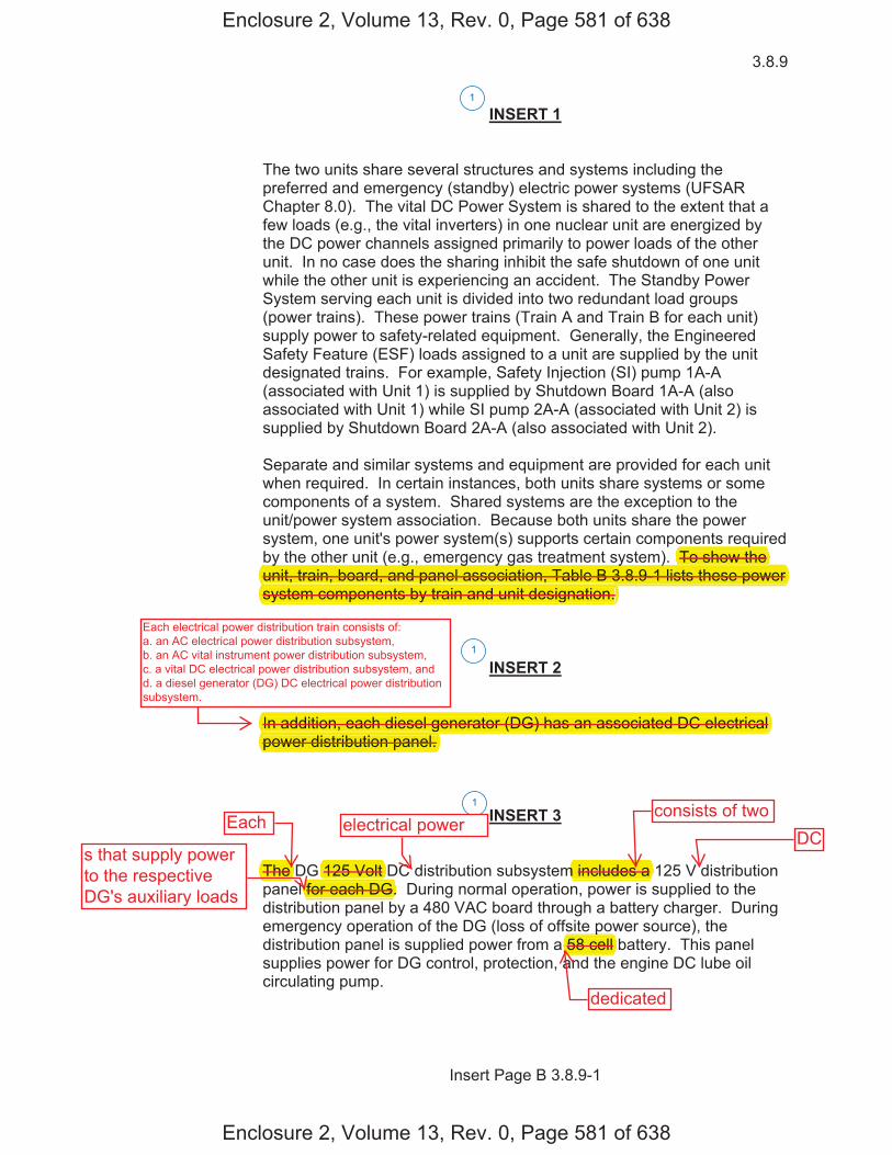
3.8.9
Insert Page B 3.8.9-1
INSERT 1
The two units share several structures and systems including the preferred and emergency (standby) electric power systems (UFSAR Chapter 8.0). The vital DC Power System is shared to the extent that a few loads (e.g., the vital inverters) in one nuclear unit are energized by the DC power channels assigned primarily to power loads of the other unit. In no case does the sharing inhibit the safe shutdown of one unit while the other unit is experiencing an accident. The Standby Power System serving each unit is divided into two redundant load groups (power trains). These power trains (Train A and Train B for each unit) supply power to safety-related equipment. Generally, the Engineered Safety Feature (ESF) loads assigned to a unit are supplied by the unit designated trains. For example, Safety Injection (SI) pump 1A-A (associated with Unit 1) is supplied by Shutdown Board 1A-A (also associated with Unit 1) while SI pump 2A-A (associated with Unit 2) is supplied by Shutdown Board 2A-A (also associated with Unit 2). Separate and similar systems and equipment are provided for each unit when required. In certain instances, both units share systems or some components of a system. Shared systems are the exception to the unit/power system association. Because both units share the power system, one unit's power system(s) supports certain components required by the other unit (e.g., emergency gas treatment system). To show the unit, train, board, and panel association, Table B 3.8.9-1 lists these power system components by train and unit designation.
INSERT 2 In addition, each diesel generator (DG) has an associated DC electrical power distribution panel.
INSERT 3 The DG 125 Volt DC distribution subsystem includes a 125 V distribution panel for each DG. During normal operation, power is supplied to the distribution panel by a 480 VAC board through a battery charger. During emergency operation of the DG (loss of offsite power source), the distribution panel is supplied power from a 58 cell battery. This panel supplies power for DG control, protection, and the engine DC lube oil circulating pump.
1
1
1
Enclosure 2, Volume 13, Rev. 0, Page 581 of 638
Enclosure 2, Volume 13, Rev. 0, Page 581 of 638
qTo show they ( g , g y g y )
unit, train, board, and panel association, Table B 3.8.9-1 lists these power psystem components by train and unit designation.
In addition, each diesel generator (DG) has an associated DC electricalgpower distribution panel.
The 125 Volt m includes a for each DG.
p58 cell
Each electrical power distribution train consists of: a. an AC electrical power distribution subsystem, b. an AC vital instrument power distribution subsystem, c. a vital DC electrical power distribution subsystem, and d. a diesel generator (DG) DC electrical power distribution subsystem.
s that supply powerto the respectiveDG's auxiliary loads
Each electrical powerconsists of two
DC
dedicated
�
�ss��i�te���it��e�������r���iste��in�����e������������re���num�er����s��et��si�ni�i��nt�e�e�tri��������s���� �en��ne��r�m�re����t�e����r�s�s�e�i�ie��in�����e������������e��mes�in��er���e��entr��int��t�e����r��ri�te����������������������is�re�uire������me����r�s���istri�uti�n���ne�s���n��m�t�r���ntr����enters�����s�����i����e�����m�rise�t�e�����n�����e�e�tri�������er��istri�uti�n�su�s�stems���re�n�t��iste��in�����e���������������e���ss����e�e�tri��������s��ss��i�te���it��t�ese����r�s����ne�s���r����s�m���n�t�resu�t�in�����m��ete���ss������s��et���un�ti�n�ne�ess�r��t��s�ut����n�t�e�re��t�r��n��m�int�in�it�in���s��e���n�iti�n�����ere��re��s��u����ne��r�m�re����t�ese����r�s����ne�s���r����s��e��me�in��er���e��ue�t������i�ure�n�t����e�tin��t�e���������������������r���iste��in�����e������������e��������re��er�su����in����sin��e��istri�uti�n���ne����i�s���en���t�e�in�i�i�u�������s��ss��i�te���it��t�e����r�����ne����r������re��e���re��in��er���e���n��t�e����r��ri�te���n�iti�ns��n���e�uire����ti�ns����t�e����s����ernin��t�e�in�i�i�u�������s��re�entere���
1
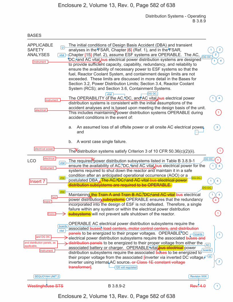
Distribution Systems - Operating B 3.8.9
Westinghouse STS B 3.8.9-2 Rev. 4.0
SEQUOYAH UNIT 2 Revision XXX
1
BASES
APPLICABLE The initial conditions of Design Basis Accident (DBA) and transient SAFETY analyses in the FSAR, Chapter [6] (Ref. 1), and in the FSAR, ANALYSES Chapter [15] (Ref. 2), assume ESF systems are OPERABLE. The AC,
DC, and AC vital bus electrical power distribution systems are designed to provide sufficient capacity, capability, redundancy, and reliability to ensure the availability of necessary power to ESF systems so that the fuel, Reactor Coolant System, and containment design limits are not exceeded. These limits are discussed in more detail in the Bases for Section 3.2, Power Distribution Limits; Section 3.4, Reactor Coolant System (RCS); and Section 3.6, Containment Systems.
The OPERABILITY of the AC, DC, and AC vital bus electrical power distribution systems is consistent with the initial assumptions of the accident analyses and is based upon meeting the design basis of the unit. This includes maintaining power distribution systems OPERABLE during accident conditions in the event of:
a. An assumed loss of all offsite power or all onsite AC electrical powerand
b. A worst case single failure.
The distribution systems satisfy Criterion 3 of 10 CFR 50.36(c)(2)(ii).
LCO The required power distribution subsystems listed in Table B 3.8.9-1 ensure the availability of AC, DC, and AC vital bus electrical power for the systems required to shut down the reactor and maintain it in a safe condition after an anticipated operational occurrence (AOO) or a postulated DBA. The AC, DC, and AC vital bus electrical power distribution subsystems are required to be OPERABLE.
Maintaining the Train A and Train B AC, DC, and AC vital bus electrical power distribution subsystems OPERABLE ensures that the redundancy incorporated into the design of ESF is not defeated. Therefore, a single failure within any system or within the electrical power distribution subsystems will not prevent safe shutdown of the reactor.
OPERABLE AC electrical power distribution subsystems require the associated buses, load centers, motor control centers, and distribution panels to be energized to their proper voltages. OPERABLE DC electrical power distribution subsystems require the associated buses and distribution panels to be energized to their proper voltage from either the associated battery or charger. OPERABLE vital bus electrical power distribution subsystems require the associated buses to be energized to their proper voltage from the associated [inverter via inverted DC voltage, inverter using internal AC source, or Class 1E constant voltage transformer].
vital
vital
vital
vital
vital
or
120 volt regulated
vital
;
U
boards
boards
boards
1 2
2
1
1
3
1
1
1
1
2
AC
DG DC,
DG DC,
DG DC,
DG DC,
DG DC,
4
4
4
4
4
Enclosure 2, Volume 13, Rev. 0, Page 582 of 638
Enclosure 2, Volume 13, Rev. 0, Page 582 of 638
instrument
instrument
electrical
electrical power
DG DC,
DG DC,
vital
vital
p p ( )The AC, DC, and AC vital bus electrical power p
distribution subsystems are required to be OPERABLE.
Train A and Train B AC, DC, and AC vital
subsystems
subsystems
gbus electrical
electrical
instrument
Insert 7
twog the
trains
trains
and DG DC
and distribution panels, as applicable,
instrument
1
1
1
4
1
�
����e�e�tri�������er��istri�uti�n�tr�ins��re�re�uire��t���e����������������tr�in�in��u�es��
�� �n����e�e�tri�������er��istri�uti�n�su�s�stem��i�e����ne��nit����������s�ut���n����r����ne�nit����������s�ut���n����r����n���ss��i�te��������s�ut���n����r�s��
�� �n�����it���instrument����er��istri�uti�n�su�s�stem��i�e���t����nit�������� ���instrument���er����r�s��n��t����nit�������� ���instrument����er����r�s��
�� ���it������e�e�tri�������er��istri�uti�n�su�s�stem��i�e���t���������������r�s����n��� ��������e�e�tri�������er��istri�uti�n�su�s�stem��i�e���t��� ����istri�uti�n���ne�s��
1 4
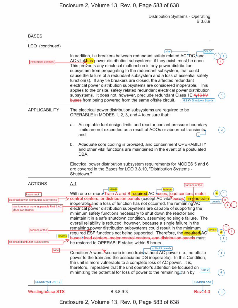
Distribution Systems - Operating B 3.8.9
Westinghouse STS B 3.8.9-3 Rev. 4.0
SEQUOYAH UNIT 2 Revision XXX
1
BASES
LCO (continued)
In addition, tie breakers between redundant safety related AC, DC, and AC vital bus power distribution subsystems, if they exist, must be open. This prevents any electrical malfunction in any power distribution subsystem from propagating to the redundant subsystem, that could cause the failure of a redundant subsystem and a loss of essential safety function(s). If any tie breakers are closed, the affected redundant electrical power distribution subsystems are considered inoperable. This applies to the onsite, safety related redundant electrical power distribution subsystems. It does not, however, preclude redundant Class 1E 4.16 kV buses from being powered from the same offsite circuit.
APPLICABILITY The electrical power distribution subsystems are required to be OPERABLE in MODES 1, 2, 3, and 4 to ensure that:
a. Acceptable fuel design limits and reactor coolant pressure boundarylimits are not exceeded as a result of AOOs or abnormal transientsand
b. Adequate core cooling is provided, and containment OPERABILITYand other vital functions are maintained in the event of a postulatedDBA.
Electrical power distribution subsystem requirements for MODES 5 and 6 are covered in the Bases for LCO 3.8.10, "Distribution Systems - Shutdown."
ACTIONS A.1
With one or more Train A and B required AC buses, load centers, motor control centers, or distribution panels (except AC vital buses), in one train inoperable and a loss of function has not occurred, the remaining AC electrical power distribution subsystems are capable of supporting the minimum safety functions necessary to shut down the reactor and maintain it in a safe shutdown condition, assuming no single failure. The overall reliability is reduced, however, because a single failure in the remaining power distribution subsystems could result in the minimum required ESF functions not being supported. Therefore, the required AC buses, load centers, motor control centers, and distribution panels must be restored to OPERABLE status within 8 hours.
Condition A worst scenario is one train without AC power (i.e., no offsite power to the train and the associated DG inoperable). In this Condition, the unit is more vulnerable to a complete loss of AC power. It is, therefore, imperative that the unit operator's attention be focused on minimizing the potential for loss of power to the remaining train by
vital
6.9 kV Shutdown Boards
;
boards
boards
1
1
1
3
1
Unit 2
boards
Unit 24
4
of Unit 2 boards
4
Unit 24
DG DC,4
Enclosure 2, Volume 13, Rev. 0, Page 583 of 638
Enclosure 2, Volume 13, Rev. 0, Page 583 of 638
,bus instrument electrical
Unit 2 boards
required , in one train
e required boards
instrument
electrical power distribution subsystems
due to one or more inoperable Unit 2 AC shutdown boards,
portions of the
electrical distribution subsystems
portions of the
Unit 2
1
4
4
9
4 1
11
case
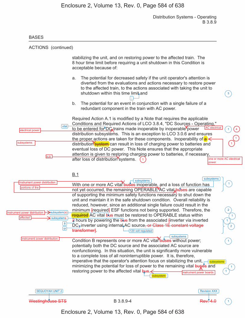
Distribution Systems - Operating B 3.8.9
Westinghouse STS B 3.8.9-4 Rev. 4.0
SEQUOYAH UNIT 2 Revision XXX
1
BASES
ACTIONS (continued)
stabilizing the unit, and on restoring power to the affected train. The 8 hour time limit before requiring a unit shutdown in this Condition is acceptable because of:
a. The potential for decreased safety if the unit operator's attention isdiverted from the evaluations and actions necessary to restore powerto the affected train, to the actions associated with taking the unit toshutdown within this time limit and
b. The potential for an event in conjunction with a single failure of aredundant component in the train with AC power.
Required Action A.1 is modified by a Note that requires the applicable Conditions and Required Actions of LCO 3.8.4, "DC Sources - Operating," to be entered for DC trains made inoperable by inoperable power distribution subsystems. This is an exception to LCO 3.0.6 and ensures the proper actions are taken for these components. Inoperability of a distribution system can result in loss of charging power to batteries and eventual loss of DC power. This Note ensures that the appropriate attention is given to restoring charging power to batteries, if necessary, after loss of distribution systems.
B.1
With one or more AC vital buses inoperable, and a loss of function has not yet occurred, the remaining OPERABLE AC vital buses are capable of supporting the minimum safety functions necessary to shut down the unit and maintain it in the safe shutdown condition. Overall reliability is reduced, however, since an additional single failure could result in the minimum [required] ESF functions not being supported. Therefore, the required AC vital bus must be restored to OPERABLE status within 2 hours by powering the bus from the associated [inverter via inverted DC, inverter using internal AC source, or Class 1E constant voltage transformer].
Condition B represents one or more AC vital buses without power; potentially both the DC source and the associated AC source are nonfunctioning. In this situation, the unit is significantly more vulnerable to a complete loss of all noninterruptible power. It is, therefore, imperative that the operator's attention focus on stabilizing the unit, minimizing the potential for loss of power to the remaining vital buses and restoring power to the affected vital bus.
vital
120 volt regulated
;
subsystems
3
1
1
2
1
1
2
1
11
8
subsystems
subsystem
subsystem
or
subsystems
subsystems
subsystem
Enclosure 2, Volume 13, Rev. 0, Page 584 of 638
Enclosure 2, Volume 13, Rev. 0, Page 584 of 638
system f a
electrical power
subsystems
sub
AC electrical
one or more AC electrical power
required
subsystem
subsystems
instrument power distribution
portions of the
instrument power distribution
affected
instrument power distribution
4
1
1
1
instrument power boards
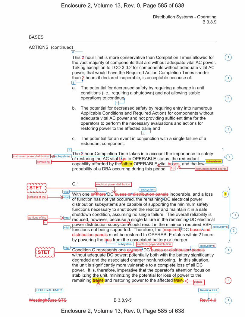
Distribution Systems - Operating B 3.8.9
Westinghouse STS B 3.8.9-5 Rev. 4.0
SEQUOYAH UNIT 2 Revision XXX
1
BASES
ACTIONS (continued) This 2 hour limit is more conservative than Completion Times allowed for the vast majority of components that are without adequate vital AC power. Taking exception to LCO 3.0.2 for components without adequate vital AC power, that would have the Required Action Completion Times shorter than 2 hours if declared inoperable, is acceptable because of:
a. The potential for decreased safety by requiring a change in unitconditions (i.e., requiring a shutdown) and not allowing stableoperations to continue,
b. The potential for decreased safety by requiring entry into numerousApplicable Conditions and Required Actions for components withoutadequate vital AC power and not providing sufficient time for theoperators to perform the necessary evaluations and actions forrestoring power to the affected train, and
c. The potential for an event in conjunction with a single failure of aredundant component.
The 2 hour Completion Time takes into account the importance to safety of restoring the AC vital bus to OPERABLE status, the redundant capability afforded by the other OPERABLE vital buses, and the low probability of a DBA occurring during this period.
C.1
With one or more DC buses or distribution panels inoperable, and a loss of function has not yet occurred, the remaining DC electrical power distribution subsystems are capable of supporting the minimum safety functions necessary to shut down the reactor and maintain it in a safe shutdown condition, assuming no single failure. The overall reliability is reduced, however, because a single failure in the remaining DC electrical power distribution subsystem could result in the minimum required ESF functions not being supported. Therefore, the [required] DC buses and distribution panels must be restored to OPERABLE status within 2 hours by powering the bus from the associated battery or charger.
Condition C represents one or more DC buses or distribution panels without adequate DC power; potentially both with the battery significantly degraded and the associated charger nonfunctioning. In this situation, the unit is significantly more vulnerable to a complete loss of all DC power. It is, therefore, imperative that the operator's attention focus on stabilizing the unit, minimizing the potential for loss of power to the remaining trains and restoring power to the affected train.
vital
vital
vital
vital
vital
;
;
subsystem
3
3
1
2
1
8
8
1
1
1
8
subsystems
subsystem
subsystem
subsystem subsystem
4
Enclosure 2, Volume 13, Rev. 0, Page 585 of 638
Enclosure 2, Volume 13, Rev. 0, Page 585 of 638
other subsystems
instrument power distribution
remaining
AC instrument power boards
electrical power distributionSTET
portions of the
portions of thes
STET
electrical power distribution
4
ptrain. trains panels 1
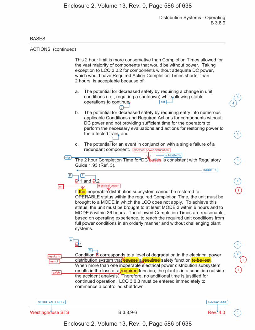
Distribution Systems - Operating B 3.8.9
Westinghouse STS B 3.8.9-6 Rev. 4.0
SEQUOYAH UNIT 2 Revision XXX
1
BASES
ACTIONS (continued) This 2 hour limit is more conservative than Completion Times allowed for the vast majority of components that would be without power. Taking exception to LCO 3.0.2 for components without adequate DC power, which would have Required Action Completion Times shorter than 2 hours, is acceptable because of: a. The potential for decreased safety by requiring a change in unit
conditions (i.e., requiring a shutdown) while allowing stable operations to continue,
b. The potential for decreased safety by requiring entry into numerous
applicable Conditions and Required Actions for components without DC power and not providing sufficient time for the operators to perform the necessary evaluations and actions for restoring power to the affected train, and
c. The potential for an event in conjunction with a single failure of a
redundant component. The 2 hour Completion Time for DC buses is consistent with Regulatory Guide 1.93 (Ref. 3). D.1 and D.2 If the inoperable distribution subsystem cannot be restored to OPERABLE status within the required Completion Time, the unit must be brought to a MODE in which the LCO does not apply. To achieve this status, the unit must be brought to at least MODE 3 within 6 hours and to MODE 5 within 36 hours. The allowed Completion Times are reasonable, based on operating experience, to reach the required unit conditions from full power conditions in an orderly manner and without challenging plant systems. E.1 Condition E corresponds to a level of degradation in the electrical power distribution system that causes a required safety function to be lost. When more than one inoperable electrical power distribution subsystem results in the loss of a required function, the plant is in a condition outside the accident analysis. Therefore, no additional time is justified for continued operation. LCO 3.0.3 must be entered immediately to commence a controlled shutdown.
vital
not
;
;
5
3
3
1
4
4
4
subsystems
F F
G
INSERT 4
G
Enclosure 2, Volume 13, Rev. 0, Page 586 of 638
Enclosure 2, Volume 13, Rev. 0, Page 586 of 638
electrical power distribution
f the
causes g
required p
to be lost.p
required
an electrical power
results inloss of
safety
1
1
1
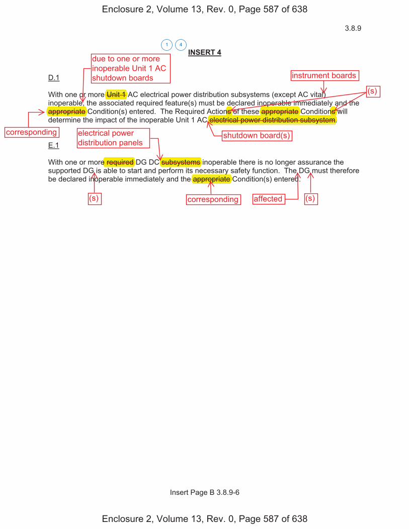
3.8.9
Insert Page B 3.8.9-6
INSERT 4 D.1 With one or more Unit 1 AC electrical power distribution subsystems (except AC vital) inoperable, the associated required feature(s) must be declared inoperable immediately and the appropriate Condition(s) entered. The Required Actions of these appropriate Conditions will determine the impact of the inoperable Unit 1 AC electrical power distribution subsystem.
E.1 With one or more required DG DC subsystems inoperable there is no longer assurance the supported DG is able to start and perform its necessary safety function. The DG must therefore be declared inoperable immediately and the appropriate Condition(s) entered.
41
Enclosure 2, Volume 13, Rev. 0, Page 587 of 638
Enclosure 2, Volume 13, Rev. 0, Page 587 of 638
Unit 1 p
appropriate
e required subsystems y
appropriate
ns p
appropriate yns pp p
electrical power distribution subsystem.pp p
due to one or moreinoperable Unit 1 ACshutdown boards instrument boards
(s)
shutdown board(s)electrical powerdistribution panels
corresponding
(s) corresponding affected (s)
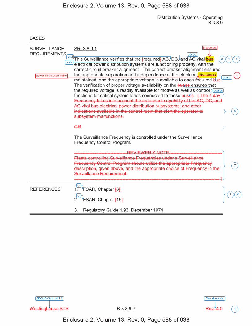
Distribution Systems - Operating B 3.8.9
Westinghouse STS B 3.8.9-7 Rev. 4.0
SEQUOYAH UNIT 2 Revision XXX
1
BASES
SURVEILLANCE SR 3.8.9.1 REQUIREMENTS
This Surveillance verifies that the [required] AC, DC, and AC vital bus electrical power distribution systems are functioning properly, with the correct circuit breaker alignment. The correct breaker alignment ensures the appropriate separation and independence of the electrical divisions is maintained, and the appropriate voltage is available to each required bus. The verification of proper voltage availability on the buses ensures that the required voltage is readily available for motive as well as control functions for critical system loads connected to these buses. [ The 7 day Frequency takes into account the redundant capability of the AC, DC, and AC vital bus electrical power distribution subsystems, and other indications available in the control room that alert the operator to subsystem malfunctions.
OR
The Surveillance Frequency is controlled under the Surveillance Frequency Control Program.
-----------------------------------REVIEWER’S NOTE----------------------------------- Plants controlling Surveillance Frequencies under a Surveillance Frequency Control Program should utilize the appropriate Frequency description, given above, and the appropriate choice of Frequency in the Surveillance Requirement. ------------------------------------------------------------------------------------------------ ]
REFERENCES 1. FSAR, Chapter [6].
2. FSAR, Chapter [15].
3. Regulatory Guide 1.93, December 1974.
vital
U
sub 12
6
7
1 2
board
boards
U
DG DC, 4
Enclosure 2, Volume 13, Rev. 0, Page 588 of 638
Enclosure 2, Volume 13, Rev. 0, Page 588 of 638
bus
divisions power distribution trains
instrument
1
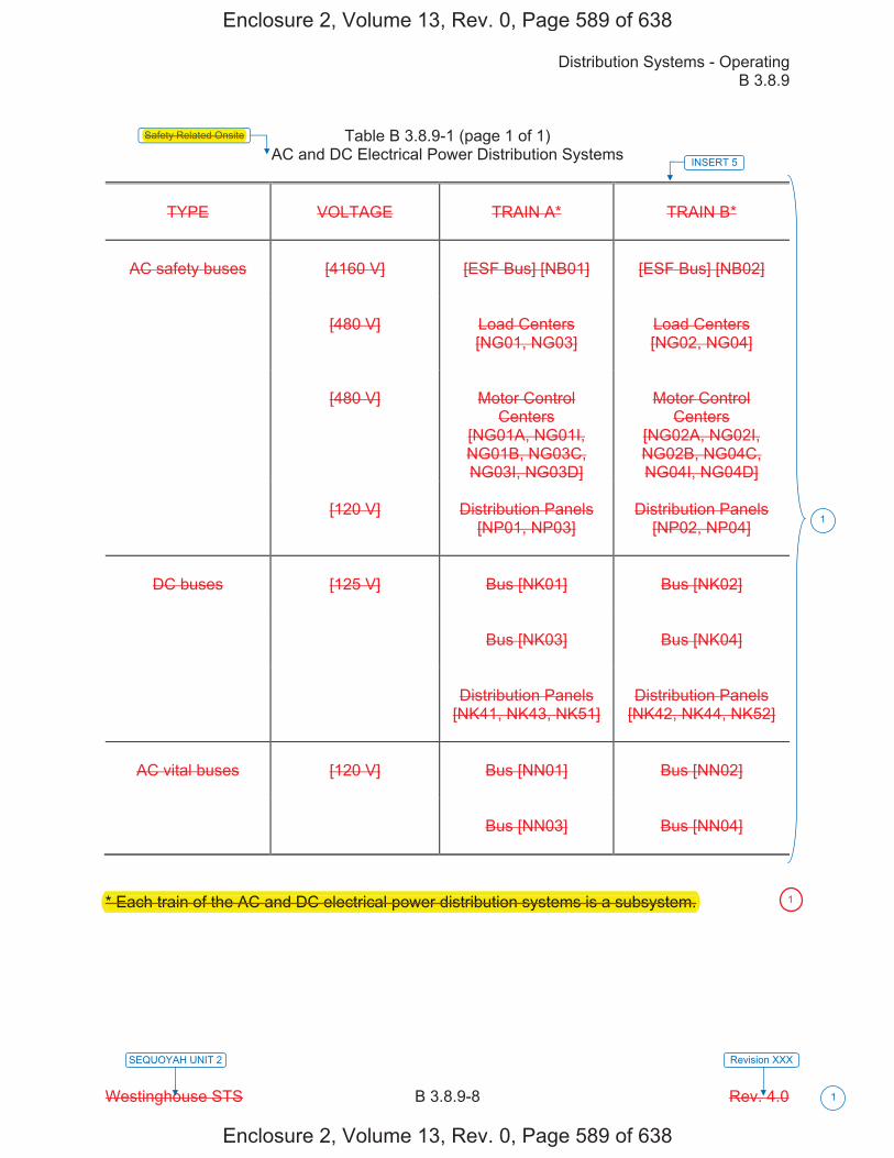
Distribution Systems - Operating B 3.8.9
Westinghouse STS B 3.8.9-8 Rev. 4.0
SEQUOYAH UNIT 2 Revision XXX
1
Table B 3.8.9-1 (page 1 of 1) AC and DC Electrical Power Distribution Systems
TYPE
VOLTAGE
TRAIN A*
TRAIN B*
AC safety buses
[4160 V]
[ESF Bus] [NB01]
[ESF Bus] [NB02]
[480 V]
Load Centers [NG01, NG03]
Load Centers [NG02, NG04]
[480 V]
Motor Control
Centers [NG01A, NG01I, NG01B, NG03C, NG03I, NG03D]
Motor Control
Centers [NG02A, NG02I, NG02B, NG04C, NG04I, NG04D]
[120 V]
Distribution Panels
[NP01, NP03]
Distribution Panels
[NP02, NP04]
DC buses
[125 V]
Bus [NK01]
Bus [NK02]
Bus [NK03]
Bus [NK04]
Distribution Panels
[NK41, NK43, NK51]
Distribution Panels
[NK42, NK44, NK52]
AC vital buses
[120 V]
Bus [NN01]
Bus [NN02]
Bus [NN03]
Bus [NN04]
* Each train of the AC and DC electrical power distribution systems is a subsystem.
INSERT 5
1
Safety Related Onsite
Enclosure 2, Volume 13, Rev. 0, Page 589 of 638
Enclosure 2, Volume 13, Rev. 0, Page 589 of 638
Safety Related Onsite
* Each train of the AC and DC electrical power distribution systems is a subsystem. 1
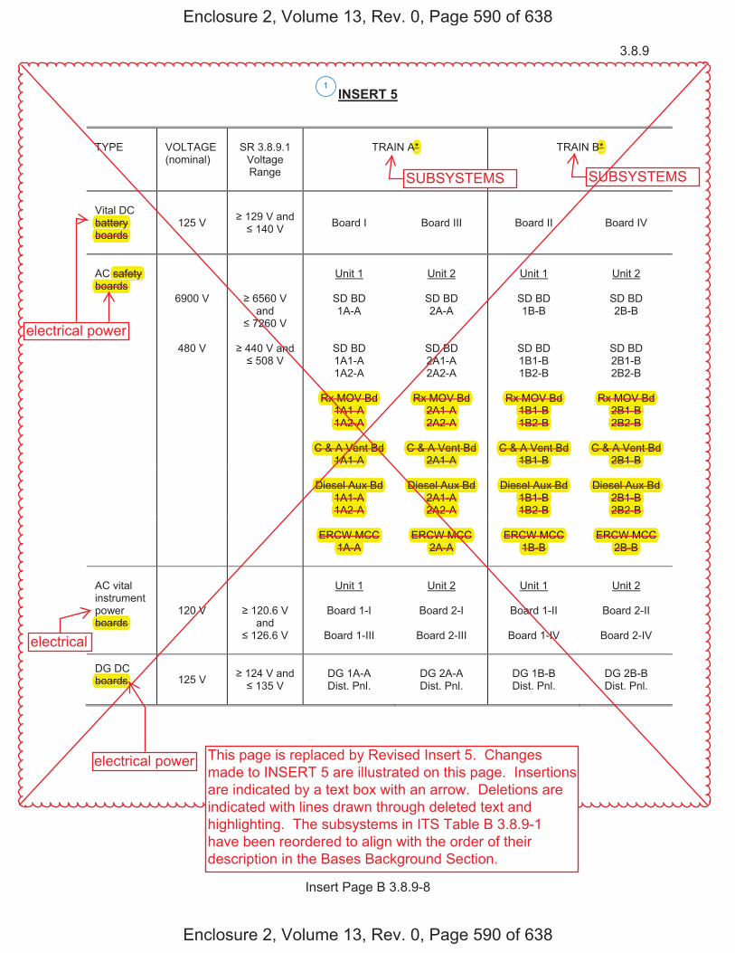
3.8.9
Insert Page B 3.8.9-8
INSERT 5
TYPE
VOLTAGE (nominal)
SR 3.8.9.1
Voltage Range
TRAIN A*
TRAIN B*
Vital DC battery boards
125 V 129 V and 140 V Board I Board III Board II
Board IV
AC safety boards
6900 V
6560 V and
7260 V
Unit 1
SD BD 1A-A
Unit 2
SD BD 2A-A
Unit 1
SD BD 1B-B
Unit 2
SD BD 2B-B
480 V
440 V and
508 V
SD BD 1A1-A 1A2-A
SD BD 2A1-A 2A2-A
SD BD 1B1-B 1B2-B
SD BD 2B1-B 2B2-B
Rx MOV Bd
1A1-A 1A2-A
Rx MOV Bd
2A1-A 2A2-A
Rx MOV Bd
1B1-B 1B2-B
Rx MOV Bd
2B1-B 2B2-B
C & A Vent Bd
1A1-A
C & A Vent Bd
2A1-A C & A Vent Bd
1B1-B
C & A Vent Bd
2B1-B
Diesel Aux Bd 1A1-A 1A2-A
Diesel Aux Bd
2A1-A 2A2-A
Diesel Aux Bd
1B1-B 1B2-B
Diesel Aux Bd
2B1-B 2B2-B
ERCW MCC
1A-A
ERCW MCC
2A-A
ERCW MCC
1B-B
ERCW MCC
2B-B
AC vital instrument power boards
120 V
120.6 V and
126.6 V
Unit 1
Board 1-I
Board 1-III
Unit 2
Board 2-I
Board 2-III
Unit 1
Board 1-II
Board 1-IV
Unit 2
Board 2-II
Board 2-IV
DG DC boards 125 V
124 V and
135 V
DG 1A-A Dist. Pnl.
DG 2A-A Dist. Pnl.
DG 1B-B Dist. Pnl.
DG 2B-B Dist. Pnl.
1
Enclosure 2, Volume 13, Rev. 0, Page 590 of 638
Enclosure 2, Volume 13, Rev. 0, Page 590 of 638
SUBSYSTEMS SUBSYSTEMS
boards
pboards
Rx MOV Bd Rx MOV Bd Rx MOV Bd Rx MOV Bd 1A1-A 2A1-A 1B1-B 2B1-B1A2-A 2A2-A 1B2-B 2B2-B
C & A Vent Bd C & A Vent Bd C & A Vent Bd C & A Vent Bd 1A1-A 2A1-A 1B1-B 2B1-B
Diesel Aux Bd Diesel Aux Bd Diesel Aux Bd Diesel Aux Bd 1A1-A 2A1-A 1B1-B 2B1-B1A2-A 2A2-A 1B2-B 2B2-B
ERCW MCC ERCW MCC ERCW MCC ERCW MCC1A-A 2A-A 1B-B 2B-B
safety boards
battery yboards
A* B*
electrical power
electrical
electrical power This page is replaced by Revised Insert 5. Changesmade to INSERT 5 are illustrated on this page. Insertionsare indicated by a text box with an arrow. Deletions areindicated with lines drawn through deleted text andhighlighting. The subsystems in ITS Table B 3.8.9-1have been reordered to align with the order of theirdescription in the Bases Background Section.
������
�
����� ���������n�min����
��������������t��e���n�e�
��������
�����������
��������
�����������
���e�e�tri�������er� ������� ��������
�n����������
�nit���
�����������
�nit���
�����������
�nit���
�����������
�nit���
�����������
������ ��������n���������
������������������
������������������
������������������
������������������
����it���instrument�e�e�tri�������er�
������ ����������n��
���������
�nit���
���r������
���r��������
�nit���
���r������
���r��������
�nit���
���r�������
���r�������
�nit���
���r�������
���r�������
�it������e�e�tri�������er�
������ ��������n��������� ���r���� ���r������ ���r����� ���r�����
������e�e�tri�������er�
�������
����������ist���n���
���������ist���n���
���������ist���n���
���������ist���n���
1
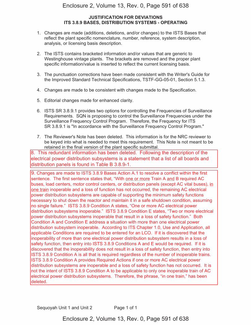
JUSTIFICATION FOR DEVIATIONS ITS 3.8.9 BASES, DISTRIBUTION SYSTEMS - OPERATING
Sequoyah Unit 1 and Unit 2 Page 1 of 1
1. Changes are made (additions, deletions, and/or changes) to the ISTS Bases that reflect the plant specific nomenclature, number, reference, system description, analysis, or licensing basis description.
2. The ISTS contains bracketed information and/or values that are generic to
Westinghouse vintage plants. The brackets are removed and the proper plant specific information/value is inserted to reflect the current licensing basis.
3. The punctuation corrections have been made consistent with the Writer's Guide for
the Improved Standard Technical Specifications, TSTF-GG-05-01, Section 5.1.3.
4. Changes are made to be consistent with changes made to the Specification.
5. Editorial changes made for enhanced clarity. 6. ISTS SR 3.8.9.1 provides two options for controlling the Frequencies of Surveillance
Requirements. SQN is proposing to control the Surveillance Frequencies under the Surveillance Frequency Control Program. Therefore, the Frequency for ITS SR 3.8.9.1 is "In accordance with the Surveillance Frequency Control Program."
7. The Reviewer's Note has been deleted. This information is for the NRC reviewer to be keyed into what is needed to meet this requirement. This Note is not meant to be retained in the final version of the plant specific submittal.
Enclosure 2, Volume 13, Rev. 0, Page 591 of 638
Enclosure 2, Volume 13, Rev. 0, Page 591 of 638
9. Changes are made to ISTS 3.8.9 Bases Action A.1 to resolve a conflict within the first sentence. The first sentence states that, “With one or more Train A and B required AC buses, load centers, motor control centers, or distribution panels (except AC vital buses), in one train inoperable and a loss of function has not occurred, the remaining AC electrical power distribution subsystems are capable of supporting the minimum safety functions necessary to shut down the reactor and maintain it in a safe shutdown condition, assuming no single failure.” ISTS 3.8.9 Condition A states, “One or more AC electrical power distribution subsystems inoperable.” ISTS 3.8.9 Condition E states, “Two or more electrical power distribution subsystems inoperable that result in a loss of safety function.” Both Condition A and Condition E address a situation with more than one electrical power distribution subsystem inoperable. According to ITS Chapter 1.0, Use and Application, all applicable Conditions are required to be entered for an LCO. If it is discovered that the inoperability of more than one electrical power distribution subsystem results in a loss of safety function, then entry into ISTS 3.8.9 Conditions A and E would be required. If it is discovered that the inoperability does not result in a loss of safety function, then entry into ISTS 3.8.9 Condition A is all that is required regardless of the number of inoperable trains. ISTS 3.8.9 Condition A provides Required Actions if one or more AC electrical power distribution subsystems are inoperable and a loss of safety function has not occurred. It is not the intent of ISTS 3.8.9 Condition A to be applicable to only one inoperable train of AC electrical power distribution subsystems. Therefore, the phrase, “in one train,” has been deleted.
8. This redundant information has been deleted. Following the description of theelectrical power distribution subsystems is a statement that a list of all boards anddistribution panels is found in Table B 3.8.9-1.

DISCUSSION OF CHANGES ITS 3.8.10, DISTRIBUTION SYSTEMS - SHUTDOWN
Sequoyah Unit 1 and Unit 2 Page 1 of 5
ADMINISTRATIVE CHANGES A01 In the conversion of the Sequoyah Nuclear Plant (SQN) Current Technical
Specifications (CTS) to the plant specific Improved Technical Specifications (ITS), certain changes (wording preferences, editorial changes, reformatting, revised numbering, etc.) are made to obtain consistency with NUREG-1431, Rev. 4.0, "Standard Technical Specifications - Westinghouse Plants" (ISTS) and additional Technical Specification Task Force (TSTF) travelers included in this submittal.
These changes are designated as administrative changes and are acceptable
because they do not result in technical changes to the CTS. A02 CTS 3.8.1.2.b.5 requires, in part, a separate and independent 125 volt DC
distribution panel for diesel generator (DG) OPERABILITY. ITS 3.8.10 ACTION B requires for one or more inoperable DG DC electrical power distribution subsystems to immediately declare the associated DG inoperable. This changes the CTS by specifying an Action to declare a DG inoperable if its associated DC electrical power distribution subsystem is inoperable.
The purpose of CTS 3.8.1.2.b.5 is to specify the requirements for DG
OPERABILITY. ITS 3.8.10 ACTION B preserves the intent of CTS 3.8.1.2.b.5 by declaring the DG inoperable if the associated DG DC distribution subsystem is inoperable. This change is designated as administrative because it does not result in technical changes to the CTS.
MORE RESTRICTIVE CHANGES M01 CTS 3.8.1.2.b.5 requires, in part, a sparate 125 volt DC distribution panel for
each DG set to be OPERABLE. CTS 3.8.2.2 states, in part, that as a minimum the following AC electrical boards shall be OPERABLE and energized, and then lists the applicable boards. CTS 3.8.2.4 requires, in part, that as a minimum the following 125 volt DC boards shall be energized and OPERABLE as listed. ITS 3.8.10 states that the necessary portion of AC, vital DC, DG DC, and AC vital electrical power distribution subsystems shall be OPERABLE to support equipment required to be OPERABLE. In addition, an optional Required Action (ITS 3.8.10 Required Action A.1) has been added which allows the associated supported required feature(s) to be declared inoperable. This changes the CTS by requiring those necessary portions of electrical power distribution subsystems to be OPERABLE to support equipment required to be OPERABLE, which could require more distribution boards or panels to be OPERABLE than is currently required. In addition, an action has been added to allow an option to the existing actions.
The purpose of CTS 3.8.1.2.b.5, CTS 3.8.2.2 and CTS 3.8.2.4 is to ensure that at
least one train of AC, vital DC, DG DC, and 120 volt AC vital electrical power distribution systems are OPERABLE. This change adds a requirement that the applicable portions of AC, vital DC, DG DC, and 120 volt AC vital electrical power distribution subsystems must be OPERABLE when required to support equipment required to be OPERABLE by the Technical Specifications. This
Enclosure 2, Volume 13, Rev. 0, Page 612 of 638
Enclosure 2, Volume 13, Rev. 0, Page 612 of 638
panels
panel
qsubsystems
subsystem
subsystem s
separate
sparate
instrument
instrument

DISCUSSION OF CHANGES ITS 3.8.10, DISTRIBUTION SYSTEMS - SHUTDOWN
Sequoyah Unit 1 and Unit 2 Page 2 of 5
added restriction conservatively assures the needed electrical power distribution boards and panels are OPERABLE, even if this results in both trains of one or more of the electrical power distribution systems being required. Because the ITS 3.8.10 electrical power distribution subsystem OPERABILITY requirements require the necessary portions of the distribution subsystems to be OPERABLE to support equipment required to be OPERABLE, if a portion of the electrical power distribution subsystem cannot supply any required equipment, that electrical power distribution subsystem is inoperable. In this event, it may not be necessary to suspend, irradiated fuel handling, and positive reactivity additions. Conservative actions can be assured if all required equipment without the necessary power is declared inoperable, and the associated ACTIONS of the individual equipment is taken (ITS 3.8.10 Required Action A.1). Therefore, along with the conservative additional requirements placed on the electrical power distribution subsystems, Required Action A.1, which requires the associated supported equipment to be declared inoperable, is also added. These changes are acceptable since the additions represent restrictions consistent with implicit assumptions for operation in shutdown conditions (required equipment receiving the necessary required power), and these restrictions are not currently imposed by the Technical Specifications. This change is designated as more restrictive because it adds a new requirement to the CTS and more boards may be required to be OPERABLE in ITS than in the CTS.
M02 CTS 3.8.1.2, CTS 3.8.2.2 and CTS 3.8.2.4 are applicable in MODES 5 and 6.
ITS 3.8.10 is applicable in MODES 5 and 6 and during movement of irradiated fuel assemblies and contains an ACTIONS Note stating that LCO 3.0.3 is not applicable. This changes the CTS by adding the Applicability of "During movement of irradiated fuel assemblies," and adds a Note to the ACTIONS stating that LCO 3.0.3 is not applicable.
This change is acceptable because the proposed requirements are necessary to
ensure the electrical power subsystems are OPERABLE to support equipment required to be OPERABLE during movement of irradiated fuel assemblies. Movement of fuel normally occurs during MODES 5 and 6; however, it can also occur outside of containment in other plant MODES (MODES 1, 2, 3, and 4) or other conditions (i.e., reactor defueled). This addition to the applicability is needed to ensure the appropriate electrical distribution system requirements are specified during fuel handling and to ensure the appropriate actions are taken (i.e., stop fuel movement) when the minimum electrical supply is not available. In addition, this change adds a clarification Note stating that LCO 3.0.3 is not applicable because LCO 3.0.3 has no Required Actions that restore safety. If moving irradiated fuel assemblies while in MODES 5 or 6, LCO 3.0.3 is not applicable because LCO 3.0.3 applicability is limited to MODES 1, 2, 3, and 4 only with a designated endpoint of MODE 5. In addition, if moving irradiated fuel assemblies while in MODES 1, 2, 3, or 4, the fuel movement is independent of reactor operations and the inability to suspend movement in accordance with ITS 3.8.10 Required Actions would not be sufficient reason to require a reactor shutdown. This Note has been added for clarification and is necessary since defaulting to LCO 3.0.3 would require the reactor to be shutdown, but would not require suspension of the activities with a potential for releasing radioactive materials. This change is designated as more restrictive because the ITS requires equipment to be OPERABLE during movement of irradiated fuel
Enclosure 2, Volume 13, Rev. 0, Page 613 of 638
Enclosure 2, Volume 13, Rev. 0, Page 613 of 638

DISCUSSION OF CHANGES ITS 3.8.10, DISTRIBUTION SYSTEMS - SHUTDOWN
Sequoyah Unit 1 and Unit 2 Page 3 of 5
assemblies both inside and outside of the containment, not only when in MODES 5 and 6.
M03 CTS 4.8.1.2 requires, in part, the performance of CTS 4.8.1.1.3, which includes a
requirement that the 125 volt DC distribution panel for each DG be demonstrated OPERABLE. ITS SR 3.8.10.1 requires, in part, verification of the correct breaker alignments and voltage to the 125 volt DC distribution panel for each DG. This changes the CTS by adding a specific surveillance requiring verification of correct breaker alignment and correct voltage to the DG DC distribution subsystem.
The purpose of CTS 4.8.1.2 is to provide assurance that necessary power to
required supported systems is available with sufficient capacity, capability, redundancy, and reliability to ensure the fuel, Reactor Coolant System, and containment design limits are not exceeded and postulated accidents are mitigated. This change is acceptable because it provides additional assurance that the distribution panels associated with the DG DC electrical power distribution subsystem are OPERABLE. This change is designated as more restrictive because it add a Surveillance Requirement to the CTS.
RELOCATED SPECIFICATIONS None REMOVED DETAIL CHANGES
LA01 (Type 1 – Removing Details of System Design and System Description, Including
Design Limits) CTS 3.8.1.2 requires AC electrical power sources to be OPERABLE, listing the sources and subsystems. CTS LCO 3.8.2.2 requires AC electrical boards to be OPERABLE, listing the boards. CTS LCO 3.8.2.4 requires DC electrical equipment and boards to be energized and OPERABLE and CTS 4.8.2.4.1 requires the overall battery voltage to be greater than or equal to 125 volts. ITS LCO 3.8.10 requires necessary portions of the AC, vital DC, DG DC, and AC vital electrical power distribution subsystems to be OPERABLE to support equipment required to be OPERABLE. ITS SR 3.8.10.1 requires the verification of correct breaker alignment and voltage to each required AC, vital DC, and vital AC electrical power distribution subsystem. The details of the boards are contained in the ITS Bases. This changes the CTS by moving description of the boards and panels (including the nominal voltages and any specified limits) from the CTS to the ITS Bases.
The removal of these details relating to system design from the Technical
Specifications is acceptable because this type of information is not necessary to be included in the Technical Specifications to provide adequate protection of public health and safety. The ITS still retains the requirement for the electrical power distribution subsystems to be OPERABLE and requires the verification of correct breaker alignment and voltage to required AC and DC electrical power distribution subsystems. This change is acceptable because the removed information will be adequately controlled in the ITS Bases. Changes to the
Enclosure 2, Volume 13, Rev. 0, Page 614 of 638
Enclosure 2, Volume 13, Rev. 0, Page 614 of 638
instrument
�ital�instrument
vital
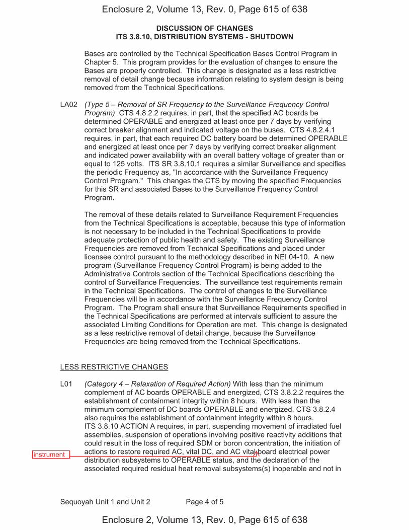
DISCUSSION OF CHANGES ITS 3.8.10, DISTRIBUTION SYSTEMS - SHUTDOWN
Sequoyah Unit 1 and Unit 2 Page 4 of 5
Bases are controlled by the Technical Specification Bases Control Program in Chapter 5. This program provides for the evaluation of changes to ensure the Bases are properly controlled. This change is designated as a less restrictive removal of detail change because information relating to system design is being removed from the Technical Specifications.
LA02 (Type 5 – Removal of SR Frequency to the Surveillance Frequency Control
Program) CTS 4.8.2.2 requires, in part, that the specified AC boards be determined OPERABLE and energized at least once per 7 days by verifying correct breaker alignment and indicated voltage on the buses. CTS 4.8.2.4.1 requires, in part, that each required DC battery board be determined OPERABLE and energized at least once per 7 days by verifying correct breaker alignment and indicated power availability with an overall battery voltage of greater than or equal to 125 volts. ITS SR 3.8.10.1 requires a similar Surveillance and specifies the periodic Frequency as, "In accordance with the Surveillance Frequency Control Program." This changes the CTS by moving the specified Frequencies for this SR and associated Bases to the Surveillance Frequency Control Program.
The removal of these details related to Surveillance Requirement Frequencies from the Technical Specifications is acceptable, because this type of information is not necessary to be included in the Technical Specifications to provide adequate protection of public health and safety. The existing Surveillance Frequencies are removed from Technical Specifications and placed under licensee control pursuant to the methodology described in NEI 04-10. A new program (Surveillance Frequency Control Program) is being added to the Administrative Controls section of the Technical Specifications describing the control of Surveillance Frequencies. The surveillance test requirements remain in the Technical Specifications. The control of changes to the Surveillance Frequencies will be in accordance with the Surveillance Frequency Control Program. The Program shall ensure that Surveillance Requirements specified in the Technical Specifications are performed at intervals sufficient to assure the associated Limiting Conditions for Operation are met. This change is designated as a less restrictive removal of detail change, because the Surveillance Frequencies are being removed from the Technical Specifications.
LESS RESTRICTIVE CHANGES L01 (Category 4 – Relaxation of Required Action) With less than the minimum
complement of AC boards OPERABLE and energized, CTS 3.8.2.2 requires the establishment of containment integrity within 8 hours. With less than the minimum complement of DC boards OPERABLE and energized, CTS 3.8.2.4 also requires the establishment of containment integrity within 8 hours. ITS 3.8.10 ACTION A requires, in part, suspending movement of irradiated fuel assemblies, suspension of operations involving positive reactivity additions that could result in the loss of required SDM or boron concentration, the initiation of actions to restore required AC, vital DC, and AC vital board electrical power distribution subsystems to OPERABLE status, and the declaration of the associated required residual heat removal subsystems(s) inoperable and not in
Enclosure 2, Volume 13, Rev. 0, Page 615 of 638
Enclosure 2, Volume 13, Rev. 0, Page 615 of 638
instrument
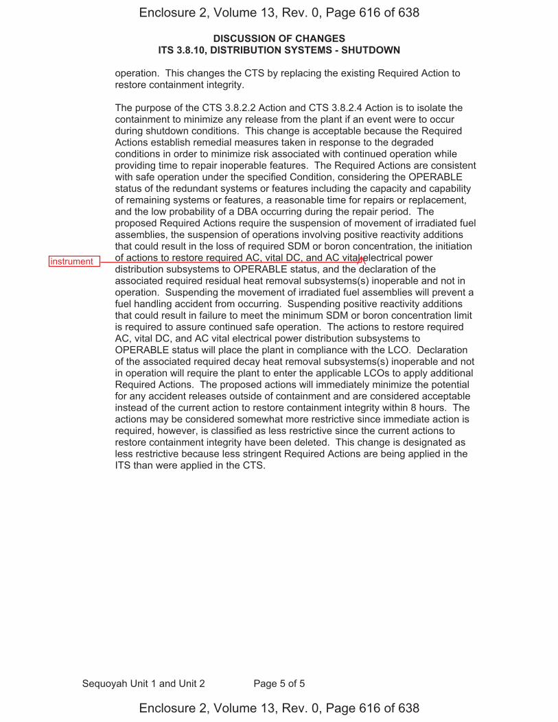
DISCUSSION OF CHANGES ITS 3.8.10, DISTRIBUTION SYSTEMS - SHUTDOWN
Sequoyah Unit 1 and Unit 2 Page 5 of 5
operation. This changes the CTS by replacing the existing Required Action to restore containment integrity.
The purpose of the CTS 3.8.2.2 Action and CTS 3.8.2.4 Action is to isolate the
containment to minimize any release from the plant if an event were to occur during shutdown conditions. This change is acceptable because the Required Actions establish remedial measures taken in response to the degraded conditions in order to minimize risk associated with continued operation while providing time to repair inoperable features. The Required Actions are consistent with safe operation under the specified Condition, considering the OPERABLE status of the redundant systems or features including the capacity and capability of remaining systems or features, a reasonable time for repairs or replacement, and the low probability of a DBA occurring during the repair period. The proposed Required Actions require the suspension of movement of irradiated fuel assemblies, the suspension of operations involving positive reactivity additions that could result in the loss of required SDM or boron concentration, the initiation of actions to restore required AC, vital DC, and AC vital electrical power distribution subsystems to OPERABLE status, and the declaration of the associated required residual heat removal subsystems(s) inoperable and not in operation. Suspending the movement of irradiated fuel assemblies will prevent a fuel handling accident from occurring. Suspending positive reactivity additions that could result in failure to meet the minimum SDM or boron concentration limit is required to assure continued safe operation. The actions to restore required AC, vital DC, and AC vital electrical power distribution subsystems to OPERABLE status will place the plant in compliance with the LCO. Declaration of the associated required decay heat removal subsystems(s) inoperable and not in operation will require the plant to enter the applicable LCOs to apply additional Required Actions. The proposed actions will immediately minimize the potential for any accident releases outside of containment and are considered acceptable instead of the current action to restore containment integrity within 8 hours. The actions may be considered somewhat more restrictive since immediate action is required, however, is classified as less restrictive since the current actions to restore containment integrity have been deleted. This change is designated as less restrictive because less stringent Required Actions are being applied in the ITS than were applied in the CTS.
Enclosure 2, Volume 13, Rev. 0, Page 616 of 638
Enclosure 2, Volume 13, Rev. 0, Page 616 of 638
instrument

Distribution Systems - Shutdown 3.8.10
Westinghouse STS 3.8.10-1 Rev. 4.0 Amendment XXXSEQUOYAH UNIT 1
CTS
1
3.8 ELECTRICAL POWER SYSTEMS 3.8.10 Distribution Systems - Shutdown LCO 3.8.10 The necessary portion of AC, DC, and AC vital bus electrical power
distribution subsystems shall be OPERABLE to support equipment required to be OPERABLE.
APPLICABILITY: MODES 5 and 6, During movement of [recently] irradiated fuel assemblies. ACTIONS ------------------------------------------------------------NOTE----------------------------------------------------------- LCO 3.0.3 is not applicable. -------------------------------------------------------------------------------------------------------------------------------
CONDITION
REQUIRED ACTION
COMPLETION TIME
A. One or more required
AC, DC, or AC vital bus electrical power distribution subsystems inoperable.
A.1 Declare associated
supported required feature(s) inoperable.
OR A.2.1 Suspend movement of
[recently] irradiated fuel assemblies.
AND A.2.2 Suspend operations
involving positive reactivity additions that could result in loss of required SDM or boron concentration.
AND
Immediately Immediately Immediately
vital
vital
3.8.1.2,3.8.2.2, 3.8.2.4
Applicability 3.8.1.2, 3.8.2.2, 3.8.2.4 DOC M02
DOC M02
ACTION 3.8.2.2 3.8.2.4 DOC M01
DOC L01
DOC L01
1
2
1
2
, and diesel generator (DG) DC
Enclosure 2, Volume 13, Rev. 0, Page 618 of 638
Enclosure 2, Volume 13, Rev. 0, Page 618 of 638
instrument
instrument

Distribution Systems - Shutdown 3.8.10
Westinghouse STS 3.8.10-2 Rev. 4.0 Amendment XXXSEQUOYAH UNIT 1
CTS
1
ACTIONS (continued)
CONDITION REQUIRED ACTION COMPLETION TIME
A.2.3 Initiate actions to restore required AC, DC, and AC vital bus electrical power distribution subsystems to OPERABLE status.
AND
A.2.4 Declare associated required residual heat removal subsystem(s) inoperable and not in operation.
Immediately
Immediately
SURVEILLANCE REQUIREMENTS
SURVEILLANCE FREQUENCY
SR 3.8.10.1 Verify correct breaker alignments and voltage to required AC, DC, and AC vital bus electrical power distribution subsystems.
[ 7 days
OR
In accordance with the Surveillance Frequency Control Program ]
vital
vital
DOC L01
DOC L01
4.8.1.2, 4.8.2.2, 4.8.2.4.1
1
1
3
1
INSERT 1 1
, and DG DC
Enclosure 2, Volume 13, Rev. 0, Page 619 of 638
Enclosure 2, Volume 13, Rev. 0, Page 619 of 638
instrument
instrument

3.8.10
Insert Page 3.8.10-2
INSERT 1
B. One or more required
DG DC electrical power distribution subsystems inoperable.
B.1 Declare associated DG(s)
inoperable.
Immediately
1
DOC A02
Enclosure 2, Volume 13, Rev. 0, Page 620 of 638
Enclosure 2, Volume 13, Rev. 0, Page 620 of 638
panels
p subsystems

Distribution Systems - Shutdown 3.8.10
Westinghouse STS 3.8.10-1 Rev. 4.0 Amendment XXXSEQUOYAH UNIT 2
CTS
1
3.8 ELECTRICAL POWER SYSTEMS 3.8.10 Distribution Systems - Shutdown LCO 3.8.10 The necessary portion of AC, DC, and AC vital bus electrical power
distribution subsystems shall be OPERABLE to support equipment required to be OPERABLE.
APPLICABILITY: MODES 5 and 6, During movement of [recently] irradiated fuel assemblies. ACTIONS ------------------------------------------------------------NOTE----------------------------------------------------------- LCO 3.0.3 is not applicable. -------------------------------------------------------------------------------------------------------------------------------
CONDITION
REQUIRED ACTION
COMPLETION TIME
A. One or more required
AC, DC, or AC vital bus electrical power distribution subsystems inoperable.
A.1 Declare associated
supported required feature(s) inoperable.
OR A.2.1 Suspend movement of
[recently] irradiated fuel assemblies.
AND A.2.2 Suspend operations
involving positive reactivity additions that could result in loss of required SDM or boron concentration.
AND
Immediately Immediately Immediately
vital
vital
3.8.1.2,3.8.2.2, 3.8.2.4
Applicability 3.8.1.2, 3.8.2.2, 3.8.2.4 DOC M02
DOC M02
ACTION 3.8.2.2 3.8.2.4 DOC M01
DOC L01
DOC L01
1
2
1
2
, and diesel generator (DG) DC
Enclosure 2, Volume 13, Rev. 0, Page 621 of 638
Enclosure 2, Volume 13, Rev. 0, Page 621 of 638
instrument
instrument
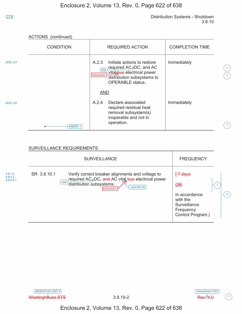
Distribution Systems - Shutdown 3.8.10
Westinghouse STS 3.8.10-2 Rev. 4.0 Amendment XXXSEQUOYAH UNIT 2
CTS
1
ACTIONS (continued)
CONDITION
REQUIRED ACTION
COMPLETION TIME
A.2.3 Initiate actions to restore
required AC, DC, and AC vital bus electrical power distribution subsystems to OPERABLE status.
AND A.2.4 Declare associated
required residual heat removal subsystem(s) inoperable and not in operation.
Immediately Immediately
SURVEILLANCE REQUIREMENTS
SURVEILLANCE
FREQUENCY
SR 3.8.10.1 Verify correct breaker alignments and voltage to
required AC, DC, and AC vital bus electrical power distribution subsystems.
[ 7 days OR In accordance with the Surveillance Frequency Control Program ]
vital
vital
DOC L01
DOC L01
4.8.1.2, 4.8.2.2, 4.8.2.4.1
1
1
3
1
INSERT 1 1
, and DG DC
Enclosure 2, Volume 13, Rev. 0, Page 622 of 638
Enclosure 2, Volume 13, Rev. 0, Page 622 of 638
instrument
instrument

3.8.10
Insert Page 3.8.10-2
INSERT 1
B. One or more required
DG DC electrical power distribution subsystems inoperable.
B.1 Declare associated DG(s)
inoperable.
Immediately
1
DOC A02
Enclosure 2, Volume 13, Rev. 0, Page 623 of 638
Enclosure 2, Volume 13, Rev. 0, Page 623 of 638
panels
p subsystems
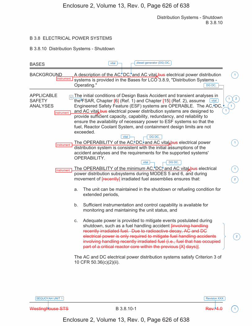
Distribution Systems - Shutdown B 3.8.10
Westinghouse STS B 3.8.10-1 Rev. 4.0
SEQUOYAH UNIT 1 Revision XXX
1
B 3.8 ELECTRICAL POWER SYSTEMS B 3.8.10 Distribution Systems - Shutdown BASES BACKGROUND A description of the AC, DC, and AC vital bus electrical power distribution
systems is provided in the Bases for LCO 3.8.9, "Distribution Systems - Operating."
APPLICABLE The initial conditions of Design Basis Accident and transient analyses in SAFETY the FSAR, Chapter [6] (Ref. 1) and Chapter [15] (Ref. 2), assume ANALYSES Engineered Safety Feature (ESF) systems are OPERABLE. The AC, DC,
and AC vital bus electrical power distribution systems are designed to provide sufficient capacity, capability, redundancy, and reliability to ensure the availability of necessary power to ESF systems so that the fuel, Reactor Coolant System, and containment design limits are not exceeded.
The OPERABILITY of the AC, DC, and AC vital bus electrical power distribution system is consistent with the initial assumptions of the accident analyses and the requirements for the supported systems' OPERABILITY. The OPERABILITY of the minimum AC, DC, and AC vital bus electrical power distribution subsystems during MODES 5 and 6, and during movement of [recently] irradiated fuel assemblies ensures that: a. The unit can be maintained in the shutdown or refueling condition for
extended periods, b. Sufficient instrumentation and control capability is available for
monitoring and maintaining the unit status, and c. Adequate power is provided to mitigate events postulated during
shutdown, such as a fuel handling accident [involving handling recently irradiated fuel. Due to radioactive decay, AC and DC electrical power is only required to mitigate fuel handling accidents involving handling recently irradiated fuel (i.e., fuel that has occupied part of a critical reactor core within the previous [X] days)].
The AC and DC electrical power distribution systems satisfy Criterion 3 of 10 CFR 50.36(c)(2)(ii).
vital
vital
vital
vital
1
2
1
1
1
2
2
1
U 1
1
,diesel generator (DG) DC,
DG DC,
DG DC,
DG DC,
Enclosure 2, Volume 13, Rev. 0, Page 626 of 638
Enclosure 2, Volume 13, Rev. 0, Page 626 of 638
instrument
instrument
instrument
instrument

Distribution Systems - Shutdown B 3.8.10
Westinghouse STS B 3.8.10-2 Rev. 4.0
SEQUOYAH UNIT 1 Revision XXX
1
BASES LCO Various combinations of subsystems, equipment, and components are
required OPERABLE by other LCOs, depending on the specific plant condition. Implicit in those requirements is the required OPERABILITY of necessary support required features. This LCO explicitly requires energization of the portions of the electrical distribution system necessary to support OPERABILITY of required systems, equipment, and components - all specifically addressed in each LCO and implicitly required via the definition of OPERABILITY.
Maintaining these portions of the distribution system energized ensures the availability of sufficient power to operate the unit in a safe manner to mitigate the consequences of postulated events during shutdown (e.g., fuel handling accidents [involving handling recently irradiated fuel]).
APPLICABILITY The AC and DC electrical power distribution subsystems required to be
OPERABLE in MODES 5 and 6, and during movement of [recently] irradiated fuel assemblies, provide assurance that: a. Systems to provide adequate coolant inventory makeup are available
for the irradiated fuel in the core, b. Systems needed to mitigate a fuel handling accident [involving
handling recently irradiated fuel (i.e., fuel that has occupied part of a critical reactor core within the previous [X] days)] are available,
c. Systems necessary to mitigate the effects of events that can lead to
core damage during shutdown are available, and d. Instrumentation and control capability is available for monitoring and
maintaining the unit in a cold shutdown condition and refueling condition.
The AC, DC, and AC vital bus electrical power distribution subsystems requirements for MODES 1, 2, 3, and 4 are covered in LCO 3.8.9.
ACTIONS LCO 3.0.3 is not applicable while in MODE 5 or 6. However, since
irradiated fuel assembly movement can occur in MODE 1, 2, 3, or 4, the ACTIONS have been modified by a Note stating that LCO 3.0.3 is not applicable. If moving irradiated fuel assemblies while in MODE 5 or 6, LCO 3.0.3 would not specify any action. If moving irradiated fuel assemblies while in MODE 1, 2, 3, or 4, the fuel movement is independent of reactor operations. Entering LCO 3.0.3, while in MODE 1, 2, 3, or 4 would require the unit to be shutdown unnecessarily.
vital
1
2
2
2
DG DC,
Enclosure 2, Volume 13, Rev. 0, Page 627 of 638
Enclosure 2, Volume 13, Rev. 0, Page 627 of 638
instrument
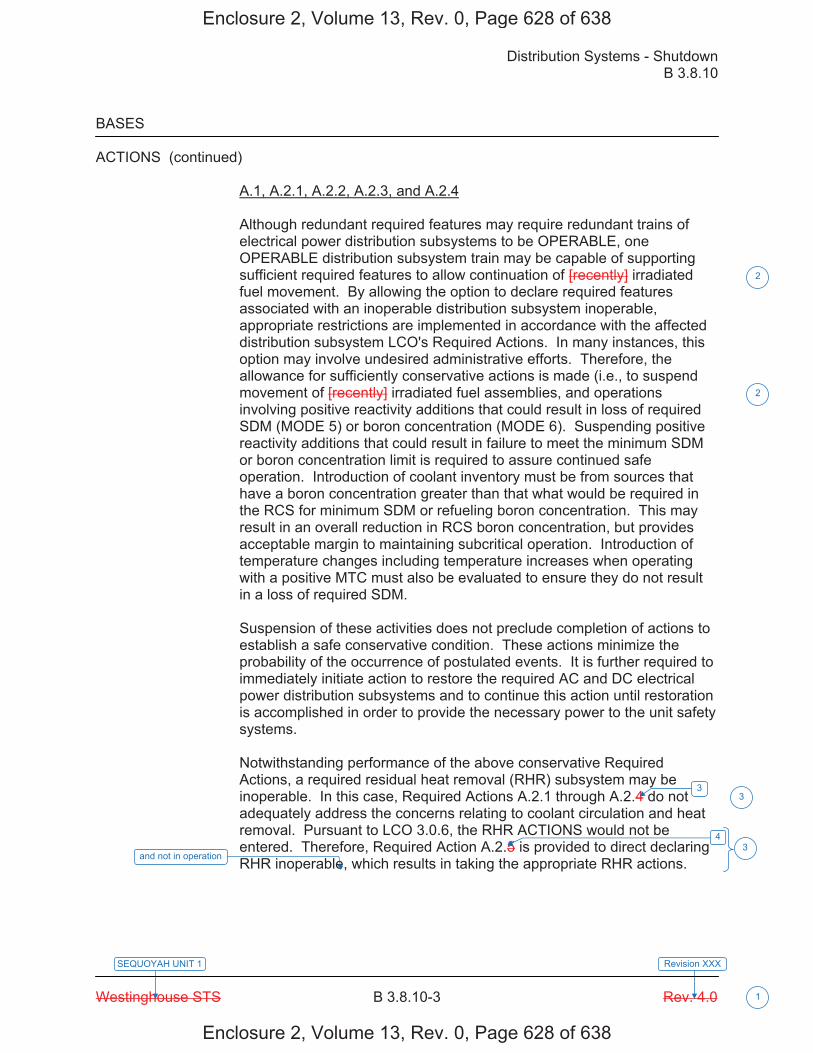
Distribution Systems - Shutdown B 3.8.10
Westinghouse STS B 3.8.10-3 Rev. 4.0
SEQUOYAH UNIT 1 Revision XXX
1
BASES ACTIONS (continued)
A.1, A.2.1, A.2.2, A.2.3, and A.2.4 Although redundant required features may require redundant trains of electrical power distribution subsystems to be OPERABLE, one OPERABLE distribution subsystem train may be capable of supporting sufficient required features to allow continuation of [recently] irradiated fuel movement. By allowing the option to declare required features associated with an inoperable distribution subsystem inoperable, appropriate restrictions are implemented in accordance with the affected distribution subsystem LCO's Required Actions. In many instances, this option may involve undesired administrative efforts. Therefore, the allowance for sufficiently conservative actions is made (i.e., to suspend movement of [recently] irradiated fuel assemblies, and operations involving positive reactivity additions that could result in loss of required SDM (MODE 5) or boron concentration (MODE 6). Suspending positive reactivity additions that could result in failure to meet the minimum SDM or boron concentration limit is required to assure continued safe operation. Introduction of coolant inventory must be from sources that have a boron concentration greater than that what would be required in the RCS for minimum SDM or refueling boron concentration. This may result in an overall reduction in RCS boron concentration, but provides acceptable margin to maintaining subcritical operation. Introduction of temperature changes including temperature increases when operating with a positive MTC must also be evaluated to ensure they do not result in a loss of required SDM. Suspension of these activities does not preclude completion of actions to establish a safe conservative condition. These actions minimize the probability of the occurrence of postulated events. It is further required to immediately initiate action to restore the required AC and DC electrical power distribution subsystems and to continue this action until restoration is accomplished in order to provide the necessary power to the unit safety systems. Notwithstanding performance of the above conservative Required Actions, a required residual heat removal (RHR) subsystem may be inoperable. In this case, Required Actions A.2.1 through A.2.4 do not adequately address the concerns relating to coolant circulation and heat removal. Pursuant to LCO 3.0.6, the RHR ACTIONS would not be entered. Therefore, Required Action A.2.5 is provided to direct declaring RHR inoperable, which results in taking the appropriate RHR actions.
2
2
33
43
and not in operation
Enclosure 2, Volume 13, Rev. 0, Page 628 of 638
Enclosure 2, Volume 13, Rev. 0, Page 628 of 638

Distribution Systems - Shutdown B 3.8.10
Westinghouse STS B 3.8.10-4 Rev. 4.0
SEQUOYAH UNIT 1 Revision XXX
BASES
ACTIONS (continued) The Completion Time of immediately is consistent with the required times for actions requiring prompt attention. The restoration of the required distribution subsystems should be completed as quickly as possible in order to minimize the time the unit safety systems may be without power.
SURVEILLANCE SR 3.8.10.1 REQUIREMENTS
This Surveillance verifies that the AC, DC, and AC vital bus electrical power distribution subsystems are functioning properly, with all the buses energized. The verification of proper voltage availability on the buses ensures that the required power is readily available for motive as well as control functions for critical system loads connected to these buses. [ The 7 day Frequency takes into account the capability of the electrical power distribution subsystems, and other indications available in the control room that alert the operator to subsystem malfunctions. OR The Surveillance Frequency is controlled under the Surveillance Frequency Control Program. -----------------------------------REVIEWER’S NOTE----------------------------------- Plants controlling Surveillance Frequencies under a Surveillance Frequency Control Program should utilize the appropriate Frequency description, given above, and the appropriate choice of Frequency in the Surveillance Requirement. ------------------------------------------------------------------------------------------------ ]
REFERENCES 1. FSAR, Chapter [6]. 2. FSAR, Chapter [15].
vital
4
5
2
U
1
1
1
boards
INSERT 1 1
DG DC,
Enclosure 2, Volume 13, Rev. 0, Page 629 of 638
Enclosure 2, Volume 13, Rev. 0, Page 629 of 638
instrument bus

3.8.10
Insert Page B 3.8.10-4
INSERT 1 B.1 If one or more required DG DC electrical power distribution subsystems are inoperable, the associated DGs may be incapable of performing their intended function and must be immediately declared inoperable. This declaration also requires entry into the applicable Conditions and Required Actions for inoperable DGs, LCO 3.8.2, "AC Sources – Shutdown."
1
Enclosure 2, Volume 13, Rev. 0, Page 630 of 638
Enclosure 2, Volume 13, Rev. 0, Page 630 of 638
panels
subsystems

Distribution Systems - Shutdown B 3.8.10
Westinghouse STS B 3.8.10-1 Rev. 4.0
SEQUOYAH UNIT 2 Revision XXX
1
B 3.8 ELECTRICAL POWER SYSTEMS B 3.8.10 Distribution Systems - Shutdown BASES BACKGROUND A description of the AC, DC, and AC vital bus electrical power distribution
systems is provided in the Bases for LCO 3.8.9, "Distribution Systems - Operating."
APPLICABLE The initial conditions of Design Basis Accident and transient analyses in SAFETY the FSAR, Chapter [6] (Ref. 1) and Chapter [15] (Ref. 2), assume ANALYSES Engineered Safety Feature (ESF) systems are OPERABLE. The AC, DC,
and AC vital bus electrical power distribution systems are designed to provide sufficient capacity, capability, redundancy, and reliability to ensure the availability of necessary power to ESF systems so that the fuel, Reactor Coolant System, and containment design limits are not exceeded.
The OPERABILITY of the AC, DC, and AC vital bus electrical power distribution system is consistent with the initial assumptions of the accident analyses and the requirements for the supported systems' OPERABILITY. The OPERABILITY of the minimum AC, DC, and AC vital bus electrical power distribution subsystems during MODES 5 and 6, and during movement of [recently] irradiated fuel assemblies ensures that: a. The unit can be maintained in the shutdown or refueling condition for
extended periods, b. Sufficient instrumentation and control capability is available for
monitoring and maintaining the unit status, and c. Adequate power is provided to mitigate events postulated during
shutdown, such as a fuel handling accident [involving handling recently irradiated fuel. Due to radioactive decay, AC and DC electrical power is only required to mitigate fuel handling accidents involving handling recently irradiated fuel (i.e., fuel that has occupied part of a critical reactor core within the previous [X] days)].
The AC and DC electrical power distribution systems satisfy Criterion 3 of 10 CFR 50.36(c)(2)(ii).
vital
vital
vital
vital
1
2
1
1
1
2
2
1
U 1
1
,diesel generator (DG) DC,
DG DC,
DG DC,
DG DC,
Enclosure 2, Volume 13, Rev. 0, Page 631 of 638
Enclosure 2, Volume 13, Rev. 0, Page 631 of 638
instrument
instrument
instrument
instrument

Distribution Systems - Shutdown B 3.8.10
Westinghouse STS B 3.8.10-2 Rev. 4.0
SEQUOYAH UNIT 2 Revision XXX
1
BASES LCO Various combinations of subsystems, equipment, and components are
required OPERABLE by other LCOs, depending on the specific plant condition. Implicit in those requirements is the required OPERABILITY of necessary support required features. This LCO explicitly requires energization of the portions of the electrical distribution system necessary to support OPERABILITY of required systems, equipment, and components - all specifically addressed in each LCO and implicitly required via the definition of OPERABILITY.
Maintaining these portions of the distribution system energized ensures the availability of sufficient power to operate the unit in a safe manner to mitigate the consequences of postulated events during shutdown (e.g., fuel handling accidents [involving handling recently irradiated fuel]).
APPLICABILITY The AC and DC electrical power distribution subsystems required to be
OPERABLE in MODES 5 and 6, and during movement of [recently] irradiated fuel assemblies, provide assurance that: a. Systems to provide adequate coolant inventory makeup are available
for the irradiated fuel in the core, b. Systems needed to mitigate a fuel handling accident [involving
handling recently irradiated fuel (i.e., fuel that has occupied part of a critical reactor core within the previous [X] days)] are available,
c. Systems necessary to mitigate the effects of events that can lead to
core damage during shutdown are available, and d. Instrumentation and control capability is available for monitoring and
maintaining the unit in a cold shutdown condition and refueling condition.
The AC, DC, and AC vital bus electrical power distribution subsystems requirements for MODES 1, 2, 3, and 4 are covered in LCO 3.8.9.
ACTIONS LCO 3.0.3 is not applicable while in MODE 5 or 6. However, since
irradiated fuel assembly movement can occur in MODE 1, 2, 3, or 4, the ACTIONS have been modified by a Note stating that LCO 3.0.3 is not applicable. If moving irradiated fuel assemblies while in MODE 5 or 6, LCO 3.0.3 would not specify any action. If moving irradiated fuel assemblies while in MODE 1, 2, 3, or 4, the fuel movement is independent of reactor operations. Entering LCO 3.0.3, while in MODE 1, 2, 3, or 4 would require the unit to be shutdown unnecessarily.
vital
1
2
2
2
DG DC,
Enclosure 2, Volume 13, Rev. 0, Page 632 of 638
Enclosure 2, Volume 13, Rev. 0, Page 632 of 638
instrument

Distribution Systems - Shutdown B 3.8.10
Westinghouse STS B 3.8.10-3 Rev. 4.0
SEQUOYAH UNIT 2 Revision XXX
1
BASES ACTIONS (continued)
A.1, A.2.1, A.2.2, A.2.3, and A.2.4 Although redundant required features may require redundant trains of electrical power distribution subsystems to be OPERABLE, one OPERABLE distribution subsystem train may be capable of supporting sufficient required features to allow continuation of [recently] irradiated fuel movement. By allowing the option to declare required features associated with an inoperable distribution subsystem inoperable, appropriate restrictions are implemented in accordance with the affected distribution subsystem LCO's Required Actions. In many instances, this option may involve undesired administrative efforts. Therefore, the allowance for sufficiently conservative actions is made (i.e., to suspend movement of [recently] irradiated fuel assemblies, and operations involving positive reactivity additions that could result in loss of required SDM (MODE 5) or boron concentration (MODE 6). Suspending positive reactivity additions that could result in failure to meet the minimum SDM or boron concentration limit is required to assure continued safe operation. Introduction of coolant inventory must be from sources that have a boron concentration greater than that what would be required in the RCS for minimum SDM or refueling boron concentration. This may result in an overall reduction in RCS boron concentration, but provides acceptable margin to maintaining subcritical operation. Introduction of temperature changes including temperature increases when operating with a positive MTC must also be evaluated to ensure they do not result in a loss of required SDM. Suspension of these activities does not preclude completion of actions to establish a safe conservative condition. These actions minimize the probability of the occurrence of postulated events. It is further required to immediately initiate action to restore the required AC and DC electrical power distribution subsystems and to continue this action until restoration is accomplished in order to provide the necessary power to the unit safety systems. Notwithstanding performance of the above conservative Required Actions, a required residual heat removal (RHR) subsystem may be inoperable. In this case, Required Actions A.2.1 through A.2.4 do not adequately address the concerns relating to coolant circulation and heat removal. Pursuant to LCO 3.0.6, the RHR ACTIONS would not be entered. Therefore, Required Action A.2.5 is provided to direct declaring RHR inoperable, which results in taking the appropriate RHR actions.
2
2
33
43
and not in operation
Enclosure 2, Volume 13, Rev. 0, Page 633 of 638
Enclosure 2, Volume 13, Rev. 0, Page 633 of 638

Distribution Systems - Shutdown B 3.8.10
Westinghouse STS B 3.8.10-4 Rev. 4.0
SEQUOYAH UNIT 2 Revision XXX
BASES
ACTIONS (continued) The Completion Time of immediately is consistent with the required times for actions requiring prompt attention. The restoration of the required distribution subsystems should be completed as quickly as possible in order to minimize the time the unit safety systems may be without power.
SURVEILLANCE SR 3.8.10.1 REQUIREMENTS
This Surveillance verifies that the AC, DC, and AC vital bus electrical power distribution subsystems are functioning properly, with all the buses energized. The verification of proper voltage availability on the buses ensures that the required power is readily available for motive as well as control functions for critical system loads connected to these buses. [ The 7 day Frequency takes into account the capability of the electrical power distribution subsystems, and other indications available in the control room that alert the operator to subsystem malfunctions. OR The Surveillance Frequency is controlled under the Surveillance Frequency Control Program. -----------------------------------REVIEWER’S NOTE----------------------------------- Plants controlling Surveillance Frequencies under a Surveillance Frequency Control Program should utilize the appropriate Frequency description, given above, and the appropriate choice of Frequency in the Surveillance Requirement. ------------------------------------------------------------------------------------------------ ]
REFERENCES 1. FSAR, Chapter [6]. 2. FSAR, Chapter [15].
vital
4
5
2
U
1
1
1
boards
INSERT 1 1
DG DC,
Enclosure 2, Volume 13, Rev. 0, Page 634 of 638
Enclosure 2, Volume 13, Rev. 0, Page 634 of 638
bus instrument

3.8.10
Insert Page B 3.8.10-4
INSERT 1 B.1 If one or more required DG DC electrical power distribution subsystems are inoperable, the associated DGs may be incapable of performing their intended function and must be immediately declared inoperable. This declaration also requires entry into the applicable Conditions and Required Actions for inoperable DGs, LCO 3.8.2, "AC Sources – Shutdown."
1
Enclosure 2, Volume 13, Rev. 0, Page 635 of 638
Enclosure 2, Volume 13, Rev. 0, Page 635 of 638
panels
subsystems
Licensee Response/NRC Response/NRC Question ClosureId 407
NRC Question Number
VKG025
Select Application NRC Response
Attachment 1
Attachment 2
Response Statement
NRC staff has a 2-part follow-up RAI to the licensee’s response to RAI# VKG025.
Part 1In the licensee’s response a term was changed. ITS and bases for 3.8.9 and 3.8.10 now contain both “AC vital instrument power” and “AC vital instrument electrical power.” The terms need to be consistent as to not imply reference to a different component. Please revise ITS and Bases so that one term is used. Keep in mind that any changes to the license should also be reflected in the UFSAR per 10 CFR 50.71(e). A comprehensive search of ITS, ITS bases, and UFSAR for varying usage is recommended.
Part 2In response to RAI # VKG025, the licensee provided an updated markup of ITS 3.8.9 and the corresponding Bases. The revised Unit 1 ITS 3.8.9.D states:
CONDITION D: One or more AC electrical power distribution subsystems inoperable due to one or more Unit 2 AC shutdown boards inoperable.
REQUIRED ACTION D1: Declare associated required feature(s) inoperable.
COMPLETION TIME: Immediately
The staff has the following concerns with ITS 3.8.9.D:
(1) One or more power distribution subsystems of Unit 2 should be limited to one train. Therefore, either the Condition D statement or the Bases D.1 should be revised appropriately to add the
Page 1 of 3Sequoyah ITS Conversion Database
05/15/2015https://members.excelservices.com/rai/index.php?requestType=areaItemPrint&itemId=407
limiting phrase, “a loss of safety function has not yet occurred,”similar to Bases of Required Actions A1, B1, and C1.
(2) Required Action D.1 does not require the shutdown board(s) to be recovered in any given time. Required Action D.1 would allow continued operation of Unit 1 for a period of 3 to 7 days depending on the required feature(s) declared inoperable – see discussion in the RAI # VKG026 (ITS 3.8.1, Condition D, one DG of Unit 2 inoperable) and RAI # VKG027 (ITS 3.8.1, Condition C, one offsite circuit to 6.9 kV shutdown board of Unit 2 inoperable). Current TS only allows 8 hours to restore one or more shutdown boards to operable status before requiring shutdown of both Units. Thus the incremental risk for safe continued operation of Unit 1 will increase by 9 to 21 times (based upon allowed outage time) the current risk assessed in CTS. The licensee has not provided enough technical justification in Discussion of Change L01 regarding the increase in risk.
In ITS 3.8.9.D, both onsite and offsite power sources to Unit 2 6.9 kV shutdown board will be inoperable compared to the ITS 3.8.1 Conditions C and D in which only either the offsite or the onsite power becomes inoperable. Therefore, the continued operation of Unit 1 should be more restrictive than allowed in ITS 3.8.1 Conditions C or D.
Please provide additional technical justification to extend the completion time from 8 hours to 3 to 7 days in ITS 3.8.9.D, or revise ITS 3.8.9.D appropriately. This applies to both Units’ ITS.
Response Date/Time 12/19/2014 6:00 PM
Closure Statement
Question Closure
Date
Notification Scott BowmanMichelle ConnerVijay GoelKhadijah HemphillAndrew HonLynn MynattRay SchieleRoger Scott
Added By Khadijah Hemphill
Date Added 12/19/2014 9:12 AM
Date
Page 2 of 3Sequoyah ITS Conversion Database
05/15/2015https://members.excelservices.com/rai/index.php?requestType=areaItemPrint&itemId=407
Modified
Modified By
Page 3 of 3Sequoyah ITS Conversion Database
05/15/2015https://members.excelservices.com/rai/index.php?requestType=areaItemPrint&itemId=407
Licensee Response/NRC Response/NRC Question ClosureId 446
NRC Question Number
VKG025
Select Application Licensee Response
Attachment 1 RAI VKG025 Attachment 1 Final Response May 1.pdf (6MB)
Attachment 2
Response Statement In response to the NRC staff’s 2-part follow-up dated December 19,
2014, SQN provides the following responses:
In response to Part 1 In RAI VKG025, dated August 13, 2014, SQN was asked to “redefine/clarify distribution subsystems” as used in both the ITS 3.8 Specifications and ITS 3.8 Bases. In response to RAI VKG025 dated November 24, 2014, SQN provided markups of the ITS and ITS Bases for 3.8.9 and 3.8.10 to show consistency in the defined terms as they relate to similar descriptions in the SQN design and Licensing Basis for distribution subsystems. SQN performed a comprehensive search of ITS, ITS Bases, and the UFSAR for variations on nomenclature associated with the distribution subsystems. SQN has determined that no change is required.
In response to Part 2 (1) In response to RAI VKG025, dated November 24, 2014, SQN provided an updated markup of ITS 3.8.9 ACTION D. In the VKG025 follow-up dated December 19, 2014, the staff expressed a concern that ITS 3.8.9 Condition D should be limited to only one opposite unit train and recommended a change to the TS Bases similar to the ITS 3.8.9 Bases discussion of Required Actions A.1, B.1 and C.1, requiring a limiting phrase, “a loss of safety function has not yet occurred.” SQN will modify the ITS Bases for ITS 3.8.9 Required Action D.1 and E.1 to include a statement similar to Required Actions A.1, B.1 and C.1. See Attachment 1 for changes to ITS 3.8.9 Bases Required Action D.1 and E.1, Insert 4 (Enclosure 2, Volume 13 - page 576 and 587).
In response to Part 2: (2) The safety function of the Standby AC Power System is to supply power to support the functioning of components and systems required to assure that (1) fuel design limits and reactor coolant pressure boundary design conditions are not exceeded due to anticipated operational occurrences, and (2) the core is cooled and vital functions are maintained in the event of postulated accidents, subject to the loss of the Preferred Power System and subject to any single failure in the Standby Power System.
To accomplish its safety function, the onsite Class 1E AC distribution system supplies electrical power to two power trains
Page 1 of 4Sequoyah ITS Conversion Database
05/15/2015https://members.excelservices.com/rai/index.php?requestType=areaItemPrint&itemId=446
for each unit. Each power train includes two Class 1E 6.9 kV shutdown boards powered from one of two separate and independent offsite power circuits or a dedicated onsite diesel generator (DG). Two DGs in one train can provide the safety related functions to mitigate a loss-of-coolant accident (LOCA) in one unit and safely shut down the other unit. The core cooling systems and containment systems credited in the mitigation of an anticipated operational occurrence (AOO) or postulated Design Basis Accident (DBA) are powered from the associated unit's shutdown boards.
The major features that are shared by Unit 1 and Unit 2 and powered from Unit 1 AC shutdown boards include the emergency gas treatment system (EGTS), essential raw cooling water (ERCW) system, component cooling water system (CCS), control room emergency ventilation system (CREVS), control room air conditioning system (CRACS), and the 125 V vital DC system. The shared features powered from Unit 2 AC shutdown boards include the auxiliary building gas treatment system (ABGTS), essential raw cooling water (ERCW) system, component cooling water system (CCS), and the 125 V vital DC system. Additionally, the auxiliary control air system (ACAS) is a technical specification support feature and is powered from Unit 2. Therefore, the SQN Technical Specifications requires both the associated unit's boards and the opposite unit's boards supplying power to required shared safety-related features to be OPERABLE.
The loss of an associated unit’s AC shutdown board(s), covered by ITS 3.8.9 Condition A, is significant in that, although safety function is being maintained, a single failure in the remaining associated unit’s shutdown board(s) could result in the minimum required engineered safety feature(s) (ESF) not being maintained. It is important that the operator’s attention be focused on
minimizing the potential for a loss of power to the remaining train by (1) stabilizing the unit, and (2) restoring power to the affected train. The ITS 3.8.9 Bases for Required Action A.1 states, “the 8 hour time limit before requiring a unit shutdown in this Condition is acceptable because of (1) the potential for decreased safety if the unit operator’s attention is diverted from the evaluations and actions necessary to restore power to the affected train, to the actions associated with taking the unit to shutdown within this time limit, and (2) The potential for an event in conjunction with a single failure of a redundant component in the train with AC Power.” Therefore, the completion time of 8 hours to restore an associated unit’s inoperable shutdown board(s) reflects SQN current licensing basis (CTS 3.8.2.1 ACTION a).
Based on multiple discussions with the NRC staff regarding their concerns with ITS 3.8.9 ACTION D, SQN has agreed to revise ITS 3.8.9 to include two actions (ACTION D and ACTION E) pertaining to the inoperability of the opposite unit’s AC shutdown board(s). ACTION D will provide a Condition when planned maintenance is
being performed on the opposite unit’s AC shutdown board(s). ACTION E will provide a Condition when an opposite unit’s AC shutdown board is inoperable for reasons other than planned
Page 2 of 4Sequoyah ITS Conversion Database
05/15/2015https://members.excelservices.com/rai/index.php?requestType=areaItemPrint&itemId=446
maintenance.
During planned maintenance with the opposite unit in either a defueled condition or in MODE 6 flooded up following being defueled, the de-energization of the opposite unit’s shutdown boards is covered by ITS 3.8.9 ACTION D. The Required Action for Condition D requires that with one or more opposite unit's shutdown boards inoperable to declare the associated supported required features inoperable immediately. The associated supported required features are limited to the shared safety-related features previously discussed. The Technical Specification ACTIONS associated with these inoperable shared safety-related features have Completion Times that range from 72 hours to 7 days to restore OPERABILITY. Therefore, as compared to the ITS 3.8.9 ACTION A Completion Time of 8 hours established for loss of an associated unit’s shutdown board(s), the ITS 3.8.9 ACTION D Completion Time established for the loss of an opposite unit’s shutdown board(s), immediately addresses the multiple, concurrent Completion Times associated with the inoperability of shared safety-related features. The ACTION D Notes restrict the use of this Condition to during planned maintenance and when the opposite unit is defueled or in MODE 6 following defueled with refueling water cavity level 23 ft. above top of the reactor vessel flange. ITS 3.8.9 Condition D Note 1, addressing planned maintenance, limits the use of ACTION D to a time when the operators have sufficient time to evaluate system alignments and the associated impact prior to making the opposite unit’s AC shutdown board(s) inoperable. ITS 3.8.9 Condition D Note 2 addresses the NRC staff’s concern of the shared system risks for the opposite unit in refueling as it relates to availability of power in support of shutdown cooling. Management and assessment of risk during the performance of on-line and outage maintenance is ensured by SQN’s compliance with 10 CFR 50.65 “Requirements for Monitoring the Effectiveness of Maintenance at Nuclear Power Plants.” In SQN’s response to RAI GMW-006, TVA proposed license conditions be added to Facility Operating License DPR-77 and Facility Operating License DPR-79, for Sequoyah Nuclear Plants, Unit 1 and 2, respectively. With the addition of ITS 3.8.9 Condition D Note 2, TVA is proposing that the availability of power in support of shutdown cooling has been addressed and the license conditions proposed in RAI GMW-006 are not necessary.
ITS 3.8.9. ACTION D requires immediately declaring the associated supported required features inoperable. The restoration time of the opposite unit's shutdown board(s) is commensurate with the restoration time of the associated unit's shared required features. Specifically, the opposite unit’s shutdown board must be returned
to OPERABLE status prior to declaring the shared required features with the shortest Completion Time OPERABLE.
ITS 3.8.9 ACTION E requires that with one or more AC electrical power distribution subsystem(s) inoperable due to one or more opposite unit AC shutdown boards inoperable for reasons other than Condition D, to restore the opposite unit’s AC electrical power distribution subsystem(s) to OPERABLE status in 24 hours. CTS
Page 3 of 4Sequoyah ITS Conversion Database
05/15/2015https://members.excelservices.com/rai/index.php?requestType=areaItemPrint&itemId=446
3.8.2.1 ACTION a has a completion time to restore any AC shutdown board to OPERABLE status in 8 hours. ITS 3.8.9 ACTION E is acceptable because the opposite unit's AC shutdown boards are not as critical to the operating unit (fewer operating unit loads) as the operating unit's AC shutdown boards. The ITS 3.8.9 ACTION E Completion Time of 24 hours is more conservative than any of the Completion Times allowed for the components that would be without power. Additional consideration for the 24 hour Completion Time is the potential for an event in conjunction with a single failure of a redundant component (e.g. ABGTS, EGTS, CCS, etc.)
While in ITS 3.8.9 ACTION D or E, if a subsequent failure results in a “loss of safety function,” the Technical Specification ACTIONS associated with the inoperable shared feature will direct the unit operator to place the plant in the appropriate “end state”associated with the current condition of the plant (i.e., LCO 3.0.3).
Attachment 1 contains the changes associated with this response to the second NRC RAI VKG025 and the response to the original NRC VKG025. Attachment 1 supersedes the previous response to VKG025.
Response Date/Time 5/6/2015 11:10 AM
Closure Statement
Question Closure
Date
Notification Scott BowmanMichelle ConnerVijay GoelKhadijah HemphillAndrew HonLynn MynattRay Schiele
Added By Lynn Mynatt
Date Added 5/6/2015 10:08 AM
Date Modified
Modified By
Page 4 of 4Sequoyah ITS Conversion Database
05/15/2015https://members.excelservices.com/rai/index.php?requestType=areaItemPrint&itemId=446
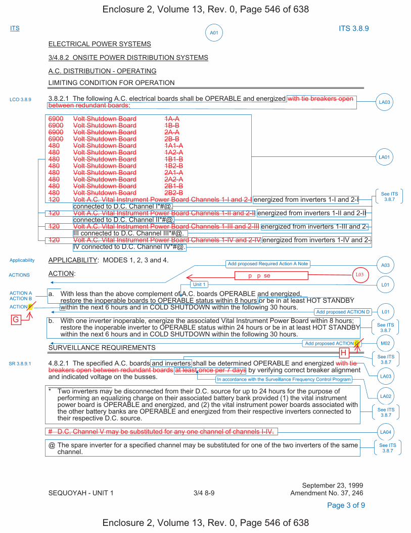
ITS A01
ITS 3.8.9
ELECTRICAL POWER SYSTEMS
3/4.8.2 ONSITE POWER DISTRIBUTION SYSTEMS
A.C. DISTRIBUTION - OPERATING
LIMITING CONDITION FOR OPERATION
3.8.2.1 The following A.C. electrical boards shall be OPERABLE and energized with tie breakers open between redundant boards: 6900 Volt Shutdown Board 1A-A6900 Volt Shutdown Board 1B-B6900 Volt Shutdown Board 2A-A6900 Volt Shutdown Board 2B-B480 Volt Shutdown Board 1A1-A480 Volt Shutdown Board 1A2-A480 Volt Shutdown Board 1B1-B480 Volt Shutdown Board 1B2-B480 Volt Shutdown Board 2A1-A480 Volt Shutdown Board 2A2-A480 Volt Shutdown Board 2B1-B480 Volt Shutdown Board 2B2-B120 Volt A.C. Vital Instrument Power Board Channels 1-I and 2-I energized from inverters 1-I and 2-I
connected to D.C. Channel I*#@.120 Volt A.C. Vital Instrument Power Board Channels 1-II and 2-II energized from inverters 1-II and 2-II
connected to D.C. Channel II*#@.120 Volt A.C. Vital Instrument Power Board Channels 1-III and 2-III energized from inverters 1-III and 2-
III connected to D.C. Channel III*#@.120 Volt A.C. Vital Instrument Power Board Channels 1-IV and 2-IV energized from inverters 1-IV and 2-
IV connected to D.C. Channel IV*#@.
APPLICABILITY: MODES 1, 2, 3 and 4.
ACTION:
a. With less than the above complement of A.C. boards OPERABLE and energized,restore the inoperable boards to OPERABLE status within 8 hours or be in at least HOT STANDBY within the next 6 hours and in COLD SHUTDOWN within the following 30 hours.
b. With one inverter inoperable, energize the associated Vital Instrument Power Board within 8 hours;restore the inoperable inverter to OPERABLE status within 24 hours or be in at least HOT STANDBYwithin the next 6 hours and in COLD SHUTDOWN within the following 30 hours.
SURVEILLANCE REQUIREMENTS
4.8.2.1 The specified A.C. boards and inverters shall be determined OPERABLE and energized with tie breakers open between redundant boards at least once per 7 days by verifying correct breaker alignment and indicated voltage on the busses. _________________ * Two inverters may be disconnected from their D.C. source for up to 24 hours for the purpose of
performing an equalizing charge on their associated battery bank provided (1) the vital instrument power board is OPERABLE and energized, and (2) the vital instrument power boards associated with the other battery banks are OPERABLE and energized from their respective inverters connected to their respective D.C. source.
# D.C. Channel V may be substituted for any one channel of channels I-IV.
@ The spare inverter for a specified channel may be substituted for one of the two inverters of the same channel.
September 23, 1999 SEQUOYAH - UNIT 1 3/4 8-9 Amendment No. 37, 246
LCO 3.8.9
ACTIONS
Applicability
SR 3.8.9.1
Page 3 of 9
Add proposed ACTION G
LA01
LA03
ACTION A ACTION B
ACTION F
M02
See ITS 3.8.7
See ITS 3.8.7
LA03
LA04
In accordance with the Surveillance Frequency Control Program
LA02
Add proposed Required Action A Note A03
Add proposed ACTION D L01
See ITS 3.8.7
See ITS 3.8.7
See ITS 3.8.7
Unit 1 L01
Enclosure 2, Volume 13, Rev. 0, Page 546 of 638
Enclosure 2, Volume 13, Rev. 0, Page 546 of 638
F
G
G
H
����p��p�se����������
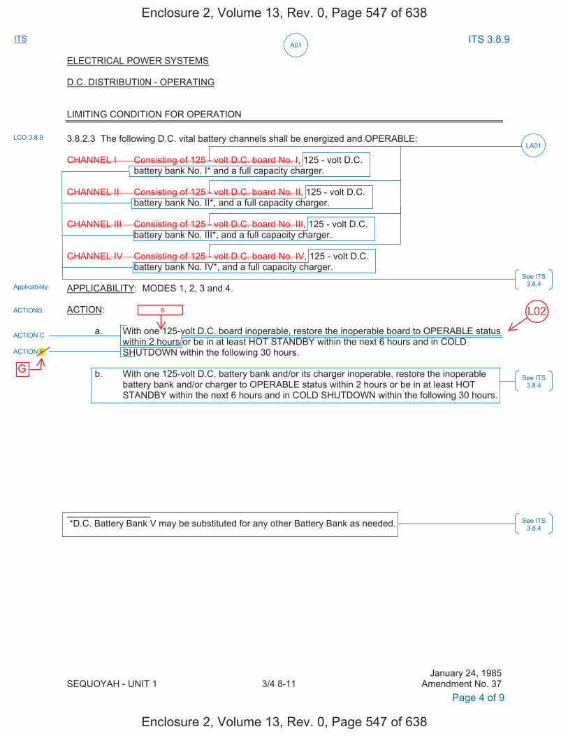
ITS A01
ITS 3.8.9
ELECTRICAL POWER SYSTEMS D.C. DISTRIBUTI0N - OPERATING LIMITING CONDITION FOR OPERATION
3.8.2.3 The following D.C. vital battery channels shall be energized and OPERABLE:
CHANNEL I Consisting of 125 - volt D.C. board No. I, 125 - volt D.C. battery bank No. I* and a full capacity charger. CHANNEL II Consisting of 125 - volt D.C. board No. II, 125 - volt D.C. battery bank No. II*, and a full capacity charger. CHANNEL III Consisting of 125 - volt D.C. board No. III, 125 - volt D.C. battery bank No. III*, and a full capacity charger. CHANNEL IV Consisting of 125 - volt D.C. board No. IV, 125 - volt D.C. battery bank No. IV*, and a full capacity charger. APPLICABILITY: MODES 1, 2, 3 and 4. ACTION: a. With one 125-volt D.C. board inoperable, restore the inoperable board to OPERABLE status
within 2 hours or be in at least HOT STANDBY within the next 6 hours and in COLD SHUTDOWN within the following 30 hours.
b. With one 125-volt D.C. battery bank and/or its charger inoperable, restore the inoperable
battery bank and/or charger to OPERABLE status within 2 hours or be in at least HOT STANDBY within the next 6 hours and in COLD SHUTDOWN within the following 30 hours.
*D.C. Battery Bank V may be substituted for any other Battery Bank as needed.
January 24, 1985 SEQUOYAH - UNIT 1 3/4 8-11 Amendment No. 37
LCO 3.8.9
ACTIONS
Applicability
Page 4 of 9
LA01
ACTION C
ACTION F
See ITS 3.8.4
See ITS 3.8.4
See ITS 3.8.4
Enclosure 2, Volume 13, Rev. 0, Page 547 of 638
Enclosure 2, Volume 13, Rev. 0, Page 547 of 638
L02������e
F
G
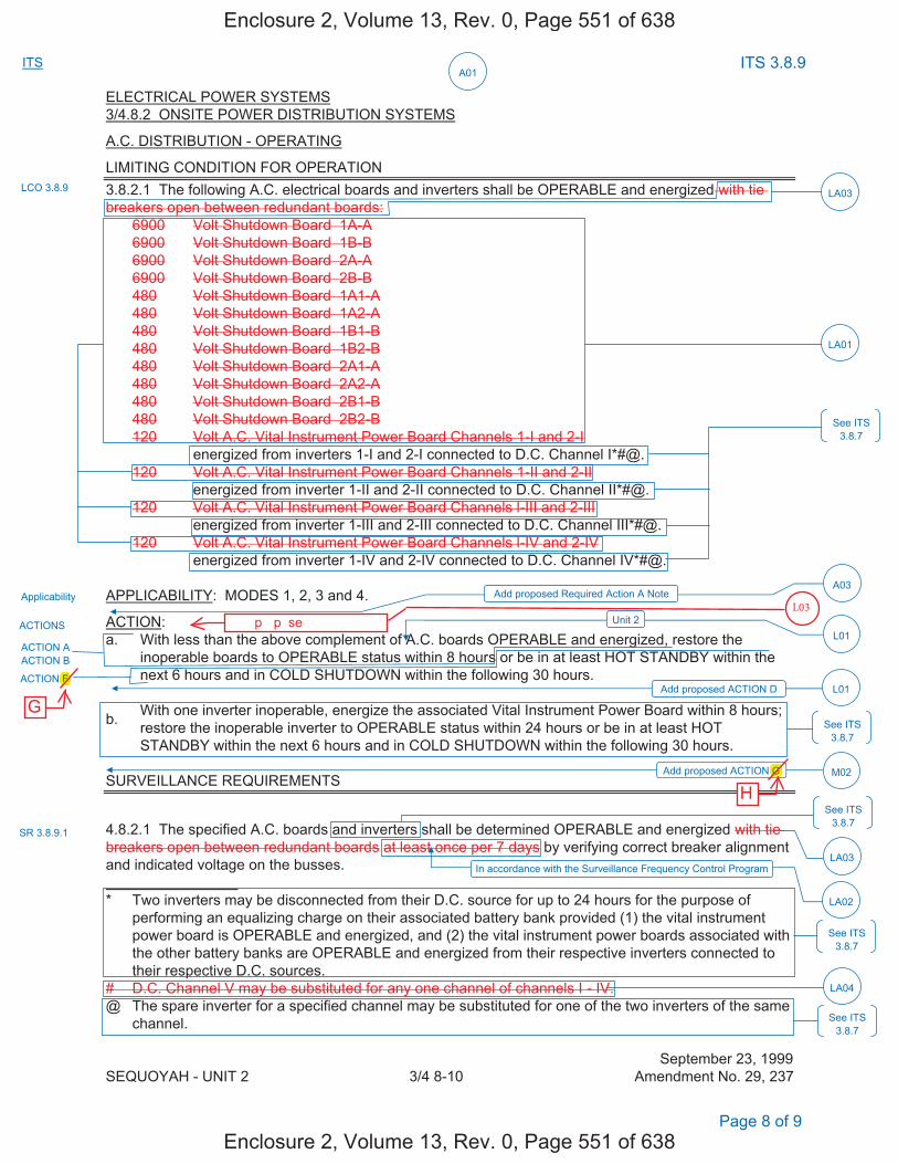
ITS A01
ITS 3.8.9
ELECTRICAL POWER SYSTEMS 3/4.8.2 ONSITE POWER DISTRIBUTION SYSTEMS
A.C. DISTRIBUTION - OPERATING
LIMITING CONDITION FOR OPERATION 3.8.2.1 The following A.C. electrical boards and inverters shall be OPERABLE and energized with tie breakers open between redundant boards: 6900 Volt Shutdown Board 1A-A 6900 Volt Shutdown Board 1B-B 6900 Volt Shutdown Board 2A-A 6900 Volt Shutdown Board 2B-B 480 Volt Shutdown Board 1A1-A 480 Volt Shutdown Board 1A2-A 480 Volt Shutdown Board 1B1-B 480 Volt Shutdown Board 1B2-B 480 Volt Shutdown Board 2A1-A 480 Volt Shutdown Board 2A2-A 480 Volt Shutdown Board 2B1-B 480 Volt Shutdown Board 2B2-B 120 Volt A.C. Vital Instrument Power Board Channels 1-I and 2-I
energized from inverters 1-I and 2-I connected to D.C. Channel I*#@. 120 Volt A.C. Vital Instrument Power Board Channels 1-II and 2-II
energized from inverter 1-II and 2-II connected to D.C. Channel II*#@. 120 Volt A.C. Vital Instrument Power Board Channels l-III and 2-III
energized from inverter 1-III and 2-III connected to D.C. Channel III*#@. 120 Volt A.C. Vital Instrument Power Board Channels l-IV and 2-IV
energized from inverter 1-IV and 2-IV connected to D.C. Channel IV*#@.
APPLICABILITY: MODES 1, 2, 3 and 4.
ACTION: a. With less than the above complement of A.C. boards OPERABLE and energized, restore the
inoperable boards to OPERABLE status within 8 hours or be in at least HOT STANDBY within the next 6 hours and in COLD SHUTDOWN within the following 30 hours.
b. With one inverter inoperable, energize the associated Vital Instrument Power Board within 8 hours;restore the inoperable inverter to OPERABLE status within 24 hours or be in at least HOTSTANDBY within the next 6 hours and in COLD SHUTDOWN within the following 30 hours.
SURVEILLANCE REQUIREMENTS
4.8.2.1 The specified A.C. boards and inverters shall be determined OPERABLE and energized with tie breakers open between redundant boards at least once per 7 days by verifying correct breaker alignment and indicated voltage on the busses.
* Two inverters may be disconnected from their D.C. source for up to 24 hours for the purpose ofperforming an equalizing charge on their associated battery bank provided (1) the vital instrumentpower board is OPERABLE and energized, and (2) the vital instrument power boards associated withthe other battery banks are OPERABLE and energized from their respective inverters connected totheir respective D.C. sources.
# D.C. Channel V may be substituted for any one channel of channels I - IV. @ The spare inverter for a specified channel may be substituted for one of the two inverters of the same
channel.
September 23, 1999 SEQUOYAH - UNIT 2 3/4 8-10 Amendment No. 29, 237
Page 8 of 9
LCO 3.8.9
ACTIONS
Applicability
SR 3.8.9.1
LA01
LA03
ACTION A ACTION B
ACTION F
See ITS 3.8.7
See ITS 3.8.7
LA03
LA04
In accordance with the Surveillance Frequency Control Program
LA02
Add proposed Required Action A Note A03
Add proposed ACTION D L01
See ITS 3.8.7
See ITS 3.8.7
See ITS 3.8.7
Unit 2 L01
Add proposed ACTION G M02
Enclosure 2, Volume 13, Rev. 0, Page 551 of 638
Enclosure 2, Volume 13, Rev. 0, Page 551 of 638
F
G
G
H
����p��p�se����������
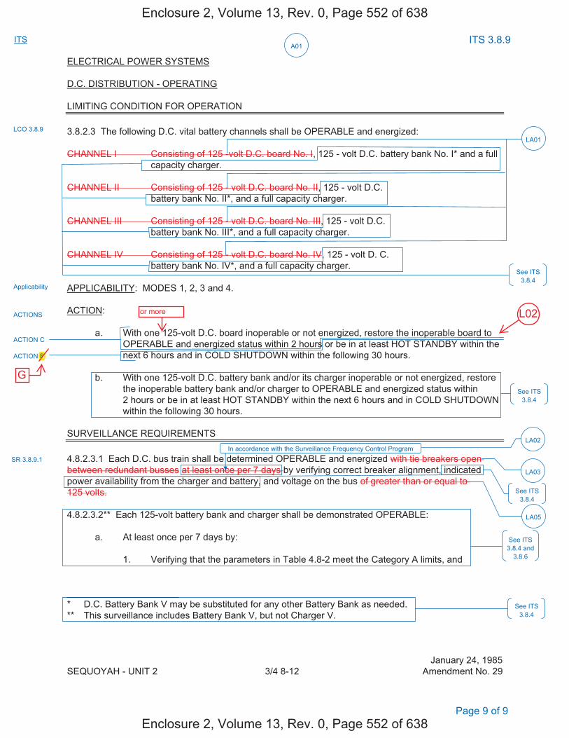
ITS A01
ITS 3.8.9
ELECTRICAL POWER SYSTEMS D.C. DISTRIBUTION - OPERATING LIMITING CONDITION FOR OPERATION
3.8.2.3 The following D.C. vital battery channels shall be OPERABLE and energized:
CHANNEL I Consisting of 125 -volt D.C. board No. I, 125 - volt D.C. battery bank No. I* and a full capacity charger.
CHANNEL II Consisting of 125 - volt D.C. board No. II, 125 - volt D.C. battery bank No. II*, and a full capacity charger. CHANNEL III Consisting of 125 - volt D.C. board No. III, 125 - volt D.C. battery bank No. III*, and a full capacity charger. CHANNEL IV Consisting of 125 - volt D.C. board No. IV, 125 - volt D. C. battery bank No. IV*, and a full capacity charger. APPLICABILITY: MODES 1, 2, 3 and 4. ACTION: a. With one 125-volt D.C. board inoperable or not energized, restore the inoperable board to
OPERABLE and energized status within 2 hours or be in at least HOT STANDBY within the next 6 hours and in COLD SHUTDOWN within the following 30 hours.
b. With one 125-volt D.C. battery bank and/or its charger inoperable or not energized, restore
the inoperable battery bank and/or charger to OPERABLE and energized status within 2 hours or be in at least HOT STANDBY within the next 6 hours and in COLD SHUTDOWN within the following 30 hours.
SURVEILLANCE REQUIREMENTS
4.8.2.3.1 Each D.C. bus train shall be determined OPERABLE and energized with tie breakers open between redundant busses at least once per 7 days by verifying correct breaker alignment, indicated power availability from the charger and battery, and voltage on the bus of greater than or equal to 125 volts. 4.8.2.3.2** Each 125-volt battery bank and charger shall be demonstrated OPERABLE: a. At least once per 7 days by: 1. Verifying that the parameters in Table 4.8-2 meet the Category A limits, and * D.C. Battery Bank V may be substituted for any other Battery Bank as needed. ** This surveillance includes Battery Bank V, but not Charger V.
January 24, 1985 SEQUOYAH - UNIT 2 3/4 8-12 Amendment No. 29
Page 9 of 9
LCO 3.8.9
ACTIONS
Applicability
LA01
ACTION C
ACTION F
See ITS 3.8.4
See ITS 3.8.4
See ITS 3.8.4
See ITS 3.8.4 and
3.8.6
SR 3.8.9.1
See ITS 3.8.4
LA03
LA05
In accordance with the Surveillance Frequency Control Program LA02
Enclosure 2, Volume 13, Rev. 0, Page 552 of 638
Enclosure 2, Volume 13, Rev. 0, Page 552 of 638
L02or more
F
G
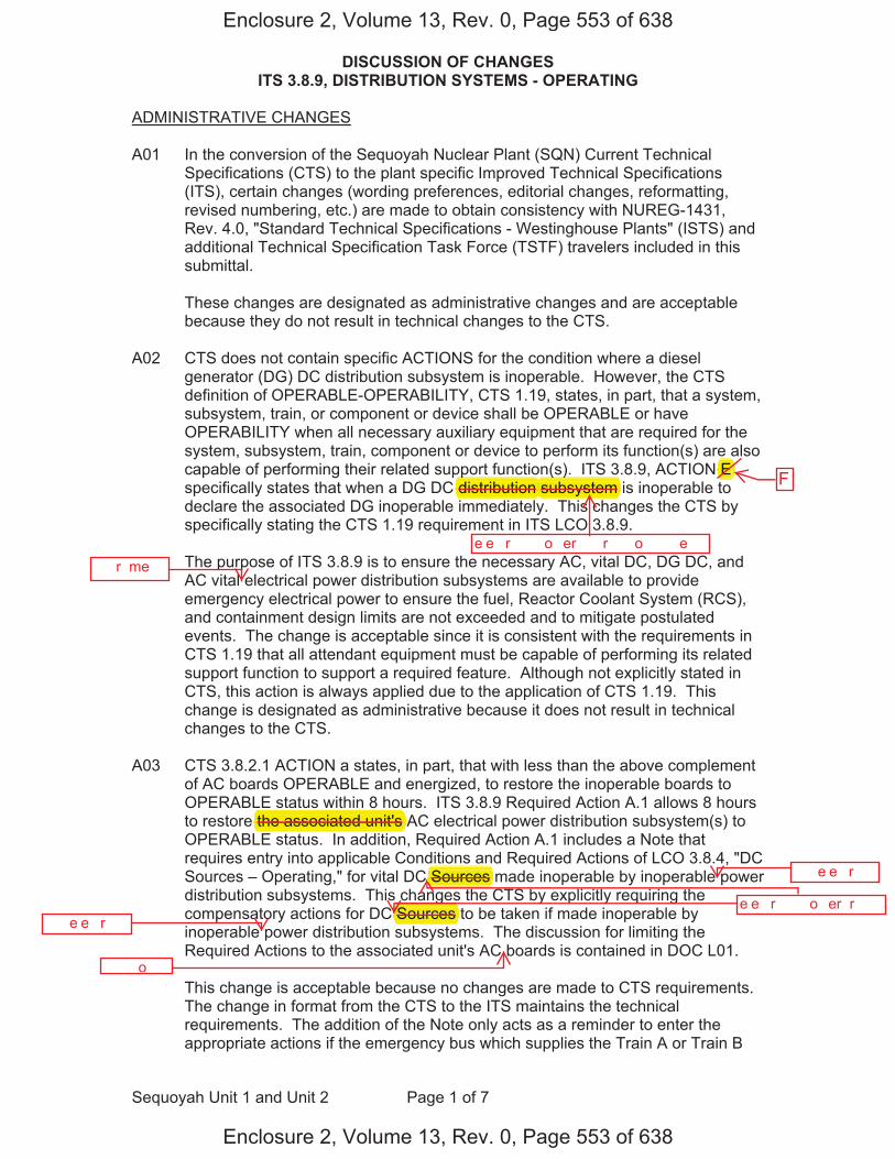
DISCUSSION OF CHANGES ITS 3.8.9, DISTRIBUTION SYSTEMS - OPERATING
Sequoyah Unit 1 and Unit 2 Page 1 of 7
ADMINISTRATIVE CHANGES A01 In the conversion of the Sequoyah Nuclear Plant (SQN) Current Technical
Specifications (CTS) to the plant specific Improved Technical Specifications (ITS), certain changes (wording preferences, editorial changes, reformatting, revised numbering, etc.) are made to obtain consistency with NUREG-1431, Rev. 4.0, "Standard Technical Specifications - Westinghouse Plants" (ISTS) and additional Technical Specification Task Force (TSTF) travelers included in this submittal.
These changes are designated as administrative changes and are acceptable
because they do not result in technical changes to the CTS. A02 CTS does not contain specific ACTIONS for the condition where a diesel
generator (DG) DC distribution subsystem is inoperable. However, the CTS definition of OPERABLE-OPERABILITY, CTS 1.19, states, in part, that a system, subsystem, train, or component or device shall be OPERABLE or have OPERABILITY when all necessary auxiliary equipment that are required for the system, subsystem, train, component or device to perform its function(s) are also capable of performing their related support function(s). ITS 3.8.9, ACTION E specifically states that when a DG DC distribution subsystem is inoperable to declare the associated DG inoperable immediately. This changes the CTS by specifically stating the CTS 1.19 requirement in ITS LCO 3.8.9.
The purpose of ITS 3.8.9 is to ensure the necessary AC, vital DC, DG DC, and
AC vital electrical power distribution subsystems are available to provide emergency electrical power to ensure the fuel, Reactor Coolant System (RCS), and containment design limits are not exceeded and to mitigate postulated events. The change is acceptable since it is consistent with the requirements in CTS 1.19 that all attendant equipment must be capable of performing its related support function to support a required feature. Although not explicitly stated in CTS, this action is always applied due to the application of CTS 1.19. This change is designated as administrative because it does not result in technical changes to the CTS.
A03 CTS 3.8.2.1 ACTION a states, in part, that with less than the above complement
of AC boards OPERABLE and energized, to restore the inoperable boards to OPERABLE status within 8 hours. ITS 3.8.9 Required Action A.1 allows 8 hours to restore the associated unit's AC electrical power distribution subsystem(s) to OPERABLE status. In addition, Required Action A.1 includes a Note that requires entry into applicable Conditions and Required Actions of LCO 3.8.4, "DC Sources – Operating," for vital DC Sources made inoperable by inoperable power distribution subsystems. This changes the CTS by explicitly requiring the compensatory actions for DC Sources to be taken if made inoperable by inoperable power distribution subsystems. The discussion for limiting the Required Actions to the associated unit's AC boards is contained in DOC L01.
This change is acceptable because no changes are made to CTS requirements.
The change in format from the CTS to the ITS maintains the technical requirements. The addition of the Note only acts as a reminder to enter the appropriate actions if the emergency bus which supplies the Train A or Train B
Enclosure 2, Volume 13, Rev. 0, Page 553 of 638
Enclosure 2, Volume 13, Rev. 0, Page 553 of 638
e�e��r���� �o�er ����r�����o� ���e�
( )subsystem
e�e��r���� �o�er �r����
�� e�e��r����
�� e�e��r����
�����o��
the associated unit's
Sources
Sources
ppdistribution
����r�me��
FE
DISCUSSION OF CHANGES ITS 3.8.9, DISTRIBUTION SYSTEMS - OPERATING
Sequoyah Unit 1 and Unit 2 Page 2 of 7
battery charger becomes de-energized. In the event an emergency board is inoperable such that a Train A or Train B battery charger were inoperable, ITS LCO 3.0.6 would allow taking only the Distribution System - Operating ACTIONS; taking exception to complying with the DC Sources - Operating ACTIONS. Since the Distribution System - Operating ACTIONS may not be sufficiently conservative in this event (i.e., a battery charger may be without power), specific direction to take appropriate ACTIONS for the DC Sources - Operating is added (ITS 3.8.9, Note to ACTION A) when there is no power to support the associated required battery charger. This change is designated as administrative because it does not result in a technical change to the CTS.
MORE RESTRICTIVE CHANGES
M01 CTS 4.8.1.1.3 requires, in part, that the 125 volt DC distribution panel for each DG be demonstrated OPERABLE. ITS SR 3.8.9.1 requires, in part, verifying correct breaker alignments and voltage to the 125 volt DC distribution subsystem for each DG. This changes the CTS by requiring correct breaker alignment verification and correct voltage for the DG DC bus electrical power distribution subsystem.
The purpose of CTS 4.8.1.1.3 is to provide assurance that necessary power to required supported systems is available with sufficient capacity, capability, redundancy, and reliability to ensure the fuel, RCS, and containment design limits are not exceeded and postulated accidents are mitigated. This change is acceptable because it provides additional assurance that the panels associated with the DG DC bus electrical power distribution subsystem are OPERABLE. This change is designated as more restrictive because it adds a new Surveillance Requirement to the CTS for verification of correct breaker alignment and voltage.
M02 CTS 3.8.2.1 ACTION a states that with less than the above complement of AC boards OPERABLE and energized, to restore the inoperable boards to OPERABLE status within 8 hours. CTS 3.8.2.3 ACTION a states that with one 125 volt DC board inoperable, to restore the inoperable boards to OPERABLE status within 2 hours. However, there are no limitations to preclude a loss of function due to numerous concurrently inoperable AC and DC boards. ITS 3.8.9 ACTION G has been added, requiring entry into ITS 3.0.3 if the loss of two or more required electrical power distribution subsystems result in a loss of safety function. This changes CTS by adding an explicit Action to enter LCO 3.0.3 for a loss of two or more electrical power distribution subsystems that result in a loss of safety function.
The purpose of the CTS ACTIONS is to limit the time the unit can operate under these conditions. CTS 3.8.2.3 ACTION a specifies the compensatory actions for one inoperable DC board. With two inoperable DC boards, CTS 3.8.2.3 does not provide any actions and entry into LCO 3.0.3 would be required. CTS 3.8.2.1 ACTION a is applicable to all inoperable AC boards even if there is a loss of safety function. Certain combinations of inoperable AC and DC electrical power distribution subsystems result in a loss of safety function (e.g., an inoperable Train A AC electrical power distribution subsystem in combination with an
Enclosure 2, Volume 13, Rev. 0, Page 554 of 638
Enclosure 2, Volume 13, Rev. 0, Page 554 of 638
gbus
for each DG.
G H
DISCUSSION OF CHANGES ITS 3.8.9, DISTRIBUTION SYSTEMS - OPERATING
Sequoyah Unit 1 and Unit 2 Page 3 of 7
inoperable Train B vital DC electrical power distribution subsystem). ITS 3.8.9 includes ACTION G, which requires immediate entry into LCO 3.0.3 if the loss of one or more required electrical power distribution subsystems boards results in a loss of safety function. ITS 3.8.9 Required Action G.1 preserves the intent of ITS LCO 3.0.3 and reflects an additional restriction on plant operation. This change is designated as more restrictive because an explicit action has been added which requires entry into LCO 3.0.3 with any combination of required AC and/or DC boards inoperable that results in a loss of safety function.
RELOCATED SPECIFICATIONS
None
REMOVED DETAIL CHANGES
LA01 (Type 1 – Removing Details of System Design and System Description, Including Design Limits) CTS 3.8.1.1.3.b.5 requires, in part, a separate 125 volt DC distribution panel to be OPERABLE for each DG. CTS 3.8.2.1 requires, in part, the AC electrical boards to be OPERABLE and lists the specific AC shutdown boards and AC vital instrument power board channels, including the applicable nominal voltage. CTS 3.8.2.3 requires, in part, vital DC boards to be OPERABLE and lists the specific boards and includes the nominal voltage. ITS LCO 3.8.9 requires the applicable electrical power distribution subsystems to be OPERABLE. This changes the CTS by moving the specific names of the buses and the associated nominal bus voltages (i.e., 6900 V, 480 V, 125 V, and 120 V) from the CTS to the ITS Bases.
The removal of these details, which are related to system design, from the Technical Specifications, is acceptable because this type of information is not necessary to be included in the Technical Specifications to provide adequate protection of public health and safety. ITS 3.8.9 retains the requirement for the required distribution subsystems to be OPERABLE. In addition, this change is acceptable because the removed information will be adequately controlled in the ITS Bases. The Technical Specification Bases Control Program in Chapter 5 controls changes to the Bases, requiring an evaluation of changes to ensure the Bases are properly controlled. This change is designated as a less restrictive removal of detail change because information relating to system design is being removed from the Technical Specifications.
LA02 (Type 5 – Removal of SR Frequency to the Surveillance Frequency Control Program) CTS 4.8.1.1.3 requires, in part, verification that the 125 volt DC distribution panel for each diesel generator is demonstrated OPERABLE. CTS 4.8.2.1 requires, in part, the specified AC boards to be determined OPERABLE and energized at least once per 7 days by verifying correct breaker alignment and indicated voltage on the busses. CTS 4.8.2.3.1 requires, in part, each DC bus train to be determined OPERABLE and energized at least once per 7 days by verifying correct breaker alignment, indicated power availability from the charger and battery, and voltage on the bus. DOC M01 discusses addition of a surveillance requirement to verify correct alignments and voltage for the DG
Enclosure 2, Volume 13, Rev. 0, Page 555 of 638
Enclosure 2, Volume 13, Rev. 0, Page 555 of 638
G,
G.
H
H
DISCUSSION OF CHANGES ITS 3.8.9, DISTRIBUTION SYSTEMS - OPERATING
Sequoyah Unit 1 and Unit 2 Page 4 of 7
DC distribution subsystem with a frequency of 7 days. ITS SR 3.8.9.1 requires a similar Surveillance and specifies the periodic Frequency as, "In accordance with the Surveillance Frequency Control Program." This changes the CTS by moving the specified Frequencies for these SRs and associated Bases to the Surveillance Frequency Control Program.
The removal of these details related to Surveillance Requirement Frequencies from the Technical Specifications is acceptable, because this type of information is not necessary to be included in the Technical Specifications to provide adequate protection of public health and safety. The existing Surveillance Frequencies are removed from Technical Specifications and placed under licensee control pursuant to the methodology described in NEI 04-10. A new program (Surveillance Frequency Control Program) is being added to the Administrative Controls section of the Technical Specifications describing the control of Surveillance Frequencies. The surveillance test requirements remain in the Technical Specifications. The control of changes to the Surveillance Frequencies will be in accordance with the Surveillance Frequency Control Program. The Program shall ensure that Surveillance Requirements specified in the Technical Specifications are performed at intervals sufficient to assure the associated Limiting Conditions for Operation are met. This change is designated as a less restrictive removal of detail change, because the Surveillance Frequencies are being removed from the Technical Specifications.
LA03 (Type 3 – Removing Procedural Details for Meeting TS Requirements or Reporting Requirements) CTS 3.8.2.1 requires the AC electrical boards to be OPERABLE and energized "with tie breakers open between redundant boards." CTS 4.8.2.1 also requires the AC boards to be determined OPERABLE and energized from AC sources "with tie breakers open between redundant busses" by verifying correct breaker alignment and indicated voltage on the buses. CTS 4.8.2.3.1 requires, in part, the DC bus trains to be determined OPERABLE and energized "with tie breakers open between redundant buses". ITS LCO 3.8.9 requires the applicable electrical power distribution subsystems to be OPERABLE and ITS SR 3.8.9.1 requires the verification of correct breaker alignments and voltage to required AC, vital DC, DG DC, and AC vital electrical power distribution subsystems. This changes the CTS by moving the procedural detail that the boards must have their tie breakers open between redundant boards from the CTS to the ITS Bases.
The removal of these details for meeting Technical Specification requirements
from the Technical Specifications is acceptable because this type of information is not necessary to be included in the Technical Specifications to provide adequate protection of public health and safety. The ITS still retains the requirement for the electrical power distribution subsystems to be OPERABLE and requires the verification of correct breaker alignments and voltage to required AC, vital DC, DG DC, and AC vital electrical power distribution subsystems. In addition, this change is acceptable because these types of procedural details will be adequately controlled in the ITS Bases. The Technical Specification Bases Control Program in Chapter 5 controls changes to the Bases. This program provides for the evaluation of changes to ensure the Bases are properly controlled. This change is designated as a less restrictive removal
Enclosure 2, Volume 13, Rev. 0, Page 556 of 638
Enclosure 2, Volume 13, Rev. 0, Page 556 of 638
����r�me��
����r�me��
DISCUSSION OF CHANGES ITS 3.8.9, DISTRIBUTION SYSTEMS - OPERATING
Sequoyah Unit 1 and Unit 2 Page 5 of 7
of detail change because procedural details for meeting Technical Specification requirements are being removed from the Technical Specifications.
LA04 (Type 1 – Removing Details of System Design and System Description, Including Design Limits) CTS 4.8.2.1 states, in part, that the specified A.C. boards shall be determined OPERABLE by verifying correct breaker alignment. CTS 3.8.2.1 includes Note # that allows D.C. Channel V to be substituted for any one channel of channels I-IV, thus verification of correct breaker alignment is required when Channel V is substituted. ITS SR 3.8.9.1 does not contain this design information. This changes the CTS by moving the details that DC channel V can be substituted for any one of channels I-IV from the CTS to the ITS Bases.
The removal of these details, which are related to system design, from the Technical Specifications, is acceptable because this type of information is not necessary to be included in the Technical Specifications to provide adequate protection of public health and safety. ITS 3.8.9 retains the requirement for the required distribution subsystems to be OPERABLE. In addition, this change is acceptable because the removed information will be adequately controlled in the ITS Bases. The Technical Specification Bases Control Program in Chapter 5 controls changes to the Bases, requiring an evaluation of changes to ensure the Bases are properly controlled. This change is designated as a less restrictive removal of detail change because information relating to system design is being removed from the Technical Specifications.
LA05 (Type 1 – Removing Details of System Design and System Description, Including Design Limits) CTS 4.8.2.3.1 requires, in part, each DC bus to be determined OPERABLE by verifying voltage of greater than or equal to 125 volt DC on the bus. ITS SR 3.8.9.1 requires, in part, verification of correct breaker alignment and voltage to the DG DC electrical power distribution subsystems. This changes the CTS by removing the specified voltage limit from the surveillance and placing it in the Bases.
The removal of these details, which are related to system design, from the Technical Specifications, is acceptable because this type of information is not necessary to be included in the Technical Specifications to provide adequate protection of public health and safety. The ITS still retains the requirement to verify the correct voltage to each diesel generator 125 volt DC distribution panel and to each vital DC board. In addition, this change is acceptable because the removed information will be adequately controlled in the ITS Bases. The Technical Specification Bases Control Program in Chapter 5 controls changes to the Bases. This program provides for the evaluation of changes to ensure the Bases are properly controlled. This change is designated as a less restrictive removal of detail change because information relating to system design is being removed from the Technical Specifications.
LESS RESTRICTIVE CHANGES
L01 CTS 3.8.2.1 ACTION a requires that with less than the listed AC electrical boards OPERABLE and energized to restore the inoperable boards to OPERABLE status within 8 hours. ITS LCO 3.8.9 ACTION A requires that with one or more
Enclosure 2, Volume 13, Rev. 0, Page 557 of 638
Enclosure 2, Volume 13, Rev. 0, Page 557 of 638
C
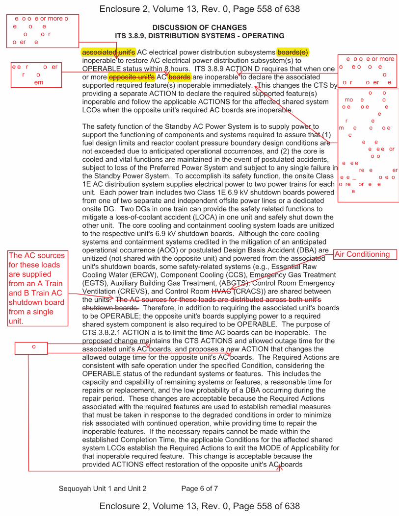
DISCUSSION OF CHANGES ITS 3.8.9, DISTRIBUTION SYSTEMS - OPERATING
Sequoyah Unit 1 and Unit 2 Page 6 of 7
associated unit's AC electrical power distribution subsystems boards(s) inoperable to restore AC electrical power distribution subsystem(s) to OPERABLE status within 8 hours. ITS 3.8.9 ACTION D requires that when one or more opposite unit's AC boards are inoperable to declare the associated supported required feature(s) inoperable immediately. This changes the CTS by providing a separate ACTION to declare the required supported feature(s) inoperable and follow the applicable ACTIONS for the affected shared system LCOs when the opposite unit's required AC boards are inoperable.
The safety function of the Standby AC Power System is to supply power to support the functioning of components and systems required to assure that (1) fuel design limits and reactor coolant pressure boundary design conditions are not exceeded due to anticipated operational occurrences, and (2) the core is cooled and vital functions are maintained in the event of postulated accidents, subject to loss of the Preferred Power System and subject to any single failure in the Standby Power System. To accomplish its safety function, the onsite Class 1E AC distribution system supplies electrical power to two power trains for each unit. Each power train includes two Class 1E 6.9 kV shutdown boards powered from one of two separate and independent offsite power lines or a dedicated onsite DG. Two DGs in one train can provide the safety related functions to mitigate a loss-of-coolant accident (LOCA) in one unit and safely shut down the other unit. The core cooling and containment cooling system loads are unitized to the respective unit's 6.9 kV shutdown boards. Although the core cooling systems and containment systems credited in the mitigation of an anticipated operational occurrence (AOO) or postulated Design Basis Accident (DBA) are unitized (not shared with the opposite unit) and powered from the associated unit's shutdown boards, some safety-related systems (e.g., Essential Raw Cooling Water (ERCW), Component Cooling (CCS), Emergency Gas Treatment (EGTS), Auxiliary Building Gas Treatment, (ABGTS), Control Room Emergency Ventilation (CREVS), and Control Room HVAC (CRACS)) are shared between the units. The AC sources for these loads are distributed across both unit's shutdown boards. Therefore, in addition to requiring the associated unit's boards to be OPERABLE; the opposite unit's boards supplying power to a required shared system component is also required to be OPERABLE. The purpose of CTS 3.8.2.1 ACTION a is to limit the time AC boards can be inoperable. The proposed change maintains the CTS ACTIONS and allowed outage time for the associated unit's AC boards, and proposes a new ACTION that changes the allowed outage time for the opposite unit's AC boards. The Required Actions are consistent with safe operation under the specified Condition, considering the OPERABLE status of the redundant systems or features. This includes the capacity and capability of remaining systems or features, a reasonable time for repairs or replacement, and the low probability of a DBA occurring during the repair period. These changes are acceptable because the Required Actions associated with the required features are used to establish remedial measures that must be taken in response to the degraded conditions in order to minimize risk associated with continued operation, while providing time to repair the inoperable features. If the necessary repairs cannot be made within the established Completion Time, the applicable Conditions for the affected shared system LCOs establish the Required Actions to exit the MODE of Applicability for that inoperable required feature. This change is acceptable because the provided ACTIONS effect restoration of the opposite unit's AC boards
Enclosure 2, Volume 13, Rev. 0, Page 558 of 638
Enclosure 2, Volume 13, Rev. 0, Page 558 of 638
��e �o o�e or more o� ��e ���o����e� ������ �� �����o�� �o�r�� ��o�er���e
e�e��r���� �o�er ����r�����o� �������em�
��e �o o�e or more o� ��e o��o���e ������ �� �����o�� �o�r�� ��o�er���e
�����o��
associated unit's
opposite unit's A boards
boards(s)
��� ����� �o�����o� � �� mo����e� �� ��o �o�e�� �o�e � ����e�� ����� ���������e ��r��� �����e� m����e����e�� �o�e � ����e�� ����� ���������e ��e� ���� � ����� �� �� �e��e�e� or �� ���� � �o��o���� �e��e�e� ���� ���� � ����� �� re��e���� ���er �e�e� � �� ��� ��o�e �o� o� re���or �e��e� �����e��
The AC sourcesfor these loadsare suppliedfrom an A Trainand B Train ACshutdown boardfrom a singleunit.
Air Conditioning
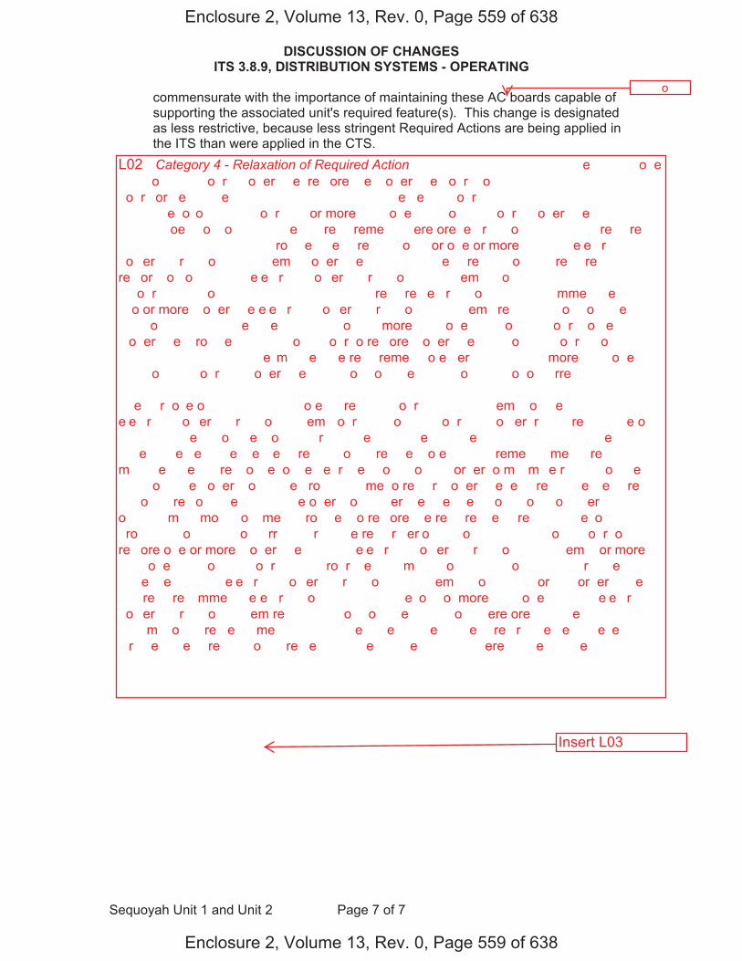
DISCUSSION OF CHANGES ITS 3.8.9, DISTRIBUTION SYSTEMS - OPERATING
Sequoyah Unit 1 and Unit 2 Page 7 of 7
commensurate with the importance of maintaining these AC boards capable of supporting the associated unit's required feature(s). This change is designated as less restrictive, because less stringent Required Actions are being applied in the ITS than were applied in the CTS.
Enclosure 2, Volume 13, Rev. 0, Page 559 of 638
Enclosure 2, Volume 13, Rev. 0, Page 559 of 638
L02 �Category 4 - Relaxation of Required Action� ��� ������� ������ �� ����e�� �� ��� o�e �����o�� ���� �o�r� ��o�er���e� re��ore ��e ��o�er���e �o�r� �o �������� ������ ������ � �o�r� or �e �� �� �e��� ��� ������� ������ ��e �e�� � �o�r� ��� �� ���� ������� � ������ ��e �o��o���� �� �o�r��� �or more ���� o�e �����o�� �� �o�r� ��o�er���e� ��� ������� �oe� �o� �o����� � ��e����� re���reme��� ��ere�ore� e��r� ���o ��� ����� �� re���re�� ��� ����� ��������� � �ro���e� �e���re� ����o�� �or o�e or more ����� �� e�e��r���� �o�er ����r�����o� �������em� ��o�er���e� ��� ����� �e���re� ����o� ��� re���re� re��or���o� o� ����� �� e�e��r���� �o�er ����r�����o� �������em��� �o �������� ������ ������ � �o�r�� ������o������ ��� ����� ������ � re���re� e��r� ���o ��� ������ �mme����e��� �� ��o or more ��o�er���e e�e��r���� �o�er ����r�����o� �������em� re���� �� � �o�� o� ���e�� ������o�� ���� �����e� ��e ��� �� ���o���� more ���� o�e �����o�� �� �o�r� �o �e ��o�er���e� �ro���e� �� ������o��� �o�r �o re��ore ��o�er���e �����o�� �� �o�r�� �o �������� ������� ��� e��m����e� ��e re���reme�� �o e��er ��� ����� �� more ���� o�e �����o�� �� �o�r� �� ��o�er���e ��� � �o�� o� ���e�� ������o� ��� �o� o���rre�� ��e ��r�o�e o� ��� ������� �� �o e���re ���� ��o �r���� ��������em�� o� ��e ����� �� e�e��r���� �o�er ����r�����o� ����em ��o�r �����o�� �� �o�r��� ��o �er �r���� �re ������e o� ��������� ��e ���o����e� �o��� ��r��� � �e���� ���e� �����e�� ������ ���� �����e �� ���e�����e �e����e ��e �e���re� ����o�� �re ��e� �o e�������� reme���� me���re� ���� m��� �e ���e� �� re��o��e �o ��e �e�r��e� �o�����o�� �� or�er �o m���m��e r��� ���o����e� ���� �o�����e� o�er���o� ����e �ro������ ��me �o re���r ��o�er���e �e���re�� ��e �e���re� ����o�� �re �o�����e�� ���� ���e o�er���o� ���er ��e ��e����e� �o�����o�� �o����er��� ���� o��� � �m��� �mo��� o� ��me �� �ro���e� �o re��ore ��e re���re� �e���re�� ��� ��e �o� �ro�������� o� � ��� o���rr��� ��r��� ��e re���r �er�o�� ���o���� �� ������o��� �o�r �o re��ore o�e or more ��o�er���e ����� �� e�e��r���� �o�er ����r�����o� �������em� �or more ���� o�e �����o�� �� �o�r�� �� ���ro�r���e �� �� m�� ��o�� � �����o��� � ���� �r����e��� ����e ��e ����� �� e�e��r���� �o�er ����r�����o� �������em �� �o� �� ���� �or���� or�er� ��e ��� re���re� �mme����e e��r� ���o ��� ����� �� ��e �o�� o� more ���� o�e ����� �� e�e��r���� �o�er ����r�����o� ����em re����� �� � �o�� o� ���e�� ������o�� ��ere�ore� ��� ���e�� �������� ����m���o�� �re �e��� me�� ���� �����e �� �e������e� �� �e�� re��r�����e �e����e �e�� ��r���e�� �e���re� ����o�� �re �e��� �����e� �� ��e ��� ���� �ere �����e� �� ��e ����
�����o��
Insert L03

L03
��� ������� ������ � re���re� ���� ���� �e�� ���� ��e ����e� �� e�e��r���� �o�r�� �������� ��� e�er���e� �o re��ore ��e ��o�er���e �o�r�� �o �������� ������ ������ � �o�r�� ��� ����� ������ � re���re� ���� ���� o�e or more �� e�e��r���� �o�er ����r�����o� �������em� ��o�er���e ��e �o o�e or more o� ��e ���o����e� ������ �� �����o�� �o�r�� ��o�er���e �o re��ore �� e�e��r���� �o�er ����r�����o� �������em��� �o �������� ������ ������ � �o�r�� ��� ����� ������ � re���re� ���� ���� o�e or more �� e�e��r���� �o�er ����r�����o� �������em� ��o�er���e ��e �o o�e or more o��o���e ���� �� �����o�� �o�r�� ��o�er���e �o �e���re ��e ���o����e� re���re� �e���re��� ��o�er���e �mme����e��� ��� ����� ����o� � �� o��� ���������e ��r��� �����e� m����e����e ��e� ��e o��o���e ���� �� �e��e�e� or �� ���� � �o��o���� �e��e�e� ���� ��e o��o���e ���� re��e���� ���er �e�e� � �� �ee� ��o�e �o� o� ��e re���or �e��e� �����e� ��� ����� ������ � re���re� ���� ���� o�e or more �� e�e��r���� �o�er ����r�����o� �������em� ��o�er���e ��e �o o�e or more o��o���e ���� �� �����o�� �o�r�� ��o�er���e �or re��o�� o��er ���� �o�����o� � �o re��ore �� e�e��r���� �o�er ����r�����o� �������em��� �o �������� ������ �� �� �o�r�� ���� �����e� ��e ��� �� �ro������ � �e� ������ ���� e��e��� ��e ��me ���o�e� �o re��ore �o �������� ������ ��e �� e�e��r���� �o�er ����r�����o� �������em m��e ��o�er���e ��e �o ��e o��o���e ������ �� �����o�� �o�r�� �or o��er ���� �����e� m����e����e �rom � �o�r� �o �� �o�r�� ��e ���e�� ������o� o� ��e ������� �� �o�er ����em �� �o ������ �o�er �o ����or� ��e ������o���� o� �om�o�e��� ��� ����em� re���re� �o ����re ���� ��� ��e� �e���� ��m��� ��� re���or �oo���� �re���re �o����r� �e���� �o�����o�� �re �o� e��ee�e� ��e �o ���������e� o�er���o��� o���rre��e�� ��� ��� ��e �ore �� �oo�e� ��� ����� ������o�� �re m�������e� �� ��e e�e�� o� �o������e� �����e���� ����e�� �o �o�� o� ��e �re�erre� �o�er ����em ��� ����e�� �o ��� �����e �����re �� ��e ������� �o�er ����em� �o ���om����� ��� ���e�� ������o�� ��e o����e ����� �� �� ����r�����o� ����em ������e� e�e��r���� �o�er �o ��o �o�er �r���� �or e��� ����� ���� �o�er �r��� ������e� ��o ����� �� ��� �� �����o�� �o�r�� �o�ere� �rom o�e o� ��o �e��r��e ��� ���e�e��e�� o�����e �o�er or � �e�����e� o����e ��� ��o ��� �� o�e �r��� ��� �ro���e ��e ���e�� re���e� ������o�� �o m������e � �o���o���oo���� �����e�� ������ �� o�e ���� ��� ���e�� ���� �o�� ��e o��er ����� ��e �ore �oo���� ��� �o�����me�� �oo���� ����em �o��� �re ������e� �o ��e re��e����e ������ ��� �� �����o�� �o�r��� ����o��� ��e m��or �ore �oo���� ����em� ��� �o�����me�� ����em� �re���e� �� ��e m�������o� o� �� ���������e� o�er���o��� o���rre��e ����� or �o������e� �e���� ����� �����e�� ����� �re ������e� ��o� ���re� ���� ��e o��o���e ����� ��� �o�ere� �rom ��e ���o����e� ������ �����o�� �o�r��� �ome ���e���re���e� ����em� �e���� ���e����� ��� �oo���� � ��er ����� �� �om�o�e�� �oo���� ������ �mer�e��� ��� �re��me�� ������� �������r� �������� ��� �re��me�� �������� �o��ro� �oom �mer�e��� �e�������o� �������� ��� �o��ro� �oom �������� �re ���re� �e��ee� ��e ������ ��e �� �o�r�e� �or ��e�e �o��� �re ������e� �rom �� � �r��� ��� � �r��� �� �����o�� �o�r� �rom � �����e ����� ��ere�ore� �� ������o� �o re���r��� ��e ���o����e� ������ �o�r�� �o �e ��������� ��e o��o���e ������ �o�r�� ��������� �o�er �o �o�� �r���� o� re���re� ���re� ����em �om�o�e��� �re ���o re���re� �o �e ��������� ��e ��r�o�e o� ��� ������� ������ � �� �o ��m�� ��e ��me �� �o�r�� ��� �e ��o�er���e� ��e �ro�o�e� �����e m�������� ��e ��� ������� ��� ���o�e� o����e ��me �or ��e ���o����e� ������ �� �����o�� �o�r��� ��� �ro�o�e� � �e� ��� ������ � ���� �����e ��e ���o�e� o����e ��me � �o�r� �o �� �o�r� �or ��e o��o���e ������ �� �����o�� �o�r�� ���� �re ��o�er���e �or re��o�� o��er ���� �����e� m����e����e� ��e �e���re� ����o�� �re �o�����e�� ���� ���e o�er���o� ���er ��e ��e����e� �o�����o�� �o����er��� ��e �������� ������ o� ��e re������� ����em� or �e���re�� ���� ������e� ��e �������� ��� ���������� o� rem������ ����em� or �e���re�� � re��o����e ��me �or re���r� or re����eme��� ��� ��e �o� �ro�������� o� � ��� o���rr��� ��r��� ��e re���r �er�o�� ��e�e �����e� �re ���e�����e �e����e ��e �� �o�r ��m�� �or ��e �� e�e��r���� �o�er ����r�����o�
INSERT L03Page 1 of 2

o��o���e ������ �� �����o�� �o�r�� �� more �o��er�����e ���� �om��e��o� ��me� ���o�e� �or ��e �om�o�e��� ���� �o��� �e ����o�� �o�er� ���� �����e �� �e������e� �� �e�� re��r�����e� �e����e ������o��� ��me �� ���o�e� �o re��ore ��e ����������� o� ��e �� e�e��r���� �o�er ����r�����o� �������em ��e� ��e �� e�e��r���� �o�er ����r�����o� �������em ��o�er���e ��e �o ��e o��o���e ������ �� �����o�� �o�r�� ���er ��e ��� ���� ���er ��e ����
INSERT L03Page 2 of 2
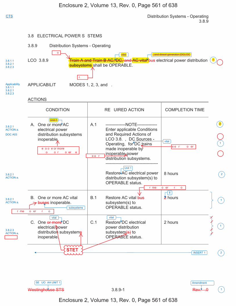
Distribution Systems - Operating 3.8.9
Westinghouse STS 3.8.9-1 Rev. �.0
CTS
SE�UO�AH UNIT 1 Amendment ���
1
3.8 ELECTRICAL POWER S�STEMS
3.8.9 Distribution Systems - Operating
LCO 3.8.9 Train A and Train B AC, DC, and AC vital bus electrical power distribution subsystems shall be OPERABLE.
APPLICABILIT�� MODES 1, 2, 3, and �.
ACTIONS
CONDITION RE�UIRED ACTION COMPLETION TIME
A. One or more AC electrical power distribution subsystems inoperable.
A.1 --------------NOTE-------------- Enter applicable Conditions and Required Actions of LCO 3.8.�, �DC Sources - Operating,� for DC trains made inoperable by inoperable power distribution subsystems.
-------------------------------------
Restore AC electrical power distribution subsystem(s) to OPERABLE status.
8 hours
B. One or more AC vital buses inoperable.
B.1 Restore AC vital bus subsystem(s) to OPERABLE status.
2 hours
C. One or more DC electrical power distribution subsystems inoperable.
C.1 Restore DC electrical power distribution subsystem(s) to OPERABLE status.
2 hours
vital
vital
INSERT 1
Unit 1
vital
8
3.8.1.1 3.8.2.1 3.8.2.3
Applicability 3.8.1.1 3.8.2.1 3.8.2.3
3.8.2.1 ACTION a.
DOC A03
3.8.2.1 ACTION a.
3.8.2.3 ACTION a.
1
2
1
1
subsystems
vital
3.8.2.1 ACTION a.
1
2
Unit 1
2
, and diesel generator (DG) DC
Enclosure 2, Volume 13, Rev. 0, Page 561 of 638
Enclosure 2, Volume 13, Rev. 0, Page 561 of 638
��o
�r����
����r�me�� �o�er ����r�����o�
����r�me�� �o�er ����r�����o�
e�e��r���� �o�er
STET
��� ���
Unit 1
�� e�e��r����
��e �o o�e or more ���� � �� �����o�� �o�r�� ��o�er���e
AC vital bTrain A and Train B AC, DC, subsystems
vital , and diesel generator (DG) DC
2
�
�
�
1
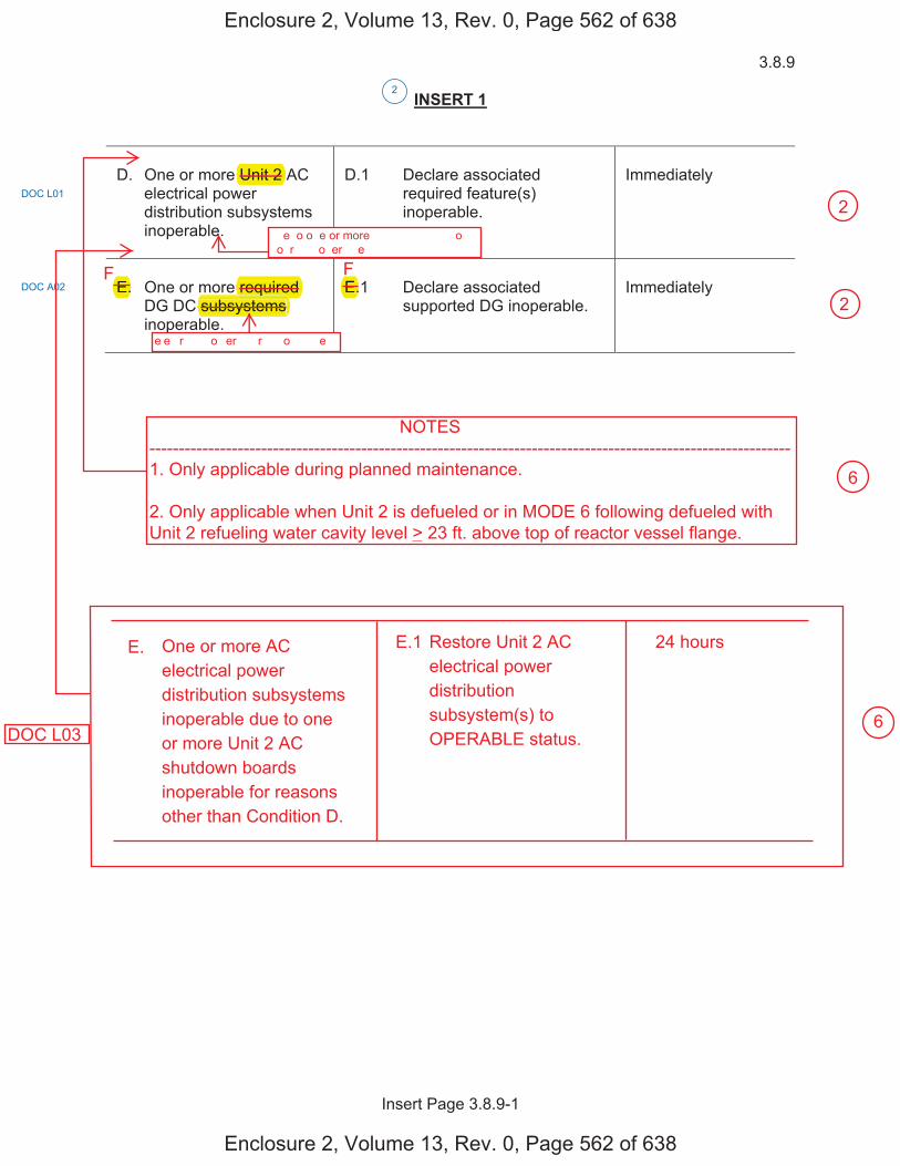
3.8.9
Insert Page 3.8.9-1
INSERT 1
D. One or more Unit 2 AC electrical power distribution subsystems inoperable.
D.1 Declare associated required feature(s) inoperable.
Immediately
E. One or more required DG DC subsystems inoperable.
E.1 Declare associated supported DG inoperable.
Immediately
DOC L01
2
DOC A02
Enclosure 2, Volume 13, Rev. 0, Page 562 of 638
Enclosure 2, Volume 13, Rev. 0, Page 562 of 638
��e �o o�e or more ���� � �� �����o�� �o�r�� ��o�er���e
e�e��r���� �o�er ����r�����o� ���e��
Unit 2
subsystems required qE. E.
F F
NOTES-------------------------------------------------------------------------------------------------------------1. Only applicable during planned maintenance.
2. Only applicable when Unit 2 is defueled or in MODE 6 following defueled withUnit 2 refueling water cavity level > 23 ft. above top of reactor vessel flange.
E. One or more ACelectrical powerdistribution subsystemsinoperable due to oneor more Unit 2 ACshutdown boardsinoperable for reasonsother than Condition D.
E.1 Restore Unit 2 ACelectrical powerdistributionsubsystem(s) toOPERABLE status.
24 hours
DOC L03
6
6
2
2
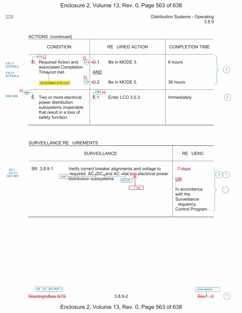
Distribution Systems - Operating 3.8.9
Westinghouse STS 3.8.9-2 Rev. �.0
CTS
SE�UO�AH UNIT 1 Amendment ���
1
ACTIONS (continued)
CONDITION RE�UIRED ACTION COMPLETION TIME
D. Required Action and associated Completion Time not met.
D.1 Be in MODE 3.
AND
D.2 Be in MODE 5.
6 hours
36 hours
E. Two or more electrical power distribution subsystems inoperable that result in a loss of safety function.
E.1 Enter LCO 3.0.3. Immediately
SURVEILLANCE RE�UIREMENTS
SURVEILLANCE �RE�UENC�
SR 3.8.9.1 Verify correct breaker alignments and voltage to �required� AC, DC, and AC vital bus electrical power distribution subsystems.
� 7 days
OR
In accordance with the Surveillance �requency Control Program �
�
for Condition A, B, or C
G
vital
�
�
G
3.8.2.1 ACTION a.
3.8.2.3 ACTION a.
DOC M02
�.8.2.1 �.8.2.3.1 DOC M01
2
3 1
�
2
DG DC,
Enclosure 2, Volume 13, Rev. 0, Page 563 of 638
Enclosure 2, Volume 13, Rev. 0, Page 563 of 638
����r�me��
for Condition A, B, or C
G G
G
H H
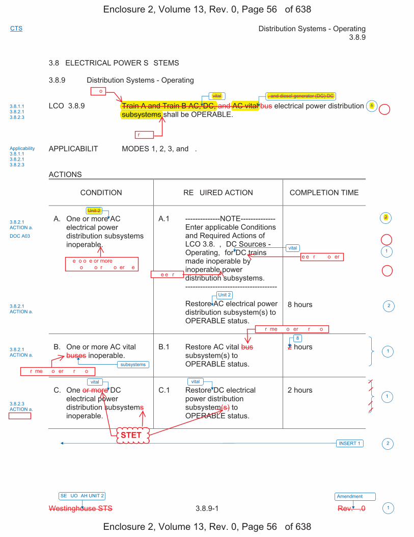
Distribution Systems - Operating 3.8.9
Westinghouse STS 3.8.9-1 Rev. �.0
CTS
SE�UO�AH UNIT 2 Amendment ���
1
3.8 ELECTRICAL POWER S�STEMS
3.8.9 Distribution Systems - Operating
LCO 3.8.9 Train A and Train B AC, DC, and AC vital bus electrical power distribution subsystems shall be OPERABLE.
APPLICABILIT�� MODES 1, 2, 3, and �. ACTIONS
CONDITION
RE�UIRED ACTION
COMPLETION TIME
A. One or more AC
electrical power distribution subsystems inoperable.
A.1 --------------NOTE-------------- Enter applicable Conditions
and Required Actions of LCO 3.8.�, �DC Sources - Operating,� for DC trains made inoperable by inoperable power distribution subsystems.
------------------------------------- Restore AC electrical power
distribution subsystem(s) to OPERABLE status.
8 hours
B. One or more AC vital
buses inoperable.
B.1 Restore AC vital bus
subsystem(s) to OPERABLE status.
2 hours
C. One or more DC
electrical power distribution subsystems inoperable.
C.1 Restore DC electrical
power distribution subsystem(s) to OPERABLE status.
2 hours
vital
vital
INSERT 1
Unit 2
vital
8
3.8.1.1 3.8.2.1 3.8.2.3
Applicability 3.8.1.1 3.8.2.1 3.8.2.3
3.8.2.1 ACTION a.
DOC A03
3.8.2.1 ACTION a.
3.8.2.3 ACTION a.
2
1
1
subsystems
vital
3.8.2.1 ACTION a.
1
2
Unit 2
2
, and diesel generator (DG) DC
1
Enclosure 2, Volume 13, Rev. 0, Page 56� of 638
Enclosure 2, Volume 13, Rev. 0, Page 56� of 638
STET
��� ���
��o
�r����
, and diesel generator (DG) DCvital
AC vital Train A and Train B AC, DC,subsystems
Unit 2
��e �o o�e or more ���� � �� �����o�� �o�r�� ��o�er���e
�� e�e��r����
e�e��r���� �o�er
2
����r�me�� �o�er ����r�����o�
����r�me�� �o�er ����r�����o�
�1
�
�
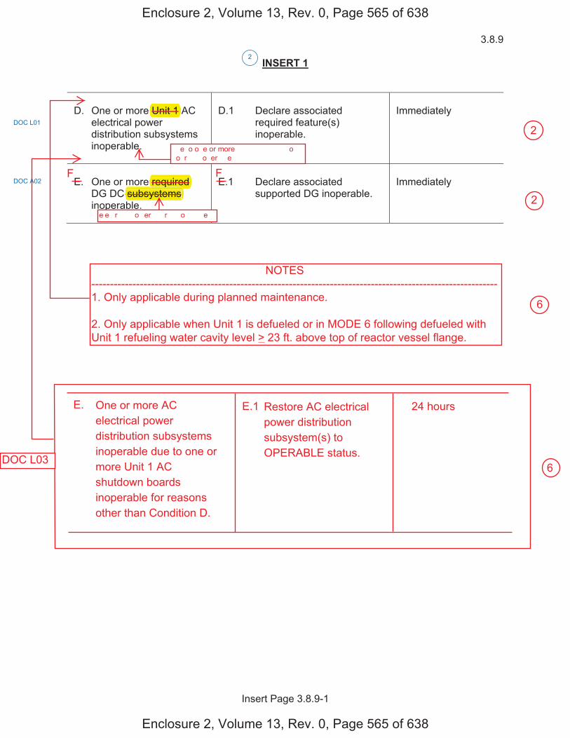
3.8.9
Insert Page 3.8.9-1
INSERT 1
D. One or more Unit 1 AC
electrical power distribution subsystems inoperable.
D.1 Declare associated
required feature(s) inoperable.
Immediately
E. One or more required
DG DC subsystems inoperable.
E.1 Declare associated
supported DG inoperable.
Immediately
DOC L01
2
DOC A02
Enclosure 2, Volume 13, Rev. 0, Page 565 of 638
Enclosure 2, Volume 13, Rev. 0, Page 565 of 638
��e �o o�e or more ���� � �� �����o�� �o�r�� ��o�er���e
e�e��r���� �o�er ����r�����o� ���e��
Unit 1
subsystems required q
NOTES-------------------------------------------------------------------------------------------------------------1. Only applicable during planned maintenance.
2. Only applicable when Unit 1 is defueled or in MODE 6 following defueled withUnit 1 refueling water cavity level > 23 ft. above top of reactor vessel flange.
One or more ACelectrical powerdistribution subsystemsinoperable due to one ormore Unit 1 ACshutdown boardsinoperable for reasonsother than Condition D.
Restore AC electricalpower distributionsubsystem(s) toOPERABLE status.
24 hoursE.1E.
F F
DOC L03
6
6
2
2
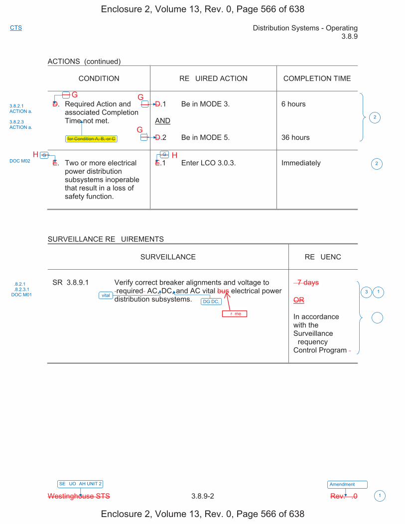
Distribution Systems - Operating 3.8.9
Westinghouse STS 3.8.9-2 Rev. �.0
CTS
SE�UO�AH UNIT 2 Amendment ���
1
ACTIONS (continued)
CONDITION
RE�UIRED ACTION
COMPLETION TIME
D. Required Action and
associated Completion Time not met.
D.1 Be in MODE 3. AND D.2 Be in MODE 5.
6 hours 36 hours
E. Two or more electrical
power distribution subsystems inoperable that result in a loss of safety function.
E.1 Enter LCO 3.0.3.
Immediately
SURVEILLANCE RE�UIREMENTS
SURVEILLANCE
�RE�UENC�
SR 3.8.9.1 Verify correct breaker alignments and voltage to
�required� AC, DC, and AC vital bus electrical power distribution subsystems.
� 7 days OR In accordance with the Surveillance �requency Control Program �
�
for Condition A, B, or C
G
vital
�
�
G
3.8.2.1 ACTION a. 3.8.2.3 ACTION a.
DOC M02
�.8.2.1 �.8.2.3.1 DOC M01 3 1
�
2
2
DG DC,
Enclosure 2, Volume 13, Rev. 0, Page 566 of 638
Enclosure 2, Volume 13, Rev. 0, Page 566 of 638
����r�me��
for Condition A, B, or C
G
G
G
H H
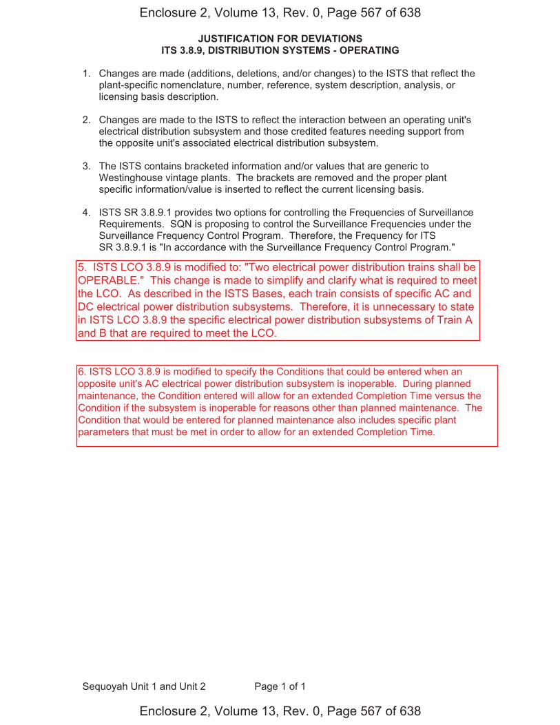
JUSTIFICATION FOR DEVIATIONS ITS 3.8.9, DISTRIBUTION SYSTEMS - OPERATING
Sequoyah Unit 1 and Unit 2 Page 1 of 1
1. Changes are made (additions, deletions, and/or changes) to the ISTS that reflect the plant-specific nomenclature, number, reference, system description, analysis, or licensing basis description.
2. Changes are made to the ISTS to reflect the interaction between an operating unit's electrical distribution subsystem and those credited features needing support from the opposite unit's associated electrical distribution subsystem.
3. The ISTS contains bracketed information and/or values that are generic to
Westinghouse vintage plants. The brackets are removed and the proper plant specific information/value is inserted to reflect the current licensing basis.
4. ISTS SR 3.8.9.1 provides two options for controlling the Frequencies of Surveillance
Requirements. SQN is proposing to control the Surveillance Frequencies under the Surveillance Frequency Control Program. Therefore, the Frequency for ITS SR 3.8.9.1 is "In accordance with the Surveillance Frequency Control Program."
Enclosure 2, Volume 13, Rev. 0, Page 567 of 638
Enclosure 2, Volume 13, Rev. 0, Page 567 of 638
5. ISTS LCO 3.8.9 is modified to: "Two electrical power distribution trains shall beOPERABLE." This change is made to simplify and clarify what is required to meetthe LCO. As described in the ISTS Bases, each train consists of specific AC andDC electrical power distribution subsystems. Therefore, it is unnecessary to statein ISTS LCO 3.8.9 the specific electrical power distribution subsystems of Train Aand B that are required to meet the LCO.
6. ISTS LCO 3.8.9 is modified to specify the Conditions that could be entered when an opposite unit's AC electrical power distribution subsystem is inoperable. During planned maintenance, the Condition entered will allow for an extended Completion Time versus the Condition if the subsystem is inoperable for reasons other than planned maintenance. The Condition that would be entered for planned maintenance also includes specific plant parameters that must be met in order to allow for an extended Completion Time.
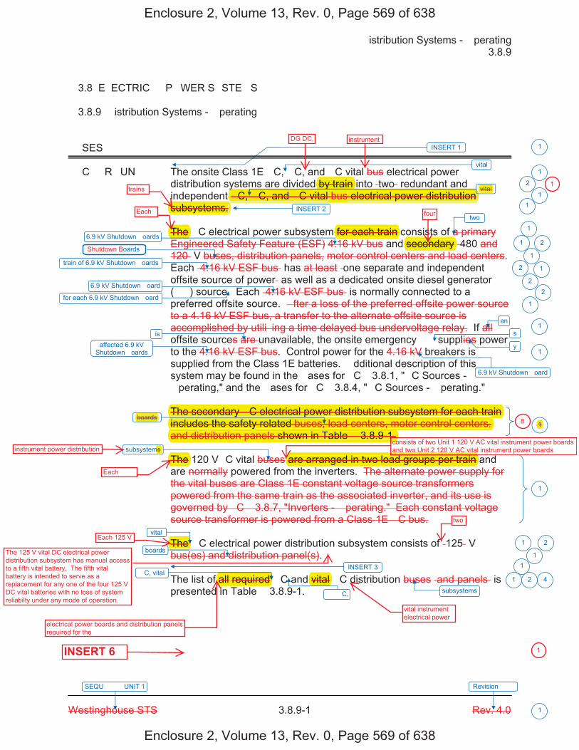
�istribution Systems - �perating � 3.8.9
Westinghouse STS � 3.8.9-1 Rev. 4.0
SEQU���� UNIT 1 Revision ���
1
� 3.8 E�ECTRIC�� P�WER S�STE�S
� 3.8.9 �istribution Systems - �perating
��SES
��C��R�UN� The onsite Class 1E �C, �C, and �C vital bus electrical power distribution systems are divided by train into �two� redundant and independent �C, �C, and �C vital bus electrical power distribution subsystems.
The �C electrical power subsystem for each train consists of a primary Engineered Safety Feature (ESF) 4.16 kV bus and secondary �480 and 120� V buses, distribution panels, motor control centers and load centers. Each �4.16 kV ESF bus� has at least �one separate and independent offsite source of power� as well as a dedicated onsite diesel generator (��) source. Each �4.16 kV ESF bus� is normally connected to a preferred offsite source. �fter a loss of the preferred offsite power source to a 4.16 kV ESF bus, a transfer to the alternate offsite source is accomplished by utili�ing a time delayed bus undervoltage relay. If all offsite sources are unavailable, the onsite emergency �� supplies power to the 4.16 kV ESF bus. Control power for the 4.16 kV breakers is supplied from the Class 1E batteries. �dditional description of this system may be found in the �ases for �C� 3.8.1, "�C Sources - �perating," and the �ases for �C� 3.8.4, "�C Sources - �perating."
The secondary �C electrical power distribution subsystem for each train includes the safety related buses, load centers, motor control centers, and distribution panels shown in Table � 3.8.9-1.
The 120 V�C vital buses are arranged in two load groups per train and are normally powered from the inverters. The alternate power supply for the vital buses are Class 1E constant voltage source transformers powered from the same train as the associated inverter, and its use is governed by �C� 3.8.7, "Inverters - �perating." Each constant voltage source transformer is powered from a Class 1E �C bus.
The �C electrical power distribution subsystem consists of �125� V bus(es) and distribution panel(s).
The list of all required �C and vital �C distribution buses �and panels� is presented in Table � 3.8.9-1.
1
1
vital
vital
6.9 kV Shutdown �oards
train of 6.9 kV Shutdown �oards
two
6.9 kV Shutdown �oard
affected 6.9 kV Shutdown �oards
boards
vital
�C, vital
INSERT 1
subsystems
boards
subsystems
oards
2
1
1 2
1
2
22
1
1
1
1
1 2
1
1 2
1
6.9 kV Shutdown �oard
an1
is
for each 6.9 kV Shutdown �oard
s
y
1
INSERT 2 1
INSERT 3 1
�� �C,
4
Enclosure 2, Volume 13, Rev. 0, Page 569 of 638
Enclosure 2, Volume 13, Rev. 0, Page 569 of 638
Each
Each
vital instrument electrical power
INSERT 6
trains
Each 125 V
two
four
consists of two Unit 1 120 V AC vital instrument power boards and two Unit 2 120 V AC vital instrument power boardsinstrument power distribution
electrical power boards and distribution panels required for the
DG DC, instrument
by train vital
The for each train secondary
The secondary �C electrical power distribution subsystem for each train y p yincludes the safety related buses, load centers, motor control centers,yand distribution panels shown in Table � 3.8.9-1.
co
boards
The ms
are arranged in two load groups per train
The
f all required vital
y y�C, �C, and �C vital bus electrical power distribution
yp
subsystems.
1
18
1
The 125 V vital DC electrical power distribution subsystem has manual access to a fifth vital battery. The fifth vital battery is intended to serve as a replacement for any one of the four 125 V DC vital batteries with no loss of system reliabilty under any mode of operation.

3.8.9
Insert Page � 3.8.9-1
INSERT 1
The two units share several structures and systems including the preferred and emergency (standby) electric power systems (UFS�R Chapter 8.0). The vital �C Power System is shared to the e�tent that a few loads (e.g., the vital inverters) in one nuclear unit are energi�ed by the �C power channels assigned primarily to power loads of the other unit. In no case does the sharing inhibit the safe shutdown of one unit while the other unit is e�periencing an accident. The Standby Power System serving each unit is divided into two redundant load groups (power trains). These power trains (Train � and Train � for each unit) supply power to safety-related equipment. �enerally, the Engineered Safety Feature (ESF) loads assigned to a unit are supplied by the unit designated trains. For e�ample, Safety In�ection (SI) pump 1�-� (associated with Unit 1) is supplied by Shutdown �oard 1�-� (also associated with Unit 1) while SI pump 2�-� (associated with Unit 2) is supplied by Shutdown �oard 2�-� (also associated with Unit 2).
Separate and similar systems and equipment are provided for each unit when required. In certain instances, both units share systems or some components of a system. Shared systems are the e�ception to the unit/power system association. �ecause both units share the power system, one unit's power system(s) supports certain components required by the other unit (e.g., emergency gas treatment system). To show the unit, train, board, and panel association, Table � 3.8.9-1 lists these power system components by train and unit designation.
INSERT 2
In addition, each diesel generator (��) has an associated �C electrical power distribution panel.
INSERT 3
The �� 125 Volt �C distribution subsystem includes a 125 V distribution panel for each ��. �uring normal operation, power is supplied to the distribution panel by a 480 V�C board through a battery charger. �uring emergency operation of the �� (loss of offsite power source), the distribution panel is supplied power from a 58 cell battery. This panel supplies power for �� control, protection, and the engine �C lube oil circulating pump.
1
1
1
Enclosure 2, Volume 13, Rev. 0, Page 570 of 638
Enclosure 2, Volume 13, Rev. 0, Page 570 of 638
Each consists of two
s that supply powerto the respectiveDG's auxiliary loads
electrical powerDC
dedicated
Each electrical power distribution train consists of: a. an AC electrical power distribution subsystem, b. an AC vital instrument power distribution subsystem, c. a vital DC electrical power distribution subsystem, and d. a diesel generator (DG) DC electrical power distribution subsystem.
qTo show they ( g , g y g y )
unit, train, board, and panel association, Table � 3.8.9-1 lists these power psystem components by train and unit designation.
In addition, each diesel generator (��) has an associated �C electricalgpower distribution panel.
The 125 Volt includes a
p58 cell
for each ��.
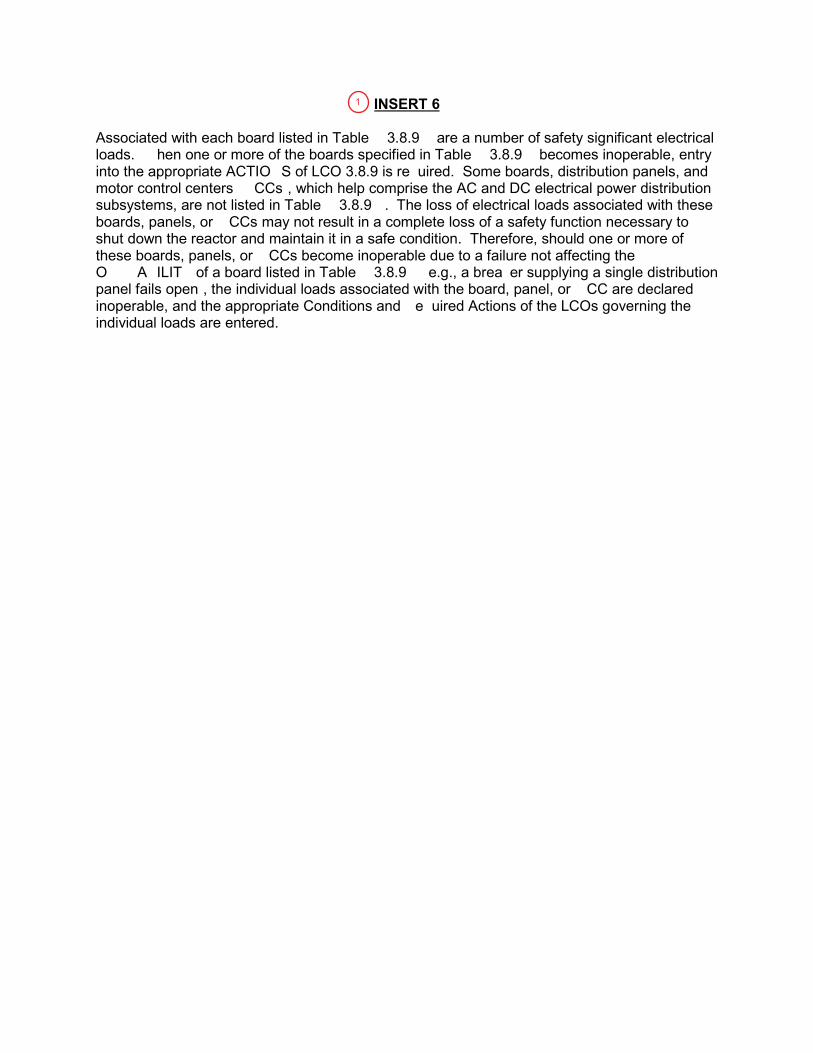
Associated with each board listed in Table � 3.8.9�� are a number of safety significant electrical loads. � hen one or more of the boards specified in Table � 3.8.9�� becomes inoperable, entry into the appropriate ACTIO�S of LCO 3.8.9 is re�uired. Some boards, distribution panels, and motor control centers ��CCs�, which help comprise the AC and DC electrical power distribution subsystems, are not listed in Table � 3.8.9��. The loss of electrical loads associated with these boards, panels, or �CCs may not result in a complete loss of a safety function necessary to shut down the reactor and maintain it in a safe condition. Therefore, should one or more of these boards, panels, or �CCs become inoperable due to a failure not affecting the O���A�ILIT� of a board listed in Table � 3.8.9�� �e.g., a brea�er supplying a single distribution panel fails open�, the individual loads associated with the board, panel, or �CC are declared inoperable, and the appropriate Conditions and �e�uired Actions of the LCOs governing the individual loads are entered.
1
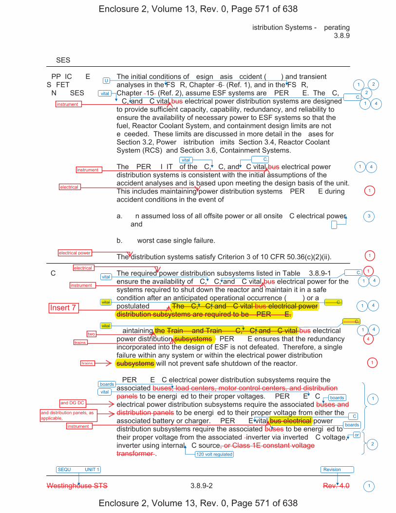
�istribution Systems - �perating � 3.8.9
Westinghouse STS � 3.8.9-2 Rev. 4.0
SEQU���� UNIT 1 Revision ���
1
��SES
�PP�IC���E The initial conditions of �esign �asis �ccident (���) and transient S�FET� analyses in the FS�R, Chapter �6� (Ref. 1), and in the FS�R, �N���SES Chapter �15� (Ref. 2), assume ESF systems are �PER���E. The �C,
�C, and �C vital bus electrical power distribution systems are designed to provide sufficient capacity, capability, redundancy, and reliability to ensure the availability of necessary power to ESF systems so that the fuel, Reactor Coolant System, and containment design limits are not e�ceeded. These limits are discussed in more detail in the �ases for Section 3.2, Power �istribution �imits� Section 3.4, Reactor Coolant System (RCS)� and Section 3.6, Containment Systems. The �PER��I�IT� of the �C, �C, and �C vital bus electrical power distribution systems is consistent with the initial assumptions of the accident analyses and is based upon meeting the design basis of the unit. This includes maintaining power distribution systems �PER���E during accident conditions in the event of� a. �n assumed loss of all offsite power or all onsite �C electrical power
and b. � worst case single failure. The distribution systems satisfy Criterion 3 of 10 CFR 50.36(c)(2)(ii).
�C� The required power distribution subsystems listed in Table � 3.8.9-1
ensure the availability of �C, �C, and �C vital bus electrical power for the systems required to shut down the reactor and maintain it in a safe condition after an anticipated operational occurrence (���) or a postulated ���. The �C, �C, and �C vital bus electrical power distribution subsystems are required to be �PER���E. �aintaining the Train � and Train � �C, �C, and �C vital bus electrical power distribution subsystems �PER���E ensures that the redundancy incorporated into the design of ESF is not defeated. Therefore, a single failure within any system or within the electrical power distribution subsystems will not prevent safe shutdown of the reactor. �PER���E �C electrical power distribution subsystems require the associated buses, load centers, motor control centers, and distribution panels to be energi�ed to their proper voltages. �PER���E �C electrical power distribution subsystems require the associated buses and distribution panels to be energi�ed to their proper voltage from either the associated battery or charger. �PER���E vital bus electrical power distribution subsystems require the associated buses to be energi�ed to their proper voltage from the associated �inverter via inverted �C voltage, inverter using internal �C source, or Class 1E constant voltage transformer�.
vital
vital
vital
vital
vital
or
120 volt regulated
vital
�
U
boards
boards
boards
1 2
2
1
1
3
1
1
1
2
�C
�� �C,
�� �C,
�� �C,
�� �C,
�� �C,
4
4
4
4
1 4
Enclosure 2, Volume 13, Rev. 0, Page 571 of 638
Enclosure 2, Volume 13, Rev. 0, Page 571 of 638
instrument
instrument
electrical
electrical power
electrical
instrument
p p ( )The �C, �C, and �C vital bus electrical power p
distribution subsystems are required to be �PER���E.Insert 7
vital
vital
�� �C,
two
trains
�� �C,
the Train � and Train � �C, �C, and �C vital subsystems �
subsystems trains
and DG DC
and distribution panels, as applicable,
gbus electrical
instrument
1
1
1
4
1
Two electrical power distribution trains are re�uired to be O���A�L�. �ach train includes�
a. an AC electrical power distribution subsystem �i.e., one �nit � 6.9 �� shutdown board, one�nit � 6.9 �� shutdown board, and associated �8� � shutdown boards�,
b. an AC vital instrument power distribution subsystem �i.e., two �nit � ��� � AC instrumentpower boards and two �nit � ��� � AC instrument power boards�,
c. a vital DC electrical power distribution subsystem �i.e., two ��� � DC boards�, andd. a D� DC electrical power distribution subsystem �i.e., two D� distribution panels�.
1 4
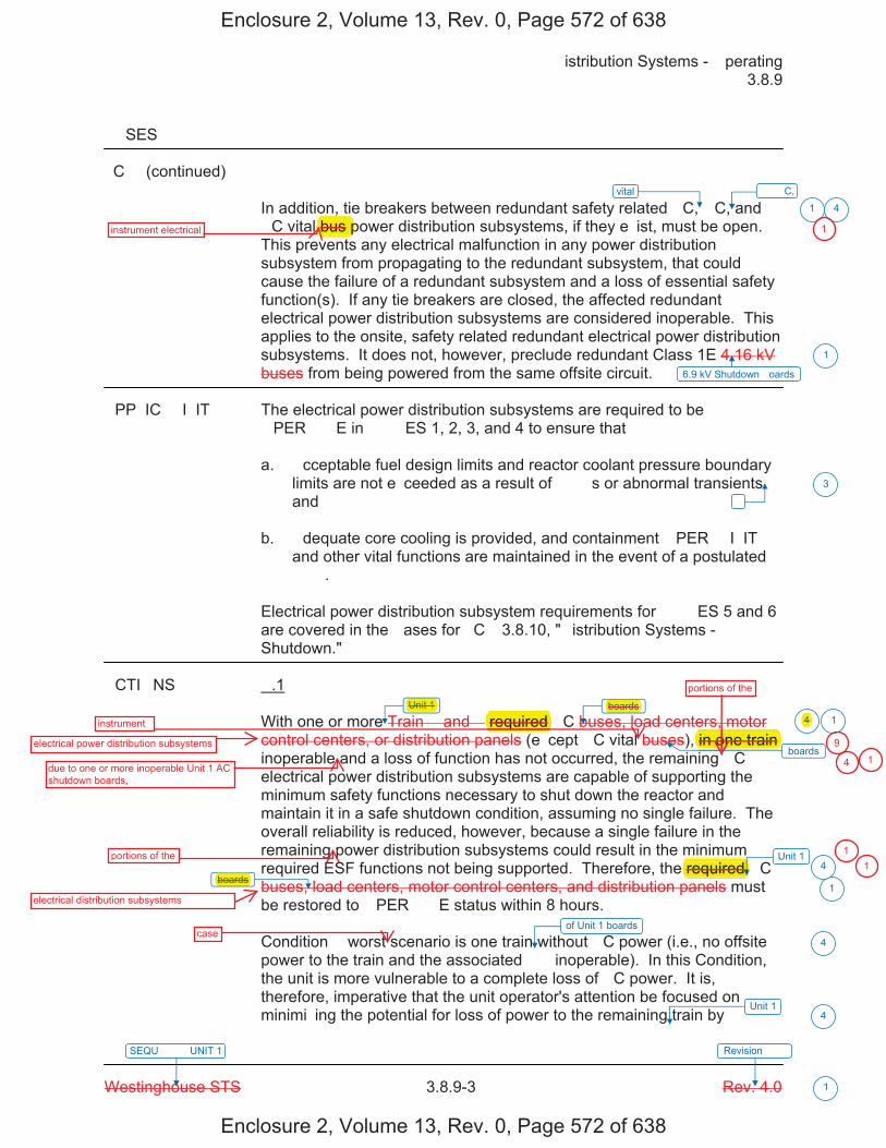
�istribution Systems - �perating � 3.8.9
Westinghouse STS � 3.8.9-3 Rev. 4.0
SEQU���� UNIT 1 Revision ���
1
��SES
�C� (continued)
In addition, tie breakers between redundant safety related �C, �C, and �C vital bus power distribution subsystems, if they e�ist, must be open. This prevents any electrical malfunction in any power distribution subsystem from propagating to the redundant subsystem, that could cause the failure of a redundant subsystem and a loss of essential safety function(s). If any tie breakers are closed, the affected redundant electrical power distribution subsystems are considered inoperable. This applies to the onsite, safety related redundant electrical power distribution subsystems. It does not, however, preclude redundant Class 1E 4.16 kV buses from being powered from the same offsite circuit.
�PP�IC��I�IT� The electrical power distribution subsystems are required to be �PER���E in ���ES 1, 2, 3, and 4 to ensure that�
a. �cceptable fuel design limits and reactor coolant pressure boundarylimits are not e�ceeded as a result of ���s or abnormal transientsand
b. �dequate core cooling is provided, and containment �PER��I�IT�and other vital functions are maintained in the event of a postulated���.
Electrical power distribution subsystem requirements for ���ES 5 and 6 are covered in the �ases for �C� 3.8.10, "�istribution Systems - Shutdown."
�CTI�NS �.1
With one or more Train � and � required �C buses, load centers, motor control centers, or distribution panels (e�cept �C vital buses), in one train inoperable and a loss of function has not occurred, the remaining �C electrical power distribution subsystems are capable of supporting the minimum safety functions necessary to shut down the reactor and maintain it in a safe shutdown condition, assuming no single failure. The overall reliability is reduced, however, because a single failure in the remaining power distribution subsystems could result in the minimum required ESF functions not being supported. Therefore, the required �C buses, load centers, motor control centers, and distribution panels must be restored to �PER���E status within 8 hours.
Condition � worst scenario is one train without �C power (i.e., no offsite power to the train and the associated �� inoperable). In this Condition, the unit is more vulnerable to a complete loss of �C power. It is, therefore, imperative that the unit operator's attention be focused on minimi�ing the potential for loss of power to the remaining train by
vital
6.9 kV Shutdown �oards
�
boards
boards
1
1
1
3
1
Unit 1
boards
Unit 14
4
of Unit 1 boards
4
Unit 14
�� �C,
4
Enclosure 2, Volume 13, Rev. 0, Page 572 of 638
Enclosure 2, Volume 13, Rev. 0, Page 572 of 638
,bus pinstrument electrical
electrical power distribution subsystems
instrument
Unit 1 boards
due to one or more inoperable Unit 1 AC shutdown boards,
portions of the
required one trainin o
portions of the
electrical distribution subsystems
boards required
1
9
4
4 1
11
case
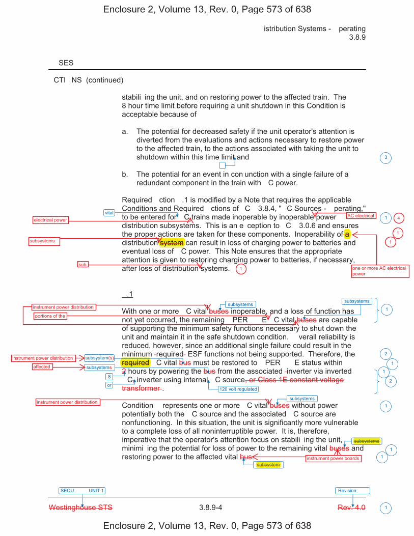
�istribution Systems - �perating � 3.8.9
Westinghouse STS � 3.8.9-4 Rev. 4.0
SEQU���� UNIT 1 Revision ���
1
��SES
�CTI�NS (continued)
stabili�ing the unit, and on restoring power to the affected train. The 8 hour time limit before requiring a unit shutdown in this Condition is acceptable because of�
a. The potential for decreased safety if the unit operator's attention isdiverted from the evaluations and actions necessary to restore powerto the affected train, to the actions associated with taking the unit toshutdown within this time limit and
b. The potential for an event in con�unction with a single failure of aredundant component in the train with �C power.
Required �ction �.1 is modified by a Note that requires the applicable Conditions and Required �ctions of �C� 3.8.4, "�C Sources - �perating," to be entered for �C trains made inoperable by inoperable power distribution subsystems. This is an e�ception to �C� 3.0.6 and ensures the proper actions are taken for these components. Inoperability of a distribution system can result in loss of charging power to batteries and eventual loss of �C power. This Note ensures that the appropriate attention is given to restoring charging power to batteries, if necessary, after loss of distribution systems.
�.1
With one or more �C vital buses inoperable, and a loss of function has not yet occurred, the remaining �PER���E �C vital buses are capable of supporting the minimum safety functions necessary to shut down the unit and maintain it in the safe shutdown condition. �verall reliability is reduced, however, since an additional single failure could result in the minimum �required� ESF functions not being supported. Therefore, the required �C vital bus must be restored to �PER���E status within 2 hours by powering the bus from the associated �inverter via inverted �C, inverter using internal �C source, or Class 1E constant voltage transformer�.
Condition � represents one or more �C vital buses without power� potentially both the �C source and the associated �C source are nonfunctioning. In this situation, the unit is significantly more vulnerable to a complete loss of all noninterruptible power. It is, therefore, imperative that the operator's attention focus on stabili�ing the unit, minimi�ing the potential for loss of power to the remaining vital buses and restoring power to the affected vital bus.
vital
120 volt regulated
�
subsystems
3
1
1
2
1
1
2
1
11
8
subsystems
subsystem
subsystem
or
subsystems
subsystems
subsystem
Enclosure 2, Volume 13, Rev. 0, Page 573 of 638
Enclosure 2, Volume 13, Rev. 0, Page 573 of 638
electrical powerAC electrical
one or more AC electrical power
f a subsystems system
sub
instrument power distribution
portions of the
required instrument power distribution
affected
instrument power distribution
4
1
1
1
subsystems
subsystem instrument power boards
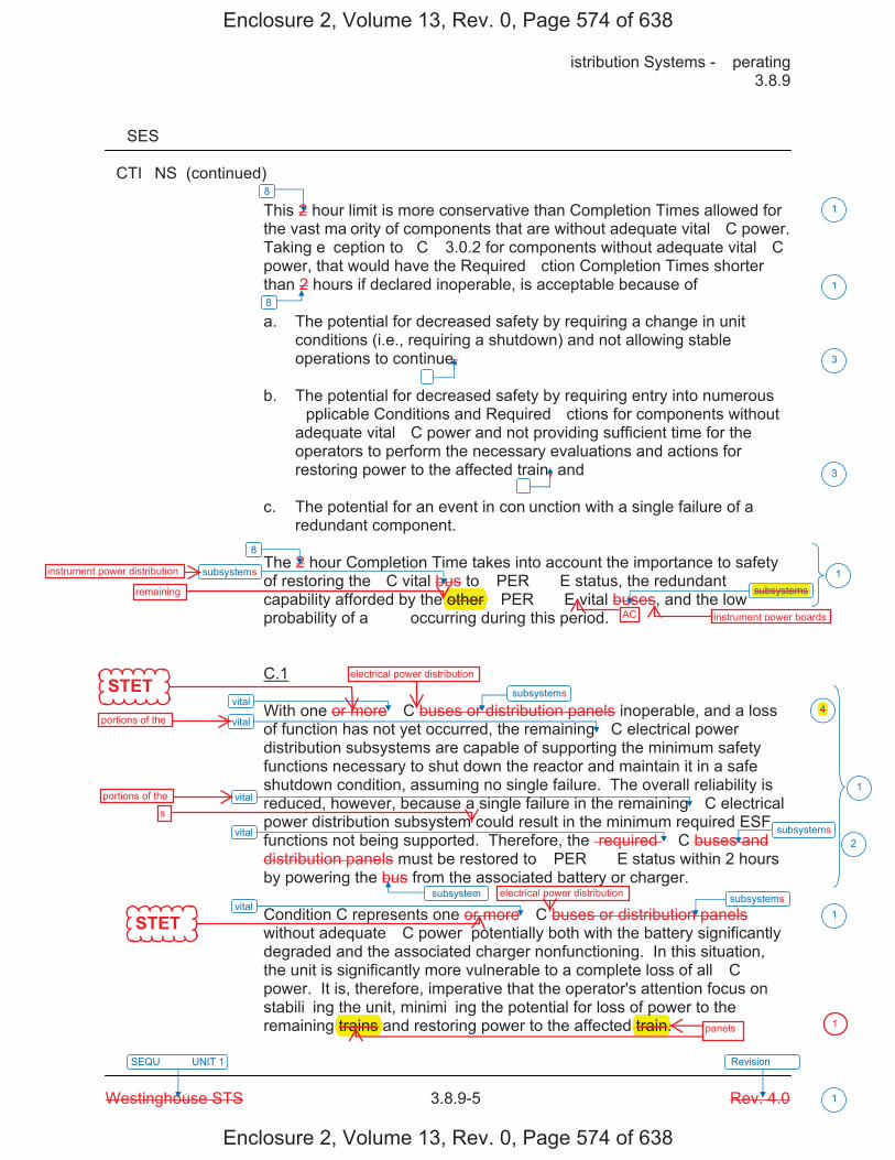
�istribution Systems - �perating � 3.8.9
Westinghouse STS � 3.8.9-5 Rev. 4.0
SEQU���� UNIT 1 Revision ���
1
��SES
�CTI�NS (continued) This 2 hour limit is more conservative than Completion Times allowed for the vast ma�ority of components that are without adequate vital �C power. Taking e�ception to �C� 3.0.2 for components without adequate vital �C power, that would have the Required �ction Completion Times shorter than 2 hours if declared inoperable, is acceptable because of�
a. The potential for decreased safety by requiring a change in unitconditions (i.e., requiring a shutdown) and not allowing stableoperations to continue,
b. The potential for decreased safety by requiring entry into numerous�pplicable Conditions and Required �ctions for components withoutadequate vital �C power and not providing sufficient time for theoperators to perform the necessary evaluations and actions forrestoring power to the affected train, and
c. The potential for an event in con�unction with a single failure of aredundant component.
The 2 hour Completion Time takes into account the importance to safety of restoring the �C vital bus to �PER���E status, the redundant capability afforded by the other �PER���E vital buses, and the low probability of a ��� occurring during this period.
C.1
With one or more �C buses or distribution panels inoperable, and a loss of function has not yet occurred, the remaining �C electrical power distribution subsystems are capable of supporting the minimum safety functions necessary to shut down the reactor and maintain it in a safe shutdown condition, assuming no single failure. The overall reliability is reduced, however, because a single failure in the remaining �C electrical power distribution subsystem could result in the minimum required ESF functions not being supported. Therefore, the �required� �C buses and distribution panels must be restored to �PER���E status within 2 hours by powering the bus from the associated battery or charger.
Condition C represents one or more �C buses or distribution panels without adequate �C power� potentially both with the battery significantly degraded and the associated charger nonfunctioning. In this situation, the unit is significantly more vulnerable to a complete loss of all �C power. It is, therefore, imperative that the operator's attention focus on stabili�ing the unit, minimi�ing the potential for loss of power to the remaining trains and restoring power to the affected train.
vital
vital
vital
vital
vital
�
�
subsystem
3
3
1
2
1
8
8
1
1
1
8
subsystems
subsystem
subsystem
subsystem subsystem
4
Enclosure 2, Volume 13, Rev. 0, Page 574 of 638
Enclosure 2, Volume 13, Rev. 0, Page 574 of 638
STET
STET
instrument power distribution
remaining other AC instrument power boards
subsystems
electrical power distribution
portions of the
portions of thes
electrical power distribution
4
panels
ptrain.trains 1
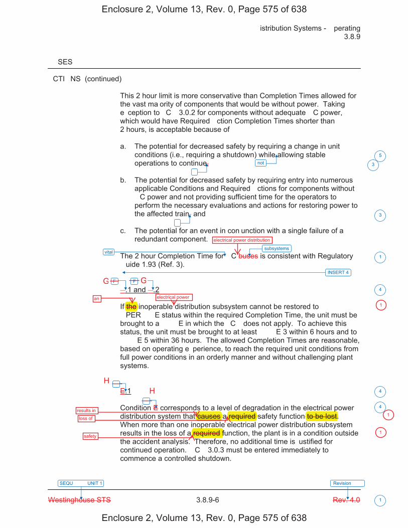
�istribution Systems - �perating � 3.8.9
Westinghouse STS � 3.8.9-6 Rev. 4.0
SEQU���� UNIT 1 Revision ���
1
��SES
�CTI�NS (continued) This 2 hour limit is more conservative than Completion Times allowed for the vast ma�ority of components that would be without power. Taking e�ception to �C� 3.0.2 for components without adequate �C power, which would have Required �ction Completion Times shorter than 2 hours, is acceptable because of� a. The potential for decreased safety by requiring a change in unit
conditions (i.e., requiring a shutdown) while allowing stable operations to continue,
b. The potential for decreased safety by requiring entry into numerous
applicable Conditions and Required �ctions for components without �C power and not providing sufficient time for the operators to perform the necessary evaluations and actions for restoring power to the affected train, and
c. The potential for an event in con�unction with a single failure of a
redundant component. The 2 hour Completion Time for �C buses is consistent with Regulatory �uide 1.93 (Ref. 3). �.1 and �.2 If the inoperable distribution subsystem cannot be restored to �PER���E status within the required Completion Time, the unit must be brought to a ���E in which the �C� does not apply. To achieve this status, the unit must be brought to at least ���E 3 within 6 hours and to ���E 5 within 36 hours. The allowed Completion Times are reasonable, based on operating e�perience, to reach the required unit conditions from full power conditions in an orderly manner and without challenging plant systems. E.1 Condition E corresponds to a level of degradation in the electrical power distribution system that causes a required safety function to be lost. When more than one inoperable electrical power distribution subsystem results in the loss of a required function, the plant is in a condition outside the accident analysis. Therefore, no additional time is �ustified for continued operation. �C� 3.0.3 must be entered immediately to commence a controlled shutdown.
vital
not
�
�
5
3
3
1
F F
�
4
4
INSERT 4
� 4
subsystems
Enclosure 2, Volume 13, Rev. 0, Page 575 of 638
Enclosure 2, Volume 13, Rev. 0, Page 575 of 638
electrical power distribution
an
f the electrical power
results inloss of
safety
causes g
required p
to be lost.p
required f
1
1
1
G G
HH
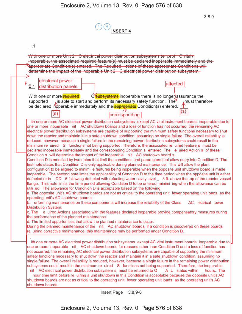
3.8.9
Insert Page � 3.8.9-6
INSERT 4
�.1
With one or more Unit 2 �C electrical power distribution subsystems (e�cept �C vital) inoperable, the associated required feature(s) must be declared inoperable immediately and the appropriate Condition(s) entered. The Required �ctions of these appropriate Conditions will determine the impact of the inoperable Unit 2 �C electrical power distribution subsystem.
E.1
With one or more required �� �C subsystems inoperable there is no longer assurance the supported �� is able to start and perform its necessary safety function. The �� must therefore be declared inoperable immediately and the appropriate Condition(s) entered.
41
Enclosure 2, Volume 13, Rev. 0, Page 576 of 638
Enclosure 2, Volume 13, Rev. 0, Page 576 of 638
electrical powerdistribution panels affected
required subsystems
(s) (s)corresponding
yappropriate
F
� ith one or more AC electrical power distribution subsystems �except AC vital instrument boards� inoperable due to one or more inoperable �nit � AC shutdown boards and a loss of function has not occurred, the remaining AC electrical power distribution subsystems are capable of supporting the minimum safety functions necessary to shut down the reactor and maintain it in a safe shutdown condition, assuming no single failure. The overall reliability is reduced, however, because a single failure in the remaining power distribution subsystems could result in the minimum re�uired �S� functions not being supported. Therefore, the associated re�uired feature�s� must be declared inoperable immediately and the corresponding Condition�s� entered. The �e�uired Action�s� of these Condition�s� will determine the impact of the inoperable �nit � AC shutdown board�s�. Condition D is modified by two notes that limit the conditions and parameters that allow entry into Condition D. The first note states that Condition D is only applicable during planned maintenance. This will allow the plant configuration to be aligned to minimi�e features being inoperable when the opposite unit shutdown board is made inoperable. The second note limits the applicability of Condition D to the time period when the opposite unit is either defueled or in �OD� 6 following defueled with refueling water cavity level � �3 ft. above the top of the reactor vessel flange. This note limits the time period allowing Condition D to be entered, minimi�ing when the allowance can be utili�ed. The allowance for Condition D is acceptable based on the following� a. The opposite unit's AC shutdown boards are not as critical to the operating unit �fewer operating unit loads� as the operating unit's AC shutdown boards. b. �erforming maintenance on these components will increase the reliability of the Class �� AC �lectrical �ower Distribution System. c. The �e�uired Actions associated with the features declared inoperable provide compensatory measures during the performance of the planned maintenance. d. The limited opportunities that allow the planned maintenance to occur. During the planned maintenance of the �nit � AC shutdown boards, if a condition is discovered on these boards re�uiring corrective maintenance, this maintenance may be performed under Condition D. �.� � ith one or more AC electrical power distribution subsystems �except AC vital instrument boards� inoperable due to one or more inoperable �nit � AC shutdown boards for reasons other than Condition D and a loss of function has not occurred, the remaining AC electrical power distribution subsystems are capable of supporting the minimum safety functions necessary to shut down the reactor and maintain it in a safe shutdown condition, assuming no single failure. The overall reliability is reduced, however, because a single failure in the remaining power distribution subsystems could result in the minimum re�uired �S� functions not being supported. Therefore, the inoperable �nit � AC electrical power distribution subsystem�s� must be returned to O���A�L� status within �� hours. The �� hour time limit before re�uiring a unit shutdown in this Condition is acceptable because the opposite unit's AC shutdown boards are not as critical to the operating unit �fewer operating unit loads� as the operating unit's AC shutdown boards.
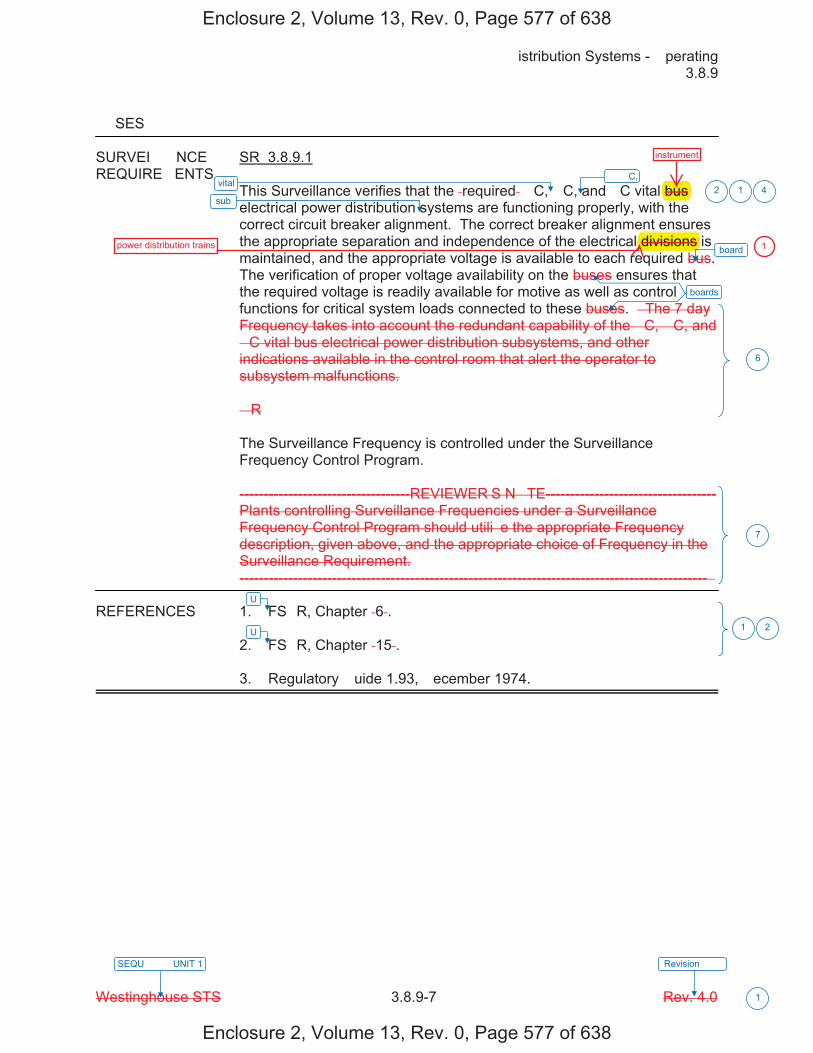
�istribution Systems - �perating � 3.8.9
Westinghouse STS � 3.8.9-7 Rev. 4.0
SEQU���� UNIT 1 Revision ���
1
��SES
SURVEI���NCE SR 3.8.9.1 REQUIRE�ENTS
This Surveillance verifies that the �required� �C, �C, and �C vital bus electrical power distribution systems are functioning properly, with the correct circuit breaker alignment. The correct breaker alignment ensures the appropriate separation and independence of the electrical divisions is maintained, and the appropriate voltage is available to each required bus. The verification of proper voltage availability on the buses ensures that the required voltage is readily available for motive as well as control functions for critical system loads connected to these buses. � The 7 day Frequency takes into account the redundant capability of the �C, �C, and �C vital bus electrical power distribution subsystems, and other indications available in the control room that alert the operator to subsystem malfunctions. �R The Surveillance Frequency is controlled under the Surveillance Frequency Control Program. -----------------------------------REVIEWER�S N�TE----------------------------------- Plants controlling Surveillance Frequencies under a Surveillance Frequency Control Program should utili�e the appropriate Frequency description, given above, and the appropriate choice of Frequency in the Surveillance Requirement. ------------------------------------------------------------------------------------------------ �
REFERENCES 1. FS�R, Chapter �6�. 2. FS�R, Chapter �15�. 3. Regulatory �uide 1.93, �ecember 1974.
vital
U
sub 12
6
7
1 2
board
boards
U
�� �C, 4
Enclosure 2, Volume 13, Rev. 0, Page 577 of 638
Enclosure 2, Volume 13, Rev. 0, Page 577 of 638
bus
divisions
instrument
power distribution trains 1
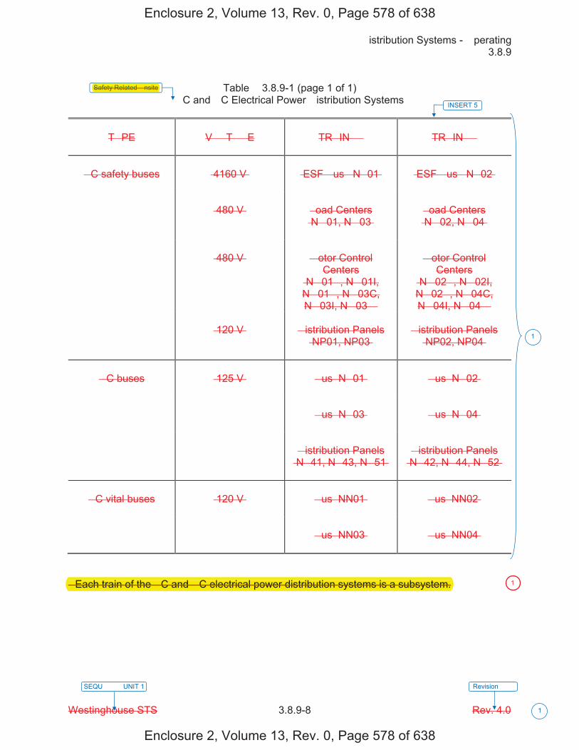
�istribution Systems - �perating � 3.8.9
Westinghouse STS � 3.8.9-8 Rev. 4.0
SEQU���� UNIT 1 Revision ���
1
Table � 3.8.9-1 (page 1 of 1) �C and �C Electrical Power �istribution Systems
T�PE
V��T��E
TR�IN ��
TR�IN ��
�C safety buses
�4160 V�
�ESF �us� �N�01�
�ESF �us� �N�02�
�480 V�
�oad Centers �N�01, N�03�
�oad Centers �N�02, N�04�
�480 V�
�otor Control
Centers �N�01�, N�01I, N�01�, N�03C, N�03I, N�03��
�otor Control
Centers �N�02�, N�02I, N�02�, N�04C, N�04I, N�04��
�120 V�
�istribution Panels
�NP01, NP03�
�istribution Panels
�NP02, NP04�
�C buses
�125 V�
�us �N�01�
�us �N�02�
�us �N�03�
�us �N�04�
�istribution Panels
�N�41, N�43, N�51�
�istribution Panels
�N�42, N�44, N�52�
�C vital buses
�120 V�
�us �NN01�
�us �NN02�
�us �NN03�
�us �NN04�
� Each train of the �C and �C electrical power distribution systems is a subsystem.
INSERT 5
1
Safety Related �nsite
Enclosure 2, Volume 13, Rev. 0, Page 578 of 638
Enclosure 2, Volume 13, Rev. 0, Page 578 of 638
Safety Related �nsite
� Each train of the �C and �C electrical power distribution systems is a subsystem. 1
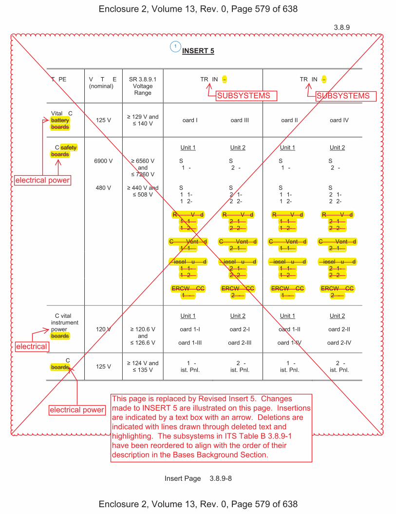
3.8.9
Insert Page � 3.8.9-8
INSERT 5
T�PE
V��T��E (nominal)
SR 3.8.9.1
Voltage Range
TR�IN ��
TR�IN ��
Vital �C battery boards
125 V 129 V and 140 V �oard I �oard III �oard II
�oard IV
�C safety boards
6900 V
6560 V and
7260 V
Unit 1
S� �� 1�-�
Unit 2
S� �� 2�-�
Unit 1
S� �� 1�-�
Unit 2
S� �� 2�-�
480 V
440 V and
508 V
S� �� 1�1-� 1�2-�
S� �� 2�1-� 2�2-�
S� �� 1�1-� 1�2-�
S� �� 2�1-� 2�2-�
R� ��V �d
1�1-� 1�2-�
R� ��V �d
2�1-� 2�2-�
R� ��V �d
1�1-� 1�2-�
R� ��V �d
2�1-� 2�2-�
C � � Vent �d
1�1-�
C � � Vent �d
2�1-� C � � Vent �d
1�1-�
C � � Vent �d
2�1-�
�iesel �u� �d 1�1-� 1�2-�
�iesel �u� �d
2�1-� 2�2-�
�iesel �u� �d
1�1-� 1�2-�
�iesel �u� �d
2�1-� 2�2-�
ERCW �CC
1�-�
ERCW �CC
2�-�
ERCW �CC
1�-�
ERCW �CC
2�-�
�C vital instrument power boards
120 V
120.6 V and
126.6 V
Unit 1
�oard 1-I
�oard 1-III
Unit 2
�oard 2-I
�oard 2-III
Unit 1
�oard 1-II
�oard 1-IV
Unit 2
�oard 2-II
�oard 2-IV
�� �C boards 125 V
124 V and
135 V
�� 1�-� �ist. Pnl.
�� 2�-� �ist. Pnl.
�� 1�-� �ist. Pnl.
�� 2�-� �ist. Pnl.
1
Enclosure 2, Volume 13, Rev. 0, Page 579 of 638
Enclosure 2, Volume 13, Rev. 0, Page 579 of 638
electrical power
electrical power
SUBSYSTEMS SUBSYSTEMS
����
electrical
This page is replaced by Revised Insert 5. Changesmade to INSERT 5 are illustrated on this page. Insertionsare indicated by a text box with an arrow. Deletions areindicated with lines drawn through deleted text andhighlighting. The subsystems in ITS Table B 3.8.9-1have been reordered to align with the order of theirdescription in the Bases Background Section.
battery yboards
safety boards
pboards
boards
R� ��V �d R� R� ��V �d R� ��V �d R� ��V �d �1-�1� 2�1-� 1�1-� 2�1-�
2-�1�2- 2�2-� 1�2-� 2�2-�
Vent �dC � � Ve �d C � � Vent �d C � � Vent �d C � � Vent �d �1-�1� 2�1-� 1�1-� 2�1-�
�iesel �u� �d � �iesel �u� �d � �iesel �u� �d �iesel �u� �d 1�1-� 2�1-� 1�1-� 2�1-�1�2-� 2�2-�2� 1�2-� 2�2-�
ERCW �CC CCERCW �C ERCW �CC ERCW �CC1�-� 2�-� 1�-� 2�-�
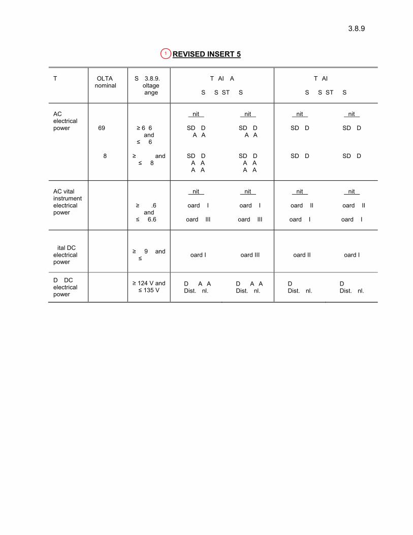
3.8.9
T��� �OLTA�� �nominal�
S� 3.8.9.� �oltage �ange
T�AI� A
S��S�ST��S
T�AI� �
S��S�ST��S
AC electrical power 69�� � 6�6� �
and ��6� �
�nit �
SD �D �A�A
�nit �
SD �D �A�A
�nit �
SD �D ����
�nit �
SD �D ����
�8� � ��� � and ��8 �
SD �D �A��A �A��A
SD �D �A��A �A��A
SD �D ����� �����
SD �D ����� �����
AC vital instrument electrical power
��� � ���.6 � and
��6.6 �
�nit �
�oard ��I
�oard ��III
�nit �
�oard ��I
�oard ��III
�nit �
�oard ��II
�oard ��I�
�nit �
�oard ��II
�oard ��I�
�ital DC electrical power
��� � ��9 � and ��� � �oard I �oard III �oard II �oard I�
D� DC electrical power
��� �
D� �A�A Dist. �nl.
D� �A�A Dist. �nl.
D� ���� Dist. �nl.
D� ���� Dist. �nl.
1
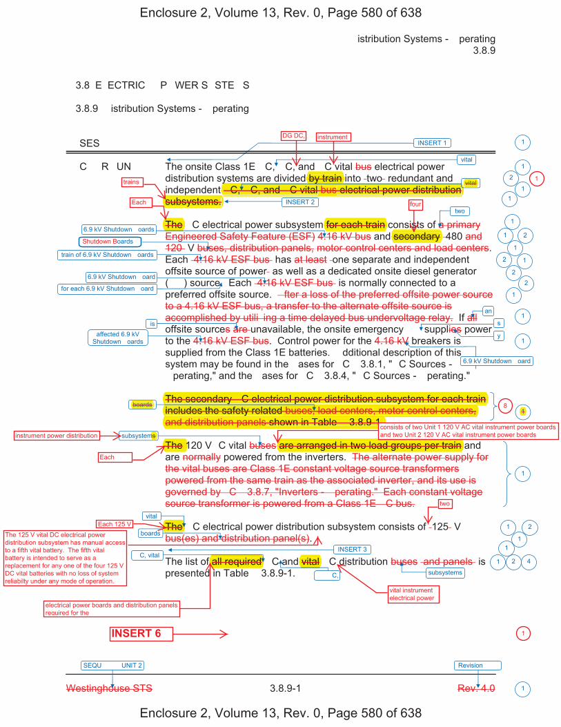
�istribution Systems - �perating � 3.8.9
Westinghouse STS � 3.8.9-1 Rev. 4.0
SEQU���� UNIT 2 Revision ���
1
� 3.8 E�ECTRIC�� P�WER S�STE�S
� 3.8.9 �istribution Systems - �perating
��SES
��C��R�UN� The onsite Class 1E �C, �C, and �C vital bus electrical power distribution systems are divided by train into �two� redundant and independent �C, �C, and �C vital bus electrical power distribution subsystems.
The �C electrical power subsystem for each train consists of a primary Engineered Safety Feature (ESF) 4.16 kV bus and secondary �480 and 120� V buses, distribution panels, motor control centers and load centers. Each �4.16 kV ESF bus� has at least �one separate and independent offsite source of power� as well as a dedicated onsite diesel generator (��) source. Each �4.16 kV ESF bus� is normally connected to a preferred offsite source. �fter a loss of the preferred offsite power source to a 4.16 kV ESF bus, a transfer to the alternate offsite source is accomplished by utili�ing a time delayed bus undervoltage relay. If all offsite sources are unavailable, the onsite emergency �� supplies power to the 4.16 kV ESF bus. Control power for the 4.16 kV breakers is supplied from the Class 1E batteries. �dditional description of this system may be found in the �ases for �C� 3.8.1, "�C Sources - �perating," and the �ases for �C� 3.8.4, "�C Sources - �perating."
The secondary �C electrical power distribution subsystem for each train includes the safety related buses, load centers, motor control centers, and distribution panels shown in Table � 3.8.9-1.
The 120 V�C vital buses are arranged in two load groups per train and are normally powered from the inverters. The alternate power supply for the vital buses are Class 1E constant voltage source transformers powered from the same train as the associated inverter, and its use is governed by �C� 3.8.7, "Inverters - �perating." Each constant voltage source transformer is powered from a Class 1E �C bus.
The �C electrical power distribution subsystem consists of �125� V bus(es) and distribution panel(s).
The list of all required �C and vital �C distribution buses �and panels� is presented in Table � 3.8.9-1.
1
1
vital
vital
6.9 kV Shutdown �oards
train of 6.9 kV Shutdown �oards
two
6.9 kV Shutdown �oard
affected 6.9 kV Shutdown �oards
boards
vital
�C, vital
INSERT 1
subsystems
boards
subsystems
oards
2
1
1 2
1
2
22
1
1
1
1
1 2
1
1 2
1
6.9 kV Shutdown �oard
an1
is
for each 6.9 kV Shutdown �oard
s
y
1
INSERT 2 1
1
�� �C,
INSERT 3
4
Enclosure 2, Volume 13, Rev. 0, Page 580 of 638
Enclosure 2, Volume 13, Rev. 0, Page 580 of 638
DG DC, instrument
trains
Each four
y y�C, �C, and �C vital bus electrical power distribution p
subsystems.
by train y vital
secondaryfor each train The
The secondary �C electrical power distribution subsystem for each train y p yincludes the safety related buses, load centers, motor control centers,yand distribution panels shown in Table � 3.8.9-1.
boards
instrument power distribution ms
EachThe 1 are arranged in two load groups per train
consists of two Unit 1 120 V AC vital instrument power boards and two Unit 2 120 V AC vital instrument power boards
Each 125 V The
two
f all required vital
electrical power boards and distribution panels required for the
INSERT 6
vital instrument electrical power
1
1
81
The 125 V vital DC electrical power distribution subsystem has manual access to a fifth vital battery. The fifth vital battery is intended to serve as a replacement for any one of the four 125 V DC vital batteries with no loss of system reliabilty under any mode of operation.
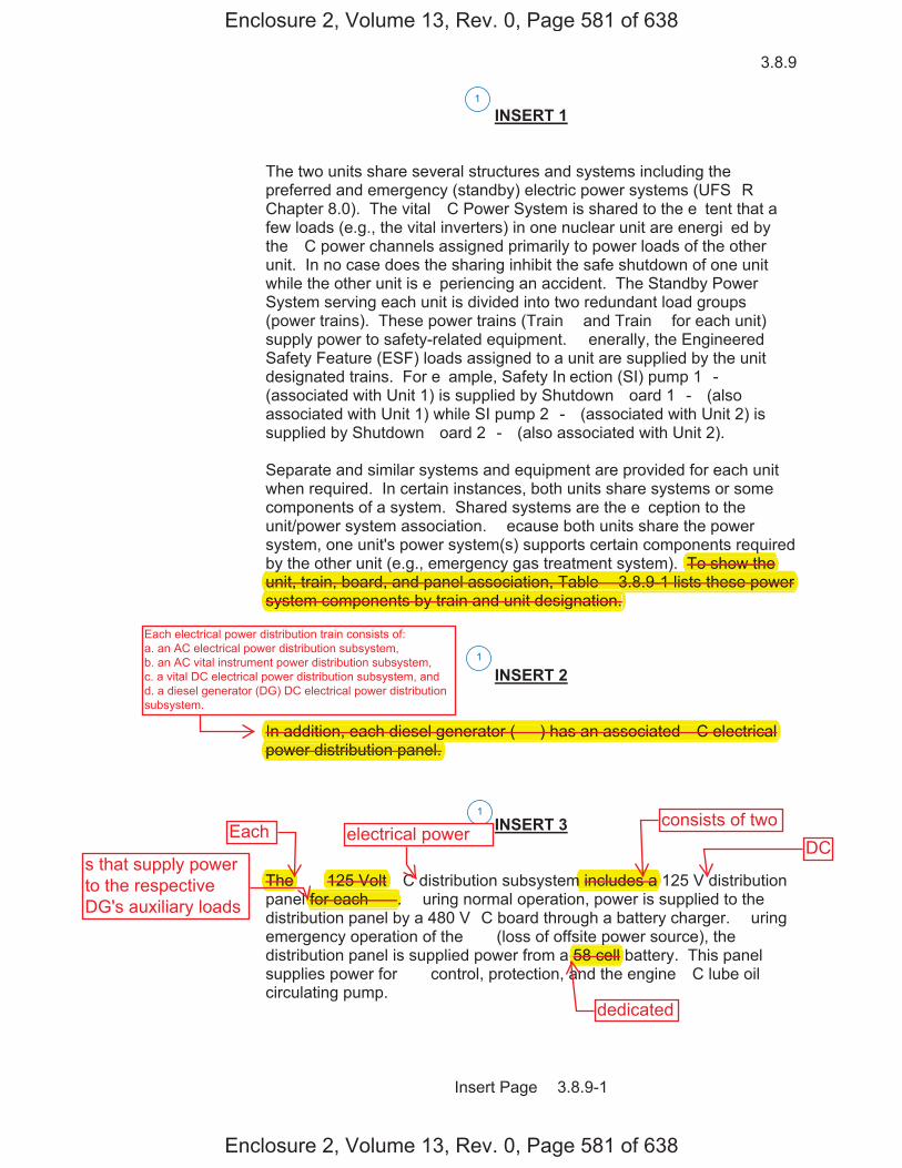
3.8.9
Insert Page � 3.8.9-1
INSERT 1
The two units share several structures and systems including the preferred and emergency (standby) electric power systems (UFS�R Chapter 8.0). The vital �C Power System is shared to the e�tent that a few loads (e.g., the vital inverters) in one nuclear unit are energi�ed by the �C power channels assigned primarily to power loads of the other unit. In no case does the sharing inhibit the safe shutdown of one unit while the other unit is e�periencing an accident. The Standby Power System serving each unit is divided into two redundant load groups (power trains). These power trains (Train � and Train � for each unit) supply power to safety-related equipment. �enerally, the Engineered Safety Feature (ESF) loads assigned to a unit are supplied by the unit designated trains. For e�ample, Safety In�ection (SI) pump 1�-� (associated with Unit 1) is supplied by Shutdown �oard 1�-� (also associated with Unit 1) while SI pump 2�-� (associated with Unit 2) is supplied by Shutdown �oard 2�-� (also associated with Unit 2). Separate and similar systems and equipment are provided for each unit when required. In certain instances, both units share systems or some components of a system. Shared systems are the e�ception to the unit/power system association. �ecause both units share the power system, one unit's power system(s) supports certain components required by the other unit (e.g., emergency gas treatment system). To show the unit, train, board, and panel association, Table � 3.8.9-1 lists these power system components by train and unit designation.
INSERT 2 In addition, each diesel generator (��) has an associated �C electrical power distribution panel.
INSERT 3 The �� 125 Volt �C distribution subsystem includes a 125 V distribution panel for each ��. �uring normal operation, power is supplied to the distribution panel by a 480 V�C board through a battery charger. �uring emergency operation of the �� (loss of offsite power source), the distribution panel is supplied power from a 58 cell battery. This panel supplies power for �� control, protection, and the engine �C lube oil circulating pump.
1
1
1
Enclosure 2, Volume 13, Rev. 0, Page 581 of 638
Enclosure 2, Volume 13, Rev. 0, Page 581 of 638
qTo show they ( g , g y g y )
unit, train, board, and panel association, Table � 3.8.9-1 lists these power psystem components by train and unit designation.
In addition, each diesel generator (��) has an associated �C electricalgpower distribution panel.
The 125 Volt m includes a for each ��.
p58 cell
Each electrical power distribution train consists of: a. an AC electrical power distribution subsystem, b. an AC vital instrument power distribution subsystem, c. a vital DC electrical power distribution subsystem, and d. a diesel generator (DG) DC electrical power distribution subsystem.
s that supply powerto the respectiveDG's auxiliary loads
Each electrical powerconsists of two
DC
dedicated

Associated with each board listed in Table � 3.8.9�� are a number of safety significant electrical loads. � hen one or more of the boards specified in Table � 3.8.9�� becomes inoperable, entry into the appropriate ACTIO�S of LCO 3.8.9 is re�uired. Some boards, distribution panels, and motor control centers ��CCs�, which help comprise the AC and DC electrical power distribution subsystems, are not listed in Table � 3.8.9��. The loss of electrical loads associated with these boards, panels, or �CCs may not result in a complete loss of a safety function necessary to shut down the reactor and maintain it in a safe condition. Therefore, should one or more of these boards, panels, or �CCs become inoperable due to a failure not affecting the O���A�ILIT� of a board listed in Table � 3.8.9�� �e.g., a brea�er supplying a single distribution panel fails open�, the individual loads associated with the board, panel, or �CC are declared inoperable, and the appropriate Conditions and �e�uired Actions of the LCOs governing the individual loads are entered.
1
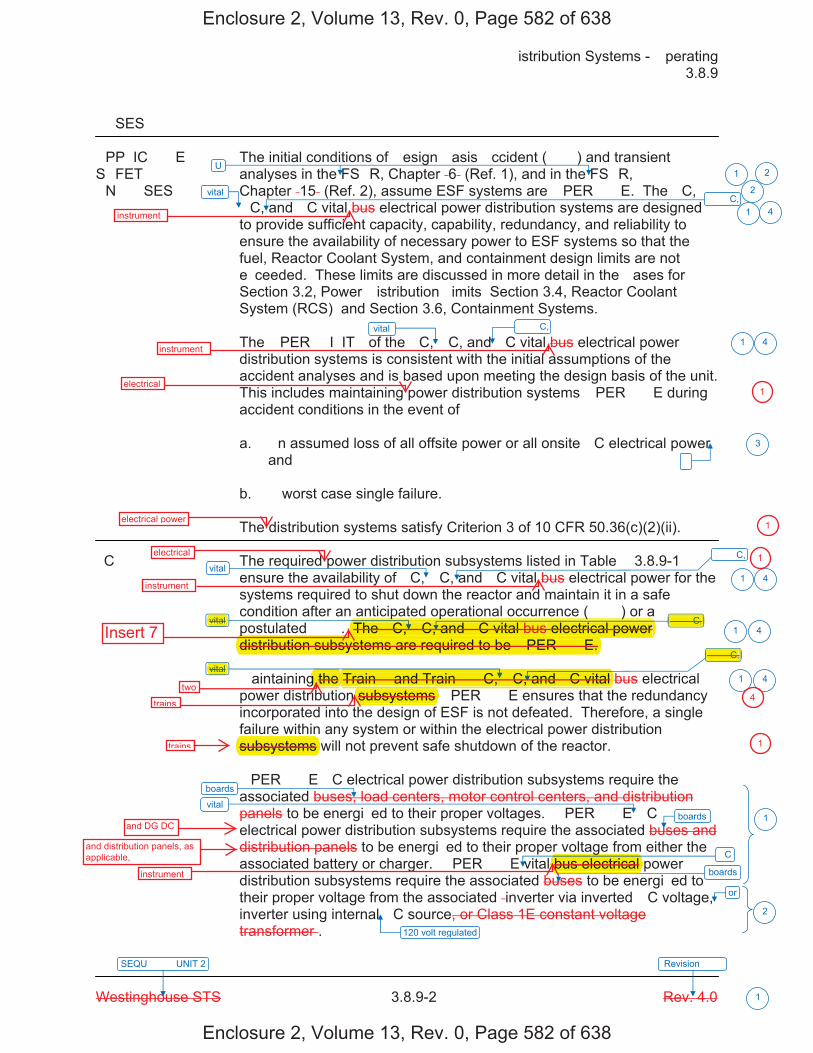
�istribution Systems - �perating � 3.8.9
Westinghouse STS � 3.8.9-2 Rev. 4.0
SEQU���� UNIT 2 Revision ���
1
��SES
�PP�IC���E The initial conditions of �esign �asis �ccident (���) and transient S�FET� analyses in the FS�R, Chapter �6� (Ref. 1), and in the FS�R, �N���SES Chapter �15� (Ref. 2), assume ESF systems are �PER���E. The �C,
�C, and �C vital bus electrical power distribution systems are designed to provide sufficient capacity, capability, redundancy, and reliability to ensure the availability of necessary power to ESF systems so that the fuel, Reactor Coolant System, and containment design limits are not e�ceeded. These limits are discussed in more detail in the �ases for Section 3.2, Power �istribution �imits� Section 3.4, Reactor Coolant System (RCS)� and Section 3.6, Containment Systems.
The �PER��I�IT� of the �C, �C, and �C vital bus electrical power distribution systems is consistent with the initial assumptions of the accident analyses and is based upon meeting the design basis of the unit. This includes maintaining power distribution systems �PER���E during accident conditions in the event of�
a. �n assumed loss of all offsite power or all onsite �C electrical powerand
b. � worst case single failure.
The distribution systems satisfy Criterion 3 of 10 CFR 50.36(c)(2)(ii).
�C� The required power distribution subsystems listed in Table � 3.8.9-1 ensure the availability of �C, �C, and �C vital bus electrical power for the systems required to shut down the reactor and maintain it in a safe condition after an anticipated operational occurrence (���) or a postulated ���. The �C, �C, and �C vital bus electrical power distribution subsystems are required to be �PER���E.
�aintaining the Train � and Train � �C, �C, and �C vital bus electrical power distribution subsystems �PER���E ensures that the redundancy incorporated into the design of ESF is not defeated. Therefore, a single failure within any system or within the electrical power distribution subsystems will not prevent safe shutdown of the reactor.
�PER���E �C electrical power distribution subsystems require the associated buses, load centers, motor control centers, and distribution panels to be energi�ed to their proper voltages. �PER���E �C electrical power distribution subsystems require the associated buses and distribution panels to be energi�ed to their proper voltage from either the associated battery or charger. �PER���E vital bus electrical power distribution subsystems require the associated buses to be energi�ed to their proper voltage from the associated �inverter via inverted �C voltage, inverter using internal �C source, or Class 1E constant voltage transformer�.
vital
vital
vital
vital
vital
or
120 volt regulated
vital
�
U
boards
boards
boards
1 2
2
1
1
3
1
1
1
1
2
�C
�� �C,
�� �C,
�� �C,
�� �C,
�� �C,
4
4
4
4
4
Enclosure 2, Volume 13, Rev. 0, Page 582 of 638
Enclosure 2, Volume 13, Rev. 0, Page 582 of 638
instrument
instrument
electrical
electrical power
�� �C,
�� �C,
vital
vital
p p ( )The �C, �C, and �C vital bus electrical power p
distribution subsystems are required to be �PER���E.
Train � and Train � �C, �C, and �C vital
subsystems
subsystems
gbus electrical
electrical
instrument
Insert 7
twog the
trains
trains
and DG DC
and distribution panels, as applicable,
instrument
1
1
1
4
1

Two electrical power distribution trains are re�uired to be O���A�L�. �ach train includes�
a. an AC electrical power distribution subsystem �i.e., one �nit � 6.9 �� shutdown board, one�nit � 6.9 �� shutdown board, and associated �8� � shutdown boards�,
b. an AC vital instrument power distribution subsystem �i.e., two �nit � ��� � AC instrumentpower boards and two �nit � ��� � AC instrument power boards�,
c. a vital DC electrical power distribution subsystem �i.e., two ��� � DC boards�, andd. a D� DC electrical power distribution subsystem �i.e., two D� distribution panels�.
1 4
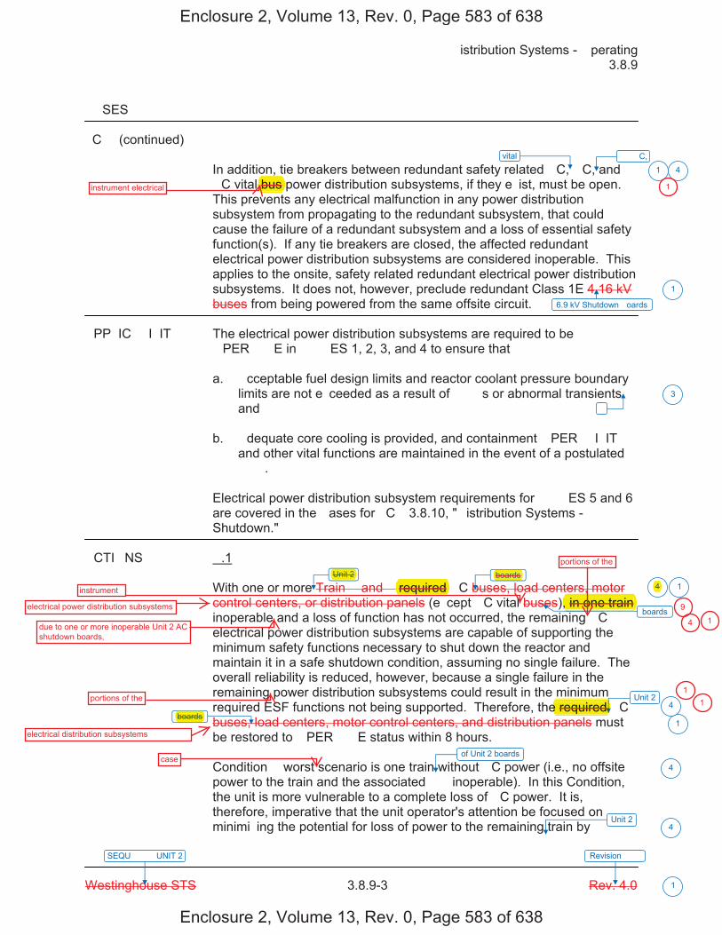
�istribution Systems - �perating � 3.8.9
Westinghouse STS � 3.8.9-3 Rev. 4.0
SEQU���� UNIT 2 Revision ���
1
��SES
�C� (continued)
In addition, tie breakers between redundant safety related �C, �C, and �C vital bus power distribution subsystems, if they e�ist, must be open. This prevents any electrical malfunction in any power distribution subsystem from propagating to the redundant subsystem, that could cause the failure of a redundant subsystem and a loss of essential safety function(s). If any tie breakers are closed, the affected redundant electrical power distribution subsystems are considered inoperable. This applies to the onsite, safety related redundant electrical power distribution subsystems. It does not, however, preclude redundant Class 1E 4.16 kV buses from being powered from the same offsite circuit.
�PP�IC��I�IT� The electrical power distribution subsystems are required to be �PER���E in ���ES 1, 2, 3, and 4 to ensure that�
a. �cceptable fuel design limits and reactor coolant pressure boundarylimits are not e�ceeded as a result of ���s or abnormal transientsand
b. �dequate core cooling is provided, and containment �PER��I�IT�and other vital functions are maintained in the event of a postulated���.
Electrical power distribution subsystem requirements for ���ES 5 and 6 are covered in the �ases for �C� 3.8.10, "�istribution Systems - Shutdown."
�CTI�NS �.1
With one or more Train � and � required �C buses, load centers, motor control centers, or distribution panels (e�cept �C vital buses), in one train inoperable and a loss of function has not occurred, the remaining �C electrical power distribution subsystems are capable of supporting the minimum safety functions necessary to shut down the reactor and maintain it in a safe shutdown condition, assuming no single failure. The overall reliability is reduced, however, because a single failure in the remaining power distribution subsystems could result in the minimum required ESF functions not being supported. Therefore, the required �C buses, load centers, motor control centers, and distribution panels must be restored to �PER���E status within 8 hours.
Condition � worst scenario is one train without �C power (i.e., no offsite power to the train and the associated �� inoperable). In this Condition, the unit is more vulnerable to a complete loss of �C power. It is, therefore, imperative that the unit operator's attention be focused on minimi�ing the potential for loss of power to the remaining train by
vital
6.9 kV Shutdown �oards
�
boards
boards
1
1
1
3
1
Unit 2
boards
Unit 24
4
of Unit 2 boards
4
Unit 24
�� �C,4
Enclosure 2, Volume 13, Rev. 0, Page 583 of 638
Enclosure 2, Volume 13, Rev. 0, Page 583 of 638
,bus instrument electrical
Unit 2 boards
required , in one train
e required boards
instrument
electrical power distribution subsystems
due to one or more inoperable Unit 2 AC shutdown boards,
portions of the
electrical distribution subsystems
portions of the
1
4
9
4 1
11
case
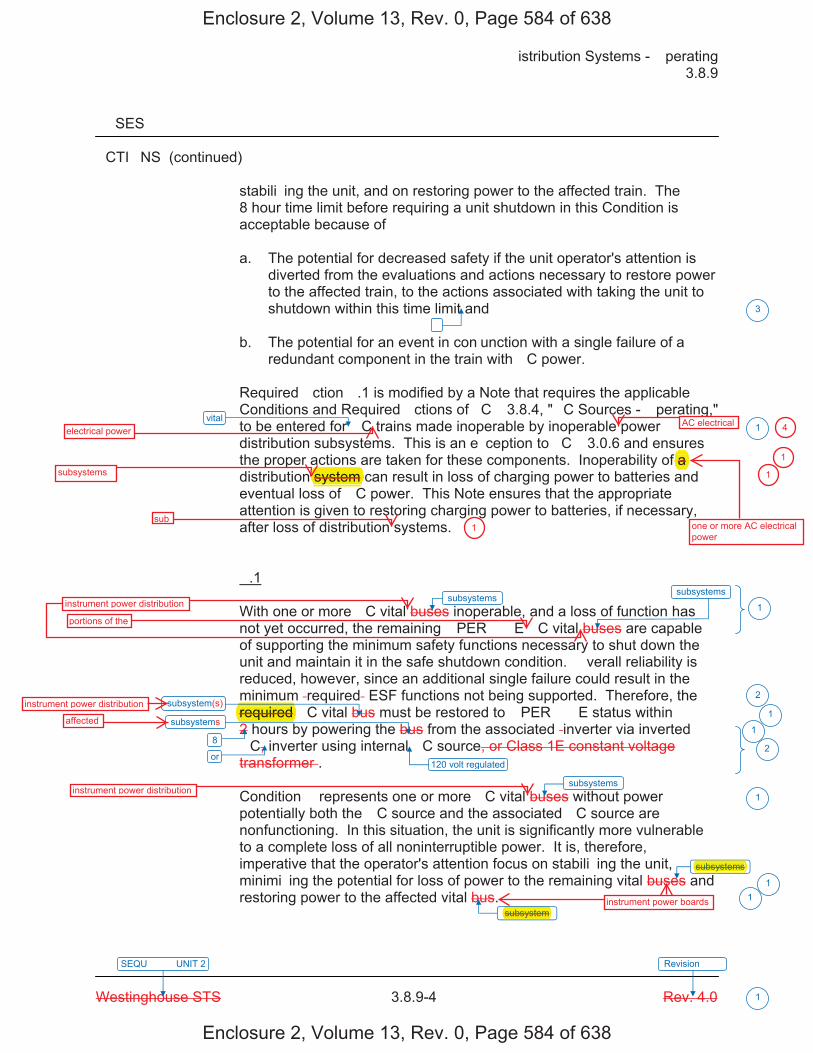
�istribution Systems - �perating � 3.8.9
Westinghouse STS � 3.8.9-4 Rev. 4.0
SEQU���� UNIT 2 Revision ���
1
��SES
�CTI�NS (continued)
stabili�ing the unit, and on restoring power to the affected train. The 8 hour time limit before requiring a unit shutdown in this Condition is acceptable because of�
a. The potential for decreased safety if the unit operator's attention isdiverted from the evaluations and actions necessary to restore powerto the affected train, to the actions associated with taking the unit toshutdown within this time limit and
b. The potential for an event in con�unction with a single failure of aredundant component in the train with �C power.
Required �ction �.1 is modified by a Note that requires the applicable Conditions and Required �ctions of �C� 3.8.4, "�C Sources - �perating," to be entered for �C trains made inoperable by inoperable power distribution subsystems. This is an e�ception to �C� 3.0.6 and ensures the proper actions are taken for these components. Inoperability of a distribution system can result in loss of charging power to batteries and eventual loss of �C power. This Note ensures that the appropriate attention is given to restoring charging power to batteries, if necessary, after loss of distribution systems.
�.1
With one or more �C vital buses inoperable, and a loss of function has not yet occurred, the remaining �PER���E �C vital buses are capable of supporting the minimum safety functions necessary to shut down the unit and maintain it in the safe shutdown condition. �verall reliability is reduced, however, since an additional single failure could result in the minimum �required� ESF functions not being supported. Therefore, the required �C vital bus must be restored to �PER���E status within 2 hours by powering the bus from the associated �inverter via inverted �C, inverter using internal �C source, or Class 1E constant voltage transformer�.
Condition � represents one or more �C vital buses without power� potentially both the �C source and the associated �C source are nonfunctioning. In this situation, the unit is significantly more vulnerable to a complete loss of all noninterruptible power. It is, therefore, imperative that the operator's attention focus on stabili�ing the unit, minimi�ing the potential for loss of power to the remaining vital buses and restoring power to the affected vital bus.
vital
120 volt regulated
�
subsystems
3
1
1
2
1
1
2
1
11
8
subsystems
subsystem
subsystem
or
subsystems
subsystems
subsystem
Enclosure 2, Volume 13, Rev. 0, Page 584 of 638
Enclosure 2, Volume 13, Rev. 0, Page 584 of 638
system f a
electrical power
subsystems
sub
AC electrical
one or more AC electrical power
required
subsystem
subsystems
instrument power distribution
portions of the
instrument power distribution
affected
instrument power distribution
4
1
1
1
instrument power boards
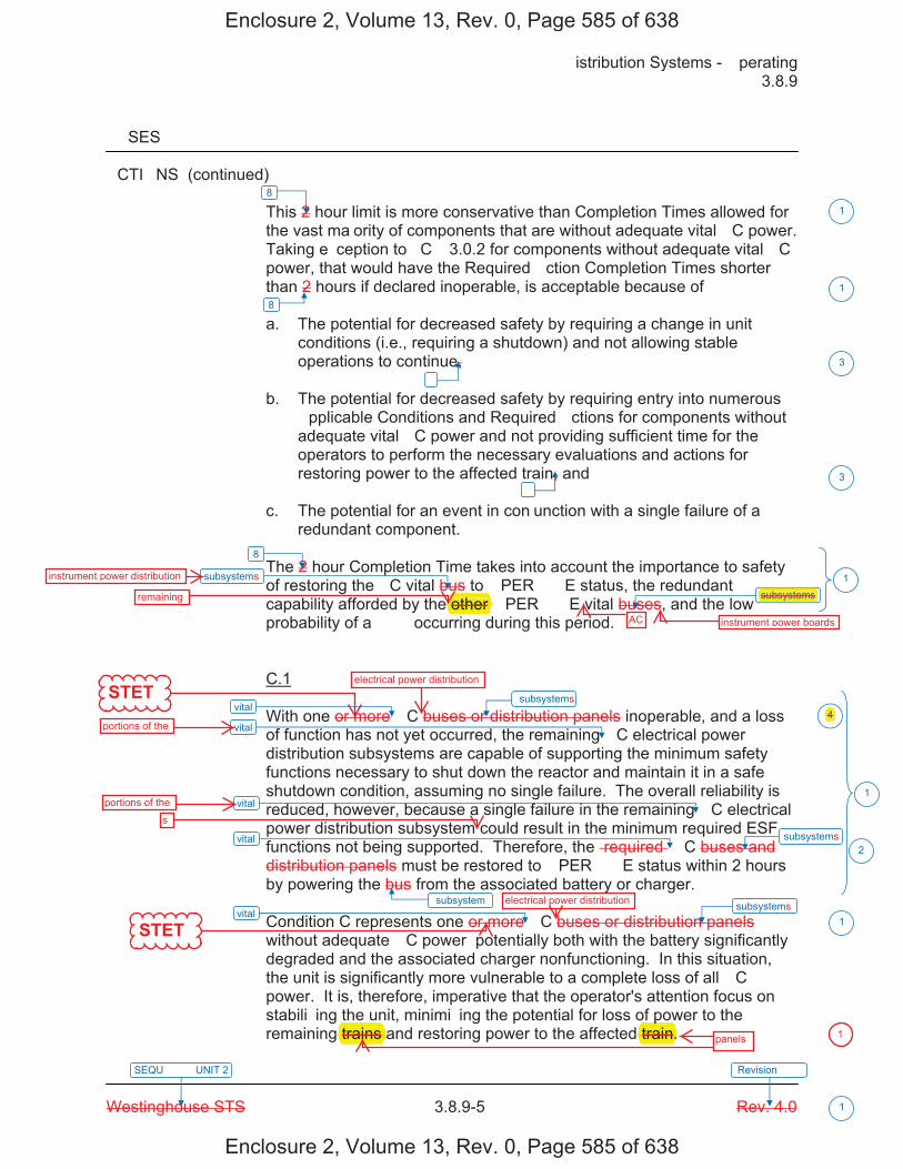
�istribution Systems - �perating � 3.8.9
Westinghouse STS � 3.8.9-5 Rev. 4.0
SEQU���� UNIT 2 Revision ���
1
��SES
�CTI�NS (continued) This 2 hour limit is more conservative than Completion Times allowed for the vast ma�ority of components that are without adequate vital �C power. Taking e�ception to �C� 3.0.2 for components without adequate vital �C power, that would have the Required �ction Completion Times shorter than 2 hours if declared inoperable, is acceptable because of�
a. The potential for decreased safety by requiring a change in unitconditions (i.e., requiring a shutdown) and not allowing stableoperations to continue,
b. The potential for decreased safety by requiring entry into numerous�pplicable Conditions and Required �ctions for components withoutadequate vital �C power and not providing sufficient time for theoperators to perform the necessary evaluations and actions forrestoring power to the affected train, and
c. The potential for an event in con�unction with a single failure of aredundant component.
The 2 hour Completion Time takes into account the importance to safety of restoring the �C vital bus to �PER���E status, the redundant capability afforded by the other �PER���E vital buses, and the low probability of a ��� occurring during this period.
C.1
With one or more �C buses or distribution panels inoperable, and a loss of function has not yet occurred, the remaining �C electrical power distribution subsystems are capable of supporting the minimum safety functions necessary to shut down the reactor and maintain it in a safe shutdown condition, assuming no single failure. The overall reliability is reduced, however, because a single failure in the remaining �C electrical power distribution subsystem could result in the minimum required ESF functions not being supported. Therefore, the �required� �C buses and distribution panels must be restored to �PER���E status within 2 hours by powering the bus from the associated battery or charger.
Condition C represents one or more �C buses or distribution panels without adequate �C power� potentially both with the battery significantly degraded and the associated charger nonfunctioning. In this situation, the unit is significantly more vulnerable to a complete loss of all �C power. It is, therefore, imperative that the operator's attention focus on stabili�ing the unit, minimi�ing the potential for loss of power to the remaining trains and restoring power to the affected train.
vital
vital
vital
vital
vital
�
�
subsystem
3
3
1
2
1
8
8
1
1
1
8
subsystems
subsystem
subsystem
subsystem subsystem
4
Enclosure 2, Volume 13, Rev. 0, Page 585 of 638
Enclosure 2, Volume 13, Rev. 0, Page 585 of 638
other subsystems
instrument power distribution
remaining
AC instrument power boards
electrical power distributionSTET
portions of the
portions of thes
STET
electrical power distribution
4
ptrain. trains panels 1

�istribution Systems - �perating � 3.8.9
Westinghouse STS � 3.8.9-6 Rev. 4.0
SEQU���� UNIT 2 Revision ���
1
��SES
�CTI�NS (continued) This 2 hour limit is more conservative than Completion Times allowed for the vast ma�ority of components that would be without power. Taking e�ception to �C� 3.0.2 for components without adequate �C power, which would have Required �ction Completion Times shorter than 2 hours, is acceptable because of� a. The potential for decreased safety by requiring a change in unit
conditions (i.e., requiring a shutdown) while allowing stable operations to continue,
b. The potential for decreased safety by requiring entry into numerous
applicable Conditions and Required �ctions for components without �C power and not providing sufficient time for the operators to perform the necessary evaluations and actions for restoring power to the affected train, and
c. The potential for an event in con�unction with a single failure of a
redundant component. The 2 hour Completion Time for �C buses is consistent with Regulatory �uide 1.93 (Ref. 3). �.1 and �.2 If the inoperable distribution subsystem cannot be restored to �PER���E status within the required Completion Time, the unit must be brought to a ���E in which the �C� does not apply. To achieve this status, the unit must be brought to at least ���E 3 within 6 hours and to ���E 5 within 36 hours. The allowed Completion Times are reasonable, based on operating e�perience, to reach the required unit conditions from full power conditions in an orderly manner and without challenging plant systems. E.1 Condition E corresponds to a level of degradation in the electrical power distribution system that causes a required safety function to be lost. When more than one inoperable electrical power distribution subsystem results in the loss of a required function, the plant is in a condition outside the accident analysis. Therefore, no additional time is �ustified for continued operation. �C� 3.0.3 must be entered immediately to commence a controlled shutdown.
vital
not
�
�
5
3
3
1
4
4
4
subsystems
F F
�
INSERT 4
�
Enclosure 2, Volume 13, Rev. 0, Page 586 of 638
Enclosure 2, Volume 13, Rev. 0, Page 586 of 638
electrical power distribution
f the
causes g
required p
to be lost.p
required
an electrical power
results inloss of
safety
1
1
1
G G
HH
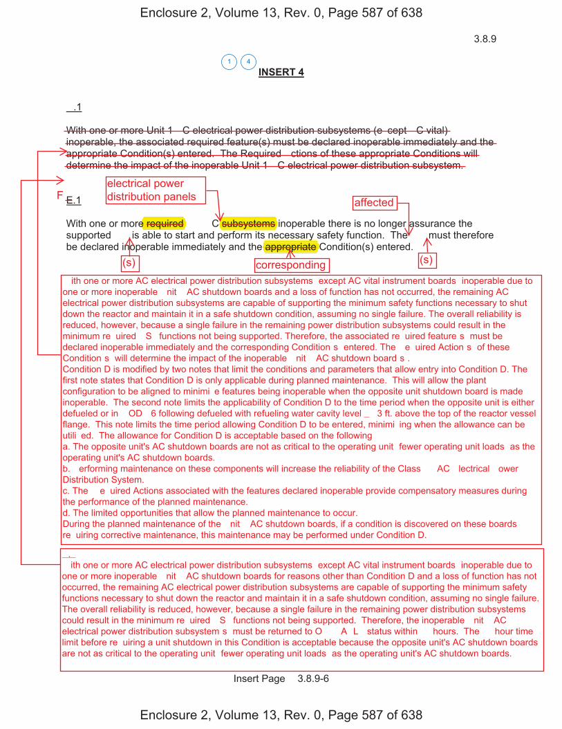
3.8.9
Insert Page � 3.8.9-6
INSERT 4
�.1
With one or more Unit 1 �C electrical power distribution subsystems (e�cept �C vital) inoperable, the associated required feature(s) must be declared inoperable immediately and the appropriate Condition(s) entered. The Required �ctions of these appropriate Conditions will determine the impact of the inoperable Unit 1 �C electrical power distribution subsystem.
E.1
With one or more required �� �C subsystems inoperable there is no longer assurance the supported �� is able to start and perform its necessary safety function. The �� must therefore be declared inoperable immediately and the appropriate Condition(s) entered.
41
Enclosure 2, Volume 13, Rev. 0, Page 587 of 638
Enclosure 2, Volume 13, Rev. 0, Page 587 of 638
e required subsystems y
appropriate
electrical powerdistribution panels
(s) corresponding
affected
(s)
F
�.� � ith one or more AC electrical power distribution subsystems �except AC vital instrument boards� inoperable due to one or more inoperable �nit � AC shutdown boards for reasons other than Condition D and a loss of function has not occurred, the remaining AC electrical power distribution subsystems are capable of supporting the minimum safety functions necessary to shut down the reactor and maintain it in a safe shutdown condition, assuming no single failure. The overall reliability is reduced, however, because a single failure in the remaining power distribution subsystems could result in the minimum re�uired �S� functions not being supported. Therefore, the inoperable �nit � AC electrical power distribution subsystem�s� must be returned to O���A�L� status within �� hours. The �� hour time limit before re�uiring a unit shutdown in this Condition is acceptable because the opposite unit's AC shutdown boards are not as critical to the operating unit �fewer operating unit loads� as the operating unit's AC shutdown boards.
� ith one or more AC electrical power distribution subsystems �except AC vital instrument boards� inoperable due to one or more inoperable �nit � AC shutdown boards and a loss of function has not occurred, the remaining AC electrical power distribution subsystems are capable of supporting the minimum safety functions necessary to shut down the reactor and maintain it in a safe shutdown condition, assuming no single failure. The overall reliability is reduced, however, because a single failure in the remaining power distribution subsystems could result in the minimum re�uired �S� functions not being supported. Therefore, the associated re�uired feature�s� must be declared inoperable immediately and the corresponding Condition�s� entered. The �e�uired Action�s� of these Condition�s� will determine the impact of the inoperable �nit � AC shutdown board�s�. Condition D is modified by two notes that limit the conditions and parameters that allow entry into Condition D. The first note states that Condition D is only applicable during planned maintenance. This will allow the plant configuration to be aligned to minimi�e features being inoperable when the opposite unit shutdown board is made inoperable. The second note limits the applicability of Condition D to the time period when the opposite unit is either defueled or in �OD� 6 following defueled with refueling water cavity level � �3 ft. above the top of the reactor vessel flange. This note limits the time period allowing Condition D to be entered, minimi�ing when the allowance can be utili�ed. The allowance for Condition D is acceptable based on the following� a. The opposite unit's AC shutdown boards are not as critical to the operating unit �fewer operating unit loads� as the operating unit's AC shutdown boards. b. �erforming maintenance on these components will increase the reliability of the Class �� AC �lectrical �ower Distribution System. c. The �e�uired Actions associated with the features declared inoperable provide compensatory measures during the performance of the planned maintenance. d. The limited opportunities that allow the planned maintenance to occur. During the planned maintenance of the �nit � AC shutdown boards, if a condition is discovered on these boards re�uiring corrective maintenance, this maintenance may be performed under Condition D.

�istribution Systems - �perating � 3.8.9
Westinghouse STS � 3.8.9-7 Rev. 4.0
SEQU���� UNIT 2 Revision ���
1
��SES
SURVEI���NCE SR 3.8.9.1 REQUIRE�ENTS
This Surveillance verifies that the �required� �C, �C, and �C vital bus electrical power distribution systems are functioning properly, with the correct circuit breaker alignment. The correct breaker alignment ensures the appropriate separation and independence of the electrical divisions is maintained, and the appropriate voltage is available to each required bus. The verification of proper voltage availability on the buses ensures that the required voltage is readily available for motive as well as control functions for critical system loads connected to these buses. � The 7 day Frequency takes into account the redundant capability of the �C, �C, and �C vital bus electrical power distribution subsystems, and other indications available in the control room that alert the operator to subsystem malfunctions.
�R
The Surveillance Frequency is controlled under the Surveillance Frequency Control Program.
-----------------------------------REVIEWER�S N�TE----------------------------------- Plants controlling Surveillance Frequencies under a Surveillance Frequency Control Program should utili�e the appropriate Frequency description, given above, and the appropriate choice of Frequency in the Surveillance Requirement. ------------------------------------------------------------------------------------------------ �
REFERENCES 1. FS�R, Chapter �6�.
2. FS�R, Chapter �15�.
3. Regulatory �uide 1.93, �ecember 1974.
vital
U
sub 12
6
7
1 2
board
boards
U
�� �C, 4
Enclosure 2, Volume 13, Rev. 0, Page 588 of 638
Enclosure 2, Volume 13, Rev. 0, Page 588 of 638
bus
divisions power distribution trains
instrument
1

�istribution Systems - �perating � 3.8.9
Westinghouse STS � 3.8.9-8 Rev. 4.0
SEQU���� UNIT 2 Revision ���
1
Table � 3.8.9-1 (page 1 of 1) �C and �C Electrical Power �istribution Systems
T�PE
V��T��E
TR�IN ��
TR�IN ��
�C safety buses
�4160 V�
�ESF �us� �N�01�
�ESF �us� �N�02�
�480 V�
�oad Centers �N�01, N�03�
�oad Centers �N�02, N�04�
�480 V�
�otor Control
Centers �N�01�, N�01I, N�01�, N�03C, N�03I, N�03��
�otor Control
Centers �N�02�, N�02I, N�02�, N�04C, N�04I, N�04��
�120 V�
�istribution Panels
�NP01, NP03�
�istribution Panels
�NP02, NP04�
�C buses
�125 V�
�us �N�01�
�us �N�02�
�us �N�03�
�us �N�04�
�istribution Panels
�N�41, N�43, N�51�
�istribution Panels
�N�42, N�44, N�52�
�C vital buses
�120 V�
�us �NN01�
�us �NN02�
�us �NN03�
�us �NN04�
� Each train of the �C and �C electrical power distribution systems is a subsystem.
INSERT 5
1
Safety Related �nsite
Enclosure 2, Volume 13, Rev. 0, Page 589 of 638
Enclosure 2, Volume 13, Rev. 0, Page 589 of 638
Safety Related �nsite
� Each train of the �C and �C electrical power distribution systems is a subsystem. 1
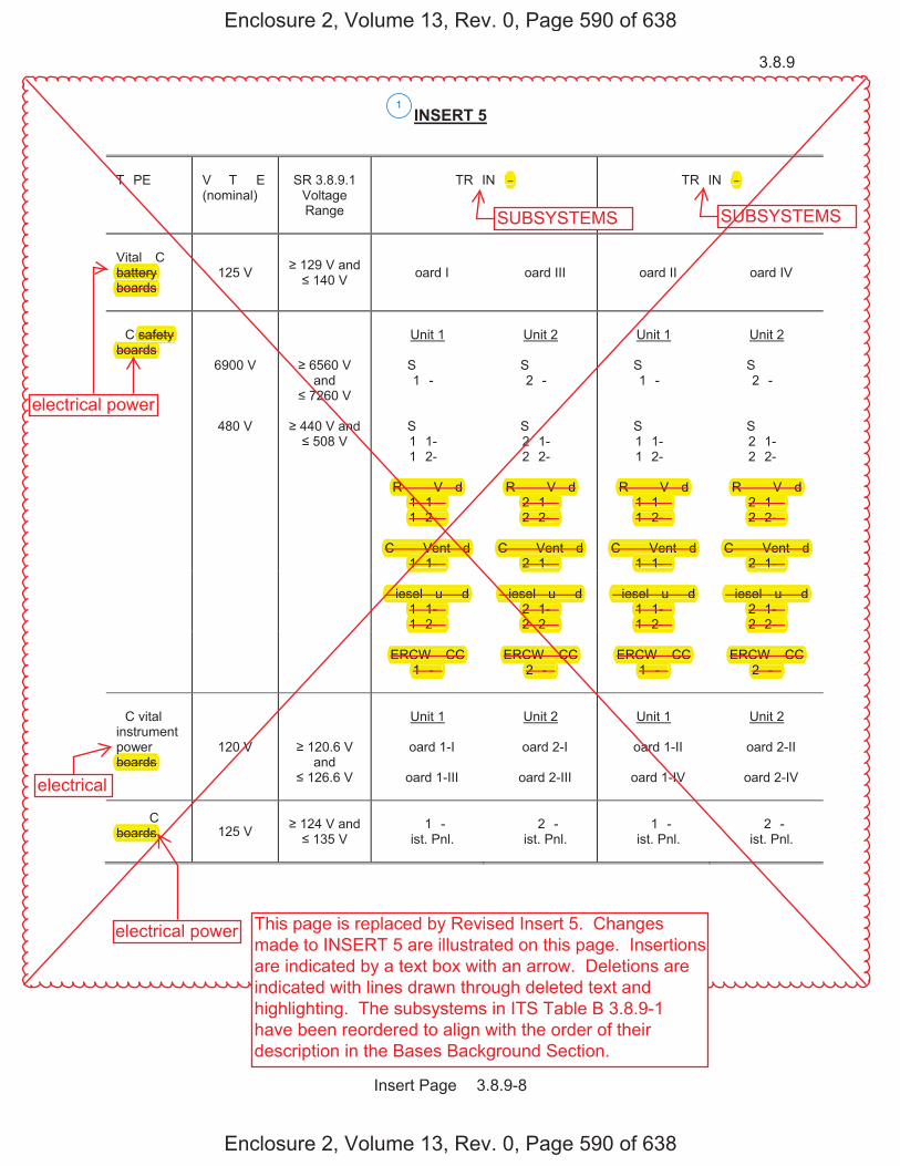
3.8.9
Insert Page � 3.8.9-8
INSERT 5
T�PE
V��T��E (nominal)
SR 3.8.9.1
Voltage Range
TR�IN ��
TR�IN ��
Vital �C battery boards
125 V 129 V and 140 V �oard I �oard III �oard II
�oard IV
�C safety boards
6900 V
6560 V and
7260 V
Unit 1
S� �� 1�-�
Unit 2
S� �� 2�-�
Unit 1
S� �� 1�-�
Unit 2
S� �� 2�-�
480 V
440 V and
508 V
S� �� 1�1-� 1�2-�
S� �� 2�1-� 2�2-�
S� �� 1�1-� 1�2-�
S� �� 2�1-� 2�2-�
R� ��V �d
1�1-� 1�2-�
R� ��V �d
2�1-� 2�2-�
R� ��V �d
1�1-� 1�2-�
R� ��V �d
2�1-� 2�2-�
C � � Vent �d
1�1-�
C � � Vent �d
2�1-� C � � Vent �d
1�1-�
C � � Vent �d
2�1-�
�iesel �u� �d 1�1-� 1�2-�
�iesel �u� �d
2�1-� 2�2-�
�iesel �u� �d
1�1-� 1�2-�
�iesel �u� �d
2�1-� 2�2-�
ERCW �CC
1�-�
ERCW �CC
2�-�
ERCW �CC
1�-�
ERCW �CC
2�-�
�C vital instrument power boards
120 V
120.6 V and
126.6 V
Unit 1
�oard 1-I
�oard 1-III
Unit 2
�oard 2-I
�oard 2-III
Unit 1
�oard 1-II
�oard 1-IV
Unit 2
�oard 2-II
�oard 2-IV
�� �C boards 125 V
124 V and
135 V
�� 1�-� �ist. Pnl.
�� 2�-� �ist. Pnl.
�� 1�-� �ist. Pnl.
�� 2�-� �ist. Pnl.
1
Enclosure 2, Volume 13, Rev. 0, Page 590 of 638
Enclosure 2, Volume 13, Rev. 0, Page 590 of 638
SUBSYSTEMS SUBSYSTEMS
boards
pboards
R� ��V �d R� ��V �d R� ��V �d R� ��V �d 1�1-� 2�1-� 1�1-� 2�1-�1�2-� 2�2-� 1�2-� 2�2-�
C � � Vent �d C � � Vent �d C � � Vent �d C � � Vent �d 1�1-� 2�1-� 1�1-� 2�1-�
�iesel �u� �d �iesel �u� �d �iesel �u� �d �iesel �u� �d 1�1-� 2�1-� 1�1-� 2�1-�1�2-� 2�2-� 1�2-� 2�2-�
ERCW �CC ERCW �CC ERCW �CC ERCW �CC1�-� 2�-� 1�-� 2�-�
safety boards
battery yboards
�� ��
electrical power
electrical
electrical power This page is replaced by Revised Insert 5. Changesmade to INSERT 5 are illustrated on this page. Insertionsare indicated by a text box with an arrow. Deletions areindicated with lines drawn through deleted text andhighlighting. The subsystems in ITS Table B 3.8.9-1have been reordered to align with the order of theirdescription in the Bases Background Section.

3.8.9
T��� �OLTA�� �nominal�
S� 3.8.9.� �oltage �ange
T�AI� A
S��S�ST��S
T�AI� �
S��S�ST��S
AC electrical power 69�� � 6�6� �
and ��6� �
�nit �
SD �D �A�A
�nit �
SD �D �A�A
�nit �
SD �D ����
�nit �
SD �D ����
�8� � ��� � and ��8 �
SD �D �A��A �A��A
SD �D �A��A �A��A
SD �D ����� �����
SD �D ����� �����
AC vital instrument electrical power
��� � ���.6 � and
��6.6 �
�nit �
�oard ��I
�oard ��III
�nit �
�oard ��I
�oard ��III
�nit �
�oard ��II
�oard ��I�
�nit �
�oard ��II
�oard ��I�
�ital DC electrical power
��� � ��9 � and ��� � �oard I �oard III �oard II �oard I�
D� DC electrical power
��� �
D� �A�A Dist. �nl.
D� �A�A Dist. �nl.
D� ���� Dist. �nl.
D� ���� Dist. �nl.
1

JUSTIFICATION FOR DEVIATIONS ITS 3.8.9 BASES, DISTRIBUTION SYSTEMS - OPERATING
Sequoyah Unit 1 and Unit 2 Page 1 of 1
1. Changes are made (additions, deletions, and/or changes) to the ISTS Bases that reflect the plant specific nomenclature, number, reference, system description, analysis, or licensing basis description.
2. The ISTS contains bracketed information and/or values that are generic to
Westinghouse vintage plants. The brackets are removed and the proper plant specific information/value is inserted to reflect the current licensing basis.
3. The punctuation corrections have been made consistent with the Writer's Guide for
the Improved Standard Technical Specifications, TSTF-GG-05-01, Section 5.1.3.
4. Changes are made to be consistent with changes made to the Specification.
5. Editorial changes made for enhanced clarity. 6. ISTS SR 3.8.9.1 provides two options for controlling the Frequencies of Surveillance
Requirements. SQN is proposing to control the Surveillance Frequencies under the Surveillance Frequency Control Program. Therefore, the Frequency for ITS SR 3.8.9.1 is "In accordance with the Surveillance Frequency Control Program."
7. The Reviewer's Note has been deleted. This information is for the NRC reviewer to be keyed into what is needed to meet this requirement. This Note is not meant to be retained in the final version of the plant specific submittal.
Enclosure 2, Volume 13, Rev. 0, Page 591 of 638
Enclosure 2, Volume 13, Rev. 0, Page 591 of 638
9. Changes are made to ISTS 3.8.9 Bases Action A.1 to resolve a conflict within the first sentence. The first sentence states that, “With one or more Train A and B required AC buses, load centers, motor control centers, or distribution panels (except AC vital buses), in one train inoperable and a loss of function has not occurred, the remaining AC electrical power distribution subsystems are capable of supporting the minimum safety functions necessary to shut down the reactor and maintain it in a safe shutdown condition, assuming no single failure.” ISTS 3.8.9 Condition A states, “One or more AC electrical power distribution subsystems inoperable.” ISTS 3.8.9 Condition E states, “Two or more electrical power distribution subsystems inoperable that result in a loss of safety function.” Both Condition A and Condition E address a situation with more than one electrical power distribution subsystem inoperable. According to ITS Chapter 1.0, Use and Application, all applicable Conditions are required to be entered for an LCO. If it is discovered that the inoperability of more than one electrical power distribution subsystem results in a loss of safety function, then entry into ISTS 3.8.9 Conditions A and E would be required. If it is discovered that the inoperability does not result in a loss of safety function, then entry into ISTS 3.8.9 Condition A is all that is required regardless of the number of inoperable trains. ISTS 3.8.9 Condition A provides Required Actions if one or more AC electrical power distribution subsystems are inoperable and a loss of safety function has not occurred. It is not the intent of ISTS 3.8.9 Condition A to be applicable to only one inoperable train of AC electrical power distribution subsystems. Therefore, the phrase, “in one train,” has been deleted.
8. This redundant information has been deleted. Following the description of theelectrical power distribution subsystems is a statement that a list of all boards anddistribution panels is found in Table B 3.8.9-1.
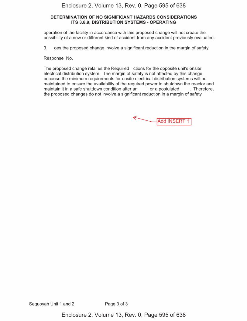
DETERMINATION OF NO SIGNIFICANT HAZARDS CONSIDERATIONS ITS 3.8.9, DISTRIBUTION SYSTEMS - OPERATING
Sequoyah Unit 1 and 2 Page 3 of 3
operation of the facility in accordance with this proposed change will not create the possibility of a new or different kind of accident from any accident previously evaluated. 3. �oes the proposed change involve a significant reduction in the margin of safety� Response� No. The proposed change rela�es the Required �ctions for the opposite unit's onsite electrical distribution system. The margin of safety is not affected by this change because the minimum requirements for onsite electrical distribution systems will be maintained to ensure the availability of the required power to shutdown the reactor and maintain it in a safe shutdown condition after an ��� or a postulated ���. Therefore, the proposed changes do not involve a significant reduction in a margin of safety
Enclosure 2, Volume 13, Rev. 0, Page 595 of 638
Enclosure 2, Volume 13, Rev. 0, Page 595 of 638
Add INSERT 1
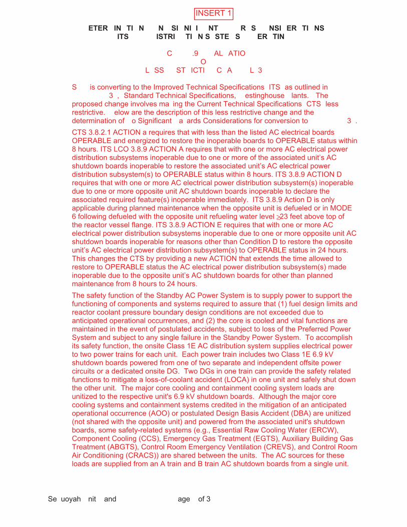
�ETER�IN�TI�N����N��SI�NI�I��NT�����R�S���NSI�ER�TI�NS�ITS���������ISTRI��TI�N�S�STE�S�����ER�TIN��
Se�uoyah �nit � and � �age � of 3
�� C�� ��.9� ��AL�ATIO� �O�
L�SS ��ST�ICTI�� C�A��� L�3
S�� is converting to the Improved Technical Specifications �ITS� as outlined in ��������3�, �Standard Technical Specifications, � estinghouse �lants.� The proposed change involves ma�ing the Current Technical Specifications �CTS� less restrictive. �elow are the description of this less restrictive change and the determination of �o Significant �a�ards Considerations for conversion to ��������3�.
INSERT 1
�ETER�IN�TI�N����N��SI�NI�I��NT�����R�S���NSI�ER�TI�NS�ITS���������ISTRI��TI�N�S�STE�S�����ER�TIN��
Se�uoyah �nit � and � �age � of 3
Tennessee �alley Authority �T�A� has evaluated whether or not a significant ha�ards consideration is involved with these proposed Technical Specification changes by focusing on the three standards set forth in �� C�� ��.9�, �Issuance of amendment,� as discussed below�
�. Does the proposed change involve a significant increase in the probability orconse�uences of any accident previously evaluated�
�esponse� �o.
The proposed change relaxes the ACTIO�s for the opposite unit's distribution system. This change will not affect the probability of an accident, since the distribution system not initiator of any accident se�uence analy�ed in the �pdated �inal Safety Analysis �eport ���SA��. �ather, the opposite unit's distribution system support e�uipment used to mitigate accidents. The conse�uences of an analy�ed accident will not be increased since the minimum re�uirements for distribution systems will be maintained to ensure the availability of the re�uired power to mitigate accidents assumed in the ��SA�. Operation in accordance with the proposed TS will ensure that sufficient onsite electrical distribution systems are O���A�L� as re�uired to support the unit's re�uired features. Therefore, the mitigating functions supported by the onsite electrical distribution systems will continue to provide the protection assumed by the accident analysis. The integrity of fission product barriers, plant configuration, and operating procedures as described in the ��SA� will not be affected by the proposed changes. Thus, the conse�uences of previously analy�ed accidents will not increase by implementing these changes. Therefore, the proposed changes do not involve an increase in the probability or conse�uences of an accident previously evaluated.
�ETER�IN�TI�N����N��SI�NI�I��NT�����R�S���NSI�ER�TI�NS�ITS���������ISTRI��TI�N�S�STE�S�����ER�TIN��
Se�uoyah �nit � and � �age 3 of 3
Does the proposed change involve a significant reduction in the margin of safety�
�esponse� �o.
The proposed change relaxes the ACTIO�s for the opposite unit's onsite electrical distribution system. The margin of safety is not affected by this change because the minimum re�uirements for onsite electrical distribution systems will be maintained to ensure the availability of the re�uired power to shutdown the reactor and maintain it in a safe shutdown condition after an AOO or a postulated D�A. Therefore, the proposed changes do not involve a significant reduction in a margin of safety
Does the proposed change create the possibility of a new or different �ind ofaccident from any previously evaluated�
�esponse� �o
�.
.
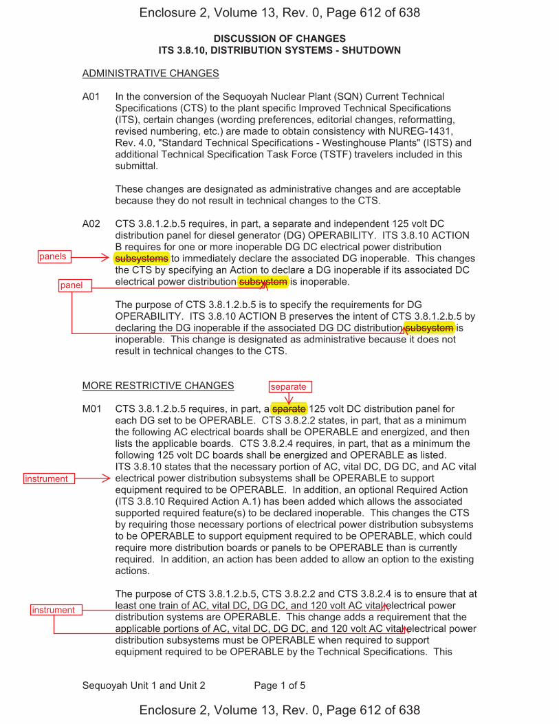
DISCUSSION OF CHANGES ITS 3.8.10, DISTRIBUTION SYSTEMS - SHUTDOWN
Sequoyah Unit 1 and Unit 2 Page 1 of 5
ADMINISTRATIVE CHANGES
A01 In the conversion of the Sequoyah Nuclear Plant (SQN) Current Technical Specifications (CTS) to the plant specific Improved Technical Specifications (ITS), certain changes (wording preferences, editorial changes, reformatting, revised numbering, etc.) are made to obtain consistency with NUREG-1431, Rev. 4.0, "Standard Technical Specifications - Westinghouse Plants" (ISTS) and additional Technical Specification Task Force (TSTF) travelers included in this submittal.
These changes are designated as administrative changes and are acceptable because they do not result in technical changes to the CTS.
A02 CTS 3.8.1.2.b.5 requires, in part, a separate and independent 125 volt DC distribution panel for diesel generator (DG) OPERABILITY. ITS 3.8.10 ACTION B requires for one or more inoperable DG DC electrical power distribution subsystems to immediately declare the associated DG inoperable. This changes the CTS by specifying an Action to declare a DG inoperable if its associated DC electrical power distribution subsystem is inoperable.
The purpose of CTS 3.8.1.2.b.5 is to specify the requirements for DG OPERABILITY. ITS 3.8.10 ACTION B preserves the intent of CTS 3.8.1.2.b.5 by declaring the DG inoperable if the associated DG DC distribution subsystem is inoperable. This change is designated as administrative because it does not result in technical changes to the CTS.
MORE RESTRICTIVE CHANGES
M01 CTS 3.8.1.2.b.5 requires, in part, a sparate 125 volt DC distribution panel for each DG set to be OPERABLE. CTS 3.8.2.2 states, in part, that as a minimum the following AC electrical boards shall be OPERABLE and energized, and then lists the applicable boards. CTS 3.8.2.4 requires, in part, that as a minimum the following 125 volt DC boards shall be energized and OPERABLE as listed. ITS 3.8.10 states that the necessary portion of AC, vital DC, DG DC, and AC vital electrical power distribution subsystems shall be OPERABLE to support equipment required to be OPERABLE. In addition, an optional Required Action (ITS 3.8.10 Required Action A.1) has been added which allows the associated supported required feature(s) to be declared inoperable. This changes the CTS by requiring those necessary portions of electrical power distribution subsystems to be OPERABLE to support equipment required to be OPERABLE, which could require more distribution boards or panels to be OPERABLE than is currently required. In addition, an action has been added to allow an option to the existing actions.
The purpose of CTS 3.8.1.2.b.5, CTS 3.8.2.2 and CTS 3.8.2.4 is to ensure that at least one train of AC, vital DC, DG DC, and 120 volt AC vital electrical power distribution systems are OPERABLE. This change adds a requirement that the applicable portions of AC, vital DC, DG DC, and 120 volt AC vital electrical power distribution subsystems must be OPERABLE when required to support equipment required to be OPERABLE by the Technical Specifications. This
Enclosure 2, Volume 13, Rev. 0, Page 612 of 638
Enclosure 2, Volume 13, Rev. 0, Page 612 of 638
panels
panel
qsubsystems
subsystem
subsystem s
separate
sparate
instrument
instrument
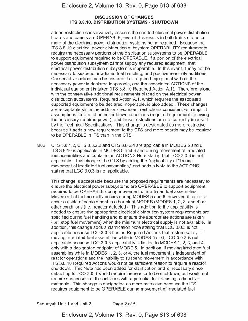
DISCUSSION OF CHANGES ITS 3.8.10, DISTRIBUTION SYSTEMS - SHUTDOWN
Sequoyah Unit 1 and Unit 2 Page 2 of 5
added restriction conservatively assures the needed electrical power distribution boards and panels are OPERABLE, even if this results in both trains of one or more of the electrical power distribution systems being required. Because the ITS 3.8.10 electrical power distribution subsystem OPERABILITY requirements require the necessary portions of the distribution subsystems to be OPERABLE to support equipment required to be OPERABLE, if a portion of the electrical power distribution subsystem cannot supply any required equipment, that electrical power distribution subsystem is inoperable. In this event, it may not be necessary to suspend, irradiated fuel handling, and positive reactivity additions. Conservative actions can be assured if all required equipment without the necessary power is declared inoperable, and the associated ACTIONS of the individual equipment is taken (ITS 3.8.10 Required Action A.1). Therefore, along with the conservative additional requirements placed on the electrical power distribution subsystems, Required Action A.1, which requires the associated supported equipment to be declared inoperable, is also added. These changes are acceptable since the additions represent restrictions consistent with implicit assumptions for operation in shutdown conditions (required equipment receiving the necessary required power), and these restrictions are not currently imposed by the Technical Specifications. This change is designated as more restrictive because it adds a new requirement to the CTS and more boards may be required to be OPERABLE in ITS than in the CTS.
M02 CTS 3.8.1.2, CTS 3.8.2.2 and CTS 3.8.2.4 are applicable in MODES 5 and 6.
ITS 3.8.10 is applicable in MODES 5 and 6 and during movement of irradiated fuel assemblies and contains an ACTIONS Note stating that LCO 3.0.3 is not applicable. This changes the CTS by adding the Applicability of "During movement of irradiated fuel assemblies," and adds a Note to the ACTIONS stating that LCO 3.0.3 is not applicable.
This change is acceptable because the proposed requirements are necessary to
ensure the electrical power subsystems are OPERABLE to support equipment required to be OPERABLE during movement of irradiated fuel assemblies. Movement of fuel normally occurs during MODES 5 and 6; however, it can also occur outside of containment in other plant MODES (MODES 1, 2, 3, and 4) or other conditions (i.e., reactor defueled). This addition to the applicability is needed to ensure the appropriate electrical distribution system requirements are specified during fuel handling and to ensure the appropriate actions are taken (i.e., stop fuel movement) when the minimum electrical supply is not available. In addition, this change adds a clarification Note stating that LCO 3.0.3 is not applicable because LCO 3.0.3 has no Required Actions that restore safety. If moving irradiated fuel assemblies while in MODES 5 or 6, LCO 3.0.3 is not applicable because LCO 3.0.3 applicability is limited to MODES 1, 2, 3, and 4 only with a designated endpoint of MODE 5. In addition, if moving irradiated fuel assemblies while in MODES 1, 2, 3, or 4, the fuel movement is independent of reactor operations and the inability to suspend movement in accordance with ITS 3.8.10 Required Actions would not be sufficient reason to require a reactor shutdown. This Note has been added for clarification and is necessary since defaulting to LCO 3.0.3 would require the reactor to be shutdown, but would not require suspension of the activities with a potential for releasing radioactive materials. This change is designated as more restrictive because the ITS requires equipment to be OPERABLE during movement of irradiated fuel
Enclosure 2, Volume 13, Rev. 0, Page 613 of 638
Enclosure 2, Volume 13, Rev. 0, Page 613 of 638
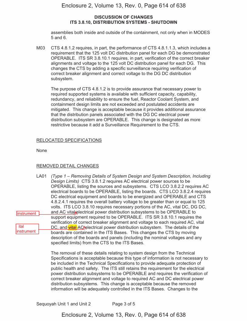
DISCUSSION OF CHANGES ITS 3.8.10, DISTRIBUTION SYSTEMS - SHUTDOWN
Sequoyah Unit 1 and Unit 2 Page 3 of 5
assemblies both inside and outside of the containment, not only when in MODES 5 and 6.
M03 CTS 4.8.1.2 requires, in part, the performance of CTS 4.8.1.1.3, which includes a
requirement that the 125 volt DC distribution panel for each DG be demonstrated OPERABLE. ITS SR 3.8.10.1 requires, in part, verification of the correct breaker alignments and voltage to the 125 volt DC distribution panel for each DG. This changes the CTS by adding a specific surveillance requiring verification of correct breaker alignment and correct voltage to the DG DC distribution subsystem.
The purpose of CTS 4.8.1.2 is to provide assurance that necessary power to
required supported systems is available with sufficient capacity, capability, redundancy, and reliability to ensure the fuel, Reactor Coolant System, and containment design limits are not exceeded and postulated accidents are mitigated. This change is acceptable because it provides additional assurance that the distribution panels associated with the DG DC electrical power distribution subsystem are OPERABLE. This change is designated as more restrictive because it add a Surveillance Requirement to the CTS.
RELOCATED SPECIFICATIONS None REMOVED DETAIL CHANGES
LA01 (Type 1 – Removing Details of System Design and System Description, Including
Design Limits) CTS 3.8.1.2 requires AC electrical power sources to be OPERABLE, listing the sources and subsystems. CTS LCO 3.8.2.2 requires AC electrical boards to be OPERABLE, listing the boards. CTS LCO 3.8.2.4 requires DC electrical equipment and boards to be energized and OPERABLE and CTS 4.8.2.4.1 requires the overall battery voltage to be greater than or equal to 125 volts. ITS LCO 3.8.10 requires necessary portions of the AC, vital DC, DG DC, and AC vital electrical power distribution subsystems to be OPERABLE to support equipment required to be OPERABLE. ITS SR 3.8.10.1 requires the verification of correct breaker alignment and voltage to each required AC, vital DC, and vital AC electrical power distribution subsystem. The details of the boards are contained in the ITS Bases. This changes the CTS by moving description of the boards and panels (including the nominal voltages and any specified limits) from the CTS to the ITS Bases.
The removal of these details relating to system design from the Technical
Specifications is acceptable because this type of information is not necessary to be included in the Technical Specifications to provide adequate protection of public health and safety. The ITS still retains the requirement for the electrical power distribution subsystems to be OPERABLE and requires the verification of correct breaker alignment and voltage to required AC and DC electrical power distribution subsystems. This change is acceptable because the removed information will be adequately controlled in the ITS Bases. Changes to the
Enclosure 2, Volume 13, Rev. 0, Page 614 of 638
Enclosure 2, Volume 13, Rev. 0, Page 614 of 638
instrument
�ital�instrument
vital

DISCUSSION OF CHANGES ITS 3.8.10, DISTRIBUTION SYSTEMS - SHUTDOWN
Sequoyah Unit 1 and Unit 2 Page 4 of 5
Bases are controlled by the Technical Specification Bases Control Program in Chapter 5. This program provides for the evaluation of changes to ensure the Bases are properly controlled. This change is designated as a less restrictive removal of detail change because information relating to system design is being removed from the Technical Specifications.
LA02 (Type 5 – Removal of SR Frequency to the Surveillance Frequency Control
Program) CTS 4.8.2.2 requires, in part, that the specified AC boards be determined OPERABLE and energized at least once per 7 days by verifying correct breaker alignment and indicated voltage on the buses. CTS 4.8.2.4.1 requires, in part, that each required DC battery board be determined OPERABLE and energized at least once per 7 days by verifying correct breaker alignment and indicated power availability with an overall battery voltage of greater than or equal to 125 volts. ITS SR 3.8.10.1 requires a similar Surveillance and specifies the periodic Frequency as, "In accordance with the Surveillance Frequency Control Program." This changes the CTS by moving the specified Frequencies for this SR and associated Bases to the Surveillance Frequency Control Program.
The removal of these details related to Surveillance Requirement Frequencies from the Technical Specifications is acceptable, because this type of information is not necessary to be included in the Technical Specifications to provide adequate protection of public health and safety. The existing Surveillance Frequencies are removed from Technical Specifications and placed under licensee control pursuant to the methodology described in NEI 04-10. A new program (Surveillance Frequency Control Program) is being added to the Administrative Controls section of the Technical Specifications describing the control of Surveillance Frequencies. The surveillance test requirements remain in the Technical Specifications. The control of changes to the Surveillance Frequencies will be in accordance with the Surveillance Frequency Control Program. The Program shall ensure that Surveillance Requirements specified in the Technical Specifications are performed at intervals sufficient to assure the associated Limiting Conditions for Operation are met. This change is designated as a less restrictive removal of detail change, because the Surveillance Frequencies are being removed from the Technical Specifications.
LESS RESTRICTIVE CHANGES L01 (Category 4 – Relaxation of Required Action) With less than the minimum
complement of AC boards OPERABLE and energized, CTS 3.8.2.2 requires the establishment of containment integrity within 8 hours. With less than the minimum complement of DC boards OPERABLE and energized, CTS 3.8.2.4 also requires the establishment of containment integrity within 8 hours. ITS 3.8.10 ACTION A requires, in part, suspending movement of irradiated fuel assemblies, suspension of operations involving positive reactivity additions that could result in the loss of required SDM or boron concentration, the initiation of actions to restore required AC, vital DC, and AC vital board electrical power distribution subsystems to OPERABLE status, and the declaration of the associated required residual heat removal subsystems(s) inoperable and not in
Enclosure 2, Volume 13, Rev. 0, Page 615 of 638
Enclosure 2, Volume 13, Rev. 0, Page 615 of 638
instrument
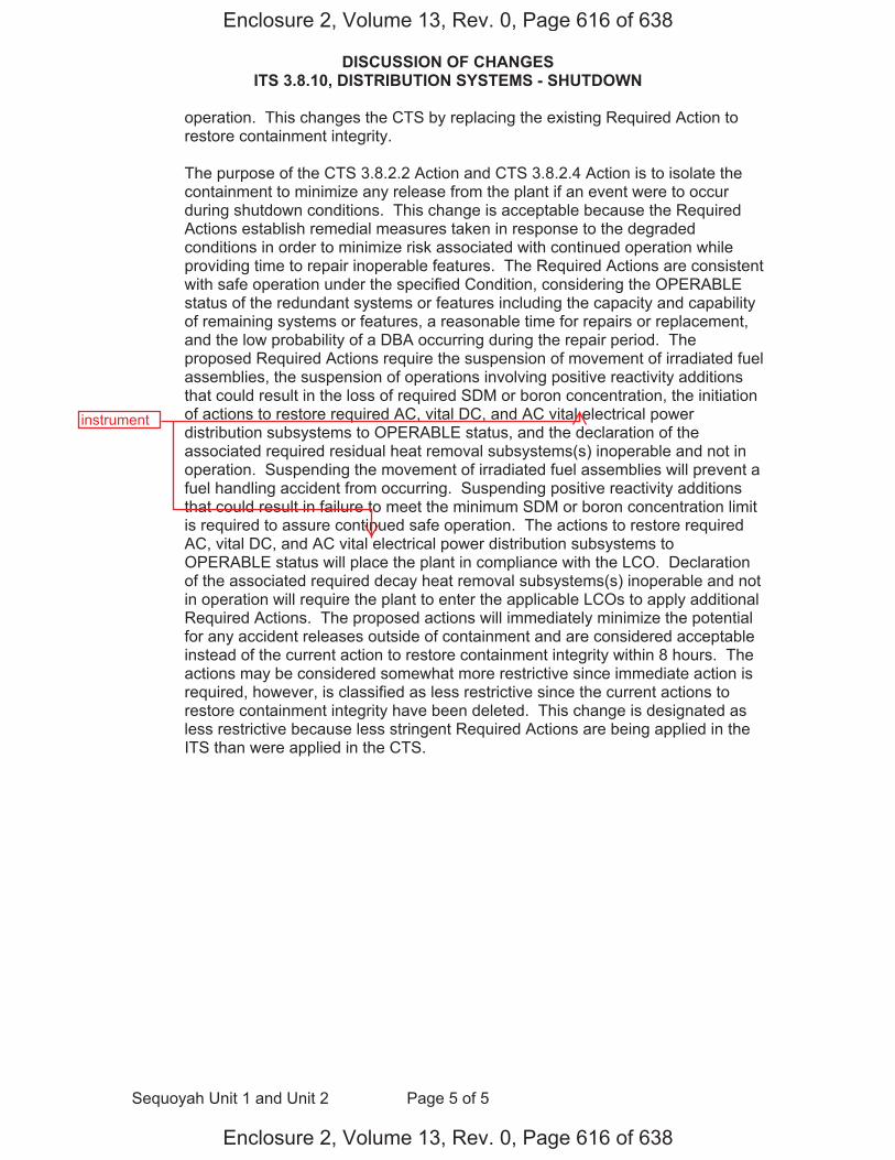
DISCUSSION OF CHANGES ITS 3.8.10, DISTRIBUTION SYSTEMS - SHUTDOWN
Sequoyah Unit 1 and Unit 2 Page 5 of 5
operation. This changes the CTS by replacing the existing Required Action to restore containment integrity.
The purpose of the CTS 3.8.2.2 Action and CTS 3.8.2.4 Action is to isolate the
containment to minimize any release from the plant if an event were to occur during shutdown conditions. This change is acceptable because the Required Actions establish remedial measures taken in response to the degraded conditions in order to minimize risk associated with continued operation while providing time to repair inoperable features. The Required Actions are consistent with safe operation under the specified Condition, considering the OPERABLE status of the redundant systems or features including the capacity and capability of remaining systems or features, a reasonable time for repairs or replacement, and the low probability of a DBA occurring during the repair period. The proposed Required Actions require the suspension of movement of irradiated fuel assemblies, the suspension of operations involving positive reactivity additions that could result in the loss of required SDM or boron concentration, the initiation of actions to restore required AC, vital DC, and AC vital electrical power distribution subsystems to OPERABLE status, and the declaration of the associated required residual heat removal subsystems(s) inoperable and not in operation. Suspending the movement of irradiated fuel assemblies will prevent a fuel handling accident from occurring. Suspending positive reactivity additions that could result in failure to meet the minimum SDM or boron concentration limit is required to assure continued safe operation. The actions to restore required AC, vital DC, and AC vital electrical power distribution subsystems to OPERABLE status will place the plant in compliance with the LCO. Declaration of the associated required decay heat removal subsystems(s) inoperable and not in operation will require the plant to enter the applicable LCOs to apply additional Required Actions. The proposed actions will immediately minimize the potential for any accident releases outside of containment and are considered acceptable instead of the current action to restore containment integrity within 8 hours. The actions may be considered somewhat more restrictive since immediate action is required, however, is classified as less restrictive since the current actions to restore containment integrity have been deleted. This change is designated as less restrictive because less stringent Required Actions are being applied in the ITS than were applied in the CTS.
Enclosure 2, Volume 13, Rev. 0, Page 616 of 638
Enclosure 2, Volume 13, Rev. 0, Page 616 of 638
instrument
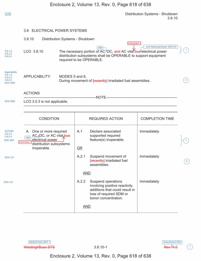
Distribution Systems - Shutdown 3.8.10
Westinghouse STS 3.8.10-1 Rev. 4.0 Amendment XXXSEQUOYAH UNIT 1
CTS
1
3.8 ELECTRICAL POWER SYSTEMS 3.8.10 Distribution Systems - Shutdown LCO 3.8.10 The necessary portion of AC, DC, and AC vital bus electrical power
distribution subsystems shall be OPERABLE to support equipment required to be OPERABLE.
APPLICABILITY: MODES 5 and 6, During movement of [recently] irradiated fuel assemblies. ACTIONS ------------------------------------------------------------NOTE----------------------------------------------------------- LCO 3.0.3 is not applicable. -------------------------------------------------------------------------------------------------------------------------------
CONDITION
REQUIRED ACTION
COMPLETION TIME
A. One or more required
AC, DC, or AC vital bus electrical power distribution subsystems inoperable.
A.1 Declare associated
supported required feature(s) inoperable.
OR A.2.1 Suspend movement of
[recently] irradiated fuel assemblies.
AND A.2.2 Suspend operations
involving positive reactivity additions that could result in loss of required SDM or boron concentration.
AND
Immediately Immediately Immediately
vital
vital
3.8.1.2,3.8.2.2, 3.8.2.4
Applicability 3.8.1.2, 3.8.2.2, 3.8.2.4 DOC M02
DOC M02
ACTION 3.8.2.2 3.8.2.4 DOC M01
DOC L01
DOC L01
1
2
1
2
, and diesel generator (DG) DC
Enclosure 2, Volume 13, Rev. 0, Page 618 of 638
Enclosure 2, Volume 13, Rev. 0, Page 618 of 638
instrument
instrument
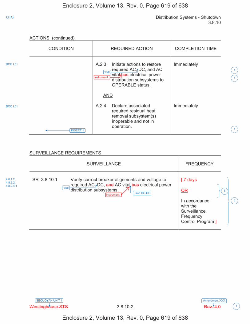
Distribution Systems - Shutdown 3.8.10
Westinghouse STS 3.8.10-2 Rev. 4.0 Amendment XXXSEQUOYAH UNIT 1
CTS
1
ACTIONS (continued)
CONDITION REQUIRED ACTION COMPLETION TIME
A.2.3 Initiate actions to restore required AC, DC, and AC vital bus electrical power distribution subsystems to OPERABLE status.
AND
A.2.4 Declare associated required residual heat removal subsystem(s) inoperable and not in operation.
Immediately
Immediately
SURVEILLANCE REQUIREMENTS
SURVEILLANCE FREQUENCY
SR 3.8.10.1 Verify correct breaker alignments and voltage to required AC, DC, and AC vital bus electrical power distribution subsystems.
[ 7 days
OR
In accordance with the Surveillance Frequency Control Program ]
vital
vital
DOC L01
DOC L01
4.8.1.2, 4.8.2.2, 4.8.2.4.1
1
1
3
1
INSERT 1 1
, and DG DC
Enclosure 2, Volume 13, Rev. 0, Page 619 of 638
Enclosure 2, Volume 13, Rev. 0, Page 619 of 638
instrument
instrument
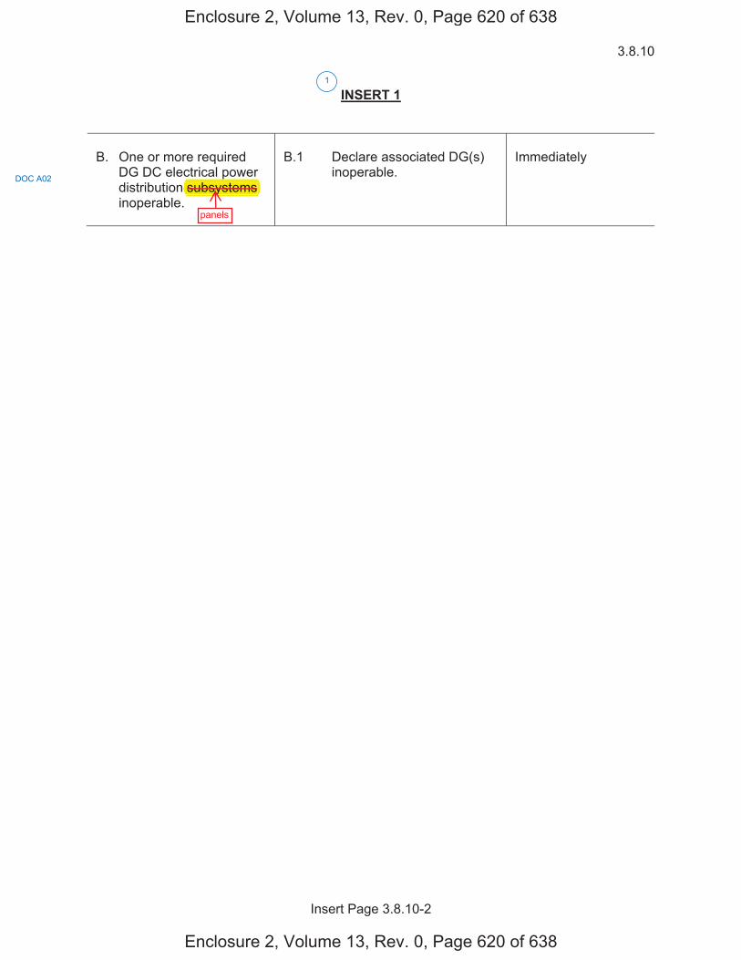
3.8.10
Insert Page 3.8.10-2
INSERT 1
B. One or more required
DG DC electrical power distribution subsystems inoperable.
B.1 Declare associated DG(s)
inoperable.
Immediately
1
DOC A02
Enclosure 2, Volume 13, Rev. 0, Page 620 of 638
Enclosure 2, Volume 13, Rev. 0, Page 620 of 638
panels
p subsystems
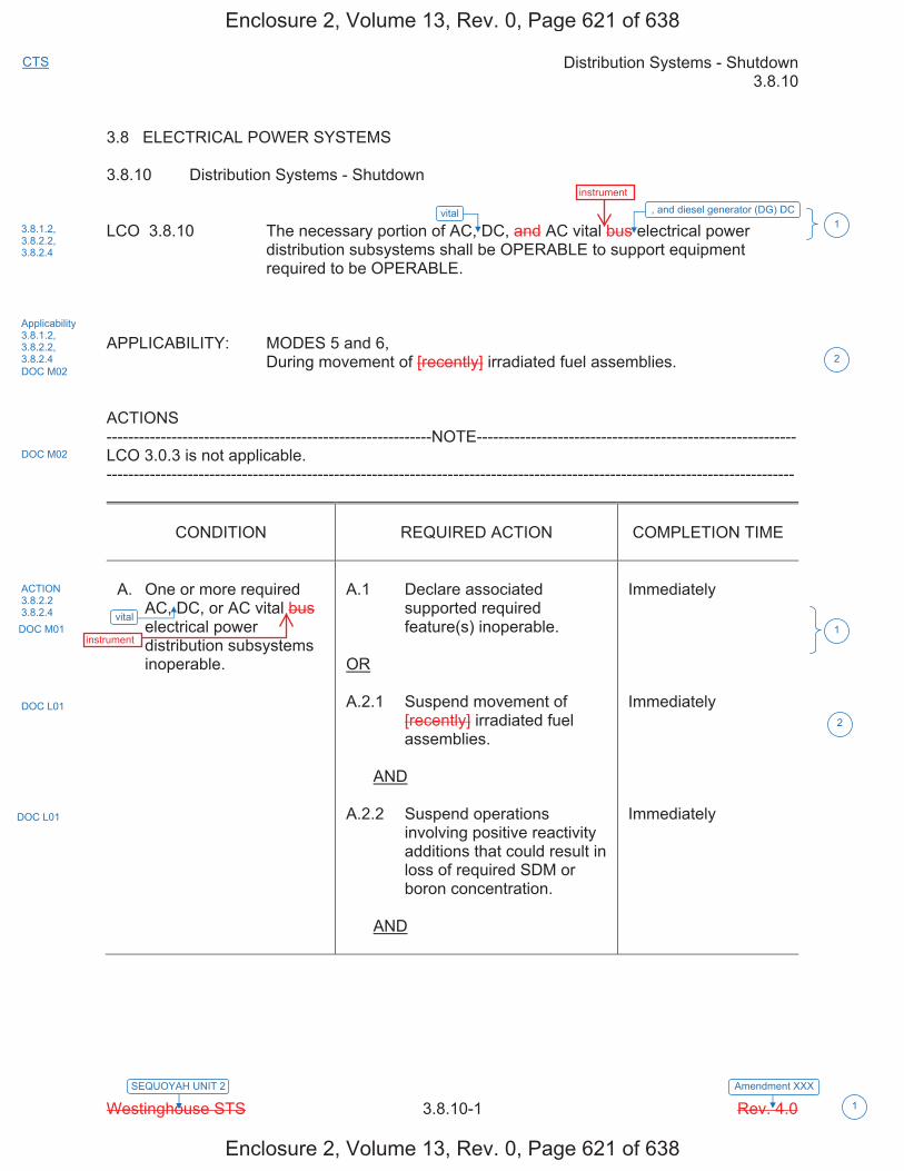
Distribution Systems - Shutdown 3.8.10
Westinghouse STS 3.8.10-1 Rev. 4.0 Amendment XXXSEQUOYAH UNIT 2
CTS
1
3.8 ELECTRICAL POWER SYSTEMS 3.8.10 Distribution Systems - Shutdown LCO 3.8.10 The necessary portion of AC, DC, and AC vital bus electrical power
distribution subsystems shall be OPERABLE to support equipment required to be OPERABLE.
APPLICABILITY: MODES 5 and 6, During movement of [recently] irradiated fuel assemblies. ACTIONS ------------------------------------------------------------NOTE----------------------------------------------------------- LCO 3.0.3 is not applicable. -------------------------------------------------------------------------------------------------------------------------------
CONDITION
REQUIRED ACTION
COMPLETION TIME
A. One or more required
AC, DC, or AC vital bus electrical power distribution subsystems inoperable.
A.1 Declare associated
supported required feature(s) inoperable.
OR A.2.1 Suspend movement of
[recently] irradiated fuel assemblies.
AND A.2.2 Suspend operations
involving positive reactivity additions that could result in loss of required SDM or boron concentration.
AND
Immediately Immediately Immediately
vital
vital
3.8.1.2,3.8.2.2, 3.8.2.4
Applicability 3.8.1.2, 3.8.2.2, 3.8.2.4 DOC M02
DOC M02
ACTION 3.8.2.2 3.8.2.4 DOC M01
DOC L01
DOC L01
1
2
1
2
, and diesel generator (DG) DC
Enclosure 2, Volume 13, Rev. 0, Page 621 of 638
Enclosure 2, Volume 13, Rev. 0, Page 621 of 638
instrument
instrument

Distribution Systems - Shutdown 3.8.10
Westinghouse STS 3.8.10-2 Rev. 4.0 Amendment XXXSEQUOYAH UNIT 2
CTS
1
ACTIONS (continued)
CONDITION
REQUIRED ACTION
COMPLETION TIME
A.2.3 Initiate actions to restore
required AC, DC, and AC vital bus electrical power distribution subsystems to OPERABLE status.
AND A.2.4 Declare associated
required residual heat removal subsystem(s) inoperable and not in operation.
Immediately Immediately
SURVEILLANCE REQUIREMENTS
SURVEILLANCE
FREQUENCY
SR 3.8.10.1 Verify correct breaker alignments and voltage to
required AC, DC, and AC vital bus electrical power distribution subsystems.
[ 7 days OR In accordance with the Surveillance Frequency Control Program ]
vital
vital
DOC L01
DOC L01
4.8.1.2, 4.8.2.2, 4.8.2.4.1
1
1
3
1
INSERT 1 1
, and DG DC
Enclosure 2, Volume 13, Rev. 0, Page 622 of 638
Enclosure 2, Volume 13, Rev. 0, Page 622 of 638
instrument
instrument

3.8.10
Insert Page 3.8.10-2
INSERT 1
B. One or more required
DG DC electrical power distribution subsystems inoperable.
B.1 Declare associated DG(s)
inoperable.
Immediately
1
DOC A02
Enclosure 2, Volume 13, Rev. 0, Page 623 of 638
Enclosure 2, Volume 13, Rev. 0, Page 623 of 638
panels
p subsystems

Distribution Systems - Shutdown B 3.8.10
Westinghouse STS B 3.8.10-1 Rev. 4.0
SEQUOYAH UNIT 1 Revision XXX
1
B 3.8 ELECTRICAL POWER SYSTEMS B 3.8.10 Distribution Systems - Shutdown BASES BACKGROUND A description of the AC, DC, and AC vital bus electrical power distribution
systems is provided in the Bases for LCO 3.8.9, "Distribution Systems - Operating."
APPLICABLE The initial conditions of Design Basis Accident and transient analyses in SAFETY the FSAR, Chapter [6] (Ref. 1) and Chapter [15] (Ref. 2), assume ANALYSES Engineered Safety Feature (ESF) systems are OPERABLE. The AC, DC,
and AC vital bus electrical power distribution systems are designed to provide sufficient capacity, capability, redundancy, and reliability to ensure the availability of necessary power to ESF systems so that the fuel, Reactor Coolant System, and containment design limits are not exceeded.
The OPERABILITY of the AC, DC, and AC vital bus electrical power distribution system is consistent with the initial assumptions of the accident analyses and the requirements for the supported systems' OPERABILITY. The OPERABILITY of the minimum AC, DC, and AC vital bus electrical power distribution subsystems during MODES 5 and 6, and during movement of [recently] irradiated fuel assemblies ensures that: a. The unit can be maintained in the shutdown or refueling condition for
extended periods, b. Sufficient instrumentation and control capability is available for
monitoring and maintaining the unit status, and c. Adequate power is provided to mitigate events postulated during
shutdown, such as a fuel handling accident [involving handling recently irradiated fuel. Due to radioactive decay, AC and DC electrical power is only required to mitigate fuel handling accidents involving handling recently irradiated fuel (i.e., fuel that has occupied part of a critical reactor core within the previous [X] days)].
The AC and DC electrical power distribution systems satisfy Criterion 3 of 10 CFR 50.36(c)(2)(ii).
vital
vital
vital
vital
1
2
1
1
1
2
2
1
U 1
1
,diesel generator (DG) DC,
DG DC,
DG DC,
DG DC,
Enclosure 2, Volume 13, Rev. 0, Page 626 of 638
Enclosure 2, Volume 13, Rev. 0, Page 626 of 638
instrument
instrument
instrument
instrument
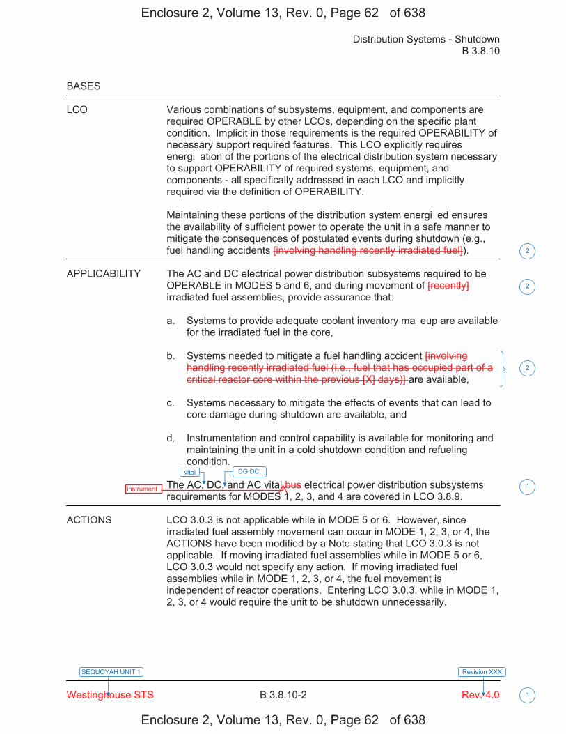
Distribution Systems - Shutdown B 3.8.10
Westinghouse STS B 3.8.10-2 Rev. 4.0
SEQUOYAH UNIT 1 Revision XXX
1
BASES LCO Various combinations of subsystems, equipment, and components are
required OPERABLE by other LCOs, depending on the specific plant condition. Implicit in those requirements is the required OPERABILITY of necessary support required features. This LCO explicitly requires energi�ation of the portions of the electrical distribution system necessary to support OPERABILITY of required systems, equipment, and components - all specifically addressed in each LCO and implicitly required via the definition of OPERABILITY.
Maintaining these portions of the distribution system energi�ed ensures the availability of sufficient power to operate the unit in a safe manner to mitigate the consequences of postulated events during shutdown (e.g., fuel handling accidents [involving handling recently irradiated fuel]).
APPLICABILITY The AC and DC electrical power distribution subsystems required to be
OPERABLE in MODES 5 and 6, and during movement of [recently] irradiated fuel assemblies, provide assurance that: a. Systems to provide adequate coolant inventory ma�eup are available
for the irradiated fuel in the core, b. Systems needed to mitigate a fuel handling accident [involving
handling recently irradiated fuel (i.e., fuel that has occupied part of a critical reactor core within the previous [X] days)] are available,
c. Systems necessary to mitigate the effects of events that can lead to
core damage during shutdown are available, and d. Instrumentation and control capability is available for monitoring and
maintaining the unit in a cold shutdown condition and refueling condition.
The AC, DC, and AC vital bus electrical power distribution subsystems requirements for MODES 1, 2, 3, and 4 are covered in LCO 3.8.9.
ACTIONS LCO 3.0.3 is not applicable while in MODE 5 or 6. However, since
irradiated fuel assembly movement can occur in MODE 1, 2, 3, or 4, the ACTIONS have been modified by a Note stating that LCO 3.0.3 is not applicable. If moving irradiated fuel assemblies while in MODE 5 or 6, LCO 3.0.3 would not specify any action. If moving irradiated fuel assemblies while in MODE 1, 2, 3, or 4, the fuel movement is independent of reactor operations. Entering LCO 3.0.3, while in MODE 1, 2, 3, or 4 would require the unit to be shutdown unnecessarily.
vital
1
2
2
2
DG DC,
Enclosure 2, Volume 13, Rev. 0, Page 62� of 638
Enclosure 2, Volume 13, Rev. 0, Page 62� of 638
instrument

Distribution Systems - Shutdown B 3.8.10
Westinghouse STS B 3.8.10-3 Rev. 4.0
SEQUOYAH UNIT 1 Revision XXX
1
BASES ACTIONS (continued)
A.1, A.2.1, A.2.2, A.2.3, and A.2.4 Although redundant required features may require redundant trains of electrical power distribution subsystems to be OPERABLE, one OPERABLE distribution subsystem train may be capable of supporting sufficient required features to allow continuation of [recently] irradiated fuel movement. By allowing the option to declare required features associated with an inoperable distribution subsystem inoperable, appropriate restrictions are implemented in accordance with the affected distribution subsystem LCO's Required Actions. In many instances, this option may involve undesired administrative efforts. Therefore, the allowance for sufficiently conservative actions is made (i.e., to suspend movement of [recently] irradiated fuel assemblies, and operations involving positive reactivity additions that could result in loss of required SDM (MODE 5) or boron concentration (MODE 6). Suspending positive reactivity additions that could result in failure to meet the minimum SDM or boron concentration limit is required to assure continued safe operation. Introduction of coolant inventory must be from sources that have a boron concentration greater than that what would be required in the RCS for minimum SDM or refueling boron concentration. This may result in an overall reduction in RCS boron concentration, but provides acceptable margin to maintaining subcritical operation. Introduction of temperature changes including temperature increases when operating with a positive MTC must also be evaluated to ensure they do not result in a loss of required SDM. Suspension of these activities does not preclude completion of actions to establish a safe conservative condition. These actions minimi�e the probability of the occurrence of postulated events. It is further required to immediately initiate action to restore the required AC and DC electrical power distribution subsystems and to continue this action until restoration is accomplished in order to provide the necessary power to the unit safety systems. Notwithstanding performance of the above conservative Required Actions, a required residual heat removal (RHR) subsystem may be inoperable. In this case, Required Actions A.2.1 through A.2.4 do not adequately address the concerns relating to coolant circulation and heat removal. Pursuant to LCO 3.0.6, the RHR ACTIONS would not be entered. Therefore, Required Action A.2.5 is provided to direct declaring RHR inoperable, which results in ta�ing the appropriate RHR actions.
2
2
33
43
and not in operation
Enclosure 2, Volume 13, Rev. 0, Page 628 of 638
Enclosure 2, Volume 13, Rev. 0, Page 628 of 638

Distribution Systems - Shutdown B 3.8.10
Westinghouse STS B 3.8.10-4 Rev. 4.0
SEQUOYAH UNIT 1 Revision XXX
BASES
ACTIONS (continued) The Completion Time of immediately is consistent with the required times for actions requiring prompt attention. The restoration of the required distribution subsystems should be completed as quic�ly as possible in order to minimi�e the time the unit safety systems may be without power.
SURVEILLANCE SR 3.8.10.1 REQUIREMENTS
This Surveillance verifies that the AC, DC, and AC vital bus electrical power distribution subsystems are functioning properly, with all the buses energi�ed. The verification of proper voltage availability on the buses ensures that the required power is readily available for motive as well as control functions for critical system loads connected to these buses. [ The � day Frequency ta�es into account the capability of the electrical power distribution subsystems, and other indications available in the control room that alert the operator to subsystem malfunctions. OR The Surveillance Frequency is controlled under the Surveillance Frequency Control Program. -----------------------------------REVIEWER�S NOTE----------------------------------- Plants controlling Surveillance Frequencies under a Surveillance Frequency Control Program should utili�e the appropriate Frequency description, given above, and the appropriate choice of Frequency in the Surveillance Requirement. ------------------------------------------------------------------------------------------------ ]
REFERENCES 1. FSAR, Chapter [6]. 2. FSAR, Chapter [15].
vital
4
5
2
U
1
1
1
boards
INSERT 1 1
DG DC,
Enclosure 2, Volume 13, Rev. 0, Page 629 of 638
Enclosure 2, Volume 13, Rev. 0, Page 629 of 638
instrument bus
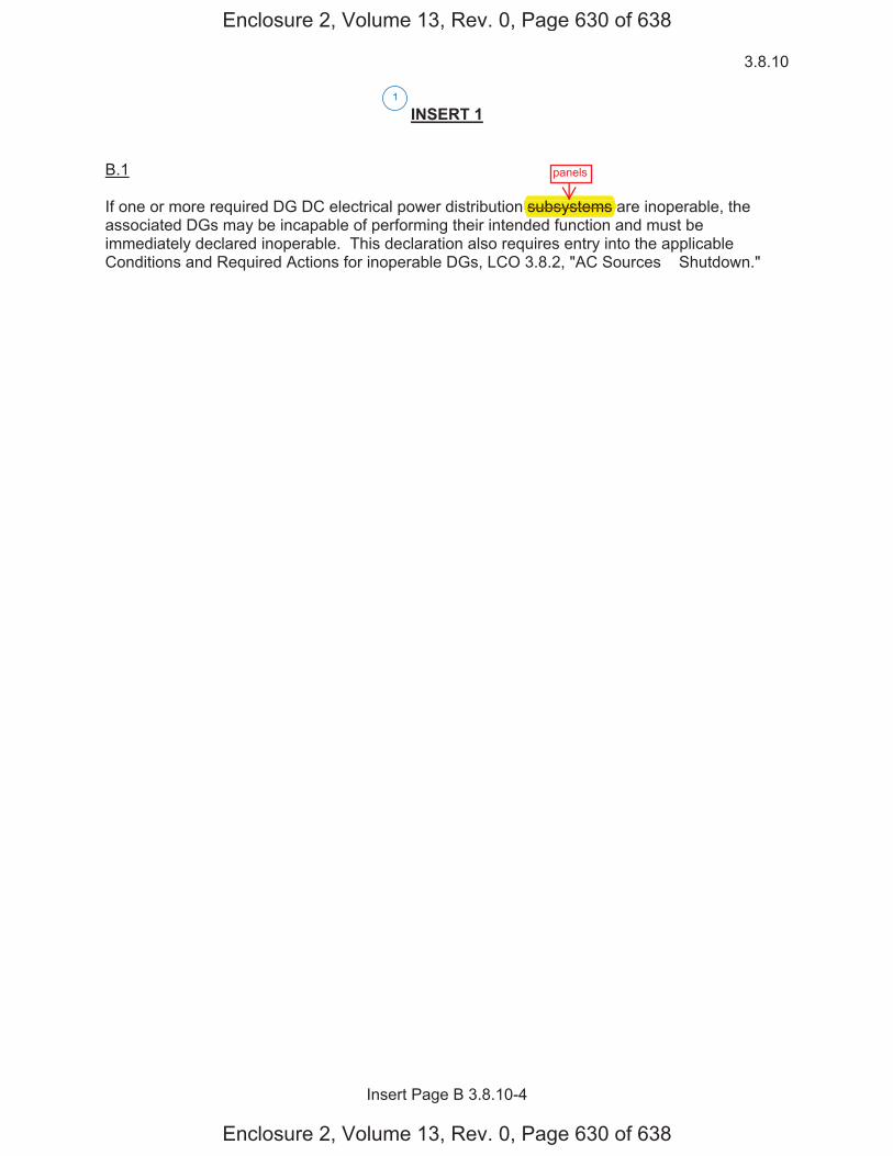
3.8.10
Insert Page B 3.8.10-4
INSERT 1 B.1 If one or more required DG DC electrical power distribution subsystems are inoperable, the associated DGs may be incapable of performing their intended function and must be immediately declared inoperable. This declaration also requires entry into the applicable Conditions and Required Actions for inoperable DGs, LCO 3.8.2, "AC Sources � Shutdown."
1
Enclosure 2, Volume 13, Rev. 0, Page 630 of 638
Enclosure 2, Volume 13, Rev. 0, Page 630 of 638
panels
subsystems

Distribution Systems - Shutdown B 3.8.10
Westinghouse STS B 3.8.10-1 Rev. 4.0
SEQUOYAH UNIT 2 Revision XXX
1
B 3.8 ELECTRICAL POWER SYSTEMS B 3.8.10 Distribution Systems - Shutdown BASES BACKGROUND A description of the AC, DC, and AC vital bus electrical power distribution
systems is provided in the Bases for LCO 3.8.9, "Distribution Systems - Operating."
APPLICABLE The initial conditions of Design Basis Accident and transient analyses in SAFETY the FSAR, Chapter [6] (Ref. 1) and Chapter [15] (Ref. 2), assume ANALYSES Engineered Safety Feature (ESF) systems are OPERABLE. The AC, DC,
and AC vital bus electrical power distribution systems are designed to provide sufficient capacity, capability, redundancy, and reliability to ensure the availability of necessary power to ESF systems so that the fuel, Reactor Coolant System, and containment design limits are not exceeded.
The OPERABILITY of the AC, DC, and AC vital bus electrical power distribution system is consistent with the initial assumptions of the accident analyses and the requirements for the supported systems' OPERABILITY. The OPERABILITY of the minimum AC, DC, and AC vital bus electrical power distribution subsystems during MODES 5 and 6, and during movement of [recently] irradiated fuel assemblies ensures that: a. The unit can be maintained in the shutdown or refueling condition for
extended periods, b. Sufficient instrumentation and control capability is available for
monitoring and maintaining the unit status, and c. Adequate power is provided to mitigate events postulated during
shutdown, such as a fuel handling accident [involving handling recently irradiated fuel. Due to radioactive decay, AC and DC electrical power is only required to mitigate fuel handling accidents involving handling recently irradiated fuel (i.e., fuel that has occupied part of a critical reactor core within the previous [X] days)].
The AC and DC electrical power distribution systems satisfy Criterion 3 of 10 CFR 50.36(c)(2)(ii).
vital
vital
vital
vital
1
2
1
1
1
2
2
1
U 1
1
,diesel generator (DG) DC,
DG DC,
DG DC,
DG DC,
Enclosure 2, Volume 13, Rev. 0, Page 631 of 638
Enclosure 2, Volume 13, Rev. 0, Page 631 of 638
instrument
instrument
instrument
instrument
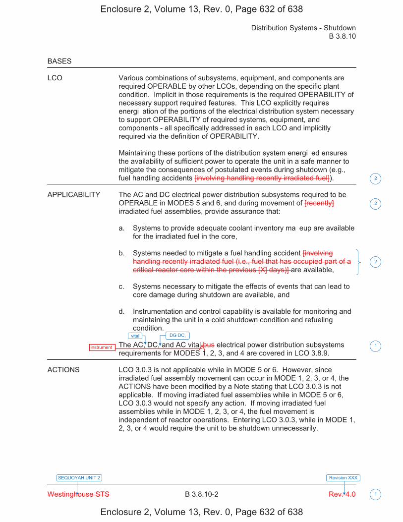
Distribution Systems - Shutdown B 3.8.10
Westinghouse STS B 3.8.10-2 Rev. 4.0
SEQUOYAH UNIT 2 Revision XXX
1
BASES LCO Various combinations of subsystems, equipment, and components are
required OPERABLE by other LCOs, depending on the specific plant condition. Implicit in those requirements is the required OPERABILITY of necessary support required features. This LCO explicitly requires energi�ation of the portions of the electrical distribution system necessary to support OPERABILITY of required systems, equipment, and components - all specifically addressed in each LCO and implicitly required via the definition of OPERABILITY.
Maintaining these portions of the distribution system energi�ed ensures the availability of sufficient power to operate the unit in a safe manner to mitigate the consequences of postulated events during shutdown (e.g., fuel handling accidents [involving handling recently irradiated fuel]).
APPLICABILITY The AC and DC electrical power distribution subsystems required to be
OPERABLE in MODES 5 and 6, and during movement of [recently] irradiated fuel assemblies, provide assurance that: a. Systems to provide adequate coolant inventory ma�eup are available
for the irradiated fuel in the core, b. Systems needed to mitigate a fuel handling accident [involving
handling recently irradiated fuel (i.e., fuel that has occupied part of a critical reactor core within the previous [X] days)] are available,
c. Systems necessary to mitigate the effects of events that can lead to
core damage during shutdown are available, and d. Instrumentation and control capability is available for monitoring and
maintaining the unit in a cold shutdown condition and refueling condition.
The AC, DC, and AC vital bus electrical power distribution subsystems requirements for MODES 1, 2, 3, and 4 are covered in LCO 3.8.9.
ACTIONS LCO 3.0.3 is not applicable while in MODE 5 or 6. However, since
irradiated fuel assembly movement can occur in MODE 1, 2, 3, or 4, the ACTIONS have been modified by a Note stating that LCO 3.0.3 is not applicable. If moving irradiated fuel assemblies while in MODE 5 or 6, LCO 3.0.3 would not specify any action. If moving irradiated fuel assemblies while in MODE 1, 2, 3, or 4, the fuel movement is independent of reactor operations. Entering LCO 3.0.3, while in MODE 1, 2, 3, or 4 would require the unit to be shutdown unnecessarily.
vital
1
2
2
2
DG DC,
Enclosure 2, Volume 13, Rev. 0, Page 632 of 638
Enclosure 2, Volume 13, Rev. 0, Page 632 of 638
instrument

Distribution Systems - Shutdown B 3.8.10
Westinghouse STS B 3.8.10-3 Rev. 4.0
SEQUOYAH UNIT 2 Revision XXX
1
BASES ACTIONS (continued)
A.1, A.2.1, A.2.2, A.2.3, and A.2.4 Although redundant required features may require redundant trains of electrical power distribution subsystems to be OPERABLE, one OPERABLE distribution subsystem train may be capable of supporting sufficient required features to allow continuation of [recently] irradiated fuel movement. By allowing the option to declare required features associated with an inoperable distribution subsystem inoperable, appropriate restrictions are implemented in accordance with the affected distribution subsystem LCO's Required Actions. In many instances, this option may involve undesired administrative efforts. Therefore, the allowance for sufficiently conservative actions is made (i.e., to suspend movement of [recently] irradiated fuel assemblies, and operations involving positive reactivity additions that could result in loss of required SDM (MODE 5) or boron concentration (MODE 6). Suspending positive reactivity additions that could result in failure to meet the minimum SDM or boron concentration limit is required to assure continued safe operation. Introduction of coolant inventory must be from sources that have a boron concentration greater than that what would be required in the RCS for minimum SDM or refueling boron concentration. This may result in an overall reduction in RCS boron concentration, but provides acceptable margin to maintaining subcritical operation. Introduction of temperature changes including temperature increases when operating with a positive MTC must also be evaluated to ensure they do not result in a loss of required SDM. Suspension of these activities does not preclude completion of actions to establish a safe conservative condition. These actions minimi�e the probability of the occurrence of postulated events. It is further required to immediately initiate action to restore the required AC and DC electrical power distribution subsystems and to continue this action until restoration is accomplished in order to provide the necessary power to the unit safety systems. Notwithstanding performance of the above conservative Required Actions, a required residual heat removal (RHR) subsystem may be inoperable. In this case, Required Actions A.2.1 through A.2.4 do not adequately address the concerns relating to coolant circulation and heat removal. Pursuant to LCO 3.0.6, the RHR ACTIONS would not be entered. Therefore, Required Action A.2.5 is provided to direct declaring RHR inoperable, which results in ta�ing the appropriate RHR actions.
2
2
33
43
and not in operation
Enclosure 2, Volume 13, Rev. 0, Page 633 of 638
Enclosure 2, Volume 13, Rev. 0, Page 633 of 638

Distribution Systems - Shutdown B 3.8.10
Westinghouse STS B 3.8.10-4 Rev. 4.0
SEQUOYAH UNIT 2 Revision XXX
BASES
ACTIONS (continued) The Completion Time of immediately is consistent with the required times for actions requiring prompt attention. The restoration of the required distribution subsystems should be completed as quic�ly as possible in order to minimi�e the time the unit safety systems may be without power.
SURVEILLANCE SR 3.8.10.1 REQUIREMENTS
This Surveillance verifies that the AC, DC, and AC vital bus electrical power distribution subsystems are functioning properly, with all the buses energi�ed. The verification of proper voltage availability on the buses ensures that the required power is readily available for motive as well as control functions for critical system loads connected to these buses. [ The � day Frequency ta�es into account the capability of the electrical power distribution subsystems, and other indications available in the control room that alert the operator to subsystem malfunctions. OR The Surveillance Frequency is controlled under the Surveillance Frequency Control Program. -----------------------------------REVIEWER�S NOTE----------------------------------- Plants controlling Surveillance Frequencies under a Surveillance Frequency Control Program should utili�e the appropriate Frequency description, given above, and the appropriate choice of Frequency in the Surveillance Requirement. ------------------------------------------------------------------------------------------------ ]
REFERENCES 1. FSAR, Chapter [6]. 2. FSAR, Chapter [15].
vital
4
5
2
U
1
1
1
boards
INSERT 1 1
DG DC,
Enclosure 2, Volume 13, Rev. 0, Page 634 of 638
Enclosure 2, Volume 13, Rev. 0, Page 634 of 638
bus instrument

3.8.10
Insert Page B 3.8.10-4
INSERT 1 B.1 If one or more required DG DC electrical power distribution subsystems are inoperable, the associated DGs may be incapable of performing their intended function and must be immediately declared inoperable. This declaration also requires entry into the applicable Conditions and Required Actions for inoperable DGs, LCO 3.8.2, "AC Sources � Shutdown."
1
Enclosure 2, Volume 13, Rev. 0, Page 635 of 638
Enclosure 2, Volume 13, Rev. 0, Page 635 of 638
panels
subsystems

Licensee Response/NRC Response/NRC Question ClosureId 452
NRC Question Number VKG025
Select Application NRC Question Closure
Attachment 1
Attachment 2
Response Statement
Response Date/Time
Closure Statement This question is closed and no further information is required at this time to draft the Safety Evaluation.
Question Closure Date 5/14/2015
Notification Michelle ConnerVijay GoelKhadijah HemphillAndrew HonLynn MynattRay SchieleRoger Scott
Added By Khadijah Hemphill
Date Added 5/14/2015 3:10 PM
Date Modified
Modified By
Page 1 of 1Sequoyah ITS Conversion Database
05/15/2015https://members.excelservices.com/rai/index.php?requestType=areaItemPrint&itemId=452
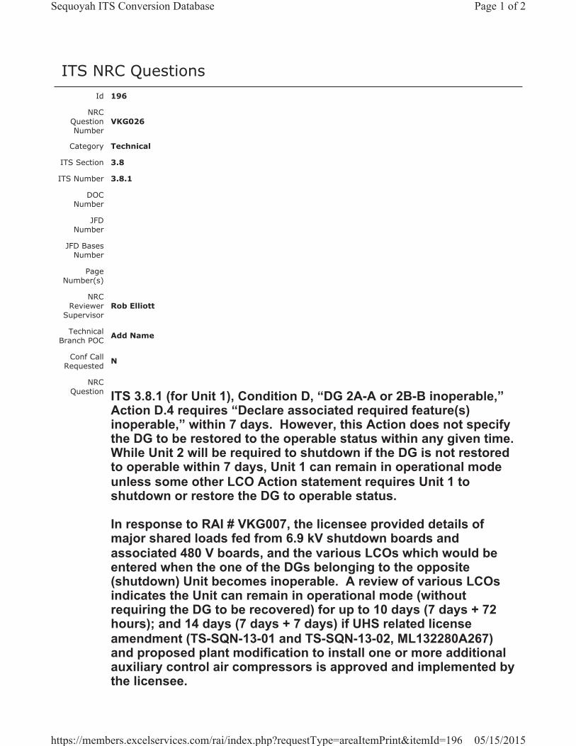
ITS NRC QuestionsId 196
NRC Question Number
VKG026
Category Technical
ITS Section 3.8
ITS Number 3.8.1
DOC Number
JFD Number
JFD Bases Number
Page Number(s)
NRC Reviewer
Supervisor Rob Elliott
Technical Branch POC Add Name
Conf Call Requested N
NRC Question ITS 3.8.1 (for Unit 1), Condition D, “DG 2A-A or 2B-B inoperable,”
Action D.4 requires “Declare associated required feature(s) inoperable,” within 7 days. However, this Action does not specify the DG to be restored to the operable status within any given time.While Unit 2 will be required to shutdown if the DG is not restored to operable within 7 days, Unit 1 can remain in operational mode unless some other LCO Action statement requires Unit 1 to shutdown or restore the DG to operable status.
In response to RAI # VKG007, the licensee provided details of major shared loads fed from 6.9 kV shutdown boards and associated 480 V boards, and the various LCOs which would be entered when the one of the DGs belonging to the opposite (shutdown) Unit becomes inoperable. A review of various LCOs indicates the Unit can remain in operational mode (without requiring the DG to be recovered) for up to 10 days (7 days + 72 hours); and 14 days (7 days + 7 days) if UHS related license amendment (TS-SQN-13-01 and TS-SQN-13-02, ML132280A267) and proposed plant modification to install one or more additional auxiliary control air compressors is approved and implemented by the licensee.
Page 1 of 2Sequoyah ITS Conversion Database
05/15/2015https://members.excelservices.com/rai/index.php?requestType=areaItemPrint&itemId=196
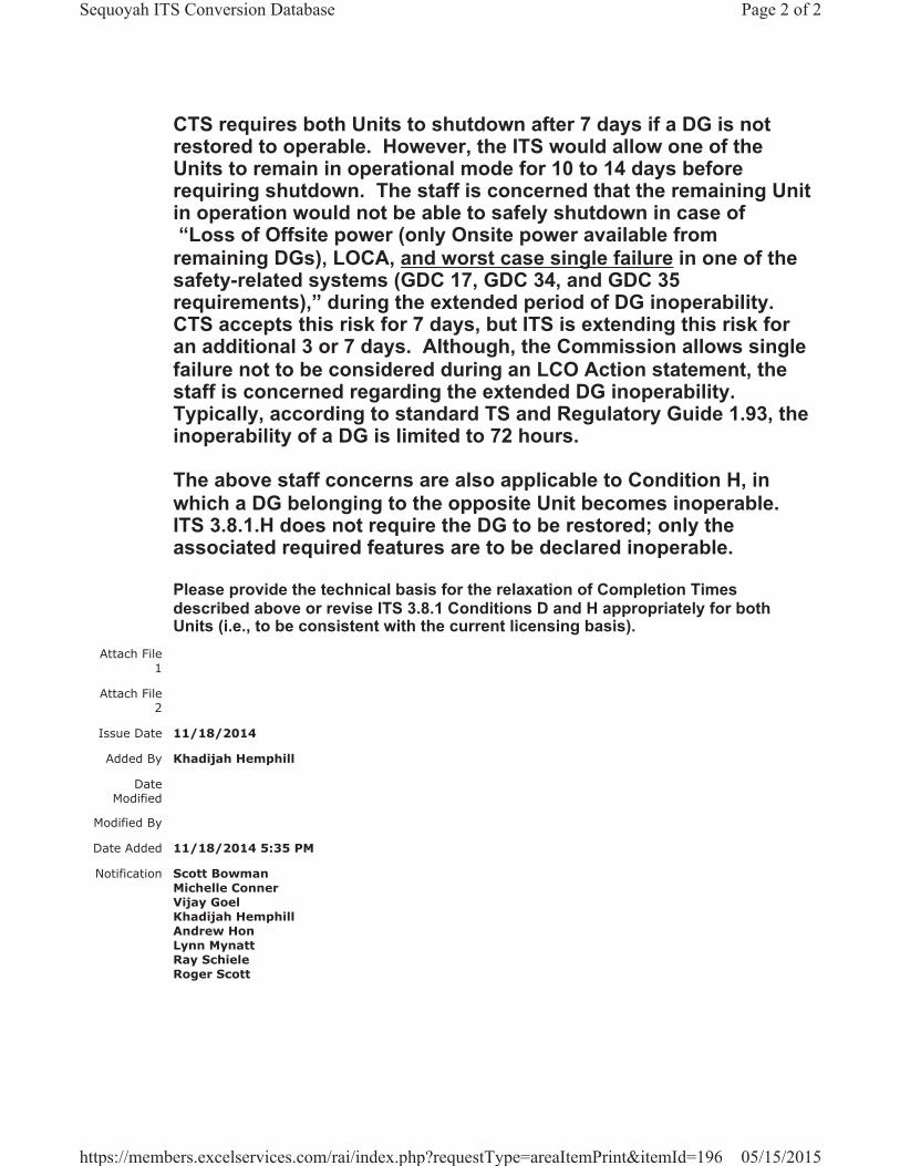
CTS requires both Units to shutdown after 7 days if a DG is not restored to operable. However, the ITS would allow one of the Units to remain in operational mode for 10 to 14 days before requiring shutdown. The staff is concerned that the remaining Unit in operation would not be able to safely shutdown in case of “Loss of Offsite power (only Onsite power available from
remaining DGs), LOCA, and worst case single failure in one of the safety-related systems (GDC 17, GDC 34, and GDC 35 requirements),” during the extended period of DG inoperability. CTS accepts this risk for 7 days, but ITS is extending this risk for an additional 3 or 7 days. Although, the Commission allows single failure not to be considered during an LCO Action statement, the staff is concerned regarding the extended DG inoperability.Typically, according to standard TS and Regulatory Guide 1.93, the inoperability of a DG is limited to 72 hours.
The above staff concerns are also applicable to Condition H, in which a DG belonging to the opposite Unit becomes inoperable.ITS 3.8.1.H does not require the DG to be restored; only the associated required features are to be declared inoperable.
Please provide the technical basis for the relaxation of Completion Times described above or revise ITS 3.8.1 Conditions D and H appropriately for both Units (i.e., to be consistent with the current licensing basis).
Attach File 1
Attach File 2
Issue Date 11/18/2014
Added By Khadijah Hemphill
Date Modified
Modified By
Date Added 11/18/2014 5:35 PM
Notification Scott BowmanMichelle ConnerVijay GoelKhadijah HemphillAndrew HonLynn MynattRay SchieleRoger Scott
Page 2 of 2Sequoyah ITS Conversion Database
05/15/2015https://members.excelservices.com/rai/index.php?requestType=areaItemPrint&itemId=196
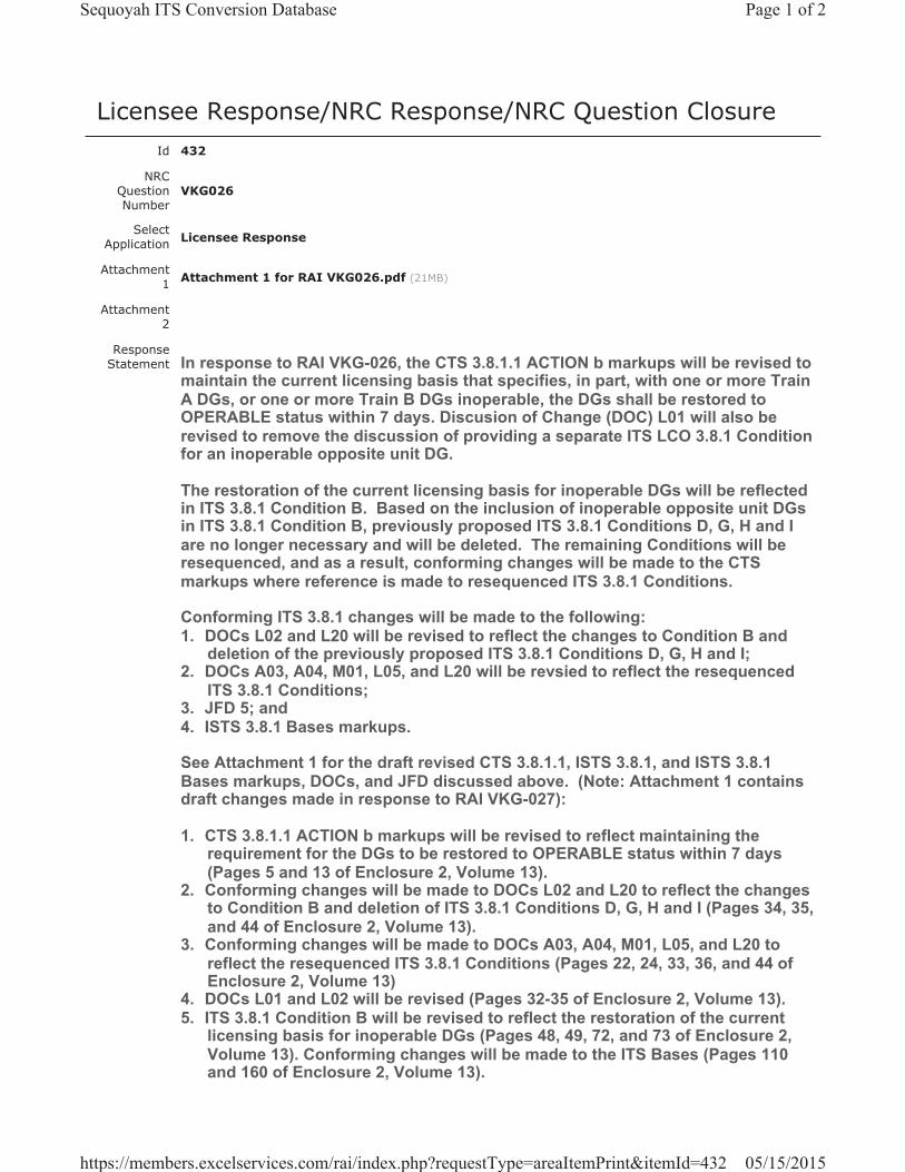
Licensee Response/NRC Response/NRC Question ClosureId 432
NRC Question Number
VKG026
Select Application Licensee Response
Attachment 1 Attachment 1 for RAI VKG026.pdf (21MB)
Attachment 2
Response Statement In response to RAI VKG-026, the CTS 3.8.1.1 ACTION b markups will be revised to
maintain the current licensing basis that specifies, in part, with one or more Train A DGs, or one or more Train B DGs inoperable, the DGs shall be restored to OPERABLE status within 7 days. Discusion of Change (DOC) L01 will also be revised to remove the discussion of providing a separate ITS LCO 3.8.1 Condition for an inoperable opposite unit DG.
The restoration of the current licensing basis for inoperable DGs will be reflected in ITS 3.8.1 Condition B. Based on the inclusion of inoperable opposite unit DGs in ITS 3.8.1 Condition B, previously proposed ITS 3.8.1 Conditions D, G, H and I are no longer necessary and will be deleted. The remaining Conditions will be resequenced, and as a result, conforming changes will be made to the CTS markups where reference is made to resequenced ITS 3.8.1 Conditions.
Conforming ITS 3.8.1 changes will be made to the following:1. DOCs L02 and L20 will be revised to reflect the changes to Condition B and
deletion of the previously proposed ITS 3.8.1 Conditions D, G, H and I; 2. DOCs A03, A04, M01, L05, and L20 will be revsied to reflect the resequenced
ITS 3.8.1 Conditions; 3. JFD 5; and4. ISTS 3.8.1 Bases markups.
See Attachment 1 for the draft revised CTS 3.8.1.1, ISTS 3.8.1, and ISTS 3.8.1 Bases markups, DOCs, and JFD discussed above. (Note: Attachment 1 contains draft changes made in response to RAI VKG-027):
1. CTS 3.8.1.1 ACTION b markups will be revised to reflect maintaining the requirement for the DGs to be restored to OPERABLE status within 7 days (Pages 5 and 13 of Enclosure 2, Volume 13).
2. Conforming changes will be made to DOCs L02 and L20 to reflect the changes to Condition B and deletion of ITS 3.8.1 Conditions D, G, H and I (Pages 34, 35, and 44 of Enclosure 2, Volume 13).
3. Conforming changes will be made to DOCs A03, A04, M01, L05, and L20 to reflect the resequenced ITS 3.8.1 Conditions (Pages 22, 24, 33, 36, and 44 of Enclosure 2, Volume 13)
4. DOCs L01 and L02 will be revised (Pages 32-35 of Enclosure 2, Volume 13).5. ITS 3.8.1 Condition B will be revised to reflect the restoration of the current
licensing basis for inoperable DGs (Pages 48, 49, 72, and 73 of Enclosure 2, Volume 13). Conforming changes will be made to the ITS Bases (Pages 110 and 160 of Enclosure 2, Volume 13).
Page 1 of 2Sequoyah ITS Conversion Database
05/15/2015https://members.excelservices.com/rai/index.php?requestType=areaItemPrint&itemId=432
6. ITS 3.8.1 Condition D, G, H, and I will be deleted. The remaining Conditions will be resequenced, where necessary. (Pages 50-55 and 74-79 of Enclosure 2, Volume 13). Conforming changes will be made to the ITS Bases (Pages 107, 110, 111, 113, 115-121, 157, 160, 161, 163, and 165-171 of Enclosure 2, Volume 13). CTS markups will be revised where reference is made to resequenced ITS 3.8.1 Conditions (Pages 5, 6, 11-14, 20, and 21 of Enclosure 2, Volume 13).
7. JFD 5 will be revised to reflect conforming changes (Page 95 and Insert JFD 5 of Enclosure 2, Volume 13).
8. Determination of No Significant Hazards will be revised to reflect the restoration of the current licensing basis for inoperable DGs (Pages 200-203 of Enclosure 2, Volume 13).
Response Date/Time 4/9/2015 2:30 PM
Closure Statement
Question Closure Date
Notification Scott BowmanMichelle ConnerVijay GoelKhadijah HemphillAndrew HonLynn MynattRay Schiele
Added By Scott Bowman
Date Added 4/9/2015 1:23 PM
Date Modified
Modified By
Page 2 of 2Sequoyah ITS Conversion Database
05/15/2015https://members.excelservices.com/rai/index.php?requestType=areaItemPrint&itemId=432

A01ITS ITS 3.8.1
3/4.8 ELECTRICAL POWER SYSTEMS
3/4.8.1 A.C. SOURCES
OPERATING
LIMITING CONDITION FOR OPERATION
3.8.1.1 As a minimum, the following A.C. electrical power sources shall be OPERABLE:
a. Two physically independent circuits between the offsite transmissionnetwork and the onsite Class 1E distribution system@, and
b. Four separate and independent diesel generator sets each with:
1. Two diesels driving a common generator
2. Two engine-mounted fuel tanks containing a minimum volume of250 gallons of fuel, per tank
3. A separate fuel storage system containing a minimum volume of62,000 gallons of fuel,
4. A separate fuel transfer pump, and
5. A separate 125-volt D.C. distribution panel, 125-volt D.C.battery bank and associated charger.
APPLICABILITY: MODES 1, 2, 3 and 4.
ACTION:
a. With one offsite A.C. circuit of the above required A.C. electrical power source inoperable,demonstrate the OPERABILITY of the remaining offsite A.C. circuit by performing Surveillance Requirement 4.8.1.1.1.a within one hour and at least once per 8 hours thereafter. Restore at least two offsite circuits to OPERABLE status within 72 hours or be in at least HOT STANDBY within the next 6 hours and in COLD SHUTDOWN within the following 30 hours.
b.# With diesel generator set(s) 1A-A and/or 2A-A or 1B-B and/or 2B-B of the above required A.C. electrical power sources inoperable,* demonstrate the OPERABILITY of the remaining A.C. sources by performing Surveillance Requirement 4.8.1.1.1.a within one hour and at least once per 8 hours thereafter, and determining OPERABLE diesel generator sets are not inoperable due to common cause failure or performing Surveillance Requirement 4.8.1.1.2.a.4 within 24 hours; restore at least four diesel generator sets to OPERABLE status within 7 days or be in at least HOT STANDBY within the next 6 hours and in COLD SHUTDOWN within the following 30 hours.
# Required actions, to verify OPERABLE diesel generator sets are not inoperable due to common cause failure or perform SR 4.8.1.1.2.a.4, shall be completed if this action is entered.
* No more than one diesel generator may be made simultaneously inoperable on a pre-planned basisfor maintenance, modifications, or surveillance testing.
@ Offsite circuits utilizing USST 2A and USST 2B as the normal power sources require CSST A and CSST C to be available as the alternate power sources via automatic transfer at the associated 6.9 kV Unit Boards. (CSST B can be substituted for CSST A or CSST C.) This Note remains in effect until November 30, 2013, or until the USST modifications are implemented on Units 1 and 2, whichever occurs first.
October 31, 2012 SEQUOYAH - UNIT 1 3/4 8-1 Amendment No. 100, 132, 137, 205, 241, 332
LCO 3.8.1
Applicability
Page 1 of 17
LCO 3.8.1.a
LCO 3.8.1.b
SR 3.8.1.4
SR 3.8.1.6
See ITS 3.8.4 and
3.8.9
LA01
LA01qualified
ACTION A
ACTION K
ACTION B
ACTION K
L01Add proposed ACTIONS C and D
L01Add proposed Condition B
L01
L01
L02
L02
L03SR 3.8.1.3 Note 3
Add proposed Condition A L01
See ITS 3.8.3
A02
A02
Enclosure 2, Volume 13, Rev. 0, Page 5 of 638
Enclosure 2, Volume 13, Rev. 0, Page 5 of 638
G
G
STET
STET
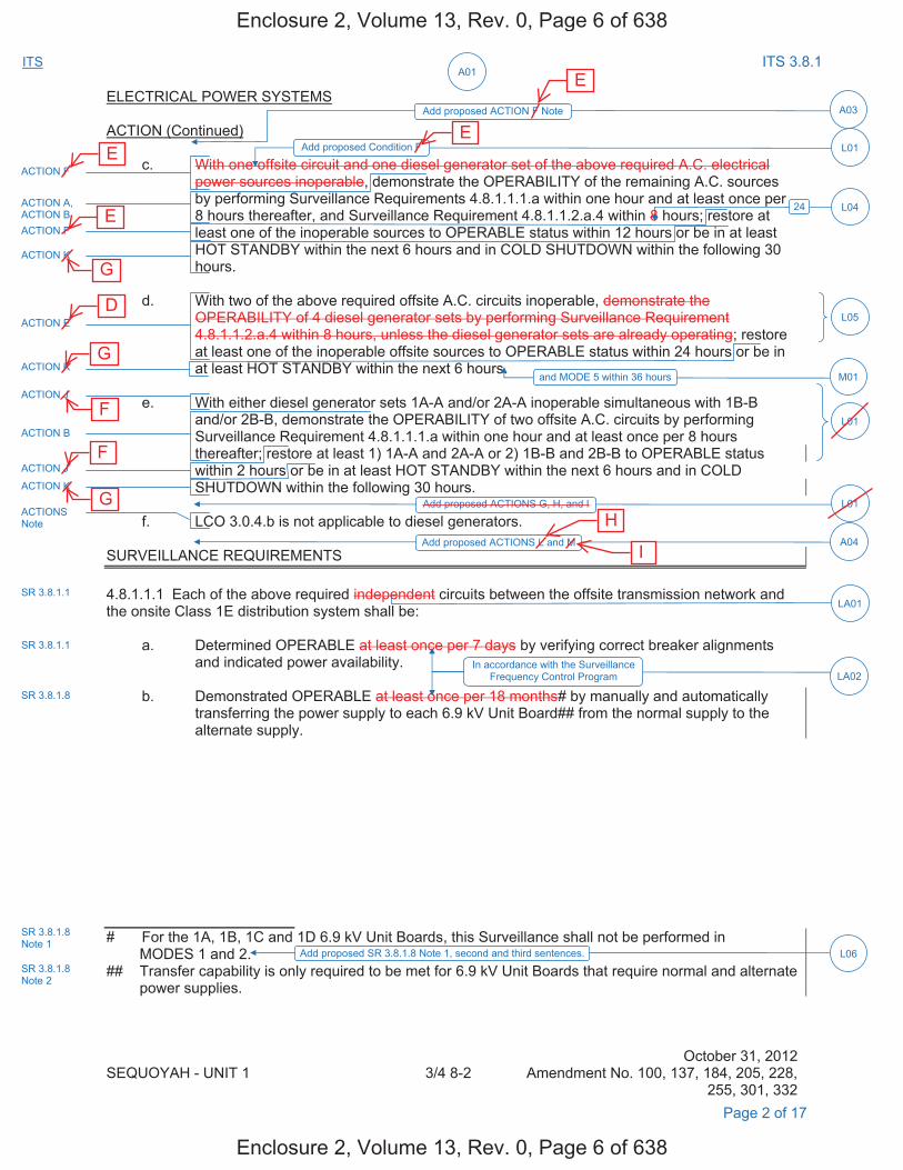
A01ITS ITS 3.8.1
ELECTRICAL POWER SYSTEMS
ACTION (Continued)
c. With one offsite circuit and one diesel generator set of the above required A.C. electricalpower sources inoperable, demonstrate the OPERABILITY of the remaining A.C. sources by performing Surveillance Requirements 4.8.1.1.1.a within one hour and at least once per 8 hours thereafter, and Surveillance Requirement 4.8.1.1.2.a.4 within 8 hours; restore at least one of the inoperable sources to OPERABLE status within 12 hours or be in at least HOT STANDBY within the next 6 hours and in COLD SHUTDOWN within the following 30 hours.
d. With two of the above required offsite A.C. circuits inoperable, demonstrate theOPERABILITY of 4 diesel generator sets by performing Surveillance Requirement4.8.1.1.2.a.4 within 8 hours, unless the diesel generator sets are already operating; restoreat least one of the inoperable offsite sources to OPERABLE status within 24 hours or be inat least HOT STANDBY within the next 6 hours.
e. With either diesel generator sets 1A-A and/or 2A-A inoperable simultaneous with 1B-Band/or 2B-B, demonstrate the OPERABILITY of two offsite A.C. circuits by performingSurveillance Requirement 4.8.1.1.1.a within one hour and at least once per 8 hoursthereafter; restore at least 1) 1A-A and 2A-A or 2) 1B-B and 2B-B to OPERABLE statuswithin 2 hours or be in at least HOT STANDBY within the next 6 hours and in COLDSHUTDOWN within the following 30 hours.
f. LCO 3.0.4.b is not applicable to diesel generators.
SURVEILLANCE REQUIREMENTS
4.8.1.1.1 Each of the above required independent circuits between the offsite transmission network and the onsite Class 1E distribution system shall be:
a. Determined OPERABLE at least once per 7 days by verifying correct breaker alignmentsand indicated power availability.
b. Demonstrated OPERABLE at least once per 18 months# by manually and automaticallytransferring the power supply to each 6.9 kV Unit Board## from the normal supply to the alternate supply.
# For the 1A, 1B, 1C and 1D 6.9 kV Unit Boards, this Surveillance shall not be performed in MODES 1 and 2.
## Transfer capability is only required to be met for 6.9 kV Unit Boards that require normal and alternate power supplies.
October 31, 2012 SEQUOYAH - UNIT 1 3/4 8-2 Amendment No. 100, 137, 184, 205, 228,
255, 301, 332 Page 2 of 17
ACTION F
ACTION A, ACTION B ACTION F
ACTION K
L01Add proposed Condition F
A03Add proposed ACTION F Note
24 L04
ACTION E
ACTION K
ACTION J
L05
M01and MODE 5 within 36 hours
L01
ACTION J
ACTION K
ACTION B
L01Add proposed ACTIONS G, H, and I
A04Add proposed ACTIONS L and M
SR 3.8.1.1
SR 3.8.1.1
LA02
ACTIONS Note
LA01
In accordance with the Surveillance Frequency Control Program
SR 3.8.1.8
SR 3.8.1.8 Note 1
L06Add proposed SR 3.8.1.8 Note 1, second and third sentences.SR 3.8.1.8 Note 2
Enclosure 2, Volume 13, Rev. 0, Page 6 of 638
Enclosure 2, Volume 13, Rev. 0, Page 6 of 638
H
I
E
E E
E
G
G
G
F
F
D
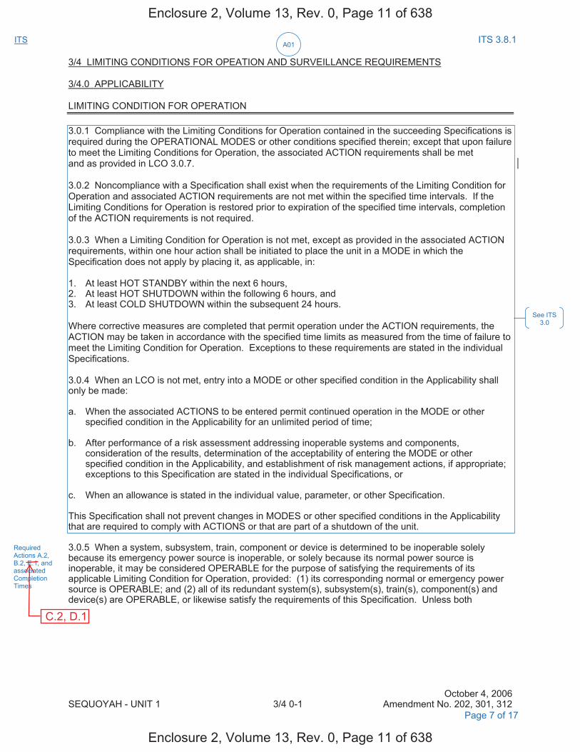
A01ITS ITS 3.8.1
3/4 LIMITING CONDITIONS FOR OPEATION AND SURVEILLANCE REQUIREMENTS
3/4.0 APPLICABILITY
LIMITING CONDITION FOR OPERATION
3.0.1 Compliance with the Limiting Conditions for Operation contained in the succeeding Specifications is required during the OPERATIONAL MODES or other conditions specified therein; except that upon failure to meet the Limiting Conditions for Operation, the associated ACTION requirements shall be met and as provided in LCO 3.0.7.
3.0.2 Noncompliance with a Specification shall exist when the requirements of the Limiting Condition for Operation and associated ACTION requirements are not met within the specified time intervals. If the Limiting Conditions for Operation is restored prior to expiration of the specified time intervals, completion of the ACTION requirements is not required.
3.0.3 When a Limiting Condition for Operation is not met, except as provided in the associated ACTION requirements, within one hour action shall be initiated to place the unit in a MODE in which the Specification does not apply by placing it, as applicable, in:
1. At least HOT STANDBY within the next 6 hours,2. At least HOT SHUTDOWN within the following 6 hours, and3. At least COLD SHUTDOWN within the subsequent 24 hours.
Where corrective measures are completed that permit operation under the ACTION requirements, the ACTION may be taken in accordance with the specified time limits as measured from the time of failure to meet the Limiting Condition for Operation. Exceptions to these requirements are stated in the individual Specifications.
3.0.4 When an LCO is not met, entry into a MODE or other specified condition in the Applicability shall only be made:
a. When the associated ACTIONS to be entered permit continued operation in the MODE or otherspecified condition in the Applicability for an unlimited period of time;
b. After performance of a risk assessment addressing inoperable systems and components,consideration of the results, determination of the acceptability of entering the MODE or otherspecified condition in the Applicability, and establishment of risk management actions, if appropriate;exceptions to this Specification are stated in the individual Specifications, or
c. When an allowance is stated in the individual value, parameter, or other Specification.
This Specification shall not prevent changes in MODES or other specified conditions in the Applicability that are required to comply with ACTIONS or that are part of a shutdown of the unit.
3.0.5 When a system, subsystem, train, component or device is determined to be inoperable solely because its emergency power source is inoperable, or solely because its normal power source is inoperable, it may be considered OPERABLE for the purpose of satisfying the requirements of its applicable Limiting Condition for Operation, provided: (1) its corresponding normal or emergency power source is OPERABLE; and (2) all of its redundant system(s), subsystem(s), train(s), component(s) and device(s) are OPERABLE, or likewise satisfy the requirements of this Specification. Unless both
October 4, 2006 SEQUOYAH - UNIT 1 3/4 0-1 Amendment No. 202, 301, 312
See ITS 3.0
Required Actions A.2, B.2, E.1, and associated Completion Times
Page 7 of 17
Enclosure 2, Volume 13, Rev. 0, Page 11 of 638
Enclosure 2, Volume 13, Rev. 0, Page 11 of 638
C.2, D.1

A01ITS ITS 3.8.1
APPLICABILITY
LIMITING CONDITION FOR OPERATION (Continued)
3.0.5 (Continued)
conditions (1) and (2) are satisfied, within 2 hours action shall be initiated to place the unit in a MODE in which the applicable Limiting Condition for Operation does not apply by placing it as applicable in:
1. At least HOT STANDBY within the next 6 hours,2. At least HOT SHUTDOWN within the following 6 hours, and3. At least COLD SHUTDOWN within the subsequent 24 hours.
This Specification is not applicable in MODES 5 or 6.
3.0.6 Equipment removed from service or declared inoperable to comply with ACTIONS may be returned to service under administrative control solely to perform testing required to demonstrate its OPERABILITY or the OPERABILITY of other equipment. This is an exception to LCO 3.0.1 and 3.0.2 for the system returned to service under administrative control to perform the testing required to demonstrate OPERABILITY.
3.0.7 When one or more required snubbers are unable to perform their associated support function(s), any affected supported LCO(s) are not required to be declared not met solely for this reason if risk is assessed and managed, and:
a. the snubbers not able to perform their associated support function(s) are associated with only onetrain or subsystem of a multiple train or subsystem supported system or are associated with a singletrain or subsystem supported system and are able to perform their associated support function within72 hours; or
b. the snubbers not able to perform their associated support function(s) are associated with more thanone train or subsystem of a multiple train or subsystem supported system and are able to performtheir associated support function within 12 hours.
At the end of the specified period the required snubbers must be able to perform their associated support function(s), or the affected supported system LCO(s) shall be declared not met.
SURVEILLANCE REQUIREMENTS
4.0.1 Surveillance Requirements shall be met during the MODES or other specified conditions in the Applicability for individual Limiting Condition for Operation, unless otherwise stated in the individual Surveillance Requirement. Failure to meet a Surveillance Requirement, whether such failure is experienced during the performance of the Surveillance or between performances of the Surveillance, shall be failure to meet the Limiting Condition for Operation. Failure to perform a Surveillance within the specified surveillance interval shall be failure to meet the Limiting Conditions for Operation except as provided in Specification 4.0.3. Surveillances do not have to be performed on inoperable equipment or variables outside specified limits.
4.0.2 Each Surveillance Requirement shall be performed within the specified surveillance interval with a maximum allowable extension not to exceed 25 percent of the specified surveillance interval.
4.0.3 If it is discovered that a Surveillance was not performed within its specified surveillance interval (including the allowed extension per Specification 4.0.2), then compliance with the requirement to declare the Limiting Condition for Operation not met may be delayed, from the time of discovery, up to 24 hours or up to the limit of the specified surveillance interval, whichever is greater. This delay period is permitted to allow performance of the Surveillance. A risk evaluation shall be performed for any Surveillance delayed greater than 24 hours and the risk impact shall be managed.
October 4, 2006 SEQUOYAH - UNIT 1 3/4 0-2 Amendment No. 78, 162, 202, 208,
274, 280, 293, 312 Page 8 of 17
See ITS 3.0
L20
24 hours for Required Action A.2 4 hours for Required Action B.2
12 hours for Required Action E.1
Declare required features inoperable.
A08
Enclosure 2, Volume 13, Rev. 0, Page 12 of 638
Enclosure 2, Volume 13, Rev. 0, Page 12 of 638
D
, C.2
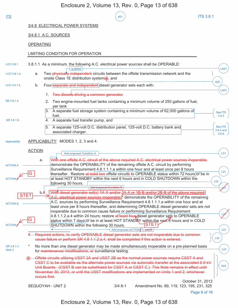
A01ITS ITS 3.8.1
3/4.8 ELECTRICAL POWER SYSTEMS
3/4.8.1 A.C. SOURCES
OPERATING
LIMITING CONDITION FOR OPERATION
3.8.1.1 As a minimum, the following A.C. electrical power sources shall be OPERABLE:
a. Two physically independent circuits between the offsite transmission network and theonsite Class 1E distribution system@, and
b. Four separate and independent diesel generator sets each with:
1. Two diesels driving a common generator
2. Two engine-mounted fuel tanks containing a minimum volume of 250 gallons of fuel,per tank
3. A separate fuel storage system containing a minimum volume of 62,000 gallons offuel,
4. A separate fuel transfer pump, and
5. A separate 125-volt D.C. distribution panel, 125-volt D.C. battery bank andassociated charger.
APPLICABILITY: MODES 1, 2, 3 and 4.
ACTION:
a. With one offsite A.C. circuit of the above required A.C. electrical power sources inoperable,demonstrate the OPERABILITY of the remaining offsite A.C. circuit by performing Surveillance Requirement 4.8.1.1.1.a within one hour and at least once per 8 hours thereafter. Restore at least two offsite circuits to OPERABLE status within 72 hours or be in at least HOT STANDBY within the next 6 hours and in COLD SHUTDOWN within the following 30 hours.
b.# With diesel generator set(s) 1A-A and/or 2A-A or 1B-B and/or 2B-B of the above required A.C. electrical power sources inoperable,* demonstrate the OPERABILITY of the remaining A.C. sources by performing Surveillance Requirement 4.8.1.1.1.a within one hour and at least once per 8 hours thereafter, and determining OPERABLE diesel generator sets are not inoperable due to common cause failure or performing Surveillance Requirement 4.8.1.1.2.a.4 within 24 hours; restore at least four diesel generator sets to OPERABLE status within 7 days or be in at least HOT STANDBY within the next 6 hours and in COLD SHUTDOWN within the following 30 hours.
# Required actions, to verify OPERABLE diesel generator sets are not inoperable due to common cause failure or perform SR 4.8.1.1.2.a.4, shall be completed if this action is entered.
* No more than one diesel generator may be made simultaneously inoperable on a pre-planned basisfor maintenance, modifications, or surveillance testing.
@ Offsite circuits utilizing USST 2A and USST 2B as the normal power sources require CSST A and CSST C to be available as the alternate power sources via automatic transfer at the associated 6.9 kV Unit Boards. (CSST B can be substituted for CSST A or CSST C.) This Note remains in effect until November 30, 2013, or until the USST modifications are implemented on Units 1 and 2, whichever occurs first.
October 31, 2012 SEQUOYAH - UNIT 2 3/4 8-1 Amendment No. 89, 119, 123, 195, 231, 325
LCO 3.8.1
Applicability
Page 9 of 16
LCO 3.8.1.a
LCO 3.8.1.b
SR 3.8.1.4
SR 3.8.1.6
See ITS 3.8.4 and
3.8.9
LA01
LA01qualified
ACTION A
ACTION K
ACTION B
ACTION K
L01Add proposed ACTIONS C and D
L01Add proposed Condition B
L01
L01
L02
L02
L03SR 3.8.1.3 Note 3
Add proposed Condition A L01
See ITS 3.8.3
A02
A02
Enclosure 2, Volume 13, Rev. 0, Page 13 of 638
Enclosure 2, Volume 13, Rev. 0, Page 13 of 638
G
G
STET
STET
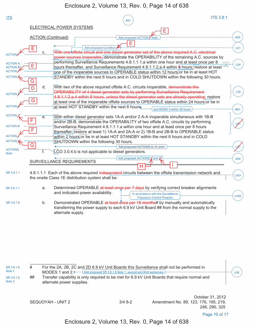
A01ITS ITS 3.8.1
ELECTRICAL POWER SYSTEMS
ACTION (Continued)
c. With one offsite circuit and one diesel generator set of the above required A.C. electricalpower sources inoperable, demonstrate the OPERABILITY of the remaining A.C. sources by performing Surveillance Requirements 4.8.1.1.1.a within one hour and at least once per 8 hours thereafter, and Surveillance Requirement 4.8.1.1.2.a.4 within 8 hours; restore at least one of the inoperable sources to OPERABLE status within 12 hours or be in at least HOT STANDBY within the next 6 hours and in COLD SHUTDOWN within the following 30 hours.
d. With two of the above required offsite A.C. circuits inoperable, demonstrate theOPERABILITY of 4 diesel generator sets by performing Surveillance Requirement4.8.1.1.2.a.4 within 8 hours, unless the diesel generator sets are already operating; restoreat least one of the inoperable offsite sources to OPERABLE status within 24 hours or be inat least HOT STANDBY within the next 6 hours.
e. With either diesel generator sets 1A-A and/or 2 A-A inoperable simultaneous with 1B-Band/or 2B-B, demonstrate the OPERABILITY of two offsite A.C. circuits by performingSurveillance Requirement 4.8.1.1.1.a within one hour and at least once per 8 hoursthereafter; restore at least 1) 1A-A and 2A-A or 2) 1B-B and 2B-B to OPERABLE statuswithin 2 hours or be in at least HOT STANDBY within the next 6 hours and in COLDSHUTDOWN within the following 30 hours.
f. LCO 3.0.4.b is not applicable to diesel generators.
SURVEILLANCE REQUIREMENTS
4.8.1.1.1 Each of the above required independent circuits between the offsite transmission network and the onsite Class 1E distribution system shall be:
a. Determined OPERABLE at least once per 7 days by verifying correct breaker alignmentsand indicated power availability.
b. Demonstrated OPERABLE at least once per 18 months# by manually and automaticallytransferring the power supply to each 6.9 kV Unit Board ## from the normal supply to the alternate supply.
# For the 2A, 2B, 2C and 2D 6.9 kV Unit Boards this Surveillance shall not be performed in MODES 1 and 2.
## Transfer capability is only required to be met for 6.9 kV Unit Boards that require normal and alternate power supplies.
October 31, 2012 SEQUOYAH - UNIT 2 3/4 8-2 Amendment No. 89, 123, 176, 195, 219,
246, 290, 325
Page 10 of 17
ACTION F
ACTION A, ACTION B ACTION F
ACTION K
L01Add proposed Condition F
A03Add proposed ACTION F Note
24 L04
ACTION E
ACTION K
ACTION J
L05
M01and MODE 5 within 36 hours
L01
ACTION J
ACTION K
ACTION B
L01Add proposed ACTIONS G, H, and I
A04Add proposed ACTIONS L and M
SR 3.8.1.1
SR 3.8.1.1
LA02
ACTIONS Note
In accordance with the Surveillance Frequency Control Program
SR 3.8.1.8
SR 3.8.1.8 Note 1 L06Add proposed SR 3.8.1.8 Note 1, second and third sentences.
SR 3.8.1.8 Note 2
LA01
Enclosure 2, Volume 13, Rev. 0, Page 14 of 638
Enclosure 2, Volume 13, Rev. 0, Page 14 of 638
E
E E
E
D
G
F
F
G
G
H I

A01ITS ITS 3.8.1
3/4 LIMITING CONDITIONS FOR OPERATION AND SURVEILLANCE REQUIREMENTS
3/4.0 APPLICABILITY
LIMITING CONDITION FOR OPERATION
3.0.1 Compliance with the Limiting Conditions for Operation contained in the succeeding Specifications is required during the OPERATIONAL MODES or other conditions specified therein; except that upon failure to meet the Limiting Conditions for Operation, the associated ACTION requirements shall be met and as provided in LCO 3.0.7.
3.0.2 Noncompliance with a Specification shall exist when the requirements of the Limiting Condition for Operation and associated ACTION requirements are not met within the specified time intervals. If the Limiting Conditions for Operation is restored prior to expiration of the specified time intervals, completion of the ACTION requirements is not required.
3.0.3 When a Limiting Condition for Operation is not met, except as provided in the associated ACTION requirements, within one hour action shall be initiated to place the unit in a MODE in which the Specification does not apply by placing it, as applicable, in:
1. At least HOT STANDBY within the next 6 hours,2. At least HOT SHUTDOWN within the following 6 hours, and3. At least COLD SHUTDOWN within the subsequent 24 hours.
Where corrective measures are completed that permit operation under the ACTION requirements, the ACTION may be taken in accordance with the specified time limits as measured from the time of failure to meet the Limiting Condition for Operation. Exceptions to these requirements are stated in the individual Specifications.
3.0.4 When an LCO is not met, entry into a MODE or other specified condition in the Applicability shall only be made:
a. When the associated ACTIONS to be entered permit continued operation in the MODE or otherspecified condition in the Applicability for an unlimited period of time;
b. After performance of a risk assessment addressing inoperable systems and components,consideration of the results, determination of the acceptability of entering the MODE or otherspecified condition in the Applicability, and establishment of risk management actions, ifappropriate; exceptions to this Specification are stated in the individual Specifications, or
c. When an allowance is stated in the individual value, parameter, or other Specification.
This Specification shall not prevent changes in MODES or other specified conditions in the Applicability that are required to comply with ACTIONS or that are part of a shutdown of the unit.
3.0.5 When a system, subsystem, train, component or device is determined to be inoperable solely because its emergency power source is inoperable, or solely because its normal power source is inoperable, it may be considered OPERABLE for the purpose of satisfying the requirements of its applicable Limiting Condition for Operation, provided: (1) its corresponding normal or emergency power source is OPERABLE; and (2) all of its redundant system(s), subsystem(s), train(s), component(s) and device(s) are OPERABLE, or likewise satisfy the requirements of this Specification. Unless both
October 4, 2006 SEQUOYAH - UNIT 2 3/4 0-1 Amendment No. 192, 290, 301
See ITS 3.0
Required Actions A.2, B.2, E.1, and associated Completion Times
Page 16 of 17
Enclosure 2, Volume 13, Rev. 0, Page 20 of 638
Enclosure 2, Volume 13, Rev. 0, Page 20 of 638
C.2, D.1

A01ITS ITS 3.8.1
APPLICABILITY
LIMITING CONDITION FOR OPERATION
3.0.5 (Continued)
conditions (1) and (2) are satisfied, within 2 hours action shall be initiated to place the unit in a MODE in which the applicable Limiting Condition for Operation does not apply by placing it as applicable in:
1. At least HOT STANDBY within the next 6 hours2. At least HOT SHUTDOWN within the following 6 hours, and3. At least COLD SHUTDOWN within the subsequent 24 hours.
This Specification is not applicable in MODES 5 or 6. 3.0.6 Equipment removed from service or declared inoperable to comply with ACTIONS may be returned to service under administrative control solely to perform testing required to demonstrate its OPERABILITY or the OPERABILITY of other equipment. This is an exception to LCO 3.0.1 and 3.0.2 for the system returned to service under administrative control to perform the testing required to demonstrate OPERABILITY.
3.0.7 When one or more required snubbers are unable to perform their associated support function(s), any affected supported LCO(s) are not required to be declared not met solely for this reason if risk is assessed and managed, and:
a. the snubbers not able to perform their associated support function(s) are associated with only onetrain or subsystem of a multiple train or subsystem supported system or are associated with asingle train or subsystem supported system and are able to perform their associated supportfunction within 72 hours; or
b. the snubbers not able to perform their associated support function(s) are associated with morethan one train or subsystem of a multiple train or subsystem supported system and are able toperform their associated support function within 12 hours.
At the end of the specified period the required snubbers must be able to perform their associated support function(s), or the affected supported system LCO(s) shall be declared not met.
SURVEILLANCE REQUIREMENTS
4.0.1 Surveillance Requirements shall be met during the MODES or other specified conditions in the Applicability for individual Limiting Condition for Operation, unless otherwise stated in the individual Surveillance Requirement. Failure to meet a Surveillance Requirement, whether such failure is experienced during the performance of the Surveillance or between performances of the Surveillance, shall be failure to meet the Limiting Condition for Operation. Failure to perform a Surveillance within the specified surveillance interval shall be failure to meet the Limiting Conditions for Operation except as provided in Specification 4.0.3. Surveillances do not have to be performed on inoperable equipment or variables outside specified limits.
4.0.2 Each Surveillance Requirement shall be performed within the specified surveillance interval with a maximum allowable extension not to exceed 25 percent of the specified surveillance interval.
4.0.3 If it is discovered that a Surveillance was not performed within its specified surveillance interval (including the allowed extension per Specification 4.0.2), then compliance with the requirement to declare the Limiting Condition for Operation not met may be delayed, from the time of discovery,
October 4, 2006 SEQUOYAH - UNIT 2 3/4 0-2 Amendment No. 69, 152, 192, 198, 263, 271,
283, 301
Page 17 of 17
See ITS 3.0
L20
24 hours for Required Action A.2 4 hours for Required Action B.2
12 hours for Required Action E.1
Declare required features inoperable.
A08
Enclosure 2, Volume 13, Rev. 0, Page 21 of 638
Enclosure 2, Volume 13, Rev. 0, Page 21 of 638
D , C.2
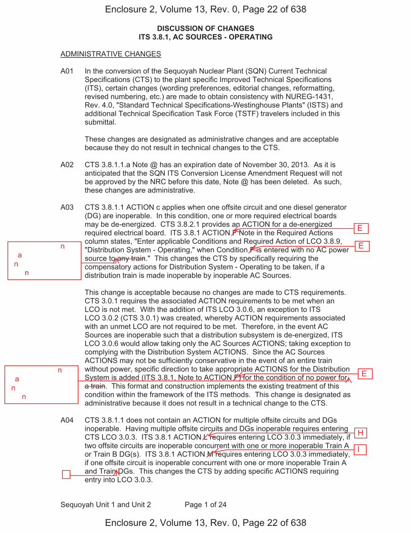
DISCUSSION OF CHANGES ITS 3.8.1, AC SOURCES - OPERATING
Sequoyah Unit 1 and Unit 2 Page 1 of 24
ADMINISTRATIVE CHANGES
A01 In the conversion of the Sequoyah Nuclear Plant (SQN) Current Technical Specifications (CTS) to the plant specific Improved Technical Specifications (ITS), certain changes (wording preferences, editorial changes, reformatting, revised numbering, etc.) are made to obtain consistency with NUREG-1431, Rev. 4.0, "Standard Technical Specifications-Westinghouse Plants" (ISTS) and additional Technical Specification Task Force (TSTF) travelers included in this submittal.
These changes are designated as administrative changes and are acceptable because they do not result in technical changes to the CTS.
A02 CTS 3.8.1.1.a Note @ has an expiration date of November 30, 2013. As it is anticipated that the SQN ITS Conversion License Amendment Request will not be approved by the NRC before this date, Note @ has been deleted. As such, these changes are administrative.
A03 CTS 3.8.1.1 ACTION c applies when one offsite circuit and one diesel generator (DG) are inoperable. In this condition, one or more required electrical boards may be de-energized. CTS 3.8.2.1 provides an ACTION for a de-energized required electrical board. ITS 3.8.1 ACTION F Note in the Required Actions column states, "Enter applicable Conditions and Required Action of LCO 3.8.9, "Distribution System - Operating," when Condition F is entered with no AC power source to any train." This changes the CTS by specifically requiring the compensatory actions for Distribution System - Operating to be taken, if a distribution train is made inoperable by inoperable AC Sources.
This change is acceptable because no changes are made to CTS requirements. CTS 3.0.1 requires the associated ACTION requirements to be met when an LCO is not met. With the addition of ITS LCO 3.0.6, an exception to ITS LCO 3.0.2 (CTS 3.0.1) was created, whereby ACTION requirements associated with an unmet LCO are not required to be met. Therefore, in the event AC Sources are inoperable such that a distribution subsystem is de-energized, ITS LCO 3.0.6 would allow taking only the AC Sources ACTIONS; taking exception to complying with the Distribution System ACTIONS. Since the AC Sources ACTIONS may not be sufficiently conservative in the event of an entire train without power, specific direction to take appropriate ACTIONS for the Distribution System is added (ITS 3.8.1, Note to ACTION F) for the condition of no power for a train. This format and construction implements the existing treatment of this condition within the framework of the ITS methods. This change is designated as administrative because it does not result in a technical change to the CTS.
A04 CTS 3.8.1.1 does not contain an ACTION for multiple offsite circuits and DGs inoperable. Having multiple offsite circuits and DGs inoperable requires entering CTS LCO 3.0.3. ITS 3.8.1 ACTION L requires entering LCO 3.0.3 immediately, if two offsite circuits are inoperable concurrent with one or more inoperable Train A or Train B DG(s). ITS 3.8.1 ACTION M requires entering LCO 3.0.3 immediately, if one offsite circuit is inoperable concurrent with one or more inoperable Train A and Train DGs. This changes the CTS by adding specific ACTIONS requiring entry into LCO 3.0.3.
Enclosure 2, Volume 13, Rev. 0, Page 22 of 638
Enclosure 2, Volume 13, Rev. 0, Page 22 of 638
I
H
E
E
E��������������n���a�������������������n�������������������������n�����
��������������n���a�������������������n�������������������������n�����
�

DISCUSSION OF CHANGES ITS 3.8.1, AC SOURCES - OPERATING
Sequoyah Unit 1 and Unit 2 Page 3 of 24
specific CTS DG loading requirement with a statement that DG loadings may include gradual loading as recommended by the manufacturer. This change is consistent with the recommendations of Generic Letter (GL) 93-05, "Line- Item Technical Specifications Improvements to Reduce Surveillance Requirements for Testing During Power Operation." GL 93-05, Section 10.1, states that DGs "should be loaded in accordance with vendor recommendations for all test purposes other than the refueling outage LOOP tests." The change is acceptable, because it will ensure the DGs will continue to be operated consistent with manufacturer recommendations. This change is designated as administrative, because it does not result in a technical change to the CTS.
A07 CTS 4.8.1.1.2.d.5 requires verification that on an ESF actuation test signal (without loss of offsite power), each DG starts and operates for at least 5 minutes. ITS SR 3.8.1.12 requires a similar test, but does not specify that the DG auto-start on an ESF actuation test signal is "without loss of offsite power." This changes the CTS by not specifying the DG auto-start on an ESF actuation test signal is without a loss of offsite power signal.
The purpose of CTS 4.8.1.1.2.d.5 is to demonstrate that each DG automatically starts on an ESF actuation test signal. The requirements of this Surveillance are retained in the ITS as SR 3.8.1.12. The purpose of CTS 4.8.1.1.2.d.6.b) is to verify that each DG starts on a loss of offsite power concurrent with an ESF actuation test signal. The requirements of this Surveillance are retained in the ITS as SR 3.8.1.18. This change is acceptable, because it is understood that the CTS 4.8.1.1.2.d.5 required DG start on an ESF actuation test signal is without a loss of offsite power signal. Therefore, it is unnecessary to provide this information in ITS SR 3.8.1.12. This change is designated as administrative, because it does not result in a technical change to the CTS.
A08 CTS 3.0.5 states that it is not applicable in MODE 5 or 6. CTS 3.0.5 has been incorporated into the ACTIONS of ITS 3.8.1. This changes the CTS by incorporating the allowances of CTS 3.0.5 in ITS 3.8.1.
This change is acceptable because ITS 3.8.1 is only applicable in MODES 1, 2, 3, and 4. Therefore, the statement in CTS 3.0.5, that states that the Specification is not applicable in MODE 5 or 6, is no longer necessary and is deleted. This change is designated as administrative, because it does not result in technical changes to the CTS.
MORE RESTRICTIVE CHANGES
M01 CTS 3.8.1.1 ACTION d specifies the compensatory actions for two inoperable offsite circuits. The action requires restoration of at least one of the offsite sources within 24 hours, and if it is not restored within the allowed time, the unit is required to be in at least HOT STANDBY within the next 6 hours. ITS 3.8.1 ACTION E requires restoration of at least one offsite circuit to OPERABLE status within 24 hours, otherwise ITS 3.8.1 ACTION K requires the unit to be in MODE 3 within 6 hours and MODE 5 within 36 hours. This changes the CTS by adding the requirement to be in MODE 5 within 36 hours.
Enclosure 2, Volume 13, Rev. 0, Page 24 of 638
Enclosure 2, Volume 13, Rev. 0, Page 24 of 638
G D
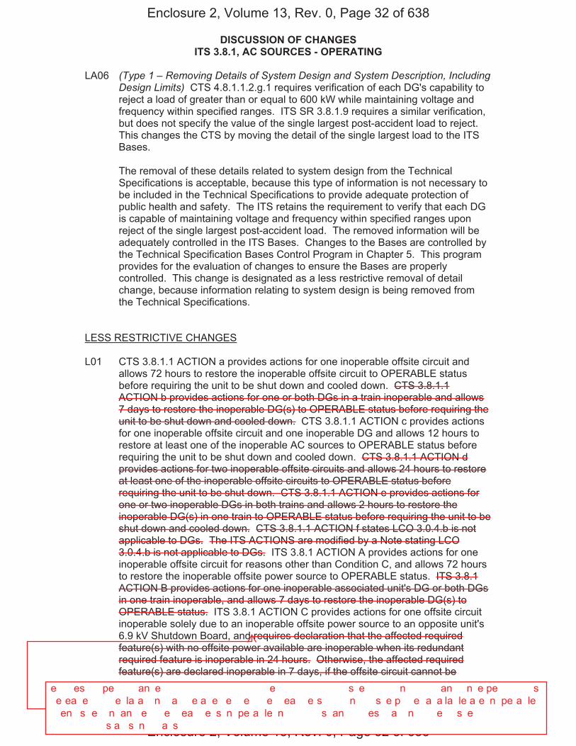
DISCUSSION OF CHANGES ITS 3.8.1, AC SOURCES - OPERATING
Sequoyah Unit 1 and Unit 2 Page 11 of 24
LA06 (Type 1 – Removing Details of System Design and System Description, Including Design Limits) CTS 4.8.1.1.2.g.1 requires verification of each DG's capability to reject a load of greater than or equal to 600 kW while maintaining voltage and frequency within specified ranges. ITS SR 3.8.1.9 requires a similar verification, but does not specify the value of the single largest post-accident load to reject. This changes the CTS by moving the detail of the single largest load to the ITS Bases.
The removal of these details related to system design from the Technical Specifications is acceptable, because this type of information is not necessary to be included in the Technical Specifications to provide adequate protection of public health and safety. The ITS retains the requirement to verify that each DG is capable of maintaining voltage and frequency within specified ranges upon reject of the single largest post-accident load. The removed information will be adequately controlled in the ITS Bases. Changes to the Bases are controlled by the Technical Specification Bases Control Program in Chapter 5. This program provides for the evaluation of changes to ensure the Bases are properly controlled. This change is designated as a less restrictive removal of detail change, because information relating to system design is being removed from the Technical Specifications.
LESS RESTRICTIVE CHANGES
L01 CTS 3.8.1.1 ACTION a provides actions for one inoperable offsite circuit and allows 72 hours to restore the inoperable offsite circuit to OPERABLE status before requiring the unit to be shut down and cooled down. CTS 3.8.1.1 ACTION b provides actions for one or both DGs in a train inoperable and allows 7 days to restore the inoperable DG(s) to OPERABLE status before requiring the unit to be shut down and cooled down. CTS 3.8.1.1 ACTION c provides actions for one inoperable offsite circuit and one inoperable DG and allows 12 hours to restore at least one of the inoperable AC sources to OPERABLE status before requiring the unit to be shut down and cooled down. CTS 3.8.1.1 ACTION d provides actions for two inoperable offsite circuits and allows 24 hours to restore at least one of the inoperable offsite circuits to OPERABLE status before requiring the unit to be shut down. CTS 3.8.1.1 ACTION e provides actions for one or two inoperable DGs in both trains and allows 2 hours to restore the inoperable DG(s) in one train to OPERABLE status before requiring the unit to be shut down and cooled down. CTS 3.8.1.1 ACTION f states LCO 3.0.4.b is not applicable to DGs. The ITS ACTIONS are modified by a Note stating LCO 3.0.4.b is not applicable to DGs. ITS 3.8.1 ACTION A provides actions for one inoperable offsite circuit for reasons other than Condition C, and allows 72 hours to restore the inoperable offsite power source to OPERABLE status. ITS 3.8.1 ACTION B provides actions for one inoperable associated unit's DG or both DGs in one train inoperable, and allows 7 days to restore the inoperable DG(s) to OPERABLE status. ITS 3.8.1 ACTION C provides actions for one offsite circuit inoperable solely due to an inoperable offsite power source to an opposite unit's 6.9 kV Shutdown Board, and requires declaration that the affected required feature(s) with no offsite power available are inoperable when its redundant required feature is inoperable in 24 hours. Otherwise, the affected required feature(s) are declared inoperable in 7 days, if the offsite circuit cannot be
Enclosure 2, Volume 13, Rev. 0, Page 32 of 638
Enclosure 2, Volume 13, Rev. 0, Page 32 of 638
�e����es�����pe�����an�e�������������������������e�������������s��e����������n��������an���n�e�pe��������s���e�ea��e�������e�la�a���n���a����e�a��e��e���e����e���ea���e�s�������n�����s��e�p��e��a�a�la�le�a�e��n�pe�a�le���en���s��e��n�an���e����e���ea���e��s��n�pe�a�le��n��������s��an������es���a���n������e����s��e���������������������s�a��s��n����a�s�
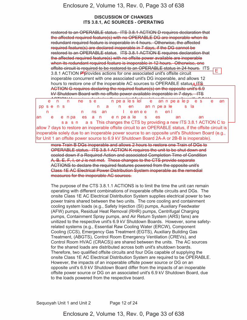
DISCUSSION OF CHANGES ITS 3.8.1, AC SOURCES - OPERATING
Sequoyah Unit 1 and Unit 2 Page 12 of 24
restored to an OPERABLE status. ITS 3.8.1 ACTION D requires declaration that the affected required feature(s) with no OPERABLE DG are inoperable when its redundant required feature is inoperable in 4 hours. Otherwise, the affected required feature(s) are declared inoperable in 7 days, if the DG cannot be restored to an OPERABLE status. ITS 3.8.1 ACTION E requires declaration that the affected required feature(s) with no offsite power available are inoperable when its redundant required feature is inoperable in 12 hours. Otherwise, one offsite circuit is required to be restored to an OPERABLE status in 24 hours. ITS 3.8.1 ACTION F provides actions for one associated unit's offsite circuit inoperable concurrent with one associated unit's DG inoperable, and allows 12 hours to restore one of the inoperable AC sources to OPERABLE status. ITS ACTION G requires declaring the required feature(s) on the opposite unit's 6.9 kV Shutdown Board with no offsite power available inoperable in 7 days. ITS ACTION H requires declaring the required feature(s) on the opposite unit's 6.9 kV Shutdown Board with no DG available inoperable in 7 days. ITS ACTION I provides actions for one offsite circuit inoperable solely due to an inoperable offsite power source to an opposite unit's 6.9 kV Shutdown Board concurrent with one opposite unit's DG inoperable, and allows 7 days to restore one of the inoperable AC sources to OPERABLE status. In addition, a Note modifying ITS ACTION I requires entry into the applicable Conditions and Required Actions of LCO 3.8.9 with no AC power source to an opposite unit's 6.9 kV Shutdown Board. ITS 3.8.1 ACTION J provides actions for one or more Train A and one or more Train B DGs inoperable and allows 2 hours to restore one Train of DGs to OPERABLE status. ITS 3.8.1 ACTION K requires the unit to be shut down and cooled down if a Required Action and associated Completion Time of Condition A, B, E, F, I, or J is not met. These changes to the CTS provide separate ACTIONS to declare the required features powered from the opposite unit's Class 1E AC Electrical Power Distribution System inoperable as the remedial measures for the inoperable AC sources.
The purpose of the CTS 3.8.1.1 ACTIONS is to limit the time the unit can remain operating with different combinations of inoperable offsite circuits and DGs. The onsite Class 1E AC Electrical Distribution System supplies electrical power to two power trains shared between the two units. The core cooling and containment cooling system loads (e.g., Safety Injection (SI) pumps, Auxiliary Feedwater (AFW) pumps, Residual Heat Removal (RHR) pumps, Centrifugal Charging pumps, Containment Spray pumps, and Air Return System (ARS) fans) are unitized to the respective unit's 6.9 kV Shutdown Boards. However, some safety-related systems (e.g., Essential Raw Cooling Water (ERCW), Component Cooling (CCS), Emergency Gas Treatment (EGTS), Auxiliary Building Gas Treatment, (ABGTS), Control Room Emergency Ventilation (CREVs), and Control Room HVAC (CRACS)) are shared between the units. The AC sources for the shared loads are distributed across both unit's shutdown boards. Therefore, two qualified offsite circuits and four DGs capable of supplying the onsite Class 1E AC Electrical Distribution System are required to be OPERABLE. However, the impacts of an inoperable offsite power source or DG on an opposite unit's 6.9 kV Shutdown Board differ from the impacts of an inoperable offsite power source or DG on an associated unit's 6.9 kV Shutdown Board, due to the loads powered from the respective board.
Enclosure 2, Volume 13, Rev. 0, Page 33 of 638
Enclosure 2, Volume 13, Rev. 0, Page 33 of 638
E
������e���n�����n�����ne����s��e����������n�pe�a�le�s�lel����e����an��n�pe�a�le�p��e��s����e����an��pp�s��e��n���s���������������n���a�����n����en�������an��n�pe�a�le�����s���la����������������������n�����������������n�����ns���an�������l���e�en�e�e����n����en�l������������������������an�����e����e���n�pa�����es���a���n������e��n�pe�a�le����s����es����������an���������an����������s�a��s��n����a�s���This changes the CTS by providing a new ITS 3.8.1 ACTION C toallow 7 days to restore an inoperable offsite circuit to an OPERABLE status, if the offsite circuit isinoperable solely due to an inoperable power source to an opposite unit's Shutdown Board (e.g.,for Unit 1 an offsite power source to 6.9 kV Shutdown Board 2A-A or 2B-B is inoperable).
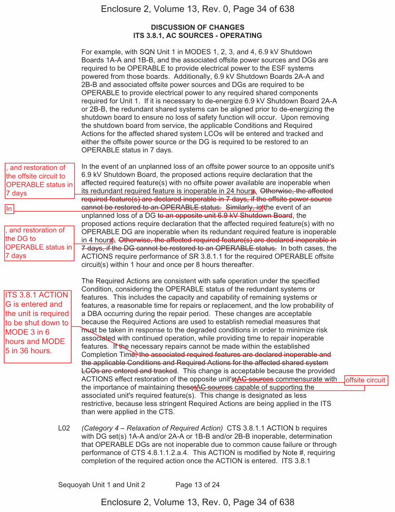
DISCUSSION OF CHANGES ITS 3.8.1, AC SOURCES - OPERATING
Sequoyah Unit 1 and Unit 2 Page 13 of 24
For example, with SQN Unit 1 in MODES 1, 2, 3, and 4, 6.9 kV Shutdown Boards 1A-A and 1B-B, and the associated offsite power sources and DGs are required to be OPERABLE to provide electrical power to the ESF systems powered from those boards. Additionally, 6.9 kV Shutdown Boards 2A-A and 2B-B and associated offsite power sources and DGs are required to be OPERABLE to provide electrical power to any required shared components required for Unit 1. If it is necessary to de-energize 6.9 kV Shutdown Board 2A-A or 2B-B, the redundant shared systems can be aligned prior to de-energizing the shutdown board to ensure no loss of safety function will occur. Upon removing the shutdown board from service, the applicable Conditions and Required Actions for the affected shared system LCOs will be entered and tracked and either the offsite power source or the DG is required to be restored to an OPERABLE status in 7 days.
In the event of an unplanned loss of an offsite power source to an opposite unit's 6.9 kV Shutdown Board, the proposed actions require declaration that the affected required feature(s) with no offsite power available are inoperable when its redundant required feature is inoperable in 24 hours. Otherwise, the affected required feature(s) are declared inoperable in 7 days, if the offsite power source cannot be restored to an OPERABLE status. Similarly, in the event of an unplanned loss of a DG to an opposite unit 6.9 kV Shutdown Board, the proposed actions require declaration that the affected required feature(s) with no OPERABLE DG are inoperable when its redundant required feature is inoperable in 4 hours. Otherwise, the affected required feature(s) are declared inoperable in 7 days, if the DG cannot be restored to an OPERABLE status. In both cases, the ACTIONS require performance of SR 3.8.1.1 for the required OPERABLE offsite circuit(s) within 1 hour and once per 8 hours thereafter.
The Required Actions are consistent with safe operation under the specified Condition, considering the OPERABLE status of the redundant systems or features. This includes the capacity and capability of remaining systems or features, a reasonable time for repairs or replacement, and the low probability of a DBA occurring during the repair period. These changes are acceptable because the Required Actions are used to establish remedial measures that must be taken in response to the degraded conditions in order to minimize risk associated with continued operation, while providing time to repair inoperable features. If the necessary repairs cannot be made within the established Completion Time, the associated required features are declared inoperable and the applicable Conditions and Required Actions for the affected shared system LCOs are entered and tracked. This change is acceptable because the provided ACTIONS effect restoration of the opposite unit's AC sources commensurate with the importance of maintaining these AC sources capable of supporting the associated unit's required feature(s). This change is designated as less restrictive, because less stringent Required Actions are being applied in the ITS than were applied in the CTS.
L02 (Category 4 – Relaxation of Required Action) CTS 3.8.1.1 ACTION b requires with DG set(s) 1A-A and/or 2A-A or 1B-B and/or 2B-B inoperable, determination that OPERABLE DGs are not inoperable due to common cause failure or through performance of CTS 4.8.1.1.2.a.4. This ACTION is modified by Note #, requiring completion of the required action once the ACTION is entered. ITS 3.8.1
Enclosure 2, Volume 13, Rev. 0, Page 34 of 638
Enclosure 2, Volume 13, Rev. 0, Page 34 of 638
ITS 3.8.1 ACTIONG is entered andthe unit is requiredto be shut down toMODE 3 in 6hours and MODE5 in 36 hours.
, and restoration of the offsite circuit to OPERABLE status in 7 days
In
, and restoration of the DG to OPERABLE status in 7 days
offsite circuit

DISCUSSION OF CHANGES ITS 3.8.1, AC SOURCES - OPERATING
Sequoyah Unit 1 and Unit 2 Page 14 of 24
ACTION B requires with an associated unit's DG inoperable (or with both DGs in a train inoperable), determination that OPERABLE DGs are not inoperable due to common cause failure or through performance of SR 3.8.1.2. However, ITS does not specify completion of the ACTIONS if the Condition is exited. This changes the CTS by removing a requirement to complete the ACTIONS once the ACTION is entered.
The purpose of CTS 3.8.1.1 ACTION b is to provide compensatory measures to be taken in response to inoperable DG set(s), including demonstration that the OPERABLE DGs are not inoperable. The Note requiring completion of the actions to verify the remaining DGs are OPERABLE once the ACTION is entered was added to the CTS with License Amendments 205 (Unit 1) and 195 (Unit 2), dated June 29, 1995 (ADAMS Accession No. ML013320017). TVA license amendment request TS 94-19, submitted on April 6, 1995, stated that the addition of this Note was being made to align with the requirements contained in NUREG-1431, LCO 3.8.1. On April 7, 1995, NUREG-1431, Rev. 1 was issued. The Note modifying LCO 3.8.1 ACTION B that required completion of Required Actions B.3.1 and B.3.2 (demonstration of DG OPERABILITY) was removed from NUREG-1431 in Revision 1. The requirement to complete the actions to demonstrate the OPERABLE DGs are not inoperable is an exception to ITS LCO 3.0.2 (CTS LCO 3.0.2). Completing the ACTIONS to verify the OPERABILITY of the remaining OPERABLE DGs is not required to restore compliance with the LCO. This change is acceptable because completion of the ACTIONS to evaluate the possibility of a DG common cause failure will be tracked as an item in the corrective action program. This change is designated as less restrictive, because less stringent Required Actions are being applied in the ITS than were applied in the CTS.
L03 (Category 4 – Relaxation of Required Action) CTS 3.8.1.1 ACTION b provides actions for one or both DGs in a train inoperable. ACTION b is modified by Note * stating that no more than one DG may be made simultaneously inoperable on a pre-planned basis for maintenance, modifications, or surveillance testing. ITS SR 3.8.1.3 verifies each DG can be started, synchronized, loaded, and operated for at least 60 minutes. SR 3.8.1.3 is modified by Note 3 stating the Surveillance shall be conducted on only one DG at a time. This changes the CTS by deleting the restriction for not making more than one DG simultaneously inoperable on a pre-planned basis, with the exception of the performance of SR 3.8.1.3.
The purpose of CTS 3.8.1.1 ACTION b is to provide required actions for one or both DGs in a train inoperable. The purpose of Note * is to ensure pre-planned activities that may result in an inoperable DG (i.e., maintenance, modifications, or surveillance testing) are not performed on both DGs in a train at the same time. The proposed required actions do not include the restriction for limiting pre-planned activities to one DG at a time. The control of pre-planned maintenance, modifications, or surveillance testing is an issue for procedures and scheduling. This change is designated as less restrictive, because less stringent Required Actions are being applied in the ITS than were applied in the CTS.
L04 (Category � – Relaxation of Co��letion �i�e) CTS 3.8.1.1 ACTION b requires, in part, with one or both DG(s) in a train inoperable to demonstrate the
Enclosure 2, Volume 13, Rev. 0, Page 35 of 638
Enclosure 2, Volume 13, Rev. 0, Page 35 of 638
thatany
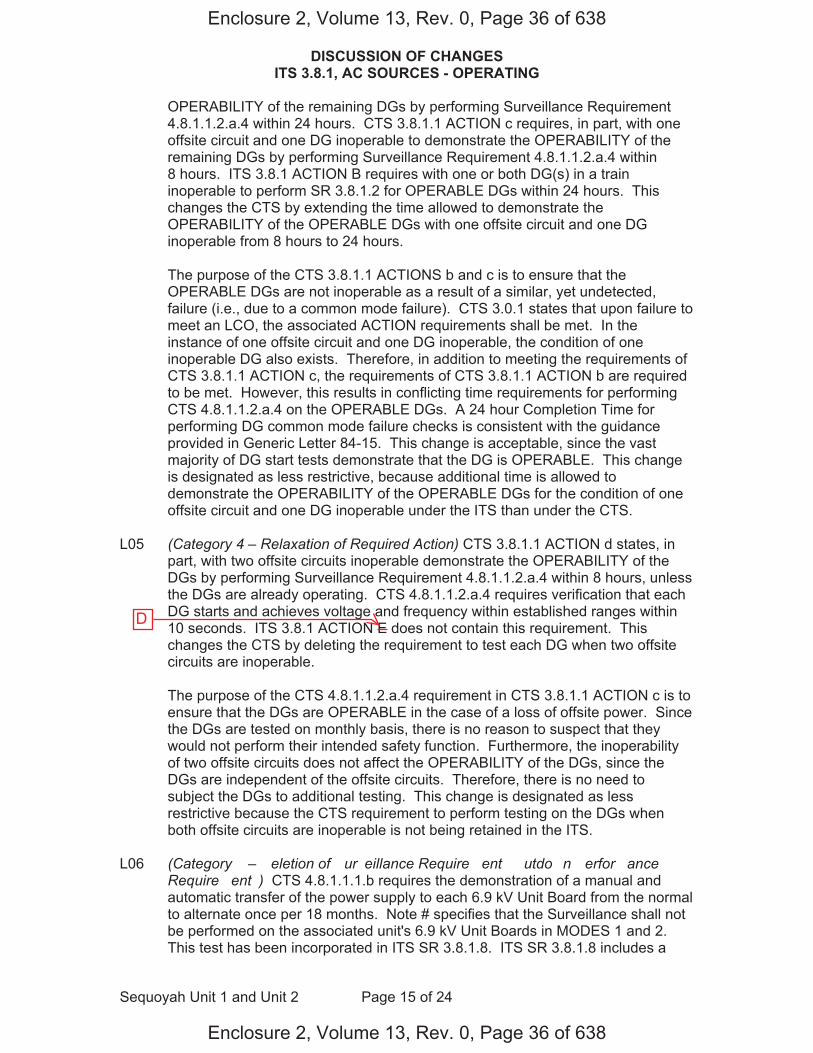
DISCUSSION OF CHANGES ITS 3.8.1, AC SOURCES - OPERATING
Sequoyah Unit 1 and Unit 2 Page 15 of 24
OPERABILITY of the remaining DGs by performing Surveillance Requirement 4.8.1.1.2.a.4 within 24 hours. CTS 3.8.1.1 ACTION c requires, in part, with one offsite circuit and one DG inoperable to demonstrate the OPERABILITY of the remaining DGs by performing Surveillance Requirement 4.8.1.1.2.a.4 within 8 hours. ITS 3.8.1 ACTION B requires with one or both DG(s) in a train inoperable to perform SR 3.8.1.2 for OPERABLE DGs within 24 hours. This changes the CTS by extending the time allowed to demonstrate the OPERABILITY of the OPERABLE DGs with one offsite circuit and one DG inoperable from 8 hours to 24 hours.
The purpose of the CTS 3.8.1.1 ACTIONS b and c is to ensure that the OPERABLE DGs are not inoperable as a result of a similar, yet undetected, failure (i.e., due to a common mode failure). CTS 3.0.1 states that upon failure to meet an LCO, the associated ACTION requirements shall be met. In the instance of one offsite circuit and one DG inoperable, the condition of one inoperable DG also exists. Therefore, in addition to meeting the requirements of CTS 3.8.1.1 ACTION c, the requirements of CTS 3.8.1.1 ACTION b are required to be met. However, this results in conflicting time requirements for performing CTS 4.8.1.1.2.a.4 on the OPERABLE DGs. A 24 hour Completion Time for performing DG common mode failure checks is consistent with the guidance provided in Generic Letter 84-15. This change is acceptable, since the vast majority of DG start tests demonstrate that the DG is OPERABLE. This change is designated as less restrictive, because additional time is allowed to demonstrate the OPERABILITY of the OPERABLE DGs for the condition of one offsite circuit and one DG inoperable under the ITS than under the CTS.
L05 (Category 4 – Relaxation of Required Action) CTS 3.8.1.1 ACTION d states, in part, with two offsite circuits inoperable demonstrate the OPERABILITY of the DGs by performing Surveillance Requirement 4.8.1.1.2.a.4 within 8 hours, unless the DGs are already operating. CTS 4.8.1.1.2.a.4 requires verification that each DG starts and achieves voltage and frequency within established ranges within 10 seconds. ITS 3.8.1 ACTION E does not contain this requirement. This changes the CTS by deleting the requirement to test each DG when two offsite circuits are inoperable.
The purpose of the CTS 4.8.1.1.2.a.4 requirement in CTS 3.8.1.1 ACTION c is to ensure that the DGs are OPERABLE in the case of a loss of offsite power. Since the DGs are tested on monthly basis, there is no reason to suspect that they would not perform their intended safety function. Furthermore, the inoperability of two offsite circuits does not affect the OPERABILITY of the DGs, since the DGs are independent of the offsite circuits. Therefore, there is no need to subject the DGs to additional testing. This change is designated as less restrictive because the CTS requirement to perform testing on the DGs when both offsite circuits are inoperable is not being retained in the ITS.
L06 (Category � – �eletion of �ur�eillance Require�ent ��utdo�n �erfor�ance Require�ent�) CTS 4.8.1.1.1.b requires the demonstration of a manual and automatic transfer of the power supply to each 6.9 kV Unit Board from the normal to alternate once per 18 months. Note # specifies that the Surveillance shall not be performed on the associated unit's 6.9 kV Unit Boards in MODES 1 and 2. This test has been incorporated in ITS SR 3.8.1.8. ITS SR 3.8.1.8 includes a
Enclosure 2, Volume 13, Rev. 0, Page 36 of 638
Enclosure 2, Volume 13, Rev. 0, Page 36 of 638
D
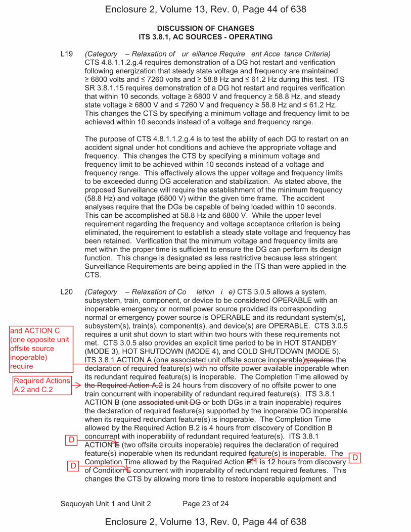
DISCUSSION OF CHANGES ITS 3.8.1, AC SOURCES - OPERATING
Sequoyah Unit 1 and Unit 2 Page 23 of 24
L19 (Category � – Relaxation of �ur�eillance Require�ent Acce�tance Criteria) CTS 4.8.1.1.2.g.4 requires demonstration of a DG hot restart and verification following energization that steady state voltage and frequency are maintained 6800 volts and 7260 volts and 58.8 Hz and 61.2 Hz during this test. ITS
SR 3.8.1.15 requires demonstration of a DG hot restart and requires verification that within 10 seconds, voltage 6800 V and frequency 58.8 Hz, and steady state voltage 6800 V and 7260 V and frequency 58.8 Hz and 61.2 Hz. This changes the CTS by specifying a minimum voltage and frequency limit to be achieved within 10 seconds instead of a voltage and frequency range.
The purpose of CTS 4.8.1.1.2.g.4 is to test the ability of each DG to restart on an accident signal under hot conditions and achieve the appropriate voltage and frequency. This changes the CTS by specifying a minimum voltage and frequency limit to be achieved within 10 seconds instead of a voltage and frequency range. This effectively allows the upper voltage and frequency limits to be exceeded during DG acceleration and stabilization. As stated above, the proposed Surveillance will require the establishment of the minimum frequency (58.8 Hz) and voltage (6800 V) within the given time frame. The accident analyses require that the DGs be capable of being loaded within 10 seconds. This can be accomplished at 58.8 Hz and 6800 V. While the upper level requirement regarding the frequency and voltage acceptance criterion is being eliminated, the requirement to establish a steady state voltage and frequency has been retained. Verification that the minimum voltage and frequency limits are met within the proper time is sufficient to ensure the DG can perform its design function. This change is designated as less restrictive because less stringent Surveillance Requirements are being applied in the ITS than were applied in the CTS.
L20 (Category � – Relaxation of Co��letion �i�e) CTS 3.0.5 allows a system, subsystem, train, component, or device to be considered OPERABLE with an inoperable emergency or normal power source provided its corresponding normal or emergency power source is OPERABLE and its redundant system(s), subsystem(s), train(s), component(s), and device(s) are OPERABLE. CTS 3.0.5 requires a unit shut down to start within two hours with these requirements not met. CTS 3.0.5 also provides an explicit time period to be in HOT STANDBY (MODE 3), HOT SHUTDOWN (MODE 4), and COLD SHUTDOWN (MODE 5). ITS 3.8.1 ACTION A (one associated unit offsite source inoperable) requires the declaration of required feature(s) with no offsite power available inoperable when its redundant required feature(s) is inoperable. The Completion Time allowed by the Required Action A.2 is 24 hours from discovery of no offsite power to one train concurrent with inoperability of redundant required feature(s). ITS 3.8.1 ACTION B (one associated unit DG or both DGs in a train inoperable) requires the declaration of required feature(s) supported by the inoperable DG inoperable when its required redundant feature(s) is inoperable. The Completion Time allowed by the Required Action B.2 is 4 hours from discovery of Condition B concurrent with inoperability of redundant required feature(s). ITS 3.8.1 ACTION E (two offsite circuits inoperable) requires the declaration of required feature(s) inoperable when its redundant required feature(s) is inoperable. The Completion Time allowed by the Required Action E.1 is 12 hours from discovery of Condition E concurrent with inoperability of redundant required features. This changes the CTS by allowing more time to restore inoperable equipment and
Enclosure 2, Volume 13, Rev. 0, Page 44 of 638
Enclosure 2, Volume 13, Rev. 0, Page 44 of 638
D
D D
and ACTION C(one opposite unitoffsite sourceinoperable)require
Required ActionsA.2 and C.2

DISCUSSION OF CHANGES ITS 3.8.1, AC SOURCES - OPERATING
Sequoyah Unit 1 and Unit 2 Page 24 of 24
replaces the explicit times to be in MODE 3, MODE 4, and MODE 5 with a requirement to declare the affected features inoperable (and thus to take the ACTIONS required by the individual system LCO, including possible shut down of the unit).
This change is acceptable because the Completion Time is consistent with safe operation under the specified Condition, considering the OPERABLE status of the redundant systems or features. This includes the capacity and capability of remaining systems or features, a reasonable time for repairs or replacement, and the low probability of a DBA occurring during the allowed Completion Time. This change allows more time to restore inoperable equipment when required AC Sources are inoperable concurrent with inoperabilities of redundant required features and deletes the explicit times to be in MODE 3, MODE 4, and MODE 5. By declaring the affected supported equipment inoperable, and as a result, taking the Technical Specifications ACTIONS of the affected supported equipment, unit operation is maintained within the bounds of the Technical Specifications and approved ACTIONS. Since the AC Sources support the OPERABILITY of the affected equipment, it is appropriate that the proper action, in this condition, would be to declare that affected supported equipment inoperable. CTS 3.0.5 is overly restrictive, in that if the associated supported equipment were inoperable for other reasons and the redundant equipment was also inoperable, a restoration time is sometimes provided, in other CTS sections. The 24 hour Completion Time when one associated unit offsite circuit is inoperable is acceptable because: a) the redundant counterpart to the inoperable required feature is still OPERABLE although single failure protection may have been lost; b) the capacity and capability of the remaining AC Sources is still available; c) areasonable time for repairs is provided for restoration before the unit is subjected to transients associated with shut down; and d) the low probability of a DBA occurring during this period. The 12 hour Completion Time when two offsite circuits are inoperable is acceptable because Regulatory Guide 1.93 allows a Completion Time of 24 hours for two offsite circuits inoperable. When a concurrent redundant required function is inoperable, a shorter Completion Time of 12 hours is appropriate. The 4 hour Completion Time with one associated unit DG inoperable takes into account the component OPERABILITY of the redundant counterpart to the inoperable required feature and is considered to be less of a risk than subjecting the unit to transients associated with shut down. Additionally, the 4 hour Completion Time takes into account the capacity and capability of the remaining AC Sources, reasonable time for repairs, and low probability of a DBA occurring during this period. This change is designated as less restrictive because additional time is allowed to restore equipment to OPERABLE status and the change deletes the explicit times to reach MODE 3, MODE 4, and MODE 5.
Enclosure 2, Volume 13, Rev. 0, Page 45 of 638
Enclosure 2, Volume 13, Rev. 0, Page 45 of 638

AC Sources - Operating 3.8.1
Westinghouse STS 3.8.1-2 Rev. 4.0
CTS
1
SEQUOYAH UNIT 1 Amendment XXX
ACTIONS (continued)
CONDITION REQUIRED ACTION COMPLETION TIME
A.3 Restore [required] offsite circuit to OPERABLE status.
72 hours
B. One [required] DG inoperable.
B.1 Perform SR 3.8.1.1 for the [required] offsite circuit(s).
AND
B.2 Declare required feature(s) supported by the inoperable DG inoperable when its required redundant feature(s) is inoperable.
AND
B.3.1 Determine OPERABLE DG(s) is not inoperable due to common cause failure.
OR
B.3.2 Perform SR 3.8.1.2 for OPERABLE DG(s).
AND
B.4 Restore [required] DG to OPERABLE status.
1 hour
AND
Once per 8 hours thereafter
4 hours from discovery of Condition B concurrent with inoperability of redundant required feature(s)
[24] hours
[24] hours
72 hours
ACTION a
ACTIONS b, c, and e
DOC L20
ACTION b
ACTION b ACTION c
ACTION b 7 days
INSERT 2
4
5
4
4
4 1
5
41A-A
INSERT 1
are1
1
(s)
Enclosure 2, Volume 13, Rev. 0, Page 48 of 638
Enclosure 2, Volume 13, Rev. 0, Page 48 of 638
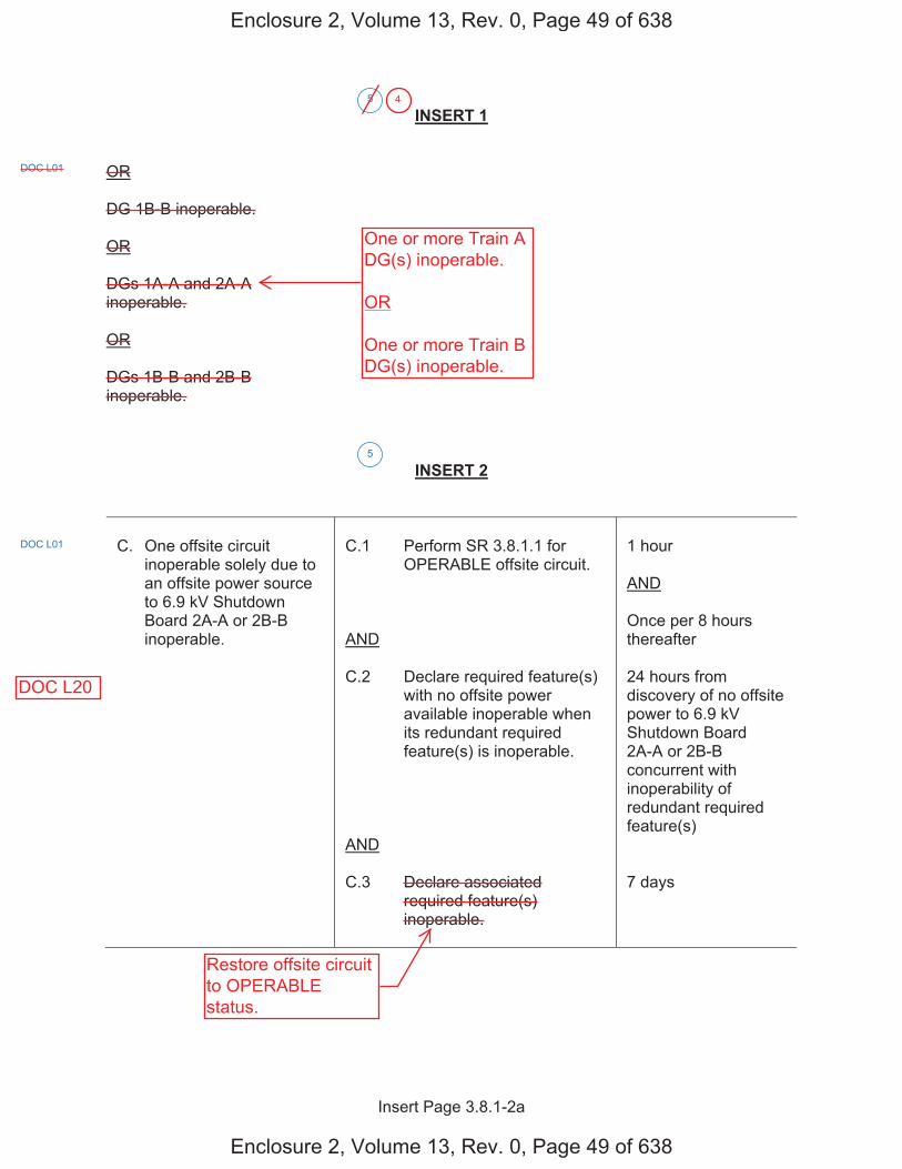
Insert Page 3.8.1-2a
INSERT 1
OR
DG 1B-B inoperable.
OR
DGs 1A-A and 2A-A inoperable.
OR
DGs 1B-B and 2B-B inoperable.
INSERT 2
C. One offsite circuit inoperable solely due to an offsite power source to 6.9 kV Shutdown Board 2A-A or 2B-B inoperable.
C.1 Perform SR 3.8.1.1 for OPERABLE offsite circuit.
AND
C.2 Declare required feature(s) with no offsite power available inoperable when its redundant required feature(s) is inoperable.
AND
C.3 Declare associated required feature(s) inoperable.
1 hour
AND
Once per 8 hours thereafter
24 hours from discovery of no offsite power to 6.9 kV Shutdown Board 2A-A or 2B-B concurrent with inoperability of redundant required feature(s)
7 days
5
DOC L01
5
DOC L01
Enclosure 2, Volume 13, Rev. 0, Page 49 of 638
Enclosure 2, Volume 13, Rev. 0, Page 49 of 638
One or more Train ADG(s) inoperable.
OR
One or more Train BDG(s) inoperable.
Restore offsite circuitto OPERABLEstatus.
DOC L20
4

Insert Page 3.8.1-2b
INSERT 2 (Continued)
D. DG 2A-A or 2B-B inoperable.
D.1 Perform SR 3.8.1.1 for OPERABLE offsite circuit(s).
AND
D.2 Declare required feature(s) supported by the inoperable DG inoperable when its redundant required feature(s) is inoperable.
AND
D.3.1 Determine OPERABLE DGs are not inoperable due to common cause failure.
OR
D.3.2 Perform SR 3.8.1.2 for OPERABLE DGs.
AND
D.4 Declare associated required feature(s) inoperable.
1 hour
AND
Once per 8 hours thereafter
4 hours from discovery of Condition D concurrent with inoperability of redundant required feature(s)
24 hours
24 hours
7 days
5
Enclosure 2, Volume 13, Rev. 0, Page 50 of 638
Enclosure 2, Volume 13, Rev. 0, Page 50 of 638
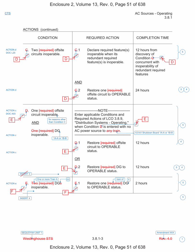
AC Sources - Operating 3.8.1
Westinghouse STS 3.8.1-3 Rev. 4.0
CTS
1
SEQUOYAH UNIT 1 Amendment XXX
ACTIONS (continued)
CONDITION REQUIRED ACTION COMPLETION TIME
C. Two [required] offsite circuits inoperable.
C.1 Declare required feature(s) inoperable when its redundant required feature(s) is inoperable.
AND
C.2 Restore one [required] offsite circuit to OPERABLE status.
12 hours from discovery of Condition C concurrent with inoperability of redundant required features
24 hours
D. One [required] offsite circuit inoperable.
AND
One [required] DG inoperable.
--------------------NOTE------------------- Enter applicable Conditions and Required Actions of LCO 3.8.9, "Distribution Systems - Operating," when Condition D is entered with no AC power source to any train. ------------------------------------------------
D.1 Restore [required] offsite circuit to OPERABLE status.
OR
D.2 Restore [required] DG to OPERABLE status.
12 hours
12 hours
E. Two [required] DGs inoperable.
E.1 Restore one [required] DG to OPERABLE status.
2 hours
ACTION d
ACTION d
ACTION c DOC A03
ACTION c
ACTION c
ACTION e
5
5
5
5
5
E
F
J
F
F
J
E
F
6.9 kV Shutdown Board 1A-A or 1B-B
E
E
4
DOC L20
for reasons other than Condition C
1A-A or 1B-B
INSERT 3
One or more Train A (s)
INSERT 4
5
4
4
train of s
Enclosure 2, Volume 13, Rev. 0, Page 51 of 638
Enclosure 2, Volume 13, Rev. 0, Page 51 of 638
D D
D
D
E
E
E
E
F F

Insert Page 3.8.1-3a
INSERT 3
G. One offsite circuit inoperable solely due to an offsite power source to 6.9 kV Shutdown Board 2A-A or 2B-B inoperable.
AND
DG 1A-A or 1B-B inoperable.
G.1 Declare required feature(s) on associated Unit 2 6.9 kV Shutdown Board inoperable.
7 days
H. One offsite circuit inoperable for reasons other than Condition C.
AND
DG 2A-A or 2B-B inoperable.
H.1 Declare required feature(s) on associated Unit 2 6.9 kV Shutdown Board inoperable.
7 days
5
DOC L01
DOC L01
Enclosure 2, Volume 13, Rev. 0, Page 52 of 638
Enclosure 2, Volume 13, Rev. 0, Page 52 of 638

Insert Page 3.8.1-3b
INSERT 3 (continued)
I. One offsite circuit inoperable solely due to an offsite power source to 6.9 kV Shutdown Board 2A-A or 2B-B inoperable.
AND
DG 2A-A or 2B-B inoperable.
--------------------NOTE------------------- Enter applicable Conditions and Required Actions of LCO 3.8.9, "Distribution Systems - Operating," when Condition I is entered with no AC power source to 6.9 kV Shutdown Board 2A-A or 2B-B. ------------------------------------------------
I.1 Restore offsite circuit to OPERABLE status.
OR
I.2 Restore DG to OPERABLE status.
7 days
7 days
INSERT 4
AND
One or more Train B DG(s) inoperable.
5
DOC L01
ACTION e
5
Enclosure 2, Volume 13, Rev. 0, Page 53 of 638
Enclosure 2, Volume 13, Rev. 0, Page 53 of 638

AC Sources - Operating 3.8.1
Westinghouse STS 3.8.1-4 Rev. 4.0
CTS
1
SEQUOYAH UNIT 1 Amendment XXX
ACTIONS (continued)
CONDITION REQUIRED ACTION COMPLETION TIME
-----REVIEWER’S NOTE----- This Condition may be deleted if the unit design is such that any sequencer failure mode will only affect the ability of the associated DG to power its respective safety loads following a loss of offsite power independent of, or coincident with, a Design Basis Event. --------------------------------------
F. [ One [required] [automatic load sequencer] inoperable.
F.1 Restore [required] [automatic load sequencer] to OPERABLE status.
[12] hours ]
G. Required Action and associated Completion Time of Condition A, B, C, D, E, or [F] not met.
G.1 Be in MODE 3.
AND
G.2 Be in MODE 5.
6 hours
36 hours
H. Three or more [required] AC sources inoperable.
H.1 Enter LCO 3.0.3. Immediately
SURVEILLANCE REQUIREMENTS
SURVEILLANCE FREQUENCY
SR 3.8.1.1 Verify correct breaker alignment and indicated power availability for each [required] offsite circuit.
[ 7 days
OR
In accordance with the Surveillance Frequency Control Program ]
3
ACTIONS a, b, c, d, e
4.8.1.1 4.8.1.1.1.a
3 5
5
4 6
K
F, I, J
K
K
6
INSERT 5
Enclosure 2, Volume 13, Rev. 0, Page 54 of 638
Enclosure 2, Volume 13, Rev. 0, Page 54 of 638
A, B, C, D, E,or F
G
G
G DOC M01

Insert Page 3.8.1-4
INSERT 5
L. Two offsite circuits inoperable.
AND
One or more Train A DG(s) inoperable.
OR
One or more Train B DG(s) inoperable.
L.1 Enter LCO 3.0.3. Immediately
M. One offsite circuit inoperable.
AND
One or more Train A DG(s) inoperable.
AND
One or more Train B DG(s) inoperable.
M.1 Enter LCO 3.0.3. Immediately
5
DOC A04
DOC A04
Enclosure 2, Volume 13, Rev. 0, Page 55 of 638
Enclosure 2, Volume 13, Rev. 0, Page 55 of 638
H H
I I
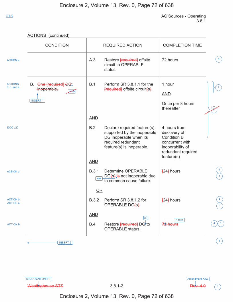
AC Sources - Operating 3.8.1
Westinghouse STS 3.8.1-2 Rev. 4.0
CTS
1
SEQUOYAH UNIT 2 Amendment XXX
ACTIONS (continued)
CONDITION REQUIRED ACTION COMPLETION TIME
A.3 Restore [required] offsite circuit to OPERABLE status.
72 hours
B. One [required] DG inoperable.
B.1 Perform SR 3.8.1.1 for the [required] offsite circuit(s).
AND
B.2 Declare required feature(s) supported by the inoperable DG inoperable when its required redundant feature(s) is inoperable.
AND
B.3.1 Determine OPERABLE DG(s) is not inoperable due to common cause failure.
OR
B.3.2 Perform SR 3.8.1.2 for OPERABLE DG(s).
AND
B.4 Restore [required] DG to OPERABLE status.
1 hour
AND
Once per 8 hours thereafter
4 hours from discovery of Condition B concurrent with inoperability of redundant required feature(s)
[24] hours
[24] hours
72 hours
ACTION a
ACTIONS b, c, and e
DOC L20
ACTION b
ACTION b ACTION c
ACTION b 7 days
INSERT 2
4
5
4
4
4 1
5
42A-A
INSERT 1
are1
1
(s)
Enclosure 2, Volume 13, Rev. 0, Page 72 of 638
Enclosure 2, Volume 13, Rev. 0, Page 72 of 638
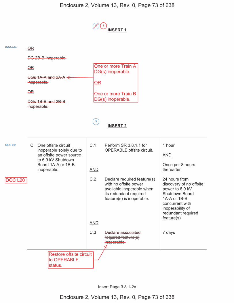
Insert Page 3.8.1-2a
INSERT 1
OR
DG 2B-B inoperable.
OR
DGs 1A-A and 2A-A inoperable.
OR
DGs 1B-B and 2B-B inoperable.
INSERT 2
C. One offsite circuit inoperable solely due to an offsite power source to 6.9 kV Shutdown Board 1A-A or 1B-B inoperable.
C.1 Perform SR 3.8.1.1 for OPERABLE offsite circuit.
AND
C.2 Declare required feature(s) with no offsite power available inoperable when its redundant required feature(s) is inoperable.
AND
C.3 Declare associated required feature(s) inoperable.
1 hour
AND
Once per 8 hours thereafter
24 hours from discovery of no offsite power to 6.9 kV Shutdown Board 1A-A or 1B-B concurrent with inoperability of redundant required feature(s)
7 days
5
DOC L01
5
DOC L01
Enclosure 2, Volume 13, Rev. 0, Page 73 of 638
Enclosure 2, Volume 13, Rev. 0, Page 73 of 638
One or more Train ADG(s) inoperable.
OR
One or more Train BDG(s) inoperable.
Restore offsite circuitto OPERABLEstatus.
DOC L20
4

Insert Page 3.8.1-2b
INSERT 2 (Continued)
D. DG 1A-A or 1B-B inoperable.
D.1 Perform SR 3.8.1.1 for OPERABLE offsite circuit(s).
AND
D.2 Declare required feature(s) supported by the inoperable DG inoperable when its redundant required feature(s) is inoperable.
AND
D.3.1 Determine OPERABLE DGs are not inoperable due to common cause failure.
OR
D.3.2 Perform SR 3.8.1.2 for OPERABLE DGs.
AND
D.4 Declare associated required feature(s) inoperable.
1 hour
AND
Once per 8 hours thereafter
4 hours from discovery of Condition D concurrent with inoperability of redundant required feature(s)
24 hours
24 hours
7 days
5
Enclosure 2, Volume 13, Rev. 0, Page 74 of 638
Enclosure 2, Volume 13, Rev. 0, Page 74 of 638
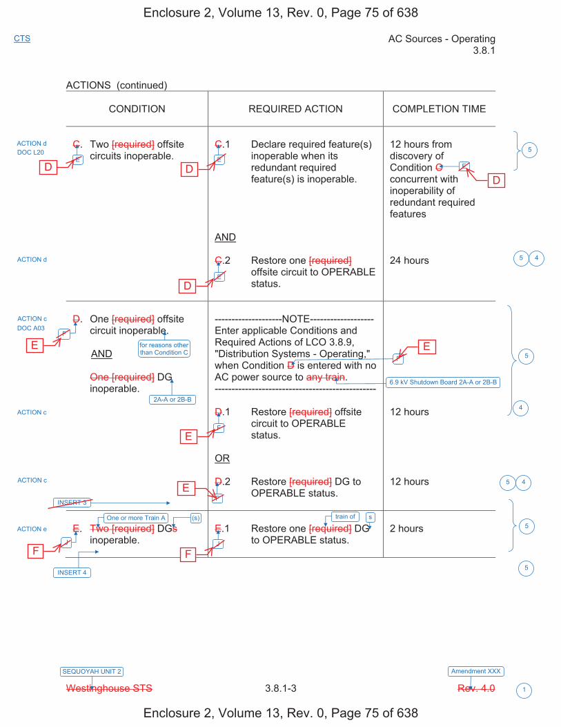
AC Sources - Operating 3.8.1
Westinghouse STS 3.8.1-3 Rev. 4.0
CTS
1
SEQUOYAH UNIT 2 Amendment XXX
ACTIONS (continued)
CONDITION REQUIRED ACTION COMPLETION TIME
C. Two [required] offsite circuits inoperable.
C.1 Declare required feature(s) inoperable when its redundant required feature(s) is inoperable.
AND
C.2 Restore one [required] offsite circuit to OPERABLE status.
12 hours from discovery of Condition C concurrent with inoperability of redundant required features
24 hours
D. One [required] offsite circuit inoperable.
AND
One [required] DG inoperable.
--------------------NOTE------------------- Enter applicable Conditions and Required Actions of LCO 3.8.9, "Distribution Systems - Operating," when Condition D is entered with no AC power source to any train. ------------------------------------------------
D.1 Restore [required] offsite circuit to OPERABLE status.
OR
D.2 Restore [required] DG to OPERABLE status.
12 hours
12 hours
E. Two [required] DGs inoperable.
E.1 Restore one [required] DG to OPERABLE status.
2 hours
ACTION d
ACTION d
ACTION c DOC A03
ACTION c
ACTION c
ACTION e
5
5
E
F
J
F
F
J
E
F
E
E
4
DOC L20
for reasons other than Condition C
2A-A or 2B-B
INSERT 3
One or more Train A (s)
INSERT 4
5
5
5
6.9 kV Shutdown Board 2A-A or 2B-B
5
4
4
train of s
Enclosure 2, Volume 13, Rev. 0, Page 75 of 638
Enclosure 2, Volume 13, Rev. 0, Page 75 of 638
D D
D
D
E
E
E
E
F F

Insert Page 3.8.1-3a
INSERT 3
G. One offsite circuit inoperable solely due to an offsite power source to 6.9 kV Shutdown Board 1A-A or 1B-B inoperable.
AND
DG 2A-A or 2B-B inoperable.
G.1 Declare required feature(s) on associated Unit 1 6.9 kV Shutdown Board inoperable.
7 days
H. One offsite circuit inoperable for reasons other than Condition C.
AND
DG 1A-A or 1B-B inoperable.
H.1 Declare required feature(s) on associated Unit 1 6.9 kV Shutdown Board inoperable.
7 days
5
DOC L01
DOC L01
Enclosure 2, Volume 13, Rev. 0, Page 76 of 638
Enclosure 2, Volume 13, Rev. 0, Page 76 of 638
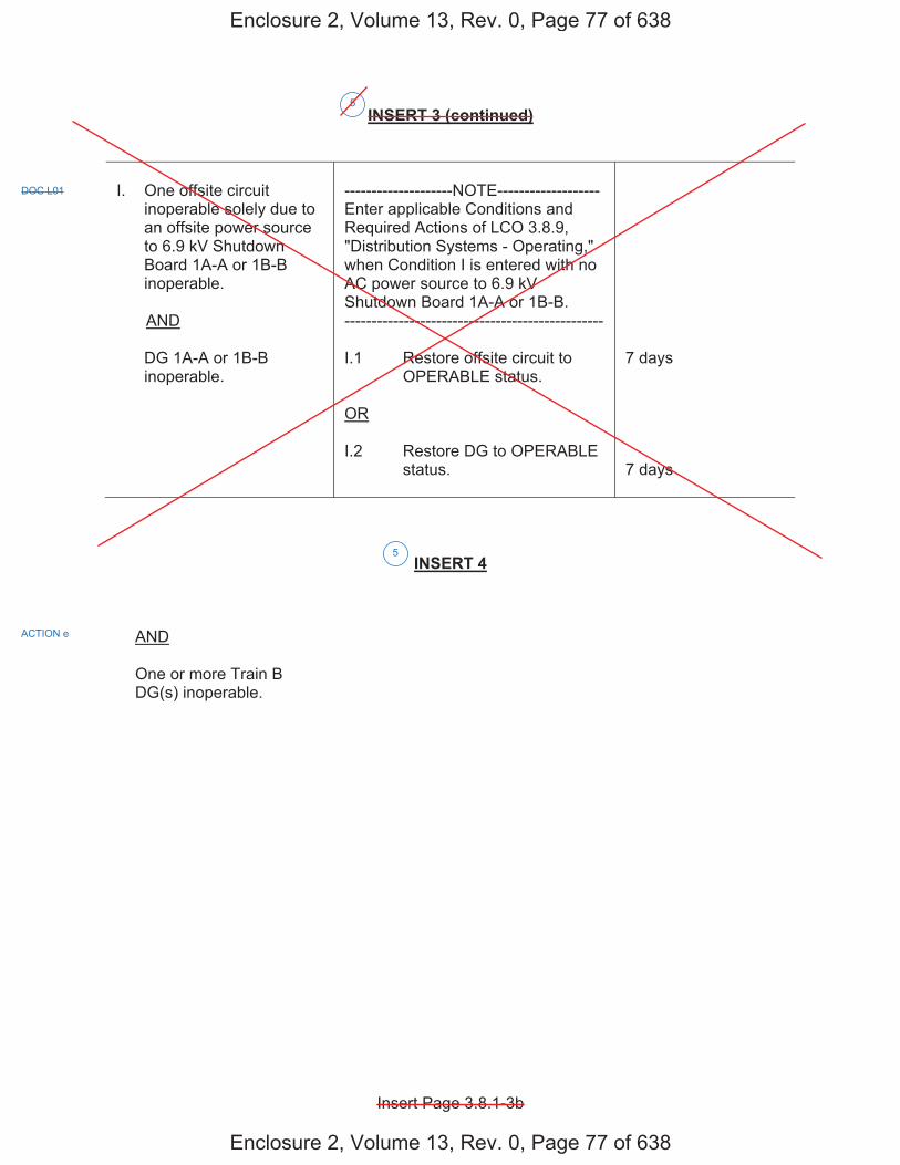
Insert Page 3.8.1-3b
INSERT 3 (continued)
I. One offsite circuit inoperable solely due to an offsite power source to 6.9 kV Shutdown Board 1A-A or 1B-B inoperable.
AND
DG 1A-A or 1B-B inoperable.
--------------------NOTE------------------- Enter applicable Conditions and Required Actions of LCO 3.8.9, "Distribution Systems - Operating," when Condition I is entered with no AC power source to 6.9 kV Shutdown Board 1A-A or 1B-B. ------------------------------------------------
I.1 Restore offsite circuit to OPERABLE status.
OR
I.2 Restore DG to OPERABLE status.
7 days
7 days
INSERT 4
AND
One or more Train B DG(s) inoperable.
5
DOC L01
ACTION e
5
Enclosure 2, Volume 13, Rev. 0, Page 77 of 638
Enclosure 2, Volume 13, Rev. 0, Page 77 of 638
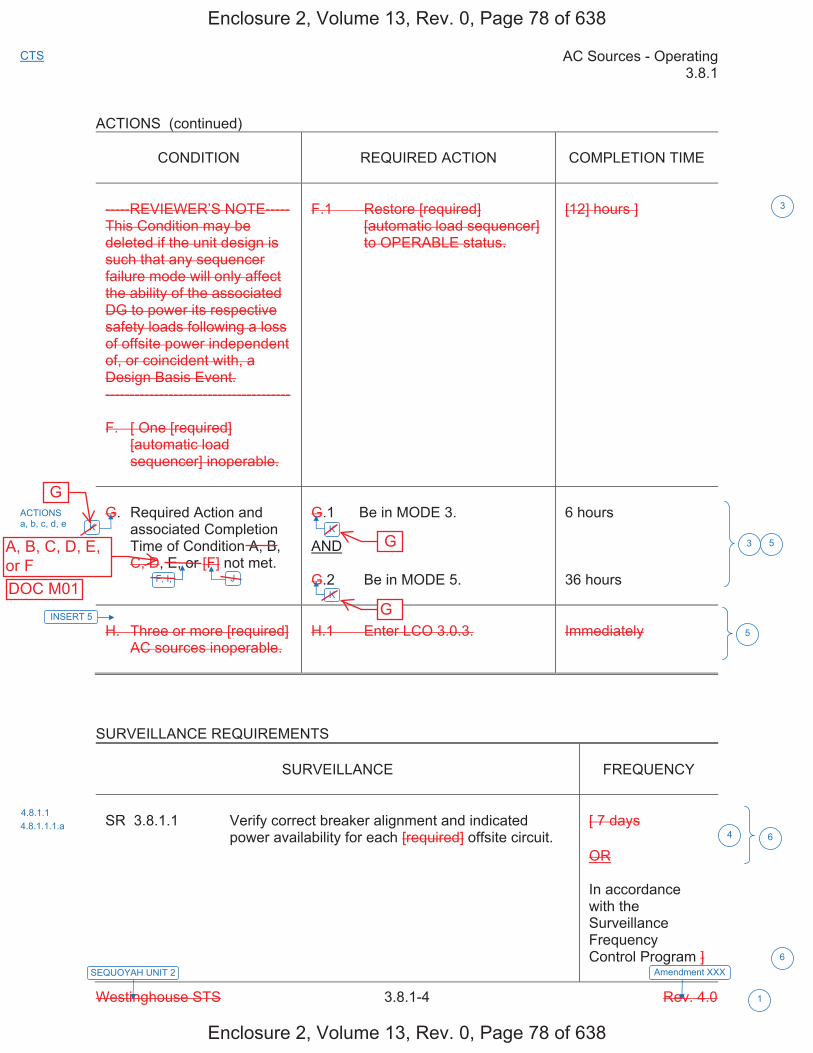
AC Sources - Operating 3.8.1
Westinghouse STS 3.8.1-4 Rev. 4.0
CTS
1
SEQUOYAH UNIT 2 Amendment XXX
ACTIONS (continued)
CONDITION REQUIRED ACTION COMPLETION TIME
-----REVIEWER’S NOTE----- This Condition may be deleted if the unit design is such that any sequencer failure mode will only affect the ability of the associated DG to power its respective safety loads following a loss of offsite power independent of, or coincident with, a Design Basis Event. --------------------------------------
F. [ One [required] [automatic load sequencer] inoperable.
F.1 Restore [required] [automatic load sequencer] to OPERABLE status.
[12] hours ]
G. Required Action and associated Completion Time of Condition A, B, C, D, E, or [F] not met.
G.1 Be in MODE 3.
AND
G.2 Be in MODE 5.
6 hours
36 hours
H. Three or more [required] AC sources inoperable.
H.1 Enter LCO 3.0.3. Immediately
SURVEILLANCE REQUIREMENTS
SURVEILLANCE FREQUENCY
SR 3.8.1.1 Verify correct breaker alignment and indicated power availability for each [required] offsite circuit.
[ 7 days
OR
In accordance with the Surveillance Frequency Control Program ]
3
ACTIONS a, b, c, d, e
4.8.1.1 4.8.1.1.1.a
3 5
4 6
K
J
K
K
6
F, I,
INSERT 5
5
Enclosure 2, Volume 13, Rev. 0, Page 78 of 638
Enclosure 2, Volume 13, Rev. 0, Page 78 of 638
G
A, B, C, D, E,or F
G
GDOC M01

Insert Page 3.8.1-4
INSERT 5
L. Two offsite circuits inoperable.
AND
One or more Train A DG(s) inoperable.
OR
One or more Train B DG(s) inoperable.
L.1 Enter LCO 3.0.3. Immediately
M. One offsite circuit inoperable.
AND
One or more Train A DG(s) inoperable.
AND
One or more Train B DG(s) inoperable.
M.1 Enter LCO 3.0.3. Immediately
5
DOC A04
DOC A04
Enclosure 2, Volume 13, Rev. 0, Page 79 of 638
Enclosure 2, Volume 13, Rev. 0, Page 79 of 638
H H
I I
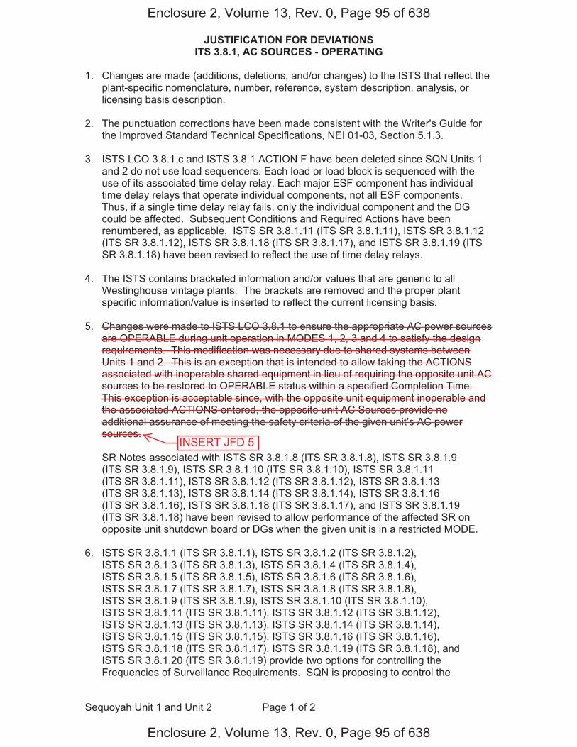
JUSTIFICATION FOR DEVIATIONS ITS 3.8.1, AC SOURCES - OPERATING
Sequoyah Unit 1 and Unit 2 Page 1 of 2
1. Changes are made (additions, deletions, and/or changes) to the ISTS that reflect theplant-specific nomenclature, number, reference, system description, analysis, orlicensing basis description.
2. The punctuation corrections have been made consistent with the Writer's Guide forthe Improved Standard Technical Specifications, NEI 01-03, Section 5.1.3.
3. ISTS LCO 3.8.1.c and ISTS 3.8.1 ACTION F have been deleted since SQN Units 1and 2 do not use load sequencers. Each load or load block is sequenced with theuse of its associated time delay relay. Each major ESF component has individualtime delay relays that operate individual components, not all ESF components.Thus, if a single time delay relay fails, only the individual component and the DGcould be affected. Subsequent Conditions and Required Actions have beenrenumbered, as applicable. ISTS SR 3.8.1.11 (ITS SR 3.8.1.11), ISTS SR 3.8.1.12(ITS SR 3.8.1.12), ISTS SR 3.8.1.18 (ITS SR 3.8.1.17), and ISTS SR 3.8.1.19 (ITSSR 3.8.1.18) have been revised to reflect the use of time delay relays.
4. The ISTS contains bracketed information and/or values that are generic to allWestinghouse vintage plants. The brackets are removed and the proper plantspecific information/value is inserted to reflect the current licensing basis.
5. Changes were made to ISTS LCO 3.8.1 to ensure the appropriate AC power sourcesare OPERABLE during unit operation in MODES 1, 2, 3 and 4 to satisfy the designrequirements. This modification was necessary due to shared systems betweenUnits 1 and 2. This is an exception that is intended to allow taking the ACTIONSassociated with inoperable shared equipment in lieu of requiring the opposite unit ACsources to be restored to OPERABLE status within a specified Completion Time.This exception is acceptable since, with the opposite unit equipment inoperable andthe associated ACTIONS entered, the opposite unit AC Sources provide noadditional assurance of meeting the safety criteria of the given unit’s AC powersources.
SR Notes associated with ISTS SR 3.8.1.8 (ITS SR 3.8.1.8), ISTS SR 3.8.1.9(ITS SR 3.8.1.9), ISTS SR 3.8.1.10 (ITS SR 3.8.1.10), ISTS SR 3.8.1.11(ITS SR 3.8.1.11), ISTS SR 3.8.1.12 (ITS SR 3.8.1.12), ISTS SR 3.8.1.13(ITS SR 3.8.1.13), ISTS SR 3.8.1.14 (ITS SR 3.8.1.14), ISTS SR 3.8.1.16(ITS SR 3.8.1.16), ISTS SR 3.8.1.18 (ITS SR 3.8.1.17), and ISTS SR 3.8.1.19(ITS SR 3.8.1.18) have been revised to allow performance of the affected SR onopposite unit shutdown board or DGs when the given unit is in a restricted MODE.
6. ISTS SR 3.8.1.1 (ITS SR 3.8.1.1), ISTS SR 3.8.1.2 (ITS SR 3.8.1.2),ISTS SR 3.8.1.3 (ITS SR 3.8.1.3), ISTS SR 3.8.1.4 (ITS SR 3.8.1.4),ISTS SR 3.8.1.5 (ITS SR 3.8.1.5), ISTS SR 3.8.1.6 (ITS SR 3.8.1.6),ISTS SR 3.8.1.7 (ITS SR 3.8.1.7), ISTS SR 3.8.1.8 (ITS SR 3.8.1.8),ISTS SR 3.8.1.9 (ITS SR 3.8.1.9), ISTS SR 3.8.1.10 (ITS SR 3.8.1.10),ISTS SR 3.8.1.11 (ITS SR 3.8.1.11), ISTS SR 3.8.1.12 (ITS SR 3.8.1.12),ISTS SR 3.8.1.13 (ITS SR 3.8.1.13), ISTS SR 3.8.1.14 (ITS SR 3.8.1.14),ISTS SR 3.8.1.15 (ITS SR 3.8.1.15), ISTS SR 3.8.1.16 (ITS SR 3.8.1.16),ISTS SR 3.8.1.18 (ITS SR 3.8.1.17), ISTS SR 3.8.1.19 (ITS SR 3.8.1.18), andISTS SR 3.8.1.20 (ITS SR 3.8.1.19) provide two options for controlling theFrequencies of Surveillance Requirements. SQN is proposing to control the
Enclosure 2, Volume 13, Rev. 0, Page 95 of 638
Enclosure 2, Volume 13, Rev. 0, Page 95 of 638
INSERT JFD 5
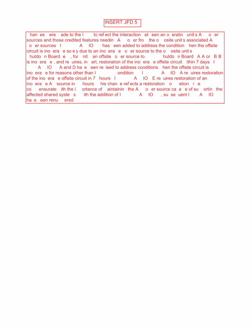
INSERT JFD 5
�han�es �ere �ade to the I��� to ref�ect the interaction �et�een an o�eratin� unit�s A� �o�er sources and those credited features needin� A� �o�er fro� the o��osite unit�s associated A� �o�er sources� I�� ����� A��IO� � has �een added to address the condition �hen the offsite circuit is ino�era��e so�e�y due to an ino�era��e �o�er source to the o��osite unit�s ��� �� �hutdo�n Board �e���, for �nit � an offsite �o�er source to ��� �� �hutdo�n Board �A�A or �B�B is ino�era��e�, and re�uires, in �art, restoration of the ino�era��e offsite circuit �ithin 7 days� I��� ����� A��IO�� A and D ha�e �een re�ised to address conditions �hen the offsite circuit is ino�era��e for reasons other than I�� ����� �ondition �� I�� ����� A��IO� A re�uires restoration of the ino�era��e offsite circuit in 7� hours� I�� ����� A��IO� E re�uires restoration of an ino�era��e A� source in �� hours� �his chan�e ref�ects a restoration �o���etion �i�e co��ensurate �ith the i��ortance of �aintainin� the A� �o�er source ca�a��e of su��ortin� the affected shared syste�s� � ith the addition of I�� ����� A��IO� �, su�se�uent I��� A��IO�� ha�e �een renu��ered�

AC Sources - Operating B 3.8.1
Westinghouse STS B 3.8.1-4 Rev. 4.0
SEQUOYAH UNIT 1
1
Revision XXX
BASES
APPLICABILITY The AC sources [and sequencers] are required to be OPERABLE in MODES 1, 2, 3, and 4 to ensure that:
a. Acceptable fuel design limits and reactor coolant pressure boundarylimits are not exceeded as a result of AOOs or abnormal transientsand
b. Adequate core cooling is provided and containment OPERABILITYand other vital functions are maintained in the event of a postulatedDBA.
The AC power requirements for MODES 5 and 6 are covered in LCO 3.8.2, "AC Sources - Shutdown."
ACTIONS A Note prohibits the application of LCO 3.0.4.b to an inoperable DG. There is an increased risk associated with entering a MODE or other specified condition in the Applicability with an inoperable DG and the provisions of LCO 3.0.4.b, which allow entry into a MODE or other specified condition in the Applicability with the LCO not met after performance of a risk assessment addressing inoperable systems and components, should not be applied in this circumstance.
A.1
To ensure a highly reliable power source remains with one offsite circuit inoperable, it is necessary to verify the OPERABILITY of the remaining required offsite circuit on a more frequent basis. Since the Required Action only specifies "perform," a failure of SR 3.8.1.1 acceptance criteria does not result in a Required Action not met. However, if a second required circuit fails SR 3.8.1.1, the second offsite circuit is inoperable, and Condition C, for two offsite circuits inoperable, is entered.
-----------------------------------REVIEWER’S NOTE-----------------------------------The turbine driven auxiliary feedwater pump is only required to be considered a redundant required feature, and, therefore, required to be determined OPERABLE by this Required Action, if the design is such that the remaining OPERABLE motor or turbine driven auxiliary feedwater pump(s) is not by itself capable (without any reliance on the motor driven auxiliary feedwater pump powered by the emergency bus associated with the inoperable diesel generator) of providing 100% of the auxiliary feedwater flow assumed in the safety analysis. --------------------------------------------------------------------------------------------------
E
2
5
5
6
for reasons other than Condition C
Enclosure 2, Volume 13, Rev. 0, Page 107 of 638
Enclosure 2, Volume 13, Rev. 0, Page 107 of 638
D

AC Sources - Operating B 3.8.1
Westinghouse STS B 3.8.1-6 Rev. 4.0
SEQUOYAH UNIT 1
1
Revision XXX
BASES
ACTIONS (continued)
A.3
According to Regulatory Guide 1.93 (Ref. 6), operation may continue in Condition A for a period that should not exceed 72 hours. With one offsite circuit inoperable, the reliability of the offsite system is degraded, and the potential for a loss of offsite power is increased, with attendant potential for a challenge to the unit safety systems. In this Condition, however, the remaining OPERABLE offsite circuit and DGs are adequate to supply electrical power to the onsite Class 1E Distribution System.
The 72 hour Completion Time takes into account the capacity and capability of the remaining AC sources, a reasonable time for repairs, and the low probability of a DBA occurring during this period.
B.1
To ensure a highly reliable power source remains with an inoperable DG, it is necessary to verify the availability of the offsite circuits on a more frequent basis. Since the Required Action only specifies "perform," a failure of SR 3.8.1.1 acceptance criteria does not result in a Required Action being not met. However, if a circuit fails to pass SR 3.8.1.1, it is inoperable. Upon offsite circuit inoperability, additional Conditions and Required Actions must then be entered.
-----------------------------------REVIEWER’S NOTE----------------------------------- The turbine driven auxiliary feedwater pump is only required to be considered a redundant required feature, and, therefore, required to be determined OPERABLE by this Required Action, if the design is such that the remaining OPERABLE motor or turbine driven auxiliary feedwater pump(s) is not by itself capable (without any reliance on the motor driven auxiliary feedwater pump powered by the emergency bus associated with the inoperable diesel generator) of providing 100% of the auxiliary feedwater flow assumed in the safety analysis. --------------------------------------------------------------------------------------------------
B.2
Required Action B.2 is intended to provide assurance that a loss of offsite power, during the period that a DG is inoperable, does not result in a complete loss of safety function of critical systems. These features are designed with redundant safety related trains. This includes motor driven auxiliary feedwater pumps. Single train systems, such as turbine driven auxiliary feedwater pumps, are not included. Redundant required feature failures consist of inoperable features associated with a train, redundant to the train that has an inoperable DG.
INSERT 9
5
6
AC Electrical Power
1
(s) 5
(s)5
Enclosure 2, Volume 13, Rev. 0, Page 109 of 638
Enclosure 2, Volume 13, Rev. 0, Page 109 of 638

B 3.8.1
Insert Page B 3.8.1-6
INSERT 9
DG 1A-A, DG 1B-B, DGs 1A-A and 2A-A, or DGs 1B-B and 2B-B
5
Enclosure 2, Volume 13, Rev. 0, Page 110 of 638
Enclosure 2, Volume 13, Rev. 0, Page 110 of 638
one or more Train A DGs, or one or more Train B DGs
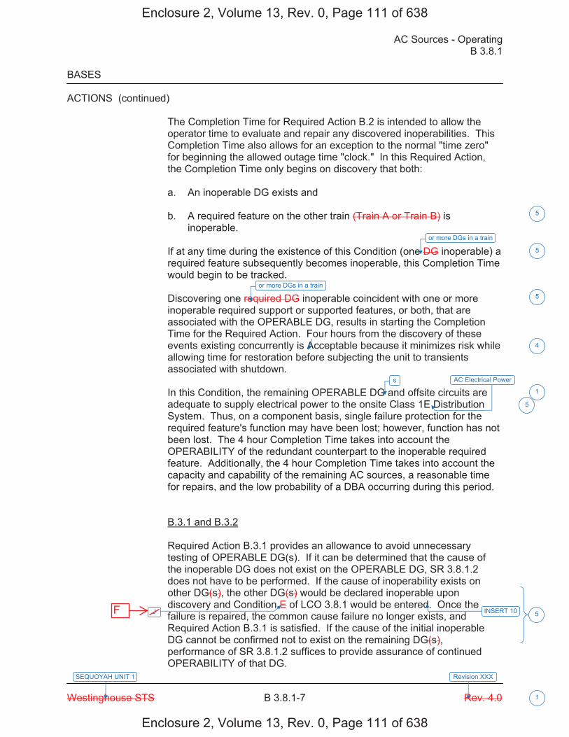
AC Sources - Operating B 3.8.1
Westinghouse STS B 3.8.1-7 Rev. 4.0
SEQUOYAH UNIT 1
1
Revision XXX
BASES
ACTIONS (continued)
The Completion Time for Required Action B.2 is intended to allow the operator time to evaluate and repair any discovered inoperabilities. This Completion Time also allows for an exception to the normal "time zero" for beginning the allowed outage time "clock." In this Required Action, the Completion Time only begins on discovery that both:
a. An inoperable DG exists and
b. A required feature on the other train (Train A or Train B) isinoperable.
If at any time during the existence of this Condition (one DG inoperable) a required feature subsequently becomes inoperable, this Completion Time would begin to be tracked.
Discovering one required DG inoperable coincident with one or more inoperable required support or supported features, or both, that are associated with the OPERABLE DG, results in starting the Completion Time for the Required Action. Four hours from the discovery of these events existing concurrently is Acceptable because it minimizes risk while allowing time for restoration before subjecting the unit to transients associated with shutdown.
In this Condition, the remaining OPERABLE DG and offsite circuits are adequate to supply electrical power to the onsite Class 1E Distribution System. Thus, on a component basis, single failure protection for the required feature's function may have been lost; however, function has not been lost. The 4 hour Completion Time takes into account the OPERABILITY of the redundant counterpart to the inoperable required feature. Additionally, the 4 hour Completion Time takes into account the capacity and capability of the remaining AC sources, a reasonable time for repairs, and the low probability of a DBA occurring during this period.
B.3.1 and B.3.2
Required Action B.3.1 provides an allowance to avoid unnecessary testing of OPERABLE DG(s). If it can be determined that the cause of the inoperable DG does not exist on the OPERABLE DG, SR 3.8.1.2 does not have to be performed. If the cause of inoperability exists on other DG(s), the other DG(s) would be declared inoperable upon discovery and Condition E of LCO 3.8.1 would be entered. Once the failure is repaired, the common cause failure no longer exists, and Required Action B.3.1 is satisfied. If the cause of the initial inoperable DG cannot be confirmed not to exist on the remaining DG(s), performance of SR 3.8.1.2 suffices to provide assurance of continued OPERABILITY of that DG.
s
J INSERT 10
4
1
5
5
or more DGs in a train
5
or more DGs in a train
5
AC Electrical Power
5
Enclosure 2, Volume 13, Rev. 0, Page 111 of 638
Enclosure 2, Volume 13, Rev. 0, Page 111 of 638
F

B 3.8.1
Insert Page B 3.8.1-7
INSERT 10
if one or more DG(s) in Train A and Train B are inoperable
5
Enclosure 2, Volume 13, Rev. 0, Page 112 of 638
Enclosure 2, Volume 13, Rev. 0, Page 112 of 638

AC Sources - Operating B 3.8.1
Westinghouse STS B 3.8.1-8 Rev. 4.0
SEQUOYAH UNIT 1
1
Revision XXX
BASES
ACTIONS (continued)
In the event the inoperable DG is restored to OPERABLE status prior to completing either B.3.1 or B.3.2, the [plant corrective action program] will continue to evaluate the common cause possibility. This continued evaluation, however, is no longer under the 24 hour constraint imposed while in Condition B.
According to Generic Letter 84-15 (Ref. 7), [24] hours is reasonable to confirm that the OPERABLE DG(s) is not affected by the same problem as the inoperable DG.
B.4
According to Regulatory Guide 1.93 (Ref. 6), operation may continue in Condition B for a period that should not exceed 72 hours.
In Condition B, the remaining OPERABLE DG and offsite circuits are adequate to supply electrical power to the onsite Class 1E Distribution System. The 72 hour Completion Time takes into account the capacity and capability of the remaining AC sources, a reasonable time for repairs, and the low probability of a DBA occurring during this period.
C.1 and C.2
Required Action C.1, which applies when two offsite circuits are inoperable, is intended to provide assurance that an event with a coincident single failure will not result in a complete loss of redundant required safety functions. The Completion Time for this failure of redundant required features is reduced to 12 hours from that allowed for one train without offsite power (Required Action A.2). The rationale for the reduction to 12 hours is that Regulatory Guide 1.93 (Ref. 6) allows a Completion Time of 24 hours for two required offsite circuits inoperable, based upon the assumption that two complete safety trains are OPERABLE. When a concurrent redundant required feature failure exists, this assumption is not the case, and a shorter Completion Time of 12 hours is appropriate. These features are powered from redundant AC safety trains. This includes motor driven auxiliary feedwater pumps. Single train features, such as turbine driven auxiliary pumps, are not included in the list.
7 day
INSERT 11
E E E
2
2
5
5
5
(s)
5
(s) AC Electrical Power
Enclosure 2, Volume 13, Rev. 0, Page 113 of 638
Enclosure 2, Volume 13, Rev. 0, Page 113 of 638
D
D D
B 3.8.1
Insert Page B 3.8.1-8a
INSERT 11
C.1, C.2, and C.3
Condition C is entered for an offsite circuit inoperable solely due to an inoperable power source to 6.9 kV Shutdown Board 2A-A or 2B-B. Required Action C.1 verifies the OPERABILITY of the remaining offsite circuit within an hour of the inoperability and every 8 hours thereafter. Since the Required Action only specifies "perform," a failure of the SR 3.8.1.1 acceptance criteria does not result in a Required Action not met.
The Completion Time for Required Action C.2 is intended to allow the operator time to evaluate and repair any discovered inoperabilities. This Completion Time also allows for an exception to the normal "time zero" for beginning the allowed outage time "clock." In this Required Action, the Completion Time only begins on discovery that both:
a. 6.9 kV Shutdown Board 2A-A or 2B-B has no offsite power; andb. A required feature on the other train is inoperable.
If at any time during the existence of Condition C a redundant required feature subsequently becomes inoperable, this Completion Time begins to be tracked.
A Completion Time of 24 hours is acceptable, because it minimizes risk while allowing time for restoration before subjecting the unit to transients associated with shutdown. The remaining OPERABLE offsite circuit and DGs are adequate to support these functions. The Completion Time takes into account the component OPERABILITY of the remaining redundant feature(s), a reasonable time for repairs, and the low probability of a DBA occurring during this period.
Operation may continue in Condition C for a period of 7 days. With one offsite circuit inoperable, the reliability of the functions is degraded. The potential for the loss of offsite power to the redundant feature(s) is increased, with the attendant potential for a challenge to their safety functions.
The required offsite circuit must be returned to OPERABLE status within 7 days, or the support function for the associated required feature is considered inoperable. At that time, the required feature must be declared inoperable and the appropriate Conditions must be entered. The 7 days Completion Time takes into account the capacity and capability of the remaining AC sources providing electrical power to the required feature(s), a reasonable time for repairs and the low probability of a DBA occurring during this period of time.
5
Enclosure 2, Volume 13, Rev. 0, Page 114 of 638
Enclosure 2, Volume 13, Rev. 0, Page 114 of 638

B 3.8.1
Insert Page B 3.8.1-8b
INSERT 11 (Continued)
D.1, D.2, D.3 and D.4
To ensure a highly reliable power source remains with an inoperable DG to a Unit 2 6.9 kV Shutdown Board, it is necessary to verify the availability of the required offsite circuits on a more frequent basis. Since the Required Action only specifies "perform," a failure of SR 3.8.1.1 acceptance criteria does not result in a Required Action being not met. Required Action D.1 verifies the OPERABILITY of the required offsite sources within an hour of the inoperability and every 8 hours thereafter. However, if a circuit fails to pass SR 3.8.1.1, it is inoperable. Upon offsite circuit inoperability, additional Conditions and Required Actions must be entered.
Required Action D.2 is intended to provide assurance that a loss of offsite power, during the period that an LCO 3.8.1.d DG is inoperable, does not result in a complete loss of the safety functions.
The Completion Time for Required Action D.2 is intended to allow the operator time to evaluate and repair any discovered inoperabilities. This Completion Time also allows for an exception to the normal "time zero" for beginning the allowed outage time "clock." In this Required Action, the Completion Time only begins on discovery that both:
a. An inoperable DG to 6.9 kV Shutdown Board 2A-A or 2B-B exists; andb. A redundant feature in the same system is inoperable.
If at any time during the existence of Condition D (one DG to 6.9 kV Shutdown Board 2A-A or 2B-B) a redundant feature in the same system subsequently becomes inoperable, this Completion Time begins to be tracked. The four hour Completion Time is acceptable, because it minimizes risk while allowing time for restoration before subjecting the unit to transients associated with shutdown.
The remaining OPERABLE offsite circuits and DGs are adequate to support the functions. The 4 hour Completion Time takes into account the component OPERABILITY of the remaining redundant feature(s), a reasonable time for repairs, and the low probability of a DBA occurring during this period.
D.3.1 and D.3.2
Required Action D.3.1 provides an allowance to avoid unnecessary testing of OPERABLE DG(s). If it can be determined that the cause of the inoperable DG does not exist on the OPERABLE DG(s), SR 3.8.1.2 does not have to be performed. If the cause of inoperability exists on another DG, the other DG would be declared inoperable, and upon discovery, Condition J of LCO 3.8.1 would be entered, if one or more DG(s) in Train A and Train B are inoperable. Otherwise, if the inoperability exists on the other DG in the same train, the other DG would be declared inoperable upon discovery, Condition B would be entered. Once the failure is repaired, the common cause failure no longer exists, and Required Action D.3.1 is satisfied. If the cause of the initial inoperable DG cannot be confirmed not to exist on the remaining DGs, performance of SR 3.8.1.2 suffices to provide assurance of continued OPERABILITY of that DG.
5
Enclosure 2, Volume 13, Rev. 0, Page 115 of 638
Enclosure 2, Volume 13, Rev. 0, Page 115 of 638
B 3.8.1
Insert Page B 3.8.1-8c
INSERT 11 (Continued)
Operation may continue in Condition D for a period of 7 days. With one Unit 2 DG inoperable, the reliability of the respective function is degraded. The potential for the loss of a DG to the redundant feature(s) is increased, with the attendant potential for a challenge to respective safety function.
The required DG must be returned to OPERABLE status within 7 days, or the support function for the associated required feature is considered inoperable. At that time, the required feature must be declared inoperable and the appropriate Conditions must be entered. The 7 day Completion Time takes into account the capacity and capability of the remaining AC sources providing electrical power to the required feature(s), a reasonable time for repairs and the low probability of a DBA occurring during this period of time.
5
Enclosure 2, Volume 13, Rev. 0, Page 116 of 638
Enclosure 2, Volume 13, Rev. 0, Page 116 of 638

AC Sources - Operating B 3.8.1
Westinghouse STS B 3.8.1-9 Rev. 4.0
SEQUOYAH UNIT 1
1
Revision XXX
BASES
ACTIONS (continued)
The Completion Time for Required Action C.1 is intended to allow the operator time to evaluate and repair any discovered inoperabilities. This Completion Time also allows for an exception to the normal "time zero" for beginning the allowed outage time "clock." In this Required Action the Completion Time only begins on discovery that both:
a. All required offsite circuits are inoperable and
b. A required feature is inoperable.
If at any time during the existence of Condition C (two offsite circuits inoperable) a required feature becomes inoperable, this Completion Time begins to be tracked.
According to Regulatory Guide 1.93 (Ref. 6), operation may continue in Condition C for a period that should not exceed 24 hours. This level of degradation means that the offsite electrical power system does not have the capability to effect a safe shutdown and to mitigate the effects of an accident; however, the onsite AC sources have not been degraded. This level of degradation generally corresponds to a total loss of the immediately accessible offsite power sources.
Because of the normally high availability of the offsite sources, this level of degradation may appear to be more severe than other combinations of two AC sources inoperable that involve one or more DGs inoperable. However, two factors tend to decrease the severity of this level of degradation:
a. The configuration of the redundant AC electrical power system thatremains available is not susceptible to a single bus or switchingfailure and
b. The time required to detect and restore an unavailable offsite powersource is generally much less than that required to detect and restorean unavailable onsite AC source.
With both of the required offsite circuits inoperable, sufficient onsite AC sources are available to maintain the unit in a safe shutdown condition in the event of a DBA or transient. In fact, a simultaneous loss of offsite AC sources, a LOCA, and a worst case single failure were postulated as a part of the design basis in the safety analysis. Thus, the 24 hour Completion Time provides a period of time to effect restoration of one of the offsite circuits commensurate with the importance of maintaining an AC electrical power system capable of meeting its design criteria.
E
E
E
5
5
5
5
Enclosure 2, Volume 13, Rev. 0, Page 117 of 638
Enclosure 2, Volume 13, Rev. 0, Page 117 of 638
D
D
D
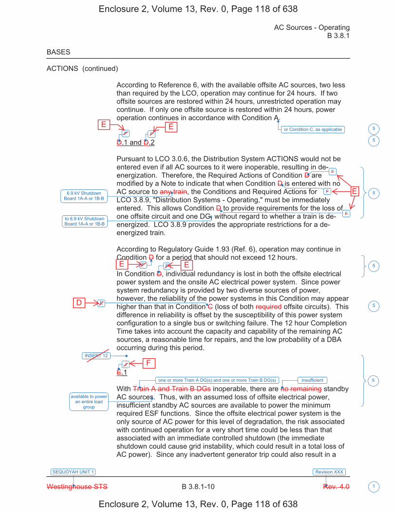
AC Sources - Operating B 3.8.1
Westinghouse STS B 3.8.1-10 Rev. 4.0
SEQUOYAH UNIT 1
1
Revision XXX
BASES
ACTIONS (continued)
According to Reference 6, with the available offsite AC sources, two less than required by the LCO, operation may continue for 24 hours. If two offsite sources are restored within 24 hours, unrestricted operation may continue. If only one offsite source is restored within 24 hours, power operation continues in accordance with Condition A.
D.1 and D.2
Pursuant to LCO 3.0.6, the Distribution System ACTIONS would not be entered even if all AC sources to it were inoperable, resulting in de-energization. Therefore, the Required Actions of Condition D are modified by a Note to indicate that when Condition D is entered with no AC source to any train, the Conditions and Required Actions for LCO 3.8.9, "Distribution Systems - Operating," must be immediately entered. This allows Condition D to provide requirements for the loss of one offsite circuit and one DG, without regard to whether a train is de-energized. LCO 3.8.9 provides the appropriate restrictions for a de-energized train.
According to Regulatory Guide 1.93 (Ref. 6), operation may continue in Condition D for a period that should not exceed 12 hours.
In Condition D, individual redundancy is lost in both the offsite electrical power system and the onsite AC electrical power system. Since power system redundancy is provided by two diverse sources of power, however, the reliability of the power systems in this Condition may appear higher than that in Condition C (loss of both required offsite circuits). This difference in reliability is offset by the susceptibility of this power system configuration to a single bus or switching failure. The 12 hour Completion Time takes into account the capacity and capability of the remaining AC sources, a reasonable time for repairs, and the low probability of a DBA occurring during this period.
E.1
With Train A and Train B DGs inoperable, there are no remaining standby AC sources. Thus, with an assumed loss of offsite electrical power, insufficient standby AC sources are available to power the minimum required ESF functions. Since the offsite electrical power system is the only source of AC power for this level of degradation, the risk associated with continued operation for a very short time could be less than that associated with an immediate controlled shutdown (the immediate shutdown could cause grid instability, which could result in a total loss of AC power). Since any inadvertent generator trip could also result in a
or Condition C, as applicableF F
F
F
F
6.9 kV Shutdown Board 1A-A or 1B-B
F F
E
J
one or more Train A DG(s) and one or more Train B DG(s)
available to power an entire load
group
5
5
5
5
5
5
INSERT 12
insufficient
to 6.9 kV Shutdown Board 1A-A or 1B-B
Enclosure 2, Volume 13, Rev. 0, Page 118 of 638
Enclosure 2, Volume 13, Rev. 0, Page 118 of 638
E E
E E
D
F
E
B 3.8.1
Insert Page B 3.8.1-10
INSERT 12
G.1 and H.1
In Conditions G and H, individual redundancy is lost in the offsite electrical power system for one unit and the onsite AC electrical power system for the other unit. Since Conditions B and C are entered concurrent with entry into Condition G, and Conditions A and D are entered concurrent with entry into Condition H, the Required Actions of Conditions B and C (or Conditions A and D) provide the appropriate compensatory measures to ensure the onsite and offsite power sources are either restored to an OPERABLE status, or the associated required features are declared inoperable, thereby requiring entry into the appropriate Conditions associated with the associated feature's LCO. The Completion Times of Required Actions G.1 and H.1 are consistent with the Completion Times of Required Actions C.3 and D.4. If, while in Condition G or H, a redundant required feature is determined to be inoperable, the required feature(s) would be declared inoperable at the Completion Times specified in Conditions A, B, C, or D, as applicable.
I.1 and I.2
Pursuant to LCO 3.0.6, the Distribution System ACTIONS would not be entered even if all AC sources to it were inoperable, resulting in de-energization. Therefore, the Required Actions of Condition I are modified by a Note to indicate that when Condition I is entered with no AC source to 6.9 kV Shutdown Board 2A-A or 2B-B, the Conditions and Required Actions for LCO 3.8.9, "Distribution Systems - Operating," must be immediately entered. This allows Condition I to provide requirements for the loss of one offsite power source and one DG, without regard to whether a train is de-energized. LCO 3.8.9 provides the appropriate restrictions for a de-energized 6.9 kV Shutdown Board.
In Condition I, individual redundancy is lost in the offsite electrical power system and the onsite AC electrical power system. Concurrent with entry into Condition I, entry into Condition C (inoperable offsite power source) and Condition D (inoperable DG) are required. The Required Actions of Conditions C and D ensure the remaining offsite circuit and DGs are OPERABLE and that required features with no offsite or onsite power sources are declared inoperable when its redundant required feature is inoperable within the Completion Times of Required Actions C.2 and D.2.
5
Enclosure 2, Volume 13, Rev. 0, Page 119 of 638
Enclosure 2, Volume 13, Rev. 0, Page 119 of 638
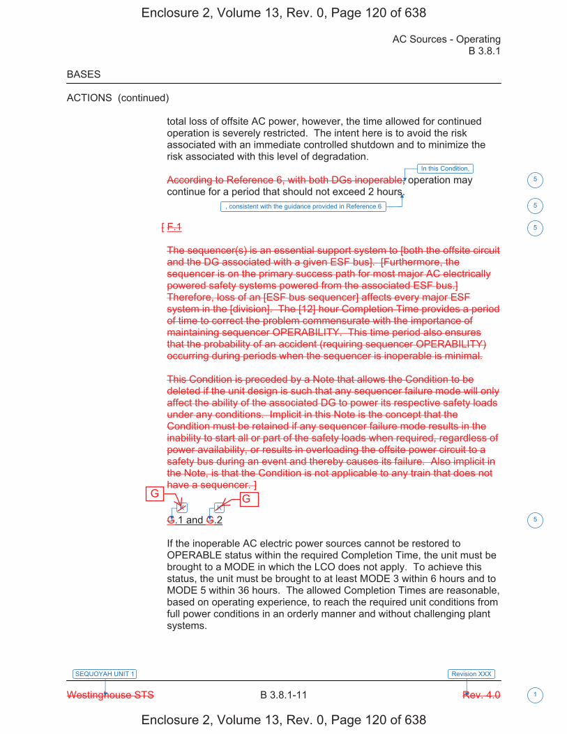
AC Sources - Operating B 3.8.1
Westinghouse STS B 3.8.1-11 Rev. 4.0
SEQUOYAH UNIT 1
1
Revision XXX
BASES
ACTIONS (continued)
total loss of offsite AC power, however, the time allowed for continued operation is severely restricted. The intent here is to avoid the risk associated with an immediate controlled shutdown and to minimize the risk associated with this level of degradation.
According to Reference 6, with both DGs inoperable, operation may continue for a period that should not exceed 2 hours.
[ F.1
The sequencer(s) is an essential support system to [both the offsite circuit and the DG associated with a given ESF bus]. [Furthermore, the sequencer is on the primary success path for most major AC electrically powered safety systems powered from the associated ESF bus.] Therefore, loss of an [ESF bus sequencer] affects every major ESF system in the [division]. The [12] hour Completion Time provides a period of time to correct the problem commensurate with the importance of maintaining sequencer OPERABILITY. This time period also ensures that the probability of an accident (requiring sequencer OPERABILITY) occurring during periods when the sequencer is inoperable is minimal.
This Condition is preceded by a Note that allows the Condition to be deleted if the unit design is such that any sequencer failure mode will only affect the ability of the associated DG to power its respective safety loads under any conditions. Implicit in this Note is the concept that the Condition must be retained if any sequencer failure mode results in the inability to start all or part of the safety loads when required, regardless of power availability, or results in overloading the offsite power circuit to a safety bus during an event and thereby causes its failure. Also implicit in the Note, is that the Condition is not applicable to any train that does not have a sequencer. ]
G.1 and G.2
If the inoperable AC electric power sources cannot be restored to OPERABLE status within the required Completion Time, the unit must be brought to a MODE in which the LCO does not apply. To achieve this status, the unit must be brought to at least MODE 3 within 6 hours and to MODE 5 within 36 hours. The allowed Completion Times are reasonable, based on operating experience, to reach the required unit conditions from full power conditions in an orderly manner and without challenging plant systems.
In this Condition,
K K
5
5
5
5
, consistent with the guidance provided in Reference 6
Enclosure 2, Volume 13, Rev. 0, Page 120 of 638
Enclosure 2, Volume 13, Rev. 0, Page 120 of 638
G G

AC Sources - Operating B 3.8.1
Westinghouse STS B 3.8.1-12 Rev. 4.0
SEQUOYAH UNIT 1
1
Revision XXX
BASES
ACTIONS (continued)
H.1
Condition H corresponds to a level of degradation in which all redundancy in the AC electrical power supplies has been lost. At this severely degraded level, any further losses in the AC electrical power system will cause a loss of function. Therefore, no additional time is justified for continued operation. The unit is required by LCO 3.0.3 to commence a controlled shutdown.
SURVEILLANCE The AC sources are designed to permit inspection and testing of all REQUIREMENTS important areas and features, especially those that have a standby
function, in accordance with 10 CFR 50, Appendix A, GDC 18 (Ref. 8). Periodic component tests are supplemented by extensive functional tests during refueling outages (under simulated accident conditions). The SRs for demonstrating the OPERABILITY of the DGs are in accordance with the recommendations of Regulatory Guide 1.9 (Ref. 3), Regulatory Guide 1.108 (Ref. 9), and Regulatory Guide 1.137 (Ref. 10), as addressed in the FSAR.
Where the SRs discussed herein specify voltage and frequency tolerances, the following is applicable. The minimum steady state output voltage of [3740] V is 90% of the nominal 4160 V output voltage. This value, which is specified in ANSI C84.1 (Ref. 11), allows for voltage drop to the terminals of 4000 V motors whose minimum operating voltage is specified as 90% or 3600 V. It also allows for voltage drops to motors and other equipment down through the 120 V level where minimum operating voltage is also usually specified as 90% of name plate rating. The specified maximum steady state output voltage of [4756] V is equal to the maximum operating voltage specified for 4000 V motors. It ensures that for a lightly loaded distribution system, the voltage at the terminals of 4000 V motors is no more than the maximum rated operating voltages. The specified minimum and maximum frequencies of the DG are 58.8 Hz and 61.2 Hz, respectively. These values are equal to ± 2% of the 60 Hz nominal frequency and are derived from the recommendations given in Regulatory Guide 1.9 (Ref. 3).
SR 3.8.1.1
This SR ensures proper circuit continuity for the offsite AC electrical power supply to the onsite distribution network and availability of offsite AC electrical power. The breaker alignment verifies that each breaker is in its correct position to ensure that distribution buses and loads are connected to their preferred power source, and that appropriate independence of offsite circuits is maintained. [ The 7 day Frequency is
L.1 and M.1
L and M
and
6900
6600
5940
7260
6600
6600
5
1
2
1
2
1
1
7
6210
10 1
1
s
cannot be assured
Enclosure 2, Volume 13, Rev. 0, Page 121 of 638
Enclosure 2, Volume 13, Rev. 0, Page 121 of 638
H and I
I H

AC Sources - Operating B 3.8.1
Westinghouse STS B 3.8.1-4 Rev. 4.0
SEQUOYAH UNIT 2
1
Revision XXX
BASES
APPLICABILITY The AC sources [and sequencers] are required to be OPERABLE in MODES 1, 2, 3, and 4 to ensure that:
a. Acceptable fuel design limits and reactor coolant pressure boundarylimits are not exceeded as a result of AOOs or abnormal transientsand
b. Adequate core cooling is provided and containment OPERABILITYand other vital functions are maintained in the event of a postulatedDBA.
The AC power requirements for MODES 5 and 6 are covered in LCO 3.8.2, "AC Sources - Shutdown."
ACTIONS A Note prohibits the application of LCO 3.0.4.b to an inoperable DG. There is an increased risk associated with entering a MODE or other specified condition in the Applicability with an inoperable DG and the provisions of LCO 3.0.4.b, which allow entry into a MODE or other specified condition in the Applicability with the LCO not met after performance of a risk assessment addressing inoperable systems and components, should not be applied in this circumstance.
A.1
To ensure a highly reliable power source remains with one offsite circuit inoperable, it is necessary to verify the OPERABILITY of the remaining required offsite circuit on a more frequent basis. Since the Required Action only specifies "perform," a failure of SR 3.8.1.1 acceptance criteria does not result in a Required Action not met. However, if a second required circuit fails SR 3.8.1.1, the second offsite circuit is inoperable, and Condition C, for two offsite circuits inoperable, is entered.
-----------------------------------REVIEWER’S NOTE-----------------------------------The turbine driven auxiliary feedwater pump is only required to be considered a redundant required feature, and, therefore, required to be determined OPERABLE by this Required Action, if the design is such that the remaining OPERABLE motor or turbine driven auxiliary feedwater pump(s) is not by itself capable (without any reliance on the motor driven auxiliary feedwater pump powered by the emergency bus associated with the inoperable diesel generator) of providing 100% of the auxiliary feedwater flow assumed in the safety analysis. --------------------------------------------------------------------------------------------------
E
2
5
5
6
for reasons other than Condition C
Enclosure 2, Volume 13, Rev. 0, Page 157 of 638
Enclosure 2, Volume 13, Rev. 0, Page 157 of 638
D

AC Sources - Operating B 3.8.1
Westinghouse STS B 3.8.1-6 Rev. 4.0
SEQUOYAH UNIT 2
1
Revision XXX
BASES
ACTIONS (continued)
A.3
According to Regulatory Guide 1.93 (Ref. 6), operation may continue in Condition A for a period that should not exceed 72 hours. With one offsite circuit inoperable, the reliability of the offsite system is degraded, and the potential for a loss of offsite power is increased, with attendant potential for a challenge to the unit safety systems. In this Condition, however, the remaining OPERABLE offsite circuit and DGs are adequate to supply electrical power to the onsite Class 1E Distribution System.
The 72 hour Completion Time takes into account the capacity and capability of the remaining AC sources, a reasonable time for repairs, and the low probability of a DBA occurring during this period.
B.1
To ensure a highly reliable power source remains with an inoperable DG, it is necessary to verify the availability of the offsite circuits on a more frequent basis. Since the Required Action only specifies "perform," a failure of SR 3.8.1.1 acceptance criteria does not result in a Required Action being not met. However, if a circuit fails to pass SR 3.8.1.1, it is inoperable. Upon offsite circuit inoperability, additional Conditions and Required Actions must then be entered.
-----------------------------------REVIEWER’S NOTE----------------------------------- The turbine driven auxiliary feedwater pump is only required to be considered a redundant required feature, and, therefore, required to be determined OPERABLE by this Required Action, if the design is such that the remaining OPERABLE motor or turbine driven auxiliary feedwater pump(s) is not by itself capable (without any reliance on the motor driven auxiliary feedwater pump powered by the emergency bus associated with the inoperable diesel generator) of providing 100% of the auxiliary feedwater flow assumed in the safety analysis. --------------------------------------------------------------------------------------------------
B.2
Required Action B.2 is intended to provide assurance that a loss of offsite power, during the period that a DG is inoperable, does not result in a complete loss of safety function of critical systems. These features are designed with redundant safety related trains. This includes motor driven auxiliary feedwater pumps. Single train systems, such as turbine driven auxiliary feedwater pumps, are not included. Redundant required feature failures consist of inoperable features associated with a train, redundant to the train that has an inoperable DG.
5
6
AC Electrical Power1
INSERT 9
(s) 5
(s) 5
Enclosure 2, Volume 13, Rev. 0, Page 159 of 638
Enclosure 2, Volume 13, Rev. 0, Page 159 of 638
B 3.8.1
Insert Page B 3.8.1-6
INSERT 9
DG 1A-A, DG 1B-B, DGs 1A-A and 2A-A, or DGs 1B-B and 2B-B
5
Enclosure 2, Volume 13, Rev. 0, Page 160 of 638
Enclosure 2, Volume 13, Rev. 0, Page 160 of 638
one or more Train A DGs, or one or more Train B DGs
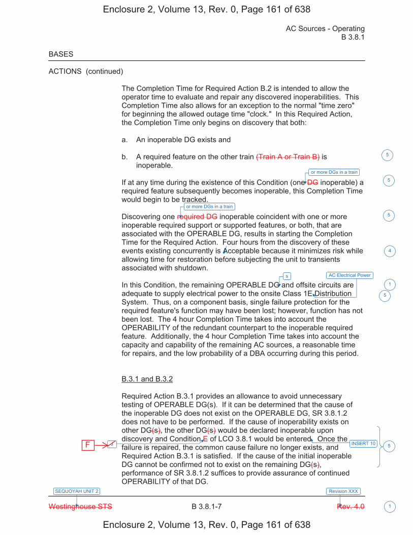
AC Sources - Operating B 3.8.1
Westinghouse STS B 3.8.1-7 Rev. 4.0
SEQUOYAH UNIT 2
1
Revision XXX
BASES
ACTIONS (continued)
The Completion Time for Required Action B.2 is intended to allow the operator time to evaluate and repair any discovered inoperabilities. This Completion Time also allows for an exception to the normal "time zero" for beginning the allowed outage time "clock." In this Required Action, the Completion Time only begins on discovery that both:
a. An inoperable DG exists and
b. A required feature on the other train (Train A or Train B) isinoperable.
If at any time during the existence of this Condition (one DG inoperable) a required feature subsequently becomes inoperable, this Completion Time would begin to be tracked.
Discovering one required DG inoperable coincident with one or more inoperable required support or supported features, or both, that are associated with the OPERABLE DG, results in starting the Completion Time for the Required Action. Four hours from the discovery of these events existing concurrently is Acceptable because it minimizes risk while allowing time for restoration before subjecting the unit to transients associated with shutdown.
In this Condition, the remaining OPERABLE DG and offsite circuits are adequate to supply electrical power to the onsite Class 1E Distribution System. Thus, on a component basis, single failure protection for the required feature's function may have been lost; however, function has not been lost. The 4 hour Completion Time takes into account the OPERABILITY of the redundant counterpart to the inoperable required feature. Additionally, the 4 hour Completion Time takes into account the capacity and capability of the remaining AC sources, a reasonable time for repairs, and the low probability of a DBA occurring during this period.
B.3.1 and B.3.2
Required Action B.3.1 provides an allowance to avoid unnecessary testing of OPERABLE DG(s). If it can be determined that the cause of the inoperable DG does not exist on the OPERABLE DG, SR 3.8.1.2 does not have to be performed. If the cause of inoperability exists on other DG(s), the other DG(s) would be declared inoperable upon discovery and Condition E of LCO 3.8.1 would be entered. Once the failure is repaired, the common cause failure no longer exists, and Required Action B.3.1 is satisfied. If the cause of the initial inoperable DG cannot be confirmed not to exist on the remaining DG(s), performance of SR 3.8.1.2 suffices to provide assurance of continued OPERABILITY of that DG.
J INSERT 10
4
1
5
5
or more DGs in a train
5
or more DGs in a train
5
s AC Electrical Power
5
Enclosure 2, Volume 13, Rev. 0, Page 161 of 638
Enclosure 2, Volume 13, Rev. 0, Page 161 of 638
F
B 3.8.1
Insert Page B 3.8.1-7
INSERT 10
if one or more DG(s) in Train A and Train B are inoperable
5
Enclosure 2, Volume 13, Rev. 0, Page 162 of 638
Enclosure 2, Volume 13, Rev. 0, Page 162 of 638

AC Sources - Operating B 3.8.1
Westinghouse STS B 3.8.1-8 Rev. 4.0
SEQUOYAH UNIT 2
1
Revision XXX
BASES
ACTIONS (continued)
In the event the inoperable DG is restored to OPERABLE status prior to completing either B.3.1 or B.3.2, the [plant corrective action program] will continue to evaluate the common cause possibility. This continued evaluation, however, is no longer under the 24 hour constraint imposed while in Condition B.
According to Generic Letter 84-15 (Ref. 7), [24] hours is reasonable to confirm that the OPERABLE DG(s) is not affected by the same problem as the inoperable DG.
B.4
According to Regulatory Guide 1.93 (Ref. 6), operation may continue in Condition B for a period that should not exceed 72 hours.
In Condition B, the remaining OPERABLE DG and offsite circuits are adequate to supply electrical power to the onsite Class 1E Distribution System. The 72 hour Completion Time takes into account the capacity and capability of the remaining AC sources, a reasonable time for repairs, and the low probability of a DBA occurring during this period.
C.1 and C.2
Required Action C.1, which applies when two offsite circuits are inoperable, is intended to provide assurance that an event with a coincident single failure will not result in a complete loss of redundant required safety functions. The Completion Time for this failure of redundant required features is reduced to 12 hours from that allowed for one train without offsite power (Required Action A.2). The rationale for the reduction to 12 hours is that Regulatory Guide 1.93 (Ref. 6) allows a Completion Time of 24 hours for two required offsite circuits inoperable, based upon the assumption that two complete safety trains are OPERABLE. When a concurrent redundant required feature failure exists, this assumption is not the case, and a shorter Completion Time of 12 hours is appropriate. These features are powered from redundant AC safety trains. This includes motor driven auxiliary feedwater pumps. Single train features, such as turbine driven auxiliary pumps, are not included in the list.
7 day
INSERT 11
E E E
2
2
5
5
5
(s)
5
(s) AC Electrical Power
Enclosure 2, Volume 13, Rev. 0, Page 163 of 638
Enclosure 2, Volume 13, Rev. 0, Page 163 of 638
D D
D

B 3.8.1
Insert Page B 3.8.1-8a
INSERT 11
C.1, C.2, and C.3
Condition C is entered for an offsite circuit inoperable solely due to an inoperable power source to 6.9 kV Shutdown Board 1A-A or 1B-B. Required Action C.1 verifies the OPERABILITY of the remaining offsite circuit within an hour of the inoperability and every 8 hours thereafter. Since the Required Action only specifies "perform," a failure of the SR 3.8.1.1 acceptance criteria does not result in a Required Action not met.
The Completion Time for Required Action C.2 is intended to allow the operator time to evaluate and repair any discovered inoperabilities. This Completion Time also allows for an exception to the normal "time zero" for beginning the allowed outage time "clock." In this Required Action, the Completion Time only begins on discovery that both:
a. 6.9 kV Shutdown Board 1A-A or 1B-B has no offsite power; andb. A required feature on the other train is inoperable.
If at any time during the existence of Condition C a redundant required feature subsequently becomes inoperable, this Completion Time begins to be tracked.
A Completion Time of 24 hours is acceptable, because it minimizes risk while allowing time for restoration before subjecting the unit to transients associated with shutdown. The remaining OPERABLE offsite circuit and DGs are adequate to support these functions. The Completion Time takes into account the component OPERABILITY of the remaining redundant feature(s), a reasonable time for repairs, and the low probability of a DBA occurring during this period.
Operation may continue in Condition C for a period of 7 days. With one offsite circuit inoperable, the reliability of the functions is degraded. The potential for the loss of offsite power to the redundant feature(s) is increased, with the attendant potential for a challenge to their safety functions.
The required offsite circuit must be returned to OPERABLE status within 7 days, or the support function for the associated required feature is considered inoperable. At that time, the required feature must be declared inoperable and the appropriate Conditions must be entered. The 7 days Completion Time takes into account the capacity and capability of the remaining AC sources providing electrical power to the required feature(s), a reasonable time for repairs and the low probability of a DBA occurring during this period of time.
5
Enclosure 2, Volume 13, Rev. 0, Page 164 of 638
Enclosure 2, Volume 13, Rev. 0, Page 164 of 638

B 3.8.1
Insert Page B 3.8.1-8b
INSERT 11 (Continued)
D.1, D.2, D.3, and D.4
To ensure a highly reliable power source remains with an inoperable DG to a Unit 1 6.9 kV Shutdown Board, it is necessary to verify the availability of the required offsite circuits on a more frequent basis. Since the Required Action only specifies "perform," a failure of SR 3.8.1.1 acceptance criteria does not result in a Required Action being not met. Required Action D.1 verifies the OPERABILITY of the required offsite sources within an hour of the inoperability and every 8 hours thereafter. However, if a circuit fails to pass SR 3.8.1.1, it is inoperable. Upon offsite circuit inoperability, additional Conditions and Required Actions must be entered.
Required Action D.2 is intended to provide assurance that a loss of offsite power, during the period that an LCO 3.8.1.d DG is inoperable, does not result in a complete loss of the safety functions.
The Completion Time for Required Action D.2 is intended to allow the operator time to evaluate and repair any discovered inoperabilities. This Completion Time also allows for an exception to the normal "time zero" for beginning the allowed outage time "clock." In this Required Action, the Completion Time only begins on discovery that both:
a. An inoperable DG to 6.9 kV Shutdown Board 1A-A or 1B-B exists; andb. A redundant feature in the same system is inoperable.
If at any time during the existence of Condition D (one DG to 6.9 kV Shutdown Board 1A-A or 1B-B) a redundant feature in the same system subsequently becomes inoperable, this Completion Time begins to be tracked. The four hour Completion Time is acceptable, because it minimizes risk while allowing time for restoration before subjecting the unit to transients associated with shutdown.
The remaining OPERABLE offsite circuits and DGs are adequate to support the functions. The 4 hour Completion Time takes into account the component OPERABILITY of the remaining redundant feature(s), a reasonable time for repairs, and the low probability of a DBA occurring during this period.
D.3.1 and D.3.2
Required Action D.3.1 provides an allowance to avoid unnecessary testing of OPERABLE DG(s). If it can be determined that the cause of the inoperable DG does not exist on the OPERABLE DG(s), SR 3.8.1.2 does not have to be performed. If the cause of inoperability exists on another DG, the other DG would be declared inoperable, and upon discovery, Condition J of LCO 3.8.1 would be entered, if one or more DG(s) in Train A and Train B are inoperable. Otherwise, if the inoperability exists on the other DG in the same train, the other DG would be declared inoperable upon discovery, Condition B would be entered. Once the failure is repaired, the common cause failure no longer exists, and Required Action D.3.1 is satisfied. If the cause of the initial inoperable DG cannot be confirmed not to exist on the remaining DGs, performance of SR 3.8.1.2 suffices to provide assurance of continued OPERABILITY of that DG.
5
Enclosure 2, Volume 13, Rev. 0, Page 165 of 638
Enclosure 2, Volume 13, Rev. 0, Page 165 of 638
B 3.8.1
Insert Page B 3.8.1-8c
INSERT 11 (Continued)
Operation may continue in Condition D for a period of 7 days. With one Unit 2 DG inoperable, the reliability of the respective function is degraded. The potential for the loss of a DG to the redundant feature(s) is increased, with the attendant potential for a challenge to respective safety function.
The required DG must be returned to OPERABLE status within 7 days, or the support function for the associated required feature is considered inoperable. At that time, the required feature must be declared inoperable and the appropriate Conditions must be entered. The 7 day Completion Time takes into account the capacity and capability of the remaining AC sources providing electrical power to the required feature(s), a reasonable time for repairs and the low probability of a DBA occurring during this period of time.
5
Enclosure 2, Volume 13, Rev. 0, Page 166 of 638
Enclosure 2, Volume 13, Rev. 0, Page 166 of 638

AC Sources - Operating B 3.8.1
Westinghouse STS B 3.8.1-9 Rev. 4.0
SEQUOYAH UNIT 2
1
Revision XXX
BASES
ACTIONS (continued)
The Completion Time for Required Action C.1 is intended to allow the operator time to evaluate and repair any discovered inoperabilities. This Completion Time also allows for an exception to the normal "time zero" for beginning the allowed outage time "clock." In this Required Action the Completion Time only begins on discovery that both:
a. All required offsite circuits are inoperable and
b. A required feature is inoperable.
If at any time during the existence of Condition C (two offsite circuits inoperable) a required feature becomes inoperable, this Completion Time begins to be tracked.
According to Regulatory Guide 1.93 (Ref. 6), operation may continue in Condition C for a period that should not exceed 24 hours. This level of degradation means that the offsite electrical power system does not have the capability to effect a safe shutdown and to mitigate the effects of an accident; however, the onsite AC sources have not been degraded. This level of degradation generally corresponds to a total loss of the immediately accessible offsite power sources.
Because of the normally high availability of the offsite sources, this level of degradation may appear to be more severe than other combinations of two AC sources inoperable that involve one or more DGs inoperable. However, two factors tend to decrease the severity of this level of degradation:
a. The configuration of the redundant AC electrical power system thatremains available is not susceptible to a single bus or switchingfailure and
b. The time required to detect and restore an unavailable offsite powersource is generally much less than that required to detect and restorean unavailable onsite AC source.
With both of the required offsite circuits inoperable, sufficient onsite AC sources are available to maintain the unit in a safe shutdown condition in the event of a DBA or transient. In fact, a simultaneous loss of offsite AC sources, a LOCA, and a worst case single failure were postulated as a part of the design basis in the safety analysis. Thus, the 24 hour Completion Time provides a period of time to effect restoration of one of the offsite circuits commensurate with the importance of maintaining an AC electrical power system capable of meeting its design criteria.
E
E
E
5
5
5
5
Enclosure 2, Volume 13, Rev. 0, Page 167 of 638
Enclosure 2, Volume 13, Rev. 0, Page 167 of 638
D
D
D
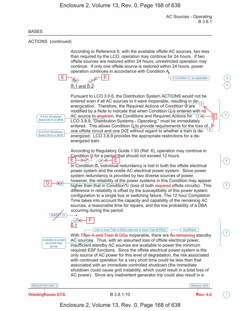
AC Sources - Operating B 3.8.1
Westinghouse STS B 3.8.1-10 Rev. 4.0
SEQUOYAH UNIT 2
1
Revision XXX
BASES
ACTIONS (continued)
According to Reference 6, with the available offsite AC sources, two less than required by the LCO, operation may continue for 24 hours. If two offsite sources are restored within 24 hours, unrestricted operation may continue. If only one offsite source is restored within 24 hours, power operation continues in accordance with Condition A.
D.1 and D.2
Pursuant to LCO 3.0.6, the Distribution System ACTIONS would not be entered even if all AC sources to it were inoperable, resulting in de-energization. Therefore, the Required Actions of Condition D are modified by a Note to indicate that when Condition D is entered with no AC source to any train, the Conditions and Required Actions for LCO 3.8.9, "Distribution Systems - Operating," must be immediately entered. This allows Condition D to provide requirements for the loss of one offsite circuit and one DG, without regard to whether a train is de-energized. LCO 3.8.9 provides the appropriate restrictions for a de-energized train.
According to Regulatory Guide 1.93 (Ref. 6), operation may continue in Condition D for a period that should not exceed 12 hours.
In Condition D, individual redundancy is lost in both the offsite electrical power system and the onsite AC electrical power system. Since power system redundancy is provided by two diverse sources of power, however, the reliability of the power systems in this Condition may appear higher than that in Condition C (loss of both required offsite circuits). This difference in reliability is offset by the susceptibility of this power system configuration to a single bus or switching failure. The 12 hour Completion Time takes into account the capacity and capability of the remaining AC sources, a reasonable time for repairs, and the low probability of a DBA occurring during this period.
E.1
With Train A and Train B DGs inoperable, there are no remaining standby AC sources. Thus, with an assumed loss of offsite electrical power, insufficient standby AC sources are available to power the minimum required ESF functions. Since the offsite electrical power system is the only source of AC power for this level of degradation, the risk associated with continued operation for a very short time could be less than that associated with an immediate controlled shutdown (the immediate shutdown could cause grid instability, which could result in a total loss of AC power). Since any inadvertent generator trip could also result in a
F F
F
F
F
F F
E
J
available to power an entire load
group
5
5
5
5
5
5
or Condition C, as applicable
6.9 kV Shutdown Board 2A-A or 2B-B
INSERT 12
one or more Train A DG(s) and one or more Train B DG(s) insufficient
to 6.9 kV Shutdown Board 2A-A or 2B-B
Enclosure 2, Volume 13, Rev. 0, Page 168 of 638
Enclosure 2, Volume 13, Rev. 0, Page 168 of 638
E E
E E
D
F
E

B 3.8.1
Insert Page B 3.8.1-10
INSERT 12
G.1 and H.1
In Conditions G and H, individual redundancy is lost in the offsite electrical power system for one unit and the onsite AC electrical power system for the other unit. Since Conditions B and C are entered concurrent with entry into Condition G, and Conditions A and D are entered concurrent with entry into Condition H, the Required Actions of Conditions B and C (or Conditions A and D) provide the appropriate compensatory measures to ensure the onsite and offsite power sources are either restored to an OPERABLE status, or the associated required features are declared inoperable, thereby requiring entry into the appropriate Conditions associated with the associated feature's LCO. The Completion Times of Required Actions G.1 and H.1 are consistent with the Completion Times of Required Actions C.3 and D.4. If, while in Condition G or H, a redundant required feature is determined to be inoperable, the required feature(s) would be declared inoperable at the Completion Times specified in Conditions A, B, C, or D, as applicable.
I.1 and I.2
Pursuant to LCO 3.0.6, the Distribution System ACTIONS would not be entered even if all AC sources to it were inoperable, resulting in de-energization. Therefore, the Required Actions of Condition I are modified by a Note to indicate that when Condition I is entered with no AC source to 6.9 kV Shutdown Board 1A-A or 1B-B, the Conditions and Required Actions for LCO 3.8.9, "Distribution Systems - Operating," must be immediately entered. This allows Condition I to provide requirements for the loss of one offsite power source and one DG, without regard to whether a train is de-energized. LCO 3.8.9 provides the appropriate restrictions for a de-energized 6.9 kV Shutdown Board.
In Condition I, individual redundancy is lost in the offsite electrical power system and the onsite AC electrical power system. Concurrent with entry into Condition I, entry into Condition C (inoperable offsite power source) and Condition D (inoperable DG) are required. The Required Actions of Conditions C and D ensure the remaining offsite circuit and DGs are OPERABLE and that required features with no offsite or onsite power sources are declared inoperable when its redundant required feature is inoperable within the Completion Times of Required Actions C.2 and D.2.
5
Enclosure 2, Volume 13, Rev. 0, Page 169 of 638
Enclosure 2, Volume 13, Rev. 0, Page 169 of 638

AC Sources - Operating B 3.8.1
Westinghouse STS B 3.8.1-11 Rev. 4.0
SEQUOYAH UNIT 2
1
Revision XXX
BASES
ACTIONS (continued)
total loss of offsite AC power, however, the time allowed for continued operation is severely restricted. The intent here is to avoid the risk associated with an immediate controlled shutdown and to minimize the risk associated with this level of degradation.
According to Reference 6, with both DGs inoperable, operation may continue for a period that should not exceed 2 hours.
[ F.1
The sequencer(s) is an essential support system to [both the offsite circuit and the DG associated with a given ESF bus]. [Furthermore, the sequencer is on the primary success path for most major AC electrically powered safety systems powered from the associated ESF bus.] Therefore, loss of an [ESF bus sequencer] affects every major ESF system in the [division]. The [12] hour Completion Time provides a period of time to correct the problem commensurate with the importance of maintaining sequencer OPERABILITY. This time period also ensures that the probability of an accident (requiring sequencer OPERABILITY) occurring during periods when the sequencer is inoperable is minimal.
This Condition is preceded by a Note that allows the Condition to be deleted if the unit design is such that any sequencer failure mode will only affect the ability of the associated DG to power its respective safety loads under any conditions. Implicit in this Note is the concept that the Condition must be retained if any sequencer failure mode results in the inability to start all or part of the safety loads when required, regardless of power availability, or results in overloading the offsite power circuit to a safety bus during an event and thereby causes its failure. Also implicit in the Note, is that the Condition is not applicable to any train that does not have a sequencer. ]
G.1 and G.2
If the inoperable AC electric power sources cannot be restored to OPERABLE status within the required Completion Time, the unit must be brought to a MODE in which the LCO does not apply. To achieve this status, the unit must be brought to at least MODE 3 within 6 hours and to MODE 5 within 36 hours. The allowed Completion Times are reasonable, based on operating experience, to reach the required unit conditions from full power conditions in an orderly manner and without challenging plant systems.
K K
5
5
5
5
In this Condition,
, consistent with the guidance provided in Reference 6
Enclosure 2, Volume 13, Rev. 0, Page 170 of 638
Enclosure 2, Volume 13, Rev. 0, Page 170 of 638
G G
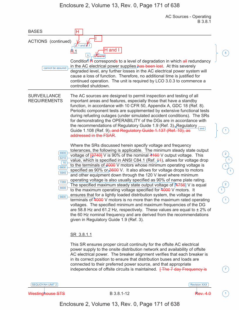
AC Sources - Operating B 3.8.1
Westinghouse STS B 3.8.1-12 Rev. 4.0
SEQUOYAH UNIT 2
1
Revision XXX
BASES
ACTIONS (continued)
H.1
Condition H corresponds to a level of degradation in which all redundancy in the AC electrical power supplies has been lost. At this severely degraded level, any further losses in the AC electrical power system will cause a loss of function. Therefore, no additional time is justified for continued operation. The unit is required by LCO 3.0.3 to commence a controlled shutdown.
SURVEILLANCE The AC sources are designed to permit inspection and testing of all REQUIREMENTS important areas and features, especially those that have a standby
function, in accordance with 10 CFR 50, Appendix A, GDC 18 (Ref. 8). Periodic component tests are supplemented by extensive functional tests during refueling outages (under simulated accident conditions). The SRs for demonstrating the OPERABILITY of the DGs are in accordance with the recommendations of Regulatory Guide 1.9 (Ref. 3), Regulatory Guide 1.108 (Ref. 9), and Regulatory Guide 1.137 (Ref. 10), as addressed in the FSAR.
Where the SRs discussed herein specify voltage and frequency tolerances, the following is applicable. The minimum steady state output voltage of [3740] V is 90% of the nominal 4160 V output voltage. This value, which is specified in ANSI C84.1 (Ref. 11), allows for voltage drop to the terminals of 4000 V motors whose minimum operating voltage is specified as 90% or 3600 V. It also allows for voltage drops to motors and other equipment down through the 120 V level where minimum operating voltage is also usually specified as 90% of name plate rating. The specified maximum steady state output voltage of [4756] V is equal to the maximum operating voltage specified for 4000 V motors. It ensures that for a lightly loaded distribution system, the voltage at the terminals of 4000 V motors is no more than the maximum rated operating voltages. The specified minimum and maximum frequencies of the DG are 58.8 Hz and 61.2 Hz, respectively. These values are equal to ± 2% of the 60 Hz nominal frequency and are derived from the recommendations given in Regulatory Guide 1.9 (Ref. 3).
SR 3.8.1.1
This SR ensures proper circuit continuity for the offsite AC electrical power supply to the onsite distribution network and availability of offsite AC electrical power. The breaker alignment verifies that each breaker is in its correct position to ensure that distribution buses and loads are connected to their preferred power source, and that appropriate independence of offsite circuits is maintained. [ The 7 day Frequency is
and
6900
6600
5940
7260
6600
6600
5
1
2
1
2
1
1
7
6210
10 1
1
L.1 and M.1
s L and M
cannot be assured
Enclosure 2, Volume 13, Rev. 0, Page 171 of 638
Enclosure 2, Volume 13, Rev. 0, Page 171 of 638
HI
H and I

DETERMINATION OF NO SIGNIFICANT HAZARDS CONSIDERATIONS ITS 3.8.1, AC SOURCES - OPERATING
Sequoyah Unit 1 and 2 Page 1 of 4
10 CFR 50.92 EVALUATION FOR
LESS RESTRICTIVE CHANGE L01
SQN is converting to the Improved Technical Specifications (ITS) as outlined in NUREG-1431, "Standard Technical Specifications, Westinghouse Plants." The proposed change involves making the Current Technical Specifications (CTS) less restrictive. Below are the descriptions of this less restrictive change and the determination of No Significant Hazards Considerations for conversion to NUREG-1431.
CTS 3.8.1.1 ACTION a provides actions for one inoperable offsite circuit and allows 72 hours to restore the inoperable offsite circuit to OPERABLE status before requiring the unit to be shut down and cooled down. CTS 3.8.1.1 ACTION b provides actions for one or both DGs in a train inoperable and allows 7 days to restore the inoperable DG(s) to OPERABLE status before requiring the unit to be shut down and cooled down. CTS 3.8.1.1 ACTION c provides actions for one inoperable offsite circuit and one inoperable DG and allows 12 hours to restore at least one of the inoperable AC sources to OPERABLE status before requiring the unit to be shut down and cooled down. CTS 3.8.1.1 ACTION d provides actions for two inoperable offsite circuits and allows 24 hours to restore at least one of the inoperable offsite circuits to OPERABLE status before requiring the unit to be shut down. CTS 3.8.1.1 ACTION e provides actions for one or two inoperable DGs in both trains and allows 2 hours to restore the inoperable DG(s) in one train to OPERABLE status before requiring the unit to be shut down and cooled down. CTS 3.8.1.1 ACTION f states LCO 3.0.4.b is not applicable to DGs. The ITS ACTIONS are modified by a Note stating LCO 3.0.4.b is not applicable to DGs. ITS 3.8.1 ACTION A provides actions for one inoperable offsite circuit for reasons other than Condition C, and allows 72 hours to restore the inoperable offsite power source to OPERABLE status. ITS 3.8.1 ACTION B provides actions for one inoperable associated unit's DG or both DGs in one train inoperable, and allows 7 days to restore the inoperable DG(s) to OPERABLE status. ITS 3.8.1 ACTION C provides actions for one offsite circuit inoperable solely due to an inoperable offsite power source to an opposite unit's 6.9 kV Shutdown Board, and requires declaration that the affected required feature(s) with no offsite power available are inoperable when its redundant required feature is inoperable in 24 hours. Otherwise, the affected required feature(s) are declared inoperable in 7 days, if the offsite circuit cannot be restored to an OPERABLE status. ITS 3.8.1 ACTION D requires declaration that the affected required feature(s) with no OPERABLE DG are inoperable when its redundant required feature is inoperable in 4 hours. Otherwise, the affected required feature(s) are declared inoperable in 7 days, if the DG cannot be restored to an OPERABLE status. ITS 3.8.1 ACTION E requires declaration that the affected required feature(s) with no offsite power available are inoperable when its redundant required feature is inoperable in 12 hours. Otherwise, one offsite circuit is required to be restored to an OPERABLE status in 24 hours. ITS 3.8.1 ACTION F provides actions for one associated unit's offsite circuit inoperable concurrent with one associated unit's DG inoperable, and allows 12 hours to restore one of the inoperable AC sources to OPERABLE status. ITS ACTION G requires declaring the required feature(s) on the opposite unit's 6.9 kV Shutdown Board with no offsite power available inoperable in 7 days. ITS ACTION H requires declaring the required feature(s) on the opposite unit's 6.9 kV Shutdown Board with no DG available inoperable in 7 days. ITS ACTION I provides actions for one offsite circuit inoperable solely due to an inoperable offsite power source to an opposite unit's 6.9 kV Shutdown Board concurrent with one opposite unit's DG inoperable, and allows 7 days
Enclosure 2, Volume 13, Rev. 0, Page 200 of 638
Enclosure 2, Volume 13, Rev. 0, Page 200 of 638
E
re�uires� �� �erfor�ance of I�� �R ������� for the OPERABLE offsite circuit in � hour and once �er � hours thereafter, �� dec�aration that the affected re�uired feature�s� �ith no offsite �o�er a�ai�a��e are ino�era��e �hen its redundant re�uired feature is ino�era��e in �� hours, and �� restoration of the offsite circuit to OPERABLE status in 7 days�
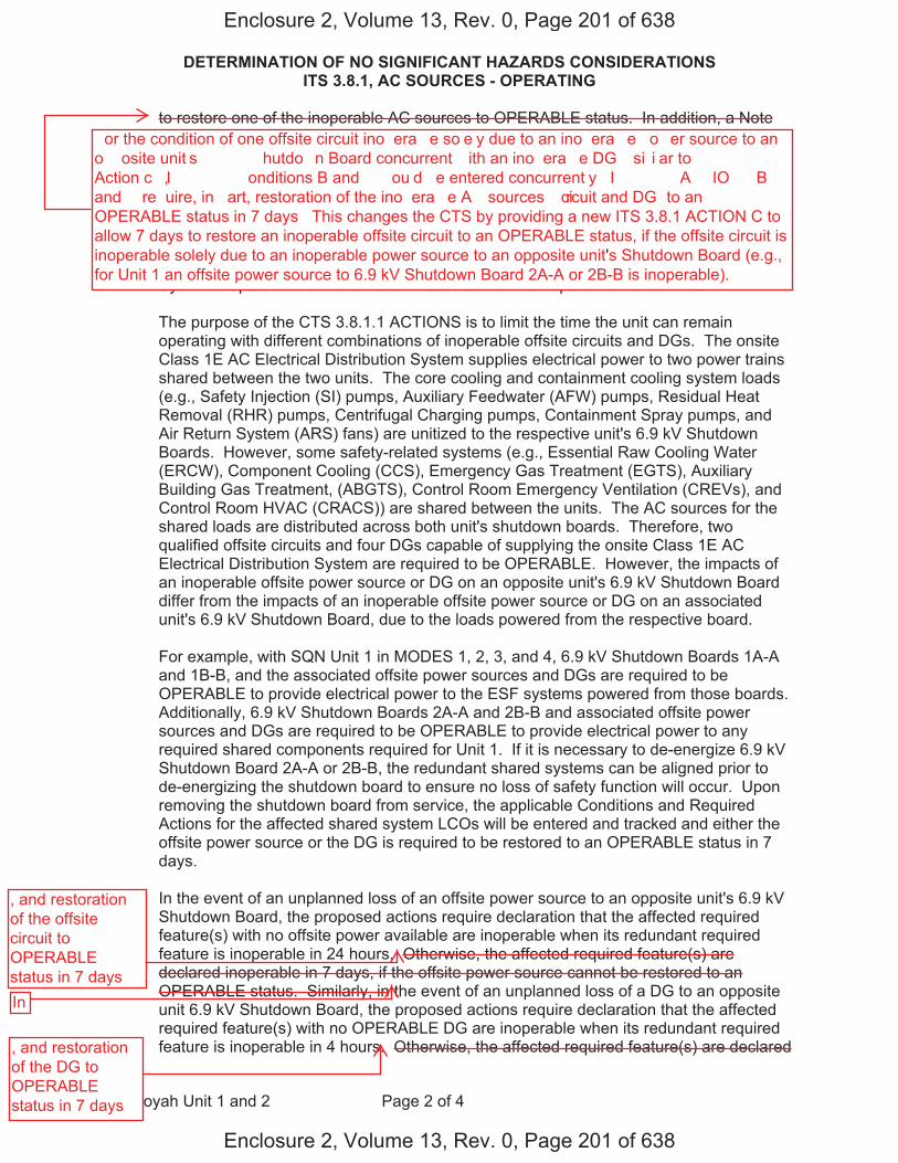
DETERMINATION OF NO SIGNIFICANT HAZARDS CONSIDERATIONS ITS 3.8.1, AC SOURCES - OPERATING
Sequoyah Unit 1 and 2 Page 2 of 4
to restore one of the inoperable AC sources to OPERABLE status. In addition, a Note modifying ITS ACTION I requires entry into the applicable Conditions and Required Actions of LCO 3.8.9 with no AC power source to an opposite unit's 6.9 kV Shutdown Board. ITS 3.8.1 ACTION J provides actions for one or more Train A and one or more Train B DGs inoperable and allows 2 hours to restore one Train of DGs to OPERABLE status. ITS 3.8.1 ACTION K requires the unit to be shut down and cooled down if a Required Action and associated Completion Time of Condition A, B, E, F, I, or J is not met. These changes to the CTS provide separate ACTIONS to declare the required features powered from the opposite unit's Class 1E AC Electrical Power Distribution System inoperable as the remedial measures for the inoperable AC sources.
The purpose of the CTS 3.8.1.1 ACTIONS is to limit the time the unit can remain operating with different combinations of inoperable offsite circuits and DGs. The onsite Class 1E AC Electrical Distribution System supplies electrical power to two power trains shared between the two units. The core cooling and containment cooling system loads (e.g., Safety Injection (SI) pumps, Auxiliary Feedwater (AFW) pumps, Residual Heat Removal (RHR) pumps, Centrifugal Charging pumps, Containment Spray pumps, and Air Return System (ARS) fans) are unitized to the respective unit's 6.9 kV Shutdown Boards. However, some safety-related systems (e.g., Essential Raw Cooling Water (ERCW), Component Cooling (CCS), Emergency Gas Treatment (EGTS), Auxiliary Building Gas Treatment, (ABGTS), Control Room Emergency Ventilation (CREVs), and Control Room HVAC (CRACS)) are shared between the units. The AC sources for the shared loads are distributed across both unit's shutdown boards. Therefore, two qualified offsite circuits and four DGs capable of supplying the onsite Class 1E AC Electrical Distribution System are required to be OPERABLE. However, the impacts of an inoperable offsite power source or DG on an opposite unit's 6.9 kV Shutdown Board differ from the impacts of an inoperable offsite power source or DG on an associated unit's 6.9 kV Shutdown Board, due to the loads powered from the respective board.
For example, with SQN Unit 1 in MODES 1, 2, 3, and 4, 6.9 kV Shutdown Boards 1A-A and 1B-B, and the associated offsite power sources and DGs are required to be OPERABLE to provide electrical power to the ESF systems powered from those boards. Additionally, 6.9 kV Shutdown Boards 2A-A and 2B-B and associated offsite power sources and DGs are required to be OPERABLE to provide electrical power to any required shared components required for Unit 1. If it is necessary to de-energize 6.9 kV Shutdown Board 2A-A or 2B-B, the redundant shared systems can be aligned prior to de-energizing the shutdown board to ensure no loss of safety function will occur. Upon removing the shutdown board from service, the applicable Conditions and Required Actions for the affected shared system LCOs will be entered and tracked and either the offsite power source or the DG is required to be restored to an OPERABLE status in 7 days.
In the event of an unplanned loss of an offsite power source to an opposite unit's 6.9 kV Shutdown Board, the proposed actions require declaration that the affected required feature(s) with no offsite power available are inoperable when its redundant required feature is inoperable in 24 hours. Otherwise, the affected required feature(s) are declared inoperable in 7 days, if the offsite power source cannot be restored to an OPERABLE status. Similarly, in the event of an unplanned loss of a DG to an opposite unit 6.9 kV Shutdown Board, the proposed actions require declaration that the affected required feature(s) with no OPERABLE DG are inoperable when its redundant required feature is inoperable in 4 hours. Otherwise, the affected required feature(s) are declared
Enclosure 2, Volume 13, Rev. 0, Page 201 of 638
Enclosure 2, Volume 13, Rev. 0, Page 201 of 638
�or the condition of one offsite circuit ino�era��e so�e�y due to an ino�era��e �o�er source to an o��osite unit�s ��� �� �hutdo�n Board concurrent �ith an ino�era��e DG �si�i�ar to ��� ������� Action c�, I�� ����� �onditions B and � �ou�d �e entered concurrent�y� I�� ����� A��IO�� B and � re�uire, in �art, restoration of the ino�era��e A� sources �circuit and DG� to an OPERABLE status in 7 days� This changes the CTS by providing a new ITS 3.8.1 ACTION C toallow 7 days to restore an inoperable offsite circuit to an OPERABLE status, if the offsite circuit isinoperable solely due to an inoperable power source to an opposite unit's Shutdown Board (e.g.,for Unit 1 an offsite power source to 6.9 kV Shutdown Board 2A-A or 2B-B is inoperable).
, and restoration of the offsite circuit to OPERABLE status in 7 daysIn
, and restoration of the DG to OPERABLE status in 7 days
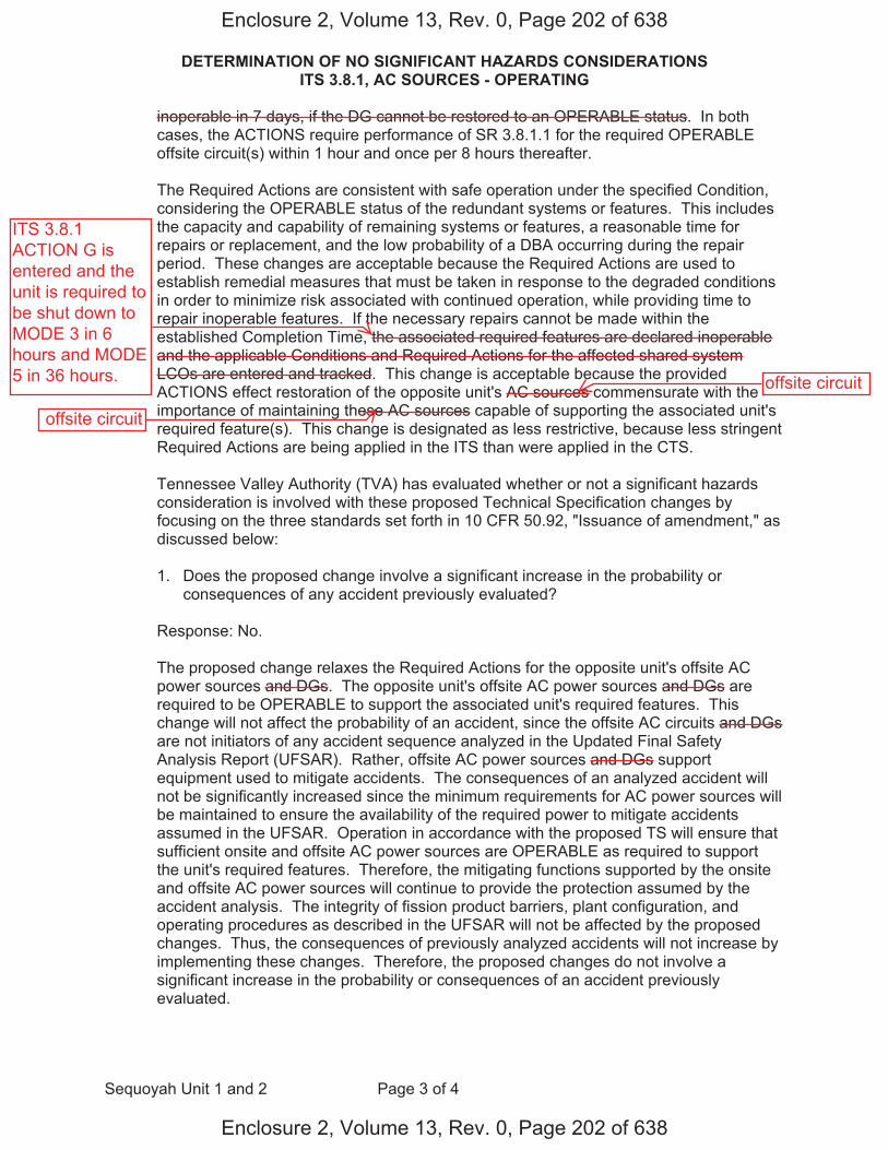
DETERMINATION OF NO SIGNIFICANT HAZARDS CONSIDERATIONS ITS 3.8.1, AC SOURCES - OPERATING
Sequoyah Unit 1 and 2 Page 3 of 4
inoperable in 7 days, if the DG cannot be restored to an OPERABLE status. In both cases, the ACTIONS require performance of SR 3.8.1.1 for the required OPERABLE offsite circuit(s) within 1 hour and once per 8 hours thereafter.
The Required Actions are consistent with safe operation under the specified Condition, considering the OPERABLE status of the redundant systems or features. This includes the capacity and capability of remaining systems or features, a reasonable time for repairs or replacement, and the low probability of a DBA occurring during the repair period. These changes are acceptable because the Required Actions are used to establish remedial measures that must be taken in response to the degraded conditions in order to minimize risk associated with continued operation, while providing time to repair inoperable features. If the necessary repairs cannot be made within the established Completion Time, the associated required features are declared inoperable and the applicable Conditions and Required Actions for the affected shared system LCOs are entered and tracked. This change is acceptable because the provided ACTIONS effect restoration of the opposite unit's AC sources commensurate with the importance of maintaining these AC sources capable of supporting the associated unit's required feature(s). This change is designated as less restrictive, because less stringent Required Actions are being applied in the ITS than were applied in the CTS.
Tennessee Valley Authority (TVA) has evaluated whether or not a significant hazards consideration is involved with these proposed Technical Specification changes by focusing on the three standards set forth in 10 CFR 50.92, "Issuance of amendment," as discussed below:
1. Does the proposed change involve a significant increase in the probability orconsequences of any accident previously evaluated?
Response: No.
The proposed change relaxes the Required Actions for the opposite unit's offsite AC power sources and DGs. The opposite unit's offsite AC power sources and DGs are required to be OPERABLE to support the associated unit's required features. This change will not affect the probability of an accident, since the offsite AC circuits and DGs are not initiators of any accident sequence analyzed in the Updated Final Safety Analysis Report (UFSAR). Rather, offsite AC power sources and DGs support equipment used to mitigate accidents. The consequences of an analyzed accident will not be significantly increased since the minimum requirements for AC power sources will be maintained to ensure the availability of the required power to mitigate accidents assumed in the UFSAR. Operation in accordance with the proposed TS will ensure that sufficient onsite and offsite AC power sources are OPERABLE as required to support the unit's required features. Therefore, the mitigating functions supported by the onsite and offsite AC power sources will continue to provide the protection assumed by the accident analysis. The integrity of fission product barriers, plant configuration, and operating procedures as described in the UFSAR will not be affected by the proposed changes. Thus, the consequences of previously analyzed accidents will not increase by implementing these changes. Therefore, the proposed changes do not involve a significant increase in the probability or consequences of an accident previously evaluated.
Enclosure 2, Volume 13, Rev. 0, Page 202 of 638
Enclosure 2, Volume 13, Rev. 0, Page 202 of 638
ITS 3.8.1ACTION G isentered and theunit is required tobe shut down toMODE 3 in 6hours and MODE5 in 36 hours. offsite circuit
offsite circuit

DETERMINATION OF NO SIGNIFICANT HAZARDS CONSIDERATIONS ITS 3.8.1, AC SOURCES - OPERATING
Sequoyah Unit 1 and 2 Page 4 of 4
2. Does the proposed change create the possibility of a new or different kind ofaccident from any previously evaluated?
Response: No
The proposed change relaxes the Required Actions for the opposite unit's offsite AC power sources and DGs. The opposite unit's offsite AC power sources and DGs are required to be OPERABLE to support the associated unit's required features. This change will not physically alter the plant (no new or different type of equipment will be installed). The proposed changes will maintain the minimum requirements for AC power sources to ensure the availability of the equipment required to mitigate accidents assumed in the UFSAR. Therefore, operation of the facility in accordance with this proposed change will not create the possibility of a new or different kind of accident from any accident previously evaluated.
3. Does the proposed change involve a significant reduction in the margin of safety?
Response: No.
The proposed change relaxes the Required Actions for the opposite unit's offsite AC power sources and DGs. The opposite unit's offsite AC power sources and DGs are required to be OPERABLE to support the associated unit's required features. The margin of safety is not affected by this change because the minimum requirements for AC power sources will be maintained to ensure the availability of the required power to shutdown the reactor and maintain it in a safe shutdown condition after an AOO or a postulated DBA. Therefore, the proposed changes do not involve a significant reduction in a margin of safety
Enclosure 2, Volume 13, Rev. 0, Page 203 of 638
Enclosure 2, Volume 13, Rev. 0, Page 203 of 638
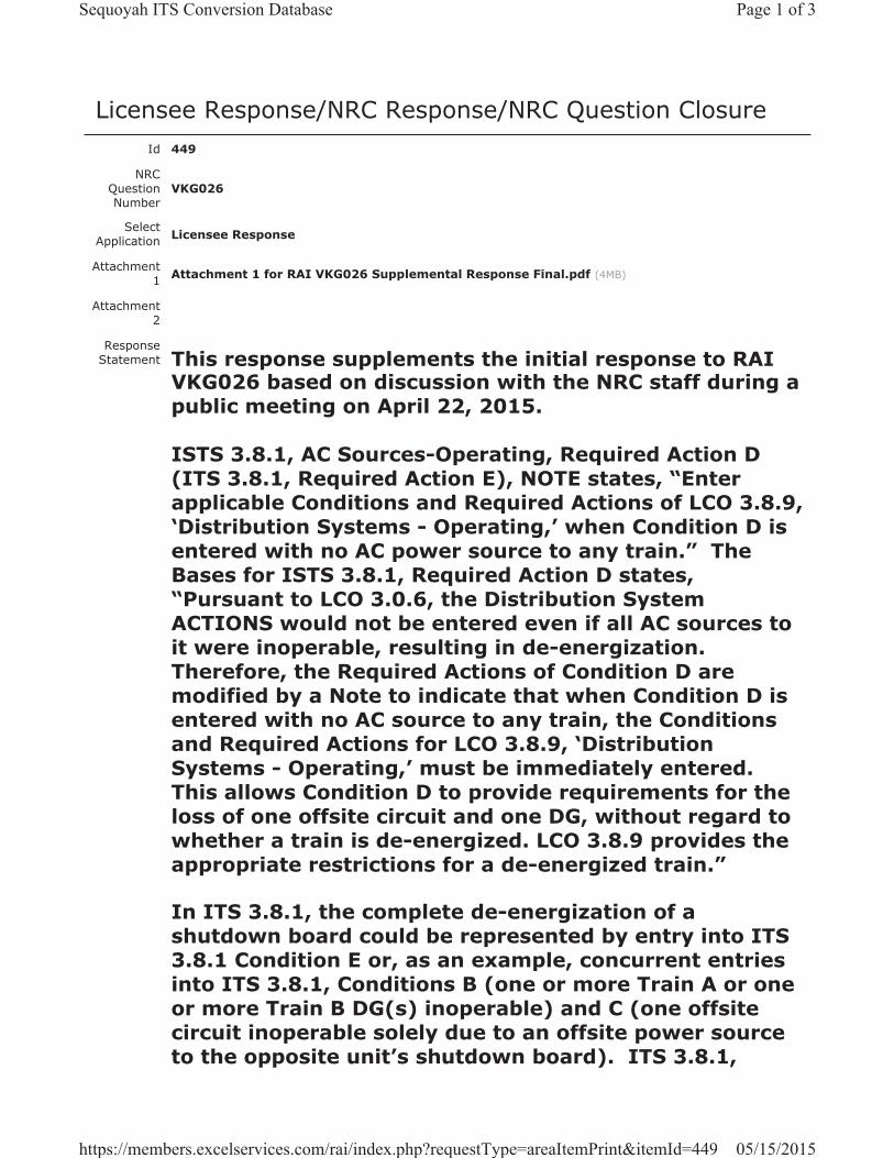
Licensee Response/NRC Response/NRC Question ClosureId 449
NRC Question Number
VKG026
Select Application Licensee Response
Attachment 1 Attachment 1 for RAI VKG026 Supplemental Response Final.pdf (4MB)
Attachment 2
Response Statement This response supplements the initial response to RAI
VKG026 based on discussion with the NRC staff during a public meeting on April 22, 2015.
ISTS 3.8.1, AC Sources-Operating, Required Action D (ITS 3.8.1, Required Action E), NOTE states, “Enterapplicable Conditions and Required Actions of LCO 3.8.9, ‘Distribution Systems - Operating,’ when Condition D is entered with no AC power source to any train.” The Bases for ISTS 3.8.1, Required Action D states, “Pursuant to LCO 3.0.6, the Distribution System ACTIONS would not be entered even if all AC sources to it were inoperable, resulting in de-energization. Therefore, the Required Actions of Condition D are modified by a Note to indicate that when Condition D is entered with no AC source to any train, the Conditions and Required Actions for LCO 3.8.9, ‘Distribution Systems - Operating,’ must be immediately entered. This allows Condition D to provide requirements for the loss of one offsite circuit and one DG, without regard to whether a train is de-energized. LCO 3.8.9 provides the appropriate restrictions for a de-energized train.”
In ITS 3.8.1, the complete de-energization of a shutdown board could be represented by entry into ITS 3.8.1 Condition E or, as an example, concurrent entries into ITS 3.8.1, Conditions B (one or more Train A or one or more Train B DG(s) inoperable) and C (one offsite circuit inoperable solely due to an offsite power source to the opposite unit’s shutdown board). ITS 3.8.1,
Page 1 of 3Sequoyah ITS Conversion Database
05/15/2015https://members.excelservices.com/rai/index.php?requestType=areaItemPrint&itemId=449
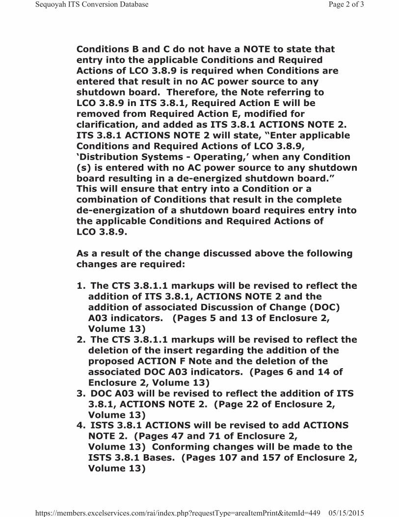
Conditions B and C do not have a NOTE to state that entry into the applicable Conditions and Required Actions of LCO 3.8.9 is required when Conditions are entered that result in no AC power source to any shutdown board. Therefore, the Note referring to LCO 3.8.9 in ITS 3.8.1, Required Action E will be removed from Required Action E, modified for clarification, and added as ITS 3.8.1 ACTIONS NOTE 2.ITS 3.8.1 ACTIONS NOTE 2 will state, “Enter applicable Conditions and Required Actions of LCO 3.8.9, ‘Distribution Systems - Operating,’ when any Condition(s) is entered with no AC power source to any shutdown board resulting in a de-energized shutdown board.”This will ensure that entry into a Condition or a combination of Conditions that result in the complete de-energization of a shutdown board requires entry into the applicable Conditions and Required Actions of LCO 3.8.9.
As a result of the change discussed above the following changes are required:
1. The CTS 3.8.1.1 markups will be revised to reflect the addition of ITS 3.8.1, ACTIONS NOTE 2 and the addition of associated Discussion of Change (DOC) A03 indicators. (Pages 5 and 13 of Enclosure 2, Volume 13)
2. The CTS 3.8.1.1 markups will be revised to reflect the deletion of the insert regarding the addition of the proposed ACTION F Note and the deletion of the associated DOC A03 indicators. (Pages 6 and 14 of Enclosure 2, Volume 13)
3. DOC A03 will be revised to reflect the addition of ITS 3.8.1, ACTIONS NOTE 2. (Page 22 of Enclosure 2, Volume 13)
4. ISTS 3.8.1 ACTIONS will be revised to add ACTIONS NOTE 2. (Pages 47 and 71 of Enclosure 2, Volume 13) Conforming changes will be made to the ISTS 3.8.1 Bases. (Pages 107 and 157 of Enclosure 2, Volume 13)
Page 2 of 3Sequoyah ITS Conversion Database
05/15/2015https://members.excelservices.com/rai/index.php?requestType=areaItemPrint&itemId=449
5. ISTS 3.8.1 Condition D will be revised to delete the Required Action D NOTE. (Pages 51 and 75 of Enclosure 2, Volume 13) Conforming changes will be made to the ISTS Bases (Pages 118 and 168 of Enclosure 2, Volume 13)
6. Justification for Deviation (JFD) 7 indicators will be added where changes are made to ISTS 3.8.1 concerning the relocation and modification of the ACTIONS Note. Additionally, a new JFD 7 will be added to the Justification for Deviations Section for ITS 3.8.1. (Pages 47, 51, 71, 75, 95 and Insert JFD 7 of Enclosure 2, Volume 13)
See Attachment 1 for the draft revised CTS and ISTS markups, DOC A03, and the addition of JFD 7.
Response Date/Time 5/10/2015 12:20 PM
Closure Statement
Question Closure
Date
Notification Scott BowmanMichelle ConnerVijay GoelKhadijah HemphillAndrew HonLynn MynattRay Schiele
Added By Scott Bowman
Date Added 5/10/2015 11:20 AM
Date Modified
Modified By
Page 3 of 3Sequoyah ITS Conversion Database
05/15/2015https://members.excelservices.com/rai/index.php?requestType=areaItemPrint&itemId=449
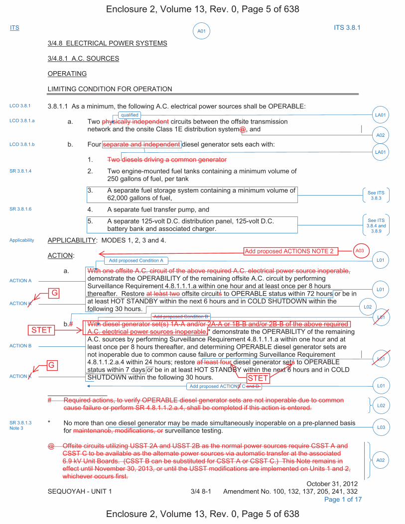
A01ITS ITS 3.8.1
3/4.8 ELECTRICAL POWER SYSTEMS
3/4.8.1 A.C. SOURCES
OPERATING
LIMITING CONDITION FOR OPERATION
3.8.1.1 As a minimum, the following A.C. electrical power sources shall be OPERABLE:
a. Two physically independent circuits between the offsite transmissionnetwork and the onsite Class 1E distribution system@, and
b. Four separate and independent diesel generator sets each with:
1. Two diesels driving a common generator
2. Two engine-mounted fuel tanks containing a minimum volume of250 gallons of fuel, per tank
3. A separate fuel storage system containing a minimum volume of62,000 gallons of fuel,
4. A separate fuel transfer pump, and
5. A separate 125-volt D.C. distribution panel, 125-volt D.C.battery bank and associated charger.
APPLICABILITY: MODES 1, 2, 3 and 4.
ACTION:
a. With one offsite A.C. circuit of the above required A.C. electrical power source inoperable,demonstrate the OPERABILITY of the remaining offsite A.C. circuit by performing Surveillance Requirement 4.8.1.1.1.a within one hour and at least once per 8 hours thereafter. Restore at least two offsite circuits to OPERABLE status within 72 hours or be in at least HOT STANDBY within the next 6 hours and in COLD SHUTDOWN within the following 30 hours.
b.# With diesel generator set(s) 1A-A and/or 2A-A or 1B-B and/or 2B-B of the above required A.C. electrical power sources inoperable,* demonstrate the OPERABILITY of the remaining A.C. sources by performing Surveillance Requirement 4.8.1.1.1.a within one hour and at least once per 8 hours thereafter, and determining OPERABLE diesel generator sets are not inoperable due to common cause failure or performing Surveillance Requirement 4.8.1.1.2.a.4 within 24 hours; restore at least four diesel generator sets to OPERABLE status within 7 days or be in at least HOT STANDBY within the next 6 hours and in COLD SHUTDOWN within the following 30 hours.
# Required actions, to verify OPERABLE diesel generator sets are not inoperable due to common cause failure or perform SR 4.8.1.1.2.a.4, shall be completed if this action is entered.
* No more than one diesel generator may be made simultaneously inoperable on a pre-planned basisfor maintenance, modifications, or surveillance testing.
@ Offsite circuits utilizing USST 2A and USST 2B as the normal power sources require CSST A and CSST C to be available as the alternate power sources via automatic transfer at the associated 6.9 kV Unit Boards. (CSST B can be substituted for CSST A or CSST C.) This Note remains in effect until November 30, 2013, or until the USST modifications are implemented on Units 1 and 2, whichever occurs first.
October 31, 2012 SEQUOYAH - UNIT 1 3/4 8-1 Amendment No. 100, 132, 137, 205, 241, 332
LCO 3.8.1
Applicability
Page 1 of 17
LCO 3.8.1.a
LCO 3.8.1.b
SR 3.8.1.4
SR 3.8.1.6
See ITS 3.8.4 and
3.8.9
LA01
LA01qualified
ACTION A
ACTION K
ACTION B
ACTION K
L01Add proposed ACTIONS C and D
L01Add proposed Condition B
L01
L01
L02
L02
L03SR 3.8.1.3 Note 3
Add proposed Condition A L01
See ITS 3.8.3
A02
A02
Enclosure 2, Volume 13, Rev. 0, Page 5 of 638
Enclosure 2, Volume 13, Rev. 0, Page 5 of 638
G
G
STET
STET
Add proposed ACTIONS NOTE 2 A03
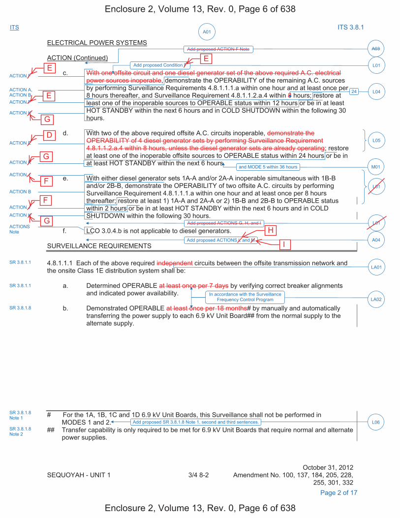
A01ITS ITS 3.8.1
ELECTRICAL POWER SYSTEMS
ACTION (Continued)
c. With one offsite circuit and one diesel generator set of the above required A.C. electricalpower sources inoperable, demonstrate the OPERABILITY of the remaining A.C. sources by performing Surveillance Requirements 4.8.1.1.1.a within one hour and at least once per 8 hours thereafter, and Surveillance Requirement 4.8.1.1.2.a.4 within 8 hours; restore at least one of the inoperable sources to OPERABLE status within 12 hours or be in at least HOT STANDBY within the next 6 hours and in COLD SHUTDOWN within the following 30 hours.
d. With two of the above required offsite A.C. circuits inoperable, demonstrate theOPERABILITY of 4 diesel generator sets by performing Surveillance Requirement4.8.1.1.2.a.4 within 8 hours, unless the diesel generator sets are already operating; restoreat least one of the inoperable offsite sources to OPERABLE status within 24 hours or be inat least HOT STANDBY within the next 6 hours.
e. With either diesel generator sets 1A-A and/or 2A-A inoperable simultaneous with 1B-Band/or 2B-B, demonstrate the OPERABILITY of two offsite A.C. circuits by performingSurveillance Requirement 4.8.1.1.1.a within one hour and at least once per 8 hoursthereafter; restore at least 1) 1A-A and 2A-A or 2) 1B-B and 2B-B to OPERABLE statuswithin 2 hours or be in at least HOT STANDBY within the next 6 hours and in COLDSHUTDOWN within the following 30 hours.
f. LCO 3.0.4.b is not applicable to diesel generators.
SURVEILLANCE REQUIREMENTS
4.8.1.1.1 Each of the above required independent circuits between the offsite transmission network and the onsite Class 1E distribution system shall be:
a. Determined OPERABLE at least once per 7 days by verifying correct breaker alignmentsand indicated power availability.
b. Demonstrated OPERABLE at least once per 18 months# by manually and automaticallytransferring the power supply to each 6.9 kV Unit Board## from the normal supply to the alternate supply.
# For the 1A, 1B, 1C and 1D 6.9 kV Unit Boards, this Surveillance shall not be performed in MODES 1 and 2.
## Transfer capability is only required to be met for 6.9 kV Unit Boards that require normal and alternate power supplies.
October 31, 2012 SEQUOYAH - UNIT 1 3/4 8-2 Amendment No. 100, 137, 184, 205, 228,
255, 301, 332 Page 2 of 17
ACTION F
ACTION A, ACTION B ACTION F
ACTION K
L01Add proposed Condition F
A03Add proposed ACTION F Note
24 L04
ACTION E
ACTION K
ACTION J
L05
M01and MODE 5 within 36 hours
L01
ACTION J
ACTION K
ACTION B
L01Add proposed ACTIONS G, H, and I
A04Add proposed ACTIONS L and M
SR 3.8.1.1
SR 3.8.1.1
LA02
ACTIONS Note
LA01
In accordance with the Surveillance Frequency Control Program
SR 3.8.1.8
SR 3.8.1.8 Note 1
L06Add proposed SR 3.8.1.8 Note 1, second and third sentences.SR 3.8.1.8 Note 2
Enclosure 2, Volume 13, Rev. 0, Page 6 of 638
Enclosure 2, Volume 13, Rev. 0, Page 6 of 638
H
I
E E
E
G
G
G
F
F
D

A01ITS ITS 3.8.1
3/4 LIMITING CONDITIONS FOR OPEATION AND SURVEILLANCE REQUIREMENTS
3/4.0 APPLICABILITY
LIMITING CONDITION FOR OPERATION
3.0.1 Compliance with the Limiting Conditions for Operation contained in the succeeding Specifications is required during the OPERATIONAL MODES or other conditions specified therein; except that upon failure to meet the Limiting Conditions for Operation, the associated ACTION requirements shall be met and as provided in LCO 3.0.7.
3.0.2 Noncompliance with a Specification shall exist when the requirements of the Limiting Condition for Operation and associated ACTION requirements are not met within the specified time intervals. If the Limiting Conditions for Operation is restored prior to expiration of the specified time intervals, completion of the ACTION requirements is not required.
3.0.3 When a Limiting Condition for Operation is not met, except as provided in the associated ACTION requirements, within one hour action shall be initiated to place the unit in a MODE in which the Specification does not apply by placing it, as applicable, in:
1. At least HOT STANDBY within the next 6 hours,2. At least HOT SHUTDOWN within the following 6 hours, and3. At least COLD SHUTDOWN within the subsequent 24 hours.
Where corrective measures are completed that permit operation under the ACTION requirements, the ACTION may be taken in accordance with the specified time limits as measured from the time of failure to meet the Limiting Condition for Operation. Exceptions to these requirements are stated in the individual Specifications.
3.0.4 When an LCO is not met, entry into a MODE or other specified condition in the Applicability shall only be made:
a. When the associated ACTIONS to be entered permit continued operation in the MODE or otherspecified condition in the Applicability for an unlimited period of time;
b. After performance of a risk assessment addressing inoperable systems and components,consideration of the results, determination of the acceptability of entering the MODE or otherspecified condition in the Applicability, and establishment of risk management actions, if appropriate;exceptions to this Specification are stated in the individual Specifications, or
c. When an allowance is stated in the individual value, parameter, or other Specification.
This Specification shall not prevent changes in MODES or other specified conditions in the Applicability that are required to comply with ACTIONS or that are part of a shutdown of the unit.
3.0.5 When a system, subsystem, train, component or device is determined to be inoperable solely because its emergency power source is inoperable, or solely because its normal power source is inoperable, it may be considered OPERABLE for the purpose of satisfying the requirements of its applicable Limiting Condition for Operation, provided: (1) its corresponding normal or emergency power source is OPERABLE; and (2) all of its redundant system(s), subsystem(s), train(s), component(s) and device(s) are OPERABLE, or likewise satisfy the requirements of this Specification. Unless both
October 4, 2006 SEQUOYAH - UNIT 1 3/4 0-1 Amendment No. 202, 301, 312
See ITS 3.0
Required Actions A.2, B.2, E.1, and associated Completion Times
Page 7 of 17
Enclosure 2, Volume 13, Rev. 0, Page 11 of 638
Enclosure 2, Volume 13, Rev. 0, Page 11 of 638
C.2, D.1
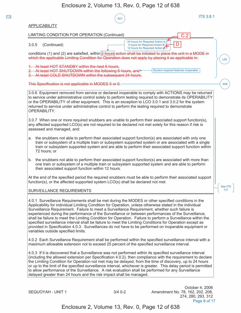
A01ITS ITS 3.8.1
APPLICABILITY
LIMITING CONDITION FOR OPERATION (Continued)
3.0.5 (Continued)
conditions (1) and (2) are satisfied, within 2 hours action shall be initiated to place the unit in a MODE in which the applicable Limiting Condition for Operation does not apply by placing it as applicable in:
1. At least HOT STANDBY within the next 6 hours,2. At least HOT SHUTDOWN within the following 6 hours, and3. At least COLD SHUTDOWN within the subsequent 24 hours.
This Specification is not applicable in MODES 5 or 6.
3.0.6 Equipment removed from service or declared inoperable to comply with ACTIONS may be returned to service under administrative control solely to perform testing required to demonstrate its OPERABILITY or the OPERABILITY of other equipment. This is an exception to LCO 3.0.1 and 3.0.2 for the system returned to service under administrative control to perform the testing required to demonstrate OPERABILITY.
3.0.7 When one or more required snubbers are unable to perform their associated support function(s), any affected supported LCO(s) are not required to be declared not met solely for this reason if risk is assessed and managed, and:
a. the snubbers not able to perform their associated support function(s) are associated with only onetrain or subsystem of a multiple train or subsystem supported system or are associated with a singletrain or subsystem supported system and are able to perform their associated support function within72 hours; or
b. the snubbers not able to perform their associated support function(s) are associated with more thanone train or subsystem of a multiple train or subsystem supported system and are able to performtheir associated support function within 12 hours.
At the end of the specified period the required snubbers must be able to perform their associated support function(s), or the affected supported system LCO(s) shall be declared not met.
SURVEILLANCE REQUIREMENTS
4.0.1 Surveillance Requirements shall be met during the MODES or other specified conditions in the Applicability for individual Limiting Condition for Operation, unless otherwise stated in the individual Surveillance Requirement. Failure to meet a Surveillance Requirement, whether such failure is experienced during the performance of the Surveillance or between performances of the Surveillance, shall be failure to meet the Limiting Condition for Operation. Failure to perform a Surveillance within the specified surveillance interval shall be failure to meet the Limiting Conditions for Operation except as provided in Specification 4.0.3. Surveillances do not have to be performed on inoperable equipment or variables outside specified limits.
4.0.2 Each Surveillance Requirement shall be performed within the specified surveillance interval with a maximum allowable extension not to exceed 25 percent of the specified surveillance interval.
4.0.3 If it is discovered that a Surveillance was not performed within its specified surveillance interval (including the allowed extension per Specification 4.0.2), then compliance with the requirement to declare the Limiting Condition for Operation not met may be delayed, from the time of discovery, up to 24 hours or up to the limit of the specified surveillance interval, whichever is greater. This delay period is permitted to allow performance of the Surveillance. A risk evaluation shall be performed for any Surveillance delayed greater than 24 hours and the risk impact shall be managed.
October 4, 2006 SEQUOYAH - UNIT 1 3/4 0-2 Amendment No. 78, 162, 202, 208,
274, 280, 293, 312 Page 8 of 17
See ITS 3.0
L20
24 hours for Required Action A.2 4 hours for Required Action B.2
12 hours for Required Action E.1
Declare required features inoperable.
A08
Enclosure 2, Volume 13, Rev. 0, Page 12 of 638
Enclosure 2, Volume 13, Rev. 0, Page 12 of 638
D
, C.2
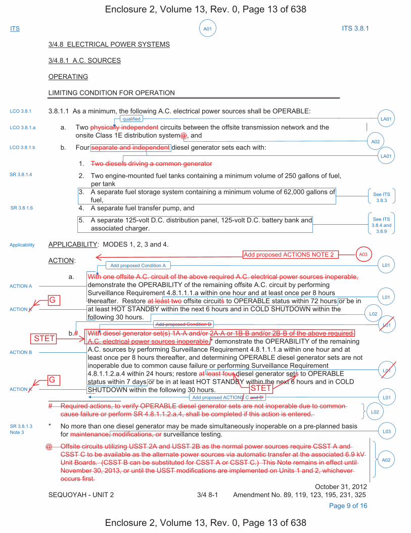
A01ITS ITS 3.8.1
3/4.8 ELECTRICAL POWER SYSTEMS
3/4.8.1 A.C. SOURCES
OPERATING
LIMITING CONDITION FOR OPERATION
3.8.1.1 As a minimum, the following A.C. electrical power sources shall be OPERABLE:
a. Two physically independent circuits between the offsite transmission network and theonsite Class 1E distribution system@, and
b. Four separate and independent diesel generator sets each with:
1. Two diesels driving a common generator
2. Two engine-mounted fuel tanks containing a minimum volume of 250 gallons of fuel,per tank
3. A separate fuel storage system containing a minimum volume of 62,000 gallons offuel,
4. A separate fuel transfer pump, and
5. A separate 125-volt D.C. distribution panel, 125-volt D.C. battery bank andassociated charger.
APPLICABILITY: MODES 1, 2, 3 and 4.
ACTION:
a. With one offsite A.C. circuit of the above required A.C. electrical power sources inoperable,demonstrate the OPERABILITY of the remaining offsite A.C. circuit by performing Surveillance Requirement 4.8.1.1.1.a within one hour and at least once per 8 hours thereafter. Restore at least two offsite circuits to OPERABLE status within 72 hours or be in at least HOT STANDBY within the next 6 hours and in COLD SHUTDOWN within the following 30 hours.
b.# With diesel generator set(s) 1A-A and/or 2A-A or 1B-B and/or 2B-B of the above required A.C. electrical power sources inoperable,* demonstrate the OPERABILITY of the remaining A.C. sources by performing Surveillance Requirement 4.8.1.1.1.a within one hour and at least once per 8 hours thereafter, and determining OPERABLE diesel generator sets are not inoperable due to common cause failure or performing Surveillance Requirement 4.8.1.1.2.a.4 within 24 hours; restore at least four diesel generator sets to OPERABLE status within 7 days or be in at least HOT STANDBY within the next 6 hours and in COLD SHUTDOWN within the following 30 hours.
# Required actions, to verify OPERABLE diesel generator sets are not inoperable due to common cause failure or perform SR 4.8.1.1.2.a.4, shall be completed if this action is entered.
* No more than one diesel generator may be made simultaneously inoperable on a pre-planned basisfor maintenance, modifications, or surveillance testing.
@ Offsite circuits utilizing USST 2A and USST 2B as the normal power sources require CSST A and CSST C to be available as the alternate power sources via automatic transfer at the associated 6.9 kV Unit Boards. (CSST B can be substituted for CSST A or CSST C.) This Note remains in effect until November 30, 2013, or until the USST modifications are implemented on Units 1 and 2, whichever occurs first.
October 31, 2012 SEQUOYAH - UNIT 2 3/4 8-1 Amendment No. 89, 119, 123, 195, 231, 325
LCO 3.8.1
Applicability
Page 9 of 16
LCO 3.8.1.a
LCO 3.8.1.b
SR 3.8.1.4
SR 3.8.1.6
See ITS 3.8.4 and
3.8.9
LA01
LA01qualified
ACTION A
ACTION K
ACTION B
ACTION K
L01Add proposed ACTIONS C and D
L01Add proposed Condition B
L01
L01
L02
L02
L03SR 3.8.1.3 Note 3
Add proposed Condition A L01
See ITS 3.8.3
A02
A02
Enclosure 2, Volume 13, Rev. 0, Page 13 of 638
Enclosure 2, Volume 13, Rev. 0, Page 13 of 638
G
G
STET
STET
Add proposed ACTIONS NOTE 2 A03
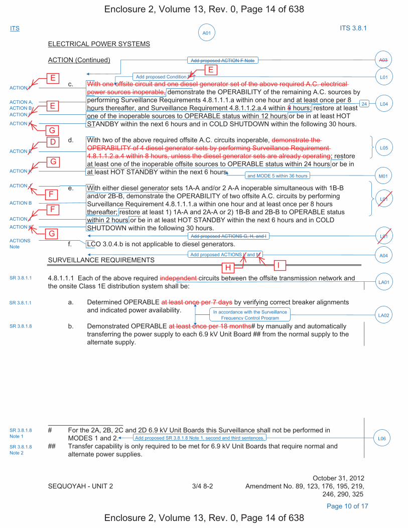
A01ITS ITS 3.8.1
ELECTRICAL POWER SYSTEMS
ACTION (Continued)
c. With one offsite circuit and one diesel generator set of the above required A.C. electricalpower sources inoperable, demonstrate the OPERABILITY of the remaining A.C. sources by performing Surveillance Requirements 4.8.1.1.1.a within one hour and at least once per 8 hours thereafter, and Surveillance Requirement 4.8.1.1.2.a.4 within 8 hours; restore at least one of the inoperable sources to OPERABLE status within 12 hours or be in at least HOT STANDBY within the next 6 hours and in COLD SHUTDOWN within the following 30 hours.
d. With two of the above required offsite A.C. circuits inoperable, demonstrate theOPERABILITY of 4 diesel generator sets by performing Surveillance Requirement4.8.1.1.2.a.4 within 8 hours, unless the diesel generator sets are already operating; restoreat least one of the inoperable offsite sources to OPERABLE status within 24 hours or be inat least HOT STANDBY within the next 6 hours.
e. With either diesel generator sets 1A-A and/or 2 A-A inoperable simultaneous with 1B-Band/or 2B-B, demonstrate the OPERABILITY of two offsite A.C. circuits by performingSurveillance Requirement 4.8.1.1.1.a within one hour and at least once per 8 hoursthereafter; restore at least 1) 1A-A and 2A-A or 2) 1B-B and 2B-B to OPERABLE statuswithin 2 hours or be in at least HOT STANDBY within the next 6 hours and in COLDSHUTDOWN within the following 30 hours.
f. LCO 3.0.4.b is not applicable to diesel generators.
SURVEILLANCE REQUIREMENTS
4.8.1.1.1 Each of the above required independent circuits between the offsite transmission network and the onsite Class 1E distribution system shall be:
a. Determined OPERABLE at least once per 7 days by verifying correct breaker alignmentsand indicated power availability.
b. Demonstrated OPERABLE at least once per 18 months# by manually and automaticallytransferring the power supply to each 6.9 kV Unit Board ## from the normal supply to the alternate supply.
# For the 2A, 2B, 2C and 2D 6.9 kV Unit Boards this Surveillance shall not be performed in MODES 1 and 2.
## Transfer capability is only required to be met for 6.9 kV Unit Boards that require normal and alternate power supplies.
October 31, 2012 SEQUOYAH - UNIT 2 3/4 8-2 Amendment No. 89, 123, 176, 195, 219,
246, 290, 325
Page 10 of 17
ACTION F
ACTION A, ACTION B ACTION F
ACTION K
L01Add proposed Condition F
A03Add proposed ACTION F Note
24 L04
ACTION E
ACTION K
ACTION J
L05
M01and MODE 5 within 36 hours
L01
ACTION J
ACTION K
ACTION B
L01Add proposed ACTIONS G, H, and I
A04Add proposed ACTIONS L and M
SR 3.8.1.1
SR 3.8.1.1
LA02
ACTIONS Note
In accordance with the Surveillance Frequency Control Program
SR 3.8.1.8
SR 3.8.1.8 Note 1 L06Add proposed SR 3.8.1.8 Note 1, second and third sentences.
SR 3.8.1.8 Note 2
LA01
Enclosure 2, Volume 13, Rev. 0, Page 14 of 638
Enclosure 2, Volume 13, Rev. 0, Page 14 of 638
E E
E
D
G
F
F
G
G
H I
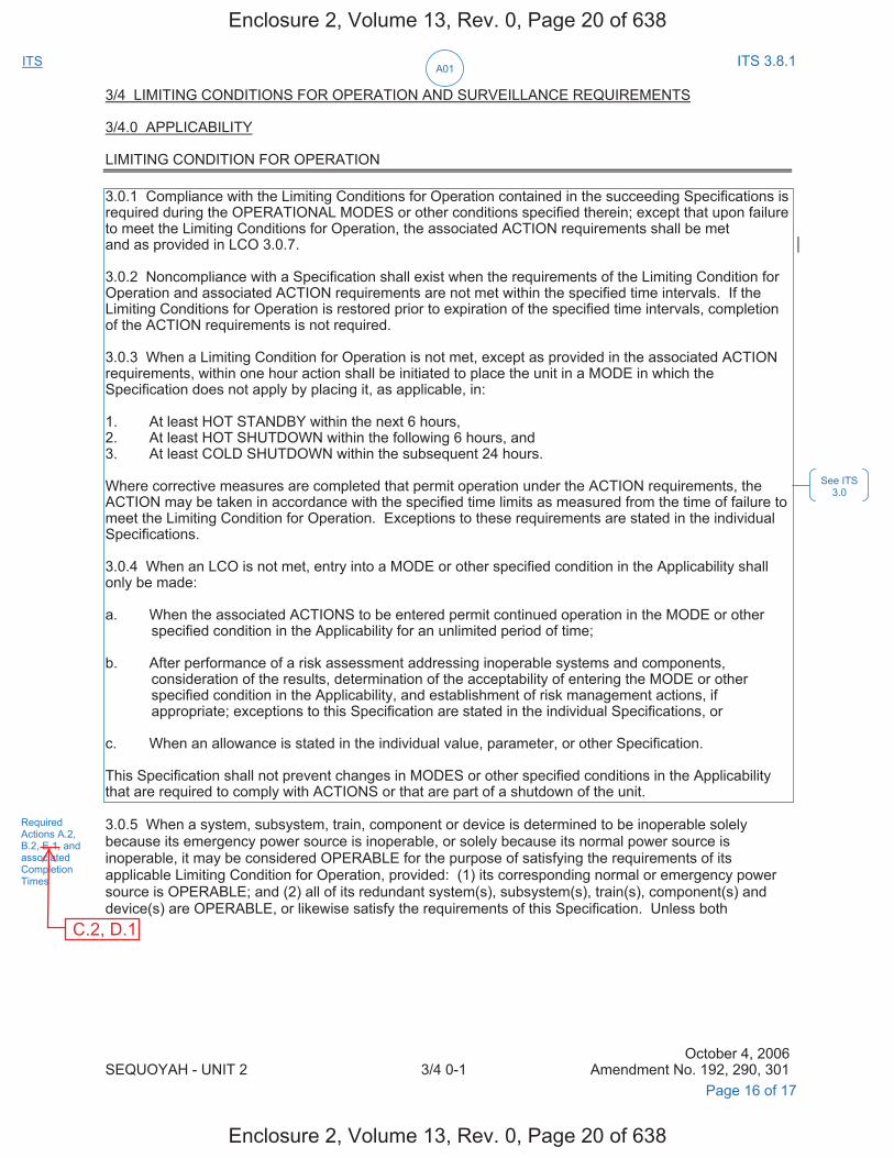
A01ITS ITS 3.8.1
3/4 LIMITING CONDITIONS FOR OPERATION AND SURVEILLANCE REQUIREMENTS
3/4.0 APPLICABILITY
LIMITING CONDITION FOR OPERATION
3.0.1 Compliance with the Limiting Conditions for Operation contained in the succeeding Specifications is required during the OPERATIONAL MODES or other conditions specified therein; except that upon failure to meet the Limiting Conditions for Operation, the associated ACTION requirements shall be met and as provided in LCO 3.0.7.
3.0.2 Noncompliance with a Specification shall exist when the requirements of the Limiting Condition for Operation and associated ACTION requirements are not met within the specified time intervals. If the Limiting Conditions for Operation is restored prior to expiration of the specified time intervals, completion of the ACTION requirements is not required.
3.0.3 When a Limiting Condition for Operation is not met, except as provided in the associated ACTION requirements, within one hour action shall be initiated to place the unit in a MODE in which the Specification does not apply by placing it, as applicable, in:
1. At least HOT STANDBY within the next 6 hours,2. At least HOT SHUTDOWN within the following 6 hours, and3. At least COLD SHUTDOWN within the subsequent 24 hours.
Where corrective measures are completed that permit operation under the ACTION requirements, the ACTION may be taken in accordance with the specified time limits as measured from the time of failure to meet the Limiting Condition for Operation. Exceptions to these requirements are stated in the individual Specifications.
3.0.4 When an LCO is not met, entry into a MODE or other specified condition in the Applicability shall only be made:
a. When the associated ACTIONS to be entered permit continued operation in the MODE or otherspecified condition in the Applicability for an unlimited period of time;
b. After performance of a risk assessment addressing inoperable systems and components,consideration of the results, determination of the acceptability of entering the MODE or otherspecified condition in the Applicability, and establishment of risk management actions, ifappropriate; exceptions to this Specification are stated in the individual Specifications, or
c. When an allowance is stated in the individual value, parameter, or other Specification.
This Specification shall not prevent changes in MODES or other specified conditions in the Applicability that are required to comply with ACTIONS or that are part of a shutdown of the unit.
3.0.5 When a system, subsystem, train, component or device is determined to be inoperable solely because its emergency power source is inoperable, or solely because its normal power source is inoperable, it may be considered OPERABLE for the purpose of satisfying the requirements of its applicable Limiting Condition for Operation, provided: (1) its corresponding normal or emergency power source is OPERABLE; and (2) all of its redundant system(s), subsystem(s), train(s), component(s) and device(s) are OPERABLE, or likewise satisfy the requirements of this Specification. Unless both
October 4, 2006 SEQUOYAH - UNIT 2 3/4 0-1 Amendment No. 192, 290, 301
See ITS 3.0
Required Actions A.2, B.2, E.1, and associated Completion Times
Page 16 of 17
Enclosure 2, Volume 13, Rev. 0, Page 20 of 638
Enclosure 2, Volume 13, Rev. 0, Page 20 of 638
C.2, D.1
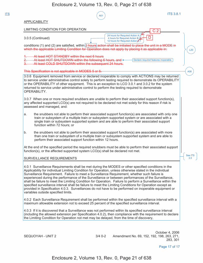
A01ITS ITS 3.8.1
APPLICABILITY
LIMITING CONDITION FOR OPERATION
3.0.5 (Continued)
conditions (1) and (2) are satisfied, within 2 hours action shall be initiated to place the unit in a MODE in which the applicable Limiting Condition for Operation does not apply by placing it as applicable in:
1. At least HOT STANDBY within the next 6 hours2. At least HOT SHUTDOWN within the following 6 hours, and3. At least COLD SHUTDOWN within the subsequent 24 hours.
This Specification is not applicable in MODES 5 or 6. 3.0.6 Equipment removed from service or declared inoperable to comply with ACTIONS may be returned to service under administrative control solely to perform testing required to demonstrate its OPERABILITY or the OPERABILITY of other equipment. This is an exception to LCO 3.0.1 and 3.0.2 for the system returned to service under administrative control to perform the testing required to demonstrate OPERABILITY.
3.0.7 When one or more required snubbers are unable to perform their associated support function(s), any affected supported LCO(s) are not required to be declared not met solely for this reason if risk is assessed and managed, and:
a. the snubbers not able to perform their associated support function(s) are associated with only onetrain or subsystem of a multiple train or subsystem supported system or are associated with asingle train or subsystem supported system and are able to perform their associated supportfunction within 72 hours; or
b. the snubbers not able to perform their associated support function(s) are associated with morethan one train or subsystem of a multiple train or subsystem supported system and are able toperform their associated support function within 12 hours.
At the end of the specified period the required snubbers must be able to perform their associated support function(s), or the affected supported system LCO(s) shall be declared not met.
SURVEILLANCE REQUIREMENTS
4.0.1 Surveillance Requirements shall be met during the MODES or other specified conditions in the Applicability for individual Limiting Condition for Operation, unless otherwise stated in the individual Surveillance Requirement. Failure to meet a Surveillance Requirement, whether such failure is experienced during the performance of the Surveillance or between performances of the Surveillance, shall be failure to meet the Limiting Condition for Operation. Failure to perform a Surveillance within the specified surveillance interval shall be failure to meet the Limiting Conditions for Operation except as provided in Specification 4.0.3. Surveillances do not have to be performed on inoperable equipment or variables outside specified limits.
4.0.2 Each Surveillance Requirement shall be performed within the specified surveillance interval with a maximum allowable extension not to exceed 25 percent of the specified surveillance interval.
4.0.3 If it is discovered that a Surveillance was not performed within its specified surveillance interval (including the allowed extension per Specification 4.0.2), then compliance with the requirement to declare the Limiting Condition for Operation not met may be delayed, from the time of discovery,
October 4, 2006 SEQUOYAH - UNIT 2 3/4 0-2 Amendment No. 69, 152, 192, 198, 263, 271,
283, 301
Page 17 of 17
See ITS 3.0
L20
24 hours for Required Action A.2 4 hours for Required Action B.2
12 hours for Required Action E.1
Declare required features inoperable.
A08
Enclosure 2, Volume 13, Rev. 0, Page 21 of 638
Enclosure 2, Volume 13, Rev. 0, Page 21 of 638
D , C.2
DISCUSSION OF CHANGES ITS 3.8.1, AC SOURCES - OPERATING
Sequoyah Unit 1 and Unit 2 Page 1 of 24
ADMINISTRATIVE CHANGES
A01 In the conversion of the Sequoyah Nuclear Plant (SQN) Current Technical Specifications (CTS) to the plant specific Improved Technical Specifications (ITS), certain changes (wording preferences, editorial changes, reformatting, revised numbering, etc.) are made to obtain consistency with NUREG-1431, Rev. 4.0, "Standard Technical Specifications-Westinghouse Plants" (ISTS) and additional Technical Specification Task Force (TSTF) travelers included in this submittal.
These changes are designated as administrative changes and are acceptable because they do not result in technical changes to the CTS.
A02 CTS 3.8.1.1.a Note @ has an expiration date of November 30, 2013. As it is anticipated that the SQN ITS Conversion License Amendment Request will not be approved by the NRC before this date, Note @ has been deleted. As such, these changes are administrative.
A03 CTS 3.8.1.1 ACTION c applies when one offsite circuit and one diesel generator (DG) are inoperable. In this condition, one or more required electrical boards may be de-energized. CTS 3.8.2.1 provides an ACTION for a de-energized required electrical board. ITS 3.8.1 ACTION F Note in the Required Actions column states, "Enter applicable Conditions and Required Action of LCO 3.8.9, "Distribution System - Operating," when Condition F is entered with no AC power source to any train." This changes the CTS by specifically requiring the compensatory actions for Distribution System - Operating to be taken, if a distribution train is made inoperable by inoperable AC Sources.
This change is acceptable because no changes are made to CTS requirements. CTS 3.0.1 requires the associated ACTION requirements to be met when an LCO is not met. With the addition of ITS LCO 3.0.6, an exception to ITS LCO 3.0.2 (CTS 3.0.1) was created, whereby ACTION requirements associated with an unmet LCO are not required to be met. Therefore, in the event AC Sources are inoperable such that a distribution subsystem is de-energized, ITS LCO 3.0.6 would allow taking only the AC Sources ACTIONS; taking exception to complying with the Distribution System ACTIONS. Since the AC Sources ACTIONS may not be sufficiently conservative in the event of an entire train without power, specific direction to take appropriate ACTIONS for the Distribution System is added (ITS 3.8.1, Note to ACTION F) for the condition of no power for a train. This format and construction implements the existing treatment of this condition within the framework of the ITS methods. This change is designated as administrative because it does not result in a technical change to the CTS.
A04 CTS 3.8.1.1 does not contain an ACTION for multiple offsite circuits and DGs inoperable. Having multiple offsite circuits and DGs inoperable requires entering CTS LCO 3.0.3. ITS 3.8.1 ACTION L requires entering LCO 3.0.3 immediately, if two offsite circuits are inoperable concurrent with one or more inoperable Train A or Train B DG(s). ITS 3.8.1 ACTION M requires entering LCO 3.0.3 immediately, if one offsite circuit is inoperable concurrent with one or more inoperable Train A and Train DGs. This changes the CTS by adding specific ACTIONS requiring entry into LCO 3.0.3.
Enclosure 2, Volume 13, Rev. 0, Page 22 of 638
Enclosure 2, Volume 13, Rev. 0, Page 22 of 638
I
H
any shutdown board
B
any shutdown board resulting in a de-energized shutdown board
ACTIONS NOTE 2
any Condition(s)
ACTIONS NOTE 2
shutdown board and de-energized
DISCUSSION OF CHANGES ITS 3.8.1, AC SOURCES - OPERATING
Sequoyah Unit 1 and Unit 2 Page 3 of 24
specific CTS DG loading requirement with a statement that DG loadings may include gradual loading as recommended by the manufacturer. This change is consistent with the recommendations of Generic Letter (GL) 93-05, "Line- Item Technical Specifications Improvements to Reduce Surveillance Requirements for Testing During Power Operation." GL 93-05, Section 10.1, states that DGs "should be loaded in accordance with vendor recommendations for all test purposes other than the refueling outage LOOP tests." The change is acceptable, because it will ensure the DGs will continue to be operated consistent with manufacturer recommendations. This change is designated as administrative, because it does not result in a technical change to the CTS.
A07 CTS 4.8.1.1.2.d.5 requires verification that on an ESF actuation test signal (without loss of offsite power), each DG starts and operates for at least 5 minutes. ITS SR 3.8.1.12 requires a similar test, but does not specify that the DG auto-start on an ESF actuation test signal is "without loss of offsite power." This changes the CTS by not specifying the DG auto-start on an ESF actuation test signal is without a loss of offsite power signal.
The purpose of CTS 4.8.1.1.2.d.5 is to demonstrate that each DG automatically starts on an ESF actuation test signal. The requirements of this Surveillance are retained in the ITS as SR 3.8.1.12. The purpose of CTS 4.8.1.1.2.d.6.b) is to verify that each DG starts on a loss of offsite power concurrent with an ESF actuation test signal. The requirements of this Surveillance are retained in the ITS as SR 3.8.1.18. This change is acceptable, because it is understood that the CTS 4.8.1.1.2.d.5 required DG start on an ESF actuation test signal is without a loss of offsite power signal. Therefore, it is unnecessary to provide this information in ITS SR 3.8.1.12. This change is designated as administrative, because it does not result in a technical change to the CTS.
A08 CTS 3.0.5 states that it is not applicable in MODE 5 or 6. CTS 3.0.5 has been incorporated into the ACTIONS of ITS 3.8.1. This changes the CTS by incorporating the allowances of CTS 3.0.5 in ITS 3.8.1.
This change is acceptable because ITS 3.8.1 is only applicable in MODES 1, 2, 3, and 4. Therefore, the statement in CTS 3.0.5, that states that the Specification is not applicable in MODE 5 or 6, is no longer necessary and is deleted. This change is designated as administrative, because it does not result in technical changes to the CTS.
MORE RESTRICTIVE CHANGES
M01 CTS 3.8.1.1 ACTION d specifies the compensatory actions for two inoperable offsite circuits. The action requires restoration of at least one of the offsite sources within 24 hours, and if it is not restored within the allowed time, the unit is required to be in at least HOT STANDBY within the next 6 hours. ITS 3.8.1 ACTION E requires restoration of at least one offsite circuit to OPERABLE status within 24 hours, otherwise ITS 3.8.1 ACTION K requires the unit to be in MODE 3 within 6 hours and MODE 5 within 36 hours. This changes the CTS by adding the requirement to be in MODE 5 within 36 hours.
Enclosure 2, Volume 13, Rev. 0, Page 24 of 638
Enclosure 2, Volume 13, Rev. 0, Page 24 of 638
G D
DISCUSSION OF CHANGES ITS 3.8.1, AC SOURCES - OPERATING
Sequoyah Unit 1 and Unit 2 Page 11 of 24
LA06 (Type 1 – Removing Details of System Design and System Description, Including Design Limits) CTS 4.8.1.1.2.g.1 requires verification of each DG's capability to reject a load of greater than or equal to 600 kW while maintaining voltage and frequency within specified ranges. ITS SR 3.8.1.9 requires a similar verification, but does not specify the value of the single largest post-accident load to reject. This changes the CTS by moving the detail of the single largest load to the ITS Bases.
The removal of these details related to system design from the Technical Specifications is acceptable, because this type of information is not necessary to be included in the Technical Specifications to provide adequate protection of public health and safety. The ITS retains the requirement to verify that each DG is capable of maintaining voltage and frequency within specified ranges upon reject of the single largest post-accident load. The removed information will be adequately controlled in the ITS Bases. Changes to the Bases are controlled by the Technical Specification Bases Control Program in Chapter 5. This program provides for the evaluation of changes to ensure the Bases are properly controlled. This change is designated as a less restrictive removal of detail change, because information relating to system design is being removed from the Technical Specifications.
LESS RESTRICTIVE CHANGES
L01 CTS 3.8.1.1 ACTION a provides actions for one inoperable offsite circuit and allows 72 hours to restore the inoperable offsite circuit to OPERABLE status before requiring the unit to be shut down and cooled down. CTS 3.8.1.1 ACTION b provides actions for one or both DGs in a train inoperable and allows 7 days to restore the inoperable DG(s) to OPERABLE status before requiring the unit to be shut down and cooled down. CTS 3.8.1.1 ACTION c provides actions for one inoperable offsite circuit and one inoperable DG and allows 12 hours to restore at least one of the inoperable AC sources to OPERABLE status before requiring the unit to be shut down and cooled down. CTS 3.8.1.1 ACTION d provides actions for two inoperable offsite circuits and allows 24 hours to restore at least one of the inoperable offsite circuits to OPERABLE status before requiring the unit to be shut down. CTS 3.8.1.1 ACTION e provides actions for one or two inoperable DGs in both trains and allows 2 hours to restore the inoperable DG(s) in one train to OPERABLE status before requiring the unit to be shut down and cooled down. CTS 3.8.1.1 ACTION f states LCO 3.0.4.b is not applicable to DGs. The ITS ACTIONS are modified by a Note stating LCO 3.0.4.b is not applicable to DGs. ITS 3.8.1 ACTION A provides actions for one inoperable offsite circuit for reasons other than Condition C, and allows 72 hours to restore the inoperable offsite power source to OPERABLE status. ITS 3.8.1 ACTION B provides actions for one inoperable associated unit's DG or both DGs in one train inoperable, and allows 7 days to restore the inoperable DG(s) to OPERABLE status. ITS 3.8.1 ACTION C provides actions for one offsite circuit inoperable solely due to an inoperable offsite power source to an opposite unit's 6.9 kV Shutdown Board, and requires declaration that the affected required feature(s) with no offsite power available are inoperable when its redundant required feature is inoperable in 24 hours. Otherwise, the affected required feature(s) are declared inoperable in 7 days, if the offsite circuit cannot be
Enclosure 2, Volume 13, Rev. 0, Page 32 of 638
Enclosure 2, Volume 13, Rev. 0, Page 32 of 638
requires: 1) performance of ITS SR 3.8.1.1 for the OPERABLE offsite circuit in 1 hour and once per 8 hours thereafter, 2) declaration that the affected required feature(s) with no offsite power available are inoperable when its redundant required feature is inoperable in 24 hours, and 3) restoration of the offsite circuit to OPERABLE status in 7 days.
DISCUSSION OF CHANGES ITS 3.8.1, AC SOURCES - OPERATING
Sequoyah Unit 1 and Unit 2 Page 12 of 24
restored to an OPERABLE status. ITS 3.8.1 ACTION D requires declaration that the affected required feature(s) with no OPERABLE DG are inoperable when its redundant required feature is inoperable in 4 hours. Otherwise, the affected required feature(s) are declared inoperable in 7 days, if the DG cannot be restored to an OPERABLE status. ITS 3.8.1 ACTION E requires declaration that the affected required feature(s) with no offsite power available are inoperable when its redundant required feature is inoperable in 12 hours. Otherwise, one offsite circuit is required to be restored to an OPERABLE status in 24 hours. ITS 3.8.1 ACTION F provides actions for one associated unit's offsite circuit inoperable concurrent with one associated unit's DG inoperable, and allows 12 hours to restore one of the inoperable AC sources to OPERABLE status. ITS ACTION G requires declaring the required feature(s) on the opposite unit's 6.9 kV Shutdown Board with no offsite power available inoperable in 7 days. ITS ACTION H requires declaring the required feature(s) on the opposite unit's 6.9 kV Shutdown Board with no DG available inoperable in 7 days. ITS ACTION I provides actions for one offsite circuit inoperable solely due to an inoperable offsite power source to an opposite unit's 6.9 kV Shutdown Board concurrent with one opposite unit's DG inoperable, and allows 7 days to restore one of the inoperable AC sources to OPERABLE status. In addition, a Note modifying ITS ACTION I requires entry into the applicable Conditions and Required Actions of LCO 3.8.9 with no AC power source to an opposite unit's 6.9 kV Shutdown Board. ITS 3.8.1 ACTION J provides actions for one or more Train A and one or more Train B DGs inoperable and allows 2 hours to restore one Train of DGs to OPERABLE status. ITS 3.8.1 ACTION K requires the unit to be shut down and cooled down if a Required Action and associated Completion Time of Condition A, B, E, F, I, or J is not met. These changes to the CTS provide separate ACTIONS to declare the required features powered from the opposite unit's Class 1E AC Electrical Power Distribution System inoperable as the remedial measures for the inoperable AC sources.
The purpose of the CTS 3.8.1.1 ACTIONS is to limit the time the unit can remain operating with different combinations of inoperable offsite circuits and DGs. The onsite Class 1E AC Electrical Distribution System supplies electrical power to two power trains shared between the two units. The core cooling and containment cooling system loads (e.g., Safety Injection (SI) pumps, Auxiliary Feedwater (AFW) pumps, Residual Heat Removal (RHR) pumps, Centrifugal Charging pumps, Containment Spray pumps, and Air Return System (ARS) fans) are unitized to the respective unit's 6.9 kV Shutdown Boards. However, some safety-related systems (e.g., Essential Raw Cooling Water (ERCW), Component Cooling (CCS), Emergency Gas Treatment (EGTS), Auxiliary Building Gas Treatment, (ABGTS), Control Room Emergency Ventilation (CREVs), and Control Room HVAC (CRACS)) are shared between the units. The AC sources for the shared loads are distributed across both unit's shutdown boards. Therefore, two qualified offsite circuits and four DGs capable of supplying the onsite Class 1E AC Electrical Distribution System are required to be OPERABLE. However, the impacts of an inoperable offsite power source or DG on an opposite unit's 6.9 kV Shutdown Board differ from the impacts of an inoperable offsite power source or DG on an associated unit's 6.9 kV Shutdown Board, due to the loads powered from the respective board.
Enclosure 2, Volume 13, Rev. 0, Page 33 of 638
Enclosure 2, Volume 13, Rev. 0, Page 33 of 638
E
For the condition of one offsite circuit inoperable solely due to an inoperable power source to an opposite unit's 6.9 kV Shutdown Board concurrent with an inoperable DG (similar to CTS 3.8.1.1 Action c), ITS 3.8.1 Conditions B and C would be entered concurrently. ITS 3.8.1 ACTIONS B and C require, in part, restoration of the inoperable AC sources (circuit and DG) to an OPERABLE status in 7 days. This changes the CTS by providing a new ITS 3.8.1 ACTION C toallow 7 days to restore an inoperable offsite circuit to an OPERABLE status, if the offsite circuit isinoperable solely due to an inoperable power source to an opposite unit's Shutdown Board (e.g.,for Unit 1 an offsite power source to 6.9 kV Shutdown Board 2A-A or 2B-B is inoperable).

DISCUSSION OF CHANGES ITS 3.8.1, AC SOURCES - OPERATING
Sequoyah Unit 1 and Unit 2 Page 13 of 24
For example, with SQN Unit 1 in MODES 1, 2, 3, and 4, 6.9 kV Shutdown Boards 1A-A and 1B-B, and the associated offsite power sources and DGs are required to be OPERABLE to provide electrical power to the ESF systems powered from those boards. Additionally, 6.9 kV Shutdown Boards 2A-A and 2B-B and associated offsite power sources and DGs are required to be OPERABLE to provide electrical power to any required shared components required for Unit 1. If it is necessary to de-energize 6.9 kV Shutdown Board 2A-A or 2B-B, the redundant shared systems can be aligned prior to de-energizing the shutdown board to ensure no loss of safety function will occur. Upon removing the shutdown board from service, the applicable Conditions and Required Actions for the affected shared system LCOs will be entered and tracked and either the offsite power source or the DG is required to be restored to an OPERABLE status in 7 days.
In the event of an unplanned loss of an offsite power source to an opposite unit's 6.9 kV Shutdown Board, the proposed actions require declaration that the affected required feature(s) with no offsite power available are inoperable when its redundant required feature is inoperable in 24 hours. Otherwise, the affected required feature(s) are declared inoperable in 7 days, if the offsite power source cannot be restored to an OPERABLE status. Similarly, in the event of an unplanned loss of a DG to an opposite unit 6.9 kV Shutdown Board, the proposed actions require declaration that the affected required feature(s) with no OPERABLE DG are inoperable when its redundant required feature is inoperable in 4 hours. Otherwise, the affected required feature(s) are declared inoperable in 7 days, if the DG cannot be restored to an OPERABLE status. In both cases, the ACTIONS require performance of SR 3.8.1.1 for the required OPERABLE offsite circuit(s) within 1 hour and once per 8 hours thereafter.
The Required Actions are consistent with safe operation under the specified Condition, considering the OPERABLE status of the redundant systems or features. This includes the capacity and capability of remaining systems or features, a reasonable time for repairs or replacement, and the low probability of a DBA occurring during the repair period. These changes are acceptable because the Required Actions are used to establish remedial measures that must be taken in response to the degraded conditions in order to minimize risk associated with continued operation, while providing time to repair inoperable features. If the necessary repairs cannot be made within the established Completion Time, the associated required features are declared inoperable and the applicable Conditions and Required Actions for the affected shared system LCOs are entered and tracked. This change is acceptable because the provided ACTIONS effect restoration of the opposite unit's AC sources commensurate with the importance of maintaining these AC sources capable of supporting the associated unit's required feature(s). This change is designated as less restrictive, because less stringent Required Actions are being applied in the ITS than were applied in the CTS.
L02 (Category 4 – Relaxation of Required Action) CTS 3.8.1.1 ACTION b requires with DG set(s) 1A-A and/or 2A-A or 1B-B and/or 2B-B inoperable, determination that OPERABLE DGs are not inoperable due to common cause failure or through performance of CTS 4.8.1.1.2.a.4. This ACTION is modified by Note #, requiring completion of the required action once the ACTION is entered. ITS 3.8.1
Enclosure 2, Volume 13, Rev. 0, Page 34 of 638
Enclosure 2, Volume 13, Rev. 0, Page 34 of 638
ITS 3.8.1 ACTIONG is entered andthe unit is requiredto be shut down toMODE 3 in 6hours and MODE5 in 36 hours.
, and restoration of the offsite circuit to OPERABLE status in 7 days
In
, and restoration of the DG to OPERABLE status in 7 days
offsite circuit
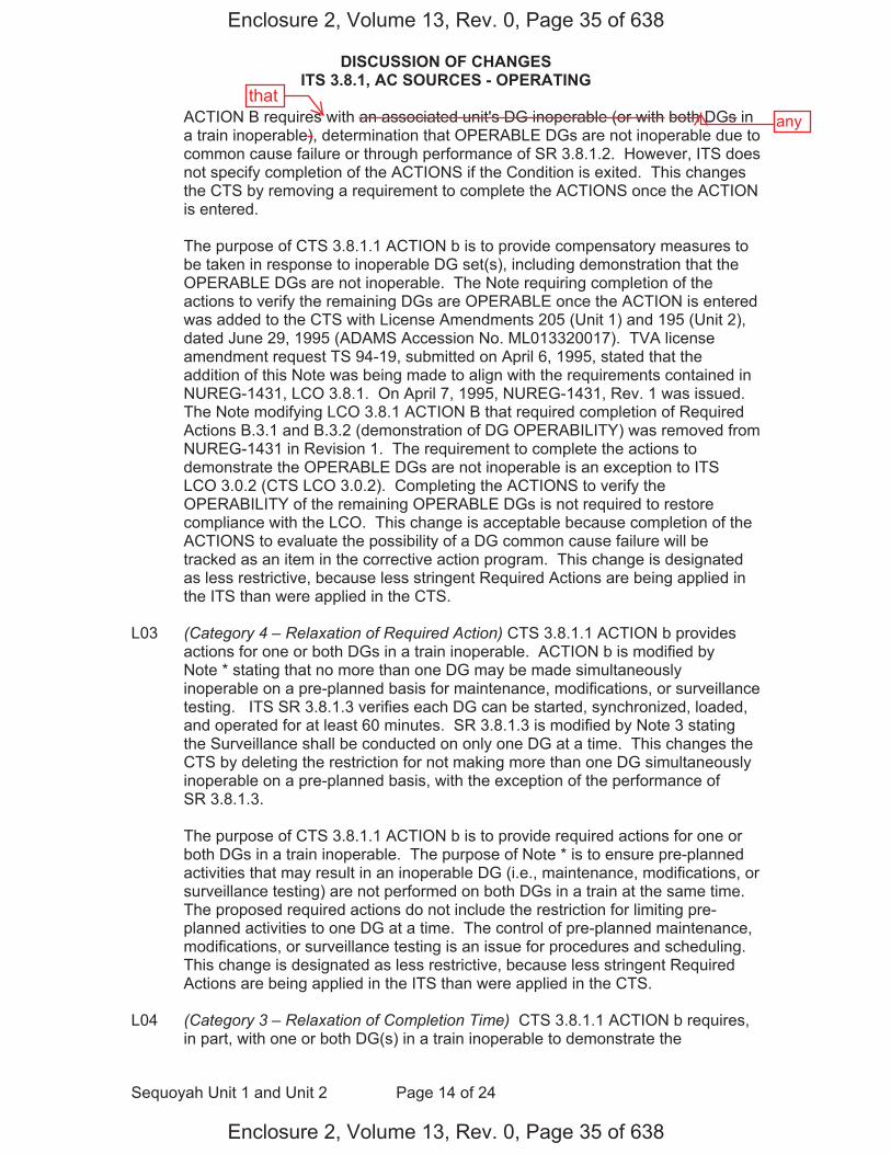
DISCUSSION OF CHANGES ITS 3.8.1, AC SOURCES - OPERATING
Sequoyah Unit 1 and Unit 2 Page 14 of 24
ACTION B requires with an associated unit's DG inoperable (or with both DGs in a train inoperable), determination that OPERABLE DGs are not inoperable due to common cause failure or through performance of SR 3.8.1.2. However, ITS does not specify completion of the ACTIONS if the Condition is exited. This changes the CTS by removing a requirement to complete the ACTIONS once the ACTION is entered.
The purpose of CTS 3.8.1.1 ACTION b is to provide compensatory measures to be taken in response to inoperable DG set(s), including demonstration that the OPERABLE DGs are not inoperable. The Note requiring completion of the actions to verify the remaining DGs are OPERABLE once the ACTION is entered was added to the CTS with License Amendments 205 (Unit 1) and 195 (Unit 2), dated June 29, 1995 (ADAMS Accession No. ML013320017). TVA license amendment request TS 94-19, submitted on April 6, 1995, stated that the addition of this Note was being made to align with the requirements contained in NUREG-1431, LCO 3.8.1. On April 7, 1995, NUREG-1431, Rev. 1 was issued. The Note modifying LCO 3.8.1 ACTION B that required completion of Required Actions B.3.1 and B.3.2 (demonstration of DG OPERABILITY) was removed from NUREG-1431 in Revision 1. The requirement to complete the actions to demonstrate the OPERABLE DGs are not inoperable is an exception to ITS LCO 3.0.2 (CTS LCO 3.0.2). Completing the ACTIONS to verify the OPERABILITY of the remaining OPERABLE DGs is not required to restore compliance with the LCO. This change is acceptable because completion of the ACTIONS to evaluate the possibility of a DG common cause failure will be tracked as an item in the corrective action program. This change is designated as less restrictive, because less stringent Required Actions are being applied in the ITS than were applied in the CTS.
L03 (Category 4 – Relaxation of Required Action) CTS 3.8.1.1 ACTION b provides actions for one or both DGs in a train inoperable. ACTION b is modified by Note * stating that no more than one DG may be made simultaneously inoperable on a pre-planned basis for maintenance, modifications, or surveillance testing. ITS SR 3.8.1.3 verifies each DG can be started, synchronized, loaded, and operated for at least 60 minutes. SR 3.8.1.3 is modified by Note 3 stating the Surveillance shall be conducted on only one DG at a time. This changes the CTS by deleting the restriction for not making more than one DG simultaneously inoperable on a pre-planned basis, with the exception of the performance of SR 3.8.1.3.
The purpose of CTS 3.8.1.1 ACTION b is to provide required actions for one or both DGs in a train inoperable. The purpose of Note * is to ensure pre-planned activities that may result in an inoperable DG (i.e., maintenance, modifications, or surveillance testing) are not performed on both DGs in a train at the same time. The proposed required actions do not include the restriction for limiting pre-planned activities to one DG at a time. The control of pre-planned maintenance, modifications, or surveillance testing is an issue for procedures and scheduling. This change is designated as less restrictive, because less stringent Required Actions are being applied in the ITS than were applied in the CTS.
L04 (Category 3 – Relaxation of Completion Time) CTS 3.8.1.1 ACTION b requires, in part, with one or both DG(s) in a train inoperable to demonstrate the
Enclosure 2, Volume 13, Rev. 0, Page 35 of 638
Enclosure 2, Volume 13, Rev. 0, Page 35 of 638
thatany
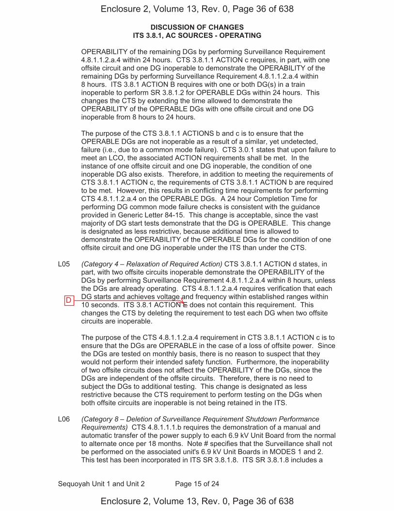
DISCUSSION OF CHANGES ITS 3.8.1, AC SOURCES - OPERATING
Sequoyah Unit 1 and Unit 2 Page 15 of 24
OPERABILITY of the remaining DGs by performing Surveillance Requirement 4.8.1.1.2.a.4 within 24 hours. CTS 3.8.1.1 ACTION c requires, in part, with one offsite circuit and one DG inoperable to demonstrate the OPERABILITY of the remaining DGs by performing Surveillance Requirement 4.8.1.1.2.a.4 within 8 hours. ITS 3.8.1 ACTION B requires with one or both DG(s) in a train inoperable to perform SR 3.8.1.2 for OPERABLE DGs within 24 hours. This changes the CTS by extending the time allowed to demonstrate the OPERABILITY of the OPERABLE DGs with one offsite circuit and one DG inoperable from 8 hours to 24 hours.
The purpose of the CTS 3.8.1.1 ACTIONS b and c is to ensure that the OPERABLE DGs are not inoperable as a result of a similar, yet undetected, failure (i.e., due to a common mode failure). CTS 3.0.1 states that upon failure to meet an LCO, the associated ACTION requirements shall be met. In the instance of one offsite circuit and one DG inoperable, the condition of one inoperable DG also exists. Therefore, in addition to meeting the requirements of CTS 3.8.1.1 ACTION c, the requirements of CTS 3.8.1.1 ACTION b are required to be met. However, this results in conflicting time requirements for performing CTS 4.8.1.1.2.a.4 on the OPERABLE DGs. A 24 hour Completion Time for performing DG common mode failure checks is consistent with the guidance provided in Generic Letter 84-15. This change is acceptable, since the vast majority of DG start tests demonstrate that the DG is OPERABLE. This change is designated as less restrictive, because additional time is allowed to demonstrate the OPERABILITY of the OPERABLE DGs for the condition of one offsite circuit and one DG inoperable under the ITS than under the CTS.
L05 (Category 4 – Relaxation of Required Action) CTS 3.8.1.1 ACTION d states, in part, with two offsite circuits inoperable demonstrate the OPERABILITY of the DGs by performing Surveillance Requirement 4.8.1.1.2.a.4 within 8 hours, unless the DGs are already operating. CTS 4.8.1.1.2.a.4 requires verification that each DG starts and achieves voltage and frequency within established ranges within 10 seconds. ITS 3.8.1 ACTION E does not contain this requirement. This changes the CTS by deleting the requirement to test each DG when two offsite circuits are inoperable.
The purpose of the CTS 4.8.1.1.2.a.4 requirement in CTS 3.8.1.1 ACTION c is to ensure that the DGs are OPERABLE in the case of a loss of offsite power. Since the DGs are tested on monthly basis, there is no reason to suspect that they would not perform their intended safety function. Furthermore, the inoperability of two offsite circuits does not affect the OPERABILITY of the DGs, since the DGs are independent of the offsite circuits. Therefore, there is no need to subject the DGs to additional testing. This change is designated as less restrictive because the CTS requirement to perform testing on the DGs when both offsite circuits are inoperable is not being retained in the ITS.
L06 (Category 8 – Deletion of Surveillance Requirement Shutdown Performance Requirements) CTS 4.8.1.1.1.b requires the demonstration of a manual and automatic transfer of the power supply to each 6.9 kV Unit Board from the normal to alternate once per 18 months. Note # specifies that the Surveillance shall not be performed on the associated unit's 6.9 kV Unit Boards in MODES 1 and 2. This test has been incorporated in ITS SR 3.8.1.8. ITS SR 3.8.1.8 includes a
Enclosure 2, Volume 13, Rev. 0, Page 36 of 638
Enclosure 2, Volume 13, Rev. 0, Page 36 of 638
D
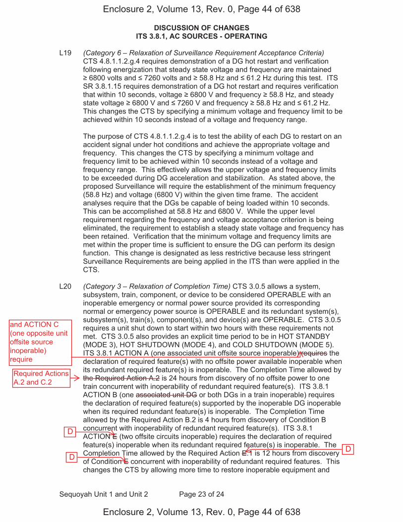
DISCUSSION OF CHANGES ITS 3.8.1, AC SOURCES - OPERATING
Sequoyah Unit 1 and Unit 2 Page 23 of 24
L19 (Category 6 – Relaxation of Surveillance Requirement Acceptance Criteria) CTS 4.8.1.1.2.g.4 requires demonstration of a DG hot restart and verification following energization that steady state voltage and frequency are maintained 6800 volts and 7260 volts and 58.8 Hz and 61.2 Hz during this test. ITS
SR 3.8.1.15 requires demonstration of a DG hot restart and requires verification that within 10 seconds, voltage 6800 V and frequency 58.8 Hz, and steady state voltage 6800 V and 7260 V and frequency 58.8 Hz and 61.2 Hz. This changes the CTS by specifying a minimum voltage and frequency limit to be achieved within 10 seconds instead of a voltage and frequency range.
The purpose of CTS 4.8.1.1.2.g.4 is to test the ability of each DG to restart on an accident signal under hot conditions and achieve the appropriate voltage and frequency. This changes the CTS by specifying a minimum voltage and frequency limit to be achieved within 10 seconds instead of a voltage and frequency range. This effectively allows the upper voltage and frequency limits to be exceeded during DG acceleration and stabilization. As stated above, the proposed Surveillance will require the establishment of the minimum frequency (58.8 Hz) and voltage (6800 V) within the given time frame. The accident analyses require that the DGs be capable of being loaded within 10 seconds. This can be accomplished at 58.8 Hz and 6800 V. While the upper level requirement regarding the frequency and voltage acceptance criterion is being eliminated, the requirement to establish a steady state voltage and frequency has been retained. Verification that the minimum voltage and frequency limits are met within the proper time is sufficient to ensure the DG can perform its design function. This change is designated as less restrictive because less stringent Surveillance Requirements are being applied in the ITS than were applied in the CTS.
L20 (Category 3 – Relaxation of Completion Time) CTS 3.0.5 allows a system, subsystem, train, component, or device to be considered OPERABLE with an inoperable emergency or normal power source provided its corresponding normal or emergency power source is OPERABLE and its redundant system(s), subsystem(s), train(s), component(s), and device(s) are OPERABLE. CTS 3.0.5 requires a unit shut down to start within two hours with these requirements not met. CTS 3.0.5 also provides an explicit time period to be in HOT STANDBY (MODE 3), HOT SHUTDOWN (MODE 4), and COLD SHUTDOWN (MODE 5). ITS 3.8.1 ACTION A (one associated unit offsite source inoperable) requires the declaration of required feature(s) with no offsite power available inoperable when its redundant required feature(s) is inoperable. The Completion Time allowed by the Required Action A.2 is 24 hours from discovery of no offsite power to one train concurrent with inoperability of redundant required feature(s). ITS 3.8.1 ACTION B (one associated unit DG or both DGs in a train inoperable) requires the declaration of required feature(s) supported by the inoperable DG inoperable when its required redundant feature(s) is inoperable. The Completion Time allowed by the Required Action B.2 is 4 hours from discovery of Condition B concurrent with inoperability of redundant required feature(s). ITS 3.8.1 ACTION E (two offsite circuits inoperable) requires the declaration of required feature(s) inoperable when its redundant required feature(s) is inoperable. The Completion Time allowed by the Required Action E.1 is 12 hours from discovery of Condition E concurrent with inoperability of redundant required features. This changes the CTS by allowing more time to restore inoperable equipment and
Enclosure 2, Volume 13, Rev. 0, Page 44 of 638
Enclosure 2, Volume 13, Rev. 0, Page 44 of 638
D
D D
and ACTION C(one opposite unitoffsite sourceinoperable)require
Required ActionsA.2 and C.2
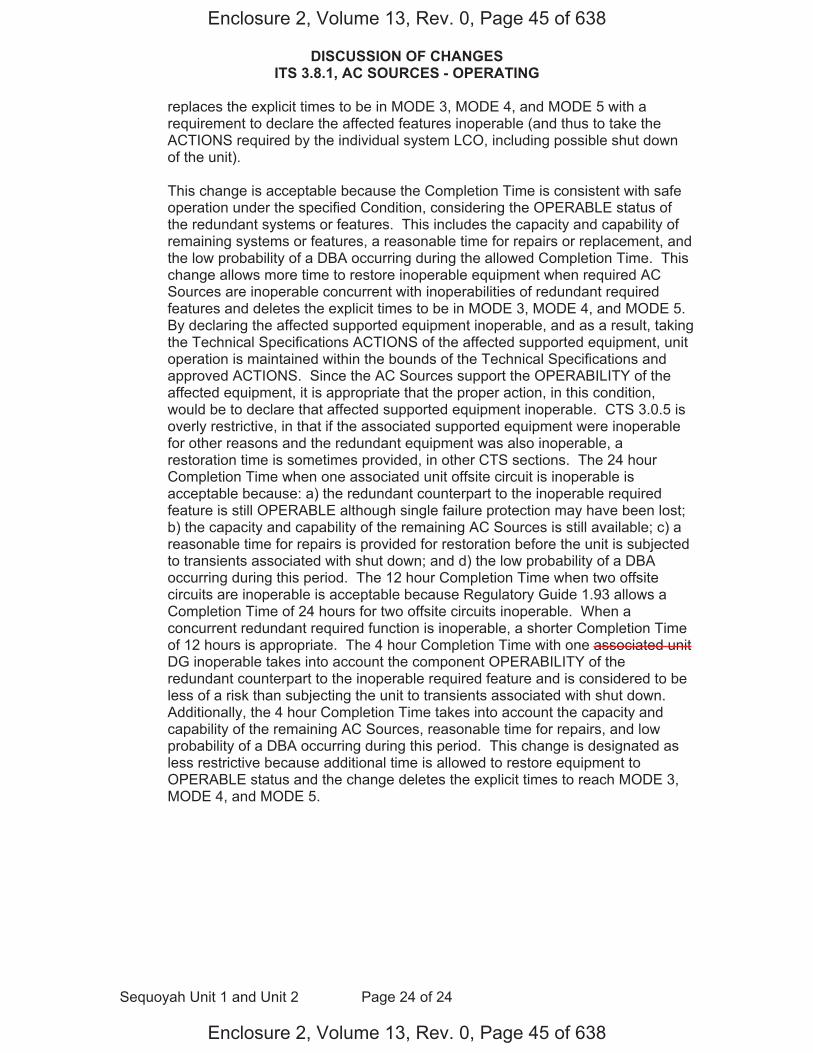
DISCUSSION OF CHANGES ITS 3.8.1, AC SOURCES - OPERATING
Sequoyah Unit 1 and Unit 2 Page 24 of 24
replaces the explicit times to be in MODE 3, MODE 4, and MODE 5 with a requirement to declare the affected features inoperable (and thus to take the ACTIONS required by the individual system LCO, including possible shut down of the unit).
This change is acceptable because the Completion Time is consistent with safe operation under the specified Condition, considering the OPERABLE status of the redundant systems or features. This includes the capacity and capability of remaining systems or features, a reasonable time for repairs or replacement, and the low probability of a DBA occurring during the allowed Completion Time. This change allows more time to restore inoperable equipment when required AC Sources are inoperable concurrent with inoperabilities of redundant required features and deletes the explicit times to be in MODE 3, MODE 4, and MODE 5. By declaring the affected supported equipment inoperable, and as a result, taking the Technical Specifications ACTIONS of the affected supported equipment, unit operation is maintained within the bounds of the Technical Specifications and approved ACTIONS. Since the AC Sources support the OPERABILITY of the affected equipment, it is appropriate that the proper action, in this condition, would be to declare that affected supported equipment inoperable. CTS 3.0.5 is overly restrictive, in that if the associated supported equipment were inoperable for other reasons and the redundant equipment was also inoperable, a restoration time is sometimes provided, in other CTS sections. The 24 hour Completion Time when one associated unit offsite circuit is inoperable is acceptable because: a) the redundant counterpart to the inoperable required feature is still OPERABLE although single failure protection may have been lost; b) the capacity and capability of the remaining AC Sources is still available; c) areasonable time for repairs is provided for restoration before the unit is subjected to transients associated with shut down; and d) the low probability of a DBA occurring during this period. The 12 hour Completion Time when two offsite circuits are inoperable is acceptable because Regulatory Guide 1.93 allows a Completion Time of 24 hours for two offsite circuits inoperable. When a concurrent redundant required function is inoperable, a shorter Completion Time of 12 hours is appropriate. The 4 hour Completion Time with one associated unit DG inoperable takes into account the component OPERABILITY of the redundant counterpart to the inoperable required feature and is considered to be less of a risk than subjecting the unit to transients associated with shut down. Additionally, the 4 hour Completion Time takes into account the capacity and capability of the remaining AC Sources, reasonable time for repairs, and low probability of a DBA occurring during this period. This change is designated as less restrictive because additional time is allowed to restore equipment to OPERABLE status and the change deletes the explicit times to reach MODE 3, MODE 4, and MODE 5.
Enclosure 2, Volume 13, Rev. 0, Page 45 of 638
Enclosure 2, Volume 13, Rev. 0, Page 45 of 638
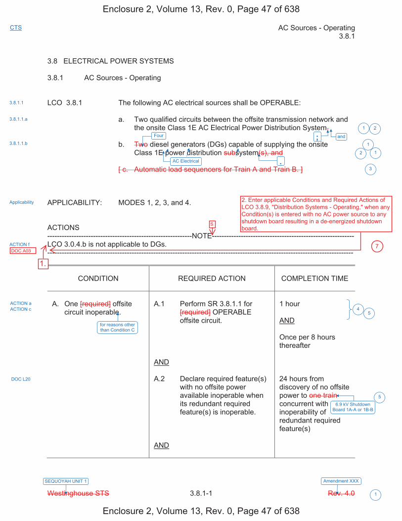
AC Sources - Operating 3.8.1
Westinghouse STS 3.8.1-1 Rev. 4.0
CTS
1
SEQUOYAH UNIT 1 Amendment XXX
3.8 ELECTRICAL POWER SYSTEMS 3.8.1 AC Sources - Operating LCO 3.8.1 The following AC electrical sources shall be OPERABLE: a. Two qualified circuits between the offsite transmission network and
the onsite Class 1E AC Electrical Power Distribution System, b. Two diesel generators (DGs) capable of supplying the onsite
Class 1E power distribution subsystem(s), and
[ c. Automatic load sequencers for Train A and Train B. ] APPLICABILITY: MODES 1, 2, 3, and 4. ACTIONS ------------------------------------------------------------NOTE----------------------------------------------------------- LCO 3.0.4.b is not applicable to DGs. -------------------------------------------------------------------------------------------------------------------------------
CONDITION
REQUIRED ACTION
COMPLETION TIME
A. One [required] offsite
circuit inoperable.
A.1 Perform SR 3.8.1.1 for
[required] OPERABLE offsite circuit.
AND A.2 Declare required feature(s)
with no offsite power available inoperable when its redundant required feature(s) is inoperable.
AND
1 hour AND Once per 8 hours thereafter 24 hours from discovery of no offsite power to one train concurrent with inoperability of redundant required feature(s)
1 2
3
5
.
and
3.8.1.1
3.8.1.1.a
3.8.1.1.b
Applicability
for reasons other than Condition C
ACTION f
ACTION a ACTION c
DOC L20
1
12
Four
AC Electrical
6.9 kV Shutdown Board 1A-A or 1B-B
5
;
4
Enclosure 2, Volume 13, Rev. 0, Page 47 of 638
Enclosure 2, Volume 13, Rev. 0, Page 47 of 638
1.
2. Enter applicable Conditions and Required Actions of LCO 3.8.9, "Distribution Systems - Operating," when any Condition(s) is entered with no AC power source to any shutdown board resulting in a de-energized shutdown board.
DOC A03 7
S
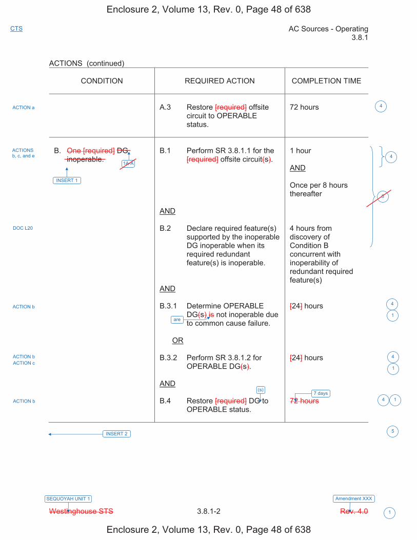
AC Sources - Operating 3.8.1
Westinghouse STS 3.8.1-2 Rev. 4.0
CTS
1
SEQUOYAH UNIT 1 Amendment XXX
ACTIONS (continued)
CONDITION REQUIRED ACTION COMPLETION TIME
A.3 Restore [required] offsite circuit to OPERABLE status.
72 hours
B. One [required] DG inoperable.
B.1 Perform SR 3.8.1.1 for the [required] offsite circuit(s).
AND
B.2 Declare required feature(s) supported by the inoperable DG inoperable when its required redundant feature(s) is inoperable.
AND
B.3.1 Determine OPERABLE DG(s) is not inoperable due to common cause failure.
OR
B.3.2 Perform SR 3.8.1.2 for OPERABLE DG(s).
AND
B.4 Restore [required] DG to OPERABLE status.
1 hour
AND
Once per 8 hours thereafter
4 hours from discovery of Condition B concurrent with inoperability of redundant required feature(s)
[24] hours
[24] hours
72 hours
ACTION a
ACTIONS b, c, and e
DOC L20
ACTION b
ACTION b ACTION c
ACTION b 7 days
INSERT 2
4
5
4
4
4 1
5
41A-A
INSERT 1
are1
1
(s)
Enclosure 2, Volume 13, Rev. 0, Page 48 of 638
Enclosure 2, Volume 13, Rev. 0, Page 48 of 638

Insert Page 3.8.1-2a
INSERT 1
OR
DG 1B-B inoperable.
OR
DGs 1A-A and 2A-A inoperable.
OR
DGs 1B-B and 2B-B inoperable.
INSERT 2
C. One offsite circuit inoperable solely due to an offsite power source to 6.9 kV Shutdown Board 2A-A or 2B-B inoperable.
C.1 Perform SR 3.8.1.1 for OPERABLE offsite circuit.
AND
C.2 Declare required feature(s) with no offsite power available inoperable when its redundant required feature(s) is inoperable.
AND
C.3 Declare associated required feature(s) inoperable.
1 hour
AND
Once per 8 hours thereafter
24 hours from discovery of no offsite power to 6.9 kV Shutdown Board 2A-A or 2B-B concurrent with inoperability of redundant required feature(s)
7 days
5
DOC L01
5
DOC L01
Enclosure 2, Volume 13, Rev. 0, Page 49 of 638
Enclosure 2, Volume 13, Rev. 0, Page 49 of 638
One or more Train ADG(s) inoperable.
OR
One or more Train BDG(s) inoperable.
Restore offsite circuitto OPERABLEstatus.
DOC L20
4

Insert Page 3.8.1-2b
INSERT 2 (Continued)
D. DG 2A-A or 2B-B inoperable.
D.1 Perform SR 3.8.1.1 for OPERABLE offsite circuit(s).
AND
D.2 Declare required feature(s) supported by the inoperable DG inoperable when its redundant required feature(s) is inoperable.
AND
D.3.1 Determine OPERABLE DGs are not inoperable due to common cause failure.
OR
D.3.2 Perform SR 3.8.1.2 for OPERABLE DGs.
AND
D.4 Declare associated required feature(s) inoperable.
1 hour
AND
Once per 8 hours thereafter
4 hours from discovery of Condition D concurrent with inoperability of redundant required feature(s)
24 hours
24 hours
7 days
5
Enclosure 2, Volume 13, Rev. 0, Page 50 of 638
Enclosure 2, Volume 13, Rev. 0, Page 50 of 638
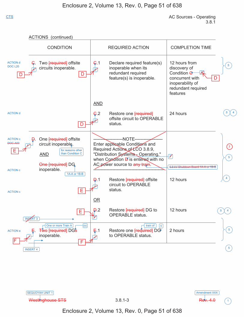
AC Sources - Operating 3.8.1
Westinghouse STS 3.8.1-3 Rev. 4.0
CTS
1
SEQUOYAH UNIT 1 Amendment XXX
ACTIONS (continued)
CONDITION REQUIRED ACTION COMPLETION TIME
C. Two [required] offsite circuits inoperable.
C.1 Declare required feature(s) inoperable when its redundant required feature(s) is inoperable.
AND
C.2 Restore one [required] offsite circuit to OPERABLE status.
12 hours from discovery of Condition C concurrent with inoperability of redundant required features
24 hours
D. One [required] offsite circuit inoperable.
AND
One [required] DG inoperable.
--------------------NOTE------------------- Enter applicable Conditions and Required Actions of LCO 3.8.9, "Distribution Systems - Operating," when Condition D is entered with no AC power source to any train. ------------------------------------------------
D.1 Restore [required] offsite circuit to OPERABLE status.
OR
D.2 Restore [required] DG to OPERABLE status.
12 hours
12 hours
E. Two [required] DGs inoperable.
E.1 Restore one [required] DG to OPERABLE status.
2 hours
ACTION d
ACTION d
ACTION c DOC A03
ACTION c
ACTION c
ACTION e
5
5
5
5
5
E
F
J
F
F
J
E
F
6.9 kV Shutdown Board 1A-A or 1B-B
E
E
4
DOC L20
for reasons other than Condition C
1A-A or 1B-B
INSERT 3
One or more Train A (s)
INSERT 4
5
4
4
train of s
Enclosure 2, Volume 13, Rev. 0, Page 51 of 638
Enclosure 2, Volume 13, Rev. 0, Page 51 of 638
D D
D
D
E
E
E
F F
7
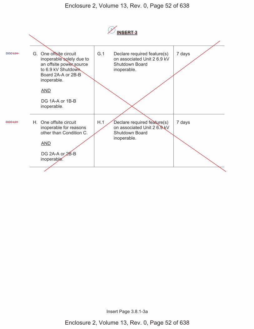
Insert Page 3.8.1-3a
INSERT 3
G. One offsite circuit inoperable solely due to an offsite power source to 6.9 kV Shutdown Board 2A-A or 2B-B inoperable.
AND
DG 1A-A or 1B-B inoperable.
G.1 Declare required feature(s) on associated Unit 2 6.9 kV Shutdown Board inoperable.
7 days
H. One offsite circuit inoperable for reasons other than Condition C.
AND
DG 2A-A or 2B-B inoperable.
H.1 Declare required feature(s) on associated Unit 2 6.9 kV Shutdown Board inoperable.
7 days
5
DOC L01
DOC L01
Enclosure 2, Volume 13, Rev. 0, Page 52 of 638
Enclosure 2, Volume 13, Rev. 0, Page 52 of 638

Insert Page 3.8.1-3b
INSERT 3 (continued)
I. One offsite circuit inoperable solely due to an offsite power source to 6.9 kV Shutdown Board 2A-A or 2B-B inoperable.
AND
DG 2A-A or 2B-B inoperable.
--------------------NOTE------------------- Enter applicable Conditions and Required Actions of LCO 3.8.9, "Distribution Systems - Operating," when Condition I is entered with no AC power source to 6.9 kV Shutdown Board 2A-A or 2B-B. ------------------------------------------------
I.1 Restore offsite circuit to OPERABLE status.
OR
I.2 Restore DG to OPERABLE status.
7 days
7 days
INSERT 4
AND
One or more Train B DG(s) inoperable.
5
DOC L01
ACTION e
5
Enclosure 2, Volume 13, Rev. 0, Page 53 of 638
Enclosure 2, Volume 13, Rev. 0, Page 53 of 638

AC Sources - Operating 3.8.1
Westinghouse STS 3.8.1-4 Rev. 4.0
CTS
1
SEQUOYAH UNIT 1 Amendment XXX
ACTIONS (continued)
CONDITION REQUIRED ACTION COMPLETION TIME
-----REVIEWER’S NOTE----- This Condition may be deleted if the unit design is such that any sequencer failure mode will only affect the ability of the associated DG to power its respective safety loads following a loss of offsite power independent of, or coincident with, a Design Basis Event. --------------------------------------
F. [ One [required] [automatic load sequencer] inoperable.
F.1 Restore [required] [automatic load sequencer] to OPERABLE status.
[12] hours ]
G. Required Action and associated Completion Time of Condition A, B, C, D, E, or [F] not met.
G.1 Be in MODE 3.
AND
G.2 Be in MODE 5.
6 hours
36 hours
H. Three or more [required] AC sources inoperable.
H.1 Enter LCO 3.0.3. Immediately
SURVEILLANCE REQUIREMENTS
SURVEILLANCE FREQUENCY
SR 3.8.1.1 Verify correct breaker alignment and indicated power availability for each [required] offsite circuit.
[ 7 days
OR
In accordance with the Surveillance Frequency Control Program ]
3
ACTIONS a, b, c, d, e
4.8.1.1 4.8.1.1.1.a
3 5
5
4 6
K
F, I, J
K
K
6
INSERT 5
Enclosure 2, Volume 13, Rev. 0, Page 54 of 638
Enclosure 2, Volume 13, Rev. 0, Page 54 of 638
A, B, C, D, E,or F
G
G
G DOC M01
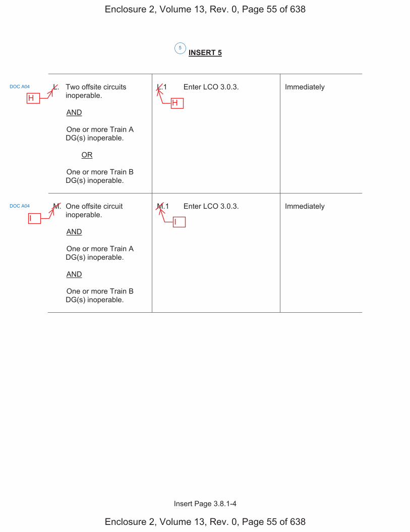
Insert Page 3.8.1-4
INSERT 5
L. Two offsite circuits inoperable.
AND
One or more Train A DG(s) inoperable.
OR
One or more Train B DG(s) inoperable.
L.1 Enter LCO 3.0.3. Immediately
M. One offsite circuit inoperable.
AND
One or more Train A DG(s) inoperable.
AND
One or more Train B DG(s) inoperable.
M.1 Enter LCO 3.0.3. Immediately
5
DOC A04
DOC A04
Enclosure 2, Volume 13, Rev. 0, Page 55 of 638
Enclosure 2, Volume 13, Rev. 0, Page 55 of 638
H H
I I
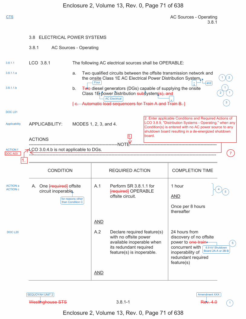
AC Sources - Operating 3.8.1
Westinghouse STS 3.8.1-1 Rev. 4.0
CTS
1
SEQUOYAH UNIT 2 Amendment XXX
3.8 ELECTRICAL POWER SYSTEMS 3.8.1 AC Sources - Operating LCO 3.8.1 The following AC electrical sources shall be OPERABLE: a. Two qualified circuits between the offsite transmission network and
the onsite Class 1E AC Electrical Power Distribution System, b. Two diesel generators (DGs) capable of supplying the onsite
Class 1E power distribution subsystem(s), and
[ c. Automatic load sequencers for Train A and Train B. ] APPLICABILITY: MODES 1, 2, 3, and 4. ACTIONS ------------------------------------------------------------NOTE----------------------------------------------------------- LCO 3.0.4.b is not applicable to DGs. -------------------------------------------------------------------------------------------------------------------------------
CONDITION
REQUIRED ACTION
COMPLETION TIME
A. One [required] offsite
circuit inoperable.
A.1 Perform SR 3.8.1.1 for
[required] OPERABLE offsite circuit.
AND A.2 Declare required feature(s)
with no offsite power available inoperable when its redundant required feature(s) is inoperable.
AND
1 hour AND Once per 8 hours thereafter 24 hours from discovery of no offsite power to one train concurrent with inoperability of redundant required feature(s)
3.8.1.1
3.8.1.1.a
3.8.1.1.b
DOC L01
Applicability
ACTION f
ACTION a ACTION c
DOC L20
1 2
3
1
12
and; Four
.AC Electrical
5
for reasons other than Condition C
6.9 kV Shutdown Board 2A-A or 2B-B
5
4
Enclosure 2, Volume 13, Rev. 0, Page 71 of 638
Enclosure 2, Volume 13, Rev. 0, Page 71 of 638
2. Enter applicable Conditions and Required Actions of LCO 3.8.9, "Distribution Systems - Operating," when any Condition(s) is entered with no AC power source to any shutdown board resulting in a de-energized shutdown board.
1.DOC A03 7
S

AC Sources - Operating 3.8.1
Westinghouse STS 3.8.1-2 Rev. 4.0
CTS
1
SEQUOYAH UNIT 2 Amendment XXX
ACTIONS (continued)
CONDITION REQUIRED ACTION COMPLETION TIME
A.3 Restore [required] offsite circuit to OPERABLE status.
72 hours
B. One [required] DG inoperable.
B.1 Perform SR 3.8.1.1 for the [required] offsite circuit(s).
AND
B.2 Declare required feature(s) supported by the inoperable DG inoperable when its required redundant feature(s) is inoperable.
AND
B.3.1 Determine OPERABLE DG(s) is not inoperable due to common cause failure.
OR
B.3.2 Perform SR 3.8.1.2 for OPERABLE DG(s).
AND
B.4 Restore [required] DG to OPERABLE status.
1 hour
AND
Once per 8 hours thereafter
4 hours from discovery of Condition B concurrent with inoperability of redundant required feature(s)
[24] hours
[24] hours
72 hours
ACTION a
ACTIONS b, c, and e
DOC L20
ACTION b
ACTION b ACTION c
ACTION b 7 days
INSERT 2
4
5
4
4
4 1
5
42A-A
INSERT 1
are1
1
(s)
Enclosure 2, Volume 13, Rev. 0, Page 72 of 638
Enclosure 2, Volume 13, Rev. 0, Page 72 of 638

Insert Page 3.8.1-2a
INSERT 1
OR
DG 2B-B inoperable.
OR
DGs 1A-A and 2A-A inoperable.
OR
DGs 1B-B and 2B-B inoperable.
INSERT 2
C. One offsite circuit inoperable solely due to an offsite power source to 6.9 kV Shutdown Board 1A-A or 1B-B inoperable.
C.1 Perform SR 3.8.1.1 for OPERABLE offsite circuit.
AND
C.2 Declare required feature(s) with no offsite power available inoperable when its redundant required feature(s) is inoperable.
AND
C.3 Declare associated required feature(s) inoperable.
1 hour
AND
Once per 8 hours thereafter
24 hours from discovery of no offsite power to 6.9 kV Shutdown Board 1A-A or 1B-B concurrent with inoperability of redundant required feature(s)
7 days
5
DOC L01
5
DOC L01
Enclosure 2, Volume 13, Rev. 0, Page 73 of 638
Enclosure 2, Volume 13, Rev. 0, Page 73 of 638
One or more Train ADG(s) inoperable.
OR
One or more Train BDG(s) inoperable.
Restore offsite circuitto OPERABLEstatus.
DOC L20
4
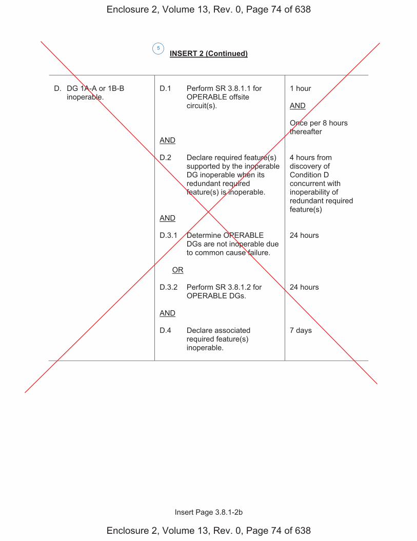
Insert Page 3.8.1-2b
INSERT 2 (Continued)
D. DG 1A-A or 1B-B inoperable.
D.1 Perform SR 3.8.1.1 for OPERABLE offsite circuit(s).
AND
D.2 Declare required feature(s) supported by the inoperable DG inoperable when its redundant required feature(s) is inoperable.
AND
D.3.1 Determine OPERABLE DGs are not inoperable due to common cause failure.
OR
D.3.2 Perform SR 3.8.1.2 for OPERABLE DGs.
AND
D.4 Declare associated required feature(s) inoperable.
1 hour
AND
Once per 8 hours thereafter
4 hours from discovery of Condition D concurrent with inoperability of redundant required feature(s)
24 hours
24 hours
7 days
5
Enclosure 2, Volume 13, Rev. 0, Page 74 of 638
Enclosure 2, Volume 13, Rev. 0, Page 74 of 638
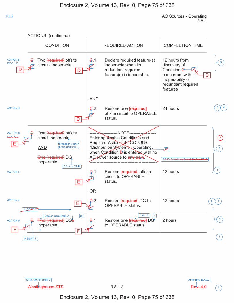
AC Sources - Operating 3.8.1
Westinghouse STS 3.8.1-3 Rev. 4.0
CTS
1
SEQUOYAH UNIT 2 Amendment XXX
ACTIONS (continued)
CONDITION REQUIRED ACTION COMPLETION TIME
C. Two [required] offsite circuits inoperable.
C.1 Declare required feature(s) inoperable when its redundant required feature(s) is inoperable.
AND
C.2 Restore one [required] offsite circuit to OPERABLE status.
12 hours from discovery of Condition C concurrent with inoperability of redundant required features
24 hours
D. One [required] offsite circuit inoperable.
AND
One [required] DG inoperable.
--------------------NOTE------------------- Enter applicable Conditions and Required Actions of LCO 3.8.9, "Distribution Systems - Operating," when Condition D is entered with no AC power source to any train. ------------------------------------------------
D.1 Restore [required] offsite circuit to OPERABLE status.
OR
D.2 Restore [required] DG to OPERABLE status.
12 hours
12 hours
E. Two [required] DGs inoperable.
E.1 Restore one [required] DG to OPERABLE status.
2 hours
ACTION d
ACTION d
ACTION c DOC A03
ACTION c
ACTION c
ACTION e
5
5
E
F
J
F
F
J
E
F
E
E
4
DOC L20
for reasons other than Condition C
2A-A or 2B-B
INSERT 3
One or more Train A (s)
INSERT 4
5
5
5
6.9 kV Shutdown Board 2A-A or 2B-B
5
4
4
train of s
Enclosure 2, Volume 13, Rev. 0, Page 75 of 638
Enclosure 2, Volume 13, Rev. 0, Page 75 of 638
D D
D
D
E
E
E
F F
7
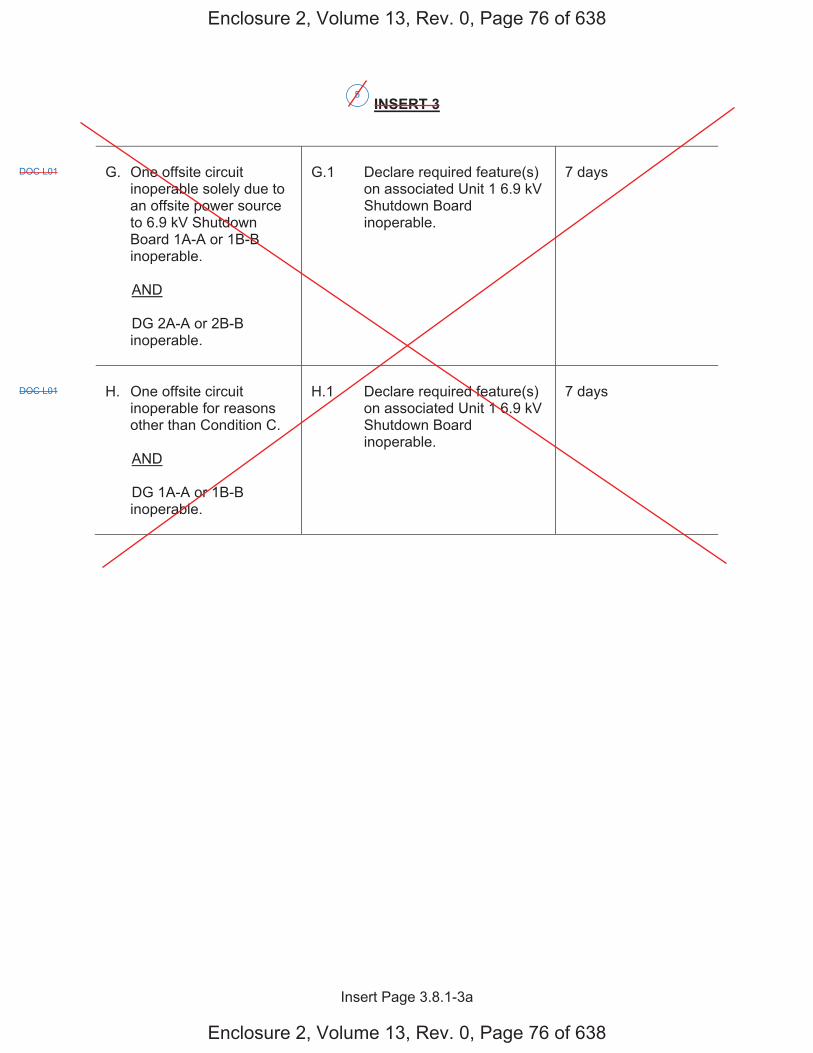
Insert Page 3.8.1-3a
INSERT 3
G. One offsite circuit inoperable solely due to an offsite power source to 6.9 kV Shutdown Board 1A-A or 1B-B inoperable.
AND
DG 2A-A or 2B-B inoperable.
G.1 Declare required feature(s) on associated Unit 1 6.9 kV Shutdown Board inoperable.
7 days
H. One offsite circuit inoperable for reasons other than Condition C.
AND
DG 1A-A or 1B-B inoperable.
H.1 Declare required feature(s) on associated Unit 1 6.9 kV Shutdown Board inoperable.
7 days
5
DOC L01
DOC L01
Enclosure 2, Volume 13, Rev. 0, Page 76 of 638
Enclosure 2, Volume 13, Rev. 0, Page 76 of 638
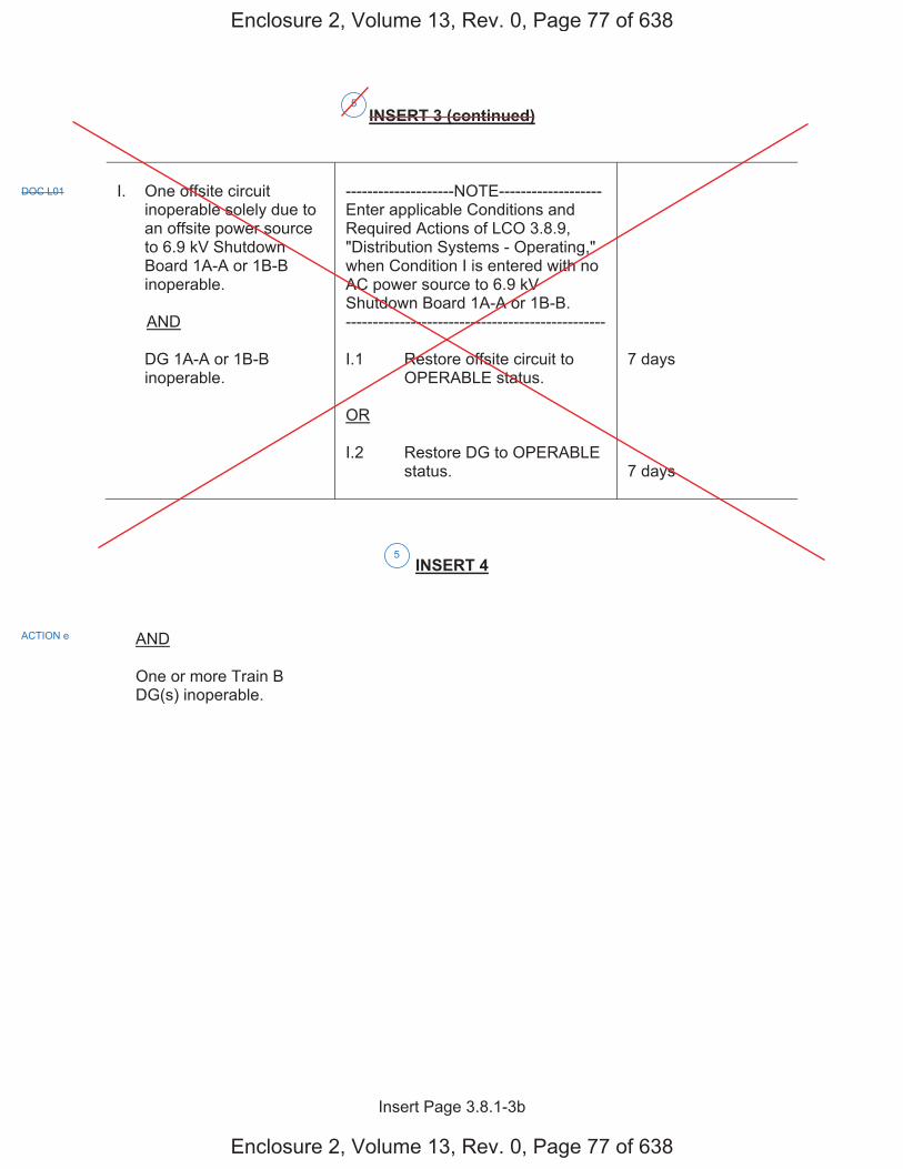
Insert Page 3.8.1-3b
INSERT 3 (continued)
I. One offsite circuit inoperable solely due to an offsite power source to 6.9 kV Shutdown Board 1A-A or 1B-B inoperable.
AND
DG 1A-A or 1B-B inoperable.
--------------------NOTE------------------- Enter applicable Conditions and Required Actions of LCO 3.8.9, "Distribution Systems - Operating," when Condition I is entered with no AC power source to 6.9 kV Shutdown Board 1A-A or 1B-B. ------------------------------------------------
I.1 Restore offsite circuit to OPERABLE status.
OR
I.2 Restore DG to OPERABLE status.
7 days
7 days
INSERT 4
AND
One or more Train B DG(s) inoperable.
5
DOC L01
ACTION e
5
Enclosure 2, Volume 13, Rev. 0, Page 77 of 638
Enclosure 2, Volume 13, Rev. 0, Page 77 of 638

AC Sources - Operating 3.8.1
Westinghouse STS 3.8.1-4 Rev. 4.0
CTS
1
SEQUOYAH UNIT 2 Amendment XXX
ACTIONS (continued)
CONDITION REQUIRED ACTION COMPLETION TIME
-----REVIEWER’S NOTE----- This Condition may be deleted if the unit design is such that any sequencer failure mode will only affect the ability of the associated DG to power its respective safety loads following a loss of offsite power independent of, or coincident with, a Design Basis Event. --------------------------------------
F. [ One [required] [automatic load sequencer] inoperable.
F.1 Restore [required] [automatic load sequencer] to OPERABLE status.
[12] hours ]
G. Required Action and associated Completion Time of Condition A, B, C, D, E, or [F] not met.
G.1 Be in MODE 3.
AND
G.2 Be in MODE 5.
6 hours
36 hours
H. Three or more [required] AC sources inoperable.
H.1 Enter LCO 3.0.3. Immediately
SURVEILLANCE REQUIREMENTS
SURVEILLANCE FREQUENCY
SR 3.8.1.1 Verify correct breaker alignment and indicated power availability for each [required] offsite circuit.
[ 7 days
OR
In accordance with the Surveillance Frequency Control Program ]
3
ACTIONS a, b, c, d, e
4.8.1.1 4.8.1.1.1.a
3 5
4 6
K
J
K
K
6
F, I,
INSERT 5
5
Enclosure 2, Volume 13, Rev. 0, Page 78 of 638
Enclosure 2, Volume 13, Rev. 0, Page 78 of 638
G
A, B, C, D, E,or F
G
GDOC M01

Insert Page 3.8.1-4
INSERT 5
L. Two offsite circuits inoperable.
AND
One or more Train A DG(s) inoperable.
OR
One or more Train B DG(s) inoperable.
L.1 Enter LCO 3.0.3. Immediately
M. One offsite circuit inoperable.
AND
One or more Train A DG(s) inoperable.
AND
One or more Train B DG(s) inoperable.
M.1 Enter LCO 3.0.3. Immediately
5
DOC A04
DOC A04
Enclosure 2, Volume 13, Rev. 0, Page 79 of 638
Enclosure 2, Volume 13, Rev. 0, Page 79 of 638
H H
I I
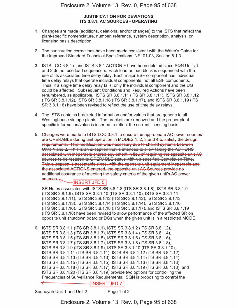
JUSTIFICATION FOR DEVIATIONS ITS 3.8.1, AC SOURCES - OPERATING
Sequoyah Unit 1 and Unit 2 Page 1 of 2
1. Changes are made (additions, deletions, and/or changes) to the ISTS that reflect theplant-specific nomenclature, number, reference, system description, analysis, orlicensing basis description.
2. The punctuation corrections have been made consistent with the Writer's Guide forthe Improved Standard Technical Specifications, NEI 01-03, Section 5.1.3.
3. ISTS LCO 3.8.1.c and ISTS 3.8.1 ACTION F have been deleted since SQN Units 1and 2 do not use load sequencers. Each load or load block is sequenced with theuse of its associated time delay relay. Each major ESF component has individualtime delay relays that operate individual components, not all ESF components.Thus, if a single time delay relay fails, only the individual component and the DGcould be affected. Subsequent Conditions and Required Actions have beenrenumbered, as applicable. ISTS SR 3.8.1.11 (ITS SR 3.8.1.11), ISTS SR 3.8.1.12(ITS SR 3.8.1.12), ISTS SR 3.8.1.18 (ITS SR 3.8.1.17), and ISTS SR 3.8.1.19 (ITSSR 3.8.1.18) have been revised to reflect the use of time delay relays.
4. The ISTS contains bracketed information and/or values that are generic to allWestinghouse vintage plants. The brackets are removed and the proper plantspecific information/value is inserted to reflect the current licensing basis.
5. Changes were made to ISTS LCO 3.8.1 to ensure the appropriate AC power sourcesare OPERABLE during unit operation in MODES 1, 2, 3 and 4 to satisfy the designrequirements. This modification was necessary due to shared systems betweenUnits 1 and 2. This is an exception that is intended to allow taking the ACTIONSassociated with inoperable shared equipment in lieu of requiring the opposite unit ACsources to be restored to OPERABLE status within a specified Completion Time.This exception is acceptable since, with the opposite unit equipment inoperable andthe associated ACTIONS entered, the opposite unit AC Sources provide noadditional assurance of meeting the safety criteria of the given unit’s AC powersources.
SR Notes associated with ISTS SR 3.8.1.8 (ITS SR 3.8.1.8), ISTS SR 3.8.1.9(ITS SR 3.8.1.9), ISTS SR 3.8.1.10 (ITS SR 3.8.1.10), ISTS SR 3.8.1.11(ITS SR 3.8.1.11), ISTS SR 3.8.1.12 (ITS SR 3.8.1.12), ISTS SR 3.8.1.13(ITS SR 3.8.1.13), ISTS SR 3.8.1.14 (ITS SR 3.8.1.14), ISTS SR 3.8.1.16(ITS SR 3.8.1.16), ISTS SR 3.8.1.18 (ITS SR 3.8.1.17), and ISTS SR 3.8.1.19(ITS SR 3.8.1.18) have been revised to allow performance of the affected SR onopposite unit shutdown board or DGs when the given unit is in a restricted MODE.
6. ISTS SR 3.8.1.1 (ITS SR 3.8.1.1), ISTS SR 3.8.1.2 (ITS SR 3.8.1.2),ISTS SR 3.8.1.3 (ITS SR 3.8.1.3), ISTS SR 3.8.1.4 (ITS SR 3.8.1.4),ISTS SR 3.8.1.5 (ITS SR 3.8.1.5), ISTS SR 3.8.1.6 (ITS SR 3.8.1.6),ISTS SR 3.8.1.7 (ITS SR 3.8.1.7), ISTS SR 3.8.1.8 (ITS SR 3.8.1.8),ISTS SR 3.8.1.9 (ITS SR 3.8.1.9), ISTS SR 3.8.1.10 (ITS SR 3.8.1.10),ISTS SR 3.8.1.11 (ITS SR 3.8.1.11), ISTS SR 3.8.1.12 (ITS SR 3.8.1.12),ISTS SR 3.8.1.13 (ITS SR 3.8.1.13), ISTS SR 3.8.1.14 (ITS SR 3.8.1.14),ISTS SR 3.8.1.15 (ITS SR 3.8.1.15), ISTS SR 3.8.1.16 (ITS SR 3.8.1.16),ISTS SR 3.8.1.18 (ITS SR 3.8.1.17), ISTS SR 3.8.1.19 (ITS SR 3.8.1.18), andISTS SR 3.8.1.20 (ITS SR 3.8.1.19) provide two options for controlling theFrequencies of Surveillance Requirements. SQN is proposing to control the
Enclosure 2, Volume 13, Rev. 0, Page 95 of 638
Enclosure 2, Volume 13, Rev. 0, Page 95 of 638
INSERT JFD 5
INSERT JFD 7
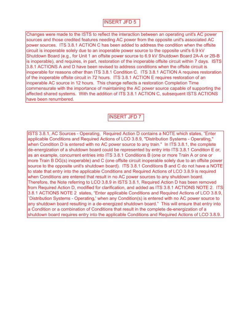
INSERT JFD 5
Changes were made to the ISTS to reflect the interaction between an operating unit's AC power sources and those credited features needing AC power from the opposite unit's associated AC power sources. ITS 3.8.1 ACTION C has been added to address the condition when the offsite circuit is inoperable solely due to an inoperable power source to the opposite unit's 6.9 kV Shutdown Board (e.g., for Unit 1 an offsite power source to 6.9 kV Shutdown Board 2A-A or 2B-B is inoperable), and requires, in part, restoration of the inoperable offsite circuit within 7 days. ISTS 3.8.1 ACTIONS A and D have been revised to address conditions when the offsite circuit is inoperable for reasons other than ITS 3.8.1 Condition C. ITS 3.8.1 ACTION A requires restoration of the inoperable offsite circuit in 72 hours. ITS 3.8.1 ACTION E requires restoration of an inoperable AC source in 12 hours. This change reflects a restoration Completion Time commensurate with the importance of maintaining the AC power source capable of supporting the affected shared systems. With the addition of ITS 3.8.1 ACTION C, subsequent ISTS ACTIONS have been renumbered.
INSERT JFD 7
ISTS 3.8.1, AC Sources - Operating, Required Action D contains a NOTE which states, “Enter applicable Conditions and Required Actions of LCO 3.8.9, "Distribution Systems - Operating," when Condition D is entered with no AC power source to any train." In ITS 3.8.1, the complete de-energization of a shutdown board could be represented by entry into ITS 3.8.1 Condition E or, as an example, concurrent entries into ITS 3.8.1 Conditions B (one or more Train A or one or more Train B DG(s) inoperable) and C (one offsite circuit inoperable solely due to an offsite power source to the opposite unit's shutdown board). ITS 3.8.1 Conditions B and C do not have a NOTE to state that entry into the applicable Conditions and Required Actions of LCO 3.8.9 is required when Conditions are entered that result in no AC power sources to any shutdown board. Therefore, the Note referring to LCO 3.8.9 in ISTS 3.8.1, Required Action D has been removed from Required Action D, modified for clarification, and added as ITS 3.8.1 ACTIONS NOTE 2. ITS 3.8.1 ACTIONS NOTE 2 states, “Enter applicable Conditions and Required Actions of LCO 3.8.9, `Distribution Systems - Operating,' when any Condition(s) is entered with no AC power source to any shutdown board resulting in a de-energized shutdown board.” This will ensure that entry into a Condition or a combination of Conditions that result in the complete de-energization of a shutdown board requires entry into the applicable Conditions and Required Actions of LCO 3.8.9.
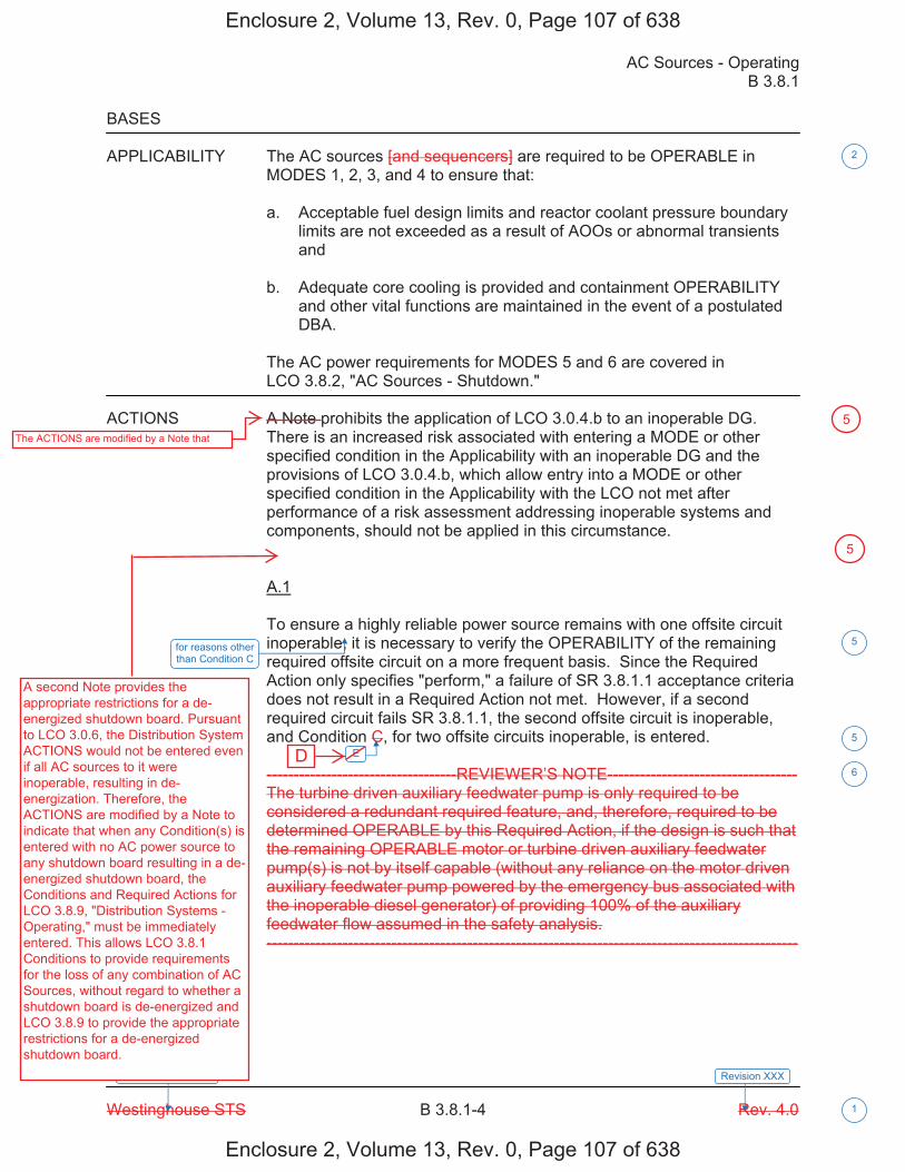
AC Sources - Operating B 3.8.1
Westinghouse STS B 3.8.1-4 Rev. 4.0
SEQUOYAH UNIT 1
1
Revision XXX
BASES
APPLICABILITY The AC sources [and sequencers] are required to be OPERABLE in MODES 1, 2, 3, and 4 to ensure that:
a. Acceptable fuel design limits and reactor coolant pressure boundarylimits are not exceeded as a result of AOOs or abnormal transientsand
b. Adequate core cooling is provided and containment OPERABILITYand other vital functions are maintained in the event of a postulatedDBA.
The AC power requirements for MODES 5 and 6 are covered in LCO 3.8.2, "AC Sources - Shutdown."
ACTIONS A Note prohibits the application of LCO 3.0.4.b to an inoperable DG. There is an increased risk associated with entering a MODE or other specified condition in the Applicability with an inoperable DG and the provisions of LCO 3.0.4.b, which allow entry into a MODE or other specified condition in the Applicability with the LCO not met after performance of a risk assessment addressing inoperable systems and components, should not be applied in this circumstance.
A.1
To ensure a highly reliable power source remains with one offsite circuit inoperable, it is necessary to verify the OPERABILITY of the remaining required offsite circuit on a more frequent basis. Since the Required Action only specifies "perform," a failure of SR 3.8.1.1 acceptance criteria does not result in a Required Action not met. However, if a second required circuit fails SR 3.8.1.1, the second offsite circuit is inoperable, and Condition C, for two offsite circuits inoperable, is entered.
-----------------------------------REVIEWER’S NOTE-----------------------------------The turbine driven auxiliary feedwater pump is only required to be considered a redundant required feature, and, therefore, required to be determined OPERABLE by this Required Action, if the design is such that the remaining OPERABLE motor or turbine driven auxiliary feedwater pump(s) is not by itself capable (without any reliance on the motor driven auxiliary feedwater pump powered by the emergency bus associated with the inoperable diesel generator) of providing 100% of the auxiliary feedwater flow assumed in the safety analysis. --------------------------------------------------------------------------------------------------
E
2
5
5
6
for reasons other than Condition C
Enclosure 2, Volume 13, Rev. 0, Page 107 of 638
Enclosure 2, Volume 13, Rev. 0, Page 107 of 638
D
A second Note provides the appropriate restrictions for a de-energized shutdown board. Pursuant to LCO 3.0.6, the Distribution System ACTIONS would not be entered even if all AC sources to it were inoperable, resulting in de-energization. Therefore, the ACTIONS are modified by a Note to indicate that when any Condition(s) is entered with no AC power source to any shutdown board resulting in a de-energized shutdown board, the Conditions and Required Actions for LCO 3.8.9, "Distribution Systems - Operating," must be immediately entered. This allows LCO 3.8.1 Conditions to provide requirements for the loss of any combination of AC Sources, without regard to whether a shutdown board is de-energized and LCO 3.8.9 to provide the appropriate restrictions for a de-energized shutdown board.
5The ACTIONS are modified by a Note that
5

AC Sources - Operating B 3.8.1
Westinghouse STS B 3.8.1-6 Rev. 4.0
SEQUOYAH UNIT 1
1
Revision XXX
BASES
ACTIONS (continued)
A.3
According to Regulatory Guide 1.93 (Ref. 6), operation may continue in Condition A for a period that should not exceed 72 hours. With one offsite circuit inoperable, the reliability of the offsite system is degraded, and the potential for a loss of offsite power is increased, with attendant potential for a challenge to the unit safety systems. In this Condition, however, the remaining OPERABLE offsite circuit and DGs are adequate to supply electrical power to the onsite Class 1E Distribution System.
The 72 hour Completion Time takes into account the capacity and capability of the remaining AC sources, a reasonable time for repairs, and the low probability of a DBA occurring during this period.
B.1
To ensure a highly reliable power source remains with an inoperable DG, it is necessary to verify the availability of the offsite circuits on a more frequent basis. Since the Required Action only specifies "perform," a failure of SR 3.8.1.1 acceptance criteria does not result in a Required Action being not met. However, if a circuit fails to pass SR 3.8.1.1, it is inoperable. Upon offsite circuit inoperability, additional Conditions and Required Actions must then be entered.
-----------------------------------REVIEWER’S NOTE----------------------------------- The turbine driven auxiliary feedwater pump is only required to be considered a redundant required feature, and, therefore, required to be determined OPERABLE by this Required Action, if the design is such that the remaining OPERABLE motor or turbine driven auxiliary feedwater pump(s) is not by itself capable (without any reliance on the motor driven auxiliary feedwater pump powered by the emergency bus associated with the inoperable diesel generator) of providing 100% of the auxiliary feedwater flow assumed in the safety analysis. --------------------------------------------------------------------------------------------------
B.2
Required Action B.2 is intended to provide assurance that a loss of offsite power, during the period that a DG is inoperable, does not result in a complete loss of safety function of critical systems. These features are designed with redundant safety related trains. This includes motor driven auxiliary feedwater pumps. Single train systems, such as turbine driven auxiliary feedwater pumps, are not included. Redundant required feature failures consist of inoperable features associated with a train, redundant to the train that has an inoperable DG.
INSERT 9
5
6
AC Electrical Power
1
(s) 5
(s)5
Enclosure 2, Volume 13, Rev. 0, Page 109 of 638
Enclosure 2, Volume 13, Rev. 0, Page 109 of 638

B 3.8.1
Insert Page B 3.8.1-6
INSERT 9
DG 1A-A, DG 1B-B, DGs 1A-A and 2A-A, or DGs 1B-B and 2B-B
5
Enclosure 2, Volume 13, Rev. 0, Page 110 of 638
Enclosure 2, Volume 13, Rev. 0, Page 110 of 638
one or more Train A DGs, or one or more Train B DGs

AC Sources - Operating B 3.8.1
Westinghouse STS B 3.8.1-7 Rev. 4.0
SEQUOYAH UNIT 1
1
Revision XXX
BASES
ACTIONS (continued)
The Completion Time for Required Action B.2 is intended to allow the operator time to evaluate and repair any discovered inoperabilities. This Completion Time also allows for an exception to the normal "time zero" for beginning the allowed outage time "clock." In this Required Action, the Completion Time only begins on discovery that both:
a. An inoperable DG exists and
b. A required feature on the other train (Train A or Train B) isinoperable.
If at any time during the existence of this Condition (one DG inoperable) a required feature subsequently becomes inoperable, this Completion Time would begin to be tracked.
Discovering one required DG inoperable coincident with one or more inoperable required support or supported features, or both, that are associated with the OPERABLE DG, results in starting the Completion Time for the Required Action. Four hours from the discovery of these events existing concurrently is Acceptable because it minimizes risk while allowing time for restoration before subjecting the unit to transients associated with shutdown.
In this Condition, the remaining OPERABLE DG and offsite circuits are adequate to supply electrical power to the onsite Class 1E Distribution System. Thus, on a component basis, single failure protection for the required feature's function may have been lost; however, function has not been lost. The 4 hour Completion Time takes into account the OPERABILITY of the redundant counterpart to the inoperable required feature. Additionally, the 4 hour Completion Time takes into account the capacity and capability of the remaining AC sources, a reasonable time for repairs, and the low probability of a DBA occurring during this period.
B.3.1 and B.3.2
Required Action B.3.1 provides an allowance to avoid unnecessary testing of OPERABLE DG(s). If it can be determined that the cause of the inoperable DG does not exist on the OPERABLE DG, SR 3.8.1.2 does not have to be performed. If the cause of inoperability exists on other DG(s), the other DG(s) would be declared inoperable upon discovery and Condition E of LCO 3.8.1 would be entered. Once the failure is repaired, the common cause failure no longer exists, and Required Action B.3.1 is satisfied. If the cause of the initial inoperable DG cannot be confirmed not to exist on the remaining DG(s), performance of SR 3.8.1.2 suffices to provide assurance of continued OPERABILITY of that DG.
s
J INSERT 10
4
1
5
5
or more DGs in a train
5
or more DGs in a train
5
AC Electrical Power
5
Enclosure 2, Volume 13, Rev. 0, Page 111 of 638
Enclosure 2, Volume 13, Rev. 0, Page 111 of 638
F

B 3.8.1
Insert Page B 3.8.1-7
INSERT 10
if one or more DG(s) in Train A and Train B are inoperable
5
Enclosure 2, Volume 13, Rev. 0, Page 112 of 638
Enclosure 2, Volume 13, Rev. 0, Page 112 of 638
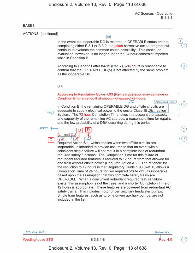
AC Sources - Operating B 3.8.1
Westinghouse STS B 3.8.1-8 Rev. 4.0
SEQUOYAH UNIT 1
1
Revision XXX
BASES
ACTIONS (continued)
In the event the inoperable DG is restored to OPERABLE status prior to completing either B.3.1 or B.3.2, the [plant corrective action program] will continue to evaluate the common cause possibility. This continued evaluation, however, is no longer under the 24 hour constraint imposed while in Condition B.
According to Generic Letter 84-15 (Ref. 7), [24] hours is reasonable to confirm that the OPERABLE DG(s) is not affected by the same problem as the inoperable DG.
B.4
According to Regulatory Guide 1.93 (Ref. 6), operation may continue in Condition B for a period that should not exceed 72 hours.
In Condition B, the remaining OPERABLE DG and offsite circuits are adequate to supply electrical power to the onsite Class 1E Distribution System. The 72 hour Completion Time takes into account the capacity and capability of the remaining AC sources, a reasonable time for repairs, and the low probability of a DBA occurring during this period.
C.1 and C.2
Required Action C.1, which applies when two offsite circuits are inoperable, is intended to provide assurance that an event with a coincident single failure will not result in a complete loss of redundant required safety functions. The Completion Time for this failure of redundant required features is reduced to 12 hours from that allowed for one train without offsite power (Required Action A.2). The rationale for the reduction to 12 hours is that Regulatory Guide 1.93 (Ref. 6) allows a Completion Time of 24 hours for two required offsite circuits inoperable, based upon the assumption that two complete safety trains are OPERABLE. When a concurrent redundant required feature failure exists, this assumption is not the case, and a shorter Completion Time of 12 hours is appropriate. These features are powered from redundant AC safety trains. This includes motor driven auxiliary feedwater pumps. Single train features, such as turbine driven auxiliary pumps, are not included in the list.
7 day
INSERT 11
E E E
2
2
5
5
5
(s)
5
(s) AC Electrical Power
Enclosure 2, Volume 13, Rev. 0, Page 113 of 638
Enclosure 2, Volume 13, Rev. 0, Page 113 of 638
D
D D

B 3.8.1
Insert Page B 3.8.1-8a
INSERT 11
C.1, C.2, and C.3
Condition C is entered for an offsite circuit inoperable solely due to an inoperable power source to 6.9 kV Shutdown Board 2A-A or 2B-B. Required Action C.1 verifies the OPERABILITY of the remaining offsite circuit within an hour of the inoperability and every 8 hours thereafter. Since the Required Action only specifies "perform," a failure of the SR 3.8.1.1 acceptance criteria does not result in a Required Action not met.
The Completion Time for Required Action C.2 is intended to allow the operator time to evaluate and repair any discovered inoperabilities. This Completion Time also allows for an exception to the normal "time zero" for beginning the allowed outage time "clock." In this Required Action, the Completion Time only begins on discovery that both:
a. 6.9 kV Shutdown Board 2A-A or 2B-B has no offsite power; andb. A required feature on the other train is inoperable.
If at any time during the existence of Condition C a redundant required feature subsequently becomes inoperable, this Completion Time begins to be tracked.
A Completion Time of 24 hours is acceptable, because it minimizes risk while allowing time for restoration before subjecting the unit to transients associated with shutdown. The remaining OPERABLE offsite circuit and DGs are adequate to support these functions. The Completion Time takes into account the component OPERABILITY of the remaining redundant feature(s), a reasonable time for repairs, and the low probability of a DBA occurring during this period.
Operation may continue in Condition C for a period of 7 days. With one offsite circuit inoperable, the reliability of the functions is degraded. The potential for the loss of offsite power to the redundant feature(s) is increased, with the attendant potential for a challenge to their safety functions.
The required offsite circuit must be returned to OPERABLE status within 7 days, or the support function for the associated required feature is considered inoperable. At that time, the required feature must be declared inoperable and the appropriate Conditions must be entered. The 7 days Completion Time takes into account the capacity and capability of the remaining AC sources providing electrical power to the required feature(s), a reasonable time for repairs and the low probability of a DBA occurring during this period of time.
5
Enclosure 2, Volume 13, Rev. 0, Page 114 of 638
Enclosure 2, Volume 13, Rev. 0, Page 114 of 638

B 3.8.1
Insert Page B 3.8.1-8b
INSERT 11 (Continued)
D.1, D.2, D.3 and D.4
To ensure a highly reliable power source remains with an inoperable DG to a Unit 2 6.9 kV Shutdown Board, it is necessary to verify the availability of the required offsite circuits on a more frequent basis. Since the Required Action only specifies "perform," a failure of SR 3.8.1.1 acceptance criteria does not result in a Required Action being not met. Required Action D.1 verifies the OPERABILITY of the required offsite sources within an hour of the inoperability and every 8 hours thereafter. However, if a circuit fails to pass SR 3.8.1.1, it is inoperable. Upon offsite circuit inoperability, additional Conditions and Required Actions must be entered.
Required Action D.2 is intended to provide assurance that a loss of offsite power, during the period that an LCO 3.8.1.d DG is inoperable, does not result in a complete loss of the safety functions.
The Completion Time for Required Action D.2 is intended to allow the operator time to evaluate and repair any discovered inoperabilities. This Completion Time also allows for an exception to the normal "time zero" for beginning the allowed outage time "clock." In this Required Action, the Completion Time only begins on discovery that both:
a. An inoperable DG to 6.9 kV Shutdown Board 2A-A or 2B-B exists; andb. A redundant feature in the same system is inoperable.
If at any time during the existence of Condition D (one DG to 6.9 kV Shutdown Board 2A-A or 2B-B) a redundant feature in the same system subsequently becomes inoperable, this Completion Time begins to be tracked. The four hour Completion Time is acceptable, because it minimizes risk while allowing time for restoration before subjecting the unit to transients associated with shutdown.
The remaining OPERABLE offsite circuits and DGs are adequate to support the functions. The 4 hour Completion Time takes into account the component OPERABILITY of the remaining redundant feature(s), a reasonable time for repairs, and the low probability of a DBA occurring during this period.
D.3.1 and D.3.2
Required Action D.3.1 provides an allowance to avoid unnecessary testing of OPERABLE DG(s). If it can be determined that the cause of the inoperable DG does not exist on the OPERABLE DG(s), SR 3.8.1.2 does not have to be performed. If the cause of inoperability exists on another DG, the other DG would be declared inoperable, and upon discovery, Condition J of LCO 3.8.1 would be entered, if one or more DG(s) in Train A and Train B are inoperable. Otherwise, if the inoperability exists on the other DG in the same train, the other DG would be declared inoperable upon discovery, Condition B would be entered. Once the failure is repaired, the common cause failure no longer exists, and Required Action D.3.1 is satisfied. If the cause of the initial inoperable DG cannot be confirmed not to exist on the remaining DGs, performance of SR 3.8.1.2 suffices to provide assurance of continued OPERABILITY of that DG.
5
Enclosure 2, Volume 13, Rev. 0, Page 115 of 638
Enclosure 2, Volume 13, Rev. 0, Page 115 of 638

B 3.8.1
Insert Page B 3.8.1-8c
INSERT 11 (Continued)
Operation may continue in Condition D for a period of 7 days. With one Unit 2 DG inoperable, the reliability of the respective function is degraded. The potential for the loss of a DG to the redundant feature(s) is increased, with the attendant potential for a challenge to respective safety function.
The required DG must be returned to OPERABLE status within 7 days, or the support function for the associated required feature is considered inoperable. At that time, the required feature must be declared inoperable and the appropriate Conditions must be entered. The 7 day Completion Time takes into account the capacity and capability of the remaining AC sources providing electrical power to the required feature(s), a reasonable time for repairs and the low probability of a DBA occurring during this period of time.
5
Enclosure 2, Volume 13, Rev. 0, Page 116 of 638
Enclosure 2, Volume 13, Rev. 0, Page 116 of 638
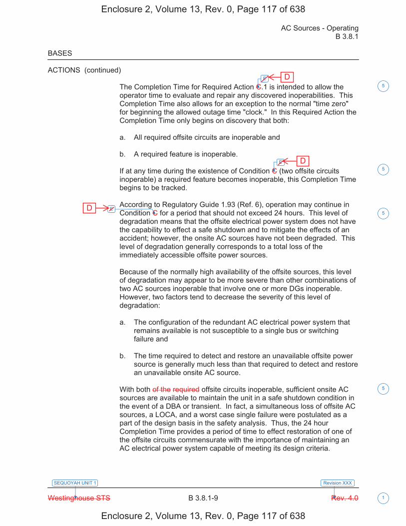
AC Sources - Operating B 3.8.1
Westinghouse STS B 3.8.1-9 Rev. 4.0
SEQUOYAH UNIT 1
1
Revision XXX
BASES
ACTIONS (continued)
The Completion Time for Required Action C.1 is intended to allow the operator time to evaluate and repair any discovered inoperabilities. This Completion Time also allows for an exception to the normal "time zero" for beginning the allowed outage time "clock." In this Required Action the Completion Time only begins on discovery that both:
a. All required offsite circuits are inoperable and
b. A required feature is inoperable.
If at any time during the existence of Condition C (two offsite circuits inoperable) a required feature becomes inoperable, this Completion Time begins to be tracked.
According to Regulatory Guide 1.93 (Ref. 6), operation may continue in Condition C for a period that should not exceed 24 hours. This level of degradation means that the offsite electrical power system does not have the capability to effect a safe shutdown and to mitigate the effects of an accident; however, the onsite AC sources have not been degraded. This level of degradation generally corresponds to a total loss of the immediately accessible offsite power sources.
Because of the normally high availability of the offsite sources, this level of degradation may appear to be more severe than other combinations of two AC sources inoperable that involve one or more DGs inoperable. However, two factors tend to decrease the severity of this level of degradation:
a. The configuration of the redundant AC electrical power system thatremains available is not susceptible to a single bus or switchingfailure and
b. The time required to detect and restore an unavailable offsite powersource is generally much less than that required to detect and restorean unavailable onsite AC source.
With both of the required offsite circuits inoperable, sufficient onsite AC sources are available to maintain the unit in a safe shutdown condition in the event of a DBA or transient. In fact, a simultaneous loss of offsite AC sources, a LOCA, and a worst case single failure were postulated as a part of the design basis in the safety analysis. Thus, the 24 hour Completion Time provides a period of time to effect restoration of one of the offsite circuits commensurate with the importance of maintaining an AC electrical power system capable of meeting its design criteria.
E
E
E
5
5
5
5
Enclosure 2, Volume 13, Rev. 0, Page 117 of 638
Enclosure 2, Volume 13, Rev. 0, Page 117 of 638
D
D
D
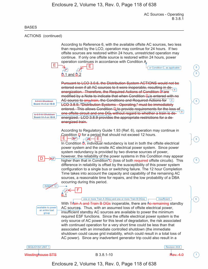
AC Sources - Operating B 3.8.1
Westinghouse STS B 3.8.1-10 Rev. 4.0
SEQUOYAH UNIT 1
1
Revision XXX
BASES
ACTIONS (continued)
According to Reference 6, with the available offsite AC sources, two less than required by the LCO, operation may continue for 24 hours. If two offsite sources are restored within 24 hours, unrestricted operation may continue. If only one offsite source is restored within 24 hours, power operation continues in accordance with Condition A.
D.1 and D.2
Pursuant to LCO 3.0.6, the Distribution System ACTIONS would not be entered even if all AC sources to it were inoperable, resulting in de-energization. Therefore, the Required Actions of Condition D are modified by a Note to indicate that when Condition D is entered with no AC source to any train, the Conditions and Required Actions for LCO 3.8.9, "Distribution Systems - Operating," must be immediately entered. This allows Condition D to provide requirements for the loss of one offsite circuit and one DG, without regard to whether a train is de-energized. LCO 3.8.9 provides the appropriate restrictions for a de-energized train.
According to Regulatory Guide 1.93 (Ref. 6), operation may continue in Condition D for a period that should not exceed 12 hours.
In Condition D, individual redundancy is lost in both the offsite electrical power system and the onsite AC electrical power system. Since power system redundancy is provided by two diverse sources of power, however, the reliability of the power systems in this Condition may appear higher than that in Condition C (loss of both required offsite circuits). This difference in reliability is offset by the susceptibility of this power system configuration to a single bus or switching failure. The 12 hour Completion Time takes into account the capacity and capability of the remaining AC sources, a reasonable time for repairs, and the low probability of a DBA occurring during this period.
E.1
With Train A and Train B DGs inoperable, there are no remaining standby AC sources. Thus, with an assumed loss of offsite electrical power, insufficient standby AC sources are available to power the minimum required ESF functions. Since the offsite electrical power system is the only source of AC power for this level of degradation, the risk associated with continued operation for a very short time could be less than that associated with an immediate controlled shutdown (the immediate shutdown could cause grid instability, which could result in a total loss of AC power). Since any inadvertent generator trip could also result in a
or Condition C, as applicableF F
F
F
F
6.9 kV Shutdown Board 1A-A or 1B-B
F F
E
J
one or more Train A DG(s) and one or more Train B DG(s)
available to power an entire load
group
5
5
5
5
5
5
INSERT 12
insufficient
to 6.9 kV Shutdown Board 1A-A or 1B-B
Enclosure 2, Volume 13, Rev. 0, Page 118 of 638
Enclosure 2, Volume 13, Rev. 0, Page 118 of 638
E E
E E
D
F

B 3.8.1
Insert Page B 3.8.1-10
INSERT 12
G.1 and H.1
In Conditions G and H, individual redundancy is lost in the offsite electrical power system for one unit and the onsite AC electrical power system for the other unit. Since Conditions B and C are entered concurrent with entry into Condition G, and Conditions A and D are entered concurrent with entry into Condition H, the Required Actions of Conditions B and C (or Conditions A and D) provide the appropriate compensatory measures to ensure the onsite and offsite power sources are either restored to an OPERABLE status, or the associated required features are declared inoperable, thereby requiring entry into the appropriate Conditions associated with the associated feature's LCO. The Completion Times of Required Actions G.1 and H.1 are consistent with the Completion Times of Required Actions C.3 and D.4. If, while in Condition G or H, a redundant required feature is determined to be inoperable, the required feature(s) would be declared inoperable at the Completion Times specified in Conditions A, B, C, or D, as applicable.
I.1 and I.2
Pursuant to LCO 3.0.6, the Distribution System ACTIONS would not be entered even if all AC sources to it were inoperable, resulting in de-energization. Therefore, the Required Actions of Condition I are modified by a Note to indicate that when Condition I is entered with no AC source to 6.9 kV Shutdown Board 2A-A or 2B-B, the Conditions and Required Actions for LCO 3.8.9, "Distribution Systems - Operating," must be immediately entered. This allows Condition I to provide requirements for the loss of one offsite power source and one DG, without regard to whether a train is de-energized. LCO 3.8.9 provides the appropriate restrictions for a de-energized 6.9 kV Shutdown Board.
In Condition I, individual redundancy is lost in the offsite electrical power system and the onsite AC electrical power system. Concurrent with entry into Condition I, entry into Condition C (inoperable offsite power source) and Condition D (inoperable DG) are required. The Required Actions of Conditions C and D ensure the remaining offsite circuit and DGs are OPERABLE and that required features with no offsite or onsite power sources are declared inoperable when its redundant required feature is inoperable within the Completion Times of Required Actions C.2 and D.2.
5
Enclosure 2, Volume 13, Rev. 0, Page 119 of 638
Enclosure 2, Volume 13, Rev. 0, Page 119 of 638

AC Sources - Operating B 3.8.1
Westinghouse STS B 3.8.1-11 Rev. 4.0
SEQUOYAH UNIT 1
1
Revision XXX
BASES
ACTIONS (continued)
total loss of offsite AC power, however, the time allowed for continued operation is severely restricted. The intent here is to avoid the risk associated with an immediate controlled shutdown and to minimize the risk associated with this level of degradation.
According to Reference 6, with both DGs inoperable, operation may continue for a period that should not exceed 2 hours.
[ F.1
The sequencer(s) is an essential support system to [both the offsite circuit and the DG associated with a given ESF bus]. [Furthermore, the sequencer is on the primary success path for most major AC electrically powered safety systems powered from the associated ESF bus.] Therefore, loss of an [ESF bus sequencer] affects every major ESF system in the [division]. The [12] hour Completion Time provides a period of time to correct the problem commensurate with the importance of maintaining sequencer OPERABILITY. This time period also ensures that the probability of an accident (requiring sequencer OPERABILITY) occurring during periods when the sequencer is inoperable is minimal.
This Condition is preceded by a Note that allows the Condition to be deleted if the unit design is such that any sequencer failure mode will only affect the ability of the associated DG to power its respective safety loads under any conditions. Implicit in this Note is the concept that the Condition must be retained if any sequencer failure mode results in the inability to start all or part of the safety loads when required, regardless of power availability, or results in overloading the offsite power circuit to a safety bus during an event and thereby causes its failure. Also implicit in the Note, is that the Condition is not applicable to any train that does not have a sequencer. ]
G.1 and G.2
If the inoperable AC electric power sources cannot be restored to OPERABLE status within the required Completion Time, the unit must be brought to a MODE in which the LCO does not apply. To achieve this status, the unit must be brought to at least MODE 3 within 6 hours and to MODE 5 within 36 hours. The allowed Completion Times are reasonable, based on operating experience, to reach the required unit conditions from full power conditions in an orderly manner and without challenging plant systems.
In this Condition,
K K
5
5
5
5
, consistent with the guidance provided in Reference 6
Enclosure 2, Volume 13, Rev. 0, Page 120 of 638
Enclosure 2, Volume 13, Rev. 0, Page 120 of 638
G G
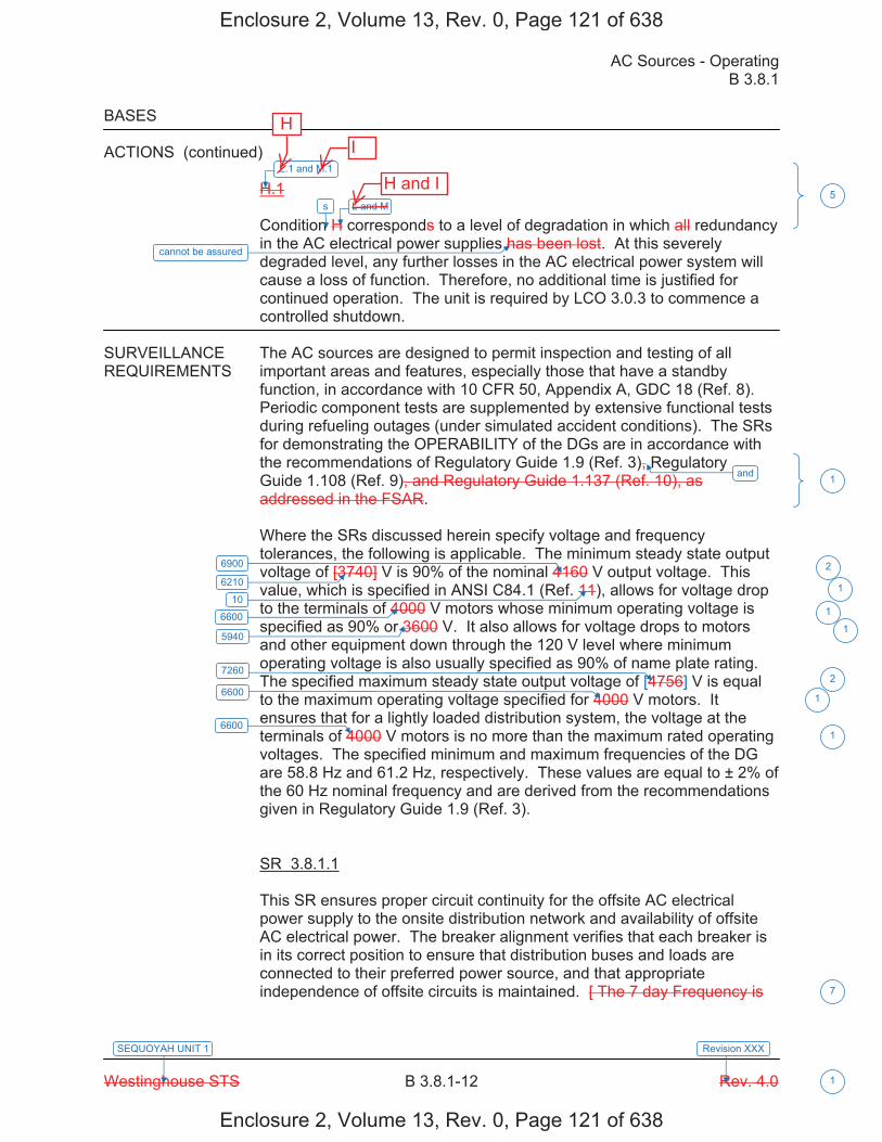
AC Sources - Operating B 3.8.1
Westinghouse STS B 3.8.1-12 Rev. 4.0
SEQUOYAH UNIT 1
1
Revision XXX
BASES
ACTIONS (continued)
H.1
Condition H corresponds to a level of degradation in which all redundancy in the AC electrical power supplies has been lost. At this severely degraded level, any further losses in the AC electrical power system will cause a loss of function. Therefore, no additional time is justified for continued operation. The unit is required by LCO 3.0.3 to commence a controlled shutdown.
SURVEILLANCE The AC sources are designed to permit inspection and testing of all REQUIREMENTS important areas and features, especially those that have a standby
function, in accordance with 10 CFR 50, Appendix A, GDC 18 (Ref. 8). Periodic component tests are supplemented by extensive functional tests during refueling outages (under simulated accident conditions). The SRs for demonstrating the OPERABILITY of the DGs are in accordance with the recommendations of Regulatory Guide 1.9 (Ref. 3), Regulatory Guide 1.108 (Ref. 9), and Regulatory Guide 1.137 (Ref. 10), as addressed in the FSAR.
Where the SRs discussed herein specify voltage and frequency tolerances, the following is applicable. The minimum steady state output voltage of [3740] V is 90% of the nominal 4160 V output voltage. This value, which is specified in ANSI C84.1 (Ref. 11), allows for voltage drop to the terminals of 4000 V motors whose minimum operating voltage is specified as 90% or 3600 V. It also allows for voltage drops to motors and other equipment down through the 120 V level where minimum operating voltage is also usually specified as 90% of name plate rating. The specified maximum steady state output voltage of [4756] V is equal to the maximum operating voltage specified for 4000 V motors. It ensures that for a lightly loaded distribution system, the voltage at the terminals of 4000 V motors is no more than the maximum rated operating voltages. The specified minimum and maximum frequencies of the DG are 58.8 Hz and 61.2 Hz, respectively. These values are equal to ± 2% of the 60 Hz nominal frequency and are derived from the recommendations given in Regulatory Guide 1.9 (Ref. 3).
SR 3.8.1.1
This SR ensures proper circuit continuity for the offsite AC electrical power supply to the onsite distribution network and availability of offsite AC electrical power. The breaker alignment verifies that each breaker is in its correct position to ensure that distribution buses and loads are connected to their preferred power source, and that appropriate independence of offsite circuits is maintained. [ The 7 day Frequency is
L.1 and M.1
L and M
and
6900
6600
5940
7260
6600
6600
5
1
2
1
2
1
1
7
6210
10 1
1
s
cannot be assured
Enclosure 2, Volume 13, Rev. 0, Page 121 of 638
Enclosure 2, Volume 13, Rev. 0, Page 121 of 638
H and I
I H
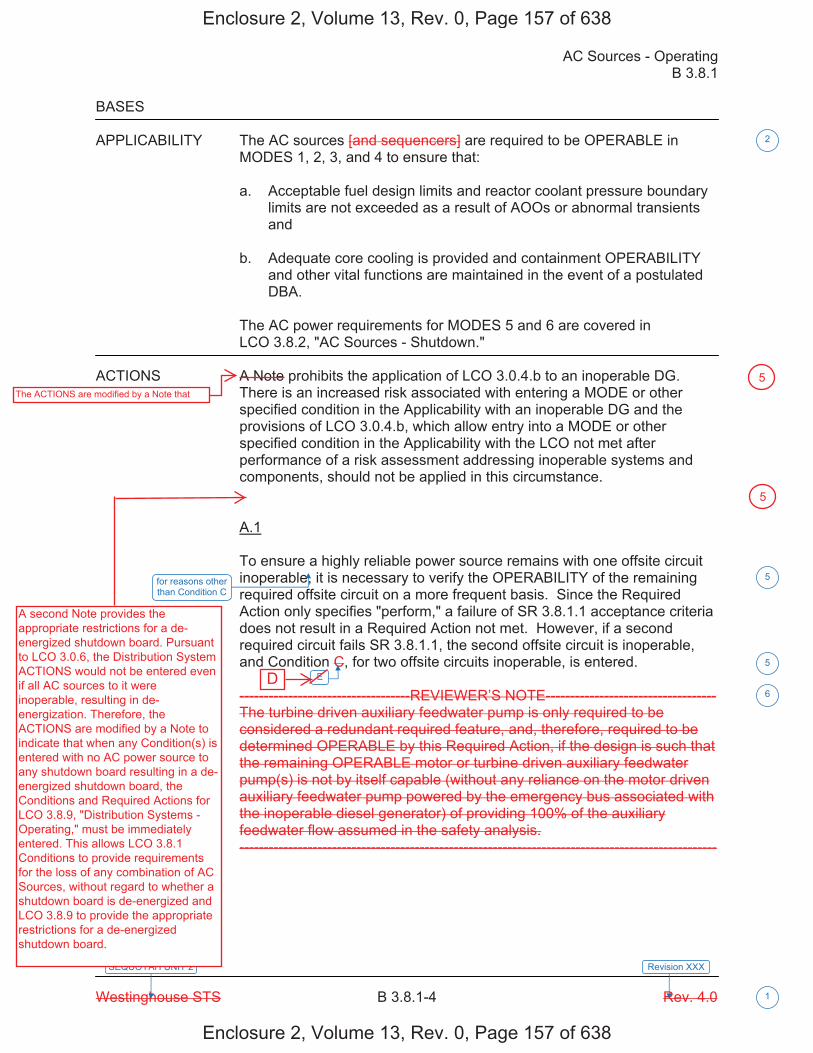
AC Sources - Operating B 3.8.1
Westinghouse STS B 3.8.1-4 Rev. 4.0
SEQUOYAH UNIT 2
1
Revision XXX
BASES
APPLICABILITY The AC sources [and sequencers] are required to be OPERABLE in MODES 1, 2, 3, and 4 to ensure that:
a. Acceptable fuel design limits and reactor coolant pressure boundarylimits are not exceeded as a result of AOOs or abnormal transientsand
b. Adequate core cooling is provided and containment OPERABILITYand other vital functions are maintained in the event of a postulatedDBA.
The AC power requirements for MODES 5 and 6 are covered in LCO 3.8.2, "AC Sources - Shutdown."
ACTIONS A Note prohibits the application of LCO 3.0.4.b to an inoperable DG. There is an increased risk associated with entering a MODE or other specified condition in the Applicability with an inoperable DG and the provisions of LCO 3.0.4.b, which allow entry into a MODE or other specified condition in the Applicability with the LCO not met after performance of a risk assessment addressing inoperable systems and components, should not be applied in this circumstance.
A.1
To ensure a highly reliable power source remains with one offsite circuit inoperable, it is necessary to verify the OPERABILITY of the remaining required offsite circuit on a more frequent basis. Since the Required Action only specifies "perform," a failure of SR 3.8.1.1 acceptance criteria does not result in a Required Action not met. However, if a second required circuit fails SR 3.8.1.1, the second offsite circuit is inoperable, and Condition C, for two offsite circuits inoperable, is entered.
-----------------------------------REVIEWER’S NOTE-----------------------------------The turbine driven auxiliary feedwater pump is only required to be considered a redundant required feature, and, therefore, required to be determined OPERABLE by this Required Action, if the design is such that the remaining OPERABLE motor or turbine driven auxiliary feedwater pump(s) is not by itself capable (without any reliance on the motor driven auxiliary feedwater pump powered by the emergency bus associated with the inoperable diesel generator) of providing 100% of the auxiliary feedwater flow assumed in the safety analysis. --------------------------------------------------------------------------------------------------
E
2
5
5
6
for reasons other than Condition C
Enclosure 2, Volume 13, Rev. 0, Page 157 of 638
Enclosure 2, Volume 13, Rev. 0, Page 157 of 638
D
5The ACTIONS are modified by a Note that
5
A second Note provides the appropriate restrictions for a de-energized shutdown board. Pursuant to LCO 3.0.6, the Distribution System ACTIONS would not be entered even if all AC sources to it were inoperable, resulting in de-energization. Therefore, the ACTIONS are modified by a Note to indicate that when any Condition(s) is entered with no AC power source to any shutdown board resulting in a de-energized shutdown board, the Conditions and Required Actions for LCO 3.8.9, "Distribution Systems - Operating," must be immediately entered. This allows LCO 3.8.1 Conditions to provide requirements for the loss of any combination of AC Sources, without regard to whether a shutdown board is de-energized and LCO 3.8.9 to provide the appropriate restrictions for a de-energized shutdown board.
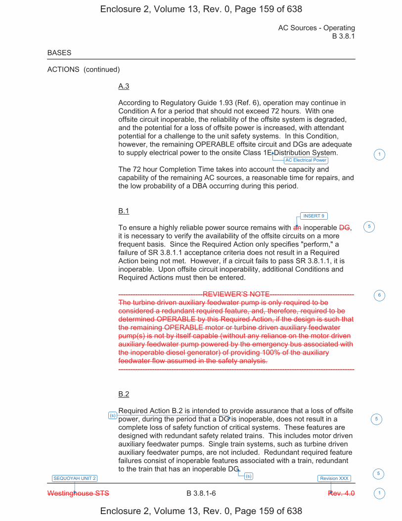
AC Sources - Operating B 3.8.1
Westinghouse STS B 3.8.1-6 Rev. 4.0
SEQUOYAH UNIT 2
1
Revision XXX
BASES
ACTIONS (continued)
A.3
According to Regulatory Guide 1.93 (Ref. 6), operation may continue in Condition A for a period that should not exceed 72 hours. With one offsite circuit inoperable, the reliability of the offsite system is degraded, and the potential for a loss of offsite power is increased, with attendant potential for a challenge to the unit safety systems. In this Condition, however, the remaining OPERABLE offsite circuit and DGs are adequate to supply electrical power to the onsite Class 1E Distribution System.
The 72 hour Completion Time takes into account the capacity and capability of the remaining AC sources, a reasonable time for repairs, and the low probability of a DBA occurring during this period.
B.1
To ensure a highly reliable power source remains with an inoperable DG, it is necessary to verify the availability of the offsite circuits on a more frequent basis. Since the Required Action only specifies "perform," a failure of SR 3.8.1.1 acceptance criteria does not result in a Required Action being not met. However, if a circuit fails to pass SR 3.8.1.1, it is inoperable. Upon offsite circuit inoperability, additional Conditions and Required Actions must then be entered.
-----------------------------------REVIEWER’S NOTE----------------------------------- The turbine driven auxiliary feedwater pump is only required to be considered a redundant required feature, and, therefore, required to be determined OPERABLE by this Required Action, if the design is such that the remaining OPERABLE motor or turbine driven auxiliary feedwater pump(s) is not by itself capable (without any reliance on the motor driven auxiliary feedwater pump powered by the emergency bus associated with the inoperable diesel generator) of providing 100% of the auxiliary feedwater flow assumed in the safety analysis. --------------------------------------------------------------------------------------------------
B.2
Required Action B.2 is intended to provide assurance that a loss of offsite power, during the period that a DG is inoperable, does not result in a complete loss of safety function of critical systems. These features are designed with redundant safety related trains. This includes motor driven auxiliary feedwater pumps. Single train systems, such as turbine driven auxiliary feedwater pumps, are not included. Redundant required feature failures consist of inoperable features associated with a train, redundant to the train that has an inoperable DG.
5
6
AC Electrical Power1
INSERT 9
(s) 5
(s) 5
Enclosure 2, Volume 13, Rev. 0, Page 159 of 638
Enclosure 2, Volume 13, Rev. 0, Page 159 of 638

B 3.8.1
Insert Page B 3.8.1-6
INSERT 9
DG 1A-A, DG 1B-B, DGs 1A-A and 2A-A, or DGs 1B-B and 2B-B
5
Enclosure 2, Volume 13, Rev. 0, Page 160 of 638
Enclosure 2, Volume 13, Rev. 0, Page 160 of 638
one or more Train A DGs, or one or more Train B DGs

AC Sources - Operating B 3.8.1
Westinghouse STS B 3.8.1-7 Rev. 4.0
SEQUOYAH UNIT 2
1
Revision XXX
BASES
ACTIONS (continued)
The Completion Time for Required Action B.2 is intended to allow the operator time to evaluate and repair any discovered inoperabilities. This Completion Time also allows for an exception to the normal "time zero" for beginning the allowed outage time "clock." In this Required Action, the Completion Time only begins on discovery that both:
a. An inoperable DG exists and
b. A required feature on the other train (Train A or Train B) isinoperable.
If at any time during the existence of this Condition (one DG inoperable) a required feature subsequently becomes inoperable, this Completion Time would begin to be tracked.
Discovering one required DG inoperable coincident with one or more inoperable required support or supported features, or both, that are associated with the OPERABLE DG, results in starting the Completion Time for the Required Action. Four hours from the discovery of these events existing concurrently is Acceptable because it minimizes risk while allowing time for restoration before subjecting the unit to transients associated with shutdown.
In this Condition, the remaining OPERABLE DG and offsite circuits are adequate to supply electrical power to the onsite Class 1E Distribution System. Thus, on a component basis, single failure protection for the required feature's function may have been lost; however, function has not been lost. The 4 hour Completion Time takes into account the OPERABILITY of the redundant counterpart to the inoperable required feature. Additionally, the 4 hour Completion Time takes into account the capacity and capability of the remaining AC sources, a reasonable time for repairs, and the low probability of a DBA occurring during this period.
B.3.1 and B.3.2
Required Action B.3.1 provides an allowance to avoid unnecessary testing of OPERABLE DG(s). If it can be determined that the cause of the inoperable DG does not exist on the OPERABLE DG, SR 3.8.1.2 does not have to be performed. If the cause of inoperability exists on other DG(s), the other DG(s) would be declared inoperable upon discovery and Condition E of LCO 3.8.1 would be entered. Once the failure is repaired, the common cause failure no longer exists, and Required Action B.3.1 is satisfied. If the cause of the initial inoperable DG cannot be confirmed not to exist on the remaining DG(s), performance of SR 3.8.1.2 suffices to provide assurance of continued OPERABILITY of that DG.
J INSERT 10
4
1
5
5
or more DGs in a train
5
or more DGs in a train
5
s AC Electrical Power
5
Enclosure 2, Volume 13, Rev. 0, Page 161 of 638
Enclosure 2, Volume 13, Rev. 0, Page 161 of 638
F

B 3.8.1
Insert Page B 3.8.1-7
INSERT 10
if one or more DG(s) in Train A and Train B are inoperable
5
Enclosure 2, Volume 13, Rev. 0, Page 162 of 638
Enclosure 2, Volume 13, Rev. 0, Page 162 of 638

AC Sources - Operating B 3.8.1
Westinghouse STS B 3.8.1-8 Rev. 4.0
SEQUOYAH UNIT 2
1
Revision XXX
BASES
ACTIONS (continued)
In the event the inoperable DG is restored to OPERABLE status prior to completing either B.3.1 or B.3.2, the [plant corrective action program] will continue to evaluate the common cause possibility. This continued evaluation, however, is no longer under the 24 hour constraint imposed while in Condition B.
According to Generic Letter 84-15 (Ref. 7), [24] hours is reasonable to confirm that the OPERABLE DG(s) is not affected by the same problem as the inoperable DG.
B.4
According to Regulatory Guide 1.93 (Ref. 6), operation may continue in Condition B for a period that should not exceed 72 hours.
In Condition B, the remaining OPERABLE DG and offsite circuits are adequate to supply electrical power to the onsite Class 1E Distribution System. The 72 hour Completion Time takes into account the capacity and capability of the remaining AC sources, a reasonable time for repairs, and the low probability of a DBA occurring during this period.
C.1 and C.2
Required Action C.1, which applies when two offsite circuits are inoperable, is intended to provide assurance that an event with a coincident single failure will not result in a complete loss of redundant required safety functions. The Completion Time for this failure of redundant required features is reduced to 12 hours from that allowed for one train without offsite power (Required Action A.2). The rationale for the reduction to 12 hours is that Regulatory Guide 1.93 (Ref. 6) allows a Completion Time of 24 hours for two required offsite circuits inoperable, based upon the assumption that two complete safety trains are OPERABLE. When a concurrent redundant required feature failure exists, this assumption is not the case, and a shorter Completion Time of 12 hours is appropriate. These features are powered from redundant AC safety trains. This includes motor driven auxiliary feedwater pumps. Single train features, such as turbine driven auxiliary pumps, are not included in the list.
7 day
INSERT 11
E E E
2
2
5
5
5
(s)
5
(s) AC Electrical Power
Enclosure 2, Volume 13, Rev. 0, Page 163 of 638
Enclosure 2, Volume 13, Rev. 0, Page 163 of 638
D D
D
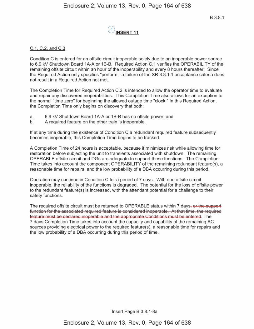
B 3.8.1
Insert Page B 3.8.1-8a
INSERT 11
C.1, C.2, and C.3
Condition C is entered for an offsite circuit inoperable solely due to an inoperable power source to 6.9 kV Shutdown Board 1A-A or 1B-B. Required Action C.1 verifies the OPERABILITY of the remaining offsite circuit within an hour of the inoperability and every 8 hours thereafter. Since the Required Action only specifies "perform," a failure of the SR 3.8.1.1 acceptance criteria does not result in a Required Action not met.
The Completion Time for Required Action C.2 is intended to allow the operator time to evaluate and repair any discovered inoperabilities. This Completion Time also allows for an exception to the normal "time zero" for beginning the allowed outage time "clock." In this Required Action, the Completion Time only begins on discovery that both:
a. 6.9 kV Shutdown Board 1A-A or 1B-B has no offsite power; andb. A required feature on the other train is inoperable.
If at any time during the existence of Condition C a redundant required feature subsequently becomes inoperable, this Completion Time begins to be tracked.
A Completion Time of 24 hours is acceptable, because it minimizes risk while allowing time for restoration before subjecting the unit to transients associated with shutdown. The remaining OPERABLE offsite circuit and DGs are adequate to support these functions. The Completion Time takes into account the component OPERABILITY of the remaining redundant feature(s), a reasonable time for repairs, and the low probability of a DBA occurring during this period.
Operation may continue in Condition C for a period of 7 days. With one offsite circuit inoperable, the reliability of the functions is degraded. The potential for the loss of offsite power to the redundant feature(s) is increased, with the attendant potential for a challenge to their safety functions.
The required offsite circuit must be returned to OPERABLE status within 7 days, or the support function for the associated required feature is considered inoperable. At that time, the required feature must be declared inoperable and the appropriate Conditions must be entered. The 7 days Completion Time takes into account the capacity and capability of the remaining AC sources providing electrical power to the required feature(s), a reasonable time for repairs and the low probability of a DBA occurring during this period of time.
5
Enclosure 2, Volume 13, Rev. 0, Page 164 of 638
Enclosure 2, Volume 13, Rev. 0, Page 164 of 638
B 3.8.1
Insert Page B 3.8.1-8b
INSERT 11 (Continued)
D.1, D.2, D.3, and D.4
To ensure a highly reliable power source remains with an inoperable DG to a Unit 1 6.9 kV Shutdown Board, it is necessary to verify the availability of the required offsite circuits on a more frequent basis. Since the Required Action only specifies "perform," a failure of SR 3.8.1.1 acceptance criteria does not result in a Required Action being not met. Required Action D.1 verifies the OPERABILITY of the required offsite sources within an hour of the inoperability and every 8 hours thereafter. However, if a circuit fails to pass SR 3.8.1.1, it is inoperable. Upon offsite circuit inoperability, additional Conditions and Required Actions must be entered.
Required Action D.2 is intended to provide assurance that a loss of offsite power, during the period that an LCO 3.8.1.d DG is inoperable, does not result in a complete loss of the safety functions.
The Completion Time for Required Action D.2 is intended to allow the operator time to evaluate and repair any discovered inoperabilities. This Completion Time also allows for an exception to the normal "time zero" for beginning the allowed outage time "clock." In this Required Action, the Completion Time only begins on discovery that both:
a. An inoperable DG to 6.9 kV Shutdown Board 1A-A or 1B-B exists; andb. A redundant feature in the same system is inoperable.
If at any time during the existence of Condition D (one DG to 6.9 kV Shutdown Board 1A-A or 1B-B) a redundant feature in the same system subsequently becomes inoperable, this Completion Time begins to be tracked. The four hour Completion Time is acceptable, because it minimizes risk while allowing time for restoration before subjecting the unit to transients associated with shutdown.
The remaining OPERABLE offsite circuits and DGs are adequate to support the functions. The 4 hour Completion Time takes into account the component OPERABILITY of the remaining redundant feature(s), a reasonable time for repairs, and the low probability of a DBA occurring during this period.
D.3.1 and D.3.2
Required Action D.3.1 provides an allowance to avoid unnecessary testing of OPERABLE DG(s). If it can be determined that the cause of the inoperable DG does not exist on the OPERABLE DG(s), SR 3.8.1.2 does not have to be performed. If the cause of inoperability exists on another DG, the other DG would be declared inoperable, and upon discovery, Condition J of LCO 3.8.1 would be entered, if one or more DG(s) in Train A and Train B are inoperable. Otherwise, if the inoperability exists on the other DG in the same train, the other DG would be declared inoperable upon discovery, Condition B would be entered. Once the failure is repaired, the common cause failure no longer exists, and Required Action D.3.1 is satisfied. If the cause of the initial inoperable DG cannot be confirmed not to exist on the remaining DGs, performance of SR 3.8.1.2 suffices to provide assurance of continued OPERABILITY of that DG.
5
Enclosure 2, Volume 13, Rev. 0, Page 165 of 638
Enclosure 2, Volume 13, Rev. 0, Page 165 of 638

B 3.8.1
Insert Page B 3.8.1-8c
INSERT 11 (Continued)
Operation may continue in Condition D for a period of 7 days. With one Unit 2 DG inoperable, the reliability of the respective function is degraded. The potential for the loss of a DG to the redundant feature(s) is increased, with the attendant potential for a challenge to respective safety function.
The required DG must be returned to OPERABLE status within 7 days, or the support function for the associated required feature is considered inoperable. At that time, the required feature must be declared inoperable and the appropriate Conditions must be entered. The 7 day Completion Time takes into account the capacity and capability of the remaining AC sources providing electrical power to the required feature(s), a reasonable time for repairs and the low probability of a DBA occurring during this period of time.
5
Enclosure 2, Volume 13, Rev. 0, Page 166 of 638
Enclosure 2, Volume 13, Rev. 0, Page 166 of 638
AC Sources - Operating B 3.8.1
Westinghouse STS B 3.8.1-9 Rev. 4.0
SEQUOYAH UNIT 2
1
Revision XXX
BASES
ACTIONS (continued)
The Completion Time for Required Action C.1 is intended to allow the operator time to evaluate and repair any discovered inoperabilities. This Completion Time also allows for an exception to the normal "time zero" for beginning the allowed outage time "clock." In this Required Action the Completion Time only begins on discovery that both:
a. All required offsite circuits are inoperable and
b. A required feature is inoperable.
If at any time during the existence of Condition C (two offsite circuits inoperable) a required feature becomes inoperable, this Completion Time begins to be tracked.
According to Regulatory Guide 1.93 (Ref. 6), operation may continue in Condition C for a period that should not exceed 24 hours. This level of degradation means that the offsite electrical power system does not have the capability to effect a safe shutdown and to mitigate the effects of an accident; however, the onsite AC sources have not been degraded. This level of degradation generally corresponds to a total loss of the immediately accessible offsite power sources.
Because of the normally high availability of the offsite sources, this level of degradation may appear to be more severe than other combinations of two AC sources inoperable that involve one or more DGs inoperable. However, two factors tend to decrease the severity of this level of degradation:
a. The configuration of the redundant AC electrical power system thatremains available is not susceptible to a single bus or switchingfailure and
b. The time required to detect and restore an unavailable offsite powersource is generally much less than that required to detect and restorean unavailable onsite AC source.
With both of the required offsite circuits inoperable, sufficient onsite AC sources are available to maintain the unit in a safe shutdown condition in the event of a DBA or transient. In fact, a simultaneous loss of offsite AC sources, a LOCA, and a worst case single failure were postulated as a part of the design basis in the safety analysis. Thus, the 24 hour Completion Time provides a period of time to effect restoration of one of the offsite circuits commensurate with the importance of maintaining an AC electrical power system capable of meeting its design criteria.
E
E
E
5
5
5
5
Enclosure 2, Volume 13, Rev. 0, Page 167 of 638
Enclosure 2, Volume 13, Rev. 0, Page 167 of 638
D
D
D
AC Sources - Operating B 3.8.1
Westinghouse STS B 3.8.1-10 Rev. 4.0
SEQUOYAH UNIT 2
1
Revision XXX
BASES
ACTIONS (continued)
According to Reference 6, with the available offsite AC sources, two less than required by the LCO, operation may continue for 24 hours. If two offsite sources are restored within 24 hours, unrestricted operation may continue. If only one offsite source is restored within 24 hours, power operation continues in accordance with Condition A.
D.1 and D.2
Pursuant to LCO 3.0.6, the Distribution System ACTIONS would not be entered even if all AC sources to it were inoperable, resulting in de-energization. Therefore, the Required Actions of Condition D are modified by a Note to indicate that when Condition D is entered with no AC source to any train, the Conditions and Required Actions for LCO 3.8.9, "Distribution Systems - Operating," must be immediately entered. This allows Condition D to provide requirements for the loss of one offsite circuit and one DG, without regard to whether a train is de-energized. LCO 3.8.9 provides the appropriate restrictions for a de-energized train.
According to Regulatory Guide 1.93 (Ref. 6), operation may continue in Condition D for a period that should not exceed 12 hours.
In Condition D, individual redundancy is lost in both the offsite electrical power system and the onsite AC electrical power system. Since power system redundancy is provided by two diverse sources of power, however, the reliability of the power systems in this Condition may appear higher than that in Condition C (loss of both required offsite circuits). This difference in reliability is offset by the susceptibility of this power system configuration to a single bus or switching failure. The 12 hour Completion Time takes into account the capacity and capability of the remaining AC sources, a reasonable time for repairs, and the low probability of a DBA occurring during this period.
E.1
With Train A and Train B DGs inoperable, there are no remaining standby AC sources. Thus, with an assumed loss of offsite electrical power, insufficient standby AC sources are available to power the minimum required ESF functions. Since the offsite electrical power system is the only source of AC power for this level of degradation, the risk associated with continued operation for a very short time could be less than that associated with an immediate controlled shutdown (the immediate shutdown could cause grid instability, which could result in a total loss of AC power). Since any inadvertent generator trip could also result in a
F F
F
F
F
F F
E
J
available to power an entire load
group
5
5
5
5
5
5
or Condition C, as applicable
6.9 kV Shutdown Board 2A-A or 2B-B
INSERT 12
one or more Train A DG(s) and one or more Train B DG(s) insufficient
to 6.9 kV Shutdown Board 2A-A or 2B-B
Enclosure 2, Volume 13, Rev. 0, Page 168 of 638
Enclosure 2, Volume 13, Rev. 0, Page 168 of 638
E E
E E
D
F

B 3.8.1
Insert Page B 3.8.1-10
INSERT 12
G.1 and H.1
In Conditions G and H, individual redundancy is lost in the offsite electrical power system for one unit and the onsite AC electrical power system for the other unit. Since Conditions B and C are entered concurrent with entry into Condition G, and Conditions A and D are entered concurrent with entry into Condition H, the Required Actions of Conditions B and C (or Conditions A and D) provide the appropriate compensatory measures to ensure the onsite and offsite power sources are either restored to an OPERABLE status, or the associated required features are declared inoperable, thereby requiring entry into the appropriate Conditions associated with the associated feature's LCO. The Completion Times of Required Actions G.1 and H.1 are consistent with the Completion Times of Required Actions C.3 and D.4. If, while in Condition G or H, a redundant required feature is determined to be inoperable, the required feature(s) would be declared inoperable at the Completion Times specified in Conditions A, B, C, or D, as applicable.
I.1 and I.2
Pursuant to LCO 3.0.6, the Distribution System ACTIONS would not be entered even if all AC sources to it were inoperable, resulting in de-energization. Therefore, the Required Actions of Condition I are modified by a Note to indicate that when Condition I is entered with no AC source to 6.9 kV Shutdown Board 1A-A or 1B-B, the Conditions and Required Actions for LCO 3.8.9, "Distribution Systems - Operating," must be immediately entered. This allows Condition I to provide requirements for the loss of one offsite power source and one DG, without regard to whether a train is de-energized. LCO 3.8.9 provides the appropriate restrictions for a de-energized 6.9 kV Shutdown Board.
In Condition I, individual redundancy is lost in the offsite electrical power system and the onsite AC electrical power system. Concurrent with entry into Condition I, entry into Condition C (inoperable offsite power source) and Condition D (inoperable DG) are required. The Required Actions of Conditions C and D ensure the remaining offsite circuit and DGs are OPERABLE and that required features with no offsite or onsite power sources are declared inoperable when its redundant required feature is inoperable within the Completion Times of Required Actions C.2 and D.2.
5
Enclosure 2, Volume 13, Rev. 0, Page 169 of 638
Enclosure 2, Volume 13, Rev. 0, Page 169 of 638
AC Sources - Operating B 3.8.1
Westinghouse STS B 3.8.1-11 Rev. 4.0
SEQUOYAH UNIT 2
1
Revision XXX
BASES
ACTIONS (continued)
total loss of offsite AC power, however, the time allowed for continued operation is severely restricted. The intent here is to avoid the risk associated with an immediate controlled shutdown and to minimize the risk associated with this level of degradation.
According to Reference 6, with both DGs inoperable, operation may continue for a period that should not exceed 2 hours.
[ F.1
The sequencer(s) is an essential support system to [both the offsite circuit and the DG associated with a given ESF bus]. [Furthermore, the sequencer is on the primary success path for most major AC electrically powered safety systems powered from the associated ESF bus.] Therefore, loss of an [ESF bus sequencer] affects every major ESF system in the [division]. The [12] hour Completion Time provides a period of time to correct the problem commensurate with the importance of maintaining sequencer OPERABILITY. This time period also ensures that the probability of an accident (requiring sequencer OPERABILITY) occurring during periods when the sequencer is inoperable is minimal.
This Condition is preceded by a Note that allows the Condition to be deleted if the unit design is such that any sequencer failure mode will only affect the ability of the associated DG to power its respective safety loads under any conditions. Implicit in this Note is the concept that the Condition must be retained if any sequencer failure mode results in the inability to start all or part of the safety loads when required, regardless of power availability, or results in overloading the offsite power circuit to a safety bus during an event and thereby causes its failure. Also implicit in the Note, is that the Condition is not applicable to any train that does not have a sequencer. ]
G.1 and G.2
If the inoperable AC electric power sources cannot be restored to OPERABLE status within the required Completion Time, the unit must be brought to a MODE in which the LCO does not apply. To achieve this status, the unit must be brought to at least MODE 3 within 6 hours and to MODE 5 within 36 hours. The allowed Completion Times are reasonable, based on operating experience, to reach the required unit conditions from full power conditions in an orderly manner and without challenging plant systems.
K K
5
5
5
5
In this Condition,
, consistent with the guidance provided in Reference 6
Enclosure 2, Volume 13, Rev. 0, Page 170 of 638
Enclosure 2, Volume 13, Rev. 0, Page 170 of 638
G G

AC Sources - Operating B 3.8.1
Westinghouse STS B 3.8.1-12 Rev. 4.0
SEQUOYAH UNIT 2
1
Revision XXX
BASES
ACTIONS (continued)
H.1
Condition H corresponds to a level of degradation in which all redundancy in the AC electrical power supplies has been lost. At this severely degraded level, any further losses in the AC electrical power system will cause a loss of function. Therefore, no additional time is justified for continued operation. The unit is required by LCO 3.0.3 to commence a controlled shutdown.
SURVEILLANCE The AC sources are designed to permit inspection and testing of all REQUIREMENTS important areas and features, especially those that have a standby
function, in accordance with 10 CFR 50, Appendix A, GDC 18 (Ref. 8). Periodic component tests are supplemented by extensive functional tests during refueling outages (under simulated accident conditions). The SRs for demonstrating the OPERABILITY of the DGs are in accordance with the recommendations of Regulatory Guide 1.9 (Ref. 3), Regulatory Guide 1.108 (Ref. 9), and Regulatory Guide 1.137 (Ref. 10), as addressed in the FSAR.
Where the SRs discussed herein specify voltage and frequency tolerances, the following is applicable. The minimum steady state output voltage of [3740] V is 90% of the nominal 4160 V output voltage. This value, which is specified in ANSI C84.1 (Ref. 11), allows for voltage drop to the terminals of 4000 V motors whose minimum operating voltage is specified as 90% or 3600 V. It also allows for voltage drops to motors and other equipment down through the 120 V level where minimum operating voltage is also usually specified as 90% of name plate rating. The specified maximum steady state output voltage of [4756] V is equal to the maximum operating voltage specified for 4000 V motors. It ensures that for a lightly loaded distribution system, the voltage at the terminals of 4000 V motors is no more than the maximum rated operating voltages. The specified minimum and maximum frequencies of the DG are 58.8 Hz and 61.2 Hz, respectively. These values are equal to ± 2% of the 60 Hz nominal frequency and are derived from the recommendations given in Regulatory Guide 1.9 (Ref. 3).
SR 3.8.1.1
This SR ensures proper circuit continuity for the offsite AC electrical power supply to the onsite distribution network and availability of offsite AC electrical power. The breaker alignment verifies that each breaker is in its correct position to ensure that distribution buses and loads are connected to their preferred power source, and that appropriate independence of offsite circuits is maintained. [ The 7 day Frequency is
and
6900
6600
5940
7260
6600
6600
5
1
2
1
2
1
1
7
6210
10 1
1
L.1 and M.1
s L and M
cannot be assured
Enclosure 2, Volume 13, Rev. 0, Page 171 of 638
Enclosure 2, Volume 13, Rev. 0, Page 171 of 638
HI
H and I
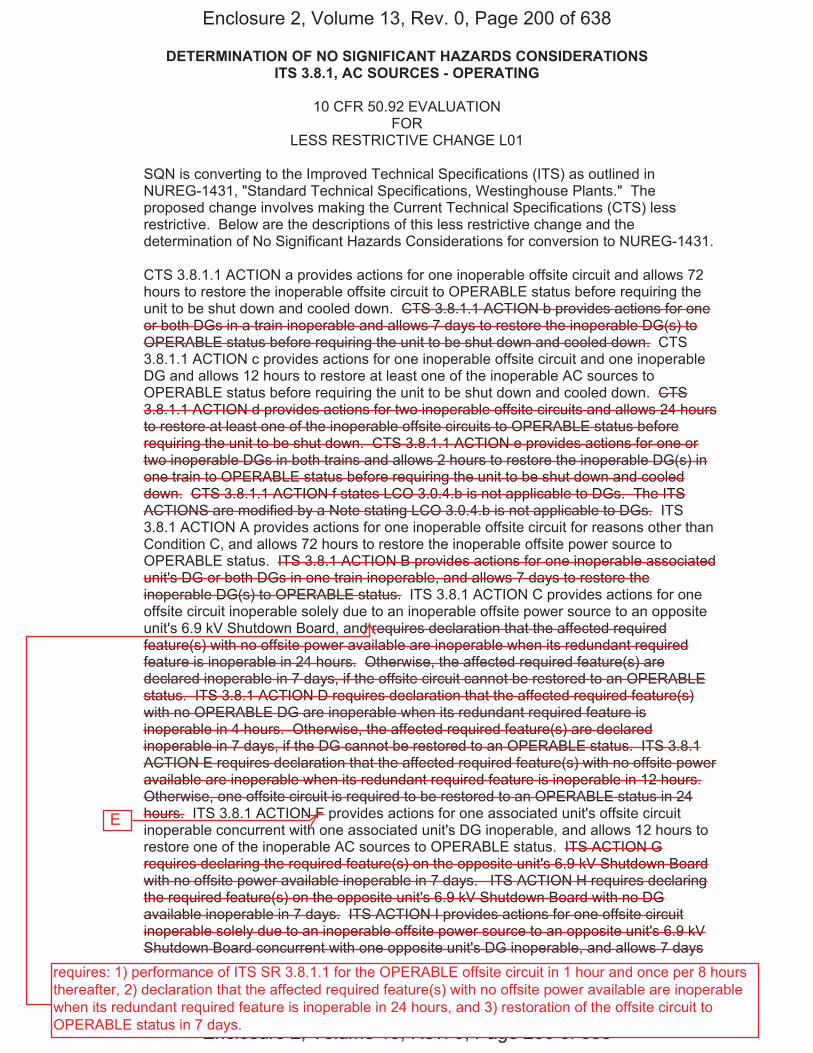
DETERMINATION OF NO SIGNIFICANT HAZARDS CONSIDERATIONS ITS 3.8.1, AC SOURCES - OPERATING
Sequoyah Unit 1 and 2 Page 1 of 4
10 CFR 50.92 EVALUATION FOR
LESS RESTRICTIVE CHANGE L01
SQN is converting to the Improved Technical Specifications (ITS) as outlined in NUREG-1431, "Standard Technical Specifications, Westinghouse Plants." The proposed change involves making the Current Technical Specifications (CTS) less restrictive. Below are the descriptions of this less restrictive change and the determination of No Significant Hazards Considerations for conversion to NUREG-1431.
CTS 3.8.1.1 ACTION a provides actions for one inoperable offsite circuit and allows 72 hours to restore the inoperable offsite circuit to OPERABLE status before requiring the unit to be shut down and cooled down. CTS 3.8.1.1 ACTION b provides actions for one or both DGs in a train inoperable and allows 7 days to restore the inoperable DG(s) to OPERABLE status before requiring the unit to be shut down and cooled down. CTS 3.8.1.1 ACTION c provides actions for one inoperable offsite circuit and one inoperable DG and allows 12 hours to restore at least one of the inoperable AC sources to OPERABLE status before requiring the unit to be shut down and cooled down. CTS 3.8.1.1 ACTION d provides actions for two inoperable offsite circuits and allows 24 hours to restore at least one of the inoperable offsite circuits to OPERABLE status before requiring the unit to be shut down. CTS 3.8.1.1 ACTION e provides actions for one or two inoperable DGs in both trains and allows 2 hours to restore the inoperable DG(s) in one train to OPERABLE status before requiring the unit to be shut down and cooled down. CTS 3.8.1.1 ACTION f states LCO 3.0.4.b is not applicable to DGs. The ITS ACTIONS are modified by a Note stating LCO 3.0.4.b is not applicable to DGs. ITS 3.8.1 ACTION A provides actions for one inoperable offsite circuit for reasons other than Condition C, and allows 72 hours to restore the inoperable offsite power source to OPERABLE status. ITS 3.8.1 ACTION B provides actions for one inoperable associated unit's DG or both DGs in one train inoperable, and allows 7 days to restore the inoperable DG(s) to OPERABLE status. ITS 3.8.1 ACTION C provides actions for one offsite circuit inoperable solely due to an inoperable offsite power source to an opposite unit's 6.9 kV Shutdown Board, and requires declaration that the affected required feature(s) with no offsite power available are inoperable when its redundant required feature is inoperable in 24 hours. Otherwise, the affected required feature(s) are declared inoperable in 7 days, if the offsite circuit cannot be restored to an OPERABLE status. ITS 3.8.1 ACTION D requires declaration that the affected required feature(s) with no OPERABLE DG are inoperable when its redundant required feature is inoperable in 4 hours. Otherwise, the affected required feature(s) are declared inoperable in 7 days, if the DG cannot be restored to an OPERABLE status. ITS 3.8.1 ACTION E requires declaration that the affected required feature(s) with no offsite power available are inoperable when its redundant required feature is inoperable in 12 hours. Otherwise, one offsite circuit is required to be restored to an OPERABLE status in 24 hours. ITS 3.8.1 ACTION F provides actions for one associated unit's offsite circuit inoperable concurrent with one associated unit's DG inoperable, and allows 12 hours to restore one of the inoperable AC sources to OPERABLE status. ITS ACTION G requires declaring the required feature(s) on the opposite unit's 6.9 kV Shutdown Board with no offsite power available inoperable in 7 days. ITS ACTION H requires declaring the required feature(s) on the opposite unit's 6.9 kV Shutdown Board with no DG available inoperable in 7 days. ITS ACTION I provides actions for one offsite circuit inoperable solely due to an inoperable offsite power source to an opposite unit's 6.9 kV Shutdown Board concurrent with one opposite unit's DG inoperable, and allows 7 days
Enclosure 2, Volume 13, Rev. 0, Page 200 of 638
Enclosure 2, Volume 13, Rev. 0, Page 200 of 638
E
requires: 1) performance of ITS SR 3.8.1.1 for the OPERABLE offsite circuit in 1 hour and once per 8 hours thereafter, 2) declaration that the affected required feature(s) with no offsite power available are inoperable when its redundant required feature is inoperable in 24 hours, and 3) restoration of the offsite circuit to OPERABLE status in 7 days.
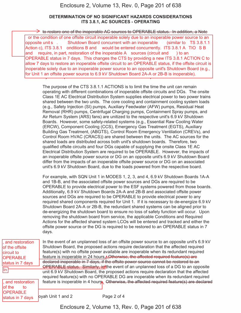
DETERMINATION OF NO SIGNIFICANT HAZARDS CONSIDERATIONS ITS 3.8.1, AC SOURCES - OPERATING
Sequoyah Unit 1 and 2 Page 2 of 4
to restore one of the inoperable AC sources to OPERABLE status. In addition, a Note modifying ITS ACTION I requires entry into the applicable Conditions and Required Actions of LCO 3.8.9 with no AC power source to an opposite unit's 6.9 kV Shutdown Board. ITS 3.8.1 ACTION J provides actions for one or more Train A and one or more Train B DGs inoperable and allows 2 hours to restore one Train of DGs to OPERABLE status. ITS 3.8.1 ACTION K requires the unit to be shut down and cooled down if a Required Action and associated Completion Time of Condition A, B, E, F, I, or J is not met. These changes to the CTS provide separate ACTIONS to declare the required features powered from the opposite unit's Class 1E AC Electrical Power Distribution System inoperable as the remedial measures for the inoperable AC sources.
The purpose of the CTS 3.8.1.1 ACTIONS is to limit the time the unit can remain operating with different combinations of inoperable offsite circuits and DGs. The onsite Class 1E AC Electrical Distribution System supplies electrical power to two power trains shared between the two units. The core cooling and containment cooling system loads (e.g., Safety Injection (SI) pumps, Auxiliary Feedwater (AFW) pumps, Residual Heat Removal (RHR) pumps, Centrifugal Charging pumps, Containment Spray pumps, and Air Return System (ARS) fans) are unitized to the respective unit's 6.9 kV Shutdown Boards. However, some safety-related systems (e.g., Essential Raw Cooling Water (ERCW), Component Cooling (CCS), Emergency Gas Treatment (EGTS), Auxiliary Building Gas Treatment, (ABGTS), Control Room Emergency Ventilation (CREVs), and Control Room HVAC (CRACS)) are shared between the units. The AC sources for the shared loads are distributed across both unit's shutdown boards. Therefore, two qualified offsite circuits and four DGs capable of supplying the onsite Class 1E AC Electrical Distribution System are required to be OPERABLE. However, the impacts of an inoperable offsite power source or DG on an opposite unit's 6.9 kV Shutdown Board differ from the impacts of an inoperable offsite power source or DG on an associated unit's 6.9 kV Shutdown Board, due to the loads powered from the respective board.
For example, with SQN Unit 1 in MODES 1, 2, 3, and 4, 6.9 kV Shutdown Boards 1A-A and 1B-B, and the associated offsite power sources and DGs are required to be OPERABLE to provide electrical power to the ESF systems powered from those boards. Additionally, 6.9 kV Shutdown Boards 2A-A and 2B-B and associated offsite power sources and DGs are required to be OPERABLE to provide electrical power to any required shared components required for Unit 1. If it is necessary to de-energize 6.9 kV Shutdown Board 2A-A or 2B-B, the redundant shared systems can be aligned prior to de-energizing the shutdown board to ensure no loss of safety function will occur. Upon removing the shutdown board from service, the applicable Conditions and Required Actions for the affected shared system LCOs will be entered and tracked and either the offsite power source or the DG is required to be restored to an OPERABLE status in 7 days.
In the event of an unplanned loss of an offsite power source to an opposite unit's 6.9 kV Shutdown Board, the proposed actions require declaration that the affected required feature(s) with no offsite power available are inoperable when its redundant required feature is inoperable in 24 hours. Otherwise, the affected required feature(s) are declared inoperable in 7 days, if the offsite power source cannot be restored to an OPERABLE status. Similarly, in the event of an unplanned loss of a DG to an opposite unit 6.9 kV Shutdown Board, the proposed actions require declaration that the affected required feature(s) with no OPERABLE DG are inoperable when its redundant required feature is inoperable in 4 hours. Otherwise, the affected required feature(s) are declared
Enclosure 2, Volume 13, Rev. 0, Page 201 of 638
Enclosure 2, Volume 13, Rev. 0, Page 201 of 638
�or the condition of one offsite circuit inoperable solely due to an inoperable power source to an opposite unit�s �.� �� Shutdown Board concurrent with an inoperable �� (similar to �TS 3.8.1.1 Action c), ITS 3.8.1 �onditions B and � would be entered concurrently. ITS 3.8.1 A�TIO�S B and � require, in part, restoration of the inoperable A� sources (circuit and ��) to an OPERABLE status in 7 days. This changes the CTS by providing a new ITS 3.8.1 ACTION C toallow 7 days to restore an inoperable offsite circuit to an OPERABLE status, if the offsite circuit isinoperable solely due to an inoperable power source to an opposite unit's Shutdown Board (e.g.,for Unit 1 an offsite power source to 6.9 kV Shutdown Board 2A-A or 2B-B is inoperable).
, and restoration of the offsite circuit to OPERABLE status in 7 daysIn
, and restoration of the �� to OPERABLE status in 7 days

DETERMINATION OF NO SIGNIFICANT HAZARDS CONSIDERATIONS ITS 3.8.1, AC SOURCES - OPERATING
Sequoyah Unit 1 and 2 Page 3 of 4
inoperable in 7 days, if the DG cannot be restored to an OPERABLE status. In both cases, the ACTIONS require performance of SR 3.8.1.1 for the required OPERABLE offsite circuit(s) within 1 hour and once per 8 hours thereafter.
The Required Actions are consistent with safe operation under the specified Condition, considering the OPERABLE status of the redundant systems or features. This includes the capacity and capability of remaining systems or features, a reasonable time for repairs or replacement, and the low probability of a DBA occurring during the repair period. These changes are acceptable because the Required Actions are used to establish remedial measures that must be taken in response to the degraded conditions in order to minimize risk associated with continued operation, while providing time to repair inoperable features. If the necessary repairs cannot be made within the established Completion Time, the associated required features are declared inoperable and the applicable Conditions and Required Actions for the affected shared system LCOs are entered and tracked. This change is acceptable because the provided ACTIONS effect restoration of the opposite unit's AC sources commensurate with the importance of maintaining these AC sources capable of supporting the associated unit's required feature(s). This change is designated as less restrictive, because less stringent Required Actions are being applied in the ITS than were applied in the CTS.
Tennessee Valley Authority (TVA) has evaluated whether or not a significant hazards consideration is involved with these proposed Technical Specification changes by focusing on the three standards set forth in 10 CFR 50.92, "Issuance of amendment," as discussed below:
1. Does the proposed change involve a significant increase in the probability orconsequences of any accident previously evaluated?
Response: No.
The proposed change relaxes the Required Actions for the opposite unit's offsite AC power sources and DGs. The opposite unit's offsite AC power sources and DGs are required to be OPERABLE to support the associated unit's required features. This change will not affect the probability of an accident, since the offsite AC circuits and DGs are not initiators of any accident sequence analyzed in the Updated Final Safety Analysis Report (UFSAR). Rather, offsite AC power sources and DGs support equipment used to mitigate accidents. The consequences of an analyzed accident will not be significantly increased since the minimum requirements for AC power sources will be maintained to ensure the availability of the required power to mitigate accidents assumed in the UFSAR. Operation in accordance with the proposed TS will ensure that sufficient onsite and offsite AC power sources are OPERABLE as required to support the unit's required features. Therefore, the mitigating functions supported by the onsite and offsite AC power sources will continue to provide the protection assumed by the accident analysis. The integrity of fission product barriers, plant configuration, and operating procedures as described in the UFSAR will not be affected by the proposed changes. Thus, the consequences of previously analyzed accidents will not increase by implementing these changes. Therefore, the proposed changes do not involve a significant increase in the probability or consequences of an accident previously evaluated.
Enclosure 2, Volume 13, Rev. 0, Page 202 of 638
Enclosure 2, Volume 13, Rev. 0, Page 202 of 638
ITS 3.8.1ACTION G isentered and theunit is required tobe shut down toMODE 3 in 6hours and MODE5 in 36 hours. offsite circuit
offsite circuit
DETERMINATION OF NO SIGNIFICANT HAZARDS CONSIDERATIONS ITS 3.8.1, AC SOURCES - OPERATING
Sequoyah Unit 1 and 2 Page 4 of 4
2. Does the proposed change create the possibility of a new or different kind ofaccident from any previously evaluated?
Response: No
The proposed change relaxes the Required Actions for the opposite unit's offsite AC power sources and DGs. The opposite unit's offsite AC power sources and DGs are required to be OPERABLE to support the associated unit's required features. This change will not physically alter the plant (no new or different type of equipment will be installed). The proposed changes will maintain the minimum requirements for AC power sources to ensure the availability of the equipment required to mitigate accidents assumed in the UFSAR. Therefore, operation of the facility in accordance with this proposed change will not create the possibility of a new or different kind of accident from any accident previously evaluated.
3. Does the proposed change involve a significant reduction in the margin of safety?
Response: No.
The proposed change relaxes the Required Actions for the opposite unit's offsite AC power sources and DGs. The opposite unit's offsite AC power sources and DGs are required to be OPERABLE to support the associated unit's required features. The margin of safety is not affected by this change because the minimum requirements for AC power sources will be maintained to ensure the availability of the required power to shutdown the reactor and maintain it in a safe shutdown condition after an AOO or a postulated DBA. Therefore, the proposed changes do not involve a significant reduction in a margin of safety
Enclosure 2, Volume 13, Rev. 0, Page 203 of 638
Enclosure 2, Volume 13, Rev. 0, Page 203 of 638

Licensee Response/NRC Response/NRC Question ClosureId 453
NRC Question Number VKG026
Select Application NRC Question Closure
Attachment 1
Attachment 2
Response Statement
Response Date/Time
Closure Statement This question is closed and no further information is required at this time to draft the Safety Evaluation.
Question Closure Date 5/14/2015
Notification Michelle ConnerVijay GoelKhadijah HemphillAndrew HonLynn MynattRay SchieleRoger Scott
Added By Khadijah Hemphill
Date Added 5/14/2015 3:11 PM
Date Modified
Modified By
Page 1 of 1Sequoyah ITS Conversion Database
05/15/2015https://members.excelservices.com/rai/index.php?requestType=areaItemPrint&itemId=453
ITS NRC QuestionsId 197
NRC Question Number
VKG027
Category Technical
ITS Section 3.8
ITS Number 3.8.1
DOC Number
JFD Number
JFD Bases Number
Page Number(s)
NRC Reviewer
Supervisor Rob Elliott
Technical Branch POC Add Name
Conf Call Requested N
NRC Question ITS 3.8.1 (for Unit 1), Condition C, “One offsite circuit inoperable
solely due to an offsite power source to 6.9 kV Shutdown Board 2A-A or 2B-B inoperable,” Action C.3 requires, “Declare associated required feature(s) inoperable,” within 7 days. While Unit 2 will be required to shutdown after 72 hours if the Shutdown Board is not restored, Unit 1 can remain in operational mode unless some other LCO Action statement requires Unit 1 to shutdown or restore the inoperable circuit to the operable status.
CTS requires both Units to shutdown after 72 hours when an offsite circuit becomes inoperable. However, based on response to RAI # VKG004 (similar to the response to RAI # VKG007), the ITS would allow one of the Units to remain in operational mode for 10 to 14 days. Staff is concerned that the Unit in operation would not be able to safely shutdown in case of “Loss of Onsite power (only Offsite power available from remaining Offsite circuits), LOCA, and worst case single failure in one of the safety-related systems (GDC 17, GDC 34, and GDC 35 requirements)” during the extended period of the one of Offsite circuits inoperability. CTS accepts this risk for 3 days, but ITS is extending this risk for an additional 7 or 11 days. Although, the Commission allows single failure not to be
Page 1 of 2Sequoyah ITS Conversion Database
05/15/2015https://members.excelservices.com/rai/index.php?requestType=areaItemPrint&itemId=197
considered during an LCO Action statement, the staff is concerned regarding the extended Offsite circuit inoperability. Typically, according to standard TS and Regulatory Guide 1.93, the inoperability of an Offsite circuit is limited to 72 hours.
The above staff concerns are also applicable to Condition G, in which an offsite circuit impacting the opposite Unit shutdown board becomes inoperable. ITS 3.8.1.G does not require the Offsite circuit to be restored; only the associated required features are to be declared inoperable.
Please provide the technical basis for the relaxation of Completion Times described above or revise ITS 3.8.1 Conditions C and G appropriately for both Units (i.e., to be consistent with the current licensing basis).
Attach File 1
Attach File 2
Issue Date 11/18/2014
Added By Khadijah Hemphill
Date Modified
Modified By
Date Added 11/18/2014 5:38 PM
Notification Scott BowmanMichelle ConnerVijay GoelKhadijah HemphillAndrew HonLynn MynattRay SchieleRoger Scott
Page 2 of 2Sequoyah ITS Conversion Database
05/15/2015https://members.excelservices.com/rai/index.php?requestType=areaItemPrint&itemId=197
Licensee Response/NRC Response/NRC Question ClosureId 433
NRC Question Number
VKG027
Select Application Licensee Response
Attachment 1 Attachment 1 for RAI VKG027 with VKG027 Indicators.pdf (3MB)
Attachment 2
Response Statement
In response to RAI VKG027, ITS 3.8.1 Required Action C.3 will be revised to reflect the requirement to restore an offsite circuit that is inoperable solely due to an inoperable offsite power source to an opposite unit’s 6.9 kV shutdown board to an OPERABLE status in 7 days.
On December 16, 1998, NRC issued Technical Specification Amendments for SQN, Units 1 and 2 (TAC Nos. M96600 and M96601)(TS 96-08)(ADAMS Accession No. 9812210233). The amendments revised the SQN Technical Specifications by extending the allowed outage time (AOT) for the SQN emergency diesel generators (EDG) from 72 hours to 7 days. Although SQN had demonstrated, based on a probabilistic risk assessment (PRA) basis, that the extended EDG AOT would result in no significant increase in risk, the staff also reviewed the submittal from a deterministic approach. Based on the Staff’s review, it was determined that a 7 day AOT was acceptable. Regulatory Guide 1.93, Rev. 0 states that “a general distinction does not appear to be warranted for operating restrictions associated with the loss of an offsite source and those restrictions associated with the loss of an onsite a.c. supply.” Regulatory Guide 1.93, Rev. 1, Section C. “Regulatory Position” discusses the seven levels of degradation of the electric power system in order of increasing degradation. The lowest level of degradation listed is “The available offsite ac power sources are one less than the LCO.” The second lowest level of degradation listed is “The available onsite ac power sources are one less than the LCO.” Both of these levels of degradation have the same AOT, which is consistent with the statement made in Rev. 0 of Regulatory Guide 1.93. The revision to ITS 3.8.1 Condition C will align the AOT for an inoperable offsite power source to an opposite unit’s 6.9 kV shutdown board to correspond to the AOT for an inoperable onsite (EDG) power source.
Page 1 of 4Sequoyah ITS Conversion Database
05/15/2015https://members.excelservices.com/rai/index.php?requestType=areaItemPrint&itemId=433
As stated in UFSAR Section 3.1.2, SQN fully meets the requirements of General Design Criteria (GDC) 17, 34, and 35. The proposed extension of the AOT for an inoperable offsite circuit to the opposite unit 6.9 kV shutdown board does not modify the electrical power, residual heat removal, or emergency core cooling systems. Each of these systems will continue to be capable of performing their intended design function. Therefore, SQN will continue to meet the requirements of GDC 17, 34, and 35 with the extension of the AOT.
At SQN, the majority of the loads necessary to mitigate design basis accidents (DBAs) are powered from the associated unit’s two trained 6.9 kV shutdown boards that each have an offsite and onsite (EDG) power source. Consistent with Regulatory Guide 1.93 and ISTS 3.8.1, a loss of the offsite power source to their respective train for the associated unit will require entry into a Condition and Required Action Completion Time of 72 hours.However, there are shared loads that are powered from the opposite unit’s trained power supply. The systems that are shared between Unit 1 and Unit 2 and powered from Unit 1 are the Emergency Gas Treatment System (EGTS), Essential Raw Cooling Water (ERCW) System, Component Cooling Water System (CCS), Control Room Emergency Ventilation System (CREVS), Control Room Air-Conditioning System (CRACS), and the 125V Vital DC System. The shared systems powered from Unit 2 are the Auxiliary Building Gas Treatment System (ABGTS), the Auxiliary Control Air System (ACAS), Essential Raw Cooling Water (ERCW) System, Component Cooling Water System (CCS), and the 125V Vital DC System. In ITS 3.8.1, a loss of an offsite power source to an opposite unit shutdown board would require verification of the breaker alignment and indicated power availability for the OPERABLE offsite circuit within 1 hour, verification that the required features with no offsite power available have OPERABLE redundant features, otherwise declare the required feature inoperable, and entry into a Condition and Required Action Completion Time of 7 days to restore the offsite circuit to OPERABLE status. With a single inoperable offsite power source to an opposite unit shutdown board, all required features remain OPERABLE with redundancy. For a loss of safety function to occur, a complete loss of onsite power along with the offsite power to the redundant train on the opposite unit would have to occur.
SQN has maintenance activities that need to be performed on the
Page 2 of 4Sequoyah ITS Conversion Database
05/15/2015https://members.excelservices.com/rai/index.php?requestType=areaItemPrint&itemId=433
shutdown boards. The entire maintenance activity cannot be performed under the current AOT of 72 hours. The extension of the AOT for an inoperable offsite circuit to an opposite unit shutdown board would allow the maintenance activities to be performed during a scheduled outage on the opposite unit. The increased AOT will not increase the probability or consequences of any accident previously evaluated. The power sources are required to be OPERABLE to support the associated unit’s required features. Because the offsite circuit is not an initiator of any accident sequence, inoperability of the circuit will not affect the probability of an accident occurring. The consequences of any accident previously evaluated will not be increased. The steam line break (SLB), steam generator tube rupture (SGTR), small break loss of coolant accident (SBLOCA), large break LOCA (LBLOCA), and main feedwater pipe rupture (MFWPR) events are sensitive to the availability of the onsite and offsite power sources. For a SLB and SGTR, the limiting analyses assume that a loss of offsite power occurs. With an offsite circuit already made inoperable, the resultant analyses for SLB and SGTR will, therefore, not be impacted. For the SBLOCA, the analysis assumes that a loss of offsite power occurs, which will trip the reactor coolant pumps (RCPs). A delay in tripping the RCPs can potentially produce more limiting results. Therefore, with an offsite circuit already made inoperable, there is no impact on the analysis for a SBLOCA. For the LBLOCA, transient calculations were performed, both with and without a loss of offsite power. As stated in UFSAR Section 15.4.1.4, the most limiting case producing the highest peak clad temperature (PCT), occurs with offsite power available. Table 15.4.1-2 indicates that offsite power was available for the limiting case and the RCPs do not trip. Because the most limiting case for the LBLOCA is having offsite power available, removing an offsite circuit would have no impact on the limiting case LBLOCA. The MFWPR event produced similar results for cases with or without offsite power. Therefore, the loss of one offsite power source will not impact the existing main feedwater pipe break analysis.
Recent modifications to the offsite power system and Technical Specification change TS-SQN-12-01 has increased the number of qualified circuits that can be used to provide offsite power to the onsite power distribution system. The unit station service transformers (USSTs) now qualify as an offsite power circuit.Additionally, SQN has never experienced a complete loss of offsite power event during commercial operation.
Page 3 of 4Sequoyah ITS Conversion Database
05/15/2015https://members.excelservices.com/rai/index.php?requestType=areaItemPrint&itemId=433
Increasing the AOT from 72 hours to 7 days for an inoperable offsite power supply to an opposite unit’s 6.9 kV shutdown board is considered acceptable due to the limited amount of equipment that is powered from the opposite unit’s shutdown board, no impact on the probability of occurrence or consequences of accidents previously evaluated, the increase in qualified circuits for providing offsite power, the fact that SQN has never experienced a loss of offsite power event, and would make the Required Action Completion Time consistent with the loss of an onsite power source.
See Attachment 1 for the draft CTS 3.8.1.1 markup, DOC, ITS 3.8.1 markup, JFD, and ITS 3.8.1 Bases markup changes based on the discussion above. Changes associated with RAI VKG027 are illustrated as such, all other changes on Attachment 1 are associated with the response to RAI VKG026.
Response Date/Time 4/9/2015 2:30 PM
Closure Statement
Question Closure
Date
Notification Scott BowmanMichelle ConnerVijay GoelKhadijah HemphillAndrew HonLynn MynattRay Schiele
Added By Scott Bowman
Date Added 4/9/2015 1:26 PM
Date Modified
Modified By
Page 4 of 4Sequoyah ITS Conversion Database
05/15/2015https://members.excelservices.com/rai/index.php?requestType=areaItemPrint&itemId=433
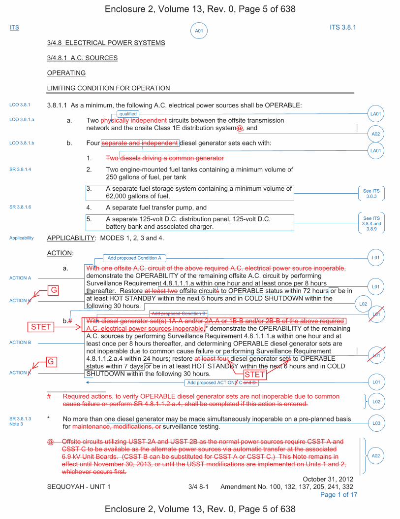
A01ITS ITS 3.8.1
3/4.8 ELECTRICAL POWER SYSTEMS
3/4.8.1 A.C. SOURCES
OPERATING
LIMITING CONDITION FOR OPERATION
3.8.1.1 As a minimum, the following A.C. electrical power sources shall be OPERABLE:
a. Two physically independent circuits between the offsite transmissionnetwork and the onsite Class 1E distribution system@, and
b. Four separate and independent diesel generator sets each with:
1. Two diesels driving a common generator
2. Two engine-mounted fuel tanks containing a minimum volume of250 gallons of fuel, per tank
3. A separate fuel storage system containing a minimum volume of62,000 gallons of fuel,
4. A separate fuel transfer pump, and
5. A separate 125-volt D.C. distribution panel, 125-volt D.C.battery bank and associated charger.
APPLICABILITY: MODES 1, 2, 3 and 4.
ACTION:
a. With one offsite A.C. circuit of the above required A.C. electrical power source inoperable,demonstrate the OPERABILITY of the remaining offsite A.C. circuit by performing Surveillance Requirement 4.8.1.1.1.a within one hour and at least once per 8 hours thereafter. Restore at least two offsite circuits to OPERABLE status within 72 hours or be in at least HOT STANDBY within the next 6 hours and in COLD SHUTDOWN within the following 30 hours.
b.# With diesel generator set(s) 1A-A and/or 2A-A or 1B-B and/or 2B-B of the above required A.C. electrical power sources inoperable,* demonstrate the OPERABILITY of the remaining A.C. sources by performing Surveillance Requirement 4.8.1.1.1.a within one hour and at least once per 8 hours thereafter, and determining OPERABLE diesel generator sets are not inoperable due to common cause failure or performing Surveillance Requirement 4.8.1.1.2.a.4 within 24 hours; restore at least four diesel generator sets to OPERABLE status within 7 days or be in at least HOT STANDBY within the next 6 hours and in COLD SHUTDOWN within the following 30 hours.
# Required actions, to verify OPERABLE diesel generator sets are not inoperable due to common cause failure or perform SR 4.8.1.1.2.a.4, shall be completed if this action is entered.
* No more than one diesel generator may be made simultaneously inoperable on a pre-planned basisfor maintenance, modifications, or surveillance testing.
@ Offsite circuits utilizing USST 2A and USST 2B as the normal power sources require CSST A and CSST C to be available as the alternate power sources via automatic transfer at the associated 6.9 kV Unit Boards. (CSST B can be substituted for CSST A or CSST C.) This Note remains in effect until November 30, 2013, or until the USST modifications are implemented on Units 1 and 2, whichever occurs first.
October 31, 2012 SEQUOYAH - UNIT 1 3/4 8-1 Amendment No. 100, 132, 137, 205, 241, 332
LCO 3.8.1
Applicability
Page 1 of 17
LCO 3.8.1.a
LCO 3.8.1.b
SR 3.8.1.4
SR 3.8.1.6
See ITS 3.8.4 and
3.8.9
LA01
LA01qualified
ACTION A
ACTION K
ACTION B
ACTION K
L01Add proposed ACTIONS C and D
L01Add proposed Condition B
L01
L01
L02
L02
L03SR 3.8.1.3 Note 3
Add proposed Condition A L01
See ITS 3.8.3
A02
A02
Enclosure 2, Volume 13, Rev. 0, Page 5 of 638
Enclosure 2, Volume 13, Rev. 0, Page 5 of 638
G
G
STET
STET

A01ITS ITS 3.8.1
ELECTRICAL POWER SYSTEMS
ACTION (Continued)
c. With one offsite circuit and one diesel generator set of the above required A.C. electricalpower sources inoperable, demonstrate the OPERABILITY of the remaining A.C. sources by performing Surveillance Requirements 4.8.1.1.1.a within one hour and at least once per 8 hours thereafter, and Surveillance Requirement 4.8.1.1.2.a.4 within 8 hours; restore at least one of the inoperable sources to OPERABLE status within 12 hours or be in at least HOT STANDBY within the next 6 hours and in COLD SHUTDOWN within the following 30 hours.
d. With two of the above required offsite A.C. circuits inoperable, demonstrate theOPERABILITY of 4 diesel generator sets by performing Surveillance Requirement4.8.1.1.2.a.4 within 8 hours, unless the diesel generator sets are already operating; restoreat least one of the inoperable offsite sources to OPERABLE status within 24 hours or be inat least HOT STANDBY within the next 6 hours.
e. With either diesel generator sets 1A-A and/or 2A-A inoperable simultaneous with 1B-Band/or 2B-B, demonstrate the OPERABILITY of two offsite A.C. circuits by performingSurveillance Requirement 4.8.1.1.1.a within one hour and at least once per 8 hoursthereafter; restore at least 1) 1A-A and 2A-A or 2) 1B-B and 2B-B to OPERABLE statuswithin 2 hours or be in at least HOT STANDBY within the next 6 hours and in COLDSHUTDOWN within the following 30 hours.
f. LCO 3.0.4.b is not applicable to diesel generators.
SURVEILLANCE REQUIREMENTS
4.8.1.1.1 Each of the above required independent circuits between the offsite transmission network and the onsite Class 1E distribution system shall be:
a. Determined OPERABLE at least once per 7 days by verifying correct breaker alignmentsand indicated power availability.
b. Demonstrated OPERABLE at least once per 18 months# by manually and automaticallytransferring the power supply to each 6.9 kV Unit Board## from the normal supply to the alternate supply.
# For the 1A, 1B, 1C and 1D 6.9 kV Unit Boards, this Surveillance shall not be performed in MODES 1 and 2.
## Transfer capability is only required to be met for 6.9 kV Unit Boards that require normal and alternate power supplies.
October 31, 2012 SEQUOYAH - UNIT 1 3/4 8-2 Amendment No. 100, 137, 184, 205, 228,
255, 301, 332 Page 2 of 17
ACTION F
ACTION A, ACTION B ACTION F
ACTION K
L01Add proposed Condition F
A03Add proposed ACTION F Note
24 L04
ACTION E
ACTION K
ACTION J
L05
M01and MODE 5 within 36 hours
L01
ACTION J
ACTION K
ACTION B
L01Add proposed ACTIONS G, H, and I
A04Add proposed ACTIONS L and M
SR 3.8.1.1
SR 3.8.1.1
LA02
ACTIONS Note
LA01
In accordance with the Surveillance Frequency Control Program
SR 3.8.1.8
SR 3.8.1.8 Note 1
L06Add proposed SR 3.8.1.8 Note 1, second and third sentences.SR 3.8.1.8 Note 2
Enclosure 2, Volume 13, Rev. 0, Page 6 of 638
Enclosure 2, Volume 13, Rev. 0, Page 6 of 638
H
I
E
E E
E
G
G
G
F
F
D
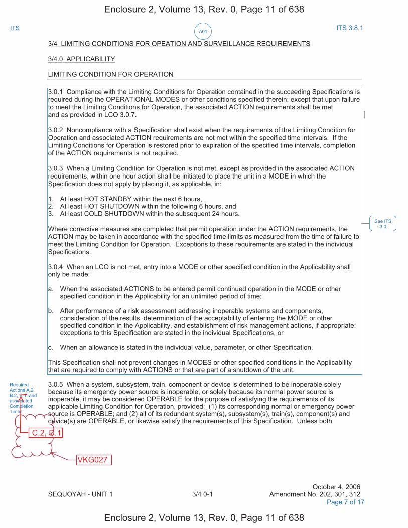
A01ITS ITS 3.8.1
3/4 LIMITING CONDITIONS FOR OPEATION AND SURVEILLANCE REQUIREMENTS
3/4.0 APPLICABILITY
LIMITING CONDITION FOR OPERATION
3.0.1 Compliance with the Limiting Conditions for Operation contained in the succeeding Specifications is required during the OPERATIONAL MODES or other conditions specified therein; except that upon failure to meet the Limiting Conditions for Operation, the associated ACTION requirements shall be met and as provided in LCO 3.0.7.
3.0.2 Noncompliance with a Specification shall exist when the requirements of the Limiting Condition for Operation and associated ACTION requirements are not met within the specified time intervals. If the Limiting Conditions for Operation is restored prior to expiration of the specified time intervals, completion of the ACTION requirements is not required.
3.0.3 When a Limiting Condition for Operation is not met, except as provided in the associated ACTION requirements, within one hour action shall be initiated to place the unit in a MODE in which the Specification does not apply by placing it, as applicable, in:
1. At least HOT STANDBY within the next 6 hours,2. At least HOT SHUTDOWN within the following 6 hours, and3. At least COLD SHUTDOWN within the subsequent 24 hours.
Where corrective measures are completed that permit operation under the ACTION requirements, the ACTION may be taken in accordance with the specified time limits as measured from the time of failure to meet the Limiting Condition for Operation. Exceptions to these requirements are stated in the individual Specifications.
3.0.4 When an LCO is not met, entry into a MODE or other specified condition in the Applicability shall only be made:
a. When the associated ACTIONS to be entered permit continued operation in the MODE or otherspecified condition in the Applicability for an unlimited period of time;
b. After performance of a risk assessment addressing inoperable systems and components,consideration of the results, determination of the acceptability of entering the MODE or otherspecified condition in the Applicability, and establishment of risk management actions, if appropriate;exceptions to this Specification are stated in the individual Specifications, or
c. When an allowance is stated in the individual value, parameter, or other Specification.
This Specification shall not prevent changes in MODES or other specified conditions in the Applicability that are required to comply with ACTIONS or that are part of a shutdown of the unit.
3.0.5 When a system, subsystem, train, component or device is determined to be inoperable solely because its emergency power source is inoperable, or solely because its normal power source is inoperable, it may be considered OPERABLE for the purpose of satisfying the requirements of its applicable Limiting Condition for Operation, provided: (1) its corresponding normal or emergency power source is OPERABLE; and (2) all of its redundant system(s), subsystem(s), train(s), component(s) and device(s) are OPERABLE, or likewise satisfy the requirements of this Specification. Unless both
October 4, 2006 SEQUOYAH - UNIT 1 3/4 0-1 Amendment No. 202, 301, 312
See ITS 3.0
Required Actions A.2, B.2, E.1, and associated Completion Times
Page 7 of 17
Enclosure 2, Volume 13, Rev. 0, Page 11 of 638
Enclosure 2, Volume 13, Rev. 0, Page 11 of 638
C.2, D.1
VKG027
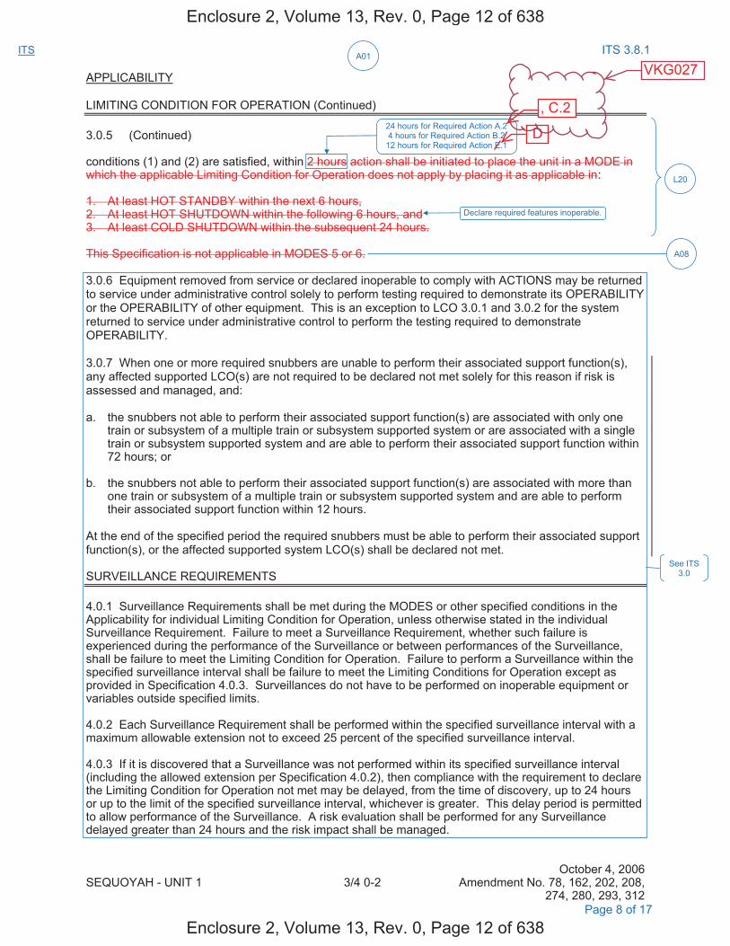
A01ITS ITS 3.8.1
APPLICABILITY
LIMITING CONDITION FOR OPERATION (Continued)
3.0.5 (Continued)
conditions (1) and (2) are satisfied, within 2 hours action shall be initiated to place the unit in a MODE in which the applicable Limiting Condition for Operation does not apply by placing it as applicable in:
1. At least HOT STANDBY within the next 6 hours,2. At least HOT SHUTDOWN within the following 6 hours, and3. At least COLD SHUTDOWN within the subsequent 24 hours.
This Specification is not applicable in MODES 5 or 6.
3.0.6 Equipment removed from service or declared inoperable to comply with ACTIONS may be returned to service under administrative control solely to perform testing required to demonstrate its OPERABILITY or the OPERABILITY of other equipment. This is an exception to LCO 3.0.1 and 3.0.2 for the system returned to service under administrative control to perform the testing required to demonstrate OPERABILITY.
3.0.7 When one or more required snubbers are unable to perform their associated support function(s), any affected supported LCO(s) are not required to be declared not met solely for this reason if risk is assessed and managed, and:
a. the snubbers not able to perform their associated support function(s) are associated with only onetrain or subsystem of a multiple train or subsystem supported system or are associated with a singletrain or subsystem supported system and are able to perform their associated support function within72 hours; or
b. the snubbers not able to perform their associated support function(s) are associated with more thanone train or subsystem of a multiple train or subsystem supported system and are able to performtheir associated support function within 12 hours.
At the end of the specified period the required snubbers must be able to perform their associated support function(s), or the affected supported system LCO(s) shall be declared not met.
SURVEILLANCE REQUIREMENTS
4.0.1 Surveillance Requirements shall be met during the MODES or other specified conditions in the Applicability for individual Limiting Condition for Operation, unless otherwise stated in the individual Surveillance Requirement. Failure to meet a Surveillance Requirement, whether such failure is experienced during the performance of the Surveillance or between performances of the Surveillance, shall be failure to meet the Limiting Condition for Operation. Failure to perform a Surveillance within the specified surveillance interval shall be failure to meet the Limiting Conditions for Operation except as provided in Specification 4.0.3. Surveillances do not have to be performed on inoperable equipment or variables outside specified limits.
4.0.2 Each Surveillance Requirement shall be performed within the specified surveillance interval with a maximum allowable extension not to exceed 25 percent of the specified surveillance interval.
4.0.3 If it is discovered that a Surveillance was not performed within its specified surveillance interval (including the allowed extension per Specification 4.0.2), then compliance with the requirement to declare the Limiting Condition for Operation not met may be delayed, from the time of discovery, up to 24 hours or up to the limit of the specified surveillance interval, whichever is greater. This delay period is permitted to allow performance of the Surveillance. A risk evaluation shall be performed for any Surveillance delayed greater than 24 hours and the risk impact shall be managed.
October 4, 2006 SEQUOYAH - UNIT 1 3/4 0-2 Amendment No. 78, 162, 202, 208,
274, 280, 293, 312 Page 8 of 17
See ITS 3.0
L20
24 hours for Required Action A.2 4 hours for Required Action B.2
12 hours for Required Action E.1
Declare required features inoperable.
A08
Enclosure 2, Volume 13, Rev. 0, Page 12 of 638
Enclosure 2, Volume 13, Rev. 0, Page 12 of 638
D
, C.2
VKG027

A01ITS ITS 3.8.1
3/4.8 ELECTRICAL POWER SYSTEMS
3/4.8.1 A.C. SOURCES
OPERATING
LIMITING CONDITION FOR OPERATION
3.8.1.1 As a minimum, the following A.C. electrical power sources shall be OPERABLE:
a. Two physically independent circuits between the offsite transmission network and theonsite Class 1E distribution system@, and
b. Four separate and independent diesel generator sets each with:
1. Two diesels driving a common generator
2. Two engine-mounted fuel tanks containing a minimum volume of 250 gallons of fuel,per tank
3. A separate fuel storage system containing a minimum volume of 62,000 gallons offuel,
4. A separate fuel transfer pump, and
5. A separate 125-volt D.C. distribution panel, 125-volt D.C. battery bank andassociated charger.
APPLICABILITY: MODES 1, 2, 3 and 4.
ACTION:
a. With one offsite A.C. circuit of the above required A.C. electrical power sources inoperable,demonstrate the OPERABILITY of the remaining offsite A.C. circuit by performing Surveillance Requirement 4.8.1.1.1.a within one hour and at least once per 8 hours thereafter. Restore at least two offsite circuits to OPERABLE status within 72 hours or be in at least HOT STANDBY within the next 6 hours and in COLD SHUTDOWN within the following 30 hours.
b.# With diesel generator set(s) 1A-A and/or 2A-A or 1B-B and/or 2B-B of the above required A.C. electrical power sources inoperable,* demonstrate the OPERABILITY of the remaining A.C. sources by performing Surveillance Requirement 4.8.1.1.1.a within one hour and at least once per 8 hours thereafter, and determining OPERABLE diesel generator sets are not inoperable due to common cause failure or performing Surveillance Requirement 4.8.1.1.2.a.4 within 24 hours; restore at least four diesel generator sets to OPERABLE status within 7 days or be in at least HOT STANDBY within the next 6 hours and in COLD SHUTDOWN within the following 30 hours.
# Required actions, to verify OPERABLE diesel generator sets are not inoperable due to common cause failure or perform SR 4.8.1.1.2.a.4, shall be completed if this action is entered.
* No more than one diesel generator may be made simultaneously inoperable on a pre-planned basisfor maintenance, modifications, or surveillance testing.
@ Offsite circuits utilizing USST 2A and USST 2B as the normal power sources require CSST A and CSST C to be available as the alternate power sources via automatic transfer at the associated 6.9 kV Unit Boards. (CSST B can be substituted for CSST A or CSST C.) This Note remains in effect until November 30, 2013, or until the USST modifications are implemented on Units 1 and 2, whichever occurs first.
October 31, 2012 SEQUOYAH - UNIT 2 3/4 8-1 Amendment No. 89, 119, 123, 195, 231, 325
LCO 3.8.1
Applicability
Page 9 of 16
LCO 3.8.1.a
LCO 3.8.1.b
SR 3.8.1.4
SR 3.8.1.6
See ITS 3.8.4 and
3.8.9
LA01
LA01qualified
ACTION A
ACTION K
ACTION B
ACTION K
L01Add proposed ACTIONS C and D
L01Add proposed Condition B
L01
L01
L02
L02
L03SR 3.8.1.3 Note 3
Add proposed Condition A L01
See ITS 3.8.3
A02
A02
Enclosure 2, Volume 13, Rev. 0, Page 13 of 638
Enclosure 2, Volume 13, Rev. 0, Page 13 of 638
G
G
STET
STET

A01ITS ITS 3.8.1
ELECTRICAL POWER SYSTEMS
ACTION (Continued)
c. With one offsite circuit and one diesel generator set of the above required A.C. electricalpower sources inoperable, demonstrate the OPERABILITY of the remaining A.C. sources by performing Surveillance Requirements 4.8.1.1.1.a within one hour and at least once per 8 hours thereafter, and Surveillance Requirement 4.8.1.1.2.a.4 within 8 hours; restore at least one of the inoperable sources to OPERABLE status within 12 hours or be in at least HOT STANDBY within the next 6 hours and in COLD SHUTDOWN within the following 30 hours.
d. With two of the above required offsite A.C. circuits inoperable, demonstrate theOPERABILITY of 4 diesel generator sets by performing Surveillance Requirement4.8.1.1.2.a.4 within 8 hours, unless the diesel generator sets are already operating; restoreat least one of the inoperable offsite sources to OPERABLE status within 24 hours or be inat least HOT STANDBY within the next 6 hours.
e. With either diesel generator sets 1A-A and/or 2 A-A inoperable simultaneous with 1B-Band/or 2B-B, demonstrate the OPERABILITY of two offsite A.C. circuits by performingSurveillance Requirement 4.8.1.1.1.a within one hour and at least once per 8 hoursthereafter; restore at least 1) 1A-A and 2A-A or 2) 1B-B and 2B-B to OPERABLE statuswithin 2 hours or be in at least HOT STANDBY within the next 6 hours and in COLDSHUTDOWN within the following 30 hours.
f. LCO 3.0.4.b is not applicable to diesel generators.
SURVEILLANCE REQUIREMENTS
4.8.1.1.1 Each of the above required independent circuits between the offsite transmission network and the onsite Class 1E distribution system shall be:
a. Determined OPERABLE at least once per 7 days by verifying correct breaker alignmentsand indicated power availability.
b. Demonstrated OPERABLE at least once per 18 months# by manually and automaticallytransferring the power supply to each 6.9 kV Unit Board ## from the normal supply to the alternate supply.
# For the 2A, 2B, 2C and 2D 6.9 kV Unit Boards this Surveillance shall not be performed in MODES 1 and 2.
## Transfer capability is only required to be met for 6.9 kV Unit Boards that require normal and alternate power supplies.
October 31, 2012 SEQUOYAH - UNIT 2 3/4 8-2 Amendment No. 89, 123, 176, 195, 219,
246, 290, 325
Page 10 of 17
ACTION F
ACTION A, ACTION B ACTION F
ACTION K
L01Add proposed Condition F
A03Add proposed ACTION F Note
24 L04
ACTION E
ACTION K
ACTION J
L05
M01and MODE 5 within 36 hours
L01
ACTION J
ACTION K
ACTION B
L01Add proposed ACTIONS G, H, and I
A04Add proposed ACTIONS L and M
SR 3.8.1.1
SR 3.8.1.1
LA02
ACTIONS Note
In accordance with the Surveillance Frequency Control Program
SR 3.8.1.8
SR 3.8.1.8 Note 1 L06Add proposed SR 3.8.1.8 Note 1, second and third sentences.
SR 3.8.1.8 Note 2
LA01
Enclosure 2, Volume 13, Rev. 0, Page 14 of 638
Enclosure 2, Volume 13, Rev. 0, Page 14 of 638
E
E E
E
D
G
F
F
G
G
H I
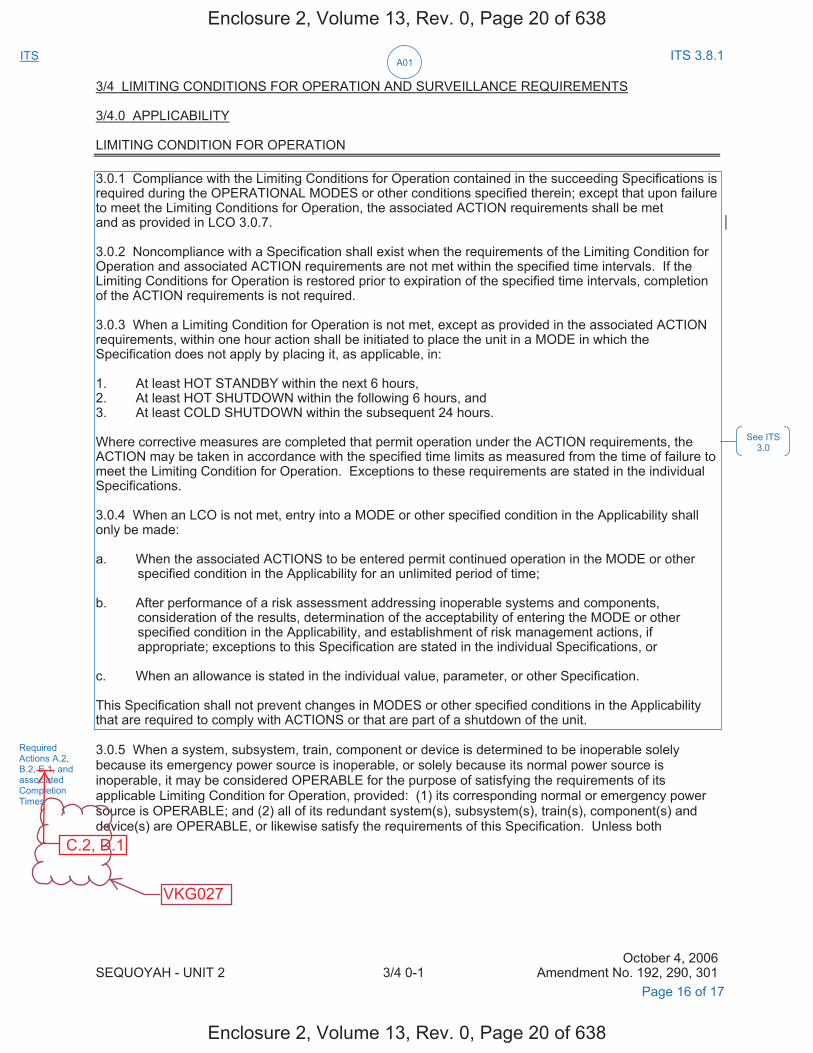
A01ITS ITS 3.8.1
3/4 LIMITING CONDITIONS FOR OPERATION AND SURVEILLANCE REQUIREMENTS
3/4.0 APPLICABILITY
LIMITING CONDITION FOR OPERATION
3.0.1 Compliance with the Limiting Conditions for Operation contained in the succeeding Specifications is required during the OPERATIONAL MODES or other conditions specified therein; except that upon failure to meet the Limiting Conditions for Operation, the associated ACTION requirements shall be met and as provided in LCO 3.0.7.
3.0.2 Noncompliance with a Specification shall exist when the requirements of the Limiting Condition for Operation and associated ACTION requirements are not met within the specified time intervals. If the Limiting Conditions for Operation is restored prior to expiration of the specified time intervals, completion of the ACTION requirements is not required.
3.0.3 When a Limiting Condition for Operation is not met, except as provided in the associated ACTION requirements, within one hour action shall be initiated to place the unit in a MODE in which the Specification does not apply by placing it, as applicable, in:
1. At least HOT STANDBY within the next 6 hours,2. At least HOT SHUTDOWN within the following 6 hours, and3. At least COLD SHUTDOWN within the subsequent 24 hours.
Where corrective measures are completed that permit operation under the ACTION requirements, the ACTION may be taken in accordance with the specified time limits as measured from the time of failure to meet the Limiting Condition for Operation. Exceptions to these requirements are stated in the individual Specifications.
3.0.4 When an LCO is not met, entry into a MODE or other specified condition in the Applicability shall only be made:
a. When the associated ACTIONS to be entered permit continued operation in the MODE or otherspecified condition in the Applicability for an unlimited period of time;
b. After performance of a risk assessment addressing inoperable systems and components,consideration of the results, determination of the acceptability of entering the MODE or otherspecified condition in the Applicability, and establishment of risk management actions, ifappropriate; exceptions to this Specification are stated in the individual Specifications, or
c. When an allowance is stated in the individual value, parameter, or other Specification.
This Specification shall not prevent changes in MODES or other specified conditions in the Applicability that are required to comply with ACTIONS or that are part of a shutdown of the unit.
3.0.5 When a system, subsystem, train, component or device is determined to be inoperable solely because its emergency power source is inoperable, or solely because its normal power source is inoperable, it may be considered OPERABLE for the purpose of satisfying the requirements of its applicable Limiting Condition for Operation, provided: (1) its corresponding normal or emergency power source is OPERABLE; and (2) all of its redundant system(s), subsystem(s), train(s), component(s) and device(s) are OPERABLE, or likewise satisfy the requirements of this Specification. Unless both
October 4, 2006 SEQUOYAH - UNIT 2 3/4 0-1 Amendment No. 192, 290, 301
See ITS 3.0
Required Actions A.2, B.2, E.1, and associated Completion Times
Page 16 of 17
Enclosure 2, Volume 13, Rev. 0, Page 20 of 638
Enclosure 2, Volume 13, Rev. 0, Page 20 of 638
C.2, D.1
VKG027
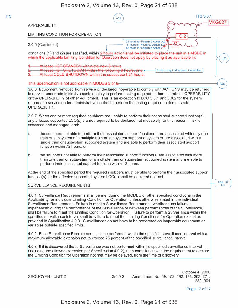
A01ITS ITS 3.8.1
APPLICABILITY
LIMITING CONDITION FOR OPERATION
3.0.5 (Continued)
conditions (1) and (2) are satisfied, within 2 hours action shall be initiated to place the unit in a MODE in which the applicable Limiting Condition for Operation does not apply by placing it as applicable in:
1. At least HOT STANDBY within the next 6 hours2. At least HOT SHUTDOWN within the following 6 hours, and3. At least COLD SHUTDOWN within the subsequent 24 hours.
This Specification is not applicable in MODES 5 or 6. 3.0.6 Equipment removed from service or declared inoperable to comply with ACTIONS may be returned to service under administrative control solely to perform testing required to demonstrate its OPERABILITY or the OPERABILITY of other equipment. This is an exception to LCO 3.0.1 and 3.0.2 for the system returned to service under administrative control to perform the testing required to demonstrate OPERABILITY.
3.0.7 When one or more required snubbers are unable to perform their associated support function(s), any affected supported LCO(s) are not required to be declared not met solely for this reason if risk is assessed and managed, and:
a. the snubbers not able to perform their associated support function(s) are associated with only onetrain or subsystem of a multiple train or subsystem supported system or are associated with asingle train or subsystem supported system and are able to perform their associated supportfunction within 72 hours; or
b. the snubbers not able to perform their associated support function(s) are associated with morethan one train or subsystem of a multiple train or subsystem supported system and are able toperform their associated support function within 12 hours.
At the end of the specified period the required snubbers must be able to perform their associated support function(s), or the affected supported system LCO(s) shall be declared not met.
SURVEILLANCE REQUIREMENTS
4.0.1 Surveillance Requirements shall be met during the MODES or other specified conditions in the Applicability for individual Limiting Condition for Operation, unless otherwise stated in the individual Surveillance Requirement. Failure to meet a Surveillance Requirement, whether such failure is experienced during the performance of the Surveillance or between performances of the Surveillance, shall be failure to meet the Limiting Condition for Operation. Failure to perform a Surveillance within the specified surveillance interval shall be failure to meet the Limiting Conditions for Operation except as provided in Specification 4.0.3. Surveillances do not have to be performed on inoperable equipment or variables outside specified limits.
4.0.2 Each Surveillance Requirement shall be performed within the specified surveillance interval with a maximum allowable extension not to exceed 25 percent of the specified surveillance interval.
4.0.3 If it is discovered that a Surveillance was not performed within its specified surveillance interval (including the allowed extension per Specification 4.0.2), then compliance with the requirement to declare the Limiting Condition for Operation not met may be delayed, from the time of discovery,
October 4, 2006 SEQUOYAH - UNIT 2 3/4 0-2 Amendment No. 69, 152, 192, 198, 263, 271,
283, 301
Page 17 of 17
See ITS 3.0
L20
24 hours for Required Action A.2 4 hours for Required Action B.2
12 hours for Required Action E.1
Declare required features inoperable.
A08
Enclosure 2, Volume 13, Rev. 0, Page 21 of 638
Enclosure 2, Volume 13, Rev. 0, Page 21 of 638
D , C.2
VKG027
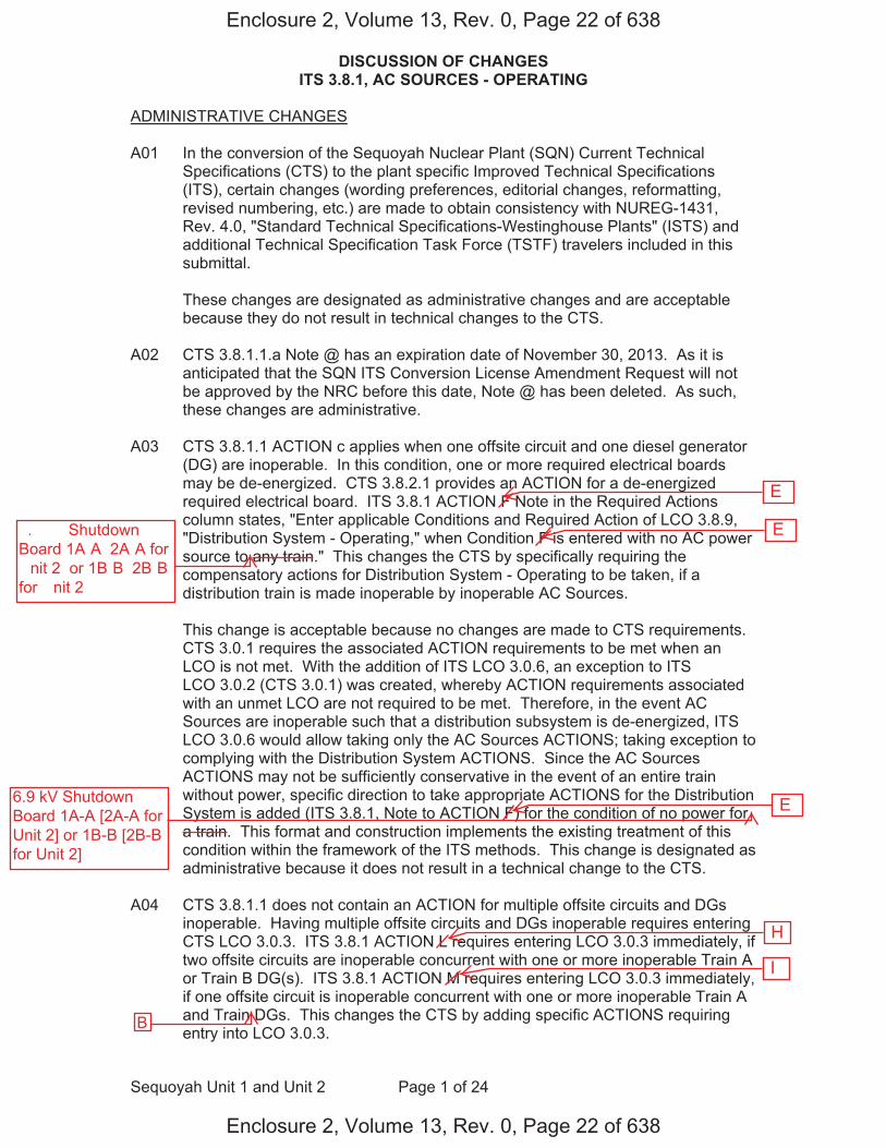
DISCUSSION OF CHANGES ITS 3.8.1, AC SOURCES - OPERATING
Sequoyah Unit 1 and Unit 2 Page 1 of 24
ADMINISTRATIVE CHANGES
A01 In the conversion of the Sequoyah Nuclear Plant (SQN) Current Technical Specifications (CTS) to the plant specific Improved Technical Specifications (ITS), certain changes (wording preferences, editorial changes, reformatting, revised numbering, etc.) are made to obtain consistency with NUREG-1431, Rev. 4.0, "Standard Technical Specifications-Westinghouse Plants" (ISTS) and additional Technical Specification Task Force (TSTF) travelers included in this submittal.
These changes are designated as administrative changes and are acceptable because they do not result in technical changes to the CTS.
A02 CTS 3.8.1.1.a Note @ has an expiration date of November 30, 2013. As it is anticipated that the SQN ITS Conversion License Amendment Request will not be approved by the NRC before this date, Note @ has been deleted. As such, these changes are administrative.
A03 CTS 3.8.1.1 ACTION c applies when one offsite circuit and one diesel generator (DG) are inoperable. In this condition, one or more required electrical boards may be de-energized. CTS 3.8.2.1 provides an ACTION for a de-energized required electrical board. ITS 3.8.1 ACTION F Note in the Required Actions column states, "Enter applicable Conditions and Required Action of LCO 3.8.9, "Distribution System - Operating," when Condition F is entered with no AC power source to any train." This changes the CTS by specifically requiring the compensatory actions for Distribution System - Operating to be taken, if a distribution train is made inoperable by inoperable AC Sources.
This change is acceptable because no changes are made to CTS requirements. CTS 3.0.1 requires the associated ACTION requirements to be met when an LCO is not met. With the addition of ITS LCO 3.0.6, an exception to ITS LCO 3.0.2 (CTS 3.0.1) was created, whereby ACTION requirements associated with an unmet LCO are not required to be met. Therefore, in the event AC Sources are inoperable such that a distribution subsystem is de-energized, ITS LCO 3.0.6 would allow taking only the AC Sources ACTIONS; taking exception to complying with the Distribution System ACTIONS. Since the AC Sources ACTIONS may not be sufficiently conservative in the event of an entire train without power, specific direction to take appropriate ACTIONS for the Distribution System is added (ITS 3.8.1, Note to ACTION F) for the condition of no power for a train. This format and construction implements the existing treatment of this condition within the framework of the ITS methods. This change is designated as administrative because it does not result in a technical change to the CTS.
A04 CTS 3.8.1.1 does not contain an ACTION for multiple offsite circuits and DGs inoperable. Having multiple offsite circuits and DGs inoperable requires entering CTS LCO 3.0.3. ITS 3.8.1 ACTION L requires entering LCO 3.0.3 immediately, if two offsite circuits are inoperable concurrent with one or more inoperable Train A or Train B DG(s). ITS 3.8.1 ACTION M requires entering LCO 3.0.3 immediately, if one offsite circuit is inoperable concurrent with one or more inoperable Train A and Train DGs. This changes the CTS by adding specific ACTIONS requiring entry into LCO 3.0.3.
Enclosure 2, Volume 13, Rev. 0, Page 22 of 638
Enclosure 2, Volume 13, Rev. 0, Page 22 of 638
I
H
E
E
E�.� �� Shutdown Board 1A�A �2A�A for �nit 2� or 1B�B �2B�B for �nit 2�
6.9 kV Shutdown Board 1A-A [2A-A for Unit 2] or 1B-B [2B-B for Unit 2]
B

DISCUSSION OF CHANGES ITS 3.8.1, AC SOURCES - OPERATING
Sequoyah Unit 1 and Unit 2 Page 3 of 24
specific CTS DG loading requirement with a statement that DG loadings may include gradual loading as recommended by the manufacturer. This change is consistent with the recommendations of Generic Letter (GL) 93-05, "Line- Item Technical Specifications Improvements to Reduce Surveillance Requirements for Testing During Power Operation." GL 93-05, Section 10.1, states that DGs "should be loaded in accordance with vendor recommendations for all test purposes other than the refueling outage LOOP tests." The change is acceptable, because it will ensure the DGs will continue to be operated consistent with manufacturer recommendations. This change is designated as administrative, because it does not result in a technical change to the CTS.
A07 CTS 4.8.1.1.2.d.5 requires verification that on an ESF actuation test signal (without loss of offsite power), each DG starts and operates for at least 5 minutes. ITS SR 3.8.1.12 requires a similar test, but does not specify that the DG auto-start on an ESF actuation test signal is "without loss of offsite power." This changes the CTS by not specifying the DG auto-start on an ESF actuation test signal is without a loss of offsite power signal.
The purpose of CTS 4.8.1.1.2.d.5 is to demonstrate that each DG automatically starts on an ESF actuation test signal. The requirements of this Surveillance are retained in the ITS as SR 3.8.1.12. The purpose of CTS 4.8.1.1.2.d.6.b) is to verify that each DG starts on a loss of offsite power concurrent with an ESF actuation test signal. The requirements of this Surveillance are retained in the ITS as SR 3.8.1.18. This change is acceptable, because it is understood that the CTS 4.8.1.1.2.d.5 required DG start on an ESF actuation test signal is without a loss of offsite power signal. Therefore, it is unnecessary to provide this information in ITS SR 3.8.1.12. This change is designated as administrative, because it does not result in a technical change to the CTS.
A08 CTS 3.0.5 states that it is not applicable in MODE 5 or 6. CTS 3.0.5 has been incorporated into the ACTIONS of ITS 3.8.1. This changes the CTS by incorporating the allowances of CTS 3.0.5 in ITS 3.8.1.
This change is acceptable because ITS 3.8.1 is only applicable in MODES 1, 2, 3, and 4. Therefore, the statement in CTS 3.0.5, that states that the Specification is not applicable in MODE 5 or 6, is no longer necessary and is deleted. This change is designated as administrative, because it does not result in technical changes to the CTS.
MORE RESTRICTIVE CHANGES
M01 CTS 3.8.1.1 ACTION d specifies the compensatory actions for two inoperable offsite circuits. The action requires restoration of at least one of the offsite sources within 24 hours, and if it is not restored within the allowed time, the unit is required to be in at least HOT STANDBY within the next 6 hours. ITS 3.8.1 ACTION E requires restoration of at least one offsite circuit to OPERABLE status within 24 hours, otherwise ITS 3.8.1 ACTION K requires the unit to be in MODE 3 within 6 hours and MODE 5 within 36 hours. This changes the CTS by adding the requirement to be in MODE 5 within 36 hours.
Enclosure 2, Volume 13, Rev. 0, Page 24 of 638
Enclosure 2, Volume 13, Rev. 0, Page 24 of 638
G D
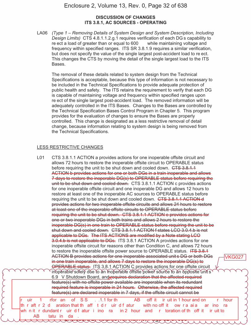
DISCUSSION OF CHANGES ITS 3.8.1, AC SOURCES - OPERATING
Sequoyah Unit 1 and Unit 2 Page 11 of 24
LA06 (Type 1 – Removing Details of System Design and System Description, Including Design Limits) CTS 4.8.1.1.2.g.1 requires verification of each DG�s capability to re�ect a load of greater than or equal to 600 �� while maintaining voltage and frequency within specified ranges. ITS SR 3.8.1.9 requires a similar verification, but does not specify the value of the single largest post-accident load to re�ect. This changes the CTS by moving the detail of the single largest load to the ITS Bases.
The removal of these details related to system design from the Technical Specifications is acceptable, because this type of information is not necessary to be included in the Technical Specifications to provide adequate protection of public health and safety. The ITS retains the requirement to verify that each DG is capable of maintaining voltage and frequency within specified ranges upon re�ect of the single largest post-accident load. The removed information will be adequately controlled in the ITS Bases. Changes to the Bases are controlled by the Technical Specification Bases Control Program in Chapter 5. This program provides for the evaluation of changes to ensure the Bases are properly controlled. This change is designated as a less restrictive removal of detail change, because information relating to system design is being removed from the Technical Specifications.
LESS RESTRICTIVE CHANGES
L01 CTS 3.8.1.1 ACTION a provides actions for one inoperable offsite circuit and allows 72 hours to restore the inoperable offsite circuit to OPERABLE status before requiring the unit to be shut down and cooled down. CTS 3.8.1.1 ACTION b provides actions for one or both DGs in a train inoperable and allows 7 days to restore the inoperable DG(s) to OPERABLE status before requiring the unit to be shut down and cooled down. CTS 3.8.1.1 ACTION c provides actions for one inoperable offsite circuit and one inoperable DG and allows 12 hours to restore at least one of the inoperable AC sources to OPERABLE status before requiring the unit to be shut down and cooled down. CTS 3.8.1.1 ACTION d provides actions for two inoperable offsite circuits and allows 24 hours to restore at least one of the inoperable offsite circuits to OPERABLE status before requiring the unit to be shut down. CTS 3.8.1.1 ACTION e provides actions for one or two inoperable DGs in both trains and allows 2 hours to restore the inoperable DG(s) in one train to OPERABLE status before requiring the unit to be shut down and cooled down. CTS 3.8.1.1 ACTION f states LCO 3.0.4.b is not applicable to DGs. The ITS ACTIONS are modified by a Note stating LCO 3.0.4.b is not applicable to DGs. ITS 3.8.1 ACTION A provides actions for one inoperable offsite circuit for reasons other than Condition C, and allows 72 hours to restore the inoperable offsite power source to OPERABLE status. ITS 3.8.1 ACTION B provides actions for one inoperable associated unit�s DG or both DGs in one train inoperable, and allows 7 days to restore the inoperable DG(s) to OPERABLE status. ITS 3.8.1 ACTION C provides actions for one offsite circuit inoperable solely due to an inoperable offsite power source to an opposite unit�s 6.9 �V Shutdown Board, and requires declaration that the affected required feature(s) with no offsite power available are inoperable when its redundant required feature is inoperable in 24 hours. Otherwise, the affected required feature(s) are declared inoperable in 7 days, if the offsite circuit cannot be
Enclosure 2, Volume 13, Rev. 0, Page 32 of 638
Enclosure 2, Volume 13, Rev. 0, Page 32 of 638
r��uir��� 1� ��rfor�an�� of ��S S� �.�.1.1 for th� ����AB�� off�it� �ir�uit in 1 hour and on�� ��r � hour� th�r�aft�r� 2� d���aration that th� aff��t�d r��uir�d f�atur���� with no off�it� �ow�r a�ai�a��� ar� ino��ra��� wh�n it� r�dundant r��uir�d f�atur� i� ino��ra��� in 2� hour�� and �� r��toration of th� off�it� �ir�uit to ����AB�� �tatu� in � da��.
VKG027
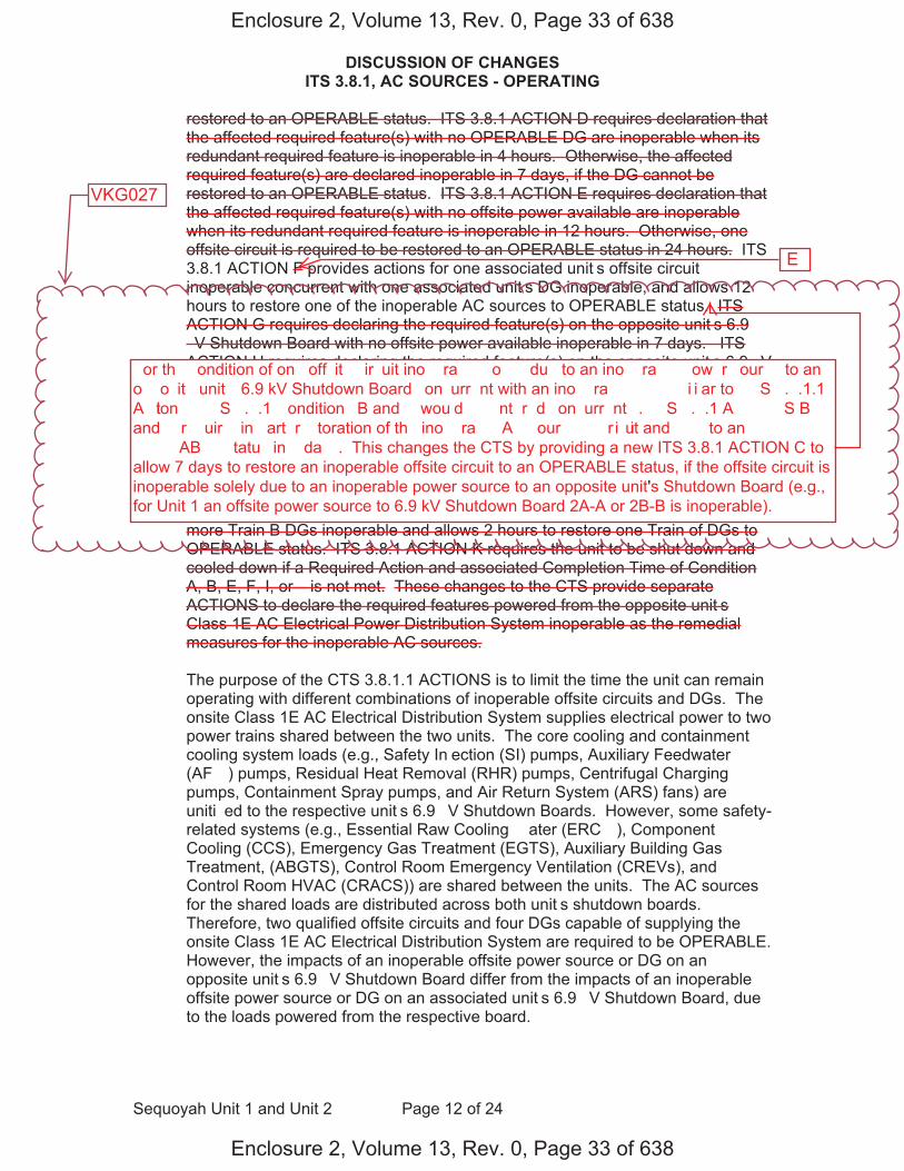
DISCUSSION OF CHANGES ITS 3.8.1, AC SOURCES - OPERATING
Sequoyah Unit 1 and Unit 2 Page 12 of 24
restored to an OPERABLE status. ITS 3.8.1 ACTION D requires declaration that the affected required feature(s) with no OPERABLE DG are inoperable when its redundant required feature is inoperable in 4 hours. Otherwise, the affected required feature(s) are declared inoperable in 7 days, if the DG cannot be restored to an OPERABLE status. ITS 3.8.1 ACTION E requires declaration that the affected required feature(s) with no offsite power available are inoperable when its redundant required feature is inoperable in 12 hours. Otherwise, one offsite circuit is required to be restored to an OPERABLE status in 24 hours. ITS 3.8.1 ACTION F provides actions for one associated unit�s offsite circuit inoperable concurrent with one associated unit�s DG inoperable, and allows 12 hours to restore one of the inoperable AC sources to OPERABLE status. ITS ACTION G requires declaring the required feature(s) on the opposite unit�s 6.9 �V Shutdown Board with no offsite power available inoperable in 7 days. ITS ACTION H requires declaring the required feature(s) on the opposite unit�s 6.9 �V Shutdown Board with no DG available inoperable in 7 days. ITS ACTION I provides actions for one offsite circuit inoperable solely due to an inoperable offsite power source to an opposite unit�s 6.9 �V Shutdown Board concurrent with one opposite unit�s DG inoperable, and allows 7 days to restore one of the inoperable AC sources to OPERABLE status. In addition, a Note modifying ITS ACTION I requires entry into the applicable Conditions and Required Actions of LCO 3.8.9 with no AC power source to an opposite unit�s 6.9 �V Shutdown Board. ITS 3.8.1 ACTION � provides actions for one or more Train A and one or more Train B DGs inoperable and allows 2 hours to restore one Train of DGs to OPERABLE status. ITS 3.8.1 ACTION K requires the unit to be shut down and cooled down if a Required Action and associated Completion Time of Condition A, B, E, F, I, or � is not met. These changes to the CTS provide separate ACTIONS to declare the required features powered from the opposite unit�s Class 1E AC Electrical Power Distribution System inoperable as the remedial measures for the inoperable AC sources.
The purpose of the CTS 3.8.1.1 ACTIONS is to limit the time the unit can remain operating with different combinations of inoperable offsite circuits and DGs. The onsite Class 1E AC Electrical Distribution System supplies electrical power to two power trains shared between the two units. The core cooling and containment cooling system loads (e.g., Safety In�ection (SI) pumps, Auxiliary Feedwater (AF� ) pumps, Residual Heat Removal (RHR) pumps, Centrifugal Charging pumps, Containment Spray pumps, and Air Return System (ARS) fans) are uniti�ed to the respective unit�s 6.9 �V Shutdown Boards. However, some safety-related systems (e.g., Essential Raw Cooling � ater (ERC� ), Component Cooling (CCS), Emergency Gas Treatment (EGTS), Auxiliary Building Gas Treatment, (ABGTS), Control Room Emergency Ventilation (CREVs), and Control Room HVAC (CRACS)) are shared between the units. The AC sources for the shared loads are distributed across both unit�s shutdown boards. Therefore, two qualified offsite circuits and four DGs capable of supplying the onsite Class 1E AC Electrical Distribution System are required to be OPERABLE. However, the impacts of an inoperable offsite power source or DG on an opposite unit�s 6.9 �V Shutdown Board differ from the impacts of an inoperable offsite power source or DG on an associated unit�s 6.9 �V Shutdown Board, due to the loads powered from the respective board.
Enclosure 2, Volume 13, Rev. 0, Page 33 of 638
Enclosure 2, Volume 13, Rev. 0, Page 33 of 638
E
�or th� �ondition of on� off�it� �ir�uit ino��ra��� �o���� du� to an ino��ra��� �ow�r �our�� to an o��o�it� unit�� 6.9 kV Shutdown Board �on�urr�nt with an ino��ra��� �� ��i�i�ar to ��S �.�.1.1 A�tion ��� ��S �.�.1 �ondition� B and � wou�d �� �nt�r�d �on�urr�nt��. ��S �.�.1 A�����S B and � r��uir�� in �art� r��toration of th� ino��ra��� A� �our��� ��ir�uit and ��� to an ����AB�� �tatu� in � da��. This changes the CTS by providing a new ITS 3.8.1 ACTION C toallow 7 days to restore an inoperable offsite circuit to an OPERABLE status, if the offsite circuit isinoperable solely due to an inoperable power source to an opposite unit's Shutdown Board (e.g.,for Unit 1 an offsite power source to 6.9 kV Shutdown Board 2A-A or 2B-B is inoperable).
VKG027
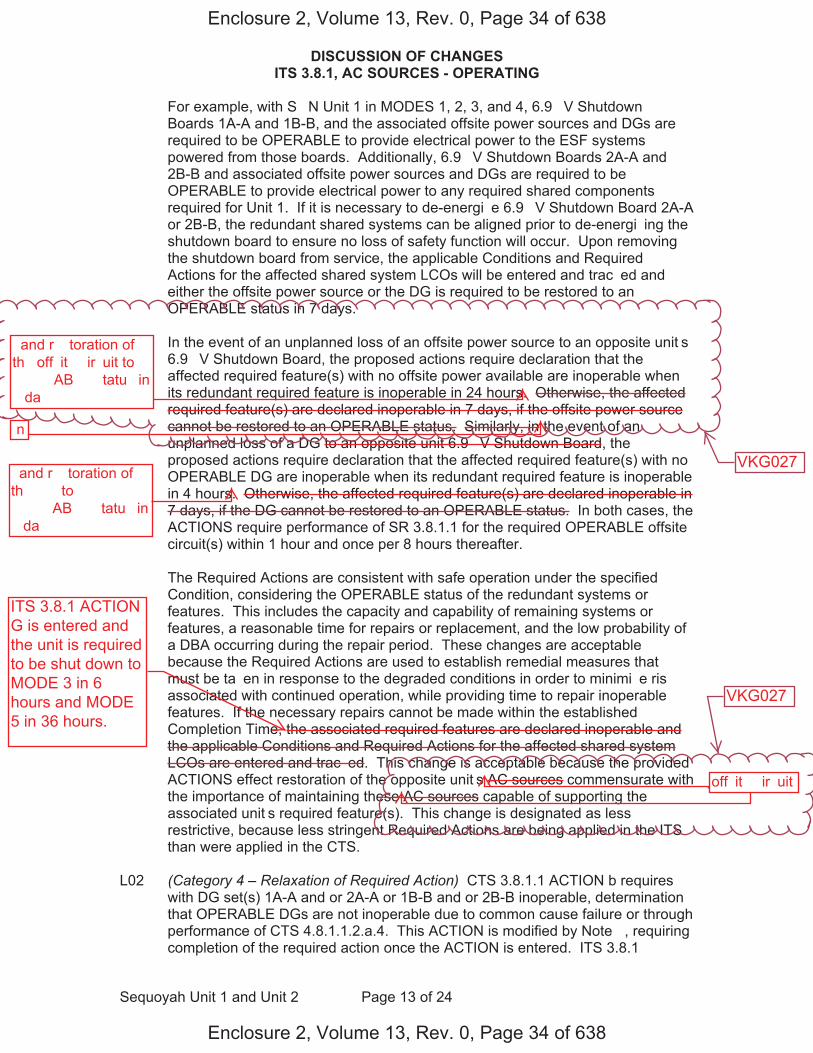
DISCUSSION OF CHANGES ITS 3.8.1, AC SOURCES - OPERATING
Sequoyah Unit 1 and Unit 2 Page 13 of 24
For example, with S�N Unit 1 in MODES 1, 2, 3, and 4, 6.9 �V Shutdown Boards 1A-A and 1B-B, and the associated offsite power sources and DGs are required to be OPERABLE to provide electrical power to the ESF systems powered from those boards. Additionally, 6.9 �V Shutdown Boards 2A-A and 2B-B and associated offsite power sources and DGs are required to be OPERABLE to provide electrical power to any required shared components required for Unit 1. If it is necessary to de-energi�e 6.9 �V Shutdown Board 2A-A or 2B-B, the redundant shared systems can be aligned prior to de-energi�ing the shutdown board to ensure no loss of safety function will occur. Upon removing the shutdown board from service, the applicable Conditions and Required Actions for the affected shared system LCOs will be entered and trac�ed and either the offsite power source or the DG is required to be restored to an OPERABLE status in 7 days.
In the event of an unplanned loss of an offsite power source to an opposite unit�s 6.9 �V Shutdown Board, the proposed actions require declaration that the affected required feature(s) with no offsite power available are inoperable when its redundant required feature is inoperable in 24 hours. Otherwise, the affected required feature(s) are declared inoperable in 7 days, if the offsite power source cannot be restored to an OPERABLE status. Similarly, in the event of an unplanned loss of a DG to an opposite unit 6.9 �V Shutdown Board, the proposed actions require declaration that the affected required feature(s) with no OPERABLE DG are inoperable when its redundant required feature is inoperable in 4 hours. Otherwise, the affected required feature(s) are declared inoperable in 7 days, if the DG cannot be restored to an OPERABLE status. In both cases, the ACTIONS require performance of SR 3.8.1.1 for the required OPERABLE offsite circuit(s) within 1 hour and once per 8 hours thereafter.
The Required Actions are consistent with safe operation under the specified Condition, considering the OPERABLE status of the redundant systems or features. This includes the capacity and capability of remaining systems or features, a reasonable time for repairs or replacement, and the low probability of a DBA occurring during the repair period. These changes are acceptable because the Required Actions are used to establish remedial measures that must be ta�en in response to the degraded conditions in order to minimi�e ris� associated with continued operation, while providing time to repair inoperable features. If the necessary repairs cannot be made within the established Completion Time, the associated required features are declared inoperable and the applicable Conditions and Required Actions for the affected shared system LCOs are entered and trac�ed. This change is acceptable because the provided ACTIONS effect restoration of the opposite unit�s AC sources commensurate with the importance of maintaining these AC sources capable of supporting the associated unit�s required feature(s). This change is designated as less restrictive, because less stringent Required Actions are being applied in the ITS than were applied in the CTS.
L02 (Category 4 – Relaxation of Required Action) CTS 3.8.1.1 ACTION b requires with DG set(s) 1A-A and�or 2A-A or 1B-B and�or 2B-B inoperable, determination that OPERABLE DGs are not inoperable due to common cause failure or through performance of CTS 4.8.1.1.2.a.4. This ACTION is modified by Note �, requiring completion of the required action once the ACTION is entered. ITS 3.8.1
Enclosure 2, Volume 13, Rev. 0, Page 34 of 638
Enclosure 2, Volume 13, Rev. 0, Page 34 of 638
ITS 3.8.1 ACTIONG is entered andthe unit is requiredto be shut down toMODE 3 in 6hours and MODE5 in 36 hours.
� and r��toration of th� off�it� �ir�uit to ����AB�� �tatu� in � da��
�n
� and r��toration of th� �� to ����AB�� �tatu� in � da��
off�it� �ir�uit
VKG027
VKG027

DISCUSSION OF CHANGES ITS 3.8.1, AC SOURCES - OPERATING
Sequoyah Unit 1 and Unit 2 Page 14 of 24
ACTION B requires with an associated unit�s DG inoperable (or with both DGs in a train inoperable), determination that OPERABLE DGs are not inoperable due to common cause failure or through performance of SR 3.8.1.2. However, ITS does not specify completion of the ACTIONS if the Condition is exited. This changes the CTS by removing a requirement to complete the ACTIONS once the ACTION is entered.
The purpose of CTS 3.8.1.1 ACTION b is to provide compensatory measures to be ta�en in response to inoperable DG set(s), including demonstration that the OPERABLE DGs are not inoperable. The Note requiring completion of the actions to verify the remaining DGs are OPERABLE once the ACTION is entered was added to the CTS with License Amendments 205 (Unit 1) and 195 (Unit 2), dated �une 29, 1995 (ADAMS Accession No. ML013320017). TVA license amendment request TS 94-19, submitted on April 6, 1995, stated that the addition of this Note was being made to align with the requirements contained in NUREG-1431, LCO 3.8.1. On April 7, 1995, NUREG-1431, Rev. 1 was issued. The Note modifying LCO 3.8.1 ACTION B that required completion of Required Actions B.3.1 and B.3.2 (demonstration of DG OPERABILITY) was removed from NUREG-1431 in Revision 1. The requirement to complete the actions to demonstrate the OPERABLE DGs are not inoperable is an exception to ITS LCO 3.0.2 (CTS LCO 3.0.2). Completing the ACTIONS to verify the OPERABILITY of the remaining OPERABLE DGs is not required to restore compliance with the LCO. This change is acceptable because completion of the ACTIONS to evaluate the possibility of a DG common cause failure will be trac�ed as an item in the corrective action program. This change is designated as less restrictive, because less stringent Required Actions are being applied in the ITS than were applied in the CTS.
L03 (Category 4 – Relaxation of Required Action) CTS 3.8.1.1 ACTION b provides actions for one or both DGs in a train inoperable. ACTION b is modified by Note � stating that no more than one DG may be made simultaneously inoperable on a pre-planned basis for maintenance, modifications, or surveillance testing. ITS SR 3.8.1.3 verifies each DG can be started, synchroni�ed, loaded, and operated for at least 60 minutes. SR 3.8.1.3 is modified by Note 3 stating the Surveillance shall be conducted on only one DG at a time. This changes the CTS by deleting the restriction for not ma�ing more than one DG simultaneously inoperable on a pre-planned basis, with the exception of the performance of SR 3.8.1.3.
The purpose of CTS 3.8.1.1 ACTION b is to provide required actions for one or both DGs in a train inoperable. The purpose of Note � is to ensure pre-planned activities that may result in an inoperable DG (i.e., maintenance, modifications, or surveillance testing) are not performed on both DGs in a train at the same time. The proposed required actions do not include the restriction for limiting pre-planned activities to one DG at a time. The control of pre-planned maintenance, modifications, or surveillance testing is an issue for procedures and scheduling. This change is designated as less restrictive, because less stringent Required Actions are being applied in the ITS than were applied in the CTS.
L04 (Category 3 – Relaxation of Completion Time) CTS 3.8.1.1 ACTION b requires, in part, with one or both DG(s) in a train inoperable to demonstrate the
Enclosure 2, Volume 13, Rev. 0, Page 35 of 638
Enclosure 2, Volume 13, Rev. 0, Page 35 of 638
thatany
DISCUSSION OF CHANGES ITS 3.8.1, AC SOURCES - OPERATING
Sequoyah Unit 1 and Unit 2 Page 15 of 24
OPERABILITY of the remaining DGs by performing Surveillance Requirement 4.8.1.1.2.a.4 within 24 hours. CTS 3.8.1.1 ACTION c requires, in part, with one offsite circuit and one DG inoperable to demonstrate the OPERABILITY of the remaining DGs by performing Surveillance Requirement 4.8.1.1.2.a.4 within 8 hours. ITS 3.8.1 ACTION B requires with one or both DG(s) in a train inoperable to perform SR 3.8.1.2 for OPERABLE DGs within 24 hours. This changes the CTS by extending the time allowed to demonstrate the OPERABILITY of the OPERABLE DGs with one offsite circuit and one DG inoperable from 8 hours to 24 hours.
The purpose of the CTS 3.8.1.1 ACTIONS b and c is to ensure that the OPERABLE DGs are not inoperable as a result of a similar, yet undetected, failure (i.e., due to a common mode failure). CTS 3.0.1 states that upon failure to meet an LCO, the associated ACTION requirements shall be met. In the instance of one offsite circuit and one DG inoperable, the condition of one inoperable DG also exists. Therefore, in addition to meeting the requirements of CTS 3.8.1.1 ACTION c, the requirements of CTS 3.8.1.1 ACTION b are required to be met. However, this results in conflicting time requirements for performing CTS 4.8.1.1.2.a.4 on the OPERABLE DGs. A 24 hour Completion Time for performing DG common mode failure chec�s is consistent with the guidance provided in Generic Letter 84-15. This change is acceptable, since the vast ma�ority of DG start tests demonstrate that the DG is OPERABLE. This change is designated as less restrictive, because additional time is allowed to demonstrate the OPERABILITY of the OPERABLE DGs for the condition of one offsite circuit and one DG inoperable under the ITS than under the CTS.
L05 (Category 4 – Relaxation of Required Action) CTS 3.8.1.1 ACTION d states, in part, with two offsite circuits inoperable demonstrate the OPERABILITY of the DGs by performing Surveillance Requirement 4.8.1.1.2.a.4 within 8 hours, unless the DGs are already operating. CTS 4.8.1.1.2.a.4 requires verification that each DG starts and achieves voltage and frequency within established ranges within 10 seconds. ITS 3.8.1 ACTION E does not contain this requirement. This changes the CTS by deleting the requirement to test each DG when two offsite circuits are inoperable.
The purpose of the CTS 4.8.1.1.2.a.4 requirement in CTS 3.8.1.1 ACTION c is to ensure that the DGs are OPERABLE in the case of a loss of offsite power. Since the DGs are tested on monthly basis, there is no reason to suspect that they would not perform their intended safety function. Furthermore, the inoperability of two offsite circuits does not affect the OPERABILITY of the DGs, since the DGs are independent of the offsite circuits. Therefore, there is no need to sub�ect the DGs to additional testing. This change is designated as less restrictive because the CTS requirement to perform testing on the DGs when both offsite circuits are inoperable is not being retained in the ITS.
L06 (Category 8 – Deletion of Surveillance Requirement Shutdown Performance Requirements) CTS 4.8.1.1.1.b requires the demonstration of a manual and automatic transfer of the power supply to each 6.9 �V Unit Board from the normal to alternate once per 18 months. Note � specifies that the Surveillance shall not be performed on the associated unit�s 6.9 �V Unit Boards in MODES 1 and 2. This test has been incorporated in ITS SR 3.8.1.8. ITS SR 3.8.1.8 includes a
Enclosure 2, Volume 13, Rev. 0, Page 36 of 638
Enclosure 2, Volume 13, Rev. 0, Page 36 of 638
D
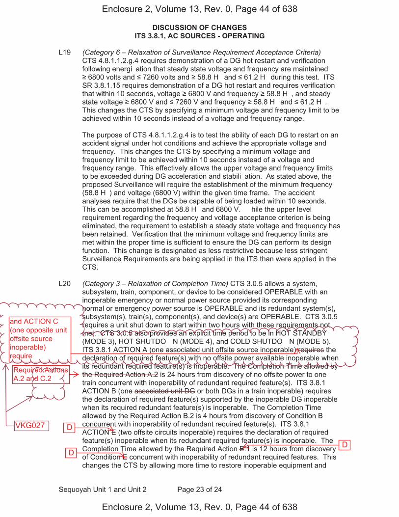
DISCUSSION OF CHANGES ITS 3.8.1, AC SOURCES - OPERATING
Sequoyah Unit 1 and Unit 2 Page 23 of 24
L19 (Category 6 – Relaxation of Surveillance Requirement Acceptance Criteria) CTS 4.8.1.1.2.g.4 requires demonstration of a DG hot restart and verification following energi�ation that steady state voltage and frequency are maintained 6800 volts and 7260 volts and 58.8 H� and 61.2 H� during this test. ITS
SR 3.8.1.15 requires demonstration of a DG hot restart and requires verification that within 10 seconds, voltage 6800 V and frequency 58.8 H�, and steady state voltage 6800 V and 7260 V and frequency 58.8 H� and 61.2 H�. This changes the CTS by specifying a minimum voltage and frequency limit to be achieved within 10 seconds instead of a voltage and frequency range.
The purpose of CTS 4.8.1.1.2.g.4 is to test the ability of each DG to restart on an accident signal under hot conditions and achieve the appropriate voltage and frequency. This changes the CTS by specifying a minimum voltage and frequency limit to be achieved within 10 seconds instead of a voltage and frequency range. This effectively allows the upper voltage and frequency limits to be exceeded during DG acceleration and stabili�ation. As stated above, the proposed Surveillance will require the establishment of the minimum frequency (58.8 H�) and voltage (6800 V) within the given time frame. The accident analyses require that the DGs be capable of being loaded within 10 seconds. This can be accomplished at 58.8 H� and 6800 V. � hile the upper level requirement regarding the frequency and voltage acceptance criterion is being eliminated, the requirement to establish a steady state voltage and frequency has been retained. Verification that the minimum voltage and frequency limits are met within the proper time is sufficient to ensure the DG can perform its design function. This change is designated as less restrictive because less stringent Surveillance Requirements are being applied in the ITS than were applied in the CTS.
L20 (Category 3 – Relaxation of Completion Time) CTS 3.0.5 allows a system, subsystem, train, component, or device to be considered OPERABLE with an inoperable emergency or normal power source provided its corresponding normal or emergency power source is OPERABLE and its redundant system(s), subsystem(s), train(s), component(s), and device(s) are OPERABLE. CTS 3.0.5 requires a unit shut down to start within two hours with these requirements not met. CTS 3.0.5 also provides an explicit time period to be in HOT STANDBY (MODE 3), HOT SHUTDO� N (MODE 4), and COLD SHUTDO� N (MODE 5). ITS 3.8.1 ACTION A (one associated unit offsite source inoperable) requires the declaration of required feature(s) with no offsite power available inoperable when its redundant required feature(s) is inoperable. The Completion Time allowed by the Required Action A.2 is 24 hours from discovery of no offsite power to one train concurrent with inoperability of redundant required feature(s). ITS 3.8.1 ACTION B (one associated unit DG or both DGs in a train inoperable) requires the declaration of required feature(s) supported by the inoperable DG inoperable when its required redundant feature(s) is inoperable. The Completion Time allowed by the Required Action B.2 is 4 hours from discovery of Condition B concurrent with inoperability of redundant required feature(s). ITS 3.8.1 ACTION E (two offsite circuits inoperable) requires the declaration of required feature(s) inoperable when its redundant required feature(s) is inoperable. The Completion Time allowed by the Required Action E.1 is 12 hours from discovery of Condition E concurrent with inoperability of redundant required features. This changes the CTS by allowing more time to restore inoperable equipment and
Enclosure 2, Volume 13, Rev. 0, Page 44 of 638
Enclosure 2, Volume 13, Rev. 0, Page 44 of 638
D
D D
and ACTION C(one opposite unitoffsite sourceinoperable)require
Required ActionsA.2 and C.2
VKG027

DISCUSSION OF CHANGES ITS 3.8.1, AC SOURCES - OPERATING
Sequoyah Unit 1 and Unit 2 Page 24 of 24
replaces the explicit times to be in MODE 3, MODE 4, and MODE 5 with a requirement to declare the affected features inoperable (and thus to ta�e the ACTIONS required by the individual system LCO, including possible shut down of the unit).
This change is acceptable because the Completion Time is consistent with safe operation under the specified Condition, considering the OPERABLE status of the redundant systems or features. This includes the capacity and capability of remaining systems or features, a reasonable time for repairs or replacement, and the low probability of a DBA occurring during the allowed Completion Time. This change allows more time to restore inoperable equipment when required AC Sources are inoperable concurrent with inoperabilities of redundant required features and deletes the explicit times to be in MODE 3, MODE 4, and MODE 5. By declaring the affected supported equipment inoperable, and as a result, ta�ing the Technical Specifications ACTIONS of the affected supported equipment, unit operation is maintained within the bounds of the Technical Specifications and approved ACTIONS. Since the AC Sources support the OPERABILITY of the affected equipment, it is appropriate that the proper action, in this condition, would be to declare that affected supported equipment inoperable. CTS 3.0.5 is overly restrictive, in that if the associated supported equipment were inoperable for other reasons and the redundant equipment was also inoperable, a restoration time is sometimes provided, in other CTS sections. The 24 hour Completion Time when one associated unit offsite circuit is inoperable is acceptable because� a) the redundant counterpart to the inoperable required feature is still OPERABLE although single failure protection may have been lost� b) the capacity and capability of the remaining AC Sources is still available� c) areasonable time for repairs is provided for restoration before the unit is sub�ected to transients associated with shut down� and d) the low probability of a DBA occurring during this period. The 12 hour Completion Time when two offsite circuits are inoperable is acceptable because Regulatory Guide 1.93 allows a Completion Time of 24 hours for two offsite circuits inoperable. � hen a concurrent redundant required function is inoperable, a shorter Completion Time of 12 hours is appropriate. The 4 hour Completion Time with one associated unit DG inoperable ta�es into account the component OPERABILITY of the redundant counterpart to the inoperable required feature and is considered to be less of a ris� than sub�ecting the unit to transients associated with shut down. Additionally, the 4 hour Completion Time ta�es into account the capacity and capability of the remaining AC Sources, reasonable time for repairs, and low probability of a DBA occurring during this period. This change is designated as less restrictive because additional time is allowed to restore equipment to OPERABLE status and the change deletes the explicit times to reach MODE 3, MODE 4, and MODE 5.
Enclosure 2, Volume 13, Rev. 0, Page 45 of 638
Enclosure 2, Volume 13, Rev. 0, Page 45 of 638
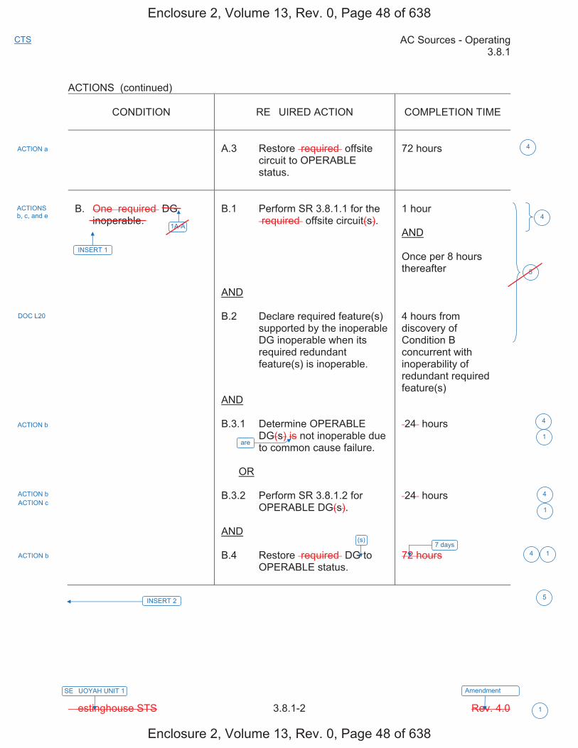
AC Sources - Operating 3.8.1
� estinghouse STS 3.8.1-2 Rev. 4.0
CTS
1
SE�UOYAH UNIT 1 Amendment ���
ACTIONS (continued)
CONDITION RE�UIRED ACTION COMPLETION TIME
A.3 Restore �required� offsite circuit to OPERABLE status.
72 hours
B. One �required� DG inoperable.
B.1 Perform SR 3.8.1.1 for the �required� offsite circuit(s).
AND
B.2 Declare required feature(s) supported by the inoperable DG inoperable when its required redundant feature(s) is inoperable.
AND
B.3.1 Determine OPERABLE DG(s) is not inoperable due to common cause failure.
OR
B.3.2 Perform SR 3.8.1.2 for OPERABLE DG(s).
AND
B.4 Restore �required� DG to OPERABLE status.
1 hour
AND
Once per 8 hours thereafter
4 hours from discovery of Condition B concurrent with inoperability of redundant required feature(s)
�24� hours
�24� hours
72 hours
ACTION a
ACTIONS b, c, and e
DOC L20
ACTION b
ACTION b ACTION c
ACTION b 7 days
INSERT 2
4
5
4
4
4 1
5
41A-A
INSERT 1
are1
1
(s)
Enclosure 2, Volume 13, Rev. 0, Page 48 of 638
Enclosure 2, Volume 13, Rev. 0, Page 48 of 638
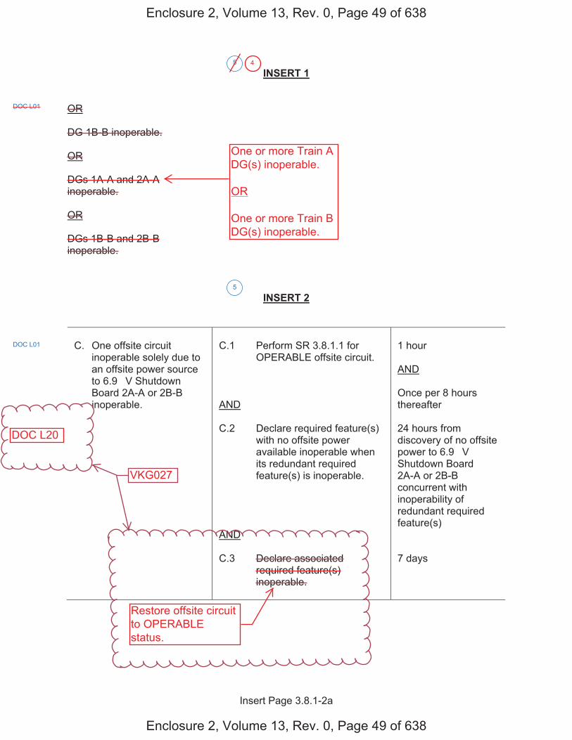
Insert Page 3.8.1-2a
INSERT 1
OR
DG 1B-B inoperable.
OR
DGs 1A-A and 2A-A inoperable.
OR
DGs 1B-B and 2B-B inoperable.
INSERT 2
C. One offsite circuit inoperable solely due to an offsite power source to 6.9 �V Shutdown Board 2A-A or 2B-B inoperable.
C.1 Perform SR 3.8.1.1 for OPERABLE offsite circuit.
AND
C.2 Declare required feature(s) with no offsite power available inoperable when its redundant required feature(s) is inoperable.
AND
C.3 Declare associated required feature(s) inoperable.
1 hour
AND
Once per 8 hours thereafter
24 hours from discovery of no offsite power to 6.9 �V Shutdown Board 2A-A or 2B-B concurrent with inoperability of redundant required feature(s)
7 days
5
DOC L01
5
DOC L01
Enclosure 2, Volume 13, Rev. 0, Page 49 of 638
Enclosure 2, Volume 13, Rev. 0, Page 49 of 638
One or more Train ADG(s) inoperable.
OR
One or more Train BDG(s) inoperable.
Restore offsite circuitto OPERABLEstatus.
DOC L20
4
VKG027
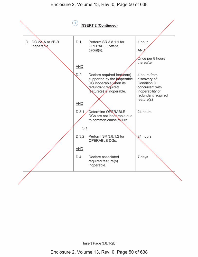
Insert Page 3.8.1-2b
INSERT 2 (Continued)
D. DG 2A-A or 2B-B inoperable.
D.1 Perform SR 3.8.1.1 for OPERABLE offsite circuit(s).
AND
D.2 Declare required feature(s) supported by the inoperable DG inoperable when its redundant required feature(s) is inoperable.
AND
D.3.1 Determine OPERABLE DGs are not inoperable due to common cause failure.
OR
D.3.2 Perform SR 3.8.1.2 for OPERABLE DGs.
AND
D.4 Declare associated required feature(s) inoperable.
1 hour
AND
Once per 8 hours thereafter
4 hours from discovery of Condition D concurrent with inoperability of redundant required feature(s)
24 hours
24 hours
7 days
5
Enclosure 2, Volume 13, Rev. 0, Page 50 of 638
Enclosure 2, Volume 13, Rev. 0, Page 50 of 638
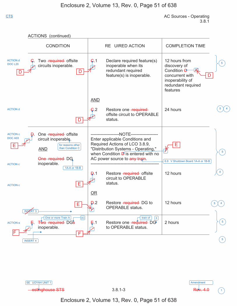
AC Sources - Operating 3.8.1
� estinghouse STS 3.8.1-3 Rev. 4.0
CTS
1
SE�UOYAH UNIT 1 Amendment ���
ACTIONS (continued)
CONDITION RE�UIRED ACTION COMPLETION TIME
C. Two �required� offsite circuits inoperable.
C.1 Declare required feature(s) inoperable when its redundant required feature(s) is inoperable.
AND
C.2 Restore one �required� offsite circuit to OPERABLE status.
12 hours from discovery of Condition C concurrent with inoperability of redundant required features
24 hours
D. One �required� offsite circuit inoperable.
AND
One �required� DG inoperable.
--------------------NOTE------------------- Enter applicable Conditions and Required Actions of LCO 3.8.9, "Distribution Systems - Operating," when Condition D is entered with no AC power source to any train. ------------------------------------------------
D.1 Restore �required� offsite circuit to OPERABLE status.
OR
D.2 Restore �required� DG to OPERABLE status.
12 hours
12 hours
E. Two �required� DGs inoperable.
E.1 Restore one �required� DG to OPERABLE status.
2 hours
ACTION d
ACTION d
ACTION c DOC A03
ACTION c
ACTION c
ACTION e
5
5
5
5
5
E
F
�
F
F
�
E
F
6.9 �V Shutdown Board 1A-A or 1B-B
E
E
4
DOC L20
for reasons other than Condition C
1A-A or 1B-B
INSERT 3
One or more Train A (s)
INSERT 4
5
4
4
train of s
Enclosure 2, Volume 13, Rev. 0, Page 51 of 638
Enclosure 2, Volume 13, Rev. 0, Page 51 of 638
D D
D
D
E
E
E
E
F F

Insert Page 3.8.1-3a
INSERT 3
G. One offsite circuit inoperable solely due to an offsite power source to 6.9 �V Shutdown Board 2A-A or 2B-B inoperable.
AND
DG 1A-A or 1B-B inoperable.
G.1 Declare required feature(s) on associated Unit 2 6.9 �V Shutdown Board inoperable.
7 days
H. One offsite circuit inoperable for reasons other than Condition C.
AND
DG 2A-A or 2B-B inoperable.
H.1 Declare required feature(s) on associated Unit 2 6.9 �V Shutdown Board inoperable.
7 days
5
DOC L01
DOC L01
Enclosure 2, Volume 13, Rev. 0, Page 52 of 638
Enclosure 2, Volume 13, Rev. 0, Page 52 of 638
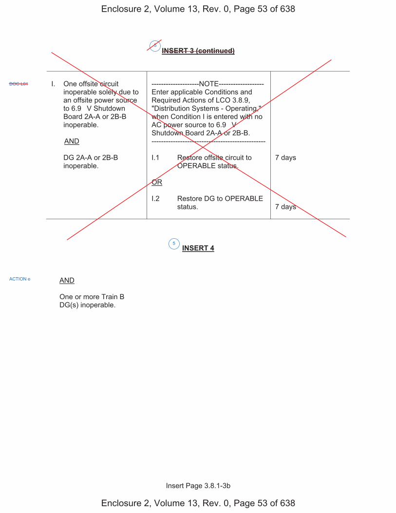
Insert Page 3.8.1-3b
INSERT 3 (continued)
I. One offsite circuit inoperable solely due to an offsite power source to 6.9 �V Shutdown Board 2A-A or 2B-B inoperable.
AND
DG 2A-A or 2B-B inoperable.
--------------------NOTE------------------- Enter applicable Conditions and Required Actions of LCO 3.8.9, "Distribution Systems - Operating," when Condition I is entered with no AC power source to 6.9 �V Shutdown Board 2A-A or 2B-B. ------------------------------------------------
I.1 Restore offsite circuit to OPERABLE status.
OR
I.2 Restore DG to OPERABLE status.
7 days
7 days
INSERT 4
AND
One or more Train B DG(s) inoperable.
5
DOC L01
ACTION e
5
Enclosure 2, Volume 13, Rev. 0, Page 53 of 638
Enclosure 2, Volume 13, Rev. 0, Page 53 of 638
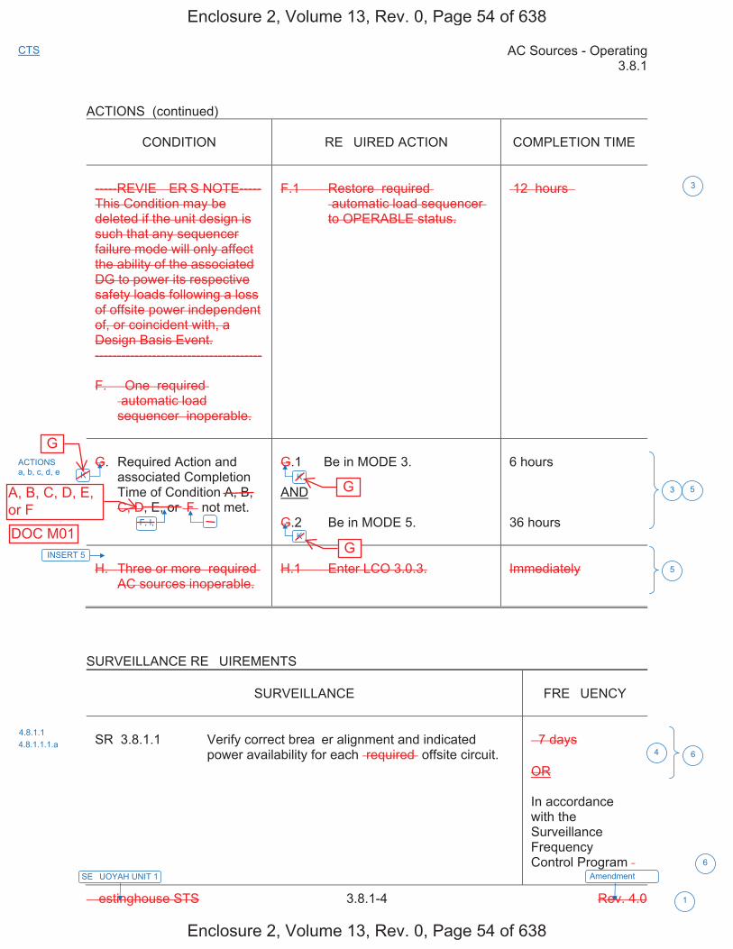
AC Sources - Operating 3.8.1
� estinghouse STS 3.8.1-4 Rev. 4.0
CTS
1
SE�UOYAH UNIT 1 Amendment ���
ACTIONS (continued)
CONDITION RE�UIRED ACTION COMPLETION TIME
-----REVIE� ER�S NOTE----- This Condition may be deleted if the unit design is such that any sequencer failure mode will only affect the ability of the associated DG to power its respective safety loads following a loss of offsite power independent of, or coincident with, a Design Basis Event. --------------------------------------
F. � One �required� �automatic load sequencer� inoperable.
F.1 Restore �required� �automatic load sequencer� to OPERABLE status.
�12� hours �
G. Required Action and associated Completion Time of Condition A, B, C, D, E, or �F� not met.
G.1 Be in MODE 3.
AND
G.2 Be in MODE 5.
6 hours
36 hours
H. Three or more �required� AC sources inoperable.
H.1 Enter LCO 3.0.3. Immediately
SURVEILLANCE RE�UIREMENTS
SURVEILLANCE FRE�UENCY
SR 3.8.1.1 Verify correct brea�er alignment and indicated power availability for each �required� offsite circuit.
� 7 days
OR
In accordance with the Surveillance Frequency Control Program �
3
ACTIONS a, b, c, d, e
4.8.1.1 4.8.1.1.1.a
3 5
5
4 6
K
F, I, �
K
K
6
INSERT 5
Enclosure 2, Volume 13, Rev. 0, Page 54 of 638
Enclosure 2, Volume 13, Rev. 0, Page 54 of 638
A, B, C, D, E,or F
G
G
G DOC M01

Insert Page 3.8.1-4
INSERT 5
L. Two offsite circuits inoperable.
AND
One or more Train A DG(s) inoperable.
OR
One or more Train B DG(s) inoperable.
L.1 Enter LCO 3.0.3. Immediately
M. One offsite circuit inoperable.
AND
One or more Train A DG(s) inoperable.
AND
One or more Train B DG(s) inoperable.
M.1 Enter LCO 3.0.3. Immediately
5
DOC A04
DOC A04
Enclosure 2, Volume 13, Rev. 0, Page 55 of 638
Enclosure 2, Volume 13, Rev. 0, Page 55 of 638
H H
I I
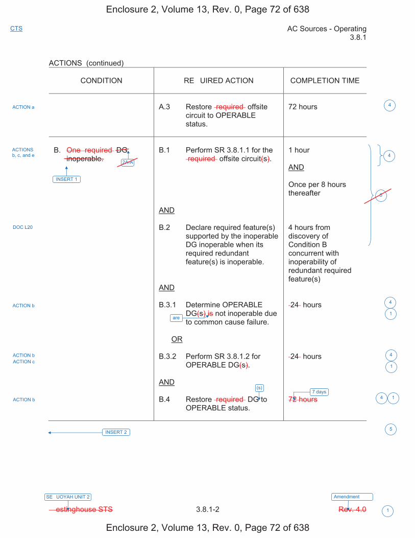
AC Sources - Operating 3.8.1
� estinghouse STS 3.8.1-2 Rev. 4.0
CTS
1
SE�UOYAH UNIT 2 Amendment ���
ACTIONS (continued)
CONDITION RE�UIRED ACTION COMPLETION TIME
A.3 Restore �required� offsite circuit to OPERABLE status.
72 hours
B. One �required� DG inoperable.
B.1 Perform SR 3.8.1.1 for the �required� offsite circuit(s).
AND
B.2 Declare required feature(s) supported by the inoperable DG inoperable when its required redundant feature(s) is inoperable.
AND
B.3.1 Determine OPERABLE DG(s) is not inoperable due to common cause failure.
OR
B.3.2 Perform SR 3.8.1.2 for OPERABLE DG(s).
AND
B.4 Restore �required� DG to OPERABLE status.
1 hour
AND
Once per 8 hours thereafter
4 hours from discovery of Condition B concurrent with inoperability of redundant required feature(s)
�24� hours
�24� hours
72 hours
ACTION a
ACTIONS b, c, and e
DOC L20
ACTION b
ACTION b ACTION c
ACTION b 7 days
INSERT 2
4
5
4
4
4 1
5
42A-A
INSERT 1
are1
1
(s)
Enclosure 2, Volume 13, Rev. 0, Page 72 of 638
Enclosure 2, Volume 13, Rev. 0, Page 72 of 638
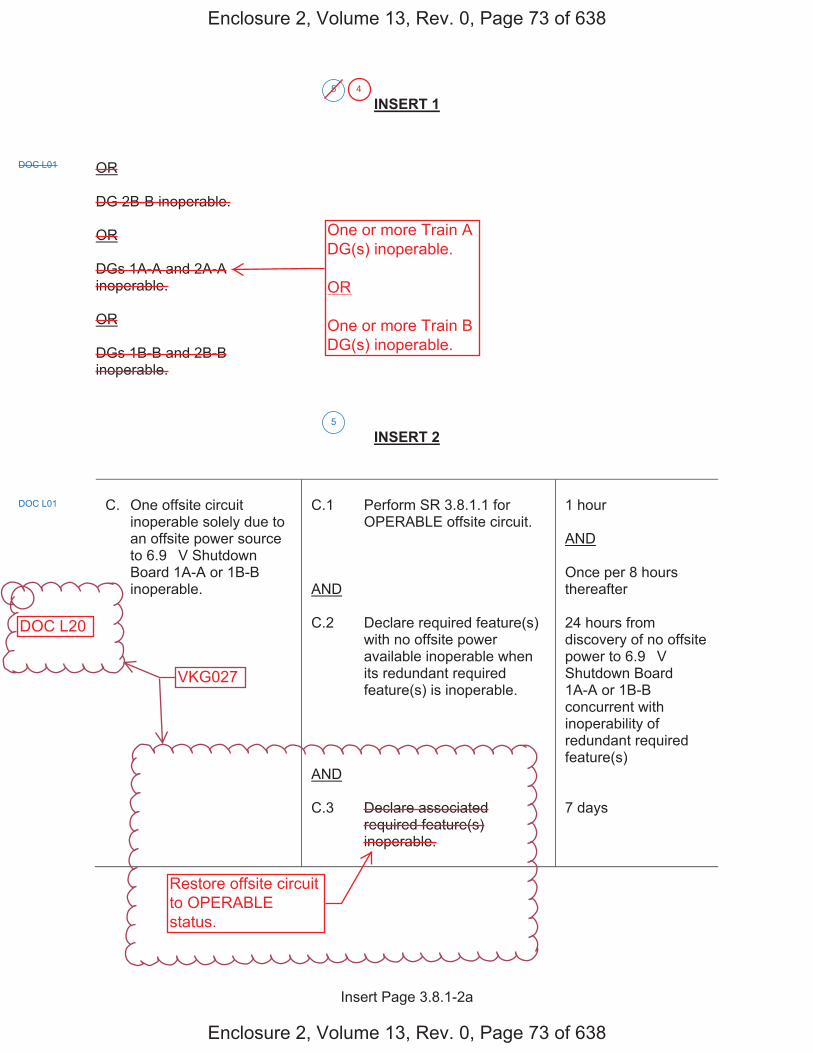
Insert Page 3.8.1-2a
INSERT 1
OR
DG 2B-B inoperable.
OR
DGs 1A-A and 2A-A inoperable.
OR
DGs 1B-B and 2B-B inoperable.
INSERT 2
C. One offsite circuit inoperable solely due to an offsite power source to 6.9 �V Shutdown Board 1A-A or 1B-B inoperable.
C.1 Perform SR 3.8.1.1 for OPERABLE offsite circuit.
AND
C.2 Declare required feature(s) with no offsite power available inoperable when its redundant required feature(s) is inoperable.
AND
C.3 Declare associated required feature(s) inoperable.
1 hour
AND
Once per 8 hours thereafter
24 hours from discovery of no offsite power to 6.9 �V Shutdown Board 1A-A or 1B-B concurrent with inoperability of redundant required feature(s)
7 days
5
DOC L01
5
DOC L01
Enclosure 2, Volume 13, Rev. 0, Page 73 of 638
Enclosure 2, Volume 13, Rev. 0, Page 73 of 638
One or more Train ADG(s) inoperable.
OR
One or more Train BDG(s) inoperable.
Restore offsite circuitto OPERABLEstatus.
DOC L20
4
VKG027

Insert Page 3.8.1-2b
INSERT 2 (Continued)
D. DG 1A-A or 1B-B inoperable.
D.1 Perform SR 3.8.1.1 for OPERABLE offsite circuit(s).
AND
D.2 Declare required feature(s) supported by the inoperable DG inoperable when its redundant required feature(s) is inoperable.
AND
D.3.1 Determine OPERABLE DGs are not inoperable due to common cause failure.
OR
D.3.2 Perform SR 3.8.1.2 for OPERABLE DGs.
AND
D.4 Declare associated required feature(s) inoperable.
1 hour
AND
Once per 8 hours thereafter
4 hours from discovery of Condition D concurrent with inoperability of redundant required feature(s)
24 hours
24 hours
7 days
5
Enclosure 2, Volume 13, Rev. 0, Page 74 of 638
Enclosure 2, Volume 13, Rev. 0, Page 74 of 638
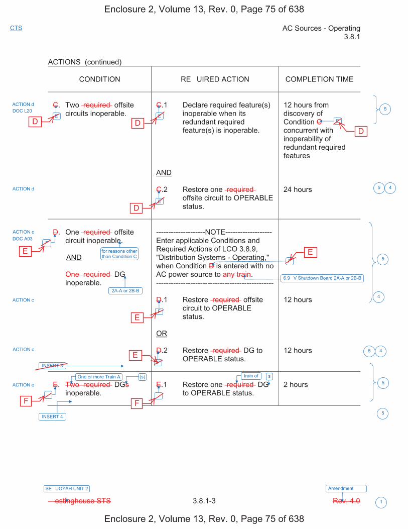
AC Sources - Operating 3.8.1
� estinghouse STS 3.8.1-3 Rev. 4.0
CTS
1
SE�UOYAH UNIT 2 Amendment ���
ACTIONS (continued)
CONDITION RE�UIRED ACTION COMPLETION TIME
C. Two �required� offsite circuits inoperable.
C.1 Declare required feature(s) inoperable when its redundant required feature(s) is inoperable.
AND
C.2 Restore one �required� offsite circuit to OPERABLE status.
12 hours from discovery of Condition C concurrent with inoperability of redundant required features
24 hours
D. One �required� offsite circuit inoperable.
AND
One �required� DG inoperable.
--------------------NOTE------------------- Enter applicable Conditions and Required Actions of LCO 3.8.9, "Distribution Systems - Operating," when Condition D is entered with no AC power source to any train. ------------------------------------------------
D.1 Restore �required� offsite circuit to OPERABLE status.
OR
D.2 Restore �required� DG to OPERABLE status.
12 hours
12 hours
E. Two �required� DGs inoperable.
E.1 Restore one �required� DG to OPERABLE status.
2 hours
ACTION d
ACTION d
ACTION c DOC A03
ACTION c
ACTION c
ACTION e
5
5
E
F
�
F
F
�
E
F
E
E
4
DOC L20
for reasons other than Condition C
2A-A or 2B-B
INSERT 3
One or more Train A (s)
INSERT 4
5
5
5
6.9 �V Shutdown Board 2A-A or 2B-B
5
4
4
train of s
Enclosure 2, Volume 13, Rev. 0, Page 75 of 638
Enclosure 2, Volume 13, Rev. 0, Page 75 of 638
D D
D
D
E
E
E
E
F F

Insert Page 3.8.1-3a
INSERT 3
G. One offsite circuit inoperable solely due to an offsite power source to 6.9 �V Shutdown Board 1A-A or 1B-B inoperable.
AND
DG 2A-A or 2B-B inoperable.
G.1 Declare required feature(s) on associated Unit 1 6.9 �V Shutdown Board inoperable.
7 days
H. One offsite circuit inoperable for reasons other than Condition C.
AND
DG 1A-A or 1B-B inoperable.
H.1 Declare required feature(s) on associated Unit 1 6.9 �V Shutdown Board inoperable.
7 days
5
DOC L01
DOC L01
Enclosure 2, Volume 13, Rev. 0, Page 76 of 638
Enclosure 2, Volume 13, Rev. 0, Page 76 of 638
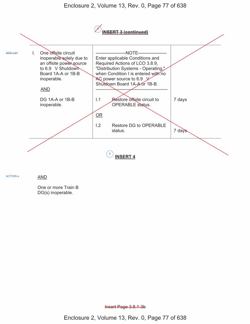
Insert Page 3.8.1-3b
INSERT 3 (continued)
I. One offsite circuit inoperable solely due to an offsite power source to 6.9 �V Shutdown Board 1A-A or 1B-B inoperable.
AND
DG 1A-A or 1B-B inoperable.
--------------------NOTE------------------- Enter applicable Conditions and Required Actions of LCO 3.8.9, "Distribution Systems - Operating," when Condition I is entered with no AC power source to 6.9 �V Shutdown Board 1A-A or 1B-B. ------------------------------------------------
I.1 Restore offsite circuit to OPERABLE status.
OR
I.2 Restore DG to OPERABLE status.
7 days
7 days
INSERT 4
AND
One or more Train B DG(s) inoperable.
5
DOC L01
ACTION e
5
Enclosure 2, Volume 13, Rev. 0, Page 77 of 638
Enclosure 2, Volume 13, Rev. 0, Page 77 of 638
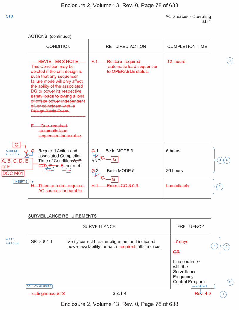
AC Sources - Operating 3.8.1
� estinghouse STS 3.8.1-4 Rev. 4.0
CTS
1
SE�UOYAH UNIT 2 Amendment ���
ACTIONS (continued)
CONDITION RE�UIRED ACTION COMPLETION TIME
-----REVIE� ER�S NOTE----- This Condition may be deleted if the unit design is such that any sequencer failure mode will only affect the ability of the associated DG to power its respective safety loads following a loss of offsite power independent of, or coincident with, a Design Basis Event. --------------------------------------
F. � One �required� �automatic load sequencer� inoperable.
F.1 Restore �required� �automatic load sequencer� to OPERABLE status.
�12� hours �
G. Required Action and associated Completion Time of Condition A, B, C, D, E, or �F� not met.
G.1 Be in MODE 3.
AND
G.2 Be in MODE 5.
6 hours
36 hours
H. Three or more �required� AC sources inoperable.
H.1 Enter LCO 3.0.3. Immediately
SURVEILLANCE RE�UIREMENTS
SURVEILLANCE FRE�UENCY
SR 3.8.1.1 Verify correct brea�er alignment and indicated power availability for each �required� offsite circuit.
� 7 days
OR
In accordance with the Surveillance Frequency Control Program �
3
ACTIONS a, b, c, d, e
4.8.1.1 4.8.1.1.1.a
3 5
4 6
K
�
K
K
6
F, I,
INSERT 5
5
Enclosure 2, Volume 13, Rev. 0, Page 78 of 638
Enclosure 2, Volume 13, Rev. 0, Page 78 of 638
G
A, B, C, D, E,or F
G
GDOC M01
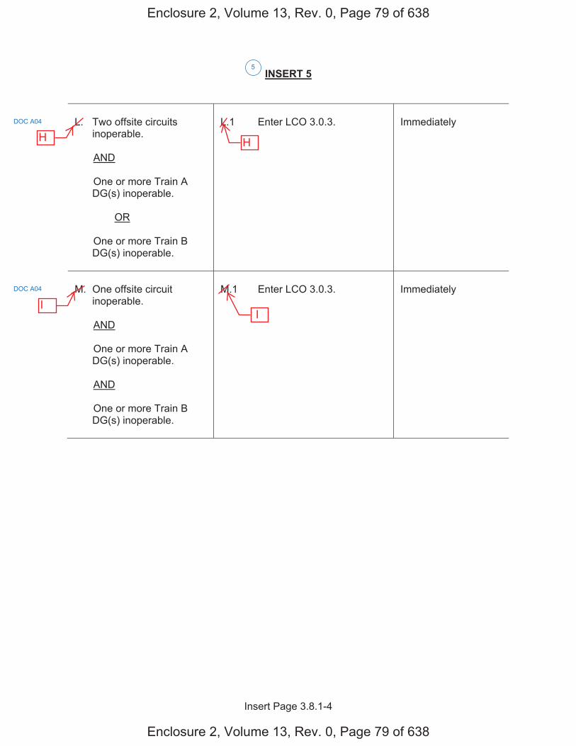
Insert Page 3.8.1-4
INSERT 5
L. Two offsite circuits inoperable.
AND
One or more Train A DG(s) inoperable.
OR
One or more Train B DG(s) inoperable.
L.1 Enter LCO 3.0.3. Immediately
M. One offsite circuit inoperable.
AND
One or more Train A DG(s) inoperable.
AND
One or more Train B DG(s) inoperable.
M.1 Enter LCO 3.0.3. Immediately
5
DOC A04
DOC A04
Enclosure 2, Volume 13, Rev. 0, Page 79 of 638
Enclosure 2, Volume 13, Rev. 0, Page 79 of 638
H H
I I
JUSTIFICATION FOR DEVIATIONS ITS 3.8.1, AC SOURCES - OPERATING
Sequoyah Unit 1 and Unit 2 Page 1 of 2
1. Changes are made (additions, deletions, and�or changes) to the ISTS that reflect theplant-specific nomenclature, number, reference, system description, analysis, orlicensing basis description.
2. The punctuation corrections have been made consistent with the � riter�s Guide forthe Improved Standard Technical Specifications, NEI 01-03, Section 5.1.3.
3. ISTS LCO 3.8.1.c and ISTS 3.8.1 ACTION F have been deleted since S�N Units 1and 2 do not use load sequencers. Each load or load bloc� is sequenced with theuse of its associated time delay relay. Each ma�or ESF component has individualtime delay relays that operate individual components, not all ESF components.Thus, if a single time delay relay fails, only the individual component and the DGcould be affected. Subsequent Conditions and Required Actions have beenrenumbered, as applicable. ISTS SR 3.8.1.11 (ITS SR 3.8.1.11), ISTS SR 3.8.1.12(ITS SR 3.8.1.12), ISTS SR 3.8.1.18 (ITS SR 3.8.1.17), and ISTS SR 3.8.1.19 (ITSSR 3.8.1.18) have been revised to reflect the use of time delay relays.
4. The ISTS contains brac�eted information and�or values that are generic to all� estinghouse vintage plants. The brac�ets are removed and the proper plantspecific information�value is inserted to reflect the current licensing basis.
5. Changes were made to ISTS LCO 3.8.1 to ensure the appropriate AC power sourcesare OPERABLE during unit operation in MODES 1, 2, 3 and 4 to satisfy the designrequirements. This modification was necessary due to shared systems betweenUnits 1 and 2. This is an exception that is intended to allow ta�ing the ACTIONSassociated with inoperable shared equipment in lieu of requiring the opposite unit ACsources to be restored to OPERABLE status within a specified Completion Time.This exception is acceptable since, with the opposite unit equipment inoperable andthe associated ACTIONS entered, the opposite unit AC Sources provide noadditional assurance of meeting the safety criteria of the given unit�s AC powersources.
SR Notes associated with ISTS SR 3.8.1.8 (ITS SR 3.8.1.8), ISTS SR 3.8.1.9(ITS SR 3.8.1.9), ISTS SR 3.8.1.10 (ITS SR 3.8.1.10), ISTS SR 3.8.1.11(ITS SR 3.8.1.11), ISTS SR 3.8.1.12 (ITS SR 3.8.1.12), ISTS SR 3.8.1.13(ITS SR 3.8.1.13), ISTS SR 3.8.1.14 (ITS SR 3.8.1.14), ISTS SR 3.8.1.16(ITS SR 3.8.1.16), ISTS SR 3.8.1.18 (ITS SR 3.8.1.17), and ISTS SR 3.8.1.19(ITS SR 3.8.1.18) have been revised to allow performance of the affected SR onopposite unit shutdown board or DGs when the given unit is in a restricted MODE.
6. ISTS SR 3.8.1.1 (ITS SR 3.8.1.1), ISTS SR 3.8.1.2 (ITS SR 3.8.1.2),ISTS SR 3.8.1.3 (ITS SR 3.8.1.3), ISTS SR 3.8.1.4 (ITS SR 3.8.1.4),ISTS SR 3.8.1.5 (ITS SR 3.8.1.5), ISTS SR 3.8.1.6 (ITS SR 3.8.1.6),ISTS SR 3.8.1.7 (ITS SR 3.8.1.7), ISTS SR 3.8.1.8 (ITS SR 3.8.1.8),ISTS SR 3.8.1.9 (ITS SR 3.8.1.9), ISTS SR 3.8.1.10 (ITS SR 3.8.1.10),ISTS SR 3.8.1.11 (ITS SR 3.8.1.11), ISTS SR 3.8.1.12 (ITS SR 3.8.1.12),ISTS SR 3.8.1.13 (ITS SR 3.8.1.13), ISTS SR 3.8.1.14 (ITS SR 3.8.1.14),ISTS SR 3.8.1.15 (ITS SR 3.8.1.15), ISTS SR 3.8.1.16 (ITS SR 3.8.1.16),ISTS SR 3.8.1.18 (ITS SR 3.8.1.17), ISTS SR 3.8.1.19 (ITS SR 3.8.1.18), andISTS SR 3.8.1.20 (ITS SR 3.8.1.19) provide two options for controlling theFrequencies of Surveillance Requirements. S�N is proposing to control the
Enclosure 2, Volume 13, Rev. 0, Page 95 of 638
Enclosure 2, Volume 13, Rev. 0, Page 95 of 638
INSERT JFD 5
INSERT JFD 5
�han��� w�r� �ad� to th� �S�S to r�f���t th� int�ra�tion ��tw��n an o��ratin� unit�� A� �ow�r �our��� and tho�� �r�dit�d f�atur�� n��din� A� �ow�r fro� th� o��o�it� unit�� a��o�iat�d A� �ow�r �our���. ��S �.�.1 A����� � ha� ���n add�d to addr��� th� �ondition wh�n th� off�it� �ir�uit i� ino��ra��� �o���� du� to an ino��ra��� �ow�r �our�� to th� o��o�it� unit�� 6.9 kV Shutdown Board ��.�.� for Unit 1 an off�it� �ow�r �our�� to 6.9 kV Shutdown Board 2A-A or 2B-B i� ino��ra����� and r��uir��� in �art� r��toration of th� ino��ra��� off�it� �ir�uit within � da��. �S�S �.�.1 A�����S A and � ha�� ���n r��i��d to addr��� �ondition� wh�n th� off�it� �ir�uit i� ino��ra��� for r�a�on� oth�r than ��S �.�.1 �ondition �. ��S �.�.1 A����� A r��uir�� r��toration of th� ino��ra��� off�it� �ir�uit in �2 hour�. ��S �.�.1 A����� � r��uir�� r��toration of an ino��ra��� A� �our�� in 12 hour�. �hi� �han�� r�f���t� a r��toration �o����tion �i�� �o���n�urat� with th� i��ortan�� of �aintainin� th� A� �ow�r �our�� �a�a��� of �u��ortin� th� aff��t�d �har�d ���t���. � ith th� addition of ��S �.�.1 A����� �� �u����u�nt �S�S A�����S ha�� ���n r�nu���r�d.
VKG027
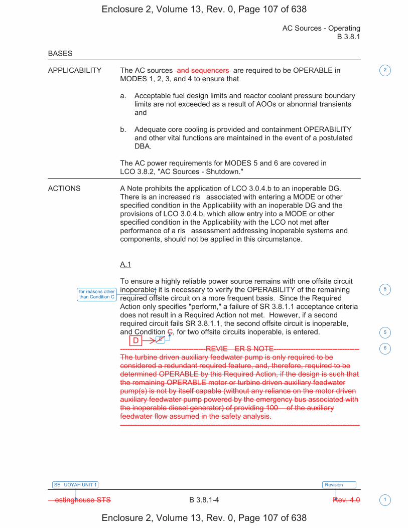
AC Sources - Operating B 3.8.1
� estinghouse STS B 3.8.1-4 Rev. 4.0
SE�UOYAH UNIT 1
1
Revision ���
BASES
APPLICABILITY The AC sources �and sequencers� are required to be OPERABLE in MODES 1, 2, 3, and 4 to ensure that�
a. Acceptable fuel design limits and reactor coolant pressure boundarylimits are not exceeded as a result of AOOs or abnormal transientsand
b. Adequate core cooling is provided and containment OPERABILITYand other vital functions are maintained in the event of a postulatedDBA.
The AC power requirements for MODES 5 and 6 are covered in LCO 3.8.2, "AC Sources - Shutdown."
ACTIONS A Note prohibits the application of LCO 3.0.4.b to an inoperable DG. There is an increased ris� associated with entering a MODE or other specified condition in the Applicability with an inoperable DG and the provisions of LCO 3.0.4.b, which allow entry into a MODE or other specified condition in the Applicability with the LCO not met after performance of a ris� assessment addressing inoperable systems and components, should not be applied in this circumstance.
A.1
To ensure a highly reliable power source remains with one offsite circuit inoperable, it is necessary to verify the OPERABILITY of the remaining required offsite circuit on a more frequent basis. Since the Required Action only specifies "perform," a failure of SR 3.8.1.1 acceptance criteria does not result in a Required Action not met. However, if a second required circuit fails SR 3.8.1.1, the second offsite circuit is inoperable, and Condition C, for two offsite circuits inoperable, is entered.
-----------------------------------REVIE� ER�S NOTE-----------------------------------The turbine driven auxiliary feedwater pump is only required to be considered a redundant required feature, and, therefore, required to be determined OPERABLE by this Required Action, if the design is such that the remaining OPERABLE motor or turbine driven auxiliary feedwater pump(s) is not by itself capable (without any reliance on the motor driven auxiliary feedwater pump powered by the emergency bus associated with the inoperable diesel generator) of providing 100� of the auxiliary feedwater flow assumed in the safety analysis. --------------------------------------------------------------------------------------------------
E
2
5
5
6
for reasons other than Condition C
Enclosure 2, Volume 13, Rev. 0, Page 107 of 638
Enclosure 2, Volume 13, Rev. 0, Page 107 of 638
D
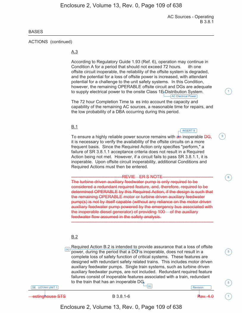
AC Sources - Operating B 3.8.1
� estinghouse STS B 3.8.1-6 Rev. 4.0
SE�UOYAH UNIT 1
1
Revision ���
BASES
ACTIONS (continued)
A.3
According to Regulatory Guide 1.93 (Ref. 6), operation may continue in Condition A for a period that should not exceed 72 hours. � ith one offsite circuit inoperable, the reliability of the offsite system is degraded, and the potential for a loss of offsite power is increased, with attendant potential for a challenge to the unit safety systems. In this Condition, however, the remaining OPERABLE offsite circuit and DGs are adequate to supply electrical power to the onsite Class 1E Distribution System.
The 72 hour Completion Time ta�es into account the capacity and capability of the remaining AC sources, a reasonable time for repairs, and the low probability of a DBA occurring during this period.
B.1
To ensure a highly reliable power source remains with an inoperable DG, it is necessary to verify the availability of the offsite circuits on a more frequent basis. Since the Required Action only specifies "perform," a failure of SR 3.8.1.1 acceptance criteria does not result in a Required Action being not met. However, if a circuit fails to pass SR 3.8.1.1, it is inoperable. Upon offsite circuit inoperability, additional Conditions and Required Actions must then be entered.
-----------------------------------REVIE� ER�S NOTE----------------------------------- The turbine driven auxiliary feedwater pump is only required to be considered a redundant required feature, and, therefore, required to be determined OPERABLE by this Required Action, if the design is such that the remaining OPERABLE motor or turbine driven auxiliary feedwater pump(s) is not by itself capable (without any reliance on the motor driven auxiliary feedwater pump powered by the emergency bus associated with the inoperable diesel generator) of providing 100� of the auxiliary feedwater flow assumed in the safety analysis. --------------------------------------------------------------------------------------------------
B.2
Required Action B.2 is intended to provide assurance that a loss of offsite power, during the period that a DG is inoperable, does not result in a complete loss of safety function of critical systems. These features are designed with redundant safety related trains. This includes motor driven auxiliary feedwater pumps. Single train systems, such as turbine driven auxiliary feedwater pumps, are not included. Redundant required feature failures consist of inoperable features associated with a train, redundant to the train that has an inoperable DG.
INSERT 9
5
6
AC Electrical Power
1
(s) 5
(s)5
Enclosure 2, Volume 13, Rev. 0, Page 109 of 638
Enclosure 2, Volume 13, Rev. 0, Page 109 of 638
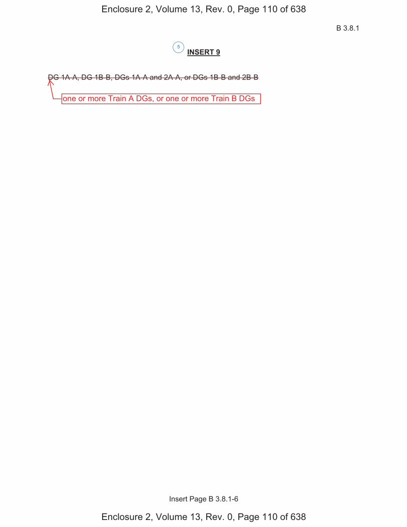
B 3.8.1
Insert Page B 3.8.1-6
INSERT 9
DG 1A-A, DG 1B-B, DGs 1A-A and 2A-A, or DGs 1B-B and 2B-B
5
Enclosure 2, Volume 13, Rev. 0, Page 110 of 638
Enclosure 2, Volume 13, Rev. 0, Page 110 of 638
one or more Train A DGs, or one or more Train B DGs
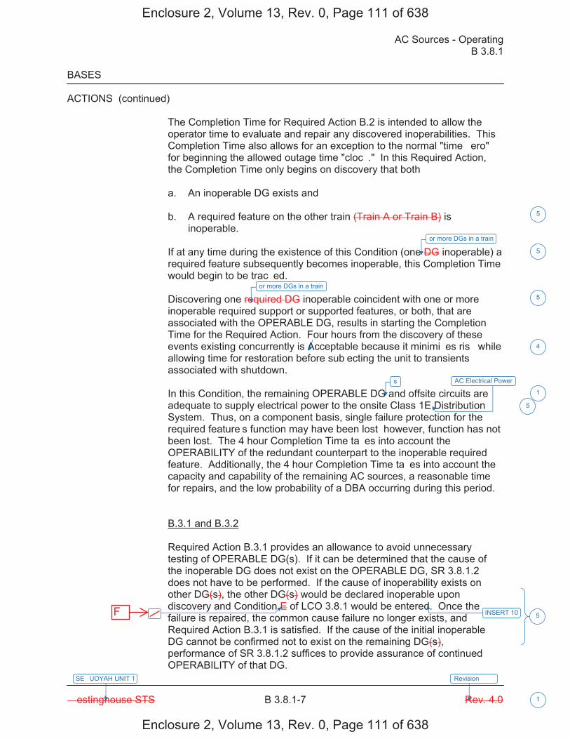
AC Sources - Operating B 3.8.1
� estinghouse STS B 3.8.1-7 Rev. 4.0
SE�UOYAH UNIT 1
1
Revision ���
BASES
ACTIONS (continued)
The Completion Time for Required Action B.2 is intended to allow the operator time to evaluate and repair any discovered inoperabilities. This Completion Time also allows for an exception to the normal "time �ero" for beginning the allowed outage time "cloc�." In this Required Action, the Completion Time only begins on discovery that both�
a. An inoperable DG exists and
b. A required feature on the other train (Train A or Train B) isinoperable.
If at any time during the existence of this Condition (one DG inoperable) a required feature subsequently becomes inoperable, this Completion Time would begin to be trac�ed.
Discovering one required DG inoperable coincident with one or more inoperable required support or supported features, or both, that are associated with the OPERABLE DG, results in starting the Completion Time for the Required Action. Four hours from the discovery of these events existing concurrently is Acceptable because it minimi�es ris� while allowing time for restoration before sub�ecting the unit to transients associated with shutdown.
In this Condition, the remaining OPERABLE DG and offsite circuits are adequate to supply electrical power to the onsite Class 1E Distribution System. Thus, on a component basis, single failure protection for the required feature�s function may have been lost� however, function has not been lost. The 4 hour Completion Time ta�es into account the OPERABILITY of the redundant counterpart to the inoperable required feature. Additionally, the 4 hour Completion Time ta�es into account the capacity and capability of the remaining AC sources, a reasonable time for repairs, and the low probability of a DBA occurring during this period.
B.3.1 and B.3.2
Required Action B.3.1 provides an allowance to avoid unnecessary testing of OPERABLE DG(s). If it can be determined that the cause of the inoperable DG does not exist on the OPERABLE DG, SR 3.8.1.2 does not have to be performed. If the cause of inoperability exists on other DG(s), the other DG(s) would be declared inoperable upon discovery and Condition E of LCO 3.8.1 would be entered. Once the failure is repaired, the common cause failure no longer exists, and Required Action B.3.1 is satisfied. If the cause of the initial inoperable DG cannot be confirmed not to exist on the remaining DG(s), performance of SR 3.8.1.2 suffices to provide assurance of continued OPERABILITY of that DG.
s
� INSERT 10
4
1
5
5
or more DGs in a train
5
or more DGs in a train
5
AC Electrical Power
5
Enclosure 2, Volume 13, Rev. 0, Page 111 of 638
Enclosure 2, Volume 13, Rev. 0, Page 111 of 638
F
B 3.8.1
Insert Page B 3.8.1-7
INSERT 10
if one or more DG(s) in Train A and Train B are inoperable
5
Enclosure 2, Volume 13, Rev. 0, Page 112 of 638
Enclosure 2, Volume 13, Rev. 0, Page 112 of 638
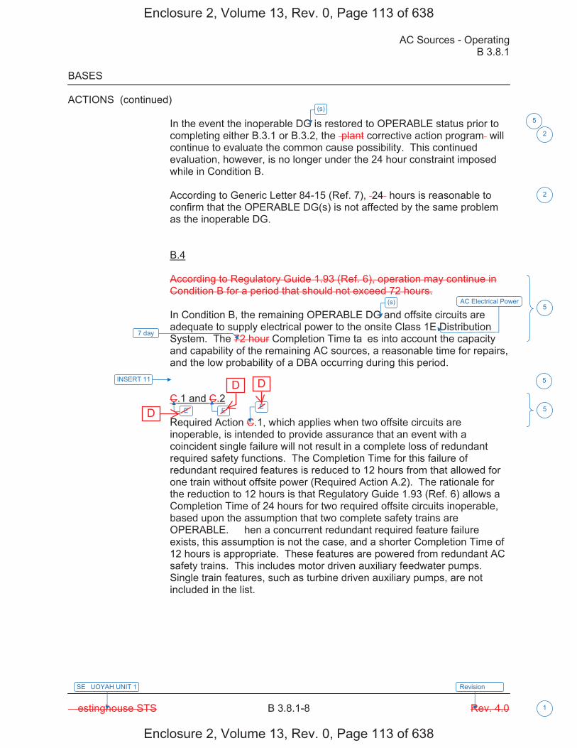
AC Sources - Operating B 3.8.1
� estinghouse STS B 3.8.1-8 Rev. 4.0
SE�UOYAH UNIT 1
1
Revision ���
BASES
ACTIONS (continued)
In the event the inoperable DG is restored to OPERABLE status prior to completing either B.3.1 or B.3.2, the �plant corrective action program� will continue to evaluate the common cause possibility. This continued evaluation, however, is no longer under the 24 hour constraint imposed while in Condition B.
According to Generic Letter 84-15 (Ref. 7), �24� hours is reasonable to confirm that the OPERABLE DG(s) is not affected by the same problem as the inoperable DG.
B.4
According to Regulatory Guide 1.93 (Ref. 6), operation may continue in Condition B for a period that should not exceed 72 hours.
In Condition B, the remaining OPERABLE DG and offsite circuits are adequate to supply electrical power to the onsite Class 1E Distribution System. The 72 hour Completion Time ta�es into account the capacity and capability of the remaining AC sources, a reasonable time for repairs, and the low probability of a DBA occurring during this period.
C.1 and C.2
Required Action C.1, which applies when two offsite circuits are inoperable, is intended to provide assurance that an event with a coincident single failure will not result in a complete loss of redundant required safety functions. The Completion Time for this failure of redundant required features is reduced to 12 hours from that allowed for one train without offsite power (Required Action A.2). The rationale for the reduction to 12 hours is that Regulatory Guide 1.93 (Ref. 6) allows a Completion Time of 24 hours for two required offsite circuits inoperable, based upon the assumption that two complete safety trains are OPERABLE. � hen a concurrent redundant required feature failure exists, this assumption is not the case, and a shorter Completion Time of 12 hours is appropriate. These features are powered from redundant AC safety trains. This includes motor driven auxiliary feedwater pumps. Single train features, such as turbine driven auxiliary pumps, are not included in the list.
7 day
INSERT 11
E E E
2
2
5
5
5
(s)
5
(s) AC Electrical Power
Enclosure 2, Volume 13, Rev. 0, Page 113 of 638
Enclosure 2, Volume 13, Rev. 0, Page 113 of 638
D
D D
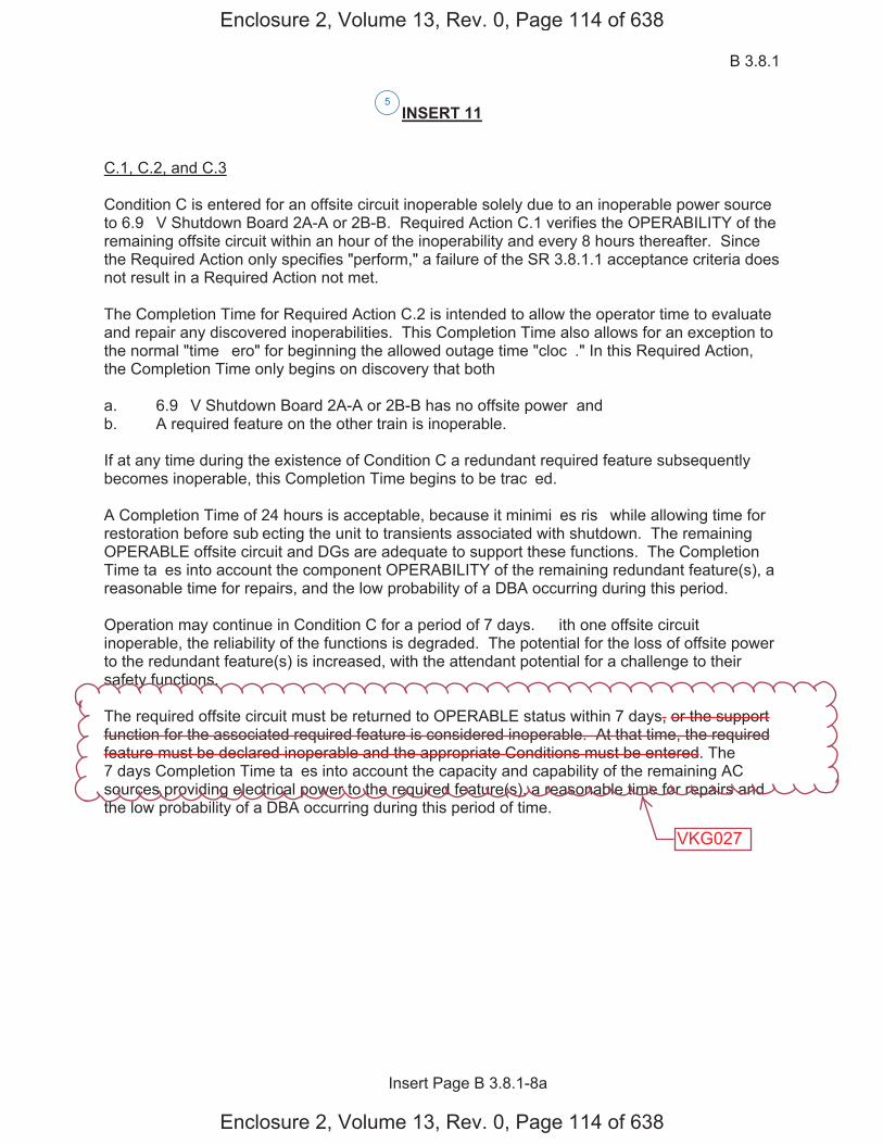
B 3.8.1
Insert Page B 3.8.1-8a
INSERT 11
C.1, C.2, and C.3
Condition C is entered for an offsite circuit inoperable solely due to an inoperable power source to 6.9 �V Shutdown Board 2A-A or 2B-B. Required Action C.1 verifies the OPERABILITY of the remaining offsite circuit within an hour of the inoperability and every 8 hours thereafter. Since the Required Action only specifies "perform," a failure of the SR 3.8.1.1 acceptance criteria does not result in a Required Action not met.
The Completion Time for Required Action C.2 is intended to allow the operator time to evaluate and repair any discovered inoperabilities. This Completion Time also allows for an exception to the normal "time �ero" for beginning the allowed outage time "cloc�." In this Required Action, the Completion Time only begins on discovery that both�
a. 6.9 �V Shutdown Board 2A-A or 2B-B has no offsite power� andb. A required feature on the other train is inoperable.
If at any time during the existence of Condition C a redundant required feature subsequently becomes inoperable, this Completion Time begins to be trac�ed.
A Completion Time of 24 hours is acceptable, because it minimi�es ris� while allowing time for restoration before sub�ecting the unit to transients associated with shutdown. The remaining OPERABLE offsite circuit and DGs are adequate to support these functions. The Completion Time ta�es into account the component OPERABILITY of the remaining redundant feature(s), a reasonable time for repairs, and the low probability of a DBA occurring during this period.
Operation may continue in Condition C for a period of 7 days. � ith one offsite circuit inoperable, the reliability of the functions is degraded. The potential for the loss of offsite power to the redundant feature(s) is increased, with the attendant potential for a challenge to their safety functions.
The required offsite circuit must be returned to OPERABLE status within 7 days, or the support function for the associated required feature is considered inoperable. At that time, the required feature must be declared inoperable and the appropriate Conditions must be entered. The 7 days Completion Time ta�es into account the capacity and capability of the remaining AC sources providing electrical power to the required feature(s), a reasonable time for repairs and the low probability of a DBA occurring during this period of time.
5
Enclosure 2, Volume 13, Rev. 0, Page 114 of 638
Enclosure 2, Volume 13, Rev. 0, Page 114 of 638
VKG027
B 3.8.1
Insert Page B 3.8.1-8b
INSERT 11 (Continued)
D.1, D.2, D.3 and D.4
To ensure a highly reliable power source remains with an inoperable DG to a Unit 2 6.9 �V Shutdown Board, it is necessary to verify the availability of the required offsite circuits on a more frequent basis. Since the Required Action only specifies "perform," a failure of SR 3.8.1.1 acceptance criteria does not result in a Required Action being not met. Required Action D.1 verifies the OPERABILITY of the required offsite sources within an hour of the inoperability and every 8 hours thereafter. However, if a circuit fails to pass SR 3.8.1.1, it is inoperable. Upon offsite circuit inoperability, additional Conditions and Required Actions must be entered.
Required Action D.2 is intended to provide assurance that a loss of offsite power, during the period that an LCO 3.8.1.d DG is inoperable, does not result in a complete loss of the safety functions.
The Completion Time for Required Action D.2 is intended to allow the operator time to evaluate and repair any discovered inoperabilities. This Completion Time also allows for an exception to the normal "time �ero" for beginning the allowed outage time "cloc�." In this Required Action, the Completion Time only begins on discovery that both�
a. An inoperable DG to 6.9 �V Shutdown Board 2A-A or 2B-B exists� andb. A redundant feature in the same system is inoperable.
If at any time during the existence of Condition D (one DG to 6.9 �V Shutdown Board 2A-A or 2B-B) a redundant feature in the same system subsequently becomes inoperable, this Completion Time begins to be trac�ed. The four hour Completion Time is acceptable, because it minimi�es ris� while allowing time for restoration before sub�ecting the unit to transients associated with shutdown.
The remaining OPERABLE offsite circuits and DGs are adequate to support the functions. The 4 hour Completion Time ta�es into account the component OPERABILITY of the remaining redundant feature(s), a reasonable time for repairs, and the low probability of a DBA occurring during this period.
D.3.1 and D.3.2
Required Action D.3.1 provides an allowance to avoid unnecessary testing of OPERABLE DG(s). If it can be determined that the cause of the inoperable DG does not exist on the OPERABLE DG(s), SR 3.8.1.2 does not have to be performed. If the cause of inoperability exists on another DG, the other DG would be declared inoperable, and upon discovery, Condition � of LCO 3.8.1 would be entered, if one or more DG(s) in Train A and Train B are inoperable. Otherwise, if the inoperability exists on the other DG in the same train, the other DG would be declared inoperable upon discovery, Condition B would be entered. Once the failure is repaired, the common cause failure no longer exists, and Required Action D.3.1 is satisfied. If the cause of the initial inoperable DG cannot be confirmed not to exist on the remaining DGs, performance of SR 3.8.1.2 suffices to provide assurance of continued OPERABILITY of that DG.
5
Enclosure 2, Volume 13, Rev. 0, Page 115 of 638
Enclosure 2, Volume 13, Rev. 0, Page 115 of 638
B 3.8.1
Insert Page B 3.8.1-8c
INSERT 11 (Continued)
Operation may continue in Condition D for a period of 7 days. � ith one Unit 2 DG inoperable, the reliability of the respective function is degraded. The potential for the loss of a DG to the redundant feature(s) is increased, with the attendant potential for a challenge to respective safety function.
The required DG must be returned to OPERABLE status within 7 days, or the support function for the associated required feature is considered inoperable. At that time, the required feature must be declared inoperable and the appropriate Conditions must be entered. The 7 day Completion Time ta�es into account the capacity and capability of the remaining AC sources providing electrical power to the required feature(s), a reasonable time for repairs and the low probability of a DBA occurring during this period of time.
5
Enclosure 2, Volume 13, Rev. 0, Page 116 of 638
Enclosure 2, Volume 13, Rev. 0, Page 116 of 638
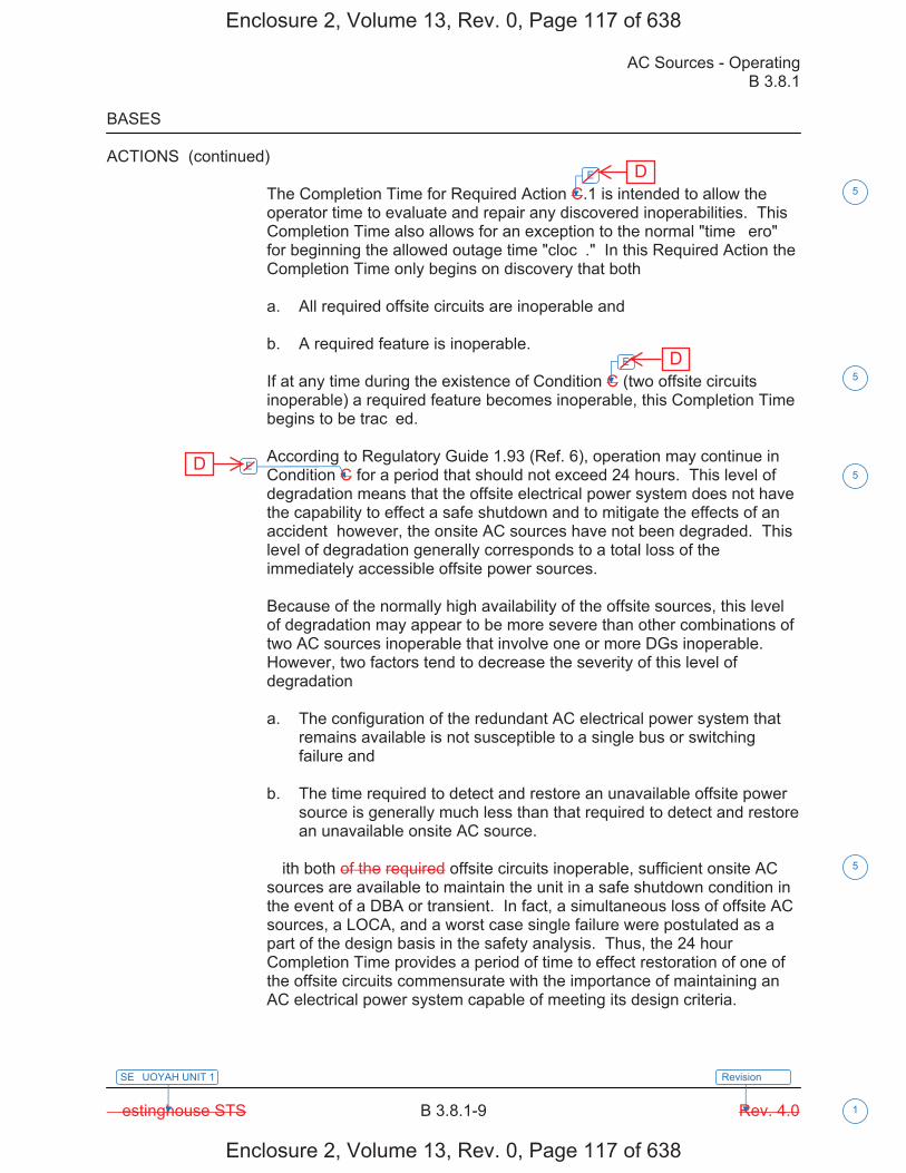
AC Sources - Operating B 3.8.1
� estinghouse STS B 3.8.1-9 Rev. 4.0
SE�UOYAH UNIT 1
1
Revision ���
BASES
ACTIONS (continued)
The Completion Time for Required Action C.1 is intended to allow the operator time to evaluate and repair any discovered inoperabilities. This Completion Time also allows for an exception to the normal "time �ero" for beginning the allowed outage time "cloc�." In this Required Action the Completion Time only begins on discovery that both�
a. All required offsite circuits are inoperable and
b. A required feature is inoperable.
If at any time during the existence of Condition C (two offsite circuits inoperable) a required feature becomes inoperable, this Completion Time begins to be trac�ed.
According to Regulatory Guide 1.93 (Ref. 6), operation may continue in Condition C for a period that should not exceed 24 hours. This level of degradation means that the offsite electrical power system does not have the capability to effect a safe shutdown and to mitigate the effects of an accident� however, the onsite AC sources have not been degraded. This level of degradation generally corresponds to a total loss of the immediately accessible offsite power sources.
Because of the normally high availability of the offsite sources, this level of degradation may appear to be more severe than other combinations of two AC sources inoperable that involve one or more DGs inoperable. However, two factors tend to decrease the severity of this level of degradation�
a. The configuration of the redundant AC electrical power system thatremains available is not susceptible to a single bus or switchingfailure and
b. The time required to detect and restore an unavailable offsite powersource is generally much less than that required to detect and restorean unavailable onsite AC source.
� ith both of the required offsite circuits inoperable, sufficient onsite AC sources are available to maintain the unit in a safe shutdown condition in the event of a DBA or transient. In fact, a simultaneous loss of offsite AC sources, a LOCA, and a worst case single failure were postulated as a part of the design basis in the safety analysis. Thus, the 24 hour Completion Time provides a period of time to effect restoration of one of the offsite circuits commensurate with the importance of maintaining an AC electrical power system capable of meeting its design criteria.
E
E
E
5
5
5
5
Enclosure 2, Volume 13, Rev. 0, Page 117 of 638
Enclosure 2, Volume 13, Rev. 0, Page 117 of 638
D
D
D
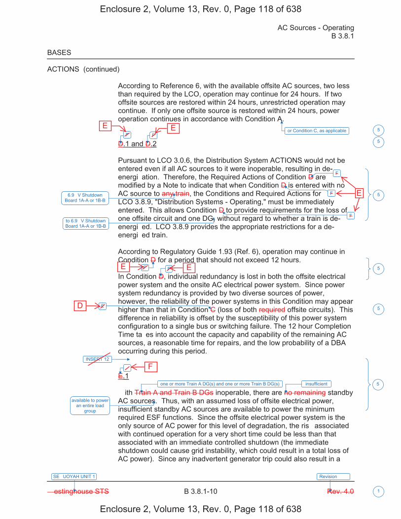
AC Sources - Operating B 3.8.1
� estinghouse STS B 3.8.1-10 Rev. 4.0
SE�UOYAH UNIT 1
1
Revision ���
BASES
ACTIONS (continued)
According to Reference 6, with the available offsite AC sources, two less than required by the LCO, operation may continue for 24 hours. If two offsite sources are restored within 24 hours, unrestricted operation may continue. If only one offsite source is restored within 24 hours, power operation continues in accordance with Condition A.
D.1 and D.2
Pursuant to LCO 3.0.6, the Distribution System ACTIONS would not be entered even if all AC sources to it were inoperable, resulting in de-energi�ation. Therefore, the Required Actions of Condition D are modified by a Note to indicate that when Condition D is entered with no AC source to any train, the Conditions and Required Actions for LCO 3.8.9, "Distribution Systems - Operating," must be immediately entered. This allows Condition D to provide requirements for the loss of one offsite circuit and one DG, without regard to whether a train is de-energi�ed. LCO 3.8.9 provides the appropriate restrictions for a de-energi�ed train.
According to Regulatory Guide 1.93 (Ref. 6), operation may continue in Condition D for a period that should not exceed 12 hours.
In Condition D, individual redundancy is lost in both the offsite electrical power system and the onsite AC electrical power system. Since power system redundancy is provided by two diverse sources of power, however, the reliability of the power systems in this Condition may appear higher than that in Condition C (loss of both required offsite circuits). This difference in reliability is offset by the susceptibility of this power system configuration to a single bus or switching failure. The 12 hour Completion Time ta�es into account the capacity and capability of the remaining AC sources, a reasonable time for repairs, and the low probability of a DBA occurring during this period.
E.1
� ith Train A and Train B DGs inoperable, there are no remaining standby AC sources. Thus, with an assumed loss of offsite electrical power, insufficient standby AC sources are available to power the minimum required ESF functions. Since the offsite electrical power system is the only source of AC power for this level of degradation, the ris� associated with continued operation for a very short time could be less than that associated with an immediate controlled shutdown (the immediate shutdown could cause grid instability, which could result in a total loss of AC power). Since any inadvertent generator trip could also result in a
or Condition C, as applicableF F
F
F
F
6.9 �V Shutdown Board 1A-A or 1B-B
F F
E
�
one or more Train A DG(s) and one or more Train B DG(s)
available to power an entire load
group
5
5
5
5
5
5
INSERT 12
insufficient
to 6.9 �V Shutdown Board 1A-A or 1B-B
Enclosure 2, Volume 13, Rev. 0, Page 118 of 638
Enclosure 2, Volume 13, Rev. 0, Page 118 of 638
E E
E E
D
F
E
B 3.8.1
Insert Page B 3.8.1-10
INSERT 12
G.1 and H.1
In Conditions G and H, individual redundancy is lost in the offsite electrical power system for one unit and the onsite AC electrical power system for the other unit. Since Conditions B and C are entered concurrent with entry into Condition G, and Conditions A and D are entered concurrent with entry into Condition H, the Required Actions of Conditions B and C (or Conditions A and D) provide the appropriate compensatory measures to ensure the onsite and offsite power sources are either restored to an OPERABLE status, or the associated required features are declared inoperable, thereby requiring entry into the appropriate Conditions associated with the associated feature�s LCO. The Completion Times of Required Actions G.1 and H.1 are consistent with the Completion Times of Required Actions C.3 and D.4. If, while in Condition G or H, a redundant required feature is determined to be inoperable, the required feature(s) would be declared inoperable at the Completion Times specified in Conditions A, B, C, or D, as applicable.
I.1 and I.2
Pursuant to LCO 3.0.6, the Distribution System ACTIONS would not be entered even if all AC sources to it were inoperable, resulting in de-energi�ation. Therefore, the Required Actions of Condition I are modified by a Note to indicate that when Condition I is entered with no AC source to 6.9 �V Shutdown Board 2A-A or 2B-B, the Conditions and Required Actions for LCO 3.8.9, "Distribution Systems - Operating," must be immediately entered. This allows Condition I to provide requirements for the loss of one offsite power source and one DG, without regard to whether a train is de-energi�ed. LCO 3.8.9 provides the appropriate restrictions for a de-energi�ed 6.9 �V Shutdown Board.
In Condition I, individual redundancy is lost in the offsite electrical power system and the onsite AC electrical power system. Concurrent with entry into Condition I, entry into Condition C (inoperable offsite power source) and Condition D (inoperable DG) are required. The Required Actions of Conditions C and D ensure the remaining offsite circuit and DGs are OPERABLE and that required features with no offsite or onsite power sources are declared inoperable when its redundant required feature is inoperable within the Completion Times of Required Actions C.2 and D.2.
5
Enclosure 2, Volume 13, Rev. 0, Page 119 of 638
Enclosure 2, Volume 13, Rev. 0, Page 119 of 638
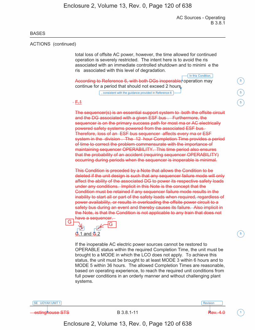
AC Sources - Operating B 3.8.1
� estinghouse STS B 3.8.1-11 Rev. 4.0
SE�UOYAH UNIT 1
1
Revision ���
BASES
ACTIONS (continued)
total loss of offsite AC power, however, the time allowed for continued operation is severely restricted. The intent here is to avoid the ris� associated with an immediate controlled shutdown and to minimi�e the ris� associated with this level of degradation.
According to Reference 6, with both DGs inoperable, operation may continue for a period that should not exceed 2 hours.
� F.1
The sequencer(s) is an essential support system to �both the offsite circuit and the DG associated with a given ESF bus�. �Furthermore, the sequencer is on the primary success path for most ma�or AC electrically powered safety systems powered from the associated ESF bus.� Therefore, loss of an �ESF bus sequencer� affects every ma�or ESF system in the �division�. The �12� hour Completion Time provides a period of time to correct the problem commensurate with the importance of maintaining sequencer OPERABILITY. This time period also ensures that the probability of an accident (requiring sequencer OPERABILITY) occurring during periods when the sequencer is inoperable is minimal.
This Condition is preceded by a Note that allows the Condition to be deleted if the unit design is such that any sequencer failure mode will only affect the ability of the associated DG to power its respective safety loads under any conditions. Implicit in this Note is the concept that the Condition must be retained if any sequencer failure mode results in the inability to start all or part of the safety loads when required, regardless of power availability, or results in overloading the offsite power circuit to a safety bus during an event and thereby causes its failure. Also implicit in the Note, is that the Condition is not applicable to any train that does not have a sequencer. �
G.1 and G.2
If the inoperable AC electric power sources cannot be restored to OPERABLE status within the required Completion Time, the unit must be brought to a MODE in which the LCO does not apply. To achieve this status, the unit must be brought to at least MODE 3 within 6 hours and to MODE 5 within 36 hours. The allowed Completion Times are reasonable, based on operating experience, to reach the required unit conditions from full power conditions in an orderly manner and without challenging plant systems.
In this Condition,
K K
5
5
5
5
, consistent with the guidance provided in Reference 6
Enclosure 2, Volume 13, Rev. 0, Page 120 of 638
Enclosure 2, Volume 13, Rev. 0, Page 120 of 638
G G
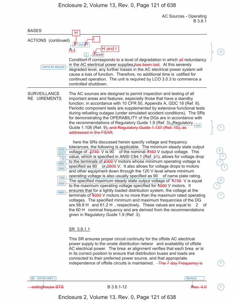
AC Sources - Operating B 3.8.1
� estinghouse STS B 3.8.1-12 Rev. 4.0
SE�UOYAH UNIT 1
1
Revision ���
BASES
ACTIONS (continued)
H.1
Condition H corresponds to a level of degradation in which all redundancy in the AC electrical power supplies has been lost. At this severely degraded level, any further losses in the AC electrical power system will cause a loss of function. Therefore, no additional time is �ustified for continued operation. The unit is required by LCO 3.0.3 to commence a controlled shutdown.
SURVEILLANCE The AC sources are designed to permit inspection and testing of all RE�UIREMENTS important areas and features, especially those that have a standby
function, in accordance with 10 CFR 50, Appendix A, GDC 18 (Ref. 8). Periodic component tests are supplemented by extensive functional tests during refueling outages (under simulated accident conditions). The SRs for demonstrating the OPERABILITY of the DGs are in accordance with the recommendations of Regulatory Guide 1.9 (Ref. 3), Regulatory Guide 1.108 (Ref. 9), and Regulatory Guide 1.137 (Ref. 10), as addressed in the FSAR.
� here the SRs discussed herein specify voltage and frequency tolerances, the following is applicable. The minimum steady state output voltage of �3740� V is 90� of the nominal 4160 V output voltage. This value, which is specified in ANSI C84.1 (Ref. 11), allows for voltage drop to the terminals of 4000 V motors whose minimum operating voltage is specified as 90� or 3600 V. It also allows for voltage drops to motors and other equipment down through the 120 V level where minimum operating voltage is also usually specified as 90� of name plate rating. The specified maximum steady state output voltage of �4756� V is equal to the maximum operating voltage specified for 4000 V motors. It ensures that for a lightly loaded distribution system, the voltage at the terminals of 4000 V motors is no more than the maximum rated operating voltages. The specified minimum and maximum frequencies of the DG are 58.8 H� and 61.2 H�, respectively. These values are equal to � 2� of the 60 H� nominal frequency and are derived from the recommendations given in Regulatory Guide 1.9 (Ref. 3).
SR 3.8.1.1
This SR ensures proper circuit continuity for the offsite AC electrical power supply to the onsite distribution networ� and availability of offsite AC electrical power. The brea�er alignment verifies that each brea�er is in its correct position to ensure that distribution buses and loads are connected to their preferred power source, and that appropriate independence of offsite circuits is maintained. � The 7 day Frequency is
L.1 and M.1
L and M
and
6900
6600
5940
7260
6600
6600
5
1
2
1
2
1
1
7
6210
10 1
1
s
cannot be assured
Enclosure 2, Volume 13, Rev. 0, Page 121 of 638
Enclosure 2, Volume 13, Rev. 0, Page 121 of 638
H and I
I H
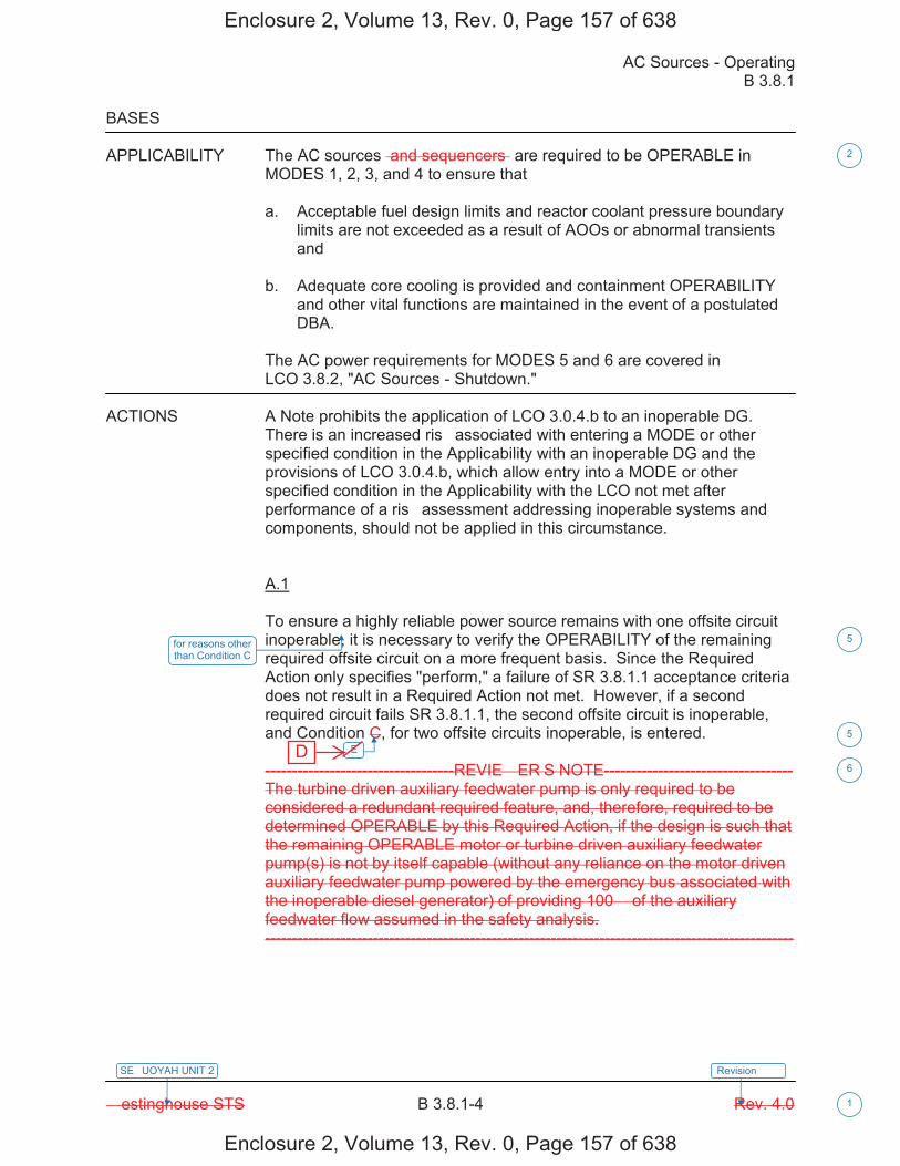
AC Sources - Operating B 3.8.1
� estinghouse STS B 3.8.1-4 Rev. 4.0
SE�UOYAH UNIT 2
1
Revision ���
BASES
APPLICABILITY The AC sources �and sequencers� are required to be OPERABLE in MODES 1, 2, 3, and 4 to ensure that�
a. Acceptable fuel design limits and reactor coolant pressure boundarylimits are not exceeded as a result of AOOs or abnormal transientsand
b. Adequate core cooling is provided and containment OPERABILITYand other vital functions are maintained in the event of a postulatedDBA.
The AC power requirements for MODES 5 and 6 are covered in LCO 3.8.2, "AC Sources - Shutdown."
ACTIONS A Note prohibits the application of LCO 3.0.4.b to an inoperable DG. There is an increased ris� associated with entering a MODE or other specified condition in the Applicability with an inoperable DG and the provisions of LCO 3.0.4.b, which allow entry into a MODE or other specified condition in the Applicability with the LCO not met after performance of a ris� assessment addressing inoperable systems and components, should not be applied in this circumstance.
A.1
To ensure a highly reliable power source remains with one offsite circuit inoperable, it is necessary to verify the OPERABILITY of the remaining required offsite circuit on a more frequent basis. Since the Required Action only specifies "perform," a failure of SR 3.8.1.1 acceptance criteria does not result in a Required Action not met. However, if a second required circuit fails SR 3.8.1.1, the second offsite circuit is inoperable, and Condition C, for two offsite circuits inoperable, is entered.
-----------------------------------REVIE� ER�S NOTE-----------------------------------The turbine driven auxiliary feedwater pump is only required to be considered a redundant required feature, and, therefore, required to be determined OPERABLE by this Required Action, if the design is such that the remaining OPERABLE motor or turbine driven auxiliary feedwater pump(s) is not by itself capable (without any reliance on the motor driven auxiliary feedwater pump powered by the emergency bus associated with the inoperable diesel generator) of providing 100� of the auxiliary feedwater flow assumed in the safety analysis. --------------------------------------------------------------------------------------------------
E
2
5
5
6
for reasons other than Condition C
Enclosure 2, Volume 13, Rev. 0, Page 157 of 638
Enclosure 2, Volume 13, Rev. 0, Page 157 of 638
D

AC Sources - Operating B 3.8.1
� estinghouse STS B 3.8.1-6 Rev. 4.0
SE�UOYAH UNIT 2
1
Revision ���
BASES
ACTIONS (continued)
A.3
According to Regulatory Guide 1.93 (Ref. 6), operation may continue in Condition A for a period that should not exceed 72 hours. � ith one offsite circuit inoperable, the reliability of the offsite system is degraded, and the potential for a loss of offsite power is increased, with attendant potential for a challenge to the unit safety systems. In this Condition, however, the remaining OPERABLE offsite circuit and DGs are adequate to supply electrical power to the onsite Class 1E Distribution System.
The 72 hour Completion Time ta�es into account the capacity and capability of the remaining AC sources, a reasonable time for repairs, and the low probability of a DBA occurring during this period.
B.1
To ensure a highly reliable power source remains with an inoperable DG, it is necessary to verify the availability of the offsite circuits on a more frequent basis. Since the Required Action only specifies "perform," a failure of SR 3.8.1.1 acceptance criteria does not result in a Required Action being not met. However, if a circuit fails to pass SR 3.8.1.1, it is inoperable. Upon offsite circuit inoperability, additional Conditions and Required Actions must then be entered.
-----------------------------------REVIE� ER�S NOTE----------------------------------- The turbine driven auxiliary feedwater pump is only required to be considered a redundant required feature, and, therefore, required to be determined OPERABLE by this Required Action, if the design is such that the remaining OPERABLE motor or turbine driven auxiliary feedwater pump(s) is not by itself capable (without any reliance on the motor driven auxiliary feedwater pump powered by the emergency bus associated with the inoperable diesel generator) of providing 100� of the auxiliary feedwater flow assumed in the safety analysis. --------------------------------------------------------------------------------------------------
B.2
Required Action B.2 is intended to provide assurance that a loss of offsite power, during the period that a DG is inoperable, does not result in a complete loss of safety function of critical systems. These features are designed with redundant safety related trains. This includes motor driven auxiliary feedwater pumps. Single train systems, such as turbine driven auxiliary feedwater pumps, are not included. Redundant required feature failures consist of inoperable features associated with a train, redundant to the train that has an inoperable DG.
5
6
AC Electrical Power1
INSERT 9
(s) 5
(s) 5
Enclosure 2, Volume 13, Rev. 0, Page 159 of 638
Enclosure 2, Volume 13, Rev. 0, Page 159 of 638

B 3.8.1
Insert Page B 3.8.1-6
INSERT 9
DG 1A-A, DG 1B-B, DGs 1A-A and 2A-A, or DGs 1B-B and 2B-B
5
Enclosure 2, Volume 13, Rev. 0, Page 160 of 638
Enclosure 2, Volume 13, Rev. 0, Page 160 of 638
one or more Train A DGs, or one or more Train B DGs
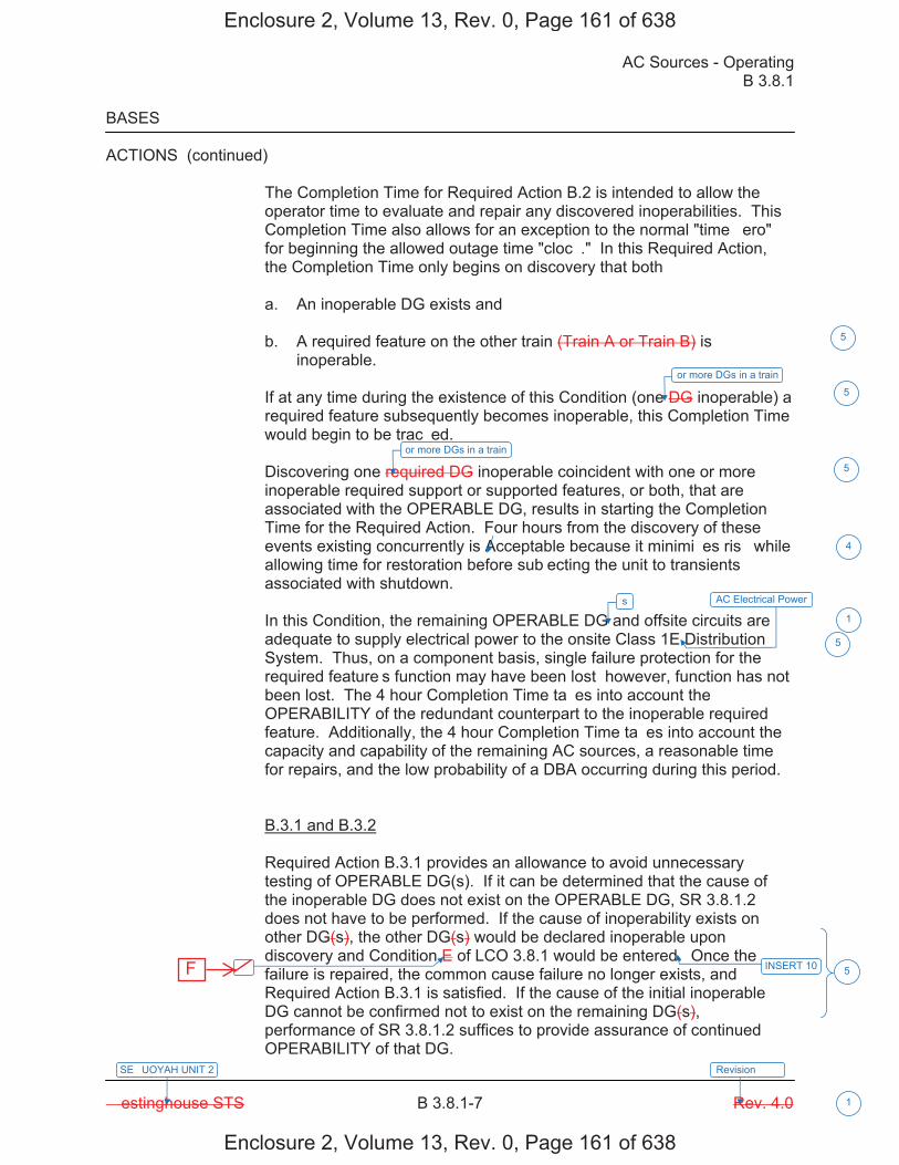
AC Sources - Operating B 3.8.1
� estinghouse STS B 3.8.1-7 Rev. 4.0
SE�UOYAH UNIT 2
1
Revision ���
BASES
ACTIONS (continued)
The Completion Time for Required Action B.2 is intended to allow the operator time to evaluate and repair any discovered inoperabilities. This Completion Time also allows for an exception to the normal "time �ero" for beginning the allowed outage time "cloc�." In this Required Action, the Completion Time only begins on discovery that both�
a. An inoperable DG exists and
b. A required feature on the other train (Train A or Train B) isinoperable.
If at any time during the existence of this Condition (one DG inoperable) a required feature subsequently becomes inoperable, this Completion Time would begin to be trac�ed.
Discovering one required DG inoperable coincident with one or more inoperable required support or supported features, or both, that are associated with the OPERABLE DG, results in starting the Completion Time for the Required Action. Four hours from the discovery of these events existing concurrently is Acceptable because it minimi�es ris� while allowing time for restoration before sub�ecting the unit to transients associated with shutdown.
In this Condition, the remaining OPERABLE DG and offsite circuits are adequate to supply electrical power to the onsite Class 1E Distribution System. Thus, on a component basis, single failure protection for the required feature�s function may have been lost� however, function has not been lost. The 4 hour Completion Time ta�es into account the OPERABILITY of the redundant counterpart to the inoperable required feature. Additionally, the 4 hour Completion Time ta�es into account the capacity and capability of the remaining AC sources, a reasonable time for repairs, and the low probability of a DBA occurring during this period.
B.3.1 and B.3.2
Required Action B.3.1 provides an allowance to avoid unnecessary testing of OPERABLE DG(s). If it can be determined that the cause of the inoperable DG does not exist on the OPERABLE DG, SR 3.8.1.2 does not have to be performed. If the cause of inoperability exists on other DG(s), the other DG(s) would be declared inoperable upon discovery and Condition E of LCO 3.8.1 would be entered. Once the failure is repaired, the common cause failure no longer exists, and Required Action B.3.1 is satisfied. If the cause of the initial inoperable DG cannot be confirmed not to exist on the remaining DG(s), performance of SR 3.8.1.2 suffices to provide assurance of continued OPERABILITY of that DG.
� INSERT 10
4
1
5
5
or more DGs in a train
5
or more DGs in a train
5
s AC Electrical Power
5
Enclosure 2, Volume 13, Rev. 0, Page 161 of 638
Enclosure 2, Volume 13, Rev. 0, Page 161 of 638
F

B 3.8.1
Insert Page B 3.8.1-7
INSERT 10
if one or more DG(s) in Train A and Train B are inoperable
5
Enclosure 2, Volume 13, Rev. 0, Page 162 of 638
Enclosure 2, Volume 13, Rev. 0, Page 162 of 638
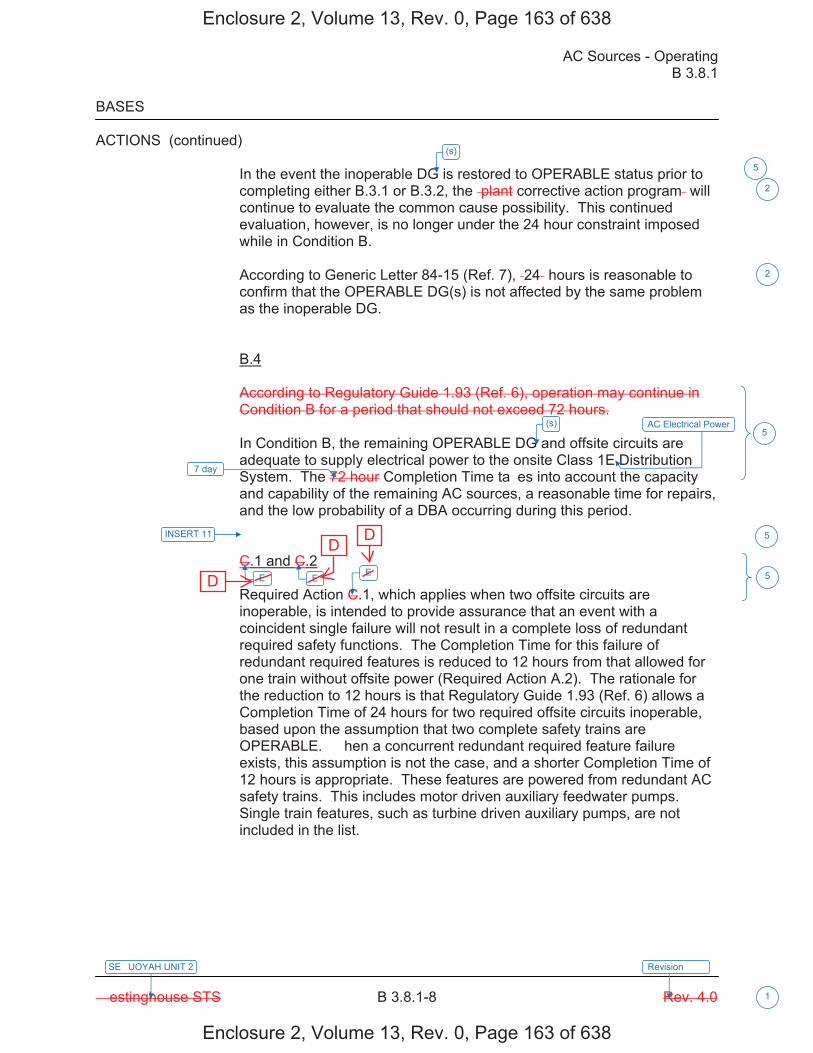
AC Sources - Operating B 3.8.1
� estinghouse STS B 3.8.1-8 Rev. 4.0
SE�UOYAH UNIT 2
1
Revision ���
BASES
ACTIONS (continued)
In the event the inoperable DG is restored to OPERABLE status prior to completing either B.3.1 or B.3.2, the �plant corrective action program� will continue to evaluate the common cause possibility. This continued evaluation, however, is no longer under the 24 hour constraint imposed while in Condition B.
According to Generic Letter 84-15 (Ref. 7), �24� hours is reasonable to confirm that the OPERABLE DG(s) is not affected by the same problem as the inoperable DG.
B.4
According to Regulatory Guide 1.93 (Ref. 6), operation may continue in Condition B for a period that should not exceed 72 hours.
In Condition B, the remaining OPERABLE DG and offsite circuits are adequate to supply electrical power to the onsite Class 1E Distribution System. The 72 hour Completion Time ta�es into account the capacity and capability of the remaining AC sources, a reasonable time for repairs, and the low probability of a DBA occurring during this period.
C.1 and C.2
Required Action C.1, which applies when two offsite circuits are inoperable, is intended to provide assurance that an event with a coincident single failure will not result in a complete loss of redundant required safety functions. The Completion Time for this failure of redundant required features is reduced to 12 hours from that allowed for one train without offsite power (Required Action A.2). The rationale for the reduction to 12 hours is that Regulatory Guide 1.93 (Ref. 6) allows a Completion Time of 24 hours for two required offsite circuits inoperable, based upon the assumption that two complete safety trains are OPERABLE. � hen a concurrent redundant required feature failure exists, this assumption is not the case, and a shorter Completion Time of 12 hours is appropriate. These features are powered from redundant AC safety trains. This includes motor driven auxiliary feedwater pumps. Single train features, such as turbine driven auxiliary pumps, are not included in the list.
7 day
INSERT 11
E E E
2
2
5
5
5
(s)
5
(s) AC Electrical Power
Enclosure 2, Volume 13, Rev. 0, Page 163 of 638
Enclosure 2, Volume 13, Rev. 0, Page 163 of 638
D D
D
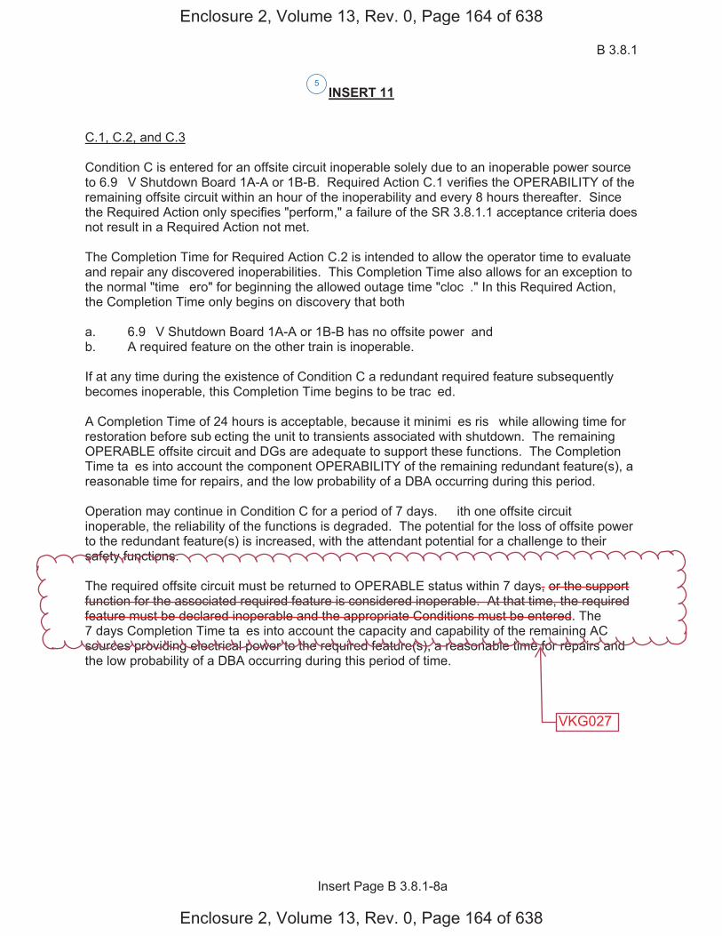
B 3.8.1
Insert Page B 3.8.1-8a
INSERT 11
C.1, C.2, and C.3
Condition C is entered for an offsite circuit inoperable solely due to an inoperable power source to 6.9 �V Shutdown Board 1A-A or 1B-B. Required Action C.1 verifies the OPERABILITY of the remaining offsite circuit within an hour of the inoperability and every 8 hours thereafter. Since the Required Action only specifies "perform," a failure of the SR 3.8.1.1 acceptance criteria does not result in a Required Action not met.
The Completion Time for Required Action C.2 is intended to allow the operator time to evaluate and repair any discovered inoperabilities. This Completion Time also allows for an exception to the normal "time �ero" for beginning the allowed outage time "cloc�." In this Required Action, the Completion Time only begins on discovery that both�
a. 6.9 �V Shutdown Board 1A-A or 1B-B has no offsite power� andb. A required feature on the other train is inoperable.
If at any time during the existence of Condition C a redundant required feature subsequently becomes inoperable, this Completion Time begins to be trac�ed.
A Completion Time of 24 hours is acceptable, because it minimi�es ris� while allowing time for restoration before sub�ecting the unit to transients associated with shutdown. The remaining OPERABLE offsite circuit and DGs are adequate to support these functions. The Completion Time ta�es into account the component OPERABILITY of the remaining redundant feature(s), a reasonable time for repairs, and the low probability of a DBA occurring during this period.
Operation may continue in Condition C for a period of 7 days. � ith one offsite circuit inoperable, the reliability of the functions is degraded. The potential for the loss of offsite power to the redundant feature(s) is increased, with the attendant potential for a challenge to their safety functions.
The required offsite circuit must be returned to OPERABLE status within 7 days, or the support function for the associated required feature is considered inoperable. At that time, the required feature must be declared inoperable and the appropriate Conditions must be entered. The 7 days Completion Time ta�es into account the capacity and capability of the remaining AC sources providing electrical power to the required feature(s), a reasonable time for repairs and the low probability of a DBA occurring during this period of time.
5
Enclosure 2, Volume 13, Rev. 0, Page 164 of 638
Enclosure 2, Volume 13, Rev. 0, Page 164 of 638
VKG027

B 3.8.1
Insert Page B 3.8.1-8b
INSERT 11 (Continued)
D.1, D.2, D.3, and D.4
To ensure a highly reliable power source remains with an inoperable DG to a Unit 1 6.9 �V Shutdown Board, it is necessary to verify the availability of the required offsite circuits on a more frequent basis. Since the Required Action only specifies "perform," a failure of SR 3.8.1.1 acceptance criteria does not result in a Required Action being not met. Required Action D.1 verifies the OPERABILITY of the required offsite sources within an hour of the inoperability and every 8 hours thereafter. However, if a circuit fails to pass SR 3.8.1.1, it is inoperable. Upon offsite circuit inoperability, additional Conditions and Required Actions must be entered.
Required Action D.2 is intended to provide assurance that a loss of offsite power, during the period that an LCO 3.8.1.d DG is inoperable, does not result in a complete loss of the safety functions.
The Completion Time for Required Action D.2 is intended to allow the operator time to evaluate and repair any discovered inoperabilities. This Completion Time also allows for an exception to the normal "time �ero" for beginning the allowed outage time "cloc�." In this Required Action, the Completion Time only begins on discovery that both�
a. An inoperable DG to 6.9 �V Shutdown Board 1A-A or 1B-B exists� andb. A redundant feature in the same system is inoperable.
If at any time during the existence of Condition D (one DG to 6.9 �V Shutdown Board 1A-A or 1B-B) a redundant feature in the same system subsequently becomes inoperable, this Completion Time begins to be trac�ed. The four hour Completion Time is acceptable, because it minimi�es ris� while allowing time for restoration before sub�ecting the unit to transients associated with shutdown.
The remaining OPERABLE offsite circuits and DGs are adequate to support the functions. The 4 hour Completion Time ta�es into account the component OPERABILITY of the remaining redundant feature(s), a reasonable time for repairs, and the low probability of a DBA occurring during this period.
D.3.1 and D.3.2
Required Action D.3.1 provides an allowance to avoid unnecessary testing of OPERABLE DG(s). If it can be determined that the cause of the inoperable DG does not exist on the OPERABLE DG(s), SR 3.8.1.2 does not have to be performed. If the cause of inoperability exists on another DG, the other DG would be declared inoperable, and upon discovery, Condition � of LCO 3.8.1 would be entered, if one or more DG(s) in Train A and Train B are inoperable. Otherwise, if the inoperability exists on the other DG in the same train, the other DG would be declared inoperable upon discovery, Condition B would be entered. Once the failure is repaired, the common cause failure no longer exists, and Required Action D.3.1 is satisfied. If the cause of the initial inoperable DG cannot be confirmed not to exist on the remaining DGs, performance of SR 3.8.1.2 suffices to provide assurance of continued OPERABILITY of that DG.
5
Enclosure 2, Volume 13, Rev. 0, Page 165 of 638
Enclosure 2, Volume 13, Rev. 0, Page 165 of 638
B 3.8.1
Insert Page B 3.8.1-8c
INSERT 11 (Continued)
Operation may continue in Condition D for a period of 7 days. � ith one Unit 2 DG inoperable, the reliability of the respective function is degraded. The potential for the loss of a DG to the redundant feature(s) is increased, with the attendant potential for a challenge to respective safety function.
The required DG must be returned to OPERABLE status within 7 days, or the support function for the associated required feature is considered inoperable. At that time, the required feature must be declared inoperable and the appropriate Conditions must be entered. The 7 day Completion Time ta�es into account the capacity and capability of the remaining AC sources providing electrical power to the required feature(s), a reasonable time for repairs and the low probability of a DBA occurring during this period of time.
5
Enclosure 2, Volume 13, Rev. 0, Page 166 of 638
Enclosure 2, Volume 13, Rev. 0, Page 166 of 638
AC Sources - Operating B 3.8.1
� estinghouse STS B 3.8.1-9 Rev. 4.0
SE�UOYAH UNIT 2
1
Revision ���
BASES
ACTIONS (continued)
The Completion Time for Required Action C.1 is intended to allow the operator time to evaluate and repair any discovered inoperabilities. This Completion Time also allows for an exception to the normal "time �ero" for beginning the allowed outage time "cloc�." In this Required Action the Completion Time only begins on discovery that both�
a. All required offsite circuits are inoperable and
b. A required feature is inoperable.
If at any time during the existence of Condition C (two offsite circuits inoperable) a required feature becomes inoperable, this Completion Time begins to be trac�ed.
According to Regulatory Guide 1.93 (Ref. 6), operation may continue in Condition C for a period that should not exceed 24 hours. This level of degradation means that the offsite electrical power system does not have the capability to effect a safe shutdown and to mitigate the effects of an accident� however, the onsite AC sources have not been degraded. This level of degradation generally corresponds to a total loss of the immediately accessible offsite power sources.
Because of the normally high availability of the offsite sources, this level of degradation may appear to be more severe than other combinations of two AC sources inoperable that involve one or more DGs inoperable. However, two factors tend to decrease the severity of this level of degradation�
a. The configuration of the redundant AC electrical power system thatremains available is not susceptible to a single bus or switchingfailure and
b. The time required to detect and restore an unavailable offsite powersource is generally much less than that required to detect and restorean unavailable onsite AC source.
� ith both of the required offsite circuits inoperable, sufficient onsite AC sources are available to maintain the unit in a safe shutdown condition in the event of a DBA or transient. In fact, a simultaneous loss of offsite AC sources, a LOCA, and a worst case single failure were postulated as a part of the design basis in the safety analysis. Thus, the 24 hour Completion Time provides a period of time to effect restoration of one of the offsite circuits commensurate with the importance of maintaining an AC electrical power system capable of meeting its design criteria.
E
E
E
5
5
5
5
Enclosure 2, Volume 13, Rev. 0, Page 167 of 638
Enclosure 2, Volume 13, Rev. 0, Page 167 of 638
D
D
D
AC Sources - Operating B 3.8.1
� estinghouse STS B 3.8.1-10 Rev. 4.0
SE�UOYAH UNIT 2
1
Revision ���
BASES
ACTIONS (continued)
According to Reference 6, with the available offsite AC sources, two less than required by the LCO, operation may continue for 24 hours. If two offsite sources are restored within 24 hours, unrestricted operation may continue. If only one offsite source is restored within 24 hours, power operation continues in accordance with Condition A.
D.1 and D.2
Pursuant to LCO 3.0.6, the Distribution System ACTIONS would not be entered even if all AC sources to it were inoperable, resulting in de-energi�ation. Therefore, the Required Actions of Condition D are modified by a Note to indicate that when Condition D is entered with no AC source to any train, the Conditions and Required Actions for LCO 3.8.9, "Distribution Systems - Operating," must be immediately entered. This allows Condition D to provide requirements for the loss of one offsite circuit and one DG, without regard to whether a train is de-energi�ed. LCO 3.8.9 provides the appropriate restrictions for a de-energi�ed train.
According to Regulatory Guide 1.93 (Ref. 6), operation may continue in Condition D for a period that should not exceed 12 hours.
In Condition D, individual redundancy is lost in both the offsite electrical power system and the onsite AC electrical power system. Since power system redundancy is provided by two diverse sources of power, however, the reliability of the power systems in this Condition may appear higher than that in Condition C (loss of both required offsite circuits). This difference in reliability is offset by the susceptibility of this power system configuration to a single bus or switching failure. The 12 hour Completion Time ta�es into account the capacity and capability of the remaining AC sources, a reasonable time for repairs, and the low probability of a DBA occurring during this period.
E.1
� ith Train A and Train B DGs inoperable, there are no remaining standby AC sources. Thus, with an assumed loss of offsite electrical power, insufficient standby AC sources are available to power the minimum required ESF functions. Since the offsite electrical power system is the only source of AC power for this level of degradation, the ris� associated with continued operation for a very short time could be less than that associated with an immediate controlled shutdown (the immediate shutdown could cause grid instability, which could result in a total loss of AC power). Since any inadvertent generator trip could also result in a
F F
F
F
F
F F
E
�
available to power an entire load
group
5
5
5
5
5
5
or Condition C, as applicable
6.9 �V Shutdown Board 2A-A or 2B-B
INSERT 12
one or more Train A DG(s) and one or more Train B DG(s) insufficient
to 6.9 �V Shutdown Board 2A-A or 2B-B
Enclosure 2, Volume 13, Rev. 0, Page 168 of 638
Enclosure 2, Volume 13, Rev. 0, Page 168 of 638
E E
E E
D
F
E
B 3.8.1
Insert Page B 3.8.1-10
INSERT 12
G.1 and H.1
In Conditions G and H, individual redundancy is lost in the offsite electrical power system for one unit and the onsite AC electrical power system for the other unit. Since Conditions B and C are entered concurrent with entry into Condition G, and Conditions A and D are entered concurrent with entry into Condition H, the Required Actions of Conditions B and C (or Conditions A and D) provide the appropriate compensatory measures to ensure the onsite and offsite power sources are either restored to an OPERABLE status, or the associated required features are declared inoperable, thereby requiring entry into the appropriate Conditions associated with the associated feature�s LCO. The Completion Times of Required Actions G.1 and H.1 are consistent with the Completion Times of Required Actions C.3 and D.4. If, while in Condition G or H, a redundant required feature is determined to be inoperable, the required feature(s) would be declared inoperable at the Completion Times specified in Conditions A, B, C, or D, as applicable.
I.1 and I.2
Pursuant to LCO 3.0.6, the Distribution System ACTIONS would not be entered even if all AC sources to it were inoperable, resulting in de-energi�ation. Therefore, the Required Actions of Condition I are modified by a Note to indicate that when Condition I is entered with no AC source to 6.9 �V Shutdown Board 1A-A or 1B-B, the Conditions and Required Actions for LCO 3.8.9, "Distribution Systems - Operating," must be immediately entered. This allows Condition I to provide requirements for the loss of one offsite power source and one DG, without regard to whether a train is de-energi�ed. LCO 3.8.9 provides the appropriate restrictions for a de-energi�ed 6.9 �V Shutdown Board.
In Condition I, individual redundancy is lost in the offsite electrical power system and the onsite AC electrical power system. Concurrent with entry into Condition I, entry into Condition C (inoperable offsite power source) and Condition D (inoperable DG) are required. The Required Actions of Conditions C and D ensure the remaining offsite circuit and DGs are OPERABLE and that required features with no offsite or onsite power sources are declared inoperable when its redundant required feature is inoperable within the Completion Times of Required Actions C.2 and D.2.
5
Enclosure 2, Volume 13, Rev. 0, Page 169 of 638
Enclosure 2, Volume 13, Rev. 0, Page 169 of 638
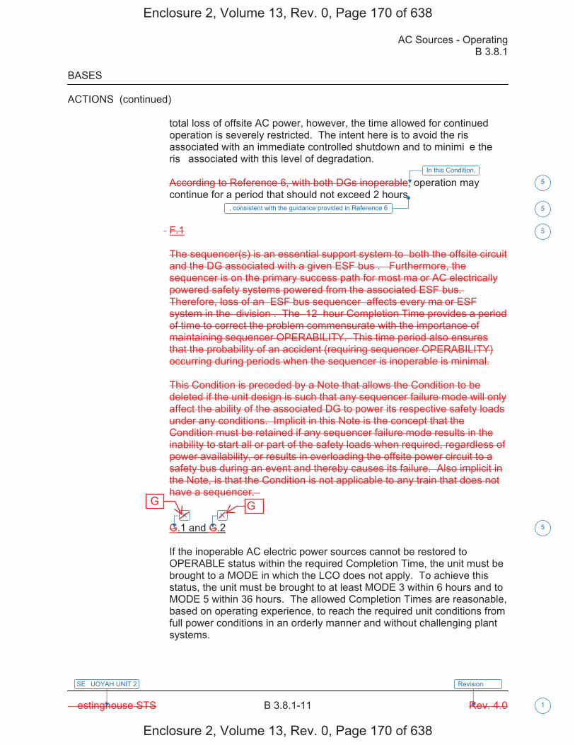
AC Sources - Operating B 3.8.1
� estinghouse STS B 3.8.1-11 Rev. 4.0
SE�UOYAH UNIT 2
1
Revision ���
BASES
ACTIONS (continued)
total loss of offsite AC power, however, the time allowed for continued operation is severely restricted. The intent here is to avoid the ris� associated with an immediate controlled shutdown and to minimi�e the ris� associated with this level of degradation.
According to Reference 6, with both DGs inoperable, operation may continue for a period that should not exceed 2 hours.
� F.1
The sequencer(s) is an essential support system to �both the offsite circuit and the DG associated with a given ESF bus�. �Furthermore, the sequencer is on the primary success path for most ma�or AC electrically powered safety systems powered from the associated ESF bus.� Therefore, loss of an �ESF bus sequencer� affects every ma�or ESF system in the �division�. The �12� hour Completion Time provides a period of time to correct the problem commensurate with the importance of maintaining sequencer OPERABILITY. This time period also ensures that the probability of an accident (requiring sequencer OPERABILITY) occurring during periods when the sequencer is inoperable is minimal.
This Condition is preceded by a Note that allows the Condition to be deleted if the unit design is such that any sequencer failure mode will only affect the ability of the associated DG to power its respective safety loads under any conditions. Implicit in this Note is the concept that the Condition must be retained if any sequencer failure mode results in the inability to start all or part of the safety loads when required, regardless of power availability, or results in overloading the offsite power circuit to a safety bus during an event and thereby causes its failure. Also implicit in the Note, is that the Condition is not applicable to any train that does not have a sequencer. �
G.1 and G.2
If the inoperable AC electric power sources cannot be restored to OPERABLE status within the required Completion Time, the unit must be brought to a MODE in which the LCO does not apply. To achieve this status, the unit must be brought to at least MODE 3 within 6 hours and to MODE 5 within 36 hours. The allowed Completion Times are reasonable, based on operating experience, to reach the required unit conditions from full power conditions in an orderly manner and without challenging plant systems.
K K
5
5
5
5
In this Condition,
, consistent with the guidance provided in Reference 6
Enclosure 2, Volume 13, Rev. 0, Page 170 of 638
Enclosure 2, Volume 13, Rev. 0, Page 170 of 638
G G
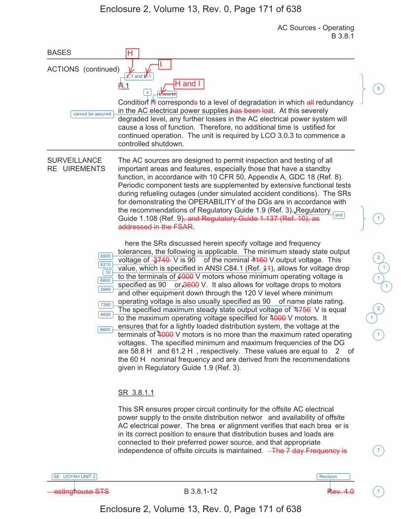
AC Sources - Operating B 3.8.1
� estinghouse STS B 3.8.1-12 Rev. 4.0
SE�UOYAH UNIT 2
1
Revision ���
BASES
ACTIONS (continued)
H.1
Condition H corresponds to a level of degradation in which all redundancy in the AC electrical power supplies has been lost. At this severely degraded level, any further losses in the AC electrical power system will cause a loss of function. Therefore, no additional time is �ustified for continued operation. The unit is required by LCO 3.0.3 to commence a controlled shutdown.
SURVEILLANCE The AC sources are designed to permit inspection and testing of all RE�UIREMENTS important areas and features, especially those that have a standby
function, in accordance with 10 CFR 50, Appendix A, GDC 18 (Ref. 8). Periodic component tests are supplemented by extensive functional tests during refueling outages (under simulated accident conditions). The SRs for demonstrating the OPERABILITY of the DGs are in accordance with the recommendations of Regulatory Guide 1.9 (Ref. 3), Regulatory Guide 1.108 (Ref. 9), and Regulatory Guide 1.137 (Ref. 10), as addressed in the FSAR.
� here the SRs discussed herein specify voltage and frequency tolerances, the following is applicable. The minimum steady state output voltage of �3740� V is 90� of the nominal 4160 V output voltage. This value, which is specified in ANSI C84.1 (Ref. 11), allows for voltage drop to the terminals of 4000 V motors whose minimum operating voltage is specified as 90� or 3600 V. It also allows for voltage drops to motors and other equipment down through the 120 V level where minimum operating voltage is also usually specified as 90� of name plate rating. The specified maximum steady state output voltage of �4756� V is equal to the maximum operating voltage specified for 4000 V motors. It ensures that for a lightly loaded distribution system, the voltage at the terminals of 4000 V motors is no more than the maximum rated operating voltages. The specified minimum and maximum frequencies of the DG are 58.8 H� and 61.2 H�, respectively. These values are equal to � 2� of the 60 H� nominal frequency and are derived from the recommendations given in Regulatory Guide 1.9 (Ref. 3).
SR 3.8.1.1
This SR ensures proper circuit continuity for the offsite AC electrical power supply to the onsite distribution networ� and availability of offsite AC electrical power. The brea�er alignment verifies that each brea�er is in its correct position to ensure that distribution buses and loads are connected to their preferred power source, and that appropriate independence of offsite circuits is maintained. � The 7 day Frequency is
and
6900
6600
5940
7260
6600
6600
5
1
2
1
2
1
1
7
6210
10 1
1
L.1 and M.1
s L and M
cannot be assured
Enclosure 2, Volume 13, Rev. 0, Page 171 of 638
Enclosure 2, Volume 13, Rev. 0, Page 171 of 638
HI
H and I
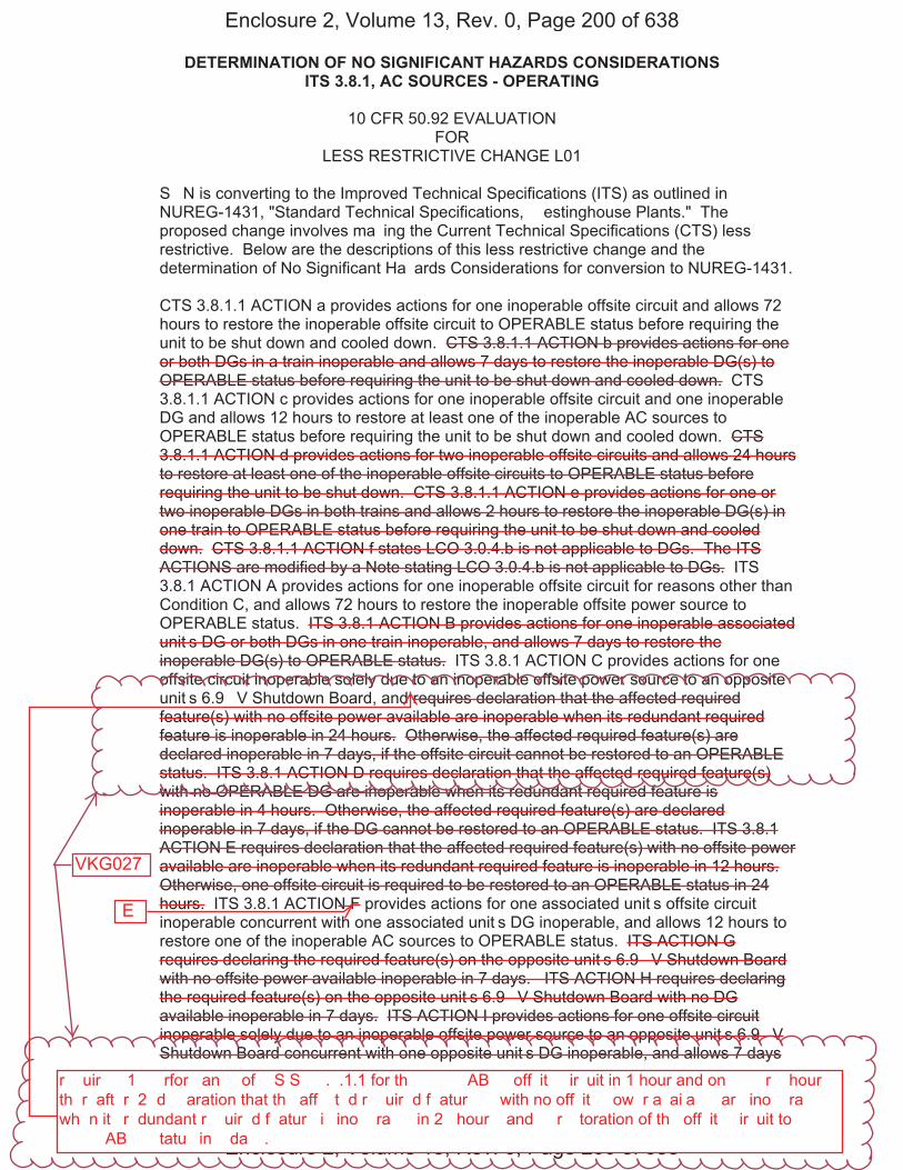
DETERMINATION OF NO SIGNIFICANT HAZARDS CONSIDERATIONS ITS 3.8.1, AC SOURCES - OPERATING
Sequoyah Unit 1 and 2 Page 1 of 4
10 CFR 50.92 EVALUATION FOR
LESS RESTRICTIVE CHANGE L01
S�N is converting to the Improved Technical Specifications (ITS) as outlined in NUREG-1431, "Standard Technical Specifications, � estinghouse Plants." The proposed change involves ma�ing the Current Technical Specifications (CTS) less restrictive. Below are the descriptions of this less restrictive change and the determination of No Significant Ha�ards Considerations for conversion to NUREG-1431.
CTS 3.8.1.1 ACTION a provides actions for one inoperable offsite circuit and allows 72 hours to restore the inoperable offsite circuit to OPERABLE status before requiring the unit to be shut down and cooled down. CTS 3.8.1.1 ACTION b provides actions for one or both DGs in a train inoperable and allows 7 days to restore the inoperable DG(s) to OPERABLE status before requiring the unit to be shut down and cooled down. CTS 3.8.1.1 ACTION c provides actions for one inoperable offsite circuit and one inoperable DG and allows 12 hours to restore at least one of the inoperable AC sources to OPERABLE status before requiring the unit to be shut down and cooled down. CTS 3.8.1.1 ACTION d provides actions for two inoperable offsite circuits and allows 24 hours to restore at least one of the inoperable offsite circuits to OPERABLE status before requiring the unit to be shut down. CTS 3.8.1.1 ACTION e provides actions for one or two inoperable DGs in both trains and allows 2 hours to restore the inoperable DG(s) in one train to OPERABLE status before requiring the unit to be shut down and cooled down. CTS 3.8.1.1 ACTION f states LCO 3.0.4.b is not applicable to DGs. The ITS ACTIONS are modified by a Note stating LCO 3.0.4.b is not applicable to DGs. ITS 3.8.1 ACTION A provides actions for one inoperable offsite circuit for reasons other than Condition C, and allows 72 hours to restore the inoperable offsite power source to OPERABLE status. ITS 3.8.1 ACTION B provides actions for one inoperable associated unit�s DG or both DGs in one train inoperable, and allows 7 days to restore the inoperable DG(s) to OPERABLE status. ITS 3.8.1 ACTION C provides actions for one offsite circuit inoperable solely due to an inoperable offsite power source to an opposite unit�s 6.9 �V Shutdown Board, and requires declaration that the affected required feature(s) with no offsite power available are inoperable when its redundant required feature is inoperable in 24 hours. Otherwise, the affected required feature(s) are declared inoperable in 7 days, if the offsite circuit cannot be restored to an OPERABLE status. ITS 3.8.1 ACTION D requires declaration that the affected required feature(s) with no OPERABLE DG are inoperable when its redundant required feature is inoperable in 4 hours. Otherwise, the affected required feature(s) are declared inoperable in 7 days, if the DG cannot be restored to an OPERABLE status. ITS 3.8.1 ACTION E requires declaration that the affected required feature(s) with no offsite power available are inoperable when its redundant required feature is inoperable in 12 hours. Otherwise, one offsite circuit is required to be restored to an OPERABLE status in 24 hours. ITS 3.8.1 ACTION F provides actions for one associated unit�s offsite circuit inoperable concurrent with one associated unit�s DG inoperable, and allows 12 hours to restore one of the inoperable AC sources to OPERABLE status. ITS ACTION G requires declaring the required feature(s) on the opposite unit�s 6.9 �V Shutdown Board with no offsite power available inoperable in 7 days. ITS ACTION H requires declaring the required feature(s) on the opposite unit�s 6.9 �V Shutdown Board with no DG available inoperable in 7 days. ITS ACTION I provides actions for one offsite circuit inoperable solely due to an inoperable offsite power source to an opposite unit�s 6.9 �V Shutdown Board concurrent with one opposite unit�s DG inoperable, and allows 7 days
Enclosure 2, Volume 13, Rev. 0, Page 200 of 638
Enclosure 2, Volume 13, Rev. 0, Page 200 of 638
E
r��uir��� 1� ��rfor�an�� of ��S S� �.�.1.1 for th� ����AB�� off�it� �ir�uit in 1 hour and on�� ��r � hour� th�r�aft�r� 2� d���aration that th� aff��t�d r��uir�d f�atur���� with no off�it� �ow�r a�ai�a��� ar� ino��ra��� wh�n it� r�dundant r��uir�d f�atur� i� ino��ra��� in 2� hour�� and �� r��toration of th� off�it� �ir�uit to ����AB�� �tatu� in � da��.
VKG027
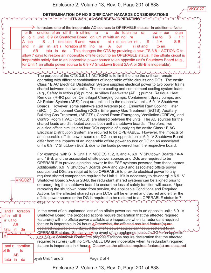
DETERMINATION OF NO SIGNIFICANT HAZARDS CONSIDERATIONS ITS 3.8.1, AC SOURCES - OPERATING
Sequoyah Unit 1 and 2 Page 2 of 4
to restore one of the inoperable AC sources to OPERABLE status. In addition, a Note modifying ITS ACTION I requires entry into the applicable Conditions and Required Actions of LCO 3.8.9 with no AC power source to an opposite unit�s 6.9 �V Shutdown Board. ITS 3.8.1 ACTION � provides actions for one or more Train A and one or more Train B DGs inoperable and allows 2 hours to restore one Train of DGs to OPERABLE status. ITS 3.8.1 ACTION K requires the unit to be shut down and cooled down if a Required Action and associated Completion Time of Condition A, B, E, F, I, or � is not met. These changes to the CTS provide separate ACTIONS to declare the required features powered from the opposite unit�s Class 1E AC Electrical Power Distribution System inoperable as the remedial measures for the inoperable AC sources.
The purpose of the CTS 3.8.1.1 ACTIONS is to limit the time the unit can remain operating with different combinations of inoperable offsite circuits and DGs. The onsite Class 1E AC Electrical Distribution System supplies electrical power to two power trains shared between the two units. The core cooling and containment cooling system loads (e.g., Safety In�ection (SI) pumps, Auxiliary Feedwater (AF� ) pumps, Residual Heat Removal (RHR) pumps, Centrifugal Charging pumps, Containment Spray pumps, and Air Return System (ARS) fans) are uniti�ed to the respective unit�s 6.9 �V Shutdown Boards. However, some safety-related systems (e.g., Essential Raw Cooling � ater (ERC� ), Component Cooling (CCS), Emergency Gas Treatment (EGTS), Auxiliary Building Gas Treatment, (ABGTS), Control Room Emergency Ventilation (CREVs), and Control Room HVAC (CRACS)) are shared between the units. The AC sources for the shared loads are distributed across both unit�s shutdown boards. Therefore, two qualified offsite circuits and four DGs capable of supplying the onsite Class 1E AC Electrical Distribution System are required to be OPERABLE. However, the impacts of an inoperable offsite power source or DG on an opposite unit�s 6.9 �V Shutdown Board differ from the impacts of an inoperable offsite power source or DG on an associated unit�s 6.9 �V Shutdown Board, due to the loads powered from the respective board.
For example, with S�N Unit 1 in MODES 1, 2, 3, and 4, 6.9 �V Shutdown Boards 1A-A and 1B-B, and the associated offsite power sources and DGs are required to be OPERABLE to provide electrical power to the ESF systems powered from those boards. Additionally, 6.9 �V Shutdown Boards 2A-A and 2B-B and associated offsite power sources and DGs are required to be OPERABLE to provide electrical power to any required shared components required for Unit 1. If it is necessary to de-energi�e 6.9 �V Shutdown Board 2A-A or 2B-B, the redundant shared systems can be aligned prior to de-energi�ing the shutdown board to ensure no loss of safety function will occur. Upon removing the shutdown board from service, the applicable Conditions and Required Actions for the affected shared system LCOs will be entered and trac�ed and either the offsite power source or the DG is required to be restored to an OPERABLE status in 7 days.
In the event of an unplanned loss of an offsite power source to an opposite unit�s 6.9 �V Shutdown Board, the proposed actions require declaration that the affected required feature(s) with no offsite power available are inoperable when its redundant required feature is inoperable in 24 hours. Otherwise, the affected required feature(s) are declared inoperable in 7 days, if the offsite power source cannot be restored to an OPERABLE status. Similarly, in the event of an unplanned loss of a DG to an opposite unit 6.9 �V Shutdown Board, the proposed actions require declaration that the affected required feature(s) with no OPERABLE DG are inoperable when its redundant required feature is inoperable in 4 hours. Otherwise, the affected required feature(s) are declared
Enclosure 2, Volume 13, Rev. 0, Page 201 of 638
Enclosure 2, Volume 13, Rev. 0, Page 201 of 638
�or th� �ondition of on� off�it� �ir�uit ino��ra��� �o���� du� to an ino��ra��� �ow�r �our�� to an o��o�it� unit�� 6.9 kV Shutdown Board �on�urr�nt with an ino��ra��� �� ��i�i�ar to ��S �.�.1.1 A�tion ��� ��S �.�.1 �ondition� B and � wou�d �� �nt�r�d �on�urr�nt��. ��S �.�.1 A�����S B and � r��uir�� in �art� r��toration of th� ino��ra��� A� �our��� ��ir�uit and ��� to an ����AB�� �tatu� in � da��. This changes the CTS by providing a new ITS 3.8.1 ACTION C toallow 7 days to restore an inoperable offsite circuit to an OPERABLE status, if the offsite circuit isinoperable solely due to an inoperable power source to an opposite unit's Shutdown Board (e.g.,for Unit 1 an offsite power source to 6.9 kV Shutdown Board 2A-A or 2B-B is inoperable).
� and r��toration of th� off�it� �ir�uit to ����AB�� �tatu� in � da���n
� and r��toration of th� �� to ����AB�� �tatu� in � da��
VKG027
VKG027
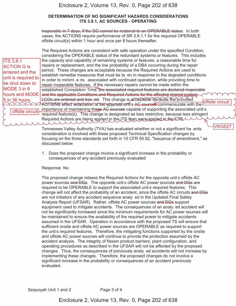
DETERMINATION OF NO SIGNIFICANT HAZARDS CONSIDERATIONS ITS 3.8.1, AC SOURCES - OPERATING
Sequoyah Unit 1 and 2 Page 3 of 4
inoperable in 7 days, if the DG cannot be restored to an OPERABLE status. In both cases, the ACTIONS require performance of SR 3.8.1.1 for the required OPERABLE offsite circuit(s) within 1 hour and once per 8 hours thereafter.
The Required Actions are consistent with safe operation under the specified Condition, considering the OPERABLE status of the redundant systems or features. This includes the capacity and capability of remaining systems or features, a reasonable time for repairs or replacement, and the low probability of a DBA occurring during the repair period. These changes are acceptable because the Required Actions are used to establish remedial measures that must be ta�en in response to the degraded conditions in order to minimi�e ris� associated with continued operation, while providing time to repair inoperable features. If the necessary repairs cannot be made within the established Completion Time, the associated required features are declared inoperable and the applicable Conditions and Required Actions for the affected shared system LCOs are entered and trac�ed. This change is acceptable because the provided ACTIONS effect restoration of the opposite unit�s AC sources commensurate with the importance of maintaining these AC sources capable of supporting the associated unit�s required feature(s). This change is designated as less restrictive, because less stringent Required Actions are being applied in the ITS than were applied in the CTS.
Tennessee Valley Authority (TVA) has evaluated whether or not a significant ha�ards consideration is involved with these proposed Technical Specification changes by focusing on the three standards set forth in 10 CFR 50.92, "Issuance of amendment," as discussed below�
1. Does the proposed change involve a significant increase in the probability orconsequences of any accident previously evaluated�
Response� No.
The proposed change relaxes the Required Actions for the opposite unit�s offsite AC power sources and DGs. The opposite unit�s offsite AC power sources and DGs are required to be OPERABLE to support the associated unit�s required features. This change will not affect the probability of an accident, since the offsite AC circuits and DGs are not initiators of any accident sequence analy�ed in the Updated Final Safety Analysis Report (UFSAR). Rather, offsite AC power sources and DGs support equipment used to mitigate accidents. The consequences of an analy�ed accident will not be significantly increased since the minimum requirements for AC power sources will be maintained to ensure the availability of the required power to mitigate accidents assumed in the UFSAR. Operation in accordance with the proposed TS will ensure that sufficient onsite and offsite AC power sources are OPERABLE as required to support the unit�s required features. Therefore, the mitigating functions supported by the onsite and offsite AC power sources will continue to provide the protection assumed by the accident analysis. The integrity of fission product barriers, plant configuration, and operating procedures as described in the UFSAR will not be affected by the proposed changes. Thus, the consequences of previously analy�ed accidents will not increase by implementing these changes. Therefore, the proposed changes do not involve a significant increase in the probability or consequences of an accident previously evaluated.
Enclosure 2, Volume 13, Rev. 0, Page 202 of 638
Enclosure 2, Volume 13, Rev. 0, Page 202 of 638
ITS 3.8.1ACTION G isentered and theunit is required tobe shut down toMODE 3 in 6hours and MODE5 in 36 hours. offsite circuit
offsite circuit
VKG027

DETERMINATION OF NO SIGNIFICANT HAZARDS CONSIDERATIONS ITS 3.8.1, AC SOURCES - OPERATING
Sequoyah Unit 1 and 2 Page 4 of 4
2. Does the proposed change create the possibility of a new or different �ind ofaccident from any previously evaluated�
Response� No
The proposed change relaxes the Required Actions for the opposite unit�s offsite AC power sources and DGs. The opposite unit�s offsite AC power sources and DGs are required to be OPERABLE to support the associated unit�s required features. This change will not physically alter the plant (no new or different type of equipment will be installed). The proposed changes will maintain the minimum requirements for AC power sources to ensure the availability of the equipment required to mitigate accidents assumed in the UFSAR. Therefore, operation of the facility in accordance with this proposed change will not create the possibility of a new or different �ind of accident from any accident previously evaluated.
3. Does the proposed change involve a significant reduction in the margin of safety�
Response� No.
The proposed change relaxes the Required Actions for the opposite unit�s offsite AC power sources and DGs. The opposite unit�s offsite AC power sources and DGs are required to be OPERABLE to support the associated unit�s required features. The margin of safety is not affected by this change because the minimum requirements for AC power sources will be maintained to ensure the availability of the required power to shutdown the reactor and maintain it in a safe shutdown condition after an AOO or a postulated DBA. Therefore, the proposed changes do not involve a significant reduction in a margin of safety
Enclosure 2, Volume 13, Rev. 0, Page 203 of 638
Enclosure 2, Volume 13, Rev. 0, Page 203 of 638
Licensee Response/NRC Response/NRC Question ClosureId 450
NRC Question Number
VKG027
Select Application Licensee Response
Attachment 1
Attachment 2
Response Statement Attachment 1 associated with the response to RAI
VKG027 contained the same attachment as the response to RAI VKG026. A supplemental response has been provided for RAI VKG026 with a revised Attachment 1. There has been no change to the attachment as it pertains to the information provided in the response to RAI VKG027. However, as a result of the change associated with RAI VKG026, please refer to Attachment 1 for the supplemental response to RAI VKG026 to view all changes to the ITS submittal associated with these two RAIs.
Response Date/Time 5/10/2015 12:25 PM
Closure Statement
Question Closure
Date
Notification Scott BowmanMichelle ConnerVijay GoelKhadijah HemphillAndrew HonLynn MynattRay Schiele
Added By Scott Bowman
Date Added 5/10/2015 11:22 AM
Date Modified
Modified By
Page 1 of 1Sequoyah ITS Conversion Database
05/15/2015https://members.excelservices.com/rai/index.php?requestType=areaItemPrint&itemId=450

Licensee Response/NRC Response/NRC Question ClosureId 454
NRC Question Number VKG027
Select Application NRC Question Closure
Attachment 1
Attachment 2
Response Statement
Response Date/Time
Closure Statement This question is closed and no further information is required at this time to draft the Safety Evaluation.
Question Closure Date 5/14/2015
Notification Michelle ConnerKhadijah HemphillAndrew HonLynn MynattRay SchieleRoger Scott
Added By Khadijah Hemphill
Date Added 5/14/2015 3:12 PM
Date Modified
Modified By
Page 1 of 1Sequoyah ITS Conversion Database
05/15/2015https://members.excelservices.com/rai/index.php?requestType=areaItemPrint&itemId=454