specifications - data holic
TRANSCRIPT
Specifications
• Chassis Specifications, on page 1• Power Supply Specifications, on page 6• Chassis and Module Power and Heat Values, on page 14• Weight Specifications, on page 15
Chassis Specifications
Catalyst 9404R Switch Chassis SpecificationsTable 1: Physical Specifications of the Chassis
SpecificationItem
10.47 x 17.3 x 16.3 inches (26.53 x 43.94 x 41.40cms)
Dimensions (H x W x D)
6 RURack units (RU1)
Chassis with fan tray—39.0 lbs (17.2 kgs)Weight
1 The chassis height is measured in rack units (RU or just U), where 1 RU or 1 U equals 1.75 in (44.45mm).
Table 2: Environmental Specifications of the Chassis
SpecificationItem
• 23° to 113°F (-5 to +45ºC), up to 6,000 feet (1800 m)
• 23° to 104°F (-5 to +40ºC), up to 10,000 feet (3000 m)
Ambient temperature andaltitude for normaloperations2
• 23° to 131°F (-5 to +55ºC), up to 6,000 feet (1800 m)
• 23° to 122°F (-5 to +50ºC), up to 10,000 feet (3000 m)
Nonoperating and storage: -40° to 167°F (-40° to 75°C)
Ambient temperature andaltitude for short-term3
exceptional conditions
Specifications1
SpecificationItem
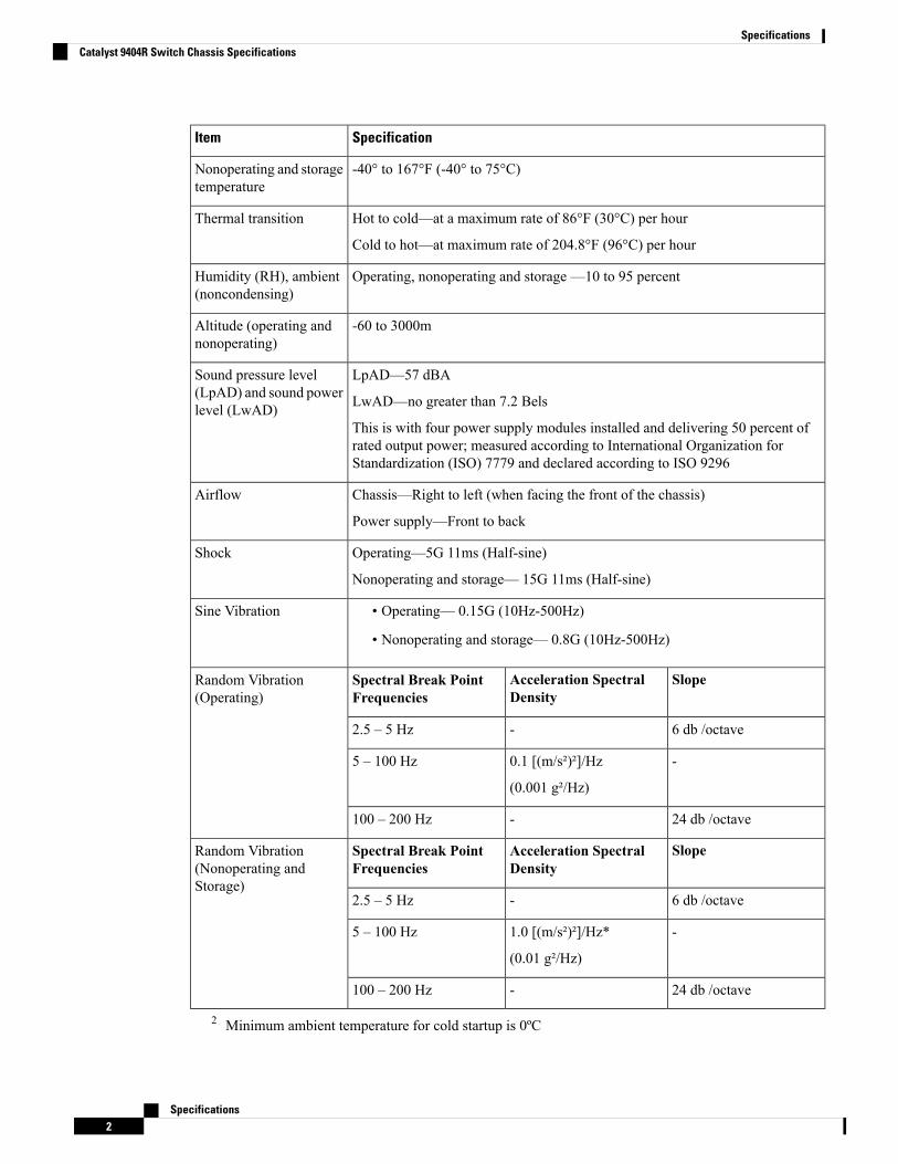
-40° to 167°F (-40° to 75°C)Nonoperating and storagetemperature
Hot to cold—at a maximum rate of 86°F (30°C) per hour
Cold to hot—at maximum rate of 204.8°F (96°C) per hour
Thermal transition
Operating, nonoperating and storage —10 to 95 percentHumidity (RH), ambient(noncondensing)
-60 to 3000mAltitude (operating andnonoperating)
LpAD—57 dBA
LwAD—no greater than 7.2 Bels
This is with four power supply modules installed and delivering 50 percent ofrated output power; measured according to International Organization forStandardization (ISO) 7779 and declared according to ISO 9296
Sound pressure level(LpAD) and sound powerlevel (LwAD)
Chassis—Right to left (when facing the front of the chassis)
Power supply—Front to back
Airflow
Operating—5G 11ms (Half-sine)
Nonoperating and storage— 15G 11ms (Half-sine)
Shock
• Operating— 0.15G (10Hz-500Hz)
• Nonoperating and storage— 0.8G (10Hz-500Hz)
Sine Vibration
SlopeAcceleration SpectralDensity
Spectral Break PointFrequencies
Random Vibration(Operating)
6 db /octave-2.5 – 5 Hz
-0.1 [(m/s²)²]/Hz
(0.001 g²/Hz)
5 – 100 Hz
24 db /octave-100 – 200 Hz
SlopeAcceleration SpectralDensity
Spectral Break PointFrequencies
Random Vibration(Nonoperating andStorage)
6 db /octave-2.5 – 5 Hz
-1.0 [(m/s²)²]/Hz*
(0.01 g²/Hz)
5 – 100 Hz
24 db /octave-100 – 200 Hz
2 Minimum ambient temperature for cold startup is 0ºC
Specifications2
SpecificationsCatalyst 9404R Switch Chassis Specifications
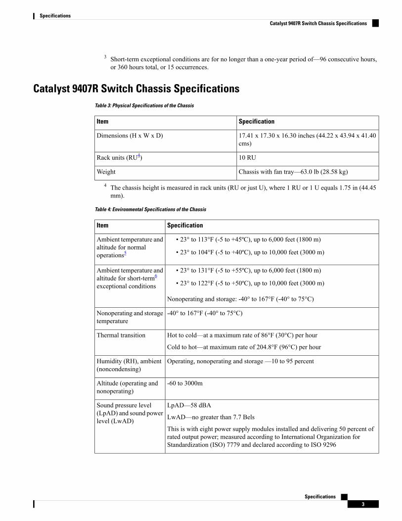
3 Short-term exceptional conditions are for no longer than a one-year period of—96 consecutive hours,or 360 hours total, or 15 occurrences.
Catalyst 9407R Switch Chassis SpecificationsTable 3: Physical Specifications of the Chassis
SpecificationItem
17.41 x 17.30 x 16.30 inches (44.22 x 43.94 x 41.40cms)
Dimensions (H x W x D)
10 RURack units (RU4)
Chassis with fan tray—63.0 lb (28.58 kg)Weight
4 The chassis height is measured in rack units (RU or just U), where 1 RU or 1 U equals 1.75 in (44.45mm).
Table 4: Environmental Specifications of the Chassis
SpecificationItem
• 23° to 113°F (-5 to +45ºC), up to 6,000 feet (1800 m)
• 23° to 104°F (-5 to +40ºC), up to 10,000 feet (3000 m)
Ambient temperature andaltitude for normaloperations5
• 23° to 131°F (-5 to +55ºC), up to 6,000 feet (1800 m)
• 23° to 122°F (-5 to +50ºC), up to 10,000 feet (3000 m)
Nonoperating and storage: -40° to 167°F (-40° to 75°C)
Ambient temperature andaltitude for short-term6
exceptional conditions
-40° to 167°F (-40° to 75°C)Nonoperating and storagetemperature
Hot to cold—at a maximum rate of 86°F (30°C) per hour
Cold to hot—at maximum rate of 204.8°F (96°C) per hour
Thermal transition
Operating, nonoperating and storage —10 to 95 percentHumidity (RH), ambient(noncondensing)
-60 to 3000mAltitude (operating andnonoperating)
LpAD—58 dBA
LwAD—no greater than 7.7 Bels
This is with eight power supply modules installed and delivering 50 percent ofrated output power; measured according to International Organization forStandardization (ISO) 7779 and declared according to ISO 9296
Sound pressure level(LpAD) and sound powerlevel (LwAD)
Specifications3
SpecificationsCatalyst 9407R Switch Chassis Specifications
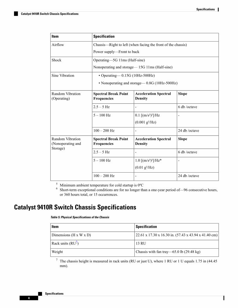
SpecificationItem
Chassis—Right to left (when facing the front of the chassis)
Power supply—Front to back
Airflow
Operating—5G 11ms (Half-sine)
Nonoperating and storage— 15G 11ms (Half-sine)
Shock
• Operating— 0.15G (10Hz-500Hz)
• Nonoperating and storage— 0.8G (10Hz-500Hz)
Sine Vibration
SlopeAcceleration SpectralDensity
Spectral Break PointFrequencies
Random Vibration(Operating)
6 db /octave-2.5 – 5 Hz
-0.1 [(m/s²)²]/Hz
(0.001 g²/Hz)
5 – 100 Hz
24 db /octave-100 – 200 Hz
SlopeAcceleration SpectralDensity
Spectral Break PointFrequencies
Random Vibration(Nonoperating andStorage)
6 db /octave-2.5 – 5 Hz
-1.0 [(m/s²)²]/Hz*
(0.01 g²/Hz)
5 – 100 Hz
24 db /octave-100 – 200 Hz
5 Minimum ambient temperature for cold startup is 0ºC6 Short-term exceptional conditions are for no longer than a one-year period of—96 consecutive hours,or 360 hours total, or 15 occurrences.
Catalyst 9410R Switch Chassis SpecificationsTable 5: Physical Specifications of the Chassis
SpecificationItem
22.61 x 17.30 x 16.30 in. (57.43 x 43.94 x 41.40 cm)Dimensions (H x W x D)
13 RURack units (RU7)
Chassis with fan tray—65.0 lb (29.48 kg)Weight
7 The chassis height is measured in rack units (RU or just U), where 1 RU or 1 U equals 1.75 in (44.45mm).
Specifications4
SpecificationsCatalyst 9410R Switch Chassis Specifications
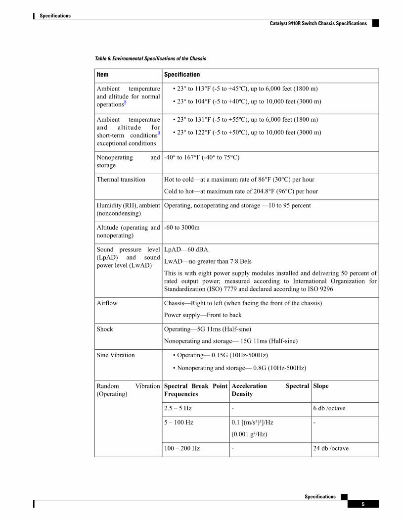
Table 6: Environmental Specifications of the Chassis
SpecificationItem
• 23° to 113°F (-5 to +45ºC), up to 6,000 feet (1800 m)
• 23° to 104°F (-5 to +40ºC), up to 10,000 feet (3000 m)
Ambient temperatureand altitude for normaloperations8
• 23° to 131°F (-5 to +55ºC), up to 6,000 feet (1800 m)
• 23° to 122°F (-5 to +50ºC), up to 10,000 feet (3000 m)
Ambient temperatureand altitude forshort-term conditions9exceptional conditions
-40° to 167°F (-40° to 75°C)Nonoperating andstorage
Hot to cold—at a maximum rate of 86°F (30°C) per hour
Cold to hot—at maximum rate of 204.8°F (96°C) per hour
Thermal transition
Operating, nonoperating and storage —10 to 95 percentHumidity (RH), ambient(noncondensing)
-60 to 3000mAltitude (operating andnonoperating)
LpAD—60 dBA.
LwAD—no greater than 7.8 Bels
This is with eight power supply modules installed and delivering 50 percent ofrated output power; measured according to International Organization forStandardization (ISO) 7779 and declared according to ISO 9296
Sound pressure level(LpAD) and soundpower level (LwAD)
Chassis—Right to left (when facing the front of the chassis)
Power supply—Front to back
Airflow
Operating—5G 11ms (Half-sine)
Nonoperating and storage— 15G 11ms (Half-sine)
Shock
• Operating— 0.15G (10Hz-500Hz)
• Nonoperating and storage— 0.8G (10Hz-500Hz)
Sine Vibration
SlopeAcceleration SpectralDensity
Spectral Break PointFrequencies
Random Vibration(Operating)
6 db /octave-2.5 – 5 Hz
-0.1 [(m/s²)²]/Hz
(0.001 g²/Hz)
5 – 100 Hz
24 db /octave-100 – 200 Hz
Specifications5
SpecificationsCatalyst 9410R Switch Chassis Specifications
SpecificationItem
SlopeAcceleration SpectralDensity
Spectral Break PointFrequencies
Random Vibration(Nonoperating andStorage)
6 db /octave-2.5 – 5 Hz
-1.0 [(m/s²)²]/Hz*
(0.01 g²/Hz)
5 – 100 Hz
24 db /octave-100 – 200 Hz
8 Minimum ambient temperature for cold startup is 0ºC9 Short-term exceptional conditions are for no longer than a one-year period of—96 consecutive hours,or 360 hours total, or 15 occurrences.
Power Supply Specifications
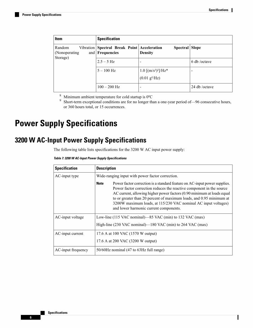
3200 W AC-Input Power Supply SpecificationsThe following table lists specifications for the 3200 W AC input power supply:
Table 7: 3200 W AC-Input Power Supply Specifications
DescriptionSpecification
Wide-ranging input with power factor correction.
Power factor correction is a standard feature on AC-input power supplies.Power factor correction reduces the reactive component in the sourceAC current, allowing higher power factors (0.90 minimum at loads equalto or greater than 20 percent of maximum loads, and 0.95 minimum at3200W maximum loads, at 115/230 VAC nominal AC input voltages)and lower harmonic current components.
Note
AC-input type
Low-line (115 VAC nominal)—85 VAC (min) to 132 VAC (max)
High-line (230 VAC nominal)—180 VAC (min) to 264 VAC (max)
AC-input voltage
17.6 A at 100 VAC (1570 W output)
17.6 A at 200 VAC (3200 W output)
AC-input current
50/60Hz nominal (47 to 63Hz full range)AC-input frequency
Specifications6
SpecificationsPower Supply Specifications
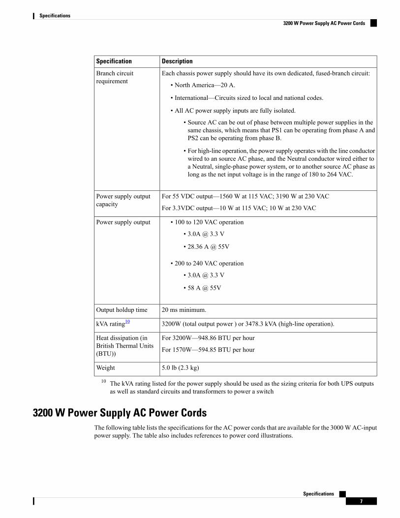
DescriptionSpecification
Each chassis power supply should have its own dedicated, fused-branch circuit:
• North America—20 A.
• International—Circuits sized to local and national codes.
• All AC power supply inputs are fully isolated.
• Source AC can be out of phase between multiple power supplies in thesame chassis, which means that PS1 can be operating from phase A andPS2 can be operating from phase B.
• For high-line operation, the power supply operates with the line conductorwired to an source AC phase, and the Neutral conductor wired either toa Neutral, single-phase power system, or to another source AC phase aslong as the net input voltage is in the range of 180 to 264 VAC.
Branch circuitrequirement
For 55 VDC output—1560 W at 115 VAC; 3190 W at 230 VAC
For 3.3VDC output—10 W at 115 VAC; 10 W at 230 VAC
Power supply outputcapacity
• 100 to 120 VAC operation
• 3.0A @ 3.3 V
• 28.36 A @ 55V
• 200 to 240 VAC operation
• 3.0A @ 3.3 V
• 58 A @ 55V
Power supply output
20 ms minimum.Output holdup time
3200W (total output power ) or 3478.3 kVA (high-line operation).kVA rating10
For 3200W—948.86 BTU per hour
For 1570W—594.85 BTU per hour
Heat dissipation (inBritish Thermal Units(BTU))
5.0 lb (2.3 kg)Weight
10 The kVA rating listed for the power supply should be used as the sizing criteria for both UPS outputsas well as standard circuits and transformers to power a switch
3200 W Power Supply AC Power CordsThe following table lists the specifications for the AC power cords that are available for the 3000WAC-inputpower supply. The table also includes references to power cord illustrations.
Specifications7
Specifications3200 W Power Supply AC Power Cords
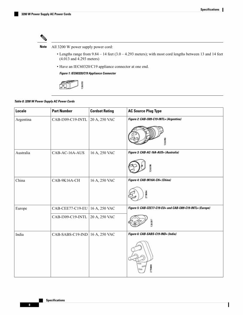
All 3200 W power supply power cord:
• Lengths range from 9.84 – 14 feet (3.0 – 4.293 meters); with most cord lengths between 13 and 14 feet(4.013 and 4.293 meters)
• Have an IEC60320/C19 appliance connector at one end.Figure 1: IEC60320/C19 Appliance Connector
Note
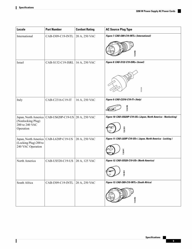
Table 8: 3200 W Power Supply AC Power Cords
AC Source Plug TypeCordset RatingPart NumberLocale
Figure 2: CAB-I309-C19-INTL= (Argentina)20 A, 250 VACCAB-I309-C19-INTLArgentina
Figure 3: CAB-AC-16A-AUS= (Australia)16 A, 250 VACCAB-AC-16A-AUSAustralia
Figure 4: CAB-9K16A-CH= (China)16 A, 250 VACCAB-9K16A-CHChina
Figure 5: CAB-CEE77-C19-EU= and CAB-I309-C19-INTL= (Europe)16 A, 250 VACCAB-CEE77-C19-EUEurope
20 A, 250 VACCAB-I309-C19-INTL
Figure 6: CAB-SABS-C19-IND= (India)16 A, 250 VACCAB-SABS-C19-INDIndia
Specifications8
Specifications3200 W Power Supply AC Power Cords
AC Source Plug TypeCordset RatingPart NumberLocale
Figure 7: CAB-I309-C19-INTL= (International)20 A, 250 VACCAB-I309-C19-INTLInternational
Figure 8: CAB-S132-C19-ISRL= (Israel)16 A, 250 VACCAB-S132-C19-ISRLIsrael
Figure 9: CAB-C2316-C19-IT= (Italy)16 A, 250 VACCAB-C2316-C19-ITItaly
Figure 10: CAB-US620P-C19-US= (Japan, North America - Nonlocking)20 A, 250 VACCAB-US620P-C19-USJapan, North America(Nonlocking Plug)200 to 240 VACOperation
Figure 11: CAB-L620P-C19-US= ( Japan, North America - Locking )20 A, 250 VACCAB-L620P-C19-USJapan, North America(Locking Plug) 200 to240 VAC Operation
Figure 12: CAB-US520-C19-US= (North America)20 A, 125 VACCAB-US520-C19-USNorth America
Figure 13: CAB-I309-C19-INTL= (South Africa)20 A, 250 VACCAB-I309-C19-INTLSouth Africa
Specifications9
Specifications3200 W Power Supply AC Power Cords
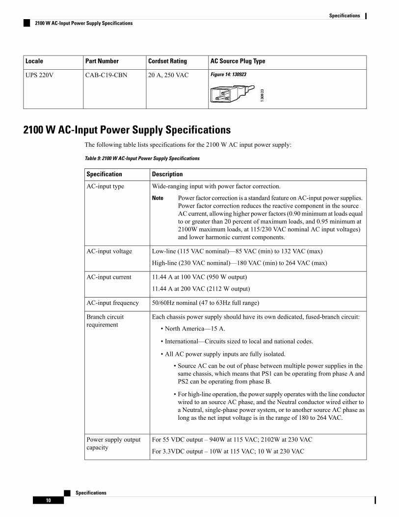
AC Source Plug TypeCordset RatingPart NumberLocale
Figure 14: 13092320 A, 250 VACCAB-C19-CBNUPS 220V
2100 W AC-Input Power Supply SpecificationsThe following table lists specifications for the 2100 W AC input power supply:
Table 9: 2100 W AC-Input Power Supply Specifications
DescriptionSpecification
Wide-ranging input with power factor correction.
Power factor correction is a standard feature on AC-input power supplies.Power factor correction reduces the reactive component in the sourceAC current, allowing higher power factors (0.90 minimum at loads equalto or greater than 20 percent of maximum loads, and 0.95 minimum at2100W maximum loads, at 115/230 VAC nominal AC input voltages)and lower harmonic current components.
Note
AC-input type
Low-line (115 VAC nominal)—85 VAC (min) to 132 VAC (max)
High-line (230 VAC nominal)—180 VAC (min) to 264 VAC (max)
AC-input voltage
11.44 A at 100 VAC (950 W output)
11.44 A at 200 VAC (2112 W output)
AC-input current
50/60Hz nominal (47 to 63Hz full range)AC-input frequency
Each chassis power supply should have its own dedicated, fused-branch circuit:
• North America—15 A.
• International—Circuits sized to local and national codes.
• All AC power supply inputs are fully isolated.
• Source AC can be out of phase between multiple power supplies in thesame chassis, which means that PS1 can be operating from phase A andPS2 can be operating from phase B.
• For high-line operation, the power supply operates with the line conductorwired to an source AC phase, and the Neutral conductor wired either toa Neutral, single-phase power system, or to another source AC phase aslong as the net input voltage is in the range of 180 to 264 VAC.
Branch circuitrequirement
For 55 VDC output – 940W at 115 VAC; 2102W at 230 VAC
For 3.3VDC output – 10W at 115 VAC; 10 W at 230 VAC
Power supply outputcapacity
Specifications10
Specifications2100 W AC-Input Power Supply Specifications
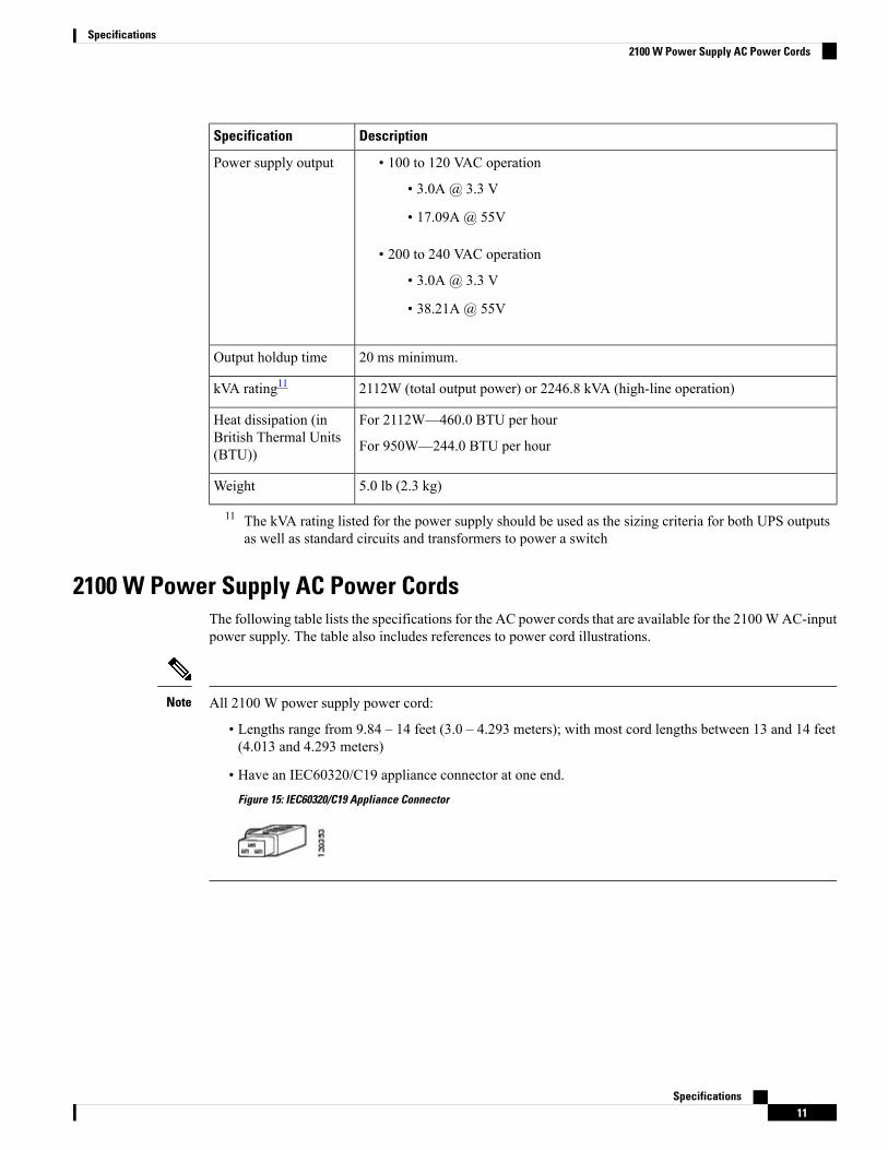
DescriptionSpecification
• 100 to 120 VAC operation
• 3.0A @ 3.3 V
• 17.09A @ 55V
• 200 to 240 VAC operation
• 3.0A @ 3.3 V
• 38.21A @ 55V
Power supply output
20 ms minimum.Output holdup time
2112W (total output power) or 2246.8 kVA (high-line operation)kVA rating11
For 2112W—460.0 BTU per hour
For 950W—244.0 BTU per hour
Heat dissipation (inBritish Thermal Units(BTU))
5.0 lb (2.3 kg)Weight
11 The kVA rating listed for the power supply should be used as the sizing criteria for both UPS outputsas well as standard circuits and transformers to power a switch
2100 W Power Supply AC Power CordsThe following table lists the specifications for the AC power cords that are available for the 2100WAC-inputpower supply. The table also includes references to power cord illustrations.
All 2100 W power supply power cord:
• Lengths range from 9.84 – 14 feet (3.0 – 4.293 meters); with most cord lengths between 13 and 14 feet(4.013 and 4.293 meters)
• Have an IEC60320/C19 appliance connector at one end.Figure 15: IEC60320/C19 Appliance Connector
Note
Specifications11
Specifications2100 W Power Supply AC Power Cords
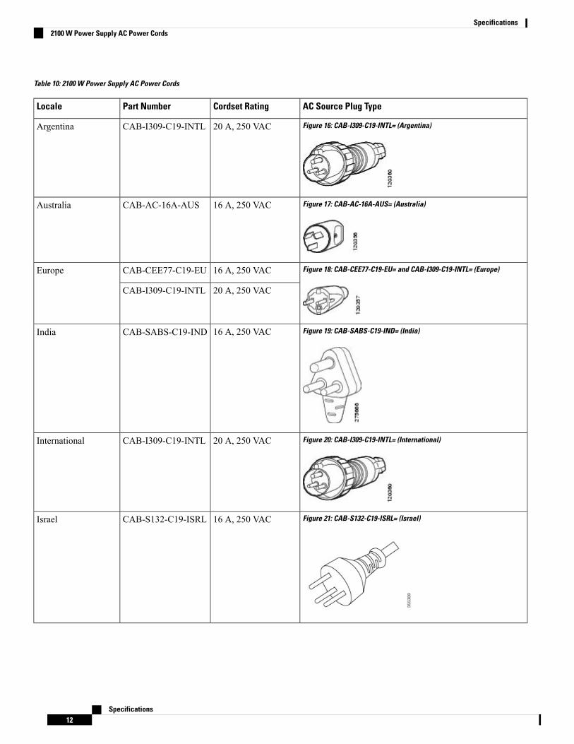
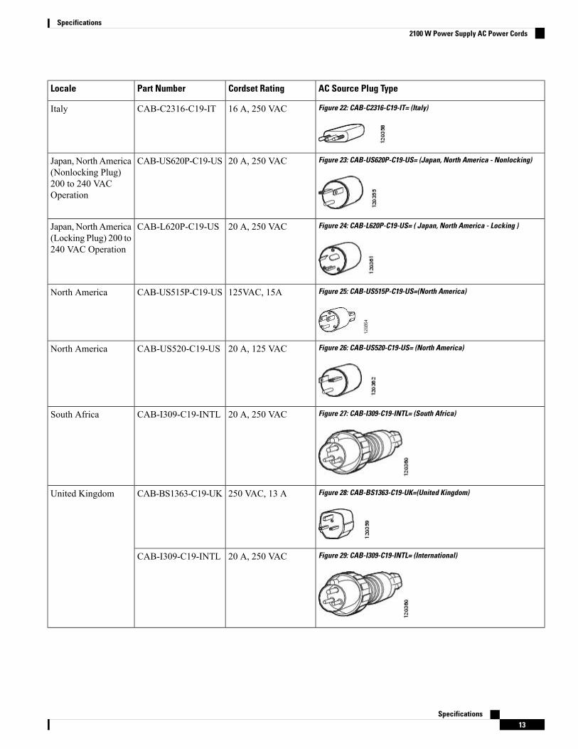
Table 10: 2100 W Power Supply AC Power Cords
AC Source Plug TypeCordset RatingPart NumberLocale
Figure 16: CAB-I309-C19-INTL= (Argentina)20 A, 250 VACCAB-I309-C19-INTLArgentina
Figure 17: CAB-AC-16A-AUS= (Australia)16 A, 250 VACCAB-AC-16A-AUSAustralia
Figure 18: CAB-CEE77-C19-EU= and CAB-I309-C19-INTL= (Europe)16 A, 250 VACCAB-CEE77-C19-EUEurope
20 A, 250 VACCAB-I309-C19-INTL
Figure 19: CAB-SABS-C19-IND= (India)16 A, 250 VACCAB-SABS-C19-INDIndia
Figure 20: CAB-I309-C19-INTL= (International)20 A, 250 VACCAB-I309-C19-INTLInternational
Figure 21: CAB-S132-C19-ISRL= (Israel)16 A, 250 VACCAB-S132-C19-ISRLIsrael
Specifications12
Specifications2100 W Power Supply AC Power Cords
AC Source Plug TypeCordset RatingPart NumberLocale
Figure 22: CAB-C2316-C19-IT= (Italy)16 A, 250 VACCAB-C2316-C19-ITItaly
Figure 23: CAB-US620P-C19-US= (Japan, North America - Nonlocking)20 A, 250 VACCAB-US620P-C19-USJapan, North America(Nonlocking Plug)200 to 240 VACOperation
Figure 24: CAB-L620P-C19-US= ( Japan, North America - Locking )20 A, 250 VACCAB-L620P-C19-USJapan, North America(Locking Plug) 200 to240 VAC Operation
Figure 25: CAB-US515P-C19-US=(North America)125VAC, 15ACAB-US515P-C19-USNorth America
Figure 26: CAB-US520-C19-US= (North America)20 A, 125 VACCAB-US520-C19-USNorth America
Figure 27: CAB-I309-C19-INTL= (South Africa)20 A, 250 VACCAB-I309-C19-INTLSouth Africa
Figure 28: CAB-BS1363-C19-UK=(United Kingdom)250 VAC, 13 ACAB-BS1363-C19-UKUnited Kingdom
Figure 29: CAB-I309-C19-INTL= (International)20 A, 250 VACCAB-I309-C19-INTL
Specifications13
Specifications2100 W Power Supply AC Power Cords
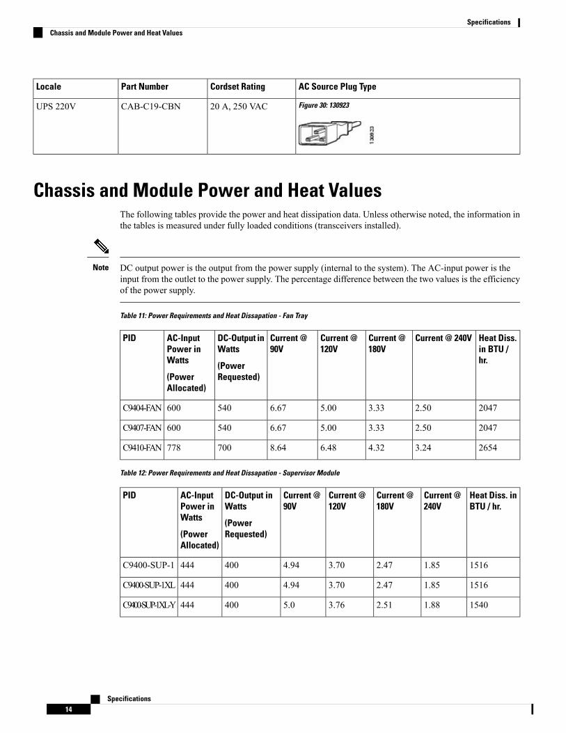
AC Source Plug TypeCordset RatingPart NumberLocale
Figure 30: 13092320 A, 250 VACCAB-C19-CBNUPS 220V
Chassis and Module Power and Heat ValuesThe following tables provide the power and heat dissipation data. Unless otherwise noted, the information inthe tables is measured under fully loaded conditions (transceivers installed).
DC output power is the output from the power supply (internal to the system). The AC-input power is theinput from the outlet to the power supply. The percentage difference between the two values is the efficiencyof the power supply.
Note
Table 11: Power Requirements and Heat Dissapation - Fan Tray
Heat Diss.in BTU /hr.
Current @ 240VCurrent @180V
Current @120V
Current @90V
DC-Output inWatts
(PowerRequested)
AC-InputPower inWatts
(PowerAllocated)
PID
20472.503.335.006.67540600C9404-FAN
20472.503.335.006.67540600C9407-FAN
26543.244.326.488.64700778C9410-FAN
Table 12: Power Requirements and Heat Dissapation - Supervisor Module
Heat Diss. inBTU / hr.
Current @240V
Current @180V
Current @120V
Current @90V
DC-Output inWatts
(PowerRequested)
AC-InputPower inWatts
(PowerAllocated)
PID
15161.852.473.704.94400444C9400-SUP-1
15161.852.473.704.94400444C9400-SUP-1XL
15401.882.513.765.0400444C9400-SUP-1XL-Y
Specifications14
SpecificationsChassis and Module Power and Heat Values
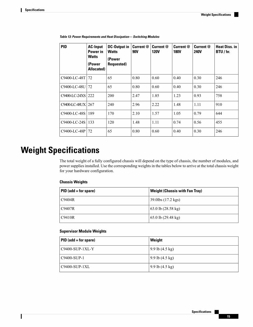
Table 13: Power Requirements and Heat Dissipation— Switching Modules
Heat Diss. inBTU / hr.
Current @240V
Current @180V
Current @120V
Current @90V
DC-Output inWatts
(PowerRequested)
AC-InputPower inWatts
(PowerAllocated)
PID
2460.300.400.600.806572C9400-LC-48T
2460.300.400.600.806572C9400-LC-48U
7580.931.231.852.47200222C9400-LC-24XS
9101.111.482.222.96240267C9400-LC-48UX
6440.791.051.572.10170189C9400-LC-48S
4550.560.741.111.48120133C9400-LC-24S
2460.300.400.600.806572C9400-LC-48P
Weight SpecificationsThe total weight of a fully configured chassis will depend on the type of chassis, the number of modules, andpower supplies installed. Use the corresponding weights in the tables below to arrive at the total chassis weightfor your hardware configuration.
Chassis Weights
Weight (Chassis with Fan Tray)PID (add = for spare)
39.0lbs (17.2 kgs)C9404R
63.0 lb (28.58 kg)C9407R
65.0 lb (29.48 kg)C9410R
Supervisor Module Weights
WeightPID (add = for spare)
9.9 lb (4.5 kg)C9400-SUP-1XL-Y
9.9 lb (4.5 kg)C9400-SUP-1
9.9 lb (4.5 kg)C9400-SUP-1XL
Specifications15
SpecificationsWeight Specifications
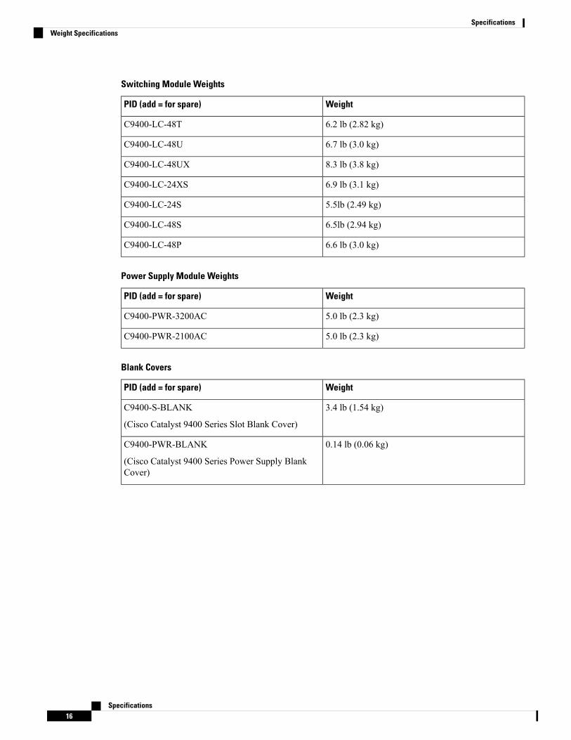
Switching Module Weights
WeightPID (add = for spare)
6.2 lb (2.82 kg)C9400-LC-48T
6.7 lb (3.0 kg)C9400-LC-48U
8.3 lb (3.8 kg)C9400-LC-48UX
6.9 lb (3.1 kg)C9400-LC-24XS
5.5lb (2.49 kg)C9400-LC-24S
6.5lb (2.94 kg)C9400-LC-48S
6.6 lb (3.0 kg)C9400-LC-48P
Power Supply Module Weights
WeightPID (add = for spare)
5.0 lb (2.3 kg)C9400-PWR-3200AC
5.0 lb (2.3 kg)C9400-PWR-2100AC
Blank Covers
WeightPID (add = for spare)
3.4 lb (1.54 kg)C9400-S-BLANK
(Cisco Catalyst 9400 Series Slot Blank Cover)
0.14 lb (0.06 kg)C9400-PWR-BLANK
(Cisco Catalyst 9400 Series Power Supply BlankCover)
Specifications16
SpecificationsWeight Specifications