technical specifications (divisions 1-16)
TRANSCRIPT
Project No. 17-082
DOCUMENTS FOR THE CONSTRUCTION OF
CITY OF MORRO BAY
WATER RECLAMATION FACILITY LIFT STATION AND OFFSITE PIPELINES
TECHNICAL SPECIFICATIONS (DIVISIONS 1-16)
FEBRUARY 2020
90% SUBMITTAL
ENGINEER:
WATER WORKS ENGINEERS, LLC.
CONTACT:
Mike Fisher, P.E. (916) 780-2888
CITY OF MORRO BAY
SEWER LIFT STATION AND FORCE MAIN
VOLUME 1 - SPECIFICATIONS
TABLE OF CONTENTS
Section Title
DIVISION 2
02140 DEWATERING
02200 SITE PREPARATION
02220 DEMOLITION
02300 EARTHWORK
02350 PIPE BORE AND JACK REQUIREMENTS
02495 GEOTECHNICAL INSTRUMENTATION
02770 ASPHALT CONCRETE PAVEMENT
02830 CHAIN LINK FENCES AND GATES
02900 LANDSCAPE PLANTING
02936 HYDROSEEDING
02930 FABRICATED STEEL GATES
DIVISION 3
03100 CONCRETE FORMWORK
03200 CONCRETE REINFORCING
03251 CONCRETE JOINTS
03300 CAST-IN-PLACE CONCRETE
03400 PRECAST CONCRETE
03420 PRECAST FRP-PVC MANHOLE
03600 GROUT
03700 COMPACTION GROUTING
03740 CRACK REPAIR BY EPOXY INJECTION
DIVISION 4
04200 CONCRETE UNIT MASONRY
DIVISION 5
05051 ANCHORS, INSERTS, AND DOWELS
05500 MISCELLANEOUS METALS
05605 GALVANIZED STEEL HANDRAILS AND RAILINGS
05610 ALUMINUM HANDRAILS AND RAILINGS
05620 GRATING AND CHECKERED PLATE
DIVISION 6
06100 ROUGH CARPENTRY
DIVISION 7
07211 BUILDING INSULATION
07320 STANDING SEAM METAL ROOF
07600 METAL FLASHING, GUTTERS, DOWNSPOUTS AND OTHER ROOFING
SPECIALTIES
07900 JOINT SEALANTS
DIVISION 8
08100 METAL DOORS
08305 ACCESS HATCHES
08700 DOOR HARDWARE
DIVISION 9
09250 GYPSUM WALLBOARD
09875 CONCRETE COATINGS FOR WASTEWATER STRUCTURES
09900 PAINTING
DIVISION 10
10400 IDENTIFICATION DEVICES
10520 SAFETY EQUIPMENT
DIVISION 11
11300 SUBMERSIBLE SEWAGE PUMPS
DIVISION 12
12100 MISCELLANEOUS FURNISHINGS
DIVISION 13
13100 ODOR CONTROL UNIT
13122 PRE-ENGINEERED PIPE BRIDGE
13250 HYDRO-PNEUMATIC TANK SYSTEM
DIVISION 15
15010 PIPING SUPPORT SYSTEMS
15100 PIPE AND FITTINGS
15100 PS PIPE SCHEDULE
15100 PSDS COP PIPING SYSTEM DATA SHEET – COPPER PIPE
15100 PSDS DIP PIPING SYSTEM DATA SHEET – DUCTILE IRON PIPE
15100 PSDS FPVC PIPING SYSTEM DATA SHEET – FUSIBLE POLYVINYL CHLORIDE PIPE
15100 PSDS HDPE PIPING SYSTEM DATA SHEET – FUSIBLE HIGH DENSITY
POLYETHYLENE PIPE
15100 PSDS HDPE1 PIPING SYSTEM DATA SHEET – HIGH DENSITY POLYETHYLENE
DRAINAGE PIPE
15100 PSDS PVC1 PIPING SYSTEM DATA SHEET – SOLVENT WELDED POLYVINYL
CHLORIDE PIPE
15100 PSDS PVC2 PIPING SYSTEM DATA SHEET –POLYVINYL CHLORIDE PRESSURE
PIPE
15100 PSDS PVC3 PIPING SYSTEM DATA SHEET – POLYVINYL CHLORIDE DRAIN,
WASTE AND VENT PIPE
15100 PSDS PVC4 PVC SEWER PIPE
15100 PSDS PVC6 PIPING SYSTEM DATA SHEET –POLYVINYL CHLORIDE
STORM DRAIN PIPE
15100 PSDS RCP PIPING SYSTEM DATA SHEET – REINFORCED CONCRETE PRESSURE
PIPE
15100 PSDS WSP PIPING SYSTEM DATA SHEET – WELDED STEEL PIPE
15120 PIPING SPECIALTIES
15200 VALVES AND OPERATORS
15200 VS VALVE SCHEDULE
15400 PLUMBING FIXTURES
15500 HEATING, VENTILATION AND AIR CONDITIONING EQUIPMENT
15990 PRESSURE TESTING OF PIPING SYSTEMS
15995 DISINFECTION OF POTABLE & RECYCLED WATER SYSTEMS
DIVISION 16
16010 ELECTRICAL GENERAL
16110 CONDUIT AND BOXES
16120 LOW VOLTAGE WIRE & DATA CABLE
16121 FIBER OPTIC COMMUNICATION SYSTEM
16210 ENGINE GENERATOR
16250 AUTOMATIC TRANSFER SWITCH
16430 LOW VOLTAGE SWITCHBOARD
16450 GROUNDING
16470 PANELBOARD AND POWER TRANSFORMER
16481 VARIABLE FREQUENCY DRIVE
16600 FACTORY AND FIELD TESTING
16600 TF TEST FORMS
16905 CONTROL PANEL
16910 PLC & OI HARDWARE
16940 INSTRUMENTATION
02140-1
CITY OF MORRO BAY 90% SUBMITTAL WRF LIFT STATION & OFFSITE PIPELINES 17-082 FEBRUARY 2020
SECTION 02140 DEWATERING
PART 1 - GENERAL
1.1 DESCRIPTION
A. Furnish all labor, materials, equipment and incidentals required and remove and dispose of all surface water and ground water entering excavations.
1.2 SUBMITTALS
A. Submit in accordance with Section 01330, shop drawings showing details of dewatering system
B. Submit a dewatering plan in accordance with Contract Specification section 01130.
1.3 DESIGN REQUIREMENTS
A. The CONTRACTOR is responsible for the proper design and implementation of methods for controlling surface water and groundwater.
B. The primary purpose of the groundwater control system is to preserve the natural undisturbed condition of the subgrade soils in the areas of the proposed excavations. Prior to excavation, the CONTRACTOR shall lower the groundwater to at least 2-ft below the lowest excavation subgrade elevation. Additional groundwater lowering may be necessary beyond the 2-ft requirement, depending on construction methods and equipment used and the prevailing groundwater and soil conditions. The CONTRACTOR is responsible for lowering the groundwater as necessary to complete construction in accordance with the Contract Documents at no additional cost to the OWNER.
C. Design deep wells, well points and sumps, and all other groundwater control system components to prevent loss of fines from surrounding soils. Sand filters shall be used with all dewatering installations unless screens are properly sized by the CONTRACTOR’s design ENGINEER to prevent passage of fines from surrounding soils.
D. The CONTRACTOR shall be responsible for damage to properties, buildings or structures, sewers and other utility installations, pavements and work that may result from dewatering or surface water control operations.
E. Design review and field monitoring activities by the OWNER or by the ENGINEER shall not relieve the CONTRACTOR of his/her responsibilities for the work.
F. The CONTRACTOR shall perform pre-conditions surveys of job site.
02140-2
CITY OF MORRO BAY 90% SUBMITTAL WRF LIFT STATION & OFFSITE PIPELINES 17-082 FEBRUARY 2020
PART 2 - PRODUCTS
2.1 MATERIALS
A. Piping, pumping equipment and all other materials required to provide dewatering of excavations shall be suitable for the intended purpose. Standby pumping units shall be maintained at the site to be used in case of failure of the normal pumping units.
B. A noise attenuation system is required for dewatering pumps producing noise louder than 70 dBA at 23 feet from pump.
PART 3 - EXECUTION
3.1 GENERAL
A. Continuously control all water during the course of construction, including surface water and ground water, to prevent any damage to any excavation or to the construction activities occurring within those excavations.
B. Maintain all dewatering systems full time (24-hours/day) during the entire time the excavation is open. Do not shut down dewatering systems at night, on weekends or on holidays, or any other time the excavation is open.
C. Provide and maintain proper equipment and facilities to remove all water entering each excavation to be kept dry during subgrade and pipe bedding preparation and continually thereafter until the structure to be built, or the pipe to be installed therein is inspected by the OWNER and the ENGINEER and backfill operations have been completed.
D. Methods of groundwater control may include but are not limited to perimeter trenches and sump pumping, perimeter groundwater cutoff, well points, and combinations thereof.
E. Where groundwater levels are above the proposed bottom of excavation level, a pumped dewatering system will be required for pre-drainage of the soils prior to excavation, and for maintaining the lowered groundwater level until construction has been completed to such an extent that the structure, pipeline or fill will not be floated or otherwise damaged.
F. Provide adequate alarm, monitoring and back-up systems for all dewatering systems to maintain control of all water during all times any excavation is open.
G. All work included in this Section shall be done in a manner which will protect adjacent structures and utilities and shall not cause loss of ground or disturbance to the pipe bearing soils or to soils which support overlying or adjacent structures.
H. Temporary dewatering and drainage systems shall be in place and operational prior to beginning excavation work.
I. Install, monitor and report groundwater data from observation wells as necessary. Evaluate the collected data relative to groundwater control system performance and modify systems as necessary to dewater the site in accordance with the Contract Documents.
02140-3
CITY OF MORRO BAY 90% SUBMITTAL WRF LIFT STATION & OFFSITE PIPELINES 17-082 FEBRUARY 2020
J. Take all additional precautions to prevent uplift of any structure during construction. All such arrangements shall be subject to the approval of the ENGINEER.
K. All damage resulting from failure to properly dewater excavations shall be repaired to the satisfaction of the ENGINEER at no additional cost to the OWNER.
3.2 SURFACE WATER CONTROL:
A. Provide and maintain adequate drainage and dewatering system to prevent surface water from entering excavations and to remove and dispose of all rainwater entering excavations, trenches, or other parts of the Work.
B. Keep the different working areas on the site free of surface water at all times. Special care will be taken to eliminate depressions that could serve as mosquito pools.
C. The diversion and removal of surface water will be performed in a manner that will prevent the accumulation of water behind temporary structures or at any other locations within the construction area where it may be detrimental.
3.3 GROUND WATER CONTROL:
A. Provide, operate and maintain dewatering system to permit excavation and subsequent construction activities in a dry, safe environment.
B. System shall be of sufficient size and capacity to maintain groundwater level a minimum of 2 feet below the lowest point of excavation.
C. CONTRACTOR shall make an assessment of the potential for dewatering induced settlement of surrounding soils and structures. CONTRACTOR shall provide all necessary equipment and facilities, including re-injection wells, cutoff walls, infiltration trenches, etc, to prevent damage to adjacent structures.
D. In no event shall water rise to cause unbalanced pressure on structures until the concrete or mortar has set at least 24 hours. Prevent flotation of the pipe by promptly placing backfill.
E. Excavation dewatering shall at all times be conducted in such a manner as to preserve the natural undisturbed condition of the subgrade soils at the proposed bottom of excavation.
F. If the subgrade of the trench or excavation bottom becomes disturbed due to inadequate dewatering or drainage, excavate below normal grade as directed by the ENGINEER and refill with trench stabilization material as approved by the ENGINEER at the CONTRACTOR's expense.
G. It is expected that the initial dewatering plan may have to be modified to suit the variable soil/water conditions to be encountered during construction. Dewater and excavate, at all times, in a manner which does not cause loss of ground or disturbance to the pipe bearing soil or soil which supports overlying or adjacent structures or instability of the excavation.
02140-4
CITY OF MORRO BAY 90% SUBMITTAL WRF LIFT STATION & OFFSITE PIPELINES 17-082 FEBRUARY 2020
3.4 OBSERVATION WELLS:
A. ENGINEER may require to install observation well(s) to monitor groundwater levels beneath and around the excavated area until adjacent structures and pipelines are completed and backfilled.
B. Locations and depths of observation wells are subject to approval by the OWNER and the ENGINEER.
C. Observation wells shall be developed so as to provide a reliable indication of groundwater levels. Wells shall be re-developed if well clogging is observed, in the event of apparent erroneous readings, or as directed by the ENGINEER.
D. The CONTRACTOR shall maintain each observation well until adjacent structures and pipelines are completed and backfilled. Clean out or replace any observation well which ceases to be operable before adjacent work is completed.
E. The groundwater level shall be kept at a minimum of 2-ft below the lowest trench level for a given excavation.
3.5 REMOVAL OF DEWATERING SYSTEM:
A. At the completion of the excavation and backfilling work, and when approved by the ENGINEER, all pipe, pumps, generators, observation wells, other equipment and accessories used for the groundwater and surface water control systems shall be removed from the site. All materials and equipment shall become the property of the CONTRACTOR. All areas disturbed by the installation and removal of groundwater control systems and observation wells shall be restored to their original condition.
3.6 DISPOSAL OF WATER:
A. Disposal of discharge water shall conform to any and all applicable permit requirements as described in the Contract Specification section 01140, Water Pollution Control.
+ + END OF SECTION + +
02200-1
CITY OF MORRO BAY 90% SUBMITTAL WRF LIFT STATION & OFFSITE PIPELINES 17-082 FEBRUARY 2020
SECTION 02200
SITE PREPARATION
PART 1 - GENERAL
1.1 DEFINITIONS
A. Interfering or Objectionable Material: Trash, rubbish, and junk; vegetation and other organic matter, whether alive, dead, or decaying; topsoil.
B. Clearing: Removal of interfering or objectionable material lying on or protruding above ground surface.
C. Grubbing: Removal of vegetation and other organic matter including stumps, buried logs, and roots greater than 0.5 inch caliper to a depth of 6 inches below subgrade.
D. Stripping: Removal of topsoil remaining after applicable scalping is completed.
E. Project Limits: Areas, as shown or specified, within which Work is to be performed.
PART 2 - PRODUCTS (NOT USED)
PART 3 - EXECUTION
3.1 GENERAL
A. Clear, grub, and strip areas actually needed for waste disposal, borrow, or site improvements within limits shown or specified.
B. Do not injure or deface vegetation that is not designated for removal.
3.2 LIMITS
A. As follows, but not to extend beyond Project limits. 1. Excavation 5 feet beyond top of cut slopes. 2. Trench Excavation: 4 feet from trench centerline, regardless of actual trench width. 3. Waste Disposal:
a. Clearing: 5 feet beyond perimeter. b. Scalping and Stripping: Not required. c. Grubbing: Around perimeter as necessary for neat finished appearance.
4. Structures: 5 feet outside of new structures. 5. Roadways: Clearing , grubbing and stripping 50 feet from centerline. 6. Overhead Utilities:
a. Clearing and Grubbing: Entire width of easements and rights-of-way. b. Scalping and Stripping: Wherever grading is required.
7. Other Areas: As shown.
B. Remove rubbish, trash, and junk from entire area within Project limits.
02200-2
CITY OF MORRO BAY 90% SUBMITTAL WRF LIFT STATION & OFFSITE PIPELINES 17-082 FEBRUARY 2020
3.3 CLEARING
A. Clear areas within limits shown or specified.
B. Fell trees so that they fall away from facilities and vegetation not designated for removal.
C. Cut stumps not designated for grubbing flush with ground surface.
D. Cut off shrubs, brush, weeds, and grasses to within 2 inches of ground surface.
3.4 GRUBBING
A. Grub areas within limits shown or specified.
3.5 STRIPPING
A. Do not remove topsoil until after scalping is completed.
B. Strip areas within limits to minimum depths shown or specified. Do not remove subsoil with topsoil.
3.6 DISPOSAL
A. Clearing and Grubbing Debris: Dispose of debris offsite.
B. Strippings: 1. Dispose of strippings that are unsuitable for topsoil or that exceed quantity required
for topsoil offsite or approved by ENGINEER. 2. Stockpile topsoil in sufficient quantity to meet Project needs. Dispose of excess
strippings as specified for clearing and grubbing.
+ + END OF SECTION + +
02220-1
CITY OF MORRO BAY 90% SUBMITTAL WRF LIFT STATION & OFFSITE PIPELINES 17-082 FEBRUARY 2020
SECTION 02220
DEMOLITION
PART 1 - GENERAL
1.1 DEFINITIONS
A. “Demolish”: CONTRACTOR shall remove from the site as property of CONTRACTOR. Demolition includes disconnecting, removal, loading, repairs, cleanup, transportation, unloading, disposal permits and fees, disposal, and all other items required to remove the material from the site.
B. “Salvage”: CONTRACTOR shall remove from area of Work and place in location designated by ENGINEER. Equipment is property of OWNER. Salvage includes disconnecting, removal, repairs, cleanup, loading, transportation, unloading, and all other items required to remove and relocate the material.
C. “OWNER to Remove”: OWNER will remove from area of Work prior to CONTRACTOR commencing demolition Work for this area.
D. “Relocate”: CONTRACTOR shall relocate material shown to new locations shown on Drawings or stated herein. Relocation includes disconnecting, removal, reconnecting, attaching, repairs, and all other items required to relocate material to new location.
E. “Abandon”: CONTRACTOR shall disconnect and leave in place as specified.
F. “Materials”: Any and all items and objects that are scheduled, specified, or shown to be demolished, salvaged, removed, relocated, or abandoned.
1.2 SUBMITTALS
A. Action Submittals: 1. Product Information: Grout, sealants, and bonding agents to be used for patching.
B. Informational Submittals: 1. Plan and schedule phased demolition, including limits of demolition, as part of and
consistent with the progress schedule specified in Section 01320, PROGRESS SCHEDULE.
2. Methods of demolition and equipment proposed to demolish materials. 3. Copies of any authorizations and permits required to perform Work. 4. Copies of Hazardous Materials Inspection Reports. 5. Repair procedures for demolition of materials beyond limits shown on Drawings.
02220-2
CITY OF MORRO BAY 90% SUBMITTAL WRF LIFT STATION & OFFSITE PIPELINES 17-082 FEBRUARY 2020
PART 2 - PRODUCTS
2.1 GENERAL
A. CONTRACTOR shall provide all materials and equipment in suitable and adequate quantity as required to accomplish the Work shown, specified herein, and as required to complete the Project.
PRODUCTS
PART 3 - EXECUTION
3.1 GENERAL
A. Drawings are based on available information. The Work may differ slightly from what is shown. CONTRACTOR shall be responsible for determining the work required by inspecting the site.
3.2 SAFETY REQUIREMENTS
A. All Work shall be done in conformance with all applicable rules and regulations pertaining to safety.
B. Hazardous Materials: 1. See General Conditions. 2. Existing facilities, or portions thereof, to be demolished may contain hazardous
materials such as asbestos cement piping, residual chemicals in existing or abandoned piping, lead-based paint, mercury seals, or other unknown hazardous materials.
3.3 SEQUENCE
A. Be responsible for the sequence of Work.
B. Conform to constraints as specified in Section 01130, SPECIAL PROJECT CONSTRAINTS.
3.4 COORDINATION
A. Coordination with ENGINEER: 1. Only materials specified herein, shown on the Demolition Photographs or the
Drawings, or approved by ENGINEER in the field shall be demolished, salvaged, removed, relocated, or abandoned.
2. Verify materials scheduled to be demolished, salvaged, removed, relocated, or abandoned with ENGINEER prior to performing Work.
3. Do not remove materials without prior approval of ENGINEER. 4. Provide at least 3 working days’ notice to ENGINEER prior to start of Work. 5. Notify ENGINEER to turn off affected services or facilities before starting Work. 6. Provide temporary services during interruptions to affected services or facilities as
acceptable to ENGINEER. 7. ENGINEER will indicate limits of Work if not clearly shown.
02220-3
CITY OF MORRO BAY 90% SUBMITTAL WRF LIFT STATION & OFFSITE PIPELINES 17-082 FEBRUARY 2020
B. Coordination with Utility Owners: 1. Notify utility owners to turn off affected services or facilities before starting Work. 2. Provide not less than 72 hours notice to utility owners prior to shutdown, unless
otherwise directed by utility owners. 3. Provide temporary services during interruptions to affected services or facilities as
acceptable to utility owners.
3.5 LIMITS
A. Drawings define minimum portions of materials to be demolished. Unless otherwise shown, rough cuts or breaks may be made to limits of demolition shown. If rough cuts or breaks are made exceeding limits shown, CONTRACTOR shall repair the cuts or breaks back to the dimensions shown on Drawings at CONTRACTOR’s expense.
B. If limits are not clear on the Drawings or Demolition Photographs, limits shall be as directed by ENGINEER.
C. All areas not within the limits of demolition Work shown on the Drawings, or as specified herein, shall be left undisturbed, unless necessary for demolition of materials.
3.6 DEMOLITION
A. General: 1. Inspect condition of materials to be demolished prior to bidding to assess potential
for salvage value. 2. Remove all materials associated with existing equipment that is to be demolished. 3. Materials within limits of demolition will become the property of CONTRACTOR. 4. All materials from the demolition process shall be removed safely from the project
site as soon as possible. They shall be disposed of in accordance with applicable federal, state, and city regulations. CONTRACTOR is responsible for determining these regulations and shall bear all costs associated with disposal of the materials.
B. Pavement and Curbs: 1. Provide saw cut at all concrete and pavement surfaces and curb removal limits and
where neat connection lines are required. 2. Surfaces exposed by demolition activities shall be repaired and finished to provide a
uniform, smooth, level transition between adjacent surfaces.
C. Concrete, CMU, and Reinforcing: 1. In areas where concrete or CMU portions are to be removed from a structure, the
edge of removal shall be cut with a concrete saw to leave a perpendicular edge or by core-drilling where a circular hole is required.
2. Damaged concrete shall be removed to solid concrete. Damaged concrete shall include concrete that is soft, spalled, cracked, or otherwise damaged as determined by ENGINEER.
3. Depth of removal shall be as determined by ENGINEER unless otherwise shown or specified.
4. Reinforcing shall be cut and removed unless otherwise shown or instructed by ENGINEER.
5. Spalled edges may be required to be resawn at the discretion of the ENGINEER. 6. Protect adjacent structures and equipment from damage during Work.
02220-4
CITY OF MORRO BAY 90% SUBMITTAL WRF LIFT STATION & OFFSITE PIPELINES 17-082 FEBRUARY 2020
7. Exposed surfaces following demolition activities shall be repaired and finished to provide a uniform, smooth, and level transition between adjacent surfaces.
8. Remove and repair designated cracked and damaged concrete areas shown in accordance with this section and Section 03300, CAST-IN-PLACE CONCRETE.
D. Concrete Embedded Items: 1. Except for core drills, demolish anchor bolts, reinforcing steel, conduit, and other
materials that are concrete embedded to a minimum of 1 inch below final finished surface. For core drills, coat rebar exposed by core drilling with System No. 304 in accordance with Section 09900, PAINTING.
2. Plug empty pipes and conduits with fireproof sealant to maintain fire ratings for floors or walls.
3. Patching: a. Demolish damaged concrete. Damaged concrete shall be removed to solid
concrete. Damaged concrete shall include concrete that is soft, spalled, cracked, or otherwise damaged as determined by ENGINEER.
b. Coat with approved bonding agent. c. Patch with nonshrink, nonmetallic grout.
E. Piping: 1. Pressurized Services: Install restrained caps or plugs at the demolished ends, unless
otherwise shown. 2. Gravity Services: Install concrete plugs, 5-foot minimum length.
F. Utilities: 1. Excavate utility lines serving structures to be demolished. 2. Demolish electrical, sanitary, and storm drainage lines serving structures to be
demolished. 3. Support or relocate utility lines exposed by Work. 4. For water and gas lines to be demolished or capped and terminated, provide a
permanent leakproof closure. Closure type shall be as recommended by utility owner.
G. Electrical: 1. Remove conduits and wiring from materials to be demolished back to nearest
junction box. 2. For existing circuits to remain operational, intercept existing conduit at the most
convenient location, or as shown, and splice and extend conduit to new location. Install new conductors as required to accomplish intended results. New conductors shall be continuous without splices between junction boxes.
3. For existing circuits no longer needed, demolish conductors from conduits. 4. Demolish all surface-mounted conduit which is no longer needed. 5. For conduit below grade or concealed within walls, cap and abandon in place.
3.7 SALVAGE
A. Salvage materials for OWNER’s own use where shown.
B. Remove materials with extreme care so as not to damage.
C. Promptly remove materials from Work area.
D. Store materials in location designated by ENGINEER.
02220-5
CITY OF MORRO BAY 90% SUBMITTAL WRF LIFT STATION & OFFSITE PIPELINES 17-082 FEBRUARY 2020
E. Clean and protect materials from dust, dirt, natural elements, and store as directed.
3.8 RELOCATION
A. ENGINEER will determine condition of materials prior to removal.
B. Remove all materials associated with items to be relocated.
C. Existing materials shall not be damaged during removal.
D. Properly store and maintain materials in same condition as when removed.
E. Clean and protect materials from dust, dirt, natural elements, and store as directed.
3.9 ABANDONMENT
A. Structures: Break holes into or core drill floor slabs, catch basins, and other below-grade concrete structures to be abandoned in place to allow water to freely migrate through.
B. Piping and Conduits: 1. General: Piping and conduits to be abandoned shall be capped with a watertight plug
at demolished end in a manner that will prevent entrance of soil, groundwater, or moisture.
2. Pressurized Services: Install restrained caps or plugs at the demolished ends, unless otherwise shown.
3. Gravity Services: Install concrete plugs, 5-foot minimum length.
3.10 REPAIR AND REPLACEMENT
A. Any damaged materials scheduled to be salvaged or relocated shall be repaired by the CONTRACTOR to the satisfaction of ENGINEER or replaced at the CONTRACTOR’s expense.
B. Any damage to areas not within the limits of demolition Work shown on the Demolition Photographs, Drawings, or as specified herein shall be repaired or replaced to original precontract conditions at the CONTRACTOR’s sole expense.
3.11 DISPOSAL
A. Dispose of materials offsite in licensed landfills and in accordance with all local, state, and federal regulations. CONTRACTOR is responsible for obtaining any and all necessary permits for disposal.
+ + END OF SECTION + +
02300-1
CITY OF MORRO BAY 90% SUBMITTAL WRF LIFT STATION & OFFSITE PIPELINES 17-082 FEBRUARY 2020
SECTION 02300
EARTHWORK
PART 1 - GENERAL
1.1 DESCRIPTION
A. Section includes: All excavating, backfilling, filling, grading, subgrade preparation and disposing of earth materials as required. It also includes all temporary means needed to prevent discharge of sediment to watercourses from dewatering systems or erosion.
1.2 REFERENCES
A. American Society for Testing and Materials (ASTM) 1. ASTM C33, Standard Specification for Aggregate Material. 2. ASTM D422, Method for Particle-Size Analysis of Soils. 3. ASTM D423, Liquid Limit of Soils. 4. ASTM D427, Shrinkage Factors of Soils. 5. ASTM D698, Test Method for Laboratory Compaction Characteristics of Soil. 6. ASTM D1556, Test Method for Density and Unit Weight of Soil in Place by the
Sand-Cone Method. 7. ASTM D2922, Test Methods for Density of Soil and Soil-Aggregate in Place by Nuclear
Methods (Shallow Depth). 8. ASTM D2166, unconfined compressive strength of soils.
B. Occupational Safety and Health Administration (OSHA) 1. Title 29, Code of Federal Regulations, Part 1926
1.3 SYSTEM DESCRIPTION
A. Permits and Regulations: 1. Perform excavation Work in compliance with applicable requirements of governing
authorities having jurisdiction. 2. Obtain all necessary permits for Work in roads, rights-of-way, railroads, etc. Also,
obtain permits as required by local, state and federal agencies for discharging water from excavations, for erosion control, and for prevention of air and water pollution.
1.4 SUBMITTALS
A. Test Reports - Borrow, Backfill, and Grading: Testing laboratory shall submit copies of the following reports directly to ENGINEER: 1. Tests on borrow material. 2. Tests on footing subgrade. 3. Field density tests. 4. Optimum moisture - maximum density curve for each soil used for backfill. 5. Reports of observations for conformance of borrow material to the Project
Geotechnical Report.
02300-2
CITY OF MORRO BAY 90% SUBMITTAL WRF LIFT STATION & OFFSITE PIPELINES 17-082 FEBRUARY 2020
6. Quality Control Plan: Names and phone numbers of independent testing companies that will be used to perform soil and asphalt concrete testing, qualifications, and proposed procedures for performing tests and providing test results to ENGINEER.
B. Submit to the ENGINEER samples of all materials, including select backfill, general backfill, bedding, crushed stone, sand and topsoil. Submit samples of the proposed material at least seven days in advance of its anticipated use.
PART 2 - PRODUCTS
2.1 MATERIALS
A. General: 1. All material will be tested by the laboratory and approved by the ENGINEER. 2. No material shall be placed without the approval of the ENGINEER.
B. Marking Tape: Marking Tape: 1. Continuously install marking tape along centerline of all buried piping, on top of last
lift of pipe zone material unless otherwise shown. Coordinate with piping installation drawings. Install in accordance with manufacturer’s recommendations.
2. Plastic Marking Tape: Install with metallic piping. a. Inert polyethylene, impervious to known alkalis, acids, chemical reagents, and
solvents likely to be encountered in soil. b. Thickness: Minimum 4 mils. c. Width: 12 inches. d. Identifying Lettering: Minimum 1-inch high, permanent black lettering imprinted
continuously over entire length. e. Manufacturers and Products:
1) Reef Industries; Terra Tape. 2) Allen; Markline. 3) Or equal.
3. Metallic Marking Tape: Install with nonmetallic piping and waterlines. Join ends with clips provided by the manufacturer: a. Solid aluminum foil, visible on unprinted side, encased in a protective high
visibility, inert polyethylene plastic jacket. b. Foil Thickness: Minimum 5.5 mils. c. Width: 12 inches. d. Identifying Lettering: Minimum 1-inch high, permanent black lettering imprinted
continuously over entire length. e. Joining Clips: Tin or nickel-coated, furnished by tape manufacturer. f. Manufacturers and Products:
1) Reef Industries; Terra ”D”. 2) Allen; Detectatape. 3) Or equal.
4. Marking tape shall be marked with the following statements: a. FM1/FM2/BR: “CAUTION – SANITARY SEWER FORCEMAIN BURIED BELOW” b. SS: “CAUTION – SANITARY SEWER PIPELINE BURIED BELOW” c. FO: “CAUTION – FIBER OPTIC CONDUIT BURIED BELOW” d. IPR: “CAUTION – RECYCLED WATER PIPELINE BURIED BELOW” e. WATER: “CAUTION – WATER PIPELINE BURIED BELOW”
5. Color:
02300-3
CITY OF MORRO BAY 90% SUBMITTAL WRF LIFT STATION & OFFSITE PIPELINES 17-082 FEBRUARY 2020
a. Sanitary Sewer Pipeline: Green, as specified in ANSI Z53.1 Safety Color Code. b. Others Disturbed: Color, as specified for specific utility in ANSI Z53.1 Safety Color
Code.
C. Tracer/Locating Wire 1. Pipe tracer wire shall be installed above all buried piping unless indicated otherwise 2. Install pipe locating wire by strapping to the top of the pipe with PVC tape,
polyethylene-backed tape, or tie locks every 10-ft at a maximum. 3. Pipe tracer wire shall be of a green color polyethylene insulated 30 mils min thickness
12 gauge annealed copper wire or copper clad steel (CCS) wire. Insulation shall conform to ANSI requirements. Bare wire or nylon jacketed wire such as type THHN are not acceptable. a. Manufacturers and products:
1) Republic Wire, Inc; 2) Copperhead Industries LLC, 3) Or Equal
4. Where a splice is required for the tracer wire, utilize an appropriate size wire nut or compression fitting which shall then be placed inside a 3M brand Direct Bury Splice kit (DBR), or approved equal, of appropriate size. No bare wire shall be left exposed anywhere. Twisting the wires together and wrapping with electrical tape is not allowed. All wires shall be spliced to all other wires for a continuous pipe locating wire system.
5. Location and frequency of tracer wire terminals shall be located on project plans. Stub the tracer wire up inside each valve box and splice together. Sufficient excess length shall be provided at terminal connections to allow continuation of the pipe-locating wire to the terminal connection.
6. Tracer wire shall be terminated or dead-end at a ground rod station. 7. Tracer wire shall pass a continuity/locating test prior to acceptance.
D. Fill Material: 1. Classification:
a. Fill adjacent to structures to a distance measured horizontally from the structure that is equal to the depth from the finished grade is classified as Select Fill.
b. Outside these limits, the fill is classified as Common Fill, unless otherwise specified.
2. Common Fill: a. Common Fill materials shall consist of soils obtained from on-site excavations or
off-site sources that are uniformly mixed, contain no organic material, and have been passed through a 3” screen.
b. The maximum expansion of off-site materials shall be 1.5% as performed on a sample remolded to approximately 9% of the maximum dry density as determined in accordance with ASTM D 698 at 2% below optimum moisture content under a 100 psf surcharge pressure.
c. If on-site material is unsuitable as determined by the ENGINEER, imported fill shall be used.
3. Select Fill: a. Select fill or backfill is material selected by the ENGINEER from the excavation. b. Select material shall be free of organic or other unsuitable materials and shall not
contain rocks, or unbroken masses of soil larger then 4" in greatest dimension. 4. Structural Fill:
02300-4
CITY OF MORRO BAY 90% SUBMITTAL WRF LIFT STATION & OFFSITE PIPELINES 17-082 FEBRUARY 2020
a. Structural fill or backfill is material that is non-expansive having an Expansion Index of less than 20 when tested according to the latest approved addition of ASTM D4829.
b. Structural material types include: SC,SM,SP, and SW per ASTM D2487. c. Fill and borrow sources shall be reviewed and approved by the ENGINEER prior to
being imported and used on the site. d. The on-site soil encountered within the anticipated depths of excavations is not
considered suitable for reuse as Structural Fill.
E. Aggregate Base: 1. Class 2, ¾” maximum conforming to Section 26 of the Caltrans Standard
Specifications.
F. Granular Bedding: 1. Well-graded sand and gravel materials. 2. Unfrozen, friable, and no clay balls, roots, or other organic material. 3. Clean or gravelly sand with less than 5 percent passing No. 200 sieve, as determined
in accordance with ASTM D1140, or gravel or crushed rock within maximum particle size and other requirements as follows unless otherwise specified.
4. 3/4-inch maximum particle size, except 1/4 inch for stainless steel pipe, copper pipe, tubing, and plastic pipe under 3-inch diameter.
5. Conduit and Direct-Buried Cable: a. Sand, clean or clean to silty, less than 12 percent passing No. 200 sieve. b. Individual Particles: Free of sharp edges. c. Maximum Size Particle: Pass a No. 4 sieve. d. If more than 5 percent passes No. 200 sieve, the fraction that passes No. 40
sieve shall be non-plastic as determined in accordance with ASTM D4318.
G. Sand: 1. Natural or manufactured granular material, containing no organic material. 2. Sand will be non-plastic, when tested in accordance with ASTM D 4318, 100%
passing a 1/2” screen and no more than 20% passing a No. 200 screen.
H. Crushed Stone : 1. Crushed stone will be crushed rock or gravel conforming to the requirements of ASTM
C33, Size #57.
I. Gravel Surfacing 1. Gravel Surfacing will be crushed rock, angular, and well-graded. 2. Maximum size of ¾”, at least 50% passing the No 4. screen, between 10 and 30%
passing the No. 10 screen and no more than 15% passing the No. 40 screen. 3. Color to be selected by OWNER.
J. Controlled Low Strength Material (CLSM): 1. Select and proportion ingredients to obtain compressive strength between 50 and
150 psi at 7 days in accordance with ASTM D4832. Sufficient cement shall be added to meet the strength and material requirements given below and as required to provide sufficient strength for compacting overlying trench backfill. Provide certified mix design and test results in accordance with submittal requirements.
2. Materials: a. Cement: ASTM C150, Type I or II, two sacks minimum per cubic yard.
02300-5
CITY OF MORRO BAY 90% SUBMITTAL WRF LIFT STATION & OFFSITE PIPELINES 17-082 FEBRUARY 2020
b. Aggregate: ASTM C33, maximum Size 7. The amount of material passing a No. 200 sieve shall not exceed 12 percent. The above No. 200 sieve material shall be well graded so as to avoid segregation. The minus #200 sieve fraction shall be nonplastic.
c. Fly Ash (if used): ASTM C618, Class C or F. d. Water: Clean, potable, containing less than 500 ppm of chlorides.
3. Mix Design: a. The CONTRACTOR and its suppliers shall determine the materials and proportions
used to meet the requirements of these Specifications. Make daily checks of the aggregate gradation and adjust the mix design as required. Modify the CLSM mix as necessary to meet the flowability, pumpability, and set time requirements for each individual pour.
b. At least 30 days before placing CLSM, submit to the ENGINEER a mix design for each CLSM to be used. The mix design shall include trial lab and field data, with pairs of 6-inch by 12-inch cylinder breaks performed at 7, 14, and 28 days. Molds shall be plastic or waxed cardboard. The mix design shall be performed by an independent laboratory under the direction of an engineer licensed in California.
c. No CLSM shall be placed until the ENGINEER has approved the mix design. The ENGINEER’s approval of the mix design shall be understood to indicate conditional acceptance. Final acceptance will be based on tests conducted on field samples and conformance with these Specifications.
PART 3 - EXECUTION
3.1 PREPARATION
A. Inspection: 1. Provide ENGINEER with sufficient notice and with means to examine the areas and
conditions under which excavating, filling, and grading are to be performed. 2. ENGINEER will notify CONTRACTOR if conditions are found that may be detrimental
to the proper and timely completion of the Work. 3. Do not proceed with the Work until unsatisfactory conditions have been corrected in a
manner acceptable to ENGINEER.
B. “Pot-holing”: 1. Excavate and backfill, in advance of the construction, test pits to determine
conditions or location of the existing utilities and structures. 2. Definite the location of each existing facility involved within the area of his excavation
for Work under this Contract. 3. Exercise care during such location work to avoid damaging and/or disrupting the
affected facility. 4. CONTRACTOR is responsible for repairing, at his expense, damage to any structure,
piping, or utility caused by his Work.
C. Temporary Fencing: 1. Furnish and install a temporary fence surrounding excavations and work area,
including the stockpile and storage areas. 2. Provide fence openings only at vehicular, equipment and worker access points.
02300-6
CITY OF MORRO BAY 90% SUBMITTAL WRF LIFT STATION & OFFSITE PIPELINES 17-082 FEBRUARY 2020
3.2 EROSION CONTROL
A. General: Implement the construction procedures outlined herein to assure minimum damage to the environment during construction. Take all additional measures required to conform to the requirements of applicable codes and regulations. 1. Whenever possible, locate and construct access and temporary roads to avoid
environmental damage. Make provisions to regulate drainage, avoid erosion and minimize damage to vegetation.
2. Where areas must be cleared for storage of materials or temporary structures, provisions will be made for regulating drainage and controlling erosion, subject to the ENGINEER'S approval.
3. Remove only those shrubs and grasses that must be removed for construction. Protect the remainder to preserve their erosion-control value.
B. Control Measures: Apply measures to control erosion and to minimize the siltation of the existing waterways, and natural ponding areas. Such measures include, but are not limited to, the use of berms, baled straw silt barriers, gravel or crushed stone, mulch, slope drains and other methods. 1. Install erosion and sediment control practices where shown and according to
applicable standards, codes and specifications. The practices will be maintained in effective working condition during construction and until the drainage area has been permanently stabilized.
2. Temporary measures will be coordinated with the construction of permanent drainage facilities and other Work to the extent practicable to assure economical, effective, and continuous erosion and siltation control.
3. CONTRACTOR will provide special care in areas with steep slopes. Disturbance of vegetation will be kept to a minimum to maintain stability.
4. After stabilization, remove all straw bale dikes, debris, etc., from the site.
C. Dust Control: 1. Prevent blowing and movement of dust from exposed soil surfaces and access roads
to reduce on- and off-site damage and health hazards. 2. Control may be achieved by irrigation in which the site is sprinkled with water until
the surface is moist. 3. Repeat the process as needed.
D. Failure to Comply: In the event CONTRACTOR repeatedly fails to satisfactorily control erosion and siltation, the OWNER reserves the right to employ outside assistance or to use its own forces to provide the corrective measures indicated. The cost of such work, plus engineering costs, will be deducted from monies due CONTRACTOR.
3.3 DEWATERING
A. General: 1. Continuously control all water during the course of construction, including surface
water and ground water, to prevent any damage to any excavation or to the construction activities occurring within those excavations.
2. Maintain all dewatering systems full time (24-hours/day) during the entire time the excavation is open. Do not shut down dewatering systems at night, on weekends or on holidays, or any other time the excavation is open.
02300-7
CITY OF MORRO BAY 90% SUBMITTAL WRF LIFT STATION & OFFSITE PIPELINES 17-082 FEBRUARY 2020
3. Each excavation will be kept dry during subgrade preparation and continually thereafter until the structure to be built, or the pipe to be installed therein is inspected by the ENGINEER and backfill operations have been completed.
4. Provide adequate alarm, monitoring and back-up systems for all dewatering systems to maintain control of all water during all times any excavation is open.
B. Surface Water: 1. Provide and maintain adequate drainage and dewatering system to prevent surface
water from entering excavations and to remove and dispose of all rainwater entering excavations, trenches, or other parts of the Work.
2. Keep the different working areas on the site free of surface water at all times. Special care will be taken to eliminate depressions that could serve as mosquito pools.
3. The diversion and removal of surface water will be performed in a manner that will prevent the accumulation of water behind temporary structures or at any other locations within the construction area where it may be detrimental.
C. Ground Water: 1. Provide, operate and maintain dewatering system to permit excavation and
subsequent construction activities in a dry, safe environment. 2. System shall be of sufficient size and capacity to maintain groundwater level a
minimum of 2 feet below the lowest point of excavation. 3. Contractor shall make an assessment of the potential for dewatering induced
settlement of surrounding soils and structures. Contractor shall provide all necessary equipment and facilities, including re-injection wells, cutoff walls, infiltration trenches, etc, to prevent damage to adjacent structures.
D. Disposal of water: 1. Disposal of discharge water shall conform to any and all applicable permit
requirements.
3.4 EXCAVATION SUPPORT SYSTEMS
A. Trench Support 1. Provide, install and maintain trench shields for all trench excavations for which trench
shields are required (at a minimum, as required by OSHA). 2. Follow all OSHA guidelines and other applicable laws and ordinances. 3. Elevation of Bottom:
a. Excavation of earth material below the bottom of a shield will not exceed the limits established by ordinances, codes, laws and regulations.
b. When using a shield for pipe installation, the bottom of the shield will not extend below the mid-diameter of installed pipe at any time.
c. When using a shield for the installation of structures, the bottom of the shield shall not extend below the top of the bedding for the structures.
4. Moving Shield: When a shield is removed or moved ahead, extreme care will be taken to prevent the movement of pipe or structures or the disturbance of the bedding for pipe or structures. Pipe or structures that are disturbed are to be removed and reinstalled as specified.
B. Below Grade Structure Excavation Support
02300-8
CITY OF MORRO BAY 90% SUBMITTAL WRF LIFT STATION & OFFSITE PIPELINES 17-082 FEBRUARY 2020
1. Provide, install and maintain excavation support systems for all structural excavations where excavation support is required (at a minimum, as required by OHSA).
2. Follow all OSHA guidelines and other applicable laws and ordinances. 3. Prepare excavation support plan addressing the following topics:
a. Details of shoring, bracing, sloping or other provisions for worker protection from the hazards of caving ground
b. Design assumptions and calculations c. Methods and sequencing of installing excavation support d. Proposed locations of stockpiled excavated materials e. Minimum lateral distance from the crest of slopes for vehicles, equipment and
materials f. Location of vertical and horizontal monitoring points on structures and
recommended frequency of monitoring for excavation support system stability and performance
4. Design of excavation support systems and excavation support plan shall be prepared by a civil or structural engineer registered in the state in which the system is installed. a. Excavation support system shall consist of h-pile and lagging, sheet piles, or
other reliable method of excavation support. b. The use of below-ground tiebacks is allowed, however, Contractor is responsible
for locating and avoiding potential conflicts with existing utilities in the area in which the tie-backs are installed. All tiebacks shall be further than 3 feet from any conflicting utility. Tiebacks shall not use existing structures for support.
C. Removal of Excavation Support 1. Completely remove all excavation support unless ENGINEER specifically allows
requested excavation support to remain in place after backfill. 2. Remove all excavation support in a manner that will maintain support as excavation
is backfilled and will not leave voids in the backfill.
3.5 EXCAVATION
A. General: 1. Material removed: Excavations include earth, sand, clay, gravel, hardpan, boulders,
rock, pavements, rubbish and all other materials within the excavation limits. 2. Excavations for structures and pipelines will be open excavations. Provide excavation
protection system(s) required by ordinances, codes, law and regulations to prevent injury to workmen and to prevent damage to new and existing structures or pipelines. Unless shown or specified otherwise, protection system(s) will be utilized under the following conditions. a. Excavation Less Than 5’ deep: Excavations in stable rock or in soil conditions
where there is no potential for a cave-in may be made with vertical sides. Under all other conditions, excavations will be sloped and benched, shielded, or shored and braced.
b. Excavations More Than 5’ deep: Excavations in stable rock where there is no potential for a cave-in may be made with vertical sides. Under all other conditions, excavations will be sloped and benched, shielded or shored and braced.
c. Excavation protection system(s) will be installed and maintained in accordance with the excavation plan submitted.
02300-9
CITY OF MORRO BAY 90% SUBMITTAL WRF LIFT STATION & OFFSITE PIPELINES 17-082 FEBRUARY 2020
B. Structural Excavation: 1. The elevation of the bottom of footings shown is approximate only. ENGINEER may
order such changes in dimensions, and elevations as may be required to secure a satisfactory footing.
2. Hand-trim all structure excavations to permit the placing of full widths and lengths of footings on horizontal beds. Rounded and undercut edges will not be permitted.
3. Excavations shall allow for aggregate base, forms, working space, installation of shoring or bracing or the safe sloping of banks.
C. Pipe Trench Excavation: 1. No more than 100’ of trench may be opened in advance of pipe laying. 2. Minimize trench width to the greatest extent practical, but conform to the following: 3. Sufficient to provide room for installing, jointing and inspecting piping, but in no case
wider at top of pipe than pipe barrel outside diameter plus 3’. 4. Enlargements at pipe joints may be made, if required, and approved by ENGINEER. 5. Sufficient for shoring and bracing, or shielding and dewatering. 6. Sufficient to allow thorough compaction of backfill adjacent to bottom half of pipe. 7. Depth of trench will be as shown. If required and approved by ENGINEER, depths
may be revised.
D. Subgrades: 1. Subgrades for roadways, structures and trench bottoms shall be firm, dense, and
thoroughly compacted and consolidated; free from mud, muck, and other soft or unsuitable materials; and remain firm and intact under all construction operations.
2. Subgrades that are otherwise solid, but which become soft or mucky on top due to construction operations, shall be reinforced with select fill.
3. The finished elevation of stabilized subgrades shall not be above subgrade elevations shown.
E. Material Storage: Stockpile satisfactory excavated materials in approved areas, until required for backfill or fill. Place, grade and shape stockpiles for proper drainage. 1. Locate and retain soil materials away from edge of excavations. 2. Dispose of excess soil material and waste materials as specified hereinafter.
F. Unauthorized Excavation: 1. All excavation outside the lines and grades shown, and which is not approved by
ENGINEER, together with the removal and disposal of the associated material is at the CONTRACTOR'S expense.
2. Unauthorized excavations shall be filled and compacted with select fill by the CONTRACTOR at his expense.
3.6 PLACEMENT OF FILL AND BACKFILL
A. General: 1. Backfill excavations as promptly as Work permits, but not until completion of the
following: a. Acceptance by the ENGINEER of construction below finish grade. b. Inspection, testing, approval, and recording of locations of underground piping
and ductwork. c. Removal of concrete formwork. d. Removal of shoring and bracing, and backfilling of voids with satisfactory
materials.
02300-10
CITY OF MORRO BAY 90% SUBMITTAL WRF LIFT STATION & OFFSITE PIPELINES 17-082 FEBRUARY 2020
e. Removal of trash and debris. 2. Remove and replace with approved fill material, as specified, fill containing organic
materials or other unacceptable material. 3. Compact all fill and backfill as specified in Subsection 3.7.
B. Structural Backfill: 1. Select fill shall be placed as structural backfill where shown on the Drawings or
indicated herein. 2. Constraints:
a. Backfill water-holding basins or structures only after satisfactory leakage tests have been conducted as specified in Sections Concrete and Precast Concrete.
b. No backfill or fill material shall be placed when free water is standing on the surface of the area.
c. No compaction of fill will be permitted with free water on any portion of the fill to be compacted.
d. No fill shall be placed or compacted in a frozen condition or on top of frozen material.
e. Any fill containing organic materials or other unacceptable material previously described shall be removed and replaced with approved fill material prior to compaction.
3. Levels of backfill against concrete walls are not to differ by more than 2’ on either side of walls, unless walls are adequately braced or all floor framing is in place up to and including grade level slabs.
4. Wherever a pipe passes through a structure backfill, the structure backfill shall be placed and compacted to an elevation 12” above the top of the pipe before the trench is excavated.
C. Backfill in Pipe Trenches: 1. Pipeline trenches may be backfilled prior to pressure testing, but no structure shall be
constructed over any pipeline until it has been tested. 2. Unless otherwise shown, place all pipe on a minimum 6” thick layer of Granular
Bedding. The bedding shall extend 12” above the top of the pipe. 3. Install bedding as follows:
a. Spread bedding and grade to provide a uniform and continuous support beneath the pipe at all points between bell holes or pipe joints.
b. After each pipe section is placed, deposit and compact sufficient bedding material under and around each side of the pipe to hold the pipe in proper position and to maintain alignment during subsequent pipe jointing and bedding operations.
c. Bedding material shall be deposited and compacted uniformly and simultaneously on each side of the pipe to prevent lateral displacement. Then place and compact the bedding material to an elevation 12” above the top of pipe.
4. Above the level of bedding, place Select or Common Fill, as specified elsewhere in these specifications.
5. Controlled Low Strength Material (CLSM): a. When CLSM pipe zone material is indicated, the pipe may be supported above the
trench floor on pea gravel bags or sandbag supports. The CONTRACTOR shall demonstrate to the ENGINEER, 7 days prior to full pipeline backfill installation, placement of CLSM as described below. This demonstration shall occur on the first 300 feet of trench, The CLSM pipe zone material shall be installed as indicated. 1) Bedding and Embedment: Place and compact CLSM pipe zone material using
the following techniques:
02300-11
CITY OF MORRO BAY 90% SUBMITTAL WRF LIFT STATION & OFFSITE PIPELINES 17-082 FEBRUARY 2020
a) Following placement and anchoring of the pipe, remove all loose soil from trench walls and floor. Remove any unstable soil at the top of the trench which might fall into the trench during placement of the CLSM.
b) Deliver the CLSM to the trench in ready mix trucks or traveling pug mill and utilize pumps or chutes to place the CLSM in the trench. Direct CLSM to one side of the pipe, taking care not to displace the pipe at any time. Continue placing CLSM on one side of the pipe until CLSM has gone under the pipe and up the other side to a depth of 6 inches above the pipe bottom. Use at least two handheld vibrators to continuously liquefy and move CLSM into all voids. Adjust water in mixture to maintain fluid consistency but maintain strength requirements. Continue placing CLSM on both sides of the pipe continuously using two vibrators for every 30 feet of pipe run.
c) Maintain stability of pipe and conduit throughout CLSM placement and curing. CLSM will likely require placement in lifts to prevent pipe flotation. No movement of the pipe caused by flotation will be allowed. If any movement occurs, the CLSM material shall be removed and/or repaired in full conformance with these Contract Documents at no additional cost to the OWNER. Remove all sloughed material or other debris from top of previously placed CLSM.
d) CLSM shall be allowed to cure a minimum of 4 hours prior to placing each lift as well as trench zone material. A smaller cure period will be allowed if it can be demonstrated to the ENGINEER that it will support the individual lift or trench zone material. The CLSM shall be sufficiently strong to support trench backfill material and the compaction effort required to achieve the specified compaction.
D. Resume backfilling operations using the techniques described above to complete the pipe zone backfill. ENGINEER will approve the pipe zone backfill prior to initiating the trench zone backfill.
E. Embankments: 1. To the maximum extent available, use excess earth obtained from structure and
trench excavations for construction of embankments. Obtain additional material from borrow pits, if such pits are shown, otherwise obtain additional material from offsite sources as necessary.
2. Strip, scarify, level and roll the subgrade so that surface materials of the subgrade will be compact and well bonded with the first layer of the embankment.
3. Wherever a pipe is to pass through a fill or embankment, place and compact the fill or embankment material to an elevation 12” above the top of the pipe before the trench is excavated.
F. Crushed Stone: 1. Place where shown on the Drawings, to the limits shown. 2. Place in hand-tamped lifts, not to exceed 6”.
G. Replacement of Unacceptable Excavated Materials: In cases where over-excavation for the replacement of unacceptable soil materials is required, backfill the excavation to the required subgrade with select backfill material and thoroughly compacted.
02300-12
CITY OF MORRO BAY 90% SUBMITTAL WRF LIFT STATION & OFFSITE PIPELINES 17-082 FEBRUARY 2020
3.7 COMPACTION
A. General: 1. Compaction by inundation with water will not be permitted. 2. Provide equipment capable of discing, aerating, and mixing the soil to ensure
reasonable uniformity of moisture content throughout the material and to reduce the moisture content by air drying, if necessary.
3. Perform compaction with equipment suitable for the type of fill material being placed. Select equipment that is capable of providing the minimum density required by these Specifications. Use hand-operated compacting equipment within a distance of 3 feet from the wall of any completed below grade structure. Between 3 feet and 12 feet adjacent to below grade structures, compaction may be completed with lightweight compaction equipment weighing less than 15,000 pounds. Beyond 12 feet adjacent to below grade structures, there are no equipment weight restrictions. Provide equipment that is capable of compacting in restricted areas next to structures and around piping.
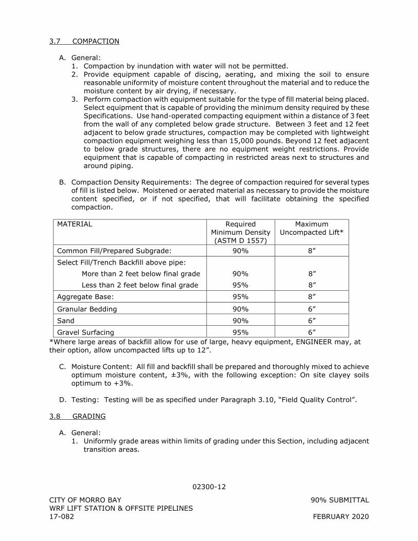
B. Compaction Density Requirements: The degree of compaction required for several types of fill is listed below. Moistened or aerated material as necessary to provide the moisture content specified, or if not specified, that will facilitate obtaining the specified compaction.
MATERIAL Required
Minimum Density (ASTM D 1557)
Maximum Uncompacted Lift*
Common Fill/Prepared Subgrade: 90% 8”
Select Fill/Trench Backfill above pipe:
More than 2 feet below final grade 90% 8”
Less than 2 feet below final grade 95% 8”
Aggregate Base: 95% 8”
Granular Bedding 90% 6”
Sand 90% 6”
Gravel Surfacing 95% 6” *Where large areas of backfill allow for use of large, heavy equipment, ENGINEER may, at their option, allow uncompacted lifts up to 12”.
C. Moisture Content: All fill and backfill shall be prepared and thoroughly mixed to achieve optimum moisture content, ±3%, with the following exception: On site clayey soils optimum to +3%.
D. Testing: Testing will be as specified under Paragraph 3.10, “Field Quality Control”.
3.8 GRADING
A. General: 1. Uniformly grade areas within limits of grading under this Section, including adjacent
transition areas.
02300-13
CITY OF MORRO BAY 90% SUBMITTAL WRF LIFT STATION & OFFSITE PIPELINES 17-082 FEBRUARY 2020
2. Smooth subgrade surfaces within specified tolerances, and compact with uniform levels or slopes between points where elevations are shown or between such points and existing grades.
B. Adjacent to Structures: Grade areas adjacent to structures to drain away from structures (including masonry fences) and to prevent ponding.
C. Walks: Shape surface of areas under walks to line, grade and cross-section, with finish surface not more than 1” above or below the required subgrade elevation.
D. Pavements: Shape surface of areas under pavement to line, and grade and cross-section with finish surface not more than 1/2” above or below the required subgrade elevation.
E. Under Building Slabs: Grade smooth and even, free of voids, compacted as specified and to required elevation. Provide final grades within a tolerance of 1/2” when tested with a 10’ straightedge.
F. Special Areas: In turfed areas or areas covered with gravel, stone, wood chips, or other special cover, grade to within not more than 1-inch above or below the required subgrade elevations.
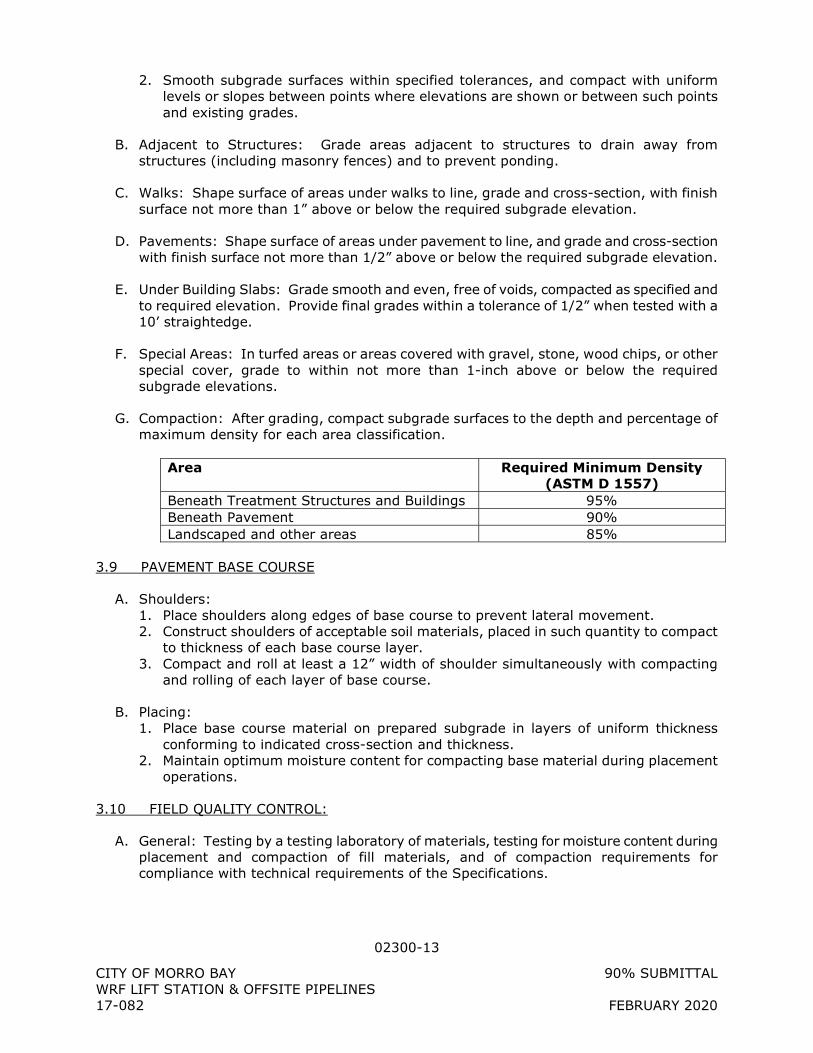
G. Compaction: After grading, compact subgrade surfaces to the depth and percentage of maximum density for each area classification.
Area Required Minimum Density
(ASTM D 1557) Beneath Treatment Structures and Buildings 95% Beneath Pavement 90% Landscaped and other areas 85%
3.9 PAVEMENT BASE COURSE
A. Shoulders: 1. Place shoulders along edges of base course to prevent lateral movement. 2. Construct shoulders of acceptable soil materials, placed in such quantity to compact
to thickness of each base course layer. 3. Compact and roll at least a 12” width of shoulder simultaneously with compacting
and rolling of each layer of base course.
B. Placing: 1. Place base course material on prepared subgrade in layers of uniform thickness
conforming to indicated cross-section and thickness. 2. Maintain optimum moisture content for compacting base material during placement
operations.
3.10 FIELD QUALITY CONTROL:
A. General: Testing by a testing laboratory of materials, testing for moisture content during placement and compaction of fill materials, and of compaction requirements for compliance with technical requirements of the Specifications.
02300-14
CITY OF MORRO BAY 90% SUBMITTAL WRF LIFT STATION & OFFSITE PIPELINES 17-082 FEBRUARY 2020
B. The CONTRACTOR shall retain one or more independent testing agencies to perform all quality control testing required for all materials except portland cement concrete. The required testing is for soil, aggregates, imported gravel, aggregate base, asphalt concrete, and CLSM. Each independent testing agency shall perform the testing under the supervision of an engineer registered in California. Technicians performing the testing shall be certified to operate the equipment and have at least 1 full year of experience in the type of tests being performed.
C. A Quality Control Plan shall be submitted by the CONTRACTOR to the ENGINEER at least 30 days before field testing is required. It shall include the names, addresses, and phone number of the companies, the major personnel that will be involved, and resumes of the individuals that will be supervising and performing the tests. Copies of certificates held by the companies and the testing personnel shall be included.
D. CONTRACTOR’s independent testing agency shall perform all field and laboratory testing as described in these Specifications. Test shall include specific gravity, sand equivalent, durability, abrasion resistance, soundness, gradation, compaction curves, lab and field moisture contents, compressive strength, and field density. Other tests shall be performed by the CONTRACTOR’s independent testing agency as may be required to meet the Specifications. Mix design testing for portland cement concrete, CLSM, and asphalt concrete shall also be performed by the CONTRACTOR. Field testing for portland cement concrete will be performed by the ENGINEER.
E. CONTRACTOR shall schedule all lab testing so that materials arriving at the site have been approved by the ENGINEER for use on the Project.
F. All lab tests shall be performed on Samples obtained from the source of actual material that will be used on the Project. No test results more than 90 days old shall be submitted for review.
G. The location of field density tests shall be determined by the ENGINEER.
H. Frequency of tests: Frequency will be not less than as follows: 1. For trenches:
a. In open fields: 2 locations every 1,000 linear feet, for each layer b. Along dirt, gravel, or paved roads or off traveled right-of-way: 2 locations every
500 linear feet, for each layer c. Crossing roads: 2 locations along each crossing, for each layer
2. For structural backfill: 1 every 50 cubic yards. 3. In embankment or fill: 1 every 200 cubic yards. 4. Base material: 1 every 50 cubic yards. 5. Footing Subgrade: 1 every 50 linear feet, for each layer. 6. Paved Areas and Building Slab Subgrade: 1 every 500 square feet, but in no case
less than 3 tests, for each layer.
I. The ENGINEER may modify the frequency or spacing of tests to provide for testing at specific structures or locations where the ENGINEER deems additional testing is required. The CONTRACTOR shall perform such additional testing up to 10 percent above the frequency and total number of tests specified at no additional cost to the OWNER.
J. Verbal and hand-written test results shall be provided to the ENGINEER and CONTRACTOR immediately following the field testing. Written test data sheets shall be
02300-15
CITY OF MORRO BAY 90% SUBMITTAL WRF LIFT STATION & OFFSITE PIPELINES 17-082 FEBRUARY 2020
provided to the ENGINEER not more than 12 hours following completion of the field test. Typed lab test results shall be provided to the ENGINEER not more than 7 calendar days following completion of the tests; however, the results must be reviewed and approved by the ENGINEER prior to placing the material in the trenches or incorporating it in the Work.
A. Any location where a failing test occurs shall be recompacted and retested until a passing test is obtained. Specified testing values are minimums and no tests shall be accepted below the specified minimums. No material shall be placed over the failing test area until the failing material is recompacted and a passing test is obtained, and the area is approved by the ENGINEER. The limits of the failing test shall be assumed to be halfway between the failing location and the nearest passing location. Additional tests may be taken to determine the limits of unsatisfactory compaction.
B. At the first of each month, the CONTRACTOR shall provide to the ENGINEER a typed summary of all tests performed for the previous month including test location by station, depth below finished grade, material tested, wet density, moisture content, dry density, maximum density curve used, and percent relative compaction. Lab test results shall also be included in the monthly report with clear description of material tested, intended use on the Project, and a statement of compliance or noncompliance with the Project Specifications.
C. Any material which does not meet the Specifications shall be removed from the site and replaced with material in compliance.
D. Material which has been softened or modified prior to placing the overlying lift shall be removed down to material which is in compliance.
3.11 DISPOSAL OF EXCAVATED MATERIALS
A. Material removed from the excavations that does not conform to the requirements for fill or is in excess of that required for backfill shall be hauled away from the Work site and disposed of by CONTRACTOR in compliance with ordinances, codes, laws and regulations at no additional cost to the OWNER.
B. A site is not available to dispose of excess material.
+ + END OF SECTION + +
02350-1
CITY OF MORRO BAY 90% SUBMITTAL WRF LIFT STATION & OFFSITE PIPELINES 17-082 FEBRUARY 2020
SECTION 02350
BORE AND JACK REQUIREMENTS
PART 1 - GENERAL
1.1 SCOPE OF WORK
A. Furnish all labor, equipment, materials, and incidentals required to install steel casing and carrier pipes by bore and jack tunneling under Willow Creek at the location shown on the Drawings. The work shall be done in strict accordance with the requirements of the California Department of Transportation (Caltrans) as shown on the Drawings and as specified herein.
B. The following geotechnical investigation has been completed for the bore and jack undercrossing of Willow Creek 1. YEH & ASSOCIATES, Project No 217-053m Geotechnical Report MB WRF PS and
Offsite Pipelines, Morro Bay 2. The CONTRACTOR is directed to this geotechnical data for characterization of
subsurface conditions (bedrock and groundwater) and selection of appropriate shaft shoring, shaft dewatering, shaft thrust block design, bore and jack jacking frame selection, casing selection, casing overcut selection and bedrock cutting head selection and tunneling productivity schedule.
C. Prior to installing the steel casing, retain at Contractor's own expense the services of a competent civil and/or geotechnical engineer with 5 years demonstrated experience in the design and installation of steel casings by bore and jack methods and, carrier pipes and appurtenances. The aforementioned engineer shall, prior to submittal, approve and affix his/her stamp to the Contractor's drawings and design concept for the bore and jack. The drawings and design concept shall include but not be limited to the dewatering, soil stabilization, jacking pit, receiving pit, jacking frame, casing overcut selection, jacking force calculations, thrust block capacity, bedrock cutting head configuration and installation/tunneling productivity schedule. The Contractor's engineer shall avail himself of all the available information contained on the contract drawings and herein including the geotechnical data referenced above and shall be responsible for making whatever additional investigations of the site and the conditions thereon that he/she may deem necessary.
D. Continuously keep the jacking and receiving pit subgrades free from groundwater and surface waters during the operation and shall be prepared to implement additional groundwater control on short notice as directed by the Engineer. Groundwater levels prior to construction are to be lowered a minimum of 3 feet below the invert elevation of the jacking and receiving pits. All pits should have crushed-rock and sump areas to clear groundwater and water used to clean the casings. Pits shall be lined with non-woven geotextile filter fabric when groundwater is found and pumping is required.
E. Be fully responsible for inspecting the location where the pipes are to be installed and shall familiarize himself with the conditions under which the work will be performed and with all necessary details as to the orderly execution of the work. The omission of any details for the satisfactory installation of the work in its entirety, which may not appear herein, shall not relieve the Contractor of full responsibility.
02350-2
CITY OF MORRO BAY 90% SUBMITTAL WRF LIFT STATION & OFFSITE PIPELINES 17-082 FEBRUARY 2020
F. Install surface and subsurface monitoring points as shown on the drawings.
G. The Contractor shall establish a “Survey Grid Line” for the proposed 72” diameter casing as per Caltrans requirements and provide it to Owner and Engineer. Stationing and centerline elevation of the pipe are per the centerline of the casing.
H. Prepare to complete the bore and jack in an orderly fashion with normal tunneling shifts working on a daily basis with no more than 24 hours between shifts.
I. If any movement or settlement occurs which causes or might cause damage to existing utilities or structures over, along or adjacent to the work, immediately stop any or all work except that which assists in making the work secure and in preventing further movement, settlement or damage. Resume tunneling only after all necessary precautions have been taken to prevent further movement, settlement or damage and shall repair the damage, at Contractor's own cost and to the satisfaction of the Engineer.
J. Place a minimum of 6-feet fencing or Type-K barrier around the work area as per Caltrans requirements. Re-vegetation of graded areas shall take place as quickly as possible as weather permits and as per project SWPPP requirements.
1.2 SUBMITTALS
A. Submittals: 1. Stamped drawings and calculations for the following: a) jacking and receiving pit
shoring design, b) selected casing overcut and systemic surface settlements along representative sections of the tunnel alignment c) anticipated jacking load on casing and safety factor on casing capacity in compression, d) thrust block bearing capacity and safety factor on the thrust block capacity, and e) vertical loading on the casing from overburden and safety factor against casing wall stress capacity and buckling capacity. For all cases of loading the steel casing shall have a minimum safety factor of 2.0.
2. Shop drawings showing size, location and design calculations for the jacking pit thrust block.
3. Number and capacities of jacking frame jacks. 4. Size, arrangement and installation of soil stabilization and dewatering wells, pumps
and associated equipment. 5. Detailed description of equipment, materials, sequence and procedures for jacking
steel casing including provisions for standby and backup equipment. Submit “Notice of materials to be used” for CEM-3101 to Caltrans on all Caltrans projects.
6. Details of casing lubrication system and description of casing lubricants to be used during bore and jack operation, including manufacturer’s literature and MSDS.
7. Revisions to shop drawings, as necessary to accommodate field conditions and/or comply with the Specifications herein.
8. Tunnel support system and shoring design shall be designed by a Registered Civil or Structural Engineer.
9. Tunneling productivity schedule. 10. Contingency plan for ground loss or equipment failure during bore & jack operation. 11. Emergency plan outlining the duties and responsibilities of all personnel during an
emergency as per Cal OSHA requirements. 12. Proof of experience as stipulated by Caltrans and as required by the encroachment
permit.
02350-3
CITY OF MORRO BAY 90% SUBMITTAL WRF LIFT STATION & OFFSITE PIPELINES 17-082 FEBRUARY 2020
B. Acceptance of the submitted material by Engineer does not indicate acceptance of responsibility for the means and methods of construction. The CONCTRACTOR shall totally responsible for the entire bore and jack operation.
1.3 RELATED WORK
A. Section 01330 – Submittal Procedures
B. Section 01725 – Pipeline Testing & Cleanup
C. Section 02140 – Dewatering
D. Section 02495 – Geotechnical Instrumentation
E. Section 15100 PSDS HDPE – Fusible HDPE Pressure Pipe
F. Section 15100 PSDS FPVC – Fusible Polyvinylchloride Pipe
G. Section 15100 PSDS WSP – Welded Steel Pipe
1.4 REFERENCE STANDARDS
A. American Society for Testing and Materials (ASTM)
1. ASTM A36 – Standard Specification for Carbon Structural Steel
2. ASTM A53 - Standard Specification for Pipe, Steel, Black and Hot-Dipped, Zinc-Coated, Welded and Seamless.
3. ASTM A139 – Standard Specification for Electric-Fusion Welded Steel Pipe, NPS 4 and
over 4. ASTM A572 – Standard Specification for High-Strength Low-Alloy Columbium-
Vanadium Structural Steel
5. ASTM C32 - Standard Specification for Sewer and Manhole Brick (Made from Clay or Shale).
6. ASTM C144 - Standard Specification for Aggregate for Masonry Mortar.
7. ASTM C150 - Standard Specification for Portland Cement.
8. ASTM C207 - Standard Specification for Hydrated Lime for Masonry Purposes.
B. American Water Works Association (AWWA)
1. AWWA C200 - Steel Water Pipe 6-in (150mm) and Larger.
2. AWWA C203 - Coal-Tar Protective Coatings and Linings for Steel Water Pipelines - Enamel and Tape - Hot-Applied.
3. AWWA C206 - Field Welding of Steel Water Pipe.
4. AWWA M11 – Steel Pipe – A Guide for Design and Installation
02350-4
CITY OF MORRO BAY 90% SUBMITTAL WRF LIFT STATION & OFFSITE PIPELINES 17-082 FEBRUARY 2020
C. American Welding Society (AWS)
D. Where reference is made to one of the above standards, the revision in effect at the time of bid opening shall apply.
PART 2 - GENERAL
2.1 MATERIALS
A. Steel casings shall conform to the requirements of ASTM A139, Grade B or A572 Grade 42 and shall have a minimum yield strength of 35,000 psi. The casing pipes shall have the minimum nominal diameter and wall thickness as shown on the Drawings.
B. Steel casing shall have a magnesium sacrificial anode inside of the casing for cathodic protection. Anodes shall be high potential magnesium conforming to ASTM B843 Grade M1C.
C. Minimum thickness of casing pipe shall be 0.75”
D. The bedrock cutting head shall provide a maximum tunnel overcut of 1-inch on diameter.
E. Welded Steel and Stainless Steel Joints (WLD) a. Field welded joints shall be in accordance with AWWA C206 b. Welder Qualifications:
1) All welding shall be done by skilled welders, welding operators, and tackers who have had adequate experience in the methods and materials to be used.
2) Welders shall be qualified by the CONTRACTOR under the provisions of ASME BPVC for shop welds and ANSI/AWS D1.1 for field welds.
3) Furnish all material and bear the expense of qualifying welders. c. Backing rings will not be permitted for 30-inch and smaller pipe. Single field-
welded butt joints with outside backing rings may be used for pipe larger than 30 inches in diameter.
d. Where exterior welds are performed, adequate space shall be provided for welding and inspection of the joints.
e. Butt Straps 1) Butt straps shall be used as closure pieces and where shown on the Drawings. 2) Where used or required, shall be as shown on the Contract Drawings or as
approved during shop drawing review. 3) When fitting up the ends of pipe to be welded or fitting butt-strap pieces,
minor jacking or clamping will be allowed. Cold working the metal and sledges or localized application of heat and working the metal and sledges will not be allowed. If field displacement of joints, where butt strap joints are indicated, does not allow proper fit-up with the tolerances indicated, special closure butt straps or mitered pieces shall be shop fabricated and installed.
4) Butt straps shall be welded on both the inside and outside of the pipe and at each end of the pipe and strap to avoid stress multiplication.
f. Prior to the backfilling or beginning the welding procedure, any tack welds or joint stops used to position the pipe during laying shall be removed. Any annular space between the faying surfaces of the bell and spigot shall be equally distributed around the circumference of the joint by shimming, jacking, or other suitable
02350-5
CITY OF MORRO BAY 90% SUBMITTAL WRF LIFT STATION & OFFSITE PIPELINES 17-082 FEBRUARY 2020
means. The weld shall then be made in accordance with ANSI/AWWA C206. Where more than one pass is required, all dirt, slag, and flux shall be removed before the succeeding bead is applied.
g. Repair of Welds: All welds that are defective shall be repaired by the CONTRACTOR to meet the requirements of this section at no additional cost to the OWNER. Defects in welds or defective welds shall be removed, and that section of the joint shall then be re-welded. Only sufficient removal of defective material that is necessary to correct the defect is required. After the repair is made, the joint shall be checked by repeating the original test procedure. Welds deficient in size shall be repaired by adding weld metal.
F. A proprietary steel pipe that is utilizing an integral, machined press-fit connection method can be used as a casing. Recommended manufactures are Permalok Corporation or equal.
G. HDPE/FPVC shall be as shown on the Drawings and as specified in these Contract Documents.
PART 3 - EXECUTION
3.1 JACKING PIT AND RECEIVING PIT
A. The pits shall be shored with full face shoring fully supporting the excavation side walls in accordance with the Contractors approved shoring plan.
B. Furnish, install and remove, to the extent required, thrust blocks or whatever provisions may be required in driving the sleeves and pipes forward.
C. Be fully responsible for the removal of the pits including the breaking up, removing and disposing of concrete, if so required, or cutting off of sheeting and furnishing and placing screened gravel fill to the normal subgrade as may be required following the installation operations.
D. Pits shall be protected by placement of 6' chain link fence or Type-K barrier around them.
3.2 JACKING OPERATIONS
A. Be fully responsible for preventing the occurrence of voids outside the steel casing. The Contractor shall keep written records of the tunnel spoil volume compared to the calculated tunnel volume and tunnel advance rate. Deviation of the tunnel spoil volume (accounting for bedrock bulking) from the calculated tunnel volume by more than 5% shall be reported to the Engineer. Ongoing deviation by more than 5% may require adjustment of the Contractor’s means and methods.
B. The bedrock cutting head shall provide a maximum tunnel overcut of 1-inch on diameter. CONTRACTOR must use lubrication system to fill the overcut annular space. The lubrication system shall be as per manufacturer’s recommendation and as approved by the ENGINEER and OWNER. Lubricant is to be injected into the overcut annular space on a full time continuous basis.
02350-6
CITY OF MORRO BAY 90% SUBMITTAL WRF LIFT STATION & OFFSITE PIPELINES 17-082 FEBRUARY 2020
C. Surface and subsurface monitoring points shall be surveyed after the jacking pit is fully excavated and shored and at least 24 hours before the start of tunneling (baseline reading), surveyed daily as the tunnel approaches and passes beneath and passes by for a distance of 20 feet and then weekly for the duration of tunneling and until the jacking pit is backfilled. More than 1” of settlement in the subsurface monitoring points shall be reported to the Engineer and will require action by the Contractor to control and minimize settlement over the tunnel. CONTRACTOR shall provide a Licensed Surveyor for this work.
D. Proper alignment and elevation of the steel casing shall be consistently maintained throughout the jacking operation. The maximum deviation at any point along the casing shall not exceed 6” from the line and grade shown on the drawings.
E. Use a jacking ring consisting of steel construction. This jacking ring will allow the jacking pressure to be distributed evenly around the wall of the steel casing.
F. The use of a jacking frame shall also be required. It shall be fabricated from structural steel members and shall be designed to distribute the stresses from the jacks evenly to the jacking ring.
G. Steel casing sections shall have beveled ends with a single v groove and shall be full penetration butt welded on the outside of the sleeve in accordance with the applicable portions of AWWA C206 and AWS D7.0 for the field welded water pipe joints. All joints of the steel sleeve shall be butt welded prior to being subject to the jacking operation. The welded joints shall be wire brushed and painted with bitumastic enamel coating in accordance with AWWA C203.
3.3 CARRIER PIPE INSTALLATION
A. After the steel casing has been completely installed, thoroughly clean the interior. Place within the steel casing, the carrier pipes using spacers bound together with steel banding as shown on the Drawings.
B. After the carrier pipes are installed within the steel casing and prior to the placement of sand fill, conduct a leakage test on carrier pipe as designated by the Engineer. Any leaks which are discovered during the testing phase shall be repaired to the satisfaction of the Engineer.
C. Brick bulkheads 8 in wide minimum shall be installed at each end of the steel casing after the carrier pipes have been installed. The portion of the pipes passing through the brick bulkhead shall be wrapped with three layers of 15 lb asphalt impregnated felt before the bulkhead is constructed.
D. The carrier pipes shall be installed to the line and grade required within the steel casing and, after they have been satisfactorily placed and approved by the Engineer, the space between the outside of the carrier pipes and the steel casing shall be completely filled with sand in one continuous uninterrupted operation in a manner to prevent occurrence of any voids between carrier pipes and steel casing.
E. Carrier pipes to be installed within the steel casing must be braced to the sides and top of the steel casing with spacers as specified to prevent motion during the placing of sand.
02350-7
CITY OF MORRO BAY 90% SUBMITTAL WRF LIFT STATION & OFFSITE PIPELINES 17-082 FEBRUARY 2020
3.4 TESTING
A. Casing: 1. All straight pipe sections are recommended to be hydrostatically tested in the shop to
the test pressures determined by Section 5.2 of AWWA C200 after fabrication and prior to shipping onsite.
2. Field testing in accordance with AWWA C200 is not required but recommended for the project.
B. Carrier: 1. See specs 01725 for carrier pipeline testing.
+ + END OF SECTION + +
02410-1
CITY OF MORRO BAY 90% SUBMITTAL WRF LIFT STATION & OFFSITE PIPELINES 17-082 FEBRUARY 2020
SECTION 02410
SHAFT EXCAVATION AND SUPPORT SYSTEM
PART 1 - GENERAL
1.1 SCOPE OF WORK
A. The work specified in this Section includes requirements for excavation and support of temporary shaft excavations and trenches. The CONTRACTOR shall design, furnish, install, and maintain a system of supports, including all bracing and associated items, to retain excavations in a safe manner and to control ground movements. Upon completion of the required construction the system of supports shall be completely removed and the excavation, shaft, and staging area sites restored as discussed herein.
B. The work shall include site grading; temporary access road construction; fencing and signing; construction staging areas; design and construction of shaft excavations; material disposal of surface water, ground water, and construction water; and site restoration.
C. Shaft excavation shoring shall consist of water tight, sheet pile or equal construction for the Roundabout crossing jacking and receiving shafts located along Quintana and/or Las Tunas, and the Willow Creek crossing jacking and receiving shafts located near Unnamed Rd on Main St. The CONTRACTOR must provide sheet pile design for review and approval prior to construction. The CONTRACTOR may propose alternative designs for review subject to the requirements specified herein. Shafts and near surface excavations must satisfy the criteria contained in this section for sheetpile support designs.
D. The shaft location shall be as shown on the Contract Drawings. The CONTRACTOR shall be responsible for sizing the excavations and shafts. The size of the shafts shall, however, be adequate for construction of any structures indicated on the Drawings and to provide adequate space to meet the CONTRACTOR's work space requirements for his selected methods of construction. Shaft excavations larger than those shown on the Drawings will be subject to the approval of the ENGINEER and any modifications to the approved traffic control measures shall be obtained and carried out at no additional cost to the OWNER.
E. The initial support of the shafts shall be designed by the CONTRACTOR based upon the anticipated ground conditions described in the Geotechnical Investigation Report (GIR). The CONTRACTOR will also be responsible for the final design of the dewatering system for the shaft and tunnel alignment as per the Contract Drawings.
F. Relocate, support, protect-in-place, or bypass all existing utilities as required in the performance of the Work.
1.2 RELATED WORK
A. Section 01140 – Water Pollution Control
B. Section 01 33 00 – Submittals
02410-2
CITY OF MORRO BAY 90% SUBMITTAL WRF LIFT STATION & OFFSITE PIPELINES 17-082 FEBRUARY 2020
C. Section 02200 – Site preparation
D. Section 02240 – Dewatering
E. Section 02300 – Earthwork
F. Section 02420 – Tunnel Portal Treatment
G. Section 02441 – Microtunneling
H. Section 03320– Contact Grouting
1.3 DEFINITIONS
A. Shaft: A vertical excavation that provides a means of access and material transport to and from an underlying tunnel. The construction of a shaft requires appropriate ground support and groundwater mitigation. During the construction phase the bottom of a shaft may serve as the beginning location of a tunnel heading.
B. Shaft Bottom: The cleaned bottom level of a shaft from where the shaft is supported and incrementally deepened by subsequent rounds of excavation and support installation.
C. Soil Overburden Initial Support: Requirements for initial ground support in the overburden soil cover varies to include a variety of types including ring beams and lagging, soldier piles and lagging, slurry walls, caissons, and secant pile walls
1.4 SUBMITTALS
A. Submit, in accordance with Section 01 33 00, shop drawings for excavations, excavation support systems, and other related information as requested by the ENGINEER. The shop drawings shall be prepared and sealed by an independent professional civil or structural ENGINEER and not in the direct employment of the CONTRACTOR. Submittals shall include the following:
1. Name and qualifications of person responsible for excavation support system design. 2. A site plan for each excavation indicating the location, excavation dimensions, site
grading and site development details for the excavation and all work areas, and the proposed limits of disturbance surrounding each excavation.
3. Drawings and design calculations indicating arrangement of supports and construction sequence for proposed support system(s) and with following data: a. Show the elevation of struts or other supports as related to the depth of
excavation at intermediate stages of construction. b. Indicate sizes, shapes, and material specifications for all support elements
including lagging, if used. c. Calculations shall include estimates of likely deflections or deformations of the
support system and maximum tolerable values. d. Site drainage and ground water control details. Show details of the measures to
control, treat, handle and dispose of surface water runoff, ground water, and construction water. Provide details of working slab, subdrains and sump construction.
02410-3
CITY OF MORRO BAY 90% SUBMITTAL WRF LIFT STATION & OFFSITE PIPELINES 17-082 FEBRUARY 2020
e. Complete geometry, grade of materials used, and dimensions of all steel set support elements and assemblages.
4. Ventilation system design criteria, calculations, and plan. 5. Breakout plans indicating support installed to transfer loads and maintain excavation
supports and stability of the excavation when commencing tunneling operations and when holing out into exit shafts.
6. Provisions for protecting adjacent facilities and utilities. All utilities within 20 feet of excavations and all structures within 50 feet of excavations shall be addressed.
7. Details of materials handling, stockpiling, and disposal sites for excavated materials. 8. For tieback anchors that project beyond vertical projections of property lines shown,
and into adjoining property, obtain permission of OWNER or agency in writing prior to installation. Submit copies of correspondence documenting property owner's or agency's permission.
9. Methods and details for repairing damage to initial support. 10. Plans indicating removal of excavation supports and site restoration details. 11. Plans for environmental controls.
B. Reports and Records: Submit the following on each day that measurements are made: 1. Excavation monitoring data of horizontal and vertical deflections of supports.
C. Proposed methods by which construction of the shaft is to be accomplished. Address each work element including the methods and sequence chosen for shaft support, excavation within soft soils and heavy groundwater conditions, and ground treatment methods for initiation of tunneling at the brows. Include details on mucking using loading equipment; hoisting using skips or buckets; hoisting of personnel; dumping and stockpiling at the surface; and transport of spoil for disposal.
D. Methods proposed for monitoring shaft support and to prevent catastrophic ground loss, running or flowing ground conditions, or loss of bottom stability and detailing contingency measures for encountering open joints in the initial support during shaft excavation, and unacceptable water inflows through the excavation subgrade.
E. Measures and repair methods to protect the public and surrounding property from hazards inherent in the operations, including leakage and spillage of slurry, if used.
F. Concrete mix design including strength at three days, seven days, and at 28 days of age. Trial mix test result is required to show development of strength during the early age when adjacent secant piles will be drilled partially in the already placed concrete piles, and include slump tests of the fresh concrete.
G. Quality Control: 1. Identify how the quality of materials and installation will be controlled (e.g.
measurements, inspections, testing, etc.) in accordance with Section 01400- Quality Control.
2. Address materials testing requirements, proof-test and performance test requirements for tiebacks, and excavation monitoring provisions.
3. Submit signed statement from the microtunneling subcontractor that the shaft support systems shown on the Contract Drawings without modifications, with proposed modifications, or proposed alternate shaft support systems have been reviewed and are acceptable to them for microtunneling.
02410-4
CITY OF MORRO BAY 90% SUBMITTAL WRF LIFT STATION & OFFSITE PIPELINES 17-082 FEBRUARY 2020
4. Submit signed statement from installer of carrier pipe that the shaft and excavation support systems shown on the Contract Documents without modifications, with proposed modifications, or proposed alternate support systems have been reviewed and are acceptable to them for installation of the carrier pipe.
1.5 REFERENCE SPECIFICATIONS, CODES, AND STANDARDS
A. American Society for Testing and Materials (ASTM) 1. ASTM A36 - Specification for Structural Steel Standard Specifications
B. American Institute of Steel Construction (AISC) 1. Manual of Steel Construction
C. American Welding Society (AWS) 1. AWS D1.1 for Public Works Construction
D. Codes 1. U.S. Occupational Safety and Health Administration (OSHA) Regulations, 29 CFR Part
1926 Subpart P - Excavations. 2. California Division of Occupational Safety and Health (Cal/OSHA)
E. Where reference is made to one of the above standards the revision in effect at the time of the bid opening shall apply.
1.6 DESIGN CRITERIA
A. General: 1. CONTRACTOR shall select and design initial support systems that complement the
means and methods selected in excavating the tunnel and shafts. 2. CONTRACTOR shall assume responsibility for the safety of excavations and initial
support systems. All initial support shall be observed, assessed for adequacy, and in proper, well-maintained service at all times.
3. Design excavation and shaft support systems and working slabs to withstand earth pressures, unrelieved hydrostatic pressures, bottom heave, equipment loads, applicable traffic and construction loads and other surcharge loads to allow the safe construction of the tunnel or jacked pipe without movement or settlement of the ground, and to prevent damage to or movement of adjacent structures, streets and utilities.
4. The CONTRACTOR shall be responsible for the control of ground water, including the removal, disposal, pressure reduction, or cutoff of ground water flows as necessary to construct the selected support system and maintain a stable excavation and shaft.
5. Design and construct shafts and near surface excavation so that they are completely within right-of-way and permanent easement limits shown on the Plans.
6. Design and construct shafts to use in-the-wet construction or dry excavation with internal unwatering within shaft or near surface excavation support systems.
7. Design, install, operate, and maintain ground water control system for excavations to control ground water inflows, prevent piping or loss of ground, and maintain stability of the excavation. All shafts shall be watertight shoring. Incorporate a sump pump into the excavation design.
02410-5
CITY OF MORRO BAY 90% SUBMITTAL WRF LIFT STATION & OFFSITE PIPELINES 17-082 FEBRUARY 2020
B. The CONTRACTOR shall provide the following: a. Size of equipment and construction and permanent materials to be hoisted
through the shaft, and size of mucking equipment and concurrent ventilation ducts/equipment and other services through the shaft.
b. Provide adequate size of openings at the base of the shaft to accommodate handling of materials and equipment for transport to and from the tunnel.
c. CONTRACTOR shall design and implement shape, size, and initial support of the shaft tunnel intersections to suit tunnel CONTRACTOR's needs for underground construction.
d. Design the support system to minimize horizontal and vertical movements, and to protect adjacent utilities from damage. Design support system to maintain the stability of the excavation and provide a factor of safety of at least 1.5 against sliding and against bottom heave.
e. Employ wales, struts, beams, and tiebacks for lateral support as required for excavation faces supported by soldier piles and lagging, liner plate, or sheeting systems. Provide struts with intermediate vertical and horizontal supports as required to prevent buckling. Provide timber lagging, liner plates, shotcrete or steel sheeting as required to retain soil between supports.
f. Design a working slab for each shaft bottom to provide stable support for guide rails, thrust block, and other construction operations.
g. Locate access and shafts as indicated on the Drawings. h. Provide temporary screen fencing around all shaft excavations. Provide traffic
control around working areas and shafts located within or adjacent to streets, roadways, freeways, driveways or parking lots.
i. Design excavation support systems in accordance with all OSHA requirements. j. Review of the CONTRACTOR's plans and methods of construction by the
ENGINEER does not relieve the CONTRACTOR of his responsibility to provide an adequate support system achieving the specified requirements.
k. The initial support of the shaft shall be designed by the CONTRACTOR based upon the anticipated ground conditions described in the GIR, and needs to account for any surcharge loads imposed by materials and equipment, and for varying field and subsurface conditions. The initial support shown in the Contract Drawings is a conceptual design, compatible with the anticipated ground conditions, and shall represent the minimum acceptable support, provided for bidding purposes only. The final design submittal for any alternative shall include complete calculations, and shall be stamped and signed by a Professional ENGINEER registered in the State of California.
C. Jacking Shaft: 1. Dewatering will be allowed for the jacking shaft only during a construction period not
to exceed four weeks and a demolition period not to exceed two weeks. Except for the construction and demolition periods, dewatering is not allowed, and the groundwater shall be allowed to return to natural levels.
2. The jacking and receiving shafts shall limit the flow of water into the shafts to less than 10 gallons per minute with the groundwater at the natural level outside the shafts. The CONTRACTOR shall utilize a support system which restricts water inflow by itself and without the use of chemical grout. Chemical grout may be utilized only in localized areas and shall not be the primary system to restrict water inflow.
02410-6
CITY OF MORRO BAY 90% SUBMITTAL WRF LIFT STATION & OFFSITE PIPELINES 17-082 FEBRUARY 2020
3. Demolition. Prior to completion of the project, the components of the jacking shaft shall be either completely removed or alternatively abandoned in-place in accordance with the following: a. No wood shall remain as part of the abandoned portion of the shaft. b. The upper 10 feet of shaft support shall be completely removed.
1.7 QUALITY ASSURANCE
A. Regulations: 1. Perform all work in accordance with current applicable regulations and codes of all
Federal and local agencies. 2. Assume responsibility for the safety of the work, the protection of personnel, and
damage to property.
B. Qualifications: 1. Submit verification that the workforce is qualified to complete the work of this
Section (licenses, certifications, etc.) and that the work has been effectively supervised (manager, foreman, etc.).
2. Excavation support systems shall be designed by a professional civil or structural engineer licensed in the State of California who has minimum of five years of experience in the design of earth retaining structures.
3. The Shaft Superintendent shall have no less than 10 years of recent on-the-job supervision experience on projects involving tunnels and shafts of similar size constructed by similar methods as those proposed by the CONTRACTOR.
C. Tolerances: 1. Location of the excavation supports shall be within 3-in of that shown on the shop
drawings. 2. Construct the shaft wall vertically within a tolerance of 0.5 percent. 3. Shaft walls must not deflect more than 0.1 feet during the excavation within the
completed initial support.
D. Testing: 1. Perform an initial test, and periodic tests, of the standby power system for the shaft
sinking operations in the presence of the OWNER’S Representative. Also, periodically demonstrate the functionality and capabilities of the automatic switchover, and notification systems.
2. The CONTRACTOR shall submit for review and approval a field testing program consistent with the proposed shaft excavation and support systems.
1.8 SAFETY
A. All shaft excavations and support systems shall conform with applicable OSHA excavation, trenching, and shoring standards which are contained in the U.S. Code of Federal Regulations 29 (C.F.R.) 1926.650-1926.653. In the event of a conflict, comply with the more restrictive applicable requirements.
B. For each underground construction effort, provide two power sources:
02410-7
CITY OF MORRO BAY 90% SUBMITTAL WRF LIFT STATION & OFFSITE PIPELINES 17-082 FEBRUARY 2020
1. A primary power system comprising commercially available or site generated power, capable of providing all of the CONTRACTOR's power requirements for the underground construction.
2. A back-up system comprising site-generated power, capable of: a. Providing uninterrupted operation of the CONTRACTOR's essential tunnel support
services such as ventilation, lighting, and pumping. b. Coming on line automatically and immediately through an automatic transfer
switch or similar device in the event of a power outage. c. Immediately notify the heading crew of the power outage.
PART 2 - PRODUCTS
2.1 MATERIALS
A. Provide all shoring materials for complete shoring systems complying with the requirements specified herein, on the Contract Drawings, and in accordance with favorably reviewed submittals.
B. All timber and structural steel used for the supporting systems, whether new or used shall be sound and free from defects which may impair their strength.
C. Structural steel shall conform to ASTM A36 unless approved otherwise.
D. Use steel sheet piling that is continuous interlocking type ASTM A328 of appropriate shape.
E. Use fabricated connections and accessories, steel H-piles, WF shapes, and other structural steel that conform to the requirements of ASTM A36, unless otherwise favorably reviewed.
F. All timber shall be structural grade with a minimum allowable flexural strength of 1100 psi.
G. Use concrete as specified in Section 03300.
PART 3 - EXECUTION
3.1 GENERAL REQUIREMENTS
A. Notify the ENGINEER not less than 15 days before beginning excavation. Excavations and construction for site development shall not extend beyond the property lines and limits of disturbance shown on the Drawings.
B. Commence excavations and site development only after shop drawings have been reviewed and accepted by the ENGINEER.
C. Methods of construction for excavations shall be such as to ensure the safety of the work CONTRACTOR's employees, ENGINEER and OWNER's employees and inspectors, the public and adjacent property and improvements, whether public or private.
02410-8
CITY OF MORRO BAY 90% SUBMITTAL WRF LIFT STATION & OFFSITE PIPELINES 17-082 FEBRUARY 2020
D. Provide shaft excavations with a concrete working slab equipped with a sump to pump out ground water and construction water.
E. The shaft bottom invert shall be thoroughly cleaned from all tunnel muck and be dry prior to placement of concrete.
F. Before beginning construction at any location of this project, adequately protect existing structures, utilities, trees, shrubs, and other existing facilities. Design excavation support systems to limit deformations that could damage facilities including utilities and structures. The repair of or compensation for damage to existing facilities shall be at no additional cost to the OWNER.
G. As a minimum, place fencing, gates, lights, and signs as necessary around the shafts and staging areas to provide for public safety.
H. Install support system monitoring provisions as indicated on the shop drawings. Monitor performance of excavation support system for both horizontal and vertical deflections daily during excavation, and at intervals not to exceed seven days following the completion of excavation work. If monitoring data indicates that deflections have exceeded estimated values, increase frequency of monitoring as required by the ENGINEER. Submit all monitoring measurements to the ENGINEER on the same day measurements are taken.
I. Install excavation support systems in accordance with shop drawings which have been reviewed by the ENGINEER. If settlement or deflections of supports indicate that support system requires modification to prevent excessive movements, redesign and resubmit revised shop drawings and calculations to the ENGINEER at no additional cost to the OWNER.
J. Conduct all shaft and tunnel construction work, including excavation, shoring, temporary facilities, materials storage, and construction traffic within construction easements established for the project. All work shall be in accordance with the applicable permits.
K. Provide excavations with a sump to pump out incidental, construction, and storm water. A sump of sufficient size shall be constructed in the invert mud slab to collect water flowing from the shaft wall and the tunnel heading sloping toward the shaft.
L. Construct shafts and near surface excavations with the shoring flush with the existing ground surface unless otherwise indicated on the Contract Drawings.
M. Before starting excavations, provide a fall protection system around the shafts and near surface excavations in accordance with 29 CFR 1926.
3.2 GROUNDWATER CONTROL
A. During allowed times, design, install, operate, and maintain a ground water control system to provide stable, dry sidewalls and subgrade for the prosecution of the work and subsequent operations. Lower ground water levels in advance of shaft excavation utilizing wells, wellpoints, jet grouting or similar methods; provide a positive cutoff to prevent ground water inflows using a continuous interlocking sheet pile system or similar system designed to cutoff ground water inflows; or provide combinations thereof to achieve the
02410-9
CITY OF MORRO BAY 90% SUBMITTAL WRF LIFT STATION & OFFSITE PIPELINES 17-082 FEBRUARY 2020
requirements described herein. Provide drainage blankets, filter fabric, trench drains, and sumps as required to collect ground water inflows at the bottom of all shaft excavations. In addition, provide positive ground water control using a water restrictive lining, dewatering, chemical grouting, or other acceptable methods to maintain excavation support and to prevent seepage and loss of ground when launching or retrieving shields or tunneling machines from access and exit shafts.
B. The CONTRACTOR shall comply jet grouting as a groundwater control system in accordance with Specs 02420.
C. Maintain the ground water level at least two feet below the base of shaft excavations until no danger to the tunnels and shafts can occur because of ground water inflows or the buildup of hydrostatic pressure. Furnish observation wells for monitoring dewatering operations at each shaft excavation in accordance with requirements of Section 02240.
D. If required, groundwater control operations shall be prosecuted and maintained 24 hours a day, 7 days a week. Qualified personnel shall be on-site at all times to monitor system operations and to perform maintenance as necessary to keep the system in operation. Provide a generator and all equipment necessary to provide a backup electrical power source in the event of a power service interruption.
E. Maintain temporary drainage facilities of adequate size, with standby pumps and adequate back-up power for emergency use, to collect and dispose of water which enters shaft excavations.
F. Dispose of all water removed for ground water control and removed from shaft excavations in accordance with Section 02240. Dispose of contaminated ground water in accordance with Federal and local authority regulations.
3.3 STEEL SHEET PILING
A. Design and construct the shaft bottom concrete base slab as an integral part of the entire shaft.
B. Drive in plumb position with each sheet pile interlocked with adjoining piles for its entire length so as to form a continuous diaphragm throughout the length of each run of wall, bearing tightly against original ground. Drive to depth indicated on the shop drawings. Exercise care in driving so that interlocking members can be extracted without damaging adjacent structures or utilities. The methods of driving, cutting, and splicing shall conform to the shop drawings.
C. If favorably reviewed by the Construction Manager, discontinue the use of vibratory equipment, which cannot provide adequate pile penetration, and use suitably sized impact- type equipment. Monitor ground for undesirable effects of vibration if sheets are vibrated. Stop and redesign excavation support system if vibration is causing undesirable affects.
D. Remove all shoring that lies within the upper six feet below final grade.
02410-10
CITY OF MORRO BAY 90% SUBMITTAL WRF LIFT STATION & OFFSITE PIPELINES 17-082 FEBRUARY 2020
3.4 GROUND IMPROVEMENT FOR PENETRATIONS
A. Provide ground improvement at shaft penetrations in accordance with the requirements of Sections 02240 and 02420.
B. Before commencing with a shaft penetration, verify that the surrounding ground outside the shaft wall is stabilized and the permeability of the ground in the vicinity of the penetrations is reduced such that water inflows into the shaft, upon penetration, will be within specified tolerances.
C. Implement excavation of shaft penetrations in accordance with the requirements of Section 02441 and other mechanical excavation methods as required to break through the improved ground behind the shaft, or through the shaft wall itself.
D. Monitor ground water inflow quantities for total inflow and note increasing or decreasing trends in flow quantities. If inflows exceed the specified inflow limit, implement additional ground treatment or other methods to reduce the inflows of acceptable levels.
3.5 INTERNAL BRACING SUPPORT SYSTEM
A. The internal bracing support system shall include wales, struts, and/or shores.
B. Provide struts with intermediate bracing as needed to enable them to carry maximum design load without distortion or buckling. Provide diagonal bracing as necessary to maintain the stability of the system. Provide web stiffeners, plates, or angles as needed to prevent rotation, crippling, or buckling of connectors at points of bearing between structural steel members. Allow for eccentricities resulting from field fabrication and assembly.
C. Include web stiffeners, plates, or angles as needed to prevent rotation, crippling, or buckling of connections and points of bearing between structural steel members. Allow for eccentricities caused by field fabrication and assembly.
D. Install and maintain all bracing support members in tight contact with each other and with the surface being supported.
E. Use walers in conjunction with struts to transfer lateral pressure from wales to the struts.
F. Bolt or weld all connections between bracing elements and the walls. Do not use connections that rely on friction between the elements.
G. Preload bracing members by jacking struts to 50 percent of the design load if necessary to control shoring movement. Preload bracing members in accordance with methods, procedures, and sequence as described on the shop drawings. Coordinate excavation work with installation of bracing and preloading. Use steel shims and steel wedges welded or bolted in place to maintain the preloading force tin the bracing after release of the jacking equipment pressure. Install support and preload immediately after installation and prior to continuing excavation.
H. Use procedures that produce uniform loading of bracing member without eccentricities or overstressing and distortion of members of system.
02410-11
CITY OF MORRO BAY 90% SUBMITTAL WRF LIFT STATION & OFFSITE PIPELINES 17-082 FEBRUARY 2020
3.6 TIEBACK SYSTEMS
A. Where a system of tiebacks is proposed in conjunction with or in lieu of struts, bracing and shores, perform on-site tests to demonstrate adequacy of tiebacks for subsurface conditions. Tieback lengths shall be adequate to obtain anchorage behind potential failure plane of excavation.
B. Conduct proof-tests and performance tests of the tieback systems in accordance with shop drawings.
3.7 SITE GRADING
A. Clear and grade the shaft sites in accordance with the shop drawings.
B. Excavations shall be performed in accordance with the requirements of Section 02200.
3.8 DUST AND EROSION CONTROL
A. Take all precautions necessary to prevent a dust nuisance to adjacent properties. Provide erosion and sediment control. Correct and repair and damage resulting from dust or erosion at no additional cost to the OWNER.
3.9 DISPOSAL OF EXCAVATED MATERIALS
A. Remove and dispose of all excavated materials in accordance with Section 02200.
B. Dispose of contaminated soils in accordance with Federal and local authority regulations.
C. Temporary stockpiling, if allowed, shall not exceed the safe height limitation in accordance with shop drawings.
D. Do not place excavated material adjacent to trenches, shafts and other excavations unless excavation side slopes and excavation support systems are designed, constructed, and maintained for embankment or surcharge loads.
E. Do not place excavated materials near or over existing facilities, adjacent property, or completed Work, if weight of stockpiled material could induce excessive settlement.
3.10 REMOVAL OF SUPPORT SYSTEM
A. All shoring and temporary construction elements, including sheet piles, wales, struts, lagging, and shores shall be removed from the excavation prior to restoration. Remove the support system in a manner that will not disturb or harm adjacent construction or facilities.
B. All voids created by the removal of the support system shall be immediately filled with well-graded cohesionless sand, lean concrete, or cement grout, as approved by the ENGINEER. The support system removed from the excavation shall remain the property of the CONTRACTOR and shall be removed from the site.
02410-12
CITY OF MORRO BAY 90% SUBMITTAL WRF LIFT STATION & OFFSITE PIPELINES 17-082 FEBRUARY 2020
C. Do not allow any shoring or excavation support elements to remain in place except as specified herein or shown on the drawings. At a minimum, the upper 10 feet of shaft support shall be completely removed.
3.11 RESTORATION
A. Furnish, compact, and backfill all excavations in accordance with Section 02300. Prepare the bottom of shaft excavations as a foundation of installing pipe in accordance with Section 02300. Restore the work area disturbed by construction activities, and repair any damage caused to existing utilities, to its original, or better, condition. Paved areas shall be restored to match existing conditions as approved.
B. Remove and dispose of all trailers, temporary utilities, drainage facilities, temporary fencing, waste materials and surplus materials, and other site development facilities provided by the CONTRACTOR following backfilling of the excavation.
C. Obtain letters or other written documentation indicating acceptance and a release from all affected property owner(s) and utility companies that the area has been satisfactorily restored, and that any damaged utilities have been repaired, to its original, or better condition respectively. Submit copies of such letters and documentation to the ENGINEER.
+ + END OF SECTION + +
02420 -1
CITY OF MORRO BAY 90% SUBMITTAL WRF LIFT STATION & OFFSITE PIPELINES 17-082 FEBRUARY 2020
SECTION 02420
TUNNEL PORTAL TREATMENT
PART 1 - GENERAL
1.1 SCOPE OF WORK
A. This section specifies the requirements for ground treatment at penetrations to and from the shafts; for the tunnel and pipelines; to provide base stability at shaft inverts; and as indicated for the protection of structures and utilities.
B. The work shall include but is not limited to the following: 1. Drilling exploratory borings as required at each grouting location to confirm ground
conditions indicated in the GIR. 2. Design and implementation of a grouting program using jet, permeation, and
chemical grouting. 3. Drilling of horizontal, inclined, and vertical cased grout holes; installation of grout
pipes allowing controlled and successive grouting of soil zones or intervals; supplying of grout materials, pump injection of grout, and filling of grout pipes.
4. Restoration of street, sidewalks, landscaped areas, and structures to the condition existing before the start of the grouting work under this Section.
5. Field and laboratory testing 6. Monitoring of grouting operations.
1.2 RELATED WORK
A. Section 01140 – Water Pollution Control
B. Section 01 33 00 - Submittals
C. Section 02200 – Site preparation
D. Section 02240 – Dewatering
E. Section 02300 – Earthwork
F. Section 02410 - Tunnel Shaft Excavation
G. Section 02441 – Microtunneling
1.3 DEFINITION
A. Permeation Grouting: Grout injected to fill the soil pore spaces without causing excessive movement or fracturing of the soil formation, accomplished with chemical or cementitious grout.
02420 -2
CITY OF MORRO BAY 90% SUBMITTAL WRF LIFT STATION & OFFSITE PIPELINES 17-082 FEBRUARY 2020
B. Chemical Grout: A fluid chemical that improves the structural properties of a geologic mass, typically composed of (1) matrix forming base materials, (2) reactants and, (3) accelerators or retarders.
C. Cement Grout: Grout composed of Portland cement (or microfine Portland Cement) and water, which may contain additives such as clay, bentonite, sodium silicate, fly ash, silica fume, and accelerators or retarders as appropriate.
D. Jet Grouting: The process of injecting cement grout to create an in-situ soil-cement mixture. The cement grout is injected and mixed with the soil under high pressure through nozzles at the end of a monitor inserted in a borehole. The monitor is rotated at slow, smooth, constant speed and lifted at a rate to achieve a continuous geometry (typically a column) and quality of soil-cement. A casing pipe around the monitor pipe is required in soft ground conditions to ensure spoil returns to the ground surface.
E. Spoil Return: All materials including, but not limited to, liquids, semi-solids, and solids that are discharged above ground surface or mudline during, or as a result of jet grouting.
F. Specialty Subcontractor: A subcontractor specializing in ground treatment, with the qualifications specified in Paragraph 1.04 A.
1.4 SUBMITTALS
A. Submit, in accordance with Section 01 33 00, shop drawings for tunnel portal treatment and other related information as requested by the Engineer. The shop drawings shall be prepared and sealed by an independent professional civil or structural engineer and not in the direct employment of the Contractor.
B. Provide descriptions of drilling, grouting, and monitoring procedures, plan, equipment, and materials, including criteria to be used to establish that the target section is fully grouted. Include major equipment to be utilized for drilling and grouting.
C. Provide certified laboratory test results at least 30 days before starting injection operations documenting that the proposed chemical grout mix meets requirements as specified herein. Include uniaxial compressive strength and set-time test results of three sets of three grouted laboratory samples, as defined in ASTM D4320.
D. Submittals shall include the following: 1. Provide drawings and procedures for grouting tunnel penetrations, shaft bottoms,
and other locations. Provide a site map showing proposed grout hole locations and depths. If the grouting is zoned vertically, describe the methods to be used to isolate the different grouting zones. Provide a discussion of potential problems and remedial measures to be used remediate zones that are incompletely grouted such that the density stability or permeability are compromised.
2. Provide methods of installation, staging, location and details of grout pipes, and computations of quantities for the grouting used for protecting the. structures. Present assumptions with respect to porosity and target volumes.
3. Provide details of testing methods used to verify the effectiveness of grouting, with respect to strength and acceptance criteria.
02420 -3
CITY OF MORRO BAY 90% SUBMITTAL WRF LIFT STATION & OFFSITE PIPELINES 17-082 FEBRUARY 2020
4. For jet grouting operations, provide locations of spoil containment structures and methods to be used to prevent migration of leakage of spoil return, disturbed in-situ soils, or other material beyond the immediate limits of jet grouting operations. Include details and methods used to collect and dispose of the spoil return and other spoil materials. Include details and methods used to ensure that jet grout spoil returns do not reach the Willow Creek or the surface.
5. Provide working drawings and calculations for the grouting operations at least 30 days before starting tunneling operations. These drawings and calculations shall be stamped and signed by a Professional Engineer licensed in the State of California.
E. Provide documentation indicating approval of chemical grout materials from the State of California, Department of Health.
F. Boring logs for exploratory borings.
G. Schedule of Operations: A schedule showing anticipated times for mobilization, grout pipe installation, and actual grouting operations as related to the excavation progress.
H. Manufacturer's product data and certification that materials meet specification requirements.
I. Grout materials: Certificate of compliance that grout materials meet the requirements as specified herein.
J. Submit suppliers written recommendations for handling, transporting, mixing, and disposing of grout materials.
K. Submit equipment for mixing, drilling, and injecting grout. Include operational parameters and instrumentation to ensure grout is mixed and injected in conformance with the design.
L. Submit proposed forms showing records of grouting operations on a daily basis. Accurate and timely records of grouting are required. Include grout mix, gel time, injection date and time, injection pressure and rate, injection volumes and exact injection location, including elevation. Provide data in an acceptable chart-type format, and update daily.
M. Grout Mix Design(s): 1. For jet grouting, submit proposed soil-cement element diameters, injection pressures
and rates, withdrawal rates, rotational speeds, and calculations to demonstrate that full continuous columns of required diameter will be achieved in the site soils.
2. For chemical grouting, submit certified laboratory test results at least 30 days before starting injection operations documenting that the proposed chemical grout mix meets requirements as specified herein and uniaxial compressive strength and set-time test results of three sets of three grouted laboratory samples.
3. For permeation grouting, submit certificate of compliance documenting that the cement grout meets requirements as specified herein.
4. For compensation grouting, submit certificate of compliance documenting that the cement mortar grout meets requirements as specified herein.
N. Monitor water quality in accordance with permit requirements.
02420 -4
CITY OF MORRO BAY 90% SUBMITTAL WRF LIFT STATION & OFFSITE PIPELINES 17-082 FEBRUARY 2020
O. Program for monitoring existing sewers, storm drains, and underground utilities.
P. Methods for determining that grouted zone is thoroughly stabilized.
Q. As-built sketches showing locations depths and orientations of drilled holes and any grout pipes left in place.
R. Quality Control: 1. Identify how the quality of materials and installation will be controlled (e.g.
measurements, inspections, testing, etc.) in accordance with Section 01 45 00- Quality Control.
2. Provide a Quality Assurance-Quality Control Plan for grouting. 3. Provide results of Quality Control Testing.
1.5 REFERENCES
A. American Society for Testing and Materials (ASTM) 1. ASTM A36 - Specification for Structural Steel Standard Specifications 2. D2166- Standard Test Method for Unconfined Compressive Strength of Cohesive Soil 3. D4219 - Unconfined Compressive Strength Index of Chemically-Grouted Soils 4. D4320 - Laboratory Preparation of Chemically Grouted Soil Specimens for Obtaining
Design Strength Parameters.
B. American Petroleum Institute (API) 1. 13A - Drilling Fluid Materials
C. American Welding Society (AWS) 1. AWS D1.1 for Public Works Construction
D. Codes 1. U.S. Occupational Safety and Health Administration (OSHA) Regulations, 29 CFR Part
1926 Subpart P - Excavations.
1.6 DESIGN CRITERIA
A. Limit total inflow through each shaft penetration to less than 5 gallons per minute (gpm).
B. Limit total inflow through each shaft excavation bottom to less than 5 gpm with leakage from all sources not to exceed 10 gpm.
C. Design tunnel shaft excavation and support in accordance with Specs 02410.
D. Project Conditions: 1. Geotechnical conditions to be anticipated are presented in the GIR. 2. Design grouting program and mobilize equipment to conduct proper grouting
operations and accommodate site restrictions. 3. Design grouting program to ensure that no grout or spoil returns enter Willow Creek
or the surface.
02420 -5
CITY OF MORRO BAY 90% SUBMITTAL WRF LIFT STATION & OFFSITE PIPELINES 17-082 FEBRUARY 2020
E. Performance Requirements: 1. Improve stability of the ground and reduce groundwater inflows to the shafts during
penetrations for the MTBM at the shafts. 2. Protect adjacent structures or utilities from damage resulting from ground
movements caused by microtunneling. 3. Provide grout plugs for stability and to limit groundwater inflows through shaft
bottoms during construction of the shafts.
1.7 QUALITY ASSURANCE
A. Qualifications: 1. Provide grouting subcontractor's supervisors with at least five years of experience in
planning and executing jet grouting programs, placement of grout pipes, and mixing and injecting grout for soil densification and stabilization to protect structures similar to those specified. The supervisors shall have completed a minimum of 3 projects with similar grouting and mixing procedures, automatic recording equipment, and types of grout to be used for this application.
2. On each grouting shift, have a supervisor assisted by an experienced grouting foreman who has similar grouting stabilization work experience.
B. Field Quality Control: 1. Verify that the surrounding ground is stabilized and the permeability of the ground is
reduced such that inflow from holes drilled around the perimeter of the penetration is less than 0.5 gal/min/hole. Drill a minimum of three (3) test holes at locations selected by the Owner's Representative. During construction, limit total inflow to less than 5 gpm by re-stabilizing and re-grouting the treated region from within the tunnel or shaft if required.
2. Do not commence penetrations until the ground is stable and water inflows are limited to the specified values.
3. Monitor surface and structure settlements during progress of the tunnel excavation in accordance with Section 02495.
4. Modify grouting procedures if subsequent tunnel penetrations indicate insufficient grout penetration or if field quality control procedures indicate inadequate densification, strengthening and/or permeation of the soils.
5. Obtain samples of grout used for chemical grouting for gel time checks: at least one for every half-hour of pumping or for every 300 gallons of grout, whichever is more frequent. Properly label gel samples and store until the completion of the project.
6. Prepare three samples for grout mortar per day or a minimum of one set per 50 cubic feet of grout mortar injected.
7. Provide a jet grouting Quality Assurance-Quality Control the following: a. Details of procedures to obtain soil-cement samples. Include catalog cuts or shop
fabrication drawings of the soil-cement sampling device and curing boxes. b. For jet grouting measures to be implemented each day, continuously monitor,
modify, and control; water-cement ratios; cement-grout injection pressures and rates; rotation speeds; penetration and withdrawal rates; horizontal and vertical alignments; and other related aspects of the jet grouting process.
c. Daily production reports. d. Methods for sampling and testing grout mix, injection mix, and in situ grouted
material for consistency and strength.
02420 -6
CITY OF MORRO BAY 90% SUBMITTAL WRF LIFT STATION & OFFSITE PIPELINES 17-082 FEBRUARY 2020
1.8 PRODUCT DELIVERY, STORAGE AND HANDLING
A. Cooperation with Property Owners: 1. Before starting Work, coordinate the sequence of operations with the property
owners, OWNER, and ENGINEER. 2. Coordinate the permitted areas of operations 3. Coordinate the time restrictions for the Work.
B. Store cement, silicates, and other materials to be used for ground improvement according to manufacturer's recommendations as well as all state, local and federal regulations and use these materials in the order received. Do not use materials beyond their expiration date.
C. Deliver reactant materials in sealed containers accompanied by the supplier's certificate of origin.
1.9 SAFETY
A. All shaft excavations and support systems shall conform with applicable OSHA excavation, trenching, and shoring standards which are contained in the U.S. Code of Federal Regulations 29 (C.F.R.) 1926.650-1926.653. In the event of a conflict, comply with the more restrictive applicable requirements.
PART 2 - PRODUCTS
2.1 EQUIPMENT \
A. Drilling: Provide equipment of type and capacity suitable for the accepted grouting program.
B. Chemical Grouting: 1. Provide chemical grouting equipment having the capacity and mechanical capability
to do the specified Work. Maintain equipment in operating condition at all times. Fill and replace by other holes any grout holes that are lost or damaged for any reason.
2. Grout Plant: Continuous mixing type, capable of supplying, proportioning, mixing and pumping the grout with a gel time of 2 to 50 minutes. Batch-type systems will not be permitted. Equip main pumps with recording, positive displacement meters that operate independently of the viscosity of the fluid. Have capability in pumping unit to vary the rate of pumping while maintaining the component ratios constant.
3. Pumping Unit: Equip with piping and/or hoses of adequate capacity to carry the base grout and reactant solutions separately to the point of mixing. Equip with check valves to prevent backflow. a baffling chamber, a sampling valve beyond the point of mixing, a water flushing connection or valve to facilitate flushing the grout from the mixing hose, and baffle between grouting sessions. Monitor distribution of proportioned grout, under pressure, to the grouting locations by separate automatic real-time display, flow rate indicators, and gauges.
02420 -7
CITY OF MORRO BAY 90% SUBMITTAL WRF LIFT STATION & OFFSITE PIPELINES 17-082 FEBRUARY 2020
4. Store chemicals per manufacturers' recommendation and protect from accidental discharge. Maintain storage tank capacity sufficient to supply grouting materials as to not interrupt the Work if chemical delivery delays occur.
5. Provide at the Site the required chemical quality control testing apparatus including, but not limited to, hydrometers, balance scales, graduates, viscometers, and other devices required to conduct chemical material acceptance tests, chemical proportioning tests, and grout quality tests for proper quality control of the Work.
C. Cement Grouting: 1. Equipment for Mixing and Injecting Cement Grout: Designed for grouting service;
maintained throughout duration of Work to be capable of satisfactorily mixing, agitating, and forcing grout into grout holes, in a continuous flow, at required pressures.
2. High speed colloidal double-tank mixer for mixing cement grouts and is capable of maintaining continuous flows of grout.
3. Provide grout pump capable of developing in a continuous, uniform manner, pressure at grout hole connection up to the maximum pressure required.
4. Hose for Pressure Grouting: Nominal 1.5 inches capable of withstanding maximum pressures used.
5. Equipment to provide for continuous circulation of grout in the system and to permit accurate pressure control at grout hole connection.
6. Configure equipment so flushing can be accomplished with grout intake valves closed, with water supply valve open, and with grout pump running at full speed.
7. Mixer Capacity: Not less than 20 cubic feet, and with an accurate water meter reading in cubic feet to nearest 0.1 cubic feet, for measuring amount of mixing water added to dry grout ingredients.
8. In addition to grout mixer, provide mechanical agitator tanks equipped with suitable screens.
9. Provide two pressure gauges, one at grout pump and other on manifold hookup at collar of hole being grouted. Provide a return hose from the grout manifold to the grout pump to allow continuous circulation and prevent pressure build-up in the hose. Use pressure gauges with ranges that include maximum required injection pressure, and which can be read to an accuracy of at least 5 psi. Furnish a separate accurately calibrated, high-precision gauge; use for periodic checking of accuracy of gauges used in grouting.
10. Provide suitable stop valves at collar of hole for use in maintaining pressure, as required, until grout has set.
11. Provide a totalizing type meter, which reads in cubic feet to accurately -determine amount of grout injected.
12. Equip pump with by-pass valve to prevent sudden excessive grout pressure from developing at the grout hole connection.
D. Jet Grouting: 1. Equipment for mixing and injecting jet grout into the formations and to the depths
required for formation of the soil-cement elements to provide stability and reduce the permeability of the underlying soil strata.
2. Maintain equipment to ensure continuous and efficient production throughout duration of jet grouting.
3. Provide jet grouting equipment with specialty drilling bits capable of advancing through the site subsurface conditions as indicated in the GIR.
02420 -8
CITY OF MORRO BAY 90% SUBMITTAL WRF LIFT STATION & OFFSITE PIPELINES 17-082 FEBRUARY 2020
4. Provide a jetting system that is capable of utilizing single, double, or triple fluid systems.
5. Provide jet grouting equipment that is capable of providing continuous positive return flow using sacrificial casing or retractable pipe casing during jetting.
6. Equip jetting tools with instrumentation that allows continuous monitoring and recording of data throughout the jet grouting operations. As a minimum, provide the following: a. Pressure gauges at the drilling rig, and recording devices to record cement grout
injection and other fluids pressures during grouting. b. Flowmeter to monitor and record the rate and total volume of cement grout
injection and other fluids through the grouting monitor at every soil-cement element.
c. A means of monitoring and recording the rate of rotation and rate of withdrawal of the monitor.
7. Provide equipment capable of replacing hardened, non-conforming elements.
E. Compensation Grouting Equipment 1. Provide grout plant for mixing and injecting grout mortar into the formations and to
the depths required for the displacement and densification of the adjacent soils. a. The mixer shall be of the pug mixer type to ensure complete uniform mixing of
the materials. b. The mixer shall be of sufficient capacity to continuously provide the pumping unit
with mixed grout mortar at its normal pumping rate. c. The pumping unit shall be capable of continuously delivering the specified mixed
grout mortar at a pressure of at least 800 psi. d. Pressure gauges shall be supplied at the pump and the grout injection pipe head.
2. Equipment for installation of grout pipes shall be capable of installing the pipes to the desired penetrations with the bores free of soil and debris and achieving a tight seal around the pipe.
3. An adequate communication system shall be maintained between the grout plant and the injection location.
2.2 MATERIALS
A. Chemical Grout 1. Use a chemical grout consisting of a liquid sodium silicate base, reactant, water,
accelerator, and other accepted admixtures required. Design the chemical grout mix so that (1) when injected into standard medium dense sand (Ottawa 20-30) specimens, the average unconfined compressive strength of the grouted test sample is a minimum of 100 psi. Design the trial mix and conduct laboratory tests to verify trial mix meets strength requirements in accordance with ASTM 04219 and D4320. After acceptance by the Owner's Representative, do not change mix designs without performing another trial mix test and submitting.
2. Base Material for Grout: Liquid sodium silicate with a specific gravity of 1.4 to 1.5, a silicate-to-soda ratio of 3.20 to 3.35, and a minimum sodium silicate concentration of 50 percent of the mix by volume. Deliver sodium silicate in sealed containers a certified tank truck, and accompanied by the supplier's certificate of origin.
3. Reactant: Organic base type which, when properly mixed with the other grout components, provides a permanent, irreversible gel with controllable gel times.
02420 -9
CITY OF MORRO BAY 90% SUBMITTAL WRF LIFT STATION & OFFSITE PIPELINES 17-082 FEBRUARY 2020
The resulting gels to exhibit less than 15 percent syneresis in 30 days when mixed with appropriate amounts of sodium silicate, water, and accelerator, and not exhibit objectionable odors such as ammonia. Sodium bicarbonate, sodium aluminate, and other reactants that produce a temporary grout will not be allowed. Deliver the reactant in sealed containers accompanied by the supplier's certificate of origin.
4. Accelerator: If required, technical grade, water soluble calcium chloride or other accepted metal salt, containing a minimum amount of insolubles.
5. Grout: Nontoxic and nonflammable during and after grouting. 6. Water Used with Grout: Potable and free of impurities that will affect the grout
gelling characteristics and strength development of the grouted soil. 7. Gel Times: Provide grout having a gel time of two to 50 minutes, with 90 percent
of the grout having gel times of ten to 30 minutes.
B. Cement Grout 1. Portland Cement Type II. 2. Water: Potable. 3. Admixtures: As accepted by the Owner's Representative. 4. Bentonite: Manufactured in accordance with API 13A.
C. Grout Pipes for Permeation Grouting 1. Provide the re-groutable sleeve-port type grout pipes, with grout ports at maximum
2-foot centers covered by expandable rubber sleeves.
D. Compaction Grouting 1. Grout Materials
a. Type I or Type II Portland Cement b. Fine aggregate shall be sandy loam with fines content (passing #200 sieve)
between 10 and 25 percent. c. Natural fines may be supplemented with fly ash, bentonite, or aggregate
washings with the consent of the Owner's Representative. d. The cement, fine aggregate and water of appropriate proportions shall be mixed
to produce a uniform grout with not more than 2-inch slump. 2. Grout pipes shall be steel casing of adequate strength to maintain the hole and to
withstand the required jacking and pumping pressures. The pipes shall be at least 2-inches in diameter.
PART 3 - EXECUTION
3.1 CONSTRUCTION
A. General 1. Perform permeation grouting or jet grouting to stabilize the soil as indicated, allowing
sufficient set time or grout prior to excavation work. The grouting shall improve the ground by increase soil strength, decrease permeability, and/or improving ground behavior so that the ground will stand sufficiently long for the shaft penetrations.
2. Before beginning grouting, drill one exploratory borehole to confirm ground conditions in each area to be grouted. Extend boreholes to a depth of 2 feet below
02420 -10
CITY OF MORRO BAY 90% SUBMITTAL WRF LIFT STATION & OFFSITE PIPELINES 17-082 FEBRUARY 2020
the proposed bottom of ground treatment zone. Provide continuous sampling within the treated zone specified in the Plans.
3. Locate, protect, support, and maintain without interruption, utility facilities, equipment and services.
4. Grout pipes may be installed horizontally, inclined or vertically to obtain the planned grout coverage between adjacent grout pipes.
5. Encase sleeve-port grout pipes with a continuous brittle mortar sheath, and an internal double packer shall be used to inject grout at a specified sleeve-port.
6. Keep equipment and lines clean by constant circulation of grout or by periodic flushing with water.
7. Monitor for ground movements throughout all grouting operations in accordance with Section 02495.
B. Chemical Grouting Procedures 1. Mixing Chemical Grout: Perform by the continuous mixing method, with the proper
amounts of sodium silicate base material, water, reactant, and admixtures flow rates and pressures. The batch system of mixing grout will not be permitted. Pass the base material and the water-accelerator-catalyst solution through parallel separate hoses to a baffling chamber near the top of the hole. Place a sampling cock, to allow frequent gel time checks, after the baffling chamber. Place check valves in the grout lines to prevent backflow.
2. Injection: . a. Using double packers, inject chemical grout into the selected zones through ports
in the sleeve pipes. Adjust injection procedures as required to prevent excessive surface heave. Temporary high injection pressures are permitted to crack open sleeve-ports, but these pressures will not be allowed for longer than one minute.
b. Conduct surface pressure test of sleeve port grout tube from manifold to injection point equivalent to the maximum grout depth to ascertain the system pressure loss. This measured pressure is used for estimating appropriate grouting pressures for production grouting. Inject grout at rates not greater than 10 gallons per minute.
c. Do not heave ground or utilities more than that Specified in Section 02495. 3. Leakage Monitoring:
a. Closely monitor the rate of grout take during grout injection. Ascertain the cause of sudden drops in grout injection pressures following initial start-up pressure adjustments. Periodically monitor paved areas and the ground surface adjacent to the grouting site for leakage. In the event that grout leaks are observed, "temporarily terminate injection and plug leaks before resuming pumping. Inform the Owner's Representative immediately of such leakage.
b. If excessive grout take is experienced that is not attributable to leakage, change injection pressure, pumping rates, gel or setting times, or grout composition, subject to the acceptance of the Owner's Representative, to reduce grout use to acceptable levels.
c. While grouting operations are ongoing continuously monitor sewers, storm drains, adjacent utilities for intrusion of grout. Notify the Owner's representative immediately if errant grout flows are detected.
C. Cement Grouting Procedures 1. Mix grout in accordance with accepted mix proportions and mixing procedures.
02420 -11
CITY OF MORRO BAY 90% SUBMITTAL WRF LIFT STATION & OFFSITE PIPELINES 17-082 FEBRUARY 2020
2. Inject cement grout through sleeve pipes as specified herein for chemical grout injection.
3. Monitor for leakage as specified above.
D. Jet Grouting Procedures 1. Verify the compressive strength (f'c) and total unit weight of the jet grouted soil
throughout the course of the Work in accordance with the Quality Assurance-Quality Control Plan.
2. Perform compressive strength testing on cores taken from the Work, in accordance with ASTM D2166.
3. Ensure jet grouted soil conforms to the following compressive strength requirements: a. For penetrations at shafts, provide jet grouted soil that achieves a 28-day
unconfined compressive strength (fc) of at least 300 psi. b. For grout plugs at shaft bottoms, provide jet grouted soil that achieves 28-day
unconfined compressive strength of at least 300 psi. 4. Confirm, with the observation of the Owner's Representative, that the design depth
of the soil-cement element has been obtained prior to commencing jetting. 5. Once jet grouting is started at any location, continue the jet grouting operation until
the soil-cement element is completed. 6. Do not install jet grout elements within 2 feet as measured between outside edges of
jet grout elements that are less than 48-hours old. The 48-hour delay may be shortened if demonstrated to the satisfaction of the Owner's Representative that the installation of any adjacent placements will not have deleterious effect on any previously installed soil-cement elements or the ground.
7. Maintain the site clear of all debris and water at all times during jet grouting operations. Pipe or channel spoil return to holding ponds, tanks or other collection equipment. Regularly dispose of all waste materials in accordance with the existing regulations of all agencies having jurisdiction.
8. Take all necessary precautions and implement measures to prevent any spoil return, other spoil material or stockpiled materials from entering sewers, storm drain structures, drainage courses and other utility lines or from leaving the site via surface runoff. Prevent the migration of spoil return, spoil material or stockpiled materials into any surface water body.
9. Coordinate all operations and the segregation of materials to prevent contaminating unregulated spoil return materials.
3.2 SEQUENCING
A. Complete Ground Improvement: 1. Ground improvement for tunnel portal treatments shall be completed after jacking
and receiving shaft excavation as shoring are fully complete. 2. Ground Improvement at Jacking Shaft Tunnel Portal near School parking lot
a. Grout area at a minimum shall begin 6-ft below the casing till 6-ft above the casing in both directions. The width of grouting at a minimum shall be 20-ft along tunnel alignment from the face of entry point of tunnel.
3. Ground Improvement at Receiving Shaft Tunnel Portal on City property a. Grout area at a minimum shall begin 6-ft below the casing till 6-ft above the
casing in both directions. The width of grouting at a minimum shall be 15-ft along tunnel alignment from the face of entry point of tunnel.
02420 -12
CITY OF MORRO BAY 90% SUBMITTAL WRF LIFT STATION & OFFSITE PIPELINES 17-082 FEBRUARY 2020
3.3 FINISHING
A. Cleanup and Site Restoration 1. Remove grout pipes installed from surface in accordance with the accepted
submittal. Abandon grout holes in accordance with the permit requirements. 2. Clean up spilled materials and grout. 3. Restore street pavement and sidewalks in accordance with Sections 02770. 4. Where grouting or grout operations are performed from ground surface, restore
grouting locations to their existing condition after completing the grouting work. 5. Remove grout intruded into adjacent utilities, sewers, and storm drains. 6. Repair and restore affected utilities and any other structure(s) affected to condition
existing before grouting operations. 7. Furnish, compact, and backfill all excavations in accordance with Section 02300.
+ + END OF SECTION + +
02441-1
CITY OF MORRO BAY 90% SUBMITTAL WRF LIFT STATION & OFFSITE PIPELINES 17-082 FEBRUARY 2020
SECTION 02441
MICROTUNNELING
PART 1 - GENERAL
1.1 DESCRIPTION
A. This section includes the provision and installation of a multiple pressurized pipelines in one casing pipe by the method of microtunneling. The project location is as follows: 1. MB Roundabout
a. Casing: 72-inch b. 4x pressurized 8”-22” carrier pipelines, and 1x 4” fiber optic conduit from FPVC or
HDPE.
B. CONTRACTOR shall furnish all labor, equipment, and materials necessary for the completion of the work described in this section including but not limited to: all microtunneling systems; spoil transportation and separation; hoisting; lifting; safety; and control equipment.
C. The casing and carrier pipes shall be installed between shafts and shall be connected to vault structures in these shafts as part of the work, as indicated on the Contract Drawings.
D. The microtunneling equipment and all necessary ancillary systems shall be selected and furnished by the CONTRACTOR and shall meet the minimum requirements specified herein, subject to the review and approval of the ENGINEER.
E. CONTRACTOR shall conduct all necessary ground improvement operations and protection and relocation of utilities as required.
F. The CONTRACTOR, including its key engineering personnel, the superintendent(s) and MTBM operator(s) shall familiarize themselves with the project Geotechnical Investigation Report (GIR) in developing and executing their means and methods to suit the baseline ground conditions.
G. CONTRACTOR shall set up staging areas and areas for the microtunneling equipment within the easement areas shown on the Contract Drawings. CONTRACTOR shall provide all site security including temporary fencing, maintenance and protection of traffic, barricades, signs, lights, etc. CONTRACTOR shall construct temporary roads and access paths as required and shall maintain the site during construction. After the operation, CONTRACTOR shall remove all temporary fencing, roads, etc. and shall restore the area to pre-existing conditions.
H. Select and utilize methods and equipment compatible with the selected dimensions of the tunnel and with the anticipated geologic conditions described in the GIR.
I. Jacking and receiving shafts shall be in accordance with the requirements of this Section and Section 02410.
02441-2
CITY OF MORRO BAY 90% SUBMITTAL WRF LIFT STATION & OFFSITE PIPELINES 17-082 FEBRUARY 2020
J. The Contractor shall conduct field testing of the installed carrier pipe in accordance with City’s Standard Section 33 08 00.
1.2 DEFINITIONS
A. Ancillary Support: The addition of selective support elements not defined and included in the required initial support for the ground classes, to maintain stable and safe conditions in the tunnel. These support elements may include spiling, forepoling, crown bars, breastboarding, wall plates, shotcrete, and extensive lagging.
B. Microtunneling: A process of installing pipe underground behind a remotely controlled, closed-face, steerable, laser-guided, articulated Microtunnel Boring Machine (MTBM) that exerts a continuous, controllable pressure at the microtunnel heading to prevent uncontrolled groundwater and soil inflow. The MTBM is connected to and followed by pipe which is installed by jacking. The MTBM ensures that the rate at which the material is being excavated is fully controlled at all times.
C. Microtunnel Boring Machine (MTBM): The MTBM or TBM refers to the remote controlled microtunnel shield and cutterhead jacked through the earth, which excavates the ground in advance of the pipe being installed.
D. Skinned-Up MTBM: An MTBM that is fitted with a steel shell or extension to increase the outer diameter of the machine to match the outer diameter of the jacking pipe and overcut.
E. Casing Pipe: Pipe capable of withstanding installation forces due to pipe jacking and other construction or temporary loads in addition to permanent ground and live and dead loads.
F. Carrier Pipe: Final product pipe used to convey sewage.
G. Jacking and Receiving Shafts: Working pits between which casing pipe is installed by means of microtunneling. Pits shall accommodate MTBM, microtunnel jacking equipment including casing pipe, and MTBM retrieval. The words pit and shaft are used interchangeably.
H. Drive: Section or reach of complete casing pipe installed by microtunneling from jacking shaft to receiving shaft.
I. Intermediate Jacking Station (IJS): Fabricated steel shield incorporating a series of hydraulic jacks temporarily installed between two casing pipe sections. IJSs are used to better distribute the thrusting force along the casing pipe string along the drive.
J. Earth Pressure Balance (EPB) TBM: A closed-face TBM designed for tunneling in unstable water bearing soils or soft fine-grained soils by trapping materials against the face and removing them at a controlled rate to maintain pressure that counter balances the earth pressure, and stabilizes the ingress of water. An EPB TBM shall be a mechanized machine fitted with a controllable bulkhead wherein disturbed earth at the cutting head balances the existing earth and hydrostatic water pressures in the face.
K. Slurry TBM: A closed-face TBM designed for tunneling in very soft, saturated or flowing ground by use of a circulating, pressurized clay or bentonite slurry applied against the
02441-3
CITY OF MORRO BAY 90% SUBMITTAL WRF LIFT STATION & OFFSITE PIPELINES 17-082 FEBRUARY 2020
tunnel face to counter balance earth pressures, minimize loss of ground, prevent ingress of water, and also to transport the muck away from the heading.
L. Annular Space: The distance measured radially between the outside radius of the jacking pipe and the excavated radius of the outermost gauge cutter on the MTBM. The gap calculated by the radial distance between the outside radius of the jacking pipe and the excavated radius of the outermost gauge cutter.
M. Compression Ring/Packer: A ring fitted between the end bearing area of the male and female ends of pipe to help distribute the jacking forces more uniformly over the entire bearing surface. The compression ring compensates for steering, misalignment, and pipe end irregularities during the jacking process. Compression rings are also referred to as packers.
N. Controls: Part of the microtunneling control system that synchronizes excavation. removal of excavated material. and jacking of pipe to balance forward movement with the removal of excavated materials so that ground settlement or heave is minimized or eliminated.
O. Cutterhead: Any rotating tool or system of tools on a common support that excavates at the face of a bore.
P. Emergency Recovery Shaft: A vertical excavation required for the removal of an obstruction or for removal or repair of the trenchless construction equipment. The location of an emergency shaft is determined by construction necessity and typically will not have permanent civil structures constructed in the shaft.
Q. Face: The location where excavation is taking place.
R. Guidance System: System that locates the actual position of the MTBM relative to the design location.
S. Inadvertent Return: The loss of drilling fluid, including slurry and lubrication, from the slurry or lubrication system. A common form of inadvertent return, where the fluid reaches the surface or waterway, is commonly called a "Frac-out."
T. Jacking Frame: A structural component, fitted with hydraulic cylinders that is used to push the MTBM/shield and jacking pipe into the ground. The jacking frame distributes the thrust load to the jacking pipe and the reaction load to the shaft wall, trench wall, or thrust block, or other structure.
U. Jacking Pipe: A specialty pipe that is engineered and manufactured with a smooth outer wall and watertight joints. The pipe is specifically designed to be jacked through the ground and may also serve as a carrier or product pipe.
V. Lubricant (Lubrication): A fluid, normally bentonite and/or polymers, used to reduce skin friction on the jacking pipe and to fill the annular space between the jacking pipe and the native unexcavated material.
W. Contact Grout: The grout injected into the annular space to completely fill the space between the casing pipe and the soil, injected through grout ports in the casing pipe.
02441-4
CITY OF MORRO BAY 90% SUBMITTAL WRF LIFT STATION & OFFSITE PIPELINES 17-082 FEBRUARY 2020
X. Backfill Grout: The grout injected into the void between the casing pipe and the carrier pipe to completely fill the space between casing pipe and carrier pipe.
Y. Spoil: Excavated material that has been mixed with slurry and pumped to surface to be separated and recycled or disposed.
Z. Waste Material: All excavated material, spoil or muck, waste slurry, drilling fluids, excess grout, and any other waste material or fluid produced as a result of any item of work performed for the project and not covered by any other specification.
AA. Groundwater Control: Dewatering and depressurization of water-bearing soil and rock layers using deep wells, well-point systems, vacuum-assisted wells or eductor systems. Use of sump pumps does not constitute groundwater control. Sump pumps are a means of collecting and removing water from excavations or open shafts/tunnels.
BB. Zone of Active Excavation: A cone-shaped zone in the ground that is centered on the invert point of the excavation face and projected to the ground surface with a radius on the ground equal to the depth of the invert point.
CC. Obstruction: An object not expected to be encountered which is located fully or partially in the direct path of the MTBM that meets one of the following requirements: 1. Object with principal dimension (Largest of an objects measurements) greater than
1/3 of the MTBM diameter with an unconfined compressive strength greater than 15,000 psi
2. Large tree trunk, timber or wood debris in the excavated spoils that completely block the MTBM slurry system
3. A reinforced concrete or steel bridge piling 4. And that stops the forward motion of the MTBM for more than 6 hours despite the
CONTRACTOR’s reasonable and diligent effort and means to overcome it or as directed by the ENGINEER.
1.3 RELATED SECTIONS
A. Section 01140 – Water Pollution Control
B. Section 01 33 00 – Submittal Procedures
C. Section 02200 – Site Preparation
D. Section 02240 - Dewatering
E. Section 02300 - Earthwork
F. Section 02410 – Tunnel Shaft Excavation
G. Section 02420 – Tunnel Portal Treatment
H. Section 03320 - Contact Grouting
02441-5
CITY OF MORRO BAY 90% SUBMITTAL WRF LIFT STATION & OFFSITE PIPELINES 17-082 FEBRUARY 2020
1.4 REFERENCES
A. OSHA – Construction Standards and Interpretations, 29 CFR Part 1926, Subpart S: Underground Construction; and Subpart P: Excavations.
B. NFPA 241 – Standard for Safeguarding Construction, Alteration and Demolition Operations, National Fire Protection Association, Current Edition.
C. ANSI A10.16-1995 (R2001) – Safety Requirements for Tunnels, Shafts, and Caissons
1.5 SUBMITTALS
A. CONTRACTOR shall submit in accordance with Section 01 33 00, but no more than 30 days after Letter of Acceptance and no less than 30 days before delivery of the MTBM at the job site.
B. CONTRACTOR shall submit a detailed MTBM Work Plan of the proposed MTBM for use. At a minimum, the following information shall be included in this submittal: 1. Include a description and details of proposed methods and procedures for:
excavating the tunnel; providing ground water control; tunnel initial support, contact grouting between excavation and initial liner, support transportation, and installation procedures; temporary face support; ventilation; illumination; procedures for handling and disposal of water; traffic control; hauling and disposal of tunnel muck; disposal sites; types of equipment to be used; equipment specifications; and other pertinent data requested by the ENGINEER.
2. For slurry MTBM – submit descriptions and details of shield systems, pressure chamber, pressure controls, slurry density to control face stability and groundwater in monitoring and testing provisions, operating procedures, cutterhead, and slurry transport, separation, and treatment.
3. For earth pressure balance MTBM - Submit descriptions and details of shield systems including screw auger discharge system, bentonite or other additives required to develop an effective sand plug, bentonite or additive injection provisions, mixing chamber, cutterhead, operating procedures and controls to balance soil and groundwater pressures and prevent loss of ground, and muck handling and transport systems.
4. Provide a written certification stating that the MTBM and backup equipment meet all the requirements of this section.
5. Means and routes of MTBM transport to site; method for MTBM assembly on site; dismantling/removal from site and transporting between shafts.
6. Sequence of operations, including proposed pipe jacking/tunneling cycle, work shifts, and scheduled shutdown times and durations for maintenance etc.
7. Methods, frequency and procedures to control line and grade accuracy to meet tolerances specified herein; Field forms for establishing and checking line, grade and invert elevation of the microtunnel; Procedures to mitigate laser distortion by heat and/or humidity in the microtunnel; Proposed emergency methods to be implemented should line and grade fall outside of tolerances.
8. Method of disposal of spoil, groundwater, tunnel construction water, or any other waste material during the course of microtunneling and shaft construction in accordance with the OWNER’s requirements.
9. Description of method of operation and provisions used to exert a positive stabilizing pressure at the tunnel heading that will prevent loss of ground and groundwater inflows. Indicate range of pressures anticipated to be required to stabilize tunnel
02441-6
CITY OF MORRO BAY 90% SUBMITTAL WRF LIFT STATION & OFFSITE PIPELINES 17-082 FEBRUARY 2020
heading and control groundwater inflows and provide details of methods and equipment to be used to monitor and control pressures.
10. Description of features and operation procedures to control heave and settlement of ground surface.
11. Details of MTBM launch and reception including details of face support and control of excavation at transitions between grouted ground and native soil.
12. Capacity of jacking equipment, jacking thrust reaction system, and jacking pipe. Include emergency measures to be taken if pipe string seizes and cannot be advanced.
13. Detailed data sheets for intermediate jacking stations (IJSs) including IJS capacity, operation requirements, installation within the pipe string, and proposed procedures for permanent closure of the IJS upon completion of the associated drive.
14. Description of slurry solids separation system, and its method of operation. 15. Details of spoil transport system shall include:
a. Procedures, materials, and equipment for slurry production during microtunneling;
b. Submit information of the proposed slurry mix and product data for the components, including materials to be added if saline water is encountered. Submit Material Safety Data. Sheets (MSDS) for the proposed slurry and lubrication materials and additives. Details of any additives that may be required, in particular any special requirements to address sticky soil conditions described in the GIR;
c. Details of target properties for slurry mix design including frequency of testing during microtunneling;
d. Contractor shall include provisions for monitoring the ground surface visually for signs of slurry frac-out.
16. Procedures for accurately and reliably measuring the volume of excavated material per pipe. Include a determination of the theoretical volume of excavated material per pipe, and allowable tolerances on this volume, to be approved by the ENGINEER. The actual excavated material volume shall be determined after each pipe is installed and prior to commencing the advance for the next pipe and shall be compared with the theoretical volume. Excavated material volumes shall also be calculated for partially installed pipes at the end of a shift or during periods of downtime, and at any other times required by the ENGINEER. The work plan shall describe measures to be taken by the CONTRACTOR in the event that the actual excavated volume exceeds the theoretical volume with tolerances.
17. MTBM Machine details shall include: a. Manufacturer, model number, and date of manufacturing. b. Previous machine use, reconstruction, and modifications. c. Method and mode of operation.
18. Descriptions including drawings of key machine components, including but not limited to: cutterhead, propulsion system, drive system, shield, pressure chamber, seals, belt conveyor, screw auger/conveyor and spoil removal system.
19. Plans for protection and/or relocation of utilities and special precautions proposed along the entire microtunnel alignment.
20. Plans for maintenance and protection of traffic; Coordination and communication plan with owners of affected properties and the public.
21. MTBM system designs shall be prepared by a licensed professional engineer, registered in the State of California and having a minimum of 5 years of professional experience in the design and construction of jacking systems.
02441-7
CITY OF MORRO BAY 90% SUBMITTAL WRF LIFT STATION & OFFSITE PIPELINES 17-082 FEBRUARY 2020
C. CONTRACTOR shall submit the following shop drawings along with the MTBM Work Plan in accordance with Section 01 33 00: 1. Construction site plans showing clear delineations of the layout of all major
equipment including control console, slurry separation system, spoil removal system, electrical equipment, pipe storage, and pipe lifting crane.
2. MTBM dimensions and major component details; MTBM set-up in jacking shafts. 3. Details of jacking assembly and any necessary specialized equipment. 4. Pipe lubrication system details. 5. Shaft entry and exit mechanical seal details including details of ground improvement
at launch and retrieval zones. 6. Electrical power supply and configuration, including location of generators,
transformers, lighting arrangement and supplies to major equipment. 7. Proposed gas monitoring and ventilation system to be used should personnel entry
into the pipeline be needed or access to the cutter head required. 8. Groundwater control provisions of MTBM. 9. Initial support system and the equipment and methods used to install the initial
support inside the MTBM shield.
D. CONTRACTOR shall submit the following calculations along with the MTBM Work Plan in accordance with Section 01 33 00: 1. Calculation of the maximum jacking load required for each drive, taking into account
the ground soil properties provided in the GIR, pipe surface texture and roughness, and pipe jacking lubricant(s) to be used.
2. Determination of the number and spacing of IJSs and their jacking capacities required. This must be based on a rational assessment of anticipated jacking loads and the capacities of both the jacking frame and the jacking pipe with a minimum factor of safety of 1.5.
3. Determination of the maximum hydraulic pressure that is required to develop the maximum allowable axial load in the pipe and descriptions of controls to ensure that the hydraulic pressure determined by the Contractor will not be exceeded during the microtunneling operations.
4. Determination of maximum allowable face pressure or slurry pressure that can be exerted at the face of the MTBM without fluid loss to the surface, other structures or features, or heave of the ground. The calculations shall identify the operating range of face pressure and target pressure for face. Corrections related to line losses shall also be provided.
5. Design calculations for zone of treated ground to be installed outside shaft at tunnel eyes for launch and reception shafts.
6. Design calculations and details relating to the construction of temporary bulkheads within the launch shaft to protect installed pipes.
7. All calculations shall be signed and sealed by a Professional Engineer licensed in the State of California.
E. CONTRACTOR shall submit a Sequence of Operations separate for MTBM portion of the project in accordance with Submittal section 01 33 00: 1. Provide a description of the proposed method of construction and the sequence of
operations to be performed during construction. This submittal shall include a general description and schedule of the tunneling procedure, including: a. Set-up of tunneling equipment, tunneling duration, and removal of tunneling
equipment from the shaft and tunnel. b. Method of spoil removal, spoil disposal transportation method, and disposal
location.
02441-8
CITY OF MORRO BAY 90% SUBMITTAL WRF LIFT STATION & OFFSITE PIPELINES 17-082 FEBRUARY 2020
c. Methods of protection and maintenance of project site. d. Groundwater control methods. e. Slurry separation plant location and operation.
2. Contingency Plan. Provide contingency plan for the following: a. When MTBM operational characteristics being monitored indicate that the MTBM is
not advancing, experiencing excessive ground movement, excessive deviation from design live and grade, excessive groundwater leakage, slurry or lubricant releases into overlying gravity utilities, or other unusual or non-compliant performances. The plan shall include an explanation of probable causes and corrective actions such as replacing operators, adjusting advance rates and slurry pressures, changing slurry mix, etc.
b. An obstruction removal plan shall include MTBM operational characteristics that indicate the MTBM is not advancing due to an obstruction. The plan shall include confirmation of the obstruction and methods to remove the obstruction considering face access, groundwater control, ground support methods, likely type of obstruction and location of stoppage.
F. CONTRACTOR shall submit a qualifications package including the following information in accordance with Submittal section 01 33 00: 1. Cover sheet with date, company name, address, telephone, and fax numbers, email
address, and contact person; 2. Resumes of managerial, supervisory, and operational key personnel; Resumes of
Superintendents and MTBM Operators; 3. Summary sheet(s) of previous projects performed using microtunneling that
demonstrates experience and expertise, including detailed descriptions. 4. Submit for each named project above, and in the same order, the following detailed
information: a. Date, full name of project, and location; b. Owner’s name, address, telephone and fax numbers, e-mail address, and contact
person; c. Client’s name, address, telephone and fax numbers, e-mail address and contact
person; d. Employees in charge of work at both head office and site; e. Description of relevant work successfully completed, including ground conditions; f. Features under which pipe passed, depth below water table, photos, and
published articles, if available; and g. Additional information, as necessary.
5. CONTRACTOR’s proposed superintendent(s) and the MTBM operator(s) shall not be permitted to be replaced without the written approval of the ENGINEER.
1.6 SYSTEM DESCRIPTION
A. Design Requirements - 1. General:
a. The ultimate methods and the determination of meeting specified tolerances is the responsibility of the CONTRACTOR. However, minimum requirements are specified in this section.
b. The thrust block backstop shall be square with the proposed pipe alignment and shall be designed to withstand the maximum jacking pressure to be used with a factor of safety of at least 2.0, without excessive deflection or displacement.
c. Ground surface settlement or heave shall be limited to one inch or less. (The CONTRACTOR shall repair any damage resulting from long or short term surface
02441-9
CITY OF MORRO BAY 90% SUBMITTAL WRF LIFT STATION & OFFSITE PIPELINES 17-082 FEBRUARY 2020
settlement or heave caused by shaft excavation, dewatering, or conduit installation at no additional cost to the Owner.)
d. Dewatering for groundwater control shall be utilized only at the jacking and receiving shafts.
e. The maximum allowable overcut shall not be greater than 1 inch larger in diameter than the outside diameter of the pipe. The annular space created by the overcut shall be fully and continuously pressure-filled with an approved bentonite lubricant.
f. No gasoline powered equipment shall be permitted in jacking and receiving shafts. Electrical, hydraulic and air powered equipment will be acceptable, subject to applicable local, state and federal regulations.
g. Intermediate jacking stations shall be used when primary jacking forces will exceed specified acceptable bearing stresses on the pipe or when primary jacking forces will exceed the capacity of the primary jacks.
2. Launch and Receiving MTBM: a. Stabilize the ground outside of the shafts before launching and receiving in
accordance with Section 02420 so that no more than 1.0 cubic yard of ground enters the shaft and that there is no measureable ground movement on the surface directly above the tunnel.
b. Prevent water from entering the shaft at a rate greater than 5 gallons per minute. c. Prevent MTBM from deviating from acceptable line and grade during launch.
3. Line and Grade Tolerances: a. 4 inches of design horizontal alignment. b. 2 inch of design vertical elevation. c. When the MTBM departs from the design line or grade, return to the design line
or grade over the remaining portion of the drive at a rate less than l-inch over 25 feet.
B. Equipment – 1. Machine Type:
a. The MTBM shall be a closed pressurized face machine that provides continuous support of the tunnel face. The TBM shall be either a slurry or an EPB type.
b. The MTBM shall be designed to resist and allow drilling under full hydrostatic groundwater conditions at the site.
c. The MTBM including all support and backup systems shall be equipped to operate safely in ground classifications at the site.
2. Jacking System: a. The installed jacking system capacity shall exceed the maximum anticipated
jacking forces by at least 20%. b. The jacking pipe shall be designed for maximum anticipated construction loads
and jacking force, or service loads if governing. 3. Lubrication System:
a. Lubrication shall be injected at the tail of the MTBM on a full time and continuous basis during pipe jacking.
C. Permits and Regulations: 1. Perform excavation Work in compliance with applicable requirements of governing
authorities having jurisdiction. 2. Obtain all necessary permits for Work in roads, rights-of-way, railroads, etc. Also,
obtain permits as required by local, state and federal agencies for discharging water from excavations, for erosion control, and for prevention of air and water pollution.
02441-10
CITY OF MORRO BAY 90% SUBMITTAL WRF LIFT STATION & OFFSITE PIPELINES 17-082 FEBRUARY 2020
D. Site Constraints: 1. Boring logs and GIR are included in the Appendix and boring locations are as
indicated in the GIR. The boring logs indicate the soil and groundwater conditions at the boring locations at the time of drilling. soil conditions can vary away from actual boring locations. Groundwater conditions can vary with time. The boring logs are made available to the CONTRACTOR for his information to be used at his own risk. The CONTRACTOR is responsible for any conclusions to be drawn from the borings including the character of the materials to be encountered and the degree of difficulty to be expected in the performance of the work. The CONTRACTOR is encouraged to perform his own subsurface investigation to supplement the borings provided.
2. Do not assume that materials other than those disclosed by the borings will not be encountered or that the proportions and character of the various materials will not vary from those indicated in the boring logs.
1.7 QUALITY ASSURANCE
A. Qualifications: All tunneling operations shall be performed by a qualified experienced Contractor in comparable soft ground tunneling work using the same methods that will be used for this project. 1. The actual work shall at all times be performed under the direct supervision of an
approved, experienced project superintendent with at least 5 years’ recent on-the-job supervision experience on similar projects involving tunnels of similar size constructed by similar methods and in similar ground conditions.
2. Safety representative(s): Shall be experience in tunnel construction and certified by OSHA.
3. Personnel responsible for testing underground gasses shall be certified by OSHA. 4. The project superintendents and MTBM operators shall have at least five (5) years of
shaft and microtunneling experience and shall have worked on at least five (5) microtunneling projects within the past ten (10) years using similar type of equipment required for this project, in similar soil and groundwater conditions, as contained in these documents. Contact information for the superintendent’s references shall be provided. ENGINEER will be the sole judge in determining if the superintendents and MTBM equipment operators meet the aforementioned work and project experience.
5. The CONTRACTOR, and the CONTRACTOR’s design engineer, shall have microtunneling design and construction experience in at least three (3) projects involving shaft construction and microtunneling of similar pipe diameter, size, and scope proposed for this project through soil and groundwater conditions similar to those expected for this project, as contained in the Contract Documents. Experience must be with MTBM meeting the requirements for this project. Shaft design and construction experience must be in similar soils, to similar depths, and using similar support of excavation and ground treatment methods.
B. Run Test and Drive Start Up: 1. Run Test: Test full system on completion of set up and before commencing each
drive. ENGINEER shall witness the Run Test prior to each launch of the MTBM. 2. Before commencement of any drive, demonstrate to Engineer that required set up
procedures and system checks are complete and required materials are at hand to commence drive.
02441-11
CITY OF MORRO BAY 90% SUBMITTAL WRF LIFT STATION & OFFSITE PIPELINES 17-082 FEBRUARY 2020
1.8 DELIVERY, STORAGE AND HANDLING
A. CONTRACTOR shall unload and handle materials in accordance with Manufacturer’s instructions and with equipment of adequate capacity, equipped with slings to protect materials from damage.
B. CONTRACTOR shall store materials on site in a reasonably level well-drained area free from brush, within the easements identified on the plans.
C. Store individual pieces and bundles off the ground in an orderly manner to minimize double-handling and with safe walking space between items to allow full view for inspection purposes.
D. Deliveries shall be scheduled so that the progress of the work is at no time delayed.
1.9 PERMIT REQUIREMENTS
A. Permits, easements, and agreements that have been obtained are attached hereto and assigned to the CONTRACTOR. CONTRACTOR shall comply with all requirements of these permits, easements, and agreements. Permits from various regulatory agencies were obtained for design purposes only. CONTRACTOR shall obtain and pay for all permits necessary for construction. All inspection fees associated with the construction permits obtained by the CONTRACTOR will be paid for by the OWNER.
PART 2 - PRODUCTS
2.1 MATERIALS
A. Jacking Pipe: Provide in accordance with Specs 02445.
B. Carrier Pipe: Provide in accordance with Specs 02511 and 02531.
2.2 EQUIPMENT
A. MTBM AND ANCILLARY EQUIPMENT: 1. CONTRACTOR shall be fully responsible for the design, testing, supply, installation
and removal of the microtunneling machine(s) and ancillary equipment. 2. The MTBM and ancillary equipment shall meet the following minimum requirements:
a. The MTBM shall be equipped with a cutter head and accessories capable of cutting, excavating and removing the soils and ground conditions as described in the GIR.
b. The MTBM shall be pressurized, closed-face, shielded and capable, at all times, of maintaining face stability through continuously monitoring and adjusting face support pressure to balance the soil and groundwater pressures at the face.
c. The MTBM shall be provided with measures to prevent clogging of the machine due to sticky soils. As a minimum, provide water jets directed into the crushing chamber.
d. The MTBM shall allow access to the cutter head to enable inspection and maintenance as well as the removal of obstructions.
e. The maximum annular space shall not exceed 1-inch on diameter.
02441-12
CITY OF MORRO BAY 90% SUBMITTAL WRF LIFT STATION & OFFSITE PIPELINES 17-082 FEBRUARY 2020
f. Skinning up of a MTBM (where the outer diameter of the MTBM shell is increased to accommodate the diameter of the jacking pipe) shall be restricted to a maximum of six (6) inches diametrically for original MTBM outer diameters greater or equal to 60 inches and to a maximum of four (4) inches diametrically for original MTBM outer diameters less than 60 inches.
g. The measuring and balancing of earth and groundwater pressures shall be achieved by the use of slurry pressure and by maintaining a pressurized mass of excavated soil against the tunnel face. The system shall be capable of continuous adjustments required to maintain face stability for the encountered soil conditions. Slurry pressure shall be controlled by use of variable flow slurry pumps, pressure control valves, and a minimum of two (2) flow meters, one on the feed side and one on the return side. Provide pressure adjustment to an accuracy of better than +/- one (1) foot of equivalent hydrostatic head.
h. The control system shall coordinate rate of excavation and machine advance rate to avoid over-excavation.
i. A slurry type MTBM shall include a slurry bypass unit in the system to allow the direction of flow to be changed and isolated, as necessary.
j. The MTBM shall be capable of controlling rotation or roll by means of bi-directional drive on the cutter head or by the use of fins or grippers. The MTBM shall be mechanically articulated to enable steering of the shield in all directions.
k. The MTBM shall be equipped with a roll indicator and laser target system to permit continuous monitoring, control and setting of line and grade. Line and grade shall be controlled by a guidance system that relates the actual position of the MTBM to a design reference established by a laser beam transmitted from the jacking shaft along the centerline of the pipe to a target mounted on the MTBM, or equivalent system. The steering information shall be monitored and transmitted to the operation console.
l. The minimum information available to the operator at the control console shall include the position of the MTBM relative to the reference position, rate of advance, MTBM roll and inclination, installed length, jacking loads and thrust force, cutter head torque and rotation rate, pressure of the slurry and earth pressure balance at the face and flow rates in both the slurry supply and return lines. All data shall be electronically recorded continuously by the control system.
m. The MTBM shall be designed to provide access for maintenance. n. The MTBM shall have protected motors and operating controls against the
anticipated water inflows. Parts and components shall be water resistant. o. The MTBM shall be equipped with a fire warning system. p. Hydraulic fluids used in the MTBM shall be fire resistant, in accordance with NFPA
241, and shall be certified by the manufacturer as being fire resistant. q. The MTBM shall be equipped for monitoring hazardous gases, with alarms and
automatic shut-off. r. A means for injecting pipe lubricant at the leading edge of the first pipe section
shall be incorporated in the MTBM. s. The interface between the tail skin of the MTBM and the lead pipe shall be
contained by watertight gaskets and/or seals to prevent materials or water from entering the MTBM or the pipe.
B. MTBM Spoil Transport and Separation: 1. The MTBM shall include an automated spoil transport system that shall match the
excavation rate to the rate of spoil removal thereby maintaining settlement or heave within tolerances specified.
02441-13
CITY OF MORRO BAY 90% SUBMITTAL WRF LIFT STATION & OFFSITE PIPELINES 17-082 FEBRUARY 2020
2. If a slurry type MTBM is used, the slurry spoil separation process shall suit the size of the tunnel being constructed, the soil type being excavated, and the available space for erecting the separation plant. The system may employ mechanical shakers, screens, hydrocyclones, and centrifuges. Slurry separation using only sedimentation tanks will not be permitted. The separation process shall be designed to provide adequate and efficient separation of excavated solids from the slurry such that clean slurry can be returned to the cutting face for re-use and the solids can be removed and disposed of in an efficient manner
3. If an auger spoil transportation system is utilized, the ground water pressures shall be managed by controlling the volume of spoil removal with respect to the advance rate (Earth Pressure Balance Method) and the application of compressed air. In soils with excessive groundwater, approval of the ENGINEER will be required for earth pressure balance auger systems. Approval will be given based on the evaluation of equipment’s ability to balance soil and water pressures at the face, stability of the soils and the significance of the groundwater present.
C. The Contractor shall maintain an inventory recommended by the MTBM and backup systems’ manufacturer(s) to ensure continued availability of MTBM and all essential systems. At a minimum, the following inventory of spare parts shall be maintained and be available on site at all times during MTBM excavation: 1. Power and control cables. 2. Drive motors. 3. Hydraulic cylinders, hoses, controls, and seals. 4. Bearings and seals for all motors and pumps.
D. JACKING SYSTEM AND THRUST REACTION STRUCTURE: 1. A main pipe jacking system consisting of hydraulic jacks and a suitable jacking frame
shall be provided. The hydraulic cylinder extension rate of the jacking system shall be synchronized with the excavation rate of the MTBM.
2. The jacking system shall develop a uniform distribution of jacking forces on the end of the pipes by the use of thrust rings and cushioning material specified herein and shall have pressure control devices to ensure that the load capacity of the pipes will not be exceeded at all times.
3. The jacking frame shall be mounted to a thrust reaction structure in accordance with approved submittals. The thrust reaction structure shall be installed such that it is normal to the pipe alignment, it will not overstress any shaft elements, and it will not load any previously installed pipes from the same jacking shaft.
4. Intermediate jacking stations (IJSs) shall be provided to maintain total jacking forces within the capacity of the pipe, jacking frame and thrust reaction structure. The design capacity of the IJSs shall be compatible with the distribution of jacking loads along the pipe.
E. SLURRY AND PIPE LUBRICANT: 1. CONTRACTOR is required to use products with a proven history of performance and
shall submit microtunneling slurry and pipe lubricant data sheets to the ENGINEER for review and approval.
2. Bentonite, polymers, or other additives used for slurry and pipe lubricant shall be nontoxic and shall not adversely affect groundwater quality.
3. Water used for making the slurry and pipe lubricant shall be clean, potable, fresh and free from oil, acid, alkali, organic matter or other deleterious substances.
4. Lubrication system shall include pressure gauge, volumetric gauge, and shut-off valve on the pump or at the point of injection.
02441-14
CITY OF MORRO BAY 90% SUBMITTAL WRF LIFT STATION & OFFSITE PIPELINES 17-082 FEBRUARY 2020
PART 3 - EXECUTION
3.1 DAILY ACTIVITY LOG
A. Maintain a daily activity log during jacking operations for casing and submit to ENGINEER for record purposes on a daily basis. 1. Start and finish time of casing pipe advancement. 2. Total length of casing pipe installed. 3. Horizontal and vertical alignment deviation at not greater than 1 foot intervals or
period not exceeding 5 minutes, whichever is most frequent. 4. Maximum jacking force exerted during installation of each casing pipe section
including forces required to re-initiate jacking following periods of system shutdown. 5. General description for each discernible ground condition mined. 6. Instrumentation monitoring readings. 7. Hydraulic pressure 8. Volume of lubricant used, viscosity, and pumping pressure 9. Volumes of excavated material and comparison with theoretical volume. 10. Volumes of slurry batched and slurry pressure at the face 11. Disposal records.
B. Where Microtunneling system utilizes an electronic data logger, set up so that the above information is recorded and can be readily identified. Data shall be recorded in 1 minute intervals. 1. Identify known errors with recorded data and explain in daily log submittal.
3.2 PREPARATION
A. Inspection: 1. Provide OWNER and ENGINEER with at least seven (7) working day notice and with
means to examine the areas and conditions under which excavating, filling, and grading are to be performed.
2. Maintain clean working conditions inside jacking operation area and remove spoil, debris, equipment, and other material not required for operations.
3. During construction, maintain access to private and commercial properties at all times, unless approval from both property owner and Engineer has been obtained.
4. ENGINEER will notify CONTRACTOR if conditions are found that may be detrimental to the proper and timely completion of the Work.
5. Do not proceed with the Work until unsatisfactory conditions have been corrected in a manner acceptable to ENGINEER.
6. Jacking shaft subgrades shall be kept continuously free from ground and surface waters during jacking operations. Additional groundwater controls may be ordered on short notice and shall be implemented as directed. Observed water levels prior to construction are to be below the invert elevation of the jacking pits. Groundwater control along and at the face of the jacking casing shall include chemical grout stabilization as required.
B. “Pot-holing”: 1. Excavate and backfill, in advance of the construction, test pits to determine
conditions or location of the existing utilities and structures. 2. Definite the location of each existing facility involved within the area of his excavation
for Work under this Contract.
02441-15
CITY OF MORRO BAY 90% SUBMITTAL WRF LIFT STATION & OFFSITE PIPELINES 17-082 FEBRUARY 2020
3. Exercise care during such location work to avoid damaging and/or disrupting the affected facility.
4. CONTRACTOR is responsible for repairing, at his expense, damage to any structure, piping, or utility caused by his Work.
C. Temporary Fencing: 1. Furnish and install a temporary fence surrounding excavations and work area,
including the stockpile and storage areas. 2. Provide fence openings only at vehicular, equipment and worker access points.
D. Subgrade conditions: 1. Jacking shaft subgrades shall be kept continuously free from ground and surface
waters during jacking operations. Groundwater control along and at the face of the jacking casing shall include chemical grout stabilization as required.
2. Provide power generation equipment and any other equipment operating on or with fuel or lubrication oils with suitable barriers and safeguards to ensure no loss of oil to drains or waterways or to contaminate ground.
3.3 INSTALLATION
A. Furnish a level concrete slab at the bottom of the jacking shaft. Steel rails or beams shall be embedded in the concrete slab for placement and alignment of each piece of casing pipe or carrier pipe during installation operations.
B. Jacking operations for the casing pipe shall be continuous and precautions shall be taken to avoid interruptions which might cause the pipe to "freeze" in place.
C. Dewatering through the casing pipe during construction will not be permitted.
D. Alignment: 1. Surveyor shall check baseline and benchmarks before commencing excavation and
immediately report any errors or discrepancies to the ENGINEER. 2. Use the baseline and benchmarks shown on the Contract Drawings to furnish and
maintain reference control lines and grades for the pipeline construction. 3. Check the primary control for the microtunneling system against an undisturbed
above ground reference at least once each week or not greater than every 100 feet of pipeline constructed.
E. Maintain an envelope of lubricant around the exterior of the casing pipe during jacking and excavation operations.
F. Locate equipment powered by combustible fuels at suitable distances from shafts and protect equipment to prevent the possibility of explosion and fire in shafts or the pipe.
G. Synchronize the rate of advance of the MTBM with the rate of spoil removed to avoid over-excavating.
H. Operate the microtunneling system within the operating parameters established in the specifications and accepted submittals.
I. Furnish and install, and later remove to the extent required, thrust blocks or other provisions for backing up the jacks employed in driving the casing pipe forward.
02441-16
CITY OF MORRO BAY 90% SUBMITTAL WRF LIFT STATION & OFFSITE PIPELINES 17-082 FEBRUARY 2020
J. Immediately following the jacking operation, pressure grout the jacked section to fill all voids existing outside of the jacked casing. Grouting shall be from the interior of the casing through the grouting holes.
K. Upon completion of installation of the carrier pipe inside the casing pipe, provide suitable restrained caps or plugs at each joint outside the end of the casing pipe and test as per City standards specs 33 08 00. There shall be no allowable leakage. Remove the carrier pipe from the casing and remake leaking joints. Repeat hydrostatic test until there are no leaks in the carrier pipe within the casing.
L. In the event a section of pipe should be damaged during the jacking operation or joint failure occurs, as evidenced by visible groundwater inflow or other observations, use one of the following procedures to correct the damage, as agreed upon by the City Representative. 1. Non-structurally damaged pipe that passes leakage test and maintains pipe barrel
and joint structural integrity, may be repaired in place with a method approved by the pipe supplier and if the proposed technique is accepted by the City Representative.
2. Structurally damaged pipe, or pipe where joint failure is evident, shall be removed from the excavation by surface excavation, except as noted above, or by jacking it through the excavation and removing it at the receiving shaft. The removed pipe, if found to be without defect after inspection, may be jacked a second time by being placed into the same pipe string at the jacking shaft.
M. Obstruction during Microtunneling: 1. Remove, clear, or otherwise make it possible for the microtunneling equipment and
pipe to progress past, or through an object in accordance with the CONTRACTOR's submitted contingency plan.
2. CONTRACTOR shall remove, clear, or otherwise make it possible for the microtunneling equipment to progress past an object that is not an obstruction.
3. Payment for obstruction removal shaft, including the removal of the obstruction, shall be made if the object is found to meet the definition of an obstruction and subject to the following requirements: a. Notify the OWNER immediately in writing upon encountering an object that stops
forward progress. b. Upon written authorization by the OWNER, proceed with removal of the object by
means of obstruction removal procedure. c. No excavation shall be allowed within 5 feet of the MTBM without the OWNER
being present. 4. The proposal of alternative methods for removing, clearing or otherwise making it
possible for the microtunneling equipment to progress past an object that does not allow for the direct observation, measurement and testing of the object to determine if the object satisfies the definition of an obstruction as provided herein shall not be considered for additional payment.
N. Inadvertent Return Contingency Plan: 1. CONTRACTOR shall provide a barrier around the perimeter of the launching and
receiving shaft work areas for the start and end of the microtunnel to prevent drilling fluids from leaving the work area.
2. CONTRACTOR shall provide minimum one (1) on-site monitor during the jacking operations to look for observable inadvertent release or frac-out conditions or
02441-17
CITY OF MORRO BAY 90% SUBMITTAL WRF LIFT STATION & OFFSITE PIPELINES 17-082 FEBRUARY 2020
lowered pressure readings on the microtunneling equipment that may indicate a potential frac-out.
3. If CONTRACTOR and/or machine operator suspect that there is a frac-out (i.e. notices a loss of circulation of slurry and cuttings or slurry is observed at the surface) CONTRACTOR shall stop work and notify the OWNER.
4. In the event of a frac-out, CONTRACTOR shall cease tunneling, including the recycling of the slurry, notify the ENGINEER and OWNER. and implement measures to stop the frac-out, such as reducing the pressure or thickening the slurry (e.g., by using less water). If the slurry does not resurface, no other actions will be taken and, at the direction of the OWNER, tunneling can resume.
5. If the slurry surfaces, CONTRACTOR shall surround affected area with a barrier (e.g., silt fence) to prevent further dissemination of the slurry.
6. CONTRACTOR may resume tunneling upon approval by the OWNER once frac-out is contained and measures have been implemented to minimize potential for continued release.
3.4 FIELD QUALITY CONTROL
A. Implement contingency plans and notify the OWNER in writing immediately upon implementation of any contingency plan.
B. If allowable tolerances are exceeded, the CONTRACTOR shall pay all costs for correction, redesign, reconstruction. and re-inspection. If redesign is required, the CONTRACTOR shall obtain the services of a Professional Engineer licensed in the State of California. The installed pipe shall be capable of meeting the design flow.
C. Perform a verification survey of the installed pipe from shaft to shaft after removal of the MTBM. Document measured conformance to design line and grade of the pipe together with locations and deviation (distance and direction) of any out-of-tolerance locations.
3.5 SITE RESTORATION
A. At the conclusion of all jacking operations, remove excavation support systems for jacking pits. If withdrawal should damage or disturb the roadway subgrade, leave supports in place and cut off 36-in below finished grade.
B. Following pipe installation and backfill operations, restore the profile of the right-of-way to its original condition. Construct sidewalks and fencing, if applicable, to match existing. Install sodding or seeding to match existing, as required.
C. Remove all equipment, supplies, excess excavation materials and miscellaneous items associated with the jacking operation and leave the site in a clean and tidy condition.
D. If required by the OWNER of the right-of-way, coordinate and schedule a final inspection of the work by the OWNER of the right-of-way.
+ + END OF SECTION + +

02441-18
CITY OF MORRO BAY 90% SUBMITTAL WRF LIFT STATION & OFFSITE PIPELINES 17-082 FEBRUARY 2020

02441-19
CITY OF MORRO BAY 90% SUBMITTAL WRF LIFT STATION & OFFSITE PIPELINES 17-082 FEBRUARY 2020
THIS PAGE INTENTIONALLY LEFT BLANK
02445 -1
CITY OF MORRO BAY 90% SUBMITTAL WRF LIFT STATION & OFFSITE PIPELINES 17-082 FEBRUARY 2020
SECTION 02445
CASING PIPE FOR UTILITY JACKING
PART 1 - GENERAL
1.1 DESCRIPTION
A. SCOPE OF WORK 1. Furnish all labor, equipment, materials and incidentals required and install all piping
and appurtenances as shown on the Drawings and as specified herein. 2. This work shall include, but not be limited to the following: steel casing pipe,
galvanized steel vent pipe, wooden skids, steel straps, masonry seals, coatings, annular space and contact grouting, miscellaneous appurtenances and restoration.
1.2 RELATED WORK
A. Section 01 33 00 – Submittal Procedures
B. Section 02200 – Site Preparation
C. Section 02240 - Dewatering
D. Section 02300 - Earthwork
E. Section 02410 – Tunnel Shaft Excavation
F. Section 02441 – Microtunneling
G. Section 02511 – HDPE Pipe
H. Section 02531 – FPVC Pipe
I. Section 03320 – Contact Grouting
J. Section 09900 –Painting
K. Steel pipe and fittings in Section 15061.
1.3 REFERENCES
A. OSHA – Construction Standards and Interpretations, 29 CFR Part 1926, Subpart S: Underground Construction; and Subpart P: Excavations.
B. NFPA 241 – Standard for Safeguarding Construction, Alteration and Demolition Operations, National Fire Protection Association, Current Edition.
C. ANSI A10.16-1995 (R2001) – Safety Requirements for Tunnels, Shafts, and Caissons
02445 -2
CITY OF MORRO BAY 90% SUBMITTAL WRF LIFT STATION & OFFSITE PIPELINES 17-082 FEBRUARY 2020
D. American Society for Testing and Materials (ASTM)
E. ASTM A139 - Standard Specification for Electric-Fusion (Arc)-Welded Steel Pipe (NPS 4-in and over).
F. American Welding Society (AWS)
G. American Water Works Association (AWWA)
1.4 SUBMITTALS
A. Submit, in accordance with Section 01 33 00, drawings showing jacking pipe details, pipe coating, lubricant used at joints, push rings and other appurtenances.
B. Submit recent certified mill test reports, joining procedure, and the method proposed to seal the ends of the casing.
1.5 QUALITY ASSURANCE
A. All pipe to be installed under this Contract may be inspected at the site of manufacture for compliance with this Section by an independent laboratory selected by the OWNER. The manufacturer's cooperation shall be required in these inspections. Any inspection requested by the OWNER of all pipe approved for this Contract, plus the cost of inspection of a reasonable amount of disapproved pipe, will be borne by the OWNER.
B. Submit to the ENGINEER for approval, within 30 days after signing of the Contract, a listing, including materials to be furnished, the name of the suppliers, the date of delivery of materials to the job site and a time schedule for the completion of the project.
PART 2 - PRODUCTS
2.1 STEEL CASING PIPE
A. Welded Steel Pipe: 1. Steel casings shall conform to the requirements of ASTM A139, Grade "B" and shall
be protected inside and outside by a black bituminous coating minimum 5 mils thick. The casing pipes shall have the minimum nominal diameter and wall thickness as shown hereon.
2. The steel casing pipe wall thicknesses shall be used:
Casing Pipe Casing Pipe Inside Diameter Wall Thickness
(inches) (inches)
72 0.750 or verified per manufacturer’s calculations 3. Dimensional Tolerances –
a. Elevation - to grade or a maximum of ½” in any 10’ length of pipe below grade. b. Plan Location – at shown alignment in Contract Drawings.
4. Field and shop welds of the casing pipes shall conform with the AWS Standards. Field welds shall be complete penetration, single-vee groove or single-bevel groove type joints.
02445 -3
CITY OF MORRO BAY 90% SUBMITTAL WRF LIFT STATION & OFFSITE PIPELINES 17-082 FEBRUARY 2020
B. Interlocking Steel Pipe: 1. An interlocking steel pipe shall conform to the requirements of ASTM A-36, ASTM
A515, grade 60 or ASTM A572, grade 42. 2. Dimensional Tolerances –
a. Roundness - The pipe diameter as measured along any single plane shall not vary more than 1% from the specified diameter.
b. Circumference - The outside circumference shall not vary more than ±1% from the nominal circumference based on the specified diameter, or ±3/4” maximum.
c. Wall Thickness - The actual wall thickness of the steel pipe sections shall not vary more than 5% under the nominal wall thickness specified.
d. Straightness - The maximum straightness deviation in any 10’ length shall be 1/8”. The maximum straightness deviation in fabricated sections up to 40’ shall be 3/8”.
3. An interlocking steel pipe shall have pre-installed precision joint connection, which is flush with the interior and exterior surfaces of the pipe.
4. The interlocking steel casing pipe wall thickness shall be 0.750-inches or verified per manufacturer’s calculations.
5. The interlocking steel casing pipe shall be T5 Permalok or equal.
2.2 SURFACE PREPARATION AND SHOP PAINTING
A. Surface preparation of steel casing pipe shall be in accordance with Section 09901.
B. Steel casing pipe shall be protected inside and outside by a black bituminous coating with a minimum thickness of 5 mils.
2.3 CARRIER PIPE
A. All carrier pipe joints within the casing pipe shall be restrained or harnessed.
B. Ductile iron fittings shall be used as shown on the Contract Drawings and as specified in Sections 15100 PSDS DIP.
C. High density polyethylene pipe shall be as shown on the Contract Drawings and as specified in Section 02511.
D. Fusible polyvinyl chloride pipe shall be as specified in Section 02531.
E. Skids or spacers shall be non-metallic or metallic casing insulators as manufactured by GPT, Inc., Cascade Waterworks Manufacturing Company, or equal.
2.4 ANNULAR SPACE GROUTING
A. Annular space grouting shall be used to fill void between the casing pipe and carrier pipe as shown in the Contract Drawings and specified herein.
B. Sand fill shall be of such sizes that when dry, 100 percent by weight shall pass a No. 20 sieve and not over 5 percent by weight shall pass a No. 100 sieve.
C. Mortar shall consist of 1 part cement, 1/4 part lime and 2 parts sand. Sand shall comply with ASTM C144. Lime shall comply with ASTM C207, Type S. Cement shall comply with ASTM C150, Type II.
02445 -4
CITY OF MORRO BAY 90% SUBMITTAL WRF LIFT STATION & OFFSITE PIPELINES 17-082 FEBRUARY 2020
D. Cement grout shall consist of a mixture of about 1 part cement to 6 parts sand. The amount of cement may be increased or decreased as necessary and as permitted to provide good flowing characteristics.
2.5 CONTACT GROUTING
A. Contact grouting shall be used to fill void between the casing pipe and surrounding ground surface outside of the casing pipe.
B. Contact grouting shall be in accordance with Section 03320.
PART 3 - EXECUTION
3.1 GENERAL
A. Care shall be taken in loading, transporting and unloading to prevent injury to the pipe or coatings. Pipe shall not be dropped. All pipe shall be examined before laying and no piece shall be installed which is found to be defective. Any damage to the pipe coatings shall be repaired as directed by the ENGINEER.
B. All pipe shall be subjected to a careful inspection prior to being installed. If the pipe fails to meet the specified requirements it shall be removed and replaced with a satisfactory replacement at no additional expense to the OWNER.
C. The carrier pipes shall be supported within the casing pipes so that the pipe bells do not rest directly on the casing. The load of the carrier pipes shall be distributed along the casing by the method of support shown on the Contract Drawings.
D. Immediately following the jacking operation, pressure grout the jacked section to fill all voids existing outside of the jacked casing. Grouting shall be performed from the interior of the casing through the grouting holes.
E. After the casing pipe has been completely installed, thoroughly clean the interior of the casing pipe and remove all excess material leaving a smooth interior throughout.
F. The carrier pipe shall be installed within the casing using skids as specified above. Carrier pipe shall be installed from the jacking pit end of the casing. Each joint shall be thoroughly checked prior to being inserted into the casing.
G. Dewatering through the casing during construction will not be permitted. All dewatering methods shall be approved by the ENGINEER before work begins.
H. Complete record information shall be obtained prior to backfilling the work.
+ + END OF SECTION + +
02495 -1
CITY OF MORRO BAY 90% SUBMITTAL WRF LIFT STATION & OFFSITE PIPELINES 17-082 FEBRUARY 2020
SECTION 02495
GEOTECHNICAL INSTRUMENTATION
PART 1 - GENERAL
1.1 SCOPE OF WORK
A. This section specifies the requirements for furnishing, installing, monitoring, reading, recording, maintaining, protecting, and removing or abandoning geotechnical instrumentation for work related to bore and jack operations. Geotechnical instrumentation consists of ground movement monitoring points (GMMP), sub-surface monitoring points (SSMP), survey reference points, and utility monitoring points (UMP).
B. CONTRACTOR shall furnish all labor, equipment, and materials necessary for the completion of the work described in this section including but not limited to monitoring all bore and jack systems.
C. Minimum instrumentation requirements are shown on the Plans and specified herein. Additionally, the CONTRACTOR shall install other instrumentation as necessary to control operations, monitor ground conditions and ground response to achieve specified project requirements and to prevent damage to existing structures and facilities.
1.2 RELATED WORK
A. Section 01330 – Submittals
B. Section 02350 – Pipe Bore and Jack Requirements
1.3 REFERENCES
A. American Society for Testing and Materials (ASTM) 1. ASTM A53 - Standard Specification for Pipe. Steel, Black and Hot-Dipped Zinc-Coated
Galvanized), Welded and Seamless. 2. ASTM C150 - Standard Specification for Portland Cement 3. ASTM C778- Standard Specification for Standard Sand 4. ASTM D54 - Standard Guide for Field Logging of Subsurface Explorations of Soil and
Rock 5. ASTM D1785 - Standard Specification for Polyvinyl Chloride (PVC) Plastic Pipe,
Schedules 40, 80, and 120 6. ASTM D2487 - Standard Practice for Classification of Soils for Engineering Purposes
(Unified Soil Classification System). 7. ASTM D2488 - Standard Practice for Description and Identification of Soils (Visual-
Manual Procedure).
02495 -2
CITY OF MORRO BAY 90% SUBMITTAL WRF LIFT STATION & OFFSITE PIPELINES 17-082 FEBRUARY 2020
1.4 DEFINITION
A. Action Trigger Level: Level or magnitude at which same day reporting to the ENGINEER and OWNER are required.
B. CONTRACTOR Response Level: The level at which the CONTRACTOR must take corrective action to actively control ground movement to prevent reaching the Maximum Allowable Movement. The CONTRACTOR response level shall be 80% of the Maximum Allowable Movement. Work is permitted to continue with corrective actions being incorporated.
C. Geotechnical Instrumentation: Devices measuring surface and subsurface movement; and movement of existing infrastructure. Includes measurement devices and appurtenant equipment, probes, sensors, cabling, readout devices, and PC based data management systems; including ancillary facilities required for their operation, such as boreholes, casings, housings, and covers.
D. Ground Movement Monitoring Point (GMMP): A system for monitoring points (rebar, survey nails) to observe vertical deformation at specific depth intervals using optical survey techniques. The monitoring points can consist of: 1. Type-A: A hard Point, such as a survey nail, round-head bolt, or an existing fixed
element embedded in at-grade pavement that cannot bridge over settling ground, or targets affixed to existing surface objects.
2. Type-B: A steel rod with a round head steel cap driven so that the tip of the rod bottom is approximately two feet below the pavement.
E. Maximum Allowable Movement: Level at which no further movement will be acceptable and if reached requires Work to be halted until submittal and acceptance of a written plan detailing corrective actions and restorative measures.
F. Response Level: Specified amount of measured movement or distortion at which point action must be taken by the CONTRACTOR.
G. Subsurface Monitoring Point (SSMP): A cased borehole settlement monitoring point located above the tunnel crown used for detecting settlement between the location of the settlement point and the tunnel excavation.
H. Survey Reference Point: A fixed point to monitor by optical survey methods the occurrence and amount of vertical and horizontal displacements at the instrument location. The points are located on existing structures and include embedded survey nails or glued-on survey targets.
I. Utility Monitoring Point (UMP): A system for monitoring vertical deformation of an existing subsurface utility.
J. Vibration Monitoring Equipment: A piece of equipment that includes geophones and data collector that monitors peak particle velocity of ground-borne vibrations adjacent to where vibration-inducing construction work is occurring.
02495 -3
CITY OF MORRO BAY 90% SUBMITTAL WRF LIFT STATION & OFFSITE PIPELINES 17-082 FEBRUARY 2020
1.5 SUBMITTALS
A. Submit, in accordance with Section 01330, shop drawings for geotechnical instrumentation and other related information as requested by the ENGINEER. The shop drawings shall be prepared and sealed by an independent professional engineer and not in the direct employment of the CONTRACTOR.
B. Submit name and qualifications of individuals designated as the instrumentation specialist.
C. Report all instrumentation readings in units as specified in Table 1.
D. Product Data: Two sets of manufacturers' catalogs, specifications, and installation, operating, and maintenance instructions for each type of data acquisition and management system, instrumentation component, and monitoring device, all as required for a complete installation at least 30 days prior to installing instruments.
E. Working Drawings and Method Statements: 1. Indicate and describe instrumentation types, locations, and layouts in conjunction
with a detailed plan of existing surface and subsurface utilities at a scale no less than 1-inch equal to 40 feet. Include identification number or label with elevation, station and offset, and coordinates as applicable for each instrumentation location.
2. Method statements for installing, monitoring, maintaining, protecting, replacing damaged, and removing or abandoning instrumentation.
3. Monitoring schedule. 4. Reporting measures if Action Trigger Level is reached. 5. Corrective measures if CONTRACTOR Response Level is reached. 6. Corrective measures if Maximum Allowable Movement is reached.
F. Designs: Materials, admixtures, other additives, and grout mix design required for settlement casing installation. Provide manufacturer's product descriptions for all admixtures and additives.
G. Detailed boring logs describing the ground conditions encountered, extent with depth, drilling rates, recovery, and details of instrument installations. Drilling activities shall be supervised and boring logs recorded by a qualified geologist or Geotechnical Engineer experienced with the specific types of earth materials to be encountered. Drafted logs depicting the lithology and the instrument build-out shall be prepared and submitted for acceptance. Field boring logs shall not be an acceptable submittal.
H. Quality Control: 1. Qualifications included in the CONTRACTOR's Quality Control Plan:
a. Manufacturer(s). b. Instrument installer(s). c. Independent personnel performing monitoring. d. Independent licensed Surveyor.
2. Certifications: a. Calibration certificates with calibration dates within 6 months of intended use for
each sensor, probe, readout device and data logger by, independent test laboratory.
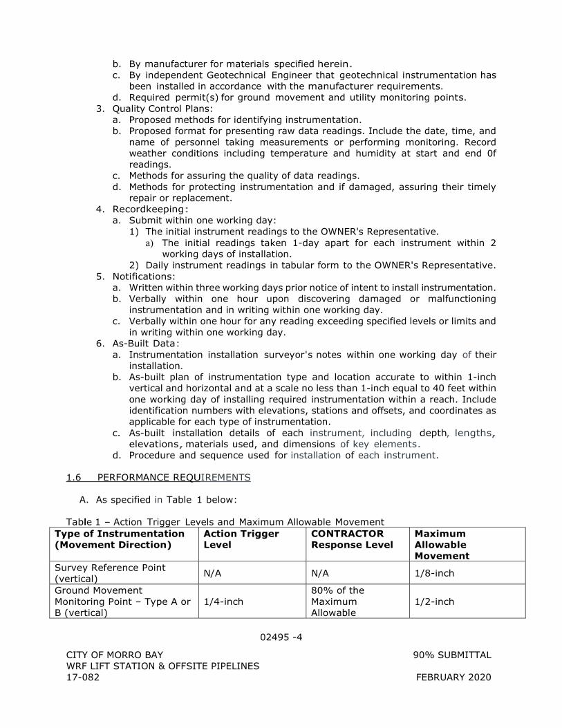
02495 -4
CITY OF MORRO BAY 90% SUBMITTAL WRF LIFT STATION & OFFSITE PIPELINES 17-082 FEBRUARY 2020
b. By manufacturer for materials specified herein. c. By independent Geotechnical Engineer that geotechnical instrumentation has
been installed in accordance with the manufacturer requirements. d. Required permit(s) for ground movement and utility monitoring points.
3. Quality Control Plans: a. Proposed methods for identifying instrumentation. b. Proposed format for presenting raw data readings. Include the date, time, and
name of personnel taking measurements or performing monitoring. Record weather conditions including temperature and humidity at start and end 0f readings.
c. Methods for assuring the quality of data readings. d. Methods for protecting instrumentation and if damaged, assuring their timely
repair or replacement. 4. Recordkeeping:
a. Submit within one working day: 1) The initial instrument readings to the OWNER's Representative.
a) The initial readings taken 1-day apart for each instrument within 2 working days of installation.
2) Daily instrument readings in tabular form to the OWNER's Representative. 5. Notifications:
a. Written within three working days prior notice of intent to install instrumentation. b. Verbally within one hour upon discovering damaged or malfunctioning
instrumentation and in writing within one working day. c. Verbally within one hour for any reading exceeding specified levels or limits and
in writing within one working day. 6. As-Built Data:
a. Instrumentation installation surveyor's notes within one working day of their installation.
b. As-built plan of instrumentation type and location accurate to within 1-inch vertical and horizontal and at a scale no less than 1-inch equal to 40 feet within one working day of installing required instrumentation within a reach. Include identification numbers with elevations, stations and offsets, and coordinates as applicable for each type of instrumentation.
c. As-built installation details of each instrument, including depth, lengths, elevations, materials used, and dimensions of key elements.
d. Procedure and sequence used for installation of each instrument.
1.6 PERFORMANCE REQUIREMENTS
A. As specified in Table 1 below: Table 1 - Action Trigger Levels and Maximum Allowable Movement
Type of Instrumentation (Movement Direction)
Action Trigger Level
CONTRACTOR Response Level
Maximum Allowable Movement
Survey Reference Point (vertical)
N/A N/A 1/8-inch
Ground Movement Monitoring Point – Type A or B (vertical)
1/4-inch 80% of the Maximum Allowable
1/2-inch
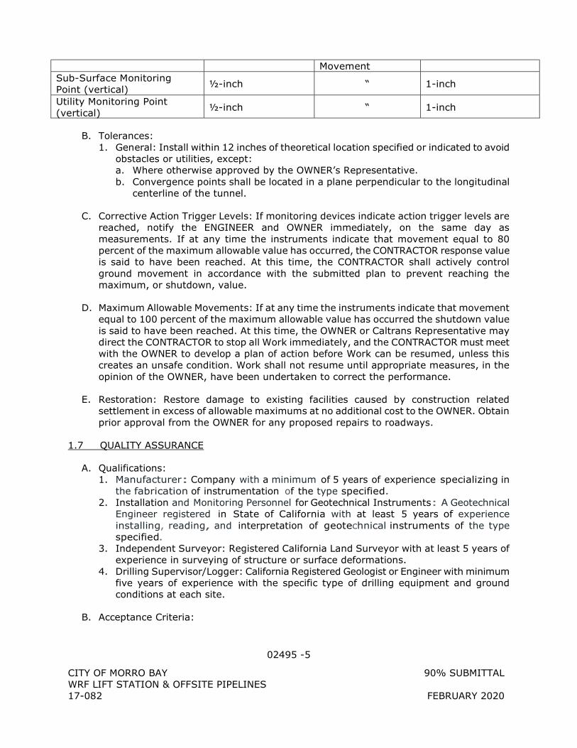
02495 -5
CITY OF MORRO BAY 90% SUBMITTAL WRF LIFT STATION & OFFSITE PIPELINES 17-082 FEBRUARY 2020
Movement Sub-Surface Monitoring Point (vertical) ½-inch “ 1-inch
Utility Monitoring Point (vertical) ½-inch “ 1-inch
B. Tolerances: 1. General: Install within 12 inches of theoretical location specified or indicated to avoid
obstacles or utilities, except: a. Where otherwise approved by the OWNER’s Representative. b. Convergence points shall be located in a plane perpendicular to the longitudinal
centerline of the tunnel.
C. Corrective Action Trigger Levels: If monitoring devices indicate action trigger levels are reached, notify the ENGINEER and OWNER immediately, on the same day as measurements. If at any time the instruments indicate that movement equal to 80 percent of the maximum allowable value has occurred, the CONTRACTOR response value is said to have been reached. At this time, the CONTRACTOR shall actively control ground movement in accordance with the submitted plan to prevent reaching the maximum, or shutdown, value.
D. Maximum Allowable Movements: If at any time the instruments indicate that movement equal to 100 percent of the maximum allowable value has occurred the shutdown value is said to have been reached. At this time, the OWNER or Caltrans Representative may direct the CONTRACTOR to stop all Work immediately, and the CONTRACTOR must meet with the OWNER to develop a plan of action before Work can be resumed, unless this creates an unsafe condition. Work shall not resume until appropriate measures, in the opinion of the OWNER, have been undertaken to correct the performance.
E. Restoration: Restore damage to existing facilities caused by construction related settlement in excess of allowable maximums at no additional cost to the OWNER. Obtain prior approval from the OWNER for any proposed repairs to roadways.
1.7 QUALITY ASSURANCE
A. Qualifications: 1. Manufacturer: Company with a minimum of 5 years of experience specializing in
the fabrication of instrumentation of the type specified. 2. Installation and Monitoring Personnel for Geotechnical Instruments: A Geotechnical
Engineer registered in State of California with at least 5 years of experience installing, reading, and interpretation of geotechnical instruments of the type specified.
3. Independent Surveyor: Registered California Land Surveyor with at least 5 years of experience in surveying of structure or surface deformations.
4. Drilling Supervisor/Logger: California Registered Geologist or Engineer with minimum five years of experience with the specific type of drilling equipment and ground conditions at each site.
B. Acceptance Criteria:
02495 -6
CITY OF MORRO BAY 90% SUBMITTAL WRF LIFT STATION & OFFSITE PIPELINES 17-082 FEBRUARY 2020
1. Provide certification to indicate that the manufacturer's test equipment is calibrated and maintained in accordance with the test equipment manufacturer's calibration requirements, and that all calibrations have been made with equipment certified as meeting standards established by the National Bureau of Standards for that purpose.
C. Preconstruction Meeting: 1. Hold a meeting at least 5 days but not more than 30 days prior to installing each
type of geotechnical instrumentation. 2. Review and discuss the following items at each meeting:
a. Construction methods and constraints to be considered in executing the work. b. Protection of survey equipment. c. Equipment operating parameters. d. Safety procedures. e. Quality Control procedures and Quality Assurance requirements. f. Reporting requirements. g. Other issues as may be raised by either party.
3. Meetings can be combined if multiple types of instrumentation are to be installed at the same time.
D. Testing: Calibrate all sensors and readout instruments at the manufacturer's facility prior to shipment. Verify readings of instruments compared to the factory calibrations once instruments are installed in the field.
E. Job Conditions: Refer to the Geotechnical Investigation Report (GIR) for a description of anticipated ground conditions.
F. Perform geotechnical instrumentation monitoring with a Geotechnical Engineer.
G. Perform ground movement monitoring with an independent licensed surveyor. Surveying for monitoring settlement instrumentation shall be referenced to the same control points and benchmarks established for setting out the Work. Control points shall be tied to benchmarks and other monuments outside of the zone of influence of the excavation or trenchless construction.
H. Procure and install the instrumentation.
1.8 PRODUCT DELIVERY, STORAGE AND HANDLING
A. As recommended by instrument manufacturers.
1.9 SEQUENCING AND SCHEDULING
A. Ensure that instrumentation is installed, fully functional, calibrated, consistent baseline readings are collected, and that the instrumentation is ready for monitoring at least 7 days prior to performing excavation within 500 feet in plan of the designated instrumentation location.
02495 -7
CITY OF MORRO BAY 90% SUBMITTAL WRF LIFT STATION & OFFSITE PIPELINES 17-082 FEBRUARY 2020
1.10 WARRANTY
A. Equipment warranty as provided by the manufacturer.
B. Installation warranty shall be for the period of construction and post-construction instrumentation monitoring as specified herein.
1.11 SAFETY
A. All shaft excavations and support systems shall conform with applicable OSHA excavation, trenching, and shoring standards which are contained in the U.S. Code of Federal Regulations 29 (C.F.R.) 1926.650-1926.653. In the event of a conflict, comply with the more restrictive applicable requirements.
PART 2 - PRODUCTS
2.1 GENERAL
A. Ensure that all instrumentation components are on hand and accepted by the OWNER's Representative before instrument installation begins.
B. Acceptable manufacturer contacts information: 1. Applied Geomechanics Inc., San Francisco, CA 2. Roctest Ltd., I Trans-Border Drive, P.O. Box 3568, Champlain, NY 12919. 3. Slope Indicator Co., 12123 Harbour Reach Drive, Suite 106, Mukilteo, WA, 98275. 4. Geokon, Inc., 48 Spencer Street, Lebanon, NH 03766. 5. RST Instruments LTD., 200-2050 Hartley Avenue, Coquitlam, BC, Canada
C. Upon delivery, check all instrumentation components for completeness and damage. When determined correct and undamaged, deliver all components not to be installed at the Project site to the OWNER.
D. Furnish street-rated monuments with access cover and install at the ground surface to protect installed casings, GMMP, SSMP and UMP. Use steel of sufficient strength to withstand HS-20 truck loadings. Provide a watertight access cover. Use a 12-inch ID traffic rated monument for the instruments.
2.2 GROUND MOVEMENT MONITORING POINT:
A. Ground Movement Monitoring point (GMMP) shall be established by an inscribed marking or approved surveyor’s nail driven flush with the surface in asphalt or concrete paved areas.
B. In landscaped areas, GMMP shall be established by driving a 2-inch by 2-inch timber stake flush with the ground. The stake shall be driven to a depth required to provide a stable control point given the soil conditions.
C. Each GMMP shall have a tag or marking indicating the station and offset from centerline.
02495 -8
CITY OF MORRO BAY 90% SUBMITTAL WRF LIFT STATION & OFFSITE PIPELINES 17-082 FEBRUARY 2020
D. Install GMMP as shown on the Plans and as approved by the OWNER’s Representative.
2.3 SUBSURFACE MONITORING POINT:
A. Subsurface monitoring point (SSMP) shall be established and installed as indicated on the Drawings. Each point shall consist of a #6 rebar settlement rod installed within and isolated from a PVC cased borehole.
B. The settlement rod shall be driven 6 to 12 inches past the bottom of the borehole casing and the tips shall be located at ten feet above the pipe crown centerline as noted on the Drawings, or as directed by the ENGINEER.
C. The settlement rod shall be secured to the PVC casing with a 12-inch length of loose cable or chain to prevent the rod from falling more than approximately 12 inches.
D. The casing shall be flush with pavement or recessed, and capped and protected with a HS-20 traffic rated box if installed within traffic lanes, shoulders, parking lots, or bike lanes and shall be in accordance with the CITY and other applicable permit requirements.
E. Refer to Plans for additional instrumentation details.
2.4 UTILITY MONITORING POINT
A. Use standard weight black steel pipe and threaded couplings, ASTM A53, welded, standard weight, for inner bench marks monitoring pipes and outer casing.
B. Use PVC or ABS glue-welded couplings for outer casings.
C. Use ball fabricated read points made of stainless steel.
D. Use centering devices for placement between the inner benchmark and outer casing that is suitable for use in deep settlement markers.
PART 3 - EXECUTION
3.1 GENERAL
A. Instrumentation shall be installed at the locations shown on the Drawings, and as approved by the ENGINEER. Instruments shall be installed in accordance with the approved installation schedule.
B. The CONTRACTOR shall locate conduits and underground utilities in all areas where borings are to be drilled and instruments installed. Instrument locations shall be modified, as approved by the ENGINEER, to avoid interference with the existing conduit and utilities. Repair damage to existing utilities resulting from instrument installations at no additional cost to the OWNER.
C. CONTRACTOR shall install and perform a baseline survey of all surface and subsurface settlement monitoring devices at least 14 days prior to excavation.
02495 -9
CITY OF MORRO BAY 90% SUBMITTAL WRF LIFT STATION & OFFSITE PIPELINES 17-082 FEBRUARY 2020
D. CONTRACTOR shall provide access and assistance to the ENGINEER for obtaining supplemental monitoring data, as requested by ENGINEER.
E. Provide data from readings of all monitoring points to the ENGINEER within 24 hours of reading.
F. Dispose of excavated materials in accordance with the requirements of Section 02220.
3.2 PREPARATION
A. Prepare, clear, and strip instrument locations in accordance with this specs and drawings.
B. Provide additional excavation in accordance with Section 02300.
3.3 INSTALLATION
A. General: 1. Install instrumentation at the locations indicated unless otherwise directed by the
OWNER. Install in accordance with the manufacturer's printed instructions and as specified in this Section. Install within the accuracy limits specified by the manufacturer.
2. Inspect and log any drilled hole for instrument installation in accordance with the associated ASTM standards. Confirm the ground conditions are compatible with proposal installation.
B. Survey Reference Point: 1. Furnish and install survey reference points as indicated on Plans and as specified
herein.
C. GMMP: 1. Furnish and install ground movement monitoring points as shown on the Plans and as
specified herein or as accepted by the OWNERs-Representative. 2. Surveying of GMMPs will consist of determining the elevation of each control point
with respect to a benchmark selected by the ENGINEER to a precision of 0.01 foot.
D. Utility Monitoring Points: 1. Locations for utility monitoring points as shown on the Plans are based on as-built
information available. Determine the locations of the utilities to be monitored accurately by potholing prior to Installation of the utility monitoring points.
2. Furnish and install utility monitoring points as shown on the Plans or as accepted by the OWNER's Representative.
E. SSMP: 1. Notify the ENGINEER at least 5 days in advance of installing subsurface monitoring
points. 2. The subsurface monitoring points shall be installed as close as practicable to the
locations shown on the Drawings. The ENGINEER may modify subsurface monitoring point locations depending on field conditions, conflicting utilities and monitoring objectives.
02495 -10
CITY OF MORRO BAY 90% SUBMITTAL WRF LIFT STATION & OFFSITE PIPELINES 17-082 FEBRUARY 2020
3. Locate and confirm all utilities and protect utilities or relocate monitoring points as necessary to protect all utilities. Follow accepted industry procedures for one-call notification and visual confirmation of locations of all crossing or adjacent utilities.
4. Subsurface monitoring point installations shall be completed at least 14 days in advance of commencing shaft construction or bore and jack operations.
5. Conduct drilling operations using appropriate methods that are consistent with anticipated geologic conditions. Use mud rotary wash methods or provide casing as required to hold drill hole open.
6. Subsurface monitoring rods shall move freely with the soil at the tip and shall be isolated from the soil surrounding the borehole by the casing.
7. Protection: Install protective housing with cap. Protective housing shall be installed within a flush-mounted precast concrete box or vault so as not to obstruct vehicle or foot traffic, and shall be in accordance with CITY standards and permit requirements.
3.4 MAINTENANCE AND REPAIR/RESTORATION
A. Protect and maintain instruments throughout the duration of monitoring. Drain water or flush debris from under traffic covers. Keep traffic covers secured.
B. Provide substantial proactive barriers around instruments in construction areas that can be damaged from construction activities.
C. Maintain instrumentation in accordance with manufacturer recommendations and industry standard of practice.
D. Repair instrumentation in accordance with manufacturer recommendations or replace damaged or missing instrumentation. Repair or replace damaged or missing instrument components or entire instrument within 48 hours or as accepted by OWNER's Representative.
E. For replacement instrumentation, take initial readings and correlate with previous readings.
3.5 SURVEYS AND INITIAL READINGS
A. After installation, survey the location of the top of each instrument or its marker point to a horizontal accuracy of 0.10 feet and elevation accuracy of 0.01 feet. Submit location information to the OWNER.
B. After completion of each instrument installation, take 3 sets of verification data readings for each instrument to demonstrate the adequacy of the installation, to demonstrate the proper operation of the instrument, and to establish an initial value. Submit the initial readings to the OWNER.
3.6 INSTRUMENTATION AND MONITORING
A. General: 1. The CONTRACTOR shall monitor all instruments during construction. Upon request,
provide such assistance, labor and equipment necessary to set up instrumentation
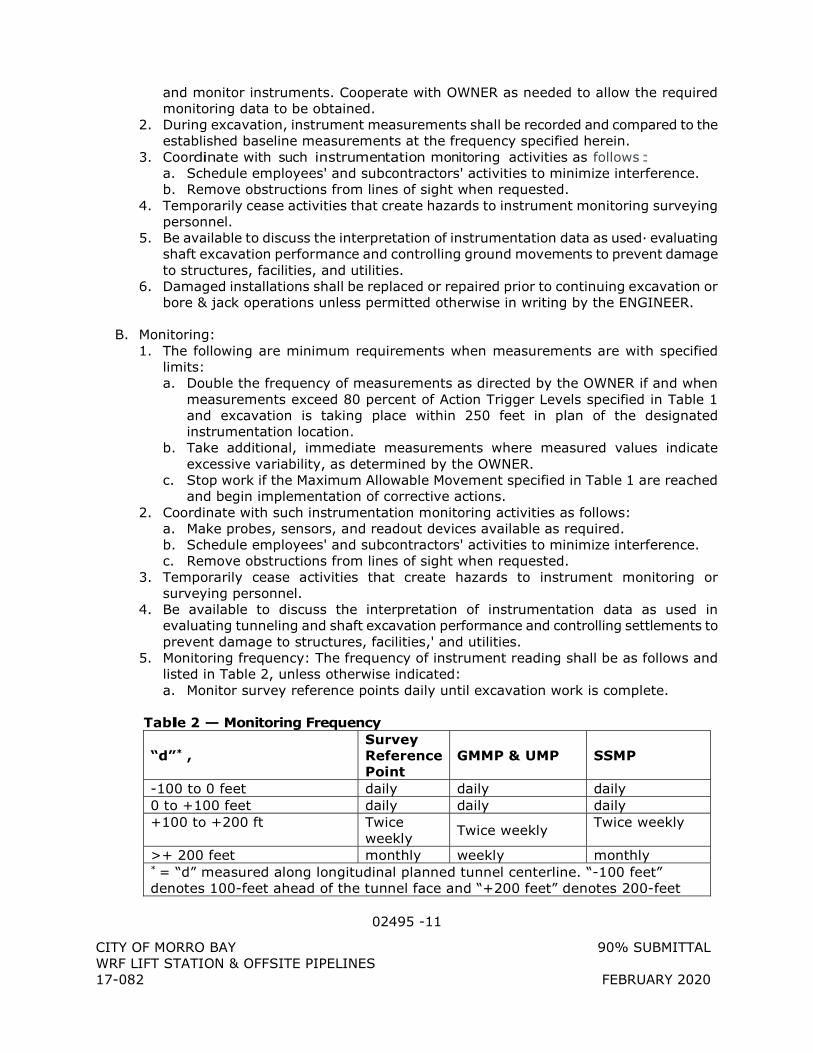
02495 -11
CITY OF MORRO BAY 90% SUBMITTAL WRF LIFT STATION & OFFSITE PIPELINES 17-082 FEBRUARY 2020
and monitor instruments. Cooperate with OWNER as needed to allow the required monitoring data to be obtained.
2. During excavation, instrument measurements shall be recorded and compared to the established baseline measurements at the frequency specified herein.
3. Coordinate with such instrumentation monitoring activities as follows: a. Schedule employees' and subcontractors' activities to minimize interference. b. Remove obstructions from lines of sight when requested.
4. Temporarily cease activities that create hazards to instrument monitoring surveying personnel.
5. Be available to discuss the interpretation of instrumentation data as used· evaluating shaft excavation performance and controlling ground movements to prevent damage to structures, facilities, and utilities.
6. Damaged installations shall be replaced or repaired prior to continuing excavation or bore & jack operations unless permitted otherwise in writing by the ENGINEER.
B. Monitoring: 1. The following are minimum requirements when measurements are with specified
limits: a. Double the frequency of measurements as directed by the OWNER if and when
measurements exceed 80 percent of Action Trigger Levels specified in Table 1 and excavation is taking place within 250 feet in plan of the designated instrumentation location.
b. Take additional, immediate measurements where measured values indicate excessive variability, as determined by the OWNER.
c. Stop work if the Maximum Allowable Movement specified in Table 1 are reached and begin implementation of corrective actions.
2. Coordinate with such instrumentation monitoring activities as follows: a. Make probes, sensors, and readout devices available as required. b. Schedule employees' and subcontractors' activities to minimize interference. c. Remove obstructions from lines of sight when requested.
3. Temporarily cease activities that create hazards to instrument monitoring or surveying personnel.
4. Be available to discuss the interpretation of instrumentation data as used in evaluating tunneling and shaft excavation performance and controlling settlements to prevent damage to structures, facilities,' and utilities.
5. Monitoring frequency: The frequency of instrument reading shall be as follows and listed in Table 2, unless otherwise indicated: a. Monitor survey reference points daily until excavation work is complete.
Table 2 – Monitoring Frequency
“d”* , Survey Reference Point
GMMP & UMP SSMP
-100 to 0 feet daily daily daily 0 to +100 feet daily daily daily +100 to +200 ft Twice
weekly Twice weekly
Twice weekly
>+ 200 feet monthly weekly monthly * = “d” measured along longitudinal planned tunnel centerline. “-100 feet” denotes 100-feet ahead of the tunnel face and “+200 feet” denotes 200-feet
02495 -12
CITY OF MORRO BAY 90% SUBMITTAL WRF LIFT STATION & OFFSITE PIPELINES 17-082 FEBRUARY 2020
behind the excavated tunnel face.
C. Response Values: 1. Action Trigger Level:
a. Identify the cause of movement. b. Provide verbal and written notice as specified herein. c. Meet with the ENGINEER and OWNER's Representative to discuss means and
methods to determine what changes, if any, must be made to better control ground movement.
2. CONTRACTOR Response Level: a. Review all monitoring, excavation, and ground condition data in the area to
establish cause of movement. Take initial actions to actively control ground movement.
b. Immediately meet with the ENGINEER and OWNER's Representative to discuss means and methods to determine what changes must be made to better control ground movement.
3. Maximum Allowable Movement: a. Stop all Work immediately. b. Provide verbal and written notice as specified herein. c. Review all monitoring, excavation and ground condition data in the area to
establish cause of movement. d. Conduct a meeting with the OWNER's Representative, ENGINEER and other
respected parties/agencies: 1) Review monitoring data. 2) Develop a plan of action, including modification to construction procedures
and means and methods, before the Work can be resumed. 3) Outline “plan of action and next steps” to the OWNER of damaged or affected
facilities and structures and perform corrective and restorative measures on an agreed timetable.
3.7 INSTRUMENT PROTECTION, MAINTENANCE AND RESTORATION
A. Protect and maintain instruments throughout the duration of' monitoring. Drain water or flush debris from under traffic covers. Keep traffic covers secured.
B. Provide substantial protective barriers around instruments in construction areas that are suitable for protecting instruments from damage due to construction activities.
C. Maintain instrumentation in accordance with manufacturer recommendations.
D. Repair or replace damaged or missing instrumentation in accordance with manufacturer recommendations. Repair or replace damaged or missing instrument components or entire instrument within 48 hours or as approved by OWNER.
E. If an instrument is considered critical to construction and becomes damaged, the CONTRACTOR will be instructed to cease Work until the damaged instrument is replaced and readings established. The CONTRACTOR will not be entitled to additional time or compensation for the damage instrument.
02495 -13
CITY OF MORRO BAY 90% SUBMITTAL WRF LIFT STATION & OFFSITE PIPELINES 17-082 FEBRUARY 2020
F. For replacement instrumentation, take initial readings and correlate with previous readings.
3.8 FILED QUALITY CONTROL
A. Quality control will be performed under the provisions of Section 01400.
B. Products: Submit verification that the installed products are authentic (delivery receipts, bill of lading, etc.).
C. Execution: Submit verification that the work was installed correctly (inspection records, as-built drawings, etc.). 1. Provide survey coordinates for all buried products. 2. Provide photographs for all buried products.
D. Testing and Inspection 1. The CONTRACTOR's QC program shall be responsible for the performance of all
inspections and testing. 2. The CONTRACTOR shall provide access to the ENGINEER or Testing Agency for
additional inspection and testing.
3.9 REMOVAL
A. General: 1. Verify with OWNER that instrumentation is no longer required. 2. Remove instrumentation prior to substantial completion of the work, unless otherwise
indicated. 3. Remove all instrumentation per requirements and methods of the applicable County
or applicable regulating agency. 4. Remove Utility Monitoring Points in accordance with Utility Owner requirements. 5. Backfill grout holes with grout mix approved by the applicable county or regulating
agency and restore surfaces to conditions existing before installation. 6. Fill holes drilled in masonry or concrete surfaces with cement mortar or CLSM to
present an appearance matching the surrounding surface.
B. GMMP & SSMP: 1. All ground movement monitoring points on public property shall remain in place at
the completion of the Work. Remove all GMMPs on private property during the cleanup and restoration work, or as required by the ENGINEER
2. Properly abandon all subsurface monitoring points, by grouting drilled holes with neat cement grout. SSMP shall be abandoned at the conclusion of the monitoring phase or as required by the ENGINEER.
+ + END OF SECTION + +
02770-1
CITY OF MORRO BAY 90% SUBMITTAL WRF LIFT STATION & OFFSITE PIPELINES 17-082 FEBRUARY 2020
SECTION 02770
ASPHALT CONCRETE PAVING
PART 1 - GENERAL
1.1 SUBMITTALS
A. Information Submittals: 1. Asphalt Concrete Mix Formula:
a. Submit minimum of 15 days prior to start of production. b. Submittal to include the following information:
1) Gradation and portion for each aggregate constituent used in mixture to produce a single gradation of aggregate within specified limits.
2) Bulk specific gravity for each aggregate constituent. 3) Measured maximum specific gravity of mix at optimum asphalt content
determined in accordance with ASTM D2041. 4) Percent of asphalt lost due to absorption by aggregate. 5) Percentage of asphalt cement, to nearest 0.1 percent, to be added to mixture. 6) Optimum mixing temperature. 7) Optimum compaction temperature. 8) Temperature-viscosity curve of asphalt cement to be used.
2. Test Report for Asphalt Cement: a. Submit minimum 10 days prior to start of production. b. Show appropriate test method(s) for each material and the test results.
3. Statement of qualification for independent testing laboratory. 4. Test Results:
a. Mix design. b. Asphalt concrete core. c. Gradation and asphalt content of uncompacted mix.
1.2 QUALITY ASSURANCE
A. Qualifications: 1. Independent Testing Laboratory: In accordance with ASTM E329. 2. Asphalt concrete mix formula shall be prepared by approved certified independent
laboratory under the supervision of a certified asphalt technician.
1.3 ENVIRONMENTAL REQUIREMENTS
A. Temperature: Do not apply asphalt materials or place asphalt mixes when ground temperature is lower than 10 degrees C (50 degrees F) or air temperature is lower than 4 degrees C (40 degrees F). Measure ground and air temperature in shaded areas away from heat sources or wet surfaces.
B. Moisture: Do not apply asphalt materials or place asphalt mixes when application surface is wet.
02770-2
CITY OF MORRO BAY 90% SUBMITTAL WRF LIFT STATION & OFFSITE PIPELINES 17-082 FEBRUARY 2020
PART 2 - PRODUCTS
2.1 MATERIALS
A. Asphalt Material: Conform to the following specification: 1. Asphalt Material shall be a hot mix asphalt concrete, consisting of a mixture of
mineral aggregate and paving asphalt conforming to Section 92 of the Caltrans Standard Specifications, PG 64-10.
B. Seal Coat: Conform to the following specification: 1. Seal coat material shall be conforming to Section 37 of the Caltrans Standard
Specifications. 2. Seal coat material shall be conforming to Section 333 of the MAG Specifications. 3. Seal coat material shall be hot mix asphalt concrete consisting of a mixture of
mineral aggregate and paving asphalt conforming to Section 407 of the Nevada Department of Transportation Standard Specifications for Road and Bridge Construction.
PART 3 - EXECUTION
3.1 GENERAL
A. Traffic Control: 1. In accordance with all applicable specification sections and laws. 2. Minimize inconvenience to traffic, but keep vehicles off freshly treated or paved
surfaces to avoid pickup and tracking of asphalt.
B. Driveways: Repave driveways from which pavement was removed. Leave driveways in as good or better condition than before start of construction.
3.2 LINE AND GRADE
A. Provide and maintain intermediate control of line and grade, independent of underlying base, to meet finish surface grades and minimum thickness.
B. Shoulders: Construct to line, grade, and cross-section shown.
3.3 PREPARATION
A. Prepare subgrade as specified.
B. Thoroughly coat edges of contact surfaces with emulsified asphalt or asphalt cement prior to laying new pavement. Prevent staining of adjacent surfaces.
3.4 PAVEMENT APPLICATION
A. General: Place asphalt concrete mixture on approved, prepared base in conformance with this section.
B. Pavement Mix: 1. Prior to Paving:
02770-3
CITY OF MORRO BAY 90% SUBMITTAL WRF LIFT STATION & OFFSITE PIPELINES 17-082 FEBRUARY 2020
a. Sweep primed surface free of dirt, dust, or other foreign matter. b. Patch holes in primed surface with asphalt concrete pavement mix.
2. Place asphalt concrete pavement mix in one single lift. 3. Total Compacted Thickness: 3 inches. 4. Apply such that meet lines are straight and edges are vertical. 5. Collect and dispose of segregated aggregate from raking process. Do not scatter
material over finished surface. 6. After placement of pavement, seal meet line by painting a minimum of
150 millimeters (6 inches) on each side of joint with cut-back or emulsified asphalt. Cover immediately with sand.
C. Compaction: Roll until roller marks are eliminated and density of 92 percent of measured maximum density determined in accordance with ASTM D2041.
D. Tolerances: 1. General: Conduct measurements for conformity with crown and grade immediately
after initial compression. Correct variations immediately by removal or addition of materials and by continuous rolling.
2. Completed Surface or Wearing Layer Smoothness: a. Uniform texture, smooth, and uniform to crown and grade. b. Maximum Deviation: 1/8 inch from lower edge of a 3.6-meter (12-foot)
straightedge, measured continuously parallel and at right angle to centerline. c. If surface of completed pavement deviates by more than twice specified
tolerances, remove and replace wearing surface. 3. Transverse Slope Maximum Deviation: 1/4 inch.
E. Seal Coat: 1. General: Apply seal coat of paving grade or emulsified asphalt to finished surface at
longitudinal and transverse joints, joints at abutting pavements, areas where asphalt concrete was placed by hand, patched surfaces, and other areas as directed by ENGINEER.
2. Preparation: a. Surfaces that are to be sealed shall be maintained free of holes, dry, and clean of
dust and loose material. b. Seal in dry weather and when temperature is above 2 degrees C (35 degrees F).
3. Application: a. Fill cracks over 1.5 millimeters (1/16 inch) in width with asphalt-sand slurry or
approved crack sealer prior to sealing. b. When sealing patched surfaces and joints with existing pavements, extend
minimum 150 millimeters (6 inches) beyond edges of patches.
+ + END OF SECTION + +
02830-1
CITY OF MORRO BAY 90% SUBMITTAL WRF LIFT STATION & OFFSITE PIPELINES 17-082 FEBRUARY 2020
SECTION 02830
CHAIN LINK FENCES AND GATES
PART 1 - GENERAL
1.1 SUBMITTALS
A. Shop Drawings: Detailed information and specifications for materials, finishes, and dimensions.
B. Samples: Approximately 6 inches square, or 6 inches long of posts, rails, braces, fabric, wire, ties, and fittings.
C. Quality Control Submittals: 1. Manufacturer's recommended installation instructions. 2. Evidence of Supplier and installer qualifications.
1.2 SCHEDULING AND SEQUENCING
A. Complete necessary site preparation and grading before installing chain link fence and gates.
PART 2 - PRODUCTS
2.1 GENERAL
A. Match style, finish, and color of each fence component with that of other fence components.
2.2 CHAIN LINK FENCE FABRIC
A. PVC-coated galvanized fabric conforming to ASTM F668, Class 1 or 29. 1. Color: Black. 2. Manufacturers and Products:
a. Colorbond Corp., Raritan, NJ; Colorbond II. b. Cyclone Fence, United States Steel, Chicago, IL; Cyclone Color Fence System.
B. Height: 72 inches, unless otherwise shown.
C. Wire Gauge: No. 9.
D. Pattern: 2-inch diamond-mesh.
E. Diamond Count: Manufacturer's standard and consistent for fabric furnished of same height.
F. Loops of Knuckled Selvages: Closed or nearly closed with space not exceeding diameter of wire.
02830-2
CITY OF MORRO BAY 90% SUBMITTAL WRF LIFT STATION & OFFSITE PIPELINES 17-082 FEBRUARY 2020
G. Wires of Twisted Selvages: 1. Twisted in a closed helix three full turns. 2. Cut at an angle to provide sharp barbs that extend minimum 1/4-inch beyond twist.
H. Privacy Slats, if called for on Drawings: 1. HDPE or PVC Top Lock slats sized for No. 9 gauge 2-inch mesh, approximately 1
3/32-inches wide. 2. Length to match the fabric height minus 2 inches. 3. Color selected by OWNER.
2.3 POSTS
A. General: 1. Strength and Stiffness Requirements: ASTM F669, Heavy Industrial Fence, except as
modified in this section. 2. Steel Pipe: ASTM F1083. 3. Roll-Formed Steel Shapes: Roll-formed from ASTM A570, Grade 45, steel. 4. Protective Coatings:
a. Zinc Coating: ASTM F1234, Type A external and internal coating. 5. Color Coating: ASTM F1043, minimum 10 mils thickness over zinc coating to match
color of chain link fabric.
B. Line Posts: 1. Steel Pipe:
a. Outside Diameter: 2.375-inch. b. Weight: 3.65 pounds per foot.
2. Roll-Formed Steel C Shape: a. Outside Dimensions: 2.25-inch by 1.625-inch. b. Weight: 2.70 pounds per foot.
3. Steel H-Section: a. Outside Dimensions: 2.25-inch by 1.70-inch. b. Weight: 3.26 pounds per foot.
C. End, Corner, Angle, and Pull Posts: 1. Steel Pipe:
a. Outside Diameter: 2.875-inch. b. Weight: 5.79 pounds per foot.
D. Posts for Removable Fence Panels: As specified for end, corner, angle, and pull posts.
E. Posts for Swing Gates: 1. Material: ASTM F1043 Group IA ASTM F1083 schedule 40 pipe. 2. Gate Post Size per ASTM F900:
For gate fabric height up to and including 6 feet Gate Leaf Width Post Outside Diameter Up to 4 ft 2.375-inch Over 4 ft to 10 ft 2.875-inch Over 10 ft to 18 ft 4.0-inch For gate fabric height over 6 feet to 12 feet Up to 6 ft 2.875-inch Over 6 ft to 12 ft 4.0-inch Over 12 ft to 18 ft 6.625-inch
02830-3
CITY OF MORRO BAY 90% SUBMITTAL WRF LIFT STATION & OFFSITE PIPELINES 17-082 FEBRUARY 2020
Over 18 ft to 24 ft 8.625-inch a. Roll-formed steel shapes may be substituted for steel pipe posts for gate leaf
widths up to 6 feet and fabric heights up to 8 feet. 1) Outside Dimensions: 3.5-inch by 3.5-inch. 2) Weight: 4.85 pounds per foot.
2.4 TOP RAILS AND BRACE RAILS
A. Galvanized steel pipe or roll-formed steel C shapes, color-coated.
B. Protective Coatings: As specified for posts.
C. Color Coating: ASTM F1043, minimum 10 mils thickness over zinc coating to match color of chain link fabric.
D. Strength and Stiffness Requirements: ASTM F669, Top Rail, Heavy or Light Industrial Fence.
E. Steel Pipe: 1. ASTM F1083. 2. Outside Diameter: 1.66-inch. 3. Weight: 2.27 pounds per foot.
F. Roll-Formed Steel C Shapes: 1. Roll formed from ASTM A570, Grade 45. 2. Outside Dimensions: 1.625-inch by 1.25-inch. 3. Weight: 1.40 pounds per foot.
2.5 FENCE FITTINGS
A. General: In conformance with ASTM F626, except as modified by this article.
B. Post and Line Caps: Designed to accommodate passage of top rail through cap, where top rail required.
C. Tension and Brace Bands: No exceptions to ASTM F626.
D. Tension Bars: 1. One-piece. 2. Equal in length to full height of fabric.
E. Truss Rod Assembly: 3/8-inch diameter.
F. Barb Arms: 45-degree arms for supporting three strands of barbed wire.
2.6 TENSION WIRE
A. Zinc-coated steel marcelled tension wire conforming to ASTM A824, Type II, Class 2.
02830-4
CITY OF MORRO BAY 90% SUBMITTAL WRF LIFT STATION & OFFSITE PIPELINES 17-082 FEBRUARY 2020
2.7 GATES
A. General: 1. Gate Operation: Opened and closed easily by one person. 2. Welded Steel Joints: Paint with zinc-based paint. 3. Chain Link Fabric: Attached securely to gate frame at intervals not exceeding
15 inches.
B. Swing Gates: ASTM F900. 1. Hinges:
a. Furnished with large bearing surfaces for clamping in position. b. Designed to swing either 180 degrees outward, 180 degrees inward, or
90 degrees in or out, as shown, and not twist or turn under action of gate. 2. Latches: Plunger bar arranged to engage stop, except single gates of openings less
than 10 feet wide may each have forked latch. 3. Gate Stops: Mushroom type or flush plate with anchors, suitable for setting in
concrete. 4. Locking Device and Padlock Eyes: Integral part of latch, requiring one padlock for
locking both gate leaves of double gates. 5. Hold-Open Keepers: Designed to automatically engage gate leaf and hold it in open
position until manually released.
C. Fabric Salvage: Knuckled.
D. Appurtenances and Framework: As specified.
2.8 REMOVABLE FENCE PANELS
A. Panel Length: 1. Equal division of total length of removable fence section. 2. Maximum 10 feet.
B. Frames: ASTM F1184, Type I.
2.9 CONCRETE
A. Provide as specified in Section 03300, CAST-IN-PLACE CONCRETE.
PART 3 - EXECUTION
3.1 GENERAL
A. Install chain link fences and gates in accordance with ASTM F567, except as modified in this section, and in accordance with fence manufacturer's recommendations, as approved by ENGINEER. Erect fencing in straight lines between angle points.
B. Provide all necessary hardware for a complete fence and gate installation.
3.2 PREPARATION
A. Establish locations of fence lines, gates, and terminal posts.
02830-5
CITY OF MORRO BAY 90% SUBMITTAL WRF LIFT STATION & OFFSITE PIPELINES 17-082 FEBRUARY 2020
3.3 POST SETTING
A. Driven posts are not acceptable.
B. Post Hole Depth: 1. Minimum 3 feet below finished grade. 2. 2 inches deeper than post embedment depth below finish grade.
C. Backfill post holes with concrete to 2 inches above finished grade.
D. Before concrete sets, crown and finish top of concrete to readily shed water.
3.4 BRACING
A. Brace gate and corner posts diagonally to adjacent line posts to ensure stability.
3.5 TOP RAILS
A. Install top rail sleeves with springs at 105 feet maximum spacing to permit expansion in rail.
3.6 CHAIN LINK FABRIC
A. Do not install fabric until concrete has cured minimum 7 days.
B. Install fabric with twisted and barbed selvage at top.
3.7 GATES
A. Hang gates and adjust hardware so gates operate satisfactorily from open or closed position.
B. Set gate stops in concrete to engage center drop rod or plunger bar.
3.8 ELECTRICAL GROUNDING
A. Ground fences in accordance with applicable requirements of IEEE C2, National Electrical Safety Code.
3.9 FIELD QUALITY CONTROL
A. Gate Tests: Prior to acceptance of installed gates and gate operator systems, demonstrate proper operation of gates under each possible open and close condition specified.
+ + END OF SECTION + +
02900-1
CITY OF MORRO BAY 90% SUBMITTAL WRF LIFT STATION & OFFSITE PIPELINES 17-082 FEBRUARY 2020
SECTION 02900
LANDSCAPE PLANTING
PART 1 - GENERAL
1.1 SCOPE OF WORK
A. Furnish all materials, labor, transportation, services, and equipment necessary to install landscape planting as shown on the Drawings and as specified herein. Any and all permits, fees, bonds, and observations necessary to perform and complete portion of the work shall be included.
B. Work included in this Section: 1. Verification of Existing Conditions 2. Surface Drainage of Planting Areas 3. Preparation 4. Plant Installation 5. Watering 6. Cleanup 7. Site Observation Before Acceptance 8. Site Observation Schedule
1.2 REQUIREMENTS OF REGULARTORY AGENCIES
A. All Federal, State, and local laws and regulations governing this work are hereby incorporated into and made part of this Section. When this Section calls for certain materials, workmanship or a level of construction that exceeds the level of Federal, State, or local requirements, the provisions of this Section shall take precedence.
1.3 REFERENCE STANDARDS
A. All plant material shall be true to botanical and common name as indicated in: 1. McClintock, E. M., and A. T. Leiser. 1979. An Annotated Checklist of Woody
Ornamental Plants of California, Oregon, and Washington. University of California, Division of Agricultural Sciences. Berkeley, CA.
2. American Nursery & Landscape Association. 2004. American Standard for Nursery Stock. ANSI Z60.1-2004. Washington, DC.
3. L. H. Bailey Hortorium of Cornell University. 1976. Hortus Third: A Concise Dictionary of Plants Cultivated in the United State and Canada. Macmillan. New York, NY.
4. Hickman, J.C. (ed.). 1993. The Jepson Manual: Higher Plants of California. University of California Press. Berkeley, CA.
5. U.S. Natural Resources Conservation Service. 2011. Plants Database. Available: <http://plants.usda.gov>. Last updated May 16, 2011.
B. All plant material shall conform to the California State Department of Agriculture’s regulations for nursery observations, rules and ratings. 1. Quality Control
02900-2
CITY OF MORRO BAY 90% SUBMITTAL WRF LIFT STATION & OFFSITE PIPELINES 17-082 FEBRUARY 2020
C. Manufacturer’s directions and drawings shall be followed in all cases where the manufacturers of articles used in this Specification furnish directions covering points not shown in the Drawings and Specifications.
D. Upon execution of the order, the Engineer has the option of either inspecting the plant material at the nursery, requesting representative color photos or inspecting the material as it is being delivered to the site for conformity to the Drawings and Specifications. 1. Such approvals shall not impair the right of additional observations during further
progress of the Work.
E. Any tagging of plant material by the Engineer does not constitute his/her approval of the plant materials’ health and vigor. The health and vigor of the plant material is the sole responsibility of the Contractor.
F. The Engineer reserves the right to refuse observation, if in his judgment; a sufficient quantity of plant material is not available for observation at that time.
1.4 QUALIFICATIONS
A. The nursery that supplied planting materials shall be a reputable nursery.
1.5 SUBMITTALS
A. Submit in accordance with Section 01330: 1. List of all proposed materials and equipment to be used indicated by description,
manufacturer and model number, if applicable. Include catalog cuts where applicable. 2. A copy of the plant procurement order from the nursery including the name, address,
and phone number of said nursery. 3. Plant quantity list.
a. Plant quantities shown on the Drawings are for estimation only. Provide the actual planting quantities.
b. List all plants indicated by botanical name, common name, quantity, size, nursery and location and any specific remarks, (e.g., “unable to locate,” “photo submitted,” etc.).
4. Written documentation that the plant material listed on the Drawings is available. Any substitutions required due to unavailability must be requested in writing before confirmation of ordering.
5. A schedule identifying plant procurement, storage, and anticipated delivery dates for review and approval.
6. Compliance with State of California and federal quarantine restrictions.
1.6 PROJECT CONDITIONS
A. Perform planting operations only when weather and soil conditions are suitable in accordance with locally accepted practice.
1.7 PRODUCT DELIVERY, STORAGE AND HANDLING
A. Delivery 1. Deliver all planting materials with legible and durable identification labels.
02900-3
CITY OF MORRO BAY 90% SUBMITTAL WRF LIFT STATION & OFFSITE PIPELINES 17-082 FEBRUARY 2020
2. Deliver fertilizer to the site in original, unopened containers bearing the manufacturer’s name, guaranteed chemical analysis, and its conformance to California State Law.
3. Notify the Engineer within 7 days of the delivery of plant materials to the site. Indicate the quantity and type of plant materials in each delivery.
B. Storage 1. Store planting materials in the shade and protect from the weather. 2. Maintain and protect plants not planted within 4 hours of delivery.
C. Protection 1. Protect plants during delivery to the site and after, in order to prevent damage to the
root balls or desiccation of leaves.
D. Handling 1. Take extreme care in the loading and unloading of plants. Do not lift or move
container plants by their stems or trunks. 2. Any plant materials that are damaged due to mishandling shall be removed and
replaced with new material at no additional cost.
1.8 REJECTION OF PLANT MATERIAL
A. All plant material not conforming to the requirements herein shall be considered defective. 1. The Engineer shall mark such plants, whether in place or not, as rejected and the
materials shall be immediately removed from the site and replaced with new material at no additional cost.
2. Replacement plant material shall be of the same size, species and condition as that indicated on the Drawings.
1.9 PROTECTION OF THE SITE
A. Protect previously installed work and materials which may be affected by work of this Section. Provide safeguards and exercise caution against injury or defacement of existing site improvements.
B. Repair damage and return the areas to the previous condition at no additional cost.
1.10 COORDINATION
A. Coordinate operations with other contractors on or adjacent to the project site.
B. Exercise extreme care in excavating and working near existing utilities. Repair any damages to these utilities at no additional cost. Check existing utility drawings for existing utility locations.
C. Coordinate installation of all planting materials to avoid interference with utilities, other construction elements, and any existing vegetation.
02900-4
CITY OF MORRO BAY 90% SUBMITTAL WRF LIFT STATION & OFFSITE PIPELINES 17-082 FEBRUARY 2020
1.11 GUARANTEE
A. The manufacturer’s warranty shall not relieve the Contractor of its own liability under the guarantee. Such warranties shall only supplement the guarantee.
B. All plant material installed under this Contract shall be guaranteed against poor, inadequate and inferior quality and installation for a period of 1 year from the date of Final Acceptance. 1. Any plant material not meeting the satisfaction of the Engineer as per the
performance standards in Section 02970, Landscape Maintenance, shall immediately be removed and replaced at no cost to the Owner.
2. Replaced plant material shall also be guaranteed for a period of 1 year upon installation.
C. Replace without cost to the Owner and as soon as weather permits, all dead plants and all plants not found in a vigorous, thriving condition, as determined by the Engineer during and at the end of the plant warranty period. 1. Replacement of plants shall closely match adjacent specimens of the same species
and shall be subject to all requirements of this section.
D. Repair damage to adjacent plant material at no cost to the Owner. All repairs shall be made with materials, varieties and sizes “in kind” with adjacent existing materials.
PART 2 - PRODUCTS
2.1 GENERAL
A. Procure all plant materials and incidentals required for this project.
B. All plant material delivered to the site shall have a normal habit of growth and be well formed and shaped, healthy, vigorous, and free of any insects, diseases, sunscalds, windburn, abrasions of the bark, or other objectionable disfigurements.
C. The size of the plant material shall correspond with that normally expected for species and variety of commercially available nursery stock or as specified on the Drawings.
D. Plant material shall be grown under climatic conditions similar to those in the locality of the project unless approved otherwise by the Engineer.
E. Plant material larger than that specified on the Drawings may be used pending approval from the Engineer. However, there will be no change in the Contract amount if the larger plant material is approved and used.
2.2 MATERIALS
A. Planting soil and backfill for all planting pits shall be existing topsoil.
B. Trees and Shrubs 1. Tree and shrub trunks shall be sturdy and well hardened with vigorous and fibrous
root systems which are not root-bound.
02900-5
CITY OF MORRO BAY 90% SUBMITTAL WRF LIFT STATION & OFFSITE PIPELINES 17-082 FEBRUARY 2020
2. In the event of a disagreement as to the condition of the root system, the root conditions of the plants will be determined by the removal of soil around the roots of not less than 10 plants or more than 2 percent of the total number of plants of each species.
3. When container-grown plants are supplied from several sources, the roots of not less than 10 plants of each species from each source will be observed. a. In case the plants sampled are found to be defective, the Engineer has the right
to reject the entire lot represented by the defective sample. b. Any plant material rendered unsuitable for use because of this observation will be
considered as samples and will be provided at no additional cost.
C. Container-Grown Stock 1. Container-grown stock shall be in a vigorous and healthy condition and not root
bound or with the root system hardened off. a. Container-grown stock shall be grown under climatic conditions similar to that
found in the locality of the site.
D. Ground Cover Stock 1. Ground cover stock shall be well-established in removable containers or come from
formed homogenous soil sections. 2. Ground cover stock shall be grown under climatic conditions similar to that found in
the locality of the site.
E. Fertilizers 1. Planting Tablets (20-10-5), shall be 21-gram, 24-month release, non-burning tablets
containing the following percentages of nutrients by weight: 20 percent Nitrogen 10 percent Phosphoric Acid 5 percent Potash 10 percent Humus 2 percent Humic Acids
2. Acceptable product – “Gro-Power Planting Tablets,” as manufactured by Gro-Power (800/473-1307), or approved equal.
2.3 TREE SUPPLIER
A. Trees shall be provided from a local nursery. 1. Chico Creek Wholesale Nursery 2. Western Tree Nursery 3. Or approved equal
PART 3 - EXECUTION
3.1 VERIFICATION OF EXISTING CONDITIONS
A. Before performing the work in this Section, examine previously installed work from other trades and verify that such work is complete and as required to the point where this installation may begin properly.
02900-6
CITY OF MORRO BAY 90% SUBMITTAL WRF LIFT STATION & OFFSITE PIPELINES 17-082 FEBRUARY 2020
B. Remove all rocks, stones, sticks and debris larger than 1-inch in diameter from the surface of the planting areas.
C. Obtain approval of fine grading by the Engineer before starting planting operations.
3.2 SURFACE DRAINAGE OF PLANTING AREAS
A. Ensure proper drainage of all planting areas. Any discrepancy in the Drawings or Specifications, obstructions on the site, or prior work done by another contractor, which could preclude the establishment of proper drainage, shall be brought to the immediate attention of the Engineer for correction or relief of said responsibility.
3.3 PREPARATION
A. Planting Layout 1. Verify with the Owner’s site superintendent and local governing agencies the location
and depth of all underground utilities. 2. If any underground construction or utility lines are encountered in the excavation of
planting holes, alternative planting locations may be selected by the Engineer. 3. Locations for all shrubs and trees shall be marked on the ground either by flagged
grade stakes indicating plant type and size or the actual plants themselves for the Engineer’s review and approval before planting. Trees and shrubs will be located according to the layout shown on the Drawings.
4. Groundcover plant locations shall be in straight rows, evenly, triangular spaced, and at the on-center spacing indicated on the Drawings.
B. General Planting Guidelines 1. Plant only as many plants as can be planted and watered on that same day within a
given planting area. 2. Protect the planting area from excessive vehicle compaction. 3. Face plant material with fullest growth into the prevailing wind and/or the primary
direction of view.
C. Container Removal 1. Plant container shall be opened and removed in such a manner that the soil
surrounding the rootball shall not be broken. 2. Do not injure the root ball while removing the container. After removing plant,
superficially cut edge roots with a knife on 3 sides.
3.4 PLANT INSTALLATION
A. Excavate planting pit 12 inches below the bottom of the rootball and to a diameter of twice the diameter of the rootball. Planting pits shall have vertical sides and roughened surfaces.
B. Before planting, place the required amount of planting tablets per plant size on top of each root ball while the plants are still in their containers so that the Engineer can easily verify their existence and quantity.
C. After obtaining approval by the Engineer on plant tablet quantity and after water has completely drained from the planting pit, add plant tables to the planting pits in the following quantities:
02900-7
CITY OF MORRO BAY 90% SUBMITTAL WRF LIFT STATION & OFFSITE PIPELINES 17-082 FEBRUARY 2020
1-gallon 1 tablet 5-gallon 3 tablets 15-gallon 5 tablets 24-inch box 5 tablets
Place the specified amount of plant tablets between the bottom of the rootball but not higher than 1/3 of the way up the rootball. Space the plant tablets equally around the perimeter of the rootball approximately 2 inches from the rootball.
D. Center plant material in the planting pit.
E. Apply backfill mix to the planting pit up to ½ the height of the rootball. Add water to the top of the remaining planting pit and let soak in before completing remainder of backfilling. Finish backfilling with planting soil of the planting pit by tamping the soil firmly around the rootball and watering thoroughly.
F. Each rooted ground cover plant shall be planted with its proportional amount of soil.
G. Water Retention Basins 1. After final backfilling, construct a water retention basin around the base of each tree
and shrub planting (only) to a 30-inch diameter with backfill mix sufficient to hold 3-inches of water. Water retention basins are not required for groundcover plantings.
H. Wood Mulch Topdressing 1. Spread a 2-inch deep layer of wood mulch in all tree, shrub, and ground cover
planting pits, not including seeding areas.
I. Plant Settling 1. Any plant material that has settled deeper than the surrounding grade shall be raised
to the correct level.
3.5 WATERING
A. All planting and seeding areas shall be watered immediately after installation. After the first watering, water shall be applied to all plants and seeded areas as conditions may require keeping the vegetation in a healthy and vigorous growing condition until the completion of the Contract.
3.6 CLEANUP
A. Remove all trash caused from the work on a weekly basis throughout the duration of the Project.
B. Upon completion of work under this Section, remove all rubbish, waste and debris to an off-site location or as directed by the Engineer.
C. Repair all scars, ruts or other marks in the ground caused by the work.
D. Remove all equipment and implements of service and leave the entire work area in a neat and clean condition as accepted by the Engineer. All sidewalks and other paving areas shall receive a broom-clean treatment.
02900-8
CITY OF MORRO BAY 90% SUBMITTAL WRF LIFT STATION & OFFSITE PIPELINES 17-082 FEBRUARY 2020
3.7 SITE OBSERVATION BEFORE ACCEPTANCE
A. Corrective actions shall be in strict conformance with the Drawings and these Specifications and according to the Engineer, and shall be completed at the Contractor’s expense.
B. The Engineer will perform progress observations of the work and construction operations on completion of construction stages. The Engineer, the Contactor, and others designated by the Owner shall be agreed upon the construction stages for this Specification before starting work and be present on mutually agreed-on dates for the observations for each stage.
C. If, after an observation, the Engineer is satisfied with the construction to date and its conformance to the Drawings and Specifications, the Engineer will grant written notice of provisional acceptance for that construction stage.
D. If, after an observation, the Engineer is dissatisfied with the construction to date and its conformance to the Drawings and the Specifications, the Engineer will prepare a written punch list of necessary corrective action on defective work for the construction stage. All corrections much be completed and will be reobserved by the Engineer within 10 working days from the date of the initial observation.
E. Project observations shall not occur until all punch list items from previous observations shall not occur until all punch list items from previous observations are corrected. Failure to correct problems in the time specified by the Engineer may result in a delay of payment for the said tasks until the items in question are remedied per the engineer’s direction.
F. The Contractor shall be charged for any additional construction observations and punch lists required from the Engineer for unscheduled and necessary reobservation of the work due to unsatisfactorily or incompletely addressing previous punch lists.
3.8 SITE OBSERVATION SCHEDULE
A. Provide the Engineer with 48 hours of advance notification, except as otherwise noted, for required stage acceptance observations including, but not limited to, the following: 1. Plant materials at nursery(s) before delivery to project site. 2. Plant materials after delivery to project site and before planting. 3. Plant locations layout before planting pit excavation. 4. Planting operations, one complete installation of each plant size before installation of
remaining plants. 5. Progress container planting operations. 6. Completed container planting operations. 7. Progress seeding operations. 8. Completed seedling operations. 9. Substantial Completion Observation: Final installation observation before the start of
the Landscape Maintenance Period (provide 10 working days of advance written notice).
+ + END OF SECTION + +
02930-1
CITY OF MORRO BAY 90% SUBMITTAL WRF LIFT STATION & OFFSITE PIPELINES 17-082 FEBRUARY 2020
SECTION 02930
FABRICATED STEEL GATES AND OPERATORS
PART 1 - GENERAL
1.1 SUBMITTALS
A. Shop Drawings: Detailed information and specifications for materials, finishes, and dimensions.
B. Quality Control Submittals: 1. Manufacturer's recommended installation instructions. 2. Evidence of Supplier and installer qualifications.
1.2 SCHEDULING AND SEQUENCING
A. Complete necessary site preparation and grading before installing fabricates steel gates and operators.
PART 2 - PRODUCTS
2.1 FABRICATED STEEL GATES
A. Fabricate steel access gates and person gates as shown on the Drawings.
B. Shop fabricate steel gates and deliver to site completely finished and painted. 1. Clean all weld residue and grind welds smooth prior to painting. 2. Paint with System 300, as described in Section 09900 PAINTING.
2.2 FABRICATED STEEL GATE OPERATORS
A. Provide gate operators as shown on the Drawings, suitable for operation of the gates, as shown on the drawings.
PART 3 - EXECUTION
3.1 INSTALLATION
A. Install all gates level, plumb and in-line for smooth operation.
B. Provide all miscellaneous fittings and accessories required for a complete installation of all gates.
C. Provide padlock hasps for all gates, attached to adjacent fencing to provide for a secure gate system utilizing OWNER’s padlocks.
D. Touch up all damaged paint after installation.
02930-2
CITY OF MORRO BAY 90% SUBMITTAL WRF LIFT STATION & OFFSITE PIPELINES 17-082 FEBRUARY 2020
3.2 FIELD QUALITY CONTROL
A. Gate Tests: Prior to acceptance of installed gates, demonstrate proper operation of gates under each possible open and close condition specified.
+ + END OF SECTION + +
02936-1
CITY OF MORRO BAY 90% SUBMITTAL WRF LIFT STATION & OFFSITE PIPELINES 17-082 FEBRUARY 2020
SECTION 02936
HYDROSEEDING
PART 1 - GENERAL
1.1 DESCRIPTION
A. This specification includes hydroseeding areas indicated and maintaining seeded areas until acceptance of the Work.
PART 2 - PRODUCTS
2.1 MATERIALS
A. Topsoil: Furnish from the project site, Topsoil shall be reasonably free from subsoil, refuse, heavy or stiff clay, stones larger than one inch in size and other deleterious substances. Break all lumps and clods before the soil is spread.
B. Erosion control slurry: A hydromulch type consisting of the following ingredients per acre:
Water 3,000 gal. Fertilizer 320 lbs. Seed 50 lbs. Fiber 1,500 lbs. Stabilizer 100 lbs.
C. Commercial fertilizers: Conform to the requirements of the California Food and Agricultural Codes uniform in composition with the guaranteed chemical analysis of 16-20-0. Soluble potash shall be a form that will rapidly dispense in the slurry; Sentinel by Albright and Towne; or equal.
D. Seed: 1. Outside of State Right of Way and CDFW jurisdiction, CONTRACTOR shall submit
for approval a seed mix that meets the following requirements: a. Recommended by an experienced regional supplier and/or nursery b. Suitable for the application season that minimizes risk of dormancy c. Adapted for local climate d. Accommodates OWNER aesthetic constraints e. When properly applied and irrigated, leads to fast uptake and coverage to
meet SWPPP-related restoration performance indicators. 2. In State Right of Way, CONTRACTOR shall submit for approval a seed mix and
hydromulch that is meets Caltrans Encroachment Permit requirements. 3. In CDFW jurisdiction, CONTRACTOR shall submit for approval a seed mix that
meets CDFW permit requirements.
E. Fiber mulch: Green colored, fibrous, wood cellulose mulch containing no growth or germination inhibiting factors. Mulch shall, after addition and agitation in slurry tanks with fertilizer, seed, water, and other approved additives, uniformly suspend fibers to form a homogeneous slurry; and when hydraulically sprayed on the ground, the
02936-2
CITY OF MORRO BAY 90% SUBMITTAL WRF LIFT STATION & OFFSITE PIPELINES 17-082 FEBRUARY 2020
material will form a blotter-like ground cover impregnated uniformly with seed. After application, mulch shall allow the absorption of moisture and allow the rainfall to percolate to underlying soil.
1. Cellulose: Certified to indicate laboratory and field testing has been accomplished
and that it meets all foregoing requirements. Weight specifications from suppliers and for application shall be the air dry weight of the fiber material.
2. Absolute air dry weight is based on the normal standards of the Technical Association of the Pulp and Paper Industry for wood cellulose and is considered equivalent to 10 percent moisture. Each package of the cellulose fiber shall be marked by the manufacturer to show the air dry weight content.
F. Stabilizing agent: A mixture of 100 percent organic, water soluble alginic acids derived from cold-water keips.
PART 3 - EXECUTION
3.1 PREPARATION AND APPLICATION
A. Restore all areas damaged by erosion, construction activities, or other causes before beginning hydroseeding activities. Restoration shall include filling depressions and gullies, establishing level grades and slopes, and compacting soils to prevent wind erosion. Only native fill shall be used for restoration.
B. Place and spread native fill a minimum depth of three inches over the areas shown to be hydroseeded, except that sloped areas greater than 1 horizontal to 2 vertical shall not receive this native fill.
C. The equipment for application of erosion control slurry shall have a minimum tank capacity of 500 gallons, a built-in agitation system of sufficient operating capacity to produce an homogeneous slurry, and a discharge system with a set of spray nozzles which will deliver slurry to the areas to be seeded in a continuous and uniform rate, without misses, waste or erosion. Slurry distribution lines shall be large enough to prevent stoppage and the equipment shall be capable of being propelled.
D. Prepare slurry at the Project site. Fill the tank with water to the quarter mark and agitate welt before adding seed and fertilizer. Agitate slurry during mixing period to assure fast, homogeneous mixing, but seed shall not be added more than twenty minutes before spraying. Continue agitation at one-half optimum rpm until all material is dispersed.
E. Using the green color of the mulch as a guide, apply slurry in sweeping motions in an arched stream so as to fall like rain. Allow materials to build on each other until a good coat is achieved and slurry is spread at the required rate per acre. In areas difficult to reach, apply in a more controlled manner.
F. Should slurry cover any object not to be covered, wash with clear water immediately. Apply slurry as soon as practicable on cut slopes; apply to filled and graded areas as directed by the Engineer. Slurry shall not be applied during rain or high wind conditions.
02936-3
CITY OF MORRO BAY 90% SUBMITTAL WRF LIFT STATION & OFFSITE PIPELINES 17-082 FEBRUARY 2020
3.2 TIMING
A. Time for hydroseeding shall be scheduled so that seed will be planted in time for the first germination-causing rain. Unless approved by Engineer, planting shall be not earlier than October 15 nor later than October 31.
3.3 MAINTENANCE
A. Maintenance shall include repair of erosion, replacement of mulch, and incidental work necessary.
B. CONTRACTOR to hydroseed and then maintain and water it until confirmed that it germinates with two-week, four-week, six-week and eight week germination field checks by owner representative with contract representative present. CONTRACTOR required to maintain hydroseeding through the confirmation of documented germination.
+ + END OF SECTION + +
03100-1
CITY OF MORRO BAY 90% SUBMITTAL WRF LIFT STATION & OFFSITE PIPELINES 17-082 FEBRUARY 2020
SECTION 03100
CONCRETE FORMWORK
PART 1 - GENERAL
1.1 SUMMARY
A. Section includes: Falsework and formwork, as required to construct cast-in-place concrete, including placing of all items such as sleeves, anchor bolts, inserts and all other items to be embedded in concrete for which placement is not specifically provided under other Sections.
B. REFERENCES 1. American Concrete Institute (ACI)
a. ACI 301, Specifications for Structural Concrete for Buildings. b. ACI 347, Guide for Concrete Formwork.
1.2 SYSTEM DESCRIPTION
A. Coordination: 1. Review installation procedures under other Sections and coordinate the installation of
items that must be installed with the formwork. 2. Coordinate formwork specifications herein with the requirements for finished surfaces
specified in Section 03300, Cast-In-Place Concrete.
1.3 SUBMITTALS
A. Submit for information purposes the following: Copies of manufacturer's data and installation instructions for all proprietary materials, including form coatings, manufac-tured form systems, ties and accessories.
B. Shop Drawings: Forming, shoring and bracing drawings for footings, walls and roofs.
C. Calculations: Calculations verifying the selection of form ties, horizontal and vertical stiff-backs or braces for wall panels, forming and form openings, falsework or roof forms, or any other part of forming, shoring or bracing which may be considered critical by the ENGINEER.
1.4 QUALITY ASSURANCE
A. Allowable Tolerances: Construct formwork to provide completed concrete surfaces complying with tolerances specified in ACI 347, Chapter 3.3, except as otherwise specified.
B. Furnish and install all items for permanent or temporary facilities in accordance with manufacturer’s instructions.
03100-2
CITY OF MORRO BAY 90% SUBMITTAL WRF LIFT STATION & OFFSITE PIPELINES 17-082 FEBRUARY 2020
PART 2 - PRODUCTS
2.1 FORM MATERIALS
A. Forms for Exposed Finish Concrete: Unless otherwise shown or specified, construct formwork for exposed concrete surfaces with plywood overlaid with MDO or HDO specifically designed for concrete forms, metal, metal-framed plywood-faced or other acceptable panel materials, to provide continuous, straight, smooth as-cast surfaces. Furnish in largest practical sizes to minimize number of joints. Provide form material with sufficient thickness to remain watertight and withstand pressure of newly placed concrete without bow or deflection.
B. Forms for Unexposed Finish Concrete: Form concrete surfaces that will be unexposed in the finished structure with plywood, lumber, metal, or other acceptable material. Provide lumber that is dressed on at least 2 edges and 1 side.
C. Form Ties: 1. Form ties on exposed surfaces shall be located in a uniform pattern or as indicated on
the Drawings. Form ties shall be constructed so that the tie remains embedded in the wall, except for a removable portion at each end. Form ties shall have conical or spherical type inserts, inserts shall be fixed so that they remain in contact with forming material, and shall be constructed so that no metal is within 1 inch of the concrete surface when the forms, inserts, and tie ends are removed. Wire ties will not be permitted. Ties shall withstand all pressures and limit deflection of forms to acceptable limits.
2. Flat bar ties for panel forms shall have plastic or rubber inserts having a minimum depth of 1 inch and sufficient dimensions to permit proper patching of the tie hole.
3. Ties for water-holding structures or dry structures with access such as basements, pipe galleries, etc., that are below finish grade, shall have either an integral steel water stop 0.103 inch thick and 0.625 inch in diameter that is tightly and continuously welded to the tie, or a neoprene water stop 3/16-inch thick and 15/16 inch in diameter whose center hole is ½ the diameter of the snap tie, or a molded plastic water stop of comparable size. Flat snap ties complying with above requirements and other sections of this Specification may be used. The water stop shall be considerably larger in area than the tie cross sectional area, and shall be oriented perpendicular to the tie and symmetrical about the center of the tie. The ties shall be constructed to provide a positive means of preventing rotation or disturbance of the center portion of the tie during removal of the ends.
D. Alternative Form Ties – Through-Bolts: 1. Alternate form ties consisting of tapered through-bolts at least 1 inch in diameter at
smallest end, or through-bolts that utilize a removable tapered sleeve of the same minimum size may be used at the CONTRACTOR’s option. Clean and roughen, fill, and seal form tie hole as shown on the Drawings; or where not shown on the Drawings, the CONTRACTOR shall provide a shop drawing submittal of his proposed method of sealing the through-bolt hole by sandblasting or mechanically cleaning and roughening the entire interior surface of the hole, epoxy coating the roughened surface and driving a vinyl plug and then dry packing the entire hole on each side of the plug with nonshrink grout, meeting these Specifications. Dry packing shall be done while the epoxy is tacky or remove the epoxy by mechanical means and reapply new epoxy. The CONTRACTOR shall be responsible for watertightness and any repair
03100-3
CITY OF MORRO BAY 90% SUBMITTAL WRF LIFT STATION & OFFSITE PIPELINES 17-082 FEBRUARY 2020
needed. Any leaks or dampness on the exterior of through-bolt patches during or after water testing shall require repair or replacement of the patch.
2. The elastic plug to be inserted into the form tie hole as shown on the Drawings shall be a Dayton Sure Plug, or approved equal, sized to allow insertion using the insertion tool to elongate the plug, place it at the correct location, and allow the plug to return to its original length and diameter upon removal to form a watertight seal. The plugs shall be as manufactured and supplied by Dayton Superior, Dayton OH, phone: 888/977-9500.
E. Forms Coatings: Provide commercial formulation form-coating compounds that will not bond with, stain, nor adversely affect concrete surfaces, and will not impair subsequent treatment of concrete surfaces requiring bond or adhesion, nor impede the wetting of surfaces to be cured with water or curing compounds. 1. For concrete structures which will be in contact with potable water, the manufacturer
shall certify that the form coating used is NSF 61 approved.
2.2 DESIGN OF FORMWORK
A. The CONTRACTOR shall design all formwork prior to fabrication. The design shall account for all the tolerances, form ties, finishes, architectural features, rebar supports, construction joint locations, and other features and other nonstructural formwork requirements specified. Forms shall contain pouring and observation windows to allow placement of concrete through windows or shall be staged to allow visual observation at all times of the fresh concrete to ensure correct placement and vibration. Provide a formwork and placement design that will limit free fall of concrete in forms 8-inch or less in width to 5 feet; and for forms wider than 8 inches, limit this fall to 8 feet, except as hereinafter specified. Review methods with ENGINEER prior to start of work. Use placement devices, such as chutes, pouring spouts, pumps, as required.
B. Wall forms shall be designed such that wall sections can be poured full height without creating horizontal cold joints and without causing snapping of form ties which shall be of sufficient strength and number to prevent spreading of the forms during the placement of concrete and which shall permit ready removal of the forms without spalling or damaging the concrete.
C. Reuse of forms will be permitted only if a “like new” condition, unless otherwise approved in writing, is maintained. The ENGINEER shall be notified 1 full working day prior to concrete placement so that the forms can be inspected. The CONTRACTOR shall correct any defective work, found in the ENGINEER’s inspection, prior to delivery of concrete to the project. Formwork surfaces that were in good condition and accepted for use, but were damaged during removal and handling shall not be reused on additional pours. The CONTRACTOR is expected to take care in the handling of forms and to obtain approval of form surfaces prior to each reuse.
D. Roof forms and falsework supports for structural slabs shall be sufficiently rigid and strong to support the wet concrete and the men and equipment necessary for its placement without appreciable deflections. A minimum of 50 PSF for live load shall be allowed in the design.
E. All forms, falsework, shoring, and other structural formwork required shall be structurally designed by the CONTRACTOR and the design shall comply with all applicable safety regulations, current OSHA regulations, and other codes. Where federal or state agencies
03100-4
CITY OF MORRO BAY 90% SUBMITTAL WRF LIFT STATION & OFFSITE PIPELINES 17-082 FEBRUARY 2020
require a licensed engineer to prepare and/or seal all formwork, falsework or shoring designs, the CONTRACTOR shall hire this engineer and pay all costs. The designs shall be made available to any governing agency upon request. Comply with applicable portions of ACI 347, ACI 318 current edition, and theses Specifications. All design, supervision, and construction for safety of property and personnel shall be the CONTRACTOR’s full responsibility.
PART 3 - EXECUTION
3.1 INSPECTION
A. Examine the substrate and the conditions under which Work is to be performed with installer and notify ENGINEER, in writing, of unsatisfactory conditions. Do not proceed with the Work until unsatisfactory conditions have been corrected in a manner acceptable to ENGINEER.
3.2 FORM CONSTRUCTION
A. Construct forms complying with ACI 347; to the exact sizes, shapes, lines and dimensions shown; as required to obtain accurate alignment, location and grades; to tolerances specified; and to obtain level and plumb work in finish structures. Provide for openings, offsets, keyways, recesses, moldings, rustications, reglets, chamfers, blocking, screeds, bulkheads, anchorages and inserts, and other features required. Use selected materials to obtain required finishes. Finish shall be as determined by approved mock-up or sample panel, if specified.
B. Fabricate forms for easy removal without damaging concrete surfaces. Provide crush plates or wrecking plates where stripping may damage cast concrete surfaces. Provide top forms for inclined surfaces where the slope is too steep to place concrete with bottom forms only. Kerf wood inserts for forming keyways, reglets, recesses, and the like, to prevent swelling and assure ease of removal.
C. Provide temporary form windows where interior area of formwork is inaccessible for cleanout, for inspection before concrete placement, and for placement of concrete. Brace temporary closures and set tightly to forms to prevent loss of concrete mortar. Locate form windows on forms in locations as inconspicuous as possible, consistent with requirements of the Work. Form intersecting planes of openings to provide true, clean-cut corners, with edge grain of plywood not exposed as form for concrete.
D. Falsework: 1. Erect falsework and support, brace and maintain it to safely support vertical, lateral
and asymmetrical loads applied until such loads can be supported by in-place concrete structures. Construct falsework so that adjustments can be made for take-up and settlement.
2. Provide wedges, jacks or camber strips to facilitate vertical adjustments. Carefully inspect falsework and formwork during and after concrete placement operations to determine abnormal deflection or signs of failure; make necessary adjustments to produce finished Work of required dimensions.
E. Forms for Exposed To View Concrete: 1. Do not use metal cover plates for patching holes or defects in forms.
03100-5
CITY OF MORRO BAY 90% SUBMITTAL WRF LIFT STATION & OFFSITE PIPELINES 17-082 FEBRUARY 2020
2. Provide sharp, clean corners at intersecting planes, without visible edges or offsets. Back joints with extra studs or girts to maintain true, square intersections.
3. Use extra studs, walers and bracing to prevent bowing of forms between studs and to avoid bowed appearance in concrete. Do not use narrow strips of form material that will produce bow.
4. Assemble forms so they may be readily removed without damage to exposed concrete surfaces.
5. Form molding shapes, recesses, rustication joints and projections with smooth-finish materials, and install in forms with sealed joints to prevent displacement.
F. Corner Treatment: 1. Form exposed corners of beams, walls, foundations, bases and columns to produce
smooth, solid, unbroken lines, except as otherwise shown. Except as specified below for reentrant or internal corners, exposed corners shall be chamfered.
2. Form chamfers with 3/4”x 3/4” strips, unless otherwise shown, accurately formed and surfaced to produce uniformly straight lines and tight edge joints. Use rigid PVC chamfers for all architecturally formed concrete. Extend terminal edges to require limit and miter chamfer strips at changes in direction.
3. Reentrant or internal corners and unexposed corners need not be formed chamfered.
G. Openings and Built-In Work: 1. Provide openings in concrete formwork shown or required by other Sections or other
contracts. 2. Accurately place and securely support items to be built into forms.
H. Cleaning and Tightening: Thoroughly clean forms and adjacent surfaces to receive concrete. Remove chips, wood, sawdust, dirt or other debris just before concrete is to be placed. Retighten forms immediately after concrete placement as required to eliminate mortar leaks.
3.3 FORM COATINGS
A. Coat form contact surfaces with a non-staining form-coating compound before reinforcement is placed. Do not allow excess form coating material to accumulate in the forms or to come into contact with surfaces that will be bonded to fresh concrete. Apply in compliance with manufacturer's instructions.
B. Coat steel forms with a non-staining, rust-preventative form oil or otherwise protect against rusting. Rust-stained steel formwork is not acceptable.
3.4 INSTALLATION OF EMBEDDED ITEMS
A. Set and build into the formwork, anchorage devices and other embedded items, shown, specified or required by other Sections and other contracts. Use necessary setting drawings, diagrams, instructions and directions.
B. Edge Forms and Screeds Strips for Slabs: Set edge forms or bulkheads and intermediate screed strips for slabs to obtain required elevations and contours in the finished slab surface. Provide and secure units to support screeds.
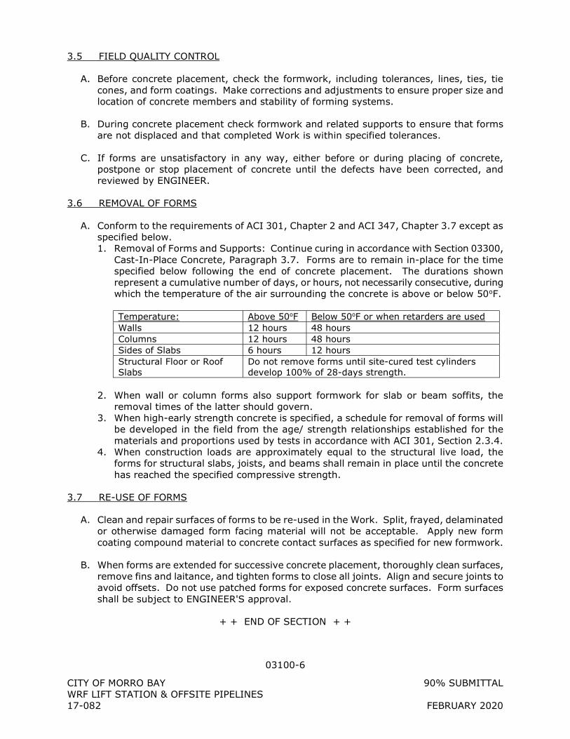
03100-6
CITY OF MORRO BAY 90% SUBMITTAL WRF LIFT STATION & OFFSITE PIPELINES 17-082 FEBRUARY 2020
3.5 FIELD QUALITY CONTROL
A. Before concrete placement, check the formwork, including tolerances, lines, ties, tie cones, and form coatings. Make corrections and adjustments to ensure proper size and location of concrete members and stability of forming systems.
B. During concrete placement check formwork and related supports to ensure that forms are not displaced and that completed Work is within specified tolerances.
C. If forms are unsatisfactory in any way, either before or during placing of concrete, postpone or stop placement of concrete until the defects have been corrected, and reviewed by ENGINEER.
3.6 REMOVAL OF FORMS
A. Conform to the requirements of ACI 301, Chapter 2 and ACI 347, Chapter 3.7 except as specified below. 1. Removal of Forms and Supports: Continue curing in accordance with Section 03300,
Cast-In-Place Concrete, Paragraph 3.7. Forms are to remain in-place for the time specified below following the end of concrete placement. The durations shown represent a cumulative number of days, or hours, not necessarily consecutive, during which the temperature of the air surrounding the concrete is above or below 50oF.
Temperature: Above 50oF Below 50oF or when retarders are used Walls 12 hours 48 hours Columns 12 hours 48 hours Sides of Slabs 6 hours 12 hours Structural Floor or Roof Slabs
Do not remove forms until site-cured test cylinders develop 100% of 28-days strength.
2. When wall or column forms also support formwork for slab or beam soffits, the
removal times of the latter should govern. 3. When high-early strength concrete is specified, a schedule for removal of forms will
be developed in the field from the age/ strength relationships established for the materials and proportions used by tests in accordance with ACI 301, Section 2.3.4.
4. When construction loads are approximately equal to the structural live load, the forms for structural slabs, joists, and beams shall remain in place until the concrete has reached the specified compressive strength.
3.7 RE-USE OF FORMS
A. Clean and repair surfaces of forms to be re-used in the Work. Split, frayed, delaminated or otherwise damaged form facing material will not be acceptable. Apply new form coating compound material to concrete contact surfaces as specified for new formwork.
B. When forms are extended for successive concrete placement, thoroughly clean surfaces, remove fins and laitance, and tighten forms to close all joints. Align and secure joints to avoid offsets. Do not use patched forms for exposed concrete surfaces. Form surfaces shall be subject to ENGINEER'S approval.
+ + END OF SECTION + +
03200-1
CITY OF MORRO BAY 90% SUBMITTAL WRF LIFT STATION & OFFSITE PIPELINES 17-082 FEBRUARY 2020
SECTION 03200
CONCRETE REINFORCEMENT
PART 1 - GENERAL
1.1 SUMMARY
A. Section includes: Fabrication and placement of reinforcement including bars, ties and supports, encasements and fireproofing.
1.2 SUBMITTALS
A. Shop Drawings: 1. Manufacturer's specifications and installation instructions for all materials and
reinforcement accessories. 2. Drawings for fabrication, bending, and placement of concrete reinforcement. Comply
with ACI 315, Parts A and B. For walls, show elevations to a minimum scale of 1/4-inch to 1 foot. For slabs, show top and bottom reinforcing on separate plan views. Show bar schedules, stirrup spacing, diagrams of bent bars, arrangements and assemblies, as required for the fabrication and placement of concrete reinforcement, unless otherwise noted. Keep splices to a minimum. Avoid splices in regions of maximum tension stresses whenever possible.
B. Certificates: Submit one (1) copy of steel producer's certificates of mill analysis, tensile and bend tests for reinforcing steel.
1.3 QUALITY ASSURANCE
A. Reference Standards: Comply with applicable provisions and recommendations of the following, except as otherwise shown or specified: 1. American Concrete Institute (ACI):
a. ACI 315, Manual of Engineering and Placing Drawings for Reinforced Concrete Structures.
b. ACI 318, Building Code Requirements for Reinforced Concrete. 2. Concrete Reinforcing Steel Institute:
a. Manual of Standard Practice, includes ASTM standards referred to herein.
B. Allowable Placing Tolerances: Comply with ACI 318, Chapter 7 - Details of Reinforcement.
1.4 DELIVERY, HANDLING AND STORAGE
A. Deliver concrete reinforcement materials to the site bundled, tagged and marked. Use metal tags indicating bar size, lengths, and other information corresponding to markings shown on placement diagrams.
B. Store concrete reinforcement material at the site to prevent damage and accumulation of dirt or excessive rust. Store on heavy wood blocking so that no part of it will come in contact with the ground.
03200-2
CITY OF MORRO BAY 90% SUBMITTAL WRF LIFT STATION & OFFSITE PIPELINES 17-082 FEBRUARY 2020
PART 2 - PRODUCTS
2.1 MATERIALS
A. Reinforcing Bars: ASTM A615, Grade 60 for all non-welded bars. ASTM A706, Grade 60 for welded bars.
B. Smooth Steel Dowels: ASTM A36. 1. Epoxy coated conforming to ASTM A775 or ASTM A934.
C. Mechanical Couplers: Reinforcement bars may be spliced with a mechanical connection. Provide a full mechanical connection which shall develop in tension or compression, as required, at least 125% of specified yield strength (fy) of the bar in accordance with ACI 318 Section 12.14.3.2. The locations of the connections are subject to the approval of the ENGINEER. 1. Dayton Superior Bar Lock S/CA Series. 2. Or approved equal
D. Threaded Splicing Systems: Dowel Bar Splicer System shall comply with ICC Report #4028. The completed splice shall exceed 160% of the specified yield strength (fy) of the bar. 1. Dayton Superior DB/DI parallel threaded couplers. 2. Or approved equal
E. Steel Wire: ASTM A82.
F. Supports for Reinforcement: Bolsters, chairs, spacers and other devices for spacing, supporting and fastening reinforcement in place. 1. Use wire bar type supports complying with CRSI recommendations, except as
specified below. Do not use wood, brick, or other unacceptable materials. 2. For slabs on grade, use 5000 psi concrete blocks. 3. At all formed surfaces, provide supports complying with CRSI "Manual of Standard
Practice" as follows: Plastic protected or stainless steel legs.
2.2 FABRICATION
A. General: Fabricate reinforcing bars to conform to required shapes and dimensions, with fabrication tolerances complying with CRSI, "Manual of Standard Practice". In case of fabricating errors, do not re-bend or straighten reinforcement in a manner that will injure or weaken the material.
B. Unacceptable Materials: Reinforcement with any of the following defects will not be permitted in the Work: 1. Bar lengths, bends, and other dimensions exceeding specified fabrication tolerances. 2. Bends or kinks not shown on approved Shop Drawings. 3. Bars with reduced cross-section due to excessive rusting or other cause.
03200-3
CITY OF MORRO BAY 90% SUBMITTAL WRF LIFT STATION & OFFSITE PIPELINES 17-082 FEBRUARY 2020
PART 3 - EXECUTION
3.1 INSPECTION
A. Examine substrate and conditions under which concrete reinforcement is to be placed with installer, and notify ENGINEER, in writing, of unsatisfactory conditions. Do not proceed with the Work until unsatisfactory conditions have been corrected in a manner acceptable to ENGINEER.
3.2 INSTALLATION
A. Comply with the applicable recommendations of specified codes and standards, and CRSI, Manual of Standard Practice, for details and methods of reinforcement placement and supports.
B. Clean reinforcement to remove loose rust and mill scale, oil, earth, ice, and other materials that reduce or destroy bond with concrete.
C. Position, support, and secure reinforcement against displacement during formwork construction or concrete placement operations. Locate and support reinforcing by metal chairs, runners, bolsters, spacers and hangers, as required. 1. Place reinforcement to obtain the minimum concrete cover as shown. Arrange,
space, and securely tie bars and bar supports together with 16-gage wire to hold reinforcement accurately in position during concrete placement operations. Slab and wall bars shall be tied at every intersection around the periphery of the slab or wall and not less than every 48 inches in the field at walls and 60 inches in the field at slabs.
2. Bar supports shall be placed no further than 4 feet apart in each direction. Supports must be completely concealed in the concrete and shall not discolor or otherwise mar the surface of the concrete.
3. Set wire ties so that twisted ends are directed away from exposed concrete surfaces. 4. Do not secure reinforcing steel to forms with wire, nails or other ferrous metal. Do
not permit metal supports subject to corrosion to touch or be within the required clearance to formed or exposed concrete surfaces.
D. Provide sufficient numbers of supports of strength required to carry reinforcement. Do not place reinforcing bars more than 2-inches beyond the last leg of any continuous bar support. Do not use supports as bases for runways for concrete conveying equipment or similar construction loads.
E. Splices: Provide reinforcement lap splices by placing bars in contact, and tying tightly with wire. Comply with requirements shown for minimum lap of spliced bars.
F. Mechanical Couplers in Lieu of Lap Splicing: 1. Provide mechanical butt splices in accordance with the recommendation of the
manufacturer of the mechanical splicing device. Butt splices shall develop 125 percent of the specified minimum yield tensile strength of the spliced bars or of the smaller bar in transition splices. Flame dry bars before butt splicing. Provide adequate jigs and clamps or other devices to support, align, and hold the longitudinal centerline of the bars to be butt spliced in a straight line.
03200-4
CITY OF MORRO BAY 90% SUBMITTAL WRF LIFT STATION & OFFSITE PIPELINES 17-082 FEBRUARY 2020
G. Reinforcement Around Openings: Place an equivalent area of steel around the pipe or opening and extend on each side sufficiently to develop bond in each bar. See the Details on Drawings for bar extension length each side of opening. Where welded wire fabric is used, provide extra reinforcing using fabric or deformed bars.
H. Field Bending: Field bending of reinforcing steel bars is not permitted when rebending will later be required to straighten bars. Rebending of bars at the same place where strain hardening has taken place due to the original bend will damage the bar. Consult with the ENGINEER prior to any pour if the CONTRACTOR foresees a need to work out a solution to prevent field bending.
3.3 INSPECTION OF REINFORCEMENT
A. Do not place concrete until the reinforcing steel is inspected and permission for placing concrete is granted by ENGINEER. All concrete placed in violation of this provision will be rejected.
+ + END OF SECTION + +
03251-1
CITY OF MORRO BAY 90% SUBMITTAL WRF LIFT STATION & OFFSITE PIPELINES 17-082 FEBRUARY 2020
SECTION 03251
CONCRETE JOINTS
PART 1 - GENERAL
1.1 SUMMARY
A. Section includes installation of concrete joints including, construction joints, expansion joints and fillers, waterstops, and contraction (control) joints.
1.2 REFERENCES
A. American Concrete Institute (ACI) 1. ACI 301, Specifications for Structural Concrete for Buildings.
B. American Society for Testing and Materials (ASTM) 1. ASTM A36, Standard Specification for Structural Steel. 2. ASTM D1752, Standard Specification for Preformed Sponge Rubber and Cork
Expansion Joint Fillers for Concrete Paving and Structural Construction. 3. ASTM D570, Standard Test Method for Water Absorption of Plastics.
C. NSF/ANSI Standard 61 Drinking Water Systems Components.
1.3 SYSTEM DESCRIPTION
A. All joints subject to hydrostatic pressure shall be provided with continuous waterstop.
1.4 SUBMITTALS
A. Product Data: Submit for approval, Manufacturer's specifications and installation instructions for all materials required.
B. Shop Drawings: Submit for approval: 1. Layout of all construction joint locations prior to the submittal of steel reinforcing
drawings. The concrete pour sequence and placement schedule shall be stated in the construction joint shop drawing layout.
2. Detail for joining polyvinyl chloride waterstops.
C. Samples: Submit for approval: 1. Waterstops for joints. 2. Expansion joint fillers.
1.5 QUALITY ASSURANCE
A. Install all manufactured items in accordance with manufacturer's instructions.
B. Store materials off the ground and protected from moisture, dirt and other contaminants. Protect installed and uninstalled materials from UV exposure in accordance with manufacturer’s instruction.
03251-2
CITY OF MORRO BAY 90% SUBMITTAL WRF LIFT STATION & OFFSITE PIPELINES 17-082 FEBRUARY 2020
PART 2 - PRODUCTS
2.1 WATERSTOPS
A. Polyvinyl Chloride: 1. At potable water facilities, provide NSF-61 Certified PVC waterstops. 2. Reference Standard: ASTM D570. 3. Construction Joints: Minimum of 3/8” thick, ribbed, width as shown, or if not shown,
6-inch minimum, center bulb type may be provided but is not required. 4. Control Joints: Minimum of 3/8” thick, ribbed, center bulb type, width as shown, or if
not shown, 6-inch minimum. 5. Expansion Joints: Minimum thickness of 3/8” and 9” minimum width. Provide with
"O" or "U" shaped center bulb. The "O" shall have an outside diameter of 3/4” minimum unless shown otherwise.
6. Product and Manufacturer: Provide polyvinyl chloride waterstops of one of the following: a. W.R. Meadows b. Sika Greenstreak c. Or approved equal
B. Hydrophilic: 1. Provide chloroprene rubber waterstops, 3/8-inch thick. 2. Product and Manufacturer: Provide one of the following:
a. Sika Hydrotite. b. Or approved equal.
2.2 PREFORMED EXPANSION JOINT FILLER
A. Bituminous type conforming to ASTM D994 or D1751, unless otherwise shown or specified.
2.3 CONCRETE CONSTRUCTION JOINT ROUGHENER
A. Provide a water-soluble non-flammable, surface-retardant roughener.
B. Product and Manufacturer: Provide one of the following: 1. Rugasol-S, as manufactured by Sika Corporation for horizontal joints. 2. MBT EAC-S, as manufactured by Master Builders for horizontal joints. 3. MBT Tuf-Cote (Deep Etch), as manufactured by Master Builders for vertical joints. 4. Or approved equal.
2.4 EPOXY BONDING AGENT
A. Provide an epoxy-resin bonding agent, two component type.
B. Product and Manufacturer: Provide one of the following: 1. Sikadur 32 Hi-Mod LPL, as manufactured by Sika Corporation. 2. Dural LPL, as manufactured by the Euclid Chemical Company. 3. Epoxtite Binder (Code # 2390), as manufactured by A.C. Horn, Incorporated. 4. Or approved equal.
03251-3
CITY OF MORRO BAY 90% SUBMITTAL WRF LIFT STATION & OFFSITE PIPELINES 17-082 FEBRUARY 2020
2.5 RUBBER BONDING AGENT
A. Product and Manufacturer: Provide one of the following: 1. Scotch-Grip 1300 Rubber Adhesive, as manufactured by 3M Company. 2. Or approved equal.
2.6 MORTAR
A. Mortar must be composed of cement, sand and water. Materials for mortar must comply with Section 03300. The proportion of sand to cement measured by volume must be 2 to 1 respectively. Mortar must contain only enough water to allow placing.
2.7 BOND BREAKER
A. Tape for Joints: Adhesive-backed glazed butyl or polyethylene tape, same width as joint that will adhere to premolded joint material or concrete surface.
PART 3 - EXECUTION
3.1 INSPECTION
A. Examine substrate and conditions under which Work is to be performed with installer and notify ENGINEER, in writing, of unsatisfactory conditions. Do not proceed with the Work until unsatisfactory conditions have been corrected in a manner acceptable to ENGINEER.
3.2 CONSTRUCTION JOINTS
A. Comply with ACI 301, Chapter 2.2, and as specified below.
B. Locate and install construction joints as shown. Locate additional construction joints as required to satisfactorily complete all Work.
C. Horizontal Joints: 1. Roughen concrete at the interface of construction joints by sandblasting to expose
the aggregate (1/4-inch minimum amplitude) and remove accumulated concrete on rebar immediately subsequent to form stripping. When sandblasting adjacent to installed waterstops, shield installed waterstops from the sandblasting operation. Immediately before placing fresh concrete, thoroughly clean the existing contact surface using a stiff brush or other tools and a stream of water under pressure. The surface shall be clean and wet, but free from pools of water at the moment the fresh concrete is placed.
2. Remove laitance, waste mortar or other substance that may prevent complete adhesion.
3. At the base of walls with waterstops, place a 3” thick coat of mortar over the surface of the old concrete. Place fresh concrete before the mortar has attained its initial set.
D. Vertical Joints: 1. Remove accumulated concrete on rebar. 2. Roughen concrete at the interface of the construction joints to expose the aggregate
(1/4-inch minimum amplitude) through one of the following:
03251-4
CITY OF MORRO BAY 90% SUBMITTAL WRF LIFT STATION & OFFSITE PIPELINES 17-082 FEBRUARY 2020
a. Apply roughener to the form in a thin, even film by brush, spray or roller in accordance with the manufacturer's instructions. After roughener is dry, concrete may be placed. When concrete has been placed and the form removed, wash loosened material off with high-pressure water spray to obtain roughened surface subject to approval by ENGINEER.
b. Sandblast after concrete has fully cured. c. Waterblast after concrete has partially cured. d. Perform cleaning so as not to damage waterstop, if one is present.
3.3 EXPANSION JOINTS
A. Locate and install expansion joints as shown. Install bituminous joint filler in accordance with manufacturer's instructions. Install caulking and sealants as specified in Section 07900, Joint Sealants.
3.4 WATERSTOPS
A. General: 1. Comply with ACI 301, Chapter 2, and as specified below. Make all joints in
accordance with manufacturer's instructions. 2. Obtain ENGINEER'S approval for waterstop locations not shown. 3. Provide waterstops in all basements, tanks and other substructures up to an
elevation at least 12” above grade or to an elevation at least 12” above highest liquid level in tanks, whichever is higher, except where otherwise shown or noted.
B. Polyvinyl Chloride Waterstop: 1. Tie waterstops to reinforcing steel at 12-inches on center, in each direction, so that it
is securely and rigidly supported in the proper position, centered in the joint, during concrete placement. Hog rings shall be used to facilitate placing and tying of waterstops to reinforcing steel forms or form-ties.
2. Continuously inspect waterstops during concrete placement to ensure their proper positioning.
3. Provide fused waterstops using equipment as supplied by or recommended by the manufacturer. Joints shall be inspected for strength and pinholes after splicing. Splices shall be strong enough to develop a pulling force of 75 percent of the strength of the waterstop, and shall be watertight.
4. Cover and protect installed waterstops from UV if the pour of concrete will be delayed more than 30 days.
5. Shield installed waterstops from sandblasting when performing surface roughening adjacent to installed waterstops.
C. Hydrophilic Waterstop: Install where shown in accordance with manufacturer's recommendations.
3.5 BONDING WITH EPOXY ADHESIVE
A. Use adhesive for the following: 1. Bonding of fresh concrete to concrete cured at least 45 days or to existing concrete. 2. Bonding of horizontal surfaces, which will receive a topping.
B. Handle and store epoxy adhesive in compliance with the manufacturer's printed instructions, including safety precautions.
03251-5
CITY OF MORRO BAY 90% SUBMITTAL WRF LIFT STATION & OFFSITE PIPELINES 17-082 FEBRUARY 2020
C. Mix the epoxy adhesive in complete accordance with the instructions of the manufacturer.
D. Before placing fresh concrete, thoroughly roughen and clean hardened concrete surfaces and coat with epoxy adhesive not less than 1/16" thick. Place fresh concrete while the epoxy material is still tacky, without removing the in-place grout coat, and as directed by the epoxy manufacturer.
+ + END OF SECTION + +
03300-1
CITY OF MORRO BAY 90% SUBMITTAL WRF LIFT STATION & OFFSITE PIPELINES 17-082 FEBRUARY 2020
SECTION 03300
CAST-IN-PLACE CONCRETE
PART 1 - GENERAL
1.1 SUMMARY
A. Section includes: Place, finish, cure, strip, and repair concrete.
1.2 REFERENCES
A. American Concrete Institute (ACI) 1. ACI 211.1, Standard Practice for Selecting Proportions for Normal, Heavyweight and
Mass Concrete. 2. ACI 214, Recommended Practice for Evaluation of Strength Test Results of Concrete. 3. ACI 301, Specifications for Structural Concrete for Buildings, (includes ASTM
Standards referred to herein). 4. ACI 304, Guide for Measuring, Mixing, Transporting and Placing Concrete. 5. ACI 305, Hot Weather Concreting. 6. ACI 306, Cold Weather Concreting. 7. ACI 309, Guide for Consolidation of Concrete. 8. ACI 311, Guide for Concrete Inspection. 9. ACI 318, Building Code Requirements for Reinforced Concrete. 10. ACI 347, Guide to Formwork for Concrete 11. ACI 350, Environmental Engineering Concrete Structures.
1.3 SYSTEM DESCRIPTION
A. Class A Concrete shall be steel reinforced and includes: 1. Foundations. 2. Walls. 3. Slabs. 4. Beams. 5. Equipment bases. 6. Pipe supports.
B. Class B Concrete shall be placed without forms or with simple forms, with little or no reinforcing, and includes: 1. Concrete fill. 2. Curbs and gutters. 3. Sidewalks. 4. Thrust blocks. 5. Encasements.
1.4 SUBMITTALS
A. Samples: Submit samples of materials as specified and as otherwise may be requested by ENGINEER, including names, sources and descriptions.
B. Product Data: Submit for approval the following:
03300-2
CITY OF MORRO BAY 90% SUBMITTAL WRF LIFT STATION & OFFSITE PIPELINES 17-082 FEBRUARY 2020
1. Manufacturer's specifications with application and installation instructions for proprietary materials and items, including admixtures and bonding agents.
2. List of concrete materials and concrete mix designs proposed for use. Include the results of all tests performed to qualify the materials and to establish the mix designs.
C. Laboratory Test Reports: Submit copies of laboratory test reports for materials and mix design tests
D. Delivery Tickets: Furnish to ENGINEER copies of all weighmaster certificate delivery tickets for each load of concrete delivered to the site. Provide items of information as specified in ASTM C94, Section 16. Delivery tickets shall be signed by a Certified Weighmaster.
1.5 QUALITY ASSURANCE
A. Tests for Concrete Materials: Submit written reports to ENGINEER, for each material sampled and tested, prior to the start of Work. Provide the Project identification name and number, date of report, name of CONTRACTOR, name of concrete testing service, source of concrete aggregates, material manufacturer and brand name for manufactured materials, values specified in the referenced specification for each material, and test results. Indicate whether or not material is acceptable for intended use.
B. If the concrete mix designs specified herein have not been used previously by the ready-mix supplier, mix proportions and concrete strength curves for regular cylinder tests shall be established by an approved ready-mix supplier or an independent testing laboratory based on the relationship of 7, 14 and 28 day strengths versus slump values of 2, 4 and 6 inches, all conforming to these Specifications. A laboratory, independent of the ready-mix supplier, shall be required to prepare and test all concrete cylinders. The costs for preparation of mix designs, not previously used by the ready-mix supplier, and testing of concrete and materials shall be borne by CONTRACTOR.
PART 2 - PRODUCTS
2.1 CONCRETE MATERIALS
A. Cement: 1. Portland cement, ASTM C150, Type II; or blended hydraulic cement, ASTM C595,
Type 1P (MS). 2. Do not use cement which has deteriorated because of improper storage or handling.
B. Aggregates: ASTM C33 and as herein specified. 1. Do not use aggregates containing soluble salts, substances such as iron sulfides,
pyrite, marcasite, ochre, or other materials that can cause stains on exposed concrete surfaces.
2. Fine Aggregate: Provide clean, sharp, natural sand free from loam, clay, lumps or other deleterious substances.
3. Coarse Aggregate: Provide clean, uncoated, processed aggregate containing no clay, mud, loam, or foreign matter, as follows: a. Crushed stone, processed from natural rock or stone.
03300-3
CITY OF MORRO BAY 90% SUBMITTAL WRF LIFT STATION & OFFSITE PIPELINES 17-082 FEBRUARY 2020
b. Coarse Aggregate Size: Size to be ASTM C33, Nos. 57 or 67, except that No. 467 may be used for footings, foundation mats and walls 16" or greater in thickness.
C. Water: Clean, free from injurious amounts of oils, acids, alkalis, organic materials or other substances that may be deleterious to concrete or steel.
2.2 CONCRETE ADMIXTURES
A. Provide admixtures produced by established reputable manufacturers, and use in compliance with the manufacturer's printed instruction. Do not use admixtures that have not been incorporated and tested in the accepted mixes, unless otherwise authorized in writing by ENGINEER.
B. Air-Entraining Admixtures: ASTM C260. 1. Product and Manufacturer: Provide one of the following:
a. SIKA AER, as manufactured by Sika Corporation. b. MasterAir AE 200, as manufactured by BASF. c. Daravair, as manufactured by W.R. Grace & Conn. d. Or approved equal.
C. High-Range Water-Reducing Admixture (“Superplasticizer”): ASTM C494, Type F/G. 1. Superplasticizer shall be used in all Class A Concrete. Do not use high range
water-reducing admixture containing more chloride ions than are contained in municipal drinking water. Add only at the job site to concrete in compliance with the manufacturer's printed instruction.
2. Product and Manufacturer: Provide one of the following: a. Sikament 320, as manufactured by Sika Corporation. b. MasterGlenium, as manufactured by BASF. c. Daracem-100, as manufactured by W.R. Grace & Conn. d. Or approved equal.
D. Water-Reducing Admixture: ASTM C 494, Type A. 1. A water-reducing, aqueous solution of a modification of the salt of polyhydroxylated
organic acids. Do not use admixture containing any lignin, nitrates or chlorides added during manufacture.
2. Product and Manufacturer: Provide one of the following: a. Eucon WR-75, as manufactured by The Euclid Chemical Company. b. MasterPozzolith, as manufactured by BASF. c. WRDA series, as manufactured by W.R. Grace & Conn. d. Or approved equal.
E. Pozzolanic Admixtures: 1. Pozzolanic admixtures shall not be used in structures with concrete in contact with
potable water, but may be used in other concrete. 2. Provide Mineral admixtures, when used, meeting the requirements of ASTM C618
Class F. 3. A substitution by weight, of the portland cement by pozzolan, so that the total
tricalcium aluminate content of the resulting cement plus pozzolan is not greater than 8%, will be considered. However, the pozzolan shall not exceed 20% by weight of the cement plus pozzolan.
F. Set-Control Admixtures: ASTM C494, as follows:
03300-4
CITY OF MORRO BAY 90% SUBMITTAL WRF LIFT STATION & OFFSITE PIPELINES 17-082 FEBRUARY 2020
1. Type B, Retarding. 2. Type C, Accelerating. 3. Type D, Water-reducing and Retarding. 4. Type E, Water-reducing and Accelerating. 5. Type F, Water-reducing, high range admixtures. 6. Type G, Water-reducing, high range, and retarding admixtures.
G. Calcium Chloride: Do not use calcium chloride in concrete, unless otherwise authorized in writing by ENGINEER. Do not use admixtures containing calcium chloride where concrete is placed against galvanized steel.
2.3 PROPORTIONING AND DESIGN OF MIXES
A. Prepare design mixes of concrete. Mixes subject to the following limitations: 1. Class A Concrete
a. Specified 28-day Compressive Strength: 4,000 psi minimum. b. Air content: 2% ± 1%. c. Slump, before addition of superplasticizer: 3½" ± ½" d. Slump, after addition of superplasticizer: 8” maximum
Coarse
Aggregate Size
Cementitious Content-Pounds Per
Cubic Yard
Water-Cement Ratio by Weight
¾” 625 min, 800 max 0.375 1” 600 min, 800 max 0.385
1 ½” 590 min, 800 max 0.400
e. Use superplasticizer in all Class A Concrete. Use water reducers in combination with superplasticizers as required for mixing.
2. Class B Concrete a. Specified 28-day Compressive Strength: 2,500 psi. b. Maximum Water-Cement Ratio by Weight: 0.49. c. Slump: 3" Minimum, 5" Maximum.
B. Use an independent testing facility acceptable to ENGINEER for preparing and reporting proposed mix designs.
C. Admixtures: 1. Use amounts of admixtures as recommended by the manufacturer for climatic
conditions prevailing at the time of placing. Adjust quantities and types of admixtures as required to maintain quality control.
2.4 EPOXY BONDING AGENT
A. For use in all dry-packed holes, concrete repair and for unplanned cold-joints.
B. Provide an epoxy-resin bonding agent, two component, polysulfide type.
C. Product and Manufacturer: Provide one of the following: 1. Sikadur 32, Hi-Mod LPL, as manufactured by Sika Corporation. 2. Eucopoxy LPL, as manufactured by the Euclid Chemical Company. 3. Or approved equal.
03300-5
CITY OF MORRO BAY 90% SUBMITTAL WRF LIFT STATION & OFFSITE PIPELINES 17-082 FEBRUARY 2020
2.5 CONCRETE CURING MATERIALS
A. Absorptive Cover: Burlap cloth made from jute or kenaf, weighing approximately 10 ounces per square yard and complying with AASHTO M182, Class 3.
B. Moisture-Retaining Cover: One of the following, complying with ASTM C171. 1. Waterproof paper. 2. Polyethylene film. 3. White burlap-polyethylene sheet.
C. Curing Compound: ASTM C309 Type 1-D (water retention requirements): 1. Product and Manufacturer: Provide one of the following:
a. Super Aqua Cure VOX, as manufactured by The Euclid Chemical Company. b. Sealtight 1100, as manufactured by W.R. Meadows, Incorporated. c. Or approved equal.
2.6 EMBEDDED ITEMS
A. Provide and install items such as plates, angles, inserts, bolts and similar items not specified elsewhere under this Section. Carbon steel embedded items shall be hot dip galvanized after fabrication.
PART 3 - EXECUTION
3.1 CONCRETE MIXING
A. Provide concrete produced by the ready-mixed process.
B. Comply with the requirements of ASTM C 94, and as herein specified. Proposed changes in mixing procedures, other than herein specified, must be accepted by ENGINEER before implementation. 1. Plant equipment and facilities: Conform to National Ready- Mix Concrete Association
“Plant and Delivery Equipment Specification.” 2. Mix concrete in revolving type truck mixers that are in good condition and which
produce thoroughly mixed concrete of the specified consistency and strength. 3. Do not exceed the proper capacity of the mixer. 4. Mix concrete for a minimum of two minutes after arrival at the job site, or as
recommended by the mixer manufacturer. 5. Mix concrete during transit only as recommended by the mixer manufacturer. 6. Mix at proper speed until concrete is discharged. 7. Maintain adequate facilities at the job site for continuous delivery of concrete at the
required rates. 8. Provide access to the mixing plant for ENGINEER at all times.
3.2 TRANSPORTING CONCRETE
A. Transport and place concrete not more than 90 minutes after water has been added to the dry ingredients or before 250 revolutions of the drum or blades, whichever occurs first.
03300-6
CITY OF MORRO BAY 90% SUBMITTAL WRF LIFT STATION & OFFSITE PIPELINES 17-082 FEBRUARY 2020
B. If an admixture is used to retard the set time and the concrete temperature does not exceed 85 degrees F, the travel and placing time may be extended to 120 minutes or 300 revolutions of the drum or blades, whichever occurs first.
C. Take care to avoid spilling and separation of the mixture during transportation.
D. Do not place concrete in which the ingredients have been separated.
E. Do not retemper partially set concrete.
F. Use suitable and approved equipment for transporting concrete from mixer to forms.
3.3 CONCRETE PLACEMENT
A. General: Place concrete continuously so that no concrete will be placed on concrete, which has hardened sufficiently to cause the formation of seams or planes of weakness within the section. If a section cannot be placed continuously, provide construction joints as specified in Section 03251, Concrete Joints. Deposit concrete as nearly as practical in its final location to avoid segregation due to rehandling or flowing. Do not subject concrete to any procedure that will cause segregation. 1. Screed concrete that is to receive other construction to the proper level to avoid
excessive skimming or grouting. 2. Do not use concrete which becomes non-plastic and unworkable, or does not meet
the required quality control limits, or which has been contaminated by foreign materials. Do not use retempered concrete. Remove rejected concrete from the job site and dispose of it in an acceptable location.
3. Do not place concrete until all forms, bracing, reinforcement, and embedded items are in final and secure position.
4. Do not place in cold weather, unless adequate precautions are taken against frost action.
5. Do not place footings, piers or pile caps on frozen soil. 6. Unless otherwise approved, place concrete only when ENGINEER is present. 7. Allow a minimum of 3 days of curing before placing new concrete against a slab or
wall already in place.
B. Concrete Conveying: 1. Handle concrete from the point of delivery and transfer to the concrete conveying
equipment and to the locations of final deposit as rapidly as practical by methods that will prevent segregation and loss of concrete mix materials.
2. Provide mechanical equipment for conveying concrete to ensure a continuous flow of concrete at the delivery end. Provide runways for wheeled concrete conveying equipment from the concrete delivery point to the locations of final deposit. Keep interior surfaces of conveying equipment, including chutes, free of hardened concrete, debris, water, ice and other deleterious materials.
3. Pumping concrete is permitted, however do not use aluminum pipe for conveying.
C. Placing Concrete into Forms: 1. Deposit concrete in forms in horizontal layers not deeper than 24" and in a manner to
avoid inclined construction joints. Where placement consists of several layers, place concrete at such a rate that concrete that is being integrated with fresh concrete is still plastic.
03300-7
CITY OF MORRO BAY 90% SUBMITTAL WRF LIFT STATION & OFFSITE PIPELINES 17-082 FEBRUARY 2020
2. Do not permit concrete to free fall within the form from a distance exceeding 8'-0", except as noted in Section 03100. Use “elephant trunks” or “wall pipes” to prevent free fall and excessive splashing on forms and reinforcement.
3. Remove temporary spreaders in forms when concrete placing has reached the elevation of such spreaders.
4. Consolidate concrete placed in forms by mechanical vibrating equipment supplemented by hand-spading, rodding or tamping. Use equipment and procedures for consolidation of concrete in accordance with the applicable recommended practices of ACI 309. Vibration of forms and reinforcing will not be permitted.
5. Vibrators shall have a frequency of at least 8,000 vpm, with amplitude required to consolidate the concrete in the section being placed. At least one stand-by vibrator in operable condition shall be at the placement site prior to initiating placement of the concrete.
6. Do not use vibrators to transport concrete inside of forms. Insert and withdraw vibrators vertically at uniformly spaced locations not farther than the visible effectiveness of the machine. Place vibrators to rapidly penetrate the layer of concrete and at least 6" into the preceding layer. Do not insert vibrators into lower layers of concrete that have begun to set. At each insertion, limit the duration of vibration to the time necessary to consolidate the concrete and complete embedment of reinforcement and other embedded items without causing segregation of the mix.
7. The forms shall contain sufficient windows or be limited in height to allow visual observation of the concrete and the vibrator operators shall be required to see the concrete being consolidated to ensure good quality workmanship or the CONTRACTOR shall have a person who is actually observing the vibration of the concrete at all times and advising the vibrator operators of any changes needed to assure complete consolidation.
8. Do not place concrete in beam and slab forms until the concrete previously placed in columns and walls is no longer plastic.
9. Force concrete under pipes, sleeves, openings and inserts from one side until visible from the other side to prevent voids.
D. Placing Concrete Slabs and Footings: 1. Deposit and consolidate concrete in a continuous operation, within the limits of
construction joints, until the placing of a panel or section is completed. 2. Consolidate concrete during placing operations using mechanical vibrating
equipment, so that concrete is thoroughly worked around reinforcement and other embedded items and into corners.
3. Consolidate concrete placed in beams and girders of supported slabs, and against bulkheads of slabs on ground, as specified for formed concrete structures.
4. Bring surfaces to the correct level. Smooth the surface, leaving it free of humps or hollows. Do not sprinkle water on the plastic surface. Do not disturb the surfaces prior to beginning finishing operations.
E. Bonding for Next Concrete Pour: Per Section 03251, Concrete Joints.
F. Quality of Concrete Work: 1. Make all concrete solid, compact and smooth, and free of laitance, cracks and cold
joints. 2. All concrete for liquid retaining structures, and all concrete in contact with earth,
water, or exposed directly to the elements shall be watertight.
03300-8
CITY OF MORRO BAY 90% SUBMITTAL WRF LIFT STATION & OFFSITE PIPELINES 17-082 FEBRUARY 2020
3. Cut out and properly replace to the extent ordered by ENGINEER, or repair to the satisfaction of ENGINEER, surfaces which contain cracks or voids, are unduly rough, or are in any way defective. Thin patches or plastering will not be acceptable.
4. Repair all leaks through concrete, and cracks, holes or other defective concrete in areas of potential leakage and make watertight.
5. Repair, remove, and replace defective concrete as ordered by ENGINEER at no additional cost to OWNER.
G. Cold Weather Placing: 1. Protect all concrete Work from physical damage or reduced strength that could be
caused by frost, freezing actions, or low temperatures, in compliance with the requirements of ACI 306 and as herein specified.
2. When the air temperature has fallen to or may be expected to fall below 40°F, provide adequate means to maintain the temperature, in the area where concrete is being placed, at between 50°F and 70°F for at least seven days after placing. Provide temporary housings or coverings including tarpaulins or plastic film. Maintain the heat and protection, if necessary, to ensure that the ambient temperature does not fall more than 30°F in the 24 hours following the seven-day period. Avoid rapid dry-out of concrete due to overheating, and avoid thermal shock due to sudden cooling or heating.
3. When air temperature has fallen to or is expected to fall below 40°F, uniformly heat all water and aggregates before mixing as required to obtain a concrete mixture temperature of not less than 55°F and not more than 85°F at point of placement.
4. Do not use frozen materials containing ice or snow. Do not place concrete on frozen subgrade or on subgrade containing frozen materials. Ascertain that forms, reinforcing steel, and adjacent concrete surfaces are entirely free of frost and ice before placing concrete.
5. When temperatures are expected to be below 32oF the night before the concrete is placed, then all reinforcing steel, forms and the ground shall be preheated, for a minimum of 12 hours, under a minimum temperature of 50oF.
6. Do not use salt and other materials containing antifreeze agents or chemical accelerators, or set-control admixtures, unless approved by ENGINEER, in mix designs.
7. Weather predictions made by the nearest NOAA station, and corrected for the local elevation and environmental conditions, may be used to determine whether cold weather protection shall be required. Thermometers will be used by ENGINEER and these readings shall determine whether cold weather protection shall be required and whether cold weather protection is adequate.
H. Hot Weather Placing: 1. When hot weather conditions exist as any combination of high air temperature, low
relative humidity and wind velocity that would seriously impair the quality and strength of concrete, place concrete as recommended by ACI 305 and as herein specified.
2. Cool ingredients before mixing to maintain concrete temperature at time of placement below 85°F. No concrete shall be placed if its temperature exceeds 90°F. Mixing water may be chilled, or chopped ice may be used, or liquid nitrogen may be added. Ice, when introduced into the mixer shall be in such form that it will be completely melted and dispersed throughout the mix at the completion of the mixing time. The addition of ice shall not increase the specified water to cement ratio.
03300-9
CITY OF MORRO BAY 90% SUBMITTAL WRF LIFT STATION & OFFSITE PIPELINES 17-082 FEBRUARY 2020
3. Cover reinforcing steel with water-soaked burlap if it becomes too hot, so that the steel temperature will not exceed the ambient air temperature immediately before embedment in concrete.
4. Thoroughly wet forms before placing concrete. Forms shall be free of standing water when concrete is placed.
5. Do not use set-control admixtures, unless approved by ENGINEER in mix designs. 6. Fog spray shall be used during finishing operations whenever necessary to avoid
surface plastic shrinkage cracking. Fog spray shall also be used after finishing and before the specified curing is commenced to avoid surface plastic shrinkage cracking.
7. Obtain ENGINEER'S approval of other methods and materials proposed for use.
I. Removal of Forms: 1. The CONTRACTOR shall be responsible for all damage resulting from improper and
premature removal of forms. Satisfy all applicable OSHA requirements with regard to safety of personnel and property.
2. Forms and shoring for elevated structural slabs or beams shall remain in place in accordance with ACI 318, Chapter 6, and until the concrete has reached a compressive strength equal to the specified 28-day compressive strength as determined by test cylinders unless noted otherwise in Section 03100 - Concrete Formwork. Removal of all supports prior to obtaining adequate field cured cylinder results and reshoring shall not be permitted.
J. Backfill Against Walls: 1. Do not place backfill against walls until the concrete has obtained a compressive
strength equal to the specified 28-day compressive strength. Where backfill is to be placed on both sides of the wall, the backfill shall be placed simultaneously on both sides to prevent differential pressures.
2. Since the walls of some structures are laterally restrained or supported by suspended slabs and/or slabs on grade and are not designed as cantilever retaining walls, the CONTRACTOR shall submit a schedule of wall shoring, bracing, and backfilling that is coordinated with the concrete curing, test cylinder reports and the design assumptions and obtain a review from the ENGINEER prior to proceeding.
K. Patching: 1. Patching of concrete shall provide an acceptable and structurally sound surface finish
uniform in appearance or the CONTRACTOR shall upgrade the finish by other means at no additional cost.
2. Tie Holes: All tie holes, except where sealant is indicated, shall be filled with dry pack nonshrink grout. White cement shall be added as needed so the color of grout after curing matches the color of adjacent concrete. Tie holes shall be thoroughly sandblasted or roughened. Flush the patch area with water and allow to dry. Coat the surface of the existing concrete with an approved bonding agent prior to filling with nonshrink grout. Complete the repair in the time duration specified by the bonding agent manufacturer. The grout shall be rammed into place in thin layers and leveled to the plane of the surrounding concrete. Cure in accordance with the manufacturer’s recommendations.
3. Defective Areas: Remove all defective concrete such as honeycombed areas and rock pockets out to sound concrete. Small shallow holes caused by air entrapment at the surface of the forms shall not be considered defects unless the amount is so great as to be considered not the standard of the industry and due primarily of poor workmanship. If chipping is required, the edges shall be perpendicular to the surface. Feather edges shall not be permitted. The defective area shall be filled with
03300-10
CITY OF MORRO BAY 90% SUBMITTAL WRF LIFT STATION & OFFSITE PIPELINES 17-082 FEBRUARY 2020
a nonshrink, nonmetallic, grout. Use an approved bonding agent on horizontal patches prior to placing nonmetallic, non shrink grout. Since some bonding agents may not be compatible for some vertical surface patching techniques, demonstrate all methods for repair of vertical surfaces using the actual materials, methods, and curing procedures required by the manufactures of the materials on the project site. The CONTRACTOR shall consult with representatives of the bonding agent manufacturer and the nonshrink grout manufacturer, and these representatives shall be onsite and assist in the demonstration.
4. Blockouts at Pipes or Other Penetrations: Conform to details shown or submit proposed blockouts for review. Use nonshrink, nonmetallic grout.
3.4 FINISH OF FORMED SURFACES
A. Rough Form Finish: 1. Standard rough form finish is with concrete surface having the texture imparted by
the form material, with tie holes and defective areas repaired and patched with mortar of 1 part cement to 1½ parts sand & all fins and other projections exceeding 1/4" in height rubbed down or chipped off.
2. Use rough form finish for the following: a. Exterior vertical surfaces up to 1' below grade. b. Interior exposed vertical surfaces of liquid containers up to 1' below liquid level. c. Interior and exterior exposed beams and undersides of slabs. d. Other areas shown.
B. Smooth Form Finish: 1. Produce smooth form finish (Class A, as defined by ACI-347) by selecting form
materials that will impart a smooth, hard, uniform texture. Arrange panels in an orderly and symmetrical manner with a minimum of seams. Repair and patch defective areas as above with all fins or other projections completely removed and smoothed.
2. Use smooth form finish for surfaces that are to be covered with a coating material. The material may be applied directly to the concrete or may be a covering bonded to the concrete such as waterproofing, damp proofing, painting or other similar system.
C. Smooth Rubbed Finish: 1. Provide smooth, rubbed finish to concrete surfaces which have received smooth form
finish as follows: a. Rubbing of concrete surfaces not later than the day after form removal. b. Moistening of concrete surfaces and rubbing with carborundum brick or other
abrasive until a uniform color and texture is produced. Do not apply cement grout other than that created by the rubbing process.
2. Except where surfaces have been previously covered as specified above, use smooth rubbed finish for the following: a. Interior exposed walls and other vertical surfaces. b. Exterior exposed walls and other vertical surfaces down to 1' below grade. c. Interior exposed vertical surfaces of liquid containers down to 1' below liquid
level. d. Other areas shown.
D. Related Unformed Surfaces: 1. At tops of walls, horizontal offsets, and similar unformed surfaces occurring adjacent
to formed surfaces, strike off smooth and finish with a texture matching the adjacent
03300-11
CITY OF MORRO BAY 90% SUBMITTAL WRF LIFT STATION & OFFSITE PIPELINES 17-082 FEBRUARY 2020
formed surfaces. Continue the final surface treatment of formed surfaces uniformly across the adjacent unformed surfaces, unless otherwise shown.
3.5 MONOLITHIC SLAB FINISHES
A. Float Finish: 1. After placing concrete slabs, do not work the surface further until ready for floating.
Begin floating when the surface water has disappeared or when the concrete has stiffened sufficiently. Check and level the surface plane to a tolerance not exceeding 1/4" in 10' when tested with a 10' straightedge. Cut down high spots and fill all low spots. Uniformly slope surface to drains as shown. Immediately after leveling, refloat the surface to a uniform, smooth, granular texture.
2. Use float finish for the following: a. Exterior below grade horizontal surfaces. b. Surfaces to receive additional finishes, except as shown or specified.
B. Trowel Finish: 1. After floating, begin the first trowel finish operation using a power-driven trowel.
Begin final troweling when the surface produces a ringing sound as the trowel is moved over the surface.
2. Consolidate the concrete surface by the final hand troweling operation. Finish shall be free of trowel marks, uniform in texture and appearance, and with a surface plane tolerance not exceeding 1/8" in 10' when tested with a 10' straight edge. Grind smooth surface defects that would telegraph through applied floor covering system.
3. Use trowel finish for the following: a. Interior exposed slabs, unless otherwise shown or specified.
C. Non-Slip Broom Finish: 1. Immediately after trowel finishing, slightly roughen the concrete surface by brooming
in the direction perpendicular to the main traffic route. Use fiber-bristle broom, unless otherwise directed. Coordinate the required final finish with ENGINEER before application.
2. Use Non-Slip Broom Finish for the following: a. Exterior exposed horizontal surfaces subject to light foot traffic. b. Interior and exterior concrete steps and ramps. c. Horizontal surfaces which will receive a grout topping or a concrete equipment
base slab.
3.6 CONCRETE CURING AND PROTECTION
A. General: 1. Protect freshly placed concrete from premature drying and excessive cold or hot
temperature, and maintain without drying at a relatively constant temperature for the period of time necessary for hydration of the cement and proper hardening of the concrete.
2. Start initial curing after placing and finishing concrete as soon as free moisture and bleed water sheen has disappeared from the concrete surface. Keep concrete continuously moist during initial curing.
3. Begin final curing procedures immediately following initial curing and before the concrete has dried. The total curing duration shall not be less than ten (10) days. For concrete sections over 30" thick, continue curing for an additional seven (7) days, minimum. Avoid rapid drying at the end of the final curing period.
03300-12
CITY OF MORRO BAY 90% SUBMITTAL WRF LIFT STATION & OFFSITE PIPELINES 17-082 FEBRUARY 2020
B. Use one of the following methods as approved by ENGINEER: 1. Walls:
a. Method 1: Leave concrete forms in place and keep entire surfaces of forms and exposed concrete surfaces wet for the entire curing duration. If forms are loosened and the contact between the concrete surface and forms is broken then the entire wall shall be wet cured.
b. Method 2: Continuously sprinkle or fog with water 100 percent of the exposed surfaces for the curing duration immediately after removal of forms.
c. Method 3: When approved by ENGINEER and as noted below, apply curing compound immediately after removal of forms.
2. Slab and Curbs: a. Method 1: Protect surface by water ponding for the entire curing duration. b. Method 2: Cover concrete surfaces and exposed edges with the specified
absorptive cover, thoroughly saturating the cover with water, and keeping the absorptive cover continuously wet with sprinklers or porous hoses during the curing duration. Lap adjacent absorptive cover sections 3-inches minimum.
c. Method 3: Cover the concrete surfaces and exposed edges with the specified moisture-retaining cover during the curing duration. Seal edges and seams with waterproof tape, adhesive or sand berm. Water must be introduced between the moisture-retaining cover and the concrete surface whenever moist drops cannot be detected on the concrete side of the cover or the concrete surface is noticeably dry.
d. Method 4: Continuously sprinkle or fog exposed surfaces for the curing duration. e. Method 5: When approved by ENGINEER and as noted below, apply liquid curing
compound immediately after final finishing when surface will no longer be damaged by traffic necessary to apply curing compound.
C. Liquid curing compound: 1. Apply the specified curing compound to concrete surfaces when permitted by
ENGINEER. Slabs to receive terrazzo floors, concrete/grout topping or ceramic tile, concrete of water bearing structures, and concrete that will receive coatings shall not be cured with liquid curing compound. The compounds shall be applied by power spray equipment in accordance with the manufacturer's directions. Recoat areas, which are subjected to heavy rainfall within 3 hours after initial application. Maintain the continuity of the coating and repair damage to the coat during the entire curing period. Remove curing compound from exposed surfaces at the end of the curing duration. For concrete surfaces, which will be in contact with potable water, the manufacturer shall certify that the curing compound used is NSF 61 approved.
D. Temperature of Concrete During Curing: 1. When the nighttime low temperature may drop to 40°F or below, maintain the
concrete temperature between 50°F and 70°F continuously throughout the curing period, by heating, covering, insulation or housing as required.
2. When the daytime high temperature may rise to 90°F or above, maintain the concrete temperature at a minimum and reduce temperature variations by providing moist curing continuously for the concrete curing period.
3. During either of the conditions specified above, the minimum curing time shall be 10 days (240 hours), after which coverings, housings, and insulation shall remain on the work for an additional 3 days, to allow gradual temperature equalization with the atmosphere.
03300-13
CITY OF MORRO BAY 90% SUBMITTAL WRF LIFT STATION & OFFSITE PIPELINES 17-082 FEBRUARY 2020
E. Protection from Mechanical Injury: During the curing period, protect concrete from damaging mechanical disturbances including load stresses, heavy shock, excessive vibration, and from damage caused by rain or flowing water. Protect all finished concrete surfaces from damage by subsequent construction operations.
3.7 FIELD QUALITY CONTROL
A. The OWNER will employ a testing laboratory to perform field quality control testing. ENGINEER will direct the number of tests and cylinders required. Furnish all necessary assistance required by ENGINEER.
B. Quality Control Testing During Construction: 1. Perform sampling and testing for field quality control during the placement of
concrete, as follows: a. Sampling Fresh Concrete: ASTM C172. b. Slump: ASTM C143; one test for each concrete load at point of discharge; and
one for each set of compressive strength test specimens. c. Air Content: ASTM C231; one for the first concrete load, and one for every two
concrete loads thereafter, or when required by an indication of change. Adjust mix if test results are unsatisfactory and resubmit for ENGINEER'S approval.
d. Compressive Strength Tests: ASTM C39; one set of 4 standard compression cylinders for each 100 cubic yards or fraction thereof, of each mix design placed in any one day; 1 specimen tested at 7 days, and 2 specimens tested at 28 days, 1 held. Cast, store and cure specimens as specified in ASTM C31. 1) Adjust mix if test results are unsatisfactory and resubmit for ENGINEER'S
approval. 2) Concrete that does not meet the strength requirements is subject to rejection
and removal from the Work, or to other such corrective measures as directed by ENGINEER, at the expense of CONTRACTOR.
e. Concrete Temperature: Test each time a slump test is made. 2. Where questionable field conditions may exist during placing concrete or immediately
thereafter, strength tests of specimens cured under field conditions will be required by ENGINEER to check the adequacy of curing and protecting of the concrete placed. Specimens shall be molded at the same time and from the same samples as the laboratory cured specimens. a. Provide improved means and procedures for protecting concrete when the 28-day
compressive strength of field- cured cylinders is less than 85% of companion laboratory-cured cylinders.
b. When laboratory-cured cylinder strengths are appreciably higher than the minimum required compressive strength, field-cured cylinder strengths need not exceed the minimum required compressive strength by more than 500 psi even though the 85 percent criterion is not met.
3. The testing laboratory shall submit certified copies of test results directly to ENGINEER and CONTRACTOR after tests are made.
C. Evaluation of Quality Control Tests: 1. Do not use concrete delivered to the final point of placement that has slump or
temperature outside the specified values, nor that which is older than specified in section 3.2.
2. Compressive strength tests for laboratory-cured cylinders will be considered satisfactory if the averages of all sets of three consecutive compressive strength tests results equal or exceed the 28 day design compressive strength of the type or class
03300-14
CITY OF MORRO BAY 90% SUBMITTAL WRF LIFT STATION & OFFSITE PIPELINES 17-082 FEBRUARY 2020
of concrete; and, no individual strength test falls below the required compressive strength by more than 500 psi.
3. If the compressive strength tests fail to meet the minimum requirements specified, the concrete represented by such tests will be considered deficient in strength and subject to replacement, reconstruction or to other action approved by ENGINEER.
D. Testing Concrete Structure for Strength: 1. When there is evidence that the strength of the in-place concrete does not meet
specification requirements, provide the services of a concrete testing service to take cores drilled from hardened concrete for compressive strength determination at no additional expense to OWNER. Provide tests complying with ASTM C42 and the following: a. Take at least three (3) representative cores from each member or suspect area at
locations directed by ENGINEER. b. Strength of concrete for each series of cores will be considered satisfactory if
their average compressive strength is at least 85% and no single core is less than 75% of the 28 day required compressive strength.
c. Report test results, in writing, to ENGINEER on the same day that tests are made. Include in test reports the Project identification name and number, date, name of CONTRACTOR, name of concrete testing service, location of test core in the structure, type or class of concrete represented by core sample, nominal maximum size aggregate, design compressive strength, compression breaking strength and type of break (corrected for length-diameter ratio), direction of applied load to core with respect to horizontal plane of the concrete as placed, and the moisture condition of the core at time of testing.
2. Fill core holes solid with non-shrink, high strength grout, and finish to match adjacent concrete surfaces.
E. Water Leakage Tests for All Water-Holding Structures: 1. All water-holding structures shall be subjected to leakage tests after the concrete has
been cured and obtained its design strength, and before backfill, brick facing, or other work which will cover the concrete surfaces of the walls is begun. Water leakage tests shall be conducted by the CONTRACTOR as follows: a. All water-holding structures shall be filled with water to the maximum liquid level
shown on the Drawings prior to leak testing at a rate less than 4 ft/hr. After these structures have been kept full for 3-days, it will be assumed for the purpose of the test that the absorption of moisture by the concrete in the basin is complete. All valves and gates to the structure shall then be closed and the change in water surface measured over a 48-hour period. The vertical distance to the water surface shall be measured to within 1/16-inch from a fixed point on the containment structure above the water surface. Measurements shall be recorded at 24-hour intervals.
b. During the test period, all exposed portions of the structure shall be examined for dampness or leaks and all visible leaks or damp spots shall be marked; such leaks or damp spots shall be later patched or corrected in a manner acceptable to the ENGINEER prior to additional leakage testing. If the drop in water surface in the 48-hour period exceeds 0.05% of the normal volume of liquid contained in the water-holding structure, after accounting for evaporation, precipitation and temperature in open basins, or if damp spots or any seepage is present on the walls or other areas exposed to view where moisture can be picked up on a dry hand, the leakage shall be considered excessive and the leakage test will be considered to have failed. A floating, restrained, partially filled, calibrated, open
03300-15
CITY OF MORRO BAY 90% SUBMITTAL WRF LIFT STATION & OFFSITE PIPELINES 17-082 FEBRUARY 2020
container for evaporation and precipitation measurement should be positioned in open containment structures, and the water level in the container recorded. Determination of evaporation by a shallow pan-type measuring device is discouraged as the heating of the bottom of a shallow pan can cause accelerated evaporation of water when compared with that taking place from a deep containment structure. 1) Wet areas on top of wall footings shall not be considered cause of a
qualitative failure of the leakage test unless the water can be observed to be flowing.
c. If the leakage is excessive, and if damp spots and observed seepage is present on exposed surfaces, the water-holding structure shall be drained, all leaks and damp spots previously marked shall be patched, and the necessary repairs made, and the basin shall be retested. The CONTRACTOR’s method of repair shall be subject to the requirements of these specifications and submitted for review and approval by the ENGINEER.
d. The water-holding structure shall then be refilled and again tested for leakage and this testing and repair process shall be repeated as many times as necessary until the leakage test passes. This process shall be continued until the drop in water surface in specified test period with the basin full is less than the quantity specified above and all damp spots and seepage disappears when the structures are full of water. All repairs of faulty workmanship and materials, and additional tests, shall be made by the CONTRACTOR in an acceptable manner, at no additional cost to the OWNER. Both the correction for excessive leakage and the removal of the damp or wet spots on exposed surfaces shall be required to pass the leakage test.
e. The purpose of this test is to determine the integrity of the finished concrete and to show that the exposed wall surfaces are visually acceptable. Therefore, all other equipment, e.g., stop gates, sluice gates, etc. or temporary bulkheads, should be made watertight prior to the test.
f. As an alternative to having watertight bulkheads, gates or valves, the CONTRACTOR shall accurately measure the leakage through gates, valves, and bulkheads with methods acceptable to the ENGINEER.
g. An assumed leakage through gates and valves based on the manufacturer’s recommendations is not acceptable.
3.8 MISCELLANEOUS CONCRETE ITEMS
A. Filling-In: Fill-in holes and openings left in concrete structures for the passage of work by other contractors, unless otherwise shown or directed, after the work of other contractors is in place. Mix, place and cure concrete as herein specified, to blend with in-place construction. Provide all other miscellaneous concrete filling shown or required to complete the Work.
B. Curbs: 1. Provide monolithic finish to interior curbs by stripping forms while concrete is still
green and steel-troweling surfaces to a hard, dense finish with corners, intersections, and terminations slightly rounded.
2. Exterior curbs shall have rubbed finish for vertical surfaces and a broomed finish for top surfaces.
C. Equipment Bases:
03300-16
CITY OF MORRO BAY 90% SUBMITTAL WRF LIFT STATION & OFFSITE PIPELINES 17-082 FEBRUARY 2020
1. Unless specifically shown otherwise, provide concrete bases for all pumps and other equipment. Construct bases to the dimensions shown, or as required to meet manufacturers; requirements and drawing elevations. Where no specific elevations are shown, bases shall be 6-inches thick and extend 3-inches outside the metal equipment base or supports. Bases to have smooth trowel finish, unless a special finish such as terrazzo, ceramic tile or heavy duty concrete topping is required. In those cases, provide appropriate concrete finish.
2. Include all concrete equipment base work not specifically included under other Sections.
3. In general, place bases up to 1-inch below the metal base. Properly shim equipment to grade and fill 1-inch void with non-shrink grout as specified in Section 03600, Grout.
D. Installation of embedded items 1. Install all embedded items prior to concrete placement, or, if necessary, as soon after
concrete placement as possible, before concrete is set. 2. Use temporary support and bracing to keep embedded items in place while concrete
cures. 3. Protect all embedded items from damage during concrete installation.
3.9 CONCRETE REPAIRS
A. Repair of Formed surfaces: 1. Repair exposed-to-view formed concrete surfaces that contain defects which
adversely affect the appearance of the finish. Surface defects that require repair include color and texture irregularities, cracks, spalls, air bubbles, honeycomb, rock pockets, and holes left by the rods and bolts; fins and other projections on the surface; and stains and other discolorations that cannot be removed by cleaning.
2. Repair concealed formed concrete surfaces that may contain defects that adversely affect the durability of the concrete. Surface defects that require repair include cracks in excess of 0.01-inch wide, cracks of any width and other surface deficiencies which penetrate to the reinforcement or completely through non-reinforced sections, honeycomb, rock pockets, holes left by tie rods and bolts, and spalls except minor breakage at corner.
3. Repair structural cracks and cracks in water-holding structures.
B. Method of Repair of Formed Surfaces: 1. Repair and patch defective areas with cement mortar immediately after removal of
forms and as directed by ENGINEER. 2. Cut out honeycomb, rock pockets, voids over 1/2" diameter, and holes left by tie
rods and bolts, down to solid concrete but, in no case, to a depth of less than 1". Make edges of cuts perpendicular to the concrete surface. Before placing the cement mortar, thoroughly clean, dampen with water, and brush-coat the area to be patched with the specified bonding agent. a. For exposed-to-view surfaces, blend white portland cement and standard portland
cement so that, when dry, the patching mortar color will match the color of the surrounding concrete. CONTRACTOR shall impart texture to repaired surfaces to match texture of existing adjacent surfaces. Provide test areas at inconspicuous locations to verify mixture, texture and color match before proceeding with the patching. Compact mortar in place and strike off slightly higher than the surrounding surface.
03300-17
CITY OF MORRO BAY 90% SUBMITTAL WRF LIFT STATION & OFFSITE PIPELINES 17-082 FEBRUARY 2020
3. Cracks which require repair shall be pressure grouted, epoxy injected, using one of the following in accordance with Section 03740. Apply in accordance with the manufacturer's directions and recommendations. a. Sikadur 35, Hi-Mod L.V. and Sikadur 31, Hi-Mod Gel, as manufactured by Sika
Corporation Company. b. Euco Epoxy #452 Epoxy System, as manufactured by The Euclid Chemical
Company. c. Or approved equal.
4. Fill holes extending through concrete by means of a plunger- type gun or other suitable device from the least exposed face, using a flush stop held at the exposed face to ensure completely filling.
5. Sandblast exposed-to-view surfaces that require removal of stains, grout accumulations, sealing compounds, and other substances marring the surfaces. Use sand finer than No. 30 and air pressure from 15 to 25 psi.
C. Repair of Unformed Surfaces: 1. Test unformed surfaces, such as monolithic slabs, for smoothness and to verify
surface plane to the tolerances specified for each surface and finish. Correct low and high areas as herein specified.
2. Test unformed surfaces sloped to drain for trueness of slope, in addition to smoothness, using a template having the required slope. Correct high and low areas as herein specified.
3. Repair finish of unformed surfaces that contain defects which adversely affect the durability of the concrete. Surface defects, as such, include crazing, cracks in excess of 0.01-inch wide or which penetrate to the reinforcement or completely through non-reinforced sections regardless of width, spalling, popouts, honeycomb, rock pockets, and other objectionable conditions.
4. Repair structural cracks and cracks in water-holding structures.
D. Methods of Repair of Unformed Surfaces: 1. Correct high areas in unformed surfaces by grinding, after the concrete has cured
sufficiently so that repairs can be made without damage to adjacent areas. 2. Correct low areas in unformed surfaces during, or immediately after completion of
surface finishing operations by cutting out the low areas and replacing with fresh concrete. Finish repaired areas to blend into adjacent concrete. Use one of the following. Apply in accordance with the manufacturer's directions and recommendations. a. Euco Poly-Patch, as manufactured by The Euclid Chemical Company. b. Sikatop 122, as manufactured by Sika Corporation. c. Or approved equal.
3. Repair defective areas, except random cracks and single holes not exceeding 2" diameter, by cutting out and replacing with fresh concrete. Remove defective areas to sound concrete with clean, square cuts, and expose reinforcing steel with at least 3/4" clearance all around. Dampen all concrete surfaces in contact with patching concrete and brush with the specified bonding agent. Place patching concrete before grout takes its initial set. Mix patching concrete of the same materials and proportions to provide concrete of the same type or class as the original adjacent concrete. Place, compact and finish as required to blend with adjacent finished concrete. Cure in the same manner as adjacent concrete.
4. Repair isolated random cracks, as approved be ENGINEER, and single holes not over 2" diameter, by the dry-pack method. Groove the top of cracks, and cut out holes to sound concrete and clean of dust, dirt and loose particles. Dampen all cleaned
03300-18
CITY OF MORRO BAY 90% SUBMITTAL WRF LIFT STATION & OFFSITE PIPELINES 17-082 FEBRUARY 2020
concrete surfaces and brush with the specified bonding agent. Place dry-pack before the cement grout takes its initial set. Mix dry-pack, consisting of 1 part portland cement to 2 parts fine aggregate passing a No. 16 mesh sieve, using only enough water as required for handling and placing. Compact dry-pack mixture in place and finish to match adjacent concrete. Keep patched areas continuously moist for not less than 72 hours.
5. Cracks which extend through the full member section, or any cracks determined by ENGINEER to require pressure grouting repair, shall be pressure grouted, epoxy injected, using one of the following in accordance with Section 03740. Apply in accordance with the manufacturer's directions and recommendations. a. Sikadur 35, Hi-Mod L.V. and Sikadur 31, Hi-Mod Gel, as manufactured by Sika
Corporation. b. Euco Epoxy #452 Epoxy System, as manufactured by The Euclid Chemical
Company. c. Or approved equal.
6. Assure that surface is acceptable for flooring material to be installed in accordance with manufacturer's recommendations.
E. Other Methods of Repair: 1. Repair methods not specified above may be used if approved by ENGINEER.
+ + END OF SECTION + +
03400-1
CITY OF MORRO BAY 90% SUBMITTAL WRF LIFT STATION & OFFSITE PIPELINES 17-082 FEBRUARY 2020
SECTION 03400
PRECAST CONCRETE
PART 1 - GENERAL
1.1 DESCRIPTION
A. Section includes all plant-precast products, including, but not limited to, wet wells, catch basins, manholes, vaults, and wheel stops.
1.2 SYSTEM DESCRIPTION
A. Precast products shall be designed for the indicated service, the loadings specified in the Contract Documents, and all transportation, handling, and erection loads, in accordance with requirements and recommendations of the references. 1. Precast products not subjected to traffic loads shall be designed to meet and exceed
the requirements of ACI 318-14. 2. Precast products subjected to traffic loads shall be designed to meet and exceed the
requirements of the current AASHTO LRFD Bridge Design Specifications. 3. Liquid containing precast products shall be designed for the additional requirements
of ACI 350-06.
B. If precast products are proposed as substitutes for cast-in-place designed structures, such precast products shall meet the above requirements and any other requirements for which the cast-in-place structures were designed by the ENGINEER. Such products shall be designed by an engineer licensed to practice in the State where the project is performed.
C. Items located in or adjacent to traffic areas shall be designed to resist AASHTO HL93 loading, unless otherwise indicated.
D. Lifting inserts shall have a minimum safety factor of 4.
1.3 QUALIFICATIONS
A. Manufacturer: 1. Manufacturer shall have at least 5 years experience in the design and manufacture of
precast concrete products substantially similar to those required for this project.
B. Installer: 1. Precast Items shall be installed by the Manufacturer or by an installer regularly
engaged for at least 5 years in erection of precast products similar to those required on this project.
1.4 SUBMITTALS
A. Shop Drawings: 1. Submit to the Engineer for review, shop drawings of the proposed details, and design
calculations; all calculations and shop drawings shall be stamped and signed by a Civil or Structural Engineer registered in the State of California.
03400-2
CITY OF MORRO BAY 90% SUBMITTAL WRF LIFT STATION & OFFSITE PIPELINES 17-082 FEBRUARY 2020
2. Material specifications. 3. All dead, live and other applicable loads used in the design. 4. Applicable standards (from "References") met by the item(s). 5. Setting plans locating and designating all items furnished by the manufacturer, with
all major openings shown and located. 6. Details to indicate quantities, location and type of reinforcing and prestressing steel. 7. Sections and details showing connections, edge conditions, support conditions, and
connections of the items. 8. Description of all embeds, including stripping, lifting and erection inserts, with piece
mark and location, including those cast into products or sent loose to the job site. 9. Description and drawings of all frames and covers. 10. Dimensions and special finishes.
B. Mix Designs: Submit all precast mix designs for approval. Mix designs shall be prepared by an independent testing facility or qualified employee of the Precast Manufacturer.
C. Design Modifications: 1. Submit design modifications necessary to meet performance requirements and field
conditions. 2. Variations in details or materials shall not adversely affect the appearance, durability
or strength of products. 3. Maintain general design concept without altering size of members, profiles and
alignment unless otherwise approved by the Engineer.
1.5 QUALITY ASSURANCE
A. In-Plant Quality Control 1. The Manufacturer shall have an established PCI quality control program in effect prior
to bidding. If requested, a copy of this program shall be submitted to the ENGINEER. 2. Testing of materials and inspection of production techniques shall be the
responsibility of the Manufacturer's Quality Control Department. 3. Keep quality control records available for two years after final acceptance. 4. Keep certificates of compliance available for five (5) years after final acceptance.
B. All other testing and inspection, if any, to be provided by OWNER.
1.6 PRODUCT DELIVERY, STORAGE, AND HANDLING
A. Handle and transport products in a position consistent with their shape and design in order to avoid excessive stresses or damage.
B. Lift or support products only at the points shown on the Shop Drawings.
C. Installer shall be responsible for the repair of damage to items except that caused by others.
D. After items are installed in their final positions, the CONTRACTOR shall be responsible for their protection. The CONTRACTOR shall be responsible for the repair of any damage to the items caused by someone other than the Manufacturer/Installer.
03400-3
CITY OF MORRO BAY 90% SUBMITTAL WRF LIFT STATION & OFFSITE PIPELINES 17-082 FEBRUARY 2020
PART 2 - PRODUCTS
2.1 CONCRETE MATERIALS
A. Portland Cement ASTM C150 Type I, II or III cement.
B. Aggregates: 1. Fine and coarse aggregate for mix shall conform to ASTM C33 or C330. 2. Aggregates shall be clean, hard, strong, durable, inert, and free of staining and
deleterious materials.
C. Water Potable, free from deleterious material.
D. Admixtures: 1. Conforming to ASTM C260 and/or ASTM C494. 2. Calcium chloride or admixtures containing chlorides shall not be used.
E. Concrete Strength: Concrete strength shall be determined by design with a minimum 28 day design strength of 4,000 psi.
2.2 STEEL MATERIALS
A. Products: 1. Structural Shapes, Bars & Plates (1.6mm and thicker): ASTM A36 2. Pipe: ASTM A53 Grades A or B 3. Tube Steel: ASTM A500 Grades A or B 4. Reinforcing Steel: ASTM A615 Grades 300 & 420 or ASTM A706 5. Prestressing Strand: ASTM A416 Grade 270, low relaxation 6. Deformed Steel Bar Mats: ASTM A184 7. Deformed Bar Anchors: ASTM A496 8. Deformed Welded Wire Fabric: ASTMA497 9. Plain Welded Wire Fabric: ASTM A185 10. Welded Headed Studs: AWS D1.1 Type B 11. Standard Machine Bolts: ASTM A307 Grade A or SAE J429 Grade 2 12. Standard Studs/Threaded Round Stock: ASTM A307 Grade C, ASTM A572 Grade 345 13. Nuts for Standard Machine Bolts and Threaded Studs: ASTM A563 Grade A Hex Nuts 14. High Strength Bolts: ASTM A325 Type 1, ASTM A449 Type 1, or SAE J429 Grade 5 15. Nuts for High-Strength Bolts and Threaded Studs: ASTM A563 Grade DH Heavy Hex
Nuts 16. Coil Rods and Bolts: ASTM A108 - SAE 1016 to 1026, Fu/FY = 480/380 MPa minimum 17. Coil Nuts for Coil Rods and Bolts: Nuts passing a proof load stress of 80 ksi, based on
the tensile stress area of the matching coil rods and bolts. 18. Carbon Steel Castings: ASTM A27 Grade 415-205
B. Protective Coatings: 1. All connection hardware permanently exposed to weather after completion shall be
protected. All connection hardware not exposed to weather after completion may be uncoated, except as otherwise explicitly required by the contract drawings. Fasteners can have either an electroplated zinc or cadmium coating.
2. Alkyd Rust Inhibitive Primers (shop primers such as red iron oxide) : a. Tnemec Series FD88 Azeron Primer b. Ameron 5105
03400-4
CITY OF MORRO BAY 90% SUBMITTAL WRF LIFT STATION & OFFSITE PIPELINES 17-082 FEBRUARY 2020
c. Weld-Thru Primer, Red, 2-0101 & Gray, 2-0102 3. Zinc Coatings:
a. Hot-Dip Galvanizing: ASTM A123, or ASTM A153 b. Electroplated Zinc for Steel Products and Steel Hardware: ASTM B633 c. Zinc Rich Paints: DOD-P-21035
4. Cadmium Coatings: a. Electrodeposited Coatings of Cadmium: ASTM B766
2.3 MISCELLANEOUS PRODUCTS
A. Grout: 1. Cement Grout: Portland cement, sand and water sufficient for placement and
hydration. 2. Non-Shrink Grout: Premixed, packaged non-ferrous aggregate shrink resistant. 3. Epoxy Resin Grout: Two-component mineral-filled resin: ASTM C881.
B. Joint Sealing Compound: The joint sealing compound shall be a permanently flexible plastic material complying in every detail to Federal Specification SS S-00210 (GSA-FSS) dated July 26, 1965. "Quickseal", or approved equal.
C. Frames and Covers: Catch basins, manholes, and vaults shall be provided with fabricated aluminum or steel frames and covers as specified or shown on the drawings and shall be built up so that the cover is flush with the surrounding surface unless otherwise specified.
2.4 FABRICATION
A. Unless otherwise noted, precast concrete structure dimensions called out on the Drawings are interior dimensions.
B. Manufacturing procedures shall be in general compliance with PCI MNL-116.
C. Manufacturer shall provide for those openings 10 in. or larger, round or square as shown on the drawings. Other openings shall be located and field drilled or cut by the trade requiring them after the units have been erected. Openings and/or cutting of prestressing strand shall be approved by ENGINEER and manufacturer before drilling or cutting.
D. Forms: 1. Forms for precast products shall be rigid and constructed of materials that will result
in finished products conforming to the profiles, dimensions and tolerances indicated by this Section, the Contract Documents and the reviewed Shop Drawings.
2. Construct forms to withstand vibration method selected. 3. Release agents shall be applied and used according to manufacturer’s instructions.
E. Plastic Liner: 1. Where called for on the Drawings, provide cast-in-place plastic liner system. 2. Install liner system per manufacturer’s instructions. 3. Follow all requirements of Specification Section 06640, Plastic Liner for Concrete Pipe
and Structures.
F. Concreting:
03400-5
CITY OF MORRO BAY 90% SUBMITTAL WRF LIFT STATION & OFFSITE PIPELINES 17-082 FEBRUARY 2020
1. Batching of Concrete shall be in accordance with approved Mix Design(s). 2. Convey concrete by methods which will prevent separation, segregation or loss of
material. 3. Consolidate all concrete in the form to minimize honeycombing or entrapped air.
G. Curing: Procedures sufficient to insure specified concrete strength of all products must be employed. Stripping of a panel shall not occur until concrete strength is sufficient to prevent cracking or damage of the panel.
H. Manufacturing Tolerances: 1. Cross Sectional Dimensions:
a. Less than 24 inches: ±1/4" b. 24 to 36 inches: ±3/8" c. Over 36 inches: ±1/2"
2. Length: a. Less than 25 ft: ±1/2" b. 25 to 50 ft: ±3/4" c. Over 50 ft: ±1"
3. Variation from square or designed skew (difference in length of two diagonal measurements): Max. ±3/4"
I. Identification: Mark each precast item to correspond to identification mark on Shop Drawings for product location, and with casting date.
PART 3 - EXECUTION
3.1 PREPARATION
A. Access: Clear unloading areas and access roadways to point of component placement shall be provided and maintained by the CONTRACTOR. The CONTRACTOR shall provide all required traffic controls, barricades, warning lights and/or signs to insure a safe installation.
B. Sitework: The CONTRACTOR shall excavate and prepare the subgrade, including 2 inches of clean sand, graded level and to the proper elevation.
C. Installer Responsibility: Prior to installation of the precast products, notify the CONTRACTOR of any discrepancies discovered which affect the work under this contract.
3.2 INSTALLATION
A. General: Precast products shall be lifted with suitable lifting devices at points provided by the Manufacturer to prevent excessive stresses or damage to the products. Brace and secure items before unhooking.
B. Sitework: 1. Openings or "knockouts" shall be located as shown on the drawings and shall be
sized sufficiently to permit passage of the largest dimension of pipe and/or coupling flange. Upon completion of installation, all voids or openings in the vault walls around pipes shall be filled with 4,000-psi concrete or mortar, using an approved epoxy for bonding concrete surfaces.
03400-6
CITY OF MORRO BAY 90% SUBMITTAL WRF LIFT STATION & OFFSITE PIPELINES 17-082 FEBRUARY 2020
2. All joints between precast sections shall be made watertight using preformed mastic material. The sealing compound shall be installed according to the manufacturer's recommendations to provide a watertight joint which remains impermeable throughout the design life of the structure. All joints shall be filled with dry-pack non-shrink grout. If plastic liner system is used, after the joint has been made and is cured, install plastic liner weld strip at all joints and seams.
3. Frames and covers shall be built up so that the cover is flush with the surrounding surface unless otherwise specified. The CONTRACTOR is responsible for placing the cover at the proper elevation where paving is to be installed and shall make all necessary adjustments so that the cover meets these requirements.
4. After the structure and all appurtenances are in place and approved, and after any required disinfection or testing, backfill shall be placed to the original ground line or to the limits designated on the plans.
3.3 FIELD QUALITY CONTROL
A. Hydrostatic Testing: 1. All Manholes, Wetwells, Junction Boxes, or other water bearing structures shall be
hydrostatically tested prior to acceptance. 2. Test Procedure:
a. Plug all inlets and outlets with temporary plugs b. Fill water bearing structure with clean, potable water c. Let stand for 24 hours, if desired, to allow for “soaking-in” d. Fill to rim elevation e. Let stand for a minimum of 2 hours f. Check distance from rim to water surface g. Calculate water loss. Leakage in each manhole may not exceed 0.1-gallon per
hour per foot of water depth during the test. 3. Repair all structures which do not meet the above test requirements with a method
approved by the ENGINEER and re-test until passing.
3.4 PATCHES AND REPAIRS:
A. Patching of products, when required, shall be performed to industry standards for structural concrete. Repairs shall be sound, permanent and flush with adjacent surface.
3.5 WARRANTY:
A. All labor and materials under the Precast Manufacturers contract shall be warranted by the Precast Manufacturer for a period of one (1) year after substantial completion.
+ + END OF SECTION + +
03420-1
CITY OF MORRO BAY 90% SUBMITTAL WRF LIFT STATION & OFFSITE PIPELINES 17-082 FEBRUARY 2020
SECTION 03410
PRECAST FRP-PVC MANHOLE SYSTEM
PART 1 - GENERAL
1.1 SCOPE
A. This specification covers all the work necessary to complete the installation of a PVC Manhole, comprising fiberglass reinforced plastic lined concrete manhole base and top sections, a polyvinyl chloride pipe riser section and all appurtenances.
B. The PVC Manhole System shall be modular and shall include: fiberglass reinforced plastic (FRP) concrete protective liners; concrete manhole base and top sections cast around the FRP concrete protective liners; PVC pressure pipe sections which shall be AWWA C900 compliant, DR-51 pressure class PVC pipe; ASTM C990 compliant elastomeric sealant and STM C877 compliant external joint wrap; grading rings, manhole ring and cover to grade, according to local jurisdictional requirements.
1.2 REFERENCES
This specification covers polymer concrete manholes intended for use in sanitary sewers, where corrosion resistance is required
A. ASTM C 478 (most current) Standard Specification for Precast Reinforced Concrete Manhole Sections
B. ASTM C 497 (most current) Determining Physical Properties of Concrete Pipe of Tile
C. ASTM D395: Standard Test Methods for Rubber Property – Compression Set
D. ASTM D412: Standard Test Methods for Vulcanized Rubber and Thermoplastic Elastomers – Tension
E. ASTM D471: Standard Test Method for Rubber Property – Effect of Liquids
F. ASTM D543: Standard Practices for Evaluating the Resistance of Plastics to Chemical Reagents
G. ASTM D573: Standard Test Method for Rubber – Deterioration in an Air Oven
H. ASTM D624: Standard Test Method for Tear Strength of Conventional Vulcanized Rubber and Thermoplastic Elastomers ASTM D695: Test Methods for Compressive Properties of Rigid Plastics
I. ASTM D638: Standard Test Method for Tensile Properties of Plastics
J. ASTM D695: Test Methods for Compressive Properties of Rigid Plastics
K. ASTM D790: Test Method for Flexural Properties of Unreinforced and Reinforced Plastics and electrical Insulating Materials
03420-2
CITY OF MORRO BAY 90% SUBMITTAL WRF LIFT STATION & OFFSITE PIPELINES 17-082 FEBRUARY 2020
L. ASTM D792: Standard Test Methods for Density and Specific Gravity (Relative Density) of Plastics by Displacement
M. ASTM D1149: Standard Test Methods for Rubber Deterioration – Cracking in an Ozone Controlled Environment
N. ASTM D2137: Standard Test Methods for Rubber Property - Brittleness Point of Flexible Polymers and Coated Fabrics
O. ASTM D2240: Standard Test Method for Rubber Property – Durometer Hardness
P. ASTM D2584: Test Method for Ignition Loss of Cured Reinforced Resins
Q. ASTM D4060: Standard Test Method for Abrasion Resistance of Organic Coatings by the Taber Abraser
R. Greenbook 2009 (or later): Standard Specifications for Public Works Construction, Chemical Resistance Test (Pickle Jar Test)
1.3 SUBMITTALS
A. Conform to bid document requirements
B. Submit manufacturer’s data and details of following items for approval:
1. Shop drawings of manhole sections, base units and construction details, jointing methods, materials, and dimensions
2. Summary of criteria used in manhole design including, as minimum, material properties, loading criteria, and dimensions assumed. Include certification from manufacturer that polymer concrete manhole design meets or exceeds the load and strength requirements of ASTM C 478 and ASTM C 857, reinforced in accordance with ACI 440.1R-15. Include current ISO 9001:2008 certification
3. Frames, grates, rings, and covers 4. Materials to be used in fabricating pipe drop connections 5. Materials to be used for pipe connections 6. Materials to be used for stubs and stub plugs, if required 7. Proof of independent Chemical Resistance testing conducted in accordance with the
Standard Specifications for Public Works Construction (California Greenbook) Section 211-2
C. Submitted sealed drawings by a registered Professional Engineer
PART 2 - PRODUCTS
2.1 FRP LINERS
A. FRP liners: The resins used shall be unsaturated, supplier certified, commercial grade polyester resins. Mixing lots of resin from different manufacturers, or “odd-lotting” of resins shall not be permitted. Quality-assurance records on the resin shall be maintained.
03420-3
CITY OF MORRO BAY 90% SUBMITTAL WRF LIFT STATION & OFFSITE PIPELINES 17-082 FEBRUARY 2020
The reinforcing materials shall be commercial grade “E-CR” type glass, specially formulated for corrosive environments, in the form of mat, chopped roving, continuous roving, roving fabric or a combination of the above, having a coupling agent that will provide a suitable bond between the glass reinforcement and resin. Fiberglass and/or polypropylene ribs and/or structural members may be utilized to meet the design criteria.
No inert fillers shall be used. Additives, such as thixotropic agents, catalysts, promoters, etc., may be added as required by the specific manufacturing process to be used to meet the requirements of this standard.
The laminate shall consist of multiple layers of glass matting and resin. The surface exposed to the sewer/chemical environment shall be resin rich and shall have no exposed fibers.
1. Bells: Bell shall be manufactured from the same unsaturated, supplier certified,
commercial grade polyester resins as the main FRP Baseliner body. If available, polypropylene injection molded bells are also allowed.
2. Gaskets: Resilient materials for connectors and filler rings shall be manufactured from natural rubber, polyisoprene, neoprene, nitrile, or ethylene propylene diene monomer (EPDM) synthetic rubber and shall conform to the material requirements prescribed in this specification. If a splice is used in the manufacture of the seal, its strength shall be such that the seal shall with-stand a 180° bend with no visible separation.
3. Mechanical devices: Expansion rings, tension bands, and take-up devices used for mechanically compressing the resilient portion of the connector against the pipe or manhole shall be made from a material or materials in combination that will ensure durability, strength, resistance to corrosion, and have properties that will ensure continued resistance to leakage.
4. All metallic mechanical devices and bolt assemblies used to mechanically deform resilient materials shall be constructed of corrosion resistant materials meeting the physical properties and chemical composition requirements of ASTM A493 and A666, Type 302 through Type 316.
5. Third party accessories: Third party accessories integral to the PVC Manhole System or the FRP Manhole Liner (flow control devices, valves, gates, inside drop assembly, man entry ladder, etc.) shall be governed by the respective manufacturers’ materials specifications.
B. Precast concrete manhole sections: The manhole base and top sections shall be constructed of precast reinforced concrete, for the purpose of providing structural integrity to the FRP manhole liners. The sections shall conform to the requirements of ASTM C-478 and shall be manufactured using the wet cast method.
C. Manhole PCV riser: The PVC riser pipe shall strictly comply with AWWA C900 and shall have DR-51 pressure rating.
D. Grading Rings: Grade rings shall be constructed of reinforced precast concrete.
E. Ring and Cover: Casting shall be tough gray iron, free from cracks, holes, swells, and cold shuts. All manhole casting shall be made accurately to the pattern and to the dimensions shown on Contract Documents.
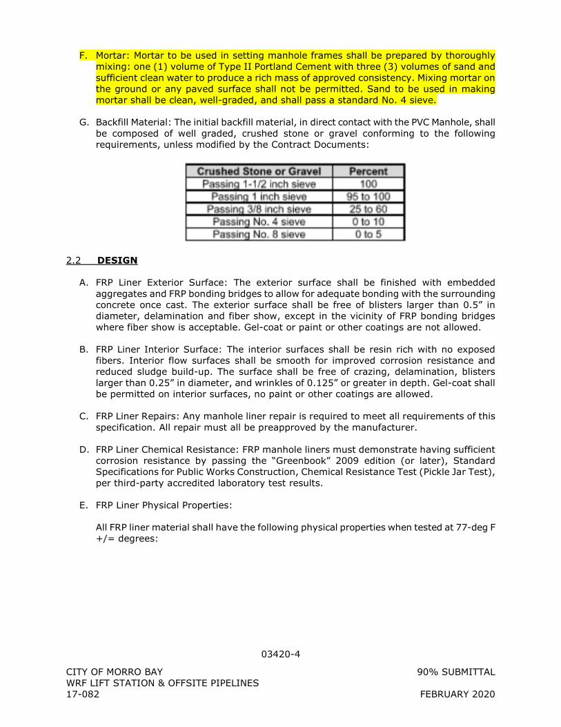
03420-4
CITY OF MORRO BAY 90% SUBMITTAL WRF LIFT STATION & OFFSITE PIPELINES 17-082 FEBRUARY 2020
F. Mortar: Mortar to be used in setting manhole frames shall be prepared by thoroughly mixing: one (1) volume of Type II Portland Cement with three (3) volumes of sand and sufficient clean water to produce a rich mass of approved consistency. Mixing mortar on the ground or any paved surface shall not be permitted. Sand to be used in making mortar shall be clean, well-graded, and shall pass a standard No. 4 sieve.
G. Backfill Material: The initial backfill material, in direct contact with the PVC Manhole, shall be composed of well graded, crushed stone or gravel conforming to the following requirements, unless modified by the Contract Documents:
2.2 DESIGN
A. FRP Liner Exterior Surface: The exterior surface shall be finished with embedded aggregates and FRP bonding bridges to allow for adequate bonding with the surrounding concrete once cast. The exterior surface shall be free of blisters larger than 0.5” in diameter, delamination and fiber show, except in the vicinity of FRP bonding bridges where fiber show is acceptable. Gel-coat or paint or other coatings are not allowed.
B. FRP Liner Interior Surface: The interior surfaces shall be resin rich with no exposed fibers. Interior flow surfaces shall be smooth for improved corrosion resistance and reduced sludge build-up. The surface shall be free of crazing, delamination, blisters larger than 0.25” in diameter, and wrinkles of 0.125” or greater in depth. Gel-coat shall be permitted on interior surfaces, no paint or other coatings are allowed.
C. FRP Liner Repairs: Any manhole liner repair is required to meet all requirements of this specification. All repair must all be preapproved by the manufacturer.
D. FRP Liner Chemical Resistance: FRP manhole liners must demonstrate having sufficient corrosion resistance by passing the “Greenbook” 2009 edition (or later), Standard Specifications for Public Works Construction, Chemical Resistance Test (Pickle Jar Test), per third-party accredited laboratory test results.
E. FRP Liner Physical Properties:
All FRP liner material shall have the following physical properties when tested at 77-deg F +/= degrees:
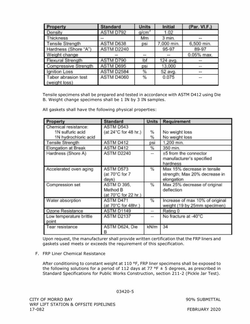
03420-5
CITY OF MORRO BAY 90% SUBMITTAL WRF LIFT STATION & OFFSITE PIPELINES 17-082 FEBRUARY 2020
Tensile specimens shall be prepared and tested in accordance with ASTM D412 using Die B. Weight change specimens shall be 1 IN by 3 IN samples.
All gaskets shall have the following physical properties:
Upon request, the manufacturer shall provide written certification that the FRP liners and gaskets used meets or exceeds the requirement of this specification.
F. FRP Liner Chemical Resistance
After conditioning to constant weight at 110 °F, FRP liner specimens shall be exposed to the following solutions for a period of 112 days at 77 °F ± 5 degrees, as prescribed in Standard Specifications for Public Works Construction, section 211-2 (Pickle Jar Test).
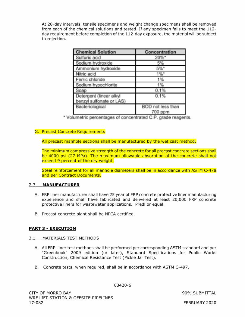
03420-6
CITY OF MORRO BAY 90% SUBMITTAL WRF LIFT STATION & OFFSITE PIPELINES 17-082 FEBRUARY 2020
At 28-day intervals, tensile specimens and weight change specimens shall be removed from each of the chemical solutions and tested. If any specimen fails to meet the 112-day requirement before completion of the 112-day exposure, the material will be subject to rejection.
G. Precast Concrete Requirements
All precast manhole sections shall be manufactured by the wet cast method.
The minimum compressive strength of the concrete for all precast concrete sections shall be 4000 psi (27 MPa). The maximum allowable absorption of the concrete shall not exceed 9 percent of the dry weight.
Steel reinforcement for all manhole diameters shall be in accordance with ASTM C-478 and per Contract Documents.
2.3 MANUFACTURER
A. FRP liner manufacturer shall have 25 year of FRP concrete protective liner manufacturing experience and shall have fabricated and delivered at least 20,000 FRP concrete protective liners for wastewater applications. Predl or equal.
B. Precast concrete plant shall be NPCA certified.
PART 3 - EXECUTION
3.1 MATERIALS TEST METHODS
A. All FRP Liner test methods shall be performed per corresponding ASTM standard and per “Greenbook” 2009 edition (or later), Standard Specifications for Public Works Construction, Chemical Resistance Test (Pickle Jar Test).
B. Concrete tests, when required, shall be in accordance with ASTM C-497.
03420-7
CITY OF MORRO BAY 90% SUBMITTAL WRF LIFT STATION & OFFSITE PIPELINES 17-082 FEBRUARY 2020
3.2 QUALITY ASSUREANCE/QUALITY CONTROL
A. Examination: Each FRP manhole liner shall be examined for dimensional requirements and workmanship prior to precasting.
B. Resin Composition Control: Controls on glass and resin content shall be maintained for all manufacturing processes and for each portion of manhole liner fabrication. Records shall be maintained for these control checks. Proper glass content may be shown by glass usage checks or glass and resin application rate checks.
C. Certified facility: FRP manhole liners shall be designed and manufactured in an ISO 9001 and 14001 certified manufacturing facility. Concrete precast plants shall be NPCA certified.
3.3 PRECASTING
A. FRP manhole liners must not be dropped or impacted. When stored for extended periods (more than a few days) Baseliners shall be stored on a flat surface, upside down to minimize deformation.
B. Baseliners shall not be exposed to direct sunlight for extended periods, either before or after precasting.
C. Liners must be monolithically cast within a concrete manhole section using the wet cast method. Custom pouring supports shall be provided with FRP liners to fully support the liners during the concrete pouring process against the vertical and horizontal forces created by the concrete during casting.
D. The poured manhole base must not be moved until adequate hydration has occurred.
E. Lifting devices, no more than 3 per section, must not penetrate any surface of the liner. No liner may have holes or openings which will permit the intrusion of liquids or gases through the liner wall and into the concrete.
3.4 FIELD INSTALLATION
A. PVC manhole installation should strictly follow the Manufacturer recommended installation procedures to ensure long-term corrosion resistant service. In addition, local codes may apply and should be consulted as applicable in manhole installation.
B. Excavation at manhole location shall be wide enough to provide working room around manhole. Ensure the depth of manhole is sufficient to accommodate for at least two concrete rings for adjustment of ring and cover at top of final grade and for a minimum of 6 inches (152 mm) of crushed stone directly below the manhole base for the purpose of adequate leveling.
C. Set and level manhole base section and connect sewer lines to manhole.
D. Install rubber butyl sealant on manhole base spigot joint following manufacturer’s installation instructions.
03420-8
CITY OF MORRO BAY 90% SUBMITTAL WRF LIFT STATION & OFFSITE PIPELINES 17-082 FEBRUARY 2020
E. Lift PVC riser in place using recommended lifting apparatus and set plumb and level. Ensure that a positive seal is established between the manhole base and the PVC riser.
F. Install rubber butyl sealant on manhole top lid spigot joint following manufacturer’s installation instructions.
G. Lift manhole top section in place and set level. Ensure that a positive seal is established between the manhole top section and the PVC riser.
H. If specified, install apply external joint wrap on joint sections, following manufacturer’s installation instructions.
I. Initial backfill material shall be used for backfilling around the manhole for a minimum distance of one foot from the outside surface and extending from the bottom of the excavation to the top of the reducer section. Secondary backfill material may be used for the remainder of the backfill. This material will be subject to approval by Engineer.
J. Backfill shall be placed in layers of not more than 12 loose measure inches and mechanically tamped to 95% Standard Proctor Density, unless otherwise approved by Engineer. Flooding will not be permitted. Backfill shall be placed in such a manner as to prevent any wedging action against the PVC manhole structure.
K. Bring to Grade: Construct reinforced concrete ring encasement as identified on details. The top the PVC manhole may be brought to proper grade for receiving manhole frames by using not more than four courses precast concrete grade rings.
3.5 FINAL TESTING AND ACCEPTANCE
A. Hydrostatic Testing: Hydrostatic testing shall be conducted, as required, by plugging with approved plugs all influent and effluent pipes in the manhole and filling the manhole to the top of the manhole cone with water. Additional water may be added over a 24-hour period to compensate for evaporate losses. At the conclusion of the 24-hour saturation period the manhole shall be filled to the top of the manhole cone and observed. A loss within a 30-minute period shall be considered an unsuccessful test.
B. Vacuum Testing: Manholes shall be tested, as required, after installation and prior to backfilling with all connections (existing and proposed) in place, in general accordance with ASTM C1244.
The lines entering the manhole shall be temporarily plugged with the plugs braced to prevent them from being drawn into the manhole. The plugs shall be installed in the lines beyond drop connections, gas sealing connections, etc. The test head shall be inflated in accordance with the manufacturer’s recommendations. A vacuum of 10 inches of mercury shall be drawn, and the vacuum pump will be turned off. With the valve closed, the level vacuum shall be read after the required test time. If the drop in the level is less than 1-inch of mercury (final vacuum greater than 9-inches of mercury), the manhole will have passed the vacuum test. The required test time is determined from the table below:
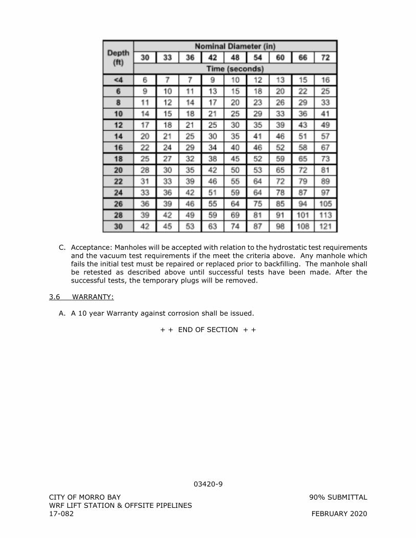
03420-9
CITY OF MORRO BAY 90% SUBMITTAL WRF LIFT STATION & OFFSITE PIPELINES 17-082 FEBRUARY 2020
C. Acceptance: Manholes will be accepted with relation to the hydrostatic test requirements and the vacuum test requirements if the meet the criteria above. Any manhole which fails the initial test must be repaired or replaced prior to backfilling. The manhole shall be retested as described above until successful tests have been made. After the successful tests, the temporary plugs will be removed.
3.6 WARRANTY:
A. A 10 year Warranty against corrosion shall be issued.
+ + END OF SECTION + +
03600-1
CITY OF MORRO BAY 90% SUBMITTAL WRF LIFT STATION & OFFSITE PIPELINES 17-082 FEBRUARY 2020
SECTION 03600
GROUT
PART 1 - GENERAL
1.1 SUMMARY
A. Section includes epoxy, non-metallic, non-shrink, and ordinary Portland cement-sand grouts.
1.2 REFERENCES
A. American Society for Testing and Materials (ASTM) 1. ASTM C33, Standard Specification for Concrete Aggregates. 2. ASTM C150, Standard Specification for Portland Cement. 3. ASTM C595, Standard Specification for Blended Hydraulic Cements. 4. ASTM C1107, Standard Specification for Packaged Dry, Hydraulic-Cement Grout.
1.3 SYSTEM DESCRIPTION
A. Furnish ordinary cement-sand grout for the following: 1. Foundation grout. 2. Construction joint grout. 3. As shown in the Drawings.
B. Furnish non-shrink, non-metallic grout for the following: 1. Equipment bases, 25 hp or less. 2. Base plates. 3. Guardrail and railings. 4. Through-bolt and form tie openings. 5. As shown in the Drawings.
C. Furnish epoxy grout for the following: 1. Equipment bases, 26 hp or more and/or sole plates with vibration, thermal
movement, etc. 2. Blockouts for gate guides. 3. Retrofit waterstop installation. 4. As shown in the Drawings.
1.4 SUBMITTALS
A. Product Data: 1. Manufacturer's specifications and installation instructions for all proprietary materials. 2. Proposed method for keeping existing concrete surfaces wet prior to placing grout. 3. Forming method for fluid grout placements. 4. Curing method for grout.
B. Laboratory Test Reports and Certificates: 1. For proprietary materials, submit copies of reports on quality control tests.
03600-2
CITY OF MORRO BAY 90% SUBMITTAL WRF LIFT STATION & OFFSITE PIPELINES 17-082 FEBRUARY 2020
2. Submit certification that materials meet specification requirements for nonproprietary materials.
3. For ordinary cement-sand grout, copies of grout mix design and laboratory strength test reports.
1.5 PRODUCT DELIVERY, STORAGE AND HANDLING
A. Delivery of Materials: Deliver grout materials from manufacturers in unopened containers and bearing intact manufacturer's labels.
B. Storage of Materials: Store grout materials in a dry shelter and protected from moisture.
PART 2 - PRODUCTS
2.1 MATERIALS
A. High-Strength Epoxy Grout. 1. Use 100% solids, prepackaged, solvent-free, moisture insensitive, high-strength
epoxy grout. 2. Product and Manufacturer: Provide one of the following:
a. E3-HP, as manufactured by The Euclid Chemical Company. b. Sikadur 42 Grout Pak, as manufactured by Sika Corporation. c. Five Star HP Epoxy Grout by Five Star Products, Incorporated. d. Or approved equal.
B. Non-shrink, Non-metallic Grout: 1. Prepackaged non-staining cementitious grout which shall meet the minimum
requirements of ASTM C1107 and requiring only the addition of water at the jobsite. 2. Product and Manufacturer: Provide one of the following:
a. NS, as manufactured by The Euclid Chemical Company. b. Five Star Grout, as manufactured by Five Star Products, Incorporated. c. Sika Grout 212, as manufactured by Sika Corporation. d. Or approved equal.
C. Ordinary Cement-Sand Grout: Prepare design mix for ordinary cement grout. 1. Cement: Portland cement, ASTM C150, Type II; or blended hydraulic cement, ASTM
C595, Type 1P. 2. Aggregates: ASTM C33 and as herein specified.
a. Do not use aggregates containing soluble salts or other substances such as iron sulfides, pyrite, marcasite, ochre, or other materials that can cause stains on exposed concrete surfaces.
b. Fine Aggregate: Clean, sharp, natural sand, free from loam, clay, lumps or other deleterious substances. 1) Dune sand, bank run sand and manufactured sand are not acceptable.
c. Coarse Aggregate: Coarse aggregate not permitted. 3. Admixtures: Provide admixtures produced by established reputable manufacturers
and use in compliance with the manufacturer's printed instruction. Do not use admixtures that have not been incorporated and tested in the accepted mixes, unless otherwise authorized in writing by ENGINEER. Refer to Section 03300 - Cast-In-Place Concrete, for additional admixture requirements.
4. Proportioning and Design of Mixes: Mixes are subject to the following limitations:
03600-3
CITY OF MORRO BAY 90% SUBMITTAL WRF LIFT STATION & OFFSITE PIPELINES 17-082 FEBRUARY 2020
a. Specified 28-day Compressive Strength: 4,000 psi. b. Minimum amount of water necessary for the mixture to flow under its own
weight. c. Fine Aggregate meeting ASTM C33. d. Air Content Percentage: ±1.5%. e. Minimum Cement Content in Pounds per Cubic Yard: 658. f. Slump at point of placement: 5"±1".
5. Proportion mix by either laboratory trial batch or field experience methods, using materials to be employed on the Project for grout required. Comply with ACI 211.1 and provide a complete report, from an independent testing laboratory, to ENGINEER, at least 30 days prior to start of Work. Do not begin grout production until ENGINEER has approved mix.
6. Laboratory Trial Batches: When laboratory trial batches are used to select grout proportions, prepare test specimens and conduct strength tests as specified in ACI 301, Chapter 3 - Proportioning.
7. Field Experience Method: When field experience methods are used to select grout proportions, establish proportions as specified in ACI 301, Chapter 4.
PART 3 - EXECUTION
3.1 INSPECTION
A. Examine the substrate and conditions under which grout is to be placed with installer and notify ENGINEER, in writing, of unsatisfactory conditions. Do not proceed with the Work until unsatisfactory conditions have been corrected in a manner acceptable to ENGINEER.
3.2 INSTALLATION
A. General: 1. Mix, place and cure grout as shown and in accordance with manufacturer's
instructions. If manufacturer's instructions conflict with the Specifications, do not proceed until ENGINEER provides clarification.
2. Manufacturers of proprietary products shall make available upon 72 hours notification the services of a qualified, full time employee to aid in assuring proper use of the product under job conditions. The cost of this service, if any, shall be borne by CONTRACTOR.
3. When placing grout conform to temperature and weather limitations in Section 03300 - Cast-In-Place Concrete.
B. Through-bolt and form-tie holes: Fill space with dry pack dense grout hammered in with steel tool and hammer. Coordinate dry pack dense grout application with bonding agent in Section 03251 - Concrete Joints.
C. Columns, Beams and Equipment Bases: Prepare concrete surface by sandblasting, chipping, or by mechanical means to remove any soft material prior to setting base plates and machinery. After shimming columns, beams and equipment indicated to be grouted on the plans to proper grade, securely tighten anchor bolts. Properly form around the base plates allowing sufficient room around the edges for placing the grout. Adequate depth between the bottom of the base plate and the top of concrete base must be provided to assure that the void is completely filled with grout.
03600-4
CITY OF MORRO BAY 90% SUBMITTAL WRF LIFT STATION & OFFSITE PIPELINES 17-082 FEBRUARY 2020
D. Guardrails and Railings: After posts and rails have been properly inserted into holes or sleeves, fill the annular space between posts and cast-in-place sleeves and/or below base plates with non-shrink grout. Bevel grout at juncture with post so that moisture flows away from posts.
E. Construction Joints: Ordinary cement-sand grout may be used in place of mortar over the contact surface of the old concrete at the interface of horizontal construction joints as outlined in Section 03251 - Concrete Joints, and Section 03300 - Cast-In-Place Concrete, of these Specifications.
F. Curing: Cure all grout in accordance with manufacturer’s written instructions. Wet cure ordinary cement-sand grout and non-shrink non-metallic grout for a minimum of three (3) days unless directed otherwise by the ENGINEER.
+ + END OF SECTION + +
03700-1
CITY OF MORRO BAY 90% SUBMITTAL WRF LIFT STATION & OFFSITE PIPELINES 17-082 FEBRUARY 2020
SECTION 03700
COMPACTION GROUTING
PART 1 - GENERAL
1.1 SUMMARY
A. This section includes requirements for constructing compaction grouting in the areas indicated on Drawings to reduce the impact of liquefaction and subsequent seismic settlement. The work includes mobilizing equipment for compaction grouting, determining suitable grouting procedures and grout mixes, and control, clean up, and disposal of waste materials resulting from compaction grouting.
B. The Geotechnical Report by Yeh and Associates, Inc. is included by reference to the Contract Documents and presents available geotechnical data, compaction grouting requirements and design criteria, and a description of anticipated subsurface conditions at the project site.
C. All ground improvement work shall be performed in accordance with all local, state, and federal safety regulations and permits required for the project.
1.2 REFERENCES
A. Commercial Standards: 1. American Society for Testing and Materials (ASTM):
a. C150, Specification for Portland Cement. b. C494, Specification for Chemical Admixtures for Concrete. c. C618, Specification for Coal Fly Ash and Raw or Calcined Natural Pozzolan for Use
in Concrete.
B. Geotechnical Report: Yeh Project No. 217-053.
1.3 DEFINITIONS
A. Compaction Grouting: The process of densifying loose fills and native soils that permit adequate fluid pressure dissipation. The process involves injecting a stiff mortarlike grout into the ground at a controlled rate to displace and compact the surrounding soil. During injection, the grout displaces the soil and forces the soil grains into tighter packing, expelling air and/or water out of the effected area, and reducing pore volume. At the end of the injection the ground should contain stiff grout masses and densified soil.
1.4 PROJECT REQUIREMENTS
A. Use extreme care to prevent discharge of grout onto the ground surface during compaction grouting operations. Provide sandbags around injection areas to contain any potential discharges. Clean up any discharge of grout immediately.
B. Compaction grouting columns should be installed in a triangular grid pattern to provide a minimum area replacement ratio of 10 percent and be spaced no more than 12 feet on center in a triangular grid pattern.
03700-2
CITY OF MORRO BAY 90% SUBMITTAL WRF LIFT STATION & OFFSITE PIPELINES 17-082 FEBRUARY 2020
C. Compaction grouting should be performed within a vertical zone between elevations 10 feet to -7 feet within the horizontal extents shown in the Construction Drawings.
D. Compaction grout should consist of a minimum of 8 percent cement and the slump at the time of pumping should not exceed 1.5 inches.
E. Compaction grouting should be performed in stages from the bottom of the treatment zone and working upwards in vertical stage heights of 1 to 4 feet.
F. Grouting should be performed under pressure at each stage within the column until either the ground begins to heave, grout pipe head pressure exceeds 200 psi, or a maximum volume of grout of 100 cubic feet is pumped.
G. Completed grout holes should be filled from the top of the treatment zone (elevation 10 feet) to the ground surface with grout placed at a minimum pressure of 5 psi to fill the void space.
H. Structures within 50 feet should be monitored for movement during grouting. Stop grouting immediately if movement of 1/8 inch or more is measured at existing structures.
1.5 SUBMITTALS
A. The Contractor shall submit the following with sufficient detail to allow the ENGINEER to judge whether or not the proposed equipment, material, procedures and qualifications will meet the Contract requirements.
B. Qualifications: 1. Submit the name of the compaction grouting subcontractor and written
documentation summarizing the qualifications of the firm and references for five similar projects. Provide qualifications detailing the experience of the compaction grouting superintendent in the supervision of compaction grouting work.
C. Work Plan and Grouting Methods. Submit a detailed work plan describing the proposed grouting methods and equipment to be used including the following: 1. Compaction grouting procedures for constructing ground improvements. 2. Description of grout mixing equipment. 3. Arrangement of grout mixing, recording, and injection equipment and other details to
illustrate the plan for setting up at each site to be treated. 4. Certification of measurement gauges used on equipment during grout injection. 5. Schedule and sequence for competing compaction grouting test columns and
production compaction grouting work. 6. Grout mix design, sources of mix materials and admixtures. 7. Shop drawings including, but not limited to, general notes, inspection requirements,
plan view layout with sections and details. 8. Quality control procedures including record keeping, field testing, sampling and
laboratory testing of completed columns.
D. Compaction Grouting Reports: Prepare and submit daily shift reports for the compaction grouting test program and the production compaction grouting. The forms shall be submitted to the ENGINEER for approval prior to commencement of compaction grouting work. As a minimum the reports shall include:
03700-3
CITY OF MORRO BAY 90% SUBMITTAL WRF LIFT STATION & OFFSITE PIPELINES 17-082 FEBRUARY 2020
1. Name of grouting technician. 2. Compaction grout column identification including column number, diameter, length,
and location. 3. Time and date of beginning and completion of each compaction grout column. 4. Grout mix data, including mix proportions. 5. Grout flow rates and total grout quantity used to construct each compaction grout
column. 6. Water and air pressures used to construct each compaction grout column. 7. Other pertinent observations, such as compaction grout escapes, ground heave, or
other unusual behavior. 8. As-built drawings indicating the locations of compaction grout columns.
1.6 QUALITY ASSURANCE
A. Due to the specialized nature of the compaction grouting portion of the work and the strict environmental restrictions, the CONTRACTOR shall engage a specialty subcontractor who will furnish the materials and perform the work. The specialty subcontractor shall have completed at least five projects of similar scope and magnitude. The compaction grouting superintendent shall be assigned full time to the project and shall be present at the work site at all times during compaction grouting operations
PART 2 - PRODUCTS
2.1 MATERIALS
A. Grout: Grout shall be a mixture of Portland cement, aggregate and water and other admixtures if required. The grout shall be mixed to combine dry cement, aggregate and water in predetermined proportions. It shall be proportioned to provide adequate mixing consistency.
B. Cement: Portland Cement ASTM C150, Type I or II
C. Fly Ash: If used, provide ASTM C618 Class F. A substitution by weight, of the cement by fly ash, shall not exceed 20% by weight of the cement plus fly ash.
D. Aggregates: Aggregate for grout mixes should be well graded and have grain size distributions that fall within the following gradation limits.
Sieve Size Percent Passing 3/4” 100 No. 4 70-98 No. 10 42-90 No. 40* 22-58 No. 100 12-38 No. 200 8-28
Clay Fraction 5 maximum * Portion of aggregate passing No. 40 sieve should have a plasticity index (PI) of no higher than 15
E. Water: Fresh and potable water shall be used.
03700-4
CITY OF MORRO BAY 90% SUBMITTAL WRF LIFT STATION & OFFSITE PIPELINES 17-082 FEBRUARY 2020
F. Admixtures: Admixtures may be used as necessary to improve pumpability, to control set time, and to prevent segregation and bleeding. Admixtures shall be non-toxic and conform to ASTM C494.
2.2 EQUIPMENT
A. Compaction Grout Mixer: Furnish a batch or auger type continuous grout mixer, or ENGINEER approved equal, to ensure complete mixing of the stiff grout. The compaction grout mixer must be of sufficient capacity to continuously deliver grout having a slump of less than 1.5 inches at pressures up to 1,000 psi and at flow rates ranging from 0.1 to 5.0 cubic feet per minute.
B. Pump: Furnish a positive displacement piston pump, or ENGINEER approved equal, capable of pumping stiff grout at pressures up to 1,500 psi at variable rates from 0 to 2 ft3/min.
C. Casing: Grout casing should be of sufficient size to permit free flow of the grout with minimal head losses. Provide pipes with an internal diameter larger than 1.75 inches.
D. Riser: Furnish a riser elbow having a minimum 1ft radius curve to minimize the potential for grout blockage.
E. Gauges: Provide gauges at the pump and the grout pipe head to measure pressure and flow rate. Provide dial gauge or meter capable of measuring to 0.5 cubic feet, or less, to measure the amount of grout pumped into the hole. Provide a pressure gauge graduated in 10 psi increments, or less, to measure the applied pressure. All gauges must be certified accurate to within 2 percent.
F. Spare parts and/or equipment shall be available onsite to maintain the compaction grouting equipment in satisfactorily operating conditions at all time during execution of the grouting work.
PART 3 - EXECUTION
3.1 GENERAL REQUIREMENTS
A. Compaction grout injection shall be sufficient to provide grout columns meeting the diameter and depth requirements specified herein and, in the Contractor’s, approved work plan. Compaction grouting procedure shall also include the following: 1. Excess grout and soil from compaction grouting operations shall be contained in
tanks, or by other approved methods to facilitate rapid cleanup at the end of each shift.
2. Equipment for mixing, holding, and pumping grout shall be in a secure location and shall be contained to prevent spillage of material. No water, waste, grout, or soil shall be allowed to discharge to finished grade.
3. At the completion of daily compaction grouting operations, thoroughly clean site and dispose of all debris, water, waste grout, and spilled material.
B. Use a drilling method that is capable of simultaneously drilling the hole and advancing the casing to prevent collapsing the hole. Install the casing in such a way that there is intimate contact with the drilled hole wall in order to prevent grout leakage and/or
03700-5
CITY OF MORRO BAY 90% SUBMITTAL WRF LIFT STATION & OFFSITE PIPELINES 17-082 FEBRUARY 2020
premature upward movement of the casing during the injection of high pressure compaction grout.
C. Continuously monitor grouting pressure and flow rate at the grout pipe head and at the pump by pressure gauges and flow meters.
D. Begin compaction grouting with the primary holes. Begin the secondary hole compaction grouting after the completion of the primary holes.
E. Additional compaction grout columns shall be installed, as directed by the ENGINEER, at no additional cost to the City if the performance requirements for the compaction grout columns specified herein are not achieved.
3.2 COLUMN LOCATIONS
A. The compaction grouted columns shall be surveyed and checked by the CONTRACTOR before the start of drilling. The CONTRACTOR shall coordinate the column locations with other construction disciplines and requirements. The column layout shall be based on the minimum column diameter designated by the subcontractor's approved work plan. The location of each column shall be noted and recorded on the daily shift report.
3.3 COLUMN INCLINATIONS
A. Only vertical columns shall be installed.
B. The drilling/grouting rods shall be of sufficient stiffness to ensure that the deviation of compaction grouted columns from the theoretical axis is maintained at 1:200 (horizontal to vertical) or less.
3.4 COLUMN DEPTH AND HEIGHT
A. Column depth shall be measured with respect to ground surface by observing the length of the rods inserted. Markings shall be located on the drill mast in one-foot increments to assist the drill operator in determining the exact depth.
B. Column length shall also be measured by observing the length of the rods withdrawn while grouting.
C. The depth to the bottom and length of each column shall be noted and recorded on the daily shift report.
3.5 GROUT MIXING
A. The mixing equipment shall be capable of supplying a uniform grout mixture in the quantities required for timely prosecution of the work.
3.6 PREVENTION OF GROUND HEAVE
A. Appropriate drilling procedures and drill bit size relative to drilling/grouting rod size shall be used to prevent ground heave and discharge of grout to the ground surface.
03700-6
CITY OF MORRO BAY 90% SUBMITTAL WRF LIFT STATION & OFFSITE PIPELINES 17-082 FEBRUARY 2020
B. The annulus between the rods and the borehole shall be kept free at all times during grouting.
3.7 CONTAINMENT OF GROUT DISCHARGE
A. All grout, water and other drilling/grouting waste material shall be contained within the work areas with berms or other measures to prevent discharge of grout to grade or other environmentally sensitive areas.
B. Sandbags, or other protective measures, shall be installed around the grouting operation at all times while grouting takes place to completely contain any grout discharge. Clean up any grout discharges, spoils or other unacceptable environmental impacts immediately.
3.8 QUALITY CONTROL
A. Inspection Notification: The ENGINEER will provide periodic, part-time inspection of compaction grout operations. The project Geotechnical Engineer will observe the placement of compaction grouting and determine whether or not the compaction grouting performed is sufficient to reduce the impact of liquefaction. The Contractor shall notify the ENGINEER at least 24 hours prior to any compaction grout injection. All compaction grout injections performed without inspection shall be subject to rejection and reinjection in the presence of the ENGINEER.
3.9 CLEANUP
A. Cleanup of the work area after compaction grouting operations shall be completed as soon as possible. Remove all grout spillage and residue from the work area prior to shaft excavation.
+ + END OF SECTION + +
03740-1
CITY OF MORRO BAY 90% SUBMITTAL WRF LIFT STATION & OFFSITE PIPELINES 17-082 FEBRUARY 2020
SECTION 03740
CRACK REPAIR BY EPOXY INJECTION
PART 1 - GENERAL
1.1 DESCRIPTION
A. Scope: 1. CONTRACTOR shall furnish all material, tools, equipment, appliances,
transportation, labor and supervision required to repair cracks by the injection of an epoxy resin adhesive.
1.2 QUALITY ASSURANCE
A. Qualifications for Epoxy Injection Staff: 1. Manufacturer’s Site Representative:
a. Capable of instructing successful methods for restoring concrete structures utilizing epoxy injection process.
b. Understands and is capable of explaining technical aspects of correct material selection and use.
c. Experienced in the operation, maintenance, and troubleshooting of application equipment.
2. Injection crew and job foreman shall provide written and verifiable evidence showing compliance with the following requirements: a. Licensed and certified by epoxy manufacturer. b. Minimum 3 years’ experience in successful epoxy injection for at least 10,000
linear feet of successful crack injection including 2,000 linear feet of wet crack injection to stop water leakage.
3. CONTRACTOR shall retain the services of a qualified and authorized technical representative of the materials manufacturer to provide a site visit to specifically address the parameters of the repair and provide recommendations at the beginning of the installation and to make periodic visits to ensure that the work is performed in accordance with the manufacturer’s recommendations and achieves the repair objectives.
1.3 SUBMITTALS
A. Product Data: Submit copies of manufacturer’s specifications and installation instructions for all materials and accessories including: 1. Manufacturer’s recommended surface preparation procedures and application
instruction for epoxy adhesives. 2. Installation instructions for repairing core holes with epoxy grout. 3. Manufacturer’s Certificate of Compliance: Certified test results for each batch of
epoxy adhesive. 4. Statements of Qualification for Epoxy Adhesive:
a. Manufacturer’s site representative. b. Injection applicator. c. Injection pump operating technician.
5. Epoxy adhesive two component ratio and injection pressure test records for concrete crack repair work.
03740-2
CITY OF MORRO BAY 90% SUBMITTAL WRF LIFT STATION & OFFSITE PIPELINES 17-082 FEBRUARY 2020
1.4 PRODUCT DELIVERY, STORAGE, AND HANDLING
A. Packing and Shipping: Package adhesive material in new sealed containers and label with the following information: 1. Manufacturer’s name. 2. Product name and lot number. 3. Material Safety and Data Sheet, MSDS. 4. Mix ratio by volume.
B. Store adhesive containers at ambient temperatures below 100oF and above 45oF. Condition adhesive before use as recommended by the manufacturer.
PART 2 - PRODUCTS
2.1 MANUFACTURERS
A. Materials, equipment and accessories specified in this section shall be products of one of the following: 1. Concresive Series, as manufactured by BASF Building Systems. 2. Sikadur Series, as manufactured by Sika Corporation. 3. Euco Series, as manufactured by Euclid Chemical Company.
2.2 EPOXY ADHESIVE
A. Epoxy adhesive grout shall be a 100% solids 2-part water insensitive low-viscosity epoxy resin system.
B. Epoxy shall be suitable for grouting both dry and damp cracks.
C. Adhesive Properties: 7-day, Tensile Strength, psi ASTM D638 5,000 min. Tensile Elongation @ Break, percent ASTM D638 1.0% min. Compressive Yield Strength, 7 days @ 73oF, psi ASTM D695 8,000 min. Compressive Modulus, psi ASTM D695 1.5x10⁵ min. Heat Deflection Temperature, oF ASTM D648 120 min. Water Absorption @ 24 hours, percent ASTM D570 1.0% max. Bond Strength @ 2 days, psi ASTM C882 1,000 min. Bond Strength @ 14 days, psi ASTM C882 1,500 min.
2.3 SURFACE SEAL
A. The surface seal material is that material used to confine the injection adhesive in the fissure during injection and cure.
B. The surface seal material shall have adequate strength to hold injection fittings firmly in place and to resist injection pressures adequately to prevent leakage during injection.
C. Capable of removal after injection adhesive has cured.
03740-3
CITY OF MORRO BAY 90% SUBMITTAL WRF LIFT STATION & OFFSITE PIPELINES 17-082 FEBRUARY 2020
PART 3 - EXECUTION
3.1 PREPARATION
A. Clean cracks in accordance with epoxy adhesive manufacturer’s instructions.
B. Surface adjacent to cracks or other areas of application shall be cleaned of dirt, dust, grease, oil, efflorescence or other foreign matter which may be detrimental to the integrity of the bond between the epoxy and the injection surface. Acids and corrosives used for cleaning shall not be permitted.
C. Entry ports shall be provided along the crack at intervals of not less than the thickness of the concrete at that location, unless otherwise specified by the adhesive manufacturer.
D. Unless the crack is in submerged concrete, remove any water that can be seen by visual inspection from the crack before the injection process, and remove water that appears during the injection process.
E. Do not inject cracks when the temperature of the concrete is below freezing and moisture conditions indicate the possibility of ice on the internal surfaces of the crack.
F. Do not inject adhesive if the temperature of the concrete is not within the range of application temperatures recommended by the manufacturer of the adhesive.
3.2 INSTALLATION
A. Sealing: Apply surface seal in accordance with manufacturer’s instructions to designated crack face prior to injection. Seal surface of crack to prevent escape of injection epoxy.
B. Entry Ports: 1. Establish openings for epoxy entry in surface seal along crack. 2. Determine space between entry ports equal to thickness of concrete member to
allow epoxy to penetrate the full thickness of the wall. 3. Provide a means to prevent concrete dusts and fines from contaminating the crack
or ports when drilling. 4. Space entry ports closer together to allow adjustment of injection pressure to
obtain minimum loss of epoxy to soil at locations where: a. Cracks extend entirely through wall. b. Backfill of walls on one side. c. Difficult to excavate behind wall to seal both crack surfaces. d. Core drill to verify epoxy depth where only one side of wall is exposed.
C. Epoxy Injection: 1. Condition epoxy at a minimum of 70oF, or as recommended by the manufacturer. 2. Start injection into each crack at lowest elevation entry port. 3. Continue injection at first port until adhesive begins to flow out of port at next
highest elevation. 4. Plug first port and start injection at second port until adhesive flows from next
port. 5. Inject entire crack with same sequence.
03740-4
CITY OF MORRO BAY 90% SUBMITTAL WRF LIFT STATION & OFFSITE PIPELINES 17-082 FEBRUARY 2020
D. Finishing: 1. Cure epoxy adhesive after cracks have been completely filled to allow surface seal
removal without draining or runback of epoxy material from cracks. 2. Remove surface seal from cured injection adhesive. 3. Finish crack face flush with adjacent concrete. 4. Indentations or protrusions caused by placement of entry ports are not
acceptable. 5. Remove surface seal material and injection adhesive runs and spills from concrete
surfaces.
E. Equipment: 1. The equipment used to meter and mix the two injection adhesive components and
inject the mixed adhesive into the crack shall be portable, positive displacement type pumps with interlock to provide positive ratio control of exact proportions of the two components at the nozzle. The pumps shall be electric or air powered and shall provide in-line metering and mixing.
2. The injection equipment shall have automatic pressure control capable of discharging the mixed adhesive at any pre-set pressure up to 200 psi plus or minus 5 psi and shall be equipped with a manual pressure control override.
3. The injection equipment shall have the capability of maintaining the volume ratio for the injection adhesive prescribed by the manufacturer of the adhesive within a tolerance of plus or minus 5 percent by volume at any discharge pressure up to 160 psi.
4. Do not use batch mix pumps.
3.3 FIELD QUALITY CONTROL
A. Injection Pressure Test: 1. The mixing head of the injection equipment shall be connected and the equipment
run until clear uniformly mixed material flows into the purge pail. The Operator shall engage the equipment shut-off nozzle valve and subsequently bump the on-off switch while monitoring pressure on psi gauge until the pressure reaches 200 psi. Pressure gauge shall be monitored for one minute. If pressure is maintained between 190 – 200 psi, check valves shall be considered to be functioning properly and the injection may proceed. If pressure drops below 190 psi, CONTRACTOR shall be required to have new seals installed on the check valves and the equipment shall be subsequently retested.
2. The pressure test shall be run for each injection unit at the beginning and after meal break of every shift that the unit is used in the work of crack repair.
3. The adequacy and accuracy of the equipment shall be solely the responsibility of CONTRACTOR.
B. Metering Accuracy Ratio Test: 1. The epoxy mixture ratio shall be monitored continuously while injecting by placing
a strip of masking tape on the sides of the A & B reservoirs full height. After filling reservoirs, the A & B levels shall be marked and monitored while running injection machine into purge pail for a period of one minute at 160 psi discharge pressure.
2. The ratio test shall be run for each injection unit at the beginning of every shift that the unit is used in the work of crack repair and when injection work has stopped for more than 1 hour.
C. Proof of Ratio and Pressure Test:
03740-5
CITY OF MORRO BAY 90% SUBMITTAL WRF LIFT STATION & OFFSITE PIPELINES 17-082 FEBRUARY 2020
1. At all times during the course of the work CONTRACTOR shall keep complete and accurate records available to ENGINEER of the pressure and ratio tests specified above.
2. In addition, ENGINEER at any time without prior notification of CONTRACTOR, may request CONTRACTOR to conduct the tests specified above in the presence of ENGINEER.
D. Daily Log 1. Maintain a written daily log for each day of injection work that includes:
a. Ambient temperatures at the start and end of the workday and 4 hours after the end of the workday.
b. Weather conditions, such as rain, snow, and wind, including changes during the shift.
c. Crack cleaning methods, if any, including locations. d. Record of injection adhesive, including manufacturer, product and batch
number, and amount used each day. e. Signature and printed name of person responsible for record keeping.
E. Core Testing 1. Initial Cores:
a. Obtain 4-inch diameter cores for the full crack depth taken from ENGINEER selected locations.
b. Visual inspection for depth of penetration: 1) Three cores from the first 100-feet and one core for each 100-feet
thereafter. 2) It is permitted to obtain 2-inch cores if they are only used to verify
adhesive penetration. c. Splitting tensile strength per ASTM C496:
1) One core for the first 100-feet and once core for each 75-feet thereafter. d. Mark each of the cores with a “T” for top or “B” for bottom for cores taken
vertically, or “H” for cores taken horizontally. e. Mark the respective end of the core with the letters “IS” (injection side) to
indicate the side from which the injection was performed. 2. Test Requirements:
a. Adhesive Penetration: Minimum of 90% of the crack shall be full of epoxy adhesive.
b. Splitting tensile strength / Compression Test: Concrete failure before adhesive failure, or 6,500 psi with no failure of either concrete or adhesive.
3. Acceptance Criteria: a. If initial cores pass the tests as specified, epoxy adhesive injection Work at the
area represented by cores will be accepted. b. If adhesive penetration or bond strength are not acceptable, stop injection
Work until the areas represented by the testing are accepted, and changes in procedures or materials for continued injection Work have been accepted. Reinject adhesive in the locations where injection has not been acceptable. If partial injection has blocked all access to the cracks on surfaces that can be reinjected, drill injection holes into the concrete to intersect the crack in their void areas.
F. Core Hole Repair: 1. Fill core holes with epoxy grout as required by the Project Specifications. Finish
surface shall blend with adjacent concrete.

03740-6
CITY OF MORRO BAY 90% SUBMITTAL WRF LIFT STATION & OFFSITE PIPELINES 17-082 FEBRUARY 2020
+ + END OF SECTION + +
04200-1
CITY OF MORRO BAY 90% SUBMITTAL WRF LIFT STATION & OFFSITE PIPELINES 17-082 FEBRUARY 2020
SECTION 04200
CONCRETE MASONRY UNITS
PART 1 - GENERAL
1.1 SUMMARY
A. Section includes: All masonry work shown on the Drawings. It also includes providing openings in masonry, to accommodate the Work under other Sections, and building into the masonry all items such as sleeves, anchor bolts, inserts and all other embedded items for which placement is not specifically provided under other Sections.
1.2 REFERENCES
A. American Concrete Institute (ACI) 1. ACI 315, "Manual of Standard Practice for Detailing Reinforced Concrete Structures."
B. American Society for Testing and Materials (ASTM) 1. ASTM A36, Carbon Structural Steel, Standard Specification for. 2. ASTM A82, Steel Wire, Plain, for Concrete Reinforcement, Standard Specification for. 3. ASTM A153, Zinc Coating (Hot Dip) on Iron and Steel Hardware, Standard
Specification for. 4. ASTM A167, Stainless and Heat-Resisting Chromium-Nickel Steel Plate, Sheet and
Strip, Standard Specification for. 5. ASTM A240, Heat-Resisting Chromium and Chromium-Nickel Stainless Steel Plate,
Sheet and Strip for Pressure Vessels, Standard Specification for. 6. ASTM A366, Steel, Sheet, Carbon, Cold-Rolled, Commercial Quality, Standard
Specification for. 7. ASTM A569, Steel, Carbon (0.15 Maximum Percent), Hot-Rolled Sheet and Strip,
Commercial Quality, Standard Specification for. 8. ASTM A580, Stainless Steel Wire, Standard Specification for. 9. ASTM A615, Deformed and Plain Billet-Steel Bars for Concrete Reinforcement,
Standard Specification for. 10. ASTM A663, Steel Bars, Carbon, Merchant Quality, Mechanical Properties, Standard
Specification for. 11. ASTM C5, Quicklime for Structural Purposes. 12. ASTM C67, Standard Methods of Sampling and Testing Brick. 13. ASTM C90, Load-bearing Concrete Masonry Units, Standard Specification for. 14. ASTM C91, Masonry Cement. 15. ASTM C136, Sieve or Screen Analysis of Fine and Coarse Aggregates. 16. ASTM C140, Sampling and Testing Concrete Masonry Units, Standard Test Methods
of. 17. ASTM C144, Aggregate for Masonry Mortar. 18. ASTM C150, Portland Cement. 19. ASTM C180, Standard Test Method for Preconstruction and Construction Evaluation of
Mortars for Plain and Reinforced Unit Masonry. 20. ASTM C207, Hydrated Lime for Masonry Purposes. 21. ASTM C270, Mortar for Unit Masonry. 22. ASTM C331, Lightweight Aggregates for Concrete Masonry Units, Standard
Specification for.
04200-2
CITY OF MORRO BAY 90% SUBMITTAL WRF LIFT STATION & OFFSITE PIPELINES 17-082 FEBRUARY 2020
23. ASTM C404, Aggregates for Masonry Grouts.
24. ASTM C426, Linear Drying Shrinkage of Concrete Masonry Units, Standard Test Method for.
25. ASTM C476, Grout for Masonry. 26. ASTM C744, Prefaced Concrete and Calcium Silicate Masonry Units, Standard
Specification for. 27. ASTM C1019, Standard Test Method of Sampling and Testing Grout. 28. ASTM D2240, Rubber Property - Durometer Hardness, Standard Test Method for. 29. ASTM E84, Surface Burning Characteristics of Building Materials, Standard Test
Method for. 30. ASTM E119, Fire Tests of Building Construction and Materials, Standard Test Methods
for.
C. Brick Institute of America 1. "Technical Notes on Brick and Tile Construction." 2. Technical Bulletin 1A, "Construction and Protection Recommendations for Cold
Weather Masonry Construction."
D. National Concrete Masonry Association, 1. "Guide Specifications" 2. "Technical Bulletins."
E. Underwriters Laboratories (UL) 1. Design Numbers U901 through U914.
1.3 SYSTEM DESCRIPTION
A. Coordination: 1. Review installation procedures under other Sections and coordinate the installation of
items that must be installed with the masonry Work. 2. Masonry Work advanced without built-in flashings and other items shall be removed
and rebuilt, at no additional cost to OWNER, even if discovered after masonry has been completed.
3. Coordinate the work of other Sections to avoid delay of the masonry Work.
1.4 SUBMITTALS
A. Shop Drawings: 1. Complete layout of all masonry walls showing modular planning and all special
shapes to be used. Show all details for each condition encountered in the Work. Provide plans and elevations drawn at 1/4-inch scale and details drawn at 1½-inch scale. Show all items required to be built into masonry.
2. Masonry control joint locations and details. 3. Fabrication, bending, and placement of reinforcing bars. Show bar schedules,
diagrams of bent bars, stirrup spacing, lateral ties and other arrangements and assemblies as required for fabrication and placement of reinforcing for masonry Work.
04200-3
CITY OF MORRO BAY 90% SUBMITTAL WRF LIFT STATION & OFFSITE PIPELINES 17-082 FEBRUARY 2020
4. Explanation of where each masonry accessory will be used in the Work, quantities purchased and intended spacings.
B. Samples: 1. One unit of each type of concrete masonry unit specified. 2. One unit or one modular length of each accessory item specified. 3. Each type of colored mortar, showing the range of color that can be expected in the
Work.
C. Product Data: 1. Complete selection of manufacturer’s standard and custom colors. 2. Mix designs for grout and mortar. 3. Manufacturer's specifications and instructions for each manufactured product.
Include data substantiating that materials comply with specified requirements.
1.5 QUALITY ASSURANCE
A. Requirements of Regulatory Agencies: 1. Comply with the applicable requirements of International Building Code, including the
requirements for Special Inspection. 2. Wherever a fire-resistance classification is shown or scheduled for masonry Work
(4-hour, 3-hour, and similar designations), comply with applicable requirements for materials and installation established by UL and other governing authorities.
B. Source Quality Control: 1. Obtain all concrete masonry units from one manufacturer, cured by one process and
of uniform texture and color or in an established uniform blend thereof. Cure units by autoclave treatment at minimum temperature of 350°F, and a minimum pressure of 125 psi.
2. Do not change source or brands of materials during the course of the Work. 3. No change shall be made in the proportions for mortar or grout, unless resubmitted
and re-approved by the ENGINEER.
C. Construction Tolerances: 1. Variation from Plumb: For lines and surfaces of columns, walls, and expansion joints,
do not exceed 1/4-inch in 10-feet, or 3/8-inch in one story height or 20-feet maximum, nor ½-inch in 40-feet or more.
2. Variation from Level: For lines of exposed lintels, sills, parapets, horizontal grooves and other conspicuous lines, do not exceed 1/4-inch in any bay or 20-feet maximum, nor 1/2-inch in 40-feet or more.
3. Variation of Linear Building Line: For position shown and related portion of columns, walls and partitions, do not exceed 3/8-inch in any bay or 20-feet maximum, nor 1/2-inch in 40' or more.
4. Variation in Cross-Sectional Dimensions: For columns and thickness of walls, do not exceed +1/2-inch-1/4-inch from dimensions shown.
D. Job Mock-up: Prior to installation of masonry Work, but after ENGINEER'S approval of samples, erect job mock-up using materials, pattern bond and joint tooling shown or specified for final Work. 1. Provide special features, including finished opening 16-inchx 16-inch and finished
end.
04200-4
CITY OF MORRO BAY 90% SUBMITTAL WRF LIFT STATION & OFFSITE PIPELINES 17-082 FEBRUARY 2020
2. Build mock-up at the site, in location approved by ENGINEER, of full required wall thickness and approximately 4'x 4', unless otherwise shown.
3. Indicate the proposed range of color, texture and workmanship to be expected in the completed Work.
4. Obtain ENGINEER'S acceptance of the mock-up before start of Work. 5. Retain and protect mock-up during construction as a standard for judging completed
masonry. Do not alter, move or destroy mock-up until given written permission by ENGINEER.
6. Build as many job mock-up panels as required to obtain ENGINEER'S acceptance of the Work.
7. Masonry construction that does not meet the standards approved on the sample panel shall be removed and rebuilt as required by ENGINEER.
E. Preconstruction Conference: Prior to the installation of masonry Work, CONTRACTOR shall schedule a Preconstruction Conference at the project site. 1. Review foreseeable methods and procedures related to the masonry Work including,
but not necessarily limited to, the following: a. Project requirements, including Contract Documents. b. Method of sequence of masonry construction. c. Special masonry details. d. Required submittals, both completed and yet to be completed. e. Standards of workmanship. f. Quality control requirements. g. Job organization and availability of materials, tradesmen, equipment and facilities
needed to make progress and avoid delays. h. Modular planning requirements. i. Weather and forecasted weather conditions and procedures for coping with
unfavorable conditions. j. Required inspection, testing and certifying procedures. k. Regulations concerning building code compliance.
2. Attendance is mandatory for the following: a. CONTRACTOR'S job superintendent. b. Masonry subcontractor's job superintendent. c. Masonry subcontractor's foreman. d. Authorized representative of concrete unit masonry supplier. e. ENGINEER'S authorized representative.
3. Reconvene the meeting at the earliest opportunity if additional information must be developed in order to conclude the subjects under consideration and to resolve any outstanding issues.
4. CONTRACTOR shall record the discussions of the conference and the decisions and agreements (or disagreements) and furnish a copy of the record to each party attending.
1.6 PRODUCT DELIVERY, STORAGE AND HANDLING
A. Delivery of Materials: 1. Deliver concrete masonry units in original, unopened and undamaged packages and
pallets, plainly marked with identification of materials and name of approved manufacturer. Delivery shall be by the manufacturer or manufacturer’s agent.
2. Deliver reinforcing to the site, bundled, tagged and marked. Use metal tags indicating size, lengths and other markings shown on approved Shop Drawings.
04200-5
CITY OF MORRO BAY 90% SUBMITTAL WRF LIFT STATION & OFFSITE PIPELINES 17-082 FEBRUARY 2020
3. Manufactured materials, such as cement and lime, shall be delivered and stored in their original containers plainly marked with identification of materials and manufacturer.
B. Storage of Materials: 1. Store materials off the ground, protected from dirt, construction traffic and
contamination. Cover using tarpaulins or polyethylene sheets to prevent damage such as wetting, staining, and chipping.
2. Do not stack concrete masonry units higher than recommended by manufacturer.
C. Handling Materials: 1. Handle materials in a manner that minimizes chips, cracks, voids, discolorations or
other defects that might be visible or cause staining in finished Work.
1.7 JOB CONDITIONS
A. Site Facilities: Supplemental heat sources, as may be required, should CONTRACTOR wish to continue masonry Work in cold weather if not available at the project site. The provision of all supplemental heat energy sources and equipment is the responsibility of CONTRACTOR.
B. Environmental Requirements: 1. Do not place any masonry Work when air temperature is below 28°F, on rising
temperatures or below 36°F, on falling temperatures, without temporary heated enclosures or without heating materials or other precautions necessary to prevent freezing.
2. No frozen materials shall be used, nor shall frozen masonry Work be built upon. 3. Remove and replace all masonry Work damaged by frost or freezing.
C. Protection: 1. Protect all masonry against freezing for at least 48 hours after being placed.
a. Mean Daily Air Temperature 40°F to 32°F: Protect masonry from rain for 48 hours after installation.
b. Mean Daily Temperature 32°F to 20°F: Completely cover masonry with insulating blankets for 48 hours.
c. Mean Daily Air Temperature 20°F and Below: Maintain masonry above 32°F for 48 hours by enclosure and supplementary heat.
2. Protect partially completed masonry against rapid heat loss and from water entering it when Work is not in progress, by covering top of walls with strong, waterproof, nonstaining membrane. Extend membrane at least 2' down both sides of walls and secure in place using wall cover clamps spaced at intervals of 4' and at each end and joint of covering.
3. Do not apply distributed floor or roof loading for at least 3 days after completing masonry columns or walls.
4. Do not apply concentrated loads for at least 7 days after completing masonry columns or walls.
D. Cold Weather Masonry Work: 1. All mortar for use in masonry Work, when the mean daily temperature is below 40°F,
shall be portland cement- lime-sand mortars using high early strength portland cement.
2. Air Temperature 40°F to 32°F: Heat sand or mixing water to 70oF-160oF.
04200-6
CITY OF MORRO BAY 90% SUBMITTAL WRF LIFT STATION & OFFSITE PIPELINES 17-082 FEBRUARY 2020
3. Air Temperature 32°F to 20oF: Heat sand and mixing water to 70oF-160oF. Provide heat on both sides of wall under construction to heat constructed masonry to 40oF. Employ wind breakers when wind is in excess of 15 mph.
4. Air Temperature below 20°F: Heat sand and mixing water to 70oF-120oF. Provide enclosure and auxiliary heat to maintain air temperature above 32°F. Heat constructed masonry to 40oF. Temperature of masonry units when laid shall not be less than 20°F.
E. Hot Weather Masonry Work: 1. Preparation – Prior to conducting masonry work:
a. When the ambient air temperature exceeds 100oF, or exceeds 90oF with a wind velocity greater than 8 mph: 1) Maintain sand piles in a damp, loose condition. 2) Provide necessary conditions and equipment to produce mortar having a
temperature below 120oF. b. When the ambient air temperature exceeds 115oF, or exceeds 105oF with a wind
velocity greater than 8 mph implement the requirements above and shade materials and mixing equipment from direct sunlight.
2. Construction – While masonry work is in progress: a. When the ambient air temperature exceeds 100oF, or exceeds 90oF with a wind
velocity greater than 8 mph: 1) Maintain temperature of mortar and grout below 120oF. 2) Flush mixer, mortar transport container, and mortar boards with cool water
before they come into contact with mortar ingredients or mortar. 3) Maintain mortar consistency by retempering with cool water. 4) Use mortar within 2 hours of initial mixing.
b. When the ambient temperature exceeds 115oF, or exceeds 105oF with a wind velocity greater than 8 mph implement the requirements listed above and use cool mixing water for mortar and grout. Ice is permitted in the mixing water prior to use. Ice is not permitted in the mixing water when added to the other mortar or grout materials.
3. Protection – When the mean daily temperature exceeds 100oF, or exceeds 90oF with a wind velocity greater than 8 mph, fog spray newly constructed masonry until damp, at least three times a day until the masonry is three days old.
PART 2 - PRODUCTS
2.1 GENERAL CONCRETE UNIT MASONRY
A. General: Unless specifically modified by other requirements specified, provide concrete masonry units in compliance with the following classifications, weights, grades, colors, textures, scores, thermal resistance values and other features specified.
B. Hollow Load-bearing Concrete Masonry Units: Provide the following: 1. ASTM C90 medium weight. 2. Minimum Compressive Strength: 1,900 pounds per square inch average of three
units; 1,700 pounds per square inch minimum for an individual unit. The manufacturer shall certify that the masonry units meet all requirements of ASTM C90 including the moisture content and linear shrinkage requirements for intermediate conditions.
04200-7
CITY OF MORRO BAY 90% SUBMITTAL WRF LIFT STATION & OFFSITE PIPELINES 17-082 FEBRUARY 2020
C. Color and Texture: Provide the following: 1. Manufacturer's complete selection of all standard and all custom colors. Submit
preliminary color selection for review by ENGINEER. 2. Color, surface texture and aggregate uniform within the normal range established by
sample submission and as approved by ENGINEER.
D. Special Shapes: Provide the following where required: 1. Lintels, bond beams, reinforcing units, and flush-end reinforcing units, interior and
exterior corner shapes, solid jambs, sash block, coves, premolded control joint blocks, headers, and other special conditions.
2. Split-face, scored, and other facings, and special sizes, as shown on the Drawings.
E. Waterproofing Admixture: Manufacture all types of concrete unit masonry, used in construction of exterior walls with an integral waterproofing admixture as follows: 1. Material: Cross-linking acrylic polymer. 2. Proportion: In strict accordance with manufacturer's instructions. 3. Product and Manufacturer: Provide one of the following:
a. DRY-BLOCK Admixture by W. R. Grace & Company Construction Products Division.
b. Moxie Shield 1800 by Moxie International. c. Or equal.
2.2 MORTAR
A. General: Anti-freeze admixture or agents, including calcium chloride are not permitted.
B. Mortar for All Unit Masonry: Type S. Comply with ASTM C270, Table 2, except limit materials to those specified herein. 1. Portland cement-Lime: Provide the following proportions by volume:
a. Portland Cement: 1 part. b. Hydrated Lime or Lime Putty: 1/4 to 1/2. c. Aggregate (sand in damp, loose condition): 2¼ to 3 times the sum of
cementitious materials. d. Pigment: as required to match approved sample.
2. Properties: a. Average Compressive Strength, ASTM C270: 1,800 pounds per square inch. b. Minimum Water Retention, ASTM C270: 75%. c. Maximum Air Content, ASTM C270: 12% for Portland cement - lime mortars.
2.3 MASONRY GROUT
A. Proportion coarse grout mixes subject to the following limitations: 1. Specified 28-day Compressive Strength: 2,000 psi 2. Minimum Cementitious Content: 550 lb/cu yd
a. Fly ash per ASTM C618 may be used replace cement but shall not exceed 20% by weight of cement plus fly ash.
3. Maximum Water-Cement Ratio by Weight: 0.52 4. Slump at point of placement: 8" to 11"
B. Proportion mixes by either laboratory trial batch or field experience methods, using materials to be employed on the Project for grout required. Comply with ACI 211.1.
04200-8
CITY OF MORRO BAY 90% SUBMITTAL WRF LIFT STATION & OFFSITE PIPELINES 17-082 FEBRUARY 2020
2.4 MATERIALS
A. Portland Cement: 1. ASTM C150: Use Type II. 2. Nonstaining and of natural color or as required to be compatible with the approved
pigment.
B. Hydrated Lime: ASTM C207, Type S, or lime putty ASTM C5.
C. Aggregates: ASTM C33 and as herein specified. 1. Do not use aggregates containing soluble salts or other substances such as iron
sulfides, pyrite, marcasite, ochre, or other materials that can cause stains on exposed surfaces.
2. Fine Aggregate: Clean, sharp, natural sand, free from loam, clay, lumps or other deleterious substances. For mortar, ASTM C144, except for mortar for joints less than 1/4-inch use aggregate graded with 100% passing the No. 16 sieve.
3. Colored/ White Mortar Aggregates: Provide ground marble, granite or other sound stone, as required to match the approved sample.
4. Coarse Aggregate: Clean, uncoated, processed aggregate containing no clay, mud, loam, or foreign matter, as follows: a. Crushed stone, processed from natural rock or stone. b. Washed gravel, natural or crushed. Use of slag and pit or bank run gravel is not
permitted. c. Coarse Aggregate Size: ASTM C33, No. 8 or 89.
D. Admixtures: 1. Provide admixtures produced by established reputable manufacturers and use in
compliance with the manufacturer's printed instruction. Do not use admixtures that have not been incorporated and tested in the accepted mixes. Refer to Section 03300, Cast-In-Place Concrete, for additional admixture requirements.
2. Waterproofing Admixture for Exterior Concrete Unit Masonry: Provide a cross-linking acrylic polymer integral waterproofing system, proportioned and mixed in strict accordance with manufacturer's instructions. Provide one of the following: a. DRY-BLOCK Mortar Admix by W.R. Grace & Company Construction Products
Division. b. Moxie Shield 1800 by Moxie International. c. Or equal.
E. Colored Mortar Pigments: 1. Commercial iron oxide, manganese dioxide, ultramarine blue, chromium oxide, or
carbon black, compounded for use in mortar mixes. 2. Do not exceed pigment to cement ratios, by weight, of 1 to 35 for carbon black and 1
to 7 for other pigments. 3. Product and Manufacturer: Provide one of the following:
a. Truetone Mortar Colors by Frank D. Davis Co., subsidiary of Rockwood Industries, Inc.
b. Sonobrite by Sonneborn Building Products Division Rexnord Chemical Products, Inc.
c. Or equal.
F. Water: Clean and free from injurious amounts of oils, acids, alkalis, or organic matter.
04200-9
CITY OF MORRO BAY 90% SUBMITTAL WRF LIFT STATION & OFFSITE PIPELINES 17-082 FEBRUARY 2020
2.5 REINFORCING
A. Reinforcing Bars: ASTM A615, Grade 60 for all bars. Shop-fabricate reinforcing bars that are shown or required to be bent or hooked. Comply with ACI 315 for the fabrication of reinforcing steel for masonry Work.
B. Wire products: Ties, and rebar positioners shall be fabricated from cold-drawn steel wire complying with ASTM A82 and hot-dipped galvanized after fabrication with 1.5 ounces per square foot of zinc coating complying with ASTM A153.
C. Rebar Positioners: Nine gage reinforcing bar positioners which accommodate both horizontal and vertical reinforcing steel. Provide one of the following: 1. #RB Series Rebar Positioners by Hohmann & Barnard, Inc. 2. Or equal.
2.6 MISCELLANEOUS ACCESSORIES
A. Compressible Filler: Provide watertight joint filler where masonry abuts structural framework members, and as shown. Provide the following: 1. Polyurethane foam strip saturated with polybutylene waterproofing material which
when installed at A compression ratio of 2:1 is impermeable to water. 2. Resilient to -40°F with 100% movement recovery. 3. Elongation of 140% with a tensile strength of not less than 53 psi. 4. Product and Manufacturer: Provide one of the following:
a. Polyseal by Sandell Construction Solutions. b. Or equal.
B. Premolded Control Joint Strips: Provide complete selection of solid extruded rubber strips with a Shore A durometer hardness of 80 to 90 complying with ASTM D2240, designed to fit standard sash block and maintain lateral stability in masonry wall. Provide one of the following: 1. #RS Series - Rubber Control Joints by Hohmann & Barnard, Incorporated. 2. Or equal.
C. Sealants: Refer to Section 07900, Joint Sealants.
PART 3 - EXECUTION
3.1 INSPECTION
A. CONTRACTOR and his installer shall examine areas and conditions under which masonry Work is to be installed, and notify ENGINEER, in writing, of unsatisfactory conditions. Do not proceed with the Work until unsatisfactory conditions have been corrected in a manner acceptable to ENGINEER.
B. Special Masonry Inspection: 1. The OWNER will employ a testing laboratory to perform Special Masonry Inspections
in accordance with Chapter 17 of the current Building Code. 2. Masonry inspection services will be provided during the following construction
activities: a. During laying of units:
04200-10
CITY OF MORRO BAY 90% SUBMITTAL WRF LIFT STATION & OFFSITE PIPELINES 17-082 FEBRUARY 2020
1) During the first day of the masonry construction, inspect proportions of site prepared mortar, construction of mortar joints, location of all reinforcing and connectors, size and location of structural elements, type, size and location of anchors, protection of masonry during cold weather.
2) Inspection to be continuous the first full day of masonry construction which requires special inspection. a) Thereafter, a minimum of 3 hours every third day of construction until the
concrete masonry work is complete. 3) Inspection while laying masonry units may be made concurrently with other
inspection duties provided all inspection duties are adequately performed. 4) When deficiencies are found, additional inspection shall be provided as
required until deficiencies have been corrected. 5) If masonry crews change, an additional full day of inspection is required
during the first day the new crew is on-site. b. Placement of reinforcing steel:
1) Verification of all reinforcing including size, grade, lap lengths, and type. 2) Inspection may be periodic as required to verify all reinforcing at Risk
Category II and III structures. Inspection of all reinforcing shall be continuous at Risk Category IV structures.
3) Inspector to be present during the concrete pour in which any dowels connecting concrete to masonry are cast to verify proper location of dowels.
c. Prior to each grouting operation, verify that grout space is clean, reinforcing and connectors are properly placed, proportions of site-prepared grout are correct and mortar joints have been properly constructed. 1) Inspection may be periodic as required to verify proper grout space at Risk
Category II and III structures. 2) Inspection shall be continuous prior to and during grout placement at Risk
Category IV structures. d. Verify compliance with International Building Code and Specifications
continuously during all grouting operations. e. Provide special inspection in accordance with ACI 530 Table 3.1.2 for Risk
Category II and III structures and ACI 530 Table 3.1.3 for Risk Category IV structures including observation of masonry work for conformance to the Contract Documents: 1) Provide inspection reports to the ENGINEER, Building Official and OWNER.
a) Notify Contractor of discrepancies for correction. b) Notify ENGINEER, Building Official and OWNER, in writing, when
discrepancies have been satisfactorily corrected. 2) Submit final signed report stating that Work requiring special inspection was,
to the best of the inspector's knowledge, in conformance to the Contract Documents and the applicable workmanship previsions of the International Building Code.
3.2 INSTALLATION, GENERAL
A. Build chases and recesses as shown or required by others. Provide not less than 8-inch of masonry between chase or recess and jamb of openings, and between adjacent chases and recesses.
B. Leave openings for equipment, piping, ducts, and other items to be installed subsequent to starting of masonry Work. After installation of said items, complete masonry Work to match Work immediately adjacent to openings.
04200-11
CITY OF MORRO BAY 90% SUBMITTAL WRF LIFT STATION & OFFSITE PIPELINES 17-082 FEBRUARY 2020
C. Cut masonry units using motor driven saws to provide clean, sharp, unchipped edges. Cut units as required to provide pattern shown and to fit adjoining Work neatly. Use full size units without cutting wherever possible.
3.3 LAYING MASONRY WALLS
A. General: 1. Lay out walls in advance for accurate spacing of surface pattern bond with uniform
joint widths and to properly locate openings, masonry control joints, returns and offsets. Avoid the use of less than half size units at corners, jambs and wherever possible at other locations.
2. Lay up walls plumb and true to comply with specified tolerances, with courses level, accurately spaced and coordinated with other Work.
3. Pattern Bond: a. Lay all concrete masonry Work in running bond with vertical joints in each course
centered on units in courses above and below unless otherwise shown. b. Bond and interlock each course of each wythe at corners. c. Do not use units with less than 8-inch horizontal face dimensions at corners or
jambs.
B. Mortar Bedding and Jointing: 1. Lay hollow concrete masonry units with full mortar coverage on horizontal and
vertical face shells. Bed webs in mortar in starting course of piers, columns and pilasters, and where adjacent to cells or cavities to be reinforced or filled with concrete or grout. a. Lay walls with 3/8-inch joints.
2. Cut joints flush for masonry walls that are to be concealed or to be covered by other materials, except paint, unless otherwise shown.
3. Tool exposed joints when mortar is “thumbprint” hard, slightly concave, unless otherwise required to match existing joint treatment. Rake out mortar in preparation for application of caulking or sealants where required.
4. Concave-tool exterior joints below grade. 5. Do not use mortar that has begun to set or if more than 30 minutes have elapsed
since initial mixing. Do not retemper mortar. 6. Remove masonry units disturbed after laying; clean and reset in fresh mortar. Do
not pound corners at jambs to fit stretcher units which have been set in position. If adjustments are required, remove units, clean off mortar and reset in fresh mortar.
C. Stopping and Resuming Work: Rack back 1/2-unit masonry length in each course, and do not tooth. Clean exposed surfaces of set masonry, wet units lightly, if required, and remove loose masonry units and mortar prior to laying new masonry.
D. Built-in Work: As the Work progresses, build in items shown, specified or required by others. Fill cores in one block width solidly with masonry grout around built-in items.
E. Structural Reinforced Masonry: 1. Shape and dimension reinforcement as shown and are required by governing codes. 2. Position reinforcing accurately at the spacing shown. Support and secure vertical
bars against displacement with rebar positioners. 3. For columns, piers and pilasters, provide a clear distance between vertical bars as
shown, but not less than 1½-inch. Provide lateral ties.
04200-12
CITY OF MORRO BAY 90% SUBMITTAL WRF LIFT STATION & OFFSITE PIPELINES 17-082 FEBRUARY 2020
4. For horizontal bars, provide fully-lapped "L" shaped corner bars at corners and intersections.
5. Provide lapped splices with reinforcing steel placed in contact with rebar positioners or tied. Provide 48 bar diameter lap length, unless otherwise shown.
F. Grouting Structural Reinforced Masonry: 1. Place grout within 1.5 hours from introducing water in the mixture and prior to initial
set. Discard grout that does not meet the specified slump, has exceeded the 1.5 hour timeframe or has reached initial set.
2. Solid grout all walls, beams, piers and pilasters, unless noted otherwise. 3. Provide temporary dams where required or barriers to control horizontal flow of grout
at ends of wall sections. Build dams full height of grout pour. If masonry units are used, do not bond into permanent masonry wythes. Remove temporary dams after completion of grout pour.
4. Grout pour height shall not exceed 5.33 feet for grouting cells of hollow units with dimensions equal to or greater than 2.5”x3”.
5. Grout pour height shall not exceed 1 foot for grouting cells of hollow units with dimensions less than or equal to 1.5”x3”.
6. Terminate pour 1½-inch below top of highest course in pour. 7. Provide metal wall ties, if required, to prevent blow outs.
3.4 ANCHORING MASONRY WORK:
A. Anchor masonry to structural members where masonry abuts or faces, such members to comply with the following: 1. Provide an open space, not less than 1/2-inch in width, between masonry and
structural member, unless otherwise shown. Keep open space free of mortar or other rigid materials.
2. Anchor masonry to structural members with metal ties embedded in masonry joints and attached to structure. Provide anchors with flexible tie sections, unless other-wise shown.
3. Space anchors as shown, but not more than 8-inch on center vertically and 36-inch on center horizontally.
4. Provide end blocks, where masonry abuts structural support, to facilitate installation of compressible filler, backer rod and sealant.
B. Lintels and Bond Beams: Provide masonry lintels and bond beams where shown. Use specially formed "U" shaped lintel and bond beam units with reinforcing bars placed as shown, filled with grout. Temporarily support formed-in-place lintels and bond beams.
3.5 REPAIR, POINTING AND CLEANING
A. Remove and replace masonry units which are loose, chipped, broken, stained or otherwise damaged, or if units do not match adjoining units as intended. Provide new units to match adjoining units and install in fresh mortar or grout, pointed to eliminate evidence of replacement.
B. Pointing: During the tooling of joints, enlarge any voids or holes, except weep holes, and completely fill with mortar. Point up all joints at corners, openings and adjacent Work to provide a neat, uniform appearance, properly prepared for application of sealant compounds.
04200-13
CITY OF MORRO BAY 90% SUBMITTAL WRF LIFT STATION & OFFSITE PIPELINES 17-082 FEBRUARY 2020
C. Cleaning Exposed, Unglazed Masonry Surfaces: 1. Wipe off excess mortar as the Work progresses. Dry brush at the end of each day's
Work. 2. Final Cleaning: After mortar is thoroughly set and cured, clean sample wall area of
approximately 20-square feet as described below. Obtain ENGINEER'S acceptance of sample cleaning before proceeding to clean remainder of masonry Work. a. Dry clean to remove large particles of mortar using wood paddles and scrappers.
Use chisel or wire brush if required. b. Presoak wall by saturating with water and flush off loose mortar and dirt. c. Acid type cleaners shall not be permitted. d. Protect other Work from cleaning operations.
D. Protection: Protect the masonry Work from deterioration, discoloration or damage during subsequent construction operations.
+ + END OF SECTION + +
05051-1
CITY OF MORRO BAY 90% SUBMITTAL WRF LIFT STATION & OFFSITE PIPELINES 17-082 FEBRUARY 2020
SECTION 05051
ANCHORS, INSERTS, AND DOWELS
PART 1 - GENERAL
1.1 SUMMARY
A. Section includes all post-installed anchors and inserts required to anchor parts of the Work to supporting concrete or masonry construction, and plaster. This Section also includes adhesives for anchoring reinforcing dowels into existing concrete.
1.2 REFERENCES
A. American Society for Testing and Materials 1. ASTM A36, Standard Specification for Carbon Structural Steel. 2. ASTM A320, Standard Specification for Alloy-Steel and Stainless Steel Bolting for
Low-Temperature Service. 3. ASTM D746, Standard Test Method for Brittleness of Temperature of Plastics and
Elastomers by Impact 4. ASTM D1505, Standard Test Method for Density of Plastics by the Density-Gradient
Technique 5. ASTM D1525, Standard Test Method for Vicat Softening Temperature of Plastics
B. 2016 California Building Code (CBC)
C. American Concrete Institute (ACI) 1. ACI 355.2, Qualification of Post-Installed Mechanical Anchors in Concrete 2. ACI 355.4, Qualification of Post-installed Adhesive Anchors in Concrete
1.3 SYSTEM DESCRIPTION
A. Provide the size, type, and length of anchor shown on the drawings or, if not shown, as specified in the detailed sections of these specifications.
B. When the size, length or load carrying capacity of an anchor bolt, expansion anchor, toggle bolt, or concrete insert is not shown or specified, provide the size, length and capacity required to carry the design load times a minimum safety factor of 4.
C. For equipment anchors, if the design load is not specified by the manufacturer, provide anchors of diameter no less than the diameter of the hole minus 3/16 inch. When the design load is not specified by the manufacturer, provide structural calculations in accordance with Section 01610.
1.4 SUBMITTALS
A. Product Data: Submit for approval copies of material certification, manufacturer's specifications, load tables, dimension diagrams and installation instructions for the devices.
05051-2
CITY OF MORRO BAY 90% SUBMITTAL WRF LIFT STATION & OFFSITE PIPELINES 17-082 FEBRUARY 2020
B. Installer’s Qualifications: When installing adhesive anchors subject to sustained tension loading or when specifically noted in the Drawings, submit for approval copies of the installer’s qualifications certified by the ACI/CRSI Adhesive Anchor Installer Certification program.
1.5 QUALITY ASSURANCE
A. Post-installed concrete anchors shall be ICC approved for seismic applications in cracked concrete and prequalified in accordance with ACI 355.2 or ACI 355.4.
PART 2 - PRODUCTS
2.1 ANCHOR BOLTS
A. Nonsubmerged Use in areas of wet use, washdown areas, or areas outside heated buildings:
1. Stainless steel Type 316, unless otherwise shown. 2. Diameter, Length and Bend Dimensions: As required by equipment or machinery
manufacturer. Unless otherwise required, provide 3/4–inch minimum diameter by 12-inches long and other geometry as shown.
3. Furnish A320 nuts and washers of same material for each bolt, unless otherwise shown.
4. Provide sleeves as required or as shown for location adjustment.
B. Submerged Use: 1. Submerged use is defined as any connection 1 foot 6 inches below the normal water
surface elevation in a water holding basin. 2. As specified for nonsubmerged use, for equipment, machinery or other connections
except as follows: a. Coating of anchor bolt threads is not required. b. Where threads are covered with fusion bonded coating, provide nut of proper size
to fit and provide connection of equal strength to embedded bolt.
C. For anchoring fabricated metalwork, structural steel, or other components where connections will be protected or dry: 1. Galvanized Steel, 36 ksi, minimum. 2. Minimum Size: ¾-inch diameter by 12-inch long, unless otherwise shown. 3. At base plates with grout pads, furnish two nuts and two washers per bolt of same
material as bolt, unless otherwise shown.
2.2 ANCHOR BOLT SLEEVE
A. High Density Polyethylene Plastic: 1. Single unit construction with deformed sidewalls such that the concrete and grout
lock in place. 2. The top of the sleeve shall be self-threading to provide adjustment of the threaded
anchor blot projection. 3. Material requirements shall conform to the following:
a. Plastic: High density polyethylene. b. Density: 0.956, ASTM D1505. c. Vicant Softening Point: 256oF, ASTM D1525
05051-3
CITY OF MORRO BAY 90% SUBMITTAL WRF LIFT STATION & OFFSITE PIPELINES 17-082 FEBRUARY 2020
d. Brittleness Temperature: -180oF, ASTM D746
B. Fabricated Steel Sleeve: 1. Material: A36 steel. 2. Dimensions, welding, and sizes as shown.
2.3 STAINLESS STEEL FASTENERS LUBRICANT (ANTISEIZING)
A. Provide for stainless steel nuts and machined bolts, anchor bolts, concrete anchors, and all other threaded fasteners.
B. Lubricant shall contain substantial amounts of molybdenum disulfide, graphite, mica, talc, or copper as manufactured by: 1. Loc Tite Co., Permatex. 2. Or equal
2.4 ADHESIVE (EPOXY) ANCHORS AND DOWELS
A. Provide adhesive anchors where specifically shown and where adhesive anchors are allowed. Unless otherwise shown, adhesive anchors are allowed for anchoring: 1. Supports for pipe, conduit, and electrical boxes, devices, and panels, on floors and
walls 2. Handrails, guardrails, sunshades, stairs, 3. Fixtures and equipment on floors and walls, and 4. Single pipes and conduits <2 inch in diameter to ceilings and soffits.
B. Adhesive shall be epoxy resin. Vinylester resin anchors are NOT allowed.
C. Product and Manufacturer: Provide one of the following: 1. Installation to Concrete:
a. HIT-HY 200 as manufactured by Hilti, Inc. b. SET-3G as manufactured by Simpson Strong-Tie, Inc. c. Or approved equal meeting ACI 355.4.
2. Installation to solid-grouted Masonry: a. HIT-HY 270 as manufactured by Hilti, Inc. b. SET as manufactured by Simpson Strong-Tie, Inc. c. Or approved equal.
2.5 EXPANSION ANCHORS
A. Provide expansion anchors only where specifically shown and where expansion anchors are allowed. Unless otherwise shown, and except as noted below, expansion anchors are allowed for anchoring: 1. Supports for pipe, conduit, and electrical boxes, devices, and panels, to floors and
walls. 2. Handrails, guardrails, and sunshades. 3. Fixtures and equipment which have no moving parts, to floors and walls.
B. Expansion anchors are NOT allowed in any submerged or chemical containment areas.
C. Leveling nuts shall not be used with expansion anchors. If leveling nuts are required, provide adhesive anchors, unless otherwise shown.
05051-4
CITY OF MORRO BAY 90% SUBMITTAL WRF LIFT STATION & OFFSITE PIPELINES 17-082 FEBRUARY 2020
D. Wedge anchors: Provide one of the following: 1. Installation to Concrete:
a. Hilti Kwik Bolt TZ by Hilti, Inc. b. Strong-Bolt 2 by Simpson Strong-Tie, Inc. c. Or approved equal meeting ACI 355.2.
2. Installation to solid-grouted Masonry: a. Hilti Kwik Bolt-3 by Hilti, Inc. b. Wedge-All by Simpson Strong-Tie, Inc. c. Or approved equal.
2.6 SCREW ANCHORS
A. Provide screw anchors only where specifically shown. Provide ICC approved screw anchors suited for seismic and cracked concrete applications.
B. Installation to Concrete or Masonry: 1. KH-EZ by Hilti, Inc. 2. Titen HD by Simpson Strong-Tie, Inc. 3. Or approved equal.
2.7 ACCESSORIES
A. Provide Belleville washers, or approved equal, at anchorage connections used to transfer anchorage loads at sheet metal equipment housings.
PART 3 - EXECUTION
3.1 INSTALLATION OF ANCHORS
A. Obtain anchor bolts in sufficient time so as not to delay concrete or masonry work.
B. Adhesives shall be stored and installed at the service temperature ranges recommended by the manufacturer.
C. Locate and accurately set the anchor bolts using templates or other devices as necessary.
D. Protect threads and shank from damage during installation of equipment and structural steel.
E. Post-installed anchors are NOT acceptable substitutes for cast-in-place anchor bolts.
F. Assure that embedded items are protected from damage and are not filled in with concrete.
G. Unless otherwise shown, the minimum diameter of anchor bolts for structural steel is ¾ inch, and for other applications, 3/8 inch.
H. Unless otherwise shown, provide the following minimum embedment, where “d” is the nominal anchor diameter: 1. Cast-in-place anchors: 12d.
05051-5
CITY OF MORRO BAY 90% SUBMITTAL WRF LIFT STATION & OFFSITE PIPELINES 17-082 FEBRUARY 2020
2. Adhesive anchors: 12d. 3. Expansion anchors: 8d.
I. Unless otherwise shown, provide a minimum edge distance equal to six times the bolt diameter for adhesive anchors, eight times the bolt diameter for expansion anchors and a bolt spacing equal to twelve times the bolt diameter.
J. Concrete shall have a minimum age of 21 days at the time of post-installed anchor installation. 1. Concrete temperature at the time of adhesive anchor installation shall be at least
50oF.
K. Existing reinforcing bars in the concrete structure may conflict with specific anchor locations. Unless noted on the Drawings that the bars can be cut, the contractor shall review the existing structural drawings and shall undertake to locate the position of the reinforcing bars at the locations of the concrete anchors by ferroscan, ground penetrating rebar (GPR), x-ray, chipping or other means.
L. Drilling equipment used and installation of post-installed anchors shall be in accordance with the manufacturer's printed instructions.
M. For the adhesive and expansion anchors, CONTRACTOR shall comply with the manufacturer's printed installation instructions on the drilled hole diameter and depth.
N. CONTRACTOR shall properly clean out the hole utilizing a wire brush and compressed air in accordance with the manufacturer’s printed installation instructions to remove all loose material from the hole, prior to installing adhesive or expansion anchors. Drilled and cleaned anchor holes shall be protected from contamination until the anchor is installed. A drilled anchor hole shall be re-cleaned assuming the hole was just drilled, if in the opinion of ENGINEER or Inspector that the hole has become contaminated after initial cleaning.
O. Unless otherwise indicated by the manufacturer, adhesive shall be dispensed through a tube or cartridge extension, beginning at the maximum depth of the hole and withdrawn as adhesive is injected, followed by insertion and rotating the anchor to the specified depth. Where necessary, spaces around anchors at the surface shall be sealed at horizontal to vertically overhead locations to prevent loss of the adhesive during curing.
P. Anchors to be installed in the adhesive shall be clean, oil-free, and free of loose rust, paint, or other coatings.
Q. Installed anchors shall be securely fixed in-place to prevent displacement. Unless shown otherwise on the Drawings, anchors shall be installed perpendicular to the concrete surface.
R. Reinforcing adhesive dowel bars or all-threaded adhesive bars shall not be bent after being adhesively embedded in hardened, sound concrete.
S. In lieu of the use of stacked standard washers, if threads of an anchor bolt protrude beyond the attachment, the installers shall use a fabricated filler plate of equal or greater size of the washer. Hole on the filler plate shall be 1/16" (or 2 to 3 mm) greater than the
05051-6
CITY OF MORRO BAY 90% SUBMITTAL WRF LIFT STATION & OFFSITE PIPELINES 17-082 FEBRUARY 2020
bolt size. Coat as appropriate in accordance with the material and installation location requirements.
3.2 FIELD QUALITY CONTROL
A. Anchors shall be installed by qualified personnel in accordance with the manufacturer’s printed installation instructions. Installation of adhesive anchors shall be performed by personnel trained to install adhesive anchors.
B. Installation of adhesive anchors horizontally or upwardly inclined to support sustained tension loads shall be performed by personnel certified by the ACI/CRSI Adhesive Anchor Installer Certification program.
C. OWNER shall employ a special inspector to perform field inspection services in accordance with Chapter 17 of the CBC for all post-installed anchors. 1. The special inspector must be periodically on the jobsite during post-installed anchor
installation. 2. Adhesive anchors installed to resist sustained tension loads shall be continuously
inspected during installation by an inspector specially approved for that purpose by the building official.
D. CONTRACTOR shall correct improper workmanship, remove and replace, or correct as instructed by the ENGINEER, all anchors or bars found unacceptable or deficient, at no additional cost to the OWNER.
E. The independent testing and inspection agency shall complete a report on each area. The report should summarize the observations made by the inspector and be submitted to ENGINEER.
F. Provide access for the testing agency to places where Work is being produced so that required inspection and testing can be accomplished.
+ + END OF SECTION + +
05500-1
CITY OF MORRO BAY 90% SUBMITTAL WRF LIFT STATION & OFFSITE PIPELINES 17-082 FEBRUARY 2020
SECTION 05500
MISCELLANEOUS METALS
PART 1 - GENERAL
1.1 SUMMARY
A. Work necessary to furnish and install, complete, fabricated metalwork and castings as shown or as required to secure various parts together and provide a complete installation.
1.2 SUBMITTALS
A. Shop Drawings: Submit Shop Drawings for the fabrication and erection of the miscellaneous metal Work. Include plans, elevations and details of sections and connections. Clearly show all field connections. Show anchorage and accessory items.
B. Product Data: Submit copies of manufacturer's specifications, load tables, dimensions, diagrams, anchor details, and installation instructions for manufactured products.
C. Samples: Submit representative samples of manufactured products.
1.3 QUALITY ASSURANCE
A. Field Measurements: Take field measurements prior to preparation of Shop Drawings and fabrication to ensure proper fitting of the Work.
B. Shop Assembly: Preassemble items in the shop to the greatest extent possible, so as to minimize field splicing and assembly of units at the project site. Disassemble units to the extent necessary for shipping limitations. Clearly mark units for reassembly and coordinated installation.
C. Qualifications: Qualify welding operators in accordance with requirements of current AWS Standard Performance Qualification Procedures in the applicable structural welding code. 1. Qualification Tests: Performed by a recognized testing laboratory.
D. Certification: Certify welders of structural and reinforcing steel for all positions of welding in accordance with such procedure.
PART 2 - PRODUCTS
2.1 GENERAL
A. Like Items of Materials: Provide end products of one manufacturer in order to achieve standardization for appearance, operation, maintenance, replacement, and manufacturer’s service.
B. Lifting Lugs: Provide on equipment and equipment components weighing over 100 pounds.
05500-2
CITY OF MORRO BAY 90% SUBMITTAL WRF LIFT STATION & OFFSITE PIPELINES 17-082 FEBRUARY 2020
C. Furnish miscellaneous items: 1. Miscellaneous metalwork and castings as shown, or as required to secure various
parts together and provide a complete installation. 2. Items specified herein are not intended to be all-inclusive. Provide metalwork and
castings shown, specified, or which can reasonably be inferred as necessary to complete the project.
2.2 MATERIALS
A. Carbon steel structural shapes: 1. Wide flange sections: ASTM A992 Grade 50. 2. Steel pipe columns: ASTM A53 Grade B. 3. Hollow Structural Sections (HSS): ASTM A500 Grade B. 4. Plates, Angles, Channels, and S Shapes: ASTM A36.
B. Stainless Steel: 1. Plates and Sheets: ASTM A240, Type 304L or 316 2. Structural shapes: ASTM A276, A479 or A1069, Type 304L or 316. 3. Fasteners and fittings: ASTM A320, Type 316
a. Where stainless steel bolts are in contact with dissimilar metals provide insulating sleeves and phenolic washers to electrically isolate the bolts and nuts.
C. Aluminum, Structural Shapes and Plates: Alloy 6061-T6, meeting Aluminum Assoc. Specification for Aluminum Structures
D. Cast Iron: A48, Class 30
E. High-Strength Threaded Fasteners: Heavy hexagonal structural bolts, heavy hexagon nuts, and hardened washers, as follows: 1. Quenched and tempered medium carbon steel bolts, nuts and washers, complying
with ASTM A325 or: 2. Quenched and tempered alloy steel bolts, nuts and washers, complying with ASTM
A490. 3. Provide two ASTM F436 washers for all bolts. 4. Provide beveled washers at connections of sloped/tapered sections. 5. Unless noted otherwise, high-strength fasteners shall be used for all non-stainless
steel fasteners.
F. Cast-in-Place Anchor Rods: 1. ASTM F1554, Grade 36 with weldability supplement S1, galvanized, unless shown
otherwise. 2. Provide ASTM F436 washers at all nuts unless shown otherwise. 3. Provide anchor bolt sleeves as required or as shown for location adjustment. 4. Provide stainless steel anchors where shown on the Drawings or listed in another
specific specification section.
G. Galvanizing: 1. Zinc coated hardware: ASTM A153. 2. Fabrications: ASTM A123. 3. Members designated as galvanized on the drawings or as directed by ENGINEER shall
be galvanized after fabrication in accordance with ASTM A385. Weight of zinc coating shall not be less than 2.5 ounces per square foot of actual surface and have a coating
05500-3
CITY OF MORRO BAY 90% SUBMITTAL WRF LIFT STATION & OFFSITE PIPELINES 17-082 FEBRUARY 2020
thickness of 0.0042 inch. Coating weight will be subject to verification by ENGINEER. Thickness of coating will be measured by means of a magnetic thickness gauge.
4. Each fabricated assembly shall be totally immersed in the galvanizing bath. The galvanizing procedure shall be such as to avoid distortion of the assembly. Straightening of members after galvanizing will not be permitted. Assemblies shall be held in the galvanizing bath until the temperature of the assembly is equal to the temperature of the bath. All deviations shall require approval by ENGINEER.
5. Any galvanized surface which has the coating removed for any cause shall be touched up with a zinc-rich cold galvanizing compound so that the entire surface has a uniform coating of 2.5 ounces of zinc per square foot.
6. Galvanized work shall be subject to inspection by ENGINEER at any time to ensure strict compliance with this specification. Any areas found to show defects or signs of improper galvanizing application will be rejected. Repairs shall be made by CONTRACTOR without additional cost to OWNER.
H. Surface preparation and Finish: 1. Steel: Where not indicated to be galvanized, steel shall be primed in the shop.
Comply with Section 09900, Painting.
2.3 ANCHOR BOLT SLEEVE
A. High Density Polyethylene Plastic: 1. Single unit construction with deformed sidewalls such that the concrete and grout
lock in place. 2. The top of the sleeve shall be self-threading to provide adjustment of the threaded
anchor blot projection. 3. Material requirements shall conform to the following:
a. Plastic: High density polyethylene. b. Density: 0.956, ASTM D1505. c. Vicant Softening Point: 256oF, ASTM D1525 d. Brittleness Temperature: -180oF, ASTM D746
B. Fabricated Steel Sleeve: 1. Material: A36 steel. 2. Dimensions, welding, and sizes as shown.
2.4 FABRICATIONS
A. Miscellaneous Framings and Supports: 1. Fabricate units to the sizes, shapes, and profiles shown, or if not shown, of the
required dimensions to receive the adjacent gratings, plates, tanks, doors, or other work to be retained by the framing.
2. Except as otherwise shown, fabricate from structural shapes, plates, and bars of compatible material, all-welded construction, using mitered corners, welded brackets and splice plates, and a minimum number of joints for field connection. Cut, drill, and tap units to receive hardware and other items to be anchored to the work.
3. Equip units with integrally welded anchors for casting into concrete or integrating into masonry. Furnish inserts for casting in, if units must be installed after concrete or grout is placed. Anchor spacing shall be 24" on-center, unless otherwise shown.
4. Galvanize where shown.
B. Miscellaneous Fabricated Metals:
05500-4
CITY OF MORRO BAY 90% SUBMITTAL WRF LIFT STATION & OFFSITE PIPELINES 17-082 FEBRUARY 2020
1. The following additional items are listed as a guide. Some items on list may not be required, and list may not be all-inclusive. Submittal data for materials and products must be approved before they are incorporated in the work. a. Float Switch Supports b. Lifting Eyes. c. Pipe Supports. d. Steel Bases and Anchors.
C. Stainless Steel Fabrication: Following welding fabrication all stainless steel assemblies shall be cleaned, descaled and passivated in accordance with ASTM A380.
D. Anchors, Fasteners, and Fittings: Provide zinc-coated carbon steel for steel fabrications, and stainless steel for aluminum and stainless steel fabrications, unless shown otherwise.
E. Pipe Sleeves 1. Provide as follows:
a. Hot-dip galvanized, Schedule 40 steel pipe sleeves where shown for piping passing through concrete or masonry.
b. Holes drilled with rotary drill may be provided in lieu of sleeves in existing walls. c. Provide a center flange for water stoppage on sleeves in exterior or water-bearing
walls. d. Provide a rubber caulking sealant or a modular mechanical unit to form a
watertight seal in the annular space between pipes and sleeves.
PART 3 - EXECUTION
3.1 FABRICATION
A. General: 1. Exposed Surfaces Finish: Smooth, sharp, well-defined lines. 2. Provide necessary rabbets, lugs, and brackets so work can be assembled in neat,
substantial manner. 3. Conceal fastenings where practical. 4. Drill metalwork and countersink holes as required for attaching hardware or other
materials. 5. Fabricate materials as specified. 6. Weld connections, except where bolting is directed. 7. Methods of fabrication not otherwise specified or shown shall be adequate for stress
and as approved. 8. Grind exposed edges of welds smooth on walkways, guardrails, handrails, stairways,
channel door frames, steel column bases and where shown. 9. Round sharp edges to 1/8-inch minimum radius. Grind burrs, jagged edges, and
surface defects smooth.
B. Aluminum: 1. Fabricate as shown, and in accordance with the Aluminum Association Standards and
manufacturer’s recommendations as approved. 2. Grind smooth sheared edges exposed in finished work.
05500-5
CITY OF MORRO BAY 90% SUBMITTAL WRF LIFT STATION & OFFSITE PIPELINES 17-082 FEBRUARY 2020
3.2 WELDING
A. General 1. Meet codes for Arc and Gas Welding in Building Construction of the AWS and AISC for
techniques of welding employed, appearance, quality of welds made, and the methods of correcting defective work.
2. Welding Surfaces: Free from loose scale, rust, grease, paint, and other foreign material, except mill scale which will withstand vigorous wire brushing may remain.
3. A light film of linseed oil may likewise be disregarded. 4. Do not weld when temperature of base metal is lower than zero degrees F. 5. Finished members shall be true to line and free from twists. 6. Prepare welds and adjacent areas such that there is:
a. No undercutting or reverse ridges on the weld bead. b. No weld spatter on or adjacent to the weld or any other area to be painted. c. No sharp peaks or ridges along the weld bead.
7. Grind embedded pieces of electrode or wire flush with adjacent surface of weld bead.
B. Welding Operators: As specified in PART 1, Article 1.3 QUALITY ASSURANCE.
3.3 INSTALLATION
A. Set units accurately in location, alignment, and elevation, level, plumb, true, and square, measured from established lines and levels. Brace or anchor temporarily in formwork where units are to be built into concrete, masonry, or similar construction.
B. Anchor securely as shown or as required for the intended use, using concealed anchors wherever possible.
C. Fit exposed edges accurately together to form tight, hairline joints. Do not weld, cut, or abrade the surfaces of galvanized or anodized units which are intended for bolted or screwed connections.
D. Field Welding: Where field welding is necessary, grind joints smooth and touch-up the shop paint. Comply with the applicable provisions of AWS D1.1 for the procedures of manual shielded metal-arc welding, the appearance and quality of welds made, and the methods used in correcting welding.
E. Field Coat all miscellaneous ferrous and steel metals per Specification Section 09900 - Painting, System 300.
F. Where aluminum is in contact with dissimilar metals, or embedded in masonry or concrete, protect surfaces as specified in Section 09900 - Painting, System 305.
+ + END OF SECTION + +
05605-1
CITY OF MORRO BAY 90% SUBMITTAL WRF LIFT STATION & OFFSITE PIPELINES 17-082 FEBRUARY 2020
SECTION 05605
GALVANIZED STEEL HANDRAILS AND RAILINGS
PART 1 - GENERAL
1.1 SCOPE
A. This section covers the supply and installation of galvanized steel handrails and guardrails.
1.2 SUBMITTALS
A. Shop Drawings: Submit for approval the following: 1. Drawings for the fabrication and erection of handrail and railing systems with sizes of
members, components and anchorage devices, all based on specified requirements. a. Include copies of manufacturer's specifications, standard and custom detail
drawings and installation instructions for handrail and railing systems. b. Include all plans and elevations identifying the location of all handrail and railing
systems, and details of sections and connections. c. Show all anchorage items.
2. Profiles of handrail and railing systems components, and the details of forming, jointing, sections, connection, internal supports, trim, and accessories. Provide details drawn at 1-1/2-inch scale.
3. All calculations for complete structural analysis of the handrail and railing systems including calculations showing compliance with system performance criteria specified. The calculations shall be prepared, signed and sealed by a Registered Professional Engineer licensed in the State of California.
B. Product Data: Submit copies of manufacturer's specifications, dimensions, anchor details, and installation instructions for manufactured products.
C. Certification: Furnish certification by manufacturer that loading tests have been performed on the handrail, and that it conforms to all applicable OSHA and ANSI requirements for load and deflection.
1.3 QUALITY ASSURANCE
A. Reference Standards: 1. ASTM A36: Specification for Carbon Structural Steel 2. ASTM A47: Specification for Ferritic Malleable Iron Castings 3. ASTM A48: Specification for Gray Iron Castings 4. ASTM A123: Specification for Zinc (Hot-Dip Galvanized) Coatings on Iron and Steel
Products 5. AWS D1.1: Structural Welding Code 6. ANSI A1264.1: Safety Requirements for Workplace Floor and Wall Openings, Stairs
and Railing Systems 7. OSHA Part 1910.23: Ladders 8. OSHA Part 1910.25: Stairways 9. OSHA Part 1910.29: Fall protection systems and falling object protection-criteria and
practices.
05605-2
CITY OF MORRO BAY 90% SUBMITTAL WRF LIFT STATION & OFFSITE PIPELINES 17-082 FEBRUARY 2020
B. Qualifications for Welding Work: 1. Qualify welding processes and welding operators in accordance with AWS D1.1,
Section 5. 2. Provide certification that all welders employed on the Work have satisfactorily passed
AWS qualification tests within the previous 12 months. Ensure that all certifications are kept current.
3. All welds will be subject to visual inspection. Where visually deficient welds are observed, the welds will be tested using non-destructive methods by a certified testing laboratory. If welds are found to be satisfactory, OWNER will pay for testing. Where welds are found unacceptable or deficient, pay for testing, correct improper workmanship, remove and replace, or correct as instructed, all welds found unacceptable or deficient. Responsibility belongs to CONTRACTOR to pay for all corrections and subsequent tests required to confirm the integrity of the weld.
C. Obtain all handrails and railings systems components and accessories from the same manufacturer.
1.4 DELIVERY, STORAGE AND HANDLING
A. Protect galvanized steel Work from abuse, staining, or damage during shipment, storage, erection and installation.
PART 2 - PRODUCTS
2.1 GENERAL
A. Where posts are shown on the Drawings at straight walkways and other locations where railing is provided on each side, locate railing system posts opposite each other.
2.2 DESIGN CRITERIA
A. Fabricate units to support a live load of 50 pounds per linear foot and a non-concurrent load of 200 pounds at the top of the railing, in any direction.
B. Bending stresses shall not exceed 60 percent of the yield stress of the material. Applied loads shall not produce permanent deflection in the completed Work when loads are removed.
C. Expansion/Contraction: 1. Provide linear expansion joints at a maximum spacing of 24’-0” designed for 1/4”
expansion and 1/4” contraction. 2. Provide expansion joints in handrail and railing systems where systems cross
expansion joints in structure.
2.3 MATERIALS
A. Handrails and Railings 1. Use a steel, welded pipe railing system with posts, top and intermediate rails, and
welded joints. 2. Rails and Posts
a. Conform to ASTM A53, Type E or Type S, Grade A
05605-3
CITY OF MORRO BAY 90% SUBMITTAL WRF LIFT STATION & OFFSITE PIPELINES 17-082 FEBRUARY 2020
b. 1-1/2” nominal diameter c. Provide Schedule 40 pipe minimum for rails and posts, unless conditions of detail
and fabrication require heavier pipe weights to comply with performance criteria specified.
B. Castings: 1. Gray iron castings: ASTM A48, Class 30 2. Malleable iron castings: ASTM A47, grade as required
C. Fittings and Accessories 1. Steel plates, shapes, and bars: ASTM A36 2. Provide mechanical fittings to join rail and post components, using bolted
connections. 3. Provide floor flanges where indicated. 4. Provide wall brackets with 2-inch minimum clearance between handrail and finished
wall surface and as indicated for ladder rails. 5. Fasteners and anchors shall be Type 304 stainless steel and of type as required by
substrate
D. Toeboard (Kick Plate) 1. Carbon steel, ASTM A36, 4-inch height 2. Furnish required clamps and fasteners for complete installation.
E. Weep Holes: 1. Fabricate joints which will be exposed to the weather so as to exclude water. 2. Provide 15/64-inch diameter weep holes at the lowest possible point on all handrail
and railing systems posts. 3. Provide pressure relief holes at closed ends of handrail and railing systems.
2.4 FABRICATION
A. General: 1. All fabricated Work shall be shop-fitted together as much as practicable, and
delivered to the field, complete and ready for installation. All miscellaneous items necessary for a complete installation shall be provided.
2. Form exposed Work true to line and level with accurate angles and surfaces and straight sharp edges.
3. Form bent-metal corners to the smallest radius possible without causing grain separation or otherwise impairing the Work.
B. Allowable Tolerances: 1. Limit variation of cast-in-place inserts, sleeves and field-drilled anchor and fastener
holes to the following: a. Spacing: ±3/8-inch. b. Alignment: ±1/4-inch. c. Plumbness: ±1/8-inch.
2. Minimum Handrails and Railings Systems Plumb Criteria: a. Limit variation of completed handrail and railing system alignment to 1/4-inch in
12’ – 0” with posts set plumb to within 1/16-inch in 3’ – 0”. b. Align rails so variations from level for horizontal members and from parallel with
rake of stairs and ramps for sloping members do not exceed 1/4-inch in 12’ – 0”.
05605-4
CITY OF MORRO BAY 90% SUBMITTAL WRF LIFT STATION & OFFSITE PIPELINES 17-082 FEBRUARY 2020
C. Connections: 1. Mechanically Fastened:
a. Use pipe and fittings of the same finish to assemble entire railing. b. Shop welding will not be permitted for mechanically fastened rail.
2. Welded: a. Cope intersections of rails and posts, weld joints and grind smooth. b. Butt weld end-to-end joints of railings or use welding connectors. c. Weld corners and seams continuously in accordance with AWS D1.1, Section 10.
D. Toeboards shall be provided on railings and handrails around openings, platforms, and balconies.
E. Brackets, Flanges, and Anchors: 1. Provide brackets, flanges, and anchors for railing posts and for handrail supports. 2. Furnish inserts and sleeves as required for anchorage to concrete and masonry. 3. Components shall be in accordance with Manufacturer’s recommendations.
F. After fabrication, all steel Work shall be hot-dip galvanized in accordance with ASTM A123.
PART 3 - EXECUTION
3.1 INSTALLATION
A. No field welding of galvanized steel is permitted.
B. Fastening to In-Place Construction: Provide anchorage devices and fasteners where necessary for securing handrails and railings to in-place construction, including threaded fasteners for concrete and masonry inserts, toggle bolts, through-bolts, lag bolts, and other connectors, as required. Use devices and fasteners that are compatible with installed material.
C. Fitting and Placement: 1. Set the Work accurately in location, alignment and elevation, plumb, level, true, and
free of rack, measured from established lines and levels. 2. Fit exposed connections accurately together to form tight hairline joints. Do not
weld, cut, or abrade galvanized surfaces. 3. Adjust railing prior to securing in place to ensure proper matching at butting joints
and correct alignment throughout their length. Plumb posts in each direction. 4. Space posts at a maximum of 6’-0” on center, except when a different spacing is
indicated on the Drawings. 5. Install toeboards and anchor to each post with clamps and bolts. Securely fasten
toeboard in place with not more than 1/4-inch space between bottom of toeboard and top of floor surface.
6. Install handrail to walls with brackets spaced not greater than 5’-0” on center, except where otherwise indicated.
7. For connecting to concrete walls, use anchors as indicated. 8. For connecting to hollow masonry walls, use toggle bolts having square heads.
05605-5
CITY OF MORRO BAY 90% SUBMITTAL WRF LIFT STATION & OFFSITE PIPELINES 17-082 FEBRUARY 2020
D. Any damage to the galvanized steel surfaces incurred during transport or installation, including scratches, nicks, and dents, shall be repaired in the field using galvanizing repair paint with high zinc-dust content.
E. Cleaning: After installation, clean all galvanized steel surfaces, free of smudges, stains, or other deleterious substances.
+ + END OF SECTION + +
05610-1
CITY OF MORRO BAY 90% SUBMITTAL WRF LIFT STATION & OFFSITE PIPELINES 17-082 FEBRUARY 2020
SECTION 05610
ALUMINUM HANDRAILS AND RAILINGS
PART 1 - GENERAL
1.1 SCOPE
A. This section covers the supply and installation of welded or non-welded mechanical construction aluminum handrails and guardrails.
1.2 SUBMITTALS
A. Shop Drawings: Submit Shop Drawings for the fabrication and erection of the handrails and guardrails. Include plans, elevations and details of sections and connections. Clearly show all field connections. Show anchorage and accessory items.
B. Product Data: Submit copies of manufacturer's specifications, dimensions, anchor details, and installation instructions for manufactured products.
1.3 QUALITY ASSURANCE
A. Reference Standards: 1. Aluminum Associate (AA)
a. Aluminum Standards and Data b. Specifications for Aluminum Structures
B. Design Criteria: 1. Fabricate units to support a live load of 20 pounds per linear foot and a non-
concurrent load of 200 pounds at the top of the railing, in any direction. 2. Expansion/Contraction:
a. Provide linear expansion joints at a maximum spacing of 20’-0” designed for ¼” expansion and ¼” contraction.
b. Provide expansion joints in handrail and railing systems where systems cross expansion joints in structure.
C. Allowable Tolerances: 1. Limit variation of cast-in-place inserts, sleeves and field-drilled anchor and fastener
holes to the following: a. Spacing: ±3/8-inch. b. Alignment: ±1/4-inch. c. Plumbness: ±1/8-inch.
2. Minimum Handrails and Railings Systems Plumb Criteria: a. Limit variation of completed handrail and railing system alignment to 1/4-inch in
12’ – 0” with posts set plumb to within 1/16-inch in 3 foot - 0 inches. b. Align rails so variations from level for horizontal members and from parallel with
rake of stairs and ramps for sloping members do not exceed 1/4-inch in 12’ - 0 inches.
D. Obtain all handrails and railings systems components and accessories from the same manufacturer.
05610-2
CITY OF MORRO BAY 90% SUBMITTAL WRF LIFT STATION & OFFSITE PIPELINES 17-082 FEBRUARY 2020
1.4 DELIVERY, STORAGE AND HANDLING
A. Protect aluminum work from abuse, staining, or damage during shipment, storage, erection and installation.
B. Store in a manner to prevent warping of materials.
PART 2 - PRODUCTS
2.1 GENERAL
A. Fabricate aluminum to conform to AA standards.
B. Handrails and railings may be either of welded construction, or non-welded mechanical construction.
2.2 MANUFACTURERS AND PRODUCTS
A. Golden Railings, Inc.; TCF Bolted System.
B. Superior Aluminum Products; Series 800 Pipe Railing.
C. Or Equal.
2.3 MATERIALS
A. Rails and Posts: 1. Conform to ASTM B221. 2. 1-1/2” nominal diameter, minimum 3. Provide Schedule 40 pipe minimum for rails and Schedule 80 pipe minimum for
posts, unless conditions of detail and fabrication require heavier pipe weights to comply with performance criteria specified.
4. All rail, posts and components shall be Aluminum Alloy 6005-T5 or 6063-T6 5. Clear satin anodized finish, 0.7 mil minimum (AA-M10-C22-A41).
B. Fittings and Accessories: 1. Either weld rail and post components, or provide mechanical fittings to join rail and
post components using bolted connections. 2. Provide floor flanges where indicated 3. Provide wall brackets with 3-inch minimum clearance between handrail and finished
wall surface and as indicated for ladder rails. 4. Fasteners and anchors shall be Type 304 stainless steel and of type as required by
substrate
C. Weep Holes: 1. Fabricate joints, which will be exposed to the weather so as to exclude water. 2. Provide 15/64-inch diameter weep holes at the lowest possible point on all handrail
and railing systems posts. 3. Provide pressure relief holes at closed ends of handrail and railing systems.
05610-3
CITY OF MORRO BAY 90% SUBMITTAL WRF LIFT STATION & OFFSITE PIPELINES 17-082 FEBRUARY 2020
PART 3 - EXECUTION
3.1 GENERAL
A. Conform to applicable AA standards.
B. At locations where welds will be made (if applicable), the anodizing shall be ground off to ensure a proper weld is made. The weld shall then be ground smooth and burn marks removed. Completed welds shall be painted to match the anodizing of the pipe.
C. Bituminous Coating: 1. Protect aluminum in contact with other metals, grout and concrete by a heavy brush
coat of alkali-resistant bituminous coating or a non-porous tape or gasket. 2. Coating is not required for aluminum in contact with stainless steel bolts. 3. Apply bituminous coating at 15-mil minimum dry film thickness. 4. Manufacturer/Product:
a. Carboline – Bitumastic No. 50 b. Tnemec – Series 46-465 c. Or Equal.
3.2 INSTALLATION
A. Space posts at a maximum of 4’-0” on center, except when a different spacing is indicated on the Drawings.
B. Install handrail to walls with brackets spaced not greater than 5’-0” on center, except where otherwise indicated. 1. For connecting to concrete walls, use anchors as indicated. 2. For connecting to hollow masonry walls, use toggle bolts having square heads.
C. Cleaning: Clean all aluminum surfaces, after installation, free of smudges, stains, or other deleterious substances.
D. Protect aluminum, after cleaning, with clear methacrylate lacquer coating.
+ + END OF SECTION + +
05620-1
CITY OF MORRO BAY 90% SUBMITTAL WRF LIFT STATION & OFFSITE PIPELINES 17-082 FEBRUARY 2020
SECTION 05620
GRATING AND CHECKERED PLATE
PART 1 - GENERAL
1.1 SCOPE
A. Furnish all materials, labor and equipment required to provide all gratings and floor plates in accordance with the Contract Documents.
1.2 SUBMITTALS
A. Shop Drawings: Submit Shop Drawings for the fabrication and erection of all gratings and checkered plate specified herein. Include plans, elevations and details of sections and connections.
B. Setting drawings and templates for location and installation of anchorage devices.
PART 2 - PRODUCTS
2.1 GENERAL
A. Grating, including support frames, fastenings and all necessary appurtenances for a complete installation shall be furnished as indicated on the Drawings.
B. All exposed bearing ends of grating shall be enclosed in a perimeter band of the same dimensions and material as the main bars, including ends at all cutouts.
C. Grating shall be fabricated into easily removable sections and shall be fastened at each corner and as required with fasteners provided by the grating manufacturer. No fasteners shall be permitted to project above the walking surface.
D. Grating and Checkered Plate shall be designed for a loading of 150 psf, with a maximum deflection of L/360, unless otherwise required by the Drawings.
E. Minimum grating depth shall be as shown on the drawings. Space bearing bars at 1-3/16 inch center to center. Band all edges with minimum 3/16 inch thick banding bar.
F. Openings in Grating: 1. Cut gratings for penetrations as indicated and as required for installing and operating
equipment. Layout grating units to allow grating removal without disturbing items penetrating grating.
2. At openings, notches, and cuts in grating, provide banding of same material and size as bearing bars, unless otherwise indicated. Weld band to each bearing bar.
G. Notching of bearing bars at supports to maintain elevations will not be permitted.
05620-2
CITY OF MORRO BAY 90% SUBMITTAL WRF LIFT STATION & OFFSITE PIPELINES 17-082 FEBRUARY 2020
2.2 ALUMINUM GRATING
A. I-bar type consisting of extruded bearing bars positioned and locked by cross bars.
B. Material: 1. All supports, cross members, etc. shall be aluminum. 2. Bearing Bars: Alloy 6061-T6 or Alloy 6063-T6, conforming to ASTM B221 3. Cross Bars or Bent Connecting Bars: Alloy conforming to either ASTM B221 or ASTM
B210.
C. Plank clips for grating hold-downs or other required attachments shall be aluminum or Type 304 stainless steel.
D. Bolts shall be stainless steel Type 316. Where stainless steel bolts are in contact with dissimilar metals provide insulating sleeves and phenolic washers to electrically isolate the bolts and nuts.
E. Manufacturer/Product: 1. Grating Pacific, “I-Bar 19-SG-4” 2. Borden Grating, “Squeeze Locked Grating” 3. Ohio Grating, “I-Bar 19-SG-4” 4. Or Equal.
2.3 GALVANIZED STEEL GRATING
A. Weld forged rectangular design (spaced approximately 1-3/16 x 4 inches on center)
B. Grating Size and Design: 1. Main bars to be 3/16 inches thick. 2. Depth as indicated on the drawings. 3. Cross bars to be twisted square steel and resistance welded at right angles to the
main bars. 4. No notching or cutting of bearing bars before welding is permissible.
C. Material: 1. Galvanized steel: ASTM A36, hot dipped galvanized per ASTM A123 after fabrication
D. Manufacturer/Product: 1. Grating Pacific W-19-4 2. Ohio Grating 19-W-4 3. Or Equal.
2.4 CHECKERED PLATE
A. Minimum thickness: As shown on the drawings
B. Material: 1. Plate to conform to ASTM B209 with anodized finish. 2. Stainless steel support angles: Type 316 unless otherwise shown.
C. Raised Pattern Floor Plate: Provide pattern standard with the manufacturer to provide non-slip surface.
05620-3
CITY OF MORRO BAY 90% SUBMITTAL WRF LIFT STATION & OFFSITE PIPELINES 17-082 FEBRUARY 2020
D. Plates shall be stiffened by angles welded to the underside as shown on the drawings.
E. Lifting Handles: 1. Each checkered plate shall be provided with four lifting handles, as shown on the
drawings.
F. Maximum weight of each checkered plate shall be 150 pounds.
PART 3 - EXECUTION
3.1 FABRICATION
A. All measurements and dimensions shall be based on field conditions and shall be verified by the CONTRACTOR prior to fabrication. Such verification shall include coordination with adjacent work.
B. All fabricated work shall be shop-fitted together as much as practicable, and delivered to the field, complete and ready for installation. All miscellaneous items such as stiffeners, fillets, connections, brackets and other details necessary for a complete installation shall be provided.
C. All work shall be fabricated and installed in a manner that will provide for expansion and contraction, prevent shearing of bolts, screws, and other fastenings, ensure rigidity, and provide a close fit of sections.
D. Finished members shall conform to the lines, angles and curves shown on the Drawings and shall be free from distortions of any kind.
E. All shearings shall be neat and accurate, with parts exposed to view neatly finished. Flame cutting is allowed only when performed utilizing a machine.
F. All shop connections shall be welded unless otherwise indicated on the Drawings or specified herein. All fastenings shall be concealed where practicable.
3.2 INSTALLATION
A. Assembly and installation of fabricated system components shall be performed in strict accordance with manufacturer’s recommendations.
B. All gratings shall be erected square, plumb and true, accurately fitted, adequately anchored in place, and set a proper elevations and positions.
+ + END OF SECTION + +
06100-1
CITY OF MORRO BAY 90% SUBMITTAL WRF LIFT STATION & OFFSITE PIPELINES 17-082 FEBRUARY 2020
SECTION 06100
ROUGH CARPENTRY
PART 1 - GENERAL
1.1 SUMMARY
A. Section Includes: Lumber, plywood, and other wood products for building framing and sheathing and miscellaneous supports. Items include wood blocking, framing, sheathing, furring, nailers, sub-flooring, rough hardware, and light wood construction.
1.2 REFERENCES
A. American Forest and Paper Association (AFPA): 1. National Design Specification for Wood Construction (NDS)
B. American Institute of Timber Construction (AITC): 1. A190.1 Structural Glued Laminated Timber
C. The Engineered Wood Association (APA): 1. E30 – APA Engineered Wood Construction Guide
D. American Society of Mechanical Engineers (ASME): 1. B18.2.1A Square and Hex Bolts and Screws 2. B18.2.2 Square and Hex Nuts 3. B18.6.1 Wood Screws 4. B18.6.4 Thread Forming and Thread Cutting Tapping Screws and Metallic Drive
Screws
E. American Society for Testing And Materials (ASTM): 1. A47 Ferritic Malleable Iron Castings 2. A48 Gray Iron Castings 3. A653 Steel Sheet Zinc-Coated (Galvanized) or Zinc-Iron Alloy Coated
(Galvannealed) by the Hot Dip Process 4. C954 Steel Drill Screws for the Application of Gypsum Board or Metal Plaster
Bases to Steel Studs from 0.033 inch to 0.112-inch in thickness 5. C1002 Steel Drill Screws for the Application of Gypsum Panel Products or Metal
Plaster Bases 6. D143 Small Clear Specimens of Timber, Method of Testing 7. D1760 Pressure Treatment of Timber Products 8. D2559 Adhesives for Structural Laminated Wood Products for Use Under Exterior
(Wet Use) Exposure Conditions 9. D3498 Adhesives for Field-Gluing Plywood to Lumber Framing for Floor Systems 10. E84 Test Method for Surface Burning Characteristics of Building Materials 11. F844 Washers, Steel, Plan (Flat) Unhardened for General Use 12. F1667 Nails, Spikes, and Staples
F. American Wood Preservers Association(AWPA): 1. AWPA Book of Standards
06100-2
CITY OF MORRO BAY 90% SUBMITTAL WRF LIFT STATION & OFFSITE PIPELINES 17-082 FEBRUARY 2020
G. Federal Specifications (Fed. Spec.): 1. MM-L-736CLumber; Hardwood H. Commercial Item Description (CID): 2. TT-W-571 Wood Preservation Treating Practices 3. A-A-55615 Shield, Expansion (Wood Screw and Lag Bolt Self Threading
Anchors)
H. International Code Council (ICC): 1. California Building Code (CBC)
I. Military Specification (Mil. Spec.): 1. MIL-L-19140E Lumber and Plywood, Fire-Retardant Treated
1.3 SUBMITTALS
A. Product Data: Provide product data for fasteners, connectors, adhesives, fire-retardant treatment, and preservative treatment.
B. Certification: Submit certificates of compliance for preservative treated lumber, fire retardant treated lumber and lumber grades.
C. Manufactured Wood Trusses: Submit for approval complete design calculations for the manufactured wood trusses: 1. Calculations shall be signed and sealed by a registered Civil or Structural Engineer
licensed to practice in California. 2. Shop drawings shall indicate the framing system layout, loads, bearing details and
framed openings. 3. Obtain approval by the ENGINEER prior to manufacturing.
1.4 DELIVERY, STORAGE AND HANDLING
A. Storage and Protection: Store lumber indoors at the site on raised platforms. If outdoor storage is temporarily incorporated, set the material on raised platforms and cover with suitable weatherproof protective coverings, such as tarpaulins or heavy polyethylene film. Batten down covers with sufficient weights, ties or anchors to prevent blowoffs.
PART 2 - PRODUCTS
2.1 LUMBER:
A. Product Standards: Unless otherwise indicated, provide materials conforming to the requirements of the National Design Specification for Stress Grade Lumber as recommended by the National Forest Products Association.
B. Maximum Moisture Content: 19%.
C. Grading: Provide visually graded dimension lumber, timbers and decking of the following minimum grades unless otherwise shown or specified.
Minimum Grade Douglas Fir-Larch 2x4 Douglas Fir-Larch 2x6 and larger
No. 2 No. 1
06100-3
CITY OF MORRO BAY 90% SUBMITTAL WRF LIFT STATION & OFFSITE PIPELINES 17-082 FEBRUARY 2020
D. Preservative Treatment: 1. Treat wood members and plywood exposed to weather or in contact with plaster,
masonry or concrete, including framing of open roofed structures; sills, sole plates, furring, and sleepers that are less than 24 inch from ground; nailers, edge strips, blocking, crickets, curbs, cant, vent strips and other members used in connection with roofing and flashing materials.
2. Treat other members specified as preservative treated (PT). 3. Provide pressure-treated lumber complying with the requirements established in the
latest AWPA P5 and TT-W-571. Use water-borne preservative with 0.25% retainage. Brand all lumber accordingly.
2.2 PLYWOOD AND STRUCTURAL-USE PANELS
A. Product Standards: Provide material conforming to the requirements of The Engineered Wood Association (APA), with the appropriate DFPA grade mark.
2.3 ENGINEERED WOOD PRODUCTS
A. Structural Glued Laminated Timber: 1. See Section 06200 for glued laminated timber.
B. Parallel Strand Lumber (PSL): 1. Columns and Posts: 1.8E Parallam (PSL). 2. Beams and Headers: 2.0E Parallam (PSL).
2.4 MANUFACTURED WOOD TRUSSES (PLATE CONNECTED)
A. Loads: 1. Roof Dead Load: 15 psf (3 psf min applied at bottom chord, 12 psf min applied at
top chord) 2. Roof Live Load: 20 psf (applied to top or bottom chord, non-concurrent) 3. Wind Uplift: 35 psf (ASD factored gross uplift) 4. Axial Seismic: 400 lbs (ASD factored)
B. Limited Deflection: 1. Live Load: L/360 2. Wind Load: L/360 3. Dead Load + Live Load: L/240
2.5 FASTENERS:
A. Nails: 1. Size and type best suited for purpose unless noted otherwise. 2. Use zinc-coated or stainless steel nails, for nailing wood work exposed to weather
and on roof blocking. 3. Wood-wood: Common nails (ASTM F1667, Type I, Style 10) unless otherwise noted.
B. Screws: ANSI B18.6.1 (Wood screws) or ASTM C1002 (Drywall Screws).
C. Framing and Timber Connectors: 1. Provide connectors as manufactured by Simpson Strong-Tie Co., Inc. (Simpson) or
approved equal. Designations on the drawings are those of Simpson.
06100-4
CITY OF MORRO BAY 90% SUBMITTAL WRF LIFT STATION & OFFSITE PIPELINES 17-082 FEBRUARY 2020
2. Use the number and type of fastener recommended by the connector manufacturer for full load value, unless otherwise shown.
D. Anchor Bolts, Bolts, Nuts, & Washers: 1. Anchor Bolts - F1554, galvanized where exposed to weather.
a. Provide 3” square by 0.229” minimum thickness washers at all anchor bolts. 2. Common Bolts - A307.
a. Provide standard cut washers where nut and bolt head contacts wood. 3. Square-headed bolts, or "L" anchors with bend of 5 times bolt diameter. 4. Embed a minimum of 12 times the bolt diameter, unless otherwise shown. 5. Size: 5/8 inch diameter unless otherwise shown.
E. Wedge Anchors and other post-installed anchoring devices. 1. As required by Section 05051 - Anchors, Inserts, and Dowels. 2. Post-installed anchors shall not replace cast-in-place anchors.
PART 3 - EXECUTION
3.1 INSTALLATION-GENERAL
A. Conform to applicable requirements of the following: 1. AFPA National Design Specification for Wood Construction for timber connectors. 2. AITC Timber Construction Manual for heavy timber construction. 3. IBC, International Building Code for nailing and framing unless specified otherwise. 4. APA for installation of plywood or structural use panels. 5. ASTM F 499 for wood underlayment. 6. TPI for metal plate connected wood trusses.
B. Fasteners: 1. Nails. Nail in accordance with IBC Table 2304.9.1, unless otherwise shown. 2. Bolts:
a. Fit bolt heads and nuts bearing on wood with washers. b. Countersink bolt heads flush with the surface of nailers. c. Embed in concrete and solid masonry. d. Use toggle bolts to hollow masonry or sheet metal. e. Use bolts to steel over 11 gage in thickness. Secure wood nailers to vertical
structural steel members with bolts, placed one at ends of nailer and 24 inch intervals between end bolts.
3. Screws a. Use to join wood to steel less than 11 gage thick. b. May be used instead of nails to join wood to wood, at same spacing as nails. c. Provide minimum 1 inch penetration into anchorage member.
4. Powder actuated drive pins may be used where practical to anchor to solid masonry, concrete, or steel.
5. Do not anchor to wood plugs or nailing blocks in masonry or concrete. Use metal inserts or similar fastening.
C. Set sills or plates level in full bed of mortar on masonry or concrete walls. 1. Space anchor bolts within 9 inch of ends and 4 feet on center unless shown
otherwise. Stagger bolts from side to side on plates over 6 inch in width.
06100-5
CITY OF MORRO BAY 90% SUBMITTAL WRF LIFT STATION & OFFSITE PIPELINES 17-082 FEBRUARY 2020
2. Use shims of slate, tile or similar approved material to level wood members resting on concrete or masonry. Do not use wood shims or wedges.
3. Closely fit, and set to required lines.
3.2 BLOCKING NAILERS, AND FURRING:
A. Use longest lengths practicable.
B. Blocking: Furnish blocking required for the attachment of ADA appurtenances, copings, roof ventilators, ducts and other sheet metal work and wood grounds for other work and as shown and required.
C. Layers of Blocking or Plates: 1. Stagger end joints between upper and lower pieces. 2. Nail at ends and 16 inch on center. 3. Stagger nails from side to side of wood member over 4 inch in width.
D. Furring: Unless otherwise shown, use 1"x3" continuous wood strips installed plumb on walls, using wood shims where necessary so face of furring forms a true, even plane. Space furring 16 inch on center, butt joints over bearings and rigidly secure in place. Anchor furring on 16 inch centers.
E. Preservative Coating: Liberally coat all field-cut edges and surfaces of treated lumber with a concentrated solution of preservative.
F. Use fire retardant treated wood blocking where shown at openings and where shown or specified.
3.3 ROOF FRAMING:
A. Set trusses in accordance with the manufacturer’s instructions and installation details.
B. Connect trusses to wall plate with framing connectors.
+ + END OF SECTION + +
07211-1
CITY OF MORRO BAY 90% SUBMITTAL WRF LIFT STATION & OFFSITE PIPELINES 17-082 FEBRUARY 2020
SECTION 07211 BUILDING INSULATION
PART 1 - GENERAL
1.1 DESCRIPTION
A. Scope: 1. CONTRACTOR shall provide all labor, materials, tools, equipment and
incidentals as shown, specified and required to furnish and install all building insulation.
2. Extent of each type of building insulation is shown. 3. Types of products required include the following:
a. Glass fiber batt insulation. b. Fire-stop sealants and other fire-stop system components. c. Miscellaneous materials and accessories.
B. Coordination: 1. Review installation procedures under other Sections and coordinate the
installation of items that must be installed with the building insulations. 2. Notify other contractors in advance of the installation of the building
insulations to provide other contractors with sufficient time for the installation of items included in their contracts that must be installed before the building insulations.
1.2 QUALITY ASSURANCE
A. Manufacturer/Installer Qualifications: 1. Engage single installers for each type of building insulation who are skilled,
trained and have a record of successful experience in the application of each product and who have a successful record of performing work in accordance with the recommendations and requirements of the manufacturer or who can submit evidence in writing of being acceptable to the manufacturer for production of guaranteed construction and who agree to employ only tradesmen with specific skill and successful experience in each type of Work.
B. Source Quality Control: 1. Obtain building insulations, requiring a hydrochlorofluorocarbon blowing
agent, from manufacturers who manufacture specified insulation using a blowing agent acceptable for use until the year 2020 complying with the requirements of the Copenhagen Amendments to the Montreal Protocol in all ways.
2. Provide a manufacturer who will provide complete technical services including preparation and review of Shop Drawings, installation methods and proposed detailing for the Work.
C. Performance Criteria: 1. Thermal Conductivity: The thicknesses shown are for the thermal
conductivity, k-value at 75 F, specified for each material.
07211-2
CITY OF MORRO BAY 90% SUBMITTAL WRF LIFT STATION & OFFSITE PIPELINES 17-082 FEBRUARY 2020
2. Provide adjusted thicknesses, based on thicknesses shown or specified for building insulations, as required to comply with required thermal resistances for use of material having a different thermal conductivity.
D. Requirements of Regulatory Agencies: Comply with fire-resistance and flammability ratings as shown and specified; and comply with code interpretations by governing authorities.
E. Reference Standards: Comply with applicable provisions and recommendations of the following, except as otherwise shown or specified: 1. ASTM C 165, Measuring Compressive Properties of Thermal Insulations, Test
Method for. 2. ASTM C 177, Steady-State Heat Flux Measurements and Thermal
Transmission Properties by Means of the Guarded-Hot-Plate Apparatus, Standard Test Methods for.
3. ASTM C 203, Breaking Load and Flexural Properties of Block-Type Thermal Insulation, Test Method for.
4. ASTM C 236, Steady-State Thermal Performance of Building Assemblies by Means of a Guarded Hot Box, Standard Test Method for.
5. ASTM C 272, Water Absorption of Core Materials for Structural Sandwich Constructions, Standard Test Method for.
6. ASTM C 303, Dimensions and Density of Preformed Block-Type Thermal Insulation, Standard Test Method for.
7. ASTM C 518, Steady-State Heat Flux Measurements and Thermal Transmission Properties by Means of Heat Flow Meter Apparatus, Standard Test Method for.
8. ASTM C 520, Density of Granular Loose Fill Insulations, Standard Test Method for.
9. ASTM C 531, Linear Shrinkage and Coefficient of Thermal Expansion of Chemical-Resistant Mortars, Monolithic Surfacings, and Polymer Concrete, Standard Test Method for.
10. ASTM C 549, Perlite Loose Fill Insulation, Standard Specification for. 11. ASTM C 553, Mineral Fiber Blanket Thermal Insulation for Commercial and
Industrial Applications, Specifiction for. 12. ASTM C 578, Rigid, Cellular Polystyrene Thermal Insulation, Standard
Specification for. 13. ASTM C 612, Mineral Fiber Block and Board Thermal Insulation, Specification
for. 14. ASTM C 665, Mineral-Fiber Blanket Thermal Insulation for Light Frame
Construction and Manufactured Housing, Standard Specification for. 15. ASTM C 764, Mineral Fiber Loose-Fill Thermal Insulation, Specification for. 16. ASTM D 696, Coefficient of Linear Thermal Expansion of Plastics between -30
Degrees C and 30 Degrees C, Standard Test Method for. 17. ASTM D 1621, Compressive Properties of Rigid Cellular Plastics, Standard Test
Method for. 18. ASTM D 1622, Apparent Density of Rigid Cellular Plastics, Standard Test
Method for. 19. ASTM D 2126, Response of Rigid Cellular Plastics to Thermal and Humid
Aging, Standard Test Method for.
07211-3
CITY OF MORRO BAY 90% SUBMITTAL WRF LIFT STATION & OFFSITE PIPELINES 17-082 FEBRUARY 2020
20. ASTM D 2842, Water Absorption of Rigid Cellular Plastics, Standard Test Method for.
21. ASTM E 84, Surface Burning Characteristics of Building Materials, Standard Test Method for.
22. ASTM E 96, Water Vapor Transmission of Materials in Sheet Form, Standard Test Method for.
23. ASTM E 119, Standard Methods of Fire Tests of Building Construction and Materials.
24. Underwriters Laboratories, Incorporated, UL 1479, Fire Tests of Through-Penetration Firestops.
F. Codes: Comply with the applicable requirements of the 2016 California Building Code for types of building insulation work specified.
1.3 SUBMITTALS
A. Test Reports: Submit for approval the following: 1. Copies of test reports verifying compliance with physical properties and
environmental features specified herein. 2. Copies of testing agencies background and experience in preforming similar
tests to those specified.
B. Certificates: Submit for approval copies of certificates stating that the manufacturer of the foam-type rigid board insulation has used an environmentally safe blowing agent complying with specified requirements.
1.4 PRODUCT DELIVERY STORAGE AND HANDLING
A. Delivery of Materials: 1. Deliver building insulation products in manufacturer’s original, unopened,
factory-sealed containers, bearing manufacturer’s name and labels, accurately representing container contents as shown on approved Shop Drawings.
2. Damaged materials shall be permanently removed from Site by CONTRACTOR.
3. Do not deliver insulation materials to the Site before the time of installation. 4. Deliver materials in sufficient quantities to allow uninterrupted continuity of
the Work.
B. Storage of Materials: 1. Store materials in original, undamaged containers with manufacturer's labels
and seals intact. 2. Store all materials in a dry, enclosed area, off the ground and away form all
possible contact with water, ice or snow. 3. Prevent damage to materials during storage, primarily by minimizing the
amount of time they are stored on-Site before being incorporated into construction systems. Store only sufficient quantity of building insulation materials on-Site as necessary for the continuous advancement of the Work without causing delay.
C. Handling of Materials:
07211-4
CITY OF MORRO BAY 90% SUBMITTAL WRF LIFT STATION & OFFSITE PIPELINES 17-082 FEBRUARY 2020
1. Handle materials carefully in order to avoid damage and breakage or compressing of boards to less than their specified thickness, or other damage.
2. Do not open containers, or expose materials to detrimental conditions or physical damage. Materials which are so exposed shall be removed from the Site and shall not be incorporated into the Work. If incorporated into the Work they shall be removed at no additional expense to OWNER.
3. Do not open packages or containers until all necessary preparatory Work is complete and installation will begin immediately.
1.5 JOB CONDITIONS
A. Protection: 1. Do not allow building insulation materials to become wet or soiled, or covered
with ice or snow. Provide continuous protection of materials against damage, wetting and moisture absorption primarily by storing materials under cover and above ground and away from all other construction traffic.
2. Do not allow building insulations to come into contact with welding operations or other fire or ignition sources.
3. Do not overload the building structure or damage in-place construction system with the weight of stored materials or use of equipment.
4. Protect materials against damage by construction activities.
B. Scheduling: 1. Proceed with building insulation Work only when preceding Work is ready to
receive the Work of this Section. 2. Proceed with the building insulation and associated Work only after
curbs, blocking, substrate board, nailer strips, vents, drains and other projections through the substrates have been installed, and when the substrate construction and framing of openings is complete.
3. Proceed with and complete the Work only when materials, equipment and tradesmen required for the installation of the building insulation and backfilling operations are at the Site and are ready to follow with the Work in a manner which will not leave the Work vulnerable to damage or deterioration.
4. Do not advance the installation of building insulation materials beyond that which is necessary for proper sequencing of the Work. Do not advance Work when there is no proper and secure protection from damaging weather and construction activities.
PART 2 - PRODUCTS
2.1 MATERIALS
A. Glass Fiber Insulations: Provide the following types: 1. General: Provide insulations formed from glass fibers and resinous binders
fabricated into flexible blankets, semi-rigid and rigid sheets complying with ASTM C665, ASTM C553, and ASTM C612.
2. Unfaced Batt Insulation: Provide unfaced thermal batt insulation complying with ASTM C665, Type I.
07211-5
CITY OF MORRO BAY 90% SUBMITTAL WRF LIFT STATION & OFFSITE PIPELINES 17-082 FEBRUARY 2020
a. Physical Properties. 1) R-value, ASTM C518: Reference Drawings. If not specified on the
Drawings, provide the maximum R-value corresponding to the framing member thickness.
2) Density, provide standard density unless high-desnity is required to achieve the specified R-value.
3) Flame Spread, ASTM E 84: 25 maximum for insulation. 4) Smoke Developed, ASTM E 84: 50 maximum for insulation.
b. Thickness: Match the framing thickness shown on the Drawings. c. Width: 16-inches, or as required based on framing member spacing. d. Product and Manufacturer: Provide one of the following:
1) Thermal Batt Insulation by Owens-Corning Fiberglas Corporation. 2) Thermal Batt Insulation by CertainTeed. 3) Thermal Batt Insulation by Johns Manville. 4) Or equal.
B. Fire-Stop Sealants and Other Fire-Stop System Components: Provide the following: 1. Complete selection of fire stop manufacturer's recommended silicone rubber
fire stop systems. Provide complete systems complying with UL 1479 with a two or three hour fire rating. Provide equal fire protection as provided by fire-rating of construction penetrated.
2. Provide multiple component systems coordinated to meet actual conditions encountered in the Work and as recommended by the fire stop manufacturer. In addition to providing fire-resistance, the fire stop systems shall also be gas and watertight.
3. Product and Manufacturer: Provide one of the following: a. 3M Fire Stop Systems by 3M Incorporated. b. Or equal.
C. Miscellaneous Materials and Accessories: Provide the following: 1. Mechanical Anchors: Type and size shown or, if not shown, as recommended
by the insulation manufacturer for the type of application shown and condition of substrate.
2. Wire Mesh Insulation Support: 2-inch by 24-gage galvanized steel wire hexagonal woven mesh.
3. Adhesive Tapes: Complete selection of insulation manufacturer's recommended taping materials.
PART 3 - EXECUTION
3.1 INSPECTION
A. CONTRACTOR and his installer shall examine the substrate and the conditions under which the building insulation Work is to be performed, and notify ENGINEER in writing of unsatisfactory conditions. Do not proceed with the Work until unsatisfactory conditions have been corrected in a manner acceptable to ENGINEER.
07211-6
CITY OF MORRO BAY 90% SUBMITTAL WRF LIFT STATION & OFFSITE PIPELINES 17-082 FEBRUARY 2020
3.2 SUBSTRATE PREPARATION
A. Verify that surfaces to receive building insulation are clean of all debris, dirt and other contamination before installation begins in any area.
3.3 INSTALLATION
A. General: 1. Comply with manufacturer's instructions for the particular conditions of
installation in each case. If printed instructions are not available or do not apply to Site conditions, submit to ENGINEER specific recommendations from manufacturer for approval before proceeding with the Work.
2. Extend all insulations full thickness over entire surface to be insulated. Cut and fit tightly around obstructions, and fill voids with insulation.
3. Apply the number of layers of insulation specified, each of the required thickness, or the required thickness to provide the thermal value indicated, unless otherwise shown or required, to make up the total thickness.
B. Safing Insulations and Fire Stop Systems: 1. Install safing insulation and fire stop systems to present a continuous fire-
rated fire barrier in areas shown and at the perimeter of all fire-rated partitions and poke through floor and wall penetrations to maintain the continuity of fire-rated construction whether or not shown.
2. Install fire stop sealants and other fire stop system components in thicknesses recommended by the manufacturer at all locations where poke through penetrations occur, at all locations where other penetrations such as ducts, pipe cables, cable trays and conduit occur and at the perimeter of all fire rated walls.
3. Include all components of manufacturer's fire/smoke stop systems for complete system responsibility installed in accordance with manufacturer's written recommendations and specifications.
C. Batt-Type Insulation: 1. Install batt insulation above ceilings and between studs and rafters as shown.
Extend insulation full width, length and height in all areas shown. 2. Fit tightly around obstructions to form a uniform insulated barrier.
3.4 PROTECTION
A. All components of the Work shall be protected from detrimental weather conditions and until construction operations including, but not limited to, backfilling, framing and sheathing, aluminum siding and concrete unit masonry Work, is completed and acceptable to ENGINEER.
B. Work which cannot for reasons acceptable to ENGINEER be covered with complete construction system before onset of weather detrimental to the Work, shall be completely covered and protected in such a manner as to deflect precipation from the installation without damaging adjacent Work.
07211-7
CITY OF MORRO BAY 90% SUBMITTAL WRF LIFT STATION & OFFSITE PIPELINES 17-082 FEBRUARY 2020
C. Protect building insulations from all damage and abuse from all other contractors and installers involved on the Site until final acceptance by OWNER.
3.5 FIELD QUALITY CONTROL
A. Submit results of all testing to ENGINEER along with recommendations for remedial Work. Do not delay job progress. Coordinate the submission of tests and remedial Work in a manner which does not impact the acceptability of substrate and which permits expeditious completion of finishing Work.
3.6 ADJUSTMENT AND CLEANING
A. System components which are dislodged, damaged, expanded, broken, penetrated, or crushed by subsequent installation operations or damaged by detrimental weather shall be immediately replaced with undamaged material in compliance with the Specifications and properly protected as specified.
B. Only the original installer shall repair or replace deteriorated or defective Work.
3.7 INSPECTION AND ACCEPTANCE
A. Do not allow construction traffic which is not associated with the installation of building insulation in the area of Work. Protect the area from access by other installers and contractors until the Work of this Section has been incorporated into finished construction systems.
B. Building insulations which have become wet, damaged, or deteriorated shall be promptly removed from the Site and replaced with materials meeting the requirements of this Specification.
+ + END OF SECTION + +

07320-1
CITY OF MORRO BAY 90% SUBMITTAL WRF LIFT STATION & OFFSITE PIPELINES 17-082 FEBRUARY 2020
SECTION 07320
STANDING SEAM METAL ROOF
PART 1 - GENERAL
1.1 DESCRIPTION
A. Scope: This Section applies to design, manufacture and installation of standing seam metal roof paneling and associated materials.
1.2 QUALITY ASSURANCE
A. References 1. American Society for Testing and Materials (ASTM)
a. ASTM A653: Steel Sheet, Zinc-Coated by the Hot Dip Process b. ASTM A792: Steel Sheet, Aluminum-Zinc Alloy Coated by the Hot Dip Process c. ASTM B209: Aluminum and Aluminum Alloy Sheet and Plate
2. Underwriters Laboratory a. UL Building Materials Directory
3. Sheet Metal and Air Condition Contractors National Association, Inc. (SMACNA) a. SMACNA Architectural Sheet Metal Manual, 1993 Edition
4. American Iron and Steel Institute (AISI) a. AISI Cold Formed Steel Design Manual
5. Aluminum Association a. Aluminum Design Manual
6. Metal Construction Association (MCA) a. Preformed Metal Wall Guidelines
7. Code References: a. ASCE 7, Minimum Loads for Buildings and Other Structures b. IBC, International Building Code
B. Experience: 1. Manufacturer shall have a minimum of ten (10) years experience in manufacturing
standing seam metal roofing. 2. Panel installer shall have a minimum of two (2) years experience in the installation of
standing seam metal roofing and shall show evidence of successful completion of at least three (3) projects of similar size, scope, and complexity.
1.3 SUBMITTALS
A. Shop Drawings: Submit Shop Drawings showing roof plan with layout of panels, clips, clip attachment, underlayment and sections of each flashing/trim condition for approval prior to fabrication. Drawings shall contain material type, metal thickness and finish. Drawings shall distinguish between factory and field fabrication.
B. Product Data: Submit manufacturer’s specifications, standard profile sheet, product data brochure and finish warranty.
C. Samples:
07320-2
CITY OF MORRO BAY 90% SUBMITTAL WRF LIFT STATION & OFFSITE PIPELINES 17-082 FEBRUARY 2020
1. Submit sample 12” long x full panel width showing proposed metal gauge, seam profile and specified finish.
2. Submit manufacturer’s standard colors for OWNER’s selection. If design or bid documents specify a color, submit color specified.
D. Test Reports: Submit the test reports prepared by Underwriters Laboratory indicating wind uplift rating of the proposed roof system. The manufacturer must be listed by name in the UL Directory.
E. Certification: Submit manufacturer’s certification that materials and finishes meet specification requirements.
1.4 PRODUCT DELIVERY, STORAGE, AND HANDLING
A. Panels and flashings shall be protected and properly packaged to protect against transportation damage in transit to the jobsite.
B. Upon delivery, exercise care in unloading, stacking, moving, storing and erecting panels and flashings to prevent twisting, bending, scratching or denting.
C. Store panels and flashings in a safe, dry environment under a waterproof covering to prevent water damage. Allow adequate ventilation to prevent condensation. Panels and flashings with strippable film shall not be stored in direct sunlight.
D. Upon installation immediately remove strippable film from panels and flashings. Protect panels and flashings from foot traffic and from all other trades.
1.5 WARRANTY
A. Standing seam metal roof manufacturer shall provide a twenty (20) year warranty on the paint finish covering chalking, cracking, checking, chipping, blistering, peeling, flaking, and fading.
B. Applicator shall furnish written warranty for a two (2) year period from date of substantial completion of building covering repairs required to maintain roof and flashings in watertight condition.
PART 2 - PRODUCTS
2.1 PRODUCT DESCRIPTION
A. Performance Requirements: Provide factory formed, prefinished, snap-together, concealed clip structural standing seam metal roof system that has been pretested and certified by manufacturer to comply with specified requirements under installed conditions. 1. Roof system shall meet the wind uplift test requirements in accordance with UL 580
Class 90 when the panels are attached to a substructure meeting the assembly requirements of UL 580.
07320-3
CITY OF MORRO BAY 90% SUBMITTAL WRF LIFT STATION & OFFSITE PIPELINES 17-082 FEBRUARY 2020
B. Structural Requirements: Engineer panels for structural properties in accordance with the latest edition of American Iron and Steel Institute’s Cold Formed Steel Design Manual using “effective width” concept and Aluminum Association’s Aluminum Design Manual.
2.2 SERVICE CONDITIONS AND PERFORMANCE
A. System shall be designed to withstand service conditions described in 01610 – General Equipment Requirements and be in compliance with all applicable codes and regulations.
2.3 COMPONENTS
A. Roof Panels: 1. Panels shall be constructed from 24 gauge, Grade 50 (50 ksi yield strength)
structural steel with AZ50 (0.50 oz./ft.2) aluminum-zinc alloy coating, both conforming to ASTM A792.
2. Each panel shall be formed with a 1-1/2” to 2-1/2” seam height 3. Panel width will be between 12- and 18-inches from seam to seam. Between seams,
each panel shall have two or more equally spaced ridges, or stiffeners running parallel with seams.
4. Each panel shall be designed to be screwed to the roof substrate, then have the adjacent panel mechanically seamed with a field-operated, electric- seaming machine provided by the manufacturer in such a way that all screws are concealed.
5. Roof panels shall use a standard UL 90 one-piece roof clip allowing for thermal movement of the panel system.
6. The maximum panel length shall be 48'. 7. The panel system shall be a true standing seam shape requiring no trapezoidal foam
closures, plugs, or fillers at eaves. 8. Texture: panels shall be smooth or have striations to eliminate oil canning potential.
B. Underlayment: 1. Asphalt-saturated organic felt meeting ASTM D226, Type II (No. 3). 2. Ice and Water Shield Waterproofing Membrane: 40 mil self-adhered roofing
underlayment meeting ASTM E96.
C. Flashing, Roof Jacks, and Trim 1. All flashing, roof jacks, and trim shall be of the same material, gauge, finish, and
color as the roof panels and fabricated in accordance with standard SMACNA procedure and details.
2. Provide transition rib covers where roofing changes pitch or Z-closure made from the same material.
3. Provide rake and eave trim at the roof perimeter. 4. Provide roof jacks at all roof penetrations. 5. Fabricate gutters and downspouts in the same gauge, material, finish and color as
the roof panels. 6. Flashings shall be designed and installed to allow thermal expansion of the roofing
system.
D. Closures: 1. Ridge and hip closures shall be protected and supported by a formed metal closure
manufactured from the same material, color and finish as the panels. 2. Metal closures shall be factory fabricated and field-cut as needed.
07320-4
CITY OF MORRO BAY 90% SUBMITTAL WRF LIFT STATION & OFFSITE PIPELINES 17-082 FEBRUARY 2020
E. Finish: 1. Metal Preparation: all metal shall have the surfaces carefully prepared for painting on
a continuous process coil coating line by alkali cleaning, hot water rinsing, application of chemical conversion coating, cold water rinsing, sealing with an acid rinse, and thorough drying.
2. Prime Coating: a base coat of epoxy paint, specifically formulated to interact with the top-coat, shall be applied to the prepared surfaces by roll coating to a dry film thickness of 0.20 ± 0.05 mils. This prime coat shall be oven cured prior to application of finish coat.
3. Exterior Coating: a Kynar® 500/Hylar® 5000 finish coating shall be applied over the primer by roll coating to a dry film thickness of 0.80 ± 0.05 mils for a total dry film thickness of 1.00 ± 0.10. This finish coating shall be oven-cured.
4. Interior Finish Coating: a washcoat shall be applied on the reverse side over the primer by roll coating to a dry film thickness of 0.30 ± 0.05 mils for a total dry film thickness of 0.50 ± 0.10 mils. The washcoat shall be oven-cured.
5. Color: Color shall be as noted on Drawings, or as selected by OWNER.
F. Fasteners: 1. Clips to Substrate: screws shall be #10 diameter, self-tapping type, zinc-plated steel,
with Phillips style pancake head. 2. Flashings to Panels: exposed screws shall be zinc plated with a #14 x 1" combination
steel and neoprene washer, color to match panel.
G. Sealants: 1. Shall not contain oil, asbestos or asphalt. 2. Field applied panel end sealant shall be mastic tape sealant. 3. Exposed sealant shall be one-part polyurethane joint sealant, color to coordinate with
roof panels.
2.4 FABRICATION
A. Field dimensions shall be taken prior to fabrication to verity jobsite conditions.
B. Roof panels shall be formed in continuous lengths. End-laps will not be allowed.
C. Panels shall be roll formed on a stationary industrial type rolling mill. Portable roll formers, rented or owned by the installer, are not acceptable.
D. Fabricate flashings from the same material as the roof system.
E. Follow tolerances in MCA’s Preformed Metal Wall Guidelines.
2.5 PRODUCT AND MANUFACTURER:
A. ATAS International: Field-Lok FLS
B. Fabral: Stand’N Seam
C. MBCI: SuperLok
D. Or Equal.
07320-5
CITY OF MORRO BAY 90% SUBMITTAL WRF LIFT STATION & OFFSITE PIPELINES 17-082 FEBRUARY 2020
PART 3 - EXECUTION
3.1 PREPARATION
A. Examine roof deck for conditions that would prevent proper application of roofing. Immediately notify Contractor and Engineer of defects, and do not proceed with roofing operation until defects are corrected.
B. Verify that surfaces to receive roofing are smooth, sound, clean and dry.
3.2 INSTALLATION
A. Conform to manufacturers written instructions, the standard set forth in the SMACNA architectural sheet metal manuals and the approved shop drawings detailed for the project.
B. Underlayment: 1. Provide a double layer of underlayment. 2. Provide 18” wide starter strip of underlayment at the eaves, followed by a 36” wide
strip of underlayment which completely overlaps the 18” wide starter strip. 3. Continue with consecutive 36” wide strips of underlayment, overlapping 19” at each
course, shingle-style. 4. Total of a double layer of underlayment plus 2” overlap at the horizontal seams is
required. 5. Overlap vertical seams 6” and minimize their occurrence. 6. Provide ice and water shield membrane at all valley and eave conditions as well as
any area at less than a 3:12 slope.
C. Panel Installation: 1. Install panels straight with the seams parallel, conforming to the design as indicated. 2. Install panel system so it is watertight, without waves, warps, buckles or distortions,
and allow for thermal movement considerations. 3. Abrasive devices shall not be used to cut on or near the roof panel system. 4. Apply sealant tape or caulking as necessary at flashing and panel joints to prevent
water penetration. 5. Remove any strippable film immediately upon exposure to direct sunlight.
3.3 CLEANING
A. Dispose of any excess materials and debris from jobsite.
B. Remove filings, grease, stains, marks, or excess sealants from roof panel system to prevent staining.
C. Protect work from damage from other trades until final acceptance.
+ + END OF SECTION + +
07600-1
CITY OF MORRO BAY 90% SUBMITTAL WRF LIFT STATION & OFFSITE PIPELINES 17-082 FEBRUARY 2020
SECTION 07600
METAL FLASHING, GUTTERS, DOWNSPOUTS AND OTHER ROOFING SPECIALTIES
PART 1 - GENERAL
1.1 SUBMITTALS
A. Shop Drawings: Provide documentation showing the gutter, gutter guard, scupper, conductor head, and downspout profiles, dimensions and material properties. Show joints, types and location of fasteners, and special shapes.
1.2 DELIVERY, HANDLING, AND STORAGE
A. Package and protect during shipment.
B. Inspect for damage, dampness, and wet storage stains upon delivery to the Work site.
C. Remove and replace damaged or permanently stained materials that cannot be restored to like-new condition.
D. Carefully handle to avoid damage to surfaces, edges, and ends.
E. Do not open packages until ready for use.
F. Store materials in dry, weathertight, ventilated areas until immediately prior to installation.
PART 2 - PRODUCTS
2.1 METAL
A. Galvanized Sheet Steel: ASTM A653, G90, commercial quality copper bearing steel, thickness 24 gauge, unless otherwise shown.
2.2 DOWNSPOUTS, GUTTERS, SCUPPERS, AND CONDUCTOR HEADS
A. Same as galvanized metal flashing.
2.3 ANCILLARY MATERIALS
A. Solder: ASTM B32, alloy composition Sn 50.
B. Soldering Flux: ASTM B32, Type RA.
C. Sealer Tape: Polyisobutylene sealer tape as specified in Section 07900, JOINT SEALANTS.
D. Isolation Paint: As specified in Section 09900, PAINTING AND PROTECTIVE COATINGS, System No. 27.
07600-2
CITY OF MORRO BAY 90% SUBMITTAL WRF LIFT STATION & OFFSITE PIPELINES 17-082 FEBRUARY 2020
E. Isolation Tape: Butyl or polyisobutylene, internally reinforced, or 20-mil thick minimum polyester.
F. Plastic Roof Cement: ASTM D4586, Type II.
G. Fasteners: 1. For Galvanized Steelwork: Steel, galvanized per ASTM A153 or stainless steel
fasteners. 2. Nails: Roofing nailhead, 10-gauge spiral or ring shank, lengths as required to
penetrate wood at least 3/4-inch.
H. Gutter Guard (Cover): Provide low profile perforated metal gutter guards compatible with the gutter style supplied. Gutter guards shall be riveted or screwed to the lip of the gutter.
2.4 FABRICATION OF FLASHING
A. Field measure prior to fabrication.
B. Fabricate in accordance with SMACNA Architectural Sheet Metal Manual.
C. Accurately form flashings to shapes shown and detailed, with angles and lines in true alignment.
D. Form angles true to line and surfaces free of waves and buckles.
E. Form bends to 1/16-inch inside radius.
F. Hem exposed edges.
G. Reinforcements and Supports: Provide same material as flashing unless other material is shown. Steel, where shown or required, shall be galvanized or stainless.
H. Rigid Joints and Seams: Make mechanically strong. Solder galvanized and stainless steel metal joints. Do not use solder to transmit stress.
I. At exposed ends of counterflashing furnish weathertight closures.
J. Neutralize soldering flux.
K. Solvent clean sheet metal. Surfaces to be in contact with roofing or otherwise concealed shall be coated with isolation paint.
2.5 FABRICATION OF DOWNSPOUTS AND GUTTERS
A. Fabricate in accordance with SMACNA Architectural Sheet Metal Manual.
B. Form downspouts and gutters in maximum lengths as practicable to sizes and shapes indicated on Drawings or to field-fit the locations shown on the drawings.
C. Telescope end joints 1-1/2 inches and lock longitudinal joints of downspouts.
07600-3
CITY OF MORRO BAY 90% SUBMITTAL WRF LIFT STATION & OFFSITE PIPELINES 17-082 FEBRUARY 2020
D. Furnish elbows at bottom where downspouts empty onto splash blocks.
PART 3 - EXECUTION
3.1 INSTALLATION
A. Flashing: 1. Coordinate flashing Work with roofing Work for weathertight and watertight
assembly. 2. Isolate metal from wood and concrete and from dissimilar metal with isolation tape or
two coats of isolation paint. 3. Use only stainless steel fasteners to connect isolated dissimilar metals. 4. Set flanges of flashings and roof accessories on continuous sealer tape or in plastic
roof cement on top of deck. Nail flanges through sealer tape and at 3-inch maximum spacing. Touch up isolation paint on flanges.
5. Joints, Fastenings, Reinforcements, and Supports: Sized and located as required to preclude distortion or displacement due to thermal expansion and contraction.
6. Provide continuous holddown clips at counterflashing and edge drips. 7. Conceal fastenings wherever possible. 8. Set flashing and sheet metal to straight, true lines with exposed faces aligned in
proper plane without bulges or waves.
B. Downspouts and Gutters: Anchor downspouts to wall with straps of same material as downspouts. Install gutters, scuppers, and conductor heads as indicated on Drawings.
3.2 FINISH
A. Exposed Surfaces of Flashing and Sheet Metalwork: Free of dents, scratches, abrasions, or other visible defects, and clean and ready for painting where applicable.
+ + END OF SECTION + +
07900-1
CITY OF MORRO BAY 90% SUBMITTAL WRF LIFT STATION & OFFSITE PIPELINES 17-082 FEBRUARY 2020
SECTION 07900
JOINT SEALANTS
PART 1 - GENERAL
1.1 SUBMITTALS
A. Product Data: Surface preparation and installation instructions. Indicate where each product is proposed to be used.
B. Samples: Material proposed for use showing color range available.
C. Quality Control Submittals: 1. Applicator Qualification: Documentation showing minimum of 5 years' experience
installing sealants in projects of similar scope. 2. Certificates of Compliance: Proposed materials meet Specification requirements.
1.2 ENVIRONMENTAL REQUIREMENTS
A. Ambient Temperature: Between 40 and 80 degrees F (4 and 27 degrees C) when sealant is applied. Consult manufacturer when sealant cannot be applied within these temperature ranges.
PART 2 - PRODUCTS
2.1 SEALANT MATERIALS
A. Sealant Characteristics: 1. Uniform, homogeneous. 2. Free from lumps, skins, and coarse particles when mixed. 3. Nonstaining, nonbleeding. 4. Hardness of 15 minimum and 50 maximum, measured by ASTM C661 method. 5. Immersible may be substituted for nonimmersible.
B. Sealant Color: To match adjacent surfaces or as selected by ENGINEER.
C. One-Part Polyurethane, Immersible: 1. Polyurethane base, single-component, moisture curing; ASTM C920, Type S,
Grade NS or P, Class 25. 2. Capable of being continuously immersed in water. 3. Designed to be used where the maximum depth of sealant will not exceed 1/2 inch. 4. Provide sealant certified to NSF/ANSI Standard 61 where sealant is in direct contact
with potable water. 5. Manufacturers and Products for Nonsag:
a. Sika Construction: Sikaflex-1a. b. Tremco: Vulkem 116. c. Or approved equal.
6. Manufacturers and Products for Self-Leveling: a. Sika Construction: Sikaflex-1C SL.
07900-2
CITY OF MORRO BAY 90% SUBMITTAL WRF LIFT STATION & OFFSITE PIPELINES 17-082 FEBRUARY 2020
b. Tremco: Vulkem 45 SSL. c. Or approved equal.
D. Two-Part Polyurethane, Immersible: 1. Polyurethane elastomeric, two-part, self leveling (or gun grade), non-staining, which
cures at ambient temperature and conforms to ASTM C920. 2. Designed to be used where the maximum depth of sealant will exceed 1/2 inch or
where chemical curing is required. 3. Manufacturers and Products:
a. Sika Construction: Sikaflex-2C. b. Tremco: Dymeric 240FC. c. Or approved equal.
2.2 BACKUP MATERIAL
A. Nongassing, extruded, closed-cell round polyethylene foam rod, compatible with sealant used, and as recommended by sealant manufacturer.
B. Size: As shown or as recommended by sealant material manufacturer. Provide for joints greater than 1/2-inch deep. Backup material should be sized to maintain 2:1 width to depth ratio to the greatest extent possible.
C. Manufacturers and Products: 1. Dow Corning; Ethafoam SB. 2. Sonneborn; Sonofoam. 3. Or approved equal.
2.3 ANCILLARY MATERIALS
A. Bond Breaker: Pressure sensitive tape as recommended by sealant manufacturer to suit application. Provide bond breaker tape in the bottom of joints to prevent 3-sided joint sealant adhesion when backup material is not used.
B. Joint Cleaner: Noncorrosive and nonstaining type, recommended by sealant manufacturer; compatible with joint forming materials.
C. Primer: Nonstaining type recommended by sealant manufacturer to suit application
PART 3 - EXECUTION
3.1 GENERAL
A. Use of more than one material for the same joint is not allowed unless approved by the sealant manufacturer.
B. Install joint sealants in accordance with ASTM C1193.
C. Horizontal and Sloping Joints of 1 Percent Maximum Slope: Use self-leveling (Grade P) joint sealant.
07900-3
CITY OF MORRO BAY 90% SUBMITTAL WRF LIFT STATION & OFFSITE PIPELINES 17-082 FEBRUARY 2020
D. Steeper Sloped Joints, Vertical Joints, and Overhead Joints: Use nonsag (Grade NS) joint sealant.
3.2 PREPARATION
A. Verify that joint dimensions, and physical and environmental conditions, are acceptable to receive sealant.
B. Surfaces to be sealed shall be clean, dry, sound, and free of dust, loose mortar, oil, and other foreign materials. 1. Mask adjacent surfaces where necessary to maintain neat edge. 2. Starting of work will be construed as acceptance of subsurfaces. 3. Apply primer to dry surfaces as recommended by sealant manufacturer.
C. Verify that joint shaping materials and release tapes are compatible with sealant.
D. Examine joint dimensions and size materials to achieve required width/depth ratios.
E. Carefully follow manufacturer's instructions for mixing multi-component products.
3.3 INSTALLATION
A. Use joint filler to achieve required joint depths, to allow sealants to perform intended function. 1. Install backup material as recommended by sealant manufacturer. 2. Where possible, provide full length sections without splices; minimize number of
splices. 3. Tape sealant may be used as joint filler if approved by sealant manufacturer.
B. Use bond breaker where recommended by sealant manufacturer and in the bottom of joints to prevent 3-sided joint sealant adhesion.
C. Seal joints around window, door and louver frames, expansion joints, and elsewhere as indicated.
D. Joint Sealant Materials: Follow manufacturer's recommendation and instructions, filling joint completely from back to top, without voids.
E. Joints: Tool slightly concave after sealant is installed. 1. When tooling white or light color sealant, use a water wet tool. 2. Finish joints free of air pockets, foreign embedded matter, ridges, and sags.
F. Tape Sealant: Compress to 50 percent of expanded thickness and install in accordance with manufacturer's instructions.
3.4 CLEANING
A. Clean surfaces next to the sealed joints of smears or other soiling resultant of sealing application.
B. Replace damaged surfaces resulting from joint sealing or cleaning activities.

07900-4
CITY OF MORRO BAY 90% SUBMITTAL WRF LIFT STATION & OFFSITE PIPELINES 17-082 FEBRUARY 2020
+ + END OF SECTION + +
08100-1
CITY OF MORRO BAY 90% SUBMITTAL WRF LIFT STATION & OFFSITE PIPELINES 17-082 FEBRUARY 2020
SECTION 08100
METAL DOORS
PART 1 - GENERAL
1.1 DESCRIPTION
A. Scope: Provide and install metal doors.
1.2 SUBMITTALS
A. Shop Drawings: Applicable information for each type of door and frame, including: 1. Frame conditions, complete anchorage details, dimensions, glazing, fire ratings, etc. 2. Reference door numbers used on Drawings and in Door Schedule on shop drawings.
1.3 DELIVERY, STORAGE, AND HANDLING
A. Identify each door with number used on Drawings and in Door Schedule.
B. Store doors upright, in protected dry area and provide for air circulation around each door. Store doors at least 4-inches off of the floor to prevent water damage and wear of door bottom on floor. Do not cover doors in plastic tarps or other storage provisions which promote water damage and rust. If door packaging becomes wet, remove it immediately.
PART 2 - PRODUCTS
2.1 HOLLOW STEEL DOORS
A. General: 1. Doors and Frames shall conform to SDI 100, except as modified herein. 2. Doors and Frame cutouts, anchors and reinforcement shall conform to SDI 107 and
ANSI A115 to receive hardware as specified elsewhere.
B. Materials: 1. Doors, frames and frame components shall be manufactured from commercial quality
carbon steel conforming to ASTM designation A366, with an A60 zinc-iron alloy coating conforming to ASTM designation A653.
C. Hollow Metal Doors: 1. Flush Panel Doors: 16-gauge, Grade III, Model 1, with honeycomb or polyurethane
core. 2. Trim for doors with glass cutouts shall be 18-gauge galvanized steel. If the trim is
installed using screws, screws shall be only visible from the non-secure side of the door. Trim shall be flush or shall protrude no more than 1/16” from the door face, and shall be the same on both sides of the door.
3. All doors shall have flush end closure at top of doors to eliminate moisture penetration. Door tops shall no have holes or openings.
08100-2
CITY OF MORRO BAY 90% SUBMITTAL WRF LIFT STATION & OFFSITE PIPELINES 17-082 FEBRUARY 2020
4. All doors shall include a self-adjusting, concealed door sweep installed in the bottom channel. The bottom seal shall not include springs.
5. Glass Lites a. Provide door with a narrow lite (N) located along the lock edge of the door with
exposed glass dimensions of approximately 4” x 25” where indicated in the door schedule.
b. Provide door with a half glass (G) where indicated in the door schedule. c. Glazing:
1) All glass shall be ¼” thick fully tempered safety glass, manufactured by a horizontal process.
2) The tempered glass shall meet, at the time of installation, quality and strength requirements of ASTM C-1036 and ASTM C-1048 and the safety criteria of CPSC 16 CFR 1201 and ANSI Z97.1-1984.
3) Glass shall be appropriate for service in environmental conditions from -10 degrees Fahrenheit air temperature to 130 degrees Fahrenheit air temperature.
4) Glass shall be labeled as follows: Each pane of safety glass shall be identified by a label specifying the labeler, whether the manufacturer or installer, the type and thickness of glass, and the safety glazing standard with which it complies. Label shall be acid etched, sand blasted, ceramic fired or an embossed mark or otherwise written so that it cannot be removed without destroying the glass.
6. Louvers a. Provide door with a louver and louver type as shown in the door schedule.
1) Louvers are of the insert type designed to be mounted into a cutout in the door and an overlapping frame. Insert type louvers shall be securely fastened to the door to provide security.
2) Frames for louvers, 20-Gauge minimum. 3) Blades for louvers, 24-Gauge minimum. 4) Provide bird or insect screen. 5) Provide prime painted, except when the louver is used in a factory prefinished
door, in which case the louver will be finished painted with a color to match the door.
6) Provide zinc coated louvers in exterior doors. 7. Door swing shall be as shown on Drawings.
D. Metal Frames: 1. Products of hollow metal door manufacturer, constructed to coordinate with hollow
metal door. 2. Frames for Doors 14-Gauge: Welded type, of cross-section shown. 3. Finished size, shape, and profile of frame members as shown. 4. Concealed fasteners or welding are preferred to through-the-face fasteners. 5. Identification: Stamp opening number, as shown on Drawings and in Door Schedule,
on center hinge reinforcement of each frame.
E. Finish: 1. Doors and frames shall be cleaned and phosphate treated. 2. Doors and frames shall be galvanized with A60 or G60 zinc coating in accordance
with ASTM A525 (Wipe Coat galvanized coating is not acceptable). 3. Doors and frames shall be finished with a baked-on rust-inhibiting primer in
accordance with ANSI A250.3. Doors shall be field finished in accordance with Section 09900.
08100-3
CITY OF MORRO BAY 90% SUBMITTAL WRF LIFT STATION & OFFSITE PIPELINES 17-082 FEBRUARY 2020
F. Manufacturers and Models: 1. Steelcraft L series with F series frame 2. Curries 727 series with M type frame 3. Or equal.
PART 3 -
PART 3 - EXECUTION
3.1 PREPARATION
A. Clean and prepare rough opening to accept metal frame. Identify and report any deficiencies in rough opening to Engineer prior to installing metal frame.
3.2 INSTALLATION
A. Metal Frames: 1. Set all frames in accordance with SDI 105. 2. Set welded frames in position prior to beginning partition work. 3. Brace frames until permanent anchors are set. 4. Set anchors for frames as work progresses. 5. Install anchors at hinge and strike levels. 6. Use temporary setting spreaders at all locations. 7. Use intermediate spreaders to assure proper door clearances and header braces for
grouted frames. 8. Install frames in prepared openings in concrete and masonry walls using countersunk
bolts and expansion shields.
B. Hollow Metal Doors: 1. Install hollow metal doors in frames using hardware specified in Section 08700 Door
Hardware. 2. Clearances at edge of doors
a. Between door and frame at head and jambs: 1/8 inch. b. At meeting edges pairs of doors and at mullions: 1/8 inch. c. At transom panels, without transom bars: 1/8 inch. d. At sills without thresholds: 5/8 inch maximum above finish floor. e. At sills with thresholds: 1/8 inch above threshold.
3.3 ADJUSTMENT AND CLEANING
A. Remove dirt and excess sealants, mortar or glazing compounds from exposed surfaces.
B. Adjust moving parts for smooth operation. Use shims if necessary to allow for proper closing.
C. Fill all dents, holes, etc. with metal filler and sand smooth and flush with adjacent surfaces - Reprime/paint to match finish.
+ + END OF SECTION + +
08305-1
CITY OF MORRO BAY 90% SUBMITTAL WRF LIFT STATION & OFFSITE PIPELINES 17-082 FEBRUARY 2020
SECTION 08305
ACCESS HATCHES
PART 1 - GENERAL
1.1 DESCRIPTION
A. Scope: Provide all materials, equipment, and accessories to furnish and install the following access hatches: 1. Flush floor hatches
1.2 QUALITY ASSURANCE
A. Warranty: Provide a 1-yr warranty on all hatches from date of installation. Warranty shall cover defects in workmanship, design, and materials. If any component should fail during the warranty period, it shall be corrected and the unit restored to service at no expense to the OWNER.
1.3 DESIGN REQUIREMENTS
A. In Rights-of-way, service roads, and driveways, and where designated on the drawings, hatches shall be designed for H20 wheel loading.
B. In other locations and where designated as "Standard" hatches shall be designed for a live load of 300 pounds per square foot.
1.4 SUBMITTALS
A. Shop Drawings: 1. Detailed drawings showing component and assembly dimensions, location of
connections, weights of all equipment, installation details, and accessory details.
B. Product Data: 1. Descriptive literature, specifications, and engineering data. 2. Materials of construction for all components and accessories.
1.5 PRODUCT DELIVERY, STORAGE, AND HANDLING
A. All equipment and accessories shall be properly protected during shipment such that no damage or deterioration shall occur between shipment and installation. 1. Finished surfaces shall be protected by wooden blanks. 2. Finished ferrous metal surfaces not painted shall be protected from corrosion. 3. Each box and package shall be clearly marked with the contents and total weight.
B. Manufacturer shall provide any special storage and handling instructions.
08305-2
CITY OF MORRO BAY 90% SUBMITTAL WRF LIFT STATION & OFFSITE PIPELINES 17-082 FEBRUARY 2020
PART 2 - PRODUCTS
2.1 MANUFACTURERS
A. General: Acceptable manufacturers are listed below. Other manufacturers of equivalent products may be submitted. 1. Aluminum hatches:
a. The Bilco Co. b. Babcock-Davis, Inc. c. Or Equal.
2. Steel hatches: a. The Bilco Co. b. Babcock-Davis Hatchways, Inc. c. Or Equal.
2.2 MATERIALS
A. Unless otherwise noted, all access hatches shall be constructed of aluminum.
B. Aluminum hatches shall be provided with aluminum frames and stainless-steel hardware.
C. Steel hatches and frames shall be galvanized and provided with galvanized or cadmium-plated hardware.
2.3 FLUSH FLOOR HATCHES
A. General 1. Doors shall be pre-assembled from the manufacturer. 2. Covers shall open 90 degrees and be equipped with a hold open arm which
automatically locks the cover in the open position. 3. Covers shall be fitted with the required number and size of compression spring
operators. Springs shall have an electrocoated acrylic finish. Spring tubes shall be constructed of a reinforced nylon 6/6-based engineered composite material.
4. A removable exterior turn/lift handle with a spring loaded ball detent shall be provided to open the cover and the latch release shall be protected by a flush, gasketed, removable screw plug.
5. Hardware: a. Hinges shall pivot so that the cover does not protrude into the channel frame. b. A Type 316 stainless steel snap lock with fixed handle shall be mounted to the
underside of the cover. 6. Entire door and all hardware components shall be highly corrosion resistant. 7. Doors shall be sealed with an EPDM gasket for odor control purposes.
B. Fall Protection Grating: 1. Provide all hatches with Fall Protection Grating. Refer to specifications section 10520
for Fall Protection Grating requirements.
C. H-100: Single leaf flush floor hatch for walking areas (up to 42-inch by 42-inch) 1. Furnish and install where indicated on drawings flush floor access hatch. The hatch
shall be single leaf. 2. Service: Floor hatch for use in areas of foot traffic. 3. Features:
08305-3
CITY OF MORRO BAY 90% SUBMITTAL WRF LIFT STATION & OFFSITE PIPELINES 17-082 FEBRUARY 2020
a. Material: 1) Cover: ¼-in aluminum diamond pattern plate or ¼-in steel diamond pattern
plate 2) Frame: ¼-in extruded aluminum or ¼-in steel
b. The cover shall be reinforced to support a minimum live load of 300 lb/ft2 with a maximum deflection of 1/150th of the span.
c. Hinges: 1) Aluminum cover: Provide heavy forged aluminum hinges with a minimum ¼-
in diameter Type 316 stainless steel pin. 2) Steel cover: Provide heavy forged brass hinges with a minimum 3/8-in
diameter Type 316 stainless steel pin
D. H-101: Double leaf flush floor hatch for walking areas (over 42-inch by 42-inch) 1. Furnish and install where indicated on drawings flush floor access hatch. The hatch
shall be double leaf. 2. Service: Floor hatch for use in areas of foot traffic. 3. Features:
a. Material: 1) Cover: ¼-in aluminum diamond pattern plate or ¼-in steel diamond pattern
plate 2) Frame: ¼-in extruded aluminum or ¼-in steel
b. The cover shall be reinforced to support a minimum live load of 300 lb/ft2 with a maximum deflection of 1/150th of the span.
c. Hinges: 1) Aluminum cover: Provide heavy forged aluminum hinges with a minimum ¼-
in diameter Type 316 stainless steel pin. 2) Steel cover: Provide heavy forged brass hinges with a minimum 3/8-in
diameter Type 316 stainless steel pin
E. H-102: Single leaf flush floor hatch for use in driving areas (up to 42-inch by 42-inch) 1. Furnish and install where indicated on drawings flush floor access hatch. The hatch
shall be single leaf. 2. Service: Floor hatch for use in off-street locations receiving vehicular traffic. 3. Features:
a. Material: 1) Cover: ¼-in aluminum diamond pattern plate or ¼-in steel diamond pattern
plate 2) Frame: ¼-in extruded aluminum or ¼-in steel
b. The cover shall be reinforced to support AASHTO H-20 wheel load with a maximum deflection of 1/150th of the span. Manufacturer to provide structural calculations stamped by a registered professional engineer upon request.
c. Hinges: 1) Aluminum hatch: Provide heavy forged aluminum hinges with a minimum ¼-
in diameter Type 316 stainless steel pin. 2) Steel hatch: Provide heavy forged brass hinges with a minimum 3/8-in
diameter Type 316 stainless steel pin
F. H-103: Double leaf flush floor hatch for use in driving areas (over 42-inch by 42-inch) 1. Furnish and install where indicated on drawings flush floor access hatch. The hatch
shall be double leaf. The door shall be pre-assembled from the manufacturer. 2. Service: Floor hatch for use in off-street locations receiving vehicular traffic. 3. Features:
08305-4
CITY OF MORRO BAY 90% SUBMITTAL WRF LIFT STATION & OFFSITE PIPELINES 17-082 FEBRUARY 2020
a. Material: 1) Cover: ¼-in aluminum diamond pattern plate or ¼-in steel diamond pattern
plate 2) Frame: ¼-in extruded aluminum or ¼-in steel
b. The cover shall be reinforced to support AASHTO H-20 wheel load with a maximum deflection of 1/150th of the span. Manufacturer to provide structural calculations stamped by a registered professional engineer upon request.
c. Hinges: 1) Aluminum hatch: Provide heavy forged aluminum hinges with a minimum ¼-
in diameter Type 316 stainless steel pin. 2) Steel hatch: Provide heavy forged brass hinges with a minimum 3/8-in
diameter Type 316 stainless steel pin
PART 3 - EXECUTION
3.1 INSTALLATION
A. General: Install in accordance with the manufacturer's recommendations and approved shop drawings. Install level and square with other construction, without warp or rack.
B. Unless otherwise shown, hatches shall be cast integrally with concrete decks, and shall not be grouted in later.
C. Coordinate precise location with equipment to be accessed thereby.
D. Aluminum surfaces shall be protected with two heavy coats of asphaltic or zinc chromate paint, where they are in contact with concrete or masonry.
+ + END OF SECTION + +
08700-1
CITY OF MORRO BAY 90% SUBMITTAL
WRF LIFT STATION & OFFSITE PIPELINES
17-082 FEBRUARY 2020
SECTION 08700
DOOR HARDWARE
PART 1 - GENERAL
1.1 DESCRIPTION
A. Scope: Provide all materials, equipment, and accessories to furnish and install door
hardware.
1.2 SUBMITTALS
A. Shop Drawings:
1. Product Data: Manufacturers’ literature for each item of finish hardware required
herein, clearly marked.
2. Finish Hardware Schedule: Furnish complete and detailed schedule, show product
items, numbers, and finishes for all hardware for each separate opening.
3. Special Tools: Provide listing and description of usage.
1.3 QUALITY ASSURANCE
A. Qualifications of Supplier: A recognized supplier of architectural finish hardware, with
warehousing facilities, who has been furnishing hardware in the vicinity of the Project for
not less than 5 years, and who is, or who employs, an architectural hardware consultant.
1.4 DELIVERY, STORAGE, AND HANDLING
A. Provide secure storage for all finish hardware until installation is made.
B. Before delivery, clearly identify and tag each item of hardware with respect to specified
description and location of installation.
1.5 SPECIAL TOOLS
A. Provide two sets of special tools for installation and maintenance of hardware.
PART 2 - PRODUCTS
2.1 DOOR HARDWARE
A. Provide all door hardware from a single manufacturer in order to have consistency in
appearance, function and maintenance procedures.
B. Fasteners:
1. All fasteners shall be type 304 stainless steel.
C. Butt Hinges:
1. Conforming to ANSI A156.1-88.
2. Quantity per Door Leaf (Minimum):
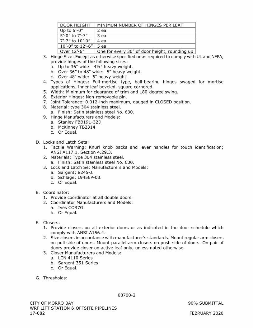
08700-2
CITY OF MORRO BAY 90% SUBMITTAL
WRF LIFT STATION & OFFSITE PIPELINES
17-082 FEBRUARY 2020
DOOR HEIGHT MINIMUM NUMBER OF HINGES PER LEAF
Up to 5’-0” 2 ea
5’-0” to 7’-7” 3 ea
7’-7” to 10’-0” 4 ea
10’-0” to 12’-6” 5 ea
Over 12’-6” One for every 30” of door height, rounding up
3. Hinge Size: Except as otherwise specified or as required to comply with UL and NFPA,
provide hinges of the following sizes:
a. Up to 36" wide: 4½" heavy weight.
b. Over 36” to 48" wide: 5" heavy weight.
c. Over 48" wide: 6" heavy weight.
4. Types of Hinges: Full-mortise type, ball-bearing hinges swaged for mortise
applications, inner leaf beveled, square cornered.
5. Width: Minimum for clearance of trim and 180-degree swing.
6. Exterior Hinges: Non-removable pin.
7. Joint Tolerance: 0.012-inch maximum, gauged in CLOSED position.
8. Material: type 304 stainless steel.
a. Finish: Satin stainless steel No. 630.
9. Hinge Manufacturers and Models:
a. Stanley FBB191-32D
b. McKinney TB2314
c. Or Equal.
D. Locks and Latch Sets:
1. Tactile Warning: Knurl knob backs and lever handles for touch identification;
ANSI A117.1, Section 4.29.3.
2. Materials: Type 304 stainless steel.
a. Finish: Satin stainless steel No. 630.
3. Lock and Latch Set Manufacturers and Models:
a. Sargent; 8245-J.
b. Schlage; L9456P-03.
c. Or Equal.
E. Coordinator:
1. Provide coordinator at all double doors.
2. Coordinator Manufacturers and Models:
a. Ives COR7G.
b. Or Equal.
F. Closers:
1. Provide closers on all exterior doors or as indicated in the door schedule which
comply with ANSI A156.4.
2. Size closers in accordance with manufacturer’s standards. Mount regular arm closers
on pull side of doors. Mount parallel arm closers on push side of doors. On pair of
doors provide closer on active leaf only, unless noted otherwise.
3. Closer Manufacturers and Models:
a. LCN 4110 Series
b. Sargent 351 Series
c. Or Equal.
G. Thresholds:
08700-3
CITY OF MORRO BAY 90% SUBMITTAL
WRF LIFT STATION & OFFSITE PIPELINES
17-082 FEBRUARY 2020
1. Provide threshold at each door as indicated in the door schedule or shown on the
drawings: One-piece full width of opening; extend beyond jamb where indicated.
2. Provide with stainless steel machine screws in threaded expansion anchors at
concrete.
3. Coordinate thresholds with the door shoes.
4. Finish: Mill finish aluminum, unless indicated otherwise.
5. Threshold Manufacturers and Models:
a. Pemko 274X4AFG
b. Reese Enterprises, Inc. S407A
c. Or approve equal
H. Door Shoes:
1. Provide door shoes at each door indicated to have a threshold. Provide vinyl or
neoprene seal with a depth coordinated with the threshold. Provide an integral drip
cap at exterior doors. Attach door shoes to doors in accordance with the
manufacturer’s installation instructions.
2. Finish: Mill finish aluminum, unless indicated otherwise.
3. Door Shoe Manufacturers and Models:
a. Pemko 216 at exterior doors and 217 at interior doors
b. Reese Enterprises, Inc. DB595 at exterior doors and DB594 at interior doors
c. Or approved equal
I. Weatherproofing:
1. Provide complete weatherstrip system including rubber or vinyl at jambs and head at
exterior doors and interior doors required to be sealed or airtight.
2. Provide astragal seal for 2-leaf doors.
3. All other weatherstripping necessary to provide a weather-sealed door system which
does not allow air or moisture movement through the gap between the door and
frame.
J. Rain Drip:
1. Provide overhead rain drip guard attached to the top of the door frame at all exterior
doors. Attach to the door frame in accordance with the manufacturer’s installation
instructions.
2. Finish: Clear anodized aluminum, unless indicated otherwise.
3. Drip Cap Manufacturers and Models:
a. Pemko 346
b. Reese Enterprises, Inc. R201
c. Or approved equal
K. Stops and Holders:
1. Provide stops and holders for all doors with closers in accordance with ANSI A156.16.
2. Finish: Satin chromium-plated No. 626.
3. Stop/Holder Manufacturers and Models:
a. Ives WS445
b. Hager Companies 256
c. Or Equal.
2.2 KEYING
A. Coordinate Keying System with OWNER. Provide master-keying and local-keying to
match OWNER’s keying system.
08700-4
CITY OF MORRO BAY 90% SUBMITTAL
WRF LIFT STATION & OFFSITE PIPELINES
17-082 FEBRUARY 2020
B. Provide removable construction core system for use during construction.
PART 3 - EXECUTION
3.1 INSTALLATION
A. In accordance with manufacturer’s written instructions.
B. Make Work neat and secure, develop full strength of components, and provide proper
function.
C. Prevent marring, scratching, or otherwise damaging adjacent finishes during hardware
installation.
D. Latchbolts: Install to engage in strikes automatically, whether activated by closers or
manually. In no case shall additional manual pressure be required to engage latchbolt in
strike.
E. Wall Mounted Hardware: Install over solid structural backing or solid blocking in hollow
walls.
F. Thresholds:
1. Cope ends neatly to profile of jamb.
2. Set in sealant and seal ends to jambs.
G. Hardware: Adjust for easy, noise-free operation.
H. Replace damaged hardware items.
3.2 MOUNTING DIMENSIONS
A. Standard Door Hardware Locations: As recommended and published by the Door and
Hardware Institute, except as noted or detailed otherwise.
B. Door Silencers: Install 3 inches from top and bottom of jamb and 1 inch above strike at
single doors, and 3 inches from edges of doors in head for pairs of doors.
3.3 MANUFACTURER’S SERVICES
A. Deliver permanent lock cores to the site.
B. Remove temporary construction cores and insert permanent cores.
C. Inspect each lock set to ensure permanent cores are operating satisfactorily.
D. Deliver to OWNER change and control keys for the permanent system.
E. Return temporary construction cores to the manufacturer.
08700-5
CITY OF MORRO BAY 90% SUBMITTAL
WRF LIFT STATION & OFFSITE PIPELINES
17-082 FEBRUARY 2020
3.4 PROTECTION
A. Cover and protect exposed surfaces of hardware during installation and until Substantial
Completion.
B. Fit, dismantle, and reinstall finish hardware as required for finish painting work.
C. Protect and prevent staining of hardware during construction in accordance with
manufacturer’s recommendations.
D. Remove protective measures and permanent lock cylinders installed prior to final
cleaning.
+ + END OF SECTION + +
09250-1
CITY OF MORRO BAY 90% SUBMITTAL WRF LIFT STATION & OFFSITE PIPELINES 17-082 FEBRUARY 2020
SECTION 09250
GYPSUM WALLBOARD
PART 1 - GENERAL
1.1 DESCRIPTION
A. Scope: Furnish all materials, labor, equipment and incidentals required to install gypsum wallboard.
1.2 QUALITY ASSURANCE
A. General: Regardless of the minimum specifications herein, utilize materials and applications recommended by the manufacturer.
B. Applicator's Qualifications: Use only workers regularly employed in this type of work who can show experience in the application of similar materials and the specific systems specified.
1.3 SUBMITTALS
A. Shop Drawings: 1. Control joint pattern proposed for gypsum wallboard. 2. Control joint pattern proposed for gypsum soffit. 3. Manufacturer's list of items and materials proposed for use, with descriptive literature
for each system used.
1.4 PRODUCT DELIVERY, STORAGE, AND HANDLING
A. Delivery of Materials: 1. Deliver materials to the project site with manufacturer's labels intact and legible. 2. Deliver fire rated materials bearing testing agency label and required fire
classification numbers.
B. Storage and Handling of Materials: 1. Store materials inside under cover, stack flat, off floor. 2. Stack gypsum wallboard so that long lengths are not over short lengths. 3. Avoid overloading floor system. 4. Store adhesives and finishing compounds in dry areas, and protect against freezing
at all times.
1.5 ENVIRONMENTAL REQUIREMENTS
A. Temperature: 1. In areas receiving gypsum wallboard installation, maintain temperature range
between 55 and 70 degrees F for 24 hours before, during, and after gypsum wallboard and joint treatment application.
2. In areas receiving veneer plaster, where outside air temperature is less than 50 degrees F, maintain interior temperature range between 50 degrees F and 80
09250-2
CITY OF MORRO BAY 90% SUBMITTAL WRF LIFT STATION & OFFSITE PIPELINES 17-082 FEBRUARY 2020
degrees F for a period of 1 week before, during, and 1 week after application of veneer plaster, base, and joint treatment.
B. Ventilation: 1. Provide ventilation during and following adhesives and joint treatment applications. 2. Use temporary air circulators in enclosed areas lacking natural ventilation. 3. Keep air circulation at a minimum level during veneer plastering to avoid excessive
drying. 4. Under slow drying conditions, allow additional drying time between coats of joint
treatment. 5. Protect installed materials from drafts of ambient air during hot, dry weather.
PART 2 - PRODUCTS
2.1 GYPSUM WALLBOARD
A. Regular Board: ASTM C36, Type X, 5/8 inch thick with tapered edges.
B. Mold and Moisture Resistant Board: ASTM C1396, 1/2 inch thick with tapered edges.
2.2 FASTENERS FOR GYPSUM WALLBOARD
A. Screws: ASTM C1002, self-drilling, self-tapping, bugle head, for use with power-driven tool. 1. Type S, 1-inch long for gypsum wallboard to sheet metal. 2. 1¾-inch long for gypsum wallboard to wood framing.
B. Nails: ASTM C514, F547, F1667 1. Reference IBC section 2508 for nail sizes in wood framing.
2.3 JOINT TREATMENT
A. Joint Tape for General Interior Applications: ASTM C475, perforated paper tape.
B. Joint Compound for General Interior Applications: ASTM C475, all-purpose, ready-mixed compound.
2.4 ANCILLARY MATERIALS
A. Adhesives: As recommended by gypsum wallboard manufacturer for intended use.
2.5 TRIM ACCESSORIES
A. Zinc-Coated Metal, ASTM C1047: 1. Corner Bead: 1-1/4 inch by 1-1/4 inch:
a. United States Gypsum; Dur-A-Bead. b. Award Metals; standard corner beads. c. Clark Dietrich: standard corner beads.
2. Edge Trim: a. United States Gypsum; L-Trim and J-Trim. b. Award Metals; L-Bead and J-Bead.
09250-3
CITY OF MORRO BAY 90% SUBMITTAL WRF LIFT STATION & OFFSITE PIPELINES 17-082 FEBRUARY 2020
c. Clark Dietrich: L-Trim and J-Trim. 3. Metal Control Joint:
a. United States Gypsum: No. 093. b. Phillips: 093 control joint. c. Clark Dietrich: No. 093.
B. Vinyl Wall Base, ASTM F1861: 1. Profile: Standard Cove 2. Gauge: 1/8-inch 3. Height: 4-inch 4. Provide factory corners and all inside and outside corners. 5. Adhesive: As recommended by manufacturer of wall base. 6. Manufacturer:
a. Roppe Corporation b. Johnsonite c. Or approved equal
2.6 LIGHT-GAUGE METAL FRAMING ACCESSORIES
A. Z Furring: Galvanized 20-gauge, 1-1/2 inch depth.
2.7 NONSTRUCTURAL FRAMING MEMBERS
A. ASTM C645, 20-gauge galvanized C-studs with 1-5/8 inch flanges, and ancillary items for interior wall framing, shaft walls, and ceiling framing.
B. Dry wall studs, tracks, shaft wall studs, Z-furring channels, and accessories. 1. Cemco. 2. Clark Dietrich 3. United Metal Products.
2.8 SPRAY TEXTURE
A. Interior Walls and Ceilings: 1. United States Gypsum; Texture I sand finish. 2. Gold Bond; Wall Spray texture finish.
2.9 FIBERGLASS-MAT FACED GYPSUM BACKING BOARD
A. Fiberglass-Mat Faced Gypsum Backing Board: ASTM C1178:
B. Water-resistant treated core with glass mat moisture protectant coating and embedded glass mats, both sides, and face side surfaced with heat-cured copolymer water- and vapor-retarding coating.
C. Thickness: ½-inch
D. Fasteners: 1. Screws: 1-1/4 inch, type S, Hi-Lo for wood or 22- to 25-gauge steel framing. 1 ¼-
inch, Type S-12, for 14- to 20-guage steel framing. 1-15/16 inch, type S-12, Pilot Point for steel joists.
09250-4
CITY OF MORRO BAY 90% SUBMITTAL WRF LIFT STATION & OFFSITE PIPELINES 17-082 FEBRUARY 2020
2. Nails: 1-1/4 inch galvanized roofing nail with 7/16-inch diameter head for wood framing.
E. Joint Reinforcement: 2 inches wide, glass fiber, open weave tape, as recommended by manufacturer.
F. Joint Compound: Chemically curing, polyindurate type material, as recommended by manufacturer.
G. Manufacturer and Product: G-P Gypsum Corp., DENS-SHIELD TILE BACKER.
2.10 ACCESS PANELS
A. Architectural grade prime coated flush steel panel and frame with concealed hinges and screwdriver-operated locking device.
B. Provide frame type and anchors to suit opening conditions.
C. Sizes Not Indicated on Drawings: 1. Smallest standard size that will permit ready access and removal of working parts
required for maintenance. 2. Not less than 8 inches square.
D. Manufacturers: 1. Milcor. 2. Acudor.
PART 3 - EXECUTION
3.1 EXAMINATION
A. Inspect surfaces to receive gypsum wallboard and related materials before beginning work and report to ENGINEER any defects in such work which will adversely affect the quality of work specified herein.
3.2 PREPARATION
A. General: Provide, install, and maintain necessary scaffolding, staging, trestles, planking, and temporary heating, lighting, and ventilation as necessary for the duration of the gypsum wallboard work.
B. Protection: Protect work of other trades.
C. Coordination: 1. Coordinate work with that of other trades. Check specifications and drawings of other
trades to determine parts of work requiring coordination. 2. Cut and repair gypsum wallboard systems for installation of omitted work.
D. Surface Preparation: Repair defective surfaces prior to starting work. Prepare as specified for application of specific materials.
09250-5
CITY OF MORRO BAY 90% SUBMITTAL WRF LIFT STATION & OFFSITE PIPELINES 17-082 FEBRUARY 2020
3.3 APPLICATION OF GYPSUM WALLBOARD
A. Inspection and Preparation: 1. Check framing for accurate spacing and alignment. 2. Verify that spacing of installed framing does not exceed maximum allowable for
thickness of gypsum wallboard to be used. 3. Verify that frames are set for thickness of gypsum wallboard to be used. 4. Do not proceed with installation of gypsum wallboard until deficiencies are corrected
and surfaces to receive gypsum wallboard are acceptable. 5. Protrusions from framing, twisted framing members, or unaligned members must be
repaired before installation of gypsum wallboard is started.
B. General: 1. Meet requirements of ASTM C840 and GA-216. 2. Joints: Use gypsum wallboard of maximum lengths to minimize end joints. Stagger
end joints when they occur. Locate end joints as far as possible from center of wall or ceiling. Abut gypsum wallboard without forcing. Neatly fit ends and edges of gypsum wallboard. Do not place butt ends against tapered edges.
3. Support ends and edges of gypsum wallboard panels on framing or furring members except for face layer of double layer and where ends are back blocked and floated.
4. Use metal edge trim where gypsum wallboard abuts another material and where shown or noted on Drawings.
5. Use gypsum fiberglass-mat faced gypsum backing board in toilet and shower walls, behind ceramic tile, and elsewhere as indicated on Drawings.
6. Follow manufacturer’s recommendation of good practice.
C. Over Framing: 1. Apply gypsum wallboard first to ceiling and then to walls for single layer horizontal
application. 2. Use vertical application for fire-rated walls. 3. Fasten gypsum wallboard securely to framing using double nailing, screw, or
adhesive method.
3.4 JOINT SYSTEM
A. Interior Gypsum Wallboard: Conform to ASTM C840.
B. Required: On exposed gypsum wallboard, under ceramic tile and wall covering, and behind casework.
C. Prefill: Fill V-grooves formed by abutting rounded edges of gypsum wallboard with prefill joint compound. Fill V-joint flush and remove excess compound beyond groove. Leave clear depression to receive tape. Permit prefill joint compound to harden prior to application of tape.
D. Taping and Finishing Joins: 1. Taping or Embedding Coat: Apply compound in thin, uniform layer to joints and
angles to be reinforced. Apply reinforcing tape immediately. Center tape over joint and seat tape into compound. Leave approximately 1/64-inch to 1/32-inch compound under tape to provide bond. Apply skim coat immediately following tape embedment but not to function as fill or second coat. Fold tape and embed in angles to provide true angle. Dry embedding coat prior to application of fill coat.
09250-6
CITY OF MORRO BAY 90% SUBMITTAL WRF LIFT STATION & OFFSITE PIPELINES 17-082 FEBRUARY 2020
2. Filling Coat: Apply joint compound over embedding coat. Fill taper flush with surface. Apply fill coat to cover tape. Feather out fill coat beyond tape and previous joint compound line. For joints with no taper, feather out at least 4 inches on either side of tape. Do not apply fill coat on interior angles. Allow fill coat to dry prior to application of finish coat.
3. Finishing coat: Spread joint compound evenly over and beyond fill coat on joints. Feather to smooth uniform finish. Apply finish coat to tapes angles to cover tape and taping compound. Sand final application of compound to provide surface ready for decoration.
4. Filling and Finishing Depressions: a. Apply joint compound as first coat to fastener depressions. Apply at least two
additional coats of compound after first coat is dry. Leave filled and finished depressions level with plane of surface.
E. Finishing Beads and Trim: 1. First Fill Coat: Apply joint compound to bead and trim. Feather out from ground to
plane of the surface. Dry compound prior to application of second fill coat. 2. Second Fill Coat: Apply joint compound in same manner as first fill coat. Extend
beyond first coat onto face of gypsum wallboard. Dry compound prior to application of finish coat.
3. Finish Coat: Apply joint compound to bead and trim. Extend beyond second fill coat. Feather finish coat from ground to plane of surface. Sand finish coat to provide flat surface ready for decoration.
3.5 FINAL FINISHES
A. Levels of Finish: Conform to GA-214.
B. Level 4: 1. Taping, filling, and finishing coats plus two separate coats applied over joints, angles,
fastener heads, and trim accessories. 2. Sand between coats and after last coat.
C. Level 5: 1. Same as Level 4, plus a thin, smooth, uniform skim coat of joint compound, or
product specially formulated for this purpose, over entire surface. 2. Produce surfaces free of tool marks and ridges, ready for decoration. 3. Use on surfaces not indicated otherwise, those indicated to receive gloss, semi-gloss,
and nontextured flat paints, and where indicated.
3.6 ADJUST AND CLEAN
A. Clean: Remove droppings or texture overspray from walls, windows, and floor, leaving room clean for following trades.
3.7 ACCESS PANELS
A. Install in accordance with manufacturer’s printed instructions.
+ + END OF SECTION + +
09875-1
CITY OF MORRO BAY 90% SUBMITTAL WRF LIFT STATION & OFFSITE PIPELINES 17-082 FEBRUARY 2020
SECTION 09875
CONCRETE COATINGS FOR WASTEWATER STRUCTURES
PART 1 - GENERAL
1.1 DESCRIPTION
A. Scope: Provide and install coatings on all interior concrete surfaces – including ceilings, as indicated herein, in the Specifications and on the Drawings.
B. System shall be a multi-component resin-based mortar lining system specifically designed to protect the concrete surfaces of municipal wastewater structures from chemical attack. The main purpose of this membrane is to offer protection of the substrate from chemicals or gases that might cause deterioration.
1.2 QUALITY ASSURANCE
A. Experience: Both coatings manufacturer and coatings installer shall have a minimum 5 years’ experience in production and application, respectively, of specified products. Coatings installer shall be approved and endorsed, in writing, by coatings manufacturer.
B. Regulations: Meet federal, state, and local requirements which apply to the work, including, but not limited to those regulations limiting the emission of volatile organic compounds.
C. Coatings Manufacturer Recommendations: Coatings installer shall follow all recommendations of the coatings manufacturer regarding storage, handling, surface preparation, application of coatings, re-coat times, environmental conditions during storage, preparation and application of coatings, and all other coatings manufacturer recommendations.
D. Warranty: Both Coatings Manufacturer and Coatings Installer shall provide a 1-year complete replacement warranty for all coatings. Manufacturer shall provide 5-year warranty for long-term performance of coatings in addition to 1-year warranty.
1.3 SUBMITTALS
A. Shop Drawings: Coatings Manufacturer shall submit for approval the following: 1. Copies of manufacturer's technical information and application instructions for each
material proposed for use. Specify exactly which product is being proposed for each coating type (as specified below). This may be accomplished through a reference table along with information on the various products, or by a separate, tabbed section with information on products being submitted for each system in a separate tab of a binder. Submittal of general manufacturer’s literature without detailing which product is proposed for each paint system will be unacceptable.
2. Letter from the Coatings Manufacturer certifying the Coatings Installer as factory trained and qualified.
3. Furnish copies of the final, approved submittal to the coatings installer so that it is clear which product is to be used for which each system.
09875-2
CITY OF MORRO BAY 90% SUBMITTAL WRF LIFT STATION & OFFSITE PIPELINES 17-082 FEBRUARY 2020
4. Test reports from an independent testing laboratory confirming chemical resistance of coating for chemicals common to municipal wastewater treatment facilities.
1.4 PRODUCT DELIVERY, STORAGE, AND HANDLING
A. Protection: Protect all pre-coated items from coating damage during shipping.
B. Store products in accordance with manufacturer’s directions.
C. Store products in a neat, orderly fashion. Protect products from damage. Protect storage area from damage from stored products.
PART 2 - PRODUCTS
2.1 PRODUCT AND MANUFACTURER:
A. Coating Systems 1. Hydro-Pox, Inc.
a. Primer: Hydro-Pox 251 b. Surface Material: Hydro-Pox 212 GL
B. Global Ecotechnologies, Inc. 1. Underlayment: Endura-Flex 1200P with 1200F Filler 2. Primer: Endura-Flex 1200P 3. Surface Material: Endura-Flex 1988
C. Environmental Coatings, LLC 1. Surface Material: Sewer Shield 100 trowelable grade
D. Sauereisen SewerGard 1. Underlayment: Sauereisen Filler Compound No. 209 2. Surface Material: Sauereisen No. 210S
E. Sherwin Williams 1. Underlayment: Duraplate 2300 2. Surface Material: Duraplate 6100
F. Or equal.
2.2 SERVICE CONDITIONS AND PERFORMANCE
A. Provide a 100% solids, VOC-free resin based coating system specifically formulated for wastewater applications. 1. The lining system shall be a non-sagging application permitting repair of vertical,
horizontal, and overhead surfaces. 2. The lining system shall provide an impermeable, high-strength, corrosion-resistant,
monolithic lining for manholes, grit chambers, wetwells, wastewater channels, and related structures subject to attack from hydrogen sulfide and acid generated by microbiological sources.
09875-3
CITY OF MORRO BAY 90% SUBMITTAL WRF LIFT STATION & OFFSITE PIPELINES 17-082 FEBRUARY 2020
B. The lining system, including underlayment, primer and surface materials, shall be from a single manufacturer.
C. Chemical Resistance (ASTM D 1308): a. Reagent: 6% sulfuric acid solution. b. Film Integrity: Unaffected.
D. Coating Thickness: 125 mils thick, minimum.
E. Texture: Semi-smooth for all surfaces.
2.3 PROPERTIES
A. Either trowel or spray application is acceptable provided the Installer follow all Manufacturer recommendations.
B. Physical Properties 1. Bond strength to dry or damp concrete: Failure in concrete per ASTM C4541 2. Compressive strength: >6,700 psi per ASTM C579 3. Flexural strength: >4,600 psi per ASTM C580 4. Tensile strength: >2,400 psi per ASTM C580 5. Moisture absorption: <0.2% per ASTM C413
PART 3 - EXECUTION
3.1 STORAGE, MIXING, AND THINNING OF MATERIALS
A. Manufacturer's Recommendations: Unless otherwise specified herein, the coating manufacturer's printed recommendations and instructions for thinning, mixing, handling, applying, and protecting its coating materials, for preparation of surfaces for coating, and for all other procedures relative to coating shall be strictly observed.
B. All protective coating materials shall be used within the manufacturer's recommended shelf life.
C. Storage: Coating materials shall be protected from exposure to inclement weather, and shall be thoroughly stirred, strained, and kept at a uniform consistency during application.
D. Mixing: 1. Coatings of different manufacturers shall not be mixed together. 2. Mixing of multi-component coating systems shall be performed in accordance with
Manufacturer’s recommendations. Components must be mixed in complete batches only and used immediately.
3.2 INSPECTION
A. Contractor and his installer shall examine the areas and conditions under which concrete coatings are to be placed and notify Engineer, in writing, of any conditions which could be detrimental to the proper and timely installation of the Work. Do not proceed with
09875-4
CITY OF MORRO BAY 90% SUBMITTAL WRF LIFT STATION & OFFSITE PIPELINES 17-082 FEBRUARY 2020
the Work until any unsatisfactory conditions have been corrected in a manner acceptable to the Engineer.
3.3 SURFACE PREPARATION
A. Surface preparation shall not begin until at least 7 days after new concrete has been placed. Chemical resistant coatings shall not be applied until at least 28 days after new concrete has been placed.
B. All oil, grease, and form release and curing compounds shall be removed by detergent cleaning in accordance with SSPC-SP1 before abrasive blast cleaning. Surface preparation shall be performed in accordance with the latest editions of the following standards: 1. ASTM D-4258: Standard Practice for Surface Cleaning Concrete for Coating 2. ASTM D-4259: Standard Practice for Abrading Concrete
C. Concrete surfaces and deteriorated concrete surfaces to be coated or lined shall be abrasive blast cleaned in accordance with SSPC SP13 to remove existing coatings, laitance, deteriorated concrete, and to roughen the surface equivalent to the surface of the No. 60 grit flint sandpaper (surface profile of 2.5 to 4 mils). 1. Evaluation of blast cleaned surface preparation work will be based upon comparison
of the blasted surfaces with the standard samples available from the NACE, using NACE Standard TM-01-70.
2. The air compressor must be equipped with efficient oil and water traps to ensure that the compressed air is clean and free of oil particles. Refer to NACE procedure for “Blotter Testing” of compressed air.
D. Concrete surfaces requiring repairs in excess of one-quarter inch (¼”) depth shall be restored with underlayment, and brought flush with the surface, in accordance with the coating manufacturers’ recommendations to provide a continuously smooth and even surface for application of top coat.
E. Surfaces shall be clean and as recommended by the coating manufacturer before coating or lining is started.
F. Unless required for proper adhesion, surfaces shall be dry prior to coating. The presence of moisture shall be determined with a moisture detection device such as Delmhorst Model DB, or equal.
G. All surfaces to be coated shall be completely dry, clean, and contaminant-free prior to application. For polyurethane lining system, after completing surface preparation, surface dryness shall be verified according to ASTM D4263. Any indication of moisture will require an appropriate corrective measure. The surface shall be re-tested after taking the corrective measure.
H. The concrete surface shall be notched to a depth equal to the total lining thickness with a power grinding tool on the perimeter of all lining termination points. The notch shall be clean and neat.
09875-5
CITY OF MORRO BAY 90% SUBMITTAL WRF LIFT STATION & OFFSITE PIPELINES 17-082 FEBRUARY 2020
3.4 APPLICATION
A. Coatings shall be installed on all surfaces described in Paragraph 1.1.A of this Section, with the systems indicated.
B. Contractor shall give the Engineer a minimum of 3 days advance notice of the start of any field surface preparation work or coating application Work. All such Work shall be performed only in the presence of the Engineer.
C. All concrete surfaces shall be coated before installation of any equipment in the area to be protected, including chemical storage tanks, pumps, pipe supports and stands, etc.
D. Contractor shall supply all temporary heating, cooling or night-time work, if required, and provide protection from the sun, heat, or other environmental conditions which may adversely affect the coatings. Moisture content of concrete, air temperature, relative humidity, and all other conditions shall be within limits recommended by coatings manufacturers.
E. Contractor shall fill all “bug holes” and other defects in the concrete to which the chemical resistant coatings are applied prior to application of the chemical resistant coatings system in accordance with the recommendations of the coatings manufacturer approved for use in each area. Filler shall be allowed to cure in accordance with manufacturers recommendation.
F. All surfaces receiving the polyurethane membrane lining shall be visually dry and at least 5oF (3oC.) above the Dew Point prior to starting the installation to prevent moisture entrapment. The Relative Humidity must be below 85%.
G. Contractor shall apply coating to prepared concrete surface. Contractor shall repeat coating application as recommended by manufacturer for complete coverage. Application and mixing shall be by the method recommended by the coatings manufacturer with the equipment recommended as the best for installing the coating system supplied. Apply the materials in the recommended quantities to provide the dimensional requirements and chemical resistance specified for the system. Successive topcoats shall be applied within 24 hours so as to not exceed the recoat window.
H. Contractor shall apply termination and expansion joint strips at the junction of the chemical resistant coating with other surfaces and at expansion joints as recommended by the coatings manufacturers.
I. Wet film thickness shall be monitored throughout the installation by means of frequent measurements with a high-range wet film thickness gage.
J. Whether spray or trowel application is used, the application shall be according to the principles of good workmanship outlined in SSPC-PA1-82 and shall provide a finish which is continuous, uniform in thickness, and verified free of pores or other defects using electrical discontinuity testing (high voltage spark testing).
09875-6
CITY OF MORRO BAY 90% SUBMITTAL WRF LIFT STATION & OFFSITE PIPELINES 17-082 FEBRUARY 2020
3.5 CURING OF COATINGS
A. Contractor shall provide curing conditions in accordance with the conditions recommended by the coating material manufacturer or by this Section, whichever is the highest requirement, prior to placing the completed coating system into service.
B. In the case of enclosed hydraulic structures, forced air ventilation, using heated or cooled air if necessary, is required for the application and curing of coatings on the interior surfaces. 1. During curing periods continuously exhaust air from the lowest level of the structure
using portable ducting. After all interior coating operations have been completed provide a final curing period for a minimum of 10 days, unless a shorter period is recommended by the coating manufacturer, during which the forced ventilation system shall operate continuously.
3.6 FIELD TESTING
A. Inspection by the Engineer, or the waiver of inspection of any particular portion of the work, shall not relieve Contractor of its responsibility to perform the Work in accordance with this Specification.
B. Proper, safe access shall be provided in locations where requested by the Engineer to facilitate inspection. Additional illumination shall be furnished when the Engineer requests. Proper ventilation and atmospheric monitoring shall be provided as well as all other safety equipment and precautions required by OSHA for a safe inspection in all areas.
C. The Engineer will conduct wet-film thickness testing. Contractor shall recoat any areas found deficient in thickness.
D. Holiday Testing: 1. Engineer will visually inspect coverage for blisters, sags, and holidays. Contractor
shall repair areas identified by this inspection prior to conducting holiday test. 2. Contractor shall holiday test, in the presence of the Engineer, all coated surfaces
which will be submerged in water or other liquids, or surfaces which are enclosed in a vapor space in such structures and surfaces coated with any of the submerged and severe service coating systems. a. Holiday testing equipment and procedures shall be done in strict accordance with
the latest edition of the NACE “Standard Recommended Practice Discontinuity (Holiday) Testing of Protective Coatings.”
b. Areas that contain holidays shall be marked and repaired or recoated in accordance with the coating manufacturer's printed instructions and then retested.
3. Holiday detectors shall be of the following type: a. High voltage pulse-type holiday detector such as Tinker & Rasor Model AP-W,
D.E. Stearns Co. Model 14/20, or equal shall be used. The unit shall be adjusted to operate at a voltage of at least 110 volts/mil desired thickness.
E. Any damaged areas, faulty areas, or discontinuities (pinholes) found during quality control inspection shall be repaired in accordance with the Manufacturer’s recommendations.
09875-7
CITY OF MORRO BAY 90% SUBMITTAL WRF LIFT STATION & OFFSITE PIPELINES 17-082 FEBRUARY 2020
3.7 ADJUSTMENT AND CLEANING
A. At the completion of the Work, Contractor shall remove all material and debris associated with the Work of this Section.
B. At the completion of the Work, Contractor shall clean all surfaces to which coatings were applied, as well as all adjacent, uncoated surfaces in a manner acceptable to the Engineer.
C. Coatings shall be protected from damage until Final Acceptance of all Work in the area that was coated. Coatings damaged in any manner by Contractor prior to Final Acceptance of all Work in that area shall be repaired or replaced in a manner acceptable to the Engineer at no additional cost to the Owner.
D. Just prior to Final Acceptance of all Work in the area that was coated, Contractor shall clean all coatings, as recommended by the manufacturer, to provide a finished product acceptable to the Owner.
+ + END OF SECTION + +
09900-1
CITY OF MORRO BAY 90% SUBMITTAL WRF LIFT STATION & OFFSITE PIPELINES 17-082 FEBRUARY 2020
SECTION 09900
PAINTING
PART 1 - GENERAL
1.1 DESCRIPTION
A. Scope: Provide and install coatings on all exposed surfaces as indicated herein, in other Specification Sections, and on the Drawings.
1.2 QUALITY ASSURANCE
A. Experience: Both Coatings Manufacturer and Coatings Installer shall have a minimum 5 years’ experience in production and application, respectively, of specified products. Coatings Installer shall be approved and endorsed, in writing, by Coatings Manufacturer.
B. Regulations: Meet federal, state, and local requirements which apply to the work, including, but not limited to those regulations limiting the emission of volatile organic compounds.
C. Coatings Manufacturer Recommendations: Coatings Installer shall follow all recommendations of the Coatings Manufacturer regarding storage, handling, surface preparation, application of coatings, recoat times, environmental conditions during storage, preparation and application of coatings, and all other Coatings Manufacturer recommendations.
D. Warranty: Both Coatings Manufacturer and Coatings Installer shall provide a 1-year complete replacement warranty for all coatings. Manufacturer shall provide 5-year warranty for long-term performance of coatings in addition to 1-year warranty.
1.3 SUBMITTALS
A. Shop Drawings: Coatings Manufacturer shall submit for approval the following: 1. Copies of Manufacturer's technical information and application instructions for each
material proposed for use. Specify exactly which product is being proposed for each coating type (as specified below). This may be accomplished through a reference table along with information on the various products, or by a separate, tabbed section with information on products being submitted for each system in a separate tab of a binder. Submittal of general Manufacturer’s literature without detailing which product is proposed for each paint system will be unacceptable.
2. Copies of Manufacturer's complete color charts for each coating system. 3. Letter from the Coatings Manufacturer approving and endorsing Coatings Installer. 4. Furnish copies of the final, approved submittal to the Coatings Installer so that it is
clear which product is to be used for which each system.
B. Reference Samples: 1. Provide reference samples of paint colors and textures as required by the ENGINEER.
Reference samples will show the color and texture of the final paint to be applied and shall be approved by the ENGINEER prior to painting. Reference samples should be applied to similar substrates to the final surfaces to be painted. If ENGINEER chooses
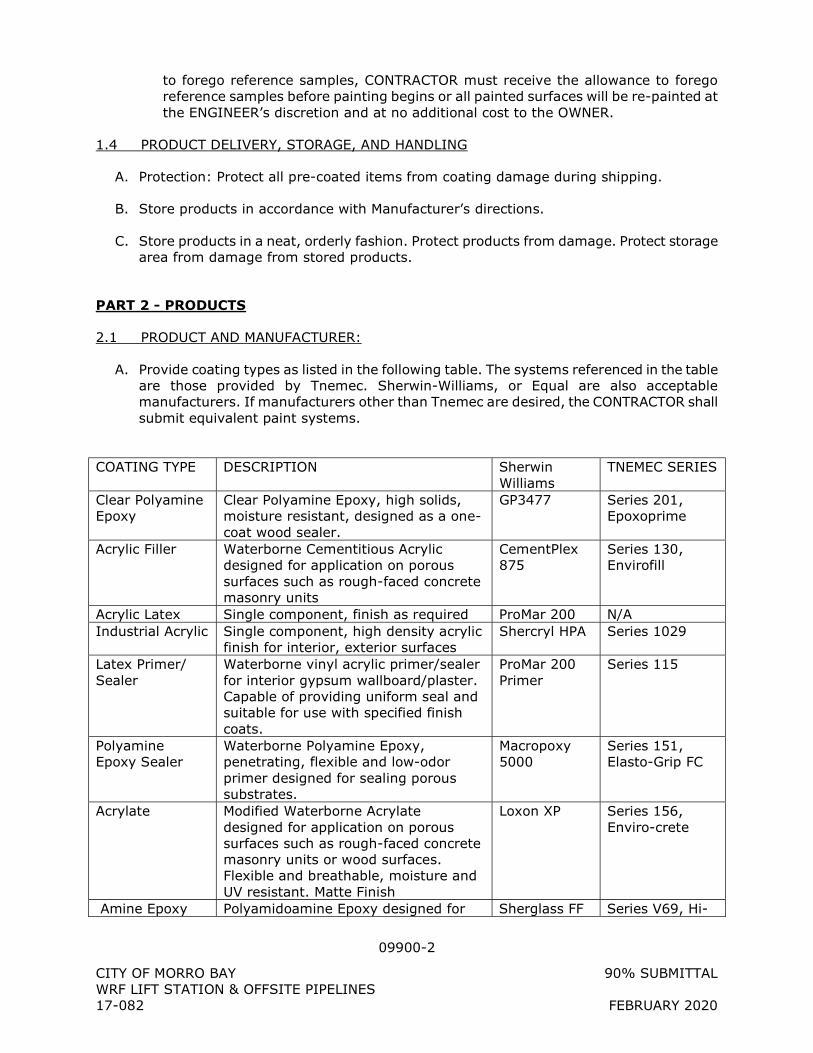
09900-2
CITY OF MORRO BAY 90% SUBMITTAL WRF LIFT STATION & OFFSITE PIPELINES 17-082 FEBRUARY 2020
to forego reference samples, CONTRACTOR must receive the allowance to forego reference samples before painting begins or all painted surfaces will be re-painted at the ENGINEER’s discretion and at no additional cost to the OWNER.
1.4 PRODUCT DELIVERY, STORAGE, AND HANDLING
A. Protection: Protect all pre-coated items from coating damage during shipping.
B. Store products in accordance with Manufacturer’s directions.
C. Store products in a neat, orderly fashion. Protect products from damage. Protect storage area from damage from stored products.
PART 2 - PRODUCTS
2.1 PRODUCT AND MANUFACTURER:
A. Provide coating types as listed in the following table. The systems referenced in the table are those provided by Tnemec. Sherwin-Williams, or Equal are also acceptable manufacturers. If manufacturers other than Tnemec are desired, the CONTRACTOR shall submit equivalent paint systems.
COATING TYPE DESCRIPTION Sherwin
Williams TNEMEC SERIES
Clear Polyamine Epoxy
Clear Polyamine Epoxy, high solids, moisture resistant, designed as a one-coat wood sealer.
GP3477 Series 201, Epoxoprime
Acrylic Filler Waterborne Cementitious Acrylic designed for application on porous surfaces such as rough-faced concrete masonry units
CementPlex 875
Series 130, Envirofill
Acrylic Latex Single component, finish as required ProMar 200 N/A Industrial Acrylic Single component, high density acrylic
finish for interior, exterior surfaces Shercryl HPA Series 1029
Latex Primer/ Sealer
Waterborne vinyl acrylic primer/sealer for interior gypsum wallboard/plaster. Capable of providing uniform seal and suitable for use with specified finish coats.
ProMar 200 Primer
Series 115
Polyamine Epoxy Sealer
Waterborne Polyamine Epoxy, penetrating, flexible and low-odor primer designed for sealing porous substrates.
Macropoxy 5000
Series 151, Elasto-Grip FC
Acrylate Modified Waterborne Acrylate designed for application on porous surfaces such as rough-faced concrete masonry units or wood surfaces. Flexible and breathable, moisture and UV resistant. Matte Finish
Loxon XP Series 156, Enviro-crete
Amine Epoxy Polyamidoamine Epoxy designed for Sherglass FF Series V69, Hi-
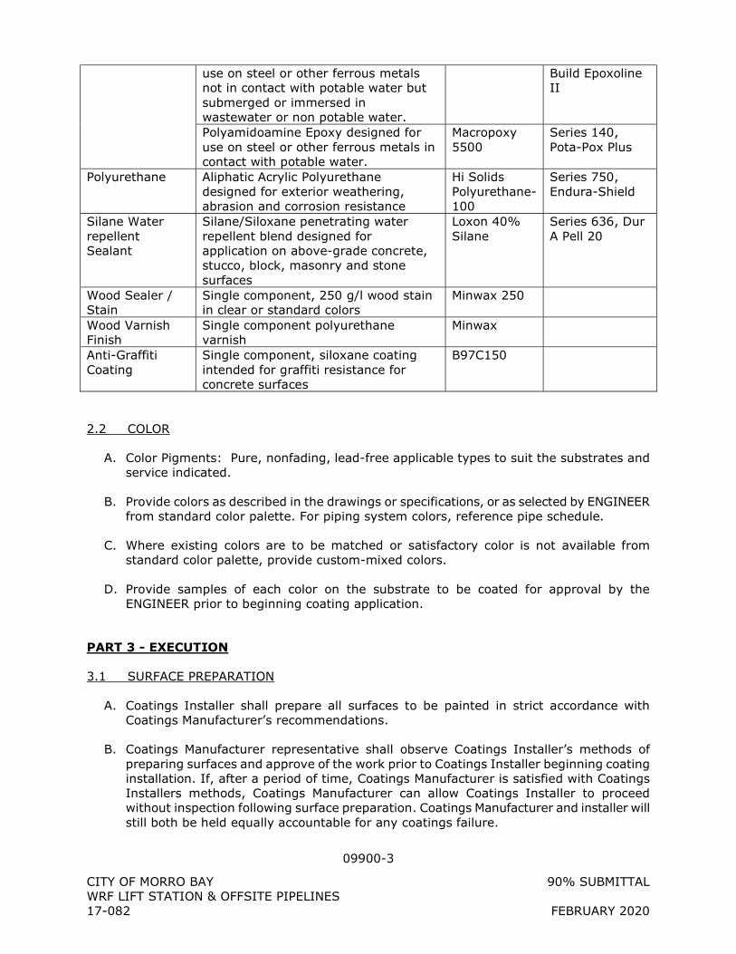
09900-3
CITY OF MORRO BAY 90% SUBMITTAL WRF LIFT STATION & OFFSITE PIPELINES 17-082 FEBRUARY 2020
use on steel or other ferrous metals not in contact with potable water but submerged or immersed in wastewater or non potable water.
Build Epoxoline II
Polyamidoamine Epoxy designed for use on steel or other ferrous metals in contact with potable water.
Macropoxy 5500
Series 140, Pota-Pox Plus
Polyurethane Aliphatic Acrylic Polyurethane designed for exterior weathering, abrasion and corrosion resistance
Hi Solids Polyurethane-100
Series 750, Endura-Shield
Silane Water repellent Sealant
Silane/Siloxane penetrating water repellent blend designed for application on above-grade concrete, stucco, block, masonry and stone surfaces
Loxon 40% Silane
Series 636, Dur A Pell 20
Wood Sealer / Stain
Single component, 250 g/l wood stain in clear or standard colors
Minwax 250
Wood Varnish Finish
Single component polyurethane varnish
Minwax
Anti-Graffiti Coating
Single component, siloxane coating intended for graffiti resistance for concrete surfaces
B97C150
2.2 COLOR
A. Color Pigments: Pure, nonfading, lead-free applicable types to suit the substrates and service indicated.
B. Provide colors as described in the drawings or specifications, or as selected by ENGINEER from standard color palette. For piping system colors, reference pipe schedule.
C. Where existing colors are to be matched or satisfactory color is not available from standard color palette, provide custom-mixed colors.
D. Provide samples of each color on the substrate to be coated for approval by the ENGINEER prior to beginning coating application.
PART 3 - EXECUTION
3.1 SURFACE PREPARATION
A. Coatings Installer shall prepare all surfaces to be painted in strict accordance with Coatings Manufacturer’s recommendations.
B. Coatings Manufacturer representative shall observe Coatings Installer’s methods of preparing surfaces and approve of the work prior to Coatings Installer beginning coating installation. If, after a period of time, Coatings Manufacturer is satisfied with Coatings Installers methods, Coatings Manufacturer can allow Coatings Installer to proceed without inspection following surface preparation. Coatings Manufacturer and installer will still both be held equally accountable for any coatings failure.
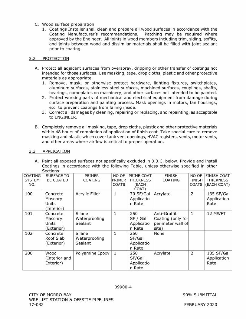
09900-4
CITY OF MORRO BAY 90% SUBMITTAL WRF LIFT STATION & OFFSITE PIPELINES 17-082 FEBRUARY 2020
C. Wood surface preparation 1. Coatings Installer shall clean and prepare all wood surfaces in accordance with the
Coating Manufacturer’s recommendations. Patching may be required where approved by the Engineer. All joints in wood members including trim, siding, soffits, and joints between wood and dissimilar materials shall be filled with joint sealant prior to coating.
3.2 PROTECTION
A. Protect all adjacent surfaces from overspray, dripping or other transfer of coatings not intended for those surfaces. Use masking, tape, drop cloths, plastic and other protective materials as appropriate. 1. Remove, mask, or otherwise protect hardware, lighting fixtures, switchplates,
aluminum surfaces, stainless steel surfaces, machined surfaces, couplings, shafts, bearings, nameplates on machinery, and other surfaces not intended to be painted.
2. Protect working parts of mechanical and electrical equipment from damage during surface preparation and painting process. Mask openings in motors, fan housings, etc. to prevent coatings from falling inside.
3. Correct all damages by cleaning, repairing or replacing, and repainting, as acceptable to ENGINEER.
B. Completely remove all masking, tape, drop cloths, plastic and other protective materials within 48 hours of completion of application of finish coat. Take special care to remove masking and plastic which cover tank vent openings, HVAC registers, vents, motor vents, and other areas where airflow is critical to proper operation.
3.3 APPLICATION
A. Paint all exposed surfaces not specifically excluded in 3.3.C, below. Provide and install Coatings in accordance with the following Table, unless otherwise specified in other Sections:
COATING SYSTEM
NO.
SURFACE TO BE COATED
PRIMER COATING
NO OF PRIMER COATS
PRIME COAT THICKNESS
(EACH COAT)
FINISH COATING
NO OF FINISH COATS
FINISH COAT THICKNESS
(EACH COAT)
100 Concrete Masonry Units (Interior)
Acrylic Filler 1 70 SF/Gal Application Rate
Acrylate 2 135 SF/Gal Application Rate
101 Concrete Masonry Units (Exterior)
Silane Waterproofing Sealant
1 250 SF / Gal Application Rate
Anti-Graffiti Coating (only for perimeter wall of site)
1 12 MWFT
102 Concrete Roof Slab (Exterior)
Silane Waterproofing Sealant
1 250 SF/Gal Application Rate
None
200 Wood (Interior and Exterior)
Polyamine Epoxy 1 250 SF/Gal Application Rate
Acrylate 2 135 SF/Gal Application Rate
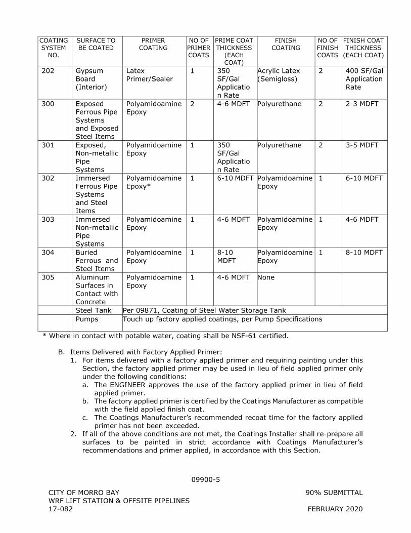
09900-5
CITY OF MORRO BAY 90% SUBMITTAL WRF LIFT STATION & OFFSITE PIPELINES 17-082 FEBRUARY 2020
COATING SYSTEM
NO.
SURFACE TO BE COATED
PRIMER COATING
NO OF PRIMER COATS
PRIME COAT THICKNESS
(EACH COAT)
FINISH COATING
NO OF FINISH COATS
FINISH COAT THICKNESS
(EACH COAT)
202 Gypsum Board (Interior)
Latex Primer/Sealer
1 350 SF/Gal Application Rate
Acrylic Latex (Semigloss)
2 400 SF/Gal Application Rate
300 Exposed Ferrous Pipe Systems and Exposed Steel Items
Polyamidoamine Epoxy
2 4-6 MDFT Polyurethane 2 2-3 MDFT
301 Exposed, Non-metallic Pipe Systems
Polyamidoamine Epoxy
1 350 SF/Gal Application Rate
Polyurethane 2 3-5 MDFT
302 Immersed Ferrous Pipe Systems and Steel Items
Polyamidoamine Epoxy*
1 6-10 MDFT Polyamidoamine Epoxy
1 6-10 MDFT
303 Immersed Non-metallic Pipe Systems
Polyamidoamine Epoxy
1 4-6 MDFT Polyamidoamine Epoxy
1 4-6 MDFT
304 Buried Ferrous and Steel Items
Polyamidoamine Epoxy
1 8-10 MDFT
Polyamidoamine Epoxy
1 8-10 MDFT
305 Aluminum Surfaces in Contact with Concrete
Polyamidoamine Epoxy
1 4-6 MDFT None
Steel Tank Per 09871, Coating of Steel Water Storage Tank Pumps Touch up factory applied coatings, per Pump Specifications
* Where in contact with potable water, coating shall be NSF-61 certified.
B. Items Delivered with Factory Applied Primer: 1. For items delivered with a factory applied primer and requiring painting under this
Section, the factory applied primer may be used in lieu of field applied primer only under the following conditions: a. The ENGINEER approves the use of the factory applied primer in lieu of field
applied primer. b. The factory applied primer is certified by the Coatings Manufacturer as compatible
with the field applied finish coat. c. The Coatings Manufacturer’s recommended recoat time for the factory applied
primer has not been exceeded. 2. If all of the above conditions are not met, the Coatings Installer shall re-prepare all
surfaces to be painted in strict accordance with Coatings Manufacturer’s recommendations and primer applied, in accordance with this Section.
09900-6
CITY OF MORRO BAY 90% SUBMITTAL WRF LIFT STATION & OFFSITE PIPELINES 17-082 FEBRUARY 2020
C. Table Definitions: 1. SF/Gal: Square foot of coverage per gallon of coating used. 2. MDFT: mil dry film thickness 3. mil: 1/1000 of an inch paint thickness 4. Ferrous Pipe: Includes Ductile Iron, Cast Iron, Steel, and Galvanized Steel piping 5. Steel Items: Includes steel and galvanized steel items such as structural steel, doors,
window frames, overhead coiling doors, bollard posts, steel gates, steel fences, and all other steel and galvanized steel items.
6. Non-Metallic Pipe: Polyvinyl Chloride, Chlorinated Polyvinyl Chloride, Fiberglass Reinforced Plastic, High Density Polyethylene
7. Exposed: Located above grade, exposed to the atmosphere not submerged. Includes surfaces inside and outside of buildings.
8. Submerged: In an area which normally is under water or other liquid or is intermittently under water or other liquid.
9. Buried: Located below grade, surrounded by backfill.
D. Surfaces Not Requiring Painting: 1. Unless otherwise stated or shown below or in other sections, the following areas or
items will not require painting or coating: a. Concrete surfaces. b. Reinforcing steel. c. Copper, bronze, brass, Monel, aluminum, chromium plate, and stainless steel
surfaces, except where: 1) Required for electrical insulation between dissimilar metals. 2) Aluminum and stainless steel are embedded in concrete or masonry, or
aluminum is in contact with concrete or masonry. 3) Color coding of equipment and piping is required.
d. Pipe unions or portions of piping systems where painting would make disassembly difficult or impossible.
e. Prefinished electrical, mechanical and architectural items such as motor control centers, switchboards, switchgear, panelboards, transformers, disconnect switches, HVAC equipment enclosures, ductwork, acoustical tile, cabinets, louvers, and wall panels.
f. Electrical conduits. g. Cathodic protection anodes. h. Insulated piping and insulated piping with jacket will require prime coat only. i. Fiberglass reinforced plastic (FRP) surfaces with an integral ultra-violet resistant
colored gel coat do not require painting, provided the color is as selected. j. Glass, plexiglass or other transparent or translucent material intended to allow
passage of light. k. Civil/site materials such as asphalt, gravel, rock, chain-link fence, and plantings.
3.4 RECOAT TIMES:
A. Coatings Installer shall observe all requirements of the Coatings Manufacturer regarding recoat times.
3.5 PAINT LOG
A. Coatings Installer shall keep a paint log 1. Specific details of the contents and format paint log shall be determined by the
Coatings Installer and approved by the ENGINEER.
09900-7
CITY OF MORRO BAY 90% SUBMITTAL WRF LIFT STATION & OFFSITE PIPELINES 17-082 FEBRUARY 2020
2. At a minimum, paint log shall record, on a daily basis for any day when coating work is performed: a. Weather conditions, including 3-day forecast b. Which surfaces were prepared for coating c. Approval of surface preparation by the Coatings Manufacturer representative d. Which surfaces or systems were coated that day e. Who the installer was (specific names of persons on crew) f. Which coating type was used g. Which coat was installed h. What the application rate or MDFT was (as approved by ENGINEER)
3. Paint log shall be kept on-site. Paint log shall be signed on a daily basis, for any day when coating work is performed, by the supervisor of the coatings installer field crew and by the ENGINEER.
4. Any painted surface which was not recorded in the paint log shall be stripped, re-prepared, and recoated at the ENGINEER’s discretion.
3.6 WARRANTY INSPECTION
A. Warranty inspection shall be conducted during the eleventh month following completion of the Work. All defective Work shall be repaired by the CONTRACTOR in accordance with this Specification and to the satisfaction of the ENGINEER and at the CONTRACTOR'S expense.
B. Any location where paint has peeled, bubbled, or cracked and any location where rusting is evident shall be considered to be a failure of the system. The CONTRACTOR shall make repair at all points where failures are observed by removing the deteriorated paint, cleaning the surface, and recoating or repainting with the same system. If the area of failure exceeds 25 percent of the total coated or painted surface, the entire coating or paint system may be required to be removed and repainted in accordance with this specification as determined by the ENGINEER.
C. All costs for CONTRACTOR'S inspection, Manufacturer's inspection and all costs for repair shall be borne by the CONTRACTOR.
+ + END OF SECTION + +
10400-1
CITY OF MORRO BAY 90% SUBMITTAL WRF LIFT STATION & OFFSITE PIPELINES 17-082 FEBRUARY 2020
SECTION 10400
IDENTIFICATION DEVICES
PART 1 - GENERAL
1.1 DESCRIPTION
A. Scope: Furnish and install signs, placards, and labels for safety equipment, hazards, and equipment and piping identification.
1.2 SUBMITTALS
A. Shop Drawings: 1. Provide manufacturer's literature showing available letter sizes and styles, standard
and custom colors, and standard mounting details. 2. Provide drawings showing layouts, actual letter sizes and styles, colors, and project-
specific mounting details.
PART 2 - PRODUCTS
2.1 FIRE EXTINGUISHER LOCATION SIGNS
A. Material: 1. Subsurface silkscreened graphics on a transparent acrylic sheet, 0.08" thick with
Helvetica Medium alphabet and matching arrows type face. 2. Provide 2" high upper case letters and 1" high lower case letters.
B. Fire Extinguisher Identification Sign: 1. Provide 15"x 15" with 1" radiused corners, unframed. 2. Provide one for each surface mounted fire extinguisher. 3. Background color shall be red with white lettering. 4. Signs shall incorporate a white directional arrow as located by ENGINEER.
C. Product and Manufacturer: Provide one of the following: 1. ASI/SPE MH (Four Corners) Plaque by ASI Sign Systems, Incorporated. 2. Or equal.
2.2 FIRE PROTECTION PLACARDS
A. Fire Protection Placards: 1. Provide diamond-shaped placards: 15" square of 0.125" rigid polyethylene. 2. The placard shall meet NFPA 704.
B. Product and Manufacturer: Provide one of the following: 1. W.H. Brady Company 2. Seton Name Plate Company 3. Or Equal
C. Provide fire protection placards in accordance with the following schedule:
10400-2
CITY OF MORRO BAY 90% SUBMITTAL WRF LIFT STATION & OFFSITE PIPELINES 17-082 FEBRUARY 2020
DRAWING
REFERENCE NUMBER MATERIAL HEALTH FLAMMABILITY REACTIVITY SYMBOL
S-XXX
2.3 MISCELLANEOUS SAFETY SIGNAGE
A. Safety signs shall comply with the following standards: 1. Occupational Safety and Health Administration (OSHA), Standards for General
Industry, Subparts 1910.200 Hazard Communication (July, 1986). 2. National Fire Protection Association (NFPA) Standard No. 704 - Label System. 3. California Fire Code, Latest Edition.
B. Safety signs shall be of height and width required by layout and shall be formed from semi-rigid butyrate, polyethylene or fiberglass. Lettering shall be 3-inches high and 1/2-inch in stroke.
C. Provide the following safety signs: DRAWING REFERENCE
NUMBER TEXT BACKGROUND
COLOR LETTERING
COLOR S-XXX CAUTION:
EQUIPMENT STARTS AUTOMATICALLY
Yellow Black
S-XXX DANGER: HIGH VOLTAGE
Yellow Black
S-XXX MAXIMUM AXLE LOAD 32,000 LBS
Yellow Black
2.4 EXIT SIGNS
A. Material: Plastic, 1/8-inch minimum thickness.
B. Lettering: 6 inches high, 3/4-inch stroke, white letters on red background.
2.5 FLOOR AND ROOF DESIGN LOADS
A. Provide a conspicuously posted sign at the lift station roof formed from semi-rigid butyrate, polyethylene or fiberglass with 3-inch high lettering and 1/2-inch in stroke in accordance with the California Building Code.
B. Text shall read: THIS ROOF IS DESIGNED FOR LIVE LOAD OF 125 PSF.
2.6 IDENTIFICATION LABELS
A. Pipe Labels and Flow Direction Arrows: 1. Label, Lettering Color, Size and Placement: In accordance with ANSI A13.1, and as
listed below. 2. Label Colors:
10400-3
CITY OF MORRO BAY 90% SUBMITTAL WRF LIFT STATION & OFFSITE PIPELINES 17-082 FEBRUARY 2020
Fluid Service Background Color Letter Color
Fire quenching fluids Safety red White Toxic and corrosive fluids Safety orange Black
Flammable fluids Safety yellow Black Combustible fluids Safety brown White
Potable, cooling, boiler feed, and other water
Safety green White
Compressed air Safety blue White
3. Label Size:
Outside Diameter of Pipe Covering,
inches
Length of Color Field, inches
Size of Letters, inches
3/4 to 1-1/4 8 ½ 1-1/2 to 2 8 3/4 2-1/2 to 6 12 1-1/4
8 to 10 24 2-1/2 Over 10 32 3-1/2
4. Label Placement:
a. Labels shall be positioned on the pipes so they can be easily read. Proper label placement is on the lower side of the pipe if the employee has to look up to the pipe, on the upper side of the pipe if the employee has to look down towards the pipe, or directly facing the employee if on the same level as the pipe. Labels should be located near valves, branches, where a change in direction occurs, on entry/re-entry points through walls or floors, and on straight segments with spacing between labels that allows for easy identification.
5. Material: Manufacture from or encase in outdoor grade plastic or vinyl that will resist damage or fading from washdown, sunlight, mildly corrosive atmosphere, dirt, grease, and abrasion.
6. Message: See Piping Schedule. 7. Labels:
a. Snap-Around Type: Size for finished outside diameter of pipe and insulation. b. For 6 Inches and Over Diameter Pipe: May furnish strap-on type fastened
without use of tools with plastic or stainless steel straps. c. Firmly grip pipe so labels remain fixed in vertical pipe runs.
8. Manufacturers and Products: a. T & B/Westline, Rariton, NJ, Model WSS Snap-Around. b. Seton Name Plate Corp., New Haven, CT, Setmark Series. c. Or equal.
B. Equipment Labels: 1. Applies to equipment with assigned tag numbers wherever specified. 2. Lettering: Black bold face, 3/4-inch minimum high. 3. Background: OSHA safety yellow. 4. Materials: Either of the following:
a. Aluminum or stainless steel base with a baked-on finish that is suitable for use on wet, oily, exposed, abrasive, and corrosive areas.
b. Fiberglass with fiberglass-encased lettering.
10400-4
CITY OF MORRO BAY 90% SUBMITTAL WRF LIFT STATION & OFFSITE PIPELINES 17-082 FEBRUARY 2020
5. Furnish 1-inch margin on each end of label for mounting. On fiberglass labels furnish grommets at each end for mounting.
6. Size: a. As appropriate for lettering provided. b. Provide same-size labels for equipment series which are adjacent.
7. Message: Equipment names and tag numbers as used in Sections where equipment is specified and/or on Drawings.
8. Manufacturers and Products: a. T & B/Westline Co., Rariton, NJ; Type KQ. b. Seton Name Plate Corp., New Haven, CT; Style EB. c. Or equal.
PART 3 - EXECUTION
3.1 INSTALLATION OF SIGNS
A. Install Fire Extinguisher location signs at all fire extinguisher locations, approximately 12” above fire extinguisher mounting bracket.
B. Install Exit Signs mounted to each door which leads to the outside of the building, on the panic bar side of the door, mounted to the door approximately 5’-6” above finished floor.
C. Install all other signs at locations as shown on the drawings. Signs should be installed approximately 5’-6” off of finished floor, attached to doors where appropriate. Where two signs are indicated in the same location, signs should be mounted side-by-side, where possible.
D. Install all signs plumb and level. They shall be attached with four stainless steel screws or anchor bolts as required for substrate. Provide theft/tamper-resistant fasteners on all signs.
3.2 INSTALLATION OF PIPE IDENTIFICATION LABELS
A. Provide pipe identification label with flow arrows on all exposed piping systems as follows: 1. At all connections to equipment, valves, tees or wall penetrations. 2. At intervals along piping not greater than 18 feet on center with at least one label
applied to each exposed horizontal and vertical run of pipe.
B. Install pipe identification labels after all painting has been completed.
3.3 INSTALLATION OF EQUIPMENT IDENTIFICATION LABELS
A. Install equipment identification labels on all equipment which has been given an equipment number in the Drawings or Specifications. Provide identification label which includes equipment name and tag number.
B. Where no damage will be caused to equipment, mount equipment identification label directly to equipment. Otherwise, mount equipment identification labels to concrete equipment base or wall space. Install equipment identification label such that it is clear which piece of equipment is being labeled.
10400-5
CITY OF MORRO BAY 90% SUBMITTAL WRF LIFT STATION & OFFSITE PIPELINES 17-082 FEBRUARY 2020
C. Anchor to equipment or base for easy removal and replacement with ordinary hand tools.
+ + END OF SECTION + +
10520-1
City of Folsom 11/20/2015 Easton Valley Parkway Sewer LS & Forcemain 14-010 100% Submittal
SECTION 10520
SAFETY EQUIPMENT
PART 1 - GENERAL
1.1 DESCRIPTION
A. Scope: 1. The following safety equipment is to be provided and installed by CONTRACTOR so
that it may be integrated into OWNER’s safety program for operation of the facility into which it is installed.
2. The following safety equipment does not represent a complete package of safety equipment required to operate the facility. Refer to OWNER’s safety program for all required safety equipment and procedures.
1.2 SUBMITTALS
A. Shop Drawings: Provide manufacturer's product data for each item including sizes, ratings, UL listings, OSHA certifications or other certifications, and mounting/installation information.
B. Warranty: Provide manufacturer’s 5-year warranty on all products provided.
1.3 PRODUCT DELIVERY, STORAGE, AND HANDLING
A. Protect all equipment provided from all damage until such time as it is turned over to the OWNER.
B. Safety equipment provided under this specification shall not be used by the CONTRACTOR in the construction of the facility. Safety equipment shall be turned over to the OWNER in new condition.
PART 2 - PRODUCTS
2.1 FIRE EXTINGUISHERS
A. Provide at all locations labeled “FEXT” on Drawings.
B. Provide Fire Extinguishers which Conform to NFPA-10 and as follows: 1. Tri-class dry chemical extinguishing agent. 2. Pressurized, red enameled steel shell cylinder. 3. Activated by top squeeze handle. 4. Agent propelled through hose or opening at top of unit. 5. For use on A, B, and C class fires. 6. Minimum UL Rating: 4A-60B:C, 10-pound capacity.
C. Mounting Hardware: 1. Furnish heavy-duty brackets with clip-together strap for wall mounting.
10520-2
City of Folsom 11/20/2015 Easton Valley Parkway Sewer LS & Forcemain 14-010 100% Submittal
2. Use all stainless steel fasteners for attaching brackets to wall.
D. Manufacturers: 1. Walter Kidde. 2. Master Protection Enterprises. 3. Or Equal.
2.2 FALL PROTECTION EQUIPMENT
A. Hatch Safety Grating: 1. Standards:
a. Comply with all applicable OSHA, UL, ANSI and other applicable standards. 1) Including, but not limited to, OSHA 29 CFR 1910.23, guarding floor and wall
openings and holes. 2. General Purpose:
a. Designed to allow visual inspection and wash down of confined space through grating while preventing falls into open hatches. Designed to be easily removed for confined space entry once entrant is properly harnessed and utilizing proper retrieval system.
3. Features: a. Materials:
1) Metallic parts shall be Aluminum 2) Grating shall have powder coat finish that is safety yellow.
b. Grating panel(s) shall be equipped with a hold open device to lock the grading panel(s) in the open position.
4. Manufacturer and Product: a. Bilco, Fall protection grating b. Or equal.
B. Portable Davit Arm Retrieval System: 1. Standards:
a. Comply with all applicable OSHA, UL, ANSI and other applicable standards. 2. General Purpose:
a. Designed to retrieve an entrant into a confined space using a standard personnel harness system.
3. Features: a. 60-inch high center post with winch mounting assembly b. Allows for either 18” or 24” reach on offset arm c. Weight rating of 350 lbs d. Safety factor of 10:1
4. Accessories: a. Winch
1) Designed to attach to a person that is entering or exiting from a confined space.
2) Built with an internal braking system to prevent the accidental pay out of line, as well as a back-up locking pawl system to prevent “free-wheeling” of the winch.
3) Cable extension (payout) should occur ONLY when the handle is turned counterclockwise AND a force of AT LEAST 10 lbs. (4.5 kg.) is applied to the line.
10520-3
City of Folsom 11/20/2015 Easton Valley Parkway Sewer LS & Forcemain 14-010 100% Submittal
4) The winch frame back plate attaches to a mounting plate which can then be mated to the Portable Davit Arm Retrieval System. Coordinate winch and Portable David Arm Retrieval System.
5) Weight rated to 350 lbs. 6) 10:1 safety factor 7) 5.5:1 gear ratio single speed drive 8) Retrieval rate of 23 feet per minute 9) Continuous braking drive prevents free wheeling 10) Double pawls on friction brake provide back up safety 11) Low wear, high temperature brake pads 12) Anti-friction drive bearings 13) Three permanent wraps of cable on the drum 14) Level wind springs to prevent loosening of cable lays 15) Slip clutch drive to prevent back-winding of cable drum 16) Galvanic zinc coating of all metal parts 17) Double action locking swivel snap hook 18) Provide with 70 feet of stainless steel cable
5. Flush Floor Mounted Davit Sleeve: a. Provide flush floor mounted davit sleeve by same manufacturer as davit crane.
1) Sleeve shall be designed specifically for davit crane and shall allow for full functionality and load rating of crane
2) Sleeve and anchor bolts shall be stainless steel 3) Sleeve to be designed for installation in concrete after concrete placement by
core drilling a hole in the concrete and bolting sleeve to concrete floor using stainless steel chemical anchors, per manufacturers instructions.
4) Provide stainless steel debris cap with sleeve. 6. Manufacturer and productProduct:
a. Davit Crane: T.A. Pelsue Company, Model PNUH1824, or equal b. Winch: T.A. Pelsue Company, Model PLPS806MR-70, or equal c. Davit Sleeve: T.A. Pelsue Company, Model PNUS102B-SS, or equal d. Debris Cap: T.A. Pelsue Company, Model PNUS106-SS, or equal e. Or equal.
PART 3 - EXECUTION
3.1 INSTALLATION
A. Install all safety equipment per manufacturers written instructions.
B. Install fire extinguishers where “FEXT” is called out on the drawings, 48” above finished floor or adjacent grade.
+ + END OF SECTION + +
11300-1
CITY OF MORRO BAY 90% SUBMITTAL WRF LIFT STATION & OFFSITE PIPELINES 17-082 FEBRUARY 2020
SECTION 11300
DRY- PIT SUBMERSIBLE SEWAGE PUMPS
PART 1 - GENERAL
1.1 DESCRIPTION
A. Scope: Provide all materials, equipment, and accessories necessary to furnish and install wet-pit submersible sewage pumps. The pumping units shall be vertical, non-clogging, centrifugal sewage pumps with bottom inlet and side discharge. The pumps shall be direct driven by integral squirrel cage, electric induction motors. Each pump shall include motor, bearings, protective control devices and all accessories specified herein.
B. The following equipment numbers have been assigned to the equipment that shall be provided. See attached pump and motor data sheets for detailed descriptions: 1. P-10-101 2. P-10-201 3. P-10-301 4. P-20-101 5. P-20-201 6. P-20-301
1.2 QUALITY ASSURANCE
A. Reference Standards: Comply with requirements and recommendations of the following references, except as otherwise specified: 1. Hydraulic Institute (HI) 2. American Water Works Association (AWWA) 3. National Electric Code (NEC) 4. National Electrical Manufacturers Association (NEMA) 5. American National Standards Institute (ANSI) 6. ASTM International (ASTM)
B. Quality Certification: Manufacturer supplying equipment furnished under this section shall hold current ISO 9001 certification.
C. Unit Responsibility: All equipment specified herein shall be coordinated and provided by the pump manufacturer. Manufacturer assumes full responsibility for coordination of all components.
D. Warranty: Provide a 5-yr warranty on all equipment from date of start-up. Warranty shall cover defects in workmanship, design, and materials. If any component should fail during the warranty period, it shall be corrected and the unit restored to service at no expense to the OWNER.
1.3 SUBMITTALS
A. Product Data: 1. Make, model, weight, and horsepower of each equipment assembly.
11300-2
CITY OF MORRO BAY 90% SUBMITTAL WRF LIFT STATION & OFFSITE PIPELINES 17-082 FEBRUARY 2020
2. Complete catalog information, descriptive literature, specifications, and identification of materials of construction.
3. Dimensional outline and installation drawing. Full installation instructions. 4. Performance data curves showing head, capacity, horsepower demand, pump
efficiency, and net positive suction head required over the entire operating range of the pump, from shutoff to maximum capacity. Indicate separately the head, capacity, horsepower demand, overall efficiency, and minimum submergence required at the guarantee point.
5. Power and control wiring diagrams, including terminals and numbers. 6. Data on the moisture/temperature protective relay 7. Complete motor nameplate data, as defined by NEMA, motor manufacturer, and
including any motor modifications. 8. Factory finish system.
B. Motor Tests and Data: 1. For each motor furnish an inspection report for the motor or for a previously
manufactured electrically duplicate motor that has been tested. Provide the following minimum data: a. Running current. b. Locked rotor current. c. Winding resistance measurement. d. High potential test.
C. Operation and Maintenance Manuals: Submit complete manuals including: copies of all approved Shop Drawings, test reports, maintenance data and schedules, description of operation, and spare parts information.
D. Guarantee: Submit Guarantee.
E. Test Data: Pumps shall not be shipped until the ENGINEER has approved the test reports. Submit: 1. Four copies of certified pump tests.
PART 2 - PRODUCTS
2.1 GENERAL
A. Provide pumps with performance curves constantly increasing head from maximum capacity to shut-off head.
B. Balancing: Pump assemblies shall be dynamically and statically balanced. Vibration at any point of pump operation shall not exceed the upper limits of the Hydraulic Institute Standards.
2.2 PRODUCT AND MANUFACTURER:
A. Flygt 1. Pumps P-10-101, P-10-201 and P-10-301: Model NP 3202 2. Pumps P-20-101, P-20-201 and P-20-301: Model NP 3231 (745 motor)
11300-3
CITY OF MORRO BAY 90% SUBMITTAL WRF LIFT STATION & OFFSITE PIPELINES 17-082 FEBRUARY 2020
2.3 PRODUCTS
A. Pump equipment shall consist of pump(s) complete with motor(s), support stand(s), inlet elbow(s), power cable(s), and protective control system.
B. Pumps and Motors: 1. Pumps P-10-101, P-10-201 and P-10-301:
a. Flow/Head: 3,147 gpm at 49 feet of Total Dynamic Head b. Horsepower: 60 hp c. Voltage: 460, 3 Phase, 60 Hertz d. 6-pole, 1170 RPM
2. Pumps P-20-101, P-20-201 and P-20-301: a. Flow/Head: 2,100 gpm at 273 feet of Total Dynamic Head b. Horsepower: 250 hp c. Voltage: 460, 3 Phase, 60 Hertz d. 4-pole, 1780 RPM
C. Pump Features: 1. Service: Raw Sewage 2. Type: Non-clog centrifugal submersible sewage pump 3. Discharge flanges shall be 125# and meet ANSI standard B16.1 4. Capacity: Passing 2” ball, minimum 5. Volute: ASTM A48 CL35B Grey Cast Iron 6. Shaft: ANSI 431 stainless steel 7. Bearings: The pump shaft shall rotate on at least three anti-friction, grease or oil
lubricated bearings 8. Impeller: ASTM A532 (Alloy IIIA) 15% chrome cast iron 9. External Hardware: All bolts, nuts and cap screws shall have hexagon heads and be
of 316 stainless steel 10. Sealing:
a. Where watertight sealing is required shall be machined and fitted with Nitrile or optional Viton rubber O-rings
b. Joint sealing will be a result of controlled compression of rubber O-rings in two planes and O-ring contact of four sides without the requirement of a specific bolt torque limit; rectangular cross sectioned rubber, paper or synthetic gaskets that required specific torque limits to achieve compression shall not be considered as adequate or equal; no secondary sealing compounds, elliptical O-rings, grease or other devices shall be used
11. Mechanical Seals: a. Tandem mechanical shaft seal system consisting of two independent seal
assemblies: 1) Lower seal shall contain one stationary and one positively driven rotating
corrosion resistant tungsten-carbide seal ring 2) Upper seal shall be a leakage-free seal and shall contain one stationary and
one positively driven rotating corrosion resistant tungsten-carbide seal ring b. Seals shall require no maintenance or adjustment and shall be able of operating
in either clockwise or counter-clockwise direction c. Shaft seals without positively driven rotating members, or conventional double
mechanical seals containing either a common single or double spring acting between the upper and lower seal faces shall not be considered acceptable or equal to the dual independent seal specified.
11300-4
CITY OF MORRO BAY 90% SUBMITTAL WRF LIFT STATION & OFFSITE PIPELINES 17-082 FEBRUARY 2020
d. No system requiring a pressure differential to offset pressure and to affect sealing shall be used.
12. Each pump/motor unity shall be provided with an integral, self-supplying cooling system utilizing the pumped media for cooling a. Motor Water Jacket: ASTM A48 CL35B Cast Iron
13. Cable entry junction chamber and motor shall be sealed from each other. Epoxies, silicones, or other secondary sealing systems shall not be considered acceptable.
D. Accessories: 1. Inlet Elbow: ASTM A48, CL35B Cast Iron, one per pump 2. Pilot Cable (one per pump):
a. SUBCAB b. Multi-conductor type, shielded c. Cable length shall be adequate to land in the junction box without the need for
splices 3. Safety Hooks and Cable Holders: 316 Stainless Steel, provide one of each per pump
E. Motors: 1. NEMA B design, induction type with a squirrel cage rotor, shell type design, housed in
an air filled, watertight chamber 2. Connected load shall not exceed 100 percent of motor nameplate horsepower 3. Furnish motors suited for operation in a Class 1, Division 1, Group D explosion-proof
atmosphere and certified as such by Factory Mutual. 4. Vertical mounting 5. Solid shaft
a. Shaft seal: Tandem mechanical seals 6. Service factor: 1.15 7. Stator windings shall be insulated with moisture resistant Class H insulation 8. Thermal Protection: Normally closed thermal switch in stator housing 9. Moisture Protection: Leakage Sensor in stator housing and junction chamber
a. The junction chamber shall be sealed off from the stator housing and will have a mechanical float switch to signal if there is water intrusion
b. Use of voltage sensitive solid-state sensors shall not be allowed. 10. Motor capable of:
a. PS-A, NP 3202: 30 starts per hour b. PD-B, NP 3231: 15 starts per hour
11. Motor capable of continuous full-load operation while unsubmerged without overheating or voiding Class 1, Division 1, Group D compliance
12. Pump and motor shall be by the same manufacturer. 13. Provide motor lifting lug 14. Provide motor power and control cables with connections made at the motor inside a
junction chamber. Cable entry shall be sealed and provided with means of strain relief. Cables shall comply with applicable code requirements. Coordinate pump cable length with distance between pump and control panel, per drawings and field installation.
F. Controls: 1. Provide moisture protection/thermal protection relay for connection to leakage sensor
and thermal switch on each motor for installation in an external control panel by others.
11300-5
CITY OF MORRO BAY 90% SUBMITTAL WRF LIFT STATION & OFFSITE PIPELINES 17-082 FEBRUARY 2020
2. Solid-state pump memory unit, thermal switches, and two float leakage sensor switches, lower bearing temperature monitor, and stator temperature monitor shall all be connected to a monitoring and status unit
G. Spare Parts: 1. Provide the following set of spare parts:
a. One complete set of upper and lower bearings b. One complete set of seals, gaskets and O-rings c. Mechanical seals d. One impeller
2. Special tools required for normal operation and maintenance of the equipment shall be furnished with the equipment by the manufacturer.
PART 3 - EXECUTION
3.1 INSTALLATION
A. Installation shall be in complete accordance with manufacturer’s instructions.
B. Check and align all pumps, motors, etc. after pump assemblies have been installed to ensure alignment and assembly has been unchanged from factory assembly conditions. Make adjustments required to place system in proper operating condition. Pump installation shall place no strain on adjacent piping systems.
C. Installation Test: Performed manufacturer’s representative in the presence of the ENGINEER or OWNER. 1. Monitor bearing and motor temperatures during all tests and correct overheating. 2. Functional Testing: Functional test complete assemblies for proper alignment,
connection, and operation. 3. Vibration Testing:
a. Each pump with its specified motor shall be tested for vibration compliance with the specified vibration limits per HI 11.6. 9.4b (2012) for field testing limits.
b. Vibration tests and vibration signatures shall be performed by a professional qualified in acquisition and analysis of vibration data and is retained by the Contractor for this work, independent of the pump manufacturer.
c. Each pump and variable speed drive system shall be tested separately without duplicate equipment running. Tests shall be conducted at various speeds between maximum and minimum. All testing shall be done in the presence of the Engineer. Each pump and motor shall be tested for vibration in the field during Functional Testing.
d. The Contractor shall be responsible for vibration testing. Test results shall be documented in accordance with HI requirements. Copies of test results shall be submitted to the Engineer for review. Should the vibration field test results exceed the limits specified, the Contractor shall correct the deficiencies. After corrections have been completed, the vibration testing shall be rerun and the results resubmitted to the Engineer for review. Corrections shall continue until results meet the specifications. The complete vibration signature of each pump and motor bearing shall be recorded and the original recording given to the Engineer.
11300-6
CITY OF MORRO BAY 90% SUBMITTAL WRF LIFT STATION & OFFSITE PIPELINES 17-082 FEBRUARY 2020
3.2 FIELD QUALITY CONTROL
A. Functional Test: Conduct on each pump. 1. Alignment: Test complete assemblies for correct rotation, proper alignment and
connection, and quiet operation.
3.3 MANUFACTURER'S FIELD SERVICES
A. A factory trained representative shall be provided for start-up and test services and operation and maintenance personnel training services. The representative shall make one one-day visit to the site for performing these services.
+ + END OF SECTION + +

11300-7
CITY OF MORRO BAY 90% SUBMITTAL WRF LIFT STATION & OFFSITE PIPELINES 17-082 FEBRUARY 2020
Section 11300 Pump and Drive Data Sheet
Project PS-A Equipment Numbers P-10-101, P-10-201, P-10-301 Equipment Location Submersible Drive Description: Drive Type Variable Speed Motor 3 PH 460V 60 HZ Motor Horsepower 60 hp Minimum B-10 Bearing Life 100,000 hours Pump Description: Pump Type Wet-pit submersible non-clog Suction Diameter 10 in Discharge Diameter 8 in Operating Conditions: Liquid Pumped Raw sewage Pumped Fluid Temperature 40 to 80 degrees F, 60 deg average Ambient Temperature 32 to 85 degrees F Site Altitude 21 ft Pump Operating Conditions: Pump Rated Speed 1170 rpm Minimum NPSHR 13 ft Minimum Continuous Stable Flow 750 gpm Minimum Shutoff Head 111 ft Pump Design Points: 1st Operating Point: Capacity (gpm) 1 pump 3,147 Total Dynamic Head (ft) 49 Minimum Efficiency 80% 2nd Operating Point: Capacity (gpm) 2 pumps 4,420 Total Dynamic Head (ft) 66 Minimum Efficiency
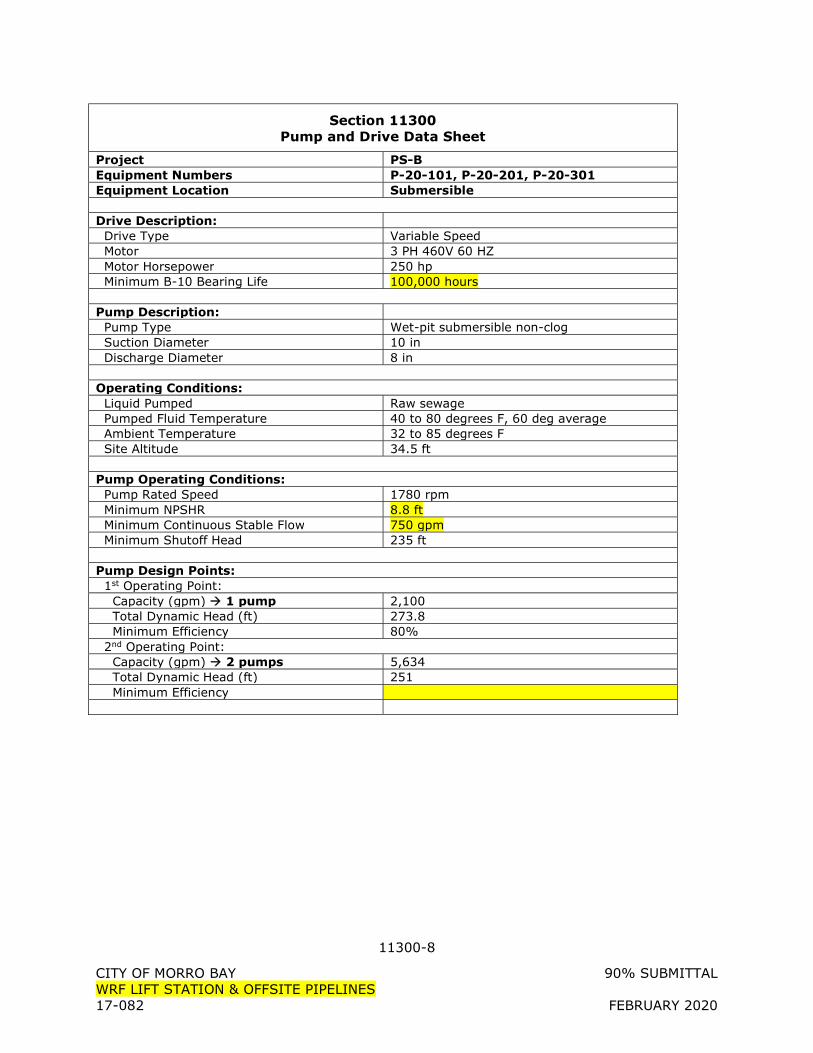
11300-8
CITY OF MORRO BAY 90% SUBMITTAL WRF LIFT STATION & OFFSITE PIPELINES 17-082 FEBRUARY 2020
Section 11300 Pump and Drive Data Sheet
Project PS-B Equipment Numbers P-20-101, P-20-201, P-20-301 Equipment Location Submersible Drive Description: Drive Type Variable Speed Motor 3 PH 460V 60 HZ Motor Horsepower 250 hp Minimum B-10 Bearing Life 100,000 hours Pump Description: Pump Type Wet-pit submersible non-clog Suction Diameter 10 in Discharge Diameter 8 in Operating Conditions: Liquid Pumped Raw sewage Pumped Fluid Temperature 40 to 80 degrees F, 60 deg average Ambient Temperature 32 to 85 degrees F Site Altitude 34.5 ft Pump Operating Conditions: Pump Rated Speed 1780 rpm Minimum NPSHR 8.8 ft Minimum Continuous Stable Flow 750 gpm Minimum Shutoff Head 235 ft Pump Design Points: 1st Operating Point: Capacity (gpm) 1 pump 2,100 Total Dynamic Head (ft) 273.8 Minimum Efficiency 80% 2nd Operating Point: Capacity (gpm) 2 pumps 5,634 Total Dynamic Head (ft) 251 Minimum Efficiency
12100-1
CITY OF MORRO BAY 90% SUBMITTAL WRF LIFT STATION & OFFSITE PIPELINES 17-082 FEBRUARY 2020
SECTION 12100
MISCELLANEOUS FURNISHINGS
PART 1 - GENERAL
1.1 SUBMITTALS
A. Shop Drawings: 1. Provide manufacturer’s information for each Miscellaneous Furnishing provided.
PART 2 - PRODUCTS
2.1 DESK (DSK-01)
A. Construction/Features: 1. Meets all Business and Institutional Furniture Manufacturer’s Association (BIFMA)
standards 2. Size: 30-inch wide by 60-inch long by 30-inch high 3. Arrangement: Double pedestal
a. Three equal drawers on the right b. Two drawers on the left, one sized and equipped for hanging files. File drawer
shall be lockable. Provide 2 keys. 4. Materials: Steel 5. Legs: 1” square tube steel, chrome plated, with leveling guides 6. Color: Grey
B. Manufacturer and Model: 1. Steelcase DP6030-GY 2. Or equal
2.2 CHAIR (CHR-01)
A. Materials: 1. Steel Core 2. Tubular steel base 3. Nylon glides 4. Polyurethane foam cushions 5. Color: Black
B. Construction: comply with ANSI/BIFMA standards.
C. Features: 1. Pneumatically adjustable seat height. 2. 360 degree swivel 3. Back tilt 4. Seat tilt 5. Waterfall edges on seat pad
D. Size:
12100-2
CITY OF MORRO BAY 90% SUBMITTAL WRF LIFT STATION & OFFSITE PIPELINES 17-082 FEBRUARY 2020
1. Seat width: 18-1/2” 2. Seat depth: 17” 3. Seat height: 17 to 35” 4. Back width: 15-1/2” 5. Back height: 12” 6. 26” footprint base 7. 2-1/2” nylon glides.
E. Manufacturer and Model: 1. Taskmaster 5120 2. Or equal
2.3 STORAGE CABINET
A. Materials: 1. Minimum 22 Gauge Steel Construction 2. Sides: 20 Gauge Steel 3. Color: Grey
B. Construction: 1. All-Welded Construction 2. Cabinet shall have sides, a back, a top and a bottom, with doors on the front. With
the doors closed, cabinet shall be completely enclosed and dust proof. 3. 2” minimum toe-kick to raise bottom shelf off of floor
C. Features: 1. Four adjustable shelves, 200 lb capacity 2. Adjustable shelf rails with shelf positions in 2-inch increments 3. Hinged doors to provide a completely enclosed cabinet
a. Three hinges per door b. Three Point Lock System on both doors c. Locking recessed paddle handle with key
D. Size: 78” High x 36 Wide x 18” Deep
E. Manufacturer and Model: 1. Sandusky, Model EA4R361878-05
2.4 2. OR EQUAL
PART 3 - EXECUTION
3.1 PREPARATION
A. Assemble all Miscellaneous Furnishings in accordance with manufacturers instructions.
3.2 INSTALLATION
A. Install plumb, level and without damaging adjacent surfaces or item being installed.
B. Clean all furnishings prior to final acceptance.
12100-3
CITY OF MORRO BAY 90% SUBMITTAL WRF LIFT STATION & OFFSITE PIPELINES 17-082 FEBRUARY 2020
+ + END OF SECTION + +
13100-1
CITY OF MORRO BAY 90% SUBMITTAL WRF LIFT STATION & OFFSITE PIPELINES 17-082 FEBRUARY 2020
SECTION 13100
ODOR CONTROL UNIT (ADSORBENT MEDIA FOUL AIR SCRUBBER)
PART 1 - GENERAL
1.1 DESCRIPTION
A. Scope: 1. Provide all labor, equipment, materials, and incidentals as required to furnish,
install, check, calibrate, test, document, start-up, and place in satisfactory operation the Odor Control Unit as shown on the Drawings and as specified.
2. The Odor Control Unit shall include, but not be limited to the following: a. Adsorber Canister b. Media c. Fan and Motor Assembly d. Electrical Control Panel
B. General: 1. Descriptions contained hereinafter are for guidance and to show the functions
desired. They do not describe or specify all components to interface equipment. All parts and equipment necessary to meet functional requirements shall be provided and fit within the dimensions and configuration shown on the Drawings.
2. The mechanical, structural, instrumentation and electrical design have been based on an odor control unit manufactured by Integrity Municipal Systems, LLC. The cost of any changes and modifications to mechanical, structural, instrumentation or electrical facilities necessary to adapt alternate equipment to the layout and design shown shall be borne by CONTRACTOR. Clearances shown on the Drawings shall be maintained. Any such proposed changes or modifications are subject to review and acceptance by the ENGINEER in accordance with the Special Provisions.
3. Complete responsibility for the proper operation and functions of the Odor control unit herein specified, belongs to CONTRACTOR. Responsibility for coordination of all interfaces with other contractors to achieve the required Odor control unit operation belongs to CONTRACTOR.
4. Odor control equipment outdoor areas are considered corrosive areas. All mechanical and electrical equipment and material shall conform to NEMA 4X, non-metallic requirements.
C. Related Divisions and Sections: 1. Section 01610 – General Equipment Requirements 2. Section 01750 – Training, Testing and Start-up 3. Section 16010 – Electrical
1.2 REFERENCES
A. American Society of testing and Materials (ASTM): 1. ASTM D-3299-88 Standard Specification for Filament Wound Glass Fiber Reinforced
Thermosetting Resin Chemically Resistant Tanks. 2. ASTM C 582- “Standard Specification for Contact-Molded Reinforced Thermosetting
Plastic (RTP) Laminates for Corrosion-Resistant Equipment”
13100-2
CITY OF MORRO BAY 90% SUBMITTAL WRF LIFT STATION & OFFSITE PIPELINES 17-082 FEBRUARY 2020
3. ASTM D-4097-82: “Standard Specifications for Contact Molded Glass Fiber Reinforced Thermoset Resin Chemical Resistant Tanks”
4. Voluntary Product Standard a. PS 15-69
1.3 QUALITY ASSURANCE
A. Odor control unit Manufacturer’s Qualifications: 1. Manufacturer shall have minimum of five years experience of producing substantially
similar equipment, and shall be able to show evidence of at least ten installations.
B. When two or more units of equipment for the same purpose are required they shall be the product of one manufacturer.
C. Inspection and Testing Requirements: The visual inspection of the equipment shall comply with ASTM D 2563, Visual Acceptance Level II.
D. Requirements of Regulatory Agencies: Meet federal, state, and local requirements which apply to the work.
E. Products used in the Work of this Section shall be produced by manufacturers regularly engaged in the production of such items and have a successful history of product acceptability, as interpreted by ENGINEER.
F. Listing, labeling or marking, as conforming to the Standards of Underwriters Laboratories, Inc., American National Standards Institute, Inc., United States Bureau of Mines, or other nationally recognized testing organization as applicable.
1.4 SUBMITTALS
A. Shop Drawings: Submit for approval the following: 1. Submit for review to ENGINEER, sufficient literature, detailed specifications, and
drawings to show dimensions, make, style, speed, size, type, horsepower, service factors, efficiency, materials used, design features, internal construction, weights, and any other information required by ENGINEER for review of all odor control equipment.
B. Operation and Maintenance Manuals: 1. Submit complete installation, operation and maintenance manuals, including, test
reports, maintenance data and schedules, description of operation and spare parts information.
C. Documentation to demonstrate that the manufacturer has been regularly engaged in fabricating odor control units for at least 5 years and provide documentation of at least 10 installations.
D. Field Assembly Instructions: Provide instructions on proper assembly of odor control unit.
13100-3
CITY OF MORRO BAY 90% SUBMITTAL WRF LIFT STATION & OFFSITE PIPELINES 17-082 FEBRUARY 2020
1.5 GUARANTEE
A. Manufacturer shall provide a guarantee stating that the hydrogen sulfide (H2S) removal efficiency (with an average inlet of 25 ppmv H2S) will be greater than 99% (or 0.1 ppm outlet, whichever is greater)prior to carbon media being spent.
PART 2 - PRODUCTS
2.1 PRODUCTS
A. Odor Control Unit 1. The purpose of the odor control unit shall be to remove H2S and odors or VOCs
emanating from ambient sewage emission. Each odor control unit shall include the following: a. Two-stage odor control:
1) Biological stage 2) Adsorption stage
b. Media 1) Biological 2) Activated carbon
c. Fan and Motor Assembly 2. Design of the odor control unit has been based on Integrity Municipal Systems, LLC,
i-BOx system. 3. Design and Performance Criteria:
a. Each odor control unit shall be designed for the following operating conditions and shall meet the following performance criteria when put in service with fresh carbon media:
b. Air Flow Rate, cfm 1) FA-10, PS-A: 333 2) FA-20, PS-B: 371
c. Average Inlet H2S Concentration, ppmv: 50-100. d. H2S Removal Efficiency, (With an average inlet of 50-100 ppmv H2S): Greater
than 99% (or 0.1 ppm outlet whichever is greater) prior to Carbon media being spent.
B. FRP Vessel 1. The adsorber canister shall be manufactured of fiberglass reinforced plastic (FRP). No
other material of construction is acceptable. 2. The system vessel shall have all components pre-mounted and piped. 3. The biological odor control system shall be manufactured with the following material
of construction according to following fabrication method: a. Vessel and accessories shall be contact molded manufactured in accordance with
NBS PS15-69, ASTM 4097 for contact molding. b. Any material of construction other than FRP with premium grade resin shall not
be acceptable. c. Reinforcement: Glass fiber reinforcement used shall be commercial grade
corrosion resistant borosilicate glass. d. Fabrication:
1) General: Fabrication shall be in accordance with NBS PS 15-69, ASTM D 3299 and ASTM D-4097.
13100-4
CITY OF MORRO BAY 90% SUBMITTAL WRF LIFT STATION & OFFSITE PIPELINES 17-082 FEBRUARY 2020
2) Corrosion Liner: The inner surface of all laminates shall be resin rich and
reinforced with one NEXUS 111-00010 with a minimum thickness of 10 mils. The total corrosion liner thickness shall be a minimum of 100 mils.
3) Structural Laminate: Structural laminates shall consist of alternating layers of
chopped glass and woven roving applied to reach a designed thickness. The exterior shall be surface coated with white gel coat containing ultra violet light inhibitors.
4. Access Manways: The vessel shall be provided with access manways to allow access to the internals of the odor control system. As a minimum, access manways shall be provided between stages.
5. Media support and screen: The system vessel shall be provided with an HDPE and FRP support system with polypropylene screen to accommodate the biological media and carbon media beds.
6. Vessel Accessories: The system shall be provided with all piping, valves and internals. Air inlet, air outlet, spray headers, drain and all vessel fittings shown on the drawings shall be provided by the Manufacturer.
7. Hardware and Gaskets: All hardware and anchor lugs shall be 316 stainless-steel. All bolts shall be designed for the specified loads. Gaskets shall be a minimum of 1/8” thick, full face, EPDM, suitable for the intended service.
8. Neoprene Pad: A ¼” thick, 60 durometer neoprene pad must be placed underneath the scrubber vessel during installation.
C. Media 1. The media utilized by the reactor vessel shall be provided by the system supplier and
supplied pre-installed in the vessel before shipping. 2. MEDIA:
a. Stage 1 – inorganic expanded clay biological media as the support substrate for selectively growing sulfur0oxidizing autotrophic bacteria. 1) Media shall be randomly dumped in the vessel to allow a low pressure drop. 2) Media is porous and resistant to hydrogen sulfide (H2S) and acidic conditions. 3) Media shall be non-proprietary and commercially available.
b. Stage 2 – coal based activated carbon media to adsorb residual H2S and other odor compounds.
c. Overall media depth shall be a minimum of 48 inches. D.
D. Fan and Motor Assembly 1. FAN: The fan shall be a centrifugal fan of FRP with a radial blade wheel. Wheel shall
be statically and dynamically balanced. All parts of the fan that are exposed to the airstream shall be epoxy coated to insure corrosion resistance. a. All fans shall be equipped with the following features and accessories:
1) Inlet shall be slip type 2) Outlet shall have a flanged nozzle 3) Double lip type shaft seal
b. Fan shall be New York Blower, Hartzell or equal. c. Fan shall be designed for the following specifications:
FA-10 FA-20
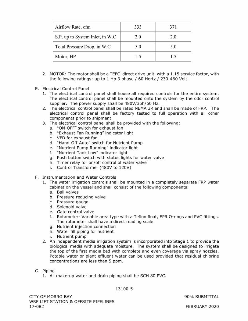
13100-5
CITY OF MORRO BAY 90% SUBMITTAL WRF LIFT STATION & OFFSITE PIPELINES 17-082 FEBRUARY 2020
Airflow Rate, cfm 333 371
S.P. up to System Inlet, in W.C 2.0 2.0
Total Pressure Drop, in W.C 5.0 5.0
Motor, HP 1.5 1.5
2. MOTOR: The motor shall be a TEFC direct drive unit, with a 1.15 service factor, with the following ratings: up to 1 Hp 3 phase / 60 Hertz / 230-460 Volt.
E. Electrical Control Panel 1. The electrical control panel shall house all required controls for the entire system.
The electrical control panel shall be mounted onto the system by the odor control supplier. The power supply shall be 480V/3ph/60 Hz.
2. The electrical control panel shall be rated NEMA 3R and shall be made of FRP. The electrical control panel shall be factory tested to full operation with all other components prior to shipment.
3. The electrical control panel shall be provided with the following: a. “ON-OFF” switch for exhaust fan b. “Exhaust Fan Running” indicator light c. VFD for exhaust fan d. “Hand-Off-Auto” switch for Nutrient Pump e. “Nutrient Pump Running” indicator light f. “Nutrient Tank Low” indicator light g. Push button switch with status lights for water valve h. Timer relay for on/off control of water valve i. Control Transformer (480V to 120V)
F. Instrumentation and Water Controls 1. The water irrigation controls shall be mounted in a completely separate FRP water
cabinet on the vessel and shall consist of the following components: a. Ball valves b. Pressure reducing valve c. Pressure gauge d. Solenoid valve e. Gate control valve f. Rotameter- Variable area type with a Teflon float, EPR O-rings and PVC fittings.
The rotameter shall have a direct reading scale. g. Nutrient injection connection h. Water fill piping for nutrient i. Nutrient pump
2. An independent media irrigation system is incorporated into Stage 1 to provide the biological media with adequate moisture. The system shall be designed to irrigate the top of the first media bed with complete and even coverage via spray nozzles. Potable water or plant effluent water can be used provided that residual chlorine concentrations are less than 5 ppm.
G. Piping 1. All make-up water and drain piping shall be SCH 80 PVC.
13100-6
CITY OF MORRO BAY 90% SUBMITTAL WRF LIFT STATION & OFFSITE PIPELINES 17-082 FEBRUARY 2020
H. Integrated Nutrient Reservoir and Nutrient Pump 1. Nutrient Addition: The packaged biological odor control system uses a non-
proprietary, commercially available fertilizer to provide essential nutrients to optimize the growth of sulfur-oxidizing bacteria. Nutrients supplied as a coating to the support media or proprietary nutrients shall not be allowed. The system shall be equipped with a nutrient addition system that provides a controlled dosage of nutrients that is automatically fed to the irrigation water during each irrigation cycle with the help of a nutrient pump.
2. The Nutrient reservoir shall be integral to the system and mounted on the system deck. The nutrient reservoir shall be made of FRP. The nutrient reservoir shall have a float-type level switch to detect a low level. Loose nutrient tanks shall not be acceptable.
3. The Nutrient pump shall be solenoid type and shall be mounted in the water cabinet.
I. Manufacturers/Models: 1. Biological Odor Control System: iBox 4000-5000: Integrity Municipal Systems 2. Or Approved Equal
2.2 SPARE PARTS AND MAINTENANCE MATERIALS
A. Each odor control unit shall be furnished with a manufacturer’s repair kit which shall include as a minimum the following:
B. Spare parts shall be packed in sturdy containers with clear indelible identification markings and shall be stored in a dry, warm location until transferred to the OWNER at the conclusion of the Project.
2.3 SURFACE PREPARATION AND PAINTING
A. Motors, drives and appurtenances shall receive shop primer and shop coating conforming to requirements of Section 09900, Painting. If any damage to the paint system occurs, the equipment shall be repainted as directed by the ENGINEER.
B. Surface preparation and painting shall conform to the requirements of Section 09900, Painting.
C. All gears, bearing surfaces, machined surfaces and other surfaces which are to remain unpainted shall receive a heavy application of grease or other rust-resistant coating. This coating shall be maintained during storage and until the equipment is placed into operation.
PART 3 - EXECUTION
3.1 INSTALLATION
A. Equipment shall be installed as specified herein, as indicated on the Drawings, and in accordance with the manufacturer's recommendations and instructions.
13100-7
CITY OF MORRO BAY 90% SUBMITTAL WRF LIFT STATION & OFFSITE PIPELINES 17-082 FEBRUARY 2020
B. All equipment shall be installed with Type 316L stainless steel anchor bolts as specified in Section 05051, Anchors, Inserts and Epoxy Dowels.
3.2 MANUFACTURER’S FIELD SERVICES
A. The manufacturer shall provide one (1) person-day for installation inspection, system start up, flow balancing, air testing and training. Manufacturer shall provide a written report on the results, air sample results .
+ + END OF SECTION + +
13122-1
CITY OF MORRO BAY 90% SUBMITTAL WRF LIFT STATION & OFFSITE PIPELINES 17-082 FEBRUARY 2020
SECTION 13122
PRE-ENGINEERED PIPE BRIDGE
PART 1 - GENERAL
1.1 DESCRIPTION
A. Scope: Design, manufacture and installation of prefabricated steel pipe bridge, including but not limited to primary framing, decking, lateral support system, railing, pipe supports, bearings and painting, to the dimensions shown on the Construction Drawings.
1.2 QUALITY ASSURANCE
A. Reference Standards: Bridges and appurtenances shall be designed, fabricated, installed and inspected to the latest edition of the following standards: 1. AASHTO Guide Specifications for Design of Pedestrian Bridges 2. American Institute of Steel Construction (AISC) 3. American Society of Testing Materials (ASTM) 4. American Welding Society (AWS) Bridge Welding Code
B. Qualifications: 1. Designer: Licensed Professional Civil or Structural Engineer valid in California. 2. Fabricator: Qualified suppliers must have at least five years experience
constructing/fabricating bridges of similar size and complexity.
C. Qualifications for Welding Work: 1. Qualify welding processes and welding operators in accordance with AWS
"Structural Welding Code" D1.1, Section 5, Qualification. 2. Provide certification that all welders employed on or to be employed for the Work
have satisfactorily passed AWS qualification tests within the previous 12 months. Ensure that all certifications are kept current.
3. All welds will be subject to visual inspection. Where visually deficient welds are observed, the welds will be tested using non-destructive methods by a certified testing laboratory. If welds are found to be satisfactory, OWNER will pay for testing. Where welds are found unacceptable or deficient, pay for testing, correct improper workmanship, remove and replace, or correct as instructed, all welds found unacceptable or deficient. Responsibility belongs to CONTRACTOR to pay for all corrections and subsequent tests required to confirm the integrity of the weld.
1.3 SUBMITTALS
A. Shop Drawings: Stamped and signed by the manufacturer’s engineer per section 1.2.B and prepared specifically for this Project. Show the following items, at minimum: 1. Design load criteria and bridge reactions. 2. Material specifications for members and connections. 3. Framing plan. 4. Bearing plate details showing anchor bolt size and layout.
13122-2
CITY OF MORRO BAY 90% SUBMITTAL WRF LIFT STATION & OFFSITE PIPELINES 17-082 FEBRUARY 2020
5. Sections showing framing and bracing. 6. Instructions for temporary bracing, as required. 7. Details for joining framing members and railing. 8. Details for pipe supports. 9. Sections and details for all components and accessories.
B. Structural Calculations: Stamped and signed by the manufacturer’s engineer per section 1.2.B. Show the following items, at minimum: 1. Complete analysis and design of structural components and connections in
accordance with the design requirements indicated and codes specified. 2. Submit calculations for approval prior to fabrication.
C. Product Data: 1. Manufacturer’s written instructions for shipping, handling, storage, protection and
erection or installation. 2. Manufacturer’s literature and technical data. 3. Painting System: Specifications including paint manufacturer’s name, product
trade-name and preparation for shop and field coats.
1.4 PRODUCT DELIVERY, STORAGE, AND HANDLING
A. Protect components and accessories from corrosion, deformation and other damage during delivery, storage, handling and installation.
B. Deliver to site with parts individually tagged. Store on wood blocking, flat and off ground, to keep clean and to prevent any damage or permanent distortion. Support bundles so there is no danger of tipping, sliding, rolling, shifting, or material damage.
1.5 WARRANTY
A. The manufacturer shall provide a warranty against defects in material and workmanship for a period of ten years.
PART 2 - PRODUCTS
2.1 MANUFACTURER
A. Bridges manufactured or supplied by the following manufacturers, and meeting these Specifications, may be used on this Project: 1. Big R Bridge. 2. Contech Engineered Solutions. 3. Gator Bridge. 4. Or equal.
2.2 SERVICE CONDITIONS AND DESIGN CRITERIA
A. General: 1. All loads shall be proportioned and applied in accordance with the current AASHTO
Guide Specifications for Design of Pedestrian Bridges. 2. Vertical Live Load deflection shall be limited to L/360. Horizontal Wind Load
deflection shall be limited to L/360.
13122-3
CITY OF MORRO BAY 90% SUBMITTAL WRF LIFT STATION & OFFSITE PIPELINES 17-082 FEBRUARY 2020
3. Assembly shall permit movement of components without buckling, failure of joints, undue stress on fasteners or other detrimental effects, when subject to temperature range of 110 degrees F.
4. Bridge shall be cambered for all Dead Loads on the bridge plus 1% of the overall span length.
B. Load Designation: 1. Dead Load:
a. Bridge self-weight plus pipelines full of water as shown on the Drawings. 2. Live Load:
a. 60 pounds per square foot. 3. Wind Load:
a. As specified by AASHTO Signs, Articles 3.8 and 3.9, but not less than 30 pounds per square foot applied to the full vertical projected area of the bridge as if enclosed, at right angles to the longitudinal axis of the structure.
4. Seismic Load, Mapped Acceleration Parameters: a. S1 = 0.426 b. SS = 1.153 c. PGA = 0.457
5. Top Chord / Rail Load: a. 50 plf applied in any direction and a non-concurrent load of 200 pounds in any
direction.
2.3 COMPONENTS
A. Bridge shall be fabricated from corrosion resistant high-strength steel material meeting, ASTM A242, A588 or A847. 1. All open ends of posts and floor support tube shaped beams shall be capped. 2. Drain holes shall be provided for all sections at the low point of the member that
may become filled with water. 3. Minimum thickness of primary hollow structural shapes (HSS) and rolled shapes
shall be ¼-inch.
B. Bridge Walkway: Grating 1. Weld forged rectangular design spaced approximately 1-3/16 inches x 4 inches on
center. 2. Grating Size and Design:
a. Main bars to be 3/16 inches thick. b. Depth as determined by the designer/manufacturer to support loads specified,
1-1/2 inches minimum. c. Cross bars to be twisted square steel and resistance welded at right angles to
the main bars. 3. Material:
a. Galvanized steel: ASTM A36, hot dipped galvanized per ASTM A123 after fabrication
4. Plank clips for grating hold-downs or other required attachments shall be galvanized steel or Type 304 stainless steel.
5. No notching or cutting of bearing bars is permissible. 6. All exposed bearing ends of grating shall be enclosed in a perimeter band of the
same dimensions and material as the main bars, including ends at all cutouts.
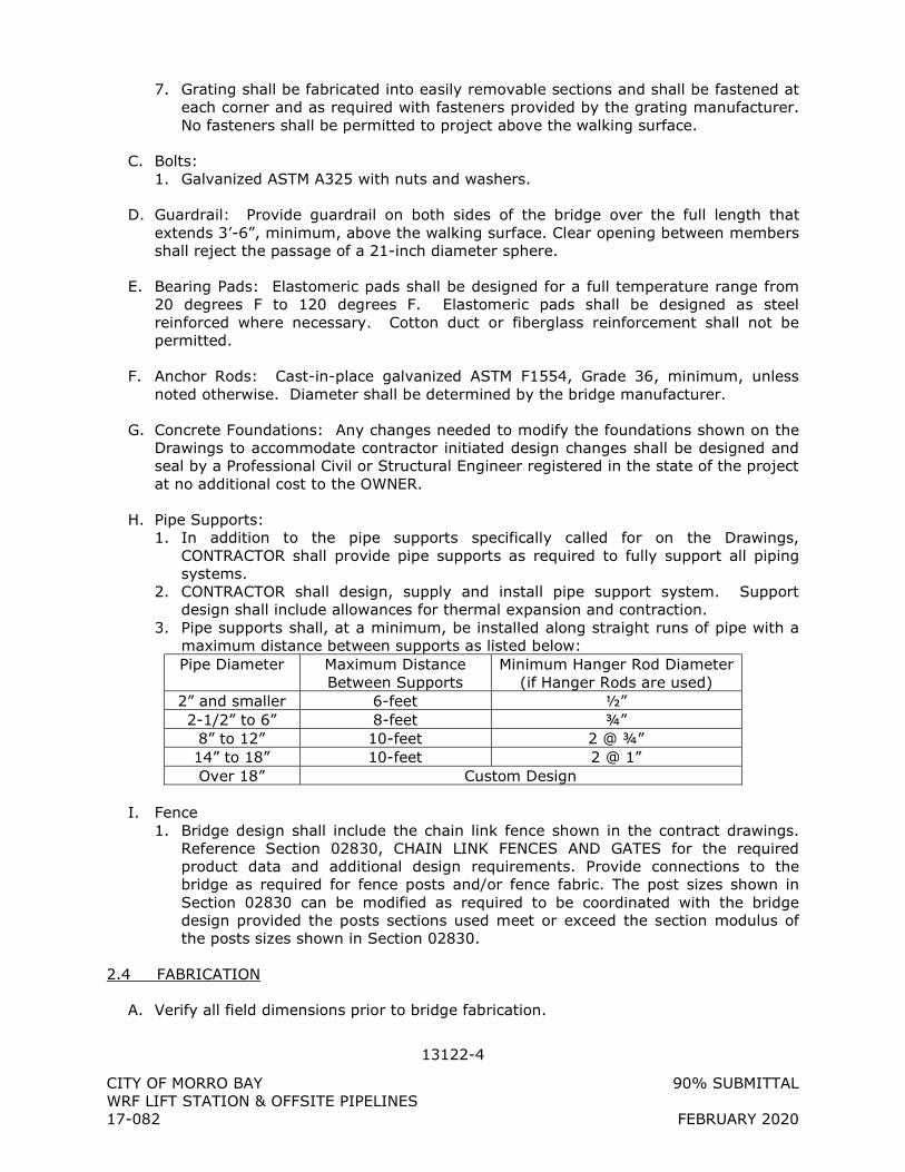
13122-4
CITY OF MORRO BAY 90% SUBMITTAL WRF LIFT STATION & OFFSITE PIPELINES 17-082 FEBRUARY 2020
7. Grating shall be fabricated into easily removable sections and shall be fastened at each corner and as required with fasteners provided by the grating manufacturer. No fasteners shall be permitted to project above the walking surface.
C. Bolts: 1. Galvanized ASTM A325 with nuts and washers.
D. Guardrail: Provide guardrail on both sides of the bridge over the full length that extends 3’-6”, minimum, above the walking surface. Clear opening between members shall reject the passage of a 21-inch diameter sphere.
E. Bearing Pads: Elastomeric pads shall be designed for a full temperature range from 20 degrees F to 120 degrees F. Elastomeric pads shall be designed as steel reinforced where necessary. Cotton duct or fiberglass reinforcement shall not be permitted.
F. Anchor Rods: Cast-in-place galvanized ASTM F1554, Grade 36, minimum, unless noted otherwise. Diameter shall be determined by the bridge manufacturer.
G. Concrete Foundations: Any changes needed to modify the foundations shown on the Drawings to accommodate contractor initiated design changes shall be designed and seal by a Professional Civil or Structural Engineer registered in the state of the project at no additional cost to the OWNER.
H. Pipe Supports: 1. In addition to the pipe supports specifically called for on the Drawings,
CONTRACTOR shall provide pipe supports as required to fully support all piping systems.
2. CONTRACTOR shall design, supply and install pipe support system. Support design shall include allowances for thermal expansion and contraction.
3. Pipe supports shall, at a minimum, be installed along straight runs of pipe with a maximum distance between supports as listed below: Pipe Diameter Maximum Distance
Between Supports Minimum Hanger Rod Diameter
(if Hanger Rods are used) 2” and smaller 6-feet ½” 2-1/2” to 6” 8-feet ¾”
8” to 12” 10-feet 2 @ ¾” 14” to 18” 10-feet 2 @ 1” Over 18” Custom Design
I. Fence 1. Bridge design shall include the chain link fence shown in the contract drawings.
Reference Section 02830, CHAIN LINK FENCES AND GATES for the required product data and additional design requirements. Provide connections to the bridge as required for fence posts and/or fence fabric. The post sizes shown in Section 02830 can be modified as required to be coordinated with the bridge design provided the posts sections used meet or exceed the section modulus of the posts sizes shown in Section 02830.
2.4 FABRICATION
A. Verify all field dimensions prior to bridge fabrication.
13122-5
CITY OF MORRO BAY 90% SUBMITTAL WRF LIFT STATION & OFFSITE PIPELINES 17-082 FEBRUARY 2020
B. Factory fabricate to manufacturer’s written standards and AISC Specifications accurately and dimensionally correct to facilitate bridge erection without field alteration.
C. All welding shall be in accordance with the current addition of the AWS D1.1 Structural Welding Code using the Gas Metal Arc or Flux Cored Arc Welding Processes.
D. Paint all surfaces of structural steel in accordance with Section 09900 - Painting.
PART 3 - EXECUTION
3.1 PREPARATION
A. Inspect mechanical piping and electrical conduit, where occurs, supporting concrete foundations, and anchorage systems for compliance with requirements for installation tolerances. Notify ENGINEER in writing of conditions detrimental to proper and timely completion of Work. Do not proceed with Work until unsatisfactory conditions have been corrected in a manner acceptable to ENGINEER.
3.2 INSTALLATION
A. General: Comply with AISC Specifications and AASHTO LRFD Bridge Design Specifications and as herein specified.
B. Surveys: Provide services of a registered surveyor to check lines and elevations of concrete bearing surfaces, location of anchor bolts and similar devices before bridge erection proceeds. Discrepancies shall be reported immediately to ENGINEER, in writing. Do not proceed with erection until corrections have been made, or until compensating adjustments to the structural steel have been agreed upon with ENGINEER.
C. Anchor Bolts: Furnish anchor bolts and other connectors required for securing structural members to the foundation and other in-place Work. 1. Furnish templates and other devices as necessary for presetting bolts and other
anchors to accurate locations.
D. Setting Bases and Bearing Plates: Clean concrete bearing surfaces. Set bearing plates loose and attach structural members. Tighten anchor bolts after the supported members have been positioned and plumbed.
E. Install bridge sections in the order shown on the shop drawings.
3.3 FIELD QUALITY CONTROL
A. Correct deficiencies in Work that inspection and/or laboratory test reports indicate do not comply with the Specifications. Perform additional tests, as may be required to reconfirm any non-compliance of the original Work, and as may be required to show compliance of corrected Work.
13122-6
CITY OF MORRO BAY 90% SUBMITTAL WRF LIFT STATION & OFFSITE PIPELINES 17-082 FEBRUARY 2020
B. Welding inspections shall be in accordance with AWS "Structural Welding Code" D1.1, Section 6, Inspection. OWNER reserves the right to conduct a separate independent visual inspection, by a Certified Welding Inspector (CWI). Any additional defects found by the OWNER’s CWI shall be repaired.
+ + END OF SECTION + +
13250-1
CITY OF MORRO BAY 90% SUBMITTAL WRF LIFT STATION & OFFSITE PIPELINES 17-082 FEBRUARY 2020
SECTION 13250
HYDRO-PNEUMATIC TANK SYSTEM
PART 1 - GENERAL
1.1 DESCRIPTION
A. Scope: Provide hydro-pneumatic tank, air compressor, automatic pressure control system, instrumentation and all appurtenances required to provide a complete fully functional system.
B. All equipment specified in this Section shall be supplied by a single system supplier or Manufacturer.
1.2 QUALITY ASSURANCE
A. Quality Control Submittals: 1. Tank Manufacturer's written instructions. 2. Manufacturer's Certificate of Compliance that tank is certified and stamped in
accordance with ASME Section VIII, Division 1. 3. All local Plumbing Codes shall be met. 4. The system and anchorage of the surge tank shall conform to the 2016 California
Building Code (2015 International Building Code (IBC), as amended by the State of California).
5. The National Electric Code (NEC) shall be used for all wiring. 6. Manufacturer's Certificate of Proper Installation. 7. Statements of Qualification: Tank welders. Tank welders shall be ASME certified. 8. Test Reports:
a. Date and time of testing. b. Description of method of testing, including pumping combinations and pressure
records. c. Description of any observed leaks or failures and method and date of repair. d. Description of catastrophic failures. e. Signature of the CONTRACTOR and Manufacturer’s representative.
1.3 SUBMITTALS
A. Shop Drawings: 1. Complete dimensional fabrication drawings of hydro-pneumatic tank and accessories
certified correct by system supplier. 2. Complete piping schematic drawings showing air and liquid piping, and flows directly
associated with hydro-pneumatic tank. 3. Complete control panel drawings, including ladder logic diagram, component
schedule and component cut-sheets, wiring diagram, terminal strip identification, etc. 4. Structural design calculations, sealed and signed by a Civil or Structural engineer,
licensed in the State of California.
B. Field Assembly Instructions: Provide instructions for unloading and installing hydro-pneumatic tank.
13250-2
CITY OF MORRO BAY 90% SUBMITTAL WRF LIFT STATION & OFFSITE PIPELINES 17-082 FEBRUARY 2020
C. Operation and Maintenance Manuals: Submit complete manuals including copies of all approved Shop Drawings, test reports, maintenance data and schedules, description of operation, and spare parts information. Include a copy of ASME Pressure Vessel Code Form U-1A.
D. Guarantee: Submit Guarantee.
PART 2 - PRODUCTS
2.1 PRODUCT AND MANUFACTURER:
A. Pulsco Corporation
B. Or equal.
2.2 DIMENSIONAL AND PHYSICAL DATA
A. Physical Data for Tank VT-72-2500: 1. Total Volume: 2,500 gallons 2. Initial Air Volume (high pressure): 875 gallons (35% of Total Volume) 3. Working Volume: 1,500 gallons (60% of Total Volume) 4. Configuration: Vertical cylinder 5. Shell Diameter: 6’-0” 6. Design Minimum Pressure: 25 psi 7. Design Maximum Pressure: 120 psi 8. Water Seal at Minimum Pressure: 15% of Total Volume 9. Design Pressure Rating: 150 psi 10. Design Temperature: 85 degrees F 11. Liquid Service: Wastewater
2.3 STRUCTURAL DESIGN
A. The hydro-pneumatic tank and its major components, including anchor bolts and other supporting and restraining parts, shall be designed by a Civil or Structural engineer, licensed in the State of California, to resist lateral forces in accordance with the 2016 California Building Code, latest edition. Forces shall be based on the empty, operating, or flooded weights, whichever is greatest.
B. Support Saddles: 1. Hydro-pneumatic tank vendor shall supply steel support saddles as required to
support tank. 2. Support saddles shall be integral with tank. 3. Support saddle shall be designed to keep the bottom of the tank 2-feet off of the
ground. 4. Hydro-pneumatic tank vendor shall size and provide stainless steel anchor bolts for
installation into concrete footings provided by others. 5. Hydro-pneumatic tank vendor shall provide transfer-load values to the ENGINEER for
the design of the concrete footings.
C. Design Criteria: 1. Snow: No snow load.
13250-3
CITY OF MORRO BAY 90% SUBMITTAL WRF LIFT STATION & OFFSITE PIPELINES 17-082 FEBRUARY 2020
2. Basic Wind Speed: 115 mph, Exp. C. 3. Seismic:
1) Ss (maximum short-term spectral response acceleration) = 0.798 2) S1 (maximum 1-second spectral response acceleration) = 0.426 3) SDs (design short-term spectral response acceleration) = 0.798 4) SD1 (design 1-second spectral response acceleration) = 0.447 5) I (Seismic Importance Factor) = 1.25 6) Seismic Use Group = II
D. Proof of Compliance: 1. Structural integrity and anchorage shall be certified by an approved calculation that
demonstrates the adequacy of the anchorage system for seismic forces. This calculation may be based on principles of structural analysis and engineering mechanics, or based on similarity to approved shake-table tests.
2. The CONTRACTOR shall submit for review and approval test data or calculations certified by a Civil or Structural Engineer registered in the State of California to show compliance with the above requirements.
2.4 FABRICATION
A. Fabricate tank in accordance with ASME Boiler and Pressure Vessel Code, Section VIII, latest edition.
B. Plate Thicknesses: Determine in accordance with allowable stresses listed in the Code for material, pressure, and temperature specified.
C. Heads: As specified in ASME Code, Section VIII, Division 1.
D. Corrosion Allowance: 1. For Liquid Service of Wastewater, increase the shell and head thicknesses to provide
a minimum corrosion allowance of 0.125 inch.
E. Stamp and certify tank in accordance with ASME Code Section VIII, Division 1.
2.5 COATINGS
A. Exterior of tank shall be painted as follows. Prepare surfaces to be painted per coating manufacturer’s requirements. 1. Primer: 2 coats polyamidolamine epoxy, 4-6 mil thickness
a. Tnemec, Series N69, Hi-Build Epoxoline II b. Or Equal
2. Polyurethane: 1 coat Aliphatic Acrylic Polyurethane designed for exterior weathering, abrasion and corrosion resistance, 3-4 mil thickness a. Tnemec, Series 73, Endura-Shield b. Or Equal
2.6 COMPONENTS AND APPURTENANCES
A. Hydro-Pneumatic Tank (VT-72-2500): Components of the hydro-pneumatic tank are shown on the Drawings and described below. Generally, components are as follows: 1. Manhole(s): One minimum, size as shown, design and fabricate in accordance with
ASME Boiler and Pressure Vessel Code, Section VIII, Article D-10.
13250-4
CITY OF MORRO BAY 90% SUBMITTAL WRF LIFT STATION & OFFSITE PIPELINES 17-082 FEBRUARY 2020
2. Nozzles: a. As shown and in accordance with ASME Code, Section VIII, Article D-6.
1) Sizes 2-1/2 Inches and Larger: Class 150 flanged or as shown, ANSI B16.5. 2) Sizes 2 Inches and Smaller: Class 3000 threaded, ANSI B16.11 (weld-o-let)
b. Nozzles, size and purpose: 1) INLET/OUTLET NOZZLE: 12-inch, flanged. 2) BLOW OFF VALVE NOZZLE: 3/4-inch, threaded. 3) AIR FILL/RELIEF NOZZLE: 3/4-inch, threaded. 4) LEVEL SENSOR NOZZLES: Two 1-inch, threaded, for level sensor/transmitter
attachment. 5) PRESSURE SENSOR NOZZLE: 1-inch, flanged, for pressure sensor/transmitter
attachment. 6) LEVEL GAUGE NOZZLES: Two ¾-inch, threaded, for level gauge attachment.
3. Inlet/Outlet piping shall enter the tank from the bottom, as shown on Drawings. 4. Blow Off Valve with Enclosure:
a. In accordance with Boiler and Pressure Vessel Code, Section VIII, GENERAL REQUIREMENTS, UG-125 and 126.
b. Size and setting per tank manufacturer. 5. Integral saddle supports for bolting to concrete foundation as shown on the
Drawings. 6. Mounting brackets for all tank-mounted appurtenances and controls. 7. Liquid Level Gauge and Guard:
a. Liquid level gauge shall be dimensioned as shown on Drawings and have a pressure rating at least equal to the tank, with bronze gauge valves, two guard rods, manual bottom drain valve, 3/4-inch pipe connections, and 3/4-inch glass.
b. Level gauge shall be mounted in a galvanized steel protecting enclosure. c. Manufacturers and Products:
1) Ernst Flow Industries; EFI-37A. 2) Penberthy, Inc.; Model K3B. 3) Or equal.
8. Lifting Lugs: Provide suitably attached for equipment assemblies and components weighing over 100 pounds.
9. Equipment Identification Plates: a. Provide 16-gauge Type 304 stainless steel identification plate securely mounted
on each separate equipment component and control panel in a readily visible location.
b. Plate shall bear 3/8-inch high block type black enamel filled equipment identification number and letters as indicated in this Specification.
10. Anchor Bolts: Type 304 stainless steel, sized and furnished by supplier of hydro-pneumatic control tanks according to design criteria listed in this Specification.
11. Piping and valves: Tank manufacturer shall supply all piping and valves required for a complete hydro-pneumatic tank assembly. a. Piping: All piping shall be stainless steel conforming to the following:
1) Schedule 40S: ASTM A312/A312M, Type 304 or 316 seamless, pickled and passivated.
2) Fittings: Threaded Forged: 1,000 CWP, ASTM A182/A182M Rev C Grade F304L or F316L.
3) Unions: Provide as necessary to allow for disassembly of piping system. Threaded Forged: ASTM A182/A182M Rev C Grade F304 or F316, 2,000-pound or 3,000-pound WOG, integral ground seats, AAR design meeting the requirements of ANSI B16.11, bore to match pipe.
13250-5
CITY OF MORRO BAY 90% SUBMITTAL WRF LIFT STATION & OFFSITE PIPELINES 17-082 FEBRUARY 2020
4) Provide reducers, tees, unions, nipples, etc. as required to connect to equipment, valves, nozzles, etc.
b. Valves: Provide the following valves where shown and specified: 1) V554-3, V554-7: Solenoid Valve
a) Service: Air b) Features:
1. Two-way internal pilot operated diaphragm type electrically actuated solenoid valve
2. CLOSED when de-energized. 3. Stainless steel body 4. Resilient seat suitable for air or water 5. Solenoid coil molded epoxy 6. Solenoid enclosure NEMA 250, Type 4 7. Electrical: NEMA Class A, 120 volts ac, 60 Hz 8. Minimum operating pressure differential no greater than 0 psig,
maximum operating pressure differential not less than 350 psig. c) Manufacturers:
1. ASCO. 2. Or equal.
2) V554-2, V554-4, V554-5, V554-6, V554-8, V554-9: Stainless Steel Ball Valve 2 Inches and Smaller for Equipment Air System: a) Service: Air b) Features: c) Threaded ends d) Rated minimum 800 psig WOG (Water-Oil-Gas) e) Stainless steel body f) Polished stainless steel ball g) Teflon seat h) Stainless steel lever-type handle i) Manufacturers and Products:
1. Apollo, Type 76 2. Or Equal
3) V554-1: Stainless Steel Ball Check Valves a) Manufacturers and Products:
1. Swagelok 2. Or Approved Equal
B. Air Compressor (COM 20) 1. The air compressor package shall include an air-cooled, two-stage, oil lubricated
reciprocating type air compressor mounted on one air receiver and piped and wired to the control panel. A Totally Enclosed Fan Cooled (TEFC) motor shall drive the compressor and shall be adequate to drive each compressor continuously at full-rated output. Motor shall be at least 5 hp. Power supply shall be 230/460 volts, 3 phase and 60 hertz.
2. Compressor unit shall include a totally enclosed crankcase of cast iron, separate detachable deep finned cylinders, matched balanced pistons, separately removable valve housing, low oil switch and a direct reading pressure gauge. The low oil switch shall shut down the compressor if the oil level is too low. The switch shall not reset without adding oil.
3. The control panel shall be provided with a power on light, Hand-Off-Automatic (HOA) switch, run light, motor thermal overload alarm light and low oil level alarm light.
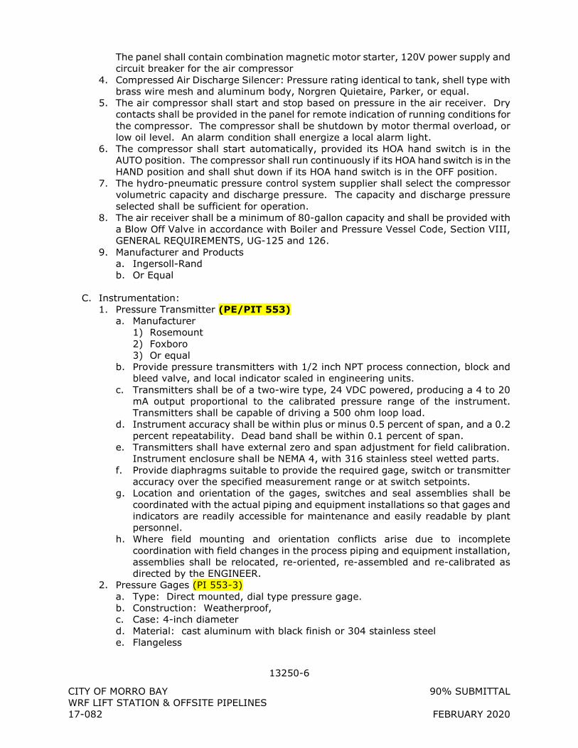
13250-6
CITY OF MORRO BAY 90% SUBMITTAL WRF LIFT STATION & OFFSITE PIPELINES 17-082 FEBRUARY 2020
The panel shall contain combination magnetic motor starter, 120V power supply and circuit breaker for the air compressor
4. Compressed Air Discharge Silencer: Pressure rating identical to tank, shell type with brass wire mesh and aluminum body, Norgren Quietaire, Parker, or equal.
5. The air compressor shall start and stop based on pressure in the air receiver. Dry contacts shall be provided in the panel for remote indication of running conditions for the compressor. The compressor shall be shutdown by motor thermal overload, or low oil level. An alarm condition shall energize a local alarm light.
6. The compressor shall start automatically, provided its HOA hand switch is in the AUTO position. The compressor shall run continuously if its HOA hand switch is in the HAND position and shall shut down if its HOA hand switch is in the OFF position.
7. The hydro-pneumatic pressure control system supplier shall select the compressor volumetric capacity and discharge pressure. The capacity and discharge pressure selected shall be sufficient for operation.
8. The air receiver shall be a minimum of 80-gallon capacity and shall be provided with a Blow Off Valve in accordance with Boiler and Pressure Vessel Code, Section VIII, GENERAL REQUIREMENTS, UG-125 and 126.
9. Manufacturer and Products a. Ingersoll-Rand b. Or Equal
C. Instrumentation: 1. Pressure Transmitter (PE/PIT 553)
a. Manufacturer 1) Rosemount 2) Foxboro 3) Or equal
b. Provide pressure transmitters with 1/2 inch NPT process connection, block and bleed valve, and local indicator scaled in engineering units.
c. Transmitters shall be of a two-wire type, 24 VDC powered, producing a 4 to 20 mA output proportional to the calibrated pressure range of the instrument. Transmitters shall be capable of driving a 500 ohm loop load.
d. Instrument accuracy shall be within plus or minus 0.5 percent of span, and a 0.2 percent repeatability. Dead band shall be within 0.1 percent of span.
e. Transmitters shall have external zero and span adjustment for field calibration. Instrument enclosure shall be NEMA 4, with 316 stainless steel wetted parts.
f. Provide diaphragms suitable to provide the required gage, switch or transmitter accuracy over the specified measurement range or at switch setpoints.
g. Location and orientation of the gages, switches and seal assemblies shall be coordinated with the actual piping and equipment installations so that gages and indicators are readily accessible for maintenance and easily readable by plant personnel.
h. Where field mounting and orientation conflicts arise due to incomplete coordination with field changes in the process piping and equipment installation, assemblies shall be relocated, re-oriented, re-assembled and re-calibrated as directed by the ENGINEER.
2. Pressure Gages (PI 553-3) a. Type: Direct mounted, dial type pressure gage. b. Construction: Weatherproof, c. Case: 4-inch diameter d. Material: cast aluminum with black finish or 304 stainless steel e. Flangeless
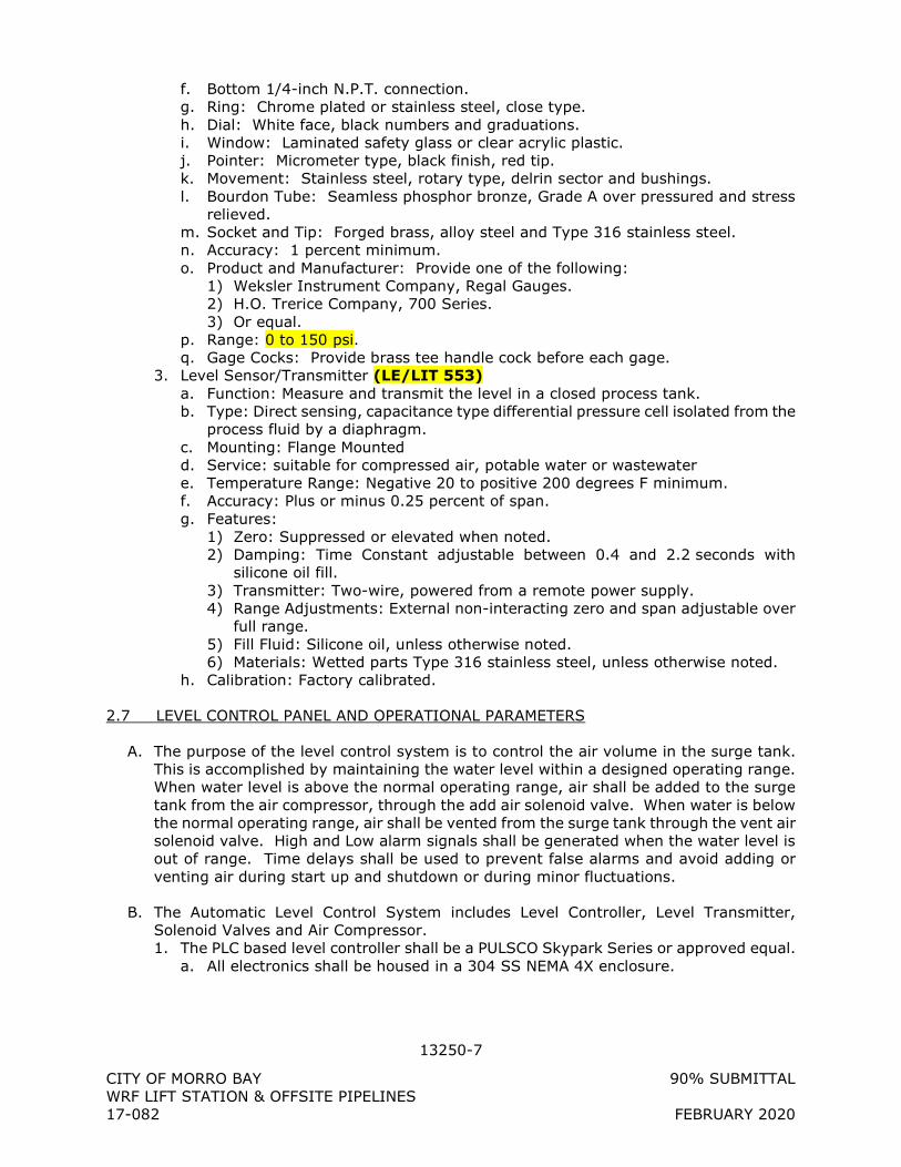
13250-7
CITY OF MORRO BAY 90% SUBMITTAL WRF LIFT STATION & OFFSITE PIPELINES 17-082 FEBRUARY 2020
f. Bottom 1/4-inch N.P.T. connection. g. Ring: Chrome plated or stainless steel, close type. h. Dial: White face, black numbers and graduations. i. Window: Laminated safety glass or clear acrylic plastic. j. Pointer: Micrometer type, black finish, red tip. k. Movement: Stainless steel, rotary type, delrin sector and bushings. l. Bourdon Tube: Seamless phosphor bronze, Grade A over pressured and stress
relieved. m. Socket and Tip: Forged brass, alloy steel and Type 316 stainless steel. n. Accuracy: 1 percent minimum. o. Product and Manufacturer: Provide one of the following:
1) Weksler Instrument Company, Regal Gauges. 2) H.O. Trerice Company, 700 Series. 3) Or equal.
p. Range: 0 to 150 psi. q. Gage Cocks: Provide brass tee handle cock before each gage.
3. Level Sensor/Transmitter (LE/LIT 553) a. Function: Measure and transmit the level in a closed process tank. b. Type: Direct sensing, capacitance type differential pressure cell isolated from the
process fluid by a diaphragm. c. Mounting: Flange Mounted d. Service: suitable for compressed air, potable water or wastewater e. Temperature Range: Negative 20 to positive 200 degrees F minimum. f. Accuracy: Plus or minus 0.25 percent of span. g. Features:
1) Zero: Suppressed or elevated when noted. 2) Damping: Time Constant adjustable between 0.4 and 2.2 seconds with
silicone oil fill. 3) Transmitter: Two-wire, powered from a remote power supply. 4) Range Adjustments: External non-interacting zero and span adjustable over
full range. 5) Fill Fluid: Silicone oil, unless otherwise noted. 6) Materials: Wetted parts Type 316 stainless steel, unless otherwise noted.
h. Calibration: Factory calibrated.
2.7 LEVEL CONTROL PANEL AND OPERATIONAL PARAMETERS
A. The purpose of the level control system is to control the air volume in the surge tank. This is accomplished by maintaining the water level within a designed operating range. When water level is above the normal operating range, air shall be added to the surge tank from the air compressor, through the add air solenoid valve. When water is below the normal operating range, air shall be vented from the surge tank through the vent air solenoid valve. High and Low alarm signals shall be generated when the water level is out of range. Time delays shall be used to prevent false alarms and avoid adding or venting air during start up and shutdown or during minor fluctuations.
B. The Automatic Level Control System includes Level Controller, Level Transmitter, Solenoid Valves and Air Compressor. 1. The PLC based level controller shall be a PULSCO Skypark Series or approved equal.
a. All electronics shall be housed in a 304 SS NEMA 4X enclosure.
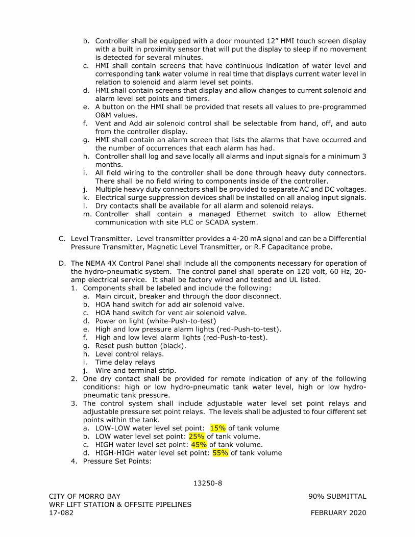
13250-8
CITY OF MORRO BAY 90% SUBMITTAL WRF LIFT STATION & OFFSITE PIPELINES 17-082 FEBRUARY 2020
b. Controller shall be equipped with a door mounted 12” HMI touch screen display with a built in proximity sensor that will put the display to sleep if no movement is detected for several minutes.
c. HMI shall contain screens that have continuous indication of water level and corresponding tank water volume in real time that displays current water level in relation to solenoid and alarm level set points.
d. HMI shall contain screens that display and allow changes to current solenoid and alarm level set points and timers.
e. A button on the HMI shall be provided that resets all values to pre-programmed O&M values.
f. Vent and Add air solenoid control shall be selectable from hand, off, and auto from the controller display.
g. HMI shall contain an alarm screen that lists the alarms that have occurred and the number of occurrences that each alarm has had.
h. Controller shall log and save locally all alarms and input signals for a minimum 3 months.
i. All field wiring to the controller shall be done through heavy duty connectors. There shall be no field wiring to components inside of the controller.
j. Multiple heavy duty connectors shall be provided to separate AC and DC voltages. k. Electrical surge suppression devices shall be installed on all analog input signals. l. Dry contacts shall be available for all alarm and solenoid relays. m. Controller shall contain a managed Ethernet switch to allow Ethernet
communication with site PLC or SCADA system.
C. Level Transmitter. Level transmitter provides a 4-20 mA signal and can be a Differential Pressure Transmitter, Magnetic Level Transmitter, or R.F Capacitance probe.
D. The NEMA 4X Control Panel shall include all the components necessary for operation of the hydro-pneumatic system. The control panel shall operate on 120 volt, 60 Hz, 20-amp electrical service. It shall be factory wired and tested and UL listed. 1. Components shall be labeled and include the following:
a. Main circuit, breaker and through the door disconnect. b. HOA hand switch for add air solenoid valve. c. HOA hand switch for vent air solenoid valve. d. Power on light (white-Push-to-test) e. High and low pressure alarm lights (red-Push-to-test). f. High and low level alarm lights (red-Push-to-test). g. Reset push button (black). h. Level control relays. i. Time delay relays j. Wire and terminal strip.
2. One dry contact shall be provided for remote indication of any of the following conditions: high or low hydro-pneumatic tank water level, high or low hydro-pneumatic tank pressure.
3. The control system shall include adjustable water level set point relays and adjustable pressure set point relays. The levels shall be adjusted to four different set points within the tank. a. LOW-LOW water level set point: 15% of tank volume b. LOW water level set point: 25% of tank volume. c. HIGH water level set point: 45% of tank volume. d. HIGH-HIGH water level set point: 55% of tank volume
4. Pressure Set Points:
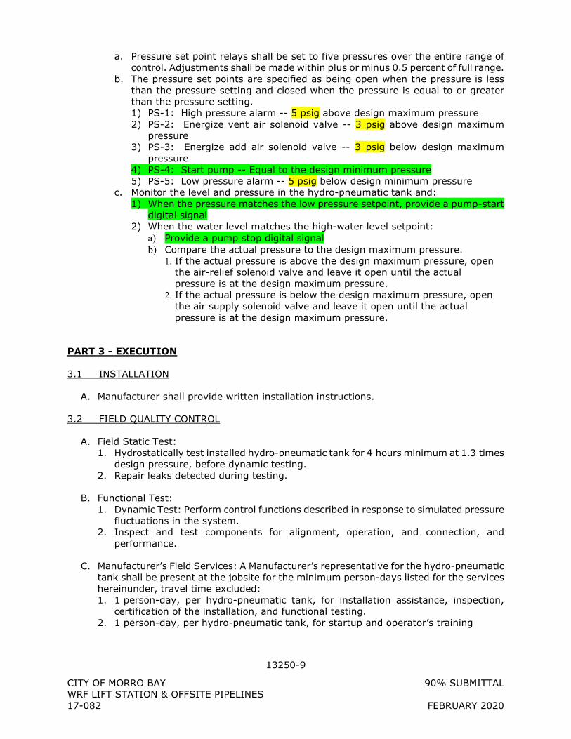
13250-9
CITY OF MORRO BAY 90% SUBMITTAL WRF LIFT STATION & OFFSITE PIPELINES 17-082 FEBRUARY 2020
a. Pressure set point relays shall be set to five pressures over the entire range of control. Adjustments shall be made within plus or minus 0.5 percent of full range.
b. The pressure set points are specified as being open when the pressure is less than the pressure setting and closed when the pressure is equal to or greater than the pressure setting. 1) PS-1: High pressure alarm -- 5 psig above design maximum pressure 2) PS-2: Energize vent air solenoid valve -- 3 psig above design maximum
pressure 3) PS-3: Energize add air solenoid valve -- 3 psig below design maximum
pressure 4) PS-4: Start pump -- Equal to the design minimum pressure 5) PS-5: Low pressure alarm -- 5 psig below design minimum pressure
c. Monitor the level and pressure in the hydro-pneumatic tank and: 1) When the pressure matches the low pressure setpoint, provide a pump-start
digital signal 2) When the water level matches the high-water level setpoint:
a) Provide a pump stop digital signal b) Compare the actual pressure to the design maximum pressure.
1. If the actual pressure is above the design maximum pressure, open the air-relief solenoid valve and leave it open until the actual pressure is at the design maximum pressure.
2. If the actual pressure is below the design maximum pressure, open the air supply solenoid valve and leave it open until the actual pressure is at the design maximum pressure.
PART 3 - EXECUTION
3.1 INSTALLATION
A. Manufacturer shall provide written installation instructions.
3.2 FIELD QUALITY CONTROL
A. Field Static Test: 1. Hydrostatically test installed hydro-pneumatic tank for 4 hours minimum at 1.3 times
design pressure, before dynamic testing. 2. Repair leaks detected during testing.
B. Functional Test: 1. Dynamic Test: Perform control functions described in response to simulated pressure
fluctuations in the system. 2. Inspect and test components for alignment, operation, and connection, and
performance.
C. Manufacturer’s Field Services: A Manufacturer’s representative for the hydro-pneumatic tank shall be present at the jobsite for the minimum person-days listed for the services hereinunder, travel time excluded: 1. 1 person-day, per hydro-pneumatic tank, for installation assistance, inspection,
certification of the installation, and functional testing. 2. 1 person-day, per hydro-pneumatic tank, for startup and operator’s training

13250-10
CITY OF MORRO BAY 90% SUBMITTAL WRF LIFT STATION & OFFSITE PIPELINES 17-082 FEBRUARY 2020
+ + END OF SECTION + +
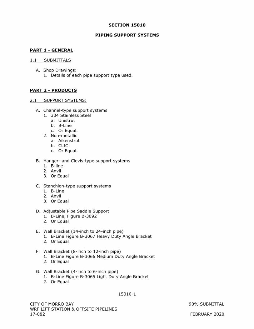
15010-1
CITY OF MORRO BAY 90% SUBMITTAL WRF LIFT STATION & OFFSITE PIPELINES 17-082 FEBRUARY 2020
SECTION 15010
PIPING SUPPORT SYSTEMS
PART 1 - GENERAL
1.1 SUBMITTALS
A. Shop Drawings: 1. Details of each pipe support type used.
PART 2 - PRODUCTS
2.1 SUPPORT SYSTEMS:
A. Channel-type support systems 1. 304 Stainless Steel
a. Unistrut b. B-Line c. Or Equal.
2. Non-metallic a. Aikenstrut b. CLIC c. Or Equal.
B. Hanger- and Clevis-type support systems 1. B-line 2. Anvil 3. Or Equal
C. Stanchion-type support systems 1. B-Line 2. Anvil 3. Or Equal
D. Adjustable Pipe Saddle Support 1. B-Line, Figure B-3092 2. Or Equal
E. Wall Bracket (14-inch to 24-inch pipe) 1. B-Line Figure B-3067 Heavy Duty Angle Bracket 2. Or Equal
F. Wall Bracket (8-inch to 12-inch pipe) 1. B-Line Figure B-3066 Medium Duty Angle Bracket 2. Or Equal
G. Wall Bracket (4-inch to 6-inch pipe) 1. B-Line Figure B-3065 Light Duty Angle Bracket 2. Or Equal
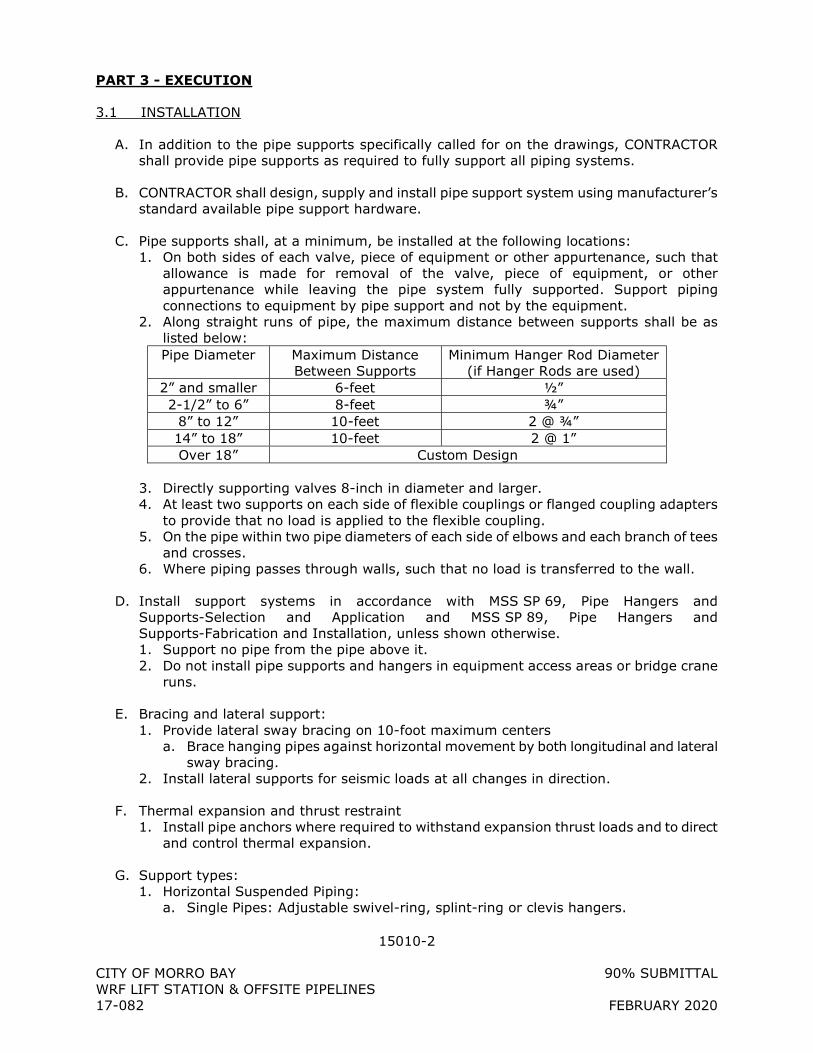
15010-2
CITY OF MORRO BAY 90% SUBMITTAL WRF LIFT STATION & OFFSITE PIPELINES 17-082 FEBRUARY 2020
PART 3 - EXECUTION
3.1 INSTALLATION
A. In addition to the pipe supports specifically called for on the drawings, CONTRACTOR shall provide pipe supports as required to fully support all piping systems.
B. CONTRACTOR shall design, supply and install pipe support system using manufacturer’s standard available pipe support hardware.
C. Pipe supports shall, at a minimum, be installed at the following locations: 1. On both sides of each valve, piece of equipment or other appurtenance, such that
allowance is made for removal of the valve, piece of equipment, or other appurtenance while leaving the pipe system fully supported. Support piping connections to equipment by pipe support and not by the equipment.
2. Along straight runs of pipe, the maximum distance between supports shall be as listed below: Pipe Diameter Maximum Distance
Between Supports Minimum Hanger Rod Diameter
(if Hanger Rods are used) 2” and smaller 6-feet ½” 2-1/2” to 6” 8-feet ¾”
8” to 12” 10-feet 2 @ ¾” 14” to 18” 10-feet 2 @ 1” Over 18” Custom Design
3. Directly supporting valves 8-inch in diameter and larger. 4. At least two supports on each side of flexible couplings or flanged coupling adapters
to provide that no load is applied to the flexible coupling. 5. On the pipe within two pipe diameters of each side of elbows and each branch of tees
and crosses. 6. Where piping passes through walls, such that no load is transferred to the wall.
D. Install support systems in accordance with MSS SP 69, Pipe Hangers and Supports-Selection and Application and MSS SP 89, Pipe Hangers and Supports-Fabrication and Installation, unless shown otherwise. 1. Support no pipe from the pipe above it. 2. Do not install pipe supports and hangers in equipment access areas or bridge crane
runs.
E. Bracing and lateral support: 1. Provide lateral sway bracing on 10-foot maximum centers
a. Brace hanging pipes against horizontal movement by both longitudinal and lateral sway bracing.
2. Install lateral supports for seismic loads at all changes in direction.
F. Thermal expansion and thrust restraint 1. Install pipe anchors where required to withstand expansion thrust loads and to direct
and control thermal expansion.
G. Support types: 1. Horizontal Suspended Piping:
a. Single Pipes: Adjustable swivel-ring, splint-ring or clevis hangers.
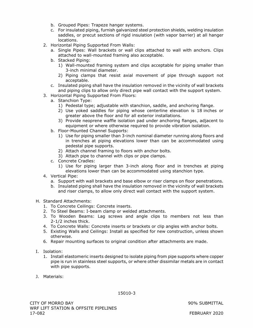
15010-3
CITY OF MORRO BAY 90% SUBMITTAL WRF LIFT STATION & OFFSITE PIPELINES 17-082 FEBRUARY 2020
b. Grouped Pipes: Trapeze hanger systems. c. For insulated piping, furnish galvanized steel protection shields, welding insulation
saddles, or precut sections of rigid insulation (with vapor barrier) at all hanger locations.
2. Horizontal Piping Supported From Walls: a. Single Pipes: Wall brackets or wall clips attached to wall with anchors. Clips
attached to wall-mounted framing also acceptable. b. Stacked Piping:
1) Wall-mounted framing system and clips acceptable for piping smaller than 3-inch minimal diameter.
2) Piping clamps that resist axial movement of pipe through support not acceptable.
c. Insulated piping shall have the insulation removed in the vicinity of wall brackets and piping clips to allow only direct pipe wall contact with the support system.
3. Horizontal Piping Supported From Floors: a. Stanchion Type:
1) Pedestal type; adjustable with stanchion, saddle, and anchoring flange. 2) Use yoked saddles for piping whose centerline elevation is 18 inches or
greater above the floor and for all exterior installations. 3) Provide neoprene waffle isolation pad under anchoring flanges, adjacent to
equipment or where otherwise required to provide vibration isolation. b. Floor-Mounted Channel Supports:
1) Use for piping smaller than 3-inch nominal diameter running along floors and in trenches at piping elevations lower than can be accommodated using pedestal pipe supports.
2) Attach channel framing to floors with anchor bolts. 3) Attach pipe to channel with clips or pipe clamps.
c. Concrete Cradles: 1) Use for piping larger than 3-inch along floor and in trenches at piping
elevations lower than can be accommodated using stanchion type. 4. Vertical Pipe:
a. Support with wall brackets and base elbow or riser clamps on floor penetrations. b. Insulated piping shall have the insulation removed in the vicinity of wall brackets
and riser clamps, to allow only direct wall contact with the support system.
H. Standard Attachments: 1. To Concrete Ceilings: Concrete inserts. 2. To Steel Beams: I-beam clamp or welded attachments. 3. To Wooden Beams: Lag screws and angle clips to members not less than
2-1/2 inches thick. 4. To Concrete Walls: Concrete inserts or brackets or clip angles with anchor bolts. 5. Existing Walls and Ceilings: Install as specified for new construction, unless shown
otherwise. 6. Repair mounting surfaces to original condition after attachments are made.
I. Isolation: 1. Install elastomeric inserts designed to isolate piping from pipe supports where copper
pipe is run in stainless steel supports, or where other dissimilar metals are in contact with pipe supports.
J. Materials:
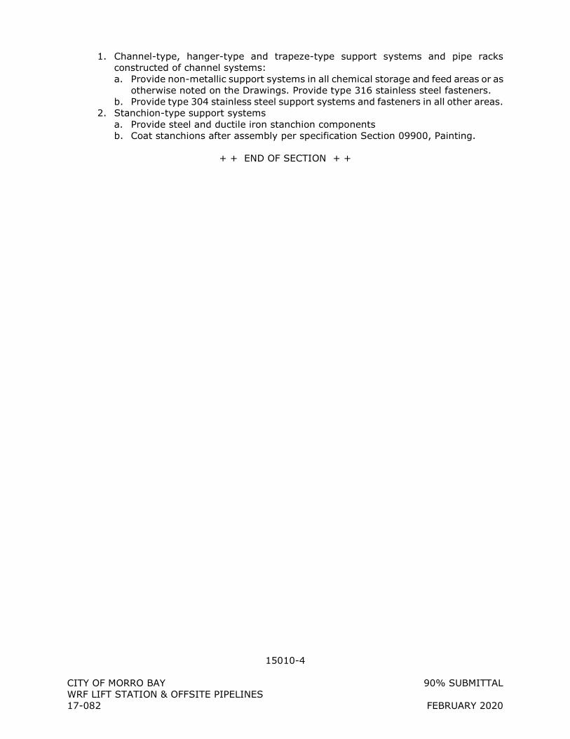
15010-4
CITY OF MORRO BAY 90% SUBMITTAL WRF LIFT STATION & OFFSITE PIPELINES 17-082 FEBRUARY 2020
1. Channel-type, hanger-type and trapeze-type support systems and pipe racks constructed of channel systems: a. Provide non-metallic support systems in all chemical storage and feed areas or as
otherwise noted on the Drawings. Provide type 316 stainless steel fasteners. b. Provide type 304 stainless steel support systems and fasteners in all other areas.
2. Stanchion-type support systems a. Provide steel and ductile iron stanchion components b. Coat stanchions after assembly per specification Section 09900, Painting.
+ + END OF SECTION + +
15100-1
CITY OF MORRO BAY 90% SUBMITTAL
WRF LIFT STATION & OFFSITE PIPELINES
17-082 FEBRUARY 2020
SECTION 15100
PIPE AND FITTINGS
PART 1 - GENERAL
1.1 SUBMITTALS
A. Shop Drawings:
1. Product data sheets for each piping system.
a. Include information on pipe, fittings and joint systems.
2. Complete catalog information, descriptive literature, specifications, and identification
of materials of construction.
3. Complete descriptions and data for all coatings and linings.
4. Tests and inspection data for pipe and coatings/linings.
5. Qualifications for welders and/or technicians performing joining processes that
requires specialized equipment to perform the work or as specifically identified
herein.
B. Operation and Maintenance Data as specified in Section 01330, SUBMITTAL
PROCEDURES.
1.2 PRODUCT DELIVERY, STORAGE, AND HANDLING
A. In accordance with manufacturer’s directions.
PART 2 - PRODUCTS
2.1 PIPING SYSTEM DATA SHEETS
A. Piping system data sheets (PSDS) have been attached to this Specification and are
incorporated herein by reference. Provide piping systems in accordance with piping
system data sheets.
2.2 THRUST RESTRAINT
A. Provide rigid or restrained joints and fittings for all piping systems specified with a test
pressure in the Pipe Schedule.
B. Unless otherwise specified in the Pipe Schedule or shown on the Drawings, thrust blocks
shall not be used.
PART 3 - EXECUTION
3.1 PIPE SCHEDULE
A. A Pipe Schedule has been attached to this Specification and is incorporated herein by
reference. Install piping systems in accordance with Pipe Schedule.
15100-2
CITY OF MORRO BAY 90% SUBMITTAL
WRF LIFT STATION & OFFSITE PIPELINES
17-082 FEBRUARY 2020
B. For pipe which is shown on the Drawings, but not referenced in the Pipe Schedule,
CONTRACTOR to provide pipe material and fittings which are appropriate for the intended
service and acceptable to the ENGINEER.
3.2 PREPARATION
A. Inspect pipe and fittings before installation, clean ends thoroughly, and remove foreign
matter and dirt from inside.
B. Repair any coatings or linings which were damaged during shipping and handling using
manufacturer-approved coating and lining repair materials in accordance with
manufacturer’s instructions.
3.3 INSTALLATION
A. General:
1. Join pipe and fittings in accordance with manufacturer’s instructions, unless
otherwise shown or specified.
B. Joint Assembly:
1. Flanged Joints (FLG):
a. Bolt Holes: Straddle vertical centerlines, aligned with connecting equipment
flanges or as shown.
b. Follow a bolt tightening pattern which produces uniform bearing pressure.
c. Do not over-tighten bolts. Follow manufacturer’s recommendation for bolt torque.
d. Provide gasket at every flanged joint.
e. Provide insulating flange kit where indicated on Drawings and required in this
Specification.
2. Threaded and Coupled Joints (THR):
a. Conform to ANSI B1.20.1.
b. Produce sufficient thread length to ensure full engagement when screwed home
in fittings.
c. Ream pipe ends and clean chips and burrs after threading.
d. Make connections with not more than three threads exposed.
e. Lubricate male threads only with thread lubricant or tape as specified on Piping
Data Sheets.
f. PVC Threaded Joints:
1) Provide Schedule 80 threaded nipple where necessary to connect to threaded
valve or fitting.
2) Use strap wrench for tightening threaded plastic joints. Do not overtighten
fittings.
g. HDPE Threaded Joints:
1) Joining HDPE pipe with threaded connections is not allowed unless specifically
approved by the ENGINEER
h. Provide dielectric union or insulating coupling where indicated on Drawings and
required in this Specification.
3. Grooved-End Joints (GRV):
a. Type: Rigid, except where joints are used to correct misalignment, to provide
flexibility, and where shown otherwise, in which case provide flexible type.
b. Grooved end joints are not allowed for plastic pipes unless approved by the
ENGINEER.
4. Soldered Joints (SLD):
15100-3
CITY OF MORRO BAY 90% SUBMITTAL
WRF LIFT STATION & OFFSITE PIPELINES
17-082 FEBRUARY 2020
a. Before soldering, remove stems and washers from solder joint valves.
b. Use only solder specified for particular service.
c. Cut pipe ends square and remove fins and burrs.
d. Protect adjacent surfaces from damage during soldering.
1) Protect from high temperatures due to flame
2) Protect from damage due to dripping flux or solder
e. After thoroughly cleaning pipe and fitting of oil and grease using solvent and
emery cloth, apply noncorrosive flux to the male end only.
f. Solder Joint
g. Wipe excess solder from exterior of joint before hardened.
5. Solvent Welded Joints (SLV):
a. Use only solvent cement which is rated for use in the service intended. Check
compatibility of solvent cement with service, especially in pipelines which carry
chemicals.
b. Observe all manufacturer’s requirements for environmental conditions for use of
solvent cement.
c. Cut pipe ends square and remove fins and burrs.
d. Apply appropriate primer.
e. Apply solvent cement and assemble joint.
1) Hold in place long enough for solvent cement to set-up and hold joint, as
assembled, until solvent cement has cured.
f. Wipe excess solvent cement from exterior of joint before hardened.
6. Proprietary Restrained Mechanical Joints (PRJ):
a. PRJ piping shall be furnished with factory-fabricated retainer weldment on spigot
end.
b. If PRJ piping is field cut, the pipe joint shall be restrained using Restrained
Mechanical Joint (RMJ) Glands as specified in Section 15120, Piping Specialties.
Field welding of retainer weldment will not be allowed.
7. Welded Steel and Stainless Steel Joints (WLD)
a. Field welded joints shall be in accordance with AWWA C206
b. Welder Qualifications:
1) All welding shall be done by skilled welders, welding operators, and tackers
who have had adequate experience in the methods and materials to be used.
2) Welders shall be qualified by the CONTRACTOR under the provisions of ASME
BPVC for shop welds and ANSI/AWS D1.1 for field welds.
3) Furnish all material and bear the expense of qualifying welders.
c. Backing rings will not be permitted for 30-inch and smaller pipe. Single field-
welded butt joints with outside backing rings may be used for pipe larger than 30
inches in diameter.
d. Where exterior welds are performed, adequate space shall be provided for
welding and inspection of the joints.
e. Butt Straps
1) Butt straps shall be used as closure pieces and where shown on the Drawings.
2) Where used or required, shall be as shown on the Contract Drawings or as
approved during shop drawing review.
3) When fitting up the ends of pipe to be welded or fitting butt-strap pieces,
minor jacking or clamping will be allowed. Cold working the metal and sledges
or localized application of heat and working the metal and sledges will not be
allowed. If field displacement of joints, where butt strap joints are indicated,
does not allow proper fit-up with the tolerances indicated, special closure butt
straps or mitered pieces shall be shop fabricated and installed.
15100-4
CITY OF MORRO BAY 90% SUBMITTAL
WRF LIFT STATION & OFFSITE PIPELINES
17-082 FEBRUARY 2020
4) Butt straps shall be welded on both the inside and outside of the pipe and at
each end of the pipe and strap to avoid stress multiplication.
f. Prior to the backfilling or beginning the welding procedure, any tack welds or joint
stops used to position the pipe during laying shall be removed. Any annular space
between the faying surfaces of the bell and spigot shall be equally distributed
around the circumference of the joint by shimming, jacking, or other suitable
means. The weld shall then be made in accordance with ANSI/AWWA C206.
Where more than one pass is required, all dirt, slag, and flux shall be removed
before the succeeding bead is applied.
g. Repair of Welds: All welds that are defective shall be repaired by the
CONTRACTOR to meet the requirements of this section at no additional cost to
the OWNER. Defects in welds or defective welds shall be removed, and that
section of the joint shall then be re-welded. Only sufficient removal of defective
material that is necessary to correct the defect is required. After the repair is
made, the joint shall be checked by repeating the original test procedure. Welds
deficient in size shall be repaired by adding weld metal.
8. Thermally butt fused (BF) HDPE joints
a. In general, the individual performing thermal butt fusion and electrofusion and
the equipment used shall meet the requirements of the Plastic Pipe Institute
(PPI), Technical Note (TN) 42, Recommended Minimum Training Guidelines for PE
Pipe Butt Fusion Joining Operators and the requirements of Title 49, CFR Subpart
F, 192.282 and 192.285.
b. Specific requirements that apply when joining HDPE pipe using butt fusion shall
be as follows:
1) Submit documentation in accordance with Section 01330, that the fusion
technician has been qualified and trained by the fusion equipment
manufacturer or pipe manufacturer in the operation and procedures of the
butt fusion process. All qualifications and training shall have been received
within 1-year from the date of submitting the information. If acceptable
documentation cannot be provided, sample joints shall be made and tested in
accordance with TN-42. If pipe wall thickness is greater than 1–inch, submit
in accordance with Section 01330, an acceptable method recommended by
the pipe manufacturer that will be used to test the sample joint. All costs
associated with the sample joint testing and any retesting shall be borne by
the CONTRACTOR.
2) Each 2” NPS and larger butt fusion joint shall be documented using a data
logging device or written log that records the following minimum parameters
per completed joint:
a) Date and time
b) OWNER’s project number and/or name
c) Fusion Machine model
d) Pipe size, rating and PE type code (i.e. PE4710)
e) Heater plate surface temperature (minimum 2 values for each side of the
heater plate per joint)
f) Recorded drag pressure
g) Gauge pressure and associated interfacial pressure (psi)
h) Heating time
i) Transfer time between heater plate being removed from the face of the
opposing pipe ends and when the pipe ends are butted together
j) Cooling time
15100-5
CITY OF MORRO BAY 90% SUBMITTAL
WRF LIFT STATION & OFFSITE PIPELINES
17-082 FEBRUARY 2020
3) Provide log records at the end of each day in hardcopy format or as agreed
upon with the OWNER and/or ENGINEER. Submit one (1) copy as a minimum
to the OWNER’s Representative or ENGINEER.
4) At the completion of the work, provide all data log records on a compact disc
that can be accessed using the data log manufacturer’s software or if using
written logs, all individual written daily logs are transferred into a pdf format
and identified by day as a separate file. Submit the records in accordance
with Section 01330.
c. All joints that are determined to be defective visually or as a result of pressure
testing shall be repaired using a thermal fusion method unless otherwise
approved by the OWNER’s Representative or ENGINEER.
d. Install buried HDPE pipe in accordance with ASTM D2774 and the pipe
manufacturer’s specific recommendations.
9. Insulating Flanges, Couplings, and Dielectric Unions:
a. Applications: Provide insulating flange, coupling or di-electric union for all joints
at the following locations:
1) Dissimilar metal piping connections.
2) Cathodically protected piping penetration to buildings.
3) Submerged to unsubmerged metallic piping connections.
4) Where required for electrically insulated connection.
b. Installation:
1) Insulating joints connecting immersed piping to non-immersed piping shall be
installed above maximum water surface elevation.
2) Align and install insulating joints according to manufacturer's
recommendations to avoid damaging insulating materials.
C. Exposed Piping Installation:
1. Piping Runs:
a. Parallel to building or column lines and perpendicular to floor, unless shown
otherwise.
b. Piping upstream and downstream of flow measuring devices shall provide straight
lengths as required for accurate flow measurement.
2. Supports: As specified in Section 15010, PIPING SUPPORT SYSTEMS.
3. Group piping wherever practical at common elevations; install to conserve building
space and not interfere with use of space and other work.
4. Provide unions or flanges at each piping connection to equipment or instrumentation
on equipment side of each block valve to facilitate installation and removal.
5. Install piping so that no load or movement in excess of that stipulated by equipment
manufacturer will be imposed upon equipment connection;
6. Install piping to allow for contraction and expansion without stressing pipe, joints, or
connected equipment.
7. Piping clearance, unless otherwise shown:
a. Over Walkway and Stairs: Minimum of 7 feet 6 inches, measured from walking
surface or stair tread to lowest extremity of piping system including flanges, valve
bodies or mechanisms, insulation, or hanger/support systems.
b. Between Equipment or Equipment Piping and Adjacent Piping: Minimum 3 feet
0 inch, measured from equipment extremity and extremity of piping system
including flanges, valve bodies or mechanisms, insulation, or hanger/support
systems.
c. From Adjacent Work: Minimum 1 inch from nearest extremity of completed piping
system including flanges, valve bodies or mechanisms, insulation, or
hanger/support systems.
15100-6
CITY OF MORRO BAY 90% SUBMITTAL
WRF LIFT STATION & OFFSITE PIPELINES
17-082 FEBRUARY 2020
d. Do not route piping in front of or to interfere with access ways, ladders, stairs,
platforms, walkways, openings, doors, or windows.
e. Headroom in front of openings, doors, and windows shall not be less than the top
of the opening.
f. Do not install piping containing liquids or liquid vapors in transformer vaults or
electrical equipment rooms.
g. Do not route piping over, around, in front of, in back of, or below electrical
equipment including controls, panels, switches, terminals, boxes, or other similar
electrical work.
D. Buried Pipe Installation:
1. Pipe Placement:
a. Keep trench dry until pipe laying and joining are completed.
b. Exercise care when lowering pipe into trench to prevent twisting or damage to
pipe.
c. Prevent foreign material from entering pipe during placement.
1) Close and block open end of last laid pipe section when placement operations
are not in progress and at close of day’s work.
d. Lay pipe upgrade with bell ends pointing in direction of laying.
e. Deflect pipe at joints for pipelines laid on a curve using unsymmetrical closure of
spigot into bell. Utilize a maximum of 75 percent of manufacturer’s recommended
allowable joint deflection.
1) If joint deflection of standard pipe lengths will not accommodate horizontal or
vertical curves in alignment, provide:
a) Shorter pipe lengths.
b) Fittings/bends.
f. Secure pipe which has been placed from movement or damage while placing the
next section of pipe.
g. Prevent uplift and floating of pipe prior to backfilling.
E. Cleaning:
1. Following assembly and testing, and prior to disinfection and final acceptance, flush
pipelines with water at 2.5 fps minimum flushing velocity until foreign matter is
removed. At a minimum, flush for a period of time which will flush the entire pipeline
volume three times.
a. If impractical to flush large diameter pipe at 2.5 fps, clean in-place from inside by
brushing and sweeping, then flush line at lower velocity. If lower velocity is used,
flush the entire pipeline volume five times.
2. Provide temporary means of removing flushing water from pipeline during flushing.
3. Provide means for removal/screening of debris from the flushing water, disposal of
debris and disposal of flushing water.
3.4 TESTING
A. Pressure test piping in accordance with the Pipe Schedule, and Section 15990, Pressure
Testing of Piping Systems.
3.5 SUPPLEMENTS
A. The following supplements are attached to this Specification section and incorporated
herein by reference:
1. 15100 PS – Pipe Schedule
15100-7
CITY OF MORRO BAY 90% SUBMITTAL
WRF LIFT STATION & OFFSITE PIPELINES
17-082 FEBRUARY 2020
2. 15100 PSDS COP – Copper Pipe
3. 15100 PSDS DIP – Ductile Iron Pipe
4. 15100 PSDS FPVC – FPVC Pressure Pipe
5. 15100 PSDS HDPE1 – High Density Polyethylene Drainage Pipe
6. 15100 PSDS PVC1 – Solvent Welded Polyvinyl Chloride Pipe
7. 15100 PSDS PVC2 – PVC Pressure Pipe
8. 15100 PSDS PVC3 – Polyvinyl Chloride Drain, Waste and Vent Pipe
9. 15100 PSDS PVC4 – PVC Sewer Pipe
10. 15100 PSDS PVC6 – PVC Storm Drain Pipe
11. 15100 PSDS RCP – Reinforced Concrete Pipe
12. 15100 PSDS WSP – Welded Steel Pipe
+ + END OF SECTION + +
15100 PS-1
WWE 8/15/2012 Master Spec 00-000 Master
SECTION 15100 PS
PIPE SCHEDULE
1.1 DESCRIPTION
A. General: 1. This schedule is provided for the convenience of the CONTRACTOR. Some flow
streams may be shown on the drawings, but not listed here.
B. Flow Stream IDs: 1. DR – Drain 2. SD – Storm Drain 3. SS – Sanitary Sewer 4. SSFM – Sanitary Sewer Forcemain 5. W1 – Potable Water 6. W2 – Non-Potable Water 7. BYP – Bypass 8. OF – Overflow 9. IPR – Indirect Potable Reuse 10. BR – Brine 11. Vent – Vent 12. FA – Foul Air
C. Pipe Materials: 1. CHE – Chemical Tubing 2. COP – Copper Pipe 3. DIP – Ductile Iron Pipe 4. PVC1 – Solvent Welded Polyvinyl Chloride Pipe 5. PVC2 – PVC Pressure Pipe 6. PVC3 – Polyvinyl Chloride Drain, Waste, and Vent Pipe 7. PVC4 – PVC Sewer Pipe 8. PVC6 – PVC Storm Drain Pipe 9. SSP – Stainless Steel Pipe 10. SST – Stainless Steel Tubing 11. WSP – Welded Steel Pipe 12. FPVC – Fusible Polyvinyl Chloride Pipe (C900) 13. HDPE – Fusible High Density Polyethylene Pipe (IPS PE4710) 14. RCP – Reinforced Concrete Pressure Pipe
D. Joint Types: 1. FLG – Flanged 2. GRV – Grooved End 3. GC – Grooved Coupling 4. MJ – Mechanical Joint 5. PO – Push On 6. PRJ – Proprietary Restrained Mechanical Joint 7. RMJ – Restrained Mechanical Joint 8. S – Swagelok stainless steel compression type 9. SLV – Solvent Welded Socket 10. SLD – Soldered Socket 11. THR – Threaded
15100 PS-2
WWE 8/15/2012 Master Spec 00-000 Master
12. WLD – Butt Welded
E. Lining Systems: 1. CM – Cement Mortar 2. PROTECTO-401
F. Coating Systems: As described in Section 09900
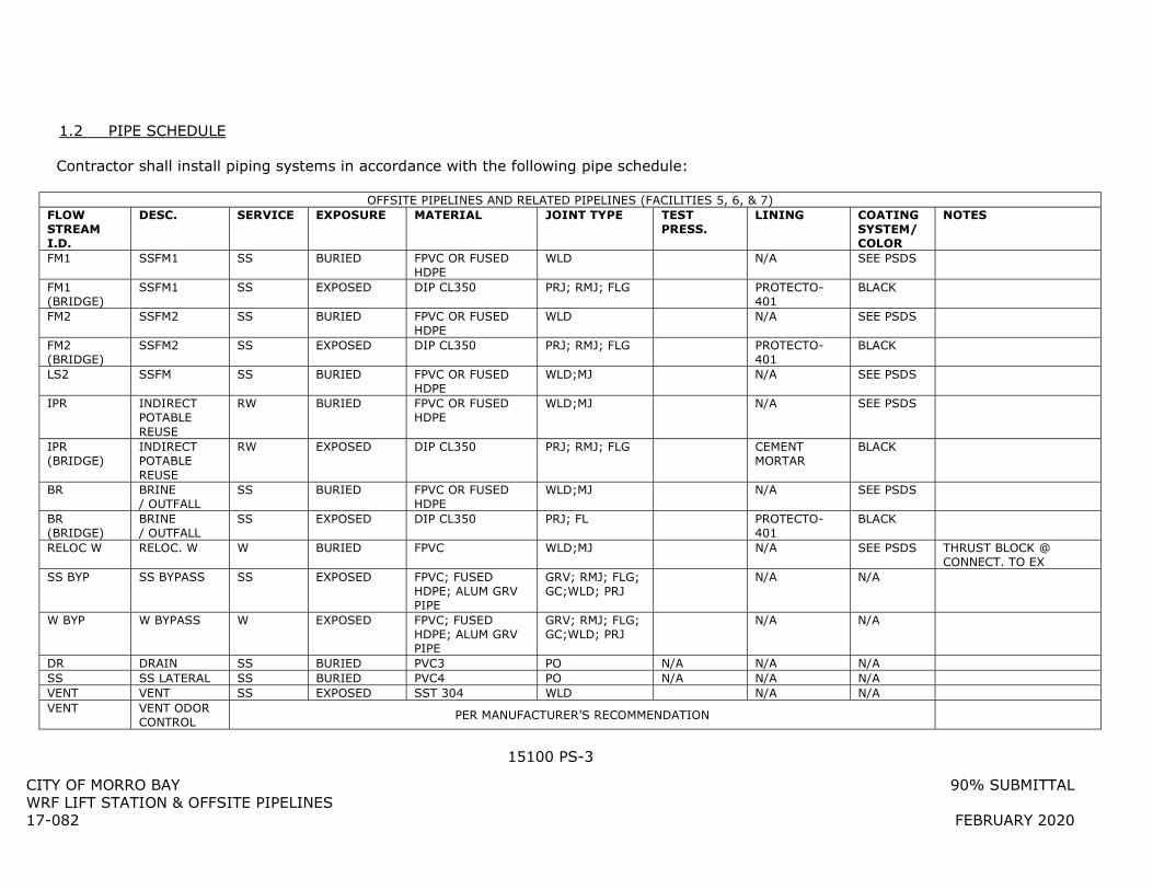
15100 PS-3
CITY OF MORRO BAY 90% SUBMITTAL WRF LIFT STATION & OFFSITE PIPELINES 17-082 FEBRUARY 2020
1.2 PIPE SCHEDULE
Contractor shall install piping systems in accordance with the following pipe schedule:
OFFSITE PIPELINES AND RELATED PIPELINES (FACILITIES 5, 6, & 7) FLOW STREAM I.D.
DESC. SERVICE EXPOSURE MATERIAL JOINT TYPE TEST PRESS.
LINING COATING SYSTEM/ COLOR
NOTES
FM1 SSFM1 SS BURIED FPVC OR FUSED HDPE
WLD N/A SEE PSDS
FM1 (BRIDGE)
SSFM1 SS EXPOSED DIP CL350 PRJ; RMJ; FLG PROTECTO-401
BLACK
FM2 SSFM2 SS BURIED FPVC OR FUSED HDPE
WLD N/A SEE PSDS
FM2 (BRIDGE)
SSFM2 SS EXPOSED DIP CL350 PRJ; RMJ; FLG PROTECTO-401
BLACK
LS2 SSFM SS BURIED FPVC OR FUSED HDPE
WLD;MJ N/A SEE PSDS
IPR INDIRECT POTABLE REUSE
RW BURIED FPVC OR FUSED HDPE
WLD;MJ N/A SEE PSDS
IPR (BRIDGE)
INDIRECT POTABLE REUSE
RW EXPOSED DIP CL350 PRJ; RMJ; FLG CEMENT MORTAR
BLACK
BR BRINE / OUTFALL
SS BURIED FPVC OR FUSED HDPE
WLD;MJ N/A SEE PSDS
BR (BRIDGE)
BRINE / OUTFALL
SS EXPOSED DIP CL350 PRJ; FL PROTECTO-401
BLACK
RELOC W RELOC. W W BURIED FPVC WLD;MJ N/A SEE PSDS THRUST BLOCK @ CONNECT. TO EX
SS BYP SS BYPASS SS EXPOSED FPVC; FUSED HDPE; ALUM GRV PIPE
GRV; RMJ; FLG; GC;WLD; PRJ
N/A N/A
W BYP W BYPASS W EXPOSED FPVC; FUSED HDPE; ALUM GRV PIPE
GRV; RMJ; FLG; GC;WLD; PRJ
N/A N/A
DR DRAIN SS BURIED PVC3 PO N/A N/A N/A SS SS LATERAL SS BURIED PVC4 PO N/A N/A N/A VENT VENT SS EXPOSED SST 304 WLD N/A N/A VENT VENT ODOR
CONTROL PER MANUFACTURER’S RECOMMENDATION
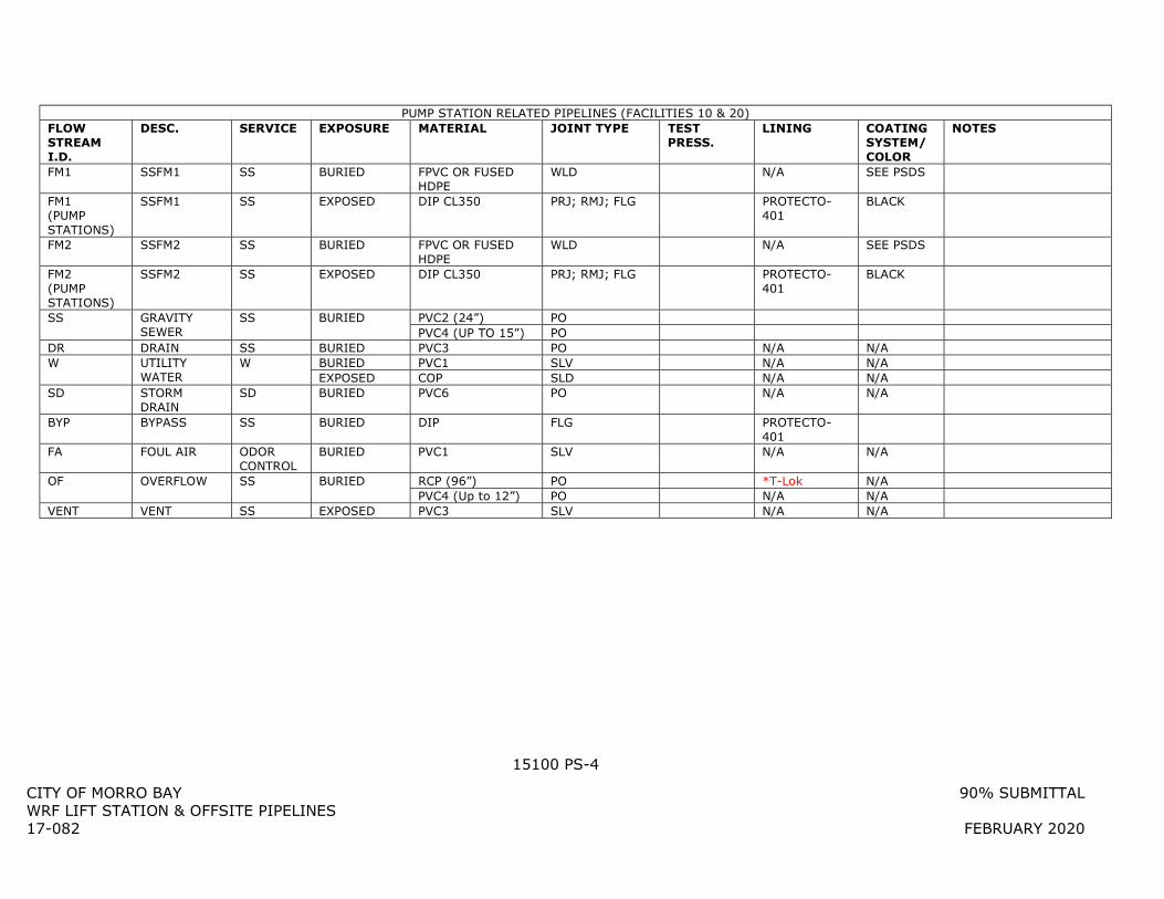
15100 PS-4
CITY OF MORRO BAY 90% SUBMITTAL WRF LIFT STATION & OFFSITE PIPELINES 17-082 FEBRUARY 2020
PUMP STATION RELATED PIPELINES (FACILITIES 10 & 20) FLOW STREAM I.D.
DESC. SERVICE EXPOSURE MATERIAL JOINT TYPE TEST PRESS.
LINING COATING SYSTEM/ COLOR
NOTES
FM1 SSFM1 SS BURIED FPVC OR FUSED HDPE
WLD N/A SEE PSDS
FM1 (PUMP STATIONS)
SSFM1 SS EXPOSED DIP CL350 PRJ; RMJ; FLG PROTECTO-401
BLACK
FM2 SSFM2 SS BURIED FPVC OR FUSED HDPE
WLD N/A SEE PSDS
FM2 (PUMP STATIONS)
SSFM2 SS EXPOSED DIP CL350 PRJ; RMJ; FLG PROTECTO-401
BLACK
SS GRAVITY SEWER
SS BURIED PVC2 (24”) PO PVC4 (UP TO 15”) PO
DR DRAIN SS BURIED PVC3 PO N/A N/A W UTILITY
WATER W BURIED PVC1 SLV N/A N/A
EXPOSED COP SLD N/A N/A SD STORM
DRAIN SD BURIED PVC6 PO N/A N/A
BYP BYPASS SS BURIED DIP FLG PROTECTO-401
FA FOUL AIR ODOR CONTROL
BURIED PVC1 SLV N/A N/A
OF OVERFLOW SS BURIED RCP (96”) PO *T-Lok N/A PVC4 (Up to 12”) PO N/A N/A
VENT VENT SS EXPOSED PVC3 SLV N/A N/A
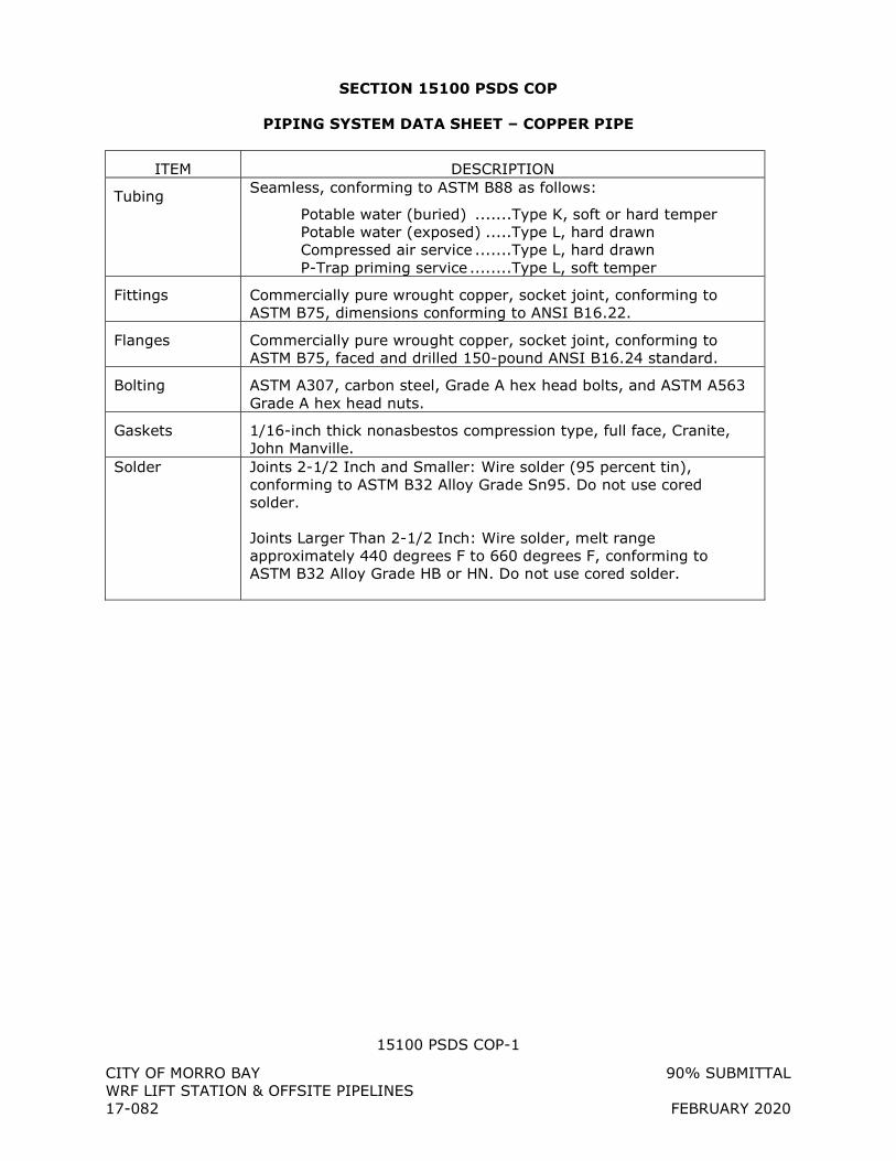
15100 PSDS COP-1
CITY OF MORRO BAY 90% SUBMITTAL WRF LIFT STATION & OFFSITE PIPELINES 17-082 FEBRUARY 2020
SECTION 15100 PSDS COP
PIPING SYSTEM DATA SHEET – COPPER PIPE
ITEM DESCRIPTION
Tubing Seamless, conforming to ASTM B88 as follows:
Potable water (buried) .......Type K, soft or hard temper Potable water (exposed) .....Type L, hard drawn Compressed air service .......Type L, hard drawn P-Trap priming service ........Type L, soft temper
Fittings Commercially pure wrought copper, socket joint, conforming to ASTM B75, dimensions conforming to ANSI B16.22.
Flanges Commercially pure wrought copper, socket joint, conforming to ASTM B75, faced and drilled 150-pound ANSI B16.24 standard.
Bolting ASTM A307, carbon steel, Grade A hex head bolts, and ASTM A563 Grade A hex head nuts.
Gaskets 1/16-inch thick nonasbestos compression type, full face, Cranite, John Manville.
Solder Joints 2-1/2 Inch and Smaller: Wire solder (95 percent tin), conforming to ASTM B32 Alloy Grade Sn95. Do not use cored solder.
Joints Larger Than 2-1/2 Inch: Wire solder, melt range approximately 440 degrees F to 660 degrees F, conforming to ASTM B32 Alloy Grade HB or HN. Do not use cored solder.
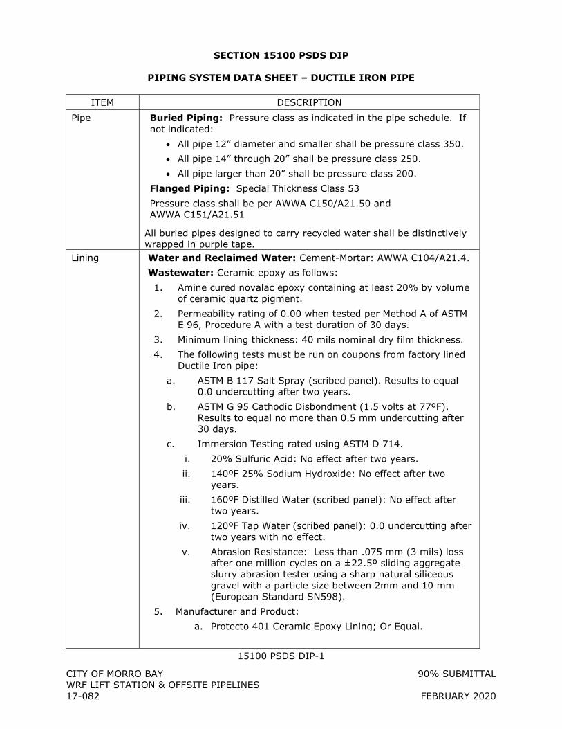
15100 PSDS DIP-1 CITY OF MORRO BAY 90% SUBMITTAL WRF LIFT STATION & OFFSITE PIPELINES 17-082 FEBRUARY 2020
SECTION 15100 PSDS DIP
PIPING SYSTEM DATA SHEET – DUCTILE IRON PIPE
ITEM DESCRIPTION
Pipe Buried Piping: Pressure class as indicated in the pipe schedule. If not indicated:
All pipe 12” diameter and smaller shall be pressure class 350.
All pipe 14” through 20” shall be pressure class 250.
All pipe larger than 20” shall be pressure class 200.
Flanged Piping: Special Thickness Class 53
Pressure class shall be per AWWA C150/A21.50 and AWWA C151/A21.51
All buried pipes designed to carry recycled water shall be distinctively wrapped in purple tape.
Lining Water and Reclaimed Water: Cement-Mortar: AWWA C104/A21.4.
Wastewater: Ceramic epoxy as follows:
1. Amine cured novalac epoxy containing at least 20% by volume of ceramic quartz pigment.
2. Permeability rating of 0.00 when tested per Method A of ASTM E 96, Procedure A with a test duration of 30 days.
3. Minimum lining thickness: 40 mils nominal dry film thickness.
4. The following tests must be run on coupons from factory lined Ductile Iron pipe:
a. ASTM B 117 Salt Spray (scribed panel). Results to equal 0.0 undercutting after two years.
b. ASTM G 95 Cathodic Disbondment (1.5 volts at 77ºF). Results to equal no more than 0.5 mm undercutting after 30 days.
c. Immersion Testing rated using ASTM D 714.
i. 20% Sulfuric Acid: No effect after two years.
ii. 140ºF 25% Sodium Hydroxide: No effect after two years.
iii. 160ºF Distilled Water (scribed panel): No effect after two years.
iv. 120ºF Tap Water (scribed panel): 0.0 undercutting after two years with no effect.
v. Abrasion Resistance: Less than .075 mm (3 mils) loss after one million cycles on a ±22.5º sliding aggregate slurry abrasion tester using a sharp natural siliceous gravel with a particle size between 2mm and 10 mm (European Standard SN598).
5. Manufacturer and Product:
a. Protecto 401 Ceramic Epoxy Lining; Or Equal.
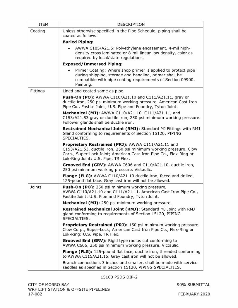
15100 PSDS DIP-2 CITY OF MORRO BAY 90% SUBMITTAL WRF LIFT STATION & OFFSITE PIPELINES 17-082 FEBRUARY 2020
ITEM DESCRIPTION
Coating Unless otherwise specified in the Pipe Schedule, piping shall be coated as follows:
Buried Piping:
AWWA C105/A21.5: Polyethylene encasement, 4-mil high-density cross laminated or 8-mil linear-low density, color as required by local/state regulations.
Exposed/Immersed Piping:
Primer Coating: Where shop primer is applied to protect pipe during shipping, storage and handling, primer shall be compatible with pipe coating requirements of Section 09900, Painting.
Fittings Lined and coated same as pipe.
Push-On (PO): AWWA C110/A21.10 and C111/A21.11, gray or ductile iron, 250 psi minimum working pressure. American Cast Iron Pipe Co., Fastite Joint; U.S. Pipe and Foundry, Tyton Joint.
Mechanical (MJ): AWWA C110/A21.10, C111/A21.11, and C153/A21.53 gray or ductile iron, 250 psi minimum working pressure. Follower glands shall be ductile iron.
Restrained Mechanical Joint (RMJ): Standard MJ Fittings with RMJ Gland conforming to requirements of Section 15120, PIPING SPECIALTIES.
Proprietary Restrained (PRJ): AWWA C111/A21.11 and C153/A21.53, ductile iron, 250 psi minimum working pressure. Clow Corp., Super-Lock Joint; American Cast Iron Pipe Co., Flex-Ring or Lok-Ring Joint; U.S. Pipe, TR Flex.
Grooved End (GRV): AWWA C606 and C110/A21.10, ductile iron, 250 psi minimum working pressure. Victaulic.
Flange (FLG): AWWA C110/A21.10 ductile iron, faced and drilled, 125-pound flat face. Gray cast iron will not be allowed.
Joints Push-On (PO): 250 psi minimum working pressure, AWWA C110/A21.10 and C111/A21.11. American Cast Iron Pipe Co., Fastite Joint; U.S. Pipe and Foundry, Tyton Joint.
Mechanical (MJ): 250 psi minimum working pressure.
Restrained Mechanical Joint (RMJ): Standard MJ Joint with RMJ gland conforming to requirements of Section 15120, PIPING SPECIALTIES.
Proprietary Restrained (PRJ): 150 psi minimum working pressure. Clow Corp., Super-Lock; American Cast Iron Pipe Co., Flex-Ring or Lok-Ring; U.S. Pipe, TR Flex.
Grooved End (GRV): Rigid type radius cut conforming to AWWA C606, 250 psi minimum working pressure. Victaulic.
Flange (FLG): 125-pound flat face, ductile iron, threaded conforming to AWWA C115/A21.15. Gray cast iron will not be allowed.
Branch connections 3 inches and smaller, shall be made with service saddles as specified in Section 15120, PIPING SPECIALTIES.
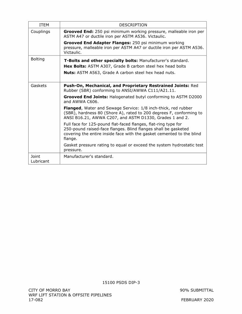
15100 PSDS DIP-3 CITY OF MORRO BAY 90% SUBMITTAL WRF LIFT STATION & OFFSITE PIPELINES 17-082 FEBRUARY 2020
ITEM DESCRIPTION
Couplings Grooved End: 250 psi minimum working pressure, malleable iron per ASTM A47 or ductile iron per ASTM A536. Victaulic.
Grooved End Adapter Flanges: 250 psi minimum working pressure, malleable iron per ASTM A47 or ductile iron per ASTM A536. Victaulic.
Bolting T-Bolts and other specialty bolts: Manufacturer's standard. Hex Bolts: ASTM A307, Grade B carbon steel hex head bolts
Nuts: ASTM A563, Grade A carbon steel hex head nuts.
Gaskets Push-On, Mechanical, and Proprietary Restrained Joints: Red Rubber (SBR) conforming to ANSI/AWWA C111/A21.11.
Grooved End Joints: Halogenated butyl conforming to ASTM D2000 and AWWA C606.
Flanged, Water and Sewage Service: 1/8 inch-thick, red rubber (SBR), hardness 80 (Shore A), rated to 200 degrees F, conforming to ANSI B16.21, AWWA C207, and ASTM D1330, Grades 1 and 2.
Full face for 125-pound flat-faced flanges, flat-ring type for 250-pound raised-face flanges. Blind flanges shall be gasketed covering the entire inside face with the gasket cemented to the blind flange.
Gasket pressure rating to equal or exceed the system hydrostatic test pressure.
Joint Lubricant
Manufacturer's standard.
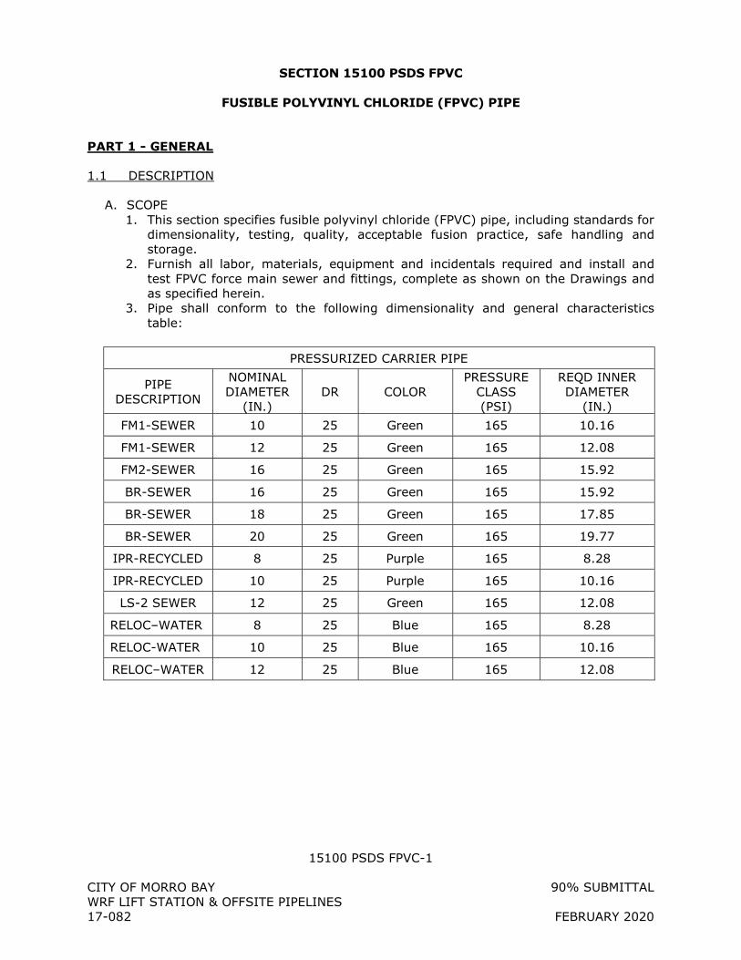
15100 PSDS FPVC-1
CITY OF MORRO BAY 90% SUBMITTAL WRF LIFT STATION & OFFSITE PIPELINES 17-082 FEBRUARY 2020
SECTION 15100 PSDS FPVC
FUSIBLE POLYVINYL CHLORIDE (FPVC) PIPE
PART 1 - GENERAL
1.1 DESCRIPTION
A. SCOPE 1. This section specifies fusible polyvinyl chloride (FPVC) pipe, including standards for
dimensionality, testing, quality, acceptable fusion practice, safe handling and storage.
2. Furnish all labor, materials, equipment and incidentals required and install and test FPVC force main sewer and fittings, complete as shown on the Drawings and as specified herein.
3. Pipe shall conform to the following dimensionality and general characteristics table:
PRESSURIZED CARRIER PIPE
PIPE DESCRIPTION
NOMINAL DIAMETER
(IN.) DR COLOR
PRESSURE CLASS (PSI)
REQD INNER DIAMETER
(IN.)
FM1-SEWER 10 25 Green 165 10.16
FM1-SEWER 12 25 Green 165 12.08
FM2-SEWER 16 25 Green 165 15.92
BR-SEWER 16 25 Green 165 15.92
BR-SEWER 18 25 Green 165 17.85
BR-SEWER 20 25 Green 165 19.77
IPR-RECYCLED 8 25 Purple 165 8.28
IPR-RECYCLED 10 25 Purple 165 10.16
LS-2 SEWER 12 25 Green 165 12.08
RELOC–WATER 8 25 Blue 165 8.28
RELOC-WATER 10 25 Blue 165 10.16
RELOC–WATER 12 25 Blue 165 12.08
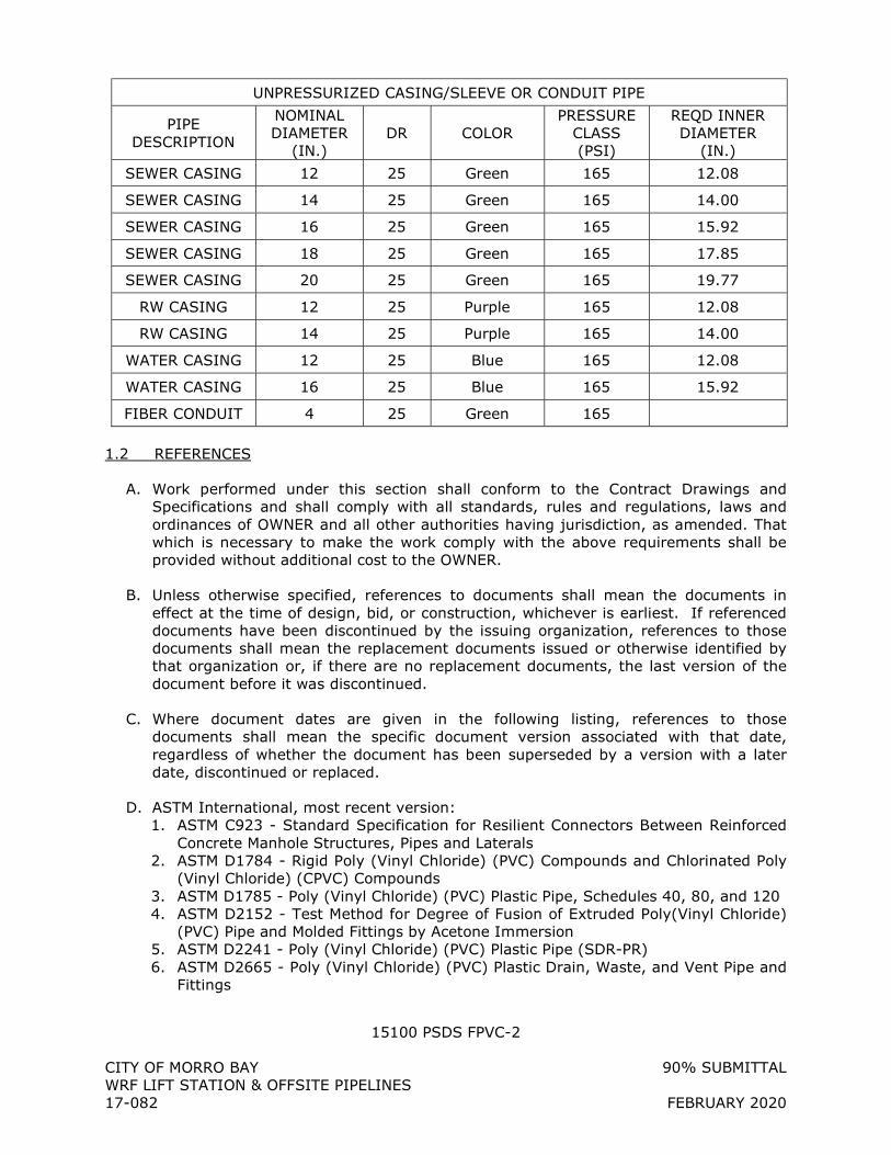
15100 PSDS FPVC-2
CITY OF MORRO BAY 90% SUBMITTAL WRF LIFT STATION & OFFSITE PIPELINES 17-082 FEBRUARY 2020
UNPRESSURIZED CASING/SLEEVE OR CONDUIT PIPE
PIPE DESCRIPTION
NOMINAL DIAMETER
(IN.) DR COLOR
PRESSURE CLASS (PSI)
REQD INNER DIAMETER
(IN.)
SEWER CASING 12 25 Green 165 12.08
SEWER CASING 14 25 Green 165 14.00
SEWER CASING 16 25 Green 165 15.92
SEWER CASING 18 25 Green 165 17.85
SEWER CASING 20 25 Green 165 19.77
RW CASING 12 25 Purple 165 12.08
RW CASING 14 25 Purple 165 14.00
WATER CASING 12 25 Blue 165 12.08
WATER CASING 16 25 Blue 165 15.92
FIBER CONDUIT 4 25 Green 165
1.2 REFERENCES
A. Work performed under this section shall conform to the Contract Drawings and Specifications and shall comply with all standards, rules and regulations, laws and ordinances of OWNER and all other authorities having jurisdiction, as amended. That which is necessary to make the work comply with the above requirements shall be provided without additional cost to the OWNER.
B. Unless otherwise specified, references to documents shall mean the documents in effect at the time of design, bid, or construction, whichever is earliest. If referenced documents have been discontinued by the issuing organization, references to those documents shall mean the replacement documents issued or otherwise identified by that organization or, if there are no replacement documents, the last version of the document before it was discontinued.
C. Where document dates are given in the following listing, references to those documents shall mean the specific document version associated with that date, regardless of whether the document has been superseded by a version with a later date, discontinued or replaced.
D. ASTM International, most recent version: 1. ASTM C923 - Standard Specification for Resilient Connectors Between Reinforced
Concrete Manhole Structures, Pipes and Laterals 2. ASTM D1784 - Rigid Poly (Vinyl Chloride) (PVC) Compounds and Chlorinated Poly
(Vinyl Chloride) (CPVC) Compounds 3. ASTM D1785 - Poly (Vinyl Chloride) (PVC) Plastic Pipe, Schedules 40, 80, and 120 4. ASTM D2152 - Test Method for Degree of Fusion of Extruded Poly(Vinyl Chloride)
(PVC) Pipe and Molded Fittings by Acetone Immersion 5. ASTM D2241 - Poly (Vinyl Chloride) (PVC) Plastic Pipe (SDR-PR) 6. ASTM D2665 - Poly (Vinyl Chloride) (PVC) Plastic Drain, Waste, and Vent Pipe and
Fittings
15100 PSDS FPVC-3
CITY OF MORRO BAY 90% SUBMITTAL WRF LIFT STATION & OFFSITE PIPELINES 17-082 FEBRUARY 2020
7. ASTM D3034 - Standard Specification for Type PSM Poly(Vinyl Chloride) (PVC) Sewer Pipe and Fittings
8. ASTM F477 - Elastomeric Seals (Gaskets) for Joining Plastic Pipe 9. ASTM F679 - Standard Specification for Poly(Vinyl Chloride) (PVC) Large Diameter
Plastic Gravity Sewer Pipe and Fittings 10. ASTM F1057 - Standard Practice for Estimating the Quality of Extruded Poly (Vinyl
Chloride) (PVC) Pipe by the Heat Reversion Technique 11. ASTM F1417 - Standard Test Method for Installation Acceptance of Plastic Gravity
Sewer Lines Using Low-Pressure Air
E. American Water Works Association, most recent version: 1. ANSI/AWWA C110/A21.10 - American National Standard for Ductile-Iron and
Gray-Iron Fittings, 3-inch through 48-inch, for Water and Other Liquids 2. ANSI/AWWA C111/A21.11 - American National Standard for Rubber-Gasket Joints
for Ductile-Iron Pressure Pipe and Fittings 3. ANSI/AWWA C153/A21.53 - AWWA Standard for Ductile-Iron Compact Fittings for
Water Service 4. AWWA C605 - Standard for Underground Installation of Polyvinyl Chloride (PVC)
Pressure Pipe and Fittings for Water 5. AWWA C651 - Standard for Disinfecting Water Mains 6. AWWA C900 - Standard for Polyvinyl Chloride (PVC) Pressure Pipe and Fabricated
Fittings, 4 in. through 12 in. (100mm Through 300mm), for Water Distribution 7. AWWA C905 - Standard for Polyvinyl Chloride (PVC Pressure Pipe and Fabricated
Fittings, 14 in. through 48 in. (350mm Through 1200mm), for Water Distribution and Transmission
8. AWWA M23 - AWWA Manual of Supply Practices PVC Pipe—Design and Installation, Second Edition
F. National Sanitation Foundation, most recent version: 1. NSF-14 - Plastics Piping System Components and Related Materials 2. NSF-61 - Drinking Water System Components--Health Effects
G. Plastics Pipe Institute, most recent version: 1. PPI TR-2 - PVC Range Composition Listing of Qualified Ingredients
H. UNI-BELL PVC Pipe Association, most recent version: 1. UNI-B-6 - Recommended Practice for Low-Pressure Air Testing of Installed Sewer
Pipe 2. UNI-PUB-08 - Tapping Guide for PVC Pressure Pipe
1.3 SUBMITTALS
A. Submit, in accordance with Section 01330, and within 30 days of the notice to proceed, the name of the pipe and fitting manufacturers and a list of materials to be furnished by each manufacturer. Also, include information on local representative for each manufacturer, if product is sold through a distributor.
B. Shop Drawings including piping layouts and schedules shall include dimensioning, fittings, types and locations of valves and appurtenances, joint details, methods and location of supports, anchorage, gasket material, grade of material and all other pertinent technical information for all items to be furnished.
15100 PSDS FPVC-4
CITY OF MORRO BAY 90% SUBMITTAL WRF LIFT STATION & OFFSITE PIPELINES 17-082 FEBRUARY 2020
C. Pipe manufacturer and Fusion services provider shall include the following: 1. Minimum Bending Radius 2. Maximum Safe Pull Force 3. Fusion technician qualification indicating conformance with this specification
D. After pipe installation, the following AS-RECORDED DATA is required from the CONTRACTOR and/or fusion provider to the OWNER upon request: 1. Approved datalogger device reports 2. Pipe Size and Thickness 3. Machine Size 4. Fusion Technician Identification 5. Job Identification 6. Fusion Joint Number 7. Fusion, Heating, and Drag Pressure Settings 8. Heat Plate Temperature 9. Time Stamp 10. Heating and Cool Down Time of Fusion 11. Ambient Temperature
1.4 QUALITY ASSURANCE
A. Fusion Technician Requirement: 1. Fusion Technician shall be fully qualified by the pipe supplier to install FPVC pipe
of the type(s) and size(s) being used. 2. Qualification shall be current as of the actual date of fusion performance on the
project. 3. Fusion technician shall have a minimum of one year and 3,000 lineal feet of FPVC
fusion experience to qualify for this work.
B. Specified Pipe Suppliers: 1. FPVC pipe shall be used as manufactured under the trade names Fusible C-900®,
Fusible C-905®, and FPVC®, for Underground Solutions, Inc., Poway, CA, (858) 679-9551 or equal.
2. Fusion process shall be as patented by Underground Solutions, Inc., Poway, CA, Patent No. 6,982,051. OWNER and ENGINEER are aware of no other supplier of FPVC pipe that is an equal to this specified pipe supplier and products.
1.5 HANDLING AND STORAGE
A. Any length of pipe showing a crack or which has received a blow that may have caused an incident fracture, even though no such fracture can be seen, shall be marked as rejected and removed at once from the work. Damaged areas, or possible areas of damage may be removed by cutting out and removing the suspected incident fracture area. Limits of the acceptable length of pipe shall be determined by the OWNER or ENGINEER.
B. Any scratch or gouge greater than 10% of the wall thickness will be considered significant and can be rejected unless determined acceptable by the OWNER or ENGINEER.
C. Pipe lengths should be stored and placed on level ground. Pipe should be stored at the job site in the unit packaging provided by the manufacturer. Caution should be
15100 PSDS FPVC-5
CITY OF MORRO BAY 90% SUBMITTAL WRF LIFT STATION & OFFSITE PIPELINES 17-082 FEBRUARY 2020
exercised to avoid compression, damage, or deformation to the ends of the pipe. The interior of the pipe, as well as all end surfaces, should be kept free from dirt and foreign matter.
D. Pipe shall be handled and supported with the use of woven fiber pipe slings or approved equal. Care shall be exercised when handling the pipe to not cut, gouge, scratch or otherwise abrade the piping in any way.
E. If pipe is to be stored for periods of 30 days or longer, the pipe should be shaded or otherwise shielded from direct sunlight. Covering of the pipe, which allows for temperature build-up is strictly prohibited. Pipe should be covered with an opaque material while permitting adequate air circulation above and around the pipe as required to prevent excess heat accumulation.
F. Pipe shall be stored and stacked per the pipe supplier’s guidelines.
1.6 DELIVERY AND OFF-LOADING
A. All FPVC pipe shall be bundled or packaged in such a manner as to provide adequate protection of the ends during transportation to the site. Any pipe damaged in shipment shall be replaced as directed by the OWNER or ENGINEER.
B. Each FPVC pipe shipment should be inspected prior to unloading to see if the load has shifted or otherwise been damaged. Notify OWNER or ENGINEER immediately if more than immaterial damage is found. Each pipe shipment should be checked for proper quantity, pipe size, color and type.
C. FPVC pipe should be loaded, off-loaded, and otherwise handled in accordance with AWWA M23, and all of the pipe supplier’s guidelines shall be followed.
D. Off-loading devices such as chains, wire rope, chokers, or other pipe handling implements that may scratch, nick, cut, or gouge the pipe are strictly prohibited.
E. During removal and handling, be sure that the pipe does not strike anything. Significant impact could cause damage, particularly during cold weather.
F. If appropriate unloading equipment is not available, pipe may be unloaded by removing individual pieces. Care should be taken to insure that pipe is not dropped or damaged. Pipe should be carefully lowered, not dropped, from trucks.
1.7 WARRANTY
A. The pipe and pipe installation via fusion services shall be warranted for one year per the pipe supplier’s standard terms.
PART 2 - PRODUCTS
2.1 GENERAL
A. All FPVC sewer pipe shall be from a single manufacturer.
15100 PSDS FPVC-6
CITY OF MORRO BAY 90% SUBMITTAL WRF LIFT STATION & OFFSITE PIPELINES 17-082 FEBRUARY 2020
B. FPVC piping shall be made from PVC compound conforming to cell classification 12454 per ASTM D1784.
C. Testing shall be in accordance with the referenced AWWA standards. Unless otherwise specified. FPVC pipe lengths shall be assembled in the field with butt-fused joints. The CONTRACTOR shall follow the pipe supplier’s written guidelines for this procedure. All fusion joints shall be completed as described in this specification.
D. FPVC pipe shall be manufactured in a standard 20’ or 40’ nominal length, or custom lengths as specified.
E. FPVC pipe shall be extruded with plain ends. The ends shall be square to the pipe and free of any bevel or chamfer. There shall be no bell or gasket of any kind incorporated into the pipe.
F. FPVC pipe shall be homogeneous throughout and be free of visible cracks, holes, foreign material, blisters, or other visible deleterious faults.
G. FPVC pipe shall be marked as follows: 1. Nominal pipe size 2. PVC 3. Dimension Ratio, Standard Dimension Ratio, or Schedule 4. AWWA pressure class, or standard pressure rating for non-AWWA pipe, as
applicable 5. AWWA standard designation number, or pipe type for non-AWWA pipe, as
applicable 6. Extrusion production-record code 7. Trademark or trade name 8. Cell Classification 12454 and/or PVC material code 1120 may also be included
2.2 FPVC PRESSURE PIPE FOR WASTEWATER
A. FPVC for pressurized wastewater not conforming to AQQA C905 dimensionally shall conform to AWWA C900, ASTM D2241 or ASTM D1785 for standard dimensionality, as applicable.
B. FPVC pipe shall be green in color for wastewater use.
2.3 CONNECTIONS AND FITTINGS FOR PRESSURE APPLICATIONS
A. Connections shall be defined in conjunction with the coupling of project piping, as well as the tie-ins to other piping systems.
B. All fittings and connections must be restrained.
C. DUCTILE IRON MECHANICAL AND FLANGED FITTINGS 1. Acceptable fittings for use with FPVC pipe shall include standard ductile iron
fittings conforming to AWWA/ANSI C110/A21.10, or AWWA/ANSI C153/A21.53 and AWWA/ANSI C111/A21.11.
2. Connections to FPVC pipe shall be made using a restrained retainer gland product for PVC pipe, as well as for MJ or flanged fittings.
3. Bends, tees and other ductile iron fittings shall be restrained.
15100 PSDS FPVC-7
CITY OF MORRO BAY 90% SUBMITTAL WRF LIFT STATION & OFFSITE PIPELINES 17-082 FEBRUARY 2020
4. Ductile iron fittings and glands must be installed per the manufacturer’s guidelines.
5. All pipe fittings outside of the Pump Station shall be long radius.
D. CONNECTION HARDWARE 1. Bolts and nuts for buried service shall be made of non-corrosive, high-strength,
low-alloy steel having the characteristics specified in ANSI/AWWA C111/A21.11, regardless of any other protective coating.
E. All ductile iron mechanical and flanged fittings shall be lined and coated with Tnemec 431 and as per manufacturer recommendation.
2.4 CONNECTIONS TO SANITARY SEWER MANHOLES AND STRUCTURES
A. FPVC pipe shall be connected to manholes and other structures to provide a leak-free, properly graded flow into or out of the manhole or structure.
B. Connections to existing manholes and structures shall be as indicated in the construction documents. 1. For a cored or drilled opening provide a flexible, watertight connection that meets
and/or exceeds ASTM C923. 2. For a knock out opening, provide a watertight connection (waterstop or other
method) meeting the material requirements of ASTM C923 that is securely attached to the pipe with stainless steel bands or other means.
3. Grout opening in manhole wall with non-shrink grout. Pour concrete collar around pipe and outside manhole opening. Provide flexible pipe joint or flexible connector within 2 feet of the collar.
C. Connections to a new manhole or structure shall be as indicated in the construction documents. 1. A flexible, watertight gasket per ASTM C923 shall be cast integrally with riser
section(s) for all precast manhole and structures. 2. Drop connections shall be required where shown on drawings. 3. Grout internal joint space with non-shrink grout.
PART 3 - EXECUTION
3.1 FUSION PROCESS
A. GENERAL 1. FPVC pipe will be handled in a safe and non-destructive manner before, during,
and after the fusion process and in accordance with this specification and pipe supplier’s guidelines.
2. FPVC pipe will be fused by qualified fusion technicians, as documented by the pipe supplier.
3. Each fusion joint shall be recorded and logged by an electronic monitoring device (data logger) connected to the fusion machine.
4. Only appropriately sized and outfitted fusion machines that have been approved by the pipe supplier shall be used for the fusion process. Fusion machines must incorporate the following elements:
15100 PSDS FPVC-8
CITY OF MORRO BAY 90% SUBMITTAL WRF LIFT STATION & OFFSITE PIPELINES 17-082 FEBRUARY 2020
a. HEAT PLATE - Heat plates shall be in good condition with no deep gouges or scratches. Plates shall be clean and free of any debris or contamination. Heater controls shall function properly; cord and plug shall be in good condition. The appropriately sized heat plate shall be capable of maintaining a uniform and consistent heat profile and temperature for the size of pipe being fused, per the pipe supplier’s guidelines.
b. CARRIAGE – Carriage shall travel smoothly with no binding at less than 50 psi. Jaws shall be in good condition with proper inserts for the pipe size being fused. Insert pins shall be installed with no interference to carriage travel.
c. GENERAL MACHINE - Overview of machine body shall yield no obvious defects, missing parts, or potential safety issues during fusion.
d. DATA LOGGING DEVICE – An approved datalogging device with the current version of the pipe supplier’s recommended and compatible software shall be used. Datalogging device operations and maintenance manual shall be with the unit at all times. If fusing for extended periods of time, an independent 110V power source shall be available to extend battery life.
5. Other equipment specifically required for the fusion process shall include the following: a. Pipe rollers shall be used for support of pipe to either side of the machine b. A weather protection canopy that allows full machine motion of the heat plate,
fusion assembly and carriage shall be provided for fusion in inclement, extreme temperatures, and /or windy weather, per the pipe supplier’s recommendations.
c. An infrared (IR) pyrometer shall be required for checking pipe and heat plate temperatures.
d. Fusion machine operations and maintenance manual shall be kept with the fusion machine at all times.
e. Facing blades specifically designed for cutting FPVC pipe shall be used.
B. JOINT RECORDING 1. Each fusion joint shall be recorded and logged by an electronic monitoring device
(data logger) connected to the fusion machine. The fusion data logging and joint report shall be generated by software developed specifically for the butt-fusion of FPVC pipe. The software shall register and/or record the parameters required by the pipe supplier and these specifications. Data not logged by the data logger shall be logged manually and be included in the Fusion Technician’s joint report.
3.2 GENERAL INSTALLATION
A. Installation guidelines from the pipe supplier shall be followed for all installations.
B. The FPVC pipe will be installed in a manner so as not to exceed the recommended bending radius.
C. Where FPVC pipe is installed by pulling in tension, the recommended Safe Pulling Force established by the pipe supplier shall not be exceeded.
D. Fusible pipelines laid on a curve shall use a maximum of 75 percent of manufacturer’s recommended allowable bend radius.
15100 PSDS FPVC-9
CITY OF MORRO BAY 90% SUBMITTAL WRF LIFT STATION & OFFSITE PIPELINES 17-082 FEBRUARY 2020
3.3 CONTRACTORPIPE SYSTEM CONNECTIONS
A. Pipe connections and connections to structures shall be installed per OWNER standards and local regulations, as well as per the connection manufacturer’s guidelines and as indicated in the construction documents.
3.4 TESTING
A. Testing shall comply with all applicable jurisdictional building codes, statutes, standards, regulations, and laws.
B. No partial testing is allowed for FPVC pipe unless approved by the OWNER and ENGINEER.
C. Testing for pressure piping to be per Section 15990.
3.5 QA/QC PROTOCOL TESTING
A. CONTRACTOR shall coordinate with the QA/QC personnel to perform all testing prior to backfill. 1. Vendor Qualification Testing – Pipe extruders shall submit pipe samples for testing
of material properties as well as the strength of the butt-fusion joint. 2. Vender Testing – Pipe manufacturer shall meet relevant AWWA and ASTM
standards and tests. 3. Independent Laboratory Testing Lot Acceptance – A lot of pipe must pass tests
conducted by an independent laboratory (AWWA Flattening, Heat Reversion, Acetone Immersion).
4. Fusion QC & Traceability a. Each fusion joint fused in the field shall have data logger and direct operator
input to record critical fusion parameters such as temperature, pressure, ambient conditions, etc on each fusion joint.
b. Link fusion data with an identifier and pipe lot. c. QA/QC personnel must provide a fusion data sheet with unique joint identifier
listed per each joint to the OWNER.
++ END OF SECTION ++
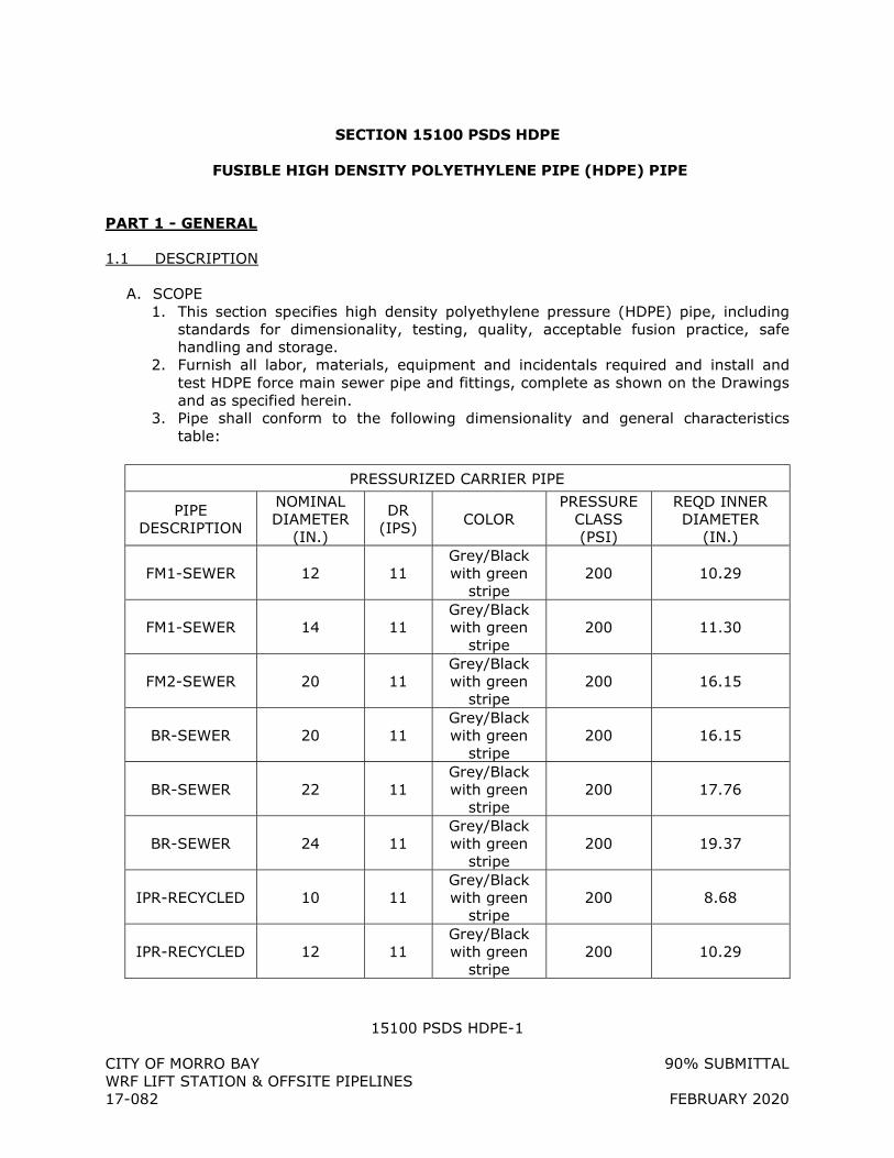
15100 PSDS HDPE-1
CITY OF MORRO BAY 90% SUBMITTAL WRF LIFT STATION & OFFSITE PIPELINES 17-082 FEBRUARY 2020
SECTION 15100 PSDS HDPE
FUSIBLE HIGH DENSITY POLYETHYLENE PIPE (HDPE) PIPE
PART 1 - GENERAL
1.1 DESCRIPTION
A. SCOPE 1. This section specifies high density polyethylene pressure (HDPE) pipe, including
standards for dimensionality, testing, quality, acceptable fusion practice, safe handling and storage.
2. Furnish all labor, materials, equipment and incidentals required and install and test HDPE force main sewer pipe and fittings, complete as shown on the Drawings and as specified herein.
3. Pipe shall conform to the following dimensionality and general characteristics table:
PRESSURIZED CARRIER PIPE
PIPE DESCRIPTION
NOMINAL DIAMETER
(IN.)
DR (IPS) COLOR
PRESSURE CLASS (PSI)
REQD INNER DIAMETER
(IN.)
FM1-SEWER 12 11 Grey/Black with green
stripe 200 10.29
FM1-SEWER 14 11 Grey/Black with green
stripe 200 11.30
FM2-SEWER 20 11 Grey/Black with green
stripe 200 16.15
BR-SEWER 20 11 Grey/Black with green
stripe 200 16.15
BR-SEWER 22 11 Grey/Black with green
stripe 200 17.76
BR-SEWER 24 11 Grey/Black with green
stripe 200 19.37
IPR-RECYCLED 10 11 Grey/Black with green
stripe 200 8.68
IPR-RECYCLED 12 11 Grey/Black with green
stripe 200 10.29
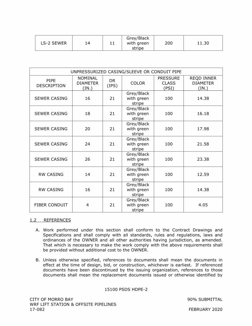
15100 PSDS HDPE-2
CITY OF MORRO BAY 90% SUBMITTAL WRF LIFT STATION & OFFSITE PIPELINES 17-082 FEBRUARY 2020
LS-2 SEWER 14 11 Grey/Black with green
stripe 200 11.30
UNPRESSURIZED CASING/SLEEVE OR CONDUIT PIPE
PIPE DESCRIPTION
NOMINAL DIAMETER
(IN.)
DR (IPS)
COLOR PRESSURE
CLASS (PSI)
REQD INNER DIAMETER
(IN.)
SEWER CASING 16 21 Grey/Black with green
stripe 100 14.38
SEWER CASING 18 21 Grey/Black with green
stripe 100 16.18
SEWER CASING 20 21 Grey/Black with green
stripe 100 17.98
SEWER CASING 24 21 Grey/Black with green
stripe 100 21.58
SEWER CASING 26 21 Grey/Black with green
stripe 100 23.38
RW CASING 14 21 Grey/Black with green
stripe 100 12.59
RW CASING 16 21 Grey/Black with green
stripe 100 14.38
FIBER CONDUIT 4 21 Grey/Black with green
stripe 100 4.05
1.2 REFERENCES
A. Work performed under this section shall conform to the Contract Drawings and Specifications and shall comply with all standards, rules and regulations, laws and ordinances of the OWNER and all other authorities having jurisdiction, as amended. That which is necessary to make the work comply with the above requirements shall be provided without additional cost to the OWNER.
B. Unless otherwise specified, references to documents shall mean the documents in effect at the time of design, bid, or construction, whichever is earliest. If referenced documents have been discontinued by the issuing organization, references to those documents shall mean the replacement documents issued or otherwise identified by

15100 PSDS HDPE-3
CITY OF MORRO BAY 90% SUBMITTAL WRF LIFT STATION & OFFSITE PIPELINES 17-082 FEBRUARY 2020
that organization or, if there are no replacement documents, the last version of the document before it was discontinued.
C. Where document dates are given in the following listing, references to those documents shall mean the specific document version associated with that date, regardless of whether the document has been superseded by a version with a later date, discontinued or replaced.
D. American Society for Testing and Materials (ASTM) International, most recent version: 1. ASTM A307 - Standard Specification for Carbon Steel Bolts and Studs, 60,000 psi
Tensile Strength 2. ASTM D2321 - Standard Practice for Underground Installation of Thermoplastic
Pipe for Sewer and Other Gravity-Flow Applications 3. ASTM D2774 – Standard Practice for Underground Installation of Thermoplastic
Pressure Piping 4. ASTM D2657 - Standard Practice for Heat Fusion Joining of Polyolefin Pipe and
Fittings 5. ASTM D2837 - Standard Test Method for Obtaining Hydrostatic Design Basis for
Thermoplastic Pipe Materials 6. ASTM D3350 - Standard Specification for Polyethylene Plastics Pipe and Fittings
Materials 7. ASTM F714 - Standard Specification for Polyethylene (PE) Plastic Pipe (SDR-PR)
Based on Outside Diameter
E. American Water Works Association (AWWA), most recent version: 1. AWWA C600 - Installation of Ductile Iron Water Mains and Their Appurtenances 2. AWWA C901 - Polyethylene (PE) Pressure Pipe and Fittings, 1/2-in Through 3-in,
for Water Distribution and Transmission 3. AWWA C906 - Polyethylene (PE) Pressure Pipe and Fittings, 4-in Through 63-in,
for Water Distribution and Transmission 4. AWWA M55 – PE Pipe – Design and Installation
F. American National Standards Institute (ANSI), most recent version: 1. ANSI B16.1 - Cast Iron Flanges and Flanged Fittings. 2. ANSI B16.21 - Nonmetallic Flat Gaskets for Pipe Flanges. 3. ANSI/NSF 61- Drinking Water System Components-Health Effects
1.3 SUBMITTALS
A. Submit, in accordance with Section 01330, and within 30 days of the notice to proceed, the name of the pipe and fitting manufacturers and a list of materials to be furnished by each manufacturer. Also, include information on local representative for each manufacturer, if product is sold through a distributor.
B. Submit the name and qualifications of the technician proposed to perform the heat fusion of the pipe joints.
15100 PSDS HDPE-4
CITY OF MORRO BAY 90% SUBMITTAL WRF LIFT STATION & OFFSITE PIPELINES 17-082 FEBRUARY 2020
C. Shop Drawings including piping layouts and schedules shall include dimensioning, fittings, types and locations of valves and appurtenances, joint details, methods and location of supports, anchorage, gasket material, grade of material and all other pertinent technical information for all items to be furnished.
D. Pipe manufacturer and Fusion services provider shall include the following: 1. Minimum Bending Radius 2. Maximum Safe Pull Force
E. Submit description of the method of testing the pipe and fittings including a complete drawing of mandrel with dimensions for each pipe size.
F. Submit certification that the stress regression testing has been performed on the specific polyethylene resin being utilized in the manufacturing of the pipe for this contract in accordance with ASTM D2837.
G. Prior to each shipment, submit certified test reports that the pipe and fittings for this contract were manufactured and tested in accordance with the ASTM [and AWWA] Standards specified herein.
H. After pipe installation, the following AS-RECORDED DATA is required from the contractor and/or fusion provider to the OWNER upon request: 1. Approved datalogger device reports 2. Pipe Size and Thickness 3. Machine Size 4. Fusion Technician Identification 5. Job Identification 6. Fusion Joint Number 7. Fusion, Heating, and Drag Pressure Settings 8. Heat Plate Temperature 9. Time Stamp 10. Heating and Cool Down Time of Fusion 11. Ambient Temperature
1.4 QUALITY ASSURANCE
A. Fusion Technician Requirement: 1. Fusion Technician shall be fully qualified by the pipe supplier to install HDPE pipe
of the type(s) and size(s) being used. 2. Qualification shall be current as of the actual date of fusion performance on the
project. 3. Fusion technician shall have a minimum of one year and 5,000 lineal feet of HDPE
fusion experience to qualify for this work.
B. All HDPE pipe and fittings shall be manufactured in strict accordance with ASTM F714, and shall be from a single manufacturer who is fully experienced, reputable and qualified in the manufacture of the polyethylene pipe and fittings to be furnished. All HDPE pipe and fittings shall be supplied by a single distributor who is fully experienced, reputable, and qualified with the distribution of the pipe and fittings to
15100 PSDS HDPE-5
CITY OF MORRO BAY 90% SUBMITTAL WRF LIFT STATION & OFFSITE PIPELINES 17-082 FEBRUARY 2020
be furnished. The pipe shall be designed, constructed, and installed in accordance with the best practices and methods and shall comply with these specifications.
C. All pipes under this contract shall be manufactured from a polyethylene resin that has been specifically stress regression tested to provide a product supplying a minimum Hydrostatic Design Basis (HDB) of 1600 psi, as determined in accordance with ASTM D2837.
D. All HDPE pipe to be installed under this Contract may be inspected at the factory for compliance with this Section by an independent testing laboratory provided by the OWNER. The manufacturer's cooperation shall be required in these inspections. The cost of these plant inspections of all pipe approved for this Contract will be borne by the OWNER.
E. Inspection of the pipe may also be made by the ENGINEER or other representatives of the OWNER after delivery. The pipe shall be subject to rejection at any time on account of failure to meet any of the specified requirements, even though pipes may have been accepted as satisfactory at the place of manufacture. Pipe rejected after delivery shall be marked for identification and shall immediately be removed from the job.
F. A representative of the pipe supplier shall witness and inspect the fusion of 30% of the pipe joints. This shall include the witnessing and inspection of the fusion of the test joint, the first 20 joints installed, and all joints for piping in the Bore and Jack portions of the project.
1.5 HANDLING AND STORAGE
A. Any length of pipe showing a crack or which has received a blow that may have caused an incident fracture, even though no such fracture can be seen, shall be marked as rejected and removed at once from the work. Damaged areas, or possible areas of damage may be removed by cutting out and removing the suspected incident fracture area. Limits of the acceptable length of pipe shall be determined by the OWNER or ENGINEER.
B. Any scratch or gouge greater than 10% of the wall thickness will be considered significant and can be rejected unless determined acceptable by the OWNER or ENGINEER.
C. Pipe lengths should be stored and placed on level ground. Pipe should be stored at the job site in the unit packaging provided by the manufacturer. Caution should be exercised to avoid compression, damage, or deformation to the ends of the pipe. The interior of the pipe, as well as all end surfaces, should be kept free from dirt and foreign matter.
D. Pipe shall be handled and supported with the use of woven fiber pipe slings or approved equal. Care shall be exercised when handling the pipe to not cut, gouge, scratch or otherwise abrade the piping in any way.
15100 PSDS HDPE-6
CITY OF MORRO BAY 90% SUBMITTAL WRF LIFT STATION & OFFSITE PIPELINES 17-082 FEBRUARY 2020
E. If pipe is to be stored for periods of 30 days or longer, the pipe should be shaded or otherwise shielded from direct sunlight. Covering of the pipe, which allows for temperature build-up is strictly prohibited. Pipe should be covered with an opaque material while permitting adequate air circulation above and around the pipe as required to prevent excess heat accumulation.
F. Pipe shall be stored and stacked per the pipe supplier’s guidelines
1.6 DELIVERY AND OFF-LOADING
A. All HDPE pipe shall be bundled or packaged in such a manner as to provide adequate protection of the ends during transportation to the site. Any pipe damaged in shipment shall be replaced as directed by the OWNER or ENGINEER.
B. Each HDPE pipe shipment should be inspected prior to unloading to see if the load has shifted or otherwise been damaged. Notify OWNER or ENGINEER immediately if more than immaterial damage is found. Each pipe shipment should be checked for proper quantity, pipe size, color and type.
C. HDPE pipe should be loaded, off-loaded, and otherwise handled in accordance with AWWA M55, and all of the pipe supplier’s guidelines shall be followed.
D. Off-loading devices such as chains, wire rope, chokers, or other pipe handling implements that may scratch, nick, cut, or gouge the pipe are strictly prohibited.
E. During removal and handling, be sure that the pipe does not strike anything. Significant impact could cause damage, particularly during cold weather.
F. If appropriate unloading equipment is not available, pipe may be unloaded by removing individual pieces. Care should be taken to insure that pipe is not dropped or damaged. Pipe should be carefully lowered, not dropped, from trucks
1.7 WARRANTY
A. The pipe and pipe installation via fusion services shall be warranted for one year per the pipe supplier’s standard terms.
PART 2 - PRODUCTS
2.1 GENERAL
A. PIPE 1. HDPE pipe is a flexible conduit and shall be designed to transfer imposed loads to
the surrounding embedment medium. The pipe and fittings shall be free from all defects including indentations, delaminations, cracks, bubbles and pinholes, which due to their nature, degree, or extent, detrimentally affect the strength and serviceability of the pipe. Any pipe or fittings with such defects which, in the
15100 PSDS HDPE-7
CITY OF MORRO BAY 90% SUBMITTAL WRF LIFT STATION & OFFSITE PIPELINES 17-082 FEBRUARY 2020
judgement of the ENGINEER, will affect the strength and serviceability shall be repaired or rejected.
2. HDPE pipe resins shall be high molecular weight, high density polyethylene with a cell classification number of 345464C or higher in accordance with ASTM D3350.
3. The pipes shall have the nominal dimensions shown on the Drawings, and shall conform to the dimension requirements of the DIPS Sizing System (ANSI B36.10). Pipe shall meet the requirements of Dimension Ratio (DR) 13.5.
4. All polyethylene pipes shall meet the requirements of ASTM F714. 5. Pipe shall be furnished in standard laying lengths not exceeding 50-ft.
B. FITTINGS 1. All polyethylene pipe fittings shall meet the requirements of ASTM F714. 2. HDPE fittings shall be fully pressure rated to match the pipe DR pressure rating.
All fittings shall be molded or fabricated by the same manufacturer as the pipe. HDPE fittings shall be joined using butt, heat fusion and/or electrofusion. Adhesives and solvent cements shall not be permitted. All joints shall be made in strict compliance with the manufacturer's recommendations and ASTM 2657.
3. Joining system a. Where required, flange connections, mechanical joint connections and butt
connections using bolted mechanical couplers shall be provided from a pipe stub with a polyethylene and steel stiffener.
b. Flanged connections shall be provided from a pipe stub and a steel back-up flanged. Back-up flanges shall be primed and painted in a corrosion protected paint recommended and supplied by the manufacturer.
c. All bolts, nuts and hardware shall be Type 304 stainless steel. 4. All pipe fittings outside of the Pump Station shall be long radius.
C. PIPE IDENTIFICATION 1. At 5-ft intervals along the pipe, the pipe shall be marked with the name of the
manufacturer, size and class (pressure and DR), and manufacturing reference to ASTM F714.
2. A color coded strip(s) shall be marked along the entire length of the pipe per the color specified in this section.
2.2 CONNECTIONS AND FITTINGS FOR PRESSURE APPLICATIONS
A. Connections shall be defined in conjunction with the coupling of project piping, as well as the tie-ins to other piping systems.
B. All fittings and connections must be restrained.
C. DUCTILE IRON MECHANICAL AND FLANGED FITTINGS 1. Acceptable fittings for use with HDPE pipe shall include standard ductile iron
fittings conforming to AWWA/ANSI C110/A21.10, or AWWA/ANSI C153/A21.53 and AWWA/ANSI C111/A21.11.
2. Connections to HDPE pipe shall be made using an HDPE plain end to flange adapter and a Welded Steel Reducer for DIP or FPVC pipes and fittings. A ductile iron or steel back-up ring conforming to ANSI B16.1 fitted to the polyethylene flange adapter may be required.
15100 PSDS HDPE-8
CITY OF MORRO BAY 90% SUBMITTAL WRF LIFT STATION & OFFSITE PIPELINES 17-082 FEBRUARY 2020
3. MJ fittings may be used at the connection. 4. Bends, tees and other ductile iron fittings shall be restrained with the use of thrust
blocking or other means as indicated in the construction documents. 5. Ductile iron fittings and glands must be installed per the manufacturer’s
guidelines.
D. CONNECTION HARDWARE 1. Bolts and nuts for buried service shall be made of non-corrosive, high-strength,
low-alloy steel having the characteristics specified in ANSI/AWWA C111/A21.11, regardless of any other protective coating.
E. All ductile iron mechanical and flanged fittings shall be lined and coated with Tnemec 431 and as per manufacturer recommendation.
2.3 CONNECTIONS TO SANITARY SEWER MANHOLES AND STRUCTURES
A. HDPE pipe shall be connected to manholes and other structures to provide a leakfree, properly graded flow into or out of the manhole or structure.
B. Connections to existing manholes and structures shall be as indicated in the construction documents. 1. For a cored or drilled opening provide a flexible, watertight connection that meets
and/or exceeds ASTM C923. 2. For a knock out opening, provide a watertight connection (waterstop or other
method) meeting the material requirements of ASTM C923 that is securely attached to the pipe with stainless steel bands or other means.
3. Grout opening in manhole wall with non-shrink grout. Pour concrete collar around pipe and outside manhole opening. Provide flexible pipe joint or flexible connector within 2 feet of the collar.
C. Connections to a new manhole or structure shall be as indicated in the construction documents. 1. A flexible, watertight gasket per ASTM C923 shall be cast integrally with riser
section(s) for all precast manhole and structures. 2. Drop connections shall be required where shown on drawings. 3. Grout internal joint space with non-shrink grout.
PART 3 - EXECUTION
3.1 INSTALLATION
A. All pipe and fittings shall be installed in accordance with the manufacturer’s instructions and this specification.
B. The contractor performing the joining shall be certified by a distributor of the pipe material supplied. All fusion joints shall be done by a factory qualified technician as
15100 PSDS HDPE-9
CITY OF MORRO BAY 90% SUBMITTAL WRF LIFT STATION & OFFSITE PIPELINES 17-082 FEBRUARY 2020
designated by the manufacturer with a minimum of one year experience with the fusion equipment to be used.
C. Joining of the pipe by heat fusion shall be done in accordance with ASTM D2657. Prior to the start of pipe installation, one test joint shall be made and tested. Test shall be done in accordance with CPChem Co. Bulletin No. 106. No joints shall be made until a successful test joint has been made.
D. When cutting pipe is required, the cutting shall be done by machine specifically designed for the cutting of HDPE pipe. The cut shall leave a smooth cut at right angles to the axis of the pipe.
E. Fittings shall be connected to HDPE pipe in accordance with manufacturer’s recommendations.
F. Flanged and mechanical connections shall consist of the following: 1. A high density polyethylene flange adapter, made by the manufacturer from the
same resin as the pipe, and fully pressure rated to match the pipe DR pressure rating, thermally butt-fused to the stub end of the pipe.
2. A ductile iron or steel back-up ring conforming to ANSI B16.1 fitted to the polyethylene flange adapter and shaped as necessary to suit the outside dimension of the pipe.
3. A full face neoprene gasket, conforming to ANSI B16.21. 4. Corrosion resistant bolts and nuts of Type 316 stainless steel as specified in ASTM
A276 and ASTM A307. Bolts shall be tightened alternatively and evenly to the manufacturer’s specified torques. After installation a bitumastic coating shall be applied to bolts and nuts.
G. Fusible pipelines laid on a curve shall use a maximum of 75 percent of manufacturer’s recommended allowable bend radius.
3.2 JOINING METHODS
A. GENERAL 1. HDPE pipe will be handled in a safe and non-destructive manner before, during,
and after the fusion process and in accordance with this specification and pipe supplier’s guidelines.
2. HDPE pipe will be fused by qualified fusion technicians, as documented by the pipe supplier.
3. Each fusion joint shall be recorded and logged by an electronic monitoring device (data logger) connected to the fusion machine.
4. Only appropriately sized and outfitted fusion machines that have been approved by the pipe supplier shall be used for the fusion process. Fusion machines must incorporate the following elements: a. HEAT PLATE - Heat plates shall be in good condition with no deep gouges or
scratches. Plates shall be clean and free of any debris or contamination. Heater controls shall function properly; cord and plug shall be in good condition. The appropriately sized heat plate shall be capable of maintaining a
15100 PSDS HDPE-10
CITY OF MORRO BAY 90% SUBMITTAL WRF LIFT STATION & OFFSITE PIPELINES 17-082 FEBRUARY 2020
uniform and consistent heat profile and temperature for the size of pipe being fused, per the pipe supplier’s guidelines.
b. CARRIAGE – Carriage shall travel smoothly with no binding at less than 50 psi. Jaws shall be in good condition with proper inserts for the pipe size being fused. Insert pins shall be installed with no interference to carriage travel.
c. GENERAL MACHINE - Overview of machine body shall yield no obvious defects, missing parts, or potential safety issues during fusion.
d. DATA LOGGING DEVICE – An approved datalogging device with the current version of the pipe supplier’s recommended and compatible software shall be used. Datalogging device operations and maintenance manual shall be with the unit at all times. If fusing for extended periods of time, an independent 110V power source shall be available to extend battery life.
5. Other equipment specifically required for the fusion process shall include the following: a. Pipe rollers shall be used for support of pipe to either side of the machine. b. A weather protection canopy that allows full machine motion of the heat plate,
fusion assembly and carriage shall be provided for fusion in inclement, extreme temperatures, and /or windy weather, per the pipe supplier’s recommendations.
c. An infrared (IR) pyrometer for checking pipe and heat plate temperatures shall be used.
d. Fusion machine operations and maintenance manual shall be kept with the fusion machine at all times.
e. Facing blades specifically designed for cutting HDPE pipe shall be used.
B. BUTT FUSION CONNECTION 1. The pipe shall be joined by the butt fusion procedure outlined in ASTM F 2620 or
PPI TR-33. 2. All fusion joints shall be made in compliance with the pipe or fitting
manufacturer’s recommendations. 3. Fusion joints shall be made by qualified fusion technicians per PPI TN-42.
C. SADDLE FUSION CONNECTION 1. Saddle fusion shall be done in accordance with ASTM F 2620 or TR-41 or the
fitting manufacturer’s recommendations and PPI TR-41. 2. Saddle fusion joints shall be made by qualified fusion technicians. Qualification of
the fusion technician shall be demonstrated by evidence of fusion training within the past year on the equipment to be utilized on this project.
3. Saddle fusion is used to fuse branch saddles, tapping tees, and other HDPE constructs onto the wall of the main pipe (ASTM F905).
D. ELECTROFUSION CONNECTION 1. Electrofusion joining shall be done in accordance with the manufacturers
recommended procedure or ASTM F 1290 and PPI TN 34. 2. The process of electrofusion requires an electric source , a transformer, commonly
called an electrofusion box that has wire leads, a method to read electronically (by laser)or otherwise input the barcode of the fitting, and a fitting that is compatible with the type of electrofusion box used.
15100 PSDS HDPE-11
CITY OF MORRO BAY 90% SUBMITTAL WRF LIFT STATION & OFFSITE PIPELINES 17-082 FEBRUARY 2020
3. The electrofusion box must be capable of reading and storing the input parameters and the fusion results for later download to a record file.
4. Qualification of the fusion technician shall be demonstrated by evidence of electrofusion training within the past year on the equipment to be utilized for this project.
E. JOINT RECORDING 1. Each fusion joint shall be recorded and logged by an electronic monitoring device
(data logger) connected to the fusion machine. 2. The fusion data logging and joint report shall be generated by software developed
specifically for the butt-fusion of HDPE pipe. 3. The software shall register and/or record the parameters required by the pipe
supplier and these specifications. 4. Data not logged by the data logger shall be logged manually and be included in
the Fusion Technician’s joint report.
3.3 TESTING
A. Testing shall comply with all applicable jurisdictional building codes, statutes, standards, regulations, and laws.
B. No partial testing is allowed for HDPE pipe unless approved by the OWNER and ENGINEER.
C. Testing for pressure piping to be per Section 15990.
3.4 QA/QC PROTOCOL TESTING
A. CONTRACTOR shall coordinate with the QA/QC personnel to perform all testing prior to backfill. 1. Vendor Qualification Testing – Pipe extruders shall submit pipe samples for testing
of material properties as well as the strength of the butt-fusion joint. 2. Vender Testing – Pipe manufacturer shall meet relevant AWWA and ASTM
standards and tests. 3. Independent Laboratory Testing Lot Acceptance – A lot of pipe must pass tests
conducted by an independent laboratory (AWWA Flattening, Heat Reversion, Acetone Immersion).
4. Fusion QC & Traceability a. Each fusion joint fused in the field shall have data logger and direct operator
input to record critical fusion parameters such as temperature, pressure, ambient conditions, etc on each fusion joint.
b. Link fusion data with an identifier and pipe lot. c. QA/QC personnel must provide a fusion data sheet with unique joint identifier
listed per each joint to the OWNER.
+ + END OF SECTION + +
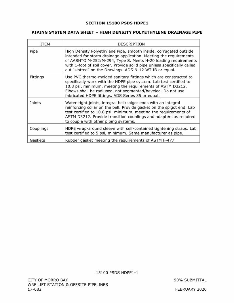
15100 PSDS HDPE1-1
CITY OF MORRO BAY 90% SUBMITTAL WRF LIFT STATION & OFFSITE PIPELINES 17-082 FEBRUARY 2020
SECTION 15100 PSDS HDPE1
PIPING SYSTEM DATA SHEET – HIGH DENSITY POLYETHYLENE DRAINAGE PIPE
ITEM DESCRIPTION
Pipe High Density Polyethylene Pipe, smooth inside, corrugated outside intended for storm drainage application. Meeting the requirements of AASHTO M-252/M-294, Type S. Meets H-20 loading requirements with 1-foot of soil cover. Provide solid pipe unless specifically called out “slotted” on the Drawings. ADS N-12 WT IB or equal.
Fittings Use PVC thermo-molded sanitary fittings which are constructed to specifically work with the HDPE pipe system. Lab test certified to 10.8 psi, minimum, meeting the requirements of ASTM D3212. Elbows shall be radiused, not segmented/beveled. Do not use fabricated HDPE fittings. ADS Series 35 or equal.
Joints Water-tight joints, integral bell/spigot ends with an integral reinforcing collar on the bell. Provide gasket on the spigot end. Lab test certified to 10.8 psi, minimum, meeting the requirements of ASTM D3212. Provide transition couplings and adapters as required to couple with other piping systems.
Couplings HDPE wrap-around sleeve with self-contained tightening straps. Lab test certified to 5 psi, minimum. Same manufacturer as pipe.
Gaskets Rubber gasket meeting the requirements of ASTM F-477
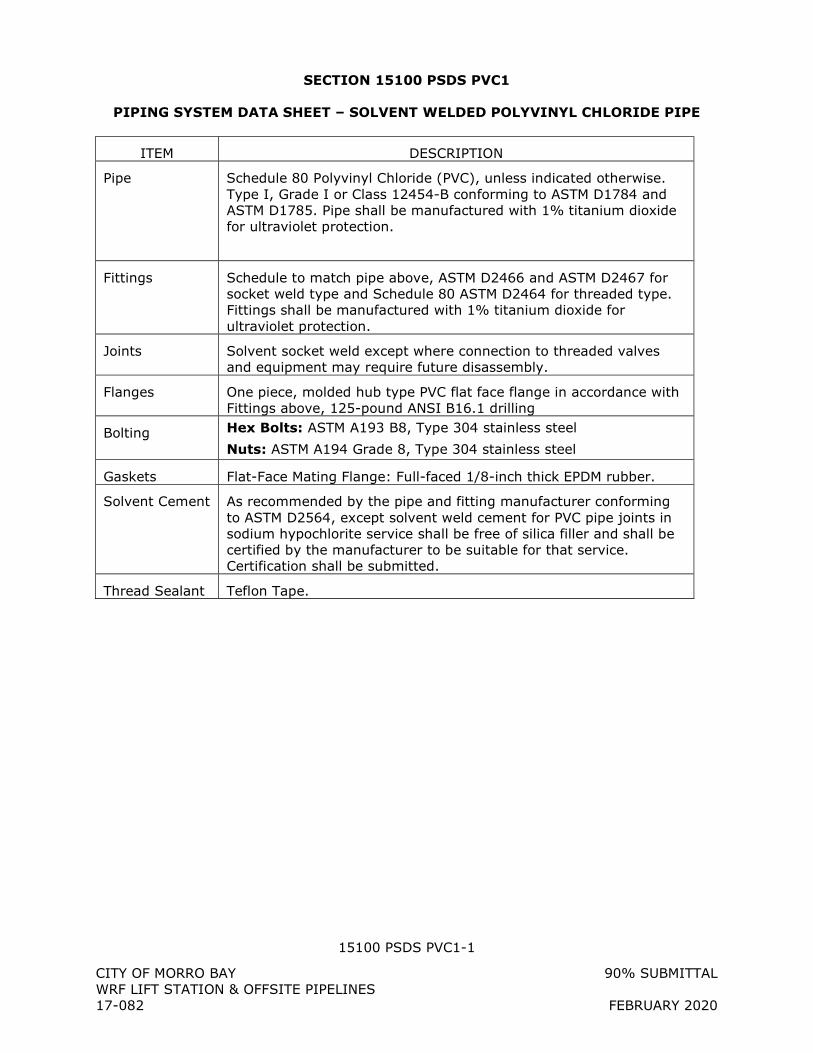
15100 PSDS PVC1-1
CITY OF MORRO BAY 90% SUBMITTAL WRF LIFT STATION & OFFSITE PIPELINES 17-082 FEBRUARY 2020
SECTION 15100 PSDS PVC1
PIPING SYSTEM DATA SHEET – SOLVENT WELDED POLYVINYL CHLORIDE PIPE
ITEM DESCRIPTION
Pipe Schedule 80 Polyvinyl Chloride (PVC), unless indicated otherwise. Type I, Grade I or Class 12454-B conforming to ASTM D1784 and ASTM D1785. Pipe shall be manufactured with 1% titanium dioxide for ultraviolet protection.
Fittings Schedule to match pipe above, ASTM D2466 and ASTM D2467 for socket weld type and Schedule 80 ASTM D2464 for threaded type. Fittings shall be manufactured with 1% titanium dioxide for ultraviolet protection.
Joints Solvent socket weld except where connection to threaded valves and equipment may require future disassembly.
Flanges One piece, molded hub type PVC flat face flange in accordance with Fittings above, 125-pound ANSI B16.1 drilling
Bolting Hex Bolts: ASTM A193 B8, Type 304 stainless steel
Nuts: ASTM A194 Grade 8, Type 304 stainless steel
Gaskets Flat-Face Mating Flange: Full-faced 1/8-inch thick EPDM rubber.
Solvent Cement As recommended by the pipe and fitting manufacturer conforming to ASTM D2564, except solvent weld cement for PVC pipe joints in sodium hypochlorite service shall be free of silica filler and shall be certified by the manufacturer to be suitable for that service. Certification shall be submitted.
Thread Sealant Teflon Tape.
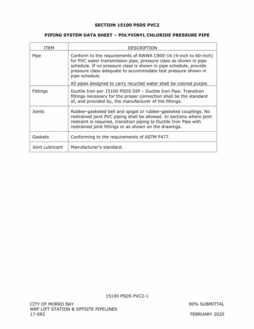
15100 PSDS PVC2-1
CITY OF MORRO BAY 90% SUBMITTAL WRF LIFT STATION & OFFSITE PIPELINES 17-082 FEBRUARY 2020
SECTION 15100 PSDS PVC2
PIPING SYSTEM DATA SHEET – POLYVINYL CHLORIDE PRESSURE PIPE
ITEM DESCRIPTION
Pipe Conform to the requirements of AWWA C900-16 (4-inch to 60-inch) for PVC water transmission pipe, pressure class as shown in pipe schedule. If no pressure class is shown in pipe schedule, provide pressure class adequate to accommodate test pressure shown in pipe schedule.
All pipes designed to carry recycled water shall be colored purple.
Fittings Ductile Iron per 15100 PSDS DIP – Ductile Iron Pipe. Transition fittings necessary for the proper connection shall be the standard of, and provided by, the manufacturer of the fittings.
Joints Rubber-gasketed bell and spigot or rubber-gasketed couplings. No restrained joint PVC piping shall be allowed. In sections where joint restraint is required, transition piping to Ductile Iron Pipe with restrained joint fittings or as shown on the drawings.
Gaskets Conforming to the requirements of ASTM F477.
Joint Lubricant Manufacturer’s standard.
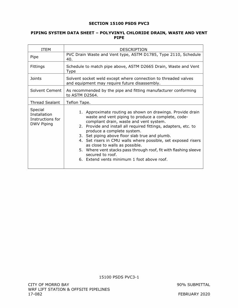
15100 PSDS PVC3-1
CITY OF MORRO BAY 90% SUBMITTAL WRF LIFT STATION & OFFSITE PIPELINES 17-082 FEBRUARY 2020
SECTION 15100 PSDS PVC3
PIPING SYSTEM DATA SHEET – POLYVINYL CHLORIDE DRAIN, WASTE AND VENT PIPE
ITEM DESCRIPTION
Pipe PVC Drain Waste and Vent type, ASTM D1785, Type 2110, Schedule 40.
Fittings Schedule to match pipe above, ASTM D2665 Drain, Waste and Vent Type
Joints Solvent socket weld except where connection to threaded valves and equipment may require future disassembly.
Solvent Cement As recommended by the pipe and fitting manufacturer conforming to ASTM D2564.
Thread Sealant Teflon Tape.
Special Installation Instructions for DWV Piping
1. Approximate routing as shown on drawings. Provide drain
waste and vent piping to produce a complete, code-compliant drain, waste and vent system.
2. Provide and install all required fittings, adapters, etc. to produce a complete system.
3. Set piping above floor slab true and plumb. 4. Set risers in CMU walls where possible, set exposed risers
as close to walls as possible. 5. Where vent stacks pass through roof, fit with flashing sleeve
secured to roof. 6. Extend vents minimum 1 foot above roof.
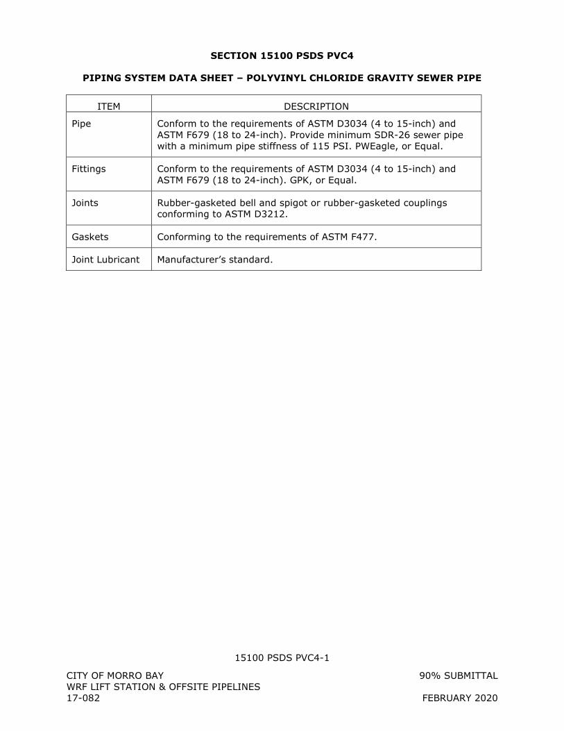
15100 PSDS PVC4-1
CITY OF MORRO BAY 90% SUBMITTAL WRF LIFT STATION & OFFSITE PIPELINES 17-082 FEBRUARY 2020
SECTION 15100 PSDS PVC4
PIPING SYSTEM DATA SHEET – POLYVINYL CHLORIDE GRAVITY SEWER PIPE
ITEM DESCRIPTION
Pipe Conform to the requirements of ASTM D3034 (4 to 15-inch) and ASTM F679 (18 to 24-inch). Provide minimum SDR-26 sewer pipe with a minimum pipe stiffness of 115 PSI. PWEagle, or Equal.
Fittings Conform to the requirements of ASTM D3034 (4 to 15-inch) and ASTM F679 (18 to 24-inch). GPK, or Equal.
Joints Rubber-gasketed bell and spigot or rubber-gasketed couplings conforming to ASTM D3212.
Gaskets Conforming to the requirements of ASTM F477.
Joint Lubricant Manufacturer’s standard.
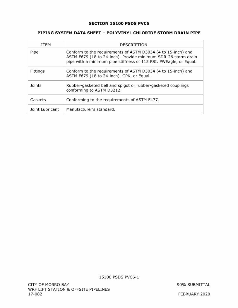
15100 PSDS PVC6-1
CITY OF MORRO BAY 90% SUBMITTAL WRF LIFT STATION & OFFSITE PIPELINES 17-082 FEBRUARY 2020
SECTION 15100 PSDS PVC6
PIPING SYSTEM DATA SHEET – POLYVINYL CHLORIDE STORM DRAIN PIPE
ITEM DESCRIPTION
Pipe Conform to the requirements of ASTM D3034 (4 to 15-inch) and ASTM F679 (18 to 24-inch). Provide minimum SDR-26 storm drain pipe with a minimum pipe stiffness of 115 PSI. PWEagle, or Equal.
Fittings Conform to the requirements of ASTM D3034 (4 to 15-inch) and ASTM F679 (18 to 24-inch). GPK, or Equal.
Joints Rubber-gasketed bell and spigot or rubber-gasketed couplings conforming to ASTM D3212.
Gaskets Conforming to the requirements of ASTM F477.
Joint Lubricant Manufacturer’s standard.
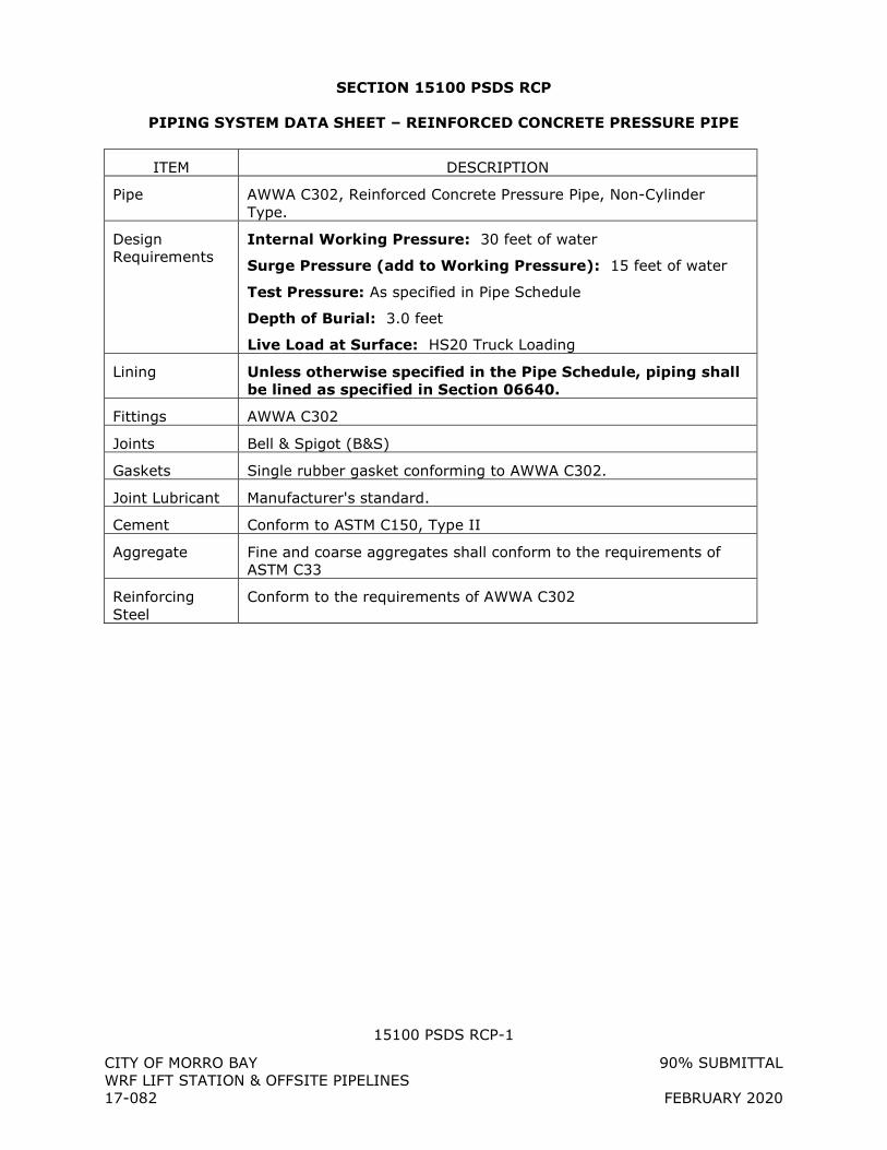
15100 PSDS RCP-1
CITY OF MORRO BAY 90% SUBMITTAL WRF LIFT STATION & OFFSITE PIPELINES 17-082 FEBRUARY 2020
SECTION 15100 PSDS RCP
PIPING SYSTEM DATA SHEET – REINFORCED CONCRETE PRESSURE PIPE
ITEM DESCRIPTION
Pipe AWWA C302, Reinforced Concrete Pressure Pipe, Non-Cylinder Type.
Design Requirements
Internal Working Pressure: 30 feet of water
Surge Pressure (add to Working Pressure): 15 feet of water
Test Pressure: As specified in Pipe Schedule
Depth of Burial: 3.0 feet
Live Load at Surface: HS20 Truck Loading
Lining Unless otherwise specified in the Pipe Schedule, piping shall be lined as specified in Section 06640.
Fittings AWWA C302
Joints Bell & Spigot (B&S)
Gaskets Single rubber gasket conforming to AWWA C302.
Joint Lubricant Manufacturer's standard.
Cement Conform to ASTM C150, Type II
Aggregate Fine and coarse aggregates shall conform to the requirements of ASTM C33
Reinforcing Steel
Conform to the requirements of AWWA C302
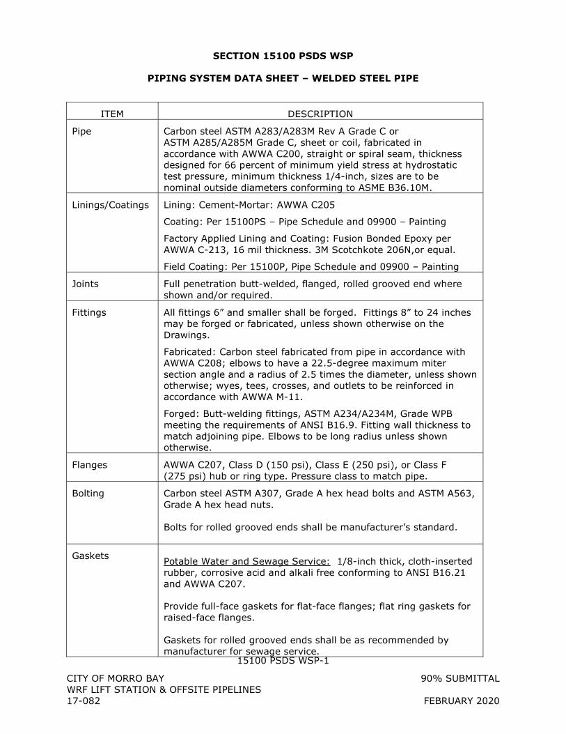
15100 PSDS WSP-1
CITY OF MORRO BAY 90% SUBMITTAL WRF LIFT STATION & OFFSITE PIPELINES 17-082 FEBRUARY 2020
SECTION 15100 PSDS WSP
PIPING SYSTEM DATA SHEET – WELDED STEEL PIPE
ITEM DESCRIPTION
Pipe Carbon steel ASTM A283/A283M Rev A Grade C or ASTM A285/A285M Grade C, sheet or coil, fabricated in accordance with AWWA C200, straight or spiral seam, thickness designed for 66 percent of minimum yield stress at hydrostatic test pressure, minimum thickness 1/4-inch, sizes are to be nominal outside diameters conforming to ASME B36.10M.
Linings/Coatings Lining: Cement-Mortar: AWWA C205
Coating: Per 15100PS – Pipe Schedule and 09900 – Painting
Factory Applied Lining and Coating: Fusion Bonded Epoxy per AWWA C-213, 16 mil thickness. 3M Scotchkote 206N,or equal.
Field Coating: Per 15100P, Pipe Schedule and 09900 – Painting
Joints Full penetration butt-welded, flanged, rolled grooved end where shown and/or required.
Fittings All fittings 6” and smaller shall be forged. Fittings 8” to 24 inches may be forged or fabricated, unless shown otherwise on the Drawings.
Fabricated: Carbon steel fabricated from pipe in accordance with AWWA C208; elbows to have a 22.5-degree maximum miter section angle and a radius of 2.5 times the diameter, unless shown otherwise; wyes, tees, crosses, and outlets to be reinforced in accordance with AWWA M-11.
Forged: Butt-welding fittings, ASTM A234/A234M, Grade WPB meeting the requirements of ANSI B16.9. Fitting wall thickness to match adjoining pipe. Elbows to be long radius unless shown otherwise.
Flanges AWWA C207, Class D (150 psi), Class E (250 psi), or Class F (275 psi) hub or ring type. Pressure class to match pipe.
Bolting Carbon steel ASTM A307, Grade A hex head bolts and ASTM A563, Grade A hex head nuts. Bolts for rolled grooved ends shall be manufacturer’s standard.
Gaskets Potable Water and Sewage Service: 1/8-inch thick, cloth-inserted rubber, corrosive acid and alkali free conforming to ANSI B16.21 and AWWA C207.
Provide full-face gaskets for flat-face flanges; flat ring gaskets for raised-face flanges. Gaskets for rolled grooved ends shall be as recommended by manufacturer for sewage service.
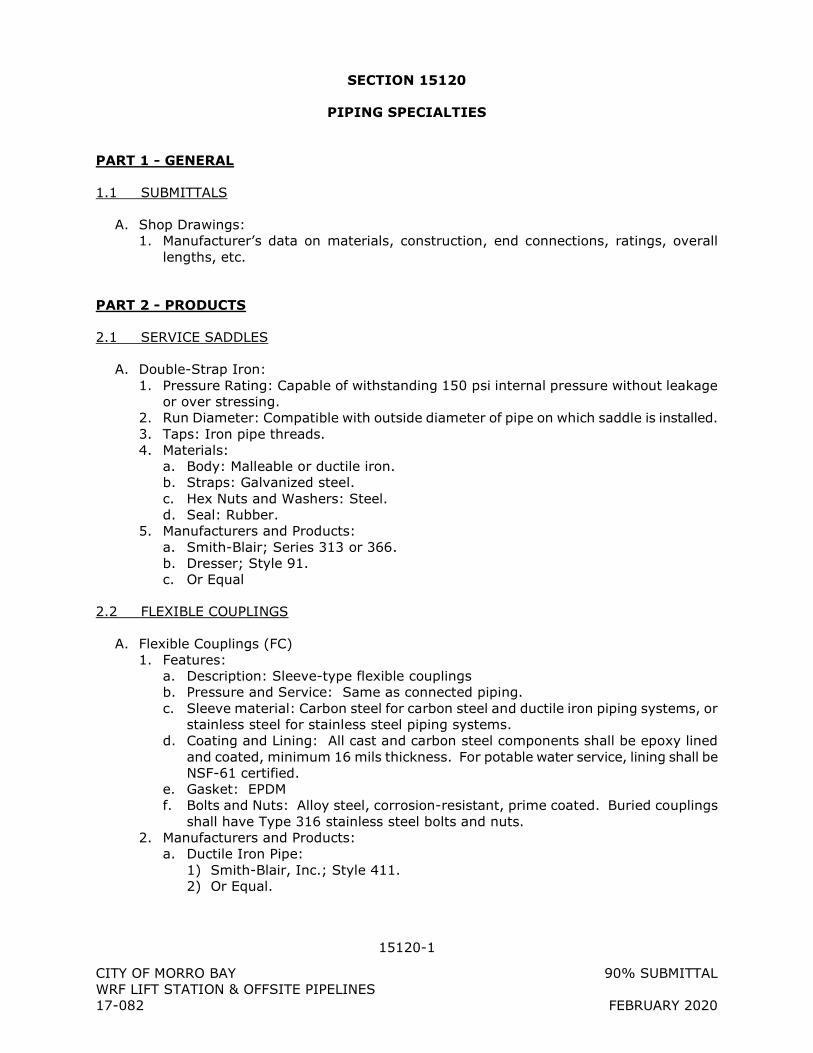
15120-1
CITY OF MORRO BAY 90% SUBMITTAL WRF LIFT STATION & OFFSITE PIPELINES 17-082 FEBRUARY 2020
SECTION 15120
PIPING SPECIALTIES
PART 1 - GENERAL
1.1 SUBMITTALS
A. Shop Drawings: 1. Manufacturer’s data on materials, construction, end connections, ratings, overall
lengths, etc.
PART 2 - PRODUCTS
2.1 SERVICE SADDLES
A. Double-Strap Iron: 1. Pressure Rating: Capable of withstanding 150 psi internal pressure without leakage
or over stressing. 2. Run Diameter: Compatible with outside diameter of pipe on which saddle is installed. 3. Taps: Iron pipe threads. 4. Materials:
a. Body: Malleable or ductile iron. b. Straps: Galvanized steel. c. Hex Nuts and Washers: Steel. d. Seal: Rubber.
5. Manufacturers and Products: a. Smith-Blair; Series 313 or 366. b. Dresser; Style 91. c. Or Equal
2.2 FLEXIBLE COUPLINGS
A. Flexible Couplings (FC) 1. Features:
a. Description: Sleeve-type flexible couplings b. Pressure and Service: Same as connected piping. c. Sleeve material: Carbon steel for carbon steel and ductile iron piping systems, or
stainless steel for stainless steel piping systems. d. Coating and Lining: All cast and carbon steel components shall be epoxy lined
and coated, minimum 16 mils thickness. For potable water service, lining shall be NSF-61 certified.
e. Gasket: EPDM f. Bolts and Nuts: Alloy steel, corrosion-resistant, prime coated. Buried couplings
shall have Type 316 stainless steel bolts and nuts. 2. Manufacturers and Products:
a. Ductile Iron Pipe: 1) Smith-Blair, Inc.; Style 411. 2) Or Equal.
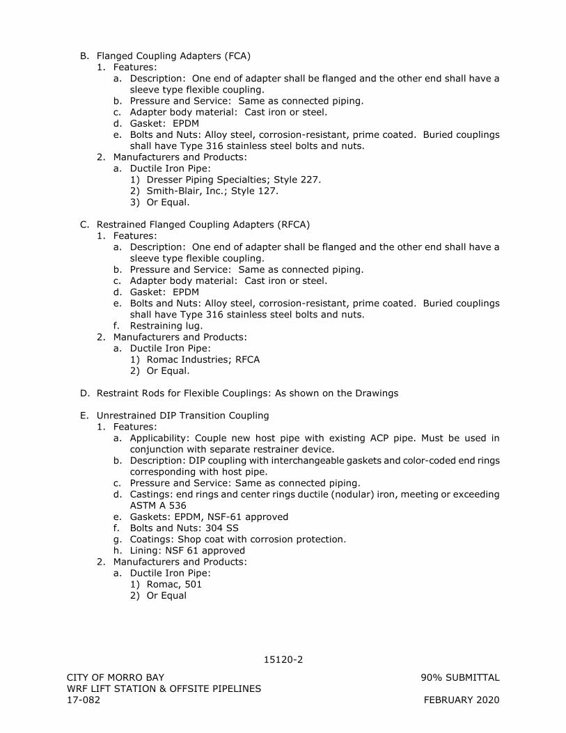
15120-2
CITY OF MORRO BAY 90% SUBMITTAL WRF LIFT STATION & OFFSITE PIPELINES 17-082 FEBRUARY 2020
B. Flanged Coupling Adapters (FCA) 1. Features:
a. Description: One end of adapter shall be flanged and the other end shall have a sleeve type flexible coupling.
b. Pressure and Service: Same as connected piping. c. Adapter body material: Cast iron or steel. d. Gasket: EPDM e. Bolts and Nuts: Alloy steel, corrosion-resistant, prime coated. Buried couplings
shall have Type 316 stainless steel bolts and nuts. 2. Manufacturers and Products:
a. Ductile Iron Pipe: 1) Dresser Piping Specialties; Style 227. 2) Smith-Blair, Inc.; Style 127. 3) Or Equal.
C. Restrained Flanged Coupling Adapters (RFCA) 1. Features:
a. Description: One end of adapter shall be flanged and the other end shall have a sleeve type flexible coupling.
b. Pressure and Service: Same as connected piping. c. Adapter body material: Cast iron or steel. d. Gasket: EPDM e. Bolts and Nuts: Alloy steel, corrosion-resistant, prime coated. Buried couplings
shall have Type 316 stainless steel bolts and nuts. f. Restraining lug.
2. Manufacturers and Products: a. Ductile Iron Pipe:
1) Romac Industries; RFCA 2) Or Equal.
D. Restraint Rods for Flexible Couplings: As shown on the Drawings
E. Unrestrained DIP Transition Coupling 1. Features:
a. Applicability: Couple new host pipe with existing ACP pipe. Must be used in conjunction with separate restrainer device.
b. Description: DIP coupling with interchangeable gaskets and color-coded end rings corresponding with host pipe.
c. Pressure and Service: Same as connected piping. d. Castings: end rings and center rings ductile (nodular) iron, meeting or exceeding
ASTM A 536 e. Gaskets: EPDM, NSF-61 approved f. Bolts and Nuts: 304 SS g. Coatings: Shop coat with corrosion protection. h. Lining: NSF 61 approved
2. Manufacturers and Products: a. Ductile Iron Pipe:
1) Romac, 501 2) Or Equal
15120-3
CITY OF MORRO BAY 90% SUBMITTAL WRF LIFT STATION & OFFSITE PIPELINES 17-082 FEBRUARY 2020
2.3 RESTRAINED COUPLINGS
A. Restrained Mechanical Joint Glands (RMJ) 1. Pressure Rating:
a. Minimum Working Pressure Rating: Not less than 150 psi. b. Safety Factor: Not less than two times working pressure and shall be supported
by manufacturer’s proof testing. 2. RMJ gland shall be designed for use with standard mechanical joint pipe. Pipe
restraint products designed for use with push-on joints will not be acceptable. 3. Thrust Restraint:
a. Provide hardened steel wedges that bear against and engage outer pipe surface, and allow articulation of pipe joint after assembly while wedges remain in their original setting position on pipe surface.
b. Products employing set screws that bear directly on pipe will not be acceptable. 4. Manufacturer and Product:
a. Ductile Iron Pipe Only 1) EBAA Iron Sales Co.; Megalug. 2) Romac Industries Inc.: RomaGrip 3) Or Equal.
B. Dismantling Joint 1. Pressure Rating
a. Minimum Working Pressure Rating: Not less than 150 psi b. Pressure rating to be no less than test pressure for piping system in which the
Restrained Dismantling Joint is used. c. Safety Factor: Not less than two times working pressure and shall be supported
by manufacturer’s proof testing. 2. Thrust Restraint
a. Provide steel tie rods, ASTM A 193 GR B7 b. Number and arrangement of tie rods to provide dismantling joint assembly which
meets pressure rating requirement. 3. Materials of Construction
a. Flanged Adapter Body: Steel b. Follower Flange: Ductile Iron c. Gasket: Buna-N, NSF-61 approved d. Flange: Steel, per AWWA C207 e. Spigot: Steel f. Studs: Type 304 stainless steel g. Coating: NSF-61 approved epoxy
4. Manufacturer and Product a. Smith-Blair, Model 975 or 972, as required for pressure rating b. Romac Industries, Style DJ400 c. Or Equal.
C. Asbestos Cement Pipe (ACP) Restrainer 1. Features:
a. Description: Restrainer with thread rods to restrain ACP to host pipe or fittings placed over fittings, hydrants, flanged coupling adapters, meter and mechanical joints.
b. Coating: Standard shop coat with heavy corrosion inhibiting metal primer. c. Restrainer Body: Pressure vessel quality steel ASTM A285 Grade C or equal.

15120-4
CITY OF MORRO BAY 90% SUBMITTAL WRF LIFT STATION & OFFSITE PIPELINES 17-082 FEBRUARY 2020
d. Bolts and Nuts: SS 18-8 Type 304 2. Manufacturers and Products:
1) JCM 630 Fitting Restrainer 631 Pipe Restrainer 2) Or Equal.
2.4 MODULAR MECHANICAL SEAL
A. Type: Interconnecting synthetic rubber links shaped and sized to continuously fill annular space between pipe and sleeve, blockout, or core-drilled opening in concrete slabs or walls.
B. Features: 1. Links: EPDM 2. Bolts and nuts: Type 316 stainless steel 3. Pressure plates: composite 4. Temperature range: -40 to 250 degrees Fahrenheit 5. Pressure rating: guaranteed by the manufacturer to provide a water-tight seal with a
differential hydrostatic head of 40-feet of water
C. Manufacturers and Products: 1. PSI-Thunderline; Link-seal, Type S-316 2. Or equal
2.5 PIPE TO MANHOLE CONNECTORS
A. Type: Resilient rubber male-to-female wedge-style flexible connector between a circular gravity pipe and a circular opening core-drilled into a precast or cast-in-place concrete structure.
B. Performance Requirements: 1. Able to hold 10 psi head pressure for 10 minutes with no leakage 2. Load Rating: 150 lbs per inch pipe diameter
C. Materials: 1. Body: resilient rubber material conforming to ASTM C923 2. Hardware: 300 Series Stainless Steel conforming to ASTM C923, ASTM A666 and
ASTM A240
D. Manufacturer and Products 1. Trelleborg Pipe Seals Milford, Inc., Model Kor-N-Seal I – 106 Series for pipes up to
18” diameter and Kor-N-Seal II – 206 Series for pipes from 20” to 54” in diameter. 2. Or Equal
2.6 FLEXIBLE HOSE CONNECTION
A. Type: Lockable Male Cam-lock 1. Materials:
a. Adapter and Cap: Glass-reinforced polypropylene b. Gaskets and O-rings: Viton c. Handles, Rings, and Pins: Stainless Steel
2. Temperature Rating: 0 to 150 deg F
15120-5
CITY OF MORRO BAY 90% SUBMITTAL WRF LIFT STATION & OFFSITE PIPELINES 17-082 FEBRUARY 2020
3. Pressure Rating: a. 0 deg F: 100 psi b. 70 deg F: 125 psi c. 150 deg F: 70 psi
4. Adapter: a. 2” FNPT x Male quick connect adapter
5. Cap a. 2” Lockable Type
B. Manufacturers and Products: 1. Banjo
a. Adapter: 200A with Viton gasket b. Cap: 200CAP with Viton gasket
2. Or equal
2.7 PRESSURE GAGES
A. Type: Direct mounted, dial type pressure gage. 1. Construction: Weatherproof,
a. Case: 1) 4-inch diameter 2) Material: cast aluminum with black finish or 304 stainless steel 3) Flangeless 4) Bottom 1/4-inch N.P.T. connection.
b. Ring: Chrome plated or stainless steel, close type. c. Dial: White face, black numbers and graduations. d. Window: Laminated safety glass or clear acrylic plastic. e. Pointer: Micrometer type, black finish, red tip. f. Movement: Stainless steel, rotary type, delrin sector and bushings. g. Bourdon Tube: Seamless phosphor bronze, Grade A over-pressured and stress
relieved. h. Socket and Tip: Forged brass, alloy steel and Type 316 stainless steel.
2. Accuracy: 1 percent minimum. 3. Range: Unless noted otherwise, provide gages with a range from 0 to 100 psi. 4. Gage Cocks: Provide brass tee handle cock before each gage. 5. Diaphragm Seals:
a. Provide diaphragm seals on all installations where called for on the Drawings, Details or Specifications
b. Diaphragm seals shall be thread-attached type with removable cleanout AISI Type 316 stainless steel diaphragm, zinc or cadmium plated carbon steel upper housing and stainless-steel lower housing.
c. The diaphragm shall be of continuous design to safely contain the process fluid in the event of gauge breakage or removal with the system under pressure.
d. The lower housing shall be provided with a tapped ¼-inch NPT flushing connection and an M x F stainless steel needle valve.
6. Provide snubber or pulsation dampener to protect gage. 7. Reference ANSI B40.1 for Grade 1A gages.
B. Product and Manufacturer: Provide one of the following: 1. Weksler Instrument Company, Regal Gauges. 2. H.O. Trerice Company, 700 Series. 3. Or equal.
15120-6
CITY OF MORRO BAY 90% SUBMITTAL WRF LIFT STATION & OFFSITE PIPELINES 17-082 FEBRUARY 2020
2.8 WATER METERS - 4-INCH:
A. General: For use in measurement of cold water in water or recycled water distribution systems.
B. Construction: 1. Housing: Cast Bronze, Low Lead Alloy. 2. Turbo Head: Cast Bronze, Low Lead Alloy. 3. Nose Cone and Straightening Vanes: Thermoplastic. 4. Rotor: Thermoplastic. 5. Rotor Radial Bearings: Lubricated Thermoplastic. 6. Rotor Thrust Bearings: Sapphire Jewels. 7. Rotor Bearing Pivots: Passivated 316 Stainless Steel. 8. Calibration Mechanism: Stainless Steel and Thermoplastic. 9. Magnet: Ceramic. 10. Register Lid and Shroud: Thermoplastic, Bronze. 11. Trim: Stainless Steel.
C. Performance: 1. Typical Operating Range: 10-1250 gpm. 2. Maximum Continuous Operation: 1000 gpm. 3. Maximum Intermittent Flow: 1250 gpm. 4. Typical Low Flow: 6 gpm. 5. Pressure Loss at Maximum Continuous Operation: 7.3 psi. 6. Maximum Operating Pressure: 150 psi.
D. Connections: 4-inch AWWA 125 pound round flanges.
E. Register: Straight reading, permanently sealed magnetic drive.
F. Registration: 10,000,000 cubic feet.
G. Special Markings for Recycle Water Service: 1. Lavender/purple color lid, shroud, register dial face, and cast iron bottom. 2. The word “RECLAIMED” or “RECYCLED” shall be cast or engraved in the meter body,
covers and bottom, and printed on the register dial face and lid.
H. Manufacturers and Products: 1. Badger Meter Co.; Recordall Turbo 1000 Meter (Standard or Reclaimed) 2. Or equal.
PART 3 - EXECUTION
3.1 INSTALLATION
A. General 1. Follow all manufacturer’s directions
B. Flexible Couplings (FC) 1. Follow all manufacturer’s directions 2. No more than 1-inch gap between pipe ends
15120-7
CITY OF MORRO BAY 90% SUBMITTAL WRF LIFT STATION & OFFSITE PIPELINES 17-082 FEBRUARY 2020
3. Center flexible coupling in joint 4. Tighten bolts in an alternating pattern to provide even tension around the coupling 5. Tighten bolts to specified torque 6. In buried installations, wrap coupling with plastic fastened to pipe to protect bolts
and coupling from backfill material
C. Flanged Coupling Adapters (FCA) 1. Follow all manufacturer’s directions 2. No more than 1-inch gap between pipe plain end and flange face 3. Tighten flange bolts prior to tightening coupling bolts 4. Tighten bolts in an alternating pattern to provide even tension around the coupling 5. Tighten bolts to specified torque 6. In buried installations, wrap coupling with plastic fastened to pipe to protect bolts
and coupling from backfill material
D. Restrained Mechanical Joint Glands (RMJ) 1. Follow all manufacturer’s directions 2. Tighten mechanical joint gland bolts before tightening restraint lugs 3. Tighten restraint lugs until torque head breaks off 4. In buried installations, wrap joint with plastic fastened to pipe to protect bolts and
coupling from backfill material
E. Pressure Gages 1. Follow all manufacturer’s directions 2. Install diaphragm seals where process liquid would be detrimental to gage life
(wastewater, chemical service, etc.) 3. Check gage accuracy
+ + END OF SECTION + +
15200 VS-1
CITY OF MORRO BAY 90% SUBMITTAL WRF LIFT STATION & OFFSITE PIPELINES 17-082 FEBRUARY 2020
SECTION 15200 VS
VALVE SCHEDULE
1.1 DESCRIPTION
A. General: 1. This schedule is provided for the convenience of the CONTRACTOR. Some valves may
be shown on the drawings, but not listed here. 2. Valve specifications are given in Section 15200, Valves and Operators.
B. Valve Tag Number: 1. Tag numbers are as noted in the Drawings.
C. Valve Type: 1. Valve types are as described in 15200, Valves and Operators
D. Valve Ends: 1. FLG – Flanged 2. GRV – Grooved End 3. LUG - Lugged 4. MJ – Mechanical Joint
a. Where the surrounding piping system is installed with restrained joints, MJ valves shall be installed using RMJ (restrained mechanical joint) glands per 15120, Piping Specialties.
5. SLV – Solvent Welded Socket 6. SLD – Soldered Socket 7. THR – Threaded 8. W – Wafer
E. Installation Codes 1. Ex – Exposed 2. Un – Underground
F. Valve Actuators, as described in 15200, Valves and Operators 1. HW – Handwheel 2. L – Lever 3. N – 2” Nut 4. N/A – Not Applicable 5. Type 100 – Motor, Heavy-Duty – Open/Close 6. Type 101 – Motor, Heavy-Duty – Modulating 7. Type 200 – Motor, Light-Duty – Open/Close 8. Type 201 – Motor, Light-Duty – Modulating 9. Type 400 – Solenoid, Normally Closed 10. Type 401 – Solenoid, Normally Open 11. Type 500: Pneumatic – open, spring to close 12. Type 501: Pneumatic – close, spring to open 13. Type 510 – Pneumatic Double-Acting, Open-Close 14. Type 600 – Hydraulic – Open/Close 15. Type 601 – Hydraulic - Modulating
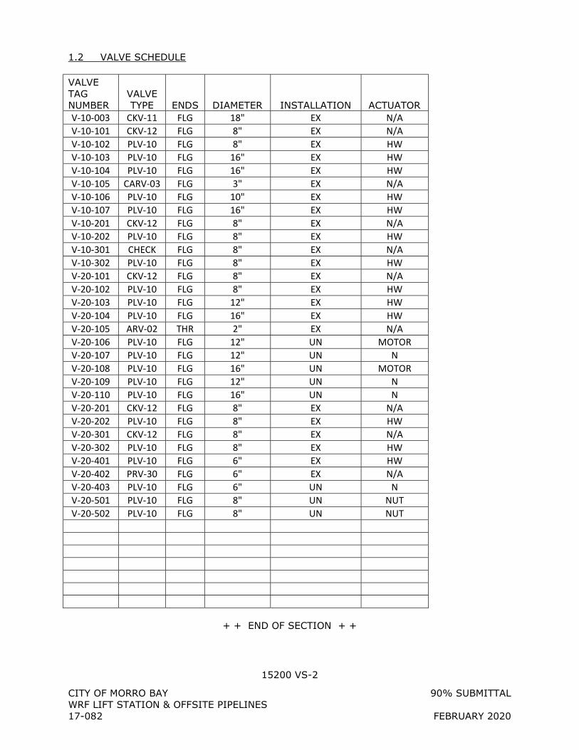
15200 VS-2
CITY OF MORRO BAY 90% SUBMITTAL WRF LIFT STATION & OFFSITE PIPELINES 17-082 FEBRUARY 2020
1.2 VALVE SCHEDULE VALVE TAG NUMBER
VALVE TYPE ENDS DIAMETER INSTALLATION ACTUATOR
V-10-003 CKV-11 FLG 18" EX N/A V-10-101 CKV-12 FLG 8" EX N/A V-10-102 PLV-10 FLG 8" EX HW V-10-103 PLV-10 FLG 16" EX HW V-10-104 PLV-10 FLG 16" EX HW V-10-105 CARV-03 FLG 3" EX N/A V-10-106 PLV-10 FLG 10" EX HW V-10-107 PLV-10 FLG 16" EX HW V-10-201 CKV-12 FLG 8" EX N/A V-10-202 PLV-10 FLG 8" EX HW V-10-301 CHECK FLG 8" EX N/A V-10-302 PLV-10 FLG 8" EX HW V-20-101 CKV-12 FLG 8" EX N/A V-20-102 PLV-10 FLG 8" EX HW V-20-103 PLV-10 FLG 12" EX HW V-20-104 PLV-10 FLG 16" EX HW V-20-105 ARV-02 THR 2" EX N/A V-20-106 PLV-10 FLG 12" UN MOTOR V-20-107 PLV-10 FLG 12" UN N V-20-108 PLV-10 FLG 16" UN MOTOR V-20-109 PLV-10 FLG 12" UN N V-20-110 PLV-10 FLG 16" UN N V-20-201 CKV-12 FLG 8" EX N/A V-20-202 PLV-10 FLG 8" EX HW V-20-301 CKV-12 FLG 8" EX N/A V-20-302 PLV-10 FLG 8" EX HW V-20-401 PLV-10 FLG 6" EX HW V-20-402 PRV-30 FLG 6" EX N/A V-20-403 PLV-10 FLG 6" UN N V-20-501 PLV-10 FLG 8" UN NUT V-20-502 PLV-10 FLG 8" UN NUT
+ + END OF SECTION + +
15200-1
CITY OF MORRO BAY 90% SUBMITTAL WRF LIFT STATION & OFFSITE PIPELINES 17-082 FEBRUARY 2020
SECTION 15200
VALVES AND OPERATORS
PART 1 - GENERAL
1.1 SUBMITTALS
A. Shop Drawings: 1. Product data sheets for make and model. 2. Complete catalog information, descriptive literature, specifications, and identification
of materials of construction. 3. Certificate of Compliance for: Butterfly valves; full compliance with AWWA C504.
B. Tests and inspection data.
C. Operation and Maintenance Data as specified in Section 01330, SUBMITTAL PROCEDURES.
1.2 PRODUCT DELIVERY, STORAGE, AND HANDLING
A. In accordance with manufacturer’s directions.
PART 2 - PRODUCTS
2.1 GENERAL
A. All valves shall be the same size as the pipe in which they are installed, unless specifically noted otherwise on the Drawings.
B. All valves shall include all appurtenant parts (operators, chainwheels, handwheels, valve stems, floor stands, gear boxes, operating nut, etc.) for a complete operating valve. 1. Valve shall be, as much as practical, fully factory assembled.
C. All valves shall open by turning counter-clockwise. Maximum force required for operation shall be 40 lbs.
D. Where Lead-Free Bronze or Brass is specified, materials shall be in compliance with California Health & Safety Code Section 116875. Not more than a weighted average of 0.25 percent of the wetted surface of the valve shall be lead. Valve shall be provided with a “hang tag” or other marking that easily identifies the valve as Lead-Free.
E. Coatings and Linings: 1. Provide factory-applied coatings as described herein. 2. Where liquid epoxy coatings are specified, coatings shall conform to AWWA C550. 3. Field coat the exterior of all valve bodies with the same coating as is required for the
adjacent pipe in Section 09900, PAINTING and Section 15100, PIPE AND FITTINGS, unless otherwise specified.
F. Nuts, Bolts and Washers
15200-2
CITY OF MORRO BAY 90% SUBMITTAL WRF LIFT STATION & OFFSITE PIPELINES 17-082 FEBRUARY 2020
1. Hex Bolts: ASTM A320/A320M, Type 304 stainless steel, Grade B8, Class 2 2. Nuts: ASTM F594, Type 304 stainless steel, Grade B8, Class 2 3. Washers: Type 304 stainless steel
2.2 BALL VALVES
A. BAV-03: Stainless Steel Ball Valve, 3 Inches and Smaller 1. Service: Water, air. 2. Features:
a. Threaded ends b. Rated minimum 800 psig WOG (Water-Oil-Gas) c. Stainless steel body d. Polished stainless steel ball e. Teflon seat f. Stainless steel lever-type handle
3. Manufacturers and Products: a. Apollo, Type 76 b. Watts Type S-FBV-1 c. Or Equal
B. BAV-05: PVC Ball Valve 4 Inches and Smaller: 1. Service: Water, Chemical Duty. 2. Features:
a. Rated 150 psi at 73 degrees F b. ASTM D1784, Type I, Grade 1 polyvinyl chloride body, ball, and stem, end entry c. Double union design, d. Flanged-end if noted in Valve Schedule, otherwise solvent-weld socket ends e. EPDM or Teflon seat f. EPDM O-rings and stem seals
3. Manufacturers and Products: a. Nibco; Chemtrol Tru-Bloc. b. ASAHI/America;Type 21/21A. c. Or Equal.
C. CRP-01: Ball Corporation Valve 3/4 Inch to 2 Inch: 1. Features:
a. Rated 300 psi at 73 degrees F b. Brass alloys C89520 or C89833 with a maximum lead content of 0.25% by
weight. Brass alloys shall meet AWWA C800, paragraph 4.1.2. c. Full round-port ball valve, no reduced port permitted d. Ends as required e. Double O-ring stem seals f. Key operator
2. Manufacturers and Products: a. Mueller Company; 300N Series Ball Corporation Valves b. Ford Meter Box Company; FB-NL Series Ballcorp Ball Corporation Valves c. Or Equal.
2.3 CHECK VALVES
A. CKV-11: Flap Gate, 4 Inches to 60 Inches 1. Service: Water.
15200-3
CITY OF MORRO BAY 90% SUBMITTAL WRF LIFT STATION & OFFSITE PIPELINES 17-082 FEBRUARY 2020
2. Features: a. Cast iron construction b. Automatic operation c. Fully adjustable linkage d. Stainless steel studs, bolts and pins e. Bronze bushings f. Minimum 5-degree seating angle g. 125 lb ANSI flange drilling h. Cast iron seat
3. Coatings and Linings: a. Liquid epoxy, 12 mil minimum, for valve interior and exterior. b. For potable water applications, epoxy lining shall be NSF 61 approved.
4. Manufacturer: a. Waterman; F-25 Drainage Gate b. HydroGate; Model 10C c. Or equal.
B. CKV-12: Swing Check Valve (2” to 48”) 1. Service: Water, Sewage, and General Service. 2. Style: Swing Check, full flow body with only two moving parts, the flexible disc and
Disc Accelerator, Flanged-End Connections 3. General: Valves shall comply with AWWA C508. The valves used in potable water
service shall be certified to NSF/ANSI 61 Drinking Water System Components – Health Effects, and certified to be Lead-Free in accordance with NSF/ANSI 372.
4. Body: The valve body and cover shall be constructed of ASTM A536 Grade 65-45-12 ductile iron or ASTM A126 class B gray iron for 30 in. (800mm) and larger. Optional body materials include ASTM A-351 Grade CF8M, stainless steel for sizes 3” (80 mm) through 12” (300 mm). The valves shall have flanged ends conforming to ANSI B16.1, Class 125.
5. Disc: The disc shall be precision molded Buna-N (NBR), ASTM D2000-BG and nylon reinforcement. Optional disc material includes Viton, EPDM, Hypalon - The disc shall be of one-piece construction, with an integral O-ring type sealing surface and reinforced with alloy steel. Non-Slam closing characteristics shall be provided through a short 35 degree disc stroke and a disc accelerator to provide a cracking pressure of 0.3 psig.
6. Disc Accelerator: Stainless Steel, Type 302 - The disc accelerator shall be of one piece construction and provide rapid closure of the valve in high head applications. The disc accelerator shall be enclosed within the valve and shall be field adjustable and replaceable without removal of the valve from the line. The disc accelerator shall be held in place captured between the cover and disc.
7. Cover Seal: Buna-N ASTM D2000 8. Cover Bolt, Cover Bolt Nut, Washer: Stainless Steel, Type 316 9. Cover Pipe Plug: Steel 10. Body Pipe Plug: Steel, Nickel plated 11. Coatings and Linings: The exterior and interior of the valve shall be coated with an
NSF/ANSI 61 approved fusion bonded epoxy coating. 12. Manufacturer:
a. Val-Matic; Surgebuster Swing Check Valve b. Or equal.
15200-4
CITY OF MORRO BAY 90% SUBMITTAL WRF LIFT STATION & OFFSITE PIPELINES 17-082 FEBRUARY 2020
2.4 GATE VALVES
A. GAV-10: Resilient-Seated Gate Valve, 2 Inches to 24 Inches: 1. Service: Water. 2. Features:
a. Conforms to AWWA C509 (2”) or AWWA C515 (3” to 24”) b. Iron body c. Resilient seat, bronze mounted d. Full port e. Valve Ends:
1) Mechanical joint ends for buried service, unless shown otherwise on drawings or valve schedule
2) Flanged ends for exposed service f. Non-rising stem g. Actuator for Buried Service:
1) Stem extension, as required, to bring operating nut to within 12” of ground surface.
2) 2-inch operating nut h. Actuator for Exposed Service:
1) Handwheel i. Design working water pressure: 250 psig j. Coatings and Linings:
1) Liquid epoxy, 12 mil minimum, for valve interior and exterior. 2) For potable water applications, epoxy lining shall be NSF 61 approved.
3. Manufacturers and Products: a. Mueller 2360 (2”) or 2361 (3” to 24”) b. M&H Valve; AWWA C509 (2”) or AWWA C515 (3” to 24”). c. Or Equal.
2.5 PLUG VALVES
A. PLV-10: Eccentric Plug Valve, 3 Inches to 20 Inches: 1. Service: Water, sewage. 2. Features:
a. Non-lubricated type. b. Drip-tight shutoff with pressure from either direction. c. Features:
1) Body: Cast iron Type ASTM A126 Class B. 2) Plug:
a) Cast iron or 316 stainless steel. b) Round or rectangular port of no less than 80 percent of connecting pipe
area. c) Coated with Buna-N, Chloroprene, or Hycar.
3) Seats: Type 316 stainless steel or nickel. 4) Stem:
a) Bearing: Self-lubricating stainless steel or reinforced Teflon. b) Seal:
1. Multiple V-rings, U-cups, or O-rings of nitrile rubber. 2. Externally adjustable and re-packable without removing the bonnet
or actuator from the valve under pressure. c) Provide upper and lower grit seals on stem.
15200-5
CITY OF MORRO BAY 90% SUBMITTAL WRF LIFT STATION & OFFSITE PIPELINES 17-082 FEBRUARY 2020
5) Ends: a) Exposed service: Flanged per ANSI B16.1 or grooved, as shown on
Drawings or indicated on Valve Schedule. b) Buried service: Mechanical joint per ANSI A21.11.
6) Actuators: a) Exposed:
1. Valves 3 Inches through 6 Inches: Wrench lever manual actuator. 2. Valves 8 Inches through 20 Inches: Totally enclosed, geared, manual
actuator with handwheel b) Buried: 2-inch nut per Valve Schedule.
7) Coatings and Linings: a) Liquid epoxy, 12 mil minimum, for valve interior and exterior. b) For potable water applications, epoxy lining shall be NSF 61 approved.
d. Pressure Rating: 1) Valves 3 Inches through 12 Inches: 175 psi. 2) Valves 14 Inches through 20 Inches: 150 psi.
3. Manufacturers and Products: a. DeZurik; Style PEC. b. Pratt; Ballcentric. c. Milliken; Millcentric. d. Or Equal.
2.6 HOSE VALVES
A. HSV-01: ¾” Angle-Pattern Hose Valve, non frost-proof 1. Service: Water. 2. Features:
a. 3/4-inch NPT female inlet, b. 3/4-inch male hose thread outlet, c. Heavy rough brass body rated 125 psi, d. Removable handle, e. Atmospheric vacuum breaker conforming to ASSE Standard 1011 and IAPMO
code 3. Manufacturers and Products:
a. Acorn; 8131 b. Or Equal.
2.7 CONTROL VALVES
A. PRV-30: Pressure Relief Valve, Sewage Service (4 Inches through 8 Inches) 1. Service: Sewage. 2. Function:
a. Pushing against compression springs, valve shall quickly open at a designated pressure setting
b. Valve shall remain in the open position as long as system pressure remains above the setting
c. Following pressure reduction below the setting, valve shall use hydraulic system to slowly return valve to the closed position
d. The valve shall be capable of full functionality in any orientation 3. Features:
a. Flanged ends, ANSI B16.1, Class 125 b. Valve body shall be inherently self-cleaning
15200-6
CITY OF MORRO BAY 90% SUBMITTAL WRF LIFT STATION & OFFSITE PIPELINES 17-082 FEBRUARY 2020
1) Net flow area no less than the area of its nominal pipe size when fully opened c. Removable seat d. Springs:
1) Valve shall have dual compression springs, tension springs are not acceptable 2) Springs shall be fully enclosed in steel cylinders, exposed springs are not
acceptable e. Hydraulic system shall be integral to valve, no external hydraulic systems shall be
required for valve functionality f. Pressure relief factory set (see valve schedule). Field adjustable from zero to ten
percent above factory setting. g. Where required on the drawings, provide NEMA 4 limit switch mounted to valve to
indicate when the valve is open. h. Orientation of valve (right angle or in-line) shall be per drawings i. Valve and spring dimensions shall allow for installation in the location shown on
the drawings without conflict 4. Materials:
a. Body: cast iron, ASTM A126, Class B b. Disc: cast iron or steel c. Springs: steel d. Seat: stainless steel e. All other wetted parts: stainless steel
5. Coatings and Linings: a. Liquid epoxy, 12 mil minimum, for valve interior and exterior.
6. Manufacturers and Products: a. GA Industries, Inc., 6” Figure 626-D (in-line); b. Or Equal.
2.8
2.9 AIR RELIEF AND VACUUM VALVES
A. ARV-01: 2-inch Air Release Valve, Water Service up to 150 psi 1. Service: Water. 2. Features:
a. Automatically exhausts small amounts of entrained air that accumulates in a system
b. Once air has been exhausted, uses water pressure to close valve. In CLOSED position, seat against resilient seat to prevent water leakage.
c. Rated 150 psi working pressure, orifice size by manufacturer (minimum orifice size 3/16-inch).
d. Cast iron, ductile iron, or semi-steel body, cover with stainless steel float and trim.
e. 2-inch inlet, 1/2-inch outlet . f. Provide No. 16 Mesh 316SS screen on inlets and outlets. g. Coatings and Linings:
1) Liquid epoxy, 12 mil minimum, for valve interior and exterior. 2) For potable water applications, epoxy lining shall be NSF 61 approved.
3. Manufacturers and Products: a. APCO Valve and Primer Corp.; Model 200a. b. Val-Matic Valve; Model VM-38.2. c. Or equal.
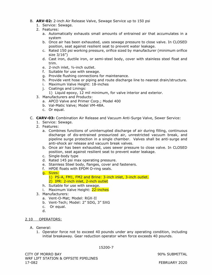
15200-7
CITY OF MORRO BAY 90% SUBMITTAL WRF LIFT STATION & OFFSITE PIPELINES 17-082 FEBRUARY 2020
B. ARV-02: 2-inch Air Release Valve, Sewage Service up to 150 psi 1. Service: Sewage. 2. Features:
a. Automatically exhausts small amounts of entrained air that accumulates in a system
b. Once air has been exhausted, uses sewage pressure to close valve. In CLOSED position, seat against resilient seat to prevent water leakage.
c. Rated 150 psi working pressure, orifice sized by manufacturer (minimum orifice size 3/16”)
d. Cast iron, ductile iron, or semi-steel body, cover with stainless steel float and trim.
e. 2-inch inlet, ½-inch outlet. f. Suitable for use with sewage. g. Provide flushing connections for maintenance. h. Provide vent hose or piping and route discharge line to nearest drain/structure. i. Maximum Valve Height: 18-inches j. Coatings and Linings:
1) Liquid epoxy, 12 mil minimum, for valve interior and exterior. 3. Manufacturers and Products:
a. APCO Valve and Primer Corp.; Model 400 b. Val-Matic Valve; Model VM-48A. c. Or equal.
C. CARV-03: Combination Air Release and Vacuum Anti-Surge Valve, Sewer Service: 1. Service: Sewage. 2. Features:
a. Combines functions of uninterrupted discharge of air during filling, continuous discharge of dis-entrained pressurized air, unrestricted vacuum break, and pipeline surge protection in a single chamber. Valves shall be anti-surge and anti-shock air release and vacuum break valves.
b. Once air has been exhausted, uses sewer pressure to close valve. In CLOSED position, seat against resilient seat to prevent water leakage.
c. Single-body type d. Rated 145 psi max operating pressure. e. Stainless Steel body, flanges, cover and fasteners. f. HPDE floats with EPDM O-ring seals. g. Sizes:
1) PS-A, FM1, FM2 and Brine: 3-inch inlet, 3-inch outlet. 2) IPR: 2-inch inlet, 2-inch outlet
h. Suitable for use with sewage. i. Maximum Valve Height: 22-inches
3. Manufacturers: a. Vent-O-Mat; Model: RGX-II b. Vent-Tech; Model: 2” SDG, 3” SXG c. Or equal. d.
2.10 OPERATORS:
A. General: 1. Operator force not to exceed 40 pounds under any operating condition, including
initial breakaway. Gear reduction operator when force exceeds 40 pounds.
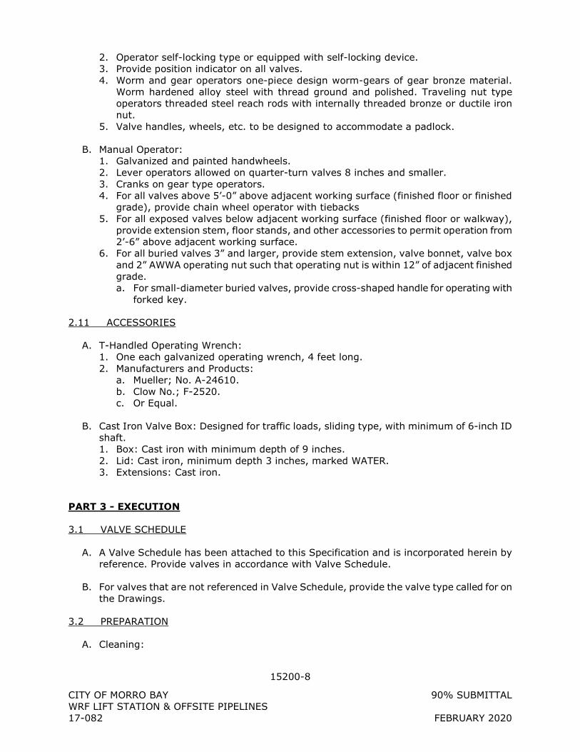
15200-8
CITY OF MORRO BAY 90% SUBMITTAL WRF LIFT STATION & OFFSITE PIPELINES 17-082 FEBRUARY 2020
2. Operator self-locking type or equipped with self-locking device. 3. Provide position indicator on all valves. 4. Worm and gear operators one-piece design worm-gears of gear bronze material.
Worm hardened alloy steel with thread ground and polished. Traveling nut type operators threaded steel reach rods with internally threaded bronze or ductile iron nut.
5. Valve handles, wheels, etc. to be designed to accommodate a padlock.
B. Manual Operator: 1. Galvanized and painted handwheels. 2. Lever operators allowed on quarter-turn valves 8 inches and smaller. 3. Cranks on gear type operators. 4. For all valves above 5’-0” above adjacent working surface (finished floor or finished
grade), provide chain wheel operator with tiebacks 5. For all exposed valves below adjacent working surface (finished floor or walkway),
provide extension stem, floor stands, and other accessories to permit operation from 2’-6” above adjacent working surface.
6. For all buried valves 3” and larger, provide stem extension, valve bonnet, valve box and 2” AWWA operating nut such that operating nut is within 12” of adjacent finished grade. a. For small-diameter buried valves, provide cross-shaped handle for operating with
forked key.
2.11 ACCESSORIES
A. T-Handled Operating Wrench: 1. One each galvanized operating wrench, 4 feet long. 2. Manufacturers and Products:
a. Mueller; No. A-24610. b. Clow No.; F-2520. c. Or Equal.
B. Cast Iron Valve Box: Designed for traffic loads, sliding type, with minimum of 6-inch ID shaft. 1. Box: Cast iron with minimum depth of 9 inches. 2. Lid: Cast iron, minimum depth 3 inches, marked WATER. 3. Extensions: Cast iron.
PART 3 - EXECUTION
3.1 VALVE SCHEDULE
A. A Valve Schedule has been attached to this Specification and is incorporated herein by reference. Provide valves in accordance with Valve Schedule.
B. For valves that are not referenced in Valve Schedule, provide the valve type called for on the Drawings.
3.2 PREPARATION
A. Cleaning:
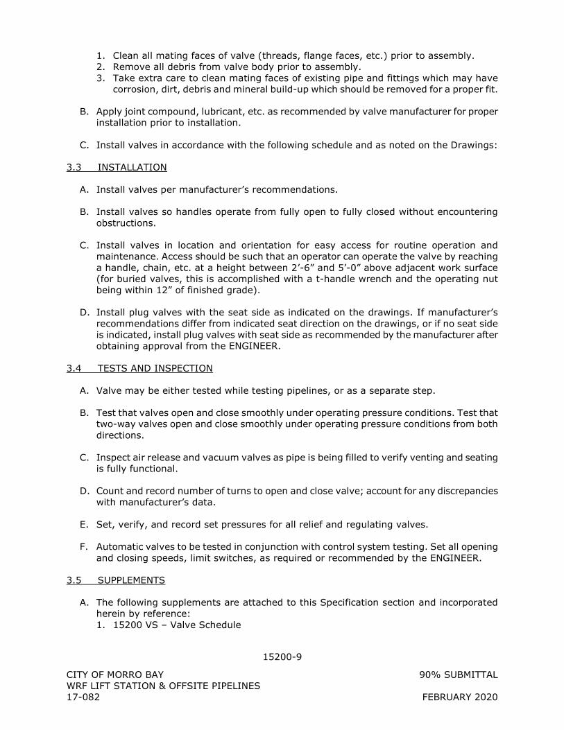
15200-9
CITY OF MORRO BAY 90% SUBMITTAL WRF LIFT STATION & OFFSITE PIPELINES 17-082 FEBRUARY 2020
1. Clean all mating faces of valve (threads, flange faces, etc.) prior to assembly. 2. Remove all debris from valve body prior to assembly. 3. Take extra care to clean mating faces of existing pipe and fittings which may have
corrosion, dirt, debris and mineral build-up which should be removed for a proper fit.
B. Apply joint compound, lubricant, etc. as recommended by valve manufacturer for proper installation prior to installation.
C. Install valves in accordance with the following schedule and as noted on the Drawings:
3.3 INSTALLATION
A. Install valves per manufacturer’s recommendations.
B. Install valves so handles operate from fully open to fully closed without encountering obstructions.
C. Install valves in location and orientation for easy access for routine operation and maintenance. Access should be such that an operator can operate the valve by reaching a handle, chain, etc. at a height between 2’-6” and 5’-0” above adjacent work surface (for buried valves, this is accomplished with a t-handle wrench and the operating nut being within 12” of finished grade).
D. Install plug valves with the seat side as indicated on the drawings. If manufacturer’s recommendations differ from indicated seat direction on the drawings, or if no seat side is indicated, install plug valves with seat side as recommended by the manufacturer after obtaining approval from the ENGINEER.
3.4 TESTS AND INSPECTION
A. Valve may be either tested while testing pipelines, or as a separate step.
B. Test that valves open and close smoothly under operating pressure conditions. Test that two-way valves open and close smoothly under operating pressure conditions from both directions.
C. Inspect air release and vacuum valves as pipe is being filled to verify venting and seating is fully functional.
D. Count and record number of turns to open and close valve; account for any discrepancies with manufacturer’s data.
E. Set, verify, and record set pressures for all relief and regulating valves.
F. Automatic valves to be tested in conjunction with control system testing. Set all opening and closing speeds, limit switches, as required or recommended by the ENGINEER.
3.5 SUPPLEMENTS
A. The following supplements are attached to this Specification section and incorporated herein by reference: 1. 15200 VS – Valve Schedule

15200-10
CITY OF MORRO BAY 90% SUBMITTAL WRF LIFT STATION & OFFSITE PIPELINES 17-082 FEBRUARY 2020
+ + END OF SECTION + +
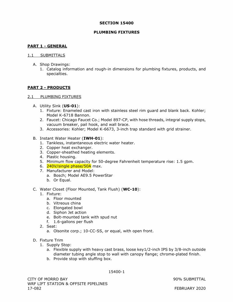
15400-1
CITY OF MORRO BAY 90% SUBMITTAL WRF LIFT STATION & OFFSITE PIPELINES 17-082 FEBRUARY 2020
SECTION 15400
PLUMBING FIXTURES
PART 1 - GENERAL
1.1 SUBMITTALS
A. Shop Drawings: 1. Catalog information and rough-in dimensions for plumbing fixtures, products, and
specialties.
PART 2 - PRODUCTS
2.1 PLUMBING FIXTURES
A. Utility Sink (US-01): 1. Fixture: Enameled cast iron with stainless steel rim guard and blank back. Kohler;
Model K-6718 Bannon. 2. Faucet: Chicago Faucet Co.; Model 897-CP, with hose threads, integral supply stops,
vacuum breaker, pail hook, and wall brace. 3. Accessories: Kohler; Model K-6673, 3-inch trap standard with grid strainer.
B. Instant Water Heater (IWH-01): 1. Tankless, instantaneous electric water heater. 2. Copper heat exchanger. 3. Copper-sheathed heating elements. 4. Plastic housing. 5. Minimum flow capacity for 50-degree Fahrenheit temperature rise: 1.5 gpm. 6. 240V/single phase/50A max. 7. Manufacturer and Model:
a. Bosch; Model AE9.5 PowerStar b. Or Equal.
C. Water Closet (Floor Mounted, Tank Flush) (WC-10): 1. Fixture:
a. Floor mounted b. Vitreous china c. Elongated bowl d. Siphon Jet action e. Bolt-mounted tank with spud nut f. 1.6-gallons per flush
2. Seat: a. Olsonite corp.; 10-CC-SS, or equal, with open front.
D. Fixture Trim 1. Supply Stop:
a. Flexible supply with heavy cast brass, loose key1/2-inch IPS by 3/8-inch outside diameter tubing angle stop to wall with canopy flange; chrome-plated finish.
b. Provide stop with stuffing box.
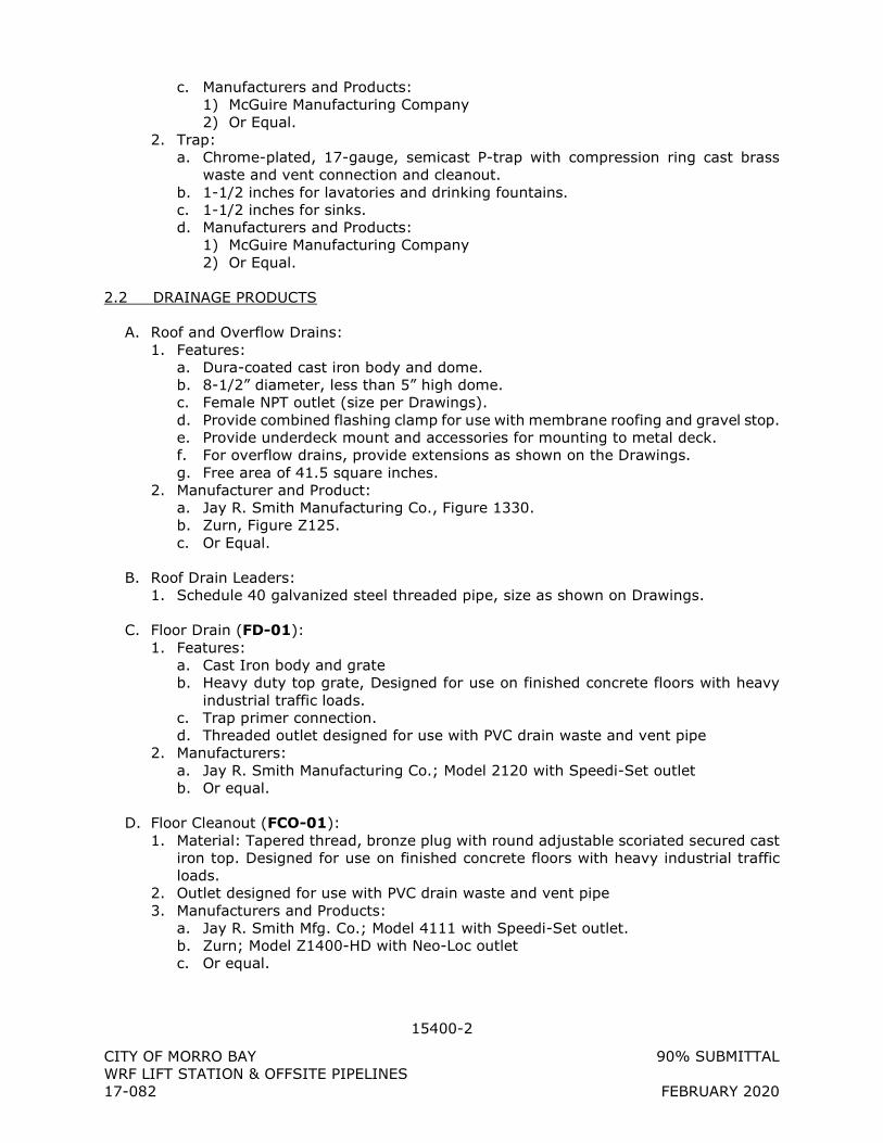
15400-2
CITY OF MORRO BAY 90% SUBMITTAL WRF LIFT STATION & OFFSITE PIPELINES 17-082 FEBRUARY 2020
c. Manufacturers and Products: 1) McGuire Manufacturing Company 2) Or Equal.
2. Trap: a. Chrome-plated, 17-gauge, semicast P-trap with compression ring cast brass
waste and vent connection and cleanout. b. 1-1/2 inches for lavatories and drinking fountains. c. 1-1/2 inches for sinks. d. Manufacturers and Products:
1) McGuire Manufacturing Company 2) Or Equal.
2.2 DRAINAGE PRODUCTS
A. Roof and Overflow Drains: 1. Features:
a. Dura-coated cast iron body and dome. b. 8-1/2” diameter, less than 5” high dome. c. Female NPT outlet (size per Drawings). d. Provide combined flashing clamp for use with membrane roofing and gravel stop. e. Provide underdeck mount and accessories for mounting to metal deck. f. For overflow drains, provide extensions as shown on the Drawings. g. Free area of 41.5 square inches.
2. Manufacturer and Product: a. Jay R. Smith Manufacturing Co., Figure 1330. b. Zurn, Figure Z125. c. Or Equal.
B. Roof Drain Leaders: 1. Schedule 40 galvanized steel threaded pipe, size as shown on Drawings.
C. Floor Drain (FD-01): 1. Features:
a. Cast Iron body and grate b. Heavy duty top grate, Designed for use on finished concrete floors with heavy
industrial traffic loads. c. Trap primer connection. d. Threaded outlet designed for use with PVC drain waste and vent pipe
2. Manufacturers: a. Jay R. Smith Manufacturing Co.; Model 2120 with Speedi-Set outlet b. Or equal.
D. Floor Cleanout (FCO-01): 1. Material: Tapered thread, bronze plug with round adjustable scoriated secured cast
iron top. Designed for use on finished concrete floors with heavy industrial traffic loads.
2. Outlet designed for use with PVC drain waste and vent pipe 3. Manufacturers and Products:
a. Jay R. Smith Mfg. Co.; Model 4111 with Speedi-Set outlet. b. Zurn; Model Z1400-HD with Neo-Loc outlet c. Or equal.
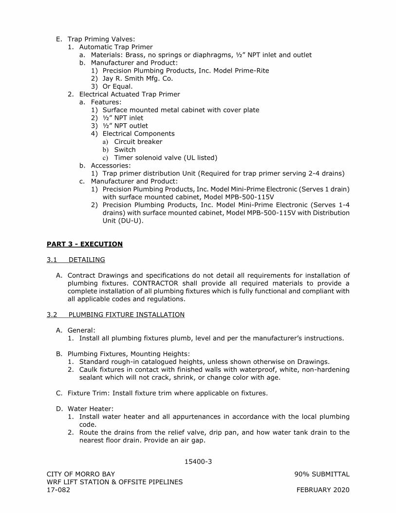
15400-3
CITY OF MORRO BAY 90% SUBMITTAL WRF LIFT STATION & OFFSITE PIPELINES 17-082 FEBRUARY 2020
E. Trap Priming Valves: 1. Automatic Trap Primer
a. Materials: Brass, no springs or diaphragms, ½” NPT inlet and outlet b. Manufacturer and Product:
1) Precision Plumbing Products, Inc. Model Prime-Rite 2) Jay R. Smith Mfg. Co. 3) Or Equal.
2. Electrical Actuated Trap Primer a. Features:
1) Surface mounted metal cabinet with cover plate 2) ½” NPT inlet 3) ½” NPT outlet 4) Electrical Components
a) Circuit breaker b) Switch c) Timer solenoid valve (UL listed)
b. Accessories: 1) Trap primer distribution Unit (Required for trap primer serving 2-4 drains)
c. Manufacturer and Product: 1) Precision Plumbing Products, Inc. Model Mini-Prime Electronic (Serves 1 drain)
with surface mounted cabinet, Model MPB-500-115V 2) Precision Plumbing Products, Inc. Model Mini-Prime Electronic (Serves 1-4
drains) with surface mounted cabinet, Model MPB-500-115V with Distribution Unit (DU-U).
PART 3 - EXECUTION
3.1 DETAILING
A. Contract Drawings and specifications do not detail all requirements for installation of plumbing fixtures. CONTRACTOR shall provide all required materials to provide a complete installation of all plumbing fixtures which is fully functional and compliant with all applicable codes and regulations.
3.2 PLUMBING FIXTURE INSTALLATION
A. General: 1. Install all plumbing fixtures plumb, level and per the manufacturer’s instructions.
B. Plumbing Fixtures, Mounting Heights: 1. Standard rough-in catalogued heights, unless shown otherwise on Drawings. 2. Caulk fixtures in contact with finished walls with waterproof, white, non-hardening
sealant which will not crack, shrink, or change color with age.
C. Fixture Trim: Install fixture trim where applicable on fixtures.
D. Water Heater: 1. Install water heater and all appurtenances in accordance with the local plumbing
code. 2. Route the drains from the relief valve, drip pan, and how water tank drain to the
nearest floor drain. Provide an air gap.
15400-4
CITY OF MORRO BAY 90% SUBMITTAL WRF LIFT STATION & OFFSITE PIPELINES 17-082 FEBRUARY 2020
E. Drains and Cleanouts: 1. Install top flush with finished floor elevation. 2. Install PVC p-traps at each floor drain. 3. Provide cleanouts where shown and where required by code.
F. Trap Priming Valves: 1. Provide one trap priming valve for each floor drain. Trap priming valves and
associated piping are not shown on the Drawings, but are required. 2. Connect each trap priming valve to W1 system. 3. Connect trap priming valve to floor drain using ½” Type K soft copper tubing. Install
copper tubing at the time of floor drain installation (before concrete for floor is placed). Route tubing to final location of trap priming valve.
4. Locate trap priming valves as required, however, group trap priming valves for floor drains in the same area.
5. Provide shut-off valve (1/2” ball valve) between trap priming valve and W1 line feeding trap priming valve directly adjacent to trap priming valve.
6. Label trap priming valve indicating which floor drain is served.
G. Roof Drain Leaders: 1. Slope horizontal leaders ¼-inch per foot in the downstream direction.
+ + END OF SECTION + +
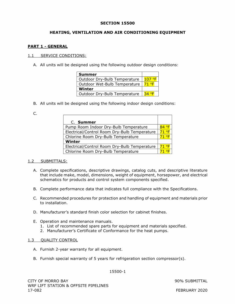
15500-1
CITY OF MORRO BAY 90% SUBMITTAL WRF LIFT STATION & OFFSITE PIPELINES 17-082 FEBRUARY 2020
SECTION 15500
HEATING, VENTILATION AND AIR CONDITIONING EQUIPMENT
PART 1 - GENERAL
1.1 SERVICE CONDITIONS:
A. All units will be designed using the following outdoor design conditions:
Summer Outdoor Dry-Bulb Temperature 107 oF Outdoor Wet-Bulb Temperature 71 oF Winter Outdoor Dry-Bulb Temperature 34 oF
B. All units will be designed using the following indoor design conditions:
C.
C. Summer
Pump Room Indoor Dry-Bulb Temperature 84 oF Electrical/Control Room Dry-Bulb Temperature 71 oF Chlorine Room Dry-Bulb Temperature 71 oF Winter Electrical/Control Room Dry-Bulb Temperature 71 oF Chlorine Room Dry-Bulb Temperature 71 oF
1.2 SUBMITTALS:
A. Complete specifications, descriptive drawings, catalog cuts, and descriptive literature that include make, model, dimensions, weight of equipment, horsepower, and electrical schematics for products and control system components specified.
B. Complete performance data that indicates full compliance with the Specifications.
C. Recommended procedures for protection and handling of equipment and materials prior to installation.
D. Manufacturer’s standard finish color selection for cabinet finishes.
E. Operation and maintenance manuals. 1. List of recommended spare parts for equipment and materials specified. 2. Manufacturer’s Certificate of Conformance for the heat pumps.
1.3 QUALITY CONTROL
A. Furnish 2-year warranty for all equipment.
B. Furnish special warranty of 5 years for refrigeration section compressor(s).
15500-2
CITY OF MORRO BAY 90% SUBMITTAL WRF LIFT STATION & OFFSITE PIPELINES 17-082 FEBRUARY 2020
PART 2 - PRODUCTS
2.1 VARIABLE REFRIGERANT FLOW (VFR) SYSTEM
A. See Drawings M1.0 and M2.0
2.2 EXHAUST FAN
A. See Drawings M1.0 and M2.0
PART 3 - EXECUTION
3.1 INSTALLATION
A. Install equipment and systems in accordance with manufacturers’ instructions.
B. Evaporative Coolers: 1. Pipe drain pan connection as recommended by manufacturer. 2. Locate units to provide access spaces required for filter changing; motor, drive, and
bearing servicing; and fan shaft removal. 3. Lubricate nonsealed bearings prior to startup. 4. Seismic Restraints:
a. Use lateral and vertical motion limiters described in the latest edition of SMACNA “Guidelines For Seismic Restraints of Mechanical Systems.”
b. Restraint Snubbers: Rubber-faced, securely anchored to the structure, and installed with sufficient clearance so that unit isolators are not restricted for proper free isolation, but do limit movement in all directions.
c. Restrain as described in the latest edition of ASHRAE “HVAC Applications,” chapter on Seismic Restrain Design.
+ + END OF SECTION + +
15990-1
CITY OF MORRO BAY 90% SUBMITTAL
WRF LIFT STATION & OFFSITE PIPELINES
17-082 FEBRUARY 2020
SECTION 15990
TESTING OF PRESSURE PIPING SYSTEMS
PART 1 - SUBMITTALS (NOT USED)
PART 2 - PRODUCTS (NOT USED)
PART 3 - EXECUTION
3.1 PRESSURE TESTING
A. General:
1. Complete installation of piping system, including all thrust restraint, prior to pressure testing.
a. If thrust blocking is specified, wait 5 days minimum after concrete thrust blocking is installed to perform pressure tests. If high-early strength cement is used for thrust blocking, wait may be reduced to 2 days.
2. Prior to test, remove and replace with pipe spools or suitably isolate appurtenant instruments or devices that could be damaged by pressure testing.
3. New Piping Connected to Existing Piping: Isolate new piping with grooved-end pipe caps, spectacle blinds, blind flanges, or as acceptable to ENGINEER.
4. Piping to be Pressure Tested and Test Pressure: as indicated on Piping Schedule.
B. Testing with Water (non-HDPE2 pipe):
1. Fluid: Clean, potable water.
2. Pipeline Protection:
a. Maximum Filling Velocity: 0.25 foot per second, applied over full area of pipe.
b. Vent piping during filling. Open vents at high points of piping system or loosen flanges, using at least four bolts, or use equipment vents to purge air pockets.
15990-2
CITY OF MORRO BAY 90% SUBMITTAL
WRF LIFT STATION & OFFSITE PIPELINES
17-082 FEBRUARY 2020
3. Exposed Piping:
a. Perform testing on insulated piping prior to application of insulation
b. Maintain hydrostatic test pressure continuously for 60 minutes, minimum, and for such additional time as necessary to conduct examinations for leakage.
c. Examine joints and connections for leakage.
1) Correct visible leakage and retest as specified.
2) Empty pipe of water prior to final cleaning or disinfection.
4. Buried Piping:
a. Test after backfilling has been completed.
b. Expel air from piping system during filling.
c. Apply and maintain specified test pressure with hydraulic force pump. Valve off piping system when test pressure is reached.
d. Maintain hydrostatic test pressure continuously for 2 hours minimum, reopening isolation valve only as necessary to restore test pressure.
e. Determine actual leakage by measuring quantity of water necessary to maintain specified test pressure for duration of test.
f. Maximum Allowable Leakage:
200,133)D(PS
= L2/1
where:
L = Allowable leakage, in gallons per hour. S = Length of pipe tested, in feet. D = Nominal diameter of pipe, in inches. P = Test pressure during leakage test, in pounds per square inch.
g. Correct leakage greater than allowable, and retest as specified.
C. Testing with Water (15100 PSDS HDPE2) per ASTM F2164:
1. Fluid: Clean, potable water.
15990-3
CITY OF MORRO BAY 90% SUBMITTAL
WRF LIFT STATION & OFFSITE PIPELINES
17-082 FEBRUARY 2020
2. Pipeline Protection:
a. Maximum Filling Velocity: 0.25 foot per second, applied over full area of pipe.
b. Vent piping during filling. Open vents at high points of piping system or loosen flanges, using at least four bolts, or use equipment vents to purge air pockets.
3. Allow the test section and test liquid to equalize to a common temperature.
4. Pressurizing (initial expansion phase):
a. Once test section is completely filled and void of all air pockets, gradually increase pressure in the test section to the specified test pressure.
b. Test section shall not exceed 1.5 x design pressure at systems lowest point.
c. Should test pressure not be obtainable, examine pipe for leaks, air pockets or other faults prior to continuing test.
d. Once test section has achieved stabile test pressure, add make-up water as necessary to maintain test pressure for four (4) hours.
5. Test Phase
a. Reduce test pressure by 10 psi and monitor pressure for one (1) hour. Do not increase pressure or add make-up water.
b. If no visual leakage is observed and pressure during the test phase remains steady (within 5% of the test phase pressure) for the one (1) hour test period, a passing test is achieved.
6. Retesting
a. If retesting is necessary, depressurize the test section by releasing test liquid at a controlled rate. Sudden depressurization can cause water hammer.
b. Do not attempt to correct faults or make repairs while test section is pressurized.
c. Allow the test section to relax for a period of eight (8) hours before restarting the pressurization step of testing.
+ + END OF SECTION + +
15995-1
CITY OF MORRO BAY 90% SUBMITTAL WRF LIFT STATION & OFFSITE PIPELINES 17-082 FEBRUARY 2020
SECTION 15995
DISINFECTION OF POTABLE WATER & RECYCLED WATER SYSTEMS
PART 1 - GENERAL
1.1 SUBMITTALS
A. Informational Submittals: 1. Plan describing and illustrating conformance to appropriate AWWA standards and this
Specification. 2. Procedure and plan for cleaning system. 3. Procedures and plans for disinfection and testing. 4. Proposed locations within system where Samples will be taken. 5. Type of disinfecting solution and method of preparation. 6. Certification that employees working with concentrated chlorine solutions or gas have
received appropriate safety training. 7. Method of disposal for highly chlorinated disinfecting water. 8. Independent Testing Agency: Certification that testing agency is qualified to perform
bacteriological testing in accordance with AWWA standards, agency requirements, and this Specification.
9. Certified Bacteriological Test Results: a. Facility tested is free from coliform bacteria contamination. b. Forward results directly to ENGINEER.
1.2 QUALIFICATIONS
A. Independent Testing Agency: Certified in the State of California with 10 years’ experience in field of water sampling and testing. Agency shall use calibrated testing instruments and equipment, and documented standard procedures for performing specified testing.
PART 2 - PRODUCTS
2.1 WATER FOR DISINFECTION
A. Clean, uncontaminated, and potable.
B. CONTRACTOR shall make arrangements for water supply and convey water in disinfected pipelines or containers.
2.2 CONTRACTOR’S EQUIPMENT
A. Furnish chemicals and equipment, such as pumps and hoses, to accomplish disinfection.
B. Water used to fill pipeline may be supplied using a temporary connection to existing distribution system. Provide protection against cross-connections as required by AWWA C651.
C.
15995-2
CITY OF MORRO BAY 90% SUBMITTAL WRF LIFT STATION & OFFSITE PIPELINES 17-082 FEBRUARY 2020
PART 3 - EXECUTION
3.1 GENERAL
A. Conform to AWWA C651 for pipes and pipelines, C652 for tanks and reservoirs, C653 for water treatment plants and filters, and C654 for wells, except as modified in these Specifications.
B. Disinfect the following items installed or modified under this Project, intended to hold, transport, or otherwise contact potable or recycled water: 1. Relocated Water Pipelines 2. Indirect Potable Reuse Pipelines 3. Existing Water Pipeline connections
C. Disinfect surfaces of materials that will contact finished water, both during and following construction, using one of the methods described in AWWA C652 and C653. Disinfect prior to contact with finished water. Take care to avoid recontamination following disinfection.
D. Prior to application of disinfectants, clean pump, tank, filters, and pipelines of loose and suspended material.
E. Allow freshwater and disinfectant solution to flow into pipe or vessel at a measured rate so chlorine-water solution is at specified strength. Do not place concentrated liquid commercial disinfectant in pipeline or other facilities to be disinfected before it is filled with water.
3.2 PIPING
A. Cleaning: 1. Before disinfecting, clean all foreign matter from pipe in accordance with
AWWA C651.
B. If the continuous feed method or the slug method of disinfection, as described in AWWA C651 are used, flush pipelines with potable water until clear of suspended solids and color. Provide hoses, temporary pipes, ditches, and other conduits as needed to dispose of flushing water without damage to adjacent properties.
C. Flush service connections and hydrants. Flush distribution lines prior to flushing hydrants and service connections. Operate valves during flushing process at least twice during each flush.
D. Flush pipe through flushing branches and remove branches after flushing is completed.
E. Disinfecting Procedure: In accordance with AWWA C651, unless herein modified.
3.3 PUMPS
A. Disinfecting Solutions: Minimum free chlorine concentration of 100 ppm.
B. Application:
15995-3
CITY OF MORRO BAY 90% SUBMITTAL WRF LIFT STATION & OFFSITE PIPELINES 17-082 FEBRUARY 2020
1. Inject disinfecting solution into pump and associated piping and circulate for a minimum 3-hour period of time. At end of 3-hour period, solution shall have a strength of at least 50 ppm free chlorine.
2. Operate valves and pump appurtenances during disinfection to ensure that disinfecting solution is dispersed into all parts of pump and lines.
3. If disinfecting solution contained in pump has a residual free chlorine concentration less than 50 ppm after the 3-hour retention period, reclean pump, reapply disinfecting solution, and retest until a satisfactory test result is obtained.
4. After chlorination, flush water from pump until water through the unit is chemically and bacteriologically equal to permanent source of supply.
3.4 DISPOSAL OF HEAVILY CHLORINATED WATER
A. Do not allow flow into a waterway without neutralizing disinfectant residual.
B. See the appendix of AWWA C651, C652, C653, and C654 for acceptable neutralization methods.
+ + END OF SECTION + +
16010-1
City of Morro Bay 90% Submittal Water Reclamation Facility Lift Station and Offsite Pipelines 17-082 02/10/20
SECTION 16010
ELECTRICAL GENERAL
PART 1: GENERAL
1.01 SCOPE OF WORK
A. The following list of components and areas of work is a summary of the work required in the drawings and specifications. The list is not comprehensive of
the total work required nor is it in any specific order. It is merely being provided as an aid to the bidder. Work not listed herein, but described in the plans or specifications, is also part of the overall scope of work.
B. Two pump stations, each including the following features:
1. Utility Metering with Main Disconnect, Distribution Section, Generator Breaker, and Transfer Switch.
2. Generator with sound attenuating enclosure.
3. Motor Controls with VFDs
4. Pump and Instrumentation Termination Panels at Wetwell
5. Control panel(s).
a. Contractor shall remove PLCs from Control Panels and provide to Owner Representative upon completion of factory testing. Purpose is for Owner Representative to complete program testing.
6. PLC, OI, and SCADA.
a. Configuration and Programming of the SCADA System is by Application Programmer, an Owner furnished function. Application programmer is defined in Qualifications.
b. Setup, configuration, programming, and software testing of the Programmable Logic Controllers and Operator Interfaces used in this project will be by Application Programmer.
c. Control Descriptions may be adjusted during construction as needed and project circumstances dictate. Application Programmer will make modifications to control descriptions (and associated PLC and SCADA configurations) as needed
during construction and start-up.
d. PLC system will be programmed in the latest version of software at time of project conception. PLC programming
16010-2
City of Morro Bay 90% Submittal Water Reclamation Facility Lift Station and Offsite Pipelines 17-082 02/10/20
software to be furnished by Application Programmer.
e. Existing PLC control system will be replaced under the
Construction project. The new system will control the existing systems, new systems, and modified existing systems.
f. Application Programmer will be available to startup systems as they become available. The Contractor shall notify the
Application programmer of start-up and testing dates via the 3 week look-ahead construction schedule.
7. Communications system. Contractor to coordinate, configure, test, and place communications system(s) into operation.
a. Fiber optic network system to connect pump stations together and to treatment plant.
1) This includes PS-A, PS-B, LS-1, LS-2, and Treatment
plant.
2) Control and Administration networks.
3) Loop network topology.
4) 4” Conduit to include 3 innerducts with fiber optic cable
as specified and fill as defined per conduit schedule.
b. Temporary Cellular based communications system. Cellular unlimited data service to be provided by Contractor for 1 year.
8. Instrumentation
a. Furnish NSF/ANSI 61 certified products that have undergone testing for any device, valve, instrument, or assembly that will come into contact with drinking water.
b. Mounting supports or other accessories as detailed and as recommended by the instrument manufacturer for the application.
c. Contractor shall calibrate, configure and test all instrumentation
and document results.
9. Coordination and timely installation of critical path equipment and services such that construction may be facilitated. The Electrical
Contractor and System Integrator should not assume that submittals, manufacturing, installation, start-up will be based on their own schedule. The Electrical Contractor and System Integrator scope of work is part of a much larger project and will need to be coordinated.
Expect that additional cost in time and labor will be required beyond normal optimistic projections.
16010-3
City of Morro Bay 90% Submittal Water Reclamation Facility Lift Station and Offsite Pipelines 17-082 02/10/20
10. Conduit – support systems, wire, and grounding system, for equipment interconnection, and operation.
11. All necessary process piping, shut off, sample and calibration valves, drains, pressure reducers and calibration equipment for connection of instrumentation.
12. Trenching, backfilling, compaction and resurfacing for all new
underground conduit routes, concrete pads, and pull boxes.
13. Coordination and equipment for connection of power utility and telephone services per utility drawings and standards.
14. Site electrical devices, lights and receptacles.
15. Seismic Anchorage Design Calculations and conforming installation.
16. System startup, calibration, testing and documentation.
a. The Application Programmer (defined in Electrical Specifications
[Electrical General].) and/or Construction Manager will be actively engaged in Operational Testing and Commissioning. These efforts shall be combined efforts of the Application-Programmer/Construction-Manager/Engineer and Contractor.
b. The Contractor shall facilitate test as outlined herein such that hardware, software and application programming are tested completely and all applicable test documentation is completed.
c. The Contractor shall assume that a minimum of 80 hours will be required to assist in this task.
d. Sufficient time shall be allocated in the construction schedule for troubleshooting, testing, startup, and verification of
application programming in front of associated construction milestones. For instance, if a pump station is required to be operational prior to a date certain, then the schedule shall allocate time for these activities. The time necessary depends
on the system to be started and shall be coordinated with the Owner Representative or Application Programmer during construction scheduling early in the project.
C. Electro-mechanical equipment to be installed in this project may be specified in other divisions but will interface to equipment provided under Electrical Specifications. Obtain submittals for those devices, review, coordinate and provide all interfacing equipment, software, communications, I/O, and testing
to integrate the equipment to the extent possible and as intended.
D. Install electrical and control portion of electro-mechanical equipment specified in other sections. Reference those specifications, pertinent details, and follow
all manufacturer instructions to erect, install and commission equipment. Furnish all electrical equipment, interconnecting wire, and make connections
16010-4
City of Morro Bay 90% Submittal Water Reclamation Facility Lift Station and Offsite Pipelines 17-082 02/10/20
to place equipment in operation.
E. All electrical equipment and materials, and methods - including installation,
calibration, and testing - shall conform to the applicable codes and standards listed in this and other Sections. All electrical materials and work shall conform to published standards of the National Electric Code (NEC) current issue, Institute of Electrical and Electronic Engineers (IEEE), and Underwriters
Laboratories Inc (UL).
1.02 RELATED SPECIFICATIONS
A. The following specification sections are part of the [Electrical Specifications].
Section Description
16110 Conduit and Boxes
16120 Low Voltage Wire and Data Cable
16121 Fiber Optic Communication System
16210 Engine Generator
16250 Automatic Transfer Switch
16430 Low Voltage Switchboard
16450 Grounding
16470 Panelboard and Power Transformer
16481 Variable Frequency Drive
16600 Factory and Field Testing
16905 Control Panels
16910 PLC & OI Hardware
16915 PLC & OI Applications Programming
16940 Instrumentation
B. Owner, Engineer, Construction Manager, Application Programmer, and City are used within Electrical Specifications and are interchangeable. They are all representatives of the Owner, in this case, the City of Morro Bay.
1.03 QUALIFICATIONS AND REQURIED WORK SCOPE
A. Electrical Contractor
1. Management and installation of the entire electrical and control system (including stand-by generator) required for this project shall be by an
Electrical Contractor meeting qualifications as defined herein.
a. Contractor shall be capable of looking at electrical equipment submittals, prior to installation, comparing hookup
requirements to the drawings, and noting any deficiencies.
2. Electrical Contractor shall select, furnish, and install all commodity electrical materials (conduit, wire, supports, fittings, ductbanks, etc)
16010-5
City of Morro Bay 90% Submittal Water Reclamation Facility Lift Station and Offsite Pipelines 17-082 02/10/20
that are generally not “custom” or uniquely manufactured for this project. Custom electrical panels, controls, and instrumentation shall
be furnished by Systems Integrator.
3. Shall be competent in and familiar with management and subcontracting of specialty electrical and instrumentation supply and engineering work as requires of a Systems Integrator as described
herein.
4. Electrical Contractor must be competent in performance, supervision and coordination of work required and performed by equipment suppliers and Systems Integrator (Subcontractors).
5. The Electrical Contractor (EC) shall meet the following minimum qualifications:
a. Has a current C10 Electrical Contractor’s License issued by the
State of California Department of Consumer Affairs. b. EC shall be regularly engaged in similar industrial power and
controls electrical contracting for the Water and Wastewater Industry.
c. EC shall have successfully performed work of similar or greater complexity (as measured in contract value on industrial power and controls projects) on at least three (3) previous projects.
d. EC shall carry all insurances as defined and required by the special provisions and as required by law.
e. EC shall be competent in methods and materials execution and selection associated in the type of electrical and
instrumentation work specified in this Division. 1) EC shall be familiar with and understand codes and
requirements from NFPA70, NFPA110, and all other governing national or local codes as required for work
scope as described in the drawings and specifications. 2) EC shall know and understand common terms and
abbreviations used in this Industry. Not all terms and
abbreviations will be defined in the drawings and specifications.
f. EC shall comply with State law which requires that all personnel installing electrical components are certified by the State of
California as “Electrician” or “Electrician Trainee.” Apprentices may install electrical components only under direct supervision of a certified Electrician.
g. EC shall have sufficient qualified personnel to staff the project and meet the construction schedule as defined by the Contract requirements or as approved during the submittal process.
B. System Integrator
1. Systems Integrator shall be a supplier to the Electrical Contractor and must be competent in performance, supervision and coordination of work required in this contract.
16010-6
City of Morro Bay 90% Submittal Water Reclamation Facility Lift Station and Offsite Pipelines 17-082 02/10/20
2. This includes, but is not limited to, all work necessary to select, furnish, construct, supervise installation, configure, calibrate, test, and
place into operation all transmitters, instruments, programmable controllers, control panels, motor controls, alarm equipment, communications, monitoring equipment, and accessories.
3. The System Integrator shall have on staff a Project Engineer with
three years prior experience on similar sized projects. This Project Engineer shall coordinate the technical aspects of this project and prepare the submittals and drawings. The Project Engineer shall attend all coordination meetings when specifically requested by the Engineer.
4. The System Integrator (SI) shall meet the following minimum qualifications:
a. SI shall be regularly engaged providing electrical and control
systems for the Municipal Water and Wastewater Industry. b. SI shall have an Electrical Engineer on staff registered in the
State of California as a Professional Engineer. c. SI shall be capable of labeling all electrical panels as
manufactured or customized by the System Integrator with appropriate Underwriters Laboratories (UL) label prior to factory testing or shipment to project site.
d. SI shall have successfully completed work of similar or greater complexity and on similar facilities on at least ten previous projects under the present company name.
e. SI shall be actively engaged in the following disciplines for the
last 5 consecutive years. 1) Design and manufacturing of custom Control Panels,
Motor Controls Centers, and associated devices and equipment as specified in this division.
2) Programming and commissioning of SCADA, PLC and Operator Interface hardware.
3) Instrumentation - selection, purchase, calibration, start-
up and commissioning. 4) Testing, calibration, start-up, and commissioning of
control systems as applied to the Water and Wastewater industry.
f. SI shall employ personnel on this project who have successfully completed ISA or equal training courses on general purpose instrumentation.
g. SI shall have a permanent, fully staffed and equipped service facility within 200 miles of the project site for a minimum of 1 year prior to bid date with personnel and equipment required to maintain, repair and calibrate the instrumentation system.
5. The companies listed below have been determined to meet the minimum qualifications specified in this Section and are pre-qualified for performing work as System Integrators on the project. Other System Integrators may submit a statement of qualifications, proving
requirements above, and listing relevant project experience on similar completed projects. Include project references with phone numbers
16010-7
City of Morro Bay 90% Submittal Water Reclamation Facility Lift Station and Offsite Pipelines 17-082 02/10/20
including the Owner, Engineer and Electrical Contractor. See submittals section of this specification section.
a. Tesco Controls, Inc. (916) 395-8800 b. Glenmount Global (707) 258-8400 c. Primex Control Systems (707) 449-0341 d. Wunderlich-Malec (925) 460-9921
e. Telstar, Inc. (925) 671-2888 f. Technical Systems, Inc (TSI) (707) 678-4444
6. A System Integrator who is not on the list but meets the qualifications may be listed by the Contractor during bid, but must submit
qualifications for consideration during construction. That listing Contractor runs the risk of the System Integrator that they choose being rejected and having to identify another System Integrator who is
approved by the Engineer as meeting the qualifications listed and provide that second integrator at no additional cost to the Owner. Contractor’s bids will not be rejected on the basis of their listed System Integrator, however, only those System Integrators who are in
the specifications are pre-qualified for the project.
C. Application Programmer
1. The Applications Programmer will be a part of the construction
management team and their work is not in contract.
2. The Application Programmer work is limited to programming and configuration, and associated startup and testing services of the PLC, Operator Interface, and SCADA. All other work is by Contractor.
3. The application programmer will further define the specific portion of the control description during the construction of the project.
4. The Application Programmer will assist to coordinate the project program installation and testing work and further define the control
descriptions.
5. The Application Programmer will attend coordination meetings when specifically requested by the Construction Manager.
1.04 CONTRACT DOCUMENTS
A. The resolution of conflicting information within the contract electrical documents shall put precedence on electrical drawings over that of electrical specifications.
B. The Drawings and specifications are intended to be descriptive of the type of electrical system to be provided with sufficient detail to construct. Minor omission of detail shall not relieve a qualified contractor from the obligation to
provide a complete operational system if it can be determined that the particular detail is usual and customary for similar systems.
16010-8
City of Morro Bay 90% Submittal Water Reclamation Facility Lift Station and Offsite Pipelines 17-082 02/10/20
C. The following specifications may incorporate specific equipment or materials that do not have equal equipment listed. These items are standards because
of their familiarity, serviceability, and/or spare parts inventory. However, equal alternate equipment or materials (noted in the submittal cover letter) will be considered for use on this project if submitted. The Engineer may reject said equipment for the purpose of adherence to standards.
D. Contract drawings are diagrammatic and indicate general arrangement of systems and equipment.
1. Exact locations and layouts of electrical products shall be defined during submittal, assembly, or field fit during construction. Field
measurements take precedence over dimensioned drawings. Drawing intent is to show initial size, capacity, approximate location, orientation, and general relationship of equipment in area shown but
may not show exact detail or arrangement.
2. However, when materials, locations, sizes, or methods are specifically dimensioned, detailed or noted, the drawings shall take precedence over electrical specifications in the event of conflict. In no case, is
NEC, UL, or other applicable governing standards to be overridden.
E. The Contractor shall examine the architectural, mechanical, structural, and electrical and instrumentation submittals and equipment furnished under
other specifications divisions in order to determine conduit routing, stub-up locations, and final terminations for all conduits and cables. Conduits shall be stubbed up as near as possible to equipment electrical terminals. The exact locations and routing of cables and conduits shall be governed by structural
conditions, physical interferences, and the physical location of wire terminations on equipment. If the Contractor installs equipment conflicting with the architectural, mechanical, structural, instrumentation or electrical equipment provided under this and other specifications sections, the
Contractor shall replace without additional cost.
F. All equipment shall be installed and located so that it can be readily accessed for operation and maintenance. If accessibility appears to be compromised,
the location of equipment or stub ups shall be modified to the extent possible.
G. Where conduits are shown on the Drawings, or stated to be furnished but not explicitly shown, as part of the scope of work; the Contractor shall provide all fittings, boxes, wiring, etc. as required for completion of the raceway system
in compliance with the NEC and the applicable specifications in this Section.
H. No changes from the Drawings or specifications shall be made without written approval of the Engineer. Should there be a need to deviate from the
Contract documents, submit written details and reasons for all changes to the Engineer for review.
I. The Contractor shall maintain a neatly and accurately marked full size set of Contract Drawings recording the as built locations and layout of all electrical
and instrumentation equipment, routing of raceways, junction and pull boxes, and other diagram or drawing changes. Drawings shall be kept current
16010-9
City of Morro Bay 90% Submittal Water Reclamation Facility Lift Station and Offsite Pipelines 17-082 02/10/20
weekly, with all "change orders", submittal modifications, and construction changes shown. Drawings shall be subject to the inspection by the Engineer
at all times, progress payments or portions thereof may be withheld if drawings are not accurate or current.
J. When documents are changed, they shall be marked with erasable colored pencils using the following coloring scheme:
Additions - red Deletions - green Comments - blue Dimensions - black
K. Prior to acceptance of the work, the Contractor shall deliver to the Engineer one set of record full size drawings neatly marked accurately showing the information required above.
1.05 UTILITY COORDINATION AND FEES
A. All fees and charges of the Power Utility for design and final connection will be paid by others.
B. Coordinate all work with the Utility for the work shown on Contract Drawings.
1. Unless already completed, apply for electric service within 10 working days from Notice to Proceed.
2. Coordinate and meet with the Utility’s Representative at the project
site(s) within 30 days after award of contract.
3. Discuss specific installation and comply with Utility requirements. Contact Engineer in the event that Utility requirements far exceed allowances in the plans and specifications. Provide an itemized list of
deviations and potential costs or credits.
4. Coordinate and obtain required inspections prior to backfill. Make corrections to installation as required.
5. Coordinate connection and date of service with Utility. Utility back-
charges due to mis-coordination or installation problems will be Contractor responsibility to pay and correct.
C. Furnish and install electric service in accordance with the serving Utility's
requirements.
1. The contract plans show the preliminary design for the Utility installation. Slight changes required by the Utility do not constitute extra work unless cost impacts in material and labor exceed $5000. In
that event, the agreed excess amount will be allowed as a contract change.
2. The Contractor shall provide and install service entrance equipment, all
16010-10
City of Morro Bay 90% Submittal Water Reclamation Facility Lift Station and Offsite Pipelines 17-082 02/10/20
material, conduits, wiring, pull ropes, pole risers, transformer pads, bollards, etc. as shown on Utility design drawings and standards for
new power service. Utility standards are available upon request from the Utility or for download from the Utility’s website.
3. The Utility will provide and install primary wire, transformer, meter, and connections.
D. Following award of Contract, schedule all service installations and connections with utilities. Construction or start-up delays as a consequence to lack of documented effort by the Contractor which delay the project completion due to lack of Utility services will not be considered valid and Contract liquidated
damages may be assessed.
1.06 PROJECT COORDINATION
A. Prior to submittal, the Electrical Contractor shall coordinate with equipment
suppliers to verify sizes, mounting, connections, storage, and delivery of equipment. If there are any issues whereby the solution will be in conflict with plans and specifications, or that are undefined and need direction, they shall be brought to the attention of the Engineer or Construction Manager via
the RFI process.
B. Where connections must be made to existing or new operational facilities, the Contractor shall schedule all the required work with Engineer, including the
power shutdown period. Carry out each shutdown so as to cause the least disruption to the operation of the installation.
1. The Contractor shall limit all unscheduled shutdown periods to less than 15 minutes and only with prior approval of the Station operator.
2. Carry out shut downs of durations greater than 15 minutes only after the time and date schedule and sequence of work proposed to be accomplished during shutdown has been favorably reviewed by the Engineer. Submit shutdown plans at least 2 days in advance of when
the scheduled shutdown is to occur.
3. Provide temporary power to all existing facilities utilizing a portable generator. The generator shall be utilized for all shutdowns that
exceed 15 minutes and run continuously for the duration of the primary power shutdown. All cost for operating the generator including equipment, fuel and labor shall be provided.
4. The Engineer reserves the right to delay, change, or modify any
scheduled shutdown at any time, at no additional cost to the Owner, when the risk of such a shutdown would jeopardize the operation of the water distribution system and/or water plant operation.
1.07 SUPERVISION
A. The Contractor shall schedule all activities, manage all technical aspects of the project, coordinate submittals and drawings, and attend all project
16010-11
City of Morro Bay 90% Submittal Water Reclamation Facility Lift Station and Offsite Pipelines 17-082 02/10/20
meetings associated with this Section. The Contractor shall coordinate and confirm that the project schedule is being adhered to and all work is being
completed within the scheduled time frames.
B. The Contractor shall supervise all work in this Section, including the electrical system general construction work, from the beginning to completion and final acceptance.
C. The Contractor shall coordinate, obtain, prepare, and/or complete the documentation required within this division. All documentation shall be complete and delivered prior to final acceptance.
1.08 INSPECTIONS
A. General
1. Contract work or materials shall be subject to inspection at any time by the Engineer. If equipment, material, or installation method does
not conform to the Contract documents, or does not have a favorably reviewed submittal status and has been determined to be unsatisfactory by the Engineer, then the Contractor shall remove said material from the premises; and if said material has been installed, the
entire expense of removing and replacing same, including any cutting and patching that may be necessary, shall be borne by the Contractor.
2. The Engineer may inspect and test the fabricated equipment at the
factory before shipment to job site. See Electrical Specifications [Factory and Field Testing] for requirements.
3. Work shall not be closed in or covered over before inspection and approval by the Engineer. All costs associated with uncovering and
making repairs where non-inspected work has been performed shall be borne by the Contractor.
4. The Contractor shall cooperate with the Engineer and provide assistance at all times for the inspection of the electrical system under
this Contract. The Contractor shall remove covers, provide access, operate equipment, and perform other reasonable work which, in the opinion of the Engineer, will be necessary to determine the quality of
the work.
B. Milestones requiring inspection and signoff.
1. Underground conduit and grounding system complete. Do not cover any portion of conduit prior to inspection. Conduits must be labeled
with temporary tags per Electrical Specifications [Conduit and Boxes] and [Grounding].
2. Factory testing. Coordinate test date with Engineer 2 weeks prior to
test scheduled date.
3. Installation of electrical equipment. Equipment is anchored in place,
16010-12
City of Morro Bay 90% Submittal Water Reclamation Facility Lift Station and Offsite Pipelines 17-082 02/10/20
conduit connections are complete, no wire is yet pulled into conduit. Permanent conduit tags must be in place per Electrical Specifications
[Conduit and Boxes] and [Grounding].
4. Wire termination complete. Do not energize equipment. All wire tags must be installed and wires terminated per Electrical Specifications [Low Voltage Wire and Data Cable]. Pre-energization testing to
commence after inspection.
5. Testing per Electrical Specifications [Factory and Field Testing]. All testing per Electrical Specifications [Factory and Field Testing] shall be witnessed unless specifically declined by the Engineer. Schedule tests
with Engineer 2 weeks prior to test date.
6. Start-up per Electrical Specifications [Factory and Field Testing]. Schedule tests with Engineer 2 weeks prior to test date.
7. Punch list – final inspection. Schedule final walkthrough with Engineer one week prior to intended project completion date. All items on punchlist must be complete prior to scheduling walk-through.
1.09 JOB CONDITIONS
A. Construction Power and Telephone Service
1. The Contractor shall coordinate, furnish and install, temporary utility services required during construction of the project, such as temporary
electrical power and telephone service. Temporary services shall be installed in accordance with the applicable codes and regulations of the serving utilities.
2. Upon completion of the project, remove temporary services. All
equipment and material shall be the property of the Contractor.
B. Equipment Storage
1. The Contractor shall provide adequate protection for all equipment and materials during shipment, storage and construction.
2. Equipment and materials shall be completely and sufficiently sealed and covered and set on a pallet above grade so that they are protected from weather, wind, dust, water, or construction operations.
3. Equipment shall not be stored outdoors. Where equipment is stored or installed in an area with susceptibility to moisture, such as unheated buildings, untested piping, etc., provide an acceptable means to prevent moisture damage, such as plastic cover and a uniformly
distributed heat source to prevent condensation.
C. The project site is located where outside temperatures vary between 10 deg F. to 110 deg F. Humidity in this area will range from 10% to 100%.
16010-13
City of Morro Bay 90% Submittal Water Reclamation Facility Lift Station and Offsite Pipelines 17-082 02/10/20
1.10 AREA CLASSIFICATIONS
A. Area classifications are shown on the site electrical plans. The area enclosed
by walls or the entire drawing area shall be classified as shown unless otherwise described in notes.
B. All electrical equipment, enclosures, conduit, and supports shall be formally rated for or, at minimum, meet the intent of the rating as interpreted by
Engineer.
C. If no area classification rating is shown on the drawings, classification shall default to a NEMA 12 rating for indoors, and NEMA 4 rating for outdoors (non corrosive) and NEMA 4X for corrosive areas both indoors and outdoors.
1.11 SUBMITTAL REQUIREMENTS
A. General
1. Requirements described herein are specific to electrical submittals and
are secondary to those described in other general specifications sections. Any additional requirements described here that are beyond those described in those sections shall be provided as described. Conflicts shall be resolved by giving priority to general specifications.
2. The Contractor shall ensure that the System Integrator and/or equipment suppliers provide the submittal documentation required in this section. Submittals shall be neat, orderly, complete (without un-
needed parsing), and indexed.
a. Like equipment shall be submitted complete in a single submittal. For instance, all general electrical materials shall be in a single submittal. All instrumentation, all control panels, or
all MCCs and so on shall be submitted complete where possible.
b. Submittals that are broken down without sufficient cause will be rejected for future inclusion into a combined submittal.
c. Do not separate submittals by area.
d. Do not separate submittals by specification division unless agreed to in advance.
e. Submittals for work scope covered in this contract are expected
to be as follows. This list is intended to be a guideline and not to be specific of all submittals required. Project circumstances or leadtimes or availability will each impact the order and division of submittals.
1) General electrical materials – conduit, wire, labels, etc. 2) Power Distribution and Motor Controls 3) PLC and Control Panels
4) Engine Generator 5) Seismic Calculations 6) Instrumentation
16010-14
City of Morro Bay 90% Submittal Water Reclamation Facility Lift Station and Offsite Pipelines 17-082 02/10/20
7) Fiber Optic Communication System 8) Factory and Field Testing forms and procedures
9) Installation details or procedures 10) O&M Manuals
3. The Contractor shall coordinate submittals with the work so that project will not be delayed. This coordination shall include scheduling
the different categories of submittals, so that one will not be delayed for lack of coordination with another. Time extensions will not be allowed due to failure to properly schedule submittals.
4. No material or equipment shall be delivered to the job site until the
submittal for such items has been reviewed by the Engineer and marked "no exceptions noted" or "make corrections noted".
5. The equipment specifications have been prepared on the basis of the
equipment first named in the Specifications. The Contractor shall note that the second named equipment, if given, is considered acceptable and equal equipment, but in some cases additional design, options, or modifications may be required to meet Specifications or functional
installation.
6. Exceptions to the Specifications or Drawings or equipment or procedures submitted as “equal” to specified equipment shall be
clearly identified in a letter at the front of the submittal. Submittal data for “equal” equipment or procedures shall contain sufficient details so a proper evaluation may be made by the Engineer. The Contractor is responsible for verifying proper application/operation of
substituted equipment.
7. The opinion of the Engineer will be the final determination whether a substitution request meets the design intent.
8. Deviations from the Contract documents shall not be incorporated into
the work without prior written approval of the Engineer. A "Change Order" directive from the Engineer is required prior to incorporating any deviation from the Contract documents that has costs associated.
The cost differential associated with this change order must be negotiated with the Owner to amend the Contract to reflect the costs or savings.
B. Electrical Equipment -- Submittal data shall be grouped by equipment type.
Each submittal shall be as complete as possible covering the entire project and scope of supply. Drawings or equipment submitted individually that are not on the critical path will not be accepted for individual review. The
electrical submittals shall include (as a minimum):
1. Table of Contents
2. Comment Letter: The Project Engineer of the System Integrator shall note all deviations from Contract Documents and the reason(s) for the
deviation. They may use this forum to inform the Engineer or
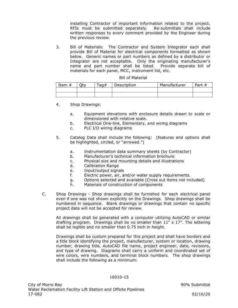
16010-15
City of Morro Bay 90% Submittal Water Reclamation Facility Lift Station and Offsite Pipelines 17-082 02/10/20
installing Contractor of important information related to the project. RFIs must be submitted separately. Re-submittals shall include
written responses to every comment provided by the Engineer during the previous review.
3. Bill of Materials: The Contractor and System Integrator each shall provide Bill of Material for electrical components formatted as shown
below. Generic names or part numbers as defined by a distributor or Integrator are not acceptable. Only the originating manufacturer’s name and part number shall be listed. Provide separate bill of materials for each panel, MCC, instrument list, etc.
Bill of Material
Item # Qty Tag# Description Manufacturer Part #
4. Shop Drawings:
a. Equipment elevations with enclosure details drawn to scale or dimensioned with relative scale.
b. Electrical One-line, Elementary, and wiring diagrams
c. PLC I/O wiring diagrams
5. Catalog Data shall include the following: (features and options shall be highlighted, circled, or “arrowed.”)
a. Instrumentation data summary sheets (by Contractor)
b. Manufacturer’s technical information brochure c. Physical size and mounting details and illustrations d. Calibration Range
e. Input/output signals f. Electric power, air, and/or water supply requirements. g. Options selected and available (Cross out items not included) h. Materials of construction of components
C. Shop Drawings - Shop drawings shall be furnished for each electrical panel even if one was not shown explicitly on the Drawings. Shop drawings shall be numbered in sequence. Blank drawings or drawings that contain no specific
project data will not be accepted for review.
All drawings shall be generated with a computer utilizing AutoCAD or similar drafting program. Drawings shall be no smaller than 11" x 17". The lettering shall be legible and no smaller than 0.75 inch in height.
Drawings shall be custom prepared for this project and shall have borders and a title block identifying the project, manufacturer, system or location, drawing number, drawing title, AutoCAD file name, project engineer, date, revisions, and type of drawing. Diagrams shall carry a uniform and coordinated set of
wire colors, wire numbers, and terminal block numbers. The shop drawings shall include the following as a minimum:
16010-16
City of Morro Bay 90% Submittal Water Reclamation Facility Lift Station and Offsite Pipelines 17-082 02/10/20
1. Electrical one-line diagrams detailing all devices associated with the power distribution system. The following applicable information or
data shall be shown on the one- or three- line diagram: location, size and amperage rating of bus; size and amperage rating of wire or cable; breaker ratings, number of poles, and frame sizes; power fail and other protective devices; fuse size and type.
2. Detailed analog and digital I/O diagrams showing the wiring requirements for each instrument or device connection. Reference the Drawings for an example of each I/O card drawing requirements. If one is not included in the Drawings, then one may be obtained from
the Engineer upon request.
3. Elementary (wiring) diagrams shall be provided for all relay logic, programmable logic controls, motor controls, power supplies, and
other wiring. All elementary (wiring) diagrams shall be drawn in JIC EMP/EGP format and standards showing ladder rung numbers and coil and contact cross referencing numbers.
4. Equipment exterior and interior scaled drawings of front, side,
elevation, deadfront, front panel devices, and backpan components. Show fabrication methods and details; including material of construction, paint color, door latch and lock, and ventilation system.
Show shipping split locations and offloading information. Submit base plan showing allowed conduit entrance areas and bolt hole locations.
5. Drawings shall show UL required information as needed to UL label the equipment in accordance with UL procedures for label applied.
6. Submit full size drawing of all nameplates and tags, as specified herein, to be used on project. Submittal to include the following:
a. Dimensions of nameplate. b. Exact lettering and font for each nameplate.
c. Color of nameplate. d. Color of lettering. e. Materials of construction.
f. Method and materials for attachment. g. Drawing showing location of nameplates on each, panel and
enclosure.
D. Seismic Anchor Design Calculations
1. All switchgear, motor controls centers, transformers, cabinets, raceways, supports, and electrical materials shall be so installed as to remain in a secure and captive position when subjected to a horizontal
force in accordance with the current, applicable, and more stringent of California Building Code (CBC) or International Building Code (IBC) requirements. Method of securing shall constrain equipment against both vertical and horizontal forces and overturning forces.
2. Calculations as prepared by a structural engineer registered in the State of California shall be submitted in accordance with code
16010-17
City of Morro Bay 90% Submittal Water Reclamation Facility Lift Station and Offsite Pipelines 17-082 02/10/20
requirements for earthquakes forces on all specified equipment. Calculations shall include wind loading forces for equipment installed
outdoors.
1.12 OPERATING AND MAINTENANCE INFORMATION
A. Operational Training
1. At time of completion, the Contractor shall provide a period of not less
than 6 hours training for instruction of operation and maintenance personnel in the use of systems. Instruct all personnel at one time in one session. Make necessary arrangements with manufacturer's representative. Provide product literature and application guides for
user's reference during instruction.
B. Operations and Maintenance Manuals
1. Provide Operation and Maintenance manuals per specifications as
described in “Submittal Requirements” in this section with the following additional requirements:
a. A comprehensive index.
b. A complete "Record" set of favorably reviewed electrical
submittals as provided under subsection “Submittal Requirements” illustrating all components, piping, and electrical connections.
c. A complete list of the equipment supplied, including serial numbers, ranges, catalog cuts, and pertinent data.
d. Full specifications on each item.
e. Detailed service, maintenance and operation instructions for
each item supplied. Schematic diagrams of all electronic devices shall be included. A complete parts list with stock numbers shall be provided for the components that make up the assembly. All of these shall be originals, no copies.
f. Special maintenance requirements particular to this system shall be clearly defined, along with special calibration and test procedures.
2. Submit electronic readable PDF file format (CD disk copies (2) or email with attachments or download links) of the proposed O&M manuals for review by the Engineer. Submittals shall be delivered timely to the Engineer to allow for review period, corrections, and re-submissions as
necessary.
a. General Contractor supervision must not be circumvented by sending submittals direct to Engineer.
b. O&M Submittals shall be published 1st electronically and 2nd on hard copy paper stock.
16010-18
City of Morro Bay 90% Submittal Water Reclamation Facility Lift Station and Offsite Pipelines 17-082 02/10/20
c. Electronic Submittals shall be transmitted with the hard copy submittals and be viewable using a PDF reader.
d. Electronic submittals shall be assembled in accordance with the specifications for hard copy submittals with table of contents, bookmarks, tabs, subtabs, etc. utilizing the electronic bookmarks feature available in the PDF assembler.
e. Electronic (PDF) submittals must follow all applicable requirements for hard copy submittals including indexing, item selection indication, bookmarks, etc.
3. Provide four (4) hard copy O&M manuals per specifications as
described in SUBMITTALS REQUIREMENTS in this section.
a. Deliver approved hard-copy O&M manuals to the project site and Owner prior to pre-operational testing or equipment start-
up.
C. At the end of the project hard copy and soft copy electronic PDF files, shall be updated to "as-built" conditions.
D. Provide two (2) sets of compact disk (CD) containing all shop drawings,
application programs, configurations, calculations, documents or other computer electronic files prepared for this project in native file format and updated to reflect as-built conditions.
PART 2: PRODUCTS
2.01 QUALITY
A. All equipment and materials shall be new, in current production, and the products of reputable suppliers having adequate experience in the
manufacture of these particular items. For uniformity, only one manufacturer will be accepted for each type of product.
B. Products specified that have become obsolete (out of current manufacturing, or have been superseded by another product) shall be cross-referenced to a
replacement product(s) and provided in lieu of the specified product(s) for no additional cost. Under no conditions, shall products be submitted or furnished that are known (on manufacturer’s list of obsolescence) and expected to be
removed from current production within 12 months after project submittal. Products found to have been furnished this way will be removed and replaced at Contractor’s expense.
C. All equipment shall be designed for the service intended and shall be of
rugged construction, of ample strength for all stresses which may occur during fabrication, transportation, erection, and continuous or intermittent operation. All equipment shall be adequately braced and anchored and shall
be installed in a neat and workmanlike manner. Appearance and safety, as well as utility, shall be given consideration in the design of details. All components and devices installed shall be standard items of industrial grade,
16010-19
City of Morro Bay 90% Submittal Water Reclamation Facility Lift Station and Offsite Pipelines 17-082 02/10/20
unless otherwise noted, and shall be of sturdy and durable construction suitable for long, trouble free service. Light duty, fragile and competitive
grade devices of questionable durability shall not be used.
D. The Contractor should expect that there will be occasional freezing conditions at the project site in outdoor locations. Instrument valves, tubing, instrumentation, and other components, etc. which are outdoors and
susceptible to damage if frozen, must be provided with internal or external protection. Freeze protection can consist of internal or external active heaters with thermostats and/or passive insulation systems. Active systems can be powered from a nearby receptacle or via the conduit intended for the
device.
E. Products that are specified and include a manufacturer, trade name or catalog number are intended to establish a standard of quality, performance,
warranty and service. Products that are specified “or equal,” do not prohibit the use of equal products of other manufacturers provided they are submitted, identified and promoted as equal, and favorably reviewed by the Engineer prior to procurement and installation.
F. Products submitted as “equal” to the named products will be reviewed for conformance with the specifications and in comparison with the first named product. If the equal product meets specifications, but does not have a
feature or performance characteristic that is available with the first named product, and that feature or performance is required for this project, then the submitted equal product may be rejected on those grounds.
G. In the event that some claims of the manufacturer of submitted “equal”
product are called into question by the Engineer, the Contractor, may be required to prove those claims either prior to installation or during startup of product. If the product does not meet the claims made or specifications, the product may be rejected by the Engineer and a replacement product must be
submitted by the Contractor in its place. All cost for the rejected product, installation, testing, and removal will be the responsibility of the Contractor.
H. Underwriters Laboratories (UL) listing is required for all substituted equipment
when such a listing is available for the first named equipment. Extra parts, labor, panel space, power supplies, circuit breakers, and/or GFIC devices shall be provided as necessary for incorporation of specified non-UL components.
I. When required herein or requested by the Engineer, the Contractor shall
submit equipment or material samples for test or evaluation. The samples shall be furnished with information as to their source and prepared in such quantities and sizes as may be required for proper examination and tests,
with all freight and charges prepaid. All samples shall be submitted before shipment of the equipment or material to the job site and in ample time to permit the making of proper tests, analyses, examinations, rejections, and resubmissions before incorporated into the work.
2.02 NAMEPLATES & TAGS
A. Equipment exterior nameplates - Nameplate material shall be rigid laminated
16010-20
City of Morro Bay 90% Submittal Water Reclamation Facility Lift Station and Offsite Pipelines 17-082 02/10/20
black plastic with beveled edges and white lettering; except for caution, warning, and danger nameplates the color shall be red with white lettering.
The size of the nameplate shall be as shown on the drawings. No letters are allowed smaller than 3/16". All nameplates located outdoors shall be UV resistant. Securely fasten nameplates in place using two stainless steel screws, type 316L, if the nameplate is not an integral part of the device.
Epoxy cement or glued on nameplates will not be acceptable. Engrave the nameplates with the inscriptions as approved by the Engineer in the submittal.
1. For each major piece of electrical equipment provide a manufacturer's
nameplate showing the Contract specified name and number designation, and pertinent ratings such as voltage, # of phases, ratings, etc.
2. For each device with a specific identity (pushbutton, indicator, instrument, etc.) mounted on the exterior or deadfront of a piece of equipment provide a nameplate with the inscription as shown on the Drawings and described herein.
3. Where no inscription is indicated on the Drawings or described herein, furnish nameplates with an appropriate inscription providing the name and number of device.
4. Install Safety Signs in accordance with the latest OSHA requirements.
a. Entrances to electrical rooms and stations: Danger Sign requirements, ELECTRICAL ROOM, HIGH VOLTAGE (define voltage, example 480 VAC) KEEP OUT, AUTHORIZED
PERSONNEL ONLY.
b. Equipment enclosures, cable tray and wireway where 120 VAC or higher and 50 V DC and higher exist: Danger Sign requirements, HIGH VOLTAGE (define voltage, example 480
VAC) AUTHORIZED PERSONNEL ONLY.
c. Equipment such as motor control centers, control panels, etc., where more than one source may be present in an enclosure or
cubicle: Danger Sign requirements, VOLTAGE (define voltage, example 120 VAC control voltage or 480 VAC power) FROM MULTIPLE SOURCES IN THIS ENCLOSURE.
d. Equipment such as switchboards, switchgear, panelboards and
motor control centers: Warning Sign requirements, WARNING, SERVICE ENTRANCE DISCONNECT FOR 1 OF ___ (define quantity) SERVICES TO THIS BUILDING. OTHER SERVICE
ENTRANCE DISCONNECTS ARE LOCATED AT (define locations).
5. Caution, warning and danger nameplates shall be red with white lettering
B. Equipment Interior Nameplates - Nameplate material shall be clear plastic
16010-21
City of Morro Bay 90% Submittal Water Reclamation Facility Lift Station and Offsite Pipelines 17-082 02/10/20
with black machine printed lettering as produced by a KROY or similar machine; except caution, warning, and danger nameplates shall have red
lettering. The size of the nameplate tape shall be no smaller than 1/2” in height with 3/8" lettering unless otherwise approved by the Engineer. Securely fasten nameplates in place on a clean surface using the adhesion of the tape. For each device with a specific identity (relay, module, power
supply, fuse, terminal block, etc.) mounted in the interior of a piece of equipment provide a nameplate with the inscription as shown on the Drawings and described herein. Where no inscription is indicated on the Drawings or described herein, furnish nameplates with an appropriate
inscription providing the name and number of device used on the submittal drawings. Stamp the nameplates with the inscriptions as approved by the Engineer in the submittal.
C. Equipment Tags - When there is no space or it is impractical to attach an engraved plastic nameplate with screws, as is the case with most field devices and instruments, the Contractor shall attach a tag to the equipment with the same inscriptions as specified above in paragraph A. The tag shall be made
from stainless steel material and the size of the nameplate shall be no smaller than 3/8"h x 2"w with 3/16" machine printed or engraved lettering unless otherwise approved by the Engineer. The tag shall be attached to the
equipment with stainless steel wire of the type normally used for this purpose.
2.03 FASTENERS
A. Fasteners for securing equipment to walls, floors, or ceilings, shall be
stainless steel. The minimum size fastener shall be 3/8 inch diameter.
2.04 COMPONENTS
A. Switches and Pushbuttons
1. Switches (HS) and pushbuttons (HC) for general purpose applications
shall be water and oil tight as defined by NEMA 4X, corrosion resistant as defined by NEMA ICS 6-110.58, U.L. listed, standard 30 mm diameter, with plastic holding nut.
2. Switches and pushbuttons shall have contacts rated NEMA A600 or 10 amperes continuous and 600 VAC. Provide NO and NC contacts as required.
3. Engraved black legend plates shall be provided to define each switch
and pushbutton function.
4. Selector switch handles and pushbutton caps shall be black unless otherwise noted on drawing. Lock-out stop caps shall be red.
5. Selector switches for hand-off-auto (HOA) applications shall have the hand position to the left, off in center, and auto in the right position.
6. Pushbuttons and selector switches in hazardous locations shall have
16010-22
City of Morro Bay 90% Submittal Water Reclamation Facility Lift Station and Offsite Pipelines 17-082 02/10/20
hermetically sealed contacts or explosion proof enclosures.
7. Lockout stop pushbuttons shall include padlocking attachment.
Pushbutton type shall be coordinated with padlock attachment type.
8. Switches and pushbuttons shall be Allen-Bradley 800H, or equal.
B. Indicating Lights
1. Indicating Lights for general purpose applications shall be NEMA 4X,
corrosion resistant as defined by NEMA ICS 6-110.58, U.L. listed, 30 mm diameter, with plastic lens, plastic holding nut, and miniature bayonet lamp base.
2. Lamp shall be full voltage 120 VAC with 28 chip (min) High Intensity
LED.
3. Indicating lights shall have contacts rated NEMA A600 or 10 amperes continuous and 600 VAC. Provide NO and NC contacts as required.
4. Engraved black legend plates shall be provided to define each lights function.
5. Indicating light type and color of lens shall as follows or as otherwise shown on the Drawings:
a. Open/On Green b. Closed/Off Red c. Alarm Amber or Blue
d. Power On White
6. Indicating lights designated "PTT" on wiring diagram or shown with push-to-test wiring shall be provided with a push-to-test switch and wiring.
7. Indication lights shall be Allen-Bradley 800H, or equal.
C. Relays and Timers
1. General: Relays and timers shall be provided with N.O. or N.C. contacts as shown on the Drawings. All spare contacts shown shall be
provided. Contacts shall be rated 10 amps minimum at 120 VAC, 60 Hz unless otherwise shown on the Drawings. Coil voltage shall be 120 VAC unless otherwise described or shown on the Drawings. Relays and
timers shall be designed for continuous duty. All relays shall be U.L. listed. All relays and sockets shall be the product of a single manufacturer. The following is a summary of abbreviations associated with relays and timers:
CR – Control relay TR – Timing relay
16010-23
City of Morro Bay 90% Submittal Water Reclamation Facility Lift Station and Offsite Pipelines 17-082 02/10/20
TDOE – Time delay on energization TDOD – Time delay on de-energization
PR – Power Relay
2. Sockets for plug-in relays and timers shall be standard industrial type DIN rail mount with barrier type pressure plate screw terminals. Sockets shall be rated 300 VAC, 10 amps minimum.
a. Blade 8 or 11 pin for coil voltage above 90 volts AC or DC.
b. Octal 8 or 11 pin for coil voltage below 90 volts AC or DC.
3. Control relays (CR) shall be plug-in type with neon indicating lights and clear see-through sealed housing to exclude dust. Provide IDEC
Type RR, or equal. Two form-C contacts (minimum) shall be provided on each relay.
4. Time delay relays on energization (TR-TDOE) shall be solid state
plug-in relays with adjustable timer ranges from 1 second to 10 hours selectable unless other ranges are shown. Provide LED timer energized indicator lamp. Time delay relays shall be IDEC RTE, or equal.
5. Time delay relays on energization (TR-TDOE) shall be solid state plug-in relays with adjustable timer ranges from 1 second to 10 hours selectable unless other ranges are shown. Provide LED timer numeric
display with countdown function. Time delay relays shall be IDEC GT3D-3EAF20, or equal.
6. Time Delay Relays (TR-TDOD)
a. Time delay relays on de-energization (TR-TDOD) (continuous
power control input) shall be solid state plug-in relays with a timer adjustable range from 1 second to 10 hours selectable unless other ranges are shown. Provide LED timer energized indicator lamp. Time delay relays shall be IDEC RTE, or equal.
b. Time delay relays on de-energization (TR-TDOD) (true off) shall be solid state plug-in relays with a timer adjustable range from 1 second to 10 minutes unless other ranges are shown. True
off time delay relays shall be IDEC GT3F-2, or equal.
7. Power relays (PR) shall be plug-in type and clear see-through sealed housing to exclude dust. Provide Magnecraft Type 389FXCXC-120A, or equal. 3PDT contacts rated 20A or 1 HP at 240 VAC (minimum) shall
be provided on each relay. Furnish compatible blade type relay socket model 70-788EL11-1 or equal.
D. Amperage Transducer:
1. Amperage transducer shall produce 4-20mADC output directly proportional to measured current (utilizing integral CT) of the power
16010-24
City of Morro Bay 90% Submittal Water Reclamation Facility Lift Station and Offsite Pipelines 17-082 02/10/20
feed. Transducer range shall be selected for the load to be measured with expected load current between 50% and 75% of available
measurement range. Transducer shall measure true RMS current and have an accuracy of 5% and repeatability of 1/2% of full scale (minimum). Operating temperature range shall be -20 deg C to 50 deg C. Transducer shall have separate zero and span adjustments.
Insulation between output and case shall be rated at 1000VAC. Amperage transducer shall be as manufactured by Neilsen-Kuljian (NK technologies) ATR series or equal.
E. Amperage Switch:
1. Amperage switch shall be self powered and provide a closed contact which closes the output contact when current is measured through the integral current transformer above adjustable setpoint (1-6, 6-40, or
40-175 amps selectable). The switch shall have an accuracy of 5% and repeatability of 1/2% of full scale (minimum). Switch shall include LED for quick visual indication of contact status. Operating temperature range shall be -20 deg C to 50 deg C. Transducer shall
have separate zero and span and time delay adjustments. Insulation between output and case shall be rated at 1000VAC. Amperage switch shall be as manufactured by Neilsen-Kuljian (NK technologies) ASX
series or equal.
2.05 MOTOR CONTROL ACCESSORIES
A. Control Power Transformer:
1. Control power transformer shall be epoxy encapsulated for dust and
moisture protection. The internal wiring shall be copper and have 105 deg. C insulation rating. The unit shall feature barriered screw terminals for connection to electrical circuits. Provide with time-delay, slow-blow secondary fuse rated to protect the transformer and
interrupt 10,000 amperes at 120VAC. Two primary fuses rated for 480 VAC and AIC as shown in the Drawings shall be provided. Transformer minimum size and voltage ratings shall be as shown on Contract
drawings. Control power transformer shall be Micron Impervitran, Cutler Hammer MTE or equal.
B. Simplex Starter:
1. The simplex starter shall be self contained motor starter and include a
three pole magnetic circuit protector, NEMA rated motor starter with adjustable overloads, HOA, lights and other buttons as defined on the motor elementary or as required for an operable system. The
enclosure shall be non-metallic 316 stainless steel and rated NEMA 4X. The motor starter shall be rated for 480 Volt, and 10 HP (minimum) unless otherwise shown on the drawings. Provide fuses, auxiliary contacts, or indicators as required by the motor control or one-line
diagram. A side or front mounted operator shall interlock the door and open/close the MCP breaker and have provisions for up to 3 padlocks. Simplex Starter shall be Cutler Hammer, ABB, Square D, or equal.
16010-25
City of Morro Bay 90% Submittal Water Reclamation Facility Lift Station and Offsite Pipelines 17-082 02/10/20
C. Voltage Monitor Relay (VMR)
1. The voltage monitor relay (VMR) shall continuously monitor the three
phases for power loss, low voltage, phase loss, and phase reversal. The VMR shall interface to the control circuit with DPDT contacts rated for 4 Amps at 120 VAC. The VMR shall have a drop-out voltage adjustment, time delay adjustment, and status indicating LEDs.
Voltage monitor relay shall be Time Mark 2652, or equal.
2.06 DEVICES
A. Switches
1. General purpose commercial grade switches shall be manufactured in
accordance with UL 20. Switches shall be one pole, brown, 20 amps at 277 VAC, 1HP at 120 VAC, 2 HP at 240 VAC. Switches shall have copper alloy contact arm with silver cadmium oxide contacts.
Switches shall have slotted terminal screws and a separate green grounding screw. Provide Leviton 1221, or equal.
2. Wall mount commercial grade motion detector switches (denoted with M next to switch symbol in drawings) shall utilize passive infrared
detection with 180 deg field of view to determine if the space is occupied by personnel. The device shall be capable of switching incandescent (800W at 120V) and fluorescent (1200VA at 120V) lamps
with electronic ballasts. The device shall feature a manual-off-auto switch. A delay off time adjustment shall be settable from 30 seconds to 30 minutes. The device shall incorporate a photocell with light intensity adjustment to keep the switch from activating when light
levels are above setting. Provide Leviton ODS10, or equal.
B. Receptacles
1. General purpose receptacles shall be commercial grade, duplex and rated 20 amps, 120 VAC, 2 pole, 3 wire grounding, NEMA 5-20R
configuration, specification grade, and side wired to screw terminals. Face color shall be brown when paired with stainless steel covers. General purpose receptacles shall be specification grade Leviton 5362-
B or equal.
2. Ground fault circuit interrupter receptacles shall be used where noted as GFI on plan or where in outdoor NEMA 3R locations. GFI receptacles shall be commercial grade, duplex, brown, 20A, 120V,
back and side wired, with "test" and "reset" buttons. “Daisy Chain” connecting multiple receptacles from one GFI unit is not acceptable. GFI receptacles shall be Leviton 8898, Leviton MGNF2-B, Leviton 7899,
or equal.
3. Boxes shown in NEMA 3R environments and outdoor locations shall be weatherproof while in-use. Furnish in-use weatherproof covers and weatherproof boxes for these areas.
16010-26
City of Morro Bay 90% Submittal Water Reclamation Facility Lift Station and Offsite Pipelines 17-082 02/10/20
4. Definite purpose receptacles and plugs in NEMA 4 or 4X environments where a receptacle is shown and a device is to be connected
continuously, shall be listed as UL type 4, 4X, (Plug) and NEMA 3R (flip cover). Receptacles, plugs, and housings shall be fabricated of impact resistant plastic with o-rings and gaskets to prevent the entrance or water, vapors, and chemicals when unplugged or plugged. Circular
plugs shall be retrofitted onto equipment so as to be compatible with the receptacles to maintain in-use ratings. Furnish Hubbel Watertight Wiring Devices and Accessories, or equal.
2.07 POWER MONITORING
A. Power Monitor
1. General:
a. Microprocessor based multifunction power and energy meter
b. Designed for multifunction electrical power, voltage, and current measurement on 3 phase power systems.
c. Measured parameters: voltage, current, frequency, unbalance, kW, KVAR, KVA, power factor, kWh.
d. Support for 3-Element Wye, 2.5 Element Wye, 2 Element Delta, 4 wire Delta systems.
e. 200 ms update for power measurement, 100ms update for
voltage, current, Hz.
f. Din rail mounting
g. 85 to 264 VAC control power, 5W.
2. Voltage Inputs
a. Configurable to potential transformer ratio.
b. Input impedance of 1 Mega Ohm, 0.014W at 120 Volts.
c. Direct voltage input range
1) 347 Volts Line to Neutral
2) 600 Volts Line to Line.
d. 2500V withstand.
3. Current Inputs:
a. Configurable to current transformer (CT) ratio 1A or 5A input.
b. Burden 0.05VA, Impedance 0.002 ohms
c. Meter shall have a maximum burden of 0.005VA per phase, at the maximum of 15 Amperes continuous input.
d. Fault current withstand shall be 200 Amps for 1/2 second.
4. Digital I/O:
a. Two status inputs 24VDC dry contact.
b. Two assignable digital relay outputs
16010-27
City of Morro Bay 90% Submittal Water Reclamation Facility Lift Station and Offsite Pipelines 17-082 02/10/20
5. Accuracy
a. Revenue meter accuracy
b. +/- 1% or better for volts and amps
c. +/- 1% for power and energy functions.
d. True RMS measurements
6. Communications
a. Ethernet - 100BaseT Ethernet IP Allen Bradley protocol
b. Modbus TCP
7. Display:
a. 4 Line backlit LCD display to display real time measured
parameters including voltage, current, power, and power factor.
8. Acceptable Products
a. Allen Bradley PM1000 1408-EM3A-ENT with Ethernet
b. Allen Bradley PM500 1420-V2P-ENT with Ethernet
c. Or Equal
B. Current Transformers
1. Furnish mounted (preferable) or unmounted current transformers
based on space allocated and installation requirements. The current transformer shall have wire leads or binding posts and ratio as shown on the drawings. The accuracy shall be metering accuracy class 0.6 at
a minimum burden at 60 hz shall be 2.5 VA and as required to meet specified accuracy of device(s) fed.
PART 3: EXECUTION
3.01 CONSTRUCTION METHODS
A. Equipment shall be assembled and wired by the manufacturer prior to shipment. Field modifications or changes are not allowed without a written "change order" to the Contract. Field changes, however large or small, shall be executed using the components, materials, wiring, labeling, and assembly
methods identical to that of the original supplied equipment.
B. Electrical plugs, receptacles, cords, and connectors required to power or interface the equipment and panels shall be furnished and installed by the
Contractor.
C. Factory as-built drawings for each custom manufactured control panel or MCC shall be shipped with the equipment and placed inside in waterproof envelopes.
3.02 EQUIPMENT FABRICATION
A. All electrical equipment, including custom manufactured equipment, shall
16010-28
City of Morro Bay 90% Submittal Water Reclamation Facility Lift Station and Offsite Pipelines 17-082 02/10/20
meet the requirements of Underwriters Laboratories (UL) and bear the appropriate label. Panels shall be affixed with UL label prior to shipment and
be built in accordance with the UL guidelines and procedure that corresponds to the UL label. Custom control panels shall bear a UL-508 label, minimum, with additional UL labels as required per intended service.
1. Design and furnish a Low Voltage Limited Energy Circuit for any
device(s) not bearing a UL listing or registration that are required to be installed into a UL labeled panel.
2. Revise voltages for any electrical parts and equipment that are specified that do not bear the UL listing or registration.
B. Panel cutouts for devices (i.e. indicating lights, switches) shall be cut, punched, or drilled and smoothly finished with rounded edges. Exposed metal from cutouts that are made after the final paint finish has been applied shall
be touched up with a matching paint prior to installing device.
C. Equipment doors shall swing freely and close and latch with proper alignment.
D. Component within the electrical equipment shall be securely mounted on an interior subpanel or backpan and arranged for easy servicing. Mounting bolts
and screws shall be front mounted for device removal without special tools or removal of entire mounting panel.
E. A ground bus shall be provided in each enclosure or cabinet. It shall have
provisions for connecting a minimum of ten grounding conductors. Screw type lugs shall be provided for connection of grounding conductors. All grounding conductors shall be sized as shown on plans or in accordance with NEC Table 250-95, whichever is larger.
F. Bolts and screws for mounting devices on doors shall have a flush head which blends into the device or door surface. No fastening devices shall project through the outer surfaces of equipment.
3.03 WORKMANSHIP
A. All work in this division shall conform to the codes and standards outlined herein.
B. Installation shall be performed by qualified personnel providing first class
workmanship per Electrical Specifications [Electrical General, Qualifications].
C. Maintain equipment installed (or to be installed) in new condition. Protect equipment from damage while in Contractor care from dust, water, or mishaps that are typical to construction sites
D. Confirm that equipment and materials are correct for their intended duty and will be installed per manufacturer guidelines. Equipment and components found to be installed inconsistent with manufacturer guidelines and/or these
specifications will not be acceptable and subject to removal and replacement.
16010-29
City of Morro Bay 90% Submittal Water Reclamation Facility Lift Station and Offsite Pipelines 17-082 02/10/20
E. Upon completion of daily work, remove excess materials, scraps, and debris from the work area and from the inside of equipment.
F. Upon notification, stop work on any portion of the installation that is determined to be non-compliant with contract or being installed by unqualified personnel.
G. Perform all work to correct improper installations at no additional cost to the
owner.
H. Equipment furnished under this contract or provided to Contractor for installation shall be installed in accordance with manufacturer's instructions, installation calculations, and contract documents.
3.04 EQUIPMENT SHIPMENT AND STORAGE
A. Shipment -- Any equipment whose destination (jobsite) is more than 25 miles from the factory shall be carefully protected for shipping. All openings shall
be protected by plywood securely fastened to the framework of the equipment. Equipment shall be adequately covered during local delivery.
B. Storage -- From the time of receipt until the equipment is installed and energized, the equipment shall be considered in storage. While in storage, a
120V, 1 phase source of power shall be made available and connected to space heaters in all items of equipment so equipped. Equipment not provided with space heaters shall be provided with a light bulb or electric heater while
in storage to prevent moisture condensation. Unless stored indoors, it shall be a least 1 foot above grade covered with at least 2 layers of heavy polyethylene plastic sheets and anchored to prevent damage by high winds. All equipment shall be protected from dust and moisture prior to and during
construction.
3.05 DAMAGED PRODUCTS
A. Damaged products that cannot be repaired to new condition shall be replaced with new products. All equipment and materials shall be in like-new condition
at start-up and commissioning.
B. Any equipment furnished outside of contract to the Contractor shall be repaired or replaced if damaged while in the Contractor’s care. The
Contractor shall pay for the parts and/or services of the original equipment manufacturer (OEM) to troubleshoot, asses, and repair damaged equipment.
C. Minor cosmetic damage shall be repaired by spray painting, after properly preparing the surface, all scratches or defects in the finish of the equipment.
Only identical paint furnished by the equipment manufacturer shall be used for such purposes.
3.06 INSTALLATION
A. General
16010-30
City of Morro Bay 90% Submittal Water Reclamation Facility Lift Station and Offsite Pipelines 17-082 02/10/20
1. Install all products per manufacturer's recommendations and the Drawings.
2. Provide all necessary hardware, conduit, wiring, fittings, and devices to connect the electrical equipment provided under other Sections.
3. Protect wiring insulation from wear by installing rubber cushions, bushings, or strip insulation, or by fastening the wiring to a rigid
surface with zip ties and anchors.
4. Provide additional devices, wiring, conduits, relays, signal converters, isolators to complete interfaces of the electrical and instrumentation system.
5. Changing normally open contacts to normally closed contacts or vice versa
6. Adding additional relays to provide more contacts as necessary.
7. All programmable devices (not specifically excluded herein) shall be programmed, set-up and tested by the Contractor prior to startup. Programming and set-up parameters shall be adjusted or changed as directed by the Engineer during start-up and throughout the warranty
period.
8. Coordinate with the Engineer and setup all alarm, process, and operation setpoints.
9. Keep a copy of the manufacturer’s installation instructions on the jobsite available for review at all times prior to and during the installation of the associated equipment.
B. Panels and enclosures:
1. Install panels and enclosures at the location shown on the Plans or approved by the Engineer.
2. Install level and plumb.
3. Seal all enclosure openings to prevent entrance of insects and rodents.
4. Clearance about electrical equipment shall meet the minimum requirements of NEC 110.26
C. Conduits and Ducts:
1. Install all conduits and ducts per Electrical Specifications [Conduit and Boxes] and [Grounding].
2. Minimum wire bending space at terminals and minimum width of wiring gutters shall comply with NEC tables 312-6 (a) & (b).
16010-31
City of Morro Bay 90% Submittal Water Reclamation Facility Lift Station and Offsite Pipelines 17-082 02/10/20
D. Wiring, Grounding, and Shielding:
1. Observe proper grounding and shielding practices as this application
environment is generally noisy. The shield of shielded cables shall be terminated to ground at one end only, the origination end. The shield at the other end shall be encased in an insulated material to isolate it from ground.
E. Cutting and Patching:
1. The Contractor shall do all cutting and patching required for installing his work. Any cutting which may impair the structure shall require prior approval by the Engineer. Cutting and patching shall be done
only by skilled labor of the respective trades. All surfaces shall be restored to their original condition after cutting and patching.
F. Cleaning and Touch up:
1. At the completion of the work, all parts of the installation, including all equipment, exposed conduit, and fittings, shall be thoroughly cleaned of grease and metal cuttings. Any discoloration or other damage to parts of the building, the finish, or the furnishings, due to the
Contractor's failure to properly clean the system, shall be repaired by the Contractor.
2. The Contractor shall thoroughly clean any of his exposed work
requiring same.
3. Vacuum and clean the inside of all electrical and instrumentation enclosures prior to applying power.
4. The Contractor shall paint scratched or blemished surfaces with the
necessary coats of quick drying paint to match existing color, texture and thickness. This shall include all prime painted electrical equipment including but not limited to enclosures, poles, boxes, devices etc.
3.07 APPLICATION OF POWER
A. The Engineer will direct the energization and de-energization of all existing and new equipment. The Contractor is not authorized to energize or de-energize any equipment unless they have been given written permission to do
so or while in the presence of the Engineer.
1. Any equipment that is under repair, demolition or installation shall be locked off and tagged out of service with Contractor supplied padlocks and tags.
2. The Contractor is required to comply with NFPA 70E and specifically in regards to safety when working on live equipment. Obtain work permits when needed to do live work.
B. The Contractor is responsible for grounding of high and medium voltage
16010-32
City of Morro Bay 90% Submittal Water Reclamation Facility Lift Station and Offsite Pipelines 17-082 02/10/20
cabling and/or bus during installation and removal of equipment. The contractor is responsible for complying with all California Electrical Safety
Orders (ESO) and Occupational Safety and Health Act (OSHA) safety requirements and procedures while working in or near medium voltage equipment.
3.08 WARRANTY
A. The Contractor shall warrant all electrical and instrumentation equipment & software for a period of 1 year from date of final acceptance. Standard published warranties of equipment which exceed the preceding specified length of time shall be honored by the manufacturer or supplier.
B. The Contractor shall have a staff of experienced personnel available to provide on-site warranty service on 2 working days notice during the warranty period. Such personnel shall be capable of fully testing and
diagnosing hardware & software and implementing corrective measures.
3.09 FINAL ACCEPTANCE
A. Final acceptance will be given by the Engineer after the equipment testing is complete, each deficiency has been corrected, final documentation has been
provided, and all the requirements of Contract documents have been fulfilled.
B. At the end of the project, following the completion of the field tests, and prior to final acceptance, the Contractor shall provide the following:
1. Each "operation and maintenance" manual shall be modified or supplemented to reflect all field changes and as-built conditions.
2. Two (2) disk copies of all final documentation to reflect as-built conditions.
C. Keys: Submit two sets of all keys for locks supplied on this project. Wire all keys for each lock securely together. Tag and plainly mark with lock number or equipment identification, and indicate physical location, such as panel or switch number.
END OF SECTION
16110-1
City of Morro Bay 90% Submittal
Water Reclamation Facility Lift Station and Offsite Pipelines
17-082 02/10/20
SECTION 16110
CONDUIT AND BOXES
PART 1: GENERAL
1.01 SCOPE OF WORK
A. Labor, materials, equipment, tools, safety gear, test equipment, incidentals,
services, and transportation for a complete electro-mechanical installation as
shown on the Drawings, included in these Specifications, or as can be
reasonably implied from project descriptions.
B. The scope of work includes:
1. Furnish and instPall conduits, wireways, raceways, cable trays,
junction boxes, pull boxes, and associated hardware. Provide conduit,
fittings, hardware, hangars, mounting channel, and other parts for a
complete raceway installation.
2. Furnish and install grounding system required by drawings, or if not
shown or defined, as required by Article 250 of the NEC.
3. Installations shall be designed and installed with components meeting
the NEMA area designation.
C. Work includes that specified in Electrical Specifications [Electrical General].
1.02 REFERENCES
A. Electrical Specifications [Electrical General]
B. Electrical Specifications [Low Voltage Wire & Data Cable]
C. Electrical Specifications [Grounding]
D. Project Drawings
1.03 QUALIFICATIONS
A. Material furnished under this specification shall be installed by qualified
installers meeting requirements specified in Electrical Specifications [Electrical
General, Qualifications].
1.04 SUBMITTAL REQUIREMENTS
A. Provide submittals and drawings as specified in Electrical Specifications
[Electrical General, Submittal Requirements].
16110-2
City of Morro Bay 90% Submittal
Water Reclamation Facility Lift Station and Offsite Pipelines
17-082 02/10/20
PART 2: PRODUCTS
2.01 CONDUIT, RACEWAYS AND WIREWAYS
A. GENERAL - Conduit, raceways, and wireways, wiring methods, materials,
installation shall meet all requirements of the NEC, be UL labeled for the
application, and meet the minimum following specifications.
1. All wiring shall be installed in conduits, raceways, or wireways when
interconnecting equipment and devices.
a. The minimum size conduit shall be 3/4-inch unless indicated
otherwise on the Drawings or for special connections to
equipment.
b. Provide cords and cord seals for devices or instrumentation
requiring waterproof seal to maintain NEMA 4 or 4X ratings.
Example devices include lighting and pipe mounted instruments
that are located below grade.
2. Conduits may connect into junction boxes or wireways as shown in the
drawings or as requested by Contractor and approved by Engineer.
Junction boxes (circle with J in drawings) can be as simple as a
condulet or JIC box, or larger box as determined by contractor and
needed for the installation. Drawing may or may not depict junction
box requirements that may be required by code. Wireways or junction
boxes shall be rated for area (as noted in the Drawings), or furnish
minimum NEMA 4 if not noted.
3. The Contractor shall use conduit material types (SPEC per conduit
schedule) as defined below or as otherwise shown in the contract
drawings or as specifically called out in the conduit schedule.
a. Non-exposed underground portions of conduit run shall be PVC-
40 for all signals and voltages unless otherwise shown in the
conduit schedule.
16110-3
City of Morro Bay 90% Submittal
Water Reclamation Facility Lift Station and Offsite Pipelines
17-082 02/10/20
b. Exposed conduit material (not underground and beyond
transition) shall be per the following table unless specifically
noted otherwise in the plan drawings. The conduit schedule
denotes the conduit type for non-exposed (under-ground, in-
concrete, etc.) and does not apply or coordinate with this table.
Exposed condulets, elbows, fittings, device boxes, and
hardware shall be of the same material and finish as the
adjacent conduit.
Location Material
NEMA 1 or 12 Galvanized rigid steel (GRS)
NEMA 3R Galvanized rigid steel (GRS)
NEMA 4 PVC-Coated Steel (GRS-PVC)
NEMA4X PVC-Coated Steel (GRS-PVC).
Class 1 Div 1 or 2 hazardous PVC-Coated Steel (GRS-PVC)
4. Conduit stubs and transitions:
a. Conduit transitions shall be GRS-PVC for 6” on either side of the
transition point (minimum) or as shown in drawing details.
Conduit transition is defined as conduit sections emerging from
or through concrete or earth or from below to above grade or
through walls or vaults, non-exposed to exposed.
b. Beneath pad mounted electrical equipment, where not exposed,
shall be installed or trimmed to 2” or less above slab and have
bushing or end bell installed. Overall height of conduit entering
into the base of equipment shall be enough for bushings/bells
to be installed but be high enough for conduit tags to be
installed.
c. Uniform in height for each panel or section. Conduits end
bushings/bells shall not vary in height above slab more than ½”
from lowest to highest.
d. Conduits shall be spaced apart such that bushings and end bells
may be installed without interfering with the adjacent conduits.
e. Transitions to PVC shall include PVC coated locknuts to shield
exposed steel pipe threads.
f. Through walls – shall protrude approximately 2” and include
end bell or bushing. Pack space around conduit with non-shrink
grout if the thru-hole was core drilled.
g. Conduits for future use shall be capped with coupling and plug.
Identify each end with conduit labels.
h. Existing conduits that are no longer able to be used due to
removal of a section or shown demolished and that protrude
16110-4
City of Morro Bay 90% Submittal
Water Reclamation Facility Lift Station and Offsite Pipelines
17-082 02/10/20
above graded shall be cut flush and filled with grout.
5. Conduit Tags
a. All conduits listed in the “Conduit and Wire Routing Schedule”
shall have conduit tags at both ends of each conduit run with
tag number from schedule identified. This shall include ends
within underground pull boxes.
b. All conduits shall have temporary tags during construction.
Temporary tags may be made from duct tape with hand written
ink marking or suitable equivalent. Temporary tags shall be
removed by Contractor at time of installation of permanent
tags.
c. Tag material shall be rigid laminated red plastic with white
lettering. The size of the tag shall be ¼” thick by ¾” round or
¾” x 1” rectangle minimum.
d. Letter height shall be ¼” minimum. Engrave the tags with the
conduit number or acronym. Labeling shall be neatly installed
for visibility and shall be clearly legible. Securely fasten tags in
place using 20ga stainless steel tie wire through a pilot hole on
the tag.
e. Conduit tags shall be Custom manufactured per specification.
6. Supports
a. Cross section of a single channel shall be 1-5/8" x 1-5/8" and
cross-section of a double channel shall be 1-5/8" x 3-1/4". The
channel wall thickness shall be 12 gauge as applicable.
b. One-Hole clamps shall be intended for pipe mounting on
support channels and equipped with clamp-backs. The clamps
shall be Efcor, Thomas and Betts, Appleton or equal
c. Spacers, provided to support underground conduits in concrete
encasements, shall be plastic. The spacers shall be Carlon,
Johns-Manville, Underground Products or equal
d. Anchors shall be expansion type for securing equipment to
concrete foundations, floors and walls. Anchors shall have
length identification mark on the exposed end of the bolt.
Provide Hilti Kwik Bolt 3, or equal.
e. Stanchions shall be provided as needed to mount equipment
and electrical components. Stanchions shall be shop fabricated
from welded 4” c-channel, 12” x 12” x ¼” steel base plate,
coated with a rust inhibiting primer and top coat of gray
polyurethane gloss paint. Attach equipment to the stanchion
direct or on a ¼” aluminum sheet sized for the equipment
16110-5
City of Morro Bay 90% Submittal
Water Reclamation Facility Lift Station and Offsite Pipelines
17-082 02/10/20
supported.
f. Conduit Hangers shall be trapeze construction, with double
channel, 3/8-inch rods and nuts. Suspend from suitable
structural support.
g. Support material and finish shall be per the following table
unless otherwise noted in the drawings. Brackets, fittings and
hardware shall be of the same material and finish.
Location Material
Indoors NEMA 12 Galvanized steel
Outdoors NEMA 3R Galvanized steel
Outdoors NEMA 4 Stainless Steel type 316
Corrosive areas
NEMA4X
PVC bonded, 40 mil, factory applied
h. Equipment mounting racks shall be designed by installer for
rigid equipment and conduit mounting. Racks shall be bolted or
welded construction and sized for equipment or as shown on
the drawings.
i. Strut channels shall be used for mounting equipment to walls
and for supporting conduit runs. Double strut channel type
shall be used for fabricating equipment mounting racks as
required and/or as detailed on the drawings. Add additional
supports to rigid mounting locations as needed to prevent
wobbling and to meet seismic requirements. All field cut
surfaces of the strut channels shall be deburred and coated to
prevent rust.
B. Galvanized Rigid Steel Conduit - (GRS)
1. Manufactured from high-strength steel and hot dipped zinc galvanized
inside and out. Conduit and fittings shall meet UL 514B, UL 6, and
conform to NEMA RN 2. Conduit shall be capable of being used as an
equipment grounding conductor per NEC 250.
2. Provide galvanized rigid steel factory sweeps and elbows for 90 degree
transitions.
3. Cast fittings and device boxes shall be malleable iron or aluminum.
Appleton type FS/FD or equal.
4. In hazardous locations, fittings shall meet and be listed UL 886.
5. All fittings, hubs, couplings, pulling elbows and connectors shall be
threaded-type. Set-screw type and compression-type are not
acceptable. All thread conduit is not allowed over 1/2” exposed
length. Cover plates shall be cast iron with sealing gasket in NEMA 3R
locations.
16110-6
City of Morro Bay 90% Submittal
Water Reclamation Facility Lift Station and Offsite Pipelines
17-082 02/10/20
6. Conduits entering enclosures shall be fitted with insulated grounding
bushing; O-Z "HBLG", Appleton "GIB", or approved equal. All
grounding bushings shall be tied to the grounding system with
properly sized bonding conductors per the NEC code.
7. Combination expansion-deflection fittings installed exposed shall be
Type XD as manufactured by Crouse-Hinds Co.; Type DX as
manufactured by O.Z. Gedney Co.; Type DF as manufactured by
Appleton Electric Co., or equal
C. Galvanized Rigid and Coated Steel Conduit (GRS-PVC)
1. Galvanized Rigid Steel conduit with a 40-mil thick polyvinylchloride
exterior coating and a 2-mil urethane interior coating meeting NEMA
RN-1, UL-6 and ETL PVC-001. The bond of the PVC to the zinc coated
pipe must be stronger than the tensile strength of the PVC.
2. Provide PVC coated galvanized rigid steel factory sweeps and elbows
for 90 degree transitions.
3. Cast fittings and device boxes shall be malleable iron or aluminum with
a 40-mil thick PVC coating meeting the same
4. In hazardous locations, fittings shall meet and be listed UL 886.
5. Provide PVC coated threaded-type fittings, hubs, pulling elbows,
couplings, and connectors; set-screw type and compression-type are
not acceptable. Form 8 conduit fittings, ½” through 4”, must have a
tongue-in-groove gasket to effectively seal out the corrosive elements.
Covers shall be supplied with plastic encapsulated stainless steel cover
screws. Form 8 fittings shall be UL and type 4X and IP69 listed.
6. A “PVC Coated Sealing Locknut” shall be used on all exposed male
threads transitioning into female NPT threads which do not have
sealing sleeves, including transitions from PVC couplings/female
adapters to PVC Coated GRC elbows in direct burial applications. “PVC
Coated Sealing Locknuts” are not to be used in place of a myers hub
7. A PVC sleeve extending one pipe diameter or two inches, whichever is
less, shall be formed at every female fitting opening except unions.
The inside sleeve diameter shall be matched to the outside diameter of
the conduit.
8. All junction and metal pull boxes shall be galvanized with exterior
surfaces PVC coated to 40 mils thickness.
9. Unistrut, strut clamps, pipe straps, and clamp back spacers, shall have
40 mil thick PVC coating. All mounting anchors shall be stainless steel.
10. Conduits entering enclosures shall be fitted with insulated grounding
bushing. All grounding bushings shall be tied to the grounding system
with properly sized bonding conductors per the NEC code.
16110-7
City of Morro Bay 90% Submittal
Water Reclamation Facility Lift Station and Offsite Pipelines
17-082 02/10/20
11. Installers of PVC Coated Conduit must be certified by the manufacturer
and be able to present a valid, unexpired certified installer card.
12. GRS-PVC conduit to be Robroy Plasti-bond, Perma-Cote, KorKap, T&B
OCAL or equal.
D. PVC Conduit, Schedule 40 or 80 (PVC-40, PVC-80)
1. Shall be high impact schedule 40 or 80 polyvinylchloride suitable for
use underground, direct burial and for use with 90 C wires, and shall
conform to UL 651. Shall be UL listed and labeled for "direct" burial.
2. A copper bonding conductor shall be pulled in each raceway and
bonded to equipment at each end with approved lugs.
3. Each underground run shall be placed in a trench with a five (5) inch
sand bed evenly compacted on all sides, top and bottom unless
otherwise noted.
4. Elbows, and risers shall be per exposed conduit transition detail. PVC
conduit is not allowed above ground except where specifically called
out on the Drawings.
5. PVC fittings shall have solvent-weld-type conduit connections. Fittings
and device boxes shall be PVC with factory fabricated conduit
connections. Provide Carlon or equal.
6. Conduits entering enclosures shall be fitted with a glued male adapter,
lock ring and bushing to prevent wire chafing. Conduits entering
panels through concrete to an open bottom or entering a pull box shall
have a glued end bell fitting.
7. PVC conduit shall be stored on a flat surface and shielded from the
sun.
E. Communications Conduit, for use in fiber optic applications, (PVC-ID)
1. PVC Conduit with Splined Bell and Spicket, Schedule 40, Splinelock
joining system. No solvent-cements required. Engineered joint
immediately achieves full strength.
2. HDPE Conduit made from Polyethylene SDR-13.5, heat fusion bonded,
3. Each option for use in trench or trenchless locations.
4. Each option suitable for innerduct installation.
F. HDPE Innerduct, for use in fiber optic applications, (PVC-ID)
1. 1-1/4” size, quantity 3, for each 4” conduit length.
2. Internal oscillating longitudinal ribs lower friction allowing longer cable
16110-8
City of Morro Bay 90% Submittal
Water Reclamation Facility Lift Station and Offsite Pipelines
17-082 02/10/20
installations.
3. Internal oscillating longitudinal rib design reduces cable twisting during
placement.
4. Externally smooth wall
5. Strength to match installation and service requirements.
6. Six color coding options for identification without tags.
7. Internal lubrication with pull tape installed as needed.
8. Continuous lengths to each pullbox without splices.
G. Liquid Tight Flexible Non-metallic Conduit (up to 2”) - (FLEX)
1. Liquid tight flexible Nonmetallic Conduit shall be constructed of flexible
PVC and have a smooth inner surface with integral crush resistant
reinforcement within the conduit and be designated as a Type LFNC-B
(for FNMC-B).
2. Liquid tight Flexible Nonmetallic Conduit shall be sunlight, oil, and
flame resistant and approved for the installation of electrical
conductors in indoor and outdoor applications.
3. Liquid tight Flexible Nonmetallic Conduit shall be listed to UL standard
UL1660.
4. Liquid tight flexible non-metallic conduit shall be installed in
accordance with Article 351, Part B of the National Electrical Code
(NEC) and other applicable sections of the NEC and/or local electrical
codes.
5. Liquid tight Fittings shall be listed for the use with Liquid tight Flexible
Nonmetallic Conduit and shall be marked LFNC-B (FNMC-B).
6. Flexible Non-Metallic Conduit shall be Carlon Carflex or equal.
H. Liquid Tight Flexible Metal Conduit (above 2-1/2”) - (FLEX)
1. Liquid Tight Flexible Metal conduit shall be moisture and oil-proof with
PVC jacket extruded over a galvanized flexible steel conduit.
2. Liquid Tight Flexible Metallic Conduit shall be sunlight, oil, and flame
resistant and approved for the installation of electrical conductors in
indoor and outdoor applications.
3. Liquid Tight Flexible Nonmetallic Conduit shall be listed to UL standard
UL 360.
4. Liquid Tight flexible metallic conduit shall be installed in accordance
16110-9
City of Morro Bay 90% Submittal
Water Reclamation Facility Lift Station and Offsite Pipelines
17-082 02/10/20
with Article 351, Part B of the National Electrical Code (NEC) and other
applicable sections of the NEC and/or local electrical codes.
5. Liquid Tight Fittings shall be listed for the use with Liquid tight Flexible
Metallic Conduit and conform to UL514B.
a. Outdoors when extension of GRS-PVC: PVC coated galvanized
steel with insulated bushings.
b. Outdoors when extension of GRS: Galvanized steel with
insulated bushings.
c. Indoors or outdoors when extension of stainless steel: 316
stainless steel with sealing ring and insulated bushing.
d. Indoors: Galvanized steel with insulated bushings.
6. Flexible Metallic Conduit shall be Amer-Tite type GP or equal.
I. EMT Conduit, Electrical Metallic Tubing
1. Thinwall electroplated galvanized steel suitable for indoor and outdoor
use with 90 C wires, and conform to UL 797.
2. All fittings, hubs, couplings, pulling elbows and connectors shall be
compression-type, set screw type are not acceptable.
2.02 DEVICE BOXES
A. BOXES
1. Device boxes shall be of zinc-galvanized malleable iron or cast
aluminum with shape and size best suited for the particular
application, rated for the location installed, and shall be supported
directly to structure by means of screws, anchors, or bolts.
2. Box dimensions shall be in accordance with size, quantity of
conductors, and conduit clearances per NEC articles 314 requirements.
3. Boxes exposed to the weather or in moist locations shall be
weatherproof (WP) by means of gasketing under a weatherproof cover.
4. Boxes connected to GRS-PVC conduit runs shall be PVC coated with 40
mil coating.
B. DEVICE PLATES and COVERS
1. Indoor general purpose device plates and covers shall be stainless
steel. Plates or covers shall be attached with stainless steel screws. An
engraved plastic label denoting circuit breaker number and panelboard
name shall be affixed to each cover with #4 stainless steel screws.
16110-10
City of Morro Bay 90% Submittal
Water Reclamation Facility Lift Station and Offsite Pipelines
17-082 02/10/20
2. Weatherproof switch, outlet, and receptacle boxes shall be fitted with
gasketed covers rated for wet locations. Each access cover shall have
a padlockable cover to maintain security and weatherproof integrity
even when a plug is connected to the receptacle. Screws and hinge
springs shall be stainless steel. Weatherproof access covers shall be
Leviton 5977-CL, Cooper 4966, or equal.
2.03 PULL BOXES
A. JUNCTION BOXES
1. Where required for best installation or where specifically called out in
the Drawings, junction boxes shall have JIC type construction with
hinged door, NEMA 4X rating, manufactured of type 304 stainless steel
or as otherwise shown. Door shall be fastened with clamps and
stainless steel screws. No devices, screws, rivets, or bolts shall
protrude through the exterior surface unless specifically shown on the
Drawings. Boxes shall be Hoffman, Circle AW, or equal.
B. UNDERGROUND BOXES
1. Underground pull boxes shall be prefabricated “Christy Box” size and
type as noted in the Drawings or equal. Size shall be as shown or
dimensioned on the Drawings. Provide larger boxes as needed to
meet code or as determined in field to allow for adequate pull area at
Contractor discretion. Extension sections shall be provided as
necessary to reach the depth of underground conduits with maximum
depth of 48”. All boxes shall have galvanized steel hold down bolts and
hardware. Boxes shall be H/20 loading rated and have traffic rated
covers. Steel covers or lids shall be galvanized and grounded with
bonding jumper to the local grounding circuit per NEC. Pull box covers
shall be labeled electrical, signal, utility, and telephone, whichever
applies. Pull boxes shall be Christy Concrete Products, Brooks or equal.
C. UNDERGROUND VAULTS:
1. BOX: Underground vaults shall be prefabricated 6” thick reinforced
concrete (4000PSI), H/20 load rating, with the interior size (minimum)
as shown on the Drawings.
a. Provide larger pull boxes when necessary to allow for adequate
pull area or to accommodate the number of conduits entering
box.
b. Vaults shall include 2” thinwall section knock out area for
conduit entry on 4 sides. Provide hole in bottom corner for
ground rod.
c. Extension sections shall be provided as necessary to reach the
depth of underground conduits.
d. Provide sloped bottom with 4” drain hole knockout in bottom
16110-11
City of Morro Bay 90% Submittal
Water Reclamation Facility Lift Station and Offsite Pipelines
17-082 02/10/20
center of vault.
2. LID: Provide hinged, torsion spring assist, traffic rated H/20, lid cover
assemblies. Provide single leaf for 3 by 3 feet pull boxes. Provide
double leaf for vaults with openings larger than 3 by 3 feet.
3. GROUND BUS: Provide a ¼” x 12” copper ground bus in each vault.
Provide 8 - 3/8” diameter holes for multiple #4/0 terminal
compression or crimp connectors. Connect ground conductors from
duct banks to the ground bus. Connect ground terminals to ground bus
using bronze or stainless steel hardware.
4. CABLE SUPPORTS: Provide heavy-duty, nonmetallic cable racks for
support of wire and cable in vaults. Racks shall be UL listed glass-
reinforced nylon consisting of slotted wall brackets supporting cable
support arms. Arms shall be designed to support a 400-pound load,
minimum. Arms shall be adjustable by moving up and down the
bracket. Each support bracket shall extend all the way from the
bottom of the handhole to the top of the handhole. Provide 1/2-inch
stainless steel bolts, washers, and anchors tosecure racks to handhole
wall. Cable racks shall be Underground Devices Incorporated type RA
arms with CR36 support brackets; Uni-strut Power-Rack F20N-STA33
Stanchions with F20N-ARM14 Arms; or equal. Provide racks to support
conductors on 18-inch centers.
5. Underground vaults shall be Oldcastle Precast, Brooks, or equal.
D. PULL BOX AND VAULT IDENTIFICATION
1. Engrave or bead weld box covers with minimum thickness of ¼” x 1”
lettering with pullbox name (i.e. PBX-XXX) and purpose (electrical,
signal, fiber, telephone, etc.). Provide an additional identifier “high
voltage” for boxes with 600 volts or higher.
2. Utility pull boxes shall be labeled per Utility Company standards.
PART 3: EXECUTION
3.01 WORKMANSHIP
A. All work in this Section shall conform to the codes and standards specified in
Electrical Specifications [Electrical General, Workmanship].
3.02 INSTALLATION
A. System:
1. Install all products per Electrical Specifications [Electrical General,
Installation].
B. Rigid Conduits and Ducts:
16110-12
City of Morro Bay 90% Submittal
Water Reclamation Facility Lift Station and Offsite Pipelines
17-082 02/10/20
1. Exposed conduits shall be neatly arranged with runs perpendicular or
level and parallel to walls. Bends shall be concentric.
2. Except as expressly indicated or approved, all conduits shall be surface
mount on block walls, concealed behind gypsum walls, and buried to
required depth below floor slabs.
3. Pipe threads shall be treated with conductive thread compound.
4. Installation of the GRS-PVC conduits must be in accordance with the
manufacturer’s installation procedures using recommended tools.
a. Apply touch up compound at each fitting sealing sleeve edge to
improve watertight seal.
b. To ensure compliance, the installer(s) must be “manufacturer
certified” before installation can proceed.
c. Certification available by contacting manufacturer’s
representative and attending a brief instructional course. Valid
and unexpired certification card shall be available for review per
installer.
5. Repair GRS-PVC coating utilizing a touch-up compound as provided by
the manufacturer of the conduit of the same material as the coating.
Overlap beyond the damaged area to cover the PVC coating. Contact
from touchup compound to PVC is required to maintain integrity. The
entire conduit shall be replaced if the repair exceeds 1” combined
length.
6. A maximum of three equivalent 90 degree elbows are allowed in any
continuous run. Install pull boxes where required to limit bends in
conduit runs to not more than 270 degrees or where pulling tension
would exceed the maximum allowable for the cable.
7. Route all above grade conduits parallel or perpendicular to structure
lines and/or piping. Conduits installed above grade shall be braced in
place with stanchions. Expansion joints shall be installed every 100
feet. Bends shall be concentric.
a. Combination expansion-deflection fittings installed exposed
shall be Type XD as manufactured by Crouse-Hinds Co.; Type
DX as manufactured by O.Z. Gedney Co.; Type DF as
manufactured by Appleton Electric Co., or equal
8. Care shall be exercised to avoid interference with the work of other
trades. This work shall be planned and coordinated with the other
trades to prevent such interference. Process Pipe, mechanical and
HVAC shall have precedence over conduits for routing and space
requirements.
9. Seal each bottom entrance conduit into the MCC and other electrical
16110-13
City of Morro Bay 90% Submittal
Water Reclamation Facility Lift Station and Offsite Pipelines
17-082 02/10/20
enclosures with plugging compound sealant to prevent the entrance of
gasses, insects and rodents. Plugging compound sealant shall be
Gardner Bender Duct Seal or equal.
10. Exposed conduit stubs for future use shall be capped with coupling and
plugged. Drill hole in plug for pull rope as necessary.
11. Explosion proof seal-off fittings shall be provided on all conduits that
enter or leave hazardous areas per requirements of the National
Electrical Code, Chapter 5 and UL 886. The seal-off fitting shall
prevent hazardous gases and/or flames from passing from one type
area to another through the conduit system. Ceramic or other non-
asbestos fiber material and sealing compound shall be placed in the
fitting to complete the seal.
12. Hazardous location conduit outlet boxes shall be used in hazardous
locations for change in direction, access to conductors and as pull and
splice boxes.
13. All spare conduits shall have 1/8" nylon pull ropes installed.
C. Flexible Conduit and Cords
1. Final connections to vibrating equipment such as motors, heaters and
fans shall be made with liquid tight flexible conduit.
2. Flexible conduit lengths shall not be greater than 36 inches for sizes up
to 2 ½” and 48 inches for 3” and larger conduit.
3. Flexible conduit shall include a ground conductor for equipment
bonding in circuits over 30 VDC or as shown in the conduit schedule.
4. Flexible conduit shall only be installed in exposed or accessible
locations.
5. Where equipment is cord connected, submersible rated, and conduit
connections are not possible without modification, devices and
equipment may be free-air cord connected in lieu of flexible conduit.
Connection to adjacent rigid conduit shall be through liquid-tight cord
connector fitting specifically designed for the purpose and sized
appropriately for the cord. Cord connectors shall be rated similar to
the adjacent conduit they are connected to: Stainless steel, galvanized
or plastic.
D. Excavation and Back Filling:
1. Trenches for conduit below floor slabs and other underground electrical
conduit shall be excavated to the required depths per utility
requirements or specific detail. Conduits under floor slabs shall have
minimum trench depth to contain bends without any portion of the
radius visible at finished grade.
16110-14
City of Morro Bay 90% Submittal
Water Reclamation Facility Lift Station and Offsite Pipelines
17-082 02/10/20
2. Underground conduits outside of structures, excluding utility conduits,
shall have a minimum cover of 24 inches except under roadways
where minimum cover shall be 30 inches or as otherwise shown in the
Contract Drawings. Back filling shall be done only after conduits have
been inspected. Excavation and back fill of conduits shall conform to
the requirements of other applicable Specifications sections unless
modified on plans, and to other entities (Utilities, etc.) as required.
3. Install spacers to support underground conduits. Horizontal and
vertical separation shall be maintained by plastic spacers set every
four feet. Spacers shall be Carlon Snap-Loc or equal.
4. At all times during the installation of the electrical system, the
Contractor shall provide barricades, fences, guard rails, etc., to
safeguard all personnel, including small children, from excavated
trenches.
E. Underground pullboxes:
1. Pullboxes shall be located in areas that will experience the least traffic
loading and in the general vicinity as shown in the Drawings. Boxes in
pavement shall be set at final grade and boxes in planter areas shall
be set 1” above final grade. Boxes shall not be buried by landscape
material.
2. Steel pull box lids shall be grounded per NEC 250.4(A)(5) and 314.4.
3. Boxes shall be set on compacted base and base rock to minimize
settling of the box over time. If the box is located in a paved traffic
area, a 6” x 6” concrete ring shall be poured around the box below the
pavement.
F. Device Mounting Heights:
1. Mounting heights of fixtures and devices shall be as follows unless
otherwise indicated or when height has to be adjusted to be over or
under counter tops.
Wall switches => 48 inches
Convenience outlets => 18 inches
Telephone outlets => 18 inches
Bracket fixtures => 7 feet 6 inches
G. Cutting, Coring, Patching and Repairing:
1. The Contractor shall do all cutting and patching required to install his
work. Any cutting which may impair the structure will require prior
approval. Cutting and patching shall be done only by skilled labor of
the respective trades. Where it is becomes necessary to cut into
existing work for the purpose of making electrical installations, locate
existing post tension cables, rebar and electrical services prior to core
drilling using ground penetrating radar or similar technologies. All
16110-15
City of Morro Bay 90% Submittal
Water Reclamation Facility Lift Station and Offsite Pipelines
17-082 02/10/20
surfaces shall be restored to their original condition after cutting and
patching.
3.03 FIELD ASSISTANCE
A. General: Provide all equipment and supplies necessary to perform all testing.
The Owner Representative shall have the option to witness and participate in
the on-site tests performed by the installer.
B. Per Electrical Specifications [Factory and Field Testing].
3.04 WARRANTY
A. Provide warranty as specified in Electrical Specifications [Electrical General,
Warranty].
END OF SECTION
16120-1
City of Morro Bay 90% Submittal
Water Reclamation Facility Lift Station and Offsite Pipelines
17-082 02/10/20
SECTION 16120
LOW VOLTAGE WIRE & DATA CABLE
PART 1: GENERAL
1.01 SCOPE OF WORK
A. Labor, materials, equipment, tools, safety gear, test equipment, incidentals,
services, and transportation for a complete electro-mechanical installation as
shown on the Drawings, included in these Specifications, or as can be
reasonably implied from project descriptions.
B. The scope of work includes:
1. Furnish and install wire, splices, lugs, or other miscellaneous devices
as defined in this specification.
2. End to end wiring and terminations for each system, device,
instrument, and piece of equipment shown in the Drawings as new, or
rehabilitated, or reconnected.
3. Testing of conductors and completed wired systems.
4. Installations shall be designed and installed with components meeting
the NEMA area designation.
C. Work includes that specified in Electrical Specifications [Electrical General].
1.02 REFERENCES
A. Electrical Specifications [Electrical General]
B. Electrical Specifications [Conduit and Boxes]
C. Electrical Specifications [Grounding]
D. Project Drawings
1.03 QUALIFICATIONS
A. Material furnished under this specification shall be installed by qualified
installers meeting requirements specified in Electrical Specifications [Electrical
General, Qualifications].
1.04 SUBMITTALS AND DRAWINGS
A. Provide submittals and drawings as specified in Electrical Specifications
[Electrical General, Submittal Requirements].
16120-2
City of Morro Bay 90% Submittal
Water Reclamation Facility Lift Station and Offsite Pipelines
17-082 02/10/20
PART 2: PRODUCTS
2.01 WIRING AND ELECTRICAL DEVICES
A. GENERAL
1. General
a. Provide wiring and electrical devices specified herein and install
field and internal panel wiring as shown on the Contract
Drawings.
b. This section applies to all wires or conductors used internal
(non-field) to electrical equipment or external for field wiring.
c. Field wire quantity and size shall be per “Conduit and Wire
Routing Schedule.”
2. Analog Signals
a. Analog signal transmission between electric or electronic
instruments shall be 4-20 milliamperes and shall operate at 24
volts DC unless otherwise specified. Milliampere signals shall
be current regulated and shall not be affected by changes in
load resistance within the unit's rating.
b. Provide powered current isolators wherever the loops’ load
resistance exceeds the originating current signal transmitter's
rating. Associated shunt resistors shall be located on rail-
mounted terminal blocks. Exposed resistor leads shall be
insulated with heat-shrink tubing.
B. LOW VOLTAGE WIRE AND CABLE (through 600V except instrument signals)
1. General: Low voltage conductors shall be used for power, control,
lighting and miscellaneous circuits. This Section applies to all wires or
conductors used internal for all electrical equipment or external for
field wiring. Wire shall be new, plainly marked with UL label, gauge,
voltage, type of insulation, and manufacturer's name.
a. Conductors shall be copper with a minimum of 98%
conductivity.
b. Class C stranding. Solid conductors may be used for lighting
and receptacle circuits.
c. Wire shall be rated 600 volt (min).
d. Size all conductors per NEC minimum or as shown on the
drawings.
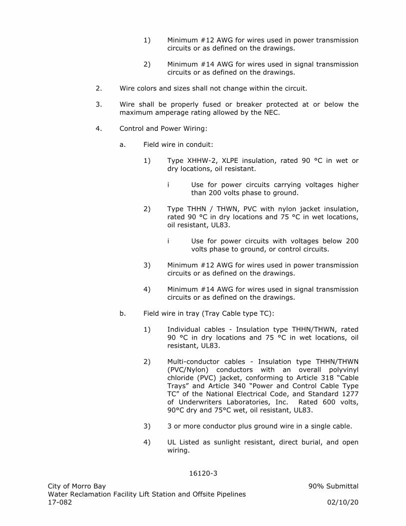
16120-3
City of Morro Bay 90% Submittal
Water Reclamation Facility Lift Station and Offsite Pipelines
17-082 02/10/20
1) Minimum #12 AWG for wires used in power transmission
circuits or as defined on the drawings.
2) Minimum #14 AWG for wires used in signal transmission
circuits or as defined on the drawings.
2. Wire colors and sizes shall not change within the circuit.
3. Wire shall be properly fused or breaker protected at or below the
maximum amperage rating allowed by the NEC.
4. Control and Power Wiring:
a. Field wire in conduit:
1) Type XHHW-2, XLPE insulation, rated 90 °C in wet or
dry locations, oil resistant.
i Use for power circuits carrying voltages higher
than 200 volts phase to ground.
2) Type THHN / THWN, PVC with nylon jacket insulation,
rated 90 °C in dry locations and 75 °C in wet locations,
oil resistant, UL83.
i Use for power circuits with voltages below 200
volts phase to ground, or control circuits.
3) Minimum #12 AWG for wires used in power transmission
circuits or as defined on the drawings.
4) Minimum #14 AWG for wires used in signal transmission
circuits or as defined on the drawings.
b. Field wire in tray (Tray Cable type TC):
1) Individual cables - Insulation type THHN/THWN, rated
90 °C in dry locations and 75 °C in wet locations, oil
resistant, UL83.
2) Multi-conductor cables - Insulation type THHN/THWN
(PVC/Nylon) conductors with an overall polyvinyl
chloride (PVC) jacket, conforming to Article 318 “Cable
Trays” and Article 340 “Power and Control Cable Type
TC” of the National Electrical Code, and Standard 1277
of Underwriters Laboratories, Inc. Rated 600 volts,
90°C dry and 75°C wet, oil resistant, UL83.
3) 3 or more conductor plus ground wire in a single cable.
4) UL Listed as sunlight resistant, direct burial, and open
wiring.
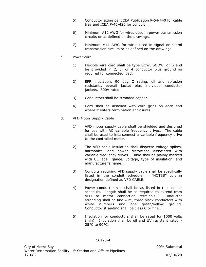
16120-4
City of Morro Bay 90% Submittal
Water Reclamation Facility Lift Station and Offsite Pipelines
17-082 02/10/20
5) Conductor sizing per ICEA Publication P-54-440 for cable
tray and ICEA P-46-426 for conduit
6) Minimum #12 AWG for wires used in power transmission
circuits or as defined on the drawings.
7) Minimum #14 AWG for wires used in signal or conrol
transmission circuits or as defined on the drawings.
c. Power cord
1) Flexible wire cord shall be type SOW, SOOW, or G and
be provided in 2, 3, or 4 conductor plus ground as
required for connected load.
2) EPR insulation, 90 deg C rating, oil and abrasion
resistant., overall jacket plus individual conductor
jackets. 600V rated
3) Conductors shall be stranded copper.
4) Cord shall be installed with cord grips on each end
where it enters termination enclosures.
d. VFD Motor Supply Cable
1) VFD motor supply cable shall be shielded and designed
for use with AC variable frequency drives. The cable
shall be used to interconnect a variable frequency drive
to the controlled motor.
2) The VFD cable insulation shall disperse voltage spikes,
harmonics, and power distortions associated with
variable frequency drives. Cable shall be plainly marked
with UL label, gauge, voltage, type of insulation, and
manufacturer's name.
3) Conduits requiring VFD supply cable shall be specifically
listed in the conduit schedule in “NOTES” column
designation defined as VFD CABLE.
4) Power conductor size shall be as listed in the conduit
schedule. Length shall be as required to extend from
VFD to motor connection terminals. Conductor
stranding shall be fine wire, three black conductors with
white numbers and one green/yellow ground.
Conductor stranding shall be class C or finer.
5) Insulation for conductors shall be rated for 1000 volts
(min). Insulation shall be oil and UV resistant rated -
25°C to 90°C.
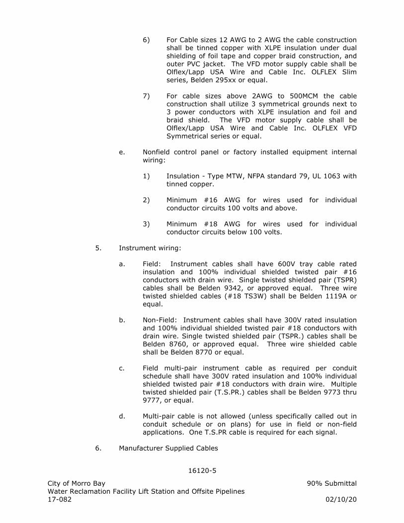
16120-5
City of Morro Bay 90% Submittal
Water Reclamation Facility Lift Station and Offsite Pipelines
17-082 02/10/20
6) For Cable sizes 12 AWG to 2 AWG the cable construction
shall be tinned copper with XLPE insulation under dual
shielding of foil tape and copper braid construction, and
outer PVC jacket. The VFD motor supply cable shall be
Olflex/Lapp USA Wire and Cable Inc. OLFLEX Slim
series, Belden 295xx or equal.
7) For cable sizes above 2AWG to 500MCM the cable
construction shall utilize 3 symmetrical grounds next to
3 power conductors with XLPE insulation and foil and
braid shield. The VFD motor supply cable shall be
Olflex/Lapp USA Wire and Cable Inc. OLFLEX VFD
Symmetrical series or equal.
e. Nonfield control panel or factory installed equipment internal
wiring:
1) Insulation - Type MTW, NFPA standard 79, UL 1063 with
tinned copper.
2) Minimum #16 AWG for wires used for individual
conductor circuits 100 volts and above.
3) Minimum #18 AWG for wires used for individual
conductor circuits below 100 volts.
5. Instrument wiring:
a. Field: Instrument cables shall have 600V tray cable rated
insulation and 100% individual shielded twisted pair #16
conductors with drain wire. Single twisted shielded pair (TSPR)
cables shall be Belden 9342, or approved equal. Three wire
twisted shielded cables (#18 TS3W) shall be Belden 1119A or
equal.
b. Non-Field: Instrument cables shall have 300V rated insulation
and 100% individual shielded twisted pair #18 conductors with
drain wire. Single twisted shielded pair (TSPR.) cables shall be
Belden 8760, or approved equal. Three wire shielded cable
shall be Belden 8770 or equal.
c. Field multi-pair instrument cable as required per conduit
schedule shall have 300V rated insulation and 100% individual
shielded twisted pair #18 conductors with drain wire. Multiple
twisted shielded pair (T.S.PR.) cables shall be Belden 9773 thru
9777, or equal.
d. Multi-pair cable is not allowed (unless specifically called out in
conduit schedule or on plans) for use in field or non-field
applications. One T.S.PR cable is required for each signal.
6. Manufacturer Supplied Cables
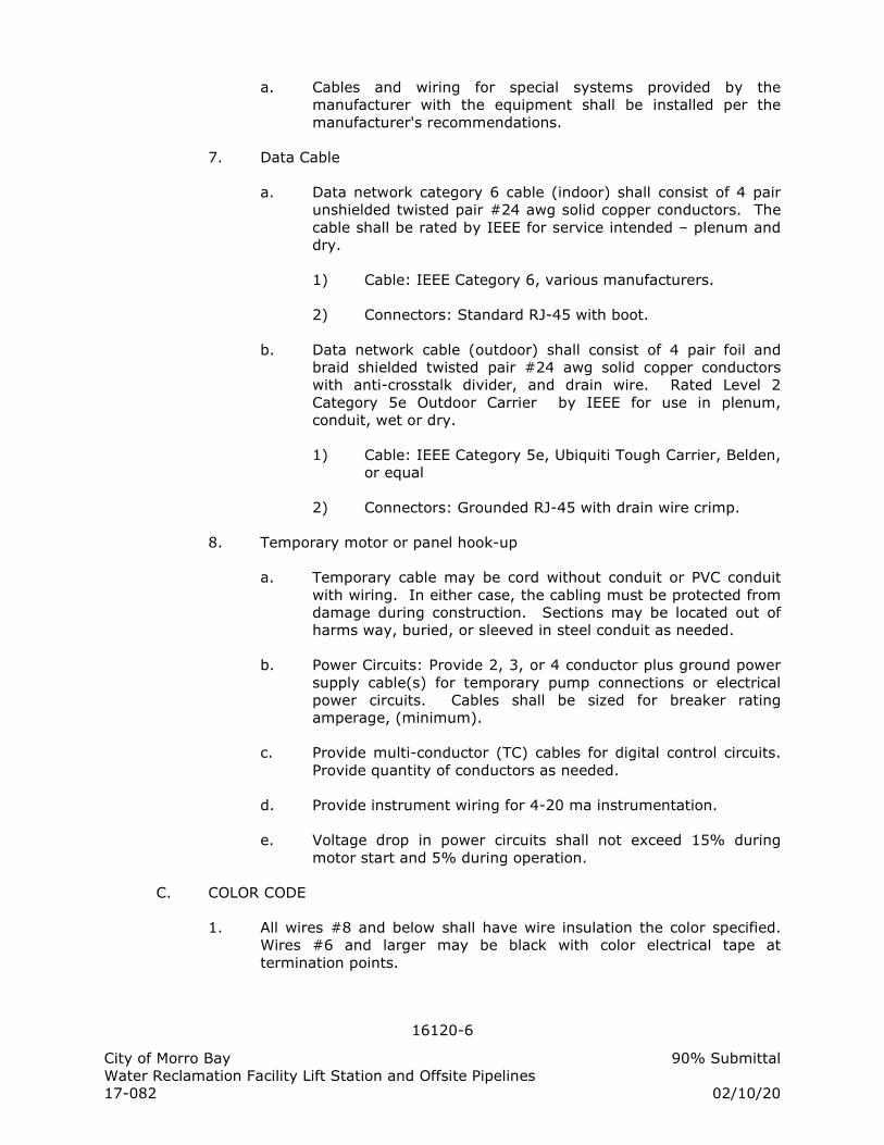
16120-6
City of Morro Bay 90% Submittal
Water Reclamation Facility Lift Station and Offsite Pipelines
17-082 02/10/20
a. Cables and wiring for special systems provided by the
manufacturer with the equipment shall be installed per the
manufacturer's recommendations.
7. Data Cable
a. Data network category 6 cable (indoor) shall consist of 4 pair
unshielded twisted pair #24 awg solid copper conductors. The
cable shall be rated by IEEE for service intended – plenum and
dry.
1) Cable: IEEE Category 6, various manufacturers.
2) Connectors: Standard RJ-45 with boot.
b. Data network cable (outdoor) shall consist of 4 pair foil and
braid shielded twisted pair #24 awg solid copper conductors
with anti-crosstalk divider, and drain wire. Rated Level 2
Category 5e Outdoor Carrier by IEEE for use in plenum,
conduit, wet or dry.
1) Cable: IEEE Category 5e, Ubiquiti Tough Carrier, Belden,
or equal
2) Connectors: Grounded RJ-45 with drain wire crimp.
8. Temporary motor or panel hook-up
a. Temporary cable may be cord without conduit or PVC conduit
with wiring. In either case, the cabling must be protected from
damage during construction. Sections may be located out of
harms way, buried, or sleeved in steel conduit as needed.
b. Power Circuits: Provide 2, 3, or 4 conductor plus ground power
supply cable(s) for temporary pump connections or electrical
power circuits. Cables shall be sized for breaker rating
amperage, (minimum).
c. Provide multi-conductor (TC) cables for digital control circuits.
Provide quantity of conductors as needed.
d. Provide instrument wiring for 4-20 ma instrumentation.
e. Voltage drop in power circuits shall not exceed 15% during
motor start and 5% during operation.
C. COLOR CODE
1. All wires #8 and below shall have wire insulation the color specified.
Wires #6 and larger may be black with color electrical tape at
termination points.
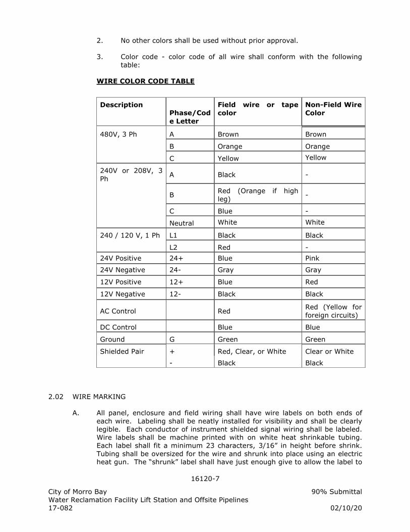
16120-7
City of Morro Bay 90% Submittal
Water Reclamation Facility Lift Station and Offsite Pipelines
17-082 02/10/20
2. No other colors shall be used without prior approval.
3. Color code - color code of all wire shall conform with the following
table:
WIRE COLOR CODE TABLE
Description Phase/Cod
e Letter
Field wire or tape
color
Non-Field Wire
Color
480V, 3 Ph A Brown Brown
B Orange Orange
C Yellow Yellow
240V or 208V, 3
Ph A Black -
B Red (Orange if high
leg) -
C Blue -
Neutral White White
240 / 120 V, 1 Ph L1 Black Black
L2 Red -
24V Positive 24+ Blue Pink
24V Negative 24- Gray Gray
12V Positive 12+ Blue Red
12V Negative 12- Black Black
AC Control Red Red (Yellow for
foreign circuits)
DC Control Blue Blue
Ground G Green Green
Shielded Pair + Red, Clear, or White Clear or White
- Black Black
2.02 WIRE MARKING
A. All panel, enclosure and field wiring shall have wire labels on both ends of
each wire. Labeling shall be neatly installed for visibility and shall be clearly
legible. Each conductor of instrument shielded signal wiring shall be labeled.
Wire labels shall be machine printed with on white heat shrinkable tubing.
Each label shall fit a minimum 23 characters, 3/16” in height before shrink.
Tubing shall be oversized for the wire and shrunk into place using an electric
heat gun. The “shrunk” label shall have just enough give to allow the label to
16120-8
City of Morro Bay 90% Submittal
Water Reclamation Facility Lift Station and Offsite Pipelines
17-082 02/10/20
be rotated. Hand lettered wire labels are not acceptable and shall be replaced
at the Contractor's expense. Provide Brady “PermaSleeve” or equal.
1. Node Style Wire Identification - All wires that are electrically the
same (connected to common termination points) and do not pass
through a contact or other switching device shall have the same wire
identification. The wire labeling code for each end of the same wire
shall be identical.
a. The wire identification code for internal panel wiring shall be
the number/letter as designated on the Contract elementary
and/or approved shop drawings.
b. Wire labeling for field wiring shall contain the panel/equipment
name as a prefix and the termination point name. (I.E. PLC50-
A103 or P10-124). The hierarchy of label names is 1) PLC
panel name, 2) MCC equipment name, and 3) Equipment name.
Therefore, wires from PLC50 to the MCC50 P10 cubicle will be
labeled PLC50-XXX. Wires from MCC50 P10 to field pressure
switch PSH10 will be labeled P10-XXX.
c. Wire labels shall be exactly per interconnection submittal
and/or control panel drawings -- abbreviations determined in
the field are not allowed. Abbreviations may be used in the
wire label as submitted and approved in the interconnection
drawings submittal.
d. Wire labels for lighting and receptacle circuits shall consist of
the panel board and circuit number and a unique node number.
(I.E. LP#3-A, LP#3-B, LP#3-N)
e. Wire labels may be omitted on “neutral jumpers” less than 8” in
length.
2.03 ELECTRICAL TAPE / SHRINKABLE INSULATORS
A. Vinyl tape shall be 7 mil, 600 volt rated, flame retardant, hot and cold
weather resistant conforming to UL510. Provide 3M Scotch Super 33+ vinyl
tape or equal
1. Vinyl tape for color coding shall be 7 mil, ¾” width, vinyl tape
conforming to UL 510. Provide 3M Scotch 35 vinyl tape or equal.
B. Rubber Tape: EPR rubber, 90 deg C continuous rated. Provide 3M 130C
rubber tape or equal.
C. Varnished Cambric Tape: Adhesive backed, 7 mil, bias cut cotton tape,
coated with yellow insulating varnish. Provide 3M Scotch 2510 or equal.
D. Shrinkable insulators shall be heat shrinkable, polyolefin thick wall sleeves,
end caps and cable repair sleeves are designed for use in splicing, sealing and
re-jacketing of direct bury secondary cables. The insulators shall comply with
16120-9
City of Morro Bay 90% Submittal
Water Reclamation Facility Lift Station and Offsite Pipelines
17-082 02/10/20
UL 486D and be rated up to 1000 Volts. They shall provide long-term reliable
performance overhead, underground or submerged with mechanical and
environmental protection. Shrinkable insulators shall be 3M ITCSN or 3M
IMCSN per manufacturer instructions for the application or equal.
PART 3: EXECUTION
3.01 WORKMANSHIP
A. All work in this Section shall conform to the codes and standards specified in
Electrical Specifications [Electrical General, Workmanship].
B. Perform work to remedy non-compliant installations after inspection.
C. Upon notification, stop work on any portion of the installation that is
determined to be substandard or being installed by unqualified personnel.
3.02 FABRICATION AND INSTALLATION
A. System:
1. Install all products specified in Electrical Specifications [Electrical
General, Installation].
2. Panels shall be completely factory wired and tested before shipment.
3. All spare PLC input / output points shall be wired to terminal blocks.
4. A minimum of 20% spare unwired terminals shall be provided in each
panel.
B. Wiring Methods:
1. Wiring Separation: Wires carrying 100 volts and above shall be
physically separated from lower voltage wiring by using separate
bundles or wire ways with sufficient distance to minimize the
introduction of noise, crossing only at 90 degree angles.
2. Harness: All wiring shall be neatly bundled and laced with plastic
tie-wraps, anchored in place by screw attached retainer. Where space
is available, wiring shall be run in slotted plastic wireways with dust
covers. Wireways shall be sized such that the wire fill does not exceed
60%. Tie-wraps shall be T&B TY-RAP or equal.
3. Retainers: Wireways, retainers, and other devices shall be screw
mounted with round-head 316 stainless steel screws or mechanically
mounted by push-in or snap-in attachments. Glue or sticky back
attachment of any type or style shall not be used. Retainers shall be
T&B TC series or equal.
4. Hinge Loops: Where wiring crosses hinged surfaces, provide a "U"
shaped hinge loop protected by clear nylon spiral wrap. The hinge loop
shall be of sufficient length to permit opening and closing the door
without stressing any of the terminations or connections. Spiral wrap
16120-10
City of Morro Bay 90% Submittal
Water Reclamation Facility Lift Station and Offsite Pipelines
17-082 02/10/20
shall be Graybar T25N or equal.
5. Routing: Wires and cable shall be routed such as to maintain
separation between 100 Volt or higher from 100 volt or lower wiring
being run in the same duct or bundle. Wires and cables shall have
sufficient length to allow slack and to avoid any strain or tension in the
wire or cable.
a. Wires shall be routed in slotted plastic wireways with snap
covers. Wires carrying 120 VAC shall be separated as much as
possible from other wires and signal cables, and shall be routed
only in ducts for 120 VAC. If the power wiring has to cross the
signal wiring, the crossing shall be as close to a right angle as
possible. Wireways for 24 VDC wiring shall be used for all other
wires and cables. Routing of 120 VAC in combined wireways
shall be minimized. Wires and cables shall be placed in the
wireways in a straight, neat and organized fashion and shall not
be kinked, tangled or twisted together. Additional wire ducting
shall be provided for use by the electrical subcontractor for
routing field wires to their landing points in the each electrical
and instrumentation panel.
b. Provide 2” minimum separation between wireway and terminal
blocks.
c. Wiring not routed in wireways shall be neatly bundled, treed,
and laced with plastic ties.
C. Wire Terminations
1. Single wire and cable conductors shall be terminated according to the
requirements of the terminal device as follows:
a. Crimp-on terminals: shall be UL listed, self-insulating sleeve
type, with ring or rectangular type tongue, suitable for the size
and material of the wire to be terminated, and for use with
either solid or stranded conductors.
b. Terminal Blocks: Remove the last +/- 0.25 inches insulation
from of the conductor and insert it under the pressure plate to
full length of the bare portion of the conductor. Tighten the
screw to close the pressure plate onto the conductor. No more
than two conductors shall be installed in a single terminal. All
strands of the conductor shall be captured under the pressure
plate.
c. Screw-less terminals: wire shall be stripped back and inserted
per the terminal manufacturer's instructions.
d. Motors with pigtail leads: Install terminal connectors on the
motor pigtails and the cable to be connected. Terminals shall
be non-insulated crimp-on type applied with a rachet-type
16120-11
City of Morro Bay 90% Submittal
Water Reclamation Facility Lift Station and Offsite Pipelines
17-082 02/10/20
crimping tool. The terminals shall be bolted together with a
nut, bolt and lock washer combination. The connection shall be
booted with 3/16” thick rubber boot. Boot kit shall include
rubber boot for each motor connection, plastic locking pins,
silicone grease, and mastic sealing strips, Boot kits shall be 3M
Motor Lead Pigtail Splice #5302, #5303,or #5404 as applicable
for wire size applied.
2. When stripping insulation from conductors, do not score or damage
conductor.
3. The drain wire and stripped end of outer jacket of shielded cables shall
be covered with heat shrink insulating tubing. The drain wire shall be
covered along its full bare length between the cable jacket cover and
the terminal lug and placed on end outer jacket to cover foil.
4. Condulets with wire nut connections shall be supplied for wire
termination to devices with leads instead of terminals (i.e. solenoid
valves, level probe, etc.).
D. Wire Splicing
1. No wires shall be spliced without prior approval.
2. Where splices are allowed or approved they shall conform to the
following:
a. Wire splicing devices shall be sized according to manufacturer's
recommendations.
b. Splices of #10 and smaller, including fixture taps, shall be
made with nylon self-insulated twist on wire nuts; T & B
"Piggys", Ideal "Wing-Nut" or equal.
c. Splices of #8 and larger shall be hex key screw, two way
connectors, insulated with molded high-dielectric strength
plastic; NSI Polaris IPL or IPLD Series terminal blocks or equal.
d. Non-Motor Splices #10 and smaller in underground pullboxes
shall have wire-nut connections inside and insulator tube which
are sealed with non-hardening silicone based sealant that
protects the connection from moisture and corrosion. The wire
nut shall be pushed to the bottom of the tube and a locking cap
closed to prevent moisture and dirt from entering the tube.
The tube is factory filled with sealant and UL listed for
waterproof connections. Provide 3M DBY-6 or DBR-6 or equal.
e. Non-Motor Splices #6 and smaller in underground pullboxes
shall have wire-nut connections which are sealed with non-
hardening silicone based sealant that protects the connection
from moisture and corrosion. The wire nuts shall be factory
filled with sealant and UL listed for waterproof connections.
16120-12
City of Morro Bay 90% Submittal
Water Reclamation Facility Lift Station and Offsite Pipelines
17-082 02/10/20
Provide Ideal Model 60 or equal.
f. Non-Motor Splices #4 and larger in underground pullboxes shall
have double hex crimp barrel connections applied with
adhesive/sealant filled heat shrinkable rubber insulation applied
over the exposed connection. The cross-linked polyolefin shrink
tube shall extend 4” on each side of the exposed connection
minimum. Heat shrink tubing shall be 3M ITCSN or equal.
E. Wire Installation
1. Exercise care in pulling wires and cables into conduit or wireways so as
to avoid kinking, stressing the cables, or damaging the insulation. Use
a UL listed pulling compound for lubrication within conduits as
necessary. The raceway construction shall be complete and protected
from weather before cable is pulled in. Swab conduits before installing
cables and exercise care in pulling, to avoid damage to the insulation
or conductors.
2. All wire and cables (with the exception of coaxial antenna cable) shall
be installed within UL listed raceways or enclosures. Install all wires
and cables in one continuous length unless splices are per Contract
Drawings, required to connect equipment or submitted and favorably
reviewed.
3. Bundle incoming wire and cables in panels. Zip-tie at intervals of 2”
and neatly spread into trees and connect to their respective terminals.
Allow sufficient slack in cables for alterations in terminal connections.
Do not bundle, tape or tie wires within conduits.
3.03 WARRANTY
A. Provide warranty as specified in Electrical Specifications [Electrical General,
Warranty].
END OF SECTION
16121-1
City of Morro Bay 90% Submittal
Water Reclamation Facility Lift Station and Offsite Pipelines
17-082 02/10/20
SECTION 16121
FIBER OPTIC COMMUNICATION SYSTEM
PART 1: GENERAL
1.01 SCOPE OF WORK
A. Ethernet network(s) shall be provided for interfacing the Pump Station PLCs,
SCADA workstations, and Administration Network Devices. 10Mb, 100Mb and
1000Mb Ethernet traffic shall be supported by network.
B. Section Includes:
1. Fiber Optic (FO) cables for data networks.
2. Network Fiber Optic Switches.
3. Termination Equipment.
1.02 REFERENCES
A. Electrical Specifications [Electrical General]
B. Project Drawings
1.03 QUALIFICATIONS
A. Provide FO cables by a reputable manufacturer in this field for at least 3 years
and has supplied FO cables to minimum of 5 major installations.
B. FO installer shall be specialized in this field and has minimum of 2 years prior
experience.
1.04 SUBMITTAL REQUIREMENTS
A. Shop Drawings and Product Data: Submit in accordance with Electrical
Specifications [Electrical General, Submittal Requirements]. Include description
of components, methods of connecting components, and the following:
1. Fittings and termination equipment.
B. Show coordination for fiber optic cable, connectors, terminations, fiber optic
switches, and other communication equipment whether specified herein or
elsewhere in the specifications. Review the project drawings for all fiber optic
communication devices and coordinate with those specifications.
C. Statement of Installer’s Training and Experience: Submit in accordance with
requirements for and with Product Data.
1.05 ENVIRONMENTAL REQUIREMENTS
A. Humidity: Maximum 95 percent, non-condensing.
B. Ambient Temperature:
1. Operational: Zero to 60 degrees Celsius.
2. Storage: Minus 40 to 80 degree Celsius.
1.06 OPERATION AND MAINTENANCE INFORMATION
16121-2
City of Morro Bay 90% Submittal
Water Reclamation Facility Lift Station and Offsite Pipelines
17-082 02/10/20
A. Provide operation and maintenance instructions as specified in Electrical
Specifications [Electrical General].
PART 2: PRODUCTS
2.01 FIBER OPTIC CABLE
A. General
1. Acceptable Manufacturer: Corning Altos or equal.
2. 24 strand (12 pairs) single mode.
B. Construction
1. Cable shall be loose tube construction with up to 6 tubes with dielectric
central strength member, gel waterblock material, overall strength
covering, and PE jacket with ripcord
2. Optical fibers shall be coated with a suitable material to preserve the
intrinsic strength of the glass.
3. Nylon yarn central strength member.
4. Up to 12 color coded fibers within each protective tube. Colors meeting
EIA/TIA-598B, Optical Fiber Color Coding. Colors shall be stable across
storage and operating temperature, will not cause fibers to stick
together, dissolve into gel material, and will not fade.
1. Blue 5. Slate 9. Yellow
2. Orange 6. White 10. Violet
3. Green 7. Red 11. Rose
4. Brown 8. Black 12. Aqua
5. Buffer tubes shall be filled with a non-hygroscopic, non-nutritive to
fungus, electrically non-conductive, homogenous gel. The gel shall be
free from dirt and foreign matter. The gel shall be readily removable with
conventional nontoxic solvents.
6. The cable shall contain at least one ripcord under the inner sheath for
easy sheath removal.
7. Exterior 0.9mm polyethylene jacket with sequential footage markings.
8. The cable jacket shall be marked with the manufacturer’s name, month
and year of manufacture, sequential length markings, fiber count, and
fiber type. The markings shall be in contrasting color to the cable sheath.
9. The shipping, storage, and operating temperature range of the cable shall
be negative 30 °C to 70°C.
10. Physical Characteristics:
a. Tensile Strength: > 600 lbs short duration
b. Min. Bending Radius: 10 inches
c. Diameter: 0.5 inches (maximum)
11. Mechanical stress applied to the cable shall not be transmitted to the
optical fibers.
12. Cable shall be suitable for underground conduit installation and shall be
waterproof and non-hydroscopic.
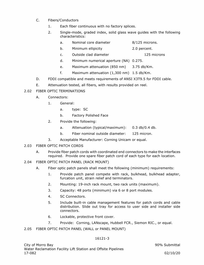
16121-3
City of Morro Bay 90% Submittal
Water Reclamation Facility Lift Station and Offsite Pipelines
17-082 02/10/20
C. Fibers/Conductors
1. Each fiber continuous with no factory splices.
2. Single-mode, graded index, solid glass wave guides with the following
characteristics:
a. Nominal core diameter 8/125 microns.
b. Minimum ellipicity 2.0 percent.
c. Outside clad diameter 125 microns
d. Minimum numerical aperture (NA) 0.275.
e. Maximum attenuation (850 nm) 3.75 db/Km.
f. Maximum attenuation (1,300 nm) 1.5 db/Km.
D. FDDI compatible and meets requirements of ANSI X3T9.5 for FDDI cable.
E. Attenuation tested, all fibers, with results provided on reel.
2.02 FIBER OPTIC TERMINATIONS
A. Connectors:
1. General:
a. type: SC
b. Factory Polished Face
2. Provide the following:
a. Attenuation (typical/maximum): 0.3 db/0.4 db.
b. Fiber nominal outside diameter: 125 micron.
3. Acceptable Manufacturer: Corning Unicam or equal.
2.03 FIBER OPTIC PATCH CORDS
A. Provide fiber patch cords with coordinated end connectors to make the interfaces
required. Provide one spare fiber patch cord of each type for each location.
2.04 FIBER OPTIC PATCH PANEL (RACK MOUNT)
A. Fiber optic patch panels shall meet the following (minimum) requirements:
1. Provide patch panel compete with rack, bulkhead, bulkhead adapter,
furcation unit, strain relief and terminators.
2. Mounting: 19-inch rack mount, two rack units (maximum).
3. Capacity: 48 ports (minimum) via 6 or 8 port modules.
4. SC Connectors.
5. Include built-in cable management features for patch cords and cable
distribution. Slide out tray for access to user side and installer side
connectors.
6. Lockable, protective front cover.
7. Provide: Corning, LANscape, Hubbell FCR., Siemon RIC., or equal.
2.05 FIBER OPTIC PATCH PANEL (WALL or PANEL MOUNT)
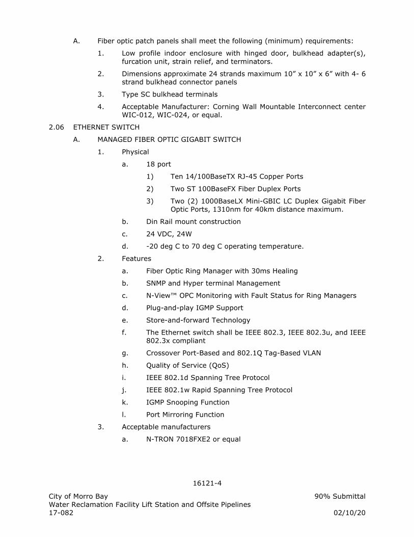
16121-4
City of Morro Bay 90% Submittal
Water Reclamation Facility Lift Station and Offsite Pipelines
17-082 02/10/20
A. Fiber optic patch panels shall meet the following (minimum) requirements:
1. Low profile indoor enclosure with hinged door, bulkhead adapter(s),
furcation unit, strain relief, and terminators.
2. Dimensions approximate 24 strands maximum 10” x 10” x 6” with 4- 6
strand bulkhead connector panels
3. Type SC bulkhead terminals
4. Acceptable Manufacturer: Corning Wall Mountable Interconnect center
WIC-012, WIC-024, or equal.
2.06 ETHERNET SWITCH
A. MANAGED FIBER OPTIC GIGABIT SWITCH
1. Physical
a. 18 port
1) Ten 14/100BaseTX RJ-45 Copper Ports
2) Two ST 100BaseFX Fiber Duplex Ports
3) Two (2) 1000BaseLX Mini-GBIC LC Duplex Gigabit Fiber
Optic Ports, 1310nm for 40km distance maximum.
b. Din Rail mount construction
c. 24 VDC, 24W
d. -20 deg C to 70 deg C operating temperature.
2. Features
a. Fiber Optic Ring Manager with 30ms Healing
b. SNMP and Hyper terminal Management
c. N-View™ OPC Monitoring with Fault Status for Ring Managers
d. Plug-and-play IGMP Support
e. Store-and-forward Technology
f. The Ethernet switch shall be IEEE 802.3, IEEE 802.3u, and IEEE
802.3x compliant
g. Crossover Port-Based and 802.1Q Tag-Based VLAN
h. Quality of Service (QoS)
i. IEEE 802.1d Spanning Tree Protocol
j. IEEE 802.1w Rapid Spanning Tree Protocol
k. IGMP Snooping Function
l. Port Mirroring Function
3. Acceptable manufacturers
a. N-TRON 7018FXE2 or equal
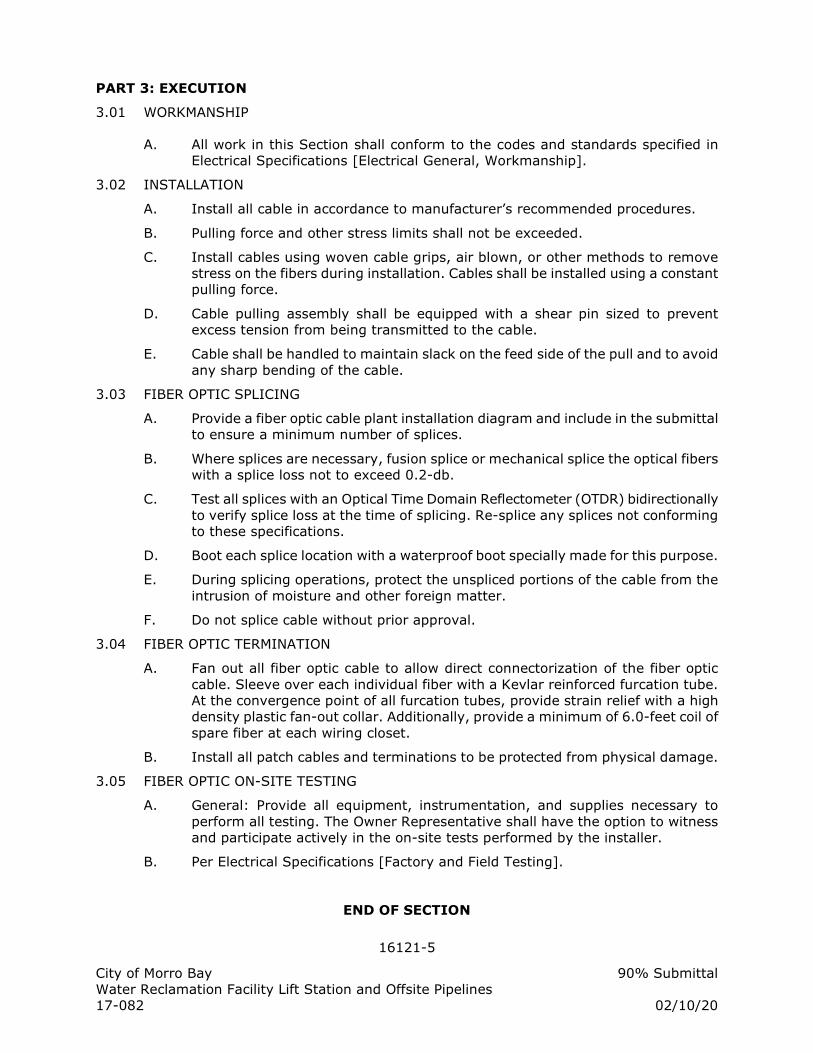
16121-5
City of Morro Bay 90% Submittal
Water Reclamation Facility Lift Station and Offsite Pipelines
17-082 02/10/20
PART 3: EXECUTION
3.01 WORKMANSHIP
A. All work in this Section shall conform to the codes and standards specified in
Electrical Specifications [Electrical General, Workmanship].
3.02 INSTALLATION
A. Install all cable in accordance to manufacturer’s recommended procedures.
B. Pulling force and other stress limits shall not be exceeded.
C. Install cables using woven cable grips, air blown, or other methods to remove
stress on the fibers during installation. Cables shall be installed using a constant
pulling force.
D. Cable pulling assembly shall be equipped with a shear pin sized to prevent
excess tension from being transmitted to the cable.
E. Cable shall be handled to maintain slack on the feed side of the pull and to avoid
any sharp bending of the cable.
3.03 FIBER OPTIC SPLICING
A. Provide a fiber optic cable plant installation diagram and include in the submittal
to ensure a minimum number of splices.
B. Where splices are necessary, fusion splice or mechanical splice the optical fibers
with a splice loss not to exceed 0.2-db.
C. Test all splices with an Optical Time Domain Reflectometer (OTDR) bidirectionally
to verify splice loss at the time of splicing. Re-splice any splices not conforming
to these specifications.
D. Boot each splice location with a waterproof boot specially made for this purpose.
E. During splicing operations, protect the unspliced portions of the cable from the
intrusion of moisture and other foreign matter.
F. Do not splice cable without prior approval.
3.04 FIBER OPTIC TERMINATION
A. Fan out all fiber optic cable to allow direct connectorization of the fiber optic
cable. Sleeve over each individual fiber with a Kevlar reinforced furcation tube.
At the convergence point of all furcation tubes, provide strain relief with a high
density plastic fan-out collar. Additionally, provide a minimum of 6.0-feet coil of
spare fiber at each wiring closet.
B. Install all patch cables and terminations to be protected from physical damage.
3.05 FIBER OPTIC ON-SITE TESTING
A. General: Provide all equipment, instrumentation, and supplies necessary to
perform all testing. The Owner Representative shall have the option to witness
and participate actively in the on-site tests performed by the installer.
B. Per Electrical Specifications [Factory and Field Testing].
END OF SECTION
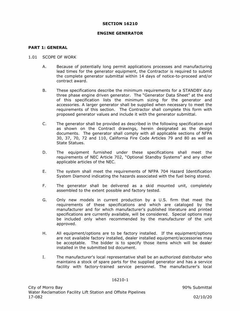
16210-1
City of Morro Bay 90% Submittal
Water Reclamation Facility Lift Station and Offsite Pipelines
17-082 02/10/20
SECTION 16210
ENGINE GENERATOR
PART 1: GENERAL
1.01 SCOPE OF WORK
A. Because of potentially long permit applications processes and manufacturing
lead times for the generator equipment, the Contractor is required to submit
the complete generator submittal within 14 days of notice-to-proceed and/or
contract award.
B. These specifications describe the minimum requirements for a STANDBY duty
three phase engine driven generator. The “Generator Data Sheet” at the end
of this specification lists the minimum sizing for the generator and
accessories. A larger generator shall be supplied when necessary to meet the
requirements of this section. The Contractor shall complete this form with
proposed generator values and include it with the generator submittal.
C. The generator shall be provided as described in the following specification and
as shown on the Contract drawings, herein designated as the design
documents. The generator shall comply with all applicable sections of NFPA
30, 37, 70, 72 and 110, California Fire Code Articles 79 and 80 as well as
State Statues.
D. The equipment furnished under these specifications shall meet the
requirements of NEC Article 702, “Optional Standby Systems” and any other
applicable articles of the NEC.
E. The system shall meet the requirements of NFPA 704 Hazard Identification
System Diamond indicating the hazards associated with the fuel being stored.
F. The generator shall be delivered as a skid mounted unit, completely
assembled to the extent possible and factory tested.
G. Only new models in current production by a U.S. firm that meet the
requirements of these specifications and which are cataloged by the
manufacturer and for which manufacturer's published literature and printed
specifications are currently available, will be considered. Special options may
be included only when recommended by the manufacturer of the unit
approved.
H. All equipment/options are to be factory installed. If the equipment/options
are not available factory installed, dealer installed equipment/accessories may
be acceptable. The bidder is to specify those items which will be dealer
installed in the submitted bid document.
I. The manufacturer's local representative shall be an authorized distributor who
maintains a stock of spare parts for the supplied generator and has a service
facility with factory-trained service personnel. The manufacturer's local
16210-2
City of Morro Bay 90% Submittal
Water Reclamation Facility Lift Station and Offsite Pipelines
17-082 02/10/20
representative shall be located within a radius of 200 miles of the project.
J. The Contractor shall perform complete startup, training and testing services
for the generator per Electrical Specifications [Factory and Field Testing] and
as detailed herein.
K. Generator system shall be EPA Certified and meet all current Local, State and
Federal air emissions requirements at time and location of installation.
L. Generator system shall be coordinated and compliant with all current Local
and State building and Fire Protection codes and requirements at time and
location of installation. Furnish alarms, signage, fuel containment,
shutdowns, and other devices and systems as required.
M. The Contractor shall supply the generator, labor, testing and associated
documentation as specified herein. This document describes the materials
and intended operation, but does not necessarily describe all devices
necessary for a functional system. All components and devices shall be
furnished and installed as required to provide a complete, operable and
reliable system for accomplishing the functions and meeting the performance
set forth hereinafter.
N. The generator scope of work includes:
1. Engine driven electric generator
2. Sub-base fuel tank with fuel pump and associated piping.
3. Battery charger (120 VAC operated) mounted to generator frame.
4. Sound attenuating housing.
5. All auxiliary apparatus and accessories shall be provided as required
for a fully functional generator and to meet local code requirements.
6. Install a steel reinforced concrete pad, adequately sized to support the
specified generator and fuel tank.
7. All piping associated with exhaust system.
8. Trenching, back filling, compaction and paving of each underground
conduit route
9. Field installation, startup, testing and training for the generator and
associated equipment as part of this scope of work.
10. Fuel for use during testing and full tank top off upon testing
acceptance.
1.02 REFERENCES
A. Electrical Specifications [Electrical General]
B. Project Drawings
C. The following manufacturing and installation standards apply to this section:
1. ASTM International (ASTM): A335/A335M, Specification for Seamless
Ferritic Alloy-Steel Pipe for High-Temperature Service.
2. Best Available Control Technology Standards (BACT)
16210-3
City of Morro Bay 90% Submittal
Water Reclamation Facility Lift Station and Offsite Pipelines
17-082 02/10/20
3. Code of Federal Regulations (CRF): Title 40 Volume 18, Control of
Emissions from New and In-Use Non-road Compression-Ignition
Engines.
4. National Fire Protection Association (NFPA):
a. 37, Installation and Use of Stationary Combustion Engines and
Gas Turbines.
b. 70, National Electric Code.
c. 110, Emergency and Standby Power Systems.
5. SAE International (SAE): J1074, Engine Sound Level Measurement.
6. Underwriters Laboratories, Inc. (UL):
a. 142, Steel Aboveground Tanks for Flammable and Combustible
Liquids.
b. 2085, Protected Aboveground Tanks for Flammable and
Combustible Liquids.
c. 508, Industrial Control Equipment.
d. 1236, Battery Chargers for Charging Engine-Starter Batteries.
e. 2200, Stationary Engine Generator.
D. The bidder shall carefully examine the plans and specifications, and be
familiar with the conditions of the location of installation.
1.03 QUALIFICATIONS
A. Equipment manufacturers shall be represented by a company capable of
servicing and testing the generator unit from a mobile service vehicle
dispatched from within a 200 mile radius.
1.04 SUBMITTAL REQUIREMENTS
A. Submit shop documents and drawings for approval in accordance with this
subsection and as specified in Electrical Specifications [Electrical General,
Submittal Requirements]. All non-relevant items not provided on this project
shall be crossed-off or deleted from all submitted documents and drawings.
B. Submit a specification compliance statement, describing differences between
specified and proposed equipment. Note equipment provided specifically to
meet local agency or authority having jurisdiction requirements.
C. Complete “Generator Data Sheet” at the end of this section and submit this
form with the generator submittal.
D. Submit data sheets and catalog information detailing:
1. Engine:
16210-4
City of Morro Bay 90% Submittal
Water Reclamation Facility Lift Station and Offsite Pipelines
17-082 02/10/20
a. Make and model.
b. Fuel type.
c. Number of cylinders and cylinder arrangement.
d. Bore and stroke.
e. Compression ratio.
f. Piston speed, Feet per Minute, at rated RPM.
g. Cylinder head, piston, valve, and block material.
h. Crankshaft material.
i. Main bearings, quantity and type.
j. Rated RPM and HP at rated RPM.
k. Governor type.
2. Generator:
a. Make and model.
b. Generator full load electrical rating, KVA, KW, Voltage,
Amperage, Frequency (Hz), # of Phases, # of Wires, Power
Factor.
c. Generator and Exciter type.
d. Insulation material, class, and temperature rise.
e. Bearings, quantity and type.
f. Peak motor starting, KVA.
g. Voltage regulator type and regulation % from no load to full
load.
h. Frequency regulator type and regulation %, from no-load to full
load.
i. One step load acceptance.
j. Unbalanced load capability.
k. Number of leads.
l. Generator transient (x'd) and subtransient (x"d) reactance in
per unit.
m. Ambient temperature range.
3. Electrical
a. Control and instrument panel.
b. Generator main breaker.
c. Batteries and battery charger.
4. Cooling System
a. Maximum ambient temperature.
b. Capacity (gallons).
c. Coolant flow (gpm).
d. Fan diameter (in).
e. Fan HP requirement at rated RPM.
5. Accessories:
a. Exhaust silencer, stack, and piping system.
b. Fuel tank and piping system.
c. Vibration isolation system.
16210-5
City of Morro Bay 90% Submittal
Water Reclamation Facility Lift Station and Offsite Pipelines
17-082 02/10/20
d. Block Heater system.
e. Weatherproof/Soundproof Housing as specified herein.
f. Paint Finish.
E. Submit electrical schematics and wiring diagrams for:
1. Generator control panel.
2. Battery charging system.
3. Main generator.
4. Voltage regulator.
5. Governing system.
6. Generator main breaker.
F. Submit dimension drawings for:
1. Engine generator side, front, and top.
2. Pad construction (minimum) size, anchor details.
3. Enclosure (if required).
4. Fuel tank and containment basin.
5. Exhaust muffler and air intake baffle.
6. Conduit stub-up areas under generator frame and/or sub-base fuel
tank.
G. Submit reports, calculations, and curves for:
1. Generator sizing calculation (computer generated report acceptable)
showing that the unit is sized adequately to start all loads as shown on
Contract Drawings “Load Calculation” without exceeding the maximum
voltage dip specified.
2. Generator air emissions data, prototype or actual, suitable for
submission to governing air quality management agency where
generator is to be installed. Emissions data shall be for fuel type as
required by local air quality agency.
3. Sound level data showing that the complete generator package meets
the sound level requirements stated herein.
4. Engine generator fuel consumption data at 25%, 50%, 75% and 100%
electrical loading.
5. Proposed concrete pad dimensions, reinforcement method and
isolation material (as necessary) for submitted generator.
6. Seismic calculations for bolt down anchorage for seismic site class D.
Calculation shall be signed by a California Registered Professional
Structural Engineer. Generator installation shall meet applicable CBC
or IBC requirements for stand-by power systems.
a. Calculations shall include calculations for wind loading on
equipment to be mounted outdoors.
16210-6
City of Morro Bay 90% Submittal
Water Reclamation Facility Lift Station and Offsite Pipelines
17-082 02/10/20
b. The Contractor shall submit a copy of the current ICBO anchor
evaluation report for each type of anchor submitted.
c. The Contractor shall submit a copy of the concrete mix design
to include the concrete design strength.
d. The Contractor shall submit Near Fault Vicinity and Location
maps.
7. Battery sizing calculations showing all anticipated DC “black start”
loads, and performance requirements including battery charger sizing
and maximum recharge time.
H. Air Quality Management Applications and Permits
1. The Contractor shall obtain the correct ATC application from the AQMD
and preliminarily complete the application by inserting the project
specific generator technical information. Submit preliminary partially
completed application to the Engineer for use by the Owner in
preparation of the final completed ATC application.
2. The Contractor shall submit all generator specific information required
to complete the ATC permit application. The Owner will not submit the
application until all the information is received and the submittal
receives a status of “make corrections noted” or “approved.” Submit
information in sufficient time for application processing and submittal
review as to not delay project completion. The generator will not be
considered approved until the ATC permit is obtained.
3. The Owner shall complete and apply for the "Authority to Construct"
(ATC) permit from the Air Quality Management District or Board with
jurisdiction for this generator system. Fees for permit and application
will be paid by the Owner. The Owner will submit the permit
application within 14 days of submittal approval. Allocate 12 weeks
for Owner to obtain ATC permit once application has been submitted.
4. The Contractor shall confirm that the submitted generator meets all
AQMD guidelines prior to submittal of the generator unit or preliminary
application. Failure to do so will delay the ATC permitting and
submittal approval.
I. Descriptive literature shall be provided that describes the generator and all
accessories. This literature shall provide sufficient detail to determine that the
generator has all the accessories, options, features, and characteristics
specified herein. Items that are not provided shall be neatly lined out.
J. Deviations from the Contract documents shall not be incorporated into the
work without prior written approval. A "Change Order" directive is required
prior to incorporating any deviation from the Contract documents that has
costs associated. The cost differential associated with this change order
must be negotiated to amend the Contract to reflect the costs or savings.
16210-7
City of Morro Bay 90% Submittal
Water Reclamation Facility Lift Station and Offsite Pipelines
17-082 02/10/20
K. Exceptions to the Specifications or Drawings or equipment or procedures
submitted as “equal” to specified equipment shall be clearly identified by the
equipment supplier in a letter at the front of the submittal. Submittal data for
“equal” equipment or procedures shall contain sufficient details so a proper
evaluation may be made. The Contractor is responsible for verifying proper
application/operation of substituted equipment.
L. The decision of the Owner governs what is acceptable as an approved equal.
If the Owner considers it necessary, tests to determine equality of the
proposed substitution shall be made, at the Contractor's expense, by an
unbiased laboratory satisfactory to the Owner. Equality will be judged on the
basis of the following:
1. Conformance with description or performance required.
2. Equal in quality.
3. Comparable in operation and maintenance.
4. Equal in longevity and service under conditions of climate and usage
for given application.
5. Conformance with space allocations.
6. Comparable in appearance and artistic effect.
7. Compatible with mechanical and electrical construction of related work
without necessitating changes in detail.
M. The Owner will not accept any ownership for material or equipment until the
corresponding submittals have been reviewed by the Owner and approved.
N. Submit complete and specific information with regard to equipment
representatives and service facilities.
1.05 OPERATION AND MAINTENANCE INFORMATION
A. Provide six (6) sets of operating, maintenance & parts instructions in original
manuals (no copies allowed).
PART 2: PRODUCTS
2.01 QUALITY
A. The generator shall be as manufactured by Caterpillar, Cummins, Generac,
Kohler or equal with accessories as defined herein.
B. The equipment supplied and installed shall meet the requirements of the
National Fire Protection Association (NFPA 70 and NFPA 110) and all
applicable local codes and regulations.
C. The generator system shall be designed as a “black start” unit capable of
starting and operating without any external power.
D. Provide all of the features, options, and accessories specified herein and
shown on the design drawings. Finished equipment shall be complete and
site tested as an installed unit with all accessories functioning.
16210-8
City of Morro Bay 90% Submittal
Water Reclamation Facility Lift Station and Offsite Pipelines
17-082 02/10/20
E. All rotating parts shall have guards to protect against accidental contact in
accordance with Federal OSHA and Cal-OSHA requirements.
2.02 RATING
A. The engine generator shall have a minimum continuous standby rating as
listed in “Generator Data Sheet” at the end of this section. Standby rated
shall mean that generator starts within 60 seconds upon being called and
operates continuously for the total duration of the generator call or fuel
supply. Rating of the generator shall be based on operation when equipped
with all necessary operating accessories such as radiator, fan, air cleaners,
lubricating oil pump, governor, exhaust silencer, etc.
B. No derating from the ratings specified shall occur for ambient temperatures
below 122°F or installation elevation below 1,000 feet.
C. The generator will be installed at approximately 200 feet above sea level.
The generator shall operate as specified at ambient temperatures between 0
degrees Fahrenheit and 122 degrees Fahrenheit.
D. The engine/generator shall accept 100% of its nameplate rating at 0.8 PF in
one step, in compliance with NFPA 110, Paragraph 5-13.2.6.
E. The generator shall be capable of successfully providing three phase, four
wire, 60 hertz power to start and continuously operate at the specified KW
rating and below for loads shown in the drawing and/or with power factors
between 0.5 lag to 0.9 lead. It shall be capable of operating in noisy
electrical environments that are typical of variable frequency drive motor
loads. The nominal voltage and maximum step voltage dip shall be per the
“Generator Data Sheet,” as measured line to line at the generator terminals,
during start of any of the station loads.
F. Generator set mean time between failures shall be a minimum of 5,000
hours.
2.03 ENGINE
A. The engine shall be a turbocharged compression ignition engine type, water
cooled, four cycle, with vertical inline or V-type cylinders and an overhead
valve configuration.
B. The engine shall utilize only NO. 2 diesel fuel. Generator shall operate per
manufacturer’s specifications using fuel approved by local air quality
authorities.
C. The engine shall be of direct injection design, i.e. pre-combustion chambers
shall not be incorporated in the cylinder heads.
D. The engine shall have sufficient power to produce the specified ratings when
operating with all accessories including exhaust, fuel, cooling, and battery
charging systems, etc.
16210-9
City of Morro Bay 90% Submittal
Water Reclamation Facility Lift Station and Offsite Pipelines
17-082 02/10/20
E. The engine shall be equipped with:
1. Engine driven or electric fuel transfer pump, fuel filters, and electric
fuel shutoff valve. The fuel transfer pump shall be capable of lifting the
fuel from the sub-base fuel tank. Primary and secondary fuel filters
shall be provided. The fuel filters shall be replaceable and conveniently
located for servicing.
2. Electrical governor; consisting of a magnetic pickup speed sensor,
adjustable electronic control, and an electrical actuator mounted
integrally with the fuel pump. The governor shall provide automatic
engine generator set frequency regulation adjustable from isochronous
to 5% droop. Governors using external throttle linkages are not
acceptable.
3. An electric starting system complete with batteries, battery charger,
battery rack, connector cables, and any other equipment required to
start the standby generator. The starting system shall not require an
auxiliary AC power supply to start, fully load, and operate the standby
generator. The batteries shall be sized to provide five starts with 30
seconds cranking for each start attempt. The battery charger shall be
sized to fully recharge the batteries within 12 hours. If required to
maintain the above criteria, an electrical heat pad for the batteries
shall be provided to keep the batteries in a ready state at the specified
minimum ambient temperature. The charger shall be furnished with
charger trouble alarm and an automatic equalize timer for fast
recharge. The charger shall alarm on loss of power and cause a
generator common alarm output.
4. Positive engagement solenoid shift-starting electric starter with DC
voltage as listed in “Generator Data Sheet.”
5. Battery charging alternator with a minimum ampere output as listed in
“Generator Data Sheet.”
6. Positive displacement, full pressure lubrication oil pump, cartridge oil
filters, dipstick, and oil drain. The oil pump shall be capable of
supplying adequate lubricating oil under pressure to the main
bearings, crankshaft bearings, pistons, piston pins, timing gears,
camshaft bearings, and valve rocker mechanism. The cartridge oil
filters shall be full flow type, conveniently located for servicing. Filters
shall be equipped with a spring loaded bypass valve to ensure oil
circulation if filters are clogged.
7. An electric DC motor-driven pre-lube oil pump shall be provided if
required by the engine manufacturer’s design for “black start” of the
standby generator.
8. Dry type replaceable air cleaner elements. The dry-type air cleaner
shall be equipped with a self-cleaning dust and water evacuator and a
vacuum restriction gauge to indicate maximum allowable restriction of
the air cleaner system according to the engine manufacturer's
16210-10
City of Morro Bay 90% Submittal
Water Reclamation Facility Lift Station and Offsite Pipelines
17-082 02/10/20
recommendations. The air cleaner elements shall be conveniently
located for servicing. The air filters shall be supplied with automatic
swing open louvers to allow inlet air flow during engine operation.
9. Unit mounted radiator, blower fan, water pump, and thermostat. The
radiator with blower type fan shall be sized to maintain safe operation
at 122° F ambient temperature. The engine cooling system shall be
filled with a solution of 50/50 ethylene glycol/water antifreeze or
equivalent as recommended by the manufacturer.
10. Replaceable type cylinder liners.
11. Replaceable insert main bearings.
2.04 GENERATOR
A. The generator shall be a synchronous wye-connected generator designed for
direct connection to the engine. It shall be salient-pole, brushless, 12-lead
reconnectable, self-ventilated, drip-proof construction, with amortisseur rotor
or damper windings and skewed stator for smooth voltage waveform. The
unit shall conform to the applicable standards for synchronous generators,
salient pole type.
B. The generator shall have the following features:
1. Temperature rise of the rotor and stator shall be limited to 125° C for
the specified KW and KVA ratings.
2. Steady state voltage regulation from no load to full load within +/-
0.25% for electronic governors, +/- 0.8% for mechanical governors.
3. Steady state regulation from no load to full load within +/- 0.25%.
4. The insulation material shall meet the NEMA standard (MG1-22.40 and
16.40) for class H and be vacuum impregnated with epoxy varnish to
be fungus resistant per MIL I-24092.
5. The excitation system shall be of brushless construction controlled by
a solid state voltage regulator with adjustable volts-per-hertz
operation capable of maintaining voltage within +/- 2% at any
constant load from 0 to 100% of rating. The regulator isolated from
the load to prevent tracking when connected to SCR loads. The
regulator shall be protected from the environment by conformal
coating and provide individual adjustments for voltage range, stability
and volts-per-hertz operations. Provide permanent magnet (PM)
excitation for generators above 150KW or AREP excitation for
generators smaller than 150KW.
6. The generator shall have a single maintenance-free bearing and be
connected to the flywheel housing with a semi-flexible coupling
between the rotor and the flywheel.
16210-11
City of Morro Bay 90% Submittal
Water Reclamation Facility Lift Station and Offsite Pipelines
17-082 02/10/20
7. Radio interference suppression to meet the BS.800 and VDE Class G
and N standards.
8. Telephone interference factor of less than 50 per NEMA MG1-22.43.
9. AC voltage waveform total harmonic distortion of less than 5% total
from no load to full load. Any individual harmonic shall have less than
3% THD.
C. The generator shall be inherently capable of sustaining at least 300% of rated
current for at least 10 seconds under a 3-phase symmetrical short circuit
without the addition of separate current support devices.
D. On starting each listed load, the instantaneous voltage dip shall not exceed
that listed in “Generator Data Sheet” and shall recover to +/- 1% of rated
voltage within one second.
2.05 CONTROLLER & INSTRUMENT PANEL
A. Provide a generator-set mounted controller & instrument panel. The controller
top shall be mounted no higher than 6 feet above finished grade. Controller
mounting shall be vibration isolated from the rest of the engine / generator
set.
B. Emergency stop maintained pushbutton located at maximum 6 feet above
grade.
C. Remote mounted emergency stop glass covered pull switch located as shown
in the drawings at maximum 54 inches above grade.
D. Controller Features
1. All solid state construction, except for interface relays. The controller
shall utilize a microcomputer based logic with a ROM based control
algorithm. Circuit boards shall be coated to protect from
environmental damage.
2. Graphical display with preconfigured screens for parameter and alarm
viewing and setpoint changes.
3. Voltage, current and power metering, engine and generator parameter
viewing.
4. Real time clock for time stamping of diagnostic events and
maintenance reminders.
5. Non-volitile memory for setpoint storage through power failures.
6. Security through password access.
7. Control of generator output circuit breaker for generator protection
and synchronizing functions.
16210-12
City of Morro Bay 90% Submittal
Water Reclamation Facility Lift Station and Offsite Pipelines
17-082 02/10/20
a. Paralleling functions to including automatic and manual
synchronizing, dead bus arbitration, load sharing, and load
sense/load demand.
b. Protective relaying functions – phase sequence, over/under
voltage, over/under frequency, reverse power, overcurrent,
current balance.
E. Control circuitry shall be of plug-in design for quick replacement. The
controller shall be equipped to accept a plug-in device capable of allowing
maintenance personnel to test controller performance without operating the
engine. The controller shall be capable of operation from –40°C to 85°C.
F. Input circuitry from fuel tank devices such as fuel level switches and level
transmitters, shall be designed to be suitable for the application and consist
of current limiting circuitry and/or non-sparking devices.
G. Control must meet NFPA-110 Level 1 requirements (2005 version) and meet
NFPA-70.
H. The panel display shall include as a minimum:
1. AC voltmeter.
2. AC ammeter.
3. Frequency meter.
4. Water temperature gauge.
5. Oil pressure gauge.
6. Battery voltmeter gauge.
7. Engine running time meter (non-resettable)
8. Voltage adjustment.
9. Pre-alarms:
a. Auxiliary fault.
b. Battery Charger Fault.
c. Fuel low level/pressure.
d. Low oil pressure.
e. Low engine temperature
f. High engine temperature.
g. High battery voltage
h. Low battery voltage
i. Fuel leak alarm
10. Engine shutdowns:
a. Auxiliary Shutdown.
b. Emergency Stop.
c. Low coolant level
d. Overcrank.
e. Overspeed.
f. Low oil pressure.
g. Low fuel level.
h. High engine temperature.
16210-13
City of Morro Bay 90% Submittal
Water Reclamation Facility Lift Station and Offsite Pipelines
17-082 02/10/20
11. Audible Alarm:
a. Generator switch not-in-auto.
12. Functions:
a. Three position (RUN-OFF-AUTO) function: In the RUN position
the engine shall start and run regardless of the position of the
remote starting contact. In the AUTO position, the engine shall
start when contacts in the remote control circuit close and stop
five minutes after those contacts open following the engine
cooldown sequence. In the OFF position the engine shall not
start even though the remote start contact closes. This position
shall also shutdown engine immediately.
I. Wiring – The manufacturer shall furnish, install at the factory, and test all
wiring required between devices mounted within or on the standby generator
unit base. All wiring shall be neatly and carefully installed in wiring gutters,
wire looms, or raceway. All power supply circuits shall be provided with
suitable isolation/electrical protection means consisting of either fuses or
circuit breakers. All internal wiring shall be marked at both ends of the
conductor.
J. Operation:
1. Two-wire generator start/stop control from an automatic transfer
switch (normal start and stop with cooldown) and from a remote
emergency stop (immediate stop with fuel shutoff).
2. Engine starter control for:
a. Cranking cycler with 15 second ON and OFF cranking periods or
as recommended by the manufacturer. Cranking shall cease
upon engine starting and running.
b. Two methods of cranking termination shall be provided:
1) After three 15 second cranking cycles.
2) After 75 seconds if the engine fails to start or as
recommended by the manufacturer
3) Each condition shall lockout the engine, and visually
indicate an overcrank alarm.
c. Starting system shall be designed for restarting in event of a
false engine start. It shall permit the engine to completely stop
rotating before reengaging the starter.
3. Provide wiring circuitry and sensing devices as required for emergency
shutdown of the engine on any occurrence of the following conditions.
a. Low coolant level.
b. Over speed.
16210-14
City of Morro Bay 90% Submittal
Water Reclamation Facility Lift Station and Offsite Pipelines
17-082 02/10/20
c. Over-crank.
d. High engine temperature.
e. Low oil pressure.
f. Low fuel
g. Emergency stop
h. Auxiliary shutdown
4. Engine cool down timer factory set at five (5) minutes to permit
unloaded running of the generator set after the call to operate is
dropped.
5. Programmable I/O contacts to be provided and brought out to
terminals for connection to remote monitoring equipment:
a. A common alarm dry contact, normally open which closes on
any alarm condition.
b. A generator running dry contact, normally open which closes
when the engine is running.
c. A generator in cool-down dry contact, normally open which
closes when the engine is running but opens when the engine
enters cool-down.
d. Low fuel level dry contact, normally open which closes on low
fuel alarm condition.
e. Fuel level (0-100% full) 4-20 mA output for PLC/SCADA
monitoring.
f. Auto switch position dry contact that closes when the three
position (RUN-OFF-AUTO) selector switch is in the "AUTO"
switch position.
g. Remote emergency shutdown from normally closed switch.
2.06 ACCESSORIES
A. Engine block heater. Thermostatically controlled and sized to maintain
manufacturers recommended engine coolant temperature to meet the start-
up requirements of NFPA-99 and NFPA-110, Level 1. Wattage and voltage
shall be per “Generator Data Sheet.”
B. Exhaust System:
1. The complete exhaust system (silencer, stack, and exhaust piping)
shall be sized to ensure that exhaust back pressure falls within the
manufacturer's minimum and maximum limitations under all operating
conditions.
2. Exhaust Silencer: Provide exhaust silencer including flexible piping &
fittings properly sized and installed according to the manufacturer's
requirements. The silencer shall be critical type (30dB attenuation
minimum) and coated to be temperature and rust resistant. The
flexible connector section(s) shall be seamless, stainless steel and the
ends shall be pipe thread (2” maximum) or SAE flanged. Support for
exhaust silencer shall be from overhead or side supports or as shown
and shall not be carried by the exhaust manifold.
16210-15
City of Morro Bay 90% Submittal
Water Reclamation Facility Lift Station and Offsite Pipelines
17-082 02/10/20
3. Exhaust Stack and Piping: Provide thin-gauge steel pipes with flange
connections, high temperature gaskets, elbows and straight runs to
complete the exhaust system. The exhaust system shall extend
vertically above roof to direct exhaust and heat away from building or
enclosure or as shown on the drawings. Provide wall thimble and roof
penetrations designed for high heat applications and a gravity actuated
steel rain cap at end of exhaust pipe. Exhaust system shall be
supported from side or above utilizing galvanized steel channel trapeze
hangars, gusseted wall brackets or custom welded brackets per
manufacturer’s recommendations to meet the specified seismic design
conditions. Design system to accommodate engine vibration and not
loosen or break exhaust system mounts.
4. Insulation system: The non-outdoor portion of the exhaust pipe, stack
and silencer shall be covered with fiberglass insulation and soft outer
cover. The outer cover shall be constructed of heat and fire resistant
canvas material with snap buttons.
C. Sub-Base Fuel Tank:
1. Fuel tanks shall be sized to provide fuel for a minimum full load run
time in hours at full load listed in “Generator Data Sheet.”
2. The sub-base fuel system shall be listed under UL 142, sub section
entitled Special Purpose Tanks EFVT category, and will bear their mark
of UL Approval according to their particular classification
3. Comply with local code requirements depending on location of
installation. For example, furnish or provide the following:
a. Tank pressure test
b. Tank venting
c. Spill containment.
d. Hazardous labeling
e. Fuel Filling Level alarm
f. Others as required per code.
4. Perform a 2 hour site fuel tank pressure test. Local codes will govern
the requirements and need for pressure testing. Comply with local
codes.
5. The fuel tank shall have the following features:
a. Constructed of sheet steel with steel framing suitable for
mounting the generator on top.
b. 1-1/4" mechanical fuel level gauge. Readout shall be fraction
of full tank with indicators at 25%, 50%, 75%, 95% and 100%
full. Provide Krueger Sentry Gauge or equal.
c. Flexible fuel line(s) rated 300°F and 100 PSI ending with pipe
thread connections. Provide normally closed solenoid shutoff
valve at fuel tank outlet that will energize/de-energize with
generator run command.
16210-16
City of Morro Bay 90% Submittal
Water Reclamation Facility Lift Station and Offsite Pipelines
17-082 02/10/20
d. 3/8" suction and return connections (minimum).
e. 3/8" diameter drain (minimum).
f. Primer and enamel exterior.
g. Venting per NFPA 30 and American Petroleum Institute
Standard No. 2000.
h. Top mounted 1" threaded fitting for future fuel sensor.
i. Code required spill containment around 2” fill port with
normally closed valve to release spilled fuel into the primary
steel tank. Provide cover for spill containment area.
j. Secondary containment tank sized to contain 110% of the
capacity of the fuel tank. A 3/8" minimum drain plug and 1”
leak detection threaded hole and plug shall be provided.
k. Fuel level switches that are rated for use in fuel or fuel vapor
atmosphere that are non-sparking. Switches shall actuate on a
float mechanism which operates a sealed switch for connection
to the generator control panel. Provide the following
independent or combination switches:
1) High High (90% full) level audible alarm.
2) High (85% full) level audible alarm.
3) Low (25% full) level for low fuel alarm indication.
4) Low Low (5% full) for low fuel engine shutdown and
indication.
5) Secondary Containment Leak for fuel tank leak alarm.
D. Batteries: Support tray with plastic battery enclosure, tie downs, battery
cables, and 12-volt batteries all mounted to the engine/generator skid. The
batteries shall be capable of delivering the cold-cranking amps required at
zero degrees Fahrenheit per SAE Standard J-537.
E. Signage:
1. Signage shall be posted on the sides of the generator enclosure facing
the main approaches to the system.
2. Provide an engraved placard with fuel filling procedure, tank capacity,
fuel type, and maximum fill guidelines.
3. Provide signage 0.08” thick white painted/silk-screened aluminum with
1-1/2” red lettering to read “No Smoking”. Signs shall be posted on all
sides of generator enclosure.
4. Provide signage 4” x 6” x 0.08” white painted aluminum with red
lettering to read “Generator Emergency Stop” for installation at a
remote emergency stop switch as shown on the drawings.
F. Automatic Battery Charger suitable for continuous operation to maintain the
battery charge voltage with no manual intervention. Battery charger features
shall be as follows:
1. Solid state circuitry with charging modes as described to automatically
recharge the starting batteries. When battery voltage drops below the
specified value the battery charger shall operate at the high rate
16210-17
City of Morro Bay 90% Submittal
Water Reclamation Facility Lift Station and Offsite Pipelines
17-082 02/10/20
constant current mode until the battery voltage rises to the preset
equalize level. The equalize mode will continue until the current
required to maintain this voltage drops to 50% of the high rate level.
2. A current limiting circuitry to prevent charger overload under low
battery voltage conditions. Provide minimum DC voltage and amp
ratings (minimum) as listed in “Generator Data Sheet.”
3. The battery charger shall provide temperature compensation of -2
mv/°C per cell over the ambient temperature of –40°C up to 60°C.
This shall automatically adjust the "float" and "equalize" voltage
settings to prevent the batteries from overcharging at high
temperature and under charging at low ambient temperatures.
4. The complete charger unit shall be U.L. listed.
5. The charger shall be mounted to the engine/ generator skid. The
charger shall be operational through an ambient temperature range of
–40°F to 140°F. It shall include the following features:
a. Fused AC input and DC output overload & short circuit
protection.
b. DC ammeter and voltmeter, 5% full scale accuracy, to indicate
battery charging amps and volts.
c. "Power on" lamp to indicate when the charger is operating.
d. DC voltage regulation +/- 1% from no load to full load and over
AC input line variations of +/- 10%.
e. Reverse polarity protection to prevent the charger from
energizing outputs if improperly connected.
f. Current limiting. Current limiting circuitry shall be provided to
prevent damage to the charger from being overloaded at low
battery voltage such as occurs during short circuit conditions or
during engine starter cranking.
g. The battery charger shall be powered from 120 VAC.
G. Sound Attenuating Weatherproof Housing for the generator shall be as
follows:
1. Manufactured from heavy-gauge aluminum or galvanized sheet steel
and painted with the manufacturer’s standard finish. Paint color shall
be submitted to Owner for approval. Color choices shall include but
not be limited to autumn white and beige. All surfaces shall be
painted inside and out.
2. The interior of housing shall have a heat resistant thermo-acoustic
insulation system designed to meet sound attenuation requirements
for the life of the generator. The placement, type, thickness and
weight of the attenuator panels shall provide sound dampening to the
specified level of allowable noise outside the generator. The air intake
16210-18
City of Morro Bay 90% Submittal
Water Reclamation Facility Lift Station and Offsite Pipelines
17-082 02/10/20
and exhaust shall have similar dampening and allow ample air flow for
proper engine cooling, without having to remove side panels. The
insulation shall be mechanically held against walls, ceiling and doors
behind full sheets of perforated galvanized sheet steel. All insulation
shall be covered with the exception of the exhaust piping.
3. The enclosure shall house the engine, generator, control & instrument
panel, battery charger, generator breaker, and all accessories.
4. The radiator discharge shall be directed upwards through the use of a
vertical duct mounted to the enclosure. The duct shall include drip
holes to allow rain water to drain out the bottom.
5. All exterior panels shall have lockable latches to prevent unauthorized
entry.
6. The specified exhaust silencer shall be mounted in or on the roof of the
enclosure with vibration isolators.
7. Pressure drops through the enclosure openings shall not exceed limits
set by the manufacturer of the generator.
8. The enclosure shall be free standing and anchored to the concrete pad
(or trailer) supporting the engine generator. The enclosure may be
mounted to the generator skid only if a skid mounted enclosure can
meet the sound attenuation requirements specified.
9. The enclosure shall be designed so that sound levels measured at a 25
feet radius from any side of the enclosure (free field) and 5 feet above
ground level, noise levels shall not exceed (Generator Data Sheet) dB
with the engine generator running at full load and full speed inclusive
of exhaust noise.
H. CIRCUIT BREAKER DISCONNECT
1. GENERAL
a. Circuit breakers and motor circuit protectors shall be
manufactured by Eaton Cutler-Hammer, Square D, G.E.,
Siemens, or equal.
b. Sized by Generator manufacturer to meet UL standards, cabling
requirements per plans, and “Generator Data Sheet.”
c. Multiple-pole circuit breakers shall be designed so that an
overload on one pole automatically causes all poles to open.
The use of tandem or dual circuit breakers in a normal
single-pole space to provide the number of poles or spaces
specified are not acceptable.
d. Molded case circuit breakers shall be operated by a single
toggle-type handle and shall have a quick-make, quick-break
switching mechanism. An automatic trip of the breaker shall be
16210-19
City of Morro Bay 90% Submittal
Water Reclamation Facility Lift Station and Offsite Pipelines
17-082 02/10/20
clearly indicated by the handle position. Contacts shall be non-
welding silver alloy and have flash reduction arc chutes. A
push-to-trip button on the front of the circuit breaker shall
provide a local manual means to exercise the trip mechanism.
e. Minimum interrupting capacity:
1) 480 volt circuit breaker shall have a minimum
interrupting capacity of 42,000 amperes.
2) 120 or 208 or 240 volt breaker shall have a minimum
interrupting capacity of 22,000 amperes
f. Circuit Breakers less than 400 volt and below 100-ampere trip
or less shall have thermal-magnetic (TM) trip units and inverse
time-current characteristics unless protecting full voltage or
solid state reduced voltage motor starters, 15kva or larger
transformer secondary, or as specifically shown on drawings.
g. Circuit Breakers protecting full voltage or solid state reduced
voltage motor starters shall be motor circuit protector (MCP)
breakers with adjustable magnetic trip unless otherwise noted
on the drawings.
h. Circuit breakers shall be UL listed for series application.
i. Where indicated circuit breakers shall be current limiting.
j. Where indicated on drawings, provide UL listed circuit breakers
for continuous duty at 100% of their ampere rating in the
intended enclosure.
2. TRIP UNIT – Molded Case Circuit Breakers
a. The trip unit shall be Eaton type Digitrip 310+ or approved
equal.
b. Each molded case circuit breaker microprocessor-based tripping
system shall consist of three (3) current sensors, a trip unit and
a flux-transfer shunt trip. The trip unit shall use
microprocessor-based technology to provide the adjustable
time-current protection functions. True RMS sensing circuit
protection shall be achieved by analyzing the secondary current
signals received from the circuit breaker current sensors, and
initiating trip signals to the circuit breaker trip actuators when
predetermined trip levels and time-delay settings are reached.
c. Interchangeable rating plugs shall establish the continuous trip
ratings of each circuit breaker. Rating plugs shall be fixed-type.
Rating plugs shall be interlocked so they are not
interchangeable between frames, and interlocked such that a
breaker cannot be closed and latched with the rating plug
removed.
d. System coordination shall be provided by the following
16210-20
City of Morro Bay 90% Submittal
Water Reclamation Facility Lift Station and Offsite Pipelines
17-082 02/10/20
microprocessor-based time-current curve shaping adjustments:
1) Adjustable long-time setting (set by adjusting the trip
setting dial to an amount not to exceed rating plug)
2) Adjustable short-time setting and delay with selective
flat or I2t curve shaping,
3) Adjustable instantaneous setting
4) Adjustable ground fault setting and delay with selective
flat or I2t curve shaping.
e. The microprocessor-based trip unit shall have both powered
and unpowered thermal memory to provide protection against
cumulative overheating should a number of overload conditions
occur in quick succession.
f. Furnish internal ground fault protection with adjustable
settings. Provide neutral ground fault sensor for four-wire
loads.
g. Breakers shall have built-in test points for testing the long-time
delay, instantaneous, and ground fault functions of the breaker
by means of a test set.
2.07 STAIR AND PLATFORM SYSTEM
A. General
1. Non-skid walking surface shall be used for safety: steel pre-galvanized
grip strut planking, 12 gauge thickness.
2. Steel welding shall be in accordance with the ANSI/AWS D1.1-02 gas
metal arc welding process and shall be performed by experienced
operators.
3. All exposed surfaces shall be smooth and free of sharp or jagged
edges.
B. Stairways
1. Stair treads, and stringers shall be designed for a uniform live load of
100 pounds per square foot and a concentrated vertical load of 300
pounds over an area of 4 square inches.
2. Stair treads, stringers and risers shall be constructed using steel alloys
for structural components.
3. The walking surface of the stairs shall be steel pre galvanized grip
strut planking slip resistant surface.
C. Landings
16210-21
City of Morro Bay 90% Submittal
Water Reclamation Facility Lift Station and Offsite Pipelines
17-082 02/10/20
1. Landings shall be designed for a uniform live load of 100 pounds per
square foot and a concentrated vertical load of 300 pounds over an
area of 4 square inches.
2. Landings shall be level and have a dimension in the direction of travel
not less than the width of the stairway. Landings shall be constructed
using steel alloys for structural components.
3. The walking surface of the landing shall be continuous, without gaps,
shall be steel pre-galvanized grip strut planking slip resistant surface.
Sizes shall be fabricated as required by local codes and/or for specific
applications as indicated on drawings.
D. Legs
1. The legs shall be designed to support the landing sections. The legs
shall be designed so that they will be perpendicular to the ground and
vertical loads are transmitted axially through them regardless of the
slope. All legs shall have 6”x 6”x ¼” anchor plate pads.
E. The stair system shall be Amer-Fab, or equal.
PART 3: EXECUTION
3.01 WORKMANSHIP
A. The construction methods specified herein shall be followed by the
manufacturer of the generator. If the manufacturer fails to comply, the
Contractor shall pay all costs required to make the changes to the equipment
to conform to these construction methods.
B. Screw type solderless terminals or lugs shall be provided for all field
connected power cables, control and instrument wiring. All connections shall
be accessible from a designated connection panel without removal of internal
components.
C. A terminal strip shall be provided for control and instrument wiring. Number
all terminals with machine printed lettering.
D. All internal and external control and instrument wiring shall have permanent
identification at each point of connection. Wire identification shall be by
machine printed numbered “shrink-tube” wiring sleeves. Internal wire
numbers shall be per generator manufacturer’s wiring diagram. External wire
numbers shall be determined by the connected control panel(s).
E. Control and instrument wiring shall be neatly bundled and secured in place
with screw down anchors and plastic cable ties. Wiring shall be protected with
plastic spiral wrap where it is subject to mechanical damage or crosses over
to a hinged door.
F. The generator and any accessories shall be a product of excellent
workmanship and shall be free from any defects or imperfections that will
16210-22
City of Morro Bay 90% Submittal
Water Reclamation Facility Lift Station and Offsite Pipelines
17-082 02/10/20
affect their appearance or serviceability.
G. The generator’s neutral shall be grounded per generator manufacturer’s
installation instructions for 3 wire distribution systems.
3.02 INSTALLATION
A. The generator shall not be delivered to the job site until the manufacturer’s
certified factory test report has been submitted, reviewed and accepted. A
non-existent or non-reviewed certified factory test report shall be sufficient
cause for the unit to be rejected.
B. The Contractor shall remove rejected equipment immediately from the jobsite
at his expense until the generator submittal and/or factory test report is
approved.
3.03 FACTORY INSPECTION AND TESTS
A. Factory or Factory Authorized Dealer shall be considered one in the same for
the purposes of inspection, testing, service facility and herein after may be
referred to as “factory” or “manufacturer.”
B. Factory Tests: Each generator to be supplied shall be tested by the
manufacturer prior to shipment. All tests shall be made with all accessories
installed. The factory tests shall be made under varying loads (30% to 100%)
for a minimum of one hour total.
The factory testing shall include the following tests:
1. Single step load pickup.
2. Transient and steady state governing.
3. Safety shutdown device testing.
4. Voltage regulation.
5. Rated power.
6. Maximum power.
7. Test all generator control panel alarms, status lights & indicators.
8. Test all remote connection status and alarm points (dry contacts).
9. Simulate remote ATS start/stop of generator utilizing a wire jumper.
C. A typewritten factory test report shall be provided which lists the factory tests
performed. The results of the each test, name & phone number of person
who performed the tests, date(s) when tests were performed, serial & part
number of equipment tested, setting values, failures encountered, and repairs
made during testing.
3.04 FIELD ASSISTANCE
A. The Contractor shall take all precautions necessary to ensure the safety of all
personnel during the tests. Absolutely no tests shall be run that could
potentially cause injury or jeopardize personnel safety.
B. The initial setup of each generator shall be performed by a factory-trained
16210-23
City of Morro Bay 90% Submittal
Water Reclamation Facility Lift Station and Offsite Pipelines
17-082 02/10/20
service person of the manufacturer's local representative. Fill the engine fuel,
lubricants, and cooling system and make all preliminary tests and checks
required before engine start-up the day prior to witness field testing.
C. The Contractor shall be responsible for and pay the costs for the necessary
fuel to fill each generator tank prior to the start of the field tests. The fuel
shall include a fuel conditioner as recommended by the manufacturer.
D. The Contractor shall pay for a factory-trained service representative to
perform one (1) 8-hour day of field tests for each generator, beginning at
8:00 a.m. any weekday, except Friday.
1. Each failure mode, alarm, and control function shall be demonstrated
to Owner by the Contractor's factory-trained service representative
prior to performing any other field tests.
2. The generator manufacturer representative shall furnish a temporary
1.0 PF load bank and connection cabling rated for a load equal to no
less than 100 percent of the generator nameplate KW. The load bank
shall be connected to the generator output terminals for a four (4)
hour, full-load test. The Owner Representative shall be allowed to
change loads during the tests to simulate normal operating conditions.
The factory-trained service person shall be responsible for running the
generator during the load tests. Any defects or failures discovered
during these tests shall be corrected or adjusted by the factory-trained
service person. The engine generator load test shall be restarted after
each repair or adjustment that requires shutdown of the generator.
The test shall be restarted as many times as necessary until the
generator runs for four (4) continuous hours without shutdown or
failure.
3. The temporary load bank shall be set-up the day before testing.
Under no circumstances shall the testing be allowed to extend beyond
5:30 p.m.
4. All field tests shall be witnessed by Owner. Written notice shall be
provided to the Owner Representative seven (7) days prior to the date
for the field test.
E. The Generator Field Checklist (GCL per Electrical Specifications [Factory and
Field Testing] shall be completed by the generator manufacturer
representative prior to beginning of operational testing. The checklist shall be
signed by the representative submitted prior to the start of operational load
bank testing.
F. The Generator Performance Test Report (GPT per Electrical Specifications
[Factory and Field Testing].) shall be completed by the generator
manufacturer representative during operational testing. The forms shall be
signed by the representative and given to the Owner Representative prior to
completion of operational load bank testing.
G. The Generator Sound Level Data Form (GSLD Electrical Specifications
16210-24
City of Morro Bay 90% Submittal
Water Reclamation Facility Lift Station and Offsite Pipelines
17-082 02/10/20
[Factory and Field Testing] shall be completed by the generator manufacturer
representative during operational testing. The forms shall be signed by the
representative and given to the Owner Representative prior to completion of
operational load bank testing.
H. Training
1. The local representative's factory-trained service person shall instruct
in the proper operating and maintenance procedures for all
components of the generator. This instruction shall be given for a
minimum length of two (2) hours. The training shall cover "operation"
and "maintenance". Training shall not begin until Operation and
Maintenance manuals are approved and field tests have been
completed.
3.05 WARRANTY
A. The Generator System Supplier shall have a staff of experienced personnel
available to provide service on two (2) working days notice during the
warranty period. Such personnel shall be capable of fully testing and
diagnosing the equipment delivered; and of implementing corrective
measures.
B. If the Generator System Supplier fails to respond in two (2) working days, the
Owner at its option will proceed to have the warranty work completed by
other resources; the total cost for these other resources shall be reimbursed
in full by the Contractor. The use of other resources, as stated above, shall
not change or relieve the Contractor from fulfilling the remainder of the
warranty requirements.
C. Prior to final acceptance, the Contractor shall furnish a listing of warranty
information for all manufacturers of materials and equipment supplied under
the scope of work covered in these design documents. The listing shall include
the following:
1. Manufacturer's name, service contact person, phone number, and
address.
2. Material and equipment description, equipment number, part number,
serial number, and model number.
3. Warranty expiration date.
D. Hardware support:
1. The Contractor shall provide warranty of all equipment for a period of
one (1) year from date of final acceptance. Standard published
warranties of equipment which exceed the preceding specified length
of time shall be honored by the manufacturer.
2. The Contractor shall provide all labor and material to replace or repair
any hardware that fails during the warranty period, at no additional
cost to the Owner.
16210-25
City of Morro Bay 90% Submittal
Water Reclamation Facility Lift Station and Offsite Pipelines
17-082 02/10/20
3.06 FINAL ACCEPTANCE
A. Final acceptance will be given by the Owner after the equipment has been
field tested satisfactorily, each deficiency has been corrected, documentation
has been provided, and all the requirements of design documents have been
fulfilled.
B. At the end of the project, following the completion of the field tests, and prior
to final acceptance, the Contractor shall provide the following to the Owner:
1. Fuel tank top off. The Contractor shall supply up to one entire tank of
fuel at the end of the project.
2. Each "operation, maintenance and parts" manual shall be modified or
supplemented by the Contractor to reflect all field changes and as-built
conditions.
3. Two sets of keys for all locks.
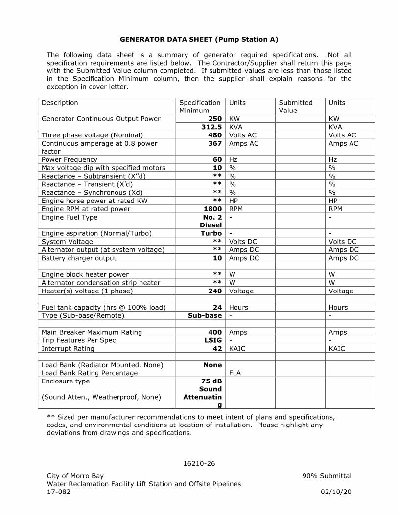
16210-26
City of Morro Bay 90% Submittal
Water Reclamation Facility Lift Station and Offsite Pipelines
17-082 02/10/20
GENERATOR DATA SHEET (Pump Station A)
The following data sheet is a summary of generator required specifications. Not all
specification requirements are listed below. The Contractor/Supplier shall return this page
with the Submitted Value column completed. If submitted values are less than those listed
in the Specification Minimum column, then the supplier shall explain reasons for the
exception in cover letter.
Description Specification
Minimum
Units Submitted
Value
Units
Generator Continuous Output Power 250 KW KW
312.5 KVA KVA
Three phase voltage (Nominal) 480 Volts AC Volts AC
Continuous amperage at 0.8 power
factor
367 Amps AC Amps AC
Power Frequency 60 Hz Hz
Max voltage dip with specified motors 10 % %
Reactance – Subtransient (X’’d) ** % %
Reactance – Transient (X’d) ** % %
Reactance – Synchronous (Xd) ** % %
Engine horse power at rated KW ** HP HP
Engine RPM at rated power 1800 RPM RPM
Engine Fuel Type No. 2
Diesel
- -
Engine aspiration (Normal/Turbo) Turbo - -
System Voltage ** Volts DC Volts DC
Alternator output (at system voltage) ** Amps DC Amps DC
Battery charger output 10 Amps DC Amps DC
Engine block heater power ** W W
Alternator condensation strip heater ** W W
Heater(s) voltage (1 phase) 240 Voltage Voltage
Fuel tank capacity (hrs @ 100% load) 24 Hours Hours
Type (Sub-base/Remote) Sub-base - -
Main Breaker Maximum Rating 400 Amps Amps
Trip Features Per Spec LSIG - -
Interrupt Rating 42 KAIC KAIC
Load Bank (Radiator Mounted, None) None
Load Bank Rating Percentage FLA
Enclosure type 75 dB
Sound
(Sound Atten., Weatherproof, None) Attenuatin
g
** Sized per manufacturer recommendations to meet intent of plans and specifications,
codes, and environmental conditions at location of installation. Please highlight any
deviations from drawings and specifications.
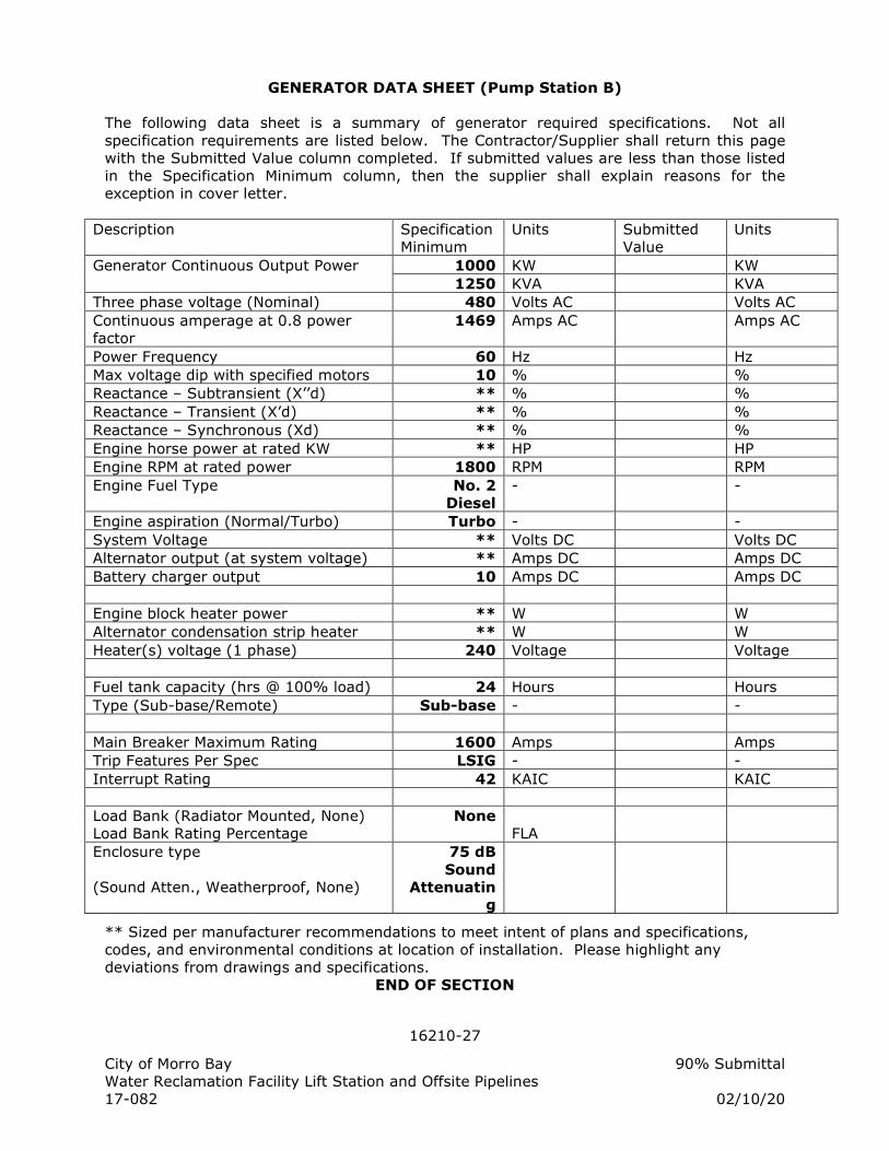
16210-27
City of Morro Bay 90% Submittal
Water Reclamation Facility Lift Station and Offsite Pipelines
17-082 02/10/20
GENERATOR DATA SHEET (Pump Station B)
The following data sheet is a summary of generator required specifications. Not all
specification requirements are listed below. The Contractor/Supplier shall return this page
with the Submitted Value column completed. If submitted values are less than those listed
in the Specification Minimum column, then the supplier shall explain reasons for the
exception in cover letter.
Description Specification
Minimum
Units Submitted
Value
Units
Generator Continuous Output Power 1000 KW KW
1250 KVA KVA
Three phase voltage (Nominal) 480 Volts AC Volts AC
Continuous amperage at 0.8 power
factor
1469 Amps AC Amps AC
Power Frequency 60 Hz Hz
Max voltage dip with specified motors 10 % %
Reactance – Subtransient (X’’d) ** % %
Reactance – Transient (X’d) ** % %
Reactance – Synchronous (Xd) ** % %
Engine horse power at rated KW ** HP HP
Engine RPM at rated power 1800 RPM RPM
Engine Fuel Type No. 2
Diesel
- -
Engine aspiration (Normal/Turbo) Turbo - -
System Voltage ** Volts DC Volts DC
Alternator output (at system voltage) ** Amps DC Amps DC
Battery charger output 10 Amps DC Amps DC
Engine block heater power ** W W
Alternator condensation strip heater ** W W
Heater(s) voltage (1 phase) 240 Voltage Voltage
Fuel tank capacity (hrs @ 100% load) 24 Hours Hours
Type (Sub-base/Remote) Sub-base - -
Main Breaker Maximum Rating 1600 Amps Amps
Trip Features Per Spec LSIG - -
Interrupt Rating 42 KAIC KAIC
Load Bank (Radiator Mounted, None) None
Load Bank Rating Percentage FLA
Enclosure type 75 dB
Sound
(Sound Atten., Weatherproof, None) Attenuatin
g
** Sized per manufacturer recommendations to meet intent of plans and specifications,
codes, and environmental conditions at location of installation. Please highlight any
deviations from drawings and specifications.
END OF SECTION
16250-1
City of Morro Bay 90% Submittal
Water Reclamation Facility Lift Station and Offsite Pipelines
17-082 02/10/20
SECTION 16250
AUTOMATIC TRANSFER SWITCH
PART 1: GENERAL
1.01 SCOPE OF WORK
A. The Contractor shall supply the automatic transfer switch (ATS) as specified
herein.
B. The ATS scope of work includes:
1. Providing and installing one automatic transfer switch of rating shown
on Contract Drawings.
2. Submittal data and drawings.
3. Startup assistance.
4. Factory and field testing.
5. Operation and maintenance manuals.
6. Warranty of all components.
C. Startup and configuration of ATS with installed voltages and loads.
D. As required under Electrical Specifications [Factory and Field Testing], furnish
all required labor, materials, safety equipment, transportation, test
equipment, incidentals and services to perform factory and/or field testing.
1.02 REFERENCES
A. Electrical Specifications [Electrical General]
B. Electrical Specifications [Factory and Field Testing]
C. Project Drawings
1.03 SUBMITTALS REQUIREMENTS
A. Provide Submittals as specified in Electrical Specifications [Electrical General,
Submittal Requirements].
B. Include a record of each parameter available to be changed by the user. The
list shall include factory defaults and space for entered values.
1.04 OPERATION AND MAINTENANCE INFORMATION
A. Provide operation and maintenance information as specified in Electrical
Specifications [Electrical General, Operating and Maintenance Information].
B. Include a record of each ATS parameter setup during startup and testing and
place a copy of setting in each O & M manual.
16250-2
City of Morro Bay 90% Submittal
Water Reclamation Facility Lift Station and Offsite Pipelines
17-082 02/10/20
PART 2: PRODUCTS
2.01 AUTOMATIC TRANSFER SWITCH
A. General:
1. The ATS shall be UL listed in accordance with UL 1008 and be labeled
in accordance with that standard's 1½ and 3 cycle, long-time ratings.
ATSs which are not tested and labeled with 1½ and 3 cycle (any
breaker) ratings and have series, or specific breaker ratings only, are
not acceptable.
2. The ATS shall be rated to close on and withstand 42,000 RMS
symmetrical short circuit amperes at the ATS terminals or otherwise
shown. Provide overcurrent protection as shown on the Contract
drawings.
3. The ATS manufacturer shall be certified to ISO 9001 International
Quality Standard and the manufacturer shall have third party
certification verifying quality assurance in design/development,
production, installation and servicing in accordance with ISO 9001.
4. ATS types utilizing components of molded-case circuit breakers,
contactors, or parts thereof, are not acceptable.
5. The switch assembly shall be installed in a NEMA enclosure located as
shown on Contract drawings.
6. The automatic transfer switch shall be an ASCO Model 7000, Eaton,
each with options to meet specified requirements, or equal.
B. Switch Unit:
1. The transfer switch unit shall be electrically operated and mechanically
held. The electrical operator shall be solenoid operated and only
momentarily energized to minimize power consumption and heat
generation.
2. The transfer switch shall feature a delayed transition mode. The
switch shall remain in the neutral position (neither emergency nor
normal) until the associated time delays have expired and allow the
switch to complete the transfer.
3. The switch shall be 3 pole double-throw with inherently interlocked
construction. A solid neutral shall be provided for all systems.
4. Wide contact gaps shall be provided to insure positive isolation of the
normal and emergency power sources.
5. The switch shall be fully rated for amperage shown on Contract
Drawings, for switching all types of loads including induction motors.
16250-3
City of Morro Bay 90% Submittal
Water Reclamation Facility Lift Station and Offsite Pipelines
17-082 02/10/20
The ratings shall apply to the voltage and mounting arrangement as
shown in the drawings.
6. The main power contacts shall have silver alloy contact construction
featuring a wiping action each time the switch is operated. Arc chutes
shall be utilized to contain the inherent spark created when switching
under load.
7. The main contact design shall allow repeated making and breaking of
rated full load current, with a combination of motor and other loads
and without damage or undue wear to the contacts.
8. All main power contacts and auxiliary contacts shall be mechanically
driven from a common actuator shaft.
9. The bus shall be constructed of silver plated copper.
10. Inspection of all contacts, linkages and moving parts shall be possible
from the front of the switch without disassembly of operating linkages
and without disconnection of power conductors.
11. All switch and relay contacts, coils, mechanical linkages, and control
elements shall be serviceable or removable from the front of the
mounted switch or accessory assembly without removal of the switch
or assembly from the compartment and without disconnection of the
power cables or control wiring.
12. The switch shall have a manual operating handle for maintenance
purposes.
13. Compression screw type solder-less terminals or lugs shall be provided
for connecting all external line & load power cables and control wiring.
All connections shall be accessible from the front without removal of
internal components.
14. A terminal strip shall be provided for terminating all control wiring. All
terminals shall be numbered with machine printed lettering matching
the wire number of the terminated wire.
15. All control wiring shall have permanent identification at each point of
connection. Wire identification shall be by machine printed numbered
wiring sleeves. Electrically common wires shall have the same wire
number. Electrically different wiring shall have unique wire numbers.
16. Control wiring shall be neatly bundled and secured in place by plastic
cable ties. Wiring shall be protected with plastic spiral wrap where it
crosses over a hinge to the door.
C. ATS CONTROL PANEL
1. A control panel shall be provided to direct the operation of the transfer
switch. The modules sensing and logic shall be a controlled by a
16250-4
City of Morro Bay 90% Submittal
Water Reclamation Facility Lift Station and Offsite Pipelines
17-082 02/10/20
built-in microprocessor. Control panels that do not utilize
microprocessor electronics to control the operation of the switch are
not acceptable.
2. A four line, 20 character LCD display and keypad shall be an integral
part of the controller for viewing all available data and setting desired
operational parameters. Operational parameters shall also be
available for viewing and limited control through the serial
communications input port.
3. The controller shall be connected to the transfer switch by an
interconnecting wiring harness. The harness shall include a keyed
disconnect plug to enable the controller to be disconnected from the
transfer switch for routine maintenance.
a. Sensing and control logic shall be provided on multi-layer
printed circuit boards.
b. The panel shall be enclosed with a protective cover and be
outer door or deadfront mounted such that it may be operated
with the door closed for safety and ease of maintenance.
4. A single controller shall provide twelve selectable nominal voltages for
maximum application flexibility and minimal spare part requirements.
Voltage sensing shall be true RMS type and shall be accurate to ± 1%
of nominal voltage. Frequency sensing shall be accurate to ± 0.2%.
a. The under-voltage of each phase of the normal source shall be
monitored, with pickup adjustable from 85% to 100% of
nominal and the dropout adjustable from 75% to 98% of pickup
setting, both in increments of 1%. These adjustments shall be
factory set at 85% dropout, and 90% pickup.
b. The voltage of each phase of the emergency source shall be
monitored, with pickup adjustable from 85% to 100% of
nominal. This adjustment shall be factory set at 95% pickup.
c. Frequency sensing of the emergency source shall be provided,
with pickup adjustable from 90% to 100% of nominal. This
adjustment shall be factory set at 97% pickup.
d. The control panel shall meet or exceed the voltage surge
withstand capability in accordance with IEEE Standard
472-1974 (ANSI C37.90a 1974) and the withstand voltage test
in accordance with the proposed NEMA Standard ICS1-109.21.
5. The transfer switch control panel shall be capable of operating over a
temperature range of -20 to +60 degrees C.
6. The control panel shall include the following field adjustable time
delays:
a. Time delay to override momentary normal source outages,
adjustable from 0 to 5 minutes. This adjustment shall be field
set to place emergency generator on-line in 1 minute.
b. Transfer to emergency time delay for controlled timing of load
16250-5
City of Morro Bay 90% Submittal
Water Reclamation Facility Lift Station and Offsite Pipelines
17-082 02/10/20
transfer to emergency, adjustable from 0 to 5 minutes. This
adjustment shall be field set switch position in 5 seconds after
power has stabilized.
c. Emergency source failure time delay to ignore momentary
transients during initial generator set loading, adjustable from 0
to 6 seconds. Set at 2 seconds.
d. Retransfer to normal time delay, adjustable 0 to 60 minutes.
This adjustment shall be factory set at 5 minutes. The time
delay is automatically bypassed if the emergency source fails
and normal source is acceptable.
e. Unloaded running time delay for emergency engine generator
cooldown, adjustable from 0 to 60 minutes. This adjustment
shall be factory set at 5 minutes.
f. Delayed transition time delay for setting the dead time when all
power is removed from the load side of ATS, adjustable 0 to 5
minutes. Set at 1 minute.
g. Generator Exercise Timer: Timer provided for operator
adjustment of day of week, time of day and run duration for
exercising the generator under operating loads by activating
the automatic transfer switch. . Timer shall be mounted on the
ATS outer deadfront door.
h. The controller shall provide an integral engine exerciser. The
timer shall be field set by the Contractor with date and time
during training. The engine exerciser shall allow the user to
program up to seven different exercise routines. For each
routine, the user shall be able to:
1) Enable or disable the routine.
2) Enable or disable transfer of the load during routine.
3) Set the start time of day, day of week, week of month,
alternate or every time start, duration of run.
4) At the end of the specified duration the switch shall
transfer the load back to normal and run the generator
for the specified cool down period. A 10-year life
battery that supplies power to the real time clock in the
event of a power loss will maintain all time and date
information.
7. The controller shall commit-to-start engine which requires the engine
to reach proper output and run at least the duration of the cooldown
setting, regardless of whether the load is transferred.
8. Provide interface relays or main switch follower contacts to comply
with I/O interface requirements as defined in the P&ID diagram.
Interfacing relays shall be industrial grade plug-in type with dust
covers. Interface connections shall be wired to backpan terminal
blocks. At minimum, the switch shall have the following unused I/O
contacts available:
a. Switch in Normal – SPDT rated 10 amps, 120 VAC
b. Switch in Emergency – SPDT rated 10 amps, 120 VAC
c. Engine starting contact -- DPDT gold-flashed contacts rated 10
16250-6
City of Morro Bay 90% Submittal
Water Reclamation Facility Lift Station and Offsite Pipelines
17-082 02/10/20
amps, 32 VDC
d. Emergency Power available – SPDT rated 10 amps, 120 VAC
e. Normal Power available – SPDT rated 10 amps, 120 VAC
9. Terminals shall be provided for a remote contact which opens to signal
the ATS to transfer to emergency and for remote contacts which open
to inhibit transfer to emergency and/or retransfer to normal.
10. Provide separate LED signal lights with nameplates indicating the
following:
a. Utility power is available (green)
b. Generator power is available (red)
c. ATS is connected to Utility source (green)
d. ATS is connected to the Generator source (red)
e. ATS in neutral position (wht)
11. A three position momentary-type test switch shall be provided for the
test / automatic / reset modes:
a. Test: simulate normal source failure
b. Automatic: normal operation
c. Reset: bypass the time delays on either transfer to emergency
or retransfer to normal.
12. All adjustments shall be field adjustable without the use of tools,
meters, power supplies, or special test equipment and can be made
safely without personal exposure to live parts
13. Each adjustment resolution shall be settable within minimum
increments of 1%.
14. Repetitive accuracy of timer, voltage and frequency settings over a
temperature range of –20° C to 70° C shall be within +/-2%.
15. The control panel programming shall be lockable via password
protection.
16. The wire harness for connection of the control panel to the transfer
switch shall have sufficient length to reach between the mounting
locations shown on the Contract drawings.
17. Provide the following displays on the controller:
a. Event log to display 99 logged events with the time and date of
the event, event type and event reason.
b. Total number of ATS transfers.
c. Number of ATS transfers caused by power source failures.
d. Total number of days ATS has been in operation.
e. Total number of hours that the normal and emergency sources
have been available.
16250-7
City of Morro Bay 90% Submittal
Water Reclamation Facility Lift Station and Offsite Pipelines
17-082 02/10/20
PART 3: EXECUTION
3.01 WORKMANSHIP
A. All work in this Section shall conform to the codes and standards specified in
Electrical Specifications [Electrical General, Workmanship].
3.02 FIELD ASSISTANCE
A. Testing, checkout and start-up of the ATS equipment shall be performed
under the technical direction of a factory trained authorized manufacturer
representative.
1. The setup and programming of the ATS shall be provided by a factory-
trained representative who is authorized by the ATS manufacturer to
perform the startup. This setup and programming shall be done prior
to and during the first application of power.
2. Provide testing as specified in Electrical Specifications [Factory and
Field Testing].
B. Provide 1 hour of “ATS Setup” Training on operating and maintenance
procedures.
3.03 WARRANTY
A. Provide warranty as specified in Electrical Specifications [Electrical General,
Warranty].
END OF SECTION
16430-1
City of Morro Bay 90% Submittal
Water Reclamation Facility Lift Station and Offsite Pipelines
17-082 02/10/20
SECTION 16430
LOW VOLTAGE SWITCHBOARD
PART 1: GENERAL
1.01 SCOPE OF WORK
A. This section applies to specifies switchboards rated 600 volts and below.
B. Provide Switchboard(s) (SWBD) as specified herein and shown on the
Drawings.
1. The System Integrator shall perform and be responsible for
procurement, submittals, shop drawings, interconnection drawings,
factory testing, and all control wiring for the SWBD. System
Integrator is defined in Electrical Specifications [Electrical General].
C. All wiring, wire color codes, wire labeling and terminal blocks within SWBD
shall be as specified in Electrical Specifications [Low Voltage Wire & Data
Cable].
D. The SWBD scope of work includes:
1. Providing SWBD structure and all internal components.
2. Installation of the SWBD on concrete pad per details.
3. Submittal data and drawings.
4. Startup and configuration of SWBD internal components.
5. Factory and field testing.
6. Operation and maintenance manuals.
7. Warranty of all components.
8. Seismic Anchorage Design Calculations and conforming installation.
9. Conduit – support systems, wire, and grounding system, for
equipment interconnection, and operation.
10. System calibration, testing and documentation.
E. Electrical Specifications [Factory and Field Testing]. Furnish all required
labor, materials, safety equipment, transportation, test equipment, incidentals
and services to perform factory and/or field testing.
F. All electrical equipment and materials, and methods - including installation,
calibration, and testing - shall conform to the applicable codes and standards
listed in this and other Sections. All electrical materials and work shall
conform to published standards of the National Electric Code (NEC), Institute
of Electrical and Electronic Engineers (IEEE), and Underwriters Laboratories
Inc (UL).
1.02 REFERENCES
A. Electrical Specifications [Electrical General]
B. Electrical Specifications [Low Voltage Wire & Data Cable]
C. Electrical Specifications [Automatic Transfer Switch]
16430-2
City of Morro Bay 90% Submittal
Water Reclamation Facility Lift Station and Offsite Pipelines
17-082 02/10/20
D. Electrical Specifications [Panelboard and Power Transformer]
E. Electrical Specifications [Factory and Field Testing]
1.03 SUBMITTALS REQUIREMENTS
A. Provide Submittals as specified in Electrical Specifications [Electrical General,
Submittal Requirements].
B. Include a record of each configurable parameter available to be changed by
the user for internal components. The list shall include factory defaults and
space for entered values for each configurable component.
1.04 OPERATION AND MAINTENANCE INFORMATION
A. Provide operation and maintenance instructions as specified in Electrical
Specifications [Electrical General].
PART 2: PRODUCTS
2.01 SWITCHBOARD
A. General:
1. The Switchboard shall be Cutler Hammer, Square D or approved equal.
2. The Switchboard (SWBD) shall be built and tested in accordance with:
a. NEMA Standards
b. ANSI
c. Underwriters Laboratories, Inc.
B. Metering Panel:
1. Provide metal enclosed, front accessible, self contained utility metering
panel. Voltage, phase, AIC and continuous amperage rating shall be
as shown on Contract Drawings. Panel will include meter socket,
factory installed main breaker(s) and test by-pass facility.
2. Design utility entrance and termination and other features per NEC,
local codes, and serving Utility requirements.
3. Enclosure shall be manufactured from galvanized 14 ga. (min) sheet
steel. The enclosure shall be finished with ANSI 61 gray enamel paint.
Provide pad mount, surface mount or flush mount cabinet per
installation detail.
C. Switchboard:
1. Switchboard shall be front accessible with group mounted, buss
connected circuit protective devices. Where provisions for future
circuit protective devices are required, space for the device,
corresponding vertical buss, device connectors and the necessary
16430-3
City of Morro Bay 90% Submittal
Water Reclamation Facility Lift Station and Offsite Pipelines
17-082 02/10/20
mounting hardware shall be supplied.
2. Distribution section shall meet all requirements per NEC, local codes,
and as defined in the drawings.
3. Buss shall be copper. Aluminum buss is not equal to copper buss.
Furnish buss mounted cable lugs sized for cabling that is required to
be directly buss connected.
4. Buss shall, 3 phase, 4 wire, 480 volt, 65,000 AIC minimum
symmetrical (or as shown otherwise in the drawings).
5. Power buss:
a. Continuous amperage rating at least equal to the main circuit
breaker or the power source and shall be braced to withstand
stresses resulting from the maximum short-circuit current
available.
b. Horizontal bus shall extend through all sections of the
switchgear unless shown otherwise in the drawings with vertical
connections to circuit breakers in each section.
c. Buss shall be mounted on heavy-duty insulated glass polyester
supports, and main bus joints shall be bolted using a minimum
of two bolts.
d. Shipping splits and provisions for future bus extensions shall
have tin-plated bolted connections.
6. Neutral bus, when specified or required, shall have the same capacity
as the main bus.
7. Ground buss shall be rated per NEC relative to the power buss
amperage rating and shall extend the entire length of the switchboard.
D. Molded Case Circuit Breakers:
1. General:
a. Circuit breakers and motor circuit protectors shall be
manufactured by Eaton Cutler-Hammer, Square D, G.E.,
Siemens, or equal.
b. Circuit breakers shall be the bolt-on type.
c. Multiple-pole circuit breakers shall be designed so that an
overload on one pole automatically causes all poles to open.
The use of tandem or dual circuit breakers in a normal
single-pole space to provide the number of poles or spaces
specified are not acceptable.
16430-4
City of Morro Bay 90% Submittal
Water Reclamation Facility Lift Station and Offsite Pipelines
17-082 02/10/20
d. Molded case circuit breakers shall be operated by a single
toggle-type handle and shall have a quick-make, quick-break
switching mechanism. An automatic trip of the breaker shall be
clearly indicated by the handle position. Contacts shall be non-
welding silver alloy and have flash reduction arc chutes. A
push-to-trip button on the front of the circuit breaker shall
provide a local manual means to exercise the trip mechanism.
e. Minimum interrupting capacity:
1) 480 volt circuit breaker shall have a minimum
interrupting capacity of 42,000 amperes.
2) 120 or 208 or 240 volt breaker shall have a minimum
interrupting capacity of 22,000 amperes
f. Circuit Breakers less than 400 volt shall have thermal-magnetic
(TM) trip units and inverse time-current characteristics unless
protecting full voltage or solid state reduced voltage motor
starters, 15kva or larger transformer secondary, or as
specifically shown on drawings.
g. Circuit breakers shall be UL listed for series application.
h. Where indicated circuit breakers shall be current limiting.
i. Where indicated on drawings, provide UL listed circuit breakers
for continuous duty at 100% of their ampere rating in the
intended enclosure.
2. TRIP UNIT – Molded Case Circuit Breakers
a. The trip unit shall be Eaton type Digitrip 310+ or approved
equal.
b. Each molded case circuit breaker microprocessor-based tripping
system shall consist of three (3) current sensors, a trip unit and
a flux-transfer shunt trip. The trip unit shall use
microprocessor-based technology to provide the adjustable
time-current protection functions. True RMS sensing circuit
protection shall be achieved by analyzing the secondary current
signals received from the circuit breaker current sensors, and
initiating trip signals to the circuit breaker trip actuators when
predetermined trip levels and time-delay settings are reached.
c. Interchangeable rating plugs shall establish the continuous trip
ratings of each circuit breaker. Rating plugs shall be fixed-type.
Rating plugs shall be interlocked so they are not
interchangeable between frames, and interlocked such that a
breaker cannot be closed and latched with the rating plug
removed.
d. System coordination shall be provided by the following
microprocessor-based time-current curve shaping adjustments:
16430-5
City of Morro Bay 90% Submittal
Water Reclamation Facility Lift Station and Offsite Pipelines
17-082 02/10/20
1) Adjustable long-time setting (set by adjusting the trip
setting dial to an amount not to exceed rating plug)
2) Adjustable short-time setting and delay with selective
flat or I2t curve shaping,
3) Adjustable instantaneous setting
4) Adjustable ground fault setting and delay with selective
flat or I2t curve shaping.
e. The microprocessor-based trip unit shall have both powered
and unpowered thermal memory to provide protection against
cumulative overheating should a number of overload conditions
occur in quick succession.
f. Furnish internal ground fault protection with adjustable
settings. Provide neutral ground fault sensor for four-wire
loads.
g. Breakers shall have built-in test points for testing the long-time
delay, instantaneous, and ground fault functions of the breaker
by means of a test set.
E. Space Heaters:
1. Outdoor rated switchgear shall be provided with 120 volts AC
thermostatically controlled space heaters. Heater wiring shall be to
terminal blocks for connection to external power source. One heater
shall be provided in each vertical breaker section. Heaters shall have
guards to prevent accidental contact with power or control wiring.
F. Key Interlocks:
1. Key interlocks shall be provided as shown on the drawings. The
switchgear manufacturer shall be responsible for coordinating
interlocks for switchgear main circuit breakers interlocked with
generator circuit breakers. Key interlocks shall be as manufactured by
Kirk Key Interlock Company, or equal.
G. Surge Protective Device (SPD)
1. SPD shall be suitable Service entrance location per ANSI/IEEE C62.41,
IEEE C62.45, and UL1449 3rd edition and tested according to IEEE
C62.44 as Secondary Surge Arrestor.
2. Unit shall be sealed and not allow vapors from entering the
switchboard enclosure after a voltage surge event.
3. Modes of protection – Line to Line, Line to Ground, Line to Neutral (as
applicable). Voltage, phase and neutral connections per one-line
diagram. Current surge capacity shall be 60,000 amps per mode
minimum
16430-6
City of Morro Bay 90% Submittal
Water Reclamation Facility Lift Station and Offsite Pipelines
17-082 02/10/20
4. The SPD shall be factory installed inside the switchboard during
assembly by the original equipment manufacturer. The OEM design
shall be integral to the design of the switchgear with special paneling
and cutouts specifically designed for unit mounting.
5. The SPD connections shall be located as close as possible to the load
side of main disconnect device and ground/neutral bar.
6. The SPD shall have integral 30-amp disconnect and fuses. Service of
the SPD assembly, fuses or other serviceable components shall be
from front access of the switchboard and shall not require disassembly
of switchboard panels to repair or replace parts.
7. SPD shall be Cutler-Hammer Clipper, Current Technology TransGuard
or equal.
H. Power Monitor:
1. General:
a. Microprocessor based multifunction power and energy meter
b. Designed for multifunction electrical power, voltage, and
current measurement on 3 phase power systems.
c. Measured parameters: voltage, current, frequency, unbalance,
kW, KVAR, KVA, power factor, kWh.
d. Support for 3-Element Wye, 2.5 Element Wye, 2 Element Delta,
4 wire Delta systems.
e. 200 ms update for power measurement, 100ms update for
voltage, current, Hz.
f. Din rail mounting
g. 85 to 264 VAC control power, 5W.
h. Furnish compatible current transformers with ratio as shown in
the drawings or as needed to measure full feeding circuit
breaker rated current.
2. Voltage Inputs
a. Configurable to potential transformer ratio.
b. Input impedance of 1 Mega Ohm, 0.014W at 120 Volts.
c. Direct voltage input range
1) 347 Volts Line to Neutral
2) 600 Volts Line to Line.
d. 2500V withstand.
3. Current Inputs:
a. Configurable to current transformer (CT) ratio 1A or 5A input.
b. Burden 0.05VA, Impedance 0.002 ohms
c. Meter shall have a maximum burden of 0.005VA per phase, at
16430-7
City of Morro Bay 90% Submittal
Water Reclamation Facility Lift Station and Offsite Pipelines
17-082 02/10/20
the maximum of 15 Amperes continuous input.
d. Fault current withstand shall be 200 Amps for 1/2 second.
4. Digital I/O:
a. Two status inputs 24VDC, dry contact.
b. One KYZ output, 24VDC, 30mA
5. Accuracy
a. Revenue meter accuracy
b. +/- 1% or better for volts and amps
c. +/- 1% for power and energy functions.
d. True RMS measurements
6. Communications
a. Ethernet - 100BaseT Ethernet IP Allen Bradley protocol
b. Modbus TCP
7. Acceptable Products
a. Allen Bradley PM1000 1408-EM3A-ENT Ethernet
b. Or Equal
I. Current Transformers
1. Furnish mounted (preferable) or unmounted current transformers
based on space allocated and installation requirements. The current
transformer shall have wire leads or binding posts and ratio as shown
on the drawings. The accuracy shall be metering accuracy class 0.6 at
a minimum burden at 60 hz shall be 2.5 VA and as required to meet
specified accuracy of device(s) fed.
PART 3: EXECUTION
3.01 WORKMANSHIP
A. All work in this Section shall conform to the codes and standards specified in
Electrical Specifications [Electrical General, Workmanship] and as specified
herein.
3.02 INSTALLATION
A. Vertical sections shall be mounted on steel channel sills continuous on two
sides. The steel channel sills shall be heavy duty to meet the specific seismic
requirements of this project location. These sills shall be mounted on the
concrete pad to be installed per the Contract Drawings.
B. Conduit entering Switchboard shall be stubbed up 1" into the bottom
horizontal wireway (typically) directly below the vertical section in which the
conductors are to be terminated.
16430-8
City of Morro Bay 90% Submittal
Water Reclamation Facility Lift Station and Offsite Pipelines
17-082 02/10/20
C. Base of Switchboard shall be adequately grouted, caulked or sealed to
prevent the entry of insects and rodents.
3.03 FIELD ASSISTANCE
A. Provide field testing as specified in Electrical Specifications [Electrical General,
Testing].
3.04 WARRANTY
A. Provide warranty as specified in Electrical Specifications [Electrical General,
Warranty].
END OF SECTION
16450-1
City of Morro Bay 90% Submittal
Water Reclamation Facility Lift Station and Offsite Pipelines
17-082 02/10/20
SECTION 16450
GROUNDING
PART 1: GENERAL
1.01 SCOPE OF WORK
A. Labor, materials, equipment, tools, safety gear, test equipment, incidentals,
services, and transportation for a complete electro-mechanical installation as
shown on the Drawings, included in these Specifications, or as can be
reasonably implied from project descriptions.
B. The scope of work includes:
1. Furnish and install grounding system required by Drawings, or if not
shown or defined, as required by Article 250 of the NEC. Ground
conductors shall be sized for the protective device, minimum.
2. Furnish and install conduits, junction boxes, underground boxes, and
associated hardware. Provide hardware, conduit, fittings, and other
parts for a complete grounding installation.
3. Installations shall be designed and installed with components meeting
the NEMA area designation.
C. Work includes that specified in Electrical Specifications [Electrical General].
1.02 REFERENCES
A. Electrical Specifications [Electrical General]
B. Electrical Specifications [Low Voltage Wire & Data Cable]
C. Project Drawings
1.03 QUALIFICATIONS
A. Material furnished under this specification shall be installed by qualified
installers meeting requirements specified in Electrical Specifications [Electrical
General, Qualifications].
1.04 SUBMITTAL REQUIREMENTS
A. Provide submittals and Drawings as specified in Electrical Specifications
[Electrical General, Submittal Requirements].
B. Submit manufacturer's product information for connections, clamps, rods,
terminals, and grounding system components.
PART 2: PRODUCTS
2.01 GROUNDING SYSTEM
16450-2
City of Morro Bay 90% Submittal
Water Reclamation Facility Lift Station and Offsite Pipelines
17-082 02/10/20
A. General
1. Grounding conductors shall be sized as shown on the Drawings or in
accordance with NEC table 250, whichever is larger.
2. Components of the grounding electrode system shall be manufactured
in accordance with UL 467 - Standard for Safety Grounding and
Bonding Equipment.
B. Grounding System
1. The utility service ground shall be tied to a building ground grid
consisting of a "UFER" and/or ground rod type grounding system.
2. The UFER shall consist of minimum 25 feet minimum of code sized
bare copper wire conductor laid at 3 foot nominal depth encased with
of concrete or ground or as detailed on the Contract Drawings. UFER
ground shall be located where soil moisture content will be maximized.
3. Ground enhancement material shall be permanent and be designed to
lower earth resistance in all soil conditions. Once set, material shall
have resistivity of not more than 20 ohm-cm resistance. Material shall
be set by mixing it with water to form a slurry and shall not dissolve or
decompose once cured. Ground enhancement material shall be Erico
Ground Enhancement Material (GEM), Lyncole XIT, or equal.
4. The main ground bonding wire from the ground rod shall extend up
into the utility service panel with readily visible UL approved "ground
clamp" attached to the ground bus.
5. Install bare copper ground bond wires from the UFER ground to the
various locations shown on the Drawings.
C. Raceway Grounds
1. Metallic conduits shall be assembled to provide a continuous ground
path. Metallic conduits shall be bonded using insulated grounding
bushings.
D. Equipment and Enclosure Grounds
1. Electrical and distribution equipment shall be connected to the
grounding system. Cables shall be sized as specified.
E. Components
1. Ground rod shall be ¾” x 10 ft solid steel with 10-mil copper-cladding.
2. Provide ground well enclosures for all outdoor ground rods. Furnish
Christy type F8 or equal unless otherwise shown on the Drawings.
3. Ground rod clamps shall be bolt-on type as manufactured by O-Z
16450-3
City of Morro Bay 90% Submittal
Water Reclamation Facility Lift Station and Offsite Pipelines
17-082 02/10/20
Gedney type GRC, or equal.
4. Grounding and bonding wires shall be installed in all PVC conduits and
nonmetallic raceways and connected to the ground bus and all
equipment.
5. Each electrical enclosure shall have a copper ground bus. Screw type
fasteners shall be provided on all ground busses for connection of
grounding conductors. Ground bus shall be a Challenger GB series,
ILSCO CAN series or equal.
PART 3: EXECUTION
3.01 WORKMANSHIP
A. All work in this Section shall conform to the codes and standards specified in
specified in Electrical Specifications [Electrical General, Workmanship].
3.02 INSTALLATION
A. Grounding System:
1. Install all products per Electrical Specifications [Electrical General,
Installation].
2. Each nonmetallic conduit shall contain a code sized grounding
conductor.
3. The system neutral conductor and all equipment and devices required
to be grounded by the National Electrical Code shall be grounded in a
manner that satisfies the requirements of the National Code.
4. The system neutral (grounded conductor) shall be connected to the
system's grounding conductor at only a single point in the system.
This connection shall be made by a removable bonding jumper sized in
accordance with the applicable provisions of the National Electrical
Code if the size is not shown on the Drawings. The grounding of the
system neutral shall be in the enclosure that houses the service
entrance main overcurrent protection.
5. Utilize mechanical connections in accessible locations and exothermic
connections in non-accessible or buried locations.
6. The secondary on all transformers shall be grounded.
7. All raceway systems, supports, enclosures, panels, motor frames, and
equipment housings shall be permanently and effectively grounded.
8. Install insulated grounding conductor with feeders and branch circuit
conductors in conduits. Size grounding conductors in accordance with
NEC. Install from grounding bus of serving panel to ground bus of
served panel, grounding screw of receptacles, lighting fixture housing,
16450-4
City of Morro Bay 90% Submittal
Water Reclamation Facility Lift Station and Offsite Pipelines
17-082 02/10/20
light switch outlet boxes or metal enclosures of service equipment.
Ground conduits by means of grounding bushings on terminations at
panelboards and distribution panels with 12ga. conductor to grounding
bus
9. All receptacles shall have their grounding contact connected to a
grounding conductor.
10. Branch circuit grounding conductors for receptacles or other electrical
loads shall be arranged such that the removal of a lighting fixture,
receptacle, or other load does not interrupt the ground continuity to
any other part of the circuit.
11. Attachment of the grounding conductor to equipment or enclosures
shall be by connectors specifically provided for grounding. Mounting,
support, or bracing bolts shall not be used as an attachment point for
ground conductors.
12. Install grounding electrode conductor and connect to reinforcing steel
in foundation footing. Electrically bond building steel to ground
system. Bond metal siding not attached to grounded structure.
B. Ductbanks
1. Provide #4/0 AWG bare, stranded ground conductor in approximately
the center of the ductbank where shown on plans and for all ductbanks
containing cables rated 2kV or greater
2. Ground wire, where required, shall be strapped to a conduit every 5
feet.
3.03 FIELD QUALITY CONTROL
A. Inspections:
1. Engineer shall inspect ground system prior to cover.
B. Testing:
1. Complete applicable test forms if provided in testing specifications
[Factory and Field Testing]. If form is not provided, furnish results on
a vendor standard form.
2. Test each grounding connection to determine the ground resistance.
The grounding test shall be IEEE 81.2 and NETA 7.13. The current
reference rod shall be driven at least 100 feet from the ground rod or
grid under test. The measurements shall be made at 10-foot intervals
beginning 20 feet from the test electrode and ending 80 feet from it, in
direct line between the ground rod or center of grid and the current
reference electrode.
END OF SECTION
16470-1
City of Morro Bay 90% Submittal
Water Reclamation Facility Lift Station and Offsite Pipelines
17-082 02/10/20
SECTION 16470
PANELBOARD AND POWER TRANSFORMER
PART 1: GENERAL
1.01 SCOPE OF WORK
A. The Contractor shall supply panelboards and power transformers as specified
herein and as shown in the Contract Drawings.
B. The Contractor shall perform complete startup and testing services for the
panelboard and power transformer per Electrical Specifications [Factory and
Field Testing].
C. Work includes that specified in Electrical Specifications [Electrical General].
D. Reference drawings for panelboard and transformer location – electrical
structures or stand-alone. If within electrical structures, the Contractor shall
supply the electrical section with factory installed panelboard and
transformer. If stand-alone, the Contractor shall install individual
components with enclosures as specified herein.
1. The quantity of breakers with size and number of poles as shown on
panelboard schedules.
2. Submittal data and drawings.
3. Startup assistance.
4. Panelboard testing.
5. Operation and maintenance manuals.
6. Warranty of all components of the panelboard and power transformer.
1.02 SUBMITTAL REQUIREMENTS
A. Provide submittals and drawings as specified in Electrical Specifications
[Electrical General, Submittal Requirements].
B. Provide ratings and characteristics including voltage, temperature rise, KVA,
efficiency, materials of construction, NEMA enclosure rating, voltage taps, and
impedance.
C. Provide catalog cuts for circuit breakers and devices.
D. Submit panelboard schedule for approval.
1.03 OPERATION AND MAINTENANCE INFORMATION
A. Provide operating instructions as specified in Electrical Specifications
[Electrical General, Operating and Maintenance Instructions].
16470-2
City of Morro Bay 90% Submittal
Water Reclamation Facility Lift Station and Offsite Pipelines
17-082 02/10/20
PART 2 – PRODUCTS
2.01 PANELBOARDS
A. General
1. The Contractor shall furnish panelboards of a type indicated on the
one-line Contract drawings and specified herein.
2. Furnish and install padlock lock-off attachment for each circuit
breaker.
3. Panelboards shall comply with the applicable sections of UL, NEC, and
NEMA and shall be Cutler Hammer Pow-R-Line, Square D, ITT or
equal.
4. A machine-typed circuit directory with clear plastic cover shall be
supplied mounted on the inside of door in a frame when equipment is
shipped. Circuit directory shall be as approved in the Submittal.
B. Interiors
1. Interiors shall be completely factory assembled with bolt-on devices.
2. Main and feeder breakers shall include lockout padlock hasp suitable
for frame size. Provide Cutler Hammer QLPB123PL, PLK1, or similar.
3. Full size insulated neutral bars shall be included. Neutral busing shall
have a suitable lug for each outgoing feeder requiring a neutral
connection.
4. Main bus bars shall be plated copper sized in accordance with UL
standards to limit temperature rise on any current carrying part to a
maximum of 50 degrees C above an ambient 40 degrees C maximum.
5. A copper ground and neutral bus shall be included in all panelboards
with terminal screws.
C. Boxes
1. Provide minimum gutter space in accordance with the National Electric
Code. Where feeder cables supplying the mains of a panel are carried
through its box to supply other electrical equipment, the box shall be
sized to include the additional required wiring space. At least four
interior mounting studs with adjustable nuts shall be provided.
D. Trims
1. Provide a hinged door over all circuit breaker handles. Doors in
panelboard trims shall not uncover any live parts. Doors shall have a
catch, lock and trim.
16470-3
City of Morro Bay 90% Submittal
Water Reclamation Facility Lift Station and Offsite Pipelines
17-082 02/10/20
2. Surfaces of the trim assembly shall be properly cleaned, primed and a
finish coat of gray ANSI 61 or 49 or to Switchboards and MCCs.
3. Surface trims shall be same height and width as box for surface
mount, and ¾” (min) beyond box on all sides for flush mount.
E. Panelboard Ratings
1. Panelboards shall have voltage, phase and short circuit (AIC) ratings
as shown on the drawings.
2. Breakers shall be a minimum of 100 ampere frame. Breakers 15
through 100 amperes trip size shall take up the same pole spacing.
3. Panelboards shall be labeled with a UL short circuit rating. When
series ratings are applied with integral or remote upstream devices, a
label shall be provided. Series ratings shall cover all trip ratings of
installed frames. It shall state the conditions of the UL series ratings
including:
a. Size and type of upstream device
b. Branch devices that can be used
c. UL series short circuit rating
2.02 POWER TRANSFORMER
A. The power transformer shall be ventilated dry type. Voltage and KVA ratings
shall be as shown on the Contract Drawings. The transformer shall be as
manufactured by Cutler Hammer, Jefferson, ACME, Square D, G.E., or equal.
B. Transformer shall meet latest DOE 2016 minimum efficiency standards.
C. Coils shall be manufactured of electrical grade aluminum (if stand-alone) or
copper (if within a MCC or Switchboard) and shall be adequately braced for
short circuit ratings and defined in ANSI and NEMA standards.
D. Transformers rated 31KVA and above shall have two 2½ percent taps above
and below normal full capacity (ANFC and BNFC).
E. The transformer shall carry full load continuously at rated voltage and
frequency without exceeding the average temperature rise of 115°C above an
ambient temperature of 40°C. Insulation shall be rated for 220°C (UL class
220°C).
F. Impedance (Z): 4.0% +/- 0.3% or above to keep downstream fault currents
to a minimum.
G. Low noise. For transformers installed within electrical equipment, vibration
isolators shall be installed between the transformer and its mounting surface
to reduce case vibration and associated noise.
H. For stand alone transformers, the transformer housing shall be securely
16470-4
City of Morro Bay 90% Submittal
Water Reclamation Facility Lift Station and Offsite Pipelines
17-082 02/10/20
fastened to the mounting surface with bolted connections sized appropriately
to withstand seismic zone 4 forces.
I. The transformer shall be finished with two coats of enamel to resist rust and
corrosion.
J. Transformers located inside electrical structures or enclosures shall be
provided with adequate ventilation for heat removal as required.
K. Transformer neutral shall be grounded in accordance with Article 250-26 and
450-10 of NEC and any applicable local ordinances. Installation and
protection of the transformer grounding conductors and attachments shall be
per NEC 250-24.
PART 3 – EXECUTION
3.01 WORKMANSHIP
A. All work in this Section shall conform to the codes and standards specified in
Electrical Specifications [Electrical General, Workmanship].
B. Perform work to remedy non-compliant installations after inspection.
3.02 INSTALLATION
A. Provide installation as recommended by the manufacturer and as specified in
Electrical Specifications [Electrical General, Installation].
3.03 FIELD ASSISTANCE
A. Provide testing as specified in Electrical Specifications [Factory and Field
Testing].
3.04 WARRANTY
A. Provide warranty as specified in Electrical Specifications [Electrical General,
Warranty].
END OF SECTION
16481-1
City of Morro Bay 90% Submittal
Water Reclamation Facility Lift Station and Offsite Pipelines
17-082 02/10/20
SECTION 16481
VARIABLE FREQUENCY DRIVE
PART 1: GENERAL
1.01 SCOPE OF WORK
A. Provide each variable frequency drive as shown on elementary and one-line
Drawings. Variable frequency drive shall be provided with full speed bypass,
harmonic conditioner, line and/or load reactor, RFI filter and/or other
accessories where shown on The Drawings. All VFDs shall be of the same
manufacturer.
1. The System Integrator shall perform and be responsible for
procurement, submittals, shop drawings, testing, and all control wiring
for the VFD. System Integrator is defined in Electrical Specifications
[Electrical General].
B. Provide enclosure (and side mounted wire chase as required) for top or
bottom feed conduit connection as shown in the Drawings. Enclosure size
shall not exceed the space allocated in the Drawings for such use.
C. Provide cooling/ventilation system, mounting hardware, associated
components, devices, and field control stations. Some components may be
specified in other Electrical Specifications such as terminal blocks, wire,
buttons, etc.
D. Installation of the VFD with components as specified in Electrical
Specifications [Electrical General]. The VFD scope of work includes:
1. Providing and installing VFD(s) of rating shown on The Drawings.
2. Submittal data and drawings.
3. Startup assistance.
4. Factory and field testing.
5. Operation and maintenance manuals.
6. Warranty of all components.
E. Startup and configuration of VFD with actual motor load.
F. Electrical Specifications [Factory and Field Testing]. Furnish all required
labor, materials, safety equipment, transportation, test equipment, incidentals
and services to perform factory and/or field testing.
1.02 REFERENCES
A. Electrical Specifications [Electrical General]
B. Electrical Specifications [Low Voltage Wire & Data Cable]
C. Electrical Specifications [Factory and Field Testing]
1.03 SUBMITTALS REQUIREMENTS
16481-2
City of Morro Bay 90% Submittal
Water Reclamation Facility Lift Station and Offsite Pipelines
17-082 02/10/20
A. Provide Submittals as specified in Electrical Specifications [Electrical General,
Submittal Requirements].
B. Include a record of each VFD parameter available to be changed by the user.
The list shall include factory defaults and space for entered values.
1.04 OPERATING AND MAINTENANCE INFORMATION
A. Provide operation and maintenance instructions as specified in Electrical
Specifications [Electrical General].
B. Include a record of each VFD parameter setup during startup and testing and
place a copy of setting in each O & M manual.
PART 2: PRODUCTS
2.01 GENERAL
A. All equipment shall be designed for the service intended and shall be of
rugged construction, of ample strength for all stresses which may occur
during fabrication, transportation, erection, and continuous or intermittent
operation. All equipment shall be adequately stayed and braced and
anchored and shall be installed in a neat and workmanlike manner.
Appearance and safety, as well as utility, shall be given consideration in the
design of details. All components and devices installed shall be industrial
grade and shall be of sturdy and durable construction suitable for long,
trouble-free service. Light duty, fragile, and competitive grade devices of
questionable durability shall not be used.
B. The VFD is inclusive of the input stage, buss, output stage, input filters,
output filters, and all other assemblies, boards, or conditioning equipment,
that make up the entire VFD system. The VFD system is herein referred to
simply as “VFD” and is not to be parsed in any way to meet a specification as
a specific part or assembly where it cannot be met as a system.
C. Products that are specified by manufacturer, trade name, or catalog number
establish a standard of quality and do not prohibit the use of equal products
of other manufacturers provided they are favorably reviewed by the Owner
and/or Engineer prior to installation.
D. Underwriter’s Laboratories (UL) listing is required for all substituted
equipment when such a listing is available for the first named equipment.
2.02 QUALITY
A. All equipment and materials shall be new and the products of reputable
suppliers having adequate experience in the manufacture of these particular
items. For uniformity, only one manufacturer will be accepted for each type
of product.
B. All equipment shall be designed for the service intended and shall be of
rugged construction, of ample strength for all stresses which may occur
16481-3
City of Morro Bay 90% Submittal
Water Reclamation Facility Lift Station and Offsite Pipelines
17-082 02/10/20
during fabrication, transportation, erection, and continuous or intermittent
operation. All equipment shall be adequately stayed and braced and
anchored and shall be installed in a neat and workmanlike manner.
Appearance and safety, as well as utility, shall be given consideration in the
design of details. All components and devices installed shall be standard items
of industrial grade, unless otherwise noted, and shall be of sturdy and durable
construction suitable for long, trouble-free service. Light duty, fragile, and
competitive grade devices of questionable durability shall not be used.
C. Products that are specified by manufacturer, trade name, or catalog number
establish a standard of quality and do not prohibit the use of equal products
of other manufacturers provided they are favorably reviewed by the Owner
and/or Engineer prior to installation.
D. Underwriter’s Laboratories (UL) listing is required for all substituted
equipment when such a listing is available for the first named equipment.
2.03 VARIABLE FREQUENCY DRIVE
A. This specification is based on Allen Bradey 755T, ABB ACS-U31 or U37,
Square D Altivar 71 with AFE (Active Front End Attenuation), or Eaton Cutler
Hammer SVX9000 series with HCU2 (active harmonic filter), or equal. Drive
must fit in the locations provided in the plans.
B. The VFD shall be of the latest technology used to control and maintain a
process variable (level, flow, pressure, speed, etc.) by varying the motor
speed. The VFD shall be available from a single manufacturer in the
horsepower range of 1 to 500 HP.
C. Performance Requirements
1. Harmonic Attenuation (applies to Ultra Low Harmonic (ULH) as shown
in Drawings)
a. The VFD shall have an active filter line supply unit which
controls the low order harmonic current to reduce the harmonic
current impressed on the incoming power feeder.
b. The input current to the VFD shall limit the total harmonic
content to less than 5% of the VFD’s rated input on any power
system and under all operating conditions.
c. The VFD shall comply with IEEE 519 requirements.
2. Open loop static speed regulation shall be 0.5 % to 1% of rated motor
speed. When motor speed feedback is provided from a suitable
encoder, closed loop speed regulation shall be 0.1% of motor nominal
speed. Dynamic speed accuracy shall be less than 1%-sec with 100%
torque step open loop and 0.5%-sec closed loop with 100% torque
step. 2. Torque control response time shall be less than 10 ms with
nominal torque. In the torque regulating mode, torque regulating
16481-4
City of Morro Bay 90% Submittal
Water Reclamation Facility Lift Station and Offsite Pipelines
17-082 02/10/20
accuracy open loop shall be +/- 5%; torque regulating accuracy closed
loop shall be +/- 2%;
D. Ratings
1. The VFD shall employ a full wave rectifier to prevent input line
notching and operate at a fundamental (displacement) input power
factor of 0.98 at all speeds and nominal load.
2. The VFD efficiency shall be 97.5% or better at full speed and load.
Efficiency is defined as the output power divided by the input power in
terms of percentage. All internal system losses recognized.
3. Load - The VFD shall be designed to continuously operate the following
motor/pump load:
a. Motor NEMA design B, squirrel-cage induction or specialty
specific use motor per Mechanical Division Specification as
shown in Drawings.
b. Horsepower at full speed R.P.M. of submitted/approved motor.
c. Voltage, 230/460 VAC, three phase, 60 Hz.
d. Service factor, 1.15 S.F.
4. Input Power - The VFD shall be rated to continuously operate under
the following input power conditions:
a. The Drive shall be rated to operate from 3-phase power at
nominal voltage (208VAC to 600VAC, +10% /-15% as shown in
Drawings), 48Hz to 63Hz.
b. The overvoltage trip level shall be a minimum of 30% over
nominal, and the undervoltage trip level shall be a minimum
35% under the nominal voltage.
c. Three phase, phase rotation insensitive.
d. Displacement power factor, 0.95 lagging at all loads and speeds
above 10% rated load.
5. Output Power - The VFD shall be rated to continuously operate while
providing the following output power conditions:
a. Voltage, 0 to 500 VAC.
b. Frequency, 3 to 60 Hz.
c. Continuous motor horsepower.
d. VFD amp output (minimum).
e. Continuous current - as shown in Drawings or 115% of rated
motor nameplate amps, whichever is higher.
f. Short term normal current, 110% of continuous rated current
for a minimum duration of 1 minute per every 10 minutes
running.
g. Short term heavy duty overload current, 150% of continuous
rated current for a minimum duration of 1 minute per every 10
minutes running.
h. Waveform - sine coded PWM.
16481-5
City of Morro Bay 90% Submittal
Water Reclamation Facility Lift Station and Offsite Pipelines
17-082 02/10/20
i. The drive’s switching pattern shall be continually adjusted to
provide optimum motor flux and avoid the high-pitched audible
noise.
j. Diodes and transistors shall have a minimum withstand of
1,200 peak inverse voltage (PIV).
6. Environmental - The VFD shall be rated to continuously operate under
the following environmental conditions:
a. Ambient temperature, 5°F to 122°F (-15°C to 50°C).
b. Altitude, no derating below 3,300 ft.
c. Relative humidity, 95% non-condensing.
d. The drive shall be protected from atmospheric contamination by
chemical gasses and solid particles pre IEC 60721-3-3,
chemical gasses Class 3C2 and solid particles Class 3S2.
e. The drive shall be protected from vibration per IEC 60721-3-3
Class 3M4 (sinusoidal displacement 3.0 mm, 2Hz to 9Hz;
acceleration 10m/s2, 9Hz to 200Hz).
E. Protection - The VFD shall be provided with the following protection:
1. For each programmed warning and fault protection function, the Drive
shall display a message in complete English words or Standard English
abbreviations. The three (3) most recent fault messages along with
time, current, speed, voltage, frequency and DI Status shall be stored
in the Drive’s fault history. The last ten (10) fault names shall be
stored in Drive memory.
2. The Drive shall include internal MOV’s for phase to phase and phase to
ground line voltage transient protection.
3. Output short circuit withstand rating and ground fault protection rated
for 100,000 AIC shall be provided per UL508C without relying on line
fuses. Motor phase loss protection shall be provided.
4. The Drive shall provide electronic motor overload protection qualified
per UL508C.
5. Protection shall be provided for AC line or DC bus overvoltage at 130%
of max. rated or undervoltage at 65% of min. rated and input phase
loss.
6. A power loss ride through feature will allow the Drive to remain fully
operational after losing power as long as kinetic energy can be
recovered from the rotating mass of the motor and load.
7. Stall protection shall be programmable to provide a warning or stop
the Drive after the motor has operated above a programmed torque
level for a programmed time limit.
8. Underload protection shall be programmable to provide a warning or
stop the Drive after the motor has operated below a selected
16481-6
City of Morro Bay 90% Submittal
Water Reclamation Facility Lift Station and Offsite Pipelines
17-082 02/10/20
underload curve for a programmed time limit.
9. Over-temperature protection shall provide a warning if the power
module temperature is less than 5°C below the over-temperature trip
level.
10. The VFD shall constantly monitor the load current with an electronic
thermal overload relay and trip the drive on motor overload. The
electronic overload relay shall be adjustable and compensate for the
reduced cooling of the motor at reduced speeds. This protection
provides an orderly shutdown should the motor's thermal capabilities
be exceeded and eliminates the requirement for conventional motor
overload relays.
F. Digital programmer/controller –The VFD shall be equipped with a front
mounted operator control panel (keypad) consisting of a backlit,
alphanumeric, graphic display and a keypad with keys for Start/Stop,
Local/Remote, Up/Down and Help. Two (2) Softkeys will be provided which
change functionality depending upon the position within the parameter
hierarchy or state of panel.
1. All parameter names, fault messages, warnings and other information
shall be displayed in complete English words or standard English
abbreviations to allow the user to understand what is being displayed
without the use of a manual or cross-reference table.
2. The Display shall have contrast adjustment provisions to optimize
viewing at any angle.
3. The control panel shall provide a real time clock for time stamping
events and fault conditions.
4. The control panel shall include a feature for uploading parameter
settings to control panel memory and downloading from the control
panel to the same Drive or to another Drive.
5. All Drives throughout the entire power range shall have the same
customer interface, including digital display, and keypad, regardless of
horsepower rating.
6. The keypad is to be used for local control, for setting all parameters,
and for stepping through the displays and menus.
7. The keypad shall be removable and insertable under Drive power,
capable of remote mounting, and shall have its own non-volatile
memory.
8. Digital Programmer/Controller (HIM) shall be capable of remote door
mounting. Cable for remote digital programmer/controller shall be
supplied as shown in the Drawings. The HIM shall be mounted and
housed to maintain the NEMA 12 door rating.
16481-7
City of Morro Bay 90% Submittal
Water Reclamation Facility Lift Station and Offsite Pipelines
17-082 02/10/20
9. The standard operator panel shall provide a start-up, maintenance and
diagnostic assistants that guides a new user through initial start-up
and commissioning of the Drive as well as provide indications for
maintenance and help to diagnose a fault. In addition, a PID assistant,
Real-time Clock assistant, Serial Communications assistant, and Drive
Optimizer assistant shall be included. A Drive Optimizer assistant
permits the user to choose Drive set-up for low nose, drive & motor
efficiency or motor control accuracy.
10. The door mounted human interface module (HIM) display shall be
capable to view and adjust the following diagnostic and status
indicators:
a. VFD Speed % or Frequency
b. Instantaneous overcurrent.
c. Ground fault.
d. Overtemperature.
e. Overvoltage.
f. Undervoltage.
g. Overload.
h. Overfrequency.
i. Amps.
j. Voltage.
k. Temperature.
l. Auxiliary Fault.
m. Phase loss.
n. Current limit.
o. Power and kilowatt hours
p. Power up delay.
q. Status of discrete inputs and outputs.
r. Values of analog input and output signals
s. Values of PID controller reference, feedback and error signals.
11. Adjustments - The following setting ranges shall be provided and made
independently accessible for operator adjustment:
12. Speed/Torque control functions shall include:
a. Minimum speed/torque limits.
b. Maximum speed/torque limits.
c. Selection of up to seven (7) preset speed settings or external
speed control
d. Two (2) independent built-in PID controllers to control a
process variable such as pressure, flow or fluid level.
e. Two (2) analog inputs shall be programmable to form a
reference by addition, subtraction, multiplication, minimum
selection or maximum selection.
13. Output control functions shall include:
a. Current and torque limit adjustments to limit the maximum
Drive output current and the maximum torque produced by the
motor. These limits shall govern the inner loop torque regulator
16481-8
City of Morro Bay 90% Submittal
Water Reclamation Facility Lift Station and Offsite Pipelines
17-082 02/10/20
to provide tight conformance with the limits with minimum
overshoot.
b. A torque regulated operating mode with adjustable torque ramp
up/down and speed/torque limits.
G. Input and Output Terminations - The VFD shall have terminals for input and
output cabling as defined in the Conduit and Wire Schedule as shown on the
Contract Electrical Drawings.
1. Provide power terminal blocks for motor lead connections where drive
terminals are hard to reach or require drive cabinet disassembly to
connect.
2. Five (5) digital inputs, all independently programmable with at least
twenty-five (25) input function selections. Inputs shall be designed for
120 volts AC input or as otherwise shown in the Drawings. Input
functions must include time delay start and hand and auto (Ethernet)
control.
3. Two (2) form C relay contact digital outputs, all independently
programmable with at least thirty (30) output function selections.
Relay contacts shall be rated to switch a maximum two (2) Amps rms
continuous current at a maximum switching voltage of 30VDC or
250VAC. Function selections shall include indications that the drive is
ready (no faults and in remote), running, and are addressable from
Ethernet as users choice.
4. Two (2) analog inputs, each selectable for 0VAC - 10VAC or 4mA -
20mA, and independently programmable with at least ten (10) input
function selections. Analog input signal processing functions shall
include scaling adjustments, adjustable filtering and signal inversion. If
the input reference (4-20mA or 0-10V) is lost, the VFD shall give the
user the option of the following: (1) stopping and displaying a fault,
(2) running at a programmable preset speed, (3) hold the VFD speed
based on the last good reference received, or (4) cause a warning to
be issued, as selected by the user. The Drive shall be programmable to
signal this condition via a keypad warning, relay output and/or over
the serial communications bus.
5. Two (2) analog outputs providing 0 (4) to 20mA signals. Outputs shall
be independently programmable to provide signals proportional to at
least twelve (12) output function selections including output speed,
frequency, voltage, current and power.
6. Provide I/O input and relay output expansion card(s) as needed to
accommodate the I/O wiring as shown in the Drawings. The option
card shall be integrally mounted to the drive.
H. Communications – The VFD shall include communications module for interface
to the PLC. All settable parameters and instantaneous operational registers
shall be accessible from the communications port.
16481-9
City of Morro Bay 90% Submittal
Water Reclamation Facility Lift Station and Offsite Pipelines
17-082 02/10/20
1. Type
a. Ethernet TCP/IP (Allen Bradley Ethernet/IP)
2. Add-On Instructions
a. The VFD manufacturer must have an add-on instruction that is
compatible with the PLC on this project. The add-on instruction
provides a preconfigured message command to send and
receive information from the drive. The add-on instruction
must be a free download available from the manufacturer
website at the time of bid and thereafter.
3. Command and Metering registers to include:
a. Digital input reads (giving status of inputs)
b. Digital output commands (to relay DOs)
c. 3 phase voltage and current
d. Power in KW, KWH and Power factor
e. Elapsed motor run time
f. Start/Stop
g. Running
h. Fault conditions
i. Heat Sink Temperature
j. Others as available.
I. Features - The VFD shall have the following features:
1. Connection of the three incoming line leads and three-motor leads
shall be the only connections necessary for manual operation of the
VFD unit. All other wiring shall be prewired at the factory and
self-contained within the VFD unit. A 120 VAC control power
transformer and other auxiliary power supplies shall be provided with
the VFD for power to pilot lights, meters, relays, and miscellaneous
devices specified to be supplied with the VFD. Lugs shall be provided
for connection of all power leads; terminal blocks shall be provided for
all other wiring. Relay logic, wiring and enclosure layout shall be
equivalent to that shown on the Drawings.
2. The VFD shall be protected by a circuit breaker disconnect unless
otherwise shown in the Drawings. The disconnect shall be externally
operated and shall have an operator mechanism that is an integral
part of the enclosure. An operator mechanism shall be provided to
allow padlocking the disconnect in the "off" position with up to two
padlocks.
3. AC input fuses shall be provided on the line and/or load side of the
VFD (if required by the manufacturer) to isolate the VFD power
circuitry upon a fault condition.
4. Three (3) programmable critical frequency lockout ranges to prevent
the VFD from operating the load continuously at an unstable speed.
16481-10
City of Morro Bay 90% Submittal
Water Reclamation Facility Lift Station and Offsite Pipelines
17-082 02/10/20
5. Transient and surge voltage power line input protection shall be
provided for the VFD through use of metal oxide varistors (MOVs),
surge protective module, or other approved equal methods. Transient
protection integral to the VFD shall be provided to a minimum of
10,000 volts, 50 joules without failure. The transient protection shall
meet or exceed ANSI C7, 90-1971 and IEEE 472-1974 Standards
without failure. Failure is defined as loss of components in the VFD
including power semiconductors and fuses. The VFD shall be protected
from the following, as a minimum, power line transients and recover to
automatically restart and resume normal operation without posting a
fault:
a. Switching the primary of a power transformer.
b. Switching power factor correction capacitors “ON” and “OFF”
line.
c. De-energization or energization of contactors, relays, and other
power equipment from the power line.
d. Starting and stopping of other motors when powered from
Utility.
6. The VFD shall not be affected by or generate excessive
electro-magnetic interference (EMI). The VFD shall be provided with a
radio interference filter (RIF) to meet the following requirements:
a. The use of a 4 Watt hand-held VHF/UHF transceiver within
three feet of the VFD with its doors closed shall not cause
erratic operation, loss of configuration, or any other deviation
from normal operation.
b. The worst case conducted and radiated EMI generated by the
VFD shall not be enough to prevent the use of hand held
VHF-UHF transceivers within three feet of the VFD with its
doors closed.
7. Opening of the VFDs input switches, circuit breakers, or output
contactors while the VFD is operating under load shall not result in
damage to the VFD power or control circuit components.
8. The VFD shall be capable of starting and operating without a motor
load connected.
9. Phase loss protection shall be provided to prevent single phasing of the
motor load.
10. The VFD shall have an instantaneous electronic trip circuit to protect
the VFD from output line-to-line and line-to-ground short circuits.
Output line-to-line and line-to-ground short circuits shall not damage
the VFD.
11. The VFD shall be protected from excessive regeneration by a full
function regeneration limit circuit which avoids nuisance tripping when
overhauling loads occur. The full function regeneration limit circuit
16481-11
City of Morro Bay 90% Submittal
Water Reclamation Facility Lift Station and Offsite Pipelines
17-082 02/10/20
reduces the negative current limit of the drive during periods of
excessive regeneration allowing the drive to remain fully operational
without exceeding the level of regenerated energy which can be safely
accepted and dissipated by the inverter. The following performance
characteristics shall be provided:
a. The regeneration circuit automatically adjusts the negative
current limit, allowing the load to decelerate at the fastest rate
possible without excessive regenerated energy. Deceleration
torque is automatically limited to its maximum safe level.
b. If the load tends to overhaul the drive motor, the negative
current limit is automatically adjusted to prevent excessive
regeneration. The inverter hold back torque decreases and
allows the motor to follow the load while maintaining hold back
torque at its maximum safe level.
12. Automatic fault reset to automatically restart the drive after any type
of fault condition. This automatic restart shall repeat up to three
attempts. This automatic reset shall be provided to prevent a drive
fault from completely locking out on isolated nuisance fluctuations.
When the drive is locked out after its automatic reset attempts the
operator shall be able to reset the VFD by a local or remote manual
reset pushbutton. Fault lockout shall be indicated on the door
mounted drive fail pilot light.
13. The VFD shall be capable of continued operation during an intermittent
loss of incoming line power up to five cycles.
14. The VFD shall automatically restart upon reapplication of power after a
loss of line power. Momentary or sustained power failures shall not
fault trip out the VFD or blow any fuses.
15. Any configuration of adjustments or controls not set by a switch or
potentiometer shall be stored in nonvolatile memory. No configuration
information shall be lost due to power failures of any duration.
16. The VFD shall be capable of starting into a rotating motor without
tripping out on a fault.
17. The drive shall have an adjustable voltage boost control capable of
providing additional starting torque to the motor at start. This control
shall provide the additional voltage only at the frequency range
required to start the motor thus reducing the additional motor heating
excess voltage would cause at normal operating speeds.
18. The drive shall be equipped with critical frequency jump circuitry which
allows the VFD to be setup to skip two bands of frequencies which
cause excessive vibration or noise.
J. Enclosure - The enclosure type shall be as shown in the Drawings -
freestanding, wall mount, motor control center full section, or MCC cubicle
16481-12
City of Morro Bay 90% Submittal
Water Reclamation Facility Lift Station and Offsite Pipelines
17-082 02/10/20
mount construction. All components shall be accessible from the front of the
enclosure. Rear or side access shall not be required in order to remove or
service any component. The enclosure shall include the following in its
construction:
1. The VFD shall incorporate thermostat/run controlled fans for cooling.
The air flow through the VFD compartment shall provide proper cooling
of the operating VFD at an (external cabinet) ambient temperature of
104°F. Fan mounting shall include reusable air filters on suction.
Provide fans for suction and discharge vents as required maintaining
air flow and forcing circulation.
2. Provide specific use fans located within the enclosure to cool, directly,
specific components such as line filters or DV/DT filters.
3. Thermostat shall have bi-metallic adjustable set point range of 30° to
140°F. Thermostat shall have a switching capacity of 10A at 120 VAC.
Provide Hoffman A-TEMNO temperature switch or approved equal to
operate fans. Thermostat shall operate fans in parallel with motor
running output of VFD.
4. The VFD, including the enclosure and input protection, shall be UL
listed for a minimum of 42,000 RMS symmetrical ampere fault
withstand capability. VFDs consisting of the VFD, enclosure, and all
accessories, that are not UL listed will not be approved.
2.04 SINGLE TURN POTENTIOMETER
A. Provide manual single turn potentiometer. Potentiometer shall be compatible
with the VFD input for manual speed control. Potentiometers shall be Allen-
Bradley 800H, Cutler Hammer or equal.
2.05 HARMONIC LINE/LOAD REACTOR
A. Provide three phase AC reactor intended for use as an input or output filter
for AC-PWM variable frequency drives. Line reactor shall be current rated to
maximum continuous VFD amp rating or as shown in the Drawings. The
impedance of the reactor shall be 5% or as shown otherwise in the Drawings.
PART 3: EXECUTION
3.01 WORKMANSHIP
A. All work in this Section shall conform to the codes and standards specified in
Electrical Specifications [Electrical General, Workmanship].
B. Requirements of Related Electrical Sections apply to design, documentation
construction and assembly of Variable Frequency Drives.
C. Perform work to remedy non-compliant installations after inspection.
3.02 FIELD ASSISTANCE
16481-13
City of Morro Bay 90% Submittal
Water Reclamation Facility Lift Station and Offsite Pipelines
17-082 02/10/20
A. Testing, checkout and start-up of the variable frequency drive equipment
shall be performed under the technical direction of a factory trained
authorized manufacturer representative.
1. The setup and programming of the VFD shall be provided by a factory-
trained representative who is authorized by the VFD manufacturer to
perform the startup. This setup and programming shall be done prior
to and during the first application of power to the motor. The VFD
electronic motor overload protection shall be set to meet the motor
nameplate and NEC Code requirements.
2. Provide testing as specified in Electrical Specifications [Factory and
Field Testing].
B. Provide 1 hour of “VFD Setup” Training on operating and maintenance
procedures.
3.03 WARRANTY
A. Provide warranty as specified in Electrical Specifications [Electrical General;
Warranty].
END OF SECTION
16600-1
City of Morro Bay 90% Submittal Water Reclamation Facility Lift Station and Offsite Pipelines 17-082 02/10/20
SECTION 16600
FACTORY AND FIELD TESTING
PART 1: GENERAL
1.01 SCOPE OF WORK
A. This Section defines factory and field testing requirements of electrical and instrumentation equipment and as specified in this section and in Electrical
Specifications. All equipment provided under Electrical Specifications and electrical equipment provided under other sections shall be tested as specified herein.
B. The Electrical Contractor shall coordinate at no additional cost to the Owner, the services of an approved qualified third party independent testing company for the purpose of performing specific tests as outlined in EXECUTION, Field Test of this section.
C. The System Integrator, Testing Company and/or Electrical Contractor shall provide all labor, tools, material, power, and technical supervision to perform the specified tests and inspections.
D. The Electrical Contractor shall be present during field testing and assist the System Integrator and/or Testing Company in testing all equipment. The Electrical Contractor shall be ready to correct any wiring problems found during testing.
E. The Application Programmer (defined in Electrical Specifications [Electrical General].) and/or Construction Manager will be actively engaged in Operational Testing and Commissioning. These efforts shall be combined efforts of the Application-Programmer/Construction-Manager/Engineer and
Contractor. The Contractor shall facilitate test as outlined herein such that hardware, software and application programming are tested completely and all applicable test documentation is completed.
1. Expect that field testing of plant operational testing, SCADA and PLC checkout, is going to require 2 weeks after pre-operational tests are done. Contractor and System Integrator shall assist in this start-up. Coordinate with Owner Representative to schedule this start-up period.
F. It is the intent of these tests to ensure that all equipment is operational within industry and manufacturer's tolerances and is assembled in accordance with design plans and Specifications.
G. The Owner and/or Construction Manager may witness testing in effort to insure quality and verify results. The Contractor is required to provide notification 2 weeks prior to any test that are intended to be documented and submitted for approval or are final tests. The Owner and Construction
Manager must specifically decline witness of each test to be performed, and the test must be successful, and it must be documented on the day of test, in
16600-2
City of Morro Bay 90% Submittal Water Reclamation Facility Lift Station and Offsite Pipelines 17-082 02/10/20
order for it to not have to be repeated in the presence of an authorized witness. Only the Owner or Construction Manager may assign an authorized
witness.
H. All tests shall be documented in writing by the person performing the test on the test forms submitted (and similar to those shown at the end of this section) and signed by the Engineer as satisfactorily completed. The Testing
Company, Electrical Contractor or System Integrator performing tests shall keep a detailed log of all tests that failed or did not meet Specifications, including date of occurrence and correction.
1.02 REFERENCES
A. Electrical Specifications [Electrical General] B. Project Drawings C. Additional testing may be specified in other Electrical Specifications.
1.03 FACTORY AND FIELD GENERAL REQUIREMENTS
A. Testing General
1. Prior to any field testing Operation & Maintenance Manuals shall have been submitted and approved.
2. The test forms shall be completed by the contractor during testing and calibration of all equipment. All tests shall be witnessed by the Owner’s Representative. Completed test forms shall be given to the
Owner’s Representative the day of the test. Complete two sets of test forms if Contractor wants to keep a copy.
3. The Contractor shall give the Engineer 10 working days notice of the dates and time for inspections and testing.
4. Include test results in the Maintenance and Operational Manual.
5. As a minimum, all the tests indicated/specified on the test forms shall be performed and test forms filled out by the Contractor.
6. Prepare and submit formal test procedures and forms at least two
weeks prior to the start of testing. Testing shall not commence until the test procedures have been reviewed and approved. Submit a combined test procedure submittal with separate sections for factory
and field tests.
7. If the results of any of tests are unacceptable, the Contractor shall make corrections and perform the tests again until they are acceptable; these tests shall be done at no additional cost.
B. Failure to Meet Test
1. Any system, material or workmanship which is found defective on the basis of these tests shall be reported immediately following the test.
The Contractor shall replace the defective material or equipment and
16600-3
City of Morro Bay 90% Submittal Water Reclamation Facility Lift Station and Offsite Pipelines 17-082 02/10/20
have tests repeated.
C. Safety
1. Testing shall conform to the respective manufacturer's recommendations. All manufacturers’ safety precautions shall be followed.
2. Safety, as shown herein and in other divisions, shall be a combination
of all methods and practices described. Safety practices may not be determined based on the least restrictive requirement, but instead, on the most restrictive requirement. Obtain clarification if there is any question prior to performing tests.
3. The procedures stated herein are guidelines for the intended tests, the Contractor shall be responsible to modify these tests to fit the particular application and ensure personnel safety. Absolutely no tests
shall be performed in such a fashion that personnel safety is jeopardized.
4. The Contractor shall have two or more personnel present at all tests.
5. Two non-licensed portable radios shall be provided by the Contractor
for use during testing.
6. Contractor shall comply with California Electrical Safety Orders (ESO) and Occupational Safety and Health Act (OSHA): All test and
procedures shall comply with ESO and OSHA as to safety, protective clothing, clearances, padlocks and barriers around electrical equipment energized during testing.
7. The first set of tests to be performed (pre-energization) shall
determine the suitability for energization and shall be completed with all power turned off.
1.04 QUALIFICATIONS
A. Testing Company
1. Testing company shall have been actively engaged in the type of electrical testing specified in this Division for the past three years (minimum). The Testing Company representative shall have two years
experience in field testing of equipment working for the Testing Company or equivalent. The following Electrical Testing Companies are pre-approved.
a. EETS (916) 339-9691
b. Industrial Test (888)-809-8550 c. Emerson Electrical Reliability Services d. Apparatus Testing and Engineering (916) 853-6280
e. Apparatus Testing and Engineering (925) 454-1363 f. Power Systems Testing (925) 583-2361
16600-4
City of Morro Bay 90% Submittal Water Reclamation Facility Lift Station and Offsite Pipelines 17-082 02/10/20
2. Testing Companies not listed are required to submit company and individual representative resumes for review and approval.
B. System Integrator Representative
1. The system integrator representative shall have 1 year experience in field testing of equipment working for the System Integrator or equivalent. If the representative does not demonstrate necessary
experience or competence during testing or start-up, the System Integrator shall provide a representative meeting the required competence and experience.
C. Electrical Contractor Representative
1. The Electrician shall have 5 years minimum experience working with industrial control systems and have a Journeyman level experience rating.
1.05 SUBMITTAL REQUIREMENTS
A. The Contractor shall ensure that the Testing Company, System Integrator, and all equipment suppliers provide the submittal documentation required in this section. Submittals shall be complete, neat, orderly, and indexed. The
Contractor shall check all submittals required under this Division for the correct number of copies, adequate identification, correctness, and compliance with the Contract Specifications and Drawings, and initial all
copies certifying compliance.
B. The System Integrator shall assemble and submit for approval complete testing procedures and forms at least two weeks prior to the start of testing. Contractor is responsible for compiling testing procedures and forms from
multiple sub-contractors as required.
C. Test submittal shall include: (as applicable)
1. Proposed procedure for operational testing whether it is performed in the factory or field. Procedure shall include method, simulated I/O
requirements, bypass piping, telemetry, and necessary materials and equipment to conduct test.
2. Test forms (for all tests, factory and field, and regardless of who
performs tests). Test forms shall be electronically completed prior to submittal with entry spaces filled to the extent possible. The only remaining data that shall require completion during the test is the test data itself. Test forms shall be provided as illustrated at the end of
this section or equal.
3. Approved shop one-line, elementary diagrams and PLC I/O drawings.
4. Control strategies photocopied at 75% reduction with room at the side
of page for comments on each paragraph or control strategy.
16600-5
City of Morro Bay 90% Submittal Water Reclamation Facility Lift Station and Offsite Pipelines 17-082 02/10/20
PART 2: PRODUCTS
2.01 TEST EQUIPMENT
A. Test equipment required to perform testing and document results shall be provided by Contractor, Testing Company or System Integrator.
B. Test instruments shall be calibrated to references traceable to the National Institute of Standards and Technology. Instrument calibration shall be
current to one year from date of start-up. Test equipment accuracy shall be at least twice the accuracy of instrument being calibrated. Test instrument certificates of calibration shall be on-hand and provided prior to testing.
C. All test equipment to be used as part of the testing shall be listed in the
submitted testing sheets. Contractor supplying the component or system to be tested shall provide all necessary test equipment.
D. The overall accuracy of each input and output loop shall be checked to ensure
that it is within manufacturer's Specification tolerances. In no case shall the error exceed 0.25% or 0.04 mA.
PART 3: EXECUTION
3.01 FACTORY TESTING
A. General Requirements
1. The System Integrator shall conduct a thorough and complete factory test witnessed by Engineer per the criteria specified herein. Factory
test shall be held within 150 miles of project location.
2. Temporary wiring and equipment shall be provided and connected during these tests to simulate the complete assembled system.
3. The testing shall not be started until the manufacturer has completed
fabrication, wiring, setup, programming; quality control testing; and can demonstrate the system is complete and operational.
4. The equipment required for factory testing shall consist of, but is not limited to, control panels, MCCs, and/or miscellaneous electrical panels
as provided under this contract.
5. Two digital multimeters/signal generators (minimum +/- 0.1% accuracy) with clip-on leads shall be supplied and utilized during
testing for measurement of digital and analog outputs.
6. All factory tests shall be conducted at the System Integrator’s facility. All factory tests shall be completed prior to shipment to the jobsite. The equipment shall be fully assembled, and connected (and
programmed) similar to as it will be installed.
7. The length of the factory testing shall be a minimum of one (1)
16600-6
City of Morro Bay 90% Submittal Water Reclamation Facility Lift Station and Offsite Pipelines 17-082 02/10/20
working day(s) (8 hours per day).
8. If the equipment is not ready for factory testing, the test will be
cancelled and rescheduled for a later date. The Contractor shall be responsible for paying liquidated damages for expenses incurred by the Owner Representative to come to a cancelled test. One thousand dollars ($1000.00) in liquidated damages shall be deducted from his
contract each occurrence.
9. Faulty and/or incorrect hardware or software operation of major portions of the system may, at the discretion of the Engineer, be cause for suspension, cancellation, or restarting of the factory test, at no
additional cost to the Owner or extension in Contract time.
10. The Systems Integrator shall develop, furnish, and install a test program to be loaded into PLCs to verify all Logic Controller I/O Point
to Point Tests prior to start of applications program testing. Systems Integrator shall use a computer running PLC programming software to confirm I/O calibration and status, force outputs and communications configuration.
11. The factory test will be considered complete only when the integrated system has successfully passed all tests. No electrical equipment shall be shipped to jobsite without completed test documentation.
12. During the testing period, under the supervision of the System Integrator, the Owner’s Representative shall have unlimited and unrestricted access to the usage and testing of system hardware, configuration, software, meters and tools.
13. The System Integrator shall pay all expenses incurred by his personnel including labor, material, transportation, lodging, daily subsistence, and other associated incidental costs during the factory testing.
14. Acceptance and witnessing of the factory tests does not relieve or
exclude the Contractor from conforming to the requirements of the Contract Documents.
15. Upon conclusion of factory testing, and at the request of the
Application Programmer, the System integrator shall remove the PLC, OI, and communication equipment for Application Programmer’s use and programming. The System Integrator shall provide equipment to Application Programmer immediately or ship unit within 2 working
days. The System Integrator shall not be responsible for equipment while in Application Programmer’s care.
16. All modifications to documentation as a result of the factory tests shall
be corrected and completed before the submittal and delivery of "Operation and Maintenance" Manuals.
17. Copies of the completed and witnessed factory testing forms shall be included in the Operation and Maintenance Manual.
16600-7
City of Morro Bay 90% Submittal Water Reclamation Facility Lift Station and Offsite Pipelines 17-082 02/10/20
B. Factory Tests
1. Structured Factory Tests: The associated factory tests are to be
performed by the System Integrator and witnessed by the Owner’s Representative. The associated test forms shall be completed during each stage of the test.
a. Visual and Mechanical Inspection Tests
b. Wiring Tests
1) Contractor shall confirm correct panel wiring per System Integrator panel shop drawings. Panel shop drawings shall be compared with Contract P&IDs and other
Drawings to verify all hardwire logic are accounted for. Panel drawings used in factory tests shall be redlined and inserted into Factory Testing Results submittal.
c. MCC and Control Panel Pre-Operational Tests
d. Logic Controller I/O Point to Point Tests
e. Simulated Alarm Tests
1) Simulate the digital and/or analog signals at the
terminals to verify that each PLC I/O point is functional and properly programmed. Verify that all parameters (i.e., setpoints, enable/disable toggle bits, timers, etc.)
for the alarms operate according to the Specifications. Multiple alarm states (i.e., LO, LO-LO, HI, HI-HI, etc.) shall be checked.
f. Simulated Operational Control Tests
1) Simulate the digital and/or analog signals at the field terminals to verify that each control system is functional and properly configured and programmed.
2) Each line of control logic in the Control Strategies
section shall be checked. When the complete control strategy has been checked, it shall be signed and dated by testing person and person witnessing test.
3) Verify that all parameters (i.e., setpoints, runtimers, totalization, etc.) operate according to the Specifications.
2. Unstructured Factory Tests: The various unstructured tests shall
include, but are not limited to, the following.
a. Simulate the equipment failure and power fail/restart of PLC. Check the effects of each failure on maintaining operations with
16600-8
City of Morro Bay 90% Submittal Water Reclamation Facility Lift Station and Offsite Pipelines 17-082 02/10/20
the remaining equipment.
b. The factory tests, as a minimum, shall simulate all normal and
abnormal operating conditions including steady state, change of state, variable changes, fluctuations, transients, upsets, start-up, shutdown, power failure, and equipment failure conditions.
c. Communications test to devices located within control panel and/or in MCCs.
d. Simulation of PLC communication error. Demonstrate error detection, alarming, and recovery.
e. Measure and test all power supplies for correct voltage. Operate rechargeable devices under battery power to test run duration, alarms and automatic recovery.
3.02 FIELD TESTING
A. General Requirements
1. Field testing is broken down into 4 components
a. Pre-Energization testing
b. Pre-Operational Testing c. Operational Testing d. Commissioning
2. Project wide, all Pre-Energization testing must be completed prior to Pre-Operational testing, all Pre-Operational testing must be completed prior to Operational Testing, and all Operational Testing must be completed prior to Commissioning.
a. Any deviation of this order, whether on a component level or larger scale, must be approved.
b. Out of order testing, if allowed, will be evaluated on a case-by-case basis when brought to the attention of the Owner’s
Representative. The Owner’s Representative may require that the entire system, or portions thereof, be retested once the missing component(s) are installed and functional.
3. All equipment supplied by the Contractor or others shall be tested by Contractor per these specifications.
4. Two digital multimeters/signal generators (minimum +/- 0.1% accuracy) , AC current meters, torque wrench, and other specialized
test equipment shall be provided by the Contractor for use during testing.
5. If the equipment is determined not to be ready for testing, the test will
16600-9
City of Morro Bay 90% Submittal Water Reclamation Facility Lift Station and Offsite Pipelines 17-082 02/10/20
be cancelled and rescheduled for a later date.
6. Faulty and/or incorrect hardware or software operation of major
portions of the system may be cause for suspension, cancellation, or restarting of the area of testing, at no additional cost or extension in Contract time.
7. During the Operational testing period, under the supervision of the
System Integrator, the Owner’s Representative shall have unlimited and unrestricted access to the usage and testing of all hardware and software in the system.
8. The System Integrator shall pay all expenses incurred by his personnel
including labor, material, transportation, lodging, daily subsistence, and other associated incidental costs during field testing.
9. Acceptance and witnessing of the tests does not relieve or exclude the
Contractor from conforming to the requirements of the Contract Documents.
10. All modifications to documentation as a result of the tests shall be corrected and completed before the delivery of "as-built”
documentation.
11. Copies of the completed and witnessed field testing forms shall be included in the Operation and Maintenance Manual.
12. The various contractors on this project (General Contractor, Electrical Contractor, Testing Company, and System Integrator) shall assume the lead role in testing activities as listed below. The Contractor shall obtain assistance of suppliers and/or manufacturers representatives
for any major equipment testing.
a. Electrical Contractor:
1) Pre Energization Tests a) Visual Mechanical Tests
b) Wire Insulation and Continuity Tests. c) Panelboard Tests d) Breaker Tests
e) Fiber Optic Cables
2) Operational Tests. a) Generator Tests
3) Commissioning.
b. System Integrator:
1) Pre-Operational Tests a) Visual Mechanical Tests
b) Control panel pre-operational test
16600-10
City of Morro Bay 90% Submittal Water Reclamation Facility Lift Station and Offsite Pipelines 17-082 02/10/20
c) MCC pre-operational test d) Motor Tests.
e) PLC I/O point to point tests. f) Instrumentation switch tests g) Instrumentation transmitter tests.
2) Operational Tests.
3) Commissioning
c. Testing Company
1) Grounding System Tests 2) Breaker Device Tests
d. General Contractor
1) Test Scheduling 2) Operational Tests.
3) Commissioning.
B. Electrical Field Tests – The following test shall be performed within each test category. Complete test forms for each electrical panel, instrument, and/or device. Provide separate form for each component to be tested.
1. Pre-Energization Inspections and Tests:
a. Visual and Mechanical Inspection Tests b. Wire Insulation and Continuity Tests
c. Grounding System Tests d. Panelboard Tests e. Breaker Tests f. Fiber Optic Cables
2. Pre-Operational Tests:
a. MCC Pre-operational Tests: b. Control Panel Pre-operational Tests: c. Motor Testing:
d. Generator Testing (if generator is furnished) e. Harmonic Measurement: (Required for systems with VFDs) f. Instrumentation Switch Calibration Tests
g. Instrument Transmitter Calibration Tests h. PLC I/O point tests. i. Communication Tests
1) The Contractor shall verify that all communications via
radio, telephone, wireline, fiber optic, or other are functional and ready for operational testing. Revise all configurable parameters without additional cost to the
Owner as required for an optimally functional system.
2) Verify that all components of the communication system
16600-11
City of Morro Bay 90% Submittal Water Reclamation Facility Lift Station and Offsite Pipelines 17-082 02/10/20
operate together under all operating and power restart conditions. If faults occur, investigate source of problem
and correct. Revise all configurable parameters without additional cost to the Owner.
3) Change setpoints from SCADA and confirm that corresponding field setpoint changes correctly. Check
every I/O point on every screen, trend, and database.
3. Operational Tests:
a. After all the previous tests in this subsection are complete, the test forms are completed and signed-off, the Contractor shall
conduct operational testing.
b. Representatives from the General Contractor, Electrical Contractor, System Integrator, and Owner’s Representative
shall be present during testing. Operational testing shall be performed by Contractor in the presence of the Owner’s Representative.
c. During operational testing the Contractor shall follow the
instructions of the Owner. The Owner may place restrictions on operation that must be followed by the Contractor during testing. Any accidents or fines caused by actions of the
Contractor where warnings or restrictions were placed, shall be remedied or paid by the Contractor.
d. Alarm Tests
1) Generate the digital and/or analog signals at the primary
device to verify that each PLC I/O point is functional and properly programmed. Verify that all parameters (i.e., setpoints, enable/disable toggle bits, timers, etc.) for the alarms operate according to the Specifications.
Multiple alarm states (i.e., LO, LO-LO, HI, HI-HI, etc.) shall be checked.
e. Operational Control Tests
1) Generate the digital and/or analog signals at the primary device by raising or lowering the actual measured process. Inject signal into the terminals or utilize a “force” function within the device only as necessary.
Verify that each control system is functional and properly configured and programmed.
2) Each line of control logic in the Control Strategies
section shall be checked. When the complete control strategy has been checked, it shall be signed and dated by testing person and person witnessing test.
16600-12
City of Morro Bay 90% Submittal Water Reclamation Facility Lift Station and Offsite Pipelines 17-082 02/10/20
3) Verify that all parameters (i.e., setpoints, runtimers, totalization, etc.) operate according to the
Specifications.
4) Verify that all data, setpoints, alarms are being received at SCADA correctly and that all I/O points on screen are true and accurate representations of field information.
f. Other Tests
1) Force a power failure and power fail/restart of PLC and all other systems. Check the effects of each failure on each piece of equipment and automatic recovery.
2) Force a PLC communication error. Demonstrate error detection, alarming, and recovery.
3) Perform additional operational testing that has not
already been witnessed.
4) Perform any additional operational testing as necessary to confirm robust and error free operation under all operational conditions.
4. Trial Period
a. Station/Equipment shall be activated to automatically run for 5 days, 24 hours per day Monday through Friday.
b. During the trial period the Owner’s Representative will test all modes of operation and will look for errors and malfunctions. A punchlist will be generated to be completed by Contractor and re-tested prior to Commissioning.
c. If equipment failure occurs during the trial period, the Contractor shall repair or replace the defective equipment and shall begin another trial period, Monday through Friday.
d. This test shall be repeated until all new equipment functions
acceptably and without failure for consecutive days.
C. Commissioning:
1. Commissioning shall not commence until Operational testing and
System Training are complete with documentation submitted and with prior approval.
2. Commissioning period
a. The new equipment shall be activated by the Contractor to
operate in full automatic for 10 consecutive days, 24 hours per day. Commissioning shall only start on Mondays or Tuesdays.
16600-13
City of Morro Bay 90% Submittal Water Reclamation Facility Lift Station and Offsite Pipelines 17-082 02/10/20
b. During Commissioning, the Owner will monitor and run the station in normal automatic mode. If equipment failure occurs
during Commissioning, the Contractor shall repair or replace the defective equipment and shall begin another commissioning period after repairs are complete.
c. Parallel, existing and/or back-up systems shall remain in place
and functional during commissioning period. Demolition of parallel, existing or back-up systems shall not begin until commissioning is completed.
d. This test shall be repeated until the new equipment functions
acceptably for a consecutive commissioning period.
e. Warranty will begin at the start of a successful commissioning period. However, if major hardware failure occurs during
commissioning, the warranty and commissioning will restart once the problem has been identified and repaired.
3.03 WARRANTY:
A. Provide warranty per Electrical Specifications [Electrical General, Warranty].
1. The completion of the above tests does not relieve the Contractor from any warranties specified in the Electrical Specifications or other sections.
2. Warranty shall begin on the start date of a successful Commissioning period.
3.04 FINAL ACCEPTANCE:
A. Final Acceptance per Electrical Specifications [Electrical General].
16600-14
City of Morro Bay 90% Submittal Water Reclamation Facility Lift Station and Offsite Pipelines 17-082 02/10/20
SECTION 16600
TEST FORMS
Index of Forms:
PC Power Conductor Test Form
CC Control Conductor Test Form
IC Instrumentation Conductor Test Form
FIBER Fiber Optic Conductor Test Form
GS Grounding System Test Form
VM Electrical Equipment Visual and Mechanical Inspection Form
PB Panelboard Test Form
MCO MCC Operational Test Form
CPO Control Panel Operational Test Form
BD Breaker Device Test Form
GCL Generator Field Check List
GPT Generator Performance Test Form
GSLD Generator Sound Level Data Form
MOTOR Motor Test Form
HM Harmonic Measurement Test Form
IOP Programmable Logic Controller I/O Point-to-Point Test Form
ISC Instrumentation Switch Calibration Test Form
ITC Instrumentation Transmitter Calibration Test Form
END OF SECTION
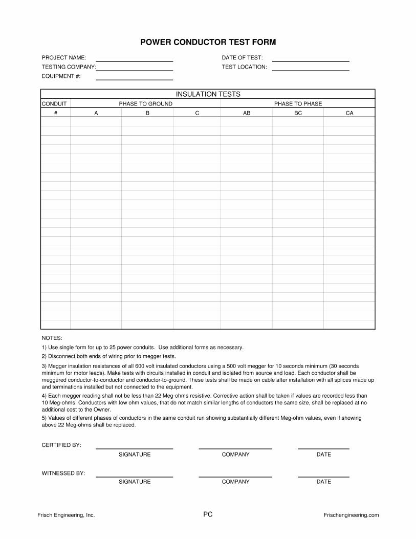
CONDUIT
#
NOTES:
WITNESSED BY:
SIGNATURE COMPANY
SIGNATURE COMPANY
CERTIFIED BY:
INSULATION TESTS
POWER CONDUCTOR TEST FORM
CB
PROJECT NAME:
TESTING COMPANY:
EQUIPMENT #:
TEST LOCATION:
DATE OF TEST:
PHASE TO GROUND PHASE TO PHASE
AB BC CAA
3) Megger insulation resistances of all 600 volt insulated conductors using a 500 volt megger for 10 seconds minimum (30 seconds
minimum for motor leads). Make tests with circuits installed in conduit and isolated from source and load. Each conductor shall be
meggered conductor-to-conductor and conductor-to-ground. These tests shall be made on cable after installation with all splices made up
and terminations installed but not connected to the equipment.
2) Disconnect both ends of wiring prior to megger tests.
1) Use single form for up to 25 power conduits. Use additional forms as necessary.
DATE
DATE
5) Values of different phases of conductors in the same conduit run showing substantially different Meg-ohm values, even if showing
above 22 Meg-ohms shall be replaced.
4) Each megger reading shall not be less than 22 Meg-ohms resistive. Corrective action shall be taken if values are recorded less than
10 Meg-ohms. Conductors with low ohm values, that do not match similar lengths of conductors the same size, shall be replaced at no
additional cost to the Owner.
Frisch Engineering, Inc. PC Frischengineering.com
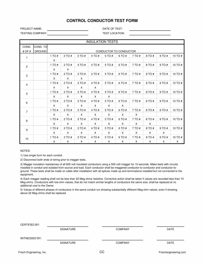
COND. COND. TO
# OF # GROUND
1 TO # 2 TO # 3 TO # 4 TO # 5 TO # 6 TO # 7 TO # 8 TO # 9 TO # 10 TO #
x
1 TO # 2 TO # 3 TO # 4 TO # 5 TO # 6 TO # 7 TO # 8 TO # 9 TO # 10 TO #
x x
1 TO # 2 TO # 3 TO # 4 TO # 5 TO # 6 TO # 7 TO # 8 TO # 9 TO # 10 TO #
x x x
1 TO # 2 TO # 3 TO # 4 TO # 5 TO # 6 TO # 7 TO # 8 TO # 9 TO # 10 TO #
x x x x
1 TO # 2 TO # 3 TO # 4 TO # 5 TO # 6 TO # 7 TO # 8 TO # 9 TO # 10 TO #
x x x x x
1 TO # 2 TO # 3 TO # 4 TO # 5 TO # 6 TO # 7 TO # 8 TO # 9 TO # 10 TO #
x x x x x x
1 TO # 2 TO # 3 TO # 4 TO # 5 TO # 6 TO # 7 TO # 8 TO # 9 TO # 10 TO #
x x x x x x x
1 TO # 2 TO # 3 TO # 4 TO # 5 TO # 6 TO # 7 TO # 8 TO # 9 TO # 10 TO #
x x x x x x x x
1 TO # 2 TO # 3 TO # 4 TO # 5 TO # 6 TO # 7 TO # 8 TO # 9 TO # 10 TO #
x x x x x x x x x
1 TO # 2 TO # 3 TO # 4 TO # 5 TO # 6 TO # 7 TO # 8 TO # 9 TO # 10 TO #
x x x x x x x x x x
NOTES:
5) Values of different phases of conductors in the same conduit run showing substantially different Meg-ohm values, even if showing
above 22 Meg-ohms shall be replaced.
1) Use single form for each conduit.
2) Disconnect both ends of wiring prior to megger tests.
3) Megger insulation resistances of all 600 volt insulated conductors using a 500 volt megger for 10 seconds. Make tests with circuits
installed in conduit and isolated from source and load. Each conductor shall be meggered conductor-to-conductor and conductor-to-
ground. These tests shall be made on cable after installation with all splices made up and terminations installed but not connected to the
equipment.
4) Each megger reading shall not be less than 22 Meg-ohms resistive. Corrective action shall be taken if values are recorded less than 10
Meg-ohms. Conductors with low ohm values, that do not match similar lengths of conductors the same size, shall be replaced at no
additional cost to the Owner.
SIGNATURE COMPANY DATE
WITNESSED BY:
CERTIFIED BY:
SIGNATURE COMPANY
CONDUCTOR TO CONDUCTOR
DATE
CONTROL CONDUCTOR TEST FORM
8
9
10
INSULATION TESTS
4
5
PROJECT NAME:
TESTING COMPANY:
DATE OF TEST:
TEST LOCATION:
1
2
3
7
6
Frisch Engineering, Inc. CC Frischengineering.com
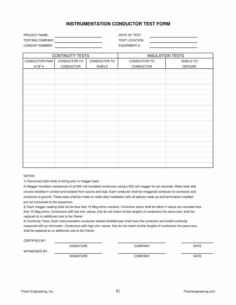
NOTES:
4) Continuity Tests: Each instrumentation conductor twisted shielded pair shall have the conductor and shield continuity
measured with an ohmmeter. Conductors with high ohm values, that do not match similar lengths of conductors the same size,
shall be replaced at no additional cost to the Owner.
2) Megger insulation resistances of all 600 volt insulated conductors using a 500 volt megger for ten seconds. Make tests with
circuits installed in conduit and isolated from source and load. Each conductor shall be meggered conductor-to-conductor and
conductor-to-ground. These tests shall be made on cable after installation with all splices made up and terminators installed
but not connected to the equipment.
replaced at no additional cost to the Owner.
3) Each megger reading shall not be less than 10 Meg-ohms resistive. Corrective action shall be taken if values are recorded less
than 10 Meg-ohms. Conductors with low ohm values, that do not match similar lengths of conductors the same size, shall be
1) Disconnect both ends of wiring prior to megger tests.
WITNESSED BY:
SIGNATURE COMPANY DATE
INSTRUMENTATION CONDUCTOR TEST FORM
CERTIFIED BY:
SIGNATURE COMPANY DATE
INSULATION TESTSCONTINUITY TESTS
PROJECT NAME:
TESTING COMPANY:
CONDUIT NUMBER:
CONDUCTOR TO SHIELD TO
GROUND
DATE OF TEST:
TEST LOCATION:
EQUIPMENT #:
CONDUCTOR PAIR
# OF #
CONDUCTOR TO
SHIELD
CONDUCTOR TO
CONDUCTOR CONDUCTOR
Frisch Engineering, Inc. IC Frischengineering.com
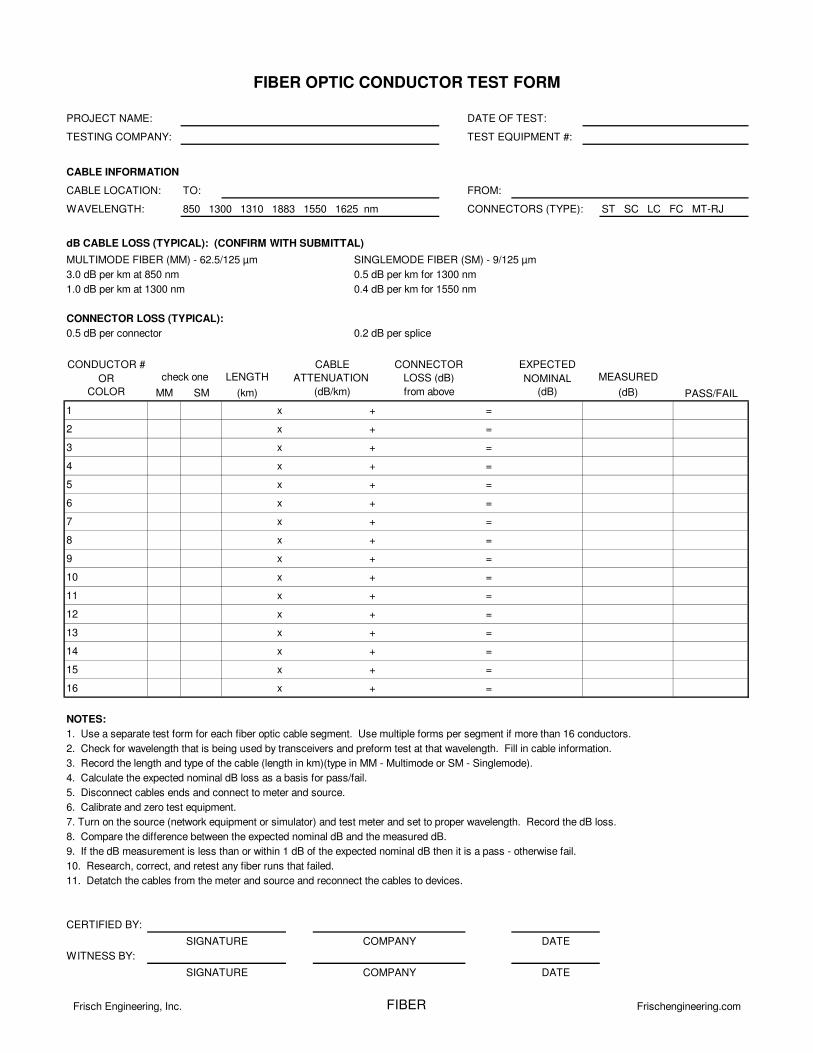
PROJECT NAME: DATE OF TEST:
TESTING COMPANY: TEST EQUIPMENT #:
CABLE LOCATION: TO: FROM:
WAVELENGTH: 850 1300 1310 1883 1550 1625 nm CONNECTORS (TYPE): ST SC LC FC MT-RJ
MULTIMODE FIBER (MM) - 62.5/125 µm SINGLEMODE FIBER (SM) - 9/125 µm
3.0 dB per km at 850 nm 0.5 dB per km for 1300 nm
1.0 dB per km at 1300 nm 0.4 dB per km for 1550 nm
CONNECTOR LOSS (TYPICAL):
0.5 dB per connector 0.2 dB per splice
CONDUCTOR # EXPECTED
OR LENGTH NOMINAL
COLOR MM SM (km) (dB)
1 x + =
2 x + =
3 x + =
4 x + =
5 x + =
6 x + =
7 x + =
8 x + =
9 x + =
10 x + =
11 x + =
12 x + =
13 x + =
14 x + =
15 x + =
16 x + =
NOTES:
1. Use a separate test form for each fiber optic cable segment. Use multiple forms per segment if more than 16 conductors.
2. Check for wavelength that is being used by transceivers and preform test at that wavelength. Fill in cable information.
3. Record the length and type of the cable (length in km)(type in MM - Multimode or SM - Singlemode).
4. Calculate the expected nominal dB loss as a basis for pass/fail.
5. Disconnect cables ends and connect to meter and source.
6. Calibrate and zero test equipment.
7. Turn on the source (network equipment or simulator) and test meter and set to proper wavelength. Record the dB loss.
8. Compare the difference between the expected nominal dB and the measured dB.
9. If the dB measurement is less than or within 1 dB of the expected nominal dB then it is a pass - otherwise fail.
10. Research, correct, and retest any fiber runs that failed.
11. Detatch the cables from the meter and source and reconnect the cables to devices.
CERTIFIED BY:
WITNESS BY:
SIGNATURE DATECOMPANY
COMPANYSIGNATURE DATE
CABLE INFORMATION
MEASUREDATTENUATION
(dB/km)
FIBER OPTIC CONDUCTOR TEST FORM
CABLE
PASS/FAIL
dB CABLE LOSS (TYPICAL): (CONFIRM WITH SUBMITTAL)
check oneCONNECTOR
from above (dB)
LOSS (dB)
Frisch Engineering, Inc. FIBER Frischengineering.com
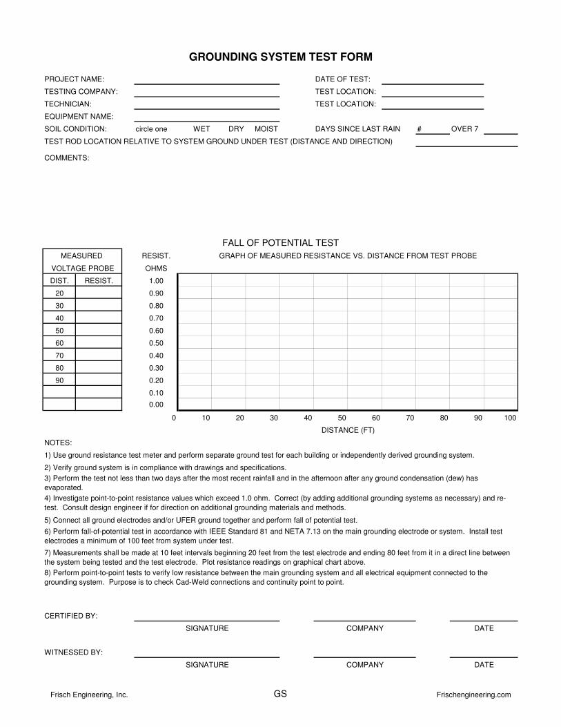
circle one WET DRY MOIST DAYS SINCE LAST RAIN # OVER 7
TEST ROD LOCATION RELATIVE TO SYSTEM GROUND UNDER TEST (DISTANCE AND DIRECTION)
RESIST.
OHMS
DIST. RESIST. 1.00
20 0.90
30 0.80
40 0.70
50 0.60
60 0.50
70 0.40
80 0.30
90 0.20
0.10
0.00
0 10 20 30 40 50 60 70 80 90 100
NOTES:
3) Perform the test not less than two days after the most recent rainfall and in the afternoon after any ground condensation (dew) has
evaporated.
2) Verify ground system is in compliance with drawings and specifications.
VOLTAGE PROBE
GROUNDING SYSTEM TEST FORM
PROJECT NAME: DATE OF TEST:
GRAPH OF MEASURED RESISTANCE VS. DISTANCE FROM TEST PROBE
FALL OF POTENTIAL TEST
MEASURED
TECHNICIAN: TEST LOCATION:
WITNESSED BY:
CERTIFIED BY:
COMMENTS:
DISTANCE (FT)
DATESIGNATURE
COMPANY
COMPANY
8) Perform point-to-point tests to verify low resistance between the main grounding system and all electrical equipment connected to the
grounding system. Purpose is to check Cad-Weld connections and continuity point to point.
SIGNATURE
4) Investigate point-to-point resistance values which exceed 1.0 ohm. Correct (by adding additional grounding systems as necessary) and re-
test. Consult design engineer if for direction on additional grounding materials and methods.
7) Measurements shall be made at 10 feet intervals beginning 20 feet from the test electrode and ending 80 feet from it in a direct line between
the system being tested and the test electrode. Plot resistance readings on graphical chart above.
DATE
TEST LOCATION:TESTING COMPANY:
EQUIPMENT NAME:
SOIL CONDITION:
1) Use ground resistance test meter and perform separate ground test for each building or independently derived grounding system.
6) Perform fall-of-potential test in accordance with IEEE Standard 81 and NETA 7.13 on the main grounding electrode or system. Install test
electrodes a minimum of 100 feet from system under test.
5) Connect all ground electrodes and/or UFER ground together and perform fall of potential test.
Frisch Engineering, Inc. GS Frischengineering.com
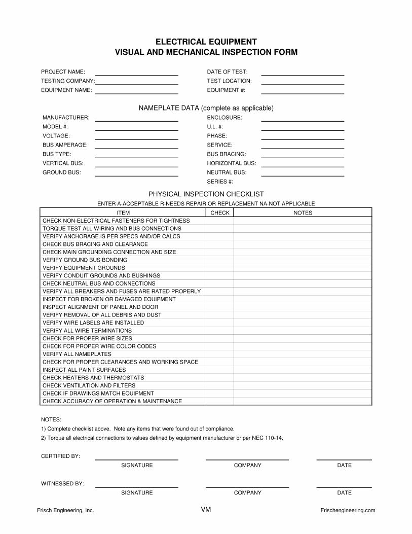
MODEL #: U.L. #:
PHASE:
SERVICE:
SERIES #:
CHECK
NOTES:
CHECK IF DRAWINGS MATCH EQUIPMENT
CHECK BUS BRACING AND CLEARANCE
1) Complete checklist above. Note any items that were found out of compliance.
VERIFY EQUIPMENT GROUNDS
CHECK HEATERS AND THERMOSTATS
CHECK VENTILATION AND FILTERS
VERIFY ALL BREAKERS AND FUSES ARE RATED PROPERLY
VERIFY ALL NAMEPLATES
INSPECT FOR BROKEN OR DAMAGED EQUIPMENT
INSPECT ALIGNMENT OF PANEL AND DOOR
VERIFY ANCHORAGE IS PER SPECS AND/OR CALCS
VERIFY REMOVAL OF ALL DEBRIS AND DUST
VERIFY CONDUIT GROUNDS AND BUSHINGS
CHECK NEUTRAL BUS AND CONNECTIONS
ENTER A-ACCEPTABLE R-NEEDS REPAIR OR REPLACEMENT NA-NOT APPLICABLE
NOTES
VERTICAL BUS:
GROUND BUS:
BUS TYPE:
NEUTRAL BUS:
BUS BRACING:
ENCLOSURE:
PROJECT NAME:
TESTING COMPANY:
EQUIPMENT NAME:
NAMEPLATE DATA (complete as applicable)
DATE OF TEST:
TEST LOCATION:
EQUIPMENT #:
VOLTAGE:
BUS AMPERAGE:
MANUFACTURER:
ELECTRICAL EQUIPMENT
VISUAL AND MECHANICAL INSPECTION FORM
HORIZONTAL BUS:
CERTIFIED BY:
SIGNATURE COMPANY
CHECK ACCURACY OF OPERATION & MAINTENANCE
DATE
2) Torque all electrical connections to values defined by equipment manufacturer or per NEC 110-14.
WITNESSED BY:
SIGNATURE COMPANY DATE
CHECK FOR PROPER CLEARANCES AND WORKING SPACE
PHYSICAL INSPECTION CHECKLIST
ITEM
INSPECT ALL PAINT SURFACES
CHECK FOR PROPER WIRE COLOR CODES
VERIFY WIRE LABELS ARE INSTALLED
VERIFY ALL WIRE TERMINATIONS
CHECK FOR PROPER WIRE SIZES
CHECK NON-ELECTRICAL FASTENERS FOR TIGHTNESS
TORQUE TEST ALL WIRING AND BUS CONNECTIONS
CHECK MAIN GROUNDING CONNECTION AND SIZE
VERIFY GROUND BUS BONDING
Frisch Engineering, Inc. VM Frischengineering.com
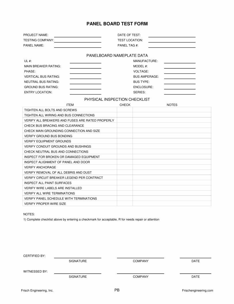
UL #:
MAIN BREAKER RATING: MODEL #:
PHASE:
VERTICAL BUS RATING:
NEUTRAL BUS RATING:
GROUND BUS RATING:
ENTRY LOCATION: SERIES:
CHECK
NOTES:
VERIFY ALL WIRE TERMINATIONS
VERIFY PANEL SCHEDULE WITH TERMINATIONS
VERIFY PROPER WIRE SIZE
CHECK NEUTRAL BUS AND CONNECTIONS
INSPECT FOR BROKEN OR DAMAGED EQUIPMENT
INSPECT ALIGNMENT OF PANEL AND DOOR
VERIFY ANCHORAGE
VERIFY CIRCUIT BREAKER LEGEND PER CONTRACT
INSPECT ALL PAINT SURFACES
VERIFY WIRE LABELS ARE INSTALLED
CHECK MAIN GROUNDING CONNECTION AND SIZE
VERIFY GROUND BUS BONDING
VERIFY EQUIPMENT GROUNDS
VERIFY CONDUIT GROUNDS AND BUSHINGS
DATE
WITNESSED BY:
SIGNATURE COMPANY DATE
SIGNATURE COMPANY
CERTIFIED BY:
PANEL BOARD TEST FORM
PROJECT NAME:
TESTING COMPANY:
PANEL NAME:
PANELBOARD NAMEPLATE DATA
DATE OF TEST:
TEST LOCATION:
PANEL TAG #:
BUS AMPERAGE:
BUS TYPE:
ENCLOSURE:
VOLTAGE:
MANUFACTURE:
PHYSICAL INSPECTION CHECKLIST
NOTESITEM
TIGHTEN ALL BOLTS AND SCREWS
VERIFY ALL BREAKERS AND FUSES ARE RATED PROPERLY
TIGHTEN ALL WIRING AND BUS CONNECTIONS
CHECK BUS BRACING AND CLEARANCE
1) Complete checklist above by entering a checkmark for acceptable, R for needs repair or attention
VERIFY REMOVAL OF ALL DEBRIS AND DUST
Frisch Engineering, Inc. PB Frischengineering.com
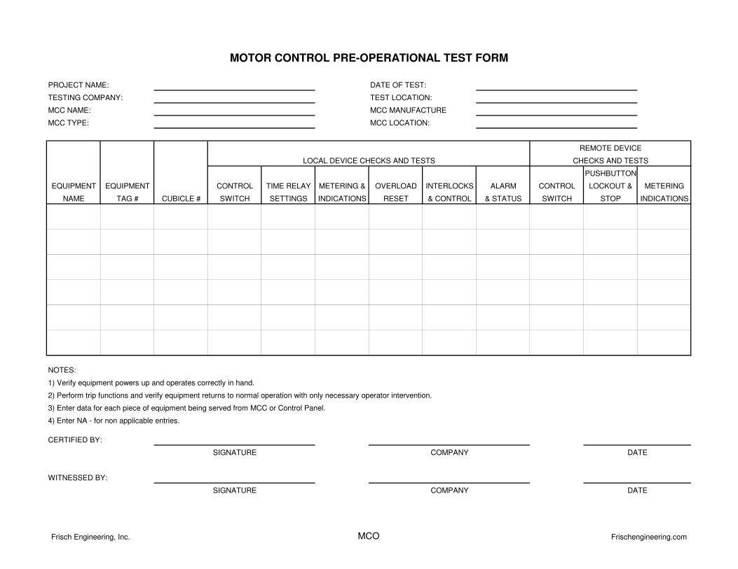
MCC NAME:
MCC TYPE:
PUSHBUTTON
EQUIPMENT EQUIPMENT CONTROL TIME RELAY METERING & OVERLOAD INTERLOCKS ALARM CONTROL LOCKOUT & METERING
NAME TAG # CUBICLE # SWITCH SETTINGS INDICATIONS RESET & CONTROL & STATUS SWITCH STOP INDICATIONS
WITNESSED BY:
SIGNATURE COMPANY DATE
CERTIFIED BY:
SIGNATURE COMPANY DATE
REMOTE DEVICE
CHECKS AND TESTSLOCAL DEVICE CHECKS AND TESTS
1) Verify equipment powers up and operates correctly in hand.
2) Perform trip functions and verify equipment returns to normal operation with only necessary operator intervention.
3) Enter data for each piece of equipment being served from MCC or Control Panel.
4) Enter NA - for non applicable entries.
MOTOR CONTROL PRE-OPERATIONAL TEST FORM
NOTES:
MCC LOCATION:
PROJECT NAME:
TESTING COMPANY:
DATE OF TEST:
TEST LOCATION:
MCC MANUFACTURE
Frisch Engineering, Inc. MCO Frischengineering.com
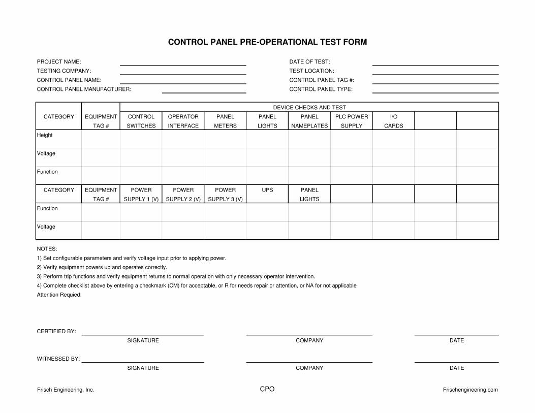
CATEGORY EQUIPMENT CONTROL OPERATOR PANEL PANEL PANEL PLC POWER I/O
TAG # SWITCHES INTERFACE METERS LIGHTS NAMEPLATES SUPPLY CARDS
Height
Voltage
Function
CATEGORY EQUIPMENT POWER POWER POWER UPS PANEL
TAG # SUPPLY 1 (V) SUPPLY 2 (V) SUPPLY 3 (V) LIGHTS
Function
Voltage
NOTES:
Attention Requied:
CERTIFIED BY:
WITNESSED BY:
CONTROL PANEL PRE-OPERATIONAL TEST FORM
TESTING COMPANY:
DATE OF TEST:
TEST LOCATION:
PROJECT NAME:
COMPANYSIGNATURE
COMPANY DATE
DATE
SIGNATURE
2) Verify equipment powers up and operates correctly.
CONTROL PANEL MANUFACTURER:
3) Perform trip functions and verify equipment returns to normal operation with only necessary operator intervention.
4) Complete checklist above by entering a checkmark (CM) for acceptable, or R for needs repair or attention, or NA for not applicable
1) Set configurable parameters and verify voltage input prior to applying power.
DEVICE CHECKS AND TEST
CONTROL PANEL NAME: CONTROL PANEL TAG #:
CONTROL PANEL TYPE:
Frisch Engineering, Inc. CPO Frischengineering.com
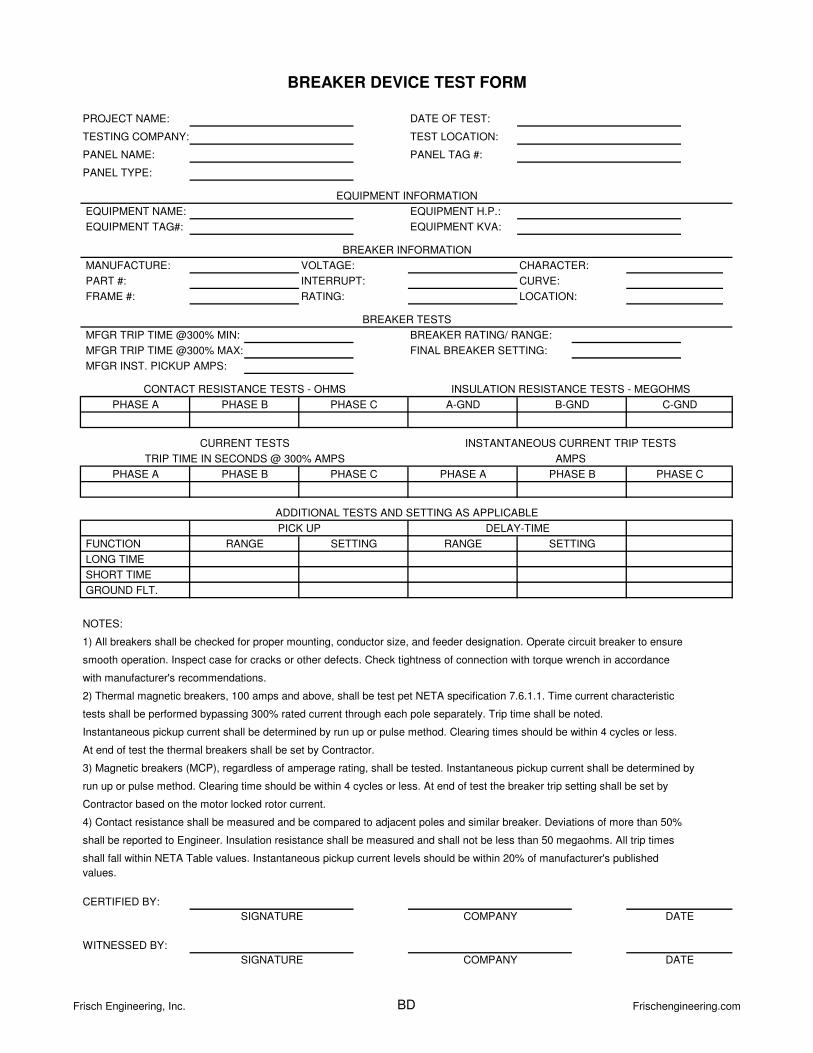
PART #: CURVE:
RATING:
values.
CERTIFIED BY:
WITNESSED BY:
DATE
DATE
SIGNATURE
SIGNATURE COMPANY
COMPANY
smooth operation. Inspect case for cracks or other defects. Check tightness of connection with torque wrench in accordance
NOTES:
GROUND FLT.
ADDITIONAL TESTS AND SETTING AS APPLICABLE
PICK UP DELAY-TIME
FUNCTION RANGE SETTINGRANGE SETTING
TRIP TIME IN SECONDS @ 300% AMPS AMPS
PHASE A PHASE B PHASE C PHASE A PHASE B PHASE C
CURRENT TESTS INSTANTANEOUS CURRENT TRIP TESTS
EQUIPMENT INFORMATION
BREAKER DEVICE TEST FORM
CHARACTER:
LOCATION:
DATE OF TEST:
TEST LOCATION:
PANEL TAG #:
EQUIPMENT NAME:
PROJECT NAME:
TESTING COMPANY:
PANEL NAME:
PANEL TYPE:
EQUIPMENT H.P.:
EQUIPMENT KVA:
BREAKER INFORMATION
PHASE A PHASE B PHASE C A-GND B-GND C-GND
BREAKER RATING/ RANGE:
BREAKER TESTS
EQUIPMENT TAG#:
MANUFACTURE: VOLTAGE:
INTERRUPT:
CONTACT RESISTANCE TESTS - OHMS INSULATION RESISTANCE TESTS - MEGOHMS
MFGR INST. PICKUP AMPS:
FINAL BREAKER SETTING:
MFGR TRIP TIME @300% MIN:
MFGR TRIP TIME @300% MAX:
1) All breakers shall be checked for proper mounting, conductor size, and feeder designation. Operate circuit breaker to ensure
LONG TIME
SHORT TIME
with manufacturer's recommendations.
tests shall be performed bypassing 300% rated current through each pole separately. Trip time shall be noted.
Instantaneous pickup current shall be determined by run up or pulse method. Clearing times should be within 4 cycles or less.
At end of test the thermal breakers shall be set by Contractor.
2) Thermal magnetic breakers, 100 amps and above, shall be test pet NETA specification 7.6.1.1. Time current characteristic
shall be reported to Engineer. Insulation resistance shall be measured and shall not be less than 50 megaohms. All trip times
shall fall within NETA Table values. Instantaneous pickup current levels should be within 20% of manufacturer's published
3) Magnetic breakers (MCP), regardless of amperage rating, shall be tested. Instantaneous pickup current shall be determined by
run up or pulse method. Clearing time should be within 4 cycles or less. At end of test the breaker trip setting shall be set by
Contractor based on the motor locked rotor current.
4) Contact resistance shall be measured and be compared to adjacent poles and similar breaker. Deviations of more than 50%
FRAME #:
Frisch Engineering, Inc. BD Frischengineering.com
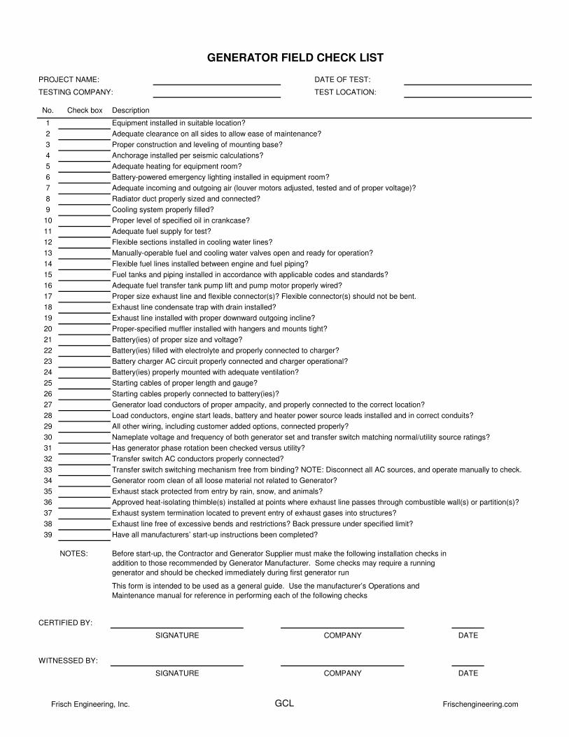
PROJECT NAME:
TESTING COMPANY:
No. Check box
1
2
3
4
5
6
7
8
9
10
11
12
13
14
15
16
17
18
19
20
21
22
23
24
25
26
27
28
29
30
31
32
33
34
35
36
37
38
39
NOTES:
CERTIFIED BY:
DATE
WITNESSED BY:
DATE
Description
Equipment installed in suitable location?
Adequate clearance on all sides to allow ease of maintenance?
GENERATOR FIELD CHECK LIST
DATE OF TEST:
TEST LOCATION:
Anchorage installed per seismic calculations?
Proper construction and leveling of mounting base?
Battery-powered emergency lighting installed in equipment room?
Adequate incoming and outgoing air (louver motors adjusted, tested and of proper voltage)?
Adequate heating for equipment room?
Radiator duct properly sized and connected?
Cooling system properly filled?
Proper level of specified oil in crankcase?
Adequate fuel supply for test?
Flexible sections installed in cooling water lines?
Manually-operable fuel and cooling water valves open and ready for operation?
Flexible fuel lines installed between engine and fuel piping?
Fuel tanks and piping installed in accordance with applicable codes and standards?
Adequate fuel transfer tank pump lift and pump motor properly wired?
Proper size exhaust line and flexible connector(s)? Flexible connector(s) should not be bent.
Exhaust line condensate trap with drain installed?
Exhaust line installed with proper downward outgoing incline?
Proper-specified muffler installed with hangers and mounts tight?
Battery(ies) of proper size and voltage?
Battery(ies) filled with electrolyte and properly connected to charger?
Battery charger AC circuit properly connected and charger operational?
Battery(ies) properly mounted with adequate ventilation?
Starting cables of proper length and gauge?
Starting cables properly connected to battery(ies)?
Generator load conductors of proper ampacity, and properly connected to the correct location?
Load conductors, engine start leads, battery and heater power source leads installed and in correct conduits?
All other wiring, including customer added options, connected properly?
Nameplate voltage and frequency of both generator set and transfer switch matching normal/utility source ratings?
Has generator phase rotation been checked versus utility?
Transfer switch AC conductors properly connected?
Transfer switch switching mechanism free from binding? NOTE: Disconnect all AC sources, and operate manually to check.
Generator room clean of all loose material not related to Generator?
Exhaust stack protected from entry by rain, snow, and animals?
Approved heat-isolating thimble(s) installed at points where exhaust line passes through combustible wall(s) or partition(s)?
Exhaust system termination located to prevent entry of exhaust gases into structures?
Exhaust line free of excessive bends and restrictions? Back pressure under specified limit?
Have all manufacturers’ start-up instructions been completed?
SIGNATURE COMPANY
Before start-up, the Contractor and Generator Supplier must make the following installation checks in
addition to those recommended by Generator Manufacturer. Some checks may require a running
generator and should be checked immediately during first generator run
This form is intended to be used as a general guide. Use the manufacturer’s Operations and
Maintenance manual for reference in performing each of the following checks
SIGNATURE COMPANY
Frisch Engineering, Inc. GCL Frischengineering.com
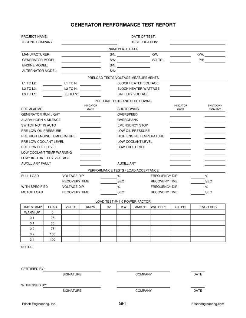
MANUFACTURER: S/N: KW: KVA:
GENERATOR MODEL S/N: VOLTS: PH:
ENGINE MODEL: S/N:
ALTERNATOR MODEL: S/N:
L1 TO L2: L1 TO N: BLOCK HEATER VOLTAGE
L2 TO L3: L2 TO N: BLOCK HEATER WATTAGE
L3 TO L1: L3 TO N: BATTERY VOLTAGE
PRE-ALARMSINDICATOR
LIGHT SHUTDOWNSINDICATOR
LIGHT
SHUTDOWN
FUNCTION
GENERATOR RUN LIGHT OVERSPEED
ALARM HORN & SILENCE OVERCRANK
SWITCH NOT IN AUTO EMERGENCY STOP
PRE LOW OIL PRESSURE LOW OIL PRESSURE
PRE HIGH ENGINE TEMPERATURE HIGH ENGINE TEMPERATURE
PRE LOW COOLANT LEVEL LOW COOLANT LEVEL
PRE LOW FUEL LEVEL LOW FUEL LEVEL
LOW COOLANT TEMP WARNING
LOW/HIGH BATTERY VOLTAGE
AUXILLIARY FAULT AUXILLIARY
FULL LOAD VOLTAGE DIP % FREQUENCY DIP %
RECOVERY TIME SEC RECOVERY TIME SEC
WITH SPECIFIED VOLTAGE DIP % FREQUENCY DIP %
MOTOR LOAD RECOVERY TIME SEC RECOVERY TIME SEC
TIME STAMP LOAD VOLTS AMPS HZ KW AMB ºF WATER ºF OIL PSI
WARM UP 0
0.1 25
0.1 50
0.2 75
0.2 100
3.4 100
NOTES:
CERTIFIED BY:
DATE
WITNESSED BY:
DATE
NAMEPLATE DATA
SIGNATURE
SIGNATURE
COMPANY
COMPANY
LOAD TEST @ 1.0 POWER FACTOR
PRELOAD TESTS VOLTAGE MEASUREMENTS
ENGR HRS
PERFORMANCE TESTS / LOAD ACCEPTANCE
GENERATOR PERFORMANCE TEST REPORT
DATE OF TEST:
TEST LOCATION:
PROJECT NAME:
TESTING COMPANY:
PRELOAD TESTS AND SHUTDOWNS
Frisch Engineering, Inc. GPT Frischengineering.com
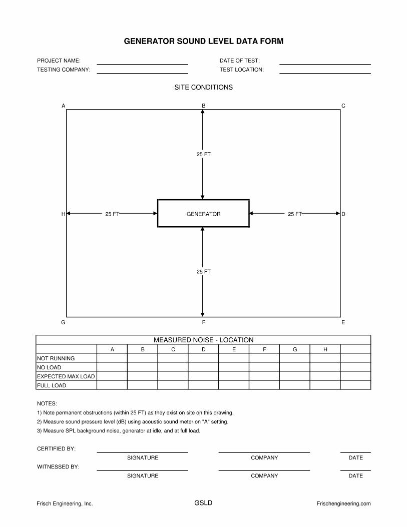
A B C
H 25 FT 25 FT D
G F E
A B C D E F G H
NOTES:
DATE
DATE
1) Note permanent obstructions (within 25 FT) as they exist on site on this drawing.
2) Measure sound pressure level (dB) using acoustic sound meter on "A" setting.
3) Measure SPL background noise, generator at idle, and at full load.
EXPECTED MAX LOAD
NO LOAD
NOT RUNNING
FULL LOAD
SITE CONDITIONS
MEASURED NOISE - LOCATION
25 FT
25 FT
GENERATOR
CERTIFIED BY:
SIGNATURE COMPANY
WITNESSED BY:
SIGNATURE COMPANY
GENERATOR SOUND LEVEL DATA FORM
PROJECT NAME:
TESTING COMPANY:
DATE OF TEST:
TEST LOCATION:
Frisch Engineering, Inc. GSLD Frischengineering.com
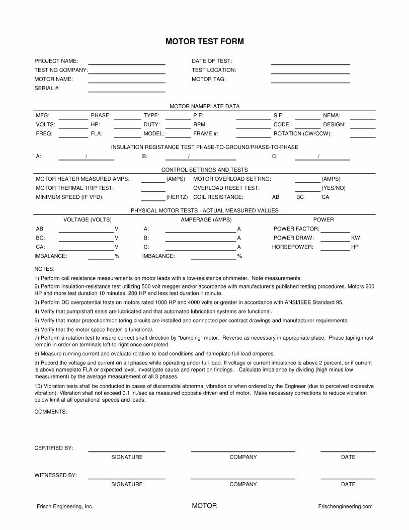
MFG: PHASE: TYPE: P.F: S.F: NEMA:
VOLTS: HP: DUTY: RPM: CODE: DESIGN:
FREQ: FLA: MODEL: FRAME #:
A: / B: / C: /
(AMPS) (AMPS)
(YES/NO)
(HERTZ) AB BC CA
AB: V A: A
BC: V B: A KW
CA: V C: A HP
% %IMBALANCE:IMBALANCE:
4) Verify that pump/shaft seals are lubricated and that automated lubrication systems are functional.
3) Perform DC overpotential tests on motors rated 1000 HP and 4000 volts or greater in accordance with ANSI/IEEE Standard 95.
NOTES:
8) Measure running current and evaluate relative to load conditions and nameplate full-load amperes.
10) Vibration tests shall be conducted in cases of discernable abnormal vibration or when ordered by the Engineer (due to perceived excessive
vibration). Vibration shall not exceed 0.1 in./sec as measured opposite driven end of motor. Make necessary corrections to reduce vibration
below limit at all operational speeds and loads.
1) Perform coil resistance measurements on motor leads with a low-resistance ohmmeter. Note measurements.
COIL RESISTANCE:
HORSEPOWER:
POWER FACTOR:
SERIAL #:
PROJECT NAME:
TESTING COMPANY:
MOTOR NAME:
MINIMUM SPEED (IF VFD):
MOTOR TAG:
DATE OF TEST:
TEST LOCATION:
MOTOR NAMEPLATE DATA
ROTATION (CW/CCW):
POWER DRAW:
INSULATION RESISTANCE TEST PHASE-TO-GROUND/PHASE-TO-PHASE
CONTROL SETTINGS AND TESTS
MOTOR HEATER MEASURED AMPS:
MOTOR THERMAL TRIP TEST:
5) Verify that motor protection/monitoring circuits are installed and connected per contract drawings and manufacturer requirements.
2) Perform insulation-resistance test utilizing 500 volt megger and/or accordance with manufacturer's published testing procedures. Motors 200
HP and more test duration 10 minutes, 200 HP and less test duration 1 minute.
6) Verify that the motor space heater is functional.
MOTOR TEST FORM
VOLTAGE (VOLTS) AMPERAGE (AMPS) POWER
MOTOR OVERLOAD SETTING:
OVERLOAD RESET TEST:
PHYSICAL MOTOR TESTS - ACTUAL MEASURED VALUES
SIGNATURE COMPANY
7) Perform a rotation test to insure correct shaft direction by "bumping" motor. Reverse as necessary in appropriate place. Phase taping must
remain in order on terminals left-to-right once completed.
DATE
9) Record the voltage and current on all phases while operating under full-load. If voltage or current imbalance is above 2 percent, or if current
is above nameplate FLA or expected level, investigate cause and report on findings. Calculate imbalance by dividing (high minus low
measurement) by the average measurement of all 3 phases.
COMMENTS:
CERTIFIED BY:
WITNESSED BY:
SIGNATURE COMPANY DATE
Frisch Engineering, Inc. MOTOR Frischengineering.com
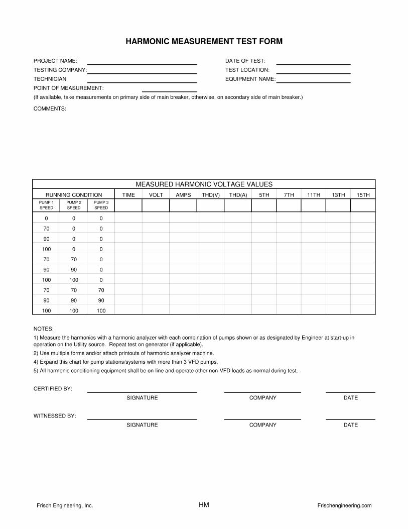
TESTING COMPANY:
TECHNICIAN
TIME VOLT AMPS THD(V) THD(A) 5TH 7TH 11TH 13TH 15TH
PUMP 1
SPEED
PUMP 2
SPEED
PUMP 3
SPEED
0 0 0
70 0 0
90 0 0
100 0 0
70 70 0
90 90 0
100 100 0
70 70 70
90 90 90
100 100 100
RUNNING CONDITION
4) Expand this chart for pump stations/systems with more than 3 VFD pumps.
5) All harmonic conditioning equipment shall be on-line and operate other non-VFD loads as normal during test.
MEASURED HARMONIC VOLTAGE VALUES
WITNESSED BY:
SIGNATURE COMPANY DATE
SIGNATURE COMPANY DATE
HARMONIC MEASUREMENT TEST FORM
NOTES:
CERTIFIED BY:
1) Measure the harmonics with a harmonic analyzer with each combination of pumps shown or as designated by Engineer at start-up in
operation on the Utility source. Repeat test on generator (if applicable).
2) Use multiple forms and/or attach printouts of harmonic analyzer machine.
COMMENTS:
EQUIPMENT NAME:
PROJECT NAME: DATE OF TEST:
TEST LOCATION:
POINT OF MEASUREMENT:
(If available, take measurements on primary side of main breaker, otherwise, on secondary side of main breaker.)
Frisch Engineering, Inc. HM Frischengineering.com
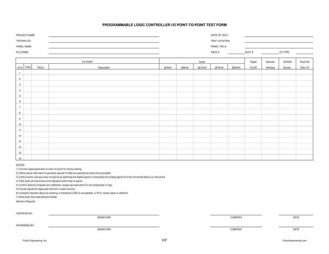
RACK # SLOT # I/O TYPE
Digital Operator SCADA Pass/Fail
I/O # TYPE TAG # @4mA @8mA @12mA @16mA @20mA On/Off Interface Screen CM or R
1
2
3
4
5
6
7
8
9
10
11
12
13
14
15
16
Attention Requied:
PROGRAMMABLE LOGIC CONTROLLER I/O POINT-TO-POINT TEST FORM
PROJECT NAME: DATE OF TEST:
TEST LOCATION:
Description
PANEL NAME: PANEL TAG #:
TESTING CO:
PLC NAME:
I/O POINT Scale
NOTES:
4) Field verify all instruments and indicators within loop of signal.
1) Connect signal generator to each I/O point for factory testing.
2) Utilize actual instrument to generate signals for field pre-operational tests where possible.
3) Verify function and accuracy of loop by by switching the digital signal or modulating the analog signal from the connected device or instrument
4) Confirm polarity of signals and calibration ranges are equivalent for all components in loop.
5) Include significant digits past decimal in scale columns
6) Complete checklist above by entering a checkmark (CM) for acceptable, or R for needs repair or attention
7) Note items that need attention below
CERTIFIED BY:
WITNESSED BY:
SIGNATURE COMPANY DATE
DATESIGNATURE COMPANY
Frisch Engineering, Inc. IOP Frischengineering.com
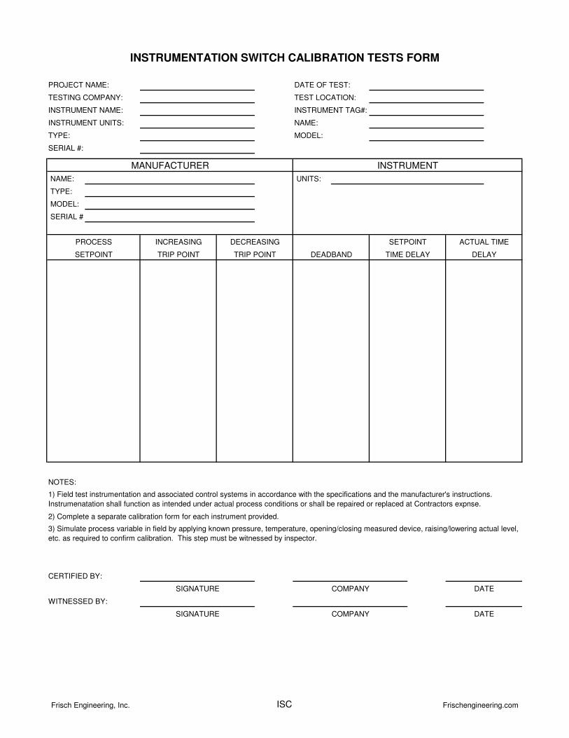
INSTRUMENT UNITS: NAME:
TYPE: MODEL:
SERIAL #:
NAME: UNITS:
TYPE:
MODEL:
SERIAL #:
NOTES:
1) Field test instrumentation and associated control systems in accordance with the specifications and the manufacturer's instructions.
Instrumenatation shall function as intended under actual process conditions or shall be repaired or replaced at Contractors expnse.
2) Complete a separate calibration form for each instrument provided.
3) Simulate process variable in field by applying known pressure, temperature, opening/closing measured device, raising/lowering actual level,
etc. as required to confirm calibration. This step must be witnessed by inspector.
WITNESSED BY:
CERTIFIED BY:
SIGNATURE COMPANY DATE
DELAY
COMPANY DATESIGNATURE
PROCESS
INSTRUMENTATION SWITCH CALIBRATION TESTS FORM
DEADBAND TIME DELAY
SETPOINT ACTUAL TIMEINCREASING
TRIP POINT
DECREASING
TRIP POINT
PROJECT NAME:
TESTING COMPANY:
INSTRUMENT NAME:
DATE OF TEST:
TEST LOCATION:
INSTRUMENT TAG#:
SETPOINT
INSTRUMENTMANUFACTURER
Frisch Engineering, Inc. ISC Frischengineering.com
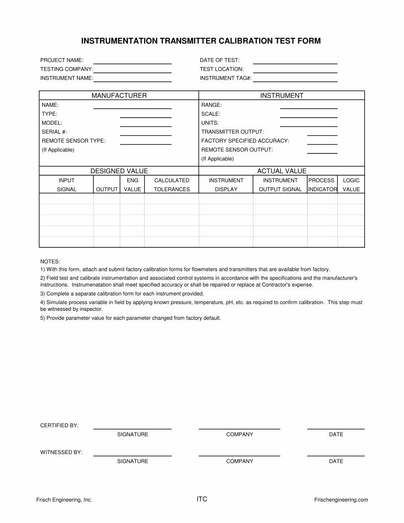
NAME: RANGE:
TYPE: SCALE:
MODEL: UNITS:
SERIAL #:
(If Applicable)
ENG PROCESS LOGIC
OUTPUT VALUE INDICATOR VALUE
NOTES:
5) Provide parameter value for each parameter changed from factory default.
INSTRUMENTINSTRUMENT
WITNESSED BY:
CERTIFIED BY:
4) Simulate process variable in field by applying known pressure, temperature, pH, etc. as required to confirm calibration. This step must
be witnessed by inspector.
2) Field test and calibrate instrumentation and associated control systems in accordance with the specifications and the manufacturer's
instructions. Instrumenatation shall meet specified accuracy or shall be repaired or replace at Contractor's expense.
3) Complete a separate calibration form for each instrument provided.
DATESIGNATURE
DATESIGNATURE COMPANY
COMPANY
DESIGNED VALUE
INPUT
REMOTE SENSOR TYPE:
CALCULATED
DISPLAY
REMOTE SENSOR OUTPUT:
1) With this form, attach and submit factory calibration forms for flowmeters and transmitters that are available from factory.
(If Applicable)
TRANSMITTER OUTPUT:
FACTORY SPECIFIED ACCURACY:
INSTRUMENTATION TRANSMITTER CALIBRATION TEST FORM
PROJECT NAME:
TESTING COMPANY:
INSTRUMENT NAME:
DATE OF TEST:
INSTRUMENT TAG#:
TEST LOCATION:
MANUFACTURER INSTRUMENT
ACTUAL VALUE
OUTPUT SIGNALTOLERANCESSIGNAL
Frisch Engineering, Inc. ITC Frischengineering.com
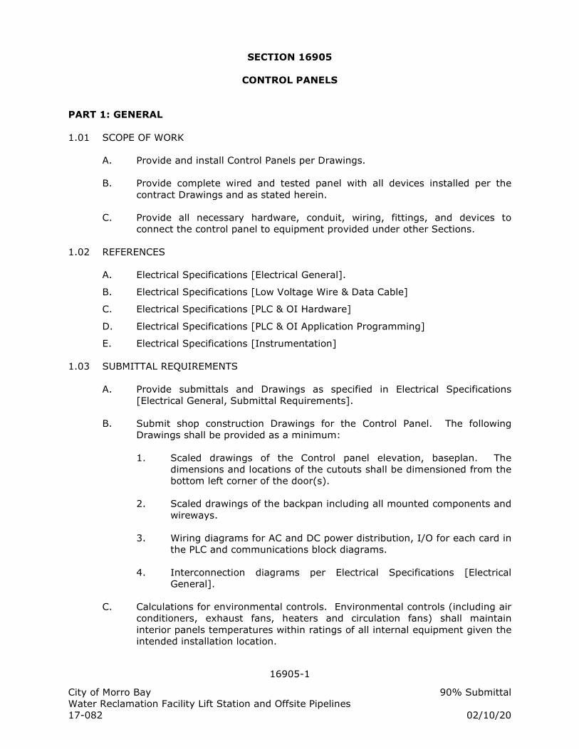
16905-1
City of Morro Bay 90% Submittal Water Reclamation Facility Lift Station and Offsite Pipelines 17-082 02/10/20
SECTION 16905
CONTROL PANELS
PART 1: GENERAL
1.01 SCOPE OF WORK
A. Provide and install Control Panels per Drawings.
B. Provide complete wired and tested panel with all devices installed per the contract Drawings and as stated herein.
C. Provide all necessary hardware, conduit, wiring, fittings, and devices to connect the control panel to equipment provided under other Sections.
1.02 REFERENCES
A. Electrical Specifications [Electrical General].
B. Electrical Specifications [Low Voltage Wire & Data Cable]
C. Electrical Specifications [PLC & OI Hardware]
D. Electrical Specifications [PLC & OI Application Programming]
E. Electrical Specifications [Instrumentation]
1.03 SUBMITTAL REQUIREMENTS
A. Provide submittals and Drawings as specified in Electrical Specifications [Electrical General, Submittal Requirements].
B. Submit shop construction Drawings for the Control Panel. The following Drawings shall be provided as a minimum:
1. Scaled drawings of the Control panel elevation, baseplan. The dimensions and locations of the cutouts shall be dimensioned from the bottom left corner of the door(s).
2. Scaled drawings of the backpan including all mounted components and wireways.
3. Wiring diagrams for AC and DC power distribution, I/O for each card in the PLC and communications block diagrams.
4. Interconnection diagrams per Electrical Specifications [Electrical General].
C. Calculations for environmental controls. Environmental controls (including air conditioners, exhaust fans, heaters and circulation fans) shall maintain interior panels temperatures within ratings of all internal equipment given the intended installation location.
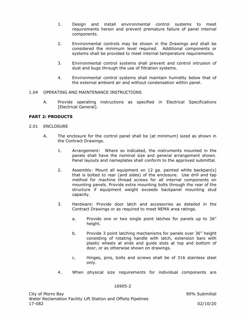
16905-2
City of Morro Bay 90% Submittal Water Reclamation Facility Lift Station and Offsite Pipelines 17-082 02/10/20
1. Design and install environmental control systems to meet requirements herein and prevent premature failure of panel internal components.
2. Environmental controls may be shown in the Drawings and shall be considered the minimum level required. Additional components or systems shall be provided to meet internal temperature requirements.
3. Environmental control systems shall prevent and control intrusion of dust and bugs through the use of filtration systems.
4. Environmental control systems shall maintain humidity below that of the external ambient air and without condensation within panel.
1.04 OPERATING AND MAINTENANCE INSTRUCTIONS
A. Provide operating instructions as specified in Electrical Specifications [Electrical General].
PART 2: PRODUCTS
2.01 ENCLOSURE
A. The enclosure for the control panel shall be (at minimum) sized as shown in the Contract Drawings.
1. Arrangement: Where so indicated, the instruments mounted in the panels shall have the nominal size and general arrangement shown. Panel layouts and nameplates shall conform to the approved submittal.
2. Assembly: Mount all equipment on 12 ga. painted white backpan(s) that is bolted to rear (and sides) of the enclosure. Use drill and tap method for machine thread screws for all internal components on mounting panels. Provide extra mounting bolts through the rear of the structure if equipment weight exceeds backpanel mounting stud capacity.
3. Hardware: Provide door latch and accessories as detailed in the Contract Drawings or as required to meet NEMA area ratings.
a. Provide one or two single point latches for panels up to 36” height.
b. Provide 3 point latching mechanisms for panels over 36” height consisting of rotating handle with latch, extension bars with plastic wheels at ends and guide slots at top and bottom of door, or as otherwise shown on drawings.
c. Hinges, pins, bolts and screws shall be of 316 stainless steel only.
4. When physical size requirements for individual components are
16905-3
City of Morro Bay 90% Submittal Water Reclamation Facility Lift Station and Offsite Pipelines 17-082 02/10/20
different than that detailed on the Control Panel backpan drawing, the wiring diagrams and specifications herein shall supersede the elevation drawing and the Contractor shall furnish additional panel width as needed to fit the electrical equipment. Deviations with sufficient evidence for the change shall be submitted for approval. The Contractor is required to provide for all equipment including spares and spaces as shown in the wiring diagrams.
2.02 CONTROL PANEL CIRCUIT BREAKERS
A. Furnish circuit breakers and accessories as required per Drawings and application.
1. Copper busbar systems, up to 480VAC, 115A, 1, 2 or 3 phase as needed for application
2. Trip rating per Drawings or as needed for protected device. Trip curves as selected by System Integrator.
a. B curve magnetic trip point: 3 to 5 times the rated current, typically used for computers and electronic equipment with very low inrush loads (PLC wiring).
b. C curve magnetic trip point: 5 to 10 times the rated current, typically used for small transformers, pilot devices, etc.
c. D curve magnetic trip point: 10 to 20 times the rated current, typically used for transformers or loads with very high inductive loads.
3. Quantity of pins and feed in lugs as required.
4. Auxiliary contact, shunt trip as required in Drawings.
5. DIN rail mounted, 18mm width per pole, finger safe pressure plate terminals.
B. Motor applications:
1. UL489 for branch circuit protection up to 40A, 1 to 3 pole.
2. 5 kAIC interrupting capacity @ 480 VAC
3. Alltech, Eaton FAZ, or equal.
C. Control circuit transformers and other Non-motor applications:
1. UL1077 supplementary protection up to 63 amps, 1 to 2 pole, AC or DC.
2. Used where a UL489 protective device is upstream powering the circuit (from a panelboard or other source).
16905-4
City of Morro Bay 90% Submittal Water Reclamation Facility Lift Station and Offsite Pipelines 17-082 02/10/20
3. Used within control circuits for power supplies, control power transformers, relays and PLC I/O points.
4. Used in place of fuses that are applied as supplementary protection.
5. Eaton FAZ, or equal.
2.03 FUSES AND FUSE HOLDER
A. Fuses shall not be used in branch or control circuits unless specifically shown in the Drawings. Circuit breakers shall be furnished and utilized where possible.
B. Fuses used in circuits 200 VAC and above shall be time- delay, 13/32" x 1-1/2", and have an interrupting rating of 10,000 AIC at 500 VAC. Fuses shall be Bussman type FNQ or approved equal. Fuse holders shall feature open fuse indication lights and shall be rated 30A at 600 VAC. Fuse holders shall be Bussman Optima Series OPM or equal.
C. Fuses used in 120 VAC shall be time-delay, 1/4" x 1-1/4", and have a rating of 250 VAC. Fuses shall be Bussman type MDA or approved equal. Fuse-holders shall be of the same manufacturer, series and color as the adjacent terminal blocks and have blown fuse neon indicators. Fuse holders shall be Entrelec ML 10/13.SFL, Allen Bradley 1492-H4 or equal.
D. Fuses used in signal and 24 VDC circuits shall be fast acting, 5mm x 20mm and have a rating of 250 VAC. Fuses shall be Bussman type GMA or approved equal Fuse-holders shall be of the same manufacturer, series and color as the adjacent terminal blocks and have blown fuse LED indicators. Fuse holders shall be Entrelec M 4/8.SFDT, Allen Bradley- 1492-H5 or equal
E. Fuses shall be sized in conformance with the NEC.
2.04 TERMINAL BLOCKS AND ACCESSORIES
A. General
1. Terminal blocks to be clamp type, 5 spacing, 300 volt, minimum rating of 20 amps, and mounted on DIN rail. DIN rail shall be same type as used for the relays. Install extra DIN rail on each type of terminal strip with 10% spare terminals for future additions.
a. Provide larger terminal as necessary based on gauge of connected wiring. Those terminals with 10 gauge larger gauge wiring or more than one 12 gauge wire should be evaluated and changed.
2. Provide terminal blocks with "follower" plates that compress the wires and have wire guide tangs for ease of maintenance. Terminal blocks that compress the wires with direct screw compression are unacceptable. All power, control and instrument wires entering and leaving a compartment shall terminate on terminal blocks with wire
16905-5
City of Morro Bay 90% Submittal Water Reclamation Facility Lift Station and Offsite Pipelines 17-082 02/10/20
numbers on terminals and on both ends of the wires.
3. Provide end clamps, separators, din rails, and jumpers to complete terminal block system. See example PLC I/O drawing for additional information. Engineer can provide on request if not available in plans.
4. Terminal Tags and Markers: Each terminal strip shall have a unique identifying alphanumeric code at one end ( i.e.: TB1, TB2, etc. ) or as shown in Drawings.
5. Plastic marking tabs shall be provided to label each terminal block. These marking tabs shall have a unique number/letter for each terminal which is identical to the "elementary" and "loop" diagram wire designation. Numbers on these marking strip shall be machine printed and 1/8” high letters minimum.
6. Terminal blocks shall be physically separated into groups by the level of signal and voltage served an by PLC I/O card. Power and control wiring above 100 volts shall have a separate group of terminal blocks from terminal blocks for wiring below 100 volts, intermixing of these two types of wiring on the same group of terminal blocks is not allowed.
7. Terminal blocks shall be gray in color unless otherwise shown on the Drawings.
8. Provide a ground terminal or connection point for each grounding conductor.
9. Provide a separate signal, common, and/or neutral terminal for every wire and PLC or remote device connection at minimum.
B. CP – Control Panel Terminal Blocks
Description Model number, Allen
Bradley or equal
General Purpose Terminal Block, 20A 1492-W3 Disconnecting Terminal Block, 20A 1492-JKD3 Grounding Terminal Block 1492-JG4 PLC AI Sensor Block, 4 Level with GND 1492-WTS3 PLC Digital Output Relays, 120VAC, 6A, SPDT 700-HLT1U1
Note 1: General purpose relays are defined in ELECTRICAL – GENERAL
Note 2: Accessories are not listed such as end caps, anchors, jumpers, bridges, marking strips, or other items necessary to make up a complete terminal block layout. Furnish all parts necessary per manufacturer’s intended solution.
C. MCC – Motor Starter Cubicle Terminal Blocks
1. MCC cubicle terminal blocks shall be pull apart as supplied standard by MCC manufacturer.
16905-6
City of Morro Bay 90% Submittal Water Reclamation Facility Lift Station and Offsite Pipelines 17-082 02/10/20
D. Power – Power terminal Blocks
1. Backpan mounted termination blocks shall be rated for 600V (min). The power termination blocks shall be rated to accept Copper or Aluminum cable and rated as shown on Contract one-line diagrams. Termination blocks shall be insulated with molded plastic covering and finger safe cover. Each termination block shall be provided with quantity and size of primary and secondary cable connections as required per installation. The power termination blocks shall be Erico UD, UDJ, BD, TD, or SB series or equal.
2. Unmounted termination blocks shall be constructed of aluminum and suitable for use with Aluminum and copper wire. Size and quantity of cable connections shall be as required for installation. Termination blocks shall be insulated with molded high-dielectric strength plastic covering and eliminate the need for tape insulation of electric connection. The termination block shall have removable access plugs over the wire entry and hex screw ports. Provide NSI Polaris IPL or IPLD Series terminal blocks or equal.
E. Panel Ground
1. Each electrical enclosure shall have a copper ground bus. Screw type fasteners shall be provided on all ground busses for connection of grounding conductors. Ground bus shall be a Challenger GB series, ILSCO CAN series or equal.
2. A 12ga. copper ground wire shall be attached between the ground bar and the panel enclosure, and between the ground bar and the mounting panels. The ground connection to the enclosure and panel shall be made by sanding the paint finish off a small area, drilling a hole for a 0.25 inch bolt and mounting a 0.25-20 bolt to the panel to serve as grounding stud. The grounding stud shall be attached with a nut and flat washers on both sides of the enclosure/panel, and with an inside tooth star lock washer next to the panel surface. The star lock washer shall be on the inside surface of the enclosure, and the front surface of the mounting panel. The grounding wire shall be secured to the stud with a nut and inside tooth star lock washer. These grounding points shall be located within 12 inches of the bottom to the grounding bar. Each terminal strip rail shall be individually grounded by means of a #12 AWG wire to the ground bus.
3. Components within the panel shall be grounded according to the manufacturer's recommendations.
2.05 POWER SUPPLIES
A. Uninterruptible Power Supply (UPS)
1. The UPS shall be installed within the control panel and power all process related 120 VAC devices and DC power supplies.
16905-7
City of Morro Bay 90% Submittal Water Reclamation Facility Lift Station and Offsite Pipelines 17-082 02/10/20
2. The UPS capacity/size shall be as shown in the contract Drawings. The battery capacity shall be such that it may provide nameplate power for 10 minutes (min) from a fully charged battery(s).
3. The UPS shall provide surge protection and filtering: 0.3% IEEE surge let-through, zero clamping response time to meet UL 1449. The inverter shall provide true sine wave output.
4. When the Utility power voltage is outside of a preset range (approx. <100 < V < 130 VAC) then the UPS shall power the load from storage batteries and a solid state inverter.
5. The power supply shall be wired into the control panel power circuit per the contract Drawings.
6. The UPS operating ambient temperature range shall be 32 deg F to 122 deg F minimum.
7. The inverter shall be self resetting and continuously on-line regardless of the Utility power existence. Configure the UPS to restart automatically upon restart of utility power without operator intervention. The rectifier/charger shall recharge and maintain float charge on the batteries automatically.
8. The UPS shall be listed UL 1778 and be specifically built for industrial applications. Provide Sola SDU, Allen Bradley bulletin 1609, or equal.
B. DC Power Supply (PS)
1. The DC power supply shall utilize a switching power stage, rectifier and voltage regulator. The power supply case shall be DIN rail mountable.
2. The power supply shall operate on 120V AC and provide DC output voltage and current as shown in the Contract Drawings.
3. The power supply shall be wired and fused per manufacturer instructions and Contract Drawings. Power supply output shall include self resetting overcurrent protection.
4. Power supplies below 101 Watts output power shall be Class 2 rated.
5. The power supply shall provide 2% voltage regulation for a change of 10% load to 100% full load.
6. The DC power supply shall be IDEC PS5R Series, Phoenix Contact Quint Power, or equal.
2.06 INTRINSICALLY SAFE BARRIER AND RELAY
A. Intrinsically Safe Barrier
1. Intrinsic safe barrier terminal blocks shall utilize a zener barrier that is
16905-8
City of Morro Bay 90% Submittal Water Reclamation Facility Lift Station and Offsite Pipelines 17-082 02/10/20
negative-earth-ground for intrinsic safety. Apply IS barrier to 4-20 mA loop powered circuits that extend into the hazardous area. Terminal block shall be rated for Class 1, Division 1 for potentially hazardous atmospheres. Intrinsic safe barrier terminal blocks shall be Pepperel and Fuchs KFD0-CS-EX1.50P, Gems Series A65800 or equal.
B. Intrinsically Safe Relay
1. Intrinsically safe relay shall be suitable for use where the probes and/or wiring is located in Class I or II, Division 1, Groups A-G hazardous atmospheres. The sensor circuit shall be incapable of igniting flammable gasses or dust. The relay shall be 24VDC powered behind a class 2 circuit with 1A current limiting circuit breaker. The relay shall interface to the controls with one SPDT relay output. The relay shall be wired to a single conductance probe or switch and actuate on low resistance. Provide Pepperel and Fuchs model KCD2-SR-Ex1 or equal.
2. Intrinsically safe relay shall be UL listed for use where the probes and/or wiring is located in Class I or II, Division 1, Groups A-G hazardous atmospheres. The sensor circuit shall be incapable of igniting flammable gasses or dust. The relay shall be 120 VAC powered and have one 8 amp SPDT relay output. The relay shall be capable of single level or differential level service. The relay shall be wired to use two probe devices (latch device and unlatch device) for differential level service. The relay shall be wired to use a single probe device for single level service. Provide UL listed Warrick Series 27 or equal.
2.07 IP SERVICE ROUTER
A. Acceptable products: Netgate SG-3100 or equal.
B. Provide shelf for panel mounting of router.
C. General Specifications
1. 2x 1 Gigabit WAN/LAN ports plus a 4 port switch provide high-speed wired connectivity
2. PF-Sense firewall to support stateful packet filtering, firewall, and pure router capability.
3. Routing policy per gateway and per-rule for multiple WAN, failover, load balancing.
4. Supports IPsec, OpenVPN, PPTP, IPv6, NAT, BGP, RADIUS
5. ARM v7 Cortex-A9, 2 GB DDR4L memory, M.2 expansion for SSD, or LTE.
2.08 BROADBAND WIRELESS CELLULAR MODEM
16905-9
City of Morro Bay 90% Submittal Water Reclamation Facility Lift Station and Offsite Pipelines 17-082 02/10/20
A. Acceptable products: Sierra Wireless Airlink Raven RV50X, or equal.
B. General Specifications
1. Internet Connections Supported: 1
2. Networks Supported for Embedded Modem: Verizon 3G, and 4G LTE
3. Ethernet ports: 1 LAN, 10/100.
4. AC wall pack power supply
5. Size approximate: 5.6" x 3.8" x 1.7"
6. Din-Rail Mounting bracket
C. Security:
1. Onboard IPSec SSL VPN client
2. VPN pass-through (All protocols)
3. MAC address filtering
4. SSH
5. HTTPS
D. Environmental:
1. Operating Temperature: -30˚C to +70˚C (-22 to 158˚F)
E. Interfaces:
1. 10/100 Base-T RJ45 Ethernet
2. Expansion Card Slot for Additional Options
3. 2 SMA/Female Antenna Connectors (RF, Rx Diversity)
4. LED Indicators for Network, Signal strength, Activity, Power
F. Warranty:
1. 3 year manufacturer warranty.
G. Minimum Requirements:
1. SIM card with active mobile broadband plan from Verizon
2. 1 year prepaid unlimited data service with each modem to begin at field testing.
16905-10
City of Morro Bay 90% Submittal Water Reclamation Facility Lift Station and Offsite Pipelines 17-082 02/10/20
H. Antenna:
1. 700-1900 MHz Magnet Mount Antenna
2. SMA Male Connector and 10-Foot RG174 Coax Cable
3. Wilson Electronics, or equal
2.09 MISCELLANEOUS COMPONENTS
A. Wireway: Manufactured from light gray rigid PVC suitable for continuous use at temperatures up to 50 deg C. Wireway shall be 2” height, width as required with 0.5” slot spacing with removable covers. Provide Panduit type “F” or equal.
B. Intrusion Switch: The intrusion switch shall have a pin plunger that is depressed when the door is closed. The form C contacts shall be rated 2A at 120 VAC. Provide Hoffman A-LFSWD, Microswitch 1AC2 or equal.
C. LED Strip Light: The LED light shall be an “under cabinet” style with multiple LED lamps and acrylic diffuser. Lamp shall be switched on/off from integral switch or PIR motion sensor. Light housing shall be capable of magnet mount to top or side of enclosure or will include mounting tabs for mounting to brackets. Lamp shall be powered from 120VAC or from 24~48 VDC or shown in the contract Drawings. LED Strip Light shall be Stego 02540, or equal.
D. Circulation Fans: The control panel temperature shall be maintained 10 deg. F below lowest internal device’s temperature rating. The fans shall be 4” or 6” unless otherwise noted on Contract Drawings. The Contractor shall calculate the heat generation of all internal components and determine if the fans submitted will meet the cooling requirements of the internal components. Circulation fans shall include louver with filter and bug screen for outdoor installations.
E. Thermostats: The air circulation fans shall be controlled by adjustable thermostat. The thermostat shall be mounted near the top of the panel and easily accessible by a technician. The thermostat shall be capable of control of a heater or cooling fan(s) by selecting the proper contact logic. The thermostat range shall be adjustable from 30 to 140 deg F. Thermostat shall be Hoffman A-TEMxx, or equal.
PART 3: EXECUTION
3.01 WORKMANSHIP
A. All work in this Section shall conform to the codes and standards specified in Electrical Specifications [Electrical General, Workmanship].
3.02 FABRICATION
A. Equipment Mounting:
16905-11
City of Morro Bay 90% Submittal Water Reclamation Facility Lift Station and Offsite Pipelines 17-082 02/10/20
1. Mount all equipment using manufacturers mounting tabs/holes or brackets where possible. Where not possible, construct custom brackets to panel mount or backpan mount components as shown in the Contract Drawings.
2. Equipment or laptop shelves shall be provided where shown on the Contract Drawings. Equipment shown on shelves shall not be placed on the bottom of the panel after field installation.
3. All nuts, bolts, screws, washers and hinges used in the panel shall be stainless steel. All components shall be mounted using bolts or screw fasteners only which are drilled and tapped into the backpan. Pop rivets shall not be allowed within panel except for enclosure support arms.
B. Environmental:
1. Control panel environmental accessories including fans, louvers, filters, bugscreens, air conditioners, etc. shall be provided as noted in the Drawings and as necessary for a complete environmental solution.
2. Panels environmental controls shall be designed during shop drawing submittal and fabricated to maintain temperatures 10 degrees F below lowest internal equipment maximum temperature rating.
3. Contractor shall provide [additional] fans, louvers, screens, sunshades, air conditioners, etc. as necessary to prevent equipment malfunction or premature failure. Provide associated wiring and thermostats as needed.
4. Environments:
a. NEMA 4X rated panels shall be cooled/heated with closed loop type conditioning systems to include air conditioners, internal panel circulation fans and resistive heaters.
b. NEMA 3R rated outdoor panels shall be cooled/heated with open loop type conditioning systems to include air conditioners, exhaust fans and louvers, internal panel circulation fans and resistive heaters. All exhaust fans and louvers shall include filters and bugscreens.
c. NEMA 12 or 1 rated indoor panels shall be cooled/heated with open loop type conditioning systems to include air conditioners, exhaust fans and louvers, internal panel circulation fans and resistive heaters. All exhaust fans and louvers shall include filters and bugscreens.
C. Wiring:
1. Panel Wiring: All wiring shall be installed in wireways between terminal blocks, PLC, and devices. Reference Contract Drawings for
16905-12
City of Morro Bay 90% Submittal Water Reclamation Facility Lift Station and Offsite Pipelines 17-082 02/10/20
control panel power distribution diagram and control panel elementary diagrams.
3.03 INSTALLATION
A. Wiring:
1. Install all equipment per Electrical Specifications [Electrical General].
2. All internal and field wiring shall be per Electrical Specifications [Low Voltage Wire].
3. Panel Wiring: All wiring shall be installed in wireways between terminal blocks and devices. Reference Contract Drawings for Control panel power distribution diagram and control panel elementary diagrams.
4. Field Wiring: Wireways shall be provided for field wiring. Reference Contract Drawings for control panel power distribution diagram and control panel elementary diagrams.
B. Cleaning:
1. The Contractor shall clean the inside of the control panel of any dust or debris remaining at the completion of installation and testing.
2. The Contractor shall exercise care when using a vacuum cleaner or compressed air such as not to damage any component within the panel.
3. Many electrical and computer components are open for ventilation. Falling debris can penetrate the openings and cause equipment failure. Equipment with debris inside shall be removed, cleaned and/or replaced.
3.04 FIELD ASSISTANCE
A. Provide testing as specified in Electrical Specifications [Factory and Field Testing].
3.05 WARRANTY
A. Provide warranty as specified in Electrical Specifications [Electrical General, Warranty].
3.06 FINAL ACCEPTANCE
A. Final Acceptance per Electrical Specifications [Electrical General].
END OF SECTION
16910-1
City of Morro Bay 90% Submittal
Water Reclamation Facility Lift Station and Offsite Pipelines
17-082 02/10/20
SECTION 16910
PLC & OI HARDWARE
PART 1: GENERAL
1.01 SCOPE OF WORK
A. Providing and installing Programmable Logic Controller (PLC) and Operator
Interface Hardware and all supporting hardware, wiring and devices as
specified in Electrical Specifications.
1.02 REFERENCES
A. Electrical Specifications [Electrical General]
B. Electrical Specifications [Low Voltage Wire and Data Cable]
C. Electrical Specifications [PLC and OI Application Programming]
1.03 SUBMITTAL REQUIREMENTS
A. Provide submittals per Electrical Specifications [Electrical General, Submittal
Requirements].
B. Submit documentation showing the number and type of I/O modules required
to meet the I/O requirements specified herein. Include complete
manufacturer's part and model numbers.
1. PLC I/O points are determined by the P&ID Drawings. The Contractor
shall count and total the PLC I/O points per PLC controller and per type
of I/O required based on the P&ID diagrams. Provide 25% spare I/O
points per I/O type per PLC.
C. Submit calculations showing that the power supply meets the specified
requirements and the requirements of the devices powered. Confirm PLC
power supply is sufficient for all possible operable conditions.
D. Submit shop drawings showing physical backpan layout of equipment in
Control Panel.
E. Submit communications block diagram including PLC, OI, motor controls,
power supplies, switches, routers, radios, and any other connected
components.
F. Submit hardware Operations and Maintenance Manual per Electrical
Specifications [Electrical General].
PART 2: PRODUCTS
2.01 GENERAL
A. Provide PLC modules from a single family of products, using the same
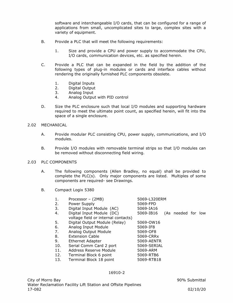
16910-2
City of Morro Bay 90% Submittal
Water Reclamation Facility Lift Station and Offsite Pipelines
17-082 02/10/20
software and interchangeable I/O cards, that can be configured for a range of
applications from small, uncomplicated sites to large, complex sites with a
variety of equipment.
B. Provide a PLC that will meet the following requirements:
1. Size and provide a CPU and power supply to accommodate the CPU,
I/O cards, communication devices, etc. as specified herein.
C. Provide a PLC that can be expanded in the field by the addition of the
following types of plug-in modules or cards and interface cables without
rendering the originally furnished PLC components obsolete.
1. Digital Inputs
2. Digital Output
3. Analog Input
4. Analog Output with PID control
D. Size the PLC enclosure such that local I/O modules and supporting hardware
required to meet the ultimate point count, as specified herein, will fit into the
space of a single enclosure.
2.02 MECHANICAL
A. Provide modular PLC consisting CPU, power supply, communications, and I/O
modules.
B. Provide I/O modules with removable terminal strips so that I/O modules can
be removed without disconnecting field wiring.
2.03 PLC COMPONENTS
A. The following components (Allen Bradley, no equal) shall be provided to
complete the PLC(s). Only major components are listed. Multiples of some
components are required- see Drawings.
B. Compact Logix 5380
1. Processor – (2MB) 5069-L320ERM
2. Power Supply 5069-FPD
3. Digital Input Module (AC) 5069-IA16
4. Digital Input Module (DC) 5069-IB16 (As needed for low
voltage field or internal contacts)
5. Digital Output Module (Relay) 5069-OW16
6. Analog Input Module 5069-IF8
7. Analog Output Module 5069-OF8
8. Extension Cable 5069-CRRx
9. Ethernet Adapter 5069-AENTR
10. Serial Comm Card 2 port 5069-SERIAL
11. Address Reserve Module 5069-ARM
12. Terminal Block 6 point 5069-RTB6
13. Terminal Block 18 point 5069-RTB18
16910-3
City of Morro Bay 90% Submittal
Water Reclamation Facility Lift Station and Offsite Pipelines
17-082 02/10/20
14. Terminal Block 6-4 point 5069-RTB64
2.04 ISOLATION/INTERFACE RELAYS
A. Provide output isolation relays on all digital outputs that operate devices
external to the control panel and on spare outputs or as otherwise shown in
the Drawings. The relay coil connection shall be on one side of the relay base
and form-C output contacts on the other.
B. Relays shall be 6A SPDT, coil voltage as required, indicating, plug in style as
manufactured by Allen Bradley 700-HLT1U1 or equal. Provide jumper bars
for common buss connections, Allen Bradley 700-TBJ20G, or equal.
2.05 OPERATOR INTERFACE (OI)
1. Automation Direct C-More Model EA9-T15CL or equal.
2. Touch Screen
a. 15 inch screen size with 1024 x 768 resolution, 65536 colors.
b. TFT color touchscreen with LED backlight and 300nits
brightness.
c. Alarm history screen with present status and acknowledge
functions.
3. Communications
a. Modbus RS232, RS485 and Ethernet communication options.
Provide cables for connection to PLC.
b. Built in Web server for remote access and viewing screens on a
network Windows computer.
c. Remote control of process through web server interface.
d. Type B USB port for programming.
e. Type A USB port for data logging and alarm history.
4. Data storage
a. 82MB backed up RAM for program, Two SD RAM slots for data.
b. Furnish one 32GB SDHC card for data storage.
c. Trending for up to 16 pens (colors) with historical data access
from USB RAM drive.
5. Environmental conditions:
a. Operating Temperature: 32 to 122 degrees F
b. Storage Temperaturew: -4 to 140 degrees F
c. Humidity Rating: 10 to 90%, non-condensing at 32°
F to 86° F
d. Rating: NEMA 12, 13, 4X (indoor only)
e. Power: 1.2A at 24 VDC.
16910-4
City of Morro Bay 90% Submittal
Water Reclamation Facility Lift Station and Offsite Pipelines
17-082 02/10/20
PART 3: EXECUTION
3.01 WORKMANSHIP
A. All work in this Section shall conform to the codes and standards specified in
Electrical Specifications [Electrical General, Workmanship].
3.02 INSTALLATION
A. Fabrication
1. Mount, wire and Ground PLC and OI per manufacturer’s
recommendations.
2. Organize equipment on control panel backpan per Backpan Layout
detail in Contract Drawings.
3. Locate and install PLC(s) and OI(s) per Contract Drawings.
B. Wiring
1. Terminate status, control and analog wiring on terminal blocks.
2. Label and wire PLC to terminal blocks per Electrical Specifications
[Wire, Fuses & Terminal Block] and Example I/O Wiring Diagram in the
Drawings.
3. All spare I/O points shall be wired to terminal blocks.
4. Install communication cables to connect the PLC to external devices.
5. Bundle and tie down wires in a neat and orderly manner.
6. Terminate drain wire of shielded cables at backpan terminal block only.
3.03 FIELD ASSISTANCE
A. Provide testing as specified in Electrical Specifications [Factory and Field
Testing].
3.04 WARRANTY
A. Provide warranty per Electrical Specifications [Electrical General, Warranty].
B. Perform the following services during the warranty period:
1. Repair or replace damaged modules returned for service within 24
hours.
2. Determine and report the cause of failure of modules returned for
service.
3. Resolve design or implementation problems discovered.
3.05 FINAL ACCEPTANCE
A. Final Acceptance per Electrical Specifications [Electrical General].
END OF SECTION
16940-1
City of Morro Bay 90% Submittal
Water Reclamation Facility Lift Station and Offsite Pipelines
17-082 02/10/20
SECTION 16940
INSTRUMENTATION
PART 1: GENERAL
1.01 SCOPE OF WORK
A. The major components in the instrumentation scope of work are:
1. Furnish, configure, test, commission, and warrant instrumentation as
shown in the P&IDs, plans, and/or listed in specification section.
2. Include necessary piping, valves, pressure reducers, mounting
brackets or flanges, supports, and anchors to complete installation.
3. Provide sunshades for instrumentation for all instruments that are
exposed to direct sunlight.
B. System Integrator selection of instrumentation shall be per manufacturer’s
recommendation for the application and per specifications. If a
manufacturer’s recommendation or installation instructions are inconsistent
with the Contract installation details or specifications, then the Contractor
shall submit an RFI describing the inconsistency. If the inconsistency is due
to substitution from the first named equipment, then the responsibility of
coordination and any additional cost shall be borne by the Contractor.
C. Projects that come into contact with drinking water: (NSF-61 certification)
1. Furnish NSF/ANSI 61 certified products that have undergone testing
for any device, valve, instrument, or assembly that will come into
contact with drinking water.
2. The certification determines what contaminants may migrate or leach
from the product into drinking water and confirms if they are below
the maximum levels allowed to be considered safe.
3. Flowmeters, pressure transmitters, and chemical analyzers are a few
of the products that may fall into this category requirement.
D. Provide all devices, valves, tubing, fittings, wiring, terminal blocks, calibration
consumables, initial calibration equipment, accessories, sunshades and
enclosures as specified herein and as shown on Contract Drawings.
E. The Contractor shall furnish all tools, calibration equipment, calibration
materials, specialized parts and incidentals necessary to integrate the
instrument to the application.
F. Contractor shall furnish labor for installation, verification, start-up, calibration,
testing and commissioning. Contractor shall prove proper function of
instrument prior project completion.
16940-2
City of Morro Bay 90% Submittal
Water Reclamation Facility Lift Station and Offsite Pipelines
17-082 02/10/20
1.02 REFERENCES
A. Electrical Specifications [Electrical General]
B. Electrical Specifications [Factory and Field Testing]
1.03 SUBMITTALS AND DRAWINGS
A. Submit shop documents and drawings for approval in accordance with this
subsection and as specified in Electrical Specifications [Electrical General,
Submittal Requirements].
B. Submit Operating Instructions (O&M Manuals) for each instrumentation
device prior to equipment installation.
1.04 OPERATING AND MAINTENANCE INFORMATION
A. Provide operating instructions as specified in Electrical Specifications
[Electrical General, Operating and Maintenance Instructions].
PART 2: PRODUCTS
2.01 QUALITY
A. Electrical Specifications [Electrical General, Quality].
B. All equipment shall be designed and constructed so that in the event of a
power interruption, the equipment specified hereunder shall resume normal
operation without requiring a manual reset.
C. Signal transmission from remote or field electric and electronic devices shall
be 4-20 mA, sourced by a 24 VDC supply internal to the instrument or from a
24 VDC power supply located within the panel that is to receive the signal.
Nonstandard transmission methods such as impulse duration, pulse rate, and
voltage regulated will not be permitted except where specifically noted.
D. Transmitters or devices located in Class 1, Division 1 hazardous areas shall be
rated for hazardous location installations per NEC and UL. Explosion proof
enclosures and raceways or current/spark limiting devices located inside or
outside of the classified area shall be furnished to comply with code
requirements.
E. Outputs of equipment that are not of the standard signals as outlined, shall
have the output immediately converted to 4-20 mA signals for remote
transmission.
2.02 INSTRUMENT IDENTIFICATION
A. All major instrumentation and equipment items or systems specified in this
Division and/or on the P&IDs are identified by tag numbers. Tag field
equipment with assigned instrumentation tag number and functional
description.
16940-3
City of Morro Bay 90% Submittal
Water Reclamation Facility Lift Station and Offsite Pipelines
17-082 02/10/20
1. Tags shall be 1/2” stainless steel DYMO impressed tape with
3/16”(minimum) height characters.
2. Metal tape embosser shall feature a built in hole punching device and
scissor cutoff tool.
B. Attach tags to equipment with a 4” long, 20-gage stainless steel wire leash
for small devices, or two stainless steel screws for larger instruments;
however, such permanent attachment shall not be on an ordinarily
replaceable part or in an area that will be subject to unintended overuse
fatigue. Make the tag plainly visible.
2.03 LEVEL COMPONENTS
A. Float Switch
1. Tilting float level switches shall be a mercury free float switch, whose
specified weight is less than that of the process liquid displaced, to
actuate switches as the level changes. The non-mercury hermetically
sealed snap action switch is actuated by a steel ball rolling back and
forth within a switching tube in plastic float housing. The SPDT switch
shall be rated 16A at 250 VAC shall be integrally mounted in the float
and connected to a control box by a PVC jacketed waterproof electric
cable with three finely stranded No.17 conductors. The weight shall be
integrally mounted so that no metals shall contact the process liquid.
Tilting type level switch shall be MJK Model 7030, or equal.
B. Radar Level Transmitter:
1. The radar level transmitter shall utilize non-contacting radar signal
reflection technology to provide level monitoring for up to 200 ft
range.
2. The transmitter shall feature advanced echo processing algorithms
that can be configured to ignore selected echos.
3. The level indicating transmitter (LIT) shall have the following features:
a. Rated for Class 1, Div. 2 hazardous atmospheres.
b. 6” Flange connection, 4” antenna cone, 8 degree beam angle
with antenna extension as required to enter tank completely.
c. NEMA 4X / IP65 enclosure.
d. 2 wire 24 vdc loop powered, ground isolated, 4-20 mA output,
max load of 750 ohm.
e. Integral 3 button keypad for configuring parameters.
f. Integral 1” x 3” (min) backlit LCD display.
g. Operating temperature range from -40 to 140 deg. F in full
sunlight.
4. The calibration of the level transmitter shall be as shown in the
instrument schedule.
5. Coordinate with Contractor for antenna length extension as required
16940-4
City of Morro Bay 90% Submittal
Water Reclamation Facility Lift Station and Offsite Pipelines
17-082 02/10/20
such that it extends below installation pipe tube completely.
6. The radar level transmitter shall be Endress and Hauser Micropilot
FMR240, or equal.
C. Ultrasonic Level Transmitter:
1. The ultrasonic level transmitter shall utilize non-contacting ultrasonic
signal reflection technology to provide level monitoring for up to 50 ft
range.
2. The transmitter shall feature advanced echo processing algorithms
that can be configured to ignore selected echos.
3. The transmitter shall be capable of controlling two pumps in a lead/lag
configuration or using outputs for high and low level alarm outputs.
4. The transducer level element (LE) shall have the following features:
a. Corrosion resistant plastic body, completely submergence
rated.
b. Rated for Class 1, Div. 1 hazardous atmospheres.
c. Operating temperature of -40 to 200 deg F.
d. Beam angle (degrees) as required for the application and to
avoid obstructions.
e. Beam range as required for the application.
5. The level indicating transmitter shall have the following features:
a. NEMA 4X / IP65 enclosure.
b. Ground isolated 4-20 mA output, max load of 750 ohm.
c. Two 5 amp at 120V AC, SPDT relays.
d. Integral 4 button keypad for configuring parameters.
e. Integral 1.5” x 4” (min) backlit LCD display.
f. Operating temperature range from -40 to 140 deg. F.
g. Provide transmitter with integral OCM flow curves for various
open channel flumes and weirs with 1 or 2 ultrasonic sensors.
h. Flow totalization with pulse output.
6. The calibration of the level transmitter and cable length shall be as
shown in the instrument schedule.
7. Provide one hand held or integral programming interface with each
transmitter provided.
8. The ultrasonic level transmitter shall be Endress and Hauser Prosonic S
FMU90, Siemens Hydroranger 200, or equal.
2.04 PRESSURE COMPONENTS
A. Gauge, Absolute, or Differential Pressure Transmitter:
16940-5
City of Morro Bay 90% Submittal
Water Reclamation Facility Lift Station and Offsite Pipelines
17-082 02/10/20
1. The pressure indicating transmitter shall be a loop powered, two wire,
4-20 mA signal transmitting device with signal derived from the
applied sensor pressure. Transmitter shall be capable of driving 0 to
500 ohm loads with 24 VDC supply.
2. The transmitter shall have the following features:
a. Programmable 4-digit Liquid Crystal Display (LCD) process
indicator.
b. HART programming with programming selections for square
root extraction, output calibration, and adjustable dampening
0.0 to 36.0 seconds, minimum.
c. Integral microprocessor based circuitry with RFI filtering and
shielding.
d. The transmitter shall have accuracy of +/- 0.1% of span over a
range of minimum 10 to 1 turndown. Elevated zero setting
capable of 0-30% upper calibration limit.
e. Operating temperature range shall be -40 to 185°F (minimum).
Process wetted materials shall be compatible with fluid being
measured with minimum hastalloy or ceramic diaphragm and
316 stainless steel wetted parts.
f. Process connection shall be as follows:
1) Low solids content - 1/2" MNPT with calibration valve.
2) High solids content - 1-1/2” or 2” flange with flushing
ring and valve.
3) And as required per installation detail.
g. The transmitter shall be scaled as shown in the instrument
schedule.
3. Provide mounting bracket per mounting requirements shown in
Contract drawings.
4. The gauge pressure transmitter shall be Endress and Hauser Cerabar
M PMC 71, Rosemount Smart 3051, or equal.
B. Calibration Valve:
1. Calibration valve for use with gauge transmitters shall have the
following features:
a. Stainless steel body with integral blocking valve and calibration
valve and port.
16940-6
City of Morro Bay 90% Submittal
Water Reclamation Facility Lift Station and Offsite Pipelines
17-082 02/10/20
b. Calibration port shall be 1/4” FNPT with 1/4” MNPT x 1/2” FNPT
adapter.
c. Valve shall have a non-rotating stem tip and a fully backseated
bonnet.
d. Process and transmitter connections shall be 1/2” MNPT.
Include 1/2” stainless steel close nipple as required.
2. Calibration valve shall be Hex HB59, Anderson Greenwood, or equal.
C. Pressure Switch:
1. Each pressure switch shall be SPDT rated minimum of 15 amps @
120VAC. Pressure switch shall consist of a pressure sensing
mechanism and the switch itself enclosed in a NEMA rated housing.
Pressure switch shall be diaphragm type with stainless steel wetted
parts and mechanical snap action switch. Switch shall have two
setpoint adjustments (trip & reset setpoints) with setpoint indicator
calibrated in engineering units. Pressure switch shall be UL listed. The
pressure switch shall be Static-O-Ring 66 Series, Ashcroft B series;
ASCO or equal.
D. Pressure Guage:
1. The pressure gauge shall be 1% accurate with C-type bourdon tube.
The bourdon tube, socket and connection tube of the gauge shall be
316 stainless steel. The case and bezel ring shall be constructed of
type 304 stainless steel. The dial shall be 4” in diameter with a black
pointer and a white gauge face with black print. The gauge shall be
filled with liquid glycerin. A bottom mount process connection shall
include a snubber as a separate component. The process connection
shall be 1/2” stainless steel. The pressure gauge shall be Ametek
gauge model 1550, Ashcroft 1009, or equal.
E. Isolation Seal:
1. Diaphragm Seal (316SS) -- shall be factory assembled and filled prior
to shipment. The fill fluid shall be silicone oil and suitable for the
application. The diaphragm seal shall be designed for continuous duty,
and shall prevent loss of process fluid if pressure instrument is
removed or fails. The diaphragm seal shall feature a flushing
connection and flushing ball valve. The diaphragm materials shall be
suitable for contact with the measurement liquid without corrosion.
The body of the diaphragm seal shall all welded made of 316 stainless
steel with removable diaphragm. Instrument connection shall be 1/2-
inch NPT. Furnish Ashcroft diaphragm seal Type 203 or equal.
2.05 FLOW COMPONENTS
A. Magnetic Flow Meter:
16940-7
City of Morro Bay 90% Submittal
Water Reclamation Facility Lift Station and Offsite Pipelines
17-082 02/10/20
1. The magnetic flow meter shall consist of a flow tube FE and a
converter FIT, complete with interconnecting cables.
2. The magnetic flow meter shall be of the low frequency electromagnetic
induction type and shall produce a DC pulse signal directly proportional
and linear to the flow rate, with the duration not less than 100
milliseconds. Complete zero stability shall be an inherent
characteristic of the metering system. Meters requiring field zero
adjustment will not be acceptable. The meter accuracy shall not be
affected by changes in fluid pressure, temperature, viscosity, or
conductivity.
3. Accuracy
a. The maximum error of the complete metering system including
flow element and flow indicating transmitter shall be 0.30% of
actual flowrate (in specified units) and readout over the range
of full scale velocity settings from 1 to 30 feet per second.
Variations in temperature, voltage, and frequency within the
ranges listed herein shall not affect the overall measuring
accuracy.
b. The flow meter shall not require more than three diameters of
straight pipe length from the center of the meter to upstream
or downstream obstructions to obtain specified accuracies.
c. Lack of straight pipe or obstructions to straight length pipe
requirements shall not cause overall flowmeter inaccuracies to
exceed more 0.5% of actual flowrate over the range of full
scale settings from 1 to 30 feet per second.
4. Flow Element (FE)
a. The flow element shall be based on a pipe spool with ANSI class
150 flange connections or be flangeless construction as
required by mechanical drawings. Class 300 flanges shall be
provided where shown or when the pressure and temperature
of the process fluid exceeds the rating of a 150 lb flange. The
flow element size shall be as shown in the mechanical drawings
and listed in the Instrumentation Schedule. Flange type and
bolt pattern shall be coordinated with the mechanical
Contractor prior to submittal.
b. The flow element shall have Hastalloy C4 coil and grounding
electrodes.
c. Stainless steel grounding rings shall be provided at both ends
of the flow element for all flowmeter applications. Grounding
rings shall be manufactured from stainless steel, 2 mm
thickness with grounding tab for electrical wire connection, and
fit within the flange bolt circle. Grounding ring shall be self
centering within pipe.
16940-8
City of Morro Bay 90% Submittal
Water Reclamation Facility Lift Station and Offsite Pipelines
17-082 02/10/20
d. The flow element internal liner material shall be Teflon,
polyurethane or hard rubber, unless recommended otherwise
by the manufacturer for the application and approved.
e. Nema rating as defined in the Instrumentation Schedule.
5. Flow Indicating Transmitter (FIT)
a. The electronic flow indicating transmitter shall be mounted
remotely from flow tube as shown on Contract drawings.
b. The electronic transmitter shall be provided in a NEMA rated
enclosure per the Instrumentation Schedule.
c. The transmitter shall be interchangeable with all sizes of flow
elements and shall be field replaceable (without replacing flow
element) in the event of transmitter failure.
d. The transmitter shall be microprocessor controlled, utilizing
digital signal processing with automatic zero correction to
provide a linear 4-20 mA signal proportional to flow rate.
e. The transmitter shall incorporate a high impedance amplifier of
100,000 Megohms or greater, eliminating the need for
electrode cleaning systems.
f. The transmitter shall contain a self test mode to allow the
operator to manually simulate the output 4-20 mA signal to any
value between 0% and 100% to check out any driven devices
in the loop.
g. Rate indicator and totalizer: An alphanumeric LCD backlit
display shall be provided to continuously display the flowrate
and totalizer with units and all programming functions.
h. All programming configuration of the Flowmeter shall be
completed through the transmitter’s pushbutton interface. A
communication device shall not be necessary to configure the
flow transmitter.
i. PC based software shall be available and included for
configuration and troubleshooting. Connection to flowmeter
shall be via computer USB port and include interface cables as
required.
j. The transmitter shall be designed for operation from a power
source of 120 volts AC, with a power consumption of less than
20 watts. The flow element shall be powered from the
transmitter.
k. The transmitter shall operate continuously without fault in an
ambient temperature range from 14 to 140 °F. The flowmeter
16940-9
City of Morro Bay 90% Submittal
Water Reclamation Facility Lift Station and Offsite Pipelines
17-082 02/10/20
shall be suitable for operation in direct sunlight without the use
of a sunshade. If a sunshade becomes required after
installation for any operational reason, one shall be furnished
and installed free of charge.
l. The following configurable parameters shall be provided at a
minimum:
1) Field adjustable flow signal dampening.
2) Low flow cutoff (forces zero flow signal) between 0.0-
5.0% of full scale rate.
3) Empty pipe detection (forces zero flow signal) if the pipe
is not full.
4) Selection for forward/reverse/both flow directions.
6. Flow Indicating Transmitter (FIT) I/O Interface
7. If the flow indicating transmitter (FIT) is shown in the Contract
drawings to be mounted remotely from the flow element (FE), the
manufacturer shall provide all cabling between flow element and flow
indicating transmitter.
8. All mounting hardware and/or devices necessary to complete the
installation shall be provided by the manufacturer at no additional cost
to the Owner.
9. The meter shall be hydraulically calibrated at a facility located in the
United States and the calibration shall be traceable to the National
Bureau of Standards. A certified copy of the calibration test results
shall be submitted to the Owner prior to shipment of the meter.
10. The magnetic flowmeter shall be Endress and Hauser Promag W,
Endress and Hauser Promag 53W, Rosemount 8705, or equal.
2.06 ANALYTICAL ELEMENTS
A. Not used.
2.07 TEMPERATURE DEVICES
A. Not used:
2.08 EVENT, STATE OR POSITION DEVICES
A. Position Switch:
1. Door switch – door intrusion switch shall have a wide gap magnetic
sensor with S.P.S.T. contacts mounted in an aluminum housing with
integral jacketed cable for wiring to a junction box. Switch contacts
16940-10
City of Morro Bay 90% Submittal
Water Reclamation Facility Lift Station and Offsite Pipelines
17-082 02/10/20
shall have 0.1A at 120VAC minimum capability. When attaching to a
ferrous metal surface, space sensor components away from metal by
minimum ¼” using plastic spacer in order to maintain magnetic gap.
Intrusion door switches shall be Sentrol 151-6Z-12K or equal.
B. Smoke Detector:
1. General
a. The smoke detector shall detect smoke produced by fire and
signal an alarm system. The detector shall be housed in a
flame retardant plastic housing and shall be unaffected by
vibration. Detector shall be sealed against dirt, insects and
back pressure
b. Detector shall utilize photoelectronic sensor technology.
c. The detector/base shall be 120V, four-wire operation with built-
in Form A and Form C dry contacts. Form A contact shall be
rated for 2.0A at 30VAC/DC. Form C contact shall be rated for
2.0A at 30VAC/DC and 1.0A at 120VAC.
d. The detector shall have an operating temperature 32 to 120°F
and an operating humidity of 10 to 93% relative humidity.
e. The detector shall have built-in test switch (magnetic proximity
actuation) and 360 degree view angle of built-in alarm LEDs.
f. The detector shall be approved by UL and Factory Mutual and
meet requirements of NFPA 72.
2. The fire alarm smoke detector shall be photoelectric type. The smoke
detector shall be System Sensor 100 Series model 2151 with B114LP
base, Gentex 8000 Series with 120VAC base, or equal.
2.09 INSTRUMENTATION SUN PROTECTION
B. Instrument Sunshade
1. Provide wall mount bracket or pole mounted sunshade where
instruments are exposed to direct sunlight. Sunshades shall be
fabricated from stainless steel with hinged rubber flap on front for
viewing of displays and performing calibrations. Sunshade shall be
custom manufactured for the instrument protected and sized such that
there is 3” free space around sides and front of instrument.
2.10 INSTRUMENTATION SCHEDULE
C. The Instrumentation Schedule spreadsheet (located at the end of this section)
is intended to be a summary of instrumentation equipment required for this
project. Not all instrumentation details are shown on the schedule. Some
requirements may be shown in the Instrumentation Schedule such as
16940-11
City of Morro Bay 90% Submittal
Water Reclamation Facility Lift Station and Offsite Pipelines
17-082 02/10/20
enclosure rating and instrument span that are not described in the
specifications. Both are required for a complete specification.
D. If an instrument is shown in the P&IDs or on the site plan, then the device
shall be provided whether or not it is shown on the Instrumentation Schedule.
PART 3: EXECUTION
3.01 WORKMANSHIP
A. Instrumentation work shall conform to workmanship standards specified in
Electrical Specifications [Electrical General, Workmanship].
B. The Contractor shall employ personnel who are skilled and experienced in the
installation and connection of equipment defined in this section. Contractor
qualifications are specified in Electrical Specifications [Electrical General].
C. Verify that all equipment and materials fit properly.
D. All instrumentation configuration, programming and calibration shall be
completed prior to the start of field tests.
E. Equipment without approved submittals shall not be installed.
F. All equipment shall be properly stored indoors while awaiting installation.
Protect installed equipment from construction debris or mishaps. The
Contractor will replace any equipment that is not in new condition at the time
of installation and/or start-up.
G. Perform work to remedy non-compliant installations after inspection.
3.02 INSTALLATION
A. Install and supply all products necessary to provide an operational
instrumentation system. This shall include the following:
1. Contract Drawings are intended to show the basic functional
requirements of the instrumentation system. Insufficient detail does
not relieve the Contractor from the responsibility to provide a complete
and functioning system. If additional detail or clarification is required,
the Contractor shall request such information prior to installation.
2. Provide relays, signal converters, isolators, boosters, power
conditioners, circuit cards, and other miscellaneous devices as required
for the compatible and functional interface.
3. Provide analog loop isolators where required to eliminate "ground
loops."
4. The instrumentation and accessory equipment shall be installed in
accordance with the manufacturer's instructions and located as shown
on the Drawings or as approved. When manufacturer's installation
16940-12
City of Morro Bay 90% Submittal
Water Reclamation Facility Lift Station and Offsite Pipelines
17-082 02/10/20
literature specifies a particular location or orientation in a process line
due to measurement accuracy considerations, the installation shall be
in conformance with the manufacturer's instructions.
B. Instrument installation methods.
1. Install instruments at the location shown on the Plans or approved.
Instruments enclosures shall be NEMA rated for the installed location.
2. Install level and plumb.
3. All instruments shall be provided with floor stands or wall brackets as
shown in installation details or as required for functional installation.
4. Mounting stands shall be custom manufactured of aluminum channel
with base plate unless otherwise noted in installation detail.
5. Mounting channels (unistrut), and spacers shall be galvanized steel
above ground outdoors and stainless steel below ground (wetwell),
unless otherwise noted in installation details.
6. All screws, bolts and anchors shall be stainless steel.
C. Wiring and raceway installation methods:
1. Terminal blocks shall be provided at all instrument cable junctions and
all wires shall be identified at such junctions.
2. Instrumentation wiring shall be run without splices between
instruments, terminal boxes, or panels.
D. Wiring, grounding, and shielding: The following practices shall be observed
unless modified by manufacturer's standards.
1. Each electronic equipment chassis shall be grounded to power ground.
2. Shielded twisted pair, shielded triad, or manufacturer supplied cables
only shall be used for analog signals and communications signals.
3. Drain wire of shielded cables used for analog inputs to the PLC shall be
connected at the PLC unit only. Shield shall be isolated from ground at
all other termination points including transmitters.
4. Drain wire of shielded cables used for analog outputs from the PLC
shall be connected at signal receiving device only. Shield shall be
isolated from ground at all other termination points.
5. If electrical interference noise is imposed on DC status and alarm
signals, then they shall be re-routed or wire changed to shielded
twisted pair cables.
6. Each shield drain wire which is not connected to ground shall be cut off
16940-13
City of Morro Bay 90% Submittal
Water Reclamation Facility Lift Station and Offsite Pipelines
17-082 02/10/20
covered with a heat shrink insulating boot at cable jacket end. Shields
shall be connected together at each transition from one cable to
another for an effectively continuous shield circuit.
3.03 SUPPLIER SERVICES
A. The Contractor shall be responsible for each supplier of equipment to provide
the following minimum services for each type of instrument supplied. Each
supplier shall provide a qualified instrumentation field technician to perform
services listed herein. Contractor shall supply all calibration materials
necessary to commission unit and shall not use any consumable materials
that are intended to be furnished for the first period of use.
1. Advise and instruct Contractor on proper installation requirements.
2. Inspect, calibrate, test, and place equipment in operation. Calibrate
instruments to values as shown in the instrument index or as noted
herein. If instrument spans are required to change (within instrument
range) during startup for process reasons, the Contractor shall change
them as directed by the Engineer.
3. Programmable devices shall be programmed and tested prior to
startup. Programming shall be adjusted or changed as directed by the
Engineer at any time prior to final acceptance.
4. Perform testing in the presence of Engineer.
5. Visit the project site as often as required and spend as much time as
necessary to ensure accurate and operational instrumentation.
6. Provide training as specified in FIELD ASSISTANCE.
B. The Contractor shall coordinate with each supplier of instrumentation to
confirm that primary elements are provided in a timely manner, meeting
critical path scheduling. The Contractor shall coordinate process connection
size, equipment size, and material type when applicable and oversee the
installation, calibration, and acceptance testing.
3.04 FIELD ASSISTANCE
A. The instrument supplier shall provide a minimum of one (1) hour of field
training to instruct Owner’s personnel in the use, operation, calibration,
programming, and maintenance on each type of "field" instrument.
3.05 SPARE PARTS
A. Provide spare parts as described in each products section herein and specified
in Electrical Specifications [Electrical General, Spare Parts].
B. Contractor shall supply all calibration materials necessary to commission unit
and shall not use any consumable materials that are intended to be handed
over to the Owner as defined in the instrument specifications.
16940-14
City of Morro Bay 90% Submittal
Water Reclamation Facility Lift Station and Offsite Pipelines
17-082 02/10/20
3.06 WARRANTY
A. Provide warranty as specified in Electrical Specifications [Electrical General,
Warranty].
3.07 FINAL ACCEPTANCE
A. Final Acceptance per Electrical Specifications [Electrical General].
END OF SECTION
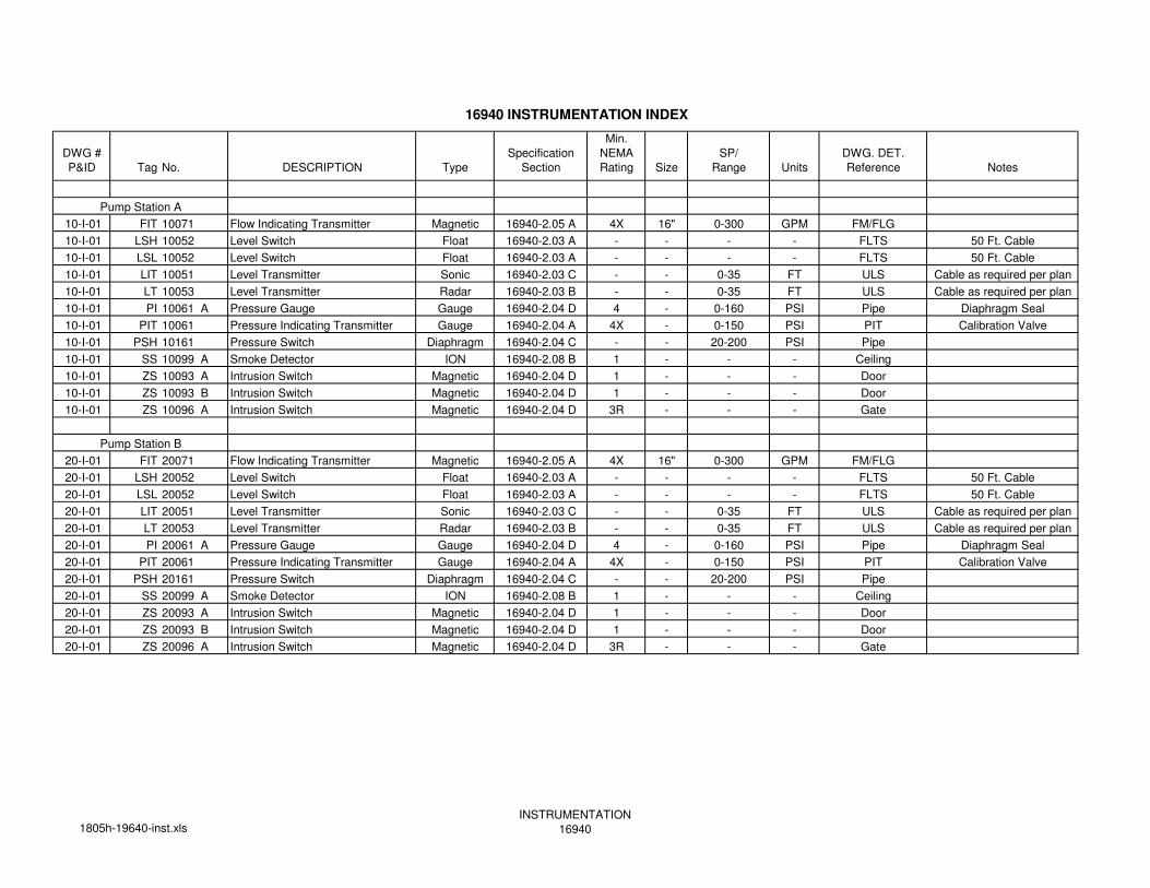
16940 INSTRUMENTATION INDEX
Min.
DWG # Specification NEMA SP/ DWG. DET.
P&ID Tag No. DESCRIPTION Type Section Rating Size Range Units Reference Notes
10-I-01 FIT 10071 Flow Indicating Transmitter Magnetic 16940-2.05 A 4X 16" 0-300 GPM FM/FLG
10-I-01 LSH 10052 Level Switch Float 16940-2.03 A - - - - FLTS 50 Ft. Cable
10-I-01 LSL 10052 Level Switch Float 16940-2.03 A - - - - FLTS 50 Ft. Cable
10-I-01 LIT 10051 Level Transmitter Sonic 16940-2.03 C - - 0-35 FT ULS Cable as required per plan
10-I-01 LT 10053 Level Transmitter Radar 16940-2.03 B - - 0-35 FT ULS Cable as required per plan
10-I-01 PI 10061 A Pressure Gauge Gauge 16940-2.04 D 4 - 0-160 PSI Pipe Diaphragm Seal
10-I-01 PIT 10061 Pressure Indicating Transmitter Gauge 16940-2.04 A 4X - 0-150 PSI PIT Calibration Valve
10-I-01 PSH 10161 Pressure Switch Diaphragm 16940-2.04 C - - 20-200 PSI Pipe
10-I-01 SS 10099 A Smoke Detector ION 16940-2.08 B 1 - - - Ceiling
10-I-01 ZS 10093 A Intrusion Switch Magnetic 16940-2.04 D 1 - - - Door
10-I-01 ZS 10093 B Intrusion Switch Magnetic 16940-2.04 D 1 - - - Door
10-I-01 ZS 10096 A Intrusion Switch Magnetic 16940-2.04 D 3R - - - Gate
20-I-01 FIT 20071 Flow Indicating Transmitter Magnetic 16940-2.05 A 4X 16" 0-300 GPM FM/FLG
20-I-01 LSH 20052 Level Switch Float 16940-2.03 A - - - - FLTS 50 Ft. Cable
20-I-01 LSL 20052 Level Switch Float 16940-2.03 A - - - - FLTS 50 Ft. Cable
20-I-01 LIT 20051 Level Transmitter Sonic 16940-2.03 C - - 0-35 FT ULS Cable as required per plan
20-I-01 LT 20053 Level Transmitter Radar 16940-2.03 B - - 0-35 FT ULS Cable as required per plan
20-I-01 PI 20061 A Pressure Gauge Gauge 16940-2.04 D 4 - 0-160 PSI Pipe Diaphragm Seal
20-I-01 PIT 20061 Pressure Indicating Transmitter Gauge 16940-2.04 A 4X - 0-150 PSI PIT Calibration Valve
20-I-01 PSH 20161 Pressure Switch Diaphragm 16940-2.04 C - - 20-200 PSI Pipe
20-I-01 SS 20099 A Smoke Detector ION 16940-2.08 B 1 - - - Ceiling
20-I-01 ZS 20093 A Intrusion Switch Magnetic 16940-2.04 D 1 - - - Door
20-I-01 ZS 20093 B Intrusion Switch Magnetic 16940-2.04 D 1 - - - Door
20-I-01 ZS 20096 A Intrusion Switch Magnetic 16940-2.04 D 3R - - - Gate
Pump Station B
Pump Station A
1805h-19640-inst.xlsINSTRUMENTATION
16940