switch gear and protection subject code: 2170908
TRANSCRIPT
1
LABORATORY MANUAL
SWITCH GEAR AND PROTECTION
SUBJECT CODE: 2170908
ELECTRICAL ENGINEERING DEPARTMENT
B.E. 7th SEMESTER
Amiraj College of Engineering and Technology, Nr.Tata Nano Plant, Khoraj, Sanand, Ahmedabad.
NAME:
ENROLLMENT NO:
BATCH NO:
YEAR:
Amiraj College of Engineering and Technology, Nr.Tata Nano Plant, Khoraj, Sanand, Ahmedabad.
CERTIFICATE
This is to certify that Mr. / Ms. ______________________________________________
Of class____________________ Enrolment No ___________________________has
Satisfactorily completed the course in ____________________________________as by
the Gujarat Technological University for ____ Year (B.E.) semester___ of Electrical
Engineering in the Academic year ______.
Date of Submission:-
Faculty Name and Signature
(Subject Teacher)
Head of Department
(Electrical)
ELECTRICAL ENGINEERING DEPARTMENT
B.E. 7th SEMESTER
SUBJECT: SWITCH GEAR AND
PROTECTION
SUBJECT CODE: 2170908
List Of Experiments
Sr.
No.
Title Date of
Performance
Date of
submission
Sign
Remark
1.
2
3
4
5
6
7
8
9

10
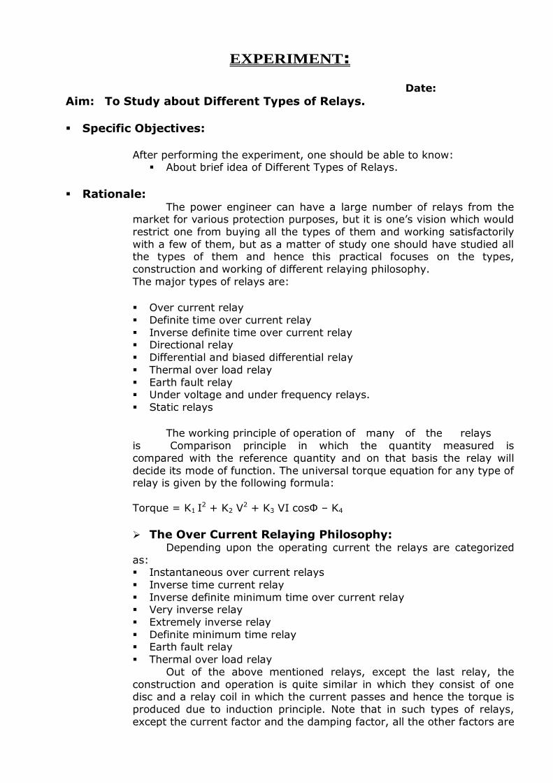
EXPERIMENT:
Date: Aim: To Study about Different Types of Relays.
Specific Objectives:
After performing the experiment, one should be able to know:
About brief idea of Different Types of Relays.
Rationale: The power engineer can have a large number of relays from the
market for various protection purposes, but it is one‟s vision which would
restrict one from buying all the types of them and working satisfactorily
with a few of them, but as a matter of study one should have studied all the types of them and hence this practical focuses on the types,
construction and working of different relaying philosophy.
The major types of relays are:
Over current relay
Definite time over current relay
Inverse definite time over current relay Directional relay
Differential and biased differential relay
Thermal over load relay
Earth fault relay Under voltage and under frequency relays.
Static relays
The working principle of operation of many of the relays
is Comparison principle in which the quantity measured is
compared with the reference quantity and on that basis the relay will
decide its mode of function. The universal torque equation for any type of relay is given by the following formula:
Torque = K1 I2 + K2 V
2 + K3 VI cosΦ – K4
The Over Current Relaying Philosophy: Depending upon the operating current the relays are categorized
as: Instantaneous over current relays
Inverse time current relay
Inverse definite minimum time over current relay Very inverse relay
Extremely inverse relay
Definite minimum time relay Earth fault relay
Thermal over load relay
Out of the above mentioned relays, except the last relay, the
construction and operation is quite similar in which they consist of one disc and a relay coil in which the current passes and hence the torque is
produced due to induction principle. Note that in such types of relays,
except the current factor and the damping factor, all the other factors are
zero in the universal torque equation. The attracted armature principle is
adopted for the instantaneous tripping in most relays with the help of a
shading ring. We know that the “drag” principle requires some constant
amount of ampere turns and if we keep turns fix, the current required for that many number of turns is also fixed and now if we change the
number of turns, accordingly the operating current requirement will also
change. Hence one relay can be set for several current ratings and thus obtained ampere turns are compared with the minimum ampere turns
requirement and the relays determines its status of function. The
damping that is designed will decide its characteristics. Normally a spiral spring and a pair of electromagnets will provide damping torque as well
as they will maintain a constant disc velocity if the disc is spital shaped.
In thermal over load relays, a bi – metallic stripe is used. The material of
the stripe and that of the winding to be protected should ideally have the same thermal expansion factor and as a result as the current starts
flowing, the bi – metallic stripe will undergo expansion and in this way
the temperature of the winding will be sensed. Because both the stripes will not have same expansion for a given temperature rise, they will trip
the system when the temperature and hence expansion is beyond certain
limit. Like all over current relays, these relays can also be set for a range of current and they are normally set for 125 per cent of the normal
operating current.
The Directional Relaying Philosophy:
In such types of relays, induction cup principle is hired in addition
to disc operation. First the induction cup will decide whether the relay has to operate or not and if it operates, the disc will operate on the basis of
current and then only the final tripping will be done. It is to be noted that
in such relays, we also require polarizing quantity for the induction cup
unit. These relays are not self powered relays like over current relays. These relays are used for the protection of parallel feeders, protection
against reverse power in conjunction with the under voltage relays.
The Differential And Biased Differential Relaying
Philosophy:
As the name suggests, this relay operates when the differential (subtracted) current exceeds certain value. This type of relaying may
also hire opposed voltage principle if supplied with juice from the
potential transformers. Due to un even characteristics of current and potential transformers, magnetic inrush currents of transformers,
saturation effects, the relay may not remain stable in normal condition
even and hence a better philosophy called biased differential is hired to
make the relay immune against mal – functioning. This philosophy is hired for large power transformer protection, protection of stator winding
of generators of rating 10 MW and above. The protection is instantaneous
in nature.
Under Voltage Relaying Philosophy:
To sense the “voltage collapse” or “voltage instability” phenomena
in power system, this relaying philosophy is hired. The relay is supplied
from the juice of potential transformer connected to the bus bar and it is
continuously compared with the reference value and if the error signal
exceeds certain value, the relay will operate. Generally these relays are
installed at sub stations feeding bulk and continuous load in addition to at generating stations.
Under Frequency Relaying Philosophy:
The “cascade tripping” is a effect of “power system instability”
phenomena and to sense the power system instability, under frequency relays are used. They are located at the Load Dispatch Centre and on the
basis of the readings of the system frequency, load shedding is carried
out. This relays also serve other function of preventing over fluxing of a
transformer as we know all the electrical machines operate on the constant V/f ratio. If the frequency collapses, flux in the core will increase
leading to over fluxing and saturation. If such situation prevails for short
time but repeated in the system, the magnetizing current will increase and thus it will lead to more iron losses in the system.
Static Relaying Philosophy:
In such relays, transistor – transistor logic is used to make the
relays compact in nature and multi functions. These relays requires less
power for operation, immune to mechanical vibration, less wear and tear as no rotating part, fast acting as absence of mechanical parts but suffers
from the effect of temperature and system voltage variations. The
primary principle of operation remains the same.
Microprocessor Based Relaying Philosophy:
They are an advanced version of relaying philosophy and far superior that their counter parts known as static relays. They are multi
functions and compact and possess all the advantages of static relays.
Besides, they are programmable and communicable. They possess a very
unique feature of self diagnosis which no other relays possess. They have an embedded chip which functions as the heart of the system.
Distance Relaying Philosophy:
In protection practice, the current based or the time based or the current - time based relaying scheme suffers from several disadvantages
and hence the protection philosophy based on the constants
measurements is hired which is known as distance relaying schemes. In this, the distance of the fault location is measured and then on the basis
of selectivity, the relays will operate. The relays are classified as:
Impedance relays (Plain) Reactance relays (Plain)
Mho relays (Plain)
Offset mho relay (Hybrid)
Conclusion:
Questions:
1. Draw the characteristics of IDMT – Normal Inverse / Very Inverse /
Extremely Inverse relays.
2. Explain the Construction & working of Induction disc type relay. 3. Enlist only the applications of distance relaying schemes.
4. Is mho relay directional? Justify.
5. Draw and explain the zone protection.
EXPERIMENT:
Date:
Aim: To Obtain The Characteristics Of Over Current Relays.
Specific Objectives:
After performing the experiment, one should be able to know:
The effect of T.S.M & magnitude of fault current on the relay
operation time.
The applications of over current relay.
Rationale: Over current protection is that protection in which the relay picks
up when the magnitude of current exceeds the pickup level. The basic element in over current protection is an over current relays are
connected to the system, normally by means of CT‟s. over current
protection includes the protection from over loads. This is most widely used protection. Over loading of machine or equipment means the
machine is taking more current than its rated current. Over current relay
are used for the protection of motor, transformer, generator line etc. there is a wide variety of relay units. These are classify accordingly to
their type and characteristics. The major characteristics include:
Define characteristics. Inverse characteristics.
Extremely Inverse characteristics.
Very Inverse characteristics.
The characteristics with definite minimum time and of inverse type
are also called Inverse Definite minimum time characteristics.
The basic terms of relays:
P.S. = Plug Setting = Relay current setting
P.S.M. = Plug Setting Multiplier = Fault current / Relay current setting
T.M.S. = Time Multiplier Setting
TOP = Time of Operation
Ideal TOP = [3/log (P.S.M.)] * T.M.S.
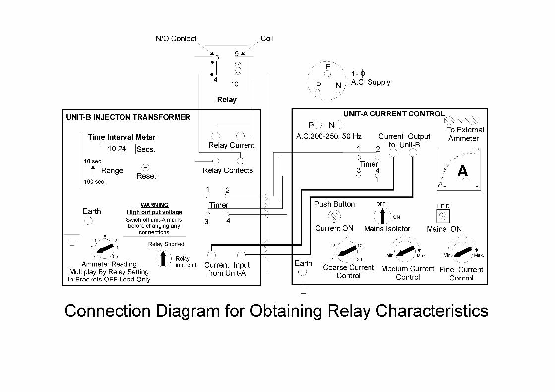
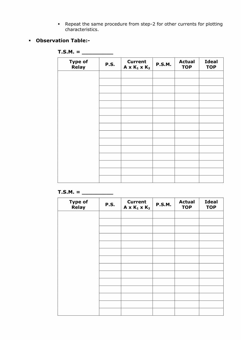
Procedure:
Connect the circuit properly as per diagram.
Check relay auxiliary contacts (for normal position)
Put the position of switch to relay short on unit B
Select suitable multiplying factor by varying coarse control switch K1 on unit A and coarse unit A and coarse control switch K2 on unit B.
Set medium and fine current control at minimum position on unit A.
Switch on main insulator on unit A (check indication also). Reset the timer on unit B, it should be zero, also select proper timer
range (10 sec or 100 sec).
Press the push button and keeping it pressed, set the current to a value just slightly higher than that required using the medium and
fine control [Current ammeter reading x K1 x K2]
Change the position of switch from relay shorted to relaying in circuit
on unit B. Allow the relay to operate while doing this check that the current is
still
Set at the required value. When relay trips take reading of timer [that is actual TOP] on unit B
Switch OFF the main isolator
Repeat the same procedure from step-2 for other currents for plotting characteristics.
Draw graph P.S.M. versus TOP for various T.M.S
Observation Table:
T.S.M. = _________
Type of Relay
P.S. Current
A x K1 x K2 P.S.M.
Actual TOP
Ideal TOP
T.S.M. = _________
Type of
Relay P.S.
Current
A x K1 x K2 P.S.M.
Actual
TOP
Ideal
TOP
Conclusion:
Questions: 1. What is the difference between plug setting & pick up value of an O/C
relay? 2. For grading relays with the fuse or MCB, what setting of TMS, you will
make on relay? Relatively lower or higher? Why?
3. State the various applications of O/C relay?
4. Distinguish between an E/F relay & an O/C relay? 5. Define the following terms as applied to protective relays: Reset,
Operating time, Reach, Over Reach, Under Reach, and Burden.
EXPERIMENT:
Date:
Aim: To Obtain The Characteristics Of Earth Fault Relays.
Specific Objectives:
After performing the experiment, one should be able to know:
The effect of T.S.M & magnitude of fault current on the relay
operation time.
The applications of E/F relay. Rationale:
Earth fault which involves ground is called an earth fault. Examples
are single line to ground (L-G) fault and double line to ground (2L-G) fault. Faults which do not involve ground are called phase faults. The
protective scheme is used for the protection of an element of a power
system of against earth fault is known as earth fault protection. Similarly,
scheme used for protection against phase faults is known as phase fault protection. Relay which is used for the protection of a section of the
power system against earth faults are called earth fault relays. Similarly,
relays used for the protection of a section for the power system against phase faults are called phase fault relays or over current relays. The
operating principles and constructional features of earth fault relays and
phase fault relays are the same. They differ only in the current in the
current levels of their operation. The plug setting for earth fault relays varies from 20% to 80% of the C.T. secondary rating in steps of 10%.
Earth fault relays are more sensitive than the relays use for phase faults.
The plug setting for phase fault relays varies from 50% to 200% of the C.T. secondary rating in steps of 25%.
Procedure:-
Connect the circuit properly as per diagram.
Check relay auxiliary contacts (for normal position)
Put the position of switch to relay short on unit B Select suitable multiplying factor by varying coarse control switch K1
on unit A and coarse unit A and coarse control switch K2 on unit B.
Set medium and fine current control at minimum position on unit A. Switch on main insulator on unit A (check indication also).
Reset the timer on unit B, it should be zero, also select proper timer
range (10 sec or 100 sec).
Press the push button and keeping it pressed, set the current to a value just slightly higher than that required using the medium and
fine control [Current ammeter reading x K x K2]
Change the position of switch from relay shorted to relaying in circuit on unit B.
Allow the relay to operate while doing this check that the current is
still Set at the required value.
When relay trips take reading of timer [that is actual TOP] on unit B
Switch OFF the main isolator
Repeat the same procedure from step-2 for other currents for plotting
characteristics.
Observation Table:-
T.S.M. = _________
Type of
Relay P.S.
Current
A x K1 x K2 P.S.M.
Actual
TOP
Ideal
TOP
T.S.M. = _________
Type of
Relay P.S.
Current
A x K1 x K2 P.S.M.
Actual
TOP
Ideal
TOP
Conclusion:
Questions: 1. Why E/F relay is provided with current setting range of 20% to 80%
of rated current compared to current setting range 50% to 200% for
O/C relay?
2. Draw the figures for various E/F protective schemes. 3. How a directional E/F relay energized?
4. What is core balance C.T.? Explain its working principle.
5. Explain the term P.S.M. & T.M.S. with reference to IDMT relays.
EXPERIMENT:
Date:
Aim: To Perform the biased differential protection of 1-Ф transformer.
Specific Objectives:
After performing the experiment, one should be able to know:
How the biased differential protection used for the protection of power system equipments.
Rationale:
“A differential relay responds to vector difference between two or
more similar electrical quantities “. From this definition the following
aspect are known: The differential relay has at least two actuating quantities say I1 & I2.
The two or more actuating quantities should be similar i.e. current
/current.
The relay respond to the vector difference between the two i.e. I1 – I2, which includes magnitude and/or phase angle difference.
Differential protection is generally a unit protection. The protected zone is exactly determined by location of C.T.s the vector difference is
achieved by suitable connections of current transformer or voltage
transformer secondary.
Principle of Biased Differential Protection
In protection of transformer, CT‟s are connected at each end of the transformer. The CT secondaries are connected in star or delta and pilot
wires are connected between the CT‟s of each end. The CT connections
and CT ratios are such that currents fed into the pilot wires from both the ends are equal during normal conditions and for through faults. During
the internal faults such as phase to phase or phase to ground, the
balance is disturbed. The out of balance current I1 – I2 flows through the relay operating coils. To avoid unwanted operation on through faults
restraining bias coil are provided in series with pilot wires. The ampere
turns provided by bias coils or restraining coil are proportional to (I1 – I2)
/ 2.
As a result the restraining torque increases with through current
and relay does not operate due to the difference in CT ratios for high values of short circuit currents.
CT connection:
There is an inherent phase displacement between the voltage
induced in the high voltage winding and low voltage winding. In case of
star-delta transformer hence the load current on the high voltage side in
displaced in phase with respect to load current on low voltage side. The power transformer are grouped according to the phase displacement e.g,
Group-1: Star-Star, phase displacement = 00
Group-2: Star-Star, phase displacement = 1800
Group-3: Delta-Star, phase displacement = -300
Group-4: Delta-Star, phase displacement = +300
In the circulating current differential protection, the phase
displacement in line current on two sides introduces phase differences in
secondary current of C.T.s on two sides.
The CT connection should such that the resultant current fed into
the pilot wires from either side are displaced in phase by an angle equal to the phase shift between the primary and secondary currents.
To get this arrangement, following rules are adopted. Secondary of C.T.s on star connected side of power transformer are
connected in delta.
Secondary of C.T.s on delta connected side of power transformer are
connected in star.
With this arrangement the phase displacement between currents
gets cancelled with the phase displacement due to star/delta connection of CT secondary.
CT Ratio:
Current ratio of C.T.s on each side will be different depending upon
the line currents of power transformer and connections of C.T.s. the
currents fed into the pilots from each side should be the same for normal condition. Suppose current required in the pilot wire is 5Amp. Then
secondary rating of the CT which is connected in star side of power
transformer must be equal to 5 Amp. And secondary rating of CT which is
connected on the delta side of power transformer must be equal to 5/ 3
Amp. Refer fig. (3) Which gives differential protection scheme for
Y/∆ power transformer considering CT connection and CT ratio aspect?
Procedure: Connect the circuit as shown in figure.
Apply the rated voltage to the H.V. winding of the transformer.
Apply the load & create the artificial fault in the circuit. Clear the fault & reduce the applied voltage to zero to release the
contactor.
Again apply the rated voltage with increased load. Repeat the above procedure for different loads.
See the fault current in the ammeter connected in the circuit.
Conclusion:
Questions:
1. What is spill current? 2. Explain the biasing in case of transformer differential protection?
3. Why the C.T.s on the star side of transformer winding is connected in
delta and C.T.s on delta side of transformer winding is connected in star?
4. Why high set element is provided in harmonic restraint relay?
5. Draw and explain the restricted earth fault protection of transformer.
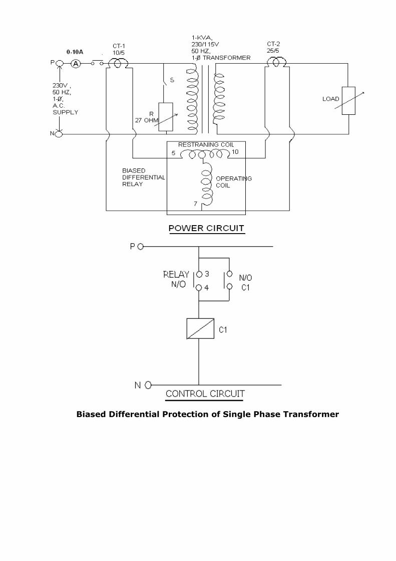
Biased Differential Protection of Single Phase Transformer
EXPERIMENT:
Date:
Aim: To Perform the Radial Feeder Protection.
Specific Objectives:
After performing the experiment, one should be able to know:
Different protection schemes used for the protection of radial
feeder
Use of time grading, current grading and combine time and current
grading systems
Rationale:
The radial feeder is the back bone of any large power system and
it connects the primary distribution with the generating source and hence
an elaborated protective gear is required for them. The usual practice for
their protection is to use: Current graded system
Time graded system
Current – time graded system Distance protection
The first two relaying schemes are not used in practice due to their
Demerits. The third system is hired for small networks or in large networks, but nearer to the load end. The panel which we are going to
study has the third type of protective gears. In such a system, the IDMT
relays are used and their coordination is carried out in order to avail the benefits of back – up protections. In such a system, the radial feeder I
divided in zones and the individual zone protection takes care of any fault
in its zone. Should the zone protection fail to operate due to any reason, the zone in the direction of generating or feeding source will take care of
that fault but after a pre determined time lag and will serve as a back up
protection. Usually for any main protection, two back up protections are
employed. The back up protection coordination does not mean delayed operation for in – zone faults. For such faults, the protection should be
fast and without any intentional time lag. Every IDMT relay has an in –
built high set unit for instantaneous tripping under very heavy faults. Of course, the used system suffers from several demerits but has proved to
be one of the effective ways to protect the radial feeder.
Procedure:
Trace the circuit at the back of the panel before switching the mains.
Switch on the MCB at the back of the panel. Note the status of semaphore indicators on the panel.
Press three START push buttons S1, S2 and S3 in sequence.
Note the changed status of semaphore indicators which simulate
circuit breaker in the system. You must have an ON “healthy panel” indication.
Now close switch S3
Start the timer at the instant of closing.
Note the time of operation of relay R3 from the timer and fault current
from the ammeter on the panel.
Open the switch S3 and note the changed status of semaphore
indicator on the panel. Change the value of T.M.S. of the relay R3 and press S3.
Repeat the steps.
Now close switch S2 and then observe similar readings. Now close switch S1 and then observe similar readings.
Precaution: After operation of any of the relays, do not forget to open the
concerned switch.
Do not touch any of the metal parts on the relay while changing
T.M.S. or P.S. as the main supply is directly available. Verify that the relay coil is properly connected across C.T. secondary
so that no over voltage results.
You may connect additional load bank for higher value of current but in doing so the studs on the panels will be having 230 V, and hence
keep yourself away from that.
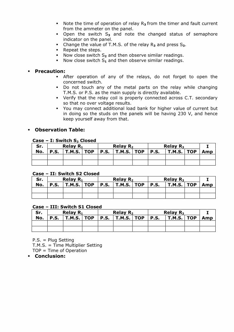
Observation Table:
Case – I: Switch S3 Closed
Sr.
No.
Relay R1 Relay R2 Relay R3 I
Amp P.S. T.M.S. TOP P.S. T.M.S. TOP P.S. T.M.S. TOP
Case – II: Switch S2 Closed
Sr.
No.
Relay R1 Relay R2 Relay R3 I Amp P.S. T.M.S. TOP P.S. T.M.S. TOP P.S. T.M.S. TOP
Case – III: Switch S1 Closed
Sr.
No.
Relay R1 Relay R2 Relay R3 I Amp P.S. T.M.S. TOP P.S. T.M.S. TOP P.S. T.M.S. TOP
P.S. = Plug Setting T.M.S. = Time Multiplier Setting
TOP = Time of Operation
Conclusion:

Questions: 1. Enlist only the demerits of current graded and time graded system. 2. Enlist only the demerits of current time graded system.
3. Explain working of radial feeder protection scheme.
4. Which distance relay you will use for long, medium and short transmission line and why?
5. What is the function of line trap and coupling capacitor in carrier
current protection? 6. What is offset mho characteristic and why it is required?
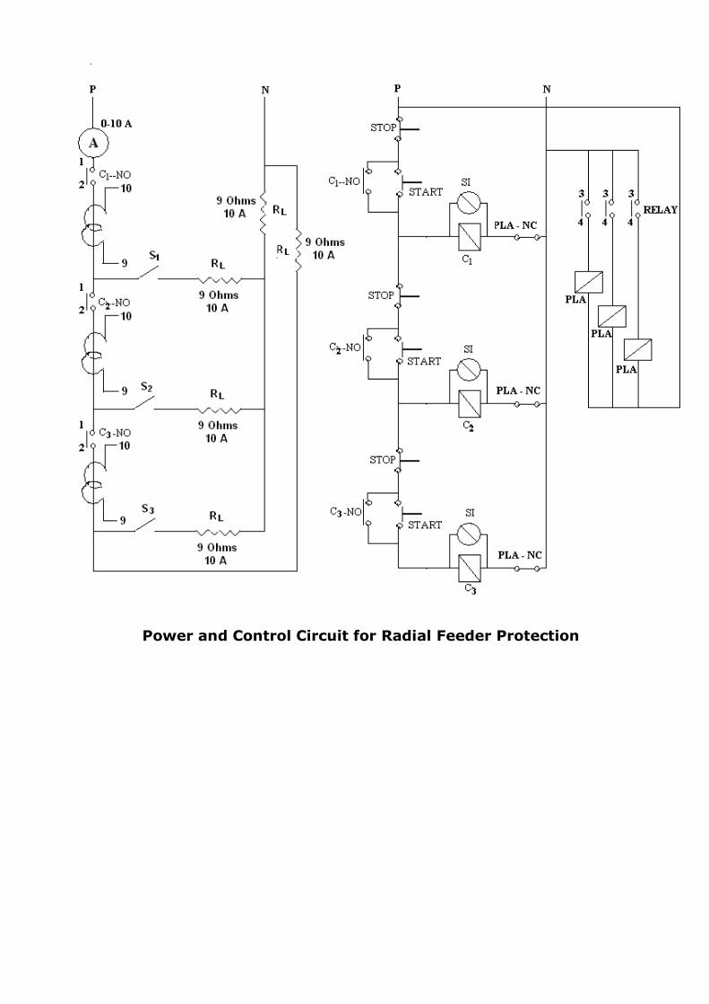
Power and Control Circuit for Radial Feeder Protection
EXPERIMENT:
Date:
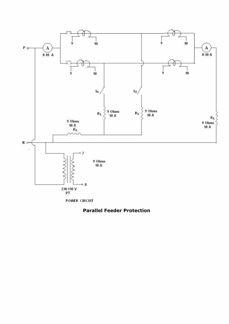
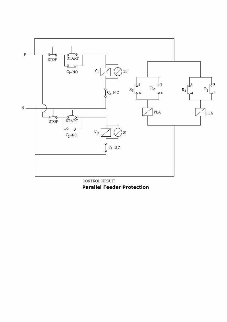
Aim: To Perform the Parallel Feeder Protection.
Specific Objectives:
After performing the experiment, one should be able to know:
Different protective schemes used for the parallel feeder
Use of directional relay in parallel feeder protection
Rationale:
When the power to be transmitted is bulk in nature and to be
transmitted over a long distance, then to reduce the over all reactance
and hence improve the maximum power transfer possible, use of parallel feeders is compulsory. The parallel feeder is to be designed for maximum
capacity and normally carries half the load and hence the utilization
factor for them is very poor. The usual current time graded philosophy fails to provide adequate protection in their case and hence in addition to
the IDMT relays, direction relays are to be installed on them. The panel
that we have also has the directional relays. It is to be noted that the IDMT and the directional relays are to be crossed coordinated. The
directional relay we have is not a self powered relay.
Procedure:
Trace the circuit at the back of the panel before switching the mains
Provide the auxiliary to the directional relay. Switch on the MCB at the back of the panel.
Note the status of semaphore indicators on the panel.
Press three START push buttons S1, S2.
Note that unlike radial feeder protection panel, here we can press any push button first and energize any of the parallel feeders.
Note the changed status of semaphore indicators which simulate
circuit breaker in the system. You must have an ON “healthy panel" indication.
Now close switch S1 and start the timer at the instant of closing.
Note the time of operation of relays R1 and R3 from the timer and fault
current from the ammeter on the panel. Open the switch S2 and note the changed status of semaphore
indicators on the panel.
Now close switch S2 and start the timer at the instant of closing. Repeat the steps from 10 and 11 for relays R2 and R4.
Precaution:
After operation of any of the relays, do not forget to open the
concerned switch. Do not touch any of the metal parts on the relay while changing
T.M.S. or P.S. as the main supply is directly available.
Verify that the relay coil is properly connected across C.T. secondary
so that no over voltage results.
You may connect additional load bank for higher value of current but
in doing so the studs on the panels will be having 230 V, and hence keep yourself away from that.
Observation Table:
Case – I: Switch S1 Closed
Case – II: Switch S2 Closed
Conclusion:
Questions:
1. Explain 300, 600 and 900 connections for directional relay. 2. Draw the directional relay characteristics for an MTA of 45 degree and
label different zones on it.
3. Justify, “For the parallel feeder protection, the relays nearer to the generating station are non directional in nature while those away from
it are directional in nature.”
4. What do you understand by cross coordination of relays in parallel
feeder protection?
Sr.
No.
Relay R1 Relay R2 Relay R3 Relay R4 I
Amp. PS
TMS
TOP PS TMS TOP PS TMS TOP PS TMS TOP
Sr. No.
Relay R1 Relay R2 Relay R3 Relay R4 I
Amp. PS
TMS
TOP PS TMS TOP PS TMS TOP PS TMS TOP
Parallel Feeder Protection
Parallel Feeder Protection
EXPERIMENT:
Date:
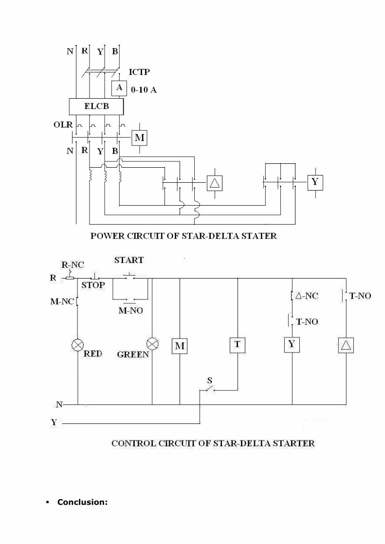
Aim: To Perform The Protection of Three Phase Induction Motor.
Specific Objectives:
After performing the experiment, one should be able to know:
Different protective schemes used for three phase induction motor
Necessecity of protection of three phase induction motor
Rationale:
The induction motor is widely used in industries and hence its
protection attains at most priority in any firm. Here first the control of
induction motor is done and then its protection is applied. The major of
the protection that we find in an induction motor are:
Overload protection
Single phasing protection
Under voltage protection Negative phase sequence protection
The motor is to be protected against the thermal overload or the Motor will burn out due to its thermal insulation breakdown. While
running, if the motor suffer a single phasing problem, it will start drawing
more current and in certain cases, it will burn also. Under the condition of under voltage while working for the same power demand, the motor will
start taking high current and hence it will once again suffer from its
thermal breakdown of insulation. When the motor is supplied with the
negative phase sequence current, the rotor will have a double frequency current flowing in it and hence it will overheat the motor.
To protect the motor in such cases, the motor is supplied with the over load relay or bi-metallic relay to take care of any gradual or sudden
overload. For protection against single phasing, the single phasing
preventor is used.
Procedure:
Switch on the supply Press the start push button
Let the motor run in STAR and then in DELTA.
Draw your conclusion.
Conclusion:
Questions:
1. How will you select the rating of the bi-metallic relay for a given
capacity of motor?
2. Explain the working of Single Phasing Preventer.
3. What modifications do you suggest to include the remaining protections of induction motor in the panel studied by you?
4. Should you go for over voltage protection of motor as normally done
for a generator? Why? 5. Enlist the effects of negative phase sequence protection failure on the
performance of motor?
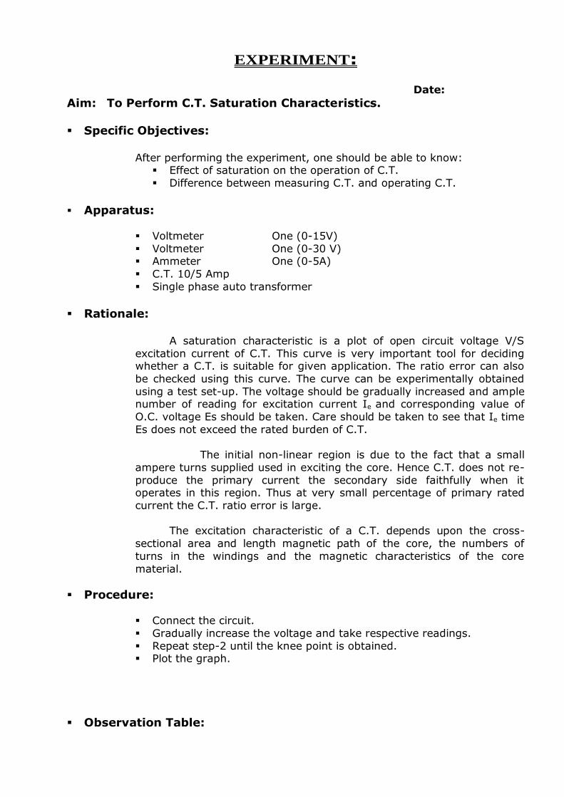
EXPERIMENT:
Date:
Aim: To Perform C.T. Saturation Characteristics.
Specific Objectives:
After performing the experiment, one should be able to know:
Effect of saturation on the operation of C.T.
Difference between measuring C.T. and operating C.T.
Apparatus:
Voltmeter One (0-15V)
Voltmeter One (0-30 V) Ammeter One (0-5A)
C.T. 10/5 Amp
Single phase auto transformer
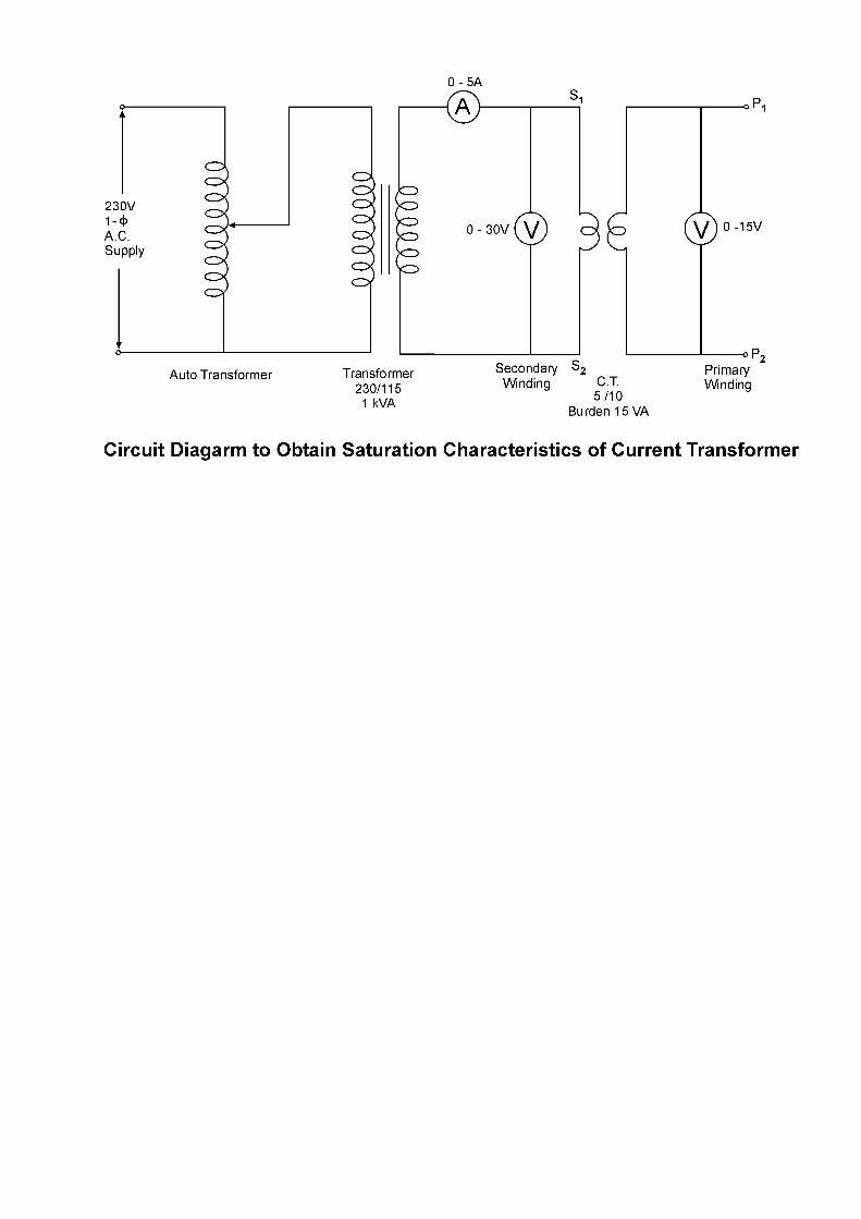
Rationale:
A saturation characteristic is a plot of open circuit voltage V/S
excitation current of C.T. This curve is very important tool for deciding whether a C.T. is suitable for given application. The ratio error can also
be checked using this curve. The curve can be experimentally obtained
using a test set-up. The voltage should be gradually increased and ample number of reading for excitation current Ie and corresponding value of
O.C. voltage Es should be taken. Care should be taken to see that Ie time
Es does not exceed the rated burden of C.T.
The initial non-linear region is due to the fact that a small
ampere turns supplied used in exciting the core. Hence C.T. does not re-
produce the primary current the secondary side faithfully when it operates in this region. Thus at very small percentage of primary rated
current the C.T. ratio error is large.
The excitation characteristic of a C.T. depends upon the cross-
sectional area and length magnetic path of the core, the numbers of
turns in the windings and the magnetic characteristics of the core
material.
Procedure:
Connect the circuit.
Gradually increase the voltage and take respective readings.
Repeat step-2 until the knee point is obtained. Plot the graph.
Observation Table:
Sr.
No.
V
primary
Volt
Isec
Amp
Vsec
Volt VA
1.
2.
3.
4.
5.
Precautions: While performing this experiment, Give supply through the auto
transformer to the C.T. secondary and primary should be open. Increase supply voltage slowly.
Conclusion:
Questions:
1. Explain the term burden.
2. Why C.T. secondary is never kept open?
3. For same rating can measuring C.T. replaces protective C.T. and for the same rating can protective C.T. replaces measuring C.T.? Justify.
4. Explain the 0.1 accuracy class.
5. Explain the meaning of each term in 5P10 C.T. rating.
EXPERIMENT:
Date:
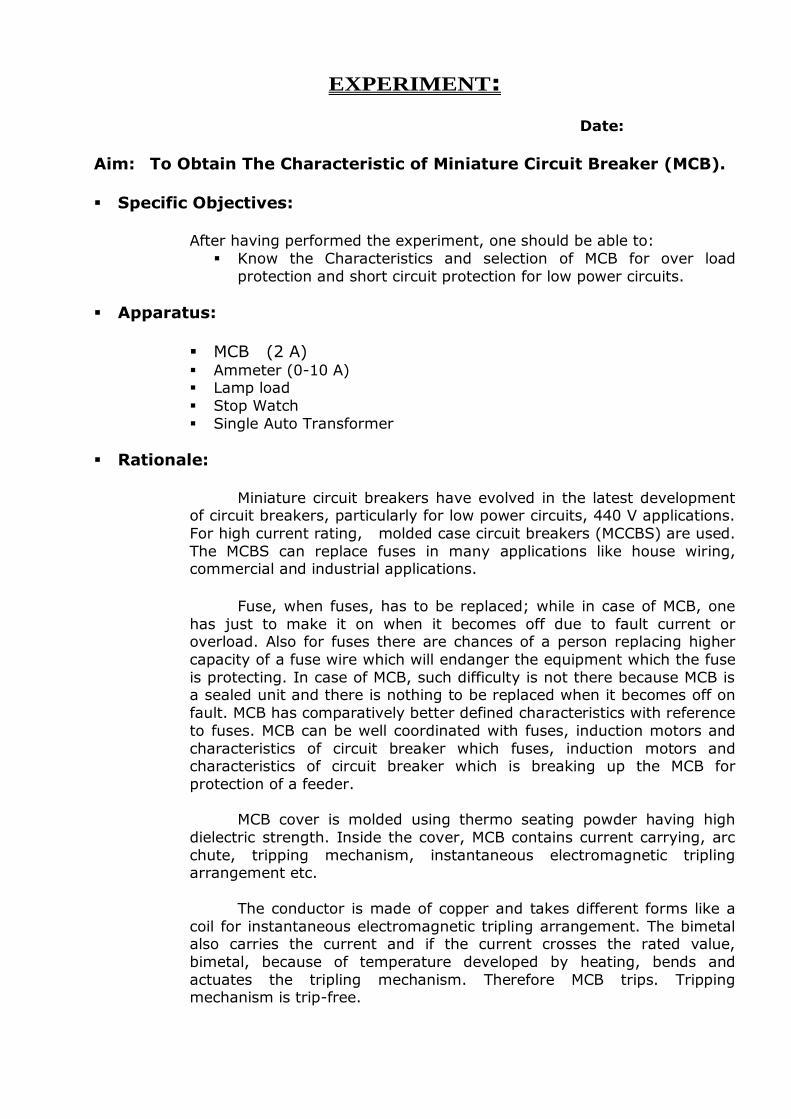
Aim: To Obtain The Characteristic of Miniature Circuit Breaker (MCB).
Specific Objectives:
After having performed the experiment, one should be able to:
Know the Characteristics and selection of MCB for over load
protection and short circuit protection for low power circuits.
Apparatus:
MCB (2 A) Ammeter (0-10 A) Lamp load
Stop Watch
Single Auto Transformer
Rationale:
Miniature circuit breakers have evolved in the latest development
of circuit breakers, particularly for low power circuits, 440 V applications.
For high current rating, molded case circuit breakers (MCCBS) are used.
The MCBS can replace fuses in many applications like house wiring, commercial and industrial applications.
Fuse, when fuses, has to be replaced; while in case of MCB, one
has just to make it on when it becomes off due to fault current or overload. Also for fuses there are chances of a person replacing higher
capacity of a fuse wire which will endanger the equipment which the fuse
is protecting. In case of MCB, such difficulty is not there because MCB is a sealed unit and there is nothing to be replaced when it becomes off on
fault. MCB has comparatively better defined characteristics with reference
to fuses. MCB can be well coordinated with fuses, induction motors and
characteristics of circuit breaker which fuses, induction motors and characteristics of circuit breaker which is breaking up the MCB for
protection of a feeder.
MCB cover is molded using thermo seating powder having high
dielectric strength. Inside the cover, MCB contains current carrying, arc
chute, tripping mechanism, instantaneous electromagnetic tripling arrangement etc.
The conductor is made of copper and takes different forms like a
coil for instantaneous electromagnetic tripling arrangement. The bimetal also carries the current and if the current crosses the rated value,
bimetal, because of temperature developed by heating, bends and
actuates the tripling mechanism. Therefore MCB trips. Tripping mechanism is trip-free.
The contacts are of silver, silver-tungsten or copper tungsten
depending on short circuit capacity. Arc chute is used for splitting the arc,
so that arc is cooled, split, lengthened and quenched fast.
Instantaneous tripping arrangement is so adjusted that the
electromagnetic attracting force generated by a coil of conductor is not
enough to attract an armature (which is responsible for actuating the tripping mechanism) at lower current at which thermal bimetallic tripling
action works. E.g. bimetallic will actuate the tripping mechanism up to
say 40 A for a 5-A MCB. Beyond this current, electromagnetic attracting force increases to a value which attracts the armature, which in turn
actuates the tripping mechanism and hence MCB trips instantaneously
(i.e. within 3 cycles).
MCBs are available in single-pole, double-pole, three-pole or four-
pole versions.
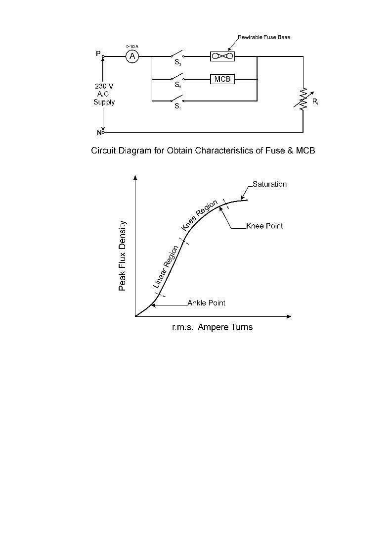
Procedure:
Connect the circuit as per diagram. Make MCB off and keep the shorting switch „on‟.
Make the connector „on‟ by a 5 amp. Switch.
Adjust the load current to about the 2 amp.
Make the MCB „on‟ and shorting switch „off‟. Observe that the MCB does not operate.
Now make the shorting switch „on‟ and MCB „off‟
Adjust the load current at about 4 amp. Make the shorting switch „off‟ and MCB „on‟.
Be ready with the stop watch.
MCB will trip as per its characteristics and stop. Note down the current and time of operation of MCB.
Repeat the procedure (sr. No. 7 to 12) for currents 6,8,10, amp.
Tabulate the readings as shown in observation table.
Observe the graph of tripping time v/s current. Draw your own conclusion.
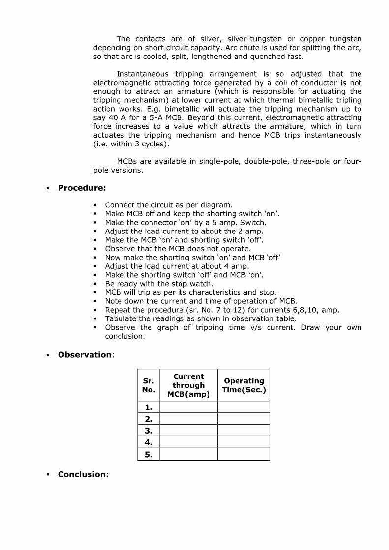
Observation:
Sr.
No.
Current
through
MCB(amp)
Operating
Time(Sec.)
1.
2.
3.
4.
5.
Conclusion:

Questions:
1. What is the difference between the fuse and MCB?
2. How is the arc extinguished in MCB?
3. What do you understand by trip-free tripping mechanism of an MCB? 4. What is the difference between MCB & ELCB?
5. Give the different ratings of MCBs available in market?
EXPERIMENT:
Date:
Aim: To Study Static Relay SPAJ 140C.
Specific Objectives:
After performing the experiment, one should be able to know:
Construction and working of Static Relay SPAJ 140C.
Rationale:
The combined over current & earth fault relay SPAJ140C is intended to be
used for the selective short circuit and earth fault protection of radial feeder in
solidly earthed, resistance or impedance earthed power system. The integrated protection relay includes a phase over current & earth fault
unit with tripping & signaling facilities. The over current & earth fault relay can
also be used for applications requiring single, two or three phase over current & earth fault features. The relay also features circuit breaker failure protection
(CBFP)
Features:
1. Three phase low set over current unit with definite & IDMT characteristics 2. Three phase high set over current unit with instantaneous & definite time
characteristics.
3. Low set earth fault unit with definite time & IDMT characteristics. 4. High set earth fault unit with instantaneous characteristics.
5. Breaker failure protection.
6. Numerical display of setting values, measuring values and memorized fault values.
7. Enhanced system reliability and availability due to software self-supervision
with auto diagnosis.
8. Software support for setting & recording of relay parameters with portable PC.
Description of characteristics:
Low set unit of over current and earth fault gives seven curves:
1. Definite time 2. Extremely inverse
3. Very inverse
4. Normal inverse
5. Long time inverse 6. RI type
7. RXIDG type
Description of operation:
There are six output relays inside the relay module.
1. Output relay A is a heavy-duty trip relay capable of controlling main circuit breaker.
2. Output relay B and C can be used for signaling on operation of relay module.
Normally relay B is used for signaling over current unit and relay C is used for
earth fault unit. 3. The start signals of relay of protection stages of the relay are routed to output
relay D.
4. The output relay E is a heavy-duty relay as output relay A. It can be
controlled by start and operate signal of protection stages. This relay can also
be used as trip relay for circuit breaker failure protection.
The functions of blocking and start signals are selected with the switches of switch
groups SGF, SGB and SGR. The checksum of the switch groups are found in the
setting menu of the protection relay module. SGF switch groups for functions
SGB switch groups for blocking
SGR switch groups for relay configuration. These switch groups are not to be found physically in hardware of relay but
they are software based. Programming (0 or 1) of different switch groups is explained
in relevant table for SGF, SGB & SGR.
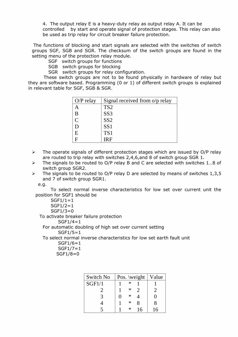
O/P relay Signal received from o/p relay
A
B
C
D
E
F
TS2
SS3
SS2
SS1
TS1
IRF
The operate signals of different protection stages which are issued by O/P relay
are routed to trip relay with switches 2,4,6,and 8 of switch group SGR 1.
The signals to be routed to O/P relay B and C are selected with switches 1…8 of
switch group SGR2. The signals to be routed to O/P relay D are selected by means of switches 1,3,5
and 7 of switch group SGR1.
e.g. To select normal inverse characteristics for low set over current unit the
position for SGF1 should be
SGF1/1=1
SGF1/2=1 SGF1/3=0
To activate breaker failure protection
SGF1/4=1 For automatic doubling of high set over current setting
SGF1/5=1
To select normal inverse characteristics for low set earth fault unit SGF1/6=1
SGF1/7=1
SGF1/8=0
Switch No Pos. \weight Value
SGF1/1
2
3
4
5
1 * 1
1 * 2
0 * 4
1 * 8
1 * 16
1
2
0
8
16
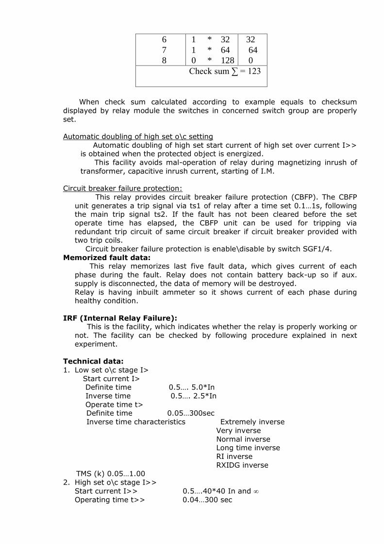
6
7
8
1 * 32
1 * 64
0 * 128
32
64
0
Check sum ∑ = 123
When check sum calculated according to example equals to checksum
displayed by relay module the switches in concerned switch group are properly
set.
Automatic doubling of high set o\c setting
Automatic doubling of high set start current of high set over current I>> is obtained when the protected object is energized.
This facility avoids mal-operation of relay during magnetizing inrush of
transformer, capacitive inrush current, starting of I.M.
Circuit breaker failure protection:
This relay provides circuit breaker failure protection (CBFP). The CBFP
unit generates a trip signal via ts1 of relay after a time set 0.1…1s, following the main trip signal ts2. If the fault has not been cleared before the set
operate time has elapsed, the CBFP unit can be used for tripping via
redundant trip circuit of same circuit breaker if circuit breaker provided with two trip coils.
Circuit breaker failure protection is enable\disable by switch SGF1/4.
Memorized fault data: This relay memorizes last five fault data, which gives current of each
phase during the fault. Relay does not contain battery back-up so if aux.
supply is disconnected, the data of memory will be destroyed.
Relay is having inbuilt ammeter so it shows current of each phase during healthy condition.
IRF (Internal Relay Failure): This is the facility, which indicates whether the relay is properly working or
not. The facility can be checked by following procedure explained in next
experiment.
Technical data:
1. Low set o\c stage I>
Start current I> Definite time 0.5…. 5.0*In
Inverse time 0.5…. 2.5*In
Operate time t> Definite time 0.05…300sec
Inverse time characteristics Extremely inverse
Very inverse
Normal inverse Long time inverse
RI inverse
RXIDG inverse TMS (k) 0.05…1.00
2. High set o\c stage I>>
Start current I>> 0.5….40*40 In and
Operating time t>> 0.04…300 sec
3. Low set earth fault stage I0>
Start current Io>
Definite time Inverse time 0.1…0.8*In
Operate time to>
Definite time 0.05…300sec Inverse time characteristics Extremely inverse
Very inverse
Normal inverse Long time inverse
RI inverse
RXIDG inverse
TMS (k) 0.05…1.00 4. High set earth fault Io>>
Start current Io>> 0.1…10.00*In and
Operating time to>> 0.04…300 sec
5. Auxiliary supply = 230 v a.c
6. Relay terminals: C.T secondary quantity:
For 1A:
R 1-3 Y 4-6
B 7-9
N 25-27 For 5A:
R 1-2
Y 4-5
B 7-8 N 25-26
Trip signal: 65-66 (TS2)
Uaux: 61-62 CBFP : 74-75(TS1)
Time/current characteristic:
1. IDMT characteristic: Slope of the
Time/current Extremely inverse 2.0 80.0
Very inverse 1.0 13.5
Normal inverse 0.02 0.14 Long time inverse 1.0 120.0
1
)(
I
I
kst
Where,
t = time of operation
k = TMS I = measured current value
I> = pick-up current
2. RI type
I
I
kst
236.0339.0
)(
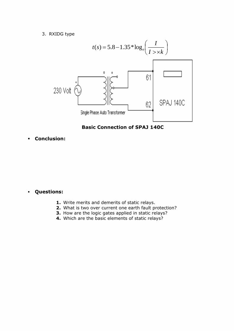
3. RXIDG type
Basic Connection of SPAJ 140C
Conclusion:
Questions:
1. Write merits and demerits of static relays.
2. What is two over current one earth fault protection? 3. How are the logic gates applied in static relays?
4. Which are the basic elements of static relays?
kI
Ist elog*35.18.5)(