spiral bevel gear - powergear - graessner gmbh
TRANSCRIPT
gmb / BA PowerGear_EN as of 29. October 2015 Page 1 of 23
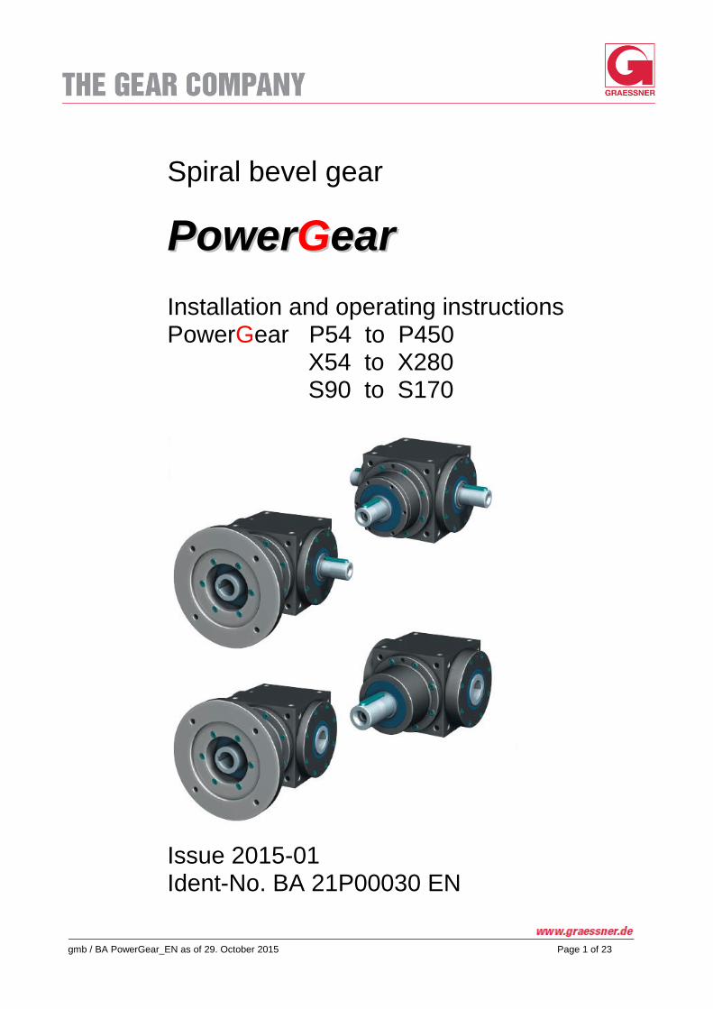
Spiral bevel gear
PPoowweerrGGeeaarr
Installation and operating instructions PowerGear P54 to P450 X54 to X280
S90 to S170
Issue 2015-01 Ident-No. BA 21P00030 EN
gmb / BA PowerGear_EN as of May 2015 / 29.10.2015 Page 2 of 23
Table of contents
1. General notes
1.1 Use of the operating instructions
1.2 Significance of the warning notes
1.3 Exclusion of liability
1.4 Copyright
4
4
4
4
4
2. Intended use of MS-Graessner Gear Units
5
3. Conversions and alterations / Modifications of the product
5
4. Set-up of gear unit / Technical data
4.1 Set-up of gear unit
4.2 Type designations
4.3 Performance tables PowerGear
4.4 Technical data PowerGear
4.5 Type plate
5
5 6 7 8 8
5. Safety notes
5.1 Basic duties
5.2 Qualified personnel
5.3 Environmental protection
9
9 9 9
6. Transport, storage and long term storage
6.1 Transport
6.2 Storage conditions
6.3 Long-term storage
6.4 To be noted before commissioning
10
10 10 10 10
7. Installation
7.1 General installation instructions
7.2 Gear unit installation in plant
7.3 Installation positions
7.4 Fitting of motors
7.5 Installation of the other fitted components
7.6 Finishing work
11
11 11 11 12 12 13
8. Commissioning
14
9. Operation of the PowerGear gear units
9.1 General notes on operation
9.2 To be watched out for during operation
9.3 Irregularities
15
15 15 15
gmb / BA PowerGear_EN as of May 2015 / 29.10.2015 Page 3 of 23
10. Faults, causes, remedy
10.1 General fault indications
10.2 Possible faults
16
16 16
11. Inspection and maintenance
11.1 General notes
11.2 Service intervals
11.3 Oil service life
11.4 Oil change
11.5 Checking gear unit condition
17
17 17 17 17 18
12. Replacement parts, replacement part stocks, service
12.1 Replacement parts
12.2 Replacement part stocks
12.3 Service department
18
18 18 18
13. Index (alphabetic)
19
gmb / BA PowerGear_EN as of May 2015 / 29.10.2015 Page 4 of 23
1. General notes
1.1 Use of the operating instructions These operating instructions are an integral part of the product and must be carefully studied before use and kept in a safe place for later consultation.
It comprises important notes on the operation and service of the PowerGear series of gear units. These operat-ing instructions are intended for all persons carrying out assembly, installation, commissioning and service work on gear units from this series of gear units.
The gear units of the PowerGear series are components for installation in machines and exclusively intended for guiding, distributing and multiplying torques and only designed for the area of use described in Chapter 2 "Tech-nical Data". Other operational uses and conditions must be agreed with MS-Graessner GmbH & Co.KG and contractually regulated. The gear units are manufactured according to the latest technical state of the art and delivered such that they are safe to operate. They meet the current state of the description as contained in these operating instructions. We reserve all rights to implement technical modifications on components, whilst retaining performance capabil-ity and safety of the gear units.
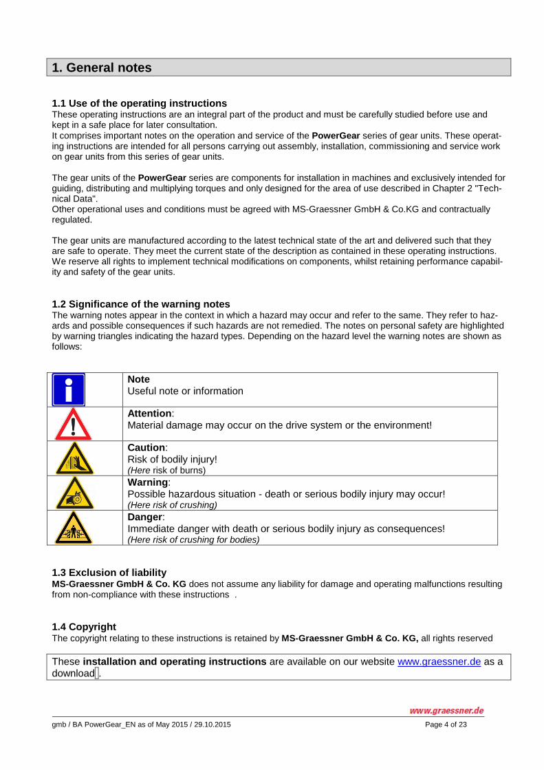
1.2 Significance of the warning notes The warning notes appear in the context in which a hazard may occur and refer to the same. They refer to haz-ards and possible consequences if such hazards are not remedied. The notes on personal safety are highlighted by warning triangles indicating the hazard types. Depending on the hazard level the warning notes are shown as follows:
Note Useful note or information
Attention: Material damage may occur on the drive system or the environment!
Caution: Risk of bodily injury! (Here risk of burns)
Warning: Possible hazardous situation - death or serious bodily injury may occur! (Here risk of crushing)
Danger: Immediate danger with death or serious bodily injury as consequences! (Here risk of crushing for bodies)
1.3 Exclusion of liability MS-Graessner GmbH & Co. KG does not assume any liability for damage and operating malfunctions resulting from non-compliance with these instructions .
1.4 Copyright The copyright relating to these instructions is retained by MS-Graessner GmbH & Co. KG, all rights reserved
These installation and operating instructions are available on our website www.graessner.de as a download .
gmb / BA PowerGear_EN as of May 2015 / 29.10.2015 Page 5 of 23
With regard to all technical queries please contact our product management or our service department:
MS-Graessner GmbH & Co. KG THE GEAR COMPANY Kuchenaecker 11 D-72135 Dettenhausen
Service Department
Product management
Tel.: +49 (0)7157 123-0 Fax: +49 (0)7157 123 220 Fax: +49 (0)7157 123 212 [email protected] www.graessner.de
These operating instructions must be read carefully before use Keep in a safe place for later reference
If these operating instructions are not complied with, damage to the gear unit, operating faults, material damage and personal injury may occur. MS-Graessner GmbH & Co. KG does not accept any liability for any resulting damage and faults.
2. Intended use of MS-Graessner Gear Units
PowerGear gear units are components for machine installation and intended exclusively for guiding, distributing and multiplying torques within the speed range up to 3500 min
-1.
They comply with the machine directives (EN 292) and EMC directives to the extent they are applicable..
PowerGear gear units must only be used in the application cases provided for in the catalogue and the associ-ated technical specifications. Any other use and/or any use exceeding those cases described in the catalogue and/or associated technical specifications is deemed not compliant with the intended use. The manufacturer does not accept any liability whatsoever for any damage resulting therefrom. This risk shall be solely borne by users.
PowerGear gear units can be used in a wide range of different areas; therefore, responsibility for the specific application passes to users upon commencement of such use..
3. Conversions and alterations / Modifications of the product
PowerGear gear units must not be changed in terms of design or technical safety without our prior agreement. Any unauthorized modification within the meaning of this provision excludes any liability on our part.
4. Set-up of gear unit / Technical data
4.1 Set-up of gear unit PowerGear are angular gear units with case-hardened spiral bevel gear pairs, with gearing according to the Gleason system, for installation in machines and plant. The gear unit housings are machined on all sides and feature threaded bores for attachment on all sides via 3 spigot fits with standard tolerances. The mounting of the shafts by tapered roller bearings in a cantilevered sup-port (drive) and fork mounting (output), shaft seal rings with dust lip, flange seals by lamella sealing discs. Math-ematically exact ratios from 1.00:1 to 5.00:1. Gear unit in full shaft or hollow shaft design, for coupling transmis-sion or direct attachment of the motor.
PowerGear gear units are intended for guiding, distributing and multiplying torques within the speed range up to
3500 min-1 (nominal), see also the current catalogue edition "PowerGear" in this regard.
gmb / BA PowerGear_EN as of May 2015 / 29.10.2015 Page 6 of 23
PowerGear gear units are in full compliance with the machine directives (EN 292) and EMC directives to the ex-tent they are applicable.
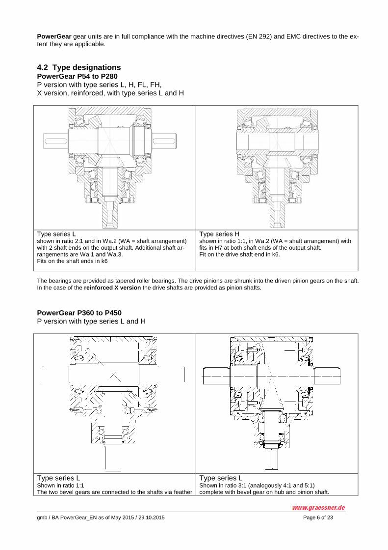
4.2 Type designations PowerGear P54 to P280 P version with type series L, H, FL, FH, X version, reinforced, with type series L and H
Type series L shown in ratio 2:1 and in Wa.2 (WA = shaft arrangement) with 2 shaft ends on the output shaft. Additional shaft ar-rangements are Wa.1 and Wa.3. Fits on the shaft ends in k6
Type series H shown in ratio 1:1, in Wa.2 (WA = shaft arrangement) with fits in H7 at both shaft ends of the output shaft. Fit on the drive shaft end in k6.
The bearings are provided as tapered roller bearings. The drive pinions are shrunk into the driven pinion gears on the shaft.
In the case of the reinforced X version the drive shafts are provided as pinion shafts.
PowerGear P360 to P450 P version with type series L and H
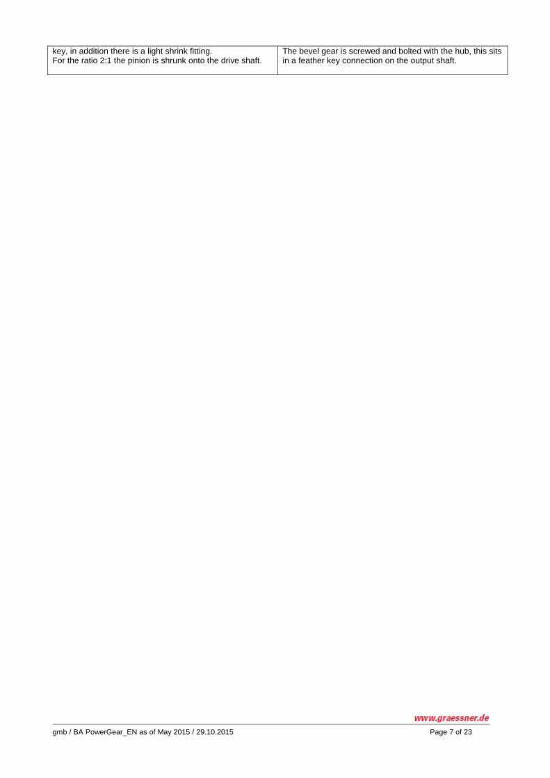
Type series L Shown in ratio 1:1 The two bevel gears are connected to the shafts via feather
Type series L Shown in ratio 3:1 (analogously 4:1 and 5:1) complete with bevel gear on hub and pinion shaft.
gmb / BA PowerGear_EN as of May 2015 / 29.10.2015 Page 7 of 23
key, in addition there is a light shrink fitting. For the ratio 2:1 the pinion is shrunk onto the drive shaft.
The bevel gear is screwed and bolted with the hub, this sits in a feather key connection on the output shaft.
gmb / BA PowerGear_EN as of May 2015 / 29.10.2015 Page 8 of 23
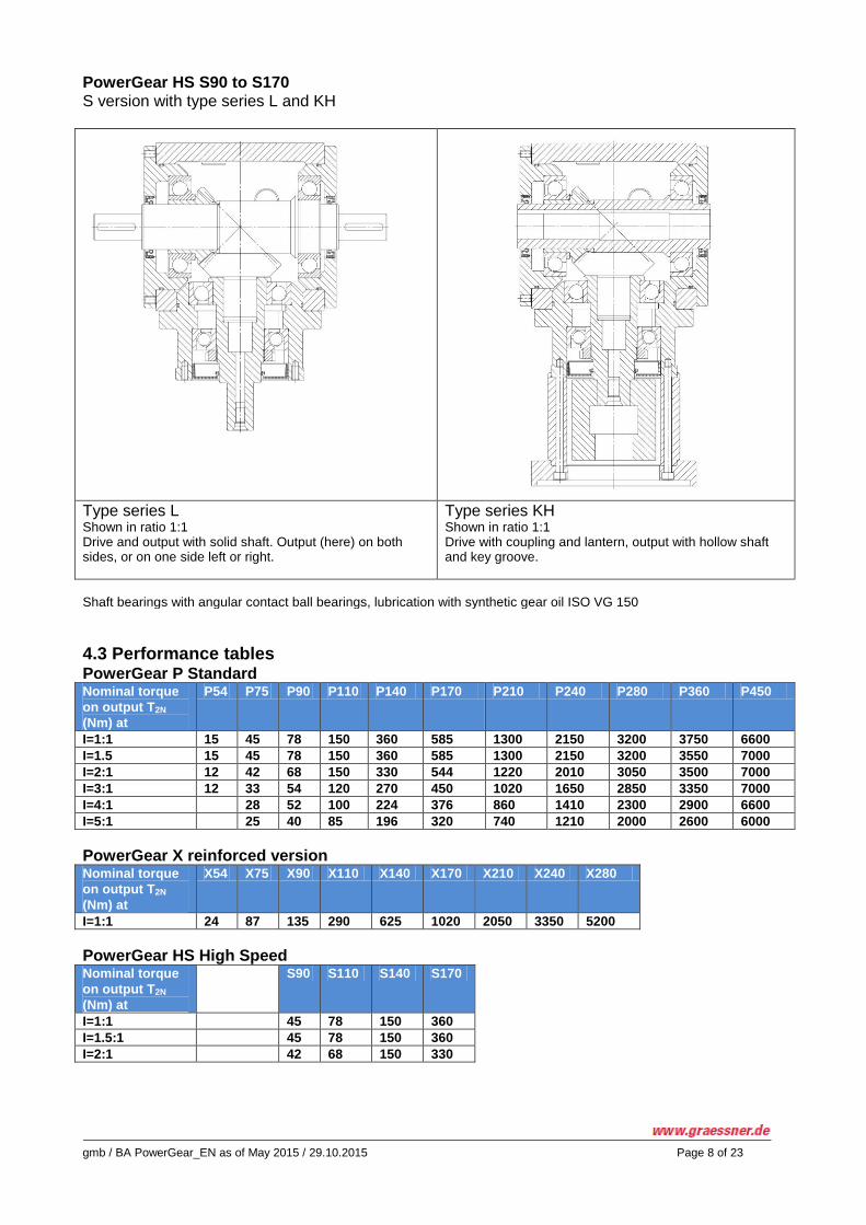
PowerGear HS S90 to S170 S version with type series L and KH
Type series L Shown in ratio 1:1 Drive and output with solid shaft. Output (here) on both sides, or on one side left or right.
Type series KH Shown in ratio 1:1 Drive with coupling and lantern, output with hollow shaft and key groove.
Shaft bearings with angular contact ball bearings, lubrication with synthetic gear oil ISO VG 150
4.3 Performance tables PowerGear P Standard Nominal torque
on output T2N
(Nm) at
P54 P75 P90 P110 P140 P170 P210 P240 P280 P360 P450
I=1:1 15 45 78 150 360 585 1300 2150 3200 3750 6600
I=1.5 15 45 78 150 360 585 1300 2150 3200 3550 7000
I=2:1 12 42 68 150 330 544 1220 2010 3050 3500 7000
I=3:1 12 33 54 120 270 450 1020 1650 2850 3350 7000
I=4:1 28 52 100 224 376 860 1410 2300 2900 6600
I=5:1 25 40 85 196 320 740 1210 2000 2600 6000
PowerGear X reinforced version Nominal torque
on output T2N
(Nm) at
X54 X75 X90 X110 X140 X170 X210 X240 X280
I=1:1 24 87 135 290 625 1020 2050 3350 5200
PowerGear HS High Speed Nominal torque
on output T2N
(Nm) at
S90 S110 S140 S170
I=1:1 45 78 150 360
I=1.5:1 45 78 150 360
I=2:1 42 68 150 330

gmb / BA PowerGear_EN as of May 2015 / 29.10.2015 Page 9 of 23
The braking as well as the emergency stop moments are shown in the performance table in the catalogue, down-
load at www.graessner.de. There you will also find the moments for the reinforced gear unit versions X54 to X280
as well as for the high speed versions S90 to S170.
4.4 Technical data PowerGear P P54 P75 P90 P110 P140 P170 P210 P240 P280 P360 P450
Running noise
at 1500min-1
Partial load in
dB(A)
70
70
74
76
77
78
80
82
83
85
85
Weight kg 1.8 4.5 8.0 13.0 22.0 38.5 71.0 103.5 155.0 240 400
Lubrication Synthetic gear oil ISO VG 150, up to size P140 with filling
Average oil
quantity in l 0.05 0.10 0.20 0.30 0.40 1.00 2.20 2.60 3.0 9.0 22.0
PowerGear X X54 X75 X90 X110 X140 X170 X210 X240 X280
Running noise
at 1500 min-1
Partial load in
dB(A)
70
70
74
76
77
78
80
82
83
Weight in kg 1.9 5.0 8.5 13.5 22.5 39.0 71.5 104.0 155.5
Lubrication Synthetic gear oil ISO VG 150, up to size P140 with filling
Average oil
quantity in l 0.05 0.10 0.20 0.30 0.40 1.00 2.20 2.60 3.00
PowerGear HS S90 S110 S140 S170
Running noise at 1500 min-1
Partial load in dB(A)
< 70
< 74
< 76
< 77
Weight in kg 4.5 8.0 13.0 22.0
Lubrication Synth. gear oil ISO VG 150
Average oil quantity in l 0.20 0.30 0.40 1.00
Operating temperatures PowerGear P and X respectively -30 to +90°C, PowerGear HS -30 to +100°C
Further technical data is shown in the catalogue
"PowerGear", download at www.graessner.de.
4.5 Type plate The type plate comprises (example):
The exact type designation P140L, the ratio 1.00:1 and the shaft arrangement Wa.13 (output on sides 1 and 3)
the article number of the gear unit 21140P000007
the serial number of the gear unit S-N.3109634
gmb / BA PowerGear_EN as of May 2015 / 29.10.2015 Page 10 of 23
Details on explosion protection area of operation / zones
gmb / BA PowerGear_EN as of May 2015 / 29.10.2015 Page 11 of 23
5. Safety notes
5.1 Basic duties The safety notes listed here are used to avoid personal injury and material damage, and must always be com-plied with and observed. For this purpose persons with responsibility for the plant as well as qualified personnel working on the gear unit under its own responsibility must have read and fully understood these operating instructions, in order - to prevent any hazards for life and limb of users and any third parties. - to provide for the operational safety of the gear unit. - to exclude downtime and environmental damage as a result of incorrect handling.
5.2 Qualified personnel means persons having relevant education and training and a professional qualification who are able to detect risks in the handling of these products and avoid possible hazards. Specialists within the meaning of these operating instructions are persons who are familiar with the set-up, me-chanical installation, fault removal and maintenance of the gear units and have the following qualifications:
Training in the field of mechanics with successfully completed professional training ( mechanic, machine fit-ter, mechatronics engineer, toolmaker)
Knowledge of these operating instructions All specialists must wear protective clothing appropriate to their activity.
5.3 Environmental protection All existing packaging material must be disposed of in accordance with regulations or recycled. When changing the oil, the used oil must be caught in suitable vessels. Any pooled oil spills must be removed immediately by means of a binding agent. Any pooled oil spills must be removed immediately by means of a binding agent. Used oil, oil binding agent or oil-contaminated cleaning cloths must be disposed of in accordance with the rele-vant environmental protection regulations.
Disposal of the gear unit following the end of its service life:
Drain oil and preservation agents completely from the gear unit and dispose of as waste oil in accordance with the applicable national regulations
Housing parts, shafts, roller bearings and geared parts must be disposed of or recycled in accordance with applicable national regulations, depending on the relevant provisions also separately.
Serious personal injury and material damage due to
incorrect use of the gear unit
incorrect installation or operation
Risk to life due to operational plant When working on the gear unit, the gear unit must always be shut down. The drive must have been secured against unintentional activation. (Keyswitch or removal of fuses). At the point of switch-on, an information sign must be affixed indicating the shut-down. The drive must have been secured against unintentional activation. (Keyswitch or removal of fuses). At the point of switch-on, an information sign must be affixed indicating the shutdown. The drive must have been secured against unintentional activation. (Keyswitch or removal of fuses). At the point of switch-on, an information sign must be affixed indicating the shut-
gmb / BA PowerGear_EN as of May 2015 / 29.10.2015 Page 12 of 23
down.
Serious personal injury and material damage due to
non-permissible removal of the necessary protective covers!
6. Transport, storage and long term storage
6.1 Transport Any work regarding transportation, storage, siting, installation, commissioning, operation, service and mainte-nance must be carried out by qualified personnel only. Any damage identified after delivery must be communicated immediately to the transport company, if appropri-ate, commissioning / activation must be excluded. The transportation of the gear unit must be effected such that personal injury and damage to the gear unit are avoided.
Danger: Immediate danger with serious bodily injury as a consequence! (Here risk of crushing for bodies or body parts)
Transportation must only be effected by means of suitable means of transportation intended for this purpose. When attaching to eye bolts this must only be carried out at the bores provided for this purpose with approved and sufficiently dimensioned means of attachment. No diagonal pull must arise. Plant-specific provisions and requirements must be complied with. Relevant national and regional regulations for safety, accident prevention and environmental protection must be complied with.
6.2 Storage conditions PowerGear - gear units must only be stored in a closed condition, in a dry, dust-free and low vibration (avoiding damage due to bearing shutdown) environment without any sun radiation at temperatures between -25 and +50°C. Series gear units can thus be stored for up to 1 year. Always check the oil level before taking the gear unit into service.
6.3 Long-term storage If storage is intended to extend for more than 1 year, the version "for long term storage" is recommended. These gear units can be stored for a period of up to 5 years maximum. External preservation is carried out by applying a permanent preserving agent. Internal preservation is carried out by applying a synthetic gear oil based on PAO. It is recommended to turn the gear units at regular intervals to ensure that the bearings do not become stuck (seize up); rotating the gear units in this way also counteracts the possible occurrence of any standstill markings and the shaft seal rings do not stick and/or become brittle.
6.4 Commissioning Before commissioning, drain the oil and replenish with fresh oil. If taken into service before the expiry of the 5 years, the function of the gear unit is assured. If commissioned at a date later than 5 years after being put into storage, the roller bearings, sealing elements and gear oil must all be replaced.
gmb / BA PowerGear_EN as of May 2015 / 29.10.2015 Page 13 of 23
7. Installation
7.1 General installation instructions The installation must only be effected by qualified, authorized and trained personnel. The safety notes in Section 3 must be complied with. When transporting the gear unit the notes in Section 6 must be complied with. Suitable crane tackle and lifting gear must be provided.
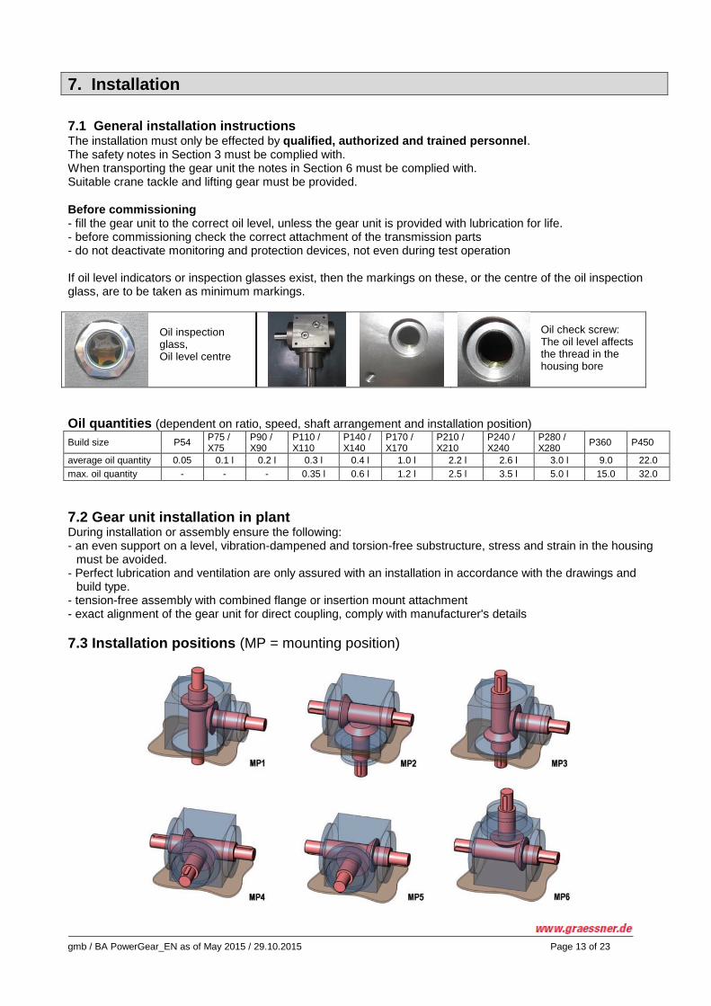
Before commissioning - fill the gear unit to the correct oil level, unless the gear unit is provided with lubrication for life. - before commissioning check the correct attachment of the transmission parts - do not deactivate monitoring and protection devices, not even during test operation If oil level indicators or inspection glasses exist, then the markings on these, or the centre of the oil inspection glass, are to be taken as minimum markings.
Oil inspection glass, Oil level centre
Oil check screw: The oil level affects the thread in the housing bore
Oil quantities (dependent on ratio, speed, shaft arrangement and installation position)
Build size P54 P75 / X75
P90 / X90
P110 / X110
P140 / X140
P170 / X170
P210 / X210
P240 / X240
P280 / X280
P360 P450
average oil quantity 0.05 0.1 l 0.2 l 0.3 l 0.4 l 1.0 l 2.2 l 2.6 l 3.0 l 9.0 22.0
max. oil quantity - - - 0.35 l 0.6 l 1.2 l 2.5 l 3.5 l 5.0 l 15.0 32.0
7.2 Gear unit installation in plant During installation or assembly ensure the following: - an even support on a level, vibration-dampened and torsion-free substructure, stress and strain in the housing
must be avoided. - Perfect lubrication and ventilation are only assured with an installation in accordance with the drawings and
build type. - tension-free assembly with combined flange or insertion mount attachment - exact alignment of the gear unit for direct coupling, comply with manufacturer's details
7.3 Installation positions (MP = mounting position)
gmb / BA PowerGear_EN as of May 2015 / 29.10.2015 Page 14 of 23
7.4 Fitting of motors The gear unit types FL and FH are equipped at the drive end with a hollow shaft complete with key groove, the
bore fitting is provided of H7 quality. The motor shaft must always be positioned and fitted such that it is in
alignment with the gear shaft. Coat shafts with assembly paste, then join up motor to the gear shaft.
Do not use a hammer to drive in motor, but use the suitable bores and threads on gear unit and motor to pull the same with mounting bolts up to the flange surfaces until the motor is in close contact. If there is stress on the bearings, the motor will spring back easily, repeat process until motor and gear unit are in stress-free contact with the flanges and the shafts can be rotated easily.
Attention damage to gear unit: If the motor is driven on by the hammer, gear unit damage may occur. Any stress and tension on the bearings may cause them to overheat and cause bearing damage with ensuing blockage.
Drive with lantern and coupling a. Preparation The surfaces of the coupling bores and the shaft ends must be free from dirt, above all from grease and oil.
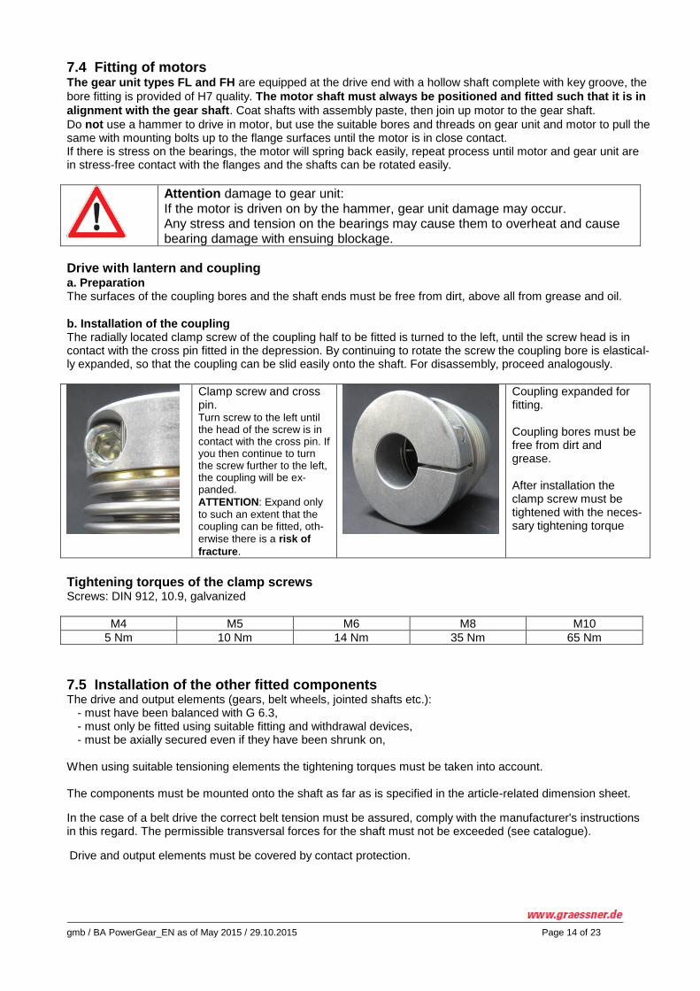
b. Installation of the coupling The radially located clamp screw of the coupling half to be fitted is turned to the left, until the screw head is in contact with the cross pin fitted in the depression. By continuing to rotate the screw the coupling bore is elastical-ly expanded, so that the coupling can be slid easily onto the shaft. For disassembly, proceed analogously.
Clamp screw and cross pin. Turn screw to the left until the head of the screw is in contact with the cross pin. If you then continue to turn the screw further to the left, the coupling will be ex-panded.
ATTENTION: Expand only to such an extent that the coupling can be fitted, oth-
erwise there is a risk of
fracture.
Coupling expanded for fitting. Coupling bores must be free from dirt and grease. After installation the clamp screw must be tightened with the neces-sary tightening torque
Tightening torques of the clamp screws Screws: DIN 912, 10.9, galvanized
M4 M5 M6 M8 M10
5 Nm 10 Nm 14 Nm 35 Nm 65 Nm
7.5 Installation of the other fitted components The drive and output elements (gears, belt wheels, jointed shafts etc.):
- must have been balanced with G 6.3, - must only be fitted using suitable fitting and withdrawal devices, - must be axially secured even if they have been shrunk on,
When using suitable tensioning elements the tightening torques must be taken into account. The components must be mounted onto the shaft as far as is specified in the article-related dimension sheet.
In the case of a belt drive the correct belt tension must be assured, comply with the manufacturer's instructions in this regard. The permissible transversal forces for the shaft must not be exceeded (see catalogue).
Drive and output elements must be covered by contact protection.
gmb / BA PowerGear_EN as of May 2015 / 29.10.2015 Page 15 of 23
7.6 Finishing work - Before fitting protective covers check again the correct oil level in the gear unit. - Check for even running free from strains, stresses and any faults. - Fit protective covers. - Carefully clear away all tools as well as any parts not fitted.
Attention:
Due to incorrect installation the gear unit can be damaged and become unusa-ble. Such damage may be caused by falling objects, dumping, welding work or insufficient attachment. Due to incorrect installation the gear unit can be damaged and become unusable. Such damage may be caused by falling objects, dumping, welding work or insuf-ficient attachment. The operator must ensure:
The gear unit must be protected against any falling objects and dumping.
Welding work must not be carried lout on any part of the drive.
The gear unit must not be used as a ground point for electric welding work.
All mounting options assigned to the build type must be used.
Any screws that have become unusable during assembly and disassembly must be replaced by new ones featuring the same design and strength class.
Attention damage to gear unit: Impacts or shocks during the mounting of the coupling may cause damage inside the gear unit. Fit couplings with pull-on devices. The shaft seal rings and the running surfaces of the shafts must not be damaged when fitting the coupling parts.
gmb / BA PowerGear_EN as of May 2015 / 29.10.2015 Page 16 of 23
8. Commissioning
- The commissioning (taking up operation in accordance with the intended use) of the PowerGear gear unit is prohibited until it has been determined that the machine or plant complies with the provisions of the EU machine directive.
- Before commissioning check the correct attachment of the transmission parts. - Check oil level - Do not deactivate monitoring and protection devices, not even during test operation.
- The use of an aeration and ventilation filter is not necessary for gear units up to P110 / X110 , for gear
units from P140 / X140 we recommend its use, as soon as the gear units exceed an operating tempera-
ture of 60°C. The first start-ups must be carried out without load and at low speeds, until it is ensured that all roller bearings, bevel gears and shaft seals are wetted with oil, then increase speed to approx. 500 min
-1
After approx. 30 min. slowly increase speeds until operational speed is reached, running-in time at idle approx. 90 minutes. - During start-up and run-up pay attention to running noise and temperature development, in particular at the
bearing points. In the case of unusual running noise, shut down machine and identify fault. See Section 10: "Faults, causes and remedies."
Apparent leakage at the shaft seal rings
Grease emerging from the lubrication in the shaft seal rings does not represent an oil leak. This is an apparent
leakage, until the remaining lubricant has become regulated. Wipe off any such apparent leakage and continue to observe.
Attention damage to gear unit: If the new gear unit is started up too rapidly, this may cause bearings to overheat, as well as cause insufficient lubrication on the gear flanks! It is necessary to allow the gear unit to run-in in stages!
Warning: Risk of burns! Serious burns possible on hot surfaces (>55°C). Wear suitable gloves and protective clothing.
gmb / BA PowerGear_EN as of May 2015 / 29.10.2015 Page 17 of 23
9. Operation of Power Gear
9.1 General notes on operation The notes at item 1 "General safety notes", item 10 "Faults, causes and remedies", and item 11 "Inspection and maintenance" must be complied with.
In order to achieve a perfect trouble-free operation of the gear unit, the operating factors defined in the "Tech-nical Data" must be complied with.
9.2 During operation monitor the following: Operating temperature
When using mineral gear oils (CLP) the operating temperature should not exceed 80°C or only exceed this limit for a short temporary time period. When using synthetic gear oils (CLP) an operating temperature - in connection with sealing rings made of FKM (fluorinated rubber, viton) - of temporarily 110°C is permissible.
Changing gear unit noises, vibrations
Oil leakage on the housing and on the shaft seal rings
Oil level – for oil level checking the gear unit must be shut down. Check oil levels only with the gear unit in a cooled down condition:
If an oil inspection glass is available, the oil level shown must be at the centre of the oil inspection glass
Without oil inspection glass, the check is performed at the screw plug of a vertically positioned hous-ing surface. The oil level must be in contact with then thread in the housing (see page 11, Section 7.1)
Attention: Insufficient lubrication caused by an excessively low oil level may cause damage to the geared parts and the bearings! Carry out a regular oil level check
Warning: Serious burns possible on hot surfaces (>55°C) Wear suitable gloves and protective clothing
9.3 Irregularities In the event of any changes in relation to standard operation, e.g. increased temperatures, noises, vibrations, the gear unit must be shut down in any case of doubt so that the cause of such changes can be determined. See Section 10: "Faults, causes, remedy." If necessary, contact our service department for consultations.
gmb / BA PowerGear_EN as of May 2015 / 29.10.2015 Page 18 of 23
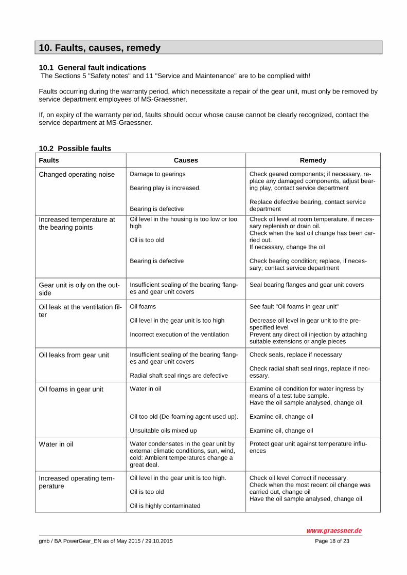
10. Faults, causes, remedy
10.1 General fault indications The Sections 5 "Safety notes" and 11 "Service and Maintenance" are to be complied with! Faults occurring during the warranty period, which necessitate a repair of the gear unit, must only be removed by service department employees of MS-Graessner. If, on expiry of the warranty period, faults should occur whose cause cannot be clearly recognized, contact the service department at MS-Graessner.
10.2 Possible faults
Faults Causes Remedy
Changed operating noise Damage to gearings Bearing play is increased. Bearing is defective
Check geared components; if necessary, re-place any damaged components, adjust bear-ing play, contact service department Replace defective bearing, contact service department
Increased temperature at the bearing points
Oil level in the housing is too low or too high Oil is too old Bearing is defective
Check oil level at room temperature, if neces-sary replenish or drain oil. Check when the last oil change has been car-ried out. If necessary, change the oil Check bearing condition; replace, if neces-sary; contact service department
Gear unit is oily on the out-side
Insufficient sealing of the bearing flang-es and gear unit covers
Seal bearing flanges and gear unit covers
Oil leak at the ventilation fil-ter
Oil foams Oil level in the gear unit is too high Incorrect execution of the ventilation
See fault "Oil foams in gear unit" Decrease oil level in gear unit to the pre-specified level Prevent any direct oil injection by attaching suitable extensions or angle pieces
Oil leaks from gear unit Insufficient sealing of the bearing flang-es and gear unit covers Radial shaft seal rings are defective
Check seals, replace if necessary Check radial shaft seal rings, replace if nec-essary.
Oil foams in gear unit
Water in oil Oil too old (De-foaming agent used up). Unsuitable oils mixed up
Examine oil condition for water ingress by means of a test tube sample. Have the oil sample analysed, change oil. Examine oil, change oil Examine oil, change oil
Water in oil Water condensates in the gear unit by external climatic conditions, sun, wind, cold: Ambient temperatures change a great deal.
Protect gear unit against temperature influ-ences
Increased operating tem-perature
Oil level in the gear unit is too high. Oil is too old Oil is highly contaminated
Check oil level Correct if necessary. Check when the most recent oil change was carried out, change oil Have the oil sample analysed, change oil.
gmb / BA PowerGear_EN as of May 2015 / 29.10.2015 Page 19 of 23
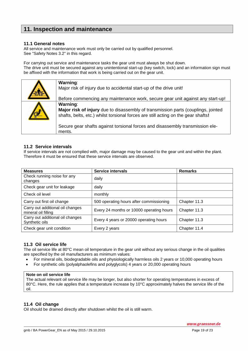
11. Inspection and maintenance
11.1 General notes All service and maintenance work must only be carried out by qualified personnel. See "Safety Notes 3.2" in this regard. For carrying out service and maintenance tasks the gear unit must always be shut down. The drive unit must be secured against any unintentional start-up (key switch, lock) and an information sign must be affixed with the information that work is being carried out on the gear unit.
Warning: Major risk of injury due to accidental start-up of the drive unit! Before commencing any maintenance work, secure gear unit against any start-up!
Warning:
Major risk of injury due to disassembly of transmission parts (couplings, jointed
shafts, belts, etc.) whilst torsional forces are still acting on the gear shafts!
Secure gear shafts against torsional forces and disassembly transmission ele-ments.
11.2 Service intervals If service intervals are not complied with, major damage may be caused to the gear unit and within the plant. Therefore it must be ensured that these service intervals are observed.
Measures Service intervals Remarks
Check running noise for any changes
daily
Check gear unit for leakage daily
Check oil level monthly
Carry out first oil change 500 operating hours after commissioning Chapter 11.3
Carry out additional oil changes mineral oil filling
Every 24 months or 10000 operating hours Chapter 11.3
Carry out additional oil changes Synthetic oils
Every 4 years or 20000 operating hours Chapter 11.3
Check gear unit condition Every 2 years Chapter 11.4
11.3 Oil service life The oil service life at 80°C mean oil temperature in the gear unit without any serious change in the oil qualities are specified by the oil manufacturers as minimum values:
For mineral oils, biodegradable oils and physiologically harmless oils 2 years or 10,000 operating hours
For synthetic oils (polyalphaolefins and polyglycols) 4 years or 20,000 operating hours
Note on oil service life The actual relevant oil service life may be longer, but also shorter for operating temperatures in excess of 80°C. Here, the rule applies that a temperature increase by 10°C approximately halves the service life of the oil.
11.4 Oil change Oil should be drained directly after shutdown whilst the oil is still warm.
gmb / BA PowerGear_EN as of May 2015 / 29.10.2015 Page 20 of 23
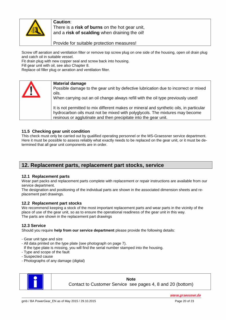
Caution:
There is a risk of burns on the hot gear unit,
and a risk of scalding when draining the oil! Provide for suitable protection measures!
Screw off aeration and ventilation filter or remove top screw plug on one side of the housing, open oil drain plug and catch oil in suitable vessel. Fit drain plug with new copper seal and screw back into housing. Fill gear unit with oil, see also Chapter 8. Replace oil filler plug or aeration and ventilation filter.
Material damage Possible damage to the gear unit by defective lubrication due to incorrect or mixed oils. When carrying out an oil change always refill with the oil type previously used!
It is not permitted to mix different makes or mineral and synthetic oils, in particular hydrocarbon oils must not be mixed with polyglycols. The mixtures may become resinous or agglutinate and then precipitate into the gear unit.
11.5 Checking gear unit condition This check must only be carried out by qualified operating personnel or the MS-Graessner service department. Here it must be possible to assess reliably what exactly needs to be replaced on the gear unit, or it must be de-termined that all gear unit components are in order.
12. Replacement parts, replacement part stocks, service
12.1 Replacement parts Wear part packs and replacement parts complete with replacement or repair instructions are available from our service department. The designation and positioning of the individual parts are shown in the associated dimension sheets and re-placement part drawings.
12.2 Replacement part stocks We recommend keeping a stock of the most important replacement parts and wear parts in the vicinity of the place of use of the gear unit, so as to ensure the operational readiness of the gear unit in this way. The parts are shown in the replacement part drawings
12.3 Service Should you require help from our service department please provide the following details: - Gear unit type and size - All data printed on the type plate (see photograph on page 7).
If the type plate is missing, you will find the serial number stamped into the housing. - Type and scope of the fault - Suspected cause - Photographs of any damage (digital)
Note
Contact to Customer Service see pages 4, 8 and 20 (bottom)
gmb / BA PowerGear_EN as of May 2015 / 29.10.2015 Page 21 of 23
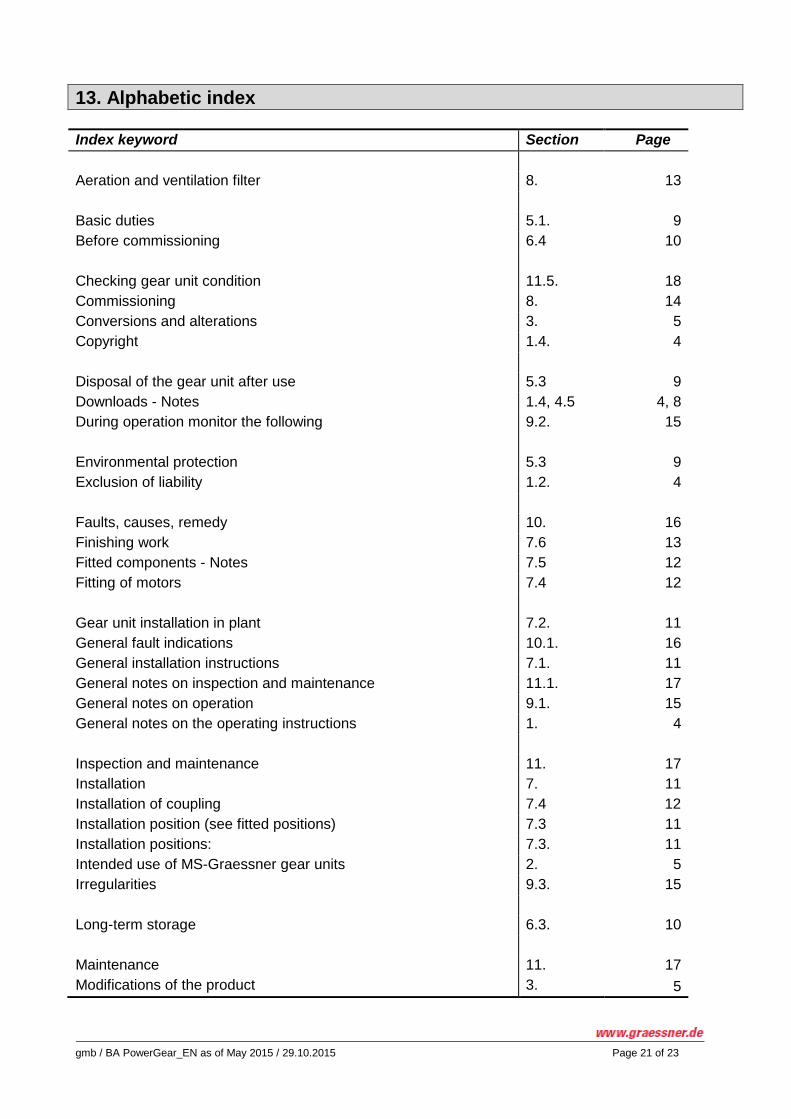
13. Alphabetic index
Index keyword Section Page
Aeration and ventilation filter 8. 13
Basic duties 5.1. 9
Before commissioning 6.4 10
Checking gear unit condition 11.5. 18
Commissioning 8. 14
Conversions and alterations 3. 5
Copyright 1.4. 4
Disposal of the gear unit after use 5.3 9
Downloads - Notes 1.4, 4.5 4, 8
During operation monitor the following 9.2. 15
Environmental protection 5.3 9
Exclusion of liability 1.2. 4
Faults, causes, remedy 10. 16
Finishing work 7.6 13
Fitted components - Notes 7.5 12
Fitting of motors 7.4 12
Gear unit installation in plant 7.2. 11
General fault indications 10.1. 16
General installation instructions 7.1. 11
General notes on inspection and maintenance 11.1. 17
General notes on operation 9.1. 15
General notes on the operating instructions 1. 4
Inspection and maintenance 11. 17
Installation 7. 11
Installation of coupling 7.4 12
Installation position (see fitted positions) 7.3 11
Installation positions: 7.3. 11
Intended use of MS-Graessner gear units 2. 5
Irregularities 9.3. 15
Long-term storage 6.3. 10
Maintenance 11. 17
Modifications of the product 3. 5
gmb / BA PowerGear_EN as of May 2015 / 29.10.2015 Page 22 of 23
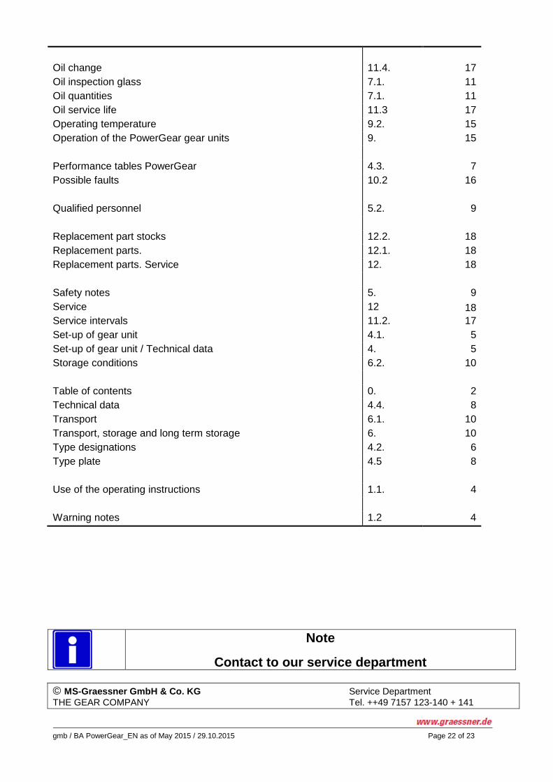
Oil change 11.4. 17
Oil inspection glass 7.1. 11
Oil quantities 7.1. 11
Oil service life 11.3 17
Operating temperature 9.2. 15
Operation of the PowerGear gear units 9. 15
Performance tables PowerGear 4.3. 7
Possible faults 10.2 16
Qualified personnel 5.2. 9
Replacement part stocks 12.2. 18
Replacement parts. 12.1. 18
Replacement parts. Service 12. 18
Safety notes 5. 9
Service 12 18
Service intervals 11.2. 17
Set-up of gear unit 4.1. 5
Set-up of gear unit / Technical data 4. 5
Storage conditions 6.2. 10
Table of contents 0. 2
Technical data 4.4. 8
Transport 6.1. 10
Transport, storage and long term storage 6. 10
Type designations 4.2. 6
Type plate 4.5 8
Use of the operating instructions 1.1. 4
Warning notes 1.2 4
Note
Contact to our service department
© MS-Graessner GmbH & Co. KG Service Department
THE GEAR COMPANY Tel. ++49 7157 123-140 + 141
gmb / BA PowerGear_EN as of May 2015 / 29.10.2015 Page 23 of 23
Kuchenaecker 11 Fax ++49 7157 123-220 D-72135 Dettenhausen Email: [email protected] www.graessner.de