analysis of spur and straight bevel gear teeth deflection by the finite strip method
TRANSCRIPT

ANALYSIS OF SPUR AND STRAIGHT BEVEL GEAR TEETH DEFLECTION BY THE
FINITE STRIP METHOD
Philippe Gagnon1, Claude Gosselin2 and Louis Cloutier2 1 Ph.D. candidate
2 Professor
Department of Mechanical Engineering
Laval University
Québec Canada G1K-7P4
Abstract A linear Finite Strip element for the analysis of rectangular and annular sector
thick plates is presented to permit the deflection analysis of spur and straight bevel gear teeth,
which are respectively modeled as rectangular and annular sector cantilever plates. Plate
deflections are obtained by a hybrid procedure based on the minimum total potential energy
theorem, which retains advantages of both the orthotropic-plate method and the Finite Element
concept and is called the Finite Strip Method. The formulation accounting for transverse shear
deformation is based on Mindlin’s plate theory. Since the presented Finite Strip element supports
any combination of continuous thickness variations, the true shape of the tooth is used in the
solution. The formulation can be easily applied to any boundary conditions and supports any type
and combination of transverse loads and moments. Application of the Finite Strip Method to
predict the deflection of spur and straight bevel gear teeth is demonstrated and results are
compared to those obtained by the Finite Element Method.
NOMENCLATURE
a strip length
aim vector of nodal parameters of node i and function m
b strip width
[ ]Bim strain displacement matrix for nodal line i and mth series term
2
[ ]D elasticity matrix
Dx , Dy flexural rigidities
Dxy torsion rigidity
D1 coupling rigidity
f im load vector for nodal line i and mth series term
Gx, Gy transverse shear rigidities
h node spacing
[ ]ki jm n,
, finite strip stiffness matrix for terms m, n and nodal lines i, j
N number of strips
Ni shape function for nodal line i
q transverse loading per unit area
R number of nodes
Ri inner radius
Ro outer radius
t plate thickness
w transverse displacement
α shear strain correction factor
β rotation due to transverse shear
δ displacement function
ε generalized strain vector
φmw mth term of transverse displacement series
φθmx mth term of nodal rotation series in x-direction
φθmy mth term of nodal rotation series in y-direction
φθmr mth term of nodal rotation series in r-direction
φθλm mth term of nodal rotation series in λ-direction
Φim mth term of displacement function for nodal line i
ν Poisson’s ratio
θx nodal rotation in x-direction

3
θy nodal rotation in y-direction
θr nodal rotation in r-direction
θλ nodal rotation in λ-direction
ξ local coordinate.
1.0 INTRODUCTION
The knowledge of gear tooth deflection under load is an important factor in gear design as
it is needed to calculate tooth profile relief, tooth load sharing, accurate bearing pattern under
load and vibratory characteristics.
Gear tooth deflections under load was investigated by many authors: Baud and Peterson
[3] were among the first to derive an analytical formulation for the deflection of a gear tooth;
they were followed by Walker, Weber, Attia and Cornell [26, 27, 2, 10] who presented more
complete solutions. Among the different approaches to predict the displacement field on a loaded
gear tooth, the cantilever plate theory was used by Wellauer and Seireg [28] and Tobe, Kato and
Inoue [23]. Cardou and Tordion [5] also presented valuable results using the Complex Potential
Method. The arrival of the Finite Element Method (FEM) offered another approach as in the
work done by Muthukumar and Raghavan [19]. Finally, the latest work by Vaidyanathan, Busby
and Houser [25] combined a numerical procedure based on the Rayleigh-Ritz method applied to
the cantilever plate theory to determine the flexural behavior of a gear tooth. In this last case,
tooth thickness was assumed to vary linearly in all directions.
FEM is now well established as a powerful and reliable tool, and is frequently used as a
reference to calibrate other numerical, analytical and experimental results. However, FEM is a
computationally intensive tool to use because of the pre and post-processing required, and
computer resources grow rapidly with the required precision level. To obtain reliable results in a
short time, a fast and accurate analysis method less demanding on computer resources and data
input is required.

4
In 1968 and 1969, Cheung [7] and, independently, Powell and Ogden [21], introduced the
Finite Strip Method (FSM). This method can be considered as a special case of the FEM.
Basically, it is a hybrid procedure retaining the advantages of both the orthotropic-plate method
and the Finite Element concept. In short, the Finite Strip is a 2-D element for the analysis of
plates, based on simple polynomial functions in one direction, and continuously differentiable
smooth series in the other direction. As a consequence of this simple formulation, less computer
resource is needed without loss of precision.
The FSM was substantially improved after its introduction in 1968. Boundary conditions
other than simple supports were introduced, and different applications to bridges were made
while free vibration and stability of thin plates were in development. In 1974, Mawenya and
Davies [16] included the effect of transverse shear to apply the FSM to thick, thin and sandwich
plates, which lead to applying this technique to thick plate free vibration and stability.
To overcome problems caused by boundary conditions and concentrated loads, the cubic-
spline FSM was introduced by Cheung, Fan and Wu [9]. In 1988, FSM thin plates with variable
thickness in the longitudinal direction were treated by Uko and Cusens [24]. Recently, Arbabi
and Li [1] presented a macrostrip for the analysis of plate systems with transverse stiffness step
changes. The thick plate formulation was also applied to annular sectorial plates of constant and
tapered thickness respectively by Cheung and Chan [6] and Mizusawa and Takami [18].
This paper presents the analysis of spur and bevel gear teeth, respectively modeled as
rectangular and annular sector cantilever thick plates, by the Finite Strip Method. The FSM
variant presented here is based on Mindlin’s theory [17] and uses cubic-spline series as
displacement functions which, combined to numerical integration in both directions, enable the
use of the tooth exact shape. Its simplicity and speed compared to those of FEM make it an
interesting tool for the analysis of gear tooth deflections. Gear tooth neutral plane displacements
obtained by the FSM are compared to those obtained by 3-D FEM.
5
2.0 THICK PLATE FINITE STRIP FORMULATION
Originally, Finite Strip elements were based on the classical thin plate theory of Kirchoff
and were therefore limited to the analysis of thin plates. To extend the application to thick plates,
Mindlin’s theory is used.
2.1 Rectangular strip
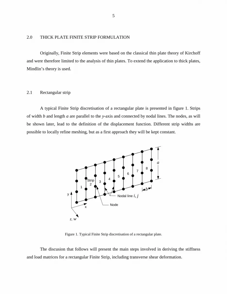
A typical Finite Strip discretisation of a rectangular plate is presented in figure 1. Strips
of width b and length a are parallel to the y-axis and connected by nodal lines. The nodes, as will
be shown later, lead to the definition of the displacement function. Different strip widths are
possible to locally refine meshing, but as a first approach they will be kept constant.
12
z, w
x
y Nodal line i, j
Strip 34
56
78
Node
a
b
Figure 1. Typical Finite Strip discretisation of a rectangular plate.
The discusion that follows will present the main steps involved in deriving the stiffness
and load matrices for a rectangular Finite Strip, including transverse shear deformation.

6
The displacement function δ for a linear strip is expressed as the sum of a series of l terms
as:
δ ===åå Φi
m
im
l
ima
1
2
1
(1)
where Φim is a combination of polynomial Ni and series φm
w, φθmx and φθmy :
Φim
i mw
i m
i m
N
N
N
x
y
=
é
ë
êêêê
ù
û
úúúú
φ
φ
φ
θ
θ
0 0
0 0
0 0
(2)
Using Mindlin’s plate theory and referring to figure 2, the mid-plane displacement vector
is:
[ ]δ θ θ= w x yT
, , (3)
and the vector of nodal parameters of node i for the mth function:
[ ]a wim
im
xim
yim T
= , ,θ θ (4)
7
The generalized strain vector ε can be expressed as:
ε∂θ∂
∂θ
∂∂θ∂
∂θ
∂∂∂
θ∂∂
θ= - - - +æèç
öø÷
- -é
ëê
ù
ûúx y x y
x y
T
x y y xwx
wy
, , , , (5)
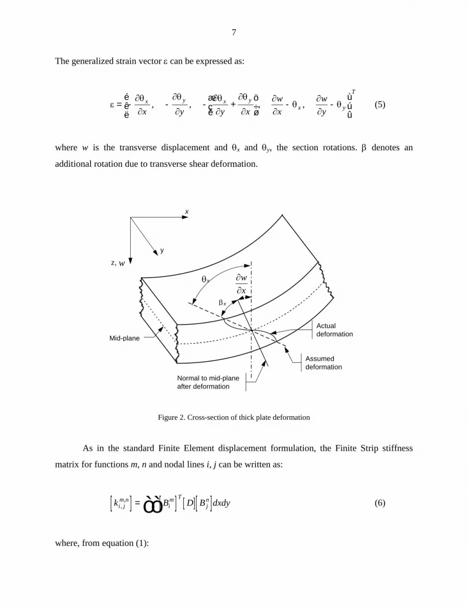
where w is the transverse displacement and θx and θy, the section rotations. β denotes an
additional rotation due to transverse shear deformation.
Mid-plane
Actualdeformation
Assumeddeformation
Normal to mid-planeafter deformation
x
z, wy
θx
βx
∂∂wx
Figure 2. Cross-section of thick plate deformation
As in the standard Finite Element displacement formulation, the Finite Strip stiffness
matrix for functions m, n and nodal lines i, j can be written as:
[ ] [ ] [ ] [ ]k B D B dxdyi jm n
im T
jn
,, = òò (6)
where, from equation (1):

8
[ ]B
Nx
Ny
Ny
Nx
Nx
N
Ny
N
im
im
im
im i
m
imw
i m
imw
i m
x
y
xy
x
y
=
-
-
- -
-
-
é
ë
êêêêêêêêêêêê
ù
û
úúúúúúúúúúúú
0 0
0 0
0
0
0
∂∂
φ
∂φ∂
∂φ∂
∂∂
φ
∂∂
φ φ
∂φ∂
φ
θ
θ
θθ
θ
θ
(7)
and:
[ ]D
D D
D D
D
G t
G t
x
y
xy
x
y
=
é
ë
êêêêêêêê
ù
û
úúúúúúúú
1
1
0 0 0
0 0 0
0 0 0 0
0 0 0 0
0 0 0 0
α
α
(8)
Dx, Gx, etc. are the standard plate flexural and shear rigidities, α is the shear strain correction
factor set to 1 and t is the plate thickness.
The terms of the Finite Strip stiffness matrix are obtained by a double integration in the x
and y-directions.
The load vector for function m and nodal line i is obtained as follows:
f q dx dyim
im= òòΦ (9)

9
where transverse load q is a function of x and y, and can be localized or distributed. Forces and
moments about axes x and y are respectively applied using the first, second and third column
terms of matrix [ ]Φim in equation (2).
Individual Finite Strip stiffness matrices, nodal parameter vectors and load vectors are
assembled in the usual manner to form the global equation:
[ ] { } { }K a f= (10)
Solving this system yields the nodal parameters. Introducing the solution in equation (1)
directly gives displacements for any strip.
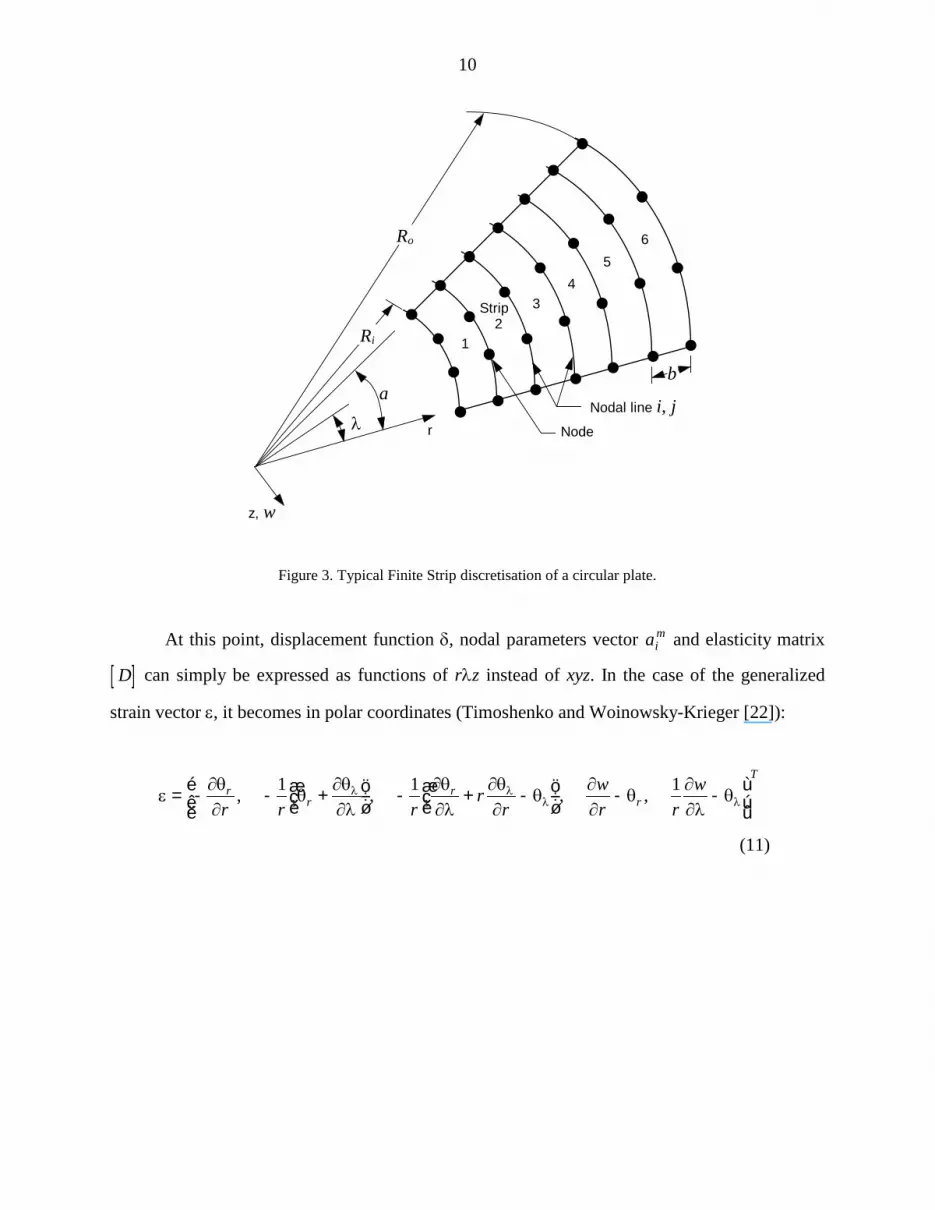
2.2 Curved strip
To deal with curved plates, the formulation presented above is extended such that all
equations are expressed in polar coordinates. Figure 3 presents a typical Finite Strip
discretisation of a circular plate. Coordinates x and y are respectively replaced by r and λ, strip
width b is along radius r, length a now corresponds to the sector angle and plate total width is the
difference between outer and inner radii Ro and Ri.
10
12
34
56
z, w
rλ
Strip
Nodal line i, jNode
ba
Ri
Ro
Figure 3. Typical Finite Strip discretisation of a circular plate.
At this point, displacement function δ, nodal parameters vector aim and elasticity matrix
[ ]D can simply be expressed as functions of rλz instead of xyz. In the case of the generalized
strain vector ε, it becomes in polar coordinates (Timoshenko and Woinowsky-Krieger [22]):
ε∂θ∂
θ∂θ∂λ
∂θ∂λ
∂θ∂
θ∂∂
θ∂∂λ
θλ λλ λ= - - +æ
èçöø÷
- + -æèç
öø÷
- -éëê
ùûú
rr
rr
T
r r rr
rwr r
w, , , ,1 1 1
(11)

11
Thus, matrix [ ]Bim in equation (7) is replaced by:
[ ]B
Nr
Nr
N
Nr
Nr
Nr
Nr
N
Nr
N
im
im
im i
m
i m im
im
imw
i m
i mw
i m
r
r
r
r
=
-
- -
- - +
-
-
é
ë
êêêêêêêêêêê
ù
û
úúúúúúúúúúú
0 0
0
0
0
0
∂∂
φ
φ∂φ∂λ
∂φ∂λ
∂∂
φ φ
∂∂
φ φ
∂φ∂λ
φ
θ
θθ
θθ θ
θ
θ
λ
λ λ
λ
(12)
The Finite Strip stiffness matrix in the rλz coordinate system is given by:
[ ] [ ] [ ] [ ]k B D B r d dri jm n
im T
jn
,, = òò λ (13)
and the load vector for a circular strip is obtained as follows:
f q r d drim
im= òòΦ λ (14)
As before, individual Finite Strip stiffness matrices, nodal parameters vectors and load
vectors can be assembled to form the global system.
3.0 DISPLACEMENT FUNCTIONS
The accuracy and efficiency of the FSM lies in the choice of a suitable displacement
function δ (equation (1)). As stated before Φim is a combination of polynomial Ni and series φm
w,
φθmx and φθmy . This function must satisfy a priori the boundary conditions of the strip and must

12
deal with thickness variations in the x and y directions. As a result, the following polynomials
and series are considered.
It is important to note at this point that all the functions presented in this section are
expressed in the xyz coordinate system. Transfer to the polar coordinate system rλz is simply
done by replacing the corresponding variables.
First, in the transverse direction, simple linear functions are used (figure 4) which respect
C0-continuity between strip-elements and were found by Oñate and Suarez [20] to be the best
compromise for the formulation of thick Finite Strips.
ξ
z, wN1 1= - ξ
N2 = ξ
bStrip i
Figure 4. Shape function.
The longitudinal direction displacement function is a cubic-spline series (Burdon and
Douglass Faires [4]). Such series have been used successfully for the analysis of variable
thickness thin plates by Uko and Cusens [24]. Also, excellent results were obtained using cubic-
splines for the analysis of bi-directional thickness variation thick plates by Gagnon, Gosselin and
Cloutier [12]. Due to their localized character, these functions can easily adapt to thickness
variations and

13
modifications are easily done to satisfy different boundary conditions. The cubic-spline (figure
5(a)) ensures C2-continuity and is formulated as:
φ i =
( )( )( )( ) ( )( ) ( )( )
( )( ) ( )( ) ( )( )( )( )
16
0 2
2 2 1
3 1 3 1 3 1 1
3 1 3 1 3 1 1
2 1 2
0 2
3
3
3 2 2 3
3 2 2 3
3
h
y i h
y i h i h y i h
h h y i h h y i h y i h i h y ih
h h i h y h i h y i h y ih y i h
i h y i h y i h
i h y
< -
- - - £ < -
+ - - + - - - - - - £ <
+ + - + + - - + - £ < +
+ - + £ £ +
+ <
ì
í
ïïïïï
î
ïïïïï
( )
( ) ( )
( )
( )
( ) ( )
( )
(15)
h h y
z, w φi
h h
φ i1 φ i
4
φ i2 φ i
3
(a)
h y
z, wφ0
h
φi
h h
φiφi
h
φi
h
φ2
h
φ1φ-1
h
φR-2 φR-1 φR φR+1
a
(b)
Figure 5. Cubic spline displacement function (a) and function series (b).

14
4.0 APPLICATION TO SPUR AND STRAIGHT BEVEL GEAR TEETH
As stated before, the analysis of spur and bevel gear teeth is done by assuming that a gear
tooth is a cantilever thick plate of varying thickness, where the plate is modeled by the Finite
Strip Method.
To do so, a Finite Strip mesh is generated. The height and width of the mesh correspond
to the tooth neutral plane dimensions as shown in figures 6 and 7. Rectangular strips are used for
the spur gear tooth and curved strips for the bevel gear tooth. To complete the model, true tooth
thickness is directly inserted in the elasticity matrix (equation (8)) and the displacement function
(equation (2)) is modified according to the desired boundary conditions.
It is interesting to note that curved strips have been tested for the spur gear tooth case by
using a large inner radius combined to a small angle, such that the mesh is quasi-rectangular.
Finite strips
xy
Figure 6. Spur gear tooth and a corresponding typical Finite Strip mesh and coordinate system.

15
z, w
Finite strips
λ
r
Figure 7. Bevel gear tooth and a corresponding typical Finite Strip mesh and coordinate system.
For boundaries parallel to the x-axis, the boundary conditions are defined as:
Free: M M Qy xy y= = = 0
Simply supported: M wy x= = =θ 0
Clamped: w x y= = =θ θ 0
and would be the same for boundaries parallel to the r-axis.

16
The series can easily be adapted to satisfy different boundary conditions, as shown in
table 1.
Boundary condition at node 0
Free Simple
Clamped
φw, φθx , φθy φw, φθx φθy φw, φθx , φθy φ-1 = φ-1 0 φ-1 0
φ0 = φ0 φ0 - 4φ-1 φ0 φ0 - 4φ-1
φ1 = φ1 φ1 - φ-1 φ1 φ1 - φ-1
Table 1. Amendment scheme for cubic-spline function series.
As figure 6 shows, it is obvious that the needed boundary conditions for the Finite Strips
correspond to a clamped edge along the x-axis at y = 0; all other edges are free for the spur gear;
for the bevel gear case of figure 7, the same conclusion can be drawn except that the clamped
edge is along the r-axis at λ = 0.
Figure 8 shows a six noded rectangular strip for the needed clamped-free case where
functions have been modified to satisfy the clamped-end condition. It is interesting to note that
the clamped-end condition allows the use of the same series for all displacement parameters w, θx
and θy.

17
Nodal line i
Nodal line jx
y
Clamped Free
wθx
θy
φ1 φ2 φ3 φ4 φ5φ0 φ6
Cubic functions
Figure 8. Displacement function for a clamped-free strip.
5.0 NUMERICAL TECHNIQUES
Numerical integration of the Finite Strip stiffness matrix (equation (6) and (13)) is
performed using Gaussian quadrature (Dhatt and Touzot [11] and Imbert [14]). As stated before,
the exact geometry of the tooth is directly inserted in elasticity matrix [D] (equation (8)). True
thickness is then used at all integration points in both transverse and longitudinal directions,
allowing the true shape to be considered instead of an approximated step shape.
The Finite Strip stiffness matrix [ ]ki jm n,
, (equation (6) and (13)) is a 6 × 6 matrix where, of
the 36 terms, only 18 must be calculated when m = n and 25 when m ≠ n because of the
similarities.
The global stiffness matrix [K] is symmetrical. Accordingly, only the terms of the upper
triangle must be calculated. Simple Gaussian elimination, without pivoting, can be used to solve
the global system since matrix [K] is positive definite.
6.0 EXAMPLE

18
Results obtained by the FSM and FEM for a spur and a straight bevel gear tooth are
presented. The geometric parameters of the gears are shown in table 2. The corresponding
geometries for the Finite Strip and Finite Element Analysis were generated using a gear
simulation software (Gosselin and Cloutier [13]).
Spur Gear Bevel Gear
Module (mm-1) 3,175 5,08
Tooth Number 28 x 28 28 x 28
Pressure Angle (°) 20 20
Addendum 3,175 mm 2,89°
Dedendum 4,011 mm 3,44°
Facewidth (mm) 25,4 25,4
Cone Angle (°) 45
Table 2. Gearset geometric parameters.

19
From figures 1, 3, 6 and 7 and the tooth geometric parameters, the dimensions indicated
in table 3 are obtained for the Finite Strip and Finite Element meshes.
Spur Gear Bevel Gear
a 7,39 mm 6,434°
Ri N/A 75,26 mm
Ro N/A 100,66 mm
(Ri + Ro) / 2 N/A 87,96 mm
Table 3. Gear tooth Finite Strip and Finite Element mesh dimensions.
A 1000 N distributed load is applied normal to the surface along the tooth tip edge (39,37
N/mm) as shown in figure 9. The Finite Element Method 3-D meshes use parabolic Hex/20
elements as is shown in figure 9.
xy
z
rλz
(a) (b) Figure 9. Finite Element model and load of the spur (a) and bevel (b) gear tooth.

20
Since the Finite Strip mesh is 2-D, the applied load was converted into an equivalent
transverse force in the z-direction and a moment about the x or r-axis. The equivalent moment
about the r-axis is variable due to the bevel gear tooth thickness variation in the r-direction.
Mesh density used for all FSM calculations is 6 strips of 4 nodes each, which corresponds
to the minimal density to obtain excellent convergence in the considered load case. Solution time
was 3 seconds for the spur gear mesh and 46 seconds for the bevel gear on a 486 personal
computer.
6.1 Spur gear tooth results
Comparison of the FEM and FSM displacement results on the neutral plane of the spur
gear tooth is shown in figure 10. Figures (a) and (b) respectively give the results along a line
parallel to the x-axis at the tip of the tooth (y = 7,39 mm) and along a line parallel to the y-axis at
mid-tooth (x = 12,7 mm).
0
0.2
0.4
0.6
0.8
1
1.2
1.4
1.6
1.8
0 4 8 12 16 20 24 28
Position x (mm)
Dis
plac
emen
t w (m
m x
10-
3)
FEMFSM 6x4
X
Y
0
0.2
0.4
0.6
0.8
1
1.2
1.4
1.6
1.8
0 1 2 3 4 5 6 7 8
Position y (mm)
Dis
plac
emen
t w (m
m x
10-3
)
FEMFSM 6x4
X
Y
(a) (b)
Figure 10. Displacement of neutral plane of the spur gear tooth at y = 7,39 mm (a) and x = 12,7 mm (b).

21
As is clearly shown, the FSM tends to give results slightly higher than the FEM, the
maximum difference reached, at tooth tip, was less than 5 % greater. These results also show
how well the FSM follows the FEM displacement curves along and across the tooth.
Very accurate results, with an error below 7 % relative to FEM, are obtained for this
distributed load case using a very coarse mesh of only 1 strip and 2 nodes, resulting in extremely
short calculation times.
6.2 Bevel gear tooth results
Figure 11 compares FEM and FSM displacement results on the neutral plane of the bevel
gear tooth. Figures (a) and (b) respectively give the results along a line parallel to the r-axis at the
tip of the tooth (λ = 6,434°) and along a line at mid face (r = 87,96 mm).
00.20.40.60.8
11.21.41.61.8
2
75 80 85 90 95 100 105
Position r (mm)
Dis
plac
emen
t w (m
m x
10-3
)
FEMFSM 6x4
rλ
00.20.40.60.8
11.21.41.61.8
2
0 2 4 6 8
Position λ (deg.)
Dis
plac
emen
t w (m
m x
10-3
)
FEMFSM 6x4
rλ
(a) (b)
Figure 11. Displacement of neutral plane of the bevel gear tooth at λ = 6,434° (a) and r = 87,96 mm (b).

22
Again, it is shown that the FSM easily matches the FEM displacement curve. As in the
spur gear case, calculated displacements are slightly higher than those obtained by FEM, but the
difference is less than 5 %.
Also, a very coarse mesh of 1 strip and 2 nodes still yields excellent results with an error
below 7 % when compared to FEM.
6.0 CONCLUSION
Rectangular and annular sector Finite Strip Elements of variable thickness thick plates
have been presented, which have been used to model the true shape of spur and bevel gear teeth
by using cubic-spline function series combined to numerical integration in all directions. The
calculated displacement results on the neutral plane, when compared to those obtained by 3-D
FEM, demonstrated that:
(1) modeling spur and straight bevel gear teeth respectively as rectangular and annular
sector thick plates of variable thickness for displacement analysis of the neutral plane
is very accurate;
(2) the FSM shows good convergence for both the spur gear and the bevel gear tooth
case;
(3) results converge to within 5 % of those of 3-D FEM;
(4) for the considered load cases, a very coarse mesh of 1 strip and 2 nodes yields very
good results, in a fraction of the FEM computing time;
(5) considering the simplicity of the Finite Strip formulation and meshing and the
resulting short calculation time compared to FEM, the FSM is definitely shown to be
a very interesting tool for spur and straight bevel gear tooth displacement analysis.
23
REFERENCES
1. Arbabi, F. and Li, F., Macrostrip for variable section plates. J. Struct. Div. 117, 1759-1779
(1991).
2. Attia, A. Y., Deflection of spur gear teeth cut in thin rims. J. Engr. Ind. 86, 333-342 (1964).
3. Baud, R. V. and Peterson, R. E., Load stress cycle in gear teeth. J. Mech. Engr. Sci. 51, 653-
662 (1929).
4. Burdon, R. L. and Douglas Faires, J., Numerical analysis. 4th Ed. PWS-KENT, Boston
(1989).
5. Cardou, A. and Tordion, G. V.. Calculation of spur gear tooth flexibility by the complex
potential method. Trans. ASME. 107, 38-42 (1985).
6. Cheung, M. S. and Chan, M. Y. T., Static and dynamic analysis of thin and thick sectorial
plates by the finite strip method. Comp. Struct. 14, 79-88 (1981).
7. Cheung, Y. K., The finite strip method in the analysis of elastic plates with two opposite
simply supported ends. Proc. Inst. Civ. Eng. 40, 1-7 (1968).
8. Cheung, Y. K., Finite strip in structural analysis. 1st Ed. Pergamon Press, Oxford (1976).
9. Cheung, Y. K., Fan, S. C. and Wu, C. Q., Spline finite strip in structure analysis. Proc. Int.
Conf. on Finite Element Method, Shanghai, 704-709 (1982)
10. Cornell, R. W., Compliance and stress sensitivity of spur gear teeth. J. Mech. Des. 103, 447-
459 (1980).
11. Dhatt, G. and Touzot, G., Une présentation de la méthode des éléments finis. Presses de
l’Université Laval, Québec (1981).
12. Gagnon, P., Gosselin, C. and Cloutier, L., A finite strip element for the analysis of variable
thickness rectangular plates. Comp. Struct. To be published.
13. Gosselin, C. J. and Cloutier, L., The generating space for parabolic motion error spiral bevel
gear cut by the Gleason method. J. Mech. Des. 115, 483-489, (1993).
14. Imbert, J. F., Analyse des structures par éléments finis. 2nd Ed. Cepadues-Editions, France
(1984).
15. Loo, Y. C. and Cusens, A. C., The finite strip method in bridge engineering. Cement and
Concrete Association (1978).

24
16. Mawenya, A. S. and Davies, J. D., Finite strip analysis of plate bending including transverse
shear effects, Building Science 9, 175-180 (1974).
17. Mindlin, R. D., Influence of rotary inertia and shear on flexural motions of isotropic elastic
plates. J. appl. Mech. 12, 69-77 (1945).
18. Mizusawa, T. and Takami, K., Vibration of tapered thickness annular sector plates by spline
element method. J. Sound Vibr. 154, 147-160 (1992).
19. Muthukumar, R. and Raghavan, M. R., Estimation of gear tooth deflection by the finite
element method. Mech. Mach. Theory 22, 177-181 (1987).
20. Oñate, E. and Suarez, B., A comparison of the linear, quadratic and cubic Mindlin strip
elements for the analysis of thick and thin plates. Comp. Struct. 17, 427-439 (1983).
21. Powell, G. H. and Ogden, D. W., Analysis of orthotropic bridge decks. Am. Soc. Civ. Engrs.
95, ST5, 909-923 (1969).
22. Timoshenko, S. P. and Woinowsky-Krieger, S., Theory of plates and shells, McGraw-Hill,
New York (1959).
23. Tobe, T., Kato, M. and Inoue, K., Bending of stub cantilever plate and some applications to
strength of gear teeth. J. Mech. Des. 100, 374-381 (1978).
24. Uko, C. E. A. and Cusens, A. R., Application of spline finite strip analysis to variable depth
bridges. Cummun. Appli. Numer. Meth. 4, 273-278 (1988).
25. Vaidyanathan, S., Busby, H. R. and Houser, D. R., A numerical approach to the static
analysis of an annular sector Mindlin plate with applications to bevel gear design. Comp.
Struct. 51, 255-266 (1994).
26. Walker, H., Gear tooth deflection and profile modification. The Engineer 166, 434-436
(1938).
27. Weber, C., The deformation of loaded gears and the effect on their load carrying capacity -
Part I, Department of Scientific and Industrial Research, London (1949).
28. Wellauer, E. J. and Seireg, A., Bending strength of gear teeth by cantilever-plate theory. J.
Engr. Ind. 82, 205-212 (1960).