gt0608.pdf - gear technology
TRANSCRIPT
THE GEAR INDUSTRY’S INFORMATION SOURCE
www.geartechnology.com The Journal of Gear Manufacturing
June 2008
TECHNOLOGYGEAR
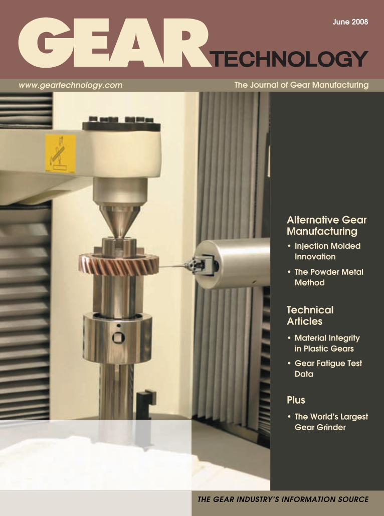
Alternative Gear Manufacturing• Injection Molded Innovation
• The Powder Metal Method
Technical Articles• Material Integrity in Plastic Gears
• Gear Fatigue Test Data
Plus• The World’s Largest Gear Grinder
Star-SU LLC5200 Prairie Stone Parkway,Suite 100Hoffman Estates, IL 60192USATel: 847.649.1450Fax: [email protected]
Go to: www.star-su.com
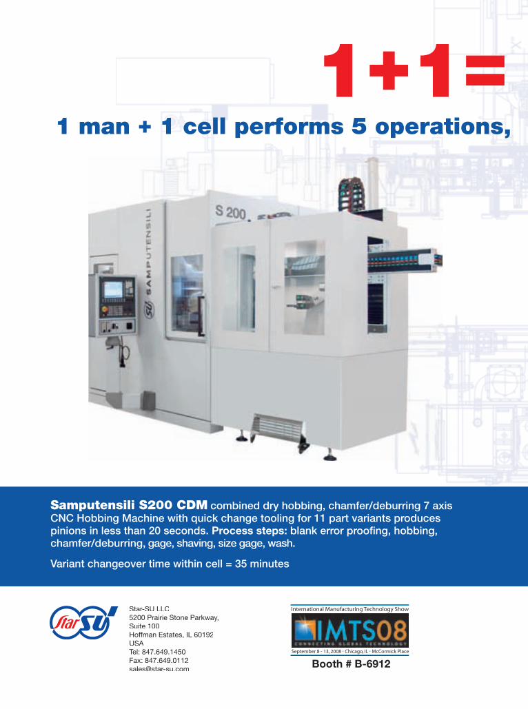
1+1= 6,0001 man + 1 cell performs 5 operations, produces 6,000 parts per day
Samputensili S200 CDM combined dry hobbing, chamfer/deburring 7 axis CNC Hobbing Machine with quick change tooling for 11 part variants produces pinions in less than 20 seconds. Process steps: blank error proofi ng, hobbing, chamfer/deburring, gage, shaving, size gage, wash.
Variant changeover time within cell = 35 minutes
Sicmat RASO 200 automated 5 axis CNC shaving machine with quick change tooling for 11 part variants produces pinions in less than 20 seconds, taking preshave hobbed parts from the Samputensili hobber, shaving the parts, and conveying them out to the wash operation. The RASO 200’s slant bed structure has a compact design that exhibits the stiffness of larger machines.
International Manufacturing Technology Show
September 8 - 13, 2008 • Chicago, IL • McCormick Place
Booth # B-6912 Star SU – your source for soft or hard gear cell production solutions.

www.geartechnology.com June 2008 GEARTECHNOLOGY 00Go to: www.star-su.com
1+1= 6,0001 man + 1 cell performs 5 operations, produces 6,000 parts per day
Samputensili S200 CDM combined dry hobbing, chamfer/deburring 7 axis CNC Hobbing Machine with quick change tooling for 11 part variants produces pinions in less than 20 seconds. Process steps: blank error proofi ng, hobbing, chamfer/deburring, gage, shaving, size gage, wash.
Variant changeover time within cell = 35 minutes
Sicmat RASO 200 automated 5 axis CNC shaving machine with quick change tooling for 11 part variants produces pinions in less than 20 seconds, taking preshave hobbed parts from the Samputensili hobber, shaving the parts, and conveying them out to the wash operation. The RASO 200’s slant bed structure has a compact design that exhibits the stiffness of larger machines.
International Manufacturing Technology Show
September 8 - 13, 2008 • Chicago, IL • McCormick Place
Star SU – your source for soft or hard gear cell production solutions.
00 GEARTECHNOLOGY June 2008 www.geartechnology.com
27
ALTERNATIVE GEAR MANUFACTURING
Vol. 25, No. 4. GEAR TECHNOLOGY, The Journal of Gear Manufacturing (ISSN 0743-6858) is published monthly, except in February, April, October and December by Randall Publishing, Inc., 1425 Lunt Avenue, P.O. Box 1426, Elk Grove Village, IL 60007, (847) 437-6604. Cover price $7.00 U.S. Periodical postage paid at Arlington Heights, IL, and at additional mailing office (USPS No. 749-290). Randall Publishing makes every effort to ensure that the processes described in GEAR TECHNOLOGY conform to sound engineering practice. Neither the authors nor the publisher can be held responsible for injuries sustained while following the procedures described. Postmaster: Send address changes to GEAR TECHNOLOGY, The Journal of Gear Manufacturing, 1425 Lunt Avenue, P.O. Box 1426, Elk Grove Village, IL, 60007. ©Contents copyrighted by RANDALL PUBLISHING, INC., 2008. No part of this publication may be reproduced or transmitted in any form or by any means, electronic or mechanical, including photocopy-ing, recording, or by any information storage and retrieval system, without permission in writing from the publisher. Contents of ads are subject to Publisher’s approval. Canadian Agreement No. 40038760.
Injection Molded Innovation Alternative business strategies from some alternative gear manufacturers.
The Powder Metal Method Despite economic uncertainty, the future looks promising for PM gears.
40 Material Integrity in Molded Plastic Gears and its Dependence on Molding PracticesHow a molder’s systems, procedures, equipment and experience can affect the final quality of a molded plastic gear.
Study of the Correlation Between Theoretical and Actual Gear Fatigue Test Data on a PolyamideDetermining the correlation between fatigue test data and actual gear life.
48
TECHNICAL ARTICLES
C O N T E N T SJune 2008
34
02
�
�
�
�
�
�
�
�
�
�
���
���
����
���
����
�������������������
�����������������
����������������
��������������������������������������
�����������������
������
����
���
���
���
���
���
��
�
���
���
���
��
������� ���� ����������������
��������������������������
�������������
���������
�����������
120
100
80
60
40
20
0
����
�����
���
Fatigue resistance at 140 C of glass fibre reinforced engineering plastics
1.00E+02 1.00E+03 1.00E+04 1.00E+05 1.00E+06 1.00E+07
No. of cycles
www.geartechnology.com June 2008 GEARTECHNOLOGY 00
C O N T E N T S
00 GEARTECHNOLOGY June 2008 www.geartechnology.com
• Power Transmission Engineering Read the April 2008 issue online. Sign up for a free subscription to our new magazine.
• NEWS The latest products, industry news and calendar items.
• BUYERS GUIDE Search for power transmission pro- ducts and services and communicate with the industry's leading suppliers. powertransmission.com
ON L I N E
www.geartechnology.com
www.powertransmission.com
• BUYERS GUIDE Search for gear industry products and services and communicate with the industry’s leading suppliers.
• SUBSCRIPTIONS Sign up for subscriptions to Gear Technology and the geartechnology.com e-mail newsletter.
• E-GT Subscribers get access to back issues of Gear Technology.
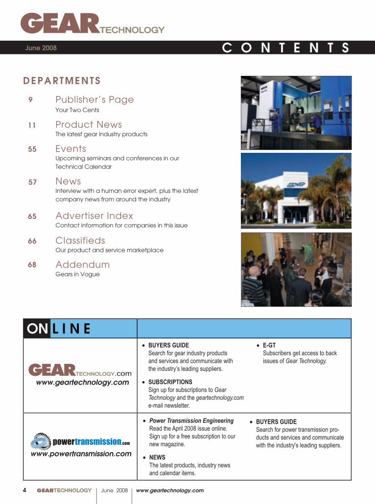
DEPARTMENTS
Publisher’s PageYour Two Cents
Product NewsThe latest gear industry products
EventsUpcoming seminars and conferences in our Technical Calendar
News Interview with a human error expert, plus the latest company news from around the industry
Advertiser IndexContact information for companies in this issue
ClassifiedsOur product and service marketplace
AddendumGears in Vogue
9
11
55
57
66
C O N T E N T S
68
June 2008
04
65
www.geartechnology.com June 2008 GEARTECHNOLOGY 00
C O N T E N T S
For the US-market please contact: Liebherr Gear Technology, Inc. 1465 Woodland Drive Saline, Michigan 48176-1259 Phone: 734-429-7225 [email protected]
Liebherr-Verzahntechnik GmbH D-87437 Kempten www.liebherr.com
Whatever you need – you can do it!
• choice of grinding process technology
• generating grinding and / or profi le grinding
• plated or dressable tools (CBN & corundum)
• multiple gears in one setup
• gear and shaft parts
• advanced software solutions
• different possibilities for noise minimized gear production
Liebherr Grinding Technology - No compromises
Flexible Technology !
00 GEARTECHNOLOGY June 2008 www.geartechnology.com
EDITORIALPublisher & Editor-in-Chief Michael Goldstein
Managing Editor William R. Stott
Senior Editor Jack McGuinn
Associate Editor Matthew Jaster
Assistant Editor Lindsey Snyder
Editorial Consultant Paul R. Goldstein
Technical Editors Robert Errichello, Joseph Mihelick, Robert E. Smith, Dan Thurman
ARTArt Director Kathleen O'Hara
ADVERTISINGAdvertising RK Media, Inc.
Ryan King
CIRCULATIONCirculation Manager Carol Tratar
RANDALL PUBLISHING STAFFPresident Michael Goldstein
Vice President Richard Goldstein
Accounting Luann Harrold
VOL. 25, NO. 4
Randall Publishing, Inc.1425 Lunt AvenueP.O. Box 1426Elk Grove Village, IL 60007Phone: 847-437-6604Fax: 847-437-6618
function of the gear set will be affected. However, if the gear was manufactured correctly, but there are still problems, there is a chance that changing the assembly process or the mounting design can make for a “better” gear within an application.
Laser welding and high-speed pulse welding are two processes that join gears and splines to various shafts and sheet metal interfaces. If there are possible component issues and permanent assembly makes the original manufacturing datums unavailable, the individual components should be measured before welding or joining. Also, by measuring parts before joining, you save through-put capacity by not performing subsequent operations on otherwise “scrap” components from a faulty manufacturing process.
Dividing gear problems into both manufacturing and assembly categories helps to isolate the focus of investigation when trying to make better gears. Being able to measure elemental gear parameters with respect to how they are made and how they are used is the key to quickly determining where to make corrections in your operation. Making “better” gears is not solely dependent on the manufacturing process but sometimes has more to do with the fi nal mounting condition with respect to the functional datums of the gear.
Add your insight by e-mailing
ON L I N E
www.geartechnology.com July 2007 GEARTECHNOLOGY 13
06
THE GEAR INDUSTRY’S INFORMATION SOURCE
www.geartechnology.com The Journal of Gear Manufacturing
June 2008
TECHNOLOGYGEAR
Alternative Gear Manufacturing• Injection Molded
Innovation
• The Powder Metal
Method
Technical Articles• Material Integrity
in Plastic Gears
• Gear Fatigue Test Data
Plus• The World’s Largest Gear Grinder
Cover photocourtesy ofCapstanAtlantic.
www.geartechnology.com June 2008 GEARTECHNOLOGY 00
00 GEARTECHNOLOGY June 2008 www.geartechnology.com
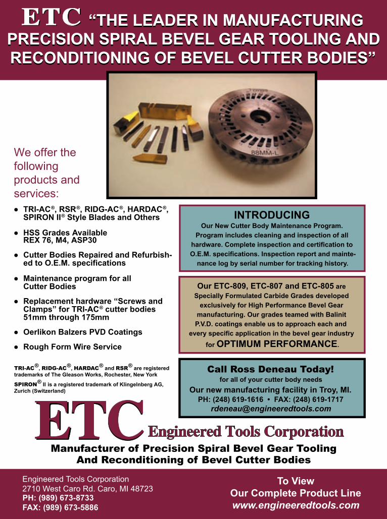
“THE LEADER IN MANUFACTURING PRECISION SPIRAL BEVEL GEAR TOOLING AND RECONDITIONING OF BEVEL CUTTER BODIES”
ETCEngineered Tools CorporationETCPH: (989) 673-8733FAX: (989) 673-5886
Engineered Tools Corporation 2710 West Caro Rd. Caro, MI 48723
Manufacturer of Precision Spiral Bevel Gear ToolingAnd Reconditioning of Bevel Cutter Bodies
To View Our Complete Product Linewww.engineeredtools.com
TRI-AC®, RIDG-AC®, HARDAC® and RSR® are registered trademarks of The Gleason Works, Rochester, New York
SPIRON® II is a registered trademark of Klingelnberg AG, Zurich (Switzerland)
We offer the following products and services:
“THE LEADER IN MANUFACTURING PRECISION SPIRAL BEVEL GEAR TOOLING AND RECONDITIONING OF BEVEL CUTTER BODIES”
Call Ross Deneau Today!for all of your cutter body needs
Our new manufacturing facility in Troy, MI.PH: (248) 619-1616 • FAX: (248) 619-1717
INTRODUCING Our New Cutter Body Maintenance Program.
Program includes cleaning and inspection of all hardware. Complete inspection and certification to O.E.M. specifications. Inspection report and mainte-
nance log by serial number for tracking history.
ETCETC
● TRI-AC®, RSR®, RIDG-AC®, HARDAC®, SPIRON II® Style Blades and Others
● HSS Grades Available REX 76, M4, ASP30
● Cutter Bodies Repaired and Refurbish- ed to O.E.M. specifications
● Maintenance program for all Cutter Bodies
● Replacement hardware “Screws and Clamps” for TRI-AC® cutter bodies 51mm through 175mm
● Oerlikon Balzers PVD Coatings
● Rough Form Wire Service
Our ETC-809, ETC-807 and ETC-805 are Specially Formulated Carbide Grades developed
exclusively for High Performance Bevel Gear manufacturing. Our grades teamed with Balinit
P.V.D. coatings enable us to approach each and every specific application in the bevel gear industry
for OPTIMUM PERFORMANCE.

00 GEARTECHNOLOGY June 2008 www.geartechnology.com
PUBLISHER’S PAGE
www.geartechnology.com June 2008 GEARTECHNOLOGY 0009
Your Two
Cents
Your Two
Cents
����������������������������
As publisher of Gear Technology, I spend a lot of time thinking about ways to improve the content of our magazine. For more than 24 years, this has been the magazine of the gear industry, and we keep it that way by continually trying to make it even more relevant, useful and important to you, our readers. Over the years, we’ve conducted surveys, held focus groups and talked to many of you in person, by telephone or through e-mail. And while many of you have given us great suggestions through those formats, we’d like to open up our suggestion box. I know what you’re thinking. You’re too busy. You have piles of work that need to get done before you can get to the piles of work that are under them. But if you can take just a few minutes of your time to help us make Gear Technology even better, the rewards will be a magazine that helps you even more than it already does. We want to improve how we bring you the information that helps you make better gears, be more productive and incorporate new technologies. In other words, investing a couple of minutes now will pay big dividends down the road. To help get you thinking, we’ve prepared a list of questions for you. We’re not expecting anyone to write us a three-page essay reviewing our magazine (although, if you think you’ve got it in you, by all means, write away), but we hope we can spark some response by giving you some starting points.
So here goes.Q– What subjects would you like us to cover?Q– What types of companies would you like to see more information about?Q– Which do you want to see less of?Q– What types of articles are most useful to you?Q– What technical article subjects are most important?Q– Is it important to you that our technical articles are reviewed by experts before publication?Q– Is it important to you that we don’t include advertisements on the pages where technical articles are featured?Q– Are my Publisher’s Page editorials of interest to you?Q– Do you use our website? Is it useful? What would improve it?Q– Do you prefer the hard copy or the digital version?Q– How often do you download E-GT, our digital version? Do E-GT, our digital version? Do E-GT you wait for the e-mail notifi cation or do you check the site every day until it shows up?Q– Have you seen our new magazine, Power Transmission Engineering? What do you think?Q– How much time do you spend with the magazine each How much time do you spend with the magazine each issue?Q– Do you like the cover design?
Q– Do you like the overall design?Q– Do you have a photo or image that would make a great cover?Q– Do you have an article in you that needs to be written?Q– Who at your company doesn’t receive the magazine but should be reading it?Q– Have you passed this magazine along to one of your co- workers? Clients? Friends? Enemies? Why or why not?Q– Do you read the advertisements?Q– Which advertisements do you like the best? Which ones do you like the least?Q– What kinds of products should be advertised here but aren’t?Q– Are the news sections useful to you?Q– Is our coverage of trade shows and events adequate?Q– Are there events we should cover but haven’t? Are there events we cover too much?Q– What kinds of product information would you rather see? Machine tools? Cutting tools? Software? Lubricants? Q– Are the articles too technical?Q– Are the articles too fl uffy?Q– What was the last article we ran that really made you think?Q– Do you love the Addendum page?Q– Why haven’t you submitted ideas for the Addendum page?Q– Why haven’t you sent a letter to the editor?Q– Does the information on our cover make you want to read the magazine?Q– Do you ever use the Advertiser Index? Should there be more or less information there?Q– Did you like my editorial on Vietnam?Q– Did you like my editorial on the Graying of the Gear Industry in Jan/Feb 2008?Q– Would you like to submit an editorial of your own for our Voices column?Q– Are there any important industry trends we haven’t covered?Q– Which article this year has been most important to you?Q– Which article this year has been your least favorite?Q– What features would you like to see on our website?Q– Would you like to see a whole issue devoted to a particular focus?
Michael Goldstein, Publisher & Editor-in-ChiefPublisher & [email protected]
00 GEARTECHNOLOGY June 2008 www.geartechnology.com
P R O D U C T N E W S P R O D U C T N E W S
00 GEARTECHNOLOGYTECHNOLOGY June 2008 www.geartechnology.com
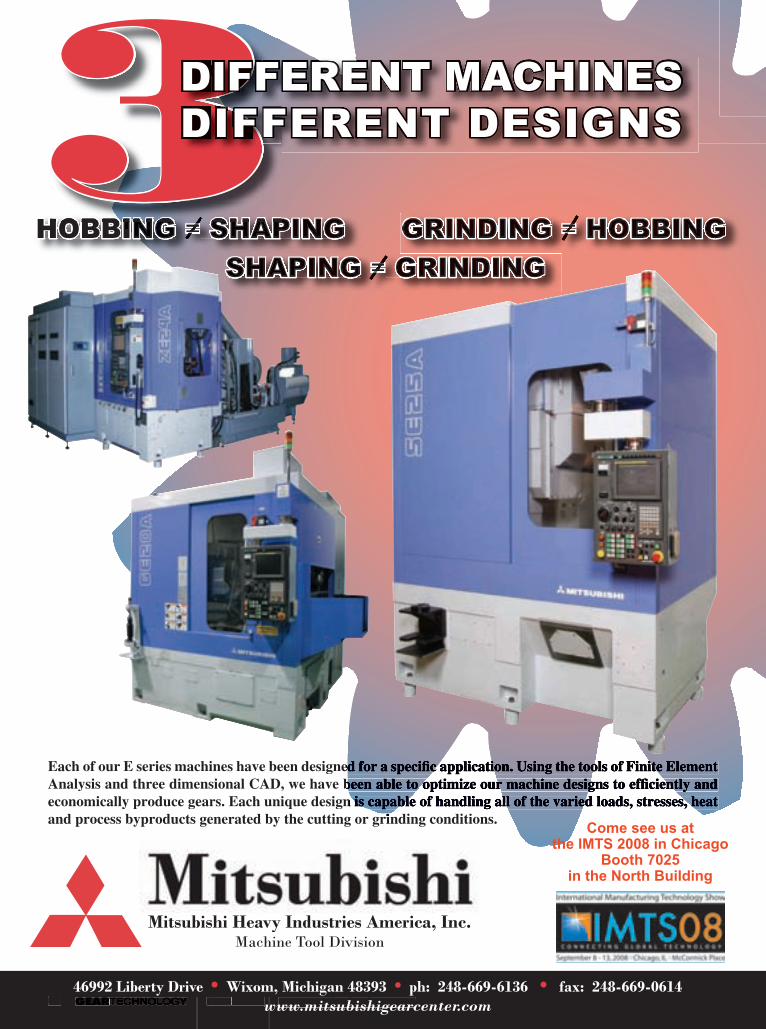
Each of our E series machines have been designed for a specifi c application. Using the tools of Finite Element Each of our E series machines have been designed for a specifi c application. Using the tools of Finite Element Analysis and three dimensional CAD, we have been able to optimize our machine designs to effi ciently and Analysis and three dimensional CAD, we have been able to optimize our machine designs to effi ciently and economically produce gears. Each unique design is capable of handling all of the varied loads, stresses, heat economically produce gears. Each unique design is capable of handling all of the varied loads, stresses, heat and process byproducts generated by the cutting or grinding conditions.and process byproducts generated by the cutting or grinding conditions.
HOBBING HOBBING HOBBING HOBBING HOBBING HOBBING HOBBING HOBBING HOBBING HOBBING HOBBING == SHAPING SHAPING==SHAPING SHAPING SHAPING == GRINDING GRINDING== GRINDING
GRINDING GRINDING == HOBBING HOBBING== HOBBING
46992 Liberty Drive • Wixom, Michigan 48393 • ph: 248-669-6136 • fax: 248-669-0614www.mitsubishigearcenter.com
Mitsubishi Heavy Industries America, Inc.Machine Tool Division
HOBBING HOBBING HOBBING HOBBING HOBBING HOBBING HOBBING SHAPING SHAPING SHAPING33333333333333333333DIFFERENT MACHINES333333333DIFFERENT DESIGNS
Come see us at the IMTS 2008 in Chicago
Booth 7025 in the North Building
www.geartechnology.com June 2008 GEARTECHNOLOGY 00
P R O D U C T N E W S P R O D U C T N E W S
11
3DIFFERENT MACHINESDIFFERENT DESIGNS
continued
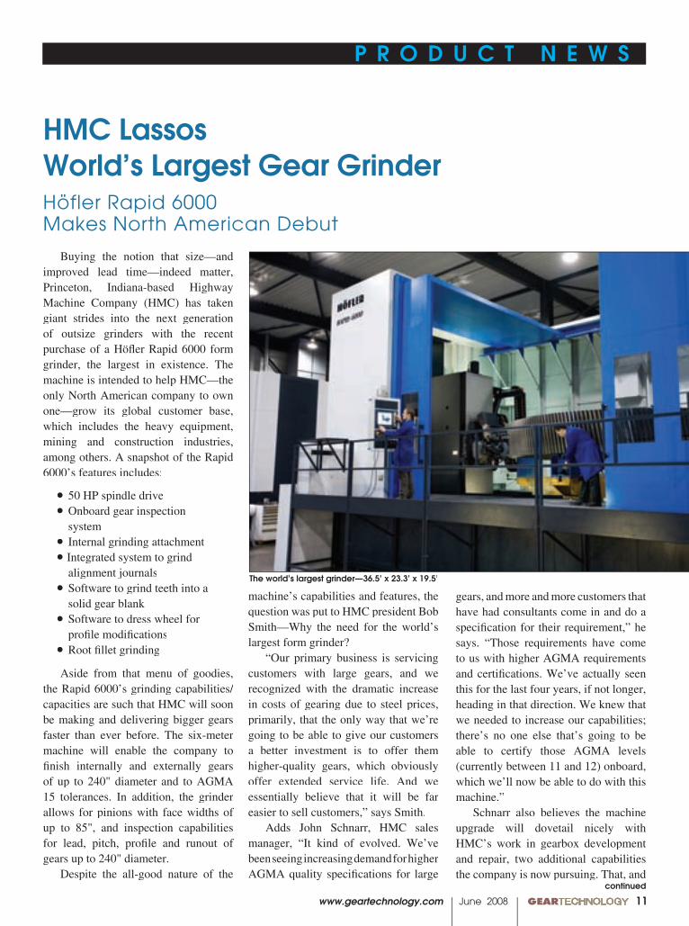
Buying the notion that size—and improved lead time—indeed matter, Princeton, Indiana-based Highway Machine Company (HMC) has taken giant strides into the next generation of outsize grinders with the recent purchase of a Höfl er Rapid 6000 form grinder, the largest in existence. The machine is intended to help HMC—the only North American company to own one—grow its global customer base, which includes the heavy equipment, mining and construction industries, among others. A snapshot of the Rapid 6000’s features includes:
Aside from that menu of goodies, the Rapid 6000’s grinding capabilities/capacities are such that HMC will soon be making and delivering bigger gears faster than ever before. The six-meter machine will enable the company to fi nish internally and externally gears of up to 240" diameter and to AGMA 15 tolerances. In addition, the grinder allows for pinions with face widths of up to 85", and inspection capabilities for lead, pitch, profi le and runout of gears up to 240" diameter.
Despite the all-good nature of the
HMC LassosWorld’s Largest Gear GrinderHöfler Rapid 6000 Makes North American Debut
machine’s capabilities and features, the question was put to HMC president Bob Smith—Why the need for the world’s largest form grinder?
“Our primary business is servicing customers with large gears, and we recognized with the dramatic increase in costs of gearing due to steel prices, primarily, that the only way that we’re going to be able to give our customers a better investment is to offer them higher-quality gears, which obviously offer extended service life. And we essentially believe that it will be far easier to sell customers,” says Smith.
Adds John Schnarr, HMC sales manager, “It kind of evolved. We’ve been seeing increasing demand for higher AGMA quality specifi cations for large
gears, and more and more customers that have had consultants come in and do a specifi cation for their requirement,” he says. “Those requirements have come to us with higher AGMA requirements and certifi cations. We’ve actually seen this for the last four years, if not longer, heading in that direction. We knew that we needed to increase our capabilities; there’s no one else that’s going to be able to certify those AGMA levels (currently between 11 and 12) onboard, which we’ll now be able to do with this machine.”
Schnarr also believes the machine upgrade will dovetail nicely with HMC’s work in gearbox development and repair, two additional capabilities the company is now pursuing. That, and
• 50 HP spindle drive• Onboard gear inspection
system• Internal grinding attachment• Integrated system to grind
alignment journals• Software to grind teeth into a
solid gear blank• Software to dress wheel for
profi le modifi cations• Root fi llet grinding
The world’s largest grinder—36.5’ x 23.3’ x 19.5’

00 GEARTECHNOLOGY June 2008 www.geartechnology.com
P R O D U C T N E W S P R O D U C T N E W SP R O D U C T N E W S P R O D U C T N E W S
12
their ability to produce the largest size gears, positions HMC to go after wind turbine business as well. Schnarr is confi dent that the new grinder—as well as the recent purchase of a number of others, including large-gear-compatible CNCs—will provide the company an occasional advantage over competing OEMs.
“One of the things that we’ve always prided ourselves in is the ability to react,” he says. “And being the size that we are, we’ve been a bit more nimble than the large OEMs can be, for example. And we can sometimes offer solutions that they can’t offer, whether it be an interim fi x or an alternative design.”
Another huge reason for the need of increased effi ciencies in the large gear world is the ever-increasing price of high-grade steel. Those companies that not only produce the gears but signifi cantly improve their delivery time as well stand to be the suppliers of choice, if not necessity.
“About three years ago or so, we were paying somewhere around $1 per pound for seamless-forged, medium-alloy steel,” says Smith. “Today we’re paying upwards of three dollars.” And that takes on added signifi cance when the size of the gears HMC makes is taken into account.
“When we buy a forged ring, we’re not talking four or fi ve thousand pounds; we’re talking anywhere from 40 to 80 thousand pounds,” says Smith.
It’s no secret that the cost spike upwards in quality steel has been attributed to demand in developing and emerging third world countries such as China, India and others. Beyond that, Smith says the higher cost can be traced back a few years ago when an inordinate amount of scrap steel was sold to China, as their ongoing development continued unabated. In fact, he adds, “All of Asia is infl uencing what’s happening, both good and bad here in the West.”
As things stand now, HMC is booked
through 2009, its new capabilities notwithstanding. As a matter of fact, the new Höfl er will not be available for actual production until late July, according to Schnarr. But the die has been cast.
“We want HMC’s name to be synonymous with quality and longer-lasting gearing,” says Smith, (and a gear made on this machine will) “offer longer service life because of less wear on the initial runoff with the Höfl er, which gives us the ability to produce more product for our customers and make faster delivery times.”
And just how big is the Rapid 6000? Suffi ce to say that its delivery requires up to six 40-foot and a number of 20-foot shipping containers to accommodate its dimensions.
One fi nal question had to be asked: What can one expect to pay for the world’s largest form grinder?
“It would have cost fi ve to six million dollars a few years ago,” says Smith. “But Höfl er has cut some corners and made the pricing more palatable.”
For more information:HMC, Inc.3010 S. Old U.S. Hwy 41Princeton, IN 47670Phone: (812) 385-3639;(800) 803-0112Fax: (812) 385-8384; (812) [email protected] www.hmcgears.com
(Höfl er North American Representative)Ray MackowskyGreat Lakes Gear Technologies, Inc.8755 Ronda DriveCanton, MI 48187Phone: (734) 416-9300Fax: (734) 416-7088inquiries@greatlakesgeartech.comwww.greatlakesgeartech.com
Workers (above) prepare the excavation prior to installation. Sixty yards of steel-reinforced concrete were poured to accommodate the machine’s base. Another 16 yards of concrete were used around the machine’s base in support of the housing. The machine is capable of producing gears with AGMA class 14–15 accuracies.
P R O D U C T N E W S P R O D U C T N E W S
www.geartechnology.com June 2008 GEARTECHNOLOGY 00
P R O D U C T N E W S P R O D U C T N E W S
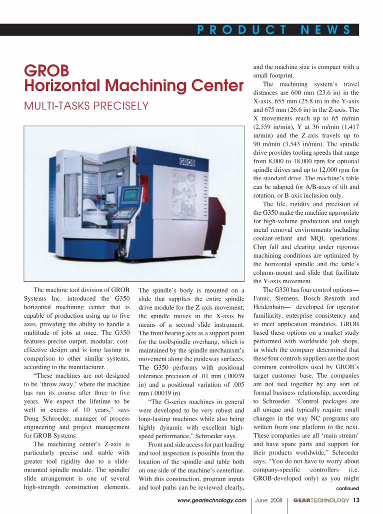
GROB Horizontal Machining CenterMULTI-TASKS PRECISELY
The machine tool division of GROB Systems Inc. introduced the G350 horizontal machining center that is capable of production using up to fi ve axes, providing the ability to handle a multitude of jobs at once. The G350 features precise output, modular, cost-effective design and is long lasting in comparison to other similar systems, according to the manufacturer.
“These machines are not designed to be ‘throw away,’ where the machine has run its course after three to fi ve years. We expect the lifetime to be well in excess of 10 years,” says Doug Schroeder, manager of process engineering and project management for GROB Systems.
The machining center’s Z-axis is particularly precise and stable with greater tool rigidity due to a slide-mounted spindle module. The spindle/slide arrangement is one of several high-strength construction elements.
The spindle’s body is mounted on a slide that supplies the entire spindle drive module for the Z-axis movement; the spindle moves in the X-axis by means of a second slide instrument. The front bearing acts as a support point for the tool/spindle overhang, which is maintained by the spindle mechanism’s movement along the guideway surfaces. The G350 performs with positional tolerance precision of .01 mm (.00039 in) and a positional variation of .005 mm (.00019 in).
“The G-series machines in general were developed to be very robust and long-lasting machines while also being highly dynamic with excellent high-speed performance,” Schroeder says.
Front and side access for part loading and tool inspection is possible from the location of the spindle and table both on one side of the machine’s centerline. With this construction, program inputs and tool paths can be reviewed clearly,
and the machine size is compact with a small footprint.
The machining system’s travel distances are 600 mm (23.6 in) in the X-axis, 655 mm (25.8 in) in the Y-axis and 675 mm (26.6 in) in the Z-axis. The X movements reach up to 65 m/min (2,559 in/min), Y at 36 m/min (1,417 in/min) and the Z-axis travels up to 90 m/min (3,543 in/min). The spindle drive provides tooling speeds that range from 8,000 to 18,000 rpm for optional spindle drives and up to 12,000 rpm for the standard drive. The machine’s table can be adapted for A/B-axes of tilt and rotation, or B-axis inclusion only.
The life, rigidity and precision of the G350 make the machine appropriate for high-volume production and tough metal removal environments including coolant-reliant and MQL operations. Chip fall and clearing under rigorous machining conditions are optimized by the horizontal spindle and the table’s column-mount and slide that facilitate the Y-axis movement.
The G350 has four control options—Fanuc, Siemens, Bosch Rexroth and Heidenhain— developed for operator familiarity, enterprise consistency and to meet application mandates. GROB based these options on a market study performed with worldwide job shops, in which the company determined that these four controls suppliers are the most common controllers used by GROB’s target customer base. The companies are not tied together by any sort of formal business relationship, according to Schroeder. “Control packages are all unique and typically require small changes in the way NC programs are written from one platform to the next. These companies are all ‘main stream’ and have spare parts and support for their products worldwide,” Schroeder says. “You do not have to worry about company-specifi c controllers (i.e. GROB-developed only) as you might
continued
13
00 GEARTECHNOLOGY June 2008 www.geartechnology.com
P R O D U C T N E W S P R O D U C T N E W SP R O D U C T N E W S P R O D U C T N E W S
14
QUALITY
TECHNOLOGY
PRECISION MANUFACTURING
OPERATIONAL EXPERTISE
The quality and precision of our broaches and gears have won customers worldwide (and beyond!) – from the smallest gear-
shop to NASA and the Mars Rover.
Precision manufacturing, modern equipment, advanced technology, and quality control, balanced with talented crafts-
manship, means you get nothing but the very best.
Guaranteed the most rigid shank cutters and the highest quality level disk cutters made.Products that perform. Why use Broach
Masters/Universal Gear? Because your parts matter!
As a complete source for all your tooling and production needs. Broach Masters/Universal Gear will supply you with the highest
quality products and services that you and your customers expect. Experience the difference!
P E R F O R M A N C EManufacturers of:BroachesSpline BroachesFine Pitch Gear BroachesFine Pitch Gear BroachesForm BroachesSerrationBearingsShaper CuttersDisk ShapersShank ShapersHex and Square CuttersHex and Square CuttersSpecial Form CuttersInspectionMaster GearsGo–No Go GagesPosiloc Arbors“Quick Spline” Software“Quick Spline” Software
Made in USA
1605 Industrial DriveAuburn, CA 95603Phone (530) 885-1939Fax (530) 885-8157 Web: www.broachmasters.com
Call 530 885-1939 or visitwww.broachmasters.com
GearGearGearGearOut of ThisWorldGearOut of ThisWorldOut of ThisWorldGearOut of ThisWorld
Tooling
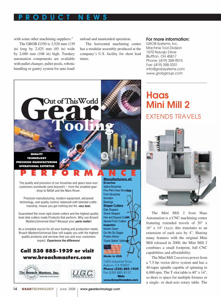
The Mini Mill 2 from Haas Automation is a CNC machining center featuring extended travels of 20" x 16" x 14" (xyz); this translates to an extension of each axis by 4". Sharing many features with the original Mini Mill released in 2000, the Mini Mill 2 combines a small footprint, full CNC capabilities and affordability.
The Mini Mill 2 receives power from a 7.5-hp vector drive system and has a 40-taper spindle capable of spinning to 6,000 rpm. The T-slot table is 40" x 14", so there is space for multiple fi xtures or a single- or dual-axis rotary table. The
Haas Mini Mill 2EXTENDS TRAVELS
with some other machining suppliers.” The GROB G350 is 3,520 mm (139
in) long by 2,425 mm (85 in) wide by 2,680 mm (106 in) high. Turnkey automation components are available with pallet changer, pallet pools, robotic handling or gantry system for auto load/
unload and unattended operation. The horizontal machining center
has a modular assembly produced at the company’s U.S. facility for short lead times.
For more information:GROB Systems, Inc.Machine Tool Division1070 Navajo DriveBluffton, OH 45817Phone: (419) 358-9015Fax: (419) [email protected]
P R O D U C T N E W S P R O D U C T N E W S
www.geartechnology.com June 2008 GEARTECHNOLOGY 00
P R O D U C T N E W S P R O D U C T N E W S
15
��������������������
■������������������������
C L I F F O R D - J A C O B S F O R G I N G
�������������
C L I F F O R D - J A C O B S F O R G I N G
�����������������������������������������
�������������������������������
�������������������������
���������������������������������������������������������
�����������������������������������������������������
�������������������������������������������������
��������� ����� ��������������������� ��� ������ ��� ����� �����
��������� ������������������������ ������� ����������� ��������������
����������� ���� ��������� ��� ��� ��� ������� ��� ��������� ������� ���
���������������������������������������������������������������
��� ���� ������������ ���������� ��������� ���� ���������� ���� ����
��������� ������������������������������� �������������� ����������
�������������������������������������������������������������
����������������������������������������������������
��������������������������������
GH Induction Group recently shipped a new design gear/raceway hardening machine capable of hardening gears and bearing raceways up to 3,000 mm in
GH Gear/Raceway Hardening MachineHANDLES LARGE BEARINGS MORE PRODUCTIVELY
continued
machine’s standard equipment includes a 15" color LCD monitor with USB port, a 10-pocket carousel-style changer and one megabyte of program memory. Optional features include fourth- and fi fth-axis drives, a programmable cool-ant nozzle, high-speed machining software, the Haas Intuitive Programming system, a chip auger and, for shops that may require more tools, the choice between a 20-pocket carousel tool changer and a 24+1 tool side-mount.
Later this year the company is releasing the Super Mini Mill 2 that features the same travel dimensions, but higher speeds, feeds and more options. The spindle is capable of 10,000 rpm with an optional 15,000 rpm spindle, along with a 15-hp vector drive system, high-speed tool changer and 1,200-ipm rapids, according to the company’s press release.
For more information:Haas Automation2800 Sturgis RoadOxnard, CA 93030Phone: (800) 331-6746Fax: (805) 278-8540www.haascnc.com
diameter and 3,000 kg. The machine’s design has been updated to increase productivity, reduce setup time and maintenance while improving process repeatability and monitoring, according to the company’s press release.
The basic design features include
multi-axis CNC control; raceway or gear teeth tracking; the ability to process OD and ID without changing inductor orientation; process monitoring; programmable setup for different diameters; automatic coil centering and gap for raceways; and self-centering
00 GEARTECHNOLOGY June 2008 www.geartechnology.com
P R O D U C T N E W S P R O D U C T N E W SP R O D U C T N E W S P R O D U C T N E W S
16
Leaderin LeanManufacturingof PowderManufacturingof PowderManufacturing
Metal Gears
InnovativeTechnology
Design Engineering SupportSPC Control ProcessAutomated Visual InspectionTotal Quality and ContinuousImprovementIn-House Tool Shop
AMES TAMARITEa subsidiary of AMES
Ctra. Laureà Miró, 38808980 Sant Feliu de Llobregat(Barcelona) SPAIN08980 Sant Feliu de Llobregat(Barcelona) SPAIN08980 Sant Feliu de Llobregat
Tel.: (+34) 93 685 51 11Fax: (+34) 93 685 44 88www.amessint.come-mail: [email protected]
Gleason Cutting Tools Corporation, located in Loves Park, Illinois, has expanded its plated diamond and CBN products and services capability with recondition services for electroplated diamond Master Dressing Gears (MDG). By adding the new grinding technology and more capacity to the North American facility, faster turn-around and more consistent MDG performance are available to customers.
MDGs that are returned for reconditioning will now be processed through the Loves Park plant instead of at Gleason Hurth in Munich. Offering the service in the United States eliminates overseas shipments, so shorter lead times are possible and pricing will not refl ect exchange rate fl uctuations.
For more information:Gleason Cutting Tools Corporation1351 Windsor Rd.Loves Park, IL 61111Phone: 815-877-8900Fax: [email protected]
Master Dressing GearsRECONDITIONED IN USA
For more information:For more information:GH Induction Group1840 Roslyn Rd. Grosse Pointe Woods, MI 48236 Phone: (313) 432-1602 [email protected] www.ghe-usa.com
locators that use a single crank. When raceway hardening or tooth
hardening for two teeth at a time occurs, a second IGBT power supply for pre-heat is included as an optional feature for enhanced productivity. This feature is capable of reducing cycle time nearly in half. A second rotation table
is another option that could increase productivity by as much as 25 percent, according to the press release. By adding a second coil mounting and a transfer switch, users can process a raceway and gear teeth in one part loading without changing coils.

P R O D U C T N E W S P R O D U C T N E W S
www.geartechnology.com June 2008 GEARTECHNOLOGY 00
P R O D U C T N E W S P R O D U C T N E W S
17
Heidenhain’s MANUALplus 620 contouring control features more functions to handle both cycle and CNC lathes. A new NC kernel has a cycle programming feature that enables programming and machining quickly, without needing to write NC programs. A new user-friendly programming mode, Smart.Turn, enables quick working block-input. The mode aims to complement programming for cycle-based lathes, but Smart.Turn also works for standard CNC lathes, according to company’s press release.
The MANUALplus 620 has three programming modes: cycle programming, Smart.Turn and DIN PLUS programming. Each of these modes allows contours to be described with Interactive Contour Programming (ICP). The contouring control is intended for lathes with spindle, one slide, one C-axis or one positionable spindle and a driven tool. Horizontal and vertical lathes are well-suited for
Contouring Control INCREASES FUNCTIONS, HANDLES BOTH CYCLE AND CNC LATHES
use with the MANUALplus 620. With a tool database of up to 250 tools and a technology database, the contouring control is designed as an integrated digital servo-drive control.
For more information:Heidenhain Corporation333 E. State ParkwaySchaumburg, IL 60173Phone: (800) 233-0388Fax: (847) [email protected]

00 GEARTECHNOLOGY June 2008 www.geartechnology.com
P R O D U C T N E W S P R O D U C T N E W SP R O D U C T N E W S P R O D U C T N E W S
18
Stainless Steel Worm Gear Speed Reducer
RESISTS CORROSION
Boston Gear’s 700 Series Worm Gear Speed Reducer is now offered in stainless steel. Using the same gearing and shafts as the cast iron sister series,
the Stainless Steel 700 series handles the harshest caustic washdown conditions.
With the new exterior design, the housings, motor fl ange and carrier are made from 316SS for caustic washdown applications. The integral input worm and shaft are produced from case-hardened alloy steel. Particle accumulation and fl uid pooling on or under the unit is avoided by a rounded housing design, plastic hardware covers and two-piece mounting base. An internal oil reservoir comes fi lled with H1 food-grade lubricant. The 700 series functions in food and beverage applications and is available for same-day air shipment, according to the company’s press release.
For more information:Boston Gear 701 Carrier Dr. Charlotte, NC 28216Phone: (704) 588-5610Fax: (704) 588-7181www.bostongear.com
Hurco featured three of its newest machines at the WESTEC 2008 Exposition in Los Angeles, held March
HurcoEXPANDS PRODUCT LINE
��������������������������
splineandgear.com
P.O. Box 340 | Marine CitP.O. Box 340 | Marine CitP y.O. Box 340 | Marine City.O. Box 340 | Marine Cit , Mi 4803y, Mi 4803y 9
P: [810] 765.8302 | F: [810] 765.9595
������������������������������������������������
������������������������ ��������� ���
��������� ���� �������������������������
���������������������������������
����������������������������������������
����� ��������� ��������������������
��������� ��������� ���� ���������� ������
����������������������������������������
����� ����������������������������
���������������������������������������
������� ��� ����� ��������� ������������
����� ����� ������ ���� ������������
����������������������������� �������������
���������������������������� �������������
������������������� ������
������������ ����������
������� ���������� ���������������������
��������������� ������ ��������������������������
��������������������� ����� ����������������������
������������������������ ������
����������� �������
����������������������������������������������������������������
���������������������������� � �����������������������������������
<<< DISCOVER WHY CUSTOMERS RELY ON OUR GEAR GRINDING SERVICES >>>
����������������
P R O D U C T N E W S P R O D U C T N E W S
www.geartechnology.com June 2008 GEARTECHNOLOGY 00
P R O D U C T N E W S P R O D U C T N E W S
19
For more information:Hurco Companies, Inc.1 Technology Way Indianapolis, IN 46268 Phone: (800) 634-2416www.hurco.com
Exclusive Sales Representativesfor North America
31–April 3. The VMX42SR 5-axis machining
center from Hurco takes up less fl oor space than typically required because of a swivel head and horizontal rotary table. The WinMax control software WinMax control software WinMaxis included in a special version that simplifi es the setup and programming of complex, multi-sided parts. The newest member of the VMX family of machining centers uses digital drives, larger ball screws, larger linear rails and heavier servo drives to create parts more accurately.
The VM1P is a vertical machining center with mill/tap functionality capable of fast rapids, tool changes and tapping at 4,000 rpm. The machine’s C-frame design is made with fi ne-grain cast iron and solid construction for rigorous cycles and lights-out machining. The VM1P has larger linear rails that are wedge-locked, instead of face-milled, so the machine is stiff enough to control vibration.
The TMM8 slant-bed lathe has live tooling that includes C-axis standard and programming to .001 degree. The 8" chuck lathe is designed to multitask for small to medium lot sizes that require turning and secondary milling/drilling operations with a wide door for easy access. Using a fast servo turret, instead of a hydraulic turret, to increase productivity, the TMM8 requires just one setup; refi xturing, which can lose accuracy, is not necessary.
“These three machines illustrate the continuing expansion of our product line that enables us to reach more customers who are looking for the type of measurable productivity improvements that our integrated control with WinMax delivers,” says Jim Kawaguchi, general manager of Hurco USA.
Visit
www.geartechnology.comfor the latest Product News
ON L I N E
00 GEARTECHNOLOGY June 2008 www.geartechnology.com
P R O D U C T N E W S P R O D U C T N E W SP R O D U C T N E W S P R O D U C T N E W S
20
Reliability begins with a cup of coffee.
olonial isn’t typical in theBROACH INDUSTRY- our mainfocus is to establish customer relationships that are a perfect fitwith our decades of service providing broaching systems
to international companies looking for experience and reliability.
The solutions we provide delivers the highest quality in the world at a reliable Lowest Cost Per Piece, GUARANTEED! An industry first. What do you takein your coffee?
Relationships are built by taking the time to sit down with you,and discovering what keeps you awake at night.
United States • Canada • Mexico • 1-866-611-5119 • [email protected] • www.colonialtool.com
EXPERIENCED • RELIABLE • INTERNATIONAL
C
Generic Half Island 2/6/08 9:27 AM Page 1
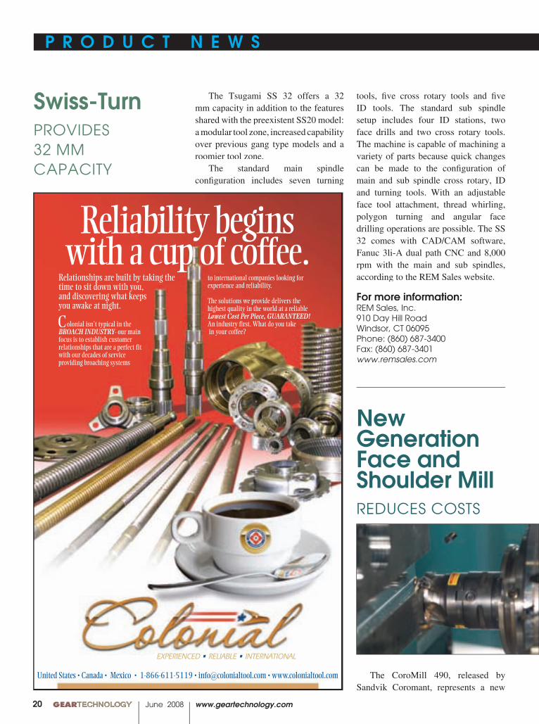
The Tsugami SS 32 offers a 32 mm capacity in addition to the features shared with the preexistent SS20 model: a modular tool zone, increased capability over previous gang type models and a roomier tool zone.
The standard main spindle confi guration includes seven turning
Swiss-TurnPROVIDES 32 MM CAPACITY
tools, fi ve cross rotary tools and fi ve ID tools. The standard sub spindle setup includes four ID stations, two face drills and two cross rotary tools. The machine is capable of machining a variety of parts because quick changes can be made to the confi guration of main and sub spindle cross rotary, ID and turning tools. With an adjustable face tool attachment, thread whirling, polygon turning and angular face drilling operations are possible. The SS 32 comes with CAD/CAM software, Fanuc 3li-A dual path CNC and 8,000 rpm with the main and sub spindles, according to the REM Sales website.
For more information:REM Sales, Inc.910 Day Hill RoadWindsor, CT 06095Phone: (860) 687-3400Fax: (860) 687-3401www.remsales.com
New Generation Face and Shoulder MillREDUCES COSTS
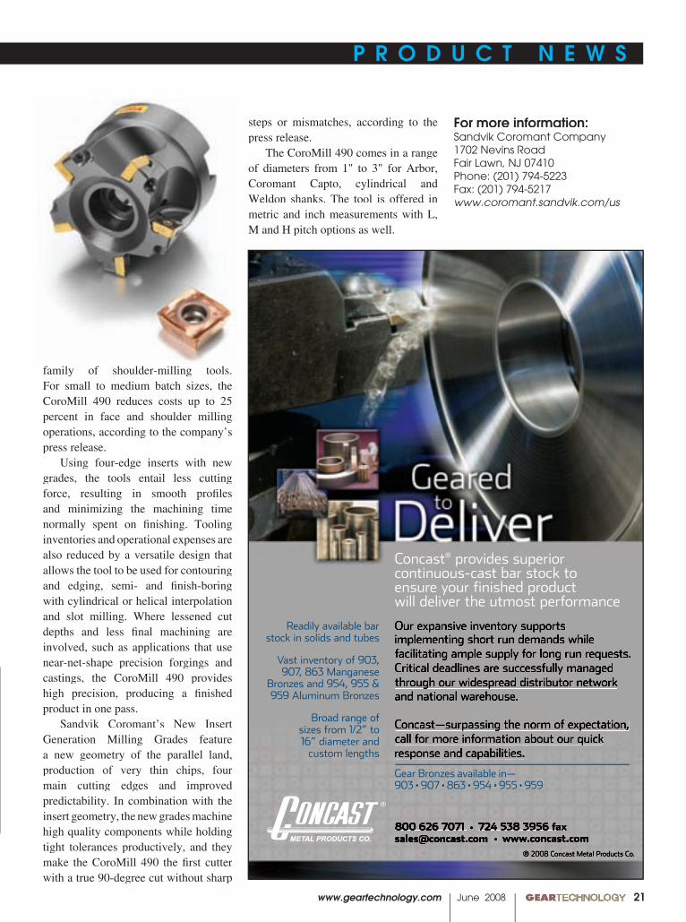
The CoroMill 490, released by Sandvik Coromant, represents a new
P R O D U C T N E W S P R O D U C T N E W S
www.geartechnology.com June 2008 GEARTECHNOLOGY 00
P R O D U C T N E W S P R O D U C T N E W S
21
steps or mismatches, according to the press release.
The CoroMill 490 comes in a range of diameters from 1" to 3" for Arbor, Coromant Capto, cylindrical and Weldon shanks. The tool is offered in metric and inch measurements with L, M and H pitch options as well.
family of shoulder-milling tools. For small to medium batch sizes, the CoroMill 490 reduces costs up to 25 percent in face and shoulder milling operations, according to the company’s press release.
Using four-edge inserts with new grades, the tools entail less cutting force, resulting in smooth profi les and minimizing the machining time normally spent on fi nishing. Tooling inventories and operational expenses are also reduced by a versatile design that allows the tool to be used for contouring and edging, semi- and fi nish-boring with cylindrical or helical interpolation and slot milling. Where lessened cut depths and less fi nal machining are involved, such as applications that use near-net-shape precision forgings and castings, the CoroMill 490 provides high precision, producing a fi nished product in one pass.
Sandvik Coromant’s New Insert Generation Milling Grades feature a new geometry of the parallel land, production of very thin chips, four main cutting edges and improved predictability. In combination with the insert geometry, the new grades machine high quality components while holding tight tolerances productively, and they make the CoroMill 490 the fi rst cutter with a true 90-degree cut without sharp
For more information:Sandvik Coromant Company1702 Nevins RoadFair Lawn, NJ 07410Phone: (201) 794-5223Fax: (201) 794-5217www.coromant.sandvik.com/us
® 2008 Concast Metal Products Co.
800 626 7071 • 724 538 3956 [email protected] • www.concast.com
Concast® provides superior continuous-cast bar stock to ensure your finished product will deliver the utmost performance
Our expansive inventory supports implementing short run demands while facilitating ample supply for long run requests.Critical deadlines are successfully managedthrough our widespread distributor network and national warehouse.
Concast—surpassing the norm of expectation, call for more information about our quickresponse and capabilities.
®
Readily available barstock in solids and tubes
Vast inventory of 903,907, 863 Manganese
Bronzes and 954, 955 &959 Aluminum Bronzes
Broad range of sizes from 1/2” to 16” diameter and
custom lengths
Gear Bronzes available in—903 • 907 • 863 • 954 • 955 • 959
00 GEARTECHNOLOGY June 2008 www.geartechnology.com
P R O D U C T N E W S P R O D U C T N E W SP R O D U C T N E W S P R O D U C T N E W S
22
Rugged, Reliable, Repeatable...For 75 Years!
• Applicable to Spur and Helical Gears!
• Gage the Part at the Machine!
PitchDiameter
MajorDiameter
Minor Diameter
Internal or External SplineMeasurement Made Easy!
Still using micrometers and pins method?
Comtor Spline Gages make pitch diameter measurement quick, easy and accurate!
For all your gaging needs,Comtorgage it!
®
COMTOR SPLINE GAGES
Comtorgage Corporation(Since 1928)
Ph: (401) 765-0900 Fax: (401) 765-2846www.comtorgage.com
Analog Dial or Digital Readout
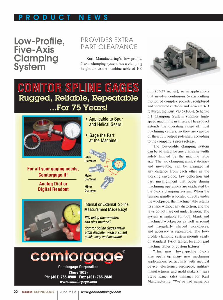
Kurt Manufacturing’s low-profi le, 5-axis clamping system has a clamping height above the machine table of 100
Low-Profi le, Five-Axis Clamping System
PROVIDES EXTRA PART CLEARANCE
mm (3.937 inches), so in applications that involve continuous 5-axis cutting motion of complex pockets, sculptured and contoured surfaces and intricate 3-D features, the Kurt VB 5x100-L Schenke 5.1 Clamping System supplies high-speed machining in all axes. The product extends the operating range of most machining centers, so they are capable of their full output potential, according to the company’s press release.
The low-profi le clamping system can be adjusted for any clamping width solely limited by the machine table size. The two clamping jaws, stationary and moveable, can be arranged at any distance from each other in the working envelope. Jaw defl ection and part misalignment that occur during machining operations are eradicated by the 5-axis clamping system. When the tension spindle is located directly under the workpiece, the machine table retains its shape without any distortion, and the jaws do not fl are out under tension. The system is suitable for both blank and machined workpieces as well as round and irregularly shaped workpieces, and accuracy is repeatable. The low-profi le clamping system mounts easily on standard T-slot tables, location grid machine tables or custom fi xtures.
“This new, lower-profi le 5-axis vise opens up many new machining applications, particularly with medical device, electronic, aerospace, military manufacturers and mold makers,” says Steve Kane, sales manager for Kurt Manufacturing. “We’ve had numerous

P R O D U C T N E W S P R O D U C T N E W S
www.geartechnology.com June 2008 GEARTECHNOLOGY 00
P R O D U C T N E W S P R O D U C T N E W S
23
© 2 0 0 6 , P r e s r i t e C o r p o r a t i o n
PRESRITE NEAR-NET GEARS GIVE YOU THE STRENGTH OF A FORGING WITH LITTLE OR NO MACHINING.
We’re as NEAR as the NET! Visit our Web site at www.presrite.com.
I S O 9 0 0 1 : 2 0 0 0 T S 1 6 9 4 9 : 2 0 0 2Presrite Corporation3665 E. 78th St. • Cleveland, OH 44105Presrite Corporation3665 E. 78th St. • Cleveland, OH 44105Presrite Corporation
Phone: (216) 441-5990 Fax: (216) 441-2644
Are you interested in reducing your gear costs while increasing their quality? Presrite hot-forges intricate gears to net and near-net shapes, so little or no hobbing is required.We’ve invested millions to save you money and improve the performance of the gears you buy. Our dedicated gear-forging facility is equipped with a state-of-the-art gear lab, high-capacity presses, and the latest in sophisticated machinery.See why customers from a wide range of industries and countries come to Presrite for forged gears. Contact us now for more information or a quote.
Weight Savings – As a blank, this large spur gear weighed 55 lbs. As a forged tooth gear with 1 millimeter of stock on the tooth profile for hobbing, it weighs just 37 lbs.
TAKE A BITE OUT OF YOUR GEAR COSTSTAKE A BIA BIA TE OUE OUT OF Y OF YT OF YT OOUR GEAR CUR GEAR CWITH TEETH LIKE THESE.
continued
Pressure–Blast System CONTROLS SURFACE ROUGHNESS ACCURATELY
An expanded rotary indexing spindle-blast machine with direct pressure media delivery and special media reclamation features is new from Guyson Corporation. The RXS-1400 is designed to control the surface roughness of components more precisely to prepare them for advanced functional coatings.
The unit dimensions are 1.98 x 2.44 x 2.59 meters (78 x 94 x 102 inches), and the vertical sliding doors were built wide to process components up to 500 mm (20 inches) in diameter. The
requests for a lower-profi le model to meet the needs of the latest generation of 5-axis machining centers. Now we can supply that need.”
For more information:Kurt Manufacturing1325 Quincy St. NEMinneapolis, MN 55413Phone: (763) 574-8309Fax: (612) 623-3902www.kurtworkholding.com
machine has six ball-bearing spindles placed around the circumference of the rotary table, each with a capacity of 25 kg (55 pounds).
Seven pressure-blast nozzles are located around two blasting stations with three nozzles programmed to traverse vertically from one station,
and four nozzles traverse horizontally at the other station. The nozzle motion is synchronized with controlled, adjustable and programmable rotation of a component to ensure the desired coverage, according to the company’s press release. The RXS-1400 is equipped with a touch-screen interface for
00 GEARTECHNOLOGY June 2008 www.geartechnology.com
P R O D U C T N E W S P R O D U C T N E W S
24
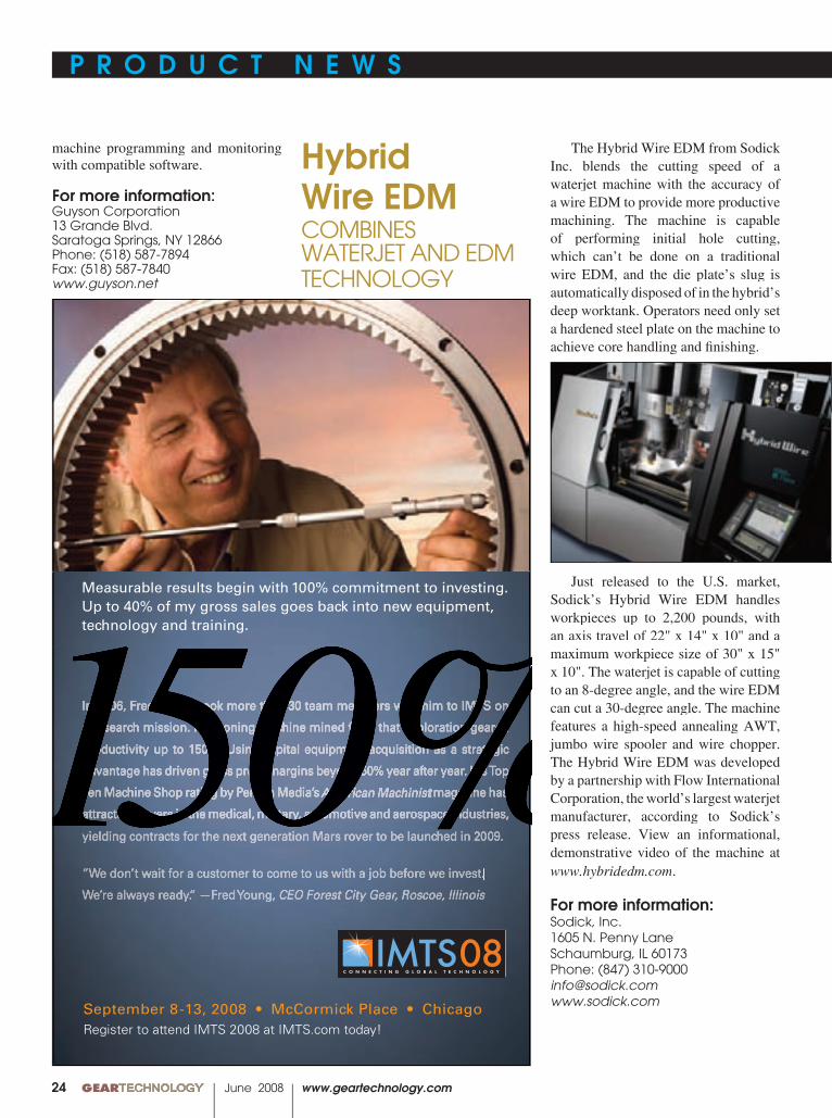
The Hybrid Wire EDM from Sodick Inc. blends the cutting speed of a waterjet machine with the accuracy of a wire EDM to provide more productive machining. The machine is capable of performing initial hole cutting, which can’t be done on a traditional wire EDM, and the die plate’s slug is automatically disposed of in the hybrid’s deep worktank. Operators need only set a hardened steel plate on the machine to achieve core handling and fi nishing.
Just released to the U.S. market, Sodick’s Hybrid Wire EDM handles workpieces up to 2,200 pounds, with an axis travel of 22" x 14" x 10" and a maximum workpiece size of 30" x 15" x 10". The waterjet is capable of cutting to an 8-degree angle, and the wire EDM can cut a 30-degree angle. The machine features a high-speed annealing AWT, jumbo wire spooler and wire chopper. The Hybrid Wire EDM was developed by a partnership with Flow International Corporation, the world’s largest waterjet manufacturer, according to Sodick’s press release. View an informational, demonstrative video of the machine at www.hybridedm.com.
For more information:Sodick, Inc.1605 N. Penny LaneSchaumburg, IL 60173Phone: (847) [email protected]
Hybrid Wire EDMCOMBINES WATERJET AND EDMTECHNOLOGY
150%September 8-13, 2008 • McCormick Place • ChicagoRegister to attend IMTS 2008 at IMTS.com today!
Measurable results begin with 100% commitment to investing. Up to 40% of my gross sales goes back into new equipment, technology and training.
150%In 2006, Fred Young took more than 30 team members with him to IMTS on 150%150%a research mission. The honing machine mined from that exploration geared 150%150%productivity up to 150%. Using capital equipment acquisition as a strategic 150%150%advantage has driven gross profit margins beyond 50% year after year. His Top 150%150%Ten Machine Shop rating by Penton Media’s 150%150%American Machinist150%150% magazine has 150%150%American Machinist150% magazine has 150%American Machinist150%150%attracted players in the medical, military, automotive and aerospace industries, 150%yielding contracts for the next generation Mars rover to be launched in 2009.
“We don’t wait for a customer to come to us with a job before we invest.
We’re always ready.” —Fred Young, CEO Forest City Gear, Roscoe, Illinois
150%
machine programming and monitoring with compatible software.
For more information:Guyson Corporation13 Grande Blvd.Saratoga Springs, NY 12866Phone: (518) 587-7894Fax: (518) 587-7840www.guyson.net
P R O D U C T N E W S P R O D U C T N E W S
www.geartechnology.com June 2008 GEARTECHNOLOGY 00
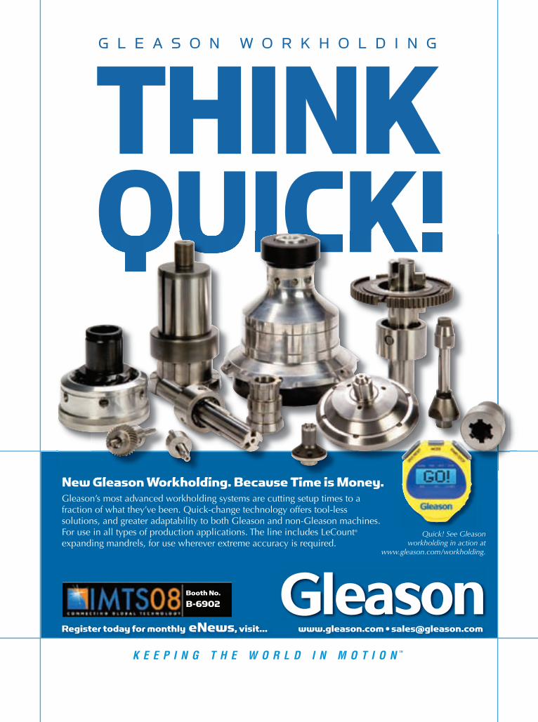
Quick! See Gleasonworkholding in action at
www.gleason.com/workholding.
�����������������������������������������������Gleason’s most advanced workholding systems are cutting setup times to a fraction of what they’ve been. Quick-change technology offers tool-less solutions, and greater adaptability to both Gleason and non-Gleason machines. For use in all types of production applications. The line includes LeCount® expanding mandrels, for use wherever extreme accuracy is required.
�����������
��������������������������������������������������������������������������������������������������
� � � � � � � � � � � � � � � � � � �
������
�����������������������������������������������
������
����������
������
00 GEARTECHNOLOGY June 2008 www.geartechnology.com

www.geartechnology.com June 2008 GEARTECHNOLOGY 0027
Heidenhain Contouring ControlEQUIPPED
Plastics denote the youngest, smallest and least understood material of the entire gear market; a sort of ambitious teenager of the industry per se. “Plastics represent less than four percent of the gears in the world,” says John Winzeler, president of Winzeler Gear.
Nevertheless, plastics are making serious inroads in many applications. Polymer is already the gear material of choice found in clocks, motorized toys, lawn sprinklers and throughout cars. Plastics boast a range of benefi ts including
Injection Molded Innovation
ALTERNATIVE BUSINESS STRATEGIES FROM SOME ALTERNATIVE GEAR MANUFACTURERS
Lindsey Snyder, Assistant Editor
cost effi ciency, corrosion resistance, noise reduction, light weight, easy coloring and fi nishing, control and tolerance; they can incorporate complex geometries, but plastic gears are simple to mass produce. All these factors contribute to their extensive use in the automotive and other transportation vehicle industries. “You can do incredibly innovative things with plastic,” says Rick Wheeler, president of ABA-PGT. “There are unlimited opportunities.”
continued
The “Liquid Gears” mural, by artist Erich Shrempp, adorns the south wall at Winzeler Gear.

00 GEARTECHNOLOGY June 2008 www.geartechnology.com28
Companies that use injection molding processes have a distinct opportunity to take advantage of manufacturing such an inimitable material by embracing innovation—the introduction of new methods or ideas—in their production. While manufacturing facilities are increasingly outsourced abroad, innovation is eroded along lines of distance and size in these ventures. Despite the obvious business logic of outsourcing to a country like China, there are inherent challenges to housing a manufacturing facility in a country where there are as many spoken dialects as there are counties. Several American gear manufacturers embrace the modern limitations of domestic production by transforming them into pioneering business models.
“China is a great place to build toys, tooth-brushes, commodities and a whole lot of other stuff. In addition, it’s a fantastic place to assemble products,” says Doug Felsenthal, vice president of sales and marketing at Kleiss Gears. “But when it comes to the business of accurate polymer gearing, this subtle science must combine with an exacting art.”
This comment is from an article Felsenthal wrote about the disadvantages of conducting business in China, which he fi nds particularly problematic in the meticulously precise nature of plastic gear manufacturing. He considers the science of measurement to be the ‘holy grail’ of plastic gear making, and a marketing platform for Kleiss Gears. The company expresses a unique attitude and devotion to producing a highly sophisticated system of gear measurement.
“Every day is a holiday at Kleiss Gears” is a personal mantra Felsenthal shares with his customers, but don’t let this, or the company’s mission statement, “To produce the most cost-effective gears on this planet and have fun doing it,” suggest any loose commitment to quality or precision. Kleiss’s dedication to accuracy is exemplifi ed by the more than $1 million the company has invested purely in measuring equipment. Kleiss’s precision molding is held to .001" tolerances, relying heavily on advanced computer technology to achieve this standard. Felsenthal estimates that Kleiss reinvests in measurement and other areas as much as 50 to
60 percent of total revenue, which stands around $4 million, while other companies might reinvest 20 to 30 percent.
While measurement is one key component to Kleiss’ approach to plastic gear manufacturing, the 20-year-old company, headquartered near Minneapolis in Grantsburg, WI, also works aggressively to meet standards of fl exibility and involvement with customers. The company found in the past that consistent repeatability was diffi cult to achieve with most supply chains, so Kleiss Gears became involved with every phase of the production cycle—from design to tooling to temperature and pressure balance to fi nal assembly. Kleiss forms a partnership with each customer where they brainstorm together. Many customers try to do more of the system planning on their own, but at Kleiss, the manufacturer steps in to aid this crucial process. Felsenthal considers Kleiss Gears to be a design house for gearing because the company is involved with many specifi c products instead of producing gears that can be used universally in many applications.
Believe it or not, fun is a business ideal Kleiss embraces. Kleiss is always working on various projects in the medical, auto, industrial and consumer industries, just to name a few. Felsenthal says he works on projects in at least two of these different industries daily, and the environment is fast-paced, both factors helping to avoid monotony. Some of their latest and most interesting projects relate to glucose measuring and injection industries. “Every day is something totally different,” Felsenthal says. “We have the ability to do a lot of different things, doing a complete system, and meshing the gears together.”
The current business practices Kleiss employs have been in place since 2002/2003. The manufacturing company has experienced signifi cant growth over the last few years, 51 percent in 2005 and 62.4 percent in 2007.
Gear University Manufacturing plastic gears doesn’t always have to be
about selling them. This may seem contradictory, but ABA-PGT effectively engages this idea at the Gear University, which the injection molding manufacturer organizes. ABA-
ABA-PGT conducts Gear University classes at the Rensselaer Polytechnic Institute’s Hartford Campus.
www.geartechnology.com June 2008 GEARTECHNOLOGY 0029
INC
HC
OKOKO
&NRU
OB
BOURN&KOCH
Your Machine ToolToolTooloolToolT Source
New O.E.M. MachinesBOURN & KOCH Gear Hobbers & Gear GrindersFELLOWS Gear ShapersROTO-CHECK Gear Inspection SystemsBOURN & KOCH Hob & Shaper CutterInspection Systems
FELLOWS Lead & Involute MastersROTO-GRIND Precision Rotary Inspection TableTableT s
Remanufacturing / RetrofittingBOURN & KOCH, FELLOWS, BARBER COLMAN,GLEASON, LIEBHERR & PFAUTERGear Hobbers, Gear Shapers & Gear Grinders
M&M, KLINGELNBERG, HOEFLER, ROTO-TECHNOLOGY & ITW Gear Inspection SystemsRecalibration Involute Masters
Attachments / Field Retrofits / CNC EnhancementsParts:Bourn & Koch/Barber Colman 800/860-4013Fellows 802/674-6500Roto-Check/Roto-Grind 937/859-8503Service: 800/860-4013
2500 Kishwaukee St. Rockford, 61104tel 815/965-4013 fax 815/965-001www.bourn-koch.com [email protected]
Innovative Machine Tool Solutions
Sales Enterprise Partner www.star-su.com
Machines proposed & sold through the Star SU direct selling group
PGT hand-picks topics that are of interest to gear designers, who are a part of the company’s customer base, but the event is designed to be purely educational, and the instructors are not permitted to sell products or services. “We just want to impart knowledge,” stresses Wheeler. “I attended gear seminars, and someone was always trying to sell me something.”
The event materialized from observations that many peo-ple learn gear design in practice, but not as much at schools, and customers requested more educational opportunities to learn gear design. After only two installments, the eight-hour, one-day course has transformed from an affair that was marketed by ABA-PGT to one that participants actively seek out. Attendees travel from all over the country and from companies such as BorgWarner and Delphi.
Instruction starts with design and includes CAD fi les, tools built from CAD fi les, how the parts are made and quality assurance. The course is held at the Rensselaer Polytechnic Institute Hartford campus. The fall season is intentionally chosen for the event, so participants can take advantage of New England’s acclaimed fall foliage. The time of year is also ideal because “kids are back in school, so the campus is alive, and people are back in work mode,” Wheeler says.
This year the Gear University format is identical in topic to that of 2007, but there are some minor changes to the young, evolving program. Organizers have decided to limit each presentation to one hour, as in the past they were not limited and tended to drag on in some instances. This also allows for the curriculum to cover more subjects. This year there will be more advanced topics such as ISO standards versus AGMA standards, refl ecting recent industry trends.
Since the intention of the Gear University is not to sell any products, Wheeler says he “can’t say this expanded the business.” There is, however, a practical benefi t he hopes the company will glean. ABA-PGT would like to draw attention to its historical reputation as a pioneer in the plastic gearing industry. ABA-PGT published the fi rst extended book about plastic gear making in 1967 written by William McKinlay and Samuel D. Pierson. This was the fi rst time equations pertaining to plastic gear design were put into book form available to anyone, according to Wheeler. ABA-PGT says on its website that, “Rather than patent our discovery work in plastics gearing, we opted to share our knowledge.”
Plastics Gearing, otherwise known as the “Orange Book,” has been recently updated with a new chapter and is available by request for full download on the ABA-PGT website (www.abapgt.com).
Overall, feedback from the Gear University has been very positive, which is refl ected by an evaluation form for the event that was completed by several attendees. The respondents spoke highly of the experience, especially regarding the Rensselaer facility. Six out of the eight presenters came from ABA-PGT; the other two were outside consultants that agreed to participate. Frank Ruck, director of business development at ABA-PGT will be presenting at this year’s event for the second
continued
00 GEARTECHNOLOGY June 2008 www.geartechnology.com30
time on the subject of mold construction. From the presenter’s angle, “I thought it was well received by participants; they asked a number of questions,” Ruck recalls.
Ruck stresses the informational and educational aspect of the event, and the necessity of educating people about gear design. He believes there is a perception about gears as being mystical or representing some sort of black magic, because information on the subject is not always out in the open, or as Wheeler mentioned, that gear design is learned mostly from experience and not through education. Despite this mysterious nature, Ruck says there is a great deal of educational material on the subject, and he points to the benefi ts of disseminating information about plastic gear design. “The more we can enlighten people about gears, the better off everyone will be,” he says.
“The Art of Gear Manufacturing” Collaboration, creativity, stimulate, vision, detail. No, we
aren’t straying from the subject of plastic gear manufacturing. These buzzwords are the essence and focus that defi ne Winzeler Gear, according to Winzeler. With a truly unique and individual approach to the plastic gear industry, Winzeler Gear uses art and partnership as “a vision for who we are and what we represent,” Winzeler says.
Located just outside Chicago, every corner of the plant has been strategically designed and considered in how it relates to the entire facility. From the painted walls adorned with colorful murals to the bright orange and purple pipes,
automation cells and each custom painted machine and lift truck, art operates at every level of Winzeler Gear, and every last detail is meticulously planned. The plant today is the result of a 20-year transformation that began one holiday season with new fl oors, mainly in response to a need for cosmetic rebuilding, which turned into a full-blown business revamping with emphasis on attention to detail and full automation.
Winzeler credits his father and grandfather as major infl uences, in addition to his background in engineering and his early career as a professional power boat racer. The family business witnessed a gradual transformation in its early years as well. First started as a tool and die making business in 1908 that was driven out of business as a result of the Depression, Winzeler Manufacturing was established in 1940 producing stamped metal gears for the radio, appliance and toy industries. Harold Winzeler foresaw the future in plastic materials, and thus the focus of Winzeler Gear today was established. The two elder Winzelers seemed to enjoy running their business, which they conveyed to the younger Winzeler. With a college degree in engineering as another major infl uence, John Winzeler carried the designing gene; he enjoyed taking things apart and trying to put them back together. “As an engineer by training, the desire to create stuff comes out of it,” he explains.
In his mid-30s, Winzeler made an important decision to give up his career racing and designing boats, which he loved, to throw himself into the family business. At the time,
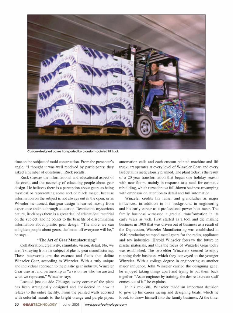
Custom-designed boxes transported by a custom-painted lift truck.
www.geartechnology.com June 2008 GEARTECHNOLOGY 0031
decade ago, 50 employees were required to produce 2 million gears in a month. In the same time span, Winzeler Gear is now capable of manufacturing 12 million plastic gears with only 35 employees.
Attention to detail is another component of Winzeler’s unique business model. The actions, appearance and behavior of the employees positively embody the strategies of Winzeler Gear. One client once criticized the company for its small size, but this same critic noted the depth of the employees and their practices, demonstrating strength of knowledge. “John was creating a picture, and the employees had to be part of that picture,” says Warren Edmondson, process engineer.
Edmondson believes they increase progress at Winzeler Gear by working on projects that are more outside of the loop, with business practices to match. Edmondson recalls the dues he paid working at traditional factories and the differences in his life working at Winzeler Gear. “I work in a place that is much more than a factory,” he says.
Although Winzeler acknowledges many personal in-fl uences to the form his company takes today, he refuses to take credit. He cites the collaborative work of a highly innovative creative team synergy. They do not just manufacture gears at Winzeler Gear. The majority of its business is in gear product design. Engineers conceptualize entire products for clients, although they only produce the gears—so far. The creative aspect of the business provides benefi ts in how the company is perceived in the marketplace, and Winzeler says that foreign visitors in particular relate very well to his business model. With the positive, engaging feedback foreign clients offer,
he wondered how he could apply his hunger for creativity to a new profession. He recalls telling himself, “If I’m going to make my work my life, how was it going to be fun?”
Art may be the most apparent sign of innovation at Winzeler Gear, but there are other unique initiatives the company employs. Partnership is a method Winzeler engages to create mutual opportunities. This approach came about a decade ago in an effort to further develop the business and benefi t from cooperative ventures. “As a small company without huge buying power, we tried to come up with a way to leverage suppliers to do joint marketing, business development,” he says.
Winzeler Gear’s strategic partners include Engel, DuPont, RJG, Inc. and Bradley University. All of the molding machines at Winzeler come from Engel, while Dupont supplies materials and Bradley performs research for the gear manufacturer. The Winzeler plant essentially serves as a showroom for Engel, and the partnerships function at many levels for all the businesses involved. Research and Development is the latest enterprise Winzeler is investing in. He views R&D as a critical element for business development with plastics.
The complete factory automation was another component of the plant rebuilding effort. Winzeler noted that in order to attract large-volume business, he needed to increase production in means that are not possible purely with labor. Particularly in the United States, where labor regulations and union considerations are critical factors, Winzeler knew that he could not create large quantities solely using a human workforce. Before the factory was automated as it is today, a
continued
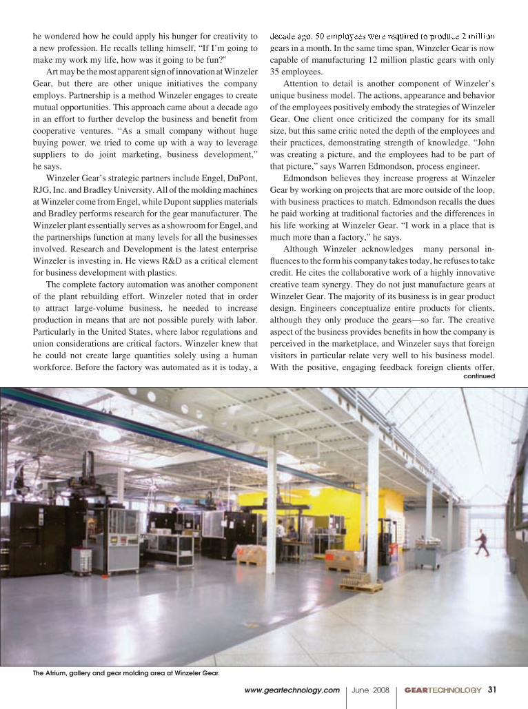
The Atrium, gallery and gear molding area at Winzeler Gear.
00 GEARTECHNOLOGY June 2008 www.geartechnology.com
companies may benefi t from testing unconventional ideas and eccentric, alternative methods towards their businesses. Some healthy risk-taking shouldn’t act as a deterrent. All innovation takes is a little coloring outside the lines, or as Felsenthal says, “We dance to the tune of a different drummer.”
For more information:ABA-PGT Inc. P.0. Box 8270Manchester, CT 06042-0270Phone: (860) 649-4591Fax: (860) [email protected] www.abapgt.com
Kleiss Gears, Inc.390 Industrial AvenueGrantsburg, WI 54840Phone: (715) 463-5995Fax: (715) [email protected]
Winzeler Gear7355 W. Wilson Ave.Harwood Heights, IL 60706 Phone: (708) 867-7971Fax: (708) [email protected]
32
Winzeler is targeting global customers more. They already make up about 20 percent of his buyers. Winzeler mentions the “WOMP,” factor, or “word of mouth potential,” which he hopes is a dynamic at work with his company. “People may love or hate the idea, but they never forget it.”
Innovation Crafted from Limitation “While the plastics industry is growing substantially
worldwide, it is struggling to maintain modest growth in North America,” according to the 2007 North American Plastics Industry Study on the plastic processing industry.
Today’s American manufacturers face a truly diffi cult challenge when it comes to distinguishing themselves and remaining competitive amidst the fl ood of international gear production. In the plastic gear manufacturing sphere, several domestic companies demonstrate unique and innovative business practices, which would be lost if the respective businesses were separated from their manufacturing facilities by vast distance and complex language barriers. This doesn’t even consider the dramatic social, cultural and economic differences that exist internally, but more importantly, that exist between countries.
“Highly successful companies appear smaller. The technical niche they exploit may be better suited to a narrower market,” the plastic processing industry study suggests.
Plastic is a distinct material in the gear industry, and the American companies that deal with it have a distinct opportunity they can take advantage of. Smaller domestic
From the inventors of the mechanical
face driver…
Industry’s best performance and run-out. Period.
• Now even tighter tolerances for improved runout and durability. No other face driver is manufactured to this precision!
• New springs for even longer life• Special applications, grinding, hard turning,
HEAVY cuts – let us prove it!
• STILL completely sealed, now with new endcap that adds
further protection against chips, coolant, and grinding swarf
• New end cap placement improves tooling clearance• Available in carbide or half carbide• Industry leading TIR down to .00008"
(or +/- .00004" the way our competitors do the math)
Get it all at drivers.LMCworkholding.comGet it all at drivers.LMCworkholding.com Get it all at centers.LMCworkholding.comGet it all at centers.LMCworkholding.com
Next Generation Neidlein Face Drivers and Centers
www.geartechnology.com June 2008 GEARTECHNOLOGY 0033
continued
455 Sheldon Dr., Cambridge, ON, N1T 2B7 Tel 519-624-6240 Fax 519-624-4119
www�hav�����������
GEAR���� �� ������ ������������� ��������� ����
Capabilities: Spur Helical Case Hardened & Ground Bevel Gears, Straight and Spiral Worm & Worm Gears Globoid Worms & Wheels
Splines-Internal & External Sprockets Split & Ring Gears Racks Special Design Services Gearbox Rebuilders
Our Machines and Capacity:Maag Gear Shaper 735 300" od 52 " face Maag Gear Shaper 250/300 120" od 26 " face 2x Maag Gear Shaper 180/300 120" od 17" face 12" internal 3x Maag Gear Shaper 100/140 50 " od 12" face 3x Fellows Gear Shapers1 x 100" | 2 x 36" 2x TOS Hobber100" od 30" face
2x NEW CNC TOS FUQ 5-AXIS X=78" - 787" Cross Travel 60" NEW CNC LATHE 150/800060" od 320" between centers NEW CNC LATHE 150/400060" od 160 " between centers 2x Maag Gear ShaperSH-75 30" CNC SCHEISS Gear Shaper120" od 15" face Plus: smaller Gear Shapers & Hobbers
������������������������������������������������������������������������������
00 GEARTECHNOLOGY June 2008 www.geartechnology.com34
There’s no top-secret, powder metal technique that’s going to eliminate the rather bleak outlook of the current automobile and housing markets; no business plan that will sweep declining powder shipments and PM parts usage under the rug; no triumphant declaration
that the PM industry is in the midst of a profi table and successful calendar year. In reality, you’ll be hard-pressed to fi nd anyone that’s not a little concerned about where United States manufacturing is at, and where it’s going.
It is nice to know, however,
there are people working to improve material properties, create innovative technologies and raise awareness of the PM industry in order to help get manufacturing back on its feet. If you submit to the notion that “the glass is half full,” you may not only listen to
The Powder Metal Method
DESPITE ECONOMIC UNCERTAINTY THE FUTURE LOOKS PROMISING FOR PM GEARS
Matthew Jaster, Associate Editor
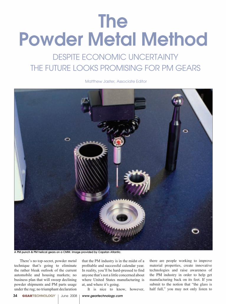
A PM punch & PM helical gears on a CMM. Image provided by Capstan Atlantic.
www.geartechnology.com June 2008 GEARTECHNOLOGY 0035
such optimism; you may start believing it.
Getting the word out. Due to its low-cost, high-performance characteristics and excellent response time, powder metallurgy remains a signifi cant form of alternative gear manufacturing. Thanks to innovative technologies and improved material properties, domestic powder metals should continue to enjoy success for many years to come.
According to the Metal Powder Industries Federation (MPIF), the typical United States passenger car contains 43 pounds of powder metallurgy parts. More than 500 million PM hot forged connecting rods have been made for cars produced in the United States, Europe and Japan.
More importantly, there are other areas where powder metallurgy has yet to reach its full potential, including transaxles for recreational vehicles, business machines and lawn and garden equipment. These, along with automobiles, will eventually help push the industry forward.
“There are so many different areas the PM industry can be called upon for,” says James Dale, vice president of the MPIF. “Problem is that it’s diffi cult to assess the various needs of our customers. We’re currently trying to increase visibility in the auto market by bringing some new ideas to the table.”
Dale adds that the driving force in powder metallurgy in 2008 is going to be word of mouth. The key will be promoting the technical aspects of the industry and trying to get engineers to start thinking about different solutions during the design phase.
“The smartest thing an engineer can do at this stage in the game is to talk to potential suppliers early and often,” Dale says. “Ask the right questions and fi nd out what a supplier can do for you and what PM systems are available. You may be short-changing yourself if you don’t know what the PM industry can provide in regards to mechanical properties and reduced component costs.”
Dale describes the current state of the PM industry as “steady,” though he admits to some recent drop-offs mainly due to the economy. Currently, the main objective of the MPIF is to get as much traffi c as possible to its website and to
promote its members. By continuously adding and updating material, the site has become a focal point for PM in the United States as well as the global market.
“The MPIF operates with the Industry Development Board and tries to get involved in conferences and seminars relevant to powder metals,” Dale says. “You’ll fi nd us at places like the National Design Engineering show and the SAE World Congress. It’s important to get out there and talk about our breakthroughs in strength requirements and density.”
The MPIF also publishes a series of material standards that serve the gear community with recognized standard alloys for designers and metallurgists to specify for their products. Wide distribution of these standards ensures the design community of up-to-date materials and properties for specifying their gear systems.
Howard Sanderow, president of Management & Engineering Technologies, a consulting fi rm, adds that there are a few other marketing thrusts currently in the industry.
“The Global PM Property Database—introduced two years ago—is a database that provides physical and mechanical property data for ferrous and non-ferrous structural materials, bearing grades and metal-injection-molded products. Free of charge, the database is available 24/7 at www.pmdatabase.com,” Sanderow says.
The website was created by a cooperative effort between the MPIF, the European Powder Metal Association (EPMA), and the Japan Powder Metallurgy Association (JPMA).
Sanderow is pleased with the collaborative efforts of these various global institutions, and as chairman of the AGMA Powder Metallurgy Gear Committee, believes there’s a great opportunity for the PM industry and AGMA to collaborate on training programs for net-formed gear manufacturing technologies as well.
While there’s PM business in the high-tech, medical and military fi elds, Sanderow believes it isn’t enough for domestic manufacturers to offset the declines in dominant markets. According to Sanderow, the auto industry registered its fi rst ever decline
in PM parts usage in 2007 as the shift to smaller vehicles impacted PM parts usage in light trucks and SUV’s. The non-automotive segment of the PM industry has been affected by the sharp decline of new home purchases.
On a positive note, the domestic PM industry continues to enjoy a strong position in gear technology for power tools, lawn and garden transmissions, pumps and gear motors for a variety of industrial and consumer products.
“We believe gears are the single largest ‘product’ manufactured by the PM process, representing an annual sales volume of more than $1 billion,” Sanderow says. “The current soft economy in 2008 will impede the immediate growth of PM gear sales, but we should see a strong recovery in 2009/2010.”
The rising cost of raw materials. According to a state-of-the-industry address at the PowderMet 2007 conference in Denver, the rising price of raw materials, especially copper and nickel, have forced a substitution trend in the industry.
Some stainless steel users are switching to lower-nickel 304 stainless or moving into non-nickel-containing stainless steels. Fabricators of bronze bearings are lowering the copper content in PM bearings with diluted bronze bearings or iron-graphite bearings. Observers expect the prices of nickel and copper to stay high until new mining capacity is targeted to hit the market in 2008.
The Hoeganaes Corporation, an iron powder manufacturer, strives for high-performing materials for its customer base, emphasizing a cost-effective alternative for PM parts makers.
“This has to be done within the context of the rapidly increasing material price environment that we live in,” says Howard Rutz, vice president of research and development at Hoeganaes. “We deal with a wide range of markets in addition to our core “press and sinter” business. When you come to work each day, you never know who is going to call with another unique application for iron powders.”
The company has been working with gear maker Capstan Atlantic on the introduction of AncorMax 200, a
continued

00 GEARTECHNOLOGY June 2008 www.geartechnology.com36
Arrow Gear is widely known as a producer of highprecision custom gears.Arrow also offers a full line of spiral bevel gearsfrom stock – including ground tooth gears. Stockgears are a cost-effective alternative to customgearing – especially beneficial for low productionvolumes and prototype work.Our state-of-the-art gear manufacturing facility isamong the most advanced in the world. Thiscapability allows us to provide high precisionstock gears in matched sets that are carburizedand hardened – meeting quality specificationsfrom AGMA Q9 up to Q13 on ground toothgears. Based on customer needs, our stockgears can often be modified to meet specificdesign requirements.To learn more about Arrow’s stock gearproducts, please visit our Website or contactour Design Engineering department.
2301 Curtiss Street • Downers Grove, IL 60515 USA(630) 969-7640 • www.ArrowGear.com
warm compaction technology that takes advantage of the Ancordense process without the need to heat the powder. This process achieves a density of 7.5g/cm3 by single pressing and sintering.
“This provides the ability to easily compact to the higher density levels that are necessary to meet gear requirements,” Rutz says.
Combining this process with high-performance alloys such as Ancorsteel 4300 has opened up new applications for PM gears and sprockets in automotive transmissions and hand tools. Ancorsteel 4300 is the fi rst in a line of engineered, high-performance, binder-treated products that stimulate wrought steel comparisons, and can be processed at conventional sintering temperatures. Good compaction, dimensional stability, and sintering conditions are just a few of the advantages of this alloy.
With large penetration in the industrial and automotive sectors, Rutz says there are many examples of different PM parts being manufactured for the gear industry.
“The advantage in near net shape production of gears is obvious, and the technology needed to compete in the highest levels of gear performance is on the horizon,” Rutz says.
An investment in technology. While there’s no breakthrough technology that’s going to turn the industry upside-down, Capstan Atlantic is moving forward on several PM advancements. The company is aware of the global growth potential available to their customers, and it is seizing every opportunity to develop new techniques to jumpstart the market.
“With powder metallurgy, you can tailor the process to the application you’ve targeted and be very specifi c without over-engineering and creating a lot of waste,” says Richard Slattery, vice president of engineering at Capstan. “People aren’t fully aware of what’s available to them and how fl exible the PM process can be.”
In 2007, Capstan targeted precise, high-performance, multi-level sprockets by launching an award-winning series of high-density, single-pressed sprockets for automotive applications. Recently, the company brought a selective densifi cation process to the market and has the fi rst PM-crowned gear in
When it comes to workholding solutions for gear machining, N.A. Woodworth provides a wealth of technical knowledge, expertise and engineering assistance
that sets us apart. Our various designs include our Universal Gear (UG) and our newly developed Pitch Line (PLD) diaphragm chucks. We have the product to fi t
your process. All built with exacting standards to provide the best workholding solutions for gear machining. Give us a call.
1391 Wheaton • Suite 700 • Troy, Michigan 48083800-544-3823 • Fax: 248-743-4401
an ISO9001: 2000 Registered Company
www.itwworkholding.com
Gear Workholding.
If it’s hard to hold...the answer’s not hard to fi nd.
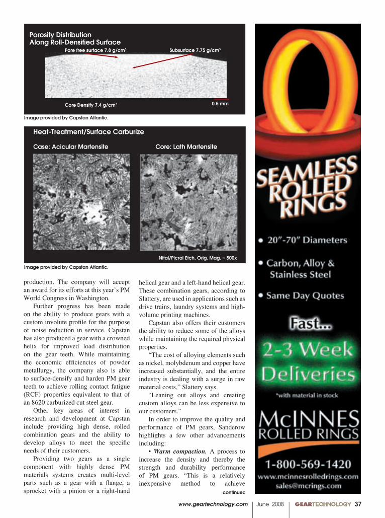
www.geartechnology.com June 2008 GEARTECHNOLOGY 0037
production. The company will accept an award for its efforts at this year’s PM World Congress in Washington.
Further progress has been made on the ability to produce gears with a custom involute profi le for the purpose of noise reduction in service. Capstan has also produced a gear with a crowned helix for improved load distribution on the gear teeth. While maintaining the economic effi ciencies of powder metallurgy, the company also is able to surface-densify and harden PM gear teeth to achieve rolling contact fatigue (RCF) properties equivalent to that of an 8620 carburized cut steel gear.
Other key areas of interest in research and development at Capstan include providing high dense, rolled combination gears and the ability to develop alloys to meet the specifi c needs of their customers.
Providing two gears as a single component with highly dense PM materials systems creates multi-level parts such as a gear with a fl ange, a sprocket with a pinion or a right-hand
helical gear and a left-hand helical gear. These combination gears, according to Slattery, are used in applications such as drive trains, laundry systems and high-volume printing machines.
Capstan also offers their customers the ability to reduce some of the alloys while maintaining the required physical properties.
“The cost of alloying elements such as nickel, molybdenum and copper have increased substantially, and the entire industry is dealing with a surge in raw material costs,” Slattery says.
“Leaning out alloys and creating custom alloys can be less expensive to our customers.”
In order to improve the quality and performance of PM gears, Sanderow highlights a few other advancements including:
• Warm compaction. A process to increase the density and thereby the strength and durability performance of PM gears. “This is a relatively inexpensive method to achieve
continued
Porosity DistributionAlong Roll-Densified Surface Pore free surface 7.8 g/cm3 Subsurface 7.75 g/cm3
Core Density 7.4 g/cm3 0.5 mm
Nital/Picral Etch, Orig. Mag. = 500x
Heat-Treatment/Surface Carburize
Case: Acicular Martensite Core: Lath Martensite
Image provided by Capstan Atlantic.
Image provided by Capstan Atlantic.
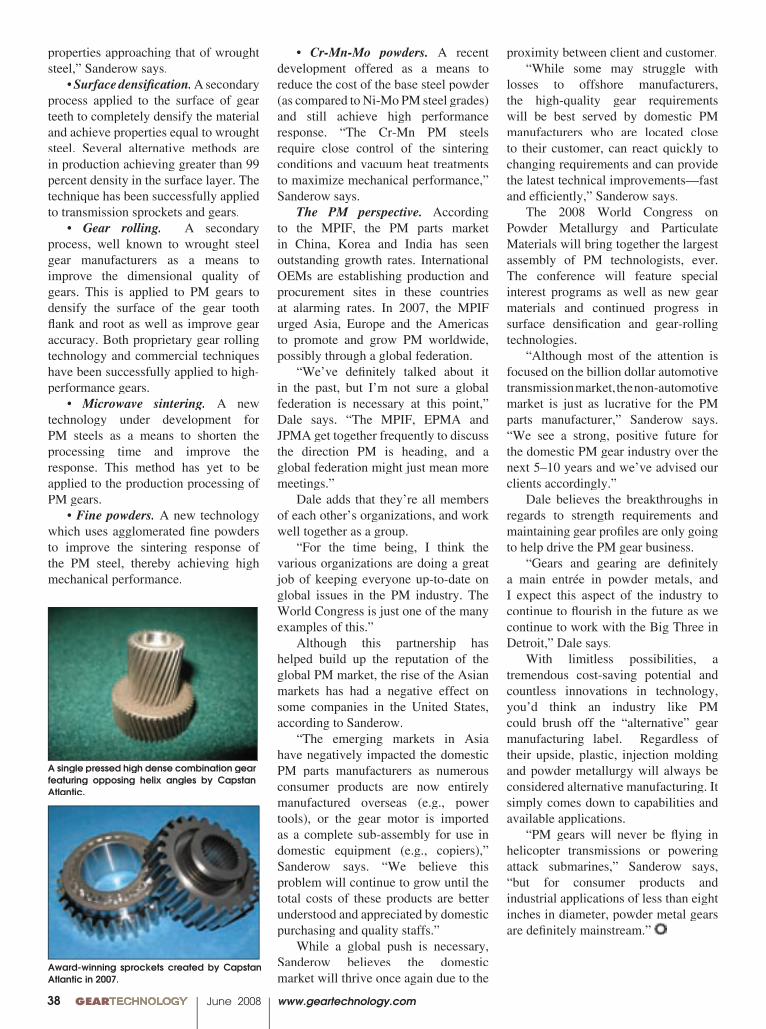
00 GEARTECHNOLOGY June 2008 www.geartechnology.com38
properties approaching that of wrought steel,” Sanderow says.
• Surface densifi cation. A secondary process applied to the surface of gear teeth to completely densify the material and achieve properties equal to wrought steel. Several alternative methods are in production achieving greater than 99 percent density in the surface layer. The technique has been successfully applied to transmission sprockets and gears.
• Gear rolling. A secondary process, well known to wrought steel gear manufacturers as a means to improve the dimensional quality of gears. This is applied to PM gears to densify the surface of the gear tooth fl ank and root as well as improve gear accuracy. Both proprietary gear rolling technology and commercial techniques have been successfully applied to high-performance gears.
• Microwave sintering. A new technology under development for PM steels as a means to shorten the processing time and improve the response. This method has yet to be applied to the production processing of PM gears.
• Fine powders. A new technology which uses agglomerated fi ne powders to improve the sintering response of the PM steel, thereby achieving high mechanical performance.
• Cr-Mn-Mo powders. A recent development offered as a means to reduce the cost of the base steel powder (as compared to Ni-Mo PM steel grades) and still achieve high performance response. “The Cr-Mn PM steels require close control of the sintering conditions and vacuum heat treatments to maximize mechanical performance,” Sanderow says.
The PM perspective. According to the MPIF, the PM parts market in China, Korea and India has seen outstanding growth rates. International OEMs are establishing production and procurement sites in these countries at alarming rates. In 2007, the MPIF urged Asia, Europe and the Americas to promote and grow PM worldwide, possibly through a global federation.
“We’ve defi nitely talked about it in the past, but I’m not sure a global federation is necessary at this point,” Dale says. “The MPIF, EPMA and JPMA get together frequently to discuss the direction PM is heading, and a global federation might just mean more meetings.”
Dale adds that they’re all members of each other’s organizations, and work well together as a group.
“For the time being, I think the various organizations are doing a great job of keeping everyone up-to-date on global issues in the PM industry. The World Congress is just one of the many examples of this.”
Although this partnership has helped build up the reputation of the global PM market, the rise of the Asian markets has had a negative effect on some companies in the United States, according to Sanderow.
“The emerging markets in Asia have negatively impacted the domestic PM parts manufacturers as numerous consumer products are now entirely manufactured overseas (e.g., power tools), or the gear motor is imported as a complete sub-assembly for use in domestic equipment (e.g., copiers),” Sanderow says. “We believe this problem will continue to grow until the total costs of these products are better understood and appreciated by domestic purchasing and quality staffs.”
While a global push is necessary, Sanderow believes the domestic market will thrive once again due to the
proximity between client and customer. “While some may struggle with
losses to offshore manufacturers, the high-quality gear requirements will be best served by domestic PM manufacturers who are located close to their customer, can react quickly to changing requirements and can provide the latest technical improvements—fast and effi ciently,” Sanderow says.
The 2008 World Congress on Powder Metallurgy and Particulate Materials will bring together the largest assembly of PM technologists, ever. The conference will feature special interest programs as well as new gear materials and continued progress in surface densifi cation and gear-rolling technologies.
“Although most of the attention is focused on the billion dollar automotive transmission market, the non-automotive market is just as lucrative for the PM parts manufacturer,” Sanderow says. “We see a strong, positive future for the domestic PM gear industry over the next 5–10 years and we’ve advised our clients accordingly.”
Dale believes the breakthroughs in regards to strength requirements and maintaining gear profi les are only going to help drive the PM gear business.
“Gears and gearing are defi nitely a main entrée in powder metals, and I expect this aspect of the industry to continue to fl ourish in the future as we continue to work with the Big Three in Detroit,” Dale says.
With limitless possibilities, a tremendous cost-saving potential and countless innovations in technology, you’d think an industry like PM could brush off the “alternative” gear manufacturing label. Regardless of their upside, plastic, injection molding and powder metallurgy will always be considered alternative manufacturing. It simply comes down to capabilities and available applications.
“PM gears will never be fl ying in helicopter transmissions or powering attack submarines,” Sanderow says, “but for consumer products and industrial applications of less than eight inches in diameter, powder metal gears are defi nitely mainstream.”
A single pressed high dense combination gear featuring opposing helix angles by Capstan Atlantic.
Award-winning sprockets created by Capstan Atlantic in 2007.
www.geartechnology.com June 2008 GEARTECHNOLOGY 0039www.geartechnology.com www.geartechnology.com www.geartechnology.com June 2008 GEARTECHNOLOGYTECHNOLOGY 0039003900
www.sunnen.com • 800-325-3670 • St. Louis, MO I06-1
ML-5000 AUTOMATIC HONING MACHINE
Gear bores demand critical tolerances. Sunnen’s ML-5000 automatic honing machinesGear bores demand critical tolerances. Sunnen’s ML-5000 automatic honing machineshold bore size tolerances to within 5 microns with virtually any surface finish hold bore size tolerances to within 5 microns with virtually any surface finish to meet stringent gear specifications.
Plus, it is up to 60% faster than previous honing techniques or I.D. grinding – perfect for mid-to-high volume production requirements. I.D. grinding – perfect for mid-to-high volume production requirements. Greater honing speed, consistency and precision all add up to cost savings that can mean payback in just months.
To get your free cost analysis for your gear or other bore sizing application, call 1-800-325-3670 or visit www.sunnen.com/ML-5000.
5 10 20 30 40 50 60 70 80 90 95 100
00 GEARTECHNOLOGY June 2008 www.geartechnology.com40
IntroductionIt is standard practice in the gear industry to defi ne the
quality of a gear based on physical measurement of size and form. This is never more evident than in the AGMA gear quality rating, where measured values of total composite error (TCE) and tooth-to-tooth error (TTE) are used to neatly categorize and rate the quality of a gear. Beyond that, a great deal of effort might also be placed on using more advanced metrology equipment to gather more information about the size and form of the gear. This could include using elemental inspection to get detailed information about the involute and lead of the gear, using optical or a coordinate measuring machine to defi ne the form of the inner diameter (ID), the fl atness of the part, the profi le of other features on the gear or using a profi lometer or other technique to quantify the surface fi nish of the gear teeth. This is all good information to have about your gear. In machined metal or plastic gears, if you have started with a quality piece of raw material, you can be confi dent that if physical measurements are repeatable and within specifi cation, your gear supplier has done a fi ne job of supplying you a quality gear. With molded plastic gears, this practice of relying on physical measurements as proof of quality overlooks potential defi ciencies in the injection molding process and the effect they may have on the integrity of the plastic material.
The scope of this paper is to spotlight these molding defi ciencies and to discuss the hidden effects they can have on the end properties of your plastic gear. There is a lot of published data available on the physical properties of every type and grade of plastic imaginable. What is less available and often disregarded by both end users and molders of plastic gears is information on just how these published properties are
Material Integrity in Molded Plastic GearsAND ITS DEPENDENCE ON MOLDING PRACTICES
Tim Vale
Management SummaryThe quality of molded plastic gears is typically judged by dimensional feature measurements only. This
practice overlooks potential defi ciencies in the plastic injection molding process and its effect on the integrity of the plastic material. These deeper issues are not often given proper consideration until a related gear failure demands study and evaluation. This paper identifi es some of these oversights in the molding process, the resultant effect on the plastic material and discusses their likely effect on short- and long-term gear performance.
affected by processing conditions during injection molding. When published data is compiled, there is a certain amount of care that goes into assuring that test specimens have been molded using optimum molding conditions which will in turn yield the best physical properties. Optimum properties of the plastic material cannot be achieved without optimum processing conditions. Proper part design plays a major role in getting the most out of your plastic material, but with all things equal, if proper care is not taken during molding, all of the up-front analysis done by a gear designer can quickly become meaningless. In addition to reducing physical properties, poor molding will also create the conditions for failure modes that could not be predicted or accounted for by even the most prudent of designers.
It is also important to note here that there is no way around the fact that a high-quality molded plastic gear starts with the design and construction of a high-quality plastic gear mold. This mold shall always have proper cooling channels; venting; properly sized gates and runners; suffi cient coring; suffi cient ejection capabilities; quality mold surface fi nish; precision fi ts and tolerances; concentricity between mold components; and proper steel selection. This paper will not focus on why those things are important or how they are achieved. Instead it will be assumed that a very sound mold with all of these considerations has been produced and is being used. This paper will describe the things that can go wrong regardless of the mold and part design if the gear molder is not disci-plined and committed to molding a high-quality gear from the inside out.
Crystallinity and shrinkage. When studying the relationship between processing and end properties of a molded gear, the two most basic fundamentals that need to
Printed with permission of the copyright holder, the American Gear Manufacturers Association, 500 Montgomery Street, Suite 350, Alexandria, Virginia 22314-1560. Statements presented in this paper are those of the authors and may not represent the position or opinion of the American Gear Manufacturers Association.
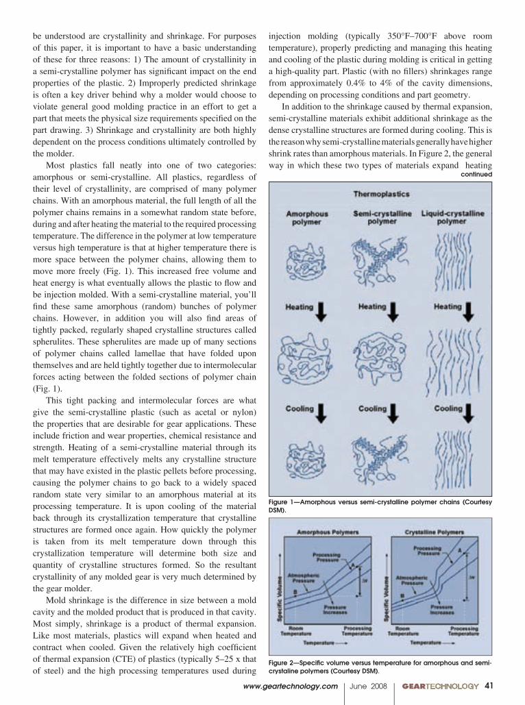
www.geartechnology.com June 2008 GEARTECHNOLOGY 0041
be understood are crystallinity and shrinkage. For purposes of this paper, it is important to have a basic understanding of these for three reasons: 1) The amount of crystallinity in a semi-crystalline polymer has signifi cant impact on the end properties of the plastic. 2) Improperly predicted shrinkage is often a key driver behind why a molder would choose to violate general good molding practice in an effort to get a part that meets the physical size requirements specifi ed on the part drawing. 3) Shrinkage and crystallinity are both highly dependent on the process conditions ultimately controlled by the molder.
Most plastics fall neatly into one of two categories: amorphous or semi-crystalline. All plastics, regardless of their level of crystallinity, are comprised of many polymer chains. With an amorphous material, the full length of all the polymer chains remains in a somewhat random state before, during and after heating the material to the required processing temperature. The difference in the polymer at low temperature versus high temperature is that at higher temperature there is more space between the polymer chains, allowing them to move more freely (Fig. 1). This increased free volume and heat energy is what eventually allows the plastic to fl ow and be injection molded. With a semi-crystalline material, you’ll fi nd these same amorphous (random) bunches of polymer chains. However, in addition you will also fi nd areas of tightly packed, regularly shaped crystalline structures called spherulites. These spherulites are made up of many sections of polymer chains called lamellae that have folded upon themselves and are held tightly together due to intermolecular forces acting between the folded sections of polymer chain (Fig. 1).
This tight packing and intermolecular forces are what give the semi-crystalline plastic (such as acetal or nylon) the properties that are desirable for gear applications. These include friction and wear properties, chemical resistance and strength. Heating of a semi-crystalline material through its melt temperature effectively melts any crystalline structure that may have existed in the plastic pellets before processing, causing the polymer chains to go back to a widely spaced random state very similar to an amorphous material at its processing temperature. It is upon cooling of the material back through its crystallization temperature that crystalline structures are formed once again. How quickly the polymer is taken from its melt temperature down through this crystallization temperature will determine both size and quantity of crystalline structures formed. So the resultant crystallinity of any molded gear is very much determined by the gear molder.
Mold shrinkage is the difference in size between a mold cavity and the molded product that is produced in that cavity. Most simply, shrinkage is a product of thermal expansion. Like most materials, plastics will expand when heated and contract when cooled. Given the relatively high coeffi cient of thermal expansion (CTE) of plastics (typically 5–25 x that of steel) and the high processing temperatures used during
injection molding (typically 350°F–700°F above room temperature), properly predicting and managing this heating and cooling of the plastic during molding is critical in getting a high-quality part. Plastic (with no fi llers) shrinkages range from approximately 0.4% to 4% of the cavity dimensions, depending on processing conditions and part geometry.
In addition to the shrinkage caused by thermal expansion, semi-crystalline materials exhibit additional shrinkage as the dense crystalline structures are formed during cooling. This is the reason why semi-crystalline materials generally have higher shrink rates than amorphous materials. In Figure 2, the general way in which these two types of materials expand heating
Figure 1—Amorphous versus semi-crystalline polymer chains (Courtesy DSM).
continued
Figure 2—Specifi c volume versus temperature for amorphous and semi-crystaline polymers (Courtesy DSM).
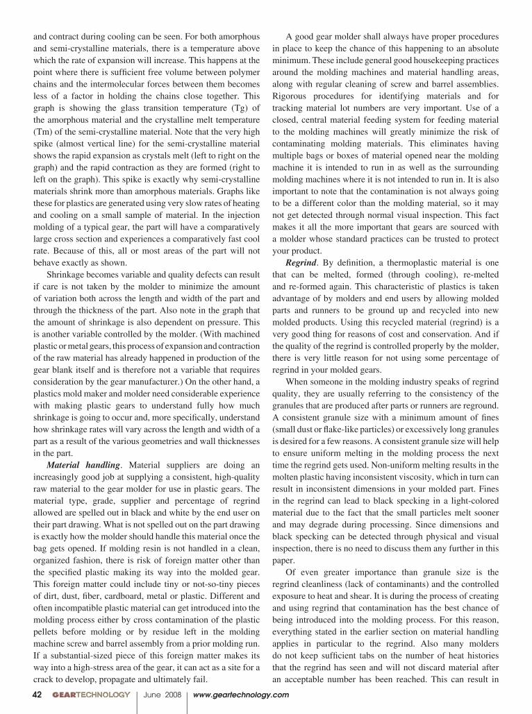
00 GEARTECHNOLOGY June 2008 www.geartechnology.com42
A good gear molder shall always have proper procedures in place to keep the chance of this happening to an absolute minimum. These include general good housekeeping practices around the molding machines and material handling areas, along with regular cleaning of screw and barrel assemblies. Rigorous procedures for identifying materials and for tracking material lot numbers are very important. Use of a closed, central material feeding system for feeding material to the molding machines will greatly minimize the risk of contaminating molding materials. This eliminates having multiple bags or boxes of material opened near the molding machine it is intended to run in as well as the surrounding molding machines where it is not intended to run in. It is also important to note that the contamination is not always going to be a different color than the molding material, so it may not get detected through normal visual inspection. This fact makes it all the more important that gears are sourced with a molder whose standard practices can be trusted to protect your product.
Regrind. By defi nition, a thermoplastic material is one that can be melted, formed (through cooling), re-melted and re-formed again. This characteristic of plastics is taken advantage of by molders and end users by allowing molded parts and runners to be ground up and recycled into new molded products. Using this recycled material (regrind) is a very good thing for reasons of cost and conservation. And if the quality of the regrind is controlled properly by the molder, there is very little reason for not using some percentage of regrind in your molded gears.
When someone in the molding industry speaks of regrind quality, they are usually referring to the consistency of the granules that are produced after parts or runners are reground. A consistent granule size with a minimum amount of fi nes (small dust or fl ake-like particles) or excessively long granules is desired for a few reasons. A consistent granule size will help to ensure uniform melting in the molding process the next time the regrind gets used. Non-uniform melting results in the molten plastic having inconsistent viscosity, which in turn can result in inconsistent dimensions in your molded part. Fines in the regrind can lead to black specking in a light-colored material due to the fact that the small particles melt sooner and may degrade during processing. Since dimensions and black specking can be detected through physical and visual inspection, there is no need to discuss them any further in this paper.
Of even greater importance than granule size is the regrind cleanliness (lack of contaminants) and the controlled exposure to heat and shear. It is during the process of creating and using regrind that contamination has the best chance of being introduced into the molding process. For this reason, everything stated in the earlier section on material handling applies in particular to the regrind. Also many molders do not keep suffi cient tabs on the number of heat histories that the regrind has seen and will not discard material after an acceptable number has been reached. This can result in
and contract during cooling can be seen. For both amorphous and semi-crystalline materials, there is a temperature above which the rate of expansion will increase. This happens at the point where there is suffi cient free volume between polymer chains and the intermolecular forces between them becomes less of a factor in holding the chains close together. This graph is showing the glass transition temperature (Tg) of the amorphous material and the crystalline melt temperature (Tm) of the semi-crystalline material. Note that the very high spike (almost vertical line) for the semi-crystalline material shows the rapid expansion as crystals melt (left to right on the graph) and the rapid contraction as they are formed (right to left on the graph). This spike is exactly why semi-crystalline materials shrink more than amorphous materials. Graphs like these for plastics are generated using very slow rates of heating and cooling on a small sample of material. In the injection molding of a typical gear, the part will have a comparatively large cross section and experiences a comparatively fast cool rate. Because of this, all or most areas of the part will not behave exactly as shown.
Shrinkage becomes variable and quality defects can result if care is not taken by the molder to minimize the amount of variation both across the length and width of the part and through the thickness of the part. Also note in the graph that the amount of shrinkage is also dependent on pressure. This is another variable controlled by the molder. (With machined plastic or metal gears, this process of expansion and contraction of the raw material has already happened in production of the gear blank itself and is therefore not a variable that requires consideration by the gear manufacturer.) On the other hand, a plastics mold maker and molder need considerable experience with making plastic gears to understand fully how much shrinkage is going to occur and, more specifi cally, understand how shrinkage rates will vary across the length and width of a part as a result of the various geometries and wall thicknesses in the part.
Material handling. Material suppliers are doing an increasingly good job at supplying a consistent, high-quality raw material to the gear molder for use in plastic gears. The material type, grade, supplier and percentage of regrind allowed are spelled out in black and white by the end user on their part drawing. What is not spelled out on the part drawing is exactly how the molder should handle this material once the bag gets opened. If molding resin is not handled in a clean, organized fashion, there is risk of foreign matter other than the specifi ed plastic making its way into the molded gear. This foreign matter could include tiny or not-so-tiny pieces of dirt, dust, fi ber, cardboard, metal or plastic. Different and often incompatible plastic material can get introduced into the molding process either by cross contamination of the plastic pellets before molding or by residue left in the molding machine screw and barrel assembly from a prior molding run. If a substantial-sized piece of this foreign matter makes its way into a high-stress area of the gear, it can act as a site for a crack to develop, propagate and ultimately fail.
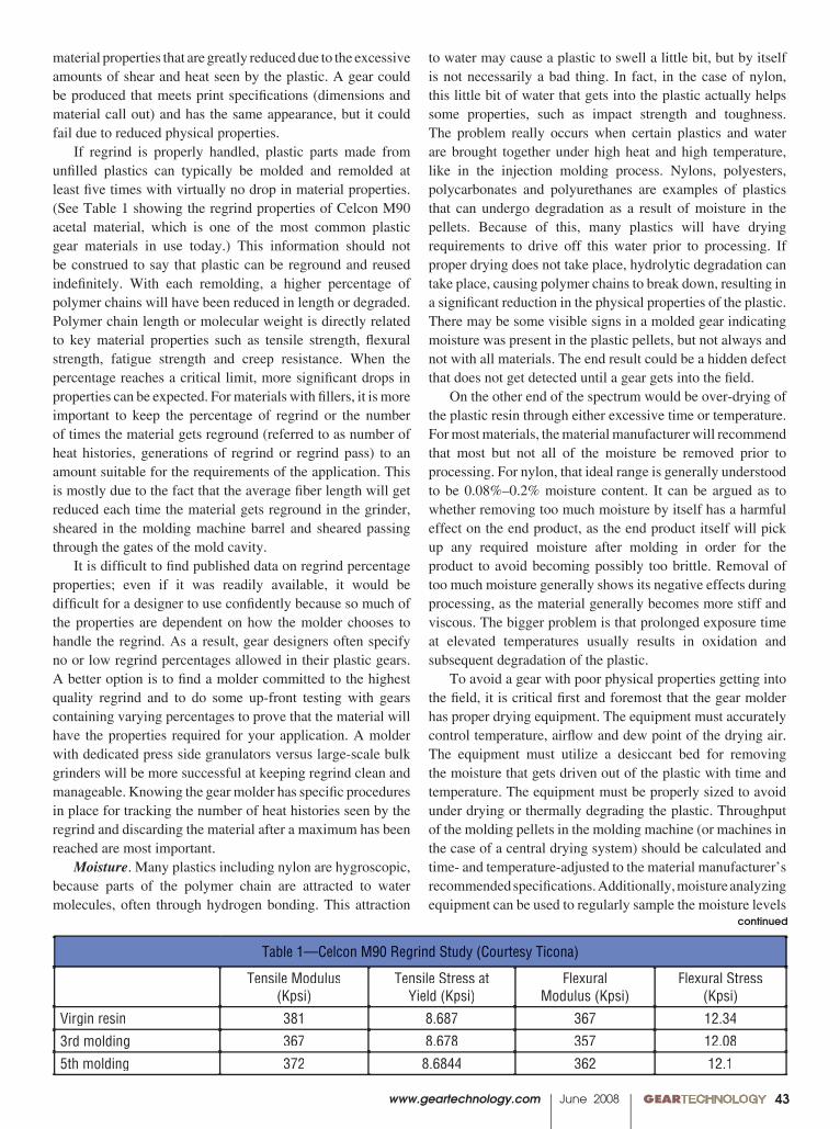
www.geartechnology.com June 2008 GEARTECHNOLOGY 00
Table 1—Celcon M90 Regrind Study (Courtesy Ticona)
Tensile Modulus(Kpsi)
Tensile Stress atYield (Kpsi)
FlexuralModulus (Kpsi)
Flexural Stress(Kpsi)
Virgin resin 381 8.687 367 12.343rd molding 367 8.678 357 12.085th molding 372 8.6844 362 12.1
43
continued
to water may cause a plastic to swell a little bit, but by itself is not necessarily a bad thing. In fact, in the case of nylon, this little bit of water that gets into the plastic actually helps some properties, such as impact strength and toughness. The problem really occurs when certain plastics and water are brought together under high heat and high temperature, like in the injection molding process. Nylons, polyesters, polycarbonates and polyurethanes are examples of plastics that can undergo degradation as a result of moisture in the pellets. Because of this, many plastics will have drying requirements to drive off this water prior to processing. If proper drying does not take place, hydrolytic degradation can take place, causing polymer chains to break down, resulting in a signifi cant reduction in the physical properties of the plastic. There may be some visible signs in a molded gear indicating moisture was present in the plastic pellets, but not always and not with all materials. The end result could be a hidden defect that does not get detected until a gear gets into the fi eld.
On the other end of the spectrum would be over-drying of the plastic resin through either excessive time or temperature. For most materials, the material manufacturer will recommend that most but not all of the moisture be removed prior to processing. For nylon, that ideal range is generally understood to be 0.08%–0.2% moisture content. It can be argued as to whether removing too much moisture by itself has a harmful effect on the end product, as the end product itself will pick up any required moisture after molding in order for the product to avoid becoming possibly too brittle. Removal of too much moisture generally shows its negative effects during processing, as the material generally becomes more stiff and viscous. The bigger problem is that prolonged exposure time at elevated temperatures usually results in oxidation and subsequent degradation of the plastic.
To avoid a gear with poor physical properties getting into the fi eld, it is critical fi rst and foremost that the gear molder has proper drying equipment. The equipment must accurately control temperature, airfl ow and dew point of the drying air. The equipment must utilize a desiccant bed for removing the moisture that gets driven out of the plastic with time and temperature. The equipment must be properly sized to avoid under drying or thermally degrading the plastic. Throughput of the molding pellets in the molding machine (or machines in the case of a central drying system) should be calculated and time- and temperature-adjusted to the material manufacturer’s recommended specifi cations. Additionally, moisture analyzing equipment can be used to regularly sample the moisture levels
material properties that are greatly reduced due to the excessive amounts of shear and heat seen by the plastic. A gear could be produced that meets print specifi cations (dimensions and material call out) and has the same appearance, but it could fail due to reduced physical properties.
If regrind is properly handled, plastic parts made from unfi lled plastics can typically be molded and remolded at least fi ve times with virtually no drop in material properties. (See Table 1 showing the regrind properties of Celcon M90 acetal material, which is one of the most common plastic gear materials in use today.) This information should not be construed to say that plastic can be reground and reused indefi nitely. With each remolding, a higher percentage of polymer chains will have been reduced in length or degraded. Polymer chain length or molecular weight is directly related to key material properties such as tensile strength, fl exural strength, fatigue strength and creep resistance. When the percentage reaches a critical limit, more signifi cant drops in properties can be expected. For materials with fi llers, it is more important to keep the percentage of regrind or the number of times the material gets reground (referred to as number of heat histories, generations of regrind or regrind pass) to an amount suitable for the requirements of the application. This is mostly due to the fact that the average fi ber length will get reduced each time the material gets reground in the grinder, sheared in the molding machine barrel and sheared passing through the gates of the mold cavity.
It is diffi cult to fi nd published data on regrind percentage properties; even if it was readily available, it would be diffi cult for a designer to use confi dently because so much of the properties are dependent on how the molder chooses to handle the regrind. As a result, gear designers often specify no or low regrind percentages allowed in their plastic gears. A better option is to fi nd a molder committed to the highest quality regrind and to do some up-front testing with gears containing varying percentages to prove that the material will have the properties required for your application. A molder with dedicated press side granulators versus large-scale bulk grinders will be more successful at keeping regrind clean and manageable. Knowing the gear molder has specifi c procedures in place for tracking the number of heat histories seen by the regrind and discarding the material after a maximum has been reached are most important.
Moisture. Many plastics including nylon are hygroscopic, because parts of the polymer chain are attracted to water molecules, often through hydrogen bonding. This attraction
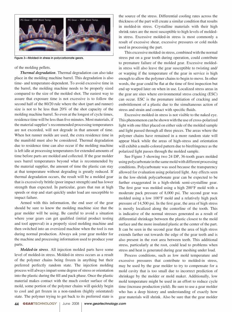
00 GEARTECHNOLOGY June 2008 www.geartechnology.com44
the source of the stress. Differential cooling rates across the thickness of the part will create a similar condition that results in molded-in stress. Crystalline materials with their high shrink rates are the most susceptible to high levels of molded-in stress. Excessive molded-in stress is most commonly a result of excessive shear, excessive pressures or cold molds used in processing the part.
This excessive molded-in stress, combined with the normal stress put on a gear tooth during operation, could contribute to premature failure of the molded gear. Excessive molded-in stress will also leave the gear susceptible to twisting and/or warping if the temperature of the gear in service is high enough to allow the polymer chains to begin to move. In other words, the gear could be fl at at the time of fi rst inspection but end up warped later on when in use. Localized stress areas in the gear are sites where environmental stress cracking (ESC) can occur. ESC is the premature initiation of cracking and embrittlement of a plastic due to the simultaneous action of stress and strain and contact with specifi c fl uids.
Excessive molded-in stress is not visible to the naked eye. This phenomenon can be shown with the use of cross-polarized light with one fi lter placed on either side of the molded sample and light passed through all three pieces. The areas where the polymer chains have remained in a more random state will appear black while the areas of high-stress and orientation will exhibit a multi-colored pattern due to birefringence as the polarized light passes through the molded sample.
See Figure 3 showing two 24 DP, 36-tooth gears molded using polycarbonate in the same mold with different processing conditions. Polycarbonate was used because the transparency allowed for evaluation using polarized light. Any effects seen in the low-shrink polycarbonate gear can be expected to be further exaggerated in a high-shrink semi-crystalline gear. The fi rst gear was molded using a high 200°F mold with a moderate pack pressure of 8,000 psi. The second gear was molded using a low 100°F mold and a relatively high pack pressure of 14,500 psi. In the fi rst gear, the area of high stress is mostly localized along the centerline of the tooth. This is indicative of the normal stresses generated as a result of differential shrinkage between the plastic closest to the mold surface and the more insulated plastic at the center of the part. It can be seen in the second gear that the area of high stress extends farther out towards the edge of the gear teeth and is also present in the root area between teeth. This additional stress, particularly at the root, could lead to problems when stress and heat is generated during gear meshing under load.
Process conditions, such as low mold temperature and excessive pressures that contribute to molded-in stress, may be used by the gear molder to try to compensate for a mold cavity that is too small due to incorrect prediction of shrinkage by the molder or mold maker. Additionally, low mold temperature might be used in an effort to reduce cycle time (increase production yield). Be sure to use a gear molder who has a deep history and understanding of exactly how gear materials will shrink. Also be sure that the gear molder
of the molding pellets. Thermal degradation. Thermal degradation can also take
place in the molding machine barrel. This degradation is also time- and temperature-dependent. To avoid excessive time in the barrel, the molding machine needs to be properly sized compared to the size of the molded shot. The easiest way to assure that exposure time is not excessive is to follow the second half of the 80/20 rule where the shot (part and runner) size is not to be less than 20% of the shot capacity of the molding machine barrel. So even at the longest of cycle times, residence time will be less than fi ve minutes. Most materials, if the material supplier’s recommended processing temperatures are not exceeded, will not degrade in that amount of time. When hot runner molds are used, the extra residence time in the manifold must also be considered. Thermal degradation due to residence time can also occur if the molding machine is left idle at processing temperatures for extended amounts of time before parts are molded and collected. If the gear molder uses barrel temperatures beyond what is recommended by the material supplier, the amount of time the plastic can stay at that temperature without degrading is greatly reduced. If thermal degradation occurs, the result will be a molded gear that is excessively brittle (poor impact strength) and has lower strength than expected. In particular, gears that run at high speeds or stop and start quickly under load are susceptible to impact failure.
Armed with this information, the end user of the gear should be sure to know the molding machine size that the gear molder will be using. Be careful to avoid a situation where your gears can get qualifi ed (initial product testing and tool approval) in a properly sized molding machine and then switched into an oversized machine when the tool is run during normal production. Always ask your gear molder for the machine and processing information used to produce your parts.
Molded-in stress. All injection molded parts have some level of molded-in stress. Molded-in stress occurs as a result of the polymer chains being frozen in anything but their preferred perfectly random state. The injection molding process will always impart some degree of stress or orientation into the plastic during the fi ll and pack phase. Once the plastic material makes contact with the much cooler surface of the mold, some portion of the polymer chains will quickly begin to cool and get frozen in a non-random (highly orientated) state. The polymer trying to get back to its preferred state is
Figure 3—Molded-in stress in polycarbonate gears.
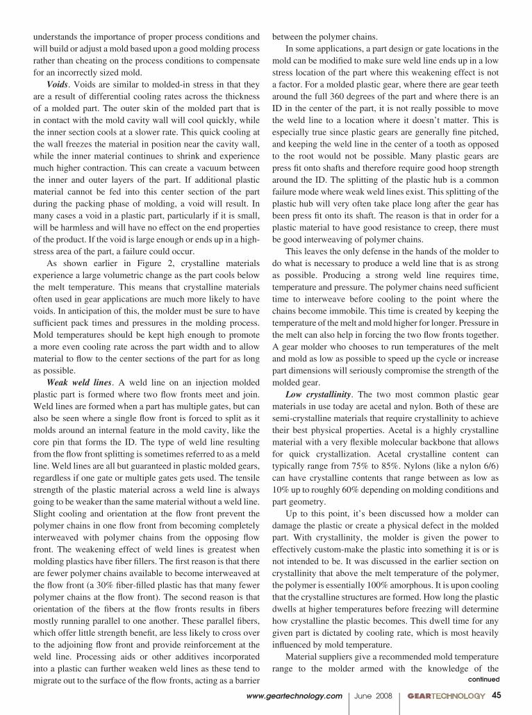
www.geartechnology.com June 2008 GEARTECHNOLOGY 0045
understands the importance of proper process conditions and will build or adjust a mold based upon a good molding process rather than cheating on the process conditions to compensate for an incorrectly sized mold.
Voids. Voids are similar to molded-in stress in that they are a result of differential cooling rates across the thickness of a molded part. The outer skin of the molded part that is in contact with the mold cavity wall will cool quickly, while the inner section cools at a slower rate. This quick cooling at the wall freezes the material in position near the cavity wall, while the inner material continues to shrink and experience much higher contraction. This can create a vacuum between the inner and outer layers of the part. If additional plastic material cannot be fed into this center section of the part during the packing phase of molding, a void will result. In many cases a void in a plastic part, particularly if it is small, will be harmless and will have no effect on the end properties of the product. If the void is large enough or ends up in a high-stress area of the part, a failure could occur.
As shown earlier in Figure 2, crystalline materials experience a large volumetric change as the part cools below the melt temperature. This means that crystalline materials often used in gear applications are much more likely to have voids. In anticipation of this, the molder must be sure to have suffi cient pack times and pressures in the molding process. Mold temperatures should be kept high enough to promote a more even cooling rate across the part width and to allow material to fl ow to the center sections of the part for as long as possible.
Weak weld lines. A weld line on an injection molded plastic part is formed where two fl ow fronts meet and join. Weld lines are formed when a part has multiple gates, but can also be seen where a single fl ow front is forced to split as it molds around an internal feature in the mold cavity, like the core pin that forms the ID. The type of weld line resulting from the fl ow front splitting is sometimes referred to as a meld line. Weld lines are all but guaranteed in plastic molded gears, regardless if one gate or multiple gates gets used. The tensile strength of the plastic material across a weld line is always going to be weaker than the same material without a weld line. Slight cooling and orientation at the fl ow front prevent the polymer chains in one fl ow front from becoming completely interweaved with polymer chains from the opposing fl ow front. The weakening effect of weld lines is greatest when molding plastics have fi ber fi llers. The fi rst reason is that there are fewer polymer chains available to become interweaved at the fl ow front (a 30% fi ber-fi lled plastic has that many fewer polymer chains at the fl ow front). The second reason is that orientation of the fi bers at the fl ow fronts results in fi bers mostly running parallel to one another. These parallel fi bers, which offer little strength benefi t, are less likely to cross over to the adjoining fl ow front and provide reinforcement at the weld line. Processing aids or other additives incorporated into a plastic can further weaken weld lines as these tend to migrate out to the surface of the fl ow fronts, acting as a barrier
between the polymer chains. In some applications, a part design or gate locations in the
mold can be modifi ed to make sure weld line ends up in a low stress location of the part where this weakening effect is not a factor. For a molded plastic gear, where there are gear teeth around the full 360 degrees of the part and where there is an ID in the center of the part, it is not really possible to move the weld line to a location where it doesn’t matter. This is especially true since plastic gears are generally fi ne pitched, and keeping the weld line in the center of a tooth as opposed to the root would not be possible. Many plastic gears are press fi t onto shafts and therefore require good hoop strength around the ID. The splitting of the plastic hub is a common failure mode where weak weld lines exist. This splitting of the plastic hub will very often take place long after the gear has been press fi t onto its shaft. The reason is that in order for a plastic material to have good resistance to creep, there must be good interweaving of polymer chains.
This leaves the only defense in the hands of the molder to do what is necessary to produce a weld line that is as strong as possible. Producing a strong weld line requires time, temperature and pressure. The polymer chains need suffi cient time to interweave before cooling to the point where the chains become immobile. This time is created by keeping the temperature of the melt and mold higher for longer. Pressure in the melt can also help in forcing the two fl ow fronts together. A gear molder who chooses to run temperatures of the melt and mold as low as possible to speed up the cycle or increase part dimensions will seriously compromise the strength of the molded gear.
Low crystallinity. The two most common plastic gear materials in use today are acetal and nylon. Both of these are semi-crystalline materials that require crystallinity to achieve their best physical properties. Acetal is a highly crystalline material with a very fl exible molecular backbone that allows for quick crystallization. Acetal crystalline content can typically range from 75% to 85%. Nylons (like a nylon 6/6) can have crystalline contents that range between as low as 10% up to roughly 60% depending on molding conditions and part geometry.
Up to this point, it’s been discussed how a molder can damage the plastic or create a physical defect in the molded part. With crystallinity, the molder is given the power to effectively custom-make the plastic into something it is or is not intended to be. It was discussed in the earlier section on crystallinity that above the melt temperature of the polymer, the polymer is essentially 100% amorphous. It is upon cooling that the crystalline structures are formed. How long the plastic dwells at higher temperatures before freezing will determine how crystalline the plastic becomes. This dwell time for any given part is dictated by cooling rate, which is most heavily infl uenced by mold temperature.
Material suppliers give a recommended mold temperature range to the molder armed with the knowledge of the
continued
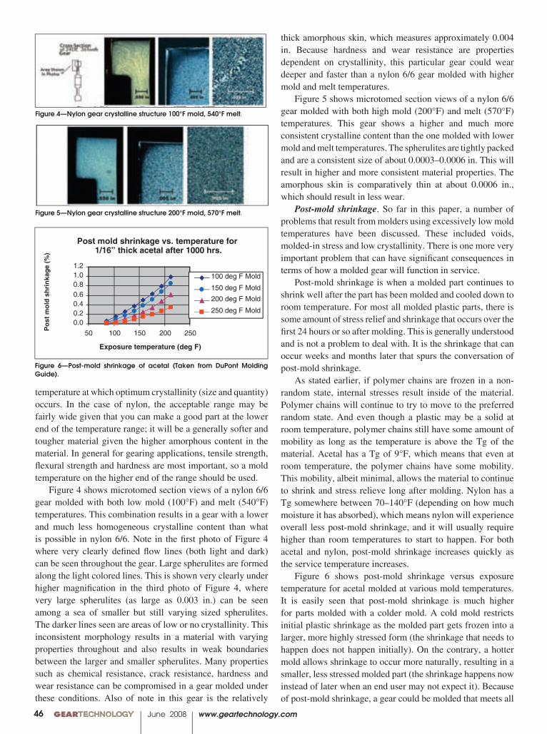
00 GEARTECHNOLOGY June 2008 www.geartechnology.com46
thick amorphous skin, which measures approximately 0.004 in. Because hardness and wear resistance are properties dependent on crystallinity, this particular gear could wear deeper and faster than a nylon 6/6 gear molded with higher mold and melt temperatures.
Figure 5 shows microtomed section views of a nylon 6/6 gear molded with both high mold (200°F) and melt (570°F) temperatures. This gear shows a higher and much more consistent crystalline content than the one molded with lower mold and melt temperatures. The spherulites are tightly packed and are a consistent size of about 0.0003–0.0006 in. This will result in higher and more consistent material properties. The amorphous skin is comparatively thin at about 0.0006 in., which should result in less wear.
Post-mold shrinkage. So far in this paper, a number of problems that result from molders using excessively low mold temperatures have been discussed. These included voids, molded-in stress and low crystallinity. There is one more very important problem that can have signifi cant consequences in terms of how a molded gear will function in service.
Post-mold shrinkage is when a molded part continues to shrink well after the part has been molded and cooled down to room temperature. For most all molded plastic parts, there is some amount of stress relief and shrinkage that occurs over the fi rst 24 hours or so after molding. This is generally understood and is not a problem to deal with. It is the shrinkage that can occur weeks and months later that spurs the conversation of post-mold shrinkage.
As stated earlier, if polymer chains are frozen in a non-random state, internal stresses result inside of the material. Polymer chains will continue to try to move to the preferred random state. And even though a plastic may be a solid at room temperature, polymer chains still have some amount of mobility as long as the temperature is above the Tg of the material. Acetal has a Tg of 9°F, which means that even at room temperature, the polymer chains have some mobility. This mobility, albeit minimal, allows the material to continue to shrink and stress relieve long after molding. Nylon has a Tg somewhere between 70–140°F (depending on how much moisture it has absorbed), which means nylon will experience overall less post-mold shrinkage, and it will usually require higher than room temperatures to start to happen. For both acetal and nylon, post-mold shrinkage increases quickly as the service temperature increases.
Figure 6 shows post-mold shrinkage versus exposure temperature for acetal molded at various mold temperatures. It is easily seen that post-mold shrinkage is much higher for parts molded with a colder mold. A cold mold restricts initial plastic shrinkage as the molded part gets frozen into a larger, more highly stressed form (the shrinkage that needs to happen does not happen initially). On the contrary, a hotter mold allows shrinkage to occur more naturally, resulting in a smaller, less stressed molded part (the shrinkage happens now instead of later when an end user may not expect it). Because of post-mold shrinkage, a gear could be molded that meets all
temperature at which optimum crystallinity (size and quantity) occurs. In the case of nylon, the acceptable range may be fairly wide given that you can make a good part at the lower end of the temperature range; it will be a generally softer and tougher material given the higher amorphous content in the material. In general for gearing applications, tensile strength, fl exural strength and hardness are most important, so a mold temperature on the higher end of the range should be used.
Figure 4 shows microtomed section views of a nylon 6/6 gear molded with both low mold (100°F) and melt (540°F) temperatures. This combination results in a gear with a lower and much less homogeneous crystalline content than what is possible in nylon 6/6. Note in the fi rst photo of Figure 4 where very clearly defi ned fl ow lines (both light and dark) can be seen throughout the gear. Large spherulites are formed along the light colored lines. This is shown very clearly under higher magnifi cation in the third photo of Figure 4, where very large spherulites (as large as 0.003 in.) can be seen among a sea of smaller but still varying sized spherulites. The darker lines seen are areas of low or no crystallinity. This inconsistent morphology results in a material with varying properties throughout and also results in weak boundaries between the larger and smaller spherulites. Many properties such as chemical resistance, crack resistance, hardness and wear resistance can be compromised in a gear molded under these conditions. Also of note in this gear is the relatively
Figure 4—Nylon gear crystalline structure 100°F mold, 540°F melt.
Figure 5—Nylon gear crystalline structure 200°F mold, 570°F melt.
0.00.20.40.60.81.01.2
50 100 150 200 250
Exposure temperature (deg F)
)%(
egaknir hsd lo
m tsoP
100 deg F Mold
150 deg F Mold
200 deg F Mold
250 deg F Mold
Post mold shrinkage vs. temperature for1/16” thick acetal after 1000 hrs.
Figure 6—Post-mold shrinkage of acetal (Taken from DuPont Molding Guide).

www.geartechnology.com June 2008 GEARTECHNOLOGY 0047
physical measurements of size and form at the time of fi rst inspection. If measured again many weeks later, especially if the gear was exposed to higher temperatures, it could measure well out of tolerance.
Table 2 demonstrates what the effect might be on a typical plastic gear’s dimensions when exposed to 150°F for 1,000 hours. A gear that measures nominal for all dimensions at the time of molding can end up being out of spec. by 0.0005 in. on the gear test radius (GTR) and 0.0014 in. on the OD when a 200°F mold gets used and end up being out of spec by 0.002 in. on GTR, and 0.005 in. for OD when a colder 100°F degree mold gets used. This will translate into reduced contact ratios and increased backlash. It is also very possible to have a gear that was fl at and round at the time of initial inspection become warped or out of round as a result of excessive post-mold shrinkage.
The best way to minimize these effects of post-mold shrinkage is to minimize stresses during molding (minimize shear and avoid excessive pack pressures) and to use a suffi ciently high mold temperature.
ConclusionIt is understandable how a molder would knowingly or
unknowingly move to using process conditions that produce a part more prone to failure than a part molded at optimum process conditions. The traditional gauge of quality, physical measured dimensions, tells the molder that if the part measures well, it is a good part. A good gear molder should know that there is more to quality than what meets the eye.
The goal of this paper was to provide knowledge to bothend users and molders of plastic gears on the crucial role that
the molder has in determining the fi nal quality of a plastic molded gear. The end user should use this knowledge to make the best decision when choosing a gear molder. The decision process should explore the molder’s systems, procedures, equipment and experience in molding high-quality plastic gears. This same knowledge then needs to be used by the gear molder to ensure that decisions regarding the molding process and material handling are made with the end properties of the molded gear as priority number one. Priority number two should be molding parts that meet print specifi cations for dimensions. If priority number one and priority number two cannot be achieved simultaneously while molding at a profi table cycle time, then some important decisions need to be made. The decisions, if made properly, should result in having an injection mold that was built around a good process and not the other way around.
Acknowledgements: Bill Stec, Columbia Station, OH – microtome and cross polarized photography
Timothy Valeis director of research and development at ABA-PGT, Inc. where his focus is on pushing the envelope of what plastic gears are capable of through the use of novel injection mold designs and advanced plastics processing techniques. He earned both his bachelor of science and master of science degrees in plastics engineering from the University of Massachusetts at Lowell. Previous positions held at ABA-PGT include engineering manager, project manager and process engineer. In these positions, Vale has successfully taken hundreds of varying plastic gear concepts of all types and materials from prototype and design to high-volume, high-precision production.
Table—2 Acetal Gear Dimensions with Post-Mold Shrinkage.
Post Mold Shrink(1000 Hours at 150 F)
Print Specs As Molded 200 F Mold 100 F Mold
Number of Teeth 36
Diametral Pitch 24 24.05 24.11
Pressure Angle 20
Pitch CircleDiameter (ref.)
1.5000 1.5000 1.4968 1.4934
Circ Tooth Thick Max 0.0655 0.0650 0.0648 0.0647
Circ Tooth Thick Min 0.0645
Gear Test Radius Max 0.7509 0.7500 0.7486 0.7471
TCE 0.0019 0.0014
TTE 0.0008 0.0005
OD Max 1.5853 1/5833 1.5799 1.5763
OD Min 1.5813
*Contact Ratio 1.552 1.477 1.398
*Backlash 0.0054 0.0079 0.016
* Contact ratio and backlash calculated based on meshing with 36T, 24DP Standard Gear at 1.506 in.C-C Distance
00 GEARTECHNOLOGY June 2008 www.geartechnology.com48
Printed with permission of the copyright holder, the American Gear Manufacturers Association, 500 Montgomery Street, Suite 350, Alexandria, Virginia 22314-1560. Statements presented in this paper are those of the authors and may not represent the position or opinion of the American Gear Manufacturers Association.
Study of the Correlation Between
Theoretical and Actual Gear Fatigue Test Data on
a PolyamideSteve Wasson
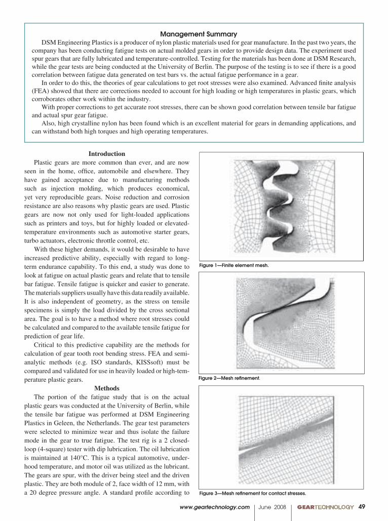
www.geartechnology.com June 2008 GEARTECHNOLOGY 0049
IntroductionPlastic gears are more common than ever, and are now
seen in the home, offi ce, automobile and elsewhere. They have gained acceptance due to manufacturing methods such as injection molding, which produces economical, yet very reproducible gears. Noise re duction and corrosion resistance are also reasons why plastic gears are used. Plastic gears are now not only used for light-loaded applications such as printers and toys, but for highly loaded or elevated-temperature environments such as automotive starter gears, turbo actuators, electronic throttle control, etc.
With these higher demands, it would be desirable to have increased predictive ability, especially with re gard to long-term endurance capability. To this end, a study was done to look at fatigue on actual plastic gears and relate that to tensile bar fatigue. Tensile fatigue is quicker and easier to generate. The materials suppliers usually have this data readily available. It is also independent of geometry, as the stress on tensile specimens is simply the load divided by the cross sectional area. The goal is to have a method where root stresses could be calcu lated and compared to the available tensile fatigue for prediction of gear life.
Critical to this predictive capability are the meth ods for calculation of gear tooth root bending stress. FEA and semi-analytic methods (e.g. ISO standards, KISSsoft) must be compared and validated for use in heavily loaded or high-tem-perature plastic gears.
MethodsThe portion of the fatigue study that is on the actual
plastic gears was conducted at the University of Berlin, while the tensile bar fatigue was performed at DSM Engineering Plastics in Geleen, the Netherlands. The gear test parameters were selected to minimize wear and thus isolate the fail ure mode in the gear to true fatigue. The test rig is a 2 closed-loop (4-square) tester with dip lubrication. The oil lubrication is maintained at 140°C. This is a typical automotive, under-hood temperature, and motor oil was utilized as the lubricant. The gears are spur, with the driver being steel and the driven plas tic. They are both module of 2, face width of 12 mm, with a 20 degree pressure angle. A standard profi le according to
Management SummaryDSM Engineering Plastics is a producer of nylon plastic materials used for gear manufacture. In the past two years, the
company has been conducting fatigue tests on actual molded gears in order to provide design data. The experiment used spur gears that are fully lubricated and temperature-controlled. Testing for the materials has been done at DSM Research, while the gear tests are being conducted at the University of Berlin. The purpose of the testing is to see if there is a good correlation between fatigue data generated on test bars vs. the actual fatigue performance in a gear.
In order to do this, the theories of gear calculations to get root stresses were also examined. Advanced fi nite analysis (FEA) showed that there are corrections needed to account for high loading or high temperatures in plastic gears, which corroborates other work within the industry.
With proper corrections to get accurate root stresses, there can be shown good correlation between tensile bar fatigue and actual spur gear fatigue.
Also, high crystalline nylon has been found which is an excellent material for gears in demanding applications, and can withstand both high torques and high operating temperatures.
Figure 1—Finite element mesh.
Figure 2—Mesh refi nement.
Figure 3—Mesh refi nement for contact stresses.
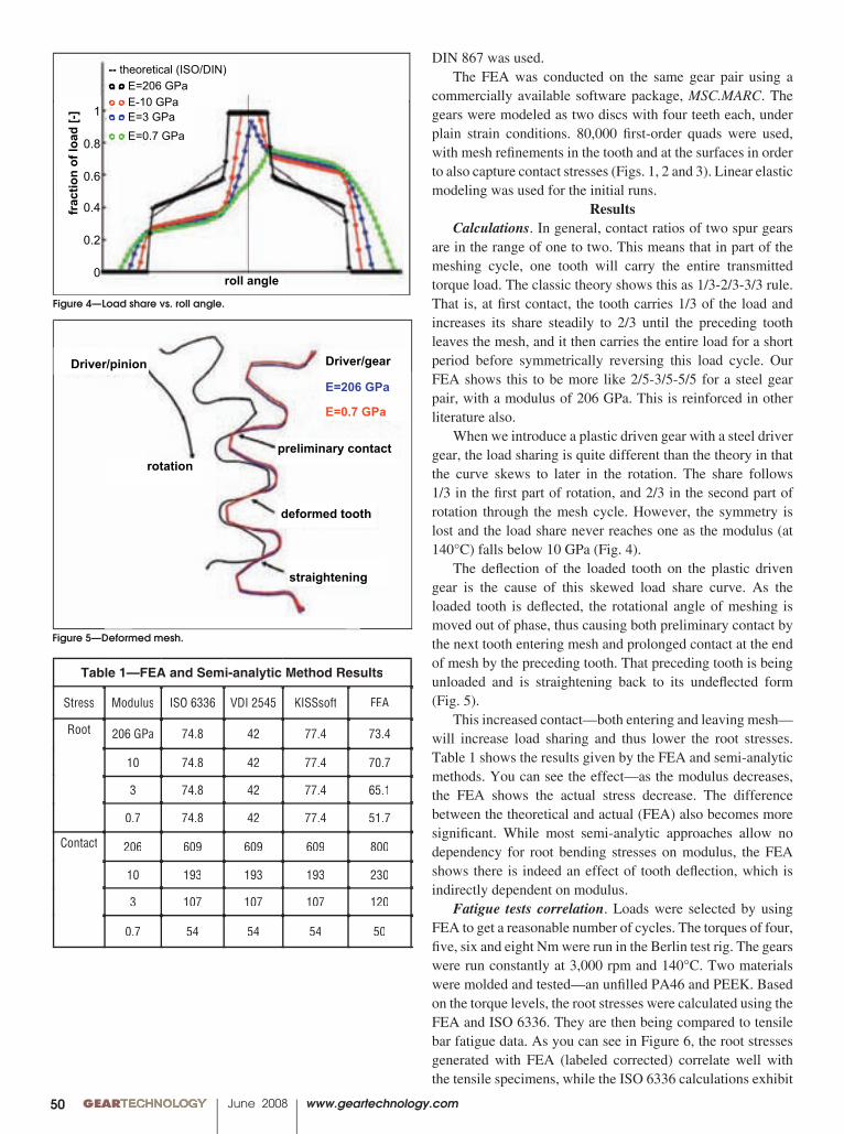
00 GEARTECHNOLOGY June 2008 www.geartechnology.com50
Figure 5—Deformed mesh.
-- theoretical (ISO/DIN)○ ○ E=206 GPa○ ○ E-10 GPa○ ○ E=3 GPa○ ○ E=0.7 GPa
roll angle
1
0.8
0.6
0.4
0.2
0
frac
tion
of lo
ad [-
]
Driver/pinion
rotation
Driver/gear
E=206 GPa
E=0.7 GPa
preliminary contact
deformed tooth
straightening
Table 1—FEA and Semi-analytic Method Results
Stress Modulus ISO 6336 VDI 2545 KISSsoft FEA
Root 206 GPa 74.8 42 77.4 73.4
10 74.8 42 77.4 70.7
3 74.8 42 77.4 65.1
0.7 74.8 42 77.4 51.7
Contact 206 609 609 609 800
10 193 193 193 230
3 107 107 107 120
0.7 54 54 54 50
Figure 4—Load share vs. roll angle.
-- theoretical (ISO/DIN)○ ○ E=206 GPa○ ○ E-10 GPa○ ○ E=3 GPa○ ○ E=0.7 GPa
roll angle
1
0.8
0.6
0.4
0.2
0
frac
tion
of lo
ad [-
]
Driver/pinion
rotation
Driver/gear
E=206 GPa
E=0.7 GPa
preliminary contact
deformed tooth
straightening
DIN 867 was used. The FEA was conducted on the same gear pair us ing a
commercially available software package, MSC.MARC. The gears were modeled as two discs with four teeth each, under plain strain conditions. 80,000 fi rst-order quads were used, with mesh re fi nements in the tooth and at the surfaces in order to also capture contact stresses (Figs. 1, 2 and 3). Linear elastic modeling was used for the initial runs.
ResultsCalculations. In general, contact ratios of two spur gears
are in the range of one to two. This means that in part of the mesh ing cycle, one tooth will carry the entire transmitted torque load. The classic theory shows this as 1/3-2/3-3/3 rule. That is, at fi rst contact, the tooth carries 1/3 of the load and increases its share steadily to 2/3 until the preceding tooth leaves the mesh, and it then carries the entire load for a short period before symmetrically reversing this load cycle. Our FEA shows this to be more like 2/5-3/5-5/5 for a steel gear pair, with a modulus of 206 GPa. This is reinforced in other literature also.
When we introduce a plastic driven gear with a steel driver gear, the load sharing is quite different than the theory in that the curve skews to later in the rotation. The share follows 1/3 in the fi rst part of rotation, and 2/3 in the second part of rotation through the mesh cycle. However, the symmetry is lost and the load share never reaches one as the modulus (at 140°C) falls below 10 GPa (Fig. 4).
The defl ection of the loaded tooth on the plastic driv en gear is the cause of this skewed load share curve. As the loaded tooth is defl ected, the rotation al angle of meshing is moved out of phase, thus causing both preliminary contact by the next tooth entering mesh and prolonged contact at the end of mesh by the preceding tooth. That preceding tooth is being unloaded and is straightening back to its undefl ected form (Fig. 5).
This increased contact—both entering and leaving mesh—will increase load sharing and thus lower the root stresses. Table 1 shows the results given by the FEA and semi-analytic methods. You can see the effect—as the modulus decreases, the FEA shows the actual stress decrease. The difference between the theoretical and actual (FEA) also be comes more signifi cant. While most semi-analytic approaches allow no dependency for root bending stresses on modulus, the FEA shows there is in deed an effect of tooth defl ection, which is indirectly dependent on modulus.
Fatigue tests correlation. Loads were selected by using FEA to get a reason able number of cycles. The torques of four, fi ve, six and eight Nm were run in the Berlin test rig. The gears were run constantly at 3,000 rpm and 140°C. Two materials were molded and tested—an unfi lled PA46 and PEEK. Based on the torque levels, the root stresses were calculated using the FEA and ISO 6336. They are then being compared to tensile bar fatigue data. As you can see in Figure 6, the root stresses generated with FEA (labeled corrected) correlate well with the tensile specimens, while the ISO 6336 calculations exhibit
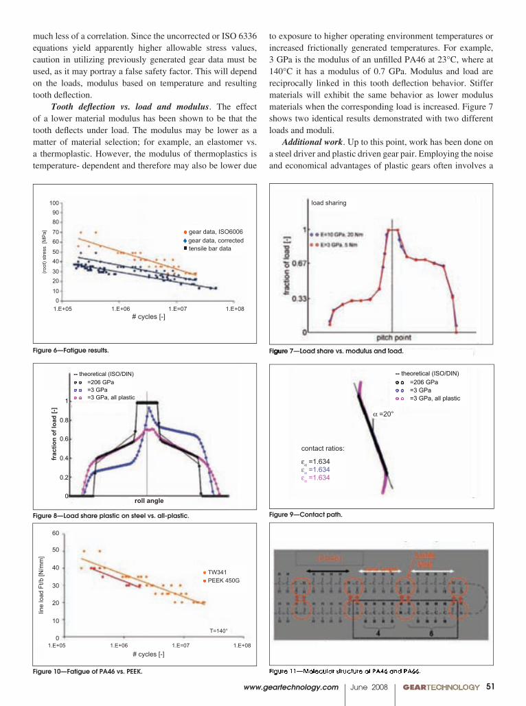
www.geartechnology.com June 2008 GEARTECHNOLOGY 0051
Figure 9—Contact path. Figure 8—Load share plastic on steel vs. all-plastic.
○ ○ E-10 GPa, 20 Nm○ ○ E=3 GPa, 5 Nm
1
0.67
0.33
0pitch point
frac
tion
of lo
ad [-
]
load sharing
1
0.8
0.6
0.4
0.2
0
frac
tion
of lo
ad [-
]
roll angle
-- theoretical (ISO/DIN)○ ○ E=206 GPa○ ○ E=3 GPa○ ○ E=3 GPa, all plastic
-- theoretical (ISO/DIN)○ ○ E=206 GPa○ ○ E=3 GPa○ ○ E=3 GPa, all plastic
��=20°
contact ratios:
���=1.634���=1.634���=1.634
Figure 6—Fatigue results.
● gear data, ISO6006♦ gear data, corrected■ tensile bar data
1.E+05 1.E+06 1.E=07 1.E+08
1009080
7060
5040
3020
100
# cycles [-]
(roo
t) st
ress
[M
Pa] ○ ○ E-10 GPa, 20 Nm
○ ○ E=3 GPa, 5 Nm
1
0.67
0.33
0pitch point
frac
tion
of lo
ad [-
]
load sharing
1
0.8
0.6
0.4
0.2
0
frac
tion
of lo
ad [-
]
roll angle
-- theoretical (ISO/DIN)○ ○ E=206 GPa○ ○ E=3 GPa○ ○ E=3 GPa, all plastic
-- theoretical (ISO/DIN)○ ○ E=206 GPa○ ○ E=3 GPa○ ○ E=3 GPa, all plastic
��=20°
contact ratios:
���=1.634���=1.634���=1.634
Figure 7—Load share vs. modulus and load. Figure 7—Load share vs. modulus and load. Figure 7—Load share vs. modulus and load.
much less of a correla tion. Since the uncorrected or ISO 6336 equations yield apparently higher allowable stress values, caution in utilizing previously generated gear data must be used, as it may portray a false safety factor. This will depend on the loads, modulus based on temperature and resulting tooth defl ection.
Tooth defl ection vs. load and modulus. The effect of a lower material modulus has been shown to be that the tooth defl ects under load. The modulus may be lower as a matter of material selec tion; for example, an elastomer vs. a thermo plastic. However, the modulus of thermoplastics is temperature- dependent and therefore may also be lower due
● TW341● PEEK 450G
1.E+05 1.E+06 1.E=07 1.E+08# cycles [-]
line
load
Ft/b
[N/m
m]
T=140°
60
50
40
30
20
10
0
Figure 10—Fatigue of PA46 vs. PEEK. �
�
�
�
�
�
�
�
�
�
���
���
����
���
����
�������������������
�����������������
����������������
��������������������������������������
�����������������
������
����
���
���
���
���
���
��
�
���
���
���
��
������� ���� ����������������
��������������������������
�������������
���������
�����������
120
100
80
60
40
20
0
����
�����
���
Fatigue resistance at 140 C of glass fibre reinforced engineering plastics
1.00E+02 1.00E+03 1.00E+04 1.00E+05 1.00E+06 1.00E+07
No. of cycles
Figure 11—Molecular structure of PA46 and PA66.
to exposure to higher operating environ ment temperatures or increased frictionally gener ated temperatures. For example, 3 GPa is the modu lus of an unfi lled PA46 at 23°C, where at 140°C it has a modulus of 0.7 GPa. Modulus and load are recipro cally linked in this tooth defl ection behavior. Stiffer materials will exhibit the same behavior as lower modulus materials when the corresponding load is increased. Figure 7 shows two identical results demonstrated with two different loads and moduli.
Additional work. Up to this point, work has been done on a steel driv er and plastic driven gear pair. Employing the noise and economical advantages of plastic gears often involves a
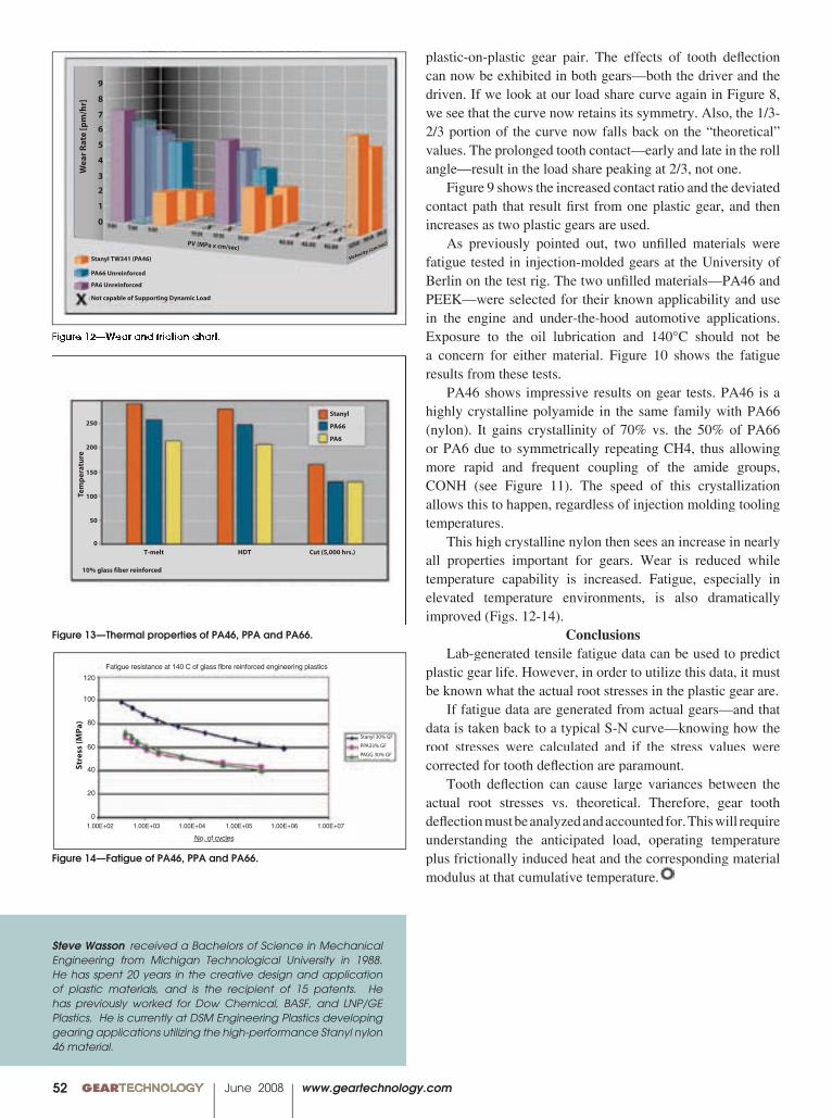
00 GEARTECHNOLOGY June 2008 www.geartechnology.com52
Steve Wasson received a Bachelors of Science in Mechanical Engineering from Michigan Technological University in 1988. He has spent 20 years in the creative design and application of plastic materials, and is the recipient of 15 patents. He has previously worked for Dow Chemical, BASF, and LNP/GE Plastics. He is currently at DSM Engineering Plastics developing gearing applications utilizing the high-performance Stanyl nylon 46 material.
Figure 14—Fatigue of PA46, PPA and PA66.
�
�
�
�
�
�
�
�
�
�
���
���
����
���
����
�������������������
�����������������
����������������
��������������������������������������
�����������������
������
����
���
���
���
���
���
��
�
���
���
���
��
������� ���� ����������������
��������������������������
�������������
���������
�����������
120
100
80
60
40
20
0
����
�����
���
Fatigue resistance at 140 C of glass fibre reinforced engineering plastics
1.00E+02 1.00E+03 1.00E+04 1.00E+05 1.00E+06 1.00E+07
No. of cycles
Figure 13—Thermal properties of PA46, PPA and PA66.
�
�
�
�
�
�
�
�
�
�
���
���
����
���
����
�������������������
�����������������
����������������
��������������������������������������
�����������������
������
����
���
���
���
���
���
��
�
���
���
���
��
������� ���� ����������������
��������������������������
�������������
���������
�����������
120
100
80
60
40
20
0
����
�����
���
Fatigue resistance at 140 C of glass fibre reinforced engineering plastics
1.00E+02 1.00E+03 1.00E+04 1.00E+05 1.00E+06 1.00E+07
No. of cycles
Figure 12—Wear and friction chart.
�
�
�
�
�
�
�
�
�
�
���
���
����
���
����
�������������������
�����������������
����������������
��������������������������������������
�����������������
������
����
���
���
���
���
���
��
�
���
���
���
��
������� ���� ����������������
��������������������������
�������������
���������
�����������
120
100
80
60
40
20
0
����
�����
���
Fatigue resistance at 140 C of glass fibre reinforced engineering plastics
1.00E+02 1.00E+03 1.00E+04 1.00E+05 1.00E+06 1.00E+07
No. of cycles
plastic-on-plastic gear pair. The effects of tooth defl ection can now be exhibited in both gears—both the driver and the driven. If we look at our load share curve again in Figure 8, we see that the curve now retains its symmetry. Also, the 1/3-2/3 portion of the curve now falls back on the “theoreti cal” values. The prolonged tooth contact—early and late in the roll angle—result in the load share peaking at 2/3, not one.
Figure 9 shows the increased contact ratio and the deviated contact path that result fi rst from one plastic gear, and then increases as two plastic gears are used.
As previously pointed out, two unfi lled materials were fatigue tested in injection-molded gears at the University of Berlin on the test rig. The two unfi lled materials—PA46 and PEEK—were selected for their known applicability and use in the engine and under-the-hood automotive applications. Exposure to the oil lubrica tion and 140°C should not be a concern for either material. Figure 10 shows the fatigue results from these tests.
PA46 shows impressive results on gear tests. PA46 is a highly crystalline polyamide in the same family with PA66 (nylon). It gains crystallinity of 70% vs. the 50% of PA66 or PA6 due to symmetrically re peating CH4, thus allowing more rapid and frequent coupling of the amide groups, CONH (see Figure 11). The speed of this crystallization allows this to happen, regardless of injection molding tooling temperatures.
This high crystalline nylon then sees an increase in nearly all properties important for gears. Wear is re duced while temperature capability is increased. Fatigue, especially in elevated temperature environments, is also dramatically improved (Figs. 12-14).
ConclusionsLab-generated tensile fatigue data can be used to predict
plastic gear life. However, in order to utilize this data, it must be known what the actual root stresses in the plastic gear are.
If fatigue data are generated from actual gears—and that data is taken back to a typical S-N curve—know ing how the root stresses were calculated and if the stress values were corrected for tooth defl ection are paramount.
Tooth defl ection can cause large variances between the actual root stresses vs. theoretical. There fore, gear tooth defl ection must be analyzed and ac counted for. This will require understanding the an ticipated load, operating temperature plus frictionally induced heat and the corresponding ma terial plus frictionally induced heat and the corresponding ma terial modulus at that cumulative temperature.

www.geartechnology.com June 2008 GEARTECHNOLOGY 0053www.powertransmission.com
■ Find suppliers for the products you need
■ Latest news, Updated as it happens
■ Improved Buyers Guide format(free listings now available)
What Can Handle a Crowd of 80,000 and
is Still Asking for More?
powertransmission.com averages more than 80,000 unique visits per month

00 GEARTECHNOLOGY June 2008 www.geartechnology.com54
AVAILABILITYFOR SOME SUPPLIERS MEANS 12 WEEKS.
TO US, IT MEANS “OUT THE DOOR” THE DAY IT’S ORDERED.
At Haas, we know that the only way you make money is by making chips, and that means keeping
your Haas equipment running in top condition. Our Platinum One-Call policy provides dependable,
immediate response and expert service to keep you making chips. Through our system
of Haas Factory Outlets, we’ve built a network of local service parts inventories that contain just about
any part you might need. In those rare instances when your local Haas Factory Outlet doesn't have
the needed part, our 1-million-square-foot California facility will. We’ll pull it and ship it the same
day it’s ordered, and have it to your HFO the next day – not next month. Simple. Innovation.
Haas Automation, Inc. | www.HaasCNC.com | 800-331-6746 | CALIFORNIA, USA
www.geartechnology.com June 2008 GEARTECHNOLOGY 0055
C A L E N D A R
June 9–10—Manufacturing Innovations Conference—Technologies for Oil and Gas. Hyatt Regency Calgary, Alberta, Canada. Organized by the Society of Manufacturing Engineers’ Oil and Gas Steering Committee, this event is designed to cover new and existing manufacturing technologies with the goal of becoming more competitive in the global marketplace. Among the presenters are lean practitioners and business leaders to speak about how innovation in people management can lead to unrivaled results and a positive change in culture. Keynote panel discussions focus on manufacturing infl uences on fi nal product delivery and creating manufacturing competitiveness with lean culture. Technical pre-sentations will be provided in subjects such as alternative material uses, material constraints that lead to product innovations, specialty alloys, rapid prototyping for cast components, ultrasonic testing of welded com-ponents, precision machining for oil and gas components and increasing component performance with post-process treatments.
June 17–19—Competitive Manu-facturers Conference. Chicago Marriott Schaumburg, Schaumburg, Illinois. The Competitive Manufacturers Conference brings industry experts and practitioners together to share the latest technical information, provide the tools to transform day-to-day operations and become successful “next generation” manufacturers. The information addressed is intended to provide answers and directions for the future to attendees. The best practices and leading-edge techniques to keep a company thriving in a diffi cult economy will be discussed. Lean manufacturing practices and applications is another topic that will be discussed, featuring case studies, culture and enabling technologies. Collaboration strategies and tools are additional subjects emphasizing outsourcing and supply chain strategies. Manufacturing in-novations and a technology watch are other primary focus areas. Industry experts will discuss questions of waste removal practices, business transformation, product development and operational excellence. For more information, visit www.sme.org.
June 17–20—OPTATEC. Frankfurt Exhibition Centre, Frankfurt, Germany. The ninth OPTATEC international trade fair is for future optical technologies, components, systems and manufacturing. Suppliers and users of optical technology attend to view new industrial optics, opto-electronics and laser technology. Optical technologies are the basis for a range of industrial fi elds including machine and apparatus engineering, metalworking, precision engineering, automotive engineering, aerospace industries, research insti-tutions and medical device technologies. The trade fair consists of expert seminars, an exhibitor forum and an analysts’ conference, which is organized by SPECTARIS, the German Industry Association for Optical, Medical and Mechatronic Technologies. The event is held every two years, and this year’s installment has already demonstrated growth, with more booth fl oor space being booked and exhibiting companies traveling from 25 countries. For more information, visit www.optatec-messe.com.
June 23–25—SAE International Powertrains, Fuels and Lubricants Congress. Shanghai Marriott Hongqiao Hotel, Shanghai, China. SAE’s fi rst conference in China will encompass more than 250 new papers about technological innovations for advanced engines and powertrains, control and calibration systems, fuels, emissions and lubricants. The keynotes and plenary sessions will all be available with immediate translations. The conference includes a technical panel discussing emissions legislation and air quality objectives with panelist insight on adapting, developing and applying regional controls. Another panel discussion is about business growth among the transforming social, political and economic landscape in China, which will be led by executives from automotive, oil and supplier companies. Some of the technical sessions will look at hybrids, fuel cells, lubricants and bearing systems, small engine technology, general emissions, exhaust system modeling, engine controls and advanced lubricants. For more information, visit www.sae.org/pfl china.
July 8–10—Experiment Design Made Easy Workshop. San Francisco. Learn how to make breakthrough improvements using design of experiments (DOE) techniques as a guide for experiments and strategic analysis and to select appropriate designs. The workshop, organized by the software company Stat-Ease, covers the powerful two-level factorial designs. This is an introductory workshop that follows the standard approach outline in Douglas Montgomery’s book Design and Analysis of Experiments. Some skills that are covered include how to interpret analysis of variance, discover hidden interactions, exploit effi cient fractional designs and determine when to use transformations. Registration is available online at www.statease.com. For more information, call (612) 378-9449.
September 16–18—Basic Gear Noise Short Course. Gear Dynamics and Gear Noise Research Laboratory.The Ohio State University, Columbus, Ohio. For more than 29 years the Basic Gear Noise Short Course has been offered by The Ohio State University’s Gearlab as a tool for gear designers and noise specialists challenged by gear noise and transmission design problems. The course shows participants how to design gears so that major excitations of gear noise, such as transmission error, dynamic friction forces and shuttling forces, are reduced. The course teaches the basics of gear noise generation and gear noise measurement, in addition to gear rattle, transmission dynamics and housing acoustics. Instructors will demonstrate specialized gear analysis software and several Ohio State gear test rigs. Attendees are invited to share specifi c gear and transmission noise concerns in an interactive workshop session. For more information, contact Jonny Harianto, OSU Department of Mechanical Engineering, 201 West 19th Avenue, Columbus, OH 43210; phone (614) 688-3952, fax (614) 292-3163, e-mail [email protected], or visit www.gearlab.orggearlab.orggearlab.or .
00 GEARTECHNOLOGY June 2008 www.geartechnology.com
N E W S N E W S
56
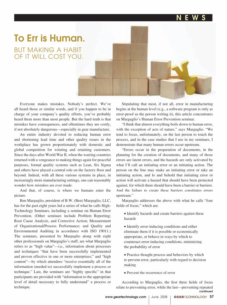
www.geartechnology.com June 2008 GEARTECHNOLOGY 00
N E W S N E W S
57
Everyone makes mistakes. Nobody’s perfect. We’ve all heard those or similar words, and if you happen to be in charge of your company’s quality efforts, you’ve probably heard them more than most people. But the hard truth is that mistakes have consequences, and oftentimes they are costly, if not absolutely dangerous—especially in gear manufacture.
An entire industry devoted to reducing human error and shortening lead time and other quality issues in the workplace has grown proportionately with domestic and global competition for winning and retaining customers. Since the days after World War II, when the warring countries returned with a vengeance to making things again for peaceful purposes, formal quality systems such as Lean, Six Sigma and others have played a central role on the factory fl oor and beyond. Indeed, with all these various systems in place, in increasingly more manufacturing settings, one can reasonably wonder how mistakes are ever made.
And that, of course, is where we humans enter the picture.
Ben Marguglio, president of B.W. (Ben) Marguglio, LLC, has for the past eight years led a series of what he calls High-Technology Seminars, including a seminar on Human Error Prevention. (Other seminars include Problem Reporting; Root Cause Analysis, and Corrective Action; Measurement of Organizational/Process Performance; and Quality and Environmental Auditing in accordance with ISO 19011.) The seminars, presented by Marguglio along with eight other professionals on Marguglio’s staff, are what Marguglio refers to as “high value”—i.e., information about processes and techniques “that have been successfully implemented and proven effective in one or more enterprises;” and “high content”—by which attendees “receive essentially all of the information (needed to) successfully implement a process or technique.” Last, the seminars are “highly specifi c” in that participants are provided with “information to the appropriate level of detail necessary to fully understand” a process or technique.
Stipulating that most, if not all, error in manufacturing begins at the human level (e.g., a software program is only as error-proof as the person writing it), this article concentrates on Marguglio’s Human Error Prevention seminar.
“I think that almost everything boils down to human error, with the exception of acts of nature,” says Marguglio. “We tend to focus, unfortunately, on the last person to touch the process, and in the case studies that I use in my seminars, I demonstrate that many human errors occur upstream.
“Errors occur in the preparation of documents, in the planning for the creation of documents, and many of those errors are latent errors, and the hazards are only activated by what I’ll call an initiating error or an initiating action. The person on the line may make an initiating error or take an initiating action, and lo and behold that initiating error or action will activate a hazard that should have been protected against, for which there should have been a barrier or barriers. And the failure to create these barriers constitutes errors upstream.”
Marguglio addresses the above with what he calls “four fi elds of focus,” which are:
• Identify hazards and create barriers against these hazards
• Identify error-inducing conditions and either eliminate them if it is possible or economically appropriate, or behave in ways by which to counteract error-inducing conditions, minimizing the probability of error
• Practice thought process and behaviors by which to prevent error, particularly with regard to decision making
• Prevent the recurrence of error
According to Marguglio, the fi rst three fi elds of focus relate to preventing error, while the last—preventing repeated
continued
To Err is Human.BUT MAKING A HABIT OF IT WILL COST YOU.
00 GEARTECHNOLOGY June 2008 www.geartechnology.com
N E W S N E W SN E W S N E W S
58
errors—recognizes that human error cannot always be prevented.
Inherent to the areas of focus are hazards and barriers—hazards being the minefi elds of potential error, and barriers serving as the preventive mechanisms put in place by management. Part of what Marguglio teaches is how best to understand and approach his four fi elds of focus. Much of what Marguglio imparts to client participants is based on the teachings of two signifi cant fi gures in the world of quality assurance—Dr. Joseph M. Juran and Dr. A. V. Feigenbaum. Both men, says Marguglio, “almost simultaneously came up with the idea of quality of design, but still today, unfortunately, the focus for quality of design is on hardware. One of the things that I’ve been trying to get people to understand is that quality of design also applies to the design of the administrative process, which governs the design of the hardware; the design of the technical process, which converts the computer design to a physical being. So quality of design can’t only apply to hardware; it has to apply to process as well.” (Some would say that lean manufacturing, among other systems, when fully implemented, addresses this as well.)
All of this may seem a bit cerebral, but it works. Just ask Hal Finley of Cameco Corporation.
“Having attended two of Ben’s courses—Problem Reporting/Root Cause Analysis and Human Error Prevention—I found the course material well researched and presented in a manner that brought out both the underlying theory and practical applications.
“Our company continues to send employees to Ben’s courses, and has now contracted him to assist with improvements to our investigation and analysis process.”
OK—most of us will admit that human bumbling is at some point a root cause for error. But why is that? Most would probably answer, who knows? But Marguglio be-lieves he has isolated the factors involved. And while it is tempting to refer to them as the seven deadly sins of error commission, Marguglio professionally calls them the seven human error causal factors. He bases this on his review of “literally—and this is not an exaggeration—on hundreds, if not over a thousand problem reports, incident reports, condition reports, etc.”
His seven human error causal factors are: • Knowledge-based error—a basic lack of knowledge of requirements or management expectation, or of a customer need
• Cognition-based error—an inability to understand the requirement, management expectation or need; or inability to apply, analyze, synthesize or evaluate a requirement
• Value- and belief-based error—a lack of respect for or acceptance of the standard, requirement or need
• Error-inducing condition or situation—a lack of recognition of the condition or situation, and/or lack of counteracting behavior
• Refl exive-based error—a lack of thought processes and behavioral techniques for conservative decision making in reacting to an immediate “fi eld stimulus”
• Skill-based error—a lack of dexterity
• Lapse-based error—nothing lacking; simply “blew it”
In Marguglio’s view, the most important conclusion ascribed to the above is that an understanding of them is paramount when attempting to identify human error causal factors and when doing root cause analysis.
Looking at these factors should prompt a question regarding training. And while training is certainly important and benefi cial, it is not a panacea in Marguglio’s world.
“A large part (of human error) is due to improper selection of personnel for a given job and improper training,” says Marguglio. “An enterprise has the responsibility to train its employees for those aspects or elements of the job that are unique to the enterprise, but the enterprise is not responsible—and should not have to train—for things that are universally available through the school system.”
Whether the “school system” can be counted upon to provide the technical training and expertise needed in today’s high-tech world has been discussed in past issues of this magazine and is grist for another day. But aside from that, manufacturers might take some solace from the fact that individuals like Marguglio are out there doing what they can to at least reduce the doh! factor.
(B. W. [Ben] Marguglio possesses many years of high-technology experience at the executive level. A Fellow of the American Society for Quality (ASQ) since 1974 and an ASQ-certifi ed quality engineer, reliability engineer, manager and auditor, Marguglio has authored dozens of technical and management papers as well as two books—Quality Systems, 1977, publ. American Society for Testing and Materials, and Environmental Management Systems, 1991, publ. Marcel Dekker, Inc.)
For more information: BW (Ben) Marguglio, LLC P. O. Box 8Cold Spring, NY 10516Phone: (845) 265-0123ben@HighTechnologySeminars.comwww.HighTechnologySeminars.com
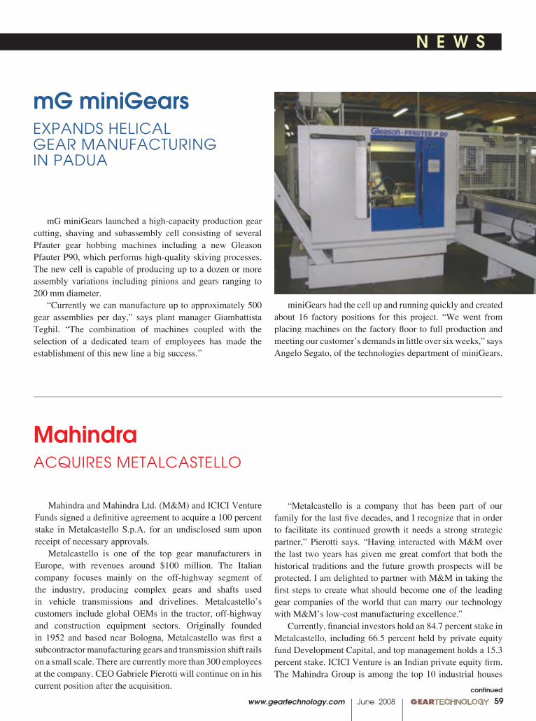
N E W S N E W S
www.geartechnology.com June 2008 GEARTECHNOLOGY 00
N E W S N E W S
59
Mahindra and Mahindra Ltd. (M&M) and ICICI Venture Funds signed a defi nitive agreement to acquire a 100 percent stake in Metalcastello S.p.A. for an undisclosed sum upon receipt of necessary approvals.
Metalcastello is one of the top gear manufacturers in Europe, with revenues around $100 million. The Italian company focuses mainly on the off-highway segment of the industry, producing complex gears and shafts used in vehicle transmissions and drivelines. Metalcastello’s customers include global OEMs in the tractor, off-highway and construction equipment sectors. Originally founded in 1952 and based near Bologna, Metalcastello was fi rst a subcontractor manufacturing gears and transmission shift rails on a small scale. There are currently more than 300 employees at the company. CEO Gabriele Pierotti will continue on in his current position after the acquisition.
MahindraACQUIRES METALCASTELLO
mG miniGears launched a high-capacity production gear cutting, shaving and subassembly cell consisting of several Pfauter gear hobbing machines including a new Gleason Pfauter P90, which performs high-quality skiving processes. The new cell is capable of producing up to a dozen or more assembly variations including pinions and gears ranging to 200 mm diameter.
“Currently we can manufacture up to approximately 500 gear assemblies per day,” says plant manager Giambattista Teghil. “The combination of machines coupled with the selection of a dedicated team of employees has made the establishment of this new line a big success.”
mG miniGearsEXPANDS HELICAL GEAR MANUFACTURING IN PADUA
miniGears had the cell up and running quickly and created about 16 factory positions for this project. “We went from placing machines on the factory fl oor to full production and meeting our customer’s demands in little over six weeks,” says Angelo Segato, of the technologies department of miniGears.
“Metalcastello is a company that has been part of our family for the last fi ve decades, and I recognize that in order to facilitate its continued growth it needs a strong strategic partner,” Pierotti says. “Having interacted with M&M over the last two years has given me great comfort that both the historical traditions and the future growth prospects will be protected. I am delighted to partner with M&M in taking the fi rst steps to create what should become one of the leading gear companies of the world that can marry our technology with M&M’s low-cost manufacturing excellence.”
Currently, fi nancial investors hold an 84.7 percent stake in Metalcastello, including 66.5 percent held by private equity fund Development Capital, and top management holds a 15.3 percent stake. ICICI Venture is an Indian private equity fi rm. The Mahindra Group is among the top 10 industrial houses
continued
00 GEARTECHNOLOGY June 2008 www.geartechnology.com
N E W S N E W SN E W S N E W S
60
Over the past several months, Ajax Rolled Ring and Machine has grown and fi lled fi ve signifi cant positions including Ken Binford as quality engineer, Bob Komisarski as controller, Jeff Arnold as lean/sigma champion, Dan Reichard as chief fi nancial offi cer and Justin McCarthy as executive vice president-sales and marketing.
“These fi ve positions are critical to the continued growth and success of Ajax. We are assembling a team that is experienced and capable of contributing to our ongoing efforts to be one of North America’s leading producers of rolled rings for use in the most demanding applications,” says Simon Ormerod, CEO of Ajax since 2006.
The company’s sales have increased from $34.6 million to more than $52 million between 2005 and 2007, which is attributed to increased demand for bearing rings and gears for transmission components in wind energy, mining and off-highway/construction equipment. “Clearly Ajax has gained signifi cant momentum in recent years that is the result of all of our employees working together to take care of our customers,” Ormerod says.
In addition to new management leaders and employees, Ormerod announced April 4 that Ajax has been acquired by Prospect Capital Corporation of New York. The current management team including CEO Ormerod, CFO Dan Reichard, vice president of operations Wil Kantus and the recently appointed executive vice president of sales and marketing, Justin McCarthy, will remain with the company under the new ownership.
Ajax Rolled Ring EXPANDS MANAGEMENT, ACQUIRED BY PROSPECT CAPITAL
in India with over 60 years of manufacturing experience. This acquisition complements the group company Mahindra Systech, an auto parts conglomerate formed in 2004.
“I am delighted to welcome Gabriele Pierotti and his management team into the Mahindra family and look forward to harnessing their expertise in building Systech’s gear vertical to match that of MFL (Mahindra Forgings),” says Anand Mahindra, vice chairman and managing director of the Mahindra Group. “Mahindra Systech has the mandate to build globally competitive business in selected verticals and this acquisition greatly enhances our capability to do so.”
N E W S
N E W S N E W S
www.geartechnology.com June 2008 GEARTECHNOLOGY 00
N E W S N E W S
61
Jim Craig joins AC Technology, a member of the Lenze Group, as the new director of engineering. He will direct the design of all new products, development and sustaining engineering activities at the company’s North American headquarters in Uxbridge, Massachusetts.
“Bringing Craig on to spearhead new product development will enable our engineers to further push the envelope of our already state-of-the-art products,” says Allen Ottoson, president and founder of Lenze-AC Technology.
Craig previously served as the product manager of high-power motor drives at Danfoss, and he has more than 28 years of experience in industrial automation. He received a bachelor’s degree in electrical engineering from Southern Illinois University and conducted graduate work at Stanford University. Craig is credited with multiple patents.
Craig says as a goal, “I’d like to see an increase in the trend of how machinery and process control are being inter-linked—the seamless automation of the whole factory.”
AC Technology develops, manufactures, supports and
Lenze-AC TechNAMES DIRECTOR OF ENGINEERING
Jim Craig
Ajax employs approximately 100, and the company operates two ring rolling mills within the 140,000 square-foot facility. Services include engineering, heat treating, shot blasting, testing and machining, and Ajax’s customers include Caterpillar, Timken and General Electric.
“With over $550 million in assets with 30-plus portfolio companies in closely related sectors of the manufacturing economy in which Ajax competes, Prospect thoroughly understands our markets,” Ormerod says. “We see this not only as a great opportunity for Ajax to grow rapidly with Prospect’s support, but as a very positive development for our employees, customers and suppliers.”
continued
CUSTOM CUT GEARSCUSTOM CUT GEARSPRECISION AND COMMERCIAL 3D.P. - 120D.P. - 1” TO 40” DIA.
• INTERNAL & EXTERNAL GEARING• SHAPING UP TO 18” O.D.• HOBBING UP TO 40” O.D.• SPURS / HELICALS / SPLINES• WORMS & WORM GEARS• TIMING PULLEYS• SPROCKETS TO 1-1/2” C.P.• CLUSTERS, SECTORS, RING GEARS• C.N.C. GEAR HOBBING• C.N.C. TURNING• C.N.C. MILLING• THREAD MILLING• BROACHING• KEY SEATING• THREAD GRINDING• O.D. & I.D. GRINDING• GEAR TOOTH FLAME HARDENING• CLIMATE CONTROLLED INSPECTION FACILITIES
Complete MachiningALL MATERIALS -
ANY QUANTITYInspection Facilities, Custom
Packaging, Prompt Quotations
NEWLY INSTALLED!Bourne & Koch
CNC Gear Hobber!
Fax: (716) 731-2553
• STANDARD • METRIC • SPECIAL
BUFFALO GEAR INC. 3635 LOCKPORT RD. • SANBORN, NY 14132-9704
(716) 731-2100 Email: [email protected] • www.buffalogear.com
00 GEARTECHNOLOGY June 2008 www.geartechnology.com
N E W S N E W SN E W S N E W S
62
MIDWEST GEARMIDWEST GEAR& TOOL, INC.
15700 Common Rd.Roseville, MI 48066
CONTACT:CRAIG D. ROSS(586) 779-1300
FAX (586) [email protected]@[email protected]
Renold plc announced the sale of its Burton-on-Trent factory site to Morris Homes, in January, as part of a continued effort to dispose of its non-core properties. The sale will be used to pay down group debt, and balance sheet gearing will be reduced, according to the London Stock Exchange’s news service, RNS.
Renold’s profi t and cash enhancement program (PACE) will be self-fi nanced with completion of the sale. Bob Davies, chief executive of Renold, says, “This is another major milestone in the implementation of the company’s PACE program and concludes a six month period in which we reported improved fi nancial results for the half-year to September 2007 and completed the strategically important acquisition of Hangzhou Shanshui in China. We look forward to the future with confi dence.”
Renold manufactures a range of gears, couplings and industrial chains worldwide for OEMs and distributors.
RenoldSELLS FACTORY SITE
markets a range of motion control solutions, including servo drives and motors, clutches and brakes, gears and gear motors and variable frequency AC motor drives.
The new Government and Education Group (GEG), created by Tooling U as part of its Business Development Division, is designed to aid educational institutions, government entities and industrial associations involved in workforce development, training and education in the manufacturing sector, according to the company’s press release.
“Manufacturers recognize the importance of a well educated workforce, but successfully training the workforce demands cooperation between employers, government and
Tooling U LAUNCHES GOVERNMENT AND EDUCATION GROUP, PLC CLASSES
N E W S
N E W S N E W S
www.geartechnology.com June 2008 GEARTECHNOLOGY 00
N E W S N E W S
63
VISITWWW.GEARTECHNOLOGY.COM
TODAY!
USE THE BUYERS GUIDEGet information from the industry’s leading suppliers
• Gear Machines• Non-Gear Machinery• Inspection Equipment• Services
• Cutting Tools & Grinding Wheels• Gear Blanks & Raw Material• Workholding & Toolholding• Gear Drives
• Software• Lubricants• Heat Treating• Heat Treating• Gears
VISIT Gear Technology ONLINEYour No. 1 source for gear-related information online
• Sign up for E-GT• Renew your subscription
• Read the latest news• Request info from our advertisers
the education sector,” says Bryan Knaack, director of business development for Tooling U. “We see our responsibility to facilitate communication between these groups.”
The GEG provides advice to educational institutions on how to build blended learning programs that facilitate workforce knowledge and effi ciency. The group offers training courses for instructors and educators and intends to collaborate with industrial associations and education organizations on projects funded by federal grants, such as Department of Labor and Workforce Development funds.
“Our expertise in government grants and public funding for education projects will help bring manufacturing associations, the private sector and public resources together, so we may develop the most effective and innovative workforce educational and training solutions,” Knaack says.
Tooling U has also developed a new series of online training classes designed to address programmable logic controllers (PLCs). They will be included with other online classes focusing on electrical systems, motor controls and mechanical systems, which are used to train maintenance professionals.
The PLC is a device driven by software that detects input signals, processes signals with a logic-based program and sends the signals to designated outputs. They are applied in a range of industrial processes in automation and electrical control such as traffi c light signals, packaging processes and assembly lines.
“Many of our customers have asked about PLC training, especially for their maintenance people. As equipment gets more complicated, the people that fi x it really have to keep up with the learning curve,” says Chad Schron, vice president of Tooling U. “With these PLC classes, or any of our subjects, we work with industry experts to make sure the material is relevant and up-to-date for our audience.”
00 GEARTECHNOLOGY June 2008 www.geartechnology.com
N E W S N E W S
64
INDUSTRY NEWS
6 0 Y E A R S O F T O P T E C H N O L O G Y
GEAR CUTTING TOOLS
ph: 011-41-32-344-0400 • fax: 011-41-32-344-0404 • www.schnyder.com • [email protected]
w w w . h a n i k c o r p . c o memail: [email protected]
HANIKCORPORATIONPHONE 630-595-7333FAX 630-595-7343
U S D i s t r i b u t o r
7606 Freedom Way • Fort Wayne, IN 46818Tel: (260) 490-3238 • Fax: (260) 490-4093
www.first-gear.com
“YOUR FIRST CHOICE”
Visit our website for more infowww.fi rst-gear.com
ISO 9001 : 2000 CERTIFIED
E N G I N E E R I N G & T E C H N O L O G Y
For Outsourcing Your Gear
Manufacturing
From Prototypes to High Volume
Production
N E W S
Haas Automation, founded by Gene Haas, fi rst opened for business in 1983 manufacturing the fi rst fully automatic programmable collet indexer. After four years of expansion, the product line included fully programmable rotary tables, indexers and machine tool accessories.
As a leading manufacturer of CNC machine tools, Haas is headquartered in Oxnard, California. All Haas products are manufactured at the one-million-square-foot facility and distributed through more than 120 Haas Factory Outlets (HFO) worldwide, each with showrooms, factory-trained service personnel, spare-parts inventories and service vehicles, according to the company’s press release.
Haas supplies published prices for their machine tool solutions, which are used by job shops and contract manufacturers. The company estimates that there are more than 85,000 Haas CNC machines and 53,000 of their rotary products currently in use.
“Our 25 years of growth and success are the result of providing customers with the affordable, dependable machine tools they need, and the service and support they demand,” says Bob Murray, general manager. “Haas Automation has always been a customer-driven company, and our goal is to provide them with the best machine tool value in the industry now and long into the future.”
HaasCELEBRATES 25 YEARS IN BUSINESS
www.powertransmission.com april 2008 powertransmissionengineering 31
www.powertransmission.com ■ powertransmission.com averages more than
80,000 unique visits per month■ Find suppliers for the products you need
■ Latest news, Updated as it happens■ Improved Buyers Guide format
(free listings now available)
What Can Take 80,000 Hits and is
Still Asking for More?
N E W S N E W S
www.geartechnology.com June 2008 GEARTECHNOLOGY 0065
A D V E R T I S E R S I N D E X ADVERTISER PAGE PHONE E-MAIL INTERNET ADVERTISER PAGE PHONE E-MAIL INTERNET
Use this index to contact advertisers
ALD-Holcroft 26 [email protected] www.ald-holcroft.com
American Metal Treating Co. 67 (216) 431-4492 www.americanmetaltreating.com
Ames S.A. 16 (34) 93-685-51-11 [email protected] www.amessint.com
Arrow Gear Co. 36 (630) 969-7640 www.arrowgear.com
B&R Machine & Gear Corp. IBC (731) 456-2636, (800) 238-0651 [email protected] www.brgear.com
Becker Gearmeisters 66 (734) 878-9669 [email protected] www.maagmachines.com
Bourn & Koch Machine Tool Co. 29 (847) 649-1450 [email protected] www.star-su.com
The Broach Masters/Universal Gear Co. 14 (530) 885-1939 [email protected] www.broachmasters.com
Buffalo Gear 61 (888) 283-3432 [email protected] www.buffalogear.com
Circle Gear & Machine Co. 67 (708) 652-1000 www.circlegear.com
Clifford-Jacobs Forging Co. 15 (217) 352-5172 [email protected] www.clifford-jacobs.com
Cole Manufacturing Systems Inc. 66 (248) 601-8145 [email protected] www.colemfgsystems.com
Colonial Tool Group Inc. 20 (734) 946-2733 [email protected] www.colonialtool.com
Comtorgage Corp. 22 (401) 765-0900 [email protected] www.comtorgage.com
Concast Metal Products Co. 21 (724) 538-4000 [email protected] www.concast.com
Engineered Tools Corp. 8 (248) 619-1616 [email protected] www.engineeredtools.com
Fässler Corp. 6 (414) 769-0072 [email protected] www.faessler-ag.ch
Gear Consulting Group 66 (269) 623-4993 [email protected] www.gearconsultinggroup.com
Gear Manufacturing Inc. 67 (800) 773-GEAR www.gearmanufacturing.com
Gear Motions Inc. 67 (315) 488-0100 [email protected] www.gearmotions.com
The Gear Works—Seattle Inc. 67 (206) 762-3333 [email protected] www.thegearworks.com
Gleason Corp. 25 (585) 473-1000 Gleason Corp. 25 (585) 473-1000 Gleason Corp. 25 (585) 473-1000 Gleason Corp. 25 (585) 473-1000 Gleason Corp. 25 (585) 473-1000 [email protected] www.gleason.com
Haas Automation 54 (800) 331-6746 www.haascnc.com
Havlik Gear 33 (519) 624-6240 [email protected] www.havlikgear.com
Höfl er OBC (734) 416-9300 [email protected] www.greatlakesgeartech.com
IMTS 24 (703) 827-5252 www.imts.com
Index Technologies 66 (440) 995-4627 www.gallenco.com
Ingersoll Cutting Tools 56 (815) 387-6600 [email protected] www.ingersoll-imc.com
Insco Corp. 61 (978) 448-6368 [email protected] www.inscocorp.com
ITW Workholding 36 (800) 544-3823 [email protected] www.itwworkholding.com
Kapp Technologies 3 (303) 447-1130 [email protected] www.kapp-usa.com
LMC Workholding 32 (574) 735-0225 [email protected] www.logan-mmk.com
McInnes Rolled Rings 37 (800) 569-1420 [email protected] www.mcinnesrolledrings.com
Micro Surface Corp. 66 (408) 723-0700 [email protected] www.ws2coating.com
Midwest Gear & Tool Inc. 62 (586) 779-1300 [email protected]
Mitsubishi Gear Technology 10 (248) 669-6136 [email protected] www.mitsubishigearcenter.com
Mutschler Edge Technologies 66 (440) 748-2520 Mutschler Edge Technologies 66 (440) 748-2520 Mutschler Edge Technologies 66 (440) 748-2520 Mutschler Edge Technologies 66 (440) 748-2520 Mutschler Edge Technologies 66 (440) 748-2520 [email protected] www.mutschleredgetech.com
Nachi Machining Technology Co. 7 (586) 263-0100 [email protected] www.nachimtc.com
Precision Gage Co. Inc. 60 (630) 655-2121 [email protected] www.precisiongageco.com
Presrite Corp. 23 (216) 441-5990 www.presrite.com
Process Equipment 19 (800) 998-4191 [email protected] www.gearinspection.com
Proto Manufacturing 62 (519) 737-6330 www.protoxrd.com
Quality Transmission Components 29 (516) 437-6700 www.qtcgears.com
Reishauer Corp. 66 (847) 888-3828 [email protected] www.reishauer.com
Riverside Spline & Gear 18 (810) 765-8302 [email protected] www.splineandgear.com
Schafer Gear Works Inc. 17 (574) 234-4116 www.schafergear.com
Schnyder S.A. 64 (630) 595-7333 [email protected] www.hanikcorp.com
SETCO 60 (800) 543-0470 [email protected] www.setcousa.com
The Shot Peener magazine 63 (800) 832-5653, (574) 256-5001 www.shotpeener.com
Sigma Pool 5 (734) 429-7225 [email protected] www.sigma-pool.com
Solar Atmospheres 67 (800) 347-3236 www.solaratm.com
Star SU LLC IFC–1,19,29,66 (847) 649-1450 [email protected] www.star-su.com
Sunnen Products Co. 39 (314) 781-2100 www.sunnen.com
00 GEARTECHNOLOGY June 2008 www.geartechnology.com66
SERVICE
Superior Grinding Wheelsfor Today’s Technology
tel: (847) 888-3828fax: (847) [email protected]
Large Inventoryof Blanks275-400mm OD84-125mm widthsFast DeliveryOrders in by noon ship next day
Pre-Profi le“On or Off” fl ange for precise, fast service
For Most Generating GrindingMachines
DULL HOBSDULL HOBSDULL HOBS
Finally! A Basic School for Non-Experts!
Do you have people who are new to GEARS?
Do your production people need toknow more about GEARS?
Cole Manufacturing Systems, Inc offers a beginninggear training course designed to your exact needs.
• Terminology of Gears• Gear Functions and Basic Formulae• Manufacturing Methods Inspection Methods• Interpretation of Inspection Data• Applying Inspection to Correct Problems
The course can be on-site, in your plant or training facilityor off-site at a nearby facility. We come to you!
(248) 601-8145 FAX (248) 601-0505Email: [email protected] www.colemfgsystems.com
Be On The Lookout for
Our Next GEAR TECHNOLOGY
July 2008 Issue FOCUSImproving Lead Time
Lean Manufacturing Machin-ery, Processes and Machinery
Hob Honing Systems
Brush honing your hobs after sharpening, manufacturing, or before coating can increase your tool life by up to 70%. Call us today for a free
evaluation of your application.
33549 Royalton Rd. Columbia Station, Ohio 44028Phone: (440) 748-2520 Fax: (440) 748-2550
www.mutschleredgetech.com
Mutschler Edge TechnologiesMutschler Edge Technologies
Sharpening Servicefor hobs, milling cutters
shaper cutters, shaving cutters.
5200 Prairie Stone Parkway, Suite 100Hoffman Estates, IL 60192
Tel: (847) 649 -1450 - Fax: (847) 649- 0112
[email protected] www.star-su.com
980 Aulerich, East Tawas, MI 48730Tel: (989) 865-0469 - Fax: (989) 884-0309
C
MAAGPARTS & SERVICE
Original MAAG parts for all:Grinding Machines • Shaping Machines
• Inspection Machines
Swiss Trained Service EngineersRepairs to Complete Rebuilds
Becker GearMeisters, Inc.
Phone/Fax: [734] 878-9669www.maagmachines.com
Immediately Available:Retrofitted Hofler EVTM Pitch Tester
MAAG ES-430 Portable Involute TesterJV-180 Internal Attachment
C L A S S I F I E D S E C T I O N C
MAAGPARTS & SERVICE
Original MAAG parts for all:Grinding Machines • Shaping Machines
• Inspection Machines
Swiss Trained Service EngineersRepairs to Complete Rebuilds
Becker GearMeisters, Inc.
Phone/Fax: [734] 878-9669www.maagmachines.com
Immediately Available:Retrofitted Hofler EVTM Pitch Tester
MAAG ES-430 Portable Involute TesterJV-180 Internal Attachment
AGMA School for
Gear ManufacturingConducted by
Gear Consulting GroupUPCOMING CLASSES
New West Coast SchoolAnaheim, CA • Sept. 17 thru 19, 2008
Hosted by Gear Manufacturing Inc.
R.P. MachineStatesville, NC • Dec. 8 thru 10, 2008
For further information on these and other classes contact:
[email protected]: (269) 623-4993
Gear Consulting Group P.O. Box 647, Richland, MI 49083
www.gearconsultinggroup.com • www.agma.org

www.geartechnology.com June 2008 GEARTECHNOLOGY 0067
HEAT TREATING GEAR MANUFACTURING
WHEN IT HAS TO BE RIGHT
• Gear Grinding to 94"• Industrial Gears to 250"• Turbo Compressor Gears• Custom Drives• Spline Broaching• Gear Metrology • Stock Planetary Speed ReducersStock Planetary Speed Reducers
GGGGGGGGGGGGGGGGGGGGGGGGGGGGGGGGGGGGGGGGGGGGGGGGGGG RRRRRRRRRRRRRRRRRRRRRRRRRRRRRRRRRRRRRRRRRRRRRRRRRRRRR
ISO-9001
www. theg. theg earworks .com
Custom Gear Services Since 1946
The Gear Works—Seattle, Inc.500 S. Portland StreetSeattle, WA 98108-0886Phone: (206) 762-3333Fax: (206) 762-3704E-mail: [email protected]
Phone: 216.431.4492Fax: 216.431.1508
Induction HardeningSpecialists in tooth by tooth contour
hardening of internalspur, helical and bevel gears.
Our gear hardening equipment includes
5 NATCO submerged process machines and
5 AJAX CNC-controlled gear scanning
machines. Tooth by tooth gear hardening
from .5DP-10 DP, up to 15 tons, 200" diameter.
Breakdown Service Availableamericanmetaltreating.com
PH: (315) 488-0100www.gearmotions.com
Gear Grinding and Cutting ServicesGear Motions’ two manufacturing locations are
leading suppliers of custom cut and ground spur and helical gears. Made complete or to your blanks.
GEAR MOTIONS, INC.An Employee Owned Company
Learn about one of the most modernfleets of Gear Grinders, including theHöfler 700 and Gleason Tag 400 at OliverGear.r.r See the latest Reishauer and KappGear Grinding technology,y,y at ISO 9001- 2000 registered Nixon Gear,r,r as well asthe latest in CNC Gear Hobbing and cell-ular manufacturing.
PH: (315) 488-0100www.gearmotions.com
Gear Grinding and Cutting Services
GEAR MOTIONS, INC.An Employee Owned Company
�
�
Circle Gear and Machine
All Sizes & Configurations. English & Metric, Spur, Helical, Internal, Herringbone, Worm & Wormgear, Internal & External Splines,
Involute & Straight Sided Spline, Straight and Spiral Bevels, Racks, Sprockets, Ratchets, Serrations, Reverse Engineering, Design Analysis, Complete Machine Shop including CNC Machining,
Documented Quality Control Program, Inspection Lab including Complete Gear Tooth Diagnostics.
1501 South 55th Ct. • Cicero, IL 60804Ph: 708-652-1000 • Fax: 708-652-1100
www.circlegear.com
Quality Custom Gearing Since 1951
Please email your inquiries to [email protected]
Manufacturers Of Quality Custom Gearing
Tooth Cutting, Grinding & Shaving Services Available
CG C
C I R C LE
G E A R C O
Manufacturers Of Quality Custom Gearing
PTE — Power Transmission Engineering The latest technical and product information about power transmission components
Gear Technology—The Gear In-dustry’s Information Source Since 1984, Gear Technology has been Gear Technology has been Gear Technologythe industry’s leading technology and edu-cational journal.
www.powertransmission.com/subscribe.htm
THE POWER OF INFORMATION
Subscribe today!
www.geartechnology.com/subscribe.htm
THE GEAR INDUSTRY’S INFORMATION SOURCE
www.geartechnology.com The Journal of Gear Manufacturing
May 2008
TECHNOLOGYGEAR
Feature• China Gear Market Update
• Communication Breakdown
Technical Articles• Pitting Load Capacity of Helical Gears
• Net-Shaped, Cold-Formed Gears
• Calibration of Two- Flank Roll-Testers
• Update on the National Metrology Lab
Bearings are Boomingfor Wind Turbines
w w w . p o w e r t r a n s m i s s i o n . c o m
®powertransmissionengineering®powertransmissionengineeringPTE FEBRUARY 2008
Technical• Optimized Timken Bearings• Rexnord Gets Extreme
Case Studies Baldor Bearings Torque Transmission Racecar Test Rig
And New This Issue—POWER PLAY!
C L A S S I F I E D S E C T I O N
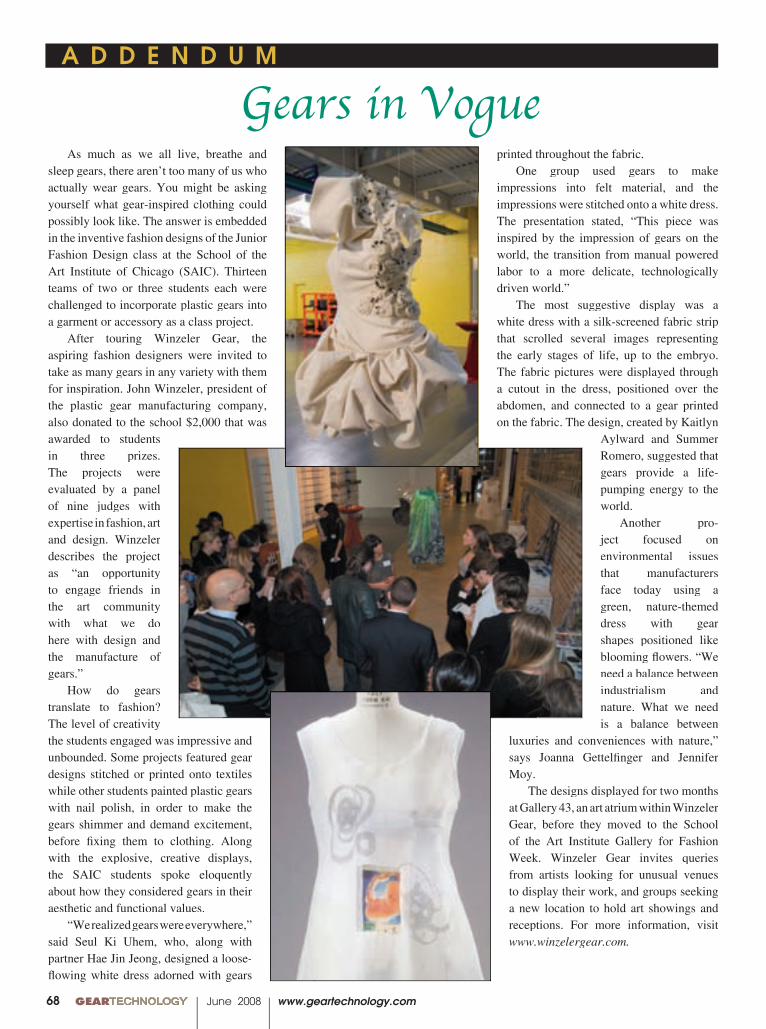
00 GEARTECHNOLOGY June 2008 www.geartechnology.com
A D D E N D U M
Gears in Vogue printed throughout the fabric.
One group used gears to make impressions into felt material, and the impressions were stitched onto a white dress. The presentation stated, “This piece was inspired by the impression of gears on the world, the transition from manual powered labor to a more delicate, technologically driven world.”
The most suggestive display was a white dress with a silk-screened fabric strip that scrolled several images representing the early stages of life, up to the embryo. The fabric pictures were displayed through a cutout in the dress, positioned over the abdomen, and connected to a gear printed on the fabric. The design, created by Kaitlyn
Aylward and Summer Romero, suggested that gears provide a life-pumping energy to the world.
Another pro-ject focused on environmental issues that manufacturers face today using a green, nature-themed dress with gear shapes positioned like blooming fl owers. “We need a balance between industrialism and nature. What we need is a balance between
luxuries and conveniences with nature,” says Joanna Gettelfi nger and Jennifer Moy.
The designs displayed for two months at Gallery 43, an art atrium within Winzeler Gear, before they moved to the School of the Art Institute Gallery for Fashion Week. Winzeler Gear invites queries from artists looking for unusual venues to display their work, and groups seeking a new location to hold art showings and receptions. For more information, visit www.winzelergear.com.
As much as we all live, breathe and sleep gears, there aren’t too many of us who actually wear gears. You might be asking yourself what gear-inspired clothing could possibly look like. The answer is embedded in the inventive fashion designs of the Junior Fashion Design class at the School of the Art Institute of Chicago (SAIC). Thirteen teams of two or three students each were challenged to incorporate plastic gears into a garment or accessory as a class project.
After touring Winzeler Gear, the aspiring fashion designers were invited to take as many gears in any variety with them for inspiration. John Winzeler, president of the plastic gear manufacturing company, also donated to the school $2,000 that was awarded to students in three prizes. The projects were evaluated by a panel of nine judges with expertise in fashion, art and design. Winzeler describes the project as “an opportunity to engage friends in the art community with what we do here with design and the manufacture of gears.”
How do gears translate to fashion? The level of creativity the students engaged was impressive and unbounded. Some projects featured gear designs stitched or printed onto textiles while other students painted plastic gears with nail polish, in order to make the gears shimmer and demand excitement, before fi xing them to clothing. Along with the explosive, creative displays, the SAIC students spoke eloquently about how they considered gears in their aesthetic and functional values.
“We realized gears were everywhere,” said Seul Ki Uhem, who, along with partner Hae Jin Jeong, designed a loose-fl owing white dress adorned with gears
68

Go to: www.star-su.com
1+1= 6,0001 man + 1 cell performs 5 operations, produces 6,000 parts per day
Samputensili S200 CDM combined dry hobbing, chamfer/deburring 7 axis CNC Hobbing Machine with quick change tooling for 11 part variants produces pinions in less than 20 seconds. Process steps: blank error proofi ng, hobbing, chamfer/deburring, gage, shaving, size gage, wash.
Variant changeover time within cell = 35 minutes
Sicmat RASO 200 automated 5 axis CNC shaving machine with quick change tooling for 11 part variants produces pinions in less than 20 seconds, taking preshave hobbed parts from the Samputensili hobber, shaving the parts, and conveying them out to the wash operation. The RASO 200’s slant bed structure has a compact design that exhibits the stiffness of larger machines.
International Manufacturing Technology Show
September 8 - 13, 2008 • Chicago, IL • McCormick Place
Star SU – your source for soft or hard gear cell production solutions.
Machine and Gear CorporationMachine and Gear Corporation
CUSTOM BEVEL GEAR MANUFACTURING
Per Your Specifications and/or SampleProviding Inverse Engineering to Make a Clone of Your Sample
· Spiral Bevel Gears: 66" PD Spiral Bevel Gears: 66" PD Spiral Bevel Gears: 66" PD
· Straight Bevel Gears: 80" PD Straight Bevel Gears: 80" PD Straight Bevel Gears: 80" PD
· Spurs Helicals Spline Shafts Spurs Helicals Spline Shafts Spurs Helicals Spline Shafts
· Gearbox Repair/Rebuilds Gearbox Repair/Rebuilds Gearbox Repair/Rebuilds
· In-House Steel Material In-House Steel Material In-House Steel Material WarehouseWarehouse
· Full Heat Treating Services Full Heat Treating Services Full Heat Treating Services
· EDM Wire Burning EDM Wire Burning
BREAKDOWN SERVICES
4809 U.S. Highway 45 Sharon, TN 382554809 U.S. Highway 45 Sharon, TN 38255Toll Free: (800) 238-0651 Ph: (731) 456-2636 Fax: (731) 456-3073
E-mail: [email protected] Internet: www.brgear.com
Family owned and operated since 1974
������������������������������������������ � ����������������������
������������������������������ ����������������
�������������������������������������������������������������������������������������������������������������������
�������������������������������������������������������������������������������������
������������������������������������������������������������������������������������������
�������������