gear technology magazine september-october 2015
TRANSCRIPT
THE JOURNAL OF GEAR MANUFACTURING
20SEP/OCT
15
www.geartechnology.com
MEET THE EXHIBITORS ATGEAR EXPO 2015
IT’S
Showtime
Phone: 847-649-14505200 Prairie Stone Pkwy. • Ste. 100 • Hoffman Estates • IL 60192
Gear cutting tools and services
Star SU offers a wide variety of gear cutting tools and services, including:
• Gear hobs• Milling cutters• Indexable Gear Milling Solutions by Sandvik
Coromant• Shaper cutters • Scudding® and Power Skiving cutters• Shaving cutters• Chamfer and deburring tools• Rack and saw cutters
• Master gears• Ring and plug gauges• Advanced coatings including ALTENSA and
ALCRONA PRO• Tool re-sharpening
Total tool life cycle management
Control your tool costs and let Star SU manage your tool room. From new tools to design work to re-sharpening and recoating, we have the equipment and resources to help keep your gear cutting operation running smoothly.
Solutions for all your gear cutting tool needs
Solutions for all
2015-09_Star-SU_Adv_2pages_us.indd 1 18.09.15 21:16
Solutions for all your gear cutting tool needs
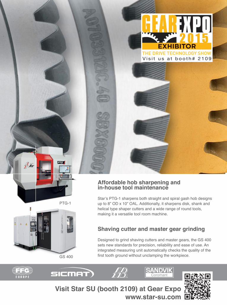
Affordable hob sharpening and in-house tool maintenance
Star’s PTG-1 sharpens both straight and spiral gash hob designs up to 8” OD x 10” OAL. Additionally, it sharpens disk, shank and helical type shaper cutters and a wide range of round tools, making it a versatile tool room machine.
Shaving cutter and master gear grinding
Designed to grind shaving cutters and master gears, the GS 400 sets new standards for precision, reliability and ease of use. An integrated measuring unit automatically checks the quality of the fi rst tooth ground without unclamping the workpiece.
PTG-1
GS 400
Visit Star SU (booth 2109) at Gear Expo www.star-su.com
V i s i t u s a t b o o t h # 2 1 0 9
2015-09_Star-SU_Adv_2pages_us.indd 2 18.09.15 21:16

Vol. 32, No. 7 GEAR TECHNOLOGY, The Journal of Gear Manufacturing (ISSN 0743-6858) is published monthly, except in February, April, October and December by Randall Publications LLC, 1840 Jarvis Avenue, Elk Grove Village, IL 60007, (847) 437-6604. Cover price $7.00 U.S. Periodical postage paid at Arlington Heights, IL, and at additional mailing office (USPS No. 749-290). Randall Publications makes every effort to ensure that the processes described in GEAR TECHNOLOGY conform to sound engineering practice. Neither the authors nor the publisher can be held responsible for injuries sustained while following the procedures described. Postmaster: Send address changes to GEAR TECHNOLOGY, The Journal of Gear Manufacturing, 1840 Jarvis Avenue, Elk Grove Village, IL, 60007. Contents copyrighted ©2015 by RANDALL PUBLICATIONS LLC. No part of this publication may be reproduced or transmitted in any form or by any means, electronic or mechanical, including photocopying, recording, or by any information storage and retrieval system, without permission in writing from the publisher. Contents of ads are subject to Publisher’s approval. Canadian Agreement No. 40038760.
features
technical
2 GEAR TECHNOLOGY | September/October 2015[www.geartechnology.com]2
contents
20 The Modern Approach to Transmission System Design and AnalysisRomax’s Right First Time approach updates designs early in design process, minimizing late changes in the design and production process.
24 Gear Expo 2015 Product PreviewA sampling of what you can expect to see in Detroit.
46 Mapping It.Our show exhibitor floor map will set you straight.
54 Gear Expo ShowstoppersOur special advertising section, featuring very important exhibitors.
64 ASM Heat Treat ShowMap and booth listings.
SEP/OCT
2015
70 Ask the ExpertGear MacrogeometryMachinery Settings
74 Development of a Face Hobbed Spiral Bevel Gearset
Bevel Gear Technology Chapter 2, Continued
80 Gear Tooth Surface Roughness of Helical Gears Manufactured by a Form Milling Cutter
A mathematical model is presented to determine the machined gear tooth surface in three dimensions, manufactured by this tool.
86 Local Simulation of the Specific Material Removal Rate for Generating Gear Grinding
A manufacturing simulation of generating gear grinding with the capability to calculate key values for the process is developed here.
46
66

www.kapp-niles.com [email protected]
KAPP Technologies2870 Wilderness Place Boulder, CO 80301Phone: (303) 447-1130 Fax: (303) 447-1131
KAPP NILES Booth #2222
See the PM 750 video on YouTube!
NEW! software for hob sharpening & worm grinding
Compact Flexible ProductiveZE 800
25 module (1 DP) external
prepared for internal
CBN or dressable
g gg
See you at
PM 750/1250Portable Customizable
CMM
dual functionality
docking station option for four-axis generative inspection
g gg
R&P Metrology’s
departments
THE JOURNAL OF GEAR MANUFACTURING
20SEP/OCT
15
www.geartechnology.com
MEET THE EXHIBITORS ATGEAR EXPO 2015
IT’S
Showtime
GEAR TESTING TECHNOLOGY FOR THE MOST CRITICAL APPLICATIONS
Utilizing eddy current technology, FOERSTER manufactures cutting edge Non-
Destructive Testing (NDT) equipment designed to be incorporated into
your current production line. Our systems can verify
material properties and heat-treat conditions;
detect cracks or cracked or missing teeth in the most intricate of gears. Contact a FOERSTER representative today to design your specific component testing system.
VISIT US AT BOOTH 1242 AT GEAR EXPO 2015
1-800-635-0613 foerstergroup.com
© Copyright 2015 FOERSTER INSTRUMENTS Inc. USA
4 GEAR TECHNOLOGY | September/October 2015[www.geartechnology.com]4
contents
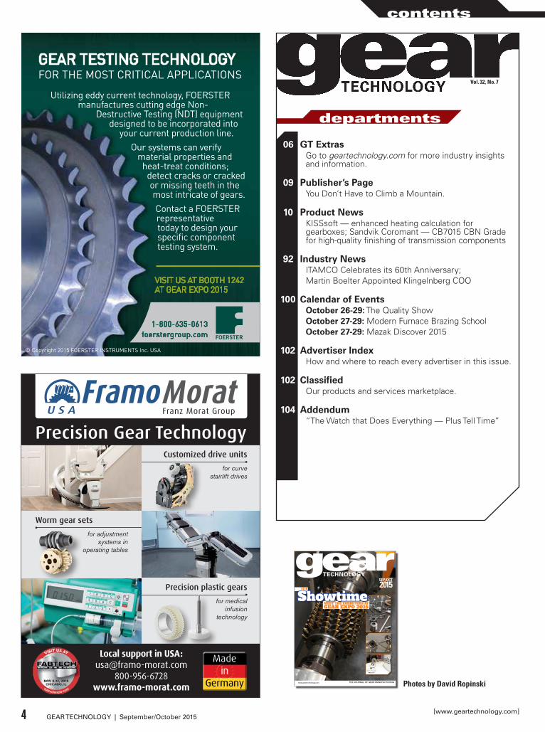
06 GT ExtrasGo to geartechnology.com for more industry insights and information.
09 Publisher’s PageYou Don’t Have to Climb a Mountain.
10 Product NewsKISSsoft — enhanced heating calculation for gearboxes; Sandvik Coromant — CB7015 CBN Grade for high-quality finishing of transmission components
92 Industry NewsITAMCO Celebrates its 60th Anniversary;Martin Boelter Appointed Klingelnberg COO
100 Calendar of EventsOctober 26-29: The Quality ShowOctober 27-29: Modern Furnace Brazing SchoolOctober 27-29: Mazak Discover 2015
102 Advertiser IndexHow and where to reach every advertiser in this issue.
102 ClassifiedOur products and services marketplace.
104 Addendum“The Watch that Does Everything — Plus Tell Time”
Photos by David Ropinski
Vol. 32, No. 7
Precision Gear TechnologyCustomized drive units
for curve stairlift drives
Precision plastic gearsfor medical
infusion technology
Worm gear setsfor adjustment
systems in operating tables
Local support in USA:[email protected]
800-956-6728www.framo-morat.com
2015_09_09_Advert_Gear_Technology_october_89x120_sfe_FINAL.indd 1 11.09.2015 17:16:52

Intelligent Production.
With a comprehensive program of machines, gear cutting tools and automation systems Liebherr can offer the right solution for the economical manufacturing of cylindrical gears, tailored to individual requirements.
Liebherr gear cutting machines for green and hard machining are well-known for their precision and reliability. In addition Liebherr also produces high quality gear manufacturing tools.
In the field of automation systems Liebherr offers products for automating machine tools as well as innovative solutions for manufacturing and factory automation. Lowering of production cost while increasing flexibility and operator friendliness are some of the numerous advantages.
Gear hobbing machines Gear shaping machines Gear grinding machines Gantry robots Transport systems Storage systems Pallet handling systems Rotary-pallet handling systems Robot integration Gear cutting tools
Gear cutting machines and automation systems from a single source.
Liebherr Gear Technology, Inc.1465 Woodland DriveSaline, Michigan 48176-1259Phone.: +1 734 429 72 25E-mail: [email protected] The Group
2014-004_14 AZ Aufbau Image-MFT_Gear-Technology 4_GB_216x279-2.indd 1 05.05.14 14:14
See us at Gear Expo 2015 Booth 1809
EDITORIALPublisher & Editor-in-ChiefMichael [email protected] Publisher & Managing EditorRandy [email protected] EditorJack [email protected] EditorErik [email protected] EditorAlex Cannella
Editorial ConsultantPaul R. Goldstein
Technical EditorsWilliam (Bill) Bradley, Robert Errichello, Octave Labath, P.E., John Lange, Joseph Mihelick, Charles D. Schultz, P.E., Robert E. Smith, Mike Tennutti, Frank Uherek
DESIGNArt DirectorDavid [email protected]
ADVERTISINGAssociate Publisher & Advertising Sales ManagerDave [email protected] CoordinatorDorothy [email protected] Sales AgentEric Wu, Eastco Industry Co., Ltd.Tel: (86)(21) 52305107Fax: (86)(21) 52305106Cell: (86) [email protected]
ON-LINEDigital Content ManagerKirk [email protected]
CIRCULATIONCirculation ManagerCarol [email protected] CoordinatorBarbara [email protected]
RANDALL STAFFPresidentMichael GoldsteinAccountingLuann Harrold
RANDALL PUBLICATIONS LLC1840 JARVIS AVENUEELK GROVE VILLAGE, IL 60007(847) 437-6604FAX: (847) 437-6618
THE GEAR INDUSTRY’S INFORMATION SOURCEwww.geartechnology.com
Stay Connected
Follow us on Twittertwitter.com/#!/Gear_Technology
Connect with us on LinkedInwww.linkedin.com/groups/Gear-Technology-Magazine-3893880
Subscribe Onlinewww.geartechnology.com/subscribe.htm
Buyers Guide: Recently Added
The Gear Technology Buyers Guide is your fastest way to find information on gear industry product and services vendors. Check back often, because we’re always improving the site and adding new companies to the listings:
This Month’s Highlighed Topics:
Every month we feature two topics from our extensive archive of 31 years of back issues. On the home page you can find a sampling of these key topics, along with links to the archive. Stop by geartechnology.com to see this month’s featured topics:
Bevel Gears
Heat Treating
Gear Talk with Chuck
Gear Technology technical editor and resident blogger Chuck Schultz weighs in on some important gear industry topics:
In Representing Our Trade, Chuck talks about the dwindling number of go-to “gear guys” (and gals!) available to answer gear-industry newcomers’ questions.
In How Reliable is Our Information, Chuck discusses our reliance on stan-dards, the traceability of the informa-tion contained in them and the impor-tance of knowing the data your gear designs are based upon.
You can join the discussion, too, by visiting www.geartechnology.com/blog
6 GEAR TECHNOLOGY | September/October 2015[www.geartechnology.com]
GT extras

At Gear Expo, All Paths Lead to Forest City GearAt Gear Expo, All Paths
Lead to Forest City Gear
Booth #182611715 Main Street, Roscoe, IL 61073
815-623-2168www.forestcitygear.com
For 60 years, we’ve taken the road less traveled. And that, as they say, has made all the difference...
Your journey to great gears starts at the Forest City Gear Booth.
For 60 years, we’ve taken the road less traveled. And that, as they say, has made all the difference...
Your journey to great gears starts at the Forest City Gear Booth.
Our Technologies, Your Tommorow
Close the Black Hole
of Downtime“What a fantastic bit of kit the GE20A hobber is having run trouble free and
500,000 parts since installation.”— Ken Manners CEO,
SP Metal Forging, South Africa
Downtime is a black hole that impairs productivity, kills the bottom line and simply shouldn’t happen due to breakdowns. With a philosophy of continuous process improvement, in conjunction with an active reliability and maintainability program, Mitsubishi’s gear machine products deliver best in the business quality and predictable production. Experience perfect production systems by visiting www.mitsubishigearcenter.com or contact sales 248-669-6136.
BOOTH #1004
publisher's page
Publisher & Editor-in-ChiefMichael Goldstein
You Don’t Have to Climb a Mountain
You have questions. Everybody does.If only there were some source of endless knowledge, experi-
ence and wisdom to guide you through your gear-related prob-lems. If only there were some philosopher on a mountaintop whose sole purpose was to bring enlightenment to your gear noise problems, to unravel the mysteries of profile shift, to provide insight to a critical gear manufacturing problem or to explain the meaning of life (gear life, that is).
If there were such a gear guru, you’d probably climb that mountain, wouldn’t you?
Well, you don’t have to climb a mountain. You just have to make the trek to Gear Expo. I promise it will be well worth the trip, because Gear Technology is making life easy for those seek-ing gear knowledge. At our booth (#2030), we’ll have not just one guru, but more than 10, arranged in groups of three or four at a time, ready to answer your questions as part of our Ask the Expert LIVE event. I wrote in depth about this in last issue’s edi-torial, but you can also see our ad on pages 60-61 for a full list of the experts and sessions at the show.
Sadly, most of you who read this magazine won’t be able to make it to Gear Expo. But there’s good news! We’ll be video recording each of the live sessions and making them available after the show via our website. That way, everyone can share in the wisdom.
More importantly, you don’t have to attend in order to get your questions answered. In addition to live questions from our in-person audience, our experts will be answering some of those submitted by readers like you.
Of course, there will be a limited amount of time during Gear Expo, so we may not be able to answer all of the questions. Fortunately, Ask the Expert isn’t just a one-time event. Answers to reader questions appear in nearly every issue of the magazine as part of our regular Ask the Expert column.
So please consider sending your toughest gear questions for our panel’s consideration. You can submit your questions either by visiting www.geartechnology.com/asktheexpert.php or by e-mailing them directly to Senior Editor Jack McGuinn ([email protected]). You’ll also see examples of past questions and answers if you visit the Ask the Expert page online.
Just remember that you can only get the answers to your problems if you ask the questions.
P.S. Those of you coming to Gear Expo should definitely stop by our booth (#2030) whether you partici-pate in Ask the Expert LIVE or not. While you’re there you can begin or renew your FREE subscrip-tions to Gear Technology and Power Transmission Engineering. If you prefer, you can take care of it now, by clicking on the “subscribe” button at the top of the page at www.geartechnology.com. Your con-tinued subscriptions are a great way to thank us for the services we provide. By signing on the dotted line, you help us demonstrate to our advertisers the importance of our magazine to the industry.
9September/October 2015 | GEAR TECHNOLOGY

KISSsoft Module KS2OFFERS ENHANCED HEATING CALCULATION FOR GEARBOXES
The efficiency calculation and thermal anal-ysis according to ISO/TR 14179 (module KS2) has recently been extended with sev-eral useful functionalities: The power loss calculation has been implemented using the contact analysis of gears, which allows the user to consider the influence of micro-geometry.
The power losses as well as the dissipated heat can be adjusted to the measurement results with individual correction factors. The outcome for this is a reliable basis for thermal calculations of gearboxes with similar designs.
The possibility of the determination of the temperature course was added. The temperature course is calculated on the basis of a load spectrum or a driving cycle and allows the evaluation of the maximum temperature occurring during operation.For more information:Phone: +41 55 254 20 50www.KISSsoft.AG
Sandvik Coromant CB7015 CBN GradeDELIVERS HIGH QUALITY FINISHING OF TRANSMISSION COMPONENTS
Sandvik Coromant’s CB7015 is a CBN grade for a broad range of applications and designed to deliver improved finish quality in the production of transmission components. The CB7015’s primary function is turning case-hardened steels (58-65 HRc). Due to the Safe-Lock clamping system, the CBN grade with a wear resistant ceramic binder is also usable for dry machining. It complies with all standard shape and position tolerances.
The CBN product range from Sandvik Coromant includes inserts with standard corner radii and wiper inserts as well as an Xcel version. The wiper geometry offers a range of process optimizations including improved finishes for standard cutting data. It also provides higher finish quality with increased feeds – roughness grades below 3.2 µm can consistently be achieved. With Xcel geometries and feeds of 0.011", roughness grades of 1 µm can be achieved.
In addition, the Xcel insert, with up to eight cutting edges, enables shorter production times and reduced tool costs per com-ponent. Dry machining avoids the costs for coolant use, offers reduced capital investment and low-cost chip disposal, all of which help to further reduce machining costs.For more information:Phone: (800) 726-3845www.sandvik.coromant.com
10 GEAR TECHNOLOGY | September/October 2015[www.geartechnology.com]
product news

Systematically optimised proven elements combined with newly developed components such as the automatic cylinder correction system and synchronous tailstock provide a contemporary platform for flexibly satisfying all the varied requirements of our customers.
www.HardingeGrindingGroup.com • 800-843-8801
STOP BY BOOTH # 2317
VARIAKELLENBERGER PRESENTSTHE NEXT GENERATION

Ajax TOCCOSELLING 5/10 KW TOCCOTRON AC INDUCTION HEATING SYSTEMS
Ajax TOCCO Magnethermic recently delivered 5/10 kW TOCCOtron AC induction heating systems to an inter-national on-site heat treating firm. These systems are designed for porta-ble/on-site preheating prior to welding applications.
The customer chose these systems over larger 35 kW induction heat-ing systems due to lower equipment costs. At 5 kW continuous output, the customer stated that the 5/10kW TOCCOtron AC systems satisfied the majority of their small to medium pre-heat prior to welding applications and was capable of heating 50 kg of steel to 200°C in 30 minutes.
The customer also cited a simple, robust design in addition to the light-weight (hand carried), 100% aircooled design as other factors in their decision.
High-frequency induction heating cables can be configured for round, flat or irregular surfaces. No tools are required for installation and use. All electrical connections are made with quick disconnects and circular military style connectors. Other
applications include bearing/sleeve shrink fitting, coatings cur-ing, coatings removal, die heating and bulk heating applica-tions.For more information:Phone: (800) 547-1527www.ajaxtocco.com
Your best investment. We’re now restoring outdated gear machines to like-new condition – and saving our customers thousands of dollars vs. a new machine purchase. With our exceptional engineering and in-house machining and grinding capabilities, EXCEL is the ‘perfect fit’ for CNC retrofits.
ExcEl-lEncE at work
815.270.1004 / www.excelgear.com
EXCEL CNC RETROFITS – SMART MOVE!
ready to Excel? contact:
Circa '80s shaper and hobber recently retrofit with powerful new FANUC CNC for a major aerospace manufacturer.
Booth #1619
12 GEAR TECHNOLOGY | September/October 2015[www.geartechnology.com]
product news
THINK INSIDE THE BOX...AND YOU’ll SEE ALL WE CAN DO!
See ourmachinesin action!
German Machine Tools of America
4630 Freedom Drive | Ann Arbor, MI 48108 | 734-973-7800 | www.gmtamerica.com | Email: [email protected]
Call Scott Knoy today for all the details.
734-973-7800
GMTA_AD5030_Gear Technology_ShowIssue_2015
GMTA brings a wide variety of high quality machine tools for component production, plus laser welding technology, robotics, advanced automation, tooling, and parts washers to your door, backed by application engineering, onsite commissioning, local service and after-sale support. We’re not all things to all people, but we’re getting closer, every day.
What this means to your production is actually quite simple…a single source, with all its advantages, those productive and those financial, who can solve your output and workflow challenges, because they’ve seen and solved similar ones for many companies like yours.
Whether your end product requires multiple machining steps, laser welding, pre- and post-cleaning, robotic materials handling, special part articulation or other
functional operations, look to a leading integrator of machining systems for the automotive,
off-highway, energy and heavy equipment sectors. You
only need to remember four letters… GMTA.
Ask Us About HARD SCUDDINGTM
See Us At Gear Expo Booth 2109
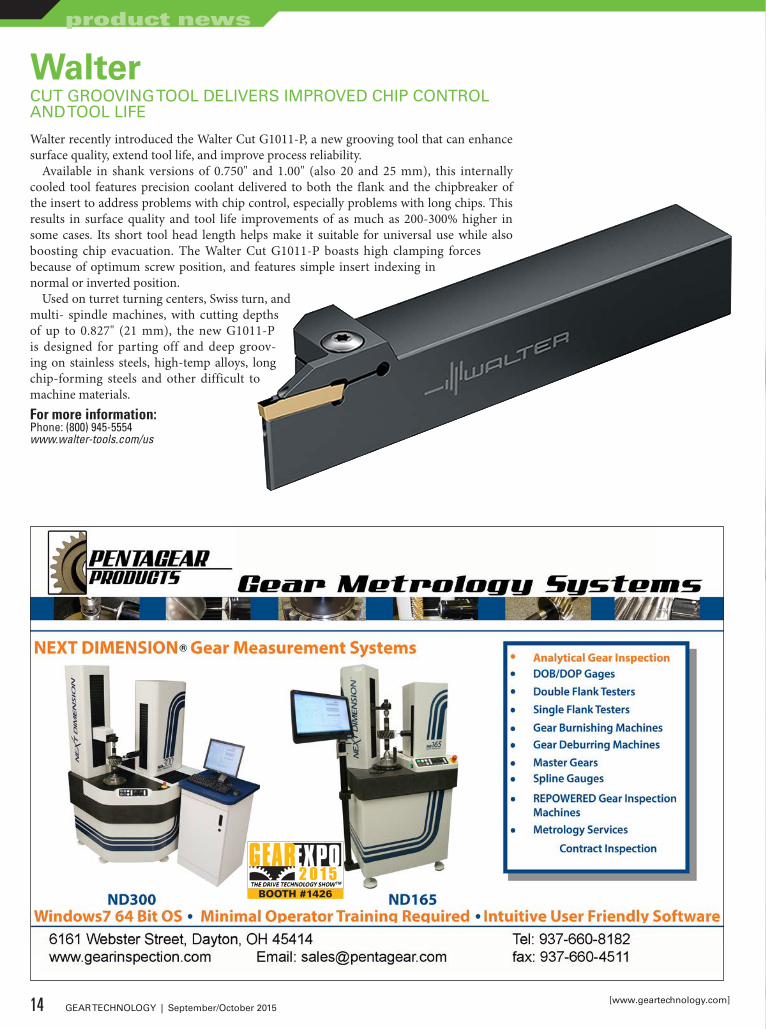
WalterCUT GROOVING TOOL DELIVERS IMPROVED CHIP CONTROL AND TOOL LIFE
Walter recently introduced the Walter Cut G1011-P, a new grooving tool that can enhance surface quality, extend tool life, and improve process reliability.
Available in shank versions of 0.750" and 1.00" (also 20 and 25 mm), this internally cooled tool features precision coolant delivered to both the flank and the chipbreaker of the insert to address problems with chip control, especially problems with long chips. This results in surface quality and tool life improvements of as much as 200-300% higher in some cases. Its short tool head length helps make it suitable for universal use while also boosting chip evacuation. The Walter Cut G1011-P boasts high clamping forces because of optimum screw position, and features simple insert indexing in normal or inverted position.
Used on turret turning centers, Swiss turn, and multi- spindle machines, with cutting depths of up to 0.827" (21 mm), the new G1011-P is designed for parting off and deep groov-ing on stainless steels, high-temp alloys, long chip-forming steels and other difficult to machine materials.For more information:Phone: (800) 945-5554www.walter-tools.com/us
Never settle for close when you can have precision fit.
When it comes to the mechanical components you count on, close just doesn’t cut it. Common sense says a poor fit and premature wear will eventually lead to failure. And no one has time for that. At Schafer, we specialize in custom, precision-fit products designed to keep equipment moving. Simply put, our service, quality and on-time delivery are second to none. Reliability is our trademark and it has helped us grow from Schafer Gear to Schafer Industries. These days, our expertise doesn’t end with gears. Now we’re leading the way in driveline, axle and brake applications as well. So whether you’re in the automotive, truck, marine, off-road leisure, heavy equipment or aviation industry, look no further than Schafer. For more information visit us online.
SchaferIndustries.com
SCHA 0092 2015 Pretty Picture GearTech Ad.indd 1 9/18/15 12:55 PM
BOOTH #1426
14 GEAR TECHNOLOGY | September/October 2015[www.geartechnology.com]
product news

Never settle for close when you can have precision fit.
When it comes to the mechanical components you count on, close just doesn’t cut it. Common sense says a poor fit and premature wear will eventually lead to failure. And no one has time for that. At Schafer, we specialize in custom, precision-fit products designed to keep equipment moving. Simply put, our service, quality and on-time delivery are second to none. Reliability is our trademark and it has helped us grow from Schafer Gear to Schafer Industries. These days, our expertise doesn’t end with gears. Now we’re leading the way in driveline, axle and brake applications as well. So whether you’re in the automotive, truck, marine, off-road leisure, heavy equipment or aviation industry, look no further than Schafer. For more information visit us online.
SchaferIndustries.com
SCHA 0092 2015 Pretty Picture GearTech Ad.indd 1 9/18/15 12:55 PM
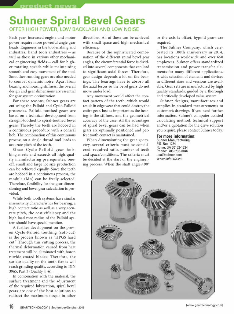
Suhner Spiral Bevel GearsOFFER HIGH POWER, LOW BACKLASH AND LOW NOISE
Each year, increased engine and motor power require more powerful angle gear heads. Engineers in the tool-making and industrial hand tools industries — as well as those in various other mechani-cal engineering fields — call for high-er rotating speeds while maintaining smooth and easy movement of the tool. Smoother-running gears are also needed to combat dynamic noise. Apart from bearing and housing stiffness, the overall design and gear dimensions are essential for gear system optimization.
For these reasons, Suhner gears are cut using the Palloid and Cyclo-Palloid processes. Palloid-toothed gears are based on a technical development from straight-toothed to spiral-toothed bevel gears. Thereby the teeth are hobbed in a continuous procedure with a conical hob. The combination of this continuous process on a single thread tool leads to accurate pitch of the teeth.
Since Cyclo-Pal loid gear hob-bing meets and exceeds all high-qual-ity manufacturing prerequisites, one-off, small and large lot size production can be achieved equally. Since the teeth are hobbed in a continuous process, the module (Mn) can be freely selected. Therefore, flexibility for the gear dimen-sioning and bevel gear calculation is pro-vided.
While both tooth systems have similar insensitivity characteristics for bearing, a high contact ratio as well as a very accu-rate pitch, the cost efficiency and the high load root radius of the Palloid sys-tem should have special mention.
A further development on the prov-en Cyclo-Palloid toothing (soft-cut) is the process known as “HPGS hard cut.” Through this cutting process, the thermal deformation caused from heat treatment will be eliminated with boron nitride coated blades. Therefore, the surface quality on the tooth flanks will reach grinding quality, according to DIN 3965, Part 3 (Quality 4 -6).
In combination with the material, the surface treatment and the adjustment of the required lubrication, spiral bevel gears are one of the best solutions to redirect the maximum torque in other
directions. All of these can be achieved with small space and high mechanical efficiency.
Because of the sophisticated combi-nation of the different spiral bevel gear angles, the circumferential force is divid-ed into several components that can lead to significant axial forces. Therefore, gear design depends a lot on the bear-ings. The bearings have to absorb all the axial forces so the bevel gears do not move under load.
Any movement would affect the con-tact pattern of the teeth, which would result in edge wear that could destroy the entire gear. Just as important as the bear-ing is the stiffness and the geometrical accuracy of the case. All the advantages of spiral bevel gears can be had when gears are optimally positioned and per-fect tooth contact is maintained.
When dimensioning the gear geom-etry, several criteria must be consid-ered: required ratio, number of teeth and space/conditions. The criteria must be decided at the start of the engineer-ing process. When the shaft angle ≠ 90°
or the axis is offset, hypoid gears are required.
The Suhner Company, which cele-brated its 100th anniversary in 2014, has locations worldwide and over 650 employees. Suhner offers standardized transmission and power transfer ele-ments for many different applications. A wide selection of elements and devices in different sizes and versions are avail-able. Gear sets are manufactured by high quality standards, guided by a thorough and critically developed value system.
Suhner designs, manufactures and supplies in standard measurements to customer’s drawings. If you need further information, Suhner’s computer-assisted calculating method, technical support and/or a quotation for the drive solution you require, please contact Suhner today.For more information:Suhner ManufacturingP.O. Box 1234Rome, GA 30162-1234Phone: (706) [email protected]
16 GEAR TECHNOLOGY | September/October 2015[www.geartechnology.com]
product news
Cimcool Cimpulse Metalworking FluidsFORMULATED FOR USE IN HIGH-PRESSURE SYSTEMS
Milacron Fluid Technologies’ brand Cimcool recently announced the launch of Cimpulse.
Cimpulse 51MP, Cimpulse 45MP and Cimpulse 33MP are new fluids in the Cimcool family. Cimpulse products are multifunctional and designed to allow metalworking shops to utilize one fluid in their entire shop. In most cases, a Cimpulse fluid can be used to consoli-date all the different fluids being used within their plant.
Cimpulse fluids have been formulat-ed for use in both high-pressure sys-tems and standard flood applications. Cimpulse metalworking fluids utilize a hybrid blend of lubricants to deliver increased stability and reduced tool wear as well as provide long sump life.
Cimpulse 51MP for example, is a mul-tipurpose non-chlorinated, triazine- free fluid that provides users high-pressure foam and corrosion control. It keeps machines and parts clean and provides emulsion stability, long sump life and good bio-control.
“We are confident that Cimcool’s Cimpulse metalworking fluids will change the way metalworking shops think about fluids,” said Jack Teat, pres-ident of Cimcool Fluid Technology. “Cimpulse is a revolutionary fluid tech-nology unmatched in the market. We believe that a Cimpulse fluid can help all of our customers reduce their inventory and improve their metalworking opera-tions.”For more information:Phone: (513) 458-8100www.cimcool.com
17September/October 2015 | GEAR TECHNOLOGY

Marposs iWave2 Wireless GaugeHAS MEASURING RESOLUTION OF 0.0001 MM
Marposs Corp. recently announced it will introduce its new iWave2 wire-less manual gauge in booth #619 at the Quality Show.
The iWave2 gauge features a durable, ergonomically designed handle with rechargeable Li-ion battery that incor-porates a computer with a 1.8" TFT color screen for displaying the mea-surement value in the operator’s hand.
Interchangeable nosepieces convert the gauge for ID, OD or length mea-surements. Measurement values can be transmitted via Bluetooth wireless technology to a gauge computer locat-ed within a 10 m distance. The iWave2 gauge has a measuring resolution of 0.0001 mm.
In addition to the measurement value, the gauge’s color graphical display with
selectable portrait/landscape view pres-ents a variety of information for the operator. The iWave2 gauge features a bar graph column with measurement units, good/scrap part indication, wire-less strength and battery levels, confir-mation of measurement transmission and an absolute/relative option setting.
The iWave2 gauge is programmable for stand-alone use via Android phone/tablet or PC. Several functions are avail-able with the iWave2 gauge when used with Marposs Quick SPC statistical soft-
ware, including on/off switching com-manded by guided sequence; calibra-tion history; and simultaneous zeroing of multiple devices.
The gauge incorporates soft touch buttons that are impervious to mois-ture. Battery duration is approximate-ly 16 hours, while the gauge’s inductive recharging system ensures continuous use 24/7.For more information:Phone: (248) 370-0404www.marposs.com
LEADERSin GEAR WORKHOLDING
60 YEARS
262-886-5050 | [email protected] | www.drewco.com
AN EXPERT LEADING YOU IN THE RIGHT DIRECTION
for Over
GEAR FIXTURES ALL OPERATIONSLARGE GEAR PEDESTAL FIXTURES
ARBORS/MANDRELSCHUCKS/ COLLETS
PROVEN ROI’S • CASE STUDIES
LEADERSin GEAR WORKHOLDING
60 YEARS
262-886-5050 | [email protected] | www.drewco.com
AN EXPERT LEADING YOU IN THE RIGHT DIRECTION
for Over
GEAR FIXTURES ALL OPERATIONSLARGE GEAR PEDESTAL FIXTURES
ARBORS/MANDRELSCHUCKS/ COLLETS
PROVEN ROI’S • CASE STUDIES
18 GEAR TECHNOLOGY | September/October 2015[www.geartechnology.com]
product news
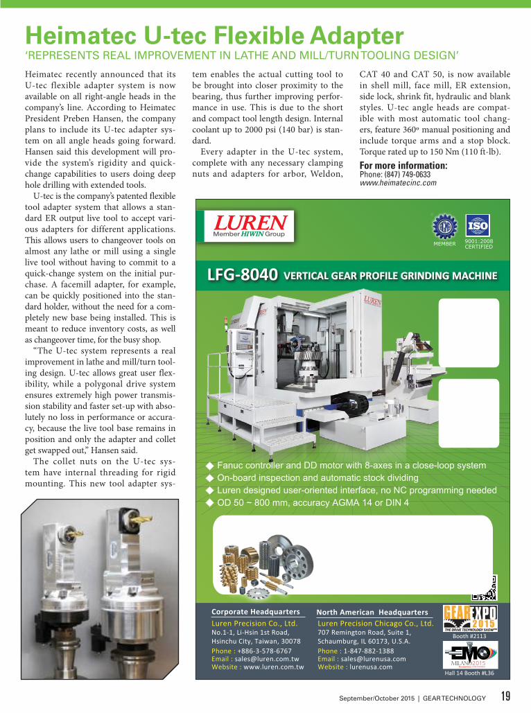
Heimatec U-tec Flexible Adapter‘REPRESENTS REAL IMPROVEMENT IN LATHE AND MILL/TURN TOOLING DESIGN’
Heimatec recently announced that its U-tec flexible adapter system is now available on all right-angle heads in the company’s line. According to Heimatec President Preben Hansen, the company plans to include its U-tec adapter sys-tem on all angle heads going forward. Hansen said this development will pro-vide the system’s rigidity and quick-change capabilities to users doing deep hole drilling with extended tools.
U-tec is the company’s patented flexible tool adapter system that allows a stan-dard ER output live tool to accept vari-ous adapters for different applications. This allows users to changeover tools on almost any lathe or mill using a single live tool without having to commit to a quick-change system on the initial pur-chase. A facemill adapter, for example, can be quickly positioned into the stan-dard holder, without the need for a com-pletely new base being installed. This is meant to reduce inventory costs, as well as changeover time, for the busy shop.
“The U-tec system represents a real improvement in lathe and mill/turn tool-ing design. U-tec allows great user flex-ibility, while a polygonal drive system ensures extremely high power transmis-sion stability and faster set-up with abso-lutely no loss in performance or accura-cy, because the live tool base remains in position and only the adapter and collet get swapped out,” Hansen said.
The collet nuts on the U-tec sys-tem have internal threading for rigid mounting. This new tool adapter sys-
tem enables the actual cutting tool to be brought into closer proximity to the bearing, thus further improving perfor-mance in use. This is due to the short and compact tool length design. Internal coolant up to 2000 psi (140 bar) is stan-dard.
Every adapter in the U-tec system, complete with any necessary clamping nuts and adapters for arbor, Weldon,
CAT 40 and CAT 50, is now available in shell mill, face mill, ER extension, side lock, shrink fit, hydraulic and blank styles. U-tec angle heads are compat-ible with most automatic tool chang-ers, feature 360º manual positioning and include torque arms and a stop block. Torque rated up to 150 Nm (110 ft-lb).For more information:Phone: (847) 749-0633www.heimatecinc.com
Fanuc controller and DD motor with 8-axes in a close-loop systemOn-board inspection and automatic stock dividing
OD 50 ~ 800 mm, accuracy AGMA 14 or DIN 4Luren designed user-oriented interface, no NC programming needed
Corporate HeadquartersLuren Precision Co., Ltd.No.1-1, Li-Hsin 1st Road,Hsinchu City, Taiwan, 30078Phone : +886-3-578-6767Email : [email protected] : www.luren.com.tw
707 Remington Road, Suite 1,Schaumburg, IL 60173, U.S.A. Phone : 1-847-882-1388Email : [email protected] : lurenusa.com
Luren Precision Chicago Co., Ltd.North American Headquarters
Our Gear Cutting Tools Hobs Shaper Cutters Master Gears
For over 20 years of manufacturing, Luren offers a wide variety of custom and standard gear cutting tools using thehighest quality materials and accuracy toensure your longest possible tool life.
MEMBER 9001:2008CERTIFIED
Booth #2113
Hall 14 Booth #L36
LFG-8040 VERTICAL GEAR PROFILE GRINDING MACHINE
19September/October 2015 | GEAR TECHNOLOGY
Over the last 15 years, there has been significant growth in the number of transmission types as well as their com-plexity: manual, conventional automat-ic, dual clutch, automated manual, con-tinuously variable, split power and pure EV transmissions. Alongside this, most manufacturers are now simultaneously developing conventional, hybrid and all-electric vehicles, with each type requir-ing different driveline architectures.
A continuous drive to deliver optimal efficiency alongside reduced weight and cost also means that newer powertrains feature much closer integration of the gearbox, prime mover and energy recov-ery systems and rely on sophisticated control systems to ensure optimum per-formance and efficiency at all times.
This shift in technical complexity has occurred against a backdrop of increased competition and demands for great effi-ciency, as well as a need to comply with changing legislative and industry stan-dards. More than ever, vehicle manufac-turers must innovate and bring to mar-ket powertrains that are comparatively unproven.
For the engineering teams tasked with developing these new powertrains, resources are being pushed harder than ever, and development processes are now very much under scrutiny.
Typically, manufacturers have used a range of individual CAE software tools
and methods to sim-ulate and design sep-arate components such as gears, meshes, gear microgeometry, shafts and bearings.
Whilst the sophis-tication and accuracy of these tools are not in question, the fact that many calcula-tions are made with-out considering the effects of the entire system can lead to later problems dur-ing the manufactur-ing process, which in turn can prove incredibly time con-suming and expen-sive to correct. For example, powertrain noise and vibration issues might go undetected until the first hardware prototypes have been tested.
The transfer of data (or lack thereof) between different design and analysis tools can compound the problem. In some cases, basic concept design chang-es can take weeks to ripple through vari-ous departments, often requiring manual updating of models, which is both slow and error prone. This can be a major hindrance to the creation of optimal, cost-effective designs.
Component-level software tools have traditionally been unable to provide the over-arching system-level analysis needed within mod-ern integrated design approach-es. Many manufacturers recognize that this critical issue needs to be addressed, but when it comes to implementing a strategy to achieve this, it can be a case of “easier said than done.”
Here are some examples of the actions you can take to address real-world challenges posed in the design and development process:
Pressure for Faster and Lower-Cost DevelopmentCost reduction and faster time-to-mar-ket are becoming the mantra for today’s driveline engineers. Carmakers are requiring shorter and cheaper develop-ment cycles, meaning less time to work and a heightened pressure from senior management to get things right the first time. The fallout from this means design and analysis phases must be more effi-cient and more streamlined.
In order to address this, it is impera-tive that action is taken during the ear-liest parts of the design and analysis phase, widely identified as the key area in which process improvements can be made. Traditionally, the earliest stages of production are carried out in isola-tion with prototypes tested and problems fixed later during the production pro-cess. The fallout from this includes slow development cycles, high development costs, opportunity for miscommunica-tion and errors, and limited opportunity for innovation.
Romax’s Right First Time approach aims to update designs early on in the design process, where changes can be
The Modern Approach to Transmission System Design and AnalysisJamie Pears
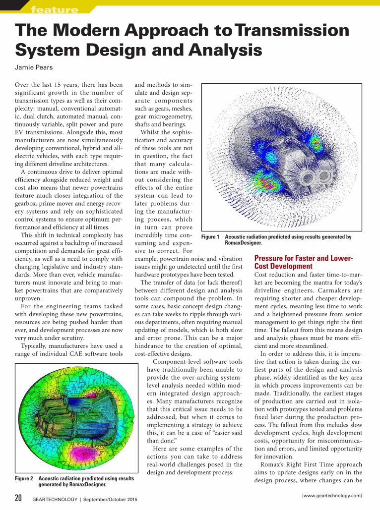
Figure 1 Acoustic radiation predicted using results generated by RomaxDesigner.
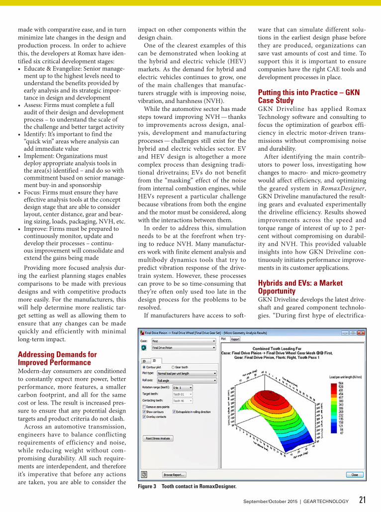
Figure 2 Acoustic radiation predicted using results generated by RomaxDesigner.
20 GEAR TECHNOLOGY | September/October 2015[www.geartechnology.com]
feature
made with comparative ease, and in turn minimize late changes in the design and production process. In order to achieve this, the developers at Romax have iden-tified six critical development stages:• Educate & Evangelize: Senior manage-
ment up to the highest levels need to understand the benefits provided by early analysis and its strategic impor-tance in design and development
• Assess: Firms must complete a full audit of their design and development process – to understand the scale of the challenge and better target activity
• Identify: It’s important to find the “quick win” areas where analysis can add immediate value
• Implement: Organizations must deploy appropriate analysis tools in the area(s) identified – and do so with commitment based on senior manage-ment buy-in and sponsorship
• Focus: Firms must ensure they have effective analysis tools at the concept design stage that are able to consider layout, center distance, gear and bear-ing sizing, loads, packaging, NVH, etc.
• Improve: Firms must be prepared to continuously monitor, update and develop their processes – continu-ous improvement will consolidate and extend the gains being madeProviding more focused analysis dur-
ing the earliest planning stages enables comparisons to be made with previous designs and with competitive products more easily. For the manufacturers, this will help determine more realistic tar-get setting as well as allowing them to ensure that any changes can be made quickly and efficiently with minimal long-term impact.
Addressing Demands for Improved PerformanceModern-day consumers are conditioned to constantly expect more power, better performance, more features, a smaller carbon footprint, and all for the same cost or less. The result is increased pres-sure to ensure that any potential design targets and product criteria do not clash.
Across an automotive transmission, engineers have to balance conflicting requirements of efficiency and noise, while reducing weight without com-promising durability. All such require-ments are interdependent, and therefore it’s imperative that before any actions are taken, you are able to consider the
impact on other components within the design chain.
One of the clearest examples of this can be demonstrated when looking at the hybrid and electric vehicle (HEV) markets. As the demand for hybrid and electric vehicles continues to grow, one of the main challenges that manufac-turers struggle with is improving noise, vibration, and harshness (NVH).
While the automotive sector has made steps toward improving NVH — thanks to improvements across design, anal-ysis, development and manufacturing processes — challenges still exist for the hybrid and electric vehicles sector. EV and HEV design is altogether a more complex process than designing tradi-tional drivetrains; EVs do not benefit from the “masking” effect of the noise from internal combustion engines, while HEVs represent a particular challenge because vibrations from both the engine and the motor must be considered, along with the interactions between them.
In order to address this, simulation needs to be at the forefront when try-ing to reduce NVH. Many manufactur-ers work with finite element analysis and multibody dynamics tools that try to predict vibration response of the drive-train system. However, these processes can prove to be so time-consuming that they’re often only used too late in the design process for the problems to be resolved.
If manufacturers have access to soft-
ware that can simulate different solu-tions in the earliest design phase before they are produced, organizations can save vast amounts of cost and time. To support this it is important to ensure companies have the right CAE tools and development processes in place.
Putting this into Practice – GKN Case StudyGKN Driveline has applied Romax Technology software and consulting to focus the optimization of gearbox effi-ciency in electric motor-driven trans-missions without compromising noise and durability.
After identifying the main contrib-utors to power loss, investigating how changes to macro- and micro-geometry would affect efficiency, and optimizing the geared system in RomaxDesigner, GKN Driveline manufactured the result-ing gears and evaluated experimentally the driveline efficiency. Results showed improvements across the speed and torque range of interest of up to 2 per-cent without compromising on durabil-ity and NVH. This provided valuable insights into how GKN Driveline con-tinuously initiates performance improve-ments in its customer applications.
Hybrids and EVs: a Market OpportunityGKN Driveline develops the latest drive-shaft and geared component technolo-gies. “During first hype of electrifica-
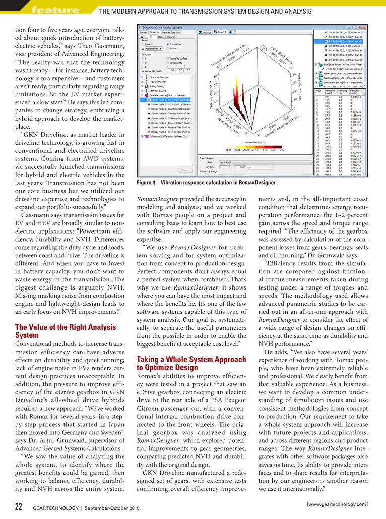
Figure 3 Tooth contact in RomaxDesigner.
21September/October 2015 | GEAR TECHNOLOGY
tion four to five years ago, everyone talk-ed about quick introduction of battery-electric vehicles,” says Theo Gassmann, vice president of Advanced Engineering. “The reality was that the technology wasn’t ready — for instance, battery tech-nology is too expensive — and customers aren’t ready, particularly regarding range limitations. So the EV market experi-enced a slow start.” He says this led com-panies to change strategy, embracing a hybrid approach to develop the market-place.
“GKN Driveline, as market leader in driveline technology, is growing fast in conventional and electrified driveline systems. Coming from AWD systems, we successfully launched transmissions for hybrid and electric vehicles in the last years. Transmission has not been our core business but we utilized our driveline expertise and technologies to expand our portfolio successfully.”
Gassmann says transmission issues for EV and HEV are broadly similar to non-electric applications: “Powertrain effi-ciency, durability and NVH. Differences come regarding the duty cycle and loads, between coast and drive. The driveline is different. And when you have to invest in battery capacity, you don’t want to waste energy in the transmission. The biggest challenge is arguably NVH. Missing masking noise from combustion engine and lightweight-design leads to an early focus on NVH improvements.”
The Value of the Right Analysis SystemConventional methods to increase trans-mission efficiency can have adverse effects on durability and quiet running; lack of engine noise in EVs renders cur-rent design practices unacceptable. In addition, the pressure to improve effi-ciency of the eDrive gearbox in GKN Driveline’s all-wheel drive hybrids required a new approach. “We’ve worked with Romax for several years, in a step-by-step process that started in Japan then moved into Germany and Sweden,” says Dr. Artur Grunwald, supervisor of Advanced Geared Systems Calculations.
“We saw the value of analyzing the whole system, to identify where the greatest benefits could be gained, then working to balance efficiency, durabil-ity and NVH across the entire system.
RomaxDesigner provided the accuracy in modeling and analysis, and we worked with Romax people on a project and consulting basis to learn how to best use the software and apply our engineering expertise.
“We use RomaxDesigner for prob-lem solving and for system optimiza-tion from concept to production design. Perfect components don’t always equal a perfect system when combined. That’s why we use RomaxDesigner: it shows where you can have the most impact and where the benefits lie. It’s one of the few software systems capable of this type of system analysis. Our goal is, systemati-cally, to separate the useful parameters from the possible in order to enable the biggest benefit at acceptable cost level.”
Taking a Whole System Approach to Optimize DesignRomax’s abilities to improve efficien-cy were tested in a project that saw an eDrive gearbox connecting an electric drive to the rear axle of a PSA Peugeot Citroen passenger car, with a conven-tional internal combustion drive con-nected to the front wheels. The orig-inal gearbox was analyzed using RomaxDesigner, which explored poten-tial improvements to gear geometries, comparing predicted NVH and durabil-ity with the original design.
GKN Driveline manufactured a rede-signed set of gears, with extensive tests confirming overall efficiency improve-
ments and, in the all-important coast condition that determines energy recu-peration performance, the 1–2 percent gain across the speed and torque range required. “The efficiency of the gearbox was assessed by calculation of the com-ponent losses from gears, bearings, seals and oil churning,” Dr. Grunwald says.
“Efficiency results from the simula-tion are compared against friction-al torque measurements taken during testing under a range of torques and speeds. The methodology used allows advanced parametric studies to be car-ried out in an all-in-one approach with RomaxDesigner to consider the effect of a wide range of design changes on effi-ciency at the same time as durability and NVH performance.”
He adds, “We also have several years’ experience of working with Romax peo-ple, who have been extremely reliable and professional. We clearly benefit from that valuable experience. As a business, we want to develop a common under-standing of simulation issues and use consistent methodologies from concept to production. Our requirement to take a whole-system approach will increase with future projects and applications, and across different regions and product ranges. The way RomaxDesigner inte-grates with other software packages also saves us time. Its ability to provide inter-faces and to share results for interpreta-tion by our engineers is another reason we use it internationally.”
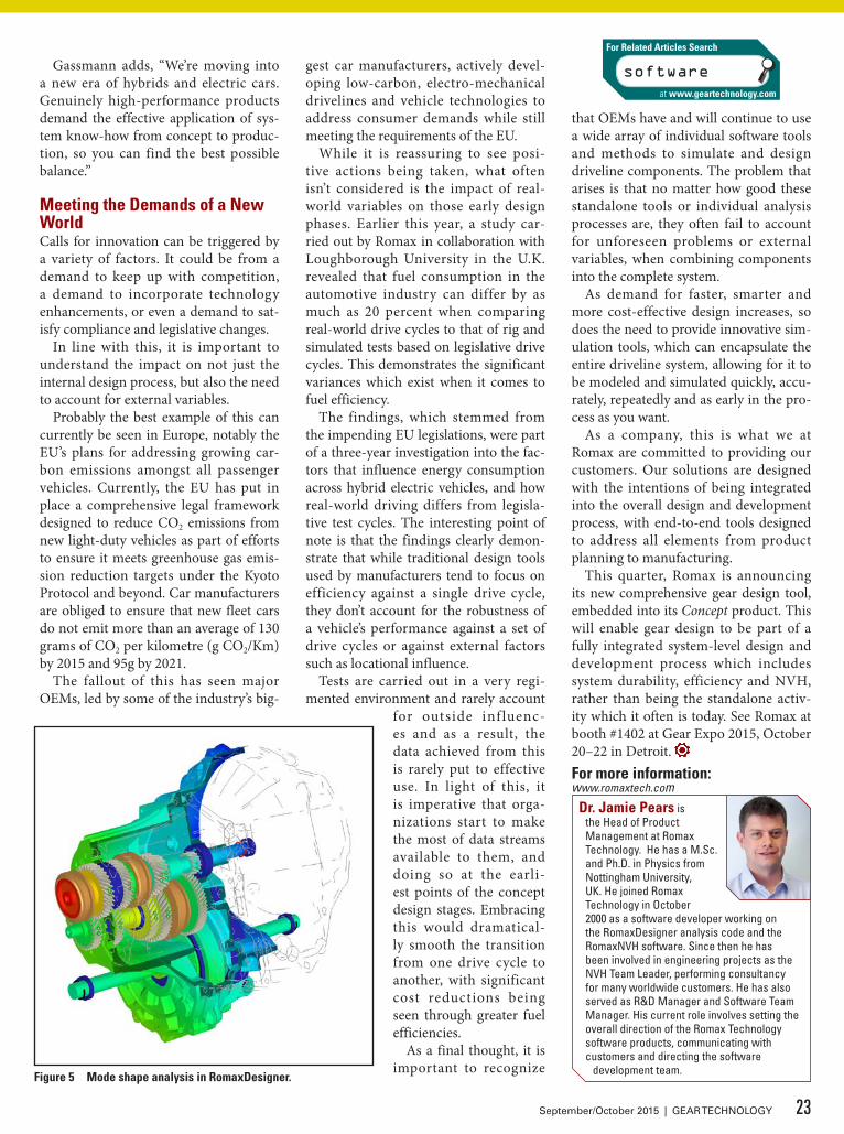
Figure 4 Vibration response calculation in RomaxDesigner.
22 GEAR TECHNOLOGY | September/October 2015[www.geartechnology.com]
feature THE MODERN APPROACH TO TRANSMISSION SYSTEM DESIGN AND ANALYSIS
Gassmann adds, “We’re moving into a new era of hybrids and electric cars. Genuinely high-performance products demand the effective application of sys-tem know-how from concept to produc-tion, so you can find the best possible balance.”
Meeting the Demands of a New WorldCalls for innovation can be triggered by a variety of factors. It could be from a demand to keep up with competition, a demand to incorporate technology enhancements, or even a demand to sat-isfy compliance and legislative changes.
In line with this, it is important to understand the impact on not just the internal design process, but also the need to account for external variables.
Probably the best example of this can currently be seen in Europe, notably the EU’s plans for addressing growing car-bon emissions amongst all passenger vehicles. Currently, the EU has put in place a comprehensive legal framework designed to reduce CO2 emissions from new light-duty vehicles as part of efforts to ensure it meets greenhouse gas emis-sion reduction targets under the Kyoto Protocol and beyond. Car manufacturers are obliged to ensure that new fleet cars do not emit more than an average of 130 grams of CO2 per kilometre (g CO2/Km) by 2015 and 95g by 2021.
The fallout of this has seen major OEMs, led by some of the industry’s big-
gest car manufacturers, actively devel-oping low-carbon, electro-mechanical drivelines and vehicle technologies to address consumer demands while still meeting the requirements of the EU.
While it is reassuring to see posi-tive actions being taken, what often isn’t considered is the impact of real-world variables on those early design phases. Earlier this year, a study car-ried out by Romax in collaboration with Loughborough University in the U.K. revealed that fuel consumption in the automotive industry can differ by as much as 20 percent when comparing real-world drive cycles to that of rig and simulated tests based on legislative drive cycles. This demonstrates the significant variances which exist when it comes to fuel efficiency.
The findings, which stemmed from the impending EU legislations, were part of a three-year investigation into the fac-tors that influence energy consumption across hybrid electric vehicles, and how real-world driving differs from legisla-tive test cycles. The interesting point of note is that the findings clearly demon-strate that while traditional design tools used by manufacturers tend to focus on efficiency against a single drive cycle, they don’t account for the robustness of a vehicle’s performance against a set of drive cycles or against external factors such as locational influence.
Tests are carried out in a very regi-mented environment and rarely account
for outside inf luenc-es and as a result, the data achieved from this is rarely put to effective use. In light of this, it is imperative that orga-nizations start to make the most of data streams available to them, and doing so at the earli-est points of the concept design stages. Embracing this would dramatical-ly smooth the transition from one drive cycle to another, with significant cost reductions being seen through greater fuel efficiencies.
As a final thought, it is important to recognize
that OEMs have and will continue to use a wide array of individual software tools and methods to simulate and design driveline components. The problem that arises is that no matter how good these standalone tools or individual analysis processes are, they often fail to account for unforeseen problems or external variables, when combining components into the complete system.
As demand for faster, smarter and more cost-effective design increases, so does the need to provide innovative sim-ulation tools, which can encapsulate the entire driveline system, allowing for it to be modeled and simulated quickly, accu-rately, repeatedly and as early in the pro-cess as you want.
As a company, this is what we at Romax are committed to providing our customers. Our solutions are designed with the intentions of being integrated into the overall design and development process, with end-to-end tools designed to address all elements from product planning to manufacturing.
This quarter, Romax is announcing its new comprehensive gear design tool, embedded into its Concept product. This will enable gear design to be part of a fully integrated system-level design and development process which includes system durability, efficiency and NVH, rather than being the standalone activ-ity which it often is today. See Romax at booth #1402 at Gear Expo 2015, October 20–22 in Detroit. For more information:www.romaxtech.com
Figure 5 Mode shape analysis in RomaxDesigner.
Dr. Jamie Pears is the Head of Product Management at Romax Technology. He has a M.Sc. and Ph.D. in Physics from Nottingham University, UK. He joined Romax Technology in October 2000 as a software developer working on the RomaxDesigner analysis code and the RomaxNVH software. Since then he has been involved in engineering projects as the NVH Team Leader, performing consultancy for many worldwide customers. He has also served as R&D Manager and Software Team Manager. His current role involves setting the overall direction of the Romax Technology software products, communicating with customers and directing the software
development team.
software
For Related Articles Search
at www.geartechnology.com
23September/October 2015 | GEAR TECHNOLOGY
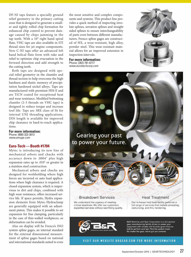
DMG Mori — Booth #1813DMG Mori will demonstrate its gear milling portfolio with a focus on GearMILL software and various gear milling processes on multi-tasking machines. The solution’s approach, which combines the machine, tooling, inspection and software, will be on dis-play to demonstrate different ways of making gears.
“The demonstrations center around the flexibility of the machines, which leads to greater productivity,” says Nitin Chaphalkar, product manager for the gear market for DMG Mori.
The booth will also have a display of their GearMILL software with lat-
est machine cycle developments and part inspection capabilities. Machining of a variety of gears such as spiral bev-els, spur, helical and internal gears will
be demonstrated on this single machine. DMG Mori will also be
presenting its solutions during pre-sentations at the solutions center. The machine exhibited will be a NTX 2000 machine (a multi axis lathe) with sec-ond spindle and lower turret. This machine is capable of producing all types of gears using InvoMilling, flank milling (end mills), hobbing, gashing and power skiving processes. DMG Mori’s gear expert team will be on site to discuss possible machining processes for your parts and recommend solu-tions.For more information:Phone: (855) 364-6674us.dmgmori.com
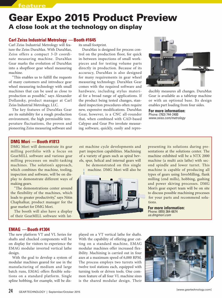
Carl Zeiss Industrial Metrology — Booth #1645Carl Zeiss Industrial Metrology will fea-ture the Zeiss DuraMax. With DuraMax, Zeiss offers a compact 3-D coordi-nate measuring machine. DuraMax Gear marks the evolution of DuraMax into a shopfloor gear wheel measuring machine.
“This enables us to fulfill the requests of many customers and introduce gear wheel measuring technology with small machines that can be used as close to production as possible,” says Alexander Dollansky, product manager at Carl Zeiss Industrial Metrology, LLC.
The key features of DuraMax Gear are its suitability for a rough production environment, the high permissible tem-perature fluctuations, the proven and pioneering Zeiss measuring software and
its small footprint.DuraMax is designed for process con-
trol on the production floor, for quick in-between inspections of small work-pieces and for testing volume parts directly in production. Because of its accuracy, DuraMax is also designed for many requirements in gear wheel measuring technology. DuraMax Gear comes with the required software and hardware, including stylus materi-al for a broad range of applications. If the product being tested changes, stan-dard inspection procedures often require new, expensive modifications. DuraMax Gear, however, is a CNC all-rounder that, when combined with CAD-based Calypso and Gear Pro involute measur-ing software, quickly, easily and repro-
ducibly measures all changes. DuraMax Gear is available as a tabletop machine or with an optional base. Its design enables part loading from four sides.For more information:Phone: (763) 744-2400www.zeiss.com/metrology
Gear Expo 2015 Product PreviewA close look at the technology on display
EMAG — Booth #1304The new platform VT and VL Series for shafts and chucked components will be on display for visitors to experience the EMAG modular inverted vertical lathe design.
With the goal to develop a system of modular machines geared for use in the manufacturing of medium and large batch runs, EMAG offers flexible solu-tions on a standard platform. Single spline hobbing, for example, will be dis-
played on a VT vertical lathe for shafts. With the capability of offering gear cut-ting on a standard machine, EMAG modular machines offer increased flex-ibility. Machining is carried out in four axes at a maximum speed of 6,000 RPM. The process employs two turrets with twelve tool stations each, equipped with turning tools or driven tools. One com-mon feature of all four VL machine sizes is the shared modular design. Their
24 GEAR TECHNOLOGY | September/October 2015[www.geartechnology.com]
feature

SEE IT IN YOUR RESULTS
ARROW GEAR’S ADVANCED DESIGN ASSISTANCEFOR GEARS THAT CARRY THE LOAD
In aerospace manufacturing, high-quality gears with complex shapes and exacting materials are the standard. Today, extremely high loads are placed on increasingly lighter gearboxes. For spiral bevel gears to perform properly under these extreme conditions, gear teeth geometry must be precisely machined to achieve optimum contact.
That’s where our Advanced Design Assistance comes in. By combining cutting-edge software with state-of-the-art machines, we speed the critical process of tooth contact pattern development. At Arrow Gear, we continually invest in our technology, equipment and people to produce the tight tolerances and extremely complex part designs the industry demands.
See it in Your Results.Call 630-969-7640 or visit arrowgear.com
2301 CURTISS STREET, DOWNERS GROVE, IL 60515 | 630-969-7640 | ARROWGEAR.COM

small footprint reduces floor space costs and increases flexibility in floor layout options. Every VL and VT machine fea-tures an integrated O-automation system for transporting workpieces.
When combined with the self-load-ing pick-up spindles, this automation concept ensures shorter cycle times and higher productivity. To accommodate machine operators, all the service units are easily within reach, with the various units (electrics, hydraulics, cooling sys-tem, cooling lubricant and central lubri-
cation system) accessible at any time so that the machines can be maintained with ease. While the standard lathes are commonly used for gear blanks, a wide range of technologies can be incorporat-ed into the machines, including turning, grinding, hobbing, chamfering, induc-tion hardening and laser welding.
The technologies in the EMAG Group cover the entire spectrum of metalwork-ing, including non-traditional process-es. Laser welding is essential in light-weighting automotive components while
electro-chemical machining (ECM) is a deburring option.
Introducing the latest addition to this technology portfolio, Eldec will dis-play induction hardening systems with a modular induction (MIND) machine at the show. Featuring Simultaneous Dual Frequency (SDF) technology where two different frequencies are applied to the workpiece, MIND machines can apply mid-frequencies to penetrate deeper and heat the root of the gear tooth simulta-neous to high frequencies to accurately heat the tip of the tooth. Eldec harden-ing systems compliment the workpiec-es machined by EMAG lathes to cre-ate more efficient, complete production lines. The flexible machine concepts and complete systems from EMAG offer modular and customized solutions for the production of workpieces in nearly every industry.For more information:Phone: (248) 477-7440www.emag.com
Emuge — Booth #1901Emuge Corp. recently announced a comprehensive line of high-perfor-mance tools for threading demanding nickel/super alloy materials to 46 HRC. The new program includes tools rang-ing from taps with unique new geom-etry designs to solid carbide thread mills designed for challenging aerospace, powergen and oil industry applications. A full line of sizes from no. 4 to ¾" are available in UNC, UNF and Metric, 87 sku’s in total.
Emuge’s Nickel Al loy Program includes new DF-NI and C-NI taps. With Emuge’s industry-first Variable Helix Correction (VHC) technology,
Products for the Aircraft
Manufacturing Industry
Christmas Tree Forms BroachCreate highly accurate form on turbine rotor disk blade of aircraft, ships and generators.
Surface Broaching MachineHigh performance and speed
production of gas turbine rotors.
Visit Our New Production Facilities ~717 Pushville Rd.
Greenwood, IN 46143
Dave Petrimoulx586-764-2263
www.nachiamerica.com
Products for the Aircraft
Manufacturing Industry
26 GEAR TECHNOLOGY | September/October 2015[www.geartechnology.com]
feature GEAR EXPO 2015 PRODUCT PREVIEW
DF-NI taps feature a specially ground relief geometry in the primary cutting zone that is designed to generate a small-er and tightly rolled chip formation for enhanced chip control to prevent dam-age caused by chips jamming in the tap teeth. With a 10° right hand spiral flute, VHC taps are also available in STI thread sizes for jet engine components. New C-NI taps offer an advanced left hand helical flute form with rake and relief to optimize chip evacuation in the forward direction and add strength to the cutting teeth.
Both taps are designed with spe-cial relief geometry in the chamfer and thread section to help overcome the high hardness and elastic memory of precipi-tation hardened nickel alloys. Taps are manufactured with premium HSS-E and are TiCN coated for exceptional heat and wear resistance. Modified bottoming chamfer (2-3 threads on VHC taps) is designed to reduce torque and increase tool life. Taps are 3BX class of fit for internal UNJ threading applications. DIN length is available for improved chip clearance in hard-to-reach applica-tions.For more information:Phone: (800) 323-3013www.emuge.com
Euro-Tech — Booth #1704Mytec is introducing its new line of mechanical arbors and chucks with accuracy down to .0004" plus high expansion rates up to .010" or greater in a stainless steel construction.
Mechanical arbors and chucks are designed for workholding where high forces are incurred or auto load applica-tions where high clearance is required. A closed expansion system, which is imper-vious to dirt and chips, combined with high wear resistance, offers increased ser-vice life. If space permits, Hydra expan-sion elements from Mytec-Hydraclamp are generally equipped with an adjust-ment piston. This makes it possible to set expansion for fine clamping, particularly in the case of thin-walled workpieces, so deformation can be avoided.
Also on display will be Frenco’s INO system spline gages, an internal standard for the external dimensional measure-ment of spline gages based on national and international standards suited to even
the most sensitive and complex compo-nents and systems. This product line pro-vides a quick method of inspecting invo-lute splines, serration splines and straight sided splines to ensure interchangeability of parts even between different manufac-turers. Frenco spline gages are construct-ed of HX, a wear-resistant, high alloy, powder steel. This wear-resistant mate-rial allows for an improved extension in inspection intervals.For more information:Phone: (262) 781-6777www.eurotechcorp.com
27September/October 2015 | GEAR TECHNOLOGY
Erwin Junker Machinery — Booth #1026The Junker Group will present its product diversity in gear manufacturing: Grinding machines from Junker and Zema in addition to air filters from LTA.
Junker’s portfolio has recently been expanded to include non-cylindrical grinding of camshafts for low to medium lot sizes. By using up to two high-performance grinding spindles, bearings journals and cam lobes can be rough and finish ground in a single clamping set-up. High powered grind-ing spindles, in combination with proven CBN grinding technology, guar-antee the highest removal rates and performance.
The Lean Selection cam is capable of grinding all cam lobe profiles and geometries at high-speed – from concave to elliptical – and is suitable for manufacturing everything from prototypes to large production runs.
Zema will be demonstrating how its Numerika G-800 accomplishes the pre-cision grinding of gear shafts. This dura-ble, cylindrical grinding machine with its hydrostatic × and Z axes and hydro-static grinding spindle reaches the tight-est tolerances reliably and is suited for an unlimited array of work pieces. In addition, Zema also offers machines for ID/OD grinding and large shafts with diameters of up to 1 meter (40 inch) and up to 4 meters (157 inch) in length. The conversational control systems (Fanuc Based) offered by Zema are operator friendly, simple and convenient to use.
LTA Lufttechnik GmbH is extending its portfolio to include a filter which has been kept deliberately simple and will be launched in the market under the name Basic Line. LTA has developed the new entry level model to allow customers from the metalworking industry to ben-efit from a simple yet fully functional oil and emulsion mist filter.
The electrostatic filter is available in two versions: The smaller of the two has a single-stage filter, the larger comes with two filters in series. The filters are configured for coolant pressures of up to 40 / 80 bar internal cooling and a machine room of up to 6 m3. Despite the suction capacity of 1,200 m3/h, the blower uses minimal energy, as LTA exclusively installs fans in accordance with the ERP directive. The filter ele-ments used also contribute towards sim-ple handling: They are optically moni-tored and fully washable. Their compact design allows the BASIC Line filters to be mounted on all machine tools.For more information:Phone: (847) 488-0406www.junker-group.com
28 GEAR TECHNOLOGY | September/October 2015[www.geartechnology.com]
feature GEAR EXPO 2015 PRODUCT PREVIEW
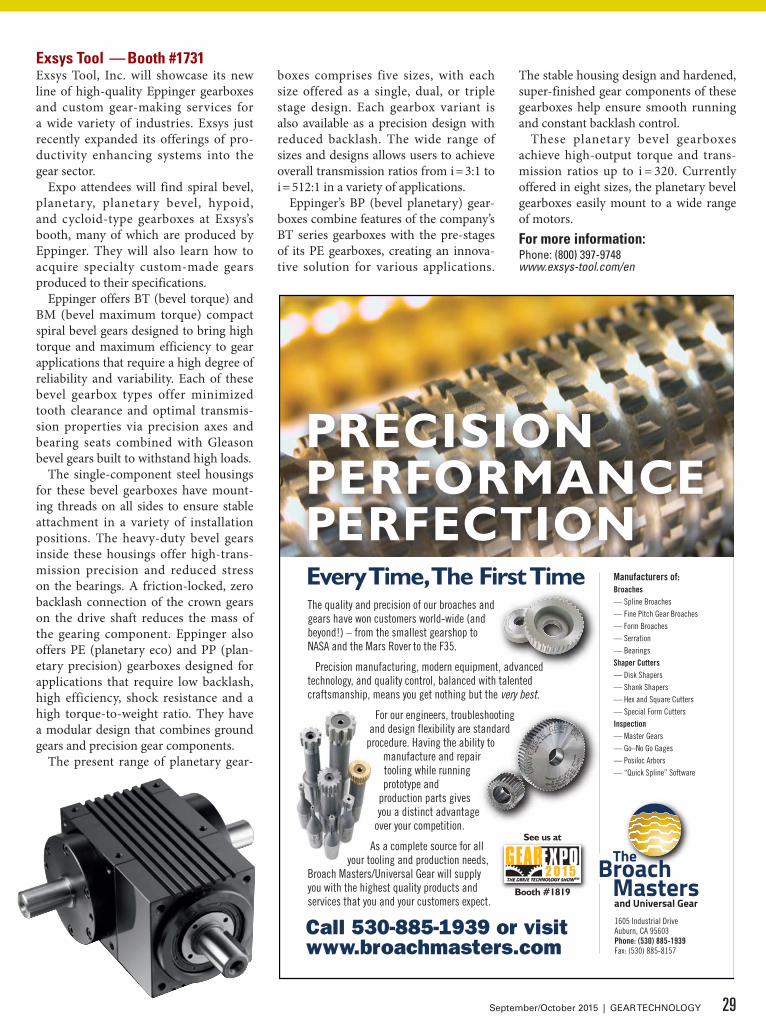
Exsys Tool — Booth #1731Exsys Tool, Inc. will showcase its new line of high-quality Eppinger gearboxes and custom gear-making services for a wide variety of industries. Exsys just recently expanded its offerings of pro-ductivity enhancing systems into the gear sector.
Expo attendees will find spiral bevel, planetary, planetary bevel, hypoid, and cycloid-type gearboxes at Exsys’s booth, many of which are produced by Eppinger. They will also learn how to acquire specialty custom-made gears produced to their specifications.
Eppinger offers BT (bevel torque) and BM (bevel maximum torque) compact spiral bevel gears designed to bring high torque and maximum efficiency to gear applications that require a high degree of reliability and variability. Each of these bevel gearbox types offer minimized tooth clearance and optimal transmis-sion properties via precision axes and bearing seats combined with Gleason bevel gears built to withstand high loads.
The single-component steel housings for these bevel gearboxes have mount-ing threads on all sides to ensure stable attachment in a variety of installation positions. The heavy-duty bevel gears inside these housings offer high-trans-mission precision and reduced stress on the bearings. A friction-locked, zero backlash connection of the crown gears on the drive shaft reduces the mass of the gearing component. Eppinger also offers PE (planetary eco) and PP (plan-etary precision) gearboxes designed for applications that require low backlash, high efficiency, shock resistance and a high torque-to-weight ratio. They have a modular design that combines ground gears and precision gear components.
The present range of planetary gear-
boxes comprises five sizes, with each size offered as a single, dual, or triple stage design. Each gearbox variant is also available as a precision design with reduced backlash. The wide range of sizes and designs allows users to achieve overall transmission ratios from i = 3:1 to i = 512:1 in a variety of applications.
Eppinger’s BP (bevel planetary) gear-boxes combine features of the company’s BT series gearboxes with the pre-stages of its PE gearboxes, creating an innova-tive solution for various applications.
The stable housing design and hardened, super-finished gear components of these gearboxes help ensure smooth running and constant backlash control.
These planetary bevel gearboxes achieve high-output torque and trans-mission ratios up to i = 320. Currently offered in eight sizes, the planetary bevel gearboxes easily mount to a wide range of motors. For more information:Phone: (800) 397-9748www.exsys-tool.com/en
29September/October 2015 | GEAR TECHNOLOGY
Manufacturers of:Broaches— Spline Broaches— Fine Pitch Gear Broaches— Form Broaches— Serration— BearingsShaper Cutters— Disk Shapers— Shank Shapers— Hex and Square Cutters— Special Form CuttersInspection— Master Gears— Go–No Go Gages— Posiloc Arbors— “Quick Spline” Software
1605 Industrial DriveAuburn, CA 95603Phone: (530) 885-1939Fax: (530) 885-8157
and Universal Gear
Call 530-885-1939 or visit www.broachmasters.com
PRECISION PERFORMANCE PERFECTIONEvery Time, The First TimeThe quality and precision of our broaches and gears have won customers world-wide (and beyond!) – from the smallest gearshop to NASA and the Mars Rover to the F35.
Precision manufacturing, modern equipment, advanced technology, and quality control, balanced with talented craftsmanship, means you get nothing but the very best.
For our engineers, troubleshooting and design flexibility are standard
procedure. Having the ability to manufacture and repair tooling while running prototype and
production parts gives you a distinct advantage
over your competition.
As a complete source for all your tooling and production needs,
Broach Masters/Universal Gear will supply you with the highest quality products and services that you and your customers expect.
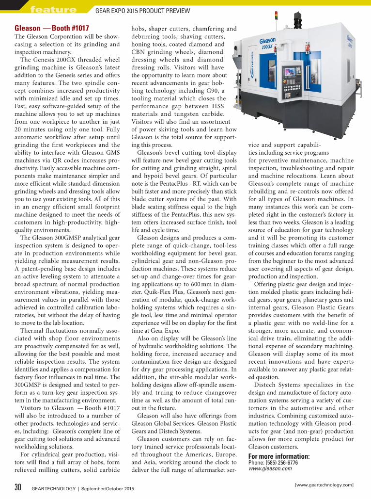
Gleason — Booth #1017The Gleason Corporation will be show-casing a selection of its grinding and inspection machinery.
The Genesis 200GX threaded wheel grinding machine is Gleason’s latest addition to the Genesis series and offers many features. The two spindle con-cept combines increased productivity with minimized idle and set up times. Fast, easy software-guided setup of the machine allows you to set up machines from one workpiece to another in just 20 minutes using only one tool. Fully automatic workflow after setup until grinding the first workpieces and the ability to interface with Gleason GMS machines via QR codes increases pro-ductivity. Easily accessible machine com-ponents make maintenance simpler and more efficient while standard dimension grinding wheels and dressing tools allow you to use your existing tools. All of this in an energy efficient small footprint machine designed to meet the needs of customers in high-productivity, high-quality environments.
The Gleason 300GMSP analytical gear inspection system is designed to oper-ate in production environments while yielding reliable measurement results. A patent-pending base design includes an active leveling system to attenuate a broad spectrum of normal production environment vibrations, yielding mea-surement values in parallel with those achieved in controlled calibration labo-ratories, but without the delay of having to move to the lab location.
Thermal fluctuations normally asso-ciated with shop floor environments are proactively compensated for as well, allowing for the best possible and most reliable inspection results. The system identifies and applies a compensation for factory floor influences in real time. The 300GMSP is designed and tested to per-form as a turn-key gear inspection sys-tem in the manufacturing environment.
Visitors to Gleason — Booth #1017 will also be introduced to a number of other products, technologies and servic-es, including: Gleason’s complete line of gear cutting tool solutions and advanced workholding solutions.
For cylindrical gear production, visi-tors will find a full array of hobs, form relieved milling cutters, solid carbide
hobs, shaper cutters, chamfering and deburring tools, shaving cutters, honing tools, coated diamond and CBN grinding wheels, diamond dressing wheels and diamond dressing rolls. Visitors will have the opportunity to learn more about recent advancements in gear hob-bing technology including G90, a tooling material which closes the performance gap between HSS materials and tungsten carbide. Visitors will also find an assortment of power skiving tools and learn how Gleason is the total source for support-ing this process.
Gleason’s bevel cutting tool display will feature new bevel gear cutting tools for cutting and grinding straight, spiral and hypoid bevel gears. Of particular note is the PentacPlus –RT, which can be built faster and more precisely than stick blade cutter systems of the past. With blade seating stiffness equal to the high stiffness of the PentacPlus, this new sys-tem offers increased surface finish, tool life and cycle time.
Gleason designs and produces a com-plete range of quick-change, tool-less workholding equipment for bevel gear, cylindrical gear and non-Gleason pro-duction machines. These systems reduce set-up and change-over times for gear-ing applications up to 600 mm in diam-eter. Quik-Flex Plus, Gleason’s next gen-eration of modular, quick-change work-holding systems which requires a sin-gle tool, less time and minimal operator experience will be on display for the first time at Gear Expo.
Also on display will be Gleason’s line of hydraulic workholding solutions. The holding force, increased accuracy and contamination free design are designed for dry gear processing applications. In addition, the stir-able modular work-holding designs allow off-spindle assem-bly and truing to reduce changeover time as well as the amount of total run-out in the fixture.
Gleason will also have offerings from Gleason Global Services, Gleason Plastic Gears and Distech Systems.
Gleason customers can rely on fac-tory trained service professionals locat-ed throughout the Americas, Europe, and Asia, working around the clock to deliver the full range of aftermarket ser-
vice and support capabili-ties including service programs for preventive maintenance, machine inspection, troubleshooting and repair and machine relocations. Learn about Gleason’s complete range of machine rebuilding and re-controls now offered for all types of Gleason machines. In many instances this work can be com-pleted right in the customer’s factory in less than two weeks. Gleason is a leading source of education for gear technology and it will be promoting its customer training classes which offer a full range of courses and education forums ranging from the beginner to the most advanced user covering all aspects of gear design, production and inspection.
Offering plastic gear design and injec-tion molded plastic gears including heli-cal gears, spur gears, planetary gears and internal gears, Gleason Plastic Gears provides customers with the benefit of a plastic gear with no weld-line for a stronger, more accurate, and econom-ical drive train, eliminating the addi-tional expense of secondary machining. Gleason will display some of its most recent innovations and have experts available to answer any plastic gear relat-ed question.
Distech Systems specializes in the design and manufacture of factory auto-mation systems serving a variety of cus-tomers in the automotive and other industries. Combining customized auto-mation technology with Gleason prod-ucts for gear (and non-gear) production allows for more complete product for Gleason customers.For more information:Phone: (585) 256-6776www.gleason.com
30 GEAR TECHNOLOGY | September/October 2015[www.geartechnology.com]
feature GEAR EXPO 2015 PRODUCT PREVIEW
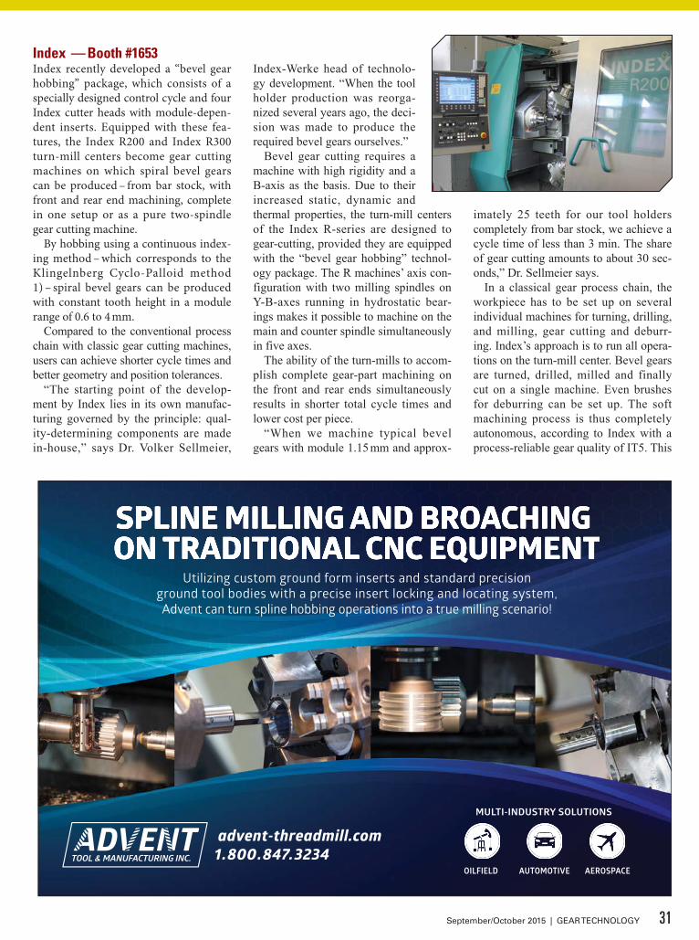
Index — Booth #1653Index recently developed a “bevel gear hobbing” package, which consists of a specially designed control cycle and four Index cutter heads with module-depen-dent inserts. Equipped with these fea-tures, the Index R200 and Index R300 turn-mill centers become gear cutting machines on which spiral bevel gears can be produced – from bar stock, with front and rear end machining, complete in one setup or as a pure two-spindle gear cutting machine.
By hobbing using a continuous index-ing method – which corresponds to the Klingelnberg Cyclo-Palloid method 1) – spiral bevel gears can be produced with constant tooth height in a module range of 0.6 to 4 mm.
Compared to the conventional process chain with classic gear cutting machines, users can achieve shorter cycle times and better geometry and position tolerances.
“The starting point of the develop-ment by Index lies in its own manufac-turing governed by the principle: qual-ity-determining components are made in-house,” says Dr. Volker Sellmeier,
Index-Werke head of technolo-gy development. “When the tool holder production was reorga-nized several years ago, the deci-sion was made to produce the required bevel gears ourselves.”
Bevel gear cutting requires a machine with high rigidity and a B-axis as the basis. Due to their increased static, dynamic and thermal properties, the turn-mill centers of the Index R-series are designed to gear-cutting, provided they are equipped with the “bevel gear hobbing” technol-ogy package. The R machines’ axis con-figuration with two milling spindles on Y-B-axes running in hydrostatic bear-ings makes it possible to machine on the main and counter spindle simultaneously in five axes.
The ability of the turn-mills to accom-plish complete gear-part machining on the front and rear ends simultaneously results in shorter total cycle times and lower cost per piece.
“When we machine typical bevel gears with module 1.15 mm and approx-
imately 25 teeth for our tool holders completely from bar stock, we achieve a cycle time of less than 3 min. The share of gear cutting amounts to about 30 sec-onds,” Dr. Sellmeier says.
In a classical gear process chain, the workpiece has to be set up on several individual machines for turning, drilling, and milling, gear cutting and deburr-ing. Index’s approach is to run all opera-tions on the turn-mill center. Bevel gears are turned, drilled, milled and finally cut on a single machine. Even brushes for deburring can be set up. The soft machining process is thus completely autonomous, according to Index with a process-reliable gear quality of IT5. This
31September/October 2015 | GEAR TECHNOLOGY
is then followed by hardening. A final finishing process is usually required only for the mounting distance and the polygonal shaft/hub connection.
The Index solution works for both contract manufacturers, which need to produce small lot sizes with high flex-ibility, and mass producers, which want to produce bevel gears in large quanti-ties at minimal cost. The investment is relatively low compared with special-ized machines. Also the consumption costs are kept within manageable limits, since the cutter heads are equipped with interchangeable inserts.
Flexibility is high: In addition to bar stock machining, which is best primar-ily for small quantities, for series pro-duction the R machine can be used as a pure gear cutting machine, working on the main and counter spindles simulta-neously.
“This requires the use of an auto-mated workpiece-loading and unload-ing system that loads the blanks and removes the finished parts gently,” said Dr. Sellmeier. “We offer a quadruple gripper with two stations on the main and counter spindle that picks up the fin-ished parts, rotates and then loads new blanks. This way we use the machine as a kind of double-spindle machine, cut-ting the time per piece in half.”
Two cutter heads are required per bevel gear. They differ slightly in their cutting circle radius in order to produce the longitudinal crowning. Index offers the cutter heads in four different sizes that can be fitted with up to six carbide inserts and feature internal cooling.
In contrast to the typical Cyclo-Palloid method with an interlocking cutter head, the Index method uses two separate cut-ter heads per bevel gear.
A control cycle developed by Index is another essential part of the technol-ogy package. The user enters there the same parameters as on a conventional gear cutting machine. These include, for example, machine distance, eccentricity and auxiliary angle. The cycle translates these values into the movements of each axis so that at the end the same relative movements are effected as on a conven-tional gear cutting machine.For more information:Phone: (317) 770-6392www.index-usa.com
32 GEAR TECHNOLOGY | September/October 2015[www.geartechnology.com]
feature GEAR EXPO 2015 PRODUCT PREVIEW
WELL MAINTAINEDMachine Tools
from Germany
Think SMART and ECONOMICAL
TECO Werkzeugmaschinen GmbH & Co. KGWestring 1, 40721 Hilden, Germany
Tel.: +49 2103/3682-0 / Fax: +49 2103/3682-20E-mail: [email protected]
see details + pictures underwww.teco-germany.com
And also gear hobbers, shapers + other machine tools
Our machines run through tests, are supplied with certificates and to be seen under power
BORERS, HBM• CNC SKODA, 1990 / 2007, spindle
250 mm, X / Y / Z / W = 7000 / 6100 / 2000 / 1600 mm, Z + W = 3600 mm, latest CNC
• CNC TITAN, 1984 / 2010, spindle 200 mm, X / Y / Z / W = 9000 / 4000 / 1200 / 800 mm, Z + W = 2000 mm, latest CNC
• UNION, 1984 / 2011, spindle 110 mm, table type, table 1600 × 1400 mm, latest DRO
GEAR MACHINES• CNC REISHAUER RZ 400, 2002, in
state-of-the art, gear grinder gear-Ø/module 400/8 mm
• CNC REISHAUER RZ 150, 2004, in state-of-the-art, gear grinder gear-Ø/module 150/3 mm
• CNC REISHAUER RZ 362, 2000, test-ed + certified, gear grinder gear-Ø/module 360/7 mm
• CNC SAMPUTENSILI S100, 2004 gear-Ø 100mm, module 3, gear hobber
A TYROLIT Companywww.radiac.com
MIRA ICEProfile gear grinding wheel
MIRA ULTRAGenerating gear grinding wheel
MIRA REXMIRA DDGGear honing tools
MIRA - GEAR PRODUCT LINE Complete line of tools for gear hard finishing
SEE THE MIRA PRODUCT LINE AT BOOTH 1822 AND BOOTH 1930.
To learn more about our ginding products please visit radiac.com or contact our GEAR TEAM at 630.566.9785 | [email protected].
Kapp Group — Booth #2222Kapp Niles will be showcasing its ZE 800 profile gear grinder while R&P Metrology GmbH will present its PM 750/1250 portable gear inspection sys-tem.
The ZE 800 offers a compact yet high-ly productive solution for a range of applications. The machine is capable for 25 module (1 DP) external gears and is prepared for internal grinding using either CBN or dressable wheels. It will be shown with new software features including hob and worm grinding.
R&P’s PM 750/1250 is the first por-table gear checker/CMM with dual func-tionality for use in the lab or on the pro-duction floor. Its flexibility enables the measuring of larger gears on produc-tion machines that may not have on-board inspection. The design makes it moveable within the plant. The optional “docking station” with granite base and rotary table allows the PM 750/1250 to become a stand-alone, fully featured four axis generative gear inspection machine when not required for portable measure-ment.
Kapp CBN tools for direct grind-ing, and DIA dressers for grinding and honing are also featured at the booth, along with grinding experts, on hand to answer questions.For more information:Phone: (303) 447-1130www.kapp-niles.com
33September/October 2015 | GEAR TECHNOLOGY
Gear Workholding.
If it’s hard to hold...the answer’s not hard to find.
ww
w.fo
rkar
dt.u
s
When it comes to workholding solutions for gear machining,
ITW Workholding provides a wealth of technical knowledge,
expertise and engineering assistance that sets us apart. Our various
designs include our N.A. Woodworth Universal Gear (UG) and our
newly developed Pitch Line (PLD) diaphragm chucks. We have the
product to fit your process. All built with exacting standards to provide
the best workholding solutions for gear machining. Give us a call.
2155 Traversefield Drive • Traverse City, MI 49686
800-544-3823 • [email protected]
Original parts for all:Grinding Machines • Shaping Machines
• Inspection Machines
IMMedIately avaIlable:Retrofitted Hofler evtM Pitch tester
MaaG eS-430 Portable Involute tester
Swiss trained Service engineers Repairs to Complete Rebuilds
PARTS & SERVICE
Becker GearMeisters, Inc.7477 Farley Road • Pinckney, MI 48169Phone/Fax: (734) [email protected] • www.maagmachines.com
Expert service, rebuild and CNC updating on MAAGand many other German & Swiss gear machines including:
LIEBHERR – HÖFLER - KLINGELNBERG and moreService Engineers Trained in Switzerland – Proven in America!
We will come to you anywhere in North America and across the globe.
(toll free in North America)
KISSsoft — Booth #1830KISSsoft is a modular calculation system for the design, optimization and analysis of machine elements and complete gearboxes.
The scope of the software ranges from a single machine element up to the automatic sizing of complete gearboxes. KISSsys is KISSsoft’s sys-tem add-on that enables the model-ing of complete gear units and drive trains and is valuable for multi-stages gear transmissions or shifted transmissions. KISSsys also provides the calculations for efficiency and losses, static analysis with housing stiffness and modal analysis.
The software includes interna-tionally recognized calculation stan-dards and a large variety of design and optimization options, based on the experience of KISSsoft’s cus-tomers and development engineers, ensuring that the software is always at the forefront of technology.
At the Gear Expo, KISSsoft will be presenting the latest version of the software. KISSsoft 03/2015 is being released with a number of innova-tions that have been implemented.
KISSsoft will be at booth 1830. Dr. Kissling and Dr. Beermann, found-ers of KISSsoft, will be on hand to answer questions. A free trial ver-sion of the KISSsoft Release 03/2015 is available at www.kisssoft.com.For more information:+41 (55) 254-20-50www.kisssoft.com
Liebherr Gear Technology — Booth #1809For Platform 2 (LSE/LFS 200 to 500) and Platform 3 (LSE/LSF 600 to 1600) machines, Liebherr Gear Technology is introducing a smaller shaping head option which facilitates electronically controlled machining of spur and helical gear teeth.
“The smaller SKE 120 shaping head enables users to machine a consider-ably wider range of components on our Platform 2 and Platform 3 gear-shaping machines,” says Dr. Hansjörg Geiser, manager development and design gear cutting machines at Liebherr-Verzahntechnik GmbH. “We are thus better able to meet contract manufactur-ers’ gear-cutting requirements.”
The new SKE 120 shaping head with highly dynamic rotary drive and move-able shaping head slide occupies less space at a stroke length of 120 mm. The design engineers used the space gained to enlarge the stroke position trav-el range on Platform 2 machines. The
34 GEAR TECHNOLOGY | September/October 2015[www.geartechnology.com]
feature GEAR EXPO 2015 PRODUCT PREVIEW
For further information please visitAFC-Holcroft USA · Wixom, Michigan | AFC-Holcroft Europe · Boncourt, Switzerland | AFC-Holcroft Asia · Shanghai, China
www.afc-holcroft.com
One of the most diverse product lines in the heat treat equipment industry: Pusher Furnaces, Continuous Belt Furnaces, Rotary Hearth Furnaces, Universal Batch Quench (UBQ) Furnaces – all designed and optimized for the production of bearings and gears
Customized solutions with full turnkey service including load/unload automation, press quenching, etc.
Worldwide infrastructure in North America, Europe and Asia
More than 90 years of experience and thousands of projects realized worldwide
Thermal Processing Equipment for the Production of Bearings and Gears.
Designed, Manufactured and Serviced by AFC-Holcroft.
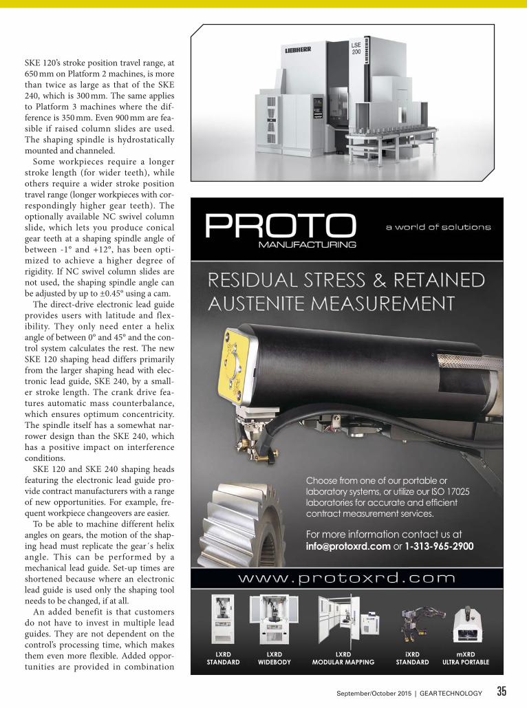
SKE 120’s stroke position travel range, at 650 mm on Platform 2 machines, is more than twice as large as that of the SKE 240, which is 300 mm. The same applies to Platform 3 machines where the dif-ference is 350 mm. Even 900 mm are fea-sible if raised column slides are used. The shaping spindle is hydrostatically mounted and channeled.
Some workpieces require a longer stroke length (for wider teeth), while others require a wider stroke position travel range (longer workpieces with cor-respondingly higher gear teeth). The optionally available NC swivel column slide, which lets you produce conical gear teeth at a shaping spindle angle of between -1° and +12°, has been opti-mized to achieve a higher degree of rigidity. If NC swivel column slides are not used, the shaping spindle angle can be adjusted by up to ±0.45° using a cam.
The direct-drive electronic lead guide provides users with latitude and flex-ibility. They only need enter a helix angle of between 0° and 45° and the con-trol system calculates the rest. The new SKE 120 shaping head differs primarily from the larger shaping head with elec-tronic lead guide, SKE 240, by a small-er stroke length. The crank drive fea-tures automatic mass counterbalance, which ensures optimum concentricity. The spindle itself has a somewhat nar-rower design than the SKE 240, which has a positive impact on interference conditions.
SKE 120 and SKE 240 shaping heads featuring the electronic lead guide pro-vide contract manufacturers with a range of new opportunities. For example, fre-quent workpiece changeovers are easier.
To be able to machine different helix angles on gears, the motion of the shap-ing head must replicate the gear´s helix angle. This can be performed by a mechanical lead guide. Set-up times are shortened because where an electronic lead guide is used only the shaping tool needs to be changed, if at all.
An added benefit is that customers do not have to invest in multiple lead guides. They are not dependent on the control’s processing time, which makes them even more flexible. Added oppor-tunities are provided in combination
35September/October 2015 | GEAR TECHNOLOGY
LXRDWIDEBODY
LXRDSTANDARD
LXRDMODULAR MAPPING
iXRDSTANDARD
mXRDULTRA PORTABLE
Choose from one of our portable or laboratory systems, or utilize our ISO 17025 laboratories for accurate and effi cient contract measurement services.
For more information contact us at [email protected] or 1-313-965-2900

with the stroke position adjustment detail.
A further requirement was the ability to manufacture efficiently and to opti-mum quality, in addition to the flexible range of workpieces. The process itself is highly productive, given the high num-ber of strokes at 1,200 double strokes per minute. This figure is based on a dynamic drive mechanism combined with effective control technology at opti-mum rigidity.
Liebherr developed its Type LSE range
of machines based on its proven LFS machines. Besides the option of using electronic lead guides, these machines also enable you to correct helix angles. Tooth flank angular deviation (fh) can be corrected simply and precisely when setting up the shaping machine.
It is possible to retain the helix angle for subsequent tempering. For even bet-ter quality, µm corrections can be under-taken: the machine achieves tooth flank quality grade 4 as per DIN3962-2.
Along with increased quality and
flexibility requirements, materials have also changed. For example the tensile strength of workpieces to be shaped has increased substantially. The LFS/LSE machines have been designed to shape high-strength materials.
Liebherr has already applied the results of internal tests in this segment using appropriately configured and coat-ed replaceable cutting inserts to industri-al applications and put these in practice. The choice of high-alloy substrates with correspondingly efficient coatings dem-onstrates that machining performance and tool service lives can be enhanced.For more information:Phone: (734) 429-7225www.liebherr.com
Koepfer America — Booth #1822Koepfer America will showcase a selec-tion of gear hobbing machines.
First is the “Repowered” Koepfer Model 160 gear hobbing machine. This K160 Repowered machine is part of the K-Repowered services offered by Koepfer America. This service offers a complete CNC re-control package for existing Koepfer models 160 and 200 gear hobbing machines. This re-control
renews the reliability of customers’ exist-ing Koepfer hobbing machines.
The Koepfer Model 200 horizontal gear hobbing machine offers increased flexibility, automation, and quality for the hobbing of fine- to medium-pitch gears. German engineering has devel-oped this model for over 20 years, lead-ing to a machine designed for manufac-turing facilities across the globe. Koepfer America will feature a Koepfer Model 200, highlighting its easy setup, quick changeover, flexible automation, and rigid construction.
36 GEAR TECHNOLOGY | September/October 2015[www.geartechnology.com]
feature GEAR EXPO 2015 PRODUCT PREVIEW
Mission InspectionSimple to use solutions for every measuring task
For an economical regrinding or manufacturing process
For complete or part measure-ment, also of micro tools
At the push of a button, including documentation
Three of many ZOLLER tool measuring experts:
»pomBasicMicro«
www.zoller-usa.com
»threadCheck«»threadCheck«
tool measuring experts:
»pomBasicMicro« »genius 3«»genius 3«
ZOLLER_ad_mission_inspection_Gear_Technology_120_5x184mm.indd 1 11.09.2015 15:34:32
From Helios Gear Products, Koepfer America will also display the first Ra-Cut fine-pitch carbide hobs, which feature up to double the number of cut-ting faces on an otherwise like design. Ra-Cut hobs can achieve higher-quality finish cut gears and increased produc-tivity using re-hobbing or skiving pro-cesses.For more information:Phone: (847) 931-4121www.koepferamerica.com
Klingelnberg — Booth #1410Klingelnberg will be exhibiting its capa-bilities with a presentation of cutting-edge technology “made in Germany” in the form of the G 30 bevel gear grinding machine and the P 26 precision measur-ing center.
Klingelnberg, utilizes this platform for an intense professional exchange on equal footing. Not only will visi-tors encounter a team of Klingelnberg experts who are available for profession-al dialogue, but Klingelnberg will also unveil its “home-made” technology from two different business units with its G 30 bevel gear grinding machine and P 26 precision measuring center.
The Oerlikon G 30 bevel gear grind-ing machine continuously advances the vertical concept for grinding technology. All bevel gear machines in this series are equipped with a heat-stable, vibra-tion-damping machine bed. An opti-mized axis arrangement ensures reduced approach paths and less load on the drive components – and a stiffer design of the overall system. The G 30 can be optionally equipped with a side load-ing door, allowing for easier loading in automatic mode using a machine inte-grated loading shuttle or handling robot. For series production, the machine also offers a range of process monitoring functions.
Klingelnberg has also continued to develop the P 40 measuring center. A height adjustable electric control console and the vibration isolation that can be integrated, now provide even better pre-requisites for shop-floor use in the new P 40.
The fully automatic CNC-controlled precision measuring center is designed as a compact unit for the workpiece diameter range up to 400 mm. At the
heart of the P 40 is an accurate, dura-b l e rot ar y t ab l e . Configured as a mea-suring axis (C axis), it provides concentric seating of the work-pieces to be tested. In combination with the three linear measur-ing axes, tangential (X axis), radial (Y axis) and vertical (Z axis),
37September/October 2015 | GEAR TECHNOLOGY
FOR MORE INFORMATION ON ASP®, ERASTEEL’S UNIQUE RANGE OF POWDER METALLURGY HIGH SPEED STEELS,
CONTACT: ERASTEEL INC, TOLL FREE 800 365 1152
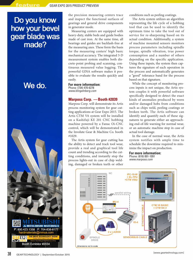
the precision measuring centers trace and inspect the functional surfaces of gearings and general drive components in generator mode.
Measuring centers are equipped with heavy-duty, stable beds and guide bodies made of cast iron. At the same time, all bearings and guides are backlash-free at the measuring axes. These form the basis for the measuring centers’ high basic mechanical accuracy. The integrated 3-D measurement system enables both dis-crete-point probing and scanning, con-tinuous measured value logging. The powerful GINA software makes it pos-sible to evaluate the results quickly and easily.For more information:Phone: (734) 470-6278www.klingelnberg.com
Marposs Corp. — Booth #2039Marposs Corp. will demonstrate its Artis process monitoring system for gear cut-ting applications at Gear Expo 2015. The Artis CTM V6 system will be installed on a Kashifuji KE 201 CNC hobbing machine powered by a Fanuc Oi-CNC control, which will be demonstrated in the Involute Gear & Machine Co. booth #1029.
The Artis system for gear cutting has the ability to detect and track tool wear, provide a real and graphical tool life count and trending according to the cut-ting conditions, and instantly stop the process lights-out in case of chip weld-ing, damaged or broken teeth or other
conditions such as peeling coatings.The Artis system utilizes an algorithm
representing the life cycle of a hobbing tool that can be used to identify the optimum time to take the tool out of service for re-sharpening based on its actual condition. Additionally, a system of machine mounted sensors monitors process parameters including spindle torque, spindle vibration, true power consumption and a number of others depending on the specific application. Using these inputs, the system then cap-tures the signature of each operation in the process and automatically generates a “good” tolerance band for the process based on that signature.
While the concept of monitoring pro-cess inputs is not unique, the Artis sys-tem couples it with powerful software specifically designed to detect the exact kinds of anomalies produced by worn and/or damaged hobs from conditions such as chips weld, peeling coatings or broken teeth. The Artis software can identify and quantify each of these sig-natures to generate either an approach-ing end-of-life warning for normal wear, or an automatic machine stop in case of actual tool damage.
In the case of normal wear, the Artis system notifies with ample time to schedule the downtime required to min-imize the impact on production.For more information:Phone: (616) 891-1091www.marposs.com
38 GEAR TECHNOLOGY | September/October 2015[www.geartechnology.com]
feature GEAR EXPO 2015 PRODUCT PREVIEW
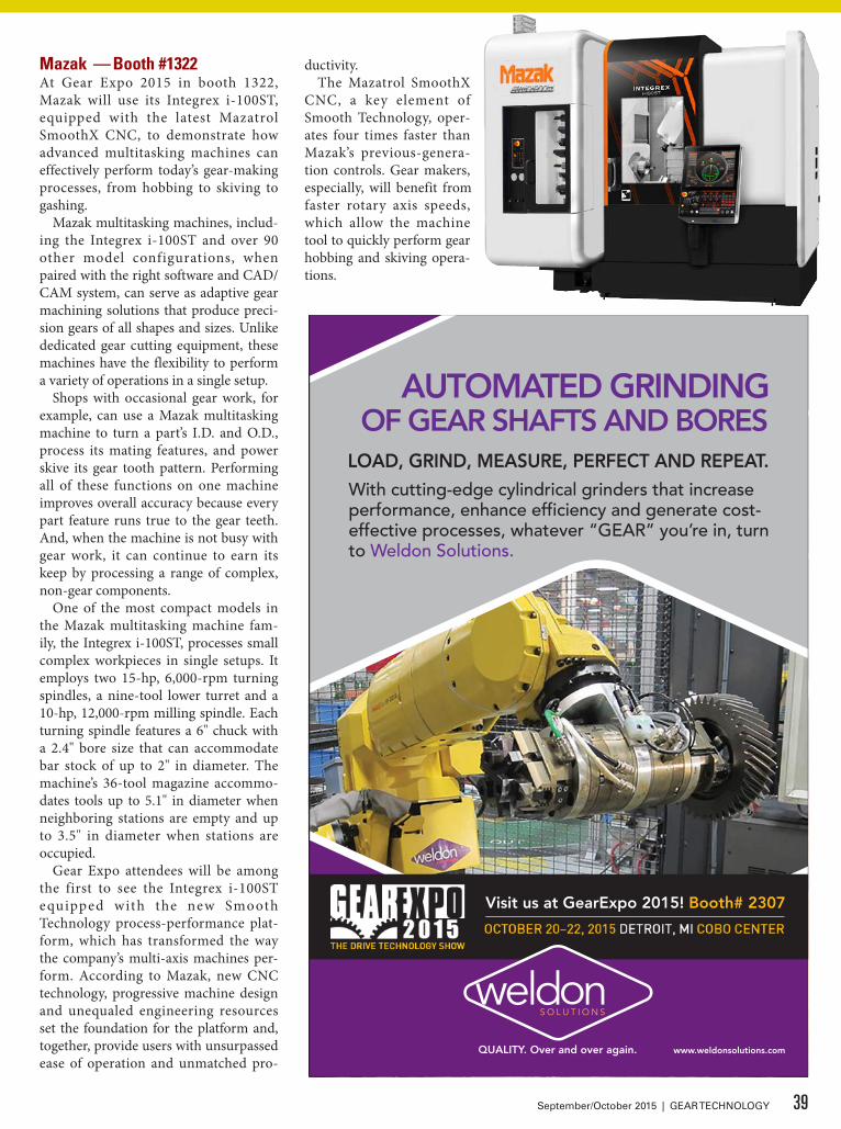
Mazak — Booth #1322At Gear Expo 2015 in booth 1322, Mazak will use its Integrex i-100ST, equipped with the latest Mazatrol SmoothX CNC, to demonstrate how advanced multitasking machines can effectively perform today’s gear-making processes, from hobbing to skiving to gashing.
Mazak multitasking machines, includ-ing the Integrex i-100ST and over 90 other model configurations, when paired with the right software and CAD/CAM system, can serve as adaptive gear machining solutions that produce preci-sion gears of all shapes and sizes. Unlike dedicated gear cutting equipment, these machines have the flexibility to perform a variety of operations in a single setup.
Shops with occasional gear work, for example, can use a Mazak multitasking machine to turn a part’s I.D. and O.D., process its mating features, and power skive its gear tooth pattern. Performing all of these functions on one machine improves overall accuracy because every part feature runs true to the gear teeth. And, when the machine is not busy with gear work, it can continue to earn its keep by processing a range of complex, non-gear components.
One of the most compact models in the Mazak multitasking machine fam-ily, the Integrex i-100ST, processes small complex workpieces in single setups. It employs two 15-hp, 6,000-rpm turning spindles, a nine-tool lower turret and a 10-hp, 12,000-rpm milling spindle. Each turning spindle features a 6" chuck with a 2.4" bore size that can accommodate bar stock of up to 2" in diameter. The machine’s 36-tool magazine accommo-dates tools up to 5.1" in diameter when neighboring stations are empty and up to 3.5" in diameter when stations are occupied.
Gear Expo attendees will be among the first to see the Integrex i-100ST equipped with the new Smooth Technology process-performance plat-form, which has transformed the way the company’s multi-axis machines per-form. According to Mazak, new CNC technology, progressive machine design and unequaled engineering resources set the foundation for the platform and, together, provide users with unsurpassed ease of operation and unmatched pro-
ductivity.The Mazatrol SmoothX
CNC, a key element of Smooth Technology, oper-ates four times faster than Mazak’s previous-genera-tion controls. Gear makers, especially, will benefit from faster rotary axis speeds, which allow the machine tool to quickly perform gear hobbing and skiving opera-tions.
39September/October 2015 | GEAR TECHNOLOGY
Visit us at GearExpo 2015! Booth# 2307
QUALITY. Over and over again.
AUTOMATED GRINDINGOF GEAR SHAFTS AND BORES
LOAD, GRIND, MEASURE, PERFECT AND REPEAT.With cutting-edge cylindrical grinders that increase performance, enhance efficiency and generate cost-effective processes, whatever “GEAR” you’re in, turn to Weldon Solutions.
www.weldonsolutions.com

Gear Expo attendees can also inquire about the company’s other gear produc-tion options while in booth 1322. The company’s larger multitasking machines with full 5-axis capabilities are known for being able to produce low-volume spiral-bevel gear sets. The Integrex e-1550V/10, for example, can machine a spiral-bevel gear set with a 29-tooth, 22"-diameter pinion gear and a 114-tooth, 6’-diameter gear ring in a matter of days as opposed to months.For more information:Phone: (859) 342-1700www.mazakusa.com
Machine Tools Builders — Booth #1804At Gear Expo 2015, MTB will display a P900 gear hobbing machine rebuilt with all mechanical linkages, gearing and other driving mechanisms replaced with new, modern servo drives and elec-tronic controls via CNC. All guide ways
have been refinished, seals and bear-ings replaced, hydraulics completely replaced, lubrication systems replaced, and a new electrical system installed. During the course of the rebuild, the machine was converted to CNC con-trol for the × (radial), Y (tangential), Z (axial), C (worktable), and A (hob head swivel) axis, along with the B (cutter) spindle. Overall features will include a hob head swivel converted to CNC, enclosure with manually operated door and access panels for maintenance and a new magnetic style chip conveyor.
MTB is also showcasing a Challenger muscle car, which has been retrofitted and customized.
At MTB, classic machine design challenges are overcome by shorten-ing the drive (gear) train for efficiency and accuracy, and by converting them to servo-driven ballscrews. Motors are designed with the proper torque and speed to move the axes at the required accelerations and speeds, which is very similar to the dynamics of supercharging an engine. MTB finds the processes of rebuilding cars and gearing equipment to be very similar. The remanufactur-ing or rebuilding of a machine includes a rebuild, a recontrol and modifications to reduce or eliminate as much as possi-ble the mechanical linkages, gearing and other driving mechanisms. Generally these are then replaced with new mod-ern servo drives, and electronic con-trol via CNC or PLC motion cards. The reduction in the number of bearings,
seals, shafts and other mechanica l e lements translates to less mechani-cal wear areas, and a more reliable and accurate machine tool. As a result, it’s a modern machine tool.
Several members will be available for ques-tions. Christoph Donner (from Donner+Pfister AG) will be visiting from Switzerland to answer questions and provide insight on gear checking and measurement sys-tems, along with upgrades
to MAAG gear grinding machines. Rick Claeyssen, heat treatment 30 plus year veteran, will be available to answer ques-tions and provide insight on atmosphere equipment. Ken Flowers (MTB co-own-er and engineer) will be available for answering gear related questions.For more information:Phone: (815) 636-7502www.machinetoolbuilders.com
40 GEAR TECHNOLOGY | September/October 2015[www.geartechnology.com]
feature GEAR EXPO 2015 PRODUCT PREVIEW

Reishauer — Booth #2242Reishauer AG will be demonstrating the RZ 160. The concept is based on the RZ 150 series. The RZ 160 has been increased in size and all relevant compo-nents have been adapted to handle high-er loads and forces which occur when grinding larger gears. The RZ 160 can grind gears with an outside diameter of 160 mm and modules up to 4 mm.
The RZ160’s design focuses on adapt-ability to the different production requirements of numerous customers. The machine can be fitted with one or two work spindles. The version with two work spindles is used to minimize the loading times. When grinding gears with space limitations, one can use the changeable Profile Grinding Spindle, enabling the use of a small plated or dressable wheel to grind gears using the discontinuous profile method. Both ver-sions of the RZ 160 can be equipped with a fixed or CNC-controlled axis for swiveling the dressing tool. This option can increase the flexibility of the dress-ing tools since the same tool can be used for a range of gears as compared to the fixed dresser where the tools are normal-ly workpiece specific.
Felsomat, a member of the Reishauer Group, has developed an automation system that is designed to match to the specific requirements of the RZ 160. In combination with the Felsomat FRC600 robot cell, the machine is suited for small to medium lot sizes. Available options include composite checking, de-oiling, SPC and NOK drawers.
Reishauer will be demonstrating pol-ish grinding on a helical gear used in a truck transmission. The grinding wheel has two different sectors and compo-sitions. One area is used to grind and remove the heat treat distortion while the other is for polishing the tooth sur-face.
The geometry of the grinding wheel is produced by using conventional dressing systems. Grinding various workpieces requires a variable shift jump to reach the polish grinding sector. The shift feed rate and the shift jump can be optimized for polish grinding depending on the dressing frequency.
This process achieves a surface fin-ish of Ra .10 µm. In addition to the improved surface, the polish ground process rounds out the edges at the tran-sition of the workpiece flank and face. The topography of the flanks remains unchanged.
Many of Reishauer’s common fea-tures are present in the RZ 160, includ-ing the Reishauer Generating Module for gear quality, Reishauer LNS Low Noise Shifting technology for low gear noise emissions, Polish and Fine Grinding for surface roughness reduction, Reishauer Twist Control grinding technology to create defined values for flank twist and the Reishauer HMI for fast change over and set-up times.
Reishauer will be at booth 2242 at Gear Expo.For more information:Phone: (847) 888-3828www.reishauer.com
THE PERFECTGEARED-ASSEMBLYFor your Medical, Laboratory,Instrument, Robotics, Semi-Conductor, Automation or otherPrecision application
CUSTOM SOLUTIONSFully integrated, turnkey solutionsincluding manufacturing,engineering, assembly, testing andcustom machining
[email protected]: (800) 243-0986Or Call: (203) 775-4877
Turnkey solutions with a higherlevel of intelligence utilizing thelatest technologies
STOCK SOLUTIONSChoose from over 31,000 standardcomponents, including bearings,belts, couplings, fasteners, gears,gearboxes, linear motion, racks,sprockets, worms and more
QUALITY SOLUTIONSSINCE 1960
41September/October 2015 | GEAR TECHNOLOGY

Riten — Booth #2201Riten Industries will display its Raptor series of live centers, specially engineered for gear hobbing and gear grinding.
Unlike the prevailing foreign import, these centers are made and serviced in the U.S., and are available for immediate delivery. Other featured prod-ucts are the Adjusta-Point live center that corrects for off-cen-ter workpiece center holes, and the C4T live center with perma-nent bearing protection. Also
on display are face drivers and a sam-pling of the world’s largest selection of live and dead centers.For more information:Phone: (800) 338-0027www.riten.com
Star SU — Booth #2109Star SU will be showcasing its Bourn & Koch 25H Horizontal Hobbing CNC Machine. The machine hobs shafts, gears, and special parts up to 25 mm in diameter. It is designed without hydrau-lics reducing wear parts and heat.
Also on display will be a variety of gear cutting tool solutions, including: gear hobs, milling cutters, gear shaper cutters, shaving tools, chamfer and deburring tools, master gears, ring and plug gauges, and broaches. The com-pany also offers precision tool re-sharp-ening services and advanced coatings, including Oerlikon Balzers Altensa and Alcrona Pro, which can extend the life of your tools and lower your costs.
Star SU partners Profilator/GMTA and Sandvik Coromant will also be
42 GEAR TECHNOLOGY | September/October 2015[www.geartechnology.com]
feature GEAR EXPO 2015 PRODUCT PREVIEW
eXPECT MORE
Our team is committed to keeping our promises and ensuring your complete
satisfaction from inquiry to delivery.
Fast Quoting
Exceptional Product Quality
On-Time Delivery
1.800.569.1420
McInnesRolledRings.com/ExpectMore
“I’ll get your quote within 4 hours.”Brandy - Inside Sales Associate
present in the booth during this year’s show. Star SU has formed an alliance with Profilator to manufacture Scudding tools for the global market. Scudding can complement shaping, broaching and other gear cutting processes to produce gear and spline teeth for both cycle time and tool cost.
See the latest in indexable gear mill-ing solutions from sandvik coromant. As national sales channel partner for Sandvik Coromant’s line of indexable gear milling solutions, Star SU pres-ents several new solutions and products enabling optimal production of small to large batch sizes, both in dedicated machines as well as multi-task machines.For more information:Phone: (847) 649-1450www.star-su.com
Gear Expo 2015October 20–22,
Cobo Center, Detroit, MIwww.gearexpo.com
43September/October 2015 | GEAR TECHNOLOGY
EXTREME!...from Incredible to
Up Your Average
Get closer to a FREE TRIAL of 3M™ Cubitron™ II
Grinding Wheels today.
Learn more: 3M.com/EXTREMEPrecisionPowertrain
Or call our 3M Customer Helpline
1-866-279-1235
3
Our customers’ average improvements are
Incredible!*
Up to 2.5x higher Q’w
removal rates
Up to 50% cycle time reduction
Up to 50% fewer dressings
And at times their improvements are
Extreme!*
Up to 6x higher Q’w
removal rates, ID grind
Up to 6.5x higher Q’w
removal rates, general grind
Up to 60% cycle time reductions, Module 3 (70 teeth gear grinding)
Up to 60% cycle time reductions, Module 10 (23 teeth gear grinding)
Up to 80% longer dressing cycles
* Above test results included comparisons against wheels containing aluminum oxide, ceramic, and other grain varieties.
© 3
M 2
015.
All
right
s re
serv
ed.
These kinds of improvements are made possible thanks to 3M’s
exclusive Precision Shaped Grain – a breakthrough abrasive technology
that “slices” through metal, to cut faster, last longer and improve your average. Nothing else comes close!

AEROSPACE & COMMERCIAL APPLICATIONS• Complete Gear Manufacture • CNC Gear Hobbing • CNC Gear Shaping• CNC Gear Grinding • CNC Inspection & Analysis • CNC Machining• CNC Hob Sharpening • BAC Coolants • Splines • Serrations• Spur • Worms • Internal & External to 12” Diameter
WWW.CLARKEGEAR.COM PHONE: 888-827-GEAR (818-768-0690) FAX: 818-767-5577 EMAIL: [email protected]
GEAR UP
OVER60 Years
CLARKE ENGINEERING, INC., known as CLARKE GEAR CO., The gear supplier other gear manufacturers turn to for complex jobs.
Boynton Beach, FL: How2Media, the producers of the television show “World’s Greatest!...”, announced today that they have recently selected Clarke Gear Company to be a part of the popular television series.
“ Clarke Gear has been in business since 1954. Operating out of a North Hollywood location, virtually in the shadow of Hollywood, seems an interesting place for a Gear Company. We think their story will be meaningful to our viewers” said Gordon Freeman, Executive Producer of the show.
ISO 9001:2008 • AS9100:2009 • AS9104/1:2012
When customers need gears expedited… …they come to us!
We maintain the highest certifications for Quality.
GEAR GRINDING SPECIALISTS AND PROUD EMPLOYER OF US VETERANS.
PERSONAL CONSULTATION FOR EACH ORDER!
VISIT US AT BOOTH 2334 FOR A “SPIN TO WIN” PRIZE!
Your 21st Century Precision Gear SpecialistGEAR COMPANY
with
of PrecisionWoman-Owned and operated with a PASSION for Manufacturing
www.worldsgreatesttv.com/tv_scheduleNovember Episode 220
Clarke
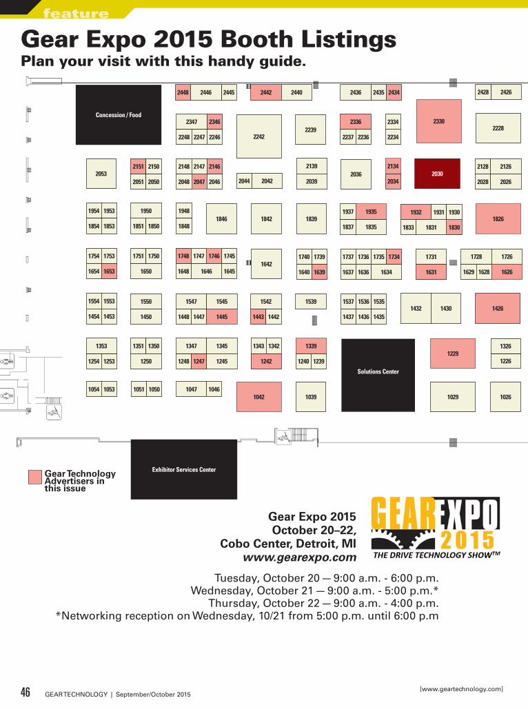
Exhi
bito
r Ser
vice
s nt
er
ENTR
AN
CE
ENTR
AN
CE
1054 1053 1051 1050 104610471042 1039 1029
1229
10261022
1226
1326
1254 1253
1353 1351 1350
1250 1248 1247
1347 1345
1245
1343 1342
1242 1240 1239
1339
1554 1553
1454 1453
1754 1753
1654 1653
1954 1953
1854 1853
1751 1750
1650
1550
1450
1851 1850
1950
2053
1448 1447
1547 1545
1445
1948
18481846
2151 2150
2051 2050
2148 2147
2048 2047
2146
2046
1842 1839
203620422044
2139
2039
1443 1442
1542 1539 1537 1536
1437 1436
1535
14351432 1430 1426
1322
16421740 1739
1640 1639
1737 1736
1637 1636
1735 1734
1634
1731
1631
1748 1747
1648 1645
1746 1745
1646
1837 1835
1937 19351826
1833 18301831
1931 19301932
1629 1628
1728 1726
1626 1624 1622
1724 1722
1822
2222
2030
23302228
2028 2026
2128 2126
1017
2034
2134
2234
2334
22422239
2237 2236
233623462347
2248 2247 2246
244524462448 2442 2440 2435 24342436 24262428
1419 1416
16161720 1719
1619
1919
1819
1917
1817
1813
2113
2220 22172218
2319 2317
2019 2017
2120 2119
2020
2118 2117
24132420 2419 2418 2417 2416
1809
2109
1610
1410
1213
10131111
1011
1311
1211
1304
1004
1001
1201
1301
1502
1402
1501
1401
160116071604
1704
1801
19011804
2201
23011601
2407
2307
2207
2107
20062007 20042005
21042105 2102 2101
2001
2403 2402 24012404
Solutions Center1033
Sales Office 2200
Show Mgmt
Office 1500
Exhibitor Services Center
Concession / Food
Gear Expo 2015 Booth ListingsPlan your visit with this handy guide.
Tuesday, October 20 — 9:00 a.m. - 6:00 p.m.Wednesday, October 21 — 9:00 a.m. - 5:00 p.m.*
Thursday, October 22 — 9:00 a.m. - 4:00 p.m.*Networking reception on Wednesday, 10/21 from 5:00 p.m. until 6:00 p.m
46 GEAR TECHNOLOGY | September/October 2015[www.geartechnology.com]
feature
Gear Expo 2015October 20–22,
Cobo Center, Detroit, MIwww.gearexpo.com
Gear Technology Advertisers in this issue
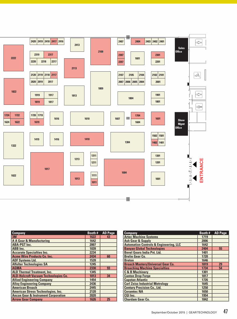
Exhi
bito
r Ser
vice
s nt
er
ENTR
AN
CE
ENTR
AN
CE
1054 1053 1051 1050 104610471042 1039 1029
1229
10261022
1226
1326
1254 1253
1353 1351 1350
1250 1248 1247
1347 1345
1245
1343 1342
1242 1240 1239
1339
1554 1553
1454 1453
1754 1753
1654 1653
1954 1953
1854 1853
1751 1750
1650
1550
1450
1851 1850
1950
2053
1448 1447
1547 1545
1445
1948
18481846
2151 2150
2051 2050
2148 2147
2048 2047
2146
2046
1842 1839
203620422044
2139
2039
1443 1442
1542 1539 1537 1536
1437 1436
1535
14351432 1430 1426
1322
16421740 1739
1640 1639
1737 1736
1637 1636
1735 1734
1634
1731
1631
1748 1747
1648 1645
1746 1745
1646
1837 1835
1937 19351826
1833 18301831
1931 19301932
1629 1628
1728 1726
1626 1624 1622
1724 1722
1822
2222
2030
23302228
2028 2026
2128 2126
1017
2034
2134
2234
2334
22422239
2237 2236
233623462347
2248 2247 2246
244524462448 2442 2440 2435 24342436 24262428
1419 1416
16161720 1719
1619
1919
1819
1917
1817
1813
2113
2220 22172218
2319 2317
2019 2017
2120 2119
2020
2118 2117
24132420 2419 2418 2417 2416
1809
2109
1610
1410
1213
10131111
1011
1311
1211
1304
1004
1001
1201
1301
1502
1402
1501
1401
160116071604
1704
1801
19011804
2201
23011601
2407
2307
2207
2107
20062007 20042005
21042105 2102 2101
2001
2403 2402 24012404
Solutions Center1033
Sales Office 2200
Show Mgmt
Office 1500
Exhibitor Services Center
Concession / Food
Company Booth # AD Page3M 1622 43A A Gear & Manufacturing 1642ABA-PGT Inc. 2007ABB Inc. 1039Accurate Specialties Inc. 2234Acme Wire Products Co. Inc. 2434 60ADF Systems Ltd. 1539Affolter Technologies SA 1245AGMA 2330 93ALD Thermal Treatment, Inc. 1345ALD-Holcroft Vacuum Technologies Co. 1013 34Allied Engineering Company 1454Alloy Engineering Company 2436American Broach 2445American Stress Technologies, Inc. 2120Ancon Gear & Instrument Corporation 2020Arrow Gear Company 1626 25
Company Booth # AD PageArtec Machine Systems 1719Ash Gear & Supply 2006Automation Controls & Engineering, LLC 1642Banyan Global Technologies 2404 55Bevel Gears India Pvt. Ltd. 1401Brelie Gear Co. 1720Breton 1646Broach Masters/Universal Gear Co. 1819 29Broaching Machine Specialties 1734 54C & B Machinery 1301Canton Drop Forge 1817Capstan Atlantic 1726Carl Zeiss Industrial Metrology 1645Century Precision Co., Ltd. 1250Ceramtec NA 1650CGI Inc. 1954Chardam Gear Co. 1842
47September/October 2015 | GEAR TECHNOLOGY
Company Booth # AD PageCincinnati Gearing Systems 1229 96Cincinnati Steel Treating 1229 55Circle Gear and Machine Company 1746 103Clarke Engineering Inc. 2334 44-45Cleveland Deburring Machine Company 1239CNC Design Pty. Ltd. 2019Cold Forming Technology, Inc 1450Colonial Tool Group 1629Columbia Gear Corporation 2147Comet Solutions, Inc. 1311Cone Drive 1353Cornell Forge Company 1211Creative Automation Inc. 1950Dalian Precision Products Co., Ltd. 2407Delta Gear 1001Diesel Progress 1253DixiTech CNC 1430DMG Mori USA 1813Dontyne Systems Limited 1831DSM 1850DTR Corporation 1722 72Ductile Iron Society 2237DVS Technology America 1432Dynamic Machine of Detroit 2403Ebbco Inc. 1537EM Gear LLC 2050EMAG LLC 1304Emuge Corporation 1901Engineered Abrasives 1226Engineered Tools Corporation 1917Erasteel 1445 37, 57Erwin Junker Machinery Inc. 1026Euro-Tech Corp. 1704 50EWAB Engineering Inc. 2248Excel Gear, Inc. 1619 12
Company Booth # AD PageEXSYS Tool Inc. 1731Finkl Steel 1550First Global Gear 1447Flame Metals 2148Foerster Instruments Inc. 1242 4Forest City Gear Company 1826 7Forging Industry Association 2420G & A Transmission Limited 1931Gear Resource Technologies, Inc. 2416Gear Solutions Magazine 2239Gear Technology and Power Transmission Engineering Magazines 2030
Geartrology 2236Gibbs Machinery Company 1919Gleason Corporation 1017 52-53Great Lakes Gear Technologies, Inc. 1610Great Taiwan Gear Ltd. 1201GS Gear 1347Guizhou Qun Jian Precision Machinery Company 1637GWJ Technology GmbH 2047 59Hainbuch America Corp. 2001Hangzhou Exceed Import and Export Trading Co., LTD 1535
Hangzhou Kailan Heavy Machinery Co., Ltd 2119Hangzhou Sino-Deutsh Power Transmission Equipment CO, Ltd. 2118
Hanik Corporation 2417 91Hanjiang Tool Company 2036Hans Precision Tool & Engr. Co 1502Hans-Juergen Geiger Maschinen-Vertrieb GMBH 1724 48Hardinge Grinding Group 2317 11, 33Headwaters MB 2401Heiko Machine Tools 2346 54HobSource Inc. 2102Hoffmann Filter Corporation 2017Horn USA, Inc. 2042
48 GEAR TECHNOLOGY | September/October 2015[www.geartechnology.com]
feature GEAR EXPO 2015 BOOTH LISTINGS

Company Booth # AD PageHy Group, Inc. 1740Hydra-Lock Corporation 2440IDC Industries Inc. 2051IMT Forge Corp 1801INDEX Corporation 1653 58, 73Industrial Machinery Digest 2426Ingersoll Cutting Tools 1607Innovative Rack & Gear Co. 2117 102Interstate Tool Corporation 2217Involute Gear & Machine Company 1029Ionic Technologies, Inc. 2204J. Schneeberger Corp. 1854JG&A Metrology Center 1848JRM International Inc. 1930Kapp Group 2222 3Kennametal, Inc. 1448KHGEARS 1751Kisssoft USA LLC 1830 95
Klingelnberg 1410 Back Cover
Koepfer America, L.L.C. 1822 28Leistritz Produktionstechnik GmbH 2046Liebherr Gear Technology, Inc. 1809 5Liugong Dressta Machinery Co., Ltd. 2139LMT USA, Inc. 1747Luren Precision Chicago Co., Ltd. 2113 19, 62Machine Tool Builders Inc. 1804Magnetic Inspection Laboratory 2220Mahr Federal Inc. 2413Marposs Corporation 2039Matrix Design, LLC 2053Mazak Corporation 1322MESYS AG 2048Metal Improvement Company 2004MicroTek Finishing LLC 2107Midwest Thermal-Vac Inc. 1748 103
Company Booth # AD PageMijno Precision Gearing 2150Minchen Gear 1750Mitsubishi Heavy Industries America, Inc. Machine Tool Division 1004 8, 54
Mitsubishi Materials USA Corp. 2034 38The Modal Shop, Inc. 2104Modern Machine Shop / Gear Production 1047Mohawk Machinery Inc. 1501Nagel Precision Inc. 1343Napoleon Engineering Services 2428New England Gear 1419Nichiei Co. Ltd. 1937Ningbo Blue Machines Co., Ltd. 1342Norton/Saint-Gobain 2105Oelheld U.S., Inc. 2301 55Oerlikon Drive Systems 2226Ovako North America 2319Panchal Engineers India Private Limited 1050Paulo 1443 56Peening Technologies 1636Pentagear Products 1426 14Perry Technology Corporation 1604Positrol, Inc. 1248Prashant Gears 1536Precision Gage Company, Inc. 1631 57Presrite Corporation 1601 79Profilator/GMTA 2109 13Proto Manufacturing Inc. 1639 35Pumphrey Marketing 1053QC American, LLC 2446QuesTek Innovations LLC 1553R.B. Forgings P. LTD 1240R.P. Machine Enterprises, Inc. 1022Ramco Steels PVT. LTD. 1453Ransohoff 2146 60
www.sst.net • [email protected] • 586-293-5355
Services Quality Accreditations
Quick Overview:Quick Overview:Since 1956, Specialty Steel Treating has evolved to become theleader in precision heat treating and operates in six (6) different facilities totaling over 200,000 square feet of manufacturing space.As a company we pride ourselves in process innovation, supply chain management and customer service with keeping quality and integrity to our customers the number one priority. We are proudly serving the aerospace, automotive, off road truck and bus and medical markets along with several other niche segments.
Quality Accreditations• TS 16949• AS9100• Nadcap• ISO 9001
Woman Owned Business
Services• Gas Carburize • Vacuum Carburize• Press & Plug Quench• Vacuum Heat Treat• Neutral Hardening• Gas Nitriding• And much more…
49September/October 2015 | GEAR TECHNOLOGY
BOOTH #1932

Company Booth # AD Page
Rave Gears LLC 1339Inside Back Cover
Raycar Gear & Machine Co. 1634Redin Production Machine 2026RedViking 2101Reishauer Corporation 2242Reliance Gear Corp. 2218REM Surface Engineering 1416Rigaku Analytical Devices 2246Riganti SPA 1628Riley Gear Corporation 1326Riten Industries Inc 2201Riverside Spline & Gear, Inc. 1254Roberts Sinto Corportation 2336 62Romax Technology Inc. 1402 57Roto-Flo & U.S. Gear Tools 1213Rubig Engineering 1835RUF Briquetting Systems 1624Russell, Holbrook & Henderson 2028S.L. Munson & Co. 1839Saini Precision Casting 1851Sanauto Engineers (I) Pvt. LTD 1853Schnyder S.A. 2417 91Schunk 2419Scot Forge 2126Shanghai Superoll Bearing Co., Ltd 1435Shivam AutoTech Ltd. 1351Six Star Machinery Co., Ltd. 2134 58SKF 1042Smart Manufacturing Technology Ltd. 2207 61SMC Powder Metallurgy, Inc. 2247SME 2347Southern Gear & Machine, Inc 1247 61Specialty Steel Treating 1932 49Stack Metallurgical Services, Inc. 1833
Star SU, LLC 2109Inside Front Cover1, 103
STD Precision Gear 1011 56Steel Market Development Institute 1753Suhner Manufacturing, Inc. 2448 96Syn-Tech Ltd. 1442Taiwan United Gear Co., Ltd. 1542Tecsia Lubricants USA 2128Thermotech, Inc. 1953THERMTECH 2402Third Wave Systems 1739Thors, LLC 1640Tianjin Shinway Transmissions Co., Ltd. 1350Tien Yi Gear Works Co., Ltd 2435TimkenSteel Corporation 1745TM Induction Heating 1948Today’s Motor Vehicles 1648Toolink Engineering Inc. 1616TSA America LLC 1846United Gear & Assembly, Inc. 1737United Tool Supply 2442 56Vigor Precision Ltd. 2418Viking Forge Corp. 1111Virgo Communications & Exhibitions 1046Walker Forge, Inc. 1837Want Win Precision CO., Ltd 2005Weldon Solutions 2307 39, 59WS GearDynamics GmbH 1547
XIMAIKE International Exhibition Co.,Ltd. 1735, 1736
Xubi Engranajes, S.L. 1545Y-12 National Security Complex 1051Zhengzhou Research Institute of Mechanical Engineering 1935 71
Zoller Inc 2151 36ZVL/ZKL Bearings Corporation 1728
50 GEAR TECHNOLOGY | September/October 2015[www.geartechnology.com]
feature GEAR EXPO 2015 BOOTH LISTINGS

Reishauer AGZürich / Switzerland+41 44 832 22 [email protected]
Gear Grinding in Swiss Precision
Since Reishauer Switzerland invented Continuous Generat-ing Gear Grinding, we have constantly been pushing the per-formance of our machines to new heights: Higher produc-tivity – higher accuracy. That‘s why the leading automotive companies rely on Reishauer.
Reishauer CorporationElgin IL / USA+1 847 888 38 [email protected]
Gear Technology_EN_203x273+3_SeptemberProposal.indd 1 18.03.2014 13:23:52
BOOTH #2242
Visit Gleason at Gear Expo, and find the latest in 150 years
of innovation:
3 Genesis® 200GX Threaded Wheel Grinding Machine
with Distech Systems automation: the new high-
performance solution for high-volume gear production.
3 300GMS®P Inspection System: bringing lab-level
inspection to the shop floor.
3 Quik-Flex®Plus workholding system: cutting cylindrical
gear changeover time to less than 30 seconds.
3 Gleason 4.0: our new ‘Smart Factory’ initiative.
3 Tooling solutions for every gear production challenge.
See what the future holds at:www.gleason.com/gearexpo.
on display...
150 years of innovation
see us at Booth #1017
October 20-22, 2015Detroit, MI • COBO Center
for worldwide sales locations and additional information, visit: www.gleason.com • [email protected]
show stoppers GEAR EXPO / HEAT TREAT - VIP EXHIBITORS
www.Galdabini.it [email protected] (800) 314-0913
Let’s Get Something Straight!
Uncompromising Excellence in Gear Straightening Technology for Over 125 Years
VISIT US AT BOOTH #2346
Our Technologies, Your Tommorow
Close the Black Hole
of Downtime“What a fantastic bit of kit the GE20A hobber is having run trouble free and
500,000 parts since installation.”— Ken Manners CEO,
SP Metal Forging, South Africa
Downtime is a black hole that impairs productivity, kills the bottom line and simply shouldn’t happen due to breakdowns. With a philosophy of continuous process improvement, in conjunction with an active reliability and maintainability program, Mitsubishi’s gear machine products deliver best in the business quality and predictable production. Experience perfect production systems by visiting www.mitsubishigearcenter.com or contact sales 248-669-6136.
BOOTH #1004
VISIT US AT BOOTH #1004
Close theBlack Hole
of Downtime
Our Technologies, Your Tommorow
“hat a fantastic bit of kit the GE20A hobber is having run trouble free and
500,000 parts since installation.”— Ken Manners CEO,
SP Metal Forging, South Africa
Downtime is a black hole that impairs productivity, kills the bottom line and simply shouldn’t happen due to breakdowns. With a philosophy of continuous process improvement, in conjunction with an active reliability and maintainability program, Mitsubishi’s gear machine products deliver best in the business quality and predictable production. Experience perfect production systems by visiting www.mitsubishigearcenter.com or contact sales 248-669-6136.
BOOTH #1004
Downtime is a black hole that impairs productivity, kills the bottom line and simply shouldn’t happen due to breakdowns. With a philosophy of continuous process improvement, in conjunction with an active reliability and maintainability program, Mitsubishi’s gear machine products deliver best in the business quality and predictable production. Experience perfect production systems by visiting www.mitsubishigearcenter.com or contact sales 248-669-6136.
54 GEAR TECHNOLOGY | September/October 2015[www.geartechnology.com]
BROACHING MACHINE SPECIALTIES (BMS) is proud to announce that BMS will act as the US and Canadian sales and service organization
for the following product lines from Ekin of Bilbao, Spain:
• HELICAL BROACHING MACHINES AND TOOLS• HARD BROACHING MACHINES AND TOOLS• DRY BROACHING MACHINES AND TOOLS• CNC BROACH SHARPENING MACHINES• SPLINE ROLLING MACHINES AND TOOLSContact BMS President Matt Egrin at Gear Expo or anytime for additional information on Ekin and BMS!
VISIT US AT BOOTH #1734
Innovative
grinding fluidsto get your production into gear.oelheld U.S., Inc.1760 Britannia Drive # 1 Elgin, IL 60124phone: +1–(847)–531-8501 fax: +1–(847)–531-8511E-Mail: [email protected]
Banyan GlobalTechnologies
55September/October 2015 | GEAR TECHNOLOGY
VISIT US AT BOOTH #2301
VISIT US AT BOOTH #2404
FULL SERVICE.EFFICIENT.FAST.
HEATTREATINGHeat Treating Services:• Carburizing,
Carbonitriding, Hardening
• Marquenching for Distortion Control
• Nitriding/Ferritic Nitrocarburizing
• Gleason Press Quenching
• Vertical Long Part Processing
• Induction Hardening
• Flame Hardening
5701 Mariemont AvenueCincinnati, OH 45227Phone (513) 271-3173Fax (513) 271-3510
ISO/TS 16949:2009ISO 14001:2004
www.steeltreating.com
VISIT US AT BOOTH #1229
ADDITIONAL MANUFACTURING SERVICES AVAILABLE
show stoppers GEAR EXPO / HEAT TREAT - VIP EXHIBITORS
56 GEAR TECHNOLOGY | September/October 2015[www.geartechnology.com]
Strength revealed
12 Months Working SafePlug & Press
Quenching Available
VISIT US AT BOOTH #1443
866-PAULO [email protected]
HEAT TREATING SINCE 1943
CLEVELAND · KANSAS CITY · MURFREESBORONASHVILLE · ST. LOUIS
VISIT US AT BOOTH #2442
GEARING AHEAD TO MEET INDUSTRY’S DEMAND FOR PRECISION
— Serving —Aircraft • Aerospace • Actuation
Instrumentation • OpticRobotics • Radar • Medical
Marine • Defense • ExperimentalPrototype • Production
Hi-Performance AutomotiveNEW CNC THREAD GRINDING
STD Precision Gear & Instrument, Inc.(888) STD-GEAR or (508) 580-0035
E-mail [email protected] site: www.stdgear.com
VISIT US AT BOOTH #1011
BOOTH #1011
VISIT US AT BOOTH #1445
Solutions to drive business & sustainability
Accelerate time to market & improve product quality with integrated conceptual design software.
Enhance the power of RomaxDESIGNER & CONCEPT; seamless integration with CAD tools for improved work fl ow effi ciency & enhanced product development.
Dynamic
Reduce multibody model development time by extracting complex, user selectable geartrain information directly from RomaxDESIGNER.
The ultimate solution for any gearbox, transmission & driveline design project, from planning to manufacturing. The core of a seamlessly integrated tool chain.
RomaxT E C H N O L O G Y
w: www.romaxtech.come: [email protected]
RomaxDESIGNER
Visit us at booth #1402
gear-expo-ad-third-pg.indd 1 03/07/2013 08:48:52VISIT US AT BOOTH #1402
57September/October 2015 | GEAR TECHNOLOGY
VISIT US AT BOOTH #1631
New
BEVEL GEAR TESTER
The makers of VARI-ROLL Gear Testers are proud to in-troduce the new Gear Master Model BGT-140 Bevel Gear Checker.Come see this unique solution for the testing of Bevel Gear assemblies both during pro-duction and final inspection at Gear Expo!• Measure the clearance of
gear flanks and detection of bearing areas
• Measure composite error by double flank rolling of Bevel Gears
• Check assembly distance• Check Backlash
Model BGT-140
630-655-2121Fax: 630-655-3073
100 Shore Drive, Burr Ridge, IL

show stoppers GEAR EXPO / HEAT TREAT - VIP EXHIBITORS
Six Star Machinery Co., Ltd.Yieh Chen Machinery Co., Ltd.
[email protected] www.yiehchen.com
Founded in 1975 by six brothers, Six Star has 40 years of experience and is one of the top five Precision Gear manufacturers in Taiwan. Six Star offers a wide range of industries, including machine tools, aerospace, robotics, transportation, agricultural machinery and gear pumps.
Experience Custom Gears with Six StarAS9100 Aerospace Quality System Certified Gear ManufacturerISO 9001:2008+ AS9100C
VISIT US AT BOOTH #2134
NEW BEVEL GEAR PROCESS.
INDEX R Series Turn-Mill Centers —Two 5-axis machines on a single base.Simultaneous 5-axis milling operations on main and counter spindle.
Precision turning solutions for people who think.
VISIT US AT BOOTH #1653
Inspectthe
UnexpectedImproving
Quality Assurance
on the Shop
Floor
Making Big Gear Measurement
a Much Smaller Task
PLUS:
Heat Treating Experts
Help You Stay Out of
Hot Water
THE JOURNAL OF GEAR MANUFACTURING
20JUL
15
www.geartechnology.com
Stop byGEAR TECHNOLOGYand meet the editors.• Nearly 80 years of
combined gear industry experience
• Learn more about contributing to GEAR TECHNOLOGY or POWER TRANSMISSION ENGINEERING.
• Find out how YOU could be featured in a future issue!
BOOTH #2030
58 GEAR TECHNOLOGY | September/October 2015[www.geartechnology.com]

VISIT US AT BOOTH #2047
Get theRoyal Treatment
top being a servant to the search bar — www.geartechnology.com is a website fit for a king or queen:
• Complete archive of articles on gears and gear components
• Directory of suppliers of gears
• Product and Industry News updated daily
• Exclusive online content in our e-mail newsletters
• The Gear Technology Blog
• Calendar of upcoming events
• Comprehensive search feature helps you find what you’re looking for
VISIT US AT BOOTH #2030
59September/October 2015 | GEAR TECHNOLOGY
QUALITY. Over and over again.
www.weldonsolutions.com
Visit us at GearExpo 2015!
Booth# 2307VISIT US AT BOOTH #2307
show stoppers GEAR EXPO / HEAT TREAT - VIP EXHIBITORS
CLEANING TECHNOLOGY TO ‘BABY’ YOUR GEARS
ctgclean.com | 800.766.6604
LEAN JET® RB-1:•ROTARYBASKETIMMERSIONCLEANING
•VARIABLEPROCESSCONFIGURATION
•NEWSIEMENSCONTROLPACKAGE
•MAINTENANCE-FRIENDLY,SMALLFOOTPRINT
See Us At Booth #2146
VISIT US AT BOOTH #2146
AS
K-T
HE
-EX
PE
RT !
LIV
E
Come to booth #2030 during Gear Expo to get your gear-related questions answered, live and in-person, by our panel of experts:
COBO HALLDETROIT, MICHIGAN
60 GEAR TECHNOLOGY | September/October 2015[www.geartechnology.com]
With 45 years of experience in design and manufacturing, the Acme Wire Products engineering team produces custom wire products to exact specifications.USA made wire baskets with interlocking handles for workpiece handling, cleaning and dunnage. Dimensional integrity ensures proper part location for automated workcells.
Acme Wire Products – Mystic, CT
800-723-7015www.acmewire.com
FromConcept
toCompletion
• Visit us at Gear Expo — Cobo Center –Detroit, MI — October 20–22 — Booth 2434
• Visit us at D2P Show — TD Convention Center — Greeneville, SC — November 18–19 — Booth 229
VISIT US AT BOOTH #2434
P r e c i s i o n c u s t o m G e a r s
Southern Gear & Machine305-691-6300800-248-5152
3685 NW 106 Street Miami, Florida
Cutting EdgE tEChnology in ExpEriEnCEd handsA leader in gear manufacturing for nearly 60 years, Southern Gear and Machine is a full-service custom gear manufacturer providing the highest quality precision gears.
Southern Gear’s one-stop-shop provides:
Spur, Helical, Worm, Bevel, Miter, Face, • Crowned and Fiber Gears, Toothed Clutches, Gear Grinding and moreMachinists and engineers with an average of 25 • years experience in gear manufacturing.More the 50 gear cutting machines alone.• Outsource only plating, heat treating & NDT.• Investments of close to one million dollars in • equipment each year for the past five years.
southern Gear & machineSoGearAdGearTechEXPOad2015.indd 1 9/11/15 1:01:00 PMVISIT US AT BOOTH #1247
Comprehensive CAE software for the design, analysis and optimisation of transmission systems. Fully predict performance characteristics of individual components as well as the full system over the entire customer duty cycle.
Visit masta.smartmt.com to discover more.
Visit our demonstration stand at booth 2207
and enter our prize draw!
@SmartMTGlobal© 2015 Smart Manufacturing Technology Ltd. linkedin.smartmt.com
AUTOMOTIVE | ENERGY | AEROSPACE | MARINE | INDUSTRIAL | DEFENCE
Empowering engineers to achieve new levels of quality in a fraction of the time!
VISIT US AT BOOTH #2207
!COBO HALL
DETROIT, MICHIGANGEAR GRINDING — Tuesday, 10/20 – 10:30 a.m.• Dr. Hermann J. Stadtfeld, Gleason
Corporation, VP Bevel Gear Technology/R&D
• Dr.-Ing Andreas Mehr, Liebherr, Technology Development, Grinding and Shaping
• Enrico Landi, Machine Tools Product Center Director, Samputensili, Star-SU
• Harald Gehlen, Head of Application Engineering, Reishauer
CUTTING TOOLS — Tuesday, 10/20 — 2:00 p.m.• Dr.-Ing. Nicklas Bylund, Sandvik
Coromant, Manager Engineering Competence Center
• Dr. Hermann J. Stadtfeld, Gleason Corporation, VP Bevel Gear Technology/R&D
• John O'Neil, Engineering Manager for Gear Cutting Tools, Star SU
GEAR DESIGN — Wednesday , 10/21 — 10:30 a.m.• Prof. Dr.-Ing. Karsten Stahl, Technical
University of Munich, Head of the Gear Research Center (FZG)
• Frank Uherek, Rexnord, Principal Engineer, Gear Engineering Software Development
• Dr. Hartmuth Müller, Klingelnberg, Chief Technical Officer
• Octave Labath, Gear Technology Technical Editor
ASK ANYTHING — Wednesday, 10/21 — 2:00 p.m.• Prof. Dr.-Ing. Karsten Stahl, Technical
University of Munich, Head of the Gear Research Center (FZG)
• Dr. Hartmuth Müller, Klingelnberg, Chief Technical Officer
• Chuck Schultz, Principal, Beyta Gear Service
• Octave Labath, Gear Technology Technical Editor
61September/October 2015 | GEAR TECHNOLOGY

show stoppers GEAR EXPO / HEAT TREAT - VIP EXHIBITORS
HIGH PRESSURE QUENCH
SSQ-IQ SERIES
VACUUM CARBURIZING FURNACES
Get fast, forceful gas cooling with
Solar Manufacturing’s SSQ series
of vacuum carburizing furnaces.
It’s high performance internal
quench system with direct-exit,
sliding radiation baffles is the least
restricted gas flow path on the market
for superior hardening at quench
pressures up to 20 bar.
T H E B R I G H T E S T S O L U T I O N S T H R O U G H I N G E N U I T Y
P 267.384.5040W solarmfg.com
Give us a call to learn more about our vacuum furnace ingenuity.
VISIT US AT ASM BOOTH #743
62 GEAR TECHNOLOGY | September/October 2015[www.geartechnology.com]
VISIT US AT BOOTH #2113
VISIT US AT BOOTH #2336
ROBERTS SINTO CORPORATIONSINTOKOGIO, LTD. 3001 W. Main Street, P.O. Box 40760Lansing, MI 48901Tel 517 371 2460 Fax 517 371 4930 www.robertssinto.com
GEAR PROCESSING SOLUTIONS Visit us at Gear Expo
Booth #2336
Brand Design Guidelinesブランドデザインガイドライン
ONE GLOBAL SINTO

Reliable, flexible solutions with repeatable results –
backed by an unmatched reputation for quality.
Strength and Innovation Since 1916.
AFC-Holcroft USA · Michigan | AFC-Holcroft Europe · Switzerland | AFC-Holcroft Asia · China
VISIT US AT ASM BOOTH #627
63September/October 2015 | GEAR TECHNOLOGY
VISIT US AT ASM BOOTH #232
• Hardeningsolutionsforvirtuallyanydimensionofbearings,raceways,balltracksandgears
• Gap-by-gap,tooth-by-toothandsingle-shot(spinning)• Patentedseamlesshardeningsolution• Maintenance,logistics,trainingandspareservices
www.efd-induction.com
Gear hardening The benefits of induction heating
Putting the smarter heat to smarter use
VACUUM PROCESSINGHeat Treating • Brazing
Carburizing • Nitriding
Vacuum Heat Treating
» Over 50 vacuum furnaces – lab-sized to 40’ long
» Argon, nitrogen and helium quenching up to 20 bar
» Operating range of -320°F to +3,600°F
» On-site metallurgical testing lab
» 24/7 responsive service
» Four convenient locations – Philadelphia, Pittsburgh, Los Angeles, South Carolina
. . .because quality is critical
ISO9001:2008 | AS9100C
Nadcap Accredited
MedAccred Accredited
ITAR Certified
1-855-WE-HEAT-ITsolaratm.com
VISIT US AT ASM BOOTH #738
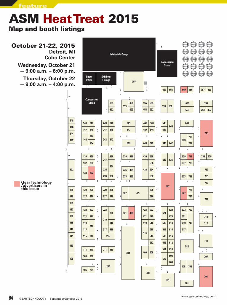
354
352
454
452353
455
453
554
552553 652
655
653
755
753 852
649
744
742643
743447 546
449 548646
547
549349
347247 346
249 348
243 342343
147 246
149 248
143242
244
146
148
142
144
443 542 543 642
137 236
139 238
133 232132
233
338
235
332
247
334
339 438
335
333
434
432
536
439 538
433
532
534
637 736
639 738537 636
739 838
737
735
733
633 732
728
726627
528
526327
527
426229
227
328
326
129
127
228
226
128
120
126
118
124
116
122
114
110
106
321 420
115
117
214
216
123
121
222
220
119
217
215
223320
318219
316
111
109
210
208
211 310
105 204
304
205
516
518
514415
423
421
522
520
419
508
512
409
521
507
513
515
511
519
517
622
620
616
618
614
608
610
606
612
617
619
623
621
715
722
719
717
707
711
511
605 704
701403
501601
557 656 657 756 757 856
357
727
ConcessionStand
ExhibitorLounge
ShowOffice
ConcessionStand
Materials Camp
ASM Heat Treat 2015Map and booth listings
October 21-22, 2015Detroit, MI
Cobo CenterWednesday, October 21— 9:00 a.m. – 6:00 p.m.
Thursday, October 22— 9:00 a.m. – 4:00 p.m.
64 GEAR TECHNOLOGY | September/October 2015[www.geartechnology.com]
feature
Gear Technology Advertisers in this issue
VISIT US AT ASM’S HEAT TREAT 2015 OCT. 21-22, 2015: BOOTH 420
InnovationECM Technologies and ECM USA have installed over 1000 cells of heat treating capacity with almost every Automotive company in the world. These systems provide low pressure vacuum carburizing and gas quenching for millions of parts that bring motion and reliability into our daily lives. From automatic, manual transmissions, dual clutch, CVT, to axles and even airplane engine parts, ECM and our processes are part of your lives. Let us build a system for you.
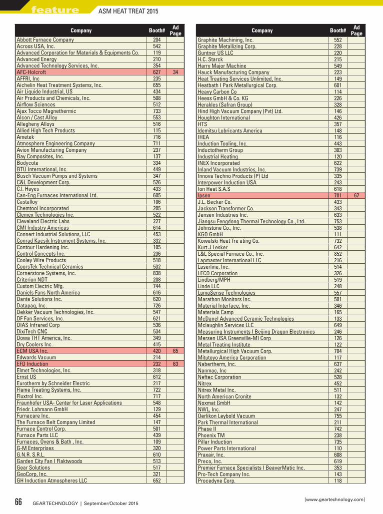
Company Booth# Ad Page
Abbott Furnace Company 204Across USA, Inc. 542Advanced Corporation for Materials & Equipments Co. 119Advanced Energy 210Advanced Technology Services, Inc. 354AFC-Holcroft 627 34AFFRI, Inc 235Aichelin Heat Treatment Systems, Inc. 655Air Liquide Industrial, US 434Air Products and Chemicals, Inc. 508Airflow Sciences 512Ajax Tocco Magnethermic 733Alcon / Cast AIIoy 553Allegheny Alloys 516Allied High Tech Products 115Ametek 716Atmosphere Engineering Company 711Avion Manufacturing Company 237Bay Composites, Inc. 137Bodycote 334BTU International, Inc. 449Busch Vacuum Pumps and Systems 347C&L Development Corp. 526C.l. Hayes 433Can-Eng Furnaces International Ltd. 605Castalloy 106Chemtool Incorporated 205Clemex Technologies Inc. 522Cleveland Electric Labs 227CMI Industry Americas 614Connert Industrial Solutions, LLC 453Conrad Kacsik Instrument Systems, Inc. 332Contour Hardening Inc. 105Control Concepts Inc. 236Cooley Wire Products 518CoorsTek Technical Ceramics 532Cornerstone Systems, Inc. 838Criterion NDT 208Custom Electric Mfg. 744Daniels Fans North America 616Dante Solutions Inc. 620Datapaq, Inc. 726Dekker Vacuum Technologies, Inc. 547DF Fan Services, Inc. 621DIAS Infrared Corp 536DixiTech CNC 534Dowa THT America, Inc. 349Dry Coolers Inc. 415ECM USA Inc. 420 65Edwards Vacuum 214EFD Induction 232 63Elmet Technologies, Inc. 318Ernst US 612Eurotherm by Schneider Electric 217Flame Treating Systems, Inc. 722Fluxtrol Inc. 717Fraunhofer USA- Center for Laser Applications 548Friedr. Lohmann GmbH 129Furnacare Inc. 454The Furnace Belt Company Limited 147Furnace Control Corp. 501Furnace Parts LLC 439Furnaces, Ovens & Bath , Inc. 109G-M Enterprises 320G.N.R. S.R.L. 610Garden City Fan I Flaktwoods 513Gear Solutions 517GeoCorp, Inc. 321GH Induction Atmospheres LLC 652
Company Booth# Ad Page
Graphite Machining, Inc. 552Graphite Metallizing Corp. 228Guntner US LLC 220H.C. Starck 215Harry Major Machine 549Hauck Manufacturing Company 223Heat Treating Services Unlimited, Inc. 149Heatbath I Park Metallurgical Corp. 601Heavy Carbon Co 114Heess GmbH & Co. KG 226Herakles (Safran Group) 328Hind High Vacuum Company (Pvt) Ltd. 146Houghton International 426HTS 357ldemitsu Lubricants America 148IHEA 116Induction Tooling, Inc. 443lnductotherm Group 303Industrial Heating 120INEX Incorporated 622Inland Vacuum Industries, Inc. 739Innova Techno Products (P) Ltd 335lnterpower Induction USA 243Ion Heat S.A.S 618Ipsen 701 67J.L. Becker Co. 433Jackson Transformer Co. 343Jensen Industries Inc. 633Jiangsu Fengdong Thermal Technology Co., Ltd. 753Johnstone Co., Inc. 538KGO GmbH 111Kowalski Heat Tre ating Co. 732Kurt J Lesker 642L&L Special Furnace Co., Inc. 852Lapmaster International LLC 216Laserline, Inc. 514LECO Corporation 326Lindberg/MPH 519Linde LLC 248LumaSense Technologies 557Marathon Monitors Inc. 501Material Interface, Inc. 346Materials Camp 165McDanel Advanced Ceramic Technologies 133Mclaughlin Services LLC 649Measuring Instruments I Beijing Dragon Electronics 246Mersen USA Greenville-MI Corp 126Metal Treating Institute 122Metallurgical High Vacuum Corp. 704Mitutoyo America Corporation 117Nabertherm, Inc. 637Nanmac, Inc 242Neftec Corporation 528Nitrex 452Nitrex Metal Inc. 511North American Cronite 132Noxmat GmbH 142NWL, Inc. 247Oerlikon Leybold Vacuum 755Park Thermal International 211Phase II 742Phoenix TM 238Pillar Induction 735Power Parts International 110Praxair, Inc. 608Preco, Inc. 619Premier Furnace Specialists I BeaverMatic Inc. 353Pro-Tech Company Inc. 143Procedyne Corp. 118
66 GEAR TECHNOLOGY | September/October 2015[www.geartechnology.com]
feature ASM HEAT TREAT 2015
• Atmosphere furnace • Easy integration • Compact footprint • Ease of maintenance • Energy-efficient combustion system • Variable-speed quench agitation
Mission: Provide customers with state-of-the-art heat treatment equipment integrated with advanced technology
• Vacuum furnace • Compact design • Predictive maintenance diagnostics • Integrated framework • Touchscreen and scrolling marquee • Available for immediate delivery
Target Acquired:
Target Acquired:
®
Engaged: PdMetrics™
PdMetrics™ is only available with certain furnace models
• Software platform for predictive maintenance • Monitors critical system elements • Stand-alone interface screen • Smart connectivity • Predicts and schedules service • Technical support via Ipsen’s Service Cloud Characters are provided by Characters For Hire, LLC. The
STAR WARS name, logo, character names, likenesses and descriptions are registered trademarks or registered copyrights of Lucasfilm Ltd. which is neither affiliated with nor endorses this promotion.
For more information, visit www.IpsenUSA.com/ASMHeatTreat2015
visit ipsen At Gear Expo 2015, ASM booth #701
and have your photo taken with a Star Wars character
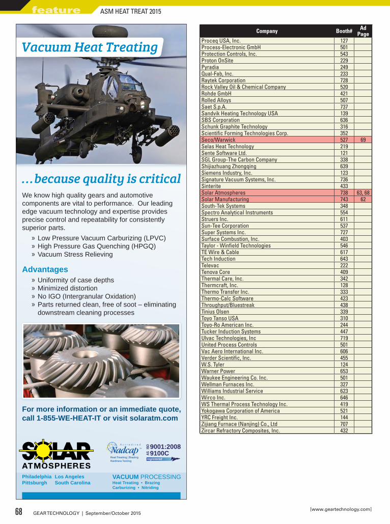
Company Booth# Ad Page
Proceq USA, Inc. 127Process-Electronic GmbH 501Protection Controls, Inc. 543Proton OnSite 229Pyradia 249Qual-Fab, Inc. 233Raytek Corporation 728Rock Valley Oil & Chemical Company 520Rohde GmbH 421Rolled Alloys 507Saet S.p.A. 737Sandvik Heating Technology USA 139SBS Corporation 636Schunk Graphite Technology 316Scientific Forming Technologies Corp. 352Seco/Warwick 527 69Selas Heat Technology 219Sente Software Ltd. 121SGL Group-The Carbon Company 338Shijiazhuang Zhongqing 639Siemens Industry, Inc. 123Signature Vacuum Systems, Inc. 736Sinterite 433Solar Atmospheres 738 63, 68Solar Manufacturing 743 62South-Tek Systems 348Spectro AnalyticaI Instruments 554Struers Inc. 611Sun-Tee Corporation 537Super Systems Inc. 727Surface Combustion, Inc. 403Taylor - Winfield Technologies 546TE Wire & Cable 617Tech Induction 643Televac 222Tenova Core 409Thermal Care, Inc. 342Thermcraft, Inc. 128Thermo Transfer Inc. 333Thermo-Calc Software 423Throughput/Bluestreak 438Tinius Olsen 339Toyo Tanso USA 310Toyo-Ro American Inc. 244Tucker Induction Systems 447Ulvac Technologies, Inc 719United Process Controls 501Vac Aero International Inc. 606Verder Scientific, Inc. 455W.S. Tyler 124Warner Power 653Waukee Engineering Co. Inc. 501Wellman Furnaces Inc. 327Williams Industrial Service 623Wirco Inc. 646WS Thermal Process Technology Inc. 419Yokogawa Corporation of America 521YRC Freight Inc. 144Zijiang Furnace (Nanjing) Co., Ltd 707Zircar Refractory Composites, Inc. 432
For more information or an immediate quote, call 1-855-WE-HEAT-IT or visit solaratm.com
We know high quality gears and automotive components are vital to performance. Our leading edge vacuum technology and expertise provides precise control and repeatability for consistently superior parts.
» Low Pressure Vacuum Carburizing (LPVC) » High Pressure Gas Quenching (HPGQ) » Vacuum Stress Relieving
» Uniformity of case depths » Minimized distortion » No IGO (Intergranular Oxidation) » Parts returned clean, free of soot – eliminating downstream cleaning processes
Advantages
. . .because quality is critical
9100CAS
9001:2008ISO
registeredHeat Treating | BrazingHardness Testing
VACUUM PROCESSINGHeat Treating • Brazing Carburizing • Nitriding
Philadelphia Pittsburgh
Los Angeles South Carolina
Vacuum Heat Treating
68 GEAR TECHNOLOGY | September/October 2015[www.geartechnology.com]
feature ASM HEAT TREAT 2015
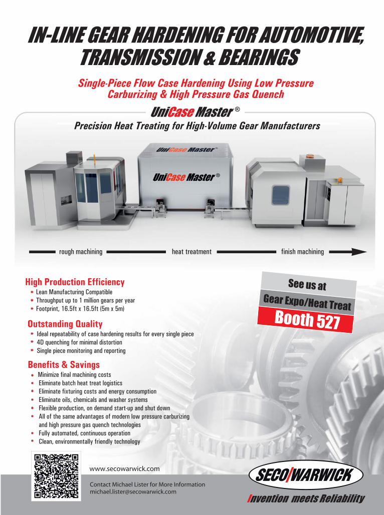
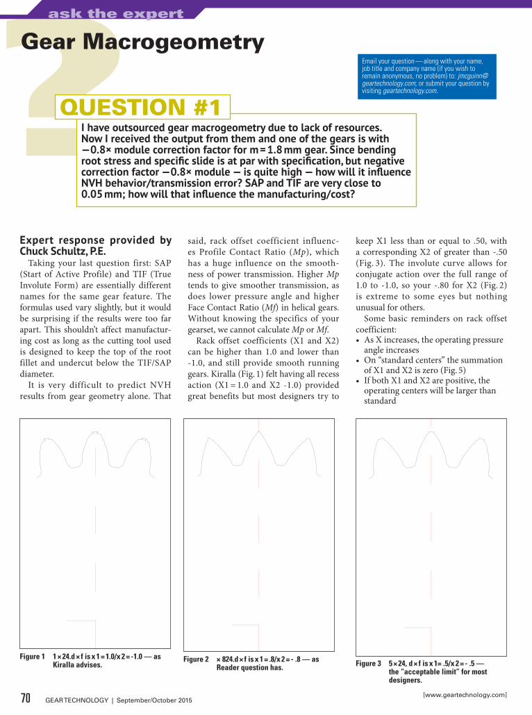
Expert response provided by Chuck Schultz, P.E.
Taking your last question first: SAP (Start of Active Profile) and TIF (True Involute Form) are essentially different names for the same gear feature. The formulas used vary slightly, but it would be surprising if the results were too far apart. This shouldn’t affect manufactur-ing cost as long as the cutting tool used is designed to keep the top of the root fillet and undercut below the TIF/SAP diameter.
It is very difficult to predict NVH results from gear geometry alone. That
said, rack offset coefficient influenc-es Profile Contact Ratio (Mp), which has a huge influence on the smooth-ness of power transmission. Higher Mp tends to give smoother transmission, as does lower pressure angle and higher Face Contact Ratio (Mf) in helical gears. Without knowing the specifics of your gearset, we cannot calculate Mp or Mf.
Rack offset coefficients (X1 and X2) can be higher than 1.0 and lower than -1.0, and still provide smooth running gears. Kiralla (Fig. 1) felt having all recess action (X1 = 1.0 and X2 -1.0) provided great benefits but most designers try to
keep X1 less than or equal to .50, with a corresponding X2 of greater than -.50 (Fig. 3). The involute curve allows for conjugate action over the full range of 1.0 to -1.0, so your -.80 for X2 (Fig. 2) is extreme to some eyes but nothing unusual for others.
Some basic reminders on rack offset coefficient:• As X increases, the operating pressure
angle increases• On “standard centers” the summation
of X1 and X2 is zero (Fig. 5)• If both X1 and X2 are positive, the
operating centers will be larger than standard
Email your question — along with your name, job title and company name (if you wish to remain anonymous, no problem) to: [email protected]; or submit your question by visiting geartechnology.com.
I have outsourced gear macrogeometry due to lack of resources. Now I received the output from them and one of the gears is with —0.8× module correction factor for m = 1.8 mm gear. Since bending root stress and specific slide is at par with specification, but negative correction factor —0.8× module — is quite high — how will it influence NVH behavior/transmission error? SAP and TIF are very close to 0.05 mm; how will that influence the manufacturing/cost?
QUESTION #1
Gear Macrogeometry
Figure 1 1 × 24.d × f is x 1 = 1.0/x 2 = -1.0 — as Kiralla advises.
Figure 2 × 824.d × f is x 1 = .8/x 2 = - .8 — as Reader question has. Figure 3 5 × 24, d × f is x 1= .5/x 2 = - .5 —
the “acceptable limit” for most designers.
70 GEAR TECHNOLOGY | September/October 2015[www.geartechnology.com]
ask the expert
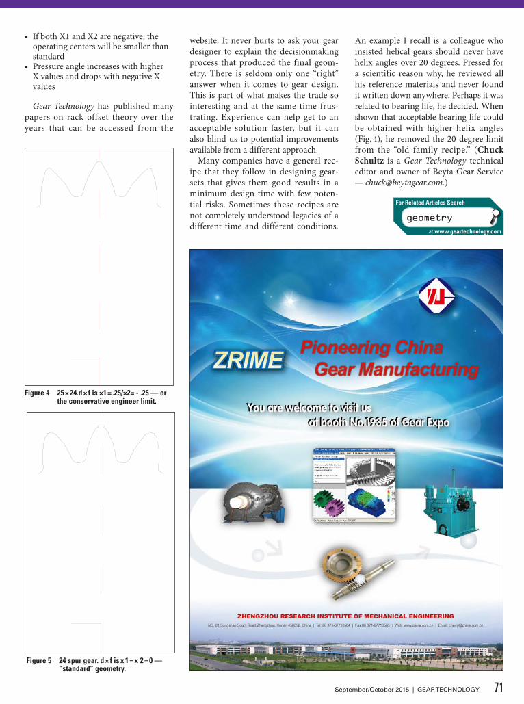
• If both X1 and X2 are negative, the operating centers will be smaller than standard
• Pressure angle increases with higher X values and drops with negative X values
Gear Technology has published many papers on rack offset theory over the years that can be accessed from the
website. It never hurts to ask your gear designer to explain the decisionmaking process that produced the final geom-etry. There is seldom only one “right” answer when it comes to gear design. This is part of what makes the trade so interesting and at the same time frus-trating. Experience can help get to an acceptable solution faster, but it can also blind us to potential improvements available from a different approach.
Many companies have a general rec-ipe that they follow in designing gear-sets that gives them good results in a minimum design time with few poten-tial risks. Sometimes these recipes are not completely understood legacies of a different time and different conditions.
An example I recall is a colleague who insisted helical gears should never have helix angles over 20 degrees. Pressed for a scientific reason why, he reviewed all his reference materials and never found it written down anywhere. Perhaps it was related to bearing life, he decided. When shown that acceptable bearing life could be obtained with higher helix angles (Fig. 4), he removed the 20 degree limit from the “old family recipe.” (Chuck Schultz is a Gear Technology technical editor and owner of Beyta Gear Service — [email protected].)
Figure 4 25 × 24.d × f is ×1 = .25/×2= - .25 — or the conservative engineer limit.
Figure 5 24 spur gear. d × f is x 1 = x 2 = 0 — “standard” geometry.
71September/October 2015 | GEAR TECHNOLOGY
geometry
For Related Articles Search
at www.geartechnology.com
U.S. Office Location (Chicago)Email inquiries to: [email protected] Hicks Road, Rolling Meadows, IL 60008 PHONE: 847-375-8892 Fax: 224-220-1311
DTR has sales territories available. Call for more information.
WWW.DRAGON.CO.KR(formerly Dragon Precision Tools)
DTR. Your best choice for high quality gear cutting tools.
DTR is a world class supplier of the finest high performance long-life gear manufacturing tools, for small and large gear cutting applications. Established in 1976, we are one of the world’s largest producers of cutting tools, shipping to over 20 countries.
DTR offers a full line of gear cutting tools including:• Hobs• Carbide Hobs• Shaper Cutters• Milling Cutters
We can produce virtually any tool you need for auto, aerospace, wind, mining, construction and other industrial gears.
Every tool is precision-made utilizing high speed steel, premium powder metal or carbide and the latest in coatings, to achieve superior cutting and long life. DTR uses top of the line equipment including Reischauer CNC grinders and Klingelnberg CNC sharpeners and inspection equipment.
Learn more about our outstanding quality tools at www.dragon.co.kr. Call us at 847-375-8892 for your local sales representative or
Email [email protected] for a quotation.
Headquarters36B-11L, Namdong Industrial Complex, Namdong-Gu, Incheon, Korea PHONE: +82.32.814.1540 FAX: +82.32.814.5381
All the Gear Cutting Tools You Will Ever Need are Right HereAll the Gear Cutting Tools You Will Ever Need are Right HereAll The Gear Cutting Tools You Will Ever Need Are Right HereAll The Gear Cutting Tools You Will Ever Need Are Right HereDTR is one of the world’s largest producers.
• Chamfering and Deburring Tools• Broaches• Master Gears
BOOTH #1722
Liebherr/Barber Colman Hob Settings
I would like some instructions for setting the degrees and minutes on a Liebherr or Barber Colman hob. Our machines use a Vernier scale to match the lead angle of the cutter to the part to form straight teeth. There is a dispute on how to do this task, and I wanted insight from another professional.
QUESTION #2
Exper t response provided by Hans Grass, vice president, Machine Tool Group, Star SU LLC.
Regardless of what model and brand of hobbing machine, the hob head angle is set to the same angle as the lead angle of the hob for spur gears. In other words, the angular position of the hob head is adjusted to line up the lead of the hob to be parallel to the axis of the work.
For example: for an RH hob, and the hob head is on the LH side of the work spindle for a vertical hobbing machine,
the hob head angle is set CW from zero, looking from the center of the work spindle towards the hob head. This is the best definition without knowledge of the plus/minus marking of the Vernier scale, depending on the manufacturer of the machine.
Helical gear example: For an RH helix angle of the workpiece, the hob head angle is set to a CCW angle equal to the helix angle minus the hob lead angle for the above mentioned hob head arrangement and definition of rotational direction.
72 GEAR TECHNOLOGY | September/October 2015[www.geartechnology.com]
ask the expert
Hans Grass, vice president, Machine Tool Group, Star SU LLC
hobbing
For Related Articles Search
at www.geartechnology.com
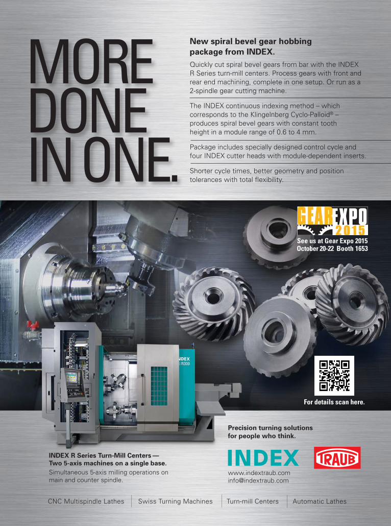
MORE DONE IN ONE.
CNC Multispindle Lathes Swiss Turning Machines Turn-mill Centers Automatic Lathes
New spiral bevel gear hobbing package from INDEX.Quickly cut spiral bevel gears from bar with the INDEX R Series turn-mill centers. Process gears with front and rear end machining, complete in one setup. Or run as a 2-spindle gear cutting machine. The INDEX continuous indexing method – which corresponds to the Klingelnberg Cyclo-Palloid® – produces spiral bevel gears with constant tooth height in a module range of 0.6 to 4 mm. Package includes specially designed control cycle and four INDEX cutter heads with module-dependent inserts. Shorter cycle times, better geometry and position tolerances with total flexibility.
INDEX R Series Turn-Mill Centers —Two 5-axis machines on a single base.Simultaneous 5-axis milling operations on main and counter spindle.
Precision turning solutions for people who think.
See us at Gear Expo 2015October 20-22 Booth 1653
For details scan here.

Development of a Face Hobbed Spiral Bevel Gearset
For this example the following data are given:
Method continuous indexing with Gleason face hobbing
Tooth depth along face width parallelShaft angle Σ 90°
Offset a = TTX 0 mmNumber of pinion teeth z1 13
Number of ring gear teeth z2 35Outer ring gear pitch diameter D02 190 mm
Face width b1 = b2 30 mmMean spiral angle β1 = β2 30°
Pinion hand of spiral HOSP1 left-handNominal cutter radius Rw 88 mm
Number of cutter starts Zw 17Pressure angle αC = αD 20°
Profile shift factor x = x1 = –x2 0Tooth depth factor fDepth 1
Top-root-clearance factor fCL 0.2Profile side shift factor xS = xS1 = –xS2 0
Pinion addendum hK1 (fDepth + x) * mn = 1.0mn
Pinion dedendum hF1 (fDepth + fCL – x) * mn = 1.2mn
Ring gear addendum hK2 (fDepth – x) * mn = 1.0mn
Ring gear dedendum hF2 (fDepth + fCL + x) * mn = 1.2mn
Wanted are the design data of the pinion and ring gear blanks as well as the cutter specifications and the basic machine set-tings.
Calculation of Blank DataSince the subject of this section is, as in the previous sec-tion (“Gear Mathematics for Bevel & Hypoid Gears,” Gear Technology’s August 2015 issue), a spiral bevel gearset with par-allel depth teeth and the same dimensions and tooth numbers, the blank dimensions in both cases are also identical. Tables 1 and 2 repeat the actual design data for the blanks of pinion and ring gear.
Calculation of the Cutter Head GeometryIt must first be mentioned that based on the continuous index-ing, the relative cutting velocity of the blades is not oriented tangentially to the circumference of the cutter. Figure 1 shows a triangular vector graphic. While RWi-1 rotated counter-clockwise, the cutter roll circle rolls on a base circle. The tip of the cutter head vector moves therefore not from “A” to “B”, but from “A” to “C”. The relation between roll circle and base circle is equal to the relation of the number of cutter head blade groups to
Hermann J. Stadtfeld
Bevel Gear TechnologyChapter 2, Continued
This article is the fourth installment in Gear Technology's series of excerpts from Dr. Hermann J. Stadtfeld's book, Gleason Bevel Gear Technology. The first three excerpts can be found in our June, July and August 2015 issues.
In the previous chapter, we demonstrated the development of a face-milled spiral bevel gearset. In this section, an analogue face-hobbed bevel gearset is derived.
— Hermann J. Stadtfeld
Table 1 Numerical ring gear blank specificationsRing Gear - Blank Data
Variable Explanation Value Dimensionz2 number of ring gear teeth 35 -
RINR2 inner cone distance (along root line) 69.56 mmRAUR2 outer cone distance (along root line) 99.56 mm
GATR2 = γ2 pitch angle 69.62 °GAKR2 face angle 69.62 °GAFR2 root angle 69.62 °ZTKR2 pitch apex to crossing point 0.00 mmZKKR2 face apex to crossing point –4.27 mmZFKR2 root apex to crossing point 5.12 mm
DOMR2= mf2 face module 4.63 mmHGER whole depth of teeth 8.80 mm
Table 2 Numerical pinion blank specificationsPinion - Blank Data
Variable Explanation Value Dimensionz1 number of teeth pinion 13 -
RINR1 inner cone distance (along root line) 58.42 mmRAUR1 outer cone distance (along root line) 88.42 mm
GATR1 = γ1 pitch angle 20.38 °GAKR1 face angle 20.38 °GAFR1 root angle 20.38 °ZTKR1 pitch apex to crossing point 0.00 mmZKKR1 face apex to crossing point –11.49 mmZFKR1 root apex to crossing point 13.78 mm
DOMR1= mf1 face module 4.63 mmHGER whole depth of teeth 8.80 mm
74 GEAR TECHNOLOGY | September/October 2015[www.geartechnology.com]
technical
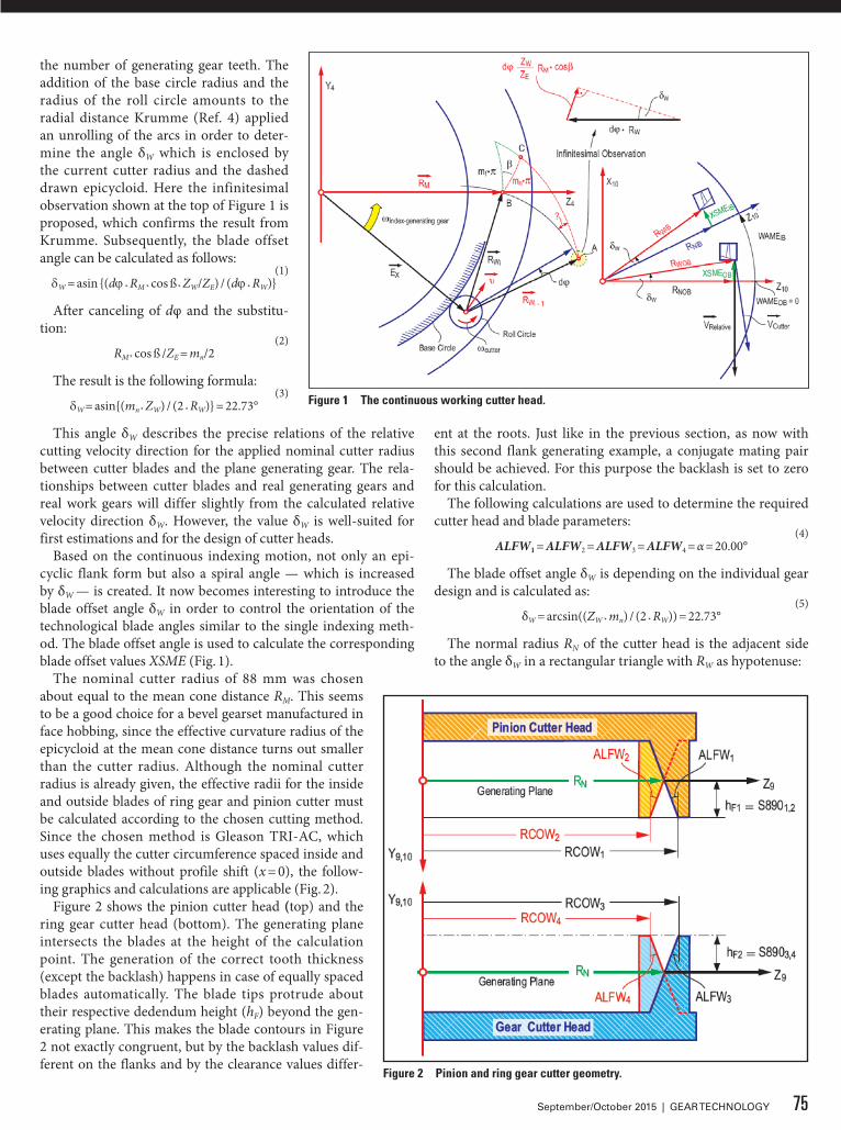
the number of generating gear teeth. The addition of the base circle radius and the radius of the roll circle amounts to the radial distance Krumme (Ref. 4) applied an unrolling of the arcs in order to deter-mine the angle δW which is enclosed by the current cutter radius and the dashed drawn epicycloid. Here the infinitesimal observation shown at the top of Figure 1 is proposed, which confirms the result from Krumme. Subsequently, the blade offset angle can be calculated as follows:
(1)dW = asin {(dj * RM * cos ß * ZW/ZE) / (dj * RW)}
After canceling of dφ and the substitu-tion:
(2)RM * cos ß /ZE = mn/2
The result is the following formula:(3)
dW = asin{(mn * ZW) / (2 * RW)} = 22.73°
This angle δW describes the precise relations of the relative cutting velocity direction for the applied nominal cutter radius between cutter blades and the plane generating gear. The rela-tionships between cutter blades and real generating gears and real work gears will differ slightly from the calculated relative velocity direction δW. However, the value δW is well-suited for first estimations and for the design of cutter heads.
Based on the continuous indexing motion, not only an epi-cyclic flank form but also a spiral angle — which is increased by δW — is created. It now becomes interesting to introduce the blade offset angle δW in order to control the orientation of the technological blade angles similar to the single indexing meth-od. The blade offset angle is used to calculate the corresponding blade offset values XSME (Fig. 1).
The nominal cutter radius of 88 mm was chosen about equal to the mean cone distance RM. This seems to be a good choice for a bevel gearset manufactured in face hobbing, since the effective curvature radius of the epicycloid at the mean cone distance turns out smaller than the cutter radius. Although the nominal cutter radius is already given, the effective radii for the inside and outside blades of ring gear and pinion cutter must be calculated according to the chosen cutting method. Since the chosen method is Gleason TRI-AC, which uses equally the cutter circumference spaced inside and outside blades without profile shift (x = 0), the follow-ing graphics and calculations are applicable (Fig. 2).
Figure 2 shows the pinion cutter head (top) and the ring gear cutter head (bottom). The generating plane intersects the blades at the height of the calculation point. The generation of the correct tooth thickness (except the backlash) happens in case of equally spaced blades automatically. The blade tips protrude about their respective dedendum height (hF) beyond the gen-erating plane. This makes the blade contours in Figure 2 not exactly congruent, but by the backlash values dif-ferent on the flanks and by the clearance values differ-
ent at the roots. Just like in the previous section, as now with this second flank generating example, a conjugate mating pair should be achieved. For this purpose the backlash is set to zero for this calculation.
The following calculations are used to determine the required cutter head and blade parameters:
(4)ALFW1 = ALFW2 = ALFW3 = ALFW4 = α = 20.00°
The blade offset angle δW is depending on the individual gear design and is calculated as:
(5)δW = arcsin((ZW * mn) / (2 * RW)) = 22.73°
The normal radius RN of the cutter head is the adjacent side to the angle δW in a rectangular triangle with RW as hypotenuse:
Figure 1 The continuous working cutter head.
Figure 2 Pinion and ring gear cutter geometry.
75September/October 2015 | GEAR TECHNOLOGY
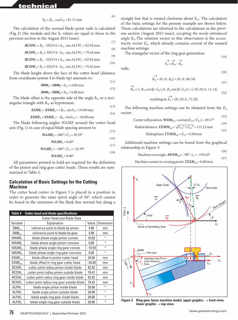
(6)RN = RW * cos dW = 81.17 mm
The calculation of the normal blade point radii is calculated (Fig. 2) (the module and the hF values are equal to those in the previous section in the August 2015 issue):
(7)RCOW1 = RN – SPLF/4 + hF1 * tan ALFW1 = 82.92 mm
(8)RCOW2 = RN + SPLF/4 – hF1 * tan ALFW2 = 79.42 mm
(9)RCOW3 = RN – SPLF/4 + hF2 * tan ALFW3 = 82.92 mm
(10)RCOW4 = RN + SPLF/4 – hF2 * tan ALFW4 = 79.42 mm
The blade height above the face of the cutter head (distance from coordinate system 9 to blade tip) amounts to:
(11)S8901 = S8902 = hF1 = 4.80 mm
(12)S8903 = S8904 = hF2 = 4.80 mm
The blade offset is the opposite side of the angle δW in a rect-angular triangle with RW as hypotenuse:
(13)XSME1 = XSME2 = +RW * sin dW = 34.00 mm
(14)XSME3 = XSME4 = –RW * sin dW = –34.00 mm
The blade following angles WAME around the cutter head axis (Fig. 1) in case of equal blade spacing amount to:
(15)WAME1 = 180° / ZW = 10.59°
(16)WAME2 = 0.00°
(17)WAME3 = –180° / ZW =–10.59°
(18)WAME4 = 0.00°
All parameters printed in bold are required for the definition of the pinion and ring gear cutter heads. Those results are sum-marized in Table 3.
Calculation of Basic Settings for the Cutting MachineThe cutter head center in Figure 3 is placed in a position in order to generate the same spiral angle of 30°, which cannot be found in the extension of the flank line normal but along a
straight line that is rotated clockwise about δW. The calculation of the basic settings for the present example are shown below. Those calculations are identical to the calculations in the previ-ous section (August 2015 issue), excepting the newly introduced angle δW.The solution vector in this observation is the eccen-tricity vector EX, which already contains several of the wanted machine settings.
The triangular vector of the ring gear generation:(19)
→ → →EX = RM – RW
with:(20)
→RM = {0., 0., RM} = {0., 0., 86.34}
(21)→RW = {–RW cos (b–dW), 0., RW sin (b–dW)} = {–87.29, 0., 11.14}
(22)→
resulting in: EX = {87.29, 0., 75.20}
The following machine settings can be obtained from the EX vector:
(23)Center roll position: W4503,4 = arctan(EXX / EXZ) = 49.27°
(24)Radial distance: TZMM3,4 = √EXX² + EXZ² = 115.22 mm
(25)Sliding base: TYMM3,4 = EXY = 0.00 mm
Additional machine settings can be found from the graphical relationship in Figure 3:
(26)Machine root angle: AWIM3,4= –90°–g2 = –159.62°
(27)Machine csenter to crossing point: TZ2M3,4 = 0.00 mm
Table 3 Cutter head and blade specificationsCutter Head and Blade Data
Variable Explanation Value DimensionS8901,2 reference point to blade tip pinion 4.80 mmS8903,4 reference point to blade tip gear 4.80 mm
WAME1 blade phase angle pinion convex 10.59 °WAME2 blade phase angle pinion concave 0.00 °WAME3 blade phase angle ring gear convex –10.59 °WAME4 blade phase angle ring gear concave 0.00 °XSME1,2 blade offset in pinion cutter head 34.00 mmXSME3,4 blade offset in ring gear cutter head –34.00 mmRCOW1 cutter point radius pinion inside blade 82.92 mmRCOW2 cutter point radius pinion outside blade 79.42 mmRCOW3 cutter point radius ring gear inside blade 82.92 mmRCOW4 cutter point radius ring gear outside blade 79.42 mmALFW1 blade angle pinion inside blade 20.00 °ALFW2 blade angle pinion outside blade 20.00 °ALFW3 blade angle ring gear inside blade 20.00 °ALFW4 blade angle ring gear outside blade 20.00 ° Figure 3 Ring gear, basic machine model, upper graphic: → front view;
lower graphic → top view.
76 GEAR TECHNOLOGY | September/October 2015[www.geartechnology.com]
technical

(28)Offset in the machine: TX2M3,4 = 0.00 mm
Further values such as cutter head tilt WXMM3,4 and tilt ori-entation WYMM3,4 are also zero in the observed conjugate design.
For the exact definition of the ring gear to be generated, the ratio of roll between generating gear and work gear as well as the indexing ratio between cutter head and work gear are still missing. From Equations 11 and 12 in Chapter 1 (“Basics of Gear Theory, Part 2,” July 2015 Gear Technology) the ratio can be computed with:
(29)UDIF3,4 = sin g2 = 0.937425
The ratio of roll number requires at least a mantissa with 6 digits, since the influence onto the gear geometry is correspond-ingly sensitive. The indexing ratio is the number of work gear teeth divided by the number of cutter starts:
(30)UTEI3,4 = Z2 / ZW = 2.058824
For the value of the indexing ratio, the input of at least 5 digits behind the decimal point is recommended.
The triangular vector of the pinion generation:(31)
→With: RW = {RW cos (b–dW), 0., RW sin (b–dW)} = {87.29, 0., 11.14}
(32)→
Resulting in: EX = {–87.29, 0., 75.20}The following machine settings can be obtained from the Ex
vector:
(33)Center of roll: W4501,2 = arctan(EXX / EXZ) = –49.26°
(34)Radial distance: TZMM1,2 = √EXX² + EXZ² = 115.22 mm
(35)Sliding base: TYMM1,2 = EXY = 0.00 mm
Additional machine settings can be found from the graphical relationship in Figure 4:
(36)Machine root angle: AWIM1,2 = –90° – g1 = –110.38°
(37)Machine center to crossing point: TZ2M1,2 = 0.00 mm
(38)Offset in the machine: TX2M1,2 = 0.00 mm
Further values, such as cutter tilt WXMM1,2 and tilt orienta-tion WYMM1,2 are also zero in the observed conjugate design. For the exact definition of the pinion to be generated, the ratio of roll between generating gear and work gear during the roll is still missing. From Equations 11 and 12 in Chapter 1 (“Basics of Gear Theory, Part 2,” July 2015 Gear Technology) the ratio can be computed with:
(39)UDIF1,2 = sin g1 = 0.348187
(40)UTEI1,2 = Z1 / ZW = 0.764706
All bold-printed values calculated in this section are input values for a bevel gear cutting simulation program whose func-tionality was discussed in the previous section (August 2015 issue). The machine settings of this section are summarizesd in Table 4.
Simulation of the Gear Cutting Process and Tooth Contact Analysis of the Face Hobbed Spiral Bevel Gearset ExampleFor the tooth contact analysis results of the gearset generated in a continuous cutting process, (face hobbing) applies basi-cally the same as explained for the face milled example in the previous section (August 2015 issue). The Ease-Offs for coast
Figure 4 Pinion, basic machine model, upper graphic: → front view, lower graphic → top view.
Table 4 Geometrical and kinematical machine settingsMachine Basic Settings
Variable Explanation Value DimensionWXMM1,2 cutter head tilt pinion 0.00 °WXMM3,4 cutter head tilt ring gear 0.00 °WYMM1,2 swivel angle pinion 0.00 °WYMM3,4 swivel angle ring gear 0.00 °W4501,2 center roll position pinion –49.26 °W4503,4 center roll position ring gear –49.26 °TYMM1,2 sliding base position pinion 0.00 mmTYMM3,4 sliding base position ring gear 0.00 mmTZMM1,2 radial distance pinion 115.22 mmTZMM34 radial distance ring gear 115.22 mmAWIM1,2 machine root angle pinion –110.38 °AWIM3,4 machine root angle ring gear –159.62 °TX2M1,2 pinion offset in the machine 0.00 mmTX2M3,4 ring gear offset in the machine 0.00 mmTZ2M1,2 machine center to crossing point pinion 0.00 mmTZ2M3,4 machine center to crossing point gear 0.00 mmUTEI1,2 indexing ratio of pinion cutting 0.764706 -UTEI3,4 indexing ratio of ring gear cutting 2.058824 -UDIF1,2 ratio of roll for pinion cutting 0.348187 -UDIF3,4 ratio of roll for ring gear cutting 0.937425 -
77September/October 2015 | GEAR TECHNOLOGY
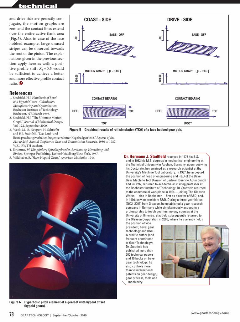
and drive side are perfectly con-jugate, the motion graphs are zero and the contact lines extend over the entire active flank area (Fig. 5). Also, in case of the face hobbed example, large unused stripes can be observed towards the root of the pinion. The expla-nations given in the previous sec-tion apply here as well; a posi-tive profile shift X1 = 0.5 would be sufficient to achieve a better and more effective profile contact ratio.
References1. Stadtfeld, H.J. Handbook of Bevel
and Hypoid Gears - Calculation, Manufacturing and Optimization, Rochester Institute of Technology, Rochester, NY, March 1993.
2. Stadtfeld, H.J. "The Ultimate Motion Graph," Journal of Mechanical Design, Vol. 122, September 2000.
3. Weck, M., B. Neupert, H. Schriefer and H.J. Stadtfeld. "Das Lauf- und Beanspruchungsverhalten bogenverzahnter Kegelradgetriebe," Reports of the 21st to 28th Annual Conference Gear and Transmission Research, 1980 to 1987, WZL-RWTH Aachen.
4. Krumme, W. Klingelnberg Spiralkegelraeder, Berechnung, Herstellung und Einbau, Springer Publishing, Berlin/Heidelberg/New York, 1967.
5. Wildhaber, E. "Skew Hypoid Gears," American Machinist, 1946.
Figure 5 Graphical results of roll simulation (TCA) of a face hobbed gear pair.
Figure 6 Hyperbolic pitch element of a gearset with hypoid offset (hypoid gears).
78 GEAR TECHNOLOGY | September/October 2015[www.geartechnology.com]
technical
Dr. Hermann J. Stadtfeld received in 1978 his B.S. and in 1982 his M.S. degrees in mechanical engineering at the Technical University in Aachen, Germany; upon receiving his Doctorate, he remained as a research scientist at the University’s Machine Tool Laboratory. In 1987, he accepted the position of head of engineering and R&D of the Bevel Gear Machine Tool Division of Oerlikon Buehrle AG in Zurich and, in 1992, returned to academia as visiting professor at the Rochester Institute of Technology. Dr. Stadtfeld returned to the commercial workplace in 1994 — joining The Gleason Works — also in Rochester — first as director of R&D, and, in 1996, as vice president R&D. During a three-year hiatus (2002–2005) from Gleason, he established a gear research company in Germany while simultaneously accepting a professorship to teach gear technology courses at the University of Ilmenau. Stadtfeld subsequently returned to the Gleason Corporation in 2005, where he currently holds the position of vice president, bevel gear technology and R&D. A prolific author (and frequent contributor to Gear Technology), Dr. Stadtfeld has published more than 200 technical papers and 10 books on bevel gear technology; he also controls more than 50 international patents on gear design, gear process, tools and
machinery.

PEOPLE AND TECHNOLOGY MAKE THE DIFFERENCE
At Presrite, our experience, innovation and expertise ensure that you get the best net and near-net forgings. Our new Tech Center has state-of-the-art design, engineering technology and die-making capabilities.
• Dedicated state-of-the-art facility• Presses up to 6,000 tons of capacity• .008-.060 stock allowance on gear blanks• ISO 9001:2008• TS 16949:2009
www.presrite.com • 216-441-5990
PRS-041_FullPg.Ad-GearTechX.indd 1 10/27/14 10:45 AM
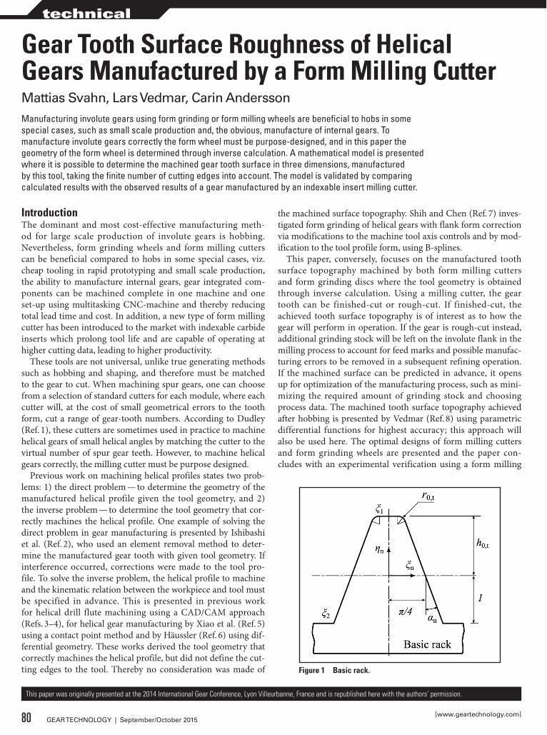
Gear Tooth Surface Roughness of Helical Gears Manufactured by a Form Milling CutterMattias Svahn, Lars Vedmar, Carin AnderssonManufacturing involute gears using form grinding or form milling wheels are beneficial to hobs in some special cases, such as small scale production and, the obvious, manufacture of internal gears. To manufacture involute gears correctly the form wheel must be purpose-designed, and in this paper the geometry of the form wheel is determined through inverse calculation. A mathematical model is presented where it is possible to determine the machined gear tooth surface in three dimensions, manufactured by this tool, taking the finite number of cutting edges into account. The model is validated by comparing calculated results with the observed results of a gear manufactured by an indexable insert milling cutter.
This paper was originally presented at the 2014 International Gear Conference, Lyon Villeurbanne, France and is republished here with the authors’ permission.
IntroductionThe dominant and most cost-effective manufacturing meth-od for large scale production of involute gears is hobbing. Nevertheless, form grinding wheels and form milling cutters can be beneficial compared to hobs in some special cases, viz. cheap tooling in rapid prototyping and small scale production, the ability to manufacture internal gears, gear integrated com-ponents can be machined complete in one machine and one set-up using multitasking CNC-machine and thereby reducing total lead time and cost. In addition, a new type of form milling cutter has been introduced to the market with indexable carbide inserts which prolong tool life and are capable of operating at higher cutting data, leading to higher productivity.
These tools are not universal, unlike true generating methods such as hobbing and shaping, and therefore must be matched to the gear to cut. When machining spur gears, one can choose from a selection of standard cutters for each module, where each cutter will, at the cost of small geometrical errors to the tooth form, cut a range of gear-tooth numbers. According to Dudley (Ref. 1), these cutters are sometimes used in practice to machine helical gears of small helical angles by matching the cutter to the virtual number of spur gear teeth. However, to machine helical gears correctly, the milling cutter must be purpose designed.
Previous work on machining helical profiles states two prob-lems: 1) the direct problem — to determine the geometry of the manufactured helical profile given the tool geometry, and 2) the inverse problem — to determine the tool geometry that cor-rectly machines the helical profile. One example of solving the direct problem in gear manufacturing is presented by Ishibashi et al. (Ref. 2), who used an element removal method to deter-mine the manufactured gear tooth with given tool geometry. If interference occurred, corrections were made to the tool pro-file. To solve the inverse problem, the helical profile to machine and the kinematic relation between the workpiece and tool must be specified in advance. This is presented in previous work for helical drill flute machining using a CAD/CAM approach (Refs. 3–4), for helical gear manufacturing by Xiao et al. (Ref. 5) using a contact point method and by Häussler (Ref. 6) using dif-ferential geometry. These works derived the tool geometry that correctly machines the helical profile, but did not define the cut-ting edges to the tool. Thereby no consideration was made of
the machined surface topography. Shih and Chen (Ref. 7) inves-tigated form grinding of helical gears with flank form correction via modifications to the machine tool axis controls and by mod-ification to the tool profile form, using B-splines.
This paper, conversely, focuses on the manufactured tooth surface topography machined by both form milling cutters and form grinding discs where the tool geometry is obtained through inverse calculation. Using a milling cutter, the gear tooth can be finished-cut or rough-cut. If finished-cut, the achieved tooth surface topography is of interest as to how the gear will perform in operation. If the gear is rough-cut instead, additional grinding stock will be left on the involute flank in the milling process to account for feed marks and possible manufac-turing errors to be removed in a subsequent refining operation. If the machined surface can be predicted in advance, it opens up for optimization of the manufacturing process, such as mini-mizing the required amount of grinding stock and choosing process data. The machined tooth surface topography achieved after hobbing is presented by Vedmar (Ref. 8) using parametric differential functions for highest accuracy; this approach will also be used here. The optimal designs of form milling cutters and form grinding wheels are presented and the paper con-cludes with an experimental verification using a form milling
Figure 1 Basic rack.
80 GEAR TECHNOLOGY | September/October 2015[www.geartechnology.com]
technical
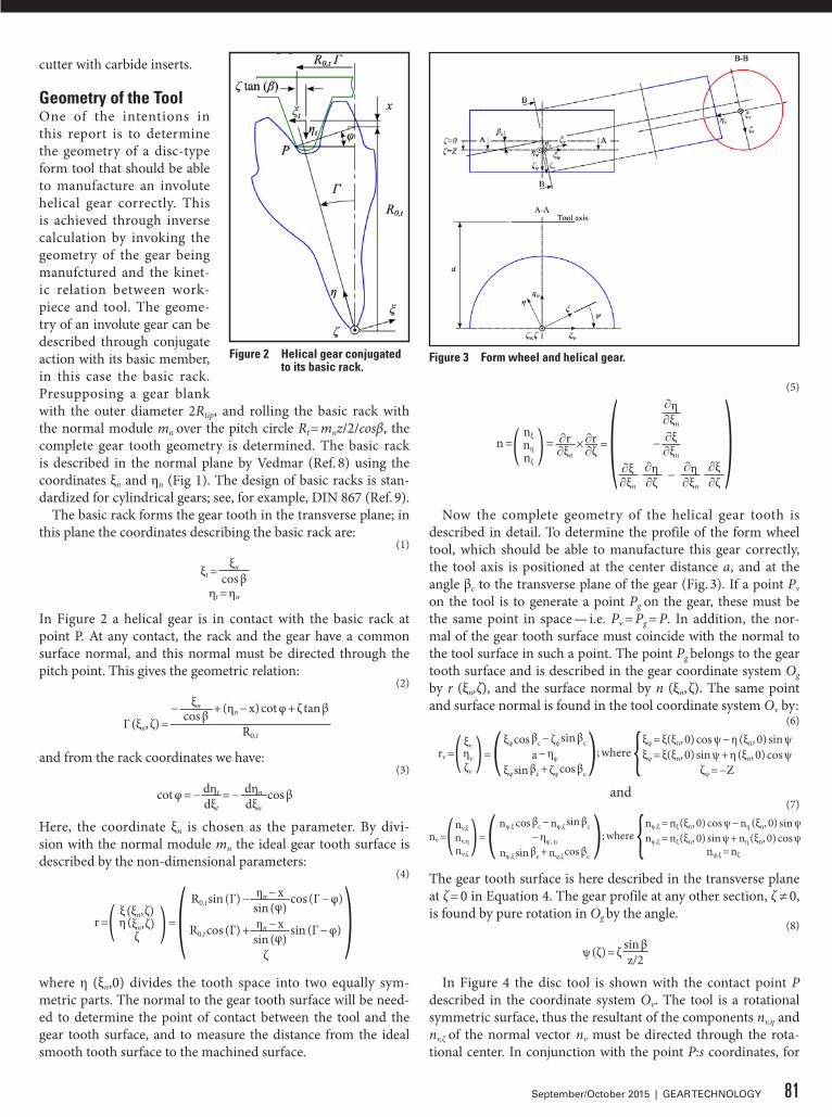
cutter with carbide inserts.
Geometry of the ToolOne of the intentions in this report is to determine the geometry of a disc-type form tool that should be able to manufacture an involute helical gear correctly. This is achieved through inverse calculation by invoking the geometry of the gear being manufctured and the kinet-ic relation between work-piece and tool. The geome-try of an involute gear can be described through conjugate action with its basic member, in this case the basic rack. Presupposing a gear blank with the outer diameter 2Rtip, and rolling the basic rack with the normal module mn over the pitch circle Rt = mnz/2/cosβ, the complete gear tooth geometry is determined. The basic rack is described in the normal plane by Vedmar (Ref. 8) using the coordinates ξn and ηn (Fig 1). The design of basic racks is stan-dardized for cylindrical gears; see, for example, DIN 867 (Ref. 9).
The basic rack forms the gear tooth in the transverse plane; in this plane the coordinates describing the basic rack are:
(1)
ξt =ξn
cos βηt = ηn
In Figure 2 a helical gear is in contact with the basic rack at point P. At any contact, the rack and the gear have a common surface normal, and this normal must be directed through the pitch point. This gives the geometric relation:
(2)
Γ (ξn, ζ) =− ξn + (ηn − x) cot φ + ζ tan βcos β
R0,t
and from the rack coordinates we have:(3)
cot φ = − dηt = − dηn cos βdξt dξn
Here, the coordinate ξn is chosen as the parameter. By divi-sion with the normal module mn the ideal gear tooth surface is described by the non-dimensional parameters:
(4)
r =( ξ (ξn, ζ)η (ξn, ζ)
ζ ) = ( R0,t sin (Γ) − ηn − x cos (Γ − φ))sin (φ)
R0,t cos (Γ) + ηn − x sin (Γ − φ)sin (φ)
ζ
where η (ξn,0) divides the tooth space into two equally sym-metric parts. The normal to the gear tooth surface will be need-ed to determine the point of contact between the tool and the gear tooth surface, and to measure the distance from the ideal smooth tooth surface to the machined surface.
(5)
n =( nξnηnζ
) = × = ( ∂η )∂ξn
∂r ∂r − ∂ξ∂ξn ∂ζ ∂ξn
∂ξ ∂η − ∂η ∂ξ∂ξn ∂ζ ∂ξn ∂ζ
Now the complete geometry of the helical gear tooth is described in detail. To determine the profile of the form wheel tool, which should be able to manufacture this gear correctly, the tool axis is positioned at the center distance a, and at the angle βc to the transverse plane of the gear (Fig. 3). If a point Pv on the tool is to generate a point Pg on the gear, these must be the same point in space — i.e. Pv = Pg = P. In addition, the nor-mal of the gear tooth surface must coincide with the normal to the tool surface in such a point. The point Pg belongs to the gear tooth surface and is described in the gear coordinate system Og by r (ξn,ζ), and the surface normal by n (ξn, ζ). The same point and surface normal is found in the tool coordinate system Ov by:
(6)
rv =( ξvηvζv
) = ( ξψ cos βc − ζψ sin βc); where {ξψ = ξ(ξn, 0) cos ψ − η (ξn, 0) sin ψa − ηψ ξψ = ξ(ξn, 0) sin ψ + η (ξn, 0) cos ψ
ξψ sin βc + ζψ cos βc ζψ = −Z
and(7)
nv =(nv,ξnv,ηnv,ζ
) = ( nψ,ξ cos βc − nψ,ζ sin βc ); where {nψ,ξ = nξ (ξn, 0) cos ψ − nη (ξn, 0) sin ψ− ηψ, n nψ,ξ = nξ (ξn, 0) sin ψ + nη (ξn, 0) cos ψ
nψ,ξ sin βc + nψ,ζ cos βc nψ,ζ = nζ
The gear tooth surface is here described in the transverse plane at ζ = 0 in Equation 4. The gear profile at any other section, ζ ≠ 0, is found by pure rotation in Og by the angle.
(8)
ψ (ζ) = ζ sin βz/2
In Figure 4 the disc tool is shown with the contact point P described in the coordinate system Ov. The tool is a rotational symmetric surface, thus the resultant of the components nv,η and nv,ζ of the normal vector nv must be directed through the rota-tional center. In conjunction with the point P:s coordinates, for
Figure 2 Helical gear conjugated to its basic rack.
Figure 3 Form wheel and helical gear.
81September/October 2015 | GEAR TECHNOLOGY

which tan γ = ζv,P/ηv,P, the relation is obtained:(9)
tan γ = ζv,P = nv,ζηv,P nv,η
Rewriting to suit numerical calculations this rela-tion will be:
(10)E(ξn, ζ) = ηv,P (ξn, ζ) nv,ζ (ξn, ζ) − ζv,P (ξn, ζ) nv,η (ξn, ζ) = 0
For given ξn, the corresponding ζ value is obtained by solving Equation 10; here, Newton-Raphson’s method is used.
(11)
ζi+1 = ζi −E(ξn, ζ)∂E(ξn, ζ)
∂ζ(12)
∂E(ξn, ζ) = ∂ηv,P (ξn, ζ) nv,ζ (ξn, ζ) + ηv,P (ξn, ζ) ∂nv,ζ (ξn, ζ)∂ζ ∂ζ ∂ζ
− ∂ζv,P (ξn, ζ) nv,η (ξn, ζ) − ζv,P (ξn, ζ) ∂nv,η (ξn, ζ)∂ζ ∂ζ
A convergent solution gives the point of contact. By varying ξn (ξ1 ≤ ξn ≤ ξ2) all contacts between the gear and the tool are found. The line of contact is found by connecting these points. The tool axis is perpendicular to the gear axis for spur gears, hence the line of contact will be a coplanar curve and located in the transverse plane of the gear. However, for helical gears, the con-tact line will be a three-dimensional curve. The contact lines are shown in Figure 5 for a disc tool with the outer radius Rc, for a spur gear and a helical gear, β = 20°.
With the contact line known, the cross-section of the form tool can be determined. The axial and radial coordinates of the disc cutter:
(13)ξc = ξv (ξn, ζ)ηc = √η2
v + ζ2v
are revolved around the rotational axis a rotation angle ϕ to describe the disc tool
(14)ξf = ξc
ηf = ηc cos fζf = ηc sin f
A form milling wheel possesses a finite number of cutting teeth n. To avoid interference in the milling process, these cutting teeth must be relieved to allow only the cutting face to remove material. The cutting faces are described by planes intersecting the cutting teeth, perpendicular to the rotational axis, where the cutting edges are the boundaries of these faces. To describe a milling cutter, the complete wheel is gashed to the desired num-ber of cutting teeth. The i:th cutting plane is then described by:
(15)ξf,i = ξc
ηf,i = ηc cos (f + (i − 1) Δf)ζf,i = ηc sin (f + (i − 1) Δf)
where Δf = 2π/n is the equian-gular increment between the cutting faces.
For a form grinding wheel, there are no defined cutting edges. The surface grinding the gear tooth is the outer bound-ary of the form wheel. The form grinding process can then be described by a form milling
process with a sufficient number of cutting planes, so that the number of planes of the milling cutter does not influence the tooth surface topography. Then a milling cutter with many cut-ting faces is approximately equivalent to a grinding wheel.
Milling ProcessThe form wheel is now positioned to machine the gear. Like before, the tool is positioned at the center distance a and the rotational axis is set at the angle βc to the transverse plane of the gear. It is not evident how the angle βc should be chosen since the helical angle of a helical gear varies with the radius accord-ing to the relation ri cot βi = constant. It is here assumed that the angle βc coincides with the helical angle β of the gear at the pitch radius Rt. The form wheel can be positioned at another angle βc ≠ β, as long as the angle βc corresponds to a radius on the gear tooth. However, the geometry of the form wheel must be deter-mined at the same angle βc as previously to machine the helical profile correctly.
The form wheel is rotated with the angu-lar velocity ωc to machine the gear here in the negative f direction. Climb milling is achieved by moving the gear blank the dis-tance Z = - S0f/(2π) at the angular displace-ment of ϕ, where S = S0mn is the feed rate in distance-per-revolution. To achieve con-ventional milling, the feed is in the reversed direction, i.e. — Z = S0ϕ/(2π).
Here the center of the cutting plane i = 1, (ξϕ,1 = 0, ηϕ,1 = ηc) is assumed to be located so it coincides with the center point of the gear (ξ = ζ = 0 and Z = 0). In the mathematical model, the form wheel is now rotated backwards and the gear blank moves the distance Z and rotates ψ (Z) so that the form wheel is out-side the range of the gear blank. The form wheel then starts to machine the gear blank over the whole width. That means as no radial feed is present, the form wheel starts to machine the gear at full depth.
As the gear blank is fed the distance Z, the coordinates of the i:th cutting edge of the form wheel can be determined in the transverse plane of the gear. Simultaneously and continuously, the gear is rotated the angle ψ (Z). The i:th cutting edge can then be represented in a coordinate system that coincides with that of the gear.
Figure 5 Contact lines.
Figure 4 Form wheel.
82 GEAR TECHNOLOGY | September/October 2015[www.geartechnology.com]
technical
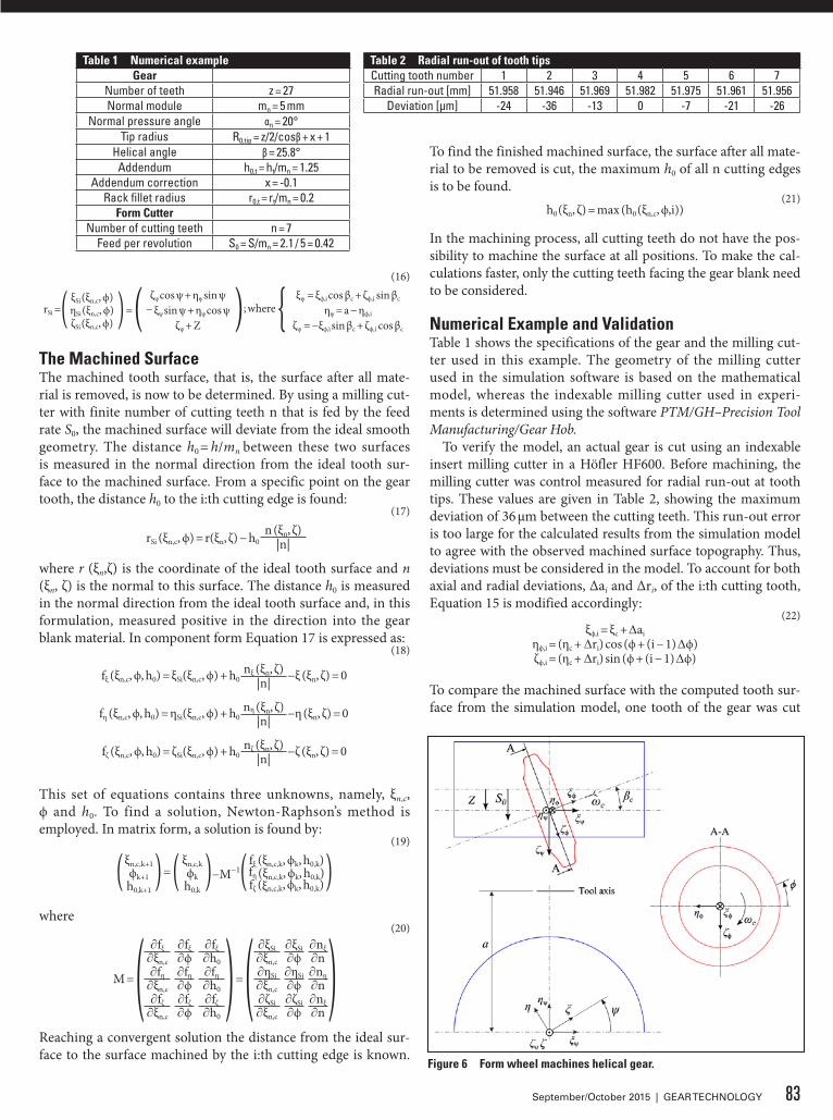
(16)
rSi =( ξSi (ξn,c, ϕ)ηSi (ξn,c, ϕ)ζSi (ξn,c, ϕ) ) = ( ζψ cos ψ + ηψ sin ψ ); where { ξψ = ξϕ,i cos βc + ζϕ,i sin βc
− ξψ sin ψ + ηψ cos ψ ηψ = a − ηϕ,i
ζψ + Z ζψ = −ξϕ,i sin βc + ζϕ,i cos βc
The Machined SurfaceThe machined tooth surface, that is, the surface after all mate-rial is removed, is now to be determined. By using a milling cut-ter with finite number of cutting teeth n that is fed by the feed rate S0, the machined surface will deviate from the ideal smooth geometry. The distance h0 = h/mn between these two surfaces is measured in the normal direction from the ideal tooth sur-face to the machined surface. From a specific point on the gear tooth, the distance h0 to the i:th cutting edge is found:
(17)
rSi (ξn,c, ϕ) = r(ξn, ζ) − h0n (ξn, ζ)
|n|
where r (ξn,ζ) is the coordinate of the ideal tooth surface and n (ξn, ζ) is the normal to this surface. The distance h0 is measured in the normal direction from the ideal tooth surface and, in this formulation, measured positive in the direction into the gear blank material. In component form Equation 17 is expressed as:
(18)
fξ (ξn,c, ϕ, h0) = ξSi(ξn,c, ϕ) + h0nξ (ξn, ζ) −ξ (ξn, ζ) = 0|n|
fη (ξn,c, ϕ, h0) = ηSi(ξn,c, ϕ) + h0nη (ξn, ζ) −η (ξn, ζ) = 0|n|
fζ (ξn,c, ϕ, h0) = ζSi(ξn,c, ϕ) + h0nζ (ξn, ζ) −ζ (ξn, ζ) = 0|n|
This set of equations contains three unknowns, namely, ξn,c, ϕ and h0. To find a solution, Newton-Raphson’s method is employed. In matrix form, a solution is found by:
(19)
(ξn,c,k+1ϕk+1h0,k+1
) = ( ξn,c,kϕkh0,k
)−M−1( fξ (ξn,c,k, ϕk, h0,k)fη (ξn,c,k, ϕk, h0,k)fζ (ξn,c,k, ϕk, h0,k) )
where(20)
M = ( ∂fξ ∂fξ ∂fξ ) = ( ∂ξSi ∂ξSi ∂nξ)∂ξn,c ∂ϕ ∂h0 ∂ξn,c ∂ϕ ∂n∂fη ∂fη ∂fη ∂ηSi ∂ηSi ∂nη
∂ξn,c ∂ϕ ∂h0 ∂ξn,c ∂ϕ ∂n∂fζ ∂fζ ∂fζ ∂ζSi ∂ζSi ∂nξ
∂ξn,c ∂ϕ ∂h0 ∂ξn,c ∂ϕ ∂n
Reaching a convergent solution the distance from the ideal sur-face to the surface machined by the i:th cutting edge is known.
To find the finished machined surface, the surface after all mate-rial to be removed is cut, the maximum h0 of all n cutting edges is to be found.
(21)h0 (ξn, ζ) = max (h0 (ξn,c, ϕ,i))
In the machining process, all cutting teeth do not have the pos-sibility to machine the surface at all positions. To make the cal-culations faster, only the cutting teeth facing the gear blank need to be considered.
Numerical Example and ValidationTable 1 shows the specifications of the gear and the milling cut-ter used in this example. The geometry of the milling cutter used in the simulation software is based on the mathematical model, whereas the indexable milling cutter used in experi-ments is determined using the software PTM/GH–Precision Tool Manufacturing/Gear Hob.
To verify the model, an actual gear is cut using an indexable insert milling cutter in a Höfler HF600. Before machining, the milling cutter was control measured for radial run-out at tooth tips. These values are given in Table 2, showing the maximum deviation of 36 μm between the cutting teeth. This run-out error is too large for the calculated results from the simulation model to agree with the observed machined surface topography. Thus, deviations must be considered in the model. To account for both axial and radial deviations, Δai and Δri, of the i:th cutting tooth, Equation 15 is modified accordingly:
(22)ξϕ,i = ξc + Δai
ηϕ,i = (ηc + Δri) cos (ϕ + (i − 1) Δϕ)ζϕ,i = (ηc + Δri) sin (ϕ + (i − 1) Δϕ)
To compare the machined surface with the computed tooth sur-face from the simulation model, one tooth of the gear was cut
Figure 6 Form wheel machines helical gear.
Table 2 Radial run-out of tooth tipsCutting tooth number 1 2 3 4 5 6 7Radial run-out [mm] 51.958 51.946 51.969 51.982 51.975 51.961 51.956
Deviation [μm] -24 -36 -13 0 -7 -21 -26
Table 1 Numerical exampleGear
Number of teeth z = 27Normal module mn = 5 mm
Normal pressure angle αn = 20°Tip radius R0,tip = z/2/cosβ + x + 1
Helical angle β = 25.8°Addendum h0,t = ht/mn = 1.25
Addendum correction x = -0.1Rack fillet radius r0,t = rt/mn = 0.2
Form CutterNumber of cutting teeth n = 7
Feed per revolution S0 = S/mn = 2.1 / 5 = 0.42
83September/October 2015 | GEAR TECHNOLOGY
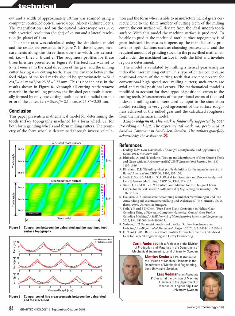
out and a width of approximately 10 mm was scanned using a computer controlled optical microscope, Alicona Infinite Focus. The magnification used on the optical microscope was 20×, with a vertical resolution (height) of 25 nm and a lateral resolu-tion (in-plane) of 3 μm.
The same area was calculated using the simulation model and the results are presented in Figure 7. In these figures, mea-surements along the three lines over the width are extract-ed, i.e. — lines a, b and c. The roughness profiles for these three lines are presented in Figure 8. The feed rate was set to S = 2.1 mm/rev in the axial direction of the gear, and the milling cutter having n = 7 cutting teeth. Thus, the distance between the feed ridges of the feed marks should be approximately s = S/n/cos β = 2.1 mm/7/cos 25.8° ≈ 0.33 mm. This is not the case in the results shown in Figure 8. Although all cutting teeth remove material in the milling process, the finished gear tooth is actu-ally formed by only one cutting tooth due to the radial run-out error of the cutter, i.e. s = S/cos β = 2.1 mm/cos 25.8° ≈ 2.33 mm.
ConclusionThis paper presents a mathematical model for determining the tooth surface topography machined by a form wheel, i.e. for both form grinding wheels and form milling cutters. The geom-etry of the form wheel is determined through inverse calcula-
tion and the form wheel is able to manufacture helical gears cor-rectly. Due to the finite number of cutting teeth of the milling cutter, the cut surface will deviate from the ideal smooth tooth surface. With this model the machine surface is predicted. To be able to predict the machined tooth surface topography is of great industrial interest as it opens up the manufacturing pro-cess for optimizations such as choosing process data and the required amount of grinding stock. In the prescribed mathemat-ical model, the machined surface in both the fillet and involute region is determined.
The model is validated by milling a helical gear using an indexable insert milling cutter. This type of cutter could cause positional errors of the cutting teeth that are not present for conventional high speed steel milling cutters; such errors are axial and radial positional errors. The mathematical model is modified to account for these types of positional errors to the cutting teeth. Measurements of the positional errors of the used indexable milling cutter were used as input to the simulation model, resulting in very good agreement of the surface rough-ness achieved of the milled gear and the calculated roughness from the mathematical model.
Acknowledgement. This work is financially supported by SSF/ProViking and SPI. The experimental work was performed at Sandvik Coromant in Sandviken, Sweden. The authors gratefully acknowledge the assistance.
References1. Dudley, D.W. Gear Handbook, The design, Manufacture, and Application of
Gears, 1962, Mc Graw-Hill.2. Ishibashi, A. and H. Yoshino. “Design and Manufacture of Gear Cutting Tools
and Gears with an Arbitrary profile,” JSME International Journal, 30, 1987, 1159-1166.
3. Ehrmann, K.F. “Grinding wheel profile definition for the manufacture of drill flutes,” Annals of the CIRP. 39, 1990, 153-156.
4. Steth, D.S and S. Malkin. “CAD/CAM for Geometry and Process Analysis of Helical Groove Machining,” CIRP, 39, 1990, 129-132.
5. Xiao, D.C. and D. Lee. “A Contact Point Method for the Design of Form Cutters for Helical Gears,” ASME Journal of Engineering for Industry, 1994, 116, 387-391.
6. Häussler, U. “Generalistere Berechnung räumlicher Verzahnungen und ihre Anwendung auf Wälzfräserherstellung und Wälzfräsen,” (In German), Ph. D. thesis, 1999, Universität Stuttgart.
7. Shih, Y-P and S-D Chen. “Free-Form Flank Correction in Helical Gear Grinding Using a Five-Axis Computer Numerical Control Gear Profile Grinding Machine,” ASME Journal of Manufacturing Science and Engineering, 2012, 134, 041006-1– 041006-13.
8. Vedmar, L. “A Parametric Analysis of the Gear Surface Roughness after Hobbing,” ASME Journal of Mechanical Design, 132, 2010, 111004-1–111004-8.
9. DIN 867 (1986). Basic Rack Tooth Profiles for involute teeth of Cylindrical Gear for General Engineering and Heavy Engineering.
Figure 8 Comparison of line measurements between the calculated and the machined.
Figure 7 Comparison between the calculated and the machined tooth surface topography.
Carin Andersson is a Professor at the Division of Production and Materials in the Department of
Mechanical Engineering, Lund University, Sweden.
Mattias Svahn is a Ph. D student at the Division of Machine Elements in the Department of Mechanical Engineering, Lund University, Sweden.
Lars Vedmar is an Associate Professor at the Division of Machine
Elements in the Department of Mechanical Engineering, Lund
University, Sweden.
84 GEAR TECHNOLOGY | September/October 2015[www.geartechnology.com]
technical

Project1_Layout 1 6/16/15 11:28 AM Page 1
BOOTH #2109
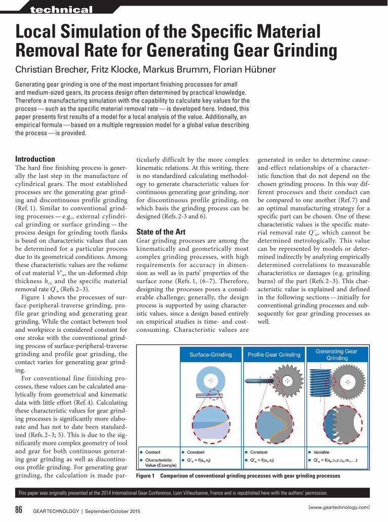
IntroductionThe hard fine finishing process is gener-ally the last step in the manufacture of cylindrical gears. The most established processes are the generating gear grind-ing and discontinuous profile grinding (Ref. 1). Similar to conventional grind-ing processes — e.g., external cylindri-cal grinding or surface grinding — the process design for grinding tooth flanks is based on characteristic values that can be determined for a particular process due to its geometrical conditions. Among these characteristic values are the volume of cut material V'w, the un-deformed chip thickness hcu and the specific material removal rate Q'w (Refs 2–3).
Figure 1 shows the processes of sur-face-peripheral-traverse grinding, pro-file gear grinding and generating gear grinding. While the contact between tool and workpiece is considered constant for one stroke with the conventional grind-ing process of surface-peripheral-traverse grinding and profile gear grinding, the contact varies for generating gear grind-ing.
For conventional fine finishing pro-cesses, these values can be calculated ana-lytically from geometrical and kinematic data with little effort (Ref. 4). Calculating these characteristic values for gear grind-ing processes is significantly more elabo-rate and has not to date been standard-ized (Refs. 2–3; 5). This is due to the sig-nificantly more complex geometry of tool and gear for both continuous generat-ing gear grinding as well as discontinu-ous profile grinding. For generating gear grinding, the calculation is made par-
ticularly difficult by the more complex kinematic relations. At this writing, there is no standardized calculating methodol-ogy to generate characteristic values for continuous generating gear grinding, nor for discontinuous profile grinding, on which basis the grinding process can be designed (Refs. 2-3 and 6).
State of the ArtGear grinding processes are among the kinematically and geometrically most complex grinding processes, with high requirements for accuracy in dimen-sion as well as in parts’ properties of the surface zone (Refs. 1, (6–7). Therefore, designing the processes poses a consid-erable challenge; generally, the design process is supported by using character-istic values, since a design based entirely on empirical studies is time- and cost-consuming. Characteristic values are
generated in order to determine cause-and-effect relationships of a character-istic function that do not depend on the chosen grinding process. In this way dif-ferent processes and their conduct can be compared to one another (Ref. 7) and an optimal manufacturing strategy for a specific part can be chosen. One of these characteristic values is the specific mate-rial removal rate Q'w, which cannot be determined metrologically. This value can be represented by models or deter-mined indirectly by analyzing empirically determined correlations to measurable characteristics or damages (e.g. grinding burns) of the part (Refs. 2–3). This char-acteristic value is explained and defined in the following sections — initially for conventional grinding processes and sub-sequently for gear grinding processes as well.
Local Simulation of the Specific Material Removal Rate for Generating Gear Grinding
Generating gear grinding is one of the most important finishing processes for small and medium-sized gears, its process design often determined by practical knowledge. Therefore a manufacturing simulation with the capability to calculate key values for the process — such as the specific material removal rate — is developed here. Indeed, this paper presents first results of a model for a local analysis of the value. Additionally, an empirical formula — based on a multiple regression model for a global value describing the process — is provided.
This paper was originally presented at the 2014 International Gear Conference, Lyon Villeurbanne, France and is republished here with the authors’ permission.
Figure 1 Comparison of conventional grinding processes with gear grinding processes
Christian Brecher, Fritz Klocke, Markus Brumm, Florian Hübner
86 GEAR TECHNOLOGY | September/October 2015[www.geartechnology.com]
technical

Specific Material Removal Rate for Conventional Grinding Processes
As the part geometry and process kine-matics are easy to follow, surface-periph-eral-traverse grinding is chosen as an example for calculating the specific mate-rial removal rate for conventional grind-ing processes. The process is applied for grinding large surfaces and its schemat-ic is depicted in Figure 2. The grinding wheel is advanced radially along the feed
ae and perpendicularly to the worktable in order to grind the desired stock.
The tool is typically fed axially by the contact width ap outside the part. The contact width correlates to the effec-tive grinding wheel width bs,eff due to the process. Generally the worktable with the clamped part is moved with the feed velocity vf. The grinding wheel rotates with the set number of rotations ns — which results in circumferential velocity vs. Should vs and vf align, the pro-cess is referred to as climb grinding; if not, as conventional grinding (Ref. 7).
According to Equation 1, the mate-rial removal rate can be referenced to the grinding wheel width in order to com-pare different processes with respect to their productivity (Refs. 6-7).
(1)Q'w = ae ∙ vf
Besides geometrical characteristic val-ues, grinding forces, power and ener-gy can be consulted for assessing and designing grinding processes (Ref. 7). Werner (Refs. 8–9) developed an initial
calculating methodology for determin-ing the normal force F'n that is based both on the presented characteristic value chip cross-section Acu and the kinematic num-ber of cutting edges nkin (Eq. 2).
(2)
F'n =lk
k ∙ Acu (l) ∙ Nkin(l)dl∫0
In addition to forces, grinding tem-peratures play a decisive role in assessing and designing processes. Until now, few studies have been conducted that exam-ined the change and influence of grinding temperatures. However, the influence on the structure by inducing energy into the part is an essential quality criterion for functionality (Ref. 10).
According to Stimpel (Ref. 3), it applies to all presented characteristic values for ideal contacts, and that the contact geom-etry:• shows stationary behavior during the
course of the process (except for start and end of contact)
• can be considered constant for the con-tact width ap of the tool
Specific Material Removal Rate for Gear Grinding ProcessesGenerally, characteristic values used for gear grinding processes mainly conform to characteristic values of convention-al grinding processes. Calculating the characteristic values is based on similar formulas which parameters are adapted to the particular process by geometrical considerations (Refs. 2-3, 6). This approx-imation, however, is hardly — or not at all — admissible, due to the presented requirements of a contact geometry that is temporally stationary, as well as con-stant along the contact width.
For continuous generating gear grind-ing, a temporally constant behavior of the contact between tool and part is not a factor. Defining the contact width ap proves to be more of a challenge for con-tinuous generating gear grinding than for conventional grinding or profile gear grinding processes, since, due to the com-plex kinematics, the contacting condi-tions cannot be described in simple terms (Ref. 6). As the resulting velocities of the profile are neither local nor temporally constant, nor can the contact width be constant (Ref. 11). Theoretically, the con-tact width conforms with the width of the chip cross-section, which is perpendicu-
lar to the resulting feed velocity (Refs. 4 and 6). The contact width, however, is temporally inconstant, thus the charac-teristic values for these processes vary along the profile and the tooth width.
Despite these restraints, formulas have been developed based on the algorithms of conventional grinding processes, with which help the specific material remov-al rate for continuous generating gear grinding can be calculated in approxi-mation (Refs. 2 and 6). Based on geo-metric considerations, Türich generated formulas for an average specific material removal rate (Eq. 3) as well as for calcu-lating Q'w locally (Eq. 4).
(3)
Q'w,m = vf ∙ z ∙ ae ∙ sin αn ∙ cos β ∙(d2a − d2
Ff)2 ∙ db ∙ cos γ0
(4)
Q'w,lok =2 ∙ vf ∙ π ∙ Δs ∙ sin αn ∙ cos β ∙ √ d2
f − d2b
d0 ∙ 1 − ( 2 ∙ Δs ∙ sin αn − d0 )2
d0
Further algorithms for calculating the specific material removal rate have been established by Schriefer (Ref. 6). A gen-eral formula (Eq. 5), as well as an extend-ed formula (Eq. 6), have been developed. Both approaches — according to Schriefer and Türich — provide significantly differ-ing results. For all presented approaches, the scope of application is limited, as the formulas have not been explicitly defined for an application to gear flanks; root grinding processes are not covered.
(5)Q'w = aw ∙ vres ∙ sin αn
(6)
Q'w = aw ∙ sin αn ∙fres ∙ n0
cos β
The desired stock — as well as the motion of the tool for generating the final slot geometry — has been greatly simplified for the presented formulas. Furthermore, a limited regard to influ-ences on the specific material removal rate has been paid in these approaches. Therefore no standardized approach for determining one or more characteristic values for the process design of continu-ous generating gear grinding and discon-tinuous profile grinding yet exists.
Objective and ApproachThe state of the art shows that signifi-cant differences exist between determin-ing characteristic values for convention-
Figure 2 Characteristic values for surface-peripheral-traverse-grinding (7), (3)
87September/October 2015 | GEAR TECHNOLOGY

al grinding processes and gear grind-ing processes. And yet the characteristic values — as established for conventional grinding processes — are transferred to generating and profile gear grinding. But in many cases this is not effective, so that designing the process has required expert knowledge or an extensive series of tests (Refs. 1-3; 6).
For the approaches presented here, the stock conditions are especially simplified and the contact conditions for continu-ous generating gear grinding are disre-garded. It therefore becomes an objective of the project to develop a methodology that allows determining characteristic values for generating and profile grinding processes. This methodology is to lead to a manageable formula that supports the design process that can provide results to a machine operator within a reasonably short time. Furthermore, a local analy-sis of the characteristic values has to be developed for a detailed analysis of criti-cal process designs.
In the following sections, a local approach for calculating the specific material removal rate is presented. This model analyzes a single process in detail for optimizing the process design; thus the local approach needs a time-consum-ing simulation of the process.
An approach for determining the spe-cific material removal rate based on a regression model follows. This approach provides an empirical formula with-out having to use the previous local approach, making it much easier to han-dle and less time-consuming.
Local Approach for Calculating the Specific Material Removal Rate for Generating Gear GrindingFrom the state of the art it can be gath-ered that a number of approaches exist to define and determine characteristic val-ues for processes. Existing approaches for defining characteristic values for continu-ous generation grinding use approximate calculations that rely on kinematic and geometrical values. Schriefer approxi-mated the generating gear grinding pro-cess by using a limited number of exter-nal grinding processes and derives char-acteristic values (Refs. 5-6). Türich and Stimpel calculate a theoretical contacting plane and derive approximation formulas as well (Eqs. 29), only in part regarding
the conditions of engagement (Eqs. 2-3). Therefore these calculation approaches cannot be applied without restrictions.
Stimpel developed a first numerical approach that allows the calculation of characteristic values for generating gear grinding (Ref. 3). However, it calls for a detailed knowledge of the algorithms or the possession of the developed program. Therefore this approach is not generally available.
In recent years, a model has been developed with the assistance of the WZL Gear Research Circle and the DFG (German Research Foundation) in order to analyze gear grinding processes (Ref. 11). An overview of this model is presented (Fig. 3). For this model, the used tool and the given slot geometry is approximated by a triangular mesh. Both geometries can be calculated by the pro-gram or imported from external data.
Additionally, the machine kinemat-ics can be represented by choosing the
respective process — generating or profile gear grinding — beforehand. For inter-nally calculating tool, part and kinemat-ics, the geometrical values for unambigu-ously describing the parts are necessary. Furthermore, the grinding stock, cutting velocity and axial feeds can be specified. By using this approach, it is possible to set up a batch operation in order to cal-culate a high number of different gear designs automatically, with the help of the model within a short period of time.
As a result, the model provides the finished part as well as the contacting geometry for the rolling positions dur-ing the process (Fig. 4). Ideal contacting geometries are calculated that are ana-lyzed for discrete rolling positions. With that, it is possible to reproduce root fin-ishing alongside flank finishing. From the calculated contacting geometry, pro-cess parameters such as the characteris-tic value of the local contracting volume Vk,lok or the contact thickness hk,lok can be
Figure 3 Scope of the manufacturing analysis GearGRIND3D
Figure 4 Numerical approach for a local calculation of the specific material removal rate
88 GEAR TECHNOLOGY | September/October 2015[www.geartechnology.com]
technical
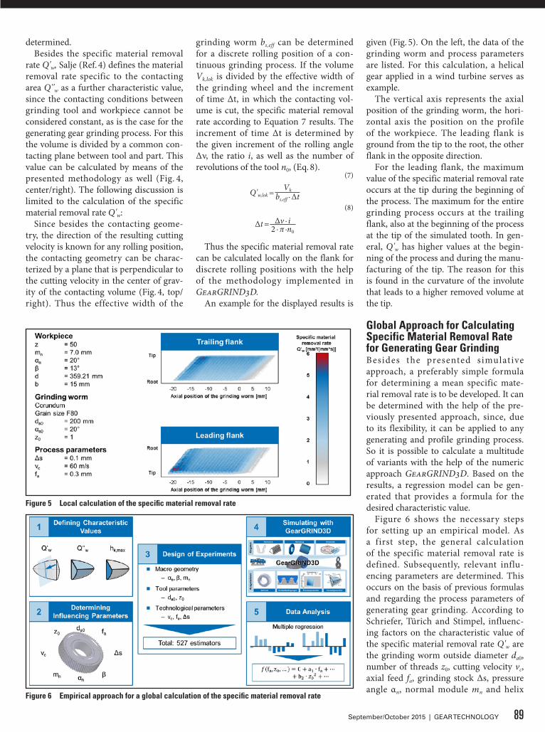
determined.Besides the specific material removal
rate Q'w, Salje (Ref. 4) defines the material removal rate specific to the contacting area Q''w as a further characteristic value, since the contacting conditions between grinding tool and workpiece cannot be considered constant, as is the case for the generating gear grinding process. For this the volume is divided by a common con-tacting plane between tool and part. This value can be calculated by means of the presented methodology as well (Fig. 4, center/right). The following discussion is limited to the calculation of the specific material removal rate Q'w:
Since besides the contacting geome-try, the direction of the resulting cutting velocity is known for any rolling position, the contacting geometry can be charac-terized by a plane that is perpendicular to the cutting velocity in the center of grav-ity of the contacting volume (Fig. 4, top/right). Thus the effective width of the
grinding worm bs,eff can be determined for a discrete rolling position of a con-tinuous grinding process. If the volume Vk,lok is divided by the effective width of the grinding wheel and the increment of time Δt, in which the contacting vol-ume is cut, the specific material removal rate according to Equation 7 results. The increment of time Δt is determined by the given increment of the rolling angle Δν, the ratio i, as well as the number of revolutions of the tool n0, (Eq. 8).
(7)
Q'w,lok =Vk
bs,eff ∙ Δt(8)
Δt = Δv ∙ i2 ∙ π ∙n0
Thus the specific material removal rate can be calculated locally on the flank for discrete rolling positions with the help of the methodology implemented in GearGRIND3D.
An example for the displayed results is
given (Fig. 5). On the left, the data of the grinding worm and process parameters are listed. For this calculation, a helical gear applied in a wind turbine serves as example.
The vertical axis represents the axial position of the grinding worm, the hori-zontal axis the position on the profile of the workpiece. The leading flank is ground from the tip to the root, the other flank in the opposite direction.
For the leading flank, the maximum value of the specific material removal rate occurs at the tip during the beginning of the process. The maximum for the entire grinding process occurs at the trailing flank, also at the beginning of the process at the tip of the simulated tooth. In gen-eral, Q'w has higher values at the begin-ning of the process and during the manu-facturing of the tip. The reason for this is found in the curvature of the involute that leads to a higher removed volume at the tip.
Global Approach for Calculating Specific Material Removal Rate for Generating Gear GrindingBesides the presented simulat ive approach, a preferably simple formula for determining a mean specific mate-rial removal rate is to be developed. It can be determined with the help of the pre-viously presented approach, since, due to its flexibility, it can be applied to any generating and profile grinding process. So it is possible to calculate a multitude of variants with the help of the numeric approach GearGRIND3D. Based on the results, a regression model can be gen-erated that provides a formula for the desired characteristic value.
Figure 6 shows the necessary steps for setting up an empirical model. As a first step, the general calculation of the specific material removal rate is defined. Subsequently, relevant influ-encing parameters are determined. This occurs on the basis of previous formulas and regarding the process parameters of generating gear grinding. According to Schriefer, Türich and Stimpel, influenc-ing factors on the characteristic value of the specific material removal rate Q'w are the grinding worm outside diameter da0, number of threads z0, cutting velocity vc, axial feed fa, grinding stock Δs, pressure angle αn, normal module mn and helix
Figure 6 Empirical approach for a global calculation of the specific material removal rate
Figure 5 Local calculation of the specific material removal rate
89September/October 2015 | GEAR TECHNOLOGY
angle β.Subsequent ly, by using a DoE
approach, the number of variants that must be examined is reduced, allowing the simulation to be conducted within a reasonable time. If the investigations had been conducted on a full factorial scale, it would result in 48 = 65,536 esti-mators; the effort would lead to a cal-culating time of several weeks. On the other hand, parameters cannot be varied independently from one another, since not every combination leads to an oper-ational gear. Variations of the module mn, pressure angle αn and helix angle β make the automated design of trial gears especially more difficult. Therefore, as a first step the process parameters fa, Δs and vc — as well as the tool parameters da0 and z0 — are varied with the help of a D-optimal design of experiment (Fig. 6, left). By applying a D-optimal design of experiment the number of estimators can be reduced from 45 = 1,024 to 31 tri-als. In order to vary mn, β and αn as well, the design of experiment is applied to 17 example gears. It is therefore assured that all examined 527 trial points are opera-tional gears for which the specific mate-rial removal rate Q'w can be calculated by means of the model presented previously in this paper.
The evaluation of the data occurs with the help of a multiple regression analysis. For this, a quadratic transfer function for the individual factors is determined in advance; thus the regression analysis is conducted by means of a quadratic basic function. Interdependencies between the individual factors are left disregarded in order to limit the complexity of the approach. The result is a lower coefficient of determination R² as well as the prog-nosis factor Q² than if the interdependen-cies had been considered. A lower coef-ficient of determination signifies a higher variance of the values — or that there is no relation between the values. A Q² that is too small means that the model will change for new tests. An able model for describing the influences is given — if Q² as well as R² are above 0.9.
By introducing a transformation of the target values, R² and Q² can be fur-ther improved. This so-called Power or Box Cox Transformation is an established instrument and generally used for tak-ing the logarithm of wear characteristics.
The results of the regression analysis are Equations 9 and 10:
(9)Q'w = ex
(10)x = 10.278 + 0.275 − z0 − 0.006 ∙ da0 + 0.018 ∙
vc − 12.275 ∙ fa2 + 12.058 ∙ fa − 22.5 ∙ π ∙ Δs2
+ 12.371 ∙ Δs − 0.069 ∙ mn2 + 0.911 ∙ mn +
0.001 ∙ β2 − 0.003 ∙ β
The coefficient of determination R² for the conducted analyses is 0.934. The value for Q² is with 0.933 on the same level. Thus, a good correlation between the formula and the simulation can be determined for examining the specific material removal rate.
Summary and OutlookDue to the limited number of scientif-ic investigations, gear grinding process-es are currently designed and optimized based on experience. For this reason, the transferal of characteristic values — as they have been applied to conventional grinding processes for many years onto continuous generation grinding and dis-continuous profile grinding — is pursued. However, no standardized methods or formulas which are able to calculate these characteristic values exist. Therefore, investigations have been initiated aimed at developing a standardized methodol-ogy for determining the specific material removal rate Q'w. This methodology is supposed to calculate Q'w locally, as well as by means of a manageable formula.”
The speci f ic mater ia l removal rate is calculated locally with the help of the process simulation program GearGRIND3D for continuous generat-ing gear grinding. Subsequently a design of experiments is defined and a regres-sion model is set up for the characteristic value. Finally, the formula for attaining the specific material removal rate Q'w is presented. The quality of the presented formula regarding the spread of the val-ues and the robustness regarding addi-tional testing points is good.
Since the presented characteristic val-ues cannot be recorded metrologically, the determined values and formulas must be verified by other means. Furthermore, there are no boundary values that would lead to part, tool or machine damage if transgressed. These values can be deter-mined by grinding trials, for instance, in which an occurrence of grinding burns is the matter of investigation. If an influ-
ence of the surface zone due to process conditions should appear for a certain amount of the characteristic value, a boundary value can be found that would lead to flank damage if transgressed. Another option for defining boundary values is the investigation of the grind-ing worm’s wear that has to be correlated to the determined characteristic value.
Acknowledgments. The authors grate-fully acknowledge financial support by the German Research Foundation (DFG) [Project Number KL500/94-1] for the achievement of the project results. For the software-based achievement of simula-tive results the authors gratefully acknowl-edge the financial support for the software development of GearGRIND3D by the WZL Gear Research Circle.
References1. Bausch, T. Innovative Zahnradfertigung:
Verfahren und Maschinen zur kostengünstigen Herstellung von Stirnrädern mit hoher Qualität. 3rd ed.: Expert Verlag, Renningen-Malmsheim, 2006.
2. Türich, A. Werkzeugprofilgenerierung beim Wälzschleifen. Dissertation, Universität Hannover, 2002.
3. Stimpel, F. Technologische Kenngrößen für das kontinuierliche Wälzschleifen von Evolventenverzahnungen. Dissertation, Universität Hannover, 2009.
4. Saljé, E.: Begriffe der Schleif- und Konditioniertechnik: Vulkan-Verl, Essen, 1991.
5. Meijboom, L. Erhöhung der Wirtschaftlichkeit beim Wälzschleifen durch verbesserung des Zerspanvorganges. Dissertation, RWTH Aachen, 1979.
6. Schriefer, H; W. Thyssen, W. Wirz, G. Scacchi and M. Gretler. Reishauer Wälzschleifen: Eigenverlag Reishauer, Walisellen, 2008.
7. Klocke, F. and W. König. Fertigungsverfahren 2: Schleifen, Honen, Läppen, Springer, Berlin, New York, 2005.
8. Werner, G. “Kinematik und Mechanik des Schleifprozesses,” Dissertation, RWTH Aachen, 1971.
9. Werner, G. Konzept und Technologische Grundlagen zur Adaptiven Prozessoptimierung des Außenrundschleifens, Habilitation, RWTH Aachen, 1973.
10. Fritz Klocke; Markus Brumm; Jan Reimann, 2013: Modeling of Surface Zone Influences in Generating Gear Grinding. Procedia CIRP 8(2013):21–26.
11. Brecher C; Brumm M; Hübner F: Manufacturing simulation for generating-gear grinding of large-module gears. In: Höhn B. International Conference on Gears: Europe invites the world. VDI Berichte 2199, VDI Verlag, München, 2013.
90 GEAR TECHNOLOGY | September/October 2015[www.geartechnology.com]
technical
GEAR CUTT ING SOLUT IONS
Prof. Dr.-Ing. Christian Brecher has since 2004 served as Ordinary Professor for Machine Tools at the Laboratory for Machine Tools and Production Engineering (WZL) of the RWTH Aachen, as well as director of the Department for Production Machines at the Fraunhofer Institute for Production Technology IPT. Upon receipt of his engineering degree he began his career as a research assistant and later as team leader in the Department for Machine Investigation and Evaluation at the WZL. From 1999–2001 Brecher worked as a senior engineer with responsibility for machine tools and director (2001–2003) for development and construction at the DS Technologie Werkzeugmaschinenbau GmbH, Mönchengladbach. Brecher has received numerous honors and awards, the Springorum Commemorative Coin and the Borchers Medal of the RWTH Aachen among them.
Markus Brumm, a RWTH graduate with a degree in mechanical engineering, began his career in 2005 as a research assistant in gear investigation at the Laboratory for Machine Tools and Production Engineering (WZL) of the RWTH Aachen. He subsequently became that group’s team leader in 2010.
Prof. Dr.-Ing. Dr.-Ing. E.h. h.c. Dr. h.c. Fritz Klocke studied manufacturing engineering at the TU Berlin, was a research fellow there at the Institute for Machine Tools and manufacturing Technology until 1981, and then as head engineer until 1984, receiving his engineering doctorate in 1982. Klocke worked in industry from 1984 until 1994 at Ernst Winter & Sohn in Hamburg. On January 1, 1995 he was called to the RWTH Aachen as Professor of Manufacturing Engineering Technology and has since then been Chair of Manufacturing Technology, co-director of the WZL Laboratory for Machine Tools & Production Engineering at the RWTH Aachen and head of the Fraunhofer Institute for Production Technology IPT in Aachen. Klocke was awarded the Otto-Kienzle Memorial Coin in 1985 by the Manufacturing Engineering University Group. The title,“Dr.-Ing. E.H,” was bestowed upon Klocke by the University of Hannover in 2006 for his outstanding achievements in science, his efforts in the industrial implementation of a broad range of manufacturing techniques, and for his commitment to numerous scientific committees. The title “Dr. h. c.” was awarded him in 2009 by the University of Thessaloniki and in 2010 by Keio University in Tokio for his achievements in production science, his engagement in international cooperation, and his benefits as a teacher and supervising tutor of student engineers.
Dipl.-Ing. Florian Hübner has since 2012 served at Aachen University of Technology, Germany as Team Leader and Research Assistant — Group Gear Design and Manufacturing Simulation — focusing on manufacturing simulation for generating gear grinding. Previously — i.e., 2005 – 2012 — Hübner devoted his attention to the study of
mechanical engineering, also at Aachen.
BOOTH #2417
91September/October 2015 | GEAR TECHNOLOGY

ITAMCOCELEBRATES ITS 60TH ANNIVERSARY
Founded in 1955, the Northern Indiana-based manufacturer has grown from a single 4000 sq. ft. plant to two facilities that encompass a total of 485,000 sq. ft. ITAMCO delivers preci-sion-machined components to OEMs worldwide in mining, off-highway vehicles, marine, and aviation. The company spe-cializes in precision gear manufacturing and their capabilities range from mining gearing to production runs of CBN-ground transmission gears.
“I believe the success of ITAMCO is due to uncommon per-severance and a true spirit of innovation. Embracing technolo-gy while holding to solid and proven principles has given us an atmosphere that is creative, yet built upon a foundation that can be relied upon,” said Gary Neidig, president of ITAMCO.
ITAMCO’s spirit of innovation makes the company adapt-able to the technology that enables it to provide better qual-ity, better lead times and better pricing. In 2011, the company installed one of the largest gear grinders on the market in its cli-mate-controlled grinding facility. The Niles ZP 40 gear grinder has taken hours out of the grinding process, saving production costs for ITAMCO’s customers. ITAMCO produces gears that meet the standards of their most demanding customers, includ-ing NASA and the Department of Defense. The grinding area with nine CNC-grinding machines is just one component of a company that includes precision machining tools, large press parts, 60-foot high bays, and 80-ton cranes.
“We’re one of the few US facilities that can do it all, from cut-
ting to finishing,” said David Neidig, business development for ITAMCO.
While acknowledging the company will always offer subtrac-tive manufacturing like gear grinding, ITAMCO believes that additive manufacturing, often called 3D printing, is the future of their business. To that end, they have developed an additive manufacturing strategy titled: “Strategic Technology Initiative for Additive Manufacturing.” Their drive to bring additive man-ufacturing to their plant floor was enhanced when they won a funding award from the National Additive Manufacturing Innovation Institute in July 2015. ITAMCO’s IT development team will be working with Johnson & Johnson, the University of Pittsburgh and the University of Notre Dame to develop an additive manufacturing CAD application.
In addition, the technology team at ITAMCO has released over 65 mobile device apps for machinists; designed and mar-kets iBlue, the first industrial Bluetooth transmitter; and devel-oped an award-winning application Google Glass application for machine tools.
ITAMCO is a privately held company that has maintained the principles of its founders, Donald and Noble Neidig.
“My uncle and father believed in a cause larger than them-selves, and were willing to make sacrifices in order to build for the future of others,” said Gary Neidig.
In 2013, ITAMCO partnered with the Plymouth, Indiana School Corporation and Ivy Tech Community College to launch the ITAMCO Manufacturing Center on the Plymouth High School’s campus. Students enrolled in the Precision Tool Manufacturing course at the center will receive credits toward high school graduation and college credits from Ivy Tech. ITAMCO donated $100,000 worth of equipment in addition to technical assistance for the program and recently donated an additional CNC precision machine tool to the large inventory of precision machining tools. ITAMCO’s goal is to help combat the skills gap in the technical trades by being an active partici-pant developing the local workforce.
ITAMCO is also preserving natural habitats for future gen-erations. The company has turned 750 acres of forest next to one of their facilities into a nature preserve. They also began the Woodland Restoration Project in 1997 with the planting of 300 acres of hardwood forest.
Martin BoelterAPPOINTED CHIEF OPERATING OFFICER OF KLINGELNBERG
Klingelnberg recently announced the appointment of Mar t in Boelter as chief operating offi-cer. Boelter will assume responsibil-ity for the production and logistics divisions within the Klingelnberg Group. A four-member senior man-agement team is now once again at the helm at Klingelnberg.
In his capacity as the new chief operating officer (COO), Boelter is now part of the senior management in the group, together with Jan Klingelnberg (CEO), Christoph Küster (CFO) and Dr. Hartmuth Müller (CTO). Due to this reinforcement, resources are now available to accelerate growth on the international stage and further strengthen its market position.
“We are delighted to have gained a highly experienced man-ager in Martin Boelter,” said Jan Klingelnberg, who also serves as chairman of the supervisory board at Klingelnberg GmbH. “His knowledge and experience will drive our company’s con-tinued growth.”
Boelter, who studied mechanical engineering at Munich Technical University, was most recently employed as COO in the Sterling SIHI Group.
“I like having the opportunity to build upon a valuable his-
92 GEAR TECHNOLOGY | September/October 2015[www.geartechnology.com]
industry news

POWERFUL CONNECTIONS
REGISTER TODAY FOR THE DRIVE TECHNOLOGY SHOW OF THE YEAR!
OCTOBER 20-22, 2015 DETROIT, MI
COBO CENTER
THE DRIVE TECHNOLOGY SHOW
GEAR EXPO 2015 brings together the full range of experts — design, manufacturing, application engineering — all in the same place — Cobo Center, Detroit, October 20–22.
From a single gear to complex drives, GEAR EXPO covers it all…
• More exhibitors — from gear making machines to systems integrators.
• More education sessions — from metallurgy and geometry to maximizing power density.
• More attendees — buyers and makers from automotive, construction, mining, agriculture — wherever high-performance drives are critical.
• More solutions — meet the experts and evaluate your capabilities.
GEAR EXPO 2015 is the place to be.
• Make powerful connections.
• See the latest technology in action.
• Get the inspiration you need to take your products to the next level.
Improved drive technology is critical to achieving higher efficiencies and longer service life. All the information and answers you need will be at GEAR EXPO 2015.
VISIT www.gearexpo.com/GETECHUse code GETECH when registering.
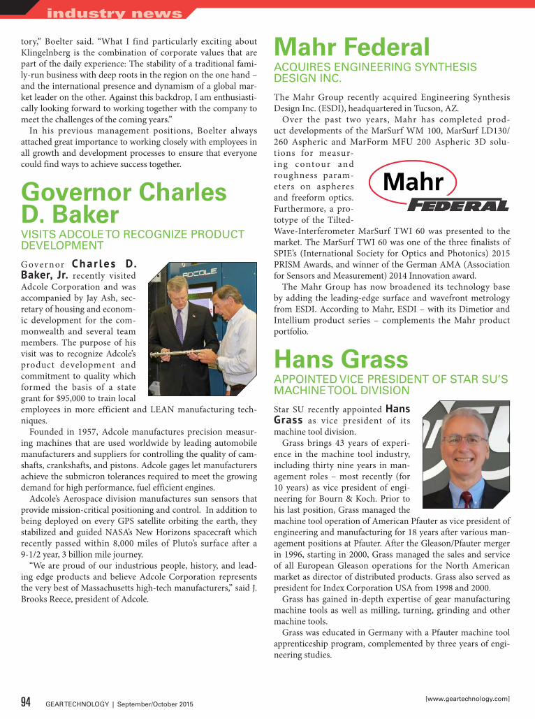
tory,” Boelter said. “What I find particularly exciting about Klingelnberg is the combination of corporate values that are part of the daily experience: The stability of a traditional fami-ly-run business with deep roots in the region on the one hand – and the international presence and dynamism of a global mar-ket leader on the other. Against this backdrop, I am enthusiasti-cally looking forward to working together with the company to meet the challenges of the coming years.”
In his previous management positions, Boelter always attached great importance to working closely with employees in all growth and development processes to ensure that everyone could find ways to achieve success together.
Governor Charles D. BakerVISITS ADCOLE TO RECOGNIZE PRODUCT DEVELOPMENT
G over nor Char les D. Baker, Jr. recently visited Adcole Corporation and was accompanied by Jay Ash, sec-retary of housing and econom-ic development for the com-monwealth and several team members. The purpose of his visit was to recognize Adcole’s product development and commitment to quality which formed the basis of a state grant for $95,000 to train local employees in more efficient and LEAN manufacturing tech-niques.
Founded in 1957, Adcole manufactures precision measur-ing machines that are used worldwide by leading automobile manufacturers and suppliers for controlling the quality of cam-shafts, crankshafts, and pistons. Adcole gages let manufacturers achieve the submicron tolerances required to meet the growing demand for high performance, fuel efficient engines.
Adcole’s Aerospace division manufactures sun sensors that provide mission-critical positioning and control. In addition to being deployed on every GPS satellite orbiting the earth, they stabilized and guided NASA’s New Horizons spacecraft which recently passed within 8,000 miles of Pluto’s surface after a 9-1/2 year, 3 billion mile journey.
“We are proud of our industrious people, history, and lead-ing edge products and believe Adcole Corporation represents the very best of Massachusetts high-tech manufacturers,” said J. Brooks Reece, president of Adcole.
Mahr FederalACQUIRES ENGINEERING SYNTHESIS DESIGN INC.
The Mahr Group recently acquired Engineering Synthesis Design Inc. (ESDI), headquartered in Tucson, AZ.
Over the past two years, Mahr has completed prod-uct developments of the MarSurf WM 100, MarSurf LD130/ 260 Aspheric and MarForm MFU 200 Aspheric 3D solu-tions for measur-ing contour and roughness param-eters on aspheres and freeform optics. Furthermore, a pro-totype of the Tilted-Wave-Interferometer MarSurf TWI 60 was presented to the market. The MarSurf TWI 60 was one of the three finalists of SPIE’s (International Society for Optics and Photonics) 2015 PRISM Awards, and winner of the German AMA (Association for Sensors and Measurement) 2014 Innovation award.
The Mahr Group has now broadened its technology base by adding the leading-edge surface and wavefront metrology from ESDI. According to Mahr, ESDI – with its Dimetior and Intellium product series – complements the Mahr product portfolio.
Hans GrassAPPOINTED VICE PRESIDENT OF STAR SU’S MACHINE TOOL DIVISION
Star SU recently appointed Hans Grass as vice president of its machine tool division.
Grass brings 43 years of experi-ence in the machine tool industry, including thirty nine years in man-agement roles – most recently (for 10 years) as vice president of engi-neering for Bourn & Koch. Prior to his last position, Grass managed the machine tool operation of American Pfauter as vice president of engineering and manufacturing for 18 years after various man-agement positions at Pfauter. After the Gleason/Pfauter merger in 1996, starting in 2000, Grass managed the sales and service of all European Gleason operations for the North American market as director of distributed products. Grass also served as president for Index Corporation USA from 1998 and 2000.
Grass has gained in-depth expertise of gear manufacturing machine tools as well as milling, turning, grinding and other machine tools.
Grass was educated in Germany with a Pfauter machine tool apprenticeship program, complemented by three years of engi-neering studies.
94 GEAR TECHNOLOGY | September/October 2015[www.geartechnology.com]
industry news

Darian DitzlerRETURNS TO LUREN PRECISION AS MACHINE TOOL SALES MANAGER
Luren Precision Chicago recently announced the return of Darian Ditzler as their machine tool sales manager.
Ditz ler star ted with Luren Precision in January of 2011 and has coordinated and attended many dif-ferent trade shows, including mul-tiple IMTS and Gear Expo shows. As a good ambassador for Luren in the U.S. market, Ditzler has visit-ed many factories in the U.S., Canada and abroad, presenting Luren’s products and understanding how Luren can continue to grow in North America.
Solar AtmospheresINSTALLS RECORD-SIZED HORIZONTAL HIGH VACUUM FURNACE
Solar Atmospheres of Western Pennsylvania recently announced the installation of the largest horizontal high vac-uum furnace ever constructed at their Hermitage facility. The furnace will be engineered and manufactured by its sister com-pany, Solar Manufacturing, Inc.
The entire investment for Solar Atmospheres will be on the order of $8 million, including the cost of this large furnace, a new 20,000 square foot building addition and utilities to oper-ate this large system.
“We will all be very busy over the next year, not only pre-paring a site to expand our current facility by another 20,000 square feet to house this newest piece of equipment, but also assembling and building the new equipment on-site,” said Robert Hill, president of Solar Atmospheres Western Pennsylvania. “All of our employees are eagerly anticipating the day that we commission one of the most unique vacuum fur-naces in the world.”
This car-bottom type furnace Model HCB-84576-2EQ will have a work-zone that measures 7 × 48 feet and will be capable
95September/October 2015 | GEAR TECHNOLOGY
[ ]• Spur / Helical up to 59" O.D. – 26" Face• Accurate quotes – Competitive prices –
Fast turn-around• Emergency “breakdown” support• Support system for OEM parts
• Full complement of testing equipment for complete and comprehensive charting. Calibrated and certified on a regular schedule.
PRECISION GEAR GRINDING
tel.773-376 4906 fax.773-376 4946
Accudrive http://www.accudrv.com/index.html
1 of 2 9/24/2013 11:25 AM
Trusted by OEM, MRO and Gear Job Shop customers for nearly two decades.Your project is as important to us as it is to you.
(773) 376-4906www.Accudrv.com
KISSsoft USA, LLC3719 N. Spring Grove Road
Johnsburg, Illinois 60051Phone (815) 363 8823
Release 03/2015
NEW
KISSsoft Highlights● Risk assessment of flank fracture for cylindrical gears● Contact analysis for bevel gears● Planet carrier deformation with FE calculation● Housing stiffness in KISSsys● Modal analysis of shaft systems● And many more ...
Get your free trial version at www.KISSsoft.com
GearTech_KISSsoft_Rel_03_2015_Highlights_89x120_5mm.indd 1 19.03.2015 15:18:24

of handling loads up to 150,000 pounds at 2400oF. Dual US patented loading cars are provided for loading/unloading from both ends of this furnace with its 48-inch long hot zone.
The vacuum chamber is being manufactured by Youngberg Industries, Inc. of Rockford, IL. and will incorporate three 48-inch diameter vacuum ports as well as six 24-inch diameter ports for gas cooling inlet and outlet. Autoclave type locking doors are included at both ends of the furnace.
“This is the largest horizontal high vacuum chamber they have ever manufactured,” said Tom Larson, CEO of Youngberg Industries.
The programs for the engineering and construction phases have been initiated with key orders placed for major system components. The ultimate goal is to have installation and test-ing completed by the first quarter of 2016.
Heiko Machine ToolsCHOSEN TO SELL CESAR GALDABINI PRODUCTS
Heiko Machine Tools of Canton, MI recently announced that it has been chosen by Cesar Galdabini SPA of Milan, Italy, as the sales and marketing representatives for their straightening and rounding machines in the North American Market. Galdabini produces manual and automatic straighteners for all sizes and types of bars, tubes, and shafts as well as special shapes like gun barrels and steering racks. The smallest of the automatic straighteners are sized from .12 inches diameter by 6 inches length while the large machines handle more than 52 inches diameter by 43 feet length.
Galdabini also makes machines for rounding of numerous types of rings such as synchro rings, gear blanks and bearing races up to large ring gears for wind power planetary systems. Laser inspec-tion developed by Galdabini can be integrated into any of the machines for unparalleled quality while full automation designed and built in house makes for unmatched productivity.
James PetiprinNAMED REGIONAL SALES MANAGER OF EMAG
EMAG recently introduced James Petiprin as the new region-al sales manager representing Michigan and Ohio, as well as east-ern Pennsylvania and New York. Petiprin has over 15 years experi-ence in the machine tool and auto-mation market.
Petiprin earned his Bachelor’s of
96 GEAR TECHNOLOGY | September/October 2015[www.geartechnology.com]
industry news
SUHNER Manufacturing Inc. · Rome, GA 30161Phone: 706-235-8046 · [email protected]
Flexible Shafts & Spiral Bevel GearsTwo different ways to transmit rotary motion.
ww
w.s
uhne
r.com

7–10 December 2015, Berlin, Germany
+ Transmission Expo
CTI SymposiumAutomotive Transmissions, HEV and EV Drives
14th International
Home of the World’s International Transmission & Drive Community
Key Note SpeakersMichael SchöffmannHead of Transmission Development | Audi AGDr Eckhard ScholzChief Executive Officer (CEO) | Volkswagen Commercial VehiclesGerald KillmannVice President R&D2 | Toyota Motor EuropeDr Robert FischerExecutive Vice President Engineering and Technology Powertrain Systems | AVL List GmbH Larry NitzExecutive Director | General MotorsWolfgang Müller-PietrallaHead of Corporate Foresight | Volkswagen Group Dr Rolf LeonhardChairman of the Advisory Board | Bosch Engineering GmbHDr Wolfgang ReikAutomotive ConsultingMihir KotechaCEO | GETRAG Corporate GroupTetsuya TakahashiSenior Vice President, R&D Management Department | Jatco LtdGuillaume DevauchelleVice President Innovation & Scientific Development Valeo Group |Valeo SADr Peter Riethformer Senior Vice President Systems & Technology and Member of the Management Board Division Chassis & Safety | Continental AG
Dr Robert FischerMichael Schöffmann Dr Eckhard Scholz Gerald Killmann
Tetsuya TakahashiMihir Kotecha Guillaume Devauchelle Dr Peter Rieth
Dr Rolf LeonhardLarry Nitz Dr Wolfgang ReikWolfgang Müller-Pietralla
Prof. Dr Ferit Küçükay
Chairman of the CTI SymposiumProf. Dr Ferit KüçükayDirector of the Institute of Automotive Engineering | Technische Universität Braunschweig
1,350 Delegates in 2014
130 Exhibitors @ the Transmission Expo
35 % International Participants from 28 Nations
Panel discussionWhat will the drivetrain be like in 2030?Will the electric vehicle remain a niche model?
Sponsors
www.transmission-symposium.com
P2300412anz_en_202_3x273mm_DD.indd 1 04.09.2015 14:43:09

• Round broaches• Involute Splines up to 7" od
and 100" oal• Spiral broaches• Flat, form and rack broaches• Fir tree• Dove tail• Keyways• Magwell & rifling
broaches
Kingsford Broach & Tool, Inc.is seeking manufacturer’s reps.Commission guaranteed monthly.
Inquiries: [email protected]
A leading manufacturer of all types of broaches and broach related tooling since 1968. We offer turnkey solutions and complete sharpening and reconditioning services. Specializing in the manufacture of:
www.kingsfordbroach.com
906.774.4917
Science from Central Michigan University and has held several positions in the manufacturing industry. Most recently he rep-resented Swedish conveyor company Ewab as a business engi-neer.
Contour Hardening Mexico Heat Treating FacilityCOMPLETES ISO/TS CERTIFICATION
Contour Hardening, Inc. recently announced the ISO/TS certi-fication of its heat treating service facility in Silao, Guanajuato, Mexico. The company’s U.S. heat treating facility has been certi-fied since 2004.
The rapid expansion of vehicle and related component manu-facturing in Mexico has resulted in a local deficit of TS-certified suppliers in general, and induction heat treating process service providers specifically. With its new TS certification, Contour Hardening will have in-country capabilities to deliver direct-to-line parts, components and assemblies that meet the industry’s mandated heat treating standards.
“Because we were one of the first ISO certified heat treat-ing operations in the U.S. and were among the first HT process service providers to achieve ISO/TS certification as well, we are uniquely suited to immediately serve the needs of a wide range of customers in Mexico,” said John Storm, president and CEO of Contour Hardening. “We’ve already solved the technical problems that will hinder others and have formed solid, long-standing relationships with all major OEMs and their tier-one and tier-two suppliers. We’ve also processed more than 12 mil-lion parts in our Mexico facility alone.”
Patented Micropulse induction heat treating equipment is built to ISO standards. Today, the company’s Micropulse equip-ment continues to process parts for virtually every major auto-motive manufacturer in the world.
98 GEAR TECHNOLOGY | September/October 2015[www.geartechnology.com]
industry news
TO WORK FOR YOU
GEAR DESIGN
PUTTING A LIFETIME
OF
EXPERIENCE
•Reverseengineering•Gearboxupgrades•Customgearboxdesign•Specificationdevelopment•Projectmanagement•Vendorqualification
•Designreviews•Bidevaluations•Toolingdesign•Customizedgeartraining•Equipmentevaluation•Custommachinedesign
Charles D. [email protected]
[630] 209-1652
www.beytagear.com
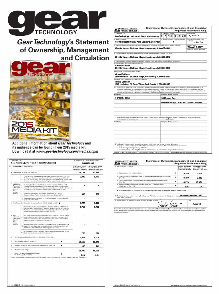
Gear Technology, the Journal of Gear Manufacturing
Monthly except February, April, October & December
0 7 4 3 6 8 5 8 9 / 2 8 / 1 5
8 $ 7 0 . 0 0
WILLIAM R. STOTT1840 Jarvis Ave., Elk Grove Village, Cook County, IL 60008-2440
1840 Jarvis Ave., Elk Grove Village, Cook County, IL 60008-2440
Michael Goldstein1840 Jarvis Ave., Elk Grove Village, Cook County, IL 60008-2440
Michael Goldstein1840 Jarvis Ave., Elk Grove Village, Cook County, IL 60008-2440
Michael Goldstein1840 Jarvis Ave., Elk Grove Village, Cook County, IL 60008-2440
Michael Goldstein 1840 Jarvis Ave.
Elk Grove Village, Cook County, IL 60008-2440
X
Gear Technology, the Journal of Gear Manufacturing AUGUST 2015
11,747
6,646
--
398
--
7,044
3,7183,718
--
--
755
4,473
11,517
230
11,74711,747
61%
11,688
6,873
--
366
--
7,239
3,7193,719
--
--
290
4,009
11,248
440
11,68811,688
64%
Gear Technology’s Statement of Ownership, Management
and Circulation
SINCE 1984
2015Media Kit
THE GEAR INDUSTRY’S INFORMATION SOURCE
Additional information about Gear Technology and its audience can be found in our 2015 media kit. Download it at www.geartechnology.com/mediakit.pdf
2,753
9,797
14,270
69%
2,603
9,842
13,851
71%
X
September/October 2015
9/28/15
calendar
October 26-29. The Quality Show. Donald E. Stephens Convention Center, Rosemont, IL. The Quality Show is the only tradeshow focused exclusively on quality technology, equipment and products. The event is produced by BNP Media, one of the country’s leading business-to-business media companies serv-ing industry professionals across 50+ industries through maga-zines, custom media, e-newsletters, webinars, events and market research. For more information, visit www.qualityshow.com.
October 27-29. Modern Furnace Brazing School. Brazing Engineering Center, Wall Colmonoy Aerobraze Division, Cincinnati, OH. The late Robert Peaslee’s tradition continues with the return of the brazing school. The Brazing Engineering Center provides engineering services and training, as well as offering new practical experience on the shop floor. For over 60 years, Wall Colmonoy engineers have gained practical experi-ence on actual problems in brazing plants around the world. Knowledge and practical application will be taught by industry-leading brazing experts. In 1950, Peaslee developed the first nickel-based brazing filler metal, Nicrobraz. Modern Furnace Brazing School will allow you to apply workable solutions to your brazing needs. For more information or to register, contact [email protected].
October 27-29 and November 3-5. Discover 2015. Mazak Corporate Headquarters, Florence, KY. Mazak Corporation encourages those involved in the metalworking industry to attend its Discover 2015 technology and education event. Here, the machine tool builder plans to spotlight new technologies and trends that will change how part manufacturers operate, includ-ing unconventional ways to drive operational efficiency via addi-tive manufacturing, CNC technology and the Industrial Internet of Things (IIoT) concept. Additive manufacturing is creating a shift in the way engineers and designers think about product development. The company will also offer a series of seminars that will teach attendees the latest metalworking tools, trends and techniques for improved productivity and profitability. For more information, visit www.MazakUSA.com/DISCOVER2015.
October 27-30. PTC Asia 2015. Shanghai New International Expo Center, Shanghai. PTC Asia is the larg-est annual industrial event in power transmission and control in Asia and the second largest in the world. In the exhibition, the debut of new products will illustrate the integration and development of Industry 4.0, highlighting the utilization of eco-friendly materials as an optimal solution to achieving industrial high efficiency and energy conservation. The expo will boast over 90,000 sq. m and 80,000 visitors. Over 15 industries will be included, but PTC will focus on the rail transportation, petro-chemical, mining machinery, wind power and food and medicine packing industries in particular. PTC will also be providing over 12 seminars as well as matchmaking services between businesses and potential buyers. Occurring alongside PTC ASIA will be six other expos: ComVac Asia, Industrial Supply Asia, Cold Chain Asia, Heavy Machinery Asia, Battery and Energy Storage Asia and CeMat Asia. Combined the seven shows will take up 17 halls of space. Visit www.ptc-asia.com/EN/.
October 27-29. The Assembly Show 2015. Donald E. Stephens Convention Center, Rosemont, IL. Focused exclusively on assembly technology, equipment and products, visitors will find the latest advances in custom automated assembly solutions, robotics, screwdriving, adhesives, dispensing, plastics assembly, conveyors, fasteners, packaging, workstations, welding, vision sys-tems and more. The target audience includes corporate manage-
ment, manufacturing engineers, design engineers and purchasing personnel. Entering its third year, the Assembly Show continues to grow. The expo floor has been expanded and exhibit hours have been extended. The show will feature 20 educational showcase theaters, almost double the number they had in 2014. There will also be three pre-show workshops for in-depth lessons and hands-on training. Visit www.theassemblyshow.com.
October 28-30. Dynamic Systems and Control 2015. Hilton Columbus, Columbus, OH. The Dynamic Systems and Control Conference is the showcase technical forum of the ASME Dynamic Systems and Control Division. It provides a focused and intimate setting for dissemination and discus-sion of the state of the art in dynamic systems and control research, with a mechanical engineering focus. The 2015 DSCC Technical Program will consist of sessions in all of the usual areas of interest to the Division. In addition, the conference will feature specific technical tracks that uniquely identify this particular DSCC. The location of the conference, in the heart of the Manufacturing and Automotive industries, makes these two areas especially appropriate for special tracks. Other special tracks will include Interplay between Biology/Ecology/Life Sciences and Engineering and Information Technology in Mechanical and Aerospace Engineering. The program will include contributed ses-sions, invited sessions, tutorial sessions, special sessions, work-shops and exhibits. Visit www.asmeconferences.org/DSCC2015/.
November 3-5. 2015 Detailed Gear Design - Beyond Simple Service Factors. Hyatt Place, Las Vegas, NV. This AGMA course explores all factors that go into good gear design, including life cycle, load, torque, tooth optimiza-tion, and evaluating consequences. Students should have a good understanding of basic gear theory and nomenclature. The course is designed for gear engineers, gear designers, applica-tion engineers, and others who are responsible for interpreting gear design or who want to better understand all aspects of gear design. AGMA members: $1,395 for first registrant from a com-pany, $1,195 for additional registrants. Non-members: $1,895 for first registrant, $1,695 for additional registrants. Visit www.agma.org.
November 4-5. Advanced Engineering UK 2015. NEC, Birmingham UK. Integrating multiple show exhibit zones with the UK’s largest free-to-attend engineering conference program, Advanced Engineering is where the supply chain meets with visiting engineering and procurement decision makers from OEMs and top tier organizations spanning: aerospace; automo-tive; motorsport; marine, civil engineering, and more. Whether you are a visitor or an exhibitor, Advanced Engineering will not only provide you with a business forum and supply chain showcase for your own sector, but will also introduce you to new opportunities in industries using related technologies and ser-vices. For more information, visit www.advancedengineeringuk.com.
November 13-19. 2015 International Mechanical Engineering Congress & Exposition. George R. Brown Convention Center, Houston, TX. ASME’s International Mechanical Engineering Congress and Exposition (IMECE) is the largest interdisciplinary mechanical engineering conference in the world. IMECE plays a signifi-cant role in stimulating innovation from basic discovery to translational application. It fosters new collaborations that engage stakeholders and partners not only from academia, but also from national laboratories, industry, research settings, and funding bodies. Visit www.asmeconferences.org.
100 GEAR TECHNOLOGY | September/October 2015[www.geartechnology.com]

FREE SUBSCRIPTIONGear Technology, is the world’s leading publication on gear design, engineering and manufacturing. To sign up or renew your FREE SUBSCRIPTION use the form below.
Company Name: ______________________________________________________
Address: ______________________________________________________________
_______________________________________________________________________
_______________________________________________________________________
City: __________________________________________________________________
State/Province: ___________________ ZIP+4/Postal Code: __________________
Country: ______________________________________________________________
Telephone: __________________________Fax: ______________________________
E-mail: _______________________________________________________________
Website: ______________________________________________________________
(print)
❏ Corporate Executive (B)❏ Manufacturing Production Management (C)❏ Manufacturing Production Department (D)❏ Manufacturing Engineering Management (E)❏ Manufacturing Engineering Department (F)❏ Product Design, R&D Management (H)❏ Product Design, R&D Department (I)
❏ Purchasing (L)❏ Marketing, Sales or Communications (M)❏ Quality Control Management (P)❏ Quality Control Department (Q)❏ Other (Please describe) (N)
______________________________
What is your primary JOB FUNCTION(check ONLY one)
FAX TO 1-847-437-6618 orVISIT US ONLINE AT
www.geartechnology.com/subscribe.htm
❏ YES, I want to be notified each issue when Gear Technology is available online
❏ YES, I would like to receive Gear Technology’s monthly e-mail newsletter
❏ YES, I would like to receive Gear Technology’s twice monthly e-mail Product Alerts
❏ YES, I would like to receive 3rd-party e-mails from Gear Technology’s advertisers and partners
❏ YES, I would like to receive subscription renewal notices by e-mail
❏ No, I do not wish to be contacted by e-mail.
(So we can notify you when the online edition is available)SAVE a TREE!
I ONLY want the digital edition (e-mail required)
DIGITAL SUBSCRIPTIONS
1
YES I want to receive/continue to receive Gear Technology FREE!
No thank you.
Name:_________________________________________JobTitle/Position: ___________________________
Signature _____________________________________________________ Date: ______________________
2 E-mail __________________________________________________________
3 Please update your contact information orattach you business card here. (No Staples)
4
FIND THE EXACT SUBJECTS YOU ARE LOOKING FOR: Subscribers now get access to the 30 years of searchable articles in our online archive.
(required)
My company MAKES gears (20) My company BUYS gears (22) I DESIGN gears (23) I am a SUPPLIER to the GEAR INDUSTRY
(please specify product or service) (24) _______________________________________
6 How are YOU involved with gears (check all that apply)?
Is there a colleague within your company that might benefit from having their own copy of Gear Technology magazine?
Name: _______________________________________________
Title: ________________________________________________
5 My company’s principal product or service is:________________________

Gear rack specialists with state-of-the-art
gear rack production capa-bilities including our most recent
acquisition; Gleason-Saikuni HR-2000 CNC rack milling machine with hard-milling
after heat treat capabilities up to 65 Rc hardness (producing impressive tooth finishes and accuracies comparable to rack grinding).
At Gear Expo we will happily demonstrate samples produced for the most demanding of needs in aerospace, automation, off-highway equipment, defense, energy, machine tool, medical and others.
630.766.2652fax: 630.766.3245
365 Balm Court, Wood Dale, IL 60191
ad index
GLEASON TOOLING
www.gearmachineryexchange.com
3M Abrasive Systems Division — 433m.com/EXTREMEPrecisionPowertrain
A.G. Davis/AA Gage — 17www.agdavis.com
Accu–Drive Inc. — 95www.accudrv.com
Acme Wire Products — 60www.acmewire.com
Advent Tool — 31advent–threadmill.com
AFC–Holcroft — 34, 63www.afc–holcroft.com
AGMA — 93www.agma.org
All Metals & Forge Group, LLC — 40www.steelforge.com
Arrow Gear Co. — 25www.arrowgear.com
B&R Machine and Gear Corp. — 27www.brgear.com
Banyan Global Technologies — 55www.banyangt.com
Becker Gearmeisters — 33www.maagmachines.com
Beyta Gear Service — 98www.beytagear.com
Bourn & Koch, Inc. — 85www.bourn–koch.com
The Broach Masters & Universal Gear — 29www.broachmasters.com
Broaching Machine Specialties — 54www.broachingmachine.com
Cincinnati Gearing Systems — 96www.cincinnatigearingsystems.com
Cincinnati Steel Treating — 55www.steeltreating.com
Circle Gear — 103www.circlegear.com
Clarke Gear Co. / Clarke Engineering — 44–45www.clarkegear.com
Cleaning Technologies Group — 60ctgclean.com
CTI – Car Training Institute — 97www.transmission–symposium.com
Drewco — 18www.drewco.com
DTR USA Corp. — 72www.dragon.co.kr
ECM USA — 65www.ecm–usa.com
EFD Induction — 63www.efd–induction.com
Erasteel — 37, 57www.erasteel.com
Excel Gear — 14www.excelgear.com
Foerster Instruments, Inc. — 4www.foerstergroup.de
Forest City Gear — 7www.forestcitygear.com
Forkardt — 33www.forkardt.us
Framo Morat — 4www.framo–morat.com
Frenco — 50www.frenco.de
Gear Machinery Exchange — 102www.gearmachineryexchange.com
Gear Manufacturing Inc. — 93www.gearmfg.com
Gleason Corporation — 52–23www.gleason.com
GMTA – German Machine Tools of America — 13www.gmtamerica.com
GWJ Technology GmbH — 59www.gwj.de
Hans–Juergen Geiger Maschinen–Vertrieb GmbH — 48www.geiger–germany.com
Hardinge Group — 11, 33www.hardingegrindinggroup.com
Heiko Machine Tools — 54www.heikomachine.com
Index / Traub — 58, 73www.indextraub.com
Index Technologies — 103www.gallenco.com
Innovative Rack & Gear — 102www.gearacks.com
Ipsen International — 67www.ipsenusa.com
Kapp Technologies — 3www.kapp–usa.com
Kingsford Broach — 98www.kingsfordbroach.com
KissSoft USA, LLC — 95www.kisssoft.com
Klingelnberg – Outside Back Coverwww.klingelnberg.com
Koepfer America LLC — 28koepferamerica.com
Koro Sharpening Service — 103www.koroind.com
Liebherr — 5www.liebherr.us
Luren Precision — 19, 62www.luren.com.tw
Mcinnes Rolled Rings — 42www.mcinnesrolledrings.com
Micro Surface Corporation — 103www.microsurfacecorp.com
Midwest Gear & Tool, Inc. — [email protected]
Midwest Thermal–Vac — 103www.mtvac.com
Mitsubishi Heavy Industries America — 8, 54www.mitsubishigearcenter.com
Mitsubishi Materials — 38www.mmus.com
Nachi America — 26www.nachiamerica.com
Nordex Inc. — 41www.nordex.com
Oelheld U.S., Inc. — 55www.oelheld.com
Paulo– 56www.paulo.com
Pentagear Products — 12www.gearinspection.com
Phoenix Tool & Thread Grinding — 103www.phoenixthreadgrinding.com
Precision Gage Company — 57www.precisiongageco.com
Presrite Corp. — 79www.presrite.com
Proto Manufacturing — 35www.protoxrd.com
Radiac Abrasives — 32www.radiac.com
Rave Gears & Machining – Inside Back Coverwww.ravegears.com
Reishauer — 51www.reishauer.com
Roberts Sinto — 62www.robertssinto.com
Romax Technology — 57www.romaxtech.com
Schafer Industries — 15www.schafergear.com
Schnyder S.A. — 91www.hanikcorp.com
Seco/Warwick — 69www.secowarwick.com
SMT—Smart Manufacturing Technology — 61masta.smartmt.com
Solar Atmospheres — 63, 68solaratm.com
Solar Manufacturing — 62www.solarmfg.com
Southern Gear & Machine — 61www.southerngear.net
Specialty Steel Treating — 49www.sst.net
Star SU LLC – IFC– 1, 103www.star–su.com
STD Precision Gear & Instruent — 56www.stdgear.com
Suhner Manufacturing Inc. — 96www.suhner.com
TECO Werkzeugmaschinen GmbH — 32www.teco–germany.com
United Tool Supply — 56unite–a–matic.com
Weldon Solutions — 39, 59www.weldonsolutions.com
Yieh Chen / Six Star Machinery — 58www.yiehchen.com
Zoller — 36www.zoller–usa.com
ZRIME — 71www.zrime.com.cn
CHANGE GEARS for Models 2, 2A, 7A, 12, 12B, 14, 16, 102, 104, 106, 108, 114, 116, 118, 24, 24A, 26, 28,
606, 607, 641, 645, 650INDEX PLATES, LIFT/DROP CAMS and GENEVAS for Models 605, 606,
607, 608, 609, 610PRECISION INDEX PLATES for Models 19, 29 and 120 CURVIC
COUPLING GRINDERSLIFT/DROP CAMS for Models 109
and 112CAMS for Models 645, 41T & 44TGENERATING and FEED CAMS for
Models 2, 2A, 102DRESSER CAMS for Models 17, 19,
120, 463CUTTER BODIES for Models 104 and
114 Coniflex Straight BevelCUTTER BODIES 3.50", 6" & 9"
HARDAC & HARDAC IIIQUENCH PRESS UNIVERSAL LOWER
DIE SETS, 15" diameter, 10 ringsGAUGE SET for Model 24A
ALIGNMENT GAUGES, #14/#14, #14 short/#39 short, #14 Long/#39 Long,
#39/#39, all with Collars & BlocksCUTTER BLADES for Model 104
PLANER FORMER for Models 54 & 154
102 GEAR TECHNOLOGY | September/October 2015[www.geartechnology.com]
SHARP HOBSChange Downtime To Productivity
You Need Your Tools Back FAST– Eliminating Downtime &Tuned To Meet or Surpass Original Design Specsand That’s Where We Come In
• Stripping & Re-Coating
• Gear Shaper Sharpening
• Milling Cutter Sharpening
• Gear Tool Certifications
Tel: 216-642-5900 • Fax: 216-642-8837 • 5755 Canal Road • Valley View, OH 44125Email: [email protected] WWW.GALLENCO.COM
4760 Briar Rd, Cleveland, OH 44135Phone: 216-433-7008 Fax: 216-433-7067
• CNC External Thread Grinding Specialists• Emergency Service Available
• Any thread form• Any lead• Multiple starts
PHOENIXTOOL & THREAD GRINDING
Dry Lube Coating
Call on MicroSurfacefor unbeatable prices!
CALL: (408) [email protected]
• WS2• MoS2• PTFE
MS 1-9pgAd.indd 1 3/4/15 3:12:22 PM
Circle Gear and Machine
• Reverse Engineering• Design Analysis• Complete Machine Shop Including CNC Machining
Documented Quality Control Program
Inspection Lab including Complete
Gear Tooth Diagnostics
1501 South 55th Ct. • Cicero, IL 60804Ph: 708-652-1000 • Fax: 708-652-1100
Quality Custom Gearing Since 1951
Please email your inquiries to [email protected] • www.circlegear.com
Tooth Cutting, Grinding & Shaving Services Available
CG C
C I R C LE
G E A R C O
QUALITY CUSTOM GEARING!
All Sizes & Configurations
QUALITY CUSTOM GEARING!
103September/October 2015 | GEAR TECHNOLOGY
classified
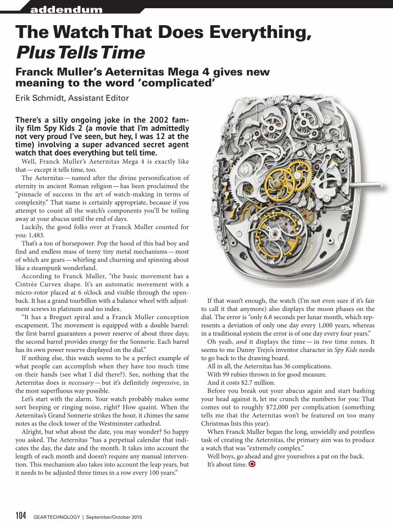
There’s a silly ongoing joke in the 2002 fam-ily film Spy Kids 2 (a movie that I’m admittedly not very proud I’ve seen, but hey, I was 12 at the time) involving a super advanced secret agent watch that does everything but tell time.
Well, Franck Muller’s Aeternitas Mega 4 is exactly like that — except it tells time, too.
The Aeternitas — named after the divine personification of eternity in ancient Roman religion — has been proclaimed the “pinnacle of success in the art of watch-making in terms of complexity.” That name is certainly appropriate, because if you attempt to count all the watch’s components you’ll be toiling away at your abacus until the end of days.
Luckily, the good folks over at Franck Muller counted for you: 1,483.
That’s a ton of horsepower. Pop the hood of this bad boy and find and endless mass of teeny tiny metal mechanisms — most of which are gears — whirling and churning and spinning about like a steampunk wonderland.
According to Franck Muller, “the basic movement has a Cintrée Curvex shape. It’s an automatic movement with a micro-rotor placed at 6 o’clock and visible through the open-back. It has a grand tourbillon with a balance wheel with adjust-ment screws in platinum and no index.
“It has a Breguet spiral and a Franck Muller conception escapement. The movement is equipped with a double barrel: the first barrel guarantees a power reserve of about three days; the second barrel provides energy for the Sonnerie. Each barrel has its own power reserve displayed on the dial.”
If nothing else, this watch seems to be a perfect example of what people can accomplish when they have too much time on their hands (see what I did there?). See, nothing that the Aeternitas does is necessary — but it’s definitely impressive, in the most superfluous way possible.
Let’s start with the alarm. Your watch probably makes some sort beeping or ringing noise, right? How quaint. When the Aeternitas’s Grand Sonnerie strikes the hour, it chimes the same notes as the clock tower of the Westminster cathedral.
Alright, but what about the date, you may wonder? So happy you asked. The Aeternitas “has a perpetual calendar that indi-cates the day, the date and the month. It takes into account the length of each month and doesn’t require any manual interven-tion. This mechanism also takes into account the leap years, but it needs to be adjusted three times in a row every 100 years.”
If that wasn’t enough, the watch (I’m not even sure if it’s fair to call it that anymore) also displays the moon phases on the dial. The error is “only 6.8 seconds per lunar month, which rep-resents a deviation of only one day every 1,000 years, whereas in a traditional system the error is of one day every four years.”
Oh yeah, and it displays the time — in two time zones. It seems to me Danny Trejo’s inventor character in Spy Kids needs to go back to the drawing board.
All in all, the Aeternitas has 36 complications.With 99 rubies thrown in for good measure.And it costs $2.7 million.Before you break out your abacus again and start bashing
your head against it, let me crunch the numbers for you: That comes out to roughly $72,000 per complication (something tells me that the Aeternitas won’t be featured on too many Christmas lists this year).
When Franck Muller began the long, unwieldly and pointless task of creating the Aeternitas, the primary aim was to produce a watch that was “extremely complex.”
Well boys, go ahead and give yourselves a pat on the back.It’s about time.
The Watch That Does Everything, Plus Tells TimeFranck Muller’s Aeternitas Mega 4 gives new meaning to the word ‘complicated’Erik Schmidt, Assistant Editor
104 GEAR TECHNOLOGY | September/October 2015
addendum
We are ready to meet your needs
• Latest Equipment• AS9100 Certified• Fast Delivery
• Talented Employees• ISO 9001-2008 Certified• Design & Engineering
425 Strempel St. Seguin, TX 78155(855) RAV GEAR | [email protected]
RAVE GEARS& MACHINING
RAVE GEARS& MACHINING
TALENT & TECHNOLOGY DRIVEN
TALENT & TECHNOLOGY DRIVEN
CURRENT customers in aerospace, racing, oil & other industries.
OUR BRAND-NEW, STATE-OF-THE-ART FACILITY IS PRODUCING THE HIGHEST QUALITY SPIRAL BEVEL, HYPOID, SPUR, AND HELICAL GEARS.
Booth # 1339

NEXT FAIRS:
EMO MILANOOct 5-10, 2015Hall 4 Booth D23Milano, Italy
GEAR EXPOOct 20-22, 2015Booth 1410Detroit, USA
MEASURING TECHNOLOGY
KLINGELNBERG
CYLINDRICAL GEAR TECHNOLOGY
HÖFLERDRIVE TECHNOLOGY
KLINGELNBERG
BEVEL GEAR TECHNOLOGY
OERLIKON
SLAM DUNK.HÖFLER CYLINDRICAL GEAR SOLUTIONS
MADE BY KLINGELNBERG
Score a basket with every shot. Every cutting
and grinding process is economical, fast, and accurate.
Our innovative cylindrical gear machining solutions give you a
global edge in gear manufacturing. Take advantage of Klingelnberg's
totally integrated system solutions and score a guaranteed slam dunk.
On target – every time. KLINGELNBERG America, Inc.
www.klingelnberg.com p. +1 734 470 6278
www.hofl er.com e. [email protected]
Score a basket with every shot. Every cutting