september/october 2009 gear technology
TRANSCRIPT
www.geartechnology.com The Journal of Gear Manufacturing
September/October 2009
TECHNOLOGYGEAR
THE GEAR INDUSTRY’S INFORMATION SOURCE
July 2009
TECHNOLOGYGEAR
Quality &Inspection
Features• Gear Metrology Soft- ware Better Than Ever
• Global Wind Turbine Gearbox Standards— a Primer
Technical Articles• Enhanced Benefi ts of Elemental Gear Inspection
• Manufacturing Microgeometry Variations
Plus• Addendum: “The Clock of the Long Now”
www.geartechnology.com The Journal of Gear Manufacturing
25 YEARS1984-2009
GT 7-09 covers 1-4.indd 1 7/8/2009 3:21:53 PM
THE GEAR INDUSTRY’S INFORMATION SOURCE
Gear Expo 2009• Product Preview• Guide to Gear Expo• Special Events
Feature Article
• Grinding Gears for Racing Transmissions
Technical Articles
• Carbide vs. PM-HSS Hobs
• Gear Corrosion During Manufacturing
• Tooth Fillet Profi le Opti-mization
• Carburizing Large Transmission Parts
Plus
• Addendum: Kid Tested, Museum-Ap-proved

Surf’s up! at star-su.com
star-su.comDownload more than 70 product brochures
and 30 machine Quick Quotes.
Access technical articles and product news.
Sign up to receive our e-newsletter.
Star SU LLC �������������������������������������������������������������������������������������
GT 7-09 covers 1-4.indd 2 7/8/2009 3:24:26 PM
Visit us
Booth #741

www.geartechnology.com July 2009 GEARTECHNOLOGY 00
and bourn-koch.com
bourn-koch.comDownload more than 20 product brochures
and machine Quick Quotes.
Access technical articles and product news.
Find parts and service information for 25 machine lines.
F I N D I N G W H AT YO U N E E D D O E S N ’ T H A V E T O
B E A W I L D R I D E O R A C O M P L E T E W I P E O U T.
S U R F O U R C O M P R E H E N S I V E W E B S I T E S F O R
T H E M O S T C O M P L E T E L I B R A R I E S O F M A C H I N E
T O O L T E C H N O L O G Y I N N O R T H A M E R I C A .
GT 7-09 80pgs.indd 1 7/8/2009 3:27:37 PM
GEARTECHNOLOGY September/October 2009 www.geartechnology.com2
September/October 2009
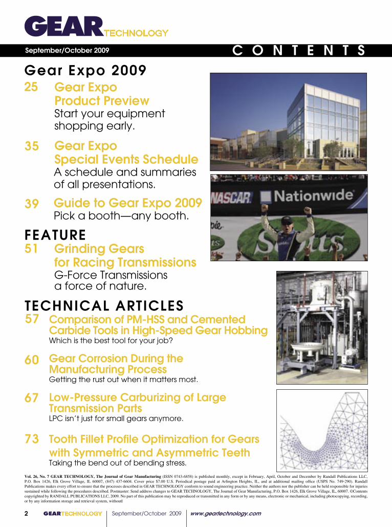
Gear Expo Product PreviewStart your equipment shopping early.
Gear Expo Special Events ScheduleA schedule and summaries of all presentations.
Guide to Gear Expo 2009 Pick a booth—any booth.
25Gear Expo 2009
57
67
TECHNICAL ARTICLES
C O N T E N T S
35
FEATURE
39
51 Grinding Gears for Racing TransmissionsG-Force Transmissions a force of nature.
60
73
Comparison of PM-HSS and Cemented Carbide Tools in High-Speed Gear HobbingWhich is the best tool for your job?
Gear Corrosion During the Manufacturing ProcessGetting the rust out when it matters most.
Low-Pressure Carburizing of Large Transmission PartsLPC isn’t just for small gears anymore.
Tooth Fillet Profile Optimization for Gearswith Symmetric and Asymmetric Teeth Taking the bend out of bending stress.
Key1 Involute tooth flanks2 Form circle diameter3 Initial fillet profile4 Fillet center5 Optimized fillet profile;
Figure 2. Fillet profile optimizationVol. 26, No. 7 GEAR TECHNOLOGY, The Journal of Gear Manufacturing (ISSN 0743-6858) is published monthly, except in February, April, October and December by Randall Publications LLC, P.O. Box 1426, Elk Grove Village, IL 60007, (847) 437-6604. Cover price $7.00 U.S. Periodical postage paid at Arlington Heights, IL, and at additional mailing office (USPS No. 749-290). Randall Publications makes every effort to ensure that the processes described in GEAR TECHNOLOGY conform to sound engineering practice. Neither the authors nor the publisher can be held responsible for injuries sustained while following the procedures described. Postmaster: Send address changes to GEAR TECHNOLOGY, The Journal of Gear Manufacturing, P.O. Box 1426, Elk Grove Village, IL, 60007. ©Contents copyrighted by RANDALL PUBLICATIONS LLC, 2009. No part of this publication may be reproduced or transmitted in any form or by any means, electronic or mechanical, including photocopying, recording, or by any information storage and retrieval system, without

www.geartechnology.com September/October 2009 GEARTECHNOLOGY 3
GEARTECHNOLOGY September/October 2009 www.geartechnology.com4
DEPARTMENTS
C O N T E N T SSeptember/October 2009
Publisher's PageWhy do YOU read Gear Technology?
VoicesA word from Joe Franklin, AGMA president
Product NewsWhat’s new in products and services
Events/CalendarEMO Milano
Industry NewsTrends, announcements, etc.
Advertiser IndexContact information for companies in this issue
ClassifiedsOur product and service marketplace
AddendumGears—Kid-Tested, Museum-Approved
9
13
84
92
96
11
• Power Transmission Engineering Read the August 2009 issue online. Sign up for a free subscription.
• NEWS The latest products, industry news and calendar items.
• BUYERS GUIDE Search for power transmission pro- ducts and services and communicate with the industry's leading suppliers
TECHNOLOGY.comGEAR
ON L I N E
www.geartechnology.com
www.powertransmission.com
• BUYERS GUIDE Search for gear industry products and services and communicate with the industry’s leading suppliers
• SUBSCRIPTIONS Sign up for subscriptions to Gear Technology and the geartechnology.com e-mail newsletter
• E-GT Subscribers get access to back issues of Gear Technology
94
80
www.geartechnology.com September/October 2009 GEARTECHNOLOGY 5
Whatever you need – you can grind it!
����������������������������������������������������������������������������������������������� ���������������������������������������������� ���������������������������������������������������������������������������������� �����������������������������������������������������������
���������������������������������������������
For the US-market please contact: Liebherr Gear Technology, Inc. 1465 Woodland Drive Saline, MI 48176 Phone: 734-429-7225 [email protected]
Think Big!
Grind Big!
EMOM i l a n o5 -10 ·10 ·20 09H A L L 2BOOTH F 12 A
G E A R E X P OIndianapolis15 -17· 9 ·20 0 9B O O T H 7 2 7
SigmaPool_LVT-LCS_203x273mm_USA_EMO-GearExpo.indd 1 01.07.2009 10:50:18
GEARTECHNOLOGY September/October 2009 www.geartechnology.com6
EDITORIALPublisher & Editor-in-Chief Michael Goldstein [email protected]
Managing Editor William R. Stott [email protected]
Senior Editor Jack McGuinn [email protected]
Associate Editor Matthew Jaster [email protected]
Assistant Editor Lindsey Snyder [email protected]
Editorial Consultant Paul R. Goldstein
Technical Editors William (Bill) Bradley Robert Errichello Octave Labath, P.E. Joseph Mihelick Charles D. Schultz, P.E. Robert E. Smith
ARTArt Director Kathleen O'Hara [email protected]
ADVERTISINGAdvertising Sales Manager RK Media, Inc. Ryan King [email protected] Matt Matteucci [email protected]
CIRCULATIONCirculation Manager Carol Tratar [email protected]
RANDALL STAFFPresident Michael GoldsteinAccounting Luann Harrold
VOL. 26, NO. 7
Randall Publications LLCP.O. Box 1426Elk Grove Village, IL 60007
www.geartechnology.com July 2009 GEARTECHNOLOGY 0039
and system suppliers from around the world, who brought many years of experience with this application to the meetings. A wind turbine is one of the—if not the most—demanding applications for a gearbox. It requires a relatively small, compact, high-power-density gear drive and electric generator to transmit fl uctuating loads in a very demanding environment of defl ections, high vibration and temperature extremes.The present standard applies to gearboxes for wind turbines with power capacities ranging from 40kW to 2MW and higher. It applies to all parallel-axis, one-stage epicyclic and combined one-stage epicyclic and parallel-shaft designs. It provides requirements on specifying, designing, manufacturing, operating and monitoring reliable wind turbine gearbox systems. Some of the more comprehensive gear application sections include: • how the system loads and environment shall be specifi ed and gear capacity calculated; • manufacturing, inspection, testing and documentation requirements; • advanced gear tooth contact analysis and verifi cation; • extensive information on the application and capacity of rolling element bearing types; • lubricant and lubrication system requirements. In addition, annexes supply in-formation on wind turbine architecture; wind turbine load description; quality assurance; operation and maintenance; minimum purchaser and gearbox manufacturer ordering data; and lubrication selection and condition monitoring. The revised standard at its present stage of development has updated all the sections of the original document, plus some additions and modifi cations, as follows: • scope changed to cover drive- trains with a power rating in excess of 500 kW; • sections on design lifetime and reliability, design process,
wind turbine load calcula- tions, gearbox components, design verifi cation valida- tion, operation, service and maintenance requirements; • new annex material. It can easily be imagined that the size of this document has increased substantively. At this stage, it is hard to determine exactly what will be retained after the three ISO/IEC ballot stages are completed, which could take two to three years—or more—if additional changes are incurred. In the meantime, it is believed that the advent of the ANSI/AGMA/AWEA standard has improved gear reliability. However, bearings still seem to need additional work.Standards Making The development and balloting of both ISO/IEC and AGMA/ANSI standards is a consensus process. However, individual positions may be expressed that can enhance the contents. Members of AGMA develop new—and continue to revise—the many standards and information sheets. They are also responsible for determining the U.S. position on ISO standards. AGMA standards development has relied heavy on the actual experience of gear system performance in related applications, whereas some others are based on theoretical and laboratory research data.
(Bill Bradley was vice president of AGMA’s Technical Division and currently serves as a technical editor for Gear Technology. As a consultant, he can be reached at (303) 350-9374, or via e-mail at [email protected].)
GT 7-09 80pgs.indd 39 7/9/2009 3:35:26 PM
Phone: 847-437-6604Fax: 847-437-6618
PhotoCourtesy ofGleason.
���������������������� ���������������������������������
�����������������������
TECHNOLOGYGEAR�����������������
THE GEAR INDUSTRY’S INFORMATION SOURCE
Gear Expo 2009 Product Preview Guide to Gear Expo Special Events
Feature Article
Grinding Gears for Racing Transmissions
Technical Articles
Carbide vs. PM-HSS Hobs
Gear Corrosion During Manufacturing
Tooth Fillet Profi le Opti-mization
Carburizing Large Transmission Parts
Plus
Addendum: Kid Tested, Museum-Ap-proved
www.geartechnology.com September/October 2009 GEARTECHNOLOGY 7
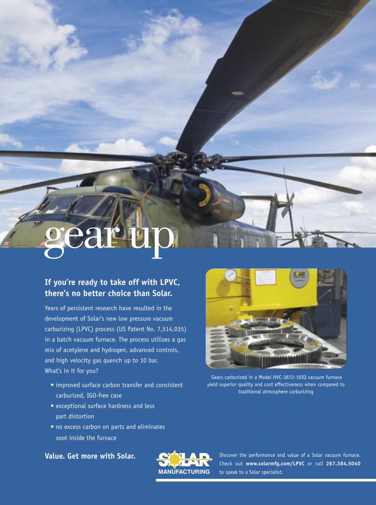
gear upIf you’re ready to take off with LPVC, there’s no better choice than Solar.
Years of persistent research have resulted in the
development of Solar’s new low pressure vacuum
carburizing (LPVC) process (US Patent No. 7,514,035)
in a batch vacuum furnace. The process utilizes a gas
mix of acetylene and hydrogen, advanced controls,
and high velocity gas quench up to 10 bar.
What’s in it for you?
������������������������������������������������������
carburized, IGO-free case
��������������������������������������������
part distortion
�����������������������������������������������
soot inside the furnace
Value. Get more with Solar. Discover the performance and value of a Solar vacuum furnace.
Check out www.solarmfg.com/LPVC or call 267.384.5040
to speak to a Solar specialist.
Gears carburized in a Model HVC-3872-10IQ vacuum furnace yield superior quality and cost effectiveness when compared to
traditional atmosphere carburizing
sol1977-4 HeliAd.indd 1 5/4/09 11:35:55 AM
GEARTECHNOLOGY September/October 2009 www.geartechnology.com800 GEARTECHNOLOGY July 2009 www.geartechnology.com
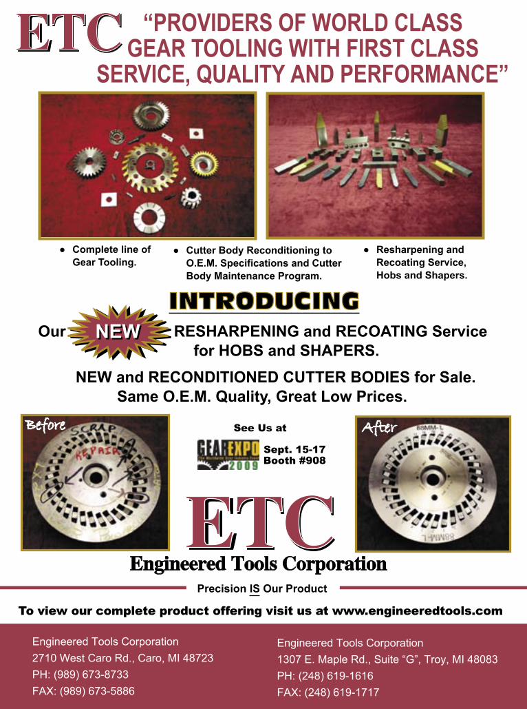
● Complete line of Gear Tooling.
Engineered Tools CorporationETCETC
“PROVIDERS OF WORLD CLASS GEAR TOOLING WITH FIRST CLASS
SERVICE, QUALITY AND PERFORMANCE”
Engineered Tools Corporation2710 West Caro Rd., Caro, MI 48723PH: (989) 673-8733FAX: (989) 673-5886
To view our complete product offering visit us at www.engineeredtools.com
Before
Our RESHARPENING and RECOATING Service for HOBS and SHAPERS.
NEW and RECONDITIONED CUTTER BODIES for Sale. Same O.E.M. Quality, Great Low Prices.
INTRODUCING
ETCETC
After
Engineered Tools Corporation1307 E. Maple Rd., Suite “G”, Troy, MI 48083PH: (248) 619-1616FAX: (248) 619-1717
● Cutter Body Reconditioning to O.E.M. Specifications and Cutter Body Maintenance Program.
● Resharpening and Recoating Service, Hobs and Shapers.
Precision IS Our Product
NEW NEW
Sept. 15-17Booth #908
See Us at
GT 7-09 80pgs.indd 8 7/8/2009 3:37:59 PM

www.geartechnology.com September/October 2009 GEARTECHNOLOGY 9
P U B L I S H E R ' S P A G E
A year ago, we sent out a small e-mail survey with one simple question: “Why do you read Gear Technology?” At that time, we were extremely gratified, even somewhat over-whelmed, by the enthusiastic and appreciative response of our readers, and I wrote about the survey and the results in my edi-torial in the September/October 2008 issue.
When we sent out the survey this year with the same question, you’d think we would have been prepared for the results. We weren’t. If anything, our readers are even more appreciative than they were a year ago.
W e e x p e c t e d t h a t G e a r Technology’s articles would be well received. We spend a lot of time and effort ensuring that our technical arti-cles are the most relevant, accurate and useful articles possible. We take great pride in the importance of the articles and the breadth of subjects we’ve covered over the years. That effort is reflected in the readers’ comments:
“I have spent 35 years in the gear industry and have found Gear Technology essential in keeping up with the latest gear design and process-ing innovations,” said a project manag-er for a Tier One automotive supplier.
“I am particularly interested in the technical articles, and I appreciate the fact that the quality of the articles seems to have increased in the last few years,” said a senior engineer at an East Coast gear manufacturer.
“The technical articles make up a large part of my ongoing education,” said the VP of engineering at a major Midwest gear manufacturer.
In addition to these, there were many more comments praising our articles and their importance to the
industry and its education. We received responses from a wide variety of com-panies including people working in gear design, manufacturing, testing, inspection and heat treating. We also heard from gear buyers and users, as well as the people who manufacture, sell, service and install gear manufac-turing equipment, tooling and fixturing. Even with such a wide spectrum of readers, there seems to be something for everybody in Gear Technology.
What surprised us most was the number of respondents who specifically cited the importance of the information in the advertisements. They consider the ads to be an important part of their gear industry education. They look to the ads for a current understanding of the state of the art and updates about what new products and processes are available in the marketplace, as well as who can supply them. Of course, we here at Gear Technology are very appreciative of our advertisers. But it’s also extremely important for the adver-tisers to understand that the readers consider their advertisements to be a part of their educational experience when reading Gear Technology.
“The advertisements do their part in bringing the latest technologies to the fore,” said a gear engineer for a major worldwide speed reducer manufacturer.
“We are investigating equipment updates and purchasing some new equipment for cutting and inspecting gears, so we find the advertising as well as the articles helpful,” said the
director of manufacturing at a major U.S. gear manufacturer.
“The ads help me find ven-dors we need to fill the gaps in our productions capabilities,” said an engineering manager at a major gear manufacturer.
So I’d like to compliment our advertisers for helping us
educate the gear industry. The informa-tion provided in the ads is often just as valuable to our readers as the informa-tion in our articles.
Although the survey is extreme-ly gratifying to us here at Gear Technology, we would like even more feedback. What could we or should we be doing that we’re not? What types of information do you need that we’re not already providing? We’ll be at Gear Expo, booth #1241, serving espresso to any who are interested. We’d love to sit and chat with you about how we can make Gear Technology even better for you. But even if you can’t make it to the show, we hope you’ll drop us a line at [email protected].
In any business, you can’t be suc-cessful unless your customers are suc-cessful. At Gear Technology, we try to provide you with the information that helps you be more productive and profitable, no matter what part of gear manufacturing you’re involved with. So we need you to tell us how we can help you.
Ultimately, you are our customer, and we want you to be as successful as possible.
Michael Goldstein,Publisher & Editor-in-Chief
Why do YOU Read Gear Technology?
GEARTECHNOLOGY September/October 2009 www.geartechnology.com10
�����������������������������������������������������������������������������������
mitsubishigearcenter.com
Introducing theZI20A
Gear GrindingMachine
Introducing theZI20AZI20A
Gear GrindingMachine
This is going to be big.��������������������������������������������������������������������������������������������������������������������������������������������������������������������������������������������������������������������������������������������
��������������������������������������������������������������������������������������������������������������������������������
����������������������������������������������������������������������������������������������������������������������������������������������������������������������������������������������������������������������������������������������������������������������������������������������������������
�����������������������������������������������������������������������������������������������������
������������������������������������������������������������������������������������������������������������������������������������������������������������������������
������248.669.6136 ���������������������
www.geartechnology.com September/October 2009 GEARTECHNOLOGY 11
V O I C E S
One of the reasons AGMA has been successful over our 93-year history is that the association’s agenda, programs and activities reflect the voices of our members.
The Board of Directors, advisory committees and councils and staff vigi-lantly review programs and vet them with members for needed changes, updates or cancellations. The organiza-tion today is much changed from what it was a quarter-century ago, a decade ago—even a year ago.
Gear Expo is a biennial event. Such a schedule demands careful review and updates to keep it fresh and repre-senting the needs of the exhibitors and attendees.
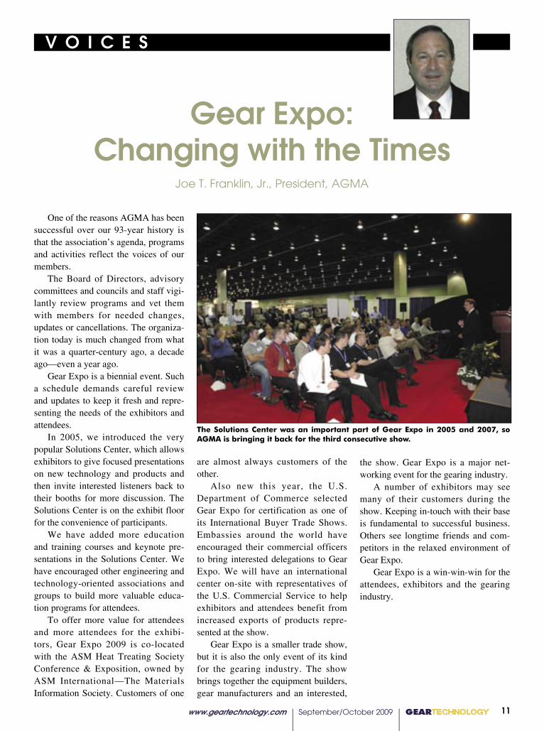
In 2005, we introduced the very popular Solutions Center, which allows exhibitors to give focused presentations on new technology and products and then invite interested listeners back to their booths for more discussion. The Solutions Center is on the exhibit floor for the convenience of participants.
We have added more education and training courses and keynote pre-sentations in the Solutions Center. We have encouraged other engineering and technology-oriented associations and groups to build more valuable educa-tion programs for attendees.
To offer more value for attendees and more attendees for the exhibi-tors, Gear Expo 2009 is co-located with the ASM Heat Treating Society Conference & Exposition, owned by ASM International—The Materials Information Society. Customers of one
Gear Expo: Changing with the Times
Joe T. Franklin, Jr., President, AGMA
quality audience. For many exhibitors, Gear Expo is their marketing program.
Attendees can see a variety of sup-pliers in a day or two. Equally, those who decide to buy gears and related products find high-quality suppliers at
the show. Gear Expo is a major net-working event for the gearing industry.
A number of exhibitors may see many of their customers during the show. Keeping in-touch with their base is fundamental to successful business. Others see longtime friends and com-petitors in the relaxed environment of Gear Expo.
Gear Expo is a win-win-win for the attendees, exhibitors and the gearing industry.
are almost always customers of the other.
Also new this year, the U.S. Department of Commerce selected Gear Expo for certification as one of its International Buyer Trade Shows. Embassies around the world have encouraged their commercial officers to bring interested delegations to Gear Expo. We will have an international center on-site with representatives of the U.S. Commercial Service to help exhibitors and attendees benefit from increased exports of products repre-sented at the show.
Gear Expo is a smaller trade show, but it is also the only event of its kind for the gearing industry. The show brings together the equipment builders, gear manufacturers and an interested,
The Solutions Center was an important part of Gear Expo in 2005 and 2007, so AGMA is bringing it back for the third consecutive show.

AEROCOM AD
www.geartechnology.com September/October 2009 GEARTECHNOLOGY 13
P R O D U C T N E W S
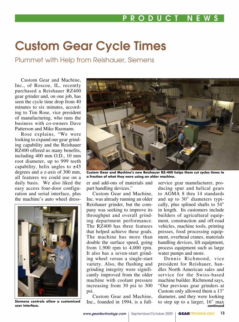
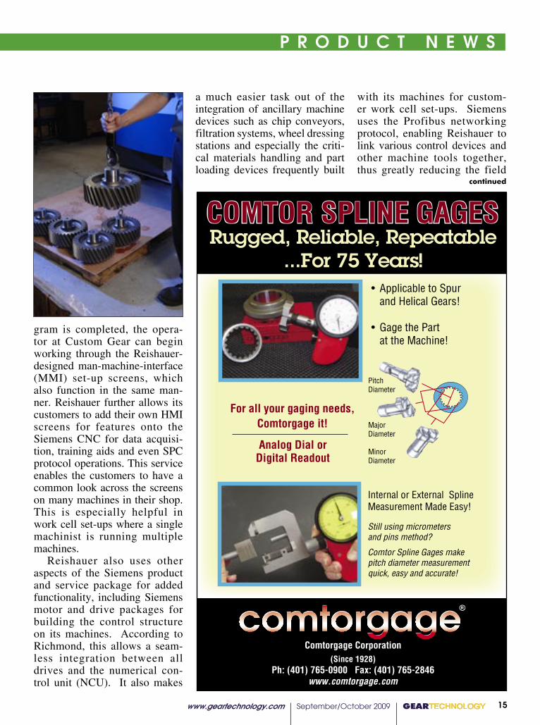
Custom Gear and Machine, Inc., of Roscoe, IL, recently purchased a Reishauer RZ400 gear grinder and, on one job, has seen the cycle time drop from 40 minutes to six minutes, accord-ing to Tim Rose, vice president of manufacturing, who runs the business with co-owners Dave Patterson and Mike Rasmann.
Rose explains, “We were looking to expand our gear grind-ing capability and the Reishauer RZ400 offered us many benefits, including 400 mm O.D., 10 mm root diameter, up to 999 teeth capability, helix angles to ±45 degrees and a z-axis of 300 mm, all features we could use on a daily basis. We also liked the easy access four-door configu-ration and serial interface, plus the machine’s auto wheel dress-
er and add-ons of materials and part handling devices.”
Custom Gear and Machine, Inc. was already running an older Reishauer grinder, but the com-pany was seeking to improve its throughput and overall grind-ing department performance. The RZ400 has three features that helped achieve these goals. The machine has more than double the surface speed, going from 1,900 rpm to 4,000 rpm. It also has a seven-start grind-ing wheel versus a single-start variety. Also, the flushing and grinding integrity were signifi-cantly improved from the older machine with coolant pressure increasing from 30 psi to 300 psi.
Custom Gear and Machine, Inc., founded in 1994, is a full-
service gear manufacturer, pro-ducing spur and helical gears to AGMA 8 thru 14 standards and up to 30" diameters typi-cally, plus splined shafts to 54" in length. Its customers include builders of agricultural equip-ment, construction and off-road vehicles, machine tools, printing presses, food processing equip-ment, overhead cranes, materials handling devices, lift equipment, process equipment such as large water pumps and more.
Dennis Richmond, vice president for Reishauer, han-dles North American sales and service for the Swiss-based machine builder. Richmond says, “Our previous gear grinders at Custom only allowed them a 13" diameter, and they were looking to step up to a larger, 16" max
Custom Gear Cycle TimesPlummet with Help from Reishauer, Siemens
continued
Custom Gear and Machine’s new Reishauer RZ-400 helps them cut cycles times to a fraction of what they were using an older machine.
Siemens controls allow a customized user interface.
GEARTECHNOLOGY September/October 2009 www.geartechnology.com14
P R O D U C T N E W S
diameter. Plus, they were seek-ing other features we were able to offer. We use the Siemens numeri-cal controls on our machines for a variety of reasons, especially the architecture’s ability to allow our engineers to customize the front ends. This simplifies the addition
of new part programs and helps operators more easily navigate the programming and set-up. When the data input is completed for the current screen, for example, the operator is prompted to enter data for the next screen and so on, until the program is completed.”
Rose confirmed this point, adding that Custom Gear’s machinists are each responsi-ble for the set-up, running and maintenance of their machine. “They take a real pride in mak-ing sure the jobs are done right and that the machine is always in great shape.”
One of the current machin-ists running the Reishauer RZ400, Daniel Warren, noted that he had not previously run a machine with a Sinumerik CNC from Siemens onboard, but explained, “I got great training from Reishauer and was up to speed very quickly. We were making parts within a few days after the installation, and I was completely comfortable with the easy operation of the CNC in less than a month.”
In describing the automat-ic wheel dressing sequence, Warren also noted how the CNC automatically adjusts the settings to compensate for the reduced wheel diameter after dressing, bringing the wheel to the correct point of contact with the subsequent workpieces every time.
Data such as gear configu-ration, fixture design and all tool settings are entered into the screens, including pitch, pres-sure angle, teeth and dressing steps. Once a new part pro-
��������������������������������������������GEARTECHNOLOGY���25
simply faster deliveries, more orga-nized shop floors or an overall lean philosophy throughout the organiza-tion, success stories have prevented
Colonial Tool Group, located in Windsor, Ontario, has done quite a bit of work involving machining cells to increase productivity, incorporating some basic lean manufacturing tech-niques into the day-to-day routine with
“We’ve placed machines so one operator can utilize between two to three machines at one time, depending on the operations,” says Chris Scott, plant manager. “We’ve also installed better hoists to make it easier and safer
These simple practices have tight-ened up many of the processes at Colonial, allowing an operator to run a CNC grinder and universal grinder at the same time. With the addition of a jib crane for ease of handling, the staff can do more in their allotted work
Scott says that implementing lean has allowed Colonial more flexibility for scheduling and for making faster deliveries, not to mention the reduced
“The economy has been very slow for the past several months and we have been working reduced hours,” Scott says. “Lean has helped us with shortening our required times to manu-
The company deals mainly with broach and spline racks, building spin-dles and machines. They’ve been work-ing on different lean scenarios not only to adjust to the current market, but in
���������
www.geartechnology.com September/October 2009 GEARTECHNOLOGY 15
P R O D U C T N E W S
continued
P R O D U C T N E W S P R O D U C T N E W S
gram is completed, the opera-tor at Custom Gear can begin working through the Reishauer-designed man-machine-interface (MMI) set-up screens, which also function in the same man-ner. Reishauer further allows its customers to add their own HMI screens for features onto the Siemens CNC for data acquisi-tion, training aids and even SPC protocol operations. This service enables the customers to have a common look across the screens on many machines in their shop. This is especially helpful in work cell set-ups where a single machinist is running multiple machines.
Reishauer also uses other aspects of the Siemens product and service package for added functionality, including Siemens motor and drive packages for building the control structure on its machines. According to Richmond, this allows a seam-less integration between all drives and the numerical con-trol unit (NCU). It also makes
a much easier task out of the integration of ancillary machine devices such as chip conveyors, filtration systems, wheel dressing stations and especially the criti-cal materials handling and part loading devices frequently built
with its machines for custom-er work cell set-ups. Siemens uses the Profibus networking protocol, enabling Reishauer to link various control devices and other machine tools together, thus greatly reducing the field
�� TECHNOLOGY ����������
��������������������������������������������
����������������������� ������������������
������������������ ���������������
�������������
�������������
��������������
��������������������������������������������������
����������������������������������������
�����������������������������������������������������������������������������
�����������������������������������������
�
�������������������
����������������������������������
����������������������������������������������������������
������������������������������
For more information:Kinefac CorporationKine-Spin/Barrett Division156 Goddard Memorial DriveWorcester, MA [email protected]
Kinefac Centrifuge CLEANS PARTS WITH 350 GS FORCE
GEARTECHNOLOGY September/October 2009 www.geartechnology.com16
P R O D U C T N E W S
TECHNOLOGY
����
���������������������������������������������
�����������������������������������������������������������������������������������������������������������������������������������������������������������������������
����������������������������������������������������������������������������������������������������������������
����������������������������������������������������������������������������������������������������������������������������������������������������������������������������������������������
�
�
�
����������������������������������������������������������������������������������������������������������������������
������������������������������������������������������������������������������������������
���� ������������������������� ������� ����������� �������� ����� ������ ����������� ����������� ����������� �����������
���������������������������������������
������������
�������� ������������ ������������������ ��������� ���������� ��������
Sandvik SECURES HEAVY ROUGHING
its machines. Mike Rasmann, vice-presi-
dent of operations at Custom Gear, concludes, “Our invest-ment in the new Reishauer gear grinder has expanded our capa-bility, allowed us to produce
work integration and wiring time during installs. Reishauer uses Profibus to link the onboard Siemens Sinumerik 840D CNC to VFDs, other drives, electronic gearboxes and balancing sys-tems for the grinding wheel on
more parts for more existing cus-tomers and even opened some new business doors for us. With the added benefit of increased safety on the machine, it was a win-win situation for us, all around.”
Rose echoed this sentiment, adding, “It’s a great machine. When we have any need for assistance on the machine, including parts and especially application engineering, we know the answer is just a phone call away. Reishauer has been there for us on many occasions. This is a big reason we’ve done business with them for 15 years and will continue to do business with them in the future.”
For more information: Custom Gear and Machine, Inc. 5466 East Rockton RoadRoscoe, IL 61073Phone: (815) 389-6065Fax: (815) [email protected]
Reishauer Corporation1525 Holmes RoadElgin, IL 60123Phone: (847) 888-3828Fax: (847) [email protected]
Siemens Energy and AutomationMotion Control Business390 Kent AvenueElk Grove Village, IL 60007Phone: (847) 640-1595Fax: (847) [email protected] www.siemenscnc.com
www.geartechnology.com September/October 2009 GEARTECHNOLOGY 17
P R O D U C T N E W S P R O D U C T N E W S
continued
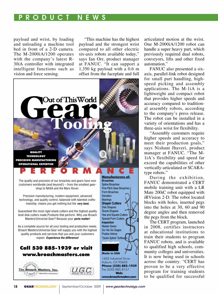
At the International Robots, Vision and Motion Control Show in Chicago, FANUC Robotics presented heavy-duty and compact assembly robot-ics that emphasized the compa-ny’s latest six-axis technology. Demonstrations included intel-ligent assembly and Certified Education Robot Training (CERT) units.
The M-200iA/1200 super heavy-duty robot is able to lift parts weighing up to 3,000 lbs.
FANUC Heavy Duty Robots
HANDLE LARGE CASTINGS
This is the second in FANUC’s l ine of heavy-duty robots designed to handle truck, trac-tor, automotive frames and other large castings. The M-2000iA/1200 has a rigid arm design with a vertical lifting
stroke of 6.2 m for transferring extremely heavy items.
The machine was equipped with iRVision 2-D error proofing and Dual Check Safety Speed and Position Check software, demonstrating its high capacity
TECHNOLOGY ���������� �
Tyrolit Grinding Wheel ACHIEVES MAX PROFILE RETENTION WITH MINIMAL WEAR
The M-1iA compact assembly robot.
GEARTECHNOLOGY September/October 2009 www.geartechnology.com18
P R O D U C T N E W S
GEARTECHNOLOGY 13
�������
����������
�����������������������
���������������������
������������������������������������������������������������������������������������������������������������������������
���������������������������������
�������������������������������������������������������������������������������������������������������������������
�������������������������������������������������
������������������������������������������������������������������������������������������������������������������������������
��������������������������������������������������
�����������������������������������������������������������������������������������������������������������������������������������������������������������������������������������������
����������������������������������
�����������������������������������������������������������������������������������������������������������������������������������������������������������������������������������������������������������������������������������������������������������������������������
�����������
�����������������������������������������������������������������������������������������������������������������������
�����������������������������������������������
���������������������������
���������� ��������� ���� ������ ����� ���
The number 815 electric rotary hearth oven, from Grieve Corporation, is currently being used by a customer to preheat various gears, usually steel and sometimes aluminum, before assembly
The dimensions of the unit’s inte-
Hearth OvenSTABILIZES MATERIAL FOR PERFORMANCE
continued
payload and wrist, by loading and unloading a machine tool bed in front of a 2-D camera. The M-2000iA/1200 operates with the company’s latest R-30iA controller with integrated intelligent functions such as vision and force sensing.
“This machine has the highest payload and the strongest wrist compared to all other electric six-axis robots available today,” says Ian Orr, product manager at FANUC. “It can support a 1,350 kg payload with a 0.6 m offset from the faceplate and full
articulated motion at the wrist. One M-2000iA/1200 robot can handle a super heavy part, which previously required dual robots, conveyors, lifts and other fixed automation.”
FANUC also presented a six-axis, parallel-link robot designed for small part handling, high-speed picking and assembly applications. The M-1iA is a lightweight and compact robot that provides higher speeds and accuracy compared to tradition-al assembly robots, according to the company’s press release. The robot can be installed in a variety of orientations and has a three-axis wrist for flexibility.
“Assembly customers require higher speeds and accuracy to meet their production goals,” says Nishant Jhaveri, product manager at FANUC. “The M-1iA’s flexibility and speed far exceed the capabilities of other vertically-articulated or SCARA-type robots.”
Dur ing the exh ib i t ion , FANUC demonstrated a CERT mobile training unit with a LR Mate 200iC robot equipped with iRVision 2-D. The robot located blocks with holes, inserted pegs into the holes at 30, 60 and 90 degree angles and then removed the pegs from the block.
The CERT program, launched in 2008, certifies instructors at educational institutions to train their students to program FANUC robots, and is available to qualified high schools, com-munity colleges and universities. It is now being used in schools across the country. “CERT has proven to be a very effective program for training students to be qualified for successful

www.geartechnology.com September/October 2009 GEARTECHNOLOGY 19
P R O D U C T N E W S P R O D U C T N E W S
continued
careers in high-tech manufac-turing,” says Kevin Ostby, vice president, customer resource center. “In just over a year there are literally hundreds of students across the country learning to use a FANUC industrial robot while getting practical knowl-edge of how math and science are applied in manufacturing.”
For more information:FANUC Robotics America, Inc.3900 W. Hamlin Rd.Rochester Hills, MI 48309Phone: (248) 377-7570www.fanucrobotics.com
CNCShapersMACHINE MULTIPLE SURFACES QUICKLY
CNC controls to oscillate a tool up and down at 600 cycles a minute while the machine axes feed work into the tool. This combination of tool and axes feed can produce a multitude of form on parts.
Ohio Broach and Machine Company introduces a line of CNC Shaper machines that machine multiple surfaces in seconds, and various parts can be fixtured for machining with repetitive cuts in one shaper cycle. The machine head uses
The CNC Shaper machines are customized individually for customer requirements. They are suited for machining small and medium sized parts with special intricate forms, shaping blind hole forms in addition to out-
GEARTECHNOLOGY September/October 2009 www.geartechnology.com20
P R O D U C T N E W S
side shapes and forms against shoulders or other obstructing features. They can be used for gear manufacturing and in the medical, electrical and aerospace industries.
All axes of the CNC Shaper machines are servo-controlled, ball screw driven and controlled through the CNC interface. The main slide ways use a preloaded linear roller system for quick, accurate axis movement. Two models are available: the OB-VM16-2 and the OB-VM20-2. Both have a two-inch standard stroke as an available option.
“The new CNC Shaper machines offer manufactur-ers capabilities that are more efficient than traditional EDM
machines, which are slower and more expensive,” says Jeffrey Frantz, sales manager for Ohio Broach and Machine Company. “One new shaper machine can now do the work of two or three standard cutting machines. This translates into less capital outlay, lower inventories, reduced lead and production time and less labor.”
For more information:Ohio Broach and Machine Company35264 Topps Industrial ParkwayWilloughby, OH 44094Phone: (440) 946-1040Fax: (440) [email protected]
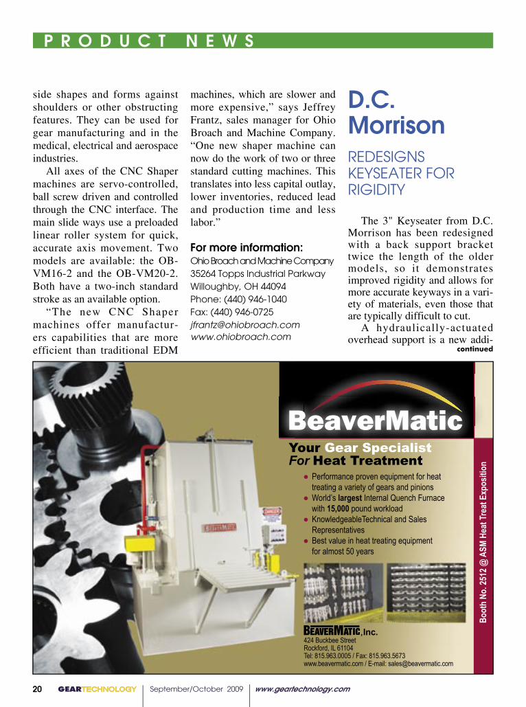
The 3" Keyseater from D.C. Morrison has been redesigned with a back support bracket twice the length of the older models, so it demonstrates improved rigidity and allows for more accurate keyways in a vari-ety of materials, even those that are typically difficult to cut.
A hydraulically-actuated overhead support is a new addi-
424 Buckbee StreetRockford, IL 61104 Tel: 815.963.0005 / Fax: 815.963.5673www.beavermatic.com / E-mail: [email protected]
,Inc.
Your Gear SpecialistFor Heat Treatment
● Performance proven equipment for heat treating a variety of gears and pinions● World’s largest Internal Quench Furnace with 15,000 pound workload● KnowledgeableTechnical and Sales Representatives● Best value in heat treating equipment for almost 50 years
D.C. MorrisonREDESIGNS KEYSEATER FOR RIGIDITY
continued

HavlikAd
www.havlikgear.com
WE’VE EXPANDED WITH A NEW LOCATION.OUR NEW GEAR GRINDING AND MANUFACTURING FACILITY HOUSES ONE OF THE
LARGEST GRINDERS IN NORTH AMERICA.
The ZP 40 grinding machine features the ultimate in design construction with true hydrostatic guideways and rotary table. The work table is direct drive. Nodular cast ironis used for the machine beds, columns, and all sub-assembly housings, for stability. The machine accuracy is therefore assured for a long lifetime.The ZP40 is designed to profile grind spur and helical external and internal gears using dressable corundum or sintered grinding wheels. An integrated measuring device furtherincreases machine’s flexibility. The ZP machine can be set up to accommodate application-specific requirements for maximum flexibility, high precision and optimum productivity.It is specifically designed to accommodate shaft pinions, mating bull gears and internal ring gears.Extended capacity for gears and profiles is:
• Internal and external gear grinding up to 4m(160”) OD x 1.5m(60”) face.• The ability to inspect lead, profile and spacing up to 4m (160”)
455 Sheldon Dr., Cambridge, Ontario N1T 2B7 tel 519-624-6240 fax 519-624-4119
Div. of Havlik International Machinery Inc.GEAR
Visit us at booth 437

GEARTECHNOLOGY September/October 2009 www.geartechnology.com22
P R O D U C T N E W S
TECHNOLOGY
Carl Zeiss IMT Corporation(800) 327-9735www.zeiss.com/imt
Styli & Accessories• Same-day Shipping• ZEISS Components• Dedicated Service • M2-M5 In-stock
The reliability of wind turbines depends highly on the accuracy of critical parts such as pinion cages and housings of planetary gears. Leading manufacturers around the world rely on Carl Zeiss MMZ CMMs with VAST Active Scanning and CALYPSO software to verify critical components and ensure part quality.
www.zeiss.com/mmz
Effective wind energy starts with high part accuracy.
ber-lined box furnace was shipped to the Goodrich Aerostructures’ Mexicali production facility by L&L Special Furnace Company. The furnace, the second Goodrich has purchased for this location, will be used to process
The L&L Special Furnace model FB668 was custom made with dimensions of 72" x 72" x 96" with a 3,200 lb load capacity. A motorized loader to facilitate material handling
“The advantage of the pit furnace is that the round gears can be stacked quite high in the furnace, and bridge cranes, a relatively inexpensive material handling system, maybe used for very heavy loads,” says Gary Armour, project engineer. “Large loads are the best way to affordably process these long cycle
L&L Furnace
tion to the keyseater, so opera-tors can move the support with the push of a button. A pro-grammable logic controller and human machine interface were added for more user friendly
programming. The Morrison Keyseater doesn’t require posi-tioning in a pit or bushings to center the keyways. The machine cuts from 1/8" to 3" wide and up to 14" deep.
For more information:D.C. Morrison201 Johnson StreetCovington, KY 41011Phone: (888) 246-6365Fax: (859) [email protected]
SlaterDOUBLES BROACH HOLDER LINE
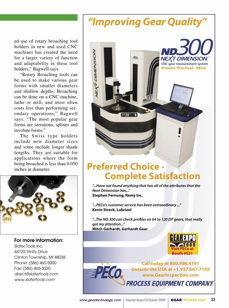
The Rotary Braoching Tool Holders line for CNC, screw and swiss lathe machines and mill-ing machines from Slater Tools Inc. has been expanded to offer 38 broach holders. The tools are used to put hex and square shaped holes into metal parts such as for aerospace appli-cations and orthopedic bone screws.
According to Peter Bagwell, engineer and marketing manager for Slater Tools, Slater broach-es are often used to make gears with spline shapes. “The expand-
www.geartechnology.com September/October 2009 GEARTECHNOLOGY 23
P R O D U C T N E W S
ed use of rotary broaching tool holders in new and used CNC machines has created the need for a larger variety of function and adaptability in these tool holders,” Bagwell says.
“Rotary Broaching tools can be used to make various gear forms with smaller diameters and shallow depths. Broaching can be done on a CNC machine, lathe or mill, and most often costs less than performing sec-ondary operations,” Bagwell says. “The most popular gear forms are serrations, splines and involute forms.”
The Swiss type holders include new diameter sizes and some include longer shank lengths. They are suitable for applications where the form being broached is less than 0.050 inches in diameter.
For more information:Slater Tools Inc.44725 Trinity DriveClinton Township, MI 48038Phone: (586) 465-5000Fax: (586) [email protected]
“Improving Gear Quality”
Call today at 800.998.4191Outside the USA at +1.937.667.7105
www.GearInspection.com
“...Have not found anything that has all of the attributes that the Next Dimension has...” Stephen Fernung, Remy Inc.
“...PECo’s customer service has been extraordinary ...” Kevin Streck, Lubrizol
”...The ND 300 can check profiles on 64 to 120 DP gears, that really got my attention...”Mitch Gerhardt, Gerhardt Gear
Preferred Choice - Complete Satisfaction
Proven, Practical...PECo
Visit PECo at Booth #521

Great Lakes Gear Technologies is proud to bring to the September 2009 Gear Expo in Indianapolis, Indiana...
The excellence of gear manufacturing.Over $4,000,000 of the newest, most technologically advanced gear manufacturing and inspection equipment worldwide.Great Lakes Gear Technologies and its principals from Hofler, Wenzel and Fassler are proud to bring to the Gear Expo gear manufacturing technology spanning all industries— from automotive to aerospace, mining to wind turbines. The applications are endless. Come and visit all three of our booths (911, 1011 and 1111) to understand the full range of our product capabilities:
Höfler• Hofler Rapid 1250 The revolutionary gear grinder offers
PowerStroke high speed grinding for 50% cycle time reductions and our newest Topological gear grinding software featuring 5 Axis of synchronized live grinding motions
• Hofler Helix 400SK The Helix series, with its multiple configurations, is the most successful line of small form grinders with almost 400 installed worldwide in the aerospace and small gear production industries.
Wenzel• Inova Gear Used for small gear (both helical and bevel)
and gear tooling inspection with an integral Barkhausen probe for gear burning checks
• LHT 2600 (2.6 meter) This advanced gear checker is targeted for wind turbine gears with integral CMM capabilities
Fässler and more!• Fassler Gear Honing and Diamond Broaching machines
and tools (Exhibit 911)• Escofier FCR force controlled gear and spline rolling machines and tools• Bharat Forge Ltd Large gear forgings for wind, mining and oil patch• DTR Gear cutting tools
Great Lakes Gear Technologies, Inc. serves
as a sales representative and consultant
for the world’s most advanced gear
manufacturing companies. In addition to
manufacturers of wind turbines and gear
jobbers our equipment is targeted to the
aerospace, automobile, truck, motorcycle,
mining, steel, oil, and power transmission
industry.
So much to see!Come and visit us at booths
911, 1011 and 11119421 Haggerty, Plymouth, MI 48170 • Telephone 734 416 9300 • Facsimile 734 416 7088
www.greatlakesgeartech.com
www.geartechnology.com September/October 2009 GEARTECHNOLOGY 25
GEAR EXPO PREVIEW
Sure, Gear Expo undoubtedly has a ton to offer attendees in education, research and networking alone, but what really draws the crowd in are the physical products and technology on display from exhibitors. Otherwise it would just be another technical meet-ing or social reception—and AGMA could save a few bucks on space to say the least. There may be familiar faces in the crowd, but it’s what everyone’s looking at that is new and different. An expanse of shiny new tools and machinery with different features, gadgets, and designs compete to resonate with visitors long after the hall closes. Exhibitors have two years to make the most from prod-uct and technology advances, so visi-tors are more than simply reminded of the last Gear Expo. Here’s a peek at what some exhibitors are hoping to wow with on the show floor:
Bourn & KochBooth 741
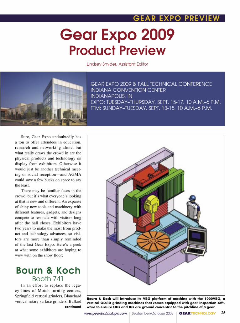
In an effort to replace the lega-cy lines of Motch turning centers, Springfield vertical grinders, Blanchard vertical rotary surface grinders, Bullard
Gear Expo 2009Product Preview
Lindsey Snyder, Assistant Editor
GEAR EXPO 2009 & FALL TECHNICAL CONFERENCEINDIANA CONVENTION CENTERINDIANAPOLIS, IN EXPO: TUESDAY–THURSDAY, SEPT. 15-17, 10 A.M.–6 P.M. FTM: SUNDAY–TUESDAY, SEPT. 13-15, 10 A.M.–6 P.M.
Bourn & Koch will introduce its VBG platform of machine with the 1000VBG, a vertical OD/ID grinding machines that comes equipped with gear inspection soft-ware to ensure ODs and IDs are ground concentric to the pitchline of a gear.continued
GEARTECHNOLOGY September/October 2009 www.geartechnology.com26
GEAR EXPO PREVIEW
turning products and Fellows mid-range mechanical stroking gear shapers, Bourn & Koch is introducing the “com-posite platform” machine, which is identified as a basic, low-cost common building block with innovative, no or low maintenance technologies and inte-gral and linear motors with high preci-
sion feedback. The B&K 1000VBG CNC Vertical OD/ID grinding machine is the first of these machines to be released, debuting at Gear Expo. One key feature of the 1000VBG is gear inspection software that includes a circular geometry inspection system for inspecting roundness and runout. This
allows manufacturers to grind hard-ened gear IDs and ODs concentric to the pitchline of a finished gear. The machine is being manufactured to U.S. standards and European CE standards, and it is available in one meter, 1.5 meter and 2.5 meter versions. In most cases, the composite plat-form design has 40 percent fewer parts than the old legacy designs, so pur-chase cost is significantly lower for customers. Bourn & Koch can stock the platform base units, columns and cross slides, which were previously the most expensive components with the longest leads on the older designs. Stocking the base units reduces the build cycle time by at least six weeks. The composite platform machine can be constructed in four configura-tions: the vertical grinding machine with hard finish turning capabilities, a vertical turning center, vertical gear shaper, a rotary surface grinder or any combination of these.
For more information:Star SU LLC5200 Prairie Stone ParkwaySuite 100Hoffman Estates, IL 60192Phone: (847) 649-1470Fax: (847) [email protected]
GleasonBooth 715
In Gleason’s approach to be the “total gear solutions provider,” it is introducing various machines, tooling and the Gleason Global Services sup-port system at Gear Expo, all for aiding various processes for bevel and cylin-drical gear production and inspection from start to finish. As part of Gleason’s new genera-
www.geartechnology.com September/October 2009 GEARTECHNOLOGY 27
P R O D U C T N E W S GEAR EXPO PREVIEW GEAR EXPO PREVIEW
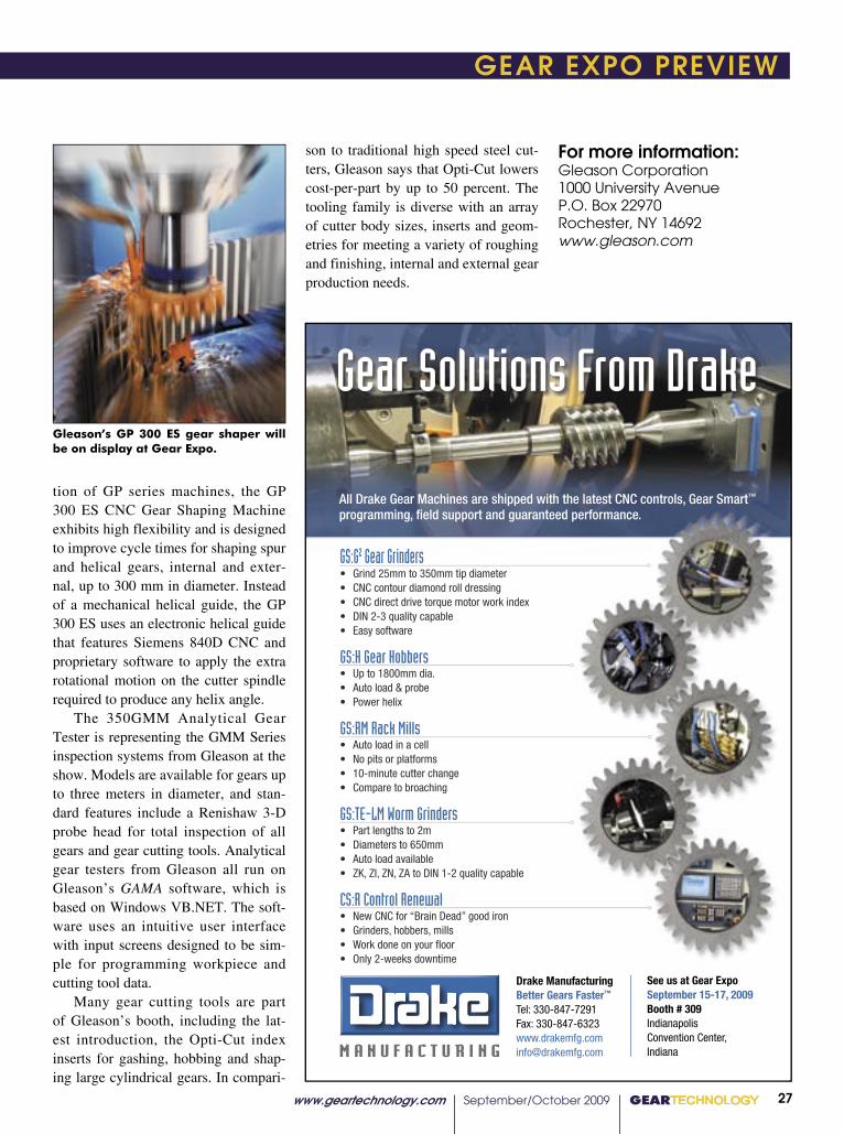
tion of GP series machines, the GP 300 ES CNC Gear Shaping Machine exhibits high flexibility and is designed to improve cycle times for shaping spur and helical gears, internal and exter-nal, up to 300 mm in diameter. Instead of a mechanical helical guide, the GP 300 ES uses an electronic helical guide that features Siemens 840D CNC and proprietary software to apply the extra rotational motion on the cutter spindle required to produce any helix angle. The 350GMM Analytical Gear Tester is representing the GMM Series inspection systems from Gleason at the show. Models are available for gears up to three meters in diameter, and stan-dard features include a Renishaw 3-D probe head for total inspection of all gears and gear cutting tools. Analytical gear testers from Gleason all run on Gleason’s GAMA software, which is based on Windows VB.NET. The soft-ware uses an intuitive user interface with input screens designed to be sim-ple for programming workpiece and cutting tool data. Many gear cutting tools are part of Gleason’s booth, including the lat-est introduction, the Opti-Cut index inserts for gashing, hobbing and shap-ing large cylindrical gears. In compari-
son to traditional high speed steel cut-ters, Gleason says that Opti-Cut lowers cost-per-part by up to 50 percent. The tooling family is diverse with an array of cutter body sizes, inserts and geom-etries for meeting a variety of roughing and finishing, internal and external gear production needs.
For more information:Gleason Corporation1000 University AvenueP.O. Box 22970Rochester, NY 14692www.gleason.com
Gleason’s GP 300 ES gear shaper will be on display at Gear Expo.
Gear Solutions From Drake
All Drake Gear Machines are shipped with the latest CNC controls, Gear Smart™
programming, field support and guaranteed performance.
GS:G2 Gear Grinders�� ���������������������������������� ����������������������������������� ������������������������������������������ ������������������������� �������������
GS:H Gear Hobbers�� ������������������� ������������������� �����������
GS:RM Rack Mills�� ��������������������� ���������������������� ������������������������� ��������������������
GS:TE-LM Worm Grinders�� �������������������� �������������������� ��������������������� �����������������������������������������
CS:R Control Renewal�� ������������������������������������ �������������������������� ������������������������ ���������������������
Drake ManufacturingBetter Gears Faster™
�������������������������������������������������������������������
See us at Gear ExpoSeptember 15-17, 2009Booth # 309��������������������������������������
DRAK-416GearSolutionsAd.indd 1 8/20/09 12:25:40 PM
GEARTECHNOLOGY September/October 2009 www.geartechnology.com28
GEAR EXPO PREVIEW
Sigma PoolBooth 727
Liebherr and Klingelnberg are both exhibiting machines at the Sigma Pool booth. Liebherr’s LC 180 CNC Gear Hobbing Machine features direct-drive cutter and table axes, a Siemens 840D
control and non-contact meshing sys-tem. Numerous combinations of drive speed and torque provide the capabili-ties to accommodate new cutting tool technologies, such as chamfer cutting. Chip augers and stainless steel liners are designed into the machine base and work area for efficient chip removal.
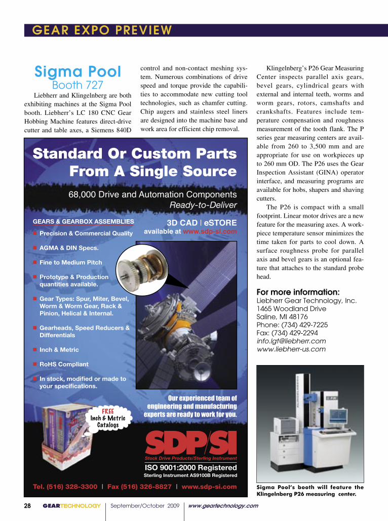
Klingelnberg’s P26 Gear Measuring Center inspects parallel axis gears, bevel gears, cylindrical gears with external and internal teeth, worms and worm gears, rotors, camshafts and crankshafts. Features include tem-perature compensation and roughness measurement of the tooth flank. The P series gear measuring centers are avail-able from 260 to 3,500 mm and are appropriate for use on workpieces up to 260 mm OD. The P26 uses the Gear Inspection Assistant (GINA) operator interface, and measuring programs are available for hobs, shapers and shaving cutters.
The P26 is compact with a small footprint. Linear motor drives are a new feature for the measuring axes. A work-piece temperature sensor minimizes the time taken for parts to cool down. A surface roughness probe for parallel axis and bevel gears is an optional fea-ture that attaches to the standard probe head.
For more information:Liebherr Gear Technology, Inc.1465 Woodland DriveSaline, MI 48176Phone: (734) 429-7225Fax: (734) [email protected]
Sigma Pool’s booth will feature the Klingelnberg P26 measuring center.
������������������� � ������������������ � ��������������
����������������������������������������
����������������������������������������������������������������������������������������
��������������������������������������������������������������
������������������������������
�����������������
��������������������
��������������������������������������������
���������������������������������������������������������������� ������� �����������
�����������������������������������������
�������������
��������������
������������������������������������������������
��������������������������
�
�
�
�
�
�
�
�
�
������������������������������������������
�����������������������������������������������������������������������������������
����������������
������������������
���������
�������������� ������ ���� ���������� ��� ��������� ������� ���� ���� ����� ����������� ����������� ����������� ����� ���������� ����
���� ����� ���������� ��� �� ������������������������������������������������������������������������������������������
28���GEARTECHNOLOGY������������������� ������������������������
“Not everything we have tried has worked. Sometimes, before getting the results we were striving for, we have tried an improvement or technique sev-
eral times in the same area,” Doshi says. “By staying the course and stick-ing to our core values and principles, we know that we will achieve our end results.”
The Lean Learning Center instructs companies to get involved in these lean programs, sooner rather than later, and urges those truly hit hard by the eco-nomic downturn to open the communi-cation lines with employees to achieve success and longevity.
“Competitive benchmarking, visit-ing other lean plants, on-site assess-ments and lean education and training at the executive level are good places to start,” Sonderman says.
That’s not to say that a commitment to lean doesn’t come with an array of challenges and a hint of skepticism.
“Companies that have been prof-itable because of a niche market or have been immune to competition for whatever reason have less force on them driving change,” Sonderman says. “We often hear ‘Why should we adopt lean?’ or ‘We have always been successful.’ A past history of finan-cial success does not always guarantee future success. The objective should be to get leadership to see the gap between current reality and the ideal state. You want them to discover how ugly the current situation is.”
With a computerized manufactur-ing floor at their fingertips, Sonderman reminds companies to be creative.
“Technology has changed, sure, but the lean tool box remains the same. The steps for reducing setup times and improving workplace organization through 5S are the same.”
It’s the understanding of lean con-cepts and principles that is constantly evolving.
“Lean is not about what you see when you visit a Toyota plant. It’s what you don’t see that is most important. What you don’t see is the critical think-ing that links lean rules and principles to meaningful progress on the shop floor.”
Sonderman adds that this type of thinking will take organizations miles farther than simply repackaging old ideas or adding new programs or twists in technology.
“We saw this with Six Sigma. It’s simply a repackaged form of problem solving. It’s a great tool if you do not have systematic problem solving in your organization, but a tool is all it is. Hopefully, many organizations now understand that lean is essentially criti-cal thinking guided by interdependent rules and principles, rather than simply a collection of tools to implement.”
Companies like Delta, Colonial and
“Competitive benchmarking, visiting other lean plants, on-site assessments and lean education and training at the executive level are good places to start,” Sonderman says.
pgs 22-29 final.indd 8 8/6/2009 2:34:20 PM

www.geartechnology.com September/October 2009 GEARTECHNOLOGY 29
GEAR EXPO PREVIEW
continued
KISSsoftBooth 615
KISSsoft 08/2009 features improve-ments in the shaft and gear modules, as well as other areas.
A toolbar was added to speed up the shaft editor function. Copy and paste capabilities are useful for repeat-ed parts. A list gives an overview of geometry, bearings and force elements. Outer and inner contour of the shaft can be exported or imported to the DXF format. Users can automatically deter-mine documentation points in the shaft editor at a random position for dis-playing the most important results for deflection line, reaction forces, stress and more in the respective cross sec-tion.
Profile and flank line diagrams, called K-charts, are available in the cylindrical and crossed axis helical gear modules. The diagrams are cre-ated according to ANSI/AGMA 2000-A88, and they are the basis for quality assurance in gear manufacturing.
Local wear in KISSsoft 08/2009 is calculated from real contact situation and graphically presented combined with worn out flank. The material data-base was expanded to include 17 new material definitions of the company SABIC, and they include measured
The latest software release from KISSsoft includes the ability to produce K-charts.
© 2009 Arrow Gear Company
As simple as ordering lunch? Well, not quite, but close.
����������������������������������������������������������������������������������������������������������������������������� �����������������������������������������������������������������������
Now that’s simple.
�������������������������������������������������������������������
P � � C I � I � N
�� � C � G � A �
�
www.arrowgear.com 630.969.7640
As simple as ordering lunch? Well, not quite, but close.
����������������������������������������������������������������������������������������������������������������������������� �������������������
ORDER’S UP.C
M
Y
CM
MY
CY
CMY
K
ArrowGearGearTechAdREV_0909.pdf 3/27/09 3:46:54 PM
GEARTECHNOLOGY September/October 2009 www.geartechnology.com30
GEAR EXPO PREVIEW
wear parameters for dry-running condi-tions.
The measuring device position used to calculate measurement over balls or rolls is now determined by applying the ball or roll to the actual tooth form. This is an advantage because it can be applied to an arbitrary tooth form.
For more information:KISSsoft, U.S.A., LLC3719 North Spring Grove RoadJohnsburg, IL 60051Phone: (815) 363-8823Fax: (815) [email protected]
Hydra-LockBooth 617
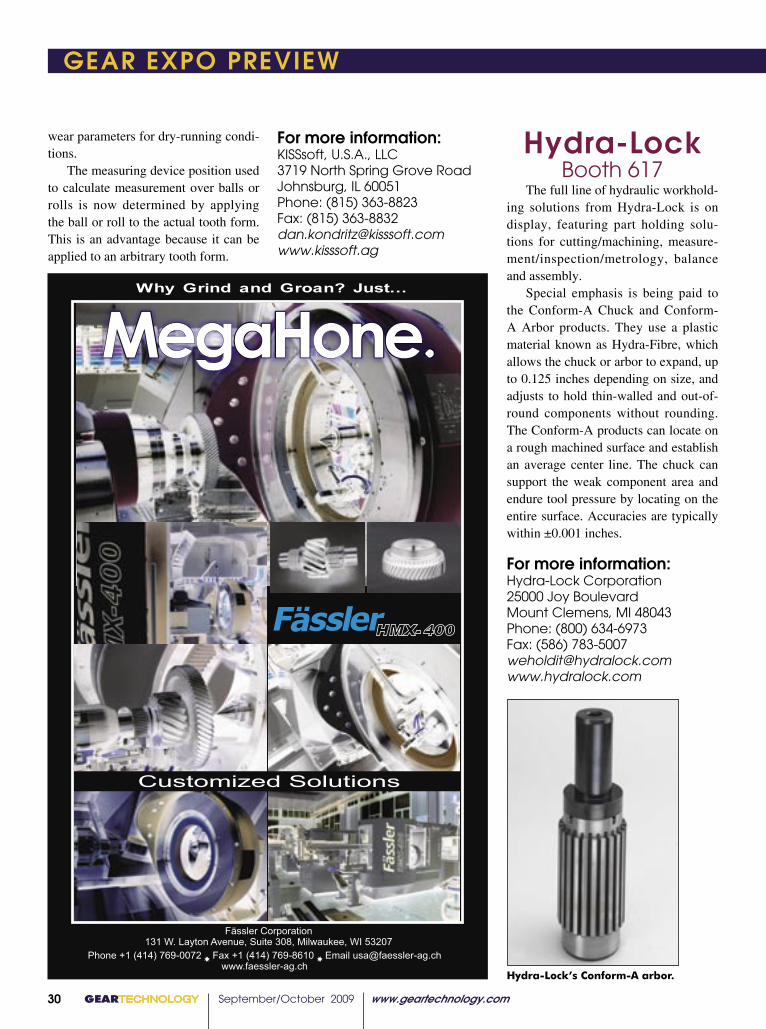
The full line of hydraulic workhold-ing solutions from Hydra-Lock is on display, featuring part holding solu-tions for cutting/machining, measure-ment/inspection/metrology, balance and assembly.
Special emphasis is being paid to the Conform-A Chuck and Conform-A Arbor products. They use a plastic material known as Hydra-Fibre, which allows the chuck or arbor to expand, up to 0.125 inches depending on size, and adjusts to hold thin-walled and out-of-round components without rounding. The Conform-A products can locate on a rough machined surface and establish an average center line. The chuck can support the weak component area and endure tool pressure by locating on the entire surface. Accuracies are typically within ±0.001 inches.
For more information:Hydra-Lock Corporation25000 Joy BoulevardMount Clemens, MI 48043Phone: (800) 634-6973Fax: (586) [email protected]
Hydra-Lock’s Conform-A arbor.
32���GEARTECHNOLOGY������������������� ������������������������
������������ �������� ������� ���� ���������� ���������� ������ ���� ����� ��������� ��� ���� �� ���� �� ����� ���� ���� �����
������ ����� �������� �� ������������� ����������� ��������� ��������������� ��� �� �������� �������� ��������������������� ���� �������� ��� ������������������������������������������������������� ��� ��������� �� �������� ������������� ������������ �� �������� ������������� ������ ����������� ������������������������������������������������������������������������������������������� ���� �������� ����� ��������� ����
���� ������������ �������������������� ������� �������� ����� �������������� ������� ���������� ���� ����������������� ��� �� ������� ������� ������������� ��� ���� ��������� �������� ��� �� ������������� ��� ���� ���������� �������
���� �������� ��������� �� ���������������� ����� �� �������������� ����������������������������������������������������������������������������������������������� ���� ������ ���� ����� ����� ����
�������
���������� ����������� �������
�����������������������������������������������������������������������
����������������������������������������������������������������������������������������������
���������������������
of solutions that we have to offer to all gear producers for all processes and all applications. The ‘goal’ is to help our customers improve quality, increase productivity, reduce costs and more effectively compete in their markets.”
Says Reishauer’s Richmond, “It is our goal to showcase our company and its capabilities and demonstrate how we stand behind the claim that we offer the ‘lowest cost-per-piece’ hard finishing process on the market today, bar none.”
As for Koepfer, says Gimpert, “Our plans are to introduce only new or advanced technology.”
And says Great Lakes’ Mackowsky, “We have a 20 x 50 booth alongside the Höfler and Fässler booths, so we’ll probably have the biggest showing in terms of floor space. And the equip-ment there, there’s probably four mil-lion dollars in equipment on the floor. It represents a huge expense for us and is kind of an indication of our com-
mitment to the AGMA, and hopefully we’ll have good participation by heavy industry. And we have some really great products, anyway. Hopefully, with the downturn in business, people will have a little more time to com-mit to the show and send more people and spend some time at the booth and maybe spend more than a day.”
Moving on to another show- and industry-related issue, wind power just can’t seem to catch a break. Despite the Obama administration’s firm support for its place in the alternative energy realm, the state of the global economy has put the skids on most continued development. In contrast to the wind turbine buzz that energized the 2007 show, its impact will be considerably muted this year.
“I think the market reality is as we’re hearing—that there is signifi-cant difficulty in getting financing for wind power,” says Franklin. “If you are a company looking to make a wind power gearbox, you’re probably going to have some difficulty in acquiring financing right this minute. The last time I went around and talked to people in the wind turbine business, money was extremely tight; demand is obvi-ously not quite there. All sources of energy dampened down in price right now, and wind turbines are reflecting the same thing as far as I read.”
Monument Circle (courtesy of the Indiana Convention and Visitors Association).
pgs 30-35.indd 4 8/6/2009 2:44:10 PM
www.geartechnology.com September/October 2009 GEARTECHNOLOGY 31
GEAR EXPO PREVIEW GEAR EXPO PREVIEW
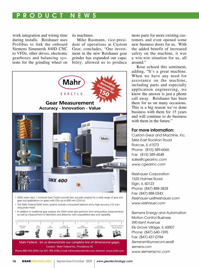
Mahr FederalBooth 515
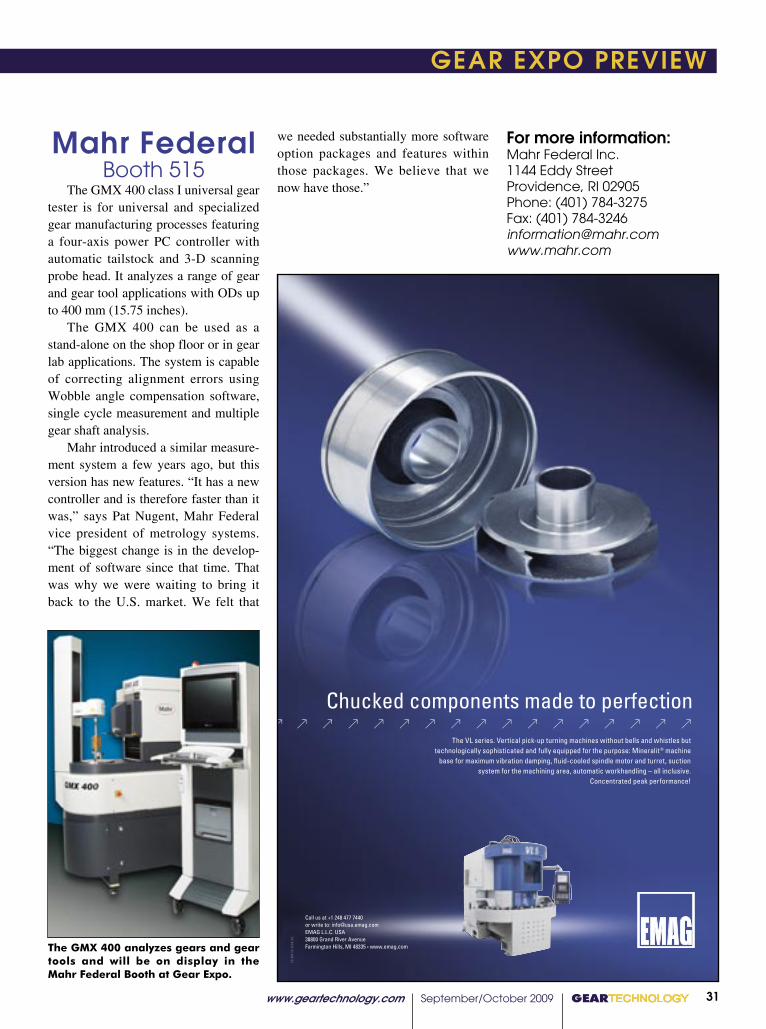
The GMX 400 class I universal gear tester is for universal and specialized gear manufacturing processes featuring a four-axis power PC controller with automatic tailstock and 3-D scanning probe head. It analyzes a range of gear and gear tool applications with ODs up to 400 mm (15.75 inches).
The GMX 400 can be used as a stand-alone on the shop floor or in gear lab applications. The system is capable of correcting alignment errors using Wobble angle compensation software, single cycle measurement and multiple gear shaft analysis.
Mahr introduced a similar measure-ment system a few years ago, but this version has new features. “It has a new controller and is therefore faster than it was,” says Pat Nugent, Mahr Federal vice president of metrology systems. “The biggest change is in the develop-ment of software since that time. That was why we were waiting to bring it back to the U.S. market. We felt that
we needed substantially more software option packages and features within those packages. We believe that we now have those.”
The GMX 400 analyzes gears and gear tools and will be on display in the Mahr Federal Booth at Gear Expo.
For more information:Mahr Federal Inc.1144 Eddy StreetProvidence, RI 02905Phone: (401) 784-3275Fax: (401) [email protected]
GEARTECHNOLOGY September/October 2009 www.geartechnology.com32
GEAR EXPO PREVIEW
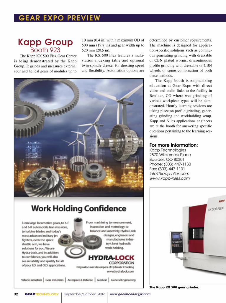
Kapp GroupBooth 923
The Kapp KX 500 Flex Gear Center is being demonstrated by the Kapp Group. It grinds and measures external spur and helical gears of modules up to
10 mm (0.4 in) with a maximum OD of 500 mm (19.7 in) and gear width up to 520 mm (20.5 in).
The KX 500 Flex features a multi-station indexing table and optional twin-spindle dresser for dressing speed and flexibility. Automation options are
determined by customer requirements. The machine is designed for applica-tion-specific solutions such as continu-ous generating grinding with dressable or CBN plated worms, discontinuous profile grinding with dressable or CBN wheels or some combination of both these methods.
The Kapp booth is emphasizing education at Gear Expo with direct video and audio links to the facility in Boulder, CO where wet grinding of various workpiece types will be dem-onstrated. Hourly learning sessions are taking place on profile grinding, gener-ating grinding and workholding setup. Kapp and Niles applications engineers are at the booth for answering specific questions pertaining to the learning ses-sions.
For more information:Kapp Technologies2870 Wilderness PlaceBoulder, CO 80301Phone: (303) 447-1130Fax: (303) [email protected]
The Kapp KX 500 gear grinder.
www.geartechnology.com June 2009 GEARTECHNOLOGY 00
P R O D U C T N E W S
017
continued
with the Type G Twist Mandrel, which can accommodate a wider range of applications, including O.D. and face grinding operations where parts have a smooth bore, as well as non-gear grinding processes like cylindrical grinding.
The LeCount Type G Twist Mandrel uses a sliding-jaw design that features a mechanical rotary device for clamping workpieces. The mandrel provides 0.0050 mm (0.0002 in) TIR accuracy, considerable holding power torsionally and axially and a wide expansion range that fi ts bore sizes from 25.40 mm (1 in) to 76.20 mm (3 in).
For more information:Gleason Corporation1000 University AvenueP.O. Box 22970Rochester, NY 14692-2970Phone: (586) 473-1000 www.gleason.com
Henkel Corporation introduced two water-soluble metal removal lubricants
designed to generate minimal foam for years with little biological degradation.
The Multan B 236 and B 414 are for machining and grinding ferrous and non-ferrous alloys. They are intended for applications in which soft water or process requirements make controlling
foam diffi cult. The Multan B 236 is appropriate for
most water conditions and multi-metal applications. It performs well on cast iron and steel applications that require rapid cooling, corrosion protection
Semi-Synthetic Metal Cutting Fluids RESIST BACTERIA AND FOAM
GT 6-09 72pgs.indd 17 6/11/2009 10:37:46 AM

www.geartechnology.com September/October 2009 GEARTECHNOLOGY 33
GEAR EXPO PREVIEW GEAR EXPO PREVIEW
Emuge Corp.Booth 700
The Emuge System SG expanding-bush design workholding solution is used for hobbing, shaping and shaving for gear production as well as milling and inspection.
The solution is designed based on a series of short tapers that expand or contract in contact with axial force. The System SG can be designed for ID or OD clamping. It features a large sur-face area contact with the workpiece, which is capable of holding almost the whole diameter of the clamping area.
The System SG gives the workpiece a slight axial movement towards an end stop for stiff operation, and it handles higher transferable torque values typi-cal of modern machining operations.
For more information:Emuge Corp.1800 Century DriveWest Boylston, MA 01583
Phone: (800) 323-3013Fax: (800) [email protected]
System SG workholding from Emuge.
��������������������������������������������GEARTECHNOLOGY���33
����������� continuedAs for Richmond at Reishauer, “I’m not certain; it seems as if the manu-facturing capacity and demand at this time are in sync. I’ve read a little about the issue of ‘energy credits’ when it comes to the business of alternative energy, and from my narrow under-standing, these energy credits (created by Congress in the recent energy legis-lation as an inducement to begin alter-native—wind—energy projects) have become a trading commodity on Wall Street, and their short-term future is unclear at this time.”
“I think the level of intensity will be greatly reduced,” says Koepfer’s Gimpert. “(But) the wind energy busi-ness has committed to many programs and has an established focus.”
Says Great Lakes’ Mackowsky, “Wind power, like just about every-thing else, is experiencing the same amount of downturn. I don’t see the activity level now that we saw two years ago.”
Taking the long view, “The wind energy market has not been immune to the economic downturn,” says Gleason’s Finegan. “In spite of the cur-rent lull in the feverish growth of wind energy, the long-term demand and outlook for alternative energy sourc-es remains strong, and we expect a rebound in all energy markets, includ-ing wind.”
As for the co-location with the heat treaters, says Finegan, “Heat treating is an integral part of gear processing, and, as such, has a role to play at Gear Expo.”
“Co-location is a new concept for Gear Expo,” says Richmond. “The plan is to meld two common processes
under one roof to broaden the appeal of the show. I think it’s a good for-mula. The attendance numbers will tell the final story, notwithstanding current economic conditions.”
“It can’t hurt,” says Mackowsky. “I would have thought some of them would probably have exhibited at Gear Expo anyway. If this brings more traf-fic, all the better.”
And last, we come to the ques-tion that pops up every two years: Is
Gear Expo in its current iteration still relevant? (Ed.’s note: For AGMA’s response to this question, please see Joe Franklin’s upcoming Voices piece in our September/October show issue.)
“It would be easy to say that Gear Expo is no longer relevant, given the current level of market activity,” says Finegan, “but this may be shortsighted. The mission of Gear Expo has always been to bring together the suppliers of gears as well as gear equipment,
Höfler ’s machinery line capabilities will be on full display at Gear Expo (courtesy Höfler).
pgs 30-35.indd 5 8/6/2009 2:44:42 PM

GEARTECHNOLOGY September/October 2009 www.geartechnology.com3400 GEARTECHNOLOGY July 2009 www.geartechnology.com50
Excellent root and deepblind hole penetration
No Intergranularoxidation (IGO)
Part-to-part andload-to-load consistency
Excellent surface finish
Superior strengthand fatigue resistance
No decarburization
Near-net shape / minimalpost-heat treating machining
Part distortion control
Environmentally-friendly witha low Greenhouse Gasemission profile.
Unparalleled Resultswith ModulTherm Vacuum Furnace Systems
The ModulTherm R vacuum furnace system produces unparalleled gear results, while allowing engineers to design and control the gear manufacturing process. With superior process and design flexibility, control over alloy selection, heat treatment, quenching, automation, configurations, and end product performanceare engineering choices. Unlimited options. One choice. ModulTherm.
System Capabilities:Fully integrated and automated systems for small to high production requirements
Multiple quench options: 20-bar high pressure gas quenching (HPGQ), oil, water, press quenching, and low pressure carburizing (LPC).
Our 80 years of gear-processing experience provide the stability you can count on. Call 248.668.4130 or link to www.ald-holcroft.com/results for your gear tools.
ALD-Holcroft 49630 Pontiac Trail Wixom, MI 48393-2009 USA Ph: 248.668.4130 Fax: 248.624.3710 E-mail: [email protected] www.ald-holcroft.com/results
ModulThermLPC System
GT 7-09 80pgs.indd 50 7/9/2009 3:41:35 PM
www.geartechnology.com September/October 2009 GEARTECHNOLOGY 35
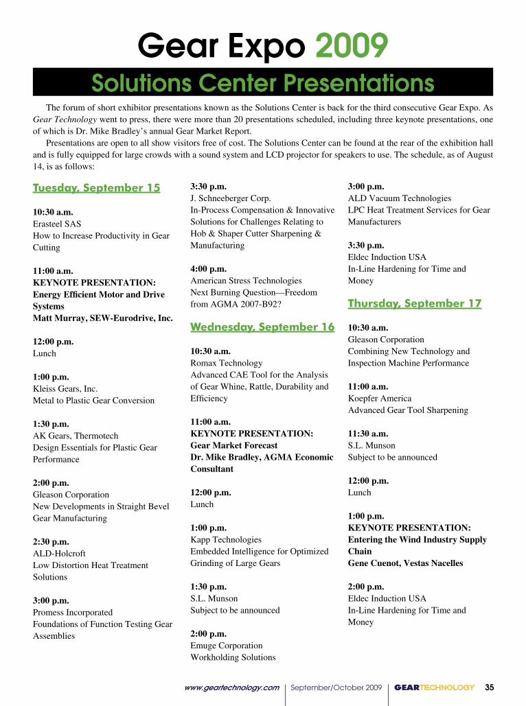
Tuesday, September 15 10:30 a.m.Erasteel SASHow to Increase Productivity in Gear Cutting 11:00 a.m.KEYNOTE PRESENTATION: Energy Efficient Motor and Drive SystemsMatt Murray, SEW-Eurodrive, Inc. 12:00 p.m.Lunch 1:00 p.m.Kleiss Gears, Inc.Metal to Plastic Gear Conversion 1:30 p.m.AK Gears, ThermotechDesign Essentials for Plastic Gear Performance 2:00 p.m.Gleason CorporationNew Developments in Straight Bevel Gear Manufacturing 2:30 p.m.ALD-HolcroftLow Distortion Heat Treatment Solutions 3:00 p.m.Promess IncorporatedFoundations of Function Testing Gear Assemblies
3:30 p.m.J. Schneeberger Corp.In-Process Compensation & Innovative Solutions for Challenges Relating to Hob & Shaper Cutter Sharpening & Manufacturing 4:00 p.m.American Stress TechnologiesNext Burning Question—Freedom from AGMA 2007-B92? Wednesday, September 16 10:30 a.m.Romax TechnologyAdvanced CAE Tool for the Analysis of Gear Whine, Rattle, Durability and Efficiency 11:00 a.m.KEYNOTE PRESENTATION: Gear Market ForecastDr. Mike Bradley, AGMA Economic Consultant 12:00 p.m.Lunch 1:00 p.m.Kapp TechnologiesEmbedded Intelligence for Optimized Grinding of Large Gears
1:30 p.m.S.L. MunsonSubject to be announced 2:00 p.m.Emuge CorporationWorkholding Solutions
3:00 p.m.ALD Vacuum TechnologiesLPC Heat Treatment Services for Gear Manufacturers 3:30 p.m.Eldec Induction USAIn-Line Hardening for Time and Money Thursday, September 17 10:30 a.m.Gleason CorporationCombining New Technology and Inspection Machine Performance 11:00 a.m.Koepfer AmericaAdvanced Gear Tool Sharpening 11:30 a.m.S.L. MunsonSubject to be announced 12:00 p.m.Lunch
1:00 p.m.KEYNOTE PRESENTATION: Entering the Wind Industry Supply ChainGene Cuenot, Vestas Nacelles 2:00 p.m.Eldec Induction USAIn-Line Hardening for Time and Money
Gear Expo 2009Solutions Center Presentations
The forum of short exhibitor presentations known as the Solutions Center is back for the third consecutive Gear Expo. As Gear Technology went to press, there were more than 20 presentations scheduled, including three keynote presentations, one of which is Dr. Mike Bradley’s annual Gear Market Report.
Presentations are open to all show visitors free of cost. The Solutions Center can be found at the rear of the exhibition hall and is fully equipped for large crowds with a sound system and LCD projector for speakers to use. The schedule, as of August 14, is as follows:
GEARTECHNOLOGY September/October 2009 www.geartechnology.com36www.geartechnology.com September/October 2008 GEARTECHNOLOGY 00
I M T S 2 0 0 8
37
�������������������������������������������
You already compete globally; Why not look to a
global supplier for gear hobs. One that enables
“your team” to take advantage of “our” competi-tive edge. DTR Corporation (formerly Dragon Precision
Tools) is a world-class leader in maximizing gear
hob tool life through innovative designs, with the latest in coatings and high
speed steels. The global gear market relies on DTR to perform in any playing
conditions. Look to us to get you through any
challenge the market-place has to offer.
NEW U.S. Office Location (Chicago)2400 E. Devon Ave., Suite 210, Des Plaines, IL 60018
PHONE: 847-375-8892 FAX: 847-699-1022Headquarters36B-11L, Namdong Industrial Complex, Namdong-Gu, Incheon, Korea
PHONE: +82.32.814.1540 FAX: +82.32.814.5381 WWW.DRAGON.CO.KR
Email inquiries to: [email protected]
(formerly Dragon Precision Tools)
��������������
Since 1952 Vancouver Gear Works’ development has be driven by the future.This foresight allows us to acquire the equipment, technology and
trade skill in advance of demand.In order to guarantee control of our
manufacturing process & maintainthe high level of quality that
our customer’s demand,VanGear’s Quality Control
has passed through alarge number ofaccredition programs.
Vancouver Gear Works Ltd.14551 Burrows Rd.
Richmond, BCCanada, V6V 1K9
Toll-Free: 1-877-888-3111Telephone: 604-278-3111
[email protected] / www.vangear.com
• API Spec Q1 • API Spec 7 • API Spec 7-1 • ISO 9001:2000 • ISO 29001:2003
Hofler Rapid 1500 CNC Gear Grinder• DIN1 / AGMA15 Quality Level
Hofler 1600 HF CNC Gear Hobbing Machine• First in the world with on-board
Gear Inspection
Hofler Rapid 2600 CNC Gear Grinder• Operational Summer 2008
• Any imaginable profile andlead modification possible
We are accredited by ANAB (ANSI-ASQ National AccreditationBoard) to the following standards:
INVESTING IN THE FUTURE
putting VANGEAR at the
forefront oftechnical
innovation
continued
Sunnen Booth B-7200
The VSS-2 Series 2 Single Stroke Honing systems have factory-aligned spindles that surpass DIN 8635 requirements for vertical honing machines. Applications include sizing bores 3.9–50 mm diameter in stamped parts, hydraulic valve bodies, gears and sprockets, parking pawls, rocker arms, turbocharger housings and other similar parts. Materials suitable for the machines are free-cutting materials like cast iron, powdered metals, ceramic and glass graphite.
“The VSS Series 2 sets a new standard for single-pass bore sizing effi ciency,” says Phil Hanna, Sunnen product manager for machines. “If a part is best suited for single-pass honing, the VSS-2 provides a level of precision not available in other designs. And, with the new touch screen control, this machine is very operator friendly. No custom electronics or special training are needed, and the control is designed to interface with part handling automation systems.”
Three models of the VSS Series 2 are available to serve mid- to high production. The model 84 is an eight-station, four-spindle machine, the 86 has six spindles and the 64 is a six-station, four-spindle design. The 10 hp spindle drive operates at speeds between 100 and 2,500 rpm.
The work envelope is accessible from both sides of the machine. Other standard features include an electric rotary index table and tool holder. Optional features include fl oating or rigid adjustable tool holders, 12- and 16-port programmable rotary air unions for index output, base coolant evacuation pump, automatic lubrication system, work area light kit, stack light, tool alignment indicator and spindle crash
GT 9-10-08 96pgs.indd 37 8/15/2008 3:44:32 PM
Gear Expo 2009 is also featuring a series of meetings, training sessions and seminars of special interest to visitors. As a supplement to AGMA’s education programs, the American Bearing Manufacturers Association (ABMA) and the Society of Manufacturing Engineers (SME) are holding seminars on current gear-industry topics. The following is a schedule of special events. For more detailed descriptions and information on registering for these events, visit www.gearexpo.com.
Training School for Gear ManufacturingPresented by: AGMATuesday, September 15–Thursday, September 17Price: $395 member/$525 nonmember
Why Bearings FailPresented by: ABMAThursday, September 17Price: $295
SME Gear Manufacturing ConferencePresented by: Society of Manufacturing Engineers (SME)Tuesday, September 15–Wednesday, September 16, 9 a.m.–4 p.m.Full conference registration: $495 member/$595 nonmemberOne-day registration $265 member/$365 nonmemberFor full conference schedule and presenters, visit www.sme.org/gears.
Entering the Wind Turbine Gearbox Supply ChainPresented by: AGMAWednesday, September 16Price: $295
Seminars and Special Events
BARITINTERNATIONALCORPORATIONINTERNATIONALCORPORATION
Prompt, Personalized Service!
3384 Commercial AvenueNorthbrook, IL 60062www.barit.com
Ph: 847-272-8128Fax: 847-272-8210E-mail: [email protected]
• Hobs• Shaper Cutters• Broach Cutters• Milling Cutters• Shaving Cutters• Rack Type Cutters• Straight Bevel Cutters• Spiral Bevel Cutters
• Hobs• Shaper Cutters
CUSTOM TOOLS• Hobs• Shaper Cutters• Broach Cutters• Milling Cutters• Shaving Cutters• Rack Type Cutters• Straight Bevel Cutters• Spiral Bevel Cutters
IN STOCK• Hobs• Shaper Cutters
ONE STOP GEAR CUTTING TOOLS AND SOLUTIONSONE STOP GEAR CUTTING TOOLS AND SOLUTIONS
Visit us Booth #1233
Celebrating 20 years of doing business
Now Accepting
Credit Cards

www.geartechnology.com September/October 2009 GEARTECHNOLOGY 37
ASM Heat Treating Society Education Courses (Ed. note. The Heat Treating Society has a complete technical program with many gear-themed sessions. For more information on those, visit www.asminternational.org/heattreat.)
Heat Treating for the Non-Heat TreaterSunday, September 13, 8 a.m.–4 p.m.Instructor: Scott MacKenziePrice: $300 nonmember, $275 ASM Member, $250 HT member
Heat Treatment of Gears 1/2 Day WorkshopTuesday, September 15, 1 p.m.–5 p.m.Presenters: Dale J. Weires, Daniel H. Herring, Scott MacKenzie, Fred Specht and B. Lynn FergusonPrice: $200
A Review of Surface Treatments for Gears and ToolingWednesday, September 16, 1–6 p.m.Instructor: David PyePrice: $200
Practical Heat TreatingThursday, September 17, 8 a.m.–4 p.m.Instructor: David PyePrice: $300 nonmember, $275 ASM
Member, $250 HT member
Seminars and Special Events
Cafe de GearsFree Espresso
atGear Expo 2009Gear Expo 2009
���������������
���������������������� ���������������������������������
������������
TECHNOLOGYGEAR�����������������
Productivity
Features
Lean Strategies for Lean Times
Gear Expo 2009— All Roads Lead to Indy
Technical Articles
How Axle Defl ection and Tooth Flank Modifi cation Affect Gearing
CFD Analysis of Gearbox Windage Loss
Plus
Addendum: Gears and Sweet Science
THE GEAR INDUSTRY’S INFORMATION SOURCE
w w w . p o w e r t r a n s m i s s i o n . c o m
April 2009
powertransmissionengineeringpowertransmissionengineeringPTE
®
Power Play Fundamentally Green
Redevelopment
Supply Chain Management Get with the (Supply Chain) Program
“Buy American”—Good or Bad?
Features Case Study: SEW
Gearmotors
Motor Solutions for Hybrid Electric Drivetrains
No Great Loss—Reducing Stepper Motor Drain
w w w . p o w e r t r a n s m i s s i o n . c o m
Fundamentally Green Redevelopment
Reducing Stepper Motor Drain
Stop by Booth #1241Stop by Booth #1241��������������
��������������������������������

Except as otherwise noted, trademarks are owned by Ticona or its affiliates. Fortron is a registered trademark of Fortron Industries LLC. Ticona is a business of Celanese Corporation.© 2009 Ticona
Ask the Ticona Gearheads.™
Great Minds!Put our polymer and application brainpower to work for you.
Ticona is the world leader in plastic gear technology. For over 30 years, our gearheads – better known as gear technology experts – have helped to dramatically reduce the cost, weight and noise of gear drives forcountless applications.
Great Gears!n Reduce noisen Boost efficienciesn Lower costn Increase design flexibilityn Eliminate the need for lubricantsn Resist chemicals and corrosion
Great Polymers!Celanex® thermoplastic polyester (PBT)Hostaform®/ Celcon® acetal copolymer (POM)Celstran® and Compel® long fiber reinforced thermoplastics (LFRT)Fortron® polyphenylene sulfide (PPS)GUR® ultra-high molecular weight polyethylene (UHMW-PE)Riteflex® thermoplastic polyester elastomer (TPC-ET)Vectra® liquid crystal polymer (LCP)
Contact the Ticona Gearheads for thebest polymer to fit your application at:1.800.833.4882 www.ticona.com
Ticona Engineering Polymers8040 Dixie HighwayFlorence, KY, USA 41042
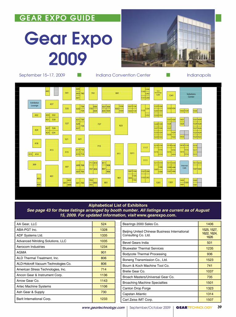
www.geartechnology.com September/October 2009 GEARTECHNOLOGY 39
GEAR EXPO GUIDE
AA Gear, LLC 524
ABA-PGT Inc. 1328
ADF Systems Ltd. 1335
Advanced Nitriding Solutions, LLC 1035
Aerocom Industries 1234
AGMA 901
ALD Thermal Treatment, Inc. 806
ALD-Holcroft Vacuum Technologies Co. 806
American Stress Technologies, Inc. 714
Ancon Gear & Instrument Corp. 1136
Arrow Gear Co. 1143
Artec Machine Systems 1106
Ash Gear & Supply 730
Barit International Corp. 1233
Gear Expo 2009 September 15–17, 2009 Indiana Convention Center Indianapolis
Alphabetical List of ExhibitorsSee page 43 for these listings arranged by booth number. All listings are current as of August
15, 2009. For updated information, visit www.gearexpo.com.
Bearings 2000 Sales Co. 1406
Beijing United Chinese Business International Consulting Co. Ltd.
1525, 1527, 1622, 1624,
1626
Bevel Gears India 501
Bluewater Thermal Services 1235
Bodycote Thermal Processing 936
Boneng Transmission Co., Ltd. 1523
Bourn & Koch Machine Tool Co. 741
Brelie Gear Co. 1037
Broach Masters/Universal Gear Co. 735
Broaching Machine Specialties 1501
Canton Drop Forge 1323
Capstan Atlantic 1314
Carl Zeiss IMT Corp. 1507
���
���
���
��� ���
���
���
���
���������������
���
���
���
���
���
���
��� ���
��� ���
���
���
������
���
���
���
���
���
���
���
���
���
���
���
������
���
���
���
���
������
���
��� ���
��� ���
��� ���
��� ���
��� ������
������
��� ���
��� ���
���
���
������
���
���
���
���
���
��� ���
���
������
������
�������
����
���
���
���
����
��������
����
����
����
���� ����
���� ����
����
����
����
����
����
���������������
����
��������
����
��������
���� ����
���� ����
���� ����
���� ����
���� ����
���� ����
�������� ����
��������
����
��������
����
��������
�������� ����
���� ����
���� ��������
��������
���� ����
���� ����
���� ������������
����
���� ����
��������
����
���� ����
��������
����
���� ����
����
����
��������
����
����
����
����
����
������������ ����
����������������
����
��������
��������
���� ����
���� ����
���� ����
����
����
����
���� ����
���� ����
����
����
�
�
�
��
��
��
���
�
������������������������������������������������������

GEARTECHNOLOGY September/October 2009 www.geartechnology.com40
GEAR EXPO GUIDEP R O D U C T N E W S
The number 815 electric rotary hearth oven, from Grieve Corporation, is currently being used by a customer to preheat various gears, usually steel and sometimes aluminum, before assembly operations.
The dimensions of the unit’s interi-
�������������������������������������������GEARTECHNOLOGY���63
N E W S
���
��
��
��
��
��
����������
�����������������������������
������������������������������� ����������������������������������� ���������������������� ����������������������������������� ��������������������
������������������������� ��������������������������������� ����������������������������������
��������������� � ����������������������������������������������������������������������������
������������������������������������������������������������������������������������������� ������������������������������������ �������������������������������
������������ � ������� � ����������� ������������������� ������������������������������������������������ ������������������� ��������������������������������� �������������������� ������������
���������������������������������� ���������������������������������������������������������������������������������������
���������������������������������
������������������������������������������
�����������������������������������������������������������������
������������������������������������������������������������������������������������������������������������������� �������� ����� �������� ����� ���� ����� ����� ���������
����
Visit us
Booth #1336
continued
The MPIF handed out various industry awards at the Industry Recognition Luncheon held during PowderMet2009 (courtesy of MPIF).
nology, FloMet LLC; and Robert F. Unkel, former manager of PM marketing, Cincinnati Incorporated.
Bose is president of Materials Processing, Inc., in Haltom City, TX. The Fellow Award is given to American Powder Metallurgy Institute (APMI) members who have made sig-nificant contributions to the society and have great expertise in PM technology and the practice or business of the PM industry. Fellows are elected based on their professional, technical and scientific achievements, continued professional growth and development, mentoring/outreach and APMI contributions.
With 25 years dedicated to the PM industry, Bose is rec-ognized for his work in materials processing. His promotion of powder injection molding technology is known interna-tionally from his licensing and technology transfer undertak-
Animesh Bose (right) accepts the 2009 Fellow Award from Nick Mares, APMI president (courtesy of MPIF).
pgs 60-68.indd 5 8/6/2009 3:09:51 PM
Visit us Booth #741
Centric International, Inc. 629
Chamfermatic Inc. 400
Cincinnati Gearing Systems 1202
Circle Gear and Machine Co. 1311
Cleveland Deburring Machine Co. 1308
Clifford-Jacobs Forging Co., Inc. 810
CNC Design Pty. Ltd. 1319
Colonial Tool Group 1341
Compass Automation 432
Comtorgage Corp. 1403
Cornell Forge Co. 1104
Creative Automation Inc. 835
CRI Machining 1511
Davall Gears Ltd. 1318
DixiTech CNC 836
DMG Chicago 541
Doncasters Gear Products 1500
Drake Manufacturing Services Co. 309
DTR Corp. 1315
Eaton Performance Products 433
Eaton Steel Bar Company 1215
Eldec Induction, USA 740
EMAG LLC 413
Emuge Corp. 700
Engineered Abrasives 1310
Engineered Lubricants Co. 1431
Engineered Tools Corp. 908
Erasteel, Inc. 1232
European Technology Center NA 1514
Euro-Tech Corp. 532
Excel Gear, Inc. 641
Fässler Corp. 1111
Fairfield Manufacturing Co., Inc. 1003
First Gear 402
Forest City Gear Co. 507
Forst USA 1244
Fubri SRL 1517
The Gear Machinery Exchange/ gearmachineryexchange.com 1241
Gear Solutions and Wind Systems magazines 1103
Gear Technology 414
Gear Technology and Power Transmission Engineering magazines 1241
Gearspect 707
GearTec, Inc. 1219
Geiger, Hans-Juergen 800
Gibbs Machinery Co. 601
Gleason Corp. 715
www.geartechnology.com September/October 2009 GEARTECHNOLOGY 41
P R O D U C T N E W S GEAR EXPO GUIDE
Golden Port International Inc. 1240
Goldstein Gear Machinery LLC 1241
Great Lakes Gear Technologies, Inc. 1011
Great Taiwan Gear Ltd. 726
Halifax Rack & Screw 1206
Hangzhou Chinabase Machinery Co., Ltd. 1007
Hangzhou Ever-Power Transmission Co., Ltd. 1630
Hangzhou Sanp Machinery Co., Ltd. 1529
Hanik Corp. 600
Harbin Tool Works 1519
Havlik Gear 437
Hexagon Metrology 1419
HobSource Inc. 906
Hoffmann Filter Corp. 807
Höfler Maschinenbau GmbH 911
Hydra-Lock Corp. 617
IBC Coating Materials & Technology 1423
IFPE 2011 1211
Induction Heat Treating 811
Induction Tooling, Inc. 801
Industrial Machinery Digest 1434
Ingersoll Cutting Tools 1336
Innovative Rack & Gear Co. 309
Interstate Tool Corp. 1331
IonBond LLC 1322
Ishmeet Forgings Pvt. Ltd. 1326
I-Tech International Corp. 535
J. Schneeberger Corp. 431
Jason Finishing Group – Osborn/Jacksonlea 1422
JRM International Inc. 1133
Kapp Technologies 923
Kisssoft USA LLC 615
Kleiss Gears, Inc. 1223
Klingelnberg GmbH 727
Koepfer America, LLC 413
Li Gear Inc. 1309
Liebherr Gear Technology, Inc. 727
LMS North America 1332
Ludeca Inc. 1334
Luoyang Hongtuo Heavy Gear-box Co., Ltd. 1628
www.geartechnology.com September/October 2008 GEARTECHNOLOGY 0049
������������������������������������������������������������������
���������������������������������������������������������������������������������������������������������������
��������������������������������������
���������������������������������������������������������������������������������������������������������������������������������������������������������������������
�������������������������������������������������������������������������������������������������������������������������������
Committee is benefi cial because every detail has to be covered in order for the program to function. “There is no better way to understand how to use a technical standard than to try and program it,” Wasilewski says.
Wasilewski has devoted countless vacation days to his work on AGMA. Most members he knows do the committee work on their own time. No matter how chaotic it might get, he’s always found something positive in the experience.
“Most of the committee members volunteer to do tasks because they want to work on a particular material. Either they’re familiar with it, or they want to be. I look at it as learning. Take time at work to learn and take time after work to learn. You should only stop learning when you’re dead!”
For George Lian, senior project engineer at AmarilloGear Co., work on the Bevel Gearing, Helical Gearing and Programming Committees has helped his full time job immensely.
“Committee work has given me advanced knowledge in AGMA standards related to the gear product for my company. Consequently, I was able to make better judgments in designing gears and improving manufacturing processes.”
Lian states that the work he’s done on the Programming Committee is a far different experience than anything else he’s worked on.
“The members would meet in a city with nice scenery, but would be in the hotel writing codes the entire time.
The sessions would usually continue late (past midnight). Members are usually easy-going, but they’re dead serious when writing codes. At times, however, a member could be infl uenced to write code in a certain way by tempting them with chocolate.”
As far as the workload is concerned, Lian says it’s not diffi cult when the work is interesting and you have an understanding family. “Although many hours are used doing committee assignments, there’s still ample time to be with family and friends.”
Technical diffi culties. The most challenging task for AGMA is recruiting new members for the technical committees. According to Wasilewski, sometimes potential members are not given support from their upper management.
“Committee participation is looked at as an expense, not as an education. Management must understand that good engineers need continuous learning and exposure to contemporaries. These companies need to realize that if you send a new engineer to the committee, you start to build the developed engineer you’ll need in the future. If nothing else, they should remember that having a participant gives them a voice in the standards that affect their products and helps protect their interests.”
Lian believes the recruitment process should be addressed at AGMA annual meetings or other functions where attendees can infl uence companies to send employees to technical
continued
GT 9-10-08 96pgs.indd 49 8/18/2008 3:44:36 PM
Visit us
Booth #1328
GEARTECHNOLOGY September/October 2009 www.geartechnology.com42
GEAR EXPO GUIDE
P R O D U C T N E W S
�������������������������������������������GEARTECHNOLOGY���65
N E W S
����������������������������������������
������������������������
�����������������������������������
�����������������������������������
�������������������������������������������
Visit us
Booth #1336
Moore Gear and Manufacturing’s Hermann, MO facil-ity now includes approximately 54,750 square feet after two expansion projects were completed.
The east side of the building is now 7,500 square feet bigger than before. This improved the shipping depart-ment by adding loading docks and space for maneuvering shipments in and out of the factory. A former industrial facility adjacent to the property was acquired as part as the expansion to the west side of Moore Gear. This is a 13,500- square-foot building that rests on four and half acres of level land. Moore intends to use the facility to store surplus machines, stock material and to free manufacturing space in Moore’s original building.
The building expansions also included new additions in CNC equipment to increase capacity and productivity. Machinery added includes a CNC gear hobber, hob sharp-ener, gear checking machine, 10-foot long CNC machining center, gear rack milling machine and cylindrical grinder.
Moore Gear COMPLETES BUILDING EXPANSIONS
Handling and Universal Technical Systems.Marsch will provide engineering consulting, customer
support and training in North America for Kisssoft. “We are fortunate to have Jim join our team here and look forward to offering our customers more services,” says Dan Kondritz, national sales manager for Kisssoft, U.S.A.
Nordex Opens North American Headquarters
On May 5, German wind turbine manufacturer Nordex officially opened its U.S. headquarters in downtown Chicago. The decision to set up shop here was influenced by the central geographic location in North America, proximity
continued
pgs 60-68.indd 7 8/6/2009 3:10:53 PM
00 GEARTECHNOLOGY January/February 2009 www.geartechnology.com28
The portable gear pitch tester ES 4100 offers the inspection of pitch on your gear production machine. A high degree of operational convenience is possible by the built in processing of the measured data and the tilt and Swivel display touch-screen. ISO, DIN or AGMA standards evaluation software. The measurements can be stored and printed out directly or on an external PC.
Portable CNC gear pitch tester ES 4100
Donner + Pfister AG Switzerland
Tel:+41554402032 [email protected] www.dpag.ch
the momentum will stay there towards solving the problems,” he says. “Everyone involved in the industry I think believes that this is only a temporary speed bump.
“I think by May or June we’ll have the credit crunch fairly under control, and it will start building up again,” he predicts.
Supply ChainThe supply chain and a new element of doubt is at hand
due to the economy. In particular, a shortage in steel supply and signifi cant demand has been an obstacle; however, the ongoing economic and automotive crises have caused a considerable drop in steel demand just in the past few months. According to the American Iron and Steel Institute (AISI), U.S. steel shipments dropped 6.8 percent from the correlating 2007 fi gure.
Reardon believes steel costs may continue coming down in the near future, which will serve to free up the supply chain.
“Material was an issue in the past,” Ertel says. “But I think that situation has improved dramatically, and I don’t see material as being an issue anymore.”
When asked why, he says, “Because they’ve qualifi ed some domestic suppliers, and steel is being purchased domestically as opposed to all of it coming from overseas.”
Nuhring notes, “Raw material deliveries for gears have improved. However, the availability of other components has indirectly affected the rate at which our customers’ gearboxes can be assembled and therefore have affected our schedules.”
Nuhring believes it’s too early to tell if current economic conditions will change this in the near future.
For Winergy, Amin says, “An overall challenge is the growing supply chain at the quality we need.
“Demand with steel is huge, but also the quality and type of steel.”
Quality is the biggest concern at Winergy because most steel mills don’t require the degree of chemistry and purity in material that is necessary for wind projects, according to Amin. He also says Winergy, like most companies, deals with bearing limitations. Winergy started an initiative about two years ago to grow their supply chain by pursuing potential suppliers and educating them about the wind market’s growth and viability. “It took awhile to get to the right management people,” he says, but “now they’re enjoying [the benefi ts of] the market.”
A regional wind power supply chain workshop sharing a similar purpose was recently cosponsored by the Jane Addams Resource Corporation (JARC), a not-for-profi t Illinois community development organization that provides technical training to metalworking trades.
“We are optimistic about the potential wind power has to add to the customer base of the companies we serve and to create manufacturing jobs here in Illinois. We believe that supply chain development is the most effective response,” according to the JARC website. “Through identifi cation of original equipment manufacturers (OEMs), fi rst-tier suppliers, and the regional suppliers able to meet their needs, we intend
GT 1-2-08 96pgs.indd 28 1/20/2009 10:00:52 AM
Machine Tool Builders Inc. 418
Mahr Federal Inc. 515
McNeil Industries (OLS Deburring Systems) 1515
Metal Improvement Co. 602
Micro Gear 627
Midwest Gear/Penn Machine 1408
Midwest Thermal-Vac Inc. 1107
Mitsubishi Heavy Industries America, Inc. Machine Tool Division 841
Mohawk Machinery Inc. 631
New England Gear 1117
O & D Manufacturing 1316
Parker Industries, Inc. 443
Perry Technology Corp. 1102
PFG Design Services, Inc. 1141
PlaTeg GmbH 1435
Power Transmission Engineering and Gear Technology magazines 1241
Precision Gage Company, Inc. 635
Preco Inc. 1606
Presrite Corp. 621
Process Equipment Co. 521
Promess, Inc. 1201
Proto Manufacturing Ltd. 1518
QC American/American Broach & Machine Co. 716
QMS Inc. 1329
R.P. Machine Enterprises, Inc. 401
Raycar Gear & Machine Co. 734
Reishauer Corp. 527
Reliance Gear Corp. 711
REM Chemicals, Inc. 1207
Riley Gear Corp. 1034
Riten Industries Inc. 1401
Rockford Heat Treaters Inc. 1534
Romax Technology Inc. 1036
Roto-Flo & U.S. Gear Tools 1301
RotoMetrics 706
Russell, Holbrook & Henderson 708
S.L. Munson & Co. 526
Saikuni Manufacturing Co. c/o Dreamtec Consulting, LLC 309
Samputensili 741
Scot Forge 1237
Seitz Corp. 1227
SIC Marking USA 1410
Smart Manufacturing Technology 837
Society of Manufacturing Engineers 1306
Solar Atmospheres 1418
www.geartechnology.com September/October 2009 GEARTECHNOLOGY 43
GEAR EXPO GUIDE
St. Louis Gear Co., Inc. 1242
Star SU, LLC 741
Supreme Industrial Works 425
Taylor-Winfield Corp. 1430
The Metal Treating Institute 424
Thermotech, Inc. 1229
Ticona Engineering Polymers 607
Tifco Gage & Gear 530
TMFM, LLC 315
Tokyo Technical Instruments Inc. 1415
Toolink Engineering Inc. 1234
TSA America LLC 609
TW Metals 703
UFE, Inc. 1324
United Gear & Assembly, Inc. 1219
Vancouver Gear Works Ltd. 1134
Vela Gear Systems 1414
Viking Forge Corp. 1225
Virgo Communications & Exhibitions 1503
Walker Forge, Inc. 934
Wiscon Products 427
Woodworth Inc. 834
X-R-I Testing 1307
Y-12 National Security Complex 736
Zhejiang Hengfengtai Reducer Mfg. 701
Zhuzhou Gear Co. Ltd. 1531
ZVL/ZKL Bearings Corp. 935
Exhibitors by Booth NumberSee page 39 for these listings arranged by alphabetically by exhibitor. All listings are current as of August 15, 2009. For
updated information, visit www.gearexpo.com.
Drake Manufacturing Services Co. 309
Innovative Rack & Gear Co. 309
Saikuni Manufacturing Co. c/o Dreamtec Consulting, LLC 309
TMFM, LLC 315
Chamfermatic Inc. 400
R.P. Machine Enterprises, Inc. 401
First Gear 402
EMAG LLC 413
Koepfer America, LLC 413
Gear Technology 414
Machine Tool Builders Inc. 418
GEARTECHNOLOGY September/October 2009 www.geartechnology.com44
GEAR EXPO GUIDE
N E W S N E W S
��������������������������������������������GEARTECHNOLOGY���61
Visit us
Booth #1336
��������������������������������������������������������������������������������������������������������������������������������������������������������������������������
��������������������������������������������������������
������������������
����������������������������������������������������������������������������������������������������������������
www.surfacecombustion.com
to the control system and its capabilities, a sample part test port is included in the furnace cover to allow in-process evaluation of the carburizing process. The test port provides for the removal of test pins for quenching and review of the results prior to completion of the cycle for the load being processed. This evaluation allows for the long furnace cycles to be adjusted in real time as needed for precise part carbon profiles.
To provide uniform temperatures and atmosphere flow to the work being processed, each furnace is provided with Surface Combustion’s patented vibration damping fan design mounted on the furnace cover. The fan works in conjunction with an internal alloy shroud for improved atmosphere and heat circulation. Thermal profiles performed during the com-missioning period of the furnaces showed temperature uni-formity within the effective workload area of the furnace to be within ± 10 degrees Fahrenheit between the temperatures of 1,550 and 1,750 degrees Fahrenheit.
After heating and processing parts in the carburizing fur-naces, the overhead building crane is utilized to remove the load and transfer it into one of the 30,000-gallon oil quench tank systems. Each quench tank includes multiple agitators working in conjunction with a fully baffled workload area to direct high-velocity oil around the parts being quenched. The quench system includes an air-to-oil heat exchanger system and a gas-fired immersion radiant-tube heating system to either cool or heat the oil and provide precise control of the quench oil temperature for the critical quenching process.
At the completion of the quench portion of the heat treat-ing process, the parts and fixture are transferred to the batch washer unit. The washer is an integrated cleaning unit that uses a gas-heated, alkaline-type system. It incorporates a
continued
The expansion has allowed Merit Gear to increase their machining capability for processed parts up to 132” (3.5 meters) in diameter (courtesy Merit Gear).
pgs 60-68.indd 3 8/6/2009 3:08:57 PM
66���GEARTECHNOLOGY������������������� ������������������������
N E W S
(courtesy of Nordex)
��������� � � � � � � � � � � � � � � � � � � � � � � � � � � � � � � � �
�����������������������������
to areas of major wind industry growth and environmental leadership by the city.
“Centering our business in Chicago brings us closer to our customers and suppliers and puts us in the heart of the wind industry,” says Ralf Sigrist, president and CEO of Nordex. “It will also support our strategy of generating 20 percent of global revenues here, while helping the U.S. to achieve its ambitious renewable energy goals and to build a vibrant domestic industry.”
Mayor Richard M. Daley expressed his enthusiasm and welcomed Nordex USA to Chicago at a news conference. “When a company such as Nordex makes a commitment like this one, it sends a strong message to the business communi-ty that our leaders work together and that Chicago can meet the needs of any company in the world—from the largest to the smallest.”
Nordex currently employs 2,200 people worldwide and has experienced over 50 percent growth in sales for the
(courtesy of Nordex)
pgs 60-68.indd 8 8/6/2009 3:11:17 PM
The Metal Treating Institute 424
Supreme Industrial Works 425
Wiscon Products 427
J. Schneeberger Corp. 431
Compass Automation 432
Eaton Performance Products 433
Havlik Gear 437
Parker Industries, Inc. 443
Bevel Gears India 501
Forest City Gear Co. 507
Mahr Federal Inc. 515
Process Equipment Co. 521
AA Gear, LLC 524
S.L. Munson & Co. 526
Reishauer Corp. 527
Tifco Gage & Gear 530
Euro-Tech Corp. 532
I-Tech International Corp. 535
DMG Chicago 541
Hanik Corp. 600
Gibbs Machinery Co. 601
Metal Improvement Co. 602
Ticona Engineering Polymers 607
TSA America LLC 609
Kisssoft USA LLC 615
Hydra-Lock Corp. 617
Presrite Corp. 621
Micro Gear 627
Centric International, Inc. 629
Mohawk Machinery Inc. 631
Precision Gage Company, Inc. 635
Excel Gear, Inc. 641
Emuge Corp. 700
Zhejiang Hengfengtai Reducer Mfg. 701
TW Metals 703
RotoMetrics 706
Gearspect 707
Russell, Holbrook & Henderson 708
Reliance Gear Corp. 711
American Stress Technologies, Inc. 714
Gleason Corp. 715
QC American/American Broach & Machine Co. 716
Great Taiwan Gear Ltd. 726
Klingelnberg GmbH 727
Liebherr Gear Technology, Inc. 727
Ash Gear & Supply 730
Raycar Gear & Machine Co. 734
www.geartechnology.com September/October 2009 GEARTECHNOLOGY 45
GEAR EXPO GUIDE
Hydra-Lock’s Conform-A arbor.
Broach Masters/Universal Gear Co. 735
Y-12 National Security Complex 736
Eldec Induction, USA 740
Bourn & Koch Machine Tool Co. 741
Samputensili 741
Star SU, LLC 741
Geiger, Hans-Juergen 800
Induction Tooling, Inc. 801
ALD Thermal Treatment, Inc. 806
ALD-Holcroft Vacuum Technologies Co. 806
Hoffmann Filter Corp. 807
Clifford-Jacobs Forging Co., Inc. 810
Induction Heat Treating 811
Woodworth Inc. 834
Creative Automation Inc. 835
DixiTech CNC 836
Smart Manufacturing Technology 837
Mitsubishi Heavy Industries America, Inc. Machine Tool Division 841
AGMA 901
HobSource Inc. 906
Engineered Tools Corp. 908
Höfler Maschinenbau GmbH 911
Kapp Technologies 923
Walker Forge, Inc. 934
ZVL/ZKL Bearings Corp. 935
Bodycote Thermal Processing 936
Fairfield Manufacturing Co., Inc. 1003
Hangzhou Chinabase Machinery Co., Ltd. 1007
Great Lakes Gear Technologies, Inc. 1011
Riley Gear Corp. 1034
Advanced Nitriding Solutions, LLC 1035
Romax Technology Inc. 1036
Brelie Gear Co. 1037
Perry Technology Corp. 1102
Gear Solutions and Wind Systems magazines 1103
Cornell Forge Co. 1104
Artec Machine Systems 1106
Midwest Thermal-Vac Inc. 1107
Fässler Corp. 1111
New England Gear 1117
JRM International Inc. 1133
Vancouver Gear Works Ltd. 1134
Ancon Gear & Instrument Corp. 1136
PFG Design Services, Inc. 1141
Arrow Gear Co. 1143
Promess, Inc. 1201

GEARTECHNOLOGY September/October 2009 www.geartechnology.com46
GEAR EXPO PREVIEW
64���GEARTECHNOLOGY������������������� ������������������������
N E W S
ings. He has also made contributions in alloy development emphasizing refractory metals, carbides, hard metals, inter-metallic compounds and other advanced materials.
Bose received a bachelor’s degree in metallurgical engi-neering and a doctorate in engineering from the Indian Institute of Technology, Kharagpur. He co-founded Materials Processing, Inc. in 1999, which specializes in precision injection molding of hard materials, cermets and advanced ceramics.
Bose has been a member of APMI for more than 23 years, and he has served on the board of directors. He also has served as co-chairman of several international conferenc-es, including six Metal Powder Industries Federation (MPIF) conferences on tungsten, refractory and hard materials, and he has served on various technical program committees. He has authored over 115 technical papers, several books and is named in eight U.S. patents.
The following industry leaders received MPIF’s Distinguished Service to Powder Metallurgy Award at PowderMet2009 (shown from left to right): Charles L. Rose, John A. Shields, Jr., Thomas L. Stockwell, Jr., Ted A. Tomlin, Robert F. Unkel, Kalathur S. Narasimhan, Lou Koehler, Shiz Kassam, Thomas J. Jesberger, John C. Hebeisen, and Gary L. Anderson (cour-tesy of MPIF).
James Marsch is now engineering manager, North America for Kisssoft, U.S.A., LLC. He has over 40 years of practical engineering design and manufacturing experi-ence including eight years of specific application support and consulting projects involving metal and plastic gear-ing for a range of customers. He has been employed by Allis-Chalmers, Harnischfeger Corporation, Morris Material
Kisssoft APPOINTS ENGINEERING MANAGER
����������������������������������������������������������������������������������������������������������������������������
���� ������� ��� ����� �������� ���� �������� ���������� ��������������������� ���������� ��� ���� ������ ��� ����������� ��������������������������������������������������������������������� ��������� ��������� ����������� ����� ��������� ��� �������������������������������������������������������������������������������������������������������������������������������������
� � � � � � � � � � � � � � � � � � � � � � � � � �
������������������
���������������������������������������������������������������������������������������
��� � � � � � � � � � � � � ��������������������������
��������������������������������������� ������������
�� � � � � � � � � � � � �
���������
������������������������
������������������� ���������������������
������������������������������������������������������������
����������������������
���������������������������������������������������������������������������������������������������������������������������������������������������������������������������������������������������������������������������������������������������������������������������������������
��������������������
pgs 60-68.indd 6 8/6/2009 3:10:22 PM
00 GEARTECHNOLOGY July 2009 www.geartechnology.com
N E W S
72
N E W S
Proven, Practical...PECo
Preferred Choice - Complete Satisfaction
Call today at 800.998.4191Outside the USA at +1.937.667.7105
www.GearInspection.com
“The ND300 is able to take extremely precise measure-ments of various gear types that we test. This allows us another method to differentiate our products from our competitors. PECo’s customer service has been extraordinary and I look forward to working with them in the future.”
Kevin StreckLubrizol
TimesaverLapping Compounds.
You’ll love our disappearing act.Only Timesaver lapping compounds end up as a fi ne powder that virtually disappears from any metal surface. Our compounds are guaranteed not to imbed in any metals. There is no real cleaning at all. Allowing you to save signifi cant time fi nishing your products.
Needless to say, Timesaver compounds work like magic.
TimesaverLapping Compounds.
Abrasive toPolish toPowder.
Micro Surface Corporation270 Hillsdale Ave. • San Jose, CA 95136408-723-0700 • email: [email protected] Tom Marino
The newly established organization that seeks to promote manufacturing system interoperability seeks new members to assist in developing and promoting the standards and materials required to implement MTConnect.
MTConnect Institute SEEKS MEMBERS
Gear Technology, a manufacturer of precision gears for aerospace, military and commercial industries, has signed a fi ve-year manufacturing agreement with Triumph Gear Systems, a group company of Triumph Aerospace Systems, headquartered in Park City, Utah.
Terms and conditions of the agreement provide a mutual benefi cial business relationship between our two companies, according to Tom Marino, president of Gear Technology.
“Gear Technology will be contract-manufacturing precision-quality machine gear products including shafts, splined rings, splined spacers and clutch plates for military V-22 Osprey Tilt-Rotor Aircraft,” Marino says. “Our integrated manufacturing processes, including sophisticated job tracking systems, ensure products are produced with careful attention to the most intricate engineering detail and product specifi cations. The company also offers gear blanking, engineering consultation and sophisticated inventory management services.”
Gear Technology SIGNS AGREEMENT WITH TRIUMPH
GT 7-09 80pgs.indd 72 7/9/2009 3:58:40 PM
Cincinnati Gearing Systems 1202
Halifax Rack & Screw 1206
REM Chemicals, Inc. 1207
IFPE 2011 1211
Eaton Steel Bar Company 1215
GearTec, Inc. 1219
United Gear & Assembly, Inc. 1219
Kleiss Gears, Inc. 1223
Viking Forge Corp. 1225
Seitz Corp. 1227
Thermotech, Inc. 1229
Erasteel, Inc. 1232
Barit International Corp. 1233
Aerocom Industries 1234
Toolink Engineering Inc. 1234
Bluewater Thermal Services 1235
Scot Forge 1237
Golden Port International Inc. 1240
Gear Technology and Power Transmission Engineering magazines
1241
Goldstein Gear Machinery LLC 1241
Power Transmission Engineering and Gear Technology magazines
1241
The Gear Machinery Exchange/gearmachineryex-change.com
1241
St. Louis Gear Co., Inc. 1242
Forst USA 1244
Roto-Flo & U.S. Gear Tools 1301
Society of Manufacturing Engineers 1306
X-R-I Testing 1307
Cleveland Deburring Machine Co. 1308
Li Gear Inc. 1309
Engineered Abrasives 1310
Circle Gear and Machine Co. 1311
Capstan Atlantic 1314
DTR Corp. 1315
O & D Manufacturing 1316
Davall Gears Ltd. 1318
CNC Design Pty. Ltd. 1319
IonBond LLC 1322
Canton Drop Forge 1323
UFE, Inc. 1324
Ishmeet Forgings Pvt. Ltd. 1326
ABA-PGT Inc. 1328
QMS Inc. 1329
Interstate Tool Corp. 1331
LMS North America 1332
Ludeca Inc. 1334
www.geartechnology.com September/October 2009 GEARTECHNOLOGY 47
GEAR EXPO PREVIEW
ADF Systems Ltd. 1335
Ingersoll Cutting Tools 1336
Colonial Tool Group 1341
Riten Industries Inc. 1401
Comtorgage Corp. 1403
Bearings 2000 Sales Co. 1406
Midwest Gear/Penn Machine 1408
SIC Marking USA 1410
Vela Gear Systems 1414
Tokyo Technical Instruments Inc. 1415
Solar Atmospheres 1418
Hexagon Metrology 1419
Jason Finishing Group – Osborn/Jacksonlea 1422
IBC Coating Materials & Technology 1423
Taylor-Winfield Corp. 1430
Engineered Lubricants Co. 1431
Industrial Machinery Digest 1434
PlaTeg GmbH 1435
Doncasters Gear Products 1500
Broaching Machine Specialties 1501
Virgo Communications & Exhibitions 1503
Carl Zeiss IMT Corp. 1507
CRI Machining 1511
European Technology Center NA 1514
McNeil Industries (OLS Deburring Systems) 1515
Fubri SRL 1517
Proto Manufacturing Ltd. 1518
Harbin Tool Works 1519
Boneng Transmission Co., Ltd. 1523
Hangzhou Sanp Machinery Co., Ltd. 1529
Zhuzhou Gear Co. Ltd. 1531
Rockford Heat Treaters Inc. 1534
Preco Inc. 1606
Luoyang Hongtuo Heavy Gear-box Co., Ltd. 1628
Hangzhou Ever-Power Transmission Co., Ltd. 1630
Beijing United Chinese Business International Consulting Co. Ltd. 1525
Beijing United Chinese Business International Consulting Co. Ltd. 1527
Beijing United Chinese Business International Consulting Co. Ltd. 1622
Beijing United Chinese Business International Consulting Co. Ltd. 1624
Beijing United Chinese Business International Consulting Co. Ltd. 1626
Forest City Gear’s business model has always
focused on keeping the very latest in gearmaking
and finishing machine technology in house. We
believe this strategy has contributed greatly to
our success and our reputation in the market.
As a result of this thinking, we have many
machines and other pieces of equipment for sale.
Every machine is in excellent working condition
and has been maintained by our service techs,
since the day it came into our shop.
Our hobbing and shaping machines can all
produce gears to AGMA 11 level quality or better.
These gently used machines are being offered
directly from our shop to yours. We’ve taken
good care of them and you’ll benefit from that,
for years to come.
We’ll even let you “test drive” a machine with
one of your jobs, if you’re interested.
Please contact Fred Young or Gene Fann
today for all the details. For a complete look
at what’s currently available, go to
www.forestcitygear.com/sale.asp.
11715 Main Street, Roscoe, IL 61073 866-623-2168
Gently Used Gearmaking Machines...We’ve Taken Care of Them For You!Gently Used Gearmaking Machines...We’ve Taken Care of Them For You!
Forest City Gear Ad4555a “GLOVE” Gear Technologyt Magazine—Bernard & Company 7/8/09
Visit us
Booth #507
GEARTECHNOLOGY September/October 2009 www.geartechnology.com50
������������������������������������������������������It’s a fact. No one provides more advanced gear machines. No one offers more solutions. And no one has more new technologies to offer. From the smallest precision gears to the largest gears for windpower, mining, and construction, you’ll find innovative solutions at Gleason’s Gear Expo booth.
�������������������������������������������������������������������������������������������
ShapingSolutions Revolutionary Gear
Grinding Solutions and OPTI-GRIND™
Cutting Tools & Workholding Solutions
Big Gear Production
Combination Machining Processes
Complete Inspection Solutions
Faster Bevel Gear Solutions
��������������������������������
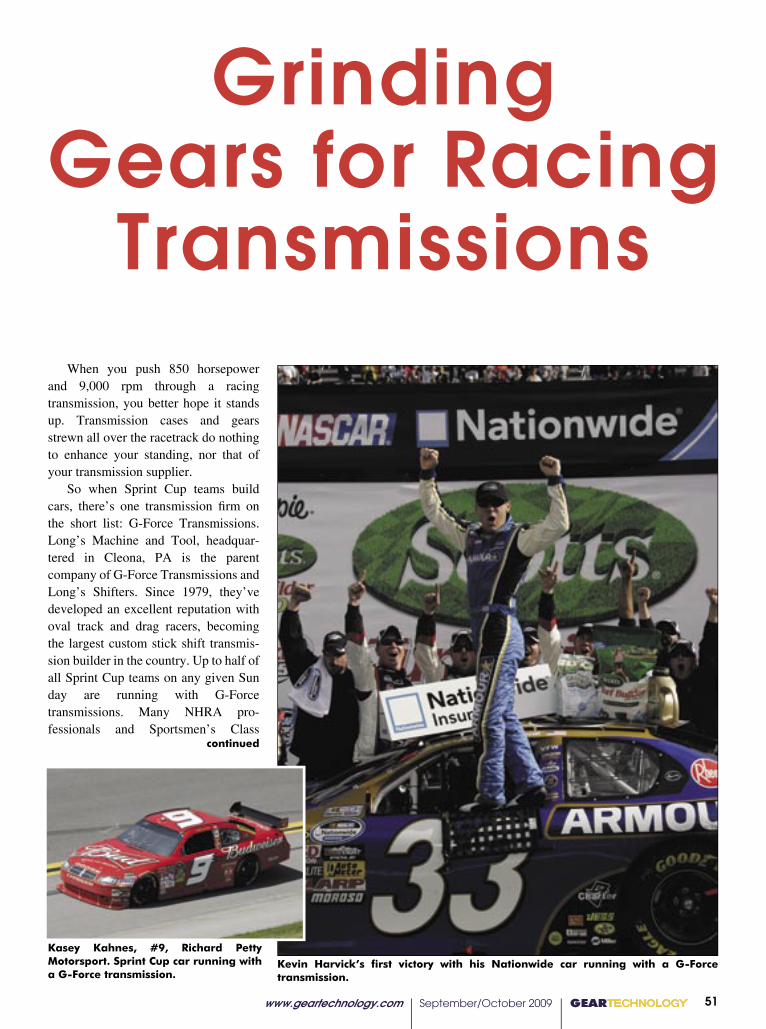
www.geartechnology.com September/October 2009 GEARTECHNOLOGY 51
When you push 850 horsepower and 9,000 rpm through a racing transmission, you better hope it stands up. Transmission cases and gears strewn all over the racetrack do nothing to enhance your standing, nor that of your transmission supplier.
So when Sprint Cup teams build cars, there’s one transmission fi rm on the short list: G-Force Transmissions. Long’s Machine and Tool, headquar-tered in Cleona, PA is the parent company of G-Force Transmissions and Long’s Shifters. Since 1979, they’ve developed an excellent reputation with oval track and drag racers, becoming the largest custom stick shift transmis-sion builder in the country. Up to half of all Sprint Cup teams on any given Sunday are running with G-Force transmissions. Many NHRA pro-fessionals and Sportsmen’s Class
continued
Grinding Gears for Racing
Transmissions
Kevin Harvick’s first victory with his Nationwide car running with a G-Force transmission.
Kasey Kahnes, #9, Richard Petty Motorsport. Sprint Cup car running with a G-Force transmission.
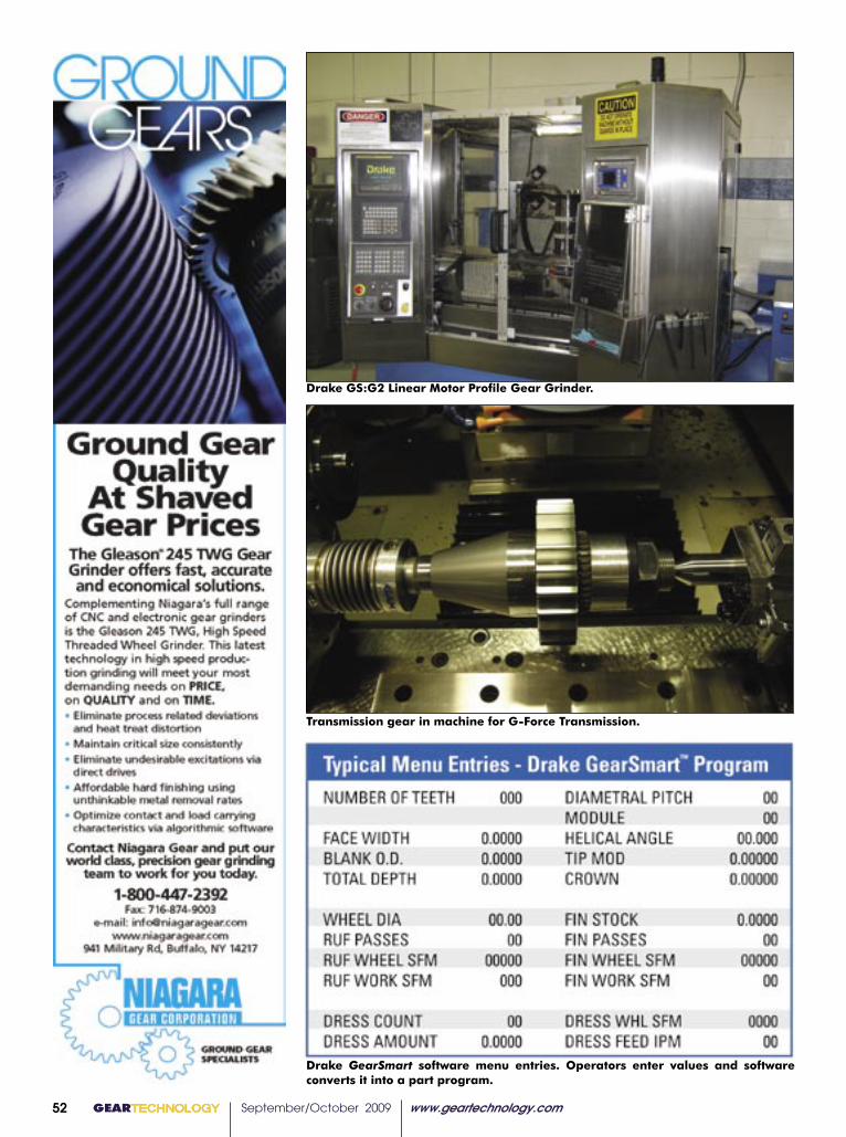
GEARTECHNOLOGY September/October 2009 www.geartechnology.com52
Drake GS:G2 Linear Motor Profile Gear Grinder.
Transmission gear in machine for G-Force Transmission.
Drake GearSmart software menu entries. Operators enter values and software converts it into a part program.
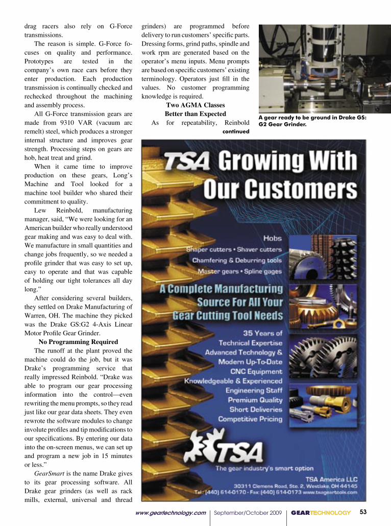
www.geartechnology.com September/October 2009 GEARTECHNOLOGY 53��������������������������������������������GEARTECHNOLOGY���27
���� ���� �������������� �����������������������������������������
���� ��� �������� ������������� ���������� ���� ����� ���� ������������������������������������������������
��������������������������������������������������������������������������������
�������������������������������������������� ����� ���������
����������� ������������ ��� ������������������������������������������������������������� ������������������������
���� ������������������ ���� �������� ����� ��������
�������������
approach that is in line with our quality standards, promotes employee satisfac-tion and saves the company money in the long run,” Werschky says.
A Case for Continuous Improvement
Robert Doshi, plant manager at Schafer Gear Works Inc., says the com-pany is not focused on any one specific lean principle, but is applying many aspects across the board.
“We’ve applied the principles that are needed in each area as the situation allows. As a job shop, it has proven dif-ficult to apply lean in mass. By keeping the overall goal of improving quality, delivery times and reducing cost while maintaining a safe and healthy environ-ment, we employ whatever tools will help us achieve our goals.”
The economic downturn has given Schafer the opportunity to focus inter-nally on customer satisfaction with shorter lead times, lower inventories and better quality products.
“It has also provided more time to streamline our processes and concen-trate on our 5S program,” Doshi says.
What lean ultimately provides for Schafer are the tools to become a growing, vibrant and customer-orient-ed company with international reach. Continuous improvement and involve-ment strategies include employees, cus-tomers and suppliers, and the company plans to spend the next five to 10 years providing its customer base with “what they want, when they want it and at a cost that allows both the customer and company to grow.”
“We feel the lean philosophy infused in every aspect of our culture. Our processes and our people will be our strength and biggest asset,” Doshi says.
Today, the company looks to its employees, the most important asset of the organization, to stand out.
“Our team’s resolve to not only sur-vive, but also shine during this time, is critical to ensuring our success,” Doshi says. “We know that there is business out there and we know that we should be the one to get it.”
This wouldn’t be possible if the
Schafer staff was unable to embrace a team concept.
“Without open lines of communica-tion and the willingness to forgive mis-takes, Schafer would not be as strong as it is today,” Doshi says. “As we learn, we share. Knowledge is a commodity that we feel grows as it is shared by our employees, and it sparks new life into areas that we thought could not get any better.”
In addition to its employees, Schafer continues to fortify relationships with
both suppliers and customers. “These relationships are open and
based on win-win thinking. By making ourselves transparent, we have found that, together, arrangements can be made to allow all of us to survive,” Doshi says.
While Schafer has always had a culture of continuous improvement, Doshi explains that a long term com-mitment is necessary to see these lean principles succeed.
continued
pgs 22-29 final.indd 7 8/6/2009 2:33:44 PM
A gear ready to be ground in Drake GS:G2 Gear Grinder.
drag racers also rely on G-Force transmissions.
The reason is simple. G-Force fo- cuses on quality and performance. Prototypes are tested in the company’s own race cars before they enter production. Each production transmission is continually checked and rechecked throughout the machining and assembly process.
All G-Force transmission gears are made from 9310 VAR (vacuum arc remelt) steel, which produces a stronger internal structure and improves gear strength. Processing steps on gears are hob, heat treat and grind.
When it came time to improve production on these gears, Long’s Machine and Tool looked for a machine tool builder who shared their commitment to quality.
Lew Reinbold, manufacturing manager, said, “We were looking for an American builder who really understood gear making and was easy to deal with. We manufacture in small quantities and change jobs frequently, so we needed a profile grinder that was easy to set up, easy to operate and that was capable of holding our tight tolerances all day long.”
After considering several builders, they settled on Drake Manufacturing of Warren, OH. The machine they picked was the Drake GS:G2 4-Axis Linear Motor Profile Gear Grinder.
No Programming RequiredThe runoff at the plant proved the
machine could do the job, but it was Drake’s programming service that really impressed Reinbold. “Drake was able to program our gear processing information into the control—even rewriting the menu prompts, so they read just like our gear data sheets. They even rewrote the software modules to change involute profiles and tip modifications to our specifications. By entering our data into the on-screen menus, we can set up and program a new job in 15 minutes or less.”
GearSmart is the name Drake gives to its gear processing software. All Drake gear grinders (as well as rack mills, external, universal and thread
grinders) are programmed before delivery to run customers’ specific parts. Dressing forms, grind paths, spindle and work rpm are generated based on the operator’s menu inputs. Menu prompts are based on specific customers’ existing terminology. Operators just fill in the values. No customer programming knowledge is required.
Two AGMA Classes Better than Expected
As for repeatability, Reinbold continued

GEARTECHNOLOGY September/October 2009 www.geartechnology.com54
Close up of a G-Force transmission gear.
explains, “The Drake grinder is very thermally stable, varying no more than 50 millionths from one gear to the next. We grind our gears to DIN standard 3962, looking for Q4. But in almost all cases, we achieve Q1 to Q2, which is 2–3 classes better.”
Linear motor axis positioning with 0.05 µm-resolution linear scale feedback helps the G2 achieve its accuracy. Its mineral-filled, cast polymer base
contributes significantly by damping vibration and controlling thermal growth. Also enhancing accuracy is the machine’s direct-drive synchronous torque motor that controls C-axis positioning. It has an 8-million-count encoder providing feedback resolution of 0.2 arc seconds and guaranteed index accuracy better than 10 arc seconds.
Acoustic Emissions MonitoringThe Drake G2 grinder is equipped
with an acoustic emissions (AE) stock dividing system that automatically locates the rough-cut gear teeth and positions the wheel spindle to grind equal amounts of stock from adjacent gear teeth.
Dyno TestsIndependent testing of G-Force
transmissions, subsequent to the addition of ground gears, showed improvements in durability and a reduction in gear noise and vibration. Parasitic drag tests indicated less horsepower is taken from the engine by the transmission, meaning more power is available at the wheel.
While credit must be given to G-Force’s team of designers, the pay-off is reserved for the gears they produce on the Drake GS:G2 Gear Grinder.
For more information:Drake Manufacturing4371 North Leavitt RoadWarren, OH 44485Phone: (330) 847-7291Fax: (330) [email protected]
Long’s Machine & Tool150 N. Grant StreetCleona, PA 17402Phone: (717) 202-8360Fax: (717) [email protected]
www.geartechnology.com September/October 2009 GEARTECHNOLOGY 5500 GEARTECHNOLOGY May 2009 www.geartechnology.com
N E W S
60© 2 0 0 6 , P r e s r i t e C o r p o r a t i o n We’re as NEAR as the NET! Visit our Web site at www.presrite.com.
I S O 9 0 0 1 : 2 0 0 0 T S 1 6 9 4 9 : 2 0 0 2
Are you interested in reducing your gear costs while increasing their quality? Presrite hot-forges intricate gears to net and near-net shapes, so little or no hobbing is required.We’ve invested millions to save you money and improve the performance of the gears you buy. Our dedicated gear-forging facility is equipped with a state-of-the-art gear lab, high-capacity presses, and the latest in sophisticated machinery.
See why customers from a wide range of industries and countries come to Presrite for forged gears. Contact us now for more information or a quote.
Weight Savings – As a blank, this large spur gear weighed 55 lbs. As a forged tooth gear with 1 millimeter of stock on the tooth profile for hobbing, it weighs just 37 lbs.
TAKE A BITE OUT OF YOUR GEAR COSTS
PRESRITE NEAR-NET GEARS GIVE YOUSTRENGTH OF A FORGING WITHLITTLE OR NO MACHINING.
Building A Better Business
Presrite Corporation3665 E. 78th St. • Cleveland, OH 44105
Phone: (216) 441-5990 Fax: (216) 441-2644
WITH TEETH LIKE THESE.
GT 5-09 72pgs.indd 60 4/27/2009 11:00:24 AM
GEARTECHNOLOGY September/October 2009 www.geartechnology.com68
������������������������������������������������������������������������������������������������������������������������������������������������������������������������������������������������������������������������������������
September 15-17, 2009Indianapolis
Come Visit Us At Booth #530
Aerospace, Defense, Automotive Prototypes
www.tifcogagegear.com www.deltaresearch.com
Delta Research &Tifco Gage & Gear
Precision Gears, Precision Machining and Complete Gearbox and Assemblies
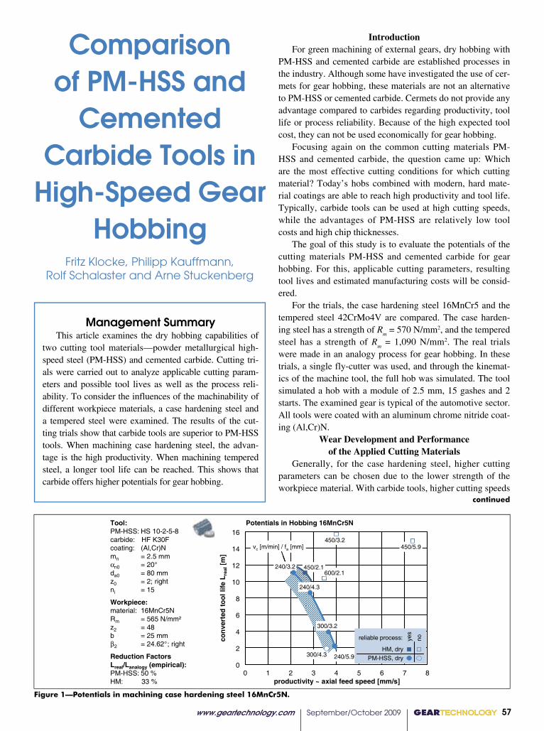
www.geartechnology.com September/October 2009 GEARTECHNOLOGY 57
continued
Management Summary This article examines the dry hobbing capabilities of
two cutting tool materials—powder metallurgical high-speed steel (PM-HSS) and cemented carbide. Cutting tri-als were carried out to analyze applicable cutting param-eters and possible tool lives as well as the process reli-ability. To consider the influences of the machinability of different workpiece materials, a case hardening steel and a tempered steel were examined. The results of the cut-ting trials show that carbide tools are superior to PM-HSS tools. When machining case hardening steel, the advan-tage is the high productivity. When machining tempered steel, a longer tool life can be reached. This shows that carbide offers higher potentials for gear hobbing.
IntroductionFor green machining of external gears, dry hobbing with
PM-HSS and cemented carbide are established processes in the industry. Although some have investigated the use of cer-mets for gear hobbing, these materials are not an alternative to PM-HSS or cemented carbide. Cermets do not provide any advantage compared to carbides regarding productivity, tool life or process reliability. Because of the high expected tool cost, they can not be used economically for gear hobbing.
Focusing again on the common cutting materials PM-HSS and cemented carbide, the question came up: Which are the most effective cutting conditions for which cutting material? Today’s hobs combined with modern, hard mate-rial coatings are able to reach high productivity and tool life. Typically, carbide tools can be used at high cutting speeds, while the advantages of PM-HSS are relatively low tool costs and high chip thicknesses.
The goal of this study is to evaluate the potentials of the cutting materials PM-HSS and cemented carbide for gear hobbing. For this, applicable cutting parameters, resulting tool lives and estimated manufacturing costs will be consid-ered.
For the trials, the case hardening steel 16MnCr5 and the tempered steel 42CrMo4V are compared. The case harden-ing steel has a strength of R
m = 570 N/mm2, and the tempered
steel has a strength of Rm = 1,090 N/mm2. The real trials
were made in an analogy process for gear hobbing. In these trials, a single fly-cutter was used, and through the kinemat-ics of the machine tool, the full hob was simulated. The tool simulated a hob with a module of 2.5 mm, 15 gashes and 2 starts. The examined gear is typical of the automotive sector. All tools were coated with an aluminum chrome nitride coat-ing (Al,Cr)N.
Wear Development and Performance of the Applied Cutting Materials
Generally, for the case hardening steel, higher cutting parameters can be chosen due to the lower strength of the workpiece material. With carbide tools, higher cutting speeds
Comparison of PM-HSS and
Cemented Carbide Tools in
High-Speed Gear Hobbing
Fritz Klocke, Philipp Kauffmann, Rolf Schalaster and Arne Stuckenberg
0 1 3 4 5 8productivity ~ axial feed speed [mm/s]
0
4
8
16
2
10
6
L efil lo ot d etr evnocl ae r
]m [
Tool:PM-HSS: HS 10-2-5-8carbide: HF K30Fcoating: (Al,Cr)Nmn = 2.5 mm�n0 = 20°da0 = 80 mmz0 = 2; rightni = 15
Workpiece:material: 16MnCr5NRm = 565 N/mm²z2 = 48b = 25 mm�2 = 24.62° ; right
Reduction Factors Lreal/Lanalogy (empirical):PM-HSS: 50 %HM: 33 %
2
vc [m/min] / fa [mm]
6 7
14
12
PM-HSS, dryHM, dry
sey onreliable process:
PM-HSS, dryHM, dry
sey onreliable process:
Potentials in Hobbing 16MnCr5N
450/5.9
300/4.3
240/4.3
300/3.2
240/3.2 450/2.1
450/3.2
600/2.1
240/5.9
450/5.9
300/4.3
240/4.3
300/3.2
240/3.2 450/2.1
450/3.2
600/2.1
240/5.9
Figure 1—Potentials in machining case hardening steel 16MnCr5N.
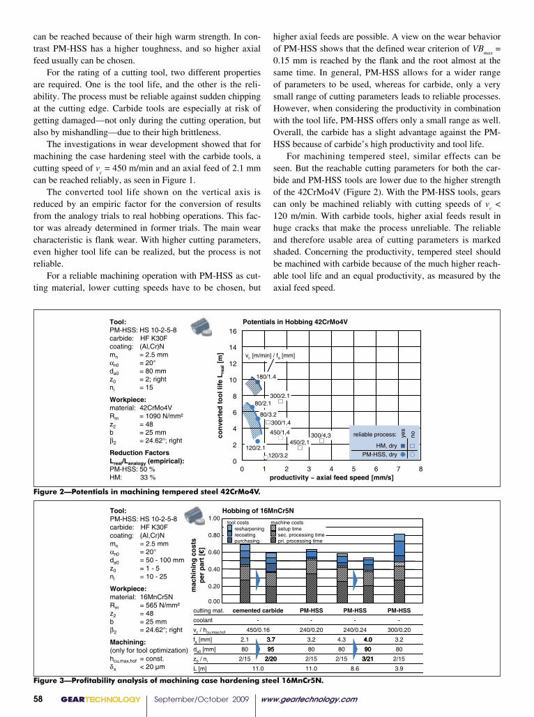
GEARTECHNOLOGY September/October 2009 www.geartechnology.com58
can be reached because of their high warm strength. In con-trast PM-HSS has a higher toughness, and so higher axial feed usually can be chosen.
For the rating of a cutting tool, two different properties are required. One is the tool life, and the other is the reli-ability. The process must be reliable against sudden chipping at the cutting edge. Carbide tools are especially at risk of getting damaged—not only during the cutting operation, but also by mishandling—due to their high brittleness.
The investigations in wear development showed that for machining the case hardening steel with the carbide tools, a cutting speed of v
c = 450 m/min and an axial feed of 2.1 mm
can be reached reliably, as seen in Figure 1. The converted tool life shown on the vertical axis is
reduced by an empiric factor for the conversion of results from the analogy trials to real hobbing operations. This fac-tor was already determined in former trials. The main wear characteristic is flank wear. With higher cutting parameters, even higher tool life can be realized, but the process is not reliable.
For a reliable machining operation with PM-HSS as cut-ting material, lower cutting speeds have to be chosen, but
Figure 3—Profitability analysis of machining case hardening steel 16MnCr5N.
Figure 2—Potentials in machining tempered steel 42CrMo4V.
0 1 3 4 5 8productivity ~ axial feed speed [mm/s]
0
4
8
16
2
10
6
Potentials in Hobbing 42CrMo4V
2
vc [m/min] / fa [mm]
6 7
80/2.1
14
12
120/3.2
180/1.4
80/3.2
300/2.1
120/2.1
Tool:PM-HSS: HS 10-2-5-8carbide: HF K30Fcoating: (Al,Cr)Nmn = 2.5 mm�n0 = 20°da0 = 80 mmz0 = 2; rightni = 15
Workpiece:material: 42CrMo4VRm = 1090 N/mm²z2 = 48b = 25 mm�2 = 24.62° ; right
Reduction FactorsLreal/Lanalogy (empirical):PM-HSS: 50 %HM: 33 %
450/1,4
450/2,1300/4,3
300/1,4
PM-HSS, dryHM, dry
sey onreliable process:
PM-HSS, dryHM, dry
sey onreliable process:
L ef il loo t d etrevnoclaer
]m[
higher axial feeds are possible. A view on the wear behavior of PM-HSS shows that the defined wear criterion of VB
max =
0.15 mm is reached by the flank and the root almost at the same time. In general, PM-HSS allows for a wider range of parameters to be used, whereas for carbide, only a very small range of cutting parameters leads to reliable processes. However, when considering the productivity in combination with the tool life, PM-HSS offers only a small range as well. Overall, the carbide has a slight advantage against the PM-HSS because of carbide’s high productivity and tool life.
For machining tempered steel, similar effects can be seen. But the reachable cutting parameters for both the car-bide and PM-HSS tools are lower due to the higher strength of the 42CrMo4V (Figure 2). With the PM-HSS tools, gears can only be machined reliably with cutting speeds of v
c <
120 m/min. With carbide tools, higher axial feeds result in huge cracks that make the process unreliable. The reliable and therefore usable area of cutting parameters is marked shaded. Concerning the productivity, tempered steel should be machined with carbide because of the much higher reach-able tool life and an equal productivity, as measured by the axial feed speed.
1.00
0.80
0.60
0.40
0.20
0.00
Hobbing of 16MnCr5N
450/0.16
80
2.1
2/15
11.0
cemented carbide-
240/0.20
80
3.2
2/15
11.0
PM-HSS-
240/0.24
80
4.3
2/15
8.6
PM-HSS-
300/0.20
80
3.2
2/15
3.9
PM-HSS-
95
3.7
2/20
90
4.0
3/21
95
3.7
2/20
95
3.7
2/20
90
4.0
3/21
90
4.0
3/21
resharpeningrecoatingpurchasing
setup timesec. processing timepri. processing time
tool costs machine costs
vc / hcu,max,hof
da0 [mm]
fa [mm]
z0 / ni
L [m]
cutting mat.
coolant
Tool:PM-HSS: HS 10-2-5-8carbide: HF K30Fcoating: (Al,Cr)Nmn = 2.5 mm�n0 = 20°da0 = 50 - 100 mmz0 = 1 - 5ni = 10 - 25
Workpiece:material: 16MnCr5NRm = 565 N/mm²z2 = 48b = 25 mm�2 = 24.62° ; right
Machining:(only for tool optimization)hcu,max,hof = const.�x < 20 µm
stsoc gninih cam
] €[ tr ap rep
beyond these values, heavy crater wear causes reductions in tool life.
To reach acceptable tool lives reliably in machining tempered steel, the cutting parameters must be reduced significantly for both cutting materials because of the high mechanical and thermal load.
With the carbide cutting material, tool lives that are simi-lar to those achieved when machining case hardening steel can be achieved.
The results of the cutting trials show that carbide tools are superior to PM-HSS tools. When machining case harden-ing steel, the advantage is the high productivity. When hob-bing tempered steel, a longer tool life can be reached. This shows that carbide basically offers higher potentials for gear hobbing.
However, the economic analysis shows that both cutting materials can be employed at similar machining costs. A trend can be identified that the application of high speed steel is slightly cheaper for machining case hardening steel while carbide tools offer advantages in cutting tempered steel.
The study shows that PM-HSS and carbide tools are capable of hobbing in a similar way. Carbide tools offer high productivity and good tool life while PM-HSS shows very low tool costs. Basically, PM-HSS hobs can be used beneficially to cut materials with lower hardness and tensile strengths, while tougher materials should be machined with carbide tools. However, the machinability of actual gears in an industrial environment is also affected by the specific tooth profile and the workpiece material.
Prof. Dr.-Ing. Dr.-Ing. E.h. Dr. h.c. Fritz Klocke is head of the Chair of Manufacturing Technology at the Laboratory for Machine Tools and Production Engineering (WZL), a part of RWTH Aachen University in Germany. Also, he is director of the Fraunhofer Institute for Production Technology in Aachen, Germany.
Dipl.-Ing. Philipp Kauffmann has a degree in mechanical engi-neering. Since 2005 he has worked for the Gear Research Center at the Laboratory of Machine Tools at RWTH Aachen University. He works in the area of PM gear manufacturing and testing with a focus on surface densification by rolling. Since 2007 he has led the team of gear manufacturing technologies.
Dipl.-Ing. Rolf Schalaster is a research associate and doctoral candidate under Prof. Klocke in production engineering at the Gear Research Center at RWTH Aachen University. His principal field of work is gear hobbing and especially process optimization of gear finish hobbing processes.
Dipl.-Ing. Arne Stuckenberg is a research associate and doc-toral candidate under Prof. Klocke in production engineering at the Gear Research Center at RWTH Aachen University. His principal research activities are in gear hobbing. He works on tool recondi-tioning of hobs and process forces in gear hobbing.
Economic AnalysisFor deciding which cutting material is preferable, not
only the productivity and the tool life are important, but also the tool costs. Generally the tool costs for a PM-HSS hob are lower. The tool costs consist of three parts: the pur-chase cost, the recoating cost and the resharpening cost. The recoating and resharpening costs are especially important in the economic analysis of hobbing tools.
The costs for recoating are similar for both cutting mate-rials. But the purchase costs and the resharpening costs, due to the strength, are higher for carbide tools. For a closing analysis regarding which is the best tool, the total costs of ownership are interesting.
For the material 16MnCr5, an analysis on the profitabili-ty is shown in Figure 3. Starting with the investigated param-eters in the analogy process trials, the process is successively optimized with gear hobbing calculation software. The first, third, fourth and sixth column each show the machining cost per part for cutting parameters used in the trials. The cost per part for PM-HSS at medium cutting speed (third and fourth columns) is already without any optimization lower than for machining with carbide.
Only the PM-HSS trial with very high cutting speeds (sixth column) is not competitive. With the results of the tri-als, an optimization is made with the target of an axial feed rate with feed marks of dx < 20 µm and a constant maxi-mum chip thickness for each cutting parameter. The tool outside diameter and number of starts and gashes is varied. With these default values, the software calculates every tool design which achieves these requirements. The result is again lower costs per part and still the lowest overall cost for a PM-HSS variant.
For tempered steel (not displayed here), the situation is just the other way around. For tempered steel, machining with carbide leads to lower costs per part.
ConclusionBased on the current state of the art regarding tool devel-
opment, the capabilities of PM-HSS and cemented carbide have been examined as materials for gear hobbing. Cutting trials were carried out in fly-cutter gear hobbing to analyze applicable cutting parameters and possible tool lives as well as the process reliability. To consider the influences of the machining properties of cutting different workpiece materi-als, a case hardening steel with a tensile strength of R
m = 570
N/mm² and a tempered steel with Rm = 1,090 N/mm² have
been examined. Machining case hardening steel has shown that a cutting
speed of vc = 450 m/min can be reached employing carbide
tools at relatively low axial feeds. A high tool life can be reached reliably using these parameters. Enhanced machin-ing parameters may lead to an increased tool life, but the fly-cutters fail because of breakouts of the cutting edge.
By the application of PM-HSS at a cutting speed of vc = 240 m/min and medium axial feeds, an appropriate tool life can be reached. By raising the cutting speed or the axial feed
www.geartechnology.com September/October 2009 GEARTECHNOLOGY 59
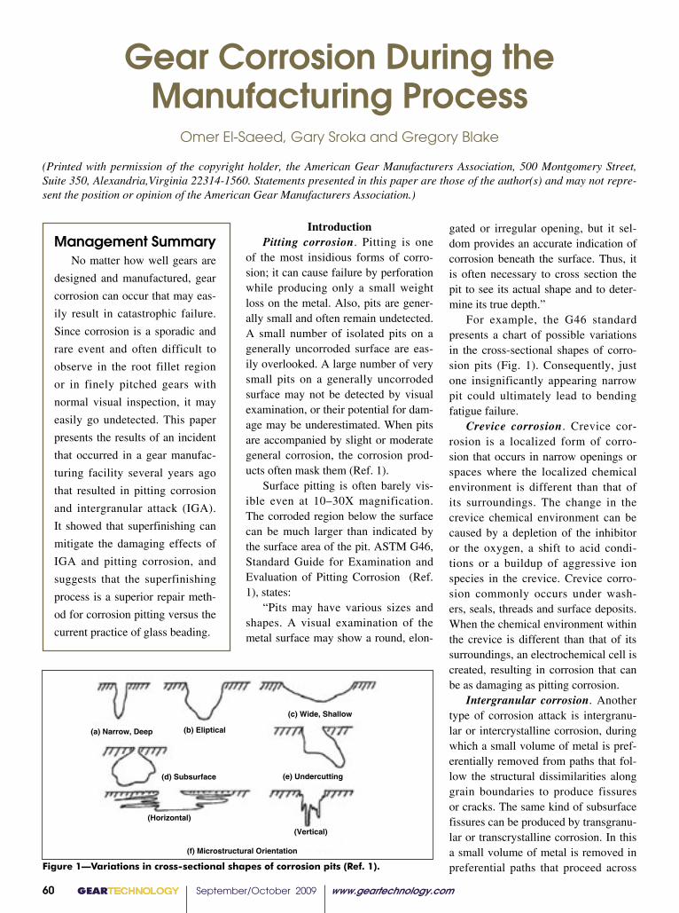
GEARTECHNOLOGY September/October 2009 www.geartechnology.com60
Gear Corrosion During the Manufacturing Process
Omer El-Saeed, Gary Sroka and Gregory Blake
(Printed with permission of the copyright holder, the American Gear Manufacturers Association, 500 Montgomery Street, Suite 350, Alexandria,Virginia 22314-1560. Statements presented in this paper are those of the author(s) and may not repre-sent the position or opinion of the American Gear Manufacturers Association.)
Figure 1—Variations in cross-sectional shapes of corrosion pits (Ref. 1).
(a) Narrow, Deep (b) Eliptical
(c) Wide, Shallow
(d) Subsurface (e) Undercutting
(Horizontal)
(Vertical)
(f) Microstructural Orientation
IntroductionPitting corrosion. Pitting is one
of the most insidious forms of corro-sion; it can cause failure by perforation while producing only a small weight loss on the metal. Also, pits are gener-ally small and often remain undetected. A small number of isolated pits on a generally uncorroded surface are eas-ily overlooked. A large number of very small pits on a generally uncorroded surface may not be detected by visual examination, or their potential for dam-age may be underestimated. When pits are accompanied by slight or moderate general corrosion, the corrosion prod-ucts often mask them (Ref. 1).
Surface pitting is often barely vis-ible even at 10–30X magnification. The corroded region below the surface can be much larger than indicated by the surface area of the pit. ASTM G46, Standard Guide for Examination and Evaluation of Pitting Corrosion (Ref. 1), states:
“Pits may have various sizes and shapes. A visual examination of the metal surface may show a round, elon-
Management SummaryNo matter how well gears are
designed and manufactured, gear
corrosion can occur that may eas-
ily result in catastrophic failure.
Since corrosion is a sporadic and
rare event and often difficult to
observe in the root fillet region
or in finely pitched gears with
normal visual inspection, it may
easily go undetected. This paper
presents the results of an incident
that occurred in a gear manufac-
turing facility several years ago
that resulted in pitting corrosion
and intergranular attack (IGA).
It showed that superfinishing can
mitigate the damaging effects of
IGA and pitting corrosion, and
suggests that the superfinishing
process is a superior repair meth-
od for corrosion pitting versus the
current practice of glass beading.
gated or irregular opening, but it sel-dom provides an accurate indication of corrosion beneath the surface. Thus, it is often necessary to cross section the pit to see its actual shape and to deter-mine its true depth.”
For example, the G46 standard presents a chart of possible variations in the cross-sectional shapes of corro-sion pits (Fig. 1). Consequently, just one insignificantly appearing narrow pit could ultimately lead to bending fatigue failure.
Crevice corrosion. Crevice cor-rosion is a localized form of corro-sion that occurs in narrow openings or spaces where the localized chemical environment is different than that of its surroundings. The change in the crevice chemical environment can be caused by a depletion of the inhibitor or the oxygen, a shift to acid condi-tions or a buildup of aggressive ion species in the crevice. Crevice corro-sion commonly occurs under wash-ers, seals, threads and surface deposits. When the chemical environment within the crevice is different than that of its surroundings, an electrochemical cell is created, resulting in corrosion that can be as damaging as pitting corrosion.
Intergranular corrosion. Another type of corrosion attack is intergranu-lar or intercrystalline corrosion, during which a small volume of metal is pref-erentially removed from paths that fol-low the structural dissimilarities along grain boundaries to produce fissures or cracks. The same kind of subsurface fissures can be produced by transgranu-lar or transcrystalline corrosion. In this a small volume of metal is removed in preferential paths that proceed across
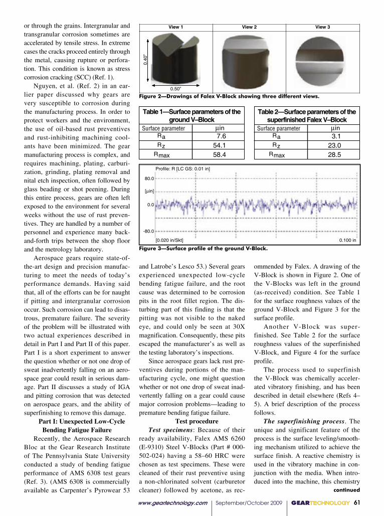
www.geartechnology.com September/October 2009 GEARTECHNOLOGY 61
continued
View 1 View 2 View 3
”04.0
0.50”Figure 2. Drawings of Falex V--Block showing three different views
Figure 3. Surface profile of the ground V--Block
Profile: R [LC GS: 0.01 in]
[0.020 in/Skt]
80.0
[�in]
0.0
-80.0
0.100 in
Surface parameter ���Ra 7.6Rz 54.1
Rmax 58.4
3.123.028.5
Table 1—Surface parameters of theground V–Block
Surface parameter ���RaRz
Rmax
Table 2—Surface parameters of thesuperfinished Falex V–Block
Surface parameter ���Ra 7.6Rz 54.1
Rmax 58.4
3.123.028.5
Table 1—Surface parameters of theground V–Block
Surface parameter ���RaRz
Rmax
Table 2—Surface parameters of thesuperfinished Falex V–Block
Figure 2—Drawings of Falex V-Block showing three different views.
Figure 3—Surface profile of the ground V-Block.
or through the grains. Intergranular and transgranular corrosion sometimes are accelerated by tensile stress. In extreme cases the cracks proceed entirely through the metal, causing rupture or perfora-tion. This condition is known as stress corrosion cracking (SCC) (Ref. 1).
Nguyen, et al. (Ref. 2) in an ear-lier paper discussed why gears are very susceptible to corrosion during the manufacturing process. In order to protect workers and the environment, the use of oil-based rust preventives and rust-inhibiting machining cool-ants have been minimized. The gear manufacturing process is complex, and requires machining, plating, carburi-zation, grinding, plating removal and nital etch inspection, often followed by glass beading or shot peening. During this entire process, gears are often left exposed to the environment for several weeks without the use of rust preven-tives. They are handled by a number of personnel and experience many back-and-forth trips between the shop floor and the metrology laboratory.
Aerospace gears require state-of-the-art design and precision manufac-turing to meet the needs of today’s performance demands. Having said that, all of the efforts can be for naught if pitting and intergranular corrosion occur. Such corrosion can lead to disas-trous, premature failure. The severity of the problem will be illustrated with two actual experiences described in detail in Part I and Part II of this paper. Part I is a short experiment to answer the question whether or not one drop of sweat inadvertently falling on an aero-space gear could result in serious dam-age. Part II discusses a study of IGA and pitting corrosion that was detected on aerospace gears, and the ability of superfinishing to remove this damage.
Part I: Unexpected Low-Cycle Bending Fatigue Failure
Recently, the Aerospace Research Bloc at the Gear Research Institute of The Pennsylvania State University conducted a study of bending fatigue performance of AMS 6308 test gears (Ref. 3). (AMS 6308 is commercially available as Carpenter’s Pyrowear 53
and Latrobe’s Lesco 53.) Several gears experienced unexpected low-cycle bending fatigue failure, and the root cause was determined to be corrosion pits in the root fillet region. The dis-turbing part of this finding is that the pitting was not visible to the naked eye, and could only be seen at 30X magnification. Consequently, these pits escaped the manufacturer’s as well as the testing laboratory’s inspections.
Since aerospace gears lack rust pre-ventives during portions of the man-ufacturing cycle, one might question whether or not one drop of sweat inad-vertently falling on a gear could cause major corrosion problems—leading to premature bending fatigue failure.
Test procedure Test specimens: Because of their
ready availability, Falex AMS 6260 (E-9310) Steel V-Blocks (Part # 000-502-024) having a 58–60 HRC were chosen as test specimens. These were cleaned of their rust preventive using a non-chlorinated solvent (carburetor cleaner) followed by acetone, as rec-
ommended by Falex. A drawing of the V-Block is shown in Figure 2. One of the V-Blocks was left in the ground (as-received) condition. See Table 1 for the surface roughness values of the ground V-Block and Figure 3 for the surface profile.
Another V-Block was super-finished. See Table 2 for the surface roughness values of the superfinished V-Block, and Figure 4 for the surface profile.
The process used to superfinish the V-Block was chemically acceler-ated vibratory finishing, and has been described in detail elsewhere (Refs 4–5). A brief description of the process follows.
The superfinishing process. The unique and significant feature of the process is the surface leveling/smooth-ing mechanism utilized to achieve the surface finish. A reactive chemistry is used in the vibratory machine in con-junction with the media. When intro-duced into the machine, this chemistry

GEARTECHNOLOGY September/October 2009 www.geartechnology.com62
Figure 4. Surface profile of the superfinished Falex V--Block
Profile: R [LC GS: 0.01 in]
[0.01 in/Skt]
40.0
[�in]
0.0
-40.0
0.05 in
Superfinished Ground
Baseline
Time = 0.0 hr
Time = 0.5 hr
Time = 1.5 hr
Time = 2.3 hr
Figure 5. View 2 -- Photographs of a superfinished (L) and ground V--Block(R) with one drop of artificial sweat deposited on the surface
Superfinished Ground
Time = 127 hr
Figure 6. View 2 -- Photograph of the superfinished (L) and ground V--Block(R) Surface after 127 hours
Figure 4—Surface profile of the superfinished Falex V-Block.
Figure 5—View 2: Photographs of a superfinished (l) and ground V-Block (r) with one drop of artificial sweat deposited on the surface.
Figure 6—View 2: Photograph of the superfinished (L) and ground V-Block (R) sur-face after 127 hours.
produces a stable, soft conversion coat-ing across the asperities (peaks and val-leys) of the gears. The rubbing motion across the gears developed by the machine and media effectively wipes the soft conversion coating off the “peaks” of the gear’s surfaces, there-by removing a microlayer of metal. The “valleys” are left untouched since the media bridges over them and can-not wipe the conversion coating. The conversion coating is continually re-formed and wiped off during this stage, producing a surface leveling/smoothing mechanism. This mechanism is contin-ued in the vibratory machine until the surfaces of the gears are free of asperi-ties. At this point, the reactive chem-istry is rinsed from the machine with a neutral soap. The conversion coating is wiped off the gears one final time to produce the mirror-like surface.
Artificial sweat. ISO 3160-2 gives a formula for artificial sweat. It con-sists of 20 g/L sodium chloride (NaCl), 17.5 g/L ammonium chloride (NH4Cl), 5 g/L urea (NH2CONH2), 5 g/L acetic acid (CH3COOH) and 15 g/L racemic lactic acid (CH3CH(OH)COOH) with the pH adjusted to 4.7 by NaOH.
Procedure. One drop of artificial sweat was placed on the test region of a superfinished V-Block and a ground V-Block. The specimens were then allowed to set in an air-conditioned office exposed to the atmosphere, and were examined as time progressed.
Results. Surprisingly, serious cor-rosion was observed in only 1.5 hours. After 2.3 hours the artificial sweat appeared dried, and a heterogeneous deposit was observed on each speci-men, giving the impression that condi-tions were ripe for crevice corrosion attack (Fig. 5).
After 127 hours, heavy corrosion products were observed on the surface of the V-Block specimens. The layer appeared thicker on the ground versus the superfinished surface (Fig. 6).
This layer was mechanically removed; the V-Block was polished with 1,500-grit paper to remove the greater part of the corrosion depos-its. The surface was then cleaned with
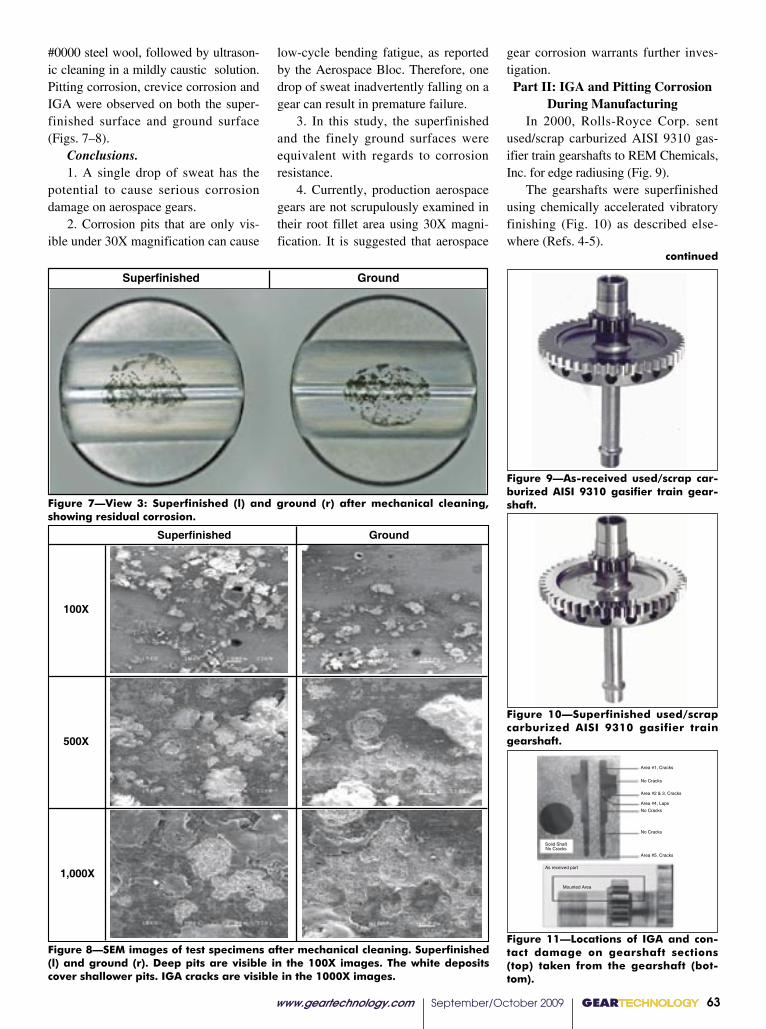
www.geartechnology.com September/October 2009 GEARTECHNOLOGY 63
continued
Superfinished Ground
Figure 7. View 3 -- Superfinished (L) and ground (R) after mechanical cleaning,showing residual corrosion
Superfinished Ground
100X
500X
1,000X
Figure 8. SEM images of test specimens after mechanical cleaning. Superfinished (L) andground (R). Deep pits are visible in the 100X images. The white deposits cover shallower pits.
IGA cracks are visible in the 1000X images.
Figure 9. As received used/scrap carburizedAISI 9310 gasifier train gearshaft
Figure 10. Superfinished used/scrapcarburized AISI 9310 gasifier train
gearshaft
As received part
Mounted Area
Solid ShaftNo Cracks
Area #1, Cracks
No Cracks
Area #2 & 3, Cracks
Area #4, Laps
No Cracks
No Cracks
Area #5, Cracks
Figure 7—View 3: Superfinished (l) and ground (r) after mechanical cleaning, showing residual corrosion.
Figure 8—SEM images of test specimens after mechanical cleaning. Superfinished (l) and ground (r). Deep pits are visible in the 100X images. The white deposits cover shallower pits. IGA cracks are visible in the 1000X images.
Figure 9—As-received used/scrap car-burized AISI 9310 gasifier train gear-shaft.
Figure 10—Superfinished used/scrap carburized AISI 9310 gasifier train gearshaft.
Figure 11—Locations of IGA and con-tact damage on gearshaft sections (top) taken from the gearshaft (bot-tom).
#0000 steel wool, followed by ultrason-ic cleaning in a mildly caustic solution.Pitting corrosion, crevice corrosion and IGA were observed on both the super-finished surface and ground surface (Figs. 7–8).
Conclusions.1. A single drop of sweat has the
potential to cause serious corrosion damage on aerospace gears.
2. Corrosion pits that are only vis-ible under 30X magnification can cause
low-cycle bending fatigue, as reported by the Aerospace Bloc. Therefore, one drop of sweat inadvertently falling on a gear can result in premature failure.
3. In this study, the superfinished and the finely ground surfaces were equivalent with regards to corrosion resistance.
4. Currently, production aerospace gears are not scrupulously examined in their root fillet area using 30X magni-fication. It is suggested that aerospace
gear corrosion warrants further inves-tigation.Part II: IGA and Pitting Corrosion
During ManufacturingIn 2000, Rolls-Royce Corp. sent
used/scrap carburized AISI 9310 gas-ifier train gearshafts to REM Chemicals, Inc. for edge radiusing (Fig. 9).
The gearshafts were superfinished using chemically accelerated vibratory finishing (Fig. 10) as described else-where (Refs. 4-5).

GEARTECHNOLOGY September/October 2009 www.geartechnology.com64
Figure 12. Photomicrographs of Area 1 at500X magnification. Circles show several IGA
cracks.
500x 20.0 µm
Polished
3% Nital etch
500x 20.0 µm
Figure 13. Photomicrographs of Area 2 at 50Xmagnification showing residual machining
lines
50x 200.0 µm
Polished
3% Nital etch
50x 200.0 µm
500x 20.0 µm
500x 20.0 µm
Polished
3% Nital etch
500x 20.0 µm
500x 20.0 µm
Polished
3% Nital etch
500x 20.0 µm
500x 20.0 µm
Polished
3% Nital etch
500x 20.0 µm
500x 20.0 µm
Polished Section od “V” Area
3% Nital Etched
Figure 12—Photomicrographs of Area 1 at 500X magnification. Circles show several IGA cracks.
Figure 15—Photomicrograph of Area 4 at 500X magnification showing surface damage.
Figure 13—Photomicrographs of Area 2 at 50X magnification showing resid-ual machining lines.
Figure 16—Photomicrograph of Area 5 at 500X magnification. Circle shows surface microcracks.
Figure 14—Photomicrograph of Area 3 at 500X magnification. Circles show visible IGA cracks in the valleys of the machining lines.
Figure 17—Photomicrograph of the V-Area of the superfinished V-Block at 500X magnification. No pitting or IGA was detected.
Superfinishing occurs in a mild-ly acidic medium. Consequently, the superfinished gearshafts were rigor-ously inspected for metallurgical damage upon return to Rolls-Royce. Surprisingly, intergranular attack (IGA) and surface microcracks were detected, and these were initially attributed to the superfinishing process. REM con-ducted their own inspection of a non-superfinished, scrap/used gearshaft at a metallurgical laboratory (Anderson & Associates, Houston, TX). The gearshaft was sectioned, polished, and examined. IGA as well as other sur-face damage were found proving that the damage was produced during the manufacturing process prior to super-finishing. Figure 11 shows the sec-tions and the target inspection areas.
Photomicrographs of the various areas are shown in Figures 12–16.
In order to demonstrate that the superfinishing process did not cause IGA, a Falex 9310 V-Block was super-finished under the same conditions as the AISI 9310 gearshaft. The V-Block was sectioned, polished and the V-area was examined. The photomicrographs showed no IGA or pitting (Fig. 17). This definitively confirmed that super-finishing does not induce IGA.
Once it was proven the superfinish-ing process does not induce IGA or pitting on AISI 9310, Rolls-Royce then questioned whether it would remove the IGA or exacerbate the problem by deepening the cracks. The reason for the latter question stems from the acid-ic chemicals used in the superfinish-
ing process. In this process, the refine-ment chemistry creates a coating on the gears that is continuously wiped off by the media. However, the media only removes the peaks, leaving the valleys of the metal surface untouched. Metallurgists often expressed concerns that the acidic chemistry had the poten-tial to cause corrosion in the valleys of the metal surface. This was a reason-able concern, eight years ago, when the superfinishing process was being intro-duced to the aerospace gear industry.
To investigate this concern, Rolls-Royce provided REM with another gearshaft that had IGA for further eval-uation (Fig. 18).
The gearshaft was sectioned, pol-ished, and examined. SEM images con-firmed the presence of IGA (Fig. 19).
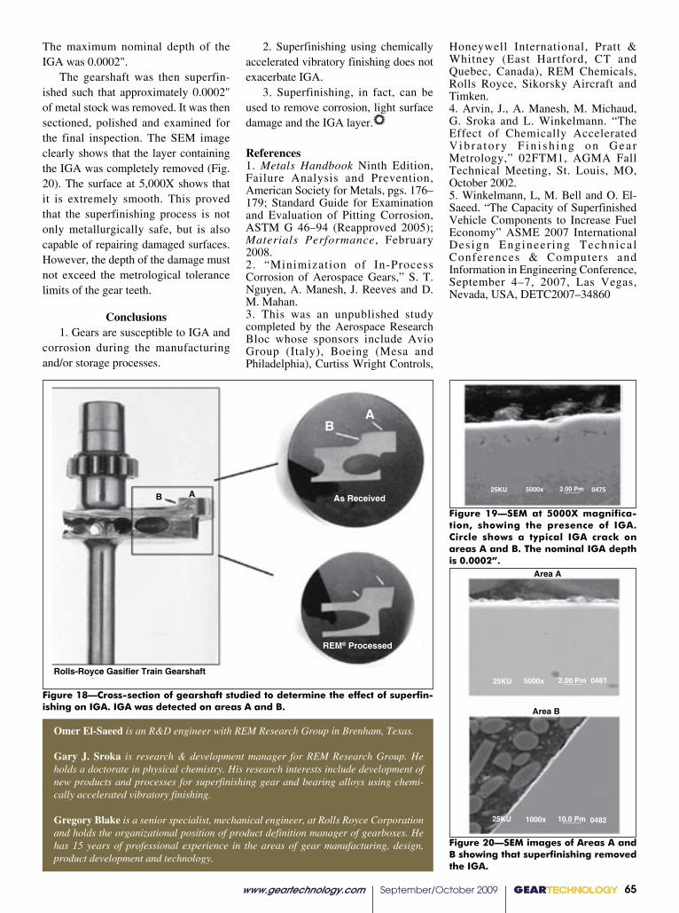
2. Superfinishing using chemically accelerated vibratory finishing does not exacerbate IGA.
3. Superfinishing, in fact, can be used to remove corrosion, light surface damage and the IGA layer.
References1. Metals Handbook Ninth Edition, Failure Analysis and Prevention, American Society for Metals, pgs. 176–179; Standard Guide for Examination and Evaluation of Pitting Corrosion, ASTM G 46–94 (Reapproved 2005); Materials Performance, February 2008.2. “Minimization of In-Process Corrosion of Aerospace Gears,” S. T. Nguyen, A. Manesh, J. Reeves and D. M. Mahan.3. This was an unpublished study completed by the Aerospace Research Bloc whose sponsors include Avio Group (Italy), Boeing (Mesa and Philadelphia), Curtiss Wright Controls,
Honeywell International, Pratt & Whitney (East Hartford, CT and Quebec, Canada), REM Chemicals, Rolls Royce, Sikorsky Aircraft and Timken.4. Arvin, J., A. Manesh, M. Michaud, G. Sroka and L. Winkelmann. “The Effect of Chemically Accelerated V i b r a t o r y F i n i s h i n g o n G e a r Metrology,” 02FTM1, AGMA Fall Technical Meeting, St. Louis, MO, October 2002.5. Winkelmann, L, M. Bell and O. El-Saeed. “The Capacity of Superfinished Vehicle Components to Increase Fuel Economy” ASME 2007 International Des ign Engineer ing Technica l Conferences & Computers and Information in Engineering Conference, September 4–7, 2007, Las Vegas, Nevada, USA, DETC2007–34860
www.geartechnology.com September/October 2009 GEARTECHNOLOGY 65
BA
B A As Received
REM® Processed
Rolls-Royce Gasifier Train Gearshaft
Figure 18—Cross-section of gearshaft studied to determine the effect of superfin-ishing on IGA. IGA was detected on areas A and B.
25KU 5000x 2.00 Pm 0475
25KU 5000x 2.00 Pm 0481
25KU 1000x 10.0 Pm 0482
Area A
Area B
Figure 20—SEM images of Areas A and B showing that superfinishing removed the IGA.
Figure 19—SEM at 5000X magnifica-tion, showing the presence of IGA. Circle shows a typical IGA crack on areas A and B. The nominal IGA depth is 0.0002”.
The maximum nominal depth of the IGA was 0.0002".
The gearshaft was then superfin-ished such that approximately 0.0002" of metal stock was removed. It was then sectioned, polished and examined for the final inspection. The SEM image clearly shows that the layer containing the IGA was completely removed (Fig. 20). The surface at 5,000X shows that it is extremely smooth. This proved that the superfinishing process is not only metallurgically safe, but is also capable of repairing damaged surfaces. However, the depth of the damage must not exceed the metrological tolerance limits of the gear teeth.
Conclusions1. Gears are susceptible to IGA and
corrosion during the manufacturing and/or storage processes.
Omer El-Saeed is an R&D engineer with REM Research Group in Brenham, Texas.
Gary J. Sroka is research & development manager for REM Research Group. He holds a doctorate in physical chemistry. His research interests include development of new products and processes for superfinishing gear and bearing alloys using chemi-cally accelerated vibratory finishing.
Gregory Blake is a senior specialist, mechanical engineer, at Rolls Royce Corporation and holds the organizational position of product definition manager of gearboxes. He has 15 years of professional experience in the areas of gear manufacturing, design, product development and technology.

In this exhibition, the masters at
Overton Chicago Gear show their
full range of capabilities. Here, they
reveal the full spectrum of custom
works created for the marine,
off-shore, locomotive, mining,
wind energy, transportation and
construction industries. Using the
latest technologies, processes and
equipment, the artists are known for
the ability to continually meet the
most demanding quality standards.
The Gear:An Industry Perspective
(630) 543-9570 | www.oc-gear.com | [email protected] 100% Employee Owned
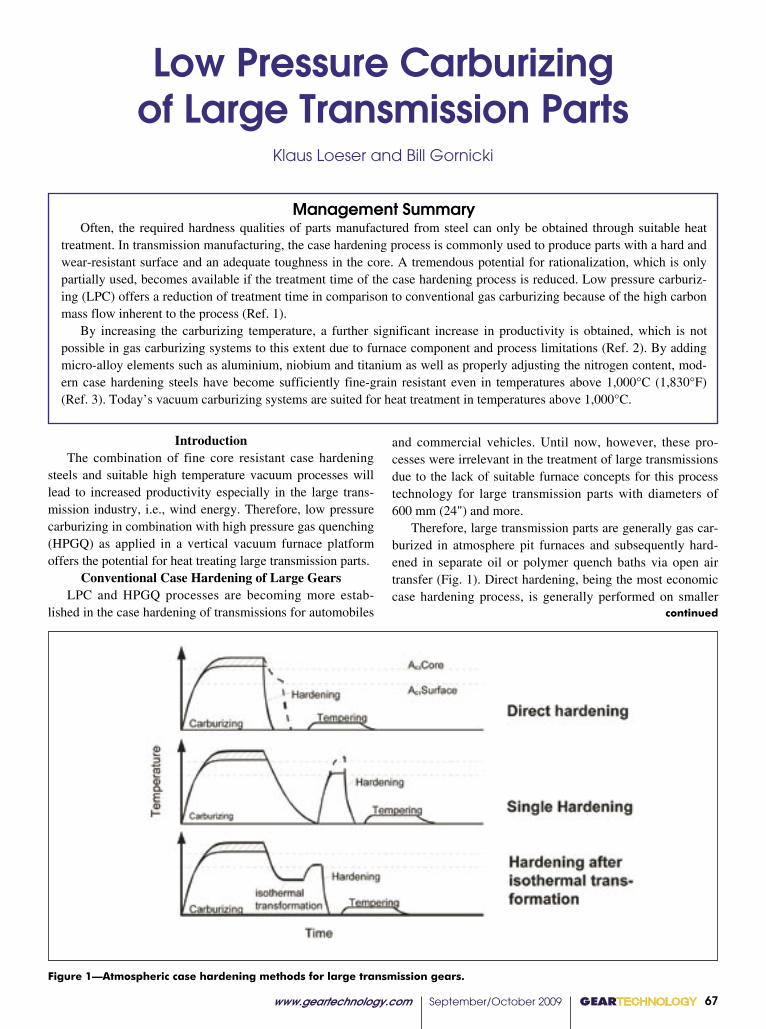
Figure 1—Atmospheric case hardening methods for large transmission gears.
IntroductionThe combination of fine core resistant case hardening
steels and suitable high temperature vacuum processes will lead to increased productivity especially in the large trans-mission industry, i.e., wind energy. Therefore, low pressure carburizing in combination with high pressure gas quenching (HPGQ) as applied in a vertical vacuum furnace platform offers the potential for heat treating large transmission parts.
Conventional Case Hardening of Large GearsLPC and HPGQ processes are becoming more estab-
lished in the case hardening of transmissions for automobiles
Low Pressure Carburizing of Large Transmission Parts
Klaus Loeser and Bill Gornicki
Management Summary Often, the required hardness qualities of parts manufactured from steel can only be obtained through suitable heat
treatment. In transmission manufacturing, the case hardening process is commonly used to produce parts with a hard and wear-resistant surface and an adequate toughness in the core. A tremendous potential for rationalization, which is only partially used, becomes available if the treatment time of the case hardening process is reduced. Low pressure carburiz-ing (LPC) offers a reduction of treatment time in comparison to conventional gas carburizing because of the high carbon mass flow inherent to the process (Ref. 1).
By increasing the carburizing temperature, a further significant increase in productivity is obtained, which is not possible in gas carburizing systems to this extent due to furnace component and process limitations (Ref. 2). By adding micro-alloy elements such as aluminium, niobium and titanium as well as properly adjusting the nitrogen content, mod-ern case hardening steels have become sufficiently fine-grain resistant even in temperatures above 1,000°C (1,830°F) (Ref. 3). Today’s vacuum carburizing systems are suited for heat treatment in temperatures above 1,000°C.
and commercial vehicles. Until now, however, these pro-cesses were irrelevant in the treatment of large transmissions due to the lack of suitable furnace concepts for this process technology for large transmission parts with diameters of 600 mm (24") and more.
Therefore, large transmission parts are generally gas car-burized in atmosphere pit furnaces and subsequently hard-ened in separate oil or polymer quench baths via open air transfer (Fig. 1). Direct hardening, being the most economic case hardening process, is generally performed on smaller
www.geartechnology.com September/October 2009 GEARTECHNOLOGY
continued
67
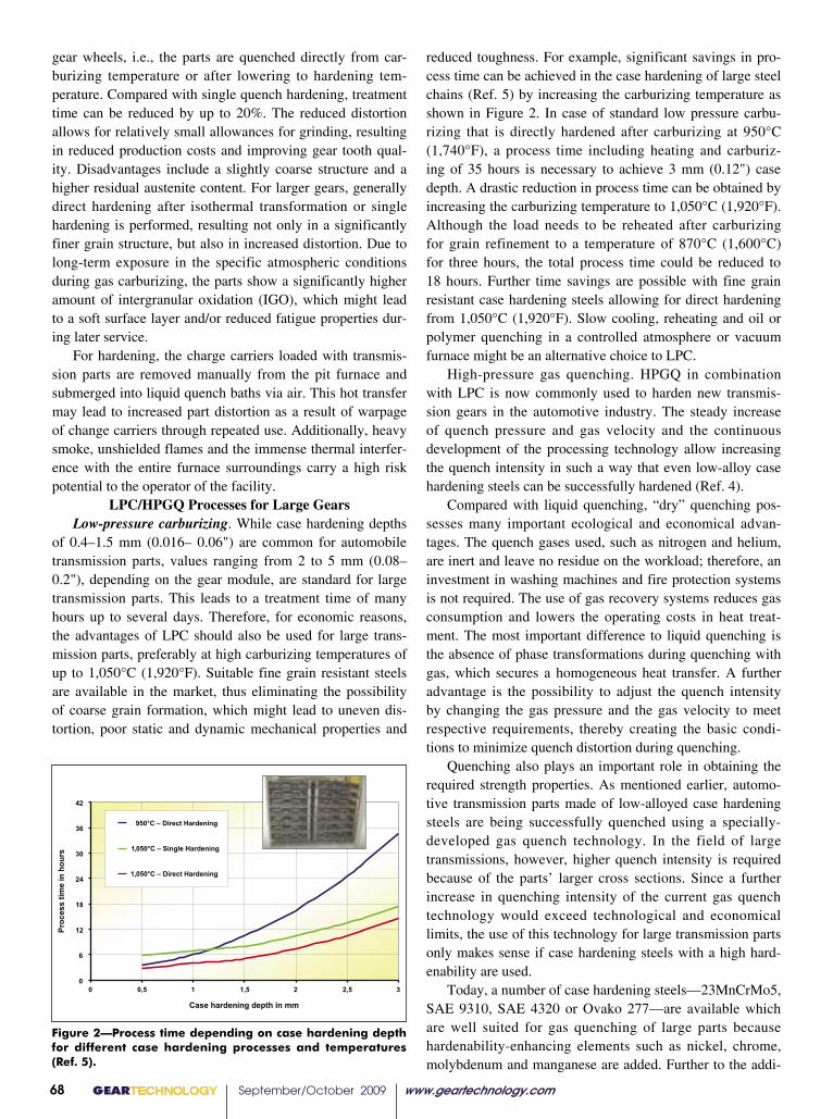
reduced toughness. For example, significant savings in pro-cess time can be achieved in the case hardening of large steel chains (Ref. 5) by increasing the carburizing temperature as shown in Figure 2. In case of standard low pressure carbu-rizing that is directly hardened after carburizing at 950°C (1,740°F), a process time including heating and carburiz-ing of 35 hours is necessary to achieve 3 mm (0.12") case depth. A drastic reduction in process time can be obtained by increasing the carburizing temperature to 1,050°C (1,920°F). Although the load needs to be reheated after carburizing for grain refinement to a temperature of 870°C (1,600°C) for three hours, the total process time could be reduced to 18 hours. Further time savings are possible with fine grain resistant case hardening steels allowing for direct hardening from 1,050°C (1,920°F). Slow cooling, reheating and oil or polymer quenching in a controlled atmosphere or vacuum furnace might be an alternative choice to LPC.
High-pressure gas quenching. HPGQ in combination with LPC is now commonly used to harden new transmis-sion gears in the automotive industry. The steady increase of quench pressure and gas velocity and the continuous development of the processing technology allow increasing the quench intensity in such a way that even low-alloy case hardening steels can be successfully hardened (Ref. 4).
Compared with liquid quenching, “dry” quenching pos-sesses many important ecological and economical advan-tages. The quench gases used, such as nitrogen and helium, are inert and leave no residue on the workload; therefore, an investment in washing machines and fire protection systems is not required. The use of gas recovery systems reduces gas consumption and lowers the operating costs in heat treat-ment. The most important difference to liquid quenching is the absence of phase transformations during quenching with gas, which secures a homogeneous heat transfer. A further advantage is the possibility to adjust the quench intensity by changing the gas pressure and the gas velocity to meet respective requirements, thereby creating the basic condi-tions to minimize quench distortion during quenching.
Quenching also plays an important role in obtaining the required strength properties. As mentioned earlier, automo-tive transmission parts made of low-alloyed case hardening steels are being successfully quenched using a specially-developed gas quench technology. In the field of large transmissions, however, higher quench intensity is required because of the parts’ larger cross sections. Since a further increase in quenching intensity of the current gas quench technology would exceed technological and economical limits, the use of this technology for large transmission parts only makes sense if case hardening steels with a high hard-enability are used.
Today, a number of case hardening steels—23MnCrMo5, SAE 9310, SAE 4320 or Ovako 277—are available which are well suited for gas quenching of large parts because hardenability-enhancing elements such as nickel, chrome, molybdenum and manganese are added. Further to the addi-
gear wheels, i.e., the parts are quenched directly from car-burizing temperature or after lowering to hardening tem-perature. Compared with single quench hardening, treatment time can be reduced by up to 20%. The reduced distortion allows for relatively small allowances for grinding, resulting in reduced production costs and improving gear tooth qual-ity. Disadvantages include a slightly coarse structure and a higher residual austenite content. For larger gears, generally direct hardening after isothermal transformation or single hardening is performed, resulting not only in a significantly finer grain structure, but also in increased distortion. Due to long-term exposure in the specific atmospheric conditions during gas carburizing, the parts show a significantly higher amount of intergranular oxidation (IGO), which might lead to a soft surface layer and/or reduced fatigue properties dur-ing later service.
For hardening, the charge carriers loaded with transmis-sion parts are removed manually from the pit furnace and submerged into liquid quench baths via air. This hot transfer may lead to increased part distortion as a result of warpage of change carriers through repeated use. Additionally, heavy smoke, unshielded flames and the immense thermal interfer-ence with the entire furnace surroundings carry a high risk potential to the operator of the facility.
LPC/HPGQ Processes for Large GearsLow-pressure carburizing. While case hardening depths
of 0.4–1.5 mm (0.016– 0.06") are common for automobile transmission parts, values ranging from 2 to 5 mm (0.08– 0.2"), depending on the gear module, are standard for large transmission parts. This leads to a treatment time of many hours up to several days. Therefore, for economic reasons, the advantages of LPC should also be used for large trans-mission parts, preferably at high carburizing temperatures of up to 1,050°C (1,920°F). Suitable fine grain resistant steels are available in the market, thus eliminating the possibility of coarse grain formation, which might lead to uneven dis-tortion, poor static and dynamic mechanical properties and
esac tnereffidrofhtpedgninedrahesac nognidneped emitssecorP .2erugiF]5[retfa ,serutarepmet dnasessecorpgninedrah
0
6
21
81
42
03
63
24
35,225,115,00
mm nihtpedgninedrahesaC
Proc
ess
time
in h
ours
gninedraHtceriD– C°059
gninedraH elgniS– C°0501
gninedraHtceriD– C°0501
,
,
Figure 2—Process time depending on case hardening depth for different case hardening processes and temperatures (Ref. 5).
GEARTECHNOLOGY September/October 2009 www.geartechnology.com68
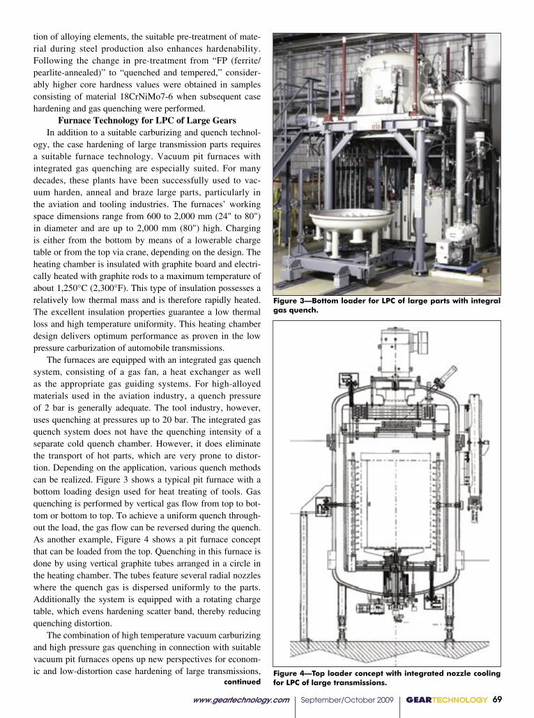
tion of alloying elements, the suitable pre-treatment of mate-rial during steel production also enhances hardenability. Following the change in pre-treatment from “FP (ferrite/pearlite-annealed)” to “quenched and tempered,” consider-ably higher core hardness values were obtained in samples consisting of material 18CrNiMo7-6 when subsequent case hardening and gas quenching were performed.
Furnace Technology for LPC of Large GearsIn addition to a suitable carburizing and quench technol-
ogy, the case hardening of large transmission parts requires a suitable furnace technology. Vacuum pit furnaces with integrated gas quenching are especially suited. For many decades, these plants have been successfully used to vac-uum harden, anneal and braze large parts, particularly in the aviation and tooling industries. The furnaces’ working space dimensions range from 600 to 2,000 mm (24" to 80") in diameter and are up to 2,000 mm (80") high. Charging is either from the bottom by means of a lowerable charge table or from the top via crane, depending on the design. The heating chamber is insulated with graphite board and electri-cally heated with graphite rods to a maximum temperature of about 1,250°C (2,300°F). This type of insulation possesses a relatively low thermal mass and is therefore rapidly heated. The excellent insulation properties guarantee a low thermal loss and high temperature uniformity. This heating chamber design delivers optimum performance as proven in the low pressure carburization of automobile transmissions.
The furnaces are equipped with an integrated gas quench system, consisting of a gas fan, a heat exchanger as well as the appropriate gas guiding systems. For high-alloyed materials used in the aviation industry, a quench pressure of 2 bar is generally adequate. The tool industry, however, uses quenching at pressures up to 20 bar. The integrated gas quench system does not have the quenching intensity of a separate cold quench chamber. However, it does eliminate the transport of hot parts, which are very prone to distor-tion. Depending on the application, various quench methods can be realized. Figure 3 shows a typical pit furnace with a bottom loading design used for heat treating of tools. Gas quenching is performed by vertical gas flow from top to bot-tom or bottom to top. To achieve a uniform quench through-out the load, the gas flow can be reversed during the quench. As another example, Figure 4 shows a pit furnace concept that can be loaded from the top. Quenching in this furnace is done by using vertical graphite tubes arranged in a circle in the heating chamber. The tubes feature several radial nozzles where the quench gas is dispersed uniformly to the parts. Additionally the system is equipped with a rotating charge table, which evens hardening scatter band, thereby reducing quenching distortion.
The combination of high temperature vacuum carburizing and high pressure gas quenching in connection with suitable vacuum pit furnaces opens up new perspectives for econom-ic and low-distortion case hardening of large transmissions,
Figure 3—Bottom loader for LPC of large parts with integral gas quench.
gral fo CPLroftpecnocredaol poT .4erugiF gniloocelzzondetargetnihtiwsnoissimsnart eFigure 4—Top loader concept with integrated nozzle cooling for LPC of large transmissions.
www.geartechnology.com September/October 2009 GEARTECHNOLOGY 69
continued

made possible by the parallel development of fine grain resistant and high hardenability case hardening steels (Fig. 5). As in conventional case hardening processes, it is pos-sible to perform direct hardening with or without isothermal transformation as well as single hardening. If it is not possi-ble to successfully gas quench the material, the parts may be rapidly carburized in the vacuum furnace, cooled in gas and subsequently quenched in the conventional pit furnace using an oil quench. This technology features a number of other advantages such as uniform and rapid carburizing without IGO as well as homogeneous, low-distortion quenching.
The energy consumption is low because the furnace employed is only heated during the process. Heating and gas absorption during idle phases are not necessary. The process gas consumption is minimal because of the pulsed carburiz-ing technology with acetylene in vacuum. Figure 6 shows the carbon profile of 18CrNiMo7-6 material after carburizing at 1,050°C (1,920°F) to a case depth of 2.5 mm (0.1"), as calcu-lated with the simulation software VC-Sim. To carburize large gear components with a total surface of 15 m2 (160 ft2) to that case depth, a net carburizing time of only 8 minutes and an acetylene volume of only 2.25 m3 (80 ft3) are necessary.
Figure 6—Calculated carbon profile after LPC at 1,050°C (VC-Sim software).
+
+
ssecorP
lairetaM
erutarepmet hgiHgnizirubracmuucav
erusserp hgiHgnihcneuq sag
tnatsiserniarg eniFleetsgninedrahesac
leetsgninedrahesaCytilibanedrah hgihhtiw
htiwecanruftip muucaVgnihcneuq sag largetniygolonhceTecanruF
sacrof ygolonhcet weN .5erugiF sraegnoissimsnart egral fogninedrahe
faeliforpnobracdetaluclaC .6erugiF )erawtfosmiS-CV( C°0501 ta CPLret
Dr.-Ing Klaus Loeser studied mechanical engineering and received a doctorate as scientific assistant at the Institute of Materials Science of the Technical University in Darmstadt. He is vice president of new technology for heat treatment at ALD Vacuum Technologies GmbH, Hanau.
William Gornicki has nearly 20 years experience in the vacuum furnace industry. He has a technical degree in communications and is vice president of sales and marketing with ALD-Holcroft Vacuum Technologies in Wixom, MI.
The furnaces show only slight thermal and gaseous emis-sions and are fully automated. Following the quench process, the parts are dry, clean and bright. The minimized distor-tion enables significant reduction in subsequent grinding processes, which leads to reduced hard machining costs and case depths.
ConclusionCase hardening using vacuum carburizing and subsequent
high pressure gas quenching has become widely established in the heat treatment of automobile parts in the recent years. However, the advantages of this technology are not limited to small transmission parts and low case hardening depths. The combination of high temperature vacuum carburizing and high pressure gas quenching in connection with suitable vacuum pit furnaces and suitable case hardening steels will hopefully open up new perspectives for the economic and low-distortion case hardening of large transmissions found in wind energy transmission components.
References1. Gupta, C., G. Willet, and A. Volkmann. “Flexible Vacuum Carburizing Systems,” Industrial Heating, September 2003, p. 87–90.2. Loeser, Klaus and G. Schmitt. “Increase of Productivity in the Gear Industry by Vacuum Carburizing and Gas Quenching,” Heat Processing (2) Issue 3, 2004, p. 141–144.3. Hippenstiel, F., W. Bleck, B. Clausen, F. Hoffmann, R. Kohlmann and P. Pouteau. Einsatzstähle als maßgesch-neiderte Werkstofflösung zur Hochtemperaturaufkohlung von Getriebekomponenten. HTM Z. Werkst. Waermebeh. Fertigung 57 2002 4, p. 290–298.4. Loeser, K. and R. Seemann. “High Pressure Gas Quenching and the Influence of Material Hardenability of Case Hardening Steels in the Gear Industry,” ALD-Technical Information, 2004.5. Koch, A. “The Way to High Temperature Vacuum Carburizing for Large Carburizing Depths in Highly Stressed Steel Chains,” The Heat Treatment Market, 4/2008, p. 5–7.Figure 5—New technology for case hardening of large trans-
mission gears.
GEARTECHNOLOGY September/October 2009 www.geartechnology.com70

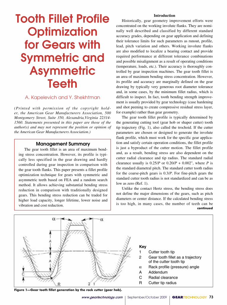
Management Summary The gear tooth fillet is an area of maximum bend-
ing stress concentration. However, its profile is typi-cally less specified in the gear drawing and hardly controlled during gear inspection in comparison with the gear tooth flanks. This paper presents a fillet profile optimization technique for gears with symmetric and asymmetric teeth based on FEA and a random search method. It allows achieving substantial bending stress reduction in comparison with traditionally designed gears. This bending stress reduction can be traded for higher load capacity, longer lifetime, lower noise and vibration and cost reduction.
continued
www.geartechnology.com September/October 2009 GEARTECHNOLOGY 73
1
Key1 Cutter tooth tip2 Gear tooth fillet as a trajectory
of the cutter tooth tip� Rack profile (pressure) angleA AddendumC Radial clearanceR Cutter tip radius
Figure 1. Gear tooth fillet generation by the rack cutter (gear hob)
IntroductionHistorically, gear geometry improvement efforts were
concentrated on the working involute flanks. They are nomi-nally well described and classified by different standard accuracy grades, depending on gear application and defining their tolerance limits for such parameters as runout, profile, lead, pitch variation and others. Working involute flanks are also modified to localize a bearing contact and provide required performance at different tolerance combinations and possible misalignment as a result of operating conditions (temperature, loads, etc.). Their accuracy is thoroughly con-trolled by gear inspection machines. The gear tooth fillet is an area of maximum bending stress concentration. However, its profile and accuracy are marginally defined on the gear drawing by typically very generous root diameter tolerance and, in some cases, by the minimum fillet radius, which is difficult to inspect. In fact, tooth bending strength improve-ment is usually provided by gear technology (case hardening and shot peening to create compressive residual stress layer, for example) rather than gear geometry.
The gear tooth fillet profile is typically determined by the generating cutting tool (gear hob or shaper cutter) tooth tip trajectory (Fig. 1), also called the trochoid. If the cutter parameters are chosen or designed to generate the involute flank profile, which must work for the specific gear applica-tion and satisfy certain operation conditions, the fillet profile is just a byproduct of the cutter motion. The fillet profile and, as a result, bending stress are also dependent on the cutter radial clearance and tip radius. The standard radial clearance usually is 0.25/P or 0.20/P + 0.002", where P is the standard diametral pitch. The standard cutter tooth radius for the coarse-pitch gears is 0.3/P. For fine-pitch gears the standard cutter tooth radius is not standardized and can be as low as zero (Ref. 1).
Unlike the contact Hertz stress, the bending stress does not define the major dimensions of the gears, such as pitch diameters or center distance. If the calculated bending stress is too high, in many cases, the number of teeth can be
Tooth Fillet Profile Optimization for Gears with
Symmetric and Asymmetric
TeethA. Kapelevich and Y. Shekhtman
(Printed with permission of the copyright hold-er, the American Gear Manufacturers Association, 500 Montgomery Street, Suite 350, Alexandria,Virginia 22314-1560. Statements presented in this paper are those of the author(s) and may not represent the position or opinion of the American Gear Manufacturers Association.)
Figure 1—Gear tooth fillet generation by the rack cutter (gear hob).
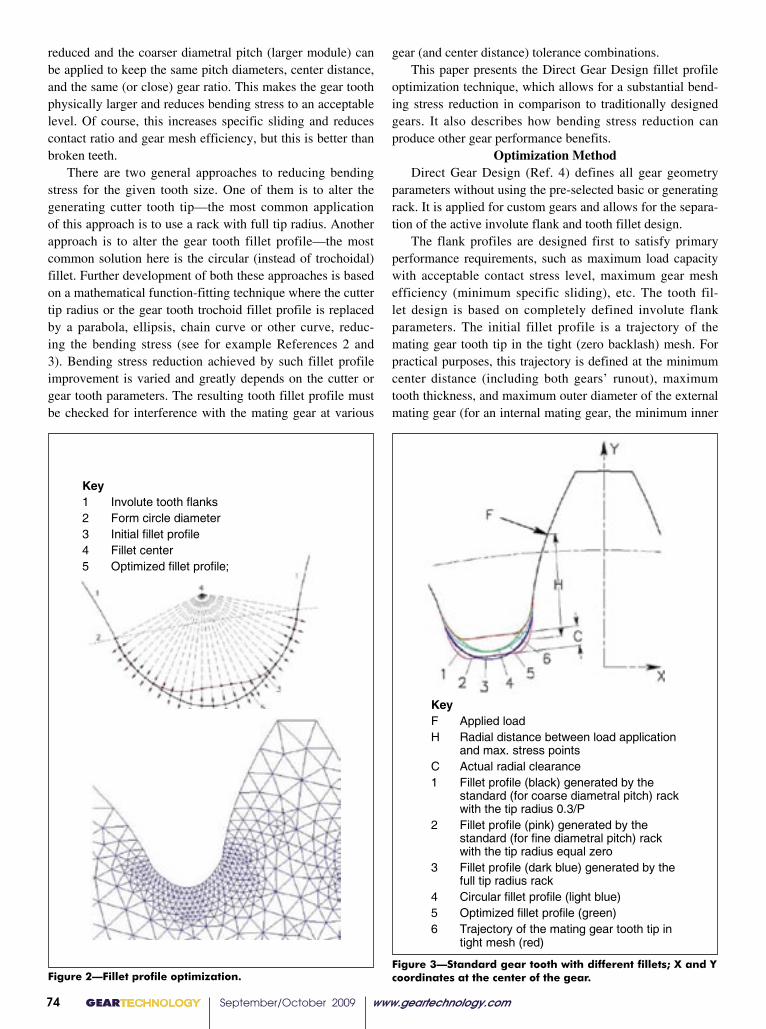
GEARTECHNOLOGY September/October 2009 www.geartechnology.com74
reduced and the coarser diametral pitch (larger module) can be applied to keep the same pitch diameters, center distance, and the same (or close) gear ratio. This makes the gear tooth physically larger and reduces bending stress to an acceptable level. Of course, this increases specific sliding and reduces contact ratio and gear mesh efficiency, but this is better than broken teeth.
There are two general approaches to reducing bending stress for the given tooth size. One of them is to alter the generating cutter tooth tip—the most common application of this approach is to use a rack with full tip radius. Another approach is to alter the gear tooth fillet profile—the most common solution here is the circular (instead of trochoidal) fillet. Further development of both these approaches is based on a mathematical function-fitting technique where the cutter tip radius or the gear tooth trochoid fillet profile is replaced by a parabola, ellipsis, chain curve or other curve, reduc-ing the bending stress (see for example References 2 and 3). Bending stress reduction achieved by such fillet profile improvement is varied and greatly depends on the cutter or gear tooth parameters. The resulting tooth fillet profile must be checked for interference with the mating gear at various
gear (and center distance) tolerance combinations.This paper presents the Direct Gear Design fillet profile
optimization technique, which allows for a substantial bend-ing stress reduction in comparison to traditionally designed gears. It also describes how bending stress reduction can produce other gear performance benefits.
Optimization MethodDirect Gear Design (Ref. 4) defines all gear geometry
parameters without using the pre-selected basic or generating rack. It is applied for custom gears and allows for the separa-tion of the active involute flank and tooth fillet design.
The flank profiles are designed first to satisfy primary performance requirements, such as maximum load capacity with acceptable contact stress level, maximum gear mesh efficiency (minimum specific sliding), etc. The tooth fil-let design is based on completely defined involute flank parameters. The initial fillet profile is a trajectory of the mating gear tooth tip in the tight (zero backlash) mesh. For practical purposes, this trajectory is defined at the minimum center distance (including both gears’ runout), maximum tooth thickness, and maximum outer diameter of the external mating gear (for an internal mating gear, the minimum inner
Key1 Involute tooth flanks2 Form circle diameter3 Initial fillet profile4 Fillet center5 Optimized fillet profile;
Figure 2. Fillet profile optimization
KeyF Applied loadH Radial distance between load application
and max. stress pointsC Actual radial clearance1 Fillet profile (black) generated by the
standard (for coarse diametral pitch) rackwith the tip radius 0.3/P
2 Fillet profile (pink) generated by thestandard (for fine diametral pitch) rackwith the tip radius equal zero
3 Fillet profile (dark blue) generated by thefull tip radius rack
4 Circular fillet profile (light blue)5 Optimized fillet profile (green)6 Trajectory of the mating gear tooth tip in
tight mesh (red)
Figure 3. Standard gear tooth with different fillets; X and Y coordinates at the center of the gearKey1 Involute tooth flanks2 Form circle diameter3 Initial fillet profile4 Fillet center5 Optimized fillet profile;
Figure 2. Fillet profile optimization
KeyF Applied loadH Radial distance between load application
and max. stress pointsC Actual radial clearance1 Fillet profile (black) generated by the
standard (for coarse diametral pitch) rackwith the tip radius 0.3/P
2 Fillet profile (pink) generated by thestandard (for fine diametral pitch) rackwith the tip radius equal zero
3 Fillet profile (dark blue) generated by thefull tip radius rack
4 Circular fillet profile (light blue)5 Optimized fillet profile (green)6 Trajectory of the mating gear tooth tip in
tight mesh (red)
Figure 3. Standard gear tooth with different fillets; X and Y coordinates at the center of the gearFigure 2—Fillet profile optimization.
Figure 3—Standard gear tooth with different fillets; X and Y coordinates at the center of the gear.

continued
diameter is used). This allows the exclusion of interference with the mating gear tooth.
The fillet optimization consists of three major compo-nents (Ref. 5):
• Trigonometric functions for fillet profile approximation;• FEA for stress calculation;• A random search method to define the optimal set of
the trigonometric functions’ coefficients, which allows them to reach the minimum bending stress.
The trigonometric functions are selected in such a way that the first and the last FE nodes of the initial fillet profile are placed on the form diameter circle (Fig. 2) and cannot be moved during the optimization process. The rest of the initial fillet FE nodes are moved along the beams that pass through the fillet center. The center of the fillet is the center of the best-fitted circle. The bending stresses are calculated for every new fillet profile configuration. The adjustment of the optimizing variable parameters is defined based on the successful (leading to stress reduction) and unsuccessful (leading to stress increase) iteration steps and some random
vector. The number of iteration steps (or optimization time) and minimal iteration steps are limited. The random nature of this method does not yield absolutely identical results for the same set of gear parameters and number of iteration steps. The program was adjusted so that the maximum bend-ing stress difference between repeated calculations does not exceed 2%. The fillet shapes for these cases are also slightly different.
Optimization ResultsAs an example of the fillet profile optimization, different
fillets were constructed for the gear pair with the standard involute tooth profile and the following parameters (Fig. 3):
• Number of teeth of both mating gears—24;• Diametral pitch—12;• Generating rack profile (pressure) angle—20°;• Addendum coefficient (also known as normalized
addendum coefficient)—1.0;• Face width of both mating gears—1.0";• Operating torque—200 in-lb.
Key1 Fillet profile (black) generated by the
standard (for coarse diametral pitch)rack with the tip radius 0.3/P
2 Fillet profile (pink) generated by thestandard (for fine diametral pitch)rack with the tip radius equal zero
3 Fillet profile (dark blue) generated bythe full tip radius rack
4 Circular fillet profile (light blue)5 Optimized fillet profile (green).
Figure 4. Bending stress distribution chart along the fillet profiles
(a)
(b)Figure 5. a – contact stress reduction;
b – increased mesh efficiency.
Key1 Fillet profile (black) generated by the
standard (for coarse diametral pitch)rack with the tip radius 0.3/P
2 Fillet profile (pink) generated by thestandard (for fine diametral pitch)rack with the tip radius equal zero
3 Fillet profile (dark blue) generated bythe full tip radius rack
4 Circular fillet profile (light blue)5 Optimized fillet profile (green).
Figure 4. Bending stress distribution chart along the fillet profiles
Figure 4—Bending stress distribution chart along the fillet profiles.
Figure 5—a = contact stress reduction; b = increased mesh efficiency.
www.geartechnology.com September/October 2009 GEARTECHNOLOGY 75
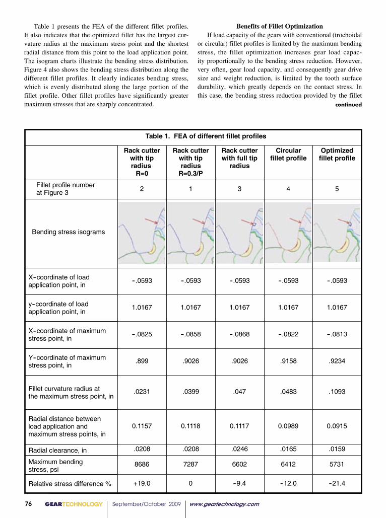
Table 1. FEA of different fillet profiles
Rack cutterwith tipradiusR=0
Rack cutterwith tipradiusR=0.3/P
Rack cutterwith full tip
radius
Circularfillet profile
Optimizedfillet profile
Fillet profile numberat Figure 3 2 1 3 4 5
Bending stress isograms
X--coordinate of loadapplication point, in
--.0593 --.0593 --.0593 --.0593 --.0593
y--coordinate of loadapplication point, in
1.0167 1.0167 1.0167 1.0167 1.0167
X--coordinate of maximumstress point, in
--.0825 --.0858 --.0868 --.0822 --.0813
Y--coordinate of maximumstress point, in
.899 .9026 .9026 .9158 .9234
Fillet curvature radius atthe maximum stress point, in
.0231 .0399 .047 .0483 .1093
Radial distance betweenload application andmaximum stress points, in
0.1157 0.1118 0.1117 0.0989 0.0915
Radial clearance, in .0208 .0208 .0246 .0165 .0159
Maximum bendingstress, psi
8686 7287 6602 6412 5731
Relative stress difference % +19.0 0 --9.4 --12.0 --21.4
Table 1 presents the FEA of the different fillet profiles. It also indicates that the optimized fillet has the largest cur-vature radius at the maximum stress point and the shortest radial distance from this point to the load application point. The isogram charts illustrate the bending stress distribution. Figure 4 also shows the bending stress distribution along the different fillet profiles. It clearly indicates bending stress, which is evenly distributed along the large portion of the fillet profile. Other fillet profiles have significantly greater maximum stresses that are sharply concentrated.
Benefits of Fillet OptimizationIf load capacity of the gears with conventional (trochoidal
or circular) fillet profiles is limited by the maximum bending stress, the fillet optimization increases gear load capac-ity proportionally to the bending stress reduction. However, very often, gear load capacity, and consequently gear drive size and weight reduction, is limited by the tooth surface durability, which greatly depends on the contact stress. In this case, the bending stress reduction provided by the fillet
continued
GEARTECHNOLOGY September/October 2009 www.geartechnology.com76
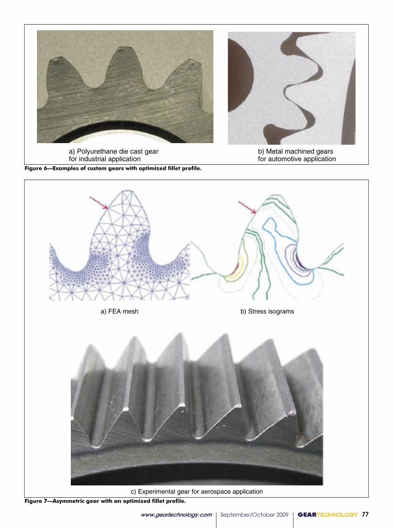
Figure 6—Examples of custom gears with optimized fillet profile.
Figure 7—Asymmetric gear with an optimized fillet profile.
a) Polyurethane die cast gearfor industrial application
b) Metal machined gearsfor automotive application
Figure 6. Examples of the custom gears with the optimized fillet profile
a) FEA mesh b) Stress isograms
c) Experimental gear for aerospace application
Figure 7. Asymmetric gear with the optimized fillet profile
www.geartechnology.com September/October 2009 GEARTECHNOLOGY 77
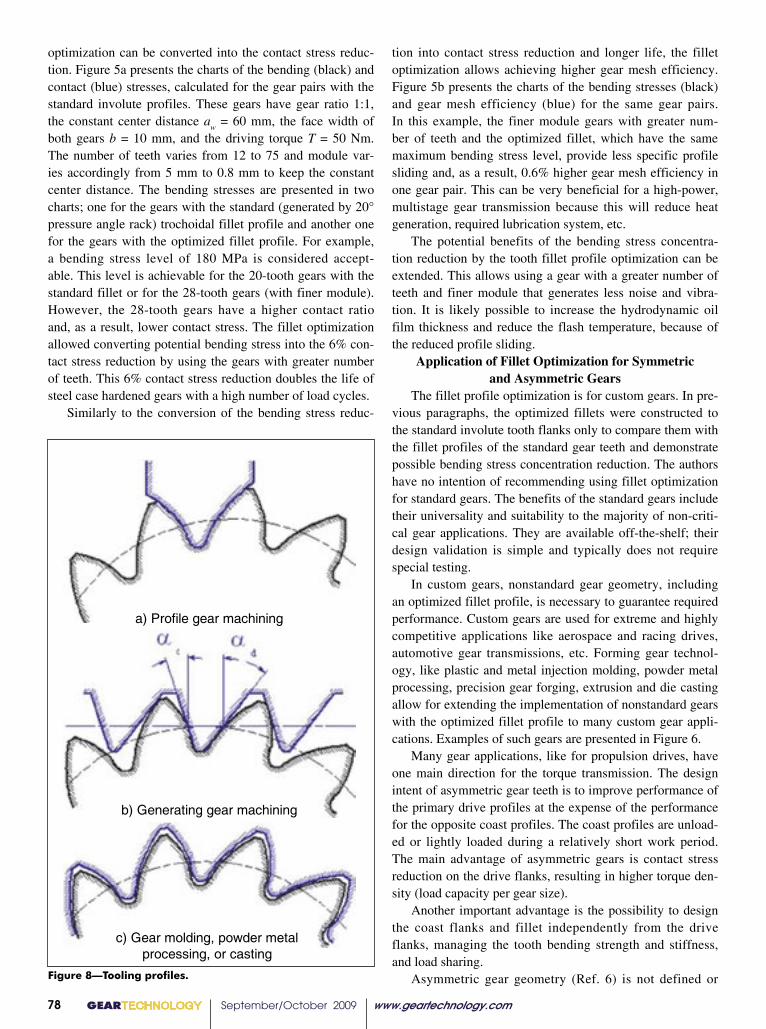
Figure 8—Tooling profiles.
a) Profile gear machining
b) Generating gear machining
c) Gear molding, powder metalprocessing, or casting
Figure 8. Tooling profiles
tion into contact stress reduction and longer life, the fillet optimization allows achieving higher gear mesh efficiency. Figure 5b presents the charts of the bending stresses (black) and gear mesh efficiency (blue) for the same gear pairs. In this example, the finer module gears with greater num-ber of teeth and the optimized fillet, which have the same maximum bending stress level, provide less specific profile sliding and, as a result, 0.6% higher gear mesh efficiency in one gear pair. This can be very beneficial for a high-power, multistage gear transmission because this will reduce heat generation, required lubrication system, etc.
The potential benefits of the bending stress concentra-tion reduction by the tooth fillet profile optimization can be extended. This allows using a gear with a greater number of teeth and finer module that generates less noise and vibra-tion. It is likely possible to increase the hydrodynamic oil film thickness and reduce the flash temperature, because of the reduced profile sliding.
Application of Fillet Optimization for Symmetric and Asymmetric Gears
The fillet profile optimization is for custom gears. In pre-vious paragraphs, the optimized fillets were constructed to the standard involute tooth flanks only to compare them with the fillet profiles of the standard gear teeth and demonstrate possible bending stress concentration reduction. The authors have no intention of recommending using fillet optimization for standard gears. The benefits of the standard gears include their universality and suitability to the majority of non-criti-cal gear applications. They are available off-the-shelf; their design validation is simple and typically does not require special testing.
In custom gears, nonstandard gear geometry, including an optimized fillet profile, is necessary to guarantee required performance. Custom gears are used for extreme and highly competitive applications like aerospace and racing drives, automotive gear transmissions, etc. Forming gear technol-ogy, like plastic and metal injection molding, powder metal processing, precision gear forging, extrusion and die casting allow for extending the implementation of nonstandard gears with the optimized fillet profile to many custom gear appli-cations. Examples of such gears are presented in Figure 6.
Many gear applications, like for propulsion drives, have one main direction for the torque transmission. The design intent of asymmetric gear teeth is to improve performance of the primary drive profiles at the expense of the performance for the opposite coast profiles. The coast profiles are unload-ed or lightly loaded during a relatively short work period. The main advantage of asymmetric gears is contact stress reduction on the drive flanks, resulting in higher torque den-sity (load capacity per gear size).
Another important advantage is the possibility to design the coast flanks and fillet independently from the drive flanks, managing the tooth bending strength and stiffness, and load sharing.
Asymmetric gear geometry (Ref. 6) is not defined or
optimization can be converted into the contact stress reduc-tion. Figure 5a presents the charts of the bending (black) and contact (blue) stresses, calculated for the gear pairs with the standard involute profiles. These gears have gear ratio 1:1, the constant center distance a
w = 60 mm, the face width of
both gears b = 10 mm, and the driving torque T = 50 Nm. The number of teeth varies from 12 to 75 and module var-ies accordingly from 5 mm to 0.8 mm to keep the constant center distance. The bending stresses are presented in two charts; one for the gears with the standard (generated by 20° pressure angle rack) trochoidal fillet profile and another one for the gears with the optimized fillet profile. For example, a bending stress level of 180 MPa is considered accept-able. This level is achievable for the 20-tooth gears with the standard fillet or for the 28-tooth gears (with finer module). However, the 28-tooth gears have a higher contact ratio and, as a result, lower contact stress. The fillet optimization allowed converting potential bending stress into the 6% con-tact stress reduction by using the gears with greater number of teeth. This 6% contact stress reduction doubles the life of steel case hardened gears with a high number of load cycles.
Similarly to the conversion of the bending stress reduc-
GEARTECHNOLOGY September/October 2009 www.geartechnology.com78

limited by any standards. This makes asymmetric gears natu-rally suitable for tooth fillet optimization. Figure 7 presents an asymmetric gear with an optimized fillet profile. The tooth fillet profile optimization is applicable for all kinds of involute (and non-involute) gears including spur, helical, bevel, face, worm gears, etc. The fillet profile is optimized in the normal section of the tooth, and then it can be protruded or swapped to define the complete gear tooth.
Tolerancing, Tooling and Inspecting the Tooth Fillet Area
No matter how the custom gear tooth profile might be different from the standard one, accuracy of the custom gears defined on the drawing is typically based on the existing standards. The gear tooth fillet optimization makes this area as important for gear performance as the involute flanks. Its specification on the gear drawing should be addressed accordingly. Unfortunately, modern gear standards do not define the fillet profile accuracy. As a temporary solution, the fillet profile tolerance (deviation from the nominal fillet profile) can be defined in relation to the involute profile tol-erance, which is well defined in the gear standards. Based on limited experience with implementation of optimized fillet profiles, their tolerance can be defined as 1.0 –2.0 multiplied by the involute profile tolerance.
Custom gears with optimized profiles require custom tooling. For the profile machining process (Fig. 8a) the tool profile is the same as the space profile between the neighbor-ing teeth. For a generating machining process like gear hob-bing (Fig. 8b), the tool profile is defined by reverse genera-tion, where the designed gear forms the tooling rack profile. The pressure angles, in this case, are selected to provide bet-ter machining conditions. For gear molding, powder metal processing, and casting (Fig. 8c), the tool cavity profile is the same as the whole gear profile, adjusted for warpage and shrinkage.
A crucial phase in custom gear development is gear inspection. The involute flank profile is inspected by a variety of available gear measuring machines and devices, which are not specifically designated to control the fillet profile. However, some of them, like CMMs, could be repro-grammed for the fillet profile inspection. Optical inspection devices like ToolScope (or Smart-Scope) are also suitable for this purpose.
Conclusions• The article presented the Direct Gear Design tooth
fillet profile optimization method;• Tooth fillet profile optimization provides significant
(10–20%) bending tress reduction in comparison with traditionally defined tooth fillet profiles;• The bending stress reduction provided by the fil-
let optimization can be converted into other gear performance benefits, such as contact stress re- duction and increased gear mesh efficiency;• The article presented implementation example of
the gears with the optimized fillet profile;• The article considered approaches to the tolerancing,
tooling and inspection of the gears with an optimized fillet profile.
References1. Townsend, D.P. Dudley’s Gear Handbook, McGraw-Hill, 1991.2. Der Hovanesian, J., M.A. Erickson, R.B. Hathaway and J.P. Savoyard, Jr., “Gear Root Stress Optimization Using Photoelastic Optimization Techniques,” SAE Transactions, ISSN 0096-736X, 1989, vol. 97 (4), pp. 748–755.3. Pulley, F.T., M.W. Kipling, G.A. Matson, D.L. Thurman and B.W. Avery. Method for Producing and Controlling a Fillet on a Gear, U.S. Patent #6164880, 2000.4. Kapelevich, A.L., “Direct Design Approach for High Performance Gear Transmissions,” Gear Solutions, December 2007, 22–31, presented at the Global Powertrain Congress 2007, June 17–19, 2007, Berlin, and published in the Global Powertrain Congress Proceedings, Vol. 39–42, 66–71.5. Kapelevich, A.L. and Y.V. Shekhtman. “Direct Gear Design: Bending Stress Minimization,” Gear Technology, September/October 2003, 44–49.6. Kapelevich, A.L. “Geometry and Design of Involute Spur Gears with Asymmetric Teeth, Mechanism and Machine Theory, 2000, Issue 35, pp. 117–130.
www.geartechnology.com September/October 2009 GEARTECHNOLOGY 79
Dr. Alexander L. Kapelevich is the owner of the consulting firm AKGears, LLC, developer of modern Direct Gear Design methodology and software. He has thirty years of experience in gear transmission development.
Dr. Yuriy Shekhtman is an expert with a 40-year experi-ence mathematical modeling and stress analysis . He created a number of computer programs based on FEA and other numerical methods. Dr. Shekhtman is a software developer for AKGears.
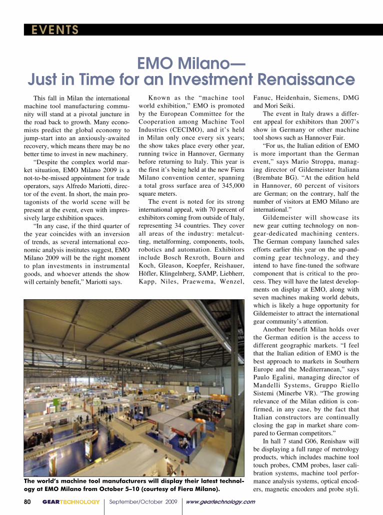
GEARTECHNOLOGY September/October 2009 www.geartechnology.com80
EVENTS
This fall in Milan the international machine tool manufacturing commu-nity will stand at a pivotal juncture in the road back to growth. Many econo-mists predict the global economy to jump-start into an anxiously-awaited recovery, which means there may be no better time to invest in new machinery. “Despite the complex world mar-ket situation, EMO Milano 2009 is a not-to-be-missed appointment for trade operators, says Alfredo Mariotti, direc-tor of the event. In short, the main pro-tagonists of the world scene will be present at the event, even with impres-sively large exhibition spaces. “In any case, if the third quarter of the year coincides with an inversion of trends, as several international eco-nomic analysis institutes suggest, EMO Milano 2009 will be the right moment to plan investments in instrumental goods, and whoever attends the show will certainly benefit,” Mariotti says.
Known as the “machine tool world exhibition,” EMO is promoted by the European Committee for the Cooperation among Machine Tool Industries (CECIMO), and it’s held in Milan only once every six years; the show takes place every other year, running twice in Hannover, Germany before returning to Italy. This year is the first it’s being held at the new Fiera Milano convention center, spanning a total gross surface area of 345,000 square meters. The event is noted for its strong international appeal, with 70 percent of exhibitors coming from outside of Italy, representing 34 countries. They cover all areas of the industry: metalcut-ting, metalforming, components, tools, robotics and automation. Exhibitors include Bosch Rexroth, Bourn and Koch, Gleason, Koepfer, Reishauer, Höfler, Klingelnberg, SAMP, Liebherr, Kapp, Niles, Praewema, Wenzel,
Fanuc, Heidenhain, Siemens, DMG and Mori Seiki. The event in Italy draws a differ-ent appeal for exhibitors than 2007’s show in Germany or other machine tool shows such as Hannover Fair. “For us, the Italian edition of EMO is more important than the German event,” says Mario Stroppa, manag-ing director of Gildemeister Italiana (Brembate BG). “At the edition held in Hannover, 60 percent of visitors are German; on the contrary, half the number of visitors at EMO Milano are international.” Gildemeister will showcase its new gear cutting technology on non-gear-dedicated machining centers. The German company launched sales efforts earlier this year on the up-and-coming gear technology, and they intend to have fine-tuned the software component that is critical to the pro-cess. They will have the latest develop-ments on display at EMO, along with seven machines making world debuts, which is likely a huge opportunity for Gildemeister to attract the international gear community’s attention. Another benefit Milan holds over the German edition is the access to different geographic markets. “I feel that the Italian edition of EMO is the best approach to markets in Southern Europe and the Mediterranean,” says Paulo Egalini, managing director of Mandelli Systems, Gruppo Riello Sistemi (Minerbe VR). “The growing relevance of the Milan edition is con-firmed, in any case, by the fact that Italian constructors are continually closing the gap in market share com-pared to German competitors.” In hall 7 stand G06, Renishaw will be displaying a full range of metrology products, which includes machine tool touch probes, CMM probes, laser cali-bration systems, machine tool perfor-mance analysis systems, optical encod-ers, magnetic encoders and probe styli.
EMO Milano— Just in Time for an Investment Renaissance
The world’s machine tool manufacturers will display their latest technol-ogy at EMO Milano from October 5–10 (courtesy of Fiera Milano).
www.geartechnology.com September/October 2009 GEARTECHNOLOGY 81
EVENTS
Representatives will also be discuss-ing Renishaw’s new retrofit service for CMMs, which includes MODUS, Renishaw’s first metrology software, as well as a new high-speed application for valve seat and guide measurement. The MTConnect Institute is dem-onstrating the MTConnect Standard similarly to how it was presented at IMTS last fall in Chicago. An appli-cation will request data from sample devices over the Internet. Participants include Bosch Rexroth, Mahr GmbH, Agie Charmilles, Monnier + Zahner Ltd., Optical Gaging Products, Inc. and System Insights, Inc. It’s no news that sales for much of the products on display at EMO Milan has stagnated this year, but exhibi-tors seem eager to show the world that research, development and innova-tion have continued to march forward. Exhibitors and organizers express great optimism that once October 5 rolls around, manufacturers will be better positioned to make those investments they’ve been cautiously holding off on all year. EMO Milano takes place October 5–10, 2009 at the Fiera Milano conven-tion center in Italy. For more informa-tion, visit www.emo-milan.com.
Renishaw probes will be on dis-play at EMO 2009 (courtesy of Renishaw).
www.geartechnology.com July 2009 GEARTECHNOLOGY 0031
continued
gear up your manufacturing,
download gear technology standards
The American National Standards Institute provides
over 1,500 gear standards relating to gear failures
and analysis, cutting, grinding, tooling, bevel gears,
hobbing, shaping, gearboxes, and Q&A.
Download at
webstore.ansi.org/gears
�������������������������������������������
WWW.DRAGON.CO.KR
Email inquiries to: [email protected]
(formerly Dragon Precision Tools)
You already compete globally; Why not look to a global supplier for gear hobs. One that enables “your team” to take advantage of “our” competi-tive edge. DTR Corporation is a world-class leader in maximizing gear hob tool life through innovative designs, with the latest in coatings and high speed steels. Look to us to get you through any challenge the market-place has to offer.
U.S. Office Location (Chicago)2400 E. Devon Ave., Suite 210, Des Plaines, IL 60018
PHONE: 847-375-8892 FAX: 847-699-1022Headquarters36B-11L, Namdong Industrial Complex, Namdong-Gu, Incheon, Korea
PHONE: +82.32.814.1540 FAX: +82.32.814.5381
Gleason-M&M is currently working on ad-vanced development in closing the loop on gear processing for bevel gear manufacturers in conjunction with The Gleason Works (cour-tesy of Gleason).
provides the feedback for corrections to the production machine,” says Lutz Berndt, product manager gear systems at Mahr. “We have also upgraded our machine software to allow our gauge head to scan the root radius on gears.”
The Process Equipment Company (PECo) has introduced a surface fi nish package that measures surface roughness on both the helix and involute profi le of a gear down to a 32 DP tooth size.
“Having the ability to measure surface roughness utilizing a skidless probe tip and our standard 3-D probe saves a tremendous amount of inspection time since it can be accomplished in one setup,” says Brian Slone, business unit manager, metrology systems division.
The company is also focusing on fi ne pitch gear measurement and can currently measure index, helix, profi le and tooth thickness on a gear with a 150 diametral pitch.
“This is the fi nest pitch that has been measured with any analytical gear measurement machine that utilizes 3-D probing technology,” Slone says. “With the development of this fi ne pitch capability, manufacturers and customers no longer have to guess at the quality of gears that are fi ner than 64 DP. They are now able to measure all the way down to 150 DP.”
GT 7-09 80pgs.indd 31 7/8/2009 4:05:18 PM
Visit us
Booth #1315
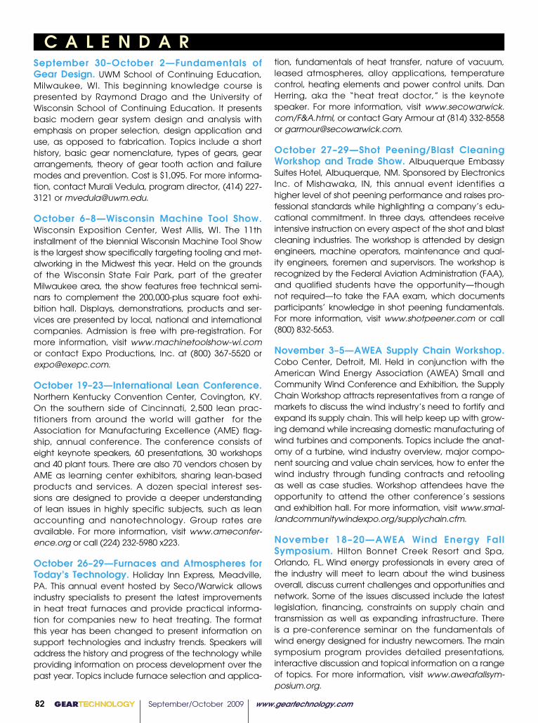
82 GEARTECHNOLOGY September/October 2009 www.geartechnology.com
C A L E N D A RSeptember 30–October 2—Fundamentals of Gear Design. UWM School of Continuing Education, Milwaukee, WI. This beginning knowledge course is presented by Raymond Drago and the University of Wisconsin School of Continuing Education. It presents basic modern gear system design and analysis with emphasis on proper selection, design application and use, as opposed to fabrication. Topics include a short history, basic gear nomenclature, types of gears, gear arrangements, theory of gear tooth action and failure modes and prevention. Cost is $1,095. For more informa-tion, contact Murali Vedula, program director, (414) 227-3121 or [email protected].
October 6–8—Wisconsin Machine Tool Show. Wisconsin Exposition Center, West Allis, WI. The 11th installment of the biennial Wisconsin Machine Tool Show is the largest show specifically targeting tooling and met-alworking in the Midwest this year. Held on the grounds of the Wisconsin State Fair Park, part of the greater Milwaukee area, the show features free technical semi-nars to complement the 200,000-plus square foot exhi-bition hall. Displays, demonstrations, products and ser-vices are presented by local, national and international companies. Admission is free with pre-registration. For more information, visit www.machinetoolshow-wi.com or contact Expo Productions, Inc. at (800) 367-5520 or [email protected].
October 19–23—International Lean Conference. Northern Kentucky Convention Center, Covington, KY. On the southern side of Cincinnati, 2,500 lean prac-titioners from around the world will gather for the Association for Manufacturing Excellence (AME) flag-ship, annual conference. The conference consists of eight keynote speakers, 60 presentations, 30 workshops and 40 plant tours. There are also 70 vendors chosen by AME as learning center exhibitors, sharing lean-based products and services. A dozen special interest ses-sions are designed to provide a deeper understanding of lean issues in highly specific subjects, such as lean accounting and nanotechnology. Group rates are available. For more information, visit www.ameconfer-ence.org or call (224) 232-5980 x223.
October 26–29—Furnaces and Atmospheres for Today’s Technology. Holiday Inn Express, Meadville, PA. This annual event hosted by Seco/Warwick allows industry specialists to present the latest improvements in heat treat furnaces and provide practical informa-tion for companies new to heat treating. The format this year has been changed to present information on support technologies and industry trends. Speakers will address the history and progress of the technology while providing information on process development over the past year. Topics include furnace selection and applica-
tion, fundamentals of heat transfer, nature of vacuum, leased atmospheres, alloy applications, temperature control, heating elements and power control units. Dan Herring, aka the “heat treat doctor,” is the keynote speaker. For more information, visit www.secowarwick.com/F&A.html, or contact Gary Armour at (814) 332-8558 or [email protected].
October 27–29—Shot Peening/Blast Cleaning Workshop and Trade Show. Albuquerque Embassy Suites Hotel, Albuquerque, NM. Sponsored by Electronics Inc. of Mishawaka, IN, this annual event identifies a higher level of shot peening performance and raises pro-fessional standards while highlighting a company’s edu-cational commitment. In three days, attendees receive intensive instruction on every aspect of the shot and blast cleaning industries. The workshop is attended by design engineers, machine operators, maintenance and qual-ity engineers, foremen and supervisors. The workshop is recognized by the Federal Aviation Administration (FAA), and qualified students have the opportunity—though not required—to take the FAA exam, which documents participants’ knowledge in shot peening fundamentals. For more information, visit www.shotpeener.com or call (800) 832-5653.
November 3–5—AWEA Supply Chain Workshop. Cobo Center, Detroit, MI. Held in conjunction with the American Wind Energy Association (AWEA) Small and Community Wind Conference and Exhibition, the Supply Chain Workshop attracts representatives from a range of markets to discuss the wind industry’s need to fortify and expand its supply chain. This will help keep up with grow-ing demand while increasing domestic manufacturing of wind turbines and components. Topics include the anat-omy of a turbine, wind industry overview, major compo-nent sourcing and value chain services, how to enter the wind industry through funding contracts and retooling as well as case studies. Workshop attendees have the opportunity to attend the other conference’s sessions and exhibition hall. For more information, visit www.smal-landcommunitywindexpo.org/supplychain.cfm.
November 18–20—AWEA Wind Energy Fall Symposium. Hilton Bonnet Creek Resort and Spa, Orlando, FL. Wind energy professionals in every area of the industry will meet to learn about the wind business overall, discuss current challenges and opportunities and network. Some of the issues discussed include the latest legislation, financing, constraints on supply chain and transmission as well as expanding infrastructure. There is a pre-conference seminar on the fundamentals of wind energy designed for industry newcomers. The main symposium program provides detailed presentations, interactive discussion and topical information on a range of topics. For more information, visit www.aweafallsym-posium.org.

www.geartechnology.com January/February 2007 GEARTECHNOLOGY 83
American Metric® CorporationA World Class International Engineering & Manufacturing Company
Stock Metric and Inch Gears and Gear Racks
Special For the Gear Industry
Just the right product
At just the right time
Just the right quality
At exceptional prices
Metric Lead Screws
Metric Spline Shaft And Hubs/Flanges
Metric Gear Boxes
Over 300,000 standard machinery
components, in stock at our US Warehouse
Visit our new website! Sign up (for those of you who haven’t) to access our
just updated Product PDF Catalogs. Take a look – www.ametric.com
Americ an Metric ® Corporation52 Metric Road · Laurens, SC 29360 USA · www.ametric.com
��������
Just the right product At just the right time Just the right quality At exceptional prices
Valued Customers,
In Stock or assembled in our South Carolina Factory... Special Attachment Chains (Metric & Inch)
Visit our new website! Sign up (for those of you who haven't) to access our just updated Product PDF Catalogs. Take a look - www.ametric.com
Ametric.com
Products
Special Products
PDF Catalogs
Custom Manufacturing
Create Account
��������
Just the right productAt just the right timeJust the right qualityAt exceptional prices
Call Today @ 1-800-967-5289To become our Customer
Place your Trial Order to Sample our QualityVisit our Interactive Web Site at www.ametric.com today!!
American Metric ® Corporationwww.ametric.com
Phone: 864-876-2011 • Fax: 864-876-2630Email: [email protected]
Great Prices!!One Stop Shopping!!
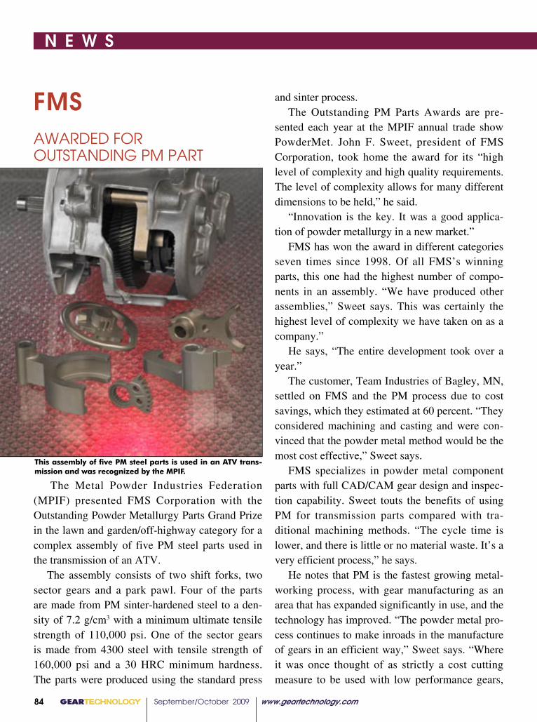
GEARTECHNOLOGY September/October 2009 www.geartechnology.com www.geartechnology.com September/October 2009 GEARTECHNOLOGY 84 85 GEARTECHNOLOGY September/October 2009 www.geartechnology.com www.geartechnology.com September/October 2009 GEARTECHNOLOGY 84 85
N E W S
FMS AWARDED FOR OUTSTANDING PM PART
Plunge—accelerated—cooling of the large furnace loads prior to quenching can be accomplished by passing cool air through the inside of the radiant tubes (courtesy Merit Gear).
This assembly of five PM steel parts is used in an ATV trans-mission and was recognized by the MPIF.
The Metal Powder Industries Federation (MPIF) presented FMS Corporation with the Outstanding Powder Metallurgy Parts Grand Prize in the lawn and garden/off-highway category for a complex assembly of five PM steel parts used in the transmission of an ATV.
The assembly consists of two shift forks, two sector gears and a park pawl. Four of the parts are made from PM sinter-hardened steel to a den-sity of 7.2 g/cm3 with a minimum ultimate tensile strength of 110,000 psi. One of the sector gears is made from 4300 steel with tensile strength of 160,000 psi and a 30 HRC minimum hardness. The parts were produced using the standard press
and sinter process.The Outstanding PM Parts Awards are pre-
sented each year at the MPIF annual trade show PowderMet. John F. Sweet, president of FMS Corporation, took home the award for its “high level of complexity and high quality requirements. The level of complexity allows for many different dimensions to be held,” he said.
“Innovation is the key. It was a good applica-tion of powder metallurgy in a new market.”
FMS has won the award in different categories seven times since 1998. Of all FMS’s winning parts, this one had the highest number of compo-nents in an assembly. “We have produced other assemblies,” Sweet says. This was certainly the highest level of complexity we have taken on as a company.”
He says, “The entire development took over a year.”
The customer, Team Industries of Bagley, MN, settled on FMS and the PM process due to cost savings, which they estimated at 60 percent. “They considered machining and casting and were con-vinced that the powder metal method would be the most cost effective,” Sweet says.
FMS specializes in powder metal component parts with full CAD/CAM gear design and inspec-tion capability. Sweet touts the benefits of using PM for transmission parts compared with tra-ditional machining methods. “The cycle time is lower, and there is little or no material waste. It’s a very efficient process,” he says.
He notes that PM is the fastest growing metal-working process, with gear manufacturing as an area that has expanded significantly in use, and the technology has improved. “The powder metal pro-cess continues to make inroads in the manufacture of gears in an efficient way,” Sweet says. “Where it was once thought of as strictly a cost cutting measure to be used with low performance gears,
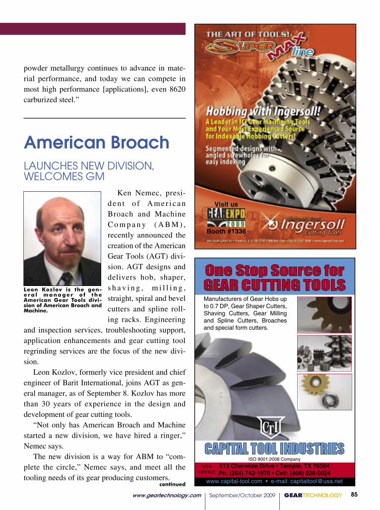
GEARTECHNOLOGY September/October 2009 www.geartechnology.com www.geartechnology.com September/October 2009 GEARTECHNOLOGY 84 85 GEARTECHNOLOGY September/October 2009 www.geartechnology.com www.geartechnology.com September/October 2009 GEARTECHNOLOGY 84 85
N E W S
Visit us
Booth #1336
continued
powder metallurgy continues to advance in mate-rial performance, and today we can compete in most high performance [applications], even 8620 carburized steel.”
Leon Kozlov is the gen-e r a l m a n a g e r o f t h e American Gear Tools divi-sion of American Broach and Machine.
American Broach
LAUNCHES NEW DIVISION, WELCOMES GM
Ken Nemec, presi-d e n t o f A m e r i c a n Broach and Machine C o m p a n y ( A B M ) , recently announced the creation of the American Gear Tools (AGT) divi-sion. AGT designs and delivers hob, shaper, s h a v i n g , m i l l i n g , straight, spiral and bevel cutters and spline roll-ing racks. Engineering
and inspection services, troubleshooting support, application enhancements and gear cutting tool regrinding services are the focus of the new divi-sion.
Leon Kozlov, formerly vice president and chief engineer of Barit International, joins AGT as gen-eral manager, as of September 8. Kozlov has more than 30 years of experience in the design and development of gear cutting tools.
“Not only has American Broach and Machine started a new division, we have hired a ringer,” Nemec says.
The new division is a way for ABM to “com-plete the circle,” Nemec says, and meet all the tooling needs of its gear producing customers.
CAPITAL TOOL INDUSTRIES
One Stop Source forGEAR CUTTING TOOLSManufacturers of Gear Hobs up to 0.7 DP, Gear Shaper Cutters, Shaving Cutters, Gear Milling and Spline Cutters, Broaches and special form cutters.
ISO 9001:2008 Company
513 Cherokee Drive • Temple, TX 76504Ph: (254) 742-1979 • Cell: (408) 828-0024
www.capital-tool.com • e-mail: [email protected]
CTI
USA OFFICE

GEARTECHNOLOGY September/October 2009 www.geartechnology.com www.geartechnology.com September/October 2009 GEARTECHNOLOGY 86 87 GEARTECHNOLOGY September/October 2009 www.geartechnology.com www.geartechnology.com September/October 2009 GEARTECHNOLOGY 86 87
N E W S
“Leon is a great addition to ABM, adding even more depth and knowledge to the ABM team in Ypsilanti, MI. Leon speaks, reads and writes several languages including English and Russian. Leon is a degreed engineer, and his specialty is gear cutting tool design and application,” Nemec says.
American Broach and Machine is exhibiting at Gear Expo in booth 716 and has extended an open invitation for visitors this fall to its Ypsilanti, MI facility to welcome Kozlov and tour the plant.
Gear Technology ADDS AQUEOUS PARTS CLEANING SYSTEM
An environmentally friendly ultrasonic, aque-ous-based parts cleaning system has joined the shop floor at Rancho Cucamonga, CA-based Gear Technology.
“This state-of-the-art system cleans machined components prior to first-article inspection points during the machining process and before final shipments are made to our customers,” says Tom Marino, president of Gear Technology. “The mul-tiple-tank process removes even the smallest parti-cles and is capable of processing up to 6,000 parts per month.
“With in-house and environmentally respon-sible parts cleaning, we ensure our customers’ pre-cision machined gears and assemblies are shipped completely free of foreign object contamination and are received ready to use.”
www.geartechnology.com June 2009 GEARTECHNOLOGY 00
N E W S
67
GT09
Dedicated to sharing information and expanding markets for shot peening and blast cleaning industries
Volume 22, Issue 3 Summer 2008ISSN 1069-2010Shot Peener
The
TheGreenIssue
Embrace it.Green can begood for business.
PLUS:An Unlikely PartnershipPRI Launches New Web SiteControl of Peened Layer Development
DISA’s RDS-Mini Shot Peening Systems
Do your gears require
More strength?Longer life?Shot peening is the answer.To learn more, subscribe to The Shot Peener. Our free quarterly magazine is dedicated to raising the awareness and appreciation for the shot peening process.
Magazine Subscription Request� I want a FREE subscription to The Shot Peener magazine.
Please send it to the address below.
Please print or attach your business card:
Name ______________________________________Title ________________
Company ________________________________________________________
Address ________________________________________________________
City _____________________State_______ Zip________Country __________
Telephone ________________________ Fax ____________________________
Email Address ____________________________________________________
Fax: (574)256-5222Mail: The Shot Peener56790 Magnetic Drive, Mishawaka, Indiana 46545 USA
The Shot Peener: www.shotpeener.com
continued
Correction
The May issue of Gear Technology featured an
industry news item “Gear Technology Recognized by
Boeing for Excellence,” on page 61. Gear Technology
was mistakenly identifi ed as being located in Newport
Beach, CA. The company is actually based out of
Rancho Cucamonga, CA. We offer our sincere regret
for this mistake.
—The Editorial Staff
Gildemeister, Mori Seiki SIGN COOPERATION AGREEMENT
Gildemeister formed a strategic partnership with Mori Seiki Co. covering production, purchasing and machine development in addition to sales and services in select markets. The agreement allows both companies to extend business activities with short- and long-term mutual advantages. The goal is to achieve synergies of 15 million euros a year for both companies.
A cross shareholding was agreed upon, with each investing in 5 percent shares. Gildemeister purchased two million Mori Seiki shares and plans to increase this to 4.4 million shares, while Mori Seiki will purchase 2.3 million shares. This makes Mori Seiki the largest, single Gildemeister shareholder.
“The world of machine tools has become global. Meeting and overcoming the challenges of the international economic crisis demands strong alliances,” says Dr. Rüdinger Kapitza, chairman of the Gildemeister executive board. “We will bundle our resources in order to achieve joint effi ciency advantages.”
Manufacturers can rent brand new Wenzel X-Orbit CMMs with no long-term purchase commitment in Xspect Solution’s Rent2Measure program. Users have the opportunity to apply 65 percent of the rental payments to offset the purchase price of the CMM at any time during the rental period.
“A rental program for CMMs is a fi rst for a U.S.-based CMM manufacturer,” says Keith Mills, president of Xspect Solutions. “As the nature of U.S. manufacturing evolves in these uncertain times, equipment suppliers like Xspect Solutions have to be more creative in the way they market
Xspect Solutions LAUNCHES RENT2MEASUREPROGRAM
GT 6-09 72pgs.indd 67 6/11/2009 11:32:34 AM
Correction.
Regarding the technical paper appearing in our June 2009 issue, “The Effect of Start-Up Load Conditions on Gearbox Performance and Life Failure Analysis and Case Study,” some revision is warranted.
The article uses the term “spalling,” whereas the preferred nomenclature is “flake macropitting,” as defined in ANSI/AGMA 1010-E95 (Ref. 1). Flake mac-ropitting starts with a crack that extends from a sur-face origin in a fan-shaped growth pattern to form a triangular crater. Tip-to-root interference is a common root cause of flake macropitting.
Also, Figure 12 and associated text claim macropits grow in the slide direction. Actually, macropits grow opposite to the slide direction.
Reference1. ANSI/AGMA 1010-E95, “Appearance of Gear Teeth—Terminology of Wear and Failure,” AGMA (1995).
—The Editorial Staff
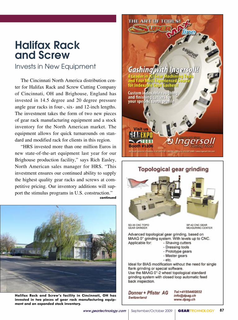
GEARTECHNOLOGY September/October 2009 www.geartechnology.com www.geartechnology.com September/October 2009 GEARTECHNOLOGY 86 87 GEARTECHNOLOGY September/October 2009 www.geartechnology.com www.geartechnology.com September/October 2009 GEARTECHNOLOGY 86 87
P R O D U C T N E W S
The number 815 electric rotary hearth oven, from Grieve Corporation, is currently being used by a customer to preheat various gears, usually steel and sometimes aluminum, before assembly operations.
The dimensions of the unit’s interi-
N E W S
Visit us
Booth #1336
continued
Halifax Rack and Screw’s facility in Cincinnati, OH has invested in two pieces of gear rack manufacturing equip-ment and an expanded stock inventory.
Halifax Rack and Screw Invests in New Equipment
The Cincinnati North America distribution cen-ter for Halifax Rack and Screw Cutting Company of Cincinnati, OH and Brighouse, England has invested in 14.5 degree and 20 degree pressure angle gear racks in four-, six- and 12-inch lengths. The investment takes the form of two new pieces of gear rack manufacturing equipment and a stock inventory for the North American market. The equipment allows for quick turnarounds on stan-dard and modified rack for clients in this region.
“HRS invested more than one million Euros in new state-of-the-art equipment last year for our Brighouse production facility,” says Rich Easley, North American sales manager for HRS. “This investment ensures our continued ability to supply the highest quality gear racks and screws at com-petitive pricing. Our inventory additions will sup-port the stimulus programs in U.S. construction.”
GEARTECHNOLOGY September/October 2009 www.geartechnology.com www.geartechnology.com September/October 2009 GEARTECHNOLOGY 88 89 GEARTECHNOLOGY September/October 2009 www.geartechnology.com www.geartechnology.com September/October 2009 GEARTECHNOLOGY 88 89
N E W S
BaritCHANGES OWNERSHIP, EXECUTIVE MANAGEMENT
Dennis and Edward Moldavsky have purchased 20-year-old gear cutting tool provider Barit International C o r p o r a t i o n . D e n n i s Moldavsky was formerly Barit’s director of sales and is now the CEO. Edward Moldavsky is the president. The new executive positions were assumed in May, and the company remains at the Northbrook, IL head-quarters.
Barit was founded in 1989 by Alexander Polevoy. “When Rita (Polevoy) mentioned she was thinking about retiring and wanted to find a buyer for the company, I knew this was a great opportunity for my family to grow and improve an already successful family-owned business,” Dennis Moldavsky says.
The Moldavskys’ first course of action as new owners was to hire chief engineer Yuriy Ardashnikov, who has 22 years of experience in the industry, from designing geared power trans-missions and mechanical drives to manufactur-ing support and quality control management. He brings Barit expertise in diesel engines, machine tools and custom gearing.
www.geartechnology.com July 2009 GEARTECHNOLOGY 00
N E W S
Partnership BRINGS ACADEMIA AND INDUSTRY TOGETHER
LMS, an engineering innovation company, recently announced its partnership with the Australian Royal Melbourne Institute of Technology. Together, they have established the RMIT–LMS Centre of Expertise in NVH (Noise, Vibration and Hardness). The center will consist of education and research giving students at the institute an opportunity for internships at one of LMS International’s worldwide offi ces.
“Establishing a strong partnership between LMS International and RMIT University provides a new way for industrial partners and universities to undertake joint research activities and develop a complementary expertise in a specialized area,” says Aleksandar Subic, professor and head of the school of aerospace, mechanical and manufacturing engineering at RMIT.
The center will integrate LMS International’s instrumentation, simulation and testing software with the university’s expertise in NVH research, application and education. Laboratories will be set up for modal analysis, spectral testing and sound intensity measurements including an advanced, multi-channel acoustic camera for fi eld mapping.
“We will be able to support the industry by offering regular technology updates as well as seminars for industry
The MTConnect Institute is open to any individual, company or organization interested in participating in MTConnect implementation. Four levels of membership are currently available including founding sponsor, institute partner, MTConnect Institute Technical Advisory Group (MTCTAG) member and registered member. Each level provides different benefi ts within the institute.
The development of MTConnect, an open, royalty-free standard, began in early 2007. It is a means of improving the ability to collect data across manufacturing technologies that address interoperability between controls, devices and software applications similar to what has been achieved in the information technology arena. MTConnect seeks to develop standardized communication protocols that will allow devices, equipment and systems to output data in a common format that can be read by another technology.
73
continued
GT 7-09 80pgs.indd 73 7/9/2009 3:59:43 PM
Yuriy Ardashnikov is chief engineer for Barit International.
GEARTECHNOLOGY September/October 2009 www.geartechnology.com www.geartechnology.com September/October 2009 GEARTECHNOLOGY 88 89 GEARTECHNOLOGY September/October 2009 www.geartechnology.com www.geartechnology.com September/October 2009 GEARTECHNOLOGY 88 89
P R O D U C T N E W S N E W S
Visit us
Booth #1336
continued
Triumph GroupAWARDED BELL HELICOPTER CONTRACT, PROMOTES MANAGEMENT
A multi-year supply agreement was made between the Triumph Group and Bell Helicopter. Under the agreement, the gear systems operations, located in Park City, UT and Macomb, MI will provide the main transmission assemblies for the 429 helicopter.
The agreement includes manufacturing, assembly/integration and testing of the transmissions in addi-tion to design and engineering the test equipment.
Vision
DOUBLING FLOOR SPACE
Vision Quality Components Inc. is moving to a facility twice as large as its previous space in the Clearfield Technology Park in Clearfield County, PA. Since opening its doors in January 2003, Vision has leased 10,000 square feet of space at the industrial park, and the new facility is only a few minutes from the former one, off Interstate 80 in Pennsylvania.
The new building is owned by Vision. It fea-tures 2,000 square feet of office space and 18,000 square feet of manufacturing space, so Vision can expand manufacturing capacity. Vision currently manufactures spur gears, helical gears and preci-sion pump gears using the powder metallurgy process.

GEARTECHNOLOGY September/October 2009 www.geartechnology.com www.geartechnology.com September/October 2009 GEARTECHNOLOGY 90 91 GEARTECHNOLOGY September/October 2009 www.geartechnology.com www.geartechnology.com September/October 2009 GEARTECHNOLOGY 90 91
N E W S
����������
��������������
��������������
��������
�������
������
��
��������������
�������������
�������������������������
���������
����������������������
�������������
��������������
��������������
�������������������������
������������
������
���������
���������
������
����������������������������
�������������������������������������������������������������������������������������
����������
������������������
�����������������������������������������������������
�����������������������������������
���������������������������������������������������������
������������������������������������������������
������������������������������������������������������������
��������������������������������
������������������������������
��������������������������������
�������������
��������������
����������������������������������������
���������������������������������
������������
����������
�����������������������������������������
�����������������������������
�������
������������������������������������
����������������
�������
������������������������������������������������������
����������
����������������������������������������
����������������������������
����������������������������������������������������������������������������������������������������
������������
���������������������������������������������������������������������������������������������������������������������������������
���������������������������������������������������������������������������������������
������������������������������������� ����
���������������������������������������������
�������������������
��������������������������
������������������������
����������������������������������������������
������������������
���������������������������������������
����������������������������������
���������������������������������������������������������
���� �������� ��� ����� ����� ��� ��� �������� ���� ��������������� ���� ��� ������������ ����������� ��� ���������� ����������� ��� ������ ��� ���������� ���� �������� ��� �������� ������������������ ������� ����� ��� ������ ������� ���� ����� ��� ����
���� ����������� ���� ������ �������� ������������������ �������� ���� ������� ����������� �������� �������� ��� �����������
����������� �������� ���� �������� ��� ������������ ��� �������������������������������������������������������������������������������������������������������������������������������������������� ���������� ���� ��� ���������� ����� ���������
�������������
����������������������������������������������������������������� �� ����������������������������������� �������������������������������������������������������������������������������������������������������������������������������������������� ����������� ������������ ������������������� ������������������������������� ��������� �������������������������������������� ������������ ����� ������������� ������ ���������
����� ��� �� ������� ������������� ��������� ����� ����������������������������������� ������������������������������������������ ������������������� �������������������� ����������� ������ ������������ ���������������� ���������� ������ ���
� ��� ����� ��� ������������ ������� ��������������������������������������������������������������������������������������������������������������������������������������������������������������������������������������������������� ��������������� ���������� �������� ������������ �����������
���������������������������������������������������������������� ��� �� ������ ��������� ������� ��� ����� ����� ����������������������������������������������������������������������� ��� ���� ����� ���������� �������� ���� �������� ������ ����
ural gas infrastructure company, and was president and CEO of Duke Energy Gas Transmission.
“Martha’s commitment to safety, customer satisfaction and communication, combined with proven business results, makes her an ideal fit for our growing North American mar-ket,” says Ditlev Engel, president and CEO of Vestas. “I know she will further enhance our vision of ‘wind, oil and gas’ in North America.”
M.M. Gears SoldCoimbatore, India-based LG Balakrishnan & Bros (LGB)
has entered into an agreement to acquire 100 percent shares in M.M. Gears Pvt. Ltd., according to multiple sources in the Indian media.
LGB manufactures automotive chains, sprockets, ten-sioners and belts as well as blanking. The company had planned a strategy to enter the gear manufacturing industry, according to IndiaTimes, and M.M.’s 30,000-square-foot manufacturing facility is likely to aid this endeavor.
M.M. Gears is an ISO 9001:2000 certified company, established in 1995. The company produces gears, gear-boxes, helical gearboxes, geared motors and non-standard gearboxes.
RP Machine Enterprises, Inc. has acquired the Statesville, NC division of Alpha/Sullivan Steel. The newly formed divi-sion is called Alpha Machining and Grinding Inc., and it is managed by Hank Kohl.
The acquisition provides RP with grinding capabilities up to 144 inches and a magnetic division to offer magnetic lifting devices, fixturing, tables and chucks. Some of the new division’s products and services will be on display at RP Machine’s booth, B-401, at Gear Expo.
Alpha Machining and Grinding Inc. Established
N E W S
68���GEARTECHNOLOGY������������������� ������������������������
pgs 60-68.indd 10 8/7/2009 7:36:16 AM
The initial agreement spans five years with five one-year contract extension options. The estimated value exceeds $363 million over the next 10 years.
“We are extremely pleased that Bell Helicopter chose Triumph to be a strategic supplier to this program,” says Richard C. Ill, chairman and CEO for Triumph. “We believe Triumph’s experience in providing cost effective solutions, our capacity to integrate complex bills of material and our com-mitment to meet or exceed stringent quality con-trol requirements enabled us to win this business. We view this award as a significant milestone in our excellent relationship with Bell Helicopter and look forward to supporting this program.”
In other news from Triumph, Jeffry D. Frisby, group president of Triumph Aerospace Systems Group, was named president and chief operating officer of the company. Ill previously held the post and was promoted to chairman. David Kornblatt was promoted from senior vice president to execu-tive vice president, and he remains the company’s chief financial officer.
“Jeff Frisby has made significant contributions to the growth of our aerospace business,” Ill says. “He is a proven member of our leadership team and has played a key role in making Triumph what it is today.”
Frisby has served as group president of the Triumph Aerospace Systems Group since 2003. He first joined the company in 1998, as president of Frisby Aerospace, Inc. when it was acquired by Triumph. He was group president of the Triumph Control Systems Group until the Aerospace Systems Group was formed in April 2003.
Frisby is a member of the board of directors at Quaker Chemical Corporation, and he is on the advisory council to the Wayne Calloway School of Business and Accountancy at Wake Forest University. He is an active member of the American Society of Mechanical Engineers, where
GEARTECHNOLOGY September/October 2009 www.geartechnology.com www.geartechnology.com September/October 2009 GEARTECHNOLOGY 90 91 GEARTECHNOLOGY September/October 2009 www.geartechnology.com www.geartechnology.com September/October 2009 GEARTECHNOLOGY 90 91
P R O D U C T N E W S N E W S
Visit us
Booth #1336
he served on the industrial advisory board.“I am proud to have been part of the Triumph
success story over the years and am honored to have been selected as President and COO,” Frisby says. “I believe we are well positioned to take advantage of the challenges and opportunities in the aerospace industry today and I look forward to working with Rick, Dave and our operating com-panies to develop, coordinate and execute strate-gies that will sustain and grow our business.”
GE Drivetrain Technolgies, a unit of GE Transportation, has formed a joint venture compa-ny with Chongqing XinXing Fengneng Investment Co., Ltd. to produce large- diameter gears for the wind turbine industry.
Chongqing XinXing Fengneng is the majority owner, and the gears will be manufactured in a new facility in Chongqing, China. Initially, the busi-ness will manufacture the gears for GE Drivetrain Technologies’ wind turbine gearbox production facility in Shenyang, China. GE Drivetrain and A-Power Energy Systems announced the facility’s development as part of a joint venture agreement made in January 2009.
“As a supplier to some of the world’s leading automotive and motorcycle companies, Chongqing XinXing brings a world-class manufacturing men-tality to the production of wind turbine gears,” says Tim Schweikert, president of GE Technology Infrastructure in China.
GE FORMS GEAR VENTURE WITH CHINESE PARTNER

���GEARTECHNOLOGY���������������������������������������������������������
� ������������ � ��������� � � � ��������� ����������� ������ ������� ������� ��������� ��������
�������������������������������������
ABA-PGT Inc. 41 (877) 840-2172 [email protected] www.abapgt.com
Aerocom Industries Inc. 12 [email protected] www.aerocom-industries.com
ALD-Holcroft 34 (248) 668-4130 [email protected] www.ald-holcroft.com
Allen Adams Shaper Services 95 (802) 226-7891 [email protected]
American Metal Treating Co. 94 (216) 431-4492 www.americanmetaltreating.com
Ametric/American Metric Corp. 83 (864) 876-2011 [email protected] www.ametric.com
Arrow Gear Co. 29 (630) 969-7640 www.arrowgear.com
B&R Machine & Gear Corp. IBC (731) 456-2636, (800) 238-0651 [email protected] www.brgear.com
Barit International 36 (847) 272-8128 [email protected] www.barit.com
Beavermatic 20 (815) 963-0005 [email protected] www.beavermatic.com
Becker Gearmeisters 95 (734) 878-9669 [email protected] www.maagmachines.com
Bourn & Koch Machine Tool Co. 40 (847) 649-1450 [email protected] www.star-su.com
The Broach Masters/Universal Gear Co. 18 (530) 885-1939 [email protected] www.broachmasters.com
Calicut Engineering Works Ltd. 94 +(91) 33-22875693 [email protected]
Capital Tool Industries 85 +(91) 175-2351089 [email protected] www.capital-tool.com
Carl Zeiss IMT Corp. 22 (800) 327-9735 [email protected] www.zeiss.com/imt
Cincinnati Gearing Systems 88 (513) 527-8600 www.cincinnatigearingsystems.com
Circle Gear & Machine Co. 81 (708) 652-1000 www.circlegear.com
Clifford-Jacobs Forging Co. 19 (217) 352-5172 [email protected] www.clifford-jacobs.com
Comtorgage Corp. 15 (401) 765-0900 [email protected] www.comtorgage.com
Concast Metal Products Co. 26 (724) 538-4000 [email protected] www.concast.com
Donner+Pfister 47, 87 (585) 586-5746 [email protected] www.dpag.ch
Drake Manufacturing 27 (330) 847-7291 [email protected] www.drakemfg.com
Drewco Corp. 40 (262) 886-5050 [email protected] www.drewco.com
DTR Corp. 81, 95 +(82) 32-814-1540, (847) 375-8892 [email protected], [email protected] www.dragon.co.kr
EMAG LLC 31 (248) 477-7440 [email protected] www.emag.com
Engineered Tools Corp. 8 (248) 619-1616 [email protected] www.engineeredtools.com
Fässler Corp. 30 (414) 769-0072 [email protected] www.faessler-ag.ch
Forest City Gear 48–49 (815) 623-2168 [email protected] www.forestcitygear.com
Frenco/Euro-Tech 45 (800) 483-3152 [email protected] www.eurotechcorp.com
Gear Manufacturing Inc. 94 (800) 773-GEAR www.gearmanufacturing.com
Gear Motions Inc. 54, 94 (315) 488-0100 [email protected] www.gearmotions.com
The Gear Works—Seattle, Inc. 94 (206) 762-3333 [email protected] www.thegearworks.com
Gleason Corp. 50, 94 (585) 473-1000 [email protected] www.gleason.com
Great Lakes Gear Technologies 24 (734) 416-9300 [email protected] www.greatlakesgeartech.com
Havlik International 21 (519) 624-6240 [email protected] www.havlikgear.com
Hobsource Inc. 94 (866) HOB-TOOL [email protected] www.hobsource.com
Höfler OBC (734) 416-9300 [email protected] www.greatlakesgeartech.com
Hydra-Lock 32 (586) 783-5007 [email protected] www.hydralock.com
Index Technologies 95 (440) 995-4627 www.gallenco.com
Ingersoll Cutting Tools 85, 87, 89, 91 (815) 387-6600 [email protected] www.ingersoll.com
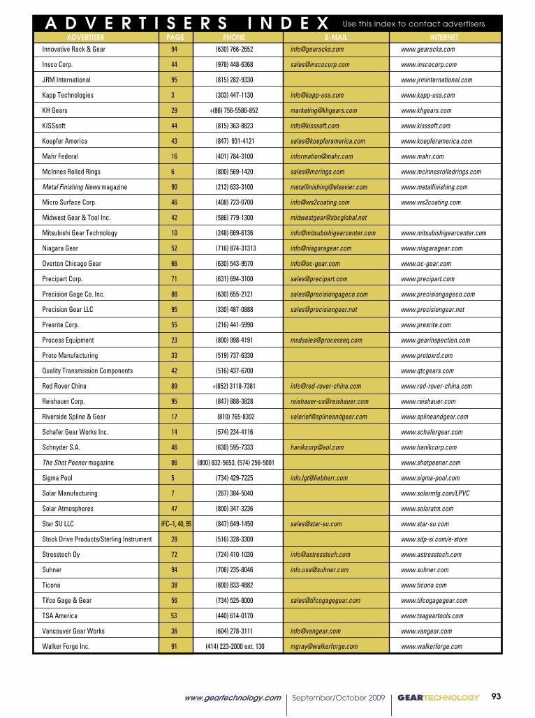
������������������������������������������������������GEARTECHNOLOGY��� ��
� ������������ � ��������� � � � ��������� ����������� ������ ������� ������� ��������� ��������
�������������������������������������
Innovative Rack & Gear 94 (630) 766-2652 [email protected] www.gearacks.com
Insco Corp. 44 (978) 448-6368 [email protected] www.inscocorp.com
JRM International 95 (815) 282-9330 www.jrminternational.com
Kapp Technologies 3 (303) 447-1130 [email protected] www.kapp-usa.com
KH Gears 29 +(86) 756-5586-852 [email protected] www.khgears.com
KISSsoft 44 (815) 363-8823 [email protected] www.kisssoft.com
Koepfer America 43 (847) 931-4121 [email protected] www.koepferamerica.com
Mahr Federal 16 (401) 784-3100 [email protected] www.mahr.com
McInnes Rolled Rings 6 (800) 569-1420 [email protected] www.mcinnesrolledrings.com
Metal Finishing News magazine 90 (212) 633-3100 [email protected] www.metalfinishing.com
Micro Surface Corp. 46 (408) 723-0700 [email protected] www.ws2coating.com
Midwest Gear & Tool Inc. 42 (586) 779-1300 [email protected]
Mitsubishi Gear Technology 10 (248) 669-6136 [email protected] www.mitsubishigearcenter.com
Niagara Gear 52 (716) 874-31313 [email protected] www.niagaragear.com
Overton Chicago Gear 66 (630) 543-9570 [email protected] www.oc-gear.com
Precipart Corp. 71 (631) 694-3100 [email protected] www.precipart.com
Precision Gage Co. Inc. 88 (630) 655-2121 [email protected] www.precisiongageco.com
Precision Gear LLC 95 (330) 487-0888 [email protected] www.precisiongear.net
Presrite Corp. 55 (216) 441-5990 www.presrite.com
Process Equipment 23 (800) 998-4191 [email protected] www.gearinspection.com
Proto Manufacturing 33 (519) 737-6330 www.protoxrd.com
Quality Transmission Components 42 (516) 437-6700 www.qtcgears.com
Red Rover China 89 +(852) 3118-7381 [email protected] www.red-rover-china.com
Reishauer Corp. 95 (847) 888-3828 [email protected] www.reishauer.com
Riverside Spline & Gear 17 (810) 765-8302 [email protected] www.splineandgear.com
Schafer Gear Works Inc. 14 (574) 234-4116 www.schafergear.com
Schnyder S.A. 46 (630) 595-7333 [email protected] www.hanikcorp.com
The Shot Peener magazine 86 (800) 832-5653, (574) 256-5001 www.shotpeener.com
Sigma Pool 5 (734) 429-7225 [email protected] www.sigma-pool.com
Solar Manufacturing 7 (267) 384-5040 www.solarmfg.com/LPVC
Solar Atmospheres 47 (800) 347-3236 www.solaratm.com
Star SU LLC IFC–1, 40, 95 (847) 649-1450 [email protected] www.star-su.com
Stock Drive Products/Sterling Instrument 28 (516) 328-3300 www.sdp-si.com/e-store
Stresstech Oy 72 (724) 410-1030 [email protected] www.astresstech.com
Suhner 94 (706) 235-8046 [email protected] www.suhner.com
Ticona 38 (800) 833-4882 www.ticona.com
Tifco Gage & Gear 56 (734) 525-8000 [email protected] www.tifcogagegear.com
TSA America 53 (440) 614-0170 www.tsageartools.com
Vancouver Gear Works 36 (604) 278-3111 [email protected] www.vangear.com
Walker Forge Inc. 91 (414) 223-2000 ext. 130 [email protected] www.walkerforge.com
GEARTECHNOLOGY September/October 2009 www.geartechnology.com94
C L A S S I F I E D S E C T I O N
HEAT TREATING
GEAR MANUFACTURING
�� � � � � � � � � � � � � � � � � � � � � � � � �
(866) HOB TOOLwww.hobsource.com
Performance • Dependability • Value
SERVICE
www.geartechnology.com September/October 2009 GEARTECHNOLOGY 95
C L A S S I F I E D S E C T I O NSERVICE HELP WANTED
HELP WANTEDSales Representation
1900 Midway Drive ● Twinsburg, OH 44087Ph: 330-487-0888
www.precisiongear.net
Precision Gear LLCWorld-class manufacturer of custom loose gearing seeks
increased penetration of close-tolerance product markets,
including aerospace, motion control, mining and capital
equipment. Territories and/or end-user markets are available throughout the United States.
Contact: Steve Senkfor [email protected]
is a Global Supplier of Custom Manufactured Bevel Gears, Spur Gears, Helical Gears, Worm Gears,
Sprockets, and Splines for the Aerospace, Mining, Medical, and Power Tool Industries - Since 1970
Territories are available in most areas in the U.S.
(except some Midwest States)
and Canada; Mexico and South
America.
Inquiries:[email protected]
Sales ManagementProfessional
seeks Industrial Sales Position
Professional Sales and Sales Management
over 2 decades experience in the precision gear, gearbox,
CNC machining and power transmission industry
Visit us
Booth #1133
MAAGPARTS & SERVICE
Original MAAG parts for all:
Grinding Machines • Shaping Machines
• Inspection Machines
Swiss Trained Service Engineers
Repairs to Complete RebuildsBecker GearMeisters, Inc.
Phone/Fax: [734] 878-9669www.maagmachines.com
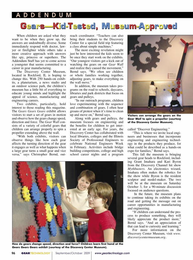
A D D E N D U M
When children are asked what they want to be when they grow up, the answers are undoubtedly diverse. Some immediately respond with doctor, law-yer or firefighter while others take a more creative approach with answers like spy, princess or superhero. The Addendum Staff has yet to come across a youngster that seems committed to a career in gear manufacturing.
The Discovery Center Museum, located in Rockford, IL is hoping to change this. With 250 hands-on exhib-its, a planetarium, a news studio and an outdoor science park, the children’s museum has a little bit of everything to educate young minds and highlight the appeal of science, manufacturing and engineering careers.
Two exhibits, particularly, hold interest to those reading this magazine. The Gears Gears Gears exhibit allows visitors to start a set of gears in motion and observe how the gears change speed, direction and force. The Gear Wall con-sists of a variety of colorful gears that children can arrange properly to spin a propeller extending above the wall.
“With both exhibits, visitors can observe things like how each gear affects the turning direction of the gear it engages as well as what happens when a large gear turns a small gear and vice versa,” says Christopher Bernd, out-
reach coordinator. “Teachers can also bring their students to the Discovery Center for a special field trip featuring a class about simple machines.”
The most exciting revelation might just be how interested the kids seem to be once they start work on the exhibits. “Our youngest visitors get a kick out of watching the gears on our Gear Wall and realize they caused the movement,” Bernd says. “We often see children or whole families working together, adjusting gears, to make everything on the wall move.”
In addition, the museum takes pro-grams on the road to schools, daycares, libraries and park districts that focus on gears and pulleys.
“In our outreach programs, children love experimenting with the sequence and combination of gears. I often hear groans of protest when it’s time to clean up and move on,” Bernd says.
Along with gears and pulleys, the museum focuses on engineering and the benefits for children to get inter-ested at an early age. For years, the Discovery Center has collaborated with local libraries, colleges and the Illinois Society of Professional Engineers to celebrate National Engineers Week in February. Activities include bridge building competitions, college and high school career nights and a program
called “Discover Engineering.”“This is where we invite local engi-
neers and businesses that incorporate engineering and engineering technol-ogy in the products they produce, for what could be described as a hands-on expo for families,” Bernd says.
This fall the museum is bringing several gear heads to Rockford, includ-ing Grant Imahara and Kari Byron from the Discovery Channel hit show Mythbusters. An electronics wizard, Imahara often makes the robotics for the show while Byron is the resident sculptor and model-maker. The two will be at the museum on Saturday October 3, for a 90-minute discussion focused on audience questions.
In the future, the museum plans to continue taking its exhibits on the road and getting the message out on career opportunities in manufacturing and engineering.
“If children can understand the pro-cess to produce something, they will likely appreciate the product more,” Bernd says. “And an appreciation of that can lead to curiosity and learning.”
For more information on the Discovery Center Museum, visit www.discoverycentermuseum.org.
Gears—Kid-Tested, Museum-ApprovedGears—Kid-Tested, Museum-Approved
GEARTECHNOLOGY September/October 2009 www.geartechnology.com96
Visitors can arrange the gears on the Gear Wall to spin a propeller (courtesy of the Discovery Center Museum).
How do gears change speed, direction and force? Children learn first hand at the Gears Gears Gears exhibit (courtesy of the Discovery Center Museum).

Machine and Gear Corporation
CUSTOM BEVEL GEAR MANUFACTURING
Per Your Specifications and/or SampleProviding Inverse Engineering to Make a Clone of Your Sample
· Spiral Bevel Gears: 66" PD
· Straight Bevel Gears: 80" PD
· Spurs Helicals Spline Shafts
· Gearbox Repair/Rebuilds
· In-House Steel Material Warehouse
· Full Heat Treating Services
· EDM Wire Burning
BREAKDOWN SERVICES
4809 U.S. Highway 45 Sharon, TN 38255
Toll Free: (800) 238-0651 Ph: (731) 456-2636 Fax: (731) 456-3073
E-mail: [email protected] Internet: www.brgear.com
Celebrating 35 YearsCelebrating 35 YearsFamily owned and operated 1974-2009
GT 5-09 covers 1-4.indd 3 4/27/2009 11:19:59 AM