september/october 1992 gear technology
TRANSCRIPT

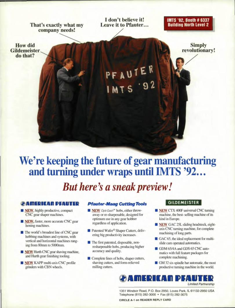
That's exactly what myeompany needs!
How didGildemeister
do that?'
I don't believe it!Leave it to Pfauter ...
IMTS "92, Boolh # 633,7Buillding NOlrlh levell 2
S~mplyrevolatlonaryl
/
We're keeping the future ,ofg,ear manufacturingand turning under wraps until IlVITS'92.,•.
But here's a sneakpreview!
.1 =--, highly productive, compacteNC gear shaper machines,I.rmw, faster, more accurate CNC gearhoning machines,
• The world' broadest line of CNC gearhobbing machines and ystems, withvertical and horizontal machines rang-ing from SOmm to 5000m~.
• HwtIl CNC gear shaving machine,and HurtIt gear finishing tooling.
• ,W KAPP multi-axis CNCprofilegrinders with CBN wheel's,
.1 NEW Opt;.(Jash"· hobs, either throw-away or re-sharpenable, designed foroptimum use in any gear bobberregardless of application.I. Patented Wafer® Shaper Cutters •.deliv-ering big productivity increases.
• The first pateated, disposable. non-resharpenable hobs, producing higheraccuracy and quality.
I. Complete lines of hobs, shaper cuners,shaving cutlers, and form-relievedmilling cutters.
---
GllDEME ISTE R
• NEW crx 400F universal CNC turningmachine, tile best- selling machine ofitshod in Europe.
I. NEW GAC 25L sliding headstock, eight-axis CN ..turning machine, for completemachining of long parts.
• GAC 65, the ideal replacement for multi-slide cam operated automatics.I.GDM 65/4A and ODS 65 CNC auto-matics with fun feature packages forcomplete machining,
• OM 32 six-spindle bar automatic.jhe mostproductive turning machine infhe world.
~lIl11lmlll:III1II'IIIIII'11111RLimited Partnership'
1351 Windsor Road, P.O. Box 2950, loves Park, Il61132-2950 USATelephone (815) 282·3000 •. :Fax (815) 282-3075
CIRCl.E A-1on READER REPLY CARD
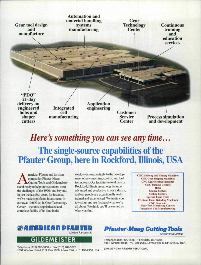
Automation andmaterial handUng
systemsmanufacturing
GearTechnology
CenterGea.r tool.designand -
manufacture
Continuoustrainlng
andeducation
"PDQ"21~day
Ideliv,eryonengineeredhobsandsbapercutters
IntegratedoeU
manufacturingCustomerServiceCenter
Process simulationand. development
Here's something you can see' any time.:The single-source capabilities of the
Pfauter Group, here inRockford, Illinois, USAworld-devoted entirely to the develop-ment of new machine, control, and tooltechnology. OW' facilities in total here inRockford. Illinois are among the mostadvanced and productive in om industry,and our people are exceptionally well-trained and experienced, We invite youto visit us and see firsthand! what we'reall about. We think you'll be excited bywhat you fmd.
Amenc.an Pfaurer an.d .its siste.rcompanies Pfauter-MaagCutting Tool and Gildemei ter
stand ready to help our customers meetthe challenges of the I.990s and beyond.Inj astthe last few years, for instance,we've made significant inve tments illour own] 0;000 sq. ft. Gear TechnologyCenter-the most sophisticated andcomplete facility of its kind in the
C Robbing and Milling M.aCblntsC ,CGear Shap.lng MacbinesCNC Gear Honing Machines
CNC l'urning CentersHobs
Shaper CutlersMilJlng 'utters
Sped!d Form ToolsP,recision Form Grinding Machines
CNC Gear lindGeur Tool Measuring CentersIntegrated Cell Manufacturing
~lIlnlml'=.I1"I.UllmLimited Partnership
.Pfaut r-Maag Cutfing ToolsUmited Partnership
Gil LlD'EME I STe R- --
Telephone (815) 877-8900· Fax (81S) 877-·02641351 Windsor Road, P.O. Box 2950, Loves Park, IL 61132-2950 USA
Telephone (815) 282-3000' Fax (815) 282-30751351 Windsor IRoad. P.O. Box 2950. Loves Park, IL 611'32-2950 USA
CIRCLEA-2 on READER REP,L'I' CARD'
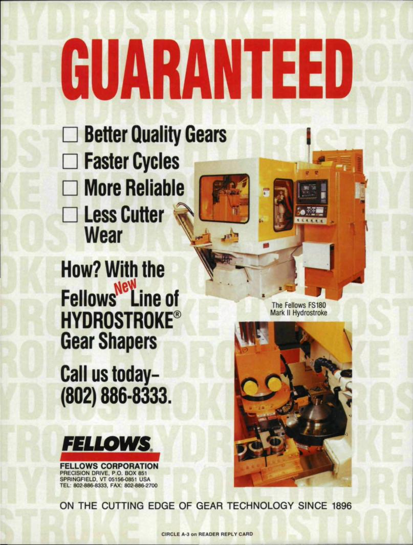
D BeHer Quality GearsD Faster CyclesD! MOire, R:eli,ab,le,D Less Clu'H,er'
WeariH,o,w? Wi't:hll:ih,e
~e .IFello,ws _InleofHIYDRO'S,!TROIKE@'Gear ShapersC,all U':S 'tlold,ay-,1(80,2)886·8333,.
II
The Fellows FS160Mark, llilliydmstroke
F:EL'LOWS CORPOR_AIIONIPRECISION DRIVE, P.O. BOX 8511SPRINGFIELD,. VT 05156-0851 USATEL: 802.886-8333, FAX: 802·886-2700
ON TIHE CUTTIING EDGE OF GEA,R TECHNO:lOGY SINCE 1896
CIRCLE A·3 on READER REPI.lI' CARD
Cover photo courtesy ofElrnuss North America Ine.,Germantown, WI.
CONTENTSSEPTE\IBER/()CTOBLI{ !'!()2
FEATURESc~c!ech-cnoil'og~ & the System-Independent Manufacture01 SpllallBevel1 G'earsOr. Dieter WienerKlingelnberg Sohne, Huckeswagen, Germany 22
Investigatlion Into Gear RaUle Phenomenaj\tfred Rust, Fr an ; K. Brandl & Ge rh a rd E. Th it'll
AVL List GmbH, Graz. Austria 30
SPECIAL FEATURESI
I
IG:ear f'undamentalsBase Piilch TabllesWilliam L, Lannl nckITW, Illinois Tools, Lincolnwood, IL. , ,.. , ., 36
DEPAI~TMENTSPublii'sher's P'ageThe Seed of Great Enterpri es., 91
M'anagement M,alersThe Bottom line Ion ir,ade' ShO,W5,Ncmn' BartelsfOIlO';"-UP i essential to maximizing trade. how succes ..13
IGTAd~,elrlisers Amongl the Hundreds ,at liMITS 1192Who will be at the show and where ,20
Shop floorIReade,.Diallogue on Functional IGear Measurement& More Good IGea:rBooksRobert E. Smith: 'William L. Janninck ,45
Advertiser I'ndexfind the products and services you need ,49
ICl,BssifiedsProducts, services. and information you can use 54
ICalendairEvents of Interest. " , 56

4 GEAR TECHNO~OClY
I GEAR TECH:\:OLOGY
FJ) ITOHL-\ L
Publisher & Editor-in-ChiefMIc1tael Goldstein
Associate Publisher & Managing EditnrPeg Short
SeniorEdilof Nancy Bartels
TechnicnlEdiwrsRobert E.rrichello
William L. Ja:-nninckDon McVittie
RobertE, Smith
,\RT
Art Director Jean SykesAr! Director Jennlter 'Goland
,\J)VERTlSI:'\G
Advertising SaJ.1!.'iManager Pa .•rieia Fl'am
Sales CoordinillOr Donna-Marie Weir
IU;'\'[),\I,l.l'l'BLlSHI);,C ST.\FF
President Michael Goldstein
Vice President Richard 'Goldstein
Vice PresidenVGeneml Manager .Peg Short
Comroller Patrick Nash
Accounting Laura Klnnane
Administrauve CoordinatorDeborah IDonigian
Art Can ulmm Marsha Goldstein
JU:,\I).\ 1.1. PLTBUSJf):'\C, ixc,
1,425Lunt AvenueP.O. Box 1426
Elk Grove Village, IL 60007nOS) 437-6604
\'OJ .. 9, :'\0, ~------------------------------------
G~ ttCllNULUC'I!, 1tbt:'Jw.maI U(GNf' ManuflldY./i"lq 41SSN 01.1 \±
M.~Ii-}~§ pubJi"hrtJ hirt'Rln:ihl) by NlIIl"IdOII'!!Vubli.d'nng. 1.1lC'_.~"23 l.wJE """nUl'.
PO.Bn!.I-I2t..F]k,C'I1'lIV('VIII"F+ILfJrX-i11 SumcriptirJPInlte"l!Il"C' s.-roIDIfl
LhcC.S ,nO.OOlnC'an •• 'S:S5-OOlii,,11 oIhercUWlIJin.. Sooimd-CI.a.u.ptJ!!lUIIICpilldl_ A.rllnl'oo Hc:-~~.lU!i.ILIdd Ift.:liiiltQti.IJ tIlIiili»&irl'f'"1Ce:R.IIIidJIJIP\ibll~-m:r IBIM.CSeYef) ~Ilon II! rTi.!lm' lhII 1M ~ deicnbtd m Ci.I!AH. 'I1£Ur
NOCOOY t'Oftfnrrr1!D iU'IIiRId Cftl~ri"l J:nCUoe- NI!'I1J1«1~ 1!Ahnrt< lHW!hr
p;lbh'iJia em IX" I:ir::Jd rnp.m.ibk' r.. a.njg'io ~ .h:i~ rollnwmJ t.he,...,.......~__ -..._ ... ",GUR TECHNQLOOY, Tbo_ 01
~~~ l"lSLu!!tA~_P_OI(IQII""~EIL.Grot;I'\; .L
,_ri,....1>y RANDAU. PUBUSHINO. INC,. Ion ..-
_1 .. Yl.\JlTEl:liN<lLUOYmo) ... ""....,- •• h"I.. ,.ponWllbuui, (Ix! r.l.prru pt"rml,uon ufk puhI.J.§hcr or th!: mlbr•.
Have you 'Jeardtgoodne s
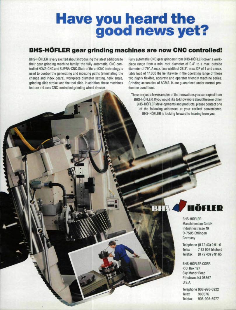
IBHS-H,OFLEIRg'ear girindinlglmachiines alre now CNC contro!lled!fully automatic CNCgear grinders from BHS-HOFLER cover a work-piece rangetrom a min. root diameter of 0.4" to a max. outsidediameter ot 79". A max. face w,idth of 28.3". max. !DP ofl and a max.table load of 17,600 lbs lie likewise in the operating range of thesetwo highly flexible, accurate and operator friendly machine series.Grind.ing accuracies of AGMA 14 are guaranteed under normal pro-duction conditions.
These are justa tewexamples olthe innovations you caaexpeetrrcmIBHS-HOFLER.lf you would like to know more about these 'Or other
BHS-HOFLER developments and products, please contact oneof the following addresses at your earliest convenience.
BHS-HOFLER is looking forward to hearing; trom you.
BHS-HOREB is very excited about introducingl the latest additions totheir gear 'grinding machine familly: the fully automatic, eNC con-trolled NOVA-CNC and SUPRA-eNC. State ottha art eNC technology isused to control the generating and indexing: paths (eHminating thechange and index gears), workpiece diameter setting, helix angile,grinding slide stroke, and the tool slide. lin addltlon, these machinesfeature a 4 axes eNC controned grinding wheel dresser.
-IIHOI lIEII!BHS-HOFLERMaschinenbau GmbHInd U striestrasse 190-7505 EttlingenGermany
Telephone (0 7243),991-0Telex 782907 bhshn dTelafax (072 43), 9 9165
BHS-HOFlER CORP:P.O. 80x 127Sky Manor RoadpatstoWl1, NIJ 08867U.S.A.Telephone 908-996-6922Telex 380576Teleiax908-996-6977

ADVERTORIAL
Tired of Smooth Talkand Poor Perfonnance?
IF YOU HAVEN'T TALKED TO FOREST CITY GEAR, WHY NOT?
Forest City Gear was started in ~953 and hasbeen continually serving both the Aerospace andComrnercialGearlndustry maintaining the high-estlevel of quality available in the fine andmedium pitch gear business .. Early 011 we de-cided to be a cut above the competition bypurchasing new gear cutting and gear inspectionequipment while confining our business to pro-ducing gears only. This new equipment allowsFore t City Gear 10 have technical capabilitiesonly a few very large captive shop enjoy.
Ask these questions about your gear currentsupplier:
Do they haveCNCanalytical inspectionequip-ment for checking gears and worms to millionths• .?mcrements.
Does your gear source have double flank rollchecking ability to analyze statistically all roIl-ing elements such as Total Composite Error.tooth to tooth error run out and center distance?
Can your gear house carbide re-hob (skive)parts to 60 RC with automatic loading?
Do they have CNC automatic loading gearhobbers with multiple cut capability?
Do they have CNC shaping equipment?Do they crown hob or single index cut?Do they hard cut gears from the solid to the
fifty rockwell range?Does your vendor upport the gear equipment
with new CNC milling machine. new grindersand new cross grinding honing equipment?
Does your gear manufacturer have $7,000
worth ofextensive gear analysis software?Does your gear house talk to you about gear
blank quality?Doe ' your gear producer welcome hi compe-
li lion to see the latest slate-of-the-art equi pment?WiU your supplier do one piece or a million.
with the last one just as the first one?Does your gear hou e supply a whole lot of
other gea:r producers?Does your gear ource periodically send their
people to gear training schools and clinics'?Is your gear house a member of AGMA?We believe there are many excellent gear
companies, but with any supplier other thanForest City 'Gear, we doubt you could answer allof the above question affirmatively ..
In fact, for the strength of the American GearIndustry, we hope that many of our competitorswill follow OUJ fool reps. Of course, we don'tintend to stop. a they will have to take aim at anadvancing target.
Just one more question, Can your gear houseperform miracles? We can't either. Despite ourcustomer' hopes. we don'[ have a magic wand.We imply roll up our sleeve and give you ourbest honest effort.
We like to think of ourselves as "A GearCompany's Gear Company."
For further ill formation about Forest Ci ty Gear,call us .al (8115) 623-2168, or come vi it our plantal.111715 Main Street, Roscoe. Illinois 61073.We welcome our eompetitorsl
TALK TO US ABOUT QUIET GEARS (OR FLY FISHING). WE'RE VERSATILE!
6, GEA R TECH NOLOGY
'CIRCLE A-291 on READER RIEPLY CARD
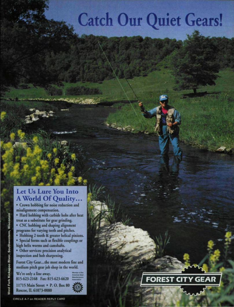
Catc •let ears!
Let Us Lure You IntoA World Of Quality ....'. Crown bobbing for noise reduction andmisalignment compensation.'. Hard bobbing with carbide bobs after heattreat 3iS a substitute for gear grinding.• CNC bob'bing and 5'haping alignmentprograms for varying teeth and pitches., Hobbing 2 tooth &. greater he1icalpinions .•' Special ~orms such 3iS flexible couplings orhigh helix worms and camshafts.• Other services: precision analyticalinspection and hob sharpening.Forest City Gear ... the most modern Sne andmedium pic.chgear job shop in the world.We're only a line away.8]5~623-2168 Fax:815~23-6620 ~11715 Mailll Street' P. O. Box 80 ~,.,~.-Roscoe, EL6107J-0080 ~

.M&M precisIon svstems-CN.-C.. 0.ear.'-Ins/J...ect..'~l/'Dn ..systems .WO.rldWlde Solutlons~Quality-hom startlDHn'lsh. Our total processinspection capabilities ean assist yoU Ii 111monitoring'gears, part blanks. and gear ,cutting tools suc'liJ,ashabs" shapers. shaver 'CUneI'S,and broaches, We'also offer inteifacing ,capabilities to transfer lestresults to standard SPC modu!esfor evalua-tion1process, monitoring.Rellability-truel generaUve Iindeil" lead, andIlnyo~lutete.Ung. Our generative metrology tech-nlquas offer superior aoclIr.acy" efficiency and sim-plicity over touch probe methods, Plus, thesetechniques, are' enhanced by computerized automa-tlon andl analysis.
:So'lutiolls-we ofler standLn:I,or customengineered pac:kages •.Our technical sUp,port taarnwilli wonk wit'hl you on your specifio reqllil1&ments ..With our years. of experience we will provide yOUI withsuperior training and after-the-sale teclu'Iical support.Shown above, our 3012-4 ao. Gear A_nalyzer [s ,oneofa family of 'gear and gear cuttingl tooll analyzers.Other optional inspect,ion capabilities include'Unknown 'gear, gear surfac·9 finish, spiral beve'l andhypoid gears, worm inspection, involute scrolls,and maleifemaIe helical rotor vanes. For a full co'iorbrochure write or call M&M Precision Systems Corp .•300 Progress Ad., West Canollton, 'Oti 45449"-Phone: 513.859.:8273, IFax: 513-859-4452.
M&M .PRECISlaN'SYSTEMS CeRA
AN ACME.cLEVELAND COMfMNY
CIRCLE A·5, on READER REPLY 'CARD
The Seeds ofGreat Enterprises
"'0·.. pportunity is the start of great enter-prises." said the Greek statesman Demosthenes,and what was true 2300 years ago is no less truenow. Plenty of opportunities which can growinto great - and successful. - enterprises arewaiting for us right now if we only have theforesight to take advantage of them.
IMTS 92 is in Chicago this month ..Hundredsof companies from around the world will bethere. and they are eager to do business with you.This could be the opportunity for you to upgradeequipment or make important contacts that willbe the source of some great future enterprise foryour business.
If ]MTS is not in your future, plenty of otheropportunities are coming up. They will requirethat you plan ahead to take the greatest advantageof them, but they t00 are out there waiting, readyto be turned into great enterprises.
In the fall of 1993, AGMA will again sponsorits GearExpo, a trade show devoted exclusivelyto our industry. Its smaller, more intimate set-ting may be the perfect opportunity for you tobuy needed equipment, learn about advances inthe industry, or show your products or servicesto the people most eager to buy.
Consider a150 the educational opportunitiesout there for the taking. AOMA, SME, and otherorganizations offerregular conferences and semi-nars on gearing subjects. So do a. number ofmachine tool manufacturers. The AGMA SmallBusiness Committee is also working in conjunc-tion with INFAC in Chicago to Set up a numberof training courses, specifically with the smallgear shop in mind.
Education is the sort of opportunity thatDernosthenes had in mind. In it are certainly theseeds of all great enterprises. Ask yourself wheth-er everyone at your plant is so well trained thatnone of these courses would be useful to them.
Tn addition to the valuable information theyoffer, these kinds of conferences and seminars
provide you with the chance to share your exper-tise and build your company creditability. Everyone of the technical organizations regularly is-sues "Cans for Papers." They need knowledge-able gear people to present papers on a variety ofgearing subjects. Gear Technology is also al-ways looking for interesting, well written ar-ticles on gearing subjects. You could be theauthor or presenter we're all wanting to hear.
Contacts madeand opportunitiesopened up by be-
coming an "ex-pert" on a particu-lar gearing sub-ject are less quan-tifiable than thosegained from atrade show ap-pearance, butthey are just asreal and also havethe potential togrow into greatenterprises.
Exhibiting attrade shows, tak-ing or teachingcourses, or writ-ing papers are noteasy. They all re-quire a lot of effort on your part, ButDernosthenes never said that turning oppor-tunity into a great enterprise would be easy;he simply implies that not taking the oppor-tunity guarantees that you won't be part of
PUBLISHER1S PAGE
ffZ~e otherend.Michael Goldstein,Publisher /Editor-in -Chief
SEPTEMBERIOCTOBER 1992 9

When Horsburgh '& Scott discovered CP~ REX®20...
Horsburgh & Scott, Cleveland, Ohio, knows what it takes to be a world class gear, manufacturer. ..like using Crucible's CPM REX 20 steel for gear cutting tools that, run longer and better between sharpenings.
Crucible CPM REX 20 not only lasts about 50% longer than M-2 or M-42, butthe tools are faster to make and sharpen. Steve Lyncha, H&S tool :room super-visor, said, "When you find something that grinds this easily, you think it'll never
Tools made of C!PM REX 20 hold up, but CPM REX 20 has handled the stop-and-go action of gear cutting bet-are used for a variety of gear ter than we could ever imagine."cutting operations at H&S. According to Lyncha, the long-term savings far outweigh the greater initial in-
vestment. "As long as CPM REX 20 is available, you could offer me M-2 at a$1.00 a pound, and I still wouldn't buy it," he added.CPM REX 20 is only one of nine CPM high speed steels specified for gear cutting tooling in major automotive
and other heavy industrial applications ..To find out more, contact your nearest Crucible Service Center or calltoll free: 1·,800·PAR· X eEL (]-800-727-9235)
...gear cutting shifted into, high
I~ Cruc:ible~_. SerVllce Centers
A Division of Crucible Materials CorporotionCIRCLE A·4 on READER REPLY CARD
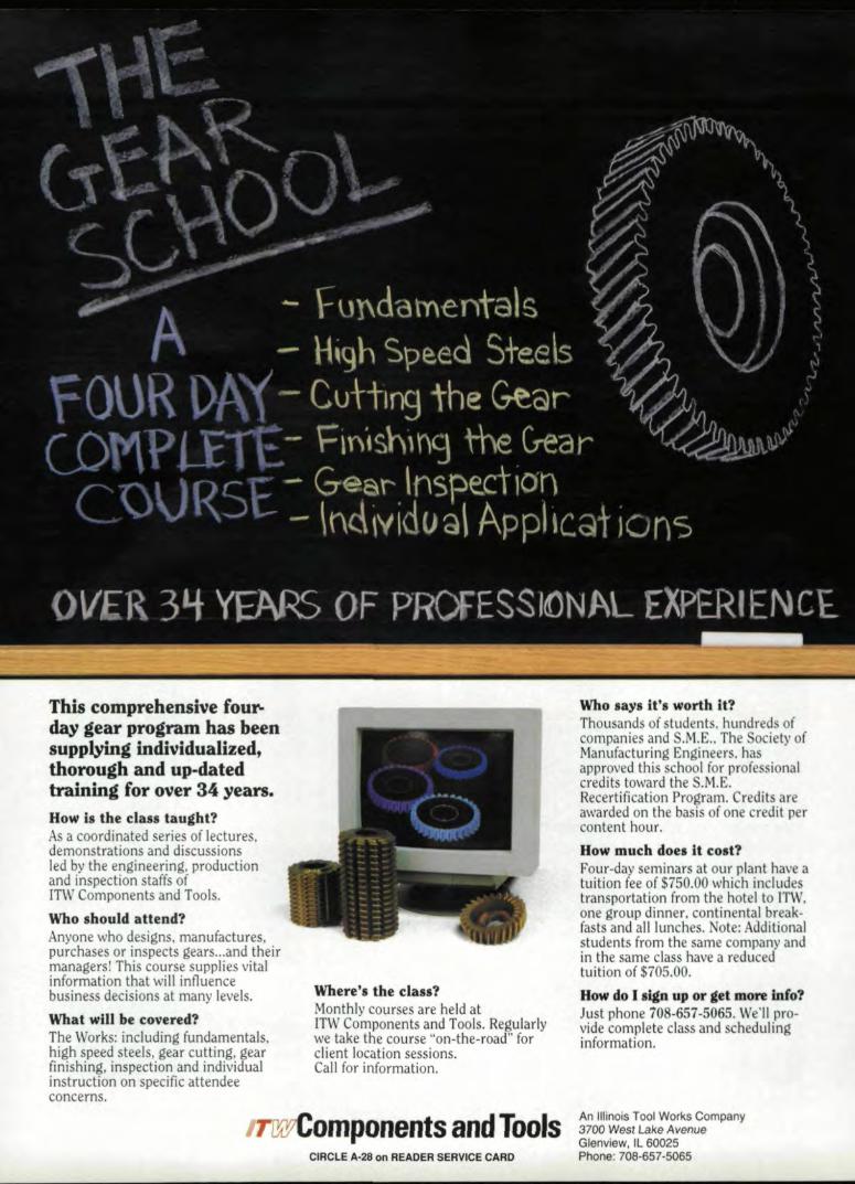
This, compl'lehensi.ve fou ....day gear program has been.supplying, .individualized,thorough and up..dat,edtraining for 'Over34 years.,How is the class taught?As a. coordinated series of lectures.demonstrations and discussionsled by the engineering, productionand inspectlon staffs ofITW Components and Tools.Who should attend?Anyone who designs. manufactures,purchases or inspects gears ...and theirmanagers! This course supplies vitalinformation that will influencebusiness decisions at many levels.WhatwiU be covered?The Works: including fundamentals,high speed steels, gear cutting, gearfinishing, inspectionand individualinstruction on specific attendeeconcerns.
Where'.! the class?Monthly courses are held atnw Components and Tools ..Regularlywe take the course "on-the-road" forclient location sessions.Call for information.
ITOOiComponents ,and Too!lsCIRCLE. 11,·28 ,on IREADEiR SERV,ICE CA.IRD'
Who says it's worth it?Thousands of students. hundreds ofcompanies and S.M.E., The Society ofManufacturing Engineers. hasapproved this school for professionalcredits toward the S.M.E.Recertification Program. Credits areawarded on the basis of one credit percontent hour.How mu.ch does It cost?Four-day seminars at our plant have atuition fee of $750.00 which includestransportation from the hotel to ITW,one group dinner. continental break-fasts and all lunches ..Note: Additional,students from the same company andin the same class have a reducedtuition of $705.00..How do. sign up 'or get morelnfo?Just phone 108·657·5065 ..We·lI. pro-vide complete class and schedulinginformation,
An Uiinois Tool Works Company3700 West Lake AvenueGienview,Il60025Phone: 708-657-5065
G
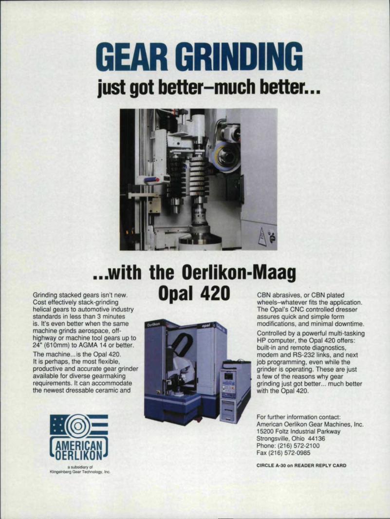
.,.,.withlthe Oerlikon-MaagD'pa11420Grinding stacked gears isn't new.
Cost effectively stack-grindinghelical ,gears to automotive in-dustrystandards in less than 3 minutesis. It's even better when the samemachine Igrinds aerospace, off-highway or machine' tooll gears ll,p to24" (611Omm) to AGIMA14 or better,The machine ... is the Opall 420.It is perhaps, the most flexible,productive and accurate gear ,grinderavailable tor diverse 'gearmakingrequirements, It can accommodatethe newest dressable ceramic and
a $!,Ibsidiary ofKlingt'lnberg Gear TechnolOgy. Int.
CBN abrasives. or CBN platedwheels-whatever fits the application.The' Opal's CNC controlled dresserassures q,uick.and simple formmcdlfications, and minimal downtime.Controlled by a powerful multi-taskingHP computer, the Opa'1420 offers: -built-in and remote diagnostics,modem and RS-232 links, and nextjob programming. even while' thegrinder is operating. These are justa few of the reasons why geargrinding just got better ....much betterwith the Opal 420.
For fur1her lntorrnauon contactAmerican Oarlikon 'Gear Machines, Inc.15200 Foltz Iindustrial ParlkwayStrongsville, Ohio 44136Phone: (216) 572-2100Fax (216) 572-0985
'CIRCI.E A-30 on R~ADER REPLY CARD

The Bottom Line onTrade Shows
Turning Trade Show Leads Into Sale's Is The Name of The Game.
he whole point of atrade show is to getleads that win tuminto sales. No mat-
ter how attracti ve yourbooth was, no matter howsmoothly tbe setup and theshow ran, no matter howmany visitors you had atyour booth, if your pres-ence at a show didn't netyou any sales, then yourconsiderable investmentof time, money, and efforthas been wasted.
But turning trade showleads into sales does nothappen by magic. Like theother parts of a successfultrade show, this transfor-mation is the result ofplanning and hard work.
Getting Them InStep I, of course, .is
getting people to yourbooth, where you canqualify them and deter-mine if they are valid pros-pects. Every trade show isfull of noise, color, andactivity, and just getting avisitor to notice your boothcan be a challenge.
The key words here arecomfortable and inviting.People have to want to stop
Nancy Barte!ls
at your booth. It shouldn'tbe too crowded or clut-tered. Avoid graphics,furniture, and colors thatwill cause visual overload.One new machine, attrac-tively displayed, will bemore effective than sev-eral similar models anjammed together.
You want to be differ-ent enough to stand outfrom the crowd, but be-ware of novelty for its ownsake. You may attract a lotof lookers with a magicianor a girl in a bathing suit,but win any of them stopto discuss your productafter the dog and ponyshow is over?
Your booth should alsobe neat and clean, ofcourse, and your peopleshould stand out. Con-sider having them weardistinctive hats, sportsjackets, or ribbons thatwill identify them as thepeople with the informa-tion about your products.Remember you want tomake it easy for the visi-tor to ask questions andget the information he orshe wants.
MANAGEMENT MATTERS I
At the same time. avoid11 booth that is too perfectOf too comfortable. JohnT. Lawrence. of DesignOrigins, lnc., says, "I'veseen booths that are so neat,pristine, and pretty that noone wants to walk intothem. They're beautiful.People walk by and say,'God, that's gorgeous,' butno one stops .. They'reafraid to mess up the whiterug or whatever."
Lawrence also warnsagainst having a lot of so-fas or comfortable chairs."You don't want peopleto use your booth as a restarea." A table and uprightchairs that say, "Let's talkbusiness," are more ap-propriate.
Are You Qualified?Once you have people
Managing a businesstoday lishard wo:rk. Let"Management IMat~ters" lend a hand. TeUus what managementmatters interest you.Write to IUS at P.O. Box1426. Ellk IGrov,e. I'lL.60009, or caU our staffat (708)437~'6604,
INancy Banelsis Gear Technology'sSenior Editor. Sh« is{lisa a freelance writerand literature and writ-ing instructor.
SEPT~MBERIOCTOBER 1992 13,
crRCiLE A-12 on IREADER RI:PLY CARD
IN STO'CKNew Gear Cutting Tools
Hlobs - Shapers - BreachesFamous Brand Names
~on the shelf -" !Fellows• Pfaute:r Moag• Star Cutter• ilTW - Illilinois Tools"Nachi - .Ameriica• Dathan Tool & 'Gauge"Tru ~Vo,hJte
Free 450 :page catalogavailable upon request.
• NiOW! Set IUp' fm "in-house" tool modifications& l'ilP sharpening H!erringbolne shapers.
• NIOW! Set UPI for "in-house" computerenginee,ri ng assistance,
• TIN: & TICN coated tools lin stock
MemberAGMA
ASH GiEAR,&SUPPlVCORP.21380 :Brid,ye St'met Southfie,ld, Michigan 480-34
Phone (3131357-'5980- Fax (31i3) 357·432.4CIIRCLE .A-13 on READER REPLY CARD
I1,4 GEAR TECHNOLOGY
in your booth, your mostimportant task is to sepa-rate the serious prospectsfrom the tire kickers. Astack of business cardsfrom booth visitors by it-self will be next to uselessin terms of generatingsales. These names haveto be evaluated > or quali-fied - for their sales potential.Qualifying leads is a pro-
cess that should begin beforethe show even opens. Yoursalespeople need to have theproper qualifying forms,and they should be trainedbefore the show to fill themout properly.
Your qualifying formshould answer the follow-ing questions: Is the pros-pect using your product ora similar one? Is he or sheconsidering purchasingone? Can he or she influ-ence the decision to buy?When is the purchaseplanned? What is the bud-get for the purchase? Youmay also wish to add ques-tions that apply uniquelyto your product, but thesefive questions should bethe basis for your form.
After you have devel-oped your qualifying form,you will need to establishsome criteria for evaluat-ing the information youreceive. What will consti-tute an "A" lead - a realIyhot prospect? What willmake a "D" lead - prob-ably not really interested?A chief decision-makerwith a half-million dollarbudget already approvedand looking to buy in thenext six months is obvi-ously a better prospectthan a someone with no
influence On purchasing ata company with no budgetfor acqursi lion s f n thecoming year. A clear set ofcriteria for evaluating leadsunderstood by everyoneworking your booth andback in the home office isnecessary to make the mostof your trade show effort.
But your planningshouldn't stop with thequalifying form. Abso-lutely crucial to YOIJrsucessin turning prospects intosales is what happens tothese leads- bath at the showand afterwards . once theyhave been qualified.
Atthe show, your salesstaff should be instructedto fill out a form everytime. Too much goes on at.a trade show to trust any-thing to memory. A sys-tem should be developedso that properly qualifiedleads get Tnto the righthands as soon as possible.You don't want good leadsto end up languishing in acoat pocket or briefcase.Don't wait to bring all theleads back from the showwith you. Get them to thehome office or to your lit-erature fulfillment houseright away.
Literature & FreebiesThe question of what
to give away and howmuch to give are open todiscussion. The issueshould always be lookedat in the context of thebasic purpose of your goalat a trade show - to qualifypotential customers. Iffreebies help, then they'reworth the trouble and ex-pense; if not, trouble andexpense are an they are.

John Lawrence puts thefreebie question this way:"The onlything more im-portant than getting yourname out i getting theprospect's name, address,and busine: s card. If thebooth visitorIsn't really a
ri RF CommunicationsGroup in Rochester, NY.has a different view ofthe literature quesriorr: "mdon 'r recommend handingout Jiterature in the boothat all. It's like flu. hing itdown the toilet .... Pros-
prospect, then you don' t pect leave it behind orcare so much about thai.but. in that en e, it's surenice if they took. a notepador ruler with your nameon ill back to the office."
Lawrence recommendspersonalizing literature.Write something - aquote, a phone number.He says, "Rather than justhanding out l iteratore ,you houldbe discussingthe brochure with thepro pect, Make a note of
throw it out. because theydon't want to carry it."
In lead Cicotta rec-omme nds sett.ing up asystem to mail literatu reto prospect. during theshow, He suggestseitherhaving a local fulfill-ment hous e do the mail-ing or have the leads sentto your home office eachday. Li teruture packetsfor each of your prod-ucts should be prepared
MANA'GEMENT MATTERS'~_ .., l06\\Uw, VIage. ~ HRlg ;" .,.,', YlIIliI HI, -len\ rllWlrl, R.o.c.
Tem: 58SS6 VI KING,FIX: 11186-37-2291111 Tel: B8&31.n61M
some kind and give il tothem. That make it morevaluable than just aprinted piece. People willsay, 'T m going to throwthis away ~ oops! - I gottakeep [hi one.'''
John Cicotta, an expe-rienced exhibit manager,formerl.y w,ith Glea onWorks and now with Har-
ahead of time and mailedto t lie prospect the dayafter he or she visit yourbooth. "Think how im-pres ed the prospect willbe when he returns fromthe show and finds theliterature he requestedwailing on his desk,". ay. Cieotra.
Richard Erschik, of
I.
·In oneGEAR. DESIIGNSOfTWAA'E
Technical Support in [he USA. and Canada;THE DUDLEY TECIINICAl ORO 1'. INGear SY'lem, Consultams17150 Via .DelCampo, Suire 30RSan Diego. California. 92127·2139 SAPhone (1·8001354-5178 Fax, (619) 487--t81J3
FIRSTYou define for each
parameter. such as ratio.center distance. prc 'sureangle" etc." a convenient
set of values that you ;1,1"1:
really able to lise.
SE ONDYou define your perfor-mance needs regarding
Pilling Life ..Bending life.Scoring Probability.
Reliability Level andOperating Conditions.
THIRDYou wail a few seconds
until diseng© finds out thebest solution within your
particular possibilities.
"Demo &. Full Oemll
SEPTEMBER/OCTOBER 19112 '15
I· Despite much effort in c<mtroling the problemsof gearbox noise and vibration at source. Uttlehas beea published demonstrat.ing satisfactorysolutions. GeariJex Noise and Vibrationrecords the proceedings of a conferenceorganised by the Instirution of MechanicalEngJneels w.hich brought together worldwideexpeneace in the control of noilSf!and vibtatfonproblems, and in the development of effectivediagnostic techniques for build quality assuranceand for inKservice moniwrlng.
085298 TUJ8!297 x 21Omm!so!tcoverI184pages!Aprl1199Q$98.00
Available from ASME, the exclusive bookdistributor for Nortb America of MechanicalEngineering rublicatiOflS (MEP), publisher 10 theInstilUUon of Mechanical Engineers.
Orders and enquiries to: ASME. 22 Law Drive,Box 2300, Paitfield, Nj @7oo7-2.3OO
I
· Fax: 1.:201..882H117I. Phone: 1-201-882-1167 IiiiiiI
l!..!IrJCIRCLE A-16 on R'EADER' REPLY CARD
A35 CNC GearHobbirg Mxhine
Mikron produces a complete range of high pe~ormancegear hobbing macr.ines for fine and medium pilch gears.Machines are available for all stages of gear production,from single piece loaded to fully automated production set·ups with CNCfor 80 years, worldWide, Mikran has been the top choiceas the 5ingle source for gear manufacturers that demandquality, precision, performance and service, ContadMikron for solutions in gear hobbing.
Gear fv\ochines and Hob Sharpeners II MIIKRONMikron Corp. Etgin Mlkron Gorp. Etgin Phone 708.888.0132
P.o. Box 7722 Telefax 708.888.3674Elgin. 1160121
A·111' on READER REPLY CARD
16 GEAR TECHf,/OLOGY
Leads to Sales, 11 market- card at your booth? Wh.iching consulting firmilllCarol Stream, IL, goesOD,e step farther. He rec-ornmend : "Send your Iit-erature only to qual ifiedpecple. As a courtesy,you should send some-thing to everyone whostopped at the booth. butsave your big, glitzy, ex-pensive catalog or productkit for qualified prospects."
Al'ter the 8a.n is OverOnce the show is over,
show? When? No. rm notinterested in your new lineof computerized portablegadgets. There's no moneyin the budget."
Not even your most ag-gressive and persistentsalesperson will be win-ing to spend a great dealtime in conversations likethat, especially when heor she can be having muchmore pleasant - and pro-ductive - ones servicing
your work with your pros- current customer.pects is only beginumg.Follow-up is the key toturn ing lead into sales,and it is here that manycompanies negate all thehard work and efforttheyhave put into making asuccessful trade show ap-pearance. According to asurvey run in New Equip-ment Digest, less than 20%of the leads brought homefrom trade shows are everfollowed up!
Why? Not becausesale forces are lazy orinefficient, but becausefoUowing up on leadsfrom trade how tends tobe the lowest priori ty forthe sale team.
Here's why. Considerthat today it takes approxi-mately 12 trie s to getthrough to a person on thephone. You have to dealwith the voice mail, leavemessages, get busy sig-nals. miss a couple of re-turned calls, and then.maybe. if you're lucky,you wil.l actuaUy makecontact with the person towhom you wanted to speak- only to get at reply like,"XYZ Gadgets? l left at
The solution? Requ-alify all those name yougot at the show. It soundslike a lot of work, and itis. but in the end, whileyou will have fewer leadsto turn over to your salesdepartment, they will bebetter leads, much moreLikely to turn into sales.And, after ail, it's results,not total number leads,that are important.
The requal ific arionshould be done by some-one from your marketingdepartment. The phonecall to requalify shouldbe a conversational onewhose aim is .not to sellproduct, but to discoverthe level. of intere st inbuying your product. Itshould answer the samefive basic questions youused to qualify prospectsat the show: Present use
of product; considerationof use: decision- makerstatus; date of purchase;budget. Only the pros-pects that survive thissecond cut are the onesthat should be sent to yoursales department.
This is a system it takes
time to implement. Beginby requalifying only thepeople who were" A"s and"B"s in your show qualifi-cation. Others can be sentliterature or put on a mail-ing list. Expect that theprocess will take two orthree months. Also expectthat it will take your salesforce a while to get usedto the fact that the leadsnow coming from tradeshows are truly valuablepotential. customers.
Realize that this sys-tem will work much betterifyou putit on a computerdata base. This is valuableinformation you can usenot just to generate sales,but also in your other ad-vertis.ingand marketing
turn into sol icl numbers onyour sales chart.
The trade show routeto sales is expensive and alot of work. If you findyourself wondering if .it'sreally worthwhile, if themoney and time might notbe better spent some otherway, consider one set ofnumbers. The cost of theaverage industrial salescall in the U.S. is $250.00- whether the call is madeall a hot prospect ready to
sign a contract or onsomeone who "might beinterested some day." Ac-cording to the NationalAssociation of ExpositionManagers. the cost of acontact generated at atrade how is nearly 50%
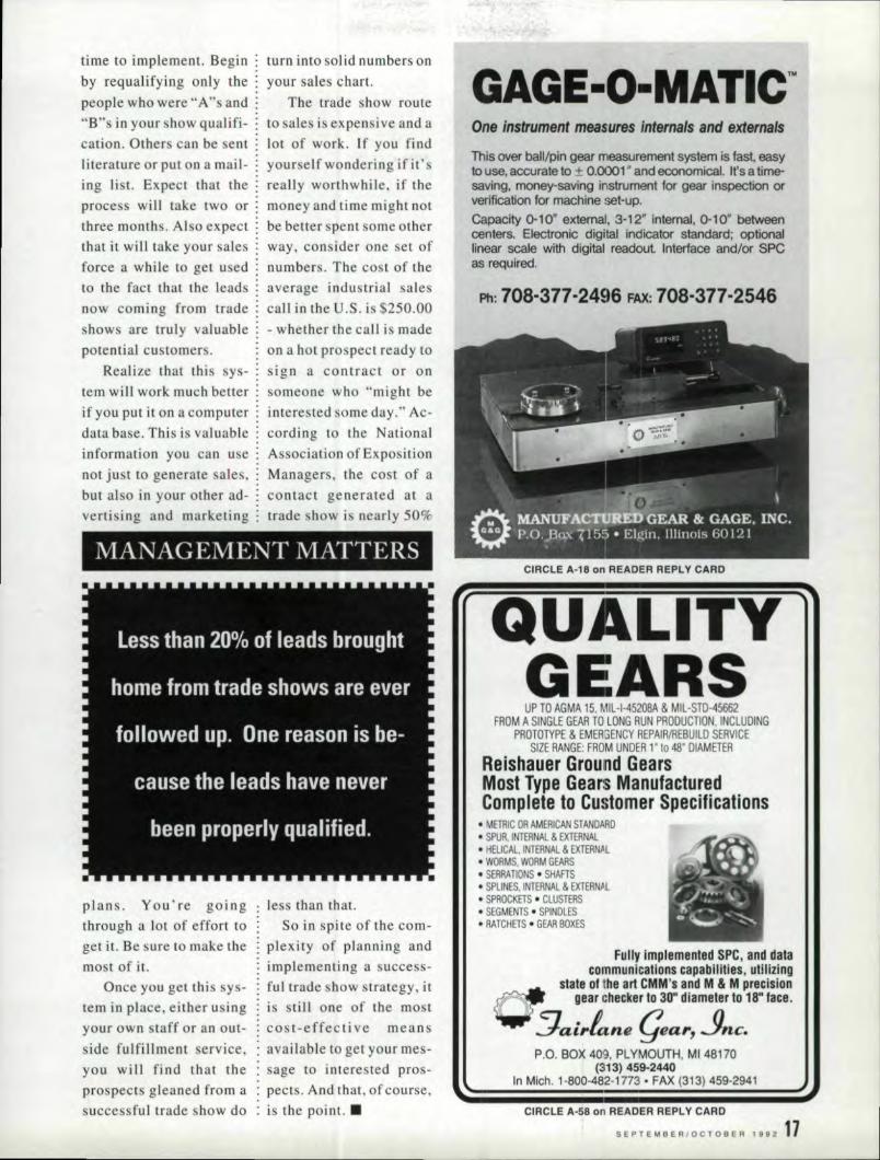
lVIANAGEMENT MATTERS
plans. You're goingthrough a lot of effort toget it. Be sure to make themost of it.
Once you get this sys-tem in place, either usingyour own taff or an QUt.-
side fulfillment service
you will fi nd that theprospects gleaned from asuccessful trade show do
less than thar.So in sp ire of the com-
plexity of planning andimplementing a success-ful trade show strategy. it.is still one of the mostcost-effective meansavailable to get your mes-sage to interested pros-pects. And that, of course,is the point, •
GAGE·O·MATIIC:~W,One instrument meas'ures internals and externals
This over ball/pin gear measurement system is fast, easyto use, accurate to ± 0.0001" and economical. It's a time-saving, money-saving instrument for gear inspection orverification for machine set-up.Capacity 0-10" external, 3-12" 'internal, 0-10· betweenoenters.Electronic digital indicator standard; optionallinear scale with digital readout.lnterfaoe and/or SPCas required.
Pb: 708-377-2496 FAX: 708-377-2546
CIRCL'E A·18 on 'READER REPLY CARD
UP TO AGM'A 15, MIL·I-4520BA & MIL-STD-45662FROM' A SINGLE GEAR TO LONG RUN PRODUCTION, INCLUDING
PROTOTYPE & EMERSENCY REPAIR/REBUILD SERVICESIZE RANGE: FROM UNDER 1'1048' DIAMETER
Reishauer Ground GearsMosl Type Gears ManufacturedComplete tOICustom,er SlpeciiUc,aUons,
• METRIC OR AMERICAN STANDARD.' SPUR, INTERNAL & EXTERNAl.' HELICAL. INTERNAL & EXTERN.6L• WORMS. WORM GEARS• SERRA nONS • SHAFTS• SPLINES. INTERNAL & EXTERNP.L• SPROCKETS • CLUSTERS• SEGMENTS. SPINDLES• RATCHETS • GEAR BOXES
Fully Implemented Sll'e. and datacommunications ,capabiliUes. uUlizingl
- statel of Ihe' art CMM's and M & 1Mprecision(;f' .'gear c~hecker 1030" diameter to 18,·faC8 .
'.- ~ai,.lane (jear,.Jncop.o. BOX 409, PLYMOUTH, MI48170
(313) 459-2440In Mich. 1-800-482-1n3· FAX (313) 459-2941
CIRCLE. ,11.·58on READER iRE'PLY CARD
SEPTEI.lBERIOCTOBER 1992 1'1
ADV.ERTORIAL
External SprocketTooth Pot Broaching
ONCE AN EXCLUSIVE GOAL, NOW A REALITY,WI'TH NATIONAL BROACH & MAGHINE CO.'S RED RING PIRODUCTS
Recent technical advances are bringingthe efficiency and part consistency of potbroaching to a wide range of sprocket-toothed parts.
In sprocket tooth broaching, two types oftools are primarily used: a stick-type (surfacebroach) and a ring-type tool. The main pot is atwo-piece split holder that has four groundlocating bars for supporting a series ofprecision ground, broach-holding bushings.
These bushings have internal slots that holdprecision, high-speed steel broach sticks. Thesticks can have from as little as one, to asmany as three splines each, to rough the partsprocket teeth by generating the form. Thebroach sticks are assembled in a staggeredformation with many teeth engaged at oncefor a smooth, quiet cutting action. Thesesticks can be easily removed for simplesharpening operations ..
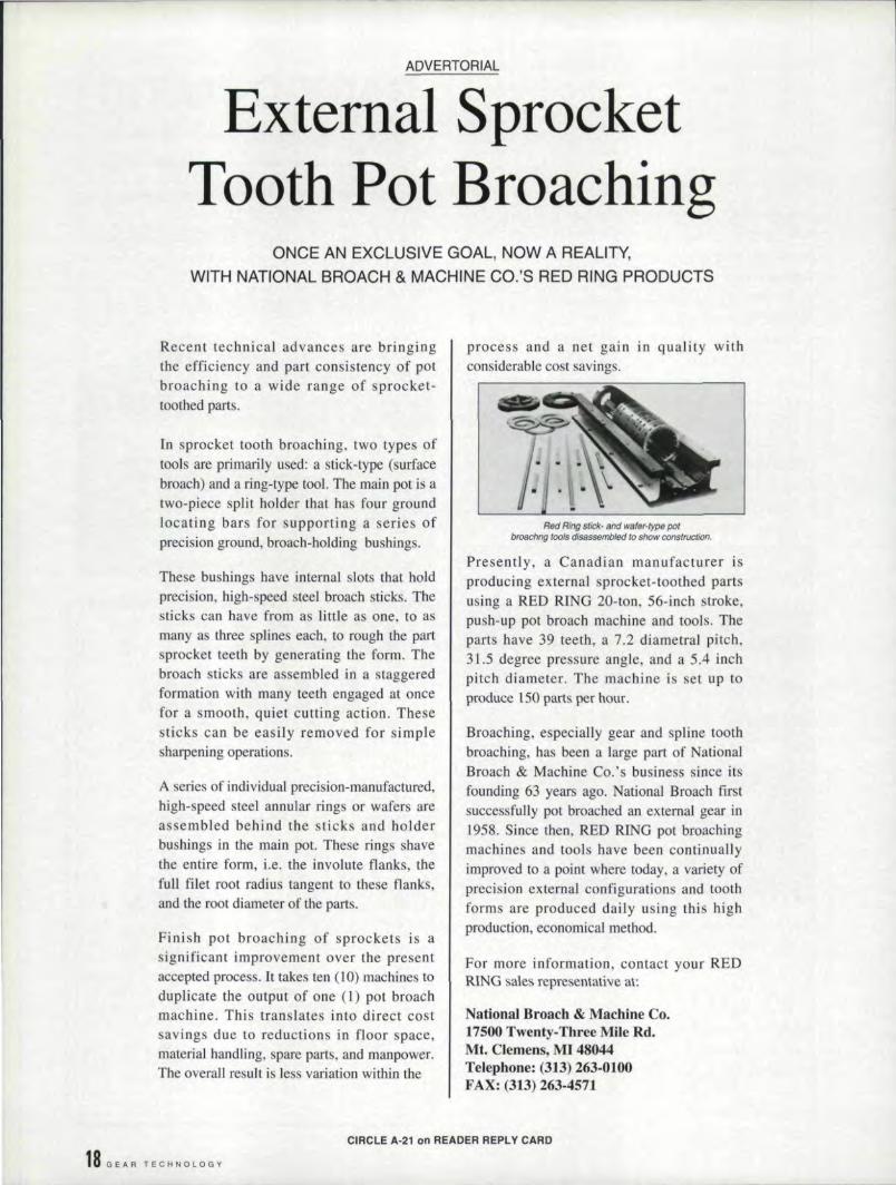
A series of individual precision-manufactured,high-speed steel annular rings or wafers areassembled behind the sticks and holderbushings in the main pot These rings shavethe entire form, i.e. the involute flanks, thefull filet root radius tangent to these flanks,and the root diameter of the parts.
Finish pot broaching of sprockets is asignificant improvement over the presentaccepted process. It takes ten (10) machines toduplicate the output of one (1) pot broachmachine .. This translates into direct costsavings due to reductions in floor space,material handling, spare parts, and manpower.The overall result is less variation within the
process and a net gain in quality withconsiderable cost savings.
Red Ring stick· and wafer· type potbroachng tools disassembled to show conemicuon:
Presently, a Canadian manufacturer isproducing external sprocket-toothed partsusing a RED RING 20-ton, 56-inch stroke,push-up pot broach machine and tools. Theparts have 39 teeth, a 7.2 diametral pitch,31.5 degree pressure angle, and a 5.4 inchpitch diameter. The machine is set up toproduce 150 parts per hour.
Broaching, especially gear and spline toothbroaching. has been a large part of NationalBroach & Machine Co.'s business since itsfounding 63 years ago .. National Broach firstsuccessfully pot broached an external gear in1958. Since then, RED RING pot broachingmachines and tools have been continuallyimproved to a point where today, a variety ofprecisionexternal configurations and toothforms are produced daily using this highproduction, economical method.
For more information, contact your REDR1NG sales representative at:
National Broach & Machine Co.17500 Tweaty-Three Mile Rd.Mt. Clemens,. MI 48044Tel.ephone: (313) 263-0100FAX: (313) 263-4571
1,8 GEAR TECHNOLOGY
CIRCL.E A·21 on READER REPL. Y CAiRO
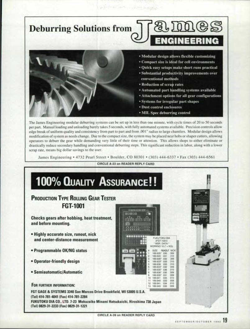
The James Engineering modular deburring systems can be set up in les ' than one minute, with cycle limes of 201050 secondper pan. Manual loading and unloading barely takes 5 seconds, with fully automated ystems available. Precision controls a'l\owedge break of uniform quality and consistency from part to part and from .00 I" radius to large chamfer. Modular design a'l\owmodifieation afsystem a needs change. Due to the compact size, the system may be placed near hob or hoper utters, allowingope rat rs to deburr the gear while demanding very little of their lime or anenuon. This allow hops 'to either eliminate ordrastically reduce secondary handling and c nventional deburring steps. This ignilicant reduction in labor, along with a lowerscrap nile, means big dollar savings to the u cr.
CIRCL'E A-23 on ,READER REPLY CARD
James Engineering • 4732 Pearl Street > Boulder" CO 80301 ·003) 444-6337· ax. (303) 444-6561
--
1000/0 QUALITY ASSURAN,CE!!- --- - - -- - - -
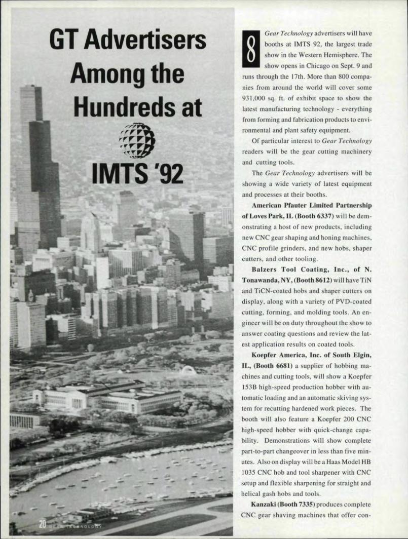
PIRODUcnON TYPE ROWNG GEAR TesrER
IFGT~1001
Checks, gears alter hobbing', heat. tteatmant,alnd bef'D!r,emounting,
• High'ly accurate' size. runDot. nick,andll:enter~distance' measurement fUKUTOKU OIA
IFGT.ICIOI)''''SR DATA'
WORKNQ 10 C' = 'to! 3)
SIZE RlIIJUr 'lICK189~' 0;)0 :lO9189&40 031 liO189 635' 032 :lO9189 633" 033 ~10189638 033 ~IO\ 89 1133' 032 009199.635' 038 010"89.636" 030 009189.835' 031 009
10 189.114I 03S, DIO11 189 Il40 033 00912 189.1141 034 01013 189.1140 033 009
• Programmalbl!e'OKlN~Gstatus
.' Operator-friendly desiOln
IFOR: FURTHER INFDRMiATIIDN:
FIGTIGAGE & S'tST:EMS: 3340 San Mar,cos Drive BrOOkfield. W,I 53005 U.S.A ..' ••••• 1ne!liI1414-78~-iW41IF8IxI414-781'-2284FUIUTOKU CIA, C.o,. LTD, 7-23 Mokuzaiko Minami Hatsukaicfl'i. Hiroshima 738: Japannen 0829!.31-2233 IFal}() 0829-31-1221
CIRCI.E A-39' on READER REPI.Y 'CARD
Sf~TEMBeRIOCTOB R 1992 19
GT AdvertisersAmong theHundreds at
;ffD~.··.,~....-r-: .o:'{,..~
'. -
IMTS '92
mG. ,a'T,rhnO.l ..ogy
. adV"'.tisers ..w. i.1.1have.booths at. IMTS 92, the largest trade
I
show in the Western Hemisphere, Theshow open in Chicago on Sept, 9 and
runs through the .17th. More than 800 compa-nies from around the world will cover ·ome931,000 sq, n. of exhibit space to show the
latest manufacturing technology - everythingfrom forming and fabrication productsto envi-ronmental and plant safety equipment.
Of particular interest to Gear Technology
reader will be the gear cutting machineryand cutting tools.
The Gear Technology advertisers will behowing a wide variety of latest equipment
and proce es at their booth ..
American Pfauter Limited. Partnership'of'Leves l:lnrk,IL (Booth ,6337) will be dem-onstrating a ho t of new products, includingnew CNC gear shaping and honi.ng machines,CNC profile grinders, and new hobs, hapercutters, and other tooling.
Balzers Tool Coating. Inc., of N.Tonawanda,. NY I (Booth 86]2) wiU have TiNand TiCN -ccated nobs and haper cutters on
display, along with a variety of PVD-coated
cutting, forming, and molding tools. An en-gineer wi II be on duty throughout the show iIO
answer coating que uonsand review the lat-est application results on coated tools.
Koepfer America, Ine, of South Elgin,
IL. (Booth 6681) a supplier of hobbing ma-
chines and cutting tools, will show a Koepfer
1.53.8 high-speed production bobber with au-tomatic loading and an automatic kiving sys-tern for recutting hardened work pieces. Thebooth win also feature a Koepfer 200 CNChigh-speed bobber with quick-change capa-
bility. Demonstration will how completepart-to-part. changeover in less than five min-utes. Also. on display will be a Haas Model H.81035 CNC hob and tool sharpener with CNC
setup and flexible sharpening for straight andhelical ga h hob and tools.
Konzaki (Booth 1335J' produces completeCNC gear si:taving machines that offer COI1-
ventional, diagonal, plunge. and underpas
shaving capabilities, Kanzaki offers full, 5-
axis CNC hard gear finishing systems,incor-
porating tool wear compensation.
Liebherr Machine Tool, a Division ofLiebherr-America, Inc., Saline, MI (Booth6466) has responsibility for sales and service
of Liebherr CNC gear cutting machines and
material handling equipmentand Lorenz CNC
gear shaping machines and gear cutnng tool .
One of the company's LC 252 CNC hobbing
machines and a Lorenz LS 1.54 CNC shaping
machineequipped with a flexible automatic
load/unload system will be on display at the
booth, along with a full range of Lorenz
cutting tools.
Mikr,on Corporation of.Elgin, IL, (Booth
4300) offers a wide range of CNC gear ma-
chines for the hobbing and shaving of gears
within the range of 112" to 2[". Mikron's "An
series machines (up to 8" dia, and 27" long) do
high precision finish hobbing with a horizontal
work axis; the "C" series doe vertical workpiece
bobbing through 21" diameter; and the "S"series machines do shaving with the conven-
tional, diagonal. underpass, and plunge meth-
ods. Complete tooling is available as well.
MH[ Machiine Tool U.S.A., Inc., ofItasca, IL. (Baoth 4191),ln a departure from
displaying small capacity machines, will dem-
onstrate a 16" capacity hobber and an 18"
capacity shaving machine. The GC40 is a 5-
axi , 400 mm (15.7"), 8 module (3.2 DP)
bobbing machine with fully conversational
programming. The FA45 is a 5-axis. 450 mm(17.7") 10 module (2.5 DP) state-of-the-anshaving machine that isalso fully conversa-
tional in its programming.
Pfauter-Maag Cutting Tools, L.P .., LovesPark, [L, ,(Booth 6337) offers a full range ofgear cutting and finishing tools, The original
Wafer Shaper Cutter and High Speed WaferHob win be demonstrated on new model ma-
chines by Pfauter. •
The photograph for this article was shot by
Ric/lOrd Goldstein.
IIMIT',S,EXIHIIBITOR IND'EX
(as 0,' Jul,,, 24,1992)
Visit the following Gear Technologyadvertisers at their booths at fMTS '92,
AMERICAN PFAUTER, LTD.D51 Wind or Road
Loves Park, IL 6.1132-2950(815) 828-3000
Fax (815) 282-3075IMTS Beoth #6,337
BALZERS TOOL COATING661 Erie Avenue
North Tonawanda, NY 14120(716) 693-8557
Fax (716) 695-1995(MTS Booth # 8612
KANZAKIp, O. Box. 31038
Independence, OK 44131(216) 642-0230
Fax (216) 642-0231lMTS Booth # 7.335
KOEI'FER AMERICA, INC.635 Schneider Drive
South Elgin. IL 60177(708) 931-4121
Fax (708) 931-4192(MTS Booth # 668.
UEBHER~ MACHINE TOOL1465 Woodland Dr.Saline, M.I 48176(313) 429-7225
Fax (3U) 429-2294IMTS Booth # 6446
MIKRON CORPORATION675P Tollgate Rd.
P. O. Box 7722Elgin, IL 760121-7722
(7118) 888-0132fax (708) 888-3674nvns Booth #4300
MRI MACHINE TOOL U.S.A., INC.907 W. Irving Park Rd.ltasca.Tl, 60143-2023
(708) 860-4222Fax (708) 860-4233IMTS Booth # 4197
I'FAUTER·MAAG CUTTING TOOLS,. L.I'.1352 Windsor Road
Loves Park. lL 61132-2950(815) 877-8900
Fax (815) 877-0264(MTS Bootb# 6337
SEPTEM8
22 G EAR TE.CHNOLOGY
CNCTechnologyandthe System-Independent
Manufacture ofSpiral Bevel Gears
Dieter WienerIKlingelnber,g Sohine,
HUckeswagen. Germanv
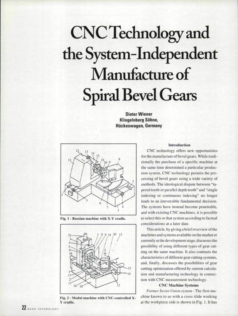
Fig. 1 - Russian machine with X-Y cradle.
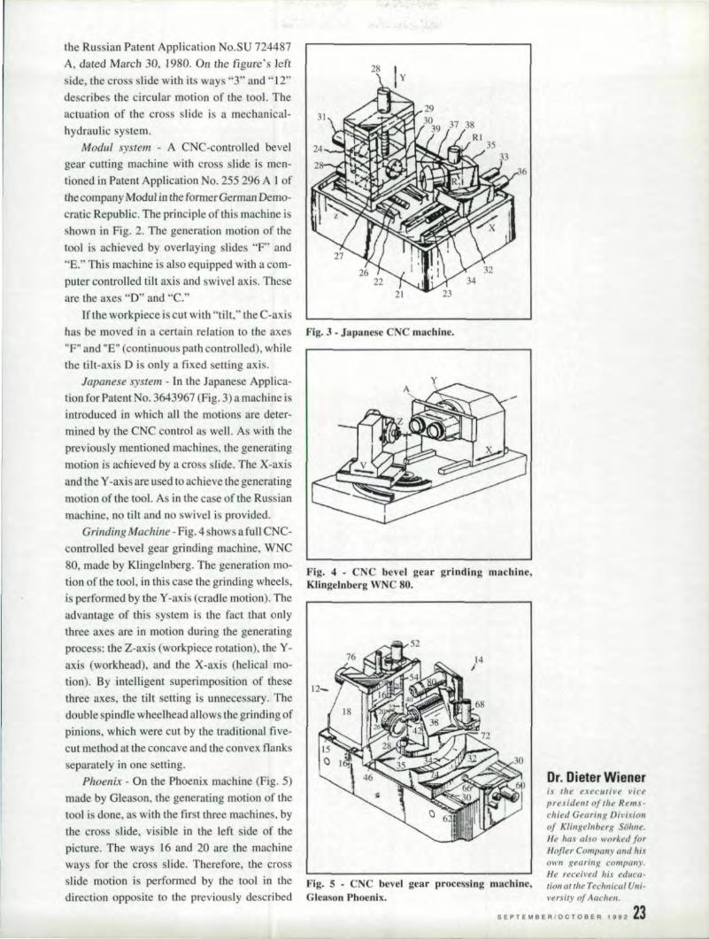
Fig. 2 - Modul machine with CNC·contlColled X-Y cradle.
IntroductionCNC technology offers new opportunities
for the manufacture of bevel gears. While tradi-tionally the purchase of a specific machine atthe same time determined a particular produc-lion system, CNC technology permits the pro-cessing of bevel. gears using a wide variety ofmethods. The ideological dispute between "ta-pered tooth or parallel depth tooth" and "singleindexing or continuous indexing" no longerleads to an irreversible fundamental decision,The systems have instead become penetrable,and with existing CNC machines, it is possibleto select this or that system according to factualconsiderations at a later date,
This article, by giving a brief overview of themachines and systems available on the market orcurrently at the development stage. discusses thepossibility of using different types of gear cut-ting on the same machine. It also contrasts thecharacteristics of different gear cutting systems.and, finally, discusses the possibilities of gearcutting optimization offered by current calcula-tion and manufacturing technology in connec-tion with CNC measurement technology.
CNC Machine SystemsFormer Soviet Union system- The first ma-
chine known to us with a cross slide workingat the workpiece side is shown in Fig .. l.1t has
the Russian Patent Application No.SU 724487A, dated MaTch 30. 1980. On the figure' s leftside, the cross slide with it ways "3" and"] 2"describe the circular motion of the tool. Theactuation of the cross slide is a mechanical-hydraulic system.
Modul system - A CNC-controlled bevelgear cutting machine withcro s slide i men-tioned in Patent Application No ..255 296 A I oftlte company Modul in itheformer German Demo-cratic Republic, The principle of'rhi machine isshown in Fig. 2. The generation motion of thetool i achieved by overlaying slides "F' and·'E." This machine is also equipped with a com-puter controlled tilt axis and swivel axis ..Theseare the axes "D" and "c."
If the workpiece is cut with "tilt," the C-axishas be moved ina certain relation to the axes"F" and "E" (continuous pathcontrolled), whilethetilt-axis D is only a fixed ettlng axis.
Japanese system - In the Japanese Applica-tion for Patent No. 3643967 (Fig. 3) a machine isintroduced in which all tile motions are deter-mined by the CNC control as well. As with thepreviously mentioned machines, the generatingmotion is achieved by a eros Iide. The X-axisand the Y-axis are used to achieve the generatingmotion of the tool. As in the case of the Ru ssianmachine, no tilt and no swivel is provided.
Grinding .Machine - Fig ..4 shows a full CNC-controlled bevel gear grinding machine, WNC80, made by Klingelnberg. The generation mo-tion of tile tool, in this case the grinding wheels,is performed by the Y-axis (cradle motion). Theadvantage of this system is the fact that onlythree axes are in motion during the generatingproce s: (he Zvaxis (workpiece rotation), the Y-axis (workhead), and the X-.axis (helical mo-tion). By intelligent superimposition of thesethree axes, the tilt setting is unnecessary. Thedouble spindle wheelhead allows the grinding ofpinions, which were cut by the traditional. five-cut method at the concave and the convex flanksseparately in one setting.
Phoenix - On the Phoenix machine (Fig. 5)made by Gleason, the generating motion of thetoo] i done, as with the first three machines, bythe em slide, visible in the left side of thepicture, The ways 16 and 20 are the machineways for the cross slide. Therefore, the cross
lide motion is performed by the tool in the Fig. 5 . CNC bevel gear processing maehlne,
28
Fig. 3 - Japanese CNC machine,
Fig. 4 • CNC bevel gear grinding machine,Kllngelnberg WNC 80.
is the executive 1';('<'
president of tile Rems-chied Gearing Divisionof Klingelnberg Sohne.He has also worked forHofler Company and M,I'OWI1 gearing compall.\'.He received his educe-tion or lire Technical UIl;'versity ofAachen.
S E PTE .. B E RIO C T 0 B E R t 9 92 ,23direction opposite to the previously described GleasonPihoen.ix.

24 GEAR TECHNOLOGY
machine .This machine ha the characteristic ofCOlIlillUOU Iy moving the machine root angleduri ng the ge nerat ing proce s, This moti.on el im i-nate the tilt ettingand the swivel. ettiag,
KNC - Fig ..6 shows a full CNC bevel gearcutting machine, the KNC 40/60 series byKlingelnberg. 0.11 thi machine all the axe areCNC controlled. The E-axi i only u ed forsingle piece and smalljot size production. Thisaxis sets the crowning eccentricity automati-cally when cutting bevel gears with the dividedcutter head. This axis is not used for high-volume production. regardless of whether theface milling or face bobbing process is applied,The advantage of Lhis machine is its great stiff-ne s, ince in the ·.1ng.le indexing process, onlythree axes are in motion at the same time: theworkpiece rotation axi B.,. the workhead rota-tion axis A, and the infeed axis X.
'Gear Cutting SystemsThe two decisive differentiating features of
gear cutting ystem are the continuou index-ing or single indexing processe and the paralleltooth depth. or the tapered tooth system,
In principle, all varietie can be combinedwith one another, but in practice, however,the following principle combinations are com-mon: Continuous with parallel tooth depthand epicycloid, and smgle indexing with ta-pered tooth and arc.
In the ca e of parallel tooth depth, manufac-ture is performed on precise pitch cone (Fig. 7).Unless corrections are made. no crowning willoccur. The gear generating proces is preci eand does not result in profile bearing, and a aresult of the identica] [001 radii of the concaveand convex flanks in a continuou process (Fig.S), without a desired correction, no longitudinalconvexity is produced. The advantage is that !i.tissimple to conduct. all calculations on the irnagi-nary crown gear in question; the complicatedthree-dimensional bevel gear problem becomesa simple two-dimensional crown gear problem.Profile bearing is produced precisely and specifi-cally via the tool. and the longitudioal crown viathe difference in radiu of the tool flanks forconvex and concave flanks, The difference illradill is achievedvia a eparated blade head (Fig.9) in individual! aad small series production; andin large series production (Fig. 10). via the tool
Fig ..9'- Split blade bead for individual and . mall inclination or the gear generating proce .erie manufacture. The continuou process i always a complet-
Fig. 6 - CNC bevel gear generating machine,KI..ingelnberg KNC 40/60..
Fig..,. - Manufacture on precise pitch cones.
Mo~
ing process: both flanks of the gear and pinionare completed simultaneously in each case.
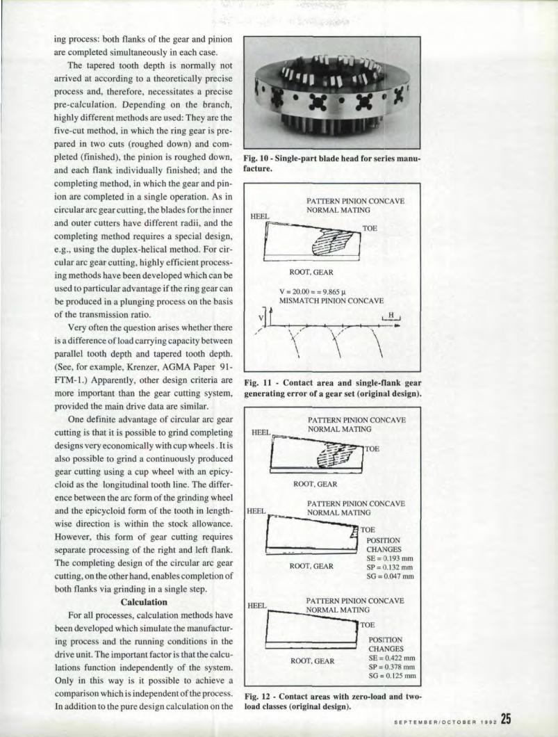
The tapered tooth depth is normally notarrived at according to a theoretically preciseprocess and, therefore, necessitates a precisepre-calculation .. Depending on the branch,highly different methods are used: They are thefive-cut method, in which the ring gear is pre-pared in two cuts (roughed down) and com-pleted (finished). the pinion is roughed down,and each flank individually finished; and thecompleting method, in which the gear and pin-ion are completed in a single operation. As incircular arc gear cutting. the blades for the innerand outer cutters have different radii, and thecompleting method requires a special. design,e.g .• using the duplex-helical method. For cir-cular arc gear cutting, highly efficient process-ing methods have been developed which can beused to particular advantage ifthe ring gear canbe produced in a plunging process on the basisof the transmission ratio.
Very often the question arises whether thereis a difference ofload carrying capacitybetweenparallel tooth depth and tapered tooth depth.(See, for example, Krenzer, AGMA Paper 91-
FTM- L) Apparently, other design criteria are Fig. 11 _ Contact area and single-flank gearmore important than the gear cutting system, generating errer ofa gear set (original design).provided the main drive data are similar.
One definite advantage of circular arc gearcutting is that it is possible to grind completingdesigns very economically with cup wheels. It isalso possjble to grind a continuously producedgear cutting using a cup wheel with an epicy-cloid as the longitudinal tooth line. The differ-ence between the arc form of the grinding wheeland the epicycloid form of the tooth in length-wise direction is within the stock allowance.However, this form of gear cutting requiresseparate processing of the right and left flank.The completing design of the circular arc gearcutting, on the other hand. enablescompletion ofboth flanks via grinding in a single step.
CalculationFor all processes, calculation methods have
been developed which simulate the manufactur-ing process and the running conditions in thedrive unit. The important factor is that the calcu-lations function independently of the system.Only in this way is it possible to achieve a
Fig. 10· Single-part blade head for series manu-facture'.
PATTERN PINION CONCAVENORMAL MATINGHEELr
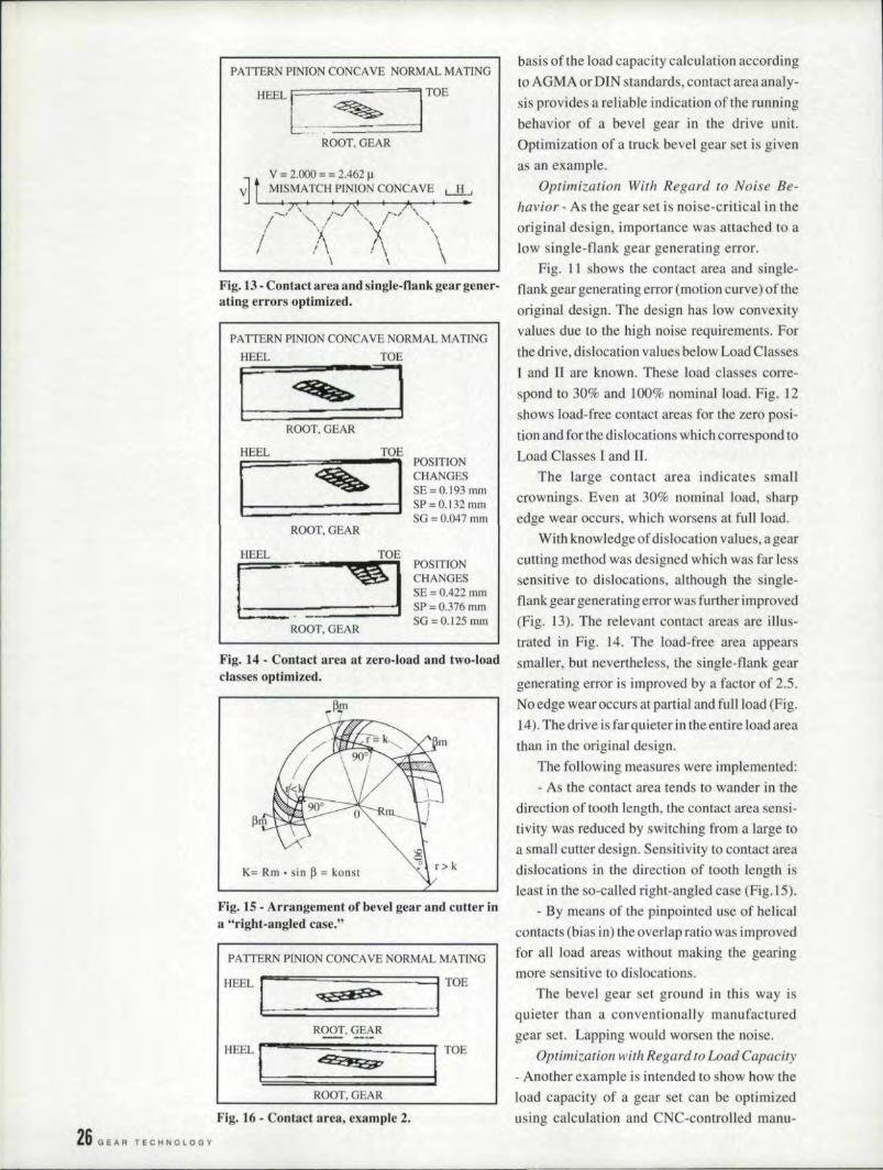
comparison which is independent of the process. Fig. 12- Contact areas with zero-load and two-In addition to the pure design calculation on the load classes (original design).
ROOT,GEAR
v = 20..00= = 9.865 J.lMISMATCH PINION CONCAVE
vlt L-L,'" .. L I .... I , j ..
\. ," '\, '\,
'\\
PATTERN PINION CONCAVENORMAL MATINGIUillL[ i!r
ROOT,GEAR
I PATIERN PINION CONCAVEIHEEL[ __ ._~MALMATING
~ ~T~~'mONt:::::::::====~~~=CHANGESSE=o..193mmSP=O.132mmSG =0..047 0101
ROOT,GEAR
fA TIERN PINION CONCAVENORMAL MATINGHEEL
II~ "1TOE
t========Jj POSITION- CHANGES5E;:; o..422mmSP=O.378mmSO= 0..125 mm
ROOT,GEAR
SEPTEMBERIOCT08ER , 992 25
26 G EA R TECHNOLOGY
PATTERN PINION CONCAVE NORMAL MATINGbasis of the load capacity calculation accordingto AGMA or DIN standards, contact area analy-sis provides a reliable indication of the runningbehavior of a bevel gear in the drive unit.Optimization of a truck bevel gear set is givenas an example.
Optimization With Regard to Noise Be-havior - As the gear set is noise-critical in theoriginal design, importance was attached to alow single-flank gear generating error.
Fig. 11 shows the contact area and single-flank gear generating error (motion curve) of theoriginal design. The design has low convexityvalues due to the high noise requirements. Forthe drive, dislocation values below Load ClassesI and ]I are known. These load classes corre-spond to 30% and 100% nominal load. Fig. 12shows load-free contact areas for the zero posi-tion and for the dislocations which correspond toLoad Classes I and II.
The large contact area indicates smallcrownings, Even at 30% nominal load, sharpedge wear occurs, which worsens at full load.
With knowledge of'dislocation values, a gearcutting method was designed which was far lesssensitive to dislocations. although the single-flank gear generating error was further improved(Fig. 13). The relevant contact areas are illus-trated in Fig. 14. The load-free area appearssmaller, but nevertheless, the single-flank geargenerating error is improved by a factor of 2.5.No edge wear occ urs at partial and full load (Fig.14). The drive is far quieter in the entire load areathan in the original design.
The following measures were implemented:- As the contact area tends to wander in the
direction of tooth length, the contact area sensi-tivity was reduced by switching from a large toa small cutter design ..Sensitivity to contact areadislocations in the direction of tooth length isleast in the so-called right-angled case (Fig. IS).
- By means of the pinpointed use of helicalcontacts (bias in) the overlap ratio was improvedfor all load areas without making the gearingmore sensitive to dislocations .
The bevel gear set ground in this way isquieter than a conventionally manufacturedgear set. Lapping would worsen the noise.
Optimization with Regard to Load Capacity- Another example is intended to show how theload capacity of a gear set can be optimizedusing calculation and CNC-controlled manu-
HEELtr=~~==~====J~TOEb ~ =ROOT, GEAR
V = 2.000 = = 2.462 ~~ t M~SMATCHPlN[ON CONCAVE LlLJ' I I /"1. • A I ..
----." '-. t""-.l -...~ ,·<v~ "\..
I "'-./ '\/ "/ I\. 1\ '\\ \
Fig..13 •Contact area, and single-flank gear gener-ating 'errors optimized.
PATTERN PINION CONCAVE NORMAL MATING
HEEL TOE[ ~JROOT. GEAR
HEEL TOE
[ I POSITION
-CHANGES
~ SE=O.193 mmSP = 0."132 mmSG=0.047mm
ROOT,GEAR
I
HEEL
ICTOE'til POSITION
CHANGESSE = 0.422 mmSP=0.376 mrnSG = 0.125 mm I
ROOT. GEAR
Fig. 14 - Contact area at zero-load and two-loadclasses optimized.
K= Rm • sin ~ = konst
Fig. IS - Arrangement of bevel gear and cutter ina "right-angled case."
PA TIERN PINION CONCAVE NORMAL MATING
. HEEL 1::1 ;:;;;;;;;;;==~=:=s.B>=:=:~=-:====11 TOE
ROOT,GEAR
ROOT. GEAR
Fig. 16 .•Contact area, example 2.
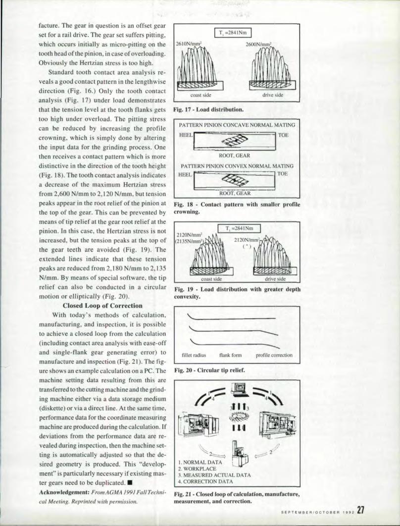
facture. Tile gear in question is all offset gearset for a rail drive. The gear set suffers pitting.which occurs initially as micro-pitting on the 26lON/mml
tooth head ofthe pinion, incase of overloading,Obviou Iy the Hertzian tress is too high.
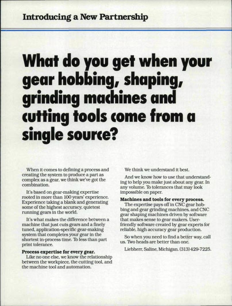
Standard tooth COntact area analysi re-veals a good contact pattern in the lengthwisedirection (Fig. 16.) Only the tooth contactanalysis (Fig. 17) under load demonstratesthat the tension level at the tooth flanks getstoo high under overload. The pitting stresscan be reduced by increasing the rprotifecrowning, which is simply done by alteringthe input data for the grinding proce s. Onethen receives a contact pattern which is moredistinctive in the direction of the tooth height(Fig. 18). The tooth contact analysis indicatesa decrease of the maximum Hertzian stressfrom 2,600 N/mm to 2.120 Nlmm, but tension
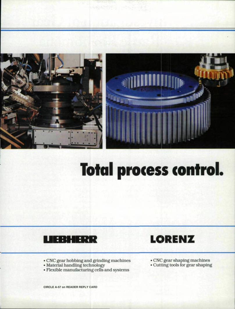
peaks appear in the root relief of the pinion atthe top of the gear. This can be prevented bymeans of tip relief at the gear root relief at thepinion. 11'1this case, the Hertziaa stress is notincreased, but. the tension peaks at the top of
the gear teeth are avoided (Fig. 19). Theextended lines indicate that these tensionpeaks are reduced from 2.180 N/mm to 2,135N/mm ..By means of special software, the tiprelief can also be conducted in a circularmotion or eHiptical1y (Fig. 20).
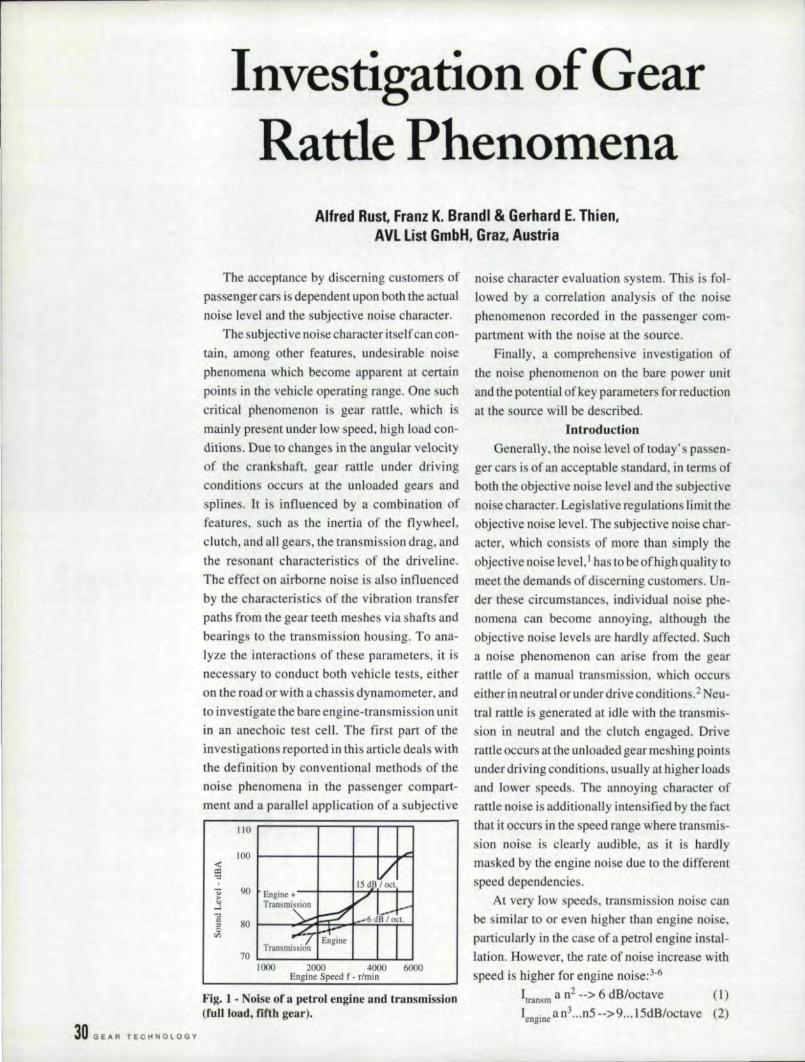
Closed Loop of CorrecticnWith roday's method. of calculation,
manufacruring, and inspection, it is possibleto achieve a closed loop from the calculation(including contact area analysis with ease-offand ingle-flank gear generating error) tomanufacture and inspection (Fig. 21). The fig-ure shows an example calculation on a Pc. Themachine setting data. resulting from this aretransferred to the cutting machine and the grind-ing machine either via a data storage medium(diskette) or via a direct tine. At the same time.performance data for the coordinate measuringmachine are produced during the calculation. Ifdeviation, from the performance data are re-vealed during inspection. then the machine set-ring i automatically adjusted so that the de-sired geometry is produced. This "develop-ment" is particularly nece ary if existing mas-ter gears need to be duplicated .•
T, =2841Nm
2600N/mml
Fig. n.Load dlstrlbutln»,
PATTERN PINION CONCAVE NORMAL MA"TING
ROOT. GEAR
PATIERN PINION CONVEX NORMAL MATlNG
aesr. I[ .~ rOE
ROOT. GEAR
Fig.. ~8 • Contact pattern with smaller prof LIecrowning.
I T, =2841Nm II2120N/mm'
(2135N/mm' .~ 1\, 2120N/mm' Xx['\ ( ") ,
~Il D.:\1\
X ,
A 1 '\\\ .~.
!~ I ~Icoast. side drive side
Fig.• 1'9 • Load distr,ibution with greater depthconve·xity..
,,_.-------------------~-.----------------~:fillel radius flank form profile correction
Fig..20 • Circular Up relief.
~~1. NORMAL DATA2. WORKPLACE
//
3. MEASURED ACTUAL DATA4. CORRECTION DATA
Acknowledgement.: From AGMA J99J Fall Techni- F:ig.2l _Closed Inop ,of calculation, manufacture,cal Meeting. Reprinted withpermission. measurement, and correction.
19H 27SEPT~M8ER'OC'08ER
Introducing a New Partnership
What do you get when yourgear hobbing, shaping,
'. d- h- dgrln_lng mac_Jines an·_cutting tools come from asingle source?
When itcomes to definmg a process andcreating the system to produce a part ascomplex as a gear. we thLnk we'Vegot thecombination.
It's based on gear-making expertiserooted in more than 100 years' experience.Experience taking a blank and generatingsome of tile highest accuracy, quietestrunning gears m the world.
It's what makes the difference between amachine that just cuts gears and a finelytuned, application-specific gear-makingsystem that completes your gear in theshortesttn-process time. 1b less than partprint tolerance..Process ,expertise for every gear.
Like no one else, we know the relationshipbetween the workpiece. the cutting tool, andthe machine tool and automation.
We think we understand itbest.And we know how to use that understand-
mg to help you make just about any gear. Inany volume.1b tolerances that may 10Dkirnpossfble on paper.Machines and tools for ev:ery prooess.
The expertise pays off in eNC gear hob-bing and geargrtnd~ng machines, and eNCgear shaping machines drtven by softwarethat makes sense to gear makers. User-friendly software created by gear experts forreliable, high accuracy gear production ..
So when you need to find a better way, callus. 1\vo heads are better than one,
Liebherr, Saline, MIchigan. 1(313) 429·7225 ..
Total process con'l 01.
• CNC gear hob bing and gnndiing machines• Material handling technology• Flexible manufacturing eefls and systems
• eNC gear shaping machines"Cutting tools for gear shaping
CIRCLE A-57 on READER R'EPLV CAIRO
Investigation of GearRatde Phenomena
.Allred Rust, Franz K. 'Brandl & Ge!rhard E. Thien,AVL List iGmbH, IGiraz,.Austrial
The acceptance by discerning customers ofpassenger cars is dependent upon both the actualnoise level and the subjective noise character.
The subjective noise character itself can con-tain, among other features. undesirable noisephenomena which become apparent at certainpoints in the vehicle operating range. One suchcritical phenomenon is gear rattle, which ismainly present under low speed, high load con-ditions. Due to changes in the angular velocityof the crankshaft, gear rattle under drivingcondition occurs at the unloaded gears andsplines. It is influenced by a combination offeatures, such as the inertia of the flywheel,clutch, and all gears, the transmission drag, andthe resonant. characteristics of the driveline.The effect on airborne noise is also influencedby the characteristics of the vibration transferpaths from the gear teeth meshes Vi.B shafts andbearings to the transmission housing. To ana-lyze the interactions of these parameters, it isnecessary to conduct both vehicle tests, eitheron the road or with a chassis dynamometer, andto investigate the bare engine-transmission unitin an anechoic test cell The first part of theinvestigations reported in this article deals withthe definition by conventional methods of thenoise phenomena in the passenger compart-ment and a parallel application of a ubjective
100«Q:I....
" 90,."..l...." 80"0'"
1000 2000 4000 6000Engine Speed f· r/rnin
Fig. 1 • Noise of D. petrol .:engine and transmission(fu.llload, fifth gear).
30 GEAR TECHNOLOGY
noise character evaluation system. This is fol-lowed by a correlation analysis of the noisephenomenon recorded in the passenger corn-
partment with the noise at the source.Finally, a comprehensive investigation of
the noise phenomenon on the bare power unitand the potential ofkey parameters for reductionar the source will be described.
IntroductionGenerally, the noise level of today' s passen-
ger cars is of an acceptable standard, in term ofboth the objective noise level and the subjectivenoi e character. Legislative regulations limit theobjective noise level, The subjective noise char-acter, which consists of more than simply theobjective noise level, I. has to be ofhigh quality tomeet the demands of discerning customers. Un-der these circumstances. individual noise phe-nomena can. become annoying. although theobjective noise levels are hardly affected. Sucha noise phenomenon can arise from the gearrattle of a manual transmission. which occurseither in neutral. or under drive condi tions.? Neu-tral rattle is generated at idle with the transmis-sion in neutral and the clutch engaged .. Driverattle occurs at the unloaded gear meshing pointsunder driving conditions, usually at higher loadsand lower speeds. The annoying character ofranle noise is additionally intensified by the factthat it occurs in the speed range where transmis-sion noise is clearly audible, as it is hardlymasked by the engine noise due to the differentspeed dependencies.
At very low speeds, transmission noi e canbe similar to or even higher than engine noise,particularly in the ca e of a petrol engine instal-lation. However, the rate of noise increase withspeed is higher for engine noise:3.6
[Iransm a n2 _.> 6 dB/octave (1)[engine a n3 ••..n5 ·->9 ...15dB/octave (2)
I"" sound intensityn "" speed
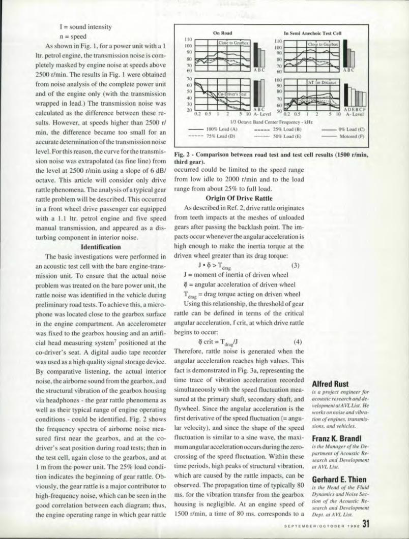
As shown in Fig. I, for a power unit with a 1ltr, petrol engine, tile transmission noise is com-pletely ma ked byengine noi e at speeds above2500 r/min, The results in Fig .. l were obtainedfrom noise analysis of the complete power unitand of the engine only (with the rransmi sionwrapped in lead.) The transmi sion noise wascalculated a the difference between the e re-ults, However, at speeds higher than 2500 rl
min.llle difference became [00 mall for ana curatedetermination of the tran mis ion nor elevel. For litis reason, the curve for rhe Iran mis-sion noise was extrapolated (as fine line) fromthe level at 2500 r/min using a slope of 6 dB!octave. This article will consider only driverattle phenomena. The analysis of a typical gearrattle problem will be de eribed. This occurredin a front wheel drive pa enger car equippedwith a 1.1 Itr. petrol engine and five . peedmaaeal iran mi sian. and appeared a a dis-turbing component in interior noise.
IdentifleatlenThe basic investigations were performed in
an acoustic test cell with the bare engine-trans-mission unit. To ensure that the actual noiseproblem was treated on die bare power unit, therattle noi e was identified in the vehicle duringpreliminary road tests ..To achieve thi: , a micro-phone wa located close to the gearbox. urfacein the engine compartment. An accelerometerwas fixed to thegearbox l10llsing and an artifi-cial head measuring system 7po itio:ned at theco-driver's seat. A digital audio tape recorderwas used as a high quality signal storage device.By comparative listening. the actual interiornoise. the airborne sound from the gearbox. andthe structural vibration ofthegearbox hou ingvia headphones -jhe gear rattle phenomena awell a their typical range of engine operatingcondition - could be identified. Fig. 2 howsshe frequency spectra of airborne noise mea-sured first near the gearbox. and at the co-driver' eat position during road re ts: then Inthe te t cell, again do e to the gearbox, and at1 m from the power unit. The 25% load condl-'lion indicate. the beginning of gear rattle. Ob-viou :Iy. the gear rattle i a major contributor tohigh-frequency noise. which can be . een in thegood correlation between each diagram; thus,the engine operating range in which gear rattle
On, Road In Semi nechnlc THI ,- tilII 0 r--'-r.::--r--=-~-.100 ~~-~~~~~9O~--I----'1-.::""""~~80 b,....;:J5:tko,~....,......p."..JI:70 ~~-t-~~~~60 L-~_L-~_~~70 r-~-r-~-T-~60 I - I I
50 "\1 ' 'I40 -I~~I Cu~1tPrf!r\ Coil I
30 I 1''::' ",,;1;20 I I ~J. 1 BC
0.2 0.5 .1 2 5 Io A· Level
110 ....---.-...--r--__....I Cl"", ,<> Geart!u.
1.001--II-+k-.~;;.:::..=i_I~90 I--II+~~,....::=I'.--iV _,__ 11"-
70 -I{. :~:.;.~~..:..-\_flO I.U' II . - ~50 0.2 O.S 1 2 5 10
1/3 Oeta ve Band Center frequency - k Ii1-
-- IOO'll-Load (AI 25'l1- Load (B) -- 0 load lei----- 75'l1: Load (01 50'1 l,Q~d IE) -- Motored (F)
Fig. 2 • Comparison between read test and te t cell results (1500 r/min,tbifld gear).occurred could be limited to the speed rangefrom low idle to 2000 r/min and to the loadrange from about 25% to full load.
Origin Of Drive RaUI.eAs described in Ref. 2, drive rattle originates
from teeth impacts at the meshes of unloadedgears after pas iag the backla h point. The im-pacts occur whenever the angular acceleration ishigh enough to make the inertia torque at thedriven wheel greater than its drag torque:
.I.;t;:> T (3)- 'I' -dmg
.I' = moment of inertia of driven wheel,~= angular acceleration of driven wheelTdrng ;;;;:drag torque acting on driven wheelUsing this relationship" the true hold of gear
rattle can be defined in terms of the criticalangular acceleration, f crit, at which drive rattlebegins to occur:
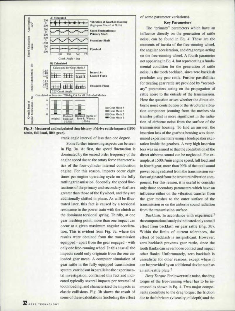
~'crit = TdralJ (4)Therefore. rattle noise .isgenerated when theangular acceleration reaches high values. Thisfact is demonstrated in Fig. 3a, representing thetime trace of vibration acceleration recordedirnultaneously with the speed fluctuation mea-
sured atthe primary shaft. econdary shaft. andflywheel. Since the angular accelerationi thefirst derivative of the speed fluctuation (= angu-lar velocity). and since the hape of the speedfluctuation is similar to a sine wave. the maxi-mum angula tr acceleration oceur during the zero-crossing of the speed fluctuatlon. Within thesetime periods, high peaks of structural vibration.which. are caused by the ranle impacts. can beobserved. The propagation time of typically 80ms, for the vibration (ran. fer fromthe gearboxhousing is negligible. At all engine speed of1500 r/min, a time of 80 ms, corresponds to a
.A!lflred IRustis o· project engineer foracoustic research andde-velopment at A. VI..USI. HI'"'orKs (1II.1I0;SI! anc/l';bra·I;(m of tllgilll! • Iran mis-sions, and vehicles.
Flranz K., IBrandlis tile Marillga of the De-partment of Acoustic Re-search ami Developmentat A vt.u«.
Gerhard E. Thienis rill' .Head of th« FluidDynamics and Noise Sec-lioll of rhl' ACI1!1S1ic Re·searcl: (/lId D« velopmentDt!pl. at i\VI..List,
5 e PTE U B E 'R I 0 C T 0,8 E A 1 11112 :3'1
1\) Me.sued.
200 ~ .~ t~ I'" I'" " I~~" I' lbratlon at Gearbox Housing_2
0oo~' PC ,.4~_=::::_=:::.==~.==: (hlgh·pass filtered at 3kHz)
_:~&'4++""'1 ;~:~~~~:~Itionat:
_~~ ~fV:' :1::::::' -=' :4"~':-:·:'1~~::9~·S~colldary Shan
_~~Fr=of f-- f-31 F1y"h ~I0' 180 360 S4Q 720
Crank Ang]e - del!
B) Cllcllllled.,:l:
eEc
!Calcu Jared for Gear Me h 3
o.rs0.]0'0.03
0.]50.]00.05o
Impact At:Loaded FlllnkIii ffi.E tJ, LI ~
----~=ti±ri .ff8a j,lll. II---720°Crank An le
u"'.e,8
UII'loodedl Fl- nk
o eE=1:1 C",,,;.... E- 0E~:> -og
Q.
.§
4
2
oIII Gear Mesh 4_Gear Mesh 3_Gear Mesh 2.' Gear Mesh I
Reduced Relluce .Inertia ofBacklash Free-R. Wheels1-35%L (-50%)
Fig. 3 - Measured nd calculated time' history or dri,ve rattle impaets (]500rlmln, fuU load, fifth gear).
crank angle interval of less than one degree.Some further interesting aspects can be seen
in Fig. 331.At first, the speed fluctuation isdominated by the second order frequency of theengine speed due to the rotary force characteri -tics of the four-cylinder internal combustionengine, For this reason, impacts occur eighttimes per engine operating cycle on the funyrattling transmission. Secondly, the speed flue-tuations ofthe primary and secondary shaft aregreater than tho e of the flywheel. and they areadditionally shifted in phase. As will be illus-trated later, this fact i caused by a torsionalresonance in the power train with the clutch asthe dominant torsional, pring. Thirdly. at onegear meshing point, more than one impact canoccur at a given maximum angular accelera-tion. This is evident from Fig. 3.£1.where theresults were obtained from the transmissionequipped - apart from the gear engaged - withonly one free-running wheel.Jn this case all theimpacts could only originate from the one un-loadedgear mesh. A computer simulation ofgear rattle in the fully equipped transmissionsystem. carried out inparallel to the experimen-tal investigation, confirmed this fact and indi-cated typically several impacts per rever aloftooth loading. and characterized the impacts aselastic collisions. Fig. 3b shows the result ofsome of these calculations (including the effect
32 GE,t,R TECHNOLOGY
of some parameter variations).Key Parameters
The "primary" parameters which have aninfluence directly on the generation of rattlenoise. can be found in Eq, 4. These are Ihemoments of inenia of the free-running w.heel,the angular acceleration, and drag torque actingon the free-running wheel, A fourth parameternot appearing in Eq. 4. but representing a funda-mental condition for the generation of rattlenoise, is the tooth backlash. since zero backlashprecludes any gear rattle. Further possibilitiesfor treating gear rattle are provided by "second-ary" parameter acting on the propagation ofrattle noise to the DIn ide of the tran mi ion ..Here the que lion arises whether Ihe direct air-borne noi econtribution or the structural vibra-don component (coming from the meshes viatransfer paths) is more significant in the radia-tion of airborne noise from the surface of thetransmissicn housing. To find an answer, the.i asertion 10 Sefthe gearbox housing wa .deter-mined experimentally using a loudspeaker exci-tation inside the gearbox. A very high insertionloss was measured so that the contribution of thedirect airborne sound can be neglected, For ex-ample, at 1500 r/min engine speed. full load. andin fourth gear, more than 99% of the total soundpower being radiated frurmhesransmission sur-race originated from the structural vibrati.on com-ponent. For thi . rea on, it is useful to con iderailly those econdary parameters which have aninfluence either on the vibration tran fer fromthe gear me hes to the miter surface .of thetransmission or on the airborne sound radiationfrom the transmission surface.
Backlash. In accordance with experience,:!the computational analysis indicated only a smalleffect from backlash on gear rattle (Fig. 3b).Within the limits of current tolerances, theeffect of backlash is insignificant. However,zero backla h prevent gear rattle. since thetooth flanks can never .100 e contact and impactother flanks. Uafornmately, zero backlash iunrealistic for other reason , except where ~[can be provided by an additional device such asan anti-rattle plate.2
Drag Torque. For lower rattle noi e, the dragtorque of the free-running wheel. bas to be in-crea ed as shown in Bq. 4. Two major compe-nents contribute lathe drag torque.the frictiondue to the lubricant (viscosity, oil depth) and the
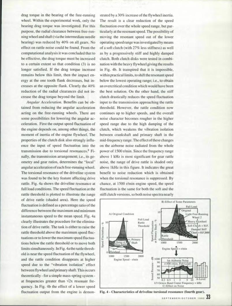
drag torque in the bearing of the free-runningwheel. W:ilthimthe experimental work, only thebearing drag torque was investigated. For thispurpose, the radial clearance between fre -run-ning whee Iand shaft (via the intermediate needlebearing) was reduced by 40% on all gears. Noeffect on ratrle noise could be found. From thecomputational analysis it wa concluded that tobe effective, the drag torque must be increa edto a certain extent so that condition (3) is DO
longer atisfied. If the drag torque increaseremains belowthis limit, then the impact en-ergy at the one t:ooth flank decrea es, but in-creases at the opposite flank. Clearly the 40%reduction of the radial clearances did not in-crea e the drag torque beyond the limit.
Angular A celeration. Benefits can be ob-tained from reducing the angular accelerationacting on the free-running wheels. here aresomepossibiliries for lowering the angular ac-celeration. First the output speed fluctuation ofthe engine depend. on, among other thing . themoment of inertia of the engine flywheel. Theproperties ofthe clutch disk also lJ'ongly influ-encethe input of speed fluctuation into thetransmission due to torsional resonance .8 Fi-nally, the transmission arrangement; i.e., its ge-ometry and gearrat.io, determines the "local"angular acceleration of each free-running wheel,The tor ional resonance onhe driveliae ysternwa found to 'be the key feature. affecting driverattle. Fig. 4a shows the driveline re onance atfull lead conditions. The peed fluctuation at therattle thre hold is plotted to iHuslrate the range'of drive rattle (shaded area). Here the speedfluctuation is defined as a percentage ratio ef thedifference between the maximum and minimuminstantaneous speed to the mean peed. Fig. 4aclearly illustrates the procedure for the elimina-tion of drive rattle. Tile La k is eitherto rai e therattle threshold above the maximum peed fluc-tuation .or to lower the maximum peed fluctua-tion below the rattle thresholdor to move bothlimits simultaneously. hl Fig. 4a the rattle thresh-old i nearthe spe-ed fluctuation of the flywheel,and the rattle condition disappears at higherspeed due to the ..vibration isolation" effectbetween flywheel and primary shaft. This occurstheoretically - for a simple mass-spring system -al. frequencies greater than v2x re onant fre-quency. In Fig. 4b the effect of a lower speed
. trated by a 30% increase of the flywheel inertia.The re ult isa dear reduction of the . peedfluctuation over the whole peed range. but par-ticularly at the resonant. speed. The possibility ofmoving the resonant speed out o:f the loweroperating speed range was mvestigated by meansof a soft. clutch (with 27~ less stiffness) a wella bya progressively stiff and highly dampedclutch. Both clutch di ks were te ted in cornbi-nation with the heavy flywheel. giving theresultsin Fig. 4b.. [t transpiredthat it is impos ible,withilnpracticallimits, I.Oslttift the resoaarn speedbelow the lowe. I. operating range; i.e., to obta:inan overcritical condition which would have beenthe best solution. On the other hand, the stiffclutch drastically reduces the . peed fluctuationinput to the tran mission approaching the rattlethreshold. However, tile rattle condition nowcontinue up to higher peeds, and the overallnoi e character becomes rougher in tile higherspeed range due to the high damping of thecluteh, which weakens the vibration isolationbetween crank haft and primary shaft in themid-frequency range. Thccffectofthe echangeson the airborne noise radiated from the wholepower of 1500 r/min, Since the frequency rangeabove 1 kHz is most significant for gear rattlenoise, the range of drive rattle is haded onlyabove l.kH.z in this figure. It indicates the greatbenefit to noise reduction which is obtainedwhen the torsional resonance i .suppressed. Bychance. at 1500 r/rnin engine speed, the speedflucnration is the arne for both the oft and the
pectra nearly
A) Original CO!ldition
. t.'!
I g,,,."R
Iii:,"':l'U..,I>.,.., .'Engine Speed = r/rm;"..1000 1500 2000
Engine Speed - r/min
113 Octave Band Center Frequency = lUiiC) Effect on Noise
fluctuation output from the engine is demon- Fig. 4 - Characteristics of dri\'eUne '~orsiomll resunanee (rourth gear I..
S 'E P T ~ M B E RIO C r ·0 B E R 1 8 11.2 33
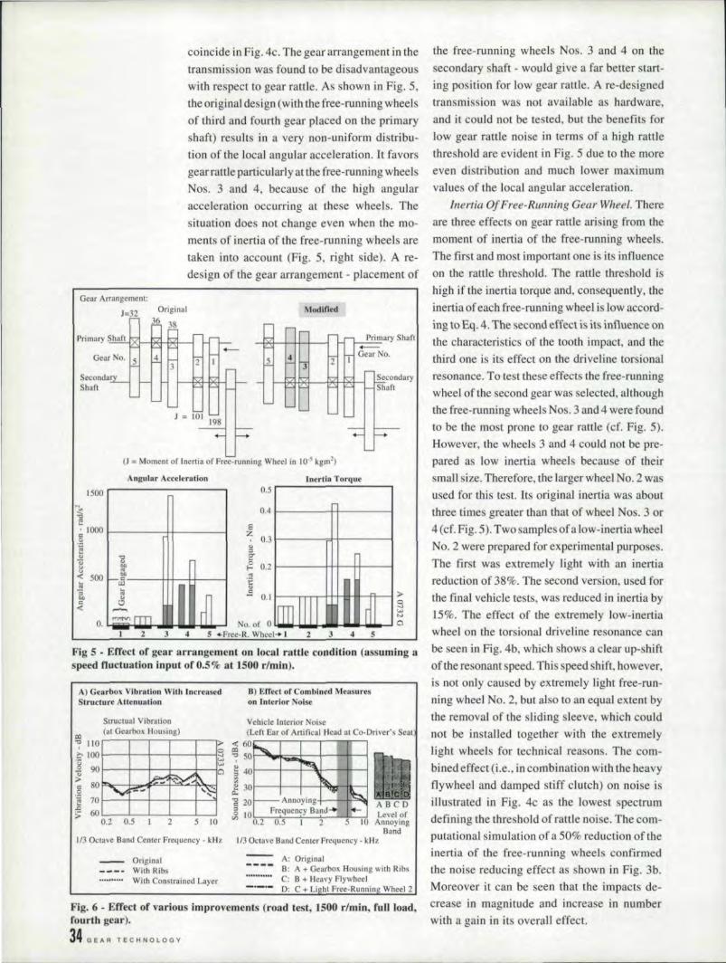
coincide in Fig. 4c. The gear arrangement in thetransrni sion was found to be disadvantageouswith respect to gear rattle. As shown in Fig. 5,the original design (with the free-running wheelsof third and fourth gear placed 011 the primaryshaft) results in a very non-uniform distribu-tion of the local angular acceleration. It favorsgear rattle particularly at the free-running wheelsNos. 3 and 4, because of the high angularacceleration occurring at these wheels .. Thesituation does not change even when the mo-ments of inertia. of the free-funning wheels aretaken into account (Fig. 5. right side). A re-design of the gear arrangement - placement of
Gear Arrangement:
J=32 Modified
SecondarShaft
(l = Momem or Inertia or Free-running Wheel in 10.5 kgm2).
Angular Aeeclerauon Inertln Torque0.5
0.4
EZ
0.3
"::l,;;r<;
0.2!-.:'!!t:".s ~--c¥~~~~~A-~>
'3w....~~ ..~ ..~ ..~w.~a
[500.
~ I,- 1000 I----.......j.-I-----Ig I
'g~ ~" ~~ 500 I ~----~-++-++-__l; fJJ
10 3~ "
.Fig 5 - Effect of gear arrangement on local rattle cOltdiUion(assuming aspeed nuctnation input of 0.5% at ~500 r/min).
B) Effect of Combined MeasuresSlrllclurc Attenuation on Interior Noise
I
Srructual Vibralional (al Gearbox Housing) (Left Ear or Artilicnl Hend al Co-Driver's Seat
1
"7110 ~~60,?:- 100I---+----,I---+---I--l;;! ';' SOl--'.. k:=1,---+-lHI---Is w-~-.; 90 a ~ '10I---+-~L.:::fo./....-----!~;\--l~ 80 ~~\ l"l 30'---I-+--·+""+..~-tt--!
, 0 v.,-::.oJ ...~ d:: I~"eo
I
I·g 70 I---+--I--I-----I-~ -g 20 - Annoying ~ ABC D~ 6OL- __ ..J....-.JL-....1.._---1_....l g ]QFrcquency Band...! ....... Level of
0.2 0.5 2 5 10 '" 0.2 0.5 11 2 5]0 AnnoyingBand
113 Octave Band Center Frequency • kl-I'z
A) 'Gearbox. Vibration Wilh Increased
Vehicle Interior Noise
1/3 Octave Band Center Prequency - kHz
OriginalWith RibsWith Constrained Layer
Fig. 6 - Effed or various improvements (road test, 1500 rlmin, fun load,fourth gear).
34 GEAR TECHNOlOGV
the free-running wheels Nos. 3 and 4 on thesecondary shaft - would give a far better start-ing position for low gear rattle. Are-designedtransmission was not available as hardware.and it could not be tested, but the benefits forlow gear rattle noise in terms of a high rattlethreshold are evident in Fig. 5 due to the moreeven distribution and much [ower maximumvalues of the local angular acceleration.
Inertia Of Free-Running Gear Wheel. Thereare three effect on gear rattle arising from themoment of inertia of the free-running wheels.The fir ,t and mo t important one is its influenceon the rattle threshold. The rattle threshold ishigh if the inertia torque and, consequently, theinertia of each free-running wheel is low accord-ing to Eq, 4. The second effect is its influence onthe characteristics of the tooth impact, and thethird one is its effect 011 the driveline torsionalresonance. To test these effects the free-runningwheel of the second gear was selected, althoughthe free-running wheels Nos. 3 and 4 were foundto be the most prone to gear rattle (d. Fig. 5).However, the wheels 3 and 4 could not be pre-pared as low inertia wheel because of theirsmall size. Therefore, the larger wheel No.2 wasused for this test. Its original inertia was aboutthree times greater than that of wheel Nos. 3 or4(cf. Fig ..5). Two samples ofa low-inertia wheelNo.2 were prepared for experimental purposes ..The first was extremely light with an inertiareduction of 38%. The second version, used forthe final vehicle tests, was reduced in inertia by15%. The effect of the extremely low-inertiawheel on the torsional driveline resonance canbe seen in Fig, 4b,. which shows a clear up-shiftof the resonant speed. This speed shift, however,is not only caused by extremely light free-run-ning wheel No, 2, but also to an equal extent bythe removal of the sliding : leeve, which couldnot be installed together with the extremelylight wheels for technical reasons. The com-bined.effect (i.e .. in combination with the heavyflywheel and damped stiff clutch) on noise isillustrated in Fig. 4cas the lowest spectrumdefining the threshold of rattle noise. The corn-
putational simulation of a 50% reduction of theinertia of the free-running wheels confirmedthe noise reducing effect as shown in Fig. 3b.Moreover it can be seen that the impacts de-crease in magnitude and increase in numberwith a gain in its overall effect.
Vibratioll Transfer. Signiflcant elements inthe vlbration transfer path from the me h to theouter gearbox urface are the. haft bearing andthe structure attenuation of the gearbox, hou ing,In Ref. 3 theeffect of the bearing de. ign isde cribed with a gain in low noise of up to 4 dB.Within the pre ent work. 'the influence of thestructure attenuation was investigated. From vi-bration measurements on the running transmis-sion using a laser vibrometer, itwa found that atfrequencies above 2kHz the shat't vibration wascared)' higher thai] the vibration at the gearbox.
housing indicating a very low intermediate true-lure attenuation.
10 determine the potentia] for noise reduc-lion in term of the structure attenuation of thegearbox hou sing two tests we re carried OlIJ t Fir t
the walls of the gearbox housing were dampedby means of a constrained layer. Secondly thewalls were uiffened by rib . Fig. 6a . hows that.tile ribbing of the gearbox housing proved to be\lery effectiee. The reductina in vibration ve-locity reached up to 5 dB. The application of theconstrained layer also improved the situation.but to a mailer extent. Finally the combinedeffect of everal measures (by succe sive addi-tion of single measures) was tested in thevehicle during road tests ..As call be een fromthe noie levels (in the frequency band ignifi-cant forthe rattle audibihly in the interiornose) in Fig.6b, the combination of improvedgearbox housing (by ribs), increased flywheelinertia, and reduced inertia of free-runningwheel NO'. 2 (second version) gave the bestresults, so that the gear rattle in the vehiclecabin wa no longer audible.
ConclusionsIn automotive tran mis ions drive rattle is
excited by the angular aceeleration ari ing fromlow frequency peed fluctuation caused by thefluctuating torque output of the combustion ell-gine due to its gas and inertia forces. Work toeliminate gearrattle thre hold - expres ed by thecritical. peed fluctuation - above the actual max i-mum speed fluctuation. The rattle tare: hold de-pend upon the drag torque and the inertia of thefree-running gear wheels, as well as all.the localangular acceleration. Therefore. the followingpotential for improvement exist. The gear ar-rangement provide the opportunity to raise therattle threshold, The proper lay-out of the geararrangement at. the design stage is a powerful
tool to minimize gear rattle or at leastto providea good condition for later improvement . In thica. e. the major item to be taken into account isthe wheel hafiarrangement. The great iafluenceof the c1riveline resonance requires a carefultreatment. of the clutch and the distribution oflnertias. Since the resonance can hardly beavoided. the solution will always be a compro-mise. Therefore much effort hould be concen-trated on accompanying measure .such a a lowpeed Ilnctuation output from the engine and a
high rattle thre hold of the transmission, Sincethe vibration tran fer from the gear meshes to. theouter surface hat a great effect on the rattle noiseemitted by a transmis ion. its structure attenua-tion has to be of a high level, There can be somepotential for improvement by stiffening ordamping the housing walls and thereby In-crea ing the "audible" rsttlethre hold. 1.1
References.I. Brandl, F. K.. Schiffbaenker, H. and Thien G.E. "AConcept for Definition of Subjective Noise Charac-ter - as a Ba is for More Efficient Vehicle NoiseReduction Strategies." Internoise Conference. New-port Beach, Dec. 1989.2. Seaman, R. L., Johnson, C. E. and Hamilton, R.F."Component Inertial Effects on Transrniss ion De-sign." SAE 841686, Dearborn. Dec. 1984.,3. Optiz ..H. "Noise ofGear ." Philosophical Trans-action. oftbe Royal Society. London. Vol. 263 A, PP'369-380, 1968-69.4. Grover. E. C. and Anderton, D. "Nol e and Vibra-tion inTransmissions," Paper No.7. 2nd Int. Power Trans-mission Conference, Engineer's Digest. Vol. 32. No.9. Sept. 19715. Austen. A. E, W. and Priede, T. "Noise of Automo-tive Diesel Engines; Its Causes and Reduction." SAE[000. A, Detroit, Jail. 1965.6. Wu,. T. and Case, J.[, "Effect of Operating Puram-eier on Bare Engine and Engine Contribution Noi eLevels:" Noise Control ill Internal Combustion EII-gines ..Ed. by Baxa, John Wi,.ley & Sons, New York,11982.pp. 48,7. Genuit, K. "Investigation and Simulation of Ve-hicle Noise sing the Binaural Measurement Tech-nique." SAE 870959. Traverse City. Apri.11987.8. Fudala, G. J. Engle. T.C . and Karvelis, A. VA."Systems Approach to Reducing Gear Rattle." SAE870396. Detroit, eb, ]987.
Acknow;ledgement: Tire authors wish to thank allthe! F colleagues at A Vi., particularly Dr. H. .P. Hueblfrom the FE-Clilcu/alion department, who colltrib-uted to this project and paper b)t their works.
Reproducedfrom the Proceedings of tile Confer-ence 0/1 Gearbox Noise' and Vibration. 1990. bypermission of the Council of the lnstitution ofMechallical Engineers. London, England. Thearticle also appeared in lire April. /991. issue ofEUFQPQWfF Tr(wsmissio/l,
II E PTE II II E RIO C TOil ;E Rig ~ 2 35
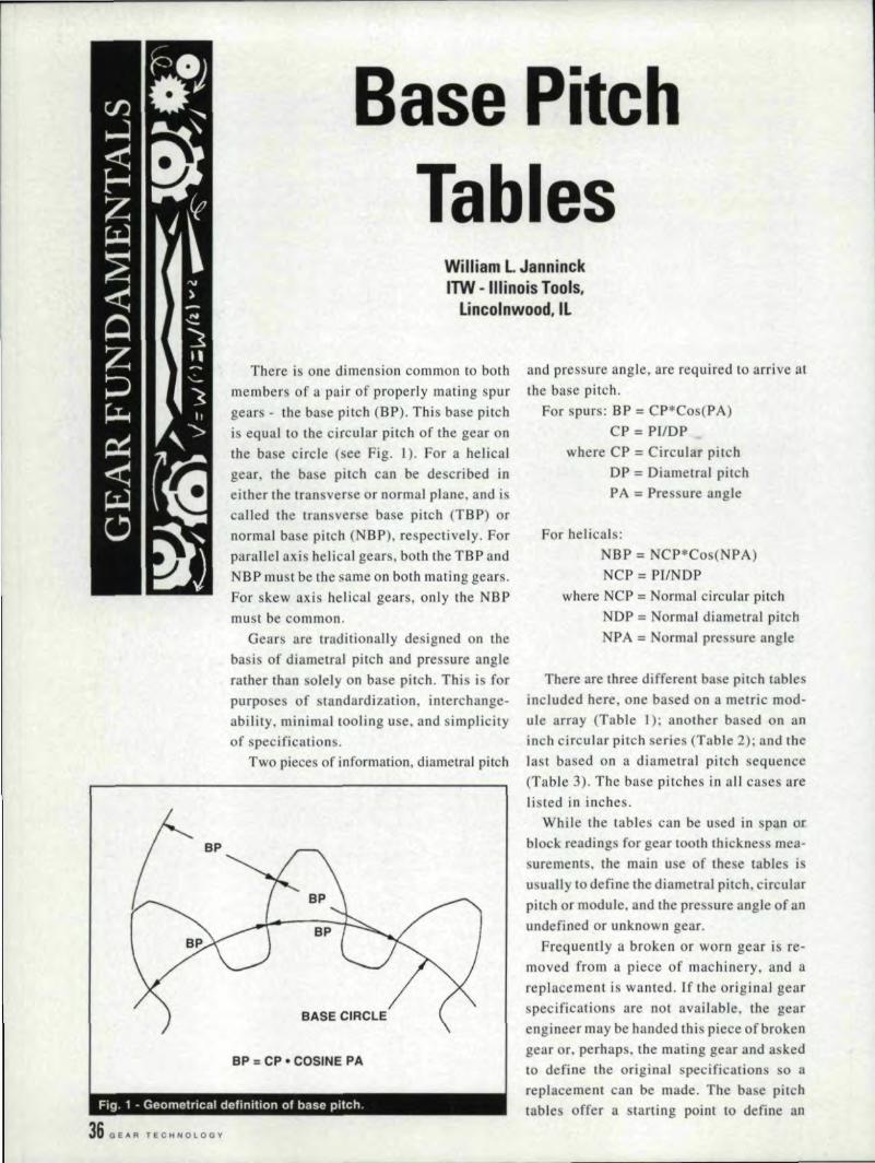
Base PitchTables
Williiam L, J!anninckITW - IIHnoisT1ool's.
ILinco'lnwood.lll
There is one dimension common to bothmembers of a pair of properly mating spurgears - the base pitch (BP) ..This base pitchis equal to the circular pitch of the gear onthe base circle [see Fig. 1). For a helicalgear. the ba e pitch can be described ineither the tran verse or normal plane, and iscalled the transverse base pitch (TBP) ornormal. base pitch (NBP). respectively, Forparallel axis helical gears, both the TB P andNBP must be the same on both mating gears.For skewaxis helical gears, only the NBPmust be common.
Gears are traditionally designed on thebasis of diametral pitch and pressure anglerather than olely on base pitch, This i ' forpurpose of srandardization interchange-ability ..minimal tooling use. and simplicisyof specifications.
Two pieces of information, diametral pitch
IBASE CIRCL'E
BP = CP • COSINE PA
3,6 BEl< R TEO Ii N 0 LOG Y
Fig. 1 - Geometrical definition of base pitch.
and pressure angle, are required to arrive atthe base pitch.
For spurs: BP .,. CP*Cos{PA)CP = P[/DP
where CP = Circular pitchDP = Diarnetral pitchFA .,.Pressure angle
for hellcats:NSP '" NCP*Cos(NPA)NCP = PIINDP
where NCP ;;;:Normal circular pitchNDP", Normal diametral pitchNPA '" Normal pre sure angle
There are three different base pitch tablesincluded here, one based on a metric mod-ule array (Table 0; another ba ed on aninch circular pitch series (Table 2); and thelast. based on a diarnetral pitch sequence(Table 3). The base pitches in an cases arelisted in inches.
WhiIe the tables can be used in span orblock readings for gear tooth thickne s mea-surements. the main u e of thesetable iusually to define the diametral pitch. circularpitch or module. and the pre ure angle efanundefined or unknown gear.
Frequently a broken or worn gear is re-moved from a piece of machinery .. and areplacement is wanted. If the original gearspecifications are not avai lable .. the gearengineer may be handed this piece of brokengear or. perhaps. the mating gear and a kedto define tile original pec.ification.o areplacement call be made. The base pitchtable offer a starting point to define an
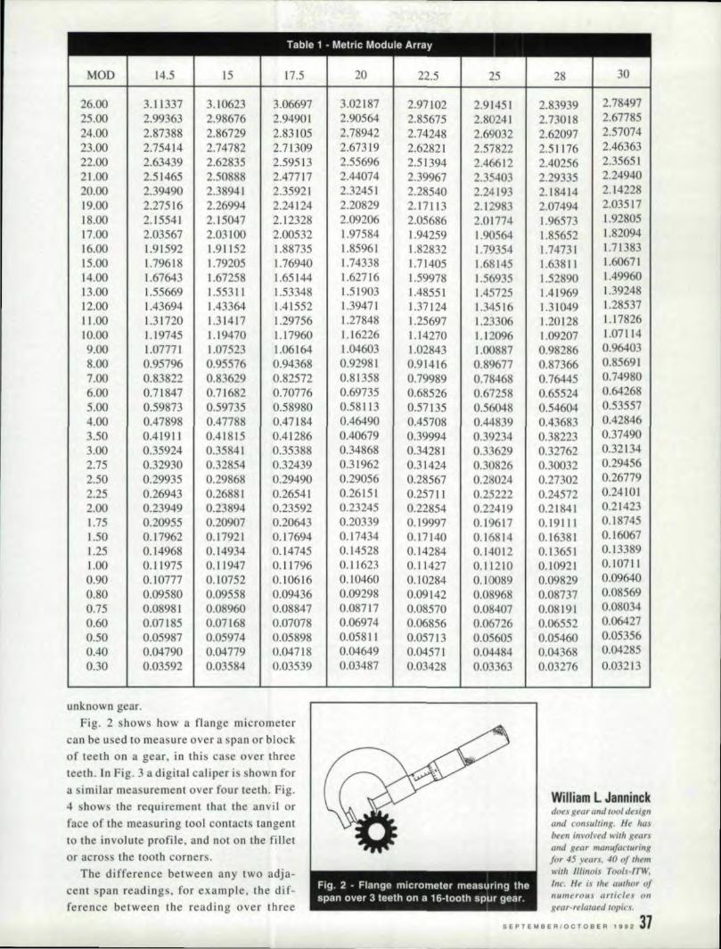
Table 1 - Metric Module Array------- - --
MOD ~4.5 IS n.s 20 22.5 25 I 28 30
26.00 3.11.337 3.10623 3.06697 3.02.187 2.97102 2.9'1451 2.83939 2.7849725.00 2.99363 2.98676 2.94901. 2.90564 2.85675 2.80241 2.73018 2.6778524.00 2.87388 2.86729 2.83105 2.78942 2.74248 2.69032 2.62097 2.5707423.00 2.754'1.4 2.74782 2.71309 2.67319 2.62821 2.57822 2.51176 2.4636322.00 2.63439 2.62835 2.59513 2.55696 2.513'94 2.46612 ,
2.40256 2.35651I
21.00 2.51465 2.50888 2.47717 2.44074 2.39967 2.35403 2.29335 2.24940~O.OO 2.39490 2.38941 2.35921. 2.32451 2.2854.0 2.24193 2.18414 2.1422819.00 2.27516 2.26994 2.24124 1.2{)829 2.17113 2.12983 2.07494 2.'03517.18.00 2.1554.1 2.15047 2.12328 2.09206 2.05686 2.01774 1.96573 1.9280517.00 2.03567 2.031.00 2.00532 1.97584 1.94259 1.90.564 1.85652 1.8209416.00 L91592 L911.52 1.88735 1.85961 1.82832 ].79354 1.74731 1.7138315.00 W.796]8 U9205 1.76940 1.74338 1..71405 1.68145 1.63811 1.6067114.00 1.67643 1.67258 1.65144 1.62716 1.59978 1.56935 1.52890 1.4996013.00 1.55669 11..5531. ] 1.53348 1.51903, 1.48551 1.45725 1.41969 1.3924812.00 1.43694 1.43364 1.41552 1.39471 1.37]24 1.34516 1.31049 1.2853711.00 1.31.720 1.31417 1.29756 1.27848 1.25697 ].23306 1.20128 1.1782610.00 U9'745 U9470 U7960 1.16226 1.14270 1.12096 1.09207 1.071.1.49.00 1.0777 J 1.07523 ] .06164 1.04603 1.02843 ] .00887 0.98286 0.964038.00 0.95796 0.95576 0.94368 '0.92981 0.91416 0.8C)677 0..87366 0.856917.00 0.83822 0.83629 0.82572 0.8.13,58 '0.79989 0.78468 0..76445 0.749806.00 0.71.847 0.71682 0.70.776 0.69735 0.68526 0.67258 0.65524 0.642685.'00 0.59873 0.59735 0.58980 0..58113 0.57135 0.56048 0.54604 0 ..535574.'00 0.47898 0.47788 0.47[84 0.4<6490 0..45708 0.44839 0.43683 0.428463.50 0.41.911. 0 ..41815 0.41286 0.40679 0.39994 0.39234 0.38223 0.374903.00 0..35924 '0.35841 0.35388 0.34868 I 0.34281 0.33629 0.32762 0.321342.75 0.32930 0..32854 0.32439 0.31.962 0.31424 0.3U826 0.30032 '0.294562.50 0.29935 0.29868 0.29490 0.29056 0.28567 0.28024 0.27302 .0.267792.25 0.26943 0..26881 0.26541 0.26151 0.25711 0.2-222 0.24572 0.241.012.00 0.23949 0.23894 0.23592 0.23245 0.22854 0.22419 0.2184] 0.2]4231.75 0..2:0955 0.2090.7 0.20643 0.20339 0.1999'7 0.19617 0.19U:1 .0.18745
I
1.50 0..17962 0..17921 0.17694 0.1.7434 0.L7140 0..16814 0.16381 0.160671.25 , 0.14968 0..14934 0.14745 0.14528 .0.14284 0.14012 0.1.3651 0.133891.00 0..11975 0..11947 0.11796 I
0.11623 0.1.1427 0.11210 0.10921 0.107110.90 0 ..10777 .0.10752 0.]0616 0.10.46.0 0.10284 0..10089 0.09829 0.096400.80 0.09580 0.09558 .0.09436 0.0.9298 0.0.9[42 0'.'08968 0.08737 0.085690.75 0.08981 0.08960. 0.08847 0.0.8717 0.0857.0 0 ..08407 0.081911 .0.080340.60 0..07185 0 ..07168 0.07078 0.06974 0.06856 0.06726 0.06552 0.064270.50 0...05987 0...05974 0..05898 0.05811 0.05713 0 ..0560.5 0.05460 '0.053560.4.0 1 0..'04790 0.04779 .0.04718 0.04649 0.04571 0..04484 I 0.04368 0.04285.0.)0 0.03592 0.03584 0.03539 0.0.3487 0.0.3428 0..03363 1 0.0.3276 0.03213
I
unknown gear.Fig. 2 shows how a flange micrometer
can be used to measure over a span or blockof reeta 011 a gear, in this case over threeteeth. In Fig. 3 a digital caliper is hown for.01 imilar mea urement over four teeth. Fig.4 shows the requirement that the anvil orface of the measuring tool contact tangentto the involute profije, and not OR the filletor across the tooth corners.
he difference between amy two adja-cent span readings, for example, the di f-ference between the reading over three
- -~ ------ ----~~-----------------~
,William L. J'anninckdoes gear and 1001 desig«ami consulting, HI! /rUJ
berm involved with gl!arJ(1110 gear manufacturingfor 45 years, 40 of IIII'mwilh Illinois Trm/s-ITW./IIC. He is .111_ (lilt/it" ofII!lmerOUS articles 011
gear-relataed topics.
3-'11
SEPTE'MBERIOCTOBER 111112 ,.
Fig. 2 - Flange micrometer measuring thespan over 3 teeth on a 16-tooth spur gear.
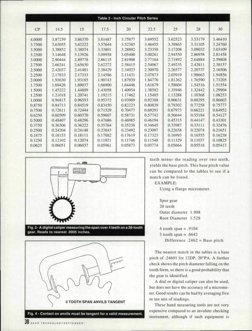
CP 14.5 15 ]7.5 20 22.5 25 28 30
4.0000 3.87259 3'.86370 3.81.487 3.75877 3.69552 3.62523 3.53179 3.464103.7500 3.63055 3.62222 3.57644 3.52385 3..46455 3.39865 3.311.05 3.247603.5000 3.38852 3.38074 3.33801 3.28892 3.23358 3.W7208 3.09032 3.031093.2500 3.14648 3.[3926 3.09958 3.05400 3.00261 2.94550 2.86958 2.814583.0000 2.90444 2.89778 2.861.1.5 2.81.908 2.77164 2.71892 2.64884 2.598082.7500 2.66241 2.65630 2.62272 2.58415 2.54067 2.49235 2.42811 2.381572.5000 2..42037 2.41481 2.38429' 2.34923 2.30970 2.26577 2.20737 2..165062.2500 , 2.17833 2.,17333 2.14586 2.1.1431 2.07873 2.03919 1.98663 1.948562.0000 1.93630 1.93185 1.90743 ].87939 1.. 84776 1.81262 1.76590 1.732051.7500 1...69426 1.69037 1.66900 1.64446 1..61679 1.58604 1.54516 1.515541.5000 1.45222 1.44889 1.43058 1.40954 1.38582 1.35946 1..32442 1.299041.2500 1.21018 1.20741 Ll9215 1.17462 U5485 L13288 L.I0368 1.082531.0000 0.96815 0.96593 0.95372 0.93969 0.92388 0.90631 0,88295 0.866030.8750 0.84713 0.84519 0,83450 0.82223 0',80839 0.79302 0.77258 0.757770.7500 0.72611 0.72444 0.71529 0.70477 o..6929l 0.67973 0.66221 0.649520.6250 0.60509 0.60370 0.59607 0.58731 0.57742 0.56644 .0.55184 .0.541270,5000 0.484'07 0.48296 0.47686 0.46985 0.46194 0.453,15 .0.44147 .0.433010.3750 0.36306 0.36222 0.35764 0.35238 0..34645 0.33987 0.,33111 0.324760.2500 0.24204 0.24!1.48 0.23843 0.23492 0.23097 0.22658 .0.22074 0.216510.1875 0.]8153 0.18Ul 0..17882 0.17619 0.17323 0.16993 '0.16555 0.162380.1250 0.12102 0.12074 0.11921 0.11746 0.11548 0.1.1.329 0.1 ]037 0.108250.0625 0.06051 0.06037 0.05961. 0.05873 0.05774 0.05664 0.05518 0.05413
Fig. 3 - A digital caliper measuring the span over 4 teeth on a 28-toothgear. Reads to nearest .0005 inches.
3 TOOTH SPAN ANV!ILS TANGENT
,38 G E ...R T IEC H N 0 LOG Y 5 E PTE M B E R I
teeth minus the reading over two teeth.yield the base pitch. This base pitch valuecan be compared to the tables to ee if amatch call be found.
EXAMPLE:Using a flange micrometer.
Spur gear20 teethOuter diameter 1.908Root Diameter 1,.528
4 tooth span = .91043 tooth span = .6642
Difference .2462 = Base pitch
The neare t match ill the table is a basepitch of .2460] for ]2DP. 20oPA. A furthercheck shows the pitch diameter falling on thetooth form, so there isagood probability thatthe gear is identified.
A dial or digital caliper can also be u edtbut doe. nOI. have the accuracy of a microme-
ter. Good results can be bad by averaging fiveor ten sets of readings.
These hand measuring tools are not veryexpensive compared to an involute checkinginstrument, although if such equipment i

------- - -
Table 3 - Diametral Pitch Sequence----
I
DP 14.5 15 17,5 20 22.5 25 28I
30
1.00 3,04153 3.03455 2..99619 2.95213 2.90245 2.84725 2.77386 2.720701.25 2.43322 2.42764 2..39695 2.36171
1
2..32196 2.27780 2.21909 2.176561.50 2.02768 2.02303 1..99746 1...9680'9
IL93497 1.8981.7 1.84924 1.81380'
I
1.75 1 1.73801 1.73403 1.71211 1.68693 1.65854 1.62700 1.58506 1..55469I
,
2.00 1.52076 1.51727 1.49810 1.47607 1.45123 1.42363 1.38693 1 1..360'35 1
1
2.25 1.35179 1.34869I
1.33164 1.31206 1.28998
I
1.26544 1.23283 1.209202.50 1.2166] 1.21382 1.19848 1.18085 1.16098 1.13890' 1.10954 1.088282.75 1.10601 1.10347 1.08952 1.07350 1.05544 1..03536 1.00868 0,989353.00 1.01384 1.01152 0.99873 0.98404 0.96748 0.94908 0,92462 0,906903.50 0.86901 0.8670[ 0.85605 0.84347 10.82927 0'.81350 0 ..79253 0.777344.00 0.76038 0,75864 '0.74905 0.73803 0.72561 0.7118] 0.69347 0,680174.50 0.67589 0.67434 0,66582 0.65603 0.64499 0.63272 0,.6164[ 0.604605.00 0.60831 0.60691 0.59924 '0.59043 0.58049 0.56945 055477 0.544L45.50 0.55300 0.55174 0.54476 '0.53675 0.52772 0.51768 0.50'434 0.494676.00 0.50692 0.50576 0.49937 0.49202 0.48374 0.47454 0.46231. 0.453457.00 : 0.43450 0.43351 0.42803 0.42173 0.41464 0.40675 0.39627 0..388678.00 0.380'19 0.37932 0.,37452 0..36902 0..36281 0.35591 0.34673 0.340'099.00 0'.33795 0.33717 0,33291 0.3280'1 I 0.32249 0.3L636 0.30'821 0,30230
10.00 0.30415 0.30345 0.29962 0.29521 1 0.29025 0.28473 0.27739 0.2720711.00 0'.27650 0.27587 0.27238 0.26838 0.26386 0.25884 0.25217 0.2473412.00 0.25346 0.25288 0.24968 0.24601 0.24187 0.23727 0.23116 0,22672 1
13.00 0.23396 0.23343 0.23048 0.22709 II 0.22327 0.21902 0.21337 0.2092814.00 0.21725 0.21675 0.21402 0.21087 'I 0.20732 0.20'338 0.19813 0.1943416.00 0.19010 0.18966 0.18726 0.18451 0.18140 0.17795 0.17337 0.1700418.00 0,]6897 0.16859 0 ..16646 0,16401 0,16125 0.15818 0.15410 0.1511520.00 0.15208 10.15173 0.1498L 0.1476L 0'.1451.2 0.1.4236 0.13869 0'.1.360322.00 0.13825 '0.13793 0.136[9 0.1.341.9 0..13193 0.12942 0.12608 0.1236724.00 0,12673 0'.12644 , 0.12484 0.12301 0.12094 0.11864 0'.11558 0.11336
I
28.00 0,.10863I
0'.10838 0.1070'1 0.10543 0.10366I
0,10169 0.09907 0.09717,
! 0.09363 0 ..08668 0.0850232.00 0,09505 0.09483 0.09225 0.09070 0 ..0889836.00 0.08449 0.08429 0.08323 0.08200 0.08062 0.07909 0.07705 0.0755738.00 0.08004 0.07986 0,07885 0.07769 0.07638 0.07493 0,07300 0,0716040.00 0.07604 0.07586 0.07490 0.'07380 0.07256 0 ..071 i8 0 ..06935 0.0680244.00 0.06913 0.06897 0.06810 0,06709 0.06596 O.O6471 0.06304
I
0.0618348.00 0.06337 0.06322 0.06242 0,06150 0.06047 0.05932 0.05779 0.05668
i52.00 0,05849 0.05836 0.05762 0,05677 0.05582 0,05475 I 0.05334 0,0523256.00 0.05431 0.05419 0.05350' 0.05272 0.05183 0.1:)5084 0.04953 0,'0485860.00 0.05069 0.05058 0.104994 0.04920 0.04837 0.04745 0.04623 0,0453464.00 0.04752 0.0474] 0.'04682 0..,04613 0'.04535 0.04449 0.04334 0,'0425172.00 0.,04224 0.04215 0,04161 0.04100 0.04031 0.03955 0.03853 0.03779
I
available, 'lI ing it would be the next tep foraccurate profile definition.
On a helical gear, the result of these mea-surements yields the NBP and. from thetables, the normal diametral pitch and nor-mal pressure angle. This is the usual plane,for basic tooling information and manytimes, the design basis. Some further determi-nation of the gear lead, such as might beaccomplished on a helical lead in pectionmachine. is nece sary to fully define the basicgear geometry.
The table for metric module gears is In-
eluded because metric gear applications arefrequently found in machine tools, printingequipment, textile machinery, packaging rna-chinery, and transmissions. Metric gears arequite widely used.
Consideration also should be given to thequality and condition of the gear being in-spected as this will influence the accuracy ofthe values. i.!Acknowl,edgement: Presented a/ SME Funda-
mentals of Gear Design &: Manufacturing Clinic,
June 9-10, 1992. Reprinted with permission.
S E PTE I.! a E RIO c r o a E R 1992 391
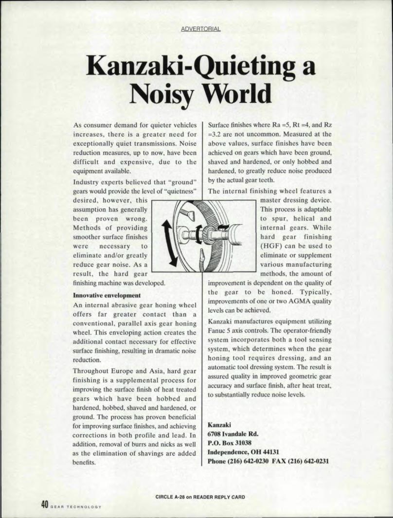
ADVERTORIAL
Kanzaki-Quieting aNoisy World
As consumer demand for quieter vehiclesincreases, there is a greater need forexceptionally quiet tran missions. Noisereduction measures, up to now, have beendifficult and expensive, due to theequipment available.
Industry experts believed that "ground"gears would provide the level. of "quietness"desired. however, this r----n~_~;:""":;""'''\""----.assumption has generallybeen proven wrong.Methods of providingsmoother surface finisheswere necessary toeliminate and/or greatlyreduce gear notse .. As aresult. the hard gearfinishing machine was developed.
Surface finishes where Ra =.5, Rt ;4, and Rz=3.2 are not uncommon. Measured at theabove values, surface finishes have beenachieved on gears which have been ground,shaved and hardened, or only bobbed andhardened, to greatly reduce noise producedby the actual gear teeth.
The internal finishing wheel featuresamaster dressing device.This process isadaptableto spur, helical andinternal gears. Whilehard gear finishing(HGF) can be used toeliminate or supplementvarious manufacturingmethods. the amount of
improvement is dependent on the quality ofthe gear to be honed. Typically,improvements of one or two AGMA qualitylevels can be achieved.
Kanaakimanufactures equipment utilizingFanue 5 axis controls. The operator-friendlysystem incorporates both a too] sen ingsystem, which determines when the gearhoning tool requires dressing. and anautomatic tool dressing system. The result isassured quality in improved geometric gearaccuracy and surface finish. after heal treat.to substantially reduce noise levels.
rnnova.tive ,envelopmentAn internal abrasive gear honing wbeeloffers Iar greater contact than aconventional. parallel axis gear honingwheel. This enveloping action creates theadditional contact necessary for effectivesurface fi--'1ishing.resulting in dramatic noisereduction.
Throughout Europe and Asia, hard gearfinishing is a supplemental process forimproving the surface finish of heat treatedgears which have been hobbed andhardened, bobbed. shaved and hardened. orground. The process has proven beneficialfor improving surface finishes, and achievingcorrections in both profile and lead. Inaddition, removal . of burrs and nicks as wellas the elimination of shavings are addedbenefits.
KanzLki6708, Ivandale Rd.P.O •.Box. 31038Independence, OH 441.11Phone (21(;)642-0230 FAX (216) 642-0231
401 G E II R TEe ioI N 0 LOG v
CIRCLE A-26 en READER R,EPl V CARD

You
THEBee a use
WORLD ISCan't
NOW AH ear Our
QUIETERG ear s
PLACEI
or many years. gearnoise has continued to
,Arel you plague the industry.concerned Tod:ay there is aabout noIsy solution ... the Kanzaklgears? Hard Gear hinishingMost likely (HGIF)I Process. This
your system will help reduce
customers noise by improvinga rei tool geometric gear accuracy,
and most importantly-surtacenmsh.KanzakL.. making theworl:d a quieter place.
Kanzaki6708 Ivandale Rd.P.O. Box. 31038lndependencs, OH' 44131Phone (216) 642·0230 FAX (216) 642-0231
ICANZAICIICOICYUOICJ MFG" CO:., LTD
'CIRC!.E. A·27 on REAIDER, IREP,L,'II" CARD'


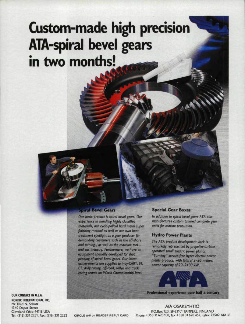
Custom-made high precisionAlA-spiral bevel gearsin two, months!
bc1s1c/lroduct Is splraJ bevel gears. Ourexperience In handling highly classifiedmaterials. our cydo-pallold hard mef41 superfinIshing method as well as our own heattrecrtment spotlight os a gear producer fordemtmding customers such as the off-shoreand mini",... GI welJ M the momlne fOOl -dIKI. ~ 1tJfJtMtry. Furthermont, we- Iurte tin
.~IitUl~Itc __dtIIll ~ fOr shotOur latest
:lJcI~"'II:H_II.I- ..ml~T. F1,~~~~~--,~~~~~~OUR CONTACT IN U.S.ANORDIC INTERNA110NAL INC.Mr Thad N. Scnott1340 Depot StreetC'leveland Ohio 44116 USATel: (216) 3312231. Fax: (216) 3312232 CIRCLE A-a on READER REPLY CARD
Special Gear BoxesIn addition to spirol be,vel gears ATA alsomanufactures custom tolfored complete gearunits for marine prpPUlslon.
Hydro Power PlantsThe ATA product development work isremorl<aty represented by propeileMurblneopemted SIlUJU ~ectrlc power plants."Turnkey" servlc,e..free hydro eJectrk powerpltlnaproduce. with ~ ofT-3D- meters,pawer~ o(20-2.otfkW.
AlA OSAKEYHTlO'P.O. Box 120, SF-331Q1: TAMPERE, :FINLAND
Phone +35831620100, fax +358 31 620457, telex: 22502 ATAsf
Reader Dialogue: FunctionalMeasurement of Gears; More
Good Gear Books
10 rom time to time, the editors of_ "Shop Floor" receive correspcn-
I den~e fr.om :eaders relating ,t.oparticulararticles they have wnt-
ten for past is ues. As One of the pur-poses of this column is to provide aforum for the exchange of ideas, wereproduce here two of these letters andtheir replies. The subject of the first isthe functional measurement of gears,(See Gear Technology, Sept/Oct, 1991,p. 17.) Robert E. Smith writes the reply.
From: Dr. Awny Y. Attiia, Pro-fessor of Machine Design, AiDShams University, Cairo, Egypt.
.. .1 believe that the aim of func-tional measurement is to determine thedeviations from uniformity of motionbetween two gears in action as theyrunand function, From the design point ofview, besides running accuracy, func-tional errors are u ed to determine the
Raben E.SmithRaben Errichello
rors are added, generated from the dy-namic increase in tooth load, inertia ofthe gears, and attached masses and vi-brations of the geared system.
In my opinion, there is no fixedvalue for the functional error in a pair ofgears in mesh, as this value is changingaccording to this multitude of factors.This has been proven to me in manyinvestigations where the functional er-rors were measured by photocells. EL-emental and roll measurements do notgive any indication of errors in func-tioning. but are very useful as a fast.check on dimensional tolerances andthe fulfillment of the product accordingto certain standard specifications.
I remember that in a gear firm, ]picked some gears that had been re-jected for having pitch errors exceed-.ing the limits of tolerances, and ]assembled them in pairs, those hav-
maximum momentary tooth load when rng positive errors with those havingrunning at speed. They are the instanta-neous deviation from correct relativeangular displacement and are usuallyspecified as a percent of the gear ratio.The value ofthe functional error is thatit changes according to the changes inmany factors, such as resultant manu-:facturing errors, errors in assembl y, andeccentricities in bearings, Under load,more functional error, caused by teethdeflections and torsional deflections ofshafts and gear bodies, are added. Whenrunning at speed, :more functional er-
negative errors. Functional measure-ments of these pairs sometimes gavemore accurate running than that. ofunrejected gear pairs. I am trying tode ign a set up for functional mea-surement of gears based on assembledmetrology. hoping to give values offunctional errors of any pair of gearsin mesh in geared systems.
Bob Smith replies: Professor AUiai just taking what [ said a step further'10 the measurement of assembled gears.In the Sept/Oct column, 1 was mainly
Addr'ess YOUirgeariing q,ues~tiens to our panel of ,experts.Write to them care ,of ShopIFloor .• IGear f.echnoloQIY, P. O.IBox142,6, Elk Grove ViiUage,lL60009, or call eur editorial staffat ~7n8)143:1~6604.
IR.obert IE. Smithis rile principal in R. E.Sm/II, & Co .. lnc., gear co/!.-sultants ill Rochester. NY.He has !JI'er40 \'l!Cu.t·expe-rience in gearillg methods,manufacture. metrology.and research.
Robert Er,richeU,ois III" principal illGEARTECH. II gear con-suiting firm ill Albany.CA. fie is a member ofAGMA. ASME. and aRegistered Professiona!Engineer ill. the State ofCali/Ofilia.
SEPTEMBER/OCTOBER 1992 45

HIGH NOON-----
)~WESTERN COLLECTIBLES ;~
Bought & Sold:
* Bridles*' Buckles* Colthing* Bits"* Books
* Belts*' Bo'ios*Chaps* Spurs*' Saddles
1310) 202·9011101by appointment'.310) 202-1340 (fax)
CIRCLE. A·31 011 READ:ER REPLY CARD
CIRCLE A,·32 on READER REPLY CARD
46 G EAR TEe H N 0 LOG Y
talking about the functional measure-ment of unassembl ed gears at the ti meof manufacture. The AGMA and ISOquahty standards are written forunassernbled gears.
When gear pairs are run in theiractual assemblies, other factors do addto the functional characteristics. AsProfessor Altia point out, it is po ibleto PUI two gears together, each of whichis out of elemental tolerance, and havethem function perfectly well. For ex-ample: two gears call have excessive"positive tip" profile errors, but theywill run together quietly. I have seenthis happen many limes. The profileerrors complement each other in such away that the gear "pair" is conjugate.They just happen to end up with adifferent pressure angle than specified.If the gear "pair" was measured bysingle flank. method . it would howgood functional characteristics. If thegears were assembled in .111 gear boxwith relatively light loads, as manyapplications are, they would run justfine. If theapplication has load suchthat the teeth deflect. considerably. theywould not run as well.
However, single flank transmissionerror measuring instruments can be ap-plied to loaded gear boxesal o. AsProfessor J.D. Smith of CambridgeUniversity commented in the Nov/Dec
I issue. (See Gear Technology, Nov/Dec,1991. "Viewpoint," p. 9) tests can and
have been run at operating load andspeeds. This takes into account gearand housing errors and deflections, aswell as dynamic conditions (vibration).Single Flanktransmission error mea-suring instruments already exist thaican do this.
The second letter. regarding TopTen Books for Gear Engineers. "comesfrom Dr. George W. Michalec, con-sulting engineer of Pleasantville, NY.
Dr. Mlchaelk writes: I read withintere t your article. "The Top TenBooks for 'Gear Engineers," in the cur-rent issue (May/June, 1992) of Gear
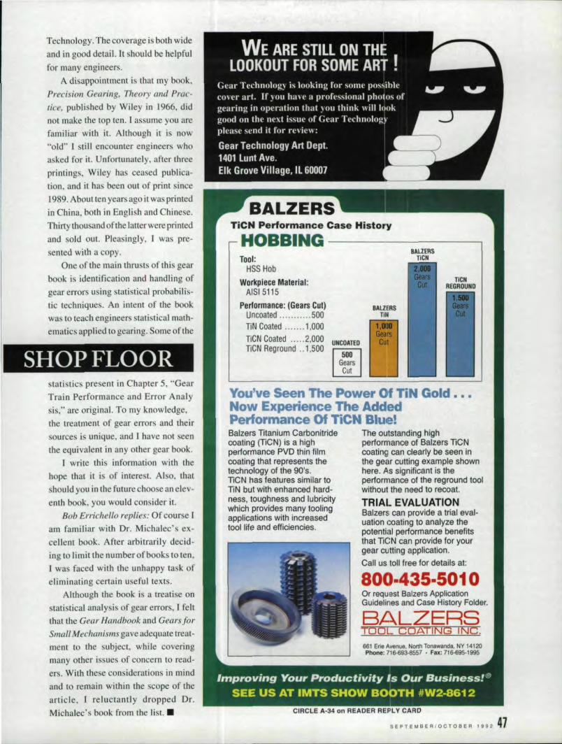
Technology. The coverage is both wideand in good detail. It should be helpfulfor many engineers ..
A disappointment. is that my book,Precision Gearing. Theory and Prac-tice. published by Wiley in 1966, didnot make the top ten. Iassume you arefamiliar with ir. Although it is now"old" 1 still encounter engineers whoasked for it. Unfortunately, after threeprintings, Wiley has ceased publica-tion, and it has been out of print since1989. About ten years ago it was printedin hina, both in English and Chinese.Thirty thousand ofthe latter were printedand. old out. Pleasingly, I was pre-sented with a copy.
One of the main thru ts of this gearbook is identification and handling ofgear errors using statistical probabilis-tic techniques. An intent of the bookwas to teach engineers stati tical math-ematics applied to gearing. Some of the
SHOP' FLOOR 'statistics present in Chapter 5, "GearTrain Performance and Error Analysis," are original. To my knowledge,the treatment of gearerrors and theirsources is unique, and I have not seenthe equivalent in any other gear book.
[ write thi information with thehope that it is of interest, Also. thatshould you lin the future choose an elev-enth book. you would consider it.
Bob Errichello replies; Of cour e Iam familiar with Dr .. Michalec's ex-cellent book. After arbitrarily decid-ing to limit the number of books to ten,twa. faced with the unhappy task ofeliminating certain useful texts.
Although the book is a treatise onslatistical.analysi!s of gear errors, [ feltthat the Gear Handbook and Gears forSIIUlIl Mechanisms gave adequate treat-ment. to the subject. while coveringmany other is. ue of concern to read-er . With these considerations in mindand to remain within the scope of thearticle. 1 reluctantly dropped Dr.Michalec's book from the list. •
TiCN P·erformance 'Case History
HOBBING ---------,10011:
HSS HobWorkpiece Materiial:
AISI5115PerfDrmance: (Gears Cui)
Uncoated 500liN' Coated , .. 1,000TiCN Goated "'" .2,000TiCN Reground .. 1,500
UNCOATED:
50101 I
G~~iI
BAUERSTilli
1,DIGearsCut
You've Seen The Power IOf TiNow Expe~ience The AddedPerformance Of TiCN Blue!Bal:zers Tltanium Carbonitrldeoeating (TlCN) is a highperfermance PVD thlnfllmcoating; that represents thetechnology of the 90's.lieN has features similar toliN but with enhanced hard-ness, toughness and lubricitywhich provides many toolingapplications with increa.sedtool lite and etiiciencies.
The outstanding highperformance ot Bailers TlCNcoating can clearly be seen inthe gear cutting example shownIhere. As significant is theperformance '0f the regrcund toolwithout the need to rscoat.
TRIAL :EVALUATIO,NBalzers can provide a triall eval-uanon ooatingl to analyze thepotential performance benefitsthat TlCN can provtde for yourgear cutting applicauon.Call us toll free for details at:
800·435·5010Or request IBalzers ApplicationGuidelines and Case History Folder.
BALZERSTClOL COATIING INC.
661 Erie Avenue. North TOnawanda, NY 14120Phone: 716·693·8557 • IFllx: 716-695·1995
SEPTEMBER/OCTOBER 1992 41'
Test y,our ,gearsby the numbers ..
Put an end to the potential perils of subjective geartesting; inherent in traditional analoq-type instruments.
Retrofit your existing double-flank rolling gear tester witha Hommel Z-2000 computer/recorder. Or upgrade to anentirely new g:ear testing: system wi,ththe Hommel 830S.
Eiitherway, you get the quantitative analysisand complete documentation you need to do thejob right.
Write to Hommel America, 30 P·eterCourt.New Britain, CT 06051. Or call (203) 827 -SSOO.FAX: (203) 223-2979. World Class MeasurementTechnology
Po. THYSSEN. Company
CIRCL'E A-25 on READER REP,LY CARD
T,ostay competitive you haveto review your options. Whenplanning your capital equipmentrequirements, look at Bourn & KochMachine Tool Co., a leader lin therebuilding, remanufacturing and'retrofitting of your Barber-Colmangear nobber, gear shaper or hobshamener ..With more than 117yearsexperience, we can iincorporate thelatest state-of-the-art features andGNG controllers based on yourrequirements. So whether it is anew, rebullt,remanufactured or
retrofitted machine, Bourn & KochMachine Tool Go. can offer you theBEST 'FIT SOLUTIONS. .
tJOURn& I!-IOCI-IImaCl-llne TOOL CD.PUrchaSfJf of me Barber~C"'m.sn Machlne TOOl Division
2500 Kishwaukee 8t.'Rockford,. IL 61104815/965·4013 Fax 815/965·0019
's·' . . CIRCLE 11-26 on R'EA'DE'R: IR:EPLV CARD.. GEAR TECHNOLOGY
CIRCL'E A-24 on IR:EADEA A·EPL V CA.RD

TRU,E DIMENSION GEAR INSP,ECT,ION
Provides actual overball/pin measure-ment of any helicalor SpW' gear orspline without theneed of costlysetting masters.
Provides vital S.P.C.information.
,CAPACITY:9" O.D.8" I.D.
851 OHIO P,IKI: • CINClNNATII!, OHIO 45245, • (513) 752·6000
CIRCLE A·37 on READER IREPLY CARD
Reader Service PageNumber Number
American Gear Manufacturers Association 33 56American Met.al Treating Co. 49 55American Oertikon Gear Machines, Inc. 30 l2
American Pfauter, L.P. I IFC
Ala Osakeyhtio 8 44Ash Gear 13 14B & R Machine & Gear Corp. 45 54BHS·Hofier Maschinebau GMBH 5
Balzers Tool Coating Inc, 34 47Berg. W.infred M.. Inc. 12 14Bourn & Koch Machine Tool 26 48Crucible Service Center 4 10
Diseng 15 15
fOT Gage & Systems 39 19
Pairlane Gear. Inc. 58 17ellows Corp. 3 2
forest City Gear 2.9.7 6.7GMI-Fhusa 36 43Gear Re. earch Institute 46 54Gildemeister 2. I
Guehring Automation 22 53Heller. R.A. SO 55High Noon 31 46Hommel: America 25 48
AD'VERTISER INDEXReader Service P.age
Number Nu.mber
I.TW Gear School 10 11
ITW Zero Systems 35 42Intercontinental Industri es 24 48James Engineering 23 19
Kanzaki 28,27 40,41Koepfer America 6 4Liebherr Machine Tool, 57 28-9M & M Precision Systems 5 8MEP 16 16
Manufactured Gear & Gage, Inc. 18 17Midwest 'Gear 42 56Mihan Corp. Elgin 17 16
Moore Products 38 53National Broach & Machine Co. 19,21 OBC. 18
Niagara Gear 44 54Normae 40.41 So,SI
Pfauter-Maag Cutting Tools, L.P. 2Profile Engineering ..Inc, 47 54Pro-Gear Company. Inc. 43 54Starcut Sales. Inc. 32 46
Tocco, Inc. 20 !BC
Unitcd Tool Supply 37 49Van Gerpen-Reece Enginee ng 48 55Yin King Industrial Co., Ltd. 14 15
SEPTEMBeR/OCTOBER 1992
J
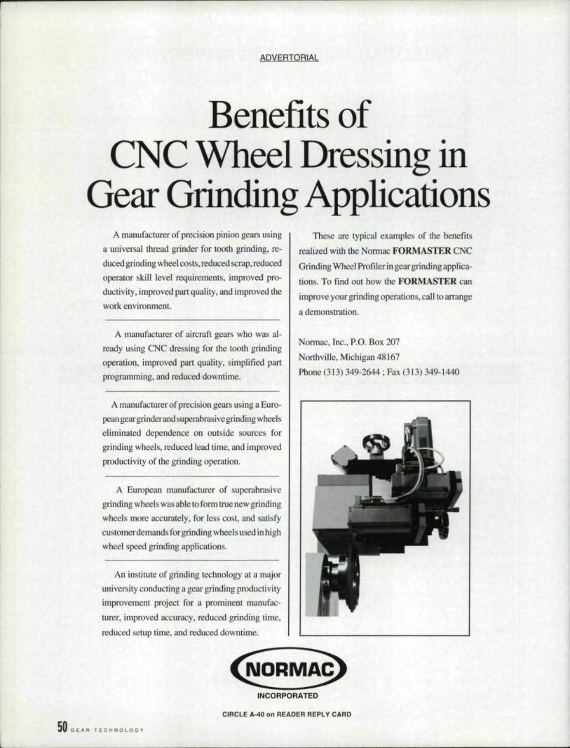
Benefits ofCNC Wheel Dressing in
Gear Grinding ApplicationsA manufacturer of precision pinion gears using
a universal thread grinder for tooth grinding, re-duced grinding wheel costs, reduced scrap, reducedoperator skill level requirements, improved pro-ductivity, improved part quality, and improved thework environment.
A manufacturer of aircraft gears who was al-ready using CNC dressing for the tooth grindingoperation, improved part quality, simplified partprogramming, and reduced downtime.
A manufacturer of precision gears using a Euro-pean gear grinder and superabrasivegrinding wheelseliminated dependence on outside sources forgrinding wheels, reduced lead time, and improvedproducti v:ity of the grinding operation.
A European manufacturer of superabrasivegrinding wheels wa .able to form true new grindingwheels more accurately, for less cost, and satisfycustomer demands for grinding wheel s used j n highwheel speed grinding applications.
An institute of grinding technology at a majoruniversity conducting a gear grinding productivityimprovement project for a prominent manufac-turer, improved accuracy, reduced grinding time,reduced! setup time, and reduced downtime ..
These are typical examples of the benefits
realized with the Normae FORMASTER CNCGrinding Wheel Profiles in gear grinding applica-tions. To find out how the FORMASTER can
improve your grinding operations.call to arrangea demonstration.
Normae, Inc., PO, Box 207Northville, Michigan 48167Phone (313) 349-2644; Fax (313) 349-1440
INCORPORATE'D
50 GEAR TECHNOLOGY
CIRCUE A.-40 on, READER REPLY 'CARD
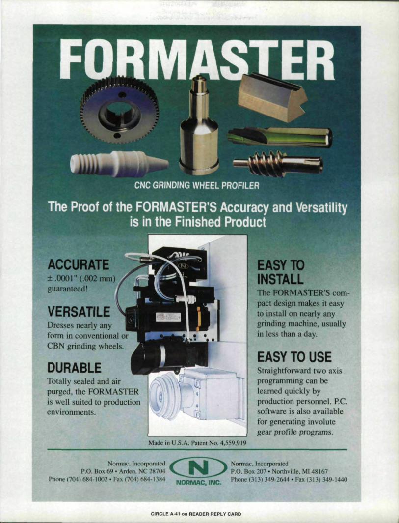
VERSATILEDresses nearly anyform in conventional oreBN grinding wheels.
DURABLETotally sealed and airpurged, the FORMASTERis well suited to productionenvironments.
Made in U.S.A. Patent No. 4,559.919
pact design makes it easyto install on nearly anygrinding machine, usuallyin less than a day.
EASY TO USEStraightforward two axisprogramming can belearned quick.ly byproduction personnel, P.C.software is also availablefor generating involutegear profile programs.
Normae, Incorporated ~ Normae.IncorporatedP.O. Box 69· Arden, NC 28704 ~ P.O. Box 207· Northville, MI48167
Phone (704) 684- I(J02 • Fax (704) 684-1384 NORMACJ
INC. Phone (313) 349-2644 • Fax (313) 349-1440
CIRCLIE 11.-41on IREADE.R REPI.V CARD
Gear TechnologyBack Issues Available
Below is a partial index ofarticles that have ap-peared in Gear Technology Oller the ["SI two years. Acomplete index of articles is available frou: our edi-torial offices. So are individua! back issue and com-plete sets. Back issues are $7.00 a piece delivered todomestic addresses and $9.00 a piece delivered toforeign addresses. For more information. contact us01800-451-8166.
Back issues may be paid for by check or Visa.MasterCard or American Express charge cards.Please have your card number and expiration dateready when you call.
Vol. 8, No.1JanIFeb, 1991• CBN Grinding in Drive Train Components• Review of Gear Standards - Part II-
I • Surface Hardening & the Total Gear ManufacturingSystem• The Marketing Menagerie: What's Right For You?• What is Runout And Why Should I Wony About It?
Vol. 8, No.2Mar/Apr, 1991• The Lubrication of Gears - Part I'. Bevel Gear Trouble hooting• The Synthesi ' of Spiral Bevel Gears• Hard Finishing by Conventional Generating and FormGrinding• Choosing an Ad Agency
:1 i . Hob Wear and Gear Inspection Question
Vol. 8, No.3, May/June, 1991
.' Lubrication of Gears - Part n
.' Surface Pining in Noninvolute 'Gears• Carbide Hob.•Shop Floor - Gear Misalignment• Management Maners - When Your Customer FilesBankruptcy
Vol'. 8, No.4.July/Aug .•1991• Lubrication of Gears - Pari HI
. i • Multi-Thread Hobs With New Cutting Diagrams• Reverse Engineering• Viewpoint- Pacific Rim Gives Stiff Competitionto U.S. Gear Producers• Shop Floor - Pineapples, Corncobs & Other Hob-bing Matters
Vol. II,No.5Sept/Oct, 1991• SPC Acceptance of Gear Mobbing & Shaping Machines• Full-Load Testing of Large Gearboxe - -• Basic Gear 'Generation - Designing the Teeth• Shop Floor- Single Flank Testing; H.P. Capacity• Management Matter - Taming the Autocratic Bo
I I
Vol. 8, No. (j
Nov/Dec, 1991• A Rational Approach for Designing Minimum- Guide-lines for Establishing an Optimum Shot• Shot Peening Specification - Part 1• Recent Developments in 'Gear Metrology• Shop Floor - Gear Inspection Chart Evaluation;Unusual Gear Sets
Vol. 9, No.1JanJFeb, 1992.•Design Guidelines for High-Capacity Bevel Gear Systems• Shot Peening Specification - Part J[
• Right & Wrong of Modern Hob Sharpening• Management Matters - Product Liability Defense• Shop Floor - Clockwork Gearing
Vol. 9, No.2Marchi April, ] 99.2• Gear Finishing by Shaving, Rolling & Honing· PartI• Proces Control & Gear Manufacturing• Gear Hardness Technology• Management Matters - Government Resources for YourBusiness• Shop Floor - Hobbing Ridges; Crooked Teeth; CrownShaving
Vo~9., No.3May/June, 1992'. Computer Technology in Gear Design• Gear Finishing by Shaving, Rolling & Honing - Part IT• Temperature Effects on Gage Repeatability & Reproduc-ibility• Gear Blanking• Shop Floor - Top 10 Books for Gear Engineers• Management Matters - ABC Accounting
Vot9,No.4July/Aug. ]992• Grinding of Spur & Helical Gears• Comparing Surface Failure Modes in Bearings & GearsGear Inspection• Management Matters - Operation Trade Show• Shop Floor - Cutting Low-Pitch-Angle Bevel Gears;Warm Gears & Oil Entry Gap
52 GEAR TECHNOLOGY

Uniiv,e'rsal'Tiiglh't IMes,hl Gllea,r Chec,ker'
• Adjustable, for gears 1H to ,aD P.O.• Computer al1a~IY5isand d'igital filtering• Nume~ic and strip chan. outputs
• ,au ick changeover., Checks:
.munctional tooth thick_ness
• tota' com,posiijeaction
.' IPnc'h diameter runouI
• sectional compes'te nmout
• pitch diameter
• over pin diameter
• sectional runeut
"tne Measurable Difference" MOORE PRODUCTS CO., Spring House, PA 19477Phone: (215) 646-7400 FAX: (215) 653-0347
CIRCLE ,A-311011 READER: IREPLY CARD
,Iof Spline Gaging.3500 Be - Man invents the wheell and says "it is good"2500 Be - Man invents the spline and says, "it is good".2499 BC - Man invents tihe spline gage' and says "Ifill do the trick"Man has Ibeen using the same spline 'gage ever since. ihat lis, until:FRENOO redesigned the gage for modem man. ihe frenco indicatinglspline gage' produces variable data 011 exact Pitch Diameter whilesimultaneously checking "GO" condition . This SPC compalable gagealso quickly checks tape~ ov:ality and other lime consuming inspections.Available for linternal, externat, straight or involut.e spline configurations.
let us show you a system for today and beyoncl. Calli or write:
h· -I
' ~ ,- -,' W227 N6193 Sussex Roadgue rIn9 PO. Box 125·Sussex, WI 53089AUT 0 MAT rON INC (414)246-4994'FAX (414)246-8623
,~,IFmlt:llRll~(Q)
~
'CIRCLE A-22 on READER REP'lV CARD ,U253SEPTEMBER/OCTOBER
--
SERVICE
Rates: Line Classified - per inch - $200. Classified Display - per inch (3" min.) lX-$I60. 3X-$150,6,X-$.I40, Type will be set to advertiser's layoutor Gear Technologv will set type at 110 extra charge.Payment: Full payment must accompany classified ads .. Send check. or Visa/Mastercard/Arnerican Express number and expiration date to: GearTechnology, P.O,Box 1426. Elk Grove Village, Il., 60009. Agency Commission: No agency commission on classitieds. Materials Deadline: Adsmust be received by the 25th of the month, two months prior to publication. Acceptance: Publisher reserves the right to accept or reject classifiedadvertisements at his discretion.
:54, (l e .~R T e C H N 0 LOG Y
-- ---
IGEARTOOTHGRINDING SERVICES
• Cost effective gear tooth grindingspecialists
• Gear manufacturers are our onlycustomers
• Prototype and production quantities• Cap.acity to 27.5" P.O., 3.5 I). P.• Able to match delivery to your
requirements• All service to AGMA standards with
Certified Gear Inspection Equipment
PRO-GEAR COMPANY, ~NC.23 Dick.Road Depew, NY 1'4043
Phone (716) 684-381i1Fax (7J.6.)'684-7717
CIRCLE A-43 on READER: REP;LY CARD'
Gear t51Research.. p~'Institute
An Institute of ASME and AGMA
- Cooperative Pre-CompetitiveResearch
- Multi-ClientTopical 'Research
• Single Client Research& Problem Solvinq
-Indi,vidual & CorporateMembership
• A Non-Profit Activity [n SUPPQrt01 U.S. Gear Produ.cers
1944 Univenity Lane Lisle, n, ,6I}S327081241-0660 FAX 7081241-0662
CIRCLE A-46, on READER REPLY CARD
Ground GearSpecial ists
P. O. Box 536Sharon, TN 38255
(901) 456-26361-800- 238-0651
•' Reishauer RZ300E geargrinders
• Manufacturing spur, helical,and pump gears
• To AGMA Class 1'5 withcrowning
'. Nital etch .nspecnon• Charting: available
Coniflex Bevels up to 34" diameter.Spirals & Straight Bevels up to 60"
diameter.Spurs & Helicals up to 120"
diameter .Ground Tooth Spur & Helicals to
27 112" diameter.
I
I
I
941 Mmtary Rd., :Buffalo, NY 14217Phone: (716) 874-31·31 Fax: (716) 874-9003
BREAKDOWN WORKIS OUR SPECIALTY!]
Complete machining, heat treat,lapping & testing.
CALL US!
B&RMa.chine & Gea.r Corporatione
CI'FlCLE A-45 en READER REPLV CARD
To advertise
CIRCLE .0.-44 on IREADER REPLY CAR,D
.InGealr Te,chnology
call(7108)1 43:7'R6604.,
®
FElLOWS GEAR MEASURINGREMANUFACTURING, SPECIAUST
New Designs and FeaturesComputer Control and Analysis
On-Time DeliveryN,ew Equipment Warranty
Partssnd Service
IPROFliT FROM OUR IEXIPERIIENCE
You May Already Qwn TheBest Gear Inspection Equipment
Money Can Buy
... ~ P,rofile, Eng!ineemg Inc"~_.". I. 100 River Street-.~~~l Springfield, VHl5156
4.,) ...i ~(l" 802-885·~176... Fax 802-885-3745
CIRCLE .A-47 ,on REAIDER' IR:EPLY CARD'
COMPUTER AlDS
IG'EA,RS SP:LINESDESIGN & TOOILING
CONSULTING & SOFTWAIRE
• lL'etus design your gears for grealerstrength or higher contact ratio.
·ll.el.us install our software and train yourpeople in Ihe, latest gear ,andcutter com-puting methods. Trial periods available.
• You can benefit from our many years ofexperience with oomputers, gear design ,and manufacturing.
• Softwar,e for IIBM and compal.iblecomputers.
\lAIN 'GERPEN-REIECE ENGINEERING1502 Grand iBlvd.
Cedar Falls, Iowa 50613(319) 266-4674
FAX .(319) 217-4236
-
HEKf 'rREA1~]NG
HELP WANTED,
'CIRCLE ,A-48 en READER REPLY 'CARll
MANUFACTURING ENGl EERA leading worldwide drivetrain supplier ofoff-highway equipment located in a desirablesoutheast U.S. locutlon ] searching for anexperienced parallel axi gear speciali I. (Spi-ral bevel gear knowledge is a plus.) Hands-onexperience in hobbing, shaping. and shaving isa !IlU'iI. along with a general undc rstu nd ing ofgear grinding. The candidate must possessgood project management skills and have ex-perience lnthe justification and in lallation ofnew capital equipment. The successfu Icundi-dale wHI be an aggressive, highly motivatedindividual with a minimum of 7 years experi-ence and have a BSME or equivalent, Forconsideration. plea e submit your resume andsalary requirement in strictes! confidence to:
Box RTP. O. BOll 1426Gear TechnologyElk Grove Village, IL ,60009
An equal opportunity employer.
~J.OOO.
Con:tour Inducli;onHI,ardening! Spe'c'iallists,
Spur. ,belical ,aRd bevel gears
Our gea.r ha.rdening equipmentIncludes 4 NATCOsubmergedprocess machines and ,3 AJAXCNC-contrOlledgear scanningmachines. We can also 1001tomeet ,anyproduction need.Wrlte lor a free brochure.
.American Metall Treating Comlumy1043 East 62nol StreetCleveland.OH44103
1216) 431-449'2Fax: (2161431-1,508
GCal' .. SbCOIii\.::~. Dnves. PnlJH1 tan;;lJC'm:enLQ ALiTY 'IANAGER; 550.000. Tran mlS.io. G.. rs,!lleuoJlurg)a, pius.
I'I:.RVISOROFMMUfACT !U~(l ENfjlNJ::EIt!Nv'SSS,OfMI Wort .11 En>omnmc'fll.S PERVISOR. GRI. DING: S45·n.000. Sup<"rvise lO.Cantle-I: Ann Hunsucker, E!'.:ccl AMIX'HIIC\, ,P.O. Bo:.:520. Cordova. TN 38018. o. call r90!.I7S7·9600: F... :c901) 154-lB96.
'CIRCLE A·49 on READERAEf'l Y CA1'ID
Gear Tool Agem/D] tributor needs sales en-gineering person with gearroohng and manu-facturing experience. Will lIrain for sales.:E tablished territories: Carolinas&: Virginia.Salary commensurate with experience, Sendre ume 1.0 Box IT Gear Technology. P. O.BOl[ 1426. Elk Grove Village. IL 60009.
Koepter America, Ine.,world leader in fine-to-mediumpitch gear hobbing sy terns. seeksales engineer. Respon ibilitie .in-
elude salesand engineering up-port of Koepfer mechanical andC ,C gear bobbing equipment,Haas nob ami tool sharpening ma-chines. cutting 1001 , and relatedequipment. Please submit resumeand salary requirements in conn-dence 1.0
Koep~er America, Inc .•635 Shneider D.rive,South Elgin, .IL 60177.Telephone:. 708-931-4]21.Fax 708~931~419.2.
Tbe'Tim'eHas Come ...... .. 10 end for Ihe latest copy of thefree Consumer Information Cata-log. It lists more than 200 free orIOW-COSl government publications.Send your name and addre: s 10:
- Ilnsumer Information CenterDepartment TH Pueblo"Colors.dll 81009
.S. General Services Administration.
CUTTERS
DO YOU IUSE T'HISIKEYSEA.'T CUTTER?
, Buy direct !lorn orlllllnal, mIg. Hundreds stocked
finished and seml-linished lor qulc~.delivery. Sizes: X.'thru 1-~. standards.and specials.
Order direct fromus and
SA.VIE,\'Irile or Phone
rer Price List
Outters are made 10 filD.C. Morrisonkeyseater.But can be usedon Mills & Merrill wilh ourrstron; ba r packages, and other machineswith sllghl bar modification.
R.A. HIELLEiR COl.10530 Chesler Rd • Cincinnati OhiO 45215
Phone 513n7Hl00 fAX 513fl71·6102
CIRCLE A-50 en REAOER: REP,I.'Il' CARD
REPS \VANTED
glu,e1hlringAutOMATION. INC
p, O. Box 125Ph. (414) 246-4994Fax (414) 246-8623
IHDT RE'PRESENTATIIVESWANTIED'
We are looking to expand our repre-sentative network for HDT hydraulicexpansion arbors and chucks. HDTis known worldwide fortheir one piececonstruction, rupture proof, leak prooldesign, and longlwananty. Withlypi-cal TIIR's below ,0001 ", they are ide-ally suited for gear hobbj,ng,shaving,shaping, grinding', and inspections,Please submit resume or call:
SEARCHI FOiRIREPRESIEINT.ATIVES
A leading wordwide gear cutting tooland machinery manutacturer Issearching for representatives 'or itsfull line in the following areas: ·Wis-consin '·Pennsylvania ··T,exas 'Iowa'New .Jersey 'Colorado "Minnesota-New England .Washiington Slale .11-linois 'Kentue,ky ,.Ohio •.Arkansas-Missouri. Send resume 10 GearTecl"nOlogy. Box ST, 11425 lLunt Av-enue, Elk G,rove Village, III &0007,
SEPTEMBER/OCTOBER 1992' 55
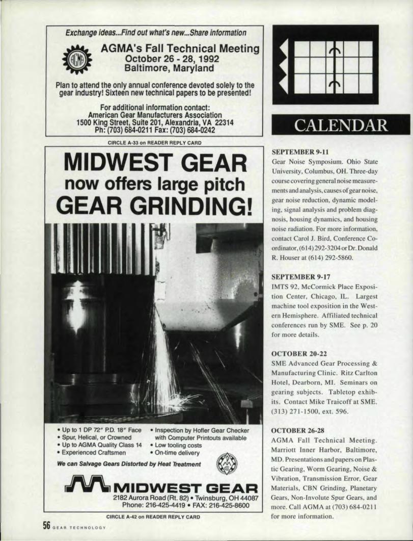
exchange Ideas...Findout wbafs new...Share information
•
AGMA·S..· Fall TeCh.nical Meeting, , (~ctC?ber:26~ 28,,_119'9,2
Baillmor,e'" Maryl,and
Pl'an to' att,end the only annual,conf,ereno,e ,devoted solely 10'thegear industry! Sixteen new teohnical papers, to be' pr,esented!'
For'addHional information contact:American Gear Manuf,ac1urers Assooiation
1500 Kingl Street, Suite 201, Alexandrla" VA ,223,14Ph: a'O'3), 6a4-02~11,Fax: (7'03) 684·'0242
CIRCLE 1\·33 on READER REPLY CA.IR.D
,MI:DWE,ST GEARnlow ,offers Ilarge pitch
GI,EA,R GIRIINDI'NG!
• Up to 1 DP 72" P.D. 18" Face• Spur; Helical, or Crownedl• Up to AGMA Quality Class,14.' ~)(pefienced Craftsmen
• Inspection by Hoffer 'Gear Checkerwi,th Computer Printouts available
.' Low tooling costs
.' On~time deJllvery~
~
rI!V\t IVIICY\lI;:ST GEAR21182Aurora Road (Rt. 82) • Twinsburg, OH' 44087
Phone: 216-425-4419' • FAX: 216-425-8600'
We can Salvage Gean; Distorted by .Heat Tlleafme.nt
CIRCLE 1\·42 on READER REPLY CARD
56 G E. ART e C H N 0 LOG Y
CALENDARSEPTEMBER. 9·11Gear Noise Symposium. Ohio StateUniversity. Columbus. OR Three-daycour e covering general noise measure-ments and analysis, causes of gear noise.gear noi e reduction, dynamic model-ing, signal analysis and problem diag-nosis, housing dynamics, and housingnoi .e radiation. For more information.contact Carol J. Bird. Conference Co-ordinator, (6] 4) 292-3204 or Dr. DonaldR. Hour er at. (614) 292-5860.
SEPTEMBER 9'-17IMTS 92, McCormick Place Exposi-tion Center, Chicago, WL. Largestmachine too] exposnien in the West-ern Hemisphere. Affiliated technicalconference run by SME. See p. 20for more details.
OCTOBER. 20·22SME Advanced Gear Processing &Manufacturing Clink. Ritz CarltonHotel, Dearborn, Ml. Seminars ongearing subjects. Tabletop exhib-its. Contact Mike Traicoff at SME.(313) 271-1500, ext, 596.
OCTOBER %6-28AGMA FaH Technical Meeting.Marriott Inner Harbor. Baltimore,MD. Presentations and papers on Plas-ric Gearing, Worm Gearing. Noise &Vibration, Transmission Error, GearMaterial , CBN Grinding. PlanetaryGears, Non-Involute Spur Gears, andmore. Call AGMA at (703) 684-021!for more information.
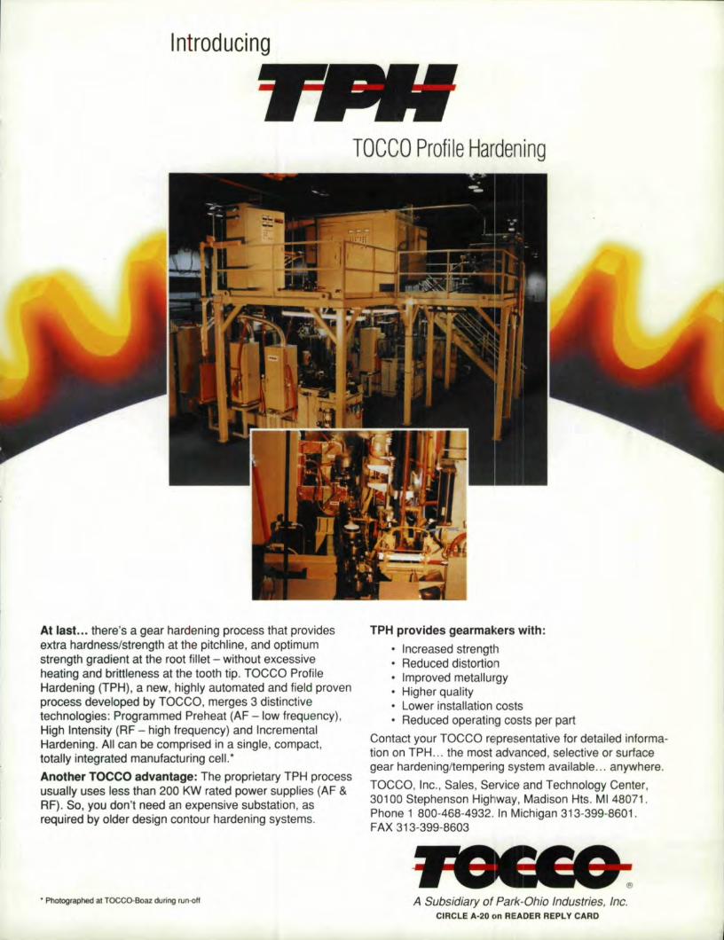
lntrooucinq
At Ilasl ...• there's a gear hardening process that providesextra hardness/strength at the pitchline, and optimumstrength gradient at the rootfjtlet - without excessiveheating and brittleness at the tooth t'ip. TOCCO I~rofile. .Hardening (TIflH) , a new, highly automated and field provenprocess devetoped by TOCCO, merges 3 distinctivetechnologies: Programmed Preheat (AF- low frequency),High Intensity (RF - high frequency) and IncrementalHardening_ All can be comprised in a s'inglle, compact,totally integrated manufacturing cell.'Another T,OCCO' advantage: The proprietary TPH processusu~Hy uses Iless than 200 IKW rated power supplies (AF &RF). So, you don't need an expensive substation, asrequired by older design contour hardening systems.
• Photographed at TOCCO-SOal during run-off
TOCCO Profil:e Hardening
TPH provides gearmakers with:• lincreased strength• Reduced distortion• Improved metallurgy• Higher quality• Lower installation costs• Reduced operating costs per part
Contact your TOCCO representative for detailed informa-tion on TPH .... the most advanced, selective or surfacegear hardening/tempering system available ... anywhere.
TOCCO, Inc., Sales, Service and Technology Center,30100 Stephenson Highway, Madison Hits. MI 48071.Phone 1 800-468·4932. In Michigan 313-399-8601!.FAX 313-399-8603
A Subsidiary of Park-Ohio Industries, Inc .CIRC'LE A.-20 on ,REA.DER REPLY' CARD,
tle RED RINGSF-series of grindersare the world's only full 6-axis ( Cprecision form gear grinders proven infour years of production.
fLEXlBIUTVIVERSATILIIT. TIley letyou choosejhe best grindi:ng method forthe Job, fromaiumlnum oxide, ceramicaluminum oxide. CB plated, ordressable CBNwheels. The SF grindersare capable of creep feed orconveruional grinding. rbis level ofversatility can produce optimum resultsonthe widest range of jobs.
[NCREnlB!LY fAST SET~UPS. Partdata input can be accomplished inapproximately ~5 minutes. Without theneed for cams, templates and indexplates, youlypically cut set-up time 10 afraction of the time required wi.lhconventional maehmes.
SF-SERiIES (H( PREI(ISIO:HI GEAR. ,GRINiDERSFOR EXTIERHAL AND INITERNiAll S,!PUR ANDHELICALI GEARS UIP 1110 36-IIN. IDIA.
, Consistently higher accuracy.fasterset ..ups,
and unmatched versatility to boost yourquality and productivity.
EASY PROFILE COORDINATEGENERATION. Our unique, user-friendlyprofile coordinate generation software(PC6S) provides prompts that ask theoperator questions aboutlhe invcluteprofile of tile part Built-iii validitychecldng all all inputs confirms all data.Pan profiling is accomplished faster thanever before.
dress cycle, providing optimurn profileaccumcy, particularly on helical gears.
AUTOMATIC STOCK DlVIDlNG.This patented option allows the gear to beaccurately positioned for optimum stockremoval in a fraction of the time pre-viousIy needed for stock dividing.
AUTOMATIC WHEEL SIZE'COMPENSATION. Grinding wheel speedand profiledara are updated with every
TEMPERA'fURE-CONTROL!LEDCOOLANTSYSTEM. Spindle and coolanttemperatures are tempera lure controlledto significantly improve grinding accuracy.
e~INationa!'IIBroac~h" Machiln;e: COl. GEARING THE WORWFOR TOMORROW
17500 T\VEN1Y-Tl:rREE MIlE ROAD - MT: CLEMENS, MIDCBIGAN 48044 • 313-263-0100 • TELEX 23-04281NA1'BROCH MENS- FAX 313-263- 57W
ManufactUring aju.llllne of gearflnisbing equ.ipment, 9roaching equipment and related products and services.CIRCLE A·19 on READER; 'REPLY CARD