gear boxes and motors - gultni.lv
TRANSCRIPT

GEAR BOXESAND MOTORSGE
AR B
OXES
AND
MOT
ORS
0
4.16
CHIA
RAVA
LLI G
ROUP
SPA

page 5
page 56
page 58
page 121
page 136
page 141
page 153
page 88
page 25

60 YEARSOF HISTORYThe goal pursued by Chiaravalli during more than 60 years ofhistory is to become the Italian and European technologicalcenter of excellence in the field of mechanical transmission.

Our Logistic Center in Cantalupa is a coordinated set of informatic functions intended for storage, picking, packaging and delivery of products.
All the functions have been automatized at the highest levels available today.
www.chiaravalli.comThe Chiaravalli logistic group has established itself over the years becoming an example of excellence for all the European companies working in the same sector.
STANDARDTRANSMISSIONStandard productsas per catalogue
GEAR BOXES& ELECTRICMOTORSStandard productsas per catalogue
MECHANICALWORM SCREWJACKSCustomized andStandard productsas percatalogue
SPECIALCOMPONENTSProduction ofspecialcomponentswith highcomplexityand extremelyhigh precision
MOTORCYCLEDIVISIONMotorcycle equipmentdistribution

INDEX
Symbols page 2General information page 2Radial loads FR - Lubrication - Painting page 3Service factor FS page 4V6/B8 mounting position page 4 CHC SERIES HELICAL GEAR UNITS page 5Introduction page 6Assembling possibility page 7General information page 8Radial loads FR page 9Lubrication - Mounting position and terminal box orientation page 10Ratio and iec motor adapters page 11Gear unit selection tables page 12Performance parameter f · s = 1 page 18Dimension sheet CHC 16 - CHC 20 page 19Dimension sheet CHC 25 page 20Dimension sheet CHC 30 page 21Dimension sheet CHC 35 - CHC 40 page 22Exploded drawing and spare parts list page 23Use and maintenance instructions page 24
CHM-CHMR-CHME-CHMREWORM GEARED MOTORS AND WORM GEAR UNITS page 25CHM worm geared motors and worm gear units page 26Premessa - Introduction page 27Quantity of oil in litres - Motor mounting flanges page 28 CHM/CHMR/CHME/CHMRE Designation - Example order page 29Mounting position page 30Performance and dimensions CHM 025/CHM 150 with 4-pole motors page 31/40CHMR Dimensions page 41CHPC/CHM worm gear with pre-stage module page 42Performance CHTPC/CHM with 4-pole motors page 43CHPC/CHM Dimensions page 44Double worm gears CHM/CHM-CHME page 45CHM/CHMR/CHME/CHMRE Designation - Example order page 46Execution page 47Performance CHM/CHM with 4-pole motors page 48CHM-CHM Dimensions of combined gears page 49Torque arm - Single and double output shaft kit page 50Cover - BRM-S and BRM-D reduction bushings kit page 51Radial loads on the output shaft CHM page 52Radial loads on the centre line of the input shaft page 53Exploded drawing and spare parts list page 54Use and maintenance instructions page 55
CHML WORM GEARBOXES WITH TORQUE LIMITER page 56Design features - Dimensions page 57
CH WORM GEARED MOTORS AND WORM GEAR UNITS page 58Introduction - Lubrication page 59Quantity of oil in litres - Motor mounting flanges - Feet rotation page 60CH 03/04/05 Worm geared motors and worm gear units page 61CH - CH..P 03/04/05 Designation - Example order page 62CH 03/04/05 Mounting positions page 63CH 03 Performance and dimensions with 4-pole motors page 64CH 04 Performance and dimensions with 4-pole motors page 65CH 05 Performance and dimensions with 4-pole motors page 66CH 06/07/08 Worm geared motors and worm gear units page 67CH 06/07/08 - Designation - Example order page 68Mounting position page 69CH 06 Performance and dimensions with 4-pole motors page 70CH 07 Performance and dimensions with 4-pole motors page 71CH 08 Performance and dimensions with 4-pole motors page 72CHR/CHRE Dimensions page 73
IND
EX

INDEX
IND
EX
CHPC/CH worm gear with pre-stage module page 74CHPC worm gear with pre-stage module page 75CHPC/CH Performance and dimensions with 4-pole motors page 76Double worm gear CH/CH page 77Double worm gear CH/CH - Example order page 78Execution page 79 CH/CH Performance and dimensions with 4-pole motors page 80Torque arm - Single and double output shaft kit page 81Cover - Reduction bushings kit page 82Exploded drawing and spare parts list CH 03/04/05 page 83Exploded drawing and spare parts list CH 06/07/08 page 84Radial loads on the output shaft page 85Radial loads on the centre line of the input shaft page 86Use and maintenance instructions page 87
CHO BEVEL HELICAL GEAR UNITS page 88Introduction page 89General information page 90Radial loads FR page 91Lubrication page 92Maintanance and designation page 93Ratios and IEC motors adapters page 94Gear unit selection tables page 96Dimension sheet page 108Accessories and mounting positions page 116Exploded drawing and spare part list page 119CHO use and maintenance instructions page 120
CHA SHAFT MOUNTED SPEED REDUCERS page 121Introduction page 122General information page 123Service factor Fs page 124Radial loads FR / Backstop device page 125Lubrication page 126Mounting position page 127Gear unit selection table page 128Dimension sheet page 129Dimension shaft page 131Torque tension arm page 132Parts list page 133CHA use and maintenance instructions page 135
SPEED VARIATORS CHV SERIES page 136Speed variators CHV series - Designation page 137Performances with 4 poles motors - Lubrication - Recommended oils page 138CHV 02/05/10/20/30/50 dimensions - Accessories page 139Use and maintenance - Spare part list page 140
RIGHT-ANGLE PRECISION BEVEL GEAR DRIVERS page 141Right-angle precision bevel gear drives page 142How to select the correct right-angle bevel gear drive for your application page 144Input power page 145External load in connection with speed page 146Right-angle precision bevel gear drives page 147
ELECTRIC MOTORS page 153Introduction - Technical characteristics page 154Function with a frequency of 60 Hz - Feeding voltage page 155 Electric motors IE1 2/4/6 poles page 156Electric motors IE2 2/4/6 poles page 157Three-phase electric motors page 158Forced ventilation kit single-phase models page 159Belt tensioner slides for electric motors page 160
General sales conditions page 164
SYMBOLS
P = Power (Kw)i = RatioT = Torque (Nm)n = Speed (RPM)Fr = Radial Load (N)Fa = Axial Load (N)f.s. = Service FactorD = Diameter (mm)
1 Kw = 1,36 HP9,81 N = 1 Kp
1 Input2 Output
T2 = Output torqueT2n = Rated output torqueP1 = Input power = Transmission efficiency
fS = Service factor
GENERAL INFORMATION
POWER P
P1 * = P2
P1 = Input powerP2 = Output power = Transmission efficiency
TORQUE T
9550 P1
n2
VELOCITA’ DI ROTAZIONE n
n1 = Input speedn2 = Output speed
An output speed ≤ 1400 rpm is suggested so as to optimize the working condition and extend the service life.
TRANSMISSION RATIO i
n1
n2
2
SYM
BO
LS -
GE
NE
RA
L IN
FOR
MA
TIO
N
i =
T2 = Nm. .
T2n ≥T2 fS Nm.
2D and 3D drawings available on the web site www.chiaravalli.comQuantity, availability and prices with Chiaravalli B2B

3
RADIAL LOADS FR
LUBRICATION
PAINTING
RA
DIA
L LO
AD
S FR
- LU
BR
ICA
TIO
N -
PA
INTI
NGAll, gearboxes and variators are supplied, CHA type excluded, complete with lubricant.
The gearboxes maintenance free are lubricated with synthetic oil the others with mineral oil. It is very important to verify the mounting position because sometimes adding some oil is enough, in other case to lubricate bearings with special grease would be necessary. Use only recommended oils.Warning in case of heavy work itis better to install, where possible, breather plug.
All the gearboxes and electrical motors are painted Grey RAL 9022 with epoxy resins powder. Big gearboxes and motors are cast iron made, aluminium all the others.
The radial loads is proportional to the requested torque and inversely proportional to the transmission member diameter following this formula.
2000 T T.e.f. D
FR = N. .
FR a (b+x)
FRx ≤.
N
FR = Radial loadT = Nm (Torque)T.e.f. = Transmission element factorT.e.f. = 1,15 gear = 1,4 chain spocket = 1,75 v-pulley = 2,5 flat-pulleyD = Transmission element diameter
FR = Radial load on the centre linea,b,x = see tables page 9-46-47-77-78
When the radial loads is not applied on the centre line of the shaft it is necessary to use the following formula.
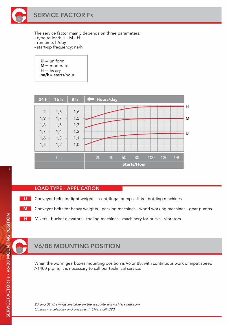
LOAD TYPE - APPLICATION
Conveyor belts for light weights - centrifugal pumps - lifts - bottling machines
Conveyor belts for heavy weights - packing machines - wood working machines - gear pumps
Mixers - bucket elevators - tooling machines - machinery for bricks - vibrators
4
SERVICE FACTOR FS
V6/B8 MOUNTING POSITION
SER
VIC
E F
AC
TOR
FS
- V
6/B
8 M
OU
NTI
NG
PO
SITI
ON
The service factor mainly depends on three parameters:- type to load: U - M - H- run time: h/day- start-up frequency: na/h
U = uniform M = moderate H = heavy na/h = starts/hour
24 h 16 h 8 h Hours/day
Starts/Hour
H
M
U
2
1,9
1,8
1,7
1,6
1,5
1,8
1,7
1,5
1,4
1,3
1,2
1,6
1,5
1,3
1,2
1,1
1,0
f . s 20 40 60 80 100 120 140
U
M
H
When the worm gearboxes mounting position is V6 or B8, with continuous work or input speed 1400 p.p.m, it is necessary to call our technical service.
2D and 3D drawings available on the web site www.chiaravalli.comQuantity, availability and prices with Chiaravalli B2B
CHC SERIES HELICALGEAR UNITS
6
INTRODUCTIONC
HC
- IN
TRO
DU
CTI
ON
- P
RO
DU
CT
FEA
TUR
ES
CHC series helical gear units is a new generation product, which designed basing on the modular system.It can be connected respectively with motors such as standard motor, brake motor, explosion-proof motor, IECmotor B5 - B14. This kind of product is widely used in drive fields such as textile, foodstuff, beverage, chemical industry, packaging and so on.
PRODUCT FEATURES
· Modularity· High efficiency· Low noise· Universal mounting· Aluminum housing, light in weight· Gears in carbonize hard, grinded· Lubricant maintenance free
CHC Series helical gear units are manufactured in 5 sizes (+ 1 on request). Power 0.12-4 Kw; Ratio 5-46.Torque max 120-500 Nm. It can be connected (foot, flange) discretionary and use multi-mounting positions according to cutomers’ requirements.
2D and 3D drawings available on the web site www.chiaravalli.comQuantity, availability and prices with Chiaravalli B2B
7
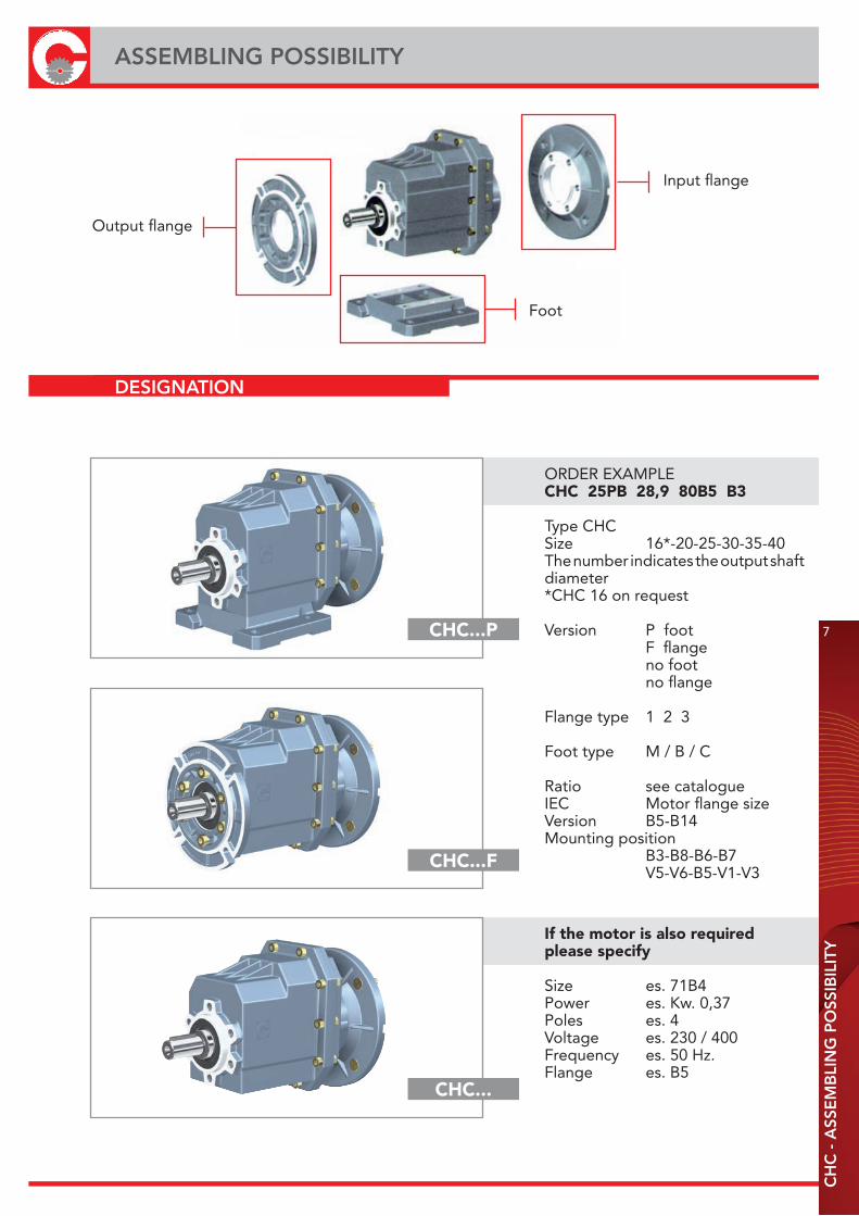
ASSEMBLING POSSIBILITY
CH
C -
ASS
EM
BLI
NG
PO
SSIB
ILIT
Y
DESIGNATION
Output flange
Foot
Input flange
CHC...P
CHC...F
CHC...
ORDER EXAMPLE CHC 25PB 28,9 80B5 B3
Type CHCSize 16*-20-25-30-35-40The number indicates the output shaft diameter *CHC 16 on request
Version P foot F flange no foot no flange
Flange type 1 2 3
Foot type M / B / C
Ratio see catalogueIEC Motor flange sizeVersion B5-B14Mounting position B3-B8-B6-B7 V5-V6-B5-V1-V3
If the motor is also required please specify
Size es. 71B4Power es. Kw. 0,37Poles es. 4Voltage es. 230 / 400Frequency es. 50 Hz.Flange es. B5
TORQUE M
9550 P1
n2
8
GENERAL INFORMATIONC
HC
- G
EN
ER
AL
INFO
RM
ATI
ON
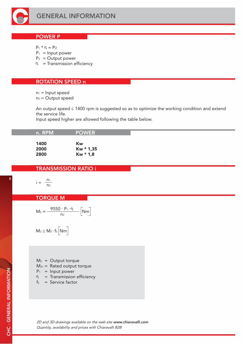
POWER P
P1 * = P2
P1 = Input powerP2 = Output power = Transmission efficiency
ROTATION SPEED n
n1 = Input speedn2 = Output speed
An output speed ≤ 1400 rpm is suggested so as to optimize the working condition and extend the service life.Input speed higher are allowed following the table below.
n. RPM POWER
1400 Kw2000 Kw * 1,352800 Kw * 1,8
TRANSMISSION RATIO i
n1
n2i =
M2 = Nm. .
M2 ≥ M2 fS Nm.
M2 = Output torqueM2n = Rated output torqueP1 = Input power = Transmission efficiency
fS = Service factor
2D and 3D drawings available on the web site www.chiaravalli.comQuantity, availability and prices with Chiaravalli B2B
9
RADIAL LOADS FR
CH
C -
RA
DIA
L LO
AD
S FR
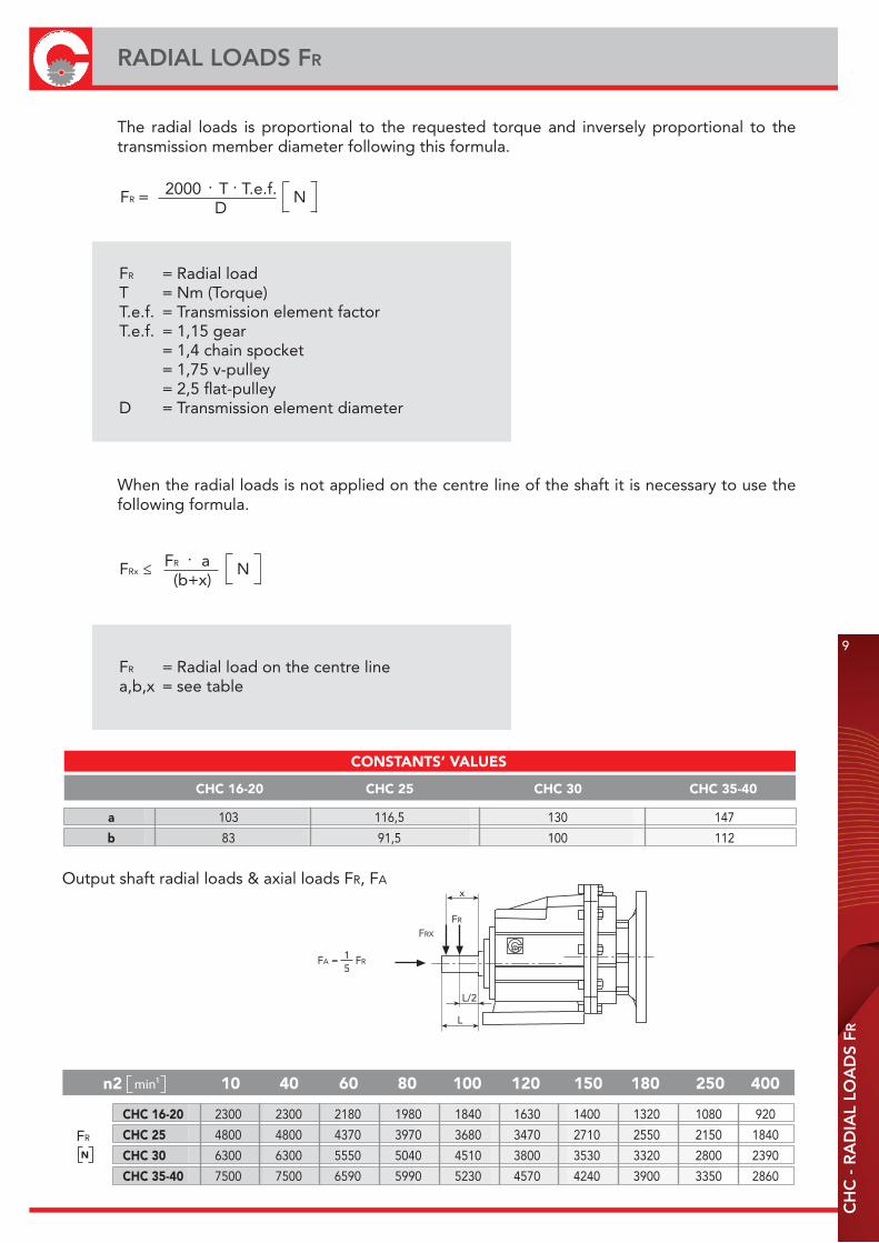
The radial loads is proportional to the requested torque and inversely proportional to the transmission member diameter following this formula.
2000 T T.e.f. D
FR = N. .
FR a (b+x)
FRx ≤.
N
FR = Radial loadT = Nm (Torque)T.e.f. = Transmission element factorT.e.f. = 1,15 gear = 1,4 chain spocket = 1,75 v-pulley = 2,5 flat-pulleyD = Transmission element diameter
FR = Radial load on the centre linea,b,x = see table
When the radial loads is not applied on the centre line of the shaft it is necessary to use the following formula.
CONSTANTS’ VALUES
n2 10 40 60 80 100 120 150 180 250 400
CHC 16-20 2300 2300 2180 1980 1840 1630 1400 1320 1080 920
CHC 25 4800 4800 4370 3970 3680 3470 2710 2550 2150 1840
CHC 30 6300 6300 5550 5040 4510 3800 3530 3320 2800 2390
CHC 35-40 7500 7500 6590 5990 5230 4570 4240 3900 3350 2860
N
FR
Output shaft radial loads & axial loads FR, FA
CHC 16-20 CHC 25 CHC 30 CHC 35-40
a 103 116,5 130 147
b 83 91,5 100 112
min1
FA = FR
FRX
FR
x
L/2
L
15
-40 +80
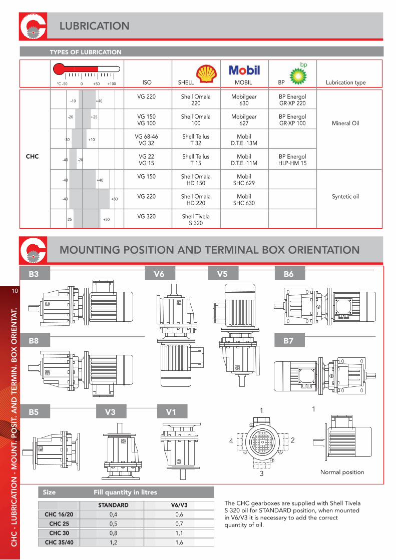
VG 220 Shell Omala Mobilgear BP Energol 220 630 GR-XP 220 VG 150 Shell Omala Mobilgear BP Energol VG 100 100 627 GR-XP 100 Mineral Oil VG 68-46 Shell Tellus Mobil VG 32 T 32 D.T.E. 13M
CHC VG 22 Shell Tellus Mobil BP Energol VG 15 T 15 D.T.E. 11M HLP-HM 15
VG 150 Shell Omala Mobil HD 150 SHC 629 VG 220 Shell Omala Mobil Syntetic oil HD 220 SHC 630
VG 320 Shell Tivela S 320
+40-10
+25-20
-30 +10
-40 -20
-40 +40
-25 +50
ISO SHELL MOBIL BP Lubrication type°C -50 0 +50 +100
Normal position
V6 V5 B6
B5 V3 V1
B3
4
3
2
1 1
B8 B7
TYPES OF LUBRICATION
The CHC gearboxes are supplied with Shell TivelaS 320 oil for STANDARD position, when mountedin V6/V3 it is necessary to add the correctquantity of oil.
STANDARD V6/V3
CHC 16/20 0,4 0,6
CHC 25 0,5 0,7
CHC 30 0,8 1,1
CHC 35/40 1,2 1,6
Size Fill quantity in litres
10
LUBRICATION
MOUNTING POSITION AND TERMINAL BOX ORIENTATION
CH
C -
LU
BR
ICA
TIO
N -
MO
UN
T. P
OSI
T. A
ND
TE
RM
IN. B
OX
OR
IEN
TAT.
11
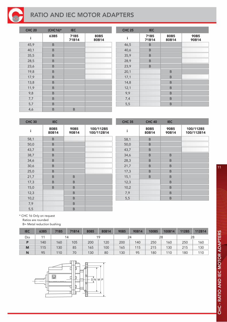
RATIO AND IEC MOTOR ADAPTERS
CH
C -
RA
TIO
AN
D IE
C M
OTO
R A
DA
PTE
RS
* CHC 16 Only on request Ratios are rounded B= Metal reduction bushing
58,1 B
46,5 B
40,6 B
35,9 B
28,9 B
23,9 B
20,1 B
17,1 B
14,8 B
12,1 B
9,9 B
7,4 B
5,5 B
CHC 25 IEC
i 71B5 80B5 90B5
71B14 80B14 90B14
50,0 B
43,7 B
34,6 B B
28,3 B B
21,7 B B
17,3 B B
15,1 B B
12,3 B
10,2 B
7,9 B
5,5 B
CHC 35 CHC 40 IEC
i 80B5 90B5 100/112B5
80B14 90B14 100/112B14
CHC 30 IEC
i 80B5 90B5 100/112B5
80B14 90B14 100/112B14
50,0 B
43,7 B
38,7 B
34,6 B
30,6 B
25,0 B
21,7 B B
17,3 B B
15,0 B B
12,3 B
10,2 B
7,9 B
5,5 B
58,1 B
45,9 B
40,1 B
35,5 B
28,5 B
23,6 B
19,8 B
17,9 B
13,8 B
11,9 B
9,8 B
7,7 B
5,7 B
4,6 B B
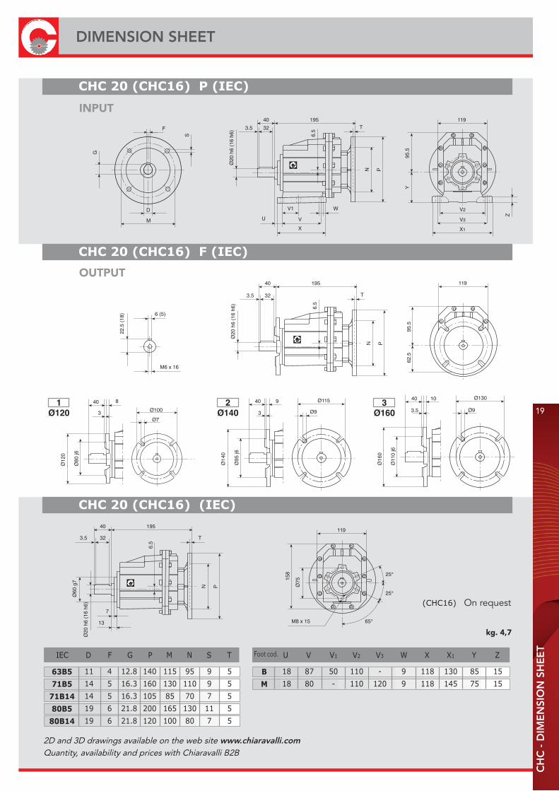
IEC 63B5 71B5 71B14 80B5 80B14 90B5 90B14 100B5 100B14 112B5 112B14
DE8 11 14 19 24 28 28
P 140 160 105 200 120 200 140 250 160 250 160
M 115 130 85 165 100 165 115 215 130 215 130
N 95 110 70 130 80 130 95 180 110 180 110
CHC 20 (CHC16)* IEC
i 63B5 71B5 80B5
71B14 80B14
PMND
12
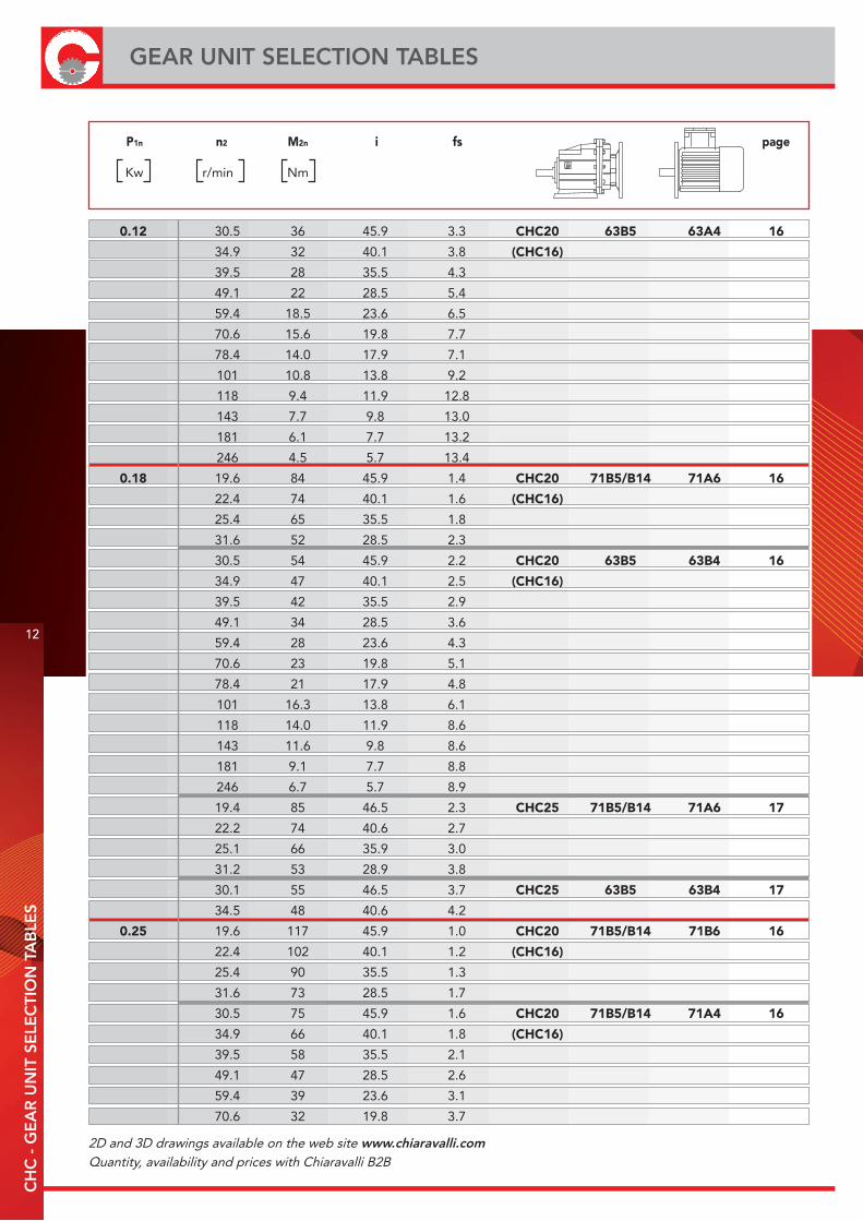
GEAR UNIT SELECTION TABLESC
HC
- G
EA
R U
NIT
SE
LEC
TIO
N T
AB
LES
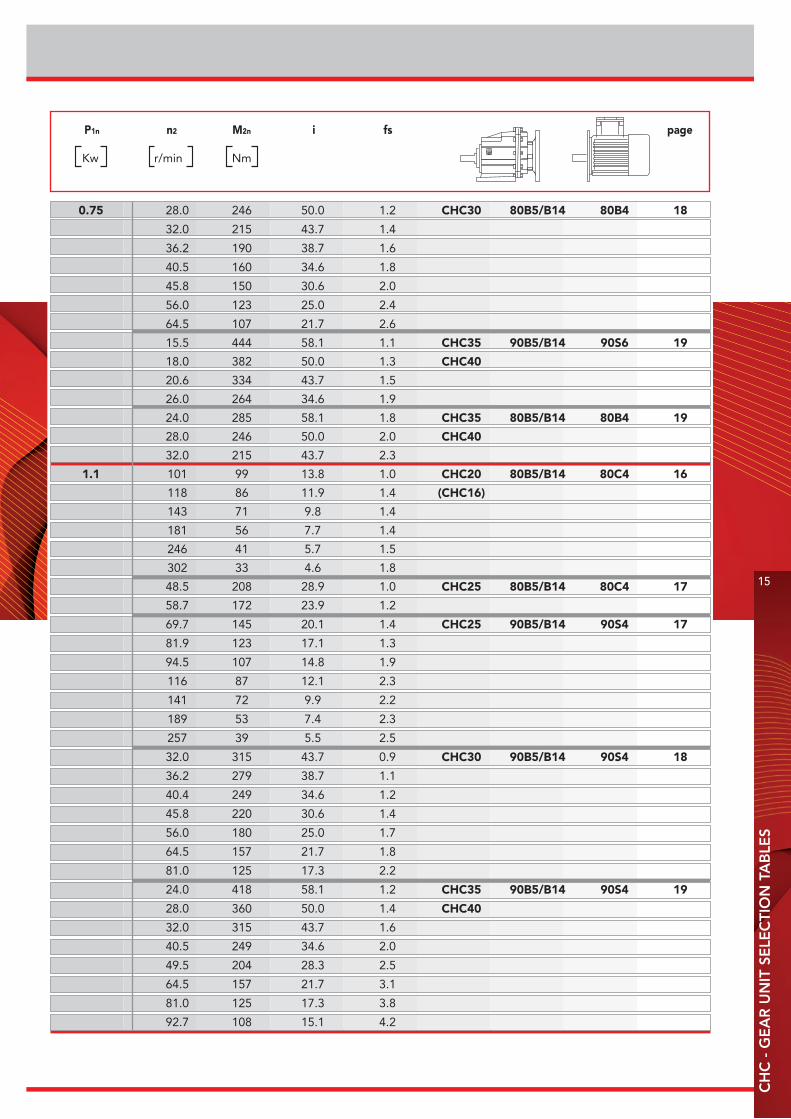
P1n n2 M2n i fs page
Kw r/min Nm
0.12 30.5 36 45.9 3.3 CHC20 63B5 63A4 16
34.9 32 40.1 3.8 (CHC16)
39.5 28 35.5 4.3
49.1 22 28.5 5.4
59.4 18.5 23.6 6.5
70.6 15.6 19.8 7.7
78.4 14.0 17.9 7.1
101 10.8 13.8 9.2
118 9.4 11.9 12.8
143 7.7 9.8 13.0
181 6.1 7.7 13.2
246 4.5 5.7 13.4
0.18 19.6 84 45.9 1.4 CHC20 71B5/B14 71A6 16
22.4 74 40.1 1.6 (CHC16)
25.4 65 35.5 1.8
31.6 52 28.5 2.3
30.5 54 45.9 2.2 CHC20 63B5 63B4 16
34.9 47 40.1 2.5 (CHC16)
39.5 42 35.5 2.9
49.1 34 28.5 3.6
59.4 28 23.6 4.3
70.6 23 19.8 5.1
78.4 21 17.9 4.8
101 16.3 13.8 6.1
118 14.0 11.9 8.6
143 11.6 9.8 8.6
181 9.1 7.7 8.8
246 6.7 5.7 8.9
19.4 85 46.5 2.3 CHC25 71B5/B14 71A6 17
22.2 74 40.6 2.7
25.1 66 35.9 3.0
31.2 53 28.9 3.8
30.1 55 46.5 3.7 CHC25 63B5 63B4 17
34.5 48 40.6 4.2
0.25 19.6 117 45.9 1.0 CHC20 71B5/B14 71B6 16
22.4 102 40.1 1.2 (CHC16)
25.4 90 35.5 1.3
31.6 73 28.5 1.7
30.5 75 45.9 1.6 CHC20 71B5/B14 71A4 16
34.9 66 40.1 1.8 (CHC16)
39.5 58 35.5 2.1
49.1 47 28.5 2.6
59.4 39 23.6 3.1
70.6 32 19.8 3.7
2D and 3D drawings available on the web site www.chiaravalli.comQuantity, availability and prices with Chiaravalli B2B
13
CH
C -
GE
AR
UN
IT S
ELE
CTI
ON
TA
BLE
S
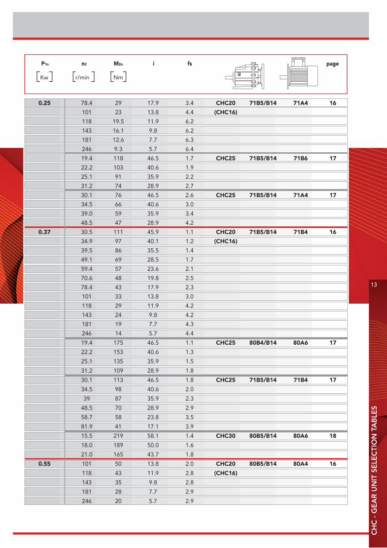
P1n n2 M2n i fs page
Kw r/min Nm
0.25 78.4 29 17.9 3.4 CHC20 71B5/B14 71A4 16
101 23 13.8 4.4 (CHC16)
118 19.5 11.9 6.2
143 16.1 9.8 6.2
181 12.6 7.7 6.3
246 9.3 5.7 6.4
19.4 118 46.5 1.7 CHC25 71B5/B14 71B6 17
22.2 103 40.6 1.9
25.1 91 35.9 2.2
31.2 74 28.9 2.7
30.1 76 46.5 2.6 CHC25 71B5/B14 71A4 17
34.5 66 40.6 3.0
39.0 59 35.9 3.4
48.5 47 28.9 4.2
0.37 30.5 111 45.9 1.1 CHC20 71B5/B14 71B4 16
34.9 97 40.1 1.2 (CHC16)
39.5 86 35.5 1.4
49.1 69 28.5 1.7
59.4 57 23.6 2.1
70.6 48 19.8 2.5
78.4 43 17.9 2.3
101 33 13.8 3.0
118 29 11.9 4.2
143 24 9.8 4.2
181 19 7.7 4.3
246 14 5.7 4.4
19.4 175 46.5 1.1 CHC25 80B4/B14 80A6 17
22.2 153 40.6 1.3
25.1 135 35.9 1.5
31.2 109 28.9 1.8
30.1 113 46.5 1.8 CHC25 71B5/B14 71B4 17
34.5 98 40.6 2.0
39 87 35.9 2.3
48.5 70 28.9 2.9
58.7 58 23.8 3.5
81.9 41 17.1 3.9
15.5 219 58.1 1.4 CHC30 80B5/B14 80A6 18
18.0 189 50.0 1.6
21.0 165 43.7 1.8
0.55 101 50 13.8 2.0 CHC20 80B5/B14 80A4 16
118 43 11.9 2.8 (CHC16)
143 35 9.8 2.8
181 28 7.7 2.9
246 20 5.7 2.9
14
GEAR UNIT SELECTION TABLESC
HC
- G
EA
R U
NIT
SE
LEC
TIO
N T
AB
LES
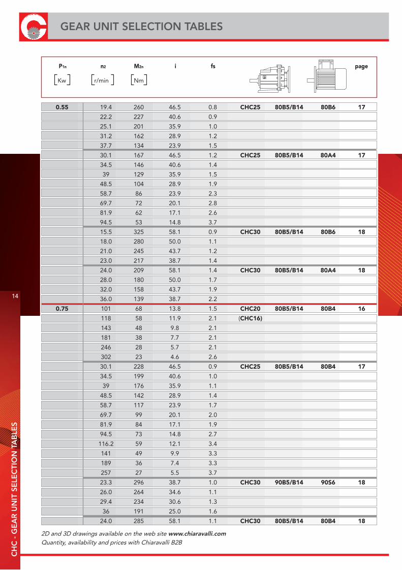
P1n n2 M2n i fs page
Kw r/min Nm
0.55 19.4 260 46.5 0.8 CHC25 80B5/B14 80B6 17
22.2 227 40.6 0.9
25.1 201 35.9 1.0
31.2 162 28.9 1.2
37.7 134 23.9 1.5
30.1 167 46.5 1.2 CHC25 80B5/B14 80A4 17
34.5 146 40.6 1.4
39 129 35.9 1.5
48.5 104 28.9 1.9
58.7 86 23.9 2.3
69.7 72 20.1 2.8
81.9 62 17.1 2.6
94.5 53 14.8 3.7
15.5 325 58.1 0.9 CHC30 80B5/B14 80B6 18
18.0 280 50.0 1.1
21.0 245 43.7 1.2
23.0 217 38.7 1.4
24.0 209 58.1 1.4 CHC30 80B5/B14 80A4 18
28.0 180 50.0 1.7
32.0 158 43.7 1.9
36.0 139 38.7 2.2
0.75 101 68 13.8 1.5 CHC20 80B5/B14 80B4 16
118 58 11.9 2.1 (CHC16)
143 48 9.8 2.1
181 38 7.7 2.1
246 28 5.7 2.1
302 23 4.6 2.6
30.1 228 46.5 0.9 CHC25 80B5/B14 80B4 17
34.5 199 40.6 1.0
39 176 35.9 1.1
48.5 142 28.9 1.4
58.7 117 23.9 1.7
69.7 99 20.1 2.0
81.9 84 17.1 1.9
94.5 73 14.8 2.7
116.2 59 12.1 3.4
141 49 9.9 3.3
189 36 7.4 3.3
257 27 5.5 3.7
23.3 296 38.7 1.0 CHC30 90B5/B14 90S6 18
26.0 264 34.6 1.1
29.4 234 30.6 1.3
36 191 25.0 1.6
24.0 285 58.1 1.1 CHC30 80B5/B14 80B4 18
2D and 3D drawings available on the web site www.chiaravalli.comQuantity, availability and prices with Chiaravalli B2B
15
CH
C -
GE
AR
UN
IT S
ELE
CTI
ON
TA
BLE
S
P1n n2 M2n i fs page
Kw r/min Nm
0.75 28.0 246 50.0 1.2 CHC30 80B5/B14 80B4 18
32.0 215 43.7 1.4
36.2 190 38.7 1.6
40.5 160 34.6 1.8
45.8 150 30.6 2.0
56.0 123 25.0 2.4
64.5 107 21.7 2.6
15.5 444 58.1 1.1 CHC35 90B5/B14 90S6 19
18.0 382 50.0 1.3 CHC40
20.6 334 43.7 1.5
26.0 264 34.6 1.9
24.0 285 58.1 1.8 CHC35 80B5/B14 80B4 19
28.0 246 50.0 2.0 CHC40
32.0 215 43.7 2.3
1.1 101 99 13.8 1.0 CHC20 80B5/B14 80C4 16
118 86 11.9 1.4 (CHC16)
143 71 9.8 1.4
181 56 7.7 1.4
246 41 5.7 1.5
302 33 4.6 1.8
48.5 208 28.9 1.0 CHC25 80B5/B14 80C4 17
58.7 172 23.9 1.2
69.7 145 20.1 1.4 CHC25 90B5/B14 90S4 17
81.9 123 17.1 1.3
94.5 107 14.8 1.9
116 87 12.1 2.3
141 72 9.9 2.2
189 53 7.4 2.3
257 39 5.5 2.5
32.0 315 43.7 0.9 CHC30 90B5/B14 90S4 18
36.2 279 38.7 1.1
40.4 249 34.6 1.2
45.8 220 30.6 1.4
56.0 180 25.0 1.7
64.5 157 21.7 1.8
81.0 125 17.3 2.2
24.0 418 58.1 1.2 CHC35 90B5/B14 90S4 19
28.0 360 50.0 1.4 CHC40
32.0 315 43.7 1.6
40.5 249 34.6 2.0
49.5 204 28.3 2.5
64.5 157 21.7 3.1
81.0 125 17.3 3.8
92.7 108 15.1 4.2
16
GEAR UNIT SELECTION TABLESC
HC
- G
EA
R U
NIT
SE
LEC
TIO
N T
AB
LES
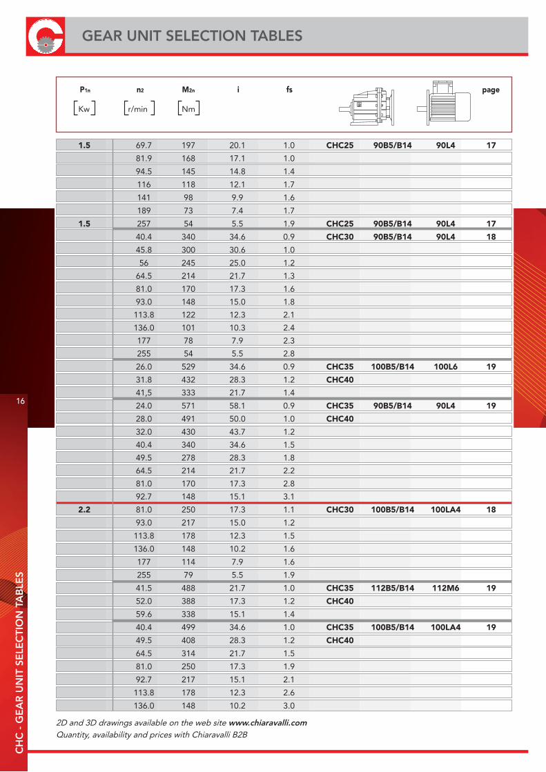
P1n n2 M2n i fs page
Kw r/min Nm
1.5 69.7 197 20.1 1.0 CHC25 90B5/B14 90L4 17
81.9 168 17.1 1.0
94.5 145 14.8 1.4
116 118 12.1 1.7
141 98 9.9 1.6
189 73 7.4 1.7
1.5 257 54 5.5 1.9 CHC25 90B5/B14 90L4 17
40.4 340 34.6 0.9 CHC30 90B5/B14 90L4 18
45.8 300 30.6 1.0
56 245 25.0 1.2
64.5 214 21.7 1.3
81.0 170 17.3 1.6
93.0 148 15.0 1.8
113.8 122 12.3 2.1
136.0 101 10.3 2.4
177 78 7.9 2.3
255 54 5.5 2.8
26.0 529 34.6 0.9 CHC35 100B5/B14 100L6 19
31.8 432 28.3 1.2 CHC40
41,5 333 21.7 1.4
24.0 571 58.1 0.9 CHC35 90B5/B14 90L4 19
28.0 491 50.0 1.0 CHC40
32.0 430 43.7 1.2
40.4 340 34.6 1.5
49.5 278 28.3 1.8
64.5 214 21.7 2.2
81.0 170 17.3 2.8
92.7 148 15.1 3.1
2.2 81.0 250 17.3 1.1 CHC30 100B5/B14 100LA4 18
93.0 217 15.0 1.2
113.8 178 12.3 1.5
136.0 148 10.2 1.6
177 114 7.9 1.6
255 79 5.5 1.9
41.5 488 21.7 1.0 CHC35 112B5/B14 112M6 19
52.0 388 17.3 1.2 CHC40
59.6 338 15.1 1.4
40.4 499 34.6 1.0 CHC35 100B5/B14 100LA4 19
49.5 408 28.3 1.2 CHC40
64.5 314 21.7 1.5
81.0 250 17.3 1.9
92.7 217 15.1 2.1
113.8 178 12.3 2.6
136.0 148 10.2 3.0
2D and 3D drawings available on the web site www.chiaravalli.comQuantity, availability and prices with Chiaravalli B2B

17
CH
C -
GE
AR
UN
IT S
ELE
CTI
ON
TA
BLE
S
P1n n2 M2n i fs page
Kw r/min Nm
177 114 7.9 2.3 CHC40
255 79 5.5 2.9
3 93.0 296 15.0 0.9 CHC30 100B5/B14 100LB4 18
113.8 243 12.3 1.1
136.0 202 10.2 1.2
177 156 7.9 1.2
3 255 108 5.5 1.4 CHC30 100B5/B14 100LB4 18
49.5 556 28.3 0.9 CHC35 100B5/B14 100LB4 19
64.5 428 21.7 1.1 CHC40
81.0 340 17.3 1.4
92.7 296 15.1 1.6
113.8 243 12.3 1.9
136 202 10.2 2.2
177 156 7.9 1.7
255 108 5.5 2.1
4 177 208 7.9 0.9 CHC30 112B5/B14 112M4 18
255 144 5.5 1.0
113.8 324 12.3 1.4 CHC35 112B5/B14 112M4 19
136.0 269 10.2 1.6 CHC40
177 208 7.9 1.3
255 144 5.5 1.6

18
PERFORMANCE PARAMETER f · s = 1C
HC
- P
ER
FOR
MA
NC
E P
AR
AM
ETE
R
f ·
s =
1
M2max n1 i P1n n2
Nm r/min Kw r/min
120 1400 45.9 0.40 30.5 CHC20
120 1400 40.1 0.46 34.9 (CHC16)
120 1400 35.5 0.52 39.5
120 1400 28.5 0.64 49.1
120 1400 23.6 0.78 59.4
120 1400 19.8 0.92 70.6
90 1400 17.9 0.77 78.4
90 1400 13.8 1.00 101
120 1400 11.9 1.54 118
120 1400 9.8 1.87 143
80 1400 7.7 1.58 181
70 1400 5.7 1.88 246
70 1400 4.6 2.31 302
200 1400 46.5 0.66 30.1 CHC25
200 1400 40.6 0.75 34.5
200 1400 35.9 0.85 39.0
200 1400 28.9 1.06 48.5
200 1400 23.9 1.28 58.7
200 1400 20.1 1.52 69.7
140 1400 17.1 1.25 81.9
200 1400 14.8 2.06 94.6
200 1400 12.1 2.53 116
200 1400 9.9 3.08 141
120 1400 7.4 2.49 190
100 1400 5.5 2.80 257
300 1400 58.1 0.79 24.0 CHC30
300 1400 50.0 0.92 28.0
300 1400 43.7 1.04 32.0
300 1400 38.7 1.18 36.1
300 1400 34.6 1.32 40.5
300 1400 30.6 1.50 45.8
300 1400 25.0 1.83 56.0
280 1400 21.7 1.96 64.5
280 1400 17.3 2.47 81.0
260 1400 15.0 2.64 93.0
260 1400 12.3 3.21 113.8
240 1400 10.2 3.57 137.0
180 1400 7.9 3.46 176
150 1400 5.5 4.17 255
500 1400 58.1 1.31 24.0 CHC35
500 1400 50.0 1.53 28.0 CHC40
500 1400 43.7 1.75 32.0
500 1400 34.6 2.21 40.5
500 1400 28.3 2.70 49.5
480 1400 21.7 3.37 64.5
480 1400 17.3 4.23 81.0
460 1400 15.1 4.66 93.0
460 1400 12.3 5.68 113.8
440 1400 10.2 6.54 136.0
260 1400 7.9 5.01 177
230 1400 5.5 6.41 255
19
CH
C -
DIM
EN
SIO
N S
HE
ET
40
3.5
Ø16
0
10Ø
110
j6Ø130
Ø9
kg. 4,7
DIMENSION SHEET
On request
Foot cod.
INPUT
OUTPUT
2D and 3D drawings available on the web site www.chiaravalli.comQuantity, availability and prices with Chiaravalli B2B
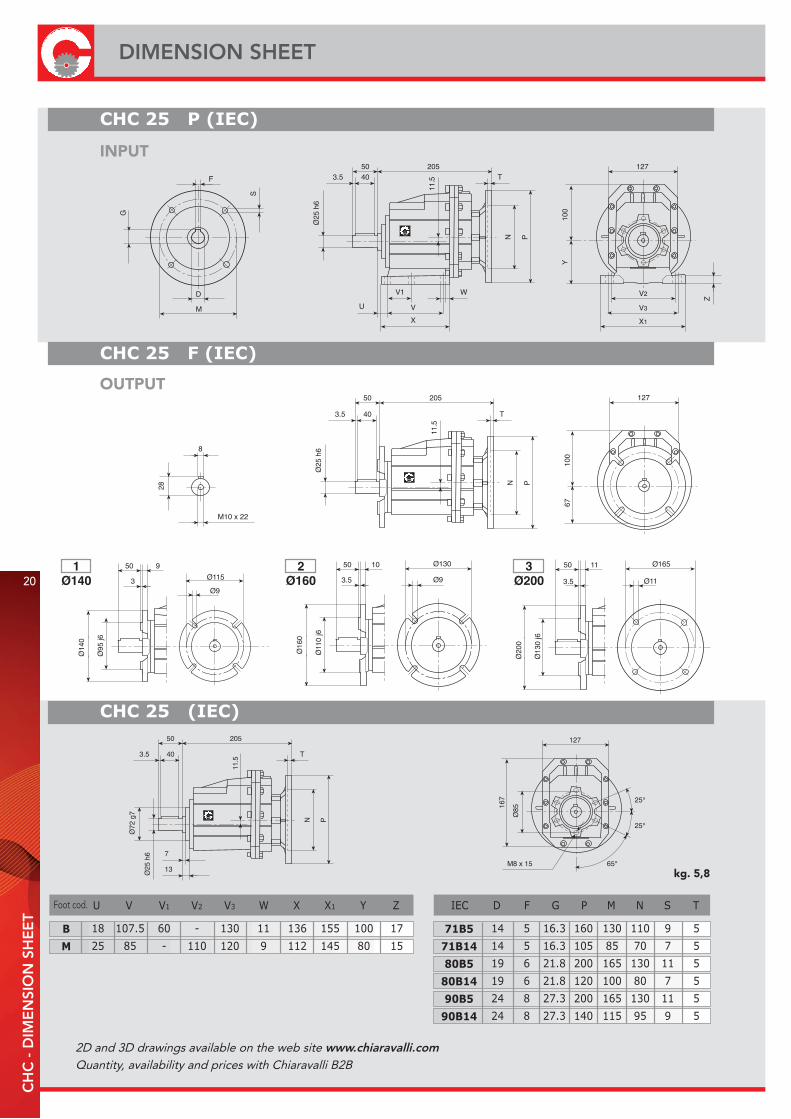
50
3.5
Ø20
0
11
Ø13
0 j6
Ø165
Ø11
kg. 5,8
20
DIMENSION SHEETC
HC
- D
IME
NSI
ON
SH
EE
T
INPUT
OUTPUT
Foot cod.
2D and 3D drawings available on the web site www.chiaravalli.comQuantity, availability and prices with Chiaravalli B2B

21
CH
C -
DIM
EN
SIO
N S
HE
ET
60
4
Ø25
0
13Ø
180
j6Ø215
Ø13.5
kg. 9,2
DIMENSION SHEET
INPUT
OUTPUT
Foot cod.

kg. 12,2
22
DIMENSION SHEETC
HC
- D
IME
NSI
ON
SH
EE
T
INPUT
OUTPUT
Foot cod.
(...) Between brackets CHC 40 dimension
2D and 3D drawings available on the web site www.chiaravalli.comQuantity, availability and prices with Chiaravalli B2B
43
41 40
42 39
3837 36
35
31
32
33
34
30
13
2928
2726
25
1514
12
2
3
1
456
7
89
11
10
1617
18
19
2022
21
2324
44
23
CH
C -
EX
PLO
DE
D D
RA
WIN
G A
ND
SPA
RE
PA
RTS
LIS
T
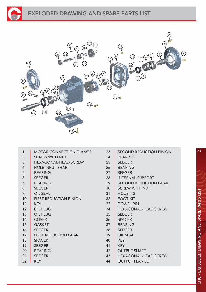
EXPLODED DRAWING AND SPARE PARTS LIST
1 MOTOR CONNECTION FLANGE2 SCREW WITH NUT3 HEXAGONAL-HEAD SCREW4 HOLE INPUT SHAFT5 BEARING6 SEEGER7 BEARING8 SEEGER9 OIL SEAL10 FIRST REDUCTION PINION11 KEY12 OIL PLUG13 OIL PLUG14 COVER15 GASKET16 SEEGER17 FIRST REDUCTION GEAR18 SPACER19 SEEGER20 BEARING21 SEEGER22 KEY
23 SECOND REDUCTION PINION24 BEARING25 SEEGER26 BEARING27 SEEGER28 INTERNAL SUPPORT29 SECOND REDUCTION GEAR30 SCREW WITH NUT31 HOUSING 32 FOOT KIT33 DOWEL PIN34 HEXAGONAL-HEAD SCREW 35 SEEGER36 SPACER37 BEARING38 SEEGER39 OIL SEAL 40 KEY41 KEY42 OUTPUT SHAFT43 HEXAGONAL-HEAD SCREW44 OUTPUT FLANGE
CHC - USE AND MAINTENANCE INSTRUCTIONS
24
CH
C -
USE
AN
D M
AIN
TEN
AN
CE
INST
RU
CTI
ON
S
INSTALLATION· The data shown on the identification name plate must correspond to the gearbox ordered.· The oil level must correspond to the quantity foreseen for the assembly position requested (see catalogue).· All of the other gearboxes are supplied complete with permanent synthetic oil in a quantity that is sufficient for any assembly position.· The gearbox must be fixed on a flat surface that is sufficiently rigid in order to avoid any vibration.· The gearbox and the axis of the machine to be driven must be perfectly aligned o in the event that knocks, overloading or blockage of the machine are foreseen, the client must install a limiting device, joints, overload cut-out etc.· Coupling with pinions, joints, pulleys and other parts must be done after the parts have been cleaned and knocks should be avoided while assembling as they could damage the bearings and other internal parts.· In the event that the motor is supplied by the client, he must check that the flange and shaft tolerances correspond to a “normal” class; our motors satisfy this requirement.· Check that the fixing screws for the gear and the related accessories are correctly tightened.· Take suitable measures to protect the groups from any aggressive atmospheric agents.· Where foreseen, protect rotating parts from any possible contact with the operators.· If the gears are painted, protect the oil seals and the machined surfaces gearboxes.· All of the gears are painted RAL 9022 grey.
OPERATION AND RUNNING-IN· To obtain the best performance the gearboxes must first be run-in by gradually increasing the power in the first few hours of operation, in this phase an increase in temperature is considered normal.· In the event of defective operation, noise, oil leakage, etc. stop the gear immediately and, when possible, remove the cause. Alternatively, send the piece to our factory to be controlled.
MAINTENANCE· The helical gearboxes are lubricated with permanent synthetic oil and therefore do not require any maintenance.
WAREHOUSE STORAGE· If the warehouse storage will be for a long time, more than 3 months, the shafts and machined surfaces should be protected using antioxidants and the oil seals should be greased.
HANDLING· Care must be taken not to damage the oil seals and the machined surfaces when handling the groups.
DISPOSAL OF PACKAGING· The packaging in which our gears are delivered should be sent to specialised companies for recycling if possible.
2D and 3D drawings available on the web site www.chiaravalli.comQuantity, availability and prices with Chiaravalli B2B
CHM WORM GEARED MOTORS ANDWORM GEAR UNITS

26
CHM - WORM GEARED MOTORS AND WORM GEAR UNITSC
HM
- W
OR
M G
EA
RE
D M
OTO
RS
AN
D W
OR
M G
EA
R U
NIT
S
CHM
CHME
CHMRE
CHMR
27
CH
M -
INTR
OD
UC
TIO
N -
LU
BR
ICA
TIO
N
INTRODUCTION
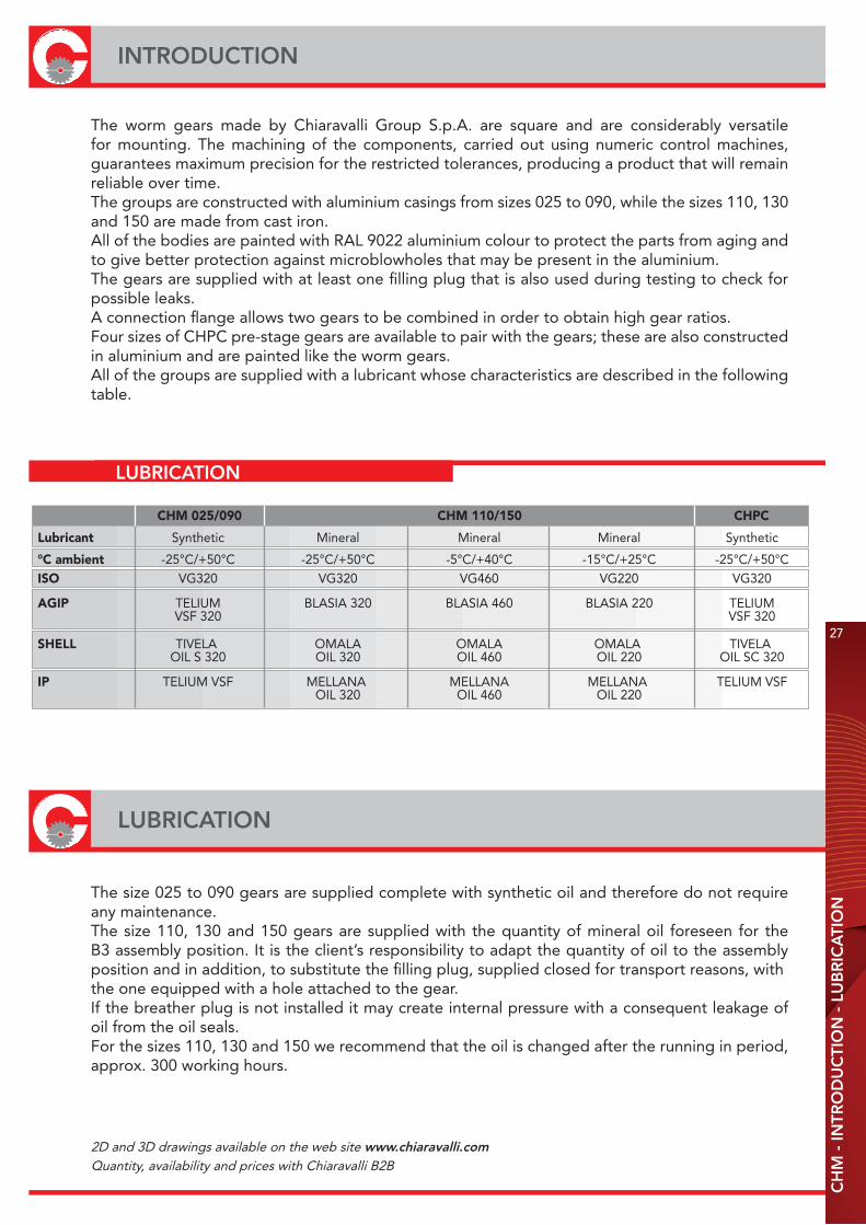
The worm gears made by Chiaravalli Group S.p.A. are square and are considerably versatile for mounting. The machining of the components, carried out using numeric control machines, guarantees maximum precision for the restricted tolerances, producing a product that will remain reliable over time. The groups are constructed with aluminium casings from sizes 025 to 090, while the sizes 110, 130 and 150 are made from cast iron.All of the bodies are painted with RAL 9022 aluminium colour to protect the parts from aging and to give better protection against microblowholes that may be present in the aluminium.The gears are supplied with at least one filling plug that is also used during testing to check for possible leaks.A connection flange allows two gears to be combined in order to obtain high gear ratios.Four sizes of CHPC pre-stage gears are available to pair with the gears; these are also constructed in aluminium and are painted like the worm gears.All of the groups are supplied with a lubricant whose characteristics are described in the following table.
LUBRICATION
CHM 025/090 CHM 110/150 CHPC
Lubricant Synthetic Mineral Mineral Mineral Synthetic
°C ambient -25°C/+50°C -25°C/+50°C -5°C/+40°C -15°C/+25°C -25°C/+50°CISO VG320 VG320 VG460 VG220 VG320
AGIP TELIUM BLASIA 320 BLASIA 460 BLASIA 220 TELIUM VSF 320 VSF 320
SHELL TIVELA OMALA OMALA OMALA TIVELA OIL S 320 OIL 320 OIL 460 OIL 220 OIL SC 320
IP TELIUM VSF MELLANA MELLANA MELLANA TELIUM VSF OIL 320 OIL 460 OIL 220
LUBRICATION
The size 025 to 090 gears are supplied complete with synthetic oil and therefore do not require any maintenance.The size 110, 130 and 150 gears are supplied with the quantity of mineral oil foreseen for the B3 assembly position. It is the client’s responsibility to adapt the quantity of oil to the assembly position and in addition, to substitute the filling plug, supplied closed for transport reasons, withthe one equipped with a hole attached to the gear.If the breather plug is not installed it may create internal pressure with a consequent leakage of oil from the oil seals.For the sizes 110, 130 and 150 we recommend that the oil is changed after the running in period,approx. 300 working hours.
2D and 3D drawings available on the web site www.chiaravalli.comQuantity, availability and prices with Chiaravalli B2B

28
QUANTITY OF OIL IN LITRESC
HM
- Q
UA
NTI
TY O
F O
IL IN
LIT
RE
S -
MO
TOR
MO
UN
TIN
G F
LAN
GE
S
CHM 025 030 040 050 063 075 090 110 130 150 CHPC 63 71 80 90
B3 0.02 0.04 0.08 0.15 0.30 0.55 1 3 4.5 7 0.05 0.07 0.15 0.16
B8 0.02 0.04 0.08 0.15 0.30 0.55 1 1.4 1.7 5.1 0.05 0.07 0.15 0.16
B6/B7 0.02 0.04 0.08 0.15 0.30 0.55 1 2.2 3.3 5.4 0.05 0.07 0.15 0.16
V5 0.02 0.04 0.08 0.15 0.30 0.55 1 3 4.5 7 0.05 0.07 0.15 0.16
V6 0.02 0.04 0.08 0.15 0.30 0.55 1 2.2 3.3 5.1 0.05 0.07 0.15 0.16
MMF 056 063 071 080 090 100 112 132
B5 9/120 11/140 14/160 19/200 24/200 28/250 28/250 38/300
B14 9/80 11/90 14/105 19/120 24/140 28/160 28/160 38/200
MOTOR MOUNTING FLANGES
Gears that are supplied with mounting flanges must be assembled with motors whose shaft and flange tolerances correspond to a “normal class” of quality in order to avoid vibration and forcing of the input bearing. Motors supplied by Chiaravalli Group S.p.A. guarantee that this requirement is fulfilled.For ease of consultation, the correspondence of the size of the B5 and B14 motor with the sizes of the shaft and the motor connection flange are shown in the following table.Remember that, as the motor connection flanges are separate from the body it is also possible to have a shaft / flange combination that does not correspond to the table, e.g. 19/140, thereby offering adaptability for other non-unified models such as the brushless or direct current types.
2D and 3D drawings available on the web site www.chiaravalli.comQuantity, availability and prices with Chiaravalli B2B
29
CH
M/C
HM
R/C
HM
E/C
HM
RE
DE
SIG
NA
TIO
N -
OR
DE
R E
XA
MP
LE
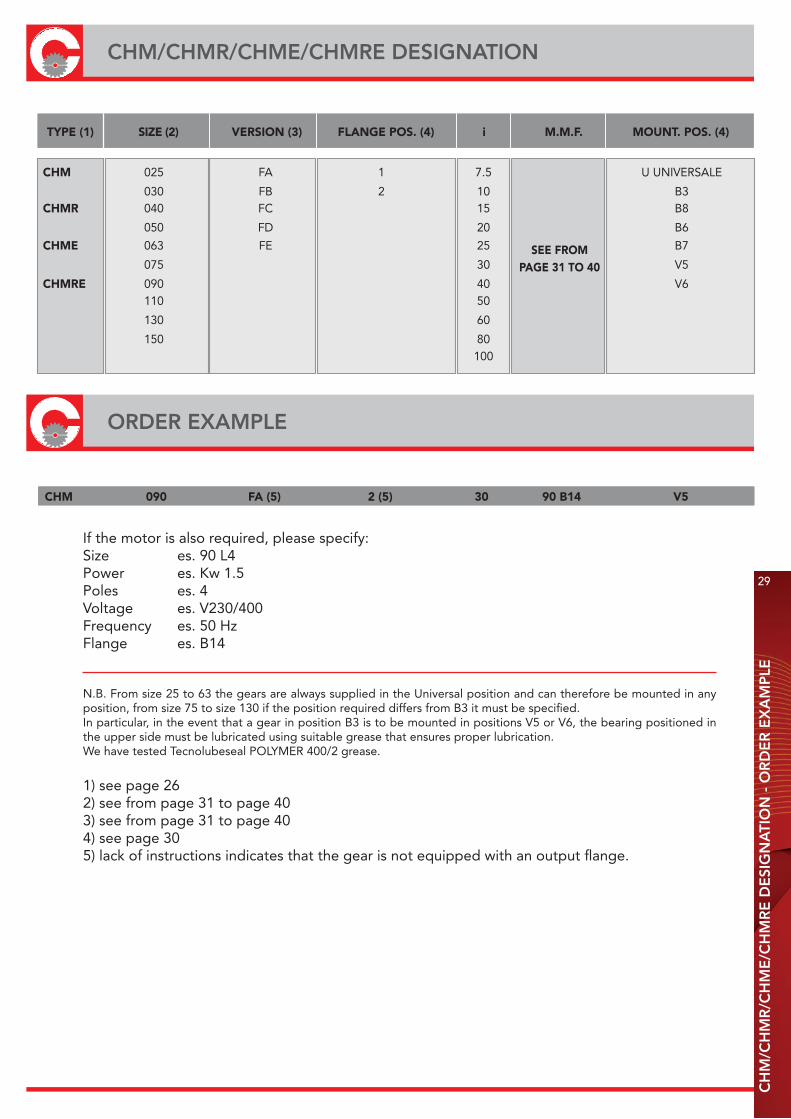
CHM/CHMR/CHME/CHMRE DESIGNATION
TYPE (1) SIZE (2) VERSION (3) FLANGE POS. (4) i M.M.F. MOUNT. POS. (4)
CHM 025 FA 1 7.5 U UNIVERSALE
030 FB 2 10 B3CHMR 040 FC 15 B8
050 FD 20 B6
CHME 063 FE 25 B7
075 30 V5
CHMRE 090 40 V6 110 50
130 60
150 80 100
SEE FROMPAGE 31 TO 40
CHM 090 FA (5) 2 (5) 30 90 B14 V5
ORDER EXAMPLE
If the motor is also required, please specify:Size es. 90 L4Power es. Kw 1.5Poles es. 4Voltage es. V230/400Frequency es. 50 HzFlange es. B14
N.B. From size 25 to 63 the gears are always supplied in the Universal position and can therefore be mounted in any position, from size 75 to size 130 if the position required differs from B3 it must be specified.In particular, in the event that a gear in position B3 is to be mounted in positions V5 or V6, the bearing positioned in the upper side must be lubricated using suitable grease that ensures proper lubrication.We have tested Tecnolubeseal POLYMER 400/2 grease.
1) see page 262) see from page 31 to page 403) see from page 31 to page 404) see page 305) lack of instructions indicates that the gear is not equipped with an output flange.
F...1 F...2
B7 B8 V6
B3 B6 V5
30
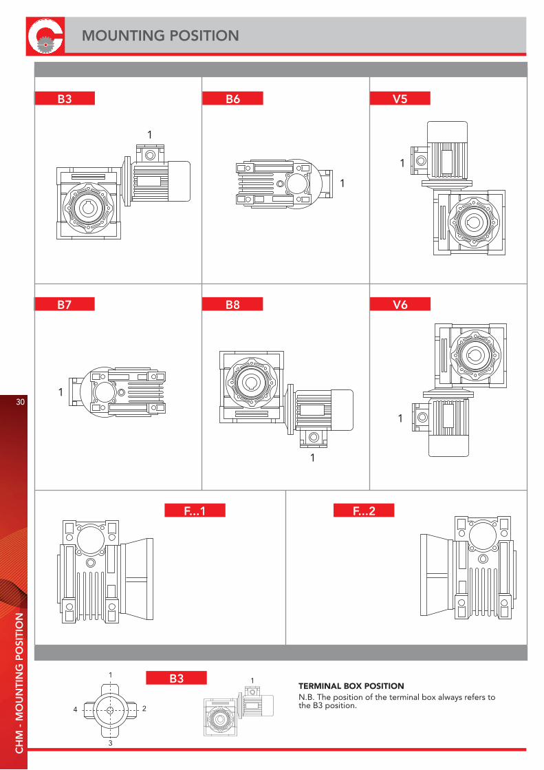
MOUNTING POSITIONC
HM
- M
OU
NTI
NG
PO
SITI
ON
B3
1
1
1
1
1
1
TERMINAL BOX POSITIONN.B. The position of the terminal box always refers tothe B3 position.4
3
2
11
31
CH
M 0
25 -
PE
RFO
RM
. WIT
H 4
-PO
LE M
OTO
RS
- 14
00 R
EV
S. IN
PU
T
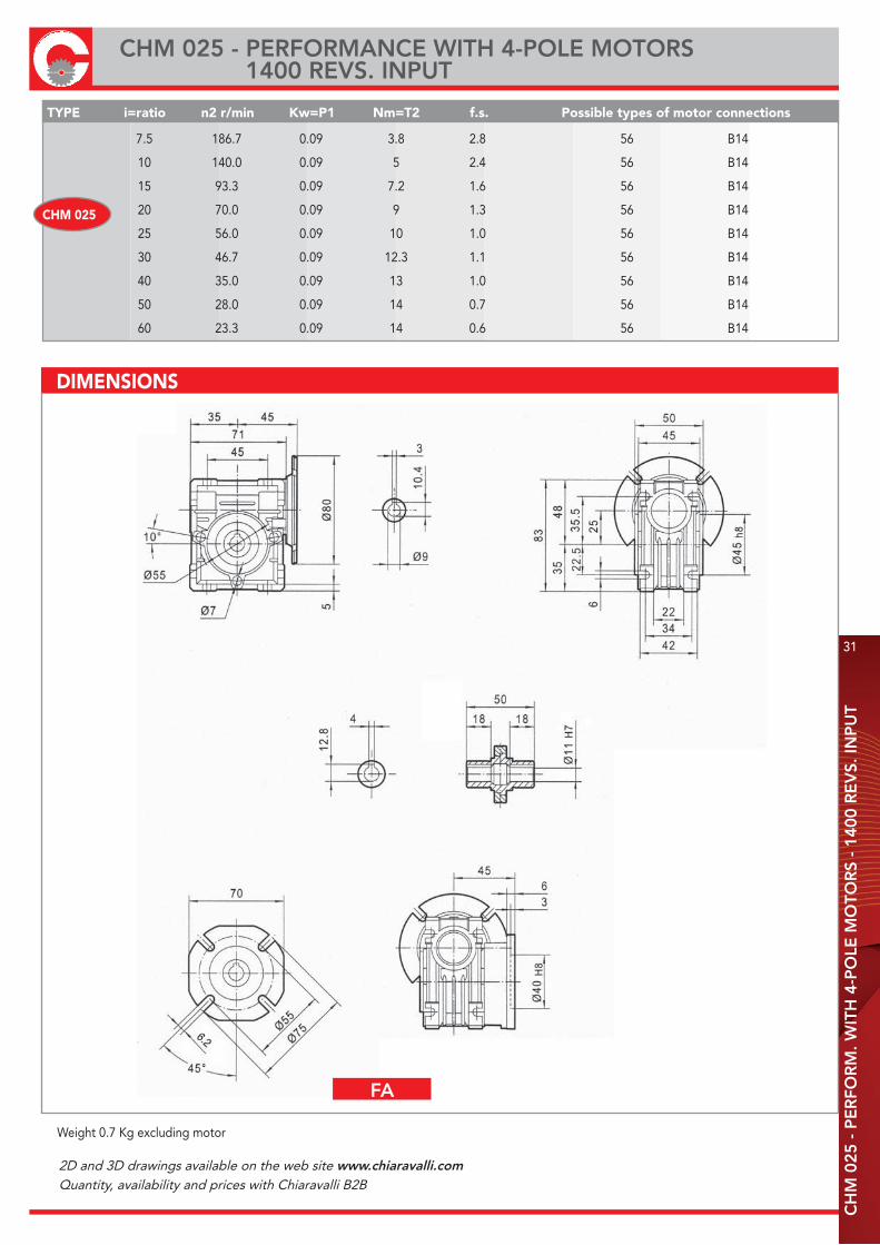
CHM 025 - PERFORMANCE WITH 4-POLE MOTORS 1400 REVS. INPUT
7.5 186.7 0.09 3.8 2.8 56 B14
10 140.0 0.09 5 2.4 56 B14
15 93.3 0.09 7.2 1.6 56 B14
20 70.0 0.09 9 1.3 56 B14
25 56.0 0.09 10 1.0 56 B14
30 46.7 0.09 12.3 1.1 56 B14
40 35.0 0.09 13 1.0 56 B14
50 28.0 0.09 14 0.7 56 B14
60 23.3 0.09 14 0.6 56 B14
CHM 025
TYPE i=ratio n2 r/min Kw=P1 Nm=T2 f.s. Possible types of motor connections
Weight 0.7 Kg excluding motor
DIMENSIONS
FA
2D and 3D drawings available on the web site www.chiaravalli.comQuantity, availability and prices with Chiaravalli B2B

32
CHM 030 - PERFORMANCE WITH 4-POLE MOTORS 1400 REVS. INPUT
CH
M 0
30 -
PE
RFO
RM
. WIT
H 4
-PO
LE M
OTO
RS
- 14
00 R
EV
S. IN
PU
T
7.5 186.7 0.22 9 2.1 63/56 B5/B14
10 140.0 0.22 11 1.6 63/56 B5/B14
15 93.3 0.22 16 1.0 63/56 B5/B14
20 70.0 0.22 20 0.9 63/56 B5/B14
25 56.0 0.18 20 1.0 63/56 B5/B14
30 46.7 0.18 22 0.9 63/56 B5/B14
40 35.0 0.18 21 0.8 63/56 B5/B14
50 28.0 0.18 19 0.8 63/56 B5/B14
60 23.3 0.09 18 0.9 56 B5/B14
80 17.5 0.09 13 0.9 56 B5/B14
TYPE i=ratio n2 r/min Kw=P1 Nm=T2 f.s. Possible types of motor connections
CHM 030
PAM IEC P DE8 b t
63B5 140 11 4 12.8
56B5 120 9 3 10.4
PAM IEC P DE8 b t
63B14 90 11 4 12.8
56B14 80 9 3 10.4Weight 1.2 Kg excluding motor
DIMENSIONS
E
FA

33
CH
M 0
40 -
PE
RFO
RM
. WIT
H 4
-PO
LE M
OTO
RS
- 14
00 R
EV
S. IN
PU
T
CHM 040 - PERFORMANCE WITH 4-POLE MOTORS 1400 REVS. INPUT
TYPE i=ratio n2 r/min Kw=P1 Nm=T2 f.s. Possible types of motor connections
7.5 186.7 0.55** 22 1.6 71/63 B5/B14 10 140.0 0.55** 30 1.4 71/63 B5/B14 15 93.3 0.55** 44 0.9 71/63 B5/B14 20 70.0 0.55** 38 1.0 71/63 B5/B14 25 56.0 0.37 45 0.9 71/63 B5/B14 30 46.7 0.37 52 0.8 71/63 B5/B14 40 35.0 0.25 43 0.9 71/63 B5/B14 50 28.0 0.22 44 0.9 63/56 B5/B14* 60 23.3 0.18 42 0.8 63/56 B5/B14* 80 17.5 0.18 36 0.8 63/56 B5/B14* 100 14.0 0.18 35 0.8 63/56 B5/B14*
CHM 040
* 56 only B5 ** Size 71 Motors
DIMENSIONS
Weight 2.3 Kg excluding motor
FA FB
FC FD
PAM IEC P DE8 b t71B5 160 14 5 16.3
63B5 140 11 4 12.8
56B5 120 9 3 10.4
PAM IEC P DE8 b t71B14 105 14 5 16.3
63B14 90 11 4 12.8
E
FA FB
FC FD
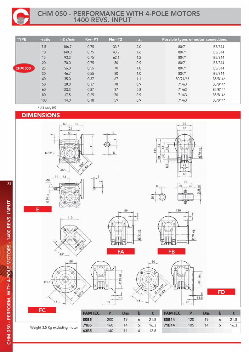
7.5 186.7 0.75 33.3 2.0 80/71 B5/B14 10 140.0 0.75 43.9 1.6 80/71 B5/B14 15 93.3 0.75 62.6 1.2 80/71 B5/B14 20 70.0 0.75 80 0.9 80/71 B5/B14 25 56.0 0.55 70 1.0 80/71 B5/B14 30 46.7 0.55 80 1.0 80/71 B5/B14 40 35.0 0.37 67 1.1 80/71/63 B5/B14* 50 28.0 0.37 78 0.9 71/63 B5/B14* 60 23.3 0.37 87 0.8 71/63 B5/B14* 80 17.5 0.25 70 0.9 71/63 B5/B14* 100 14.0 0.18 59 0.9 71/63 B5/B14*
TYPE i=ratio n2 r/min Kw=P1 Nm=T2 f.s. Possible types of motor connections
CHM 050
* 63 only B5
Weight 3.5 Kg excluding motor
PAM IEC P DE8 b t80B5 200 19 6 21.8
71B5 160 14 5 16.3
63B5 140 11 4 12.8
PAM IEC P DE8 b t80B14 120 19 6 21.8
71B14 105 14 5 16.3
DIMENSIONS
34
CHM 050 - PERFORMANCE WITH 4-POLE MOTORS 1400 REVS. INPUT
CH
M 0
50 -
PE
RFO
RM
. WIT
H 4
-PO
LE M
OTO
RS
- 14
00 R
EV
S. IN
PU
T
E
FA FB
FC
FD

TYPE i=ratio n2 r/min Kw=P1 Nm=T2 f.s. Possible types of motor connections
7.5 186.7 1.50 67.4 1.8 90/80 B5/B14 10 140.0 1.50 88.6 1.4 90/80 B5/B14 15 93.3 1.50 126 1.19 90/80 B5/B14 20 70.0 1.50 164 0.8 90/80 B5/B14 25 56.0 1.10 145 0.9 90/80 B5/B14 30 46.7 1.10 165 1.0 90/80 B5/B14 40 35.0 0.75 143 1.0 80/71 B5/B14 50 28.0 0.55 122 1.1 80/71 B5/B14 60 23.3 0.55 138 0.9 80/71 B5/B14 80 17.5 0.37 114 1.1 80/71 B5/B14 100 14.0 0.37 127 0.9 71 B5/B14
CHM 063
Weight 6.2 Kg excluding motor
PAM IEC P DE8 b t90B5 200 24 8 27.3
80B5 200 19 6 21.8
71B5 160 14 5 16.3
PAM IEC P DE8 b t90B14 140 24 8 27.3
80B14 120 19 6 21.8
71B14 105 14 5 16.3
DIMENSIONS
CH
M 0
63 -
PE
RFO
RM
. WIT
H 4
-PO
LE M
OTO
RS
- 14
00 R
EV
S. IN
PU
T
CHM 063 - PERFORMANCE WITH 4-POLE MOTORS 1400 REVS. INPUT
E
FA FB
FC
FD
35
FE
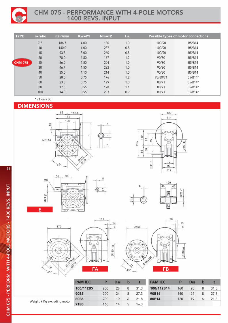
7.5 186.7 4.00 180 1.0 100/90 B5/B14 10 140.0 4.00 237 0.8 100/90 B5/B14 15 93.3 3.00 260 0.8 100/90 B5/B14 20 70.0 1.50 167 1.2 90/80 B5/B14 25 56.0 1.50 204 1.0 90/80 B5/B14 30 46.7 1.50 232 1.0 90/80 B5/B14 40 35.0 1.10 214 1.0 90/80 B5/B14 50 28.0 0.75 176 1.2 90/80/71 B5/B14* 60 23.3 0.75 199 1.0 80/71 B5/B14* 80 17.5 0.55 178 1.1 80/71 B5/B14* 100 14.0 0.55 203 0.9 80/71 B5/B14*
TYPE i=ratio n2 r/min Kw=P1 Nm=T2 f.s. Possible types of motor connections
CHM 075
* 71 only B5
Weight 9 Kg excluding motor
DIMENSIONS
PAM IEC P DE8 b t
100/112B5 250 28 8 31.3
90B5 200 24 8 27.3
80B5 200 19 6 21.8
71B5 160 14 5 16.3
PAM IEC P DE8 b t
100/112B14 160 28 8 31.3
90B14 140 24 8 27.3
80B14 120 19 6 21.8
36
CHM 075 - PERFORMANCE WITH 4-POLE MOTORS 1400 REVS. INPUT
CH
M 0
75 -
PE
RFO
RM
. WIT
H 4
-PO
LE M
OTO
RS
- 14
00 R
EV
S. IN
PU
T
E
FA FB

TYPE i=ratio n2 r/min Kw=P1 Nm=T2 f.s. Possible types of motor connections
7.5 186.7 4.00 184 1.5 100/90 B5/B14 10 140.0 4.00 242 1.3 100/90 B5/B14 15 93.3 4.00 351 1.1 100/90 B5/B14 20 70.0 4.00 456 0.8 100/90 B5/B14 25 56.0 3.00 417 0.8 100/90 B5/B14 30 46.7 3.00 478 0.9 100/90 B5/B14 40 35.0 1.50 306 1.2 90/80 B5/B14 50 28.0 1.50 367 1.0 90/80 B5/B14 60 23.3 1.50 421 0.8 90/80 B5/B14 80 17.5 0.75 257 1.1 80 B5/B14 100 14.0 0.75 300 0.9 80 B5/B14
CHM 090
PAM IEC P DE8 b t
100/112B5 250 28 8 31.3
90B5 200 24 8 27.3
80B5 200 19 6 21.8
PAM IEC P DE8 b t
100/112B14 160 28 8 31.3
90B14 140 24 8 27.3
80B14 120 19 6 21.8Weight 13 Kg excluding motor
DIMENSIONS
CH
M 0
90 -
PE
RFO
RM
. WIT
H 4
-PO
LE M
OTO
RS
- 14
00 R
EV
S. IN
PU
T
CHM 090 - PERFORMANCE WITH 4-POLE MOTORS 1400 REVS. INPUT
E
FA FB
FC
FD
37

7.5 186.7 7.50 344 1.6 132/112/100 B5/B14 10 140.0 7.50 453 1.3 132/112/100 B5/B14 15 93.3 7.50 659 1.0 132/112/100 B5/B14 20 70.0 5.50 635 1.0 132/112/100 B5/B14 25 56.0 4.00 573 1.2 112/100 B5/B14 30 46.7 4.00 645 1.1 112/100 B5/B14 40 35.0 3.00 636 1.1 112/100/90 B5/B14* 50 28.0 3.00 764 0.9 112/100/90 B5/B14* 60 23.3 2.20 645 1.0 112/100/90 B5/B14* 80 17.5 1.50 546 0.9 90 B5/B14* 100 14.0 1.10 470 1.0 90 B5/B14*
TYPE i=ratio n2 r/min Kw=P1 Nm=T2 f.s. Possible types of motor connections
CHM 110
* 90 only B5
Weight 35 Kg excluding motor
DIMENSIONS
PAM IEC P DE8 b t
132B5 300 38 10 41.3
112B5 250 28 8 31.3
100B5 250 28 8 31.3
90B5 200 24 8 27.3
80B5 200 19 6 21.8
PAM IEC P DE8 b t
132B14 200 38 10 41.3
112B14 160 28 8 31.3
100B14 160 28 8 31.3
38
CHM 110 - PERFORMANCE WITH 4-POLE MOTORS 1400 REVS. INPUT
CH
M 1
10 -
PE
RFO
RM
. WIT
H 4
-PO
LE M
OTO
RS
- 14
00 R
EV
S. IN
PU
T
E
FA FB
TYPE i=ratio n2 r/min Kw=P1 Nm=T2 f.s. Possible types of motor connections
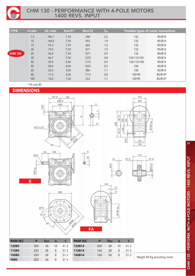
7.5 186.7 7.50 348 2.2 132 B5/B14 10 140.0 7.50 455 1.8 132 B5/B14 15 93.3 7.50 660 1.2 132 B5/B14 20 70.0 7.50 877 1.0 132 B5/B14 25 56.0 7.50 1071 0.9 132 B5/B14 30 46.7 7.50 1225 0.8 132/112/100 B5/B14 40 35.0 5.50 1173 0.9 132/112/100 B5/B14 50 28.0 4.00 1023 0.9 100 B5/B14 60 23.3 3.00 886 1.1 100 B5/B14 80 17.5 3.00 1112 0.8 100/90 B5/B14* 100 14.0 1.50 652 1.1 100/90 B5/B14*
CHM 130
* 90 only B5
Weight 48 Kg excluding motor
DIMENSIONS
PAM IEC P DE8 b t132B5 300 38 10 41.3
112B5 250 28 8 31.3
100B5 250 28 8 31.3
90B5 200 24 8 27.3
PAM IEC P DE8 b t132B14 200 38 10 41.3
112B14 160 28 8 31.3
100B14 160 28 8 31.3
CH
M 1
30 -
PE
RFO
RM
. WIT
H 4
-PO
LE M
OTO
RS
- 14
00 R
EV
S. IN
PU
T
CHM 130 - PERFORMANCE WITH 4-POLE MOTORS 1400 REVS. INPUT
E
FA
39
TYPE i=ratio n2 r/min Kw=P1 Nm=T2 f.s. Possible types of motor connections
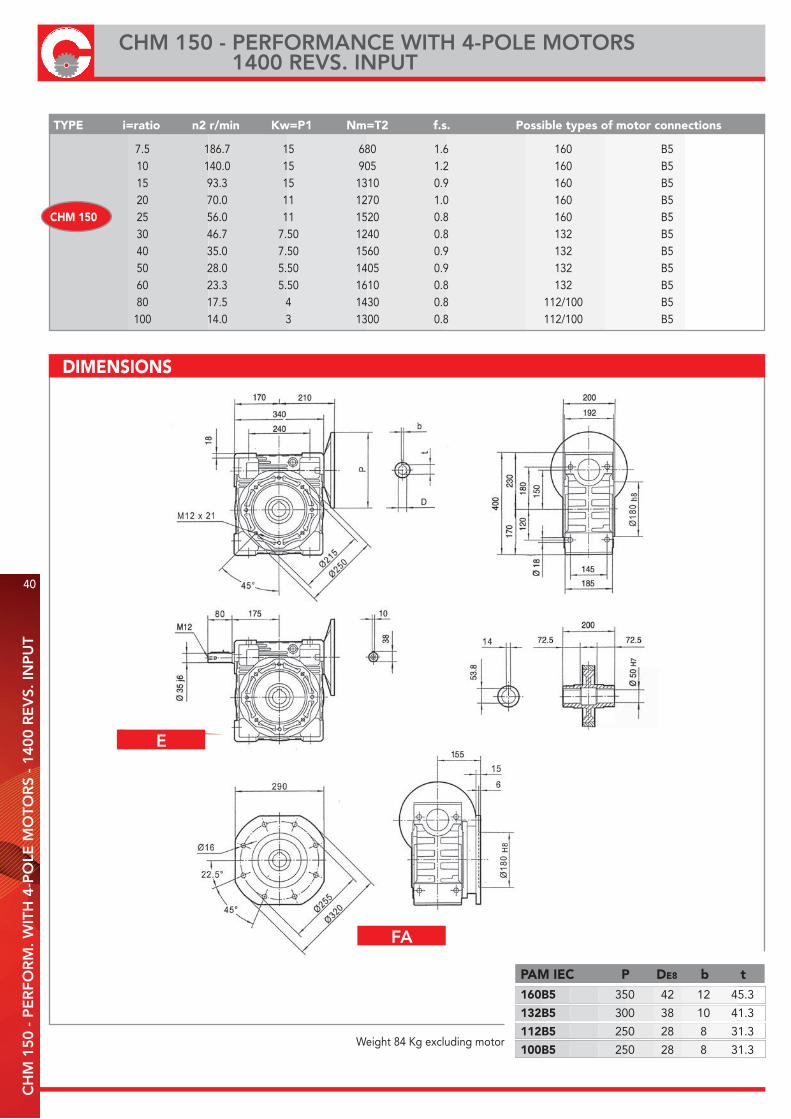
7.5 186.7 15 680 1.6 160 B5 10 140.0 15 905 1.2 160 B5 15 93.3 15 1310 0.9 160 B5 20 70.0 11 1270 1.0 160 B5 25 56.0 11 1520 0.8 160 B5 30 46.7 7.50 1240 0.8 132 B5 40 35.0 7.50 1560 0.9 132 B5 50 28.0 5.50 1405 0.9 132 B5 60 23.3 5.50 1610 0.8 132 B5 80 17.5 4 1430 0.8 112/100 B5 100 14.0 3 1300 0.8 112/100 B5
CHM 150
Weight 84 Kg excluding motor
DIMENSIONS
PAM IEC P DE8 b t160B5 350 42 12 45.3
132B5 300 38 10 41.3
112B5 250 28 8 31.3
100B5 250 28 8 31.3
40
CHM 150 - PERFORMANCE WITH 4-POLE MOTORS 1400 REVS. INPUT
CH
M 1
50 -
PE
RFO
RM
. WIT
H 4
-PO
LE M
OTO
RS
- 14
00 R
EV
S. IN
PU
T
E
FA
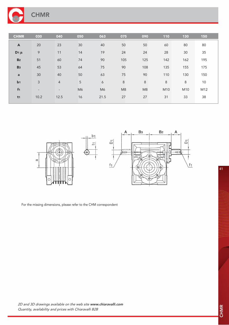
CHMR 030 040 050 063 075 090 110 130 150
A 20 23 30 40 50 50 60 80 80
D1 j6 9 11 14 19 24 24 28 30 35
B2 51 60 74 90 105 125 142 162 195
B3 45 53 64 75 90 108 135 155 175
a 30 40 50 63 75 90 110 130 150
b1 3 4 5 6 8 8 8 8 10
f1 - - M6 M6 M8 M8 M10 M10 M12
t1 10.2 12.5 16 21.5 27 27 31 33 38
For the missing dimensions, please refer to the CHM correspondent
CH
MR
41
CHMR
2D and 3D drawings available on the web site www.chiaravalli.comQuantity, availability and prices with Chiaravalli B2B
42
CH
PC
/CH
M -
WO
RM
GE
AR
WIT
H P
RE
-STA
GE
MO
DU
LE
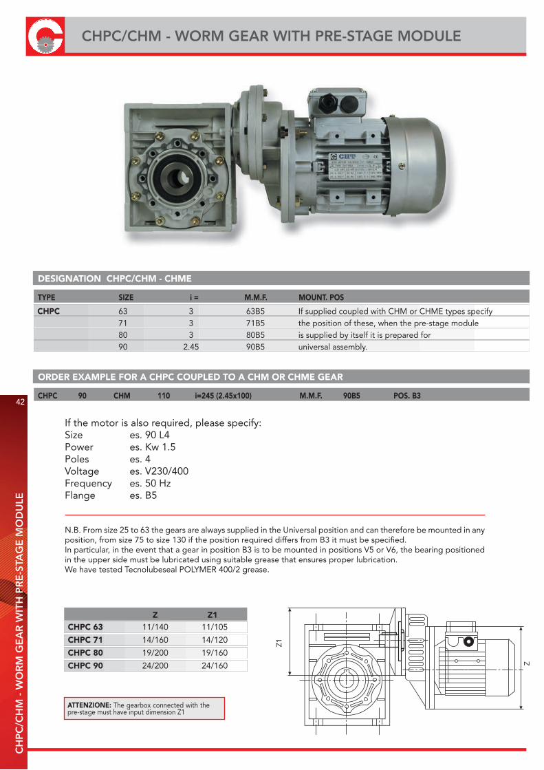
CHPC/CHM - WORM GEAR WITH PRE-STAGE MODULE
Z Z1CHPC 63 11/140 11/105
CHPC 71 14/160 14/120
CHPC 80 19/200 19/160
CHPC 90 24/200 24/160
Z1
Z
DESIGNATION CHPC/CHM - CHME
TYPE SIZE i = M.M.F. MOUNT. POS
CHPC 63 3 63B5 If supplied coupled with CHM or CHME types specify 71 3 71B5 the position of these, when the pre-stage module 80 3 80B5 is supplied by itself it is prepared for 90 2.45 90B5 universal assembly.
ORDER EXAMPLE FOR A CHPC COUPLED TO A CHM OR CHME GEAR
CHPC 90 CHM 110 i=245 (2.45x100) M.M.F. 90B5 POS. B3
ATTENZIONE: The gearbox connected with the pre-stage must have input dimension Z1
If the motor is also required, please specify:Size es. 90 L4Power es. Kw 1.5Poles es. 4Voltage es. V230/400Frequency es. 50 HzFlange es. B5
N.B. From size 25 to 63 the gears are always supplied in the Universal position and can therefore be mounted in any position, from size 75 to size 130 if the position required differs from B3 it must be specified.In particular, in the event that a gear in position B3 is to be mounted in positions V5 or V6, the bearing positioned in the upper side must be lubricated using suitable grease that ensures proper lubrication.We have tested Tecnolubeseal POLYMER 400/2 grease.
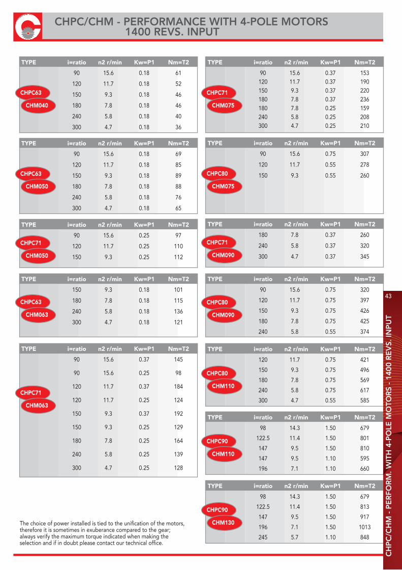
The choice of power installed is tied to the unification of the motors,therefore it is sometimes in exuberance compared to the gear;always verify the maximum torque indicated when making theselection and if in doubt please contact our technical office.
TYPE i=ratio n2 r/min Kw=P1 Nm=T2
90 15.6 0.18 61
120 11.7 0.18 52
150 9.3 0.18 46
180 7.8 0.18 46
240 5.8 0.18 40
300 4.7 0.18 36
CHPC63
CHM040
TYPE i=ratio n2 r/min Kw=P1 Nm=T2
90 15.6 0.18 69
120 11.7 0.18 85
150 9.3 0.18 89
180 7.8 0.18 88
240 5.8 0.18 76
300 4.7 0.18 65
CHPC63
CHM050
TYPE i=ratio n2 r/min Kw=P1 Nm=T2
90 15.6 0.25 97
120 11.7 0.25 110
150 9.3 0.25 112
CHPC71
CHM050
TYPE i=ratio n2 r/min Kw=P1 Nm=T2
150 9.3 0.18 101
180 7.8 0.18 115
240 5.8 0.18 136
300 4.7 0.18 121
CHPC63
CHM063
TYPE i=ratio n2 r/min Kw=P1 Nm=T2
90 15.6 0.37 145
90 15.6 0.25 98
120 11.7 0.37 184
120 11.7 0.25 124
150 9.3 0.37 192
150 9.3 0.25 129
180 7.8 0.25 164
240 5.8 0.25 139
300 4.7 0.25 128
CHPC71
CHM063
TYPE i=ratio n2 r/min Kw=P1 Nm=T2
90 15.6 0.37 153 120 11.7 0.37 190 150 9.3 0.37 220 180 7.8 0.37 236 180 7.8 0.25 159 240 5.8 0.25 208 300 4.7 0.25 210
CHPC71
CHM075
TYPE i=ratio n2 r/min Kw=P1 Nm=T2
90 15.6 0.75 307
120 11.7 0.55 278
150 9.3 0.55 260CHPC80
CHM075
TYPE i=ratio n2 r/min Kw=P1 Nm=T2
180 7.8 0.37 260
240 5.8 0.37 320
300 4.7 0.37 345
CHPC71
CHM090
TYPE i=ratio n2 r/min Kw=P1 Nm=T2
90 15.6 0.75 320
120 11.7 0.75 397
150 9.3 0.75 426
180 7.8 0.75 425
240 5.8 0.55 374
CHPC80
CHM090
TYPE i=ratio n2 r/min Kw=P1 Nm=T2
120 11.7 0.75 421
150 9.3 0.75 496
180 7.8 0.75 569
240 5.8 0.75 617
300 4.7 0.55 585
CHPC80
CHM110
TYPE i=ratio n2 r/min Kw=P1 Nm=T2
98 14.3 1.50 679
122.5 11.4 1.50 801
147 9.5 1.50 810
147 9.5 1.10 595
196 7.1 1.10 660
CHPC90
CHM110
TYPE i=ratio n2 r/min Kw=P1 Nm=T2
98 14.3 1.50 679
122.5 11.4 1.50 813
147 9.5 1.50 917
196 7.1 1.50 1013
245 5.7 1.10 848
CHPC90
CHM130
CH
PC
/CH
M -
PE
RFO
RM
. WIT
H 4
-PO
LE M
OTO
RS
- 14
00 R
EV
S. IN
PU
T
43
CHPC/CHM - PERFORMANCE WITH 4-POLE MOTORS 1400 REVS. INPUT
44
CH
PC
/CH
M -
DIM
EN
SIO
NS
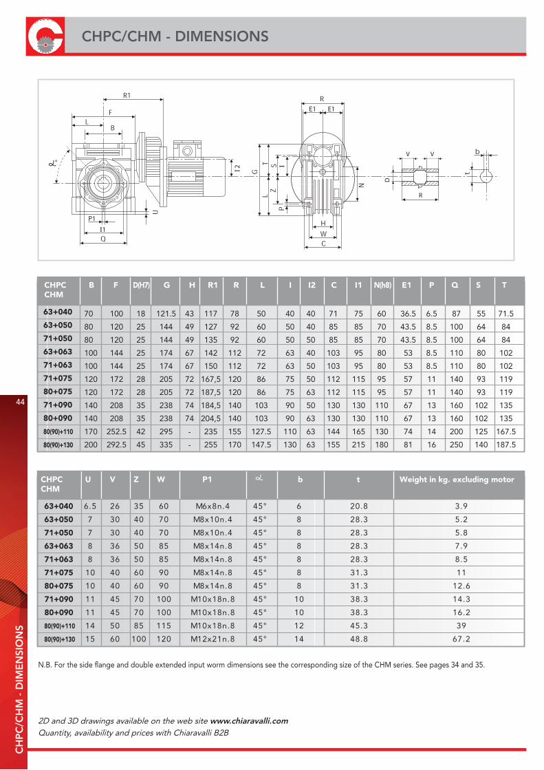
CHPC/CHM - DIMENSIONS
N.B. For the side flange and double extended input worm dimensions see the corresponding size of the CHM series. See pages 34 and 35.
P1
I1I2
E1 E1
I
D
R
VV
CHPC B F D(H7) G H R1 R L I I2 C I1 N(h8) E1 P Q S TCHM
63+040
63+050
71+050
63+063
71+063
71+075
80+075
71+090
80+090
80(90)+110
80(90)+130
CHPC U V Z W P1 b Weight in kg. excluding motortCHM
63+040 9.38.026°544.n8x6M0653625.6
63+050 2.53.828°544.n01x8M0704037
71+050 8.53.828°544.n01x8M0704037
63+063 9.73.828°548.n41x8M5805638
71+063 5.83.828°548.n41x8M5805638
71+075 113.138°548.n41x8M09060401
80+075 6.213.138°548.n41x8M09060401
71+090 3.413.8301°548.n81x01M001075411
80+090 2.613.8301°548.n81x01M001075411
80(90)+110 933.5421°548.n81x01M511580541
80(90)+130 2.768.8441°548.n12x21M0210010651
70 100 18 121.5 43 117 78 50 40 40 71 75 60 36.5 6.5 87 55 71.5
80 120 25 144 49 127 92 60 50 40 85 85 70 43.5 8.5 100 64 84
80 120 25 144 49 135 92 60 50 50 85 85 70 43.5 8.5 100 64 84
100 144 25 174 67 142 112 72 63 40 103 95 80 53 8.5 110 80 102
100 144 25 174 67 150 112 72 63 50 103 95 80 53 8.5 110 80 102
120 172 28 205 72 167,5 120 86 75 50 112 115 95 57 11 140 93 119
120 172 28 205 72 187,5 120 86 75 63 112 115 95 57 11 140 93 119
140 208 35 238 74 184,5 140 103 90 50 130 130 110 67 13 160 102 135
140 208 35 238 74 204,5 140 103 90 63 130 130 110 67 13 160 102 135
170 252.5 42 295 - 235 155 127.5 110 63 144 165 130 74 14 200 125 167.5
200 292.5 45 335 - 255 170 147.5 130 63 155 215 180 81 16 250 140 187.5
2D and 3D drawings available on the web site www.chiaravalli.comQuantity, availability and prices with Chiaravalli B2B
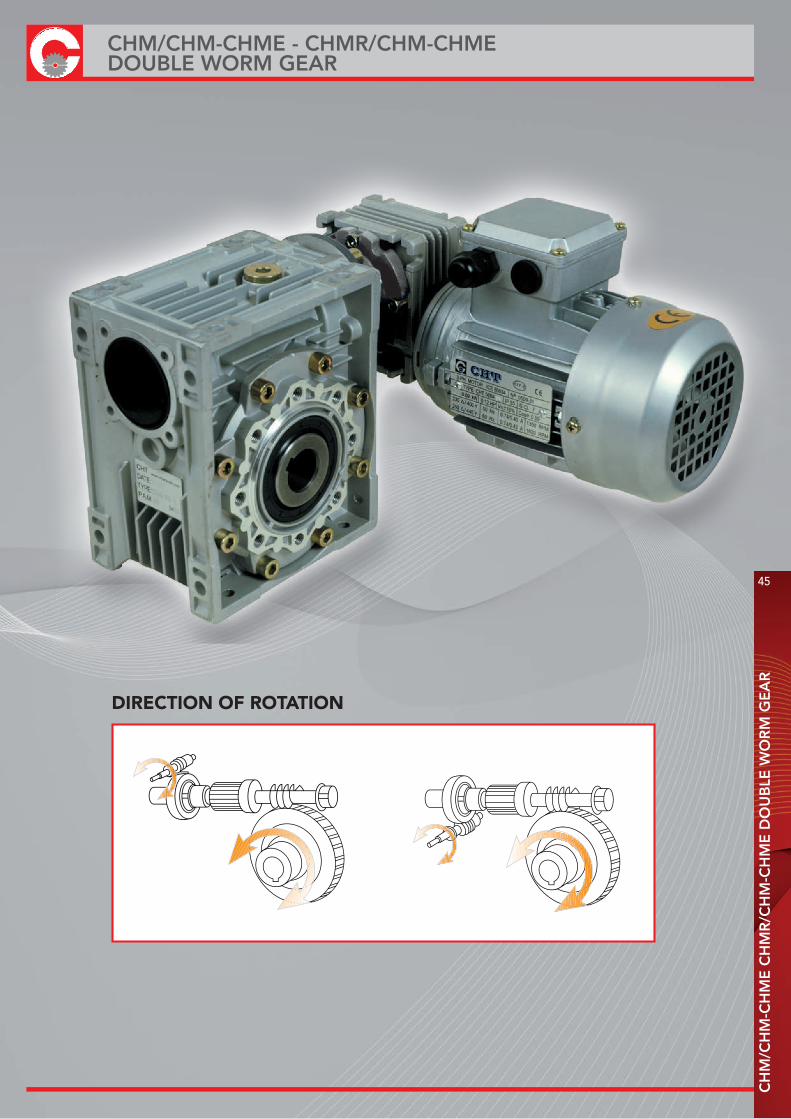
DIRECTION OF ROTATION
CH
M/C
HM
-CH
ME
CH
MR
/CH
M-C
HM
E D
OU
BLE
WO
RM
GE
AR
45
CHM/CHM-CHME - CHMR/CHM-CHMEDOUBLE WORM GEAR

46
CHM/CHMR/CHME/CHMRE DESIGNATIONC
HM
/CH
MR
/CH
ME
/CH
MR
E D
ESI
GN
ATI
ON
- O
RD
ER
EX
AM
PLE
Nel caso venga richiesto anche il motore specificare:
Grandezza es. 63 B4
Potenza es. Kw 0.18
Poli es. 4
Tensione es. V230/400
Frequenza es. 50 Hz
Flangia es. B 14
N.B. I riduttori dalla grandezza 25 alla grandezza 63 vengono sempre forniti in pos. Universale possono quindi essere montati in qualsiasi posizione, dalla grandezza 75 alla grandezza 130 è necessario specificare la pos. se diversa dalla B3.In particolare nel caso in cui un riduttore in B3 vada montato nelle pos. V5 o V6, sarà necessario lubrificare il cuscinetto posto nel lato superiore con grasso apposito che ne garantisca la lubrificazione.Il grasso da noi testato è il Tecnolubeseal POLYMER 400/2.
TYPE SIZE (1) VERSION (2) FLANGE POS. (3) i EXEC. (4) M.M.F. MOUNT. POS. (3)
CHM/CHM 040/090 FA(5) 2(5) 500 OAD 63 B14 V5
1) vedi pagina 482) vedi da pagina 31 a pagina 403) vedi pagina 30 4) vedi pagina 475) nessuna indicazione significa che il riduttore è privo di flangia in uscita
For the motor mounting flanges (M.M.F.) see the table showing the types available. For the executions see the table with drawings, if not specified OBS would be supplied. The mounting position refers to the second gear.
CHM/CHM 025/030 FA 1 300 OAD U
CHM/CHME 030/040 FB 2 400 OAS B3
CHMR/CHM 030/050 FC 500 OBD B8
CHMR/CHME 030/063 FD 600 OBS B6
040/075 FE 750 VAD B7
040/090 900 VAS V5
050/110 1200 VBD V6
063/130 1500 VBS
1800
2400
SEE FROMPAGE 31
TO PAGE 35
ORDER EXAMPLE
If the motor is also required, please specify:Size es. 63 B4Power es. Kw 0.18Poles es. 4Voltage es. V230/400Frequency es. 50 HzFlange es. B14
N.B. From size 25 to 63 the gears are always supplied in the Universal position and can therefore be mounted in any position, fromsize 75 to size 130 if the position required differs from B3 it must be specified.In particular, in the event that a gear in position B3 is to be mounted in positions V5 or V6, the bearing positioned in the upper sidemust be lubricated using suitable grease that ensures proper lubrication.We have tested Tecnolubeseal POLYMER 400/2 grease.
1) see page 482) see from page 31 to page 403) see page 304) see page 475) lack of instructions indicates that the gear is not equipped with an output flange.
2D and 3D drawings available on the web site www.chiaravalli.comQuantity, availability and prices with Chiaravalli B2B
CH
M -
EX
EC
UTI
ON
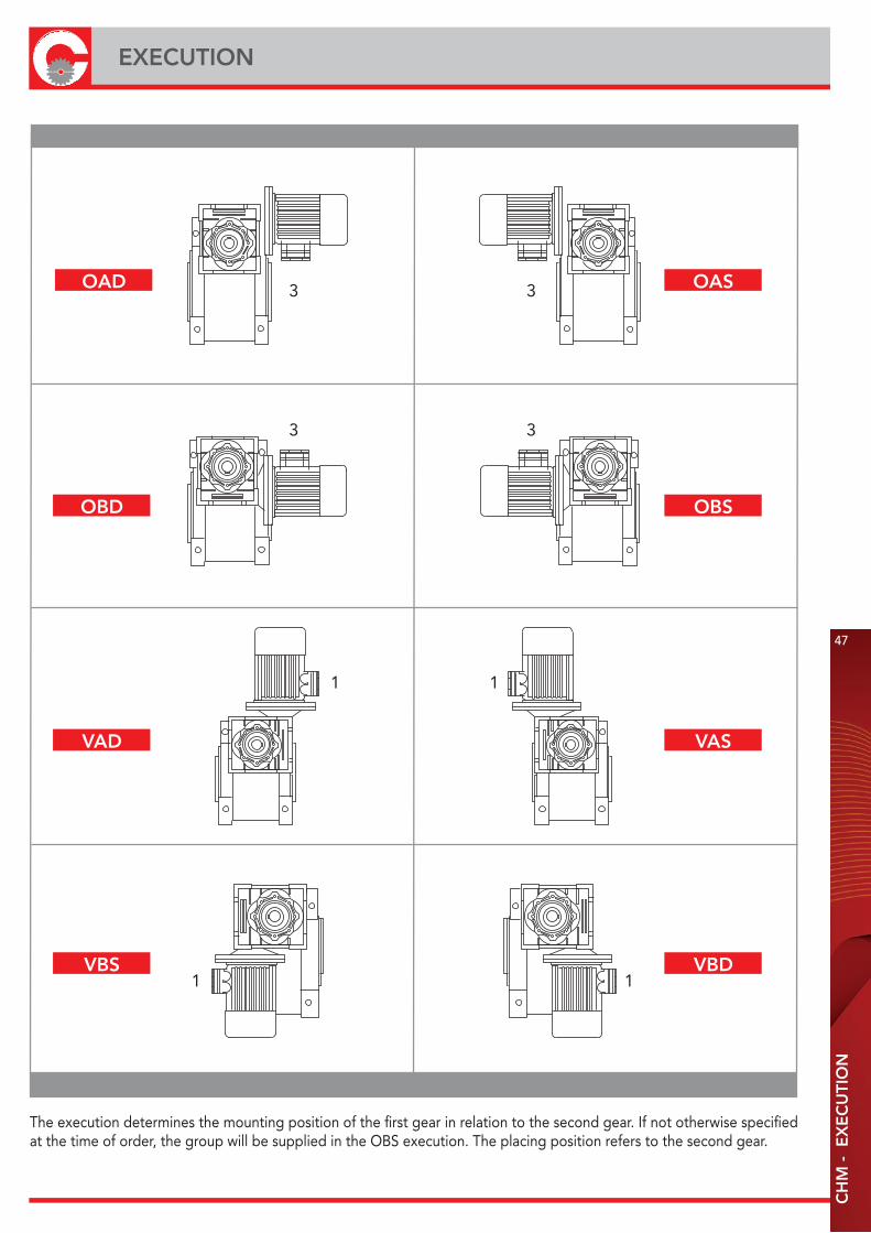
EXECUTION
47
The execution determines the mounting position of the first gear in relation to the second gear. If not otherwise specifiedat the time of order, the group will be supplied in the OBS execution. The placing position refers to the second gear.
3 3
3 3
1 1
1 1
OAD
OBD
VAD
VBS
OAS
OBS
VAS
VBD
48
CH
M/C
HM
- P
ER
FOR
M. W
ITH
4-P
OLE
MO
TOR
S -
1400
RE
VS.
INP
UT
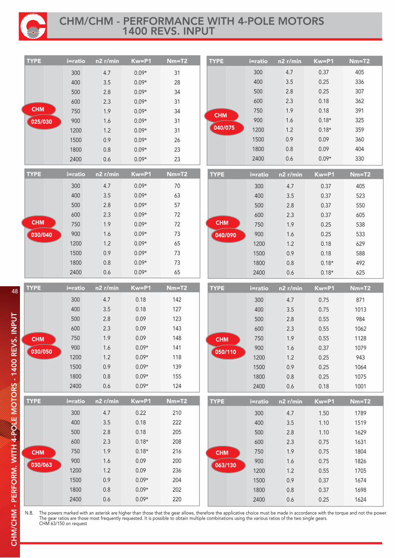
CHM/CHM - PERFORMANCE WITH 4-POLE MOTORS 1400 REVS. INPUT
N.B. The powers marked with an asterisk are higher than those that the gear allows, therefore the applicative choice must be made in accordance with the torque and not the power. The gear ratios are those most frequently requested. It is possible to obtain multiple combinations using the various ratios of the two single gears. CHM 63/150 on request
TYPE i=ratio n2 r/min Kw=P1 Nm=T2
TYPE i=ratio n2 r/min Kw=P1 Nm=T2
TYPE i=ratio n2 r/min Kw=P1 Nm=T2
300 4.7 0.75 871
400 3.5 0.75 1013
500 2.8 0.55 984
600 2.3 0.55 1062
750 1.9 0.55 1128
900 1.6 0.37 1079
1200 1.2 0.25 943
1500 0.9 0.25 1064
1800 0.8 0.25 1075
2400 0.6 0.18 1001
300 4.7 1.50 1789
400 3.5 1.10 1519
500 2.8 1.10 1629
600 2.3 0.75 1631
750 1.9 0.75 1804
900 1.6 0.75 1826
1200 1.2 0.55 1705
1500 0.9 0.37 1674
1800 0.8 0.37 1698
2400 0.6 0.25 1624
300 4.7 0.37 405
400 3.5 0.37 523
500 2.8 0.37 550
600 2.3 0.37 605
750 1.9 0.25 538
900 1.6 0.25 533
1200 1.2 0.18 629
1500 0.9 0.18 588
1800 0.8 0.18* 492
2400 0.6 0.18* 625
CHM
040/090
CHM
050/110
TYPE i=ratio n2 r/min Kw=P1 Nm=T2
TYPE i=ratio n2 r/min Kw=P1 Nm=T2
TYPE i=ratio n2 r/min Kw=P1 Nm=T2
300 4.7 0.18 142
400 3.5 0.18 127
500 2.8 0.09 123
600 2.3 0.09 143
750 1.9 0.09 148
900 1.6 0.09* 141
1200 1.2 0.09* 118
1500 0.9 0.09* 139
1800 0.8 0.09* 155
2400 0.6 0.09* 124
300 4.7 0.22 210
400 3.5 0.18 222
500 2.8 0.18 205
600 2.3 0.18* 208
750 1.9 0.18* 216
900 1.6 0.09 200
1200 1.2 0.09 236
1500 0.9 0.09* 204
1800 0.8 0.09* 202
2400 0.6 0.09* 220
300 4.7 0.09* 70
400 3.5 0.09* 63
500 2.8 0.09* 57
600 2.3 0.09* 72
750 1.9 0.09* 72
900 1.6 0.09* 73
1200 1.2 0.09* 65
1500 0.9 0.09* 73
1800 0.8 0.09* 73
2400 0.6 0.09* 65
CHM
030/040
CHM
030/050
CHM
030/063
CHM
063/130
TYPE i=ratio n2 r/min Kw=P1 Nm=T2
300 4.7 0.37 405
400 3.5 0.25 336
500 2.8 0.25 307
600 2.3 0.18 362
750 1.9 0.18 391
900 1.6 0.18* 325
1200 1.2 0.18* 359
1500 0.9 0.09 360
1800 0.8 0.09 404
2400 0.6 0.09* 330
CHM
040/075
TYPE i=ratio n2 r/min Kw=P1 Nm=T2
300 4.7 0.09* 31
400 3.5 0.09* 28
500 2.8 0.09* 34
600 2.3 0.09* 31
750 1.9 0.09* 34
900 1.6 0.09* 31
1200 1.2 0.09* 31
1500 0.9 0.09* 26
1800 0.8 0.09* 23
2400 0.6 0.09* 23
CHM
025/030
CH
M-C
HM
/CH
MR
-CH
M -
DIM
EN
SIO
NS
OF
CO
MB
INE
D G
EA
RS
49
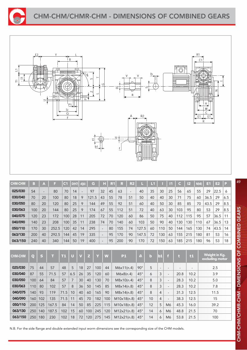
CHM-CHM/CHMR-CHM - DIMENSIONS OF COMBINED GEARS
N.B. For the side flange and double extended input worm dimensions see the corresponding size of the CHM models.
D
R
VV
T1
f
t1
b1
I1
I2 W
I
025/030
030/040
030/050
030/063
040/075
040/090
050/110
063/130
063/150
CHM-CHM
B A F C1 D(H7) d(j6) G H R1 R R2 L L1 I I1 C I2 N(h8) E1 E2 P
025/030
030/040
030/050
030/063
040/075
040/090
050/110
063/130
063/150
CHM-CHM
Weight in Kg.excluding motor
54 - 80 70 14 - 97 32 45 63 - 40 35 30 25 56 65 55 29 22.5 6
70 20 100 80 18 9 121.5 43 55 78 51 50 40 40 30 71 75 60 36.5 29 6.5
80 20 120 80 25 9 144 49 55 92 51 60 40 50 30 85 85 70 43.5 29 8.5
100 20 144 80 25 9 174 67 55 112 51 72 40 63 30 103 95 80 53 29 8.5
120 23 172 100 28 11 205 72 70 120 60 86 50 75 40 112 115 95 57 36.5 11
140 23 208 100 35 11 238 74 70 140 60 103 50 90 40 130 130 110 67 36.5 13
170 30 252.5 120 42 14 295 - 80 155 74 127.5 60 110 50 144 165 130 74 43.5 14
200 40 292.5 144 45 19 335 - 95 170 90 147.5 72 130 63 155 215 180 81 53 16
240 40 340 144 50 19 400 - 95 200 90 170 72 150 63 185 215 180 96 53 18
75 44 57 48 5 18 27 100 44 M6x11(n.4) 90° 5 - - - - 2.5
87 55 71.5 57 6.5 26 35 120 60 M6x8(n.4) 45° 6 3 - 20.8 10.2 3.9
100 64 84 57 7 30 40 130 70 M8x10(n.4) 45° 8 3 - 28.3 10.2 5.0
110 80 102 57 8 36 50 145 85 M8x14(n.8) 45° 8 3 - 28.3 10.2 7.8
140 93 119 71.5 10 40 60 165 90 M8x14(n.8) 45° 8 4 - 31.3 12.5 11.5
160 102 135 71.5 11 45 70 182 100 M10x18(n.8) 45° 10 4 - 38.3 12.5 15
200 125 167.5 84 14 50 85 225 115 M10x18(n.8) 45° 12 5 M6 45.3 16.0 39.2
250 140 187.5 102 15 60 100 245 120 M12x21(n.8) 45° 14 6 M6 48.8 21.5 70
250 180 230 102 18 72 120 275 145 M12x21(n.8) 45° 14 6 M6 53.8 21.5 100
TYPE A Ø d B R b t 1 L d 2
TL
BA
d h6
d h6
d 2
b
t 1
DIN 332DIN 6885UNI 6604
TYPE A Ø d B b t 1 T L d 2
CHT MVS 25 23 11 25.5 4 12.5 55.5 81 - 0.07
CHT MVS 30 30 14 32.5 5 16 69.5 102 M6x16 0.14
CHT MVS 40 40 18 43 6 20.5 85 128 M6x16 0.27
CHT MVS 50 50 25 53.5 8 28 99.5 153 M10x22 0.60
CHT MVS 63 50 25 53.5 8 28 119.5 173 M10x22 0.67
CHT MVS 75 60 28 63.5 8 31 128.5 192 M10x22 0.94
CHT MVS 90 80 35 84.5 10 38 149.5 234 M12x28 1.79
CHT MVS 110 80 42 84.5 12 45 164.5 249 M16x35 2.70
CHT MVS 130 80 45 85 14 48.5 180 265 M16x35 3.60
CHT MVS 150 82 50 87 14 53.5 210 297 M16x35 5.00
CHT MVD 25 23 11 25.5 50 4 12.5 101 - 0.11
CHT MVD 30 30 14 32.5 63 5 16 128 M6x16 0.16
CHT MVD 40 40 18 43 78 6 20.5 164 M6x16 0.34
CHT MVD 50 50 25 53.5 92 8 28 199 M10x22 0.75
CHT MVD 63 50 25 53.5 112 8 28 219 M10x22 0.84
CHT MVD 75 60 28 63.5 120 8 31 247 M10x22 1.20
CHT MVD 90 80 35 84.5 140 10 38 309 M12x28 2.50
CHT MVD 110 80 42 84.5 155 12 45 324 M16x35 3.44
CHT MVD 130 80 45 85 170 14 48.5 340 M16x35 4.25
RL
BA
d h6
d h6t 1
d 2
DIN 332
b
DIN 6885
UNI 6604
d h6
AB
TYPE I R F H Ø E A B Ø C Ø d Ø P N°
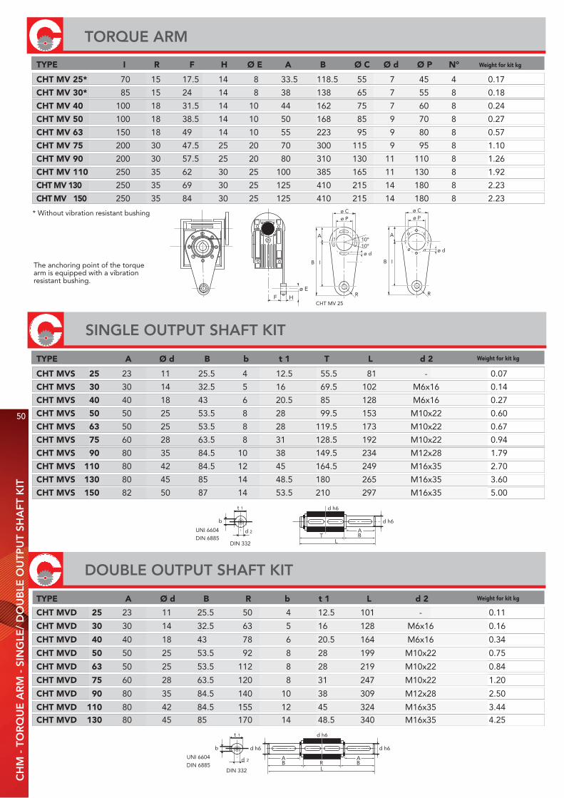
* Without vibration resistant bushing
The anchoring point of the torquearm is equipped with a vibrationresistant bushing.
F H
ø E
ø Cø P
A
B I
R
ø d
ø Cø P
A
B I
R
ø d
10°10°
CHT MV 25
Weight for kit kg
Weight for kit kg
Weight for kit kg
CHT MV 25* 70 15 17.5 14 8 33.5 118.5 55 7 45 4 0.17
CHT MV 30* 85 15 24 14 8 38 138 65 7 55 8 0.18
CHT MV 40 100 18 31.5 14 10 44 162 75 7 60 8 0.24
CHT MV 50 100 18 38.5 14 10 50 168 85 9 70 8 0.27
CHT MV 63 150 18 49 14 10 55 223 95 9 80 8 0.57
CHT MV 75 200 30 47.5 25 20 70 300 115 9 95 8 1.10
CHT MV 90 200 30 57.5 25 20 80 310 130 11 110 8 1.26
CHT MV 110 250 35 62 30 25 100 385 165 11 130 8 1.92
CHT MV 130 250 35 69 30 25 125 410 215 14 180 8 2.23
CHT MV 150 250 35 84 30 25 125 410 215 14 180 8 2.23
DOUBLE OUTPUT SHAFT KIT
50
CH
M -
TO
RQ
UE
AR
M -
SIN
GLE
/ D
OU
BLE
OU
TPU
T SH
AFT
KIT
TORQUE ARM
SINGLE OUTPUT SHAFT KIT

ø e
ø i
L
* to drawing
Tongue acc. to UNI 6604 - DIN 6885Quenched
ø e
ø i
L
C3
TYPE ø i/ø e L Key Weight for kit kg
SINGLE
TYPE ø i/ø e L Key Weight for kit kg
DOUBLE
CHT BRM-S 9/11 20 4/3x4x11 RB* 0.006
CHT BRM-S 11/14 30 5/4x6x10 RB* 0.015
CHT BRM-S 14/19 40 6x5x30 * 0.045
CHT BRM-S 19/24 50 6x5.5x20 * 0.07 8x5.5x40 *
CHT BRM-S 24/28 60 8x9x40 * 0.08
CHT BRM-S 28/38 80 10x7x60 * 0.33
CHT BRM-S 38/42 110 12/10x10x48 RB* 0.22
CHT BRM-D 11/19 40 6x6x30 * 0.06
CHT BRM-D 14/24 50 8x7x40 A 0.12
CHT BRM-D 19/28 60 8x7x50 A 0.16
CHT BRM-D 24/38 80 10x8x60 A 0.44
TYPE C3
030 43
040 50
050 59
063 70
075 75
090 87
110 95
130 103
150 117
REDUCTION BUSHINGS KIT
CH
M -
CO
VE
R -
RE
DU
CTI
ON
BU
SHIN
GS
KIT
COVER
51
2D and 3D drawings available on the web site www.chiaravalli.comQuantity, availability and prices with Chiaravalli B2B

52
RADIAL LOADS ON THE OUTPUT SHAFTC
HM
- R
AD
IAL
LOA
DS
ON
TH
E O
UTP
UT
SHA
FT
400 390 530 1020 1400 1830 2160 2390 3530 3950 5290
250 460 620 1200 1650 2150 2520 2800 4130 4610 6140
150 550 740 1420 1960 2540 2990 3310 4890 5470 7300
100 630 850 1620 2250 2910 3430 3800 5600 6260 8330
60 740 1000 1920 2660 3450 4060 4500 6640 7420 9800
40 850 1150 2200 3050 3950 4650 5150 7600 8500 11330
25 990 1350 2570 3570 4620 5440 6020 8890 9940 13250
10 1350 1830 3490 4840 6270 7380 8180 12000 13500 18000
a 50 65 84 101 120 131 162 176 188 215
b 38 50 64 76 95 101 122 136 148 174
SIZES
Output speed 025 030 040 050 063 075 090 110 130 150(n2)
CONSTANTS’ VALUES
FA = 1
5FR
FRX = FRa
b+x
FR
= =
X
FRX
The loads indicated are valid for all application directions.The maximum allowable axial loads are equal to 1/5 of the radial load value shown in the table when applied with the same radial load; if this is not the case, please contact our technical office. If double output shafts are used, the sum of radial loads applicable to the centre lines of the two ends of the shaft must not exceed the value shown in the table below.The radial loads related to the output speed (n2)=10 are the maximum loads supported by the gear.
a GEAR CONSTANTb GEAR CONSTANTx LOAD DISTANCE FROM SHAFT SHOULDER IN MM.FRX RADIAL LOAD IN POSITION X (IN N)FR RADIAL LOAD (N)FA AXIAL LOAD (N)
CH
M -
RA
DIA
L LO
AD
S O
N T
HE
CE
NTR
E L
INE
OF
THE
INP
UT
SHA
FT
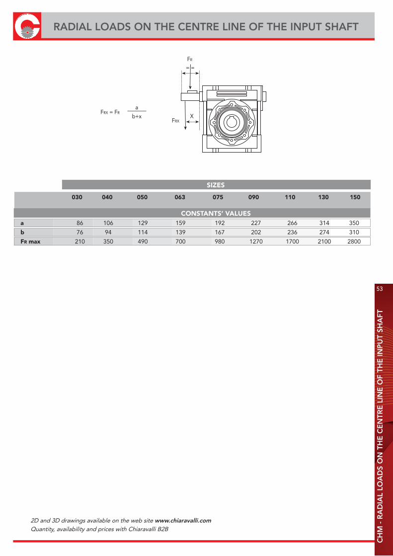
RADIAL LOADS ON THE CENTRE LINE OF THE INPUT SHAFT
53
a 86 106 129 159 192 227 266 314 350
b 76 94 114 139 167 202 236 274 310
FR max 210 350 490 700 980 1270 1700 2100 2800
SIZES
030 040 050 063 075 090 110 130 150
CONSTANTS’ VALUES
FR
= =
XFRX
FRX = FRa
b+x
2D and 3D drawings available on the web site www.chiaravalli.comQuantity, availability and prices with Chiaravalli B2B
54
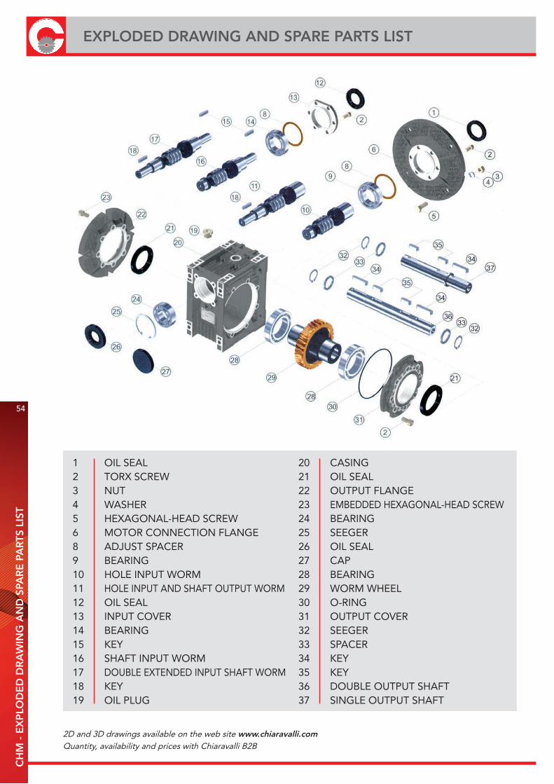
EXPLODED DRAWING AND SPARE PARTS LISTC
HM
- E
XP
LOD
ED
DR
AW
ING
AN
D S
PAR
E P
AR
TS L
IST
20 CASING21 OIL SEAL22 OUTPUT FLANGE23 EMBEDDED HEXAGONAL-HEAD SCREW24 BEARING25 SEEGER26 OIL SEAL27 CAP28 BEARING29 WORM WHEEL30 O-RING31 OUTPUT COVER32 SEEGER33 SPACER34 KEY35 KEY36 DOUBLE OUTPUT SHAFT37 SINGLE OUTPUT SHAFT
1 OIL SEAL2 TORX SCREW3 NUT4 WASHER5 HEXAGONAL-HEAD SCREW6 MOTOR CONNECTION FLANGE8 ADJUST SPACER9 BEARING10 HOLE INPUT WORM11 HOLE INPUT AND SHAFT OUTPUT WORM12 OIL SEAL13 INPUT COVER14 BEARING15 KEY16 SHAFT INPUT WORM17 DOUBLE EXTENDED INPUT SHAFT WORM18 KEY19 OIL PLUG
2D and 3D drawings available on the web site www.chiaravalli.comQuantity, availability and prices with Chiaravalli B2B
CH
M -
USE
AN
D M
AIN
TEN
AN
CE
INST
RU
CTI
ON
S
55
CHM - USE AND MAINTENANCE INSTRUCTIONS
INSTALLATION· The data shown on the identification name plate must correspond to the gear ordered.· The oil level, for the sizes 110 and 130 equipped with filling, draining and level plug, must correspond to the quantity foreseen for the assembly position requested (see catalogue), in addition, always for the sizes indicated, it will be the client’s responsibility to substitute the blind plug, supplied for transport, with the corresponding plug equipped with a bleed hole includedin the supply with the gear.· All of the other gears are supplied complete with permanent synthetic oil in a quantity that is sufficient for any assembly position.· The gear must be fixed on a flat surface that is sufficiently rigid in order to avoid any vibration.· The gear and the axis of the machine to be driven must be perfectly aligned.· In the event that knocks, overloading or blockage of the machine are foreseen, the client must install a limiting device, joints, overload cut-out etc.· Coupling with pinions, joints, pulleys and other parts must be done after the parts have been cleaned and knocks should be avoided while assembling as they could damage the bearingsand other internal parts.· In the event that the motor is supplied by the client, he must check that the flange and shaft tolerances correspond to a “normal” class; our motors satisfy this requirement.· Check that the fixing screws for the gear and the related accessories are correctly tightened.· Take suitable measures to protect the groups from any aggressive atmospheric agents.· Where foreseen, protect rotating parts from any possible contact with the operators.· If the gears are painted, protect the oil seals and the machined surfaces.· All of the gears are painted RAL 9022 grey.
OPERATION AND RUNNING-IN· To obtain the best performance the gears must first be runin by gradually increasing the power in the first few hours of operation, in this phase an increase in temperature is considerednormal.· In the event of defective operation, noise, oil leakage, etc. stop the gear immediately and, when possible, remove the cause. Alternatively, send the piece to our factory to be controlled.
MAINTENANCE· The worm gears from size 25 to size 90 and the pre-stage modules are lubricated with permanent synthetic oil and therefore do not require any maintenance.· The gears size 110 and 130 are lubricated with mineral oil and are equipped with a breather plug, therefore the oil level must be checked periodically and if necessary topped up with thesame oil or one that is compatible with those indicated in our catalogue.· For the gears size 110 and 130 proceed with the substitution of the oil after the first 300 working hours, replacing it with the correct quantity in accordance with the assembly position,as detailed in our catalogue, after the inside of the gear has been thoroughly washed.
WAREHOUSE STORAGE· If the warehouse storage will be for a long time, more than 3 months, the shafts and machined surfaces should be protected using antioxidants and the oil seals should be greased.
HANDLING· Care must be taken not to damage the oil seals and the machined surfaces when handling the groups.
DISPOSAL OF PACKAGING· The packaging in which our gears are delivered should be sent to specialised companies for recycling if possible.

CHML WORM GEARBOXES WITHTORQUE LIMITER
CH
ML
- D
ESI
GN
FE
ATU
RE
S
57
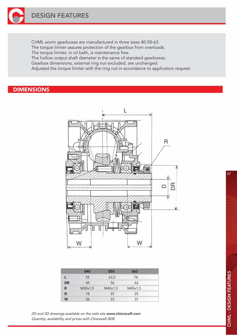
DESIGN FEATURES
CHML worm gearboxes are manufactured in three sizes 40-50-63.The torque limiter assures protection of the gearbox from overloads.The torque limiter, in oil bath, is maintenance free.The hollow output shaft diameter is the same of standard gearboxes.Gearbox dimensions, external ring nut excluded, are unchanged.Adjusted the torque limiter with the ring nut in accordance to application request.
040 050 063
L 55 63,5 74
DR 45 56 62
R M30x1,5 M40x1,5 M45x1,5
D 18 25 25
W 26 33 37
DIMENSIONS
2D and 3D drawings available on the web site www.chiaravalli.comQuantity, availability and prices with Chiaravalli B2B
CH WORM GEARED MOTORS ANDWORM GEAR UNITS
LUBRICATION
CH
- IN
TRO
DU
CTI
ON
- L
UB
RIC
ATI
ON
59
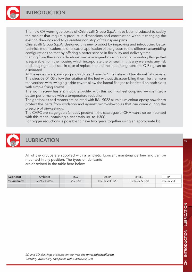
INTRODUCTION
The new CH worm gearboxes of Chiaravalli Group S.p.A. have been produced to satisfy the market that require a product in dimensions and construction without changing the existing drawings and to guarantee non stop of their spare parts.Chiaravalli Group S.p.A. designed this new product by improving and introducing better technical modifications to offer easier application of the groups to the different assembling configurations so that by offering a better service in flexibility and delivery time.Starting from these considerations, we have a gearbox with a motor mounting flange that is separable from the housing which incorporate the oil seal; in this way we avoid any risk of damaging the oil seal in case of replacement of the input flange and the O-Ring can beeliminated.All the aside covers, swinging and with feet, have O-Rings instead of traditional flat gaskets.The sizes 03-04-05 allow the rotation of the feet without disassembling them; furthermore the versions with swinging aside covers allow the lateral flanges to be fitted on both sides with simple fixing screws.The worm screw has a ZI involute profile: with this worm-wheel coupling we shall get a better performance with a temperature reduction.The gearboxes and motors are painted with RAL 9022 aluminium colour epoxy powder to protect the parts from oxidation and against micro-blowholes that can come during the pressure of die-castings.The CHPC pre-stage gears (already present in the catalogue of CHM) can also be mounted with this range, obtaining a gear ratio up to 1:300.For bigger reductions is possible to have two gears together using an appropriate kit.
All of the groups are supplied with a synthetic lubricant maintenance free and can be mounted in any position. The types of lubricantsare described in the table here below.
Lubricant Ambient ISO AGIP SHELL IP°C ambient -25°C/+50°C VG 320 Telium VSF 320 Tivela oil S 320 Telium VSF
2D and 3D drawings available on the web site www.chiaravalli.comQuantity, availability and prices with Chiaravalli B2B
FEET ROTATION60
QUANTITY OF OIL IN LITRESC
H -
QU
AN
TITY
OF
OIL
IN L
ITR
ES
- M
OTO
R M
OU
NTI
NG
FLA
NG
ES
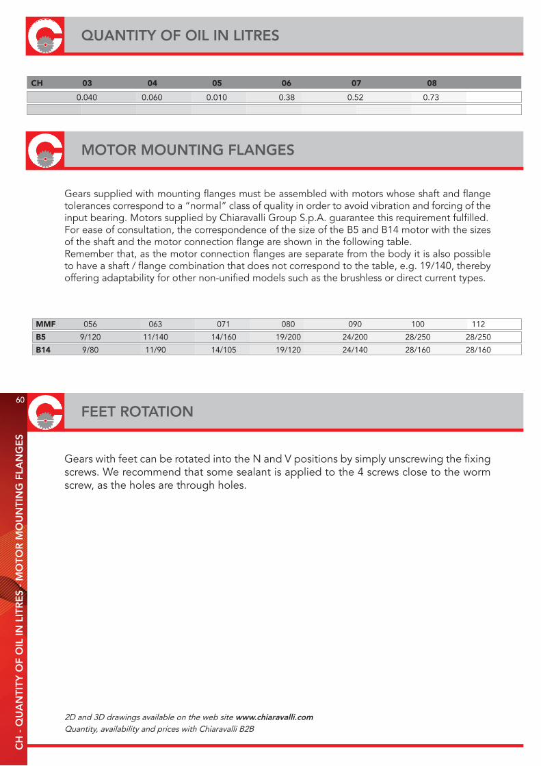
CH 03 04 05 06 07 08
0.040 0.060 0.010 0.38 0.52 0.73
MMF 056 063 071 080 090 100 112
B5 9/120 11/140 14/160 19/200 24/200 28/250 28/250
B14 9/80 11/90 14/105 19/120 24/140 28/160 28/160
MOTOR MOUNTING FLANGES
Gears supplied with mounting flanges must be assembled with motors whose shaft and flange tolerances correspond to a “normal” class of quality in order to avoid vibration and forcing of the input bearing. Motors supplied by Chiaravalli Group S.p.A. guarantee this requirement fulfilled.For ease of consultation, the correspondence of the size of the B5 and B14 motor with the sizes of the shaft and the motor connection flange are shown in the following table.Remember that, as the motor connection flanges are separate from the body it is also possible to have a shaft / flange combination that does not correspond to the table, e.g. 19/140, thereby offering adaptability for other non-unified models such as the brushless or direct current types.
Gears with feet can be rotated into the N and V positions by simply unscrewing the fixing screws. We recommend that some sealant is applied to the 4 screws close to the worm screw, as the holes are through holes.
2D and 3D drawings available on the web site www.chiaravalli.comQuantity, availability and prices with Chiaravalli B2B

61
CH
03/
04/0
5 W
OR
M G
EA
RE
D M
OTO
RS
AN
D W
OR
M G
EA
R U
NIT
S
CH 03/04/05 WORM GEARED MOTORS AND WORM GEAR UNITS
CH...
CH...P
CHE...P
CHE...
CHR...
CHR...P
CHRE...PCHRE...

ORDER EXAMPLE
CH 03 A 1 63B5 UNIVERSALE
CH..P P 2 63B14
CHR PF 56B5
CHR..P N 56B14
CHE V
CHE..P
CHRE
CHRE..P
TYPE (1) SIZE VERSION FLANGE POS. (2) i M.M.F. MOUNT. POS.
RATIO SEE PAGE 64
CH 04 A 1 71B5 UNIVERSALE
CH..P P 2 71B14
CHR PF 63B5
CHR..P PFA 63B14
CHE N
CHE..P V
CHRE
CHRE..P
TYPE (1) SIZE VERSION FLANGE POS. (2) i M.M.F. MOUNT. POS.
CH 05 A 1 80B5 UNIVERSALE
CH..P P 2 80B14
CHR PF 71B5
CHR..P PFA 71B14
CHE N 63B5
CHE..P V 63B14
CHRE
CHRE..P
TYPE (1) SIZE VERSION FLANGE POS. (2) i M.M.F. MOUNT. POS.
RATIO SEE PAGE 65
RATIO SEE PAGE 66
CH 04P FA 2 35 63 B14 CH 04 10 71 B5
62
CH - CH...P 03/04/05 DESIGNATIONC
H -
CH
...P
03/
04/0
5 D
ESI
GN
ATI
ON
- O
RD
ER
EX
AM
PLE
If the motor is also required, please specify:Size es. 63 C4Power es. Kw 0.22Poles es. 4Voltage es. V230/400Frequency es. 50 HzFlange es. B14
N.B. Gear box required with output flanges F or FA must be ordered PF or PFA version.
1) see page 612) see page 63
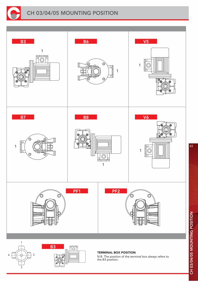
CH
03/
04/0
5 M
OU
NTI
NG
PO
SITI
ON
CH 03/04/05 MOUNTING POSITION
63
TERMINAL BOX POSITION N.B. The position of the terminal box always refers tothe B3 position.
4
3
2
1
1
1
1
1
1
1
B3 B6 V5
B7 B8 V6
PF1 PF2
B3

TYPE i=ratio n2 r/min Kw=P1 Nm=T2 f.s. Possible types of motor connections
7 200 0.22 8 1.8 63/56 B5/B14
10 140 0.22 11 1.4 63/56 B5/B14
15 93 0.22 16 1.0 63/56 B5/B14
20 70 0.22 20 0.9 63/56 B5/B14
30 47 0.18 22 0.8 63/56 B5/B14
40 35 0.12 18 1.0 63/56 B5/B14
60 23 0.09 18 1.0 63/56 B5/B14
70 20 0.09 15 0.9 56 B5/B14
CH 03
Weight Kg 1
97.3
16
81
16
66
55
55
66
81
1616
55
66
81
16 16
52 46
3055
50
80
7
63
301.5
øh8
50 81.5
52 46
40
65
30
50
52 46
68
750.5
5
øH
850ø 8
0
5255
50
80
30
7
30
55
50
80
7
52 46
8
105
4
M6
50
30
DIMENSIONS
64
CH 03 - PERFORMANCE WITH 4-POLE MOTORS 1400 REVS. INPUT
CH
03
- P
ER
FOR
M. W
ITH
4-P
OLE
MO
TOR
S -
1400
RE
VS.
INP
UT
A P
V PF1
N

* Motors 71 gr.
TYPE i=ratio n2 r/min Kw=P1 Nm=T2 f.s. Possible types of motor connections
7 200 0.55* 22 1.4 71/63 B5/B14
10 140 0.55* 30 1.0 71/63 B5/B14
14 100 0.37 29 1.0 71/63 B5/B14
20 70 0.37 38 1.0 71/63 B5/B14
28 50 0.37 40 0.9 71/63 B5/B14
35 40 0.25 41 0.9 71/63 B5/B14
46 30 0.18 37 1.0 63 B5/B14
60 23 0.18 37 0.9 63 B5/B14
70 20 0.12 33 0.9 63 B5/B14
100 14 0.12 30 0.9 63 B5/B14
CH 04
Weight Kg 2,1
DIMENSIONS
81
98
64
24.5 24.5
64
98
81
24.5 24.5
98
64
81
24.5 24.5
44,6
6572
9052
9
65 54
44,6
123,
7
90
52
9
44,6
72
143,
1
52
90
10
65 54
9
74
80
35
2
h850
60,5
110
60 h
8
3,5
9
90
ø11
0
ø 6
0 h8
9
65 54
44,6 71
,1
87
44,6 71
,152
,2
65
65 5411
44,6 71
,1
65 54
87
ø 8,5
ø 8,5
M6
72
3,5
CH
04
- P
ER
FOR
M. W
ITH
4-P
OLE
MO
TOR
S -
1400
RE
VS.
INP
UT
CH 04 - PERFORMANCE WITH 4-POLE MOTORS 1400 REVS. INPUT
65
A P
V PF1
N
PFA1

49,5 80,2
580
,25
6382
22 22
98,5
124
70
82
162,
2549,5
63
109,5
9
82
107
øh8
68
6370
49,5
94
82
22 22
98,5
124
49,5
7082
63
109,5
9
85,5
ø12
5
6370
9012
10
øH
870
82
22 22
98,5
124
63
109,5
82
137,
3
6370
9
115
ø12
5 49,5 80,2
5
6370
9012
10
øH
870
10
372.5
55M6
49.5
* Motors 80 gr.
TYPE i=ratio n2 r/min Kw=P1 Nm=T2 f.s. Possible types of motor connections
7 200 1.1* 40 1.4 80/71 B5/B14
10 140 1.1* 49 1.2 80/71 B5/B14
14 100 0.75 57 1.1 80/71 B5/B14
18 78 0.55 52 1.1 80/71 B5/B14
24 58 0.55 67 0.9 80/71 B5/B14
28 50 0.55 73 1.0 80/71 B5/B14
36 39 0.37 61 1.1 71 B5/B14
45 31 0.37 65 0.9 71/63 B5/B14
60 23 0.25 60 1.0 71/63 B5/B14
70 20 0.22 55 0.9 63 B5/B14
80 17 0.18 54 1.0 63 B5/B14
100 14 0.18 50 0.9 63 B5/B14
CH 05
Weight Kg 3
DIMENSIONS
66
CH 05 - PERFORMANCE WITH 4-POLE MOTORS 1400 REVS. INPUT
CH
05
- P
ER
FOR
M. W
ITH
4-P
OLE
MO
TOR
S -
1400
RE
VS.
INP
UT
A P
V PF1
NPFA1
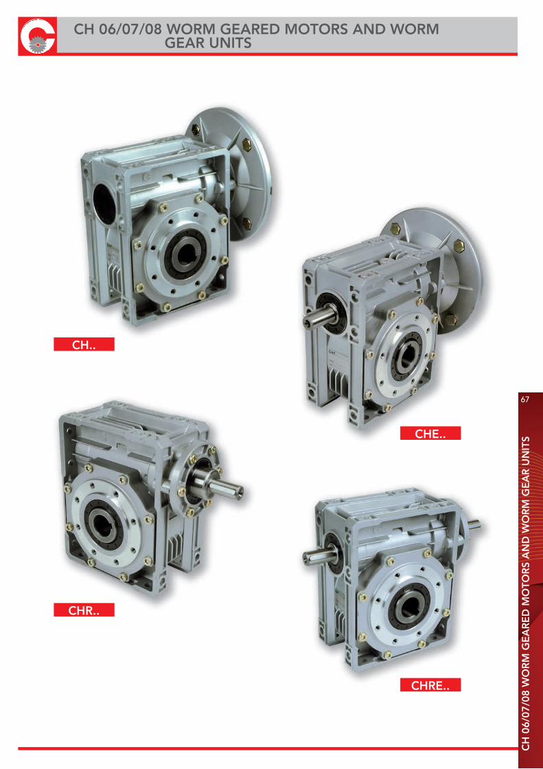
67
CH
06/
07/0
8 W
OR
M G
EA
RE
D M
OTO
RS
AN
D W
OR
M G
EA
R U
NIT
S
CH 06/07/08 WORM GEARED MOTORS AND WORM GEAR UNITS
CH..
CHE..
CHR..
CHRE..

68
CH 06/07/08 DESIGNATIONC
H 0
6/07
/08
DE
SIG
NA
TIO
N -
OR
DE
R E
XA
MP
LE
CH 06 FC 1 100B5 UNIVERSALE
CHR 07 F 2 100B14
CHE 08 (3) 90B5
CHRE 90B14
80B5
80B14
71B5
71B14
TYPE (1) SIZE VERSION FLANGE POS. (2) i M.M.F. MOUNT. POS.
RATIO SEEPAGE
70-71-72
CH 06 FC 1 19 90 B5
ORDER EXAMPLE
If the motor is also required, please specify:Size es. 90 L4Power es. Kw 1.5Poles es. 4Voltage es. V230/400Frequency es. 50 HzFlange es. B5
1) see page 672) see page 693) lack of instructions indicates that the gear is not equipped with an output flange
2D and 3D drawings available on the web site www.chiaravalli.comQuantity, availability and prices with Chiaravalli B2B
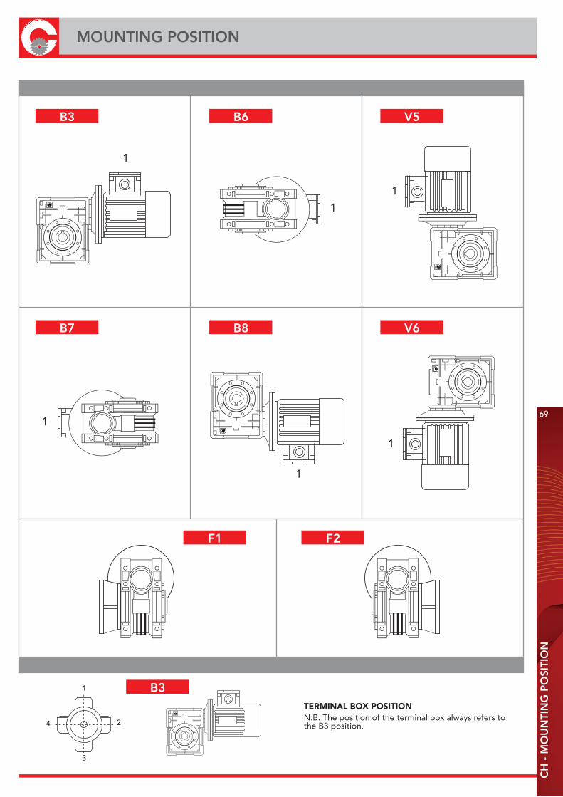
CH
- M
OU
NTI
NG
PO
SITI
ON
MOUNTING POSITION
69
TERMINAL BOX POSITIONN.B. The position of the terminal box always refers tothe B3 position.4
3
2
1
1
1
1
1
1
1
B3 B6 V5
B7 B8 V6
F1 F2
B3
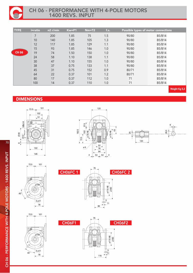
70
CH 06 - PERFORMANCE WITH 4-POLE MOTORS 1400 REVS. INPUT
CH
06
- P
ER
FOR
MA
NC
E W
ITH
4-P
OLE
MO
TOR
S -
1400
RE
VS.
INP
UT
TYPE i=ratio n2 r/min Kw=P1 Nm=T2 f.s. Possible types of motor connections
7 200 1.85 75 1.5 90/80 B5/B14 10 140 1.85 105 1.3 90/80 B5/B14 12 117 1.85 129 1.1 90/80 B5/B14 15 93 1.85 146 1.0 90/80 B5/B14 19 74 1.50 150 1.0 90/80 B5/B14 24 58 1.10 138 1.1 90/80 B5/B14 30 47 1.10 155 1.0 90/80 B5/B14 38 37 0.75 133 1.1 90/80 B5/B14 45 31 0.75 152 0.9 80/71 B5/B14 64 22 0.37 101 1.2 80/71 B5/B14 80 17 0.37 112 1.0 71 B5/B14 100 14 0.37 110 1.0 71 B5/B14
CH 06
Weight Kg 5,2
DIMENSIONS
CH06FC 1 CH06FC 2
CH06F1 CH06F2

CH
07
- P
ER
FOR
MA
NC
E W
ITH
4-P
OLE
MO
TOR
S -
1400
RE
VS.
INP
UT
CH 07 - PERFORMANCE WITH 4-POLE MOTORS 1400 REVS. INPUT
71
TYPE i=ratio n2 r/min Kw=P1 Nm=T2 f.s. Possible types of motor connections
7 200 4 170 1.1 100/90 B5/B14
10 140 3 175 1.3 100/90 B5/B14
15 93 3 250 1.0 100/90 B5/B14
20 70 2.20 240 1.0 100/90 B5/B14
25 56 1.85 250 1.0 90/80 B5/B14
30 47 1.50 230 1.2 90/80 B5/B14
40 35 1.1 215 1.2 90/80 B5/B14
50 28 1.1 220 0.9 90/80 B5/B14
60 23 0.75 200 1.0 90/80 B5/B14
80 17 0.55 180 1.0 80/71 B5/B14 * 100 14 0.37 140 1.1 80/71 B5/B14 * *71 solo B5
CH 07
Weight Kg 9,2
DIMENSIONS
30
127
8
33,3
87 124
109.5
46.5
174
126
127
4482
104
3 58.5
ø 10.5
358.5
12487
ø165
45∞
4-ø12
ø20
0
ø13
0 H
8
90
82
85
512
Ø 1
10
22.5
∞
9
220.
5
87
126
46.5
ø 9
0 H
8 75
M8x
14
ø 9
0 H
8
12487
ø130
45∞4-ø11
82
85
512
ø16
0
ø11
0 H
8
82
111
512
ø20
0
ø13
0 H
8CH07FC 1 CH07FC 2
CH07FE1 CH07FE2
CH07F1
CH07F2

72
CH 08 - PERFORMANCE WITH 4-POLE MOTORS 1400 REVS. INPUT
CH
08
- P
ER
FOR
MA
NC
E W
ITH
4-P
OLE
MO
TOR
S -
1400
RE
VS.
INP
UT
DIMENSIONS
TYPE i=ratio n2 r/min Kw=P1 Nm=T2 f.s. Possible types of motor connections
7 200 4 170 1.5 112/100/90 B5/B14
10 140 4 240 1.2 112/100/90 B5/B14
15 93 4 350 0.9 112/100/90 B5/B14
20 70 3.00 340 0.9 100/90 B5/B14
23 61 2.20 280 1.1 100/90 B5/B14
30 47 2.20 340 1.1 100/90 B5/B14
40 35 1.85 340 0.9 90/80 B5/B14
46 30 1.5 340 1.0 90/80 B5/B14
56 25 1.1 290 1.0 90/80 B5/B14
64 22 1.1 290 0.9 90/80 B5/B14
80 17 0.75 260 1.0 90/80 B5/B14
100 14 0.55 220 1.0 80 B5/B14
CH 08
Weight Kg 12,2
35
140
10
38,3
Ø 1
30
22.5∞
11
245.
5
100
144
45.5
ø 1
10 H
8
86.9
ø 1
10 H
8
M10
x18
100 137
144
72
200
144
140
57101125
3 64.4
ø 11.5
364.4
135100
ø176
45∞
4-ø12.5
ø21
0
ø15
2 H
8
101
110.5
615
135100
ø176
45∞4-ø12.5
ø21
0
ø15
2 H
8
101
151
615
CH08FC 1 CH08FC 2
CH08F1 CH08F2
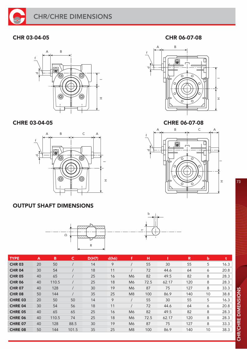
CH
R/C
HR
E D
IME
NSI
ON
S
CHR/CHRE DIMENSIONS
73
CHR 03-04-05 CHR 06-07-08
CHRE 03-04-05 CHRE 06-07-08
OUTPUT SHAFT DIMENSIONS
D
R
b
t
d
f
A B
IH
d
f
A B
IH
C
d
f
A B
IH
d
f
A B
IH
CA
A
TYPE A B C D(H7) d(h6) f H I R b t
CHR 03 20 50 / 14 9 / 55 30 55 5 16.3
CHR 04 30 54 / 18 11 / 72 44.6 64 6 20.8
CHR 05 40 65 / 25 16 M6 82 49.5 82 8 28.3
CHR 06 40 110.5 / 25 18 M6 72.5 62.17 120 8 28.3
CHR 07 40 128 / 30 19 M6 87 75 127 8 33.3
CHR 08 50 144 / 35 25 M8 100 86.9 140 10 38.8
CHRE 03 20 50 50 14 9 / 55 30 55 5 16.3
CHRE 04 30 54 56 18 11 / 72 44.6 64 6 20.8
CHRE 05 40 65 65 25 16 M6 82 49.5 82 8 28.3
CHRE 06 40 110.5 74 25 18 M6 72.5 62.17 120 8 28.3
CHRE 07 40 128 88.5 30 19 M6 87 75 127 8 33.3
CHRE 08 50 144 101.5 35 25 M8 100 86.9 140 10 38.3
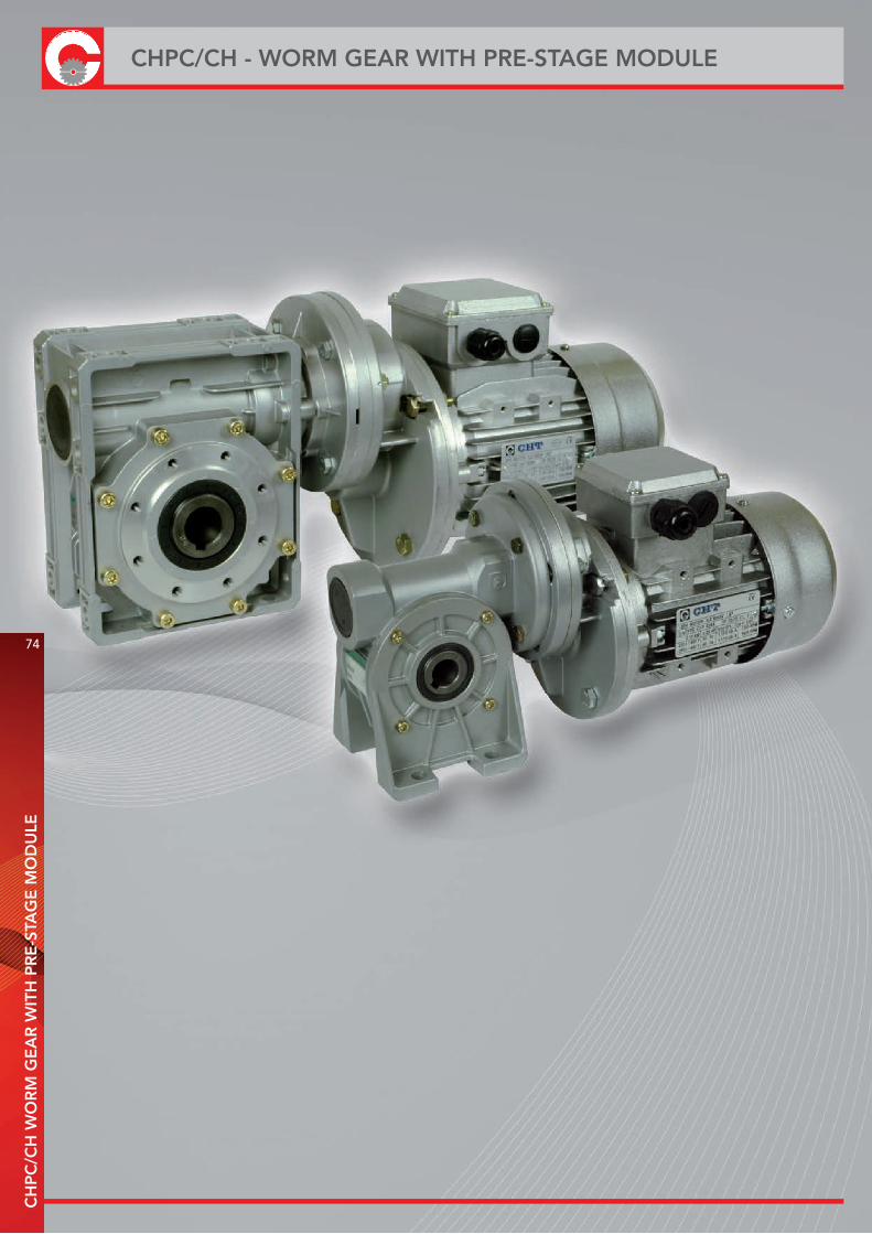
74
CHPC/CH - WORM GEAR WITH PRE-STAGE MODULEC
HP
C/C
H W
OR
M G
EA
R W
ITH
PR
E-S
TAG
E M
OD
ULE

CH
PC
WO
RM
GE
AR
WIT
H P
RE
-STA
GE
MO
DU
LE
WORM GEAR WITH PRE-STAGE MODULE
75
ORDER EXAMPLE
CHPC 71 CH 05 i= 108(3x36) M.M.F. 71
DESIGNATION CHPC / CH - CH..P CHPC / CHE - CH..P
TYPE SIZE i = M.M.F.
CHPC 63 3 63B5
71 3 71B5
80 3 80B5
Z Z1
CHPC 63 11/140 11/105
CHPC 71 14/160 14/120
CHPC 80 19/200 19/160
Z
Z1
Z
WARNING: The gearbox connected with the pre-stage must have input dimension Z1
If the motor is also required, please specify:Size es. 71 B4Power es. Kw 0.37Poles es. 4Voltage es. V230/400Frequency es. 50 Hz
2D and 3D drawings available on the web site www.chiaravalli.comQuantity, availability and prices with Chiaravalli B2B
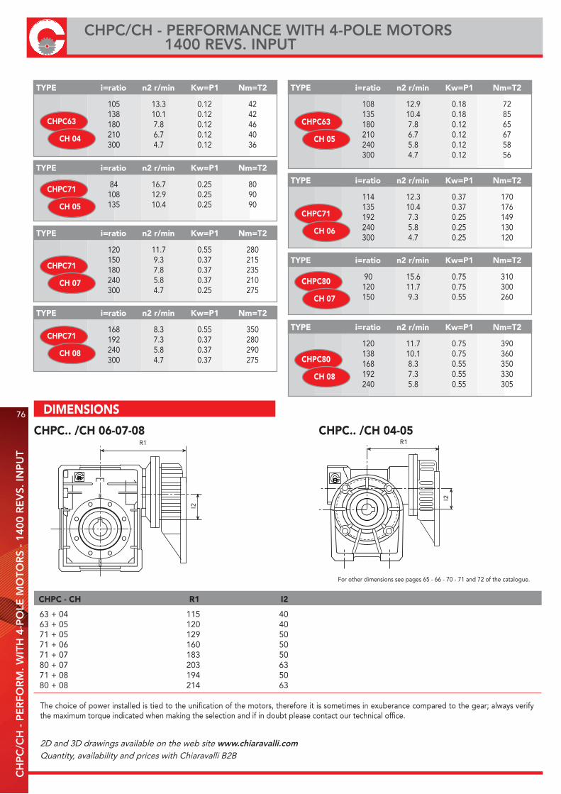
76
CHPC/CH - PERFORMANCE WITH 4-POLE MOTORS 1400 REVS. INPUT
CH
PC
/CH
- P
ER
FOR
M. W
ITH
4-P
OLE
MO
TOR
S -
1400
RE
VS.
INP
UT
CHPC.. /CH 04-05CHPC.. /CH 06-07-08
63 + 04 115 4063 + 05 120 4071 + 05 129 5071 + 06 160 5071 + 07 183 5080 + 07 203 6371 + 08 194 5080 + 08 214 63
CHPC - CH R1 I2
The choice of power installed is tied to the unification of the motors, therefore it is sometimes in exuberance compared to the gear; always verify the maximum torque indicated when making the selection and if in doubt please contact our technical office.
For other dimensions see pages 65 - 66 - 70 - 71 and 72 of the catalogue.
R1
I2
105 13.3 0.12 42 138 10.1 0.12 42 180 7.8 0.12 46 210 6.7 0.12 40 300 4.7 0.12 36
TYPE i=ratio n2 r/min Kw=P1 Nm=T2
CHPC63
CH 04
108 12.9 0.18 72 135 10.4 0.18 85 180 7.8 0.12 65 210 6.7 0.12 67 240 5.8 0.12 58 300 4.7 0.12 56
TYPE i=ratio n2 r/min Kw=P1 Nm=T2
CHPC63
CH 05
84 16.7 0.25 80 108 12.9 0.25 90 135 10.4 0.25 90
TYPE i=ratio n2 r/min Kw=P1 Nm=T2
CHPC71
CH 05 114 12.3 0.37 170 135 10.4 0.37 176 192 7.3 0.25 149 240 5.8 0.25 130 300 4.7 0.25 120
TYPE i=ratio n2 r/min Kw=P1 Nm=T2
CHPC71
CH 06
120 11.7 0.55 280 150 9.3 0.37 215 180 7.8 0.37 235 240 5.8 0.37 210 300 4.7 0.25 275
TYPE i=ratio n2 r/min Kw=P1 Nm=T2
CHPC71
CH 07
168 8.3 0.55 350 192 7.3 0.37 280 240 5.8 0.37 290 300 4.7 0.37 275
TYPE i=ratio n2 r/min Kw=P1 Nm=T2
CHPC71
CH 08
90 15.6 0.75 310 120 11.7 0.75 300 150 9.3 0.55 260
TYPE i=ratio n2 r/min Kw=P1 Nm=T2
CHPC80
CH 07
120 11.7 0.75 390 138 10.1 0.75 360 168 8.3 0.55 350 192 7.3 0.55 330 240 5.8 0.55 305
TYPE i=ratio n2 r/min Kw=P1 Nm=T2
CHPC80
CH 08
R1I2
DIMENSIONS
2D and 3D drawings available on the web site www.chiaravalli.comQuantity, availability and prices with Chiaravalli B2B
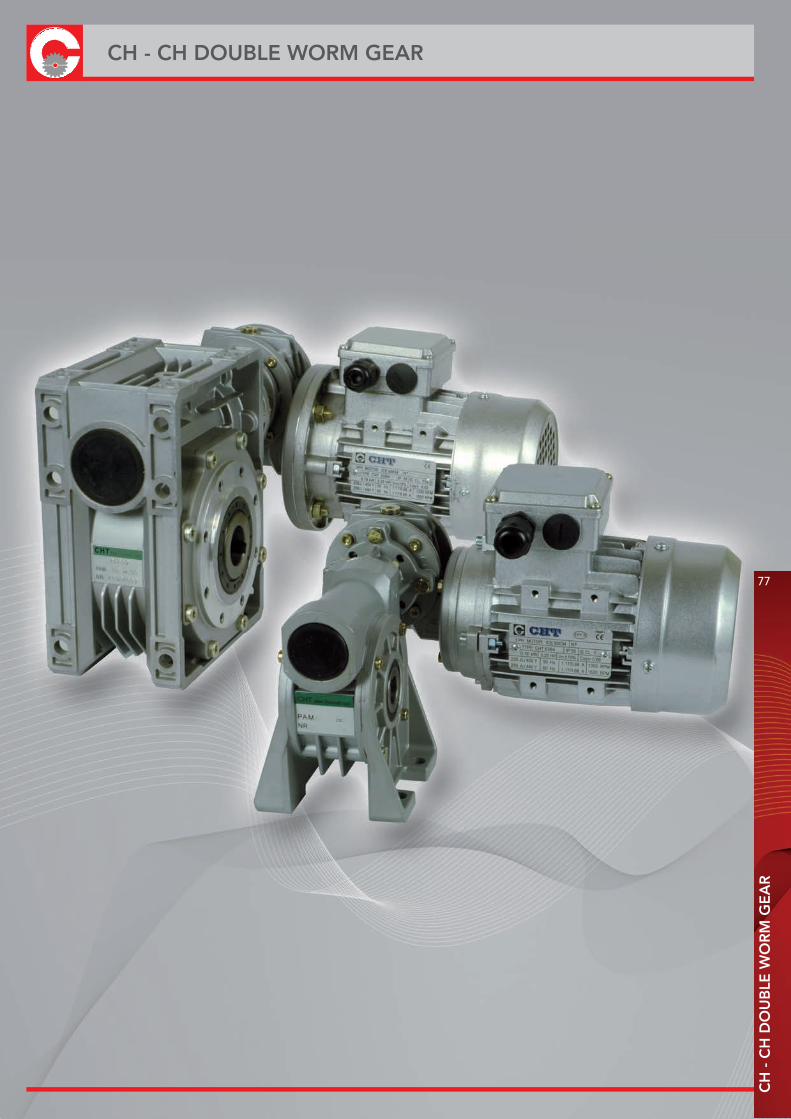
CH
- C
H D
OU
BLE
WO
RM
GE
AR
CH - CH DOUBLE WORM GEAR
77
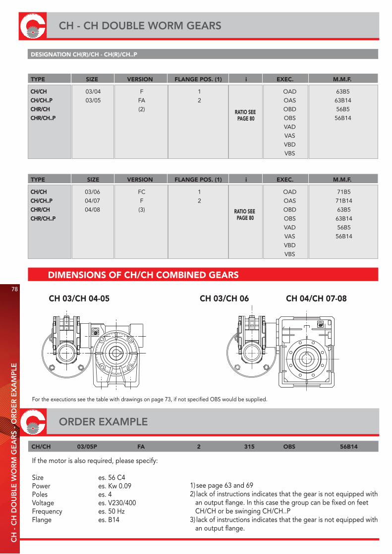
CH 03/CH 04-05 CH 03/CH 06 CH 04/CH 07-08
CH/CH 03/06 FC 1 OAD 71B5
CH/CH..P 04/07 F 2 OAS 71B14
CHR/CH 04/08 (3) OBD 63B5
CHR/CH..P OBS 63B14
VAD 56B5
VAS 56B14
VBD
VBS
TYPE SIZE VERSION FLANGE POS. (1) i EXEC. M.M.F.
1) see page 63 and 692) lack of instructions indicates that the gear is not equipped with an output flange. In this case the group can be fixed on feet CH/CH or be swinging CH/CH..P3) lack of instructions indicates that the gear is not equipped with an output flange.
If the motor is also required, please specify:
Size es. 56 C4Power es. Kw 0.09Poles es. 4Voltage es. V230/400Frequency es. 50 HzFlange es. B14
CH/CH 03/05P FA 2 315 OBS 56B14
For the executions see the table with drawings on page 73, if not specified OBS would be supplied.
CH/CH 03/04 F 1 OAD 63B5
CH/CH..P 03/05 FA 2 OAS 63B14
CHR/CH (2) OBD 56B5
CHR/CH..P OBS 56B14
VAD
VAS
VBD
VBS
TYPE SIZE VERSION FLANGE POS. (1) i EXEC. M.M.F.
DESIGNATION CH(R)/CH - CH(R)/CH..P
RATIO SEE PAGE 80
RATIO SEE PAGE 80
DIMENSIONS OF CH/CH COMBINED GEARS
ORDER EXAMPLE
78
CH - CH DOUBLE WORM GEARSC
H -
CH
DO
UB
LE W
OR
M G
EA
RS
- O
RD
ER
EX
AM
PLE

CH
- E
XE
CU
TIO
N
EXECUTION
79
The execution determines the mounting position of the first gear in relation to the second gear. If not otherwise specified at the time of order, the group will be supplied in the OBS execution. The placing position refers to the second gear.
3 3
3 3
1 1
1 1
OAD
OBD
VAD
VBS
OAS
OBS
VAS
VBD
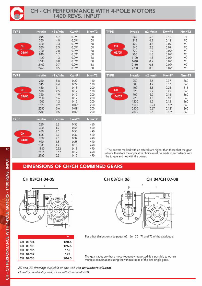
80
CH - CH PERFORMANCE WITH 4-POLE MOTORS 1400 REVS. INPUT
CH
- C
H P
ER
FOR
MA
NC
E W
ITH
4-P
OLE
MO
TOR
S -
1400
RE
VS.
INP
UT
245 5.7 0.09 58 350 4.0 0.09* 58 420 3.3 0.09* 58 560 2.5 0.09* 58 700 2.0 0.09* 58 840 1.7 0.09* 58 1120 1.3 0.09* 58 1680 0.8 0.09* 58 2100 0.7 0.09* 58 2760 0.5 0.09* 50
TYPE i=ratio n2 r/min Kw=P1 Nm=T2
CH
03/04
240 5.8 0.12 77 315 4.4 0.12 90 420 3.3 0.09 90 540 2.6 0.09 90 720 1.9 0.09* 90 900 1.6 0.09* 90 1120 1.3 0.09* 90 1440 0.9 0.09* 90 2160 0.6 0.09* 90 2700 0.5 0.09* 90
TYPE i=ratio n2 r/min Kw=P1 Nm=T2
CH
03/05
* The powers marked with an asterisk are higher than those that the gear allows, therefore the applicative choice must be made in accordance with the torque and not with the power.
240 5.8 0.22 160 315 4.4 0.22 180 450 3.1 0.18 200 570 2.5 0.12 180 720 1.9 0.12 200 900 1.6 0.12 200 1200 1.2 0.12 200 1520 0.9 0.09* 200 2280 0.6 0.09* 200 2700 0.5 0.09* 200
TYPE i=ratio n2 r/min Kw=P1 Nm=T2
CH
03/06
250 5.6 0.37 360 300 4.7 0.37 360 400 3.5 0.25 315 525 2.7 0.25 360 700 2.0 0.18 360 920 1.5 0.18 360 1200 1.2 0.12 360 1500 0.93 0.12* 360 2100 0.67 0.12* 360 2800 0.5 0.12* 360
TYPE i=ratio n2 r/min Kw=P1 Nm=T2
CH
04/07
TYPE i=ratio n2 r/min Kw=P1 Nm=T2
CH
04/08
230 5.6 0.55 460 300 4.7 0.55 490 400 3.5 0.55 490 525 2.7 0.37 490 700 2.0 0.37 490 920 1.5 0.25 490 1380 1.2 0.18 490 1840 0.93 0.18 490 2116 0.67 0.12 490 2760 0.5 0.12 490
CH 03/CH 04-05 CH 03/CH 06 CH 04/CH 07-08
For other dimensions see pages 65 - 66 - 70 - 71 and 72 of the catalogue.
The gear ratios are those most frequently requested. It is possible to obtainmultiple combinations using the various ratios of the two single gears.
CH 03/04 120.5CH 03/05 125.5CH 03/06 165CH 04/07 192CH 04/08 204.5
Y
Y Y
DIMENSIONS OF CH/CH COMBINED GEARS
2D and 3D drawings available on the web site www.chiaravalli.comQuantity, availability and prices with Chiaravalli B2B

TORQUE ARM
RL
BA
d h6
d h6t 1
d 2
DIN 332
b
DIN 6885
UNI 6604
d h6
AB
The anchoring point of the torque arm is equippedwith a vibration resistant bushing.* Without anti vibrationbush
ø d
AB
I
øC øP
H
øE
S
øC øP
AB
I
ø d22°30’
H
øE
S03-04-05 06-07-08
TYPE I A B Ø P Ø C Ø d H øE S
CH 03 100 40 157.5 50 65 7 14 8 4
CH 04 100 40 157.5 50 65 7 14 8 4
CH 05 100 55 172.5 68 94 7 14 8 4
CH 06 150 52.5 232.5 75 90 9 20 10 6
CH 07 200 62.5 300 90 110 9 25 20 6
CH 08 200 75 312.5 110 130 11 25 20 6
TYPE A Ø d B b t1 T L d2 ød1
CH 03 30 14 35 5 16 61 96 M5x13 14
CH 04 40 18 45 6 20.5 70 115 M6x16 18
CH 05 60 25 65 8 28 89 154 M8x20 25
CH 06 60 25 65 8 28 127 192 M8x20 25
CH 07 60 30 65 8 33 134 199 M10x22 30
CH 08 60 35 65 10 38 149 214 M10x25 35
TL
BA
d h6
d h6
d 2
b
t 1
DIN 332DIN 6885UNI 6604
TYPE A Ø d B R b t1 L d2 ød1
CH 03 30 14 32.5 55 5 16 120 M5x13 14
CH 04 40 18 42.7 64 6 20.5 149.4 M6x16 18
CH 05 60 25 63.2 82 8 28 208.4 M8x20 25
CH 06 60 25 63.2 120 8 28 246.4 M8x20 25
CH 07 60 30 64 127 8 33 255 M10x22 30
CH 08 60 35 64 140 10 38 268 M10x25 35
DOUBLE OUTPUT SHAFT KIT
CH
- T
OR
QU
E A
RM
- S
ING
LE/D
OU
BLE
OU
TPU
T SH
AFT
KIT
81
SINGLE OUTPUT SHAFT KIT
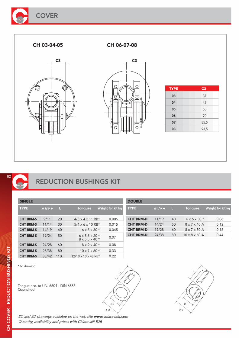
C3
CH 03-04-05 CH 06-07-08
C3
ø e
ø i
L
TYPE ø i/ø e L tongues Weight for kit kg
SINGLE
TYPE ø i/ø e L tongues Weight for kit kg
DOUBLE
* to drawing
Tongue acc. to UNI 6604 - DIN 6885Quenched
CHT BRM-S 9/11 20 4/3 x 4 x 11 RB* 0.006
CHT BRM-S 11/14 30 5/4 x 6 x 10 RB* 0.015
CHT BRM-S 14/19 40 6 x 5 x 30 * 0.045
CHT BRM-S 19/24 50 6 x 5.5 x 20 * 0.07 8 x 5.5 x 40 *
CHT BRM-S 24/28 60 8 x 9 x 40 * 0.08
CHT BRM-S 28/38 80 10 x 7 x 60 * 0.33
CHT BRM-S 38/42 110 12/10 x 10 x 48 RB* 0.22
ø e
ø i
L
CHT BRM-D 11/19 40 6 x 6 x 30 * 0.06
CHT BRM-D 14/24 50 8 x 7 x 40 A 0.12
CHT BRM-D 19/28 60 8 x 7 x 50 A 0.16
CHT BRM-D 24/38 80 10 x 8 x 60 A 0.44
TYPE C3
03 37
04 42
05 55
06 70
07 85,5
08 93,5
REDUCTION BUSHINGS KIT82
COVERC
H C
OV
ER
- R
ED
UC
TIO
N B
USH
ING
S K
IT
2D and 3D drawings available on the web site www.chiaravalli.comQuantity, availability and prices with Chiaravalli B2B

CH
03/
04/0
5 E
XP
LOD
ED
DR
AW
ING
AN
D S
PAR
E P
AR
TS L
IST
CH 03/04/05 EXPLODED DRAWING AND SPARE
83
2
3
4
6
17
8
9
15
13
12 1110
14
15
536
37
3536
37
37
38
19
23
2322
21
16
17
2425
262728
29
21
33
34
23 19
20
32
3118
30
3132
2039
40
3940
3940
21 SIDE COVER22 OUTPUT FLANGE23 SCREW24 BEARING25 SEEGER26 SPACER27 SEEGER28 CAP29 OIL SEAL30 WORM WHEEL31 BEARING32 O-RING33 BRACCIO DI REAZIONE34 SCREW35 SINGLE OUTPUT SHAFT36 KEY37 KEY38 DOUBLE OUTPUT SHAFT39 SPACER40 SEEGER
1 OIL SEAL2 SCREW3 NUT4 WASHER5 SCREW6 MOTOR CONNECTION FLANGE7 BEARING8 HOLE INPUT WORM9 HOLE INPUT AND SHAFT OUTPUT WORM10 OIL SEAL11 BEARING12 KEY13 SHAFT INPUT WORM14 DOUBLE EXTENDED INPUT SHAFT WORM15 KEY16 OIL PLUG17 GASKET18 CASING19 OIL SEAL20 FOOT COVER

84
CH 06/07/08 EXPLODED DRAWING AND SPARE PARTS LISTC
H 0
6/07
/08
EX
PLO
DE
D D
RA
WIN
G A
ND
SPA
RE
PA
RTS
LIS
T
20 CASING21 OIL SEAL22 OUTPUT FLANGE23 EMBEDDED HEXAGONAL-HEAD SCREW24 BEARING25 SEEGER26 OIL SEAL27 CAP28 BEARING29 WORM WHEEL30 O-RING31 OUTPUT COVER32 SEEGER33 SPACER34 KEY35 KEY36 DOUBLE OUTPUT SHAFT37 SINGLE OUTPUT SHAFT
1 OIL SEAL2 TORX SCREW3 NUT4 WASHER5 HEXAGONAL-HEAD SCREW6 MOTOR CONNECTION FLANGE8 ADJUST SPACER9 BEARING10 HOLE INPUT WORM11 HOLE INPUT AND SHAFT OUTPUT WORM12 OIL SEAL13 INPUT COVER14 BEARING15 KEY16 SHAFT INPUT WORM17 DOUBLE EXTENDED INPUT SHAFT WORM18 KEY19 OIL PLUG
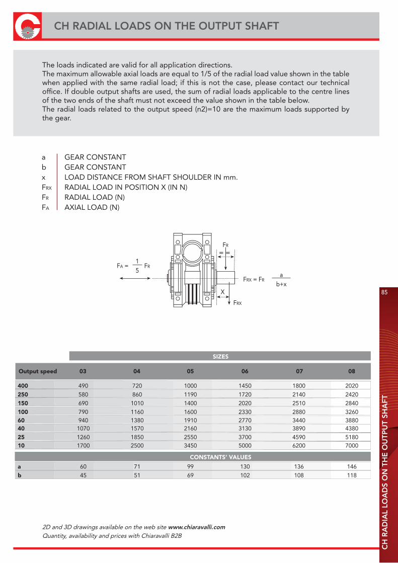
CH
RA
DIA
L LO
AD
S O
N T
HE
OU
TPU
T SH
AFT
CH RADIAL LOADS ON THE OUTPUT SHAFT
85
400 490 720 1000 1450 1800 2020
250 580 860 1190 1720 2140 2420
150 690 1010 1400 2020 2510 2840
100 790 1160 1600 2330 2880 326060 940 1380 1910 2770 3440 388040 1070 1570 2160 3130 3890 4380
25 1260 1850 2550 3700 4590 518010 1700 2500 3450 5000 6200 7000
a 60 71 99 130 136 146
b 45 51 69 102 108 118
SIZES
Output speed 03 04 05 06 07 08
CONSTANTS’ VALUES
FA =15
FR
FRX = FRa
b+x
FR
= =
X
FRX
The loads indicated are valid for all application directions.The maximum allowable axial loads are equal to 1/5 of the radial load value shown in the table when applied with the same radial load; if this is not the case, please contact our technical office. If double output shafts are used, the sum of radial loads applicable to the centre lines of the two ends of the shaft must not exceed the value shown in the table below.The radial loads related to the output speed (n2)=10 are the maximum loads supported by the gear.
a GEAR CONSTANTb GEAR CONSTANTx LOAD DISTANCE FROM SHAFT SHOULDER IN mm.FRX RADIAL LOAD IN POSITION X (IN N)FR RADIAL LOAD (N)FA AXIAL LOAD (N)
2D and 3D drawings available on the web site www.chiaravalli.comQuantity, availability and prices with Chiaravalli B2B

86
RADIAL LOADS ON THE CENTRE LINE OF THE INPUT SHAFTC
H R
AD
IAL
LOA
DS
ON
TH
E C
EN
TRE
LIN
E O
F TH
E IN
PU
T SH
AFT
FR max 100 150 220 700 975 1150
SIZES
03 04 05 06 07 08
Notes: value of tables are in N
FR= =
2D and 3D drawings available on the web site www.chiaravalli.comQuantity, availability and prices with Chiaravalli B2B
CH
- U
SE A
ND
MA
INTE
NA
NC
E IN
STR
UC
TIO
NS
87
CH - USE AND MAINTENANCE INSTRUCTIONS
INSTALLATION· The data shown on the identification name plate must correspond to the gear ordered.· All the gears are supplied complete with permanent synthetic oil in a quantity that is sufficient for any assembly position.· The gear must be fixed on a flat surface that is sufficiently rigid in order to avoid any vibration.· The gear and the axis of the machine to be driven must be perfectly aligned.· In the event that knocks, overloading or blockage of the machine are foreseen, the client must install a limiting device, joints, overload cut-out etc.· Coupling with pinions, joints, pulleys and other parts must be done after the parts have been cleaned and knocks should be avoided whilst assembling as they could damage the bearingsand other internal parts.· In the event that the motor is supplied by the client, he must check that the flange and shaft tolerances correspond to a “normal” class; our motors satisfy this requirement.· Check that the fixing screws for the gear and the related accessories are correctly tightened.· Take suitable measures to protect the groups from any aggressive atmospheric agents.· Where foreseen, protect rotating parts from any possible contact with the operators.· If the gears are painted, protect the oil seals and the machined surfaces.· All of the gears are painted RAL 9022 grey.
OPERATION AND RUNNING-IN· To obtain the best performance the gears must first be runin by gradually increasing the power in the first few hours of operation, in this phase an increase in temperature is considered normal.· In the event of defective operation, noise, oil leakage, etc. stop the gear immediately and, when possible, remove the cause. Alternatively, send the piece to our factory to be controlled.
MAINTENANCE· The worm gears from size 03 to size 08 and the pre-stage modules are lubricated with permanent synthetic oil and therefore do not require any maintenance.
WAREHOUSE STORAGE· If the warehouse storage will be for a long time, more than 3 months, the shafts and machined surfaces should be protected using antioxidants and the oil seals should be greased.
HANDLING· Care must be taken not to damage the oil seals and the machined surfaces when handling the groups.
DISPOSAL OF PACKAGING · The packaging in which our gears are delivered should be sent to specialised companies for recycling if possible.
CHO HELICAL-HYPOID GEAR UNITS
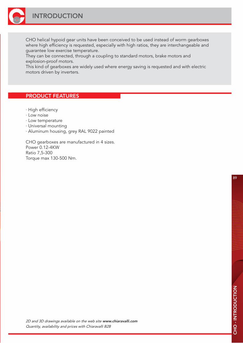
CH
O -
INTR
OD
UC
TIO
N
89
INTRODUCTION
CHO helical hypoid gear units have been conceived to be used instead of worm gearboxes where high efficiency is requested, especially with high ratios, they are interchangeable and guarantee low exercise temperature.They can be connected, through a coupling to standard motors, brake motors and explosion-proof motors.This kind of gearboxes are widely used where energy saving is requested and with electric motors driven by inverters.
· High efficiency· Low noise· Low temperature· Universal mounting· Aluminum housing, grey RAL 9022 painted
CHO gearboxes are manufactured in 4 sizes.Power 0.12-4KWRatio 7,5-300Torque max 130-500 Nm.
PRODUCT FEATURES
2D and 3D drawings available on the web site www.chiaravalli.comQuantity, availability and prices with Chiaravalli B2B
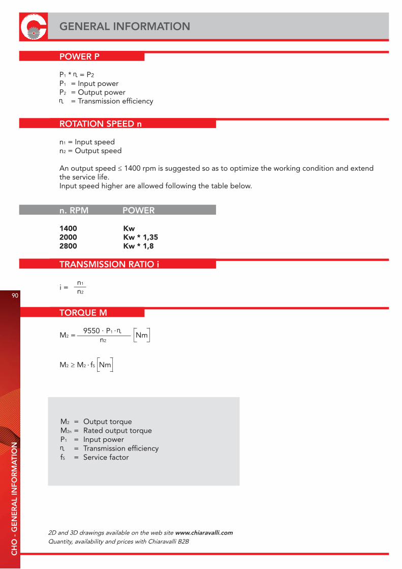
TORQUE M
9550 P1
n2M2 = Nm
. .
M2 ≥ M2 fS Nm.
M2 = Output torqueM2n = Rated output torqueP1 = Input power = Transmission efficiency
fS = Service factor
GENERAL INFORMATION
POWER P
P1 * = P2
P1 = Input powerP2 = Output power = Transmission efficiency
ROTATION SPEED n
n1 = Input speedn2 = Output speed
An output speed ≤ 1400 rpm is suggested so as to optimize the working condition and extend the service life.Input speed higher are allowed following the table below.
TRANSMISSION RATIO i
n1
n290
CH
O -
GE
NE
RA
L IN
FOR
MA
TIO
N
i =
n. RPM POWER
1400 Kw2000 Kw * 1,352800 Kw * 1,8
2D and 3D drawings available on the web site www.chiaravalli.comQuantity, availability and prices with Chiaravalli B2B

OUTPUT SHAFT RADIAL LOADS & AXIAL LOADS FR, FA
91
RADIAL LOADS FR
CH
O -
RA
DIA
L LO
AD
S FR
- O
UTP
UT
SHA
FT R
AD
IAL
LOA
DS
& A
XIA
L LO
AD
S FR
, FA
The radial loads is proportional to the requested torque and inversely proportional to the transmission member diameter following this formula.
2000 T T.e.f. D
FR = N. .
FR a (b+x)
FRx ≤.
N
FR = Radial loadT = Nm (Torque)T.e.f. = Transmission element factorT.e.f. = 1,15 gear = 1,4 chain spocket = 1,75 v-pulley = 2,5 flat-pulleyD = Transmission element diameter
FR = Radial load on the centre linea,b,x = See table
When the radial loads is not applied on the centre line of the shaft it is necessary to use the following formula.
a 104 104 128 128 135 135 148.5 148.5
b 78 70 98 98 105 105 118.5 118.5
CHO 52 CHO 53 CHO 62 CHO 63 CHO 72 CHO 73 CHO 82 CHO 83
FA = FRX 0.1
FRX FR
X
L/2
L
92
LUBRICATIONC
HO
LU
BR
ICA
TIO
N
TYPES OF LUBRICATION
LUBRICANT FILL QUANTITY
fill quantity in liters size B3 B6 B7 B8 V5 V6
CHO 52 0.22 0.20 0.13 0.15 0.25 0.14
CHO 53 0.07 0.04 0.04 0.05 0.08 0.09
CHO 62 0.38 0.35 0.25 0.26 0.44 0.25
CHO 63 0.07 0.04 0.04 0.05 0.08 0.09
CHO 72 0.66 0.60 0.45 0.48 0.78 0.47
CHO 73 0.13 0.09 0.09 0.09 0.15 0.17
CHO 82 1.15 0.93 0.70 0.74 1.25 0.75
CHO 83 0.13 0.09 0.09 0.09 0.15 0.17
-40
+80
+40-10
+25-20
-30 +10
-40 -20
-40
+40
-40 +10
Lubrication type ISO SHELL MOBIL BP °C -50 0 +50 +100
standard
The specified fill quantities are recomended values. The precise values vary depending on the number of stages and gear ratio. The following tables show guide values for lubricant fill quantities in relation to the mounting position (B3, B6, B7...)
CHO gearboxes are supplied complete with mineral oil for mounting position B3.The pre-stage used for third stage is lubricated with syntetic oil and it does not need the breather plug.
VG 220 Shell Omala Mobilgear BP Energol 220 630 GR-XP 220 VG 150 Shell Omala Mobilgear BP Energol VG 100 100 627 GR-XP 100 Mineral Oil VG 68-46 Shell Tellus Mobil VG 32 T 32 D.T.E. 13M
CHO VG 22 Shell Tellus Mobil BP Energol VG 15 T 15 D.T.E. 11M HLP-HM 15
VG 220 Shell Omala Mobil HD 150 SHC 630 VG 150 Mobil Syntetic oil SHC 629
VG 32 Mobil SHC 624
2D and 3D drawings available on the web site www.chiaravalli.comQuantity, availability and prices with Chiaravalli B2B
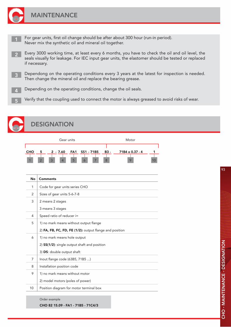
CH
O -
MA
INTE
NA
NC
E -
DE
SIG
NA
TIO
N
93
MAINTENANCE
For gear units, first oil change should be after about 300 hour (run-in period).Never mix the synthetic oil and mineral oil together.
Every 3000 working time, at least every 6 months, you have to check the oil and oil level, the seals visually for leakage. For IEC input gear units, the elastomer should be tested or replaced if necessary.
Dependong on the operating conditions every 3 years at the latest for inspection is needed. Then change the mineral oil and replace the bearing grease.
Depending on the operating conditions, change the oil seals.
Verify that the coupling used to connect the motor is always greased to avoid risks of wear.
1
2
3
4
5
DESIGNATION
Gear units Motor
CHO 5 2 - 7.60 FA1 SS1 - 71B5 B3 - 71B4 o 0.37 - 4 1
1 Code for gear units series CHO
2 Sizes of gear units 5-6-7-8
3 2 means 2 stages
3 means 3 stages
4 Speed ratio of reducer i=
5 1) no mark means without output flange
2) FA, FB, FC, FD, FE (1/2): output flange and position
6 1) no mark means hole output
2) SS(1/2): single output shaft and position
3) DS: double output shaft
7 Inout flange code (63B5, 71B5 ...)
8 Installation position code
9 1) no mark means without motor
2) model motors (poles of power)
10 Position diagram for motor terminal box
No Comments
Order example
CHO 82 15.09 - FA1 - 71B5 - 71C4/3

94
RATIO AND IEC MOTOR ADAPTERSC
HO
- R
ATI
O A
ND
IEC
MO
TOR
AD
AP
TER
S
CHO 53
CHO 52
CHO 63
3 stages
CHO 62
2 stages
i i n2 M2n Fr2 nominal actual P1=Kw M1 F.S. 63B5 71B5 80B5 90B5 r/min Nm N 71B14 80B14 90B14
CHO 62/63 n1 = 1400 r/min 200Nm
i i n2 M2n Fr2 nominal actual P1=Kw M1 F.S. 63B5 71B5 80B5 90B5 r/min Nm N 71B14 80B14 90B14
CHO 52/53 n1 = 1400 r/min 130Nm
3 stages
2 stages
300 291.79 4.8 110 0.12 183 0.60 4100
250 244.29 5.8 130 0.12 173 0.75 4100
200 200.44 7.0 130 0.12 137 0.95 4100
150 146.67 9.6 130 0.18 151 0.86 4000
125 120.34 12 130 0.18 124 1.05 3770
100 101.04 14 130 0.25 144 0.90 3560
75 74.62 19 130 0.37 159 0.82 3220
60 58.36 24 110 0.37 133 0.83 2960
50 48.86 29 130 0.37 110 1.18 2790
40 40.09 35 130 0.55 130 1.00 2610
30 29.33 48 130 0.75 137 0.95 2350
25 24.07 59 130 0.75 110 1.18 2200
20 20.21 70 130 1.10 130 1.00 2080
15 14.92 94 130 1.50 137 0.95 1880
12.5 12.47 113 120 1.50 114 1.05 1770
10 10.47 134 110 1.50 96 1.15 1670
7.5 7.73 182 100 1.50 70 1.42 1510
300 302.50 4.7 170 0.12 210 0.81 4800
250 243.57 5.8 200 0.18 250 0.80 4800
200 196.43 7.2 200 0.25 286 0.70 4800
150 151.56 9.3 200 0.25 222 0.90 4650
125 122.22 12 200 0.37 263 0.76 4330
100 101.27 14 200 0.37 215 0.93 4070
75 73.33 20 200 0.55 233 0.86 3650
60 60.50 24 170 0.55 205 0.83 3430
50 48.71 29 200 0.75 217 0.92 3190
40 39.29 36 200 0.75 180 1.11 2970
30 30.31 47 200 1.10 200 1.00 2720
25 24.44 58 200 1.50 217 0.92 2530
20 20.25 70 200 1.50 180 1.11 2380
15 14.67 96 200 1.50 135 1.48 2130
12.5 12.67 111 180 1.50 118 1.53 2030
10 10.50 134 170 1.50 94 1.80 1910
7.5 7.60 185 160 1.50 68 2.35 1710
2D and 3D drawings available on the web site www.chiaravalli.comQuantity, availability and prices with Chiaravalli B2B
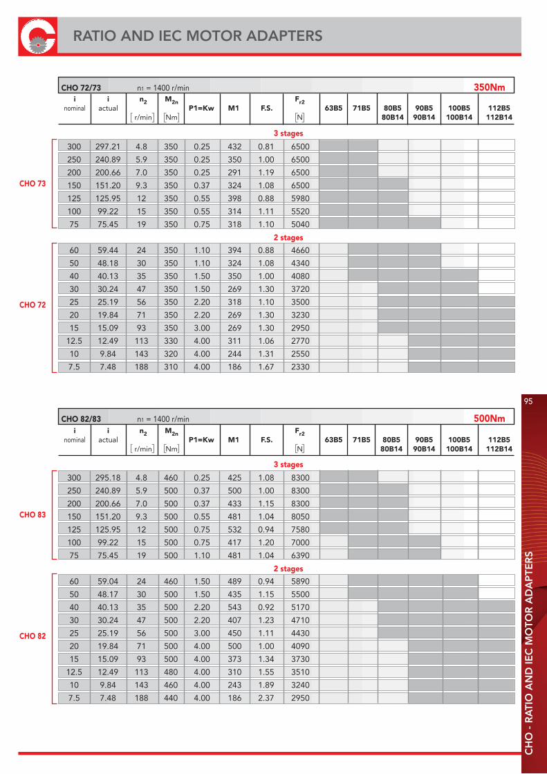
CH
O -
RA
TIO
AN
D IE
C M
OTO
R A
DA
PTE
RS
95
RATIO AND IEC MOTOR ADAPTERS
CHO 73
3 stages
CHO 72
2 stages
CHO 83
3 stages
CHO 82
2 stages
i i n2 M2n Fr2 nominal actual P1=Kw M1 F.S. 63B5 71B5 80B5 90B5 100B5 112B5 r/min Nm N 80B14 90B14 100B14 112B14
CHO 72/73 n1 = 1400 r/min 350Nm
300 295.18 4.8 460 0.25 425 1.08 8300
250 240.89 5.9 500 0.37 500 1.00 8300
200 200.66 7.0 500 0.37 433 1.15 8300
150 151.20 9.3 500 0.55 481 1.04 8050
125 125.95 12 500 0.75 532 0.94 7580
100 99.22 15 500 0.75 417 1.20 7000
75 75.45 19 500 1.10 481 1.04 6390
60 59.04 24 460 1.50 489 0.94 5890
50 48.17 30 500 1.50 435 1.15 5500
40 40.13 35 500 2.20 543 0.92 5170
30 30.24 47 500 2.20 407 1.23 4710
25 25.19 56 500 3.00 450 1.11 4430
20 19.84 71 500 4.00 500 1.00 4090
15 15.09 93 500 4.00 373 1.34 3730
12.5 12.49 113 480 4.00 310 1.55 3510
10 9.84 143 460 4.00 243 1.89 3240
7.5 7.48 188 440 4.00 186 2.37 2950
300 297.21 4.8 350 0.25 432 0.81 6500
250 240.89 5.9 350 0.25 350 1.00 6500
200 200.66 7.0 350 0.25 291 1.19 6500
150 151.20 9.3 350 0.37 324 1.08 6500
125 125.95 12 350 0.55 398 0.88 5980
100 99.22 15 350 0.55 314 1.11 5520
75 75.45 19 350 0.75 318 1.10 5040
60 59.44 24 350 1.10 394 0.88 4660
50 48.18 30 350 1.10 324 1.08 4340
40 40.13 35 350 1.50 350 1.00 4080
30 30.24 47 350 1.50 269 1.30 3720
25 25.19 56 350 2.20 318 1.10 3500
20 19.84 71 350 2.20 269 1.30 3230
15 15.09 93 350 3.00 269 1.30 2950
12.5 12.49 113 330 4.00 311 1.06 2770
10 9.84 143 320 4.00 244 1.31 2550
7.5 7.48 188 310 4.00 186 1.67 2330
i i n2 M2n Fr2 nominal actual P1=Kw M1 F.S. 63B5 71B5 80B5 90B5 100B5 112B5 r/min Nm N 80B14 90B14 100B14 112B14
CHO 82/83 n1 = 1400 r/min 500Nm
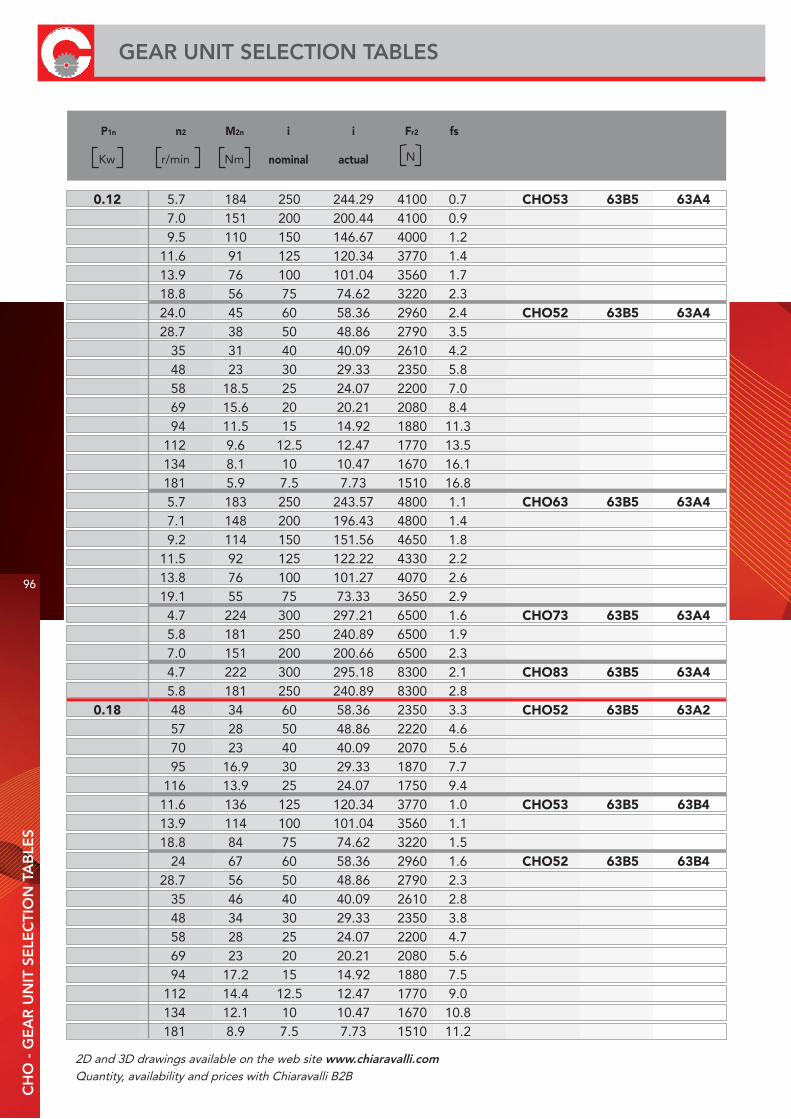
P1n n2 M2n i i Fr2 fs
nominal actual
Kw r/min Nm N
0.12 5.7 184 250 244.29 4100 0.7 CHO53 63B5 63A4 7.0 151 200 200.44 4100 0.9 9.5 110 150 146.67 4000 1.2 11.6 91 125 120.34 3770 1.4 13.9 76 100 101.04 3560 1.7 18.8 56 75 74.62 3220 2.3 24.0 45 60 58.36 2960 2.4 CHO52 63B5 63A4 28.7 38 50 48.86 2790 3.5 35 31 40 40.09 2610 4.2 48 23 30 29.33 2350 5.8 58 18.5 25 24.07 2200 7.0 69 15.6 20 20.21 2080 8.4 94 11.5 15 14.92 1880 11.3 112 9.6 12.5 12.47 1770 13.5 134 8.1 10 10.47 1670 16.1 181 5.9 7.5 7.73 1510 16.8 5.7 183 250 243.57 4800 1.1 CHO63 63B5 63A4 7.1 148 200 196.43 4800 1.4 9.2 114 150 151.56 4650 1.8 11.5 92 125 122.22 4330 2.2 13.8 76 100 101.27 4070 2.6 19.1 55 75 73.33 3650 2.9 4.7 224 300 297.21 6500 1.6 CHO73 63B5 63A4 5.8 181 250 240.89 6500 1.9 7.0 151 200 200.66 6500 2.3 4.7 222 300 295.18 8300 2.1 CHO83 63B5 63A4 5.8 181 250 240.89 8300 2.8 0.18 48 34 60 58.36 2350 3.3 CHO52 63B5 63A2 57 28 50 48.86 2220 4.6 70 23 40 40.09 2070 5.6 95 16.9 30 29.33 1870 7.7 116 13.9 25 24.07 1750 9.4 11.6 136 125 120.34 3770 1.0 CHO53 63B5 63B4 13.9 114 100 101.04 3560 1.1 18.8 84 75 74.62 3220 1.5 24 67 60 58.36 2960 1.6 CHO52 63B5 63B4 28.7 56 50 48.86 2790 2.3 35 46 40 40.09 2610 2.8 48 34 30 29.33 2350 3.8 58 28 25 24.07 2200 4.7 69 23 20 20.21 2080 5.6 94 17.2 15 14.92 1880 7.5 112 14.4 12.5 12.47 1770 9.0 134 12.1 10 10.47 1670 10.8 181 8.9 7.5 7.73 1510 11.2
96
GEAR UNIT SELECTION TABLESC
HO
- G
EA
R U
NIT
SE
LEC
TIO
N T
AB
LES
2D and 3D drawings available on the web site www.chiaravalli.comQuantity, availability and prices with Chiaravalli B2B

P1n n2 M2n i i Fr2 fs
nominal actualKw r/min Nm N
0.18 15.4 105 60 58.36 3430 1.0 CHO52 71B5/B14 71A6
18.4 88 50 48.86 3240 1.5
22.4 72 40 40.09 3030 1.8
31 53 30 29.33 2730 2.5
37 43 25 24.07 2550 3.0
7.1 222 200 196.43 4800 0.9 CHO63 63B5 63B4
9.2 171 150 151.56 4650 1.2
11.5 138 125 122.22 4330 1.4
13.8 114 100 101.27 4070 1.7
19.1 83 75 73.33 3650 1.9
23.1 70 60 60.50 3430 2.4 CHO62 63B5 63B4
28.7 56 50 48.71 3190 3.6
7.4 215 125 122.22 4800 0.9 CHO63 71B5/B14 71A6
8.9 178 100 101.27 4720 1.1
12.3 129 75 73.33 4230 1.2
14.9 109 60 60.50 3970 1.6 CHO62 71B5/B14 71A6
18.5 87 50 48.71 3690 2.3
22.9 71 40 38.29 3440 2.8
4.7 336 300 297.21 6500 1.0 CHO73 63B5 63B4
5.8 272 250 240.89 6500 1.3
7.0 227 200 200.66 6500 1.5
9.3 171 150 151.20 6500 2.0
11.1 142 125 125.95 5980 2.5
14.1 112 100 99.22 5520 3.1
4.5 353 200 200.66 6500 1.0 CHO73 71B5 71A6
6.0 266 150 151.20 6500 1.3
7.1 221 125 125.95 6500 1.6
9.1 174 100 99.22 6400 2.0
11.9 133 75 75.45 5840 2.6
4.7 333 300 295.18 8300 1.4 CHO83 63B5 63B4
5.8 272 250 240.89 8300 1.8
7.0 227 200 200.66 8300 2.2
9.3 171 150 151.20 8050 2.9
3.7 423 250 240.89 8300 1.2 CHO83 71B5 71A6
4.5 353 200 200.66 8300 1.4
6.0 266 150 151.20 8300 1.9
7.1 221 125 125.95 8300 2.3
9.1 174 100 99.22 8110 2.9
0.25 19.1 115 150 146.67 3200 1.1 CHO53 63B5 63B2
23.3 94 125 120.34 2990 1.4
27.7 79 100 101.04 2820 1.6
38 59 75 74.62 2550 2.2
48 47 60 58.36 2350 2.4 CHO52 63B5 63B2
57 39 50 48.86 2220 3.3
70 32 40 40.09 2070 4.0
CH
O -
GE
AR
UN
IT S
ELE
CTI
ON
TA
BLE
S
97
GEAR UNIT SELECTION TABLES

P1n n2 M2n i i Fr2 fs
nominal actual
Kw r/min Nm N
0.25 24 94 60 58.36 2960 1.2 CHO52 71B5/B14 71A4
28.7 78 50 48.86 2790 1.7
35 64 40 40.09 2610 2.0
48 47 30 29.33 2350 2.8
58 39 25 24.07 2200 3.4
69 32 20 20.21 2080 4.0
94 24 15 14.92 1880 5.4
18.4 122 50 48.86 3240 1.1 CHO52 71B5/B14 71B6
22.4 100 40 40.09 3030 1.3
31 73 30 29.33 2730 1.8
37 60 25 24.07 2550 2.2
45 50 20 20.21 2410 2.6
60 37 15 14.92 2180 3.5
72 31 12.5 12.47 2050 4.2
86 26 10 10.47 1930 5.0
116 19 7.5 7.73 1750 5.2
11.5 191 250 243.57 4330 1.0 CHO63 63B5 63B2
14.3 154 200 196.43 4030 1.3
18.5 119 150 151.56 3690 1.7
22.9 96 125 122.22 3440 2.1
27.6 78 100 101.27 3230 2.5
38 58 75 73.33 2900 2.8
11.5 192 125 122.22 4330 1.0 CHO63 71B5/B14 71A4
13.8 159 100 101.27 4070 1.3
19.1 115 75 73.33 3650 1.4
23.1 97 60 60.50 3430 1.8 CHO62 71B5/B14 71A4
28.7 78 50 48.71 3190 2.6
36 63 40 39.29 2970 3.2
46 49 30 30.31 2720 4.1
14.9 151 60 60.50 3970 1.1 CHO62 71B5/B14 71B6
18.5 121 50 48.71 3690 1.6
22.9 98 40 39.29 3440 2.0
29.7 76 30 30.31 3150 2.6
9.4 233 300 297.21 6320 1.5 CHO73 63B5 63B2
11.6 189 250 240.89 5890 1.9
14 157 200 200.66 5540 2.2
18.5 119 150 151.20 5040 3.0
5.8 378 250 240.89 6500 0.9 CHO73 71B5 71A4
7.0 315 200 200.66 6500 1.1
9.3 237 150 151.20 6500 1.5
11.1 198 125 125.95 5980 1.8
14.1 156 100 99.22 5520 2.2
18.6 118 75 75.45 5040 3.0
6 369 150 151.20 6500 0.9 CHO73 71B5 71B6
7.1 307 125 125.95 6500 1.1
98
GEAR UNIT SELECTION TABLESC
HO
- G
EA
R U
NIT
SE
LEC
TIO
N T
AB
LES
2D and 3D drawings available on the web site www.chiaravalli.comQuantity, availability and prices with Chiaravalli B2B
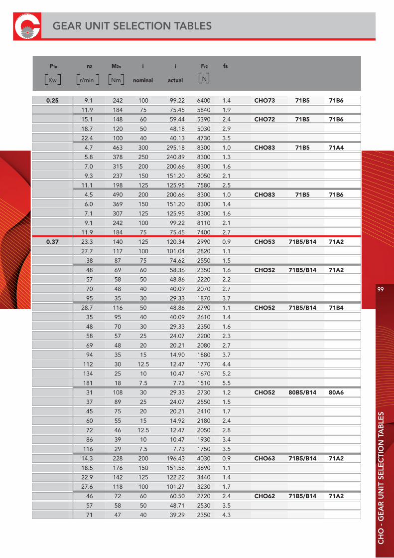
P1n n2 M2n i i Fr2 fs
nominal actual
Kw r/min Nm N
0.25 9.1 242 100 99.22 6400 1.4 CHO73 71B5 71B6
11.9 184 75 75.45 5840 1.9
15.1 148 60 59.44 5390 2.4 CHO72 71B5 71B6
18.7 120 50 48.18 5030 2.9
22.4 100 40 40.13 4730 3.5
4.7 463 300 295.18 8300 1.0 CHO83 71B5 71A4
5.8 378 250 240.89 8300 1.3
7.0 315 200 200.66 8300 1.6
9.3 237 150 151.20 8050 2.1
11.1 198 125 125.95 7580 2.5
4.5 490 200 200.66 8300 1.0 CHO83 71B5 71B6
6.0 369 150 151.20 8300 1.4
7.1 307 125 125.95 8300 1.6
9.1 242 100 99.22 8110 2.1
11.9 184 75 75.45 7400 2.7
0.37 23.3 140 125 120.34 2990 0.9 CHO53 71B5/B14 71A2
27.7 117 100 101.04 2820 1.1
38 87 75 74.62 2550 1.5
48 69 60 58.36 2350 1.6 CHO52 71B5/B14 71A2
57 58 50 48.86 2220 2.2
70 48 40 40.09 2070 2.7
95 35 30 29.33 1870 3.7
28.7 116 50 48.86 2790 1.1 CHO52 71B5/B14 71B4
35 95 40 40.09 2610 1.4
48 70 30 29.33 2350 1.6
58 57 25 24.07 2200 2.3
69 48 20 20.21 2080 2.7
94 35 15 14.90 1880 3.7
112 30 12.5 12.47 1770 4.4
134 25 10 10.47 1670 5.2
181 18 7.5 7.73 1510 5.5
31 108 30 29.33 2730 1.2 CHO52 80B5/B14 80A6
37 89 25 24.07 2550 1.5
45 75 20 20.21 2410 1.7
60 55 15 14.92 2180 2.4
72 46 12.5 12.47 2050 2.8
86 39 10 10.47 1930 3.4
116 29 7.5 7.73 1750 3.5
14.3 228 200 196.43 4030 0.9 CHO63 71B5/B14 71A2
18.5 176 150 151.56 3690 1.1
22.9 142 125 122.22 3440 1.4
27.6 118 100 101.27 3230 1.7
46 72 60 60.50 2720 2.4 CHO62 71B5/B14 71A2
57 58 50 48.71 2530 3.5
71 47 40 39.29 2350 4.3
CH
O -
GE
AR
UN
IT S
ELE
CTI
ON
TA
BLE
S
99
GEAR UNIT SELECTION TABLES
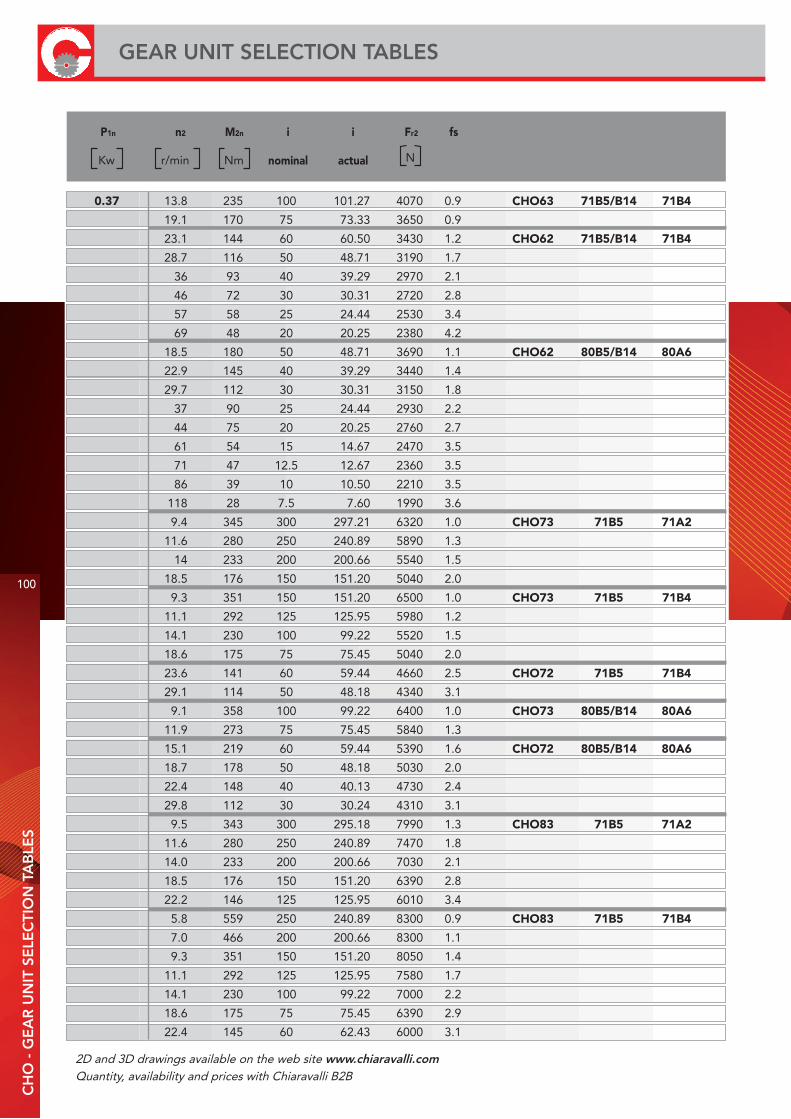
P1n n2 M2n i i Fr2 fs
nominal actual
Kw r/min Nm N
0.37 13.8 235 100 101.27 4070 0.9 CHO63 71B5/B14 71B4
19.1 170 75 73.33 3650 0.9
23.1 144 60 60.50 3430 1.2 CHO62 71B5/B14 71B4
28.7 116 50 48.71 3190 1.7
36 93 40 39.29 2970 2.1
46 72 30 30.31 2720 2.8
57 58 25 24.44 2530 3.4
69 48 20 20.25 2380 4.2
18.5 180 50 48.71 3690 1.1 CHO62 80B5/B14 80A6
22.9 145 40 39.29 3440 1.4
29.7 112 30 30.31 3150 1.8
37 90 25 24.44 2930 2.2
44 75 20 20.25 2760 2.7
61 54 15 14.67 2470 3.5
71 47 12.5 12.67 2360 3.5
86 39 10 10.50 2210 3.5
118 28 7.5 7.60 1990 3.6
9.4 345 300 297.21 6320 1.0 CHO73 71B5 71A2
11.6 280 250 240.89 5890 1.3
14 233 200 200.66 5540 1.5
18.5 176 150 151.20 5040 2.0
9.3 351 150 151.20 6500 1.0 CHO73 71B5 71B4
11.1 292 125 125.95 5980 1.2
14.1 230 100 99.22 5520 1.5
18.6 175 75 75.45 5040 2.0
23.6 141 60 59.44 4660 2.5 CHO72 71B5 71B4
29.1 114 50 48.18 4340 3.1
9.1 358 100 99.22 6400 1.0 CHO73 80B5/B14 80A6
11.9 273 75 75.45 5840 1.3
15.1 219 60 59.44 5390 1.6 CHO72 80B5/B14 80A6
18.7 178 50 48.18 5030 2.0
22.4 148 40 40.13 4730 2.4
29.8 112 30 30.24 4310 3.1
9.5 343 300 295.18 7990 1.3 CHO83 71B5 71A2
11.6 280 250 240.89 7470 1.8
14.0 233 200 200.66 7030 2.1
18.5 176 150 151.20 6390 2.8
22.2 146 125 125.95 6010 3.4
5.8 559 250 240.89 8300 0.9 CHO83 71B5 71B4
7.0 466 200 200.66 8300 1.1
9.3 351 150 151.20 8050 1.4
11.1 292 125 125.95 7580 1.7
14.1 230 100 99.22 7000 2.2
18.6 175 75 75.45 6390 2.9
22.4 145 60 62.43 6000 3.1
100
GEAR UNIT SELECTION TABLESC
HO
- G
EA
R U
NIT
SE
LEC
TIO
N T
AB
LES
2D and 3D drawings available on the web site www.chiaravalli.comQuantity, availability and prices with Chiaravalli B2B
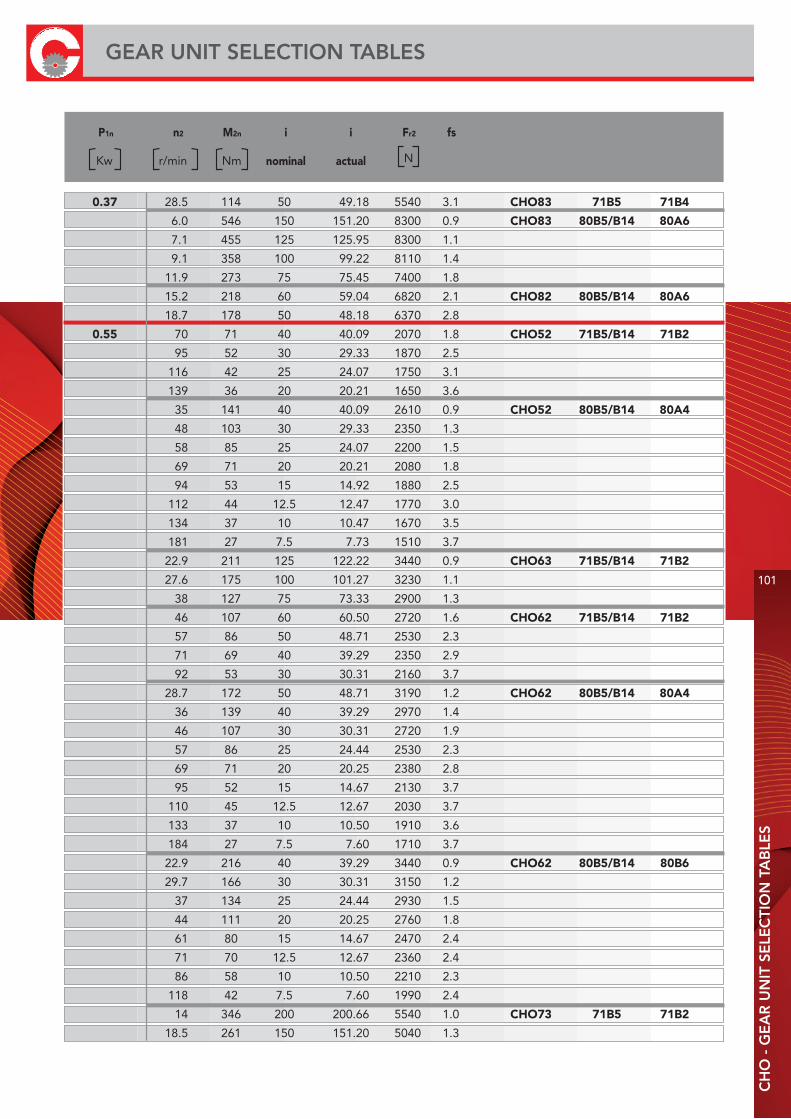
P1n n2 M2n i i Fr2 fs
nominal actual
Kw r/min Nm N
0.37 28.5 114 50 49.18 5540 3.1 CHO83 71B5 71B4
6.0 546 150 151.20 8300 0.9 CHO83 80B5/B14 80A6
7.1 455 125 125.95 8300 1.1
9.1 358 100 99.22 8110 1.4
11.9 273 75 75.45 7400 1.8
15.2 218 60 59.04 6820 2.1 CHO82 80B5/B14 80A6
18.7 178 50 48.18 6370 2.8
0.55 70 71 40 40.09 2070 1.8 CHO52 71B5/B14 71B2
95 52 30 29.33 1870 2.5
116 42 25 24.07 1750 3.1
139 36 20 20.21 1650 3.6
35 141 40 40.09 2610 0.9 CHO52 80B5/B14 80A4
48 103 30 29.33 2350 1.3
58 85 25 24.07 2200 1.5
69 71 20 20.21 2080 1.8
94 53 15 14.92 1880 2.5
112 44 12.5 12.47 1770 3.0
134 37 10 10.47 1670 3.5
181 27 7.5 7.73 1510 3.7
22.9 211 125 122.22 3440 0.9 CHO63 71B5/B14 71B2
27.6 175 100 101.27 3230 1.1
38 127 75 73.33 2900 1.3
46 107 60 60.50 2720 1.6 CHO62 71B5/B14 71B2
57 86 50 48.71 2530 2.3
71 69 40 39.29 2350 2.9
92 53 30 30.31 2160 3.7
28.7 172 50 48.71 3190 1.2 CHO62 80B5/B14 80A4
36 139 40 39.29 2970 1.4
46 107 30 30.31 2720 1.9
57 86 25 24.44 2530 2.3
69 71 20 20.25 2380 2.8
95 52 15 14.67 2130 3.7
110 45 12.5 12.67 2030 3.7
133 37 10 10.50 1910 3.6
184 27 7.5 7.60 1710 3.7
22.9 216 40 39.29 3440 0.9 CHO62 80B5/B14 80B6
29.7 166 30 30.31 3150 1.2
37 134 25 24.44 2930 1.5
44 111 20 20.25 2760 1.8
61 80 15 14.67 2470 2.4
71 70 12.5 12.67 2360 2.4
86 58 10 10.50 2210 2.3
118 42 7.5 7.60 1990 2.4
14 346 200 200.66 5540 1.0 CHO73 71B5 71B2
18.5 261 150 151.20 5040 1.3
CH
O -
GE
AR
UN
IT S
ELE
CTI
ON
TA
BLE
S
101
GEAR UNIT SELECTION TABLES
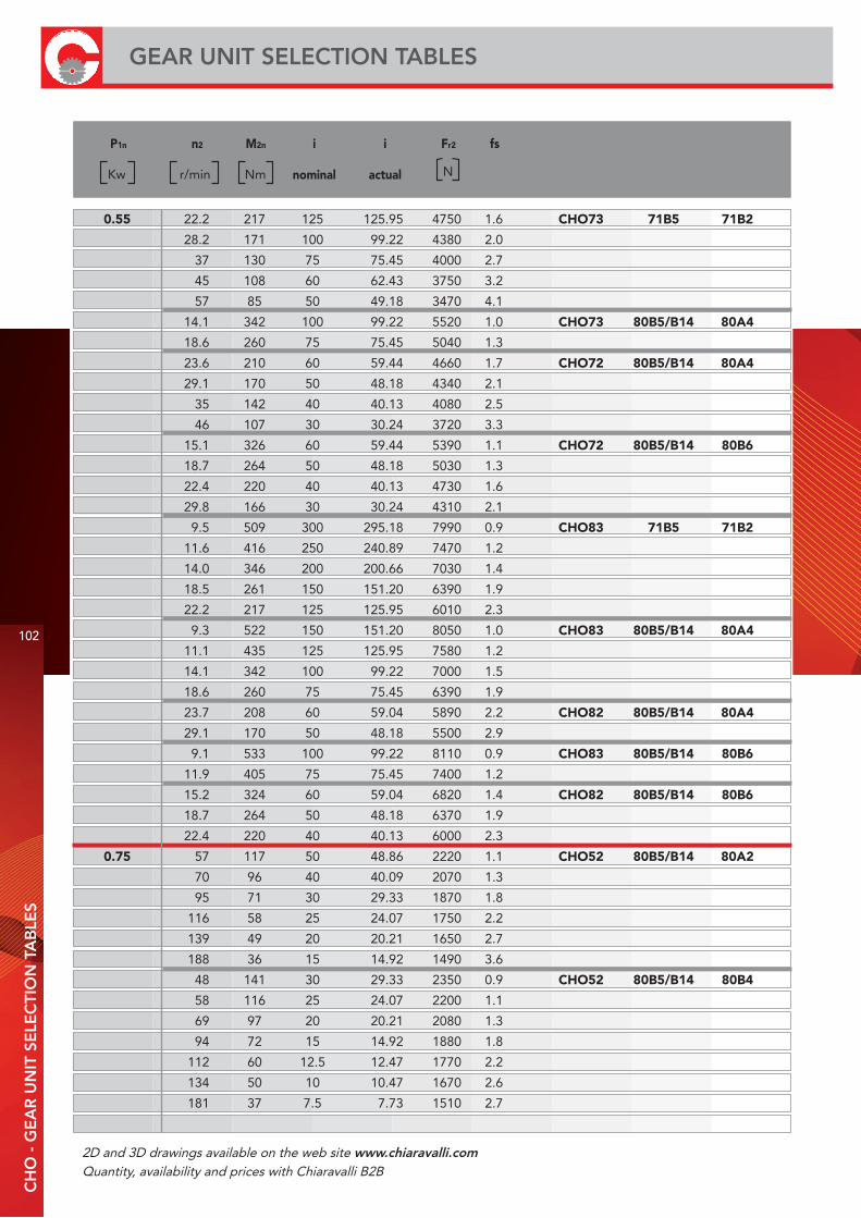
P1n n2 M2n i i Fr2 fs
nominal actual
Kw r/min Nm N
0.55 22.2 217 125 125.95 4750 1.6 CHO73 71B5 71B2
28.2 171 100 99.22 4380 2.0
37 130 75 75.45 4000 2.7
45 108 60 62.43 3750 3.2
57 85 50 49.18 3470 4.1
14.1 342 100 99.22 5520 1.0 CHO73 80B5/B14 80A4
18.6 260 75 75.45 5040 1.3
23.6 210 60 59.44 4660 1.7 CHO72 80B5/B14 80A4
29.1 170 50 48.18 4340 2.1
35 142 40 40.13 4080 2.5
46 107 30 30.24 3720 3.3
15.1 326 60 59.44 5390 1.1 CHO72 80B5/B14 80B6
18.7 264 50 48.18 5030 1.3
22.4 220 40 40.13 4730 1.6
29.8 166 30 30.24 4310 2.1
9.5 509 300 295.18 7990 0.9 CHO83 71B5 71B2
11.6 416 250 240.89 7470 1.2
14.0 346 200 200.66 7030 1.4
18.5 261 150 151.20 6390 1.9
22.2 217 125 125.95 6010 2.3
9.3 522 150 151.20 8050 1.0 CHO83 80B5/B14 80A4
11.1 435 125 125.95 7580 1.2
14.1 342 100 99.22 7000 1.5
18.6 260 75 75.45 6390 1.9
23.7 208 60 59.04 5890 2.2 CHO82 80B5/B14 80A4
29.1 170 50 48.18 5500 2.9
9.1 533 100 99.22 8110 0.9 CHO83 80B5/B14 80B6
11.9 405 75 75.45 7400 1.2
15.2 324 60 59.04 6820 1.4 CHO82 80B5/B14 80B6
18.7 264 50 48.18 6370 1.9
22.4 220 40 40.13 6000 2.3
0.75 57 117 50 48.86 2220 1.1 CHO52 80B5/B14 80A2
70 96 40 40.09 2070 1.3
95 71 30 29.33 1870 1.8
116 58 25 24.07 1750 2.2
139 49 20 20.21 1650 2.7
188 36 15 14.92 1490 3.6
48 141 30 29.33 2350 0.9 CHO52 80B5/B14 80B4
58 116 25 24.07 2200 1.1
69 97 20 20.21 2080 1.3
94 72 15 14.92 1880 1.8
112 60 12.5 12.47 1770 2.2
134 50 10 10.47 1670 2.6
181 37 7.5 7.73 1510 2.7
102
GEAR UNIT SELECTION TABLESC
HO
- G
EA
R U
NIT
SE
LEC
TIO
N T
AB
LES
2D and 3D drawings available on the web site www.chiaravalli.comQuantity, availability and prices with Chiaravalli B2B
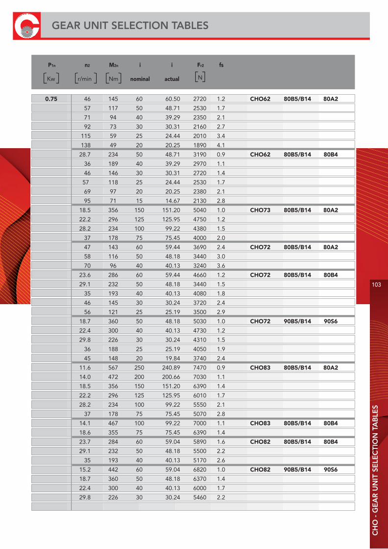
P1n n2 M2n i i Fr2 fs
nominal actualKw r/min Nm N
0.75 46 145 60 60.50 2720 1.2 CHO62 80B5/B14 80A2
57 117 50 48.71 2530 1.7
71 94 40 39.29 2350 2.1
92 73 30 30.31 2160 2.7
115 59 25 24.44 2010 3.4
138 49 20 20.25 1890 4.1
28.7 234 50 48.71 3190 0.9 CHO62 80B5/B14 80B4
36 189 40 39.29 2970 1.1
46 146 30 30.31 2720 1.4
57 118 25 24.44 2530 1.7
69 97 20 20.25 2380 2.1
95 71 15 14.67 2130 2.8
18.5 356 150 151.20 5040 1.0 CHO73 80B5/B14 80A2
22.2 296 125 125.95 4750 1.2
28.2 234 100 99.22 4380 1.5
37 178 75 75.45 4000 2.0
47 143 60 59.44 3690 2.4 CHO72 80B5/B14 80A2
58 116 50 48.18 3440 3.0
70 96 40 40.13 3240 3.6
23.6 286 60 59.44 4660 1.2 CHO72 80B5/B14 80B4
29.1 232 50 48.18 3440 1.5
35 193 40 40.13 4080 1.8
46 145 30 30.24 3720 2.4
56 121 25 25.19 3500 2.9
18.7 360 50 48.18 5030 1.0 CHO72 90B5/B14 90S6
22.4 300 40 40.13 4730 1.2
29.8 226 30 30.24 4310 1.5
36 188 25 25.19 4050 1.9
45 148 20 19.84 3740 2.4
11.6 567 250 240.89 7470 0.9 CHO83 80B5/B14 80A2
14.0 472 200 200.66 7030 1.1
18.5 356 150 151.20 6390 1.4
22.2 296 125 125.95 6010 1.7
28.2 234 100 99.22 5550 2.1
37 178 75 75.45 5070 2.8
14.1 467 100 99.22 7000 1.1 CHO83 80B5/B14 80B4
18.6 355 75 75.45 6390 1.4
23.7 284 60 59.04 5890 1.6 CHO82 80B5/B14 80B4
29.1 232 50 48.18 5500 2.2
35 193 40 40.13 5170 2.6
15.2 442 60 59.04 6820 1.0 CHO82 90B5/B14 90S6
18.7 360 50 48.18 6370 1.4
22.4 300 40 40.13 6000 1.7
29.8 226 30 30.24 5460 2.2
CH
O -
GE
AR
UN
IT S
ELE
CTI
ON
TA
BLE
S
103
GEAR UNIT SELECTION TABLES
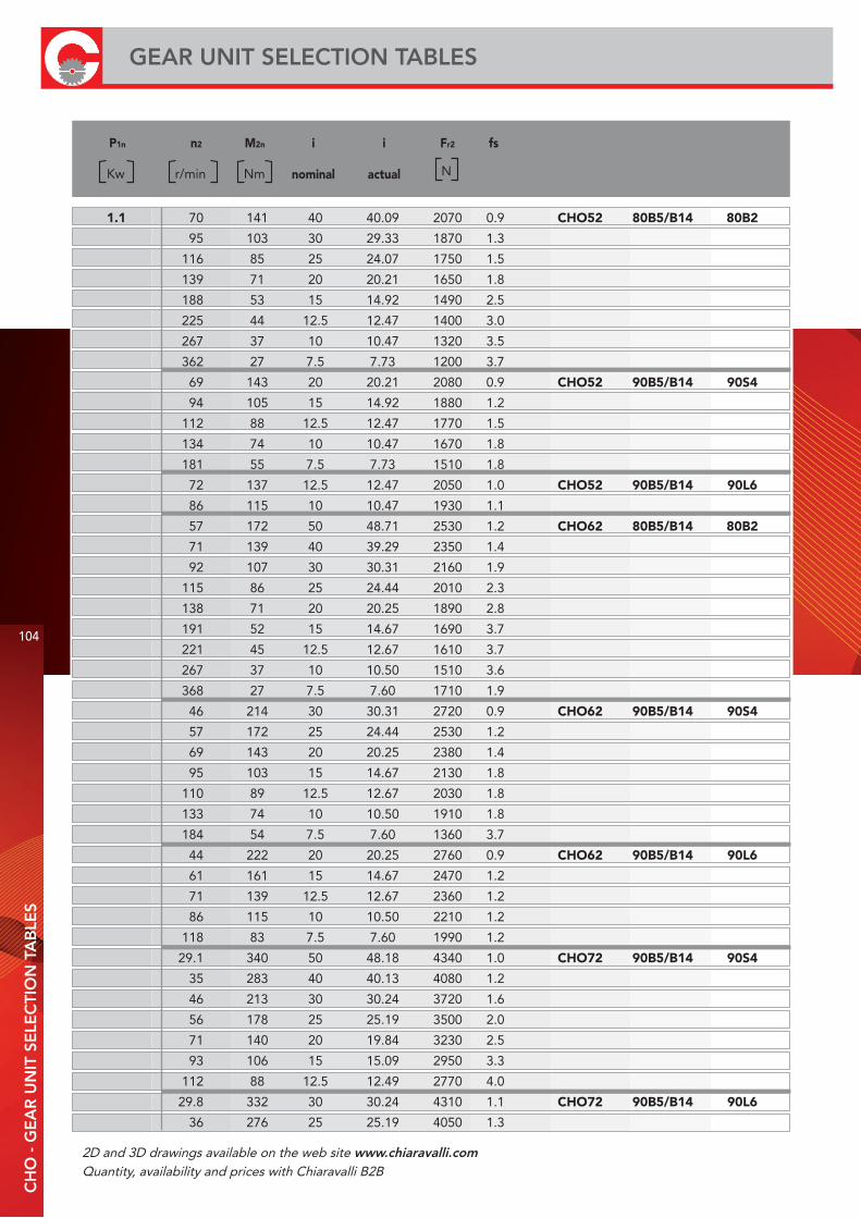
P1n n2 M2n i i Fr2 fs
nominal actualKw r/min Nm N
1.1 70 141 40 40.09 2070 0.9 CHO52 80B5/B14 80B2
95 103 30 29.33 1870 1.3
116 85 25 24.07 1750 1.5
139 71 20 20.21 1650 1.8
188 53 15 14.92 1490 2.5
225 44 12.5 12.47 1400 3.0
267 37 10 10.47 1320 3.5
362 27 7.5 7.73 1200 3.7
69 143 20 20.21 2080 0.9 CHO52 90B5/B14 90S4
94 105 15 14.92 1880 1.2
112 88 12.5 12.47 1770 1.5
134 74 10 10.47 1670 1.8
181 55 7.5 7.73 1510 1.8
72 137 12.5 12.47 2050 1.0 CHO52 90B5/B14 90L6
86 115 10 10.47 1930 1.1
57 172 50 48.71 2530 1.2 CHO62 80B5/B14 80B2
71 139 40 39.29 2350 1.4
92 107 30 30.31 2160 1.9
115 86 25 24.44 2010 2.3
138 71 20 20.25 1890 2.8
191 52 15 14.67 1690 3.7
221 45 12.5 12.67 1610 3.7
267 37 10 10.50 1510 3.6
368 27 7.5 7.60 1710 1.9
46 214 30 30.31 2720 0.9 CHO62 90B5/B14 90S4
57 172 25 24.44 2530 1.2
69 143 20 20.25 2380 1.4
95 103 15 14.67 2130 1.8
110 89 12.5 12.67 2030 1.8
133 74 10 10.50 1910 1.8
184 54 7.5 7.60 1360 3.7
44 222 20 20.25 2760 0.9 CHO62 90B5/B14 90L6
61 161 15 14.67 2470 1.2
71 139 12.5 12.67 2360 1.2
86 115 10 10.50 2210 1.2
118 83 7.5 7.60 1990 1.2
29.1 340 50 48.18 4340 1.0 CHO72 90B5/B14 90S4
35 283 40 40.13 4080 1.2
46 213 30 30.24 3720 1.6
56 178 25 25.19 3500 2.0
71 140 20 19.84 3230 2.5
93 106 15 15.09 2950 3.3
112 88 12.5 12.49 2770 4.0
29.8 332 30 30.24 4310 1.1 CHO72 90B5/B14 90L6
36 276 25 25.19 4050 1.3
104
GEAR UNIT SELECTION TABLESC
HO
- G
EA
R U
NIT
SE
LEC
TIO
N T
AB
LES
2D and 3D drawings available on the web site www.chiaravalli.comQuantity, availability and prices with Chiaravalli B2B

P1n n2 M2n i i Fr2 fs
nominal actual
Kw r/min Nm N
1.1 45 218 20 19.84 3740 1.6 CHO72 90B5/B14 90L6
60 166 15 15.09 3410 2.1
72 137 12.5 12.49 3210 2.6
18.5 522 150 151.20 6390 1.0 CHO83 80B5/B14 80B2
22.2 435 125 125.95 6010 1.2
28.2 342 100 99.22 5550 1.5
37 260 75 75.45 5070 1.9
47 208 60 59.04 4670 2.2 CHO82 80B5/B14 80B2
58 170 50 48.18 4360 2.9
18.6 521 75 75.45 6390 1.0 CHO83 90B5/B14 90S4
23.7 416 60 59.04 5890 1.1 CHO82 90B5/B14 90S4
29.1 340 50 48.18 5500 1.5
35 283 40 40.13 5170 1.8
46 213 30 30.24 4710 2.3
18.7 529 50 48.18 6370 0.9 CHO82 90B5/B14 90L6
22.4 440 40 40.13 6000 1.1
29.8 332 30 30.24 5460 1.5
36 276 25 25.19 5130 1.8
45 218 20 19.84 4740 2.3
1.5 116 116 25 24.07 1750 1.1 CHO52 90B5/B14 90S2
139 97 20 20.21 1650 1.3
188 72 15 14.92 1490 1.8
225 60 12.5 12.47 1400 2.0
267 50 10 10.47 1320 2.2
362 37 7.5 7.73 1200 2.6
94 144 15 14.92 1880 0.9 CHO52 90B5/B14 90L4
112 120 12.5 12.47 1770 1.6
134 101 10 10.47 1670 1.1
181 74 7.5 7.73 1510 1.3
57 234 50 48.71 2530 0.9 CHO62 90B5/B14 90S2
71 189 40 39.29 2350 1.1
92 146 30 30.31 2160 1.4
115 118 25 24.44 2010 1.7
138 97 20 20.25 1890 2.0
191 71 15 14.67 1690 2.8
57 235 25 24.44 2530 0.9 CHO62 90B5/B14 90L4
69 195 20 20.25 2380 1.0
95 141 15 14.67 2130 1.4
110 122 12.5 12.67 2030 1.4
133 101 10 10.50 1910 1.7
184 73 7.5 7.60 1710 2.1
47 286 60 59.44 3690 1.2 CHO72 90B5/B14 90S2
58 232 50 48.18 3440 1.5
70 193 40 40.13 3240 1.8
93 145 30 30.24 2950 2.4
CH
O -
GE
AR
UN
IT S
ELE
CTI
ON
TA
BLE
S
105
GEAR UNIT SELECTION TABLES

P1n n2 M2n i i Fr2 fs
nominal actual
Kw r/min Nm N
1.5 35 386 40 40.13 4080 0.9 CHO72 90B5/B14 90L4
46 291 30 30.24 3720 1.2
56 242 25 25.19 3500 1.4
71 191 20 19.84 3230 1.8
93 145 15 15.09 2950 2.4
112 120 12.5 12.49 2770 2.8
142 95 10 9.84 2550 3.3
47 284 60 59.04 4670 1.6 CHO82 90B5/B14 90S2
58 232 50 48.18 4360 2.2
29.1 463 50 48.18 5500 1.1 CHO82 90B5/B14 90L4
35 386 40 40.13 5170 1.3
46 291 30 30.24 4710 1.7
56 242 25 25.19 4430 2.1
71 191 20 19.84 4090 2.6
2.2 139 143 20 20.21 1650 0.9 CHO52 90B5/B14 90L2
188 105 15 14.92 1490 1.2
225 88 12.5 12.47 1400 1.4
267 74 10 10.47 1320 1.5
362 55 7.5 7.73 1200 1.8
92 214 30 30.31 2160 0.9 CHO62 90B5/B14 90L2
115 172 25 24.44 2010 1.2
138 143 20 20.25 1890 1.4
191 103 15 14.67 1690 1.8
221 89 12.5 12.67 1610 1.8
267 74 10 10.50 1510 1.8
368 54 7.5 7.60 1360 1.9
58 340 50 48.18 3440 1.0 CHO72 90B5/B14 90L2
70 283 40 40.13 3240 1.2
93 213 30 30.24 2950 1.6
111 178 25 25.19 2770 2.0
56 355 25 25.19 3500 1.0 CHO72 100B5/B14 100A4
71 280 20 19.84 3230 1.3
93 213 15 15.09 2950 1.6
112 176 12.5 12.49 2770 1.9
142 139 10 9.84 2550 2.3
187 106 7.5 7.48 2330 2.9
47 416 60 59.04 4670 1.1 CHO82 90B5/B14 90L2
58 340 50 48.18 4360 1.5
70 283 40 40.13 4110 1.8
93 213 30 30.24 3740 2.3
35 566 40 40.13 5170 0.9 CHO82 100B5/B14 100A4
46 427 30 30.24 4710 1.2
56 355 25 25.19 4430 1.4
71 280 20 19.84 4090 1.8
93 213 15 15.09 3730 2.3
106
GEAR UNIT SELECTION TABLESC
HO
- G
EA
R U
NIT
SE
LEC
TIO
N T
AB
LES
2D and 3D drawings available on the web site www.chiaravalli.comQuantity, availability and prices with Chiaravalli B2B

P1n n2 M2n i i Fr2 fs
nominal actual
Kw r/min Nm N
2.2 112 176 12.5 12.49 3510 2.6 CHO82 100B5/B14 100A4
3 70 386 40 40.13 3240 0.9 CHO72 100B5/B14 100L2
93 291 30 30.24 2950 1.2
111 242 25 25.19 2770 1.4
141 191 20 19.84 2560 1.8
186 145 15 15.09 2340 2.4
224 120 12.5 12.49 2190 2.9
285 95 10 9.84 2030 3.7
374 72 7.5 7.48 1850 3.9
93 290 15 15.09 2950 1.2 CHO72 100B5/B14 100LB4
112 240 12.5 12.49 2770 1.5
142 189 10 9.84 2550 1.8
187 144 7.5 7.48 2330 1.9
47 568 60 59.04 4670 0.8 CHO82 100B5/B14 100L2
58 463 50 48.18 4360 1.1
70 386 40 40.13 4110 1.3
93 291 30 30.24 3740 1.7
111 242 25 25.19 3520 2.1
141 191 20 19.84 3250 2.6
56 485 25 25.19 4430 1.0 CHO82 100B5/B14 100LB4
71 382 20 19.84 4090 1.3
93 290 15 15.09 3730 1.7
112 240 12.5 12.49 3510 1.9
142 189 10 9.84 3240 2.4
4 111 323 25 25.19 2770 1.1 CHO72 112B5/B14 100LB2
141 254 20 19.84 2560 1.4
186 194 15 15.09 2340 1.8
224 160 12.5 12.49 2190 2.2
285 126 10 9.84 2030 2.5
374 96 7.5 7.48 1850 2.9
112 320 12.5 12.49 2770 1.0 CHO72 112B5/B14 112M4
142 252 10 9.84 2550 1.3
187 192 7.5 7.48 2330 1.5
70 515 40 40.13 4110 1.0 CHO82 112B5/B14 100LB2
93 388 30 30.24 3740 1.3
111 323 25 25.19 3520 2.0
141 254 20 19.84 3250 2.0
186 194 15 15.09 2960 2.6
71 509 20 19.84 4090 1.0 CHO82 112B5/B14 112M4
93 387 15 15.09 3730 1.3
112 320 12.5 12.49 3510 1.4
142 252 10 9.84 3240 1.8
187 192 7.5 7.48 2950 2.3
CH
O -
GE
AR
UN
IT S
ELE
CTI
ON
TA
BLE
S
107
GEAR UNIT SELECTION TABLES
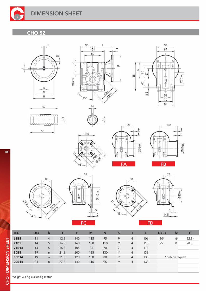
IEC DE8 b t P M N S T L D1 H8 b1 t1
63B5 11 4 12.8 140 115 95 9 4 106 20* 6* 22.8*
71B5 14 5 16.3 160 130 110 9 4 113 25 8 28.3
71B14 14 5 16.3 105 85 70 7 4 113
80B5 19 6 21.8 200 165 130 11 4 133
80B14 19 6 21.8 120 100 80 7 4 133
90B14 24 8 27.3 140 115 95 9 4 133
CHO 52
Weight 3.5 Kg excluding motor
* only on request
108
DIMENSION SHEETC
HO
- D
IME
NSI
ON
SH
EE
T
FA FB
FC FD
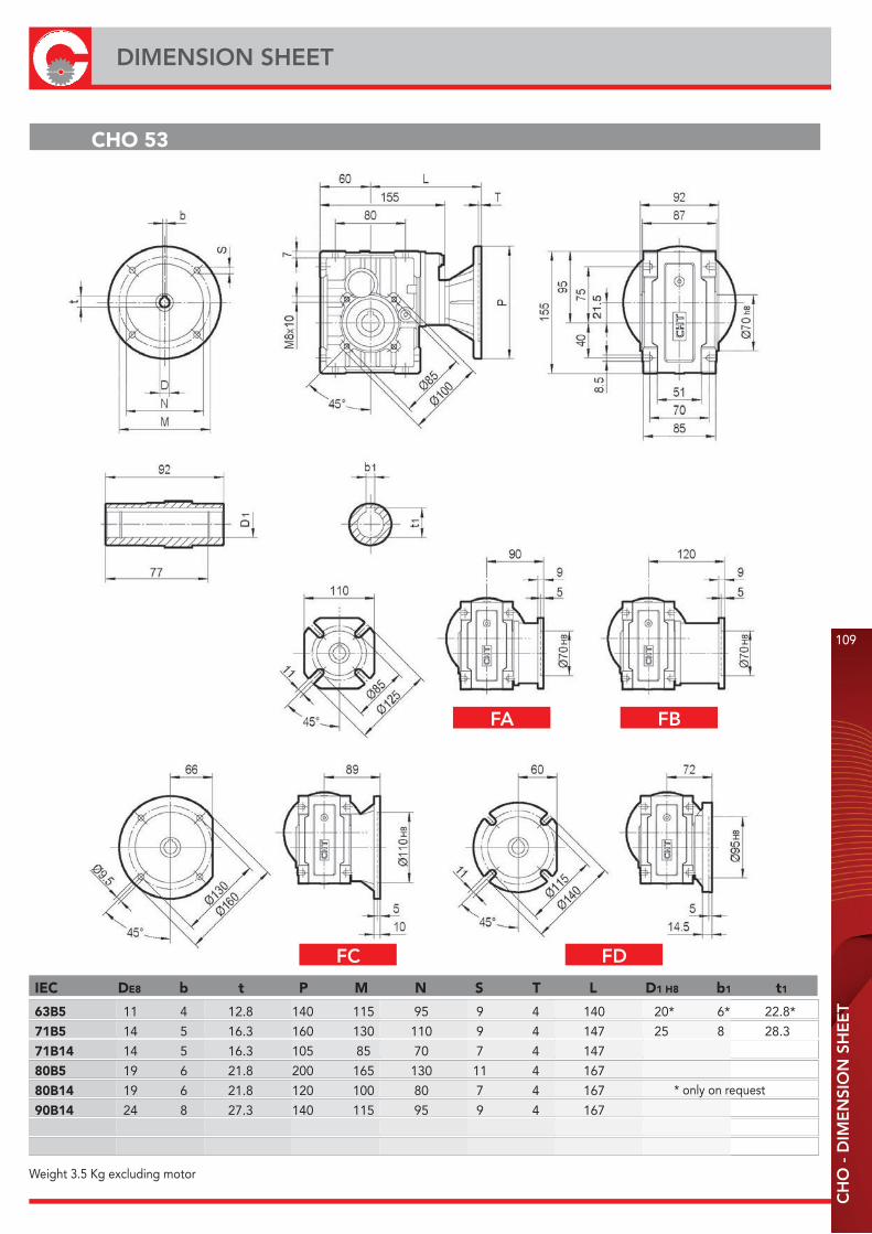
IEC DE8 b t P M N S T L D1 H8 b1 t1
63B5 11 4 12.8 140 115 95 9 4 140 20* 6* 22.8*
71B5 14 5 16.3 160 130 110 9 4 147 25 8 28.3
71B14 14 5 16.3 105 85 70 7 4 147
80B5 19 6 21.8 200 165 130 11 4 167
80B14 19 6 21.8 120 100 80 7 4 167
90B14 24 8 27.3 140 115 95 9 4 167
CHO 53
Weight 3.5 Kg excluding motor
* only on request
CH
O -
DIM
EN
SIO
N S
HE
ET
109
DIMENSION SHEET
FA FB
FC FD
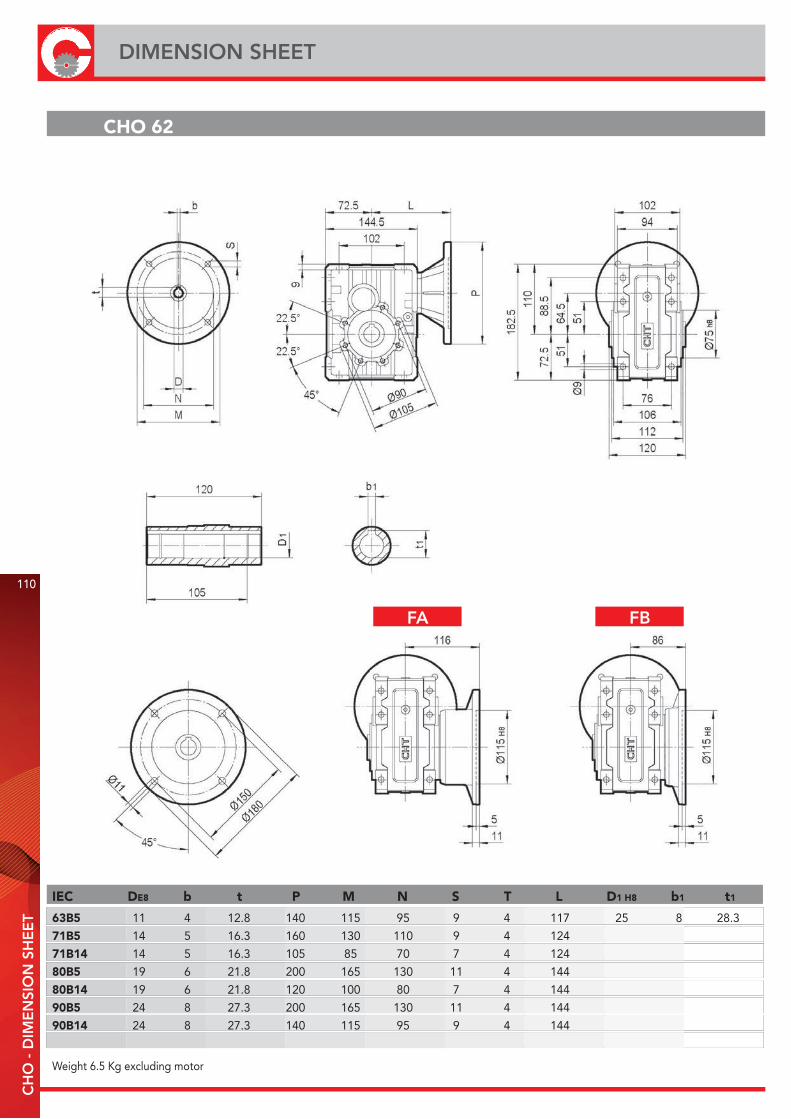
IEC DE8 b t P M N S T L D1 H8 b1 t1
63B5 11 4 12.8 140 115 95 9 4 117 25 8 28.3
71B5 14 5 16.3 160 130 110 9 4 124
71B14 14 5 16.3 105 85 70 7 4 124
80B5 19 6 21.8 200 165 130 11 4 144
80B14 19 6 21.8 120 100 80 7 4 144
90B5 24 8 27.3 200 165 130 11 4 144
90B14 24 8 27.3 140 115 95 9 4 144
CHO 62
Weight 6.5 Kg excluding motor
110
DIMENSION SHEETC
HO
- D
IME
NSI
ON
SH
EE
T
FA FB
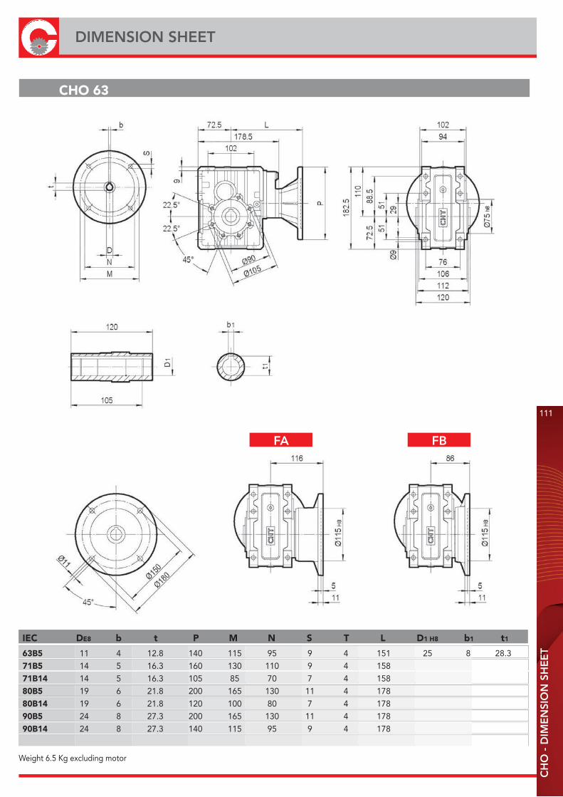
IEC DE8 b t P M N S T L D1 H8 b1 t1
63B5 11 4 12.8 140 115 95 9 4 151 25 8 28.3
71B5 14 5 16.3 160 130 110 9 4 158
71B14 14 5 16.3 105 85 70 7 4 158
80B5 19 6 21.8 200 165 130 11 4 178
80B14 19 6 21.8 120 100 80 7 4 178
90B5 24 8 27.3 200 165 130 11 4 178
90B14 24 8 27.3 140 115 95 9 4 178
CHO 63
Weight 6.5 Kg excluding motor
CH
O -
DIM
EN
SIO
N S
HE
ET
111
DIMENSION SHEET
FA FB

IEC DE8 b t P M N S T L D1 H8 b1 t1
63B5 11 4 12.8 140 115 95 9 4 139 28* 8* 31.3*71B5 14 5 16.3 160 130 110 9 4 146 30 8 33.380B5 19 6 21.8 200 165 130 11 4 166 80B14 19 6 21.8 120 100 80 7 4 16690B5 24 8 27.3 200 165 130 11 4 16690B14 24 8 27.3 140 115 95 9 4 166100/112B5 28 8 31.3 250 215 180 13.5 4.5 176100/112B14 28 8 31.3 160 130 110 9 4.5 176
CHO 72
Weight 9.5 Kg excluding motor
* only on request
112
DIMENSION SHEETC
HO
- D
IME
NSI
ON
SH
EE
T
FA
FB FC

IEC DE8 b t P M N S T L D1 H8 b1 t1
63B5 11 4 12.8 140 115 95 9 4 179 28* 8* 31.3*
71B5 14 5 16.3 160 130 110 9 4 186 30 8 33.3
80B5 19 6 21.8 200 165 130 11 4 206
80B14 19 6 21.8 120 100 80 7 4 206
90B5 24 8 27.3 200 165 130 11 4 206
90B14 24 8 27.3 140 115 95 9 4 206
100/112B5 28 8 31.3 250 215 180 13.5 4.5 216
100/112B14 28 8 31.3 160 130 110 9 4.5 216
CHO 73
Weight 9.5 Kg excluding motor
* only on request
CH
O -
DIM
EN
SIO
N S
HE
ET
113
DIMENSION SHEET
FA
FB FC
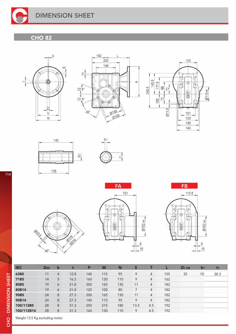
IEC DE8 b t P M N S T L D1 H8 b1 t1
63B5 11 4 12.8 140 115 95 9 4 155 35 10 38.371B5 14 5 16.3 160 130 110 9 4 162 80B5 19 6 21.8 200 165 130 11 4 182 80B14 19 6 21.8 120 100 80 7 4 18290B5 24 8 27.3 200 165 130 11 4 18290B14 24 8 27.3 140 115 95 9 4 182100/112B5 28 8 31.3 250 215 180 13.5 4.5 192100/112B14 28 8 31.3 160 130 110 9 4.5 192
CHO 82
Weight 13.5 Kg excluding motor
114
DIMENSION SHEETC
HO
- D
IME
NSI
ON
SH
EE
T
FA FB
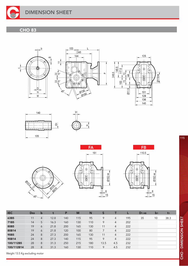
IEC DE8 b t P M N S T L D1 H8 b1 t1
63B5 11 4 12.8 140 115 95 9 4 195 35 10 38.371B5 14 5 16.3 160 130 110 9 4 202 80B5 19 6 21.8 200 165 130 11 4 222 80B14 19 6 21.8 120 100 80 7 4 22290B5 24 8 27.3 200 165 130 11 4 22290B14 24 8 27.3 140 115 95 9 4 222100/112B5 28 8 31.3 250 215 180 13.5 4.5 232100/112B14 28 8 31.3 160 130 110 9 4.5 232
CHO 83
Weight 13.5 Kg excluding motor
CH
O -
DIM
EN
SIO
N S
HE
ET
115
DIMENSION SHEET
FA FB

B3 B6 V5 V6
B8 B7
TYPE N2
CHO 52/53 59
CHO 62/63 70
CHO 72/73 85.5
CHO 82/83 93.5
COVER
116
DIMENSION SHEETC
HO
- D
IME
NSI
ON
SH
EE
T
ACCESSORIES
MOUNTING POSITIONS
2D and 3D drawings available on the web site www.chiaravalli.comQuantity, availability and prices with Chiaravalli B2B
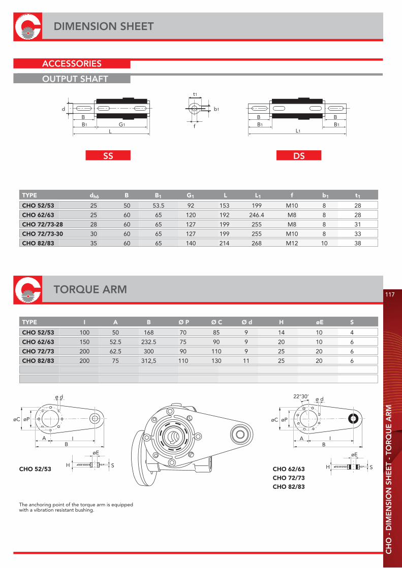
ø d
AB
I
øC øP
L1
b1
BB1
BB1
L
BB1 G1
d
The anchoring point of the torque arm is equippedwith a vibration resistant bushing.
øC øP
AB
I
ø d22°30’
H
øE
SCHO 52/53 CHO 62/63CHO 72/73CHO 82/83
TYPE I A B Ø P Ø C Ø d H øE S
CHO 52/53 100 50 168 70 85 9 14 10 4
CHO 62/63 150 52.5 232.5 75 90 9 20 10 6
CHO 72/73 200 62.5 300 90 110 9 25 20 6
CHO 82/83 200 75 312,5 110 130 11 25 20 6
TYPE dh6 B B1 G1 L L1 f b1 t1
CHO 52/53 25 50 53.5 92 153 199 M10 8 28
CHO 62/63 25 60 65 120 192 246.4 M8 8 28
CHO 72/73-28 28 60 65 127 199 255 M8 8 31
CHO 72/73-30 30 60 65 127 199 255 M10 8 33
CHO 82/83 35 60 65 140 214 268 M12 10 38
H
øE
S
t1
f
CH
O -
DIM
EN
SIO
N S
HE
ET
- TO
RQ
UE
AR
M
117
DIMENSION SHEET
ACCESSORIES
OUTPUT SHAFT
SS DS
TORQUE ARM
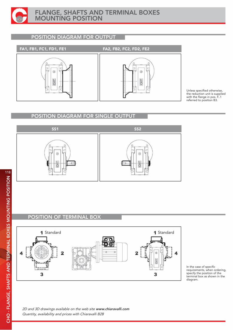
Unless specified otherwise,the reduction unit is suppliedwith the flange in pos. F..1referred to position B3.
In the case of specificrequirements, when ordering,specify the position of theterminal box as shown in thediagram.
FA1, FB1, FC1, FD1, FE1 FA2, FB2, FC2, FD2, FE2
SS1 SS2
Standard Standard
POSITION OF TERMINAL BOX
118
FLANGE, SHAFTS AND TERMINAL BOXESMOUNTING POSITION
CH
O -
FLA
NG
E, S
HA
FTS
AN
D T
ER
MIN
AL
BO
XE
S M
OU
NTI
NG
PO
SITI
ON
POSITION DIAGRAM FOR OUTPUT
POSITION DIAGRAM FOR SINGLE OUTPUT SHAFT
2D and 3D drawings available on the web site www.chiaravalli.comQuantity, availability and prices with Chiaravalli B2B
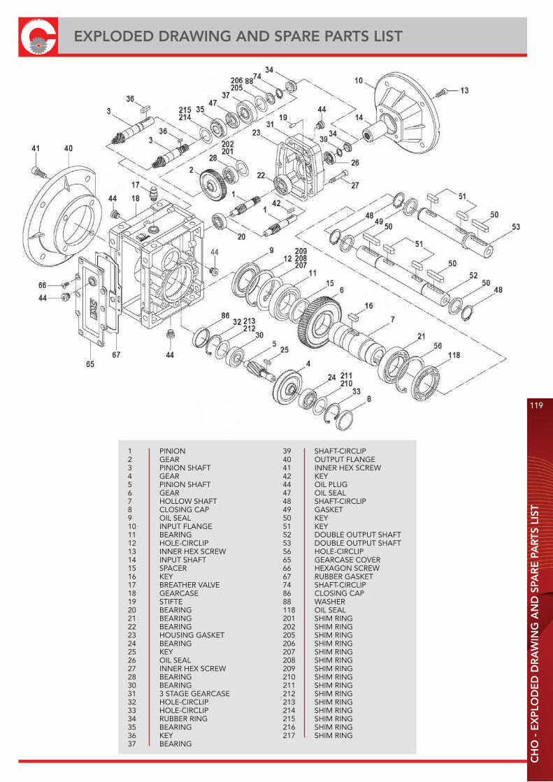
CH
O -
EX
PLO
DE
D D
RA
WIN
G A
ND
SPA
RE
PA
RTS
LIS
T
119
EXPLODED DRAWING AND SPARE PARTS LIST
39 SHAFT-CIRCLIP40 OUTPUT FLANGE41 INNER HEX SCREW42 KEY44 OIL PLUG47 OIL SEAL48 SHAFT-CIRCLIP49 GASKET50 KEY51 KEY52 DOUBLE OUTPUT SHAFT53 DOUBLE OUTPUT SHAFT56 HOLE-CIRCLIP65 GEARCASE COVER66 HEXAGON SCREW67 RUBBER GASKET74 SHAFT-CIRCLIP86 CLOSING CAP88 WASHER118 OIL SEAL201 SHIM RING202 SHIM RING205 SHIM RING206 SHIM RING207 SHIM RING208 SHIM RING209 SHIM RING210 SHIM RING211 SHIM RING212 SHIM RING213 SHIM RING214 SHIM RING215 SHIM RING216 SHIM RING217 SHIM RING
1 PINION2 GEAR3 PINION SHAFT4 GEAR5 PINION SHAFT6 GEAR7 HOLLOW SHAFT8 CLOSING CAP9 OIL SEAL10 INPUT FLANGE11 BEARING12 HOLE-CIRCLIP13 INNER HEX SCREW14 INPUT SHAFT15 SPACER16 KEY17 BREATHER VALVE18 GEARCASE19 STIFTE20 BEARING21 BEARING22 BEARING23 HOUSING GASKET24 BEARING25 KEY26 OIL SEAL27 INNER HEX SCREW28 BEARING30 BEARING31 3 STAGE GEARCASE32 HOLE-CIRCLIP33 HOLE-CIRCLIP34 RUBBER RING35 BEARING36 KEY37 BEARING
USE AND MAINTENANCE INSTRUCTIONS
120
CH
O -
USE
AN
D M
AIN
TEN
AN
CE
IN
STR
UC
TIO
NS
INSTALLATION· The data shown on the identification name plate must correspond to the gearbox ordered.· The oil level must correspond to the quantity foreseen for the assembly position requested (see catalogue).· All of the other gearboxes are supplied complete with permanent synthetic oil in a quantity that is sufficient for any assembly position.· The gearbox must be fixed on a flat surface that is sufficiently rigid in order to avoid any vibration.· The gearbox and the axis of the machine to be driven must be perfectly aligned o in the event that knocks, overloading or blockage of the machine are foreseen, the client must install a limiting device, joints, overload cut-out etc.· Coupling with pinions, joints, pulleys and other parts must be done after the parts have been cleaned and knocks should be avoided while assembling as they could damage the bearings and other internal parts.· In the event that the motor is supplied by the client, he must check that the flange and shaft tolerances correspond to a “normal” class; our motors satisfy this requirement.· Check that the fixing screws for the gear and the related accessories are correctly tightened.· Take suitable measures to protect the groups from any aggressive atmospheric agents.· Where foreseen, protect rotating parts from any possible contact with the operators.· If the gears are painted, protect the oil seals and the machined surfaces gearboxes.· All of the gears are painted RAL 9022 grey.
OPERATION AND RUNNING-IN· To obtain the best performance the gearboxes must first be run-in by gradually increasing the power in the first few hours of operation, in this phase an increase in temperature is considered normal.· In the event of defective operation, noise, oil leakage, etc. stop the gear immediately and, when possible, remove the cause. Alternatively, send the piece to our factory to be controlled.
MAINTENANCE see page 93· The helical gearboxes are lubricated with mineral, oil do not mix with synthetic oil. Check oil level regularly.
WAREHOUSE STORAGE· If the warehouse storage will be for a long time, more than 3 months, the shafts and machined surfaces should be protected using antioxidants and the oil seals should be greased.
HANDLING· Care must be taken not to damage the oil seals and the machined surfaces when handling the groups.
DISPOSAL OF PACKAGING· The packaging in which our gears are delivered should be sent to specialised companies for recycling if possible.
2D and 3D drawings available on the web site www.chiaravalli.comQuantity, availability and prices with Chiaravalli B2B
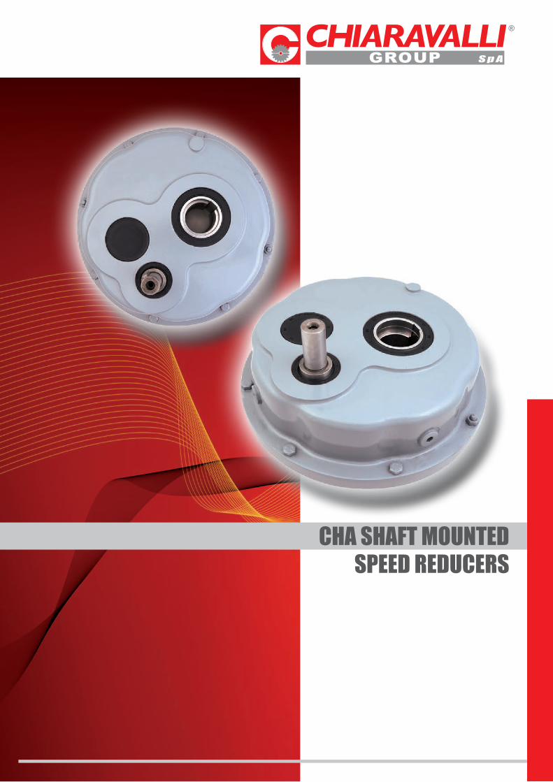
CHA SHAFT MOUNTEDSPEED REDUCERS

122
INTRODUCTIONC
HA
- IN
TRO
DU
CTI
ON
CHA shaft mounted gear units have been conceived to be mainly used for belt conveyors, because of backstop system mounting possibility they can be used on inclined planes assuring the system irreversibility.The reducers are manufactured with GG20 painted cast iron cases and grinded gears 21NiCrMo2 material.
PRODUCT FEATURES
· High efficiency· Low noise· Easy mounting· Backstop mounting possibility
CHA gearboxes are manufactured in 8 sizes. Other ratios available on request.

M2 = Output torqueM2n = Rated output torqueP1 = Input power = Transmission efficiency
fS = Service factor
GENERAL INFORMATION
POWER P
P1 * = P2
P1 = Input powerP2 = Output power = Transmission efficiency
ROTATION SPEED n
n1 = Input speedn2 = Output speed
An output speed ≤ 1400 rpm is suggested so as to optimize the working condition and extend the service life.
TRANSMISSION RATIO i
n1
n2i =
TORQUE M
9550 P1
n2M2 = Nm
. .
M2 ≥ M2 fS Nm.
CH
A -
GE
NE
RA
L IN
FOR
MA
TIO
N
123
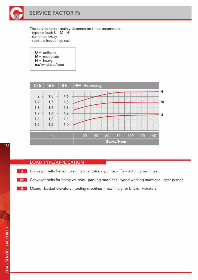
LOAD TYPE/APPLICATION
Conveyor belts for light weights - centrifugal pumps - lifts - bottling machines
Conveyor belts for heavy weights - packing machines - wood working machines - gear pumps
Mixers - bucket elevators - tooling machines - machinery for bricks - vibrators
124
SERVICE FACTOR FS
CH
A -
SE
RV
ICE
FA
CTO
R F
S
The service factor mainly depends on three parameters:- type to load: U - M - H- run time: h/day- start-up frequency: na/h
U = uniform M = moderate H = heavy na/h = starts/hour
24 h 16 h 8 h Hours/day
Starts/Hour
H
M
U
2
1,9
1,8
1,7
1,6
1,5
1,8
1,7
1,5
1,4
1,3
1,2
1,6
1,5
1,3
1,2
1,1
1,0
f . s 20 40 60 80 100 120 140
U
M
H
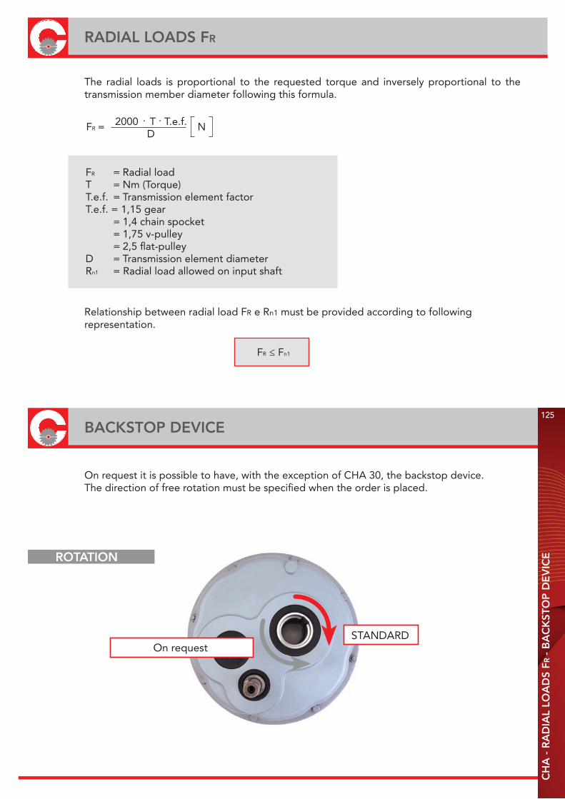
BACKSTOP DEVICE125
RADIAL LOADS FR
CH
A -
RA
DIA
L LO
AD
S FR
- B
AC
KST
OP
DE
VIC
E
The radial loads is proportional to the requested torque and inversely proportional to the transmission member diameter following this formula.
2000 T T.e.f. D
FR = N. .
FR ≤ Fn1
FR = Radial loadT = Nm (Torque)T.e.f. = Transmission element factorT.e.f. = 1,15 gear = 1,4 chain spocket = 1,75 v-pulley = 2,5 flat-pulleyD = Transmission element diameterRn1 = Radial load allowed on input shaft
Relationship between radial load FR e Rn1 must be provided according to following representation.
On request it is possible to have, with the exception of CHA 30, the backstop device.The direction of free rotation must be specified when the order is placed.
On requestSTANDARD
ROTATION

126
LUBRICATIONC
HA
- L
UB
RIC
ATI
ON
NOTE: The gearboxes are supplied without oil.
For choosing suitable oil, you must consider viscosity values which are specified according to type of load and ambient temperature on above table.
LUBRICATION (Litres)
VALUE OF VISCOSITY ACCORDING TO TYPE OF LOAD AND TEMPERATURE
Gears of CHA gear unit series run at oil bath and lubrication could be provided with splashing.Applicable plug position and oil quantity are given at tables according to variable mounting positions.Suitable checking of oil level must always be according to center of oil-level plug or with dipstick.Sometimes, there are possibility difference between oil-level and oil quantity which is given at table.
CHA 30 CHA 35/2 CHA 40/2 CHA 45/2 CHA 50/2 CHA 60/2 CHA 70/2 CHA 80/2
0.5 1.1 1.8 3.6 7.3 7.5 14.0 11.0
CHA CHA 0°C - 20°C 20°C - 40°C
Type of loads Mineral Oil Synthetic Oil Mineral Oil Synthetic Oil ISO VG ISO VG ISO VG ISO VG
Uniform load 150 150 220 220
Medium load 150 150 320 220
Heavy load 200 200 460 320
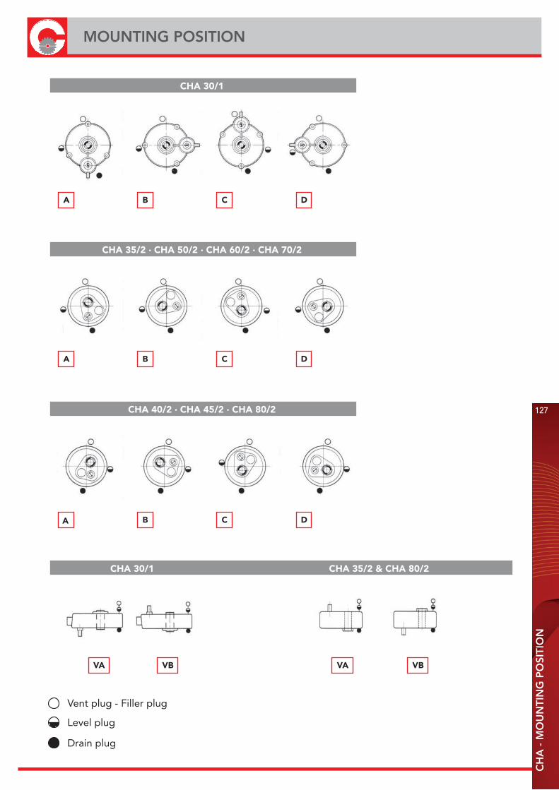
127
MOUNTING POSITION
CH
A -
MO
UN
TIN
G P
OSI
TIO
N
CHA 30/1
VA VB VA VB
A
Vent plug - Filler plug
Level plug
Drain plug
B C D
A B C D
A B C D
CHA 35/2 · CHA 50/2 · CHA 60/2 · CHA 70/2
CHA 40/2 · CHA 45/2 · CHA 80/2
CHA 30/1 CHA 35/2 & CHA 80/2

128
GEAR UNIT SELECTION TABLEC
HA
- G
EA
R U
NIT
SE
LEC
TIO
N T
AB
LE
CHA 30/1/30
i 10 12,7 15 20 25 15 20 25 33
CHA 35/2/35 CHA 40/2/40-45
n 1=
1400
min
-1
n2min-1
Mn2NmPn1kWRn1N
140 110 93 71 56 93 71 56 42
130 130 330 360 380 715 740 760 760
2 1,5 3,4 2,9 2,4 7,3 5,8 4,7 3,5
350 350 500 500 500 850 850 850 850
n 1=
900
min
-1
n2min-1
Mn2NmPn1kWRn1N
90 71 60 46 36 60 46 36 27
140 140 380 380 380 760 760 810 850
1,3 1 2,5 1,9 1,5 5 3,8 3,2 2,6
400 400 600 600 600 950 950 950 950
n 1=
500
min
-1
n2min-1
Mn2NmPn1kWRn1N
50 39 33 25 20 33 25 20 15
170 170 400 400 420 850 850 900 920
0,9 0,7 1,4 1,1 0,9 2,9 2,4 1,9 1,5
500 500 750 750 750 1200 1200 1200 1200
CHA
50/2/50-55-60
i 15 20 25 30 15 25 15 15 15
CHA
60/2/60-70
CHA
80/2/80
n 1=
1400
min
-1
n2min-1
Mn2NmPn1kWRn1N
93 71 56 46 93 56 93 93 93
1140 1190 1235 1235 1805 1900 3040 4180 5795
11,7 9,3 7,6 6,3 18,5 11,7 31,4 42,8 59,9
1150 1150 1150 1150 1700 1700 2600 3400 4200
n 1=
900
min
-1
n2min-1
Mn2NmPn1kWRn1N
60 46 36 30 60 36 60 60 60
1190 1235 1300 1300 1850 1995 3135 4275 5985
7,9 6,2 5,1 4,2 12,3 7,9 20,9 28,5 39,9
1300 1300 1300 1300 1900 1900 2900 3800 4700
n 1=
500
min
-1
n2min-1
Mn2NmPn1kWRn1N
33 25 20 16 33 20 33 33 33
1300 1350 1400 1400 2100 2300 3500 4900 6600
4,7 3,8 3 2,5 7,3 4,8 12,4 17,1 22,8
1200 1200 1200 1200 2400 2400 3600 4750 5900
CHA
70/2/70
CHA
45/2/45-50-55
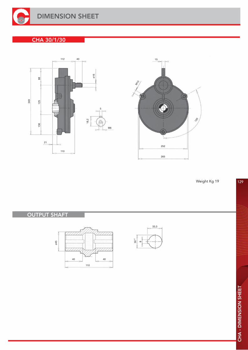
112
110
40
21
349
136
125
88 ø16
18,2
5
M6
15
252
265
M10
120
Weight Kg 19
110
40
ø45
40
30 8
G7
33,3
129
DIMENSION SHEET
CH
A -
DIM
EN
SIO
N S
HE
ET
CHA 30/1/30
OUTPUT SHAFT
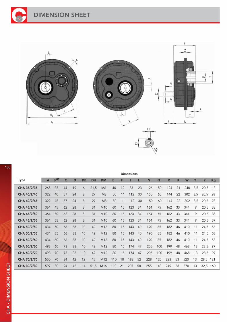
130
DIMENSION SHEETC
HA
- D
IME
NSI
ON
SH
EE
T
A B G7 C D DB DH DM E F I L N Q R U W Y Z Kg
CHA 35/2/35
CHA 40/2/40
CHA 40/2/45
CHA 45/2/45
CHA 45/2/50
CHA 45/2/55
CHA 50/2/50
CHA 50/2/55
CHA 50/2/60
CHA 60/2/60
CHA 60/2/70
CHA 70/2/70
CHA 80/2/80
265 35 44 19 6 21,5 M6 40 12 83 23 126 50 124 21 240 8,5 20,5 18
322 40 57 24 8 27 M8 50 11 112 30 150 60 144 22 302 8,5 20,5 28
322 45 57 24 8 27 M8 50 11 112 30 150 60 144 22 302 8,5 20,5 28
364 45 62 28 8 31 M10 60 15 123 34 164 75 162 33 344 9 20,5 38
364 50 62 28 8 31 M10 60 15 123 34 164 75 162 33 344 9 20,5 38
364 55 62 28 8 31 M10 60 15 123 34 164 75 162 33 344 9 20,5 37
434 50 66 38 10 42 M12 80 15 143 40 190 85 182 46 410 11 24,5 58
434 55 66 38 10 42 M12 80 15 143 40 190 85 182 46 410 11 24,5 58
434 60 66 38 10 42 M12 80 15 143 40 190 85 182 46 410 11 24,5 58
498 60 73 38 10 42 M12 80 15 174 47 205 100 199 48 468 13 28,5 97
498 70 73 38 10 42 M12 80 15 174 47 205 100 199 48 468 13 28,5 97
550 70 84 42 12 45 M12 110 18 188 52 228 120 223 53 520 13 28,5 121
597 80 94 48 14 51,5 M16 110 21 207 58 255 140 249 58 570 13 32,5 160
Type
Dimensions
R
Z
B Q
A
A
D
E N
C
F
U
L
I
IW
A
L
Y
DB
DH
DH

131
SHAFT DIMENSION
CH
A -
SH
AFT
DIM
EN
SIO
N
OUTPUT SHAFT
BG7 BB BH G H HB HC R S T
CHA 30/1/30
CHA 35/2/35
CHA 40/2/40
CHA 40/2/45
CHA 45/2/45
CHA 45/2/50
CHA 45/2/55
CHA 50/2/50
CHA 50/2/55
CHA 50/2/60
CHA 60/2/60
CHA 60/2/70
CHA 70/2/70
CHA 80/2/80
30 8 33,3 - - - - 110 - -
35 10 38,3 8 M12 - - 124 40 106
40 12 43,3 8 M12 - - 144 52 124
45 14 47,3 8 M12 - - 144 52 124
45 14 48,8 10 M16 - - 162 62 140
50 14 53,8 10 M16 - - 162 62 140
55 16 59,3 10 M16 - - 162 72 140
50 14 53,8 10 M16 - - 182 62 160
55 16 59,3 10 M16 - - 182 72 160
60 18 64,4 12 17 M12 42 182 72 160
60 18 64,4 12 17 M12 42 199 72 175
70 20 74,9 12 22 M16 50 199 90 175
70 20 74,9 12 22 M16 50 223 90 193
80 22 85,4 18 22 M16 60 249 95 219
Type
Dimensions
BB
HB
HHHC
S BH
TG
R
B

132
TORQUE TENSION ARMC
HA
- T
OR
QU
E T
EN
SIO
N A
RM
A B C D E F G H I L Min LMax M N O P
CHA 35/2
CHA 40/2
CHA 45/2
CHA 50/2
CHA 60/2
CHA 70/2
CHA 80/2
10
16
16
18
18
20
20
Type
25
35
35
40
40
45
45
75
105
105
115
115
135
135
M10
M12
M12
M14
M14
M16
M16
50
70
70
75
75
85
85
111
143
164
195
221
247
272
120
151
172
205
234
260
285
45
51
57
70
84
100
102
92
115,5
132
157
179
199
218
200
210
210
240
240
260
260
300
310
310
360
360
410
410
4
4
5
5
5
6
6
25
35
35
40
40
50
50
8,5
8,5
10,5
10,5
12,5
12,5
13
8,5
10,5
10,5
12,5
12,5
14,5
14,5
H
I
G
F
O
D
E
C
BA
L
MNP
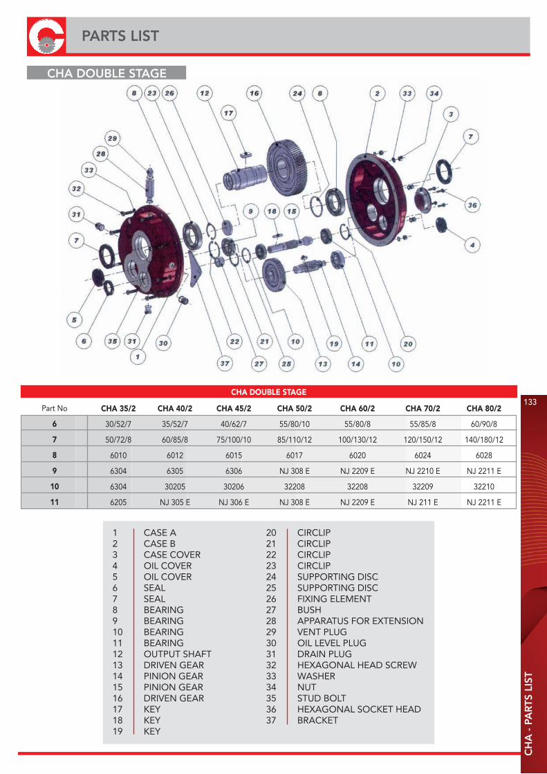
20 CIRCLIP21 CIRCLIP22 CIRCLIP23 CIRCLIP24 SUPPORTING DISC25 SUPPORTING DISC26 FIXING ELEMENT27 BUSH28 APPARATUS FOR EXTENSION29 VENT PLUG30 OIL LEVEL PLUG31 DRAIN PLUG32 HEXAGONAL HEAD SCREW33 WASHER34 NUT35 STUD BOLT36 HEXAGONAL SOCKET HEAD37 BRACKET
1 CASE A2 CASE B3 CASE COVER4 OIL COVER5 OIL COVER6 SEAL7 SEAL8 BEARING9 BEARING10 BEARING11 BEARING12 OUTPUT SHAFT13 DRIVEN GEAR14 PINION GEAR15 PINION GEAR16 DRIVEN GEAR17 KEY18 KEY19 KEY
CHA DOUBLE STAGE
Part No
6
7
8
9
10
11
CHA 35/2 CHA 40/2 CHA 45/2 CHA 50/2 CHA 60/2 CHA 70/2 CHA 80/2
30/52/7 35/52/7 40/62/7 55/80/10 55/80/8 55/85/8 60/90/8
50/72/8 60/85/8 75/100/10 85/110/12 100/130/12 120/150/12 140/180/12
6010 6012 6015 6017 6020 6024 6028
6304 6305 6306 NJ 308 E NJ 2209 E NJ 2210 E NJ 2211 E
6304 30205 30206 32208 32208 32209 32210
6205 NJ 305 E NJ 306 E NJ 308 E NJ 2209 E NJ 211 E NJ 2211 E
133
PARTS LIST
CH
A -
PA
RTS
LIS
T
CHA DOUBLE STAGE
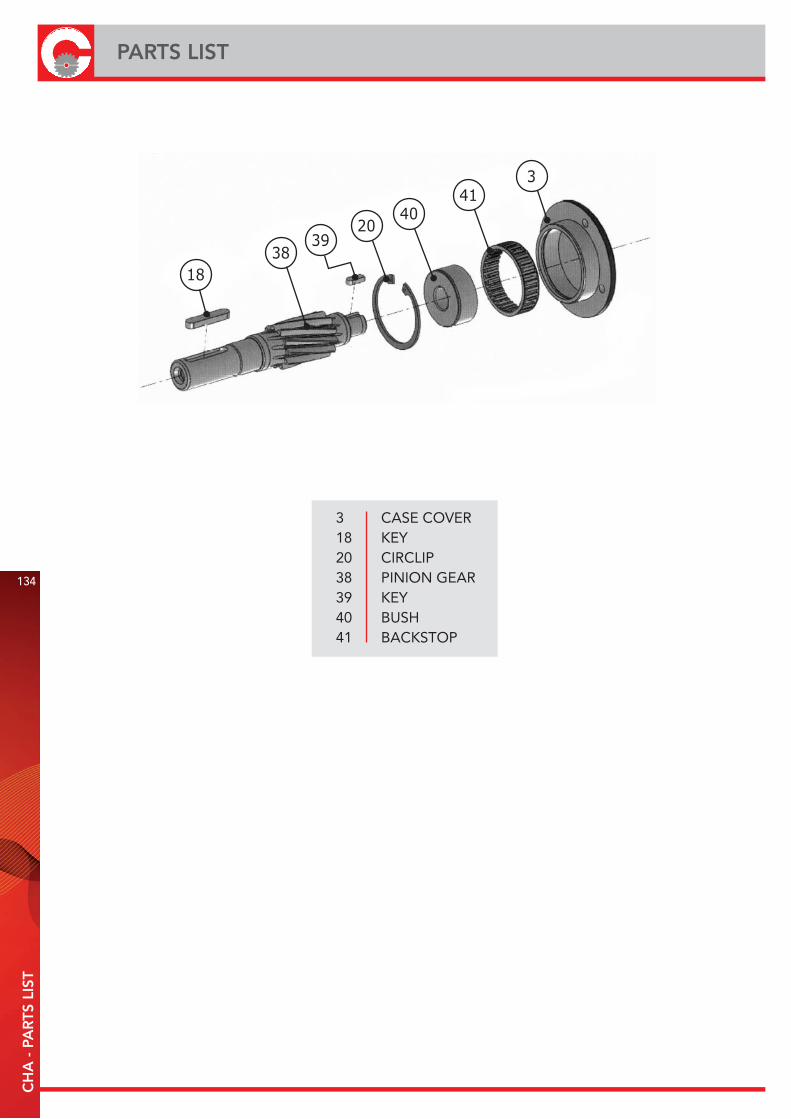
3 CASE COVER18 KEY20 CIRCLIP38 PINION GEAR39 KEY40 BUSH41 BACKSTOP
134
PARTS LISTC
HA
- P
AR
TS L
IST
1838
3920
4041
3

CH
A -
USE
AN
D M
AIN
TEN
AN
CE
INST
RU
CTI
ON
S
135
CHA - USE AND MAINTENANCE INSTRUCTIONS
INSTALLATION· The data shown on the identification name plate must correspond to the gearbox ordered.· The oil level must correspond to the quantity foreseen for the assembly position requested (see catalogue).· All of the other gearboxes are supplied complete with permanent synthetic oil in a quantity that is sufficient for any assembly position.· In the event that knocks, overloading or blockage of the machine are foreseen, the client must install a limiting device, joints, overload cut-out etc.· Coupling with pinions, joints, pulleys and other parts must be done after the parts have been cleaned and knocks should be avoided while assembling as they could damage the bearings and other internal parts.· Check that the fixing screws for the gear and the related accessories are correctly tightened.· Take suitable measures to protect the groups from any aggressive atmospheric agents.· Where foreseen, protect rotating parts from any possible contact with the operators.· If the gears are painted, protect the oil seals and the machined surfaces gearboxes.· All of the gears are painted RAL 9022 grey.
OPERATION AND RUNNING-IN· To obtain the best performance the gearboxes must first be run-in by gradually increasing the power in the first few hours of operation, in this phase an increase in temperature is considered normal.· In the event of defective operation, noise, oil leakage, etc. stop the gear immediately and, when possible, remove the cause. Alternatively, send the piece to our factory to be controlled.
MAINTENANCE· The gearboxes are supplied empy of oil and must be filled by teh customer before used.
WAREHOUSE STORAGE· If the warehouse storage will be for a long time, more than 3 months, the shafts and machined surfaces should be protected using antioxidants and the oil seals should be greased.
HANDLING· Care must be taken not to damage the oil seals and the machined surfaces when handling the groups.
DISPOSAL OF PACKAGING· The packaging in which our gears are delivered should be sent to specialised companies for recycling if possible.
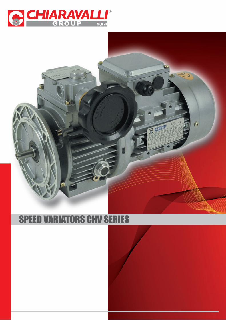
SPEED VARIATORS CHV SERIES
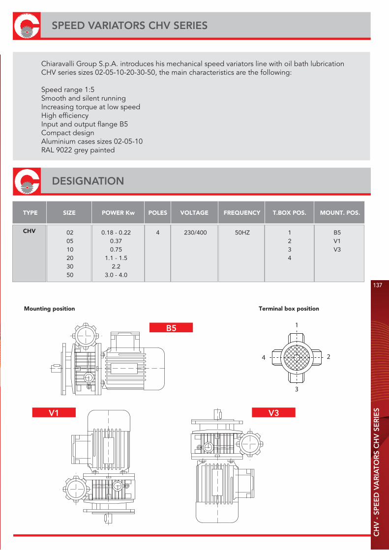
Mounting position Terminal box position
CHV
TYPE SIZE POWER Kw POLES VOLTAGE FREQUENCY T.BOX POS. MOUNT. POS.
4
3
2
1
02 0.18 - 0.22 4 230/400 50HZ 1 B505 0.37 2 V110 0.75 3 V320 1.1 - 1.5 430 2.250 3.0 - 4.0
CH
V -
SP
EE
D V
AR
IATO
RS
CH
V S
ER
IES
137
SPEED VARIATORS CHV SERIES
Chiaravalli Group S.p.A. introduces his mechanical speed variators line with oil bath lubrication CHV series sizes 02-05-10-20-30-50, the main characteristics are the following:
Speed range 1:5Smooth and silent runningIncreasing torque at low speedHigh efficiencyInput and output flange B5Compact designAluminium cases sizes 02-05-10RAL 9022 grey painted
DESIGNATION
B5
V1 V3
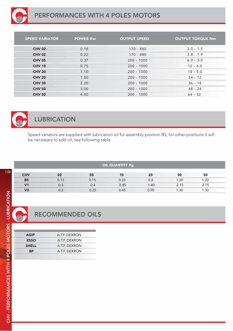
CHV 02 5.1 - 0.3088 - 07181.0
CHV 02 9.1 - 8.3088 - 07122.0
CHV 05 0.3 - 0.60001 - 00273.0
CHV 10 0.6 - 210001 - 00257.0
CHV 20 0.9 - 810001 - 00201.1
CHV 20 21 - 420001 - 00205.1
CHV 30 81 - 630001 - 00202.2
CHV 50 42 - 840001 - 00200.3
CHV 50 23 - 460001 - 00200.4
SPEED VARIATOR POWER Kw OUTPUT SPEED OUTPUT TORQUE Nm
AGIP A.T.F. DEXRON
ESSO A.T.F. DEXRON
SHELL A.T.F. DEXRON
BP A.T.F. DEXRON
CHV 02 05 10 20 30 50B5 0.13 0.15 0.33 0.8 1.20 1.20V1 0.3 0.4 0.85 1.40 2.15 2.15V3 0.2 0.25 0.45 0.90 1.30 1.30
OIL QUANTITY Kg
RECOMMENDED OILS
138
PERFORMANCES WITH 4 POLES MOTORSC
HV
- P
ER
FOR
MA
NC
ES
WIT
H 4
PO
LES
MO
TOR
S -
LUB
RIC
ATI
ON
LUBRICATION
Speed variators are supplied with lubrication oil for assembly position B5, for other positions it will be necessary to add oil, see following table.
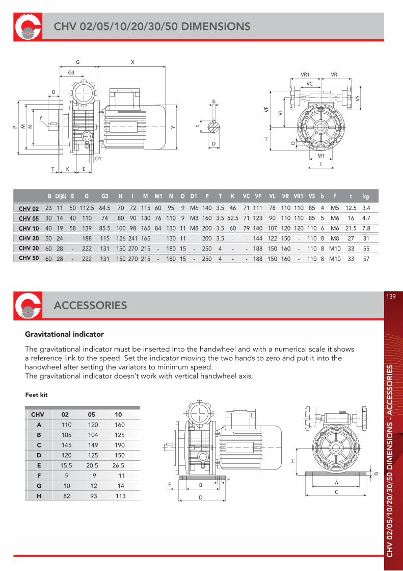
Gravitational indicator
CHV 02
CHV 05
CHV 10
CHV 20
CHV 30
CHV 50
B D(j6) E G G3 H I M M1 N D D1 P T K VC VF VL VR VR1 VS b f t kg
f
NMP
B
G3
G X
Y
D1
EKT
b
t
D
HVF VL
D
M1
I
VR1 VR
VC
VS
H
A
C
G
D
BEF
Feet kit
CHV 02 05 10
A 110 120 160
B 105 104 125
C 145 149 190
D 120 125 150
E 15.5 20.5 26.5
F 9 9 11
G 10 12 14
H 82 93 113
23 11 50 112.5 64.5 70 72 115 60 95 9 M6 140 3.5 46 71 111 78 110 110 85 4 M5 12.5 3.4
30 14 40 110 74 80 90 130 76 110 9 M8 160 3.5 52.5 71 123 90 110 110 85 5 M6 16 4.7
40 19 58 139 85.5 100 98 165 84 130 11 M8 200 3.5 60 79 140 107 120 120 110 6 M6 21.5 7.8
50 24 - 188 115 126 241 165 - 130 11 - 200 3.5 - - 144 122 150 - 110 8 M8 27 31
60 28 - 222 131 150 270 215 - 180 15 - 250 4 - - 188 150 160 - 110 8 M10 33 55
60 28 - 222 131 150 270 215 - 180 15 - 250 4 - - 188 150 160 - 110 8 M10 33 57
ACCESSORIES
CH
V 0
2/05
/10/
20/3
0/50
DIM
EN
SIO
NS
- A
CC
ESS
OR
IES
139
CHV 02/05/10/20/30/50 DIMENSIONS
The gravitational indicator must be inserted into the handwheel and with a numerical scale it shows a reference link to the speed. Set the indicator moving the two hands to zero and put it into the handwheel after setting the variators to minimum speed.The gravitational indicator doesn’t work with vertical handwheel axis.
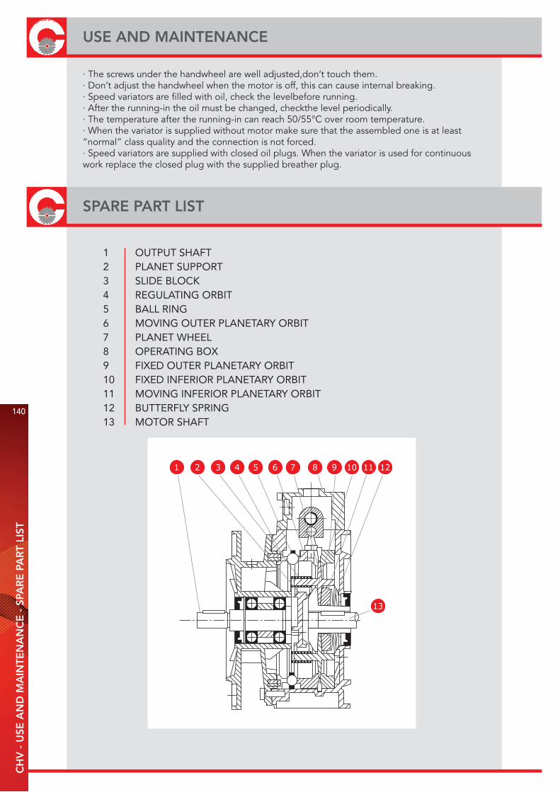
· The screws under the handwheel are well adjusted,don’t touch them.· Don’t adjust the handwheel when the motor is off, this can cause internal breaking.· Speed variators are filled with oil, check the levelbefore running.· After the running-in the oil must be changed, checkthe level periodically.· The temperature after the running-in can reach 50/55°C over room temperature.· When the variator is supplied without motor make sure that the assembled one is at least “normal” class quality and the connection is not forced.· Speed variators are supplied with closed oil plugs. When the variator is used for continuous work replace the closed plug with the supplied breather plug.
140
USE AND MAINTENANCEC
HV
- U
SE A
ND
MA
INTE
NA
NC
E -
SPA
RE
PA
RT
LIST
SPARE PART LIST
1 OUTPUT SHAFT2 PLANET SUPPORT3 SLIDE BLOCK4 REGULATING ORBIT5 BALL RING6 MOVING OUTER PLANETARY ORBIT7 PLANET WHEEL8 OPERATING BOX9 FIXED OUTER PLANETARY ORBIT10 FIXED INFERIOR PLANETARY ORBIT11 MOVING INFERIOR PLANETARY ORBIT12 BUTTERFLY SPRING13 MOTOR SHAFT
1 2 3 4 5 6 7 8 9 10 11 12
13

RIGHT-ANGLE PRECISIONBEVEL GEAR DRIVES
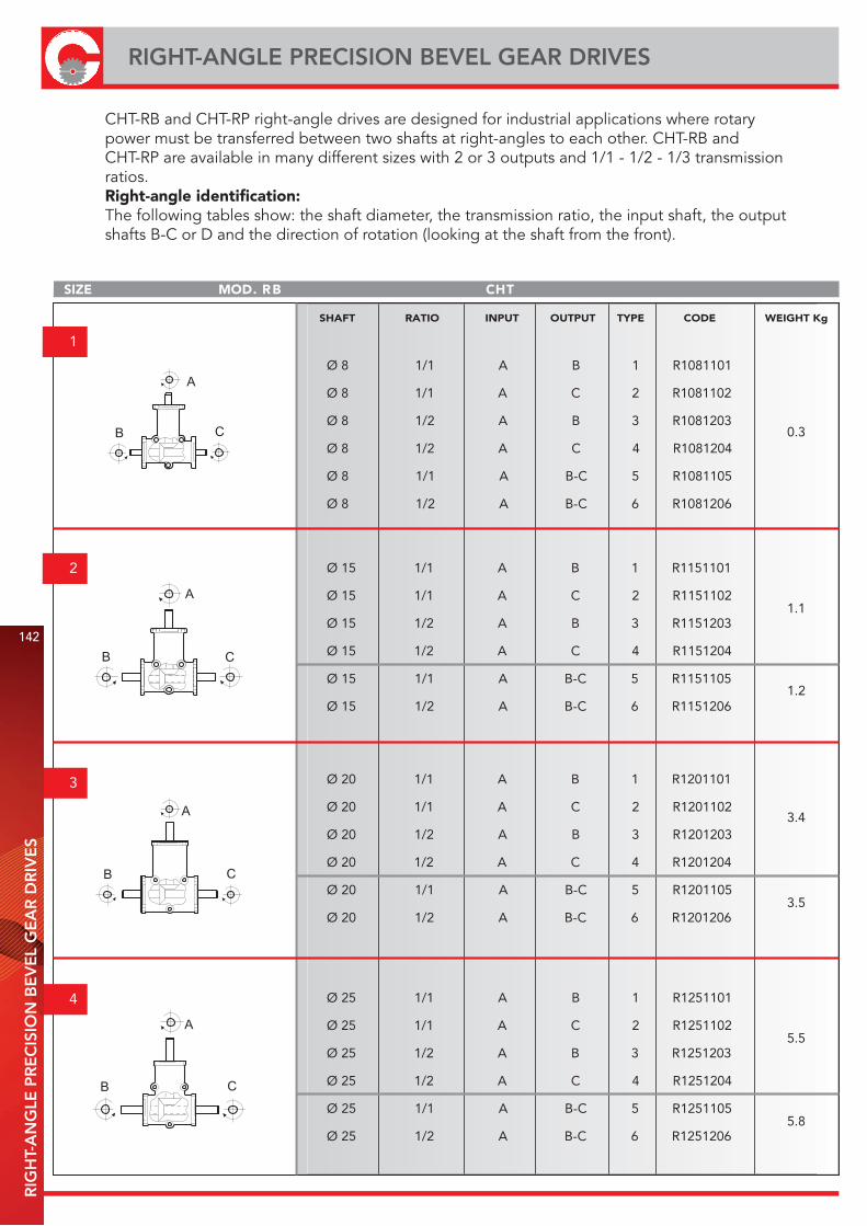
SIZE THCBR .DOM
1
2
3
4
A
C B
A
C B
A
C B
A
C B
SHAFT RATIO INPUT OUTPUT TYPE CODE WEIGHT Kg
Ø 8 1/1 A B 1 R1081101
Ø 8 1/1 A C 2 R1081102
Ø 8 1/2 A B 3 R1081203
Ø 8 1/2 A C 4 R1081204
Ø 8 1/1 A B-C 5 R1081105
Ø 8 1/2 A B-C 6 R1081206
Ø 15 1/1 A B 1 R1151101
Ø 15 1/1 A C 2 R1151102
Ø 15 1/2 A B 3 R1151203
Ø 15 1/2 A C 4 R1151204
Ø 15 1/1 A B-C 5 R1151105
Ø 15 1/2 A B-C 6 R1151206
Ø 20 1/1 A B 1 R1201101
Ø 20 1/1 A C 2 R1201102
Ø 20 1/2 A B 3 R1201203
Ø 20 1/2 A C 4 R1201204
Ø 20 1/1 A B-C 5 R1201105
Ø 20 1/2 A B-C 6 R1201206
Ø 25 1/1 A B 1 R1251101
Ø 25 1/1 A C 2 R1251102
Ø 25 1/2 A B 3 R1251203
Ø 25 1/2 A C 4 R1251204
Ø 25 1/1 A B-C 5 R1251105
Ø 25 1/2 A B-C 6 R1251206
0.3
1.1
1.2
3.4
3.5
5.5
5.8
142
RIGHT-ANGLE PRECISION BEVEL GEAR DRIVESR
IGH
T-A
NG
LE P
RE
CIS
ION
BE
VE
L G
EA
R D
RIV
ES
CHT-RB and CHT-RP right-angle drives are designed for industrial applications where rotary power must be transferred between two shafts at right-angles to each other. CHT-RB andCHT-RP are available in many different sizes with 2 or 3 outputs and 1/1 - 1/2 - 1/3 transmission ratios.Right-angle identification:The following tables show: the shaft diameter, the transmission ratio, the input shaft, the output shafts B-C or D and the direction of rotation (looking at the shaft from the front).
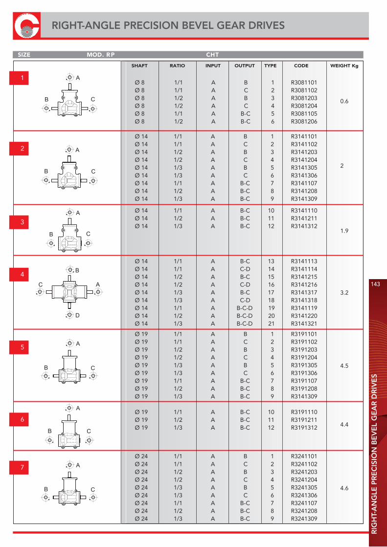
RIG
HT-
AN
GLE
PR
EC
ISIO
N B
EV
EL
GE
AR
DR
IVE
S
143
RIGHT-ANGLE PRECISION BEVEL GEAR DRIVES
SIZE THCPR .DOM
1
2
3
6
4
5
7
A
C B
C A
B
D
B
A
C
B C
A
A
C B
A
C B
B C
A
SHAFT RATIO INPUT OUTPUT TYPE CODE WEIGHT Kg
Ø 8 1/1 A B 1 R3081101Ø 8 1/1 A C 2 R3081102Ø 8 1/2 A B 3 R3081203Ø 8 1/2 A C 4 R3081204Ø 8 1/1 A B-C 5 R3081105Ø 8 1/2 A B-C 6 R3081206
Ø 14 1/1 A B 1 R3141101Ø 14 1/1 A C 2 R3141102Ø 14 1/2 A B 3 R3141203Ø 14 1/2 A C 4 R3141204Ø 14 1/3 A B 5 R3141305Ø 14 1/3 A C 6 R3141306Ø 14 1/1 A B-C 7 R3141107Ø 14 1/2 A B-C 8 R3141208Ø 14 1/3 A B-C 9 R3141309
Ø 14 1/1 A B-C 10 R3141110Ø 14 1/2 A B-C 11 R3141211Ø 14 1/3 A B-C 12 R3141312
Ø 14 1/1 A B-C 13 R3141113Ø 14 1/1 A C-D 14 R3141114Ø 14 1/2 A B-C 15 R3141215Ø 14 1/2 A C-D 16 R3141216Ø 14 1/3 A B-C 17 R3141317Ø 14 1/3 A C-D 18 R3141318Ø 14 1/1 A B-C-D 19 R3141119Ø 14 1/2 A B-C-D 20 R3141220Ø 14 1/3 A B-C-D 21 R3141321
Ø 19 1/1 A B 1 R3191101Ø 19 1/1 A C 2 R3191102Ø 19 1/2 A B 3 R3191203Ø 19 1/2 A C 4 R3191204Ø 19 1/3 A B 5 R3191305Ø 19 1/3 A C 6 R3191306Ø 19 1/1 A B-C 7 R3191107Ø 19 1/2 A B-C 8 R3191208Ø 19 1/3 A B-C 9 R3141309
Ø 19 1/1 A B-C 10 R3191110Ø 19 1/2 A B-C 11 R3191211Ø 19 1/3 A B-C 12 R3191312
Ø 24 1/1 A B 1 R3241101Ø 24 1/1 A C 2 R3241102Ø 24 1/2 A B 3 R3241203Ø 24 1/2 A C 4 R3241204Ø 24 1/3 A B 5 R3241305Ø 24 1/3 A C 6 R3241306Ø 24 1/1 A B-C 7 R3241107Ø 24 1/2 A B-C 8 R3241208Ø 24 1/3 A B-C 9 R3241309
0.6
2
1.9
3.2
4.5
4.4
4.6
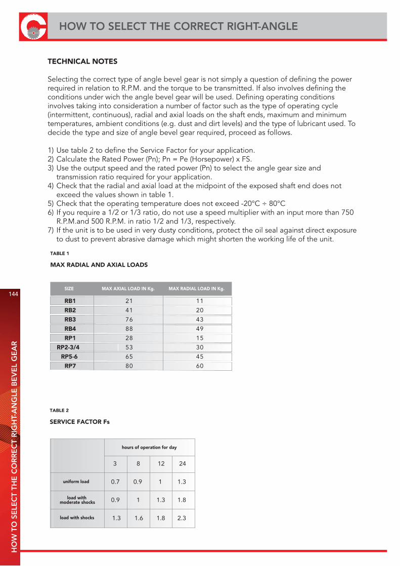
144
HOW TO SELECT THE CORRECT RIGHT-ANGLE H
OW
TO
SE
LEC
T TH
E C
OR
RE
CT
RIG
HT-
AN
GLE
BE
VE
L G
EA
R
TECHNICAL NOTES
Selecting the correct type of angle bevel gear is not simply a question of defining the power required in relation to R.P.M. and the torque to be transmitted. If also involves defining the conditions under wich the angle bevel gear will be used. Defining operating conditions involves taking into consideration a number of factor such as the type of operating cycle (intermittent, continuous), radial and axial loads on the shaft ends, maximum and minimum temperatures, ambient conditions (e.g. dust and dirt levels) and the type of lubricant used. To decide the type and size of angle bevel gear required, proceed as follows.
1) Use table 2 to define the Service Factor for your application.2) Calculate the Rated Power (Pn); Pn = Pe (Horsepower) x FS.3) Use the output speed and the rated power (Pn) to select the angle gear size and transmission ratio required for your application.4) Check that the radial and axial load at the midpoint of the exposed shaft end does not exceed the values shown in table 1.5) Check that the operating temperature does not exceed -20°C ÷ 80°C6) If you require a 1/2 or 1/3 ratio, do not use a speed multiplier with an input more than 750 R.P.M.and 500 R.P.M. in ratio 1/2 and 1/3, respectively.7) If the unit is to be used in very dusty conditions, protect the oil seal against direct exposure to dust to prevent abrasive damage which might shorten the working life of the unit.
MAX RADIAL AND AXIAL LOADS
SIZE MAX AXIAL LOAD IN Kg. MAX RADIAL LOAD IN Kg.
RB1 1112
RB2 0214
RB3 3467
RB4 9488
RP1 5182
RP2-3/4 0335
RP5-6 5456
RP7 0608
TABLE 1
SERVICE FACTOR Fs
3 8 12 24
0.7 0.9 1 1.3
0.9 1 1.3 1.8
1.3 1.6 1.8 2.3
uniform load
load with moderate shocks
load with shocks
hours of operation for day
TABLE 2

INP
UT
PO
WE
R (P
n) O
UTP
UT
TOR
QU
E T
145
INPUT POWER (Pn) Output torque T
Output speed
Output torque
Type Ratio
50 rpm 100 rpm 200 rpm 400 rpm 800 rpm 1400 rpm 2000 rpm 3000 rpm
T power T power T power T power T power T power T power T power
Nm Kw Nm Kw Nm Kw Nm Kw Nm Kw Nm Kw Nm Kw Nm Kw
RB 1-1/2- RB 1-5 4,7 0,02 3,9 0,04 3,3 0,07 2,8 0,12 2,3 0,19 2,0 0,30 1,8 0,39 1,7 0,53
RP 1-1/2- RP 1-5 9,1 0,05 7,6 0,08 6,4 0,13 5,4 0,23 4,5 0,38 4,0 0,58 3,6 0,76 3,3 1,03
RB 2-1/2- RB 2-5 16,5 0,09 13,9 0,15 11,7 0,24 9,8 0,41 8,2 0,69 7,2 1,05 6,6 1,37 5,9 1,86
RP 3-10 28,8 0,15 24,2 0,25 20,3 0,43 17,1 0,72 14,4 1,20 12,5 1,83 11,4 2,39 10,3 3,25
RP 2-1/2
RP 4-13/14
RP 2-7
RP 4-19
RB 3-1/2
RB 3-5
RP 6-10 75,7 0,40 63,7 0,67 53,5 1,12 45,0 1,89 37,9 3,17 32,9 4,82 30,1 6,30 27,2 8,54
RB 4-1/2 - RP 5-1/2
RP 7-1/2- RB 4-5
RP 5-7- RP 7-7
34,5 0,18 29,0 0,30 24,4 0,51 20,5 0,86 17,2 1,44 15,0 2,20 13,7 2,87 12,4 3,89
53,1 0,28 44,6 0,47 37,5 0,79 31,6 1,32 26,5 2,22 23,1 3,38 21,1 4,42 19,1 5,99
87,3 0,46 73,4 0,77 61,8 1,29 51,9 2,17 43,7 3,66 38,0 5,56 34,7 7,27 31,4 9,86
RB 1-3/4- RB 1-6 4,0 0,02 3,4 0,04 2,8 0,06 2,4 0,10 2,0 0,17 1,7 0,26 1,6 0,33 1,4 0,45
RP 1-3/4- RP 1-6 8,9 0,05 7,5 0,08 6,3 0,13 5,3 0,22 4,4 0,37 3,9 0,57 3,5 0,74 3,2 1,00
RB 2-3/4- RB 2-6 14,6 0,08 12,3 0,13 10,3 0,22 8,7 0,36 7,3 0,61 6,3 0,93 5,8 1,21 5,2 1,65
RP 3-11 28,1 0,15 23,7 0,25 19,9 0,42 16,7 0,70 14,1 1,18 12,2 1,79 11,2 2,34 10,1 3,17
RP 2-3/4
RP 4-15/16
RP 2-8
RP 4-20
RB 3-3/4-RB 3-6
RP 6-11 71,3 0,37 59,9 0,63 50,4 1,06 42,4 1,77 35,6 2,98 31,0 4,54 28,3 5,93 25,6 8,04
RB 4-3/4 - RP 4-6
RP 7-3/4- RB 4-6
RP 5-8- RP 7-8
RP 2-5/6
RP 2-9
RP 3-12
RP 4-17/18
RP 4-21
RP 5-5/6
RP 5-9
RP 6-12
RP 7-5/6
RP 7-9
33,8 0,18 28,5 0,30 23,9 0,50 20,1 0,84 16,9 1,42 14,7 2,16 13,5 2,82 12,2 3,82
42,5 0,22 35,7 0,37 30,1 0,63 25,3 1,06 21,3 1,78 18,5 2,71 16,9 3,54 15,3 4,80
82,3 0,43 69,2 0,72 58,2 1,22 48,9 2,05 41,1 3,44 35,8 5,24 32,7 6,85 29,6 9,28
27,5 0,14 23,1 0,24 19,4 0,41 16,3 0,68 13,7 1,15 12,0 1,75 10,9 2,29 9,9 3,10
63,4 0,33 53,3 0,56 44,9 0,94 37,7 1,58 31,7 2,66 27,6 4,04 25,2 5,28 22,8 7,16
R 1:1
R 1:2
R 1:3
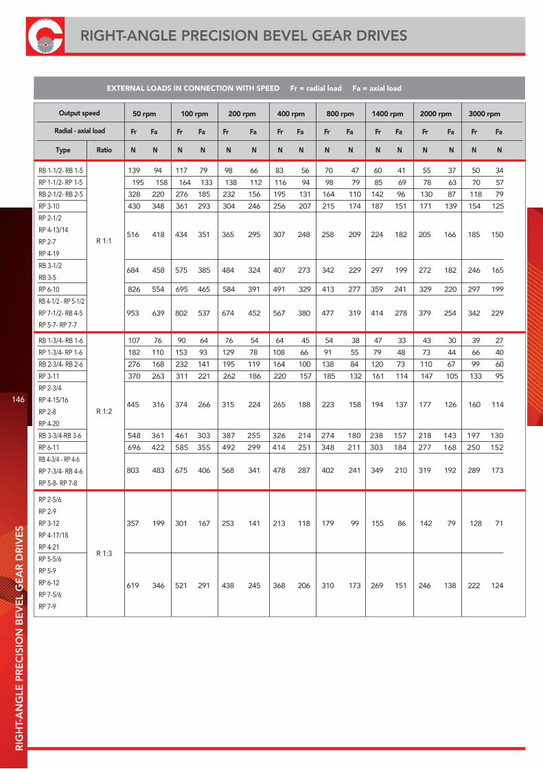
146
RIGHT-ANGLE PRECISION BEVEL GEAR DRIVESR
IGH
T-A
NG
LE P
RE
CIS
ION
BE
VE
L G
EA
R D
RIV
ES
EXTERNAL LOADS IN CONNECTION WITH SPEED Fr = radial load Fa = axial load
Output speed
Radial - axial load
Type Ratio
50 rpm 100 rpm 200 rpm 400 rpm 800 rpm 1400 rpm 2000 rpm 3000 rpm
Fr Fa Fr Fa Fr Fa Fr Fa Fr Fa Fr Fa Fr Fa Fr Fa
N N N N N N N N N N N N N N N N
RB 1-1/2- RB 1-5 139 94 117 79 98 66 83 56 70 47 60 41 55 37 50 34
RP 1-1/2- RP 1-5 195 158 164 133 138 112 116 94 98 79 85 69 78 63 70 57
RB 2-1/2- RB 2-5 328 220 276 185 232 156 195 131 164 110 142 96 130 87 118 79
RP 3-10 430 348 361 293 304 246 256 207 215 174 187 151 171 139 154 125
RP 2-1/2
RP 4-13/14
RP 2-7
RP 4-19
RB 3-1/2
RB 3-5
RP 6-10 826 554 695 465 584 391 491 329 413 277 359 241 329 220 297 199
RB 4-1/2 - RP 5-1/2
RP 7-1/2- RB 4-5
RP 5-7- RP 7-7
516 418 434 351 365 295 307 248 258 209 224 182 205 166 185 150
684 458 575 385 484 324 407 273 342 229 297 199 272 182 246 165
953 639 802 537 674 452 567 380 477 319 414 278 379 254 342 229
RB 1-3/4- RB 1-6 107 76 90 64 76 54 64 45 54 38 47 33 43 30 39 27
RP 1-3/4- RP 1-6 182 110 153 93 129 78 108 66 91 55 79 48 73 44 66 40
RB 2-3/4- RB 2-6 276 168 232 141 195 119 164 100 138 84 120 73 110 67 99 60
RP 3-11 370 263 311 221 262 186 220 157 185 132 161 114 147 105 133 95
RP 2-3/4
RP 4-15/16
RP 2-8
RP 4-20
RB 3-3/4-RB 3-6 548 361 461 303 387 255 326 214 274 180 238 157 218 143 197 130
RP 6-11 696 422 585 355 492 299 414 251 348 211 303 184 277 168 250 152
RB 4-3/4 - RP 4-6
RP 7-3/4- RB 4-6
RP 5-8- RP 7-8
RP 2-5/6
RP 2-9
RP 3-12
RP 4-17/18
RP 4-21
RP 5-5/6
RP 5-9
RP 6-12
RP 7-5/6
RP 7-9
445 316 374 266 315 224 265 188 223 158 194 137 177 126 160 114
803 483 675 406 568 341 478 287 402 241 349 210 319 192 289 173
357 199 301 167 253 141 213 118 179 99 155 86 142 79 128 71
619 346 521 291 438 245 368 206 310 173 269 151 246 138 222 124
R 1:1
R 1:2
R 1:3
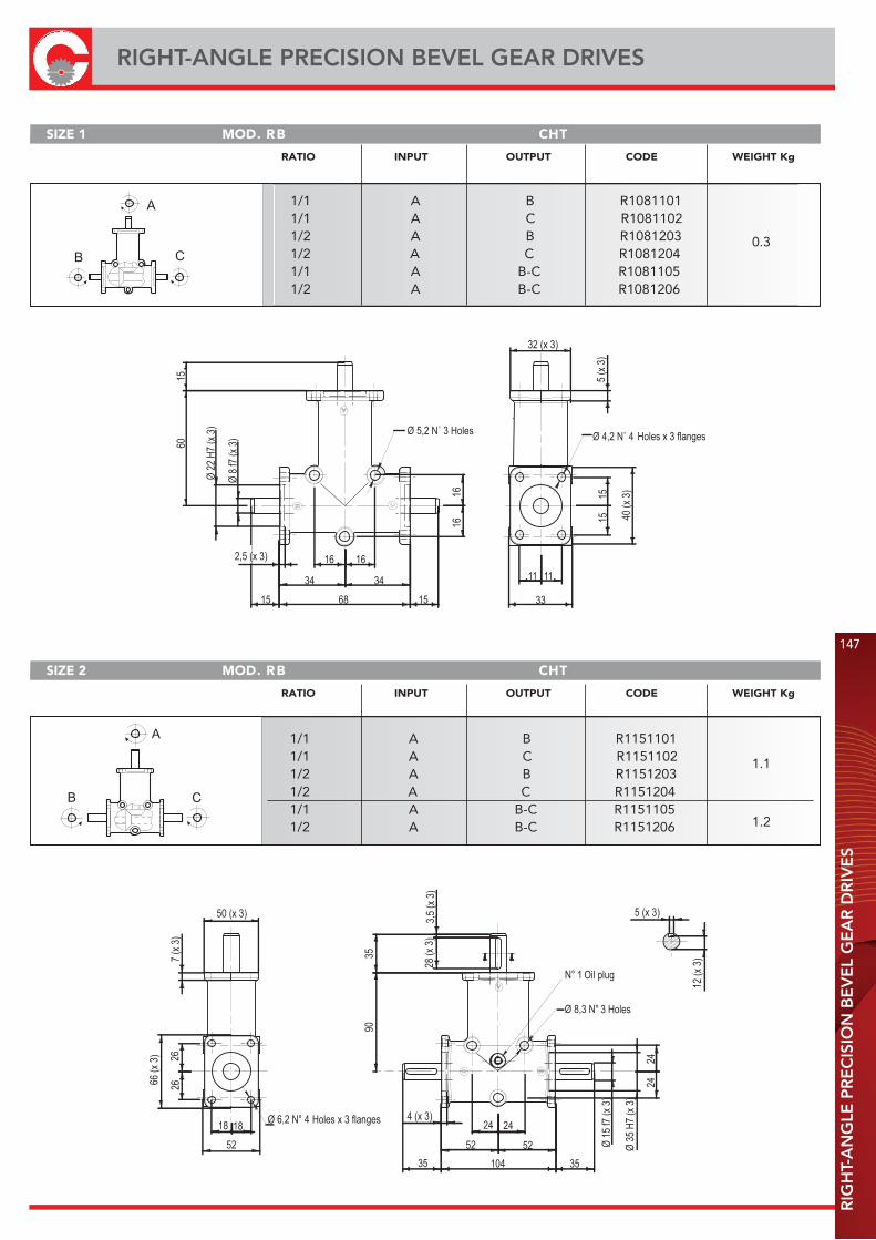
RIG
HT-
AN
GLE
PR
EC
ISIO
N B
EV
EL
GE
AR
DR
IVE
S
147
RIGHT-ANGLE PRECISION BEVEL GEAR DRIVES
1616
1568
16 16
34 34
15
6015
32 (x 3)
5 (x
3)
1515 40
(x 3
)
33
1111
2,5 (x 3)
SIZE 1 THCBR .DOM
A
C B
SIZE 2 THCBR .DOM
A
C B
RATIO INPUT OUTPUT CODE WEIGHT Kg
1/1 A B R10811011/1 A C R10811021/2 A B R10812031/2 A C R10812041/1 A B-C R10811051/2 A B-C R1081206
RATIO INPUT OUTPUT CODE WEIGHT Kg
1/1 A B R11511011/1 A C R11511021/2 A B R11512031/2 A C R11512041/1 A B-C R11511051/2 A B-C R1151206
0.3
1.1
1.2
Holes Holes x 3 flanges
Holes x 3 flanges
3 Holes
Oil plug
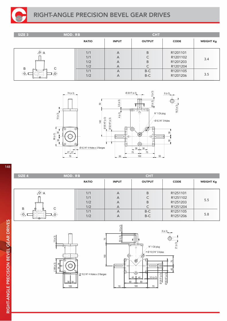
148
RIGHT-ANGLE PRECISION BEVEL GEAR DRIVESR
IGH
T-A
NG
LE P
RE
CIS
ION
BE
VE
L G
EA
R D
RIV
ES
SIZE 3 THCBR .DOM
SIZE 4 THCBR .DOM
A
C B
A
C B
RATIO INPUT OUTPUT CODE WEIGHT Kg
1/1 A B R12011011/1 A C R12011021/2 A B R12012031/2 A C R12012041/1 A B-C R12011051/2 A B-C R1201206
3.4
RATIO INPUT OUTPUT CODE WEIGHT Kg
1/1 A B R12511011/1 A C R12511021/2 A B R12512031/2 A C R12512041/1 A B-C R12511051/2 A B-C R1251206
5.5
3.5
5.8
Oil plug
Holes
Holes x 3 flanges
Holes x 3 flanges
Holes
Oil plug
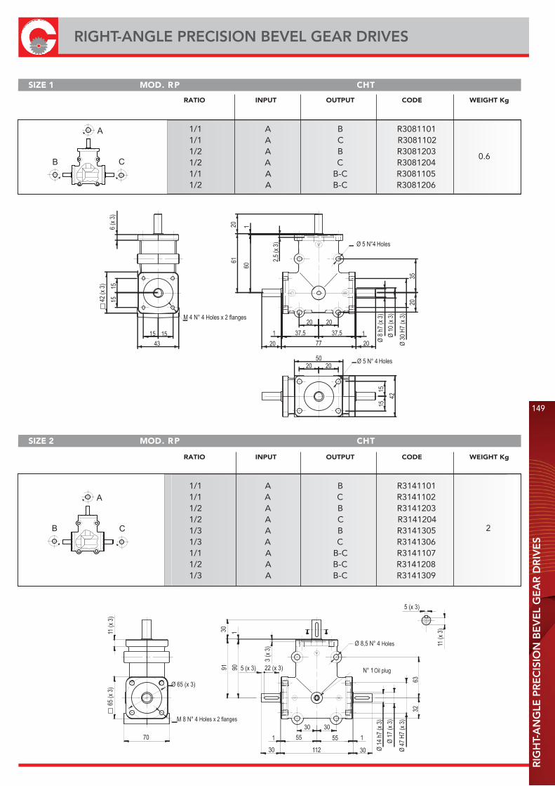
RIG
HT-
AN
GLE
PR
EC
ISIO
N B
EV
EL
GE
AR
DR
IVE
S
149
RIGHT-ANGLE PRECISION BEVEL GEAR DRIVES
SIZE 1 THCPR .DOM
SIZE 2 THCPR .DOM
A
C B
A
C B
Holes x 2 flanges
Holes
Holes
Holes
Holes x 2 flanges
Oil plug
RATIO INPUT OUTPUT CODE WEIGHT Kg
1/1 A B R30811011/1 A C R30811021/2 A B R30812031/2 A C R30812041/1 A B-C R30811051/2 A B-C R3081206
0.6
RATIO INPUT OUTPUT CODE WEIGHT Kg
1/1 A B R31411011/1 A C R31411021/2 A B R31412031/2 A C R31412041/3 A B R31413051/3 A C R31413061/1 A B-C R31411071/2 A B-C R31412081/3 A B-C R3141309
2
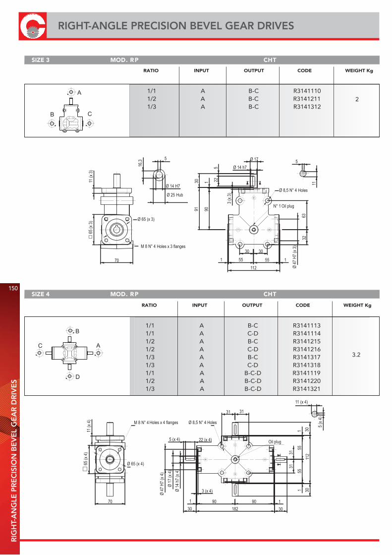
150
RIGHT-ANGLE PRECISION BEVEL GEAR DRIVESR
IGH
T-A
NG
LE P
RE
CIS
ION
BE
VE
L G
EA
R D
RIV
ES
SIZE 3 THCPR .DOM
A
C B
SIZE 4 THCPR .DOM
C A
B
D
RATIO INPUT OUTPUT CODE WEIGHT Kg
1/1 A B-C R31411101/2 A B-C R31412111/3 A B-C R3141312
2
RATIO INPUT OUTPUT CODE WEIGHT Kg
1/1 A B-C R31411131/1 A C-D R31411141/2 A B-C R31412151/2 A C-D R31412161/3 A B-C R31413171/3 A C-D R31413181/1 A B-C-D R31411191/2 A B-C-D R31412201/3 A B-C-D R3141321
3.2
Holes
Oil plug
Oil plug
HolesHoles x 4 flanges
Hub
Holes x 3 flanges
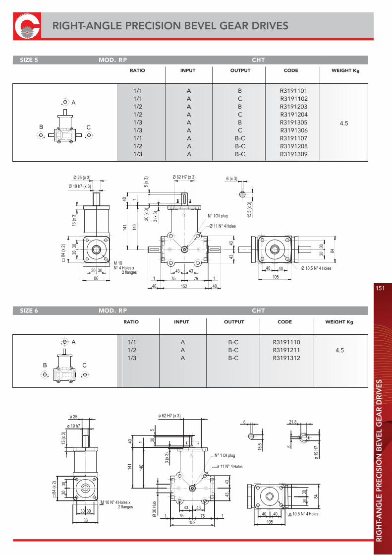
RIG
HT-
AN
GLE
PR
EC
ISIO
N B
EV
EL
GE
AR
DR
IVE
S
151
RIGHT-ANGLE PRECISION BEVEL GEAR DRIVES
SIZE 5 THCPR .DOM
SIZE 6 THCPR .DOM
B
A
C
B C
A
RATIO INPUT OUTPUT CODE WEIGHT Kg
1/1 A B R31911011/1 A C R31911021/2 A B R31912031/2 A C R31912041/3 A B R31913051/3 A C R31913061/1 A B-C R31911071/2 A B-C R31912081/3 A B-C R3191309
4.5
RATIO INPUT OUTPUT CODE WEIGHT Kg
1/1 A B-C R31911101/2 A B-C R31912111/3 A B-C R3191312
4.5
Oil plug
Holes
HolesHoles x2 flanges
Holes
Holes
Oil plug
Holes x2 flanges Hu
b
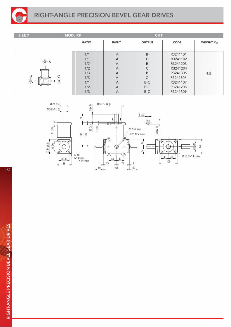
152
RIGHT-ANGLE PRECISION BEVEL GEAR DRIVESR
IGH
T-A
NG
LE P
RE
CIS
ION
BE
VE
L G
EA
R D
RIV
ES
SIZE 7 THCPR .DOM
B C
A
RATIO INPUT OUTPUT CODE WEIGHT Kg
1/1 A B R32411011/1 A C R32411021/2 A B R32412031/2 A C R32412041/3 A B R32413051/3 A C R32413061/1 A B-C R32411071/2 A B-C R32412081/3 A B-C R3241309
4.5
Holesx 2 flanges
Holes
Holes
Oil plug
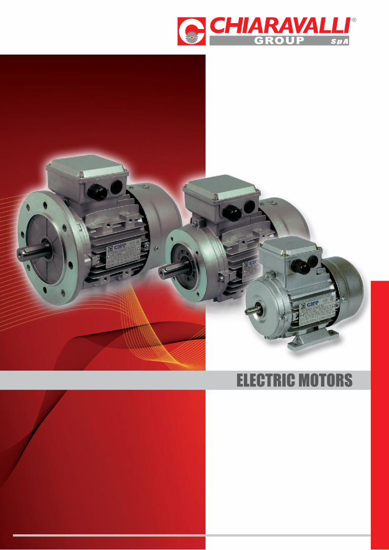
ELECTRIC MOTORS
154
INTRODUCTION IN
TRO
DU
CTI
ON
- T
EC
HN
ICA
L C
HA
RA
CTE
RIS
TIC
S
CHT series motors have been produced to be mounted on gearboxes and therefore they have mechanical and electrical characteristics particularly right for this use.All our motors are IP55, insulation class F with phase separator to be used with frequency variators, in this condition they can be provided complete with forced ventilation.The motors like the gearboxes are painted with RAL 9022 grey colour epoxy powder.
- Cage rotor motors, locked with outside surface ventilation.- Project, construction and test in compliance with CEI2-3, international norms IEC34-1 and principal foreign/international standard.- Power-sizes in specification with IEC 72, national norms UNEL-MEC.- Insulation: class F- Protection: class IP55- Rated power delivered on continuous: S1- European directive ROHS 2002/95/CE- Phase separator- Motors size 160 up to 355- Volt 400/690 standard from 160 up to 355 on request for other sizes
TECHNICAL CHARACTERISTICS
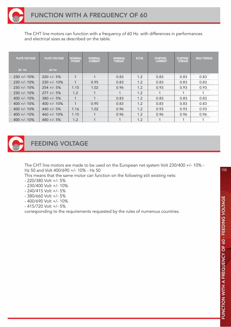
FUN
CTI
ON
WIT
H A
FR
EQ
UE
NC
Y O
F 60
- F
EE
DIN
G V
OLT
AG
E
155
FUNCTION WITH A FREQUENCY OF 60
The CHT line motors can function with a frequency of 60 Hz. with differences in performances and electrical sizes as described on the table.
PLATE VOLTAGE PLATE VOLTAGE NOMINAL NOMINAL NOMINAL R.P.M. STARTING STARTING MAX TORQUE POWER CURRENT TORQUE CURRENT TORQUE
50 Hz 60 Hz
230 +/- 10% 220 +/- 5% 1 1 0.83 1.2 0.83 0.83 0.83
230 +/- 10% 230 +/- 10% 1 0.95 0.83 1.2 0.83 0.83 0.83
230 +/- 10% 254 +/- 5% 1.15 1.02 0.96 1.2 0.93 0.93 0.93
230 +/- 10% 277 +/- 5% 1.2 1 1 1.2 1 1 1
400 +/- 10% 380 +/- 5% 1 1 0.83 1.2 0.83 0.83 0.83
400 +/- 10% 400 +/- 10% 1 0.95 0.83 1.2 0.83 0.83 0.83
400 +/- 10% 440 +/- 5% 1.16 1.02 0.96 1.2 0.93 0.93 0.93
400 +/- 10% 460 +/- 10% 1.15 1 0.96 1.2 0.96 0.96 0.96
400 +/- 10% 480 +/- 5% 1.2 1 1 1.2 1 1 1
FEEDING VOLTAGE
The CHT line motors are made to be used on the European net system Volt 230/400 +/- 10% - Hz 50 and Volt 400/690 +/- 10% - Hz 50This means that the same motor can function on the following stili existing nets:- 220/380 Volt +/- 5%- 230/400 Volt +/- 10%- 240/415 Volt +/- 5%- 380/660 Volt +/- 5%- 400/690 Volt +/- 10%- 415/720 Volt +/- 5%corresponding to the requirements requested by the rules of numerous countries.
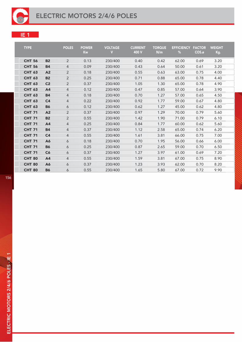
156
ELECTRIC MOTORS 2/4/6 POLESE
LEC
TRIC
MO
TOR
S 2/
4/6
PO
LES
- IE
1
TYPE POLES POWER VOLTAGE CURRENT TORQUE EFFICIENCY FACTOR WEIGHTKw V 400 V N/m % COS.ø Kg.
CHT 56 B2 2 0.13 230/400 0.40 0.42 62.00 0.69 3.20
CHT 56 B4 4 0.09 230/400 0.43 0.64 50.00 0.61 3.20
CHT 63 A2 2 0.18 230/400 0.55 0.63 63.00 0.75 4.00
CHT 63 B2 2 0.25 230/400 0.71 0.88 65.00 0.78 4.40
CHT 63 C2 2 0.37 230/400 1.05 1.30 65.00 0.78 4.90
CHT 63 A4 4 0.12 230/400 0.47 0.85 57.00 0.64 3.90
CHT 63 B4 4 0.18 230/400 0.70 1.27 57.00 0.65 4.50
CHT 63 C4 4 0.22 230/400 0.92 1.77 59.00 0.67 4.80
CHT 63 B6 6 0.12 230/400 0.62 1.27 45.00 0.62 4.80
CHT 71 A2 2 0.37 230/400 0.97 1.29 70.00 0.79 5.60
CHT 71 B2 2 0.55 230/400 1.42 1.90 71.00 0.79 6.10
CHT 71 A4 4 0.25 230/400 0.84 1.77 60.00 0.62 5.60
CHT 71 B4 4 0.37 230/400 1.12 2.58 65.00 0.74 6.20
CHT 71 C4 4 0.55 230/400 1.61 3.81 66.00 0.75 7.00
CHT 71 A6 6 0.18 230/400 0.70 1.95 56.00 0.66 6.00
CHT 71 B6 6 0.25 230/400 0.87 2.65 59.00 0.70 6.50
CHT 71 C6 6 0.37 230/400 1.27 3.97 61.00 0.69 7.20
CHT 80 A4 4 0.55 230/400 1.59 3.81 67.00 0.75 8.90
CHT 80 A6 6 0.37 230/400 1.23 3.93 62.00 0.70 8.20
CHT 80 B6 6 0.55 230/400 1.65 5.80 67.00 0.72 9.90
IE 1
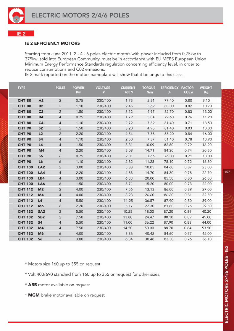
ELE
CTR
IC M
OTO
RS
2/4/
6 P
OLE
S -
IE2
157
ELECTRIC MOTORS 2/4/6 POLES
IE 2 EFFICIENCY MOTORS
Starting from June 2011, 2 - 4 - 6 poles electric motors with power included from 0,75kw to 375kw. sold into European Community, must be in accordance with EU MEPS European Union Minimum Energy Performance Standards regulation concerning efficiency level, in order to reduce consumptions and C02 emissions.IE 2 mark reported on the motors nameplate will show that it belongs to this class.
IE 2
TYPE POLES POWER VOLTAGE CURRENT TORQUE EFFICIENCY FACTOR WEIGHTKw V 400 V N/m % COS.ø Kg.
CHT 80 A2 2 0.75 230/400 1.75 2.51 77.40 0.80 9.10
CHT 80 B2 2 1.10 230/400 2.45 3.69 80.00 0.82 10.70
CHT 80 C2 2 1.50 230/400 3.12 4.97 82.70 0.83 13.00
CHT 80 B4 4 0.75 230/400 1.79 5.04 79.60 0.76 11.20
CHT 80 C4 4 1.10 230/400 2.72 7.39 81.40 0.71 13.50
CHT 90 S2 2 1.50 230/400 3.20 4.95 81.40 0.83 13.30
CHT 90 L2 2 2.20 230/400 4.54 7.38 83.20 0.84 16.00
CHT 90 S4 4 1.10 230/400 2.50 7.37 81.40 0.78 13.90
CHT 90 L4 4 1.50 230/400 3.31 10.09 82.80 0.79 16.20
CHT 90 M4 4 2.20 230/400 5.09 14.71 84.30 0.74 20.50
CHT 90 S6 6 0.75 230/400 2.01 7.66 76.00 0.71 13.00
CHT 90 L6 6 1.10 230/400 2.82 11.23 78.10 0.72 16.30
CHT 100 LA2 2 3.00 230/400 5.88 10.05 84.60 0.87 23.00
CHT 100 LA4 4 2.20 230/400 4.83 14.70 84.30 0.78 22.70
CHT 100 LB4 4 3.00 230/400 6.33 20.00 85.50 0.80 26.50
CHT 100 LA6 6 1.50 230/400 3.71 15.20 80.00 0.73 22.00
CHT 112 M2 2 4.00 230/400 7.56 13.13 86.00 0.89 27.00
CHT 112 M4 4 4.00 230/400 8.23 26.60 86.60 0.81 32.50
CHT 112 L4 4 5.50 230/400 11.25 36.57 87.90 0.80 39.00
CHT 112 M6 6 2.20 230/400 5.17 22.30 81.80 0.75 29.50
CHT 132 SA2 2 5.50 230/400 10.25 18.00 87.20 0.89 40.20
CHT 132 SB2 2 7.50 230/400 13.80 24.47 88.10 0.89 45.00
CHT 132 S4 4 5.50 230/400 11.00 36.22 87.90 0.83 44.00
CHT 132 M4 4 7.50 230/400 14.50 50.00 88.70 0.84 53.50
CHT 132 M6 6 4.00 230/400 8.86 40.42 84.60 0.77 45.00
CHT 132 S6 6 3.00 230/400 6.84 30.48 83.30 0.76 36.10
* Motors size 160 up to 355 on request
* Volt 400/690 standard from 160 up to 355 on request for other sizes.
* ABB motor available on request
* MGM brake motor available on request
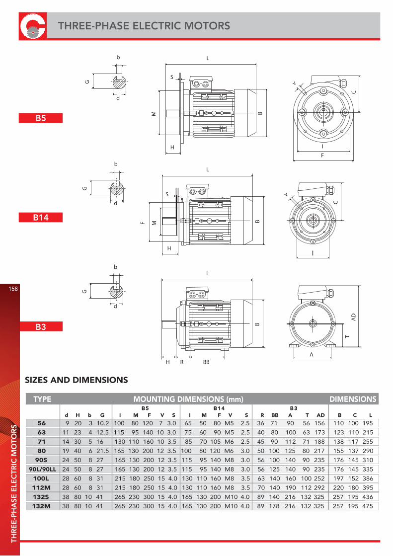
H
S
L
BM
v
C
I
F
G
d
b
S
L
H
F M B
C
v
I
G
d
b
56 9 20 3 10.2 100 80 120 7 3.0 65 50 80 M5 2.5 36 71 90 56 156 110 100 195
63 11 23 4 12.5 115 95 140 10 3.0 75 60 90 M5 2.5 40 80 100 63 173 123 110 215
71 14 30 5 16 130 110 160 10 3.5 85 70 105 M6 2.5 45 90 112 71 188 138 117 255
80 19 40 6 21.5 165 130 200 12 3.5 100 80 120 M6 3.0 50 100 125 80 217 155 137 290
90S 24 50 8 27 165 130 200 12 3.5 115 95 140 M8 3.0 56 100 140 90 235 176 145 310
90L/90LL 24 50 8 27 165 130 200 12 3.5 115 95 140 M8 3.0 56 125 140 90 235 176 145 335
100L 28 60 8 31 215 180 250 15 4.0 130 110 160 M8 3.5 63 140 160 100 252 197 152 386
112M 28 60 8 31 215 180 250 15 4.0 130 110 160 M8 3.5 70 140 190 112 292 220 180 395
132S 38 80 10 41 265 230 300 15 4.0 165 130 200 M10 4.0 89 140 216 132 325 257 195 436
132M 38 80 10 41 265 230 300 15 4.0 165 130 200 M10 4.0 89 178 216 132 325 257 195 475
SIZES AND DIMENSIONS
d H b G I M F V S I M F V S R BB A T AD B C L3B41B5B
TYPE MOUNTING DIMENSIONS (mm) DIMENSIONS
H
B
G
d
b
R BB
L
TAD
A
B3
158
THREE-PHASE ELECTRIC MOTORSTH
RE
E-P
HA
SE E
LEC
TRIC
MO
TOR
S
B5
B14
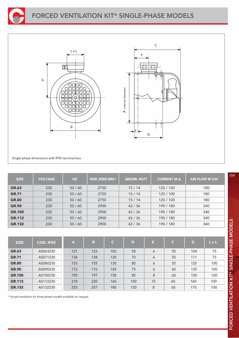
FOR
CE
D V
EN
TILA
TIO
N K
IT*
SIN
GLE
-PH
ASE
MO
DE
LS
159
FORCED VENTILATION KIT* SINGLE-PHASE MODELS
SIZE VOLTAGE HZ NOM. SPEED MIN/1 ABSORB. WATT CURRENT M.A. AIR FLOW M 3/H
GR.63 230 50 / 60 2750 15 / 14 120 / 100 180
GR.71 230 50 / 60 2750 15 / 14 120 / 100 180
GR.80 230 50 / 60 2750 15 / 14 120 / 100 180
GR.90 230 50 / 60 2900 42 / 36 190 / 180 340
GR.100 230 50 / 60 2900 42 / 36 190 / 180 340
GR.112 230 50 / 60 2900 42 / 36 190 / 180 340
GR.132 230 50 / 60 2900 42 / 36 190 / 180 340
Single-phase dimensions with IP55 terminal box
F
A in
tern
al d
iam
eter
DE
C
L x L
B
G
SIZE COD. IP55
GR.63 AS063230
GR.71 AS071230
GR.80 AS080230
GR.90 AS090230
GR.100 AS100230
GR.112 AS112230
GR.132 AS132230
A B C D E F G L x L
121 123 102 58 6 50 104 75
136 138 120 70 6 50 111 75
153 155 130 80 6 55 125 100
172 176 145 75 6 60 135 100
195 197 158 85 8 60 150 100
218 220 160 100 10 60 160 100
255 257 180 120 8 65 175 100
* forced ventilation kit three-phase models available on request

BELT TENSIONER SLIDES FOR ELECTRIC MOTORS

BE
LT T
EN
SIO
NE
R S
LID
ES
FOR
ELE
CTR
IC M
OTO
RS
161
BELT TENSIONER SLIDES FOR ELECTRIC MOTORS
Galvanized metal sheet FE 430
MATERIAL LG G J
K
CM mm
EV
H
B NK
30 E
CP
SW
S
63/80 210 90100210 210 195 33 100 70 20 25 50 10,5 43 98 19 3
63/112 270 90100270 270 195 33 100 70 20 25 50 10,5 43 98 19 3
90/132 340 90100340 340 290 40 135 95 27 29 62,5 12,5 90 165 22 4
100/160 430 90100430 460 290 40 140 95 27 29 62,5 12,5 90 165 22 4
160/180 490 90100490 490 410 40 254 95 40 30 60 15 193 142/284 22 4
MOTOR TYPE CODE L B H Mmin G E J K C N P SW SSIZE
210 70 58 45 2,2
270 130 118 105 90 70 40 2,8
340 140 130 100 75 6,7
430 216 186 10 122 7,5
490 156 131 10,8
DIMENSIONS
ADJUSTMENT WIDENESS
TYPE 63 71 80 90 100 112 132 160 180 WEIGHT kg
Quantities, prices and availability by B2B Chiaravalli

The Chiaravalli group is the technological partner that you should turn to knowing that reliability and respect are valuescommonly shared.

THE CUSTOMER: ALWAYS AT THE CENTRE OF OUR ATTENTION.
The Chiaravalli group is a dynamic, modern company oriented infulfilling customersneeds and desires.
Human progress has always been based on mechanical application and discovery that stem from human intutition and genius.
Mechanics: the genetic heritage ofChiaravalli Group
The Chiaravalli Group, always aware of the needs of the market has found it necessary to provide its long-standing customers with complete, steady up-dated information about its products 24 hours a day 365 days in a year.
This attention comes from B2B, which is the direct consequence of our interest and dedication to our customers. It is an advanced system of research,purchasing and delivery of all Chiaravalli products.B2B Chiaravalli Group becomes a virtual extension of the customer’s warehouse.

GENERAL SALES CONDITIONSG
EN
ER
AL
SALE
S C
ON
DIT
ION
S
1) ORDERS - Orders for special and standard material must always refer to offers made by CHIARAVALLI GROUP S.p.A. The orders are binding for the client.Once work has commenced no cancellations or order reductions will be accepted unless the client reimburses the costs of the material and the work carried out up to the moment in which the order was suspended.The quantity despatched can vary by ± 5% compared to the quantity ordered.
2) PRICES - The prices are those in force at the date of order.All prices are for goods delivered ex-works Premezzo, packing excluded. If there should be any increase in production and material costs over the duration of the supply, CHIARAVALLI GROUP S.p.A. reserves the right to adapt the prices accordingly, even for orders in course.
3) TERMS OF DELIVERY - Only the terms of delivery indicated by CHIARAVALLI GROUP SpA are to be considered valid. However, they must only be considered as indicative.In the event of difficulty in the procurement of materials, strikes or in any event in all cases of force majeure, the terms of delivery will be automatically extended without CHIARAVALLI GROUP S.p.A having to pay any reimbursement for damages.The client is obligated to collect special material ordered when ready.
4) DELIVERIES - Deliveries are the responsibility of the purchaser and are carried out at his own risk and peril.Any claims for shortages must be presented within 8 days of receipt of the goods.If it is agreed that the cost of transport is to be paid, even if only in part, by CHIARAVALLI GROUP S.p.A., the latter reserves the right to choose the most economical means of transport.
5) PACKING - Packing will be invoiced at cost.
6) RETURNS - No returns for any reason will be accepted unless previously authorised and with packing, any customs clearance and the return paid for by the purchaser.To cover warehouse and administrative expenses a debit note will be issued for approx. 15% of the value of the goods returned.
7) WARRANTY - CHIARAVALLI GROUP S.p.A. promises to repair or substitute free of charge any parts that they recognise as being defective. The questioned goods must be returned to the factory of CHIARAVALLI GROUP S.p.A., free of all expenses.The warranty will be considered cancelled in the event that the parts returned as defective have been repaired or tampered with. The repair of defective parts carried out by the purchaser will only be accepted after authorisation from CHIARAVALLI GROUP S.p.A. and after their approval of the cost estimate. CHIARAVALLI GROUP S.p.A. does not accept responsibility or pay any reimbursement for damages that occur during the use of their products, even if defective.Warranty is excluded for leakage of lubricant caused by wear of the oil seals.
8) RESPONSIBILITY - CHIARAVALLI GROUP S.p.A. does not accept responsibility or pay any reimbursement for damages that occur during the use of their products, even if defective.CHIARAVALLI GROUP S.p.A. declines all responsibility in the execution of parts to a client’s design under any patents.
9) PAYMENTS - Only payments carried out in the manner and terms agreed will be considered valid. Once the due date of payment has passed, CHIARAVALLI GROUP S.p.A. will calculate the interest on delayed payment at a rate that is 3% higher than the legal one, retaining the right to demand payment. In the event of delayed or missing payment by the purchaser, the company CHIARAVALLI GROUP S.p.A. reserves the right to suspend deliveries of the orders in course or to demand advance payment without having to pay any reimbursement or compensation to the purchaser. Any dispute regarding materials in manufacture or already possessed by the purchaser does not free the latter from the commitment of making the payment by the agreed date and for the whole amount of the invoice without making any deductions.
10) OWNERSHIP - All of the goods despatched remain the property of CHIARAVALLI GROUP S.p.A. until the invoice is fully paid.
11) COMPETENT COURT - Any controversy concerning business relations with CHIARAVALLI GROUP SpA will be dealt with under the jurisdiction of the Court of Busto Arsizio.
CHIARAVALLI GROUP SpA, do not accepts responsibility for any errors in the production of this catalogue and reserves the right to add to the drawings designs of the listed products any modification request by manufacturing requirements or due to evolution of the products.

Via per Cedrate, 47621044 Cavaria con Premezzo (VA)ItalyTel. +39 0331 214 511Fax +39 0331 218 175
Satellite position: coordinates N 45° 41.394 · E8° 48.726
CHIARAVALLI Cz a.s.Prumyslová 208359401 Velké MezirícíCeská republika Tel. +420 566 502 030www.chiaravalli.cz
CHIARAVALLI POLSKA Sp. z o. o.ul. Polna 13387 - 100 TorunPolskaTel. + 48 56 623 30 00www.chiaravalli.pl