torque motors - etel.ch
TRANSCRIPT

Torque MotorsTMK INTERFACE DRAWINGS
I
I
J
J
1 2 3 4 5 6 7 8 9 10 11 12 13 14 15 16
A
B
C
D
E
F
G
H
J
K
A
1
B
C
D
E
F
G
H
J
K
L
2 3 4 5 6 7 8 9 10 11 12
M
17
- --ETEL S.A.2112 MôtiersSWITZERLAND
-0.1-0.3
+0.3+0.0
A
740.1
185
L1 0.2
0.05 A
9.5
12.5
30
Water Cooling Inlet / Outlet
L3
12.5
N1x 14
N1x
M6
A
(X)
50 H
8(+0
.039
0)
Cus
tom
er o
uter
sh
aft t
oler
ance
: g8
86 g
8(-0
.012
-0.0
66)
7±0.2 L2
10
62 m
in
(Y) C
usto
mer
's h
ousi
ng m
ust b
e 19
8 H
8 D
iam
eter
s (X
) and
(Y) m
ust b
e co
ncen
tric
with
in 0
,1 w
hen
mou
nted
N1 xß1
22.5°
N2 xß2
20 20
30° 30°
24 24
2
30°
2
30°
0.2 0 -0
.1
0.2 0 -0
.1
(25)
(25)
(27)
( 5.7) Cable 7x0.25mm²
( 5.5) Cable 2.5mm² (4x)
( 5.7) Cable 7x0.25mm²
( 7.5) Cable 6mm² (4x)
30° 30°
1 1
7±0.2
89 max
N2x M5
N2x M5
N2x 11
N2x 11
50.5
min
118
min
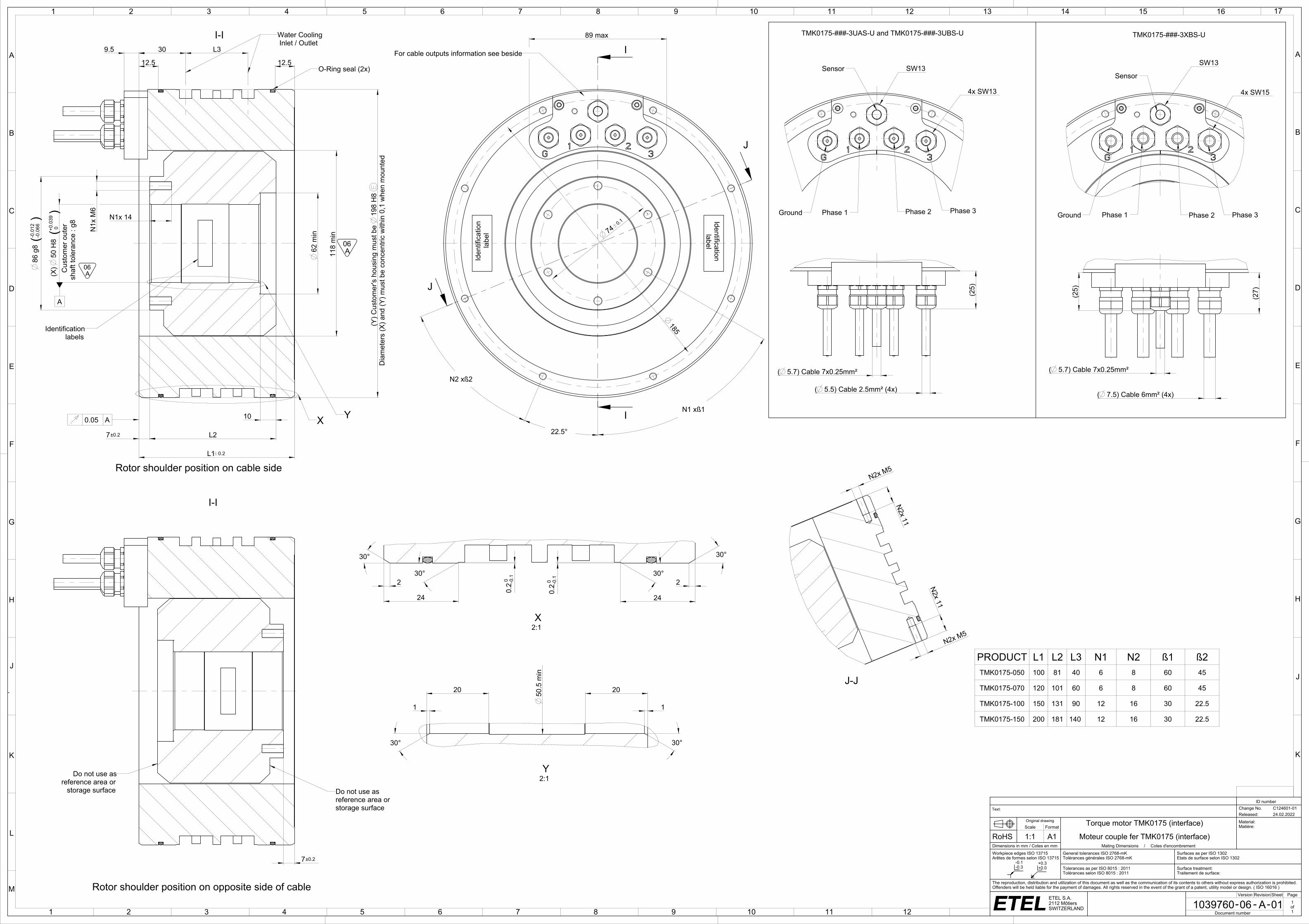
PRODUCT L1 L2 L3 N1 N2 ß1 ß2TMK0175-050 100 81 40 6 8 60 45
TMK0175-070 120 101 60 6 8 60 45
TMK0175-100 150 131 90 12 16 30 22.5
TMK0175-150 200 181 140 12 16 30 22.5
ttf_etl
ID number
Text: Change No. C124601-01Released: 24.02.2022
Original drawing Torque motor TMK0175 (interface) Material:Matière:Scale Format
RoHS 1:1 A1 Moteur couple fer TMK0175 (interface)Dimensions in mm / Cotes en mm Mating Dimensions / Cotes d'encombrementWorkpiece edges ISO 13715Arêtes de formes selon ISO 13715
General tolerances ISO 2768-mKTolérances générales ISO 2768-mK
Surfaces as per ISO 1302Etats de surface selon ISO 1302
Tolerances as per ISO 8015 : 2011Tolérances selon ISO 8015 : 2011
Surface treatment:Traitement de surface:
The reproduction, distribution and utilization of this document as well as the communication of its contents to others without express authorization is prohibited. Offenders will be held liable for the payment of damages. All rights reserved in the event of the grant of a patent, utility model or design. ( ISO 16016 )
Version Revision Sheet Page
1039760 06 A 01 1of1Document number
storage surfacereference area or
Do not use as
For cable outputs information see beside
Identification label
X Y
Rotor shoulder position on cable side
O-Ring seal (2x)
labelsIdentification
TMK0175-###-3XBS-UI-I
Rotor shoulder position on opposite side of cable
Do not use asreference area or storage surface
2:1X
Phase 1 = Wire 1Phase 2 = Wire 2Phase 3 = Wire 3Ground = Wire yellow-Green (G)
For the temperature sensor configutation see the Integration manual
2:1Y
Iden
tific
atio
n la
bel
TMK0175-###-3UAS-U and TMK0175-###-3UBS-U
Sensor
Ground Phase 1 Phase 3Phase 2
4x SW13
SW13Sensor
Ground Phase 1 Phase 3Phase 2
SW13
4x SW15
J-J
I-I
A06
A06

1 2 3 4 5 6 7 8 9 10 11 12
A
B
C
D
E
F
G
H
1 2 3 4 5 6 7 8
A
B
C
D
E
F
- --ETEL S.A.2112 MôtiersSWITZERLAND
-0.1-0.3
+0.3+0.0
D
R
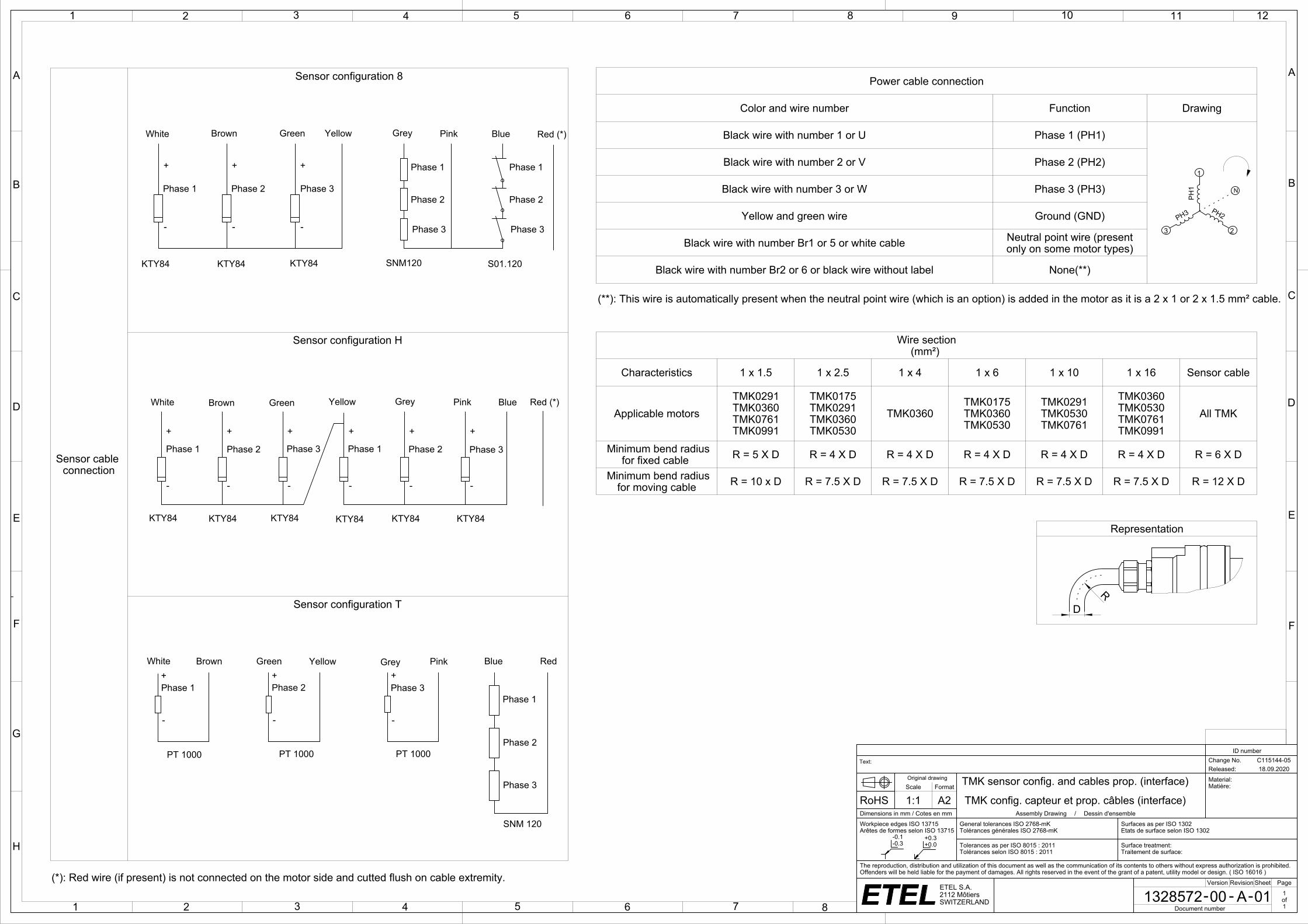
Power cable connection
Color and wire number Function Drawing
Black wire with number 1 or U Phase 1 (PH1)
Black wire with number 2 or V Phase 2 (PH2)
Black wire with number 3 or W Phase 3 (PH3)
Yellow and green wire Ground (GND)
Black wire with number Br1 or 5 or white cable Neutral point wire (presentonly on some motor types)
Black wire with number Br2 or 6 or black wire without label None(**)
Motors family
temperature sensorconfiguration Temperature sensor wiring
TMBTMLTMMTMK
Configuration 8(TMB.....-#8#-##)(TML.....-#8#-##)(TMM.....-#8#-##)(TMK.....-#8#-##)
Configuration H(TMB.....-#H#-##)(TML.....-#H#-##)(TMM.....-#H#-##)(TMK.....-#H#-##)
Configuration T(TMB.....-#T#-##)(TML.....-#T#-##)(TMM.....-#T#-##)(TMK.....-#T#-##)
Wire section(mm²)
Characteristics 1 x 1.5 1 x 2.5 1 x 4 1 x 6 1 x 10 1 x 16 Sensor cable
Applicable motorsTMK0291TMK0360TMK0761TMK0991
TMK0175TMK0291TMK0360TMK0530
TMK0360TMK0175TMK0360TMK0530
TMK0291TMK0530TMK0761
TMK0360TMK0530TMK0761TMK0991
All TMK
Minimum bend radiusfor fixed cable R = 5 X D R = 4 X D R = 4 X D R = 4 X D R = 4 X D R = 4 X D R = 6 X D
Minimum bend radiusfor moving cable R = 10 x D R = 7.5 X D R = 7.5 X D R = 7.5 X D R = 7.5 X D R = 7.5 X D R = 12 X D
Representation
Sensors cable connection
Sensors configuration 8 Sensors Configuration H Sensors Configuration T
_etl
ID number
Text: Change No. C115144-05Released: 18.09.2020
Original drawing TMK sensor config. and cables prop. (interface) Material:Matière:Scale Format
RoHS 1:1 A2 TMK config. capteur et prop. câbles (interface)Dimensions in mm / Cotes en mm Assembly Drawing / Dessin d'ensembleWorkpiece edges ISO 13715Arêtes de formes selon ISO 13715
General tolerances ISO 2768-mKTolérances générales ISO 2768-mK
Surfaces as per ISO 1302Etats de surface selon ISO 1302
Tolerances as per ISO 8015 : 2011Tolérances selon ISO 8015 : 2011
Surface treatment:Traitement de surface:
The reproduction, distribution and utilization of this document as well as the communication of its contents to others without express authorization is prohibited. Offenders will be held liable for the payment of damages. All rights reserved in the event of the grant of a patent, utility model or design. ( ISO 16016 )
Version Revision Sheet Page
1328572 00 A 01 1of1Document number
Sensors cable connection
Sensors configuration 8 Sensors Configuration H Sensors Configuration T
Sensor cable connection
Sensor configuration 8
Sensor configuration H
Sensor configuration T
Power cable connection
Phase 1 = wire 1Phase 2 = wire 2Phase 3 = wire 3PE = yellow/green wire
Sensor cable connection: "P" configuration
PH3
3 2
PH2
1
PH1
White Brown
PT 1000
+
-
Green Yellow Grey Pink
SNM 120
Blue Red
SNM 120
SNM 120
PT 1000
+
-PT 1000
+
-
N
Pink
Temperature sensor configuration
White
KTY84
Phase 3
KTY84KTY84 SNM120
+
Green
Phase 3
-
Brown
+
Phase 1
-
+
Phase 2
-
Yellow
Phase 1
Phase 2
Grey
Phase 3
S01.120
Phase 2
Phase 1
Blue
Phase 3
KTY84 KTY84 KTY84 KTY84KTY84 KTY84
White
Temperature sensor configuration
Phase 2
-
Phase 1
-
+ +
Brown
-
Green
Phase 3
+
Grey
Phase 1
-
+
Yellow
-
Phase 2
-
+ +
Pink Blue(*): Red wire (if present) is not connected on the motor side and cutted flush on cable extremity.
PinkWhite
KTY84
Phase 3
KTY84KTY84 SNM120
+
Green
Phase 3
-
Brown
+Phase 1
-
+Phase 2
-
Yellow
Phase 1
Phase 2
Grey
Phase 3
S01.120
Phase 2
Phase 1
Blue
Phase 3
KTY84 KTY84 KTY84 KTY84KTY84 KTY84
White
Phase 2
-
Phase 1
-
+ +
Brown
-
Green
Phase 3
+
Grey
Phase 1
-
+
Yellow
-
Phase 2
-
+ +
Pink Blue White Brown
PT 1000
Green Yellow Grey Pink
Phase 1
Blue Red
Phase 2
Phase 3
PT 1000
SNM 120
Phase 1 Phase 2 Phase 3
(**): This wire is automatically present when the neutral point wire (which is an option) is added in the motor as it is a 2 x 1 or 2 x 1.5 mm² cable.
Red (*)
Red (*)
PinkWhite
KTY84
Phase 3
KTY84KTY84 SNM120
+
Green
Phase 3
-
Brown
+
Phase 1
-
+
Phase 2
-
Yellow
Phase 1
Phase 2
Grey
Phase 3
S01.120
Phase 2
Phase 1
Blue
Phase 3
KTY84 KTY84 KTY84 KTY84KTY84 KTY84
White
Phase 2
-
Phase 1
-
+ +
Brown
-
Green
Phase 3
+
Grey
Phase 1
-
+
Yellow
-
Phase 2
-
+ +
Pink Blue
White Brown
Phase 1
+
-
Green Yellow Grey Pink
Phase 1
Blue Red
Phase 2
Phase 3
Phase 2
+
-Phase 3
+
-
Pink
Temperature sensor configuration
White
KTY84
Phase 3
KTY84KTY84 SNM120
+
Green
Phase 3
-
Brown
+
Phase 1
-
+
Phase 2
-
Yellow
Phase 1
Phase 2
Grey
Phase 3
S01.120
Phase 2
Phase 1
BluePink
Temperature sensor configuration
White
KTY84
Phase 3
KTY84KTY84 SNM120
+
Green
Phase 3
-
Brown
+
Phase 1
-
+
Phase 2
-
Yellow
Phase 1
Phase 2
Grey
Phase 3
S01.120
Phase 2
Phase 1
Blue
PT 1000
White Brown
Phase 1+
-
Green Yellow Grey Pink
Phase 1
Blue Red
Phase 2
Phase 3
Phase 2+
-
Phase 3+
-
I
I
J
J
1 2 3 4 5 6 7 8 9 10 11 12 13 14 15 16
A
B
C
D
E
F
G
H
J
K
A
1
B
C
D
E
F
G
H
J
K
L
2 3 4 5 6 7 8 9 10 11 12
M
17
- --ETEL S.A.2112 MôtiersSWITZERLAND
-0.1-0.3
+0.3+0.0
A
A
35
17.5
9.5
L3
12.5
(X)
144
H8
(+0.0
63 0
)C
usto
mer
out
er s
haft
tole
ranc
e : g
8
190
g8(-0
.015
-0.0
87)
165.
5 m
in
L20.05 A
12
12
L1±0.2
100.05 A
N2 x ß
15°
108 max
46°
N2x M5
N2x 10
N2x 10
N2x M5
N1 x ß
19
30°
2.5
30°
0.2 0 -0
.1
0.2 0 -0
.1
24
30°
30°
2.5
30°
120 20
1
30°
144.
5 m
in
118 max
(Y) C
usto
mer
's h
ousi
ng m
ust b
e 31
0 H
8
228
min
300
N1x
M6
N1x 12
156
N1x
M6
N1x 12
2±0.2
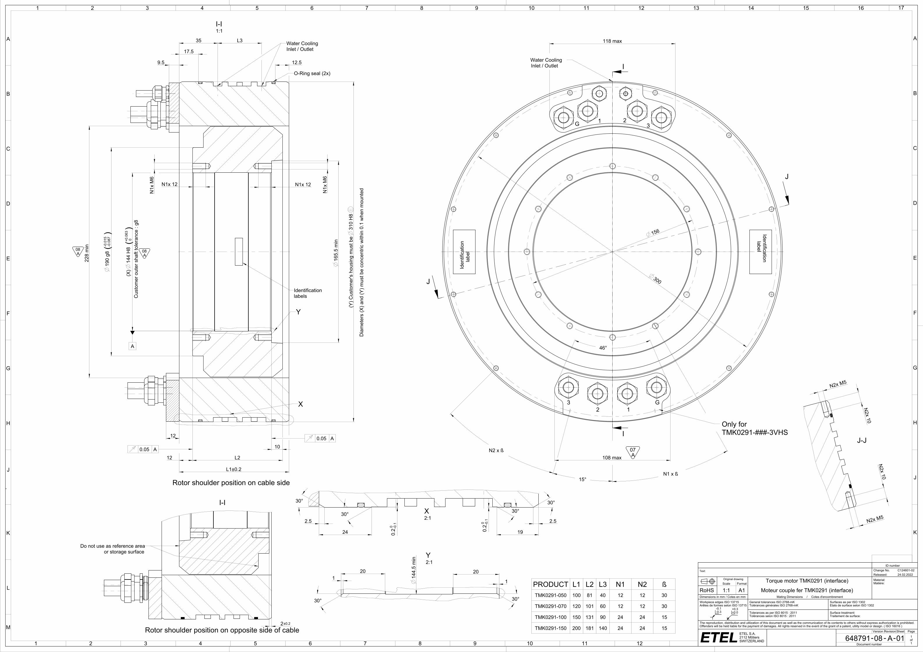
PRODUCT L1 L2 L3 N1 N2 ßTMK0291-050 100 81 40 12 12 30
TMK0291-070 120 101 60 12 12 30
TMK0291-100 150 131 90 24 24 15
TMK0291-150 200 181 140 24 24 15
ttf_etl
ID number
Text: Change No. C124601-02Released: 24.02.2022
Original drawing Torque motor TMK0291 (interface) Material:Matière:Scale Format
RoHS 1:1 A1 Moteur couple fer TMK0291 (interface)Dimensions in mm / Cotes en mm Mating Dimensions / Cotes d'encombrementWorkpiece edges ISO 13715Arêtes de formes selon ISO 13715
General tolerances ISO 2768-mKTolérances générales ISO 2768-mK
Surfaces as per ISO 1302Etats de surface selon ISO 1302
Tolerances as per ISO 8015 : 2011Tolérances selon ISO 8015 : 2011
Surface treatment:Traitement de surface:
The reproduction, distribution and utilization of this document as well as the communication of its contents to others without express authorization is prohibited. Offenders will be held liable for the payment of damages. All rights reserved in the event of the grant of a patent, utility model or design. ( ISO 16016 )
Version Revision Sheet Page
648791 08 A 01 1of1Document number
Identification label
I-I1:1
X
Y
Water CoolingInlet / Outlet
O-Ring seal (2x)
Dia
met
ers
(X) a
nd (Y
) mus
t be
conc
entri
c w
ithin
0.1
whe
n m
ount
ed
Rotor shoulder position on cable side
Rotor shoulder position on opposite side of cable
Identificationlabels
Water CoolingInlet / Outlet
Iden
tific
atio
n
lab
el
Only for TMK0291-###-3VHS
G 1 23
G12
3
J-J
X2:1
Y2:1
or storage surfaceDo not use as reference area
I-I
A07
A08
A08
1 2 3 4 5 6 7 8 9 10 11 12
A
B
C
D
E
F
G
H
1 2 3 4 5 6 7 8
A
B
C
D
E
F
- --ETEL S.A.2112 MôtiersSWITZERLAND
-0.1-0.3
+0.3+0.0
( 5.7) Cable 7x0.25mm²
( 9) Cable 10mm² (4x)
(31)
(25)
(31)
( 9) Cable 10mm² (4x)
( 5.7) Cable 7x0.25mm²
(25)
( 9) Cable 10mm² (4x)
(39)
( 5.5) Cable 2,5mm² (4x)
( 5.7) Cable 7x0.25mm²
(28)(25)
(24)
( 3.5) Cable 1,5mm²
ttf_etl
ID number
Text: Change No. C124601-02Released: 24.02.2022
Original drawing Torque motor TMK0291 cables outputs U (interface) Material:Matière:Scale Format
RoHS 1:1 A2 Moteur couple fer TMK0291 sorties de câbles U (interface)Dimensions in mm / Cotes en mm Mating Dimensions / Cotes d'encombrementWorkpiece edges ISO 13715Arêtes de formes selon ISO 13715
General tolerances ISO 2768-mKTolérances générales ISO 2768-mK
Surfaces as per ISO 1302Etats de surface selon ISO 1302
Tolerances as per ISO 8015 : 2011Tolérances selon ISO 8015 : 2011
Surface treatment:Traitement de surface:
The reproduction, distribution and utilization of this document as well as the communication of its contents to others without express authorization is prohibited. Offenders will be held liable for the payment of damages. All rights reserved in the event of the grant of a patent, utility model or design. ( ISO 16016 )
Version Revision Sheet Page
648791 08 A 02 1of1Document number
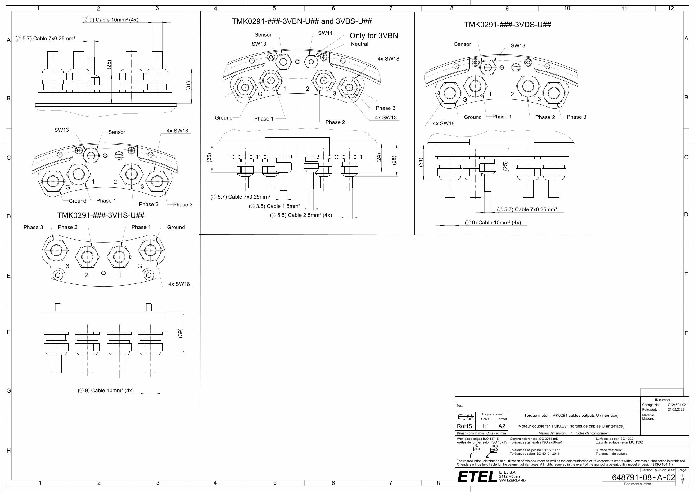
TMK0291-###-3VHS-U##
TMK0291-###-3VDS-U##TMK0291-###-3VBN-U## and 3VBS-U##
Power cable connection
Phase 1 = Wire 1Phase 2 = Wire 2Phase 3 = Wire 3Ground = Wire yellow-Green (G)Neutral = Wire 5 or Br1 or white
For the temperature sensorconfiguration see theintegration manual
G1 2
3
Ground
Sensor
Phase 1 Phase 2 Phase 3
SW13 4x SW18
Only for 3VBN
G1 2
3
Ground
Sensor
Phase 1 Phase 2
Phase 3
NeutralSW13
SW11
4x SW18
4x SW13
G1 2
3
Ground
Sensor
Phase 1 Phase 2 Phase 3
SW13
4x SW18
GroundPhase 1Phase 2Phase 3
4x SW18
G12
3
A06
1 2 3 4 5 6 7 8 9 10 11 12
A
B
C
D
E
F
G
H
1 2 3 4 5 6 7 8
A
B
C
D
E
F
- --ETEL S.A.2112 MôtiersSWITZERLAND
-0.1-0.3
+0.3+0.0
D
R
Power cable connection
Color and wire number Function Drawing
Black wire with number 1 or U Phase 1 (PH1)
Black wire with number 2 or V Phase 2 (PH2)
Black wire with number 3 or W Phase 3 (PH3)
Yellow and green wire Ground (GND)
Black wire with number Br1 or 5 or white cable Neutral point wire (presentonly on some motor types)
Black wire with number Br2 or 6 or black wire without label None(**)
Motors family
temperature sensorconfiguration Temperature sensor wiring
TMBTMLTMMTMK
Configuration 8(TMB.....-#8#-##)(TML.....-#8#-##)(TMM.....-#8#-##)(TMK.....-#8#-##)
Configuration H(TMB.....-#H#-##)(TML.....-#H#-##)(TMM.....-#H#-##)(TMK.....-#H#-##)
Configuration T(TMB.....-#T#-##)(TML.....-#T#-##)(TMM.....-#T#-##)(TMK.....-#T#-##)
Wire section(mm²)
Characteristics 1 x 1.5 1 x 2.5 1 x 4 1 x 6 1 x 10 1 x 16 Sensor cable
Applicable motorsTMK0291TMK0360TMK0761TMK0991
TMK0175TMK0291TMK0360TMK0530
TMK0360TMK0175TMK0360TMK0530
TMK0291TMK0530TMK0761
TMK0360TMK0530TMK0761TMK0991
All TMK
Minimum bend radiusfor fixed cable R = 5 X D R = 4 X D R = 4 X D R = 4 X D R = 4 X D R = 4 X D R = 6 X D
Minimum bend radiusfor moving cable R = 10 x D R = 7.5 X D R = 7.5 X D R = 7.5 X D R = 7.5 X D R = 7.5 X D R = 12 X D
Representation
Sensors cable connection
Sensors configuration 8 Sensors Configuration H Sensors Configuration T
_etl
ID number
Text: Change No. C115144-05Released: 18.09.2020
Original drawing TMK sensor config. and cables prop. (interface) Material:Matière:Scale Format
RoHS 1:1 A2 TMK config. capteur et prop. câbles (interface)Dimensions in mm / Cotes en mm Assembly Drawing / Dessin d'ensembleWorkpiece edges ISO 13715Arêtes de formes selon ISO 13715
General tolerances ISO 2768-mKTolérances générales ISO 2768-mK
Surfaces as per ISO 1302Etats de surface selon ISO 1302
Tolerances as per ISO 8015 : 2011Tolérances selon ISO 8015 : 2011
Surface treatment:Traitement de surface:
The reproduction, distribution and utilization of this document as well as the communication of its contents to others without express authorization is prohibited. Offenders will be held liable for the payment of damages. All rights reserved in the event of the grant of a patent, utility model or design. ( ISO 16016 )
Version Revision Sheet Page
1328572 00 A 01 1of1Document number
Sensors cable connection
Sensors configuration 8 Sensors Configuration H Sensors Configuration T
Sensor cable connection
Sensor configuration 8
Sensor configuration H
Sensor configuration T
Power cable connection
Phase 1 = wire 1Phase 2 = wire 2Phase 3 = wire 3PE = yellow/green wire
Sensor cable connection: "P" configuration
PH3
3 2
PH2
1
PH1
White Brown
PT 1000
+
-
Green Yellow Grey Pink
SNM 120
Blue Red
SNM 120
SNM 120
PT 1000
+
-PT 1000
+
-
N
Pink
Temperature sensor configuration
White
KTY84
Phase 3
KTY84KTY84 SNM120
+
Green
Phase 3
-
Brown
+
Phase 1
-
+
Phase 2
-
Yellow
Phase 1
Phase 2
Grey
Phase 3
S01.120
Phase 2
Phase 1
Blue
Phase 3
KTY84 KTY84 KTY84 KTY84KTY84 KTY84
White
Temperature sensor configuration
Phase 2
-
Phase 1
-
+ +
Brown
-
Green
Phase 3
+
Grey
Phase 1
-
+
Yellow
-
Phase 2
-
+ +
Pink Blue(*): Red wire (if present) is not connected on the motor side and cutted flush on cable extremity.
PinkWhite
KTY84
Phase 3
KTY84KTY84 SNM120
+
Green
Phase 3
-
Brown
+Phase 1
-
+Phase 2
-
Yellow
Phase 1
Phase 2
Grey
Phase 3
S01.120
Phase 2
Phase 1
Blue
Phase 3
KTY84 KTY84 KTY84 KTY84KTY84 KTY84
White
Phase 2
-
Phase 1
-
+ +
Brown
-
Green
Phase 3
+
Grey
Phase 1
-
+
Yellow
-
Phase 2
-
+ +
Pink Blue White Brown
PT 1000
Green Yellow Grey Pink
Phase 1
Blue Red
Phase 2
Phase 3
PT 1000
SNM 120
Phase 1 Phase 2 Phase 3
(**): This wire is automatically present when the neutral point wire (which is an option) is added in the motor as it is a 2 x 1 or 2 x 1.5 mm² cable.
Red (*)
Red (*)
PinkWhite
KTY84
Phase 3
KTY84KTY84 SNM120
+
Green
Phase 3
-
Brown
+
Phase 1
-
+
Phase 2
-
Yellow
Phase 1
Phase 2
Grey
Phase 3
S01.120
Phase 2
Phase 1
Blue
Phase 3
KTY84 KTY84 KTY84 KTY84KTY84 KTY84
White
Phase 2
-
Phase 1
-
+ +
Brown
-
Green
Phase 3
+
Grey
Phase 1
-
+
Yellow
-
Phase 2
-
+ +
Pink Blue
White Brown
Phase 1
+
-
Green Yellow Grey Pink
Phase 1
Blue Red
Phase 2
Phase 3
Phase 2
+
-Phase 3
+
-
Pink
Temperature sensor configuration
White
KTY84
Phase 3
KTY84KTY84 SNM120
+
Green
Phase 3
-
Brown
+
Phase 1
-
+
Phase 2
-
Yellow
Phase 1
Phase 2
Grey
Phase 3
S01.120
Phase 2
Phase 1
BluePink
Temperature sensor configuration
White
KTY84
Phase 3
KTY84KTY84 SNM120
+
Green
Phase 3
-
Brown
+
Phase 1
-
+
Phase 2
-
Yellow
Phase 1
Phase 2
Grey
Phase 3
S01.120
Phase 2
Phase 1
Blue
PT 1000
White Brown
Phase 1+
-
Green Yellow Grey Pink
Phase 1
Blue Red
Phase 2
Phase 3
Phase 2+
-
Phase 3+
-
I
I
J
J
1 2 3 4 5 6 7 8 9 10 11 12 13 14 15 16
A
B
C
D
E
F
G
H
J
K
A
1
B
C
D
E
F
G
H
J
K
L
2 3 4 5 6 7 8 9 10 11 12
M
17
- --ETEL S.A.2112 MôtiersSWITZERLAND
-0.1-0.3
+0.3+0.0
A
8.5 8.5
9.5
129 max
N2xM6
N2x 11
N2x 11
N2x M6
30° 30°
28 28
30° 30°
0.2 0 -0
.1
0.2 0 -0
.1
L1 0.2
124 max
35
2.5 2.5
15
100.05 A
L20.05 A
12
201
30°
201
30°
216.
5 m
in
264
g8(-0
.017
-0.0
98)
(X)
216
H8
(+0.0
72 0
)C
usto
mer
out
er s
haft
tole
ranc
e : g
8
238
min
(Y) C
usto
mer
's h
ousi
ng m
ust b
e 38
5 H
8 D
iam
eter
s (X
) and
(Y) m
ust b
e co
ncen
tric
with
in 0
,2 w
hen
mou
nted
15°
N2 x ß
L3
N1 x ß
298
min
370
N1x
M6 N1x 12
N1x
M6
N1x 12
228 ( 7.5) Cable 6mm² (4x)
( 5.7) Cable 7x0.25mm²
(24)
(29)
( 5.7) Cable 7x0.25mm²
( 10) Cable 16mm² (4x)
(29)
(24)
( 10) Cable 16mm² (4x)
(35)
( 5.7) Cable 7x0.25mm²
( 5.5) Cable 2,5mm² (4x)
( 3.5) Cable 1,5mm²
(24)
(23)
(27)
( 5.7) Cable 7x0.25mm² ( 10) Cable 16mm² (4x)( 3.5) Cable 1,5mm²
(24)
(23)
(29)( 6.5) Cable 4mm² (4x)
( 3.5) Cable 1,5mm²( 5.7) Cable 7x0.25mm²
(24)
(23)
(29)
( 10) Cable 16mm² (4x)
( 5.7) Cable 7x0.25mm²
(24)
(29)
12±0.2
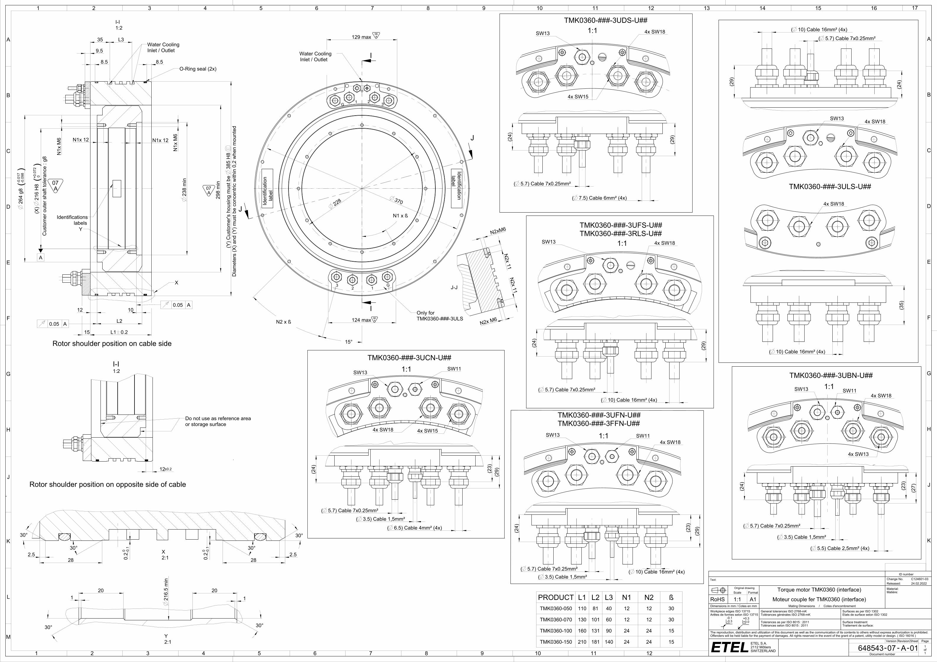
PRODUCT L1 L2 L3 N1 N2 ßTMK0360-050 110 81 40 12 12 30
TMK0360-070 130 101 60 12 12 30
TMK0360-100 160 131 90 24 24 15
TMK0360-150 210 181 140 24 24 15
ttf_etl
ID number
Text: Change No. C124601-03Released: 24.02.2022
Original drawing Torque motor TMK0360 (interface) Material:Matière:Scale Format
RoHS 1:1 A1 Moteur couple fer TMK0360 (interface)Dimensions in mm / Cotes en mm Mating Dimensions / Cotes d'encombrementWorkpiece edges ISO 13715Arêtes de formes selon ISO 13715
General tolerances ISO 2768-mKTolérances générales ISO 2768-mK
Surfaces as per ISO 1302Etats de surface selon ISO 1302
Tolerances as per ISO 8015 : 2011Tolérances selon ISO 8015 : 2011
Surface treatment:Traitement de surface:
The reproduction, distribution and utilization of this document as well as the communication of its contents to others without express authorization is prohibited. Offenders will be held liable for the payment of damages. All rights reserved in the event of the grant of a patent, utility model or design. ( ISO 16016 )
Version Revision Sheet Page
648543 07 A 01 1of1Document number
Do not use as reference areaor storage surface
TMK0360-###-3UBN-U##1:1
TMK0360-###-3UFS-U##TMK0360-###-3RLS-U##
1:1
1:1
Iden
tific
atio
n
labe
l
Identification label
I-I1:2
X
Y
Water CoolingInlet / Outlet
O-Ring seal (2x)
Power cable connectionPhase 1 = Wire 1Phase 2 = Wire 2Phase 3 = Wire 3Ground = Wire Yellow-Green (G)Neutral = Wire 5 or Br1 or White
For the temperature sensorconfiguration see theintegration manual
TMK0360-###-3UDS-U##
TMK0360-###-3ULS-U##
Rotor shoulder position on cable side
Rotor shoulder position on opposite side of cable
labelsIdentifications
Water CoolingInlet / Outlet
Only forTMK0360-###-3ULS
G 1 2 3
G12
3 J-J
X2:1
Y2:1
TMK0360-###-3UFN-U##TMK0360-###-3FFN-U##
1:1SW13 4x SW18
4x SW15
SW13 4x SW18
4x SW18
SW11SW13
4x SW13
4x SW18
SW13 SW114x SW18
TMK0360-###-3UCN-U##1:1SW13
SW11
4x SW154x SW18
SW13 4x SW18
I-I1:2
A07
A07
A06
A06

1 2 3 4 5 6 7 8 9 10 11 12
A
B
C
D
E
F
G
H
1 2 3 4 5 6 7 8
A
B
C
D
E
F
- --ETEL S.A.2112 MôtiersSWITZERLAND
-0.1-0.3
+0.3+0.0
D
R
Power cable connection
Color and wire number Function Drawing
Black wire with number 1 or U Phase 1 (PH1)
Black wire with number 2 or V Phase 2 (PH2)
Black wire with number 3 or W Phase 3 (PH3)
Yellow and green wire Ground (GND)
Black wire with number Br1 or 5 or white cable Neutral point wire (presentonly on some motor types)
Black wire with number Br2 or 6 or black wire without label None(**)
Motors family
temperature sensorconfiguration Temperature sensor wiring
TMBTMLTMMTMK
Configuration 8(TMB.....-#8#-##)(TML.....-#8#-##)(TMM.....-#8#-##)(TMK.....-#8#-##)
Configuration H(TMB.....-#H#-##)(TML.....-#H#-##)(TMM.....-#H#-##)(TMK.....-#H#-##)
Configuration T(TMB.....-#T#-##)(TML.....-#T#-##)(TMM.....-#T#-##)(TMK.....-#T#-##)
Wire section(mm²)
Characteristics 1 x 1.5 1 x 2.5 1 x 4 1 x 6 1 x 10 1 x 16 Sensor cable
Applicable motorsTMK0291TMK0360TMK0761TMK0991
TMK0175TMK0291TMK0360TMK0530
TMK0360TMK0175TMK0360TMK0530
TMK0291TMK0530TMK0761
TMK0360TMK0530TMK0761TMK0991
All TMK
Minimum bend radiusfor fixed cable R = 5 X D R = 4 X D R = 4 X D R = 4 X D R = 4 X D R = 4 X D R = 6 X D
Minimum bend radiusfor moving cable R = 10 x D R = 7.5 X D R = 7.5 X D R = 7.5 X D R = 7.5 X D R = 7.5 X D R = 12 X D
Representation
Sensors cable connection
Sensors configuration 8 Sensors Configuration H Sensors Configuration T
_etl
ID number
Text: Change No. C115144-05Released: 18.09.2020
Original drawing TMK sensor config. and cables prop. (interface) Material:Matière:Scale Format
RoHS 1:1 A2 TMK config. capteur et prop. câbles (interface)Dimensions in mm / Cotes en mm Assembly Drawing / Dessin d'ensembleWorkpiece edges ISO 13715Arêtes de formes selon ISO 13715
General tolerances ISO 2768-mKTolérances générales ISO 2768-mK
Surfaces as per ISO 1302Etats de surface selon ISO 1302
Tolerances as per ISO 8015 : 2011Tolérances selon ISO 8015 : 2011
Surface treatment:Traitement de surface:
The reproduction, distribution and utilization of this document as well as the communication of its contents to others without express authorization is prohibited. Offenders will be held liable for the payment of damages. All rights reserved in the event of the grant of a patent, utility model or design. ( ISO 16016 )
Version Revision Sheet Page
1328572 00 A 01 1of1Document number
Sensors cable connection
Sensors configuration 8 Sensors Configuration H Sensors Configuration T
Sensor cable connection
Sensor configuration 8
Sensor configuration H
Sensor configuration T
Power cable connection
Phase 1 = wire 1Phase 2 = wire 2Phase 3 = wire 3PE = yellow/green wire
Sensor cable connection: "P" configuration
PH3
3 2
PH2
1
PH1
White Brown
PT 1000
+
-
Green Yellow Grey Pink
SNM 120
Blue Red
SNM 120
SNM 120
PT 1000
+
-PT 1000
+
-
N
Pink
Temperature sensor configuration
White
KTY84
Phase 3
KTY84KTY84 SNM120
+
Green
Phase 3
-
Brown
+
Phase 1
-
+
Phase 2
-
Yellow
Phase 1
Phase 2
Grey
Phase 3
S01.120
Phase 2
Phase 1
Blue
Phase 3
KTY84 KTY84 KTY84 KTY84KTY84 KTY84
White
Temperature sensor configuration
Phase 2
-
Phase 1
-
+ +
Brown
-
Green
Phase 3
+
Grey
Phase 1
-
+
Yellow
-
Phase 2
-
+ +
Pink Blue(*): Red wire (if present) is not connected on the motor side and cutted flush on cable extremity.
PinkWhite
KTY84
Phase 3
KTY84KTY84 SNM120
+
Green
Phase 3
-
Brown
+Phase 1
-
+Phase 2
-
Yellow
Phase 1
Phase 2
Grey
Phase 3
S01.120
Phase 2
Phase 1
Blue
Phase 3
KTY84 KTY84 KTY84 KTY84KTY84 KTY84
White
Phase 2
-
Phase 1
-
+ +
Brown
-
Green
Phase 3
+
Grey
Phase 1
-
+
Yellow
-
Phase 2
-
+ +
Pink Blue White Brown
PT 1000
Green Yellow Grey Pink
Phase 1
Blue Red
Phase 2
Phase 3
PT 1000
SNM 120
Phase 1 Phase 2 Phase 3
(**): This wire is automatically present when the neutral point wire (which is an option) is added in the motor as it is a 2 x 1 or 2 x 1.5 mm² cable.
Red (*)
Red (*)
PinkWhite
KTY84
Phase 3
KTY84KTY84 SNM120
+
Green
Phase 3
-
Brown
+
Phase 1
-
+
Phase 2
-
Yellow
Phase 1
Phase 2
Grey
Phase 3
S01.120
Phase 2
Phase 1
Blue
Phase 3
KTY84 KTY84 KTY84 KTY84KTY84 KTY84
White
Phase 2
-
Phase 1
-
+ +
Brown
-
Green
Phase 3
+
Grey
Phase 1
-
+
Yellow
-
Phase 2
-
+ +
Pink Blue
White Brown
Phase 1
+
-
Green Yellow Grey Pink
Phase 1
Blue Red
Phase 2
Phase 3
Phase 2
+
-Phase 3
+
-
Pink
Temperature sensor configuration
White
KTY84
Phase 3
KTY84KTY84 SNM120
+
Green
Phase 3
-
Brown
+
Phase 1
-
+
Phase 2
-
Yellow
Phase 1
Phase 2
Grey
Phase 3
S01.120
Phase 2
Phase 1
BluePink
Temperature sensor configuration
White
KTY84
Phase 3
KTY84KTY84 SNM120
+
Green
Phase 3
-
Brown
+
Phase 1
-
+
Phase 2
-
Yellow
Phase 1
Phase 2
Grey
Phase 3
S01.120
Phase 2
Phase 1
Blue
PT 1000
White Brown
Phase 1+
-
Green Yellow Grey Pink
Phase 1
Blue Red
Phase 2
Phase 3
Phase 2+
-
Phase 3+
-
I
I
1 2 3 4 5 6 7 8 9 10 11 12 13 14 15 16
A
B
C
D
E
F
G
H
J
K
A
1
B
C
D
E
F
G
H
J
K
L
2 3 4 5 6 7 8 9 10 11 12
M
17
- --ETEL S.A.2112 MôtiersSWITZERLAND
-0.1-0.3
+0.3+0.0
5480.3
548 0.3
L1±0.2
11 max.
Cus
tom
er o
uter
shaf
t tol
eran
ce: g
8
N2x ß
A
(X) 2
x 36
0 H
8(+0
.089
0)
360.
5 m
in.
2x 28
2x 30
0.2 0 -0
.1
6±0.2
L3
12+1 0
12
11
20
30° 30°
N1x 15 N1x 15
(6)
N2x 14
N2x
M8
N3x M8x14
3760.4
3760.4
9 min.42
0 h9
( 0 -0.1
55)
459.
2 m
in.
458
max
.
(Y) C
usto
mer
's h
ousi
ng m
ust b
e 56
5 H
8 C
usto
mer
hou
sing
for (
Y) a
nd s
haft
for (
X) m
ust b
e co
ncen
tric
at 0
.3
20
2x 30
2x 3
15°
N3x ß
15°
N1x ß
L2 0.25
N1x
M8
N1x ß
15°
N3x ß
18±0.2
35
392
min
.
N1x
M8
165 max.
130 max.
(12)
2x 18
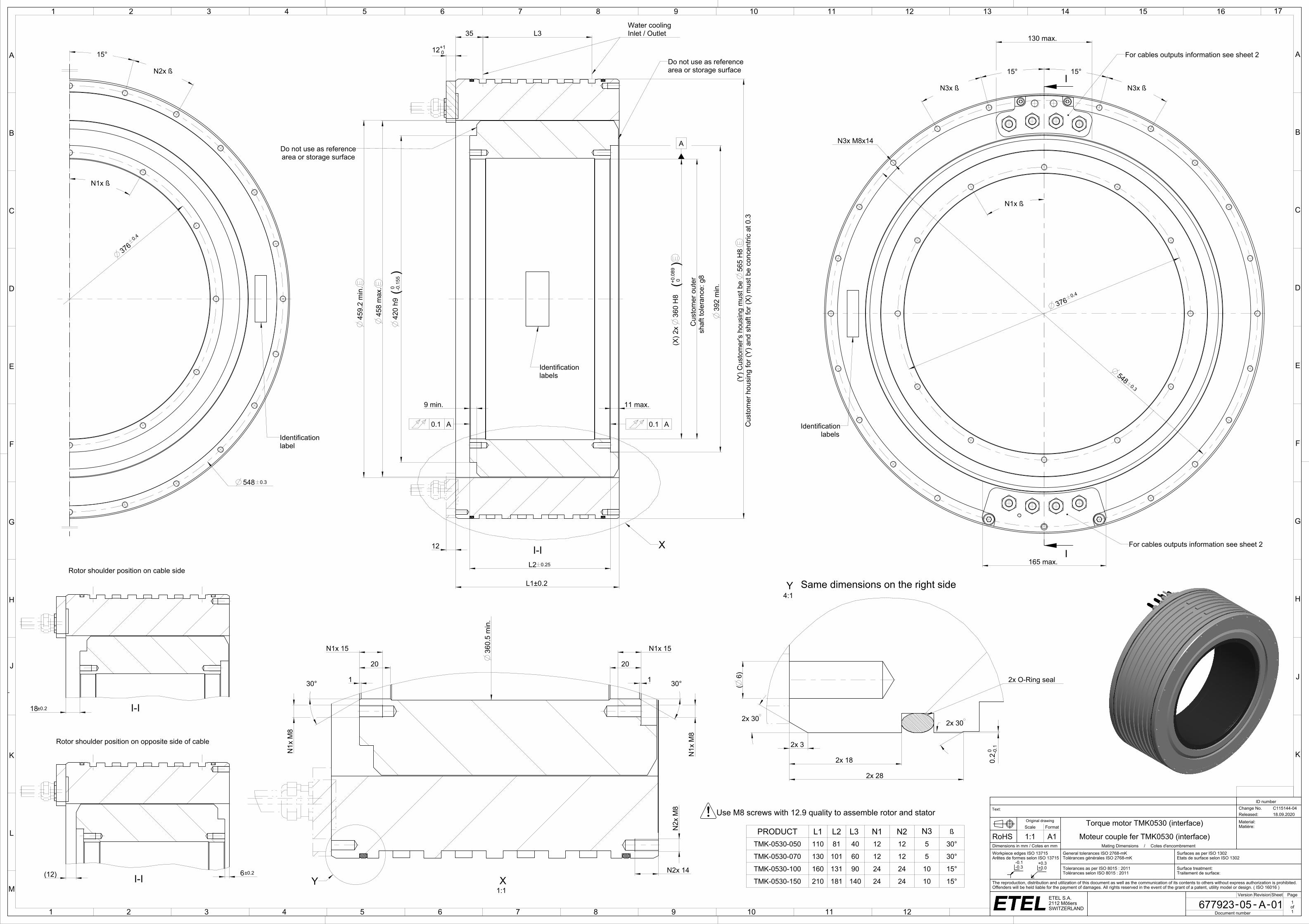
PRODUCT L1 L2 L3 N1 N2 N3 ß
TMK-0530-050 110 81 40 12 12 5 30°
TMK-0530-070 130 101 60 12 12 5 30°
TMK-0530-100 160 131 90 24 24 10 15°
TMK-0530-150 210 181 140 24 24 10 15°
ttf_etl
ID number
Text: Change No. C115144-04Released: 18.09.2020
Original drawing Torque motor TMK0530 (interface) Material:Matière:Scale Format
RoHS 1:1 A1 Moteur couple fer TMK0530 (interface)Dimensions in mm / Cotes en mm Mating Dimensions / Cotes d'encombrementWorkpiece edges ISO 13715Arêtes de formes selon ISO 13715
General tolerances ISO 2768-mKTolérances générales ISO 2768-mK
Surfaces as per ISO 1302Etats de surface selon ISO 1302
Tolerances as per ISO 8015 : 2011Tolérances selon ISO 8015 : 2011
Surface treatment:Traitement de surface:
The reproduction, distribution and utilization of this document as well as the communication of its contents to others without express authorization is prohibited. Offenders will be held liable for the payment of damages. All rights reserved in the event of the grant of a patent, utility model or design. ( ISO 16016 )
Version Revision Sheet Page
677923 05 A 01 1of1Document number
labelsIdentification
For cables outputs information see sheet 2
For cables outputs information see sheet 2
Identificationlabel
I-I
Rotor shoulder position on opposite side of cable
I-I
0.1 A
Do not use as referencearea or storage surface
Water coolingInlet / Outlet
X
area or storage surfaceDo not use as reference
Identificationlabels
Use M8 screws with 12.9 quality to assemble rotor and stator
0.1 A
Rotor shoulder position on cable side
I-I
1:1XY
2x O-Ring seal
4:1Y Same dimensions on the right side
I
I
I
I
I
I
I
I
I
I
I
I
I
I
I
I
I
I
I
I
I
I
I
I
1
A
2 3 4 5 6 7 8 9 10 11 12 13 14 15 16 17 18 19 20 21 22 23
B
C
D
E
F
G
J
K
L
M
N
P
Q
R
1
A
H
2 3 4 5 6 7 8 9 10 11 12 13 14 15 16 17 18 19
S
24
B
C
D
E
F
G
H
J
K
L
M
N
P
Q
- --ETEL S.A.2112 MôtiersSWITZERLAND
-0.1-0.3
+0.3+0.0
(7.
5) C
able
6m
m² (
4x)
(5.
5) C
able
2.5
mm
²
29 max
38.5 max
(9)
Cab
le 1
0mm
² (4x
)
(5.
5) C
able
2.5
mm
²(
5.5)
Cab
le 2
.5m
m²
29 max
34 max
29 max
(5.
5) C
able
2.5
mm
²
(9)
Cab
le 1
0mm
² (4x
)(
9) C
able
10m
m² (
4x)
(5.
5) C
able
2.5
mm
²
(5.
7) C
able
7x0
.25m
m²
29 max
(5.
7) C
able
7x0
.25m
m²
29 max
(5.
7) C
able
7x0
.25m
m²
29 max
(5.
7) C
able
7x0
.25m
m²
(5.
7) C
able
7x0
.25m
m²
29 max
29 max
29 max
34 max
34 max
29 max(10
) Cab
le 1
6mm
² (4x
)
34 max
34 max
(10
) Cab
le 1
6mm
² (4x
)(
10) C
able
16m
m² (
4x)
34 max
ttf_etl
ID number
Text: Change No. C115144-04Released: 18.09.2020
Original drawing Torque motor TMK0530 cables outputs (interface) Material:Matière:Scale Format
RoHS 1:1 A0 Moteur couple fer TMK0530 sorties de câbles (interface)Dimensions in mm / Cotes en mm Mating Dimensions / Cotes d'encombrementWorkpiece edges ISO 13715Arêtes de formes selon ISO 13715
General tolerances ISO 2768-mKTolérances générales ISO 2768-mK
Surfaces as per ISO 1302Etats de surface selon ISO 1302
Tolerances as per ISO 8015 : 2011Tolérances selon ISO 8015 : 2011
Surface treatment:Traitement de surface:
The reproduction, distribution and utilization of this document as well as the communication of its contents to others without express authorization is prohibited. Offenders will be held liable for the payment of damages. All rights reserved in the event of the grant of a patent, utility model or design. ( ISO 16016 )
Version Revision Sheet Page
677923 05 A 02 1of1Document number
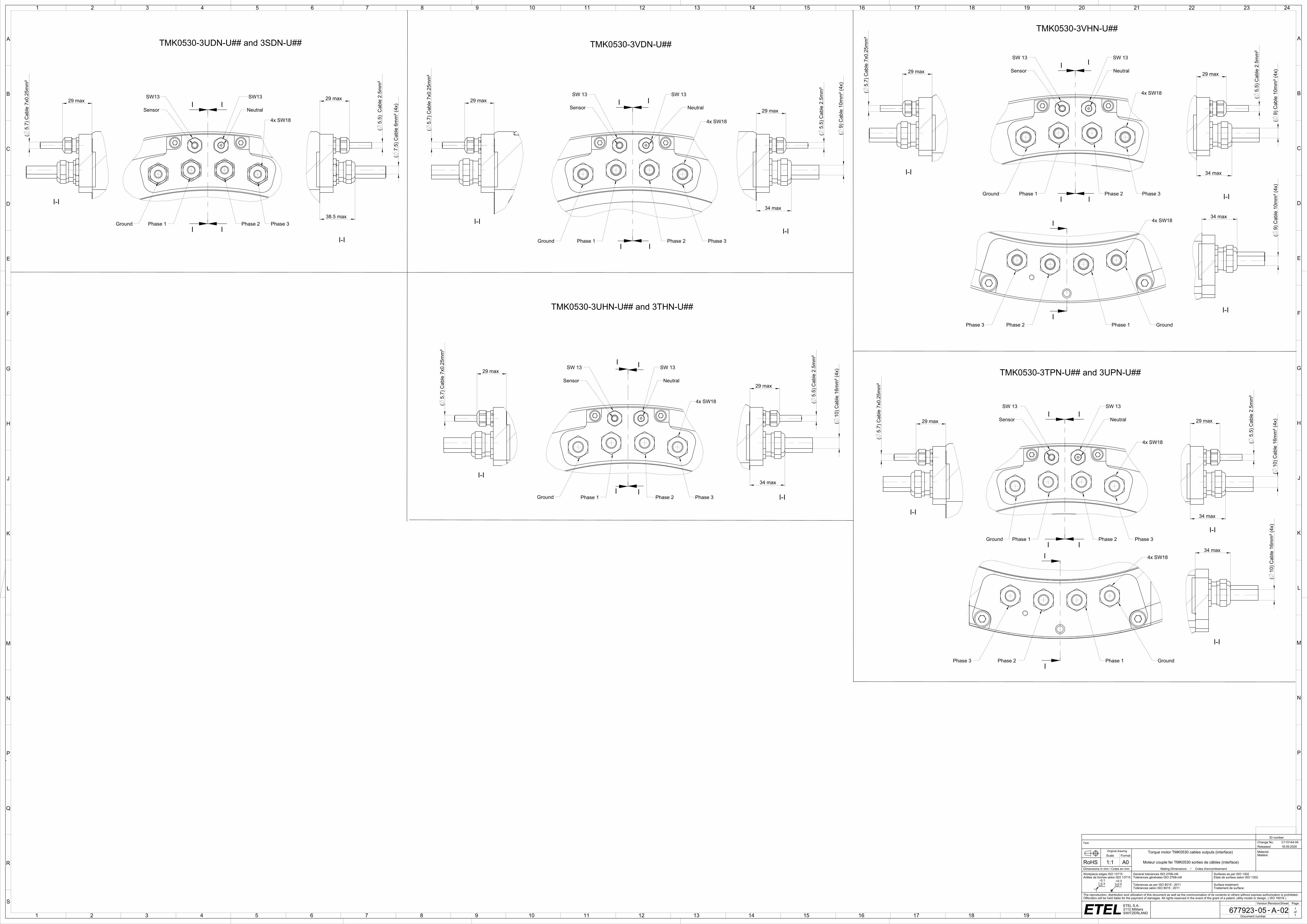
TMK0530-3UDN-U## and 3SDN-U## TMK0530-3VDN-U##
TMK0530-3UHN-U## and 3THN-U##
TMK0530-3VHN-U##
SW 13
Neutral
SW 13
Sensor
Ground Phase 1 Phase 2 Phase 3
4x SW18
I-II-I
SW 13
Neutral
SW 13
Sensor
Ground Phase 1 Phase 2 Phase 3
TMK0530-3TPN-U## and 3UPN-U##
4x SW18
I-I
I-I
SW 13
Neutral
SW 13
Sensor
Ground Phase 1 Phase 2 Phase 3
4x SW18
GroundPhase 1Phase 2Phase 3
4x SW18
I-I
I-I
I-I
SW 13
Neutral
SW 13
Sensor
Ground Phase 1 Phase 2 Phase 3
4x SW18
GroundPhase 1Phase 2Phase 3
4x SW18
I-I
I-I
I-I
SW13
4x SW18
NeutralSensor
SW13
Ground Phase 1 Phase 2 Phase 3
I-I
I-I

1 2 3 4 5 6 7 8 9 10 11 12
A
B
C
D
E
F
G
H
1 2 3 4 5 6 7 8
A
B
C
D
E
F
- --ETEL S.A.2112 MôtiersSWITZERLAND
-0.1-0.3
+0.3+0.0
D
R
Power cable connection
Color and wire number Function Drawing
Black wire with number 1 or U Phase 1 (PH1)
Black wire with number 2 or V Phase 2 (PH2)
Black wire with number 3 or W Phase 3 (PH3)
Yellow and green wire Ground (GND)
Black wire with number Br1 or 5 or white cable Neutral point wire (presentonly on some motor types)
Black wire with number Br2 or 6 or black wire without label None(**)
Motors family
temperature sensorconfiguration Temperature sensor wiring
TMBTMLTMMTMK
Configuration 8(TMB.....-#8#-##)(TML.....-#8#-##)(TMM.....-#8#-##)(TMK.....-#8#-##)
Configuration H(TMB.....-#H#-##)(TML.....-#H#-##)(TMM.....-#H#-##)(TMK.....-#H#-##)
Configuration T(TMB.....-#T#-##)(TML.....-#T#-##)(TMM.....-#T#-##)(TMK.....-#T#-##)
Wire section(mm²)
Characteristics 1 x 1.5 1 x 2.5 1 x 4 1 x 6 1 x 10 1 x 16 Sensor cable
Applicable motorsTMK0291TMK0360TMK0761TMK0991
TMK0175TMK0291TMK0360TMK0530
TMK0360TMK0175TMK0360TMK0530
TMK0291TMK0530TMK0761
TMK0360TMK0530TMK0761TMK0991
All TMK
Minimum bend radiusfor fixed cable R = 5 X D R = 4 X D R = 4 X D R = 4 X D R = 4 X D R = 4 X D R = 6 X D
Minimum bend radiusfor moving cable R = 10 x D R = 7.5 X D R = 7.5 X D R = 7.5 X D R = 7.5 X D R = 7.5 X D R = 12 X D
Representation
Sensors cable connection
Sensors configuration 8 Sensors Configuration H Sensors Configuration T
_etl
ID number
Text: Change No. C115144-05Released: 18.09.2020
Original drawing TMK sensor config. and cables prop. (interface) Material:Matière:Scale Format
RoHS 1:1 A2 TMK config. capteur et prop. câbles (interface)Dimensions in mm / Cotes en mm Assembly Drawing / Dessin d'ensembleWorkpiece edges ISO 13715Arêtes de formes selon ISO 13715
General tolerances ISO 2768-mKTolérances générales ISO 2768-mK
Surfaces as per ISO 1302Etats de surface selon ISO 1302
Tolerances as per ISO 8015 : 2011Tolérances selon ISO 8015 : 2011
Surface treatment:Traitement de surface:
The reproduction, distribution and utilization of this document as well as the communication of its contents to others without express authorization is prohibited. Offenders will be held liable for the payment of damages. All rights reserved in the event of the grant of a patent, utility model or design. ( ISO 16016 )
Version Revision Sheet Page
1328572 00 A 01 1of1Document number
Sensors cable connection
Sensors configuration 8 Sensors Configuration H Sensors Configuration T
Sensor cable connection
Sensor configuration 8
Sensor configuration H
Sensor configuration T
Power cable connection
Phase 1 = wire 1Phase 2 = wire 2Phase 3 = wire 3PE = yellow/green wire
Sensor cable connection: "P" configuration
PH3
3 2
PH2
1
PH1
White Brown
PT 1000
+
-
Green Yellow Grey Pink
SNM 120
Blue Red
SNM 120
SNM 120
PT 1000
+
-PT 1000
+
-
N
Pink
Temperature sensor configuration
White
KTY84
Phase 3
KTY84KTY84 SNM120
+
Green
Phase 3
-
Brown
+
Phase 1
-
+
Phase 2
-
Yellow
Phase 1
Phase 2
Grey
Phase 3
S01.120
Phase 2
Phase 1
Blue
Phase 3
KTY84 KTY84 KTY84 KTY84KTY84 KTY84
White
Temperature sensor configuration
Phase 2
-
Phase 1
-
+ +
Brown
-
Green
Phase 3
+
Grey
Phase 1
-
+
Yellow
-
Phase 2
-
+ +
Pink Blue(*): Red wire (if present) is not connected on the motor side and cutted flush on cable extremity.
PinkWhite
KTY84
Phase 3
KTY84KTY84 SNM120
+
Green
Phase 3
-
Brown
+Phase 1
-
+Phase 2
-
Yellow
Phase 1
Phase 2
Grey
Phase 3
S01.120
Phase 2
Phase 1
Blue
Phase 3
KTY84 KTY84 KTY84 KTY84KTY84 KTY84
White
Phase 2
-
Phase 1
-
+ +
Brown
-
Green
Phase 3
+
Grey
Phase 1
-
+
Yellow
-
Phase 2
-
+ +
Pink Blue White Brown
PT 1000
Green Yellow Grey Pink
Phase 1
Blue Red
Phase 2
Phase 3
PT 1000
SNM 120
Phase 1 Phase 2 Phase 3
(**): This wire is automatically present when the neutral point wire (which is an option) is added in the motor as it is a 2 x 1 or 2 x 1.5 mm² cable.
Red (*)
Red (*)
PinkWhite
KTY84
Phase 3
KTY84KTY84 SNM120
+
Green
Phase 3
-
Brown
+
Phase 1
-
+
Phase 2
-
Yellow
Phase 1
Phase 2
Grey
Phase 3
S01.120
Phase 2
Phase 1
Blue
Phase 3
KTY84 KTY84 KTY84 KTY84KTY84 KTY84
White
Phase 2
-
Phase 1
-
+ +
Brown
-
Green
Phase 3
+
Grey
Phase 1
-
+
Yellow
-
Phase 2
-
+ +
Pink Blue
White Brown
Phase 1
+
-
Green Yellow Grey Pink
Phase 1
Blue Red
Phase 2
Phase 3
Phase 2
+
-Phase 3
+
-
Pink
Temperature sensor configuration
White
KTY84
Phase 3
KTY84KTY84 SNM120
+
Green
Phase 3
-
Brown
+
Phase 1
-
+
Phase 2
-
Yellow
Phase 1
Phase 2
Grey
Phase 3
S01.120
Phase 2
Phase 1
BluePink
Temperature sensor configuration
White
KTY84
Phase 3
KTY84KTY84 SNM120
+
Green
Phase 3
-
Brown
+
Phase 1
-
+
Phase 2
-
Yellow
Phase 1
Phase 2
Grey
Phase 3
S01.120
Phase 2
Phase 1
Blue
PT 1000
White Brown
Phase 1+
-
Green Yellow Grey Pink
Phase 1
Blue Red
Phase 2
Phase 3
Phase 2+
-
Phase 3+
-
I
I
1 2 3 4 5 6 7 8 9 10 11 12 13 14 15 16
A
B
C
D
E
F
G
H
J
K
A
1
B
C
D
E
F
G
H
J
K
L
2 3 4 5 6 7 8 9 10 11 12
M
17
- --ETEL S.A.2112 MôtiersSWITZERLAND
-0.1-0.3
+0.3+0.0
620
min
.
11 max
9 min
688
max
.
689
min
.
12+1 0
12+1 0
L1 0.2
L2 0.25
180 max
(N3-1)x ß7.5°
N2 x ß
40 L3
180 max
N1 x ß
N2x 14
N1 x ß
(Y) C
usto
mer
's h
ousi
ng m
ust b
e 81
0 H
8 C
usto
mer
hou
sing
for (
Y) a
nd s
haft
for (
X) m
ust b
e co
ncen
tric
at 0
.3
Cus
tom
er o
uter
shaf
t tol
eran
ce :
g8
A
(X) 2
x 58
0 H
8(+0
.11
0)
N3x M8x14
7.5°7.5°
(N3-1)x ß
653
h9( 0 -0
.2)
37±0.2
7±0.2
1
20
N1x 15
30° 30°
20
N1x 15
0.08
B
(Y) C
usto
mer
's h
ousi
ng m
ust b
e 80
8 H
8 C
usto
mer
hou
sing
for (
Y) a
nd s
haft
for (
X) m
ust b
e co
ncen
tric
at 0
.3
2x 330
22
2x 330
1
N1x
M8
N1x
M8
580.
5 m
in.
600
0.4
778 0.3
600
0.4
778 0.3
3
6.5
N2x
M8
N3x M8x14
3
6.5
22
30°30°
0.2 0 -0
.1
30°
30°
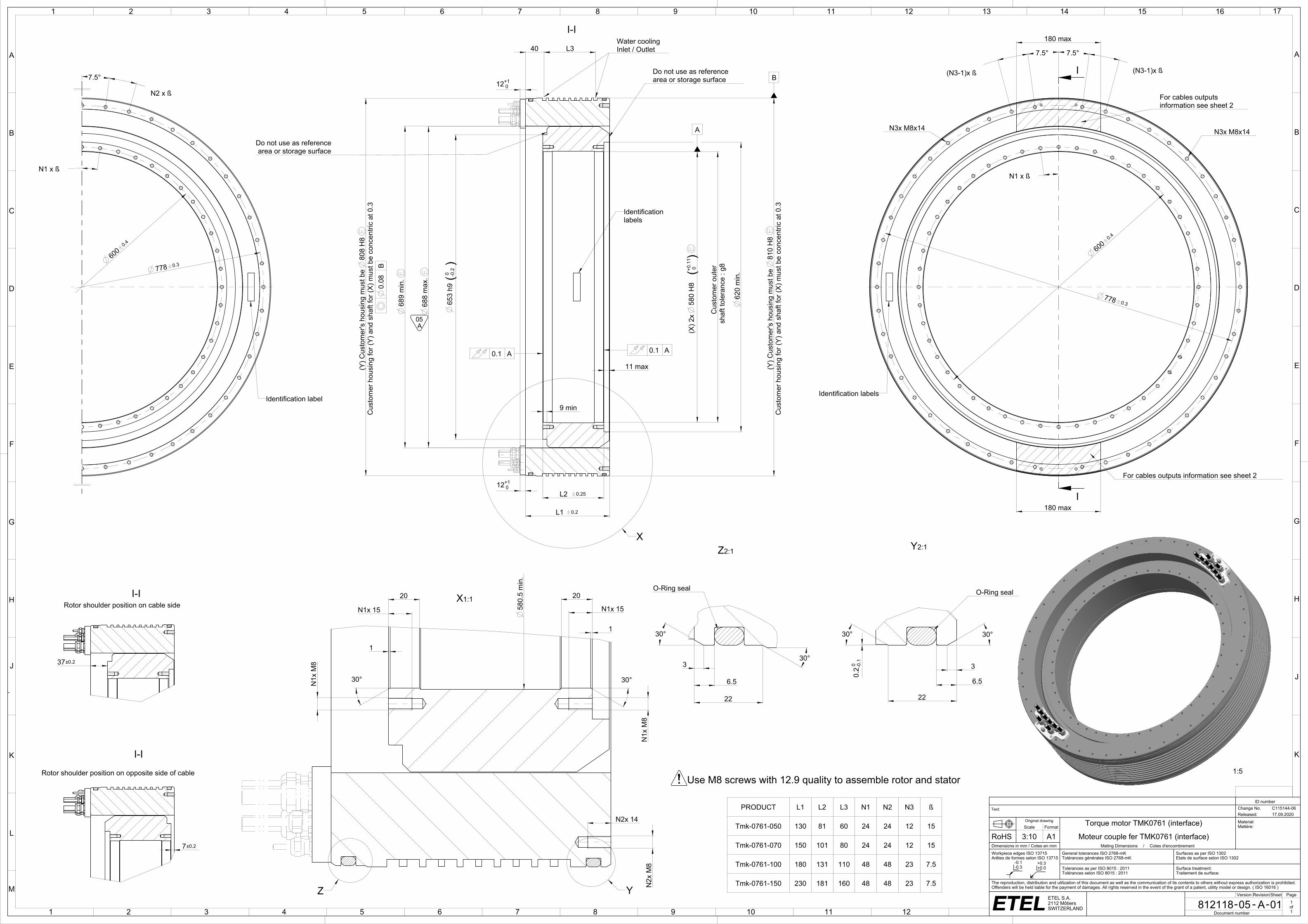
PRODUCT L1 L2 L3 N1 N2 N3 ß
Tmk-0761-050 130 81 60 24 24 12 15
Tmk-0761-070 150 101 80 24 24 12 15
Tmk-0761-100 180 131 110 48 48 23 7.5
Tmk-0761-150 230 181 160 48 48 23 7.5
ttf_etl
ID number
Text: Change No. C115144-06Released: 17.09.2020
Original drawing Torque motor TMK0761 (interface) Material:Matière:Scale Format
RoHS 3:10 A1 Moteur couple fer TMK0761 (interface)Dimensions in mm / Cotes en mm Mating Dimensions / Cotes d'encombrementWorkpiece edges ISO 13715Arêtes de formes selon ISO 13715
General tolerances ISO 2768-mKTolérances générales ISO 2768-mK
Surfaces as per ISO 1302Etats de surface selon ISO 1302
Tolerances as per ISO 8015 : 2011Tolérances selon ISO 8015 : 2011
Surface treatment:Traitement de surface:
The reproduction, distribution and utilization of this document as well as the communication of its contents to others without express authorization is prohibited. Offenders will be held liable for the payment of damages. All rights reserved in the event of the grant of a patent, utility model or design. ( ISO 16016 )
Version Revision Sheet Page
812118 05 A 01 1of1Document number
Rotor shoulder position on cable side
Rotor shoulder position on opposite side of cableUse M8 screws with 12.9 quality to assemble rotor and stator
Identification labels
For cables outputs information see sheet 2
For cables outputs information see sheet 2
X
Identification labels
0.1 A
Water coolingInlet / Outlet
Do not use as referencearea or storage surface
Do not use as referencearea or storage surface
0.1 A
I-I
Identification label
I-I 1:1X
YZ
I-I1:5
2:1Y
O-Ring seal
2:1Z
O-Ring seal
A05
B
I
I
I
I
I
I
I
I
I
I
I
I
1 2 3 4 5 6 7 8 9 10 11 12 13 14 15 16
A
B
C
D
E
F
G
H
J
K
A
1
B
C
D
E
F
G
H
J
K
L
2 3 4 5 6 7 8 9 10 11 12
M
17
- --ETEL S.A.2112 MôtiersSWITZERLAND
-0.1-0.3
+0.3+0.0
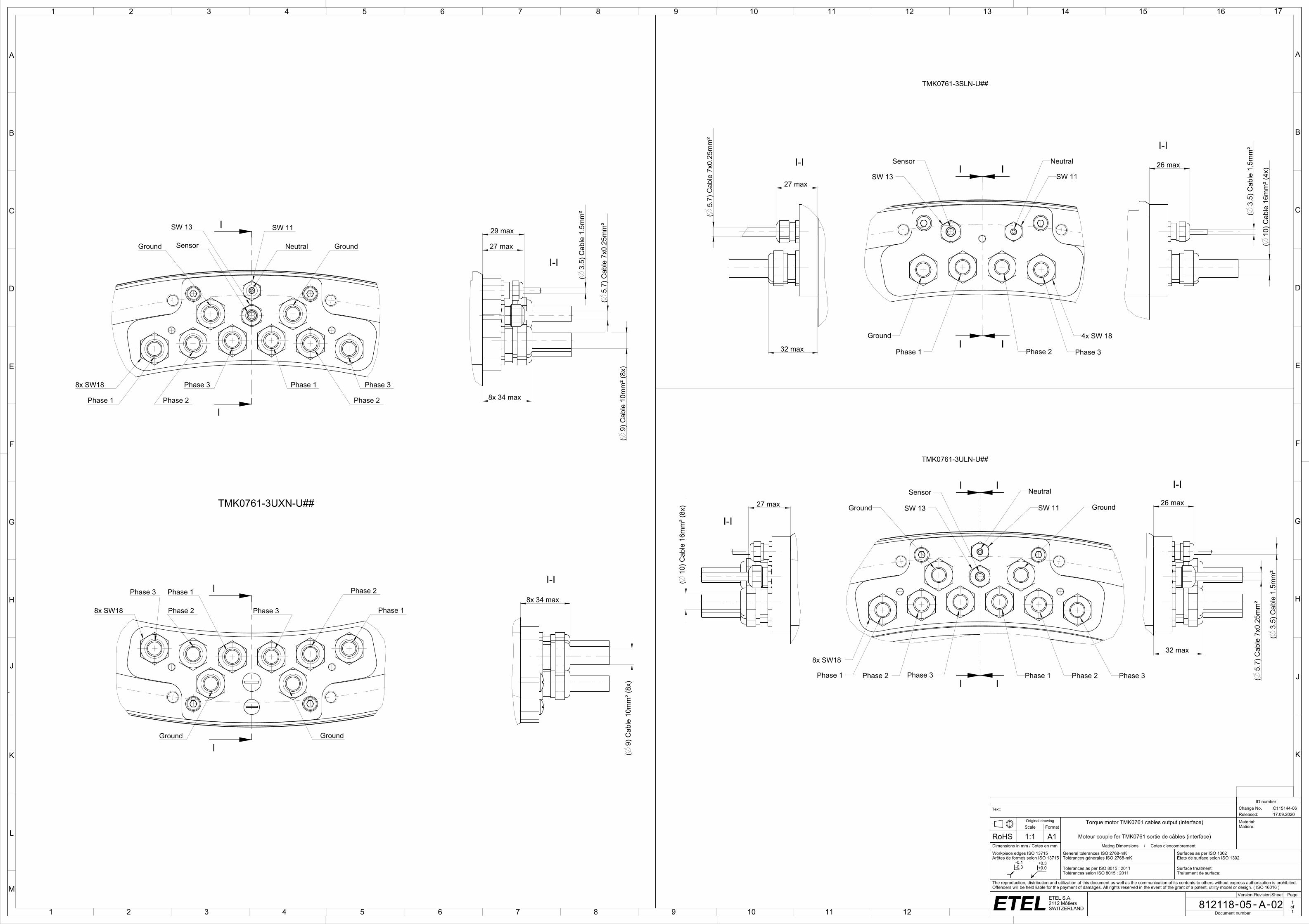
(3.
5) C
able
1.5
mm
²
(10
) Cab
le 1
6mm
² (4x
)
(5.
7) C
able
7x0
.25m
m²
27 max
32 max
26 max
26 max27 max
32 max
(3.
5) C
able
1.5
mm
²
(5.
7) C
able
7x0
.25m
m²
(10
) Cab
le 1
6mm
² (8x
)
(9)
Cab
le 1
0mm
² (8x
)(
9) C
able
10m
m² (
8x)
8x 34 max
29 max
27 max
8x 34 max(
5.7)
Cab
le 7
x0.2
5mm
²
(3.
5) C
able
1.5
mm
²
ttf_etl
ID number
Text: Change No. C115144-06Released: 17.09.2020
Original drawing Torque motor TMK0761 cables output (interface) Material:Matière:Scale Format
RoHS 1:1 A1 Moteur couple fer TMK0761 sortie de câbles (interface)Dimensions in mm / Cotes en mm Mating Dimensions / Cotes d'encombrementWorkpiece edges ISO 13715Arêtes de formes selon ISO 13715
General tolerances ISO 2768-mKTolérances générales ISO 2768-mK
Surfaces as per ISO 1302Etats de surface selon ISO 1302
Tolerances as per ISO 8015 : 2011Tolérances selon ISO 8015 : 2011
Surface treatment:Traitement de surface:
The reproduction, distribution and utilization of this document as well as the communication of its contents to others without express authorization is prohibited. Offenders will be held liable for the payment of damages. All rights reserved in the event of the grant of a patent, utility model or design. ( ISO 16016 )
Version Revision Sheet Page
812118 05 A 02 1of1Document number
TMK0761-3SLN-U##
TMK0761-3ULN-U##
NeutralSensor
Ground
Phase 1 Phase 2 Phase 3
SW 13 SW 11
4x SW 18
I-II-I
Phase 1 Phase 2 Phase 3 Phase 1 Phase 2 Phase 3
Ground Ground
Sensor Neutral
8x SW18
SW 13 SW 11TMK0761-3UXN-U##
I-I
I-I
8x SW18
Phase 1 Phase 2
Phase 3
Ground GroundSensor Neutral
SW 13 SW 11
Phase 1
Phase 2
Phase 3
8x SW18
Phase 1
Phase 2
Phase 3
Ground Ground
Phase 1
Phase 2
Phase 3
C-C I-I
I-I
C-C

1 2 3 4 5 6 7 8 9 10 11 12
A
B
C
D
E
F
G
H
1 2 3 4 5 6 7 8
A
B
C
D
E
F
- --ETEL S.A.2112 MôtiersSWITZERLAND
-0.1-0.3
+0.3+0.0
D
R
Power cable connection
Color and wire number Function Drawing
Black wire with number 1 or U Phase 1 (PH1)
Black wire with number 2 or V Phase 2 (PH2)
Black wire with number 3 or W Phase 3 (PH3)
Yellow and green wire Ground (GND)
Black wire with number Br1 or 5 or white cable Neutral point wire (presentonly on some motor types)
Black wire with number Br2 or 6 or black wire without label None(**)
Motors family
temperature sensorconfiguration Temperature sensor wiring
TMBTMLTMMTMK
Configuration 8(TMB.....-#8#-##)(TML.....-#8#-##)(TMM.....-#8#-##)(TMK.....-#8#-##)
Configuration H(TMB.....-#H#-##)(TML.....-#H#-##)(TMM.....-#H#-##)(TMK.....-#H#-##)
Configuration T(TMB.....-#T#-##)(TML.....-#T#-##)(TMM.....-#T#-##)(TMK.....-#T#-##)
Wire section(mm²)
Characteristics 1 x 1.5 1 x 2.5 1 x 4 1 x 6 1 x 10 1 x 16 Sensor cable
Applicable motorsTMK0291TMK0360TMK0761TMK0991
TMK0175TMK0291TMK0360TMK0530
TMK0360TMK0175TMK0360TMK0530
TMK0291TMK0530TMK0761
TMK0360TMK0530TMK0761TMK0991
All TMK
Minimum bend radiusfor fixed cable R = 5 X D R = 4 X D R = 4 X D R = 4 X D R = 4 X D R = 4 X D R = 6 X D
Minimum bend radiusfor moving cable R = 10 x D R = 7.5 X D R = 7.5 X D R = 7.5 X D R = 7.5 X D R = 7.5 X D R = 12 X D
Representation
Sensors cable connection
Sensors configuration 8 Sensors Configuration H Sensors Configuration T
_etl
ID number
Text: Change No. C115144-05Released: 18.09.2020
Original drawing TMK sensor config. and cables prop. (interface) Material:Matière:Scale Format
RoHS 1:1 A2 TMK config. capteur et prop. câbles (interface)Dimensions in mm / Cotes en mm Assembly Drawing / Dessin d'ensembleWorkpiece edges ISO 13715Arêtes de formes selon ISO 13715
General tolerances ISO 2768-mKTolérances générales ISO 2768-mK
Surfaces as per ISO 1302Etats de surface selon ISO 1302
Tolerances as per ISO 8015 : 2011Tolérances selon ISO 8015 : 2011
Surface treatment:Traitement de surface:
The reproduction, distribution and utilization of this document as well as the communication of its contents to others without express authorization is prohibited. Offenders will be held liable for the payment of damages. All rights reserved in the event of the grant of a patent, utility model or design. ( ISO 16016 )
Version Revision Sheet Page
1328572 00 A 01 1of1Document number
Sensors cable connection
Sensors configuration 8 Sensors Configuration H Sensors Configuration T
Sensor cable connection
Sensor configuration 8
Sensor configuration H
Sensor configuration T
Power cable connection
Phase 1 = wire 1Phase 2 = wire 2Phase 3 = wire 3PE = yellow/green wire
Sensor cable connection: "P" configuration
PH3
3 2
PH2
1
PH1
White Brown
PT 1000
+
-
Green Yellow Grey Pink
SNM 120
Blue Red
SNM 120
SNM 120
PT 1000
+
-PT 1000
+
-
N
Pink
Temperature sensor configuration
White
KTY84
Phase 3
KTY84KTY84 SNM120
+
Green
Phase 3
-
Brown
+
Phase 1
-
+
Phase 2
-
Yellow
Phase 1
Phase 2
Grey
Phase 3
S01.120
Phase 2
Phase 1
Blue
Phase 3
KTY84 KTY84 KTY84 KTY84KTY84 KTY84
White
Temperature sensor configuration
Phase 2
-
Phase 1
-
+ +
Brown
-
Green
Phase 3
+
Grey
Phase 1
-
+
Yellow
-
Phase 2
-
+ +
Pink Blue(*): Red wire (if present) is not connected on the motor side and cutted flush on cable extremity.
PinkWhite
KTY84
Phase 3
KTY84KTY84 SNM120
+
Green
Phase 3
-
Brown
+Phase 1
-
+Phase 2
-
Yellow
Phase 1
Phase 2
Grey
Phase 3
S01.120
Phase 2
Phase 1
Blue
Phase 3
KTY84 KTY84 KTY84 KTY84KTY84 KTY84
White
Phase 2
-
Phase 1
-
+ +
Brown
-
Green
Phase 3
+
Grey
Phase 1
-
+
Yellow
-
Phase 2
-
+ +
Pink Blue White Brown
PT 1000
Green Yellow Grey Pink
Phase 1
Blue Red
Phase 2
Phase 3
PT 1000
SNM 120
Phase 1 Phase 2 Phase 3
(**): This wire is automatically present when the neutral point wire (which is an option) is added in the motor as it is a 2 x 1 or 2 x 1.5 mm² cable.
Red (*)
Red (*)
PinkWhite
KTY84
Phase 3
KTY84KTY84 SNM120
+
Green
Phase 3
-
Brown
+
Phase 1
-
+
Phase 2
-
Yellow
Phase 1
Phase 2
Grey
Phase 3
S01.120
Phase 2
Phase 1
Blue
Phase 3
KTY84 KTY84 KTY84 KTY84KTY84 KTY84
White
Phase 2
-
Phase 1
-
+ +
Brown
-
Green
Phase 3
+
Grey
Phase 1
-
+
Yellow
-
Phase 2
-
+ +
Pink Blue
White Brown
Phase 1
+
-
Green Yellow Grey Pink
Phase 1
Blue Red
Phase 2
Phase 3
Phase 2
+
-Phase 3
+
-
Pink
Temperature sensor configuration
White
KTY84
Phase 3
KTY84KTY84 SNM120
+
Green
Phase 3
-
Brown
+
Phase 1
-
+
Phase 2
-
Yellow
Phase 1
Phase 2
Grey
Phase 3
S01.120
Phase 2
Phase 1
BluePink
Temperature sensor configuration
White
KTY84
Phase 3
KTY84KTY84 SNM120
+
Green
Phase 3
-
Brown
+
Phase 1
-
+
Phase 2
-
Yellow
Phase 1
Phase 2
Grey
Phase 3
S01.120
Phase 2
Phase 1
Blue
PT 1000
White Brown
Phase 1+
-
Green Yellow Grey Pink
Phase 1
Blue Red
Phase 2
Phase 3
Phase 2+
-
Phase 3+
-
I
I
1
A
2 3 4 5 6 7 8 9 10 11 12 13 14 15 16 17 18 19 20 21 22 23
B
C
D
E
F
G
J
K
L
M
N
P
Q
R
1
A
H
2 3 4 5 6 7 8 9 10 11 12 13 14 15 16 17 18 19
S
24
B
C
D
E
F
G
H
J
K
L
M
N
P
Q
- --ETEL S.A.2112 MôtiersSWITZERLAND
-0.1-0.3
+0.3+0.0
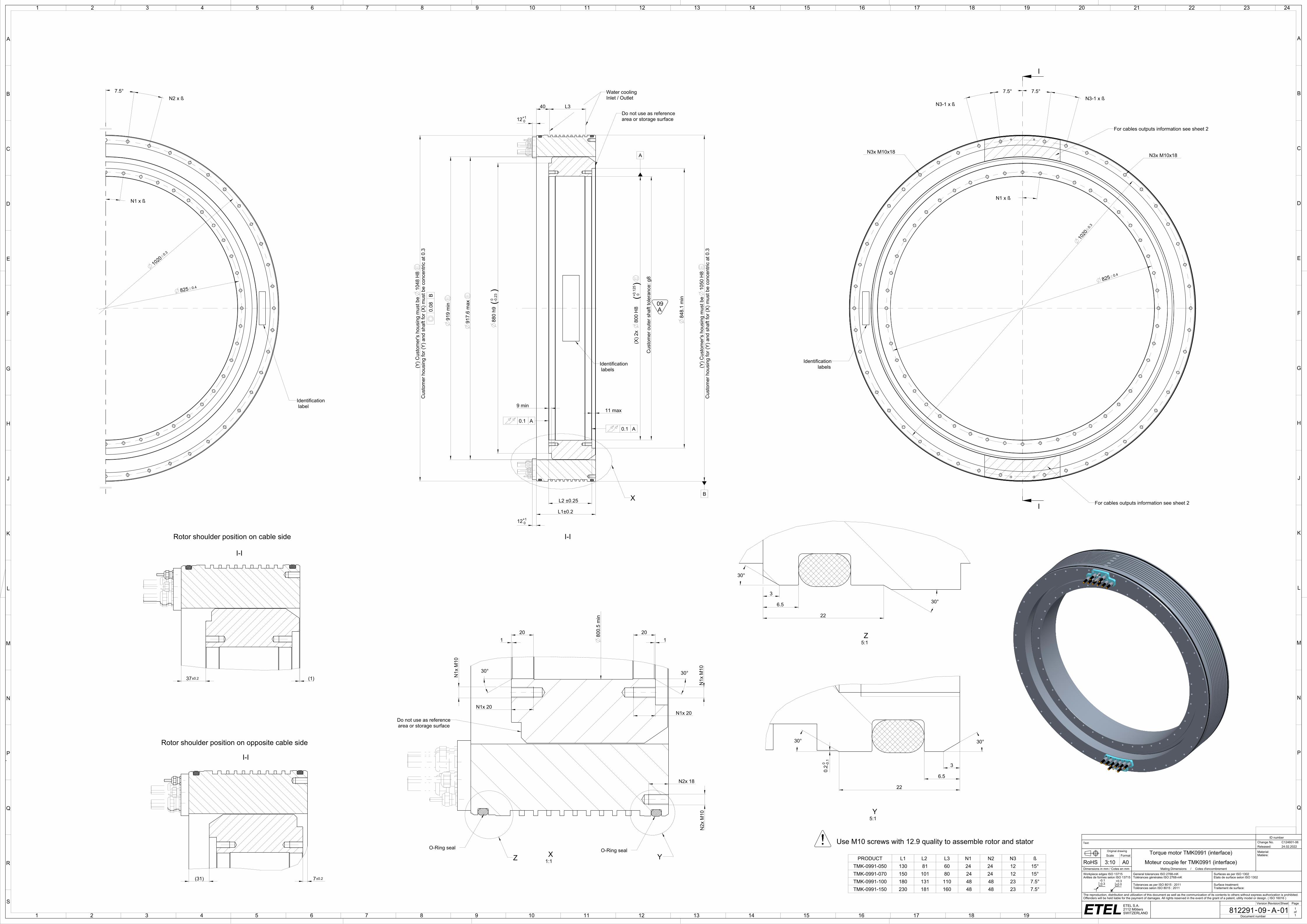
40
Water coolingInlet / Outlet
L3
7.5° N2 x ß
9 min
917.
6 m
ax
919
min
848.
1 m
in
Cus
tom
er o
uter
sha
ft to
lera
nce:
g8
7.5° N3-1 x ß
7.5°
N3-1 x ß
20
B
(Y) C
usto
mer
's h
ousi
ng m
ust b
e 10
50 H
8 C
usto
mer
hou
sing
for (
Y) a
nd s
haft
for (
X) m
ust b
e co
ncen
tric
at 0
.3
A
(X) 2
x
800
H8
(+0.1
25 0
)
37±0.2 (1)
880
h9( 0 -0
.23)
0.08
B
(Y) C
usto
mer
's h
ousi
ng m
ust b
e 10
48 H
8 C
usto
mer
hou
sing
for (
Y) a
nd s
haft
for (
X) m
ust b
e co
ncen
tric
at 0
.3
11 max
L1±0.2
L2 ±0.25
12+1 0
(31) 7±0.2
N1 x ß N1 x ß
N1x
M10
20
N1x
M10
1
30° 30°
800.
5 m
in
12+1 0
1
30°
3
6.5
22
0.2 0 -0
.1
30°
N1x 20N1x 20
825 0.4
10200.3
N2x 18
N2x
M10
825 0.4
1020
0.3
N3x M10x18
22
6.5
330°
30°
N3x M10x18
PRODUCT L1 L2 L3 N1 N2 N3 ßTMK-0991-050 130 81 60 24 24 12 15°TMK-0991-070 150 101 80 24 24 12 15°TMK-0991-100 180 131 110 48 48 23 7.5°TMK-0991-150 230 181 160 48 48 23 7.5°
ttf_etl
ID number
Text: Change No. C124601-06Released: 24.02.2022
Original drawing Torque motor TMK0991 (interface) Material:Matière:Scale Format
RoHS 3:10 A0 Moteur couple fer TMK0991 (interface)Dimensions in mm / Cotes en mm Mating Dimensions / Cotes d'encombrementWorkpiece edges ISO 13715Arêtes de formes selon ISO 13715
General tolerances ISO 2768-mKTolérances générales ISO 2768-mK
Surfaces as per ISO 1302Etats de surface selon ISO 1302
Tolerances as per ISO 8015 : 2011Tolérances selon ISO 8015 : 2011
Surface treatment:Traitement de surface:
The reproduction, distribution and utilization of this document as well as the communication of its contents to others without express authorization is prohibited. Offenders will be held liable for the payment of damages. All rights reserved in the event of the grant of a patent, utility model or design. ( ISO 16016 )
Version Revision Sheet Page
812291 09 A 01 1of1Document number
Use M10 screws with 12.9 quality to assemble rotor and statorO-Ring seal
I-I
X
Rotor shoulder position on cable side
Do not use as referencearea or storage surface
I-I
0.1 A0.1 A
Identification labels
Identification label
For cables outputs information see sheet 2
For cables outputs information see sheet 2
labelsIdentification
1:1X O-Ring seal
Y
area or storage surfaceDo not use as reference
Z
3:5NCB-NCB
3:5NCC-NCC
Rotor shoulder position on opposite cable side
I-I
5:1Y
5:1Z
A09
I
I
I
I
I
I
I
I
I
I
I
I
1 2 3 4 5 6 7 8 9 10 11 12
A
B
C
D
E
F
G
H
1 2 3 4 5 6 7 8
A
B
C
D
E
F
- --ETEL S.A.2112 MôtiersSWITZERLAND
-0.1-0.3
+0.3+0.0
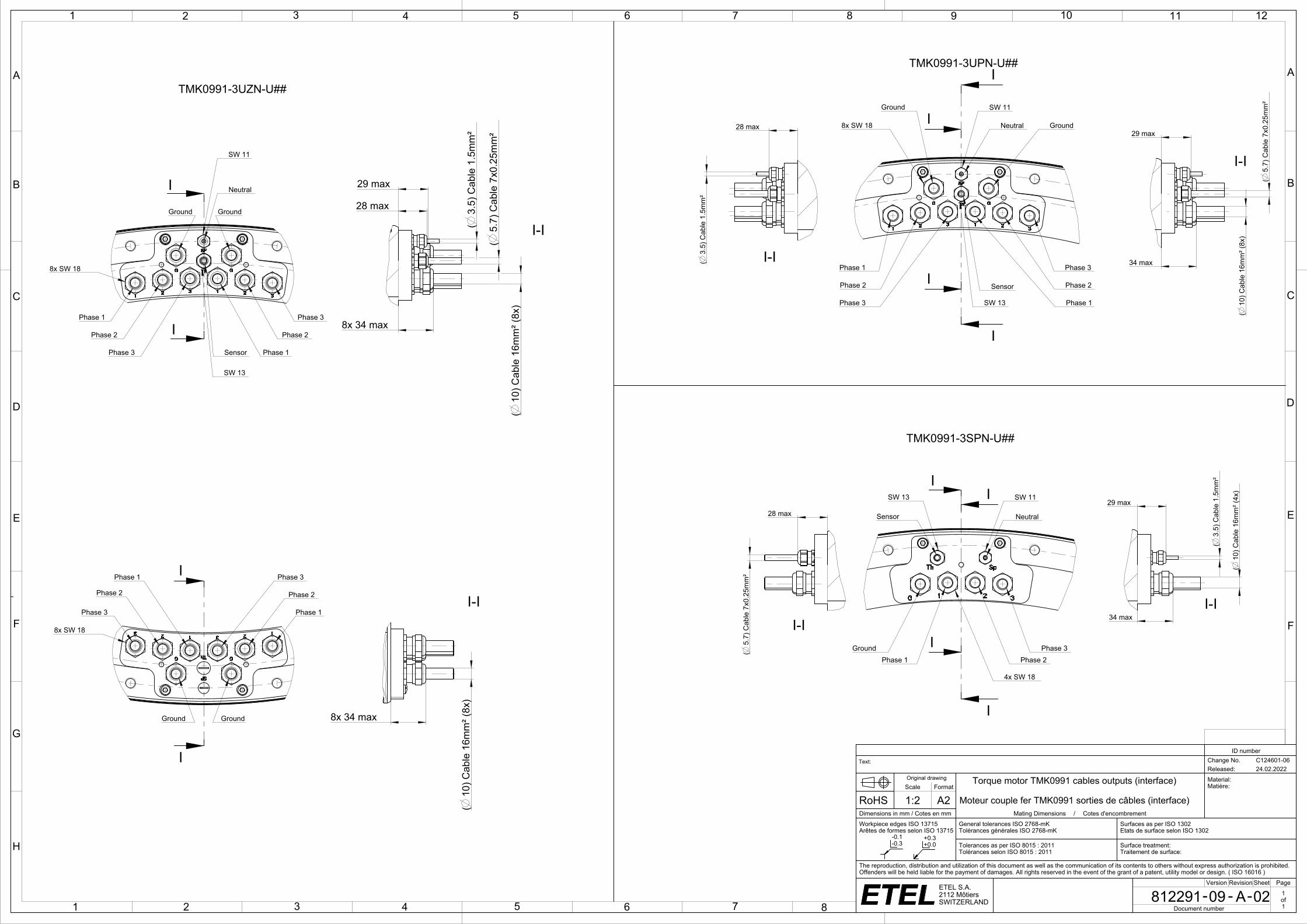
34 max
28 max
(3.
5) C
able
1.5
mm
²
(5.
7) C
able
7x0
.25m
m²
(10
) Cab
le 1
6mm
² (8x
)
29 max
(3.
5) C
able
1.5
mm
²
(10
) Cab
le 1
6mm
² (4x
)
34 max
29 max
(5.
7) C
able
7x0
.25m
m²
28 max
(5.
7) C
able
7x0
.25m
m²
(3.
5) C
able
1.5
mm
²
(10
) Cab
le 1
6mm
² (8x
)
(10
) Cab
le 1
6mm
² (8x
)
8x 34 max
8x 34 max
28 max
29 max
ttf_etl
ID number
Text: Change No. C124601-06Released: 24.02.2022
Original drawing Torque motor TMK0991 cables outputs (interface) Material:Matière:Scale Format
RoHS 1:2 A2 Moteur couple fer TMK0991 sorties de câbles (interface)Dimensions in mm / Cotes en mm Mating Dimensions / Cotes d'encombrementWorkpiece edges ISO 13715Arêtes de formes selon ISO 13715
General tolerances ISO 2768-mKTolérances générales ISO 2768-mK
Surfaces as per ISO 1302Etats de surface selon ISO 1302
Tolerances as per ISO 8015 : 2011Tolérances selon ISO 8015 : 2011
Surface treatment:Traitement de surface:
The reproduction, distribution and utilization of this document as well as the communication of its contents to others without express authorization is prohibited. Offenders will be held liable for the payment of damages. All rights reserved in the event of the grant of a patent, utility model or design. ( ISO 16016 )
Version Revision Sheet Page
812291 09 A 02 1of1Document number
TMK0991-3UPN-U##
TMK0991-3UZN-U##
For the connection of temperature sensorsee the configuration in theintegration manual
I-I
Phase 1
Phase 2
Phase 3
Phase 3
Phase 2
Phase 1
Ground
GroundNeutral
Sensor
SW 11
SW 13
8x SW 18
I-I
I-I
Phase 1 Phase 2Phase 3Ground
NeutralSensor
SW 11SW 13
4x SW 18
I-I
TMK0991-3SPN-U##
Phase 1
Phase 2
Phase 3 Phase 1
Phase 2
Phase 3
Ground Ground
Neutral
Sensor
SW 11
SW 13
8x SW 18
Phase 1
Phase 2
Phase 3Phase 1
Phase 2
Phase 3
Ground Ground
8x SW 18
I-I
I-I

1 2 3 4 5 6 7 8 9 10 11 12
A
B
C
D
E
F
G
H
1 2 3 4 5 6 7 8
A
B
C
D
E
F
- --ETEL S.A.2112 MôtiersSWITZERLAND
-0.1-0.3
+0.3+0.0
D
R
Power cable connection
Color and wire number Function Drawing
Black wire with number 1 or U Phase 1 (PH1)
Black wire with number 2 or V Phase 2 (PH2)
Black wire with number 3 or W Phase 3 (PH3)
Yellow and green wire Ground (GND)
Black wire with number Br1 or 5 or white cable Neutral point wire (presentonly on some motor types)
Black wire with number Br2 or 6 or black wire without label None(**)
Motors family
temperature sensorconfiguration Temperature sensor wiring
TMBTMLTMMTMK
Configuration 8(TMB.....-#8#-##)(TML.....-#8#-##)(TMM.....-#8#-##)(TMK.....-#8#-##)
Configuration H(TMB.....-#H#-##)(TML.....-#H#-##)(TMM.....-#H#-##)(TMK.....-#H#-##)
Configuration T(TMB.....-#T#-##)(TML.....-#T#-##)(TMM.....-#T#-##)(TMK.....-#T#-##)
Wire section(mm²)
Characteristics 1 x 1.5 1 x 2.5 1 x 4 1 x 6 1 x 10 1 x 16 Sensor cable
Applicable motorsTMK0291TMK0360TMK0761TMK0991
TMK0175TMK0291TMK0360TMK0530
TMK0360TMK0175TMK0360TMK0530
TMK0291TMK0530TMK0761
TMK0360TMK0530TMK0761TMK0991
All TMK
Minimum bend radiusfor fixed cable R = 5 X D R = 4 X D R = 4 X D R = 4 X D R = 4 X D R = 4 X D R = 6 X D
Minimum bend radiusfor moving cable R = 10 x D R = 7.5 X D R = 7.5 X D R = 7.5 X D R = 7.5 X D R = 7.5 X D R = 12 X D
Representation
Sensors cable connection
Sensors configuration 8 Sensors Configuration H Sensors Configuration T
_etl
ID number
Text: Change No. C115144-05Released: 18.09.2020
Original drawing TMK sensor config. and cables prop. (interface) Material:Matière:Scale Format
RoHS 1:1 A2 TMK config. capteur et prop. câbles (interface)Dimensions in mm / Cotes en mm Assembly Drawing / Dessin d'ensembleWorkpiece edges ISO 13715Arêtes de formes selon ISO 13715
General tolerances ISO 2768-mKTolérances générales ISO 2768-mK
Surfaces as per ISO 1302Etats de surface selon ISO 1302
Tolerances as per ISO 8015 : 2011Tolérances selon ISO 8015 : 2011
Surface treatment:Traitement de surface:
The reproduction, distribution and utilization of this document as well as the communication of its contents to others without express authorization is prohibited. Offenders will be held liable for the payment of damages. All rights reserved in the event of the grant of a patent, utility model or design. ( ISO 16016 )
Version Revision Sheet Page
1328572 00 A 01 1of1Document number
Sensors cable connection
Sensors configuration 8 Sensors Configuration H Sensors Configuration T
Sensor cable connection
Sensor configuration 8
Sensor configuration H
Sensor configuration T
Power cable connection
Phase 1 = wire 1Phase 2 = wire 2Phase 3 = wire 3PE = yellow/green wire
Sensor cable connection: "P" configuration
PH3
3 2
PH2
1
PH1
White Brown
PT 1000
+
-
Green Yellow Grey Pink
SNM 120
Blue Red
SNM 120
SNM 120
PT 1000
+
-PT 1000
+
-
N
Pink
Temperature sensor configuration
White
KTY84
Phase 3
KTY84KTY84 SNM120
+
Green
Phase 3
-
Brown
+
Phase 1
-
+
Phase 2
-
Yellow
Phase 1
Phase 2
Grey
Phase 3
S01.120
Phase 2
Phase 1
Blue
Phase 3
KTY84 KTY84 KTY84 KTY84KTY84 KTY84
White
Temperature sensor configuration
Phase 2
-
Phase 1
-
+ +
Brown
-
Green
Phase 3
+
Grey
Phase 1
-
+
Yellow
-
Phase 2
-
+ +
Pink Blue(*): Red wire (if present) is not connected on the motor side and cutted flush on cable extremity.
PinkWhite
KTY84
Phase 3
KTY84KTY84 SNM120
+
Green
Phase 3
-
Brown
+Phase 1
-
+Phase 2
-
Yellow
Phase 1
Phase 2
Grey
Phase 3
S01.120
Phase 2
Phase 1
Blue
Phase 3
KTY84 KTY84 KTY84 KTY84KTY84 KTY84
White
Phase 2
-
Phase 1
-
+ +
Brown
-
Green
Phase 3
+
Grey
Phase 1
-
+
Yellow
-
Phase 2
-
+ +
Pink Blue White Brown
PT 1000
Green Yellow Grey Pink
Phase 1
Blue Red
Phase 2
Phase 3
PT 1000
SNM 120
Phase 1 Phase 2 Phase 3
(**): This wire is automatically present when the neutral point wire (which is an option) is added in the motor as it is a 2 x 1 or 2 x 1.5 mm² cable.
Red (*)
Red (*)
PinkWhite
KTY84
Phase 3
KTY84KTY84 SNM120
+
Green
Phase 3
-
Brown
+
Phase 1
-
+
Phase 2
-
Yellow
Phase 1
Phase 2
Grey
Phase 3
S01.120
Phase 2
Phase 1
Blue
Phase 3
KTY84 KTY84 KTY84 KTY84KTY84 KTY84
White
Phase 2
-
Phase 1
-
+ +
Brown
-
Green
Phase 3
+
Grey
Phase 1
-
+
Yellow
-
Phase 2
-
+ +
Pink Blue
White Brown
Phase 1
+
-
Green Yellow Grey Pink
Phase 1
Blue Red
Phase 2
Phase 3
Phase 2
+
-Phase 3
+
-
Pink
Temperature sensor configuration
White
KTY84
Phase 3
KTY84KTY84 SNM120
+
Green
Phase 3
-
Brown
+
Phase 1
-
+
Phase 2
-
Yellow
Phase 1
Phase 2
Grey
Phase 3
S01.120
Phase 2
Phase 1
BluePink
Temperature sensor configuration
White
KTY84
Phase 3
KTY84KTY84 SNM120
+
Green
Phase 3
-
Brown
+
Phase 1
-
+
Phase 2
-
Yellow
Phase 1
Phase 2
Grey
Phase 3
S01.120
Phase 2
Phase 1
Blue
PT 1000
White Brown
Phase 1+
-
Green Yellow Grey Pink
Phase 1
Blue Red
Phase 2
Phase 3
Phase 2+
-
Phase 3+
-