gear-unit lubrication and gear-unit preservation 7300en
TRANSCRIPT
siemens.com
FLENDER suppliesGear-unit lubrication and gear-unit preservation7300en
Operating Instructions
Edition 07/2016

14.07.2016 13:41V2.00
Gear-unit lubrication and gear-unit preservationFLENDER supplies7300en
Operating Instructions
Edition 07/2016
Introduction 1
Safety instructions 2
Description 3
Lubrication 4
Preservation 5
Commissioning 6
Servicing 7
Service & Support 8
Disposal 9Documentation sheet for oil change ACheck list for oil filling and oil change B
Legal informationWarning notice system
This manual contains notices you have to observe in order to ensure your personal safety, as well as to prevent damage to property. The notices referring to your personal safety are highlighted in the manual by a safety alert symbol, notices referring only to property damage have no safety alert symbol. These notices shown below are graded according to the degree of danger.
DANGERindicates that death or severe personal injury will result if proper precautions are not taken.
WARNINGindicates that death or severe personal injury may result if proper precautions are not taken.
CAUTIONindicates that minor personal injury can result if proper precautions are not taken.
NOTICEindicates that property damage can result if proper precautions are not taken.If more than one degree of danger is present, the warning notice representing the highest degree of danger will be used. A notice warning of injury to persons with a safety alert symbol may also include a warning relating to property damage.
Qualified PersonnelThe product/system described in this documentation may be operated only by personnel qualified for the specific task in accordance with the relevant documentation, in particular its warning notices and safety instructions. Qualified personnel are those who, based on their training and experience, are capable of identifying risks and avoiding potential hazards when working with these products/systems.
Proper use of Siemens productsNote the following:
WARNINGSiemens products may only be used for the applications described in the catalog and in the relevant technical documentation. If products and components from other manufacturers are used, these must be recommended or approved by Siemens. Proper transport, storage, installation, assembly, commissioning, operation and maintenance are required to ensure that the products operate safely and without any problems. The permissible ambient conditions must be complied with. The information in the relevant documentation must be observed.
TrademarksAll names identified by ® are registered trademarks of Siemens AG. The remaining trademarks in this publication may be trademarks whose use by third parties for their own purposes could violate the rights of the owner.
Disclaimer of LiabilityWe have reviewed the contents of this publication to ensure consistency with the hardware and software described. Since variance cannot be precluded entirely, we cannot guarantee full consistency. However, the information in this publication is reviewed regularly and any necessary corrections are included in subsequent editions.
Siemens AGProcess Industries and DrivesPostfach 48 4890026 NÜRNBERGGERMANY
Document order number: Ⓟ 07/2016 Subject to change
Copyright © Siemens AG 2016.All rights reserved
Table of contents
1 Introduction...................................................................................................................................................9
2 Safety instructions......................................................................................................................................11
2.1 Security notes........................................................................................................................11
2.2 General information................................................................................................................11
2.3 General warnings and symbols..............................................................................................13
2.4 Regulations and documents...................................................................................................13
3 Description..................................................................................................................................................15
4 Lubrication..................................................................................................................................................17
4.1 Gear oils.................................................................................................................................174.1.1 Oil groups and base oils.........................................................................................................174.1.2 Flushing oil.............................................................................................................................184.1.3 Oil temperatures.....................................................................................................................194.1.4 General service lives of oils...................................................................................................194.1.5 Quality, code numbers, approval lists....................................................................................204.1.5.1 Required quality of the gear oils to be used...........................................................................204.1.5.2 Lists of approved lubricants...................................................................................................214.1.5.3 Code numbers........................................................................................................................22
4.2 Lubricants for rolling-contact bearings...................................................................................24
5 Preservation...............................................................................................................................................25
5.1 Preservation of the gear unit..................................................................................................25
5.2 Interior preservation of the gear unit......................................................................................275.2.1 Special aspects of Tacolab seals...........................................................................................275.2.2 Durability of interior preservation prior to commissioning......................................................275.2.3 Effects of changing packaging or type of storage on the durability period of the
preservation...........................................................................................................................295.2.4 Extension of the interior preservation.....................................................................................305.2.4.1 Extension of the interior preservation through oil filling..........................................................315.2.4.2 Extension of the interior preservation using Castrol Corrosion Inhibitor N 213......................33
5.3 Exterior preservation of metallic bright surfaces....................................................................355.3.1 Preservative agents and durability period of exterior preservation........................................355.3.2 Extension of exterior preservation..........................................................................................35
6 Commissioning...........................................................................................................................................37
6.1 Necessary oil filling measures for commissioning..................................................................37
6.2 Information on initial filling and oil change.............................................................................40
6.3 Removing exterior preservation.............................................................................................40
7 Servicing.....................................................................................................................................................43
7.1 General maintenance information..........................................................................................43
Gear-unit lubrication and gear-unit preservation 7300enOperating Instructions 07/2016 5
7.2 Checking the oil level.............................................................................................................437.2.1 Checking the oil level using the oil dipstick............................................................................437.2.2 Checking the oil level with the oil sight glass.........................................................................447.2.3 Controlling the oil level with the oil level indicator..................................................................45
7.3 Oil samples............................................................................................................................457.3.1 Taking oil samples.................................................................................................................467.3.2 Evaluating oil sample test results...........................................................................................48
7.4 Topping up with oil.................................................................................................................50
7.5 Oil change..............................................................................................................................507.5.1 Conditions and comments......................................................................................................507.5.2 Draining used oil....................................................................................................................517.5.3 Flushing procedure................................................................................................................527.5.3.1 Compatibility of preservative and operating oil......................................................................527.5.3.2 Flushing the gear unit.............................................................................................................527.5.4 Checks and tasks to be performed prior to a new oil refill.....................................................547.5.4.1 Comparing the oil quantity.....................................................................................................547.5.4.2 Performing a visual check of the oil.......................................................................................547.5.4.3 Checking gear unit components.............................................................................................557.5.4.4 Cleaning the oil filter or replacing the filter element...............................................................557.5.4.5 Cleaning the air filter..............................................................................................................557.5.4.6 Replacing wet-air filters..........................................................................................................567.5.4.7 Checking the air/oil cooler......................................................................................................567.5.4.8 Checking the water/oil cooler.................................................................................................577.5.5 Filling with new oil..................................................................................................................57
7.6 Changing the oil type.............................................................................................................59
7.7 Checking the hose lines.........................................................................................................59
7.8 Re-greasing grease-lubricated labyrinths..............................................................................60
7.9 Leakage and leak-tightness...................................................................................................60
8 Service & Support.......................................................................................................................................63
9 Disposal......................................................................................................................................................65
A Documentation sheet for oil change...........................................................................................................67
B Check list for oil filling and oil change.........................................................................................................69
Glossary.....................................................................................................................................................71
Index...........................................................................................................................................................75
Tables
Table 2-1 Symbols and markings................................................................................................................12Table 2-2 General warnings........................................................................................................................13Table 4-1 Quality tests.................................................................................................................................21Table 4-2 Code numbers of standard oils...................................................................................................23Table 4-3 Code numbers of biologically degradable oils.............................................................................23Table 4-4 Code numbers of physiologically safe oils..................................................................................23
Table of contents
Gear-unit lubrication and gear-unit preservation 7300en6 Operating Instructions 07/2016
Table 4-5 Code numbers of rolling-contact bearing greases.......................................................................23Table 5-1 Basic durability period HD0 and the extension of the durability period of the gear unit interior
preservation.................................................................................................................................28Table 5-2 Durability period HDX...................................................................................................................29Table 5-3 Durability period of exterior preservation.....................................................................................35Table 6-1 Measures prior to commissioning................................................................................................38Table 6-2 Measures prior to recommissioning............................................................................................39Table 7-1 Test intervals for taking oil samples............................................................................................47Table 7-2 Water content measurement results...........................................................................................49Table 7-3 Trend analysis.............................................................................................................................49Table 7-4 Flushing requirements dependent on the preservative...............................................................52Table 7-5 Condition of the sealing edge......................................................................................................61
Figures
Figure 5-1 Tacolab seal................................................................................................................................27
Table of contents
Gear-unit lubrication and gear-unit preservation 7300enOperating Instructions 07/2016 7

Table of contents
Gear-unit lubrication and gear-unit preservation 7300en8 Operating Instructions 07/2016
Introduction 1Purpose of the operating instructions
These operating instructions describe the gear unit lubrication and preservation and provide information about how to go about it - from application planning through to maintenance.
Please keep these operating instructions for later use. Please read these operating instructions prior to handling the gear unit and follow the information in them.
NoteDisclaimer
Please make sure that every person who is commissioned to work on the gear unit has read and understood these operating instructions prior to handling the gear unit and adheres to all of the points. Failure to observe these operating instructions can cause product or property damage and personal injury.
Siemens does not accept any liability for damage or operating failures which are due to non-adherence to these operating instructions.
The gear unit lubrication described in these instructions reflects the state of technical development at the time these operating instructions went to print.
In the interest of technical advancements, Siemens reserves the right to make changes to the individual components of the gear unit and accessories which are considered necessary for improving their performance and safety, while maintaining their essential features.
Basic knowledge requiredIn order to understand these operating instructions, you will need the following general knowledge about gear units. You will also need a basic understanding of the following topics:
● Application planning
● Assembly
● Commissioning
● Maintenance
ConventionsPlease note the following naming convention:
● The term “gear unit” will be used for “FLENDER® gear unit” in the following.
Gear-unit lubrication and gear-unit preservation 7300enOperating Instructions 07/2016 9
Documentation landscapeThese operating instructions form part of the complete documentation supplied with the gear unit. The complete documentation encompasses other documents, including:
● Gear unit operating instructions
● Data sheet
● Connecting elements operating instructions
● Operating instructions for third-party vendor devices
CopyrightThe copyright for these operating instructions is held by Siemens AG.
Without the authorisation of Siemens AG, these operating instructions may not be used wholly or in parts for competitors’ purposes or be given to third parties.
If you have any technical queries, please contact one of our Customer Services addresses (Page 63).
ValidityThe information provided in these operating instructions will only apply providing no conflicting information is contained in the product-related operating instructions or in the order-related documentation.
Introduction
Gear-unit lubrication and gear-unit preservation 7300en10 Operating Instructions 07/2016
Safety instructions 22.1 Security notes
Siemens offers products and solutions with industrial security functions, which support the safe and secure operation of plants, systems, machines and networks.
In order to safeguard plants, systems, machines and networks against cyber threats it is necessary to implement (and continually maintain) a holistic industrial security concept that corresponds to the current state of the art. Siemens products and solutions undergo continuous development in this respect.
Customers are responsible for preventing unauthorised access to their plants, systems, machines and networks. Systems, machines and components shall only be connected to the company network or the Internet when and as far as this is absolutely necessary and appropriate protective measures (e.g. use of firewalls and network segmentation) shall be taken.
In addition the recommendations of Siemens regarding appropriate protective measures shall be observed. You can find further information about industrial security at http://www.siemens.com/industrialsecurity.
Siemens products and solutions undergo continuous development in order to make them even safer. Siemens expressly recommends that you regularly carry out any updates as soon as they are available and that you only use the current product versions. Use of older or no longer supported versions can increase the risk of cyber threats.
To keep yourselves informed of any updates to our products you can register for the Siemens Industrial Security RSS Feed at:http://www.siemens.com/industrialsecurity
2.2 General information
IntroductionAll work on the gear unit should be performed with care and only by qualified personnel.
Gear-unit lubrication and gear-unit preservation 7300enOperating Instructions 07/2016 11
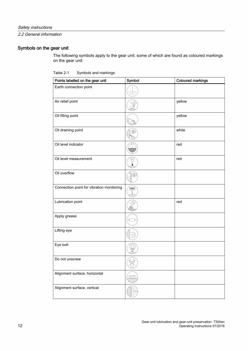
Symbols on the gear unitThe following symbols apply to the gear unit; some of which are found as coloured markings on the gear unit:
Table 2-1 Symbols and markings
Points labelled on the gear unit Symbol Coloured markingsEarth connection point
Air relief point yellow
Oil filling point yellow
Oil draining point white
Oil level indicator red
Oil level measurement red
Oil overflow
Connection point for vibration monitoring
Lubrication point red
Apply grease
Lifting eye
Eye bolt
Do not unscrew
Alignment surface, horizontal
Alignment surface, vertical
Safety instructions2.2 General information
Gear-unit lubrication and gear-unit preservation 7300en12 Operating Instructions 07/2016
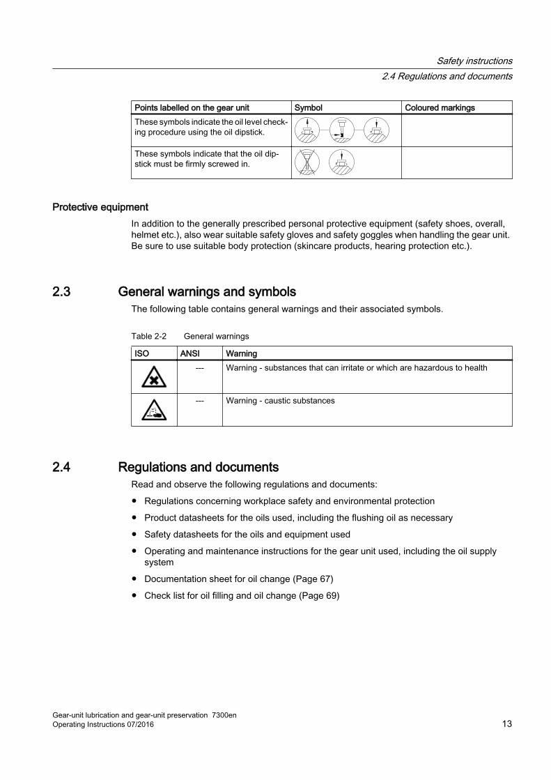
Points labelled on the gear unit Symbol Coloured markingsThese symbols indicate the oil level check‐ing procedure using the oil dipstick.
These symbols indicate that the oil dip‐stick must be firmly screwed in.
Protective equipmentIn addition to the generally prescribed personal protective equipment (safety shoes, overall, helmet etc.), also wear suitable safety gloves and safety goggles when handling the gear unit. Be sure to use suitable body protection (skincare products, hearing protection etc.).
2.3 General warnings and symbolsThe following table contains general warnings and their associated symbols.
Table 2-2 General warnings
ISO ANSI Warning--- Warning - substances that can irritate or which are hazardous to health
--- Warning - caustic substances
2.4 Regulations and documentsRead and observe the following regulations and documents:
● Regulations concerning workplace safety and environmental protection
● Product datasheets for the oils used, including the flushing oil as necessary
● Safety datasheets for the oils and equipment used
● Operating and maintenance instructions for the gear unit used, including the oil supply system
● Documentation sheet for oil change (Page 67)
● Check list for oil filling and oil change (Page 69)
Safety instructions2.4 Regulations and documents
Gear-unit lubrication and gear-unit preservation 7300enOperating Instructions 07/2016 13
Safety instructions2.4 Regulations and documents
Gear-unit lubrication and gear-unit preservation 7300en14 Operating Instructions 07/2016
Description 3General description
These operating instructions are valid for Siemens industrial gear units and for Siemens geared motors without worm gear stages.
Gear-unit lubrication and gear-unit preservation 7300enOperating Instructions 07/2016 15
Description
Gear-unit lubrication and gear-unit preservation 7300en16 Operating Instructions 07/2016
Lubrication 44.1 Gear oils
IntroductionOnly use approved oils for the gear unit which meet Siemens specifications (Page 20).
Mixing oil typesMixing different types of oil may damage the gear unit due to the lack of lubrication caused by the possible incompatibility of the oils.
As a rule, fill the gear unit using the same type of oil previously used. It is not permitted to mix different types of oils or oils from different manufacturers without taking special precautions. Contact us before changing to a different oil type.
In particular, polyglycols may never be mixed with mineral oils or with other synthetic oils. Rinse out the gear unit thoroughly every time there is a change to the type of oil. Use the new oil type for this purpose.
Further informationFurther information on the specifications and the properties of the gear oils is available from the oil manufacturer’s technical datasheets and safety datasheets.
4.1.1 Oil groups and base oils
Oil groupsSiemens makes a distinction between the following oil groups with regard to gear oils:
● Standard oils
● Readily biodegradable oils (BIO)
● Physiologically safe oils (PHY) approved in accordance with NSF-H1, known as food grade oils
Base oil typesThe tested and recommended gear oils can be manufactured on the basis of the following base oil types:
● API Group I and II mineral oils
● API Group III semisynthetic oils
Gear-unit lubrication and gear-unit preservation 7300enOperating Instructions 07/2016 17
● API Group IV poly-α-olefins (PAO)
● API Group V polyglycols (PG or PAG)
● API Group V saturated synthetic esters
Note
All base oil types can theoretically occur in every oil group.
4.1.2 Flushing oilTo prevent incompatibilities, Siemens recommends that the gear oil type to be used later should be used for flushing. You can also use low-viscosity and low-alloyed mineral oils, such as Castrol Magna 32 oil, if you are not planning to subsequently use polyglycol as the operating oil.
Do not use the flushing oil as the operating oil.
NoteSpecial cleaning or flushing oils
It is possible and sometimes essential to use special cleaning or flushing oils.
Consult the oil supplier and Siemens prior to using special cleaning or flushing oils.
In this case the gear unit may not be run during the flushing procedure.
In the following situations you must perform a flushing procedure (Page 52) before filling with operating oil in order to start up the system:
● Requirement prescribed in the gear unit operating instructions
● Changing the brand of oil, especially the type of base oil
● In the case of heavier accumulations of soiling in the gear unit or in the oil supply system
● Following major repairs to the gear unit
CAUTION
Risk of scalding from escaping oil
If the flushing oil is overheated, scalding can result.
Do not heat the flushing oil over 50 °C, to avoid scalding.
Lubrication4.1 Gear oils
Gear-unit lubrication and gear-unit preservation 7300en18 Operating Instructions 07/2016
4.1.3 Oil temperatures
OverviewCompared to mineral oils, synthetic gear oils have a larger operating temperature range and a higher viscosity index, i.e. a flatter viscosity temperature profile. The operating temperature range of the operating oils depends not only on the base oil type (Page 17), but also on the nominal viscosity and the lubrication type (with or without the use of pumps), and may vary. Special additives can be used to extend the operating temperature range,.
Flash point and pour point provide indications for special operating conditions, which are usually not understood as being operating limits.
The oil manufacturer can inform you of the possible oil-dependent operating temperature range of the operating oil.
NoteRecommended oil temperature during operation
If the oil temperature is too high during operation, the viscosity of the oil can fall so drastically that the load-bearing capacity of the oil is reduced to an unacceptable level. High temperatures accelerate the aging of oil.
If the oil temperatures are too low during operation, this can retard or stop the efficacy of some oil additives, thereby deteriorating the properties of the oil. Oil tends to foam at low temperatures.
In standard situations, Siemens recommends an operating temperature range of between 60 °C and 85 °C for the operating oil. Note any contrary information provided in the product operating instructions.
You may not change the agreed operating temperatures of the gear unit or the type of base oil without consulting Siemens.
Further information Further information on the specifications and the properties of the gear oils is available from the oil manufacturer’s technical datasheets and safety datasheets.
4.1.4 General service lives of oils
Operating conditionsThe service lives of the various types of base oil specified below are valid for the following operating conditions:
● Daily operating time 24 hours
● ON duration “ED” 100%
● Gear unit input speed 1500 rpm
Lubrication4.1 Gear oils
Gear-unit lubrication and gear-unit preservation 7300enOperating Instructions 07/2016 19
● Average oil temperature in the oil sump 80 °C
● Medium capacity
● With no harmful environmental influences
Service lifeUnder the aforementioned operating conditions, the oil manufacturers guarantee that the gear oils approved (Page 21) by Siemens will fulfil the following service lives without significant changes in the quality of the oil:
● API Groups I or II mineral oils, saturated synthetic esters: 10,000 operating hours, 2 years maximum
● API Group III semisynthetic oils, poly-α-olefines and polyglycols: 20,000 operating hours, 4 years maximum
NoteThe Arrhenius Law
The actual service life may vary from this. The rule of thumb applicable here is the formula for the temperature dependence of reaction rates (Arrhenius equation), which states that a temperature increase of 10 K will reduce the service life by about one-half, and that a 10 K temperature reduction will roughly double it.
4.1.5 Quality, code numbers, approval lists
4.1.5.1 Required quality of the gear oils to be used
WarrantyAdhere to the oil group, base oil and viscosity class as per the specifications on the rating plates and observe the information contained in the overall documentation for the gear units. Failure to do so will invalidate Siemens warranty obligations.
If you use oil filters, obtain the oil supplier’s confirmation that the filters will not negatively affect the characteristics of the oil.
If you use oils that do not correspond to the quality requirements stated below, the warranty obligations of Siemens will be rendered invalid. Consult Siemens in the event of any deviations.
Subsequently modified operating conditions that do not conform to those stated in the customer's order require the gear oil used to be approved in writing by Siemens.
Lubrication4.1 Gear oils
Gear-unit lubrication and gear-unit preservation 7300en20 Operating Instructions 07/2016
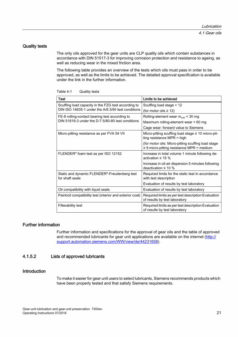
Quality testsThe only oils approved for the gear units are CLP quality oils which contain substances in accordance with DIN 51517-3 for improving corrosion protection and resistance to ageing, as well as reducing wear in the mixed friction area.
The following table provides an overview of the tests which oils must pass in order to be approved, as well as the limits to be achieved. The detailed approval specification is available under the link in the further information.
Table 4-1 Quality tests
Test Limits to be achievedScuffing load capacity in the FZG test according to DIN ISO 14635-1 under the A/8.3/90 test conditions
Scuffing load stage > 12(for motor oils ≥ 12)
FE-8 rolling-contact bearing test according to DIN 51819-3 under the D-7.5/80-80 test conditions
Rolling-element wear mw50 < 30 mgMaximum rolling-element wear < 60 mgCage wear: forward value to Siemens
Micro-pitting resistance as per FVA 54 VII Micro-pitting scuffing load stage ≥ 10 micro-pit‐ting resistance MPR = high (for motor oils: Micro-pitting scuffing load stage ≥ 9 micro-pitting resistance MPR = medium
FLENDER® foam test as per ISO 12152 Increase in total volume 1 minute following de‐activation ≤ 15 %Increase in oil-air dispersion 5 minutes following deactivation ≤ 10 %
Static and dynamic FLENDER®-Freudenberg test for shaft seals
Required limits for the static test in accordance with test descriptionEvaluation of results by test laboratory
Oil compatibility with liquid seals Evaluation of results by test laboratoryPaint/oil compatibility test (interior and exterior coat) Required limits as per test description Evaluation
of results by test laboratoryFilterability test Required limits as per test description Evaluation
of results by test laboratory
Further informationFurther information and specifications for the approval of gear oils and the table of approved and recommended lubricants for gear unit applications are available on the internet (http://support.automation.siemens.com/WW/view/de/44231658).
4.1.5.2 Lists of approved lubricants
IntroductionTo make it easier for gear unit users to select lubricants, Siemens recommends products which have been properly tested and that satisfy Siemens requirements.
Lubrication4.1 Gear oils
Gear-unit lubrication and gear-unit preservation 7300enOperating Instructions 07/2016 21
To help their customers, Siemens has grouped oils in approval lists (http://support.automation.siemens.com/WW/view/de/44231658). The oil manufacturers have verified to Siemens that these oils fulfil the aforementioned test results (Page 20). These oil manufacturers guarantee that the characteristics, features and minimum requirements required by Siemens are globally observed.
WarrantyThe approval of these gear oils for use in gear units and their consequent inclusion in the relevant lists does not mean that Siemens accepts any liability for the suitability and quality of these oils. Nor will Siemens be liable for any damage sustained by the gear units as a result of using these gear oils. The gear oil manufacturer is liable for the suitability and quality of his product.
Using a non-listed lubricantThe user is responsible for selecting the lubricants. Siemens does not oblige the gear unit users to use the listed products.
The gear unit user assumes all risks associated with using a non-listed lubricant. In the event of damage occurring, the user must prove that the properties of the product used meet Siemens requirements (Page 20).
Using a lubricant that does not satisfy the requirements of Siemens will result in the loss of the warranty provided by Siemens.
NOTICE
Damage to the gear unit
The use of unsuitable lubricants can result in malfunctions, increased wear, damage to gear teeth, rolling-contact bearings and/or plain bearings, or even the functional failure of the gear unit.
Siemens recommends the use of approved lubricants.
If using one of the listed lubricants, Siemens does not demand that if said lubricant is deleted from the T 7300 approval list, it be immediately replaced in the gear unit by another lubricant.
If you use one of the listed oils, before every oil change check whether the selected lubricant is still approved by Siemens. If the selected lubricant is no longer approved, use an approved lubricant of the same type and viscosity.
Any remaining stocks of the previously used lubricant held by the gear unit user may still be used up, provided it has not exceeded its permissible service life and no negative anomalies in the oil have been experienced during the time it was used.
4.1.5.3 Code numbersThe code numbers in the approval list provide the assignment of the approved oils to their oil groups, their base oils and their viscosity. The code number A13, for example, designates all standard mineral oils with the viscosity ISO VG 460.
Lubrication4.1 Gear oils
Gear-unit lubrication and gear-unit preservation 7300en22 Operating Instructions 07/2016
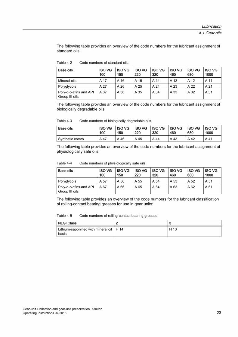
The following table provides an overview of the code numbers for the lubricant assignment of standard oils:
Table 4-2 Code numbers of standard oils
Base oils ISO VG 100
ISO VG 150
ISO VG 220
ISO VG 320
ISO VG 460
ISO VG 680
ISO VG 1000
Mineral oils A 17 A 16 A 15 A 14 A 13 A 12 A 11Polyglycols A 27 A 26 A 25 A 24 A 23 A 22 A 21Poly-α-olefins and API Group III oils
A 37 A 36 A 35 A 34 A 33 A 32 A 31
The following table provides an overview of the code numbers for the lubricant assignment of biologically degradable oils:
Table 4-3 Code numbers of biologically degradable oils
Base oils ISO VG 100
ISO VG 150
ISO VG 220
ISO VG 320
ISO VG 460
ISO VG 680
ISO VG 1000
Synthetic esters A 47 A 46 A 45 A 44 A 43 A 42 A 41
The following table provides an overview of the code numbers for the lubricant assignment of physiologically safe oils:
Table 4-4 Code numbers of physiologically safe oils
Base oils ISO VG 100
ISO VG 150
ISO VG 220
ISO VG 320
ISO VG 460
ISO VG 680
ISO VG 1000
Polyglycols A 57 A 56 A 55 A 54 A 53 A 52 A 51Poly-α-olefins and API Group III oils
A 67 A 66 A 65 A 64 A 63 A 62 A 61
The following table provides an overview of the code numbers for the lubricant classification of rolling-contact bearing greases for use in gear units:
Table 4-5 Code numbers of rolling-contact bearing greases
NLGI Class 2 3Lithium-saponified with mineral oil basis
H 14 H 13
Lubrication4.1 Gear oils
Gear-unit lubrication and gear-unit preservation 7300enOperating Instructions 07/2016 23
4.2 Lubricants for rolling-contact bearings
IntroductionFor special applications, grease lubrication of the rolling-contact bearings may be necessary.
NoteUse of greases
Greases may only be used if specified in the operating instructions of the gear units.
Observe the intervals for subsequent lubrication.
Lubricating greaseApart from lubrication, lubricating grease can also be used as a sealant, e.g. for vertical gear unit connecting shafts or can also be applied to counter the environmental impact of dust or splash water.
NoteMixture of oil and grease
In closed gear units with internal oil lubrication, the gear oil and rolling-contact bearing grease must not be allowed to mix.
Further informationFurther information on the lubricating greases approved and recommended for use in gear units can be found on the Internet (http://support.automation.siemens.com/WW/view/de/44231658).
When using greases, Siemens recommends an annual check to ascertain whether the selected lubricating grease is still approved by Siemens.
Lubrication4.2 Lubricants for rolling-contact bearings
Gear-unit lubrication and gear-unit preservation 7300en24 Operating Instructions 07/2016
Preservation 55.1 Preservation of the gear unit
Preservation stateWhen delivered, the gear units have the following preservation state as standard:
● The interior preservation is performed depending on the operating oil used:
– Mineral oil, PAO-based oil, synthetic esters: Castrol Alpha SP 150 S or Castrol Alpha SP 220 S
– Polyglycol: Castrol Optigear Synthetic 1390/220 formerly Castrol Tribol 1390/220
– Deviations from this standard regulation will be specified in the product-specific operating instructions where relevant.
● The metallic bright exterior surfaces of the gear units, such as shaft ends, are preserved with Tectyl 846 K-19.
● The remaining exterior surfaces of the gear unit are coated with a paint system. The properties for exterior coating depend on the environmental conditions for the transport route and location specified in the order.
NOTICE
Risk of corrosion if there is no top coat
The gear unit may be damaged by corrosion if no top coat has been applied. The undercoat does not by itself offer any durable corrosion protection.
It can be contractually agreed on a case-by-case basis that the gear unit is shipped only with the undercoat applied.
In this case a top coat in accordance with the guidelines relevant to the application must be applied shortly after the delivery.
Note that signs, connections, monitoring devices and similar accessories as well as shaft seals may not be coated with top coat when this is being applied.
StorageWhen making the inquiry and placing the purchase order with Siemens AG, agree special environmental conditions during transport and storage. Special environmental conditions for example include tropical climate or marine transport. The gear unit may be damaged by corrosion if it is packaged or stored incorrectly.
Storage must take place in the position of the original packaging or in the position of use.
Gear-unit lubrication and gear-unit preservation 7300enOperating Instructions 07/2016 25
Prevent the corrosion protection layers from becoming damaged during storage.
WARNING
Danger to life through falling gear unit
Persons are at risk of being crushed or struck by a gear unit that falls down.
Never stack gear units on top of one another.
With indoor storage the rule is:
● Select a dry room with vibration-free base.
● Cover the gear unit.
With outdoor storage the rule is:
● Select a vibration-free and dry base.
● Store the gear unit in a location which is protected against the influences of weather.
● Cover the gear unit very carefully.
● Ensure that the gear unit surface is wiped clean of any moisture or foreign bodies.
● Avoid waterlogging.
The following regulations apply to your incoming goods control where marine transport packaging has been applied and the gear unit is not scheduled to be used straight away:
● Only open the outer part of the packaging where possible, and check the condition of the film.
● Keep the film open for no longer than 10 minutes.
● Do not remove any corrosion protection materials such as VCI products and desiccants.
● Reseal the film making it airtight.
NOTICE
Damage caused by external sources
The gear unit could be damaged if exposed to harmful effects such as aggressive chemical products.
Do not expose the gear unit to harmful effects such as aggressive chemical products.
Preservation5.1 Preservation of the gear unit
Gear-unit lubrication and gear-unit preservation 7300en26 Operating Instructions 07/2016
5.2 Interior preservation of the gear unit
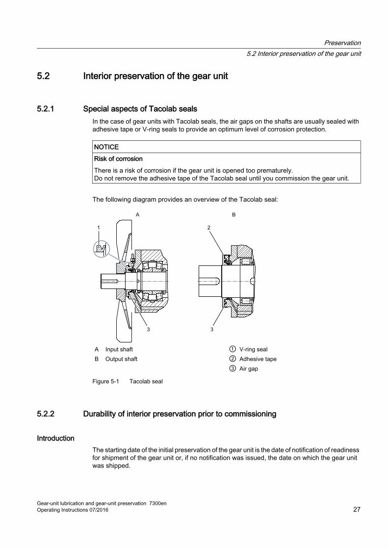
5.2.1 Special aspects of Tacolab sealsIn the case of gear units with Tacolab seals, the air gaps on the shafts are usually sealed with adhesive tape or V-ring seals to provide an optimum level of corrosion protection.
NOTICE
Risk of corrosion
There is a risk of corrosion if the gear unit is opened too prematurely.Do not remove the adhesive tape of the Tacolab seal until you commission the gear unit.
The following diagram provides an overview of the Tacolab seal:
A Input shaft ① V-ring sealB Output shaft ② Adhesive tape ③ Air gap
Figure 5-1 Tacolab seal
5.2.2 Durability of interior preservation prior to commissioning
IntroductionThe starting date of the initial preservation of the gear unit is the date of notification of readiness for shipment of the gear unit or, if no notification was issued, the date on which the gear unit was shipped.
Preservation5.2 Interior preservation of the gear unit
Gear-unit lubrication and gear-unit preservation 7300enOperating Instructions 07/2016 27
Without any additional measures, the corrosion protection for gear units with standard packaging will keep for up to 6 months when it is transported and stored in a dry, draught-free, closed room not subject to significant temperature fluctuations. The durability period will differ if the gear unit is packed as follows, for example:
● Sealed airtightAn airtight sealed gear unit must fulfil the following criteria:
– The gear unit is sealed so as to prevent the intrusion of ambient air, e.g. by using labyrinth seals with adhesive tape or Tacolab seals with V ring seals.
– Any existing air filters/wet-air filters are replaced by screw plugs.
● SeaworthySeaworthy packaging must fulfil the following criteria:
– The gear unit is packed in a wooden crate.
– The wooden crate contains climate-proof packaging with composite aluminium film.
– The composite aluminium film contains desiccants packed alongside the gear unit.
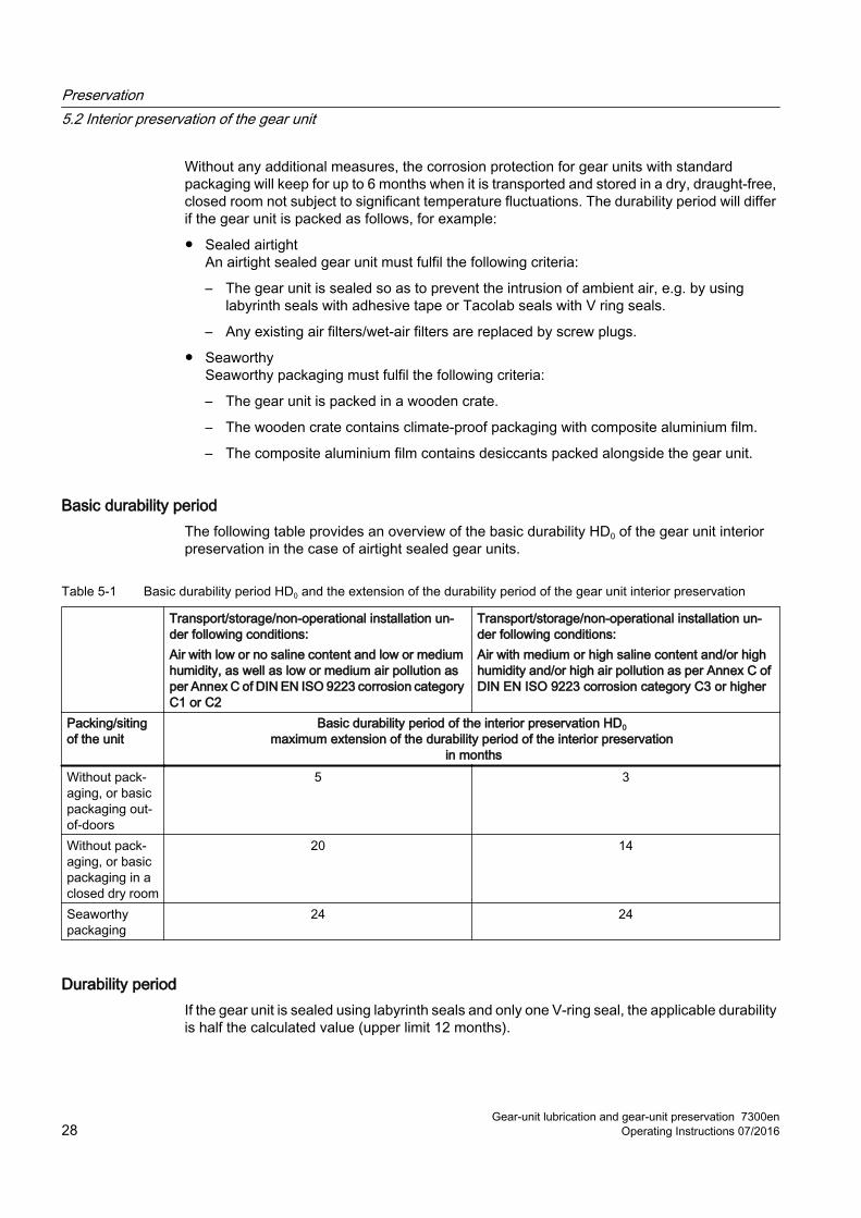
Basic durability periodThe following table provides an overview of the basic durability HD0 of the gear unit interior preservation in the case of airtight sealed gear units.
Table 5-1 Basic durability period HD0 and the extension of the durability period of the gear unit interior preservation
Transport/storage/non-operational installation un‐der following conditions:Air with low or no saline content and low or medium humidity, as well as low or medium air pollution as per Annex C of DIN EN ISO 9223 corrosion category C1 or C2
Transport/storage/non-operational installation un‐der following conditions:Air with medium or high saline content and/or high humidity and/or high air pollution as per Annex C of DIN EN ISO 9223 corrosion category C3 or higher
Packing/siting of the unit
Basic durability period of the interior preservation HD0maximum extension of the durability period of the interior preservation
in monthsWithout pack‐aging, or basic packaging out-of-doors
5 3
Without pack‐aging, or basic packaging in a closed dry room
20 14
Seaworthy packaging
24 24
Durability periodIf the gear unit is sealed using labyrinth seals and only one V-ring seal, the applicable durability is half the calculated value (upper limit 12 months).
Preservation5.2 Interior preservation of the gear unit
Gear-unit lubrication and gear-unit preservation 7300en28 Operating Instructions 07/2016
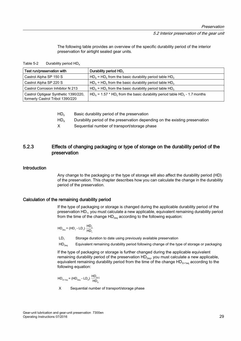
The following table provides an overview of the specific durability period of the interior preservation for airtight sealed gear units.
Table 5-2 Durability period HDX
Test run/preservation with Durability period HDX
Castrol Alpha SP 150 S HDX = HD0 from the basic durability period table HD0
Castrol Alpha SP 220 S HDX = HD0 from the basic durability period table HD0
Castrol Corrosion Inhibitor N 213 HDX = HD0 from the basic durability period table HD0
Castrol Optigear Synthetic 1390/220, formerly Castrol Tribol 1390/220
HDX = 1.57 * HD0 from the basic durability period table HD0 - 1.7 months
HD0 Basic durability period of the preservationHDX Durability period of the preservation depending on the existing preservationX Sequential number of transport/storage phase
5.2.3 Effects of changing packaging or type of storage on the durability period of the preservation
IntroductionAny change to the packaging or the type of storage will also affect the durability period (HD) of the preservation. This chapter describes how you can calculate the change in the durability period of the preservation.
Calculation of the remaining durability periodIf the type of packaging or storage is changed during the applicable durability period of the preservation HD1, you must calculate a new applicable, equivalent remaining durability period from the time of the change HD2eq according to the following equation:
= (HD1 - LD
1)
HD2
HD1
HD2eq
LD1 Storage duration to date using previously available preservationHD2eq Equivalent remaining durability period following change of the type of storage or packaging
If the type of packaging or storage is further changed during the applicable equivalent remaining durability period of the preservation HD2eq, you must calculate a new applicable, equivalent remaining durability period from the time of the change HDX+1eq according to the following equation:
= (HDXeq
- LDX)
HDX+1
HDX
HDX+1eq
X Sequential number of transport/storage phase
Preservation5.2 Interior preservation of the gear unit
Gear-unit lubrication and gear-unit preservation 7300enOperating Instructions 07/2016 29
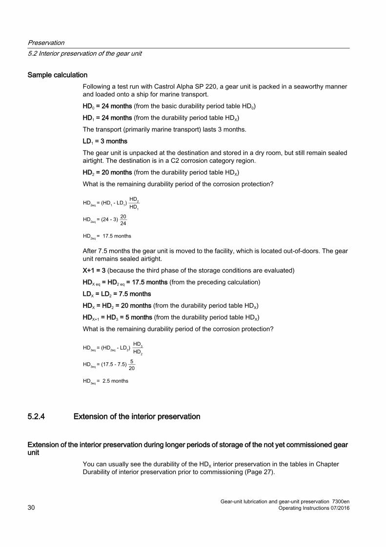
Sample calculationFollowing a test run with Castrol Alpha SP 220, a gear unit is packed in a seaworthy manner and loaded onto a ship for marine transport.
HD0 = 24 months (from the basic durability period table HD0)
HD1 = 24 months (from the durability period table HDX)
The transport (primarily marine transport) lasts 3 months.
LD1 = 3 months
The gear unit is unpacked at the destination and stored in a dry room, but still remain sealed airtight. The destination is in a C2 corrosion category region.
HD2 = 20 months (from the durability period table HDX)
What is the remaining durability period of the corrosion protection?
= 17.5 months
= (24 - 3)20
24
= (HD1 - LD
1)
HD2
HD1
HD2eq
HD2eq
HD2eq
After 7.5 months the gear unit is moved to the facility, which is located out-of-doors. The gear unit remains sealed airtight.
X+1 = 3 (because the third phase of the storage conditions are evaluated)
HDX eq = HD2 eq = 17.5 months (from the preceding calculation)
LDX = LD2 = 7.5 months
HDX = HD2 = 20 months (from the durability period table HDX)
HDX+1 = HD3 = 5 months (from the durability period table HDX)
What is the remaining durability period of the corrosion protection?
= 2.5 months
= (17.5 - 7.5)5
20
= (HD2eq
- LD2)
HD3
HD2
HD3eq
HD3eq
HD3eq
5.2.4 Extension of the interior preservation
Extension of the interior preservation during longer periods of storage of the not yet commissioned gear unit
You can usually see the durability of the HDX interior preservation in the tables in Chapter Durability of interior preservation prior to commissioning (Page 27).
Preservation5.2 Interior preservation of the gear unit
Gear-unit lubrication and gear-unit preservation 7300en30 Operating Instructions 07/2016
You must extend the preservation if the gear unit is scheduled for commissioning at a later point in time.
Record the extension of the interior preservation and keep the document with these operating instructions.
Extension of the interior preservation following shutdown of the gear unitTo preserve the gear unit for a storage period of more than 6 weeks following shutdown, follow the procedure described in Chapters Extension of the interior preservation through oil filling (Page 31) and Extension of the interior preservation with Castrol Corrosion Inhibitor N 213 (Page 33).
NOTICE
Risk of corrosion
The gear unit is prone to corrosion if it is not properly preserved over a shutdown period in excess of 6 weeks.
With shutdown periods in excess of 6 weeks, preserve the gear unit interior as described in this chapter. Installed air filters must be replaced with screw plugs or wet-air filters.
5.2.4.1 Extension of the interior preservation through oil filling
IntroductionGear units solely fitted with contacting shaft seals or shafts sealable with special additional devices can be filled with oil during storage. In doing so, all interior metallic bright surfaces, e.g. gear teeth, rolling-contact bearings and/or plain bearings and backstops, must be covered with oil.
Contact the oil manufacturer for the storage shelf life.
NOTICE
Corrosion damage to the gear unit due to loss of preservation effectiveness
Filled gear units may not be leak-tight, and gear oil may leak.
Perform a check every 4 weeks to make sure the filled gear unit is leak-tight. Fix any leakages. Siemens assumes no liability whatsoever for damage occurring due to an oil leakage during storage.
Preservation5.2 Interior preservation of the gear unit
Gear-unit lubrication and gear-unit preservation 7300enOperating Instructions 07/2016 31
Oils as interior preservationSiemens recommends the following oils to fill gear units in order to preserve the interior:
● Same oil subsequently used as operating oil
● Same oil subsequently used as operating oil, only with low viscosity
● Low-viscosity, low-alloy mineral oil with corrosion protection additive, such as Castrol Magna 32
NOTICE
Risk of blockage to oil lines
High-viscous deposits may occur due to incompatibilities.
If the test run was conducted using Castrol Optigear Synthetic 1390/220, formerly Castrol Tribol 1390/220, and if the gear unit is to be preserved by filling it with a mineral oil, PAO or synthetic ester, before filling you first have to remove the remains of the test run oil from the gear unit by flushing (Page 52) it using a mineral oil.
Shaft sealThe durability of the preservation depends on the shaft seals and oil used. As long as the gear unit remains leak-tight and the storage shelf life of the oil is observed, the preservation will remain intact.
NOTICE
Damage to the shaft seals
Overfilling the gear unit with oil can result in an unacceptably high build-up of pressure and damage to the shaft seals. This will result in an oil leak.Be sure to avoid overfilling the gear unit with oil.
Shafts are usually sealed with rotary shaft seals.
Be sure to keep the rotary shaft seals protected from UV light, so that the material retains its resistance. Foreseeable durability of rotary shaft seals:
● NBR material with mineral oil fill, at least 5 years
● NBR material with synthetic oils, at least 2 years
● FKM material, up to 10 years
In the following situations renew the rotary shaft seals before commissioning:
● NBR material with mineral oil fill after a preservation period in excess of 3 years
● NBR material following preservation with synthetic oils
● FKM material after a preservation period in excess of 5 years
Preservation5.2 Interior preservation of the gear unit
Gear-unit lubrication and gear-unit preservation 7300en32 Operating Instructions 07/2016
Sealing the gear unitYou must seal the oil filling point after filling the gear unit with preservative oil.
The use of a wet-air filter is recommended which enables pressure equalisation with the environment and prevents the intrusion of water during respiration of the gear unit. The wet-air filter is not included in the standard scope of supply. You have to purchase wet-air filters separately or expressly order them as additions to the gear unit.
If you use a screw plug, make sure that the internal pressure of the gear unit does not exceed 0.5 bar due to the maximum expected temperature rise during storage. This means that the free space inside the gear unit should be at least 20% of the volume of oil.
ProcedureTo preserve the gear unit with an oil filling, proceed as follows:
1. Remove any soiling from around the oil filling point.
2. Open the oil filling point.
3. Fill the gear unit with oil, ensuring that all metallic bright parts are covered with oil.
4. If you use a screw plug, make sure that the internal pressure of the gear unit does not exceed 0.5 bar.
5. Alternatively you can use a wet-air filter instead of the screw plug.
6. Close the oil filling point.
7. Ensure that the storage temperature remains constant.
5.2.4.2 Extension of the interior preservation using Castrol Corrosion Inhibitor N 213
Introduction To extend the durability period of the interior preservation, Siemens recommends the VCI-degassing preservative oil Castrol Corrosion Inhibitor N 213 for airtight-sealed gear units. Oil already filled does not have to be drained.
CAUTION
Risk of chemical burns
There is a risk of injury to eyes or hands from chemically aggressive operating substances.
Wear suitable safety goggles and protective gloves.
Remove oil puddles immediately with oil binding agents.
Preservation5.2 Interior preservation of the gear unit
Gear-unit lubrication and gear-unit preservation 7300enOperating Instructions 07/2016 33
CAUTION
Risk of scalding
Emerging vapours could ignite when opening the gear unit filled with Castrol Corrosion Inhibitor N 213.
Keep naked flames, sparks and hot objects at a distance.
Proportion of Castrol Corrosion Inhibitor N 213 in the oil You may not use the oil as the operating oil if you are using pumps, filters or oil sensors or if the proportion of Castrol Corrosion Inhibitor N 213 in the oil exceeds 5%.
Flush (Page 52) the gear unit after draining by using a mixture of operating and preservative oil. Use the operating oil type to be used later for flushing. This will help you prevent incompatibilities. Do not use the flushing oil as the operating oil.
NOTICE
Risk of corrosion
There is a risk of corrosion if the gear unit is left open for a longer period of time.
Seal the gear unit airtight again at the very latest one hour after it was opened.
Avoid the preservative oil coming into contact with elastomers.
ProcedureTo extend the durability period of the interior preservation, proceed as follows::
1. Remove any soiling from around the oil filling point.
2. Open the oil filling point.
3. Fill the preservative oil at a recommended ambient and gear unit temperature ≥ 5 °C. Use 1 litre of preservative oil per cubic metre of clear chamber volume.You can determine the approximate gear unit chamber volume using the following formula:Gear unit chamber volume ≈ length x width x height
4. Close the oil filling point.
5. Use adhesive tape or another suitable material to make the air gaps of any labyrinth seals airtight.
ResultThe durability period of the interior preservation of the gear unit is extended.
The table "Basic durability period HD0 and extension of the durability period of the gear unit interior preservation" in chapter Durability of interior preservation prior to commissioning (Page 27) provides an overview of the durability period of the gear unit interior preservation extended with Castrol Corrosion Inhibitor N 213 in airtight sealed gear units:
Preservation5.2 Interior preservation of the gear unit
Gear-unit lubrication and gear-unit preservation 7300en34 Operating Instructions 07/2016
If a vibration-free storage environment is not achievable, you must turn the input shaft a little each month to prevent corrosion damage. After turning, the input and output shaft must be in a new turned position.
5.3 Exterior preservation of metallic bright surfaces
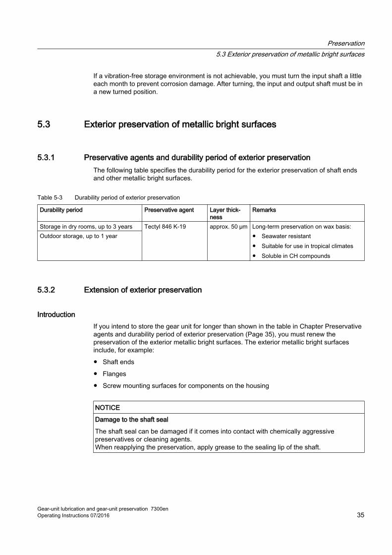
5.3.1 Preservative agents and durability period of exterior preservationThe following table specifies the durability period for the exterior preservation of shaft ends and other metallic bright surfaces.
Table 5-3 Durability period of exterior preservation
Durability period Preservative agent Layer thick‐ness
Remarks
Storage in dry rooms, up to 3 years Tectyl 846 K-19 approx. 50 µm Long-term preservation on wax basis:● Seawater resistant● Suitable for use in tropical climates● Soluble in CH compounds
Outdoor storage, up to 1 year
5.3.2 Extension of exterior preservation
IntroductionIf you intend to store the gear unit for longer than shown in the table in Chapter Preservative agents and durability period of exterior preservation (Page 35), you must renew the preservation of the exterior metallic bright surfaces. The exterior metallic bright surfaces include, for example:
● Shaft ends
● Flanges
● Screw mounting surfaces for components on the housing
NOTICE
Damage to the shaft seal
The shaft seal can be damaged if it comes into contact with chemically aggressive preservatives or cleaning agents.When reapplying the preservation, apply grease to the sealing lip of the shaft.
Preservation5.3 Exterior preservation of metallic bright surfaces
Gear-unit lubrication and gear-unit preservation 7300enOperating Instructions 07/2016 35
ProcedureTo extend the preservation of the exterior metallic bright surfaces, proceed as follows:
1. Clean the metallic bright surfaces and remove any old preservative.
2. Apply the appropriate preservative (Page 35).
3. Record the extension of the exterior preservation and keep the document with these operating instructions.
Further informationFurther information about approved greases is available in the "T 7300” approval list (Page 21).
Preservation5.3 Exterior preservation of metallic bright surfaces
Gear-unit lubrication and gear-unit preservation 7300en36 Operating Instructions 07/2016
Commissioning 6Introduction
The following describes the lubrication and preservation measures for commissioning.
6.1 Necessary oil filling measures for commissioning
RequirementsMake the following preparations on the gear unit:
● Ensure there is sufficient space within the workplace and that it is clean.
● Provide the following aids and parts:
– Suitably sized devices for draining and collecting the oil
– Suitably cleaned devices and containers for oil sampling (Page 46)
– Suitable devices for marking the oil sample
– Sufficient quantity of clean flushing oil (where required)
– Correct type and sufficient quantity of fresh oil for refilling the gear unit (Page 57)
– Cleaned filling system and further aids, including filling filters
– New seals (if required)
– Oil binding agents and cleaning agents
– Sufficient quantities of lint-free and clean cleaning cloths
Procedure To fill the gear unit with operating oil for the first time, proceed as follows:
1. Drain off the preservative oil (Page 51) and close the oil draining point.
2. Remove any adhesive tape used for sealing.
3. If it is necessary to flush the gear unit, carry out a flushing procedure (Page 52).
4. Take a sample of the fresh oil (Page 46), have it tested in a laboratory and keep the results with the gear unit documentation.
5. Remove any soiling found around the oil filling point.
6. Open the oil filling point.
7. Fill new operating oil to the specified quantity (Page 57).
Gear-unit lubrication and gear-unit preservation 7300enOperating Instructions 07/2016 37
8. Close the oil filling point in accordance with regulations.
9. Replace the attached screw plug with the applicable air filter.
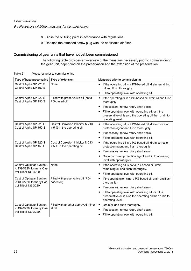
Commissioning of gear units that have not yet been commissioned The following table provides an overview of the measures necessary prior to commissioning the gear unit, depending on the preservation and the extension of the preservation:
Table 6-1 Measures prior to commissioning
Type of base preservative Type of extension Measures prior to commissioningCastrol Alpha SP 220 SCastrol Alpha SP 150 S
None ● If the operating oil is a PG-based oil, drain remaining oil and flush thoroughly.
● Fill to operating level with operating oil.Castrol Alpha SP 220 SCastrol Alpha SP 150 S
Filled with preservative oil (not a PG-based oil)
● If the operating oil is a PG-based oil, drain oil and flush thoroughly.
● If necessary, renew rotary shaft seals.● Fill to operating level with operating oil, or if the
preservative oil is also the operating oil then drain to operating level.
Castrol Alpha SP 220 SCastrol Alpha SP 150 S
Castrol Corrosion Inhibitor N 213 ≤ 5 % in the operating oil
● If the operating oil is a PG-based oil, drain corrosion protection agent and flush thoroughly.
● If necessary, renew rotary shaft seals.● Fill to operating level with operating oil.
Castrol Alpha SP 220 SCastrol Alpha SP 150 S
Castrol Corrosion Inhibitor N 213 > 5 % in the operating oil
● If the operating oil is a PG-based oil, drain corrosion protection agent and flush thoroughly.
● If necessary, renew rotary shaft seals.● Drain corrosion protection agent and fill to operating
level with operating oil.Castrol Optigear Synthet‐ic 1390/220, formerly Cas‐trol Tribol 1390/220
None ● If the operating oil is not a PG-based oil, drain remaining oil and flush thoroughly.
● Fill to operating level with operating oil.Castrol Optigear Synthet‐ic 1390/220, formerly Cas‐trol Tribol 1390/220
Filled with preservative oil (PG-based oil)
● If the operating oil is not a PG-based oil, drain and flush thoroughly.
● If necessary, renew rotary shaft seals.● Fill to operating level with operating oil, or if the
preservative oil is also the operating oil then drain to operating level.
Castrol Optigear Synthet‐ic 1390/220, formerly Cas‐trol Tribol 1390/220
Filled with another approved miner‐al oil
● Drain oil and flush thoroughly.● If necessary, renew rotary shaft seals.● Fill to operating level with operating oil.
Commissioning6.1 Necessary oil filling measures for commissioning
Gear-unit lubrication and gear-unit preservation 7300en38 Operating Instructions 07/2016
Castrol Optigear Synthet‐ic 1390/220, formerly Cas‐trol Tribol 1390/220
Castrol Corrosion Inhibitor N 213 ≤ 5 % in the operating oil
● If the operating oil is not a PG-based oil, drain corrosion protection agent and flush thoroughly.
● If necessary, renew rotary shaft seals.● Fill to operating level with operating oil.
Castrol Optigear Synthet‐ic 1390/220, formerly Cas‐trol Tribol 1390/220
Castrol Corrosion Inhibitor N 213 > 5 % in the operating oil
● If the operating oil is not a PG-based oil, drain corrosion protection agent and flush thoroughly.
● If necessary, renew rotary shaft seals.● Drain corrosion protection agent and fill to operating
level with operating oil.
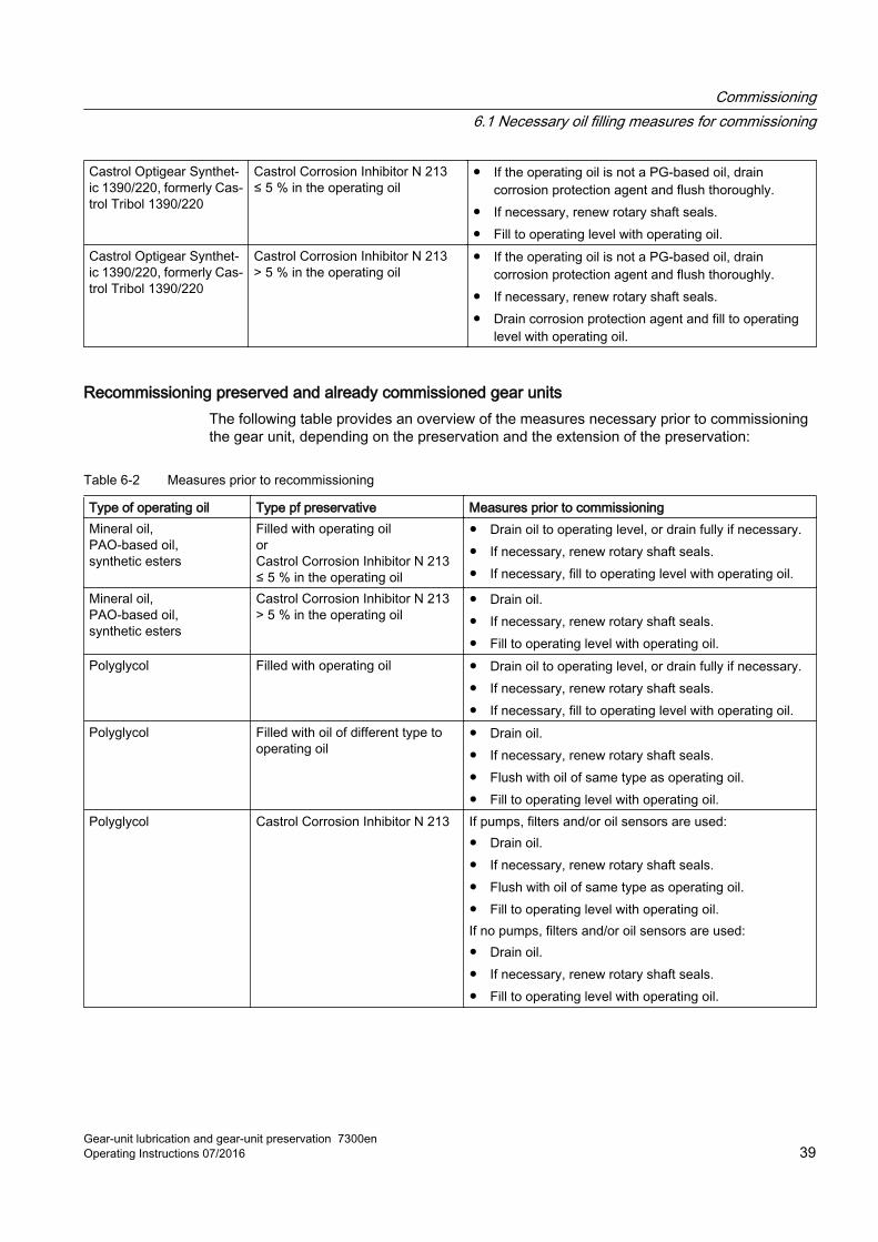
Recommissioning preserved and already commissioned gear units The following table provides an overview of the measures necessary prior to commissioning the gear unit, depending on the preservation and the extension of the preservation:
Table 6-2 Measures prior to recommissioning
Type of operating oil Type pf preservative Measures prior to commissioningMineral oil,PAO-based oil,synthetic esters
Filled with operating oil orCastrol Corrosion Inhibitor N 213 ≤ 5 % in the operating oil
● Drain oil to operating level, or drain fully if necessary.● If necessary, renew rotary shaft seals.● If necessary, fill to operating level with operating oil.
Mineral oil,PAO-based oil,synthetic esters
Castrol Corrosion Inhibitor N 213 > 5 % in the operating oil
● Drain oil.● If necessary, renew rotary shaft seals.● Fill to operating level with operating oil.
Polyglycol Filled with operating oil ● Drain oil to operating level, or drain fully if necessary.● If necessary, renew rotary shaft seals.● If necessary, fill to operating level with operating oil.
Polyglycol Filled with oil of different type to operating oil
● Drain oil.● If necessary, renew rotary shaft seals.● Flush with oil of same type as operating oil.● Fill to operating level with operating oil.
Polyglycol Castrol Corrosion Inhibitor N 213 If pumps, filters and/or oil sensors are used:● Drain oil.● If necessary, renew rotary shaft seals.● Flush with oil of same type as operating oil.● Fill to operating level with operating oil.If no pumps, filters and/or oil sensors are used:● Drain oil.● If necessary, renew rotary shaft seals.● Fill to operating level with operating oil.
Commissioning6.1 Necessary oil filling measures for commissioning
Gear-unit lubrication and gear-unit preservation 7300enOperating Instructions 07/2016 39
6.2 Information on initial filling and oil change
Important informationPlease note the following information on the initial filling of a gear unit and during an oil change:
● Always make sure that the oil in the gear unit is clean.
● The purity level of the operating oil has an impact on operational safety and the service life of the gear unit and the gear oil.
● When performing an oil fill or and oil change no contaminants such as foreign bodies, water or other fluids may be allowed to enter the gear unit.
● With larger quantities of oil, perform an oil analysis (Page 48) first. Perform an oil change (Page 50) as and when needed.
● Use the check list for oil filling and oil change (Page 69) to document these procedures.
Further informationWhere required, further information about the initial filling and about changing oil can also be found in the gear unit operating instructions.
6.3 Removing exterior preservation
IntroductionPrior to assembly, you must remove all the preservative from the metallic bright exterior surfaces.
CAUTION
Risk of injury from solvents
Lengthy and repeated contact with skin can result in brittle, chapped skin.
Observe the manufacturer's information on handling solvents and wear suitable protective clothing.
NOTICE
Damage to the shaft seal
The shaft seal can be damaged if it comes into contact with chemically aggressive preservatives or cleaning agents.When reapplying preservative, apply grease to the sealing lip of the shaft.
Commissioning6.3 Removing exterior preservation
Gear-unit lubrication and gear-unit preservation 7300en40 Operating Instructions 07/2016
ProcedureTo remove the exterior preservation, proceed as follows:
● Remove the preservative agent from the metallic bright exterior surfaces.
● You can use white spirit, special solvents or wax remover as the solvent.
Commissioning6.3 Removing exterior preservation
Gear-unit lubrication and gear-unit preservation 7300enOperating Instructions 07/2016 41
Commissioning6.3 Removing exterior preservation
Gear-unit lubrication and gear-unit preservation 7300en42 Operating Instructions 07/2016
Servicing 7Introduction
The following describes the lubrication and preservation measures for servicing.
7.1 General maintenance informationUse a service and maintenance schedule to document all servicing and maintenance work. The service and maintenance schedule can found in the operating instructions for the gear unit.
The operator must ensure compliance with the stipulated intervals. This also applies if the maintenance activities are included in the operator’s internal maintenance schedules.
The gear unit could be damaged if the stipulated intervals for maintenance and repair work are not observed.
7.2 Checking the oil level
7.2.1 Checking the oil level using the oil dipstick
RequirementsThe oil level may only be checked when the gear unit is at a standstill and the oil is in a foam-free state. Shut down the gear unit for 5 to 10 minutes.
NoteChecking the oil level in the case of planetary gear units
With planetary gear units, the oil level is affected by the position of the planetary drives.
Observe the marking on the input shaft to ensure that the position can be reproduced.
ProcedureTo check the oil level using the oil dipstick, proceed as follows:
1. Remove the oil dipstick.
2. Clean the measuring surface.
Gear-unit lubrication and gear-unit preservation 7300enOperating Instructions 07/2016 43
3. Reinsert the oil dipstick back into the oil filling point.
4. Check the oil level.
5. Reattach the oil dipstick.
ResultThe oil level is correct if it lies between the Min and Max marks of the oil dipstick.
If the oil level is above the Max mark, this may indicate the intrusion of a foreign liquid, e.g. water. Check the water content (Page 48) of the oil.
If the oil level is below the Min mark, this may indicate there is a leakage.
Both situations can result in gear unit damage. Before filling with new oil, identify the cause of the fault and eliminate it.
7.2.2 Checking the oil level with the oil sight glass
RequirementsThe oil level may only be checked when the gear unit is at a standstill and the oil is in a foam-free state. Shut down the gear unit for 5 to 10 minutes.
NoteChecking the oil level in the case of planetary gear units
With planetary gear units, the oil level is affected by the position of the planetary drives.
Observe the marking on the input shaft to ensure that the position can be reproduced.
ProcedureTo check the oil level using the oil sight glass, proceed as follows:
1. Clean the oil sight glass where necessary.
2. Check the oil level in the oil sight glass.
ResultThe oil level is correct if it lies in the middle of the oil sight glass.
If the oil level is above the oil sight glass, this may indicate the intrusion of a foreign liquid, e.g. water. Check the water content (Page 48) of the oil.
If the oil level is below the oil sight glass, this may indicate there is a leakage.
Both situations can result in gear unit damage. Before filling with new oil, identify the cause of the fault and eliminate it.
Servicing7.2 Checking the oil level
Gear-unit lubrication and gear-unit preservation 7300en44 Operating Instructions 07/2016
7.2.3 Controlling the oil level with the oil level indicator
RequirementsThe oil level may generally only be checked when the gear unit is at a standstill and the oil is more or less foam free. Shut down the gear unit for 5 to 10 minutes.
NoteChecking the oil level in the case of planetary gear units
With planetary gear units, the oil level is affected by the position of the planetary drives.
Observe the marking on the input shaft to ensure that the position can be reproduced.
ProcedureTo check the oil level using the oil level indicator, proceed as follows:
1. Clean the oil level indicator as necessary.
2. Check the oil level in the oil level indicator.
ResultThe oil level is correct if it lies between the Min and Max marks of the oil level indicator.
If the oil level is above the Max mark, this may indicate the intrusion of a foreign liquid, e.g. water. Check the water content (Page 48) of the oil.
If the oil level is below the Min mark, this may indicate there is a leakage.
Both situations can result in gear unit damage. Before filling with new oil, identify the cause of the fault and eliminate it.
7.3 Oil samplesThe test results of oil samples provide not only information about the condition of the oil, they also frequently enable conclusions to be made about the condition of the gear unit parts.
As an alternative to observing the fixed interval for oil changes, you have the option of arranging for the technical services of the oil manufacturer to regularly examine an oil sample, and approve the oil for further use. In this case the oil manufacturer guarantees that the properties of the oil comply with Siemens specifications.
Servicing7.3 Oil samples
Gear-unit lubrication and gear-unit preservation 7300enOperating Instructions 07/2016 45
7.3.1 Taking oil samples
IntroductionBefore filling the gear unit, arrange for a fresh sample of the lubricating oil to be tested in the laboratory for reference purposes. Have the subsequent used oil samples tested in the same laboratory.
Record and keep the test results for later comparisons.
CAUTION
Risk of scalding
Risk of serious injury possible through escaping hot operating media (> 50 °C) during sampling.
Wear suitable protective gloves, safety goggles and protective clothing.
RequirementsTake the oil sample in a manner to ensure it is representative:
● Ensure that oil filling is performed as homogenously as possible. Where possible, take the oil sample when the gear unit is running and has achieved operating temperature.
● If it is necessary to bring the gear unit to a standstill, take the sample within 10 minutes after the gear unit has been shut down. This will largely prevent any exsolution or depositing.
● Arrange for sampling to be consistently performed at the same point, according to the same method and by the same staff.
Sample container Suitable sample containers are clean, dry vessels with tight seals. The sample containers must be resistant to the specimen product up to operating oil temperature. Transparent, tightly sealable glass or PE-HD wide-neck bottles are particularly suitable.
CAUTION
Selection of unsuitable sample containers
Swallowing oil can result in physical injury.
Residue in the sample container can distort the oil sample.
Do not use milk, wine, beer, or mineral water bottles or any other containers used to store foodstuffs, even if these have been cleaned and labelled appropriately.
Servicing7.3 Oil samples
Gear-unit lubrication and gear-unit preservation 7300en46 Operating Instructions 07/2016
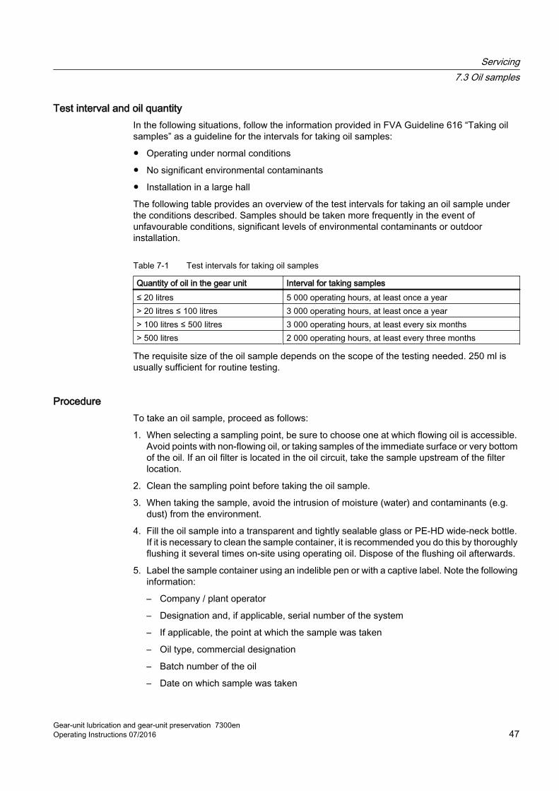
Test interval and oil quantity In the following situations, follow the information provided in FVA Guideline 616 “Taking oil samples” as a guideline for the intervals for taking oil samples:
● Operating under normal conditions
● No significant environmental contaminants
● Installation in a large hall
The following table provides an overview of the test intervals for taking an oil sample under the conditions described. Samples should be taken more frequently in the event of unfavourable conditions, significant levels of environmental contaminants or outdoor installation.
Table 7-1 Test intervals for taking oil samples
Quantity of oil in the gear unit Interval for taking samples≤ 20 litres 5 000 operating hours, at least once a year> 20 litres ≤ 100 litres 3 000 operating hours, at least once a year> 100 litres ≤ 500 litres 3 000 operating hours, at least every six months> 500 litres 2 000 operating hours, at least every three months
The requisite size of the oil sample depends on the scope of the testing needed. 250 ml is usually sufficient for routine testing.
ProcedureTo take an oil sample, proceed as follows:
1. When selecting a sampling point, be sure to choose one at which flowing oil is accessible. Avoid points with non-flowing oil, or taking samples of the immediate surface or very bottom of the oil. If an oil filter is located in the oil circuit, take the sample upstream of the filter location.
2. Clean the sampling point before taking the oil sample.
3. When taking the sample, avoid the intrusion of moisture (water) and contaminants (e.g. dust) from the environment.
4. Fill the oil sample into a transparent and tightly sealable glass or PE-HD wide-neck bottle. If it is necessary to clean the sample container, it is recommended you do this by thoroughly flushing it several times on-site using operating oil. Dispose of the flushing oil afterwards.
5. Label the sample container using an indelible pen or with a captive label. Note the following information:
– Company / plant operator
– Designation and, if applicable, serial number of the system
– If applicable, the point at which the sample was taken
– Oil type, commercial designation
– Batch number of the oil
– Date on which sample was taken
Servicing7.3 Oil samples
Gear-unit lubrication and gear-unit preservation 7300enOperating Instructions 07/2016 47
6. In addition to the data on the sample container, complete a sample consignment note which can be clearly assigned to the sample.
7. A copy of the sample consignment note should be kept with the gear unit documentation.
8. After the sample has been taken, the oil level must be checked and, if necessary, the oil topped up by adding fresh oil.
Further informationFurther information on the properties of a suitable sample container can be found in ISO 3722 "Hydraulic fluid power-Fluid sample containers–Qualifying and controlling cleaning methods".
Further information on the required size of the oil sample can be obtained by consulting the analysing laboratory.
7.3.2 Evaluating oil sample test results
IntroductionNote the following points when analysing the oil:
● Determine the water content of the oil using the indirect Karl Fischer Method.
● The deviation in the viscosity of the oil sample from the viscosity of the oil specified in the technical data should not exceed 10% in accordance with DIN 51517-3.
● The purity of the oil should not be less than -/20/15 in accordance with ISO 4406.Notify the test laboratory that for the purposes of measurement, the oil must be thinned with toluol to ensure that no air bubbles or soft substances are included in the measurement.
● Trend analyses of the measured element constituents are generally of greater importance than the magnitude of the absolute values. Compared to systems with filtration, higher contaminant values are of course to be expected without filtration.
Servicing7.3 Oil samples
Gear-unit lubrication and gear-unit preservation 7300en48 Operating Instructions 07/2016
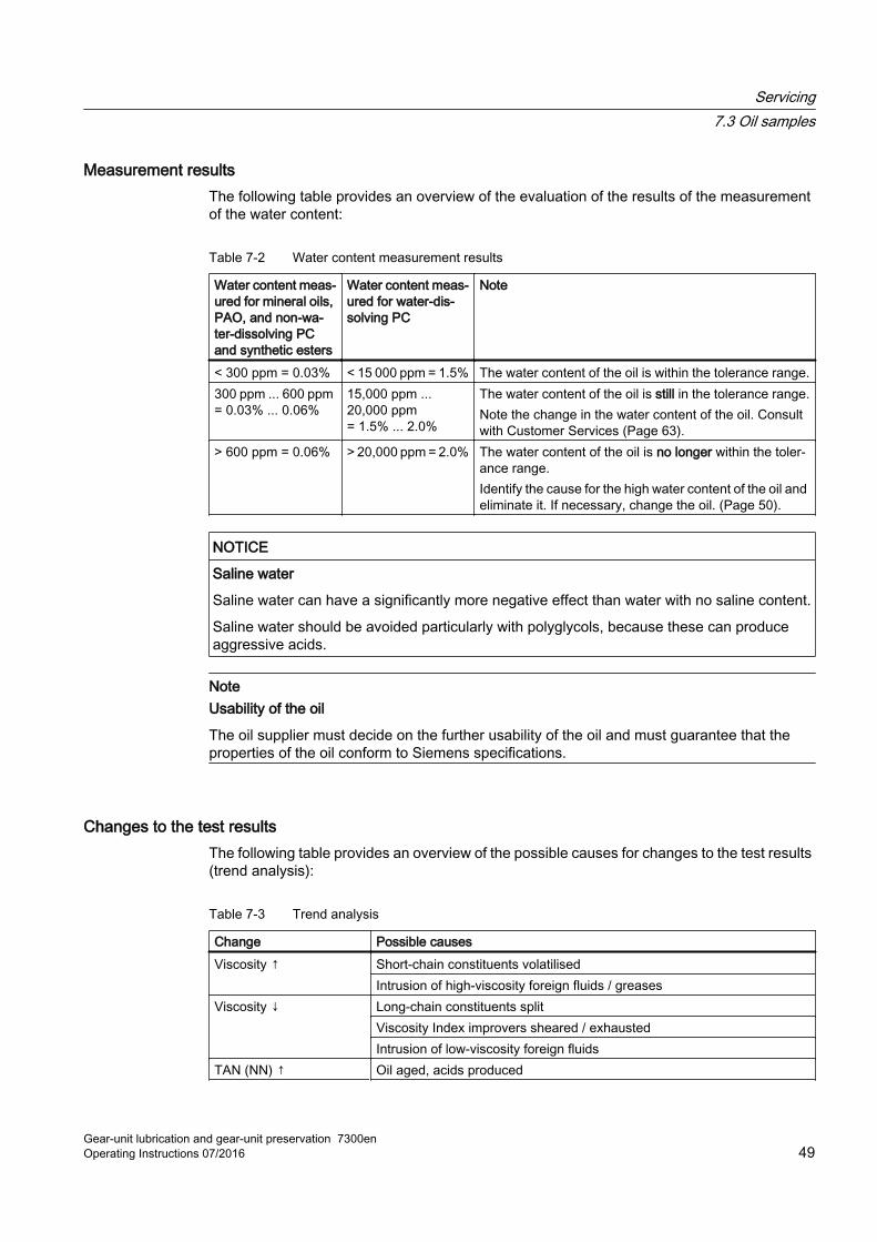
Measurement resultsThe following table provides an overview of the evaluation of the results of the measurement of the water content:
Table 7-2 Water content measurement results
Water content meas‐ured for mineral oils, PAO, and non-wa‐ter-dissolving PC and synthetic esters
Water content meas‐ured for water-dis‐solving PC
Note
< 300 ppm = 0.03% < 15 000 ppm = 1.5% The water content of the oil is within the tolerance range.300 ppm ... 600 ppm = 0.03% ... 0.06%
15,000 ppm ... 20,000 ppm = 1.5% ... 2.0%
The water content of the oil is still in the tolerance range.Note the change in the water content of the oil. Consult with Customer Services (Page 63).
> 600 ppm = 0.06% > 20,000 ppm = 2.0% The water content of the oil is no longer within the toler‐ance range.Identify the cause for the high water content of the oil and eliminate it. If necessary, change the oil. (Page 50).
NOTICE
Saline water
Saline water can have a significantly more negative effect than water with no saline content.
Saline water should be avoided particularly with polyglycols, because these can produce aggressive acids.
NoteUsability of the oil
The oil supplier must decide on the further usability of the oil and must guarantee that the properties of the oil conform to Siemens specifications.
Changes to the test resultsThe following table provides an overview of the possible causes for changes to the test results (trend analysis):
Table 7-3 Trend analysis
Change Possible causesViscosity ↑ Short-chain constituents volatilised
Intrusion of high-viscosity foreign fluids / greasesViscosity ↓ Long-chain constituents split
Viscosity Index improvers sheared / exhaustedIntrusion of low-viscosity foreign fluids
TAN (NN) ↑ Oil aged, acids produced
Servicing7.3 Oil samples
Gear-unit lubrication and gear-unit preservation 7300enOperating Instructions 07/2016 49
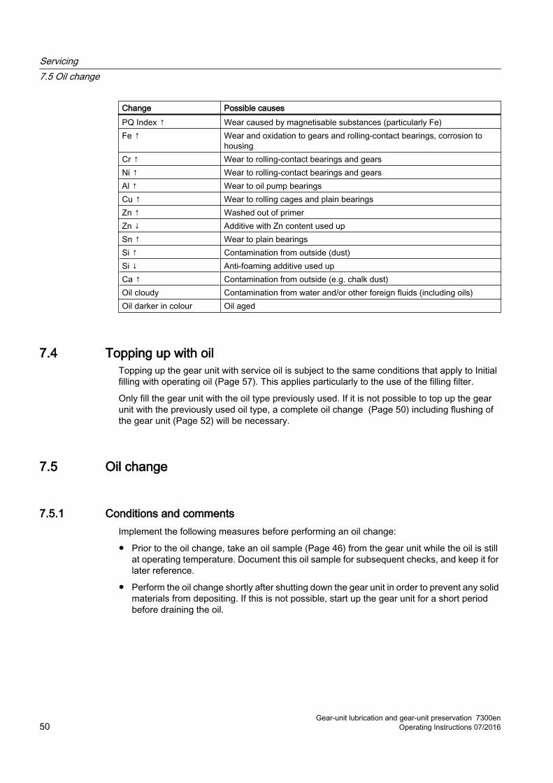
Change Possible causesPQ Index ↑ Wear caused by magnetisable substances (particularly Fe)Fe ↑ Wear and oxidation to gears and rolling-contact bearings, corrosion to
housingCr ↑ Wear to rolling-contact bearings and gearsNi ↑ Wear to rolling-contact bearings and gearsAl ↑ Wear to oil pump bearingsCu ↑ Wear to rolling cages and plain bearingsZn ↑ Washed out of primerZn ↓ Additive with Zn content used upSn ↑ Wear to plain bearingsSi ↑ Contamination from outside (dust)Si ↓ Anti-foaming additive used upCa ↑ Contamination from outside (e.g. chalk dust)Oil cloudy Contamination from water and/or other foreign fluids (including oils)Oil darker in colour Oil aged
7.4 Topping up with oilTopping up the gear unit with service oil is subject to the same conditions that apply to Initial filling with operating oil (Page 57). This applies particularly to the use of the filling filter.
Only fill the gear unit with the oil type previously used. If it is not possible to top up the gear unit with the previously used oil type, a complete oil change (Page 50) including flushing of the gear unit (Page 52) will be necessary.
7.5 Oil change
7.5.1 Conditions and commentsImplement the following measures before performing an oil change:
● Prior to the oil change, take an oil sample (Page 46) from the gear unit while the oil is still at operating temperature. Document this oil sample for subsequent checks, and keep it for later reference.
● Perform the oil change shortly after shutting down the gear unit in order to prevent any solid materials from depositing. If this is not possible, start up the gear unit for a short period before draining the oil.
Servicing7.5 Oil change
Gear-unit lubrication and gear-unit preservation 7300en50 Operating Instructions 07/2016
7.5.2 Draining used oil
IntroductionBefore you can fill up the fresh oil, you must drain the old oil and perform a flushing procedure (Page 52) if necessary.
You can drain off or suck out the oil.
Observe the information in the gear unit operating instructions about draining off the old oil. This particularly also applies to central lubricating systems and other oil supply equipment.
If no relevant information is given, use the lowest possible point to drain off or suck out the oil.
RequirementsDrain off the oil while it is still warm with a temperature of approx. 50 °C.
CAUTION
Risk of scalding
Risk of injury from leakage of hot oil.
Do not heat the oil to above 50 °C.
Open the oil drain screw or the oil drain tap carefully.
Wear suitable protective gloves, safety goggles and protective clothing. Use an oil-binding agent to immediately clean up any oil spillage.
ProcedureTo drain off the used oil, proceed as follows:
1. Shut down the gear unit and ensure that it cannot be restarted.
2. Check and record the oil level (Page 43).
3. Check the gear unit for leakages (Page 60). If there is a leakage, check and eliminate the cause before refilling.
4. Open all vent holes provided before draining the oil.Unscrew the reduction screw from the air filter or, where relevant, the screw plug from the wet-air filter.
5. Position the oil collector under the oil drain.
6. Drain off the oil. Also empty any oil pockets.
7. Ancillary units (such as oil supply systems, filters), pipework and attachments must likewise be emptied.
8. Collect the drained oil in accordance with regulations.
9. On gear units equipped with an oil circulation system and oil supply systems, the oil-conducting system must be emptied in accordance with the manufacturer’s instructions in the operating and maintenance instructions.
Servicing7.5 Oil change
Gear-unit lubrication and gear-unit preservation 7300enOperating Instructions 07/2016 51
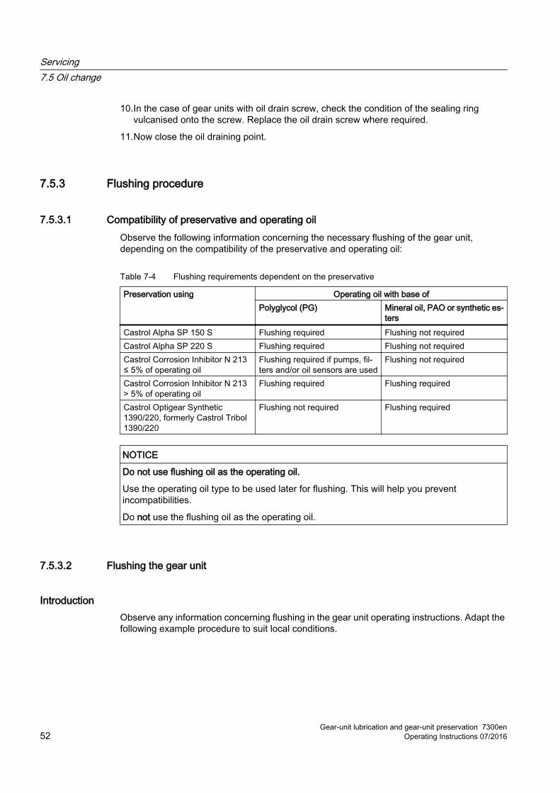
10.In the case of gear units with oil drain screw, check the condition of the sealing ring vulcanised onto the screw. Replace the oil drain screw where required.
11.Now close the oil draining point.
7.5.3 Flushing procedure
7.5.3.1 Compatibility of preservative and operating oilObserve the following information concerning the necessary flushing of the gear unit, depending on the compatibility of the preservative and operating oil:
Table 7-4 Flushing requirements dependent on the preservative
Preservation using Operating oil with base ofPolyglycol (PG) Mineral oil, PAO or synthetic es‐
tersCastrol Alpha SP 150 S Flushing required Flushing not requiredCastrol Alpha SP 220 S Flushing required Flushing not requiredCastrol Corrosion Inhibitor N 213 ≤ 5% of operating oil
Flushing required if pumps, fil‐ters and/or oil sensors are used
Flushing not required
Castrol Corrosion Inhibitor N 213 > 5% of operating oil
Flushing required Flushing required
Castrol Optigear Synthetic 1390/220, formerly Castrol Tribol 1390/220
Flushing not required Flushing required
NOTICE
Do not use flushing oil as the operating oil.
Use the operating oil type to be used later for flushing. This will help you prevent incompatibilities.
Do not use the flushing oil as the operating oil.
7.5.3.2 Flushing the gear unit
IntroductionObserve any information concerning flushing in the gear unit operating instructions. Adapt the following example procedure to suit local conditions.
Servicing7.5 Oil change
Gear-unit lubrication and gear-unit preservation 7300en52 Operating Instructions 07/2016
Use the operating oil type to be used later for flushing. This will help you prevent incompatibilities.
NOTICE
Risk of scalding from escaping oil
If the flushing oil is overheated, scalding can result.
Do not heat the flushing oil over 50 °C, to avoid scalding.
ProcedureTo perform a flushing procedure, proceed as follows:
1. Ensure the gear unit is not in operation, and secure it against being unintentionally started up.
2. Prior to use, perform a visual check of the flushing oil for homogeneity and impurities. Do not use impure flushing oil.
3. Fill the system with flushing oil until a short run without load or in the part-load range is possible without disruptions and the pump does not suck in air.If no pump is installed, you can use a separate filter unit with its own pump. This unit is not included in the standard scope of supply of the gear unit.Heated flushing oil improves the flushing action and reduces the required flushing time. Do not exceed 50 °C otherwise there is a risk of scalding.
4. Take any existing ancillary units into consideration when filling with flushing oil. If necessary, these should be filled separately before being emptied after the flushing run.
5. If possible, operate the gear unit for a short time with the flushing oil filling to ensure that it is mixed intensively with the residual oil remaining in the system, and to dissolve impurities as far as possible. If this is not possible, you must extend the flushing procedure as required.If no flushing time is specified in the gear unit operating instructions, it is recommended that you flush for the time needed to allow the flushing oil to perform 10 circuits. You can calculate this time for the gear unit by dividing the quantity of the flushing oil by the pump flow rate.The greater the quantity of operating oil and the worse the degree of contamination, the longer you should allow the gear unit to flush.
6. Clean the flushing oil in the bypass flow during the flushing procedure using a filter with a 10 μm filter mesh and a filtration quotient of β10(c) ≥ 200.
7. Drain off the flushing oil (Page 51).
8. Perform a visual check of the flushing oil (Page 54).
ResultIf there are any impurities in the oil or the gear unit, repeat the flushing procedure until the desired result is achieved.
Servicing7.5 Oil change
Gear-unit lubrication and gear-unit preservation 7300enOperating Instructions 07/2016 53
You can clean the flushing oil if necessary, and reuse it. If the flushing oil is no longer suitable for a flushing procedure, dispose of it properly.
NoteDo not use flushing oil as the operating oil.
Do not use the flushing oil as the operating oil.
Drain the flushing oil following the flushing procedure.
7.5.4 Checks and tasks to be performed prior to a new oil refill
You must perform the following checks and tasks prior to refilling the gear unit with operating oil.
7.5.4.1 Comparing the oil quantityTo compare the oil quantity, proceed as follows:
1. Compare the drained oil quantity with the manufacturer’s nominal fill quantity.If the quality of oil drained is significantly less than this, despite the oil level having been correct, you may assume there are considerable residual amounts of old oil in the gear unit or in the ancillary units.
2. Perform a flushing procedure (Page 52).
7.5.4.2 Performing a visual check of the oilTo check the oil, proceed as follows:
1. Perform a visual check of the drained oil for the following characteristics:
– Appearance
– Colour
– Contamination
2. If there is serious contamination (e.g. water, metal particles, sludge), contact Siemens Customer Services (Page 63) to identify the cause.
3. Flush (Page 52) the lubricating oil system out thoroughly before refilling.
Servicing7.5 Oil change
Gear-unit lubrication and gear-unit preservation 7300en54 Operating Instructions 07/2016
7.5.4.3 Checking gear unit componentsTo check the gear unit components, proceed as follows:
1. Check oil drain screws equipped with a magnet or magnetic extractors provided or filters for metal abrasion.
2. Clean the oil drain screw if necessary.If there is a large amount of abrasion, contact Siemens Customer Services (Page 63) to identify the cause.
3. Thoroughly clean the area around the inspection hole before opening to prevent dirt from getting into the interior of the gear unit from the outside when the inspection cover is opened.
4. Open the inspection cover.
5. Check the gear unit interior for deposits and the gear teeth, the rolling-contact bearings and/or the plain bearings for damage.
6. Arrange for any damage to be repaired by Siemens Customer Services.
7. If heavy deposits or other high levels of impurities are present, perform a flushing procedure (Page 52).If it is evident that the impurities cannot be removed by flushing alone, you should remove them mechanically. Use a rubber scraper to remove residues from storage containers.
7.5.4.4 Cleaning the oil filter or replacing the filter elementThe filter may be cleaned or the filter element replaced, depending on the type of filter.
To clean the oil filter, proceed as follows:
1. Clean and replace the existing oil filter in accordance with regulations.
2. Dispose of the old oil in accordance with regulations.With certain synthetic oils or impurities, different disposal methods may be required compared to those used for normal used oils. Note the oil datasheets.
Further informationFurther information on the filter type can be found on the gear unit operating instructions.
7.5.4.5 Cleaning the air filter
WARNING
Risk of eye injury from compressed air
Water residue and dirt particles can cause damage to eyes.
Wear suitable safety goggles.
If a layer of dust has accumulated on the air filter, clean the air filter even if the prescribed time limit has not yet expired.
Servicing7.5 Oil change
Gear-unit lubrication and gear-unit preservation 7300enOperating Instructions 07/2016 55
To clean the air filter, proceed as follows:
1. Clean the area around the filter and disassemble the filter cap of the air filter, where necessary.
2. Unscrew the air filter and filter cap.
3. Clean the air filter using a suitable cleaning agent, such as white spirit.
4. Optional: Blast the air filter with compressed air.
5. Allow the air filter to dry.
6. Screw the air filter back into the bore.
7. Reattach the filter cap of the air filter where necessary
7.5.4.6 Replacing wet-air filtersIf a wet-air filter has been mounted on the gear unit, and the silica gel in the wet-air filter has undergone a complete colour change compared to when it is new, you should replace the filter.
To change the wet-air filter, proceed as follows:
1. Unscrew the old wet-air filter.
2. Open 2 of the 8 closed holes on the bottom of the new wet-air filter.
3. Screw the new wet-air filter back into the hole.
7.5.4.7 Checking the air/oil cooler
WARNING
Risk of eye injury from compressed air
Water residue and dirt particles can cause damage to eyes.
Wear suitable safety goggles.
To check the air/oil cooler, proceed as follows:
1. Remove any dirt from the cooler block.
2. Check the condition of the cooler block.
3. Check the screw connections and and pipework for leakages, and replace them if necessary.
Servicing7.5 Oil change
Gear-unit lubrication and gear-unit preservation 7300en56 Operating Instructions 07/2016
7.5.4.8 Checking the water/oil cooler
WARNING
Risk of eye injury from compressed air
Water residue and dirt particles can cause damage to eyes.
Wear suitable safety goggles.
To check a water/oil cooler, proceed as follows:
1. Check the water pipes of the water/oil cooler for leakages.
2. Check the screw connections and and pipework for leakages, and replace them if necessary.
7.5.5 Filling with new oil
IntroductionWhen performing an oil change, as a rule fill the gear unit only with fresh oil of the type previously used. Note any information in the operating instructions detailing the stipulated purity class. Important reasons must exist to change the brand of oil. Perform a flushing procedure (Page 52) if there are incompatibilities between the previously and subsequently used oils.
For future comparisons, keep a sample of the fresh oil taken prior to filling as a reference sample.
NoteInitial filling
When performing an initial filling, note the information from No. 27 onwards in the "Check list for oil filling and oil change (Page 69)".
Filling with oil filterFresh oil can contain impurities. Fill in the oil through a filter. If no information is available on the filter, you should normally use a filling filter with a 10 μm mesh and a filtration quotient of β10(c) ≥ 100. When using highly-viscous oils, to perform the filling with a filter you will usually need a filter unit with its own pump. This unit is not included in the standard scope of supply of the gear unit. Prior to filtering, ask your oil supplier if the oil can be filtered using a filter with the planned mesh size. During filling, the oil should not be too cool because the maximum permissible viscosity for the units is frequently 1 000 mm2/s.
Servicing7.5 Oil change
Gear-unit lubrication and gear-unit preservation 7300enOperating Instructions 07/2016 57
ProcedureTo fill in new gear oil, proceed as follows:
1. Clean the air filter (Page 55) or replace the wet-air filter (Page 56).
2. Perform a flushing procedure if necessary.
3. Perform a visual check of the fresh oil for the following parameters:
– Homogeneity
– Solid impurities and water (cloudiness)
– Colour and appearance according to the oil manufacturer’s product-specific data
4. Clean the oil filling point and open it. Note the information in the dimension drawing.
5. Fill the fresh oil, using an oil filter if necessary, until the prescribed fill level is reached. The oil quantity specified on the rating plate serves as a guide only. The decisive factors for the quantity of oil to be put in are the marks on the oil dipstick or the other oil level indicator systems (Page 43).
6. Record the purity class.
7. Optional: For gear units with an add-on flange pump, use the screw-turn filling point to fill the flange pump and suction line with oil.
8. Optional: For gear units with pressure lubrication or oil cooling systems, you also have to fill the oil circuit. To do this, briefly start up the gear unit with attached pump.
9. Optional: If present, fill any oil pockets with oil. The gear teeth should also be lubricated with oil.
10.Ensure that the gear unit and all the components of the oil supply system, the filters and pipework are filled with oil.
11.Use an oil-binding agent to immediately clean up any oil spillage.
12.Check the oil level (Page 43) once again after a short operating time of approx. 10 minutes and an idle period of at least 15 minutes. Fill or drain off oil as necessary.
13.Close the oil filling point.
ResultThe oil change or the initial filling have now been carried out.
Complete the documentation sheet for the oil change (Page 67) and keep it safely.
Check the oil filter (if fitted) for deposits after a week at the most. Clean or replace the oil filter if necessary. Any impurities still remaining in the system may have dissolved and may be blocking the oil filter.
Approx. 5 operating hours after the oil change take another oil sample (Page 45) from the gear unit; this will be documented and kept for later checking.
Servicing7.5 Oil change
Gear-unit lubrication and gear-unit preservation 7300en58 Operating Instructions 07/2016
7.6 Changing the oil type
IntroductionYou should only change the oil type if there are important reasons for doing so or in exceptional cases after having consulted with Siemens.
NoteFlushing the gear unit
Perform a flushing procedure (Page 52) when changing the oil type to a new type with a similar composition.
The compatibility of different gear oils can only be assessed by oil manufacturers. You should therefore include the manufacturer into the decision-making process.
Changing to another base oil type Incompatibilities can arise particularly when changing to another base oil type or to an oil with a very different additive technology.
After draining the used oil, you must thoroughly clean and flush (Page 52) the entire system. In this case you can, at the most, use the flushing oil a second time for flushing out the same gear unit. Then dispose of the flushing oil.
Note the following additional points when changing the type of base oil:
● Check the compatibility of other gear unit components, e.g. sealing materials or varnishes and paints, with the new oil. Recommended are the oils approved by Siemens (Page 20).
● Cavitation problems may arise with oils with a higher viscosity; larger suction line cross-sections may be required.
7.7 Checking the hose linesEven hoses and hose lines that are properly stored and exposed only to permissible wear are subject to a natural ageing process. This limits their serviceable life.
Changing the hose linesHose lines can become damaged due to excessive aging or external influences. Check hose lines before initially commissioning the system, and at least once a year thereafter, to ensure these are in good working order.
Ensure that hose lines are replaced at appropriate intervals, even if the hose line does not show any technical/safety defect. Only use hose lines not more than 6 years old. The date of manufacture is printed on the hose lines.
Taking account of the operating conditions, you can determine the foreseeable serviceable life based on tested and empirical values.
Servicing7.7 Checking the hose lines
Gear-unit lubrication and gear-unit preservation 7300enOperating Instructions 07/2016 59
ProcedureTo check the hose lines, proceed as follows:
1. Check the hose lines for tightness and leaks.
2. Check the date of manufacture printed on the hose lines.
3. Replace leaking or excessively old hose lines in good time, but at least every 6 years.
7.8 Re-greasing grease-lubricated labyrinths
IntroductionOnly use lubricating greases approved by Siemens AG (Page 24).
The exact designation of the grease nipples can be found in the overall documentation for the gear unit.
ProcedureTo re-grease a labyrinth, proceed as follows:
1. Clean the grease nipples.
2. Connect the lubricating device to the grease nipple.
3. Re-grease with 30 g grease to each grease nipple.
4. Remove the lubricating device from the grease nipple.
CAUTION
Risk of slipping
Escaping grease creates a risk of slipping.
Remove grease escaping from the labyrinth immediately, and dispose of it properly.
7.9 Leakage and leak-tightnessThe following table provides an overview of possible leaks in shaft seals, descriptions, necessary measures and more detailed information:
Servicing7.9 Leakage and leak-tightness
Gear-unit lubrication and gear-unit preservation 7300en60 Operating Instructions 07/2016
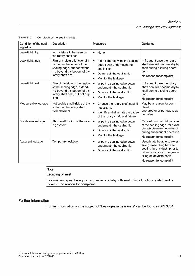
Table 7-5 Condition of the sealing edge
Condition of the seal‐ing edge
Description Measures Guidance
Leak-tight, dry No moisture to be seen on the rotary shaft seal
● None
Leak-tight, moist Film of moisture functionally formed in the region of the sealing edge, but not extend‐ing beyond the bottom of the rotary shaft seal
● If dirt adheres, wipe the sealing edge down underneath the sealing lip.
● Do not soil the sealing lip.● Monitor the leakage.
In frequent case the rotary shaft seal will become dry by itself during ensuing opera‐tion.No reason for complaint
Leak-tight, wet Film of moisture in the region of the sealing edge, extend‐ing beyond the bottom of the rotary shaft seal, but not drip‐ping
● Wipe the sealing edge down underneath the sealing lip.
● Do not soil the sealing lip.● Monitor the leakage.
In frequent case the rotary shaft seal will become dry by itself during ensuing opera‐tion.No reason for complaint
Measureable leakage Noticeable small trickle at the bottom of the rotary shaft seal, dripping
● Change the rotary shaft seal, if necessary.
● Identify and eliminate the cause of the rotary shaft seal failure.
May be a reason for com‐plaint,one drop of oil per day is ac‐ceptable.
Short-term leakage Short malfunction of the seal‐ing system
● Wipe the sealing edge down underneath the sealing lip.
● Do not soil the sealing lip.● Monitor the leakage.
Caused by small dirt particles at the sealing edge, for exam‐ple, which are removed again during subsequent operation.No reason for complaint
Apparent leakage Temporary leakage ● Wipe the sealing edge down underneath the sealing lip.
● Do not soil the sealing lip.
Usually attributable to exces‐sive grease filling between sealing lip and dust lip, or to oil secretions from the grease filling of labyrinth seals.No reason for complaint
NoteEscaping oil mist
If oil mist escapes through a vent valve or a labyrinth seal, this is function-related and is therefore no reason for complaint.
Further informationFurther information on the subject of “Leakages in gear units" can be found in DIN 3761.
Servicing7.9 Leakage and leak-tightness
Gear-unit lubrication and gear-unit preservation 7300enOperating Instructions 07/2016 61
Servicing7.9 Leakage and leak-tightness
Gear-unit lubrication and gear-unit preservation 7300en62 Operating Instructions 07/2016
Service & Support 8Contact
When requesting a customer service technician or in the case of technical queries, please contact the address for Siemens Customer Services:
Siemens AG
Am Industriepark 2
46562 Voerde
Germany
Tel.: +49 (0) 2871 / 92-4
Fax.: +49 (0) 2871 / 92-2487
Gear-unit lubrication and gear-unit preservation 7300enOperating Instructions 07/2016 63
Service & Support
Gear-unit lubrication and gear-unit preservation 7300en64 Operating Instructions 07/2016
Disposal 9Disposal of the gear unit
When disposing of the gear unit after its useful life, please observe the following measures:
● Remove operating oil, preservative agents and/or cooling liquid from the gear unit and dispose of them according to regulations.
● Dispose of the gear unit parts according to applicable national regulations or recycle them.
Environmental protectionObserve the following environmental protection measures for disposal:
● Dispose of or recycle packaging material according to applicable national regulations.
● When changing the oil, collect the used oil in suitable containers. Use oil-binding agents to clean up any oil spillages immediately.
● Store preservative agents separately from used oil.
● Dispose of used oil, preservative agents, oil binding agents and oil-soaked cloths according to the applicable environmental protection regulations.
Gear-unit lubrication and gear-unit preservation 7300enOperating Instructions 07/2016 65

Disposal
Gear-unit lubrication and gear-unit preservation 7300en66 Operating Instructions 07/2016
Documentation sheet for oil change A
Gear-unit lubrication and gear-unit preservation 7300enOperating Instructions 07/2016 67
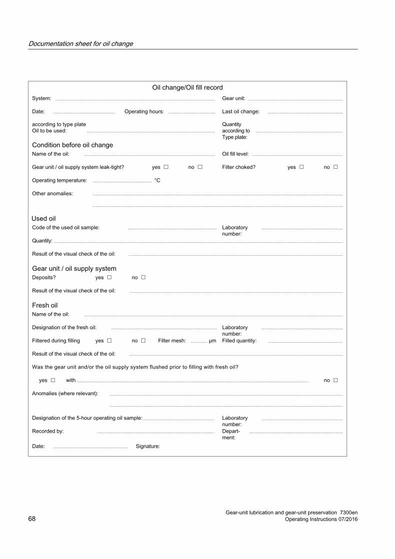
Documentation sheet for oil change
Gear-unit lubrication and gear-unit preservation 7300en68 Operating Instructions 07/2016
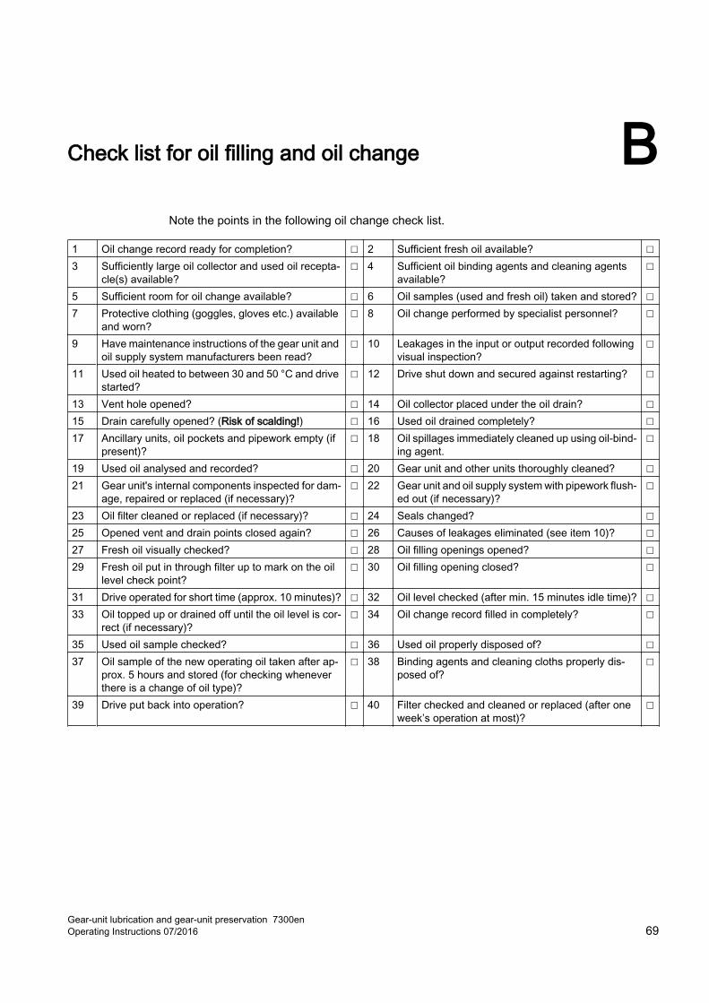
Check list for oil filling and oil change BNote the points in the following oil change check list.
1 Oil change record ready for completion? ☐ 2 Sufficient fresh oil available? ☐3 Sufficiently large oil collector and used oil recepta‐
cle(s) available?☐ 4 Sufficient oil binding agents and cleaning agents
available?☐
5 Sufficient room for oil change available? ☐ 6 Oil samples (used and fresh oil) taken and stored? ☐7 Protective clothing (goggles, gloves etc.) available
and worn?☐ 8 Oil change performed by specialist personnel? ☐
9 Have maintenance instructions of the gear unit and oil supply system manufacturers been read?
☐ 10 Leakages in the input or output recorded following visual inspection?
☐
11 Used oil heated to between 30 and 50 °C and drive started?
☐ 12 Drive shut down and secured against restarting? ☐
13 Vent hole opened? ☐ 14 Oil collector placed under the oil drain? ☐15 Drain carefully opened? (Risk of scalding!) ☐ 16 Used oil drained completely? ☐17 Ancillary units, oil pockets and pipework empty (if
present)?☐ 18 Oil spillages immediately cleaned up using oil-bind‐
ing agent.☐
19 Used oil analysed and recorded? ☐ 20 Gear unit and other units thoroughly cleaned? ☐21 Gear unit's internal components inspected for dam‐
age, repaired or replaced (if necessary)?☐ 22 Gear unit and oil supply system with pipework flush‐
ed out (if necessary)?☐
23 Oil filter cleaned or replaced (if necessary)? ☐ 24 Seals changed? ☐25 Opened vent and drain points closed again? ☐ 26 Causes of leakages eliminated (see item 10)? ☐27 Fresh oil visually checked? ☐ 28 Oil filling openings opened? ☐29 Fresh oil put in through filter up to mark on the oil
level check point?☐ 30 Oil filling opening closed? ☐
31 Drive operated for short time (approx. 10 minutes)? ☐ 32 Oil level checked (after min. 15 minutes idle time)? ☐33 Oil topped up or drained off until the oil level is cor‐
rect (if necessary)?☐ 34 Oil change record filled in completely? ☐
35 Used oil sample checked? ☐ 36 Used oil properly disposed of? ☐37 Oil sample of the new operating oil taken after ap‐
prox. 5 hours and stored (for checking whenever there is a change of oil type)?
☐ 38 Binding agents and cleaning cloths properly dis‐posed of?
☐
39 Drive put back into operation? ☐ 40 Filter checked and cleaned or replaced (after one week’s operation at most)?
☐
Gear-unit lubrication and gear-unit preservation 7300enOperating Instructions 07/2016 69
Check list for oil filling and oil change
Gear-unit lubrication and gear-unit preservation 7300en70 Operating Instructions 07/2016
Glossary
APIAmerican Petroleum Institute
BIOBIO is the term given to oils that are relatively easily biodegradable.
CH compoundsHydrocarbon compounds
CKCOil with enhanced wear-protection characteristics. Designed for use in highly stressed gear units with constant, average thermal load.
CLP qualityCLP oils must be fit for circulation lubrication (C) in accordance with DIN 51517-3. These must also contain substances for improving corrosion protection, resistance to ageing (L), as well as substances for reducing wear in mixed friction areas (P).
EDON duration
FKMFluorinated rubber
Flash pointThe flash point of an oil is the lowest temperature at which a flammable vapour/air mixture can form. The combustion process usually stops a short time after the ignition, because not enough flammable vapour is produced at this temperature to sustain the combustion.
FVAFVA GmbH is a joint venture company operated by VDMA (Verband Deutscher Maschinen- und Anlagenbau e.V.) and FVA (Forschungsvereinigung Antriebstechnik e.V.).
Gear-unit lubrication and gear-unit preservation 7300enOperating Instructions 07/2016 71
FZGFLENDER® gear unit
GFMicropitting
HD-PEHigh-density polyethylene
ISO VGISO viscosity grade, average kinematic viscosity at 40 °C in mm²/s in accordance with DIN ISO 3448
MDMechanical Drives
NBRNitrile rubber
NLGINational lubrication grease institute
NLGI states a consistency value for lubricating grease pursuant to DIN 51818 for classifying them into consistency classes.
NLGI ClassThe consistency of the lubricating grease is defined according to a scale published by the US National Lubricating Grease Institute (NLGI). The consistency value pursuant to DIN 51818 classifies lubricating greases into consistency classes (= NLGI classes). The softer the grease, the lower the value.
Nominal viscositySee ISO VG
NSF-H1The NSF (National Sanitation Foundation) performs tests to ascertain if lubricants are food grade. H1 means that occasional, technically unavoidable contact is allowed between the lubricant and foodstuffs.
Glossary
Gear-unit lubrication and gear-unit preservation 7300en72 Operating Instructions 07/2016
PAOPoly-alpha-olefin is a synthetic paraffin and naphthenic base oil.
PG/PAGPolyglycol is a synthetic, common water soluble polymer-based base oil.
PHYPHY is the term given to physiologically safe oils with approval (see also NSF-H1).
Pour pointThe pour point of an oil is the temperature at which the oil still pours when cooled down in accordance with DIN ISO 3016. This value provides an indicator for the fluidity of the oil.
PQ indexThe Particle Quantifier index determines the proportion of magnetisable iron in the oil.
TAN (NN)The Total Acid Number describes the acid number or the NN, the neutralisation number. It states how many mg COH are required to neutralise the acids contained in 1 g oil.
The Arrhenius LawThe Arrhenius Law provides a rule of thumb for chemical kinetics and enables numerous chemical phenomena to be estimated. It states that chemical reactions will take place twice to four times faster when the temperature is raised by 10 K. The factor by which the reaction speed specifically increases when the temperature is raised by 10 K is known as the Q10 value.
VCIVolatile Corrosion Inhibitor
VI improverVI improvers stands for viscosity index improvers. These induce improved viscosity-temperature behaviour with a reduced temperature influence on the viscosity.
Viscosity indexThe viscosity index (VI) describes the temperature dependency of the kinematic viscosity of an oil. The higher the viscosity index, the lower the changes in viscosity as the temperature changes. The viscosity index is calculated according to DIN ISO 2909, based on a kinematic viscosity at 40 °C and 100 °C.
Glossary
Gear-unit lubrication and gear-unit preservation 7300enOperating Instructions 07/2016 73
Viscosity temperature profileThe viscosity temperature profile illustrates the change of the viscosity as a function of the change in temperature. The viscosity index is calculated in order to compare the behaviour of two or more oils.
Glossary
Gear-unit lubrication and gear-unit preservation 7300en74 Operating Instructions 07/2016
Index
AAir filter, 55
Cleaning, 55Filter cap, 55Wet-air filter, 56
Air/oil cooler, 56
BBasic knowledge required, 9
CColoured markings, 12Commissioning, 38Contract address, 63Copyright, 10Customer Services address, 63
DDipstick, 43Disclaimer, 9Disposal, 65Documentation landscape, 10Durability period, 28
EEnvironmental protection, 65
GGear unit markings, 12
HHose line, 59
IIntroduction, 9
LLeak, 60Leakage, 60
MMaintenance activities, 43Maintenance information, 43Maintenance schedule, 43
OOil
Base oil types, 17Changing type, 59Check list, 69Code numbers, 22Commissioning, 37Disposal, 65Flushing oil, 18, 52Impurities, 53Initial filling, 40Mixing types, 17Oil change, 40Oil groups, 17Oil level check, 43, 44, 45Oil sample, 46Oil temperature, 19Quality tests, 21Selection, 21Service life, 20, 46Warranty, 20Water content, 48
Oil changeChanging base oil type, 59Changing type, 59Check list, 69Check of the oil, 54Cleaning the air filter, 55Cleaning the oil filter, 55Documentation, 58Draining oil, 51Filling filter, 57Flushing, 52General inspection of the gear unit, 55Impurities, 53
Gear-unit lubrication and gear-unit preservation 7300enOperating Instructions 07/2016 75
Oil quantity, 54Oil sample, 50Refilling, 54, 57Replacing wet-air filters, 56
Oil level, 43, 44, 45Oil level indicator, 45Oil sample
Influences, 49Oil change, 50Oil quantity, 47Result, 49Sample container, 46Taking, 46Test interval, 47Test results, 48
Oil sight glass, 44
PPackaging, 25Preparations, 37Preservation
Basic durability period, 28Delivered state, 25Durability, 27Extension, 30, 31, 33Exterior preservation, 35Interior preservation, 30, 32, 33Remaining durability period, 29Remove, 40Renew, 35Solvent, 41Tacolab seal, 27
Protective equipment, 13
RRecommissioning, 39Regulations, 13Rolling-contact bearing grease
Code numbers, 22Grease lubrication, 24Re-grease, 60Sealing effect, 24Selection, 21
SSeaworthy packaging, 27Servicing activities, 43
Shaft sealLabyrinth seal, 60Rotary shaft seal, 32Tacolab, 27V-ring seal, 27
StorageAmbient conditions, 35Indoor storage, 25Outdoor storage, 25Packaging, 27
TTacolab seal, 27
WWarning symbols, 13Warranty
Gear oils, 22Oil quality, 20
Water/oil cooler, 57Wet-air filter
Colour change, 56Holes, 56Replace, 56
Index
Gear-unit lubrication and gear-unit preservation 7300en76 Operating Instructions 07/2016


Siemens AGProcess Industries and DrivesPostfach 48 4890026 NÜRNBERGGERMANY
www.siemens.com/drives