lubrication notes - bosch rexroth
TRANSCRIPT

Bosch Rexroth AG, R999000354
Roller Rail Systems | Lubrication
Lubrication Notes – The service life of the roller rail systems crucially depends on the lubrication. For this purpose, the documentation, especially the chapter
on lubrication, must be read and understood completely.
– The operator is responsible for the selection and adequate supply of an appropriate lubricant to the roller rail system. These instructions do not exempt the operator from the individual examination of the conformity and suitability of the lubricant for its application.
– For recommended lubricants, see the chapter “Notes on Dynalub”.
– Rexroth roller rail systems are delivered filled with an anti-corrosion agent (sufficient for mounting and start-up).
– Immediately after mounting the roller runner blocks (before start-up), make sure the system has sufficient initial lubrication (basic lubrication). All roller runner blocks are designed for both grease lubrication and for oil lubrication.
To safeguard the supply of lubricant the lube ports from the “Accessories” section are to be used. On the usage of different lube ports attention is to be paid to ensuring they are identical to Rexroth lube ports (M6 x 8).
If using a progressive lubrication system, with grease lubrication, please pay attention to the minimum dosing amount for relubrication stated in table 5. We recommend carrying out initial lubrication separately using a grease gun before connecting to the central lubrica-tion system. If using a central lubrication system, you must make sure that all the pipes and elements are filled with lubricant and do not contain any air pockets until they are connected to the consumer (roller runner block). The number of pulses results from the partial amounts and the piston distributor size.
▶ With fluid grease lubrication according to table 5 ▶ With oil lubrication according to table 8
The seals on the roller runner block must be oiled or greased with the respective lubricant before installation.
If you use different lubricants from the ones stated, you may find that relubrication intervals are shorter and that per-formance decreases with short stroke and load ratio; in addition, chemical interactions can take place between the plastics, lubricants and the preservative agents. In addition, pumpability in single-line central lubrication systems must be guaranteed.
Pumping or storage tanks for the lubricant must be fitted with a stirrer to guarantee the flow of lubricant (to avoid funneling in the tank).
You must not use lubricants containing solid lubricating components (like graphite and MoS2 for example)!
In the case of relubrication, it is not possible to change from grease to oil lubrication.
When applying metalworking fluids at the start or after a relatively long standstill, carry out two to five lubrication pulses in succession. When the system is in operation, 3 to 4 pulses per hour are recommended, irrespective of the distance traveled. If possible, carry out lubrication in one lubricating stroke. Carry out cleaning cycles (see “Maintenance”). The user alone is responsible for selecting suitable metalworking fluids. An unfavorable selection of metalworking fluids may lead to damage to the roller rail system. We recommend getting in touch with the manufacturer of the metalworking fluids. Bosch Rexroth accepts no liability. Lubricant and metalworking fluids must be coordinated.
In the case of environmental influences such as contamination, vibration, jolting, etc., we recommend shortening the relubrication intervals appropriately. Even under normal operating conditions, the system must be relubricated at the latest after 2 years due to aging of the grease.

Dynalub 510Lubricating greaseProperties:
▶ Lithium-based, high-performance grease of NLGI grade 2 according to DIN 51818 (KP2K-20 according to DIN 51825)
▶ Good water resistance ▶ Corrosion protection ▶ Temperature range: –20 to +80 °C
Material numbers for Dynalub 510: ▶ R3416 037 00 (cartridge 400 g) ▶ R3416 035 00 (hobbock 25 kg)
Alternative greases: ▶ Castrol Longtime PD2 or Elkalub GLS 135/N2
Dynalub 520Liquid greaseProperties:
▶ Lithium-based, high-performance grease of NLGI grade 00 according to DIN 51818 (GP00K-20 according to DIN 51826)
▶ Good water resistance ▶ Corrosion protection ▶ Temperature range: –20 to +80 °C
Material numbers for Dynalub 520: ▶ R3416 043 00 (cartridge 400 g) ▶ R3416 042 00 (bucket 5 kg)
Alternative greases: ▶ Castrol Longtime PD00 or Elkalub GLS 135/N00
Notes on Dynalub
Pay attention to the assignment of the roller rail system.
Under conventional environmental conditions this ground-fiber, homogeneous grease is ideally suited for the lubrication of linear elements:
▶ With loads up to 50% C ▶ With short-stroke applications > 1 mm ▶ For the permissible speed range of roller rail systems
The product and safety data sheets can be found on our website at: www.boschrexroth.com.
Notes on lubricant oil
We recommend Shell Tonna S3 M 220 or similar products with the following properties: ▶ Special demulsifying oil CLP or CGLP as per DIN 51517-3 for machine bed tracks and tool guides ▶ A blend of highly refined mineral oils and additives ▶ Can be used even when mixed with significant quantities of metalworking fluids
– If your application involves more demanding environmental requirements (such as clean room, vacuum, food industry applications, incre-ased exposure to fluids or aggressive media, extreme temperatures), please consult us. Each application must be considered on its own merits in order to choose the most appropriate lubricant. Be sure to have all the information concerning your application at hand when contacting us. Pay attention to the chapter “Maintenance”.
– Rexroth recommends piston distributors manufactured by SKF. These should be installed as close as possible to the lube ports of the roller runner blocks. Long lines and small line diameters should be avoided, and the lines should be laid on an upward slant. Install the lines at a gradient.
– Refer to the chapter entitled “Roller runner block accessories” for a selection of possible lube ports (in this connection, contact the manuf-acturer of your lubrication system too).
– If other consumers are connected to the single-line centralized lubrication system, the weakest link in the chain will determine the lubri-cation cycle time.
Note on load ratioThe load ratio F/C is the quotient of the equivalent dynamic load on the bearing F (making allowance for the preload C) divided by the dynamic load capacity C (see “General Technical Data and Calculations”).
Bosch Rexroth AG, R999000354
Roller Rail Systems | Lubrication

L R
Stroke < 2 · roller runner block length B1 (short stroke) ▶ Install and lubricate two lube fittings per roller runner
block, one on each of the two end caps!Initial lubrication is applied to each fitting in three partial quantities as specified in Table 1:
1. Grease each fitting on the roller runner block with the first partial quantity as per Table 1, pressing it in slowly with the help of a grease gun.
2. Slide the roller runner block back and forth over at least three times the block length for three full cycles.
3. Repeat steps 1. and 2. twice more.
4. Make sure there is a visible film of lubricant on the roller guide rail.
Initial lubrication of the roller runner blocks (basic lubrication)
Stroke ≥ 2 · roller runner block length B1 (normal stroke) ▶ For initial lubrication, mount one lube fitting per roller
runner block, at either of the two end caps!Initial lubrication is applied in three partial quantities as specified in Table 1:
1. Grease the roller runner block with the first partial quantity as per Table 1, pressing it in slowly with the help of a grease gun.
2. Slide the roller runner block back and forth over at least three times the block length for three full cycles.
3. Repeat steps 1. and 2. twice more.
4. Make sure there is a visible film of lubricant on the roller guide rail.
Take note of “Lubrication Notes” section.
Lubricating greaseWe recommend using Dynalub 510. For further information, see “Lubrication Notes” section.
Size Initial lubrication quantity
Normal strokePartial quantity (cm3)
Short strokePartial quantity per port (cm3)
L R
25*)
30*)
35 0,9 (3x) 0,9 (3x) 0,9 (3x)
45 1,0 (3x) 1,0 (3x) 1,0 (3x)
55 2,5 (3x) 2,5 (3x) 2,5 (3x)
65 2,7 (3x) 2,7 (3x) 2,7 (3x)
Table 1
Lubrication of the RSHP
Lube port end capL = leftR = right
Lubrication using a grease gun or a progressive feeder system
*) Values in preparation
Bosch Rexroth AG, R999000354
Roller Rail Systems | Lubrication
0 0,1 0,2 0,3 0,4F/C
10
110
275
550
1000
1
165
50
s(k
m)
35
45
5565
1
fKSS
Table 2
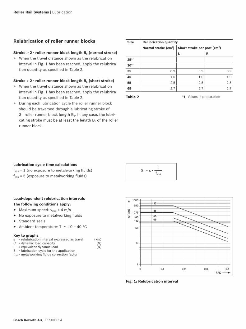
Stroke < 2 · roller runner block length B1 (short stroke) ▶ When the travel distance shown as the relubrication
interval in Fig. 1 has been reached, apply the relubrica-tion quantity as specified in Table 2.
▶ During each lubrication cycle the roller runner block should be traversed through a lubricating stroke of 3 · roller runner block length B1. In any case, the lubri-cating stroke must be at least the length B1 of the roller runner block.
Relubrication of roller runner blocks
Stroke ≥ 2 · roller runner block length B1 (normal stroke) ▶ When the travel distance shown as the relubrication
interval in Fig. 1 has been reached, apply the relubrica-tion quantity as specified in Table 2.
Load-dependent relubrication intervalsThe following conditions apply:
▶ Maximum speed: vmax = 4 m/s ▶ No exposure to metalworking fluids ▶ Standard seals ▶ Ambient temperature: T = 10 – 40 °C
Fig. 1: Relubrication interval
Key to graphss = relubrication interval expressed as travel (km)C = dynamic load capacity (N)F = equivalent dynamic load (N)ST = lubrication cycle for the applicationfKSS = metalworking fluids correction factor
Size Relubrication quantity
Normal stroke (cm3) Short stroke per port (cm3)
L R
25*)
30*)
35 0.9 0.9 0.9
45 1.0 1.0 1.0
55 2,5 2,5 2,5
65 2,7 2,7 2,7
Lubrication cycle time calculations ST = s ● fKSS = 1 (no exposure to metalworking fluids)
fKSS = 5 (exposure to metalworking fluids)
*) Values in preparation
Bosch Rexroth AG, R999000354
Roller Rail Systems | Lubrication

L R
Stroke < 2 · roller runner block length B1 (short stroke) ▶ Install and lubricate two lube fittings per roller runner
block, one on each of the two end caps!Initial lubrication is applied to each fitting in three partial quantities as specified in Table 3:
1. Grease each fitting on the roller runner block with the first partial quantity as per Table 3, pressing it in slowly with the help of a grease gun.
2. Slide the roller runner block back and forth over at least three times the block length for three full cycles.
3. Repeat steps 1. and 2. twice more.
4. Make sure there is a visible film of lubricant on the roller guide rail.
Stroke ≥ 2 · roller runner block length B1 (normal stroke) ▶ For initial lubrication, mount one lube fitting per roller
runner block, at either of the two end caps!Initial lubrication is applied in three partial quantities as specified in Table 3:
1. Grease the roller runner block with the first partial quantity as per Table 3, pressing it in slowly with the help of a grease gun.
2. Slide the roller runner block back and forth over at least three times the block length for three full cycles.
3. Repeat steps 1. and 2. twice more.
4. Make sure there is a visible film of lubricant on the roller guide rail.
Initial lubrication of the roller runner blocks (basic lubrication) We recommend applying initial lubrication with a manual grease gun before connecting the equipment to the centralized lubrication system. If initial lubrication is nevertheless carried out via the centralized lubrication system, it is essential that all lines and piston distributors should be filled. The pulse count can then be calculated from the partial quantities accord-ing to Table 3 and the piston distributor size according to Table 5.
Size Initial lubrication quantity
Normal strokePartial quantity (cm3)
Short strokePartial quantity per port (cm3)
L R
25*)
30*)
35 0.9 (3x) 0.9 (3x) 0.9 (3x)
45 1.0 (3x) 1.0 (3x) 1.0 (3x)
55 2,5 (3x) 2,5 (3x) 2,5 (3x)
65 2,7 (3X) 2,7 (3X) 2,7 (3X)
Table 3
Lubrication of the RSHPLiquid grease lubrication (NLGI 00, with centralized lubrication system via piston distributor)
Take note of “Lubrication Notes” section.
Liquid greaseWe recommend using Dynalub 520. For further information, see “Lubrication Notes” section.
Lube port end capL = left, R = right
*) Values in preparation
Bosch Rexroth AG, R999000354
Roller Rail Systems | Lubrication

0 0,1 0,2 0,3 0,4F/C
10
100
206
412
1000
1
124
82
s(k
m)
35
45
5565
Stroke < 2 · roller runner block length B1 (short stroke) ▶ Apply the minimum quantity according to Table 4 per
lube port until the relubrication interval as specified (in Fig. 2) has been reached. Calculate the required pulse count and lubricant cycle time in the same way as for relubrication (normal stroke).
▶ During each lubrication cycle the roller runner block should be traversed through a lubricating stroke of 3 · roller runner block length B1. In any case, the lubri-cating stroke must be at least the length B1 of the roller runner block.
Relubrication of roller runner blocks
Stroke ≥ 2 · roller runner block length B1 (normal stroke) ▶ Apply the minimum quantity according to Table 4 to the
lube port until the relubrication interval as specified (in Fig. 2) has been reached.
Part numberRoller runner blocks
Smallest permissible piston distributor size(≙ minimum pulse quantity) per port (cm3)
Size 25 30 35 45 55 65
R18 .. ... 2X – – 0,1 0,1 0,1 0,2
Table 5
Size Relubrication quantity
Normal stroke (cm3) Short stroke per port (cm3)
L R
25*)
30*)
35 0.9 0.9 0.9
45 1.0 1.0 1.0
55 2,5 2,5 2,5
65 2,7 2,7 2,7
Table 4
Load-dependent relubrication intervals The following conditions apply:
▶ Maximum speed: vmax = 4 m/s ▶ No exposure to metalworking fluids ▶ Standard seals ▶ Ambient temperature: T = 10 – 40 °C
Fig. 2: Relubrication interval
Notes: The required pulse count is the quotient (as a whole number) of the minimum relubrication quantity according to Table 4 and the selected piston distributor size according to Table 5. The smallest permissible piston distributor size is independent of the mounting orientation. The lubricant cycle time as per Formula 1 can then be obtained by dividing the relubrication interval (according to Fig. 2) by the calculated pulse count (see design calculation example).
Key to graphsni = number of pulses (-)VGrease = relubrication quantity according to Table 4 (cm3)Kv = piston distributor size according to Table 5 (cm3)sT = lubrication cycle (km)s = relubrication interval according to Fig. 2 (km)C = dynamic load capacity (N)F = equivalent dynamic load (N)ST = lubrication cycle for the applicationfKSS = metalworking fluids correction factor
ni = VGrease / Kv
Formula 1
Lubrication cycle time calculations 1
fKSS
1
ni
ST = s ● ●
fKSS = 1 (no exposure to metalworking fluids)fKSS = 5 (exposure to metalworking fluids)
*) Values in preparation
Bosch Rexroth AG, R999000354
Roller Rail Systems | Lubrication

Normal or short-stroke Normal stroke Stroke ≥ 2 ● roller runner block length B1
500 mm ≥ 2 x 79.6 mm 500 mm ≥ 159.2 mm i.e. normal stroke is applicable
Initial lubrication quantity 0.90 cm3 (3x) According to Table 3
Relubrication quantity VGrease = 0.90 cm3 According to Table 4
Permissible piston distributor size Kv = 0.1 cm3 According to Table 5
Number of pulses ni = VGrease / KV = 0.90 cm3 / 0.1 = 9 According to Formula 1
Load ratio F/C = 18,300 N/61,000 N = 0.30
Relubrication interval s = 100 km According to Fig. 2
Lubrication cycle sT = s / ni = 100 km / 9 = 11.11 km According to Formula 1
Exposure to contaminants No exposure to media: Chips, dust...
11
sT = s ● ●
19
Roller runner block 1851 323 2X
Dynamic load capacity C 61,000 N
Equivalent dynamic load on bearing F 18,300 N
Stroke 500 mm
Average linear speed vm 1.0 m/s
Temperature T 20 – 30 °C
Mounting orientation horizontal
Lubrication Single-line centralized lubrication system for allaxes with liquid grease Dynalub 520
Exposure to contaminants No exposure to fluids, chips, dust
Liquid grease lubrication (NLGI 00, with centralized lubrication system via piston distributor) (continued)
Calculation example:Given data:
Result:Every 11.10 km a minimum quantity of 0.1 cm3 Dynalub 520 must be supplied to the roller runner block.
Calculation of relubrication quantity:
Bosch Rexroth AG, R999000354
Roller Rail Systems | Lubrication

L R
Take note of “Lubrication Notes” section.
Oil lubricantWe recommend using Shell Tonna S3 M 220. For further information, see “Lubrication Notes” section.
Lube port end capL = leftR = right
Oil lubrication via single-line piston distributor systems
Stroke < 2 · roller runner block length B1 (short stroke) ▶ Install and lubricate two lube fittings per roller runner
block, one on each of the two end caps!Initial lubrication is applied in two partial quantities per lube fitting as specified in Table 6:
1. Oil the roller runner block per port with the first partial quantity as per Table 6.
2. Slide the roller runner block back and forth over at least three times the block length for three full cycles.
3. Repeat steps 1. and 2.
4. Make sure there is a visible film of lubricant on the roller guide rail.
Stroke ≥ 2 · roller runner block length B1 (normal stroke) ▶ For initial lubrication, mount one lube fitting per roller
runner block, at either of the two end caps!Initial lubrication is applied in two partial quantities as specified in Table 6:
1. Oil the roller runner block with the first partial quantity as per Table 6.
2. Slide the roller runner block back and forth over at least three times the block length for three full cycles.
3. Repeat steps 1. and 2.
4. Make sure there is a visible film of lubricant on the roller guide rail.
Size Initial lubrication quantity
Normal strokePartial quantity (cm3)
Short strokePartial quantity per port (cm3)
L R
25*)
30*)
35 1,3 (2x) 1,3 (2x) 1,3 (2x)
45 1,5 (2x) 1,5 (2x) 1,5 (2x)
55 2,0 (2x) 2,0 (2x) 2,0 (2x)
65 4,0 (2x) 4,0 (2x) 4,0 (2x)
Table 6
Lubrication of the RSHP
Initial lubrication of the roller runner blocks (basic lubrication) We recommend applying initial lubrication with a manual grease gun before connecting the equipment to the centralized lubrication system. If initial lubrication is nevertheless carried out via the centralized lubrication system, it is essential that all lines and piston distributors should be filled.
*) Values in preparation
Bosch Rexroth AG, R999000354
Roller Rail Systems | Lubrication

0 0,1 0,2 0,3 0,4F/C
10
100137
275
1000
1
s (k
m)
8255
35
45
5565
VOil = round 16.67 ● SAP ● Kv
vm ● tT
Stroke < 2 · roller runner block length B1 (short stroke) ▶ Install and lubricate two lube fittings per roller runner
block, one on each of the two end caps. ▶ Apply the minimum quantity according to Table 7 to the
lube port until the relubrication interval as specified has been reached. Calculate the actual quantity applied as described in Relubrication (normal stroke), and if neces-sary adjust the piston distributor size and/or cycle time.
▶ During the lubrication cycle the roller runner block should be traversed through a lubricating stroke of 3 · roller runner block length B1. In any case, the lubri-cating stroke must be at least the length B1 of the roller runner block.
Relubrication of roller runner blocks
Stroke ≥ 2 · roller runner block length B1 (normal stroke) ▶ Apply the minimum quantity according to Table 7 to the
lube port until the relubrication interval as specified has been reached.
Size Relubrication quantity Vmin
Normal stroke (cm3) Short stroke per port (cm3)
L R
25*)
30*)
35 1.3 1.3 1.3
45 1.5 1.5 1.5
55 2.0 2.0 2.0
65 4.0 4.0 4.0
Table 7
Load-dependent relubrication intervals The following conditions apply:
▶ Maximum speed: vmax = 4 m/s ▶ No exposure to metalworking fluids ▶ Standard seals ▶ Ambient temperature: T = 10 – 40 °C
Fig. 3: Relubrication interval
Notes: The actual amount applied in the relubrication interval is calculated taking into account the average speed, the piston distributor selected and the cycle time according to Formula 2. The quantity calculated must be greater than or equal to the relubrication quantity according to Table 7. Should this amount be lower, either the cycle time must be reduced and/or a larger piston distributor selected. The calculation process according to Formula 2 is then to be repeated.
Calculation of relubrication quantity
Key to graphsVOil = relubrication quantity applied in the relubrication
interval (cm3)Vmin = relubrication quantity (cm3)s = relubrication interval according to Fig. 3 (km)Kv = piston distributor size according to Table 8 (cm3)Vm = average linear speed (including waiting times) (m/s)tT = cycle time for the centralized lubrication system (min)C = dynamic load capacity (N)F = equivalent dynamic load (N)SAP = relubrication interval for the applicationfKSS = metalworking fluids correction factor
Formula 2
≥ Vmin according to Table 7
1
fKSS SAP = s ●
Calculation of the relubrication interval for the application
fKSS = 1 (no exposure to metalworking fluids)fKSS = 5 (exposure to metalworking fluids)
*) Values in preparation
Bosch Rexroth AG, R999000354
Roller Rail Systems | Lubrication

Lubrication of the RSHPOil lubrication via single-line piston distributor systems(continued)
Roller runner block size 35 45
Mounting orientation
Cycle time (min) Permissible piston distributor size (cm3)
Up to 30 0.06 0.06 0.10 0.10 0.10 0.16
30 to 60 0.10 0.10 0.20 0.16 0.16 0.40
60 to 90 0.16 0.16 0.40 0.20 0.20 0.40
90 to 120 0.20 0.20 0.40 0.40 0.40 0.40
> 120 0.40 0.40 0.40 0.40 0.40 0.40
On the usage of lube ports that are not offered by Rexroth for usage on the RSHP, an extension is imperative for all mounting orientations.
Mounting orientations:
horizontal
horizontal, top-down
vertical
wall attachment
Table 8
Roller runner block size 55 65
Mounting orientation
Cycle time (min) Permissible piston distributor size (cm3)
Up to 30 0.16 0.16 0.20 0.20 0.20 0.40
30 to 60 0.20 0.20 0.40 0.40 0.40 0.60
60 to 90 0.40 0.40 0.60 0.60 0.60 1.00
90 to 120 0.60 0.60 0.60 1.00 1.00 1.00
> 120 0.60 0.60 0.60 1.00 1.00 1.00
Bosch Rexroth AG, R999000354
Roller Rail Systems | Lubrication

Normal or short-stroke Normal stroke Stroke ≥ 2 ● roller runner block length B1
500 mm ≥ 2 x 79.6 mm 500 mm ≥ 159.2 mm i.e. normal stroke is applicable
Initial lubrication quantity 1.30 cm3 (2x) According to Table 6
Relubrication quantity VOil = 1.30 cm3 According to Table 7
Piston distributor size Kv = 0.06 cm3 According to Table 8
Load ratio F/C = 18,300 N/61,000 N = 0.30
Relubrication interval on exposureto metalworking fluids
SAP = 60 km ● =60 km ● = 12 kmAccording to Fig. 3
Relubrication quantity applied in therelubrication interval:
According to Formula 2
Result:The lubrication design with a piston distributor of 0.06 cm3 is inadequate, as the necessary relubrication quantity accor-ding to Table 7 of 1.30 cm3 is not applied during the relubrication interval. The calculation is to be repeated with a larger piston distributor.New piston distributor size selected Kv = 0.16 cm3
New calculated relubrication quantity applied in the relubrication interval
According to Formula 2
Roller runner block 1851 323 2X
Dynamic load capacity C 61,000 N
Equivalent dynamic load on bearing F 18,300 N
Stroke 500 mm
Average linear speed vm 1.0 m/s
Temperature T 20 – 30 °C
Mounting orientation Horizontal
Lubrication Single-line centralized lubrication system for all axes with oil Shell Tonna S3 M 220
Cycle time for the centralized lubrication system tT 20 min
Exposure to contaminants Exposure to metalworking fluids
Result:The lubrication design with a piston distributor of 0.16 cm3 is adequate, as the necessary relubrication quantity according to Table 7 of 1.30 cm3 is exceeded during the relubrication interval.
VOil = round 16.67 ● SAP ● Kv
vm ● tT
VOil = round 16.67 ● SAP ● Kv
vm ● tT
VOil = round 16.67 ● 12 ● 0.06
1.0 ● 20= 0.6 cm3
VOil = round 16.67 ● 12 ● 0.16
1.0 ● 20= 1.6 cm3
Calculation example:Given data:
Calculation of relubrication quantity:
1fKSS
15
Bosch Rexroth AG, R999000354
Roller Rail Systems | Lubrication

and on the roller runner block body at all four side lube ports: 7.5 cm3 each (3x)
Initial lubrication for size 125 (normal stroke)At one of the end face or side lube ports
on either of the two end caps: 25 cm3 (3x)
Lubrication using a grease gun or a progressive feeder system
Table 10
Stroke < 2 · roller runner block length B1 (short stroke) ▶ Install and lubricate two lube fittings per roller runner
block, one on each of the two end caps!Initial lubrication is applied to each fitting in three partial quantities as specified in Table 10:
1. Grease each fitting on the roller runner block with the first partial quantity as per Table 10, pressing it in slowly with the help of a grease gun.
2. to 4. Repeat the procedure as for initial lubrication (normal stroke).
Initial lubrication of the roller runner blocks (basic lubrication)
Stroke ≥ 2 · roller runner block length B1 (normal stroke) ▶ For initial lubrication, mount one lube fitting per roller
runner block, at either of the two end caps!Initial lubrication is applied in three partial quantities as specified in Table 10:
1. Grease the roller runner block with the first partial quantity as per Table 10, pressing it in slowly with the help of a grease gun.
2. Slide the roller runner block back and forth over at least three times the block length (size 125 at least 300 mm) for three full cycles.
3. Repeat steps 1. and 2. twice more.
4. Make sure there is a visible film of lubricant on the roller guide rail.
Size Initial lubrication
Normal strokePartial quantity (cm3)
Short strokePartial quantity per port (cm3)
left right
55/85 1.8 (3x) 1.8 (3x) 1.8 (3x)
65/10065 FXS
3.2 (3x) 3.2 (3x) 3.2 (3x)
100 15.0 (3x) 15.0 (3x) 15.0 (3x)
125 as shown in Fig. 10 Ports left, right and side as shown in Fig. 11
Fig. 10
and on the roller runner block body at all four side lube ports: 7.5 cm3 each (3x)
Initial lubrication for size 125 (short stroke)At two lube ports, one on each of the
two end caps:
Fig. 11
25 cm3 (3x) 25 cm3 (3x)
Take note of “Lubrication Notes” section.
Lubricating greaseWe recommend using Dynalub 510. For further information, see “Lubrication Notes” section.
Lubrication of the Heavy Duty Roller Rail System
Bosch Rexroth AG, R999000354
Roller Rail Systems | Lubrication

0 0,1 0,2 0,3 0,4F/C
10
30
100
150
1000
1
s (k
m)
65/100
100 + 125
55/85
or on the roller runner block body at all four side lube ports: 15 cm3 each
Relubrication for size 125 (normal stroke)At one of the end face or side lube ports
on either of the two end caps: 55 cm3
Stroke < 2 · roller runner block length B1 (short stroke) ▶ When the travel distance shown as the relubrication
interval in Fig. 14 has been reached, apply the relubri-cation quantity as specified in Table 11 per lube port.
▶ During each lubrication cycle the roller runner block should be traversed through a lubricating stroke of 3 · roller runner block length B1. In any case, the lubri-cating stroke must be at least the length B1 of the roller runner block.
Relubrication of roller runner blocks
Stroke ≥ 2 · roller runner block length B1 (normal stroke) ▶ When the travel distance shown as the relubrication
interval in Fig. 14 has been reached, apply the relubri-cation quantity as specified in Table 11.
Table 11
Fig. 12
On the roller runner block body at all four side lube ports: 15 cm3 each
Relubrication for size 125 (short stroke)
Fig. 13
Size Relubrication
Normal strokePartial quantity (cm3)
Short strokePartial quantity per port (cm3)
left right
55/85 1.8 1.8 1.8
65/10065 FXS
3.2 3.2 3.2
100 15.0 15.0 15.0
125 As shown in Fig. 12 Side ports as shown in Fig. 13
Load-dependent relubrication intervals (“dry axes”)
The following conditions apply: ▶ Maximum speed: vmax = 2 m/s ▶ No exposure to metalworking fluids ▶ Standard seals ▶ Ambient temperature: T = 10 – 40 °C
Fig. 14
Key to graphss = relubrication interval expressed as travel (km)C = dynamic load capacity (N)F = equivalent dynamic load (N)
Bosch Rexroth AG, R999000354
Roller Rail Systems | Lubrication

Take note of “Lubrication Notes” section.
Liquid greaseWe recommend using Dynalub 520. For further information, see “Lubrication Notes” section.
25 cm3 (3x) 25 cm3 (3x)
and on the roller runner block body at all four side lube ports: 7.5 cm3 each (3x)
Liquid grease lubrication via single-line piston distributor systems
Stroke < 2 · roller runner block length B1 (short stroke) ▶ Install and lubricate two lube fittings per roller runner
block, one on each of the two end caps!Initial lubrication is applied to each fitting in three partial quantities as specified in Table 12:
1. Grease each fitting on the roller runner block with the first partial quantity as per Table 12, pressing it in slowly with the help of a grease gun.
2. to 4. Repeat the procedure as for initial lubrication (normal stroke).
Stroke ≥ 2 · roller runner block length B1 (normal stroke) ▶ For initial lubrication, mount one lube fitting per roller
runner block, at either of the two end caps!Initial lubrication is applied in three partial quantities as specified in Table 12:
1. Grease the roller runner block with the first partial quantity as per Table 12, pressing it in slowly with the help of a grease gun.
2. Slide the roller runner block back and forth over at least three times the block length (size 125 at least 300 mm) for three full cycles.
3. Repeat steps 1. and 2. twice more.
4. Make sure there is a visible film of lubricant on the roller guide rail.
Table 12
Fig. 15
and on the roller runner block body at all four side lube ports: 7.5 cm3 each (3x)
Fig. 16
Initial lubrication of the roller runner blocks (basic lubrication) We recommend applying initial lubrication with a manual grease gun before connecting the equipment to the centralized lubrication system. If initial lubrication is nevertheless carried out via the centralized lubrication system, it is essential that all lines and piston distributors should be filled. The pulse count can then be calculated from the partial quantities and the piston distributor size according to Table 14.
Initial lubrication for size 125 (normal stroke)At one of the end face or side lube ports
on either of the two end caps: 25 cm3 (3x)
Initial lubrication for size 125 (short stroke)At two lube ports, one on each of the
two end caps:
Size Initial lubrication
Normal strokePartial quantity (cm3)
Short strokePartial quantity per port (cm3)
left right
55/85 1.8 (3x) 1.8 (3x) 1.8 (3x)
65/10065 FXS
3.2 (3x) 3.2 (3x) 3.2 (3x)
100 15.0 (3x) 15.0 (3x) 15.0 (3x)
125 As shown in Fig. 15 Ports left, right and side as shown in Fig. 16
Lubrication of the Heavy Duty Roller Rail System
Bosch Rexroth AG, R999000354
Roller Rail Systems | Lubrication

0 0,1 0,2 0,3 0,4F/C
1
10
75
22,5
112,5100
1000
s (k
m)
65/100
100 + 125
55/85
or on the roller runner block body at all four side lube ports: 15 cm3 each
Stroke < 2 · roller runner block length B1 (short stroke) ▶ Apply the minimum quantity according to Table 13 per
lube port until the relubrication interval as specified (in Fig. 19) has been reached. Calculate the required pulse count and lubricant cycle time in the same way as for relubrication (normal stroke).
▶ During each lubrication cycle the roller runner block should be traversed through a lubricating stroke of 3 · roller runner block length B1. In any case, the lubri-cating stroke must be at least the length B1 of the roller runner block.
Relubrication of roller runner blocks
Stroke ≥ 2 · roller runner block length B1 (normal stroke) ▶ Apply the minimum quantity according to Table 13 to
the lube port until the relubrication interval as specified (in Fig. 19) has been reached.
Fig. 17
On the roller runner block body at all four side lube ports: 15 cm3 each
Relubrication for size 125 (short stroke)
Fig. 18
Relubrication for size 125 (normal stroke)At one of the end face or side lube ports
on either of the two end caps: 55 cm3
Size Relubrication
Normal stroke (cm3) Short stroke per port (cm3)
left right
55/85 1.8 1.8 1.8
65/10065 FXS
3.2 3.2 3.2
100 15.0 15.0 15.0
125 As shown in Fig. 17 Side ports as shown in Fig. 18
Table 13
NotesThe required pulse count is the quotient (as a whole num-ber) of the minimum relubrication quantity according to Table 13 and the smallest permissible piston distributor size (≙ the minimum pulse quantity) according to Table 14. The smallest permissible piston distributor size also depends on the mounting orientation. The lubricant cycle time can then be obtained by dividing the relubrication interval (according to Fig. 19) by the calculated pulse count (see design calculation example).
Load-dependent relubrication intervals (“dry axes”)
The following conditions apply: ▶ Maximum speed: vmax = 2 m/s ▶ No exposure to metalworking fluids ▶ Standard seals ▶ Ambient temperature: T = 10 – 40 °C
Fig. 19
Key to graphss = relubrication interval expressed as travel (km)C = dynamic load capacity (N)F = equivalent dynamic load (N)
Bosch Rexroth AG, R999000354
Roller Rail Systems | Lubrication

Roller runner blocks Smallest permissible piston distributor size (≙ minimum pulse quantity) per lube port (cm3) for liquid grease, NLGI class 00
Size
55/85 65/100/65 FXS 100 125
Part numbers Mounting orientations
R18.. ... 10 or ... 60 Horizontal I, IV 0.1 0.2 0.3 1.5
Vertical II, V 0.1 0.2 0.3 1.5
Wall mounting III, VI 0.1 0.2 0.3 (2x)2) 0.3 (2x)2)3)
Smallest permissible piston distributor sizes for liquid grease lubrication through single-line centralized systems1)
Horizontal1 lube port at either of the two end caps
Mounting orientation I – normal stroke Mounting orientation II – normal stroke Mounting orientation III – normal stroke
Mounting orientation IV – short stroke Mounting orientation V – short stroke Mounting orientation VI – short stroke
Horizontal, top-downSame port
Horizontal, top-downSame port
Horizontal2 lube ports, one on each of the two end caps
Vertical to inclined horizontal2 lube ports, one on each of the two end caps (top and bottom)
Vertical to inclined horizontal1 lube port at top end cap
Vertical to inclined, top-downSame port
Vertical to, top-downSame port
Wall mounting2 lube ports, one on each of the two end caps
Wall mounting1 lube port at either of the two end caps
1) The following conditions apply: Liquid grease Dynalub 520 (or Castrol Longtime PD 00, or Elkalub GLS 135/N00) and piston distributors from SKF
2) Sizes 100 and 125: Either two pulses in short succession or two metering valves delivering one pulse simultaneously3) Size 125: 0.3 cm3 per port when all four ports in the roller runner block body are used
0° to max. ±90°
0° to max. ±90°
0° to max. ±90°
0° to max. ±90°
Liquid grease lubrication via single-line piston distributor systems (continued)
Table 14
Lubrication of the Heavy Duty Roller Rail System
Bosch Rexroth AG, R999000354
Roller Rail Systems | Lubrication

Take note of “Lubrication Notes” section.
Oil lubricantWe recommend using Shell Tonna S3 M 220. For further information, see “Lubrication Notes” section.
and on the roller runner block body at all four side lube ports: 9 cm3 each (1x)
Oil lubrication via single-line piston distributor systems
Stroke < 2 · roller runner block length B1 (short stroke) ▶ Install and lubricate two lube fittings per roller runner
block, one on each of the two end caps!
Initial lubrication is applied in two partial quantities per lube fitting as specified in Table 15:
1. Apply the first of the oil quantities as specified in Table 15 to the roller runner block.
2. to 4. Repeat the procedure as for initial lubrication (normal stroke).
Stroke ≥ 2 · roller runner block length B1 (normal stroke) ▶ For initial lubrication, mount one lube fitting per roller
runner block, at either of the two end caps!
Initial lubrication is applied in two partial quantities as specified in Table 15:
1. Apply the first of the oil quantities as specified in Table 15 to the roller runner block.
2. Slide the roller runner block back and forth over at least three times the block length (size 125 at least 300 mm) for three full cycles.
3. Repeat steps 1. and 2.
4. Make sure there is a visible film of lubricant on the roller guide rail.
Fig. 20
and on the roller runner block body at all four side lube ports: 9 cm3 each (1x)
Fig. 21
Initial lubrication of the roller runner blocks (basic lubrication)We recommend applying initial lubrication with a manual grease gun before connecting the equipment to the centra-lized lubrication system.
Initial lubrication for size 125At one of the end face or side lube ports
on either of the two end caps: 38 cm3 (1x)
Initial lubrication for size 125At two lube ports, one on each of the
two end caps:
38 cm3 (1x) 38 cm3 (1x)
Size Initial lubrication
Normal strokePartial quantity (cm3)
Short strokePartial quantity per port (cm3)
left right
55/85 2.7 (2x) 2.7 (2x) 2.7 (2x)
65/10065 FXS
4.8 (2x) 4.8 (2x) 4.8 (2x)
100 11.0 (2x) 11.0 (2x) 11.0 (2x)
125 As shown in Fig. 20 Ports left, right and side as shown in Fig. 21
Table 15
If initial lubrication is nevertheless carried out via the cen-tralized lubrication system, it is essential that all lines and piston distributors should be filled. The pulse count can then be calculated from the partial quantities and the piston distributor size according to Table 17.
Lubrication of the Heavy Duty Roller Rail System
Bosch Rexroth AG, R999000354
Roller Rail Systems | Lubrication

0 0,1 0,2 0,3 0,4F/C
10
15
5075
100
1000
1
s (k
m)
65/100
100 + 125
55/85
or on the roller runner block body at all four side lube ports: 9 cm3 each
Relubrication for size 125At one of the lube ports on either of
the two end caps: 38 cm3
Stroke < 2 · roller runner block length B1 (short stroke) ▶ Apply the minimum quantity according to Table 16
to the lube port until the relubrication interval as specified (in Fig. 24) has been reached. Calculate the required pulse count and lubricant cycle time in the same way as for relubrication (normal stroke).
▶ During each lubrication cycle the roller runner block should be traversed through a lubricating stroke of 3 · roller runner block length B1. In any case, the lubri-cating stroke must be at least the length B1 of the roller runner block.
Relubrication of roller runner blocks
Stroke ≥ 2 · roller runner block length B1 (normal stroke) ▶ Apply the minimum quantity according to Table 16 to the
lube port until the relubrication interval as specified (in Fig. 24) has been reached.
Fig. 22
On the roller runner block body at all four side lube ports: 9 cm3 each
Relubrication for size 125
Fig. 23
Size Relubrication
Normal stroke (cm3) Short stroke per port (cm3)
left right
55/85 2.7 2.7 2.7
65/10065 FXS
4.8 4.8 4.8
100 11.0 11.0 11.0
125 As shown in Fig. 22 Side ports as shown in Fig. 23
Table 16
NotesThe required pulse count is the quotient (as a whole num-ber) of the minimum relubrication quantity according to Table 16 and the smallest permissible piston distributor size (≙ minimum pulse quantity) according to Table 17. The smallest permissible piston distributor size also depends on the mounting orientation. The lubricant cycle time can then be obtained by dividing the relubrication interval (according to Fig. 24) by the calculated pulse count.
Load-dependent relubrication intervals ("dry axes")
The following conditions apply: ▶ Maximum speed: vmax = 2 m/s ▶ No exposure to metalworking fluids ▶ Standard seals ▶ Ambient temperature: T = 20 – 30 °C
Fig. 24
Key to graphss = relubrication interval expressed as travel (km)C = dynamic load capacity (N)F = equivalent dynamic load (N)
Bosch Rexroth AG, R999000354
Roller Rail Systems | Lubrication

Horizontal1 lube port at either of the two end caps
Mounting orientation I – normal stroke Mounting orientation II – normal stroke Mounting orientation III – normal stroke
Mounting orientation IV – short stroke Mounting orientation V – short stroke Mounting orientation VI – short stroke
Horizontal, top-downSame port
Horizontal, top-downSame port
Horizontal2 lube ports, one on each of the two end caps
Vertical to inclined horizontal2 lube ports, one on each of the two end caps (top and bottom)
Vertical to inclined horizontal1 lube port at top end cap
Vertical to inclined, top-downSame port
Vertical to inclined, top-downSame port
Wall mounting2 lube ports, one on each of the two end caps
Wall mounting1 lube port at either of the two end caps
0° to max. ±90°
0° to max. ±90°
0° to max. ±90°
0° to max. ±90°
Roller runner blocks Smallest permissible piston distributor size (≙ minimum pulse quantity) per lube port (cm3) for oil viscosity 220 mm2/s
Size
Part numbers Mounting orientations 55/85 65/100/65 FXS 100 125
R18.. ... 10 or ... 60 Horizontal I, IV 0.6 0.6 1.5 1.5
Vertical II, V 0.6 0.6 1.5 1.5
Wall mounting III, VI 1.0 1.5 1.5 (3x)2) 1.5 (3x)2)3)
Smallest permissible piston distributor sizes for oil lubrication via single-line centralized systems1)
1) The following conditions apply: Lube oil Shell Tonna S3 M 220 using piston distributors from SKF 2) Sizes 100 and 125: Either three pulses in short succession or three metering valves delivering one pulse simultaneously3) Size 125: 1.5 cm3 per port when all four ports in the roller runner block body are used
Oil lubrication via single-line piston distributor systems (continued)
Table 17
Lubrication of the Heavy Duty Roller Rail System
Bosch Rexroth AG, R999000354
Roller Rail Systems | Lubrication

Design variables Design input (per roller runner block) Information sources
Normal or short-stroke Normal stroke: Stroke ≥ 2 · roller runner block length B1
800 mm ≥ 2 · 204 mm? 800 mm ≥ 408 mm! i.e. normal stroke applicable!
Normal stroke formula from catalog, B1 from catalog
Initial lubrication quantity Initial lubrication quantity: 15.0 cm3 (3x) Initial lubrication quantity from table
Relubrication quantity Relubrication quantity: 15.0 cm3 Relubrication quantity from table
Mounting orientation Mounting orientation I – normal stroke (horizontal) Mounting orientation from catalog
Piston distributor size Permissible piston distributor size: 0.3 cm3 Piston distributor size from table for size 100, mounting orientation I
Pulse countPulse count = = 50
15.0 cm3
0.3 cm3 Pulse count =
Relubrication quantity
Perm. piston distributor size
Load ratioLoad ratio = = 0.25
115,250 N
461,000 N Load ratio =
F
C
F and C from given data in catalog
Relubrication interval Relubrication interval: 10 km Relubrication interval from figure Curve size 100 at load ratio 0.25
Lubrication cycleLubrication cycle = = 0.2 km
10 km
50 Lubrication cycle =
Relubrication interval
Pulse count
X-axisDesign example for lubrication of a typical 2-axis application with centralized lubrication
Component or parameter Given data
Roller runner block Size 100; 4 blocks; C = 461,000 N; part number: R1861 223 10
Roller guide rail Size 100; 2 rails; L = 1,500 mm; part number: R1835 263 61
Equivalent dynamic load on bearing F = 115,250 N (per roller runner block) taking into account the preload (in this case 8% C)
Stroke 800 mm
Average linear speed vm = 1 m/s
Temperature 20 to 30 °C
Mounting orientation Horizontal
Lubrication Single-line centralized lubrication system for all axes with liquid grease Dynalub 520
Exposure to contaminants No exposure to fluids, chips, dust
Interim result (X-axis)
Every 0.2 km a minimum quantity of 0.3 cm3 Dynalub 520 must be supplied to the roller runner block on the X-axis.
Bosch Rexroth AG, R999000354
Roller Rail Systems | Lubrication

Design variables Design input (per roller runner block) Information sources
Normal or short-stroke Normal stroke: Stroke ≥ 2 · roller runner block length B1
300 mm ≥ 2 · 194 mm? 300 mm < 388 mm! i.e. short stroke applicable!
Normal stroke formula from catalog, B1 from catalog
Initial lubrication quantity 2 lube ports, initial lubrication quantity per lube port: 3.2 cm3 (3x)
Initial lubrication quantity from table
Relubrication quantity 2 lube ports, relubrication quantity per port: 3.2 cm3 Relubrication quantity from table
Mounting orientation Mounting orientation V – short stroke (vertical) Mounting orientation from catalog
Piston distributor size Permissible piston distributor size: 0.2 cm3 Piston distributor size from table for size 65/100, mounting orientation V
Pulse countPulse count = = 16
3.2 cm3
0.2 cm3 Pulse count =
Relubrication quantity
Perm. piston distributor size
Load ratioLoad ratio = = 0.25
66,375 N
265,500 N Load ratio =
F
C
F and C from given data in catalog
Relubrication interval Relubrication interval: 30 km Relubrication interval from figure Curve size 65/100 at load ratio 0.25
Lubrication cycleLubrication cycle = = 1.875 km
30 km
16 Lubrication cycle =
Relubrication interval
Pulse count
Design example for lubrication of a typical 2-axis application with centralized lubrication (continued)Y-axis
Component or parameter Given data
Roller runner block Size 65/100; 4 blocks; C = 265,500 N; part number: R1851 323 10
Roller guide rail Size 65/100; 2 rails; L = 1,500 mm; part number: R1875 663 61
Equivalent dynamic load on bearing F = 66,375 N (per roller runner block) taking into account the preload
Stroke 300 mm
Average linear speed vm = 1 m/s
Temperature 20 to 30 °C
Mounting orientation Vertical
Lubrication Single-line centralized lubrication system for all axes with liquid grease Dynalub 520
Exposure to contaminants No exposure to fluids, chips, dust
End result (two-axis lubrication)
Since both the axes in this example are supplied by a single-line centralized lubrication system, the X-axis with its smaller lube cycle (0.2 km) determines the overall cycle of the system, i.e. the Y-axis will also be lubricated every 0.2 km. The number of ports and the minimum lubricant quantities determined for each axis remain the same.
Interim result (Y-axis)
Every 1.875 km a minimum quantity of 0.2 cm3 Dynalub 520 must be supplied to the roller runner block on the Y-axis.
Lubrication of the Heavy Duty Roller Rail System
Bosch Rexroth AG, R999000354
Roller Rail Systems | Lubrication

Bosch Rexroth AG, R999000354
Roller Rail Systems | Lubrication
Tmax
Ø 1,5
2,5
Subsequent opening of a lube hole at the top for heavy duty roller runner blocks sizes 100 and 65 FXSIf a lube hole is to be opened up at the top of heavy duty roller runner blocks, the following points should be noted:
In the O-ring recess there is a further pre-formed small recess (5). Do not use a drill to open this. Risk of contamination!
▶ Heat up a pointed metal punch (4) with diameter of 1.5 mm.
▶ Carefully punch through the recess (5) to open the lube hole. Do not exceed the permissible depth Tmax as specified in the table!
▶ Insert O-ring (2) in the recess (O-ring is not supplied with the roller runner block).
Size Lube hole at top: Maximum permitted depth for punching open
Tmax (mm)
65 FXS,100
5
Roller runner block FNSR186. ... 10 or ... 60
flanged, normal, standard height(example)
3
3
2
2
1

Cleaning cycle Dirt can settle and encrust on roller guide rails, especially when these are not enclosed.To ensure that seals and cover strips retain their functionality, this dirt must be removed at regular intervals.It is advisable to run the machine through at least one full cleaning cycle over the entire installed rail length every 8 hours.Depending on the amount of soiling and on the coolant used, more frequent cleaning may be required.
Before shutting down the machine, always apply 3 lubrication pulses or lubrication strokes. The lubrication pulses should be applied during the movement of the axis over the largest possible travel (cleaning cycle).
Maintenance of accessories All accessories used for scraping or wiping the roller guide rails must be checked at regular intervals.In environments with heavy contamination, it is advisable to replace all the parts directly exposed to such contamination.We recommend checking the accessories at least once a year.
Maintenance
Bosch Rexroth AG, R999000354
Roller Rail Systems | Lubrication