trainingssystem mms 4.0 | r901429162/04.16 - bosch rexroth
TRANSCRIPT
R901429162/04.16
Operating manual
Replaces: R901429162/09.15 English
Training system mMS 4.0
This information is intended to describe the product.
If this information is to be applied, it only serves
as possible applications and suggestions.
Catalog information is not guaranteed features
of the product. The information provided does not
release the user from the obligation to conduct his
own assessments and tests. Our products
are subject to a natural process of wear and aging.
This document, as well as the data, specifications
and other information set forth in it, are the
exclusive property of Bosch Rexroth AG. We retain
all rights of use, including the rights of reproduction
and distribution.
An example configuration is shown on the
title page. The delivered product may differ from
the illustration.
Original operating instructions
Training system mMS 4.0 | R901429162/04.16 Bosch Rexroth AG 3/68
Contents
Contents
1 About this documentation ...................................................................... 5
1.1 Validity of the documentation ................................................................ 5 1.2 The following signs and symbols are used in this manual: ..................... 5 1.3 Required and supplementary documentation ....................................... 5 1.4 Layout of documentation ....................................................................... 5
1.4.1 Safety instructions ........................................................................ 5 1.4.2 Symbols ......................................................................................... 6 1.4.3 Abbreviations ................................................................................ 7
2 Safety instructions .................................................................................. 8 2.1 About this chapter .................................................................................. 8 2.2 Intended use ........................................................................................... 8 2.3 Improper use .......................................................................................... 8 2.4 Staff qualification ................................................................................... 9
2.4.1 Firms offering apprenticeships ..................................................... 9 2.4.2 Transport, set-up, installation and commissioning ..................... 10 2.4.3 Troubleshooting, maintenance and repair ................................. 10
2.5 General safety instructions ................................................................... 11 2.6 Product- and technology-dependent safety instructions ..................... 12 2.7 Personal protective equipment ............................................................ 13 2.8 Duties of the operator .......................................................................... 13 2.9 Safety installations ............................................................................... 14 2.10 Operator operating positions .......................................................... 15
3 General instructions concerning property damage and product damage 16 4 Scope of supply ..................................................................................... 17 5 About this product ................................................................................ 18
5.1 General information ............................................................................. 18 5.2 Product Description .............................................................................. 18
Control box left side - exterior .................................................................. 19 Control box right side - exterior ................................................................ 19 5.2.1 Rack, work piece detection station ............................................. 20 Control box ................................................................................................ 21 5.2.2 Processing with press station ...................................................... 22 Control box ................................................................................................ 23 Circuit diagram for hydraulic press ........................................................... 23 Hydraulic power unit description .............................................................. 24 5.2.3 High rack storage station ........................................................ 25 Control box ................................................................................................ 26 Zero point reference position ................................................................... 27 5.2.4 Conveyor R901371451 ................................................................ 28 5.2.5 Separating rack R115801073 ...................................................... 28 Filling the racks .......................................................................................... 29 5.2.6 Picking unit R115801073 ............................................................. 30 5.2.7 Sensors ........................................................................................ 30 5.2.8 Light conductor R115801073 ...................................................... 31 5.2.9 Machine control panel VAM 40 R115801080 ............................. 31 5.2.10 Maintenance unit R480318553 .............................................. 32 5.2.11 Light barrier R901396882 ....................................................... 32 5.2.12 Pinning unit R115701062 ....................................................... 33 Replenishing pins ...................................................................................... 33
4/68 Bosch Rexroth AG Training system mMS 4.0 | R901429162/04.16
Contents
5.2.13 Portal R115701064 ................................................................. 34 5.2.14 Press R115701072................................................................... 35 5.2.15 High-stack storage R115701074 ............................................. 35
6 Technical data and dimensions ............................................................. 36 6.1 Technical data ....................................................................................... 36
6.1.1 Training system mMS 4.0 ............................................................ 36 6.2 Identification of the mMS 4.0 training system ...................................... 37
7 Operating and display elements ........................................................... 38 7.1 EMERGENCY STOP button ..................................................................... 38 7.2 Operating elements on the training system ......................................... 39
7.2.1 Machine control panel VAM ........................................................ 39 7.2.2 HMI small operating panel VCP ................................................... 40
8 Transport and storage .......................................................................... 41 8.1 Delivery and unpacking ......................................................................... 41 8.2 Transport ............................................................................................... 42
8.2.1 Transport inside the building ....................................................... 42 8.2.2 Transporting between two buildings ........................................... 43
8.3 Storage .................................................................................................. 44 9 Set-up, installation and commissioning ................................................ 45
9.1 Setting up the mMS 4.0 training system ............................................... 45 9.2 Check the pneumatic supply ................................................................. 46 9.3 Check electric installation ..................................................................... 47 9.4 Installing installation and stations......................................................... 48 9.5 Commissioning the training system ...................................................... 52 9.6 Check the EMERGENCY STOP circuit ..................................................... 52
10 Description of the operating functions ................................................. 53 10.1 Select the operating mode ............................................................... 53 10.2 Manual mode operation .................................................................. 54 10.3 Operating Single Step mode ............................................................. 54 10.4 Automatic mode operation .............................................................. 55 10.5 Homing mode operation .................................................................. 56 10.6 „Check Stock“ function ..................................................................... 56 10.7 „Clear Stock“ function ...................................................................... 56 10.8 Description of the buttons ............................................................... 57
11 Fault assistance .................................................................................... 59 11.1 Faults ................................................................................................ 59 11.2 Troubleshooting ............................................................................... 60
12 Maintenance and inspection ................................................................ 61 12.1 General information ......................................................................... 61 12.2 Maintenance and inspection schedule ............................................. 62
13 Maintenance work ................................................................................ 63 13.1 General information ......................................................................... 63 13.2 Maintenance schedule ..................................................................... 64
13.2.1 Working materials, consumables, tools, measuring devices .. 64 13.2.2 Replace parts .......................................................................... 65
14 Disposal ................................................................................................ 65 15 Declaration of conformity ..................................................................... 66
Training system mMS 4.0 | R901429162/04.16 Bosch Rexroth AG 5/68
About this documentation
1 About this documentation
1.1 Validity of the documentation
This documentation describes the “mMS 4.0” training system.
For reasons of simplicity, we refer to it as “mMS 4.0” in the following.
This documentation is intended for assemblers, operators, service technicians
and the system end-user.
This documentation contains important information on how to assemble,
transport, commission, operate, use, maintain and disassemble the product safely
and properly and to resolve simple faults independently.
Read the documentation in full, in particular, the “Safety information” chapter
before you start working with the product.
1.2 The following signs and symbols are used in this manual:
Activity symbol: The text next to this symbol describe activities which are
to be carried out from top to bottom in the indicated sequence.
1.3 Required and supplementary documentation
In addition to this manual on the (turnkey) mMS 4.0 training system, the following
additional documentation applies:
All user manuals for the components.
These can be viewed on the enclosed CD.
Documentation about mMS 4.0 from Bosch Rexroth.
1.4 Layout of documentation
To be able to use this documentation quickly and safely, standard safety
instructions, symbols, terms and abbreviations are used. These are explained
in the following sections to aid understanding.
1.4.1 Safety instructions
This documentation contains safety information prior to the directions whenever
there is a risk of personal injury or damage to equipment. The measures
described to avert danger must be observed.
6/68 Bosch Rexroth AG Training system mMS 4.0 | R901429162/04.16
About this documentation
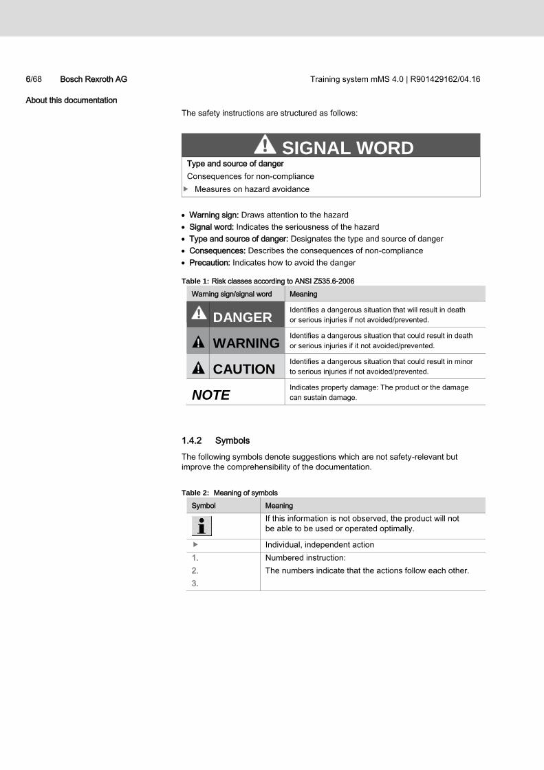
The safety instructions are structured as follows:
Warning sign: Draws attention to the hazard
Signal word: Indicates the seriousness of the hazard
Type and source of danger: Designates the type and source of danger
Consequences: Describes the consequences of non-compliance
Precaution: Indicates how to avoid the danger
Table 1: Risk classes according to ANSI Z535.6-2006
Warning sign/signal word Meaning
DANGER Identifies a dangerous situation that will result in death
or serious injuries if not avoided/prevented.
WARNING Identifies a dangerous situation that could result in death
or serious injuries if it not avoided/prevented.
CAUTION Identifies a dangerous situation that could result in minor
to serious injuries if not avoided/prevented.
NOTE Indicates property damage: The product or the damage
can sustain damage.
1.4.2 Symbols
The following symbols denote suggestions which are not safety-relevant but
improve the comprehensibility of the documentation.
Table 2: Meaning of symbols
Symbol Meaning
If this information is not observed, the product will not
be able to be used or operated optimally.
Individual, independent action
1.
2.
3.
Numbered instruction:
The numbers indicate that the actions follow each other.
SIGNAL WORD Type and source of danger
Consequences for non-compliance
Measures on hazard avoidance

Training system mMS 4.0 | R901429162/04.16 Bosch Rexroth AG 7/68
About this documentation
1.4.3 Abbreviations
The following abbreviations are used in this documentation:
Table 3: Abbreviations
Abbreviation Meaning
OCE Open Core Engineering
mMS 4.0 Modular Mechatronics System for Industry 4.0
Smart Device Android or iOS smart phone or tablet
HMI Human Machine Interface
Station One of three mMS 4.0 stations
Installation All three mMS 4.0 stations together
MDI Machine Data Interface, CNC manual data entry
8/68 Bosch Rexroth AG Training system mMS 4.0 | R901429162/04.16
Safety instructions
2 Safety instructions
2.1 About this chapter
The mMS 4.0 training system has been manufactured in accordance with
the general rules of technology. Nevertheless, there is the danger of personal
injury or property damage if this chapter and the safety instructions in this
documentation are not observed.
Read this documentation fully and thoroughly before you work with
the mMS 4.0 training system.
Keep the documentation in a place where there are available to all users
at any time.
Whenever passing on the Training system to third parties, include the required
documentation.
2.2 Intended use
The mMS 4.0 training system is a mechanical and electrical system with
pneumatics and/or hydraulics systems.
It may only be used to impart knowledge and expertise of advanced technical
education in the high-level programming language area and control engineering.
With respect to the set-up of whole assemblies and simulations, only the devices
and device sets are only used for the mMS 4.0 training system.
Operation is only permitted under the indicated operating conditions.
The mMS 4.0 training system is only intended for professional and not
for private use.
The mMS 4.0 training system made by Bosch Rexroth has been designed and
is intended for industrial power supply networks. Supplying the demo system
from different supply network requires additional disturbance suppression
measures (line filter, throttles, etc.).
Intended use also includes having thoroughly read and understood the safety
regulations, product information and operating instructions below, in particular,
the “Safety instructions”.
2.3 Improper use
Any other use than that described under intended use, is not intended use and
is therefore not authorized.
If unsuitable products are installed in safety-relevant applications, unintended
operating states may arise in the application which could cause personal injury
and/or property damage. Therefore, only use the product in safety-relevant
applications if such a use is specified and allowed in the product documentation.
For example in explosion-protected areas or in safety-relevant parts of a control
(functional safety).
Bosch Rexroth AG cannot assume liability for damage in the event of improper use
of the product. The user is solely responsible for the risks due to improper use.
Training system mMS 4.0 | R901429162/04.16 Bosch Rexroth AG 9/68
Safety instructions
Improper use of the product is defined as in particular
Failing to the mMS 4.0 training system seriously in an appropriate manner
during the exercises and outside of lesson time,
Using the parts in a different training system,
Connecting or using other devices or device sets than that authorized
for the mMS 4.0 training system,
Combining or modifying pneumatic pressure circuits.
Supplying the system without supplementary disturbance suppression
measures (filters, throttles, etc) from non-industrial supply networks.
2.4 Staff qualification
2.4.1 Firms offering apprenticeships
Students and apprentices may only work on the mmS 4.0 training system:
Under direct supervision,
after being given appropriate instructions
by a instructor or trained member of staff.
The instructor working with the mMS 4.0 training system must be a trained
specialist familiar with the electrical pneumatic and mechanical device and
the mechatronics field.
The instructor must
give clear instructions when students or participants in the training program
are required to install control circuits in the mMS 4.0 training system,
inspect the installation and functional effects of the control circuit ensuring
safe use before switch on,
answers questions in a clear, understandable way.
Trained members of staff may also be used to supervise the mMS 4.0 training
system during the exercises.
These are qualified persons to be trained and instructed about:
the information given,
possible dangers in the event of improper use,
safeguards and safety measures.
Instructor
Trained personnel
10/68 Bosch Rexroth AG Training system mMS 4.0 | R901429162/04.16
Safety instructions
2.4.2 Transport, set-up, installation and commissioning
Work on the mMS 4.0 training system such as set-up, connection,
commissioning, and repair must only be performed by experts or persons with
sufficient qualifications and authorization who have been instructed to do so.
Persons instructed to work on the mMS 4.0 training system must be able to follow
the information in this documentation, and also, in the event of missing
information, and supplement missing information independently on account
of their professional qualifications.
2.4.3 Troubleshooting, maintenance and repair
Maintenance, repair, troubleshooting and fault removal require particular
knowledge. This work may only be performed by trained skilled workers!
Work on the electrical equipment must only be performed by a qualified
felectrician.
A qualified electrician is someone who can recognize possible hazards and
implement the appropriate safety measures due to their professional training,
knowledge, and experience, as well as their understanding of the relevant
conditions pertaining to the work to be done.
Only skilled personnel with special expertise and experience in pneumatic
components are allowed to work on the pneumatic system. Special knowledge
of pneumatics means that personnel must
– be able to read and understand pneumatic plans completely,
– in particular, fully understands the interdependencies of the installed safety
installations and
– are familiar with the function and arrangement of pneumatic components.
Only skilled personnel with special expertise in and experience of hydraulic
components are allowed to work in the hydraulics system. Specialist knowledge
of hydraulics means that the employee must
– be able to read and understand hydraulic plans completely,
– in particular, fully understands the interdependencies of the installed safety
installations and
– be familiar with the function and arrangement of hydraulic components.
Training system mMS 4.0 | R901429162/04.16 Bosch Rexroth AG 11/68
Safety instructions
2.5 General safety instructions
Follow the valid regulations on accident prevention and environmental
protection.
Observe the safety regulations and provisions of the country in which
the product is used.
Only use Rexroth products when they are in a technically faultless condition.
Observe all information about the product.
Persons permitted to assemble, operate, disassemble or maintain Rexroth
products must not be under the influence of alcohol, other drugs or medication
which can impair responsiveness when doing so.
Only use accessories or spare parts approved by the manufacturer to prevent
hazards to persons owing to unsuitable spare parts.
Adhere to the technical data and environmental conditions given in the product
documentation.
If unsuitable products are installed or used in safety-relevant applications,
unintended operating states may arise in the application which could cause
personal injury and/or property damage. Therefore, only use the product in
safety-relevant applications if such a use is specified and allowed in the product
documentation.
You may only put the product into operation after it has been established that
the end product (e.g. a machine or installation) in which the Rexroth products
are fitted, meet the country-specific regulations, safety regulations and
standards for the application.
The product must not be put into operation unless this operating manual has
been read and understood.
12/68 Bosch Rexroth AG Training system mMS 4.0 | R901429162/04.16
Safety instructions
2.6 Product- and technology-dependent safety instructions
WARNING High electrical voltage
Danger to life, danger of injury due to electrical shock or severe injury!
Always de-energize the installation.
Secure the installation against being switched on accidentally.
Do not operate a device terminal box or sockets which are not connected
to the power supply (fuse boxes) of the mMS 4.0 training system. All of the
components not powered by the device's own electrical control boxes, but
using components (in use) installed in the mMS 4.0 training system are
unaffected by an EMERGENCY STOP circuit (and OFF switch). The mains
voltage continues to apply in the electrical control box.
Do not open the electrical control box. If opening is necessary, only have
the electrical control box open by a qualified electrician.
When connecting additional consumers to the mMS 4.0 training system, only
use ones approved by the manufacturer.
Only operate the mMS 4.0 training system from a supply with a functioning FI
circuit-breaker or protective earthing.
The energy cables which carry 230 V AC must not be disconnected from
the drive while the system is in operation.
Manipulated and/or non-functioning safety devices and safeguards!
Major risk of injury
Shut off the installation immediately.
Skilled personnel must remedy the fault or manipulation immediately.
Hazard caused by incorrect assembly and installation
Major risk of injury during live operation!
Assembly works and commissioning work may only be carried out
by employees at Bosch Rexroth or specialists instructed to do so.
This also applies when the product is returned to service after repair work.
Maintenance work must only be carried out by skilled workers.
WARNING Danger of crushing by the system!
Risk of injury!
Do not remove any safeguards (e.g. door switches, isolating elements)
Under no circumstances remove safety instructions or signage - make sure
they are installed.
Training system mMS 4.0 | R901429162/04.16 Bosch Rexroth AG 13/68
Safety instructions
2.7 Personal protective equipment
The personal protective equipment for users of the product comprises:
Safety shoes for use during set-up/transportation of the training system
Safety gloves and eye protection for use during installation of pneumatic and
hydraulic components
All components of the personal protective equipment must be intact.
2.8 Duties of the operator
The operator must do the necessary prerequisites for the Installation and set-up
of the mMS 4.0 training system and
shall ensure that the mMS 4.0 training system is installed safely by its
personnel and/or persons instructed by him to carry out the work; he shall in
particular make sure that the underground / the surface of the table
– has sufficient load-bearing capacity
– is level and horizontal;
shall ensure compliance with accident prevention regulations (UVV), safety
regulations of the trade associations and other in-house, local requirements.
He shall instruct his employees and/or third party firm employees on possible
hazards at the place of installation.
The operator must provide adequate illumination around the area of installation
of the training system.
He must train his personnel on the following topics at regular intervals:
Observing and using the operating manual and complying with the legal
requirements;
Using the mMS 4.0 training system as intended;
Following the instructions of factory security offices and the operating
instructions from the operator;
Behavior in the event of an emergency.
14/68 Bosch Rexroth AG Training system mMS 4.0 | R901429162/04.16
Safety instructions
2.9 Safety installations
To protect personnel, the mMS 4.0 training system must be equipped with
the following safety installations:
EMERGENCY STOP buttons one for each station to complete
the EMERGENCY STOP circuit
Pneumatic and/or hydraulic pressure limitation
Mechanical safeguards
The above devices are described in greater detail as follows.
The front of the mMS 4.0 training system has an EMERGENCY STOP button
placed within easy reach.
The EMERGENCY STOP button must be pressed to prevent danger to personnel
or the mMS 4.0 training system.
A component with the EMERGENCY STOP button must be connected
to the mMS 4.0.
If a component with the EMERGENCY STOP button is not connected to the mMS
4.0, the EMERGENCY OFF button is not closed and thus will not be able
to operate.
Pressing the EMERGENCY STOP button puts the system out of operation,
i.e. the control and the drive is switched off; the mMS 4.0 training system is
stopped. The power supply unit, the PLC and the drive continue to be powered
by electricity.
The training system may only be operated at a maximum pneumatic operating
pressure of 5-6 bars. The pressure setting is made at the factory. The
compressed air is switched off when an EMERGENCY STOP is actuated.
The maximum hydraulic operating pressure for the training system is
50 bar. The pressure setting is made at the factory. The hydraulic
power unit is switched off when an EMERGENCY STOP is actuated.
To monitor circuitry in training mode, appropriate pressure gauges/pressure
limiting valves may need to be integrated in the exercise circuitry. The instructor
is responsible for doing so.
The following mechanical safeguards are available:
Contact protection for the racks, pinning unit
Contact protection on the conveyor belt
Contact protection on the press
Electrical control box for 115-230 V AC components
Casing of station 3
Additional control technology safeguards are affixed:
Light barriers on the conveyor belts
EMERGENCY STOP buttons
Pneumatic pressure limitation
Hydraulic pressure limitation
Mechanical safeguards
Control technology safeguards
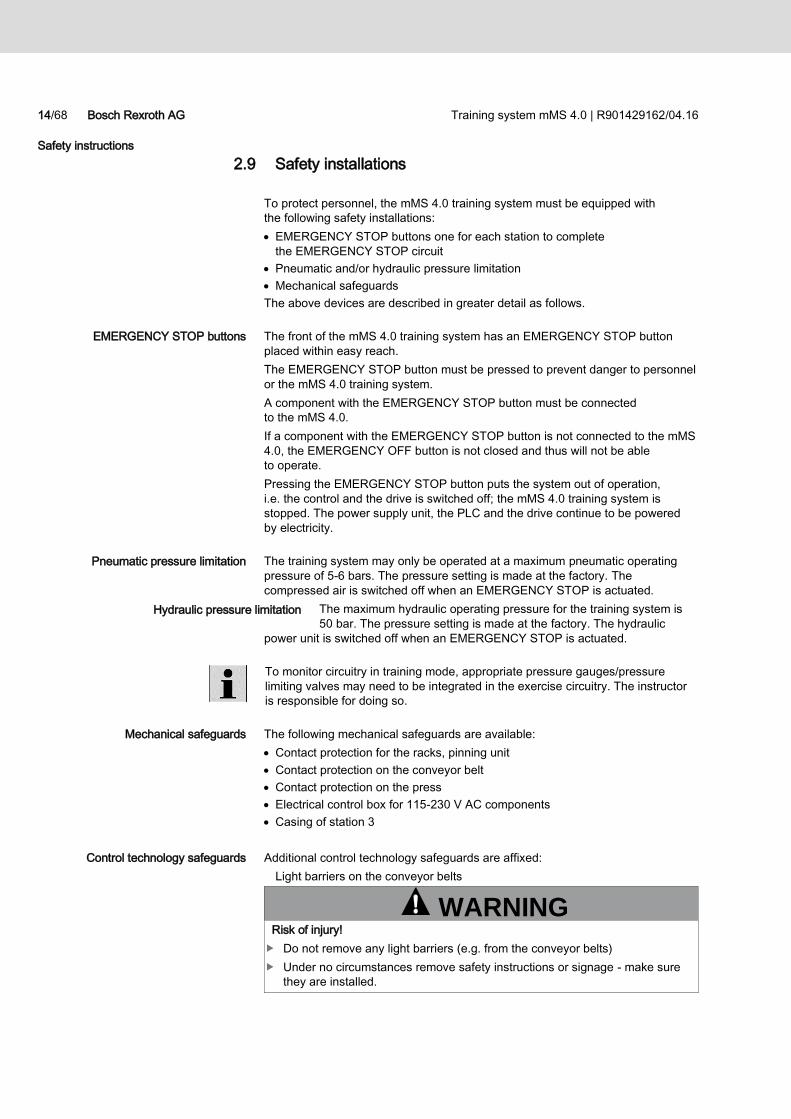
WARNING Risk of injury!
Do not remove any light barriers (e.g. from the conveyor belts)
Under no circumstances remove safety instructions or signage - make sure
they are installed.
Training system mMS 4.0 | R901429162/04.16 Bosch Rexroth AG 15/68
Safety instructions
2.10 Operator operating positions
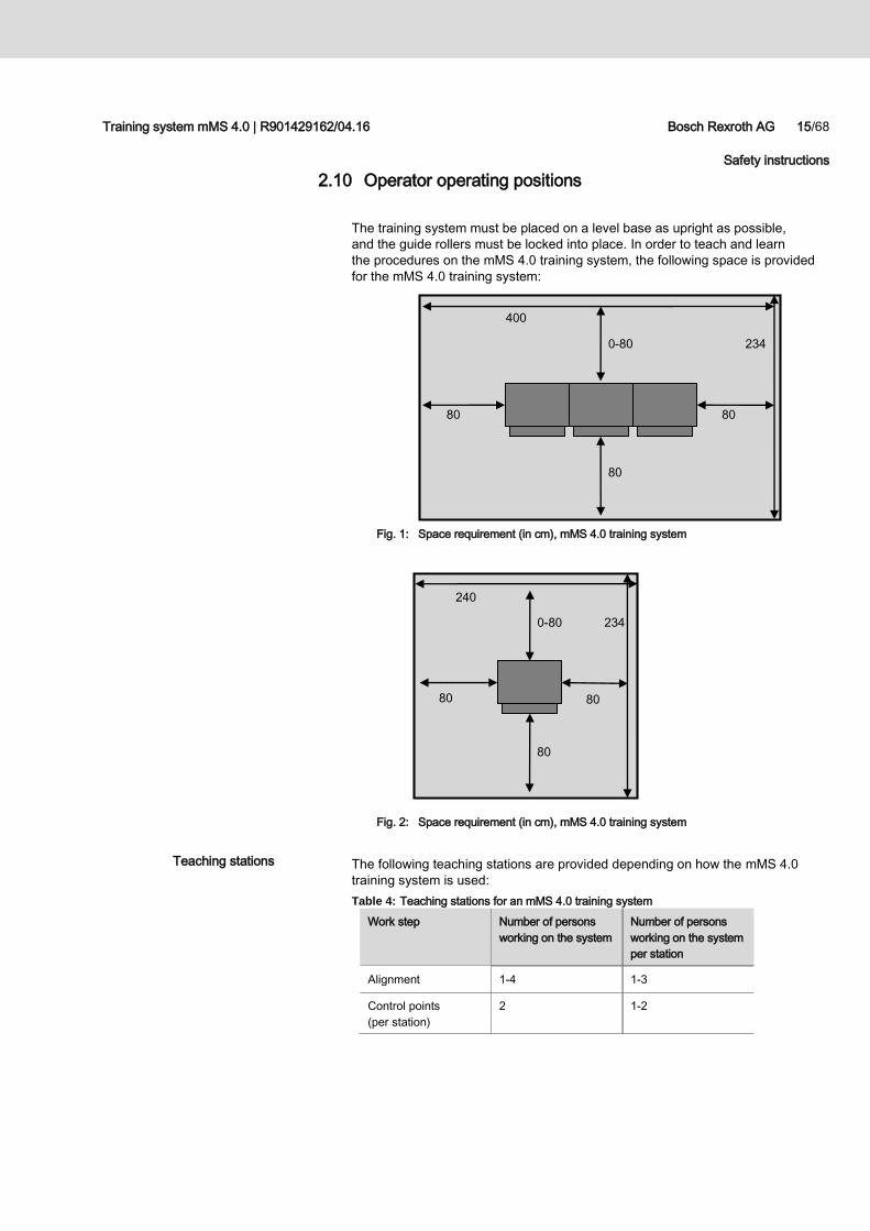
The training system must be placed on a level base as upright as possible,
and the guide rollers must be locked into place. In order to teach and learn
the procedures on the mMS 4.0 training system, the following space is provided
for the mMS 4.0 training system:
Fig. 1: Space requirement (in cm), mMS 4.0 training system
Fig. 2: Space requirement (in cm), mMS 4.0 training system
The following teaching stations are provided depending on how the mMS 4.0
training system is used:
Table 4: Teaching stations for an mMS 4.0 training system
Work step Number of persons
working on the system
Number of persons
working on the system
per station
Alignment 1-4 1-3
Control points
(per station)
2 1-2
Teaching stations
80
0-80
400
234
80 80
234
240
80 80
80
0-80
16/68 Bosch Rexroth AG Training system mMS 4.0 | R901429162/04.16
General instructions concerning property damage and product damage
3 General instructions concerning property damage
and product damage
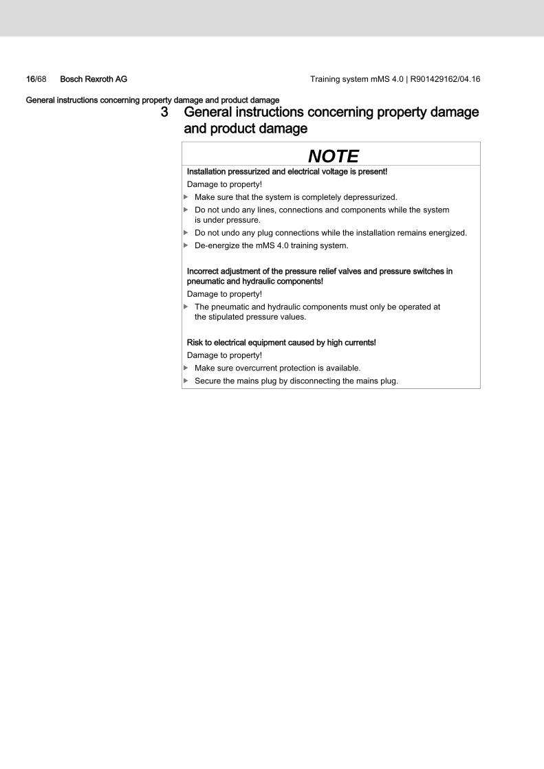
NOTE Installation pressurized and electrical voltage is present!
Damage to property!
Make sure that the system is completely depressurized.
Do not undo any lines, connections and components while the system
is under pressure.
Do not undo any plug connections while the installation remains energized.
De-energize the mMS 4.0 training system.
Incorrect adjustment of the pressure relief valves and pressure switches in
pneumatic and hydraulic components!
Damage to property!
The pneumatic and hydraulic components must only be operated at
the stipulated pressure values.
Risk to electrical equipment caused by high currents!
Damage to property!
Make sure overcurrent protection is available.
Secure the mains plug by disconnecting the mains plug.
Training system mMS 4.0 | R901429162/04.16 Bosch Rexroth AG 17/68
Scope of supply
4 Scope of supply
The mMS 4.0 training system comes pre-packaged as a turnkey system.
It comprises three modules delivered on three wooden crates. The wood is heat
treated.
These stations stand on a base pallet which can be removed from four sides
by means of a pallet truck.
The upper parts of the wooden crate, comprising 4 side panels and a lid
are screwed and nailed together to bottom pallet.
Table 5: Dimensions of the wooden boxes
Designation Unit Value
Dimension Length mm 2,100
Width mm 800
Height mm 1,800
Table 6: Weight of the wooden boxes
Designation Unit Value
Weight kg 100
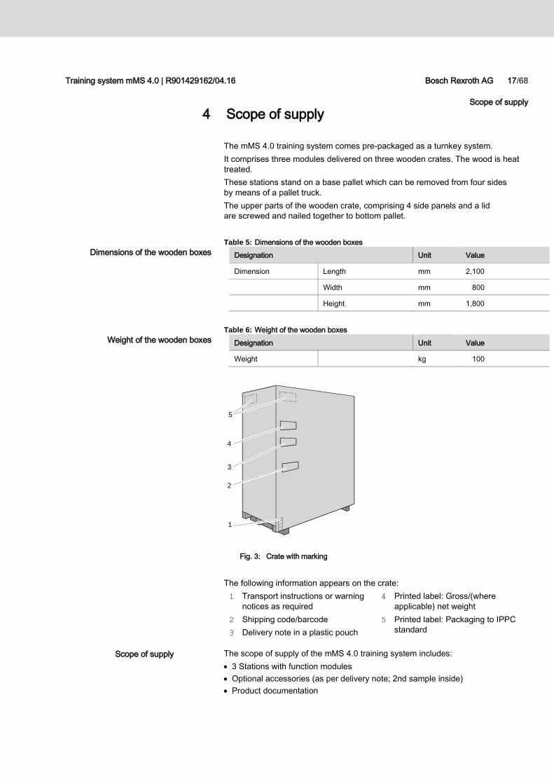
Fig. 3: Crate with marking
The following information appears on the crate:
1 Transport instructions or warning
notices as required
2 Shipping code/barcode
3 Delivery note in a plastic pouch
4 Printed label: Gross/(where
applicable) net weight
5 Printed label: Packaging to IPPC
standard
The scope of supply of the mMS 4.0 training system includes:
3 Stations with function modules
Optional accessories (as per delivery note; 2nd sample inside)
Product documentation
1
5
4
2
3
Dimensions of the wooden boxes
Weight of the wooden boxes
Scope of supply
18/68 Bosch Rexroth AG Training system mMS 4.0 | R901429162/04.16
About this product
5 About this product
5.1 General information
The following sections of this operating manual illustrate
a variant of the mMS 4.0 training system and its components for example
purposes.
The three stations are described individually.
All operating manuals of the individual industrial components can be found
in the enclosed CD.
5.2 Product Description
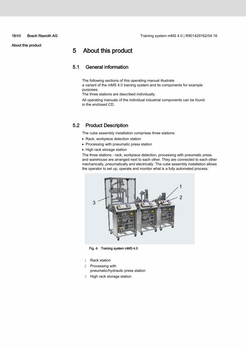
The cube assembly installation comprises three stations:
Rack, workpiece detection station
Processing with pneumatic press station
High rack storage station
The three stations - rack, workpiece detection, processing with pneumatic press
and warehouse are arranged next to each other. They are connected to each other
mechanically, pneumatically and electrically. The cube assembly installation allows
the operator to set up, operate and monitor what is a fully automated process.
Fig. 4: Training system mMS 4.0
1 Rack station
2 Processing with
pneumatic/hydraulic press station
3 High rack storage station
2 3
1
Training system mMS 4.0 | R901429162/04.16 Bosch Rexroth AG 19/68
About this product
2 1
3
4
2
3
1
4
5
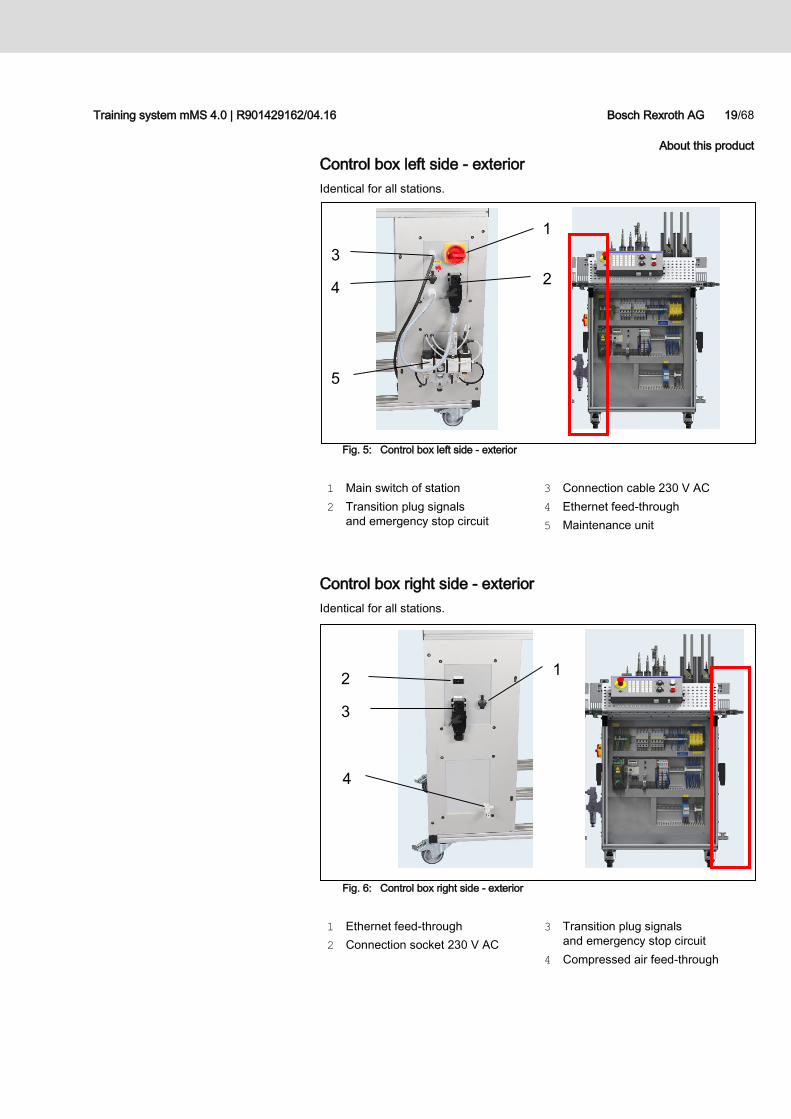
Control box left side - exterior
Identical for all stations.
Fig. 5: Control box left side - exterior
1 Main switch of station
2 Transition plug signals
and emergency stop circuit
3 Connection cable 230 V AC
4 Ethernet feed-through
5 Maintenance unit
Control box right side - exterior
Identical for all stations.
Fig. 6: Control box right side - exterior
1 Ethernet feed-through
2 Connection socket 230 V AC
3 Transition plug signals
and emergency stop circuit
4 Compressed air feed-through
20/68 Bosch Rexroth AG Training system mMS 4.0 | R901429162/04.16
About this product
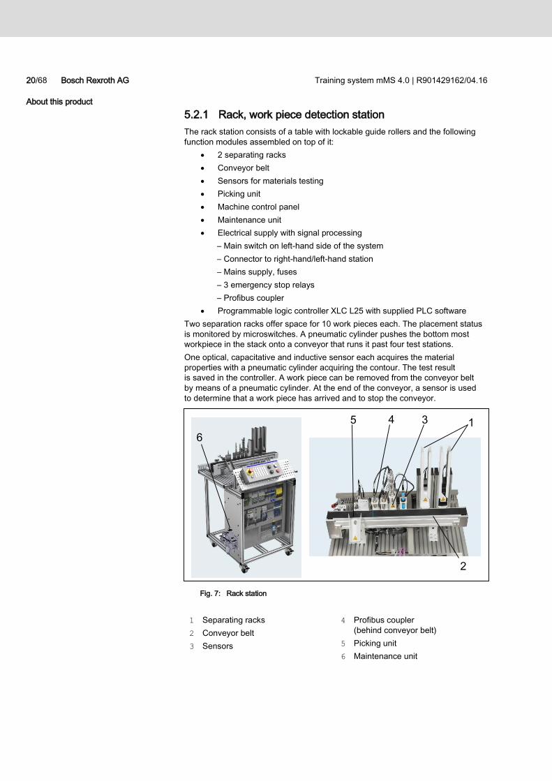
5.2.1 Rack, work piece detection station
The rack station consists of a table with lockable guide rollers and the following
function modules assembled on top of it:
2 separating racks
Conveyor belt
Sensors for materials testing
Picking unit
Machine control panel
Maintenance unit
Electrical supply with signal processing
– Main switch on left-hand side of the system
– Connector to right-hand/left-hand station
– Mains supply, fuses
– 3 emergency stop relays
– Profibus coupler
Programmable logic controller XLC L25 with supplied PLC software
Two separation racks offer space for 10 work pieces each. The placement status
is monitored by microswitches. A pneumatic cylinder pushes the bottom most
workpiece in the stack onto a conveyor that runs it past four test stations.
One optical, capacitative and inductive sensor each acquires the material
properties with a pneumatic cylinder acquiring the contour. The test result
is saved in the controller. A work piece can be removed from the conveyor belt
by means of a pneumatic cylinder. At the end of the conveyor, a sensor is used
to determine that a work piece has arrived and to stop the conveyor.
Fig. 7: Rack station
1 Separating racks
2 Conveyor belt
3 Sensors
4 Profibus coupler
(behind conveyor belt)
5 Picking unit
6 Maintenance unit
1
2
6
3 4 5
Training system mMS 4.0 | R901429162/04.16 Bosch Rexroth AG 21/68
About this product
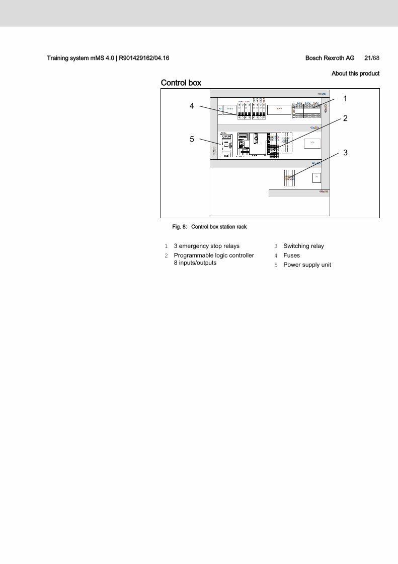
Control box
Fig. 8: Control box station rack
1 3 emergency stop relays
2 Programmable logic controller
8 inputs/outputs
3 Switching relay
4 Fuses
5 Power supply unit
3
4
2
5
1
22/68 Bosch Rexroth AG Training system mMS 4.0 | R901429162/04.16
About this product
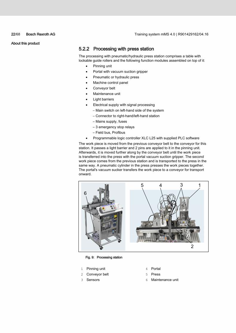
5.2.2 Processing with press station
The processing with pneumatic/hydraulic press station comprises a table with
lockable guide rollers and the following function modules assembled on top of it:
Pinning unit
Portal with vacuum suction gripper
Pneumatic or hydraulic press
Machine control panel
Conveyor belt
Maintenance unit
Light barriers
Electrical supply with signal processing
– Main switch on left-hand side of the system
– Connector to right-hand/left-hand station
– Mains supply, fuses
– 3 emergency stop relays
– Field bus, Profibus
Programmable logic controller XLC L25 with supplied PLC software
The work piece is moved from the previous conveyor belt to the conveyor for this
station. It passes a light barrier and 2 pins are applied to it in the pinning unit.
Afterwards, it is moved further along by the conveyor belt until the work piece
is transferred into the press with the portal vacuum suction gripper. The second
work piece comes from the previous station and is transported to the press in the
same way. A pneumatic cylinder in the press presses the work pieces together.
The portal's vacuum sucker transfers the work piece to a conveyor for transport
onward.
Fig. 9: Processing station
1 Pinning unit
2 Conveyor belt
3 Sensors
4 Portal
5 Press
6 Maintenance unit
6
2
3 4 1 5
Training system mMS 4.0 | R901429162/04.16 Bosch Rexroth AG 23/68
About this product
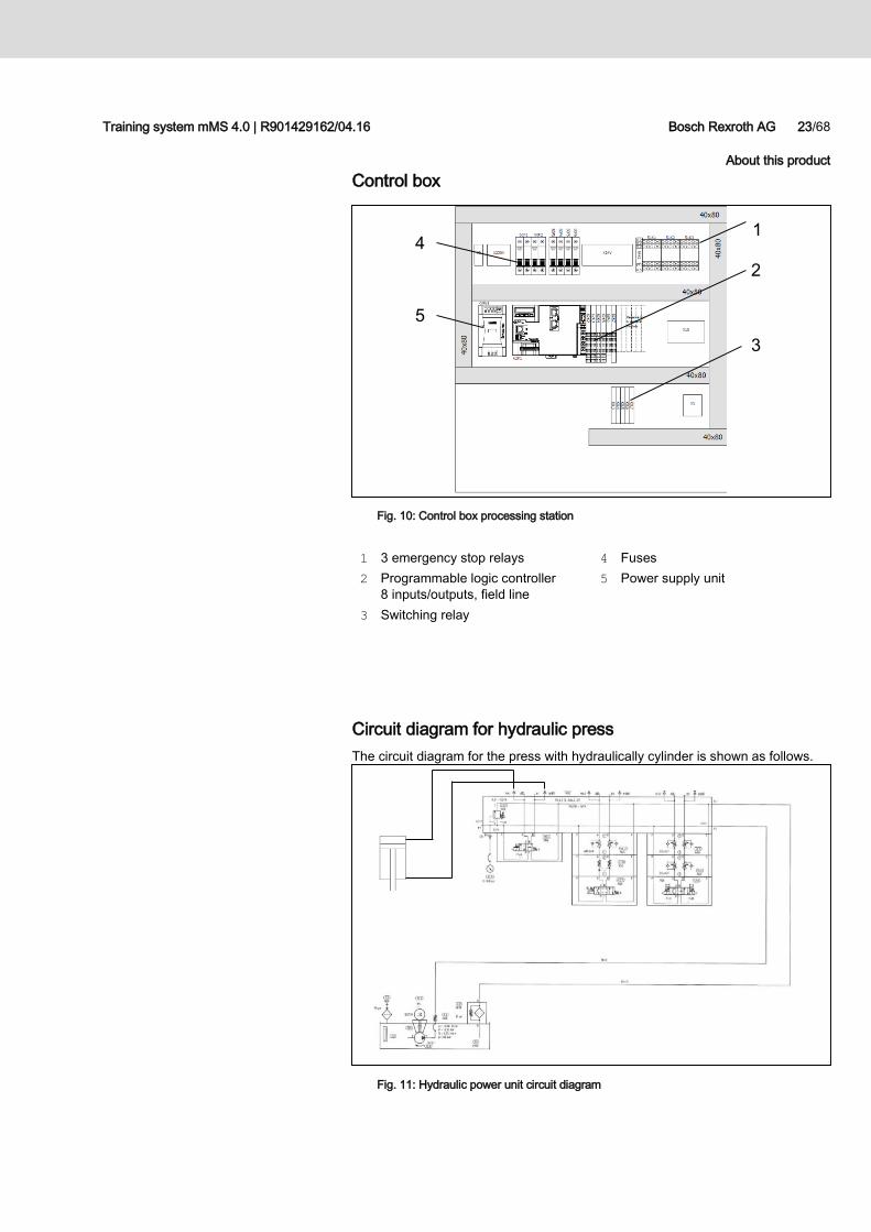
Control box
Fig. 10: Control box processing station
1 3 emergency stop relays
2 Programmable logic controller
8 inputs/outputs, field line
3 Switching relay
4 Fuses
5 Power supply unit
Circuit diagram for hydraulic press
The circuit diagram for the press with hydraulically cylinder is shown as follows.
Fig. 11: Hydraulic power unit circuit diagram
3
4
2
5
1
24/68 Bosch Rexroth AG Training system mMS 4.0 | R901429162/04.16
About this product
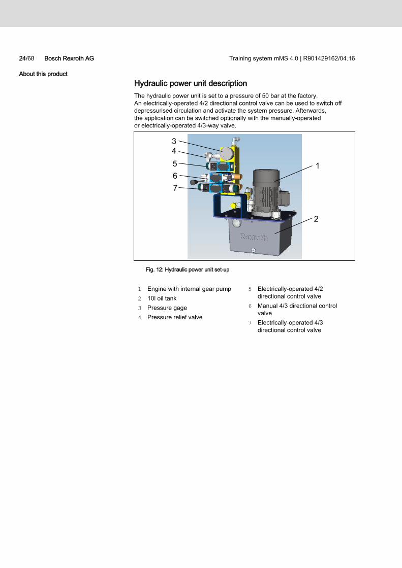
Hydraulic power unit description
The hydraulic power unit is set to a pressure of 50 bar at the factory.
An electrically-operated 4/2 directional control valve can be used to switch off
depressurised circulation and activate the system pressure. Afterwards,
the application can be switched optionally with the manually-operated
or electrically-operated 4/3-way valve.
Fig. 12: Hydraulic power unit set-up
1 Engine with internal gear pump
2 10l oil tank
3 Pressure gage
4 Pressure relief valve
5 Electrically-operated 4/2
directional control valve
6 Manual 4/3 directional control
valve
7 Electrically-operated 4/3
directional control valve
1
2
4
3
5
6
7
Training system mMS 4.0 | R901429162/04.16 Bosch Rexroth AG 25/68
About this product
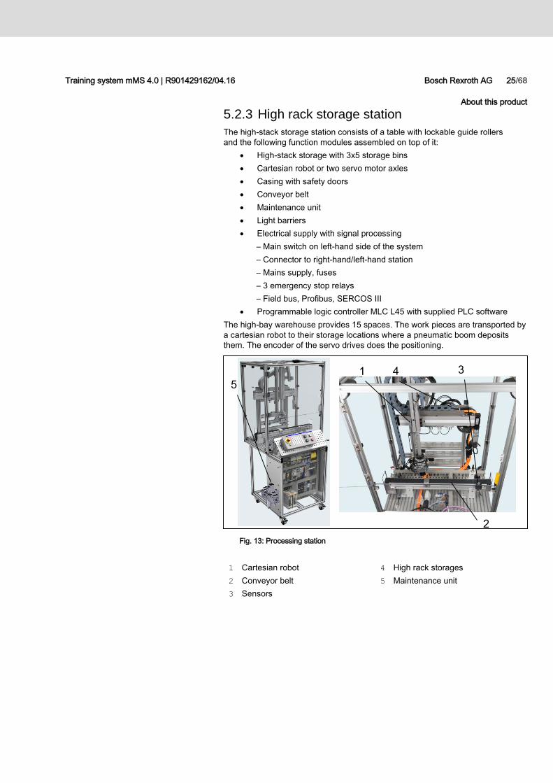
5.2.3 High rack storage station
The high-stack storage station consists of a table with lockable guide rollers
and the following function modules assembled on top of it:
High-stack storage with 3x5 storage bins
Cartesian robot or two servo motor axles
Casing with safety doors
Conveyor belt
Maintenance unit
Light barriers
Electrical supply with signal processing
– Main switch on left-hand side of the system
– Connector to right-hand/left-hand station
– Mains supply, fuses
– 3 emergency stop relays
– Field bus, Profibus, SERCOS III
Programmable logic controller MLC L45 with supplied PLC software
The high-bay warehouse provides 15 spaces. The work pieces are transported by
a cartesian robot to their storage locations where a pneumatic boom deposits
them. The encoder of the servo drives does the positioning.
Fig. 13: Processing station
1 Cartesian robot
2 Conveyor belt
3 Sensors
4 High rack storages
5 Maintenance unit
5
3 4 1
2
26/68 Bosch Rexroth AG Training system mMS 4.0 | R901429162/04.16
About this product
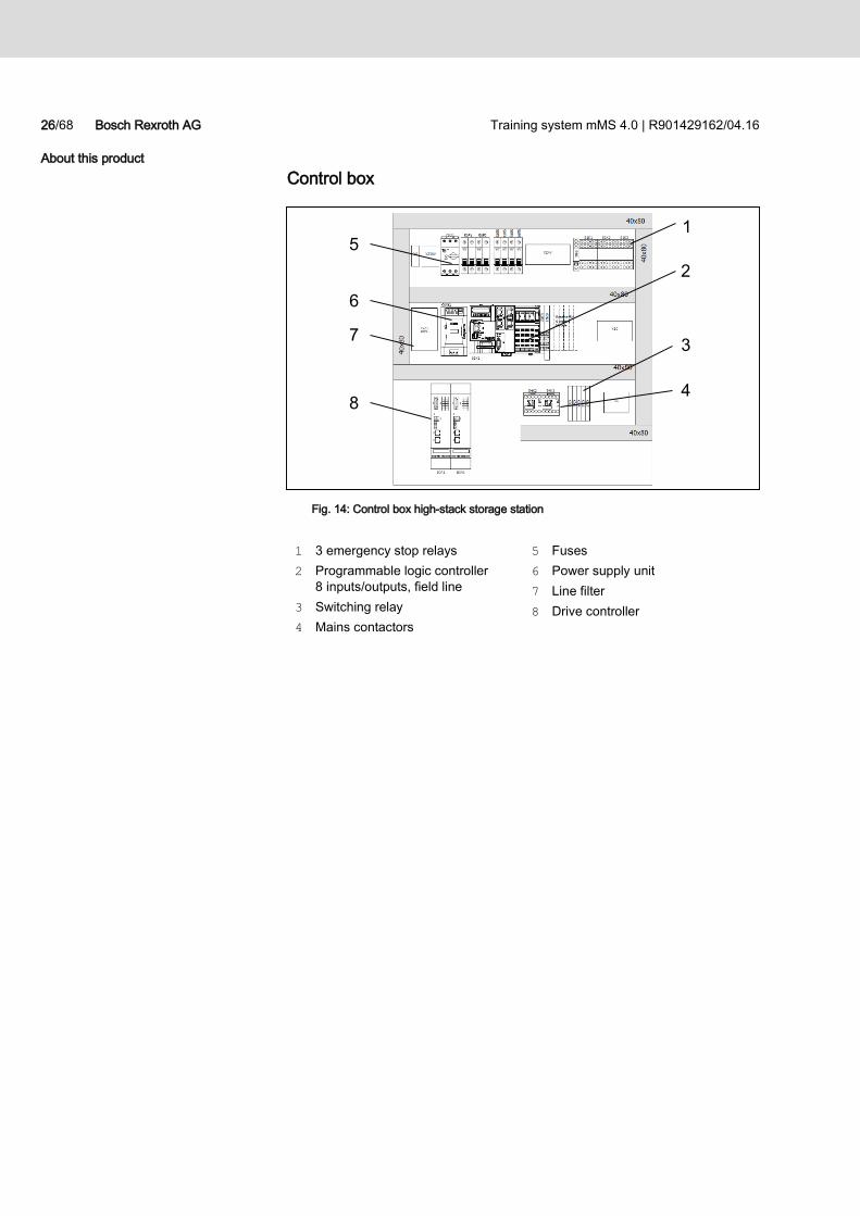
Control box
Fig. 14: Control box high-stack storage station
1 3 emergency stop relays
2 Programmable logic controller
8 inputs/outputs, field line
3 Switching relay
4 Mains contactors
5 Fuses
6 Power supply unit
7 Line filter
8 Drive controller
3
5
2
6
4
7
8
1
Training system mMS 4.0 | R901429162/04.16 Bosch Rexroth AG 27/68
About this product
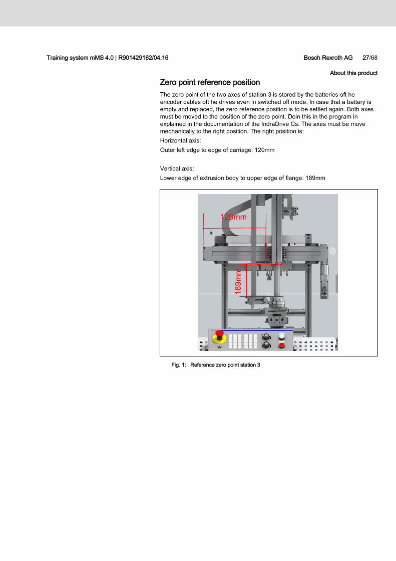
Zero point reference position
The zero point of the two axes of station 3 is stored by the batteries oft he
encoder cables oft he drives even in switched off mode. In case that a battery is
empty and replaced, the zero reference position is to be settled again. Both axes
must be moved to the position of the zero point. Doin this in the program in
explained in the documentation of the IndraDrive Cs. The axes must be move
mechanically to the right position. The right position is:
Horizontal axis:
Outer left edge to edge of carriage: 120mm
Vertical axis:
Lower edge of extrusion body to upper edge of flange: 189mm
Fig. 1: Reference zero point station 3
120mm
18
9m
m
28/68 Bosch Rexroth AG Training system mMS 4.0 | R901429162/04.16
About this product
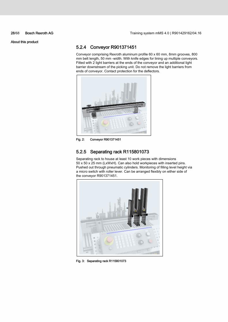
5.2.4 Conveyor R901371451
Conveyor comprising Rexroth aluminum profile 60 x 60 mm, 8mm grooves, 800
mm belt length, 50 mm -width. With knife edges for lining up multiple conveyors.
Fitted with 2 light barriers at the ends of the conveyor and an additional light
barrier downstream of the picking unit. Do not remove the light barriers from
ends of conveyor. Contact protection for the deflectors.
Fig. 2: Conveyor R901371451
5.2.5 Separating rack R115801073
Separating rack to house at least 10 work pieces with dimensions
50 x 50 x 25 mm (LxWxH). Can also hold workpieces with inserted pins.
Pushed out through pneumatic cylinders. Monitoring of filling level height via
a micro switch with roller lever. Can be arranged flexibly on either side of
the conveyor R901371451.
Fig. 3: Separating rack R115801073
Training system mMS 4.0 | R901429162/04.16 Bosch Rexroth AG 29/68
About this product
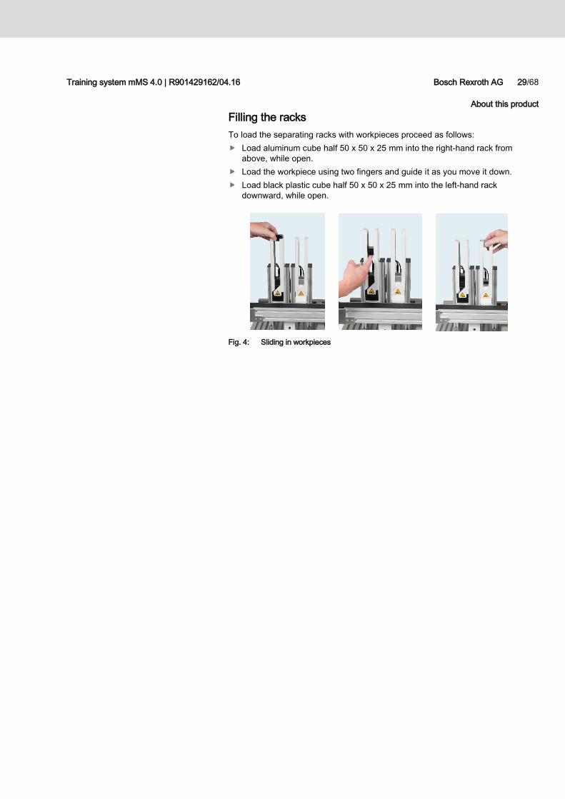
Filling the racks
To load the separating racks with workpieces proceed as follows:
Load aluminum cube half 50 x 50 x 25 mm into the right-hand rack from
above, while open.
Load the workpiece using two fingers and guide it as you move it down.
Load black plastic cube half 50 x 50 x 25 mm into the left-hand rack
downward, while open.
Fig. 4: Sliding in workpieces
30/68 Bosch Rexroth AG Training system mMS 4.0 | R901429162/04.16
About this product
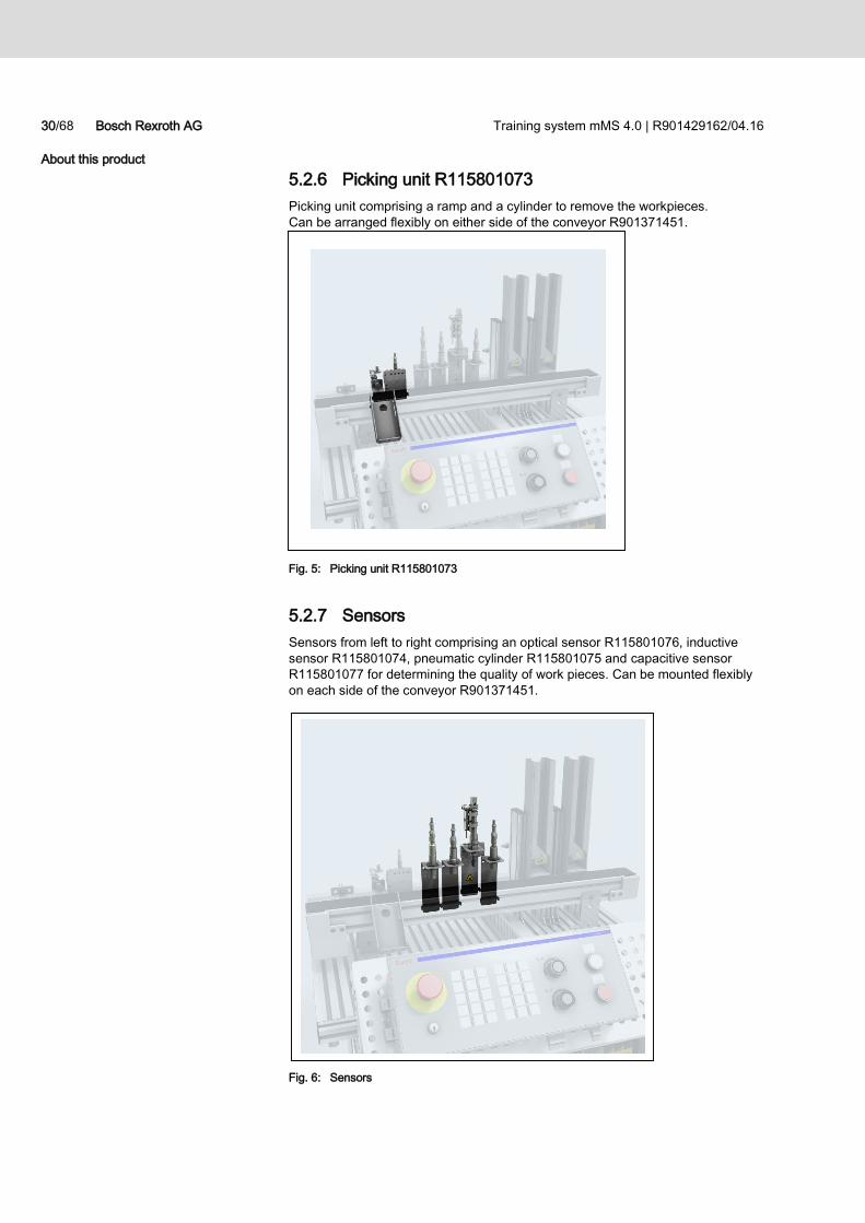
5.2.6 Picking unit R115801073
Picking unit comprising a ramp and a cylinder to remove the workpieces.
Can be arranged flexibly on either side of the conveyor R901371451.
Fig. 5: Picking unit R115801073
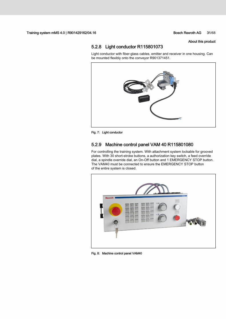
5.2.7 Sensors
Sensors from left to right comprising an optical sensor R115801076, inductive
sensor R115801074, pneumatic cylinder R115801075 and capacitive sensor
R115801077 for determining the quality of work pieces. Can be mounted flexibly
on each side of the conveyor R901371451.
Fig. 6: Sensors
Training system mMS 4.0 | R901429162/04.16 Bosch Rexroth AG 31/68
About this product
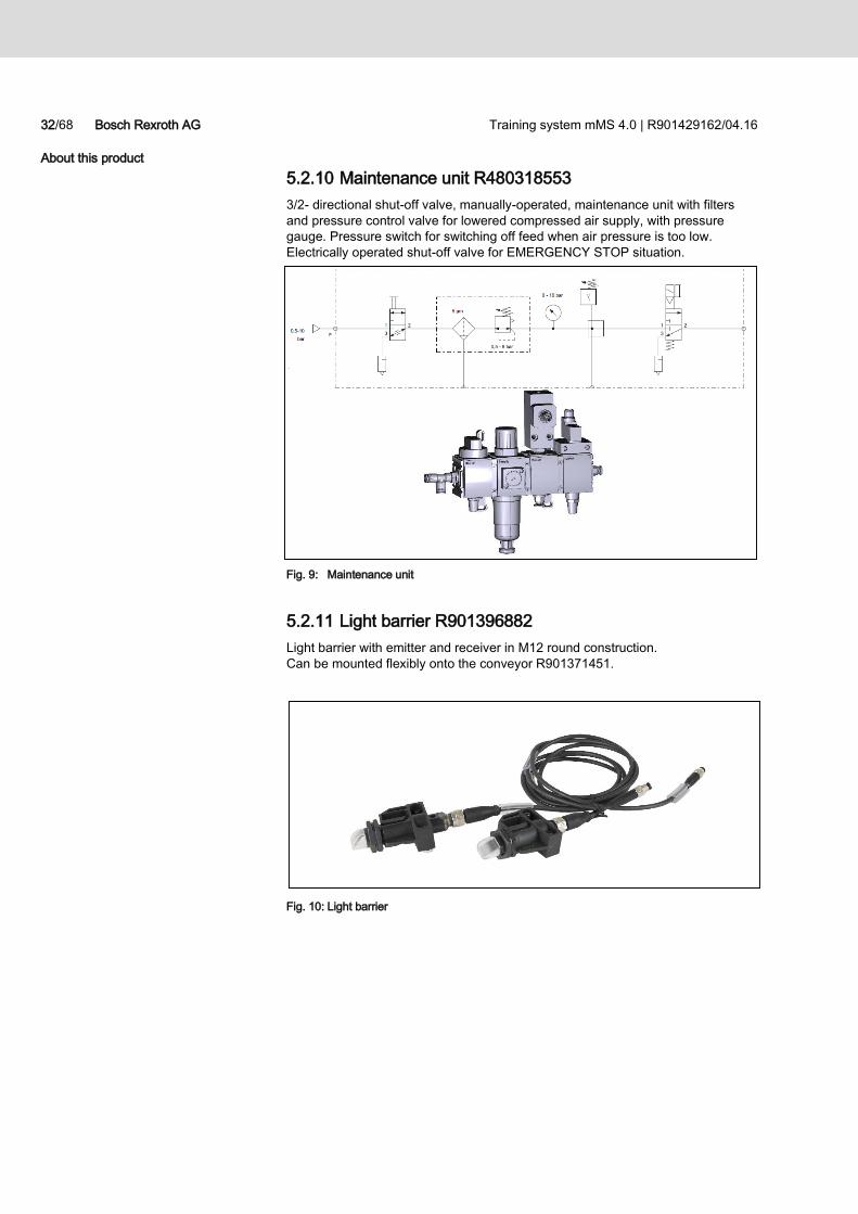
5.2.8 Light conductor R115801073
Light conductor with fiber-glass cables, emitter and receiver in one housing. Can
be mounted flexibly onto the conveyor R901371451.
Fig. 7: Light conductor
5.2.9 Machine control panel VAM 40 R115801080
For controlling the training system. With attachment system lockable for grooved
plates. With 30 short-stroke buttons, a authorization key switch, a feed override
dial, a spindle override dial, an On-Off button and 1 EMERGENCY STOP button.
The VAM40 must be connected to ensure the EMERGENCY STOP button
of the entire system is closed.
Fig. 8: Machine control panel VAM40
32/68 Bosch Rexroth AG Training system mMS 4.0 | R901429162/04.16
About this product
5.2.10 Maintenance unit R480318553
3/2- directional shut-off valve, manually-operated, maintenance unit with filters
and pressure control valve for lowered compressed air supply, with pressure
gauge. Pressure switch for switching off feed when air pressure is too low.
Electrically operated shut-off valve for EMERGENCY STOP situation.
Fig. 9: Maintenance unit
5.2.11 Light barrier R901396882
Light barrier with emitter and receiver in M12 round construction.
Can be mounted flexibly onto the conveyor R901371451.
Fig. 10: Light barrier
Training system mMS 4.0 | R901429162/04.16 Bosch Rexroth AG 33/68
About this product
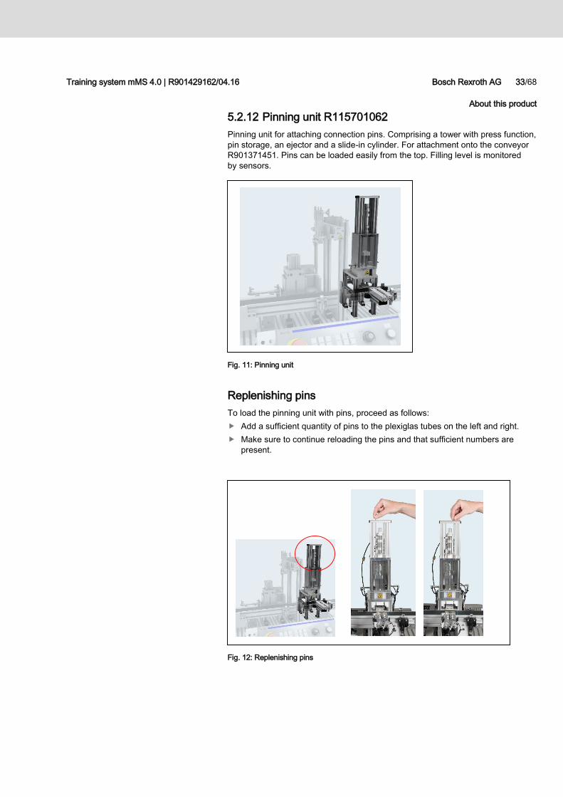
5.2.12 Pinning unit R115701062
Pinning unit for attaching connection pins. Comprising a tower with press function,
pin storage, an ejector and a slide-in cylinder. For attachment onto the conveyor
R901371451. Pins can be loaded easily from the top. Filling level is monitored
by sensors.
Fig. 11: Pinning unit
Replenishing pins
To load the pinning unit with pins, proceed as follows:
Add a sufficient quantity of pins to the plexiglas tubes on the left and right.
Make sure to continue reloading the pins and that sufficient numbers are
present.
Fig. 12: Replenishing pins
34/68 Bosch Rexroth AG Training system mMS 4.0 | R901429162/04.16
About this product
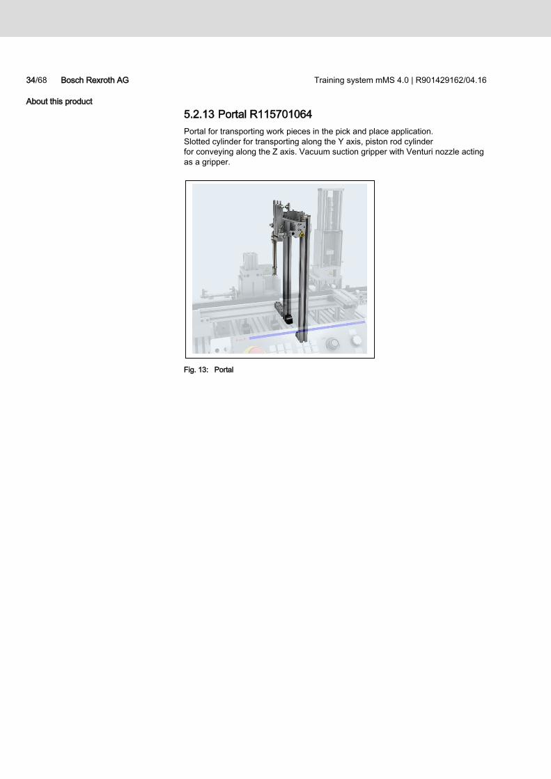
5.2.13 Portal R115701064
Portal for transporting work pieces in the pick and place application.
Slotted cylinder for transporting along the Y axis, piston rod cylinder
for conveying along the Z axis. Vacuum suction gripper with Venturi nozzle acting
as a gripper.
Fig. 13: Portal
Training system mMS 4.0 | R901429162/04.16 Bosch Rexroth AG 35/68
About this product
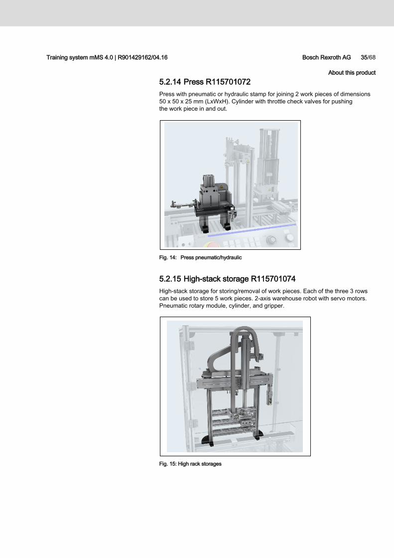
5.2.14 Press R115701072
Press with pneumatic or hydraulic stamp for joining 2 work pieces of dimensions
50 x 50 x 25 mm (LxWxH). Cylinder with throttle check valves for pushing
the work piece in and out.
Fig. 14: Press pneumatic/hydraulic
5.2.15 High-stack storage R115701074
High-stack storage for storing/removal of work pieces. Each of the three 3 rows
can be used to store 5 work pieces. 2-axis warehouse robot with servo motors.
Pneumatic rotary module, cylinder, and gripper.
Fig. 15: High rack storages
36/68 Bosch Rexroth AG Training system mMS 4.0 | R901429162/04.16
Technical data and dimensions
6 Technical data and dimensions
6.1 Technical data
6.1.1 Training system mMS 4.0
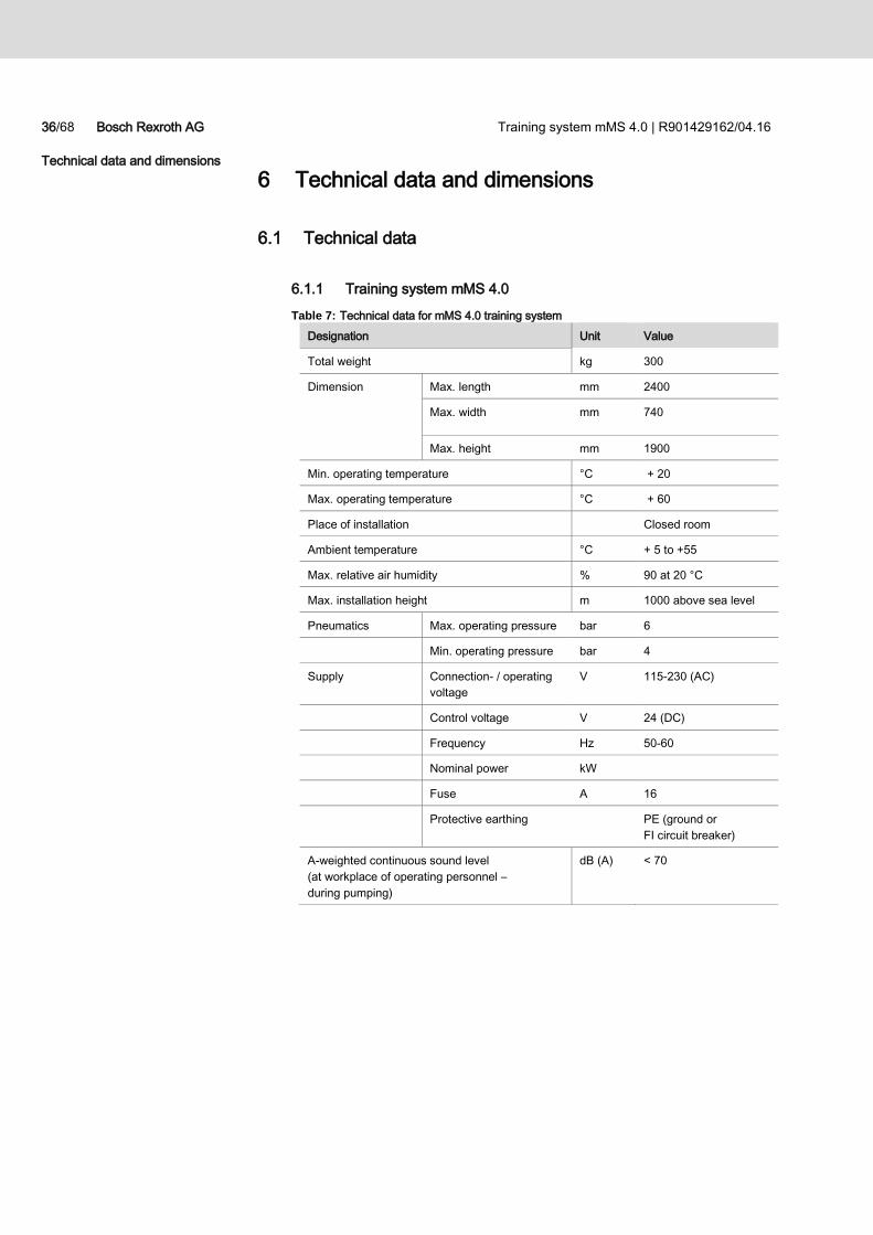
Table 7: Technical data for mMS 4.0 training system
Designation Unit Value
Total weight kg 300
Dimension Max. length mm 2400
Max. width mm 740
Max. height mm 1900
Min. operating temperature °C + 20
Max. operating temperature °C + 60
Place of installation Closed room
Ambient temperature °C + 5 to +55
Max. relative air humidity % 90 at 20 °C
Max. installation height m 1000 above sea level
Pneumatics Max. operating pressure bar 6
Min. operating pressure bar 4
Supply Connection- / operating
voltage
V 115-230 (AC)
Control voltage V 24 (DC)
Frequency Hz 50-60
Nominal power kW
Fuse A 16
Protective earthing PE (ground or
FI circuit breaker)
A-weighted continuous sound level
(at workplace of operating personnel –
during pumping)
dB (A) < 70
Training system mMS 4.0 | R901429162/04.16 Bosch Rexroth AG 37/68
Technical data and dimensions
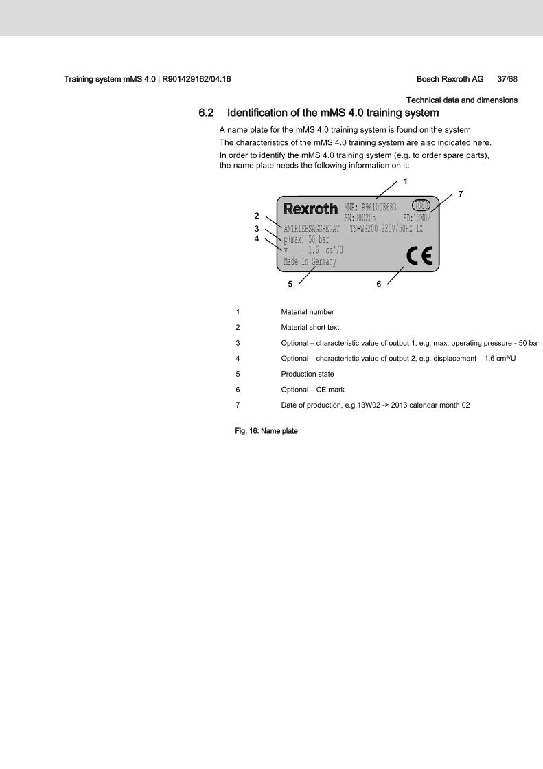
6.2 Identification of the mMS 4.0 training system
A name plate for the mMS 4.0 training system is found on the system.
The characteristics of the mMS 4.0 training system are also indicated here.
In order to identify the mMS 4.0 training system (e.g. to order spare parts),
the name plate needs the following information on it:
1 Material number
2 Material short text
3 Optional – characteristic value of output 1, e.g. max. operating pressure - 50 bar
4 Optional – characteristic value of output 2, e.g. displacement – 1.6 cm³/U
5 Production state
6 Optional – CE mark
7 Date of production, e.g.13W02 -> 2013 calendar month 02
Fig. 16: Name plate
38/68 Bosch Rexroth AG Training system mMS 4.0 | R901429162/04.16
Operating and display elements
7 Operating and display elements
7.1 EMERGENCY STOP button
An EMERGENCY STOP button must be placed on the front of the training system.
All operating modules (machine control panels) have an EMERGENCY STOP
button which can close the EMERGENCY STOP circuit.
In the event of a risk to person or machine, switch off the mMS 4.0 training
system with the button.
Actuating the EMERGENCY STOP button interrupts the power supply.
All work procedures are stopped right away and any hazardous control currents
(servo drive) and thus all movements are switched off.
There is a local EMERGENCY STOP circuit for the individual station and a global
EMERGENCY STOP circuit for the entire installation.
The circuit diagram can be viewed in the enclosed CD.
Do not use the EMERGENCY STOP button to switch off the training system
normally!
Training system mMS 4.0 | R901429162/04.16 Bosch Rexroth AG 39/68
Operating and display elements
7.2 Operating elements on the training system
7.2.1 Machine control panel VAM
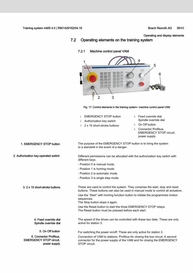
Fig. 17: Control elements in the training system– machine control panel VAM
1 EMERGENCY STOP button
2 Authorization key switch
3 2 x 15 short-stroke buttons
4 Feed override dial
Spindle override dial
5 On Off button
6 Connector Profibus,
EMERGENCY STOP circuit,
power supply
The purpose of the EMERGENCY STOP button is to bring the system
to a standstill in the event of a danger.
Different permissions can be allocated with the authorization key switch with
different keys.
- Position 0 is manual mode.
- Position 1 is homing mode.
- Position 2 is automatic mode.
- Position 3 is single step mode.
These are used to control the system. They comprise the start, stop and reset
buttons. These buttons can also be used in manual mode to control all actuators.
Use the “Start” with homing function button to initiate the programmed motion
sequences.
The Stop button stops it again.
Use the Reset button to start the three EMERGENCY STOP relays.
The Reset button must be pressed before each start.
The speed of the drives can be controlled with these two dials. These are only
active for station 3.
For switching the power on/off. These are only active for station 3.
Connection of VAM to stations. Profibus for closing the bus circuit. A second
connector for the power supply of the VAM and for closing the EMERGENCY
STOP circuit.
1. EMERGENCY STOP button
2. Authorization key-operated switch
3. 2 x 15 short-stroke buttons
4. Feed override dial
Spindle override dial
5. On Off button
6. Connector Profibus,
EMERGENCY STOP circuit,
power supply
1
2 3
5
6
4
40/68 Bosch Rexroth AG Training system mMS 4.0 | R901429162/04.16
Operating and display elements
7.2.2 HMI small operating panel VCP
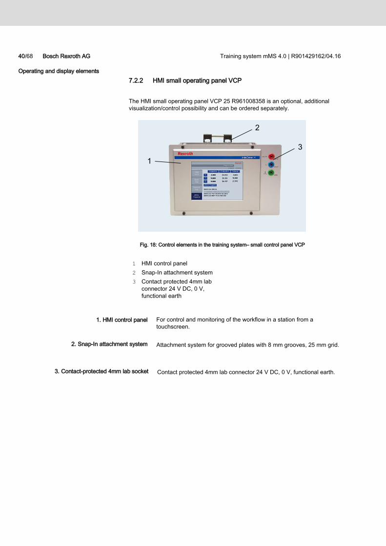
The HMI small operating panel VCP 25 R961008358 is an optional, additional
visualization/control possibility and can be ordered separately.
Fig. 18: Control elements in the training system– small control panel VCP
1 HMI control panel
2 Snap-In attachment system
3 Contact protected 4mm lab
connector 24 V DC, 0 V,
functional earth
For control and monitoring of the workflow in a station from a
touchscreen.
Attachment system for grooved plates with 8 mm grooves, 25 mm grid.
Contact protected 4mm lab connector 24 V DC, 0 V, functional earth.
1. HMI control panel
2. Snap-In attachment system
3. Contact-protected 4mm lab socket
1
2
3
Training system mMS 4.0 | R901429162/04.16 Bosch Rexroth AG 41/68
Transport and storage
8 Transport and storage
8.1 Delivery and unpacking
Screwdriver, knife, pry bar.
Transport the wooden crate n upright to the place of unpacking using a fork lift
truck or pallet truck.
Open the wire ties on the wooden crate using a knife.
Using a screwdriver, undo the front of the wooden crates and put them away.
Open up the plastic packaging using a knife.
Carefully lift each station of the mMS 4.0 training system down from the pallet
and remove from the crate.
Carefully remove the cable ties and wire ties and dispose of them
appropriately.
Dispose of the pallet and wooden box properly or store appropriately for
subsequent use.
Any transport damage and defects must be noted right away and reported
in a written damage report.
Required tool:
CAUTION Risk that the training system may fall over.
Risk of injury when lifting and transporting the machine!
When lifting and transporting the machine, always carefully do so with at least
two persons in order to prevent it from dropping.
Lift the mMS 4.0 training system by hand or with a floor conveyor.
Procedure
42/68 Bosch Rexroth AG Training system mMS 4.0 | R901429162/04.16
Transport and storage
8.2 Transport
8.2.1 Transport inside the building
The mMS 4.0 training system can be moved and installed in a different location
any time.
Note the following during transport:
Ensure that the doors and passages are of sufficient size.
Remove attachment parts and device sets that are not needed beforehand.
Disconnect the 3 stations from all connections.
Carefully shift the individual stations.
Proceed as follows:
Disconnect the mains plug and stow away the power cable.
Remove the compressed air supplies.
Disconnect all connecting cables between the stations.
Move the training system to the new place of installation.
Move the mMS 4.0 training system on a fixed and level base.
Lock the parking brakes on the castors.
Connect up the electrical and pneumatic supplies to the system.
The mMS 4.0 training system can be put into storage or connected
to the energy supply again.
Whenever putting the system down during transportation and when using
a table with wheels, always lock the parking brakes on the wheels.
General information
Transport
CAUTION Risk that the training system may fall over.
Risk of injury when lifting and transporting the machine!
When lifting and transporting the machine, always carefully do so with at least
two persons in order to prevent it from dropping.
Lift the mMS 4.0 training system by hand or with a floor conveyor.
Training system mMS 4.0 | R901429162/04.16 Bosch Rexroth AG 43/68
Transport and storage
8.2.2 Transporting between two buildings
Note the following during transport:
Ensure that the doors and passages are of sufficient size.
Remove attachment parts and device sets that are not needed beforehand.
Disconnect the 3 stations from all connections.
Carefully shift the individual stations.
Proceed as follows:
Disconnect the mains plug and stow away the power cable.
Remove the compressed air supplies.
Disconnect all connecting cables between the stations.
Transport the mMS 4.0 training system as follows:
Place each station of the mMS 4.0 training system onto a pallet.
Prevent the stations of the mMS 4.0 training system from falling using belts
or plastic ties; You can use the original transport crates.
Protect each station of the mMS 4.0 training system against moisture.
Transport the pallet with the mMS 4.0 training system with a fork lift truck
or similar.
Move the mMS 4.0 training system on a fixed and level base.
At the predesignated position carefully lift each station of the mMS 4.0 training
system out of the transport box or down from the pallet.
Remove any packaging and securing ties with belts and plastic ties.
Connect the voltage supply and compressed air supply.
General information
Transport
CAUTION Risk that the training system may fall over.
Risk of injury when lifting and transporting the machine!
When lifting and transporting the machine, always carefully do so with at least
two persons in order to prevent it from dropping.
Lift the mMS 4.0 training system by hand or with a floor conveyor.
44/68 Bosch Rexroth AG Training system mMS 4.0 | R901429162/04.16
Transport and storage
8.3 Storage
Table 8: Storage conditions
Designation Unit Value
Footprint of the mMS 4.0 training system mm approx. 4000 x 2340
Condition of the footprint level
Min. storage temperature °C +5
Max. storage temperature °C +55
Relative air humidity % 25 - 70
Max. installation height m 1000 above sea level
Requirements for storing the stations of the training system:
Remove attachment parts and device sets that are not needed beforehand.
Remove the connecting cables.
Put the stations of the mMS 4.0 into storage as follows:
Place the stations of the training system onto a pallet
Protect the training system from dust and moisture.
The stations of the mMS 4.0 training system have now been placed into
storage.
Training system mMS 4.0 | R901429162/04.16 Bosch Rexroth AG 45/68
Set-up, installation and commissioning
9 Set-up, installation and commissioning
9.1 Setting up the mMS 4.0 training system
Perfect execution of the set-up requires that:
delivery, transport or unpacking has been carried out properly as per chapter 7.2.2,
all of the required parts are in range and in a functional condition,
required auxiliary equipment, such as lifting tools, tables, are present.
Before the final set-up, please note the following points:
Make sure the required clearance for the mMS 4.0 training system and
the safety clearances to other fixed installations is present (for specifications,
see Fig. 1: Space requirement (in cm), ). Any possible attachment parts
should be taken into account.
Check the levelness of the installation surface.
Make sure that an electrical connection is present.
Make sure there is sufficient lighting at the place of installation.
The following must be taken into account during installation:
Check alignment of the mMS 4.0 training system at the place of installation.
Lock the castors of the stations.
Connect each station with each other mechanically.
Also connect the electrical and pneumatic connections.
NOTE Risk of anomalies, deviations, faults, defects during set-up or inspection
Risk of damage!
Do not put the mMS 4.0 training system in operation or place it immediately
out of service.
Find the causes of the fault and fix the defect.
Replace the damaged part.
Preparations for the set-up
Installation
46/68 Bosch Rexroth AG Training system mMS 4.0 | R901429162/04.16
Set-up, installation and commissioning
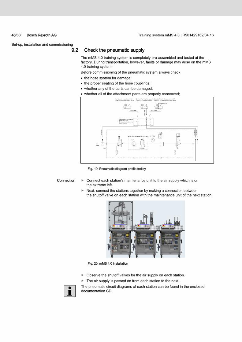
9.2 Check the pneumatic supply
The mMS 4.0 training system is completely pre-assembled and tested at the
factory. During transportation, however, faults or damage may arise on the mMS
4.0 training system.
Before commissioning of the pneumatic system always check
the hose system for damage;
the proper seating of the hose couplings;
whether any of the parts can be damaged;
whether all of the attachment parts are properly connected;
Fig. 19: Pneumatic diagram profile trolley
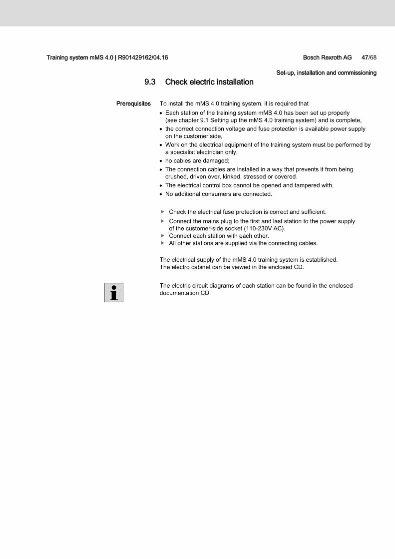
Connect each station's maintenance unit to the air supply which is on
the extreme left.
Next, connect the stations together by making a connection between
the shutoff valve on each station with the maintenance unit of the next station.
Fig. 20: mMS 4.0 installation
Observe the shutoff valves for the air supply on each station.
The air supply is passed on from each station to the next.
The pneumatic circuit diagrams of each station can be found in the enclosed
documentation CD.
Connection
Training system mMS 4.0 | R901429162/04.16 Bosch Rexroth AG 47/68
Set-up, installation and commissioning
9.3 Check electric installation
To install the mMS 4.0 training system, it is required that
Each station of the training system mMS 4.0 has been set up properly
(see chapter 9.1 Setting up the mMS 4.0 training system) and is complete,
the correct connection voltage and fuse protection is available power supply
on the customer side,
Work on the electrical equipment of the training system must be performed by
a specialist electrician only,
no cables are damaged;
The connection cables are installed in a way that prevents it from being
crushed, driven over, kinked, stressed or covered.
The electrical control box cannot be opened and tampered with.
No additional consumers are connected.
Check the electrical fuse protection is correct and sufficient.
Connect the mains plug to the first and last station to the power supply
of the customer-side socket (110-230V AC).
Connect each station with each other.
All other stations are supplied via the connecting cables.
The electrical supply of the mMS 4.0 training system is established.
The electro cabinet can be viewed in the enclosed CD.
The electric circuit diagrams of each station can be found in the enclosed
documentation CD.
Prerequisites
48/68 Bosch Rexroth AG Training system mMS 4.0 | R901429162/04.16
Set-up, installation and commissioning
9.4 Installing installation and stations
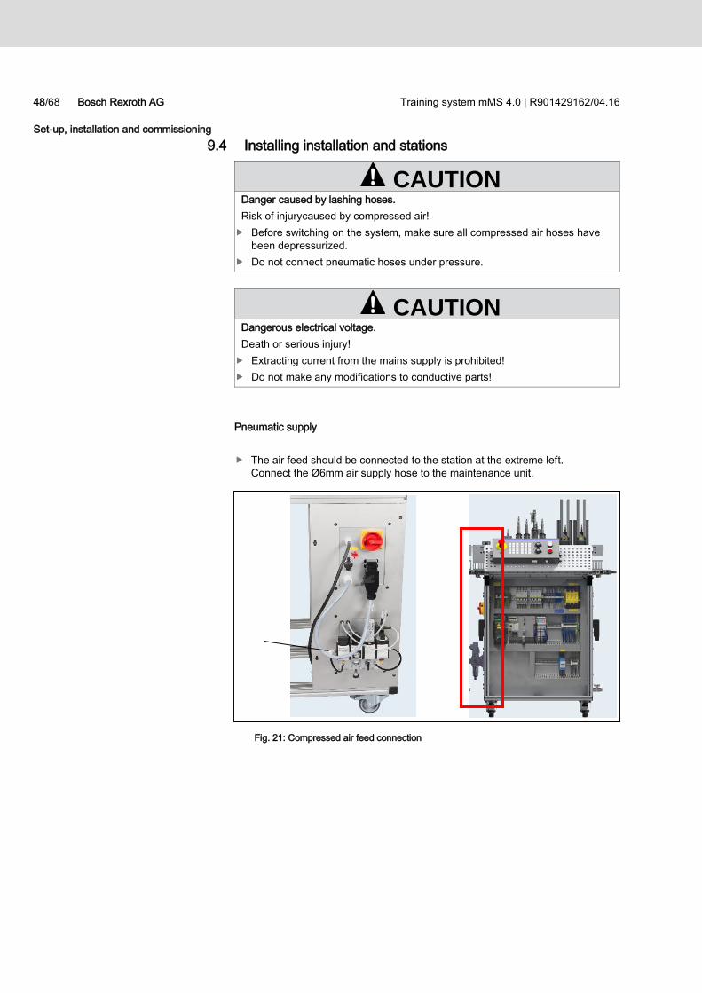
Pneumatic supply
The air feed should be connected to the station at the extreme left.
Connect the Ø6mm air supply hose to the maintenance unit.
Fig. 21: Compressed air feed connection
CAUTION Danger caused by lashing hoses.
Risk of injurycaused by compressed air!
Before switching on the system, make sure all compressed air hoses have
been depressurized.
Do not connect pneumatic hoses under pressure.
CAUTION Dangerous electrical voltage.
Death or serious injury!
Extracting current from the mains supply is prohibited!
Do not make any modifications to conductive parts!
Training system mMS 4.0 | R901429162/04.16 Bosch Rexroth AG 49/68
Set-up, installation and commissioning
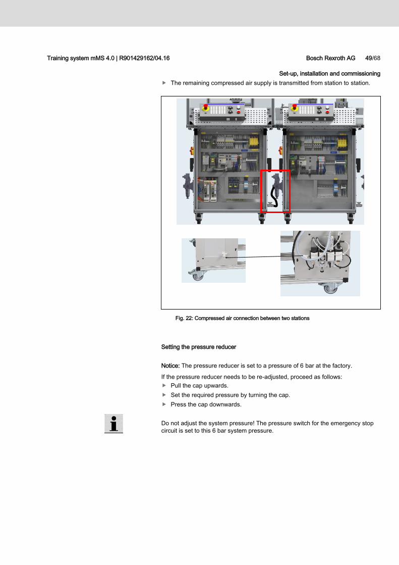
The remaining compressed air supply is transmitted from station to station.
Fig. 22: Compressed air connection between two stations
Setting the pressure reducer
Notice: The pressure reducer is set to a pressure of 6 bar at the factory.
If the pressure reducer needs to be re-adjusted, proceed as follows:
Pull the cap upwards.
Set the required pressure by turning the cap.
Press the cap downwards.
Do not adjust the system pressure! The pressure switch for the emergency stop
circuit is set to this 6 bar system pressure.
50/68 Bosch Rexroth AG Training system mMS 4.0 | R901429162/04.16
Set-up, installation and commissioning
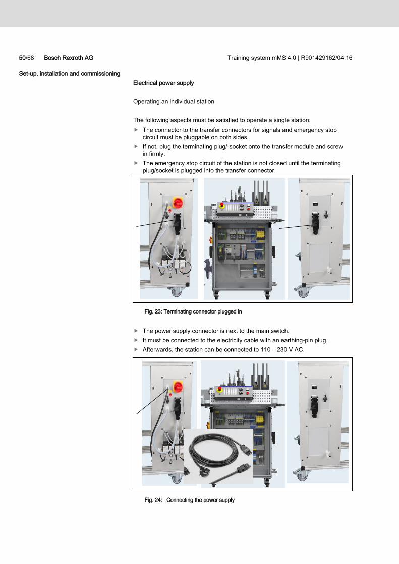
Electrical power supply
Operating an individual station
The following aspects must be satisfied to operate a single station:
The connector to the transfer connectors for signals and emergency stop
circuit must be pluggable on both sides.
If not, plug the terminating plug/-socket onto the transfer module and screw
in firmly.
The emergency stop circuit of the station is not closed until the terminating
plug/socket is plugged into the transfer connector.
Fig. 23: Terminating connector plugged in
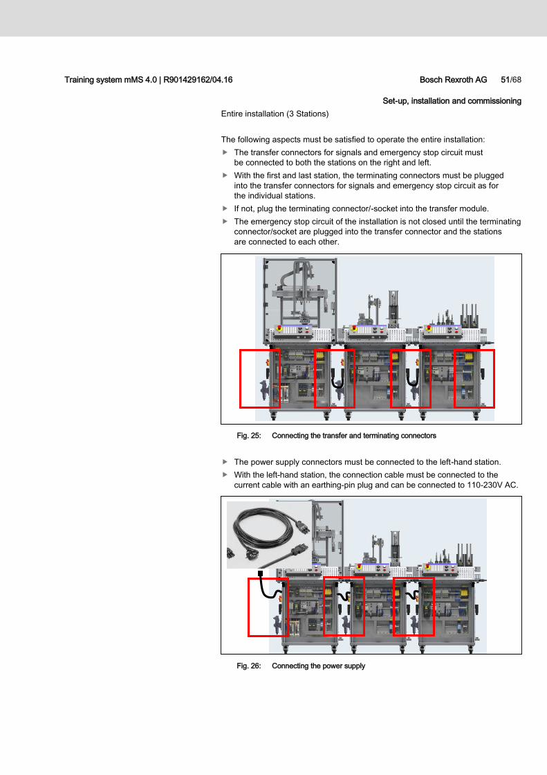
The power supply connector is next to the main switch.
It must be connected to the electricity cable with an earthing-pin plug.
Afterwards, the station can be connected to 110 – 230 V AC.
Fig. 24: Connecting the power supply
Training system mMS 4.0 | R901429162/04.16 Bosch Rexroth AG 51/68
Set-up, installation and commissioning
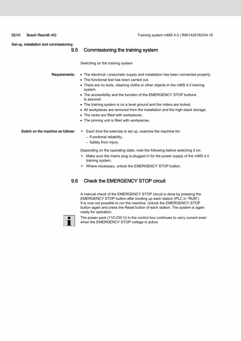
Entire installation (3 Stations)
The following aspects must be satisfied to operate the entire installation:
The transfer connectors for signals and emergency stop circuit must
be connected to both the stations on the right and left.
With the first and last station, the terminating connectors must be plugged
into the transfer connectors for signals and emergency stop circuit as for
the individual stations.
If not, plug the terminating connector/-socket into the transfer module.
The emergency stop circuit of the installation is not closed until the terminating
connector/socket are plugged into the transfer connector and the stations
are connected to each other.
Fig. 25: Connecting the transfer and terminating connectors
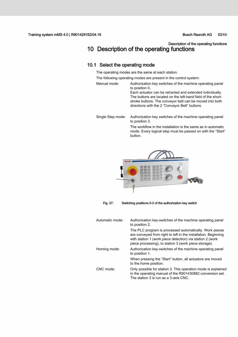
The power supply connectors must be connected to the left-hand station.
With the left-hand station, the connection cable must be connected to the
current cable with an earthing-pin plug and can be connected to 110-230V AC.
Fig. 26: Connecting the power supply
52/68 Bosch Rexroth AG Training system mMS 4.0 | R901429162/04.16
Set-up, installation and commissioning
9.5 Commissioning the training system
Switching on the training system
The electrical / pneumatic supply and installation has been connected properly.
The functional test has been carried out.
There are no tools, cleaning cloths or other objects in the mMS 4.0 training
system.
The accessibility and the function of the EMERGENCY STOP buttons
is assured.
The training system is on a level ground and the rollers are locked.
All workpieces are removed from the installation and the high-stack storage.
The racks are filled with workpieces.
The pinning unit is filled with workpieces.
Each time the exercise is set up, examine the machine for:
– Functional reliability,
– Safety from injury.
Depending on the operating state, note the following before switching it on:
Make sure the mains plug is plugged in for the power supply of the mMS 4.0
training system.
Where necessary, unlock the EMERGENCY STOP button.
9.6 Check the EMERGENCY STOP circuit
A manual check of the EMERGENCY STOP circuit is done by pressing the
EMERGENCY STOP button after booting up each station (PLC in “RUN”).
It is now not possible to run the machine. Unlock the EMERGENCY STOP
button again and press the Reset button of each station. The system is again
ready for operation.
The power pack (115-230 V) in the control box continues to carry current even
when the EMERGENCY STOP voltage is active.
Requirements:
Switch on the machine as follows:
Training system mMS 4.0 | R901429162/04.16 Bosch Rexroth AG 53/68
Description of the operating functions
10 Description of the operating functions
10.1 Select the operating mode
The operating modes are the same at each station.
The following operating modes are present in the control system:
Manual mode: Authorization key switches of the machine operating panel
to position 0.
Each actuator can be retracted and extended individually.
The buttons are located on the left-hand field of the short-
stroke buttons. The conveyor belt can be moved into both
directions with the 2 “Conveyor Belt” buttons.
Single Step mode: Authorization key switches of the machine operating panel
to position 3.
The workflow in the installation is the same as in automatic
mode. Every logical step must be passed on with the “Start”
button.
Fig. 27: Switching positions 0-3 of the authorization key switch
Automatic mode: Authorization key-switches of the machine operating panel
to position 2.
The PLC program is processed automatically. Work pieces
are conveyed from right to left in the installation. Beginning
with station 1 (work piece detection) via station 2 (work
piece processing), to station 3 (work piece storage).
Homing mode: Authorization key-switches of the machine operating panel
to position 1.
When pressing the “Start” button, all actuators are moved
to the home position.
CNC mode: Only possible for station 3. This operation mode is explained
in the operating manual of the R901430882 conversion set.
The station 3 is run as a 3-axis CNC.
54/68 Bosch Rexroth AG Training system mMS 4.0 | R901429162/04.16
Description of the operating functions
10.2 Manual mode operation
To launch the existing programs at each station in manual mode, proceed
as follows:
Ensure that the EMERGENCY STOP button is unlocked.
The PLC must display “RUN” on the display.
Choose manual mode using the authorization key-switch of the machine
operating panel to position 0.
The buttons to be pressed flash.
Actuate the reset button.
Connect the “Power on” output (Station 3).
Each actuator can be actuated individually.
The conveyor belt can be moved in both directions.
Short-stroke buttons on the actuators can only be operated in manual mode.
10.3 Operating Single Step mode
To launch the existing programs at each station in single step mode, proceed
as follows:
Ensure that the EMERGENCY STOP button is unlocked.
The PLC must display “RUN” on the display.
Choose Single step mode using the authorization key-switch of the machine
operating panel to position 3.
The buttons to be pressed flash.
Actuate the reset button.
Connect the “Power on” output (Station 3).
Press the Start button.
Press the Start button again after each logical step.
The PLC program runs automatically with each press of the “Start” button,
the work pieces must be removed by hand from the end of the conveyor and
the ramp. After a cycle has been run through completely, the cycle can begin
from new. In the event of an interruption, press the “Start” button again.
CAUTION Risk of damage!
Before initiating a program, all work pieces are removed from the training
system and loaded into the racks. At the manual mode Station 3 either "Check
Stock" or "Clear Stock" must have been performed.
The pinning unit must be filled with pins. A friction-free processing of the system
is ensured.
Training system mMS 4.0 | R901429162/04.16 Bosch Rexroth AG 55/68
Description of the operating functions
10.4 Automatic mode operation
The mMS 4.0 training system is delivered with the following example programs:
“Station 1”: To issue, convey and test work pieces for their material
conditions and quality. Sampling incorrect parts.
Transfer to the next station.
Extended: Operation/visualization via a VCP touchpad,
control/visualization via an Open Core Engineering System.
Integrating RFID and safety technology.
“Station 2”: Transport and process work pieces. Add 3 pins, process
in a press, press together two work pieces.
Return to conveyor belt and transfer to next station.
Extended: Operation/visualization via a VCP touchpad,
integrating RFID and safety technology.
“Station 3”: Transport and put work pieces into storage. The work pieces
can also be removed from storage again. Transfer to the next
station is possible.
Extended: Operation/visualization via a VCP touchpad,
integrating RFID and safety technology.
To launch the existing programs at each station in automatic mode, proceed
as follows:
Ensure that the EMERGENCY STOP button is unlocked.
The PLC must display “RUN” on the display.
Choose automatic mode using the authorization key-switch of the machine
operating panel to position 2.
The buttons to be pressed flash.
Actuate the reset button.
Connect the “Power on” output (Station 3).
Press the “Start” button.
The PLC program runs automatically, the work pieces must be removed by hand
from the end of the conveyor and the ramp. After a cycle has been run through
completely, the cycle can begin from new. In the event of an interruption, press
the “Start” button again.
CAUTION Risk of damage!
Before initiating a program, all work pieces are removed from the training
system and loaded into the racks. At the manual mode Station 3 either "Check
Stock" or "Clear Stock" must have been performed.
The pinning unit must be filled with pins. A friction-free processing of the system
is ensured.
56/68 Bosch Rexroth AG Training system mMS 4.0 | R901429162/04.16
Description of the operating functions
10.5 Homing mode operation
To launch the existing programs at each station in homing mode, proceed
as follows:
Ensure that the EMERGENCY STOP button is unlocked.
The PLC must display “RUN” on the display.
Choose homing mode using the authorization key-switch of the machine
operating panel to position 1.
The buttons to be pressed flash.
Actuate the reset button.
Connect the “Power on” output (Station 3).
Press the Start button.
All actuators move to the home position.
The PLC program runs automatically, the work pieces must be removed by hand
from the end of the conveyor and the ramp. After a cycle has been run through
completely, the cycle can begin from new. In the event of an interruption, press
the “Start” button again.
10.6 „Check Stock“ function
To check the high-bay warehouse of the station on already existing pieces,
proceed as follows:
Choose homing mode using the authorization key-switch of the machine
operating panel to position 1.
Actuate the start button. System in home position.
Actuate start and stop button for approx. 10 sec.
High-bay warehouse checks stock for available work pieces and stores them
New work pieces will be put to free storage places
10.7 „Clear Stock“ function
To clear counter of full stock in PLC program after emptiing stock manually,
proceed as follows:
Choose homing mode using the authorization key-switch of the machine
operating panel to position 1.
Actuate the start button. System in home position.
Actuate start, stop and home button for approx. 10 sec.
PLC counter is deleted
CAUTION Risk of damage!
Before initiating a program, all work pieces are removed from the training
system and loaded into the racks. At the manual mode Station 3 either "Check
Stock" or "Clear Stock" must have been performed.
The pinning unit must be filled with pins. A friction-free processing of the system
is ensured.
Training system mMS 4.0 | R901429162/04.16 Bosch Rexroth AG 57/68
Description of the operating functions
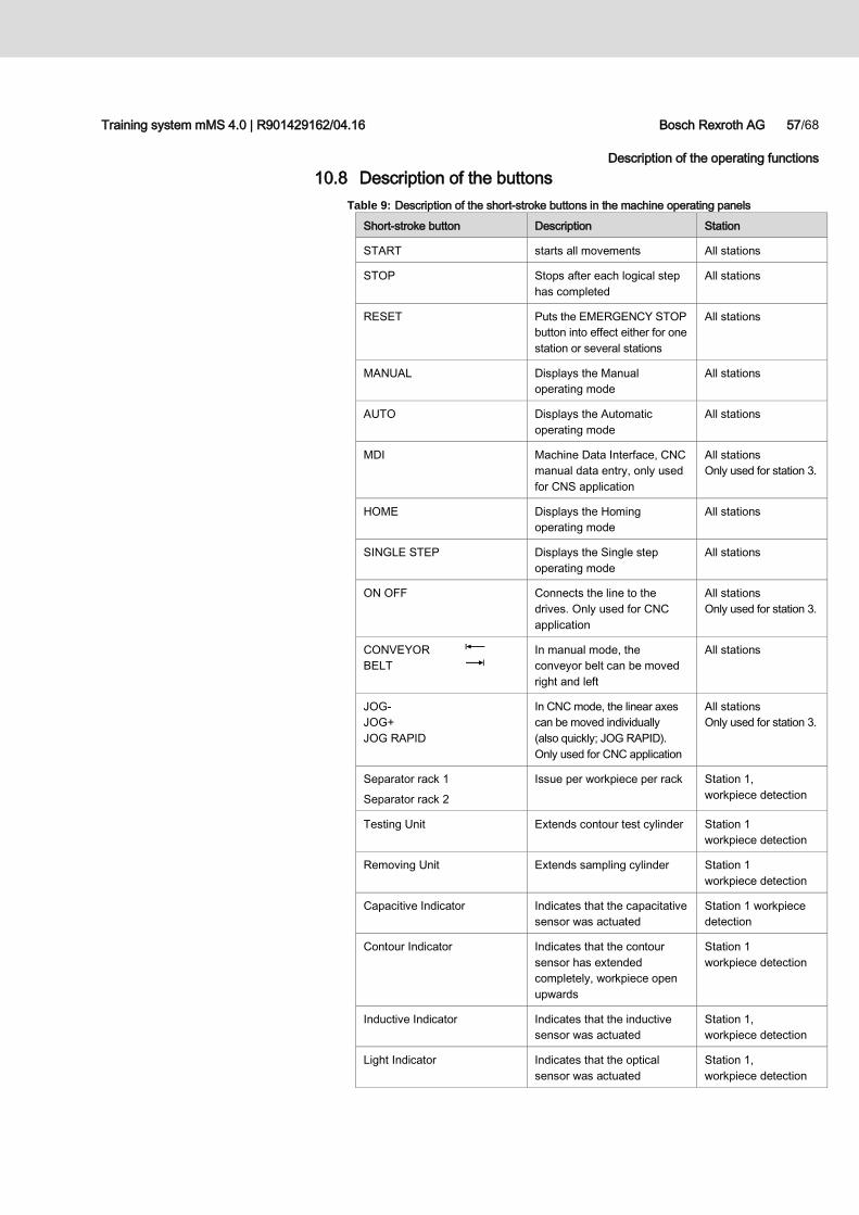
10.8 Description of the buttons
Table 9: Description of the short-stroke buttons in the machine operating panels
Short-stroke button Description Station
START starts all movements All stations
STOP Stops after each logical step
has completed
All stations
RESET Puts the EMERGENCY STOP
button into effect either for one
station or several stations
All stations
MANUAL Displays the Manual
operating mode
All stations
AUTO Displays the Automatic
operating mode
All stations
MDI Machine Data Interface, CNC
manual data entry, only used
for CNS application
All stations
Only used for station 3.
HOME Displays the Homing
operating mode
All stations
SINGLE STEP Displays the Single step
operating mode
All stations
ON OFF Connects the line to the
drives. Only used for CNC
application
All stations
Only used for station 3.
CONVEYOR
BELT
In manual mode, the
conveyor belt can be moved
right and left
All stations
JOG-
JOG+
JOG RAPID
In CNC mode, the linear axes
can be moved individually
(also quickly; JOG RAPID).
Only used for CNC application
All stations
Only used for station 3.
Separator rack 1
Separator rack 2
Issue per workpiece per rack Station 1,
workpiece detection
Testing Unit Extends contour test cylinder Station 1
workpiece detection
Removing Unit Extends sampling cylinder Station 1
workpiece detection
Capacitive Indicator Indicates that the capacitative
sensor was actuated
Station 1 workpiece
detection
Contour Indicator Indicates that the contour
sensor has extended
completely, workpiece open
upwards
Station 1
workpiece detection
Inductive Indicator Indicates that the inductive
sensor was actuated
Station 1,
workpiece detection
Light Indicator Indicates that the optical
sensor was actuated
Station 1,
workpiece detection
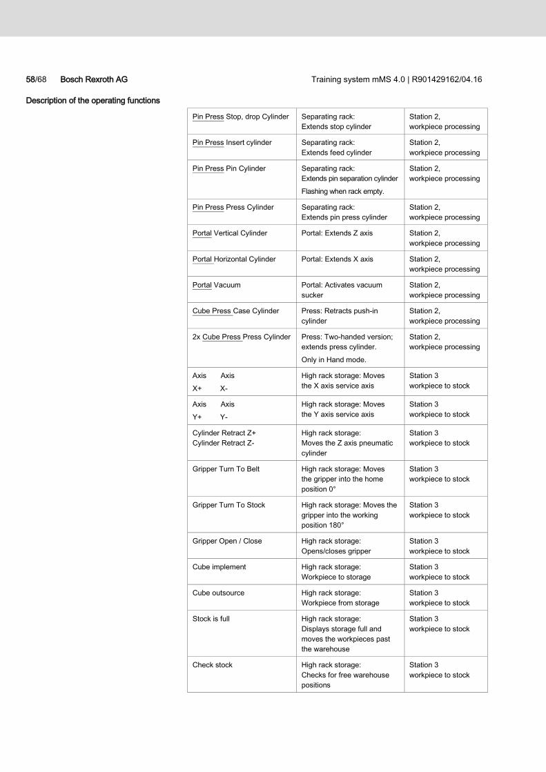
58/68 Bosch Rexroth AG Training system mMS 4.0 | R901429162/04.16
Description of the operating functions
Pin Press Stop, drop Cylinder Separating rack:
Extends stop cylinder
Station 2,
workpiece processing
Pin Press Insert cylinder Separating rack:
Extends feed cylinder
Station 2,
workpiece processing
Pin Press Pin Cylinder Separating rack:
Extends pin separation cylinder
Flashing when rack empty.
Station 2,
workpiece processing
Pin Press Press Cylinder Separating rack:
Extends pin press cylinder
Station 2,
workpiece processing
Portal Vertical Cylinder Portal: Extends Z axis Station 2,
workpiece processing
Portal Horizontal Cylinder Portal: Extends X axis Station 2,
workpiece processing
Portal Vacuum Portal: Activates vacuum
sucker
Station 2,
workpiece processing
Cube Press Case Cylinder Press: Retracts push-in
cylinder
Station 2,
workpiece processing
2x Cube Press Press Cylinder Press: Two-handed version;
extends press cylinder.
Only in Hand mode.
Station 2,
workpiece processing
Axis Axis
X+ X-
High rack storage: Moves
the X axis service axis
Station 3
workpiece to stock
Axis Axis
Y+ Y-
High rack storage: Moves
the Y axis service axis
Station 3
workpiece to stock
Cylinder Retract Z+
Cylinder Retract Z-
High rack storage:
Moves the Z axis pneumatic
cylinder
Station 3
workpiece to stock
Gripper Turn To Belt High rack storage: Moves
the gripper into the home
position 0°
Station 3
workpiece to stock
Gripper Turn To Stock High rack storage: Moves the
gripper into the working
position 180°
Station 3
workpiece to stock
Gripper Open / Close High rack storage:
Opens/closes gripper
Station 3
workpiece to stock
Cube implement High rack storage:
Workpiece to storage
Station 3
workpiece to stock
Cube outsource High rack storage:
Workpiece from storage
Station 3
workpiece to stock
Stock is full High rack storage:
Displays storage full and
moves the workpieces past
the warehouse
Station 3
workpiece to stock
Check stock High rack storage:
Checks for free warehouse
positions
Station 3
workpiece to stock
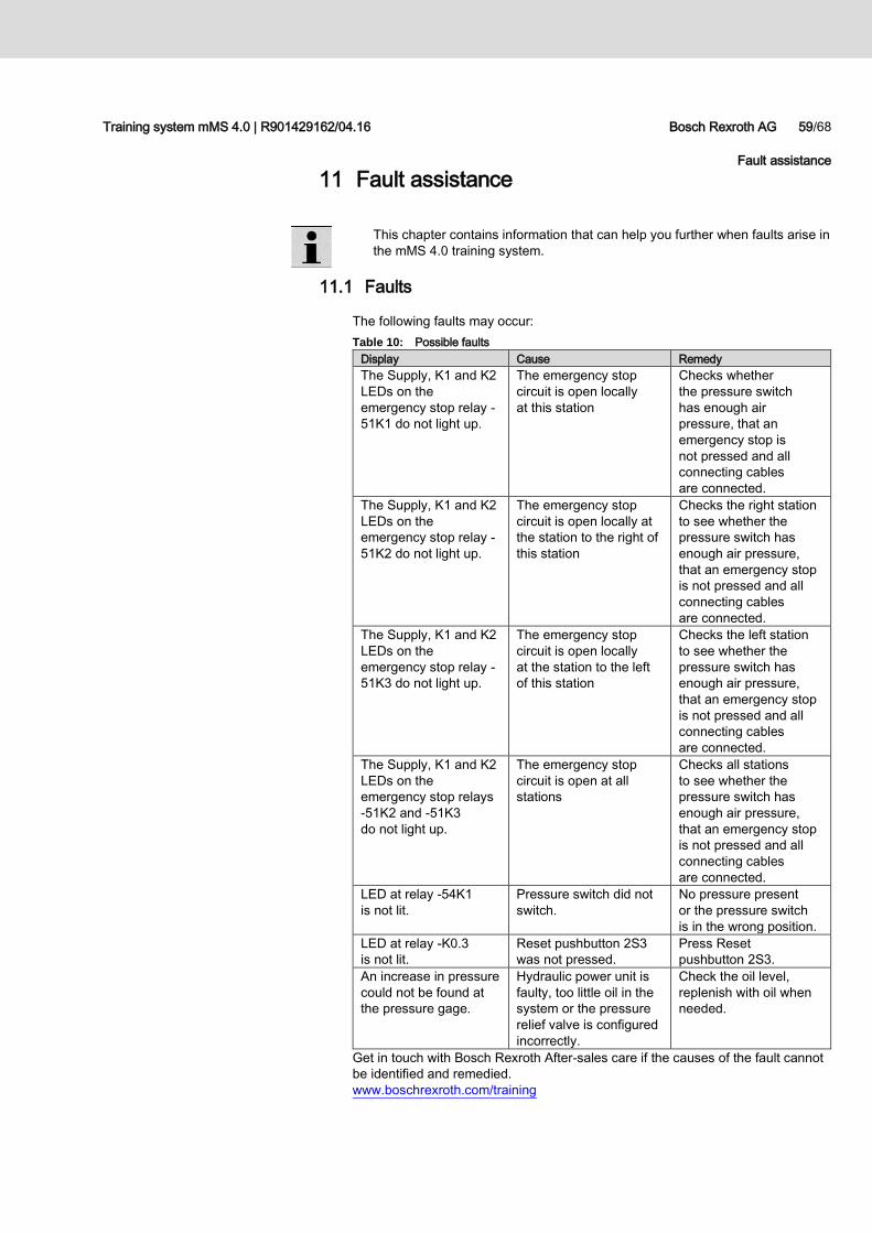
Training system mMS 4.0 | R901429162/04.16 Bosch Rexroth AG 59/68
Fault assistance
11 Fault assistance
This chapter contains information that can help you further when faults arise in
the mMS 4.0 training system.
11.1 Faults
The following faults may occur:
Table 10: Possible faults
Display Cause Remedy
The Supply, K1 and K2
LEDs on the
emergency stop relay -
51K1 do not light up.
The emergency stop
circuit is open locally
at this station
Checks whether
the pressure switch
has enough air
pressure, that an
emergency stop is
not pressed and all
connecting cables
are connected.
The Supply, K1 and K2
LEDs on the
emergency stop relay -
51K2 do not light up.
The emergency stop
circuit is open locally at
the station to the right of
this station
Checks the right station
to see whether the
pressure switch has
enough air pressure,
that an emergency stop
is not pressed and all
connecting cables
are connected.
The Supply, K1 and K2
LEDs on the
emergency stop relay -
51K3 do not light up.
The emergency stop
circuit is open locally
at the station to the left
of this station
Checks the left station
to see whether the
pressure switch has
enough air pressure,
that an emergency stop
is not pressed and all
connecting cables
are connected.
The Supply, K1 and K2
LEDs on the
emergency stop relays
-51K2 and -51K3
do not light up.
The emergency stop
circuit is open at all
stations
Checks all stations
to see whether the
pressure switch has
enough air pressure,
that an emergency stop
is not pressed and all
connecting cables
are connected.
LED at relay -54K1
is not lit.
Pressure switch did not
switch.
No pressure present
or the pressure switch
is in the wrong position.
LED at relay -K0.3
is not lit.
Reset pushbutton 2S3
was not pressed.
Press Reset
pushbutton 2S3.
An increase in pressure
could not be found at
the pressure gage.
Hydraulic power unit is
faulty, too little oil in the
system or the pressure
relief valve is configured
incorrectly.
Check the oil level,
replenish with oil when
needed.
Get in touch with Bosch Rexroth After-sales care if the causes of the fault cannot
be identified and remedied.
www.boschrexroth.com/training
60/68 Bosch Rexroth AG Training system mMS 4.0 | R901429162/04.16
Fault assistance
11.2 Troubleshooting
Basic procedure
Remove all workpieces from the stations.
Check
- All electrical connections for possible faults,
- The pneumatic and mechanical components for possible faults.
After the fault has been removed:
1. Actuate the reset button.
The reset button is lit.
If the reset pushbutton continues to flash, this means there is a fault.
2. Remedy the fault, then go to Step 1.
3. Press the Start button.
Process can be continued.
Restarting after a power failure
Remove all cubes and cube halves from the stations.
Empty the high-stack storage.
Re-establish the voltage.
The programmable logic controllers are rebooted.
Once they are ready, the reset and start buttons will flash.
Training system mMS 4.0 | R901429162/04.16 Bosch Rexroth AG 61/68
Maintenance and inspection
12 Maintenance and inspection
This chapter describes the maintenance and inspection work which may
be carried out by trained personnel on the mMS 4.0 training system.
Maintenance and inspection work which may only be performed by specially
trained and qualified personnel is described in 13 “Maintenance work”.
12.1 General information
Report the faults which were identified to the responsible manager immediately
so as to be able to remedy them immediately. Note that small faults can lead
to big ones if these are not remedied in time.
Only clean the plastic parts with a lightweight, damp cloth. Only use water
and a mild cleaning agent without chemical additives. Never use solvents or
aggressive cleaning agents.
Before using a cleaning agent, examine the usage instructions and possible
hazards in the user information and DIN safety data sheet.
Never blow out the training system with compressed air as sensors and valves
of the functional assemblies may get damaged.
If you must remove oil, use suitable binding agents and cleaning cloths.
Protect the training system from dust and moisture to prevent it from being
contaminated and can be used for a long time.
Store and dispose of ejected and consumed working materials and
consumables appropriately in accordance with legal requirements.
In case of doubt, get information about the type of storage and disposal
provided by the material manufacturer/supplier.
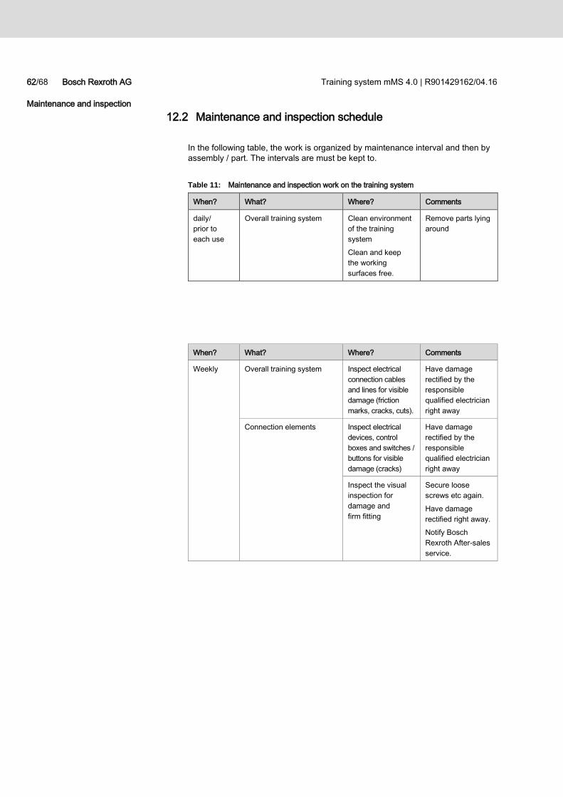
62/68 Bosch Rexroth AG Training system mMS 4.0 | R901429162/04.16
Maintenance and inspection
12.2 Maintenance and inspection schedule
In the following table, the work is organized by maintenance interval and then by
assembly / part. The intervals are must be kept to.
Table 11: Maintenance and inspection work on the training system
When? What? Where? Comments
daily/
prior to
each use
Overall training system Clean environment
of the training
system
Clean and keep
the working
surfaces free.
Remove parts lying
around
When? What? Where? Comments
Weekly
Overall training system Inspect electrical
connection cables
and lines for visible
damage (friction
marks, cracks, cuts).
Have damage
rectified by the
responsible
qualified electrician
right away
Connection elements Inspect electrical
devices, control
boxes and switches /
buttons for visible
damage (cracks)
Have damage
rectified by the
responsible
qualified electrician
right away
Inspect the visual
inspection for
damage and
firm fitting
Secure loose
screws etc again.
Have damage
rectified right away.
Notify Bosch
Rexroth After-sales
service.
Training system mMS 4.0 | R901429162/04.16 Bosch Rexroth AG 63/68
Maintenance work
13 Maintenance work
13.1 General information
Inadequate maintenance leads to
Faults,
Possible breakdown
High repair costs.
Observe the following instructions if anomalies, faults and wear is identified during
operation or during the inspection:
Immediately place the training system out of service.
Find the causes of the fault and fix the defects.
Replace the damaged part.
Do not put the mMS 4.0 training system back into operation where unsafe
to do so.
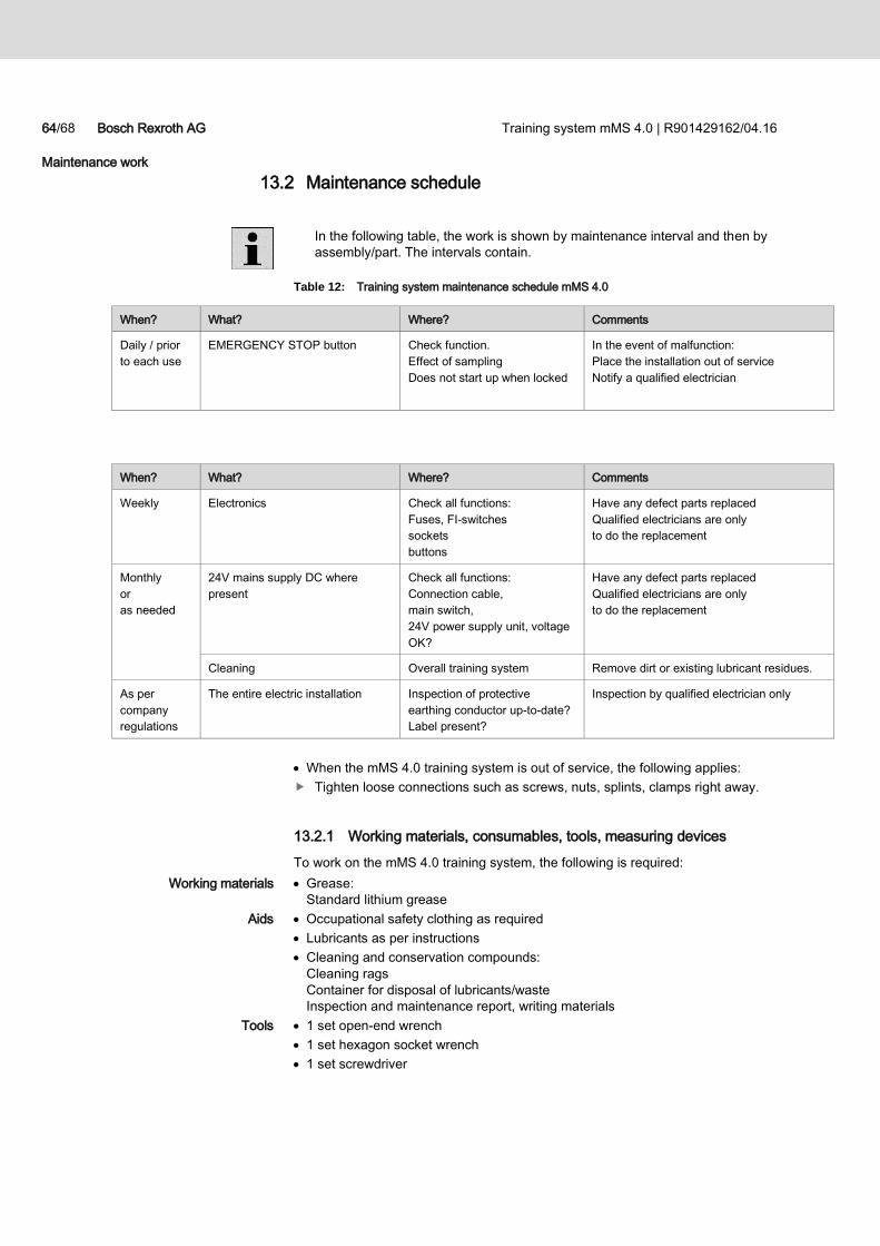
64/68 Bosch Rexroth AG Training system mMS 4.0 | R901429162/04.16
Maintenance work
13.2 Maintenance schedule
In the following table, the work is shown by maintenance interval and then by
assembly/part. The intervals contain.
Table 12: Training system maintenance schedule mMS 4.0
When the mMS 4.0 training system is out of service, the following applies:
Tighten loose connections such as screws, nuts, splints, clamps right away.
13.2.1 Working materials, consumables, tools, measuring devices
To work on the mMS 4.0 training system, the following is required:
Grease:
Standard lithium grease
Occupational safety clothing as required
Lubricants as per instructions
Cleaning and conservation compounds:
Cleaning rags
Container for disposal of lubricants/waste
Inspection and maintenance report, writing materials
1 set open-end wrench
1 set hexagon socket wrench
1 set screwdriver
When? What? Where? Comments
Daily / prior
to each use
EMERGENCY STOP button Check function.
Effect of sampling
Does not start up when locked
In the event of malfunction:
Place the installation out of service
Notify a qualified electrician
When? What? Where? Comments
Weekly Electronics Check all functions:
Fuses, FI-switches
sockets
buttons
Have any defect parts replaced
Qualified electricians are only
to do the replacement
Monthly
or
as needed
24V mains supply DC where
present
Check all functions:
Connection cable,
main switch,
24V power supply unit, voltage
OK?
Have any defect parts replaced
Qualified electricians are only
to do the replacement
Cleaning Overall training system Remove dirt or existing lubricant residues.
As per
company
regulations
The entire electric installation Inspection of protective
earthing conductor up-to-date?
Label present?
Inspection by qualified electrician only
Working materials
Aids
Tools
Training system mMS 4.0 | R901429162/04.16 Bosch Rexroth AG 65/68
Disposal
13.2.2 Replace parts
Only use original spare parts.
When ordering spare parts, always specify the device type, material number,
year of manufacture and parts designation.
Get in touch with Bosch Rexroth After-sales.
For the address and other contact data, consult the reverse of this
operating manual.
www.boschrexroth.com/training
Immediately rectify the wear on the mMS 4.0 training system when
– Workplace safety and functions are not in place
– Subsequent damage is expected
If elements are damaged, check whether the wear limit has been reached.
Decide whether you need to replace the part or wait until the next
maintenance.
Only rectify wear when
– The mMS 4.0 training system is in an upright position safe for personnel and
– There is no risk to health (falling, slipping due to moisture, etc).
Have a skilled person check the following after rectification of the wear and
before the machine is put into operation
– Has the work been carried out properly
– Is the mMS 4.0 training system ready for operation without impairment.
14 Disposal
The training system is made of materials which are recyclable and can be reused.
Specialized firms cab recycle this training system to gain valuable materials from
it and to minimize the amount of material requiring disposal.
Dispose of the training system based on local and legal requirements.
Water-polluting materials such as hydraulic oil and cleaning liquids containing
solvents must not be allowed to contaminate the soil or get into the water supply.
Working materials and consumables must be placed in suitable containers,
stored, transported, collected and disposed of according to the legal
requirements. In case of doubt, obtain information about storage and disposal
types from the manufacturer / vendor.
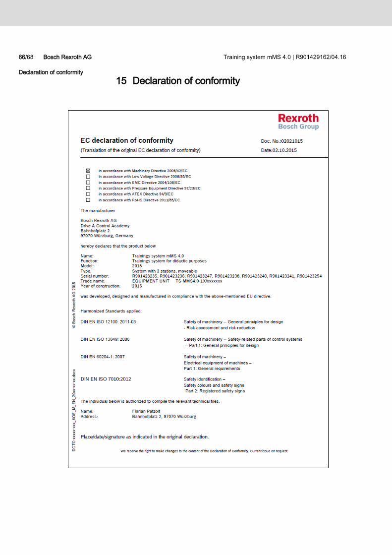
66/68 Bosch Rexroth AG Training system mMS 4.0 | R901429162/04.16
Declaration of conformity
15 Declaration of conformity


Subject to change
Printed in Germany
Mat No. R901429162
Bosch Rexroth AG
Drive & Control Academy
Bahnhofplatz 2
D-97070 Würzburg, Germany
Phone: 09352 18 1920
Fax: 09352 18 6882
[email protected] www.boschrexroth.com\training