sedimentology and stratigraphic architecture of the late
TRANSCRIPT
University of Nebraska - Lincoln University of Nebraska - Lincoln
DigitalCommons@University of Nebraska - Lincoln DigitalCommons@University of Nebraska - Lincoln
Papers in the Earth and Atmospheric Sciences Earth and Atmospheric Sciences, Department of
11-2007
Sedimentology and Stratigraphic Architecture of the Late Permian Sedimentology and Stratigraphic Architecture of the Late Permian
Betts Creek Beds, Queensland, Australia Betts Creek Beds, Queensland, Australia
Jonathan P. Allen University of Nebraska-Lincoln, [email protected]
Christopher R. Fielding University of Nebraska-Lincoln, [email protected]
Follow this and additional works at: https://digitalcommons.unl.edu/geosciencefacpub
Part of the Earth Sciences Commons
Allen, Jonathan P. and Fielding, Christopher R., "Sedimentology and Stratigraphic Architecture of the Late Permian Betts Creek Beds, Queensland, Australia" (2007). Papers in the Earth and Atmospheric Sciences. 278. https://digitalcommons.unl.edu/geosciencefacpub/278
This Article is brought to you for free and open access by the Earth and Atmospheric Sciences, Department of at DigitalCommons@University of Nebraska - Lincoln. It has been accepted for inclusion in Papers in the Earth and Atmospheric Sciences by an authorized administrator of DigitalCommons@University of Nebraska - Lincoln.
1. Introduction
While the past ten years have seen remarkable prog-ress and advances in our understanding of the ma-jor controls on the large-scale sediment body archi-tecture of alluvial successions, these controls are still not clearly understood (Blum and Törnqvist, 2000). Outcrop, laboratory, and computer modeling studies have suggested that sea level, tectonics, and climate act as major controls on the architecture of alluvial successions (e.g. Shanley and McCabe, 1993; Mackey
and Bridge, 1995; Olsen et al., 1995; Heller and Paola, 1996; and see Blum and Törnqvist, 2000, and Bridge, 2003, for reviews). However, analyses of the strati-graphic architecture of coal-bearing alluvial plain se-quences are more limited. While some studies have highlighted the effects of sea level (Bohacs and Suter, 1997), tectonics (Fielding, 1987), and climate (Fielding and Webb, 1996; papers in Pashin and Gastaldo, 2004) on coal-bearing strata, few have successfully decon-volved signals of multiple controls within individual successions.
Published in Sedimentary Geology 202:1-2 (November 15, 2007), pp. 5–34; doi: 10.1016/j.sedgeo.2006.12.010 ; Selected papers pre-sented at the Eighth International Conference on Fluvial Sedimentology. Copyright © 2007 Elsevier B.V. Used by permission.
http://www.sciencedirect.com/science/journal/00370738
Published online January 8, 2007.
Sedimentology and Stratigraphic Architecture of the Late Permian Betts Creek Beds, Queensland, Australia
Jonathan P. Allen and Christopher R. Fielding
Department of Geosciences, 214 Bessey Hall, University of Nebraska–Lincoln, Lincoln, NE 68588-0340, USACorresponding author — J. P. Allen, fax 402 472-4917, email [email protected]
AbstractThe Late Permian Betts Creek Beds form a succession of coal-bearing alluvial-coastal plain sediments in a basin marginal setting within the northeastern Galilee Basin, Queensland, Australia. The unit is ~ 50–60 m in thick-ness at Porcupine Creek National Park where outcrop is laterally continuous for several kilometers. Eight fa-cies have been identified within the formation and can be grouped into 2 facies associations: (A) channel depos-its and (B) floodbasin deposits. The channel association consists of conglomerate (A1) and trough cross-bedded multistorey sandstone facies (A2), both interpreted as deposits of low-sinuosity river systems, tidally influenced fluvial channels (A3), interbedded sandstone and siltstone (A4) interpreted as the abandonment fill of the al-luvial systems, and diamictite (A5) interpreted as debris flows. The floodbasin facies association is composed of sandy siltstone (B1; proximal–distal floodbasin), carbonaceous siltstone (B2; mire), and bioturbated siltstone (B3; estuarine) facies.
The overall sediment body architecture can be resolved into 6 unconformity-bounded cycles interpreted as sequences in the genetic sense, which are sheet-like in geometry and, in general, consist of amalgamated mul-tistorey, multilateral braided fluvial deposits at the base overlain by extensive sheet-like overbank mudstones, carbonaceous shales, and coals. Sea-level change is interpreted as the primary control on the sequence architec-ture of the formation, while the internal stratigraphic architecture, however, varies between sequences and is a function of a combination of sea level, tectonic, and autogenic controls.
Keywords: alluvial architecture, Late Permian, Eastern Australia, sea-level change, cyclicity
5
6 All en & Fi el d i n g i n Sed i m ent a r y Geo l oG y 202 (2007)
The Betts Creek Beds in north-central Queensland, Australia provide an excellent opportunity to examine the interplay of both allogenic (sea level, tectonics, cli-
mate) and autogenic controls on the sediment body ar-chitecture of coal-bearing alluvial plain systems. In this study, the effects of sea level and tectonics are dominant
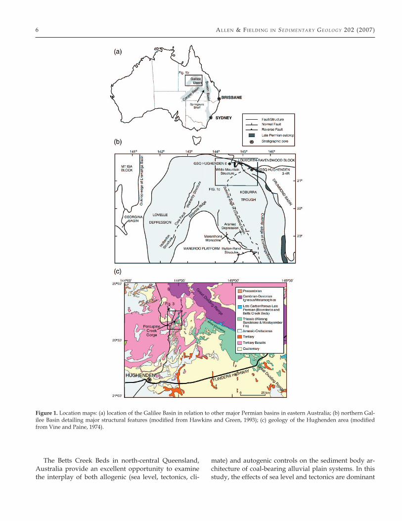
Figure 1. Location maps: (a) location of the Galilee Basin in relation to other major Permian basins in eastern Australia; (b) northern Gal-ilee Basin detailing major structural features (modified from Hawkins and Green, 1993); (c) geology of the Hughenden area (modified from Vine and Paine, 1974).
lA te Pe r mi A n Be tts Cr ee k Be d s, Que en s l A n d, Aus tr A l iA 7
controls on the sediment body architecture and the re-lationship between these and autogenic controls can be differentiated.
2. Regional geology
2.1. Basin setting
The Galilee Basin is a large intracratonic basin of Late Carboniferous to Triassic age located in central Queensland (Figure 1a). Basement comprises the Late Devonian–Early Carboniferous Drummond Basin to the east (Evans, 1980), the early Paleozoic metasedimen-tary and intrusive rocks of the Thomson Orogen in the center (Evans, 1980), and Precambrian to early Paleo-zoic metamorphic rocks west of the Cork Fault (Vine,
1976; Hawkins and Green, 1993). Much of the Gali-lee Basin is deeply buried beneath Jurassic–Cretaceous and Cenozoic sediments of the Eromanga Basin, with the only significant surface exposure along the eastern and northeastern basin margin (Figure 1a, b). Therefore, determining the lithostratigraphy of the basin is heav-ily dependent on limited subsurface data. The basin is divided into southern and northern regions at approxi-mately 24° S (Hawkins and Green, 1993). This paper fo-cuses on exposures near the northeastern margin of the Galilee Basin.
The northern Galilee Basin is bounded to the east by the Drummond Basin, to the north by the early Paleo-zoic Lolworth–Ravenswood Block, and to the west by the Precambrian Mount Isa Block and Georgina Basin (Evans, 1980; Scott and Hawkins, 1992; Hawkins and Green, 1993; Figure 1b). Two depressions, the Koburra
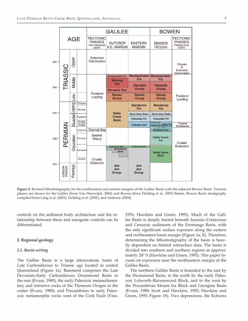
Figure 2. Revised lithostratigraphy for the northeastern and eastern margins of the Galilee Basin with the adjacent Bowen Basin. Tectonic phases are shown for the Galilee (from Van Heeswijck, 2004) and Bowen (from Fielding et al., 2001) Basins. Bowen Basin stratigraphy compiled from Lang et al. (2001), Fielding et al. (2001), and Anthony (2004).
8 All en & Fi el d i n g i n Sed i m ent a r y Geo l oG y 202 (2007)
Trough and the Lovelle Depression, are separated by the early Paleozoic Maneroo Platform (Figure 1b).
In general, the Paleozoic basin fill can be divided into two sections (Evans, 1980; Figure 2). The Late Carbonif-erous to Early Permian basin fill is characterized by flu-vial and lacustrine sediments of the Joe Joe Group, some of which are glaciogenic (Jochmus Formation and Boon-deroo Beds). The late Early Permian was a time of wide-spread peat development represented by the Aramac Coal Measures. The basin experienced a period of non-deposition and/or gentle uplift (Evans, 1980) before the accumulation of widespread fluvial and coal deposits of the Betts Creek Beds and correlatives (Vine, 1976; Ev-ans, 1980). During the Late Permian, sediments from the Bowen Basin spilled across the Springsure Shelf into the Galilee Basin (Fielding et al., 2001), and may have bur-ied the bounding ridges, thereby connecting not only the Bowen and Galilee Basins, but also the Cooper Ba-sin (Hawkins, 1978). Triassic strata in the basin are dom-inantly fluvial (Rewan Group, Warang and Clematis
Sandstones, and Moolayember Formation; Hawkins and Green, 1993).
The Galilee Basin fill was initially regarded as en-tirely non-marine (Vine and Paine, 1974; Vine, 1976), but Evans (1980) later suggested that marine condi-tions entered the southern Koburra Trough during the Late Permian. Furthermore, Scott and Hawkins (1992) and Hawkins and Green (1993) recognized bioturbated paralic facies along the eastern margin which they con-sidered equivalent to the Peawaddy Formation of the Denison Trough. The present study recognizes several horizons of bioturbation and indications that paralic sedimentation extends farther northward along the ba-sin margin.
2.2. Tectonic and structural setting
There have been several interpretations of the struc-tural evolution of the Galilee Basin including: (1) a pull-apart basin formed by shearing along the north-
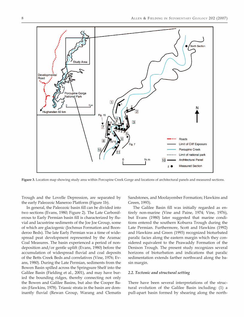
Figure 3. Location map showing study area within Porcupine Creek Gorge and locations of architectural panels and measured sections.
lA te Pe r mi A n Be tts Cr ee k Be d s, Que en s l A n d, Aus tr A l iA 9
eastern and eastern margin of Australia (Evans, 1980), (2) a pericratonic basin (Vine, 1976; Veevers et al., 1982), (3) a basin formed by convective downwelling and regional downwarp (Middleton and Hunt, 1989), and (4) a foreland basin (De Caritat and Braun, 1992). Subsequently, Van Heeswijck (2004) re-evaluated the structural development of the Drummond and Gali-lee Basins and concluded that the development of the Galilee Basin was similar to the development of the ad-jacent and coeval Bowen Basin (Van Heeswijck, 2004). Fielding et al. (2001) developed a paleogeographic syn-thesis for the Bowen–Gunnedah–Sydney Basin Sys-tem (BGSBS) in which major events and sequences were found to be synchronous from north Queensland to southernmost New South Wales. The BGSBS is con-
sidered to have developed sequentially by crustal ex-tension (Late Carboniferous–Early Permian), passive thermal subsidence (mid-Permian), and then fore-land crustal loading (Late Permian–Middle Triassic) in response to pulsed thrust sheet propagation during the Hunter–Bowen Event (Fielding et al., 2001). Van Heeswijck (2004) recognized a similar three-phase his-tory within the Galilee Basin, concluding that the Gal-ilee and Bowen basins were closely related in their de-velopment (Figure 2).
2.3. Regional geology of the Betts Creek Beds
The Betts Creek Beds (BCB) and their correlatives rep-resent the final development of coal-forming condi-
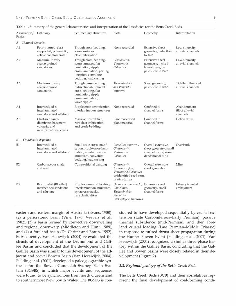
Table 1. Summary of the general characteristics and interpretation of the lithofacies for the Betts Creek Beds
Association/ Lithology Sedimentary structures Biota Geometry Interpretation Facies
A—Channel depositsA1 Poorly sorted, clast- Trough cross-bedding, None recorded Extensive sheet Low-sinuosity supported, polymictic, scour surfaces, geometry, paleoflow alluvial channels cobble conglomerate clast imbrication to 142° A2 Medium- to very Trough cross-bedding, Glossopteris, Extensive sheet Low-sinuosity coarse-grained scour surfaces, flat Vertebraria, geometry, incised alluvial channels sandstones lamination, ripple Calamites lateral margins, cross-lamination, parting paleoflow to 192° lineation, convolute bedding, load casting A3 Medium- to very Trough cross-bedding, Thalassinoides Sheet geometry, Tidally influenced coarse-grained bidirectional/bimodal and Planolites paleoflow to 188° alluvial channels sandstones cross-bedding, flat burrows lamination, ripple cross-lamination, wave ripples A4 Interbedded to Ripple cross-stratification, None recorded Confined to Abandonment interlaminated interlamination structures channel forms fill of alluvial sandstone and siltstone channelsA5 Clast-rich sandy Massive unstratified, Rare macerated Confined to Debris flows diamictite, basement, rare clast imbrication plant material channel forms volcanic, and and crude bedding intraformational clasts
B — Floodbasin depositsB1 Interbedded to Small-scale cross-stratifi- Planolites burrows, Overall extensive Overbank interlaminated cation, ripple cross-lami- Glossopteris, sheet geometry, small sandstone and siltstone nation, interlamination Vertebraria, channel forms, some structures, convolute Calamites depositional dips bedding, load casting B2 Carbonaceous shale Compositional banding Glossopteris, Overall extensive Mire and coal Araucarioxylon, sheet geometry Vertebraria, Calamites, unidentified seed-fern, in situ stumps B3 Bioturbated (BI = 0–5) Ripple cross-stratification, Diplocraterion habichi, Extensive sheet Estuary/coastal interbedded sandstone interlamination structures, Conichnus, geometry, small embayment and siltstone synaeresis cracks, Thalassinoides, channel forms rare clastic dikes Planolites, Palaeophycus burrows
10 All en & Fi el d i n g i n Sed i m ent a r y Geo l oG y 202 (2007)
tions within the Galilee Basin. Age control for the Gali-lee Basin relies on palynological and plant macrofossils (White, in press; Evans, 1967). Evans (1967) proposed palynological stages for eastern Australia, placing the BCB in his Stage 5 (late Early Permian–Late Perm-ian). Nonetheless, several authors contend that Stage 5 represents only the Late Permian (Hawkins, 1978; Hawkins and Green, 1993), and this is the view taken in this paper.
The BCB vary greatly in thickness, reaching a maxi-mum thickness of 390 m (Evans, 1980). Hawkins (1976) described the entire succession as an eastward-thicken-ing lens, thinning rapidly westward and to the north. The BCB crop out in the Hughenden area and in Porcu-pine Creek (Galah) Gorge (Figure 1c, 3), where the max-imum thickness is ~ 60 m. The only published study of the BCB outcrop was part of a mapping survey in which the BCB were interpreted as fluvial and paludal sediments, with alluvial fan, piedmont, and mudflow deposits (Vine and Paine, 1974). The present study fo-cuses on the BCB sensu stricto in Porcupine Creek Gorge (Figure 3).
3. Study area and methods
The BCB are well exposed for several kilome-ters in > 75 m high cliffs along Porcupine Creek Gorge ~ 65 km northeast of Hughenden in northern Queensland, Australia (Figure 3). The nature of the ex-posures is ideal for a three-dimensional architectural study. The area studied as well as the location of cliff exposures (referred to as panels) used for architectural analysis and measured sections are shown in Figure 3. Photomosaics were taken for all exposures in order to map out bounding surfaces and large-scale archi-tectural elements. Twenty, detailed measured sections were logged at the centimeter scale and the resulting data were coupled to the corresponding photomosa-ics. Major bounding surfaces identified first in pho-tomosaics and measured sections were walked out in the field in order to correlate surfaces between outcrop panels and accurately describe the geometry of the for-mation. A laser rangefinder was used to delineate ma-jor bounding surfaces and to measure thicknesses of major units that were inaccessible. Regional dip, how-ever, allowed the entire formation to be investigated and detailed at some point along the outcrop belt. Pa-leocurrent measurements and hand specimens from a lithologic suite representative of the BCB were also collected.
4. Lithofacies and architectural elements
Eight lithofacies are recognized within the BCB (Table 1). These facies have been assigned to two associations that reflect the architecture and major depositional en-vironments of the BCB and are (A) channel deposits and (B) floodbasin deposits.
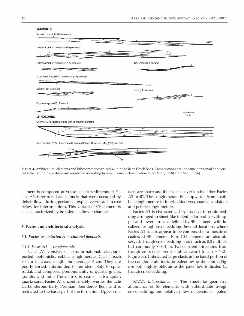
Eight architectural elements and two higher-order lithosomes have been identified within the succession of the BCB (Table 2). The two higher-order lithosomes, channel and overbank, were established in order to avoid confusion within the architectural classification. Architectural features are observed at different scales and orders, and should therefore have a hierarchy for their classification, just as bounding surfaces have a hi-erarchy that establishes the scale of feature that they en-close (channel-belt, channel, macroform, etc.). Therefore, lithosomes are defined as architectural features that are made up of architectural elements, which in turn are composed of smaller, internal features.
Architectural elements are distinguished by a variety of characteristics including bounding surfaces, lithofa-cies composition, geometry, vertical and lateral associa-tions, and paleocurrent distributions. Bounding surfaces were assigned a numerical rank after Miall (1996). Bounding surfaces of first-and second-order have not been detailed on any of the architectural panels, because they cannot be distinguished. The criteria for recogni-tion of architectural elements are summarized in Fig-ure 4 and Table 2, and were adapted and modified after Miall (1985, 1988, & 1996). For ease of comparison be-tween this study and others, elements have been given codes in the fashion of Miall (1996). Several elements, however, warranted a different code from those set out by Miall (1996) and will be discussed below, along with modified elements. Those elements that have already been defined (DA, LA, SF, OF, LE, CS) will not be de-tailed further.
4.1. Channel (CH) lithosome
Channel lithosomes as discussed above contain within-channel elements. CH lithosomes are not clearly defined within the study area and only a few channel margins have been observed. This lack of definition may be due to the abundance of outcrop exposure roughly paral-lel to paleoflow. It is not expected that channel margins would be observed with such orientations; instead a sheet-like channel geometry is observed. Where outcrop orientations are normal to paleoflow, several channel margins can be delineated, but only two architectural panels (2, 5) are observed with this orientation. Where
lA te Pe r mi A n Be tts Cr ee k Be d s, Que en s l A n d, Aus tr A l iA 11
channel margins are exposed, they probably represent the temporary margins of migrating channels within a wide channel belt.
4.2. Nested channel fill (NC)
This element broadly equates to the SB element of Miall (1996), and is composed of sediments of Facies A2.
4.3. Channel fill (CF)
Two variations of this element are recognized within the BCB. The most common CF elements are infilled with fine-grained sediments of Facies A4 and are in-terpreted as representing channels undergoing aban-donment. This variant of CF element is similar to the FF(C) element of Miall (1996). The other variant of CF
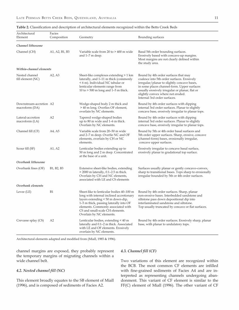
Table 2. Classification and description of architectural elements recognized within the Betts Creek Beds
Architectural Facies Element Composition Geometry Bounding surfaces
Channel lithosome
Channel (CH) A1, A2, B1, B3 Variable scale from 20 to > 400 m wide Basal 5th order bounding surfaces. and 1–7 m deep. Erosively based with concave-up margins. Most margins are not clearly defined within the study area.
Within-channel elements
Nested channel A2, A3 Sheet-like complexes extending > 1 km Bound by 4th order surfaces that may fill element (NC) laterally, and 1–11 m thick (commonly coalesce into 5th order surfaces. Erosively < 6 m). Individual NC tabular or irregular/planar to slightly concave bases, lenticular elements range from in some places channel-form. Upper surfaces 10 to > 500 m long and 1–5 m thick. usually erosively irregular or planar, flat or slightly convex where not eroded. Internal 3rd order surfaces.
Downstream-accretion A2 Wedge-shaped body 2 m thick and Bound by 4th order surfaces with dipping macroform (DA) > 40 m long. Overlies OF element, internal 3rd order surfaces. Planar to slightly overlain by NC elements. concave base, erosively irregular to planar tops.
Lateral-accretion A2 Tapered wedge-shaped bodies Bound by 4th order surfaces with dipping macroform (LA) up to 80 m wide and 1–6 m thick. internal 3rd order surfaces. Planar to slightly Overlain by NC elements. concave base, erosively irregular to planar tops.
Channel fill (CF) A4, A5 Variable scale from 20–50 m wide Bound by 5th or 4th order basal surfaces and and 2–7 m deep. Overlie NC and OF 5th order upper surfaces. Sharp, erosive, concave elements, overlain by CH or NC (channel-form) bases, erosionally irregular, elements. concave upper surfaces.
Scour fill (SF) A1, A2 Lenticular bodies extending up to Erosively irregular to concave basal surface, 50 m long and 2 m deep. Concentrated erosively planar to gradational top surface. at the base of a unit.
Overbank lithosome
Overbank fines (OF) B1, B2, B3 Extensive sheet-like bodies, extending Surfaces usually planar or gently concavo–convex, > 2000 m laterally, 0.1–2.5 m thick. sharp to transitional bases. Tops sharp to erosionally Overlain by CH and NC elements, irregular bounded by 5th or 4th order surfaces. associated with LE and CS elements
Overbank elements
Levee (LE) B1 Sheet-like to lenticular bodies 40–100 m Bound by 4th order surfaces. Sharp, planar long with internal inclined accretionary non-erosive bases. Interbedded sandstone and layers extending < 50 m down-dip, siltstone pass down depositional dip into 1–5 m thick, passing laterally into OF interlaminated sandstone and siltstone. elements. Commonly associated with Top usually truncated by concave or flat surfaces. CS and small-scale CH elements. Overlain by NC elements.
Crevasse splay (CS) A2 Lenticular bodies, extending < 40 m Bound by 4th order surfaces. Erosively sharp, planar laterally and 0.1–2 m thick. Associated base, with planar to undulatory tops. with LE and OF elements. Erosively overlain by NC elements.
Architectural elements adapted and modified from (Miall, 1985 & 1996).
12 All en & Fi el d i n g i n Sed i m ent a r y Geo l oG y 202 (2007)
element is composed of volcaniclastic sediments of Fa-cies A5, interpreted as channels that were occupied by debris flows during periods of explosive volcanism (see below for interpretation). This variant of CF element is also characterized by broader, shallower channels.
5. Facies and architectural analysis
5.1. Facies association A — channel deposits
5.1.1. Facies A1 — conglomerateFacies A1 consists of extraformational, clast-sup-
ported, polymictic, cobble conglomerate. Clasts reach 80 cm in a-axis length, but average 8 cm. They are poorly sorted, subrounded to rounded, platy to sphe-roidal, and composed predominantly of quartz, gneiss, granite, and tuff. The matrix is coarse, sub-angular, quartz sand. Facies A1 unconformably overlies the Late Carboniferous–Early Permian Boonderoo Beds and is restricted to the basal part of the formation. Upper con-
tacts are sharp and the facies is overlain by either Facies A2 or B1. The conglomerate fines upwards from a cob-ble conglomerate to interbedded very coarse sandstone and pebble conglomerate.
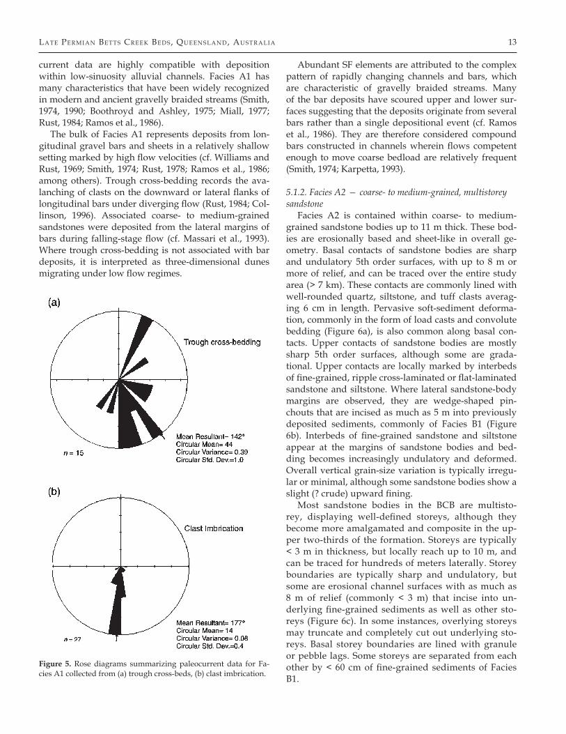
Facies A1 is characterized by massive to crude bed-ding arranged in sheet-like to lenticular bodies with up-per and lower surfaces defined by SF elements with lo-calized trough cross-bedding. Several locations where Facies A1 occurs appear to be composed of a mosaic of coalesced SF elements. Rare CH elements are also ob-served. Trough cross-bedding is as much as 0.8 m thick, but commonly < 0.4 m. Paleocurrent directions from trough cross-beds trend southeastward (mean = 142°; Figure 5a). Imbricated large clasts in the basal portion of the conglomerate indicate paleoflow to the south (Fig-ure 5b), slightly oblique to the paleoflow indicated by trough cross-bedding.
5.1.1.1. Interpretation — The sheet-like geometry, abundance of SF elements with subordinate trough cross-bedding, and relatively low dispersion of paleo-
Figure 4. Architectural elements and lithosomes recognized within the Betts Creek Beds. Cross-sections are the same horizontal and verti-cal scale. Bounding surfaces are numbered according to rank. Element classification after (Miall, 1988) and (Miall, 1996).
lA te Pe r mi A n Be tts Cr ee k Be d s, Que en s l A n d, Aus tr A l iA 13
current data are highly compatible with deposition within low-sinuosity alluvial channels. Facies A1 has many characteristics that have been widely recognized in modern and ancient gravelly braided streams (Smith, 1974, 1990; Boothroyd and Ashley, 1975; Miall, 1977; Rust, 1984; Ramos et al., 1986).
The bulk of Facies A1 represents deposits from lon-gitudinal gravel bars and sheets in a relatively shallow setting marked by high flow velocities (cf. Williams and Rust, 1969; Smith, 1974; Rust, 1978; Ramos et al., 1986; among others). Trough cross-bedding records the ava-lanching of clasts on the downward or lateral flanks of longitudinal bars under diverging flow (Rust, 1984; Col-linson, 1996). Associated coarse- to medium-grained sandstones were deposited from the lateral margins of bars during falling-stage flow (cf. Massari et al., 1993). Where trough cross-bedding is not associated with bar deposits, it is interpreted as three-dimensional dunes migrating under low flow regimes.
Abundant SF elements are attributed to the complex pattern of rapidly changing channels and bars, which are characteristic of gravelly braided streams. Many of the bar deposits have scoured upper and lower sur-faces suggesting that the deposits originate from several bars rather than a single depositional event (cf. Ramos et al., 1986). They are therefore considered compound bars constructed in channels wherein flows competent enough to move coarse bedload are relatively frequent (Smith, 1974; Karpetta, 1993).
5.1.2. Facies A2 — coarse- to medium-grained, multistorey sandstone
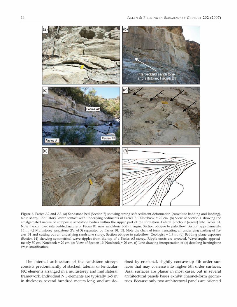
Facies A2 is contained within coarse- to medium-grained sandstone bodies up to 11 m thick. These bod-ies are erosionally based and sheet-like in overall ge-ometry. Basal contacts of sandstone bodies are sharp and undulatory 5th order surfaces, with up to 8 m or more of relief, and can be traced over the entire study area (> 7 km). These contacts are commonly lined with well-rounded quartz, siltstone, and tuff clasts averag-ing 6 cm in length. Pervasive soft-sediment deforma-tion, commonly in the form of load casts and convolute bedding (Figure 6a), is also common along basal con-tacts. Upper contacts of sandstone bodies are mostly sharp 5th order surfaces, although some are grada-tional. Upper contacts are locally marked by interbeds of fine-grained, ripple cross-laminated or flat-laminated sandstone and siltstone. Where lateral sandstone-body margins are observed, they are wedge-shaped pin-chouts that are incised as much as 5 m into previously deposited sediments, commonly of Facies B1 (Figure 6b). Interbeds of fine-grained sandstone and siltstone appear at the margins of sandstone bodies and bed-ding becomes increasingly undulatory and deformed. Overall vertical grain-size variation is typically irregu-lar or minimal, although some sandstone bodies show a slight (? crude) upward fining.
Most sandstone bodies in the BCB are multisto-rey, displaying well-defined storeys, although they become more amalgamated and composite in the up-per two-thirds of the formation. Storeys are typically < 3 m in thickness, but locally reach up to 10 m, and can be traced for hundreds of meters laterally. Storey boundaries are typically sharp and undulatory, but some are erosional channel surfaces with as much as 8 m of relief (commonly < 3 m) that incise into un-derlying fine-grained sediments as well as other sto-reys (Figure 6c). In some instances, overlying storeys may truncate and completely cut out underlying sto-reys. Basal storey boundaries are lined with granule or pebble lags. Some storeys are separated from each other by < 60 cm of fine-grained sediments of Facies B1.
Figure 5. Rose diagrams summarizing paleocurrent data for Fa-cies A1 collected from (a) trough cross-beds, (b) clast imbrication.
14 All en & Fi el d i n g i n Sed i m ent a r y Geo l oG y 202 (2007)
The internal architecture of the sandstone storeys consists predominantly of stacked, tabular or lenticular NC elements arranged in a multistorey and multilateral framework. Individual NC elements are typically 1–5 m in thickness, several hundred meters long, and are de-
fined by erosional, slightly concave-up 4th order sur-faces that may coalesce into higher 5th order surfaces. Basal surfaces are planar in most cases, but in several architectural panels bases exhibit channel-form geome-tries. Because only two architectural panels are oriented
Figure 6. Facies A2 and A3. (a) Sandstone bed (Section 7) showing strong soft-sediment deformation (convolute bedding and loading). Note sharp, undulatory lower contact with underlying sediments of Facies B1. Notebook = 20 cm. (b) View of Section 1 showing the amalgamated nature of composite sandstone bodies within the upper part of the formation. Lateral pinchout (arrow) into Facies B1. Note the complex interbedded nature of Facies B1 near sandstone body margin. Section oblique to paleoflow. Section approximately 15 m. (c) Multistorey sandstone (Panel 3) separated by Facies B1, B2. Note the channel form truncating an underlying parting of Fa-cies B1 and cutting out an underlying sandstone storey. Section oblique to paleoflow. Geologist = 1.9 m. (d) Bedding plane exposure (Section 14) showing symmetrical wave ripples from the top of a Facies A3 storey. Ripple crests are arrowed. Wavelengths approxi-mately 50 cm. Notebook = 20 cm. (e) View of Section 19. Notebook = 20 cm. (f) Line drawing interpretation of (e) detailing herringbone cross-stratification.
lA te Pe r mi A n Be tts Cr ee k Be d s, Que en s l A n d, Aus tr A l iA 15
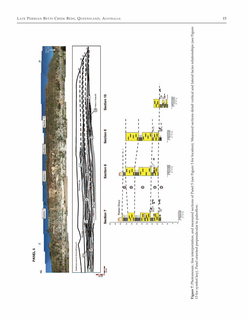
Figu
re 7
. Pho
tom
osai
c, li
ne in
terp
reta
tion,
and
mea
sure
d se
ctio
ns o
f Pan
el 5
(see
Fig
ure
3 fo
r loc
atio
n). M
easu
red
sect
ions
det
ail v
ertic
al a
nd la
tera
l fac
ies
rela
tions
hips
(see
Fig
ure
13 fo
r sym
bol k
ey).
Pane
l ori
ente
d pe
rpen
dicu
lar t
o pa
leofl
ow.
16 All en & Fi el d i n g i n Sed i m ent a r y Geo l oG y 202 (2007)
normal to paleoflow, lateral dimensions of NC elements are not easily discerned, but where observed these el-ements range from 50–150 m wide to > 200 m (Figure 7). Thin, discontinuous fine-grained partings are com-monly observed separating NC elements, especially lower in the formation. SF elements up to 2 m in thick-ness are common at the bases of sandstone storeys, but may be found throughout the interval.
LA and DA elements are rare in the lower two-thirds of the formation, but increase in abundance in the up-per one-third (Figure 7). Where observed, accretionary elements are typically between 2–6 m in thickness and have a distinctive wedge-shaped geometry bounded by 4th order surfaces with internal 3rd order surfaces.
In some instances Facies A2 is associated with the finer-grained facies of Association B. These occur as CS elements. CS elements are typically observed as lentic-ular bodies, although one CS element is observed as a clear channel feature with “wings” extending out on ei-ther side (Figure 7). This element has a maximum chan-nel fill of 1.6 m and is ~ 35 m wide not including the wings. At the margins, this CS element becomes increas-ingly interbedded with ripple cross-laminated sand-stone and siltstone.
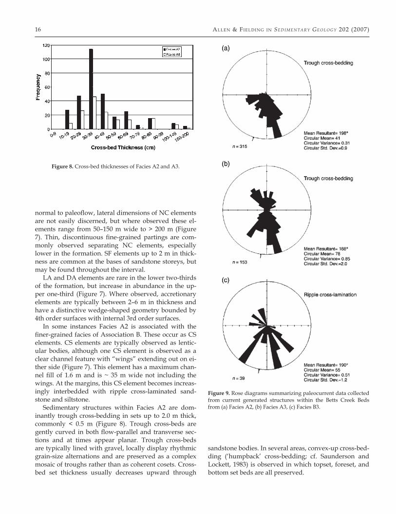
Sedimentary structures within Facies A2 are dom-inantly trough cross-bedding in sets up to 2.0 m thick, commonly < 0.5 m (Figure 8). Trough cross-beds are gently curved in both flow-parallel and transverse sec-tions and at times appear planar. Trough cross-beds are typically lined with gravel, locally display rhythmic grain-size alternations and are preserved as a complex mosaic of troughs rather than as coherent cosets. Cross-bed set thickness usually decreases upward through
sandstone bodies. In several areas, convex-up cross-bed-ding (‘humpback’ cross-bedding; cf. Saunderson and Lockett, 1983) is observed in which topset, foreset, and bottom set beds are all preserved.
Figure 8. Cross-bed thicknesses of Facies A2 and A3.
Figure 9. Rose diagrams summarizing paleocurrent data collected from current generated structures within the Betts Creek Beds from (a) Facies A2, (b) Facies A3, (c) Facies B3.
lA te Pe r mi A n Be tts Cr ee k Be d s, Que en s l A n d, Aus tr A l iA 17
In addition to trough cross-bedding, diffuse, flat lam-ination is common in the lowermost storeys. Discontin-uous siltstone partings are common throughout Facies A2. Partings are typically < 2 cm and are of limited lat-eral extent. In some instances, partings preserve plant material referable to Glossopteris sp., Vertebraria, and Cordaites sp.
Soft-sediment deformation (loading and convolute bedding) is commonly associated with the basal con-tacts described above. Horizons of soft-sediment defor-mation may be traced laterally over < 100 m’s, but these horizons normally vary in both vertical extent and de-gree of deformation. Cross-beds are also observed to pass laterally into convolute bedding in several places.
Paleocurrent directions measured from trough cross-beds are predominantly southward (mean = 198°; Fig-ure 9a), with little dispersion about the mean.
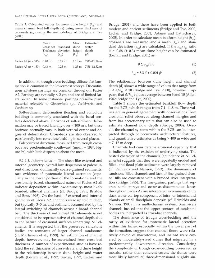
5.1.2.1. Interpretation — The sheet-like external and internal geometry, overall low dispersion of paleocur-rent directions, dominantly coarse-grained sediments, rare evidence of systematic lateral accretion (espe-cially in the lower portion of the formation), and the erosionally based, channelized nature of Facies A2 all indicate deposition within low-sinuosity, most likely braided, alluvial channels (cf. Bridge, 1985; Bristow and Best, 1993). On the basis of external and internal geometry of Facies A2, channels were up to 8 m deep, but typically 3–5 m, and sediment accumulated by the lateral switching of channels across a broad channel belt. The thickness of individual NC elements is not considered to be representative of channel depth, due to the nature of erosional surfaces separating NC el-ements. It is suggested that the preserved sandstone bodies are remnants of larger channel sandstones (cf. Martinsen et al., 1999). An estimation of channel depth, however, may be ascertained from cross-bed thickness. A number of experimental studies have re-lated the set thickness of cross-strata and dune height to the relationship between dune height and water depth (Leclair et al., 1997; Bridge, 1997; Leclair and
Bridge, 2001) and these have been applied to both modern and ancient sediments (Bridge and Tye, 2000; Leclair and Bridge, 2001; Adams and Battacharya, 2005). In order to calculate mean bedform height (hm), cross-sets are measured and a mean (sm) and stan-dard deviation (ssd) are calculated. If the ssd/sm ratio is ~ 0.88 (± 0.3) mean dune height can be estimated (Leclair and Bridge, 2001) as:
β ≅ sm/1.8 (1)
hm = 5.3 β + 0.001 β2 (2)
The relationship between dune height and channel depth (d) shows a wide range of values that range from 3 < d/hm < 20 (Bridge and Tye, 2000), however it ap-pears that d/hm values average between 6 and 10 (Allen, 1982; Bridge and Tye, 2000).
Table 3 shows the estimated bankfull flow depth for the BCB, which ranges from 7.1–11.8 m. These val-ues are in general agreement with observations from erosional relief observed along channel margins and from bar accretionary units that can also be used to estimate channel flow depth (Bridge, 2003). Over-all, the channel systems within the BCB can be inter-preted through paleocurrents, architectural features, and quantitative estimates as being > 400 m wide and ~ 7–12 m deep.
Channels had considerable erosional capability that is indicated by the excision of underlying strata. The nested character of the channels (abundance of NC el-ements) suggests that they were repeatedly eroded and filled, and flood-plain sediments were largely removed (cf. Reinfelds and Nanson, 1993). The dominance of sandstone-filled channels and lack of fine-grained chan-nel fills are consistent with a braided river interpreta-tion (Bridge, 1985). The fine-grained partings that sep-arate some storeys and occur as discontinuous lenses throughout Facies A2 are interpreted as remnants of the slack-water bar-top component of intra- or interchannel islands or small floodplain deposits (cf. Reinfelds and Nanson, 1993) in a multi-channel system. Small-scale channels incised into the upper contacts of sandstone bodies are interpreted as cross-bar channels.
The dominance of trough cross-bedding and the rarity of evidence for systematic lateral accretion within this facies, especially within the lower part of the formation, suggest that channel floors were rela-tively devoid of macroforms, and instead were cov-ered by moderately-sized dunes that migrated in a predominantly downstream direction. Considering the complexity of trough cross-bedding preserved as mosaics rather than coherent cosets, the dunes were most likely low-relief, three-dimensional, slightly sin-
Table 3. Calculated values for mean dune height (hm) and mean channel bankfull depth (d) using mean thickness of cross-sets (sm) using the methodology of Bridge and Tye (2000)
Mean Mean Estimated Cross-set Standard dune water Thickness deviation height depth (sm) (ssd) (hm) (d)
Facies A2 (n = 315) 0.40 m 0.29 m 1.18 m 7.06–11.76 m
Facies A3 (n = 153) 0.43 m 0.25 m 1.25 m 7.51–12.52 m
18 All en & Fi el d i n g i n Sed i m ent a r y Geo l oG y 202 (2007)
uous dunes. Paleocurrent data also suggest that dune migration had a minor across-channel migration com-ponent. Lateral accretion is observed within the upper part of the formation and records lateral accretion on braid bars in these areas. The general paucity of lateral accretion in the lower part of the formation compared to the upper part suggests that braiding became more pronounced during the history of the Betts Creek allu-vial system.
The convex-up crossbedding (‘humpback’ dunes) is similar to structures produced experimentally (Simons et al., 1965; Saunderson and Lockett, 1983) and found within ancient sequences (Allen, 1983; Røe, 1987; Røe and Hermansen, 1993; Fielding and Webb, 1996; Hjell-bakk, 1997). In each of these cases, these structures were representative of the transition from dune to up-per-stage, plane-bed flow regimes. The abundance of chaotic and convolute bedding is interpreted as auto-kinetic (produced purely by sedimentary processes; sensu Leeder, 1987) in origin and suggests rapid sedi-ment accumulation rates (Allen, 1982; Owen, 1996; Røe and Hermansen, 2006). Rapid sediment accumulation rates are further supported by the occurrence of SF el-ements found at the bases of sandstone storeys. Where SF elements are preserved, they are interpreted as chan-nel-lag deposits that were transported within the thal-weg of major channels. The coarse nature of the lag de-posited within SF elements indicates that flows were at times powerful.
Where this facies is associated with Association B as CS elements, it is interpreted as most likely representing crevasse splays.
5.1.3. Facies A3 — bidirectional trough cross-bedded sandstone
Facies A3 is similar to Facies A2 in overall character; however, key differences warrant a separate facies des-ignation. Facies A3 occurs in sandstone bodies 1–2 m in thickness with overall sheet-like geometries. Lower and upper contacts are commonly sharp, but locally lower contacts may be gradational. Facies A3 every-where overlies Faces A2. Locally, upper bedding plane contacts preserve symmetrical wave ripples (Figure 6d) trending 016°, and Thalassinoides and Planolites burrows. In some areas, upper contacts are also associated with small-scale channels of Facies B1 and B3.
Internally, sandstone bodies of Facies A3 are com-posed of NC elements with very similar geometries to the NC elements found in Facies A2. Trough cross-bed-ding is the dominant sedimentary structure, although small-scale trough cross-bedding, flat lamination, rip-ple cross-lamination, and local parting lineation and carbonaceous/coaly laminae are common near the up-per (~1 m) bed contacts with either overlying sandstone
storeys of this facies or fine-grained sediments of Facies B1-3.
Paleocurrent data from trough cross-bedding show a bidirectional distribution with an overall southward di-rection (mean = 188°; Figure 9b) and in some instances bipolar distributions (herringbone cross-stratification; Figure 6e, f).
5.1.3.1. Interpretation — Facies A3 is interpreted as the deposits of tidally influenced alluvial channels. The overall similarities and close association with Facies A2 suggest that Facies A3 was deposited under similar con-ditions. Channel depth estimates within this facies are ~7–12 m, similar to those from Facies A2 (Table 3).
Paleocurrent distributions, along with the presence of herringbone cross-stratification, suggest that the upper storeys of sandstone beds have been strongly influenced by reversing flows, most likely related to tidal pro-cesses. Tidal processes have been documented to occur 0–300 km inland from a coeval shoreline in modern en-vironments (Gelfenbaum, 1983; Allen, 1991). However, in this case the increasing mud component, ripple cross-lamination, wave ripples, and marine trace fossils (i.e. Thalassinoides) suggest deposition in near-coastal envi-ronments. The association with small channel fills of an estuarine character (Facies B3, see below) is consistent with such an interpretation.
5.1.4. Facies A4 — interbedded sandstone and siltstoneFacies A4 is composed of interbedded sandstone
and siltstone in varying proportions, in units up to 3 m thick. This facies is preserved as CF elements and oc-curs predominantly in the upper half of the formation. Lower contacts are sharp and erosional, and always oc-cur above sediments of Facies A2. Upper contacts are erosional, sharp, undulatory, and generally concave-up-ward boundaries with overlying Facies A2 sediments. Although sedimentary structures are not observable in detail due to inaccessibility, structures representing low-energy conditions from waning flows such as rip-ple cross-lamination and interlamination structures (fla-ser, wavy, lenticular, pinstripe bedding) are thought to dominate within this facies.
Sandstone beds are < 1 m in thickness, exhibiting lat-eral variability with beds < 10 m in length. Sandstone to siltstone proportion decreases upwards.
5.1.4.1. Interpretation —The occurrence of Facies A4 above Facies A2 and its limitation to CF elements sug-gest that these sediments were formed during abandon-ment of river channels. This facies, therefore, represents the abandonment fill of the low-sinuosity alluvial chan-nel deposits of Facies A2. Facies A4 is everywhere over-lain by Facies A2, suggesting that abandoned channels
lA te Pe r mi A n Be tts Cr ee k Be d s, Que en s l A n d, Aus tr A l iA 19
within the floodplain were reactivated by subsequent channels (cf. Reinfelds and Nanson, 1993). This further supports the interpretation that sediments of A2 accu-mulated by lateral switching of active channels across a broad channel belt.
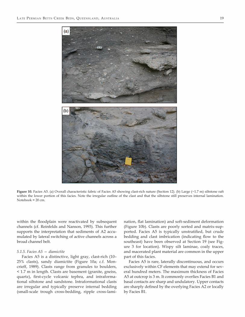
5.1.5. Facies A5 — diamictiteFacies A5 is a distinctive, light gray, clast-rich (10–
25% clasts), sandy diamictite (Figure 10a; c.f. Mon-crieff, 1989). Clasts range from granules to boulders, < 1.7 m in length. Clasts are basement (granite, gneiss, quartz), first-cycle volcanic tephra, and intraforma-tional siltstone and sandstone. Intraformational clasts are irregular and typically preserve internal bedding (small-scale trough cross-bedding, ripple cross-lami-
nation, flat lamination) and soft-sediment deformation (Figure 10b). Clasts are poorly sorted and matrix-sup-ported. Facies A5 is typically unstratified, but crude bedding and clast imbrication (indicating flow to the southeast) have been observed at Section 19 (see Fig-ure 3 for location). Wispy silt laminae, coaly traces, and macerated plant material are common in the upper part of this facies.
Facies A5 is rare, laterally discontinuous, and occurs exclusively within CF elements that may extend for sev-eral hundred meters. The maximum thickness of Facies A5 at outcrop is 3 m. It commonly overlies Facies B1 and basal contacts are sharp and undulatory. Upper contacts are sharply defined by the overlying Facies A2 or locally by Facies B1.
Figure 10. Facies A5. (a) Overall characteristic fabric of Facies A5 showing clast-rich nature (Section 12). (b) Large (~1.7 m) siltstone raft within the lower portion of this facies. Note the irregular outline of the clast and that the siltstone still preserves internal lamination. Notebook = 20 cm.
20 All en & Fi el d i n g i n Sed i m ent a r y Geo l oG y 202 (2007)
5.1.5.1. Interpretation — Facies A5 is interpreted as re-worked pyroclastic material deposited by debris flows. The extremely poor sorting, lack of internal stratifica-tion, and presence of matrix-supported clasts are all characteristic of subaerial debris flows documented from both ancient and modern environments, where de-position is en masse rather than by grain-by-grain sed-imentation (Nemec and Steel, 1984; Smith, 1986; Smith and Lowe, 1991; Major, 1997). Intraformational clasts with irregular shapes and displaying internal stratifi-cation suggest that debris flows were relatively viscous and lacked turbulence (cf. Jorgensen and Fielding, 1999; Kataoka and Nakajo, 2002) in order for these features to be preserved during transport and deposition.
It is believed that debris flows formed in association with contemporaneous volcanism, with source area(s) to the north and/or east. During this time interval wide-spread volcanic activity was occurring on the northeast-ern margin of the Bowen Basin as a result of foreland tectonics and the establishment of a continental volca-
nic arc (Fielding et al., 2001), and may have provided the volcaniclastic detritus that sourced debris flows. Pa-leocurrent data from the Bowen Basin show that during the Late Permian (263–258 Ma) alluvial conditions were established that led to an overfilling situation in which first-cycle volcanic detritus spilled across the Spring-sure Shelf into the Galilee Basin (Fielding et al., 2001). The absence of coeval primary proximal volcaniclastic facies associated with Facies A5 suggests that the loca-tion of volcanism was far away and most likely extra-basinal, which is consistent with an interpretation that volcanism in the Bowen Basin sourced debris flows. While debris flows generated on alluvial fans rarely ex-tend further than 10 km, volcanic debris flows can travel > 100 km away from the source (Smith, 1986; Mothes et al., 1998). Facies A5, therefore, records evidence for dis-tal debris-flow deposition as the result of large-scale volcanism several hundred kilometers away. The pau-city of airfall tuff beds within the study area is note-worthy. Although no coeval primary volcaniclastic sed-
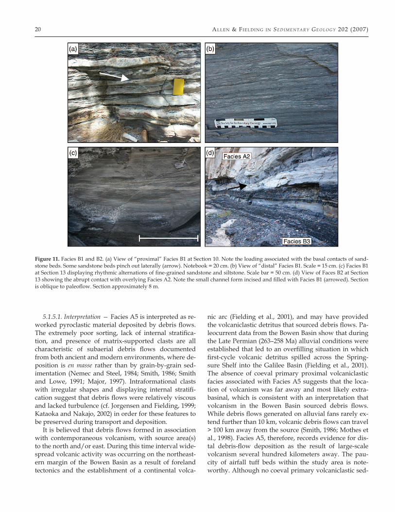
Figure 11. Facies B1 and B2. (a) View of “proximal” Facies B1 at Section 10. Note the loading associated with the basal contacts of sand-stone beds. Some sandstone beds pinch out laterally (arrow). Notebook = 20 cm. (b) View of “distal” Facies B1. Scale = 15 cm. (c) Facies B1 at Section 13 displaying rhythmic alternations of fine-grained sandstone and siltstone. Scale bar = 50 cm. (d) View of Faces B2 at Section 13 showing the abrupt contact with overlying Facies A2. Note the small channel form incised and filled with Facies B1 (arrowed). Section is oblique to paleoflow. Section approximately 8 m.
lA te Pe r mi A n Be tts Cr ee k Be d s, Que en s l A n d, Aus tr A l iA 21
iments occur within the northeastern Galilee Basin, explosive volcanism was ongoing during the Late Perm-ian in the Bowen Basin. Airfall from such explosive vol-canism could reach the study area, but recent climate models predict westerly trade winds (offshore) during the Permian winter and southerly directed winds dur-ing summer (Gibbs et al., 2002). Under these circum-stances, airfall from volcanism would not be expected in the northeastern portion of the Galilee, because pre-vailing surface winds were blowing in the opposite direction.
All BCB debris-flow deposits are confined to CF ele-ments that have sharp, concave-up, channelized bases. These debris flows probably exploited pre-existing to-pography by occupying existing channels. Debris flows
within volcanic settings have been shown to follow drainage paths and be partially or completely confined to channels (Pierson and Scott, 1985). The intraforma-tional siltstone and sandstone clasts in the BCB are most likely the result of floodbasin and channel sediment en-trainment during the occupation of channels by debris flows. Further support for this interpretation lies in the characteristics of Facies A5 at Section 19, where clast im-brication and crude bedding appear. Imbrication is con-sistent with a debris-flow interpretation (Smith, 1986), in which particles at the base of debris flows display a directional fabric formed by pulsed shearing within the flow body (Mulder and Alexander, 2001). The direc-tion of imbrication predominantly to the southeast is comparable to the overall paleoflow measured from fa-
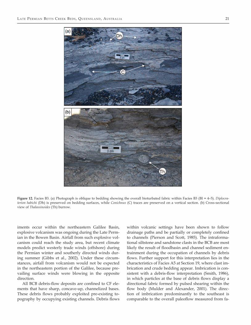
Figure 12. Facies B3. (a) Photograph is oblique to bedding showing the overall bioturbated fabric within Facies B3 (BI = 4–5). Diplocra-terion habichi (Dh) is preserved on bedding surfaces, while Conichnus (C) traces are preserved on a vertical section. (b) Cross-sectional view of Thalassinoides (Th) burrow.
22 All en & Fi el d i n g i n Sed i m ent a r y Geo l oG y 202 (2007)
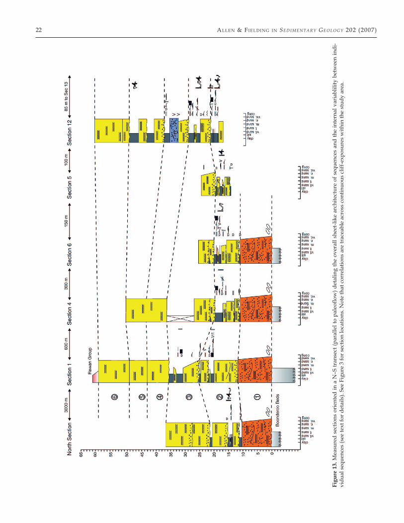
Figu
re 1
3. M
easu
red
sect
ions
ori
ente
d in
a N
–S tr
anse
ct (p
aral
lel t
o pa
leofl
ow) d
etal
ing
the
over
all s
heet
-like
arc
hite
ctur
e of
seq
uenc
es a
nd th
e in
tern
al v
aria
blili
ty b
etw
een
indi
-vi
dual
seq
uenc
es (s
ee te
xt fo
r det
ails
). Se
e Fi
gure
3 fo
r sec
tion
loca
tions
. Not
e th
at c
orre
latio
ns a
re tr
acea
ble
acro
ss c
ontin
uous
clif
f-exp
osur
es w
ithin
the
stud
y ar
ea.
lA te Pe r mi A n Be tts Cr ee k Be d s, Que en s l A n d, Aus tr A l iA 23
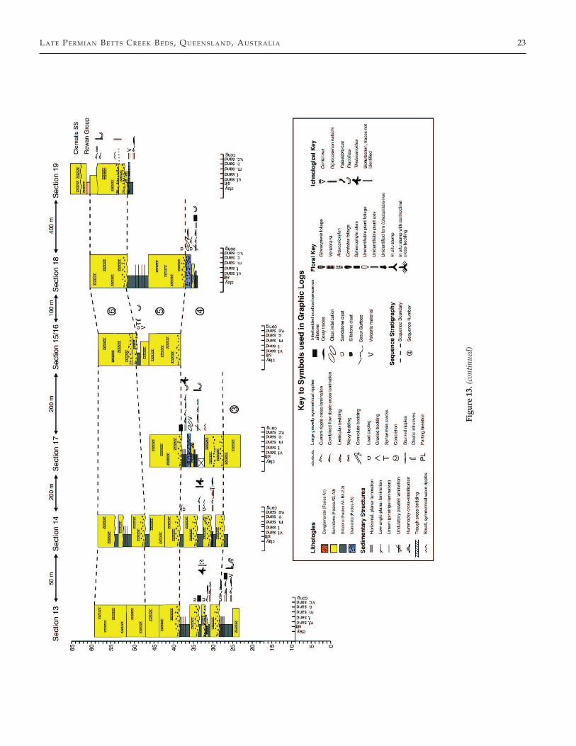
Figu
re 1
3. (c
ontin
ued)
24 All en & Fi el d i n g i n Sed i m ent a r y Geo l oG y 202 (2007)
cies within the channel association, suggesting flow was confined by pre-existing topography.
5.2. Facies Association B — floodbasin deposits
5.2.1. Facies B1 — interbedded to interlaminated sandstone and siltstone
Facies B1 comprises intervals up to 6 m thick of inter-bedded to interlaminated sandstone and siltstone. The interbedded/interlaminated nature and the proportion of sandstone to siltstone within this facies vary mark-edly depending on where in the formation it is found (laterally and vertically) and the relationships to other facies. As a result, this facies is typically a complex mo-saic of sandstone and siltstone that varies laterally and vertically. Two “endmembers” (“proximal” and “dis-tal”) are described below in order to give an adequate description of the range of characteristics found within Facies B1. In general, sandstone beds are medium- to fine-grained and have sharp, basal and upper contacts. Siltstones are medium to dark gray and are character-ized by a number of interlamination structures includ-ing pinstripe (linsen), lenticular, and wavy lamination. Siltstones also contain significant amounts of tuffaceous material.
The “proximal” endmember (Figure 11a) is recog-nized where Facies B1 is connected to channel mar-gins of Facies A2. Here this facies consists of interbed-ded, fining-upwards 70:30 to 50:50 sandstone:siltstone,. Sandstones range from medium to very fine, but are mostly medium-grained. Individual beds are typically 2–10 cm thick. Both upper and lower bed contacts are sharp and undulatory, and lower contacts show vary-ing amounts of soft-sediment deformation mainly in the form of loading and localized convolute bedding (Figure 11a). Many individual sandstone beds are lat-erally persistent, but some have been observed as lens-oid bodies < 5 m wide. Sandstones contain small-scale cross-stratification and ripple cross-lamination. Siltstone beds are 1–5 cm thick and contain mainly pinstripe and lenticular bedding, as well as abundant ripple cross-lamination (locally occurring as climbing ripples). No trace fossils have been observed within the proximal endmember.
Where associated with channel sandstones of Fa-cies A2, the thickly interbedded nature of Facies B1 is restricted laterally, and with increasing distance from the channel margin, sand percentage and grain-size de-crease and the unit as a whole passes and interfingers into thinly interbedded and increasingly more inter-laminated sandstones and siltstones of the more “dis-tal” endmember (Figure 11b). This lateral change occurs over a few tens of meters. In several locations the proxi-mal variant of Facies B1 occurs within LE elements with
inclined accretionary layers dipping ~5–10° at the mar-gins of channel bodies (Figure 7).
Siltstones of the distal endmember of Facies B1 con-tain the same features as mentioned above but addition-ally show abundant coaly laminae, rare Planolites, and starved ripples. These siltstones also preserve fragments of Glossopteris, Vertebraria, and Cordaites. This endmem-ber of facies B1 occurs within OF lithosomes and is later-ally persistent over several hundred meters.
Additionally, Facies B1 appears locally as medium to dark gray massive to fissile siltstone with an increasing-upward organic content. Plant remains of Glossopteris, Vertebraria, Cordaites, and other unidentifiable plant fragments are common on bedding planes. This vari-ant of Facies B1 is commonly found as partings within or separating sandstone beds of Facies A2 and A3, and typically passes vertically into Facies B2.
At one locality, Facies B1 displays rhythmic lamina-tions of heterolithic fine-grained sand and silt (Figure 11c).
5.2.1.1. Interpretation — Facies B1 is interpreted as floodbasin deposits that range from environments proximal to channel margins to distal locations not in-fluenced by active channel processes. The “proximal” endmember of Facies B1, occurring laterally adjacent to channel margins and composed of interbedded sandstone and siltstone, represents a proximal flood-basin setting, with sediment deposited by initially high energy sheet flows from waning flood currents. These conditions produced the sharply bounded na-ture of sandstone bodies, and then as flow energy de-creased, low-energy currents and suspension fall-out sedimentation occurred. Where this facies occurs as LE elements, it is interpreted as levee deposits as the geometry is similar to other examples (cf. Field-ing et al., 1993; Michaelson et al., 2000; Ray and Chakraborty, 2002). Depositional dips in Facies B1, representing the alluvial-ridge topography, the lat-eral fining into more distal floodbasin deposits, and close association with channel margins, are all consis-tent with a proximal overbank/levee interpretation (cf. Fielding et al., 1993).
Thicker and more laterally extensive sandstone beds within Facies B1 are similar to splay deposits (cf. Farrell, 1987; Tye and Coleman, 1989; Jorgensen and Fielding, 1996), and most likely represent the proximal portions of crevasse splays. However, for the most part, sand-stone beds are not laterally persistent, and crevassing is not thought to have been a major process.
The “distal” endmember of Facies B1, due to its lat-eral and vertical relationships, suggests processes simi-lar to those of the “proximal” end member. The paucity of sandstone beds and abundance of interlamination
lA te Pe r mi A n Be tts Cr ee k Be d s, Que en s l A n d, Aus tr A l iA 25
structures representative of a lower flow regime suggest that sedimentation was primarily due to suspension fallout. In these cases, Facies B1 was not affected by ac-tive channel processes but deposition occurred mainly during sheet-flood events in shallow ponds. The rarity of trace fossils suggests that these ponds were anoxic or dysoxic. Here, and where associated with Facies B2, Fa-cies B1 represents a transitional environment from shal-low, stagnant ponds, to peat-forming mires where abun-dant plant material and coaly laminae occur.
At one locality, Facies B1 shows evidence of influence from tidal processes. The deposits of fine-grained sand-stone and siltstone in rhythmic alternations are inter-preted as tidal rhythmites (Figure 11c).
5.2.2. Facies B2 — carbonaceous siltstone/coalFacies B2 is composed of laterally extensive carbo-
naceous siltstone and coal in units up to 2.5 m thick in the study area, but reaching up to 10 m thick in cored sections (GSQ Hughenden 3-4R). Basal contacts are gradational from Facies B1, whereas upper boundaries are sharp and erosionally truncated by Facies A2 (Fig-ure 11d). At the lower contacts, Facies B2 is variably interbedded with Facies B1. Where well-developed, this facies becomes increasingly coal-rich upward. This facies displays lateral continuity over several ki-lometers in extensive OF lithosomes. Abundant plant remains are preserved at several horizons, includ-ing Glossopteris, Vertebraria, Araucarioxylon-like wood, and Cordaites. In situ tree stumps up to 20 cm wide are preserved at the top of Facies B2 in one area. Stumps are rooted into a carbonaceous horizon that also con-tains well-preserved Glossopteris foliage, and are bur-ied by sediments of Facies B1 displaying centroclinal cross-stratification.
In several places, sharply bounded sandstone bodies of Facies A2 up to 2.5 m thick occur within this facies.
5.2.2.1. Interpretation — Facies B2 is the result of peat accumulation in coastal wetland environments. Peat accumulation was evidently in situ from the abundance of roots (Vertebraria). The number of chan-nelized sandstone bodies (Facies A2) within this fa-cies suggests that the wetland may have been crossed by a network of small channels. The extensive sheet-like geometry of Facies B2 suggests that the mires were predominantly low-lying, rheotrophic environ-ments, rather than raised and rain-water fed swamps (McCabe, 1984). The association of Facies B2 with Fa-cies B3 (see below) suggests that these were coastal wetland environments situated on a coastal plain near estuarine embayments.
5.2.3. Facies B3 — bioturbated interbedded sandstone and siltstone
Facies B3 comprises intervals of bioturbated inter-bedded very fine- to fine-grained sandstone and silt-stone no more than 50 cm and in most places < 10 cm thick. Medium, gray, sandy siltstone is the predominant lithology within this facies with siltstone:sandstone pro-portions varying from 50:50 to 90:10 depending on lo-cation. Lower contacts are typically sharp. Facies B3 is everywhere observed overlying sediments of Facies A3. Upper contacts are commonly gradational into Facies B1, but are locally sharply bounded by Facies B1 and B2. This facies occurs at several stratigraphic horizons and can be traced laterally over at least 3 km within OF lithosomes.
Sandstone beds are sharply bounded and some are discontinuous, passing laterally into sandy siltstone. Sandstones are < 3 cm in thickness and commonly rip-ple cross-laminated (current-, wave-, and combined flow-generated). Siltstones are characterized by a vari-ety of interlamination structures ranging from pinstripe (linsen) to lenticular and wavy lamination, and thicker beds are internally flat or ripple cross-laminated. Mea-surements from ripple cross-lamination indicate paleo-flow to the southwest (mean resultant = 190°; Figure 9c), although azimuths range from northwest to southeast. Small synaeresis cracks are common throughout this fa-cies, and other soft-sediment deformation structures occur locally. At one location (Section 6) clastic dikes composed of very fine- to fine-grained sandstone were observed at the lower contact of this facies with under-lying Facies A3. Sandstone dikes are variable in width ranging from 10–20 cm and up to 50 cm in length. No preferred orientation was observed.
The intensity of bioturbation is variable through-out Facies B3, but typically decreases upwards. Biotur-bation varies from location to location and within in-dividual beds. The Bioturbation Index (BI, Bann et al., 2004: where BI = 0 is no bioturbation and BI = 6 rep-resents complete bioturbation) ranges from 0 to 5. The trace fossil suite is low in diversity and dominated by Diplocraterion habichi (Figure 12a), Conichnus (Figure 12a), and Thalassinoides (Figure 12b), with minor Plan-olites and Palaeophycus sp. D. habichi are most often ob-served in plan view as small (1–5 mm) paired vertical burrows. The other traces were readily identified in both plan and cross-sectional views. The trace fossils have reduced sizes, except in a few instances where es-pecially large individuals (< 15 cm) of Conichnus were noted. Trace fossils occur throughout Facies B3 and do not show any preferential clustering at any one strati-graphic horizon.
26 All en & Fi el d i n g i n Sed i m ent a r y Geo l oG y 202 (2007)
Small-scale channel forms (2 × 20 m) were observed in several areas incised into sediments of Facies A2, A3, B1, B3 and infilled by Facies B3.
5.2.3.1. Interpretation — Facies B3 was deposited within estuaries or coastal embayments. The dominance of ripples (wave-and tide-influenced) and wavy and
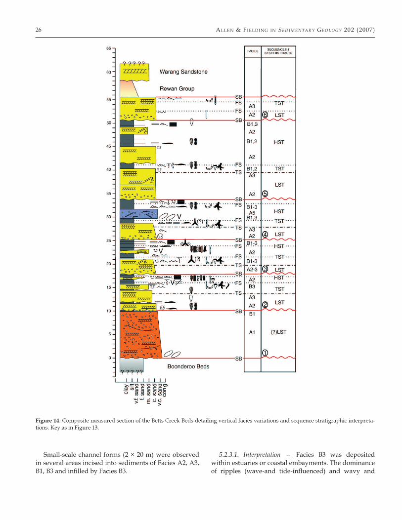
Figure 14. Composite measured section of the Betts Creek Beds detailing vertical facies variations and sequence stratigraphic interpreta-tions. Key as in Figure 13.
lA te Pe r mi A n Be tts Cr ee k Be d s, Que en s l A n d, Aus tr A l iA 27
lenticular bedding implies deposition within a shallow-water environment. Bipolar and bimodal paleocurrent distributions also reflect tidal processes.
Synaeresis cracks suggest deposition in a perma-nently subaqueous, brackish-water setting. Cracks found throughout Facies B3 have been interpreted as the product of synaeresis rather than desiccation due to the lack of well developed polygonal patterns on bed-ding planes, elongate to trilete planform, ptygmatically folded cross-section, and the absence of other evidence that would suggest subaerial exposure (soil develop-ment, roots, etc.). Synaeresis cracks form in response to tension as muddy, water-saturated sediment loses wa-ter to an overlying fluid layer causing an increase in the strength of interparticle forces within the clays (cf. Plummer and Gostin, 1981; Allen, 1982). They typically form in muddy environments where there are large fluctuations in salinity (Burst, 1965). Salinity variations during or immediately following the deposition of muddy sediments induced the formation of synaeresis cracks in experiments (Plummer and Gostin, 1981; Al-len, 1982). The appearance of synaeresis cracks in asso-ciation with sandstone beds in Facies B3 suggests that sand deposition was accompanied by an influx of saline water.
The trace fossil assemblage is also consistent with a brackish-water interpretation because it contains a mixture of size-reduced, simple dwelling and feeding structures (deposit-feeders dominant, with less abun-dant suspension feeders) characteristic of opportunistic suites. It is a restricted expression of a mixed Skolithos/Cruziana Ichnofacies that is characteristic of inshore coastal environments (cf. Bann et al., 2004). Typical es-tuarine trace fossil assemblages from both modern and ancient settings are characterized by (1) low diversity, (2) ichnotaxa typically found in marine environments, (3) reduced size compared to open marine counter-parts, (4) simple burrows constructed by trophic gener-alists, and (5) vertical and horizontal burrows common to both Skolithos and Cruziana Ichnofacies (Howard and Frey, 1973; Ekdale et al., 1984; Beynon and Pember-ton, 1992; Pemberton et al., 1992; Bann and Fielding, 2004; Bann et al., 2004). These criteria can all be recog-nized within Facies B3. The preponderance of diminu-tive traces found within Facies B3 is considered to be an adaptive response to salinity-induced physical and chemical stresses. Size reduction is most noticeable in organisms that maintain constant contact with surfi-cial brackish waters, whereas deeper, deposit-feeding structures display less size reduction (Bann and Field-ing, 2001). Larger forms of Conichnus are believed to represent sites at a distance from the brackish water interface.
The combined sedimentological and ichnological data, therefore, point to a highly stressed brackish wa-ter environment (i.e. coastal/estuarine embayment) that was influenced by both wave and tidal processes.
6. Stratigraphic and sequence architecture
One of the most distinctive features in the vertical stack-ing patterns of the Betts Creek Beds is a series of 6 un-conformity-bounded cycles each 10–14 m thick (Figure 13). These cycles could represent autogenic cycles, high-frequency parasequences (Van Wagoner et al., 1988; Na-ish and Kamp, 1997), or true sequences formed in low-accommodation settings (Kidwell, 1997; Fielding et al., 2000; Bann et al., 2004). Given that the BCB represent the entire Late Permian Galilee Basin fill (~ 20 myr), it is likely that these cycles represent true sequences. The BCB display the typical sequence architecture character-istic of the examples cited above that were preserved in low-accommodation settings where they are thin, con-densed, and show considerable top truncation of the highstand systems tract.
Although autogenic cycles may result in regular sedimentary cycles, it is unlikely that semirandom pro-cesses such as river avulsion and mire growth and ac-cumulation could be the controlling force on the BCB cycles. Given the period of time represented by the BCB, the facies distribution would be expected to be truly random if autocyclicity were the controlling mechanism. Evidence suggesting that such autocyclic processes operate on timescales of < 103 years (Calder and Gibling, 1994), supports an allocyclic sequence de-velopment for the cycles within the BCB rather than autogenic cyclicity.
The recognition of these cycles as sequences and the ability to separate the sequences into conventional systems tracts (LST, TST, HST), rely on subtle indica-tors, such as tidally influenced fluvial deposits (Facies A3) and thin, discrete horizons of bioturbated estua-rine deposits (Facies B3) interpreted as flooding sur-faces (Figure 14). If not examined in detail, the BCB could easily be mistaken for the archetypal amalgam-ated stacked fluvial deposits characteristic of updip basin margin settings (i.e. Shanley and McCabe, 1993; Miall, 1996).
6.1. Sequence boundaries
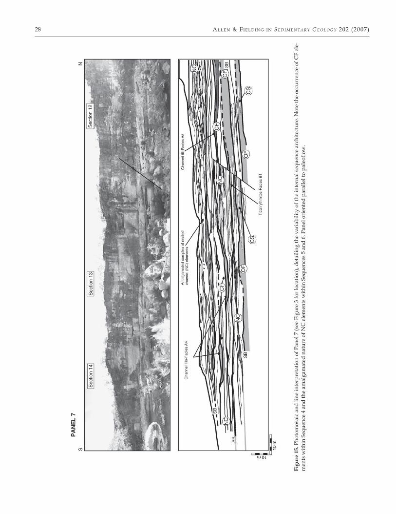
Major erosion surfaces interpreted as sequence bound-aries are defined by the bases of coarse-grained, laterally extensive, braided fluvial sandstones that erode into un-derlying coastal plain coals. These surfaces can be traced
28 All en & Fi el d i n g i n Sed i m ent a r y Geo l oG y 202 (2007)
Figu
re 1
5. P
hoto
mos
aic
and
line
inte
rpre
tatio
n of
Pan
el 7
(see
Fig
ure
3 fo
r loc
atio
n), d
etai
ling
the
vari
abili
ty o
f the
inte
rnal
seq
uenc
e ar
chite
ctur
e. N
ote
the
occu
rren
ce o
f CF
ele-
men
ts w
ithin
Seq
uenc
e 4
and
the
amal
gam
ated
nat
ure
of N
C e
lem
ents
with
in S
eque
nces
5 a
nd 6
. Pan
el o
rien
ted
para
llel t
o pa
leofl
ow.
lA te Pe r mi A n Be tts Cr ee k Be d s, Que en s l A n d, Aus tr A l iA 29
continuously in the cliff exposures over the entire study area, and therefore represent regionally extensive ero-sional surfaces. In addition, they can be distinguished from other, more local, erosional surfaces caused by au-togenic processes. The erosional relief on these surfaces can only be observed locally where channel margins are observed, and is typically < 5 m. There is no evidence that they have any significant regional erosional relief and are more-or-less planar in nature at the scale of sev-eral km’s (Figure 13).
These surfaces differ from scoured erosional sur-faces characteristic of fluvial environments result-ing from autogenic processes, because they are more prominent and widespread. The sequence boundar-ies within the BCB are similar to other interpreted se-quence boundaries in alluvial strata (Van Wagoner et al., 1990; Shanley and McCabe, 1991, 1993, 1994; Gib-ling and Bird, 1994; Olsen et al., 1995; Yoshida et al., 1996), in that there is a sharp juxtaposition between braided fluvial sandstones and carbonaceous coastal-plain deposits marking a change in the amount of ac-commodation space. However, the sequence bound-aries within the BCB are planar and show minimal erosional relief, similar to sequence boundaries ob-served in the Ericson Sandstone by Martinsen et al. (1999). A planar sequence boundary is to be expected in low-gradient settings such as basin margins. Where the slope of the fluvial profile near the coastline is sim-ilar to the bathymetric profile of a shallow shelf, only minor fluvial incision will occur and incised valleys tend to be relatively wide (Shanley and McCabe, 1994; Posamentier and Allen, 1999). Under such circum-stances the fluvial systems may simply be extended. This is in contrast to areas where there is a distinct difference in slope between the alluvial/coastal plain and shallow marine shelf, which favors valley inci-sion (Shanley and McCabe, 1994; Posamentier and Al-len, 1999). Flume studies (Wood et al., 1991; Koss et al., 1994), theoretical models (Schumm, 1993; Posamen-tier and Allen, 1999), and outcrop studies (Shanley and McCabe, 1991, 1994; Martinsen et al., 1999) suggest that planar sequence boundaries and fluvial sheet sand-stones are common in low-accommodation settings during base-level fall and early rise.
6.2. Flooding surfaces
As mentioned above, flooding surfaces (FS) within the BCB are represented by the thin deposits of Facies B3. FS occur as sharp contacts between tidally influenced, alluvial-channel facies and estuarine/coastal embay-ment facies (Facies B3) marking an increase in water depth. Where FS occur between Facies A3 and B3 (TST
deposits) and Facies B1, B2 (HST deposits), they may represent the maximum flooding surface (MFS; Figure 14). A MFS interpretation, however, is tentative: none-theless, these intervals are interpreted as having formed under conditions of greatest water depths and minimal sediment supply.
6.3. Sequence architecture
Sequences show an overall, extensive sheet-like archi-tecture which varies little across the study area (Fig-ure 13). Sequences consist of a basal, sheet-like, braided fluvial sandstone complex predominantly made up of stacked tabular or lenticular NC elements arranged in a multistorey and multilateral framework that erosionally overlies sediments of the underlying sequence (typically OF elements; Figure 15).
Overlying the sandstone complexes are extensive, sheet-like, floodbasin and coastal plain OF lithosomes locally containing LE and CS elements. OF elements contain a mosaic of facies that vary both laterally and vertically, but always begin with Facies B3 at the base, overlain by Facies B2 and B1. OF lithosomes are ero-sionally overlain by a sheet-like NC sandstone com-plex that marks the base of the overlying sequence (Figure 15).
6.3.1. Variation in sequence architectureThe sequences of the BCB show variation in inter-
nal architecture vertically through the formation. The sequences can be divided on this basis into 4 groups (Sequence 1; Sequences 2, 3; Sequence 4; Sequences 5, 6) within each of which architecture is similar, but be-tween which, architecture differs.
6.3.1.1. Sequence 1 — Sequence 1 is composed entirely of Facies A1, and is markedly different from the overly-ing sequences. It is typically 11 m in thickness and thins slightly southward. This sequence consists mostly of SF elements, although some CH features are also observed. SF elements are broad and shallow (2 × 50 m) and form a complex mosaic that characterizes this basal sequence of the formation.
6.3.1.2. Sequences 2, 3 — Sequences 2 and 3 are char-acterized by the overall architecture outlined above. These sequences contain the best developed OF litho-somes (Figure 15), but this may possibly be the result of bias in data collection due to the fact that they are eas-ily accessed from creek level, whereas other sequences are in most places inaccessible vertical cliff exposures. Only two accretionary elements (DA, LA) have been ob-served in these lower sequences, where they overlie an
30 All en & Fi el d i n g i n Sed i m ent a r y Geo l oG y 202 (2007)
OF lithosome. The two elements are at the same strati-graphic horizon and they may represent the same archi-tectural feature.
6.3.1.3. Sequence 4 — Sequence 4 is similar to Se-quences 2 and 3; however, this sequence contains the vast majority and best preservation of CF elements (Fig-ure 15). As a result of the abnormally higher proportion of CF elements within this sequence as compared to the other sequences, Sequence 4 has a much higher propor-tion of mud-to-sand.
6.3.1.4. Sequences 5, 6 — These sequences are similar in overall nature to Sequences 2 and 3; however, there are some key differences. The basal sandstone com-plexes within these sequences have a much more amal-gamated character in comparison to those of underly-ing sequences (Figure 15). NC elements are laterally restricted and are typically < 100 m in length. This is in contrast to NC elements of the previous sequences that in some instances measure > 500 m in length. Observa-tions indicate a general paucity of fine-grained partings between individual NC elements.
Along with NC elements, basal sandstone complexes also consist of LA and DA elements. Accretionary ele-ments typically average ~ 3 m in thickness, although in Sequence 6, LA elements measuring 6–7 m in thickness are observed (Figure 7).
7. Discussion
The above architectural analysis highlights several dif-ferent controlling forces on the sediment body archi-tecture of the Betts Creek alluvial system. The overall sediment body architecture of the BCB was affected by allogenic controls, and we argue that sea level is the only control whose signal can account for the genetic sequence architecture of the formation. The recogni-tion and interpretation of Facies B3 as an estuarine de-posit and the subsequent development of a sequence stratigraphic framework for the BCB demonstrate that changes in relative sea level had a profound con-trol on the overall sediment body architecture of the formation. Given the basin-marginal context and evi-dence for a steady, slow subsidence regime through-out accumulation of the BCB, it is considered most likely that absolute (eustatically driven) sea-level fluc-tuations were largely responsible for the observed se-quence patterns. While climate has major influences on the stratigraphic architecture of fluvial systems (Field-ing and Webb, 1996; Blum and Törnqvist, 2000; Ray and Chakraborty, 2002; Bridge, 2003), and fluvial sys-
tems reflect the influence of both sea level and climate change (Blum and Törnqvist, 2000), the effects of sea-level change, in this study, are believed to have over-whelmed any recognizable climatic signature. Poor age constraints would also make any estimates of a cli-matic signal difficult.
The low-accommodation, basin-marginal setting, the overall lack of evidence to suggest changes in tectonic subsidence rates (stratigraphic discordance, changes in paleocurrent direction, increased soft-sediment defor-mation, etc.), along with evidence for periodic marine-influenced conditions argue persuasively for a strong sea-level control on the genetic fluvial architecture. The relatively homogeneous overall sheet-like, sequence ar-chitecture, therefore, is reflective of sea-level change and suggests that the magnitude of change responsible for creating these sequences was relatively consistent dur-ing the Late Permian. The BCB were deposited at the end of the Late Paleozoic Ice Age, and recent evidence from eastern Australia suggests that during BCB depo-sition, Gondwana experienced at least two discrete peri-ods of glaciation (Fielding et al., 2006; Birgenheier et al., 2006). It is believed that the sequences within the BCB are the result of glacioeustatic sea-level changes caused by the expansion and contraction of polar ice volumes on Gondwana.
While sea-level change is invoked to explain the se-quence architecture, other controls must also be called upon in order to explain the internal variability of the sequences illustrated in previous sections.
The tectonic setting of the Galilee and adjacent Bowen Basins provides insights into one of the con-trols affecting the internal stratigraphic architecture of the BCB. During the Late Permian, both basins were ex-periencing a period of foreland loading in response to thrust sheet propagation from the Hunter-Bowen Event (Fielding et al., 2001; Van Heeswijck, 2004). This period of foreland loading is associated with widespread and explosive volcanism in the north-northeastern portion of the Bowen Basin, which is believed to have sourced the volcanic detritus observed in the BCB. Sudden in-fluxes of volcanic debris have been shown to drastically alter fluvial sedimentation patterns in several stud-ies (Besly and Collinson, 1991; Fielding et al., 1993; Na-kayama and Yoshikawa, 1997; Kataoka and Nakajo, 2002). This influx of fine-grained material is thought to have increased the preservation of abandoned channel deposits that has resulted in architecture with a higher proportion of CF elements and a fluvial system with an increased mudstone-to-sandstone proportion as ob-served in Sequence 4. Braided systems with high mud-to-sand proportions have been documented from a va-riety of tectonic settings including extensional basins
lA te Pe r mi A n Be tts Cr ee k Be d s, Que en s l A n d, Aus tr A l iA 31
(Mack and Seager, 1990; Mack and James, 1993), inter-montane basins (Lorenz and Nadon, 2002), and fore-land basins (Bentham et al., 1993; Willis, 1993; Adams and Battacharya, 2005). While tectonic processes in the basin-marginal setting may not have been an impor-tant control on the fluvial style of the BCB, tectonic pro-cesses and explosive volcanism in the source area (i.e. the Bowen Basin) may have been (cf. Mack and James, 1993; Lorenz and Nadon, 2002). While the majority of the BCB has a very low mudstone-to-sandstone pro-portion, this section of the formation adds to a grow-ing number of examples of low net-to-gross fluvial sys-tems that challenge classic braided fluvial facies models (Walker and Cant, 1984).
The internal architecture of the BCB was also influ-enced by more localized autogenic controls. The in-creased amalgamation of channel sandstones observed in the higher sequences (Sequences 5, 6) is believed to be a result of increased rates of avulsion. Considering that avulsion rates are influenced by a number of variables (sedimentation rate, sinuosity increase, base level, cli-mate, tectonic uplift, etc.; see Jones and Schumm, 1999), there are several possible explanations for an increased rate of avulsion in the upper portion of the BCB. How-ever, the most likely explanation is the interplay be-tween changes in base level (sea level in this scenario) and tectonics, and the subsequent effects on sedimenta-tion rates these processes would have caused. Mackey and Bridge (1995) and Heller and Paola (1996) have shown that increased rates in sediment supply increase rates of avulsion frequency. Increased rates of sediment supply caused by periodic explosive volcanism are en-visaged to have caused increased topographic relief of channels above the floodplain, which led to a greater in-crease in avulsion frequency. These increased rates of sediment supply may also explain the increase in chan-nel depth and prevalence of braiding (as indicated by the occurrence of accretionary elements in higher se-quences) in this part of the formation.
8. Conclusions
The Betts Creek Beds represent deposition on an allu-vial/coastal-plain setting and consists of two major fa-cies associations: channel and floodbasin. The channel facies association includes the deposits of low-sinuos-ity, braided rivers, tidally influenced rivers, and flu-vially reworked, pyroclastic deposits. The floodbasin facies association consists of proximal to distal flood-plain, swamp/mire, and estuarine/coastal embayment deposits.
The architecture of the formation is characterized by 6 sequences that are each 10–14 m in thickness, con-
densed, and top-truncated. The internal architecture of the sequences is characterized by amalgamated sheet-like, multistorey, multilateral braided fluvial sandstones overlain by estuarine mudstones and coastal-plain car-bonaceous shales and coals. The overall sequence archi-tecture was controlled by changes (presumed eustatic) in sea level, while the internal architecture, which is more variable and complex, was the result of a combina-tion of sea level, tectonic, and autogenic controls.
The fact that well-developed, albeit thin and con-densed, sequences can be preserved and recognized in a low-accommodation, basin-marginal succession is quite striking. Traditionally, such settings have proved diffi-cult to analyze by sequence stratigraphic methods, be-cause key surfaces are not easily discerned from more local erosional surfaces. The nature of the BCB outcrop and the recognition of discrete marine-influenced units interpreted as flooding surfaces allow for a high-resolu-tion sequence framework to be established in a unit that could easily be mistakenly interpreted as archetypal amalgamated, stacked fluvial deposits characteristic of updip basin-margin settings.
Acknowledgments — The authors would like to thank the re-viewers for Sedimentary Geology, whose critical comments con-siderably improved the quality of this manuscript. This re-search was supported by the Mr. and Mrs. J. B. Coffman endowment in sedimentary geology at the University of Ne-braska-Lincoln. We would also like to thank the Queensland Parks and Wildlife Service for allowing research to be under-taken and samples collected at Porcupine Creek Gorge.
References
Adams and Battacharya, 2005 • M. M. Adams and J. P. Battacharya, No change in fluvial style across a sequence boundary, Cretaceous Blackhawk and Castlegate Formations of Central Utah, U.S.A. J. Sediment. Res. 75 (2005), pp. 1038–1051.
Allen, 1982 • J. R. L. Allen, Sedimentary Structures: Their Character and Physical Basis, Elsevier, Amsterdam (1982) 593 pp.
Allen, 1983 • J. R. L. Allen, Studies in fluviatile sedimentation: bars, bar-complexes and sandstone sheets (low-sinuosity braided streams) in the Brownstones (L. Devonian), Welsh Borders, Sedi-ment. Geol. 33 (1983), pp. 237–293.
Allen, 1991 • G. P. Allen, Sedimentary processes and facies in the Gi-ronde estuary: A recent model for macrotidal estuarine systems. In: D. G. Smith, G. E. Reinson, B. A. Zaitlin, and R. A. Rahmani, eds., Clastic Tidal Sedimentology, Memoir Can. Soc. Petrol. Geol. vol. 16 (1991), pp. 29–40.
Anthony, 2004 • D. P. Anthony, A review of recent conventional pe-troleum exploration and in-field gas reserves growth in the Deni-son Trough, Queensland. Eastern Australasian Basins Symposium II., Petrol. Explor. Soc. Austr. Adelaide (2004), pp. 276–295.
Bann and Fielding, 2001 • K. L. Bann and C. R. Fielding, Applica-tions of ichnology to hydrocarbon exploration-examples from the Permian of eastern Australia. In: K. C. Hill and T. Bernecker, eds., Eastern Australasian Basins Symposium 2001, Spec. Publ. Petrol. Ex-
32 All en & Fi el d i n g i n Sed i m ent a r y Geo l oG y 202 (2007)
plor. Soc. Austr., AustIMM, Melbourne (2001), pp. 603–612. Bann and Fielding, 2004 • K. L. Bann and C. R. Fielding, An inte-
grated ichnological and sedimentological comparison of non-del-taic shoreface and subaqueous delta deposits in the Permian res-ervoir units of Australia. In: D. McIlroy, ed., The Application of Ichnology to Palaeoenvironmental and Stratigraphic Analysis, Geol. Soc. Spec. Publ. vol. 228 (2004), pp. 273–307.
Bann et al., 2004 • K. L. Bann, C. R. Fielding, J. A. MacEachern, and S. C. Tye, Differentiation of estuarine and offshore marine deposits using integrated ichnology and sedimentology: Permian Pebbley Beach Formation, Sydney Basin, Australia. In: D. McIlroy, ed., The Application of Ichnology to Palaeoenvironmental and Stratigraphic Analysis, Geol. Soc. Spec. Publ. vol. 228 (2004), pp. 179–212.
Bentham et al., 1993 • P. A. Bentham, P. J. Talling, and D. W. Bur-bank, Braided stream and floodplain deposition in a rapidly ag-grading basin: The Escanilla Formation, Spanish Pyrenees. In: J. L. Best and C. S. Bristow, eds., Braided Rivers, Geol. Soc. Spec. Publ. vol. 75 (1993), pp. 177–194.
Besly and Collinson, 1991 • B. M. Besly and J. D. Collinson, Volca-nic and tectonic controls of lacustrine and alluvial sedimentation in the Stephanian coal-bearing sequence of the Malpas–Sort Basin, Catalonian Pyrenees, Sedimentology 38 (1991), pp. 3–26.
Beynon and Pemberton, 1992 • B. M. Beynon and S. G. Pemberton, Ichnological signature of a brackish water deposit: An example from the Lower Cretaceous Grand Rapids Formation, Cold Lake Oil Sands area, Alberta. In: S. G. Pemberton, ed., Applications of Ichnology to Petroleum Exploration; A Core Workshop, Soc. Econ. Pale-ont. Miner. Core Workshop vol. 17 (1992), pp. 199–222.
Birgenheier et al., 2006 • L. T. Birgenheier, C. R. Fielding, T. D. Frank, M. C. Rygel, and J. Roberts, Lithologic consequences of glacially influenced deposition: A case study from the Late Paleozoic of New South Wales, Australia, AAPG Annual Convention Abstracts (2006), p. 10.
Blum and Törnqvist, 2000 • M. D. Blum and T. E. Törnqvist, Fluvial response to climate and sea-level change: A review and look for-ward, Sedimentology 47 (2000), pp. 2–48.
Bohacs and Suter, 1997 • K. Bohacs and J. Suter, Sequence strati-graphic distribution of coaly rocks: Fundamental controls and paralic examples, AAPG Bull. 81 (1997), pp. 1612–1639.
Boothroyd and Ashley, 1975 • J. C. Boothroyd and G. M. Ashley, Pro-cess, bar morphology, and sedimentary structures on braided out-wash fans, northeastern Gulf of Alaska. In: A. V. Jopling and B. C. McDonalds, eds., Glaciofluvial and Glaciolacustrine Sedimentation, Spec. Publ. Soc. Econ. Paleont. Miner. vol. 23 (1975), pp. 193–222.
Bridge, 1985 • J. S. Bridge, Paleochannel patterns inferred from allu-vial deposits: A critical evaluation, J. Sediment. Petrol. 55 (1985), pp. 579–589.
Bridge, 1997 • J. S. Bridge, Thickness of sets of cross strata and planar strata as a function of formative bed-wave geometry and migra-tion, and aggradation rate, Geology 25 (1997), pp. 971–974.
Bridge, 2003 • J. S. Bridge, Rivers and Floodplains: Forms, Processes, and the Sedimentary Record, Blackwell, Oxford (2003), 491 pp.
Bridge and Tye, 2000 • J. S. Bridge and R. S. Tye, Interpreting the di-mensions of ancient fluvial channel bars, channels, and chan-nel belts from wireline-logs and cores, AAPG Bull. 84 (2000), pp. 1205–1228.
Bristow and Best, 1993 • C. S. Bristow and J. L. Best, Braided rivers: Perspectives and problems. In: J. L. Best and C. S. Bristow, eds., Braided Rivers, Geol. Soc. Spec. Publ. vol. 75 (1993), pp. 291–304.
Burst, 1965 • J. F. Burst, Subaqueously formed shrinkage cracks in clay, J. Sediment. Petrol. 35 (1965), pp. 348–353.
Calder and Gibling, 1994 • J. H. Calder and M. R. Gibling, The Eura-merican Coal Province: Controls on Late Paleozoic peat accumula-tion, Palaeogeogr. Palaeoclim. Palaeoecol. 106 (1994), pp. 1–21.
Collinson, 1996 • J. D. Collinson, Alluvial sediments. In: H. G. Read-ing, ed., Sedimentary Environments: Processes, Facies, and Stratigra-phy, Blackwell Science, Oxford (1996), pp. 37–83.
De Caritat and Braun, 1992 • P. De Caritat and J. Braun, Cyclic devel-
opment of sedimentary basins at convergent plate margins: struc-tural and tectono-thermal evolution of some Gondwana basins of eastern Australia, J. Geodyn. 16 (1992), pp. 241–282.
Ekdale et al., 1984 • A. A. Ekdale, R. G. Bromley, and S. G. Pember-ton, Ichnology; The use of trace fossils and stratigraphy, Soc. Econ. Paleont. Miner. Short Course vol. 15 (1984), 317 pp.
Evans, 1967 • P. R. Evans, Upper Carboniferous and Permian palyno-logical stages and their distribution in eastern Australia. Record 1967/99, Bur. Min. Res. Geol. Geophys., Aust. (1967).
Evans, 1980 • P. R. Evans, Geology of the Galilee Basin. In: R. A. Hen-erson and P. J. Stephenson, eds., The Geology and Geophysics of Northeastern Australia, Geolog. Soc. Aust. (1980), pp. 299–305.
Farrell, 1987 • K. M. Farrell, Sedimentology and facies architecture of overbank deposits of the Mississippi River, False River region, Louisiana. In: F. G. Ethridge, R. M. Flores, and M. D. Harvey, eds., Recent Developments in Fluvial Sedimentology, Spec. Publ. Soc. Econ. Paleont. Miner. vol. 39 (1987), pp. 111–120.
Fielding, 1987 • C. R. Fielding, Coal depositional models for deltaic and alluvial plain sequences, Geology 15 (1987), pp. 661–664.
Fielding and Webb, 1996 • C. R. Fielding and J. A. Webb, Facies and cyclicity of the Late Permian Bainmedart Coal Measures in the Northern Prince Charles Mountains, MacRobertson Land, Antarc-tica, Sedimentology 43 (1996), pp. 295–322.
Fielding et al., 1993 • C. R. Fielding, A. J. Falkner, and S. G. Scott, Flu-vial response to foreland basin overfilling: The Late Permian Ran-gal Coal Measures in the Bowen Basin, Queensland, Australia, Sediment. Geol. 85 (1993), pp. 475–497.
Fielding et al., 2000 • C. R. Fielding, T. R. Naish, K. J. Woolfe, and M. A. Lavelle, Facies analysis and stratigraphy of CRP-2/2A, Victo-ria Land Basin, Antarctica, Terra Antarctica 7 (2000), pp. 323–338.
Fielding et al., 2001 • C. R. Fielding, R. Sliwa, R. J. Holcombe, and A. T. Jones, A new paleogeographic synthesis for the Bowen, Gunneday, and Sydney basins of Eastern Australia. In: K. C. Hill and T. Bernecker, eds., Eastern Australasian Basins Symposium, Spec. Publ. Petrol. Explor. Soc. Austr., AustIMM, Melbourne (2001), pp. 269–279.
Fielding et al., 2006 • C. R. Fielding, K. L. Bann, J. A. MacEachern, T. Frank, and M. C. Rygel, Stratigraphic stacking patterns through a protracted Icehouse interval disclose alternating glacial and non-glacial periods: The Permian of Eastern Australia, AAPG Annual Convention Abstracts (2006), p. 32.
Gelfenbaum, 1983 • G. Gelfenbaum, Suspended sediment response to semidiurnal and fortnightly tidal variations in a mesotidal estu-ary: Columbia River, U. S. A., Mar. Geol. 52 (1983), pp. 39–57.
Gibbs et al., 2002 • M. T. Gibbs, P. A. Rees, J. E. Kutzbach, A. M. Ziegler, P. J. Behling, and D. B. Rowley, Simulations of Permian climate and comparisons with climate-sensitive sediments, J. Geol. 110 (2002), pp. 33–55.
Gibling and Bird, 1994 • M. R. Gibling and D. J. Bird, Late Carbonif-erous cyclothems and alluvial paleovalleys in the Sydney Basin, Nova Scotia, Geol. Soc. Amer. Bull. 106 (1994), pp. 105–117.
Hawkins, 1976 • P. J. Hawkins, Facies analysis and economic signif-icance of the Late Permian strata in the northern Galilee Basin: Queensland Govt, Min. J. 77 (1976), pp. 15–32.
Hawkins, 1978 • P. J. Hawkins, Galilee Basin—Review of petroleum prospects, Queensl. Gov. Min. J. 79 (1978), pp. 96–112.
Hawkins and Green, 1993 • P. J. Hawkins and P. M. Green, Explora-tion results, hydrocarbon potential, and future strategies for the northern Galilee Basin, APEA J. 33 (1993), pp. 280–296.
Heller and Paola, 1996 • P. L. Heller and C. Paola, Downstream changes in alluvial architecture: an exploration of controls on channel stacking patterns, J. Sediment. Res. 66 (1996), pp. 297–306.
Howard and Frey, 1973 • J. D. Howard and R. W. Frey, Characteristic physical and biogenic sedimentary structures in Georgia estuaries, AAPG Bull. 57 (1973), pp. 1159–1184.
Hjellbakk, 1997 • A. Hjellbakk, Facies and fluvial architecture of a high-energy braided river; The upper Proterozoic Seglodden Member, Varanger Peninsula, Northern Norway, Sediment. Geol.
lA te Pe r mi A n Be tts Cr ee k Be d s, Que en s l A n d, Aus tr A l iA 33
144 (1997), pp. 131–161. Jones and Schumm, 1999 • L. S. Jones and S. A. Schumm, Causes of
avulsion: An overview. In: N. D. Smith and J. Roger, eds., Fluvial sedimentology VI, Spec. Publ. Intern. Assoc. Sediment. vol. 28 (1999), pp. 171–178.
Jorgensen and Fielding, 1996 • P. J. Jorgensen and C. R. Fielding, Fa-cies architecture of alluvial floodbasin deposits; Three-dimen-sional data from the Upper Triassic Callide Coal Measures of east-central Queensland, Australia, Sedimentology 43 (1996), pp. 479–495.
Jorgensen and Fielding, 1999 • P. J. Jorgensen and C. R. Fielding, De-bris-flow deposits in an alluvial-plain succession: The Upper Tri-assic Callide Coal Measures of Queensland, Australia, J. Sediment. Res. 69 (1999), pp. 1027–1040.
Karpetta, 1993 • W. P. Karpetta, Sedimentology and gravel bar mor-phology in an Archaean braided river sequence: The Witpan Con-glomerate Member (Witwatersrand Supergroup) in the Welkom Goldfield, South Africa. In: J. L. Best and C. S Bristow, eds., Braided Rivers, Geol. Soc. Spec. Publ. vol. 75 (1993), pp. 369–388.
Kataoka and Nakajo, 2002 • K. Kataoka and T. Nakajo, Volcaniclastic resedimentation in distal fluvial basins induced by large-volume explosive volcanism: The Ebisutoge-Fukuda tephr, Plio-Pleisto-cene boundary, central Japan, Sedimentology 49 (2002), pp. 319–334.
Kidwell, 1997 • S. M. Kidwell, Anatomy of extremely thin marine se-quences landward of a passive-margin hinge zone: Neogene Cal-vert Cliffs succession, Maryland, USA, J. Sediment. Res. 67 (1997), pp. 322–340.
Koss et al., 1994 • J. E. Koss, F. G. Ethridge, and S. A. Schumm, An experimental study of the effects of base-level change on fluvial, coastal plain, and shelf systems, J. Sediment. Res. 66 (1994), pp. 354–363.
Lang et al., 2001 • S. C. Lang, P. Grech, R. Root, A. Hill, and D. Harri-son, The application of sequence stratigraphy to exploration and reservoir development in the Cooper–Eromanga–Bowen–Surat basin system, APPEA J. 41 (2001), pp. 223–250.
Leclair and Bridge, 2001 • S. F. Leclair and J. S. Bridge, Quantitative interpretation of sedimentary structures formed by river dunes, J. Sediment. Res. 71 (2001), pp. 713–716.
Leclair et al., 1997 • S. F. Leclair, J. S. Bridge, and F. Wang, Preserva-tion of cross-strata due to the migration of subaqueous dunes over aggrading and non-aggrading beds: Comparison of experimental data with theory, Geosci. Can. 24 (1997), pp. 55–66.
Leeder, 1987 • M. R. Leeder, Sediment deformation structures and the palaeotectonic analysis of sedimentary basins, with a case-study from the Carboniferous of northern England. In: M. E. Jones and R. M. F. Preston, eds., Deformation of Sediments and Sedimentary Rocks, Geol. Soc. Spec. Publ. vol. 29 (1987), pp. 137–146.
Lorenz and Nadon, 2002 • J. C. Lorenz and G. C. Nadon, Braided-river deposits in a muddy depositional setting: The Molina Mem-ber of the Wasatch Formation (Paleogene), west-central Colorado, USA, J. Sediment. Res. 72 (2002), pp. 376–385.
Mack and James, 1993 • G. H. Mack and W. C. James, Control of ba-sin symmetry on fluvial lithofacies, Camp Rice and Palomas for-mations (Plio-Pleistocene), southern Rio Grande Rift, USA. In: M. Marzo and C. Puigdefabregas, eds., Alluvial Sedimentation, Spec. Publ. Intern. Assoc. Sediment. vol. 17 (1993), pp. 439–449.
Mack and Seager, 1990 • G. H. Mack and W. R. Seager, Tectonic con-trol on facies distribution of the Camp Rice and Palomas forma-tions (Plio-Pleistocene), southern Rio Grande Rift, USA, Geol. Soc. Amer. Bull. 102 (1990), pp. 45–53.
Mackey and Bridge, 1995 • S. D. Mackey and J. S. Bridge, Three di-mensional model of alluvial stratigraphy: Theory and application, J. Sediment. Res. 65 (1995), pp. 7–31.
Major, 1997 • J. J. Major, Depositional processes in large-scale debris flow experiments, J. Geol. 105 (1997), pp. 345–366.
Martinsen et al., 1999 • O. J. Martinsen, A. Ryseth, W. Helland-Han-sen, H. Flesche, G. Torkildsen, and S. Idil, Stratigraphic base level and fluvial architecture: Ericson Sandstone (Campanian), Rock
Springs Uplift, SW Wyoming, U. S. A., Sedimentology 46 (1999), pp. 235–259.
Massari et al., 1993 • F. Massari, D. Mellere, and C. Doglion, Cyclic-ity in non-marine foreland-basin sedimentary fill: The Messinian conglomerate-bearing succession of the Venetian Alps (Italy). In: M. Marzo and C. Puigdefabregas, eds., Alluvial Sedimentation, Spec. Publ. Intern. Assoc. Sediment. vol. 17 (1993), pp. 501–520.
McCabe, 1984 • P. J. McCabe, Depositional environments of coal and coal-bearing strata. In: R. A. Rahmani and R. M. Flores, eds., Sed-imentology of Coal-bearing Sequences, Spec. Publ. Intern. Assoc. Sedi-ment. vol. 7 (1984), pp. 13–42.
Miall, 1977 • A. D. Miall, A review of the braided river depositional environment, Earth-Sci. Rev. 13 (1977), pp. 1–62.
Miall, 1985 • A. D. Miall, Architectural-element analysis: A new method of facies analysis applied to fluvial deposits, Earth-Sci. Rev. 22 (1985), pp. 261–308.
Miall, 1988 • A. D. Miall, Architectural elements and bounding sur-faces in fluvial deposits: Anatomy of the Kayenta Formation (Lower Jurassic), southwest Colorado, Sediment. Geol. 55 (1988), pp. 233–262.
Miall, 1996 • A. D. Miall, The Geology of Fluvial Deposits: Sedimentary Facies, Basin Analysis, and Petroleum Geology, Springer-Verlag, Ber-lin (1996), 586 pp.
Michaelson et al., 2000 • P. Michaelson, R. A. Henderson, P. J. Cros-dale, and S. O. Mikkelsen, Facies architecture and depositional dy-namics of the Upper Permian Rangal coal measures, Bowen Basin, Australia, J. Sediment. Res. 70 (2000), pp. 879–895.
Middleton and Hunt, 1989 • M. F. Middleton and J. W. Hunt, Influ-ence of tectonics on Permian coal-rank patterns in Australia, Int. J. Coal Geol. 13 (1989), pp. 391–411.
Moncrieff, 1989 • A. C. M. Moncrieff, Classification of poorly sorted sedimentary rocks, Sediment. Geol. 65 (1989), pp. 191–194.
Mothes et al., 1998 • P. A. Mothes, M. L. Hall, and R. J. Janda, The enormous Chillos Valley lahar: An ash-flow-generated debris flow from Cotopaxi volcano, Equador, Bull. Volcanol. 59 (1998), pp. 233–244.
Mulder and Alexander, 2001 • T. Mulder and J. Alexander, The phys-ical character of subaqueous sedimentary density flows and their deposits, Sedimentology 48 (2001), pp. 269–299.
Naish and Kamp, 1997 • T. R. Naish and P. J. J. Kamp, Sequence stra-tigraphy of sixth-order (41 k. y.) Pliocene–Pleistocene cyclothems, Wanganui Basin, New Zealand: A case for the regressive systems tract, Geol. Soc. Amer. Bull. 109 (1997), pp. 978–999.
Nakayama and Yoshikawa, 1997 • K. Nakayama and S. Yoshikawa, Depositional processes of primary to reworked volcaniclastics on an alluvial plain; An example from the Lower Pliocene Ohta tephra bed of the Tokai Group, central Japan, Sediment. Geol. 107 (1997), pp. 211–229.
Nemec and Steel, 1984 • W. Nemec and R. J. Steel, Alluvial and coastal conglomerates; Their significant features and some com-ments on gravelly mass-flow deposits. In: E. H. Koster, ed., Sed-imentology of Gravels and Conglomerates, Memoir Can. Soc. Petrol. Geol. vol. 10 (1984), pp. 1–31.
Olsen et al., 1995 • T. Olsen, R. Steel, K. Høgseth, T. Skar, and S. L. Røe, Sequential architecture in a fluvial succession: Sequence stra-tigraphy in the Upper Cretaceous Mesa Verde Group, Price Can-yon, Utah, J. Sediment. Res., Sect. B Stratigr. Glob. Stud. 65 (1995), pp. 265–280.
Owen, 1996 • G. Owen, Experimental soft-sediment deformation; Structures formed by the liquefaction of unconsolidated sands and some ancient examples, Sedimentology 43 (1996), pp. 279–293.
Pashin and Gastaldo, 2004 • J. C. Pashin and R. A. Gastaldo, eds., Se-quence Stratigraphy, Paleoclimate, and Tectonics of Coal-Bearing Strata, AAPG Stud. Geol. vol. 51 (2004), 238 pp.
Pemberton et al., 1992 • S. G. Pemberton, J. A. MacEachern, and R. W. Frey, Trace fossil facies models: Environmental and allostrati-graphic significance. In: R. G. Walker and N. P. James, eds., Fa-cies Models: Response to Sea Level Change, Geol. Assoc. Can. (1992),
34 All en & Fi el d i n g i n Sed i m ent a r y Geo l oG y 202 (2007)
pp. 47–72. Pierson and Scott, 1985 • T. C. Pierson and K. M. Scott, Downstream
dilution of a lahar; Transition from debris flow to hyperconcen-trated streamflow, Water Resour. Res. 21 (1985), pp. 1511–1524.
Plummer and Gostin, 1981 • P. S. Plummer and V. A. Gostin, Shrink-age cracks: Desiccation or synaeresis, J. Sediment. Petrol. 51 (1981), pp. 1147–1156.
Posamentier and Allen, 1999 • H. W. Posamentier and G. P. Allen, Si-liciclastic Sequence Stratigraphy—Concepts and Applications, Soc. Econ. Paleont. Miner. Conc. Sediment. Paleont. 7 (1999) 210 pp.
Ramos et al., 1986 • A. Ramos, A. Sopeña, and M. Perez-Arlucea, Evo-lution of Buntsandstein fluvial sedimentation in the northwest Iberian Ranges (central Spain), J. Sediment. Petrol. 56 (1986), pp. 862–875.
Ray and Chakraborty, 2002 • S. Ray and T. Chakraborty, Lower Gondwana fluvial succession of the Pench–Kanhan valley, In-dia: Stratigraphic architecture and depositional controls, Sediment. Geol. 151 (2002), pp. 243–271.
Reinfelds and Nanson, 1993 • I. Reinfelds and G. Nanson, Formation of braided river floodplains, Waimakariri, New Zealand, Sedimen-tology 40 (1993), pp. 1113–1127.
Røe, 1987 • S.-L. Røe, Cross-strata and bedforms of probable dune to upper-stage plane-bed origin from a Late Precambrian fluvial sandstone, northern Norway, Sedimentology 34 (1987), pp. 89–101.
Røe and Hermansen, 1993 • S.-L. Røe and M. Hermansen, Processes and products of large, Late Precambrian sand rivers in northern Norway. In: M. Marzo and C. Puigdefabregas, eds., Alluvial Sed-imentation, Spec. Publ. Intern. Assoc. Sediment. vol. 17 (1993), pp. 151–166.
Røe and Hermansen, 2006 • S.-L. Røe and M. Hermansen, New as-pects of deformed cross-strata in fluvial sandstones: Examples from Neoproterozoic formations in northern Norway, Sediment. Geol. 186 (2006), pp. 283–293.
Rust, 1978 • B. R. Rust, Depositional models for braided alluvium. In: A. D. Miall, ed., Fluvial Sedimentology, Memoir Can. Soc. Petrol. Geol. vol. 5 (1978), pp. 605–625.
Rust, 1984 • B. R. Rust, Proximal braidplain deposits in the Middle Devonian Malbaie Formation of eastern Gaspé, Quebec, Canada, Sedimentology 31 (1984), pp. 675–695.
Saunderson and Lockett, 1983 • H. C. Saunderson and F. P. J. Lock-ett, Flume experiments on bedforms and structures at the dune-plane bed transition. In: J. D. Collinson and J. Lewin, eds., Modern and Ancient Fluvial Systems, Spec. Publ. Intern. Assoc. Sediment. vol. 6 (1983), pp. 49–58.
Schumm, 1993 • S. A. Schumm, River response to baselevel change: Implications for sequence stratigraphy, J. Geol. 101 (1993), pp. 279–294.
Scott and Hawkins, 1992 • S. G. Scott and P. J. Hawkins, Coal geol-ogy of the northern Galilee Basin and its implications for coalseam methane investigations. In: B. B. Beamish and P. D. Gamson, eds., Symposium on Coalbed Methane Research and Development in Austra-lia vol. 5 (1992), pp. 85–102.
Shanley and McCabe, 1991 • K. W. Shanley and P. J. McCabe, Pre-dicting facies architecture through sequence stratigraphy — An example from the Kaiparowits Plateau, Utah, Geology 19 (1991), pp. 742–745.
Shanley and McCabe, 1993 • K. W. Shanley and P. J. McCabe, Allu-vial architecture in a sequence stratigraphic framework: A case history from the Upper Cretaceous of southern Utah, USA. In: S. S. Flint and I. D. Bryant, eds., The Geological Modeling of Hydrocar-bon Reservoirs and Outcrop Analogues, Spec. Publ. Intern. Assoc. Sedi-ment. vol. 15 (1993), pp. 21–56.
Shanley and McCabe, 1994 • K. W. Shanley and P. J. McCabe, Per-spectives on the sequence stratigraphy of continental strata, AAPG Bull. 78 (1994), pp. 544–568.
Simons et al., 1965 • D. B. Simons, E. V. Richardson and C. L. Nordin Jr., Sedimentary structures generated by flow in alluvial channels.
In: G. V. Middleton, ed., Primary Sedimentary Structures and their Hydrodynamic Interpretation, Spec. Publ. Soc. Econ. Paleont. Miner. vol. 12 (1965), pp. 84–115.
Smith, 1974 • N. D. Smith, Sedimentology and bar formation in the upper Kicking Horse River, a braided outwash stream, J. Geol. 81 (1974), pp. 205–223.
Smith, 1986 • G. A. Smith, Coarse-grained nonmarine volcaniclastic sediment: terminology and depositional process, Geol. Soc. Amer. Bull. 97 (1986), pp. 1–10.
Smith, 1990 • S. A. Smith, The sedimentology and accretionary styles of an ancient gravel-bed stream: The Budleigh Salterton Peb-ble Beds (Lower Triassic), southwest England, Sediment. Geol. 67 (1990), pp. 199–219.
Smith and Lowe, 1991 • G. A. Smith and D. R. Lowe, Lahars: Vol-cano-hydrologic events and deposition in the debris flow-hyper-concentrated flow continuum. In: R. V. Fisher and G. A. Smith, eds., Sedimentation in Volcanic Settings, Spec. Publ. Soc. Econ. Pale-ont. Miner. vol. 45 (1991), pp. 59–70.
Tye and Coleman, 1989 • R. S. Tye and J. M. Coleman, Depositional processes and stratigraphy of fluvially dominated lacustrine del-tas; Mississippi delta plain, J. Sediment. Petrol. 59 (1989), pp. 973–996.
Van Heeswijck, 2004 • A. Van Heeswijck, The structure and hydro-carbon potential of the northern Drummond Basin and northeast-ern Galilee Basin, central Queensland, Australia, Eastern Austral-asian Basins Symposium II. Petrol. Explor. Soc. Austr. Adelaide (2004), pp. 319–330.
Van Wagoner et al., 1988 • J. C. Van Wagoner, H. W. Posamentier, R. M. Mitchum, P. R. Vail, J. F. Sarg, T. S. Loutit, and J. Hardenbol, An overview of the fundamentals of sequence stratigraphy and key definitions. In: C. K. Wilgus, B. S. Hastings, C. G. St. C. Ken-dall, H. W. Posamentier, C. A. Ross, and J. C. Van Wagoner, eds., Sea Level Changes—An Integrated Approach, Spec. Publ. Soc. Econ. Pa-leont. Miner. vol. 42 (1988), pp. 35–39.
Van Wagoner et al., 1990 • J. C. Van Wagoner, R. M. Mitchum, K. M. Campion, and V. D. Rahmanian, Siliciclastic Sequence Stratigra-phy in Well Logs, Cores, and Outcrops: Concepts for High-Reso-lution Correlation of Time and Facies, AAPG Meth. Explor. Ser. vol. 7 (1990), 63 pp.
Veevers et al., 1982 • J. J. Veevers, J. G. Jones and C. M. Powell, Tec-tonic framework of Australia’s sedimentary basins, APEA J. 22 (1982), pp. 283–300.
Vine, 1976 • R. R. Vine, Galilee Basin. In: R. B. Leslie, H. J. Evans, and C. L. Knight, eds., Economic Geology of Australia and Papua New Guinea, Australas, Inst. Min. Metal. AIMM Monograph Series vol. 7 (1976), pp. 316–321.
Vine and Paine, 1974 • R. R. Vine and A. G. L. Paine, Hughenden Queensland, 1:250,000 Geological Series Sheet SG/55-1, Explana-tory Notes, Bur. Min. Res. Geol. Geophys. Aust. (1974), 39 pp.
Walker and Cant, 1984 • R. G. Walker and D. J. Cant, Sandy fluvial systems. In: R. G. Walker, ed., Facies Models (2nd edition), Geosci. Can. Reprint Series vol. 1 (1984), pp. 71–89.
White, in press • M. E.White, in press. 1963 plant fossil collections from Hughenden area, Great Artesian Basin. Record 1964/64 Bur. Min. Res. Geol. Geophys. Aust.
Williams and Rust, 1969 • P. F. Williams and B. R. Rust, The sedimen-tology of a braided river, J. Sediment. Petrol. 39 (1969), pp. 649–679.
Willis, 1993 • B. J. Willis, Ancient river systems in the Himalayan foredeep, Chinji Village area, northern Pakistan, Sediment. Geol. 88 (1993), pp. 1–76.
Wood et al., 1991 • L. J. Wood, F. G. Ethridge, and S. A. Schumm, In-fluence of subaqueous shelf angle on coastal plain-shelf slope sys-tems: An experimental approach, AAPG Bull. 74 (1991), p. 1349.
Yoshida et al., 1996 • S. Yoshida, A. Willis, and A. D. Miall, Tectonic control of nested sequence architecture in the Castlegate Sand-stone (Upper Cretaceous), Book Cliffs, Utah, J. Sediment. Res. 66 (1996), pp. 737–748.