sedimentology, stratigraphic occurrence and origin of linked debrites in the west crocker formation...
TRANSCRIPT

lable at ScienceDirect
Marine and Petroleum Geology 26 (2009) 1957–1973
Contents lists avai
Marine and Petroleum Geology
journal homepage: www.elsevier .com/locate/marpetgeo
Sedimentology, stratigraphic occurrence and origin of linked debritesin the West Crocker Formation (Oligo-Miocene), Sabah, NW Borneo
Christopher A-L. Jackson a,*, A. Adli Zakaria a,b, Howard D. Johnson a, Felix Tongkul c, Paul D. Crevello d
a Department of Earth Science and Engineering, Imperial College, Prince Consort Road, London, SW7 2BP, UKb PETRONAS Research Sdn. Bhd., Bangi, Selangor Darul Ehsen, Malaysiac School of Science & Technology, University of Malaysia Sabah, Kota Kinabalu, Malaysiad BPC Ltd, Boulder, CO, USA
a r t i c l e i n f o
Article history:Received 18 September 2007Accepted 28 August 2008Available online 5 April 2009
Keywords:TurbiditeDebriteLinked debriteGravity-flowSubmarine fan
* Corresponding author. Tel.: þ44 20 7594 7450; faE-mail address: [email protected] (C.A-L. Ja
0264-8172/$ – see front matter � 2009 Elsevier Ltd.doi:10.1016/j.marpetgeo.2009.02.019
a b s t r a c t
The West Crocker Formation (Oligocene–Early Miocene), NW Borneo, consists of a large (>20 000 km2)submarine fan deposited as part of an accretionary complex. A range of gravity-flow deposits areobserved, the most significant of which are mud-poor, massive sandstones interpreted as turbidites andclast-rich, muddy sandstones and sandy mudstones interpreted as debrites. An upward transition fromturbidite to debrite is commonly observed, with the contact being either gradational and planar, or sharpand highly erosive. Based on their repeated vertical relationship and the nature of the contact betweenthem, these intervals are interpreted as being deposited from one flow event which consisted of twodistinct flow phases: fully turbulent turbidity current and weakly turbulent to laminar debris flow. Theassociated bed is called a co-genetic turbidite–debrite, with the upper debrite interval termed a linkeddebrite. Linked debrites are best developed in the non-channellised parts of the fan system, and areabsent to poorly-developed in the proximal channel-levee and distal basin floor environments. Due tooutcrop limitations, the genesis of linked debrites within the West Crocker Formation is unclear. Basedon clast size and type, it seems likely that a weakly turbulent to laminar debris-flow flow phase waspresent when the flow event entered the basin. A change in flow behaviour may have led to deposition ofa sand-rich unit with ‘turbidite’ characteristics, which was subsequently overlain by a mud-rich unit with‘debrite’ characteristics. Flow transformation may have been enhanced by the disintegration andincorporation into the flow of muddy clasts derived from the upstream channel floor, channel mouth orfrom channel-levee collapse. Lack of preservation of this debrite in proximal areas may indicate eitherbypass of this flow phase or that the available outcrops fail to capture the debris flow entry point.Establishing robust sedimentological criteria from a variety of datasets may lead to the increasingrecognition of co-genetic turbidite-debrite beds, and an increased appreciation of the importance ofbipartite flows in the transport and deposition of sediments in deepwater environments.
� 2009 Elsevier Ltd. All rights reserved.
1. Introduction
1.1. Bipartite gravity-flow beds
Deposits from individual submarine gravity flows (‘beds’) maydisplay a bipartite vertical organisation, comprising a lower mud-poor sandstone interval, overlain by a mud- and commonly clast-rich sandstone interval. Such beds have been documented fromdeepwater environments in both Quaternary (Zeng et al., 1991;Nelson et al., 1992; Schwab et al., 1996; Ito, 2008) and ancient(Wood and Smith, 1958; Clayton, 1994; McCaffrey and Kneller,2001; Haughton et al., 2009) sedimentary successions. Based on
x: þ44 20 7594 7444.ckson).
All rights reserved.
sedimentological characteristics, the lower interval has beeninterpreted to have been deposited by a fully turbulent flow (i.e. thedeposit is a turbidite) whereas the upper interval has been inter-preted to have been deposited by a weakly turbulent or cohesive,laminar flow (i.e. the deposit is a debrite). The gravity-flow typesand depositional processes responsible for these deposits havebeen variably interpreted, with most studies suggesting depositionof both intervals by separate, but temporally closely-related flowevents or phases within a single event (see below for definition offlow event and flow phase). Both flow phases were interpreted tohave been sourced from failure of separate parts of the coeval shelfor slope (Wood and Smith, 1958; Nelson et al., 1992; Schwab et al.,1996) or from impingement of one of the flow phases on the basinmargin to produce a co-genetic flow phase (McCaffrey and Kneller,2001).

C.A-L. Jackson / Marine and Petroleum Geology 26 (2009) 1957–19731958
1.2. Flow transformation and linked debrites
The increasing recognition that the mechanism of grain supportmay evolve during a single flow event (e.g. Hampton, 1972; Mid-dleton and Hampton, 1976; Sohn, 2000; Waltham, 2004; Haughtonet al., 2009) has led several authors to suggest that both the lowerturbidite and upper debrite intervals of the bipartite beds describedabove may have been deposited from a single flow with a singlesource area (see Talling et al., 2004). Accordingly, the bipartite bedcharacter reflects transformation of the flow event from fullyturbulent to weakly turbulent or laminar (i.e. the flow has multipleflow phases; see definitions below) (e.g. Elmore et al., 1979). This ledto the proposal of a newly-defined class of submarine gravity-flowdeposit termed a linked debrite (sensu Haughton et al., 2003).Although sedimentologically similar to classic (i.e. unlinked)debrites, linked debrites differ in that the flow phase whichdeposits them is interpreted to have travelled on an underlyingsand bed emplaced by an immediately preceding, co-genetic, fullyturbulent flow phase (see discussions by Haughton et al., 2003;Talling et al., 2004; Amy et al., 2005; Amy and Talling, 2006; Tallinget al., 2007; Haughton et al., 2009).
Based on a number of outcrop (Talling et al., 2004; Amy et al.,2005; Amy and Talling, 2006; Ito, 2008; Felix et al., 2009; Hodgson,2009; Pyles and Jennette, 2009) and subsurface studies (Haughtonet al., 2003; Talling et al., 2007; Davies et al., 2009; Haughton et al.,2009; Georgiopoulou et al., 2009), it has been demonstrated thatco-genetic turbidite–debrite beds (sensu Talling et al., 2004; seealso definitions below) have a distinct vertical organisation offacies; they typically consist of a lower, mud-poor, ungraded tofining-upward, structureless sandstone, interpreted to have beendeposited by a fully turbulent flow (i.e. turbidite), which is overlainby a poorly-sorted, clast-rich, ungraded, mud-rich sandstone orsandy mudstone which is interpreted to record deposition ofmaterial en masse from a cohesive debris flow (i.e. debrite). Thesebeds are often, but not always, overlain by ripple cross-laminated,fine-grained sandstone which documents waning of the turbulentflow phase of the bipartite flow event. In detail, variations in thesedimentary structures in the turbidite sandstone, the nature of thecontact between the constituent facies, and the clast content andamount within the linked debrite are observed. Although recog-nised as a volumetrically significant style of sediment delivery tobasin floor environments in a variety of sedimentary basins ofvarying ages, a key question is how flows responsible for thedeposition of linked debrites originate. In particular it is unclearwhat mechanism or mechanisms control the development of co-genetic, fully turbulent and weakly turbulent or laminar flowphases (see discussions by Haughton et al., 2003; Talling et al.,2004; Amy and Talling, 2006; Talling et al., 2007; Haughton et al.,2009). This poor understanding partly reflects the paucity ofdocumented examples, in addition to a lack of either direct obser-vations or modelling of such events.
1.3. Terminology
In this study the following terms are used: (i) (gravity) flowevent – a depositional event maintained by excess density withinthe fluid-sediment mix relative to the ambient sea-water. This flowevent deposits a bed and, importantly, may consist of multiple flowphases; (ii) (gravity) flow phases – a phase within a flow event whichis characterised by a distinct grain support and grain settling(deposition) mechanism. These phases may be segregated longi-tudinally and evolve with any one flow event; (iii) bed – a strati-graphic unit deposited by a flow event which may consist ofmultiple flow phases; (iv) interval – a discrete portion of a bed withdistinct sedimentological characteristics. An interval is linked to
a discrete flow phase within any one flow event; (v) co-geneticturbidite–debrite (CGTD) – a bed consisting of a lower turbidite andupper debrite interval, each of which was deposited by a distinctflow phase within one flow event; and (vi) linked debrite – the upperdebrite interval of a co-genetic turbidite–debrite.
1.4. Study aims
This study focuses on the Oligocene to Early Miocene, WestCrocker Fm, which is exposed in NW Sabah, Borneo (Fig. 1A, B). Thethree key aims of this study are to: (i) document the range of sedi-mentary facies in gravity-flow deposits in the studied stratigraphicunit and determine the physical processes of deposition; (ii) illustratethat the different flow phases responsible for depositing many of thesand-rich beds originated in the same flow event, and that theresultant deposits may be classified as CGTD deposits; and (iii)determine the stratigraphic occurrence and infer the spatial distri-bution of these beds within the context of a large, sand-rich subma-rine fan.
2. Geological setting
The NW Sabah Basin is one of the main Tertiary depocentres inNW Borneo and two distinct periods of basin filling are recorded(Sandal, 1996; Leong Khee Meng, 1999; Madon, 1999). The firstperiod spanned the Palaeocene to Eocene when deepwater sedi-ments of the Rajang-Embaluh Group (Trusmadi Fm and EastCrocker Fm) were deposited. These comprised part of an accre-tionary complex which formed due to subduction of the SouthChina margin beneath Borneo along the North Borneo-Luzon Arc(Hall, 2002). During the Late Eocene, due to ongoing subduction andcompression, the Rajang-Embaluh Group accretionary complex wasuplifted, folded and eroded, resulting in the formation of a majorunconformity (the Late Eocene unconformity; Fig. 2). Ongoingcompression resulted in the formation of a second NE–SW trendingaccretionary complex which developed outboard of the topo-graphic range represented by the now uplifted Rajang-EmbaluhGroup. Oligocene to Early Miocene sediments of the West CrockerFm, and the Temburong Fm, were deposited in the arc-related basin(Stauffer, 1968; Hutchison, 1996). Uplift of NW Borneo continuedinto the Middle Miocene due to ongoing subduction of the SouthChina margin. This resulted in uplift, folding and thrusting of theWest Crocker Fan, hence the unit is preserved in a number ofsteeply-dipping (typically >60�), thrust-bounded slices (Fig. 1C).
The West Crocker Fm, which forms the focus of this study, wasdeposited in a large, sand-rich submarine fan (herein termed theWest Crocker Fan; sensu Crevello et al., 2008) interfingers basinwardand laterally with mud-dominated units of the Temburong Fm(Fig. 3). Based on offshore well data and onshore palaeontologicalanalysis, it is suggested that the time-equivalent shoreline to theWest Crocker Fan was located ca. 200 km to the SW of the presentstudy area (Hageman, 1987; Hutchison, 2005). Palaeogeographicreconstructions also suggest a number of large, discrete deltas weredeveloped along this shoreline (Fig. 3). Due to lack of exposure andsubsurface data between the West Crocker Fan and its coeval palaeo-shoreline, it is not known if a distinct shelf-slope break was devel-oped basinward of the shoreline and, accordingly, if deltas developedalong this shoreline prograded to the shelf-edge and deliveredsediment to the West Crocker Fan. However, due to the occurrence ofcoal fragments and coal-rich heteroliths within almost all of thegravity-flow beds within the West Crocker Fan, it is speculated thatsediment may have been at least partly derived from slumping ofone or more shelf-edge deltas. It is worth noting that althougha shoreline is interpreted to have existed to the east of the basin ca.200 km from the present study area (Fig. 3), a southerly derivation of

C
B
200 km
N
BORNEO
Kota Kinabalu
Bandar SeriBegawan
SOUTH CHINA SEA
Miri
SULU SEA
CELEBES
SEA
JAVA SEA
5 km
SOUTH CHINA SEA
N
Sepangar Bay
Likas Bay
Gaya
Sepangar
KOTA KINABALU
Lok Kawi
Inaman
Telipok
PQ
TSN
S
TV
LK
X
X‘
coastline
Key
Quaternary
West Crocker Fm
LK
Namedvillages
Outcroplocalities
Bedding strike & dip
Inaman
1000500
0
X‘X
2 km
??
Gaya Kota Kinabalu
= thrust fault = stratal form lines
sea-level
A study area
50
30
80
75
70
80
85
55
85
K
TMS
70
Fig. 1. (A) Regional map of Borneo indicating the location of the study area (boxed). (B) Simplified geological map of the study area illustrating the inferred outcrop extent of theWest Crocker Fm and location of localities named in the text (modified from Tongkul, 1987; Crevello et al., 2008). K ¼ Kingfisher; PQ ¼ Pascal Quarry; T ¼ Telipok; S ¼ Sepangar;SN ¼ Sepangar North; TV ¼ Taman Viewpoint; LK ¼ Lok Kawi; TMS ¼ Taktik Megah Sawmill. Note that much of the West Crocker Fm outcrop is heavily vegetated and poorly-exposed or inaccessible. X–X0 shows location of cross-section illustrated in (C). (C) Structural cross-section across the study area illustrating deformation of the West Crocker Fmoutcrop belt by high-angle thrust faults (modified from Tongkul, 1987; Crevello et al., 2008). This illustrates the nature of steeply-dipping bedding in the West Crocker Fm and thedifficulty in correlating between adjacent fault-bounded segments.
C.A-L. Jackson / Marine and Petroleum Geology 26 (2009) 1957–1973 1959
gravity-flows for the West Crocker Fan is further supported by; (i)provenance analysis of constituent sandstones which indicate deri-vation of material from the Schwaner mountains in southernSarawak (Van Hattum et al., 2006), and (ii) the dominant north tonorth-eastwards palaeocurrent evidence from gravity-flow beds(Hutchison, 2005; Crevello et al., 2008). Likewise, the small drainagearea available to the eastern shoreline suggests only limited sedi-ment derivation from this margin (Fig. 3).
3. Dataset and methodology
The present study is based on 1:10–1:25 scale logging of sixlocalities located near the city of Kota Kinabalu, NW Sabah (Fig. 1B).Four of these localities were previously studied and logged at 1:100and 1:1000 scale by Crevello et al. (2008). Their study provides thelarge-scale stratigraphic framework for the West Crocker Fan. Theaim of the new, higher-resolution logging was to document ingreater detail the bed-scale sedimentology of gravity-flow deposits,with particular emphasis placed on grain size and sedimentary
structures, and the nature of the upper and lower boundingsurfaces of individual beds (or constituent intervals). These featuresallow the physical processes depositing the studied units and thetemporal linkage between these processes to be determined. Due tothe vertically (i.e. stratigraphically) extensive but laterally (i.e. downor across depositional dip) restricted nature of the outcrops in thestudy area, the stratigraphic occurrence of CGTD and associatedlinked debrites in the West Crocker Fan was determined by doc-umenting the occurrence of these units in different depositionalelements located within individual thrust-bounded segments.
The West Crocker Fan is deformed by large-displacement thrustfaults (Fig. 1C) and there is poor biostratigraphic control within thefan. This makes it impossible to correlate confidently betweenindividual outcrops. Therefore, the palaeogeography of the studiedfan and the palaeogeographic context of CGTD and linked debriteswithin is deduced based on the identification of individual depo-sitional elements at individual outcrop localities, and by theninferring their original (pre-deformation) spatial relationshipwithin the regional paleogeographic context of the West Crocker

Mio
cene
Epo
ch
Age
(my)
Eoc
ene
Olig
ocen
e
Plio.
Pal.
DRU
LEU
BMU
RegionalUnconformities Lithostratigraphy
Belait Fm
Setap Fm
Temburong Fm
West Crocker Fm
Trusmadi &East Crocker fms
5
45
40
35
30
25
20
15
10
Fig. 2. Simplified stratigraphic column showing the age, stratigraphic context andprincipal lithologies of Tertiary strata in NW Borneo. LEU ¼ Late Eocene Unconformity;BMU ¼ base Miocene Unconformity; DRU ¼ Deep Regional Unconformity. Modifiedfrom Crevello et al. (2008). Stippled and grey ornamentation indicates sand-dominatedand mud-dominated stratigraphic units respectively.
C.A-L. Jackson / Marine and Petroleum Geology 26 (2009) 1957–19731960
Fm (Fig. 3). Within individual outcrops there is only minor internalfaulting, however, such that thickness measurements and strati-graphic interpretations are not problematic. It is also important tonote that although the studied outcrops are aligned N–S within thestudy area (Fig. 1B) and could be assumed to represent a deposi-tional dip section through the West Crocker Fan (based on thedominantly N- to NE-sediment transport direction; see below), dueto the tectonic deformation discussed above, localities in the northof the area do not necessarily represent more distal facies.
4. Sedimentary facies
Based on grain size, bedding contacts, sedimentary structures,degree of sorting, matrix and clast content, and bioturbation styleand intensity, five main sedimentary facies are identified in the
West Crocker Fan. In the following section these facies aredescribed and interpreted, with particular emphasis placed on thephysical processes responsible for their deposition. This workbuilds on the sedimentological analysis conducted by Crevello et al.(2008), who focused on the general sedimentology and large-scalestacking patterns of the fan.
4.1. Facies 1 – mud-poor, massive to planar-parallellaminated sandstone
4.1.1. DescriptionFacies 1 is characterised by fine to coarse-grained sandstone,
which in hand specimen is moderately-sorted and mud-poor(Fig. 4). This facies may pass upward gradationally or sharply intohemipelagic or turbiditic mudstone (Facies 5) or debrites (Facies4) (Figs. 5 and 6). Sandstones occur in units typically 0.1 m–9 mthick which have sharp, loaded bases, commonly associated withtool marks and granule to pebble-filled flute casts (Fig. 4A, B).These flute casts provide the most reliable palaeocurrent data, andindicate dominantly northwards paleoflow (see inset in Fig. 6)which is consistent with the overall palaeogeographic setting ofthe West Crocker Fan (see Fig. 3). Facies 1 is internally struc-tureless (Fig. 4C, D and F) or may occasionally contain planar-parallel lamination (Fig. 4E). It is usually ungraded althougha gradual or abrupt fining-upwards trend may be observed in itsupper parts (Figs. 4D, 5 and 6). In the finer-grained, upper parts ofthese sandstones, planar-parallel, current-ripple and climbingcurrent-ripple lamination may be well-developed (Fig. 4E, 5 and6). Moderately to well-rounded, spherical to tabular mudclasts,<1–30 cm in diameter occur in Facies 1, and these are eitherdeveloped along discrete horizons typically towards the tops (Figs. 4Fand 5) or, more rarely, randomly scattered throughout thesandstones. Finely-disseminated coal clasts are also observedtowards the tops of sandstones, lying parallel to and often well-exposed on bedding surfaces. Soft-sediment deformation iscommon within Facies 1, with convolute bedding, dish struc-tures, and dewatering pipes and sheets being observed the latterbeing best developed towards the tops of sandstone beds or inter-vals (Fig. 5C).
4.1.2. InterpretationFlute marks are interpreted to have been caused by erosive,
turbulent eddies at the base of the flow whereas the tool markswere formed by large clasts transported at the base of the flow (i.e.the pebbles which infill the large flutes). The massive character ofFacies 1 implies rapid deposition either en masse by hyper-concentrated gravity flows (sensu Mulder and Alexander, 2001) orby grain-by-grain, progressive aggradation beneath fully tomoderately turbulent gravity-flows (e.g. Kneller and Branney,1995). Units which gradually or abruptly fine upwards may be moreconfidently interpreted as having been deposited by progressively-waning flows, with current-ripples (Tc Bouma division) providingevidence for tractional deposition towards the end of a flow event(Bouma, 1962). The occasional development of planar-parallellamination (Tb Bouma division) may also be indicative of graintraction and segregation during deposition. Mudclasts are inter-preted to have been derived from erosion of the mud-rich basinfloor by fully turbulent flows or ‘ploughing’ of the basin floor byweakly turbulent or laminar debris flows. The common occurrenceof mudclasts towards the tops of the sandstones may indicatepartitioning of these clasts towards the rear of the flow (if deposit isinterpreted as the product of a turbidity current) or transport in thetop of a flow (if deposit is interpreted as the product of a debris flowand en masse freezing). Based on the evidence for turbulent andgradually waning flow conditions in the majority of the sandstones,

N
slope(Temburong Fm)
shelf
ophiolites andforearc basin
oceanic crust
(basin-floor fan)West Crocker Fm
inferredpalaeo-drainage
divide
Schwaner Mountains(Cretaceous granites
& metamorphics)
approximate locaiton
of study area
present day
coastline
shelf
200 km
present day
coastline
Fig. 3. Paleogeographic setting of the West Crocker Fan during the Oligocene to Early Miocene (adapted from Van Hattum, 2005). This is based on provenance analysis of sandstoneswithin the unit (Van Hattum, 2005), offshore well and onshore paleontological data (Hageman, 1987), paleocurrent data (Tongkul, 1987; Crevello et al., 2008) and regionalcorrelations (Hutchison, 2005). Note that the study area is located ca. 400 km from the inferred sediment source area located at the coeval shelf-edge.
C.A-L. Jackson / Marine and Petroleum Geology 26 (2009) 1957–1973 1961
the preferred interpretation for Facies 1 is as the deposit of a high-density turbidite. High sediment concentration and fallout sup-pressed the development of bedforms (Lowe, 1982), until the end ofthe flow event when flow velocity waned and current ripples andplanar lamination could form. The dominant grain transportmechanism in this type of flow is fluid turbulence (e.g. Mulder andAlexander, 2001). The soft-sediment deformation which iscommonly observed is interpreted to indicate syn- to very earlypost-depositional dewatering of the sandstones; the significance ofthis is discussed later.
4.2. Facies 2 – fining-upwards, wavy to current-ripple laminatedvery-fine sandstone
4.2.1. DescriptionFacies 2 consists of well-sorted, siltstone to very-fine sandstone in
units 0.02–0.5 m thick which have sharp, planar bases and whichlack flute casts or tool marks (Figs. 7A, B and 8). Facies 2 overlies andpass upward sharply or gradationally into hemipelagic or turbiditicmudstone (Facies 5) (Figs. 7A and 8); however, very thin (<0.05 m)examples of this facies may also sharply overlie debrites (Facies 4).Internally, beds of Facies 2 either gradually or abruptly fine upwardin their upper parts. This fining-upwards trend is accompanied by anupwards change in sedimentary structures from a lower massive or,more rarely, planar-laminated lower part, to an upper part with well-developed current-ripples, climbing current-ripples or wavy lami-nation (Figs. 7B and 8).
4.2.2. InterpretationBased on its relationship to mudstones of hemipelagic or turbiditic
origin (Facies 5) and internal sedimentary structures, Facies 2 is inter-preted to record deposition from surge-like, low-density turbiditycurrents (e.g. Bouma, 1962; Mulder and Alexander, 2001). The sharp,planar base lacking flute or groove marks suggest that these flows wererelatively low-energy and non-erosive (compared to the flows depos-iting Facies 1). The progressive upwards-fining records waning of theturbidity current, with massive bedding, planar-parallel lamination
and current and climbing current-ripple lamination representingBouma Ta, Tb and Tc intervals respectively (Bouma, 1962).
4.3. Facies 3 – planar and climbing-ripple laminatedvery-fine sandstone
4.3.1. DescriptionFacies 3 occurs in units 0.05–0.3 m thick which are inter-bedded
with mudstones of hemipelagic or turbiditic origin (Facies 5). Thisfacies has a sharp, planar lower contact and a gradational uppercontact with associated mudstones (Fig. 7C). Internally, Facies 3consists of intervals of current-rippled to climbing-current rippledvery fine-grained sandstone which repetitively alternates withwavy and planar laminated very-fine sandstone and mudstone(Fig. 7D). Current and climbing current-ripples are remarkable inthat they are commonly draped by mud in a manner reminiscent offlaser bedding in tidal deposits (Fig. 7D, E). Lamination in both theripple and planar laminated intervals is commonly disrupted bya variety of small burrow forms.
4.3.2. InterpretationCurrent-ripples indicate that uni-directional tractional processes
occurred during deposition of Facies 3, with the dominance ofclimbing current-ripples suggesting that sediment supply to the bedwas relatively high and balanced the transport of sediment acrossthe bed. This allowed the ripples to aggrade as well as migrate. Thepresence of mud drapes on ripple foresets indicates that these uni-directional flows were pulsatory in nature, however, with periods oflower flow velocity allowing mud-sized particles to settle out ofsuspension. Intervals of wavy and planar lamination may indicateperiods when flow velocity was high enough to preclude theformation of migrating ripples. Taken together, the alternationsbetween rippled and wavy/planar laminated intervals indicatefluctuations in flow velocity and/or sediment supply. Based on thesedimentological characteristics and the inferred hydrodynamicregime, the association of facies 3 with mudstones of hemipelagic orturbiditic origin (Facies 5) and the large-scale stratigraphic occur-rence of this facies directly above submarine channel fill deposits

Fig. 4. Field photographs illustrating the characteristics of high-density turbidite sandstones (Facies 1) in the West Crocker Fan. (A) Giant flute casts at the base of a 9 m thickturbidite sandstone bed, Pascal Quarry. 15 cm long, yellow field notebook (circled) for scale. (B) Detail of large (>4 cm) pebbles infilling giant flute casts at base of sandstoneillustrated in (A). (C) Ungraded, medium-grained turbidite sandstone with water-escape sheets developed towards the upper part of the bed, Taktik Megah Sawmill. (D) Massiveturbidite sandstone overlain by a heterolithic rippled interval (Tc interval of Bouma, 1962), Kingfisher. (E) Well-developed planar-parallel lamination (Tb interval of Bouma, 1962) ina turbidite sandstone, Sepangar. (F) Large mudstone clasts at the top of a turbidite sandstone bed, Lok Kawi. Note the sharp base to the overlying turbidite sandstone bed and themassive (Ta interval of Bouma, 1962) nature of both beds.
C.A-L. Jackson / Marine and Petroleum Geology 26 (2009) 1957–19731962
(see below), Facies 3 is interpreted to document deposition on thelevees of a submarine channel. Overspill of relatively dilute, low-density turbidity currents from the main channel is interpreted tohave nourished the levees and led to the development of current-ripples and climbing current-ripples. Lower energy periods betweenflow overspill events allowing mud particles to settle out ofsuspension and drape the ripples (compare levee facies described byKing et al., 1994; Cronin et al., 2000; Hickson and Lowe, 2002; Kaneet al., 2007). Facies 3 is distinguished from low-density turbidites ofFacies 2 due to; (i) the dominance of climbing current-ripples withinthe unit; (ii) the repeated vertical alternation between climbing-current ripples and wavy and planar lamination; (iii) the frequentclay drapes on ripple foresets; and (iv) the absence of well-devel-oped upwards-fining trends. All of these features suggest flowsdepositing Facies 3 were more pulsatory in nature than the graduallywaning, surge-like flows associated with Facies 2.
4.4. Facies 4 – mud-rich sandstone with matrix-supported clasts
4.4.1. DescriptionFacies 4 consists of clast-rich units, 0.05–1.5 m thick, which have
a matrix comprising either: (i) poorly-sorted, fine-grained sand-stones which in hand specimen, appear to contain significantlymore mud than high-density turbidite sandstones (Facies 1), or (ii)sandy mudstones containing scattered sand granules (Fig. 9A, B, Eand F). This facies sharply and erosively, or gradationally overlieshigh-density turbidites (Facies 1) (Fig. 5), and is usually grada-tionally overlain by hemipelagic or turbiditic mudstones (Facies 5)or low-density turbidites (Facies 2). Internally, Facies 4 is alwaysstructureless and ungraded, although units of Facies 4 with a mud-rich matrix may display a convolute bedding texture (Fig. 9E).Facies 4 is rich in a variety of clasts which include; (i) tabular to sub-spherical, sub-rounded to rounded, finely-laminated, internally
CG
TDLi
thol
ogy
Gra
in s
ize
& st
ruct
ures
Lith
olog
yG
rain
siz
e&
stru
ctur
es
Lith
olog
yG
rain
siz
e&
stru
ctur
es
Lith
olog
yG
rain
siz
e&
stru
ctur
es
CG
TD
CG
TD
CG
TD
vcscs
msfs
vfssc
vcscs
msfs
vfssc
vcscs
msfs
vfssc
vcscs
msfs
vfssc
2 m
6
5
4
3
2
1
11
10
9
8
7
AB
2 m
3
2
1
4
non-
chan
nellis
ed s
heet
(pro
xim
al)
non-
chan
nellis
ed s
heet
(med
ial)
non-
chan
nellis
ed s
heet
(med
ial)
non-
chan
nellis
ed s
heet
(med
ial)
non-
chan
nellis
ed s
heet
(pro
xim
al)
non-
chan
nellis
ed s
heet
(pro
xim
al)
= Clastic injections
= Loaded bed base= Flutes marks
= Coaly material= Floating granules
KEY
Sedimentary symbols
Lithology and facies
= (High or low-density) Turbidite (F1/F2)
= Debrite (F4)
= Dish structures= Convolute bedding
= Sandstone clasts= Mudstone/heterolithic clasts
= Dewatering pipe
= Wavy bedding= Climbing ripples= Current ripples
= Planar bedding= Massive bedding
= Basin-floor mudstone (F5)
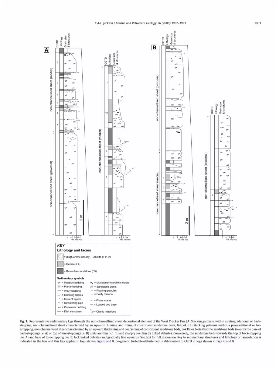
Fig. 5. Representative sedimentary logs through the non-channellised sheet depositional element of the West Crocker Fan. (A) Stacking patterns within a retrogradational or back-stepping, non-channellised sheet characterised by an upward thinning and fining of constituent sandstone beds, Telipok. (B) Stacking patterns within a progradational or for-estepping, non-channellised sheet characterised by an upward thickening and coarsening of constituent sandstone beds, Lok Kawi. Note that the sandstone beds towards the base ofback-stepping (i.e. A) or top of fore-stepping (i.e. B) units are thin (<1 m) and sharply overlain by linked debrites. Conversely, the sandstone beds towards the top of back-stepping(i.e. A) and base of fore-stepping (i.e. B) lack linked debrites and gradually fine upwards. See text for full discussion. Key to sedimentary structures and lithology ornamentation isindicated in the box and this key applies to logs shown Figs. 6 and 8. Co-genetic turbidite-debrite bed is abbreviated to CGTD in logs shown in Figs. 6 and 8.
C.A-L. Jackson / Marine and Petroleum Geology 26 (2009) 1957–1973 1963

Gra
in s
ize
&st
ruct
ures
Lith
olog
y
CG
TDGra
in s
ize
&st
ruct
ures
Lith
olog
y
CG
TD
vcscs
msfs
vfssc
vcscs
msfs
vfssc
2 m
1
2?
Lok Kawi (N=17)
Inaman Quarry (N=6)
Papar Highway (N=5)
Taman Bukit Sepangar (N=14)
Taman Viewpoint (N=4)
Taktik Megah Sawmill (N=5)
Fig. 6. Representative sedimentary log through the channelised part of the channel-levee depositional element of the West Crocker Fan, Pascal Quarry. The channel fill is char-acterised by thick-bedded, high-density turbidite sandstones in beds up to 9 m thick, which fine upwards and typically lack linked debrites. Paleoflow data taken by Crevello et al.(2008) from large flute casts at the base of thick-bedded sandstones indicate an overall north-westerly to north-easterly direction.
C.A-L. Jackson / Marine and Petroleum Geology 26 (2009) 1957–19731964

Fig. 7. Field photographs illustrating the sedimentological characteristics of very-fine to fine-grained, thin-bedded sandstones (Facies 2 and 3) in the West Crocker Fm.(A) Interbedded low-density turbidites (Facies 2) and basin-floor mudstones (Facies 5) in the distal lobe depositional element, Sepangar North. Field of view is 2 m wide and thesuccession is younging from left to right. (B) Details of beds shown in (A) illustrating wavy bedding passing upwards into ripple and climbing-ripple lamination (Tc interval ofBouma, 1962) in low-density turbidites (Facies 2). In the lowermost bed a basal interval of planar-parallel lamination (Tb interval of Bouma, 1962) is also developed. (C) Interbedded‘‘levee’’ sandstones (Facies 3) and basin-floor mudstones (Facies 5) overlying a thick (30 m) channel fill unit composed of high-density turbidite sandstones (Facies 1), TamanViewpoint Succession is younging from left to right. (D) Climbing cross-ripple lamination developed within a ‘‘levee’’ sandstone (Facies 3). Arrows illustrate angle of climb. Note thedevelopment of darker, finer-grained drapes on many of the ripple foresets. Location of photograph is shown in (C). (E) Cross-ripple laminated, very fine-grained sandstone (Facies3) inter-bedded with laminated mudstones (Facies 5) within the levee part of the channel-levee depositional element.
C.A-L. Jackson / Marine and Petroleum Geology 26 (2009) 1957–1973 1965
undeformed shale clasts (Fig. 9F); (ii) cauliform, typically highly-sheared (Fig. 9B, E) patches of very fine to fine-grained sand-stone. These clasts have irregular margins with, and are lightercoloured and interpreted to be better sorted than the encasingmatrix (Fig. 9B, E); (iii) coal or coal-rich heteroliths which occuras intact clasts or, more commonly in the case of coal, occur asfinely-disseminated chips within the matrix (Fig. 9A); and (iv)laminated heteroliths containing current ripples, climbingcurrent-ripples and wavy lamination which are typically strongly
sheared or display mm-scale offset faults (Fig. 9D, F). The clasttypes described above range in size from silt- to fine sand-sizedin the case of disseminated coal, up to 0.2 m in the case of theshale, coal and sheared sandstone clasts, and up to 2 m in thecase of the laminated heterolithic clasts (Fig. 9G). As observed forthe matrix, clasts within Facies 4 do not to show any gradingtrends. Due to lack of basal erosion and absence of internalsedimentary structures, palaeoflow data is not available forFacies 4.

CG
TDLi
thol
ogy
Gra
in s
ize
& st
ruct
ures
CG
TDLi
thol
ogy
Gra
in s
ize
& st
ruct
ures
vcscs
msfs
vfssc
vcscs
msfs
vfssc
1 m
Fig. 8. Representative sedimentary log through the distal lobe depositional element ofthe West Crocker Fan, Sepangar North. Note the dominance of fine-grained, upward-fining, Bouma-type turbidites, dominated by current and climbing current-ripplelamination, and the complete absence of linked debrites.
C.A-L. Jackson / Marine and Petroleum Geology 26 (2009) 1957–19731966
4.4.2. InterpretationThe ungraded matrix within Facies 4 coupled with the ungraded
nature of contained clasts suggest that Facies 4 was deposited enmasse, such that grain-size segregation and differential settling, asis typical for a progressively-waning, fully to moderately turbulentflow, did not occur (cf. Facies 1 and 2). Based on comparisons with
similar deposits documented elsewhere in submarine successions(see review by Mulder and Alexander, 2001) and its occurrencewith other submarine gravity-flow and suspension deposits, Facies4 is interpreted as a debrite, deposited by a flow which was eithertruly laminar (i.e. non-turbulent with grain-to-grain collision andyield strength of the flow being the main grain support mecha-nism) or possibly weakly turbulent (see Costa and Williams, 1984;Iverson, 1997). Furthermore, based on the dominant matrixcomponent, this facies can be further sub-divided into muddydebrite or sandy debrites. The variety of clast types within thedebrite and the nature of their internal deformation providesinsights into the state of the clasts prior to incorporation into theflow and the flow conditions itself. For example, many of the clastsare internally deformed (Fig. 9B, D–F) and have irregular margins,suggesting they were poorly lithified prior to incorporation withinthe flow and deformed by internal shearing and/or clast interactionwithin the flow. The preservation of mechanically-weak coalclasts within the debrite indicates that shearing and clast interac-tion within the flow was not severe, however, and supports theinterpretation that the flow was weakly turbulent or possiblylaminar. In contrast, the preservation of fine laminae within sub-spherical and rounded mudclasts may suggest these lithologieswere partly to fully lithified prior to erosion and transport.
4.5. Facies 5 – massive to finely-laminated mudstone
4.5.1. DescriptionFacies 5 consists of massive to finely-laminated mudstone in
units up to 2.5 m thick. This facies occurs in association with and istypically sharply and commonly erosively overlain by all thepreviously described gravity-flow facies (Figs. 5, 6 and 8). Bio-turbation is not observed in Facies 5.
4.5.2. InterpretationFacies 5 may have been deposited by two mechanisms. Firstly,
the mudstone may document deposition by suspension fallout ofhemipelagic mud particles in a low-energy, offshore, probably basinfloor setting. Alternatively, this fine-grained material could havebeen associated with and transported within the flow responsiblefor deposition of the immediately underlying bed; such deposits areoften referred to as ‘turbiditic mudstones’ (see Talling et al., 2004;Amy et al., 2005; Amy and Talling, 2006). The lack of bioturbationwithin the mudstones suggests stressed environmental conditions,probably due to a combination of the frequency and volume ofgravity flows onto the basin floor and/or anoxic basinal conditions.
5. Vertical facies organisation and evidence for turbidite anddebrite deposition from a single flow event
Within the West Crocker Fan a somewhat unusual vertical faciestransition occurs whereby high-density turbidite sandstone (Facies1) is overlain by debrite (Facies 4) (Figs. 5 and 10). This isa commonly observed relationship, with approximately 90% ofdebrites underlain by turbidite deposits. The contact between thesandstone and debrite intervals is either: (i) sharp and undulose,with a well-defined grain size break and up to 0.2 m of relief (Figs. 5and 10A, C); or (ii) transitional over <5 cm, with a gradationalupward decrease in grain size, an upward increase in mud contentwithin the sandstone and an upward increase in lithic clast content(Figs. 5 and 10E, F). Where extremely undulose (>0.15 m relief)contacts are developed between the turbidite and debrite, thecontact is almost invariably associated with clastic injectionssourced from the underlying turbidite and injected upwards intothe base of the overlying debrite. These clastic injections may be upto 0.1 m wide and 1 m high, and are commonly highly sheared (Figs.

C.A-L. Jackson / Marine and Petroleum Geology 26 (2009) 1957–1973 1967
5 and 9B, C, 11). These composite turbidite–debrite beds may becapped (ca. 30% of studied examples) by a thin (<0.05 m) interval ofcurrent ripple-laminated siltstone or very-fine sandstone (Facies 2).This gradationally or abruptly overlies the upper debrite and is
Fig. 9. Field photographs illustrating the sedimentological characteristics of debrites (Facicontaining a variety of clast types including indurated sandstones (IS), coal-rich heterolithirregular lower contact with underlying turbidite sandstone (Facies 1), Kingfisher. Note themargins to the injections. (C) Muddy ‘linked’ debrite overlying turbidite sandstone (Faciesdebrite has resulted in the envelopment of portions of the muddy debrite which could be mifaulted laminated heterolithic clast within a muddy debrite, Kingfisher. (E) Convolute beddinclean, fine-grained sandstone (arrowed), Kingfisher. (F) Very fine-grained, rippled sandstoneof abundant tabular shale clasts within the mud-rich matrix. (G) Large (>1m), laminated heploughed into and deformed the underlying turbidite sandstone (Facies 1) bed, Kingfisher.
always finer grained than the both underlying turbidite and debriteintervals. It is noted that mudstone (Facies 5) is never preservedbetween the lower sandstone and upper debrite intervals althoughit commonly caps the composite beds.
es 4) in the West Crocker Fan. (A) Fine sand matrix-supported conglomeratic debrites (C) and mudstone (M), Telipok. (B) Muddy ‘linked’ debrite sandstone displaying anupwards injection of sandstone (arrowed) into the overlying debrites and the irregular1), Lok Kawi. Pervasive small-scale injection of sandstone at the base of the overlyingstaken as shale clasts (pseudo-clasts) in the upper part of the sandstone. (D) Folded andg texture developed in a muddy debrite associated with contorted (cauliform) clasts of(similar to that characterising Facies 3) clast in a muddy debrite. Note also the presenceterolithic clast (arrowed) at the base of a muddy linked debrite which appears to have

Fig. 10. Field photographs illustrating the variable characteristics of bedding contacts between turbidite and debrite portions of linked debrite beds in the West Crocker Fan. (A) Undulosecontact between the turbidite (Facies 1) and linked debrite (Facies 4) intervals in a co-genetic turbidite-debrite beds (CGTD), Taman Viewpoint. Note the development of water-escapesheets in the upper part of the lower turbidite bed and the fine-grained rippled cap (Facies 2) to the debrite. (B) Very undulose contact with 0.45 m of relief between a turbidite (Facies 1) andlinked debrite (Facies 4), Sepangar. 0.15 m ruler is circled. (C) Gradational contact between a turbidite (Facies 1) and linked debrite (Facies 4) bed, Taman Viewpoint. The contact is definedby an abrupt increase in (visible) mud content, a gradual decrease in sand grain size and a marked increase in the density of mudstone clasts. (D) Gradational contact between a turbidite(Facies 1) and linked debrite (Facies 4) bed, where the contact is defined by an abrupt increase in (visible) mud content and mud-grade coal fragments, Telipok. Note the development ofcontorted, very fine-grained sandstones clasts with irregular margins (arrowed) and large coal clasts within the debrite. (E) Stacked CGTD beds with gradational but abrupt contactsbetween the turbidite and linked debrite portions linked, Sepangar. In both beds the dark clasts in the debrite portions are coal fragments and mud chips.
C.A-L. Jackson / Marine and Petroleum Geology 26 (2009) 1957–19731968
These observations provide good evidence for a close temporallinkage between the turbidite and debrite intervals. The absence ofa hemipelagic or turbiditic mudstone (i.e. Facies 5) between theturbidite and debrite intervals of the bed suggests there was nohiatus between deposition of the two units. In addition, thegradational contact between the two facies indicates a gradualchange in the flow conditions (i.e. from fully turbulent to weaklyturbulent or laminar). Where a sharp, erosional contact is devel-oped between the two facies, clastic injections in the upper debriteindicate that the underlying sandstone was still water-rich andcould be liquefied. Furthermore, shearing of the injections suggestthat the debris flow was still mobile during injection. Finally, thecurrent ripple-laminated very-fine sandstone which cap thecomposite beds is finer grained than the underlying turbidite anddebrite. It seems unlikely, therefore, that this unit was depositedfrom a genetically separate flow. It is more likely that this unitrepresents deposition from the waning-flow stage of the bipartiteflow event. Composite beds with similar sedimentological charac-teristics have been previously described from other deepwater
successions (Wood and Smith, 1958; Haughton et al., 2003; Tallinget al., 2004; Amy et al., 2005; Amy and Talling, 2006; Ito, 2008;Davies et al., 2009; Felix et al., 2009; Georgiopoulou et al., 2009;Haughton et al., 2009; Hodgson, 2009). Thus, despite the lack ofpalaeocurrent data from the linked debrite interval with which toconclusively demonstrate that the flows depositing these units hada similar northerly flow direction as the flows depositing theunderlying turbidite, we follow previous workers in terming thecomposite beds ‘co-genetic turbidite-debrites’ (sensu Talling et al.,2004) or, more simply, CGTD beds. The upper debrite interval iscalled ‘linked’ debrite (Haughton et al., 2003; Amy and Talling,2006; Haughton et al., 2009).
6. Stratigraphic context of linked debrites and constraints ontheir geometry
Due to the vertically extensive but laterally restricted nature ofthe available outcrops, it is not possible to use bed correlations toaccurately constrain the downstream or across-stream geometry of

Fig. 11. (A) Sheared clastic injections derived from the underlying turbidite sandstone (Facies 1) bed within a muddy ‘linked’ debrite, Taktik Megah Sawmill. (B) Highly shearedclastic injections in a muddy linked debrite derived from the underlying turbidite sandstone (Facies 1) bed, Low Kawi. In both (A) and (B) note the markedly undulose upper surfaceto the underlying sandstone and the pinch-and-swell texture and bulbous forms developed in the clastic injections.
C.A-L. Jackson / Marine and Petroleum Geology 26 (2009) 1957–1973 1969
linked debrites in the West Crocker Fan (cf. Talling et al., 2004; Amyand Talling, 2006). However, based on the previous identification ofgenetically-related ‘submarine fan’ depositional elements by Cre-vello et al. (2008) and by observations on the occurrence of linkeddebrites within these elements, it is possible to place these unitswithin their stratigraphic context and infer their downstream(if not across-stream; see Amy and Talling, 2006) geometry. Asdiscussed above, due to exposures of the sand-rich portion of theWest Crocker Fan occurring within relatively isolated, thrust-bounded slices and the relative paucity of palaeocurrent data(especially within the linked debrites), the proximal to distal trendsdescribed here should be considered speculative. Irrespective ofthese uncertainties, in this section the depositional elements ofCrevello et al. (2008) are summarised in the inferred proximal todistal order. This is interpreted to record progressive, down-slopeunconfinement of gravity-flow events, from channel-levee to non-channellised sheet to distal sheet. It should be noted that althougha ‘fan’ depositional setting was suggested by Crevello et al. (2008)for the majority of medium to thick-bedded, sand-rich depositswithin the West Crocker Fan, it is considered equally as likely thatthese units could have been deposited in a relatively unconfined,basin floor setting in the absence of true ‘fan’ development.
6.1. Channel-levee
The channel-levee depositional element represents the mostproximal portion of the West Crocker Fan. This depositionalelement is 30–60 m thick, may overlie or pass upwards into thenon-channellised lobe depositional element and displays an overallthinning and fining-upward stacking pattern. In the lower part ofthese units, a representative example of which is illustrated inFig. 6, sandstone beds are typically 1–3 m thick. They may, however,amalgamate to form beds up to 30 m thick. These sandstonesdisplay the coarsest basal lags, coarsest overall grain size (coarse-grained) and largest flute casts and groove marks observed in theWest Crocker Fan (see Fig. 4A, B). The middle and upper part of thisdepositional element consists of fine to medium-grained high-
density (Facies 1) or low-density (Facies 2) turbidite sandstonesinter-bedded with hemipelagic or turbiditic mudstone (Facies 5).These facies pass upwards into sandy levee deposits (Facies 3)inter-bedded with hemipelagic or turbiditic mudstones (Facies 5)(Fig. 7C). Linked debrites (and debrites lacking an associatedunderlying sandstone interval) are rare or very thin (<5% of thetotal sandstone bed thickness) within the channel-levee deposi-tional element. High-density turbidite beds, irrespective of theirthickness, either fining-upwards into a planar to current-rippledinterval or are sharply overlain by an overlying high-densityturbidite (Fig. 6).
The thinning and fining-upward stacking pattern observed inthe channel-levee depositional element is interpreted to docu-ment the incision, migration and abandonment of a majorsubmarine channel (Crevello et al., 2008). The lower, thick-bedded, amalgamated high-density turbidites document depo-sition in the axis of the channel, whereas the overlying, finer-grained, thin- to medium-bedded turbidites were depositedtowards the channel margin. The thickness (i.e. up to 50 m) ofthe channel portion of the channel-levee depositional elementsuggests that the channels where confined by levees, such asthose interpreted to be developed in the upper part of thedepositional element (Fig. 7C). The absence of linked debrites inthe channel-levee depositional element is not attributed toerosion beneath subsequent turbidity currents, as many of theturbidite beds fine upwards and display a sequence of sedi-mentary structures which are consistent with gradually waningflow conditions (Fig. 6).
6.2. Non-channellised sheet
The non-channellised sheet depositional element overlies orunderlies the distal sheet depositional element or channel-leveedepositional element. It is represented by coarsening and thick-ening-upward, or fining and thinning-upward units which 5-15 mthick. Representative examples of this depositional element fromtwo localities, which display contrasting stacking patterns (i.e.

C.A-L. Jackson / Marine and Petroleum Geology 26 (2009) 1957–19731970
thickening and thinning-upward), are illustrated in Fig. 5. Thick-ening-upwards units within the non-channellised sheet faciesassociation typically commence with either CGTD beds or, morerarely, high-density turbidite sandstones (Facies 1) lacking debritecaps. These facies are inter-bedded with hemipelagic or turbiditicmudstone (Facies 5) (Fig. 5B). The CGTD beds thicken upwardsbefore being replaced in the upper part of the thickening-upwardsunits by high-density turbidite sandstones (Facies 1) up to 3.5 mthick (Fig. 5B). In contrast to the turbidite sandstone beds in thelower part of this depositional element, these sandstone bedstypically lack or have only thin (i.e. <10 cm) debrite caps and arenormally graded with a rippled or wavy laminated, fine-grainedupper part (Fig. 5B). Note that the opposite trends for all the rela-tionships described above are observed where thinning- ratherthan thickening-upwards units are developed (Fig. 5A). Within thenon-channellised sheet depositional element, sandstone beds(with or without debrite caps) only rarely display coarse basal lagsor flute casts (Fig. 5A, B).
A non-channellised interpretation is made for this depositionalelement based on; (i) the overall finer grain size (fine to medium-grained) in the high-density turbidite sands (Facies 1) compared tothat in the channel-levee depositional element; (ii) the lack oferosion (flutes) at bed bases and; (iii) the absence of coarse basallags at bed bases. All of these observations suggest weak confine-ment of the gravity flows. The coarsening and thickening-upwardpatterns observed within the non-channellised sheet depositionalelement may be interpreted to document progradation of a sand-rich sheet, with the lower interval, comprised of inter-beddedCGTD beds and hemipelagic or turbiditic mudstones, representingthe relatively more distal medial sheet, and the upper interval,which comprises amalgamated high-density turbidites, repre-senting the more proximal part of the sheet near the mouth of thechannel-levee feeder system. In contrast, fining and thinning-upwards patterns within the depositional element may representperiods of sheet retrogradation. Due to a lack of exposure of time-equivalent slope or shelf depositional systems, the mechanismdriving these variations in sheet dynamics can only be speculatedupon. It may be speculated, however, that temporal variations ingravity-flow energy and associated transported sediment volumemay control such behaviour. (e.g. Pirmez et al., 2000; Kneller,2003). Alternatively, if a submarine fan ‘lobe’ interpretation ispreferred (Crevello et al., 2008), avulsion and compensationalstacking of adjacent lobes (with no temporal variations in flowenergy or volume) could also lead to this vertical facies stackingpattern.
6.3. Distal sheet
The distal sheet depositional element represents the most distalpart of the West Crocker Fan, and is composed of low-densityturbidite sandstones (Facies 2) inter-bedded with hemipelagic orturbiditic mudstones (Facies 5). A well-exposed, relatively sand-rich, representative example of this depositional element is illus-trated in Fig. 8. This depositional element typically underlies oroverlies the non-channellised sheet depositional element. It isinterpreted to record deposition towards the edge of a non-chan-nellised sheet. Linked (and unlinked) debrites are rare to absent inthis depositional element (Fig. 8).
6.4. Summary and inferred downstream geometry of linkeddebrite beds
Linked debrites are very thin (<5 cm) or absent in the channel-levee (e.g. Fig. 6) depositional element and are absent in the distalsheet (e.g. Fig. 8) depositional elements of the West Crocker Fan.
They are relatively common, however, within the non-channellisedsheet depositional element (e.g. Fig. 5). Based on the stackingpattern within this depositional element unit, linked debritesappear to thicken from the proximal sheet where flows are inter-preted to be slightly more confined, to the medial sheet where theflows are interpreted to be more unconfined. Further downstreamonto the distal sheet, although the underlying sandstone interval isinterpreted to progressive thin and fine into this location (recordinga progressive downstream decrease in sediment concentrationwithin the flow as indicated by a transition from high-density (i.e.Facies 1) to low-density (i.e. Facies 2) turbidite), linked debrites areinterpreted to pinchout. Based on these observations, a represen-tation of the inferred geometry and distribution of CGTD beds andlinked debrites is shown in Fig. 12.
7. Discussion
7.1. Origin of linked debrites in the West Crocker Fan
Linked debrites appear to be almost exclusively developed in thenon-channellised, unconfined part of the West Crocker Fan, withthis bed interval thinning both upstream and downstream (e.g.Fig. 12). Similar, wedge-shaped, linked bed geometries associatedwith debrites in relatively distal settings have been documentedfrom outcrop studies of the Marnoso Arenacea Fm, Italy (Tallinget al., 2004; Amy and Talling, 2006), in Skoorsteenberg Fm, SouthAfrica (Hodgson, 2009) and the Otadai Fm, Japan (Ito, 2008). In andthe subsurface, examples have been provided from Upper Jurassicdeposits of the North Sea Basin (Haughton et al., 2003) Paleocenedeposits in the Central North Sea (Davies et al., 2009) and Pleisto-cene deposits from offshore NW Africa (Talling et al., 2004, 2007;Georgiopoulou et al., 2009). Based on this bed geometry and theclast composition within these deposits, five main models havebeen proposed to account for the generation of co-genetic, fully-turbulent (turbidity current) and weakly-turbulent or laminarsediment gravity- flows (debris flow): (i) ingestion of water maycause the dilution of an initial debris flow, which in turn leads toa reduction in sediment concentration and generation of an asso-ciated low-density turbidity current (Model 1) (e.g. Marr et al.,2001); (ii) erosion of a mud-rich substrate by an initial turbiditycurrent may cause an increase in mud-grade material within theflow, increase sediment concentration, suppress flow turbulence,and cause a transformation to a weakly-turbulent or laminar debrisflow (Model 2) (e.g. Haughton et al., 2009); (iii) the deceleration ofa ‘low-coherency’ debris flow may cause coarse grains to come outof suspension and deposit a unit displaying characteristics ofa turbidite. The remaining mud-rich flow phase then depositsa mud-rich debrite interval (Model 3) (e.g. Talling et al., 2007); (iv)the deceleration of an initial turbidity current may lead to deposi-tion of a (graded) turbidite sandstone, with the associated reduc-tion of near bed turbulence (due to increasing mud content withinthe remaining flow) resulting in a transition to debris flow (Model4; Talling et al., 2007); and (v) the passage of a turbidity currentalong or against an unstable slope such as the basin margin ora channel levee, which may trigger an associated debris flow whichoverrides the precursor turbidite (Model 5) (McCaffrey and Kneller,2001). The reader is referred to Haughton et al. (2003) and Tallinget al. (2004) for a full discussion of these models.
A situation similar to that represented by Model 4 has recentlybeen suggested by Talling et al. (2007) as one potential mechanismfor deposition of an interpreted CGTD bed in the Agadir Basin,offshore NW Africa. In this example, it is speculated that depositionof the turbidite occurred due to the deceleration of a well-mixedand presumably turbulent flow at a relatively small (0.05–0.01�)but abrupt change in slope angle; this allowed coarse grains to

1-2
m Facies 1Facies 4
(linked debrite)Facies 5
Facies 2
iiiiii iv v
channel-levee
pinch-out of linked debritepinch-out of linked debrite
pinch-out of linked debrite
(i) (v)(iv)(iii)(ii)proximal distalsheet ‘advancement’
unconfined sheet
linked debritesheet margin
basin floor
basin floor
csfsvfsmsvcs
sccsfsvfsmsvcs
sccsfsvfsmsvcs
sccsfsvfsmsvcs
sccsfsvfsmsvcs
sc
Fig. 12. Conceptual diagram indicating the inferred geometry and distribution of linked debrites in the West Crocker Fan based on the stratigraphic occurrence of theseunits in three key depositional elements (i.e. channel-levee, non-channellised sheet and distal sheet). A proximal to distal correlation parallel to paleoflow is shown fora basinward advancing, non-channellised sheet. Note that in the vertical profiles the linked debrites systematically thin-upwards although this is not the case in all studiedexamples. Compare the vertical stacking pattern at locations (iii)–(v) with that shown in Fig. 5B. The inset cartoon diagram indicates the spatial arrangement of depo-sitional elements in the West Crocker Fan (adapted from Crevello et al., 2008) and the distribution of linked debrites within this system. Approximate locations ofschematic log localities shown in the correlation are illustrated. Note that no scale is implied and that the sheet may be supplied with sediment from several channel-leveefeeder systems.
C.A-L. Jackson / Marine and Petroleum Geology 26 (2009) 1957–1973 1971
come out of suspension and deposit a turbidite sand interval thatwas then subsequently overlain by a debrite. However, the occur-rence of large (up to 2 m) clasts within linked debrites in the WestCrocker Fan suggests that this mechanism is highly unlikely to beresponsible for the occurrence of CGTD beds in this case, asa turbidity current is unlikely to have been able to support suchlarge clasts. In addition, mechanically weak clasts such as coal andcoal-rich heteroliths would also have become disaggregated duringtransport within a relatively turbulent flow. Likewise the presenceof coal and coal-rich heterolithic clasts indicates an extra-basinalsource for clasts, thereby arguing strongly against Models 2 and 5.However, the occurrence of large (metre-scale) scales and extra-basinal clasts does provide support for a model in which a weaklyturbulent to laminar debris flow phase was present when the flowevent entered the basin (i.e. Models 1 and 3). Such a flow couldtransport large clasts and also reduce abrasion and disaggregationof mechanically-weak clasts. A model similar to this, wherebya low-coherency (i.e. well-mixed and weakly turbulent) debris flowwas present as the flow event entered the basin, was also consid-ered plausible for the Agadir Basin example. In this case it wasinterpreted that a change in slope angle and associated decrease inflow velocity resulted in coarse grains coming out of suspensionand depositing a sand-rich interval with ‘turbidite’ characteristics.As a result the remaining phase within the flow event was muddier,less turbulent and possibly laminar, resulting in deposition ofa mud-rich unit with ‘debrite’ characteristics. Although flowtransformation from an initial debris-flow is an appealing mecha-nism to account for the development of linked debrites in the WestCrocker Fan, due to post-depositional deformation it is difficult todeduce if flow transformation and linked debrite depositionconsistently occurred at a change in slope angle. In addition, and asdocumented in the Agadir Basin, it is not possible to constrain ifflow transformation and linked debrite deposition occurs imme-diately downdip of a major turbidity current-related scour field.However, the presence of possibly basin floor-derived mudstone
clasts and channel-levee-derived laminated heteroliths provideevidence for intra-basinal derivation of some of the clast assem-blage. Partial abrasion and disaggregation of these clasts wouldhave resulted in addition of fine-grained material to the flow,a further reduction in flow turbulence and development ofa laminar flow phase (i.e. elements of Model 2). If, as seems likely,that a debris-flow phase was present as the flow event entered thebasin, the lack of preservation of linked debrites in the proximalreaches of the depositional system suggests; (i) this flow phase wasable to bypass proximal areas and leave little or no evidence ofdeposition (cf. Talling et al., 2007); or (ii) the deposits associatedwith this flow phase are present at the entry point but availableoutcrops fail to capture this location (cf. Amy and Talling, 2006).
7.2. Basinal occurrence of linked debrites
Although the location of and depositional regime operating atthe shelf-edge during deposition of the West Crocker Fan is difficultto constrain, this study is in agreement with previous studies whichindicate that linked debrites are most common in relatively distal,non-channellised depositional settings (Haughton et al., 2003;Talling et al., 2004; Amy et al., 2005; Amy and Talling, 2006; Tallinget al., 2007; Ito, 2008; Georgiopoulou et al., 2009; Haughton et al.,2009; Hodgson, 2009). Based on palaeogeographic reconstructionsand the presence of coal clasts within the linked debrites, it isinterpreted that gravity flows were derived from delta front failuresat a coeval shelf edge located ca. 200 km to the south (see Fig. 3).The run-out distance for linked debrites in the West Crocker Fan is,therefore, comparable to some of the largest distances previouslyproposed. For example, a run-out distance of at least 350 km hasbeen proposed for linked debrites in the Agadir Basin (Talling et al.,2004). Likewise, although not interpreted as linked debrites byoriginal workers, Talling et al. (2004) suggest that Quaternarydeposits from the Mississippi fan, offshore southern USA, andPleistocene deposits from the Hatteras Abyssal Plain, offshore

C.A-L. Jackson / Marine and Petroleum Geology 26 (2009) 1957–19731972
south-eastern USA, have similar sedimentological characteristics tolinked debrites and these deposits may, therefore, have run-outdistances of ca. 600 and ca. 200 km respectively. In some of theexamples cited above, the occurrence of linked debrites in rela-tively distal environments reflects the fact that formation of the‘linked’ debris flow has been interpreted to be related to flow‘bulking’ by seafloor erosion (Model 2 described above; cf. Tallinget al., 2004; Amy and Talling, 2006; Ito, 2008; Haughton et al.,2009; Hodgson, 2009; Pyles and Jennette, 2009). This style of flowtransformation requires significant run-out distances to allowdisintegration of the ingested, muddy clasts within the flow. Inother examples, where deceleration of a weakly turbulent debrisflow is interpreted as plausibly being the main flow transformationmechanism (i.e. Talling et al., 2007), variation in basin topography isthe critical control on ‘linked’ debris flow formation. Interestingly,this suggests that linked debrites could be deposited in relativelyproximal locations if depositional topography is conducive to trig-gering the required flow transformation.
7.3. Comparisons with core-based sedimentological observations
Linked debrites in the subsurface have been most thoroughlydescribed from cores in the Faroe-Shetland and North Sea Basins,offshore UK (Haughton et al., 2003; Davies et al., 2009; Haughtonet al., 2009) and from the Agadir Basin, offshore Morocco (Tallinget al., 2004, 2007; Georgiopoulou et al., 2009). In all these cases, theinterpretation of a linked debrite as opposed to an ‘unlinked’ debrite(i.e. one lacking a precursor turbidite) relies on the recognition ofsubtle bedding textures, clast assemblages and bedding contacts. Inthe absence of high-quality core, therefore, many of these featuresmay go unrecognised and/or their origin misinterpreted. Field-based studies such as that presented here from the West Crocker Fanare useful as they support the interpretation that many of thebedding textures and contacts observed in core originated fromlinked flows. Firstly, large (>1 m) clasts of shale or laminated het-eroliths identified towards the base of a linked debrite (e.g. Fig. 9G)could easily traverse a standard subsurface core (typically <15 cmwide) and be misinterpreted as a fine-grained interval, separatinga turbidite below from a genetically-unrelated debrite above.Discriminating between in-situ, bedded units or a reworked lithicclast may be made on; (i) the identification of deformation withinthe clast which is not present within the encasing matrix; and (ii)the clasts being extra-formational or ‘exotic’, in that they appear tobe genetically-unrelated to the encasing depositional units(Haughton et al., 2003; Haughton et al., 2009). Secondly, previousinterpretations that the irregular sandstone patches within theupper debrite interval were derived from the upward injection,shearing and disintegration of sand from the underlying turbiditebed (Haughton et al., 2003) appear to be substantiated by this study.For example, small cauliform sandstone clasts which are partlyconnected to the underlying sandstone bed (e.g. Fig. 9B), highlysheared injections (e.g. Fig. 11) and completely detached, highlycontorted sandstone clasts (e.g. Fig. 9E) are all observed in the linkeddebrites. This suite of structures may be interpreted to represent anidealised evolutionary sequence for the origin of the sandstoneclasts, with upwardly-injected sandstone becoming progressivelymore sheared by the overriding debris flow before being completelydetached, further deformed and transported in the flow as a discreteclast.
8. Conclusions
The main conclusions of this field-based sedimentological studyof the West Crocker Fm (Oligo-Miocene), Sabah, NW Borneo are:
1. Two main gravity-flow sandstone facies are identified in theWest Crocker Fm; (i) mud-poor, fine to medium-grained,massive to planar laminated, poorly-graded sandstones inter-preted as the deposits of high-density turbulent gravity-flows(turbidites), and (ii) clast-rich, mud-rich sandstones and sandymudstones interpreted as having been deposited en masse byweakly-turbulent or laminar gravity flows (debrites).
2. Debrites typically overlie turbidites, with the contact betweenthe two units being either gradational and planar or sharp andhighly erosive, with upwards injection of sand from the lowerturbidite interval into the upper debrite interval beingcommon. Based on the depositional processes interpreted forthe turbidite (turbulent flow) and debrite (weakly-turbulent orlaminar flow) intervals, their repeated vertical relationship andthe nature of the contact between the two units, thesecomposite beds are interpreted as being sourced from the sameflow event and are termed co-genetic turbidite-debrite (sensuTalling et al., 2004); the upper debrite interval is called a linkeddebrite (sensu Haughton et al., 2003).
3. Linked debrites in the West Crocker Fm are best developed indistal, non-channellised depositional environments. Due tooutcrop limitations, the genesis of linked debrites within theWest Crocker Fm is not unequivocal. However, based on clastsize and type, it seems likely that a weakly turbulent tolaminar debris-flow flow phase was present when the evententered the basin. A change in flow behaviour may have ledto deposition of a sand-rich unit with ‘turbidite’ characteris-tics, which was subsequently overlain by a mud-rich unitwith ‘debrite’ characteristics. Erosion and disintegration ofmuddy material from within the upstream channel floor andchannel mouth, in addition to material derived from channellevee collapse, may have both contributed to flow trans-formation. Lack of preservation of the linked debrite inproximal areas may indicate either bypass of the associatedflow phase or that the available outcrops fail to capture thedebris flow entry point.
4. Field studies such as this add confidence to the interpretationof the origins of CGTD-related fabrics and bedding contactsobserved in subsurface core data. Establishing robustsedimentological criteria from a variety of datasets may lead tothe increasing recognition of such deposits in deepwaterdepositional environments. This may lead to an increasedappreciation of the importance of bipartite flows in the trans-port and deposition of sediments in deepwater depositionalenvironments.
Acknowledgements
We would like to thank journal reviewers Russell Wynn andGary Nichols, and Special Edition editor Peter Talling for insightful,critical reviewers which helped improve this manuscript enor-mously. Thanks also to PETRONAS for funding the PhD studies ofAdli and providing logistical support in the field.
References
Amy, L.A., Talling, P.J., 2006. Anatomy of turbidites and linked debrites based onlong distance (120 � 30 km) bed correlation, Marnoso Arenacea Formation,Northern Apennines, Italy. Sedimentology 53, 161–212.
Amy, L.A., Talling, P.J., Peakall, J., Wynn, R.B., Arzola Thynne, R.G., 2005. Bedgeometry used to test recognition criteria of turbidites and (sandy) debrites.Sedimentary Geology 179, 163–174.
Bouma, A.H., 1962. Sedimentology of Some Flysch Deposits: a Graphic Approach toFacies Interpretation. Elsevier, 168 pp.
Clayton, C.J., 1994. Contrasting sediment gravity flow processes in the late Llan-dovery, Rhuddnant Grits turbidite system, Welsh Basin. Geological Journal 29,167–181.

C.A-L. Jackson / Marine and Petroleum Geology 26 (2009) 1957–1973 1973
Costa, J.E., Williams, G.P., 1984. Debris-flow Dynamics (Video). United StatesGeological Society, Open File Report, pp. 84–606.
Crevello, P.D., Johnson, H.D., Tongkul, F., Wells, M.R., 2008. Mixed braided andleveed-channel turbidites, West Crocker Fan system, Northwest Borneo. In:Nielsen, T.H., Shew, R.D., Steffens, G.S., Studlick, J.R.J. (Eds.), Atlas of Deep-WaterOutcrops, vol. 56. AAPG Studies in Geology.
Cronin, B.T., Hurst, A., Celik, H., Turkmen, I., 2000. Superb exposures of a channel,levee and overbank complex in an ancient deep-water slope environments.Sedimentary Geology 132, 205–216.
Davies, C., Haughton, P., McCaffrey, W., Scott, E., Hogg, N., Kitching, D., 2009. Characterand distribution of hybrid sediment gravity flow deposits from the outer FortiesFan, Paleocene Central North Sea. UKCS. Marine and Petroleum Geology 26,1919–1939.
Elmore, R.D., Pilkey, O.H., Clearey, W.J., Curran, H.A., 1979. The Black Shell turbidite,Hatteras Abyssal Plain, western Atlantic Ocean. Geological Society of AmericaBulletin 90, 1165–1176.
Felix, M., Leszczynski, S., Slaczka, A., Uchman, A., Amy, L., Peakall, J., 2009. Fieldexpressions of the transformation of debris flows into turbidity currents, withexamples from the Polish Carpathians and the French Maritime Alps. Marineand Petroleum Geology 26, 2011–2020.
Georgiopoulou, A., Wynn, R., Masson, D.G., Frenz, M., 2009. Linked turbidite-debriteresulting from recent Sahara Slide headwall reactivation. Marine and PetroleumGeology 26, 2021–2031.
Hageman, H., 1987. Palaeobathymetric changes in NW Sarawak during Oligocene toPliocene. Geological Society of Malaysia Bulletin 21, 91–102.
Hall, R., 2002. Cenozoic geological and plate tectonic evolution of SE Asia and theSW Pacific: computer-based reconstructions, models and animations. Journal ofAsian Earth Sciences 20, 353–431.
Hampton, M.A., 1972. The role of subaqueous debris flow in generating turbiditycurrents. Journal of Sedimentary Petrology 42, 775–793.
Haughton, P.D.W., Barker, S.P., McCaffrey, W.D., 2003. ‘Linked’ debrites in sand-richturbidite systems – origin and significance. Sedimentology 50, 459–482.
Haughton, P., Davis, C., McCaffrey, W., Barker, S., 2009. Hybrid gravity-flowdeposits – classification, origin and significance. Marine and PetroleumGeology 26, 1900–1918.
Hickson, T.A., Lowe, D.R., 2002. Facies architecture of a submarine fan channel-leveecomplex: the Juniper Ridge Conglomerate, Coalinga, California. Sedimentology49, 335–362.
Hodgson, D.M., 2009. Distribution and origin of hybrid beds in sand-rich submarinefans of the Tanqua depocentre, Karoo Basin, South Africa. Marine and PetroleumGeology 26, 1940–1956.
Hutchison,C.S.,1996. Geologic Evolutionof South-east Asia. Oxford Press, Oxford, 368 pp.Hutchison, C.S., 2005. Geology of North-west Borneo. Elsevier, Sarawak, Brunei and
Sabah.Ito, M., 2008. Downfan transformations from turbidity currents to debris flows at
a channel-to-lobe transitional zone: the Lower Pleistocene Otadi Formation,Boso Peninsula, Japan. Journal of Sedimentary Research 78, 668–682.
Iverson, R.M., 1997. The physics of debris flows. Review of Geophysics 35, 245–296.Kane, I.A., Kneller, B.C., Dykstra, M., Kassem, A., McCaffrey, W.D., 2007. Anatomy of
a submarine channel-levee: an example from Upper Cretaceous slope sedi-ments, Rosario Formation, Baja California, Mexico. Marine and PetroleumGeology 24, 540–563.
King, P.R., Browne, G.H., Slatt, R.M., 1994. Sequence architecture of exposed LateMiocene basin floor fan and channel-levee complexes (Mount MessengerFormation) Taranaki Basin, New Zealand. In: Weimer, P., Bouma, A.H.,Perkins, B.F. (Eds.), Submarine Fans and Turbidite Systems. GSSSEPM Founda-tion 15th Annual Research Conference, pp. 177–192.
Kneller, B.C., 2003. The influence of flow parameters on turbidite slope channelarchitecture. Marine and Petroleum Geology 20, 901–910.
Kneller, B.C., Branney, M.J., 1995. Sustained high-density turbidity currents and thedeposition of thick massive sands. Sedimentology 42, 607–616.
Leong Khee Meng, 1999. Geological setting of Sabah. In: The Petroleum Geology andResources of Malaysia. Petroliam Nasional Berhad (PETRONAS), pp. 475–497.
Lowe, D.R., 1982. Sediment gravity flows. II. Depositional models with specialreference to the deposits of high-density turbidity currents. Journal of Sedi-mentary Petrology 52, 279–297.
Madon, M.B.H., 1999. Basin types, tectono-stratigraphic provinces and structuralstyles. In: The Petroleum Geology and Resources of Malaysia. PetroliamNasional Berhad (PETRONAS), pp. 79–111.
Marr, J.G., Harff, P.A., Shanmugam, G., Parker, G., 2001. Experiments on subaqueoussandy gravity flows: the role of clay and water content in flow dynamics anddepositional structures. Geological Society of America Bulletin 113, 1377–1386.
McCaffrey, W.D., Kneller, B.C., 2001. Process controls on the development ofstratigraphic trap potential on the margins of confined turbidite systems andaids to reservoir evaluation. AAPG Bulletin 85, 971–988.
Middleton, G.V., Hampton, M.A., 1976. Subaqueous sediment transport and depo-sition. In: Stanley, D.J., Swift, P.J.P. (Eds.), Marine Sediment Transport andEnvironmental Management. John Wiley and Sons, New York, pp. 197–218.
Mulder, T., Alexander, J., 2001. The physical character of subaqueous sedimentarydensity flows and their deposits. Sedimentology 48, 269–299.
Nelson, C.H., Twichell, D.C., Schwab, W.C., Lee, H.J., Kenyon, N.H., 1992. UpperPleistocene turbidite sand beds and chaotic silt beds in the channelised, distal,outer-fan lobes of the Mississippi fan. Geology 20, 693–696.
Pirmez, C., Beauboeuf, R.T., Friedmann, S.J., Mohrig, D.C., 2000. Equilibrium profileand baselevel in submarine channels: examples from Late Pleistocene systemsand implications for the architecture of deepwater reservoirs. In: Weimer, P.,Slatt, R.M., Coleman, J., Rosen, N.C., Nelson, H., Bouma, A.H., Styzen, M.J.,Lawrence, D.T. (Eds.), Deep Water Reservoirs of the World. GCSSEPM Founda-tion 20th Annual Bob F, pp. 782–805. Perkins Research Conference.
Pyles, D.R., Jennette, D.C., 2009. Geometry and architectural associations of co-geneticdebrite-turbidite beds in basin-margin strata, Carboniferous Ross Sandstone(Ireland): applications to reservoirs located on the margins of structural confinedsubmarine fans. Marine and Petroleum Geology 26, 1974–1996.
Sandal, S.T., 1996. The Geology and Hydrocarbon Resources of Negara Brunei Dar-ussalam, second ed. Brunei Museum and Brunei Shell Petroleum Company, 243 pp.
Schwab, W.C., Lee, H.J., Twichell, D.C., Locat, J., Nelson, C.H., McArthur, W.G.,Kenyon, N.H., 1996. Sediment mass-flow processes on a depositional lobe, outerMississippi Fan. Journal of Sedimentary Research 66, 916–927.
Sohn, Y.K., 2000. Depositional processes of submarine debris flows in the Miocenefan deltas, Pohang Basin, SE Korea with special reference to flow trans-formation. Journal of Sedimentary Research 70, 491–503.
Stauffer, P.H., 1968. Studies in the Crocker Formation, Sabah, Borneo region,Malaysia. Bulletin of the Geological Survey of Malaysia 8, 1–13.
Talling, P.J., Amy, L.A., Wynn, R.B., Peakall, J., Robinson, M., 2004. Beds comprisingdebrite sandwiched within co-genetic turbidite: origin and widespread occur-rence in distal depositional environments. Sedimentology 51, 163–194.
Talling, P.J., Wynn, R.B., Masson, D.G., Frenz, M., Cronin, B.T., Schiebel, R.,Akhmetzhanov, A.M., Dallmeier-Tiessen, S., Benetti, S., Weaver, P.P.E.,Georgiopoulou, A., Zuhlsdorff, C., Amy, L., 2007. Onset of submarine debris-flowdeposition far from the original giant landslide. Nature 450, 541–544.
Tongkul, F., 1987. The sedimentology and structure of the Crocker Formation in theKota Kinabalu area, Sabah. Unpublished PhD thesis, University of London,London.
Van Hattum, M., 2005. Provenance of Cenozoic sedimentary rocks of northernBorneo. Unpublished PhD thesis, University of London.
Van Hattum, M.W.A., Hall, R., Pickard, A.L., Nichols, G.J., 2006. Southeast Asiansediments not from Asia: provenance and geochronology of north Borneosandstones. Geology 34, 589–592.
Waltham, D., 2004. Flows transformations in particulate gravity currents. Journal ofSedimentary Research 74, 129–134.
Wood, A., Smith, A.J., 1958. The sedimentation and sedimentary history of theAberystwyth Grits (Upper Llandoverian). Journal of Geological Society ofLondon 114, 163–195.
Zeng, J., Lowe, D.R., Prior, D.B., Wiseman, W.J.J., Bornhold, B.D., 1991. Flow propertiesof turbidity currents in Bute Inlet, British Colombia. Sedimentology 38,975–996.