3-d architecture and sequence stratigraphic evolution of a forced regressive top-truncated...
TRANSCRIPT

Journal of Sedimentary Research, 2007, v. 77, 303–323
Research Article
DOI: 10.2110/jsr.2007.031
3-D ARCHITECTURE AND SEQUENCE STRATIGRAPHIC EVOLUTION OF A FORCED REGRESSIVE TOP-TRUNCATED MIXED-INFLUENCED DELTA, CRETACEOUS WALL CREEK SANDSTONE, WYOMING, U.S.A.
KEUMSUK LEE,1,2 GEORGE A. MCMECHAN,1 M. ROYHAN GANI,1,3 JANOK P. BHATTACHARYA,1,4 XIAOXIAN ZENG,1 AND
CHARLES D. HOWELL, JR.11Center for Lithospheric Studies, The University of Texas at Dallas, P.O. Box 830688, Richardson, Texas 75083-0688, U.S.A.
, 2Bureau of Economic Geology, John A. and Katherine G. Jackson School of Geosciences, University of Texas at Austin, Austin, Texas 78713-8924, U.S.A.
, 3Energy & Geoscience Institute, The University of Utah, 423 Wakara Way 300, Salt Lake City, Utah 84108, U.S.A.4The Geosciences Department, University of Houston, 4800 Calhoun Road, Houston, Texas 77204-5007, U.S.A.
e-mail: [email protected]
ABSTRACT: Ground-penetrating radar (GPR) is used to delineate the 3-D facies architectural elements and examine theevolution of a top-truncated, forced-regressive, mixed-influenced delta front in the Cretaceous Wall Creek Member of theFrontier Formation, Wyoming. The GPR data provide a bridge between outcrop facies architecture and recently publishedhigh-resolution 2-D seismic studies of Quaternary delta systems. The GPR data were integrated with outcrops, photomosaics,cores, and GPS data. Two orthogonal grids of 2-D GPR profiles provide information on the 3-D facies architecture andstratigraphy of the deltaic deposits. Three main GPR architectural elements are identified within the delta front: (1) mouth barsare characterized by seaward-dipping reflections (foreset beds) in dip view, and mounded bidirectionally downlappingreflections in strike view; (2) shallow delta-slope channels show truncation and onlap and also show low-angle landward(northwest) dipping reflections. The mouth bars are locally interrupted by (3) sub-horizontal radar reflections that areinterpreted as tidally modulated bars. Within the mouth-bar radar facies, both top-preserved (proximal) and top-truncated(distal) examples are observed. Top-preserved proximal bars show evidence of mounded bar crests and landward accretion, as isobserved in the upstream end of mouth bars on the modern Atchafalaya Delta in the Gulf of Mexico. Distal bar depositsprimarily comprise the top-truncated, seaward-dipping foresets.
The GPR interpretation shows two laterally overlapping delta lobes, interpreted to represent autocyclic delta switching. Theolder lower lobe forms a fan-shaped delta lobe composed of top-truncated coalesced mouth bars. The second phase of bars islargely top-preserved, building over the older bars. The presence of thicker bedsets and upstream accretion suggests that theyounger lobe was quickly abandoned, as seen in the overlying transgressive ravinement. Although marine erosion duringtransgression was less effective on these later-stage bar deposits, ravinement increased landward. A comparison of thearchitectural elements at a more regional scale in two separate Wall Creek delta lobes (Murphy Creek and Raptor Ridge,, 30 km apart) indicates that the bar complexes were deposited on the delta fronts as accretionary forced-regressive depositsduring a relative sea-level fall; the older river-dominated deltaic deposits at the Murphy Creek site prograded southeastward(, 124u), whereas the younger and more tidally influenced Raptor Ridge bar deposits expanded southward (, 171u) beforefinal abandonment and regional transgression. The most distal lowstand lobe sediments within the offlapping parasequence atRaptor Ridge are more completely preserved and also show the greatest tidal influence, compared to the more severely top-truncated Murphy Creek, which is in an otherwise more landward location. This challenges the notion that tidal facies arepredominantly associated with transgressive or highstand systems tracts. Greater preservation of deltaic facies in forced-regressive and lowstand deltas, as shown here, has also been documented in Quaternary shelf-edge deltas, such as theLagniappe in the Gulf of Mexico and the Mahakham in Kalimantan.
INTRODUCTION
The large-scale stratigraphic architecture of deltaic clastic wedges iswell known from many sequence stratigraphic studies (e.g., Duncan 1983;Suter and Berryhill 1985; Tesson et al. 1990; Bhattacharya 1993; Plint2000; Barton et al. 2004; Garrison and van den Bergh 2004; Porebskiand Steel 2005; and numerous other examples quoted in Bhattacharya2006). However, the regional nature of these studies provides littleinformation about internal bed-scale facies variability within individ-
ual delta lobes. These older seismic and sequence stratigraphicexamples also emphasize dip-oriented cross-sectional depictions ofshelf depositional systems, versus along-strike variability. Strike-orientedvariability reflects the timing and spacing of overlapping lenses orlobes, which may be dependant on the number, spacing, and avul-sion frequency of distributary channels but may also depend on theshape of the sea floor, especially if there is differential subsidence oruplift related to tectonics, since deltas commonly fill low areas on the seafloor.
Copyright E 2007, SEPM (Society for Sedimentary Geology) 1527-1404/07/077-303/$03.00

More recent high-resolution seismic examples of Quaternary shelf-edgedeltas provide examples of bed-scale architecture of delta-front depositsas well as showing strike variability (e.g., Suter and Berryhill 1985; Tessonet al. 1990; Sydow and Roberts 1994; Hart and Long 1996; Hiscott 2003;Roberts and Sydow 2003; Roberts et al. 2005; Bart and Anderson 2004;other papers in Anderson and Fillon 2004). Unfortunately, only a few ofthese seismic-based studies are calibrated in terms of lithology and faciesbecause of a lack of core and well-log data, and the emphasis of most ofthese papers is on the broader regional sequence stratigraphic controls ondeposition (mostly eustasy and climate) as opposed to the internal faciesvariability and facies architecture, which are more critical in reservoircharacterization applications.
Outcrop examples that illustrate the bed-scale architecture of delta-front deposits are even fewer (Willis et al. 1999; Willis and Gabel 2001;Soria et al. 2003; Johnson and Graham 2004; Mattson and Chan 2004;Bhattacharya and Davies 2004; Anderson et al. 2004; Gani andBhattacharya 2007; Plink-Bjorklund and Steel 2005), while a largernumber of previous works focused primarily on delta-plain channels andincised valleys (see recent summaries by Gibling 2006, Olariu andBhattacharya 2006, Bhattacharya 2006). Most of these outcrop studies ofdelta-front deposits emphasize dip variability, with the exception of thepaper by Willis and Gabel (2001) on tide-influenced deltas in theCretaceous Sego Sandstone, Utah.
The concept of facies architecture was originally developed for fluvialand eolian rocks (Jackson 1975; Brookfield 1977; Allen 1983; Miall 1985,1996) and may be considered a reasonably mature field as applied toeolian, fluvial, and deep-marine facies models (e.g., Mountney 2006;Bridge 2006; Posamentier and Walker 2006). In contrast, facies-architecture analysis of deltaic and shallow marine counterparts remainsunderstudied. Despite their extreme complexity, a general model cannotyet be fully proposed (Bhattacharya 2006; Suter 2006).
The focus of this paper is to bridge the gap between these high-resolutionseismic and outcrop examples by investigating the within-lobe 3-Darchitecture of bar-scale facies architectural elements of an ancientCretaceous delta lobe. The key architectural elements that we wish toinvestigate include terminal distributary channels and mouth bars, which arecommon in river-dominated deltas (Olariu and Bhattacharya 2006). Tide-influenced delta fronts are expected to have a smaller proportion ofdistributary channels, although tidal scours may mimic distributary channels(Willis and Gabel 2001; Willis 2005). Tides rework mouth bars into tidalbars, but the scale of cross stratification produced by migrating shallow-water bars may be similar to deeper-water bedforms (e.g., dunes; Willis2005). Formation of multiple distributary channels is inhibited in wave-influenced deltas (Bhattacharya and Giosan 2003) and wave- or storm-dominated sand sheets and shorefaces may be associated with, or attachedto, more river- or tide-dominated components (Bhattacharya 2006). Mouth
FIG. 1.— The Raptor Ridge site is located on the west margin of the PowderRiver basin in east-central Wyoming, U.S.A. The lower panel shows thetopography of the study area (with 20 ft [6.096 m] contour interval), and thelocations of the GPR survey grid and the boreholes.
FIG. 2.—Stratigraphic section along the Frontier outcrop belt, containing six parasequences. The Raptor Ridge site lies in the topmost parasequence (PS 6) near thesouthern end of the section X–X9. Modified after Howell et al. (2003).
304 K. LEE ET AL. J S R
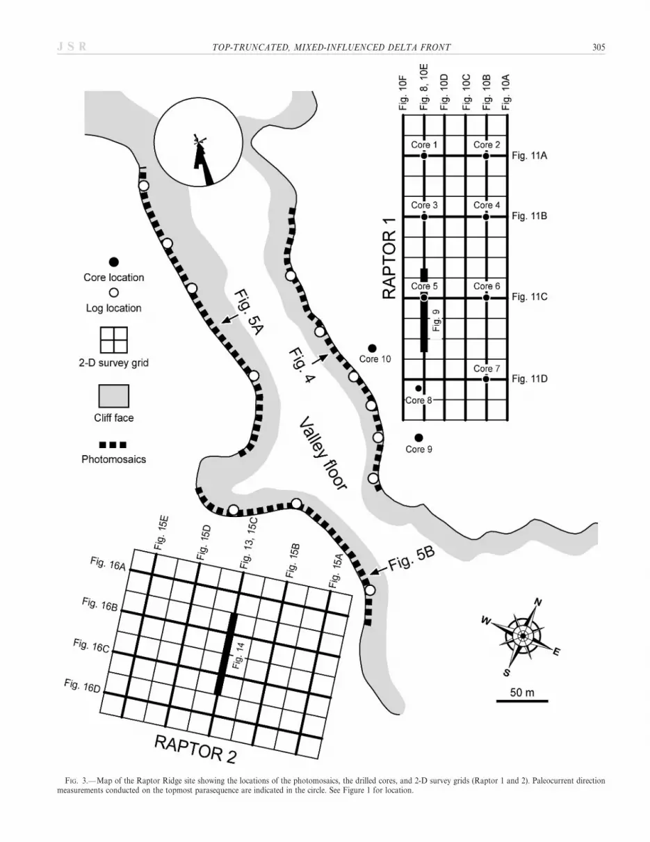
FIG. 3.—Map of the Raptor Ridge site showing the locations of the photomosaics, the drilled cores, and 2-D survey grids (Raptor 1 and 2). Paleocurrent directionmeasurements conducted on the topmost parasequence are indicated in the circle. See Figure 1 for location.
TOP-TRUNCATED, MIXED-INFLUENCED DELTA FRONT 305J S R

bars in wave-influenced deltas may also show alongshore elongation(Reynolds 1999; Garrison and van den Bergh 2004; Fielding et al. 2005).
Thus, the internal facies architecture of bar types is a key todetermining delta type (Galloway and Hobday 1996); variation indominance of depositional processes over time plus seasonal changes indischarge (Hart and Long 1996; Rodriguez et al. 2000; Lee et al. 2005)may produce complicated bedding geometry and facies patterns, such asin tide-dominated river deltas (Willis and Gabel 2003; Willis 2005) or tide-influenced river deltas (Bhattacharya and Walker 1992; Reading andCollinson 1996; Willis et al. 1999).
Tide-influenced river deltas have been historically difficult to modelbecause of their complexity and a lack of good ancient examples,although general models have been recently proposed (Willis 2005). Thisstudy takes a multidisciplinary approach to establish facies architecturalelements of a Cretaceous lowstand tide-influenced river delta, which iscapped by a transgressive ravinement surface (Gani 2005; Gani andBhattacharya 2007). The sedimentology and core and outcrop faciesdescriptions, which form the basis for this work, are presented in Gani(2005), Gani et al. (in press), and Gani and Bhattacharya (2007). Sixfacies architectural elements were recognized in the outcrops at theRaptor Ridge site (Fig. 1) at the top of the upper Turonian Wall CreekMember of the Frontier Formation, Wyoming. Although these architec-tural elements allow interpretation of the process-based morphometricelements that built the delta and may facilitate the recognition of similarsystems present elsewhere in the ancient record, not all scales can beresolved in GPR data, let alone in seismic or well-log data sets, and thenature of the outcrops precludes determining the 3-D geometry, criticalfor reservoir characterization studies. As a consequence, the outcrop-based observations are still in need of 3-D facies architectural geometry todevelop reliable 3-D models.
Kilometer-scale 3-D stratigraphic information on the delta front haspreviously been acquired in ground-penetrating radar (GPR) surveys of
the Wall Creek Member. For example, a GPR study was conducted tocharacterize a Cretaceous lowstand delta-front outcrop at the MurphyCreek site, located about 30 km to the northeast of the Raptor Ridge site(Fig. 1). The deltaic sandstones of both sites contain southward-prograding deltaic bar deposits interpreted to be formed during a relativesea level fall; a subsequent transgression left behind top-eroded, delta-front mouth bars (Lee et al. 2005). Although these two sites have a similardepositional history, lateral architectural variations within and betweenthem, during the seaward migration, in response to the relative sea-levelfall, have not been studied in detail.
There has recently also been an interest in examining the evolution ofdelta types during forced regressions and lowstands of sea level (Porebskiand Steel 2005). The delta deposits of the Frontier Formation lie severalhundred kilometers seaward of coeval highstand systems in the Bighornand Green River basins to the west (Bhattacharya and Willis 2001). Thebasin-distal positions of these sandstones, as well as the general lack ofpreserved paralic, coastal-plain or nonmarine facies (e.g., Posamentier etal. 1992; Hart and Long 1996; Posamentier and Morris 2000) are themain evidence for a forced-regressive to lowstand origin for thesesandstones (Bhattacharya and Willis 2001). Recent work on the WallCreek Member shows a complex series of offlapping sandstone bodies.Seven parasequences have been identified regionally in outcrop (Howell etal. 2003); in this study we focus on parasequence 6 (PS 6, Fig. 2). Withinparasequence 6, several lens-shaped offlapping, or shingled, sandbodieshave been mapped. The most distal shingle, exposed at Raptor Ridge, isthe subject of this paper. A paper on an older shingle, exposed alongMurphy Creek (Lee et al. 2005) describes the internal facies architectureof a more proximal river-dominated, and more severely top-truncated,delta lobe.
In this paper, we (1) document the 3-D facies architectural elements ofa top-truncated, mixed-influenced deltaic sandstone, with an emphasis onthe lateral variability, and (2) compare the type of facies and degree of
FIG. 4.— Bedding diagrams of the eastern cliff face (in the depositional dip direction) showing south dipping foreset beds (see Figure 3 for locations).
306 K. LEE ET AL. J S R

preservation within a strongly offlapping and downstepping system, and(3) discuss the implications for sequence stratigraphic interpretation offorced-regressive and lowstand systems tracts. The 3-D models areproduced from two grids of ground-penetrating radar (GPR) data,constrained by ten cores and by cliff-face maps.
GEOLOGICAL SETTING
Continuous north–south oriented exposures of the Turonian WallCreek Member in the Frontier Formation occur in a series of sandstonecliffs along the Frontier outcrop belt (Figs. 1, 2). The Wall Creeksediments were sourced from the Sevier highlands to the western flanks ofthe Cretaceous epicontinental seaway. Winn (1991) interpreted thesandstone bodies as storm-dominated offshore shelf deposits; however,a recent study (Bhattacharya and Willis 2001) suggests that the formationconsists of top-truncated deltas. Key evidence for a deltaic interpretationincludes well-developed, upward-coarsening facies successions, a mixed tohighly stressed ichnofossil assemblage, which indicates a possible brackishor fluvial stress (MacEachern et al. 2005), well-developed basinward-dipping clinoform strata interpreted as the preserved delta front, as well
as southward-directed paleocurrent data that dip broadly south, in thesame direction as the clinoforms. Where available, subsurface mapping ofthe Frontier sand bodies shows a broadly lobate shape, which suggestsa deltaic setting (e.g., Bhattacharya and Willis 2001; Gani andBhattacharya 2007).
Extensive pebbly erosional surfaces at the tops of the sandstone bodiesare interpreted as transgressive ravinement lags associated with the toptruncation. No fluvial or coastal-plain facies are observed or preserved,although a deltaic nature is inferred from the facies within the preservedlower parts of the sandstone bodies (e.g., the Belle Fourche Member;Bhattacharya and Willis 2001). The Wall Creek outcrops show severalofflapping delta lobes, indicated by different, coarsening-upward, top-truncated sandstone bodies. Within the Wall Creek Member, sevenparasequences have been identified along the outcrop belt, although onlysix are present along the western outcrop margin (PS 1 to PS 6 fromoldest to youngest, Fig. 2) (Howell and Bhattacharya 2004). The exposedtopmost parasequence (PS 6) at Raptor Ridge lies near the southern endof the Frontier outcrop belt, although several additional youngersandstones have been identified in subsurface farther to the south andeast. Internally, PS 6 contains several offlapping shingled sandstone
FIG. 5.—Bedding diagrams of the western cliff face. A) The northern segment, showing south dipping foreset beds (in the depositional dip direction); B) the southernsegment, containing intermediate depositional dip and strike directions (see Figure 3 for locations).
TOP-TRUNCATED, MIXED-INFLUENCED DELTA FRONT 307J S R

308 K. LEE ET AL. J S R

bodies. The sandstones exposed at Raptor Ridge are within parasequence6, and show depositional pinchout in the adjacent subsurface (Gani andBhattacharya 2007). These sandstones show a complex mixture of river-,tide-, and wave-influenced facies (Gani 2005; Gani and Bhattacharya2007). The present study focuses on mapping of the sub-regional 3-Dfacies architecture integrating previously published outcrop data withnew GPR surveys.
The Raptor Ridge site has , 12-m-thick sandstones exposed in clifffaces, and relatively planar mesa tops that provide favorable conditionsfor a GPR survey. The sandstone cliffs are separated by a NW–SEoriented, U-shaped valley which is , 600 m long and widens to thesoutheast as the elevation drops (Fig. 1). The two exposed outcropsections (the eastern and western cliff faces in Figs. 1, 3, 4, 5) on the valleysides show top-eroded, southward-thickening, wedge-shaped sandstones.The sandstone wedge exposed in the eastern outcrop is slightly thicker(3 m to 12 m) than in the western one (2.5 m to 9 m). According to Gani(2005) and Gani and Bhattacharya (2007), the cliff face showsa coarsening-upward sandy facies succession and overlying prodeltaicmudstones, capped by a transgressive ravinement surface. Generally, the
facies show a mixture of river, tide, and wave influences, suggesting that itis a mixed-influenced delta.
DATABASE AND METHODOLOGY
A total of 7.8 km of 2-D GPR reflection data were acquired on tworectangular grids of 100 m 3 300 m (Raptor 1) and 160 m 3 200 m(Raptor 2) at the Raptor Ridge site in the summer of 2002 (Fig. 3), usinga PulseEKKO IV system (manufactured by Sensors & Software, Inc.).The NW–SE lines in Raptor 1 are approximately parallel andperpendicular to the paleotransport direction (as measured primarilyfrom dune-scale cross bedding), whereas the NNW–SSE lines in Raptor2, which is located about 170 m southwest of Raptor 1, are about 12uoblique to the average southeast paleocurrent direction (Fig. 3). Acommon-offset geometry with 3 m transmitter-to-receiver spacing wasused to record both the GPR data grids, at a nominal frequency of50 MHz. The time window and sampling interval were set at 300 ns and0.8 ns, respectively, and traces were stacked 128 times at each survey
r
FIG. 6.—Examples of sedimentary facies identified at Raptor Ridge. A) Seaward-dipping large-scale cross strata of Facies 5a, interpreted as accreting mouth bars. B)Mud-draped, landward-directed cross bedding of Facies 5b, indicated tidal modulation. C) Erosionally-based massive sandstones with distinct wings, interpreted asa terminal distributary channel of Facies 4. D) Sharp-based, flat-stratified sandstone of Facies 3, interpreted as a frontal splay. E) Interbedded sandstones and mudstonesof Facies 2, interpreted as proximal prodelta deposits. See Figure 7 for details.
FIG. 7.— A generic stratigraphic section anddescription of sedimentary facies at the RaptorRidge site (after Gani 2005 and Gani andBhattacharya 2007).
TOP-TRUNCATED, MIXED-INFLUENCED DELTA FRONT 309J S R

point to improve the signal-to-noise ratio. A few common-midpointgathers were also collected for velocity analysis.
GPS locations with an accuracy of 0.01 to 0.03 m were used forpositioning the survey lines and for the GPR data processing. Preliminarydigital processing of all the GPR reflection data sets includes ‘‘dewow-ing,’’ time-zero alignment, trace editing, and air/direct wave removal.Bandpass filtering was applied to remove high- and low-frequency noise.Detailed information on the preliminary data processing was described byLee et al. (in press). The pre-processed GPR data were migrated usingprestack-Kirchhoff depth migration (Epili and McMechan 1996) witha core-controlled velocity model. The migrated GPR data have 0.1 msampling both horizontally and vertically. Finally, an automatic gaincontrol was applied for a better visual interpretation of the migrated GPRdata, which were imported into a seismic interpretation software packagefor digitizing horizons.
For a confident interpretation of the migrated GPR data, the two cliff-face exposures (the eastern and western cliff face) were photographed.Line drawings of the interpreted photographs are included in this paper(Figs. 1, 4, 5); for the original photographs, the reader is referred to Gani(2005) and Gani and Bhattacharya (2007). The bedding architecture andfacies diagram of the eastern outcrop (Fig. 4) shows , 300-m-longdeltaic sandstones, which can be correlated with the GPR profiles in theRaptor 1 survey. The western cliff face is split into two segments (Fig. 3),a northern one (Fig. 5A), and a southern one (Fig. 5B). The southern
segment is closest to the GPR lines in the Raptor 2 survey but showspoorer preservation of sedimentary structures because of surfaceweathering.
Ten cores were drilled behind the eastern cliff (Figs. 1, 3) to a depth of, 11 m. The cores are used to derive the velocity model for the GPR datamigration and to calibrate the depositional bounding surfaces andsedimentary facies with the migrated GPR profiles for a reliablegeological interpretation. The calibration is, however, applicable onlyfor the GPR data in Raptor 1, because Raptor 2 is an undrilled area.Analysis of the core data is included in Gani (2005) and Gani andBhattacharya (2007).
FACIES ARCHITECTURE IN OUTCROPS
The present paper uses the facies architectural model proposed for theRaptor Ridge site by Gani (2005) and Gani and Bhattacharya (2007). Thedeposits consist of six facies architectural elements (Figs. 4–7) includingprodelta fines (Facies 1 and 2), frontal splays (Facies 3), channels (Facies4) , bar accretion elements (Facies 5a), tidally modulated bars (Facies 5b),and storm sheets (Facies 6). Scoured sandstones of Facies 4 (Fig. 6C) arefilled with poorly stratified to massive fine- to medium-grainedsandstones containing abundant floating mud clasts, and are interpretedas subaqueous terminal distributary-channel elements, formed duringriver flooding events. These are interbedded with fine-grained, meter-scale
FIG. 8.— GPR profiles in Raptor 1 exhibiting typical reflection patterns of delta-front deposits in both A), B) dip and C) strike directions. The correspondinginterpreted profiles are shown in Figure 9A and Figure 10C, respectively. The positions of the GPR profiles are indicated in Figure 3.
310 K. LEE ET AL. J S R

basinward-dipping cross-stratified sandstones of Facies 5a (Fig. 6A)interpreted to be deposits of prograding sandy mouth bars (bar accretionelements). Distally, sandy beds extend from the mouth bars into theprodelta shales, where they are interpreted as frontal splay elements ofFacies 3 (Fig. 6D). The mouth bars are also associated with lens-shapedsandstones that contain abundant bidirectional herringbone cross-strataand abundant double mud drapes of Facies 5a (Fig. 6B) which reflectreworking of the mouth bars into tidal bars and dunes (tidally modulatedbar elements). Farther to the north, from the Raptor Ridge area, adjacentgullies show more extensive hummocky cross-stratified sand sheet-elements (Facies 6) which are interpreted to represent storm-wavereworking. The corresponding sedimentary facies are labeled in Figures 4and 5. Only Facies 1–6 are illustrated in Figures 6 and 7. More details onthe facies are presented in Gani (2005) and Gani and Bhattacharya(2007).
The six facies architectural elements are bounded by several orders ofbounding surfaces. The top transgressive erosional surface (TES)represents the most extensive, fourth-order surface that truncates lower-order surfaces and is assumed to have eroded any delta-plain deposits(Gani and Bhattacharya 2007); it is a regionally traceable surface strewnwith granules and pebbles. The inherent resolution limitation (a quarterwavelength) allows 50 MHz GPR to detect no lower than third-ordersurfaces. Thus, the discussion of the present paper will be limited to thefour facies elements that can be identified in the GPR data. These arechannels, bar accretion elements, tidally modulated bars, and frontalsplays.
Field-based observations on vertical sections (Figs. 4, 5), combinedwith the high-resolution photographs of each cliff section (see Gani andBhattacharya 2007), show that, because of the modest distance betweenthe two walls (an average of 100 m), both outcrops are very similar in
sedimentary facies and characteristics. These include a (rarely exposed)sharp-based basal mud–sand contact, broadly seaward-dipping clinoformbedding geometry, and a coarsening-upward facies succession (Figs. 4, 5).The high degree of similarity in both facies and paleocurrent indicatorsbetween the outcrops (the eastern cliff face and the north segment of thewestern cliff face) suggest that both belong to a single deltaic lobeexpanding southward into the basin; however, the south segment of thewestern cliff face affords a more strike-oriented view that shows twodifferent delta lobes (Fig. 5B) with bidirectional dip that is similar to thatseen in strike geometries in high-resolution seismic data from recentlystudied Quaternary deltas (e.g., Roberts et al. 2005). Onlap of the upperbeds to the left (Fig. 5B) suggests two distinct bedsets, associated witha younger and an older lobe, or younger and older mouth bars. The lowerlobe is more fully developed in the north segment of the western clifffaces, and in the eastern cliff face.
Facies analysis of the outcrops shows that bar-accretion elements(Facies 5a) are dominant and consist of southward dipping beds (Figs. 4,5A). Apparent dip angles were measured between the planar-toppedtopography and the clinoforms in the outcrops, and vary from 4u to 8u inthe bedding planes. The bar accretion elements and channels areoccasionally interstratified or reworked into tidally modulated elements(Facies 5b) in both outcrops. Tidal facies elements (Facies 5b) extendmore than 90 m down dip, attaining a maximum thickness of 2.5 m.Frontal splays (Facies 2) associated with bar-growth elements occur moreabundantly in the southwestern exposure (in the western cliff face,Fig. 5B) than in the other two outcrops. The south segment of the westerncliff face contains both strike and dip sections. The strike segment showsa local bidirectional bounding surface representing mouth-bar deposits ofthe older lobe, onlapped by converging beds from a younger mouth bar(Fig. 5B). The bounding surface is thus interpreted as a boundary
FIG. 9.—A) Northwest–southeast uninterpreted GPR section through the core #5 and B) interpreted profile of Part A, illustrating the correlation of corehole to GPRfacies. Three facies were identified in the section: distal mouth bar, channel, and tidal bar. Channel and tidal bars have similar internal reflection geometry, but channelelements have a distinctly undulating bottom surface, suggesting erosion, whereas the tidal bars have nearly flat bases. See Figure 3 for location. No vertical exaggeration.
TOP-TRUNCATED, MIXED-INFLUENCED DELTA FRONT 311J S R

between two prograding bar complexes or delta lobes. The lower lobeshows some hummocky cross-stratified sandstones of Facies 6, represent-ing local storm reworking.
Channels are encountered in both the outcrops; they are moreabundant in the eastern than in the western cliff faces, suggesting thatthe fluvial axis lay closer to the eastern side of the area. There is a thicksequence of stacked channels identified in the southeast half of the easterncliff face (Fig. 4), attaining a maximum thickness of about 5 m. Thegeneral direction of the channel migration appears to be toward thenorthwest (approximately perpendicular to the depositional dip), basedon the geometry of the accretion surfaces within the channels in both thedip and strike directions (Gani 2005; Gani and Bhattacharya 2007). Thechannels are U-shaped, have thin lateral wings (Fig. 6C), and arecompletely contained within the shallow marine mouth-bar and tidallymodulated elements. They show no evidence of subaerial exposure, suchas roots, coals, or paleosols, and they are interpreted as subaqueous
extensions of terminal distributary channels formed on the frontal slopeof the delta. The thick (but poorly defined) beds within the channels, theabundance of floating mud clasts, as well as the coarser-grained nature ofthe sandstone (medium grained) as opposed to the fine-grainedsandstones of the overlying and underlying facies, suggest that theseterminal distributary channels were likely connected to an upstreamfluvial system (Olariu and Bhattacharya 2006) and probably weredeposited rapidly during major river flood events.
GPR INTERPRETATION AND 3-D FACIES ARCHITECTURE MODEL
The migrated GPR data were interpreted using the principles of radarstratigraphy (Jol and Smith 1991; Beres and Haeni 1991), which is basedon those of seismic sequence stratigraphy (Mitchum et al. 1977). Theinterpretation technique relies on the identification of reflection relation-ships (i.e., toplap, onlap, downlap) to define a radar sequence. The
FIG. 10.— Line drawings of migrated GPR lines of Raptor 1 in the dip direction showing southward dipping GPR reflections (GF1), which are interpreted as top-truncated prograding foreset beds cut by migrating channels (GF2) and punctuated by tidal modulations (GF3) at the delta front. GPR tie points are indicated byinverted triangles. See Figure 3 for locations. Vertical exaggeration is 31.2.
312 K. LEE ET AL. J S R

defined individual radar sequences are internally characterized by one ormore GPR facies, as described below. The GPR facies are identified usingreflection amplitude, continuity, and configuration (Gawthorpe et al.1993), and they are better distinguished in the dip direction than in thestrike direction. The identification of radar facies was possible to , 12 mdepth in Raptor 1 and , 8 m depth in Raptor 2, because of the limitedGPR penetration depth; however, only the GPR bounding reflections andradar facies in Raptor 1 are confirmed by, and correlated with, the coresin terms of individual reflections with lithologic changes, facies depths,and thicknesses (Fig. 8). Cores and outcrop measurements were also usedto guide the large-scale continuity of units and boundaries, as the GPRdata indicate on recorded profiles. The GPR reflection terminations arewell correlated with the third- and fourth-order stratigraphic surfacesmapped on the cliff faces and the photomosaics, and four radar facieswere defined: (channels, tidally modulated bars, and distal and proximalbar-growth elements).
The present paper also documents 3-D architectural shapes of thevarious mapped sediment bodies as constructed from the 3-D digital solidmodel. Although we identified four GPR facies, the tidal deposits are notincluded in the 3-D solid models because of their limited occurrence andconsequently uncertain dimensions. Details of the modeled 3-D faciesarchitecture, which were found to consist mostly of compound mouthbars and delta-slope channels, are discussed in the following section. Inthe present paper, we show that the compound bedsets are key elementsof a delta lobe, the scale of which may vary depending on the depositionalenvironments.
Facies Architecture in Raptor 1
Description.—The GPR profiles in Raptor 1 are dominated by(northward and southward) dipping and subhorizontal patterns for dip
FIG. 11.—Line drawings of migrated GPR lines of Raptor 1 in the strike direction showing undulation in GPR reflections which increase in the seaward direction.GPR tie points are indicated by inverted triangles. See Figure 3 for locations. Vertical exaggeration is 31.2.
TOP-TRUNCATED, MIXED-INFLUENCED DELTA FRONT 313J S R

and strike directions, respectively (Fig. 8). Three of the four GPR facieswere recognized in the eastern GPR grid (Raptor 1), and are referred to asGF1 to GF3 (Fig. 9). GF1 consists of high-amplitude, high-continuityreflections, forming southward (seaward) dipping clinoforms, which areinterpreted as seaward-accreting mouth bars and their associated frontalsplays (Fielding et al. 2005; Lee et al. 2005). GF2 is characterized bymoderate- to high-amplitude, moderate- to good-continuity reflections,cutting, or parallel to, GF1. GF2 is interpreted as laterally migratingchannels because of basal scours and internal landward-dipping reflec-tions (Figs. 9, 10, 11), which are interpreted to represent accretionsurfaces within the channels. GF3 is characterized by moderate to highamplitude and continuity showing a series of slightly landward-dipping,
or subhorizontal, reflection patterns which are less than 10 m long. GF3is interpreted as tidally modulated bars consisting of alternating sand-mud beds.
Raptor 1 contains nine mapped 3-D GPR facies architectural elements,which are genetically identified as either bar or channel deposits (barsR1MB1 to 6, and channels R1CH1 to 3 [Fig. 12]). It is difficult todelineate the complete individual body shapes, because of the limited gridsize. The six bar bodies (R1MBs) are similar in shape and are laterallystacked to the southeast. All the bodies face southeast (with mean dipdirection of 168u; Fig. 12A), with varying along-dip distances betweensuccessive bar deposits, ranging from 3 m to 120 m; the volume of thesolid bodies varies correspondingly. R1MB3 encloses two tongue-shaped
FIG. 12.—A) A 3-D GPR interpreted volumeof Raptor 1 and B) the nine 3-D faciesarchitectural elements within Part A, verticallyseparated. Dip-direction measurements con-ducted on the bounding surfaces between the bardeposits are indicated in the circle in Part A. Thesequence from R1MB1 to R1MB6 is from distalto proximal. Vertical exaggeration is 330.
314 K. LEE ET AL. J S R

channel bodies (R1CH1 and 2) which are completely defined in the dipdirection. R1MB5 also contains a channel (R1CH3), but both areincompletely imaged at their southern edges.
The R1MBs are dominated by GF1, which can be seen on all GPRprofiles (Figs. 10, 11). Most of GF1 is represented by reflections dipping, 8u toward the southeast. The southward dipping clinoforms (GF1) aremostly cut by GF2. Since the dip angle of GF2 is mostly conformablewith that of GF1, it would be difficult to identify the bounding reflectorsof GF2, without confirmation by the core ties. A few of the dipping layersare internally truncated by the younger overlying layers within the radarsequences. GF1 is uniformly defined in the GPR lines parallel todepositional dip (Fig. 10); the dominant reflection package along thedepositional strike shows that the relief of the undulations increasestowards the southeast (Fig. 11). GF1 is occasionally interbedded withGF3, the reflections of which onlap onto the underlying GF1; GF3 istruncated by the overlying GF1 (Fig. 10B, E).
Interpretation.—The facies and geometry in the Raptor 1 radar volumesuggest that sediments, derived mainly from the north, were deposited ona delta slope primarily as mouth bars (Fielding et al. 2005). Thesoutheast-prograding bar assemblages form dipping, clinoforming,foreset beds, which correspond to the measured bedding planes observedin the eastern outcrop (Fig. 4). The seaward increase in rugosity of the
strike sections, and the distribution of the tidally modulated bars, whichalso become longer and deeper toward the west and southeast (Fig. 10),may suggest a transition from river-dominated to tide-influencedconditions. The increased mounding, seen in Figure 11D, suggestsbidirectional downlap, and may indicate more complete preservation ofmouth bar crests in a down-dip direction. Such mounding is similar tothat seen in other outcrops of delta-front sandstones (Olariu andBhattacharya 2006) and in many seismic examples (e.g., Hart and Long1996; Roberts et al. 2005; Bart and Anderson 2004).
The lateral extent and volume of the compound mouth bars appear tobe substantially larger than the Raptor 1 grid. This suggests greaterelongation along strike and a length-to-width ratio substantially less than1. However, locally, individual reflections, which likely reflect bar crests,show lens-shaped geometries (especially in Figure 11D) with along-strikewavelengths of approximately 100 m, compared to the maximum 120 mdown-dip extent of mapped bar elements. These bars coalesce to form thelarger-scale bar-assemblage deposits that in turn build the depositionallobes.
The channels (R1CH1 to 3 in Fig. 12B) enclosed within the compoundbars suggest that the channel migrations were initiated and terminatedwithin the bar system, although their east–west extents are uncertain. Incontrast to the mouth bars, length-to-width ratios of the channel depositsare clearly greater than or equal to 1.
FIG. 13.—GPR profiles in Raptor 2 showing typical reflection patterns of delta front deposits in both A) dip and B) strike directions. The corresponding interpretedprofiles are shown in Figure 14C and Figure 15B, respectively. The positions of the GPR profiles are indicated in Figure 3.
TOP-TRUNCATED, MIXED-INFLUENCED DELTA FRONT 315J S R

Facies Architecture in Raptor 2
Description.—The Raptor 2 GPR profiles are characterized byreflection patterns similar to those in Raptor 1 (Fig. 13). The three faciesGF1 to GF3 are also identified in the southwestern GPR dataset (Raptor2), in addition to GF4 (which occurs only in the upper part of the GPRprofiles) (Figs. 14, 15, 16). GF4 consists of high-amplitude, variable-continuity, low-angle reflections which form conformable aggradational/up-dip migrating patterns and/or are interfingered with each other. Thevertical separation between the main reflections is more than 2 m in theNNW–SSE sections, suggesting that GF4 consists of somewhat thicker-bedded sandstones than GF1 (Fig. 15). Raptor 2 contains eight GPRfacies architectural elements (bars R2MB1 to 7, and a channel R2CH)(Fig. 17) and is divided into two (upper and lower) units. The unitboundary separates two distinct bar-succession radar facies (GF1 andGF4) throughout the survey grid (Figs. 15, 16). The unit boundary formsa south-southeast-facing surface (with mean dip direction of 187u;Fig. 16A) and is defined mostly by reflection terminations (toplap andonlap). The lower unit contains seven facies architectural elements(R2MB1 to 6 and R2CH), which are stacked in a pattern similar to thosein Raptor 1 except for a slightly different orientation. The south-southeast-facing bodies are more visible because of the survey orienta-tion; the imaged portions of the individual volumes of the solid bodies aresmaller because of the shallower average GPR penetration depth inRaptor 2. The lower unit bar, R2MB3, is larger than its neighboringbodies and has a correspondingly longer lateral extent (, 80 m). BarR2MB3 encloses a channel R2CH which is incompletely imaged in thenortheast (Figs. 15A, B, 17). R2MB6 partially overlies an older body(R2MB5); the latter has an east–west elongation with a maximumthickness of 5 m at the western edge of Raptor 2 (Fig. 15). The embedded
channel R2CH extends over a distance of about 130 m to the southwest,attaining a maximum width of about 70 m in the north end of Raptor 2.The channel architectural element has a maximum thickness of about2.5 m, thinning both westward and southward, and it terminates about75 m away from the southern end of the western cliff face outcrop(Figs. 16, 17).
The upper unit is composed of a single facies architectural ele-ment (R2MB7 in Fig. 17), which crosses the entire survey grid. Theupper tabular body (R2MB7) lies on a discontinuity and thickensslightly to the northeast, attaining a maximum thickness of 2.8 m.Although it is difficult to measure the paleocurrent direction for theupper unit, a roughly defined surface provides a mean dip direction of182u.
All architectural bodies (except for R2MB7) in Raptor 2 arecharacterized by southward dipping clinoforms (GF1) (Fig. 15); however,the average angle of the dipping reflections is different from that ofRaptor 1. In the lower unit, the reflection slope is on average 4u, which isabout a half that in Raptor 1 (Fig. 10); however, R2MB5 and 6 showeven gentler slopes, ranging from 1.5u to nearly horizontal. Thecorresponding radar facies in the strike sections are generally subhor-izontal reflections with local truncations and onlap. GF3 is a rarelyoccurring radar facies in Raptor 2 (Fig. 15C), but R2CH shows internalreflection patterns (GF2) very similar to those of the R1CHs in Raptor 1.R2MB7 is characterized by GF4 in both dip and strike directions. Themagnitude of the undulations in GF4 increases toward the south-centralpart of the survey grid, and their dimensions in both strike and dipdirections vary from , 10 m to , 100 m (Fig. 15), which are consistentwith the scale of mouth bars noted in Raptor 1; the GPR reflections in theR2MB7 become conformable with those of the R2MBs in the lower unitat the north end of Figure 14A.
FIG. 14.—A) North-northwest to south-southeast uninterpreted GPR section and B) interpreted profile of Part A. Part B shows a delta-lobe boundary separating theupper and lower units. Two facies were identified in the section: distal mouth bars (in the lower unit) and proximal mouth bars (in the upper unit). See Figure 3 forlocation. No vertical exaggeration.
316 K. LEE ET AL. J S R

Interpretation.—The reflection relationship defining the regionallytraceable bounding surface is interpreted to be a result of erosion(Mitchum et al. 1977). Although the unit boundary (Figs. 14, 15, 16) istraceable throughout Raptor 2, the corresponding erosional surface is notseen in Raptor 1; therefore, we interpret the discontinuity as a delta-lobeboundary separating the distal (lower) and proximal (upper) bar deposits.
The six architectural elements (R2MB1 to 6) and associated radar facesin the lower succession (Figs. 15, 16, 17) suggest that they are top-eroded,compound mouth-bar deposits probably fed by the same sediment source
as in Raptor 1. The more gently dipping foreset beds and the relativeincrease in the proportion of the frontal splay deposits in the southsegment of the western cliff face (Fig. 5B) indicate that the compoundbars were deposited in an environment that is in a more distal part of thedelta front than Raptor 1; the elongate external geometry of R2MB6(Fig. 17) is interpreted as an isolated bar deposit.
The volume and lateral extent of R2MB3 suggest that a large amountof riverine deposits were occasionally delivered by river-flood-drivensediment gravity flows on the frontal slope causing progradation of the
FIG. 15.—Line drawings of migrated GPR lines of Raptor 2 in the dip direction, showing a delta-lobe boundary separating the upper and lower deltaic successions.The southward dipping GPR reflections (GF1) in the lower unit are interpreted as top-truncated prograding foresets cut by migrating channels at the delta front. The low-angle reflection patterns with undulations (GF4) in the upper unit are interpreted as proximal mouth bars. GPR tie points are indicated by inverted triangles. See Figure 3for locations. Vertical exaggeration is 32.0.
TOP-TRUNCATED, MIXED-INFLUENCED DELTA FRONT 317J S R

delta front. Progradation of the distal bar deposits was interrupted bya channel that was migrating in the same direction as the similar channelelements in Raptor 1. The westward-thinning shape of R2CH (Fig. 17B)suggests that the channel was initiated from the east and migratedwestward into R2MB3. Considering the characteristics (including the dipdirection and the similar radar facies, but with different reflection angles),the facies architectural bodies are prograding about 20u oblique to thosein Raptor 1, suggesting all the bar deposits in Raptor 1 and the lower bardeposits in Raptor 2 probably belong to a single radiating deltaic lobe,which was deposited before the upper proximal bar deposits. The GPRfacies architectural elements are consistent with the outcrop observationsas discussed in the previous section.
The upper GF4 unit is interpreted as amalgamated mouth bars thatcontain better-preserved bar crests than GF1 (Figs. 15, 16). They are thusinterpreted to represent greater preservation of bar tops, representing themore proximal portions of mouth bars, compared to what is mostly seenin GF1. The low-angle onlap, in both strike and dip directions, suggeststhat the distributary mouth bars were formed around a river mouthincluding landward-growing mouth bars similar to those documented inother modern and ancient delta systems (van Heerden and Roberts 1988;Olariu and Bhattacharya 2006). The undulating GPR reflection patternsmay represent a combination of distributary channels and mouth-bars.The corresponding sedimentary facies in the cliff faces show pre-dominantly mouth-bar deposits of Facies 5a. The vertical reflectioninterval in GF4 indicates that the beds in the upper unit are thicker than
those in the lower succession, which appears to be consistent with theoutcrop observations (right hand side of Fig. 5B). Therefore, R2MB7 isinterpreted to represent a younger proximal bar system (delta lobe)overlying the older distal bar assemblage.
DEPOSITIONAL MODEL
The depositional evolution of the Raptor Ridge delta front includestwo distinct phases. In detail, mouth bars were radially distributed alongthe delta front, similar to those documented in the Quaternary Lagniappedelta in the Gulf of Mexico (Roberts et al. 2005). The bars coalesced overtime, forming a bar assemblage that resulted in a semicircular, fan-shapeddeltaic lobe (Fig. 18A; Coleman and Prior 1980). The more proximalparts of the lobe contain distinctive channel elements, which are likely tobe the subaqueous extensions of terminal distributary channels (Colemanet al. 1964; Olariu and Bhattacharya 2006; Flocks et al. 2006). Similarsubaqueous channels are seen in many modern mixed-influenced deltassuch as the Burdekin in Australia (Fielding et al. 2005).
The progradation of the lobe was by successive bar accretion along thedelta slope following the paleocurrent direction (with mean direction of171u), but it was occasionally reworked by tidal currents on the easternportion of the lobe, resulting in a greater proportion of tide-influencedfacies farther basinward (Lee et al. in press); this is consistent with thepaleogeographic setting (Gani and Bhattacharya 2007). As the offlapping
FIG. 16.—Line drawings of migrated GPR lines of Raptor 2 in the strike direction showing subparallel reflection patterns in the lower unit and in the upper unit. GPRtie points are indicated by inverted triangles. See Figure 3 for locations. Vertical exaggeration is 32.0.
318 K. LEE ET AL. J S R

bar complexes successively prograded, river floods are interpreted to haveintermittently caused the foreset beds of the bars to be scoured, resultingin channels along the delta slopes. During the second phase, youngersediments were deposited onto the previously abandoned lobe (all units inRaptor 1 and the lower unit in Raptor 2), forming a bar complex on thedelta slope. The new delta lobe (the upper unit in Raptor 2) progradedabout 10u oblique to the west (, 181u), eroding the distal part of the oldlobe (the lower unit in Raptor 2). The new lobe continued to expandseaward until the subsequent regional transgressive ravinement.
COMPARISON OF FACIES ARCHITECTURE
In this section, we compare the bar deposits in two separate deltadeposits within the same parasequence (PS 6 in Fig. 2) (Murphy Creekand Raptor Ridge) to infer changes in the seaward migration patterns inresponse to a relative sea-level fall, using the criteria proposed byPosamentier and Morris (2000) (Fig. 18). We assume that the two deltaicenvironments were built by the same river during a quasi-continuousprogradation event. The architectural information from the MurphyCreek site used in this study is described by Lee et al. (2005).
The Murphy Creek site is about 30 km northeast of the Raptor Ridgesite (Figs. 1, 2), and is interpreted as a considerably more river-dominatedlowstand delta than at Raptor Ridge. Despite these differences, theMurphy Creek and Raptor Ridge sandstones both contain top-eroded,
sharp-based, coarsening-upward, seaward-dipping foreset beds thatdownlap onto prodelta muds. Radiating paleocurrents are present atboth sites. The average progradation directions of the delta lobes are 124u(in Murphy Creek) and 171u (in Raptor Ridge) (Fig. 19). The toptruncation of the bar deposits is attributed to fluvial processes (duringregression) followed by marine processes (during transgression) (Bhatta-charya and Willis 2001). The regression and transgression produced anerosional bounding surface that caps the two truncated deltaic deposits,but it is uncertain whether the upper bounding surface was dippingseaward. Figure 20 shows the present Raptor Ridge sand-isolith contoursdetermined from both surface and subsurface data; the 3-D geometry ofthe sandbody is visible and consistent with the paleocurrents (after Ganiand Bhattacharya 2007).
The average grain size (fine sand) and exposure height (, 10 m) of thetwo deltaic sandstones are similar, but the thicknesses of the identifiedmud layers at the two sites are different; the Raptor Ridge site containsa higher ratio of sand to mud. The Murphy Creek site shows a clearlyexposed prodelta mud layer that is thicker (up to 5 m) than the RaptorRidge site (less than 2 m) (Gani and Bhattacharya 2007). There is alsoa difference in erosion between the two upward-coarsening deltaicsuccessions. The bar deposits at Murphy Creek consist mainly ofsediment-gravity-flow successions deposited onto the distal part of thedelta front; these deposits are believed to be eroded down to half(, 12 m) of their pre-erosion height. Raptor Ridge contains well-
FIG. 17.—A) A 3-D GPR interpreted volumeof Raptor 2 and B) vertically separated eight 3-Dfacies architectural elements within Part A. Dip-direction measurements conducted on thebounding surfaces between the bar deposits inthe lower unit are indicated in the circle in PartA. The truncated bars are expected to look likethe more complete one labeled R2MB3, if theywere sampled more completely. Vertical exag-geration is 330.
TOP-TRUNCATED, MIXED-INFLUENCED DELTA FRONT 319J S R

developed tidal bars and subaqueous channels, and it is estimated thatthere has been significantly less top erosion (Fig. 18B and Gani andBhattacharya 2007).
The lack of well-developed channels, or of paralic coastal-plain facies,at the Murphy Creek site is attributed to little lowstand subaerialaccommodation, suggesting that deposition was associated with a negativeshoreline trajectory, typical of forced regressions (Posamentier et al. 1992;Helland-Hansen and Martinsen 1996) whereas the Raptor Ridge site haspreserved delta-front channels, implying a shallower-water deltaicsuccession. While no tidal evidence is found in the older river-dominateddelta front at the Murphy Creek site, the younger delta-front sandstonesat the Raptor Ridge site contain distinct tidal features such asherringbone cross-bedding and double mud drapes (in Facies 5b,Fig. 6). The observation of the two river-influenced exposures suggeststhat tidal influence increases basinward in shallower water during the
relative sea-level fall. This is consistent with the model of Porebski andSteel (2005).
The top-truncated lowstand shingles within PS 6 show that thesediment bodies at Murphy Creek and Raptor Ridge in the Wall CreekMember are separated by prodeltaic muds several hundred meters inlateral extent (Fig. 2). The mudstone intervals are consistent with bypasszones between earlier and later deposits associated with sea-level fall, atthe Murphy Creek and the Raptor Ridge sites, respectively, providinga regionally consistent context for a forced regression (Posamentier andMorris 2000).
The GPR-driven facies architectures at both sites suggest that deltasbecome increasingly complicated internally in the seaward direction. TheMurphy Creek GPR data (Lee et al. 2005) show bar deposits withrelatively simple architectural geometry; dip-direction GPR profiles showthat the uniformly defined foreset beds and the corresponding reflectionsalong depositional strike are subparallel to moderately wavy. Thiscontrasts with the Raptor Ridge GPR profiles, which show relativelycomplicated reflection patterns caused by tides and channels (and thus, isa mixed-influenced delta environment).
The lack of paralic facies, tidal influence, the thinness of thesuccessions, the substantial top truncation, and the observation of thinto sharp transitions between the prodelta mudstones and delta-frontsandstones suggest that delta-front mouth bars at both Murphy Creekand Raptor Ridge sites were deposited in a forced-regressive to lowstandsetting during a relative sea-level fall to form a seaward-expandingaccretionary prism (Helland-Hansen and Martinsen 1996), followed byerosion of topsets and feeder systems by ravinement during subsequenttransgression (Posamentier and Morris 2000).
Varying amounts of top truncation, which appear to decreasebasinward, result in greater facies architectural complexity in the betterpreserved basin-distal sandstones, and are interpreted to have beendeposited shortly before the transgressive turnaround. Similar trends inpreservation have been documented in Quaternary forced-regressive andlowstand shelf edge deltas in the Lagniappe delta in the Gulf of Mexico(Roberts et al. 2005) and in the Mahakham delta in Kalimantan (Robertsand Sydow 2003), although continental shelf-edge deltas typically showmuch greater development of growth faults and shelf failure than theramp-type setting that characterized the Cretaceous Interior Seaway ofNorth America. Our study also shows that the most distal shingle withinthe parasequence contains significant tidal effects near the maximumlowstand. This challenges the general notion that tidal deposits areformed primarily within the transgressive or highstand systems tract.
CONCLUSIONS
1. Detailed facies analysis and 10 cores drilled in Upper Cretaceousdeltaic sandstones at Raptor Ridge in the Frontier Formation,Wyoming, indicate that the delta-front sediments were deposited ina tide-influenced river delta. Interpretation of the 2-D GPRreflection data shows a depositional transition of the top-erodedlowstand delta front, from a tide-influenced, into a tide- and wave-influenced river delta, despite the short distance between the twoGPR survey grids (Raptor 1 and 2). The lowstand history of thisdeltaic system can be a useful analog in interpretation of otherancient successions deposited under similar paleogeographic con-ditions.
2. The mixed-influenced delta front at Raptor Ridge is composed ofthree main GPR-derived facies elements. Distal bars are character-ized by seaward-dipping (foreset) beds. Proximal bars are charac-terized by thicker, low-angle foreset beds. The distal bar depositsare interrupted by a subhorizontal radar facies that is interpreted astidally modulated bars, and shallow delta-slope channels charac-terized by landward (northwest) dipping accretionary reflections.
FIG. 18.— A schematic plan-view map illustrating the inferred development ofthe Raptor Ridge during the Late Cretaceous. A) The period of progradation ofa delta lobe fed by river-borne sediments from the north before it was abandoned;B) the period of expansion of a new lobe overlying the abandoned (dashedlines) lobe.
320 K. LEE ET AL. J S R

3. Mouth bars show length-to-width ratios of less than 1, whereas thechannel deposits show ratios greater than 1, although we do nothave enough completely constrained architectural elements to makea meaningful statistical comparison.
4. The GPR interpretation shows two laterally overlapping deltalobes, interpreted to represent autocyclic delta switching. The olderlower lobe forms a fan-shaped delta lobe composed of top-truncated coalesced mouth bars. The second phase of bars islargely top-preserved, building over the older bars. The presence ofthicker bedsets and upstream accretion suggests that this youngerlobe was quickly abandoned, as seen in the overlying transgressiveravinement. Transgressive erosion was less effective on these later-stage bar deposits but increases landward.
5. An architectural comparison in outcrop observations and GPRinterpretation, between the bar deposits in the successions at themore regional scale at two separate sites (Murphy Creek andRaptor Ridge, , 30 km apart) within the same offlappingparasequence, indicates that the bar complexes were deposited onthe delta fronts as accretionary forced-regressive deposits duringa relative sea-level fall. The older, river-dominated deltaic depositsin the Murphy Creek sandstones, prograded southeastward(, 124u), whereas the younger, mixed-influenced delta lobe in theRaptor Ridge sandstones expanded southward (, 171u).
6. The degree of top truncation decreases basinward, resulting ingreater facies architectural complexity in the better-preserved basindistal sandstones. The most distal lowstand lobe sediments within
FIG. 19.—Schematic depiction of A) inter-preted forced regression in the deltaic sandstonesin the Wall Creek in response to a relative sea-level fall. Modified after Posamentier and Morris(2000). B) A comparison of upper boundingsurface between the two representative mouth-bar deposits at Murphy Creek and at RaptorRidge. Modified after Lee et al. (2005).
FIG. 20.—Sandstone isolith map of thetopmost Wall Creek parasequence (PS 6),showing a geometry that is elongated parallel tothe paleoshore. The paleocurrent rose diagram(in the circle) contains measurements only fromthe outcrop data. Contours are in meters.Modified after Gani and Bhattacharya (2007).
TOP-TRUNCATED, MIXED-INFLUENCED DELTA FRONT 321J S R

the parasequence show the greatest tidal influence, challenging thenotion that tidal facies are associated predominantly with thetransgressive or highstand systems tracts.
ACKNOWLEDGMENTS
This research is funded by the Department of Energy under contractDEFG0301-ER15166 with supplementary support from the PetroleumResearch Fund of the American Chemical Society, ACS-PRF GrantNo. 35855-AC8, and BP and Chevron, who sponsored of the UTDQuantitative Sedimentology Consortium. Winpics (Divestco, Inc.) and Gocad(Earth Decision Sciences) software were used for 3-D GPR interpretation andthe corresponding visualization of the solid model, respectively. We areindebted to reviewers James MacEachern, Lee Krystinik, and Chris Fieldingfor their critical reviews which helped to greatly improve the manuscript. Thispaper is Contribution No. 1099 from the Department of Geosciences at theUniversity of Texas at Dallas.
REFERENCES
ALLEN, J.R.L., 1983, Studies in fluviatile sedimentation: bars, bar complexes andsandstone sheets (low-sinuosity braided streams) in the Brownstones (L. Devonian),Welsh Borders: Sedimentary Geology, v. 33, p. 237–293.
ANDERSON, J.B., AND FILLON, R.H., 2004, Late Quaternary Stratigraphic Evolution ofthe Northern Gulf of Mexico: SEPM, Special Publication 79, 311 p.
ANDERSON, P.B., CHIDSEY, T.C, JR, RYER, T.A., ADAMS, R.D., AND MCLURE, K., 2004,Geologic Framework, facies, paleogeography, and reservoir analogs of the FerronSandstone in the Ivie Creek area, east-central Utah, in Chidsey, T.C, JR, Adams,R.D., and Morris, T.H., eds., The Fluvial–Deltaic Ferron Sandstone: Regional toWellbore-Scale Outcrop Analog Studies and Application to Reservoir Modeling:American Association of Petroleum Geologists, Studies in Geology 50, p. 331–356.
BART, P.J., AND ANDERSON, J.B., 2004, Late Quaternary stratigraphic evolution of theAlabama–west Florida outer continental shelf, in Anderson, J.B., and Fillon, R.H.,eds., Late Quaternary Stratigraphic Evolution of the Northern Gulf of MexicoMargin: SEPM, Special Publication 79, p. 43–53.
BARTON, M.D., ANGLE, E.S., AND TYLER, N., 2004, Stratigraphic architecture of fluvial–deltaic sandstones from the Ferron Sandstone outcrop, east-central Utah, in Chidsey,T.C, JR, Adams, R.D., and Morris, T.H., eds., The Fluvial–Deltaic Ferron Sandstone:Regional to Wellbore-Scale Outcrop Analog Studies and Application to ReservoirModeling: American Association of Petroleum Geologists, Studies in Geology 50, p.193–210.
BERES, M., AND HAENI, F.P., 1991, Applications of ground-penetrating-radar methods inhydrogeologic studies: Ground Water, v. 29, p. 375–386.
BHATTACHARYA, J.P., 1993, The expression and interpretation of marine floodingsurfaces and erosional surfaces in core: examples from the Upper CretaceousDunvegan Formation in the Alberta foreland basin, in Summerhayes, C.P., andPosamentier, H.W., eds., Sequence Stratigraphy and Facies Associations: Interna-tional Association of Sedimentologists, Special Publication 18, p. 125–160.
BHATTACHARYA, J.P., 2006, Deltas, in Walker, R.G., and Posamentier, H., eds., FaciesModels Revisited: SEPM, Special Publication 84, p. 237–292.
BHATTACHARYA, J.P., AND DAVIES, R.K., 2004, Sedimentology and structure of growthfaults at the base of the Ferron Member along Muddy Creek, Utah, in Chidsey, T.C,JR, Adams, R.D., and Morris, T.H., eds., The Fluvial–Deltaic Ferron Sandstone:Regional-to-Wellbore-Scale Outcrop Analog Studies and Applications to ReservoirModeling, American Association of Petroleum Geologists, Studies in Geology 50, p.279–304.
BHATTACHARYA, J.P., AND GIOSAN, L., 2003, Wave-influenced deltas: geomorphologicalimplications for facies reconstruction: Sedimentology, v. 50, p. 187–210.
BHATTACHARYA, J.P., AND WALKER, R.G., 1992, Deltas, in Walker, R.G., and James,N.P., eds., Facies Models: Response to Sea Level Change: St. John’s, Newfoundland,Geological Association of Canada, p. 157–177.
BHATTACHARYA, J.P., AND WILLIS, B.J., 2001, Lowstand deltas in the FrontierFormation, Power River basin, Wyoming: implications for sequence stratigraphicmodels: American Association of Petroleum Geologists, Bulletin, v. 85, p. 261–294.
BRIDGE, J.S., 2006, Fluvial facies models: Recent Developments, in Posamentier, H.W.,and Walker, R.G., eds., Facies Models Revisited: SEPM, Special Publication 84, p.83–168.
BROOKFIELD, M.E., 1977, The origin of bounding surfaces in ancient aeolian sandstone:Sedimentology, v. 24, p. 303–332.
COLEMAN, J.M., AND PRIOR, D.B., 1980, Deltaic Sand Bodies: American Association ofPetroleum Geologists, Short Course Note Series 15, 171 p.
COLEMAN, J.M., GAGLIANO, S.M., AND WEBB, J.E., 1964, Minor sedimentary structuresin a prograding distributary: Marine Geology, v. 1, p. 240–258.
DUNCAN, E.A., 1983, Delineation of delta types: Norias delta system, Frio Formation,South Texas: Gulf Coast Association of Geological Societies, Transactions, v. 33, p.269–273.
EPILI, D., AND MCMECHAN, G.A., 1996, Implementation of 3-D prestack-Kirchhoffmigration, with application to data from the Ouachita frontal thrust zone:Geophysics, v. 61, p. 1400–1411.
FIELDING, C., TRUEMAN, J., AND ALEXANDER, J., 2005, Sharp-based, flood-dominatedmouth bar sands from the Burdekin River Delta of northeastern Australia: extendingthe spectrum of mouth-bar facies, geometry, and stacking patterns: Journal ofSedimentary Research, v. 75, p. 55–66.
FLOCKS, J.G., FERINA, N.F., DREHER, C., KINDINGER, J.L., FITZGERALD, D.M., AND
KULP, M.A., 2006, High-resolution stratigraphy of Mississippi subdelta-lobeprogradation in the Barataria Bight, north-central Gulf of Mexico: Journal ofSedimentary Research, v. 75, p. 429–443.
GALLOWAY, W.E., AND HOBDAY, D.K., 1996. Terrigenous Clastic Depositional Systems,Second Edition: Berlin, Springer-Verlag, 489 p.
GANI, M.R., 2005. 3-D facies architecture of river deltas: lessons from the TuronianWall Creek Member, central Wyoming, U.S.A. [Ph.D. dissertation]: University ofTexas at Dallas, 148 p.
GANI, M.R., AND BHATTACHARYA, J.P., 2007, Basic building blocks and processvariability of a Cretaceous delta: internal facies architecture reveals a more dynamicinteraction of river, wave, and tidal processes than is indicated by external shape:Journal of Sedimentary Research, v. 77, p. 284–302.
GANI, M.R., BHATTACHARYA, J.P., AND MACEACHERN, J.A., in press, Using ichnology todetermine relative influence of waves, storms, tides and rivers in deltaic deposits:examples from Cretaceous Western Interior Seaway, U.S.A, in MacEachern, J.A.,Bann, K.L., Gingras, M.K., and Pemberton, S.G., eds., Applied Ichnology: SEPM,Core Workshop Volume.
GARRISON, J.R., AND VAN DEN BERGH, T.C.V., 2004, High-resolution depositionalsequence stratigraphy of the upper Ferron Sandstone Last Chance Delta: anapplication of coal-zone stratigraphy (in regional to wellbore analog for fluvial–deltaic reservoir modeling; the Ferron Sandstone of Utah): American Association ofPetroleum Geologists, Studies in Geology 50, p. 125–192.
GIBLING, M.R., 2006, Width and thickness of fluvial channel bodies and valley fills inthe geological record: a literature compilation and classification: Journal ofSedimentary Research, v. 76, p. 731–770.
GAWTHORPE, R.L., COLLIER, R.E., ALEXANDER, J., LEEDER, M., AND BRIDGE, J.S., 1993,Ground penetrating radar: application to sandbody geometry and heterogeneitystudies, in North, C.P., and Prosser, D.J., eds., Characterisation of Fluvial andAeolian Reservoirs: Geological Society of London, Special Publication 73, p.421–432.
HART, B.S., AND LONG, B.F., 1996, Forced regressions and lowstand deltas: HoloceneCanadian examples: Journal of Sedimentary Research, v. 66, p. 820–829.
HELLAND-HANSEN, W., AND MARTINSEN, O., 1996, Shoreline trajectories and sequences:description of variable depositional-dip scenarios: Journal of Sedimentary Research,v. 66, p. 670–688.
HISCOTT, R.N., 2003, Latest Quaternary Baram prodelta, northwestern Borneo, in Sidi,F.H., Nummedal, D., Imbert, P., Darman, H., and Posamentier, H.W., eds., TropicalDeltas of Southeast Asia; Sedimentology, Stratigraphy, and Petroleum Geology:SEPM, Special Publication 76, p. 89–107.
HOWELL, C.D., AND BHATTACHARYA, J.P., 2004, Geology and stratigraphic architectureof the Upper Cretaceous Wall Creek Member, Frontier Formation, Powder RiverBasin, Wyoming: an outcrop analog for top-truncated mixed-influenced lowstanddeltas (abstract): American Association of Petroleum Geologists, Annual Convention,Abstract Volume, 67 p.
HOWELL, C.D., BHATTACHARYA, J.P., ROBINSON, A.B., AND GRIFFIN, W.R., 2003,Topographically controlled, mixed-influence top-truncated deltas: Turonian WallCreek Member, Frontier Formation, Powder River Basin, Wyoming, U.S.A(abstract): American Association of Petroleum Geologists, Annual Convention,Abstract Volume, 81 p.
JACKSON, R.G, II, 1975, Hierarchical attributes and a unifying model of bedformscomposed of cohesionless material and produced by shearing flow: Geological Societyof America, Bulletin, v. 86, p. 1523–1533.
JOHNSON, C.L., AND GRAHAM, S.A., 2004, Sedimentology and reservoir architecture ofa synrift lacustrine delta, southeastern Mongolia: Journal of Sedimentary Research,v. 74, p. 770–785.
JOL, H.M., AND SMITH, D.G., 1991, Ground penetrating radar of northern lacustrinedeltas: Canadian Journal of Earth Sciences, v. 28, p. 1939–1947.
LEE, K., ZENG, X., MCMECHAN, G.A., HOWELL, C.D., BHATTACHARYA, J.P., MARCY, F.,AND OLARIU, C., 2005, A GPR survey of a delta-front reservoir analog in the WallCreek Member, Frontier Formation, Wyoming: American Association of PetroleumGeologists, Bulletin, v. 89, p. 1139–1155.
LEE, K., GANI, R.M., MCMECHAN, G.A., BHATTACHARYA, J.P., NYMAN, S.L., AND ZENG,X., in press, Three-dimensional facies architecture and three-dimensional calciteconcretion distributions in a tide-influenced delta front, Wall Creek Member, FrontierFormation, Wyoming: American Association of Petroleum Geologists, Bulletin..
MACEACHERN, J.A., BANN, K.L., BHATTACHARYA, J.P., AND HOWELL, C.D., 2005,Ichnology of deltas: organism responses to the dynamic interplay of rivers, waves,storms, and tides, in Giosan, L., and Bhattacharya, J.P., eds., River Deltas: Concepts,Models, and Examples: SEPM, Special Publication 83, p. 49–85.
MATTSON, A., AND CHAN, M.A., 2004, Facies and permeability relationships for wave-modified and fluvial-dominated deposits for the Cretaceous Ferron Sandstone, centralUtah, in Chidsey, T.C, JR, Adams, R.D., and Morris, T.H., eds., The Fluvial–DeltaicFerron Sandstone: Regional to Wellbore-Scale Outcrop Analog Studies andApplications to Reservoir Modeling: American Association of Petroleum Geologists,Studies in Geology 50, p. 251–275.
322 K. LEE ET AL. J S R

MIALL, A.D., 1985, Architectural-element analysis: a new method of facies analysisapplied to fluvial deposits: Earth-Science Reviews, v. 22, p. 261–308.
MIALL, A.D., 1996. The Geology of Fluvial Deposits: Berlin, Springer-Verlag, 582 p.MITCHUM, R.M, JR, VAIL, P.R., AND SANGREE, J.B., 1977, Seismic stratigraphy and
global changes of sea levels, part 6: Stratigraphic interpretation of seismic reflectionpatterns in depositional sequences, in Payton, C.E., ed., Seismic Stratigraphy—Applications to Hydrocarbon Exploration: American Association of PetroleumGeologists, Memoir 26, p. 117–133.
MOUNTNEY, N.P., 2006, Periodic accumulation and destruction of aeolian erg sequencesin the Permian Cedar Mesa Sandstone, White Canyon, southern Utah, U.S.A.:Sedimentology, v. 53, p. 789–823.
OLARIU, C., AND BHATTACHARYA, J.P., 2006, Terminal distributary channels of fluvialdominated delta systems: Journal of Sedimentary Research, v. 76, p. 212–233.
PLINK-BJORKLUND, P., AND STEEL, R., 2005, Deltas on falling-stage and lowstand shelfmargins, the Eocene Central Basin of Spitsbergen: importance of sediment supply, inGiosan, L., and Bhattacharya, J.P., eds., River Deltas: Concepts, Models andExamples: SEPM, Special Publication 83, p. 179–206.
PLINT, A.G., 2000, Sequence stratigraphy and paleogeography of a Cenomanian deltaiccomplex: the Dunvegan and lower Kaskapau formations in subsurface and outcrop,Alberta and British Columbia, Canada: Bulletin of Canadian Petroleum Geology,v. 48, p. 43–79.
POSAMENTIER, H.W., AND MORRIS, W.R., 2000, Aspects of the stratal architecture offorced regressive deposits, in Hunt, D., and Gawthorpe, R.L., eds., SedimentaryResponses to Forced Regressions: Geological Society of London, Special Publication172, p. 19–46.
POSAMENTIER, H., and WALKER, R.G., eds., Facies Models Revisited, SEPM, SpecialPublication 85.
POSAMENTIER, H.W., ALLEN, G.P., JAMES, D.P., AND TESSON, M., 1992, Forcedregressions in a sequence stratigraphic framework: concepts, examples, andexploration significance: American Association of Petroleum Geologists, Bulletin,v. 76, p. 1687–1709.
POREBSKI, S., AND STEEL, R., 2005, Deltas and sea-level change: Journal of SedimentaryResearch, v. 76, p. 390–403.
READING, H.G., AND COLLINSON, J.D., 1996, Clastic coasts, in Reading, H.G., ed.,Sedimentary Environments: Processes, Facies and Stratigraphy, Third edition:Oxford, U.K., Blackwell Science, p. 154–231.
REYNOLDS, A.D., 1999, Dimensions of paralic sandstone bodies: American Associationof Petroleum Geologists, Bulletin, v. 83, p. 211–229.
ROBERTS, H.H., AND SYDOW, J., 2003, Late Quaternary stratigraphy and sedimentologyof the offshore Mahakam delta, east Kalimantan (Indonesia), in Sidi, F.H.,Nummedal, D., Imbert, P., Darman, H., and Posamentier, H.W., eds., TropicalDeltas of Southeast Asia; Sedimentology, Stratigraphy, and Petroleum Geology:SEPM, Special Publication 76, p. 125–145.
ROBERTS, H.H., FILLON, R.H., KOHL, B., ROBALIN, J.M., AND SYDOW, J.C., 2005,Depositional architecture of the Lagniappe Delta: sediment characteristics, timing ofdepositional events, and temporal relationship with adjacent shelf-edge deltas, inAnderson, J.B., and Fillon, R.H., eds., Late Quaternary Stratigraphic Evolution ofthe Northern Gulf of Mexico Margin: SEPM, Special Publication 79, p. 143–188.
RODRIGUEZ, A.B., HAMILTON, M.D., AND ANDERSON, J.B., 2000, Facies and evolution ofthe modern Brazos delta, Texas: wave versus flood influence: Journal ofSedimentology, v. 70, p. 283–295.
SORIA, J.M., FERNANDEZ, J., GARCIA, F., AND VISERAS, C., 2003, Correlative lowstanddeltaic and shelf systems in the Guadix basin (late Miocene, Betic Cordillera, Spain):the stratigraphic record of forced and normal regressions: Journal of SedimentaryResearch, v. 73, p. 912–925.
SUTER, J.R., 2006, Facies models revisited: clastic shelves, in Walker, R.G., andPosamentier, H., eds., Facies Models Revisited: SEPM, Special Publication 84, p.337–395.
SUTER, J.R., AND BERRYHILL, H.L, JR, 1985, Late Quaternary shelf-margin deltas,Northwest Gulf of Mexico: American Association of Petroleum Geologists, Bulletin,v. 69, p. 77–91.
SYDOW, J., AND ROBERTS, H.H., 1994, Stratigraphic framework of a late Pleistoceneshelf-edge delta, northeast Gulf of Mexico: American Association of PetroleumGeologists, Bulletin, v. 78, p. 1276–1312.
TESSON, M., GENSOUS, B., ALLEN, G.P., AND RAVENE, C., 1990, Late Quaternary deltaiclowstand wedges on the Rhone continental shelf, France: Marine Geology, v. 91, p.325–332.
VAN HEERDEN, I.L., AND ROBERTS, H.H., 1988, Facies development of Atchafalaya Delta,Louisiana: a modern bayhead delta: American Association of Petroleum Geologists,Bulletin, v. 72, p. 439–453.
WILLIS, B.J., 2005, Deposits of tide-influenced river deltas, in Giosan, L., andBhattacharya, J.P., eds., River Deltas: Concepts, Models, and Examples: SEPM,Special Publication 83, p. 87–132.
WILLIS, B.J., AND GABEL, S.L., 2001, Sharp-based tide-dominated deltas of the SegoSandstone, Book Cliffs, Utah, USA: Sedimentology, v. 48, p. 479–506.
WILLIS, B.J., AND GABEL, S.L., 2003, Formation of deep incisions into tide-dominatedriver deltas: implications for the stratigraphy of the Sego Sandstone, Book Cliffs,Utah, U.S.A.: Journal of Sedimentary Research, v. 73, p. 246–263.
WILLIS, B.J., BHATTACHARYA, J.P., GABEL, S.L., AND WHITE, C.D., 1999, Architecture ofa tide-influenced delta in the Frontier Formation of Central Wyoming, USA:Sedimentology, v. 46, p. 667–688.
WINN, R.D., 1991, Storm deposition in marine sand sheets: Wall Creek Member,Frontier Formation, Power River basin, Wyoming: Journal of Sedimentary Petrology,v. 61, p. 86–101.
Received 5 October 2005; accepted 2 December 2006.
TOP-TRUNCATED, MIXED-INFLUENCED DELTA FRONT 323J S R