over-speeding warning system using wireless
TRANSCRIPT
Journal of Advances in Technology and Engineering Studies JATER2016 2(5) 140-155
PRIMARY RESEARCH
Over-speeding warning system using wireless communications for road signs andvehicles
Samuel N Cubero 1 Simon McLernon 2 Aaron Sharpe 3
1 General Studies College of Arts and Science The Petroleum Institute Abu Dhabi United Arab Emirates (UAE)
2 3 Department of Mechanical Engineering Curtin University of Technology Perth WA Australia
Index TermsOver-Speeding
Vehicle
Wireless
Communications
Microcontroller
Automobile
Road Safety
Received 11 June 2016
Accepted 12 July 2016
Published 27 October 2016
Abstractmdash Theproblemof exceeding theposted speed limit on roads typically leads to ahighpercentage
of accidents and fatalities each year in most developed countries Unless the vehicles speed can be limited
or controlled drivers are able to drive at dangerously high speeds risk lives and attract costly speeding
1048939ines after being photographed by a lsquospeed camerarsquo Thismay happendue to lack of awareness of the current
speed limit in aparticular area or driversnot being careful enough to check their current vehicle speed This
paper describes a prototype system that can help reduce the over-speeding problemby 1048939itting a transmitter
on road signs and a receiver on vehicles A maximum speed limit data signal is broadcasted continuously
from a road sign and a vehicle 1048939itted with a wireless receiver module can detect the speed limit signal The
system can compare the vehicles current speedwith the speed limit and trigger an audible alarm (and alert
message) to indicate that the speed limit has been exceeded A working prototype has been designed built
and tested successfully using an 8-bit embedded microcontroller Using appropriate transceiver modules
it is possible to implement Vehicle-to-Vehicle (V2V) and Vehicle-to-Infrastructure (V2I) communications
in order to implement a wide range of different and useful functions including collision detection vehicle
identi1048939ication and even the processing of 1048939ines for traf1048939ic rule violations This paper describes the design
details of an over-speeding warning system and addresses several other practical applications of wireless
technologies for improving road safety It is hoped that this research will encourage further research into
V2V and V2I applications by demonstrating how low-cost wireless communications modules and low-cost
microcontrollers can be used to perform several different useful functions If products like the devices
described in this paper are marketed and sold they could save lives and promote safer driving by simply
annoying or constantly warning drivers who exceed the current speed limit using a loud audible alarm
which cannot be disabled by the driver and warning of nearby dangers
copy 2017 The Author(s) Published by TAF Publishing
I INTRODUCTION
Exceeding themaximumspeed limit on a road is usu-
ally among the top reasons for road accident fatalities The
lsquoTraf1048939ic Coordination General Directoratersquo at the Ministry of
Interior (UAE) reports the followingmotor vehicle accident
statistics for the year 2015 [1]
bull Therewere 675deaths and6863 injuries recorded onUAE
Roads
bull Sudden swerving caused 919 accidents (1919 of all ac-
cidents) and 143 deaths (Number 1 cause of fatalities)
bull Failure to maintain suf1048939icient safe distance between vehi-
cles caused 623 accidents (1301) and 76 deaths
bull Misjudgment of road users 556 accidents (1161) and
75 deaths
bull Lack of attention 499 accidents (1042) and 73 deaths
bull Failure to comply with lane rules 388 accidents (81)
and 63 deaths
bull Entering a road without making sure it is clear 349 acci-
dents and 32 deaths
bullOver-speeding caused281accidents and82deaths (Num-
Corresponding author Samuel N CuberodaggerEmail scuberopiacae
copy The Author(s) Published by TAF Publishing This is an Open Access article distributed under a Creative Commons
Attribution-NonCommercialNoDerivatives 40 International License
141 J Adv Tec Eng 2016
ber 2 cause of road fatalities)
According to [2] 28 deaths out of a total of 255 road
fatalities inDubai (UAE) during 2009 - or about 11of road
deaths - were related to over-speeding and losing control of
a motor vehicle During 2009 a total of 112 people were
also injured due to speeding-related accidents 49 of which
were severe or moderate injuries leaving permanent scar-
ring or some form of permanent disability (eg inability to
walk paralysis etc) Although over-speeding is not among
the leading causes of accidents it is ranked as the 2nd lead-
ing cause of death on roads during the year 2015 in the
UAE due to the severity of collisions Fatalities due to over-
speeding is a serious problem that can bemitigated through
various means such as
1 Continuous education of teenagers and the general pub-
lic regarding the serious consequences of over-speeding
2 Traf1048939ic authorities could charge harsher penalties1048939ines
for over-speeding (however thiswill not stop thosewho are
unaware of the maximum speed limit from over-speeding)
3 Speed limiters These ensure that a vehicle cannot exceed
a 1048939ixedmaximum speed (say 120 kmhour) Themaximum
speed setting cannot be adjusted by the driver These de-
vices are already 1048939itted tomany commercial trucks and taxis
but most cannot automatically adjust the speed limit
4 Speed limit controller (orwarning device)may adjust the
maximum speed limit based on the speed limit in a given
traf1048939ic zone using GPS (Satellite navigation software) cell
phone tracking or a DSRC (Dedicated Short-Range Commu-
nication) system attached to road infrastructure
Unfortunately the 1048939irst two of thesemethods depend
on human choice and can be rendered ineffective or circum-
vented by those who wish to violate traf1048939ic laws or those
who are simply unaware of the current maximum speed
limit in a given area
Sometimes drivers may fail to notice a maximum
speed limit sign perhaps due to distraction (not looking in
the direction of the sign) or the speed limit signmay be dif-
1048939icult to see due to obstructions like signs trees or other
foliage Sometimes drivers leaving an 80 kmhour speed
limit zone may turn into a new street or enter a new traf1048939ic
zonewith a 60 kmhour speed limit without seeing the sign
or without being given any warning of the new lower speed
limit Hence the driver can be charged with a speeding 1048939ine
due to lack of awareness of the speed limit in that area es-
pecially if the driver is new to that area It is important for
the driver to be aware of the maximum speed limit in each
area at all times
II LITERATURE REVIEW
Over the last two decades extensive research has
been conducted leading to the development of several dif-
ferent kinds of technologies in the area of wireless commu-
nications
bull lsquoVehicle-to-Vehiclersquo (V2V) communication [2-5]
bull lsquoVehicle-to-Infrastructurersquo (V2I) communication [6-8]
bull lsquoVehicle-to-Vehicle-to-Infrastructurersquo (V2V2I) [9]
bull Collision Warning Systems (CWS) [8]
The word lsquoInfrastructurersquo refers to stationary
transceivers or wireless modules attached to a 1048939ixed lo-
cation such as a power pole bridge overpass traf1048939ic light
or a road sign V2V and V2I communications are not yet
ubiquitous nor widely implemented mainly because not
all automobile manufacturers have included such comput-
ing and communication hardware as a lsquostandard featurersquo
in modern vehicles V2V2I is a lsquohybridrsquo of V2V and V2I
and exploits the advantages of both types of communica-
tion methods [9] by combining their features Many high-
end luxury cars also feature a variety of different lsquoCollision
Warning Systemsrsquo which can communicate with compati-
ble vehicles (that can detect a CWS broadcast) and these
devices can warn drivers of potential danger or imminent
collision based on relative speed and proximity data from
onboard sensors (such as distance sensors or machine vi-
sion image analysis) Most of the prototypes developed for
the systems described above employ fairly expensive long-
range data communications hardware such as cell phones
80111 Wireless networks and even lsquoWiMaxrsquo Such proto-
types are quite complex and expensive to implement on a
large scale
GPS enabled speeding alarm systems are now quite
popular and used by many different taxi companies how-
ever these units are quite expensive and do not come as a
lsquostandardrsquo feature on most new vehicles except for many
lsquotop endrsquo luxury vehicles GPS systems work quite well in
most developed areas however they do notwork in tunnels
and they are not very reliable when driving under metal
bridges or when there are many tall buildings surrounding
a vehicle driving on narrow roads such as in central busi-
ness districts within a modern city
A physical prototype of a very simple DSRC system
was developed by Ahsan et al [10] in 2014 however this
system only employed a wireless speed sensor and did not
have the ability to warn or alert the driver of actual over-
speeding because data communication was only lsquoone wayrsquo
(V2I) Its main purpose was to automate the detection of
ISSN 2414-4592
DOI 1020474jater-252
2016 S N Cubero S McLernon Aaron Sharpe - Over-speeding warning system 142
an over-speeding vehicle (similar to the function of modern
radar sensors or lsquospeed camerasrsquo) by transmitting speed
information via a wireless (radio) link from the remote
lsquowheelrsquo to a monitoring computer that displays lsquospeedrsquo data
from the wireless speed sensor This system also had no
way of automatically adapting to different or new speed
limit settings in different traf1048939ic zones and cannot warn for
over-speeding
Jing describe a wireless over-speeding detection
system which reads RFID tags embedded in the road us-
ing an onboard RFID tag reader [11] [12] describe an
automated over-speeding detection and reporting system
which uses lsquomachine visionrsquo technology (CCD cameras and
software-based image analysis) however this system uses
expensive camera hardware and MATLAB software and is
still unable to provide the driverwith awarning about over-
speeding
This paper demonstrates how very low cost elec-
tronic hardware and sensors can be implemented into ex-
isting vehicles and traf1048939ic infrastructure as lsquoadd-onsrsquo for de-
tecting an over-speeding vehicle warning an over-speeding
driver to slow down and setting new lsquospeed limitsrsquo based
on the data transmitted from a road sign so that the driver
can be made fully aware of the new lsquospeed limitrsquo in each
new traf1048939ic zone that is entered Devices like this provide
audiovisual information to ensure the driver is aware of the
current speed limit at all times This study is signi1048939icant be-
cause it demonstrates and describes several different kinds
of novel practical applications that can enhance road safety
using very low cost wireless communications hardware
III METHODOLOGY
A Speed Limit Indicator and Over-SpeedingWarning
Many new vehicles are 1048939itted with speed alarms but
these require manual pre-setting by the driver each time
the vehicle enters a new speed limit The system described
in this paper repeatedly sends the current speed limit from
a road sign to a computer (mounted on a vehicle) via short-
range wireless technology A display panel informs the
driver of a speed limit change
If the motorist exceeds the broadcasted speed limit
a warning buzzer will be triggered to alert the driver This
device can increase the awareness of motorists who are un-
intentionally speeding and encourage them to slow down
It may also help to reduce the number of accidents caused
by over-speeding and reduce the economic burden caused
by serious road accidents
B Emergency Vehicle Warning System (EV)
Emergency Vehicle drivers (Ambulance Police lsquoFire
and rescuersquo workers) often complain that other motorists
are not aware of their presence and often do not lsquogive wayrsquo
and make a clear path for them to proceed through con-
gested traf1048939ic The EV application will serve to warn drivers
further ahead in front of the EV Current methods of sirens
and 1048939lashing lights are only effective if people are close
enough to hear or see them Allowing emergency vehicles
a less congested passage through traf1048939ic will reduce their
travel times and improve road safety This may help to save
lives by reducing the likelihood of a collision with another
vehicle and allowing EV drivers to arrive at their destina-
tions much faster
C Motorcyclist Proximity Alert (MPA)
Motorcyclists can die very easily in a road accident
Collisions between cars andmotorcycles are quite common
because most drivers cannot see motorcycles as easily as
other bigger vehicles The MPA system will alert drivers of
motorcyclists in their lsquoblind spotrsquo This application is sim-
ilar to the EV algorithm except it uses a different address
number
D Project Objectives
The project goals are outlined below
bull Create a working prototype of a car to model a standard
motor vehicle This involves the design of a speed sensor
for the car and a circuit to control motor speed
bull Design and then construct the onboard circuitry andwire-
less networking protocols to receive and display the speed
limit (This will be 1048939itted to the model car)
bull Create speed signs that repeatedly transmit the speed
limit This involves designing the speed sign and the con-
nection of the transmitter beacon
bull Demonstrate wireless technologies in a variety of differ-
ent practical applications Applications include speed limit
detection and triggering an over-speeding alarm to warn a
driver a Motorcycle Proximity Alert (MPA) application and
an Emergency Vehicle (EV) application ndash where the motor-
cycle or EV transmits a proximity warning signal
bull Performand record a series of experiments to test a numb-
ISSN 2414-4592
DOI 1020474jater-252
143 J Adv Tec Eng 2016
er of parameters affecting the range of the project design
and its applications (Assessment of these parameters will
lead us to determine the optimum parameter conditions
for all designs - These will be incorporated into the existing
designs)
bull Design and create a device to limit and control the area
range and direction of the electromagnetic waves for the
emergency vehicle application
This paper describes the design functions and dif-
ferent modes of operation for a prototype DSRC (Dedicated
Short-Range Communication) system comprised of two
main modules ndash each with built-in microcontrollers (exe-
cuting embedded control software) namely (1) The Vehi-
cle module and (2) the Infrastructure module attached to
a (stationary) road sign The DSRC system described in this
paper will be referred to as OSWA (Over Speeding Warn-
ing Alarm) A lsquoRemote Controlledrsquo (RC) toy car is used as
a lsquotest vehiclersquo 1048939itted with the OSWA system (comprised of
an 8-bit AVR microcontroller wheel speed sensor a wire-
less receiver module a LED display screen a motor speed
controller and a power supply battery) OSWA calculates
the test vehiclersquos speed using an onboard speed sensor con-
nected to one wheel The lsquoSmart Road Signrsquo or SRS has a
built-in microcontroller and transmitter that repeatedly
broadcast the actual lsquospeed limitrsquo for that traf1048939ic area The
lsquospeed limitrsquo data are received and stored in OSWA and an
alarm is activated (including a warning message) if the cur-
rent vehicle speed exceeds the lsquospeed limitrsquo sent by the SRS
For the sake of brevity details about antenna design
range testing lsquodead zonesrsquo (unreliable data reception) er-
ror checking communication protocol design and micro-
controller software algorithms were omitted but can be
supplied by the authors
Each design with a transmitter module requires a
different set ofmaximum range characteristics These char-
acteristics (for each of the transmitter designs) are outlined
below
bull SRS ApplicationndashOptimizes range to minimize the chance
of lsquooverlaprsquo from nearby signals but attains a minimum
range equating to the width of the road The range must
also be suitable for higher speed moving vehicles to re-
trieve information successfully (ie small ranges may not
allow higher speed vehicles to retrieve the signal this is
also dependent on software and the number of transmis-
sion cycles per second)
bull MPA ApplicationndashNecessary to minimize the range to
transmit a maximum radial distance of 7 m
bull EV ApplicationndashMaximizing the range of the transmitted
signal The area covered by the electromagnetic signal how-
evermust be limited to a forward bias direction This iswhy
the design of a suitable device to limit the range of the area
is required
At this stage the model vehicle has the ability to re-
ceive information regarding speed limits and the proximity
of motorcycle and emergency vehicles Since the model
vehicle (RC car) is not able to attain car-like road speeds
the model vehicle speed has been calibrated to an effective
speed range to mimic that of a regular car (with accurate
speed control)
The following sections describe the OSWA and SRS
designs basic components and communications principles
used for establishing wireless data transfer between the
lsquoinfrastructurersquo and the lsquovehiclersquo microcontroller modules
E Electro-Magnetic Wave (EMW) Signal Transmission
Communication between the transmitter and re-
ceiver modules is achieved through radio communication
The transmitter and receiver modules make use of a UART
[13] (Universal Asynchronous Receive-Transmit) interface
within the microcontroller A UART is a simple lsquoserial com-
munications portrsquo for sending data 1 bit at a time in groups
of a lsquobytersquo of data (or 10 bits per character 1 start bit 8
data bits and 1 stop bit) Information is encoded and sent
through the TX line of the microcontroller (micro) where it
is transmitted through an antenna Receivers in the range
of the transmitter area are able to pick up the encoded ra-
dio transmission from a transmitter pass these data to the
UART interface of the microcontroller and the data are de-
coded back to their original form This is the basic process
for wireless communication between the microcontrollers
A microcontroller sends data from its UART to a
transmittermodule then the signals are sent to an antenna
An alternating voltage applied at the center of the antenna
causes electron currents to 1048939low up and down the antenna
[14] The result is that electrical charges develop at the
ends of the antenna with one end being positive and the
other being negative alternating with the frequency of the
carrier wave This process produces an electric 1048939ield in the
space surrounding the antenna Since electrons are moving
up and down the antenna a magnetic 1048939ield is also produced
[15]
Both electric and magnetic 1048939ields are produced
around the antenna and will exhibit sinusoidal variation at
the oscillator frequency The oscillator drives the antenna
at Radio Frequency (RF) producing rapid variations
ISSN 2414-4592
DOI 1020474jater-252
2016 S N Cubero S McLernon Aaron Sharpe - Over-speeding warning system 144
This causes the electric and magnetic 1048939ields to break free
from the antenna producing an EMW (Electro-Magnetic
Wave)
Modulation is the term used for EMWs being trans-
ported through the air on what is referred to as a carrier
wave Figure 1 shows three types of waves The 1048939irst wave
Part (a) is not modulated by any external signal wave and
thus a constant signal would be retrieved at the receiver
end A separate signal transmitted from an AmplitudeMod-
ulated (AM) transmitter will affect the carrier wave by al-
tering its amplitude This is shown in Part (b) of Fig 1 The
amplitude of the carrier wave is altered and highly sensitive
to static interference especially electrical noise
Fig 1 (a) Unmodulated signal (b) AM signal (c) FM signal
Frequency Modulation (FM) EMWs use a differ-
ent approach to Amplitude Modulation (AM) EMWs This
formofmodulation affects the frequency of the carrierwave
rather than the amplitude Part (c) of Fig 1 shows an FM
carrier wave with the frequency changing over time Typ-
ically AM transceiver (transmitter receiver) packages re-
quire less power to transmit over larger distances and are
less expensive than FM packages However FM transceiver
packages can handle transmissions at the extremes of the
electromagnetic spectrum unlike AM packages
F Data Transmission between Microcontrollers
There are several different ways to send and receive
data betweenmicrocontrollers Some commonmethods in-
clude UART SPI TCPIP and JTAG Our project utilized Uni-
versal Asynchronous ReceiverTransmitter (UART) data
transfer methods that were readily available onboard the
AT90S8535 microcontroller UART is a standard commu-
nications component that is provided by most microcon-
trollers to enable full-duplex serial communications
The UART takes bytes of data and transmits the in-
dividual bits in a sequential manner 1 bit at a time At the
destination another UART reassembles the bits into com-
plete bytes The UART section of the Atmel AVR AT90S8535
microcontroller chip has two signi1048939icant pins 14 and 15
where all the information is either transmitted or received
AM EMW transmission systems are susceptible to
electrical noise whichmay alter what the receiver retrieves
Methods were developed to counteract electrical noise and
these are outlined in a later section
Fig 2 AMWireless (a) Receiver and (b) Transmitter modules
The UART also has limitations Since this method
of transferring data is undertaken in a sequential manner
only one bit at any time can be transferred through the
interface like a First-In-First-Out (FIFO) lsquostackrsquo Data are
transmitted only one bit at a time (serial communications)
hence the data transmission rate is limited Introducing
parallel lines to the system may improve this limitation
however regardless of how many parallel lines are used
there will always be a limitation to the data rate
ISSN 2414-4592
DOI 1020474jater-252
145 J Adv Tec Eng 2016
TheUARTof theAT90S8535microcontroller is how-
ever capable of transferring and receiving data fast enough
for this project and its applications Controlling the direc-
tion and the range of radio waves can be achieved by block-
ing a particular section of the transmission source Certain
materials have the ability to re1048939lect the majority of EMWs
with only a small percentage being absorbed and given off
as heat Aluminium is one element with this re1048939lective abil-
ity An alternative method is the use of re1048939lective netting
Sizing the netting mesh to one-hundredth the wavelength
of the carrier wave will allow the re1048939lection of the majority
of EMWs within the netting
Figure 3 shows signi1048939icant noise levels within the AM
transmission A lsquodecoupling circuitrsquo built into the receiver
module minimized the effect of noise and thus minimized
the chance of triggering a logic low signal (resulting in cor-
rupted data)
Fig 3 Example CRO readout for a varying digital output signal
(AM)
The 43392 MHz AM transmitters and receivers
were chosen over competing sets due to their low cost and
simplicity of design Being able to directly implement the
package onto prototyping boards proved bene1048939icial during
general testing This was also one of the reasons for choos-
ing AM transmitters instead of FM transmitters FM trans-
mitters are also less common than AM transmitters and an
FM transmitter usually requires greater power to deliver
information at the same data rate as an AM transmitter
FM transmitter signals do not suffer static (like in
Fig 3) and thus provide higher accuracy for data transmis-
sion than AM signals This would eliminate the need for a
decoupling circuit
G Aerials
Different aerial lengthswere tested forRF range Sin-
gle core wire was used and a range of lengths was tested
Recording the range achieved for the different aerial lengths
showed the general relationship between the distance
achieved and the length of the aerial The cross-sectional
area of the aerial affected the resistance of thewire and thus
the range of transmission The greater the cross-sectional
area of the wire the lower the resistance and therefore the
greater the range Even though the aerial cross-sectional
area was not changed the effect of altering the transmitter
antenna resistancewould have the same effect on range and
thus was taken into account when interpreting the results
from the range testing experiment
Controlling the direction of radio waves required a
signi1048939icant amount of work Attempting to propagate radio
waves required a sophisticated aerial design These aerial
designs require an array of multiple aerials on top of each
other A lsquobase platersquo creates a support for the radio waves
to propagate off Without a lsquobase platersquo many of the radio
waves will be wasted and the signal will not propagate as
expected The lsquobase platersquo propagates the signal from each
aerial producing the overall increase in signal strength for
the main aerial design
H Range Requirements
Electromagnetic waves emitted from a transmitter
have the ability to expand in a spherical shape as shown in
Fig 4 The strength of the transmitter will determine both
the distance they travel and the strength of the signal over
that distance
Fig 4 Resulting transmission area of the motorcycle beacon (top
view)
Fig 5 Limiting the range of the motorcycle beacon (for MPA
system)
ISSN 2414-4592
DOI 1020474jater-252
2016 S N Cubero S McLernon Aaron Sharpe - Over-speeding warning system 146
It is important that the motorcycle proximity
alert system is only activatedwhenmotorcycles are in close
proximity to the motor vehicle to ensure that motorists do
not become desensitized to the alarm For this reason the
motorcycle transmitter has been limited to a range of ap-
proximately 7 m as shown in Fig 4 to provide adequate
proximity warning
The area that the emergency vehicle application cov-
ers was controlled much like a channel This is shown in
Fig 6 The Emergency Vehicle (EV) transmitters have been
designed to only alert vehicles in front or ahead of the EV
vehicle When the EV beacon is detected by these vehicles
internal alarms will activate to request motorists to give
way or clear a path for the EV For vehicles travelling on the
road at 100 kmhour a range distance of 60 m does not
give much time for cars to get out of the emergency vehi-
clersquos path In fact within this distance drivers of vehicles
wouldmost likely be able to hear the siren before the signal
is received by the in-car receiver module however 60 m is
suf1048939icient for our experimental purposes
Fig 6 Transmission area of the emergency vehicle (EV beacon)
More powerful transmitterreceiver modules andor
using propagation techniques would need to be used to sig-
ni1048939icantly increase the transmission range for the EV bea-
con The propagation of the signal would likely be the most
useful Using a lsquowhip antennarsquo that has a series of aerials set
out inside the antenna instead of using a single core wire
will help to achieve greater range
Such designs are capable of magnifying the distance
that a similar single-core non-grounded aerial covers by
45 times When compared to the project model transmit-
terreceiver a whip antenna installation would be capable
of achieving distances in excess of 250 m (the theoretical
maximum is 270 m) This distance is suf1048939icient for a lsquoreal
worldrsquo EV transmitter
IAchieving the RF Direction Requirement
Electromagnetic waves like sound waves have the
ability to re1048939lect to be absorbed and to diffract A design to
minimize the 1048939ield of propagation requires certain materi-
als to re1048939lect and absorb radio waves This will help stop EV
signals from reaching other vehicles either behind or par-
allel to the emergency vehicle so their alarms do not need
to be triggered as shown in Fig 6
There are several methods of blocking electromag-
netic waves This project explored two such methods
These were wire-mesh lsquonettingrsquo and re1048939lection via material
properties Both thesemethods have the ability to block ra-
dio signals through re1048939lection andor absorption principles
Aluminium foil has highly re1048939lective properties with
both electromagnetic (radio) and light waves In this
project aluminium foil was used as it has greater accuracy
than netting (also creating a grid with small tolerances us-
ing limited manufacturing tools would be dif1048939icult) The
outside casing would preferably be cylindrical since these
directional radio transmitters are mounted on vehicles and
will thus be exposed to signi1048939icant wind forces Using a
cylindrical shape for the casing with the front lip being of
a spherical nature would improve the aerodynamics of the
design Alternatively placing the design inside the vehicle
in front of the windshield would be equally effective Radio
waves have the ability to travel though glass andmost of the
signal would be able to pass through This method of im-
plementation would eliminate the need for an aerodynamic
design and thus reduce the overall complexity of the design
Fig 7 Controlling the direction of electromagnetic waves (EV
beacon)
ISSN 2414-4592
DOI 1020474jater-252
147 J Adv Tec Eng 2016
Due to electromagnetic wave diffraction proper-
ties a reduction in the aperture would lead to undesirable
diffraction occurring The design had to be completely rid
of holes particularly very small holes as it is at these points
where the greatest diffraction occurs with electromagnetic
waves Lining the inside of the pipe with several layers of
aluminium foil helped achieve this and added to both the
re1048939lectivity and the concave nature inside the pipe
Figure7 shows thebasic radio signal blockingdesign
Section A of the design is ametal container from a spray gun
and is made entirely of thin aluminium Attachment B is a
long rectangular shoe-boxwhich encased an aluminium foil
cylinder to achieve the required length of the design The
blue waves indicate those which are being transmitted by
the beacon The redwaves indicate those being successfully
re1048939lected from the design walls It should be noted that Fig
7 only shows the 1048939irst phase of re1048939lection in a model envi-
ronment Normally the transmitted and re1048939lected signals
would result in a series of re1048939lections occurring before the
RF signals that reach the opening at the end of section B
The interior of the path that the radio waves 1048939low through
was lined with several layers of aluminium foil to minimize
the number of small holes through which the signal can
diffract
The signal that 1048939inally leaves the opening at section
B is now a controlled radio signal in reference to the vol-
ume covered The volume covered by this design was in
the form of a frustum (ie a truncated cone shape having
a small angle of spread) and would be directed one way
only The distance that the waves travelled outside the end
opening would depend on the strength of the signal This
is directly related to both the number of successful re1048939lec-
tions within the design and the size of the antenna As it
was desirable to maximize distance for the emergency ve-
hicle application using the recommended antenna length
of 35 cm was essential for optimum performance and the
re1048939lections within had to be limited Each time a radio sig-
nal hit a re1048939lective material although the majority of the
signal would be re1048939lected a portion of the signal would be
absorbed and given off in the form of heat If there are too
many re1048939lections the signal strength of the transmitted data
would leave the opening successfully but would not neces-
sarily be strong enough to provide a satisfactory range
J Free-for-all Networking
The most common way of networking computers or
microcontrollers is to have all transmissions linked back
to a central hub or multiple central hubs that continually
manage all transmissions as shown in Fig 8
Fig 8 Star network layout
Fig 9 Free-for-all communication network
A networking technique called lsquofree-for-all net-
workingrsquo can be used to effectively run multiple microcon-
trollers in a wireless network without a central master
microcontroller devoted to managing the data transmis-
sions of multiple slave microcontrollers This networking
method allows every microcontroller that is within wire-
less networking range to be its own master and to talk to
any other microcontroller directly without communicating
through an intermediary or series of microcontrollers This
is shown in Fig 9
As with other networking methods lsquofree-for-all net-
workingrsquo has advantages and disadvantages For low cost
wireless networking the advantages of lsquofree-for-all net-
workingrsquo generally outweigh the disadvantages thus it is
the preferredmethod forwirelessly interfacingmultiplemi-
crocontrollers (if each unit can both transmit and receive)
Since the AM transmitters and receivers used in the
design only had a frequency of 43392 MHz the limitation
of the maximum reliable transmission speed was exper-
ISSN 2414-4592
DOI 1020474jater-252
2016 S N Cubero S McLernon Aaron Sharpe - Over-speeding warning system 148
imentally proven to be 2400 bps Developing a suitable
network to handle multiple microcontrollers that could en-
ter or leave the network at any time was heavily reliant on
the ef1048939iciency of the protocols (or communication rules)
If the protocol required a large number of bytes to be sent
back and forth for initialization then a large amount of radio
transmission time would be wasted lsquoFree-for-allrsquo network-
ing eliminates the need for initialization protocols as it sim-
ply uses a lsquowakersquo byte The lsquowakersquo byte is usually followed
by the address of the intended recipient microcontroller
which may be one or more bytes long which is then fol-
lowed by the data command byte(s) Transmitting data this
way allows any microcontroller to talk directly with any
other microcontroller within the network
However lsquofree-for-all networkingrsquo does have limita-
tions If there were hundreds of microcontrollers all trying
to transmit their data every second or when the next trans-
mission gap occurred after that second then there would
simply be too many signals being sent over the radio fre-
quency for every microcontroller to be included The likeli-
hoodof this situationoccurring is dependent on thenumber
of bytes being sent per transmission on the gap detection
time and on how often each microcontroller needs to send
a transmission This could be overcome by either using a
higher transmission frequency or multiple radio frequen-
cies
If lsquofree-for-all networkingrsquo was to be used for a small
number of microcontrollers that were transmitting large
amounts of data then some microcontrollers may lsquohogrsquo the
RF line due to the large number of bytes being sent sequen-
tially in a single transmission This would mean that the
delays between transmissions from other microcontrollers
would be larger than desirable which would decrease ef-
1048939iciency and increase the delay time for other shorter and
more urgent transmissions
To eliminate this transmissions can be broken up
into smaller segments So for example after three data
command bytes are sent it could wait for a time slightly
longer than the gap detection time thus allowing for any
other microcontrollers to detect a gap and to start their
own transmission Meanwhile the original microcontroller
should wait for the next transmission gap then send any
remaining data command bytes
The purpose of gap identi1048939ication is to detect when
an asynchronous wireless serial communication transmis-
sion has stopped (radio silence) so that another micro will
be able to begin a new transmission Only one micro on the
serial bus or network should talk (or transmit) on the net-
work at any time and all the others must listen The active
micro (or microcontrollers) must respond or act on such
data This is important to ensure that there are no data
collisions on the serial bus It is imperative to prevent the
conditionwhere two ormore bytes are being transmitted at
any given time because this will confuse all the listeners
on the serial bus (or lsquofree-for-allrsquo network)
Since this project did not require every microcon-
troller to have its own unique address a generic 16-bit
address was assigned to all microcontrollers However be-
cause the software design took addressing into considera-
tion there was no need to restructure the software This
meant that to create a number of microcontrollers that
would operate in the same network each microcontroller
could easily be assigned a new 16-bit address number to
provide uniqueness to individual microcontrollers or to
different groups of microcontrollers
The software was also designed to be able to easily
lsquodaisy-chainrsquo multiple bytes together This allows the byte
length of the addresses used to be easily adjusted For ex-
ample if an 8-bit addresswas used then therewould be 254
different combinations since the number 255 is used as a
lsquowakersquo command and zero cannot be transmitted There-
fore there could be 254 different microcontrollers operat-
ing uniquely from each other that could come and go at any
time within the same wireless network
If a 16-bit address is used then there would be
64516 different microcontrollers that would be able to
operate uniquely from each other and could come and go
at any time The number of unique addresses is given by
(254)a where lsquoarsquo is the number of bytes lsquodaisy-chainedrsquo to-
gether The same numerical principle could be applied to
the number of unique data commands that were received
by the microcontroller K Gap detection
Development of an effective networking system such
as lsquofree-for-all networkingrsquo required all transmissions to be
dependent on each other This means that every microcon-
troller would continually check for periods of null trans-
mission (no data) These null transmissions are commonly
referred to as lsquogapsrsquo meaning that there is a gap between
signals being sent on the radio frequency By detecting
the length of these transmission gaps microcontrollers are
able to wait for an appropriate time to send their informa-
tion so that information isnrsquot sent when another microcon-
troller is sending as this would cause the information to be
mixed and result in a garbage signal Only 1microcontroller
should be transmitting at a time
The timing of these gaps is based on the number of
ISSN 2414-4592
DOI 1020474jater-252
149 J Adv Tec Eng 2016
consecutive times the timer interrupt has been triggered
without the value (that is received) changing If there has
been no change in 1728 timer interrupts which is approxi-
mately 006 seconds then a lsquogap detectedrsquo 1048939lag is set If the
gap detection time was shorter than 006 seconds then the
reliability would quickly decrease Any gap detection time
greater than 006 seconds is considered wasteful of time
between transmissions
The reliability was directly proportional to the tim-
ing of the gap thus the shorter the timing the less time the
micro had to measure to determine if a transmission was
being sent or not and so it was more likely that the delay
was too quick By tuning the gap detection time an ef1048939icient
and reliable method of sorting data transmissions amongst
multiple microcontrollers was developed
Tuning the gap detection time was only possible
by creating a program designed to 1048939lood the RF with data
where only one bit of each byte was high which thus pro-
duced the longest gap possible while datawere being trans-
mitted For example if microcontroller lsquoxrsquo attempted to
transmit its own signal while the RF was being 1048939looded by
the gap detection program running on microcontroller lsquoyrsquo
then it would indicate that the gap detection time of mi-
crocontroller lsquoxrsquo was too short and needed to be increased
Using this method it was possible to determine a gap de-
tection time that would produce a 100 success rate for
recognizing transmission gaps
The gap detectionwas responsible for triggering two
important functions namely the transmitting functions and
the receiving functions When the gaps were detected on
the RF this gave the micro an opportunity to transmit any
information that was waiting to be sent However when
therewere no gaps detected (eg signalswere being sent by
another microcontroller) and the data are for that particu-
lar lsquoactiversquo or lsquoawakersquo micro then the receiver function was
triggered to capture and process each byte being received
by the receiver interrupt (stored in a lsquobufferrsquo memory the
size of which had to be large enough to avoid lsquoover1048939lowrsquo er-
rors or lost data)
L OSWA System Components
The hardware for the 1048939irst vehicle-mounted OSWA
(Over-Speeding Warning Alarm) is shown in Figs 10 and
11 including the motor speed control knob an audible
speaker (buzzer) and a LCD (Liquid Crystal Display) screen
These components were later mounted on a custom de-
signed and manufactured double-sided PCB (Printed Cir-
cuit Board) and housed in a protective case as shown in
Fig 10
Fig 10 OSWA PCB prototype inside a protective case (for the
vehicle)
Fig 11 Electronic components of the OSWA (on a prototyping
board)
The PCB for the stationary transmitter module
(SRS) that is mounted on the lsquoinfrastructurersquo (eg road sign
for new speed zone) is shown in Fig 12 (shownwithout the
protective case) The SRS includes the transmitter module
(TWS434) Ideally it should be placed at a very high po-
sition at least several meters above the ground (perhaps
at a 3 or 4 meter height above the ground ideally on an
overhead bridge or traf1048939ic light) to minimize interference
and poor signal strength due to obstructions between the
transmitter (on the road sign) and the receiver (the OSWA
module on the vehicle) Other vehicles such as large trucks
ISSN 2414-4592
DOI 1020474jater-252
2016 S N Cubero S McLernon Aaron Sharpe - Over-speeding warning system 150
and other cars may weaken transmitted data signals be-
cause AM signals are very susceptible to interference from
metal objects and obstructions For example it is possible
for the metal body of a large semitrailer truck or a large
metal container to corrupt or block the speed limit signal
sent from an ordinary lsquospeed limit signrsquo to a motor vehi-
cle with an OSWA if the truck or metal body is taller than
the OSWA vehicle The transmitter should ideally be placed
above all traf1048939ic in order to maximize the reliability of data
reception
The speed sensor is a non-contact through-beam IR
(Infra-Red) optical sensor (H2A11 lsquoslotted sensorrsquo) that is
interrupted by themetal of a rotatingmetal disk attached to
the driven wheel the speed of which is controlled manually
by the operator (using the lsquoMotor Controlrsquo knob which is
a simple potentiometer connected to an ADC lsquoAnalogue to
Digital Converterrsquo input pin of the microcontroller) The ro-
tatingmetal diskhasholesdrilled into it to allow light pulses
to be detected by the optical sensor and such pulses are
counted by the AVR AT90S8535 microcontroller as shown
in Fig 13
Fig 12 Transmitter circuit mounted on lsquoinfrastructurersquo (SRS or
beacon unit)
Fig 13 Radio controlled toy car with OSWA system
Fig 14 Each SRS (Smart Road Sign) broadcasts a speed limit
(yellow zones)
M Setting a New Speed Limit
The simple procedure described in this section explains
how a simple I2V (Infrastructure to Vehicle) communica-
tion system works between a SRS (Smart Road Sign) and
an OSWA system mounted on a vehicle Since this is a very
simple lsquohalf-duplexrsquo communication system data is only
sent lsquoonewayrsquo or from the SRS to the OSWA (because in this
project there was only one transmitter on the SRS and one
receiver - on the vehicle holding the OSWA) By 1048939itting an
additional transmitter module on the vehicle and an addi-
tional receiver module on the SRS full-duplex (or two-way)
data communications can be implemented for all devices
(both the OSWA and the SRS)
Half-Duplex Wireless Communications
The OSWA prototype system described in this paper
only implements I2V (Infrastructure to Vehicle) communi-
cations The transmitter module (beacon) is mounted on a
road sign (a lsquospeed limit signrsquo ndash or SRS lsquoSmart Road Signrsquo)
For lsquohalf-duplexrsquo operation the speed limit data value is be-
ing continually broadcasted by the SRS at 2400 bps The
OSWA (on the vehicle) is always monitoring its UDR (UART
Data Register ndash or serial port) connected to the receiver
module checking for incoming data from an SRS beacon
Once the OSWA is within radio range of the SRS it quickly
adopts the new speed limit value and compares its cur-
rent speed to this SRS data If the current speed is above
the broadcasted speed limit an audible warning alarm is
triggered and new speed limit information is displayed
on the LCD screen The OSWA maintains this same lsquomax-
imum speed limitrsquo until it is changed again by a different
SRS broadcasting a different speed limit
2) Full-duplex wireless communications
True lsquofree-for-allrsquo V2I (Vehicle to Infrastructure) I2V
(Infrastructure to Vehicle) and V2V (Vehicle to Vehicle) net-
work communications can be achieved if each microcon-
ISSN 2414-4592
DOI 1020474jater-252
151 J Adv Tec Eng 2016
troller is 1048939itted with both a transmitter and a receiver mod-
ule There are many different ways to design a lsquofree-for-
allrsquo networking protocol each with their own advantages
and disadvantages however great care must be taken to
ensure that correct data are received by the correct micro-
controller There are two main types of network communi-
cations (1) lsquoOne to Onersquo connections (with only one micro
talking to another micro) and (2) lsquoOne to Manyrsquo connec-
tions where one microcontroller can send common data to
two or more selected microcontrollers that need the same
information
For setting themaximum speed a lsquoOne toManyrsquo con-
nectionmethodmay be desired however it is easier to keep
operating in lsquohalf-duplexrsquo mode most of the time as de-
scribed earlier broadcasting a common speed limit value to
all passing vehicles If the SRS is 1048939itted with a receiver it can
respond to and detect an incoming transmission from an
OSWA that detects that its vehicle is actually over-speeding
The SRS can record information like the vehiclersquos identi1048939ica-
tion details (eg registration plate number driver details)
and the excessive speed ndash which can be used to process a
speeding 1048939ine
Owners of OSWA devices also have the option to set
the alarm to trigger at a set speed just below the lsquospeed limitrsquo
(say 5 or 3 kmhour below the speed limit) so drivers can
receive advanced warning and avoid going over the speed
limit For lsquofree-for-allrsquo networking the SRS could repeatedly
send out lsquowake-uprsquo calls within its RF zone This lsquowake uprsquo
call is a simple transmission that is repeatedly sent out to
invite OSWA systems within range to lsquohandshakersquo (estab-
lish a communication link) and begin transferring data Ini-
tially before initial contact both SRS andOSWA systems are
lsquoasleeprsquo or not engaged in any data communication When
the OSWA receives a lsquowake uprsquo call from the SRS (Smart
Road Sign) the SRS can proceed to transmit the new speed
limit data and any other crucial warning messages about
nearby traf1048939ic dangers This connection and communica-
tion process can occur completely automatically between
one vehicle and another vehicle (1048939itted with a compatible
OSWA including motorcycles) and between vehicles and a
nearby SRS
IV RESULTS
To examine all the factors likely to have an impact
on the RF transmissions a series of tests were performed
involving several different software and hardware factors
The software variables tested were error checking resolu-
tion transmitter buffer size and the number of transmis-
sion repeats per byte The hardware factors tested were
transmitter input and signal voltage the length of the an-
tennaon the receiver andon the transmitter the transmitter
antenna resistance and the receiver 1048939iltering resistance
These tests were important for determining the dif-
ferent transmission ranges that could be achieved for reli-
able data transmission Once completed such information
allowed us to implement the primary project objectives
The motorcycle application in particular required these
tests to be performed since a 7 m radial range must not be
exceeded so that misleading information is not received by
vehicles in further lanes (Ideally the motorcycle RF range
should be no less than 4 m)
TABLE 1
IMPACT OF BATCH SIZE ON ACCURACY
Beacon Car Motorcycle Emergency Vehicle
Error checking resolution 3 3 3 3
Transmitter supply and signal voltage 5 5 5 5
Transmitter antenna resistance 0 0 0 0
Transmitter antenna size 35cm 35cm 9cm 35cm
Receiver antenna size 15MΩ 15MΩ 15MΩ 15MΩ
Transmitter buffer size 19 19 19 19
Number of repeats per byte 5 5 5 5
Finally the speed sign tests required a controlled
transmission range referred to as lsquozonesrsquo Both the project
and its applications involved controlling the range to some
extent so these series of RF tests were intended to provide
ISSN 2414-4592
DOI 1020474jater-252
2016 S N Cubero S McLernon Aaron Sharpe - Over-speeding warning system 152
a sound understanding of both the advantages and disad-
vantages of the factors affecting the overall transmission
range
The OSWA (Over-Speeding Warning Alarm) system
was built successfully to implement lsquohalf-duplexrsquo commu-
nications between a SRS (Smart Road Sign with the trans-
mitter) and an OSWA (with a receiver module) Demon-
stration videos showing this system working successfully
under various different modes of operation are on YouTube
at [16-20]
Wireless communication hardware for the SRS
(lsquospeed limitrsquo beacon) OSWA (Car) MPA and EV applica-
tions were built and tested successfully After much exper-
imental testing optimal operating parameters were found
(see Table 1)
The receivermodule (RWS434) has two outputs dig-
ital out and linear out Since the microcontrollerrsquos UART
input is connected directly to the receiver module the sig-
nal being sent to the UARTmust be a digital signal thus the
digital output is used instead of the linear output However
leaving the linear output disconnected can cause problems
with interference on the digital output signal It was discov-
ered that linking a large resistive load between the linear
output pin of the receiver module and ground produced a
more stable digital output signal This was done to leak a
small amount of power to the ground thus helping to elimi-
nate possible standing waves
Initially during the software design a 1 MΩ resistor
was used to link this linear output pin to ground This re-
sistance value was discovered accidentally and seemed to
1048939ilter out a large amount of interference with only a slight
decrease in range Yet this was simply an estimate and was
later optimized using the results of many range testing ex-
periments
It was found that a receiver 1048939iltering resistor of 15
MΩ provided the maximum range for reliable data trans-
mission
Selecting an antenna size of 9 cm for the motorcy-
cle transmitter allowed the range of the transmitted signals
to be restricted to a radius of 3 m (although this could be
increased to 7 m) A 35 cm antenna was selected to give
all other transmitters and all receivers a maximum range
of approximately 60 m With the addition of a directional
antenna the RF range of the signal was boosted substan-
tially therefore allowing the emergency vehicle to have a
much longer range The 1048939iltering resistance for the RWS434
was selected as 15 MΩ because of the large increase in
range (less noise) for such a small decrease in reliability
Re-testing this value proved the reliability was de1048939initely
still within an acceptable level to meet the many situations
that the project may encounter The transmitter buffer size
and number of repeats per bytewere acceptable at 15 and 4
respectively As this is the absoluteminimum for the level of
error checking resolution that was selected it was decided
that if one or two bytes was not received properly then er-
ror detectionwould not function properly and thus it would
skip the transmission To make sure that every transmis-
sion was detected the 1048939irst time every time the number of
repeats was increased to 1048939ive and therefore the transmitter
buffer size also had to be increased to 19
For lsquoreal worldrsquo motor vehicle applications a 60 m
radial RF range surrounding the SRS would be suf1048939icient
for establishing reliable communications between anOSWA
(on a very fastmoving vehicle) and a stationary SRSmodule
(on a street sign) The faster a vehicle travels the larger the
RF range needs to be in order to avoidmissing the detection
of the SRS signal Also a much faster baud rate (wireless
communication speed) would provide better overall trans-
mission reliability and signal detection for faster moving
vehicles
V DISCUSSION
Throughout the course of the project therewere sev-
eral major problem areas encountered Due to budgetary
constraints the availability of resources was limited The
project revolved around wireless networking between mi-
crocontrollers and this section was tackled 1048939irst In hind-
sight the type of transmitter-receiver packages used could
have been more thoroughly researched possibly leading
to an overall increase in the reliability of the range testing
results This would have saved many hours in the labs con-
1048939iguring the optimum parameters for the wireless modules
in particular the transmitter modules Other wireless tech-
nologies may have also yielded better performance such
as lsquoZigBeersquo (wireless modems eg lsquoXBeersquo and lsquoXBee-PROrsquo
transmitterreceiver modules) and IEEE 80211 however
these wireless systems are considerably muchmore expen-
sive than the basic AM transmitter and receiver modules
used (shown in Fig 2)
It was dif1048939icult tomanipulate the con1048939iguration of the
modules for testing purposes as they came pre-built Lim-
ited knowledge of radio transmitters and receivers meant
that we were not aware of decoupling principles and base-
plate antenna design considerations Pre-existing knowl-
edge would have led us to design custom transmitterre-
ISSN 2414-4592
DOI 1020474jater-252
153 J Adv Tec Eng 2016
ceivers allowing greater understanding for both the ca-
pabilities and limitations of generic transmitter-receiver
modules through testing
The design of a suitable algorithm to effectively en-
able communication using high AM frequencies between
microcontrollers saw many unanticipated errors Getting
the modules to communicate to each other required a great
amount of debugging time let alone further time spent op-
timizing the ef1048939iciency of the design
Wireless technologies have a much higher degree of
complexity than hard-wired applications Even though the
properties of electromagnetic waves are relatively simple
applying them in practice was more dif1048939icult Electromag-
netic waves are not visible to the naked eye so it was dif1048939i-
cult to understand the extent of interference from various
different sources We did not initially appreciate that inter-
ference would affect the overall range and create areas of
dead-zones (where no data could be received) to the extent
realized
Attempting the project a second time would see us
move away from the transmitter-receiver packages alto-
gether and move to Global Positioning Systems (GPS) that
relate vehicle position to a database of speed limits Since
GPS is now being implemented in many newer vehicles it
could utilize an existing UART interface to communicate
with automotive warning devices (eg GarminTM [21] sells
a wide range of different GPS ndash or Global Positioning Satel-
lite - sensors that can connect to a PC or any standardmicro-
controller UART and receive NMEA [22] data for determin-
ing location information from several satellites) Installing
thousands of transmittermodules on individual speed signs
would not be cost effective However this could be justi1048939ied
economically if SRS units are used for collecting and pro-
cessing lsquoover-speedingrsquo data since they could be made and
installed at much lower cost than dedicated speed camera
boxes
Also low-cost speed cameras could be interfaced to a
networked SRS computer Integrating the MPA and EV alert
features with already available GPS systems would be more
economically viable or GPS sensors could be connected di-
rectly to OSWA devices Beacon transmitters mounted on
motorcycles (for MPA) and emergency vehicles (EVs) may
still be useful for providing proximity alerts to surround-
ing drivers who have a compatible receiver (similar to an
OSWA) Although such functions may also be implemented
in a future downloadable lsquoroad safety apprsquo that can run on
most popular mobile phone operating systems (like the iOS
iPhone Windows Phone and Android)
The maximum range attainable by the current trans-
mitter receiver packages (in Fig 2) was limited Using
antennas with well-designed base-plates would have sig-
ni1048939icantly increased the range achieved by this transmit-
ter receiver package Alternatively choosing different
wireless hardware with greater range capability could have
extended the transmission range signi1048939icantly (eg IEEE
80211-type lsquoWiFirsquo transceivers ZigBee XBee etc)
The SRS devices described in this paper required
each speed sign to have a power source for the transmit-
ters In rural areas where there is no access to the grid
renewable energy alternatives should be considered (eg a
small solar panel could recharge a small lithium battery to
provide constant power)
The maximum speed of vehicles passing the speed
signs is a limitation This limiting factor is directly depen-
dent on the radial RF range The radial range of the SRS
transmitters will determine the maximum speed that a ve-
hicle must not exceed in order to ensure successful data
reception The speed sign transmitter broadcasts the speed
limit value about every half-second On main roads and
freeways vehicle speeds are greater than those in subur-
ban areas The radial range therefore must be greater on
these main roads and freeways to cater for higher speeds
A speed sign with a radial range of 30 m for example will
limit speeds to a maximum of 430 kmhour Hence this
radial range is acceptable for this scenario
To our best knowledge the authors have not seen
RWS434 and TWS434 wireless modules used in any other
free-for-all networking applications Other researchers
working on V2V and V2I research tend to use ZigBee XBee
and 80211 technologies which are more expensive alter-
natives However one robotics project that successfully em-
ployed RWS434 and TWS434 transmitters for half-duplex
communications was described by Aye et al [23] These re-
searcherswere able to achieve transmission distances up to
200 feet (61m) - similar range results thatwere successfully
tested by the authors however range is also dependent on
antenna design A wireless data link was used to transfer
information between a ground-based controller and a mi-
crocontroller on a UAV (Unmanned Aerial Vehicle) Reliable
manual 1048939light control of the aircraft was achieved however
only PWM (Pulse Width Modulated) signals were trans-
mitted for manually controlling the speeds and positions
of several different lsquoservo-motorsrsquo on the UAV Therefore
there was no need for high precision data transfer nor any
stringent error checking of received bytes since only lsquorough
positionsrsquo and lsquoapproximate speedsrsquo (at lowdata resolution)
ISSN 2414-4592
DOI 1020474jater-252
2016 S N Cubero S McLernon Aaron Sharpe - Over-speeding warning system 154
were required Signi1048939icant data errors could be tolerated
with this type of application without seriously diminishing
control performance
Wireless communication between microcontrollers
can be used as a basis for many future control and sensor
applications The applications need not be restricted to the
automotive 1048939ield Applications linking lsquointelligentrsquo systems
together to assist in automation are ideal derivatives of
this project Examples of lsquointelligentrsquo systems include home
automation and security communication between indus-
trial robots and cooperative mobile robots and relaying
information around corners (multi-hop networking) eg
communicating between different sectors of a mineshaft by
passing information through a series of connected lsquonodesrsquo
or wireless microcontrollers
These kinds of applications are not yet implemented
nor ubiquitous worldwide nor are their features found in
all modern commercially available vehicles It is quite likely
that these technologies will 1048939ind their way into most mod-
ern motor vehicles and will become standard features in
perhaps 15 to 20 years from now
VI CONCLUSION AND FUTUREWORK
All of the main objectives of this project were suc-
cessfully completed and successfully demonstrated using
low-cost AM transmitter and receiver modules Wireless
communication between microcontrollers was achieved
providing the basic framework for themodel motorcar The
Motorcycle Proximity Alert (MPA) and Emergency Vehicle
(EV) applications were designed and tested A total of three
model vehicles were built One model vehicle acted as the
motorcar while the other two models simulated a motor-
cycle and an emergency vehicle Speed signs were con-
structed to display and transmit the speed limit in a radial
range The range for the transmission was tested against a
set of operating parameters The maximum outdoor range
of approximately 60 m was achieved with a 35 cm antenna
size a value of three for error checking resolution antenna
resistance of zero 1048939ilter resistance of 15 MΩ transmitter
buffer size of 19 and the number of repeats per byte being
1048939ive All model vehicles were able to retrieve the speed limit
from the speed signs and the MPA and EV proximity alert
applications also worked as planned The model motorcar
had additional capabilities and was able to demonstrate
the detection of the other two models under appropriate
conditions through audiovisual aids (ie an audible alarm
warning lights and notices on the LCD screen)
This project is a major improvement on the work
of [10] because it allows a new speed limit to be adopted
by a speeding alert system onboard a vehicle and it has
the ability to detect nearby motorcycles and emergency ve-
hicles 1048939itted with a transmitter It can be easily extended
to allow full-duplex (bi-directional) data communications
such as lsquoVehicle to Vehiclersquo (V2V) lsquoVehicle to Infrastructurersquo
(V2I) and lsquoInfrastructure to Vehiclersquo (I2V) wireless commu-
nications - if the OSWA is 1048939itted with an additional onboard
lsquotransmitterrsquo
An OSWAmay also broadcast a lsquoPlease stop and helprsquo
request or an lsquoEmergencyrsquo call in the event of a problem
such as
bull A car hijacking (if a lsquopanic buttonrsquo is pressed)
bull Engine problems ndash eg radiator overheating leakage a
1048939lat battery or the engine just wonrsquot start
bull A 1048939lat tire (wheel) that needs changing or
bull An empty fuel tank
A special message can be displayed on the display
screens of nearby OSWA units requesting emergency assis-
tance frompassingmotorists AnetworkedSRSwould come
in very handy in remote rural areas where mobile phone
services do not work well (due to poor signal strength)
or if the driverrsquos mobile phone is 1048939lat and heshe forgot the
battery charger andor there is no otherway to contact any-
one for help The OSWA may even be connected to airbag
or crash detection sensors so in the event of an accident or
a collision details of the accident and location information
can be sent almost instantly to a nearby OSWA vehicle or a
networked SRS Such information can be sent immediately
to emergency services and traf1048939ic authorities (including am-
bulance police vehicle towing and lsquoFireampRescuersquo services)
The OSWA computer could connect to and use an existing
cell phone and its mobile network to contact emergency
services
One possible V2V application would be to warn the
drivers of both vehicles about a potential collision if the
relative speed between both vehicles is too high or un-
safe given known lsquosafersquo braking distances (similar to the
lsquocollision alertrsquo features in many modern lsquohigh-endrsquo luxury
vehicles) Distance sensors (or range-1048939inders) can be con-
tinuously monitored by a microcontroller in each vehicle
Distance to the nearest vehicle can be measured in all di-
rections (forwards backwards left and right sides) This
could signi1048939icantly reduce road accidents caused by care-
less lane changes or sudden swerving caused by a driver
who forgets to look quickly and check for a gap in an ad-
jacent lane before changing lane If the lsquoSmart Road Signsrsquo
ISSN 2414-4592
DOI 1020474jater-252
155 J Adv Tec Eng 2016
(SRSs) are networked and made remote controllable in-
dividual speed limits can even be adjusted or set immedi-
ately based on weather traf1048939ic and road conditions Also
drivers can be given advanced warnings to slow down or
drive more carefully in that particular area if there happens
to be dangerous traf1048939ic conditions ahead such as a serious
accident scene poor visibility (due to fog or a sandstorm)
slippery road conditions (like lsquoblack icersquo a chemical spill or
loose gravel) or perhaps an avalanche or a major roadblock
ahead The practical applications for wireless computers
(with sensors) that can communicate data with each other
are literally endless
Since this projectwas very limited in scope and none
of the OSWAmodules were 1048939itted with transmitters (except
for theMPA -MotorcycleProximityAlert and theEV -Emer-
gency Vehicle applications which behaved just like the SRS
ndash lsquoSmart Road Signrsquo transmitters) a full-duplex lsquofree-for-
allrsquo network was not implemented (containingmany nodes
or many different microcontrollers) since only half-duplex
(one-way) wireless communication was tested
tab Hence this paper only brie1048939ly discussed the possibility
of implementing a true lsquofree-for-allrsquo network It is beyond
the scope of this paper to describe in detail serial com-
munications protocol design for a complete lsquofree-for-allrsquo
wireless network This could be a topic for future research
using the same or more reliable receiver transmitter (or
transceiver) modules where each node or micro in the
network is capable of transmitting and receiving
Future researchwill focus on how to exploit and har-
ness the power of modern smart phones for road safety
applications because most of the essential hardware de-
scribed in this paper are already built-in features of mod-
ern mobile phones (eg GPS location sensors cell phone
networking direct access to Emergency services tele-
phone numbers and Bluetooth connectivity to wireless
speakers or hands-free headphones) It may even be pos-
sible for mobile phones to communicate with other nearby
mobile phones even if they are not on the same cell phone
network just like they are nodes in an ad-hoc or free-
for-all network (ie Using automatic Wi-Fi connectivity
features) This will be a subject for future investigation
ACKNOWLEDGEMENTS
The authorswould like to thank theDepartment ofMechan-
ical andMechatronic Engineering Curtin University (Perth
Western Australia) for the use of their mechatronic studio
labs and equipment during the development of this project
Special thanks also goes to Jeff Pickles Professor Kah-Seng
Chung John McLernon Chris Sharpe Joshua Portlock Lee
Hearn Anthony Foster and Kate Reynolds for all their help
advice and support
REFERENCES
[1] Abu Dhabi NewsNet ldquo32nd Gulf traf1048939ic week events
to kick off on sunday March 13 2016 [Online]
Available googlQoJqVX
[2] The Suraya Foundation ldquoCauses of accidents in
Dubai 2009 (Dubai Police)-Statistical breakdown of
accidents-by cause of accident 2009rdquo 2009 [Online]
Available googlRj22RI
[3] S Biswas R TatchikouandFDion Vehicle-to- ve-
hicle wireless communication protocols for enhan-
cing highway traf-
1048939ic safety IEEE Communications Magazine vol 44
no 1 pp 74-82 2006
[4] Q Xu TMak J Ko andR Sengupta Vehicle-to-vehicle
safety messaging in DSRC in Proceedings of the 1st ACM
Inter- national Workshop on Vehicular ad hoc Net-
works 2004 pp 19-28
[5] X Yang L Liu N H Vaidya and F Zhao A vehicle-to-
vehicle communication protocol for cooperative collision
warn- ing in Proceeding 1st Annual International
Conference on Mobile and Ubiquitous Systems Networking
and Services (MOBIQUITOUS) 2004 pp 114-123
[6] P Belanovic D Valerio A Paier T Zemen F Ricciato
and C F Mecklenbrauker On wireless links for vehicle-to-
infrastructure communications IEEE Transactions
on Vehicular Technology vol 59 no 1 pp 269-282 2009
[7] J Gosalvez M Sepulcre and R Bauza IEEE 80211p
vehicle to infrastructure communications in urban environ-
ments IEEE Communications Magazine vol 50 no
5 pp 176-183 2012
[8] S Wang Y Cheng C Lin W Hong and T He A
vehicle collision warning system employing vehicle-to-
infrastructure
communications in Proceeding IEEE Wireless
Communications and Networking Conference 2008 pp
3075-3080
[9] JMiller Vehicle-to-vehicle-to-infrastructure (V2V2I)
intelligent transportation system architecture in IEEE
Intelli- gent Vehicles Symposium 2008 pp 715-720
[10] M Ahsan J McManis and M S J Hashmi Prototype
system development for wireless vehicle speed monitor-
ing in Proceeding 9th International Symposium on
Communication Systems Networks amp Digital Signal Process-
ing (CSNDSP) 2014 pp 287-292ISSN 2414-4592
DOI 1020474jater-252
2016 S N Cubero S McLernon Aaron Sharpe - Over-speeding warning system 156
[11] T Jing X Li W Cheng Y Huo and X Xing Speeding
detection in RFID systems on roads in Proceeding Interna-
tional Conference on Connected Vehicles and Expo
(ICCVE) 2013 pp 953-954
[12] S Malik M Iqbal Z Hassan T Tauqeer R Ha1048939iz and
U Nasir Automated over speeding detection and reporting
sys-
tem in 16th International Power Electronics and
Motion Control Conference and Exposition (PEMC) 2014
pp 1104- 1109
[13] F Dura ldquoThe UART What it is and how it worksrdquo Jan-
uary 13 1996 [Online] Available googl91rsGz
[14] Yerkes Summer Institute ldquoThe other side of crystal
radiondashBasics of AM radio transmissionrdquo 2002 [Online]
Available googlg0JNkr
[15] ldquoEnergy in an electromagnetic waverdquo [Online] Avail-
able googldjc4rt
[16] ldquoOSWA-Emergency vehicle detectionrdquo [Online Video
1048939ile] Available googlEQE4Wb
[17] ldquoOSWA-Motorcycle detectionrdquo [Online Video 1048939ile]
Available googlPIkr9i
[18] ldquoOSWA-Speed alert front viewrdquo [Online Video 1048939ile]
Available googlrGTdnE
[19] ldquoOSWA-Speed alert side viewrdquo [Online Video 1048939ile]
Available googlwKlUIH
[20] ldquoOSWA-Varying speed limitsrdquo [Online Video 1048939ile]
Available googlkdeZPd
[21] Garmin ldquoGarmin GPS sensorsrdquo 2016 [Online] Avail-
able googluGQK0F
[22] Wikipedia ldquoNMEA 0183rdquo 2016 [Online] Available
googliP4Xq2
[23] T S Aye P T Tun Z M Naing and Y M Myint Devel-
opment of unmanned aerial vehiclemanual control system
World Academy of Science Engineering and Technol-
ogy vol 42 no pp 392-396 2008
mdash This article does not have any appendix mdash
ISSN 2414-4592
DOI 1020474jater-252
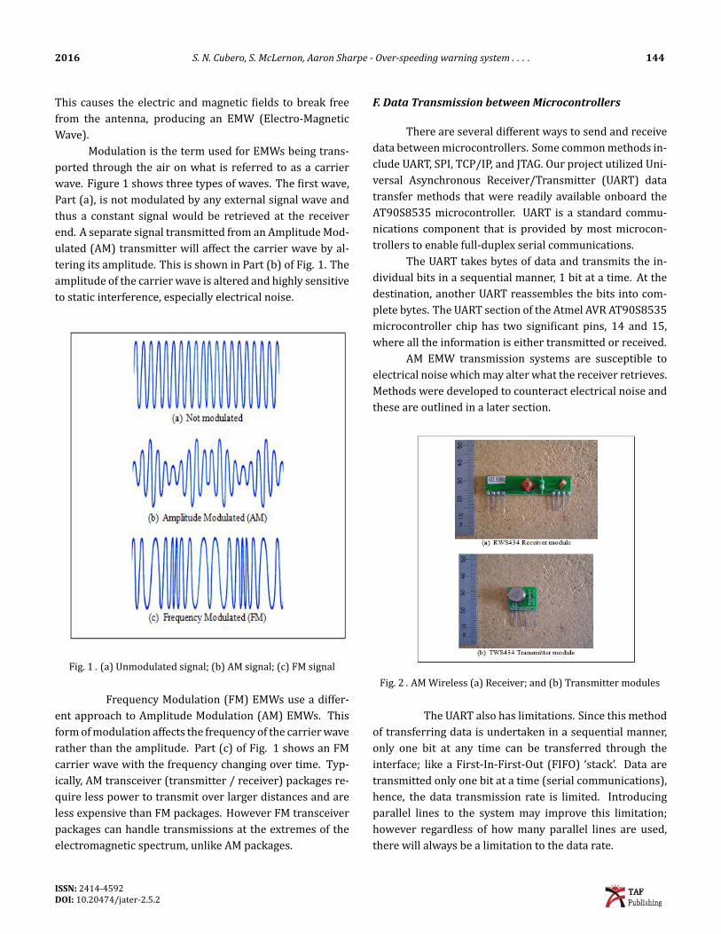
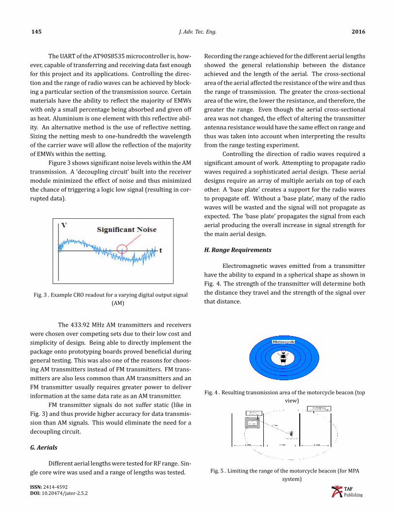
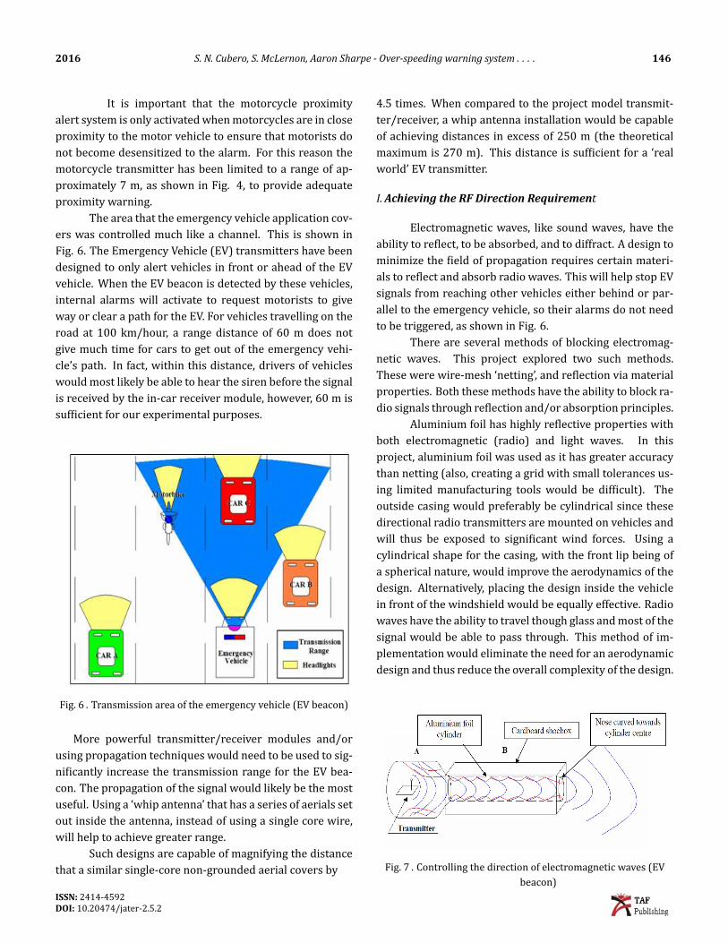
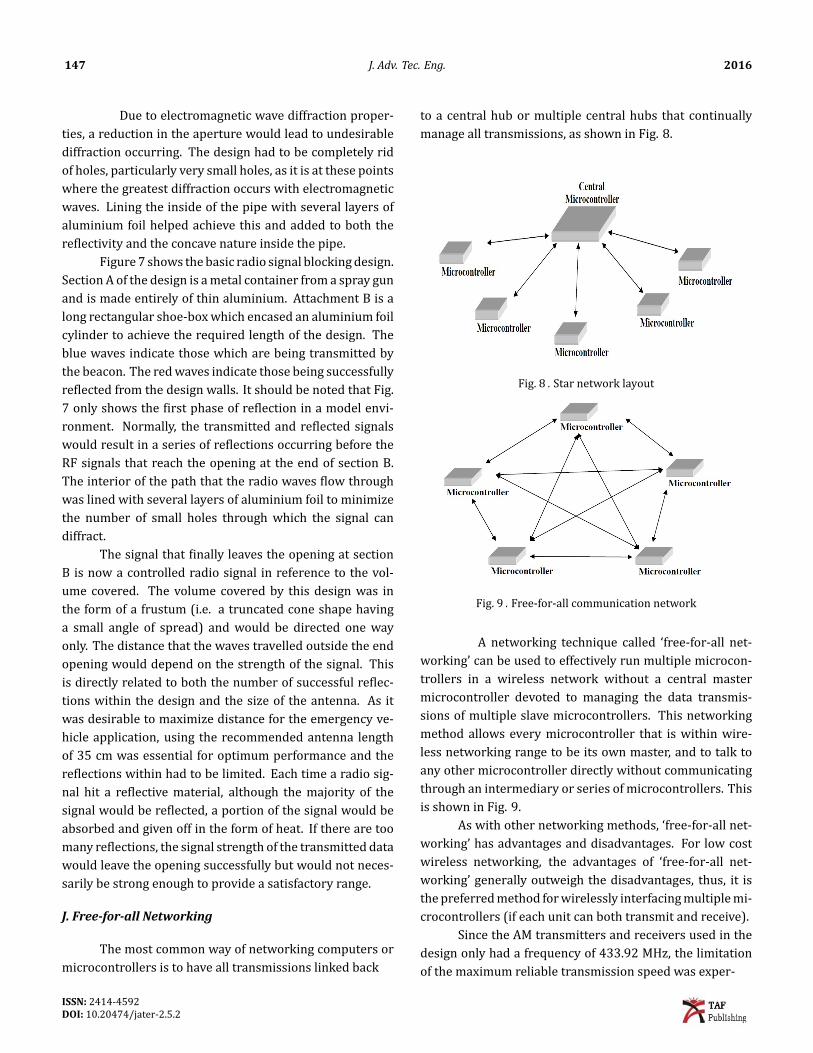
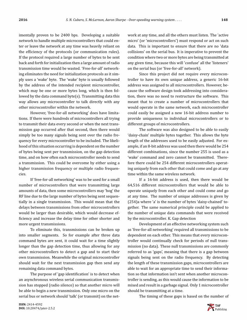
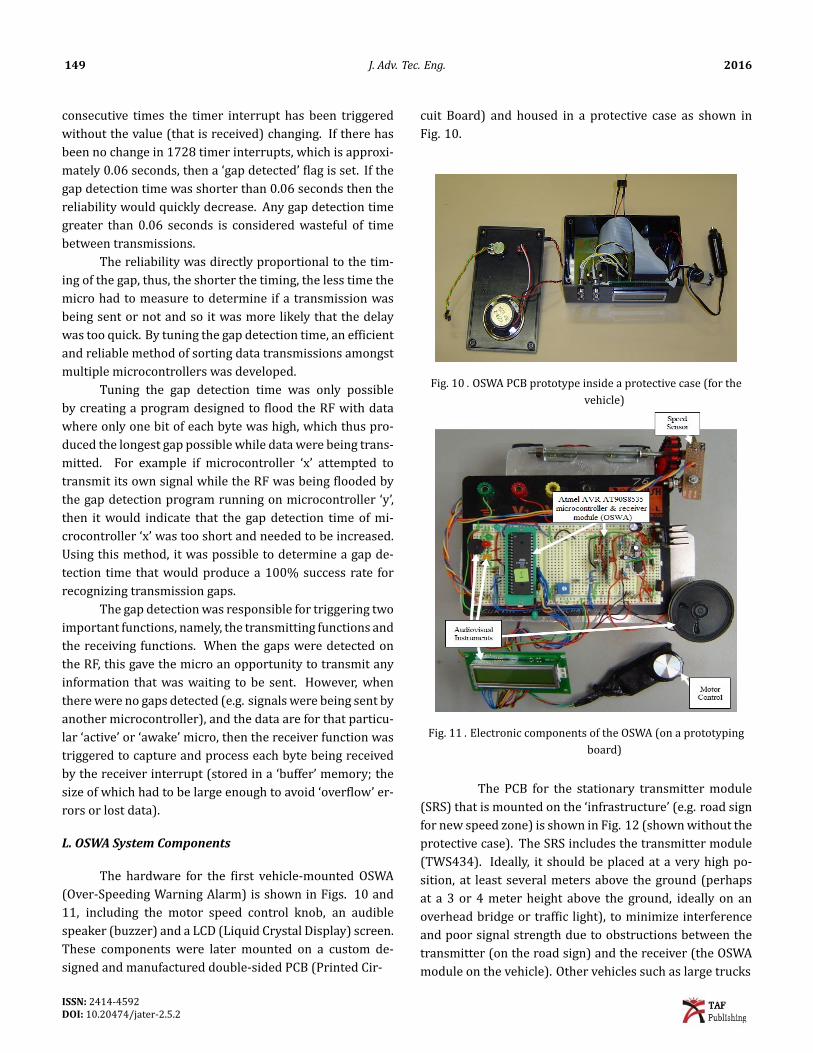
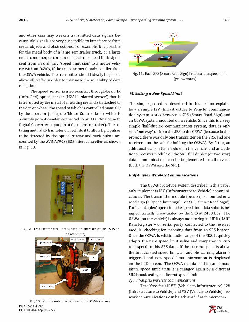
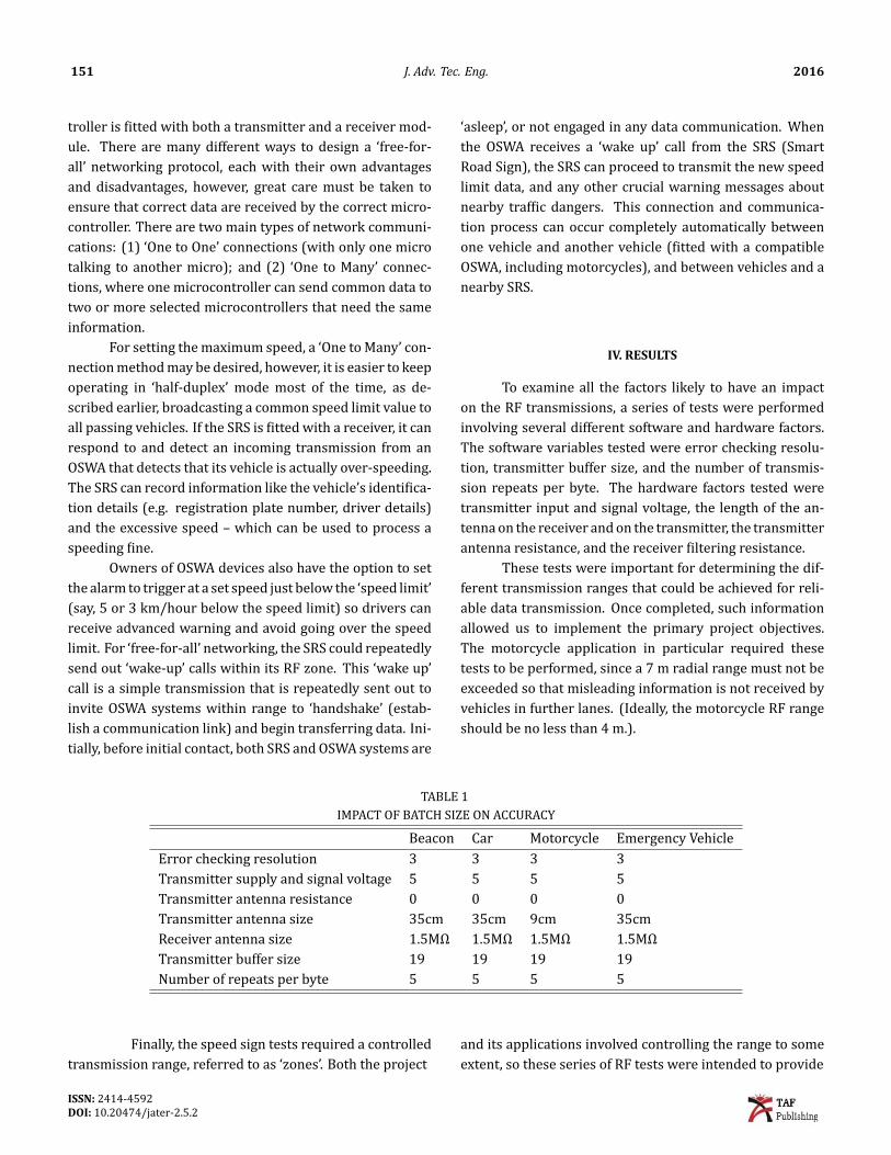