danger, warning, caution, and note statements
TRANSCRIPT

©1999 ELECTROMOTIVE SYSTEMS, INC.
All rights reserved. This notice applies to all copyrighted materials included with this product, including, but not limited to, this manual and software embodied within the product. This manual is intended for the sole use of the persons to whom it was provided, and any unauthorized distribution of the manual or dispersal of its contents is strictly forbidden. This manual may not be reproduced in whole or in part by any means whatsoever without the expressed written permission of ELECTROMOTIVE SYSTEMS, INC.
DANGER, WARNING, CAUTION, and NOTE Statements
DANGER, WARNING, CAUTION, and Note statements are used throughout this manual to emphasize important and critical information. You must read these statements to help ensure safety and to prevent product damage. The statements are defined below.
DANGER
DANGER indicates an imminently hazardous situation which, if not avoided, will result in death or serious injury. This signal word is to be limi ted to the most extreme situations.
WARNING
WARNING indicates a potentially hazardous situation which, if not avoided, could result in death or serious injury.
CAU TION
CAUTION indicates a potentially hazardous situation which, if not avoided, could result in minor or moderate injury. It may also be used to alert against unsafe practices.
NOTE: A NOTE statement is used to notify people of installation, operation, programming, or maintenance information that is important, but not hazard-related.

WARNING
• This manual instructs you how to use PulseStar•610. If you disregard the instructions, information, and/or warranty in the manual, you could be assuming responsibility for damages, costs, or injury incurred by such disregard.
• Do not touch any circuit components on the circuit board while the main AC or DC power is on.
• Do not make any address code or frequency channel changes in the transmitter or receiver without first contacting Electromotive Systems.

. . .
. .
. . .
1-3
. . 1-3
1-4
.
. 2-4
2-5
. . 2-5
. . 2-6
. . 2-7
. . 2-8
2-9
.
. 2-9
2-10
2-11
ContentsWelcome! . . . . . . . . . . . . . . . . . . . . . . . . . . . . . . . . . . . . . . . . . . . . . . . . . . . . . . . . . . . . . . . . . vii
PulseStar•610 Components. . . . . . . . . . . . . . . . . . . . . . . . . . . . . . . . . . . . . . . . . . . . . . . . viii
Receiver . . . . . . . . . . . . . . . . . . . . . . . . . . . . . . . . . . . . . . . . . . . . . . . . . . . . . . . . . . . . . . viii
Transmitter . . . . . . . . . . . . . . . . . . . . . . . . . . . . . . . . . . . . . . . . . . . . . . . . . . . . . . . . . . . . viii
How to Use This Manual . . . . . . . . . . . . . . . . . . . . . . . . . . . . . . . . . . . . . . . . . . . . . . . . . . . ix
Important System Information . . . . . . . . . . . . . . . . . . . . . . . . . . . . . . . . . . . . . . . . . . . . . . ix
Chapter 1: PulseStar•610 System Overview
PulseStar•610 System Overview . . . . . . . . . . . . . . . . . . . . . . . . . . . . . . . . . . . . . . . . . . . . .
Introduction. . . . . . . . . . . . . . . . . . . . . . . . . . . . . . . . . . . . . . . . . . . . . . . . . . . . . . . . . . . . . . . 1-3
Theory of Operation . . . . . . . . . . . . . . . . . . . . . . . . . . . . . . . . . . . . . . . . . . . . . . . . . . . . . . . . 1-3
Active Emergency Stop (E-STOP) Function . . . . . . . . . . . . . . . . . . . . . . . . . . . . . . . . . . .
Sleep and Time-Out Modes. . . . . . . . . . . . . . . . . . . . . . . . . . . . . . . . . . . . . . . . . . . . . . . . . .
Transmitter Sleep Mode . . . . . . . . . . . . . . . . . . . . . . . . . . . . . . . . . . . . . . . . . . . . . . . . . . .. 1-4
Receiver Safe Mode . . . . . . . . . . . . . . . . . . . . . . . . . . . . . . . . . . . . . . . . . . . . . . . . . . . . . .. . 1-4
Chapter 2: The PulseStar•610 Receiver
Overview . . . . . . . . . . . . . . . . . . . . . . . . . . . . . . . . . . . . . . . . . . . . . . . . . . . . . . . . . . . . . . . . . . 2-3
Receiver Components. . . . . . . . . . . . . . . . . . . . . . . . . . . . . . . . . . . . . . . . . . . . . . . . . . . . . .
Installing the PulseStar•610 Receiver. . . . . . . . . . . . . . . . . . . . . . . . . . . . . . . . . . . . . . . . .
Assessing the Receiver Enclosure Environment . . . . . . . . . . . . . . . . . . . . . . . . . . . . . . . .
Serial Nameplate. . . . . . . . . . . . . . . . . . . . . . . . . . . . . . . . . . . . . . . . . . . . . . . . . . . . . . . . . . . 2-5
Mounting the PulseStar•610 Receiver . . . . . . . . . . . . . . . . . . . . . . . . . . . . . . . . . . . . . . . .
Connecting a Standard External Antenna. . . . . . . . . . . . . . . . . . . . . . . . . . . . . . . . . . . . . .
Connecting a Gain Flex Antenna . . . . . . . . . . . . . . . . . . . . . . . . . . . . . . . . . . . . . . . . . . . .
Wiring the PulseStar•610 Receiver. . . . . . . . . . . . . . . . . . . . . . . . . . . . . . . . . . . . . . . . . . .
Quick Disconnect Plug . . . . . . . . . . . . . . . . . . . . . . . . . . . . . . . . . . . . . . . . . . . . . . . . . . . . . 2-9
Terminating Wires to the Quick Disconnect Plug . . . . . . . . . . . . . . . . . . . . . . . . . . . . .
Quick Disconnect Plug Housing Orientation . . . . . . . . . . . . . . . . . . . . . . . . . . . . . . . . .
Startup and Test Procedures . . . . . . . . . . . . . . . . . . . . . . . . . . . . . . . . . . . . . . . . . . . . . . . .
PulseStar•610 Instruction Manual– 6/21/99i

. 2-14
. 2-14
. 2-
. 2-17
2-18
. 2-18
. 2-18
3-4
. . 3-4
. . 3-5
. . 3-6
. 3-7
. 3-8
. 3-9
3-10
3-11
3-12
3-13
. 3-14
. 3-16
3-17
. 3-
Pre-operation check list . . . . . . . . . . . . . . . . . . . . . . . . . . . . . . . . . . . . . . . . . . . . . . . . . . .. 2-11
Testing the Receiver . . . . . . . . . . . . . . . . . . . . . . . . . . . . . . . . . . . . . . . . . . . . . . . . . . . . . . . 2-12
Changing the Frequency Channel of the Receiver . . . . . . . . . . . . . . . . . . . . . . . . . . . . . . .
Standard RF Module. . . . . . . . . . . . . . . . . . . . . . . . . . . . . . . . . . . . . . . . . . . . . . . . . . .
Scan RF Module . . . . . . . . . . . . . . . . . . . . . . . . . . . . . . . . . . . . . . . . . . . . . . . . . . . . . . 16
Setting the Scan Mode . . . . . . . . . . . . . . . . . . . . . . . . . . . . . . . . . . . . . . . . . . . . . . . . .
Receiver Options . . . . . . . . . . . . . . . . . . . . . . . . . . . . . . . . . . . . . . . . . . . . . . . . . . . . . . . . . .
Range Limitation . . . . . . . . . . . . . . . . . . . . . . . . . . . . . . . . . . . . . . . . . . . . . . . . . . . . . . . . . 2-18
Special Enclosures . . . . . . . . . . . . . . . . . . . . . . . . . . . . . . . . . . . . . . . . . . . . . . . . . . . . . . . . 2-18
Intrinsically Safe Systems. . . . . . . . . . . . . . . . . . . . . . . . . . . . . . . . . . . . . . . . . . . . . . .
Marine Duty/Corrosion Resistant Systems. . . . . . . . . . . . . . . . . . . . . . . . . . . . . . . . . .
Chapter 3: The PulseStar•610 Transmitter
Overview . . . . . . . . . . . . . . . . . . . . . . . . . . . . . . . . . . . . . . . . . . . . . . . . . . . . . . . . . . . . . . . . . . 3-3
PulseStar•610 Transmitters. . . . . . . . . . . . . . . . . . . . . . . . . . . . . . . . . . . . . . . . . . . . . . . . . .
JRT Transmitter . . . . . . . . . . . . . . . . . . . . . . . . . . . . . . . . . . . . . . . . . . . . . . . . . . . . . . . . . . . 3-4
JRT Transmitter Components. . . . . . . . . . . . . . . . . . . . . . . . . . . . . . . . . . . . . . . . . . . .
JRT Transmitter Functions . . . . . . . . . . . . . . . . . . . . . . . . . . . . . . . . . . . . . . . . . . . . . .
PBT Transmitter . . . . . . . . . . . . . . . . . . . . . . . . . . . . . . . . . . . . . . . . . . . . . . . . . . . . . . . . . . . 3-6
PBT Transmitter Components . . . . . . . . . . . . . . . . . . . . . . . . . . . . . . . . . . . . . . . . . . .
PBT Transmitter Functions. . . . . . . . . . . . . . . . . . . . . . . . . . . . . . . . . . . . . . . . . . . . . . .
NVT Transmitter. . . . . . . . . . . . . . . . . . . . . . . . . . . . . . . . . . . . . . . . . . . . . . . . . . . . . . . . . . . 3-8
NVT Transmitter Components (Joystick Model) . . . . . . . . . . . . . . . . . . . . . . . . . . . . . .
NVT Transmitter Components (Paddle Lever Model) . . . . . . . . . . . . . . . . . . . . . . . . . .
NVT Transmitter Functions . . . . . . . . . . . . . . . . . . . . . . . . . . . . . . . . . . . . . . . . . . . . . .
GLT Transmitter . . . . . . . . . . . . . . . . . . . . . . . . . . . . . . . . . . . . . . . . . . . . . . . . . . . . . . . . . . 3-11
GLT Transmitter Components (Joystick Model) . . . . . . . . . . . . . . . . . . . . . . . . . . . . . .
GLT Transmitter Components (Paddle Lever Model) . . . . . . . . . . . . . . . . . . . . . . . . . .
GLT Transmitter Functions . . . . . . . . . . . . . . . . . . . . . . . . . . . . . . . . . . . . . . . . . . . . . .
GRT Transmitter . . . . . . . . . . . . . . . . . . . . . . . . . . . . . . . . . . . . . . . . . . . . . . . . . . . . . . . . . . 3-14
GRT Transmitter Components . . . . . . . . . . . . . . . . . . . . . . . . . . . . . . . . . . . . . . . . . . .
GRT Transmitter Functions . . . . . . . . . . . . . . . . . . . . . . . . . . . . . . . . . . . . . . . . . . . . .
Transmitter Setup. . . . . . . . . . . . . . . . . . . . . . . . . . . . . . . . . . . . . . . . . . . . . . . . . . . . . . . . . .
Placing the Push-button Labels. . . . . . . . . . . . . . . . . . . . . . . . . . . . . . . . . . . . . . . . . . . . . .17
PulseStar•610 Instruction Manual–6/21/99 ii

. 3-18
.
. 3-19
. 3-19
. 3-20
. 3-22
3-23
.
.
. 3
3
3
. 3
. 3
3-28
3-28
. 3-29
.
3-30
.
3-30
.
3-30
. 3-31
3-31
3-31
.
. 3-32
-34
. 3-34
.
Transmitter Address Code and Frequency Channel . . . . . . . . . . . . . . . . . . . . . . . . . . . . . .
Serial Nameplate. . . . . . . . . . . . . . . . . . . . . . . . . . . . . . . . . . . . . . . . . . . . . . . . . . . . . . 3-18
Setting the Address Code and Frequency Channel of a Transmitter: . . . . . . . . . . . . . . . . .
Determining the Address Code. . . . . . . . . . . . . . . . . . . . . . . . . . . . . . . . . . . . . . . . . . .
Setting the Address Code . . . . . . . . . . . . . . . . . . . . . . . . . . . . . . . . . . . . . . . . . . . . . . .
Setting the Frequency Channel . . . . . . . . . . . . . . . . . . . . . . . . . . . . . . . . . . . . . . . . . . .
Start-up and Operation . . . . . . . . . . . . . . . . . . . . . . . . . . . . . . . . . . . . . . . . . . . . . . . . . . . . .
Holding the Transmitter . . . . . . . . . . . . . . . . . . . . . . . . . . . . . . . . . . . . . . . . . . . . . . . . . . . 3-23
JRT Transmitter . . . . . . . . . . . . . . . . . . . . . . . . . . . . . . . . . . . . . . . . . . . . . . . . . . . . . . 3-23
PBT Transmitter . . . . . . . . . . . . . . . . . . . . . . . . . . . . . . . . . . . . . . . . . . . . . . . . . . . . . . -24
NVT Transmitter. . . . . . . . . . . . . . . . . . . . . . . . . . . . . . . . . . . . . . . . . . . . . . . . . . . . . . .-25
GLT Transmitter . . . . . . . . . . . . . . . . . . . . . . . . . . . . . . . . . . . . . . . . . . . . . . . . . . . . . . .-26
GRT Transmitter . . . . . . . . . . . . . . . . . . . . . . . . . . . . . . . . . . . . . . . . . . . . . . . . . . . . . . -27
Start-up . . . . . . . . . . . . . . . . . . . . . . . . . . . . . . . . . . . . . . . . . . . . . . . . . . . . . . . . . . . . . . . . . 3-28
Emergency Stop . . . . . . . . . . . . . . . . . . . . . . . . . . . . . . . . . . . . . . . . . . . . . . . . . . . . . .-28
Using the Motion Push-buttons (JRT and PBT). . . . . . . . . . . . . . . . . . . . . . . . . . . . . . .
Using the Joysticks and/or Paddle Levers (NVT, GLT and GRT). . . . . . . . . . . . . . . . .
Optional Switches and Push-buttons . . . . . . . . . . . . . . . . . . . . . . . . . . . . . . . . . . . . . .
Shutting Off the Transmitter. . . . . . . . . . . . . . . . . . . . . . . . . . . . . . . . . . . . . . . . . . . . . . . . 3-29
Transmitter Options. . . . . . . . . . . . . . . . . . . . . . . . . . . . . . . . . . . . . . . . . . . . . . . . . . . . . . . .
Spare Transmitter . . . . . . . . . . . . . . . . . . . . . . . . . . . . . . . . . . . . . . . . . . . . . . . . . . . . . . . . . 3-30
Address Plugs . . . . . . . . . . . . . . . . . . . . . . . . . . . . . . . . . . . . . . . . . . . . . . . . . . . . . . . . 3-30
Crane Control Using Multiple Transmitters . . . . . . . . . . . . . . . . . . . . . . . . . . . . . . . . . . . . .
Pitch and Catch . . . . . . . . . . . . . . . . . . . . . . . . . . . . . . . . . . . . . . . . . . . . . . . . . . . . . . . 3-30
Independent/Combined Control of Multiple Cranes . . . . . . . . . . . . . . . . . . . . . . . . . . .
Safety Devices . . . . . . . . . . . . . . . . . . . . . . . . . . . . . . . . . . . . . . . . . . . . . . . . . . . . . . . . . . . 3-31
Press To Operate Safety Switch . . . . . . . . . . . . . . . . . . . . . . . . . . . . . . . . . . . . . . . . . .
Lift To Operate Joysticks . . . . . . . . . . . . . . . . . . . . . . . . . . . . . . . . . . . . . . . . . . . . . . . .
Lift To Operate Toggle Switches . . . . . . . . . . . . . . . . . . . . . . . . . . . . . . . . . . . . . . . . . .
Tilt Switches . . . . . . . . . . . . . . . . . . . . . . . . . . . . . . . . . . . . . . . . . . . . . . . . . . . . . . . . . . 3-31
Free Channel Search . . . . . . . . . . . . . . . . . . . . . . . . . . . . . . . . . . . . . . . . . . . . . . . . . . . . . . 3-32
Setting the Odd/Even Channel Search of the Free Channel Search Function . . . . . . .
Battery and Charger Information. . . . . . . . . . . . . . . . . . . . . . . . . . . . . . . . . . . . . . . . . . . . 3
Removing and Inserting the Battery From the Transmitter . . . . . . . . . . . . . . . . . . . . . . . .
JRT Transmitter . . . . . . . . . . . . . . . . . . . . . . . . . . . . . . . . . . . . . . . . . . . . . . . . . . . . . . 3-34
PulseStar•610 Instruction Manual– 6/21/99iii

. 3
3
3
. 3
. 3
. 3-
. 4-3
.
A-3
. . A-3
. B
PBT Transmitter . . . . . . . . . . . . . . . . . . . . . . . . . . . . . . . . . . . . . . . . . . . . . . . . . . . . . . -35
NVT Transmitter. . . . . . . . . . . . . . . . . . . . . . . . . . . . . . . . . . . . . . . . . . . . . . . . . . . . . . .-36
GLT Transmitter . . . . . . . . . . . . . . . . . . . . . . . . . . . . . . . . . . . . . . . . . . . . . . . . . . . . . . .-37
GRT Transmitter . . . . . . . . . . . . . . . . . . . . . . . . . . . . . . . . . . . . . . . . . . . . . . . . . . . . . . -38
Charging the Battery . . . . . . . . . . . . . . . . . . . . . . . . . . . . . . . . . . . . . . . . . . . . . . . . . . . . . . . 3-39
Standard Charger . . . . . . . . . . . . . . . . . . . . . . . . . . . . . . . . . . . . . . . . . . . . . . . . . . . . .-40
Discharge Charger . . . . . . . . . . . . . . . . . . . . . . . . . . . . . . . . . . . . . . . . . . . . . . . . . . . .40
Memory Effect . . . . . . . . . . . . . . . . . . . . . . . . . . . . . . . . . . . . . . . . . . . . . . . . . . . . . . . . . . . 3-40
Chapter 4: Troubleshooting PulseStar•610
Troubleshooting . . . . . . . . . . . . . . . . . . . . . . . . . . . . . . . . . . . . . . . . . . . . . . . . . . . . . . . . . . .
Introduction. . . . . . . . . . . . . . . . . . . . . . . . . . . . . . . . . . . . . . . . . . . . . . . . . . . . . . . . . . . . . . . 4-3
Common Problems . . . . . . . . . . . . . . . . . . . . . . . . . . . . . . . . . . . . . . . . . . . . . . . . . . . . . . .. 4-3
Questions to Ask . . . . . . . . . . . . . . . . . . . . . . . . . . . . . . . . . . . . . . . . . . . . . . . . . . . . . . . . . . . 4-5
Transmitter . . . . . . . . . . . . . . . . . . . . . . . . . . . . . . . . . . . . . . . . . . . . . . . . . . . . . . . . . . . . 4-5
Receiver . . . . . . . . . . . . . . . . . . . . . . . . . . . . . . . . . . . . . . . . . . . . . . . . . . . . . . . . . . . . . . 4-5
Appendix A: Definitions and Abbreviations
Definitions and Abbreviations . . . . . . . . . . . . . . . . . . . . . . . . . . . . . . . . . . . . . . . . . . . . . . .
Definitions . . . . . . . . . . . . . . . . . . . . . . . . . . . . . . . . . . . . . . . . . . . . . . . . . . . . . . . . . . . . . . . A-3
Commonly Used Abbreviations . . . . . . . . . . . . . . . . . . . . . . . . . . . . . . . . . . . . . . . . . . . . .
Appendix B: Specifications
Specifications . . . . . . . . . . . . . . . . . . . . . . . . . . . . . . . . . . . . . . . . . . . . . . . . . . . . . . . . . . . . .-3
System Specifications . . . . . . . . . . . . . . . . . . . . . . . . . . . . . . . . . . . . . . . . . . . . . . . . . . . . .. . B-3
JRT Specifications . . . . . . . . . . . . . . . . . . . . . . . . . . . . . . . . . . . . . . . . . . . . . . . . . . . . . . . . . B-3
PBT Specifications . . . . . . . . . . . . . . . . . . . . . . . . . . . . . . . . . . . . . . . . . . . . . . . . . . . . . . . . . B-4
NVT Specifications. . . . . . . . . . . . . . . . . . . . . . . . . . . . . . . . . . . . . . . . . . . . . . . . . . . . . . . . . B-5
GLT Specifications . . . . . . . . . . . . . . . . . . . . . . . . . . . . . . . . . . . . . . . . . . . . . . . . . . . . . . . . . B-6
GRT Specifications. . . . . . . . . . . . . . . . . . . . . . . . . . . . . . . . . . . . . . . . . . . . . . . . . . . . . . . . . B-7
Receiver Specifications. . . . . . . . . . . . . . . . . . . . . . . . . . . . . . . . . . . . . . . . . . . . . . . . . . . .. . B-7
PulseStar•610 Instruction Manual–6/21/99 iv

. C-3
. . C-3
. .
C-5
. . C-6
. . C-6
Appendix C: StarService and Warranty
StarService Policy . . . . . . . . . . . . . . . . . . . . . . . . . . . . . . . . . . . . . . . . . . . . . . . . . . . . . . . . .
On-Call Service. . . . . . . . . . . . . . . . . . . . . . . . . . . . . . . . . . . . . . . . . . . . . . . . . . . . . . . . . . . . C-3
Warranty . . . . . . . . . . . . . . . . . . . . . . . . . . . . . . . . . . . . . . . . . . . . . . . . . . . . . . . . . . . . . . . . . C-3
Transmitter Loaner, Replacement & Repair Program . . . . . . . . . . . . . . . . . . . . . . . . . . . .
Receiver Repair Program . . . . . . . . . . . . . . . . . . . . . . . . . . . . . . . . . . . . . . . . . . . . . . . . . . C-4
Limited Warranty And Terms Of Sale. . . . . . . . . . . . . . . . . . . . . . . . . . . . . . . . . . . . . . . .
Special Terms and Conditions: Orders of $25,000 or More. . . . . . . . . . . . . . . . . . . . . . . .
Special Terms and Conditions: Orders for Special Control Panels. . . . . . . . . . . . . . . . . .
PulseStar•610 Instruction Manual– 6/21/99v

This page intentionally left blank.

w line
s
r’s roved
stand,
Welcome!
Welcome to the PulseStar•610 radio remote crane control system. Electromotive Systems has set a whole new standard in radio-remote performance, dependability, and value with this unique neof modular transmitters and receivers. Without a doubt, PulseStar•610 is the ultimate solution for having precise, untethered, and safe control of overhead loads.
Using state-of-the-art synthesizer technology and the best circuit board manufacturing designavailable, Electromotive Systems has eliminated many of the unreliable and expendable electromechanical components found in traditional radio remote systems.
The PulseStar•610 system consists of a receiver and a transmitter. The system uses PulseStasynthesizer technology and operates over the 400-470 MHz band. PulseStar•610 is FCC appwith no site license required.
PulseStar’s unique transmitter and receiver design provide a sophisticated, yet easy-to-underefficient, and safe radio remote control. PulseStar’s modular design has the following advantages:
• Flexible design allows easy mixing and matching
• On-board diagnostic allow easy troubleshooting
• Standardized spare parts; kits available
• Simple design
PulseStar•610 Instruction Manual – 6/21/99vii

10
PulseStar•610 Components
The typical PulseStar•610 system consists of a receiver and transmitter kit. Each PulseStar•6system is engineered per customer specification. Some PulseStar•610 systems can consist of multiple receivers and transmitters.
Receiver
Each PulseStar•610 receiver has the following standard features:
• Start relay, horn relay, Active E-STOP relay, and OPTION relay.
• Up to 32 digital outputs.
• Up to 8 proportional channels (0 to 10V, 0 to 20 mA, etc.).
• Self-diagnostics to ensure trouble-free operation.
• 115 Volts or 230 Volts reconnectable input power supply for AC cranes.
• 12VDC or 24VDC reconnectable input power supply for DC cranes.
• Discrete 16 frequencies or autoscan.
• Sixteen-bit address code (over 65,000 combinations).
• Quick disconnect connector.
Transmitter
The PulseStar•610 system can be supplied with several types of transmitters. The following are the most commonly used transmitters with the PulseStar•610 system:
• JRT hand held transmitter
• PBT hand held transmitter
• NVT belly box transmitter
• GLT belly box transmitter
• GRT belly box transmitter
Each PulseStar•610 transmitter has the following standard features:
• Active E-STOP for immediate stopping action.
• Sleep Mode to save battery charge and enhance safety.
• Removable key switch for added security.
• 16-bit address security code (over 65,000 possibilities).
• 330 foot range.
• Internal antenna.
• START/HORN push-button.
• Carrying belt or holster.
PulseStar•610 Instruction Manual – 6/21/99viii

d e
nel,
nd
2
How to Use This Manual
PulseStar•610 Instruction Manual has a comprehensive introduction chapter that you should reabefore installing, wiring, or operating the system. It introduces some of the many features of thPulseStar•610 system.
Chapter 2 covers installing and wiring the receiver, as well as start-up and test procedures to make sure the system is working properly before you begin regular operation.
Chapter 3 covers each type of transmitter individually. Refer to this chapter to identify the transmitter you have. This chapter also covers how to set the address code and frequency chanstart up, and how to operate the transmitter.
Chapter 4 gives you a basic troubleshooting guide, plus a checklist of things to look for before calling Electromotive Systems for service. In most cases, problems are minor and easy to solve.
Important System Information
Before working with the PulseStar•610 system, read and understand the following important systeminformation.
• Surge suppressors must be used when the PulseStar•610 receiver is controlling magneticcontactors.
• When not in use, the transmitter should be turned off and stored in a safe place to prevent unauthorized users from operating it.
• If the crane fails to respond properly, stop operation immediately, turn off the transmitter, and report the condition immediately to an appropriate technician or supervisor.
• Wire the receiver circuit board to the crane’s ground.
• When using a standard external antenna mount it on a conductive metal surface with the same ground as the receiver circuit board. Remove any burrs from the antenna mounting hole ascrape away any paint which may prohibit the antenna base from making a good ground contact with the surface. Make sure that the antenna is not surrounded by metal or other conductive materials. Failure to properly install the antenna will result in intermittent operation.
• When using a gain flex external antenna make sure that your mounting location is at leastmeters (6 feet) from any metallic or conductive objects. These objects may interfere with the antenna and cause intermittent operation.
• Before working on the transmitter, turn off the key switch and remove the battery.
• When taking a break or changing the battery, turn the transmitter off with the key switch.
• Always have a battery in the battery charger to ensure a fully charged battery.
• Perform initial setup or service work only if you have been authorized to do so. Use only Electromotive Systems spare parts.
PulseStar•610 Instruction Manual – 6/21/99ix

This page intentionally left blank.

c h a p t e r 1
PulseStar•610System Overview

This page intentionally left blank.

z
me
e
in
PulseStar•610 System Overview
Introduction
This chapter introduces the basic conceptual information that you should know before installing, wiring, and operating the PulseStar•610 system.
Theory of Operation
The PulseStar•610 system consists of a transmitter kit and a receiver. The transmitter, using PulseStar’s synthesizer technology, electronically generates a carrier frequency over which it and the receiver communicate. PulseStar•610 transmitters and receivers operate over the 400-470 Mhfrequency range (70 cm. band). To guarantee safety when the crane is being operated in conjuction with other radio controls, the receiver and transmitter are configured with the same address code. This way, the receiver only seeks out and accepts commands from the transmitter with the saaddress code.
NOTE: PulseStar•610 receiver(s) and transmitter(s) already have their address code set upbefore they are shipped. Never change the address code in the receiver. The only timyou should need to change the address code inside the transmitter is when you are setting up a spare or replacement transmitter. If you have any questions about address codes and how they are used, contact Electromotive Systems.
Active Emergency Stop (E-STOP) Function
One of the most important features of the PulseStar•610 is Active E-STOP. The transmitter continuously sends the Active E-STOP status signal, followed by the desired crane function. This constant communication between the transmitter and the receiver confirm that the ongoing operations are safe. If the Active E-STOP push-button is pressed on the transmitter, the Active E-STOP relay module in the receiver opens, and crane motion then ceases. The receiver is thenSafe Mode.
To restart the system after activating Active E-STOP via the Active E-STOP push-button, pull out the Active E-STOP push-button and press the START/HORN push-button.
NOTE: There are other situations in which the system automatically goes into Active E-STOP without the operator pressing the Active E-STOP push-button on the transmitter. These are explained in later sections of the manual.
Active E-STOP responds faster than any other PulseStar function. When Active E-STOP occurs, the system ignores any other signal it receives. Active E-STOP is the only signal that is recognized until the problem is corrected.
Active E-STOP is fail-safe and self-monitoring in both the transmitter and receiver. When you apply power to the receiver, it performs a self-test to make sure the Active E-STOP circuitry is working properly. If the receiver detects an error in the Active E-STOP circuitry, the system automatically goes into Safe Mode.
When you first turn on the transmitter, it also performs a self-test to make sure CPU circuitry is working properly. If it detects an error, the transmitter will not begin transmitting.
PulseStar•610 Instruction Manual – 6/21/991-3

ower
Sleep and Time-Out Modes
Transmitter Sleep Mode
To prevent accidental operation, PulseStar•610 transmitters have a built-in safety feature called Sleep Mode. If a transmitter is not used for 10 minutes, it turns itself off. While the transmitter is in Sleep Mode, the push-buttons, joysticks, or switches will not operate. To restart the transmitter cycle p(turn the key off and back on), and press the START/HORN push-button.
NOTE: If the transmitter has a selector switch or latching push-button, sleep mode will not occur because the selector switch or push-button is constantly sending a signal to the receiver.
Receiver Safe Mode
Another PulseStar•610 safety feature is the Safe Mode. The receiver will go into Safe Mode if any of the following should occur.
• The transmitter goes into Sleep Mode.
• Interference caused by other transmitters or other radio-controlled products in the area.
• The transmitter is taken out of its operating range (330 feet).
• The Active E-STOP push-button is activated.
• There is a failure with the Active E-STOP circuitry.
When the receiver loses the transmitter carrier frequency signal, the Time Out Waiting Period process begins. The Time Out Waiting Period is factory set at 450msec, however it can be extended to 2 seconds. If the receiver does not regain the transmitter carrier frequency signal before the Time Out Waiting Period expires, the receiver immediately goes into Safe Mode. When in Safe Mode the receiver shuts off power to the output modules, and drops out the mainline contactor by opening the Active E-STOP relay module.
To restart the system, make sure the transmitter carrier frequency signal is being picked up by the receiver. Then press the START/HORN push-button on the transmitter.
PulseStar•610 Instruction Manual – 6/21/991-4

c h a p t e r 2
The PulseStar•610 Receiver

This page intentionally left blank.

up and
Overview
This chapter tells you how to install and wire the PulseStar•610 receiver. It also contains start-test procedures so you can ensure that the transmitter(s) and receiver are working properly before you actually use them to control the overhead crane.
This chapter covers the following information.
• Receiver Components
• Installing the PulseStar•610 Receiver
• Wiring the PulseStar•610 Receiver
• Startup and Test Procedures
• Receiver Options
WARNING
Only authorized personnel are permitted to perform the initial installation, setup or service work. Use only Electromotive Systems spare parts.
PulseStar•610 Instruction Manual – 6/21/992-3

tion, yout for
Receiver Components
The PulseStar•610 receiver receives commands from the remote transmitter, and interfaces with the crane controls to move the crane. The PulseStar•610 receiver is custom built for each applicahowever each receiver has common components. See Figure 2.1: PulseStar•610 Receiver Laa typical PulseStar•610 receiver layout.
Figure 2.1: PulseStar•610 Receiver Layout
1. Enclosure
2. Antenna Base
3. Power Pack (50/110/240vac)
4. Decoder Module
5. Miniflex Antenna
6. Standard RF Module
7. Active E-STOP Decoder Module
8. End Stop
9. DIN Rail
10. Wire Duct
11. ACM-1 Module (0-20vac)
12. AD5S Module (analog to 5 step)
13. SYM-2 Module (0-10vdc, 0-20mA)
14. Quick Disconnect Base
15. RK-1 Module (directional contacts)
16. REL-6 Module
17. Normally Open or Normally Closed Relay Module
18. SNZ Active E-STOP Module
19. EMVS-1 Interference Suppressor Module
20. Line Terminal Block w/Fuse
21. Ground Terminal Block (PE)
22. Enclosure Cover
12
34
56
78
Off
12
34
56
78
Off
12
34
56
78
Off
12
34
56
78
Off
1 2 3 4
5
6 7 8 9
10
111213
14
1516171819202122
PulseStar•610 Instruction Manual – 6/21/992-4

tive u
er is
Installing the PulseStar•610 Receiver
Assessing the Receiver Enclosure Environment
When you choose a location for the receiver enclosure, consider the following guidelines.
1. The Receiver can be operated on the following power supplies:
• 12-24V, DC (+/-50%)
• 50V/110V/240V (+/-20%), AC, Single Phase
2. Ensure that the receiver enclosure will be protected or isolated from:
• Ambient temperatures outside the range of -18°F to 158°F (-25°C to +70°C) (Consult Electromotive Systems if you must exceed this temperature range).
• Corrosive gases or liquids.
3. As much as possible, ensure that the receiver is not surrounded by metal or other conducmaterials that could prevent the internal antenna from receiving the transmitter signal. If yoare using an external antenna, ensure that it is not surrounded by metal or other conductive materials.
Serial Nameplate
Before you prepare to mount the receiver, locate the serial nameplate. The receiver serial nameplate is typically located on the right hand side of the enclosure. The serial nameplate contains the Electromotive Systems job number, the address code used by the system, and the frequency channelused by the system. The Electromotive Systems job number is important if you ever need to call Electromotive Systems for service. When you mount the receiver, ensure that the serial nameplate is visible so that you can easily read the Electromotive Systems job number.
Figure 2.2: Serial Nameplate
WARNING
• Only authorized personnel are permitted to perform the initial setup or service work. Use onlyElectromotive Systems parts.
• Do NOT touch any circuit components on the circuit board while the main AC or DC powon.
• Do NOT change the address code settings in the receiver.
• Do NOT run control wires with power wires.
• Surge Suppressors must be used with all magnetic contactors that are controlled by the PulseStar•610 system.
PulseStarJob # 2 0 0 0 0Addr. 1 9 3 2 7Freq. 5
PulseStar•610 Instruction Manual – 6/21/992-5

into unt
y.
Mounting the PulseStar•610 Receiver
Refer to Figure 2.3: Receiver Dimensions for mounting the PulseStar•610 receiver.
1. Determine the position of the receiver.
2. Determine the sizes and connection locations for the components that need to be wired.
3. Loosen the screws holding the cover of the enclosure.
4. Using the diameter and dimensions shown in Figure 2.3: Receiver Dimensions, drill holesthe mounting surface. The depth of the hole depends on the type of screw you are using to mothe receiver enclosure.
NOTE: The PulseStar•610 receiver is custom built for each application. The vast majority ofapplications use the receiver specified below. However some applications require a larger enclosure (DC cranes, multi-systems). Please consult Electromotive Systemsprior to installation if you have questions.
5. Insert the screws through each of the mounting holes, and then tighten the mounting screws to the mounting surface.
6. Lay out the wire runs. At a minimum, use #16 AWG for power wiring.
7. If receiver is to be mounted inside a control panel or enclosure, an external antenna is necessar
Figure 2.3: Receiver Dimensions
.295" DIA. HOLE(7.5mm DIA.)
7 7/8"
14 61/64"
15 3/4"
4 25/32"
9 27/32"
2 3/8"
PulseStar•610 Instruction Manual – 6/21/992-6
ect an
t
g hole
m the
housing.
hten
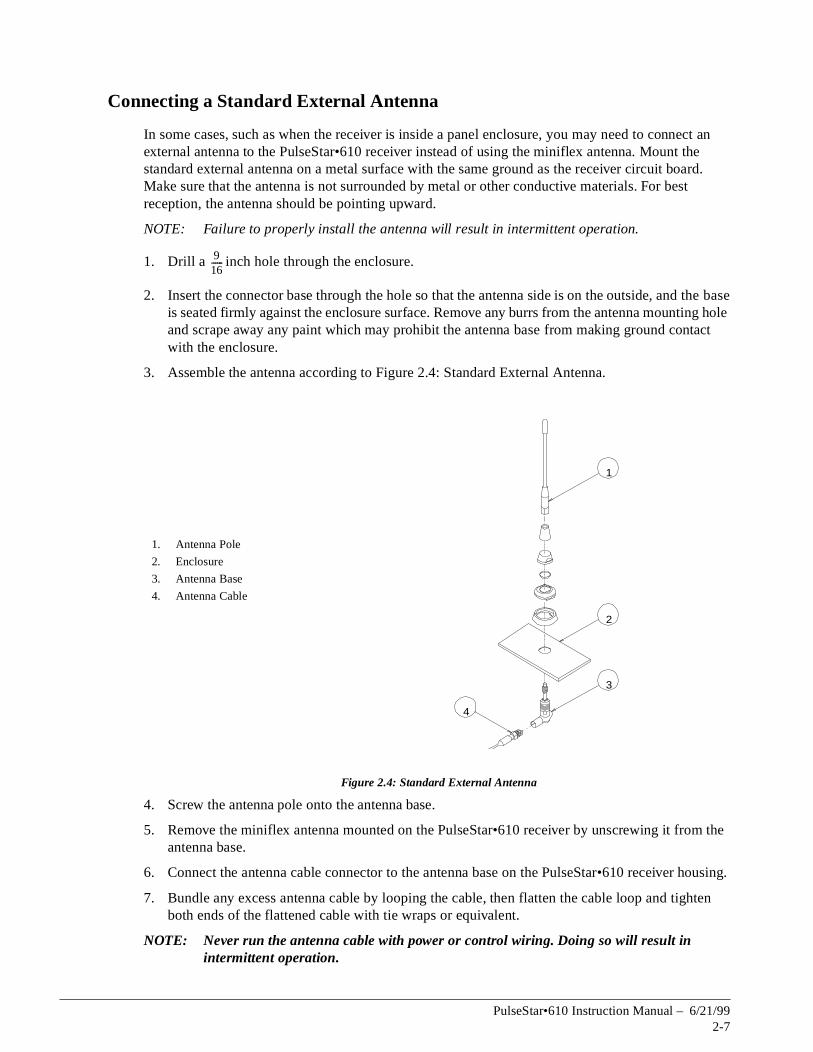
Connecting a Standard External Antenna
In some cases, such as when the receiver is inside a panel enclosure, you may need to connexternal antenna to the PulseStar•610 receiver instead of using the miniflex antenna. Mount the standard external antenna on a metal surface with the same ground as the receiver circuit board. Make sure that the antenna is not surrounded by metal or other conductive materials. For besreception, the antenna should be pointing upward.
NOTE: Failure to properly install the antenna will result in intermittent operation.
1. Drill a inch hole through the enclosure.
2. Insert the connector base through the hole so that the antenna side is on the outside, and the base is seated firmly against the enclosure surface. Remove any burrs from the antenna mountinand scrape away any paint which may prohibit the antenna base from making ground contact with the enclosure.
3. Assemble the antenna according to Figure 2.4: Standard External Antenna.
Figure 2.4: Standard External Antenna
4. Screw the antenna pole onto the antenna base.
5. Remove the miniflex antenna mounted on the PulseStar•610 receiver by unscrewing it froantenna base.
6. Connect the antenna cable connector to the antenna base on the PulseStar•610 receiver
7. Bundle any excess antenna cable by looping the cable, then flatten the cable loop and tigboth ends of the flattened cable with tie wraps or equivalent.
NOTE: Never run the antenna cable with power or control wiring. Doing so will result in intermittent operation.
1. Antenna Pole
2. Enclosure
3. Antenna Base
4. Antenna Cable
916------
1
2
3
4
PulseStar•610 Instruction Manual – 6/21/992-7

e
d.
m the
housing.
hten
Connecting a Gain Flex Antenna
Some applications require the use of a gain flex antenna. The gain flex antenna can extend thoperating range of the PulseStar•610 system up to 300 meters (1000 feet). It is also used with intrinsically safe applications, and applications where a standard antenna is too difficult to mount. Make sure that there are no metallic or other conductive materials within 2 meters (6 feet) radius of the gain flex antenna. These objects will interfere with the reception of the gain flex antenna, and will result in intermittent crane operation. For best reception, the antenna should be pointing upwar
NOTE: Failure to properly install the antenna will result in intermittent operation.
Refer to Figure 2.5: Gain Flex Antenna when installing the gain flex antenna.
1. Affix the antenna base of the gain flex antenna to a mounting surface by using the two tie wraps included with the antenna kit. For best reception the antenna base should be mounted verticallywith the antenna base pointing upward.
Figure 2.5: Gain Flex Antenna
2. Screw the gain flex antenna pole onto the antenna base.
3. Remove the miniflex antenna mounted on the PulseStar•610 receiver by unscrewing it froantenna base.
4. Connect the antenna cable connector to the antenna base on the PulseStar•610 receiver
5. Bundle any excess antenna cable by looping the cable, then flatten the cable loop and tigboth ends of the flattened cable with tie wraps or equivalent.
NOTE: Never run the antenna cable with power or control wiring. Doing so will result in intermittent operation.
1. Antenna Pole
2. Antenna Base
3. Tie Wrap
4. Antenna Cable
1
2
3
4
PulseStar•610 Instruction Manual – 6/21/992-8

s
g and pin
apter, using
.
y
er. rge
er is
Wiring the PulseStar•610 Receiver
Each Pulsestar•610 system is supplied with a wiring diagram which shows how to connect thePulsestar•610 system to your crane controls. Please use this wiring diagram when interfacing the Pulsestar•610 system to your crane controls. If the Pulsestar•610 system is part of a TControlcontrol panel, the receiver will already be wired to the crane controls.
Quick Disconnect Plug
All Pulsestar•610 receivers are supplied with quick disconnect plugs. The plugs will contain either 24 or 64 pins depending on the number of outputs needed. The receiver outputs are connected to the quick disconnect base. It is the customers responsibility to wire the female quick disconnect pluterminate this plug to the crane controls. The 24 pin plug is a screw terminal type, while the 64plug requires crimp pin terminations. These pins are provided with the quick disconnect plug hardware.
Terminating Wires to the Quick Disconnect Plug
1. Using the wire runs created in the Mounting the PulseStar•610 Receiver section in this chconnect the single-phase power wires and output wires to the female quick disconnect plugthe wiring diagram provided with the system.
NOTE: Ensure that the receiver signal wires and the high voltage power wires cross at 90° angles. Never combine high voltage power and control wires in the same cable run
2. Install Resistor/Capacitor (RC) type surge absorbers (not MOV type) across the coils of ancontactors installed in the crane control circuit.
NOTE: Surge suppression is required on all magnetic contactors controlled by the receivUncommanded crane motion and/or serious component damage may occur if susuppressors are not used.
WARNING
• Only authorized personnel are permitted to perform the initial setup or service work. Use onlyElectromotive Systems parts.
• Do NOT touch any circuit components on the circuit board while the main AC or DC powon.
• Do NOT change the address code settings in the receiver.
• Do NOT run control wires with power wires.
• Surge Suppressors must be used with all magnetic contactors that are controlled by the PulseStar•610 system.
PulseStar•610 Instruction Manual – 6/21/992-9
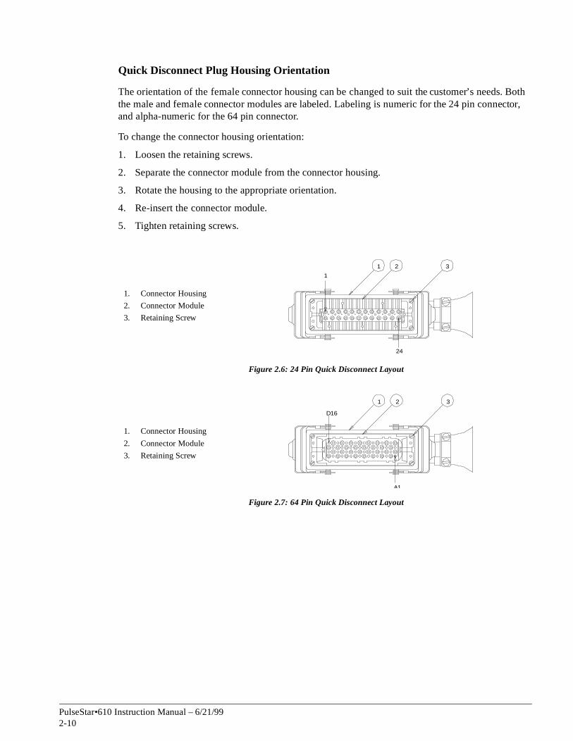
Quick Disconnect Plug Housing Orientation
The orientation of the female connector housing can be changed to suit the customer’s needs. Both the male and female connector modules are labeled. Labeling is numeric for the 24 pin connector, and alpha-numeric for the 64 pin connector.
To change the connector housing orientation:
1. Loosen the retaining screws.
2. Separate the connector module from the connector housing.
3. Rotate the housing to the appropriate orientation.
4. Re-insert the connector module.
5. Tighten retaining screws.
1. Connector Housing
2. Connector Module
3. Retaining Screw
Figure 2.6: 24 Pin Quick Disconnect Layout
1. Connector Housing
2. Connector Module
3. Retaining Screw
Figure 2.7: 64 Pin Quick Disconnect Layout
1
24
1 2 3
D16
A1
1 2 3
PulseStar•610 Instruction Manual – 6/21/992-10

is
,
Startup and Test Procedures
Pre-operation check list
Before you begin operating the PulseStar•610 system to control your overhead crane, confirm the following check list to ensure that your system is working safely and correctly.
• There is a fully-charged battery in the transmitter.
• The second battery is in the charger being charged at all times. Ensure that the battery chargerplugged into a power source that is not turned off at night with the crane.
• The Active E-STOP push-button on the transmitter is pushed in.
• The joysticks and/or paddle levers are in the center (off) position (NVT, GLT, GRT transmitters)or the motion push-buttons are not depressed (JRT, PBT transmitters).
WARNING
• Only authorized personnel are permitted to perform testing or service work.
• Make sure the crane is clear of any obstructions, and there is no load on the hook.
• Serious injury or component damage can occur if the PulseStar•610 system is not properly installed and tested.
PulseStar•610 Instruction Manual – 6/21/992-11

at the k
e
Testing the Receiver
As you perform the following startup test, place yourself in front of the PulseStar•610 receiver with the cover off so that you can clearly see each LED and connection. Refer to Figure 2.8: PulseStar•610 Receiver Test Layout for LED and module locations.
1. Turn on the power to the receiver. The CPU Standby LED should flash yellow to indicate thmicroprocessor is functioning properly and X1 LED, X2 LED, and X3 LED on the Power Pacshould turn on.
2. Insert the key into the key switch and turn to the ON position. A buzzer sounds to indicate the start of a diagnostic test. The diagnostic test checks for the following.
• The CPU and software is functioning properly.
• The joysticks and/or paddle levers are in the center (off) position (NVT, GLT, GRT transmitter) or the motion push-buttons are not pressed down (JRT, PBT transmitter).
NOTE: With the NVT, GLT and GRT transmitter the buzzer will sound a second time if thtransmitter passes the diagnostic tests.
Figure 2.8: PulseStar•610 Receiver Test Layout
1. Power Pack X1 LED
2. Power Pack X2 LED
3. Power Pack X3 LED
4. Power Pack X4 LED
5. Power Pack (50/110/240vac)
6. Decoder Module
7. Active E-STOP Decoder Module
8. Telegram LED
9. CPU Standby LED
10. Active E-STOP LED
11. Start Relay
12. SNZ Active E-STOP Module
13. Start Relay LED
14. Active E-STOP Decoder E-STOP LED
15. Decoder E-STOP LED
12
34
56
78
Off
12
34
56
78
Off
12
34
56
78
Off
12
34
56
78
Off
1 2 3 4
5 6 7
8 9 10
12
1415
1113
PulseStar•610 Instruction Manual – 6/21/992-12

or
elays
urn on.
3. After the diagnostic test the following should occur.
• The Telegram LED should flash on the Decoder Module and Active E-STOP Decoder Module to indicate that the receiver is detecting a valid signal from the transmitter.
4. Pull out the Active E-STOP push-button. The following should occur.
• The X4 LED on the Power Pack should turn on.
• The Decoder E-STOP LED and Active E-STOP Decoder LED on the Active E-STOP relay module should turn on.
5. Test the Active E-STOP function by pushing in the Active E-STOP push-button on the transmitter.The following should occur.
• The X4 LED on the Power Pack turns off.
• The Decoder E-STOP LED and Active E-STOP Decoder LED on the Active E-STOP relay module turn off.
6. Pull the Active E-STOP push-button out and press the START/HORN push-button on the transmitter. The start relay LED should turn on, and the start relay should close to activate the mainline contactor, and the horn will sound (when supplied).
7. Activate the motion push-buttons (JRT or PBT), joysticks and/or paddle levers (NVT, GLT,GRT) to test the crane functions. Confirm that the crane moves appropriately and that the LEDs corresponding to the motion relays or analog output modules turn on. These LED’s will belocated on the individual motion modules for analog signals, or directly above the discrete rfor digital signals.
8. Activate the OPTION function(s) (if applicable) to test optional crane functions. Confirm thatthe crane moves appropriately and that the LEDs corresponding to the relays or modules t
9. Turn the key switch to OFF. The following should occur.
• The X4 LED on the power pack turns off.
• The Decoder E-STOP LED and Active E-STOP Decoder LED on the Active E-STOP relay module turn off.
• The Telegram LED on the Decoder Module and Active E-STOP Decoder Module turn off.
10. If all transmitter and receiver functions work properly, the system is ready for use.
NOTE: If you experienced any problems during this test refer to Chapter 4 Troubleshooting PulseStar•610 for help, or call Electromotive Systems.
PulseStar•610 Instruction Manual – 6/21/992-13

(70-cm
position
ame
s
Changing the Frequency Channel of the Receiver
Standard RF Module
The standard RF module is capable of receiving one of 16 discrete frequency channels. The frequency channel of the transmitter and receiver are set by Electromotive Systems prior to shipment. Should interferences occur on a particular frequency channel it may be necessary to change the frequency channel of the receiver and transmitter.
NOTE: Do not change the receiver address code under any circumstances. Contact Electromotive Systems before making any frequency channel changes.
The PulseStar•610 transmitter and receiver operate over the 400—470 MHz frequency range band). There are 16 possible frequencies and 16 corresponding channels available. Figure 2.9: Receiver Frequency Channel Diagram shows each channel, its respective frequency, and the of the five jumpers according to the diagram for the frequency channel you are setting.
• Do NOT change the address code or frequency channel of the original transmitter that cwith your PulseStar•610 system without first contacting Electromotive Systems.
• Do NOT change the address code settings in the PulseStar•610 receiver.
• Do NOT operate two transmitters set with the same frequency channel and address codes athe receiver at the same time.
WARNING
PulseStar•610 Instruction Manual – 6/21/992-14

nel
agram
1. Remove the receiver cover.
2. Reference Figure 2.9: Receiver Frequency Channel Diagram to locate the Frequency ChanJumper Block inside the receiver.
3. Set the frequency channel jumpers according Figure 2.9: Receiver Frequency Channel Difor the appropriate frequency channel. A black box indicates that a jumper should be present in that position. A white box indicates there should be no jumper present in that position.
4. When finished, replace the receiver cover and tighten the four screws.
Figure 2.9: Receiver Frequency Channel Diagram
1. Antenna Connector
2. TTL Connector
3. Standard RF Module
4. Frequency Channel Jumper Block
A1
D0
D1
D2
D3
1 2
4
3
Channel A1 D0 D1 D2 D3 Frequency
0 458.800 MHz
1 458.825 MHz
2 458.850 MHz
3 458.875 MHz
4 458.900 MHz
5 458.925 MHz
6 458.950 MHz
7 458.975 MHz
8 459.000 MHz
9 459.025 MHz
10 459.050 MHz
11 459.075 MHz
12 459.100 MHz
13 459.125 MHz
14 459.150 MHz
15 459.175 MHz
Jumper is present
Jumper is not present
PulseStar•610 Instruction Manual – 6/21/992-15

in the
tory
d
y
(70-cm
ame
s
Scan RF Module
The scan RF module is a module used in conjunction with Free Channel Search, or when more than one transmitter will be used to control the crane. The scan RF module is used when AutoScan is required in the receiver.
AutoScan is where the receiver ‘scans’ for valid frequency channels. Once a valid frequency channel is found, the receiver checks for a valid address code. If the frequency channel does not contacorrect address code, the receiver continues to scan until a valid frequency channel containing the correct address code is found. Once a valid frequency channel containing the correct address code is found, the receiver locks on to that frequency channel and ignores all other signals.
The scan RF module is capable of scanning for up to 16 frequency channels, however the facsetting is for scanning either the odd or even frequency channels. The scan RF module is used with PulseStar•610 systems which have Free Channel Search in the transmitter, or are set up for pitch ancatch which does not use interlocking.
The frequency channel of the transmitter and scan mode setting of the receiver are set by Electromotive Systems prior to shipment. Should interferences occur on a particular frequencchannel it may be necessary to change the frequency channel of the transmitter, and the scan mode setting of the scan RF module in the receiver. Contact Electromotive Systems before making any frequency channel changes.
NOTE: Do not change the receiver address code under any circumstances.
The PulseStar•610 transmitter and receiver operate over the 400—470 MHz frequency range band). There are 16 possible frequencies and 16 corresponding channels available. Figure 2.10: Scan RF Module shows the scan RF module and location of the configuration jumpers.
• Do NOT change the address code or frequency channel of the original transmitter that cwith your PulseStar•610 system without first contacting Electromotive Systems.
• Do NOT change the address code settings in the PulseStar•610 receiver.
• Do NOT operate two transmitters set with the same frequency channels and address codes athe receiver at the same time.
WARNING
PulseStar•610 Instruction Manual – 6/21/992-16

is r 8
r odd 10, 12,
Setting the Scan Mode
1. Remove the receiver cover.
2. Set the jumpers to scan for the frequency channel used by the transmitter(s).
• Solder jumper J1 selects either 8 channel or 16 channel scan. When solder jumper J1open, it scans for 8 channels. When closed it scans 16 channels. Factory setting is fochannel scan.
• Jumper J2 is the odd/even channel scan select. When jumper J2 is closed, it scans fochannels (1, 3, 5, 7, 9, 11, 13, 15). When open it scans for even channels (0, 2, 4, 6, 8,14).
NOTE: When solder jumper J1 is set for 16 channel scan, jumper J2 is ignored.
3. When finished, replace the receiver cover and tighten the four screws.
Figure 2.10: Scan RF Module
1. J2 Odd/Even Scan Select
2. J1 8/16 Scan Select
3. Scan RF Module
4. Antenna Connector
5. TTL Signal Connector
6. Blink Signal Connector
1 2
456
3
PulseStar•610 Instruction Manual – 6/21/992-17

the act e.
0
ass I
which
Receiver Options
All PulseStar•610 receivers are engineered specifically to operate your crane. Because of this you may have features and functionality which is not covered in the PulseStar•610 manual. The following are some of the more common options which pertain to the PulseStar•610 receiver. If you have any questions about the functionality of your PulseStar•610 system contact Electromotive Systems.
Range Limitation
The PulseStar•610 receiver can limit the operating range of the PulseStar•610 system. Due tonature of radio frequency transmissions it is not possible to limit the operating range to an exdistance. However it is possible to limit the operating range to a percentage of maximum rang
A special module is used inside the PulseStar•610 receiver which measures the PulseStar•61transmitter signal strength. A threshhold point is determined by using a potentiometer on the range limitation module. If the power of the transmitted signal is lower than the threshhold point, the receiver goes into Safe Mode, and the Active E-STOP circuitry is activated. The range limitation module has an operating range of 80’ to 200’ +/- 20% (20M to 50M +/- 20%).
Special Enclosures
Intrinsically Safe Systems
The PulseStar•610 receiver can be provided as intrinsically safe. A standard receiver can be mounted inside an explosion-proof enclosure, or the receiver can be provided with it’s own explosion-proof enclosure for mounting by the customer. The PulseStar•610 receiver can accommodate all Cland Class II environments when provided in this manner.
Marine Duty/Corrosion Resistant Systems
The PulseStar•610 receiver can be provided with a NEMA 4X enclosure, as well as enclosuresare resistant to corrosive environments such as marine duty and galvanizing/pickling.
PulseStar•610 Instruction Manual – 6/21/992-18

c h a p t e r 3
The PulseStar•610Transmitter

This page intentionally left blank.

asic
is
Overview
This chapter tells you how to configure and use the PulseStar•610 transmitter. Several types of transmitters are available for use with the PulseStar•610 system. This manual will cover the bfeatures of each transmitter, as well as some of the more common options. For a complete description of how your engineered PulseStar•610 system functions contact Electromotive Systems.
Once you’ve installed, wired, and tested the PulseStar•610 system, you are ready to use it. Thchapter covers the following information.
• PulseStar•610 Transmitters
• Start-up and Operation
• Transmitter Options
• Battery and Charger Information
PulseStar•610 Instruction Manual – 6/21/993-3

include:
e
eds
ut to
PulseStar•610 Transmitters
There are several types of transmitters which can be used with a PulseStar•610 system. They
• JRT hand held transmitter
• PBT hand held transmitter
• NVT belly box transmitter
• GLT belly box transmitter
• GRT belly box transmitter
JRT Transmitter
The JRT transmitter is a hand-held radio control device with push-buttons used to control cranmotions. The JRT transmitter can control up to three crane motions with two speed control, and onecrane motion with single speed control. The crane motion push-buttons which control two spehave two detents. The START/HORN and OPTION push-buttons are single detent.
JRT Transmitter Components
The JRT transmitter has the following components. Refer to Figure 3.1: JRT Transmitter Layoidentify parts of the JRT transmitter.
Figure 3.1: JRT Transmitter Layout
1. Key Switch
2. Key Cap
3. Right Side Bezel and Membrane
4. START/HORN Push-button
5. OPTION Push-buttons
6. Housing
7. Battery
8. Motion Push-button
9. Power LED
10. Top Bezel and Membrane
11. Active E-STOP Push-button
A B A B
1 2
11
10
9
8
7
6
3
4
5
PulseStar•610 Instruction Manual – 6/21/993-4

d this
ane
The
hing
rted,
hoist
JRT Transmitter Functions
The following describes the basic functionality of the JRT transmitter. Please reference Figure 3.1: JRT Transmitter Layout for the location of these functions.
START/HORN Push-button. The START/HORN push-button activates the mainline contactor ansounds the horn (when provided). Once the mainline contactor has been turned on, pressing push-button sounds the horn only (when provided).
Active E-STOP Push-button. Pressing the Active E-STOP push-button will place the receiver in Safe Mode. The Active E-STOP push-button must be pulled out for the transmitter to control the crmotions.
NOTE: The Active E-STOP push-button is for emergency situations only. Do NOT use it as anOFF switch. Use the key switch to turn the transmitter on and off.
Power LED. As soon as the JRT transmitter is turned on, this LED will emit a flashing red light. transmitter performs a self-test to check the JRT software. If it passes, the LED changes to flashing green and continues flashing green until the transmitter is turned off. This LED changes to flasred when the battery is low.
Key Switch. The key switch turns the transmitter on and off. It only works with the key cap inseand the key cap can only be removed while in the OFF position.
Motion Push-buttons. These push-buttons control the various crane motions and are labeled accordingly.
OPTION Push-buttons. These push-buttons can control a single speed crane motion such as ablock rotate, or various crane auxiliary functions.
PulseStar•610 Instruction Manual – 6/21/993-5

to
y/
PBT Transmitter
The PBT-4 and PBT-5A transmitter is a hand-held radio control device with push-buttons usedcontrol crane motions. Both transmitters can control up to four crane motions with two speed control. The PBT-5A provides independent/combined control of two bridge cranes or two trollehoists on a single bridge crane.
The crane motion push-buttons have two detents corresponding to two speeds. The START/HORN, OPTION, and SELECTOR (PBT-5A only) push-buttons are single detent.
PBT Transmitter Components
The PBT-4 and PBT-5A transmitters have the following components. Refer to Figure 3.2: PBT-5A Transmitter Layout to identify parts of the PBT transmitter.
Figure 3.2: PBT-5A Transmitter Layout
1. Upper Housing
2. Lower Housing
3. START/HORN Push-button
4. OPTION Push-button
5. Top Bezel and Membrane
6. Power LED
7. Motion Push-button
8. Carrying Belt Fastener
9. Battery
10. Active E-STOP Push-button
11. Key Switch
12. Key Cap
13. SELECTOR Push-button (PBT-5A only)
14. SELECTOR LED (PBT-5A only)
Aux
Option
1
Option
2
1 2 3 4 5 6 7 8
9
10
111214 13
Pre
ss
PulseStar•610 Instruction Manual – 6/21/993-6

d this
rted,
eled
stops.
a
s are the ction
PBT Transmitter Functions
The following describes the basic functionality of the PBT transmitter. Please reference Figure 3.2: PBT-5A Transmitter Layout for the location of these functions.
START/HORN Push-button. The START/HORN push-button activates the mainline contactor ansounds the horn (when provided). Once the mainline contactor has been turned on, pressing push-button sounds the horn only (when provided).
Active E-STOP Push-button. Pressing the Active E-STOP push-button will turn off the mainline contactor. The Active E-STOP push-button must be pulled out for the transmitter to control the crane motions.
NOTE: The Active E-STOP push-button is for emergency situations only. Do NOT use it as anOff switch. Use the key switch to turn the transmitter on and off.
Power LED. As soon as the PBT is turned on, this light will flash green. This indicates that the transmitter powered up and has passed a diagnostic check. If the OPTION push-button in the transmitter is set to latching, the power LED will flash red whenever the OPTION push-button is activated.
Key Switch. The key switch turns the transmitter on and off. It only works with the key cap inseand the key cap can only be removed while in the OFF position.
Crane Motion Push-buttons. These push-buttons control the various crane motions and are labaccordingly.
OPTION Push-button. This push-button controls the OPTION function such as Micro-Positioning
ControlTM . A jumper on the PBT circuit board controls whether the OPTION push-button is latching or momentary.
• If the OPTION push-button is set to momentary, the OPTION function is activated only while the operator holds down the push-button. As soon as the push-button is released, the function
• If the OPTION push-button is set to latching, the OPTION function is activated when the push-button is depressed, and the power LED is flashing red. When the push-button is pressedsecond time and released, the function stops and the power LED flashes green.
SELECTOR Push-buttons (PBT5A ONLY). These push-buttons control the independent or combined control of main and aux hoists, two trolley/hoists, or two cranes. These push-buttonelectronically latched. The SELECTOR function is active when the push-button is depressed, andSELECTOR LED is on. When the push-button is pressed a second time and released, the funstops, and the SELECTOR LED turns off.
SELECTOR LED’s (PBT5A ONLY). These LED’s indicate which SELECTOR push-button is activated.
PulseStar•610 Instruction Manual – 6/21/993-7

etents. The
e
NVT Transmitter
The NVT transmitter has a “belly box” design where the operator maneuvers joysticks or paddle levers to control crane motions. The standard NVT joysticks and paddle levers offer proportional speed control without detents. Joysticks are available which provide up to three speeds with dThe NVT joystick model can contain up to two dual axis joysticks for up to four motion control.NVT paddle lever model can contain up to six single axis paddle levers for up to six motion control.
The NVT also offers a SELECTOR toggle switch for controlling multiple crane motions with one joystick or paddle lever. With the SELECTOR toggle switch, the NVT can control up to seven cranmotions for independent/combined control.
NVT Transmitter Components (Joystick Model)
The NVT joystick transmitter has the following components. Refer to Figure 3.3: NVT Joystick Transmitter Layout to identify parts of the NVT transmitter.
Figure 3.3: NVT Joystick Transmitter Layout
1. Active E-STOP Push-button
2. OPTION Toggle Switch
3. SELECTOR Toggle Switch
4. START/HORN Push-button
5. Key Switch
6. Key Cap
7. Joystick
8. Lower Housing
9. Carrying Belt Retainer
10. Upper Housing
11. Power LED
L Trolley R
Rev
B
ridg
e F
or
Up
Ho
ist
Do
wn
Option
EM
E
RG E N C Y
S-
TO
P
CCW Ro tate CW
A + B
A B
O
I
1 2 3
4
5 6
78
9
10
11
PulseStar•610 Instruction Manual – 6/21/993-8

ddle
NVT Transmitter Components (Paddle Lever Model)
The NVT paddle lever transmitter has the following components. Refer to Figure 3.4: NVT PaLever Transmitter Layout to identify parts of the NVT transmitter.
Figure 3.4: NVT Paddle Lever Transmitter Layout
1. Power LED
2. OPTION Toggle Switch
3. Active E-STOP Push-button
4. SELECTOR Toggle Switch
5. Paddle Lever Cap
6. Key Switch
7. Key Cap
8. Upper Housing
9. Paddle Lever
10. Lower Housing
11. Carrying Belt Retainer
12. START/HORN Push-button
EE
EM
RG
NC
Y
ST
OP
EE
EM
RG
NC
Y
ST
OP
Fo rwa rdB rid ge B rid ge
Re verse
L ef tTrolle yR igh t
Do wnM Ho istUp
A Ho istUp
A HoistUp
O
I
1 2 3 4 5
12
11
10
9
8
6 7
Op tio n A A +B B
PulseStar•610 Instruction Manual – 6/21/993-9

d this
hed
rted,
ents
ion
hout
0
e er. ich
NVT Transmitter Functions
The following describes the basic functionality of the NVT transmitter. Please reference Figure 3.3: NVT Joystick Transmitter Layout or Figure 3.4: NVT Paddle Lever Transmitter Layout for the location of these functions.
START/HORN Push-Button. The START/HORN push-button activates the mainline contactor ansounds the horn (when provided). Once the mainline contactor has been turned on, pressing push-button sounds the horn only (when provided).
Active E-STOP Push-button. Pressing the Active E-STOP push-button will turn off the mainline contactor. The Active E-STOP push-button must be pulled out for the transmitter to control the crane motions.
NOTE: The Active E-STOP push-button is for emergency situations only. Do NOT use it as anOff switch. Use the key switch to turn the transmitter on and off.
Power LED. As soon as the NVT is turned on, this light will flash once. The transmitter then goes through a diagnostic check. If the transmitter passes the diagnostic check the Power LED flasgreen. This indicates that the transmitter is powered up.
Key Switch. The key switch turns the transmitter on and off. It only works with the key cap inseand the key cap can only be removed while in the OFF position.
Joysticks. The standard NVT joysticks provide stepless proportional speed control without detof up to four crane motions. The number of motions can be increased by using the SELECTOR toggle switch for independent/combined control of cranes or trolley/hoists. Other joysticks areavailable that offer three-step speed control with detents.
NOTE: The five, six, and seven-motion NVT transmitters use two joysticks and a three-positSELECTOR toggle switch for independent and combined control of multi-motions.
Paddle Levers. The standard NVT paddle lever provide stepless proportional speed control witdetents of up to six crane motions. The number of motions can be increased by using the SELECTOR toggle switch for independent/combined control of cranes or trolley/hoists.
OPTION Toggle Switch. This switch controls the OPTION function connected to the PulseStar•61receiver (lights, for example). The function will begin when the switch is moved to the On position. The function will continue working until the switch is moved to the Off position.
SELECTOR Toggle Switch. The SELECTOR toggle switch allows the operator to control multiplcranes from a single transmitter, or multiple crane motions from a single joystick or paddle levWhen the SELECTOR toggle switch is set to A, the transmitter controls the crane or motion(s) whare designated as A. When the SELECTOR toggle switch is set to B, the transmitter controls the crane or motion(s) which are designated as B. When the SELECTOR toggle switch is set to A+B, both A and B cranes or motions are controlled by the transmitter.
PulseStar•610 Instruction Manual – 6/21/993-10

ents.
GLT Transmitter
The GLT transmitter has a “belly box” design where the operator maneuvers joysticks or paddle levers to control crane motions. The standard GLT joysticks and paddle levers offer proportional speed control without detents. Joysticks are available which provide up to six speeds with detThe GLT joystick model can contain up to three dual axis joysticks for up to six motion control. TheGLT paddle lever model can contain up to seven single axis paddle levers for up to seven motion control.
The GLT also offers a SELECTOR toggle switch for controlling multiple crane motions with one joystick or paddle lever. With the SELECTOR toggle switch, the GLT can control up to nine crane motions for independent/combined control.
GLT Transmitter Components (Joystick Model)
The GLT joystick transmitter has the following components. Refer to Figure 3.5: GLT Joystick Transmitter Layout to identify parts of the GLT transmitter.
Figure 3.5: GLT Joystick Transmitter Layout
1. OPTION Toggle Switch
2. SELECTOR Toggle Switch
3. Active E-STOP Push-button
4. Power LED
5. START/HORN Push-button
6. Key Switch
7. Key Cap
8. Handle
9. Belt Retaining Bracket
10. Upper Housing
11. Lower Housing
12. Safety Bar
13. Joystick
St art/ Ho rnE-STOP
A A+B BO ptio n
O
I
1 2 3 4 5
6 7
8
9
10
11
12
13
PulseStar•610 Instruction Manual – 6/21/993-11
dle
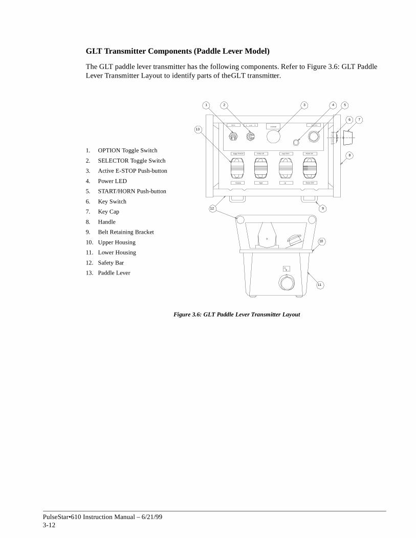
GLT Transmitter Components (Paddle Lever Model)
The GLT paddle lever transmitter has the following components. Refer to Figure 3.6: GLT PadLever Transmitter Layout to identify parts of the GLT transmitter.
Figure 3.6: GLT Paddle Lever Transmitter Layout
1. OPTION Toggle Switch
2. SELECTOR Toggle Switch
3. Active E-STOP Push-button
4. Power LED
5. START/HORN Push-button
6. Key Switch
7. Key Cap
8. Handle
9. Belt Retaining Bracket
10. Upper Housing
11. Lower Housing
12. Safety Bar
13. Paddle Lever
6 7
8
S tart/ HornE-STOP
A A +B BOpt ion
O
I
Bridge Forward Trolley Left Hoist Down Rotate CW
Reverse Right Up Rotate CCW
1 2 3 4 5
9
10
12
13
11
PulseStar•610 Instruction Manual – 6/21/993-12

d this
hed
rted,
nts of
e that
a
hout
0
e er. ich
GLT Transmitter Functions
The following describes the basic functionality of the GLT transmitter. Please reference for the location of these functions.
START/HORN Push-button. The START/HORN push-button activates the mainline contactor ansounds the horn (when provided). Once the mainline contactor has been turned on, pressing push-button sounds the horn only (when provided).
Active E-STOP Push-button. Pressing the Active E-STOP push-button will turn off the mainline contactor. The Active E-STOP push-button must be pulled out for the transmitter to control the crane motions.
NOTE: The Active E-STOP push-button is for emergency situations only. Do NOT use it as anOff switch. Use the key switch to turn the transmitter on and off.
Power LED. As soon as the NVT is turned on, this light will flash once. The transmitter then goes through a diagnostic check. If the transmitter passes the diagnostic check the Power LED flasgreen. This indicates that the transmitter is powered up.
Key Switch. The key switch turns the transmitter on and off. It only works with the key cap inseand the key cap can only be removed while in the OFF position.
Joysticks. The standard GLT joysticks provide stepless proportional speed control without deteup to six crane motions. This number of motions can be increased by using the SELECTOR toggle switch for independent/combined control of cranes or trolley/hoists. Other models are availabloffer six-step speed control with detents.
NOTE: The five, six, seven, and nine-motion GLT transmitters use two or three joysticks andthree-position SELECTOR toggle switch for independent and combined control of multi-motions.
Paddle Levers. The standard GLT paddle lever provide stepless proportional speed control witdetents of up to seven crane motions. The number of motions can be increased by using the SELECTOR toggle switch for independent/combined control of cranes or trolley/hoists.
OPTION Toggle Switch. This switch controls the OPTION function connected to the PulseStar•61receiver (lights, for example). The function will begin when the switch is moved to the On position. The function will continue working until the switch is moved to the Off position.
SELECTOR Toggle Switch. The SELECTOR toggle switch allows the operator to control multiplcranes from a single transmitter, or multiple crane motions from a single joystick or paddle levWhen the SELECTOR toggle switch is set to A, the transmitter controls the crane or motion(s) whare designated as A. When the SELECTOR toggle switch is set to B, the transmitter controls the crane or motion(s) which are designated as B. When the SELECTOR toggle switch is set to A+B, both A and B cranes or motions are controlled by the transmitter.
PulseStar•610 Instruction Manual – 6/21/993-13

ents. . The
out
GRT Transmitter
The GRT transmitter has a “belly box” design where the operator maneuvers joysticks or paddle levers to control crane motions. The standard GRT joysticks and paddle levers offer proportional speed control without detents. Joysticks are available which provide up to six speeds with detThe GRT joystick model can contain up to three dual axis joysticks for up to six motion controlGRT paddle lever model can contain up to seven single axis paddle levers for up to seven motion control.
The GRT also offers a SELECTOR toggle switch for controlling multiple crane motions with one joystick or paddle lever. With the SELECTOR toggle switch, the GRT can control up to nine crane motions for independent/combined control.
GRT Transmitter Components
The GRT transmitter has the following components. Refer to Figure 3.7: GRT Transmitter Lay(Top View) and Figure 3.8: GRT Transmitter Layout (Side View) to identify parts of the GRT transmitter.
Figure 3.7: GRT Transmitter Layout (Top View)
1. Joystick
2. Paddle Lever
3. Key Switch
4. Key Cap
5. START/HORN Push-button
6. SELECTOR Toggle Switch
7. Breast Plate with Harness
8. Active E-STOP Push-button
9. Power LED
10. OPTION Toggle Switch
11. Guard
3 4S ta rt /Ho rn
B rid ge Fo rward
B rid ge Re ve rse
Ho is t Do wn
Ho ist Up
Tro
lley
Le
ft Trolle
y Rig
ht
ON
T - A US
N
EM
ER
GE
C Y
S
TO
P
A A +B BOp tion
Op tion Op tio n
Op tion Op tio n
1 2
5678910
11
PulseStar•610 Instruction Manual – 6/21/993-14

Figure 3.8: GRT Transmitter Layout (Side View)
1. Upper Housing
2. Guard
3. Breast Plate with Harness
4. Lower Housing
1
2 3
4
PulseStar•610 Instruction Manual – 6/21/993-15

d this
hed
rted,
ents
e that
a
hout
0
e er. ich
GRT Transmitter Functions
The following describes the basic functionality of the GRT transmitter. Please reference for the location of these functions.
START/HORN Push-button. The START/HORN push-button activates the mainline contactor ansounds the horn (when provided). Once the mainline contactor has been turned on, pressing push-button sounds the horn only (when provided).
Active E-STOP Push-button. Pressing the Active E-STOP push-button will turn off the mainline contactor. The Active E-STOP push-button must be pulled out for the transmitter to control the crane motions.
NOTE: The Active E-STOP push-button is for emergency situations only. Do NOT use it as anOff switch. Use the key switch to turn the transmitter on and off.
Power LED. As soon as the NVT is turned on, this light will flash once. The transmitter then goes through a diagnostic check. If the transmitter passes the diagnostic check the Power LED flasgreen. This indicates that the transmitter is powered up.
Key Switch. The key switch turns the transmitter on and off. It only works with the key cap inseand the key cap can only be removed while in the OFF position.
Joysticks. The standard GRT joysticks provide stepless proportional speed control without detof up to six crane motions. The number of motions can be increased by using the SELECTOR toggle switch for independent/combined control of cranes or trolley/hoists. Other models are availabloffer six-step speed control with detents.
NOTE: The five, six, seven, and nine-motion GRT transmitters use two or three joysticks andthree-position SELECTOR toggle switch for independent and combined control of multi-motions.
Paddle Levers. The standard GRT paddle lever provide stepless proportional speed control witdetents of up to seven crane motions. The number of motions can be increased by using the SELECTOR toggle switch for independent/combined control of cranes or trolley/hoists.
OPTION Toggle Switch. This switch controls the OPTION function connected to the PulseStar•61receiver (lights, for example). The function will begin when the switch is moved to the On position. The function will continue working until the switch is moved to the Off position.
SELECTOR Toggle Switch. The SELECTOR toggle switch allows the operator to control multiplcranes from a single transmitter, or multiple crane motions from a single joystick or paddle levWhen the SELECTOR toggle switch is set to A, the transmitter controls the crane or motion(s) whare designated as A. When the SELECTOR toggle switch is set to B, the transmitter controls the crane or motion(s) which are designated as B. When the SELECTOR toggle switch is set to A+B, both A and B cranes or motions are controlled by the transmitter.
PulseStar•610 Instruction Manual – 6/21/993-16

il all
and hen
l you are
pl
d
Transmitter Setup
This section covers how to set up a PulseStar•610 transmitter.
Placing the Push-button Labels
If your new, spare or replacement JRT or PBT transmitter came with push-button legends that you need to insert, refer to Figure 3.9: PBT Transmitter Label Insertion and the following instructions. The same procedure can be used with the JRT transmitter. Do not operate the transmitter untlegends are properly installed.
Figure 3.9: PBT Transmitter Label Insertion
1. Unsnap the push-button cover from the push-button base. Remove the push-button label replace it with the new label. Place the label in the push-button cover face down so that wyou turn the push-button over, the push-button label is visible.
2. Snap the push-button base into the cover. Repeat steps 1 and 2 for each push-button labereplacing.
3. Assemble the push-buttons on the transmitter according to the layout for your application.
4. Ensure that the transmitter housing is free of dirt, oil and other contaminants or the bezel with membrane covering won’t stick. Use rubbing alcohol to clean any dirt or oils which may be present.
5. Once you are satisfied with the push-button layout, remove the adhesive strip on the back of the bezel with membrane covering and line it up on the enclosure. Press the bezel firmly into ace.
NOTE: DO NOT use any glues or adhesives to affix the bezel with membrane covering to the transmitter housing. Doing this can permanently damage the transmitter, and will voithe warranty.
1. Top Bezel With Membrane Covering
2. Push-button Cover
3. Push-button Label
4. Push-button Base
5. Housing
1
2
3
4
5
PulseStar•610 Instruction Manual – 6/21/993-17

ive
Transmitter Address Code and Frequency Channel
This section explains how to set the address code and frequency channel of the PulseStar•610 transmitter. The PulseStar•610 address code and frequency channel are configured at the factory. This should be done ONLY if you are setting up a spare or replacement transmitter, or directed to do so by Electromotive Systems.
Serial Nameplate
The transmitter serial nameplate is located on one of the side walls of the PulseStar•610 transmitter battery cavity. The serial nameplate contains the Electromotive Systems job number, the address code used by the system, and the frequency channel used by the system. The Electromotive Systems job number is important if you ever need to call Electromotive Systems for service. Please have this information available when contacting Electromotive Systems.
Figure 3.10: Serial Nameplate
• Do NOT change the address code or frequency channel of the original PulseStar•610 transmitter that came with your PulseStar•610 system without first contacting ElectromotSystems.
• Do NOT change the address code settings in the receiver.
• Do NOT operate two transmitters set with the same frequency channel and address code as the receiver at the same time.
WARNING
PulseStarJob # 2 0 0 0 0Addr. 1 9 3 2 7Freq. 5
PulseStar•610 Instruction Manual – 6/21/993-18

late
re
code
code e of the
ht,
Setting the Address Code and Frequency Channel of a Transmitter:
Before setting the address code and frequency channel of the transmitter, ensure you first know the address code and frequency channel of the receiver it is going to control. This information can be found by locating the serial nameplate on the PulseStar•610 receiver. Refer to the Serial Namepsection in chapter 2 for the location of the receiver serial nameplate.
1. Make sure the transmitter is off. Remove the key to be sure.
2. Remove the battery from the transmitter, refer to Battery and Charger Information later in this chapter.
3. Access the inside of the PulseStar•610 transmitter.
• For the JRT transmitter remove the screws on the back of the JRT transmitter that fastens the back plate to the housing and remove back plate.
• For the PBT, NVT, GLT and GRT transmitter remove the four screws which hold the upper housing and lower housing together.
4. Locate the two blocks of address code DIP switches on the transmitter coder board, and the frequency channel jumper block on the RF module inside the PulseStar•610 transmitter.
Determining the Address Code
Refer to Figure 3.11: JRT Coder Board Layout, Figure 3.12: PBT Coder Board Layout, or Figu3.13: NVT, GLT, GRT Coder Board Layout for typical transmitter coder boards, and the location of the address code dip switches.
The address code is a 16 bit binary number which is assigned to each PulseStar system. Thisensures that no other PulseStar system or other radio controlled device can accidentally operate the crane. The address code number on the serial nameplate is a decimal equivalent to the binaryassigned to the system. To determine the binary code of your PulseStar system you can do onfollowing:
• Using a calculator with decimal to binary conversion, enter the decimal address code number from the serial nameplate on the receiver. Then convert this number to it’s binary equivalent.
• Record the 16 address code switch positions inside the receiver. All switches are either ‘on’ or ‘off’. Always read the switches with the numbering and lettering right side up, from left to rigand with switch number one being on the left.
• Consult Electromotive Systems for information concerning your address code.
Once you have the correct address code information you can configure the transmitter to work with the existing receiver.
CAUTION
Before working on the transmitter, remove the battery.
PulseStar•610 Instruction Manual – 6/21/993-19

r,
ive
Setting the Address Code
Reference Figure 3.11: JRT Coder Board Layout for changing the address for a JRT transmitteFigure 3.12: PBT Coder Board Layout for changing the address for a PBT transmitter, or Figure 3.13: NVT, GLT, GRT Coder Board Layout for changing the address for a NVT, GLT, or GRT transmitter.
1. Orientate the address code switches so that the numbering and lettering is right side up.
2. Locate switch 1 on the left most block of the address code switches. This switch is the first bit of the binary address code.
3. Set each switch to either ‘on’ or ‘off’ according the binary address code information.
4. If you do not have to set the frequency channel you can now close the transmitter by placing the back plate in place and inserting the screws for the JRT transmitter, or by mating the lower and upper halves and inserting the four screws for the PBT, NVT, GLT and GRT transmitter.
Figure 3.11: JRT Coder Board Layout
1. Switch 16
2. Address Code DIP Switches
3. Frequency Channel Jumper Block
4. RF Module
5. Fuse
6. Switch 1
• Do NOT change the address code or frequency channel of the original PulseStar•610 transmitter that came with your PulseStar•610 system without first contacting ElectromotSystems.
• Do NOT change the address code settings in the receiver.
• Do NOT operate two transmitters set with the same frequency channel and address code as the receiver at the same time.
WARNING
1ON 2
34
56
78
ON
78
65
43
21
1ON
2
ON
23
45
67
81
2 23
45
67
8
1
2
3
4
5
6
PulseStar•610 Instruction Manual – 6/21/993-20

Figure 3.12: PBT Coder Board Layout
Figure 3.13: NVT, GLT, GRT Coder Board Layout
1. Switch 1
2. Fuse
3. Address Code DIP Switches
4. Coder Board for PBT
5. Switch 16
1. Analog Signal Connector
2. Fuse
3. Coder Board For NVT, GLT, GRT
4. Address Code DIP Switches
5. Switch 16
6. Switch 1
7. Multi-pin Connector
ON1
23
45
67
8
ON1
23
45
67
8
SW
2S
W1
1
SW
2S
W1
ON
23
45
67
81
23
45
67
8
ON
1
2
5
3
41
9
210
ON
1
ON
2 3 4 5 6 7 8 1 2 3 4 5 6 7 8
ON
1
ON
2 3 4 5 6 7 8 1 2 3 4 5 6 7 8
1 2 3
4
56
7
PulseStar•610 Instruction Manual – 6/21/993-21

(70- the
so that
x
ws for
Setting the Frequency Channel
The frequency channel of the transmitter must be set to the frequency channel of the receiver it is going to control. The transmitter and receiver operate over the 400–470 MHz frequency rangecm band). There are 16 possible frequency channels. Figure 3.14: Frequency Diagram showstransmitter RF Module, and each channel, its respective frequency, and the position of the fivejumpers.
1. Locate the RF Module inside the transmitter.
2. Locate the Frequency Channel Jumper Block on the RF Module. Orientate the transmitter the A1 jumper position is on your left-hand side.
3. Set the frequency jumpers according to the diagram for the desired frequency. A black boindicates that a jumper should be present in that position. A white box indicates there should be no jumper present in that position.
4. When finished, close the transmitter by placing the back plate in place and inserting the screws for the JRT transmitter, or by mating the lower and upper halves and inserting the four screthe PBT, NVT, GLT and GRT transmitter.
Figure 3.14: Frequency Diagram
1. TTL Connector
2. RF Module
3. Ground Connector
4. Antenna Connector
5. Frequency Channel Jumper Block
A1
D0
D1
D2
D3
Pin
1 - b
lu
Pin
2 - b
lu/w
ht
Pin
3 - re
d
1
2
3
4
5
Channel A1 D0 D1 D2 D3 Frequency
0 458.800 MHz
1 458.825 MHz
2 458.850 MHz
3 458.875 MHz
4 458.900 MHz
5 458.925 MHz
6 458.950 MHz
7 458.975 MHz
8 459.000 MHz
9 459.025 MHz
10 459.050 MHz
11 459.075 MHz
12 459.100 MHz
13 459.125 MHz
14 459.150 MHz
15 459.175 MHz
Jumper is present
Jumper is not present
PulseStar•610 Instruction Manual – 6/21/993-22

.
Start-up and Operation
Holding the Transmitter
Before using the PulseStar•610 transmitter, refer to the following information on how to hold the PulseStar•610 transmitter the correct way.
JRT Transmitter
Please refer to Figure 3.15: JRT Transmitter Orientation on how to properly hold the JRT transmitter
Figure 3.15: JRT Transmitter Orientation
To make sure that you are oriented correctly in relation to the directional push-buttons, paddle levers or joysticks. Hold the transmitter as shown.
WARNING
PulseStar•610 Instruction Manual – 6/21/993-23

PBT Transmitter
Please refer to Figure 3.16: PBT Transmitter Orientation on how to properly hold the PBT transmitter.
Figure 3.16: PBT Transmitter Orientation
PulseStar•610 Instruction Manual – 6/21/993-24

NVT Transmitter
Please refer to Figure 3.17: NVT Transmitter Orientation on how to properly hold the NVT transmitter.
Figure 3.17: NVT Transmitter Orientation
SYST EMS INC.ELECTROMOTIVE
TM
Pul seStar X
L
Remote
Cra ne
Con
trol
TMEL ECTR
OMO
T IVE
SYSTEM
S INC.TM
PulseStar•610 Instruction Manual – 6/21/993-25

GLT Transmitter
Please refer to Figure 3.18: GLT Transmitter Orientation on how to properly hold the GLT transmitter.
Figure 3.18: GLT Transmitter Orientation
S YS TE MS I NC.ELE CTROMOT IV E
T M
PulseStar•610 Instruction Manual – 6/21/993-26

GRT Transmitter
Please refer to Figure 3.19: GRT Transmitter Orientation on how to properly hold the GRT transmitter.
Figure 3.19: GRT Transmitter Orientation
SYSTEMS INC.ELECTROMOTIVE
TM
PulseStar•610 Instruction Manual – 6/21/993-27

the
icate t the
the ound w
p to ttons
n the
mitter
n the
Start-up
Refer to the appropriate transmitter layout figure shown in PulseStar•610 Transmitters section for location of the various functions on the PulseStar•610 transmitter. To start the PulseStar•610 transmitter:
1. Make sure that there is a charged battery in the transmitter.
2. Make sure the Active E-STOP push-button is pressed in.
3. Make sure no motion push-buttons are depressed (JRT, PBT) or all joysticks or paddle levers arein the center (off) position (NVT, GLT and GRT transmitters).
4. Insert the key into the key switch and turn to the ON position. The power LED flashes to indpower is on. NVT, GLT and GRT models will emit two sounds. The first sound indicates thatransmitter is going through the diagnostic check. The second sound indicates that the transmitter has passed the diagnostic check.
5. Pull out the Active E-STOP push-button and press the START/HORN push-button to provide power to the mainline contactor.
The transmitter is now ready for use.
Emergency Stop
For all emergency situations, push in the Active E-STOP push-button. To restart, pull out the Active E-STOP push-button and press the START/HORN push-button.
When the PulseStar•610 battery voltage drops below approximately 8 volts, the power LED ontransmitter will begin flashing red for about 30 seconds for the JRT model, and a buzzer will sfor PBT, NVT, GLT, and GRT transmitters. At the end of the 30 second period, the transmitter ill automatically shut itself off and places the receiver in Safe Mode. This blocks all crane motion commands.
Using the Motion Push-buttons (JRT and PBT)
The JRT transmitter can control up to three crane motions. The PBT transmitter can control ufour crane motions. Each pair of push-buttons corresponds to one crane motion. The push-buare “interlocked,” which means that only one push-button in each horizontal row is operational at a time. In other words, if you press a push-button, the crane function corresponding to that push-buttonwill be activated. If you then press the other push-button in the same row while still holding dowfirst push-button pressed, the receiver will ignore the crane motion corresponding to the second push-button pressed.
Using the Joysticks and/or Paddle Levers (NVT, GLT and GRT)
All joysticks and paddle levers have a spring return to the center (off) position. Locate the translabel which corresponds to the joystick or paddle lever function you wish to operate. Deflect the joystick or paddle lever in the direction you want the crane motion to move according to the label. If the crane motion is more than one speed, the further you deflect the joystick or paddle lever from it’scenter position, the faster the crane motion will move. To stop the crane motion(s) simply returjoystick or paddle lever to the center (off) position.
PulseStar•610 Instruction Manual – 6/21/993-28

of what
r will
Optional Switches and Push-buttons
Depending on the application, PulseStar•610 transmitter can be provided with an assortment rotary switches, toggle switches, or push-buttons. These functions will be labeled according tothey are controlling. Typically it is necessary to position the switch to the proper location according to transmitter labeling to operate that specific function. If you are unsure how to correctly operate these switches, Consult Electromotive Systems for a detailed description on how to use them.
Shutting Off the Transmitter
When you are finished using the transmitter, turn the key switch to OFF. The mainline contactodrop out. Remove the key switch and take it with you to prevent unintended use.
PulseStar•610 Instruction Manual – 6/21/993-29

are
r in now
at the e
s
em by a
Transmitter Options
All PulseStar•610 transmitters are engineered to order. Because of this you may have features and functionality which are not covered in the PulseStar•610 manual. The following are some of the more common options which are available with the PulseStar•610 transmitter. If you have any questions about the functionality of your PulseStar•610 system contact Electromotive Systems.
Spare Transmitter
Spare transmitters can be used in the event that the primary transmitter becomes lost or damaged. One transmitter is used as the main crane control and the other is designated as a spare. Only one transmitter is active at any given time.
NOTE: If both transmitters are set to the same frequency and address, and both transmittersturned on, the receiver will go into Safe Mode.
Address Plugs
For applications where several PulseStar•610 systems are used, address plugs can be used to configure a spare transmitter to be used on any of the cranes. Simply place the address plug corresponding to that specific crane into the address plug receptacle, and the spare transmitteconfigured to operate that crane.
Crane Control Using Multiple Transmitters
Several crane applications require the use of more than one transmitter, or a transmitter may be required to control several cranes simultaneously.
Pitch and Catch
Pitch and catch is where multiple (typically two) transmitters control the same receiver, but not same time. This is ideal for applications with long crane bays where control of the crane will bhanded off to another operator, or where restricted visibility makes it necessary for more than one operator to position the load.
• All transmitters must be configured with the same address code as the receiver
• Each transmitter must be set to a different frequency channel.
• The receiver must be configured for AutoScan.
The first transmitter to be turned on will control the crane. An operator moves the load with thitransmitter to a specific location and then switches the transmitter off. A second operator switches their transmitter on and presses the START/HORN push-button. The second operator then takes over control of the crane the rest of the way. If a transmitter is turned on while the other transmitter is controlling the crane, the receiver ignores the signal from the transmitter which was turned on last.
Independent/Combined Control of Multiple Cranes
In this situation there are multiple cranes (typically two) on a single runway. Each crane is independently controlled at the same time, but occasionally these cranes are operated in tandsingle operator. Transmitter interlocking is typically used to accomplish this.
PulseStar•610 Instruction Manual – 6/21/993-30

hannel. h
l of
ty level
O
nd
e k
d
Interlocking is where each transmitter is set up with a different address code and frequency cInstead of using AutoScan in the receiver, the receiver has a RF module and decoder set for eactransmitter which can be used to control the cranes. A special module inside the receiver determines which transmitter is requesting control of each specific crane. This module then ‘locks’ controthat particular crane to the transmitter, and all other transmitters are ignored.
Transmitters used for these applications are provided with SELECTOR switches which can select each crane individually, or can select multiple cranes. Simply move the SELECTOR switch to the position which matches how many cranes you want to control.
Crane control can be relinquished by turning off the transmitter which is controlling the crane(s). Turning off the transmitter makes the crane(s) previously selected available to be controlled by another transmitter.
Safety Devices
Additional features can be incorporated into the PulseStar•610 transmitter to increase the safeof operation.
Press To Operate Safety Switch
When controlling the dropping of loads with the PulseStar•610 transmitter it is necessary to incorporate two-handed operation by means of a Press To Operate (PTO) Safety Switch. The PTswitch must be activated simultaneously with the load drop switch in order to release the load. Common applications for PTO switches are magnet control systems, vacuum lifter systems, agrabs. If desired any crane motion can be provided with PTO control.
Lift To Operate Joysticks
GLT and GRT transmitters can be provided with Lift To Operate (LTO) joysticks. A safety deviclocated near the top of the joystick handle must be grasped and lifted toward the top of the joystichandle in order to operate the joystick.
Lift To Operate Toggle Switches
NVT, GLT and GRT transmitter can be provided with Lift To Operate (LTO) toggle switches. These toggle switches must be lifted out of their home position in order to be moved to the ‘on’ position. LTO toggle switches can be maintained or spring return to center (momentary).
Tilt Switches
GLT and GRT transmitters can be equipped with mercury tilt switches. If the transmitter is tiltemore than 30 degrees or 45 degrees from level, the tilt switch activates, and the transmitter sends an Active E-STOP signal to the receiver, placing it in Safe Mode.
PulseStar•610 Instruction Manual – 6/21/993-31

to
nes if
y y
k on
n
ive
Free Channel Search
All PulseStar•610 transmitters except the JRT transmitter can be provided with Free Channel Search. Free Channel Search is a module located inside the transmitter which works with the RF modulefind a frequency channel which is suitable for broadcasting. Free Channel Search is ideal for environments which have a large amount of RF interference caused by equipment broadcasting in the same frequency range as the PulseStar•610 system
When the transmitter is turned on, the Free Channel Search module begins to scan the environmentfor interference. The Free Channel Search module can be configured to scan all 16 frequency channels, or just the odd or even frequency channels. Scanning all 16 frequency channels takes approximately 3 seconds. The PulseStar•610 receiver must be configured for AutoScan to use Free Channel Search.
When activated the Free Channel Search module starts at frequency channel 0 (even or sixteen frequency channel mode) or frequency channel 1 (odd frequency channel mode) and determithat frequency channel is clear for communicating with the receiver.
If the frequency channel is clear for communications, the transmitter locks on to that frequencchannel, and begins transmitting information to the receiver. If there is interference on that frequencchannel, the Free Channel Search module goes to the next frequency channel until it finds a clear channel.
If interference begins to affect crane operation, simply cycle transmitter power (turn off and bacagain). Free Channel Search finds another frequency channel to broadcast on which is free from interference.
NOTE: Not all applications are appropriate for Free Channel Search. Consult Electromotive Systems and discuss your application prior to using Free Channel Search.
Setting the Odd/Even Channel Search of the Free Channel Search Function
If you ordered you PulseStar•610 system with the Free Channel Search feature, the transmitter automatically begins broadcasting on the first available clear channel when turned on. You can control which frequency channels the transmitter searches though (odd or even) to find the cleanest frequency channel by setting jumper J2 odd/even scan select on the Free Channel Search module.
NOTE: The Free Channel Search module is set at the factory to work with the scan RF module ithe receiver. If changes are made to the Free Channel Search module, the same changes must be made to the scan RF module in the receiver.
• Do NOT change the address code or frequency channel of the original PulseStar•610 transmitter that came with your PulseStar•610 system without first contacting ElectromotSystems.
• Do NOT change the address code settings in the receiver.
• Do NOT operate two transmitters set with the same frequency channel and address code as the receiver at the same time.
WARNING
PulseStar•610 Instruction Manual – 6/21/993-32

d the
r
is r 8
r odd 10, 12,
the
Use Figure 3.20: Free Channel Search Module to locate the jumpers on the Free Channel Search module.
Figure 3.20: Free Channel Search Module
1. Make sure the transmitter is off. Remove the key to be sure.
2. Remove the battery from the transmitter, refer to Battery and Charger Information later in this section.
3. Access the inside of the PulseStar•610 transmitter by removing the four screws which holupper housing and lower housing together.
4. Remove the Free Channel Search module from the RF module.
• Remove the screw which holds the Free Channel Search module to the stand-off.
• Unplug the Free Channel Search module from the RF Module Frequency Channel JumpeBlock.
5. Access the back side of the Free Channel Search module and locate the configuration jumpers.
6. Set the jumpers to scan for the frequency channels used by the receiver.
• Solder jumper J1 selects either 8 channel or 16 channel scan. When solder jumper J1open, it scans for 8 channels. When closed it scans 16 channels. Factory setting is fochannel scan.
• Jumper J2 is the odd/even channel scan select. When jumper J2 is closed, it scans fochannels (1, 3, 5, 7, 9, 11, 13, 15). When open it scans for even channels (0, 2, 4, 6, 8,14).
NOTE: When solder jumper J1 is set for 16 channel scan, jumper J2 is ignored.
7. When finished, attach the Free Channel Search module to the RF module, replace the screw holding the Free Channel Search module to the stand-off, and close the transmitter by mating lower and upper halves and inserting the four screws.
1. Test Connector
2. Frequency Channel Jumper Block Connector
3. Free Channel Search Module
4. J1 8/16 scan select
5. J2 Odd/Even Scan Select
6. Sensitivity Potentiometer
1
1 2 3
6
BACK SIDE
45
PulseStar•610 Instruction Manual – 6/21/993-33

using
p spring
Battery and Charger Information
Removing and Inserting the Battery From the Transmitter
JRT Transmitter
To remove or insert the battery from the JRT transmitter, refer to Figure 3.21: JRT Transmitter Battery Removal.
Removal: Push the battery toward the spring-loaded contacts. Tilt the battery away from the hountil the battery pops out of the compartment.
Insertion: Place the battery in the battery cavity at an angle, with the end containing the gold lated contacts facing the spring-loaded contacts. Push battery into the battery cavity and against theloaded contacts until the battery can be placed flush against the battery cavity wall. The battery should now be securely positioned inside the battery cavity.
Figure 3.21: JRT Transmitter Battery Removal
1 2
3
Depress here to release battery Pivot battery pack to remove
Reverse procedure for installation
PulseStar•610 Instruction Manual – 6/21/993-34

il
i
PBT Transmitter
To remove or insert the battery from the PBT transmitter, refer to Figure 3.22: PBT Transmitter Battery Removal.
Removal: Push the battery tab toward the battery. Pivot the battery away from the housing untthe battery pops out of the compartment.
Insertion: Locate the two battery hinges on the battery. They are opposite the battery tab. Line up the battery hinges with the corresponding hinge guides in the battery cavity wall of the transmitter. Place the battery, hinge side first, into the battery cavity and slide the battery hinges into the hnge guides. Slowly press downward on the battery until the battery tab locks into place.
Figure 3.22: PBT Transmitter Battery Removal
Depress here to release battery
1 2
3
PR
ES
S
PR
ES
S
Pivot battery pack to remove
Reverse procedure for installation
PulseStar•610 Instruction Manual – 6/21/993-35

r
using
p spring
NVT Transmitter
To remove or insert the battery from the NVT transmitter, refer to Figure 3.23: NVT TransmitteBattery Removal.
Removal: Push the battery toward the spring-loaded contacts. Tilt the battery away from the hountil the battery pops out of the compartment.
Insertion: Place the battery in the battery cavity at an angle, with the end containing the gold lated contacts facing the spring-loaded contacts. Push battery into the battery cavity and against theloaded contacts until the battery can be placed flush against the battery cavity wall. The battery should now be securely positioned inside the battery cavity.
Figure 3.23: NVT Transmitter Battery Removal
Depress here to release battery Pivot battery pack to remove
Reverse procedure for installation
1 2
3
PulseStar•610 Instruction Manual – 6/21/993-36

il
i
GLT Transmitter
To remove or insert the battery from the GLT transmitter, refer to Figure 3.24: GLT TransmitterBattery Removal.
Removal: Push the battery tab toward the battery. Pivot the battery away from the housing untthe battery pops out of the compartment.
Insertion: Locate the two battery hinges on the battery. They are opposite the battery tab. Line up the battery hinges with the corresponding hinge guides in the battery cavity wall of the transmitter. Place the battery, hinge side first, into the battery cavity and slide the battery hinges into the hnge guides. Slowly press downward on the battery until the battery tab locks into place.
Figure 3.24: GLT Transmitter Battery Removal
1 2
3
Depress here to release battery Pivot battery pack to remove
Reverse procedure for installation
PR
ES
S
PR
ES
S
PulseStar•610 Instruction Manual – 6/21/993-37

r
il
i
GRT Transmitter
To remove or insert the battery from the GRT transmitter, refer to Figure 3.25: GRT TransmitteBattery Removal.
Removal: Push the battery tab toward the battery. Pivot the battery away from the housing untthe battery pops out of the compartment.
Insertion: Locate the two battery hinges on the battery. They are opposite the battery tab. Line up the battery hinges with the corresponding hinge guides in the battery cavity wall of the transmitter. Place the battery, hinge side first, into the battery cavity and slide the battery hinges into the hnge guides. Slowly press downward on the battery until the battery tab locks into place.
Figure 3.25: GRT Transmitter Battery Removal
1 2
3
Depress here to release battery Pivot battery pack to remove
Reverse procedure for installation
PR
ES
S
PR
ES
S
PulseStar•610 Instruction Manual – 6/21/993-38
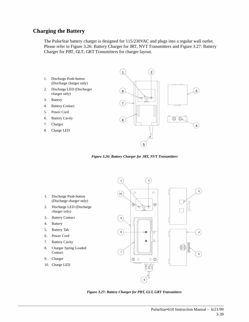
t. ry
Charging the Battery
The PulseStar battery charger is designed for 115/230VAC and plugs into a regular wall outlePlease refer to Figure 3.26: Battery Charger for JRT, NVT Transmitters and Figure 3.27: BatteCharger for PBT, GLT, GRT Transmitters for charger layout.
Figure 3.26: Battery Charger for JRT, NVT Transmitters
Figure 3.27: Battery Charger for PBT, GLT, GRT Transmitters
1. Discharge Push-button (Discharge charger only)
2. Discharge LED (Discharger charger only)
3. Battery
4. Battery Contact
5. Power Cord
6. Battery Cavity
7. Charger
8. Charge LED
1. Discharge Push-button (Discharge charger only)
2. Discharge LED (Discharge charger only)
3. Battery Contact
4. Battery
5. Battery Tab
6. Power Cord
7. Battery Cavity
8. Charger Spring Loaded Contact
9. Charger
10. Charge LED
CHARGE DISCHARGE
STARTDISCHARGE
1 2
3
4
5
8
7
6
CHARGE DISCHARGE
STARTDISCHARGE
PR
ES
S
1 2
3
4
5
6
7
8
10
9
PulseStar•610 Instruction Manual – 6/21/993-39

D
rns off,
s to
Standard Charger
Insert the battery into the charger. The green charge LED emits a steady light to indicate that the battery is being charged.
The processor in the charger checks the capacity of the battery until the battery is fully charged. The maximum charging time is four hours. When the battery is fully charged, the green charge LEbegins to flash. Leave the battery in the charger until needed to ensure it is fully-charged.
If the power supply to the charger is interrupted, or the battery is removed and then reinserted into the charger (before the battery was fully charged), the charger detects how much charge the battery has left and resumes the charging process.
Discharge Charger
Insert the battery into the charger. The green charge LED emits a steady light to indicate that the battery is being charged. Press the red Start Discharge push-button. The green charge LED tuand the red discharge LED turns on. The battery will now fully discharge. Once the battery is fully discharged, the red discharge LED will turn off, and the green charge LED will turn on. The green charge LED emits a steady light to indicate that the battery is being charged.
The processor in the charger checks the capacity of the battery until the battery is fully charged. The maximum charging time is four hours. When the battery is fully charged, the green LED beginflash. Leave the battery in the charger until needed to ensure it is fully-charged.The following table summarizes battery information for JRT and NVT transmitters.
The following table summarizes battery information for PBT, GLT and GRT transmitters.
NOTE: A long life Nickel Cadmium battery is available for the PBT, GLT and GRT transmitters. Operation time is 12-14 hours, and the capacity is 1000mAH.
All charger and battery contacts are gold-plated to provide superior contact. Batteries and chargers are IP65-rated. The mechanical design of the battery case and the battery pocket ensures that each insertion and removal of the battery will clean the contacts. This is known as “self-cleaning” contacts.
Memory Effect
To maximize the lifetime of your battery, only charge completely discharged batteries whenever possible. Charging a partially discharged battery may result in a memory effect in the battery, which reduces the number of times it can be effectively charged.
Charging Time 4 hours (from fully discharged)
Operation Time 7–10 hours continuous
Type Nickel Metal Hydrite; 9.6 Volts, 750 milliampere hours
Maximum number of charges Approximately 800 times
Charging Time 4 hours (from fully discharged)
Operation Time 7–10 hours continuous
Type Nickel Cadmium; 9.6 Volts, 600 milliampere hours
Maximum number of charges Approximately 800 times
PulseStar•610 Instruction Manual – 6/21/993-40

c h a p t e r 4
TroubleshootingPulseStar•610

This page intentionally left blank.

unable
ss the
ks,
uses.
er is
Troubleshooting
Introduction
This chapter covers what to do if the PulseStar•610 does not seem to work properly. If you areto resolve the problem after using this section, contact Electromotive Systems immediately at1-800-288-8178.
Common Problems
The following are common problems associated with using the PulseStar•610 system, and their possible solutions. For help in diagnosing problems in the receiver, refer to the drawing in the Start-up and Test Procedures section in chapter 2 that shows the location of each diagnostic LED.
Problem: The transmitter is turned on, but it does not broadcast (Power LED not flashing).
Possible Solution(s):
• Battery is dead. Replace with fully charged battery.
• Fuse located on coder board is blown. Check fuse and replace if blown.
• Key switch is broken. Check wiring to the key switch contact element. Replace key switchwiring or contact element.
• The coder board has failed. Contact Electromotive Systems.
Problem: The transmitter is broadcasting, but all crane motions are not working.
Possible Solution(s):
• The Active E-STOP push-button is activated (pushed in). Pull out the Active E-STOP push-button and press the START/HORN push-button.
• Transmitter is out of range (328 feet typical). Bring the transmitter back into range, and preSTART/HORN push-button.
• A crane motion function was not ‘off’ when transmitter was turned on. Make sure all joysticpaddle levers, push-button, etc. are in the center (off) position. Cycle transmitter power (turn off and then on) and press the START/HORN push-button.
• Incoming power to receiver is off. Turn on power to receiver.
• Fuse is blown in receiver. Check all line fuses and power pack fuses. Replace any blown f
WARNING
• Only authorized personnel are permitted to perform the initial setup or service work. Use onlyElectromotive Systems parts.
• Do NOT touch any circuit components on the circuit board while the main AC or DC powon.
• Do NOT change the address code settings in the receiver.
PulseStar•610 Instruction Manual – 6/21/994-3

ecoder
dress s
• Receiver is set for different frequency channel. If green Telegram LED located on the decoder board is not flashing, check that the receiver frequency channel matches that of the transmitter.
NOTE: Always match the transmitter frequency channel to the receiver. Never change the receiver frequency channel without consulting Electromotive Systems first.
• Receiver is set for different address code. Check to make sure the address code on the dboard and Active E-STOP stop decoder board matches the address code of the transmitter.
NOTE: Always match the transmitter address code to the receiver. Never change the receiver address code without consulting Electromotive Systems first.
• Active E-STOP failure in transmitter. Check Active E-STOP push-button for damage. Check wiring to Active E-STOP push-button contact element for broken or disconnected wire(s). Replace broken wire(s) or Active E-STOP push-button.
• Active E-STOP failure in the receiver. Check red Active E-STOP LED on decoder board. If it is illuminated:
• Check to make sure the address code is the same on the decoder board and the Active E-STOP decoder board. If they are different consult Electromotive Systems for correct adcode and set both the decoder board and Active E-STOP decoder board to the correct addrescode.
• Wire may have come disconnected from the Active E-STOP module, decoder module, or Active E-STOP decoder module. Check for loose wiring.
• Active E-STOP module has failed. Replace the Active E-STOP module.
Problem: All crane motions work intermittently.
Possible Solution(s):
• Antenna on receiver is loose or has fallen off. Tighten or replace antenna.
• External antenna (when used) is loose, poorly grounded, or receiving interference. See Connecting a Standard External Antenna section in Chapter 2.
• Surge suppressors are not installed on contactors being controlled by the receiver. Make sure all contactors being controlled by the receiver have surge suppressors installed.
• Control wiring may be combined with power wiring. Make sure that all control wiring is separate from power wires.
• Connector inside receiver has come loose. Check all Dubox (blue) connectors.
PulseStar•610 Instruction Manual – 6/21/994-4

prior to
h-
n
Problem: Some crane motions work intermittently.
Possible Solution(s):
• Wiring may be loose to that crane motion. Check wiring from the receiver to the quick disconnect plug, and check wiring from quick disconnect plug to crane motion.
• Connector inside receiver has come loose. Check all Dubox (blue) connectors.
• Surge suppressors may not be installed on contactors controlling that crane motion. Make sure all contactors being controlled by the receiver have surge suppressors installed.
• Control wiring may be combined with power wiring. Make sure that all control wiring is separate from power wires.
Questions to Ask
When reporting a problem to Electromotive Systems you may be asked several questions pertaining to the PulseStar•610 system. Asking these questions to the person who reported the problemcalling Electromotive Systems will speed up the troubleshooting process.
Transmitter
• Is the Active E-STOP push-button pulled out?
• Is the key switch in the ON position?
• Did you press the START/HORN push-button?
• Are the joysticks, switches, and push-buttons in the center (off) position?
• Did you press the START/HORN push-button while accidently holding in one of the other pusbuttons?
• Is there a charged battery installed?
• Did you take the transmitter out of its operating range (328 feet)?
Receiver
Open the cabinet enclosure where the receiver circuit board is installed and check the following. Refer to the drawing in the Start-up and Test Procedures section in chapter 2 that shows the locatioof each diagnostic LED.
• Is the CPU Standby LED flashing?
• Is the Telegram LED flashing?
• Is the Active E-STOP LED lit on either the decoder module or Active E-STOP decoder module?
• Are the connections/screw terminals tight?
• Check the antenna plug for a secure connection.
• Check the antenna connection assembly outside the enclosure.
• Check the power supply and ground wires.
• Are the signal wires separated from the power wires?
• Are surge suppressors installed on all magnetic contactors being controlled by the receiver?
PulseStar•610 Instruction Manual – 6/21/994-5

This page intentionally left blank.

a p p e n d i xA
Definitions and Abbreviations

This page intentionally left blank.

ta
Definitions and Abbreviations
Definitions
The following terms are used throughout the PulseStar•610 Instruction Manual and may be unfamiliar to some operators.
Commonly Used Abbreviations
Term Definition
analog Proportional-stepless or infinite control
baud The transmitting speed measured in bits per second
decoder Converts a serial data message into parallel signals
double superheterodyne A method to build an extremely narrow band receiver by converting the receiver frequency twice.
coder Converts parallel signals into a serial data message
hamming distance A measurement of data transmission safety. The amount of failures in the dastream which has to occur during the transmission in order to create a wrongsignal. A low hamming distance means that the test is not very sensitive to data transmission errors and could be potentially unsafe. A high hamming distance means that the system is very sensitive and could potentially be unreliable due to potential noise interference.
latching The auxiliary function will turn on when the operator presses option button once and releases it (PBT) or flips the spring return switch up (NVT, GLT, GRT). The auxiliary function will not turn off until the operator presses the option button a second time (PBT) or flips the spring return switch (NVT, GLT, GRT).
maintained The auxiliary function will turn on when the operator flips the maintained switch to the appropriate position (NVT, GLT, GRT). The auxiliary function will turn off as soon as the operator flips the maintained switch to the off position (NVT, GLT, GRT).
momentary The auxiliary function will turn on when the operator presses the option button and holds it down (PBT) or flips the spring-return switch and holds it up (NVT, GLT, GRT). The auxiliary function will turn off as soon as the operator releases the option button (PBT) or releases the spring-return switch (NVT, GLT, GRT).
synthesizer technology Used to electronically generate a carrier frequency.
Abbreviation Meaning
A/D Analog to digital conversion
AK Analog channel (German: Analog Kanal)
AMP Ampere
AWG American wire gauge
BPS Bits per second
DK Digital channel (German: Digital Kanal)
EMC Electromagnetic compatibility
EMI Electromagnetic immunity
EPROM Electrical programmable read-only memory
FM Frequency modulation
PulseStar•610 Instruction Manual – 6/21/99A-3

GND Ground
HF High frequency
KHz Kilohertz
mAH Milliampere hours
mA Milliampere
msec Millisecond
MHz Megahertz
mW Milliwatt
NiCd Nickel cadmium
NiMH Nickel Metal Hydrite
PLC Programmable logic controller
PLL Phased locked loop
PWM Pulse width modulation
RF Radio frequency (same as HF - high frequency)
RMS Root mean squared
Rx Receiver
RxD Receiving data
SMD Surface mount device
SMT Surface mount technology
TTL Transistor transistor logic
Tx Transmitter
TxD Transmitting data
Ub Operating power
Uv Microvolts
VAC Volts (alternating current)
VDC Volts (direct current)
Abbreviation Meaning
PulseStar•610 Instruction Manual – 6/21/99A-4

a p p e n d i xB
Specifications

This page intentionally left blank.

Specifications
System Specifications
JRT Specifications
Specification Setting
Certification TÜV and CE
Temperature range -18°F to 158°F (-25°C to 70°C)
Operating range 330 feet (100 meters) typical
Humidity range 0-95% maximum non-condensing
Modulation Narrow band - FM
Frequency range 400 - 470 MHz (16 preset frequencies)
Bandwidth 12.5 kHz/25kHz
Frequency generation Microprocessor controlled PLL Synthesizer
Microprocessor 80C31 Intel
Baud rate 4800 bps (approx. 55 msec response time)
Hamming distance 4
Security 16-bit addressing (more than 65,000 possibilities)
Specification JRT
Weight Less than 1.5 lbs (including battery)
Physical size (LxWxH) 7.8” x 3.4” x 1.4”(19.8 cm x 8.6 cm x 3.6 cm)
HF output power Maximum 10 mW
Deviation ±2kHz
Power supply 9.6-V Nickel Metal Hydrite rechargeable battery; 750 milliamp-hours
Operation time 7–10 hours continuous with one charge
Enclosure IP65 Weatherproof (exceeds NEMA 12/13)
Protection Key switch with cap
Antenna Built-in
Functions Emergency-stop button (push/pull)3 crane motions 2 speeds, interlocked1 crane motion 1 speedHorn and mainline activation Option push-button
Features Sleep mode (10 minutes)Switch-ON protectionMechanical protection against accidental activation
Battery charger 115/220VAC (±20%)Charging time—4 hoursGold plated and self-cleaning contacts2 batteries included
PulseStar•610 Instruction Manual – 6/21/99B-3

PBT Specifications
Specification PBT
Weight <1.75 pounds (including battery)
Physical size (LxWxH)
9.25” x 3.42” x 2.3”(23.5cm x 8.7cm x 5.8cm)
HF output power max 10 mW
Deviation +/- 2kHz
Power supply 9.6 V Nickel Cadmium rechargeable battery
Operation time 7-10 hours continuous with one charge
Enclosure IP65 Weatherproof (better than NEMA 12/13)
Protection Key switch with cap
Antenna Built-in
Functions Emergency-stop button (push/pull)4 crane motions 2 speeds, interlockedHorn and mainline activation Option button2 Selector buttons (PBT-5A only)
Features Sleep mode (PBT-4 only)Switch on protectionElectrical interlocking of crane motionsMechanical protection against accidental activation
Battery charger 115/220 VAC (+/- 20%)Charging time - 3 hoursGold plated and self-cleaning contacts2 batteries included
PulseStar•610 Instruction Manual – 6/21/99B-4

e
NVT Specifications
Specification NVT
Weight <2 pounds (including battery)
Physical size (LxWxH) 9.3” x 4” x 6.4”(23.6cm x 10.2cm x 16.3cm)
HF output power max 10 mW
Deviation +/- 2kHz
Power supply 9.6 V Nickel Metal Hydrite rechargeable battery
Operation time 7-10 hours with one charge
Enclosure IP65 Weatherproof (better than NEMA 12/13)
Protection Key switch with cap
Antenna Built-in
Functions Emergency-stop button (push/pull)6 or more crane motionsFully-proportional with 8-bit resolution (256 increments for each crane motion activated by joystick and/or lever masters or up to 3 discreet speedsactivated by joystick)Horn and mainline activation Toggle switch for auxiliary function (latching or non-latching) (example, micro-positioning)Hoist selector switch (A-A+B-B) where applicableCan be custom designed to suit the needs of special applications with a widvariety of master switches, toggles, selector switches, lights, etc.
Features Sleep mode (10 minutes)Switch on protectionMechanical protection against accidental activation
Battery charger 115/220 VAC (+/- 20%)Charging time - 4 hoursGold plated and self-cleaning contacts2 batteries included
PulseStar•610 Instruction Manual – 6/21/99B-5

GLT Specifications
Specification GLT
Weight <4.4 pounds (including battery)
Physical size (LxWxH)
11.7” x 7” x 4.3”(29.7cm x 17.8cm x 10.9cm)
HF output power approximately 10 mW
Deviation +/- 2kHz
Power supply 9.6 V Nickel Cadmium rechargeable battery
Operation time 7-10 hours continuous with one charge
Enclosure IP65 Weatherproof (better than NEMA 12/13)Explosion-proof enclosures available
Protection Key switch with cap
Antenna Built-in
Functions Emergency-stop button (push/pull)7 or more crane motionsFully-proportional with 8-bit resolution (256 increments for each crane motion activated by joystick and/or lever masters or up to 6 discreet speeds activated by joystick)Horn and mainline activation Toggle switch for auxiliary function (latching or non-latching) (example, micro-positioning)Hoist selector switch (A-A+B-B) where applicableCan be custom designed to suit the needs of special applications with a wide variety of master switches, toggles, selector switches, lights, etc.Available with LCD for remote readout of weights, diagnostics, etc.
Features Sleep mode (10 minutes)Switch on protectionMechanical protection against accidental activation
Battery charger 115/220 VAC (+/- 20%)Charging time - 3 hoursGold plated and self-cleaning contacts2 batteries included
PulseStar•610 Instruction Manual – 6/21/99B-6

GRT Specifications
Receiver Specifications
Specification GRT
Weight <12 pounds (including battery)
Physical size (LxWxH)
12” x 8” x 8” (overall height with the breast plate is 15.5”)(30.5cm x 20.3cm x 20.3cm)
HF output power approximately 10 mW
Deviation +/- 2kHz
Power supply 9.6 V Nickel Cadmium rechargeable battery
Operation time 7-10 hours continuous with one charge
Enclosure IP65 Weatherproof (better than NEMA 12/13)Explosion-proof enclosures available
Protection Key switch with cap
Antenna Built-in
Functions Emergency-stop button (push/pull)7 or more crane motionsFully-proportional with 8-bit resolution (256 increments for each crane motion activated by joystick and/or lever masters or up to 6 discreet speeds activated by joystick)Horn and mainline activation Toggle switch for auxiliary function (latching or non-latching) (example, micro-positioning)Hoist selector switch (A-A+B-B) where applicableCan be custom designed to suit the needs of special applications with a wide variety of master switches, toggles, selector switches, lights, etc.
Features Sleep mode (10 minutes)Switch on protectionMechanical protection against accidental activation
Battery charger 115/220 VAC (+/- 20%)Charging time - 3 hoursGold plated and self-cleaning contacts2 batteries included
Specification GA610
Operating power 50/110/240 VAC 50/60Hz (+/- 20%) or 12/24 VDC (+/- 50%)
Current <100 mA
HF part Double Superheterodyne
Sensitivity 0.4 microvolts (Root Mean Squared)
Safety Self-monitoring emergency circuitryFail-safe, spring-forced Emergency-stop relaySelf-test during start-up and operation
Diagnostic On-board diagnostic system with indicators for: RF communication, power status, active outputs
Output 1 Emergency-Stop relay, 275 VAC 8 Amp/30 VDC 5 Amp1 Horn relay - normally open, 275 VAC 8 Amp/30 VDC 5 Amp1 Start/Mainline relay - normally open, 275 VAC 8 Amp/30 VDC 5 Amp1 Auxiliary relay - normally open, 275 VAC 8 Amp/30 VDC 5 AmpUp to 32 digital outputsDC applications up to 250 VDC 2.5 AmpUp to 8 proportional outputs (0-10 volts DC, 4-20 milliamperes, 0-20 volts AC, etc)
PulseStar•610 Instruction Manual – 6/21/99B-7

This page intentionally left blank.

a p p e n d i xC
StarService and Warranty

This page intentionally left blank.

ot, or g this
e over the
oss
d
ment
freight
StarService Policy
This chapter includes information pertaining to on-call service, transmitter loaner and Repair program, and Receiver Replacement/Repair Program warranty. Before you install, troubleshoservice the radio control system, we highly recommend that you read this entire chapter. Doinwill help assure quick service response, minimize your on-site repair costs, and reduce crane downtime.
On-Call Service
If you ever have a problem with your PulseStar•609 system, call Electromotive Systems at 1-800-288-8178. Technical support is available 24 hours a day, seven days a week. If necessary, Electromotive Systems can arrange to have a service technician visit your site to evaluate the situation (normally at your expense.)
Warranty
Every PulseStar product includes a two-year warranty from the date of shipment. The warranty is described in detail later in this chapter.
Transmitter Loaner, Replacement & Repair Program
The PulseStar Transmitter Loaner, Replacement & Repair Program provides a replacement transmitter, or loaner transmitter while your transmitter is being repaired. Under the terms of thLoaner, Replacement and Repair Program, please provide a purchase order or credit card to ccost of the loaner transmitter.
NOTE: The PulseStar•610 systems are engineered to order. Because of this it is often not pible to provide a loaner or replacement transmitter with the identical functionality of the transmitter being submitted for repair. On some occasions a loaner or replacement transmitter will not be available because of the complexity of the application.
If you need to return a defective transmitter, please follow the steps below.
1. Request a Return Authorization (RA) from Electromotive Systems’ Service Department anreturn the defective transmitter to Electromotive Systems via pre-paid freight . When you call, please have the information from the serial nameplate of the transmitter available.
2. Electromotive Systems will ship a loaner or replacement transmitter within 24 business hours.
3. Electromotive Systems will inspect the defective transmitter and determine if the defects are covered under warranty. If the defects are covered under warranty, Electromotive Systems, at their discretion, will do one of the following:
• Replace the defective transmitter with the loaner or equivalent transmitter. The replacetransmitter will be covered for the duration of the original transmitter warranty period.
• Credit the full cost of the loaner transmitter, plus pay for all freight charges for both the loaner transmitter and the transmitter repaired under warranty.
NOTE: Freight charges incurred from sources other than common ground carriers WILL NOT be reimbursed unless pre-approved by Electromotive Systems.
• If the defects are not covered under warranty, Electromotive Systems will credit the cost of the loaner transmitter, less the cost of the repairs, a $50 loaner inspection fee, and anycharges incurred by Electromotive Systems.
PulseStar•610 Instruction Manual – 6/21/99C-3

s.
d
at
4. Electromotive Systems will repair or replace the transmitter. Repaired transmitters will be shipped from Electromotive Systems within 72 business hours of receipt of transmitter (three working days).
5. If the original transmitter is repaired, return the loaner transmitter in good condition to Electromotive Systems via prepaid freight.
Receiver Repair Program
The process for returning a defective PulseStar•609 receiver is described in the following step
1. Request a Return Authorization (RA) from Electromotive Systems’ Service Department anreturn the defective receiver to Electromotive Systems via prepaid freight. You are responsiblefor the shipping charges for sending the defective parts to Electromotive Systems.
2. Electromotive Systems will inspect the receiver and determine if the defects are covered under warranty.
• If the defects are covered under warranty, Electromotive Systems will repair the receiver no cost, and credit the full cost of all freight charges.
NOTE: Freight charges incurred from sources other than common ground carriers WILL NOT be reimbursed unless pre-approved by Electromotive Systems.
• If the defects are not covered under warranty, you are responsible for the cost of the repairs and all freight charges.
PulseStar•610 Instruction Manual – 6/21/99C-4

ured by
E is
eyond
liability
or a
. f n and
he k to said
d to all
Limited Warranty And Terms Of Sale
Prices: Subject to Change Without Notice F.O.B. Electromotive Systems, Inc.Terms: Net 30 Days Milwaukee, Wisconsin
Electromotive Systems, Inc., hereafter referred to as Company, guarantees all items manufactit against any defects of material and/or workmanship for a period of two years from the date of shipment. Company makes NO OTHER WARRANTY, EXPRESSED OR IMPLIED, AS TO THMERCHANTABILITY OR FITNESS OF THE ITEMS FOR THEIR INTENDED USE OR AS TOTHEIR PERFORMANCE. Any statement, description or specification in Company’s literaturefor the sole purpose of identification of items sold by the Company and imparts no guarantee,warranty or undertaking by company of any kind. Components and accessories not manufactured by Electromotive Systems are not included in this warranty and are warranted separately by their respective manufacturers.
Company’s sole liability shall be to repair at its factory, or replace any item returned to it within two years from date of shipment, which Company finds to contain defective material or workmanship. All items to be repaired or replaced shall be shipped to Company (Note: return authorization by Company is required) within said two year period, freight prepaid, as a condition to repair or replace defective material or workmanship. Company’s herein assumed responsibility does not coverdefects resulting from improper installation, maintenance, or improper use. Any corrective maintenance performed by anyone other than the Company during the warranty period shall void thewarranty. Company shall not be liable for damages of any kind from any cause whatsoever bthe price of the defective Company supplied items involved. Company shall not be liable for economic loss, property damage, or other consequential damages or physical injury sustained by the purchaser or by any third party as a result of the use of any Company supplied items or material.
Company neither assumes nor authorizes any other person to assume for Company any otherin connection with the sale or use of items sold by Company.
List prices or discounts are subject to change without notice. Quoted prices will be honored fperiod of 30 days from the date of the written quotation unless otherwise stated.
Orders of $25,000 or more, and orders for special control panels are subject to special terms and conditions of sale. Refer to those specific sections within this document.
Orders are not subject to alteration or cancellation except upon written consent of Company and payment of proper cancellation charges, when deemed applicable by Company.
Materials or items may not be returned for credit, without the prior written consent of the CompanyAny authorized return of materials or items shall be subject to a restocking charge equal to 20% othe net invoiced amount after Company determines that the material or item is in good conditiomay be resold without alteration or service. If upon receipt of the material or items returned, the Company determines that said materials or items cannot be resold without alteration or service, tCompany reserves the right to reject the returned materials or items and to send the same bacpurchaser at purchaser’s expense.
Terms of payment are NET 30 days. All materials and items are sold F.O.B. Company’s shipping point. Company retains a security interest in all items sold by it so long as they remain in Company’s possession to secure all obligations of purchaser to Company. A processing fee will be applieinvoices for requested prepaid freight charges other than UPS. A service charge will be incurred on past due accounts extending beyond the Terms of Sale described above, at a rate of 1.5 per month or a fraction thereof, of the net balance extending beyond 30 days..
PulseStar•610 Instruction Manual – 6/21/99C-5

g slip.
ays
rders as
, will
ed ty and
ays
rders as
Any claim for errors in shipment or for material or item shortages must be received by Company within 30 days of shipment and must be accompanied by copies of the bill of lading and packin
Special Terms and Conditions: Orders of $25,000 or More
Electrification and Control OrdersDrawings and Drawing Approvals (if applicable)In most cases, Electromotive Systems will submit drawings for customer approval within 30 dafter receipt of purchase order.
Customer drawing approval and Electromotive Systems credit approval is required before Electromotive Systems will proceed with parts procurement or assembly work.
Progress payment25% of total order is required prior to shipment.
75% balance to be paid Net 30 days upon shipment of order.
Customer Requested ChangesCustomer shall pay for any additional charges that may be incurred due to customer change oincurred.
Cancellation PolicyCancellation fee of 10% of orders, plus all charges that may to incurred to-date of cancellationbe applicable to all orders cancelled after receipt of order.
Credit ApprovalAll orders are subject credit approval by Electromotive Systems, Inc.
All items manufactured and offered for sale by Electromotive Systems, Inc. are subject to limitwarranty and terms of sale. These special terms and conditions are part of the limited warranterms, and only supersede to take exception to said warranty and terms section of this document for a complete description.
Special Terms and Conditions: Orders for Special Control Panels
Drawing and Drawing ApprovalsIn most cases, Electromotive Systems will submit drawings for customer approval within 30 dafter receipt of purchase order.
Customer drawing approval and Electromotive Systems credit approval is required before Electromotive Systems will proceed with parts procurement or assembly work.
Progress payments25% of total net order is required upon drawing approval.
25% of total net order is required prior to shipment.
50% balance to be paid Net 30 days upon shipment of order.
Customer Requested ChangesCustomer shall pay for any additional charges that may be incurred due to customer change oincurred.
PulseStar•610 Instruction Manual – 6/21/99C-6

ed ty and . Refer
Cancellation PolicyCancellation fee of 10% of order, plus all changes that may be incurred to-date of cancellation, will be applicable to all orders cancelled after receipt of purchase order.
Credit ApprovalAll orders are subject to credit approval by Electromotive Systems, Inc.
All items manufactured and offered for sale by Electromotive Systems, Inc. are subject to limitwarranty and terms of sale. These special terms and conditions are part of the limited warranterms, and only supersede to take exception to said warranty and terms as specifically outlinedto limited warranty and terms section of this document for a complete description.
PulseStar•610 Instruction Manual – 6/21/99C-7

This page intentionally left blank.