nitridation of zirconium using energetic ions from plasma focus device
TRANSCRIPT
Available online at www.sciencedirect.com
008) 8255–8263www.elsevier.com/locate/tsf
Thin Solid Films 516 (2
Nitridation of zirconium using energetic ions from plasma focus device
I.A. Khan a, M. Hassan a, R. Ahmad a,⁎, A. Qayyum a, G. Murtaza b, M. Zakaullah c, R.S. Rawat d
a Department of Physics, GC University, 54000 Lahore, Pakistanb Salam Chair in Physics, GC University, 54000 Lahore, Pakistan
c Department of Physics, Quaid-i-Azam University, 45320 Islamabad, Pakistand National Institute of Education, Nanyang Technological University, Singapore 637616, Singapore
Received 3 March 2007; received in revised form 4 March 2008; accepted 11 March 2008Available online 19 March 2008
Abstract
The nitridation of zirconium disks is achieved by irradiating energetic nitrogen ions from 2.3 kJ plasma focus device using multiple focusdeposition shots (10, 20, 30 and 40) at different angular positions with respect to the anode axis. The X-ray diffraction analysis reveals theevolution of ZrN, Zr2N and Zr3N4 phases of zirconium nitride depending upon the ion energy flux and angular positions. The crystallite size ofZrN and Zr2N phases increases by increasing the number of focus deposition shots. The residual stresses estimated for Zr (101), ZrN (111) andZrN (200) phases are maximum in the nitrided surfaces at lower nitrogen ion dose, decreases as the nitrogen ion dose increases. The field emissionscanning electron microscopy results exhibit the uniform and smooth film of zirconium nitride with granular surface morphology at 10° angularposition. The energy dispersive X-rays spectroscopy data indicate that nitrogen content in the film is improved for higher nitrogen ion dose whilereduced at larger angular positions. The Vickers microhardness of the film is enhanced up to 400%. The microhardness increases by increasing thenitrogen ion dose and decreases rapidly by increasing the angular position.© 2008 Elsevier B.V. All rights reserved.
Keywords: Plasma focus; Zirconium nitride; Sputtering; Surface hardening; Residual stresses
1. Introduction
The dense plasma focus (DPF) is a pulsed radiation sourcein which electrical energy of the capacitor bank is stored asmagnetic energy during the discharge. A portion of this energy isconverted into plasma energy resulting in the formation of shortlived, (∼100 ns) dense (1025–1026 m−3) and high temperature(1–2 keV) plasma which emits neutrons, X-rays, highly energeticions and relativistic electrons [1–4]. In the last two decades, theDPF has been used in materials processing such as thin filmdeposition [5,6], phase change of thin films [7,8], ion implanta-tion [9] and surface modification [10]. Nitrogen ion beamsemanated from pinched plasma column have been employed fornitriding of metals and alloys [11] due to their characteristic broadenergy spectrum (few keV to few MeV). These energetic ions
⁎ Corresponding author.E-mail address: [email protected] (R. Ahmad).
0040-6090/$ - see front matter © 2008 Elsevier B.V. All rights reserved.doi:10.1016/j.tsf.2008.03.012
chemically react with the atoms sputtered from the target materialand form thin nitride layer. The nitride layer is beneficial fortribological applications such as improvement of wear resistance,hardness and corrosion performance of various metals and alloys[2,11]. The recent usages of the DPF inmaterials processing is themotivation for the synthesis of zirconium nitride thin films.
Zirconium forms more stable nitrides owing to its highernegative free energy of formation (−291 kJ/mol) [12]. The du-rability of zirconium nitride coating is about 5 times that of tita-nium nitride coating [13]. Zirconium nitride coating has received agreat deal of attention because of its high hardness, chemical andthermal stability, low electrical resistivity, golden color [14,15]highmelting point, highYoung'smodulus and corrosion resistance[13,16,17]. Because of these properties, zirconium nitride filmshave been investigated for different applications including hardand decorative coatings [12,18], biocompatible materials posses-sing excellent histocompatibility [19], diffusion barriers, cryogenicthermometers and Josephson junction [13,20]. Zirconium nitridethin films have been synthesized by various techniques such as
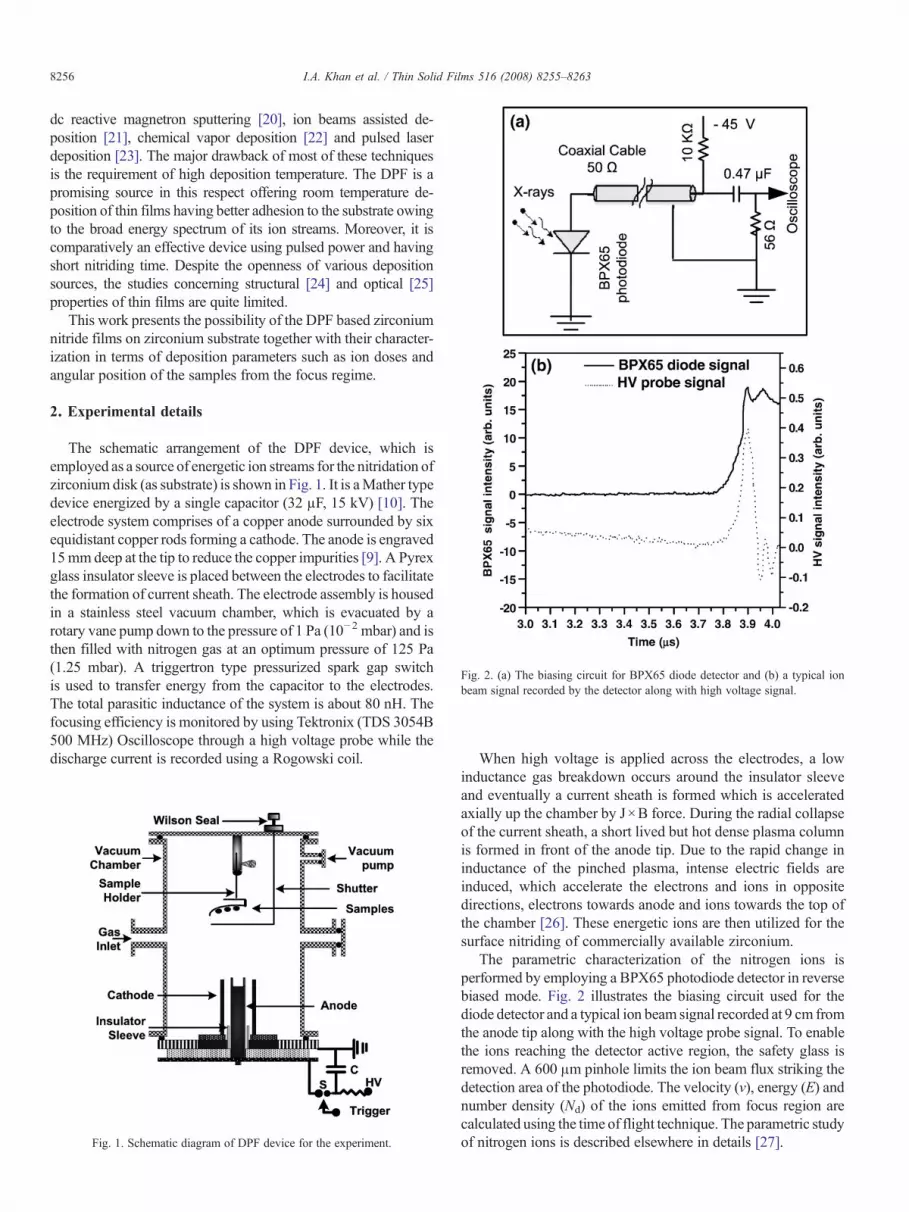
Fig. 2. (a) The biasing circuit for BPX65 diode detector and (b) a typical ionbeam signal recorded by the detector along with high voltage signal.
8256 I.A. Khan et al. / Thin Solid Films 516 (2008) 8255–8263
dc reactive magnetron sputtering [20], ion beams assisted de-position [21], chemical vapor deposition [22] and pulsed laserdeposition [23]. The major drawback of most of these techniquesis the requirement of high deposition temperature. The DPF is apromising source in this respect offering room temperature de-position of thin films having better adhesion to the substrate owingto the broad energy spectrum of its ion streams. Moreover, it iscomparatively an effective device using pulsed power and havingshort nitriding time. Despite the openness of various depositionsources, the studies concerning structural [24] and optical [25]properties of thin films are quite limited.
This work presents the possibility of the DPF based zirconiumnitride films on zirconium substrate together with their character-ization in terms of deposition parameters such as ion doses andangular position of the samples from the focus regime.
2. Experimental details
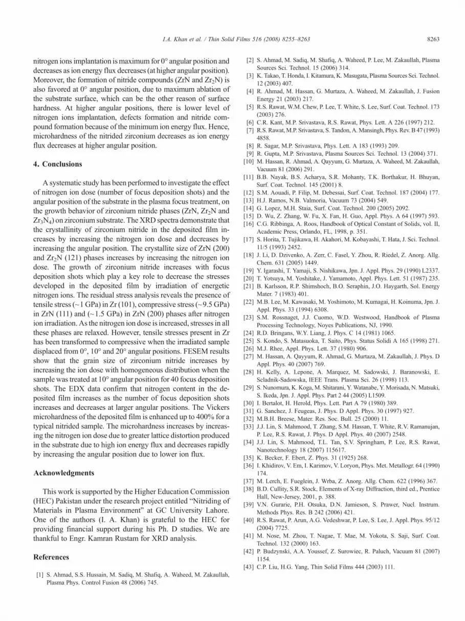
The schematic arrangement of the DPF device, which isemployed as a source of energetic ion streams for the nitridation ofzirconium disk (as substrate) is shown in Fig. 1. It is aMather typedevice energized by a single capacitor (32 µF, 15 kV) [10]. Theelectrode system comprises of a copper anode surrounded by sixequidistant copper rods forming a cathode. The anode is engraved15mmdeep at the tip to reduce the copper impurities [9]. A Pyrexglass insulator sleeve is placed between the electrodes to facilitatethe formation of current sheath. The electrode assembly is housedin a stainless steel vacuum chamber, which is evacuated by arotary vane pump down to the pressure of 1 Pa (10−2 mbar) and isthen filled with nitrogen gas at an optimum pressure of 125 Pa(1.25 mbar). A triggertron type pressurized spark gap switchis used to transfer energy from the capacitor to the electrodes.The total parasitic inductance of the system is about 80 nH. Thefocusing efficiency is monitored by using Tektronix (TDS 3054B500 MHz) Oscilloscope through a high voltage probe while thedischarge current is recorded using a Rogowski coil.
Fig. 1. Schematic diagram of DPF device for the experiment.
When high voltage is applied across the electrodes, a lowinductance gas breakdown occurs around the insulator sleeveand eventually a current sheath is formed which is acceleratedaxially up the chamber by J×B force. During the radial collapseof the current sheath, a short lived but hot dense plasma columnis formed in front of the anode tip. Due to the rapid change ininductance of the pinched plasma, intense electric fields areinduced, which accelerate the electrons and ions in oppositedirections, electrons towards anode and ions towards the top ofthe chamber [26]. These energetic ions are then utilized for thesurface nitriding of commercially available zirconium.
The parametric characterization of the nitrogen ions isperformed by employing a BPX65 photodiode detector in reversebiased mode. Fig. 2 illustrates the biasing circuit used for thediode detector and a typical ion beam signal recorded at 9 cm fromthe anode tip along with the high voltage probe signal. To enablethe ions reaching the detector active region, the safety glass isremoved. A 600 μm pinhole limits the ion beam flux striking thedetection area of the photodiode. The velocity (v), energy (E) andnumber density (Nd) of the ions emitted from focus region arecalculated using the time of flight technique. The parametric studyof nitrogen ions is described elsewhere in details [27].

Fig. 3. XRD patterns of the films deposited for multiple numbers of focusdeposition shots (10, 20, 30 and 40).
8257I.A. Khan et al. / Thin Solid Films 516 (2008) 8255–8263
Zirconium samples are prepared in the form of a disk of12 mm diameter and 4 mm thickness. The substrate surface ispolished with SiC abrasive paper of 2000 grit, ultrasonicallycleaned in water for 30 min and finally washed with acetone.The samples are mounted at 9 cm above the anode tip with thehelp of a sample holder, bearing three samples at angularpositions of 0°, 10° and 20° with respect to anode axis and areexposed to multiple focus shots (10, 20, 30 and 40). A stainlesssteel shutter is arranged to avoid the samples exposure duringfirst few weak focus shots.
The structural properties of the deposited zirconium nitridefilms have been investigated to explore the ion induced changeson zirconium substrate by using PAnalytical X'Pert PRO MPDθ–θ X-ray diffractometer (XRD) operated at a voltage of 40 kVand a current of 40 mA using a CuKα (λ=1.540598 Å) radiationsource. The diffraction patterns were recorded at small grazingincident angle (2°). The surface morphology and elemental com-position of the deposited film have been demonstrated with thehelp of a field emission scanning electron microscopy (FESEM)[Jeol JSM-6700F] operated at a voltage of 5 kV, providedwith theOxford Instruments, UK, energy dispersive X-rays spectroscopy(EDX) attachment (operated at 10 kVwith 180 s collection time).Micro-indentation measurements were performed as a functionof imposed loads (10, 25, 50, 100 and 200 g) for a dwell time of5 s using a Wilson Wolpert 401MVAVickers microhardness tes-ter equipped with a pyramid shaped diamond indenter. Averagemicrohardness value of five measurements taken at different po-sitions on the sample surface is evaluated in terms of the in-dentation depth.
3. Results and discussion
Fig. 2b exhibits a typical ion beam signal recorded withBPX65 photodiode detector placed at 9 cm from the anode tip,along with a high voltage probe signal. The first peak in the diodesignal (solid line) indicates an X-ray pulse due to its highsensitivity for X-rays whereas the second peak is the desired ionpulse. The discrimination of X-rays and ion pulses has beenconfirmed bymasking the detector with a thin foil allowing the X-rays to pass while stopping the ions. Such ion beam pulses havealready been reported by Kelly et al. [28] and Nunomura et al.[29]. For the axial distance of 9 cm, the estimated values of ionenergy (E) and ion number density (Nd) of the ion pulse rangefrom 40 keV to 1.2 MeVand 9.7×10¹⁹ m−3 to 1.796×10¹⁹ m−3
respectively. It is a well known fact that the ions emanated frompinched plasma column, in wide energy range, are in a fountainlike geometry with anisotropy in their angular distribution. Mostof the ions are emitted in a small solid angle along the anode axisand their flux decreases with increasing the angle [30]. It has alsobeen reported [27] that energy and ion number density decreaseby increasing the axial distance; ion energy decreasesmore slowlyas compared to ion number density. These energetic ions hit thezirconium substrate and transfer enough energy at a fast rate to thesubstrate which rapidly achieves high temperature resulting inlocal melting and evaporation [31]. The growth of zirconiumnitride film on zirconium substrate can be attributed to twodifferent processes (i) direct implantation of energetic nitrogen
ions into the zirconium disk where these energetic ions may beincorporated interstitially into the zirconium lattice and ionsinduced collision cascades creating point defects and distortion inits lattice structure [32] and (ii) reaction of background nitrogenions with evaporated zirconium that may be re-deposit onto thesubstrate surface due to the backscattering of the ablated materialby the relatively high pressure filling gas. It may be pointed thatthe pulsed ion beam can ablate the material in a way similar to thepulse laser beam used in pulsed laser deposition (PLD) [33]. Athigher filling gas pressure of about fewmbar, it was found that theablated material in PLD process can be re-deposited on the targetitself by backward plume deposition which is essentially due tobackscattering of the ablated material by the filling backgroundgas [33,34]. We hypothesize that in the present plasma focusbased deposition similar process is possible as the backgroundfilling gas pressure is of the same order of magnitude as used byLin et al. [33,34]. The differences between backward plumedeposition reported in Refs. [33,34] and our current investigationare: (i) the ablation of the material is caused by pulsed laser in thefirst methodwhile it is done by pulsed ion beam in the present caseand (ii) in PLD the background gas is essentially neutral while inour case it is that of nitrogen ions and nitrogen plasma which alsoreact with ablated zirconium plasma. It is difficult to decide whichprocess is being dominant.
Fig. 3 shows the XRD spectra of the samples treated at 0°angular position for multiple focus shots (10, 20, 30 and 40) alongwith the untreated sample. The irradiated samples show theemergence of ZrN and Zr2N crystalline phases for all theexposures varying from 10 to 40 focus deposition shots. Thediffraction peaks of (111) and (200) ZrN reflection planes and(020), (111) and (121) Zr2N reflection planes are observed at 2θvalues of 34.0°, 39.0°, 34.6°, 35.5° and 47.6° respectively. Theintensity of diffraction peaks of ZrN and Zr2N phases increaseswith increasing number of focus deposition shots, which suggeststhe crystal growth with the nitrogen ion dose. The unexposedzirconium disk has a (101) preferred orientation along with other

Fig. 4. XRD patterns of the films deposited with 40 focus deposition shots atdifferent angular positions.
8258 I.A. Khan et al. / Thin Solid Films 516 (2008) 8255–8263
significant diffraction planes (100), (002) and (102). Uponexposure the intensities of peaks of (101) and (100) Zr reflectionplanes are reduced while those of peaks of (102) and (002) Zrplanes initially reduce and finally disappear completely for highernumber of focus shots. Both of these facts, i.e. increase in theintensity of nitride phases and decrease/disappearance of Zrreflection planes point out that zirconium nitride coating growswith increasing number of focus deposition shots. It may beinteresting to note that the intensity of (111) Zr2N reflection planeis stronger than that of any of the ZrN reflection planes, indicatingthereby that the amount of Zr2N phase ismore as compared to thatof ZrN on the top surface of the irradiated samples. From this onecan infer that the zirconium nitride film formation in the presentinvestigation is not only due to the implantation of the energeticnitrogen ions on the zirconium substrate. If the process is only theion implantation then we would expect the formation of ZrN,Zr2N and finally Zr starting from the surface to inside the sample.This validates our earlier suggestion that plasma focus assistedthin film formation is due to the combination of two differentprocesses viz ion implantation and re-deposition of ion beamablated backscattered plasmas.
Fig. 4 shows the XRD spectra of the samples treated atdifferent angular positions (0°, 10° and 20°) for 40 focus
Table 1Presents the various crystalline phases with orientations detected from the XRD datafor 40 focus deposition shots
Number of focus shots Angular positions of the samples (°) V
Z
h
10 0 120 0 130 0 140 0 1
10 120 –
deposition shots. The respective positions of observed zirco-nium nitride peaks corresponding to ZrN, Zr2N and Zr3N4
phases are in agreement with the literature [14,35–37] as wellas Inorganic Crystal Structure Database (ICSD). Differentphases of zirconium nitride showing different crystalline planesevolved for various numbers of focus deposition shots (10, 20,30 and 40) and at different angular position (0°, 10° and 20°) for40 focus shots are presented in Table 1.
The main features of the XRD spectra shown in Fig. 4 are: (i)with the increase in the angular position of irradiation the dif-fraction peaks of Zr start to regain their intensity to the same levelas that of the untreated sample, (ii) the crystallinity of ZrN andZr2N degrades with increasing angle of exposure and (iii) ap-pearance of Zr3N4 (340) phase at 2θ values of 43.5°, which isidentified as the insulating phase of the zirconium nitride in theliterature [18]. As mentioned earlier, the ion flux in plasma focusdevice decreases with the increase in angular position and hencethe irradiations at higher angles of 10° and 20° will result in lowlevel of nitrogen ion implantation (mechanism (i)) of zirconiumsample as well as lower ablation assisted deposition of zirconiumnitride layer (mechanism (ii)). This explains the first two keyfeatures of theXRDspectra of Fig. 4,mentioned above. The abovefact also explains the observation of Zr3N4 phase on samplesirradiated at 10° and 20° angular positions. It is reported [18] thatthe Zr3N4 is stable at lower temperatures and at temperaturesabove 650 °C, the Zr3N4 decomposes into compound with lowernitrogen content. For all the samples irradiated at 0° the ion flux/energy and hence the corresponding heating of the sample ismaximum which results in total decomposition of Zr3N4 phaseinto other lowerN content nitride phases. For the sample irradiatedat 10° the ion flux/energy decreases resulting in less efficientheating of the sample and hence the nitrogen rich Zr3N4 phasepartially decomposes into phases with lower nitrogen content.Whereas, at 20° the ion flux/energy decreases so significantly thatthe nitrogen rich Zr3N4 phase does not decompose.
The average crystallite size of particular phases of zirconiumnitride film is measured using Scherrer's formula [38]
Crystallite size ¼ 0:93kFWHMð Þ cos h
where λ=1.54 Å is the wavelength of the X-ray, FWHM is thefull width at half maxima (in radian) of the particular diffraction
for different number of focus deposition shots and at different angular positions
arious phases of zirconium nitride with their plane reflections
rN Zr2N Zr3N4
kl hkl hkl hkl hkl hkl
11 200 020 111 121 –11 200 020 111 121 –11 200 020 111 121 –11 200 020 111 121 –11 200 020 111 – 340
– – – – 340

8259I.A. Khan et al. / Thin Solid Films 516 (2008) 8255–8263
peak and θ is the corresponding Bragg's angle of the diffractionpeak. Fig. 5 plots the variation of the average crystallite size andthe corresponding relative phase content as a function of numberof focus deposition shots for samples irradiated at 0° angularposition for the diffraction peaks of ZrN (200) and Zr2N (121)phases observed at 2θ value of 39.0° and 47.6° respectively. Theaverage crystallite size for ZrN (200) phase, refer to Fig. 5a, isfound to increase from about 36±2.0 nm for 10 focus shotsdeposition to about 54±2.5 nm for 40 focus shots depositionwhereas for Zr2N (121) phase, refer to Fig. 5b, it increases fromabout 20±1.5 nm for 10 focus deposition shots to about 54±2.5 nm for 40 focus deposition shots. These typical averagecrystallite sizes are of the order of nanoscale features observed inthe FESEM image. Hence, the average crystallite size andrelative content of both the phases (as indicated from their peakintensity) increase with the increasing the number of focusdeposition shots. The increase in number of focus depositionshots results in higher nitrogen ion dose and hence greatertransient annealing of the zirconium sample surface takes place.The increased local and transient annealing of the depositedsurface layer may result in the growth of average grain and
Fig. 5. Variation of crystallite size and relative phase content as a function ofnumbers of focus deposition shots estimated from (a) (200) plane reflection ofZrN and (b) (121) plane reflection of Zr2N.
crystallite size of the deposited nitride layer. The increase inrelative intensity of the diffraction peaks can be attributed toincreasing thickness of the crystalline nitride phase material withthe increasing number of focus deposition shots which will resultin increase in diffracted photon counts if X-ray can still penetrateup to the increased depth of nitride crystalline layer.
XRD data is also used to determine the residual stress in thetreated and untreated samples. The displacement of diffractionpeaks from their corresponding stress free data indicatesresidual stresses developed in the deposited film by irradiationof nitrogen ions. These residual stresses may also be attributedto the lattice distortion (strain) owing to the implantation ofnitrogen in the interstitial position, creation of lattice defects(vacancies by energetic ions) and pulsed thermal shocks of thesubstrate surface. The stress due to ion implantation is generallycompressive while the thermal shock results in tensile stress[39]. The above mentioned strain results in the change in thed-spacing and hence the shifting of diffraction peaks. The resid-ual stresses present in the deposited film are deduced by multi-plying strain Dd
d
� �with the appropriate value of elastic constant
of zirconium and zirconium nitride. The strain developed for(101) plane of zirconium, (111) and (200) planes of zirconiumnitride (ZrN) film is evaluated by using the formula [40]
Ddd
¼ d observedð Þ � d ICSDð Þd ICSDð Þ
where Ddd
� �indicates the strain developed in the deposited film.
Fig. 6a shows the behavior of residual stresses developed in thefilm as function of number of focus deposition shots. A smalltensile stress is evident in the Zr (101) phase (before ionirradiation) which may be due to the rise in temperature duringmanual polishing of the sample surface. When the sample isirradiated with 10 focus deposition shots, tensile stresses (~1 GPa)in Zr (101) phase and compressive stresses in ZrN (111)(~9.5 GPa) and ZrN (200) (~1.5 GPa) phases are developed.The pulsed energetic ions in plasma focus device will deposit theirmaximum energy near their stopping range in the bulk substrate.This will cause high local heating at that position resulting inincrease in tensile stress due to thermal shock in bulk zirconium forZr (101) phase while the top nitride layer suffer lattice distortiondue to point defects (interstitial implanted atoms and vacancies)created by energetic nitrogen ions. However, as the nitrogen iondose is increased with the increase in number of focus depositionshots, stresses in all these phases are relaxed due to annealing ofthe treated surface, due to over all increase in the zirconium sub-strate temperature. Nose et al. [41] have reported a stress de-creasing and hardness increasing behavior by increasing siliconcontent in theZrSiN thin films depositedwithRF sputtering. In ourcase, similar trend is observed and the stresses (tensile or com-pressive) decrease (Fig. 6a) whereas hardness increases (Fig. 9a)with increasing number of focus deposition shots, and hencethe nitrogen content. The stress relaxation with the ion dose alsosupports the improvement in crystallinity (Fig. 3a) and graingrowth (Fig. 8) of the nitride phases due to annealing effect.
Fig. 6b shows the variation of residual stresses in the depositedfilm at different angular positions (0°, 10° and 20°) for 40 focus

Fig. 6. Variation of residual stresses in the zirconium matrix and the zirconiumnitride as a function of (a) number of focus shots (10–40), (b) different angularpositions (0°, 10° and 20°) for 40 focus shots and (c) variation of crystallite sizeas a function of stress for ZrN (200) phase.
8260 I.A. Khan et al. / Thin Solid Films 516 (2008) 8255–8263
deposition shots. It may be noted that except for Zr (101) at 0° allother stresses are found to be compressive. This can be un-derstood again in terms of competitive contributions of tensilestress due to thermal shock by efficient heating of bulk materialby energetic ions through the top most layer (nitrided on non-nitrided). With the increase in angle of exposure the ion fluxas well as the ion energies decrease in plasma focus resultingin significant decrease in transient heating (and hence thermalshock) of the bulk Zr and corresponding tensile must be reduced.The net stress is compressive as the number of point defects willstill be significant, even though the number of ions per area hasdecreased, because due to decrease in ion energies the point defectcreation efficiency of ions will increase. Moreover, as the ion fluxand ion energies decrease with the increase in exposure angle thenet heating of the bulk over 40 exposure shots is not enough tocause significant relaxation of stress.
Fig. 6c demonstrates the variation of crystallite size as func-tion of stresses developed in ZrN (200) phase. The stress de-creases as the crystallite size of ZrN (200) phase increases. Hence,
Fig. 7. FESEM micrographs of the samples exposed for 10 focus depositionshots at (a) 0°, (b) 10° and (c) 20° angular positions.

Fig. 8. FESEM micrographs of the samples exposed for 40 focus depositionshots at (a) 0°, (b) 10° and (c) 20° angular positions.
8261I.A. Khan et al. / Thin Solid Films 516 (2008) 8255–8263
strain/stress developed in the deposited film decreases andcrystallite size of zirconium nitride film increases by increasingthe focus deposition shots which is consistent with the previousresults [42]. This suggests that growth of zirconium nitrideincreases with focus deposition shots which play a key role to
Table 2Demonstrates the EDX data showing elemental compositions of the species present indeposition shots and at different angular positions for 40 focus shots
Number of focus shots Angular positions of the samples (°) Elem
Zirc
wt.%
Unexposed No 89±10 0 95±20 0 95±30 0 92±40 0 84±
10 71±20 53±
decrease the stresses developed in the deposited film by irra-diation of energetic nitrogen ions.
The surface morphology of the films deposited with differentnumber of focus deposition shots at different angular positionsrevealed that the quality of the film is better at 10° angular positionrather than at 0° angular position. This is due to significantlymelting and damaging surface and consequently the presence oflarge pits on the surface at 0° angular position whereas the surfacequality of the film deposited at 10° angular position is betterbecause a smoother, uniform and crack free microstructure isobserved at this angular position. Therefore, we have focusedon the angular positions after optimizing the number of focusdeposition shots dependence of the films with respect to theirsurface quality. Eventually, the best conditions of the samplestreatment for 40 shots have been compared with the treatment forminimum number of 10 shots to explore the film properties.
Figs. 7 and 8 present the FESEM micrographs of the samplesexposed for 10 and 40 focus deposition shots at 0°, 10° and 20°,angular positions, depicting distinct surface features. The surfacesof the samples exposed at 0° angular position (Figs. 7a and 8a)exhibit a significant surface damage, showing pits of variousshapes on the surface owing to melting, which may be due to thenormal incidence of energetic nitrogen ions with maximum ionenergy flux.No definitemicrostructure pattern is exhibited becauseof substantial melting and subsequent cooling despite significantnitrogen ion implantation and nitrides formation. Zirconiumnitrides are formed at this position and their crystal growthincreases by increasing the number of focus deposition shots. Thisis agreed well with peak intensities that correspond to nitridephases (XRD results) and grain sizes from FESEMmicrograph. Agranular surface morphology is depicted for the film deposited at10° angular position showing homogeneous distribution of grains(Figs. 7b and 8b) which may be due to lower ion energy fluxsuitable for grain growth. The FESEM micrograph shows anidentical distribution of grains that corresponds to various phasesof zirconium nitride. The average grain size is determined by thelinear interception method and is found to increase from 40±2 nmfor 10 focus shots to 50±2.5 nm for 40 focus shots, which agreeswell with the XRD results. The FESEM images for the samplestreated for 10 and 40 shots at 20° angular position (Figs 7c and 8crespectively) show slight restructuringwhichmay be due to lowestion energy flux. This lowest energy flux of ions is less effective toalter the surface properties. Therefore, the polishing marks are
the nano-phase of zirconium nitride film deposited with various number of focus
ental concentration
onium Oxygen Nitrogen
at.% wt.% at.% wt.% at.%
27 59 11±3 42 0 029 93 0 0 0.2±0 129 74 0 0 3±1 1728 77 0 0 5±2 2625 52 0 0 11±3 4421 63 0 0 4±1 116 26 11±3 19 3±1 0.4

Fig. 9. Variation of surface hardness (GPa) as a function of indentation depth(µm) of the film deposited (a) for different numbers of focus deposition shots at0° angular position and (b) at different angular positions for 40 shots.
8262 I.A. Khan et al. / Thin Solid Films 516 (2008) 8255–8263
visible only for 10 focus deposition shots. The surfacemorphologyof the sample surface treated with 40 focus deposition shots(Fig. 8c) shows the presence of crystallites of nano-size in the formof clusters. These clusters probably consist of Zr3N4 phase coagu-lated with the oxide layer left un-sputtered at this position dueto lowest ion energy flux which is agreed well with the XRD andEDX results. Noticeably, FESEM micrographs depict the graingrowth by increasing the number of focus deposition shots whichis agreed well with the XRD results. It means that crystal growthof nitride increases by increasing the number of focus depositionshots. As the crystal growth is attributedwith the surface roughnesshence it increases by increasing the number of focus depositionshots and decreases as the angle of the treated sample from theanode axis increases comparatively.
Table 2 demonstrates the EDX data showing various elementspresent in the film deposited along the anode axis with 10, 20, 30and 40 focus deposition shots and at different angular positions(0°, 10° and 20°) for 40 focus deposition shots. The nitrogencontent in the film increases by increasing the number of focusdeposition shots along the anode axis as the ion energy fluxincreases, whereas nitrogen content decreases by increasing theangular position. The maximum nitrogen content is found to be43.71 at.% in the film deposited at 0° angular position whereas0.92 at.% and 0.42 at.% in the films deposited at 10° and 20°angular positions respectively for 40 focus deposition shots.
The EDX data also show that 10 and 40 focus deposition shotsare sufficient to remove native oxide layer from the substratesurface exposed at 0° and 10° angular positions respectively.At these angular positions, the temperature of the substrate surfacerises significantly due to energetic nitrogen ions bombardment.The oxygen in the unexposed sample is just the oxidation of toplayer of zirconium which has been sputtered out by the energeticimpinging nitrogen ions at these angular positions. However,at 20° angular position, nitrogen ion energy flux is inadequateto remove the oxides (lowest ion energy flux). C.P. Liu et al. [43]have demonstrated that resistivity and color of zirconium nitridefilm depends upon the atomic ratio (N/Zr). The resistivity de-creases as the atomic ratio increases. We have also estimated theatomic ratio in the deposited zirconium nitride film which rangesfrom 0.014 to 0.8495. This suggests that resistivity of zirconiumnitride film may decrease by increasing the focus deposition shots.
Fig. 9 shows the Vickers microhardness (GPa) as a function ofindentation depth (μm) at different imposed loads (10, 25, 50, 100and 200 g) for the samples exposed to multiple focus depositionshots and at different angular positions. The ion dose dependenceof the microhardness of the films deposited at 0° angular positionis given in Fig. 9a. The typical microhardness value of thezirconiumnitride layer is found to be 6.3GPa (about 4 times that ofthe substrate) corresponding to indentation depth of 1.01μmwhensamples are exposed for 40 focus deposition shots. The slow fall inthe microhardness values with the indentation depth shows theformation of a thick compound layer. The microhardness is twiceas compared to that of the unexposed sample up to the penetrationdepth of 10 μm. After the bombardment of energetic nitrogen ionswith the substrate surface, zirconium lattice is distorted by theincorporation of nitrogen ions interstitially and ions that inducedcollision cascades create point defects. This may improve the
microhardness of the deposited films. The microhardness of thedeposited film increases by increasing the number of focusdeposition shots. The ion dose causes the substrate bulk tem-perature rise, which may improve crystallinity and relieve stresslevel and reduce the hardness. However, the dominant reason forincreasing hardness is the nitrogen content and the nitride com-pound which increase with the ion dose. Thus the hardest filmdeposited for 40 focus deposition shots (Fig. 9a) owes to themaximum nitrogen content alongwith nitride compound althoughhaving minimum stresses (Fig. 6a). Fig. 9b shows the Vickersmicrohardness profile for the samples treated for 40 focusdeposition shots at different angular positions (0°, 10° and 20°).It is observed that the microhardness decreases rapidly by in-creasing the angular position. The incorporation rate of nitrogenions depends upon the nitrogen ion energy flux, which is highest at0° angular position and decreases as the angle of the sampletreatment increases from the anode axis. Eventually, the rate of
8263I.A. Khan et al. / Thin Solid Films 516 (2008) 8255–8263
nitrogen ions implantation ismaximum for 0° angular position anddecreases as ion energy flux decreases (at higher angular position).Moreover, the formation of nitride compounds (ZrN and Zr2N) isalso favored at 0° angular position, due to maximum ablation ofthe substrate surface, which can be the other reason of surfacehardness. At higher angular positions, there is lower level ofnitrogen ions implantation, defects formation and nitride com-pound formation because of the minimum ion energy flux. Hence,microhardness of the nitrided zirconium decreases as ion energyflux decreases at higher angular position.
4. Conclusions
A systematic study has been performed to investigate the effectof nitrogen ion dose (number of focus deposition shots) and theangular position of the substrate in the plasma focus treatment, onthe growth behavior of zirconium nitride phases (ZrN, Zr2N andZr3N4) on zirconium substrate. TheXRD spectra demonstrate thatthe crystallinity of zirconium nitride in the deposited film in-creases by increasing the nitrogen ion dose and decreases byincreasing the angular position. The crystallite size of ZrN (200)and Zr2N (121) phases increases by increasing the nitrogen iondose. The growth of zirconium nitride increases with focusdeposition shots which play a key role to decrease the stressesdeveloped in the deposited film by irradiation of energeticnitrogen ions. The residual stress analysis reveals the presence oftensile stress (~1 GPa) in Zr (101), compressive stress (~9.5 GPa)in ZrN (111) and (~1.5 GPa) in ZrN (200) phases after nitrogenion irradiation. As the nitrogen ion dose is increased, stresses in allthese phases are relaxed. However, tensile stresses present in Zrhas been transformed to compressive when the irradiated sampledisplaced from 0°, 10° and 20° angular positions. FESEM resultsshow that the grain size of zirconium nitride increases byincreasing the ion dose with homogeneous distribution when thesample was treated at 10° angular position for 40 focus depositionshots. The EDX data confirm that nitrogen content in the de-posited film increases as the number of focus deposition shotsincreases and decreases at larger angular positions. The Vickersmicrohardness of the deposited film is enhanced up to 400% for atypical nitrided sample. The microhardness increases by increas-ing the nitrogen ion dose due to greater lattice distortion producedin the substrate due to high ion energy flux and decreases rapidlyby increasing the angular position due to lower ion flux.
Acknowledgments
This work is supported by the Higher Education Commission(HEC) Pakistan under the research project entitled “Nitriding ofMaterials in Plasma Environment” at GC University Lahore.One of the authors (I. A. Khan) is grateful to the HEC forproviding financial support during his Ph. D studies. We arethankful to Engr. Kamran Rustam for XRD analysis.
References
[1] S. Ahmad, S.S. Hussain, M. Sadiq, M. Shafiq, A. Waheed, M. Zakaullah,Plasma Phys. Control Fusion 48 (2006) 745.
[2] S. Ahmad, M. Sadiq, M. Shafiq, A. Waheed, P. Lee, M. Zakaullah, PlasmaSources Sci. Technol. 15 (2006) 314.
[3] K. Takao, T. Honda, I. Kitamura, K. Masugata, Plasma Sources Sci. Technol.12 (2003) 407.
[4] R. Ahmad, M. Hassan, G. Murtaza, A. Waheed, M. Zakaullah, J. FusionEnergy 21 (2003) 217.
[5] R.S. Rawat, W.M. Chew, P. Lee, T. White, S. Lee, Surf. Coat. Technol. 173(2003) 276.
[6] C.R. Kant, M.P. Srivastava, R.S. Rawat, Phys. Lett. A 226 (1997) 212.[7] R.S. Rawat,M.P. Srivastava, S. Tandon,A.Mansingh, Phys. Rev. B 47 (1993)
4858.[8] R. Sagar, M.P. Srivastava, Phys. Lett. A 183 (1993) 209.[9] R. Gupta, M.P. Srivastava, Plasma Sources Sci. Technol. 13 (2004) 371.[10] M. Hassan, R. Ahmad, A. Qayyum, G. Murtaza, A. Waheed, M. Zakaullah,
Vacuum 81 (2006) 291.[11] B.B. Nayak, B.S. Acharya, S.R. Mohanty, T.K. Borthakur, H. Bhuyan,
Surf. Coat. Technol. 145 (2001) 8.[12] S.M. Aouadi, P. Filip, M. Debessai, Surf. Coat. Technol. 187 (2004) 177.[13] H.J. Ramos, N.B. Valmoria, Vacuum 73 (2004) 549.[14] G. Lopez, M.H. Staia, Surf. Coat. Technol. 200 (2005) 2092.[15] D. Wu, Z. Zhang, W. Fu, X. Fan, H. Guo, Appl. Phys. A 64 (1997) 593.[16] C.G. Ribbinga, A. Roos, Handbook of Optical Constant of Solids, vol. II,
Academic Press, Orlando, FL, 1998, p. 351.[17] S. Horita, T. Tujikawa, H. Akahori, M. Kobayashi, T. Hata, J. Sci. Technol.
11/5 (1993) 2452.[18] J. Li, D. Dzivenko, A. Zerr, C. Fasel, Y. Zhou, R. Riedel, Z. Anorg. Allg.
Chem. 631 (2005) 1449.[19] Y. Igarashi, T. Yamaji, S. Nishikawa, Jpn. J. Appl. Phys. 29 (1990) L2337.[20] T. Yotsuya, M. Yoshitake, J. Yamamoto, Appl. Phys. Lett. 51 (1987) 235.[21] B. Karlsson, R.P. Shimshoch, B.O. Seraphin, J.O. Haygarth, Sol. Energy
Mater. 7 (1983) 401.[22] M.B. Lee, M. Kawasaki, M. Yoshimoto, M. Kumagai, H. Koinuma, Jpn. J.
Appl. Phys. 33 (1994) 6308.[23] S.M. Rossnaget, J.J. Cuomo, W.D. Westwood, Handbook of Plasma
Processing Technology, Noyes Publications, NJ, 1990.[24] R.D. Bringans, W.Y. Liang, J. Phys. C 14 (1981) 1065.[25] S. Kondo, S. Matasuoka, T. Saito, Phys. Status Solidi A 165 (1998) 271.[26] M.J. Rhee, Appl. Phys. Lett. 37 (1980) 906.[27] M. Hassan, A. Qayyum, R. Ahmad, G. Murtaza, M. Zakaullah, J. Phys. D
Appl. Phys. 40 (2007) 769.[28] H. Kelly, A. Lepone, A. Marquez, M. Sadowski, J. Baranowski, E.
Scladnik-Sadowska, IEEE Trans. Plasma Sci. 26 (1998) 113.[29] S. Nunomura, K. Koga,M. Shitarani, Y.Watanabe, Y.Morisada, N.Matsuki,
S. Ikeda, Jpn. J. Appl. Phys. Part 2 44 (2005) L1509.[30] I. Bertalot, H. Herold, Phys. Lett. Part A 79 (1980) 389.[31] G. Sanchez, J. Feugeas, J. Phys. D Appl. Phys. 30 (1997) 927.[32] M.B.H. Breese, Mater. Res. Soc. Bull. 25 (2000) 11.[33] J.J. Lin, S. Mahmood, T. Zhang, S.M. Hassan, T. White, R.V. Ramanujan,
P. Lee, R.S. Rawat, J. Phys. D Appl. Phys. 40 (2007) 2548.[34] J.J. Lin, S. Mahmood, T.L. Tan, S.V. Springham, P. Lee, R.S. Rawat,
Nanotechnology 18 (2007) 115617.[35] K. Becker, F. Ebert, Z. Phys. 31 (1925) 268.[36] I. Khidirov, V. Em, I. Karimov, V. Loryon, Phys. Met. Metallogr. 64 (1990)
174.[37] M. Lerch, E. Fueglein, J. Wrba, Z. Anorg. Allg. Chem. 622 (1996) 367.[38] B.D. Cullity, S.R. Stock, Elements of X-ray Diffraction, third ed., Prentice
Hall, New-Jersey, 2001, p. 388.[39] V.N. Gurarie, P.H. Otsuka, D.N. Jamieson, S. Prawer, Nucl. Instrum.
Methods Phys. Res. B 242 (2006) 421.[40] R.S. Rawat, P. Arun, A.G. Vedeshwar, P. Lee, S. Lee, J. Appl. Phys. 95/12
(2004) 7725.[41] M. Nose, M. Zhou, T. Nagae, T. Mae, M. Yokota, S. Saji, Surf. Coat.
Technol. 132 (2000) 163.[42] P. Budzynski, A.A. Youssef, Z. Surowiec, R. Paluch, Vacuum 81 (2007)
1154.[43] C.P. Liu, H.G. Yang, Thin Solid Films 444 (2003) 111.