microfluidic-chipshop_catalog_2019.pdf - labsmith
TRANSCRIPT
3
Miniaturized solutions for diagnostics, analytical sciences, and life sciences
Miniaturization has already transformed the world of electronics and became a driver for many markets. Now it‘s a driving force for an innovation in the life sciences, diagnostics, analytical sciences, and chemistry, which is labeled “lab-on-a-chip.” The use of micro- and nano-technologies allows the development of fast, portable, and easy-to-use systems with a high level of functional integration for applications such as point-of-care diagnostics, forensics, the analysis of biomolecules, environmental or food analysis, and drug development. The core of such “lab-on-a-chip” systems are polymer substrates in standard laboratory formats such as microscopy slides or microtiter plates, equipped with tiny structures for the transport and handling of samples. All the functionalities of a chemical orbiochemical laboratory, such as the mixing of liquids, aliquoting, the amplification of biomolecules, the synthesis of novel materials, the hybridization of DNA molecules, or the detection of specific substances by optical or electrochemical methods, can be integrated on a single chip. Furthermore, components such as filtration or separation membranes, valves, biochemical sensors, electrodes, and magnetic beads can be integrated into a microstructured polymer substrate.
The integration of biochemical functions on a single chip makes numerous time-consuming and potentially error-prone individual steps redundant, such as multiple pipetting or sample transfer from one device to another.
Standardization: Established formats – Innovation in the core
Lab-on-a-chip technology as a novel technology offers a wide range of advantages for the different applications and at the same time throws up some challenges. On the one hand, restrictions on using novel tools need to be overcome, while on the other hand the introduction of new technologies needs to be affordable. In order to meet these challenges, microfluidic ChipShop drives standardization efforts forcefully:
In chip formats, microfluidic ChipShop makes use of existing laboratory standards like the microscopy slide or the microtiter plate, allowing the use of standard laboratory equipment like microscopes, pipettes, or laboratory automation. Directly integrated fluidic interfaces enable an easy chip-to-world coupling and a seamless transfer of liquids from the standard lab to the microworld.
The second major advantage of the strict implementation of the standardization concept is cost. During the development process, an investment in an injection-molding tool is a significant hurdle, especially for small- and medium-scale production. To overcome this obstacle, microfluidic ChipShop has various injection-molding tools that can be used on existing platforms – ranging from microscopy slides, microtiter plates, to the CD format – for the integration of custom-specific designs. This approach not only minimizes costs, but it also speeds up the development process, since the time from design release to the first chips in our customers‘ hands can be reduced significantly.
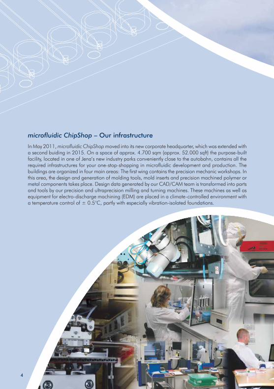
microfluidic ChipShop – Our infrastructure
In May 2011, microfluidic ChipShop moved into its new corporate headquarter, which was extended with a second buiding in 2015. On a space of approx. 4.700 sqm (approx. 52.000 sqft) the purpose-built facility, located in one of Jena‘s new industry parks conveniently close to the autobahn, contains all the required infrastructures for your one-stop-shopping in microfluidic development and production. The buildings are organized in four main areas: The first wing contains the precision mechanic workshops. In this area, the design and generation of molding tools, mold inserts and precision machined polymer or metal components takes place. Design data generated by our CAD/CAM team is transformed into parts and tools by our precision and ultraprecision milling and turning machines. These machines as well as equipment for electro-discharge machining (EDM) are placed in a climate-controlled environment with a temperature control of ± 0.5°C, partly with especially vibration-isolated foundations.
4
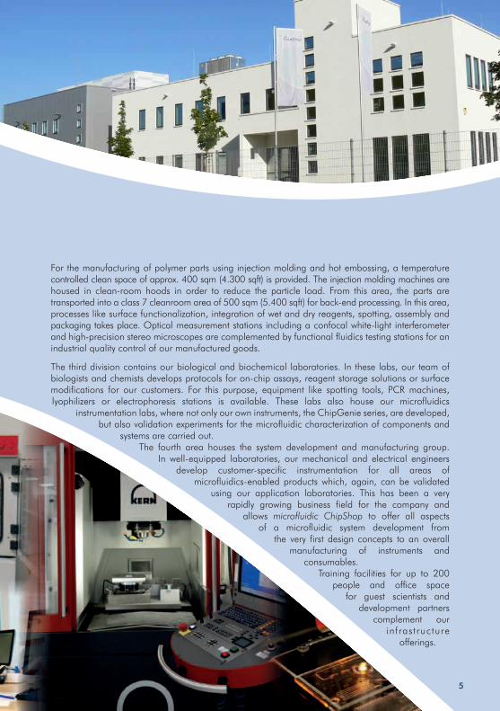
For the manufacturing of polymer parts using injection molding and hot embossing, a temperature controlled clean space of approx. 400 sqm (4.300 sqft) is provided. The injection molding machines are housed in clean-room hoods in order to reduce the particle load. From this area, the parts are transported into a class 7 cleanroom area of 500 sqm (5.400 sqft) for back-end processing. In this area, processes like surface functionalization, integration of wet and dry reagents, spotting, assembly andpackaging takes place. Optical measurement stations including a confocal white-light interferometer and high-precision stereo microscopes are complemented by functional fluidics testing stations for an industrial quality control of our manufactured goods.
The third division contains our biological and biochemical laboratories. In these labs, our team of biologists and chemists develops protocols for on-chip assays, reagent storage solutions or surface modifications for our customers. For this purpose, equipment like spotting tools, PCR machines, lyophilizers or electrophoresis stations is available. These labs also house our microfluidics
instrumentation labs, where not only our own instruments, the ChipGenie series, are developed, but also validation experiments for the microfluidic characterization of components and
systems are carried out.The fourth area houses the system development and manufacturing group.
In well-equipped laboratories, our mechanical and electrical engineers develop customer-specific instrumentation for all areas of
microfluidics-enabled products which, again, can be validated using our application laboratories. This has been a very
rapidly growing business field for the company and allows microfluidic ChipShop to offer all aspects
of a microfluidic system development from the very first design concepts to an overall
manufacturing of instruments and consumables.
Training facilities for up to 200 people and office space
for guest scientists and development partners
complement our infrastructure
offerings.
5
The Lab-on-a-Chip Catalogue – Shortcut to the world of microfluidics
Offering catalogue devices and development platforms, fulfilling common laboratory standards in their dimensions and interfaces, microfluidic ChipShop allows users a quick, low-cost, and low-risk entry into the innovative field of microfluidics. The chips offered within microfluidic ChipShop‘s Lab-on-a-Chip Catalogue cover a range of applications from simple liquid handling, electrophoresis, extraction, or mixing up to sample preparation and complete analytical tasks.
Please enjoy our Lab-on-a-Chip Catalogue as your roadmap to microfluidics. We will be more than happy to assist you with our design and fabrication services as well as to discuss your special requirements in the microfluidic world.
Yours,
Dr. Claudia Gärtner CEO
6
Contents
7
1 microfluidic ChipShop‘s Lab-on-a-Chip Catalogue 10
2 Materials in microfluidics 11
3 Microfluidic chips – Polymers 21
3.1 Introduction to microfluidic chips 22
3.2 Straight channel chips – Microscope slide format 24
3.3 Straight channel chips – Microtiter-plate format 33
3.4 Cross-shaped channel chips 36
3.5 H-shaped channel chips 43
3.6 Chamber chips 44
3.7 Waste chamber chips 58
3.8 Cuvette chips 60
3.9 Splitter chips 62
3.10 Micro mixer 64
3.11 Titer plates in microscopy slide format 70
3.12 Droplet generator chips and integrated droplet
generation solutions 72
3.13 Meander and continuous-flow PCR chips 81
3.14 Sample preparation chips 82
3.15 Cell culture chips 87
3.16 Weir-filter chip 96
Contents
8
3.17 Particle & cell sorting chips 96
3.18 Gradient chip 99
3.19 Pillar chip 100
3.20 Field-flow fractionation chips 101
3.21 Turning valve chip 102
3.22 Blister test chips 103
4 Microfluidic devices for customization and sensor
integration 109
4.1 Open chip platforms for self-assembly 110
4.2 Self-sealing and releasable chips – slide format 112
4.3 Sensor integration chips 113
5 Microfluidic chips – Integrated chips 123
6 Microfluidic chips – Glass 133
7 Silicone chips 139
8 Accessories 145
9 Polymer substrates and foils 183
10 ChipGenie® editions – Instruments and applications 189
11 Special instruments 201
12 Pumps and pressure controllers 211
13 Microfluidic kits 237
Contents
9
14 Application development: Assay & reagent
implementation 253
15 Application notes 257
16 Fabrication services 277
17 Finally – Some examples 291
18 One for all – A universal diagnostic platform 301
18.1 One for all – A partnership with Stratos Product
Development for the Bill & Melinda Gates foundation 302
18.2 In continuation – The ChipGenie® edition Dx series –
The universal diagnostic platform 303
19 Literature 307
20 Order form 313
1 microfluidic ChipShop‘s Lab-on-a-Chip Catalogue
Our mission at microfluidic ChipShop is to shrink the biological and chemical laboratory and to bring lab-on-a-chip systems into daily laboratory life.
This catalogue is part of our service to make our mission happen: From off-the-shelf microfluidic chips to complete lab-on-a-chip systems, our products serve a wide range of customer needs.
Whether you need a single chip or thousands, in the following pages you will find the essential components for an easy route into the world of microfluidic handling and manipulation. Be it for the first steps with lab-on-a-chip systems or the evaluation of new designs and functions: you do not need to make up your own design, you avoid tooling costs, and we ensure fast delivery to your doorstep.
Of course, our expertise at microfluidic ChipShop extends well beyond the products listed in this catalogue: Whether you seek a competent microfluidic-chip manufacturer, whether you want to translate specific functions into microfluidic designs, whether you need to adopt biological or biochemical assays to a miniaturized format or develop them from scratch for a microfluidic consumable or whether you want to develop entire lab-on-a-chip systems, we are here to help you with our full range of production and development services.
10
2 Materials in microfluidics
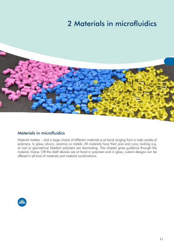
Materials in microfluidics
Material matters – and a large choice of different materials is at hand ranging from a wide variety of polymers, to glass, silicon, ceramics or metals. All materials have their pros and cons, looking e.g. at cost or geometrical freedom polymers are dominating. This chapter gives guidance through the material choice. Off-the shelf devices are at hand in polymers and in glass, custom-designs can be offered in all kind of materials and material combinations.
11
2 Materials
2.1 Materials in microfluidicsIn microfluidics, a wide variety of materials is in use. Historically, microfluidics and the use as lab-on-a-chip for applications in life sciences or analytical sciences started with technologies being available from semiconductor industries. Consequently, since these technologies were available and allowed for microstructuring, they were used for the first microfluidic devices. Materials that were applicable to be structured by technologies used in semiconductor industries were glass and silicon. First microfluidic devices, besides ink jet printer heads for non-life science microfluidics, were made from glass and silicon, reaching back to the 1970ies with Stephen Terry’s gas chromatograph integrated on a silicon wafer, functional but rather expensive.
These semiconductor manufacturing technologies have been available at many engineering institutes, thus these disciplines pioneered in microfluidics due to the availability of elaborate and usually expensive technologies.
Another manufacturing technology arose by simply taking the microstructured silicon devices made by the semiconductor technologies and replicating the structures into a soft polymer in a process called casting (often also referred to as “soft lithography”), just by pouring the liquid polymer onto the silicone matrix, hardening it and removing the soft polymer replicate. This process can be repeated many times, and besides one-time investment in the silicon master, it is from an equipment point of view an extremely low-cost technology. Material used for this process is a special kind of silicone, usually PDMS (Polydimethylsiloxane).
Later on, a merger of conventional fabrication technologies for e.g. standard life science plastic lab ware, namely injection molding, with microtechnology took place. The challenge that had to be overcome to make this technology available for microfluidics was in a first instance the generation of the microstructured master in metals that withstands, depending on the feature sizes, several thousands to several hundred thousand replication cycles. After the replication, assembling technologies needed to be developed. The adoption of industrial replication technologies in combination with the wide variety of commercially available polymers enables a most cost efficient fabrication together with the widest design freedom and is the reason for the current progress made in the commercialization of microfluidic devices.
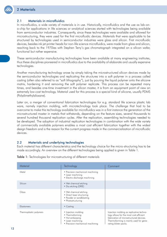
2.2 Materials and underlying technologies Each material has different characteristics and the technology choice for the micro-structuring has to be made accordingly. An overview on the different technologies being applied is given in Table 1.
Table 1: Technologies for microstructuring of different materials
Metal
Silicon
Glass
Elastomers
Thermoplastic polymers
• Precision mechanical machining• Laser machining• Electro discharge machining
• Wet chemical etching• Dry etching (DRIE)
• Wet chemical etching• Direct laser structuring• Powder or sandblasting• Photostructuring
• Casting
• Injection molding• Thermoforming• Hot embossing• Laser machining• Precision mechanical machining
Material Technology
Injection molding as replicative techno-logy allows for the most cost-efficient fabrication of microstructured devices. Thermoforming is mainly used for gene-rating blister packs.
Comment
12
2 Materials
Design freedom
Combination of different structural depths in one device
Direct integration of fluidic interfaces
Direct integration of e.g. reservoirs
Part design
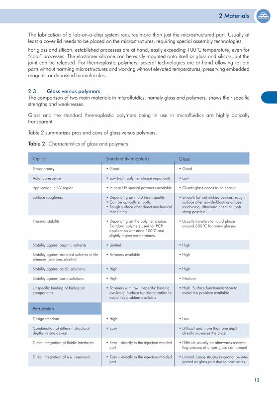
2.3 Glass versus polymersThe comparison of two main materials in microfluidics, namely glass and polymers, shows their specific strengths and weaknesses.
Glass and the standard thermoplastic polymers being in use in microfluidics are highly optically transparent.
Table 2 summarizes pros and cons of glass versus polymers.
Table 2: Characteristics of glass and polymers
Transparency
Autofluorescence
Application in UV region
Surface roughness
Thermal stability
Stability against organic solvents
Stability against standard solvents in life sciences (acetone, alcohol)
Stability against acidic solutions
Stability against basic solutions
Unspecific binding of biological components
• Good
• Low (right polymer choice important)
• In near UV special polymers available
• Depending on mold insert quality.• Can be optically smooth. • Rough surface after direct mechanical machining
• Depending on the polymer choice. Standard polymers used for PCR application withstand 100°C and slightly higher temperatures.
• Limited
• Polymers available
• High
• High
• Polymers with low unspecific binding available. Surface functionalization to avoid this problem available
Standard thermoplasts
• Good
• Low
• Quartz glass needs to be chosen
• Smooth for wet etched devices, rough surface after powderblasting or laser machining. Afterward chemical poli shing possible.
• Usually transfers to liquid phase around 600˚C for many glasses
• High
• High
• High
• Medium
• High. Surface functionalization to avoid this problem available
GlassOptics
• High
• Easy
• Easy – directly in the injection molded part
• Easy – directly in the injection molded part
• Low
• Difficult and more than one depth directly increases the price
• Difficult, usually an afterwards assemb- ling process of a non-glass-component
• Limited. Large structures cannot be inte- grated as glass part due to cost issues.
13
The fabrication of a lab-on-a-chip system requires more than just the microstructured part. Usually at least a cover lid needs to be placed on the microstructures, requiring special assembly technologies.
For glass and silicon, established processes are at hand, easily exceeding 100°C temperature, even for “cold” processes. The elastomer silicone can be easily mounted onto itself or glass and silicon, but the joint can be released. For thermoplastic polymers, several technologies are at hand allowing to join parts without harming microstructures and working without elevated temperatures, preserving embedded reagents or deposited biomolecules.
2 Materials
Possessing different characteristics and financial benefits, polymers will always be used when glass is not required, since they are the cheaper devices. Glass is of interest if elevated temperatures are necessary, much above 100°C, what is usually not the case in life sciences, and if specific organic solvents should be used.
If bioreagents should be stored on-chip, complex fluidics, hybrid components like membranes are necessary, valves should be part of the device etc. polymers will be the material of choice.
Furthermore, interfaces, reservoirs and different structural depths do not impact the price of the device in polymers, but partly are impossible to be implemented in a glass device or massively increase cost.
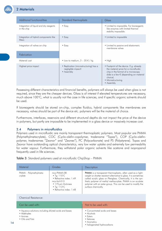
Integration of liquid and dry reagents in the chip
Integration of hybrid components like filters
Integration of valves on chip
• Easy
• Easy
• Easy
Standard thermoplasts
• Limited to impossible. For bioreagents like enzymes with limited thermal stability impossible.
• Limited to impossible
• Limited to passive and elastomeric membrane valves
GlassAdditional functionalities
Material cost
Highest price impact
• Low to medium, 2 – 20 € / kg
• Replication (microstructuring) has a negligible impact!• Assembly
• High
• Footprint of the device. E.g. already the material price for a microfluidic chip in the format of a microscopy slide is a few € (depending on material choice).• Microstructuring• Assembly
Fabrication
2.4 Polymers in microfluidicsPolymers used in microfluidic are mainly transparent thermoplastic polymers. Most popular are PMMA (Polymethylmetacrylate), COC (Cyclo-olefin-copolymer, tradename “Topas”), COP (Cyclo-olefin-polymer, tradenames “Zeonor” and “Zeonex”), PC (Polycarbonate) and PS (Polystyrene). Topas and Zeonor have outstanding optical characteristics, very low water uptake and extremely low permeability for water vapour. Furthermore, they withstand polar organic solvents like acetone and isopropanol frequently used in life sciences.
Table 3: Standard polymers used at microfluidic ChipShop – PMMA
PMMA – Polymethylmeta-crylate
mcs-PMMA-08 • Tg: 110°C • Refractive index: 1.49mcs-foil-013 • 175 µm thickness • Tg: 113°C • Refractive index: 1.48
Grades
PMMA is a transparent thermoplastic, often used as a light-weight or shatter-resistant alternative to glass. It is sometimes called acrylic glass or Plexiglass. Chemically, it is the syn-thetic polymer of methyl methacrylate. PMMA is an acrylate polymer with an ester-group. This can be used to modify the surface chemically.
DescriptionMaterial
Chemical Resistance:
• Aqueous solutions including diluted acids and bases• Aldehydes• Amines• Oils and Fats
• Concentrated acids and bases• Alcohols • Esters• Ketones• Aromatics• halogenated hydrocarbons
Can be used with: Not to be used with:
14
2 Materials
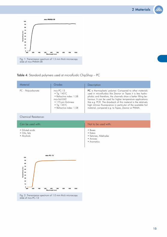
Table 4: Standard polymers used at microfluidic ChipShop – PC
PC – Polycarbonate mcs-PC-13 • Tg: 145°C • Refractive index: 1.58mcs-foil-042 • 175 µm thickness • Tg: 145°C • Refractive index: 1.58
Grades
PC is thermoplastic polymer. Compared to other materials used in microfluidics like Zeonor or Topas it is less hydro-phobic and therefore, the channels show a better filling be-haviour. It can be used for higher temperature applications like e.g. PCR. The drawback of this material is the relatively high intrinsic fluorescence in particular of the available foil material, compared e.g. to Topas, Zeonor or PMMA.
DescriptionMaterial
Chemical Resistance:
• Diluted acids• Oils, fats• Alcohols
• Bases• Esters• Ketones, Aldehydes• Amines• Aromatics
Can be used with: Not to be used with:
15
Fig. 1: Transmission spectrum of 1.5 mm thick microscopy slide of mcs-PMMA-08
Fig. 2: Transmission spectrum of 1.0 mm thick microscopy slide of mcs-PC-13
2 Materials
16
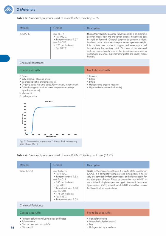
Table 5: Standard polymers used at microfluidic ChipShop – PS
mcs-PS-17 mcs-PS-17 • Tg: 100°C • Refractive index: 1.57mcs-foil-095 • 125 µm thickness • Tg: 100°C
Grades
PS is a thermoplastic polymer. Polystyrene (PS) is an aromatic polymer made from the monomer styrene. Polystyrene can be rigid or foamed. General purpose polystyrene is clear, hard and brittle. It is a very inexpensive resin per unit weight. It is a rather poor barrier to oxygen and water vapor and has relatively low melting point. PS is one of the standard material conventionally used in the life sciences also due to is relatively low price. E.g. microtiter plates are usually made from PS.
DescriptionMaterial
Chemical Resistance:
• Bases• Butyl alcohol, ethylene glycol• Isopropanol (at room temperature)• Organic acids like citric acids, formic acids, tartaric acids• Diluted inorganic acids at lower temperatures (except hydrofluoric acids)• Mineral oil• Hydrogen oxide
• Ketones• Esters• Ethers• Halogenated organic reagents• Hydrocarbons (mineral oil works)
Can be used with: Not to be used with:
Fig. 3: Transmission spectrum of 1.0 mm thick microscopy slide of mcs-PS-17
Table 6: Standard polymers used at microfluidic ChipShop – Topas (COC)
Topas (COC)
Grades
Topas is thermoplastic polymer. It is cyclo-olefin copolymer (COC). It is completely nonpolar and amorphous. It has a very low permeability for water vapour and a low capacity for the absorption of water. Please be aware that mcs-foil-011 is not suitable for high temperature applications as it features a Tg of around 75°C, instead mcs-foil-081 should be chosen for those kinds of applications.
DescriptionMaterial
Chemical Resistance:
• Aqueous solutions including acids and bases• Polar solvents• Can be used with mcs-oil-04• Silicone oil
• Nonpolar solvents • Mineral oils (hydrocarbons)• Fats• Halogenated hydrocarbons
Can be used with: Not to be used with:
mcs-COC-13 • Tg: 142°C • Refractive index: 1.53mcs-foil-011 • 140 µm thickness • Tg: 78°C • Refractive index: 1.53mcs-foil-081 • 175 µm thickness • Tg: 142°C • Refractive index: 1.53
2 Materials
17
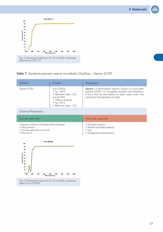
Table 7: Standard polymers used at microfluidic ChipShop – Zeonor (COP)
Zeonor (COP) mcs-COP-02 • Tg: 136°C • Refractive index: 1.53mcs-foil-005 • 188 µm thickness • Tg: 134°C • Refractive index: 1.53
Grades
Zeonor is a thermoplastic polymer. Zeonor is a cyclo-olefin polymer (COP). It is completely nonpolar and amorphous. It has a very low permeability for water vapour and a low capacity for the absorption of water.
DescriptionMaterial
Chemical Resistance:
• Aqueous solutions including acids and bases• Polar solvents• Can be used with mcs-oil-04• Silicone oil
• Nonpolar solvents • Mineral oils (hydrocarbons)• Fats• Halogenated hydrocarbons
Can be used with: Not to be used with:
Fig. 4: Transmission spectrum of 1.0 mm thick microscopy slide of mcs-COC-13
Fig. 5: Transmission spectrum of 1.0 mm thick microscopy slide of mcs-COP-02
2 Materials
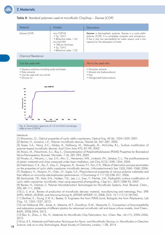
Table 8: Standard polymers used at microfluidic ChipShop – Zeonex (COP)
Zeonex (COP) mcs-COP-04 • Tg: 134°C • Refractive index: 1.53mcs-foil-005 • 188 µm thickness • Tg: 134°C • Refractive index: 1.53
Grades
Zeonex is thermoplastic polymer. Zeonex is a cyclo-olefin polymer (COP). It is completely nonpolar and amorphous. It has a very low permeability for water vapour and a low capacity for the absorption of water.
DescriptionMaterial
Chemical Resistance:
• Aqueous solutions including acids and bases• Polar solvents• Can be used with mcs-oil-04• Silicone oil
• Nonpolar solvents • Mineral oils (hydrocarbons)• Fats• Halogenated hydrocarbons
Can be used with: Not to be used with:
18
Fig. 6: Transmission spectrum of 1.0 mm thick microscopy slide of mcs-COP-04
Literature:[1] Khanarian, G., Optical properties of cyclic olefin copolymers, Optical Eng. 40 (6), 1024-1029, 2001. [2] Becker, H., Locascio, L.E., Polymer microfluidic devices, Talanta 56, 267–287, 2002.[3] Soper, S.A., Henry, A.C., Vaidya, B., Galloway, M., Wabuyele, M., McCarley, R.L., Surface modification of polymer-based microfluidic devices, Anal Chim Acta 470, 87–99, 2002.[4] Alvaro, M., Fleischman, A.J., Roy, S., Characterization of Polydimethylsiloxane (PDMS) Properties for Biomedical Micro/Nanosystems, Biomed. Microdev. 7 (4), 281-293, 2005. [5] Piruska ,A., Nikcevic, I., Lee, S.H., Ahn, C., Heineman, W.R., Limbach, P.A., Seliskar, C.J., The autofluorescence of plastic materials and chips measured under laser irradiation, Lab Chip 5(12),1348–1354, 2005.[6] Fredrickson, C.K., Xia, Z., Das, C., Ferguson, R., Tavares, F.T., Fan, Z.H., Effects of fabrication process parameters on the properties of cyclic olefin copolymer microfluidic devices, J Microelectromech Syst 15(5),1060–1068, 2006.[7] Shadpour, H., Musyimi, H., Chen, J.F., Soper, S.A., Physiochemical properties of various polymer substrates and their effects on microchip electrophoresis performance. J Chromatogr A 1111(2),238–251, 2006.[8] Stachowiak, T.B., Mair, D.A., Holden, T.G., Lee, L.J., Svec, F., Fréchet, J.M., Hydrophilic surface modification of cyclic olefin copolymer microfluidic chips using sequential photografting, J Sep Sci., 30(7):1088-93, 2007.[9] Becker, H.; Gärtner, C. Polymer Microfabrication Technologies for Microfluidic Systems, Anal. Bioanal. Chem., 390, 89–111, 2008.[10] Li, S. et al., Review of production of microfluidic devices: material, manufacturing and metrology, Proc. SPIE 6993, MEMS, MOEMS, and Micromachining III, 69930F-69930F-12, 2008. DOI: 10.1117/12.781942.[11] Berthier, E.; Young, E.W. K.; Beebe, D. Engineers Are from PDMS-Land, Biologists Are from Polystyrenia, Lab Chip, 12, 1224–1237, 2012.[12] van Midwoud, P.M., Janse, A., Merema, M.T., Groothuis, G.M., Verpoorte, E., Comparison of biocompatibility and adsorption properties of different plastics for advanced microfluidic cell and tissue culture models, Anal Chem., 84(9), 3938-3944, 2012.[13] Ren, K., Zhou, J., Wu, H., Materials for Microfluidic Chip Fabrication, Acc. Chem. Res., 46 (11), 2396–2406, 2013.[14] Lei, K.F., Materials and Fabrication Techniques for Nano- and Microfluidic Devices, in: Microfluidics in Detection Science: Lab-on-a-chip Technologies, Royal Society of Chemistry, London, 1-28, 2014.

19
20
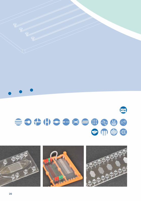
Microfluidic chips – Polymers
Ready-to-go microfluidic chips – this chapter summarizes various kinds of standard chips such as simple straight channels, cross-shaped channel chips for electrophoresis, extractors, micro-mixers, droplet generators, and nanotiter plates.
Taking our standardization principles into account, all these chips have the format of a microscopy slide or a microtiter plate. The spacing between the fluidic interfaces either corresponds with the spacing of a 96 or 384 well plate, namely 4.5 mm or 9 mm respective distance from center to center of the wells. All polymer chips have the fluidic interconnects on the top and the microfludic structure on the bottom side. The micro structures are sealed with a cover lid of identical material. The thickness of the respective cover lid is indicated in the product.
3 Microfluidic chips – Polymers
21
3 Microfluidic chips – Polymers
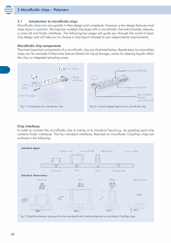
3.1 Introduction to microfluidic chipsMicrofluidic chips can vary greatly in their design and complexity. However, a few design features mostchips have in common: the injection molded chip body with a microfluidic channel/chamber network, a cover lid and fluidic interfaces. The following two pages will guide you through the world of basic chip design and will help you to choose a chip layout tailored to your experimental requirements.
Fig. 7: Components of a microfluidic chip
Microfluidic chip componentsThe most important components of a microfluidic chip are illustrated below. Beside basic functionalities chips can for example furthermore feature blisters for liquid storage, valves for steering liquids within the chip or integrated sampling areas.
Chip interfacesIn order to connect the microfluidic chip to tubing or to introduce liquid e.g. via pipetting each chip contains fluidic interfaces. The four standard interfaces, featured on microfluidic ChipShop chips are outlined in the following.
Fig. 9: Detailed schematic drawing of the four standard fluidic interfaces featured on microfluidic ChipShop chips
Fig. 8: Common design features on a microfluidic chip
22
3 Microfluidic chips – Polymers
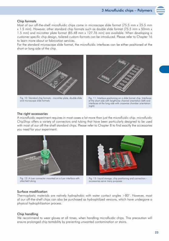
Chip formatsMost of our off-the-shelf microfluidic chips come in microscope slide format (75.5 mm x 25.5 mm x 1.5 mm). However, other standard chip formats such as double slide format (75.5 mm x 50mm x 1.5 mm) and microtiter plate format (85.48 mm x 127.76 mm) are available. When developing a customer-specific chip design, tailered custom-formats can be introduced. Please refer to Chapter 16 to learn more about or fabrication services. For the standard microscope slide format, the microfluidic interfaces can be either positioned at the short or long side of the chip.
Chip handlingWe recommend to wear gloves at all times, when handling microfluidic chips. This precaution will ensure prolonged chip tentability by preventing unwanted contamination or stains.
Fig. 10: Standard chip formats - microtiter plate, double slide and microscope slide formats
The right accessoriesA microfluidic experiment requires in most cases a lot more than just the microfluidic chip. microfluidic ChipShop offers a variety of connectors and tubing that have been particularly designed to be used with most of our off-the-shelf standard chips. Please refer to Chapter 8 to find exactly the accessories you need for your experiment.
Fig. 11: Interface positioning on a slide format chip. Interfaces at the short side with lengthwise channel orientation (left) and interfaces at the long side with crosswise chamber orientation (right)
Fig. 12: A Luer connector mounted on a Luer interface with attached tubing
Fig. 13: Liquid storage, chip positioning and connection - accessories serve many purposes
Surface modification Thermoplastic materials are natively hydrophobic with water contact angles >80°. However, most of our off-the-shelf chips can also be purchased as hydrophilized versions, which have undergone a physical hydrophilization process.
23
3 Microfluidic chips – Polymers
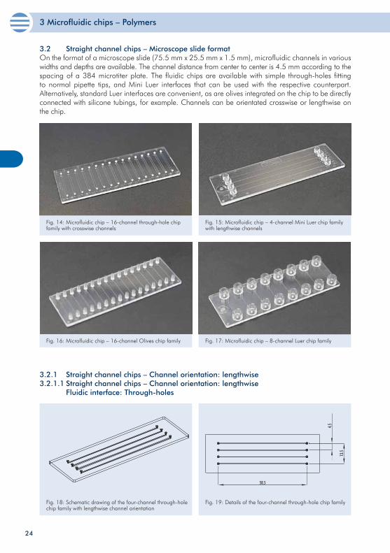
3.2 Straight channel chips – Microscope slide format On the format of a microscope slide (75.5 mm x 25.5 mm x 1.5 mm), microfluidic channels in various widths and depths are available. The channel distance from center to center is 4.5 mm according to the spacing of a 384 microtiter plate. The fluidic chips are available with simple through-holes fitting to normal pipette tips, and Mini Luer interfaces that can be used with the respective counterpart. Alternatively, standard Luer interfaces are convenient, as are olives integrated on the chip to be directly connected with silicone tubings, for example. Channels can be orientated crosswise or lengthwise on the chip.
Fig. 14: Microfluidic chip – 16-channel through-hole chip family with crosswise channels
Fig. 15: Microfluidic chip – 4-channel Mini Luer chip family with lengthwise channels
Fig. 16: Microfluidic chip – 16-channel Olives chip family Fig. 17: Microfluidic chip – 8-channel Luer chip family
24
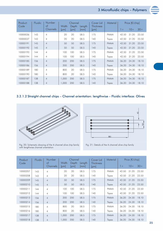
3.2.1 Straight channel chips – Channel orientation: lengthwise3.2.1.1 Straight channel chips – Channel orientation: lengthwise Fluidic interface: Through-holes
Fig. 18: Schematic drawing of the four-channel through-hole chip family with lengthwise channel orientation
Fig. 19: Details of the four-channel through-hole chip family
3 Microfluidic chips – Polymers
25
10000036
10000037
10000191
10000192
10000193
10000194
10000185
10000186
10000189
10000190
10000187
10000188
20
20
50
50
100
100
200
200
800
800
1,000
1,000
20
20
50
50
100
100
200
200
20
20
200
200
58.5
58.5
58.5
58.5
58.5
58.5
58.5
58.5
58.5
58.5
58.5
58.5
175
140
175
140
175
140
175
140
175
140
175
140
PMMA
Topas
PMMA
Topas
PMMA
Topas
PMMA
Topas
PMMA
Topas
PMMA
Topas
Product Code
ChannelWidth[µm]
Depth[µm]
Cover LidThickness[µm]
Material Price [€/chip]
1+ 10+ 30+Length[mm]
42.50
42.50
42.50
42.50
42.50
42.50
36.20
36.20
36.20
36.20
36.20
36.20
31.20
31.20
31.20
31.20
31.20
31.20
24.30
24.30
24.30
24.30
24.30
24.30
23.50
23.50
23.50
23.50
23.50
23.50
18.10
18.10
18.10
18.10
18.10
18.10
Fluidic Number of Channels
4
4
4
4
4
4
4
4
4
4
4
4
143
143
145
145
144
144
156
156
180
180
138
138
3.2.1.2 Straight channel chips – Channel orientation: lengthwise – Fluidic interface: Olives
Fig. 20: Schematic drawing of the 4-channel olive chip family with lengthwise channel orientation
Fig. 21: Details of the 4-channel olive chip family
10000207
10000208
10000209
10000210
10000211
10000212
10000213
10000214
10000215
10000216
10000217
10000218
20
20
50
50
100
100
200
200
800
800
1,000
1,000
20
20
50
50
100
100
200
200
20
20
200
200
58.5
58.5
58.5
58.5
58.5
58.5
58.5
58.5
58.5
58.5
58.5
58.5
175
140
175
140
175
140
175
140
175
140
175
140
PMMA
Topas
PMMA
Topas
PMMA
Topas
PMMA
Topas
PMMA
Topas
PMMA
Topas
ChannelWidth[µm]
Depth[µm]
Cover LidThickness[µm]
Material Price [€/chip]
1+ 10+ 30+Length[mm]
42.50
42.50
42.50
42.50
42.50
42.50
36.20
36.20
36.20
36.20
36.20
36.20
31.20
31.20
31.20
31.20
31.20
31.20
24.30
24.30
24.30
24.30
24.30
24.30
23.50
23.50
23.50
23.50
23.50
23.50
18.10
18.10
18.10
18.10
18.10
18.10
Product Code
Fluidic Number of Channels
4
4
4
4
4
4
4
4
4
4
4
4
143
143
145
145
144
144
156
156
180
180
138
138
3 Microfluidic chips – Polymers
26
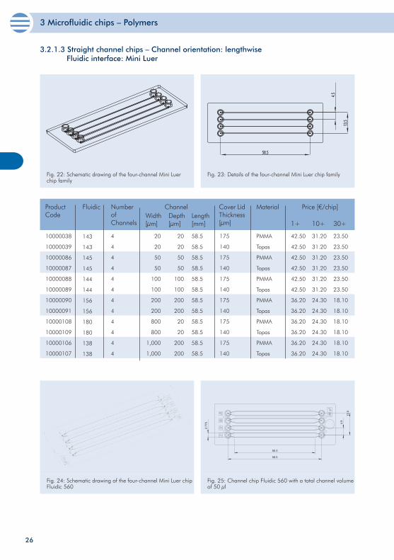
3.2.1.3 Straight channel chips – Channel orientation: lengthwise Fluidic interface: Mini Luer
Fig. 22: Schematic drawing of the four-channel Mini Luer chip family
Fig. 23: Details of the four-channel Mini Luer chip family
10000038
10000039
10000086
10000087
10000088
10000089
10000090
10000091
10000108
10000109
10000106
10000107
20
20
50
50
100
100
200
200
800
800
1,000
1,000
20
20
50
50
100
100
200
200
20
20
200
200
58.5
58.5
58.5
58.5
58.5
58.5
58.5
58.5
58.5
58.5
58.5
58.5
175
140
175
140
175
140
175
140
175
140
175
140
PMMA
Topas
PMMA
Topas
PMMA
Topas
PMMA
Topas
PMMA
Topas
PMMA
Topas
Price [€/chip]
1+ 10+ 30+
42.50
42.50
42.50
42.50
42.50
42.50
36.20
36.20
36.20
36.20
36.20
36.20
31.20
31.20
31.20
31.20
31.20
31.20
24.30
24.30
24.30
24.30
24.30
24.30
23.50
23.50
23.50
23.50
23.50
23.50
18.10
18.10
18.10
18.10
18.10
18.10
Width[µm]
Depth[µm]
Cover LidThickness[µm]
MaterialLength[mm]
Product Code
Fluidic Number of Channels
4
4
4
4
4
4
4
4
4
4
4
4
143
143
145
145
144
144
156
156
180
180
138
138
Channel
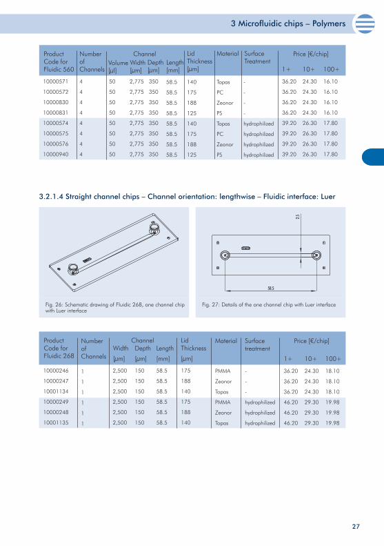
Fig. 24: Schematic drawing of the four-channel Mini Luer chip Fluidic 560
Fig. 25: Channel chip Fluidic 560 with a total channel volume of 50 µl
3 Microfluidic chips – Polymers
27
10000571
10000572
10000830
10000831
10000574
10000575
10000576
10000940
50
50
50
50
50
50
50
50
350
350
350
350
350
350
350
350
140
175
188
125
140
175
188
125
Topas
PC
Zeonor
PS
Topas
PC
Zeonor
PS
-
-
-
-
hydrophilized
hydrophilized
hydrophilized
hydrophilized
Product Code for Fluidic 560
Volume[µl]
Depth[µm]
Material SurfaceTreatment
Price [€/chip]
1+ 10+ 100+
LidThickness[µm]
36.20
36.20
36.20
36.20
39.20
39.20
39.20
39.20
24.30
24.30
24.30
24.30
26.30
26.30
26.30
26.30
16.10
16.10
16.10
16.10
17.80
17.80
17.80
17.80
ChannelWidth[µm]
Length[mm]
Number of Channels
4
4
4
4
4
4
4
4
58.5
58.5
58.5
58.5
58.5
58.5
58.5
58.5
2,775
2,775
2,775
2,775
2,775
2,775
2,775
2,775
3.2.1.4 Straight channel chips – Channel orientation: lengthwise – Fluidic interface: Luer
Fig. 26: Schematic drawing of Fluidic 268, one channel chip with Luer interface
Fig. 27: Details of the one channel chip with Luer interface
10000246
10000247
10001134
10000249
10000248
10001135
Product Code for Fluidic 268
175
188
140
175
188
140
LidThickness
[µm]
PMMA
Zeonor
Topas
PMMA
Zeonor
Topas
Material
2,500
2,500
2,500
2,500
2,500
2,500
150
150
150
150
150
150
58.5
58.5
58.5
58.5
58.5
58.5
ChannelWidth
[µm]
Depth
[µm]
Length
[mm]
Price [€/chip]
1+ 10+ 100+
36.20
36.20
36.20
46.20
46.20
46.20
24.30
24.30
24.30
29.30
29.30
29.30
18.10
18.10
18.10
19.98
19.98
19.98
-
-
-
hydrophilized
hydrophilized
hydrophilized
Surface treatment
Number of Channels
1
1
1
1
1
1
3 Microfluidic chips – Polymers
28
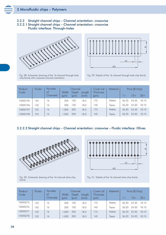
3.2.2.2 Straight channel chips – Channel orientation: crosswise – Fluidic interface: Olives
Fig. 30: Schematic drawing of the 16-channel olive chip family
Fig. 31: Details of the 16-channel olive chip family
200
200
1,000
1,000
100
100
200
200
18.0
18.0
18.0
18.0
175
140
175
140
PMMA
Topas
PMMA
Topas
36.20
36.20
36.20
36.20
24.30
24.30
24.30
24.30
18.10
18.10
18.10
18.10
Product Code
ChannelWidth[µm]
Depth[µm]
Cover LidThickness[µm]
Material Price [€/chip]
1+ 10+ 30+Length[mm]
Fluidic Number of Channels
16
16
16
16
142
142
152
152
10000275
10000276
10000277
10000278
3.2.2 Straight channel chips – Channel orientation: crosswise3.2.2.1 Straight channel chips – Channel orientation: crosswise Fluidic interface: Through-holes
Fig. 28: Schematic drawing of the 16-channel through-hole chip family with crosswise channel orientation
Fig. 29: Details of the 16-channel through-hole chip family
10000195
10000196
10000197
10000198
200
200
1,000
1,000
100
100
200
200
18.0
18.0
18.0
18.0
175
140
175
140
PMMA
Topas
PMMA
Topas
36.20
36.20
36.20
36.20
24.30
24.30
24.30
24.30
18.10
18.10
18.10
18.10
Product Code
ChannelWidth[µm]
Depth[µm]
Cover LidThickness[µm]
Material Price [€/chip]
1+ 10+ 30+Length[mm]
Fluidic Number of Channels
16
16
16
16
142
142
152
152
3 Microfluidic chips – Polymers
29
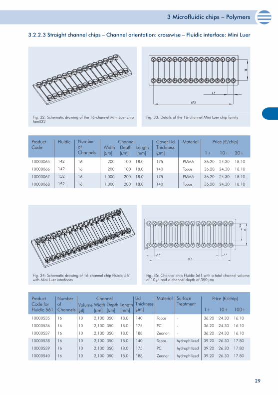
3.2.2.3 Straight channel chips – Channel orientation: crosswise – Fluidic interface: Mini Luer
Fig. 32: Schematic drawing of the 16-channel Mini Luer chip famil32
Fig. 33: Details of the 16-channel Mini Luer chip family
10000065
10000066
10000067
10000068
200
200
1,000
1,000
100
100
200
200
18.0
18.0
18.0
18.0
175
140
175
140
PMMA
Topas
PMMA
Topas
36.20
36.20
36.20
36.20
24.30
24.30
24.30
24.30
18.10
18.10
18.10
18.10
Product Code
ChannelWidth[µm]
Depth[µm]
Cover LidThickness[µm]
Material Price [€/chip]
1+ 10+ 30+Length[mm]
Fluidic Number of Channels
16
16
16
16
142
142
152
152
Fig. 34: Schematic drawing of 16-channel chip Fluidic 561 with Mini Luer interfaces
Fig. 35: Channel chip Fluidic 561 with a total channel volume of 10 µl and a channel depth of 350 µm
10000535
10000536
10000537
10000538
10000539
10000540
10
10
10
10
10
10
350
350
350
350
350
350
140
175
188
140
175
188
Topas
PC
Zeonor
Topas
PC
Zeonor
36.20
36.20
36.20
39.20
39.20
39.20
24.30
24.30
24.30
26.30
26.30
26.30
16.10
16.10
16.10
17.80
17.80
17.80
Product Code for Fluidic 561
Volume[µl]
Depth[µm]
Material SurfaceTreatment
Price [€/chip]
1+ 10+ 100+
LidThickness[µm]
ChannelWidth[µm]
Length[mm]
Number of Channels
-
-
-
hydrophilized
hydrophilized
hydrophilized
2,100
2,100
2,100
2,100
2,100
2,100
18.0
18.0
18.0
18.0
18.0
18.0
16
16
16
16
16
16
3 Microfluidic chips – Polymers
30
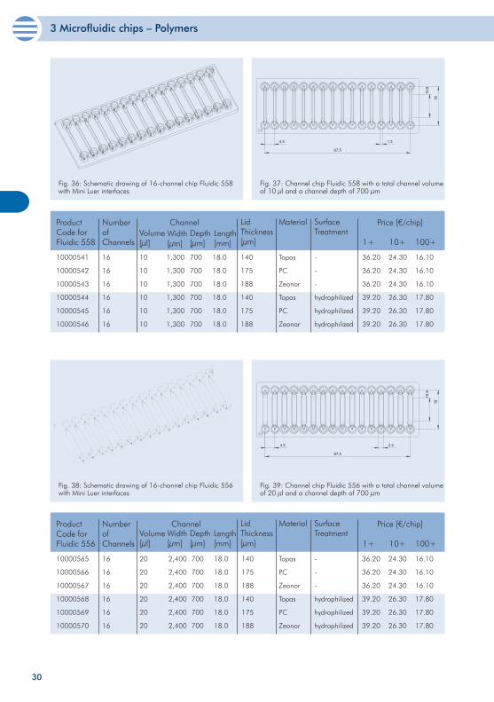
Fig. 36: Schematic drawing of 16-channel chip Fluidic 558 with Mini Luer interfaces
Fig. 37: Channel chip Fluidic 558 with a total channel volume of 10 µl and a channel depth of 700 µm
10
10
10
10
10
10
Product Code for Fluidic 558
Volume[µl]
Depth[µm]
Material SurfaceTreatment
Price [€/chip]
1+ 10+ 100+
LidThickness[µm]
Width[µm]
Length[mm]
Number of Channels
16
16
16
16
16
16
10000541
10000542
10000543
10000544
10000545
10000546
700
700
700
700
700
700
140
175
188
140
175
188
Topas
PC
Zeonor
Topas
PC
Zeonor
-
-
-
hydrophilized
hydrophilized
hydrophilized
36.20
36.20
36.20
39.20
39.20
39.20
24.30
24.30
24.30
26.30
26.30
26.30
16.10
16.10
16.10
17.80
17.80
17.80
18.0
18.0
18.0
18.0
18.0
18.0
1,300
1,300
1,300
1,300
1,300
1,300
Channel
Fig. 38: Schematic drawing of 16-channel chip Fluidic 556 with Mini Luer interfaces
Fig. 39: Channel chip Fluidic 556 with a total channel volume of 20 µl and a channel depth of 700 µm
10000565
10000566
10000567
10000568
10000569
10000570
20
20
20
20
20
20
700
700
700
700
700
700
140
175
188
140
175
188
Topas
PC
Zeonor
Topas
PC
Zeonor
-
-
-
hydrophilized
hydrophilized
hydrophilized
36.20
36.20
36.20
39.20
39.20
39.20
24.30
24.30
24.30
26.30
26.30
26.30
16.10
16.10
16.10
17.80
17.80
17.80
Product Code for Fluidic 556
Volume[µl]
Depth[µm]
Material SurfaceTreatment
Price [€/chip]
1+ 10+ 100+
LidThickness[µm]
Width[µm]
Length[mm]
Number of Channels
16
16
16
16
16
16
18.0
18.0
18.0
18.0
18.0
18.0
Channel
2,400
2,400
2,400
2,400
2,400
2,400
3 Microfluidic chips – Polymers
31
67.5
4.5
18
2
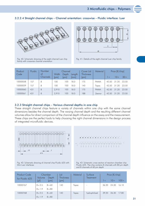
Fig. 42: Schematic drawing of channel chip Fluidic 625 with Mini Luer interfaces
Fig. 43: Schematic cross-section of reaction chamber chip Fluidic 625. The chip contains 8 channels with 80 µm depth and 8 channels of 60 µm depth
3.2.3 Straight channel chips – Various channel depths in one chip These straight channel chips feature a variety of channels within one chip with the same channel dimensions besides the channel depth. The varying channel depth and the resulting different channel volumes allow for direct comparison of the channel depth influence on the assay and the measurement. These chips are the perfect tools to help choosing the right channel dimensions in the design process of integrated microfluidic devices.
10000767
10000768
8 x 2.5
8 x 1.9
8 x 2.5
8 x 1.9
8 x 60
8 x 80
8 x 60
8 x 80
140
140
Topas
Topas
-
hydrophilized
Product Code
for Fluidic 625
ChamberVolume[µl]
Depth[µm]
Material SurfaceTreatment
Price [€/chip]
1+ 10+ 100+
LidThickness[µm]
36.20
39.20
24.30
26.30
16.10
17.80
3.2.2.4 Straight channel chips – Channel orientation: crosswise – Fluidic interface: Luer
Fig. 40: Schematic drawing of the eight-channel Luer chip family with crosswise channel orientation
Fig. 41: Details of the eight-channel Luer chip family
10000058
10000059
10000060
10000061
100
100
2,910
2,910
100
100
100
100
18.0
18.0
18.0
18.0
175
140
175
188
PMMA
Topas
PMMA
Zeonor
42.50
42.50
42.50
42.50
31.20
31.20
31.20
31.20
23.50
23.50
23.50
23.50
Product Code
ChannelWidth[µm]
Depth[µm]
Cover LidThickness[µm]
Material Price [€/chip]
1+ 10+ 30+Length[mm]
Fluidic Number of Channels
8
8
8
8
157
157
431
431
3 Microfluidic chips – Polymers
32
10000583
10000584
10000585
10000586
10000587
10000588
3.6 – 28.8
3.6 – 28.8
3.6 – 28.8
3.6 – 28.8
3.6 – 28.8
3.6 – 28.8
100 - 800
100 - 800
100 - 800
100 - 800
100 - 800
100 - 800
175
140
125
175
140
125
PMMA
Topas
PS
PMMA
Topas
PS
-
-
-
hydrophilized
hydrophilized
hydrophilized
36.20
36.20
36.20
39.20
39.20
39.20
24.30
24.30
24.30
26.30
26.30
26.30
16.10
16.10
16.10
17.80
17.80
17.80
Product Code for Fluidic 620
Volume[µl]
Depth[µm]
Material SurfaceTreatment
Price [€/chip]
1+ 10+ 100+
LidThickness[µm]
Length[mm]
Number of Channels
16
16
16
16
16
16
Channel
18.0
18.0
18.0
18.0
18.0
18.0
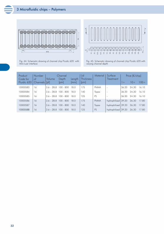
Fig. 44: Schematic drawing of channel chip Fluidic 620 with Mini Luer interface
Fig. 45: Schematic drawing of channel chip Fluidic 620 with varying channel depth
3 Microfluidic chips – Polymers
33
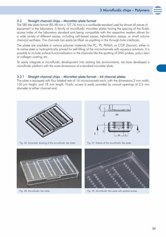
3.3 Straight channel chips – Microtiter-plate format The SBS titer-plate format (85.48 mm x 127.76 mm) is a worldwide standard used by almost all pieces ofequipment in the laboratory. A family of microfluidic microtiter plates having the spacing of the fluidic access holes of the laboratory standard and being compatible with the respective readers allows for a wide variety of different assays, including cell-based assays, hybridization assays, or small volume chemical synthesis. The channels can easily be filled via pipetting in the through-hole interfaces.
The plates are available in various polymer materials like PC, PS, PMMA, or COP (Zeonor), either in its native state or hydrophilically primed for self-filling of the microchannels with aqueous solutions. It is possible to include surface functionalization in the channels like the spotting of DNA probes, poly-L-lysin or collagen coating, etc.
To easily integrate a microfluidic development into existing lab environments, we have developed a microfluidic platform with the outer dimensions of a standard microtiter plate.
3.3.1 Straight channel chips – Microtiter-plate format – 64 channel platesThe plate is equipped with four labeled sets of 16 microchannels each, with the dimensions 2 mm width, 150 µm height, and 18 mm length. Fluidic access is easily provided by conical openings of 2.5 mm diameter at either channel end.
Fig. 46: Schematic drawing of the microfluidic titer plate Fig. 47: Details of the microfluidic titer plate
Fig. 48: Microfluidic titer plate Fig. 49: Microfluidic titer plate with spotted probes
3 Microfluidic chips – Polymers
34
10000352
10000353
10000335
10000320
10000646
10000647
10000364
10000649
2
2
2
2
2
2
2
2
0.15
0.15
0.15
0.15
0.15
0.15
0.15
0.15
18
18
18
18
18
18
18
18
PMMA
PC
PS
Zeonor
PMMA
PC
PS
Zeonor
-
-
-
-
hydrophilized
hydrophilized
hydrophilized
hydrophilized
Product Code
for Fluidic 102
Channel DimensionsWidth[mm]
Depth[mm]
Material SurfaceTreatment
Price [€/chip]
1+ 10+ 30+Length[mm]
79.00
79.00
79.00
79.00
98.00
98.00
98.00
98.00
59.00
59.00
59.00
59.00
78.00
78.00
78.00
78.00
29.00
29.00
29.00
29.00
38.00
38.00
38.00
38.00
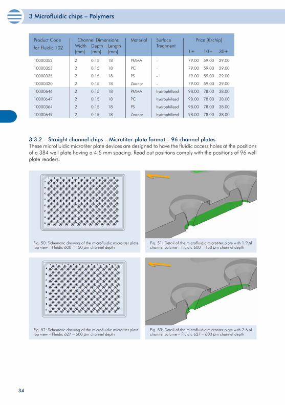
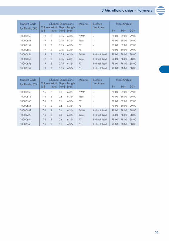
3.3.2 Straight channel chips – Microtiter-plate format – 96 channel plates These microfluidic microtiter plate devices are designed to have the fluidic access holes at the positions of a 384 well plate having a 4.5 mm spacing. Read out positions comply with the positions of 96 well plate readers.
Fig. 51: Detail of the microfluidic microtiter plate with 1.9 µl channel volume – Fluidic 600 – 150 µm channel depth
Fig. 50: Schematic drawing of the microfluidic microtiter plate top view – Fluidic 600 – 150 µm channel depth
Fig. 52: Schematic drawing of the microfluidic microtiter plate top view – Fluidic 627 – 600 µm channel depth
Fig. 53: Detail of the microfluidic microtiter plate with 7.6 µl channel volume – Fluidic 627 – 600 µm channel depth
3 Microfluidic chips – Polymers
35
10000650
10000651
10000652
10000653
10000654
10000655
10000656
10000657
2
2
2
2
2
2
2
2
0.15
0.15
0.15
0.15
0.15
0.15
0.15
0.15
6.364
6.364
6.364
6.364
6.364
6.364
6.364
6.364
PMMA
Topas
PC
PS
PMMA
Topas
PC
PS
-
-
-
-
hydrophilized
hydrophilized
hydrophilized
hydrophilized
Product Code
for Fluidic 600
Channel DimensionsWidth[mm]
Depth[mm]
Material SurfaceTreatment
Price [€/chip]
1+ 10+ 30+Length[mm]
79.00
79.00
79.00
79.00
98.00
98.00
98.00
98.00
59.00
59.00
59.00
59.00
78.00
78.00
78.00
78.00
29.00
29.00
29.00
29.00
38.00
38.00
38.00
38.00
1.9
1.9
1.9
1.9
1.9
1.9
1.9
1.9
Volume[µl]
10000658
10000616
10000660
10000661
10000662
10000720
10000664
10000665
2
2
2
2
2
2
2
2
0.6
0.6
0.6
0.6
0.6
0.6
0.6
0.6
6.364
6.364
6.364
6.364
6.364
6.364
6.364
6.364
PMMA
Topas
PC
PS
PMMA
Topas
PC
PS
-
-
-
-
hydrophilized
hydrophilized
hydrophilized
hydrophilized
Product Code
for Fluidic 627
Channel DimensionsWidth[mm]
Depth[mm]
Material SurfaceTreatment
Price [€/chip]
1+ 10+ 30+Length[mm]
79.00
79.00
79.00
79.00
98.00
98.00
98.00
98.00
59.00
59.00
59.00
59.00
78.00
78.00
78.00
78.00
29.00
29.00
29.00
29.00
38.00
38.00
38.00
38.00
7.6
7.6
7.6
7.6
7.6
7.6
7.6
7.6
Volume[µl]
3 Microfluidic chips – Polymers
36
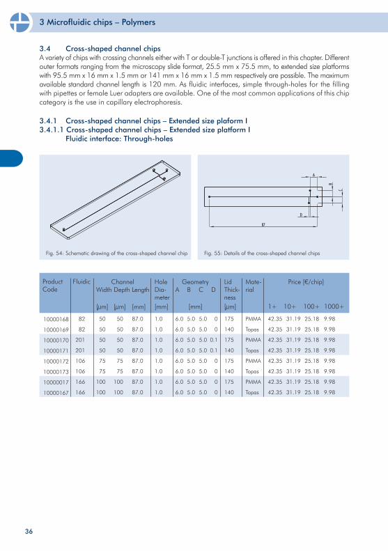
3.4 Cross-shaped channel chipsA variety of chips with crossing channels either with T or double-T junctions is offered in this chapter. Different outer formats ranging from the microscopy slide format, 25.5 mm x 75.5 mm, to extended size platforms with 95.5 mm x 16 mm x 1.5 mm or 141 mm x 16 mm x 1.5 mm respectively are possible. The maximum available standard channel length is 120 mm. As fluidic interfaces, simple through-holes for the filling with pipettes or female Luer adapters are available. One of the most common applications of this chip category is the use in capillary electrophoresis.
3.4.1 Cross-shaped channel chips – Extended size plaform I3.4.1.1 Cross-shaped channel chips – Extended size platform I Fluidic interface: Through-holes
Fig. 54: Schematic drawing of the cross-shaped channel chip Fig. 55: Details of the cross-shaped channel chips
10000168
10000169
10000170
10000171
10000172
10000173
10000017
10000167
50
50
50
50
75
75
100
100
87.0
87.0
87.0
87.0
87.0
87.0
87.0
87.0
6.0
6.0
6.0
6.0
6.0
6.0
6.0
6.0
175
140
175
140
175
140
175
140
ChannelWidth
[µm]
Depth
[µm]
Geometry Price [€/chip]
1+ 10+ 100+
Length
[mm]
42.35
42.35
42.35
42.35
42.35
42.35
42.35
42.35
31.19
31.19
31.19
31.19
31.19
31.19
31.19
31.19
25.18
25.18
25.18
25.18
25.18
25.18
25.18
25.18
50
50
50
50
75
75
100
100
HoleDia-meter[mm]
1.0
1.0
1.0
1.0
1.0
1.0
1.0
1.0
A B C D
[mm]
5.0
5.0
5.0
5.0
5.0
5.0
5.0
5.0
5.0
5.0
5.0
5.0
5.0
5.0
5.0
5.0
0
0
0.1
0.1
0
0
0
0
LidThick-ness[µm]
PMMA
Topas
PMMA
Topas
PMMA
Topas
PMMA
Topas
Mate-rial
1000+
9.98
9.98
9.98
9.98
9.98
9.98
9.98
9.98
Product Code
Fluidic
82
82
201
201
106
106
166
166
3 Microfluidic chips – Polymers
37
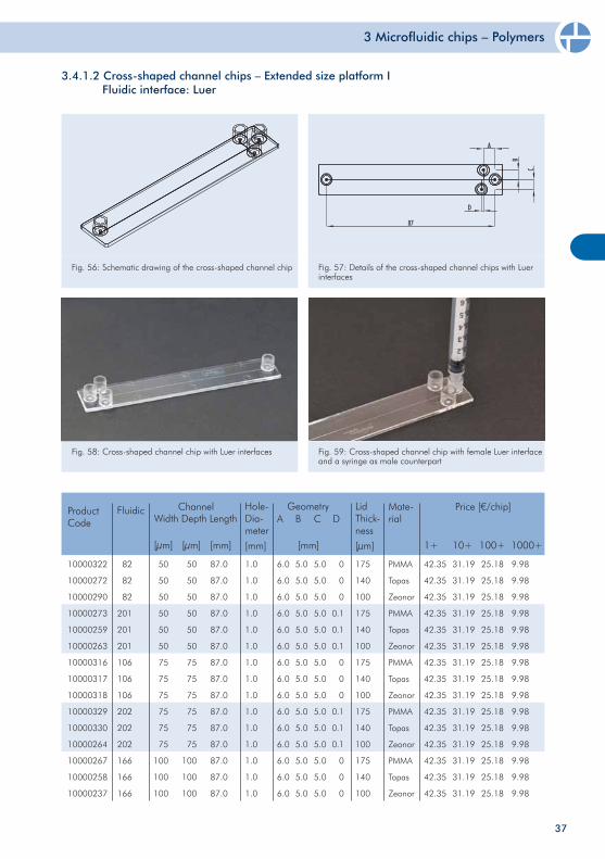
3.4.1.2 Cross-shaped channel chips – Extended size platform I Fluidic interface: Luer
Fig. 56: Schematic drawing of the cross-shaped channel chip Fig. 57: Details of the cross-shaped channel chips with Luer interfaces
Fig. 58: Cross-shaped channel chip with Luer interfaces Fig. 59: Cross-shaped channel chip with female Luer interface and a syringe as male counterpart
ChannelWidth Depth Length
LidThick-ness
[µm]
Mate-rial
Price [€/chip]
1+ 10+ 100+ 1000+
Hole-Dia-meter
[mm]
Geometry
[mm][mm][µm] [µm]
A B
10000322
10000272
10000290
10000273
10000259
10000263
10000316
10000317
10000318
10000329
10000330
10000264
10000267
10000258
10000237
50
50
50
50
50
50
75
75
75
75
75
75
100
100
100
50
50
50
50
50
50
75
75
75
75
75
75
100
100
100
87.0
87.0
87.0
87.0
87.0
87.0
87.0
87.0
87.0
87.0
87.0
87.0
87.0
87.0
87.0
1.0
1.0
1.0
1.0
1.0
1.0
1.0
1.0
1.0
1.0
1.0
1.0
1.0
1.0
1.0
6.0
6.0
6.0
6.0
6.0
6.0
6.0
6.0
6.0
6.0
6.0
6.0
6.0
6.0
6.0
5.0
5.0
5.0
5.0
5.0
5.0
5.0
5.0
5.0
5.0
5.0
5.0
5.0
5.0
5.0
5.0
5.0
5.0
5.0
5.0
5.0
5.0
5.0
5.0
5.0
5.0
5.0
5.0
5.0
5.0
0
0
0
0.1
0.1
0.1
0
0
0
0.1
0.1
0.1
0
0
0
175
140
100
175
140
100
175
140
100
175
140
100
175
140
100
PMMA
Topas
Zeonor
PMMA
Topas
Zeonor
PMMA
Topas
Zeonor
PMMA
Topas
Zeonor
PMMA
Topas
Zeonor
42.35
42.35
42.35
42.35
42.35
42.35
42.35
42.35
42.35
42.35
42.35
42.35
42.35
42.35
42.35
31.19
31.19
31.19
31.19
31.19
31.19
31.19
31.19
31.19
31.19
31.19
31.19
31.19
31.19
31.19
25.18
25.18
25.18
25.18
25.18
25.18
25.18
25.18
25.18
25.18
25.18
25.18
25.18
25.18
25.18
9.98
9.98
9.98
9.98
9.98
9.98
9.98
9.98
9.98
9.98
9.98
9.98
9.98
9.98
9.98
C DProduct Code
Fluidic
82
82
82
201
201
201
106
106
106
202
202
202
166
166
166
3 Microfluidic chips – Polymers
38
ChannelWidth Depth Length
LidThick-ness
[µm]
Mate-rial
Price [€/chip]
1+ 10+ 100+ 1000+
Hole-Dia-meter
[mm]
Geometry
[mm][mm][µm] [µm]
A B
10000232
10000016
10000233
10000234
10000235
10000236
200
200
200
400
400
400
200
200
200
200
200
200
87.0
87.0
87.0
87.0
87.0
87.0
1.0
1.0
1.0
1.0
1.0
1.0
6.0
6.0
6.0
6.0
6.0
6.0
5.0
5.0
5.0
5.0
5.0
5.0
5.0
5.0
5.0
5.0
5.0
5.0
0
0
0
0
0
0
175
140
100
175
140
100
PMMA
Topas
Zeonor
PMMA
Topas
Zeonor
42.35
42.35
42.35
42.35
42.35
42.35
31.19
31.19
31.19
31.19
31.19
31.19
25.18
25.18
25.18
25.18
25.18
25.18
9.98
9.98
9.98
9.98
9.98
9.98
C DProduct Code
Fluidic
394
394
394
395
395
395
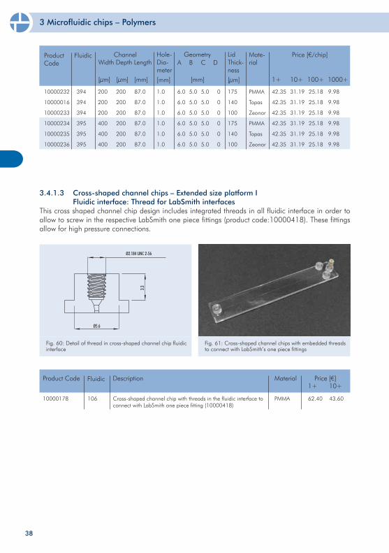
3.4.1.3 Cross-shaped channel chips – Extended size platform I Fluidic interface: Thread for LabSmith interfacesThis cross shaped channel chip design includes integrated threads in all fluidic interface in order to allow to screw in the respective LabSmith one piece fittings (product code:10000418). These fittings allow for high pressure connections.
Fig. 60: Detail of thread in cross-shaped channel chip fluidic interface
Fig. 61: Cross-shaped channel chips with embedded threads to connect with LabSmith’s one piece fittings
10000178 Cross-shaped channel chip with threads in the fluidic interface to connect with LabSmith one piece fitting (10000418)
Product Code Price [€]1+ 10+
62.40 43.60
Description
PMMA
MaterialFluidic
106
3 Microfluidic chips – Polymers
39
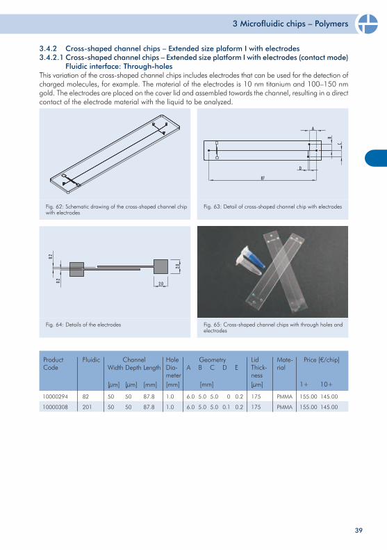
Fig. 62: Schematic drawing of the cross-shaped channel chip with electrodes
Fig. 63: Detail of cross-shaped channel chip with electrodes
3.4.2 Cross-shaped channel chips – Extended size plaform I with electrodes 3.4.2.1 Cross-shaped channel chips – Extended size platform I with electrodes (contact mode) Fluidic interface: Through-holesThis variation of the cross-shaped channel chips includes electrodes that can be used for the detection of charged molecules, for example. The material of the electrodes is 10 nm titanium and 100–150 nm gold. The electrodes are placed on the cover lid and assembled towards the channel, resulting in a direct contact of the electrode material with the liquid to be analyzed.
Fig. 64: Details of the electrodes Fig. 65: Cross-shaped channel chips with through holes and electrodes
10000294
10000308
50
50
87.8
87.8
6.0
6.0
175
175
ChannelWidth
[µm]
Depth
[µm]
Geometry Price [€/chip]
1+ 10+
Length
[mm]
155.00
155.00
145.00
145.00
50
50
HoleDia-meter[mm]
1.0
1.0
A B C D E
[mm]
5.0
5.0
5.0
5.0
0
0.1
LidThick-ness[µm]
PMMA
PMMA
Mate-rial
0.2
0.2
Product Code
Fluidic
82
201
3 Microfluidic chips – Polymers
40
10000028
10000027
10000337
10000338
10000464
10000398
10000397
10000396
50
50
100
100
200
200
400
400
87.0
87.0
87.0
87.0
87.0
87.0
87.0
87.0
6.0
6.0
6.0
6.0
6.0
6.0
6.0
6.0
60
60
60
50
60
50
60
50
ChannelWidth
[µm]
Depth
[µm]
Geometry Price [€/chip]
1+ 10+ 100+
Length
[mm]
125.00
125.00
125.00
125.00
125.00
125.00
125.00
125.00
85.00
85.00
85.00
85.00
85.00
85.00
85.00
85.00
32.50
32.50
32.50
32.50
32.50
32.50
32.50
32.50
50
50
100
100
200
200
200
200
HoleDia-meter[mm]
1.0
1.0
1.0
1.0
1.0
1.0
1.0
1.0
A B C D
[mm]
5.0
5.0
5.0
5.0
5.0
5.0
5.0
5.0
5.0
5.0
5.0
5.0
5.0
5.0
5.0
5.0
LidThick-ness[µm]
PMMA
PMMA
PMMA
Zeonor
PMMA
Zeonor
PMMA
Zeonor
Mate-rial
0
0.1
0
0
0
0
0
0
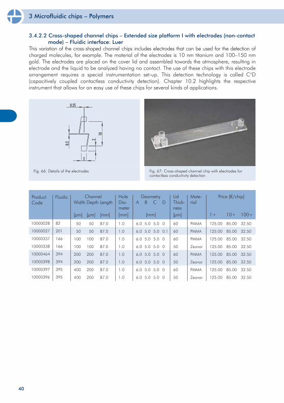
Fig. 66: Details of the electrodes Fig. 67: Cross-shaped channel chip with electrodes for contactless conductivity detection
Product Code
Fluidic
82
201
166
166
394
394
395
395
3.4.2.2 Cross-shaped channel chips – Extended size platform I with electrodes (non-contact mode) – Fluidic interface: Luer This variation of the cross-shaped channel chips includes electrodes that can be used for the detection of charged molecules, for example. The material of the electrodes is 10 nm titanium and 100–150 nm gold. The electrodes are placed on the cover lid and assembled towards the atmosphere, resulting in electrode and the liquid to be analyzed having no contact. The use of these chips with this electrode arrangement requires a special instrumentation set-up. This detection technology is called C4D (capacitively coupled contactless conductivity detection). Chapter 10.2 highlights the respective instrument that allows for an easy use of these chips for several kinds of applications.
3 Microfluidic chips – Polymers
41
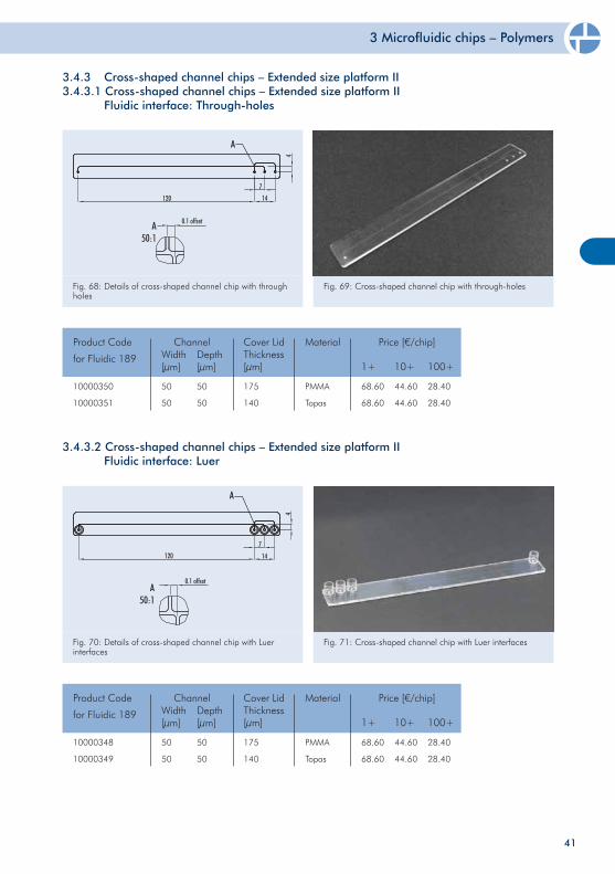
3.4.3.2 Cross-shaped channel chips – Extended size platform II Fluidic interface: Luer
Fig. 70: Details of cross-shaped channel chip with Luer interfaces
Fig. 71: Cross-shaped channel chip with Luer interfaces
10000348
10000349
50
50
50
50
175
140
PMMA
Topas
68.60
68.60
44.60
44.60
28.40
28.40
Product Code
for Fluidic 189
ChannelWidth[µm]
Depth[µm]
Cover LidThickness[µm]
Material Price [€/chip]
1+ 10+ 100+
3.4.3 Cross-shaped channel chips – Extended size platform II 3.4.3.1 Cross-shaped channel chips – Extended size platform II Fluidic interface: Through-holes
Fig. 68: Details of cross-shaped channel chip with through holes
Fig. 69: Cross-shaped channel chip with through-holes
10000350
10000351
50
50
50
50
175
140
PMMA
Topas
68.60
68.60
44.60
44.60
28.40
28.40
Product Code
for Fluidic 189
ChannelWidth[µm]
Depth[µm]
Cover LidThickness[µm]
Material Price [€/chip]
1+ 10+ 100+
3 Microfluidic chips – Polymers
42
10000325
10000326
10000303
10000327
50
50
80
80
50
50
80
80
175
140
175
140
PMMA
Topas
PMMA
Topas
42.50
42.50
42.50
42.50
31.20
31.20
31.20
31.20
23.50
23.50
23.50
23.50
Product Code ChannelWidth[µm]
Depth[µm]
Cover LidThickness[µm]
Material Price [€/chip]
1+ 10+ 30+
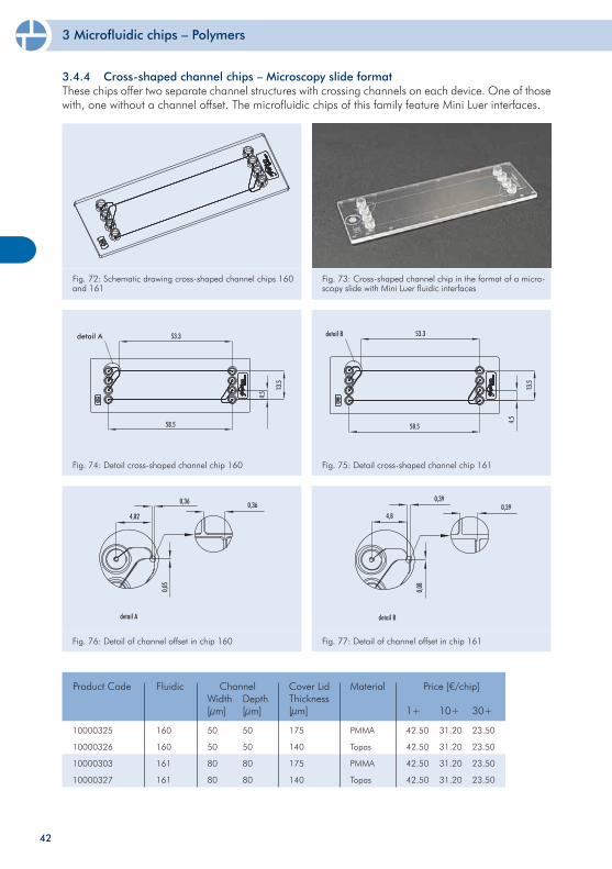
Fig. 75: Detail cross-shaped channel chip 161
Fig. 73: Cross-shaped channel chip in the format of a micro-scopy slide with Mini Luer fluidic interfaces
3.4.4 Cross-shaped channel chips – Microscopy slide format These chips offer two separate channel structures with crossing channels on each device. One of those with, one without a channel offset. The microfluidic chips of this family feature Mini Luer interfaces.
Fig. 72: Schematic drawing cross-shaped channel chips 160 and 161
Fig. 74: Detail cross-shaped channel chip 160
Fig. 76: Detail of channel offset in chip 160 Fig. 77: Detail of channel offset in chip 161
Fluidic
160
160
161
161
3 Microfluidic chips – Polymers
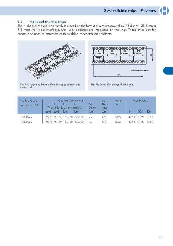
Fig. 78: Schematic drawing of the H-shaped channel chip Fluidic 164
Fig. 79: Detail of H-shaped channel chip
3.5 H-shaped channel chips The H-shaped channel chip family is placed on the format of a microscopy slide (75.5 mm x 25.5 mm x 1.5 mm). As fluidic interfaces, Mini Luer adapters are integrated on the chip. These chips can for example be used as extractors or to establish concentration gradients.
43
10000265
10000266
175
140
Product Code
for Fluidic 164
Channel Dimensions
Width inlet & outlet / middle
Price [€/chip]
1+ 10+ 30+
42.50
42.50
31.20
31.20
23.50
23.50
[µm]
150/300
150/300
75
75
LidThick-ness[µm]
PMMA
Topas
Mate-rialAll
DepthIV
[µm][µm]
150/150
150/150
III
[µm]
75/150
75/150
II
[µm]
75/75
75/75
I
3 Microfluidic chips – Polymers
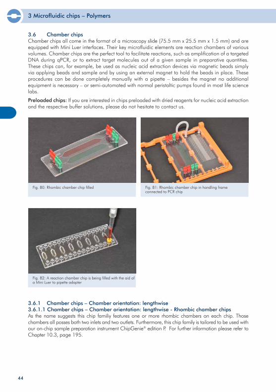
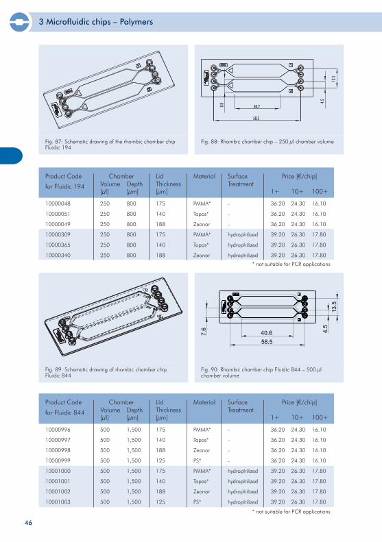
3.6 Chamber chips Chamber chips all come in the format of a microscopy slide (75.5 mm x 25.5 mm x 1.5 mm) and are equipped with Mini Luer interfaces. Their key microfluidic elements are reaction chambers of various volumes. Chamber chips are the perfect tool to facilitate reactions, such as amplification of a targeted DNA during qPCR, or to extract target molecules out of a given sample in preparative quantities. These chips can, for example, be used as nucleic acid extraction devices via magnetic beads simply via applying beads and sample and by using an external magnet to hold the beads in place. These procedures can be done completely manually with a pipette – besides the magnet no additional equipment is necessary – or semi-automated with normal peristaltic pumps found in most life science labs.
Preloaded chips: If you are interested in chips preloaded with dried reagents for nucleic acid extraction and the respective buffer solutions, please do not hesitate to contact us.
Fig. 82: A reaction chamber chip is being filled with the aid of a Mini Luer to pipette adapter
3.6.1 Chamber chips – Chamber orientation: lengthwise3.6.1.1 Chamber chips – Chamber orientation: lengthwise - Rhombic chamber chipsAs the name suggests this chip familiy features one or more rhombic chambers on each chip. Those chambers all posses both two inlets and two outlets. Furthermore, this chip family is tailored to be used with our on-chip sample preparation instrument ChipGenie® edition P. For further information please refer to Chapter 10.3, page 195.
44
Fig. 80: Rhombic chamber chip filled Fig. 81: Rhombic chamber chip in handling frame connected to PCR chip
3 Microfluidic chips – Polymers
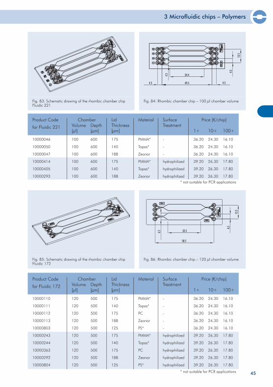
Fig. 83: Schematic drawing of the rhombic chamber chip Fluidic 221
Fig. 84: Rhombic chamber chip – 100 µl chamber volume
10000110
10000111
10000112
10000113
10000803
10000243
10000244
10000363
10000292
10000804
120
120
120
120
120
120
120
120
120
120
500
500
500
500
500
500
500
500
500
500
175
140
175
188
125
175
140
175
188
125
PMMA*
Topas*
PC
Zeonor
PS*
PMMA*
Topas*
PC
Zeonor
PS*
-
-
-
-
-
hydrophilized
hydrophilized
hydrophilized
hydrophilized
hydrophilized
Product Code
for Fluidic 172
ChamberVolume[µl]
Depth[µm]
Material SurfaceTreatment
Price [€/chip]
1+ 10+ 100+
LidThickness[µm]
36.20
36.20
36.20
36.20
36.20
39.20
39.20
39.20
39.20
39.20
24.30
24.30
24.30
24.30
24.30
26.30
26.30
26.30
26.30
26.30
16.10
16.10
16.10
16.10
16.10
17.80
17.80
17.80
17.80
17.80
10000046
10000050
10000047
10000414
10000405
10000293
100
100
100
100
100
100
600
600
600
600
600
600
175
140
188
175
140
188
PMMA*
Topas*
Zeonor
PMMA*
Topas*
Zeonor
-
-
-
hydrophilized
hydrophilized
hydrophilized
Product Code
for Fluidic 221
ChamberVolume[µl]
Depth[µm]
Material SurfaceTreatment
Price [€/chip]
1+ 10+ 100+
LidThickness[µm]
36.20
36.20
36.20
39.20
39.20
39.20
24.30
24.30
24.30
26.30
26.30
26.30
16.10
16.10
16.10
17.80
17.80
17.80
Fig. 85: Schematic drawing of the rhombic chamber chipFluidic 172
Fig. 86: Rhombic chamber chip – 120 µl chamber volume
45
* not suitable for PCR applications
* not suitable for PCR applications
3 Microfluidic chips – Polymers
10000048
10000051
10000049
10000309
10000365
10000340
250
250
250
250
250
250
800
800
800
800
800
800
175
140
188
175
140
188
PMMA*
Topas*
Zeonor
PMMA*
Topas*
Zeonor
-
-
-
hydrophilized
hydrophilized
hydrophilized
Product Code
for Fluidic 194
ChamberVolume[µl]
Depth[µm]
Material SurfaceTreatment
Price [€/chip]
1+ 10+ 100+
LidThickness[µm]
36.20
36.20
36.20
39.20
39.20
39.20
24.30
24.30
24.30
26.30
26.30
26.30
16.10
16.10
16.10
17.80
17.80
17.80
Fig. 87: Schematic drawing of the rhombic chamber chip Fluidic 194
Fig. 88: Rhombic chamber chip – 250 µl chamber volume
46
Fig. 89: Schematic drawing of rhombic chamber chip Fluidic 844
Fig. 90: Rhombic chamber chip Fluidic 844 – 500 µl chamber volume
10000996
10000997
10000998
10000999
10001000
10001001
10001002
10001003
500
500
500
500
500
500
500
500
1,500
1,500
1,500
1,500
1,500
1,500
1,500
1,500
175
140
188
125
175
140
188
125
PMMA*
Topas*
Zeonor
PS*
PMMA*
Topas*
Zeonor
PS*
-
-
-
-
hydrophilized
hydrophilized
hydrophilized
hydrophilized
Product Code
for Fluidic 844
ChamberVolume[µl]
Depth[µm]
Material SurfaceTreatment
Price [€/chip]
1+ 10+ 100+
LidThickness[µm]
36.20
36.20
36.20
36.20
39.20
39.20
39.20
39.20
24.30
24.30
24.30
24.30
26.30
26.30
26.30
26.30
16.10
16.10
16.10
16.10
17.80
17.80
17.80
17.80
* not suitable for PCR applications
* not suitable for PCR applications
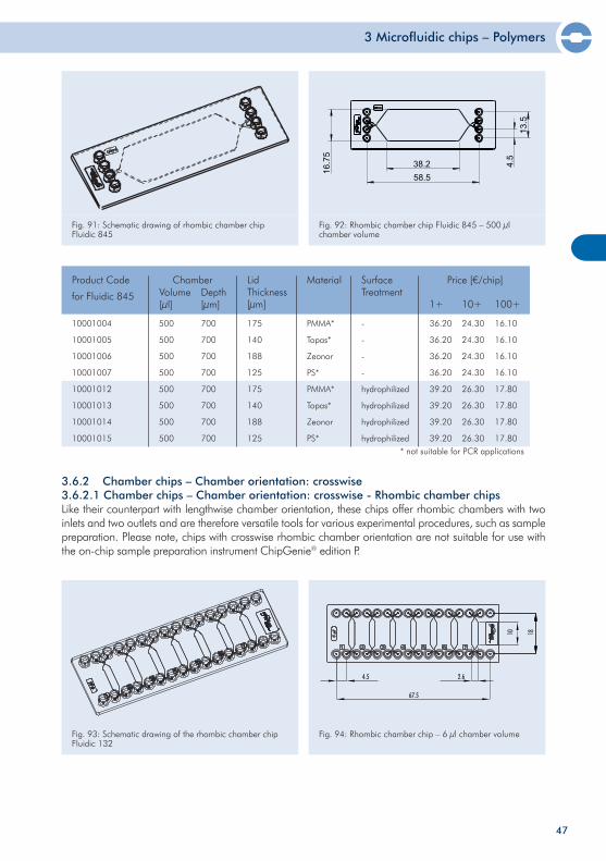
3 Microfluidic chips – Polymers
Fig. 91: Schematic drawing of rhombic chamber chip Fluidic 845
Fig. 92: Rhombic chamber chip Fluidic 845 – 500 µl chamber volume
10001004
10001005
10001006
10001007
10001012
10001013
10001014
10001015
500
500
500
500
500
500
500
500
700
700
700
700
700
700
700
700
175
140
188
125
175
140
188
125
PMMA*
Topas*
Zeonor
PS*
PMMA*
Topas*
Zeonor
PS*
-
-
-
-
hydrophilized
hydrophilized
hydrophilized
hydrophilized
Product Code
for Fluidic 845
ChamberVolume[µl]
Depth[µm]
Material SurfaceTreatment
Price [€/chip]
1+ 10+ 100+
LidThickness[µm]
36.20
36.20
36.20
36.20
39.20
39.20
39.20
39.20
24.30
24.30
24.30
24.30
26.30
26.30
26.30
26.30
16.10
16.10
16.10
16.10
17.80
17.80
17.80
17.80
47
3.6.2 Chamber chips – Chamber orientation: crosswise3.6.2.1 Chamber chips – Chamber orientation: crosswise - Rhombic chamber chipsLike their counterpart with lengthwise chamber orientation, these chips offer rhombic chambers with two inlets and two outlets and are therefore versatile tools for various experimental procedures, such as sample preparation. Please note, chips with crosswise rhombic chamber orientation are not suitable for use with the on-chip sample preparation instrument ChipGenie® edition P.
Fig. 93: Schematic drawing of the rhombic chamber chip Fluidic 132
Fig. 94: Rhombic chamber chip – 6 µl chamber volume
* not suitable for PCR applications
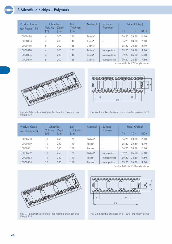
3 Microfluidic chips – Polymers
48
10000114
10000034
10000115
10000310
10000035
10000279
6
6
6
6
6
6
200
200
200
200
200
200
175
140
188
175
140
188
PMMA*
Topas*
Zeonor
PMMA*
Topas*
Zeonor
-
-
-
hydrophilized
hydrophilized
hydrophilized
Product Code
for Fluidic 132
ChamberVolume[µl]
Depth[µm]
Material SurfaceTreatment
Price [€/chip]
1+ 10+ 100+
LidThickness[µm]
36.20
36.20
36.20
39.20
39.20
39.20
24.30
24.30
24.30
26.30
26.30
26.30
16.10
16.10
16.10
17.80
17.80
17.80
10000530
10000399
10000531
10000532
10000533
10000534
10
10
10
10
10
10
250
250
250
250
250
250
175
140
188
175
140
188
PMMA*
Topas*
Zeonor
PMMA*
Topas*
Zeonor
-
-
-
hydrophilized
hydrophilized
hydrophilized
Product Code
for Fluidic 439
ChamberVolume[µl]
Depth[µm]
Material SurfaceTreatment
Price [€/chip]
1+ 10+ 100+
LidThickness[µm]
36.20
36.20
36.20
39.20
39.20
39.20
24.30
24.30
24.30
26.30
26.30
26.30
16.10
16.10
16.10
17.80
17.80
17.80
Fig. 95: Schematic drawing of the rhombic chamber chip Fluidic 439
Fig. 96: Rhombic chamber chip – chamber volume 10 µl
Fig. 97: Schematic drawing of the rhombic chamber chip Fluidic 131
Fig. 98: Rhombic chamber chip – 20 µl chamber volume
* not suitable for PCR applications
* not suitable for PCR applications
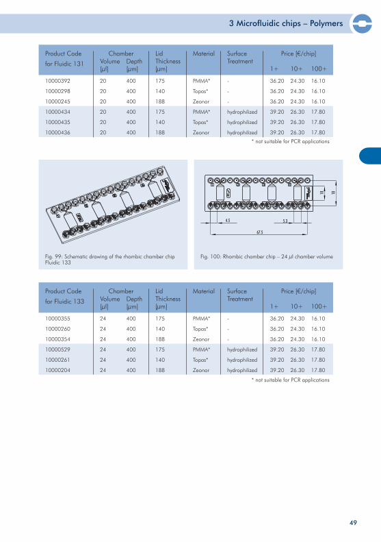
3 Microfluidic chips – Polymers
49
10000392
10000298
10000245
10000434
10000435
10000436
20
20
20
20
20
20
400
400
400
400
400
400
175
140
188
175
140
188
PMMA*
Topas*
Zeonor
PMMA*
Topas*
Zeonor
-
-
-
hydrophilized
hydrophilized
hydrophilized
Product Code
for Fluidic 131
ChamberVolume[µl]
Depth[µm]
Material SurfaceTreatment
Price [€/chip]
1+ 10+ 100+
LidThickness[µm]
36.20
36.20
36.20
39.20
39.20
39.20
24.30
24.30
24.30
26.30
26.30
26.30
16.10
16.10
16.10
17.80
17.80
17.80
Fig. 99: Schematic drawing of the rhombic chamber chip Fluidic 133
Fig. 100: Rhombic chamber chip – 24 µl chamber volume
10000355
10000260
10000354
10000529
10000261
10000204
24
24
24
24
24
24
400
400
400
400
400
400
175
140
188
175
140
188
PMMA*
Topas*
Zeonor
PMMA*
Topas*
Zeonor
-
-
-
hydrophilized
hydrophilized
hydrophilized
Product Code
for Fluidic 133
ChamberVolume[µl]
Depth[µm]
Material SurfaceTreatment
Price [€/chip]
1+ 10+ 100+
LidThickness[µm]
36.20
36.20
36.20
39.20
39.20
39.20
24.30
24.30
24.30
26.30
26.30
26.30
16.10
16.10
16.10
17.80
17.80
17.80
* not suitable for PCR applications
* not suitable for PCR applications
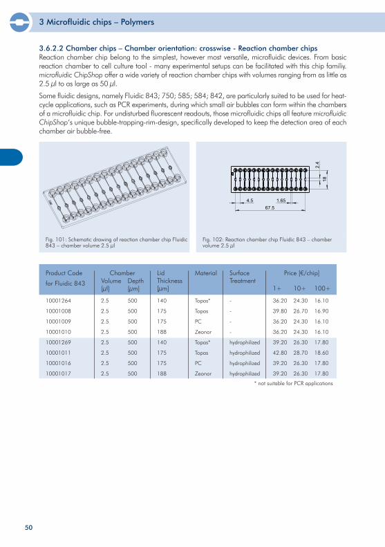
3 Microfluidic chips – Polymers
50
10001264
10001008
10001009
10001010
10001269
10001011
10001016
10001017
2.5
2.5
2.5
2.5
2.5
2.5
2.5
2.5
500
500
500
500
500
500
500
500
140
175
175
188
140
175
175
188
Topas*
Topas
PC
Zeonor
Topas*
Topas
PC
Zeonor
-
-
-
-
hydrophilized
hydrophilized
hydrophilized
hydrophilized
Product Code
for Fluidic 843
ChamberVolume[µl]
Depth[µm]
Material SurfaceTreatment
Price [€/chip]
1+ 10+ 100+
LidThickness[µm]
36.20
39.80
36.20
36.20
39.20
42.80
39.20
39.20
24.30
26.70
24.30
24.30
26.30
28.70
26.30
26.30
16.10
16.90
16.10
16.10
17.80
18.60
17.80
17.80
* not suitable for PCR applications
Fl. 843
Fig. 92: Reaction chamber chip Fluidic 843 - chamber volume 2.5 µl
67.54.5 1.65
2.4
18
Fig. 101: Schematic drawing of reaction chamber chip Fluidic 843 – chamber volume 2.5 µl
Fig. 102: Reaction chamber chip Fluidic 843 – chamber volume 2.5 µl
3.6.2.2 Chamber chips – Chamber orientation: crosswise - Reaction chamber chipsReaction chamber chip belong to the simplest, however most versatile, microfluidic devices. From basic reaction chamber to cell culture tool - many experimental setups can be facilitated with this chip familiy. microfluidic ChipShop offer a wide variety of reaction chamber chips with volumes ranging from as little as 2.5 µl to as large as 50 µl.
Some fluidic designs, namely Fluidic 843; 750; 585; 584; 842, are particularly suited to be used for heat-cycle applications, such as PCR experiments, during which small air bubbles can form within the chambers of a microfluidic chip. For undisturbed fluorescent readouts, those microfluidic chips all feature microfluidic ChipShop‘s unique bubble-trapping-rim-design, specifically developed to keep the detection area of each chamber air bubble-free.
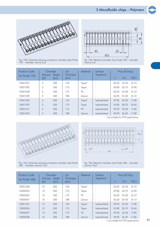
3 Microfluidic chips – Polymers
51
10001037
10001292
10001038
10001039
10001040
10001293
10001041
10001042
5
5
5
5
5
5
5
5
500
500
500
500
500
500
500
500
140
175
175
188
140
175
175
188
Topas*
Topas
PC
Zeonor
Topas*
Topas
PC
Zeonor
-
-
-
-
hydrophilized
hydrophilized
hydrophilized
hydrophilized
Product Code
for Fluidic 750
ChamberVolume[µl]
Depth[µm]
Material SurfaceTreatment
Price [€/chip]
1+ 10+ 100+
LidThickness[µm]
36.20
39.80
36.20
36.20
39.20
42.80
39.20
39.20
24.30
26.70
24.30
24.30
26.30
28.70
26.30
26.30
16.10
16.90
16.10
16.10
17.80
18.60
17.80
17.80
* not suitable for PCR applications
Fig. 105: Schematic drawing of reaction chamber chip Fluidic 585 – chamber volume 10 µl
Fig. 106: Reaction chamber chip Fluidic 585 – chamber volume 10 µl
Chamber
10001268
10000524
10000525
10000447
10001267
10000526
10000527
10000528
10
10
10
10
10
10
10
10
500
500
500
500
500
500
500
500
140
175
175
188
140
175
175
188
Topas*
Topas
PC
Zeonor
Topas*
Topas
PC
Zeonor
-
-
-
-
hydrophilized
hydrophilized
hydrophilized
hydrophilized
Product Code
for Fluidic 585 Volume[µl]
Depth[µm]
Material SurfaceTreatment
Price [€/chip]
1+ 10+ 100+
LidThickness[µm]
36.20
39.80
36.20
36.20
39.20
42.80
39.20
39.20
24.30
26.70
24.30
24.30
26.30
28.70
26.30
26.30
16.10
16.90
16.10
16.10
17.80
18.60
17.80
17.80
* not suitable for PCR applications
Chamber
67.54.5 2.3
4.918
Fig. 103: Schematic drawing of reaction chamber chip Fluidic 750 – chamber volume 5 µl
Fig. 104: Reaction chamber chip Fluidic 750 – chamber volume 5 µl
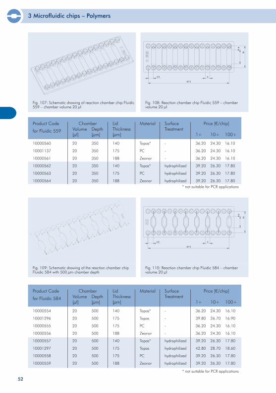
3 Microfluidic chips – Polymers
52
Fig. 107: Schematic drawing of reaction chamber chip Fluidic 559 – chamber volume 20 µl
Fig. 108: Reaction chamber chip Fluidic 559 – chamber volume 20 µl
10000560
10001137
10000561
10000562
10000563
10000564
20
20
20
20
20
20
350
350
350
350
350
350
140
175
188
140
175
188
Topas*
PC
Zeonor
Topas*
PC
Zeonor
-
-
-
hydrophilized
hydrophilized
hydrophilized
Product Code
for Fluidic 559
ChamberVolume[µl]
Depth[µm]
Material SurfaceTreatment
Price [€/chip]
1+ 10+ 100+
LidThickness[µm]
36.20
36.20
36.20
39.20
39.20
39.20
24.30
24.30
24.30
26.30
26.30
26.30
16.10
16.10
16.10
17.80
17.80
17.80
Fig. 109: Schematic drawing of the reaction chamber chip Fluidic 584 with 500 µm chamber depth
Fig. 110: Reaction chamber chip Fluidic 584 – chamber volume 20 µl
10000554
10001296
10000555
10000556
10000557
10001297
10000558
10000559
20
20
20
20
20
20
20
20
500
500
500
500
500
500
500
500
140
175
175
188
140
175
175
188
Topas*
Topas
PC
Zeonor
Topas*
Topas
PC
Zeonor
-
-
-
-
hydrophilized
hydrophilized
hydrophilized
hydrophilized
Product Code
for Fluidic 584
ChamberVolume[µl]
Depth[µm]
Material SurfaceTreatment
Price [€/chip]
1+ 10+
LidThickness[µm]
36.20
39.80
36.20
36.20
39.20
42.80
39.20
39.20
24.30
26.70
24.30
24.30
26.30
28.70
26.30
26.30
* not suitable for PCR applications
100+
16.10
16.90
16.10
16.10
17.80
18.60
17.80
17.80
* not suitable for PCR applications
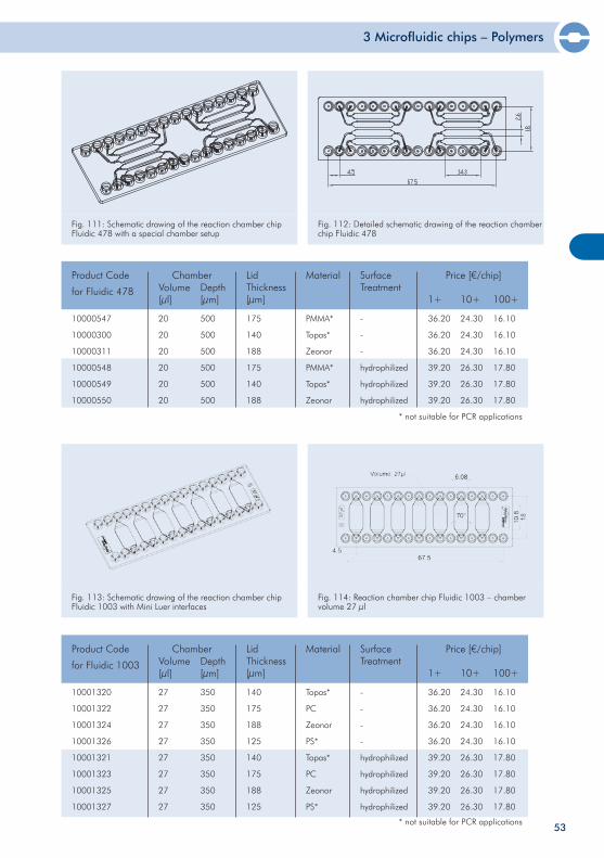
3 Microfluidic chips – Polymers
53
Fig. 111: Schematic drawing of the reaction chamber chip Fluidic 478 with a special chamber setup
Fig. 112: Detailed schematic drawing of the reaction chamber chip Fluidic 478
10000547
10000300
10000311
10000548
10000549
10000550
20
20
20
20
20
20
500
500
500
500
500
500
175
140
188
175
140
188
PMMA*
Topas*
Zeonor
PMMA*
Topas*
Zeonor
-
-
-
hydrophilized
hydrophilized
hydrophilized
Product Code
for Fluidic 478
ChamberVolume[µl]
Depth[µm]
Material SurfaceTreatment
Price [€/chip]
1+ 10+ 100+
LidThickness[µm]
36.20
36.20
36.20
39.20
39.20
39.20
24.30
24.30
24.30
26.30
26.30
26.30
16.10
16.10
16.10
17.80
17.80
17.80
Fig. 113: Schematic drawing of the reaction chamber chip Fluidic 1003 with Mini Luer interfaces
Fig. 114: Reaction chamber chip Fluidic 1003 – chamber volume 27 µl
10001320
10001322
10001324
10001326
10001321
10001323
10001325
10001327
27
27
27
27
27
27
27
27
350
350
350
350
350
350
350
350
140
175
188
125
140
175
188
125
Topas*
PC
Zeonor
PS*
Topas*
PC
Zeonor
PS*
-
-
-
-
hydrophilized
hydrophilized
hydrophilized
hydrophilized
Product Code
for Fluidic 1003
ChamberVolume[µl]
Depth[µm]
Material SurfaceTreatment
Price [€/chip]
1+ 10+ 100+
LidThickness[µm]
36.20
36.20
36.20
36.20
39.20
39.20
39.20
39.20
24.30
24.30
24.30
24.30
26.30
26.30
26.30
26.30
16.10
16.10
16.10
16.10
17.80
17.80
17.80
17.80
* not suitable for PCR applications
* not suitable for PCR applications
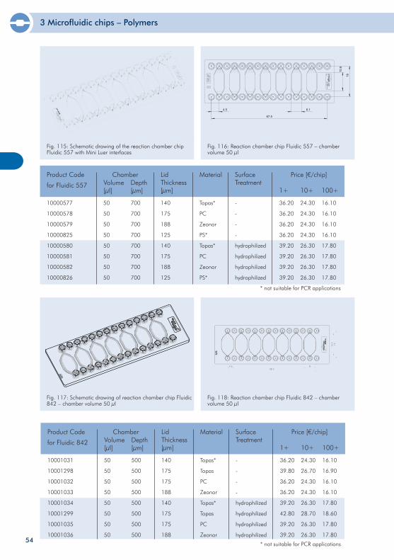
3 Microfluidic chips – Polymers
54
Fig. 117: Schematic drawing of reaction chamber chip Fluidic 842 – chamber volume 50 µl
Fig. 118: Reaction chamber chip Fluidic 842 – chamber volume 50 µl
10001031
10001298
10001032
10001033
10001034
10001299
10001035
10001036
50
50
50
50
50
50
50
50
500
500
500
500
500
500
500
500
140
175
175
188
140
175
175
188
Topas*
Topas
PC
Zeonor
Topas*
Topas
PC
Zeonor
-
-
-
-
hydrophilized
hydrophilized
hydrophilized
hydrophilized
Product Code
for Fluidic 842
ChamberVolume[µl]
Depth[µm]
Material SurfaceTreatment
Price [€/chip]
1+ 10+ 100+
LidThickness[µm]
36.20
39.80
36.20
36.20
39.20
42.80
39.20
39.20
24.30
26.70
24.30
24.30
26.30
28.70
26.30
26.30
16.10
16.90
16.10
16.10
17.80
18.60
17.80
17.80
* not suitable for PCR applications
Fig. 115: Schematic drawing of the reaction chamber chip Fluidic 557 with Mini Luer interfaces
Fig. 116: Reaction chamber chip Fluidic 557 – chamber volume 50 µl
10000577
10000578
10000579
10000825
10000580
10000581
10000582
10000826
50
50
50
50
50
50
50
50
700
700
700
700
700
700
700
700
140
175
188
125
140
175
188
125
Topas*
PC
Zeonor
PS*
Topas*
PC
Zeonor
PS*
-
-
-
-
hydrophilized
hydrophilized
hydrophilized
hydrophilized
Product Code
for Fluidic 557
ChamberVolume[µl]
Depth[µm]
Material SurfaceTreatment
Price [€/chip]
1+ 10+ 100+
LidThickness[µm]
36.20
36.20
36.20
36.20
39.20
39.20
39.20
39.20
24.30
24.30
24.30
24.30
26.30
26.30
26.30
26.30
16.10
16.10
16.10
16.10
17.80
17.80
17.80
17.80
* not suitable for PCR applications
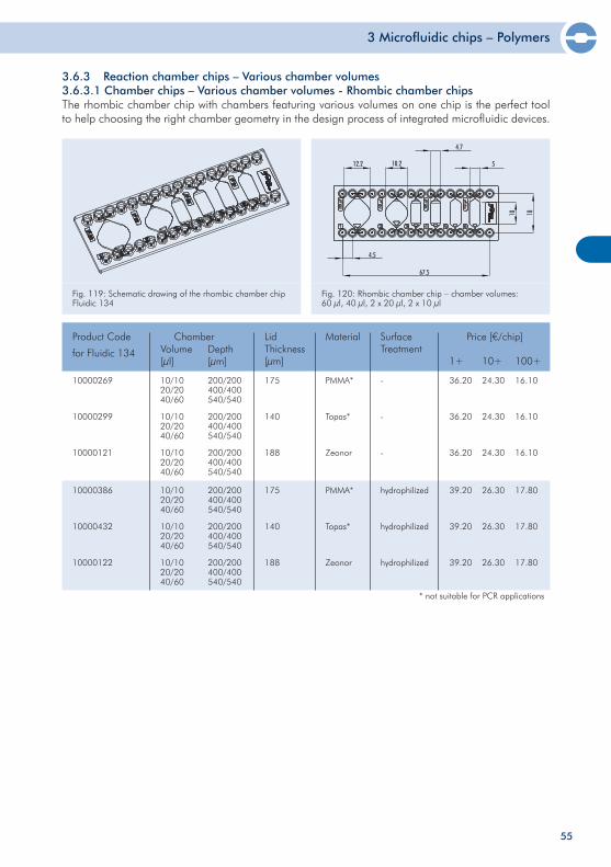
3 Microfluidic chips – Polymers
55
10000269
10000299
10000121
10000386
10000432
10000122
10/1020/2040/60
10/1020/2040/60
10/1020/2040/60
10/1020/2040/60
10/1020/2040/60
10/1020/2040/60
175
140
188
175
140
188
PMMA*
Topas*
Zeonor
PMMA*
Topas*
Zeonor
-
-
-
hydrophilized
hydrophilized
hydrophilized
Product Code
for Fluidic 134
ChamberVolume[µl]
Depth[µm]
Material SurfaceTreatment
Price [€/chip]
1+ 10+ 100+
LidThickness[µm]
36.20
36.20
36.20
39.20
39.20
39.20
24.30
24.30
24.30
26.30
26.30
26.30
16.10
16.10
16.10
17.80
17.80
17.80
200/200400/400540/540
200/200400/400540/540
200/200400/400540/540
200/200400/400540/540
200/200400/400540/540
200/200400/400540/540
Fig. 119: Schematic drawing of the rhombic chamber chip Fluidic 134
Fig. 120: Rhombic chamber chip – chamber volumes: 60 µl, 40 µl, 2 x 20 µl, 2 x 10 µl
3.6.3 Reaction chamber chips – Various chamber volumes3.6.3.1 Chamber chips – Various chamber volumes - Rhombic chamber chipsThe rhombic chamber chip with chambers featuring various volumes on one chip is the perfect tool to help choosing the right chamber geometry in the design process of integrated microfluidic devices.
* not suitable for PCR applications
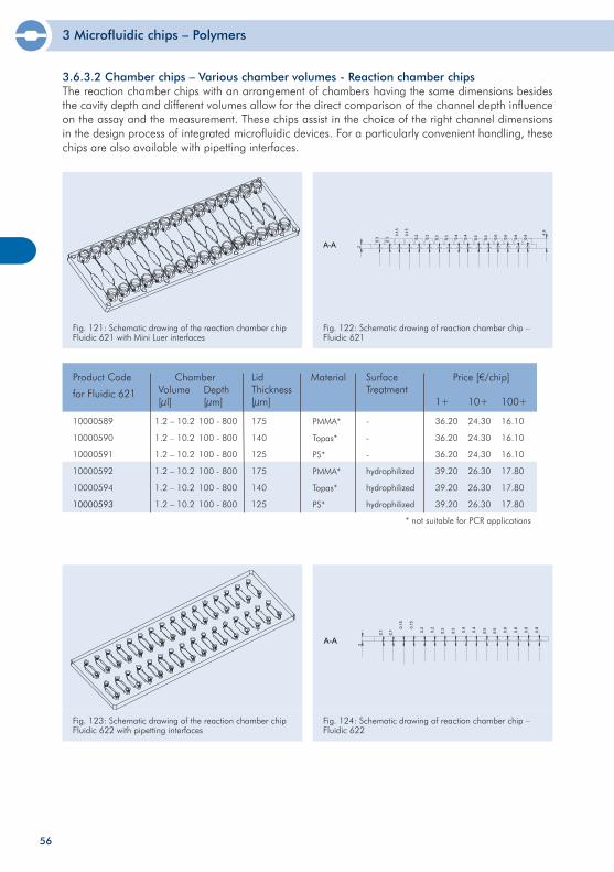
3 Microfluidic chips – Polymers
56
Fig. 123: Schematic drawing of the reaction chamber chip Fluidic 622 with pipetting interfaces
Fig. 124: Schematic drawing of reaction chamber chip – Fluidic 622
10000589
10000590
10000591
10000592
10000594
10000593
1.2 – 10.2
1.2 – 10.2
1.2 – 10.2
1.2 – 10.2
1.2 – 10.2
1.2 – 10.2
100 - 800
100 - 800
100 - 800
100 - 800
100 - 800
100 - 800
175
140
125
175
140
125
PMMA*
Topas*
PS*
PMMA*
Topas*
PS*
-
-
-
hydrophilized
hydrophilized
hydrophilized
Product Code
for Fluidic 621
ChamberVolume[µl]
Depth[µm]
Material SurfaceTreatment
Price [€/chip]
1+ 10+ 100+
LidThickness[µm]
36.20
36.20
36.20
39.20
39.20
39.20
24.30
24.30
24.30
26.30
26.30
26.30
16.10
16.10
16.10
17.80
17.80
17.80
3.6.3.2 Chamber chips – Various chamber volumes - Reaction chamber chipsThe reaction chamber chips with an arrangement of chambers having the same dimensions besides the cavity depth and different volumes allow for the direct comparison of the channel depth influence on the assay and the measurement. These chips assist in the choice of the right channel dimensions in the design process of integrated microfluidic devices. For a particularly convenient handling, these chips are also available with pipetting interfaces.
Fig. 121: Schematic drawing of the reaction chamber chip Fluidic 621 with Mini Luer interfaces
Fig. 122: Schematic drawing of reaction chamber chip – Fluidic 621
* not suitable for PCR applications
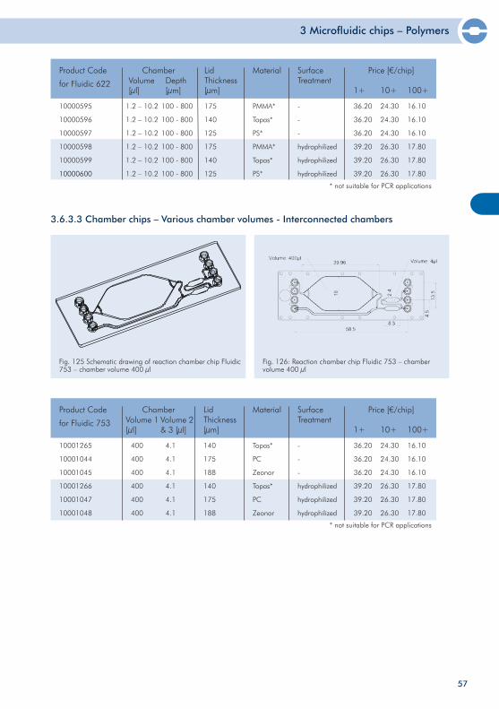
3 Microfluidic chips – Polymers
10001265
10001044
10001045
10001266
10001047
10001048
400
400
400
400
400
400
4.1
4.1
4.1
4.1
4.1
4.1
140
175
188
140
175
188
Topas*
PC
Zeonor
Topas*
PC
Zeonor
-
-
-
hydrophilized
hydrophilized
hydrophilized
Product Code
for Fluidic 753
ChamberVolume 1 [µl]
Volume 2 & 3 [µl]
Material SurfaceTreatment
Price [€/chip]
1+ 10+ 100+
LidThickness[µm]
36.20
36.20
36.20
39.20
39.20
39.20
24.30
24.30
24.30
26.30
26.30
26.30
16.10
16.10
16.10
17.80
17.80
17.80
Fig. 125 Schematic drawing of reaction chamber chip Fluidic 753 – chamber volume 400 µl
Fig. 126: Reaction chamber chip Fluidic 753 – chamber volume 400 µl
3.6.3.3 Chamber chips – Various chamber volumes - Interconnected chambers
10000595
10000596
10000597
10000598
10000599
10000600
1.2 – 10.2
1.2 – 10.2
1.2 – 10.2
1.2 – 10.2
1.2 – 10.2
1.2 – 10.2
100 - 800
100 - 800
100 - 800
100 - 800
100 - 800
100 - 800
175
140
125
175
140
125
PMMA*
Topas*
PS*
PMMA*
Topas*
PS*
-
-
-
hydrophilized
hydrophilized
hydrophilized
Product Code
for Fluidic 622
ChamberVolume[µl]
Depth[µm]
Material SurfaceTreatment
Price [€/chip]
1+ 10+ 100+
LidThickness[µm]
36.20
36.20
36.20
39.20
39.20
39.20
24.30
24.30
24.30
26.30
26.30
26.30
16.10
16.10
16.10
17.80
17.80
17.80
* not suitable for PCR applications
57
* not suitable for PCR applications
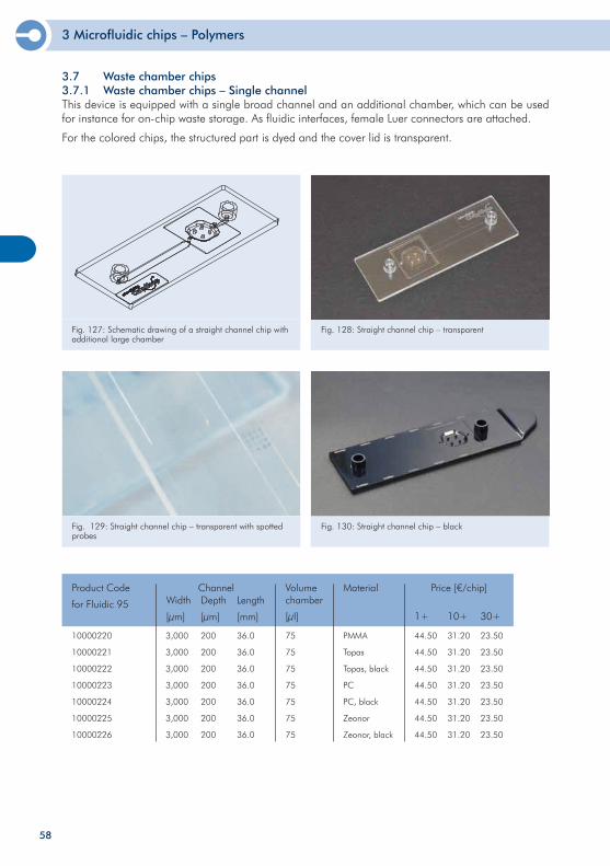
3 Microfluidic chips – Polymers
3.7 Waste chamber chips3.7.1 Waste chamber chips – Single channel This device is equipped with a single broad channel and an additional chamber, which can be used for instance for on-chip waste storage. As fluidic interfaces, female Luer connectors are attached.
For the colored chips, the structured part is dyed and the cover lid is transparent.
Fig. 128: Straight channel chip – transparentFig. 127: Schematic drawing of a straight channel chip withadditional large chamber
Fig. 129: Straight channel chip – transparent with spotted probes
Fig. 130: Straight channel chip – black
10000220
10000221
10000222
10000223
10000224
10000225
10000226
3,000
3,000
3,000
3,000
3,000
3,000
3,000
200
200
200
200
200
200
200
36.0
36.0
36.0
36.0
36.0
36.0
36.0
75
75
75
75
75
75
75
PMMA
Topas
Topas, black
PC
PC, black
Zeonor
Zeonor, black
Product Code
for Fluidic 95
ChannelWidth
[µm]
Depth
[µm]
Volumechamber
[µl]
Material Price [€/chip]
1+ 10+ 30+
Length
[mm]
44.50
44.50
44.50
44.50
44.50
44.50
44.50
31.20
31.20
31.20
31.20
31.20
31.20
31.20
23.50
23.50
23.50
23.50
23.50
23.50
23.50
58
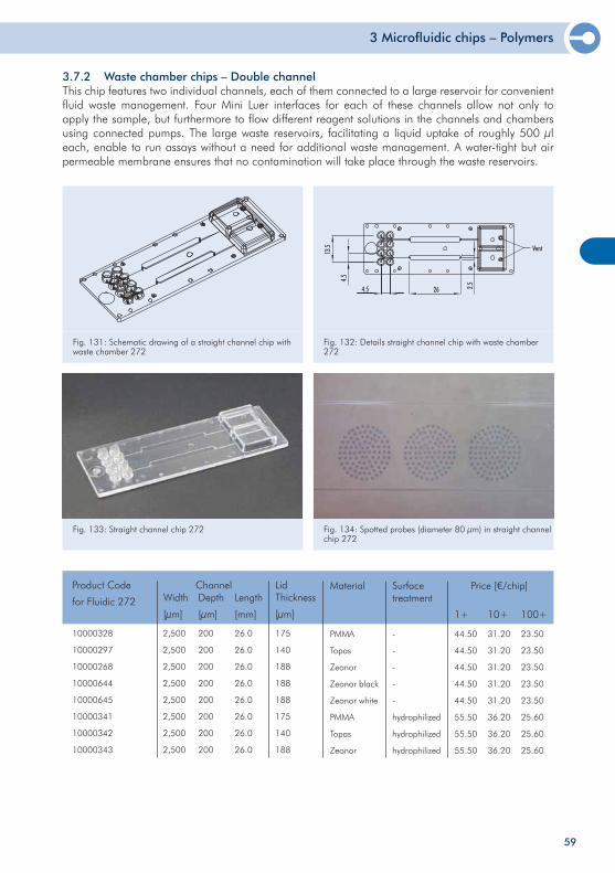
3 Microfluidic chips – Polymers
59
3.7.2 Waste chamber chips – Double channelThis chip features two individual channels, each of them connected to a large reservoir for convenient fluid waste management. Four Mini Luer interfaces for each of these channels allow not only to apply the sample, but furthermore to flow different reagent solutions in the channels and chambers using connected pumps. The large waste reservoirs, facilitating a liquid uptake of roughly 500 µl each, enable to run assays without a need for additional waste management. A water-tight but air permeable membrane ensures that no contamination will take place through the waste reservoirs.
Fig. 131: Schematic drawing of a straight channel chip with waste chamber 272
Fig. 132: Details straight channel chip with waste chamber 272
Fig. 133: Straight channel chip 272 Fig. 134: Spotted probes (diameter 80 µm) in straight channel chip 272
10000328
10000297
10000268
10000644
10000645
10000341
10000342
10000343
Product Code
for Fluidic 272
175
140
188
188
188
175
140
188
LidThickness
[µm]
PMMA
Topas
Zeonor
Zeonor black
Zeonor white
PMMA
Topas
Zeonor
Material
2,500
2,500
2,500
2,500
2,500
2,500
2,500
2,500
200
200
200
200
200
200
200
200
26.0
26.0
26.0
26.0
26.0
26.0
26.0
26.0
ChannelWidth
[µm]
Depth
[µm]
Length
[mm]
Price [€/chip]
1+ 10+ 100+
44.50
44.50
44.50
44.50
44.50
55.50
55.50
55.50
31.20
31.20
31.20
31.20
31.20
36.20
36.20
36.20
23.50
23.50
23.50
23.50
23.50
25.60
25.60
25.60
-
-
-
-
-
hydrophilized
hydrophilized
hydrophilized
Surface treatment
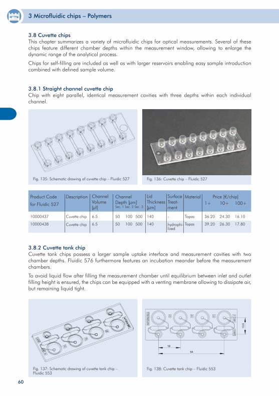
3 Microfluidic chips – Polymers
60
3.8.1 Straight channel cuvette chipChip with eight parallel, identical measurement cavities with three depths within each individual channel.
Fig. 135: Schematic drawing of cuvette chip – Fluidic 527 Fig. 136: Cuvette chip – Fluidic 527
10000437
10000438
Product Code
for Fluidic 527
Price [€/chip]1+ 10+ 100+
36.20
39.20
24.30
26.30
16.10
17.80
Description
Topas
Topas
Material
50
50
ChannelDepth [µm]Sec. 1 Sec. 2 Sec. 3
140
140
Lid Thickness[µm]
Cuvette chip
Cuvette chip
Channel Volume[µl]
6.5
6.5
-
hydrophi-lized
SurfaceTreat-ment
100
100
500
500
3.8 Cuvette chipsThis chapter summarizes a variety of microfluidic chips for optical measurements. Several of these chips feature different chamber depths within the measurement window, allowing to enlarge the dynamic range of the analytical process.
Chips for self-filling are included as well as with larger reservoirs enabling easy sample introduction combined with defined sample volume.
3.8.2 Cuvette tank chip Cuvette tank chips possess a larger sample uptake interface and measurement cavities with two chamber depths. Fluidic 576 furthermore features an incubation meander before the measurement chambers.
To avoid liquid flow after filling the measurement chamber until equilibrium between inlet and outlet filling height is ensured, the chips can be equipped with a venting membrane allowing to dissipate air, but remaining liquid tight.
Fig. 137: Schematic drawing of cuvette tank chip – Fluidic 553
18
54
13.5
Fig. 138: Cuvette tank chip – Fluidic 553
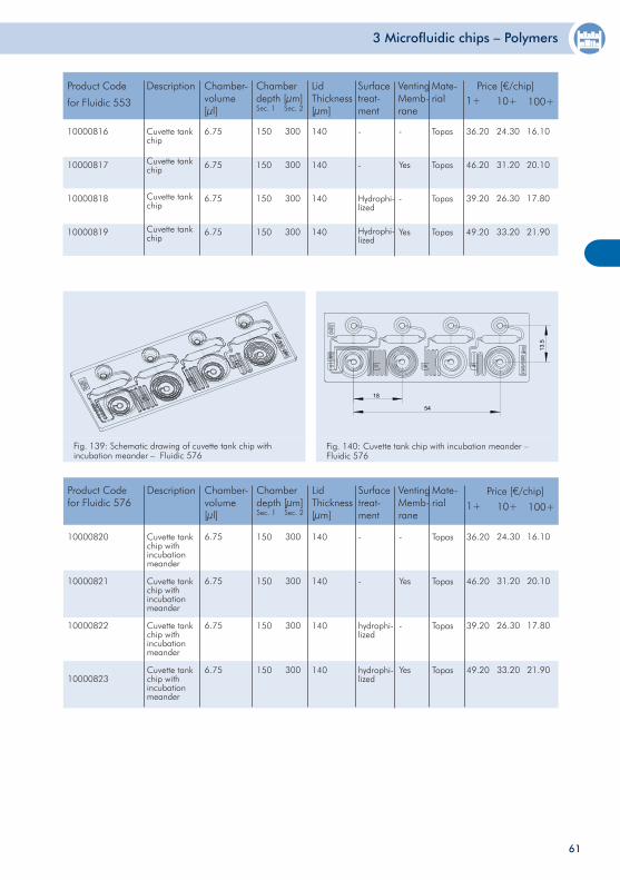
3 Microfluidic chips – Polymers
61
10000816
10000817
10000818
10000819
Product Code
for Fluidic 553
Price [€/chip]1+ 10+
36.20
46.20
39.20
49.20
24.30
31.20
26.30
33.20
Description
Topas
Topas
Topas
Topas
Mate-rial
150
150
150
150
Chamber depth [µm]Sec. 1 Sec. 2
140
140
140
140
Lid Thickness[µm]
Cuvette tank chip
Cuvette tank chip
Cuvette tank chip
Cuvette tank chip
Chamber-volume[µl]
6.75
6.75
6.75
6.75
-
-
Hydrophi-lized
Hydrophi-lized
Surfacetreat-ment
300
300
300
300
100+
16.10
20.10
17.80
21.90
-
Yes
-
Yes
Venting Memb-rane
Fig. 139: Schematic drawing of cuvette tank chip with incubation meander – Fluidic 576
18
54
13.5
Fig. 140: Cuvette tank chip with incubation meander – Fluidic 576
Price [€/chip]
10000820
10000821
10000822
10000823
Product Codefor Fluidic 576 1+ 10+
36.20
46.20
39.20
49.20
24.30
31.20
26.30
33.20
Description
Topas
Topas
Topas
Topas
Mate-rial
150
150
150
150
Chamber depth [µm]Sec. 1 Sec. 2
140
140
140
140
Lid Thickness[µm]
Cuvette tank chip with incubation meander
Cuvette tank chip with incubation meander
Cuvette tank chip with incubation meander
Cuvette tank chip with incubation meander
Chamber-volume[µl]
6.75
6.75
6.75
6.75
-
-
hydrophi-lized
hydrophi-lized
Surfacetreat-ment
300
300
300
300
100+
16.10
20.10
17.80
21.90
-
Yes
-
Yes
Venting Memb-rane
Price [€/chip]
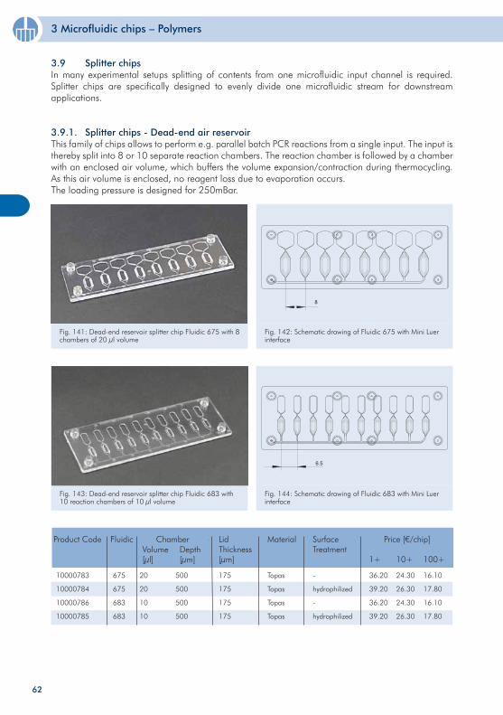
3 Microfluidic chips – Polymers
62
Fig. 143: Dead-end reservoir splitter chip Fluidic 683 with 10 reaction chambers of 10 µl volume
Fig. 144: Schematic drawing of Fluidic 683 with Mini Luer interface
10000783
10000784
10000786
10000785
20
20
10
10
500
500
500
500
175
175
175
175
Topas
Topas
Topas
Topas
-
hydrophilized
-
hydrophilized
Product Code ChamberVolume[µl]
Depth[µm]
Material SurfaceTreatment
Price [€/chip]
1+ 10+ 100+
LidThickness[µm]
36.20
39.20
36.20
39.20
24.30
26.30
24.30
26.30
16.10
17.80
16.10
17.80
Fluidic
675
675
683
683
3.9 Splitter chips In many experimental setups splitting of contents from one microfluidic input channel is required. Splitter chips are specifically designed to evenly divide one microfluidic stream for downstream applications.
3.9.1. Splitter chips - Dead-end air reservoirThis family of chips allows to perform e.g. parallel batch PCR reactions from a single input. The input is thereby split into 8 or 10 separate reaction chambers. The reaction chamber is followed by a chamber with an enclosed air volume, which buffers the volume expansion/contraction during thermocycling. As this air volume is enclosed, no reagent loss due to evaporation occurs.The loading pressure is designed for 250mBar.
Fig. 141: Dead-end reservoir splitter chip Fluidic 675 with 8 chambers of 20 µl volume
Fig. 142: Schematic drawing of Fluidic 675 with Mini Luer interface
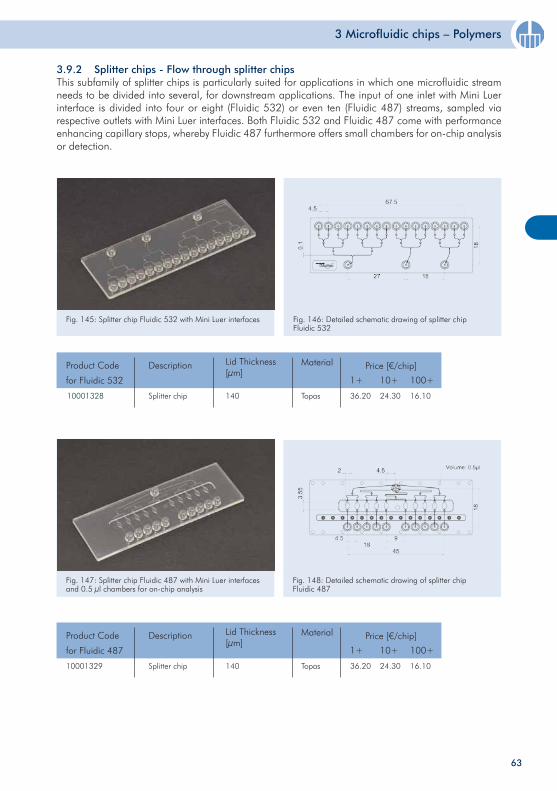
3 Microfluidic chips – Polymers
3.9.2 Splitter chips - Flow through splitter chipsThis subfamily of splitter chips is particularly suited for applications in which one microfluidic stream needs to be divided into several, for downstream applications. The input of one inlet with Mini Luer interface is divided into four or eight (Fluidic 532) or even ten (Fluidic 487) streams, sampled via respective outlets with Mini Luer interfaces. Both Fluidic 532 and Fluidic 487 come with performance enhancing capillary stops, whereby Fluidic 487 furthermore offers small chambers for on-chip analysis or detection.
Fig. 146: Detailed schematic drawing of splitter chip Fluidic 532
Fig. 145: Splitter chip Fluidic 532 with Mini Luer interfaces
10001328 Splitter chip
Product Code
for Fluidic 532
Description
Topas
Fig. 148: Detailed schematic drawing of splitter chip Fluidic 487
Fig. 147: Splitter chip Fluidic 487 with Mini Luer interfaces and 0.5 µl chambers for on-chip analysis
Price [€/chip]
1+ 10+ 100+
36.20 24.30 16.10
MaterialLid Thickness [µm]
140
Splitter chip
Product Code
for Fluidic 487
Description
10001329 Topas
Price [€/chip]
1+ 10+ 100+
36.20 24.30 16.10
MaterialLid Thickness [µm]
140
63
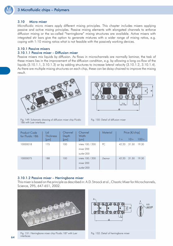
3 Microfluidic chips – Polymers
3.10.1 Passive mixers3.10.1.1 Passive mixer – Diffusion mixerPassive mixers mix liquids by diffusion. As flows in microchannels are normally laminar, the task of these mixers lies in the improvement of the diffusion condition, e.g. by allowing a long co-flow of the liquids (3.10.1.1, 3.10.1.3) or by adding structures to increase lateral velocity (3.10.1.2, 3.10.1.4). As there are multiple mixing structures on each chip, these can be daisy-chained to improve the mixing result.
3.10 Micro mixerMicrofluidic micro mixers apply different mixing principles. This chapter includes mixers applying passive and active mixing principles. Passive mixing elements with elongated channels to enforce diffusion mixing or the so-called “herringbone” mixing structures are available. Active mixers with integrated stir bars give the option to generate mixtures with a wider range of mixing ratios, e.g. coping with 1:10 mixing ratios what is not feasible with the passively working devices.
Fig. 149: Schematic drawing of diffusion mixer chip Fluidic 186 with Luer interfaces
Fig. 150: Detail of diffusion mixer
Fig. 151: Herringbone mixer chip Fluidic 187 with Luer interfaces
Fig. 152: Detail of herringbone mixer
10000018
10000075
175
188
100
100
inlets 100 / 200
mixer 200
outlet 200
intets 100 / 200
mixer 200
outlet 200
PC
Zeonor
Product Codefor Fluidic 186
Lid Thickness[µm]
ChannelWidth[µm]
Material Price [€/chip]
1+ 10+ 100+
ChannelDepth[µm]
42.20
42.20
31.50
31.50
19.30
19.30
3.10.1.2 Passive mixer – Herringbone mixerThis mixer is based on the principle as described in: A.D. Stroock et al., Chaotic Mixer for Microchannels, Science, 295, 647-651, 2002.
64
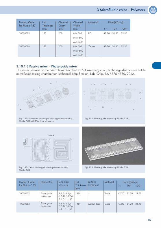
3 Microfluidic chips – Polymers
10000019
10000076
175
188
200
200
inlet 300
mixer 600
outlet 600
inlet 300
mixer 600
outlet 600
PC
Zeonor
Product Codefor Fluidic 187
Lid Thickness[µm]
ChannelWidth[µm]
Material Price [€/chip]
1+ 10+ 100+
ChannelDepth[µm]
42.20
42.20
31.50
31.50
19.30
19.30
Fig. 153: Schematic drawing of phase guide mixer chip Fluidic 533 with Mini Luer interfaces
Fig. 154: Phase guide mixer chip Fluidic 533
Fig. 155: Detail drawing of phase guide mixer chip Fluidic 533
Fig. 156: Phase guide mixer chip Fluidic 533
10000552
10000553
Product Codefor Fluidic 533
Price [€/chip]1+ 10+ 100+
42.20
46.20
31.50
34.70
19.30
21.40
Description
Topas
Topas
Material
140
140
Lid Thickness[µm]
-
hydrophilized
Surface Treatment
Phase guide mixer chip
Phase guide mixer chip
Chamber volumes
A & B: 5.6 µlC & D: 13.2 µlE & F: 11.1 µl
A & B: 5.6 µlC & D: 13.2 µlE & F: 11.1 µl
3.10.1.3 Passive mixer – Phase guide mixerThis mixer is based on the principle as described in: S. Hakenberg et al., A phaseguided passive batch microfluidic mixing chamber for isothermal amplification, Lab Chip, 12, 4576-4580, 2012.
65
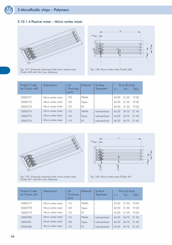
3 Microfluidic chips – Polymers
2
de
pth
0.4
0.2
7
de
pth
0.4
4.5
63
4.5
13
.5
Fig. 157: Schematic drawing of the micro vortex mixer Fluidic 640 with Mini Luer interfaces
Fig. 158: Micro vortex mixer Fluidic 640
10000771
10000772
10000773
10000774
10000775
10000776
Product Codefor Fluidic 640
Price [€/chip]1+ 10+ 100+
42.20
42.20
42.20
46.20
46.20
46.20
31.50
31.50
31.50
34.70
34.70
34.70
19.30
19.30
19.30
21.40
21.40
21.40
Description
PMMA
Topas
PC
PMMA
Topas
PC
Material
175
140
175
175
140
175
Lid Thickness[µm]
Micro vortex mixer
Micro vortex mixer
Micro vortex mixer
Micro vortex mixer
Micro vortex mixer
Micro vortex mixer
4.5
13
.5
4.5
63
2
0.4
de
pth
0.4
0.4
de
pth
Fig. 159: Schematic drawing of the micro vortex mixer Fluidic 641 with Mini Luer interfaces
Fig. 160: Micro vortex mixer Fluidic 641
Product Codefor Fluidic 641
3.10.1.4 Passive mixer – Micro vortex mixer
-
-
-
hydrophilized
hydrophilized
hydrophilized
SurfaceTreatment
10000777
10000778
10000779
10000780
10000781
10000782
Price [€/chip]1+ 10+ 100+
42.20
42.20
42.20
46.20
46.20
46.20
31.50
31.50
31.50
34.70
34.70
34.70
19.30
19.30
19.30
21.40
21.40
21.40
Description
PMMA
Topas
PC
PMMA
Topas
PC
Material
175
140
175
175
140
175
Lid Thickness[µm]
Micro vortex mixer
Micro vortex mixer
Micro vortex mixer
Micro vortex mixer
Micro vortex mixer
Micro vortex mixer
-
-
-
hydrophilized
hydrophilized
hydrophilized
SurfaceTreatment
66
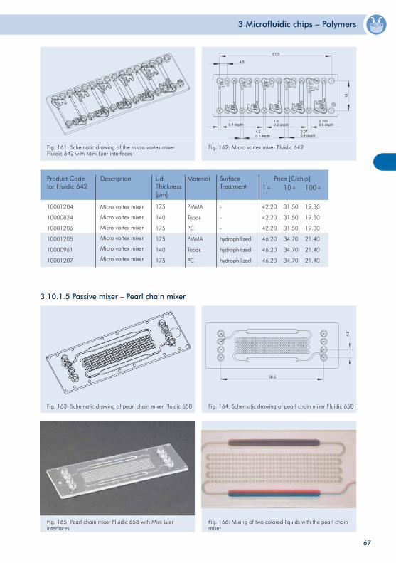
3 Microfluidic chips – Polymers
4.5
67.5
18
1
0.1 depth
1.5
0.1 depth
2.07
0.4 depth
1.5
0.2 depth
2.105
0.6 depth
Fig. 161: Schematic drawing of the micro vortex mixer Fluidic 642 with Mini Luer interfaces
Fig. 162: Micro vortex mixer Fluidic 642
3.10.1.5 Passive mixer – Pearl chain mixer
Fig. 163: Schematic drawing of pearl chain mixer Fluidic 658 Fig. 164: Schematic drawing of pearl chain mixer Fluidic 658
Product Codefor Fluidic 642
10001204
10000824
10001206
10001205
10000961
10001207
Price [€/chip]1+ 10+ 100+
42.20
42.20
42.20
46.20
46.20
46.20
31.50
31.50
31.50
34.70
34.70
34.70
19.30
19.30
19.30
21.40
21.40
21.40
Description
PMMA
Topas
PC
PMMA
Topas
PC
Material
175
140
175
175
140
175
Lid Thickness[µm]
Micro vortex mixer
Micro vortex mixer
Micro vortex mixer
Micro vortex mixer
Micro vortex mixer
Micro vortex mixer
-
-
-
hydrophilized
hydrophilized
hydrophilized
SurfaceTreatment
Fig. 165: Pearl chain mixer Fluidic 658 with Mini Luer interfaces
Fig. 166: Mixing of two colored liquids with the pearl chain mixer
67
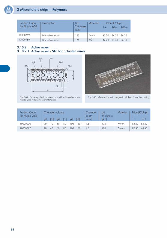
3 Microfluidic chips – Polymers
10000020
10000077
20
20
1.5
1.5
PMMA
Zeonor
Product Codefor Fluidic 286
Chamber volume
[µl] [µl] [µl] [µl] [µl] [µl]
Chamberdepth[mm]
Material Price [€/chip]
1+ 10+
82.50
82.50
63.50
63.50
175
188
Lid Thickness[µm]
40
40
60
60
80
80
100
100
150
150
Fig. 167: Drawing of micro mixer chip with mixing chambers Fluidic 286 with Mini Luer interfaces
Fig. 168: Micro mixer with magnetic stir bars for active mixing
3.10.2 Active mixer3.10.2.1 Active mixer - Stir bar actuated mixer
Product Codefor Fluidic 658 1+ 10+ 100+
42.20
42.20
34.30
34.30
26.10
26.10
Description MaterialLid Thickness[µm]
10000759
10000760
Pearl-chain mixer
Pearl-chain mixer
125
175
Topas
PC
Price [€/chip]
68
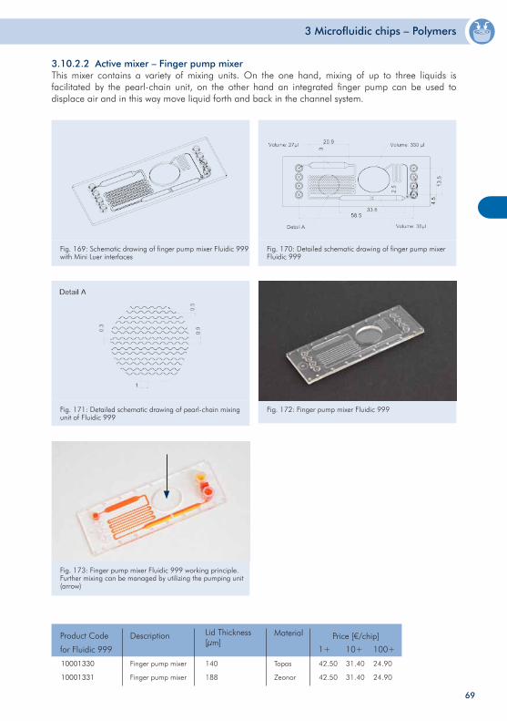
3 Microfluidic chips – Polymers
Fig. 172: Finger pump mixer Fluidic 999
Fig. 173: Finger pump mixer Fluidic 999 working principle. Further mixing can be managed by utilizing the pumping unit (arrow)
10001330
10001331
Finger pump mixer
Finger pump mixer
Product Code
for Fluidic 999
Description
Topas
Zeonor
Price [€/chip]
1+ 10+ 100+
42.50
42.50
31.40
31.40
24.90
24.90
MaterialLid Thickness [µm]
140
188
3.10.2.2 Active mixer – Finger pump mixerThis mixer contains a variety of mixing units. On the one hand, mixing of up to three liquids is facilitated by the pearl-chain unit, on the other hand an integrated finger pump can be used to displace air and in this way move liquid forth and back in the channel system.
Fig. 169: Schematic drawing of finger pump mixer Fluidic 999 with Mini Luer interfaces
Fig. 170: Detailed schematic drawing of finger pump mixer Fluidic 999
Fig. 171: Detailed schematic drawing of pearl-chain mixing unit of Fluidic 999
69
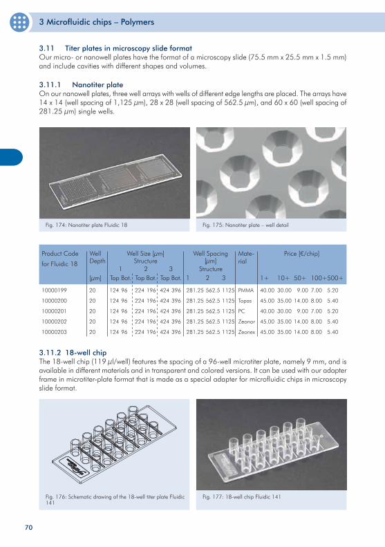
3 Microfluidic chips – Polymers
70
3.11 Titer plates in microscopy slide formatOur micro- or nanowell plates have the format of a microscopy slide (75.5 mm x 25.5 mm x 1.5 mm) and include cavities with different shapes and volumes.
Fig. 174: Nanotiter plate Fluidic 18 Fig. 175: Nanotiter plate – well detail
3.11.1 Nanotiter plate On our nanowell plates, three well arrays with wells of different edge lengths are placed. The arrays have 14 x 14 (well spacing of 1,125 µm), 28 x 28 (well spacing of 562.5 µm), and 60 x 60 (well spacing of 281.25 µm) single wells.
3.11.2 18-well chipThe 18-well chip (119 µl/well) features the spacing of a 96-well microtiter plate, namely 9 mm, and is available in different materials and in transparent and colored versions. It can be used with our adapter frame in microtiter-plate format that is made as a special adapter for microfluidic chips in microscopy slide format.
Fig. 176: Schematic drawing of the 18-well titer plate Fluidic 141
Fig. 177: 18-well chip Fluidic 141
10000199
10000200
10000201
10000202
10000203
20
20
20
20
20
Product Code
for Fluidic 18
Well Size [µm]Structure
WellDepth
[µm]
Price [€/chip]
1+ 10+ 50+
40.00
45.00
40.00
45.00
45.00
30.00
35.00
30.00
35.00
35.00
9.00
14.00
9.00
14.00
14.00
124
124
124
124
124
281.25
281.25
281.25
281.25
281.25
PMMA
Topas
PC
Zeonor
Zeonex
Mate-rial
100+
7.00
8.00
7.00
8.00
8.00
1Top Bot.
96
96
96
96
96
224
224
224
224
224
2Top Bot.
196
196
196
196
196
424
424
424
424
424
3Top Bot.
396
396
396
396
396
Well Spacing [µm]
Structure1 2 3
562.5
562.5
562.5
562.5
562.5
1125
1125
1125
1125
1125
500+
5.20
5.40
5.20
5.40
5.40
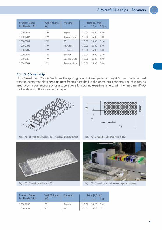
3 Microfluidic chips – Polymers
71
10000883
10000907
10000885
10000905
10000906
10000250
10000251
10000884
119
119
119
119
119
119
119
119
Product Code for Fluidic 141
Price [€/chip]1+ 10+ 100+
20.00
20.00
20.00
20.00
20.00
20.00
20.00
20.00
15.00
15.00
15.00
15.00
15.00
15.00
15.00
15.00
5.40
5.40
5.40
5.40
5.40
5.40
5.40
5.40
Well Volume[µl]
Topas
Topas, black
PS
PS, white
PS, black
Zeonor
Zeonor, white
Zeonor, black
Material
3.11.3 65-well chip This 65-well chip (25.9 µl/well) has the spacing of a 384 well plate, namely 4.5 mm. It can be used with the micro-titer plate sized adapter frames described in the accessories chapter. The chip can be used to carry out reactions or as a source plate for spotting experiments, e.g. with the instrumentTWO spotter shown in the instrument chapter.
Fig. 178: 65-well chip Fluidic 383 – microscopy slide format Fig. 179: Details 65-well chip Fluidic 383
Fig. 180: 65-well chip Fluidic 383 Fig. 181: 65-well chip used as source plate in spotter
10000252
10000253
25
25
Product Code for Fluidic 383
Price [€/chip]1+ 10+ 100+
20.00
20.00
15.20
15.20
5.45
5.45
Well Volume[µl]
Zeonor
PP
Material
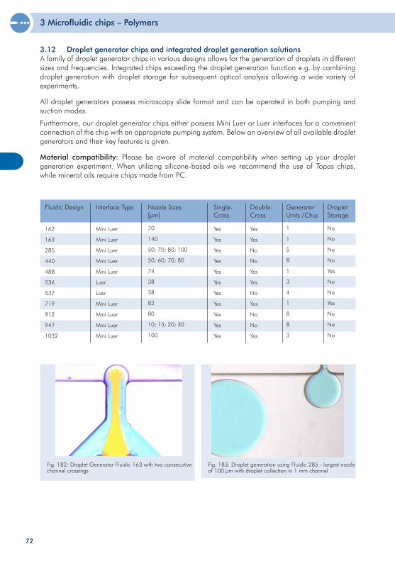
3 Microfluidic chips – Polymers
72
3.12 Droplet generator chips and integrated droplet generation solutionsA family of droplet generator chips in various designs allows for the generation of droplets in different sizes and frequencies. Integrated chips exceeding the droplet generation function e.g. by combining droplet generation with droplet storage for subsequent optical analysis allowing a wide variety of experiments.
All droplet generators possess microscopy slide format and can be operated in both pumping and suction modes.
Furthermore, our droplet generator chips either possess Mini Luer or Luer interfaces for a convenient connection of the chip with an appropriate pumping system. Below an overview of all available droplet generators and their key features is given.
Material compatibility: Please be aware of material compatibility when setting up your droplet generation experiment. When utilizing silicone-based oils we recommend the use of Topas chips, while mineral oils require chips made from PC.
70
140
50; 70; 80; 100
50; 60; 70; 80
74
38
38
82
80
10; 15; 20; 30
100
Fluidic Design Nozzle Sizes[µm]
GeneratorUnits /Chip
Interface Type Single-Cross
Mini Luer
Mini Luer
Mini Luer
Mini Luer
Mini Luer
Luer
Luer
Mini Luer
Mini Luer
Mini Luer
Mini Luer
Yes
Yes
Yes
Yes
Yes
Yes
Yes
Yes
Yes
Yes
Yes
Yes
Yes
No
No
Yes
Yes
No
Yes
No
No
Yes
Double-Cross
162
163
285
440
488
536
537
719
912
947
1032
Droplet Storage
No
No
No
No
Yes
No
No
Yes
No
No
No
1
1
5
8
1
3
4
1
8
8
3
Fig. 182: Droplet Generator Fluidic 163 with two consecutive channel crossings
Fig. 183: Droplet generation using Fluidic 285 - largest nozzle of 100 µm with droplet collection in 1 mm channel
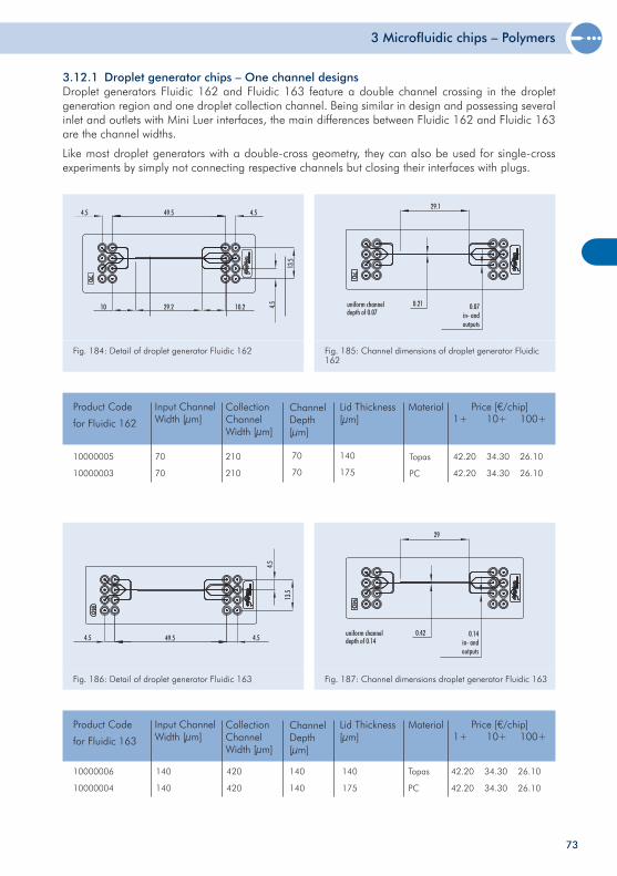
3 Microfluidic chips – Polymers
73
3.12.1 Droplet generator chips – One channel designs Droplet generators Fluidic 162 and Fluidic 163 feature a double channel crossing in the droplet generation region and one droplet collection channel. Being similar in design and possessing several inlet and outlets with Mini Luer interfaces, the main differences between Fluidic 162 and Fluidic 163 are the channel widths.
Like most droplet generators with a double-cross geometry, they can also be used for single-cross experiments by simply not connecting respective channels but closing their interfaces with plugs.
Fig. 184: Detail of droplet generator Fluidic 162 Fig. 185: Channel dimensions of droplet generator Fluidic 162
10000005
10000003
140
175
Product Code
for Fluidic 162
Price [€/chip]1+ 10+ 100+
42.20
42.20
34.30
34.30
26.10
26.10
Lid Thickness[µm]
Topas
PC
MaterialInput Channel Width [µm]
Collection Channel Width [µm]
70
70
210
210
70
70
Channel Depth [µm]
Fig. 186: Detail of droplet generator Fluidic 163 Fig. 187: Channel dimensions droplet generator Fluidic 163
140
175
42.20
42.20
34.30
34.30
26.10
26.10
Topas
PC
Product Code
for Fluidic 163
Price [€/chip]1+ 10+ 100+
Lid Thickness[µm]
MaterialInput Channel Width [µm]
Collection Channel Width [µm]
Channel Depth [µm]
10000006
10000004
140
140
420
420
140
140
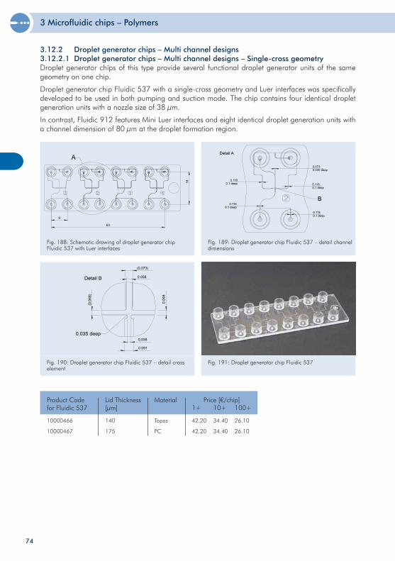
3 Microfluidic chips – Polymers
74
Fig. 188: Schematic drawing of droplet generator chip Fluidic 537 with Luer interfaces
Fig. 189: Droplet generator chip Fluidic 537 – detail channel dimensions
Fig. 190: Droplet generator chip Fluidic 537 – detail cross element
10000466
10000467
140
175
Product Code for Fluidic 537
Price [€/chip]1+ 10+ 100+
42.20
42.20
34.40
34.40
26.10
26.10
Lid Thickness[µm]
Topas
PC
Material
3.12.2 Droplet generator chips – Multi channel designs 3.12.2.1 Droplet generator chips – Multi channel designs – Single-cross geometryDroplet generator chips of this type provide several functional droplet generator units of the same geometry on one chip.
Droplet generator chip Fluidic 537 with a single-cross geometry and Luer interfaces was specifically developed to be used in both pumping and suction mode. The chip contains four identical droplet generation units with a nozzle size of 38 µm.
In contrast, Fluidic 912 features Mini Luer interfaces and eight identical droplet generation units with a channel dimension of 80 µm at the droplet formation region.
Fig. 191: Droplet generator chip Fluidic 537
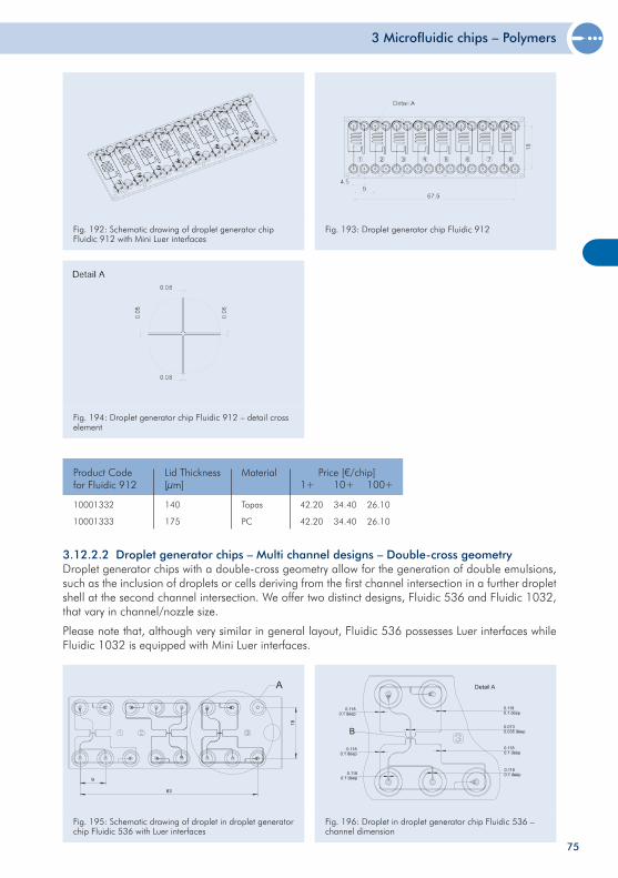
3 Microfluidic chips – Polymers
75
Fig. 195: Schematic drawing of droplet in droplet generator chip Fluidic 536 with Luer interfaces
Fig. 196: Droplet in droplet generator chip Fluidic 536 – channel dimension
3.12.2.2 Droplet generator chips – Multi channel designs – Double-cross geometryDroplet generator chips with a double-cross geometry allow for the generation of double emulsions, such as the inclusion of droplets or cells deriving from the first channel intersection in a further droplet shell at the second channel intersection. We offer two distinct designs, Fluidic 536 and Fluidic 1032, that vary in channel/nozzle size.
Please note that, although very similar in general layout, Fluidic 536 possesses Luer interfaces while Fluidic 1032 is equipped with Mini Luer interfaces.
Fig. 192: Schematic drawing of droplet generator chip Fluidic 912 with Mini Luer interfaces
Fig. 193: Droplet generator chip Fluidic 912
Fig. 194: Droplet generator chip Fluidic 912 – detail cross element
10001332
10001333
140
175
Product Code for Fluidic 912
Price [€/chip]1+ 10+ 100+
42.20
42.20
34.40
34.40
26.10
26.10
Lid Thickness[µm]
Topas
PC
Material
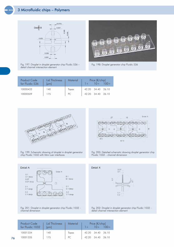
3 Microfluidic chips – Polymers
76
Fig. 201: Droplet in droplet generator chip Fluidic 1032 – channel dimension
10001334
10001335
140
175
Product Codefor Fluidic 1032
Price [€/chip]1+ 10+ 100+
42.20
42.20
34.40
34.40
26.10
26.10
Lid Thickness[µm]
Topas
PC
Material
Fig. 199: Schematic drawing of droplet in droplet generator chip Fluidic 1032 with Mini Luer interfaces
Fig. 200: Detailed schematic drawing droplet generator chip Fluidic 1032 – channel dimension
Fig. 197: Droplet in droplet generator chip Fluidic 536 – detail channel intersection element
10000433
10000509
140
175
Product Codefor Fluidic 536
Price [€/chip]1+ 10+ 100+
42.20
42.20
34.40
34.40
26.10
26.10
Lid Thickness[µm]
Topas
PC
Material
Fig. 198: Droplet generator chip Fluidic 536
Fig. 202: Droplet in droplet generator chip Fluidic 1032 – detail channel intersection element
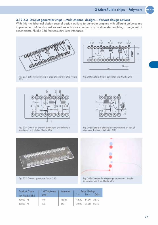
3 Microfluidic chips – Polymers
77
10000175
10000176
140
175
Product Code
for Fluidic 285
Price [€/chip]1+ 10+ 100+
42.20
42.20
34.30
34.30
26.10
26.10
Lid Thickness[µm]
Topas
PC
Material
Fig. 207: Droplet generator Fluidic 285 Fig. 208: Example for droplet generation with droplet generation unit 1 on Fluidic 285
3.12.2.3 Droplet generator chips – Multi channel designs – Various design optionsWith this multichannel design several design options to generate droplets with different volumes are implemented. Main channel as well as entrance channel vary in diameter enabling a large set of experiments. Fluidic 285 features Mini Luer interfaces.
Fig. 203: Schematic drawing of droplet generator chip Fluidic 285
Fig. 204: Details droplet generator chip Fluidic 285
Fig. 205: Details of channel dimensions and off-sets of structures 1 – 3 of chip Fluidic 285
Fig. 206: Details of channel dimensions and off-sets of structures 4 – 5 of chip Fluidic 285
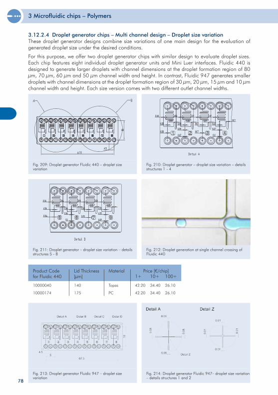
3 Microfluidic chips – Polymers
78
Fig. 211: Droplet generator – droplet size variation – details structures 5 - 8
Fig. 212: Droplet generation at single channel crossing of Fluidic 440
10000040
10000174
140
175
Product Codefor Fluidic 440
Price [€/chip]1+ 10+ 100+
42.20
42.20
34.40
34.40
26.10
26.10
Lid Thickness[µm]
Topas
PC
Material
3.12.2.4 Droplet generator chips – Multi channel design – Droplet size variationThese droplet generator designs combine size variations of one main design for the evaluation of generated droplet size under the desired conditions.
For this purpose, we offer two droplet generator chips with similar design to evaluate droplet sizes. Each chip features eight individual droplet generator units and Mini Luer interfaces. Fluidic 440 is designed to generate larger droplets with channel dimensions at the droplet formation region of 80 µm, 70 µm, 60 µm and 50 µm channel width and height. In contrast, Fluidic 947 generates smaller droplets with channel dimensions at the droplet formation region of 30 µm, 20 µm, 15 µm and 10 µm channel width and height. Each size version comes with two different outlet channel widths.
Fig. 209: Droplet generator Fluidic 440 – droplet size variation
Fig. 210: Droplet generator – droplet size variation – details structures 1 - 4
Fig. 213: Droplet generator Fluidic 947 – droplet size variation
Fig. 214: Droplet generator Fluidic 947– droplet size variation – details structures 1 and 2
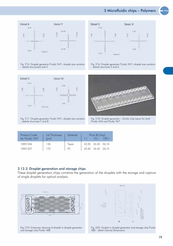
3 Microfluidic chips – Polymers
79
Fig. 217: Droplet generator Fluidic 947– droplet size variation – details structures 7 and 8
Fig. 218: Droplet generator – Similar chip layout for both Fluidic 440 and Fluidic 947
10001336
10001337
140
175
Product Codefor Fluidic 947
Price [€/chip]1+ 10+ 100+
42.20
42.20
34.40
34.40
26.10
26.10
Lid Thickness[µm]
Topas
PC
Material
Fig. 219: Schematic drawing of droplet in droplet generator and storage chip Fluidic 488
Fig. 220: Droplet in droplet generator and storage chip Fluidic 488 – detail channel dimensions
3.12.3 Droplet generation and storage chipsThese droplet generation chips combine the generation of the droplets with the storage and capture of single droplets for optical analysis.
Fig. 215: Droplet generator Fluidic 947– droplet size variation – details structures3 and 4
Fig. 216: Droplet generator Fluidic 947– droplet size variation – details structures 5 and 6
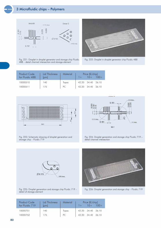
3 Microfluidic chips – Polymers
80
Fig. 221: Droplet in droplet generator and storage chip Fluidic 488 – detail channel intersection and storage element
Fig. 222: Droplet in droplet generator chip Fluidic 488
10000510
10000511
140
175
Product Codefor Fluidic 488
Price [€/chip]1+ 10+ 100+
42.20
42.20
34.40
34.40
26.10
26.10
Lid Thickness[µm]
Topas
PC
Material
Fig. 223: Schematic drawing of droplet generation and storage chip – Fluidic 719
58.5
4.5
13
.5
Fig. 224: Droplet generation and storage chip Fluidic 719 – detail channel intersection
10000751
10000752
140
175
Product Codefor Fluidic 719
Price [€/chip]1+ 10+ 100+
42.20
42.20
34.40
34.40
26.10
26.10
Lid Thickness[µm]
Topas
PC
Material
Fig. 225: Droplet generation and storage chip Fluidic 719 – detail of storage element
Fig. 226: Droplet generation and storage chip – Fluidic 719
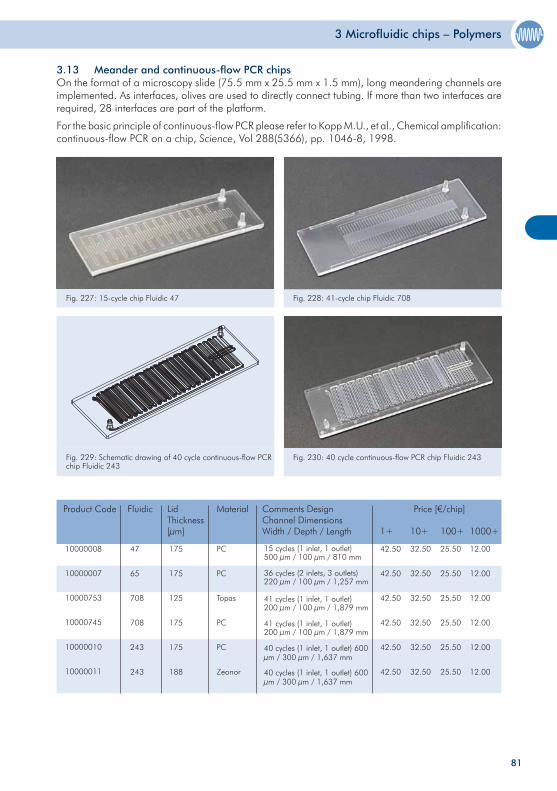
3 Microfluidic chips – Polymers
81
Fig. 227: 15-cycle chip Fluidic 47 Fig. 228: 41-cycle chip Fluidic 708
3.13 Meander and continuous-flow PCR chipsOn the format of a microscopy slide (75.5 mm x 25.5 mm x 1.5 mm), long meandering channels are implemented. As interfaces, olives are used to directly connect tubing. If more than two interfaces are required, 28 interfaces are part of the platform.
For the basic principle of continuous-flow PCR please refer to Kopp M.U., et al., Chemical amplification: continuous-flow PCR on a chip, Science, Vol 288(5366), pp. 1046-8, 1998.
Fig. 229: Schematic drawing of 40 cycle continuous-flow PCR chip Fluidic 243
Fig. 230: 40 cycle continuous-flow PCR chip Fluidic 243
10000008
10000007
10000753
10000745
10000010
10000011
175
175
125
175
175
188
Product Code LidThickness[µm]
Price [€/chip]
1+ 10+ 100+
42.50
42.50
42.50
42.50
42.50
42.50
32.50
32.50
32.50
32.50
32.50
32.50
25.50
25.50
25.50
25.50
25.50
25.50
PC
PC
Topas
PC
PC
Zeonor
Material
15 cycles (1 inlet, 1 outlet)500 µm / 100 µm / 810 mm
36 cycles (2 inlets, 3 outlets)220 µm / 100 µm / 1,257 mm
41 cycles (1 inlet, 1 outlet)200 µm / 100 µm / 1,879 mm
41 cycles (1 inlet, 1 outlet)200 µm / 100 µm / 1,879 mm
40 cycles (1 inlet, 1 outlet) 600 µm / 300 µm / 1,637 mm
40 cycles (1 inlet, 1 outlet) 600 µm / 300 µm / 1,637 mm
Comments DesignChannel DimensionsWidth / Depth / Length 1000+
12.00
12.00
12.00
12.00
12.00
12.00
Fluidic
47
65
708
708
243
243
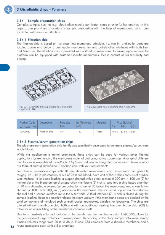
3 Microfluidic chips – Polymers
82
3.14 Sample preparation chipsComplex samples such as e.g. blood often require purificaton steps prior to further analysis. In this regard, one prominent procedure is sample preparation with the help of membranes, which can facilitate purfication and filtration.
3.14.1 Filtration chipThe fitration chip is based on the cross-flow membrane principle, i.e. two in- and outlet ports are located above and below a permeable membrane. In- and outlets offer interfaces with both Luer and Mini Luer. The filtration chip is provided with a standard membrane. However, upon request the platform can be equipped with customer-specific membranes. Please contact us for feasibility and pricing.
Fig. 231: Schematic drawing of cross-flow membrane chip Fluidic 398
Fig. 232: Cross-flow membrane chip Fluidic 398
10000022 Filtration chip
Product Code
for Fluidic 398
Price [€/chip]1+ 10+
79.50 63.50
Description
Topas
Material
140
Lid Thickness[µm] 100+
42.50
Pore size[µm]
0.4
3.14.2 Plasma/serum generation chipsThe plasma/serum generation chip family was specifically developed to generate plasma/serum from whole blood.
While this application is rather prominent, these chips can be used for various other filtering applications by exchanging the membrane material and using various pore sizes. A range of different membranes is available at microfluidic ChipShop and can be integrated on request. Please contact our team at [email protected] with your requirements.
For plasma generation chips with 10 mm diameter membranes, each membrane can generate roughly 12 – 15 µl plasma/serum out of 25 µl full blood. Each unit of these chips consists of a (Mini) Luer interface (1) for blood loading, a support channel with a cross-section of 300 µm × 100 µm (2) for the transfer of the blood on top of a separation membrane (3) that is fused into a chip-based chamber of 10 mm diameter, a plasma/serum collection channel (4) below the membrane, and a ventilation channel of 100 µm × 100 µm (5) also below the membrane. The vacuum is applied via the collection channel and a second interface (6) to the outer world. A third interface (7), which is closed during the sample loading, helps to smoothly release the slight vacuum if the membrane pores are blocked by the solid components of the blood such as erythrocytes, monocytes, platelets, or leucocytes. The chips are offered without (membrane chip 168) and with an additional venting line (membrane chip 200) to allow for an easier filling of the membrane chamber itself.
Due to a massively enlarged footprint of the membrane, the membrane chip Fluidic 535 allows for the generation of larger volumes of plasma/serum. Depending on the blood sample achievable serum/plasma volumes range from 20 µl to 35 µl. Fluidic 783 combines both a rhombic membrane and a round membrane each witth a 5 µl chamber.
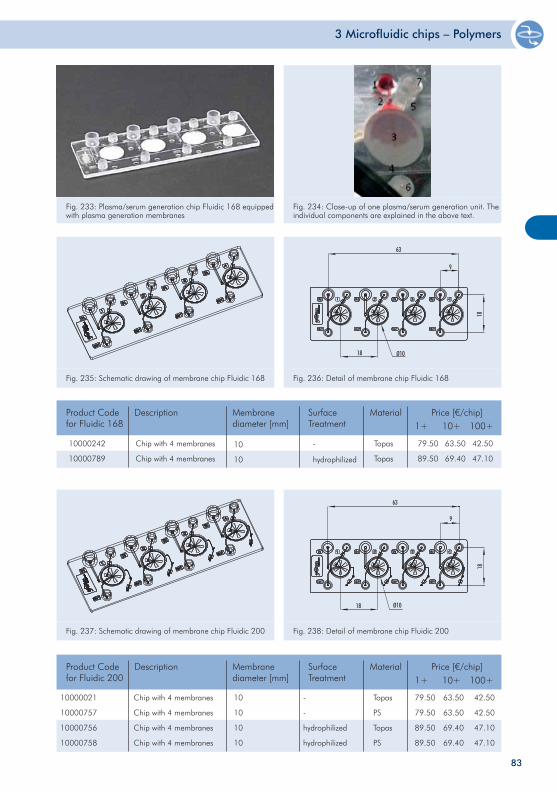
3 Microfluidic chips – Polymers
83
Fig. 233: Plasma/serum generation chip Fluidic 168 equipped with plasma generation membranes
Fig. 234: Close-up of one plasma/serum generation unit. The individual components are explained in the above text.
Fig. 235: Schematic drawing of membrane chip Fluidic 168 Fig. 236: Detail of membrane chip Fluidic 168
Fig. 237: Schematic drawing of membrane chip Fluidic 200 Fig. 238: Detail of membrane chip Fluidic 200
10
10
10
10
10000021
10000757
10000756
10000758
79.50
79.50
89.50
89.50
63.50
63.50
69.40
69.40
42.50
42.50
47.10
47.10
Topas
PS
Topas
PS
-
-
hydrophilized
hydrophilized
Product Code for Fluidic 200
Price [€/chip]1+ 10+ 100+
Description MaterialSurfaceTreatment
Membrane diameter [mm]
Chip with 4 membranes
Chip with 4 membranes
Chip with 4 membranes
Chip with 4 membranes
10000242
10000789
Chip with 4 membranes
Chip with 4 membranes
Product Code for Fluidic 168
Price [€/chip]1+ 10+ 100+
79.50
89.50
63.50
69.40
42.50
47.10
Description
Topas
Topas
Material
-
hydrophilized
SurfaceTreatment
Membrane diameter [mm]
10
10
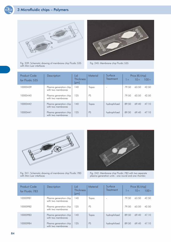
3 Microfluidic chips – Polymers
84
Fig. 239: Schematic drawing of membrane chip Fluidic 535 with Mini Luer interfaces
Fig. 240: Membrane chip Fluidic 535
Product Code
for Fluidic 535
Price [€/chip]1+ 10+ 100+
Description MaterialLid Thickness[µm]
Surface Treatment
Plasma generation chip with two membranes
Plasma generation chip with two membranes
Plasma generation chip with two membranes
Plasma generation chip with two membranes
Fig. 241: Schematic drawing of membrane chip Fluidic 783 with Mini Luer interfaces
Fig. 242: Membrane chip Fluidic 783 with two separate plasma generation units - one round and one rhombic
140
125
140
125
10000439
10000440
10000442
10000441
Topas
PS
Topas
PS
-
hydrophilized
hydrophilized
79.50
79.50
89.50
89.50
63.50
63.50
69.40
69.40
42.50
42.50
47.10
47.10
Product Code
for Fluidic 783
Price [€/chip]1+ 10+ 100+
Description MaterialLid Thickness[µm]
Surface Treatment
Plasma generation chip with two membranes
Plasma generation chip with two membranes
Plasma generation chip with two membranes
Plasma generation chip with two membranes
140
125
140
125
10000981
10000982
10000983
10000984
Topas
PS
Topas
PS
-
hydrophilized
hydrophilized
79.50
79.50
89.50
89.50
63.50
63.50
69.40
69.40
42.50
42.50
47.10
47.10
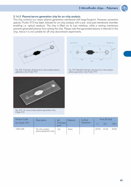
3 Microfluidic chips – Polymers
Fig. 243: Schematic drawing of on-chip analysis plasma generation chip Fluidic 973
Fig. 244 Detailed schematic drawing of on-chip analysis plasma generation chip Fluidic 973
3.14.3 Plasma/serum generation chip for on-chip analysisThis chip contains our classic plasma generation membrane with large footprint. However, somewhat special, Fluidic 973 has been tailored for on-chip analysis with a pre- and post-membrane chamber enabling i.e. optical readouts. The chip is filled via its Luer interface, while a venting membrane prevents generated plasma from exiting the chip. Please note that generated plasma is retained in this chip, hence it is not suitable for off-chip downstream experiments.
Product Code
for Fluidic 973
Price [€/chip]
1+ 10+ 100+
Description MaterialLid Thickness[µm]
Surface Treatment
On-chip analysis plasma generation chip
10001338 Topas - 69.20 44.40 39.80140
Fig. 245: On-chip analysis plasma generation chip Fluidic 973
85
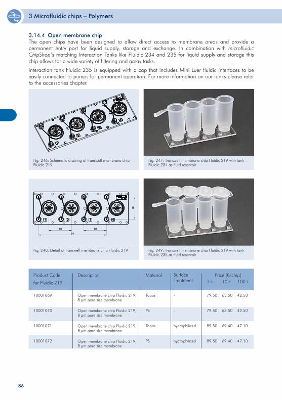
3 Microfluidic chips – Polymers
3.14.4 Open membrane chipThe open chips have been designed to allow direct access to membrane areas and provide a permanent entry port for liquid supply, storage and exchange. In combination with microfluidic ChipShop’s matching Interaction Tanks like Fluidic 234 and 235 for liquid supply and storage this chip allows for a wide variety of filtering and assay tasks.
Interaction tank Fluidic 235 is equipped with a cap that includes Mini Luer fluidic interfaces to be easily connected to pumps for permanent operation. For more information on our tanks please refer to the accessories chapter.
Fl. 219
Fig. 246: Schematic drawing of transwell membrane chip Fluidic 219
Fig. 247: Transwell membrane chip Fluidic 219 with tank Fluidic 234 as fluid reservoir
Fl. 219
18
18
1854
Fig. 248: Detail of transwell membrane chip Fluidic 219 Fig. 249: Transwell membrane chip Fluidic 219 with tank Fluidic 235 as fluid reservoir
10001069
10001070
10001071
10001072
Product Code
for Fluidic 219
Price [€/chip]1+ 10+ 100+
79.50
79.50
89.50
89.50
63.50
63.50
69.40
69.40
42.50
42.50
47.10
47.10
Description
Topas
PS
Topas
PS
Material
-
-
hydrophilized
hydrophilized
Surface Treatment
Open membrane chip Fluidic 219, 8 µm pore size membrane
Open membrane chip Fluidic 219, 8 µm pore size membrane
Open membrane chip Fluidic 219, 8 µm pore size membrane
Open membrane chip Fluidic 219, 8 µm pore size membrane
86
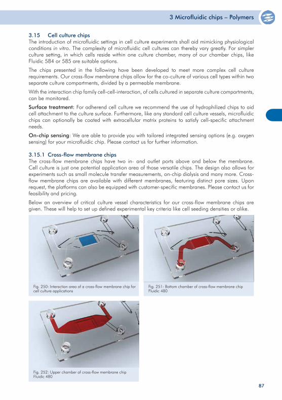
3 Microfluidic chips – Polymers
3.15 Cell culture chipsThe introduction of microfluidic settings in cell culture experiments shall aid mimicking physiological conditions in vitro. The complexity of microfluidic cell cultures can thereby vary greatly. For simpler culture setting, in which cells reside within one culture chamber, many of our chamber chips, like Fluidic 584 or 585 are suitable options.
The chips presented in the following have been developed to meet more complex cell culture requirements. Our cross-flow membrane chips allow for the co-culture of various cell types within two separate culture compartments, divided by a permeable membrane.
With the interaction chip family cell-cell-interaction, of cells cultured in separate culture compartments, can be monitored.
Surface treatment: For adherend cell culture we recommend the use of hydrophilized chips to aid cell attachment to the culture surface. Furthermore, like any standard cell culture vessels, microfluidic chips can optionally be coated with extracellular matrix proteins to satisfy cell-specific attachment needs.
On-chip sensing: We are able to provide you with tailored integrated sensing options (e.g. oxygen sensing) for your microfluidic chip. Please contact us for further information.
3.15.1 Cross-flow membrane chipsThe cross-flow membrane chips have two in- and outlet ports above and below the membrane. Cell culture is just one potential application area of those versatile chips. The design also allows for experiments such as small molecule transfer measurements, on-chip dialysis and many more. Cross-flow membrane chips are available with different membranes, featuring distinct pore sizes. Upon request, the platforms can also be equipped with customer-specific membranes. Please contact us for feasibility and pricing.
Below an overview of critical culture vessel characteristics for our cross-flow membrane chips are given. These will help to set up defined experimental key criteria like cell seeding densities or alike.
Fig. 250: Interaction area of a cross-flow membrane chip for cell culture applications
Fig. 251: Bottom chamber of cross-flow membrane chip Fluidic 480
Fig. 252: Upper chamber of cross-flow membrane chip Fluidic 480
87
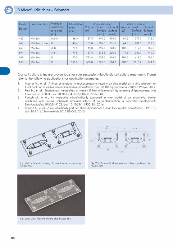
3 Microfluidic chips – Polymers
Fig. 253: Schematic drawing of cross-flow membrane chip Fluidic 480
Fig. 254: Schematic drawing of cross-flow membrane chip Fluidic 480
Fig. 255: Cross-flow membrane chip Fluidic 480
Our cell culture chips are proven tools for your successful microfluidic cell culture experiment. Please refer to the following publications for application examples:
1. Maurer M., et al., A three-dimensional immunocompetent intestine-on-chip model as in vitro platform for functional and microbial interaction studies, Biomaterials, doi: 10.1016/j.biomaterials.2019.119396, 2019
2. Pein H., et al., Endogenous metabolites of vitamin E limit inflammation by targeting 5-lipoxygenase, Nat Commun.,9(1):3834. doi: 10.1038/s41467-018-06158-5, 2018
3. Raasch M., et al., An integrative microfluidically supported in vitro model of an endothelial barrier combined with cortical spheroids simulates effects of neuroinflammation in neocortex development, Biomicrofluidics,10(4):044102. doi: 10.1063/1.4955184, 2016
4. Rennert K., et al., A microfluidically perfused three dimensional human liver model, Biomaterials, 119-131, doi: 10.1016/j.biomaterials.2015.08.043, 2015
0.2; 8
8
3; 8
3; 8
8
8
Fluidic
Design
Available membranepore sizes [µm]
Interface Type Upper chamber
Mini Luer
Mini Luer + Luer
Mini Luer
Mini Luer
Mini Luer
Mini Luer
480
568
653
694
747
846
Volume [µl]
TotalSurface [mm²]
Ground Surface [mm²]
Bottom chamberTotalSurface [mm²]
Ground Surface [mm²]
Interactionarea[mm²]
Volume [µl]
36.0
40.6
71.5
71.5
71.5
395.5
87.5
105.8
145.0
137.8
281.4
500.0
440.0
605.0
595.0
573.5
1138.0
1795.5
154.0
151.0
223.5
220.0
456.0
803.0
61.5
64.0
101.8
79.5
101.8
402.8
271.0
281.0
419.0
340.7
419.0
1818.7
118.0
120.0
185.0
140.0
185.0
674.7
88
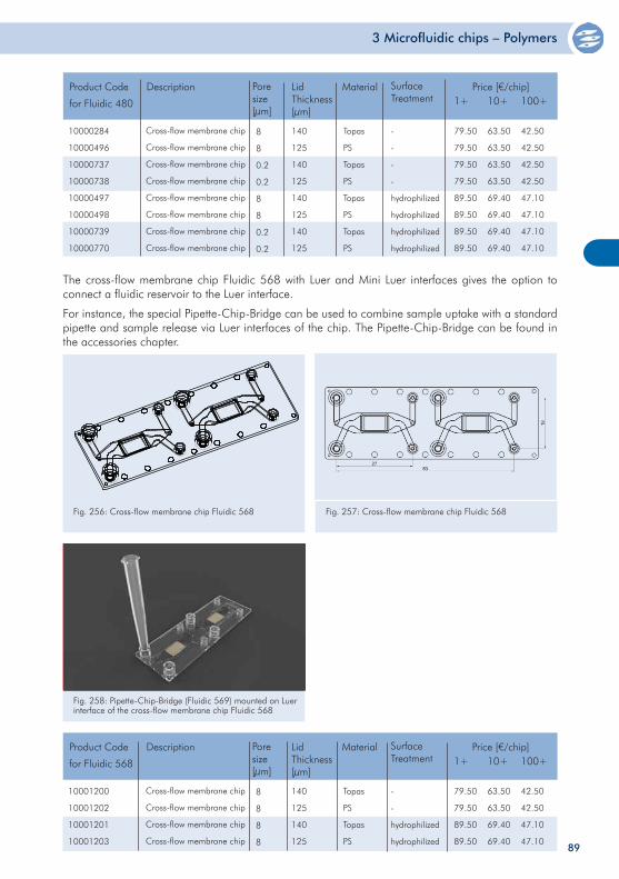
3 Microfluidic chips – Polymers
The cross-flow membrane chip Fluidic 568 with Luer and Mini Luer interfaces gives the option to connect a fluidic reservoir to the Luer interface.
For instance, the special Pipette-Chip-Bridge can be used to combine sample uptake with a standard pipette and sample release via Luer interfaces of the chip. The Pipette-Chip-Bridge can be found in the accessories chapter.
Fl. 568
Fig. 256: Cross-flow membrane chip Fluidic 568
Fig. 258: Pipette-Chip-Bridge (Fluidic 569) mounted on Luer interface of the cross-flow membrane chip Fluidic 568
10001200
10001202
10001201
10001203
Product Code
for Fluidic 568
Price [€/chip]1+ 10+ 100+
79.50
79.50
89.50
89.50
63.50
63.50
69.40
69.40
42.50
42.50
47.10
47.10
Description
Topas
PS
Topas
PS
Material
140
125
140
125
Lid Thickness[µm]
-
-
hydrophilized
hydrophilized
Surface Treatment
Pore size[µm]
8
8
8
8
Cross-flow membrane chip
Cross-flow membrane chip
Cross-flow membrane chip
Cross-flow membrane chip
10000284
10000496
10000737
10000738
10000497
10000498
10000739
10000770
Product Code
for Fluidic 480
Price [€/chip]1+ 10+ 100+
79.50
79.50
79.50
79.50
89.50
89.50
89.50
89.50
63.50
63.50
63.50
63.50
69.40
69.40
69.40
69.40
42.50
42.50
42.50
42.50
47.10
47.10
47.10
47.10
Description
Topas
PS
Topas
PS
Topas
PS
Topas
PS
Material
140
125
140
125
140
125
140
125
Lid Thickness[µm]
-
-
-
-
hydrophilized
hydrophilized
hydrophilized
hydrophilized
Surface Treatment
Pore size[µm]
8
8
0.2
0.2
8
8
0.2
0.2
Cross-flow membrane chip
Cross-flow membrane chip
Cross-flow membrane chip
Cross-flow membrane chip
Cross-flow membrane chip
Cross-flow membrane chip
Cross-flow membrane chip
Cross-flow membrane chip
Fig. 257: Cross-flow membrane chip Fluidic 568
89
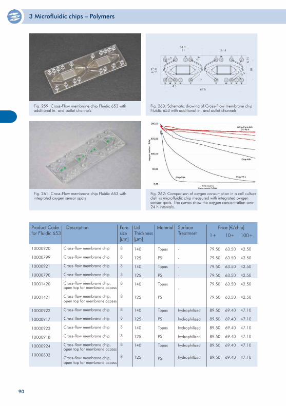
3 Microfluidic chips – Polymers
10000920
10000799
10000921
10000790
10001420
10001421
10000922
10000917
10000923
10000918
10000924
10000832
Product Code for Fluidic 653
Price [€/chip]
1+ 10+ 100+
79.50
79.50
79.50
79.50
79.50
79.50
89.50
89.50
89.50
89.50
89.50
89.50
63.50
63.50
63.50
63.50
63.50
63.50
69.40
69.40
69.40
69.40
69.40
69.40
42.50
42.50
42.50
42.50
42.50
42.50
47.10
47.10
47.10
47.10
47.10
47.10
Description
Topas
PS
Topas
PS
Topas
PS
Topas
PS
Topas
PS
Topas
PS
Material
140
125
140
125
140
125
140
125
140
125
140
125
Lid Thickness[µm]
-
-
-
-
-
-
hydrophilized
hydrophilized
hydrophilized
hydrophilized
hydrophilized
hydrophilized
Surface Treatment
Pore size[µm]
8
8
3
3
8
8
8
8
3
3
8
8
Cross-flow membrane chip
Cross-flow membrane chip
Cross-flow membrane chip
Cross-flow membrane chip
Cross-flow membrane chip, open top for membrane access
Cross-flow membrane chip,open top for membrane access
Cross-flow membrane chip
Cross-flow membrane chip
Cross-flow membrane chip
Cross-flow membrane chip
Cross-flow membrane chip, open top for membrane access
Cross-flow membrane chip,open top for membrane access
Fig. 259: Cross-Flow membrane chip Fluidic 653 with additional in- and outlet channels
Fig. 260: Schematic drawing of Cross-Flow membrane chip Fluidic 653 with additional in- and outlet channels
Fig. 261: Cross-Flow membrane chip Fluidic 653 with integrated oxygen sensor spots
Fig. 262: Comparison of oxygen consumption in a cell culture dish vs microfluidic chip measured with integrated oxygen sensor spots. The curves show the oxygen concentration over 24 h intervals.
90
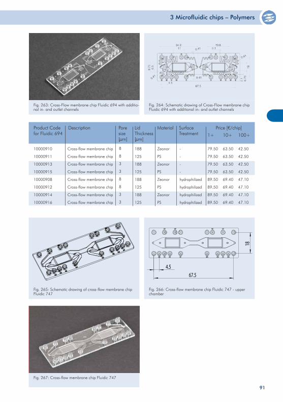
3 Microfluidic chips – Polymers
Fig. 265: Schematic drawing of cross-flow membrane chip Fluidic 747
4.567.5
18
Fig. 266: Cross-flow membrane chip Fluidic 747 - upper chamber
10000910
10000911
10000913
10000915
10000908
10000912
10000914
10000916
Product Code for Fluidic 694
Price [€/chip]
1+ 10+ 100+
79.50
79.50
79.50
79.50
89.50
89.50
89.50
89.50
63.50
63.50
63.50
63.50
69.40
69.40
69.40
69.40
42.50
42.50
42.50
42.50
47.10
47.10
47.10
47.10
Description
Zeonor
PS
Zeonor
PS
Zeonor
PS
Zeonor
PS
Material
188
125
188
125
188
125
188
125
Lid Thickness[µm]
-
-
-
-
hydrophilized
hydrophilized
hydrophilized
hydrophilized
Surface Treatment
Pore size[µm]
8
8
3
3
8
8
3
3
Cross-flow membrane chip
Cross-flow membrane chip
Cross-flow membrane chip
Cross-flow membrane chip
Cross-flow membrane chip
Cross-flow membrane chip
Cross-flow membrane chip
Cross-flow membrane chip
Fig. 263: Cross-Flow membrane chip Fluidic 694 with additio-nal in- and outlet channels
Fig. 264: Schematic drawing of Cross-Flow membrane chip Fluidic 694 with additional in- and outlet channels
Fig. 267: Cross-flow membrane chip Fluidic 747
91
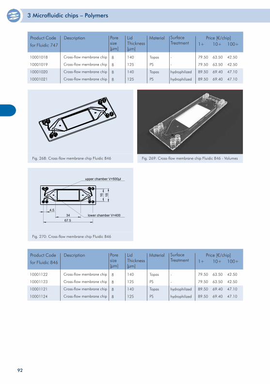
3 Microfluidic chips – Polymers
Fl. 846
Fig. 182: Cross-flow membrane chip Fluidic 846
Fig. 268: Cross-flow membrane chip Fluidic 846 Fig. 269: Cross-flow membrane chip Fluidic 846 - Volumes
Fl. 846
Fig. 183: Cross-flow membrane chip Fluidic 846 - Volumes
upper chamber V=500µl
lower chamber V=40067.5
4.5
1816
34
Fig. 270: Cross-flow membrane chip Fluidic 846
10001122
10001123
10001121
10001124
Product Code
for Fluidic 846
Price [€/chip]1+ 10+ 100+
79.50
79.50
89.50
89.50
63.50
63.50
69.40
69.40
42.50
42.50
47.10
47.10
Description
Topas
PS
Topas
PS
Material
140
125
140
125
Lid Thickness[µm]
-
-
hydrophilized
hydrophilized
Surface Treatment
Pore size[µm]
8
8
8
8
Cross-flow membrane chip
Cross-flow membrane chip
Cross-flow membrane chip
Cross-flow membrane chip
10001018
10001019
10001020
10001021
Product Code
for Fluidic 747
Price [€/chip]1+ 10+ 100+
79.50
79.50
89.50
89.50
63.50
63.50
69.40
69.40
42.50
42.50
47.10
47.10
Description
Topas
PS
Topas
PS
Material
140
125
140
125
Lid Thickness[µm]
-
-
hydrophilized
hydrophilized
Surface Treatment
Pore size[µm]
8
8
8
8
Cross-flow membrane chip
Cross-flow membrane chip
Cross-flow membrane chip
Cross-flow membrane chip
92
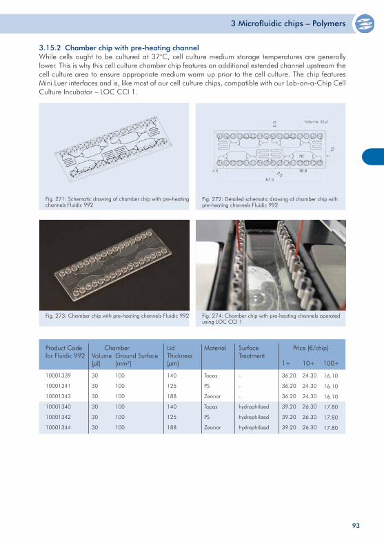
3 Microfluidic chips – Polymers
3.15.2 Chamber chip with pre-heating channelWhile cells ought to be cultured at 37°C, cell culture medium storage temperatures are generally lower. This is why this cell culture chamber chip features an additional extended channel upstream the cell culture area to ensure appropriate medium warm up prior to the cell culture. The chip features Mini Luer interfaces and is, like most of our cell culture chips, compatible with our Lab-on-a-Chip Cell Culture Incubator – LOC CCI 1.
Fig. 271: Schematic drawing of chamber chip with pre-heating channels Fluidic 992
Fig. 272: Detailed schematic drawing of chamber chip with pre-heating channels Fluidic 992
Fig. 273: Chamber chip with pre-heating channels Fluidic 992 Fig. 274: Chamber chip with pre-heating channels operated using LOC CCI 1
30
30
30
30
30
30
100
100
100
100
100
100
140
125
188
140
125
188
Topas
PS
Zeonor
Topas
PS
Zeonor
-
-
-
hydrophilized
hydrophilized
hydrophilized
Product Codefor Fluidic 992
ChamberVolume[µl]
Ground Surface [mm²]
Material SurfaceTreatment
Price [€/chip]
1+ 10+ 100+
LidThickness[µm]
36.20
36.20
36.20
39.20
39.20
39.20
24.30
24.30
24.30
26.30
26.30
26.30
16.10
16.10
16.10
17.80
17.80
17.80
10001339
10001341
10001343
10001340
10001342
10001344
93
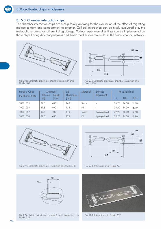
3 Microfluidic chips – Polymers
3.15.3 Chamber interaction chipsThe chamber interaction chips are a chip family allowing for the evaluation of the effect of migrating molecules from one compartment to another. Cell-cell-interaction can be nicely evaluated e.g. the metabolic response on different drug dosage. Various experimental settings can be implemented on these chips having different pathways and fluidic modules for molecules in the fluidic channel network.
58.517.8
513
.8
4.5 513
.8
Fig. 275: Schematic drawing of chamber interaction chip Fluidic 688
Fig. 276 Schematic drawing of chamber interaction chip Fluidic 688
10001055
10001056
10001057
10001058
37.8
37.8
37.8
37.8
400
400
400
400
140
125
140
125
Topas
PS
Topas
PS
-
-
hydrophilized
hydrophilized
Product Code
for Fluidic 688
ChamberVolume[µl]
Depth[µm]
Material SurfaceTreatment
Price [€/chip]
1+ 10+ 100+
LidThickness[µm]
36.20
36.20
39.20
39.20
24.30
24.30
26.30
26.30
16.10
16.10
17.80
17.80
58.5
4.5
13.5
5
18.2
Fig. 277: Schematic drawing of interaction chip Fluidic 737 Fig. 278: Interaction chip Fluidic 737
Fig. 279: Detail contact zone channel & cavity interaction chip Fluidic 737
12.2n 0.37
Fig. 280: Interaction chip Fluidic 737
94
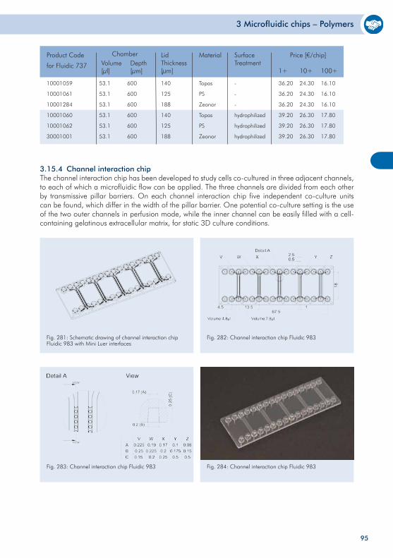
3 Microfluidic chips – Polymers
95
3.15.4 Channel interaction chipThe channel interaction chip has been developed to study cells co-cultured in three adjacent channels, to each of which a microfluidic flow can be applied. The three channels are divided from each other by transmissive pillar barriers. On each channel interaction chip five independent co-culture units can be found, which differ in the width of the pillar barrier. One potential co-culture setting is the use of the two outer channels in perfusion mode, while the inner channel can be easily filled with a cell-containing gelatinous extracellular matrix, for static 3D culture conditions.
Fig. 281: Schematic drawing of channel interaction chip Fluidic 983 with Mini Luer interfaces
Fig. 284: Channel interaction chip Fluidic 983Fig. 283: Channel interaction chip Fluidic 983
Fig. 282: Channel interaction chip Fluidic 983
Chamber
10001059
10001061
10001284
10001060
10001062
30001001
53.1
53.1
53.1
53.1
53.1
53.1
600
600
600
600
600
600
140
125
188
140
125
188
Topas
PS
Zeonor
Topas
PS
Zeonor
-
-
-
hydrophilized
hydrophilized
hydrophilized
Product Code
for Fluidic 737 Volume[µl]
Depth[µm]
Material SurfaceTreatment
Price [€/chip]
1+ 10+ 100+
LidThickness[µm]
36.20
36.20
36.20
39.20
39.20
39.20
24.30
24.30
24.30
26.30
26.30
26.30
16.10
16.10
16.10
17.80
17.80
17.80
Chamber
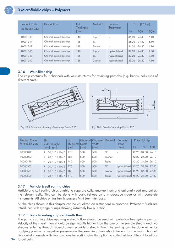
3 Microfluidic chips – Polymers
96
3.16 Weir-filter chipThe chip contains four channels with weir structures for retaining particles (e.g. beads, cells etc.) of different sizes.
Fig. 285: Schematic drawing of weir chip Fluidic 220 Fig. 286: Detail of weir chip Fluidic 220
10000092
10000093
10000499
10000502
10000501
10000500
500
500
500
500
500
500
500
500
500
500
500
500
PC
Zeonor
Topas
PC
Zeonor
Topas
Product Codefor Fluidic 220
ChannelDepth[µm]
ChannelWidth[µm]
Material Price [€/chip]
1+ 10+ 100+
42.20
42.20
42.20
45.20
45.20
45.20
34.30
34.30
34.30
36.30
36.30
36.30
26.10
26.10
26.10
27.80
27.80
27.80
175
188
140
175
188
140
Lid Thickness[µm]
7
7
7
7
7
7
Slitwidth /height[mm] [µm]
20 / 10 / 10 / 5
20 / 10 / 10 / 5
20 / 10 / 10 / 5
20 / 10 / 10 / 5
20 / 10 / 10 / 5
20 / 10 / 10 / 5
-
-
-
hydrophilized
hydrophilized
hydrophilized
SurfaceTreat-ment
3.17 Particle & cell sorting chipsParticle and cell sorting chips enable to separate cells, analyze them and optionally sort and collect the relevant cells. This can be done with basic set-ups on a microscope stage or with complete instruments. All chips of tjos family possess Mini Luer interfaces.
All the chips shown in this chapter can be visualized on a standard microscope. Preferably fluids are introduced with syringe pumps showing extremely low pulsation.
3.17.1 Particle sorting chips – Sheath flowThe particle sorting chips applying a sheath flow should be used with pulsation free syringe pumps. Velocity of the sheath flow should be significantly higher than the one of the sample stream and two streams entering through side-channels provide a sheath flow. The sorting can be done either by applying positive or negative pressure via the sampling channels at the end of the main channel. Five outlet channels with two junctions for sorting give the option to collect at two different locations target cells.
Description
10001345
10001347
10001349
10001346
10001348
10001350
Channel interaction chip
Channel interaction chip
Channel interaction chip
Channel interaction chip
Channel interaction chip
Channel interaction chip
140
125
188
140
125
188
Topas
PS
Zeonor
Topas
PS
Zeonor
-
-
-
hydrophilized
hydrophilized
hydrophilized
Product Code
for Fluidic 983
Material SurfaceTreatment
Price [€/chip]
1+ 10+ 100+
LidThickness[µm]
36.20
36.20
36.20
39.20
39.20
39.20
24.30
24.30
24.30
26.30
26.30
26.30
16.10
16.10
16.10
17.80
17.80
17.80
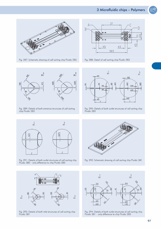
3 Microfluidic chips – Polymers
97
Fig. 291: Details of both outlet structures of cell sorting chip Fluidic 380 – only difference to chip Fluidic 283
Fig. 292: Schematic drawing of cell sorting chip Fluidic 381
Fig. 289: Details of both entrance structures of cell sorting chip Fluidic 283
Fig. 290: Details of both outlet structures of cell sorting chip Fluidic 283
Fig. 293: Details of both inlet structures of cell sorting chip Fluidic 381
Fig. 294: Details of both outlet structures of cell sorting chip Fluidic 381 – only difference to chip Fluidic 283
Fig. 287: Schematic drawing of cell sorting chip Fluidic 283 Fig. 288: Detail of cell sorting chip Fluidic 283
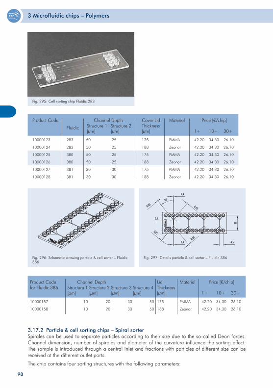
3 Microfluidic chips – Polymers
98
Fig. 296: Schematic drawing particle & cell sorter – Fluidic 386
Fig. 297: Details particle & cell sorter – Fluidic 386
10000123
10000124
10000125
10000126
10000127
10000128
50
50
50
50
30
30
25
25
25
25
30
30
175
188
175
188
175
188
PMMA
Zeonor
PMMA
Zeonor
PMMA
Zeonor
Product Code Channel DepthStructure 1[µm]
Structure 2[µm]
Cover LidThickness[µm]
Material Price [€/chip]
1+ 10+ 30+
42.20
42.20
42.20
42.20
42.20
42.20
34.30
34.30
34.30
34.30
34.30
34.30
26.10
26.10
26.10
26.10
26.10
26.10
Fluidic
283
283
380
380
381
381
10000157
10000158
10
10
20
20
175
188
PMMA
Zeonor
Product Codefor Fluidic 386
Channel DepthStructure 1[µm]
Structure 2[µm]
LidThickness[µm]
Material Price [€/chip]
1+ 10+ 30+
42.20
42.20
34.30
34.30
26.10
26.10
30
30
Structure 3[µm]
50
50
Structure 4[µm]
3.17.2 Particle & cell sorting chips – Spiral sorterSpirales can be used to separate particles according to their size due to the so-called Dean forces. Channel dimension, number of spirales and diameter of the curvature influence the sorting effect. The sample is introduced through a central inlet and fractions with particles of different size can be received at the different outlet ports.
The chip contains four sorting structures with the following parameters:
Fig. 295: Cell sorting chip Fluidic 283
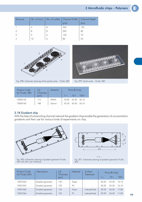
3 Microfluidic chips – Polymers
99
Fig. 298: Schematic drawing of the spirale sorter – Fluidic 382 Fig. 299: Spiral sorter – Fluidic 382
10000159
10000160
175
188
PMMA
Zeonor
Product Codefor Fluidic 382
Lid Thickness[µm]
Material Price [€/chip]
1+ 10+ 100+
42.20
42.20
34.30
34.30
26.10
26.10
3.18 Gradient chipWith the help of a branching channel network the gradient chips enable the generation of concentration gradients and their use for various kinds of experiments on chip.
Fl. 834
58.5
4.5
13.58
Fig. 300: Schematic drawing of gradient generator Fluidic 834 with Mini Luer InterfacesFl. 834
Fig. 301: Schematic drawing of gradient generator Fluidic 834
10001063
10001064
10001065
10001066
Gradient generator
Gradient generator
Gradient generator
Gradient generator
140
125
140
125
Topas
PS
Topas
PS
-
-
hydrophilized
hydrophilized
Product Codefor Fluidic 834
Description Material SurfaceTreatment
Price [€/chip]
1+ 10+
LidThickness[µm]
36.20
36.20
39.20
39.20
24.30
24.30
26.30
26.30
100+
16.10
16.10
17.80
17.80
1
2
3
4
Structure
120
80
70
50
Channel Depth
[µm]
4
8
9
12
No. of turns
8
8
6
6
No. of outlets
500
300
150
80
Channel Width
[µm]
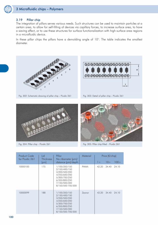
3 Microfluidic chips – Polymers
100
3.19 Pillar chipThe integration of pillars serves various needs. Such structures can be used to maintain particles at a certain area, to allow for self-filling of devices via capillary forces, to increase surface area, to have a sieving effect, or to use these structures for surface functionalization with high surface area regions in a microfluidic device.
In these pillar chips the pillars have a demolding angle of 10°. The table indicates the smallest diameter.
10000100
10000099
175
188
PMMA
Zeonor
Product Codefor Fluidic 261
Lid Thickness[µm]
Material Price [€/chip]
1+ 10+ 100+
42.20
42.20
34.40
34.40
24.10
24.10
1/100/350/1502/150/400/1503/200/500/2004/250/600/2005/300/700/2506/350/800/2507/150/500/3008/150/500-700/300
1/100/350/1502/150/400/1503/200/500/2004/250/600/2005/300/700/2506/350/800/2507/150/500/3008/150/500-700/300
Pillar No./diameter [µm]/ distance [µm]/depth
Fig. 302: Schematic drawing of pillar chip – Fluidic 261 Fig. 303: Detail of pillar chip – Fluidic 261
Fig. 304: Pillar chip – Fluidic 261 Fig. 305: Pillar chip filled – Fluidic 261
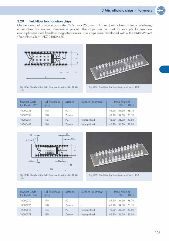
3 Microfluidic chips – Polymers
101
3.20 Field-flow fractionation chipsOn the format of a microscopy slide (75.5 mm x 25.5 mm x 1.5 mm) with olives as fluidic interfaces, a field-flow fractionation structure is placed. The chips can be used for example for free-flow electrophoresis and free-flow magnetophoresis. The chips were developed within the BMBF-Project “Free-Flow-Chip”, FKZ 01RI0643D.
1858.5
4.5
Fig. 306: Details of the field flow fractionation chip Fluidic 120
Fig. 307: Field flow fractionation chip Fluidic 120
Fig. 308: Details of the field flow fractionation chip Fluidic 159
Fig. 309: Field flow fractionation chip Fluidic 159
10000333
10000334
10000954
10000408
175
188
175
188
Product Codefor Fluidic 120
Price [€/chip]1+ 10+ 100+
42.20
42.20
45.20
45.20
34.30
34.30
36.30
36.30
26.10
26.10
27.80
27.80
Lid Thickness[µm]
PC
Zeonor
PC
Zeonor
Material
-
-
hydrophilized
hydrophilized
Surface Treatment
10000270
10000296
10000845
10000271
175
188
175
188
Product Codefor Fluidic 159
Price [€/chip]1+ 10+ 100+
42.20
42.20
45.20
45.20
34.30
34.30
36.30
36.30
26.10
26.10
27.80
27.80
Lid Thickness[µm]
PC
Zeonor
PC
Zeonor
Material
-
-
hydrophilized
hydrophilized
Surface Treatment
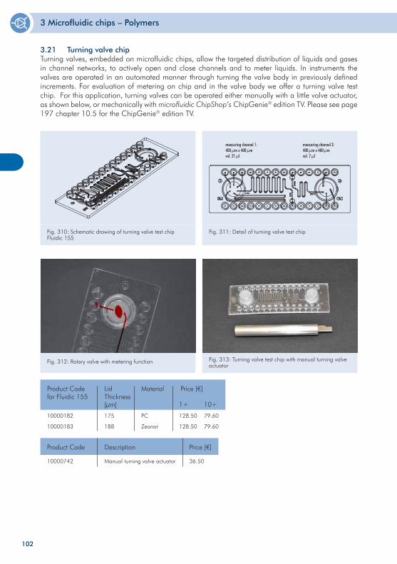
3 Microfluidic chips – Polymers
102
Fig. 312: Rotary valve with metering function Fig. 313: Turning valve test chip with manual turning valve actuator
10000182
10000183
175
188
PC
Zeonor
Product Codefor Fluidic 155
Lid Thickness[µm]
Material Price [€]
1+ 10+
128.50
128.50
79.60
79.60
10000742 Manual turning valve actuator 36.50
Product Code Description Price [€]
Fig. 310: Schematic drawing of turning valve test chip Fluidic 155
Fig. 311: Detail of turning valve test chip
3.21 Turning valve chipTurning valves, embedded on microfluidic chips, allow the targeted distribution of liquids and gases in channel networks, to actively open and close channels and to meter liquids. In instruments the valves are operated in an automated manner through turning the valve body in previously defined increments. For evaluation of metering on chip and in the valve body we offer a turning valve test chip. For this application, turning valves can be operated either manually with a little valve actuator, as shown below, or mechanically with microfluidic ChipShop’s ChipGenie® edition TV. Please see page 197 chapter 10.5 for the ChipGenie® edition TV.
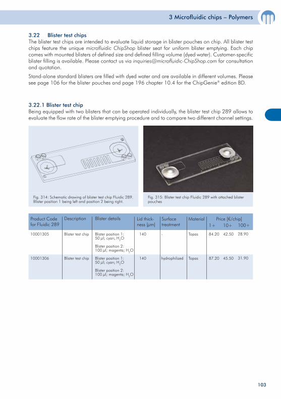
3 Microfluidic chips – Polymers
103
3.22 Blister test chipsThe blister test chips are intended to evaluate liquid storage in blister pouches on chip. All blister test chips feature the unique microfluidic ChipShop blister seat for uniform blister emptying. Each chip comes with mounted blisters of defined size and defined filling volume (dyed water). Customer-specific blister filling is available. Please contact us via [email protected] for consultation and quotation.
Stand-alone standard blisters are filled with dyed water and are available in different volumes. Please see page 106 for the blister pouches and page 196 chapter 10.4 for the ChipGenie® edition BD.
3.22.1 Blister test chip Being equipped with two blisters that can be operated individually, the blister test chip 289 allows to evaluate the flow rate of the blister emptying procedure and to compare two different channel settings.
Fig. 314: Schematic drawing of blister test chip Fluidic 289. Blister position 1 being left and position 2 being right.
Fig. 315: Blister test chip Fluidic 289 with attached blister pouches
Product Codefor Fluidic 289
Price [€/chip]1+ 10+ 100+
84.20
87.20
42.50
45.50
28.90
31.90
Description
Topas
Topas
Material
140
140
Lid thick-ness [µm]
Blister test chip
Blister test chip
Blister details
Blister position 1:50 µl; cyan; H2O
Blister position 2:100 µl; magenta; H2O
Blister position 1:50 µl; cyan; H2O
Blister position 2:100 µl; magenta; H2O
-
hydrophilized
Surfacetreatment
10001305
10001306
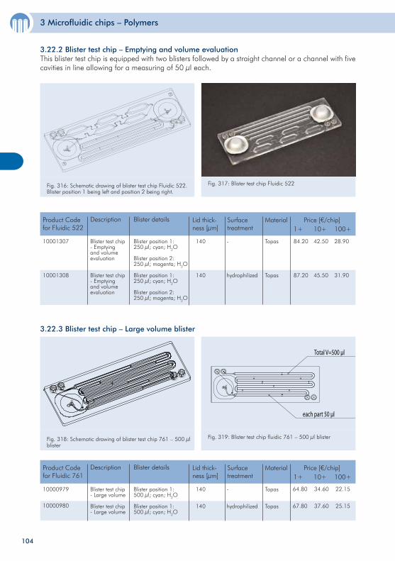
3 Microfluidic chips – Polymers
104
Product Codefor Fluidic 522
Price [€/chip]1+ 10+ 100+
84.20
87.20
42.50
45.50
28.90
31.90
Description
Topas
Topas
Material
140
140
Lid thick-ness [µm]
Blister test chip- Emptying and volume evaluation
Blister test chip- Emptying and volume evaluation
Blister details
Blister position 1:250 µl; cyan; H2O
Blister position 2:250 µl; magenta; H2O
Blister position 1:250 µl; cyan; H2O
Blister position 2:250 µl; magenta; H2O
-
hydrophilized
Surfacetreatment
10001307
10001308
3.22.3 Blister test chip – Large volume blister
Fig. 318: Schematic drawing of blister test chip 761 – 500 µl blister
Total V=500 µl
each part 50 µl
Fig. 319: Blister test chip fluidic 761 – 500 µl blister
3.22.2 Blister test chip – Emptying and volume evaluationThis blister test chip is equipped with two blisters followed by a straight channel or a channel with five cavities in line allowing for a measuring of 50 µl each.
Fig. 316: Schematic drawing of blister test chip Fluidic 522. Blister position 1 being left and position 2 being right.
Fig. 317: Blister test chip Fluidic 522
64.80
67.80
34.60
37.60
22.15
25.15
Product Codefor Fluidic 761
Price [€/chip]1+ 10+ 100+
Description
Topas
Topas
Material
140
140
Lid thick-ness [µm]
Blister test chip- Large volume
Blister test chip- Large volume
Blister details
Blister position 1:500 µl; cyan; H2O
Blister position 1:500 µl; cyan; H2O
-
hydrophilized
Surfacetreatment
10000979
10000980
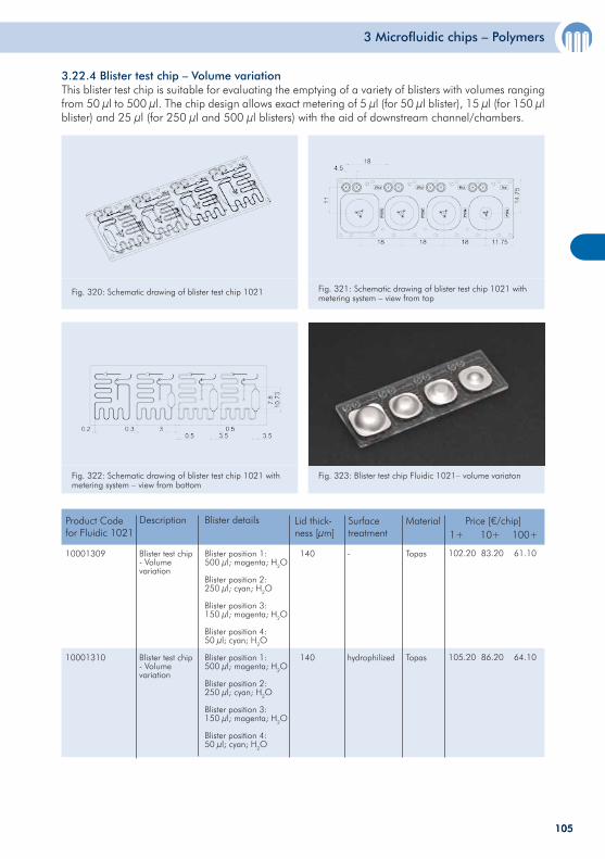
3 Microfluidic chips – Polymers
105105
3.22.4 Blister test chip – Volume variationThis blister test chip is suitable for evaluating the emptying of a variety of blisters with volumes ranging from 50 µl to 500 µl. The chip design allows exact metering of 5 µl (for 50 µl blister), 15 µl (for 150 µl blister) and 25 µl (for 250 µl and 500 µl blisters) with the aid of downstream channel/chambers.
Fig. 320: Schematic drawing of blister test chip 1021 Fig. 321: Schematic drawing of blister test chip 1021 with metering system – view from top
102.20
105.20
83.20
86.20
61.10
64.10
Product Codefor Fluidic 1021
Price [€/chip]1+ 10+ 100+
Description
Topas
Topas
Material
140
140
Lid thick-ness [µm]
Blister test chip- Volume variation
Blister test chip- Volume variation
Blister details
Blister position 1:500 µl; magenta; H2O
Blister position 2:250 µl; cyan; H2O
Blister position 3:150 µl; magenta; H2O
Blister position 4:50 µl; cyan; H2O
Blister position 1:500 µl; magenta; H2O
Blister position 2:250 µl; cyan; H2O
Blister position 3:150 µl; magenta; H2O
Blister position 4:50 µl; cyan; H2O
-
hydrophilized
Surfacetreatment
10001309
10001310
Fig. 323: Blister test chip Fluidic 1021– volume variatonFig. 322: Schematic drawing of blister test chip 1021 with metering system – view from bottom
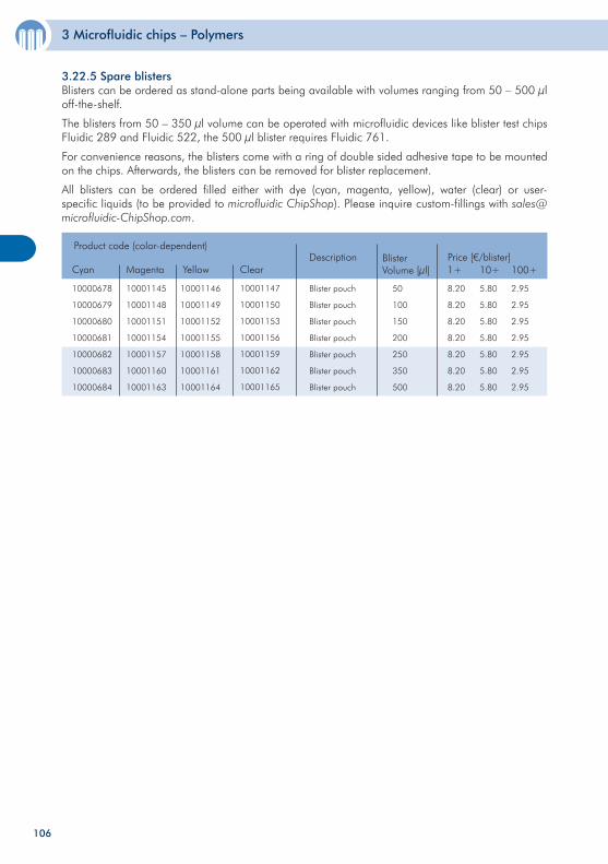
3 Microfluidic chips – Polymers
106
3.22.5 Spare blistersBlisters can be ordered as stand-alone parts being available with volumes ranging from 50 – 500 µl off-the-shelf.
The blisters from 50 – 350 µl volume can be operated with microfluidic devices like blister test chips Fluidic 289 and Fluidic 522, the 500 µl blister requires Fluidic 761.
For convenience reasons, the blisters come with a ring of double sided adhesive tape to be mounted on the chips. Afterwards, the blisters can be removed for blister replacement.
All blisters can be ordered filled either with dye (cyan, magenta, yellow), water (clear) or user-specific liquids (to be provided to microfluidic ChipShop). Please inquire custom-fillings with [email protected].
10000678
10000679
10000680
10000681
10000682
10000683
10000684
Blister pouch
Blister pouch
Blister pouch
Blister pouch
Blister pouch
Blister pouch
Blister pouch
Description Price [€/blister]1+
8.20
8.20
8.20
8.20
8.20
8.20
8.20
10+
5.80
5.80
5.80
5.80
5.80
5.80
5.80
100+
2.95
2.95
2.95
2.95
2.95
2.95
2.95
50
100
150
200
250
350
500
BlisterVolume [µl]
Product code (color-dependent)
Cyan Magenta Yellow Clear
10001145
10001148
10001151
10001154
10001157
10001160
10001163
10001146
10001149
10001152
10001155
10001158
10001161
10001164
10001147
10001150
10001153
10001156
10001159
10001162
10001165

107107
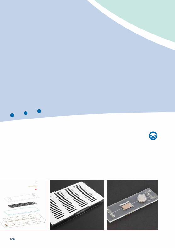
108
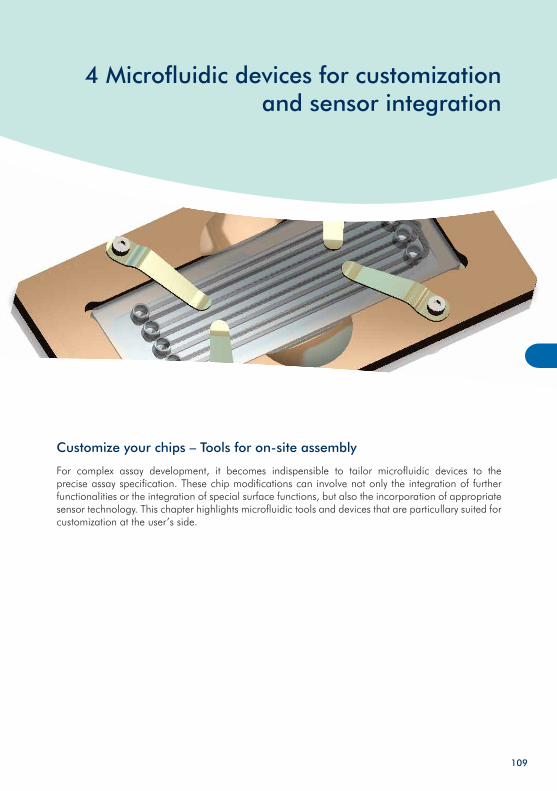
4 Microfluidic devices for customization and sensor integration
109
Customize your chips – Tools for on-site assembly
For complex assay development, it becomes indispensible to tailor microfluidic devices to the precise assay specification. These chip modifications can involve not only the integration of further functionalities or the integration of special surface functions, but also the incorporation of appropriate sensor technology. This chapter highlights microfluidic tools and devices that are particullary suited for customization at the user’s side.
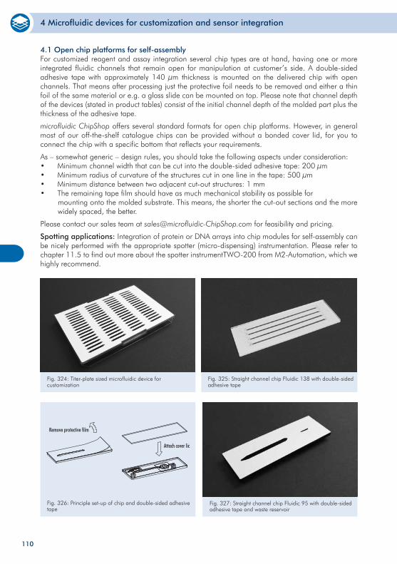
4 Microfluidic devices for customization and sensor integration
4.1 Open chip platforms for self-assemblyFor customized reagent and assay integration several chip types are at hand, having one or more integrated fluidic channels that remain open for manipulation at customer’s side. A double-sided adhesive tape with approximately 140 µm thickness is mounted on the delivered chip with open channels. That means after processing just the protective foil needs to be removed and either a thin foil of the same material or e.g. a glass slide can be mounted on top. Please note that channel depth of the devices (stated in product tables) consist of the initial channel depth of the molded part plus the thickness of the adhesive tape.
microfluidic ChipShop offers several standard formats for open chip platforms. However, in general most of our off-the-shelf catalogue chips can be provided without a bonded cover lid, for you to connect the chip with a specific bottom that reflects your requirements.
As – somewhat generic – design rules, you should take the following aspects under consideration:• Minimum channel width that can be cut into the double-sided adhesive tape: 200 µm• Minimum radius of curvature of the structures cut in one line in the tape: 500 µm• Minimum distance between two adjacent cut-out structures: 1 mm• The remaining tape film should have as much mechanical stability as possible for mounting onto the molded substrate. This means, the shorter the cut-out sections and the more widely spaced, the better.
Please contact our sales team at [email protected] for feasibility and pricing.
Spotting applications: Integration of protein or DNA arrays into chip modules for self-assembly can be nicely performed with the appropriate spotter (micro-dispensing) instrumentation. Please refer to chapter 11.5 to find out more about the spotter instrumentTWO-200 from M2-Automation, which we highly recommend.
Fig. 324: Titer-plate sized microfluidic device for customization
Fig. 325: Straight channel chip Fluidic 138 with double-sided adhesive tape
Fig. 326: Principle set-up of chip and double-sided adhesive tape
Fig. 327: Straight channel chip Fluidic 95 with double-sided adhesive tape and waste reservoir
110
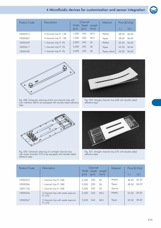
4 Microfluidic devices for customization and sensor integration
Fig. 328: Schematic drawing of the one channel chip with Luer interface 268 to be equipped with double-sided adhesive tape
Fig. 329: Straight channel chip 268 with double-sided adhesive tape
Fig. 330: Schematic drawing of a straight channel chip with waste chamber 272 to be equipped with double-sided adhesive tape
Fig. 331: Straight channel chip 272 with double-sided adhesive tape
10000376
10000306
10001136
10000346
10000347
1 channel chip Fl. 268
1 channel chip Fl. 268
1 channel chip Fl. 268
2 channel chip with waste reservoir Fl. 272
2 channel chip with waste reservoir Fl. 272
Product Code Description
2,500
2,500
2,500
2,500
2,500
290
290
290
340
340
26
26
26
58.5
58.5
PMMA
Topas
Zeonor
PMMA
Topas
ChannelWidth[µm]
Depth[µm]
Material Price [€/chip]
1+ 10+Length[mm]
48.50
48.50
52.50
52.50
36.50
36.50
36.60
36.60
111
10000313
10000307
10000429
10000417
10000430
4 channel chip Fl. 138
4 channel chip Fl. 138
1 channel chip Fl. 95
1 channel chip Fl. 95
1 channel chip Fl. 95
Product Code Description
1,000
1,000
3,000
3,000
3,000
340
340
340
340
340
58.5
58.5
36
36
36
PMMA
Topas
PMMA
Topas
Topas, black
ChannelWidth[µm]
Depth[µm]
Material Price [€/chip]
1+ 10+Length[mm]
48.50
48.50
52.50
52.50
52.50
36.50
36.50
36.60
36.60
36.60
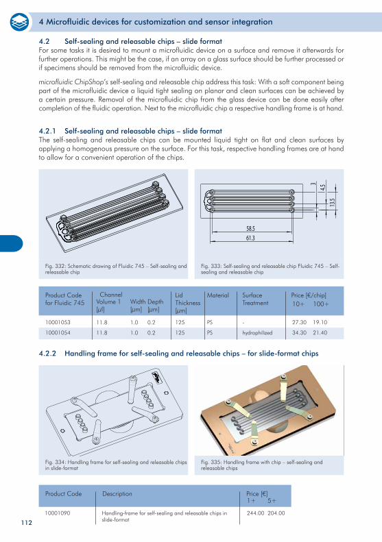
4 Microfluidic devices for customization and sensor integration
112
4.2.1 Self-sealing and releasable chips – slide formatThe self-sealing and releasable chips can be mounted liquid tight on flat and clean surfaces by applying a homogenous pressure on the surface. For this task, respective handling frames are at hand to allow for a convenient operation of the chips.
Fig. 332: Schematic drawing of Fluidic 745 – Self-sealing and releasable chip
Fig. 333: Self-sealing and releasable chip Fluidic 745 – Self-sealing and releasable chip
58.5
4.513
.5
61.3
310001053
10001054
Product Codefor Fluidic 745
Price [€/chip]10+ 100+
27.30
34.30
19.10
21.40
SurfaceTreatment
PS
PS
Material
125
125
Lid Thickness[µm]
-
hydrophilized
Channel
1.0
1.0
11.8
11.8
Width[µm]
Depth[µm]
Volume 1[µl]
0.2
0.2
4.2.2 Handling frame for self-sealing and releasable chips – for slide-format chips
Fig. 334: Handling frame for self-sealing and releasable chips in slide-format
Fig. 335: Handling frame with chip – self-sealing and releasable chips
10001090
Product Code Price [€]
Handling-frame for self-sealing and releasable chips in slide-format
Description1+ 5+
244.00 204.00
4.2 Self-sealing and releasable chips – slide formatFor some tasks it is desired to mount a microfluidic device on a surface and remove it afterwards for further operations. This might be the case, if an array on a glass surface should be further processed or if specimens should be removed from the microfluidic device.
microfluidic ChipShop’s self-sealing and releasable chip address this task: With a soft component being part of the microfluidic device a liquid tight sealing on planar and clean surfaces can be achieved by a certain pressure. Removal of the microfluidic chip from the glass device can be done easily after completion of the fluidic operation. Next to the microfluidic chip a respective handling frame is at hand.
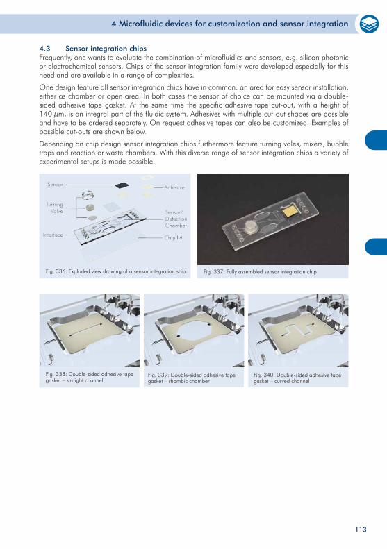
4 Microfluidic devices for customization and sensor integration
4.3 Sensor integration chipsFrequently, one wants to evaluate the combination of microfluidics and sensors, e.g. silicon photonic or electrochemical sensors. Chips of the sensor integration family were developed especially for this need and are available in a range of complexities.
One design feature all sensor integration chips have in common: an area for easy sensor installation, either as chamber or open area. In both cases the sensor of choice can be mounted via a double-sided adhesive tape gasket. At the same time the specific adhesive tape cut-out, with a height of 140 µm, is an integral part of the fluidic system. Adhesives with multiple cut-out shapes are possible and have to be ordered separately. On request adhesive tapes can also be customized. Examples of possible cut-outs are shown below.
Depending on chip design sensor integration chips furthermore feature turning vales, mixers, bubble traps and reaction or waste chambers. With this diverse range of sensor integration chips a variety of experimental setups is made possible.
113
Fig. 337: Fully assembled sensor integration chipFig. 336: Exploded view drawing of a sensor integration ship
Fig. 338: Double-sided adhesive tape gasket – straight channel
Fig. 339: Double-sided adhesive tape gasket – rhombic chamber
Fig. 340: Double-sided adhesive tape gasket – curved channel
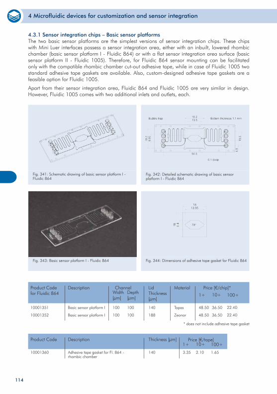
4 Microfluidic devices for customization and sensor integration
114
4.3.1 Sensor integration chips – Basic sensor platformsThe two basic sensor platforms are the simplest versions of sensor integration chips. These chips with Mini Luer interfaces possess a sensor integration area, either with an inbuilt, lowered rhombic chamber (basic sensor platform I - Fluidic 864) or with a flat sensor integration area surface (basic sensor platform II - Fluidic 1005). Therefore, for Fluidic 864 sensor mounting can be facilitated only with the compatible rhombic chamber cut-out adhesive tape, while in case of Fluidic 1005 two standard adhesive tape gaskets are available. Also, custom-designed adhesive tape gaskets are a feasible option for Fluidic 1005.
Apart from their sensor integration area, Fluidic 864 and Fluidic 1005 are very similar in design. However, Fluidic 1005 comes with two additional inlets and outlets, each.
Fig. 341: Schematic drawing of basic sensor platform I - Fluidic 864
Fig. 342: Detailed schematic drawing of basic sensor platform I - Fluidic 864
Fig. 343: Basic sensor platform I - Fluidic 864 Fig. 344: Dimensions of adhesive tape gasket for Fluidic 864
10001351
10001352
Product Codefor Fluidic 864
Price [€/chip]*
10+ 100+
36.50
36.50
22.40
22.40
Topas
Zeonor
Material
140
188
Lid Thickness[µm]
Channel
100
100
100
100
Width[µm]
Depth[µm]
Basic sensor platform I
Basic sensor platform I
1+
Description
48.50
48.50
* does not include adhesive tape gasket
10001360
Product Code Price [€/tape]
140
Thickness [µm]Description
3.35Adhesive tape gasket for Fl. 864 - rhombic chamber
10+ 100+1+
2.10 1.65
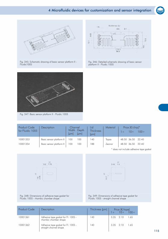
4 Microfluidic devices for customization and sensor integration
115
Fig. 345: Schematic drawing of basic sensor platform II - Fluidic1005
Fig. 346: Detailed schematic drawing of basic sensor platform II - Fluidic 1005
Fig. 347: Basic sensor platform II - Fluidic 1005
Fig. 349: Dimensions of adhesive tape gasket for Fluidic 1005 - straight channel shape
10001353
10001354
Product Codefor Fluidic 1005
Price [€/chip]*
10+ 100+
36.50
36.50
22.40
22.40
Topas
Zeonor
Material
140
188
Lid Thickness[µm]
Channel
100
100
100
100
Width[µm]
Depth[µm]
Basic sensor platform II
Basic sensor platform II
1+
Description
48.50
48.50
* does not include adhesive tape gasket
10001361
10001362
Product Code Price [€/tape]
140
140
Thickness [µm]Description
3.35
3.35
Adhesive tape gasket for Fl. 1005 - rhombic chamber shape
Adhesive tape gasket for Fl. 1005 - straight channel shape
10+ 100+1+
2.10
2.10
1.65
1.65
Fig. 348: Dimensions of adhesive tape gasket for Fluidic 1005 - rhombic chamber shape
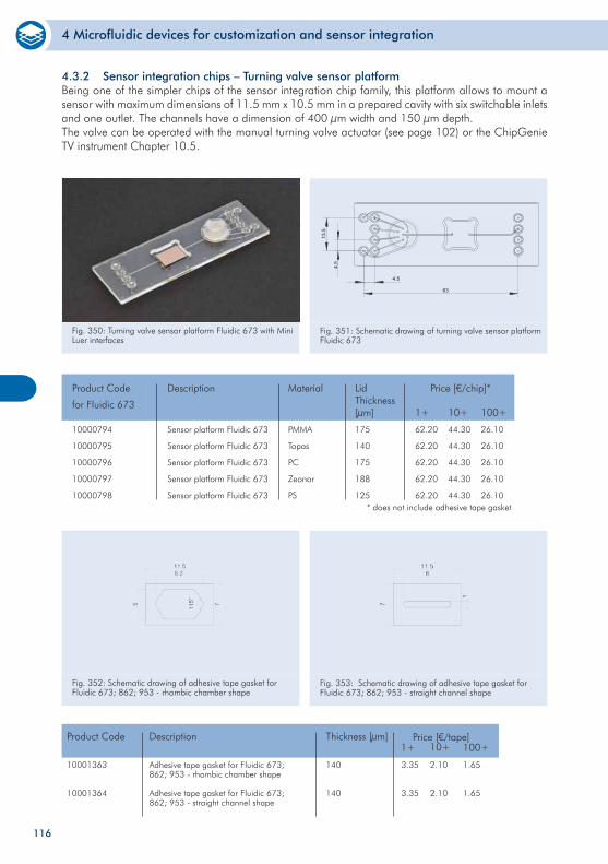
4 Microfluidic devices for customization and sensor integration
10000794
10000795
10000796
10000797
10000798
Sensor platform Fluidic 673
Sensor platform Fluidic 673
Sensor platform Fluidic 673
Sensor platform Fluidic 673
Sensor platform Fluidic 673
Product Code
for Fluidic 673
Price [€/chip]*
1+ 10+ 100+
62.20
62.20
62.20
62.20
62.20
44.30
44.30
44.30
44.30
44.30
26.10
26.10
26.10
26.10
26.10
Description
PMMA
Topas
PC
Zeonor
PS
Material
175
140
175
188
125
Lid Thickness[µm]
Fig. 350: Turning valve sensor platform Fluidic 673 with Mini Luer interfaces
Fig. 351: Schematic drawing of turning valve sensor platform Fluidic 673
4.3.2 Sensor integration chips – Turning valve sensor platformBeing one of the simpler chips of the sensor integration chip family, this platform allows to mount a sensor with maximum dimensions of 11.5 mm x 10.5 mm in a prepared cavity with six switchable inlets and one outlet. The channels have a dimension of 400 µm width and 150 µm depth. The valve can be operated with the manual turning valve actuator (see page 102) or the ChipGenie TV instrument Chapter 10.5.
* does not include adhesive tape gasket
Fig. 352: Schematic drawing of adhesive tape gasket for Fluidic 673; 862; 953 - rhombic chamber shape
Fig. 353: Schematic drawing of adhesive tape gasket for Fluidic 673; 862; 953 - straight channel shape
10001363
10001364
Product Code Price [€/tape]
140
140
Thickness [µm]Description
3.35
3.35
Adhesive tape gasket for Fluidic 673; 862; 953 - rhombic chamber shape
Adhesive tape gasket for Fluidic 673; 862; 953 - straight channel shape
10+ 100+1+
2.10
2.10
1.65
1.65
116
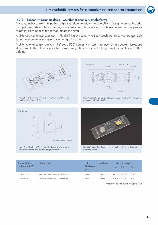
4 Microfluidic devices for customization and sensor integration
4.3.3 Sensor integration chips – Multifunctional sensor platformsThese complex sensor integration chips provide a variety of funcitonalities. Design features include: multiple inlets steerable via turning valve; reaction chambers and a three-dimensional serpentine mixer structure prior to the sensor integration area.
Multifunctional sensor platform I (Fluidic 862) includes Mini Luer interfaces on a microscope slide format and contains a single sensor integration area.
Multifunctional sensor platform II (Fluidic 953) comes with Luer interfaces on a double microscope slide format. This chip includes two sensor integration areas and a large (waste) chamber of 500 µl volume.
Fig. 354: Schematic drawing of multifunctional sensor platform I - Fluidic 862
Fig. 355: Detailed schematic drawing of multifunctional sensor platform I - Fluidic 862
Fig. 356: Fluidic 862 - Detailed schematic drawing of serpentine mixer and sensor integration area
Fig. 357: Multifunctional sensor platform I Fluidic 862 with mounted sensor
10001355
10001356
Product Codefor Fluidic 862
Price [€/chip]*
10+ 100+
44.30
44.30
26.10
26.10
Topas
Zeonor
Material
140
188
Lid Thickness[µm]
Multifunctional sensor platform I
Multifunctional sensor platform I
1+
Description
62.20
62.20
* does not include adhesive tape gasket
117
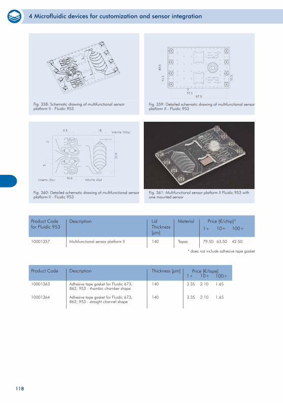
4 Microfluidic devices for customization and sensor integration
Fig. 358: Schematic drawing of multifunctional sensor platform II - Fluidic 953
Fig. 359: Detailed schematic drawing of multifunctional sensor platform II - Fluidic 953
Fig. 360: Detailed schematic drawing of multifunctional sensor platform II - Fluidic 953
Fig. 361: Multifunctional sensor platform II Fluidic 953 with one mounted sensor
10001357
Product Codefor Fluidic 953
Price [€/chip]*
10+ 100+
63.50 42.50Topas
Material
140
Lid Thickness[µm]
Multifunctional sensor platform II
1+
Description
79.50
* does not include adhesive tape gasket
10001363
10001364
Product Code Price [€/tape]
140
140
Thickness [µm]Description
3.35
3.35
Adhesive tape gasket for Fluidic 673; 862; 953 - rhombic chamber shape
Adhesive tape gasket for Fluidic 673; 862; 953 - straight channel shape
10+ 100+1+
2.10
2.10
1.65
1.65
118
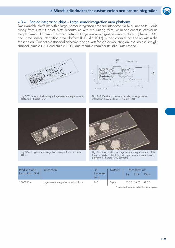
4 Microfluidic devices for customization and sensor integration
4.3.4 Sensor integration chips – Large sensor integration area platformsTwo available platforms with a larger sensor integration area are interfaced via Mini Luer ports. Liquid supply from a multitude of inlets is controlled with two turning vales, while one outlet is located on the platforms. The main difference between Large sensor integration area platform I (Fluidic 1004) and Large sensor integration area platform II (Fluidic 1012) is their channel positioning within the sensor area. Compatible standard adhesive tape gaskets for sensor mounting are available in straight channel (Fluidic 1004 and Fluidic 1012) and rhombic chamber (Fluidic 1004) shape.
Fig. 362: Schematic drawing of large sensor integration area platform I - Fluidic 1004
Fig. 363: Detailed schematic drawing of large sensor integration area platform I - Fluidic 1004
Fig. 364: Large sensor integration area platform I - Fluidic 1004
Fig. 365: Comparison of Large sensor integration area plat-form I - Fluidic 1004 (top) and Large sensor integration area platform II - Fluidic 1012 (bottom)
10001358
Product Codefor Fluidic 1004
Price [€/chip]*
10+ 100+
Topas
Material
140
Lid Thickness[µm]
Large sensor integration area platform I
1+
Description
* does not include adhesive tape gasket
63.50 42.5079.50
119
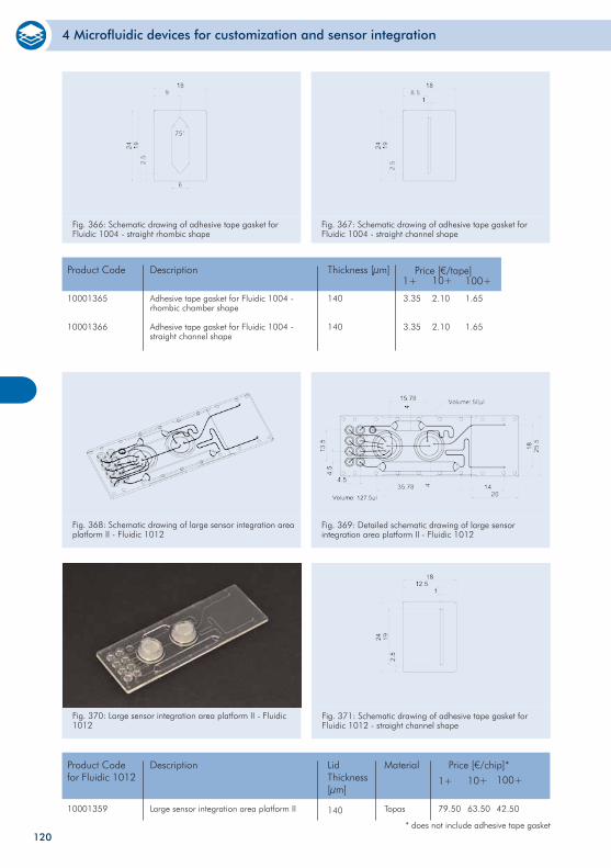
4 Microfluidic devices for customization and sensor integration
10001365
10001366
Product Code Price [€/tape]
140
140
Thickness [µm]Description
3.35
3.35
Adhesive tape gasket for Fluidic 1004 - rhombic chamber shape
Adhesive tape gasket for Fluidic 1004 - straight channel shape
10+ 100+1+
2.10
2.10
1.65
1.65
Fig. 366: Schematic drawing of adhesive tape gasket for Fluidic 1004 - straight rhombic shape
Fig. 367: Schematic drawing of adhesive tape gasket for Fluidic 1004 - straight channel shape
Fig. 368: Schematic drawing of large sensor integration area platform II - Fluidic 1012
Fig. 369: Detailed schematic drawing of large sensor integration area platform II - Fluidic 1012
Fig. 370: Large sensor integration area platform II - Fluidic 1012
10001359
Product Codefor Fluidic 1012
Price [€/chip]*
10+
Topas
MaterialLid Thickness[µm]
Large sensor integration area platform II
1+
Description
* does not include adhesive tape gasket
63.5079.50
100+
42.50140
Fig. 371: Schematic drawing of adhesive tape gasket for Fluidic 1012 - straight channel shape
120

4 Microfluidic devices for customization and sensor integration
10001367
Product Code Price [€/tape]
140
Thickness [µm]Description
3.35Adhesive tape gasket for Fluidic 1012 - straight channel shape
10+ 100+1+
2.10 1.65
121
122
5 Microfluidic chips – Integrated chips
Microfluidic chips – Integrated chips
This chapter summarizes various integrated chips combining different fluidic functions. Depending on the operator’s choice, these chips can be used for a variety of applications ranging from immunoassays, molecular based assays to the detection of small molecules. On request the surface can be modified or for hybridization assays DNA or protein arrays can be integrated. For any custom modification of these devices, please contact us for feasibility and pricing.
123
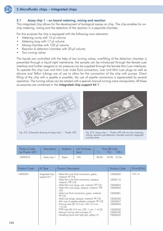
5 Microfluidic chips – Integrated chips
124
5.1 Assay chip 1 – on board metering, mixing and reactionThis integrated chip allows for the development of biological assays on chip. The chip enables for on-chip metering, mixing and the detection of the reaction in a separate chamber.
For this purpose the chip is equipped with the following main elements:• Metering cavity with 15 µl volume• Metering loop with 17 µl volume• Mixing chamber with 102 µl volume• Reaction & detection chamber with 20 µl volume• Two turning valves
The liquids are controlled with the help of two turning valves, overfilling of the detection chamber is prevented through a liquid tight membrane, the sample can be introduced through the female Luer interface and further reagents or air pressure can be supplied through the female Mini Luer interfaces. To operate this chip Luer and Mini Luer male fluid connectors, Luer and Mini Luer plugs as well as silicone and Teflon tubings are of use to allow for the connection of the chip with pumps. Direct filling of the chip with a pipette is possible, the use of pipette connectors is appreciated by several operators. The turning valves can be rotated with a special manual turning valve manipulator. All these accessories are combined in the integrated chip support kit 1.
Fig. 372: Schematic drawing of assay chip 1 – Fluidic 429 Fig. 373: Assay chip 1 – Fluidic 429 with on-chip metering, mixing, reaction and detection chamber and two integrated turning valves
10000373 Assay chip 1
Product Codefor Fluidic 429
Price [€/chip]1+ 10+ 100+
84.85 43.90 27.56
Description
Topas
Material
140
Lid Thickness[µm]
10000301 Integrated chip support kit 1
Product Code Price [€/kit]
197.14
Kit Type
- Male Mini Luer fluid connectors, green, material: PP (10)- Male Mini Luer fluid connectors, opaque, material: TPE (10)- Male Mini Luer plugs, red, material: PP (10)- Male Mini Luer plugs, opaque, material: TPE (10)- Male Luer fluid connectors, green, material: PP (10)- Male Luer plugs, opaque, material: PP (10)- Mini Luer to pipette adapter, material: PP (10)- Silicone tube (ID: 0.5 mm, OD: 2.5 mm, 1 m) (2)- PTFE tube (ID: 0.5 mm, OD: 1 mm, 1 m) (5)- Manual turning valve actuator (1)- Handling frame with high skirt, yellow (1)
Product Description
10000029
10000116
1000005310000054
10000081
100002301000005710000033
100000321000074210000042
Product Code
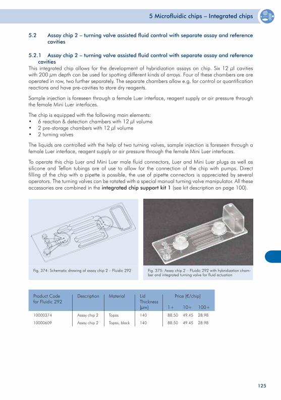
5 Microfluidic chips – Integrated chips
125
5.2 Assay chip 2 – turning valve assisted fluid control with separate assay and reference cavities
5.2.1 Assay chip 2 – turning valve assisted fluid control with separate assay and reference cavitiesThis integrated chip allows for the development of hybridization assays on chip. Six 12 µl cavities with 200 µm depth can be used for spotting different kinds of arrays. Four of these chambers are are operated in row, two further separately. The separate chambers allow e.g. for control or quantification reactions and have pre-cavities to store dry reagents.
Sample injection is foreseen through a female Luer interface, reagent supply or air pressure through the female Mini Luer interfaces.
The chip is equipped with the following main elements:• 6 reaction & detection chambers with 12 µl volume• 2 pre-storage chambers with 12 µl volume• 2 turning valves
The liquids are controlled with the help of two turning valves, sample injection is foreseen through a female Luer interface, reagent supply or air pressure through the female Mini Luer interfaces.
To operate this chip Luer and Mini Luer male fluid connectors, Luer and Mini Luer plugs as well as silicone and Teflon tubings are of use to allow for the connection of the chip with pumps. Direct filling of the chip with a pipette is possible, the use of pipette connectors is appreciated by several operators. The turning valves can be rotated with a special manual turning valve manipulator. All these accessories are combined in the integrated chip support kit 1 (see kit description on page 100).
Fig. 374: Schematic drawing of assay chip 2 – Fluidic 292 Fig. 375: Assay chip 2 – Fluidic 292 with hybridization cham-ber and integrated turning valve for fluid actuation
10000374
10000609
Assay chip 2
Assay chip 2
Product Codefor Fluidic 292
Price [€/chip]
1+ 10+ 100+
88.50
88.50
49.45
49.45
28.98
28.98
Description
Topas
Topas, black
Material
140
140
Lid Thickness[µm]
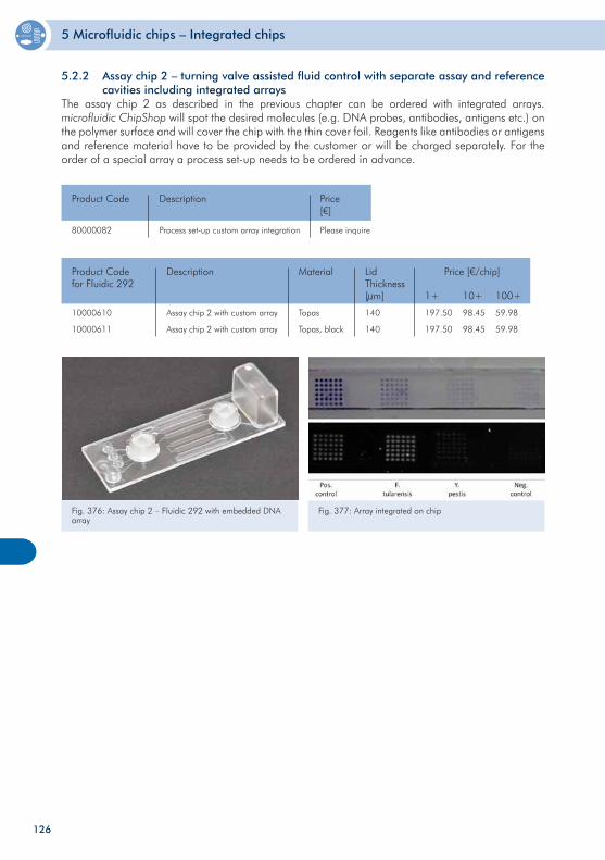
5 Microfluidic chips – Integrated chips
126
5.2.2 Assay chip 2 – turning valve assisted fluid control with separate assay and reference cavities including integrated arraysThe assay chip 2 as described in the previous chapter can be ordered with integrated arrays. microfluidic ChipShop will spot the desired molecules (e.g. DNA probes, antibodies, antigens etc.) on the polymer surface and will cover the chip with the thin cover foil. Reagents like antibodies or antigens and reference material have to be provided by the customer or will be charged separately. For the order of a special array a process set-up needs to be ordered in advance.
80000082 Process set-up custom array integration
Product Code Price[€]
Please inquire
Description
10000610
10000611
Assay chip 2 with custom array
Assay chip 2 with custom array
Product Codefor Fluidic 292
Price [€/chip]
1+ 10+ 100+
197.50
197.50
98.45
98.45
59.98
59.98
Description
Topas
Topas, black
Material
140
140
Lid Thickness[µm]
Fig. 376: Assay chip 2 – Fluidic 292 with embedded DNA array
Fig. 377: Array integrated on chip
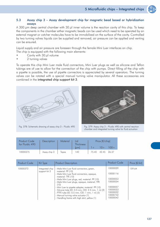
5 Microfluidic chips – Integrated chips
127
5.3 Assay chip 3 – Assay development chip for magnetic bead based or hybridization assaysA 300 µm deep central chamber with 30 µl inner volume is the reaction cavity of this chip. To keep the components in the chamber either magnetic beads can be used which need to be operated by an external magnet or catcher molecules have to be immobilized on the surface of the cavity. Controlled by two turning valves liquids can be supplied and removed, air pressure can be applied and venting can be ensured.
Liquid supply and air pressure are foreseen through the female Mini Luer interfaces on chip.The chip is equipped with the following main elements:• Cavity with 30 µl volume• 2 turning valves
To operate this chip Mini Luer male fluid connectors, Mini Luer plugs as well as silicone and Teflon tubings are of use to allow for the connection of the chip with pumps. Direct filling of the chip with a pipette is possible, the use of pipette connectors is appreciated by several operators. The turning valves can be rotated with a special manual turning valve manipulator. All these accessories are combined in the integrated chip support kit 3.
Fig. 378: Schematic drawing of assay chip 3 – Fluidic 490 Fig. 379: Assay chip 3 – Fluidic 490 with central reaction chamber and integrated turning valve for fluid actuation
10000375 Assay chip 3
Product Codefor Fluidic 490
Price [€/chip]
1+ 10+ 100+
75.40 42.45 26.37
Description
Topas
Material
140
Lid Thickness[µm]
10000372 Integrated chip support kit 3
Product Code Price [€/kit]
159.64
Kit Type
- Male Mini Luer fluid connectors, green, material: PP (10)- Male Mini Luer fluid connectors, opaque, material: TPE (10)- Male Mini Luer plugs, red, material: PP (10)- Male Mini Luer plugs, opaque, material: TPE (10)- Mini Luer to pipette adapter, material: PP (10)- Silicone tube (ID: 0.5 mm, OD: 2.5 mm, 1 m) (2)- PTFE tube (ID: 0.5 mm, OD: 1 mm, 1 m) (5)- Manual turning valve actuator (1)- Handling frame with high skirt, yellow (1)
Product Description
10000029
10000116
1000005310000054
1000005710000033100000321000074210000042
Product Code
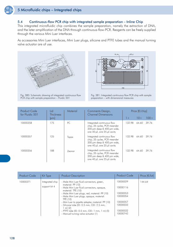
5 Microfluidic chips – Integrated chips
128
5.4 Continuous-flow PCR chip with integrated sample preparation – Inline ChipThis integrated microfluidic chip combines the sample preparation, namely the extraction of DNA, and the later amplification of the DNA through continuous-flow-PCR. Reagents can be freely supplied through the various Mini Luer interfaces.
As accessories Mini Luer interfaces, Mini Luer plugs, silicone and PTFE tubes and the manual turning valve actuator are of use.
Fig. 380: Schematic drawing of integrated continuous flow PCR chip with sample preparation – Fluidic 501
Fig. 381: Integrated continuous flow PCR chip with sample preparation – with dimensional measures
10000358
10000357
10000356
Integrated continuous flow chip, 35 cycles, PCR meander 200 µm deep & 400 µm wide, one 40 µl, one 25 µl cavity
Integrated continuous flow chip, 35 cycles, PCR meander 200 µm deep & 400 µm wide, one 40 µl, one 25 µl cavity
Integrated continuous flow chip, 35 cycles, PCR meander 200 µm deep & 400 µm wide, one 40 µl, one 25 µl cavity
Product Codefor Fluidic 501
Price [€/chip]
1+ 10+ 100+
132.98
132.98
132.98
64.60
64.60
64.60
39.76
39.76
39.76
Comments Design, Channel Dimensions
PC
Topas
Zeonor
Material
175
125
188
Lid Thickness[µm]
10000371 Integrated chip
support kit 4
Product Code Price [€/kit]
144.64
Kit Type
- Male Mini Luer fluid connectors, green, material: PP (10)- Male Mini Luer fluid connectors, opaque, material: TPE (10)- Male Mini Luer plugs, red, material: PP (10)- Male Mini Luer plugs, opaque, material: TPE (10)- Mini Luer to pipette adapter, material: PP (10)- Silicone tube (ID: 0.5 mm, OD: 2.5 mm, 1 m) (2)- PTFE tube (ID: 0.5 mm, OD: 1 mm, 1 m) (5)- Manual turning valve actuator (1)
Product Description
10000029
10000116
1000005310000054
1000005710000033
1000003210000742
Product Code
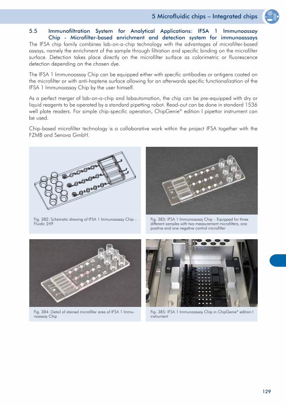
5 Microfluidic chips – Integrated chips
129
5.5 Immunofiltration System for Analytical Applications: IFSA 1 Immunoassay Chip - Microfilter-based enrichment and detection system for immunoassays The IFSA chip family combines lab-on-a-chip technology with the advantages of microfilter-based assays, namely the enrichment of the sample through filtration and specific binding on the microfilter surface. Detection takes place directly on the microfilter surface as colorimetric or fluorescence detection depending on the chosen dye.
The IFSA 1 Immunoassay Chip can be equipped either with specific antibodies or antigens coated on the microfilter or with anti-haptene surface allowing for an afterwards specific functionalization of the IFSA 1 Immunoassay Chip by the user himself.
As a perfect merger of lab-on-a-chip and labautomation, the chip can be pre-equipped with dry or liquid reagents to be operated by a standard pipetting robot. Read-out can be done in standard 1536 well plate readers. For simple chip-specific operation, ChipGenie® edition I pipettor instrument can be used.
Chip-based microfilter technology is a collaborative work within the project IFSA together with the FZMB and Senova GmbH.
Fig. 382: Schematic drawing of IFSA 1 Immunoassay Chip – Fluidic 249
Fig. 383: IFSA 1 Immunoassay Chip – Equipped for three different samples with two measurement microfilters, one positive and one negative control microfilter
Fig. 384: Detail of stained microfilter area of IFSA 1 Immu-noassay Chip
Fig. 385: IFSA 1 Immunoassay Chip in ChipGenie® edition I instrument
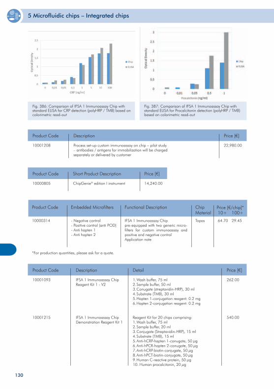
5 Microfluidic chips – Integrated chips
130
Fig. 386: Comparison of IFSA 1 Immunoassay Chip with standard ELISA for CRP detection (polyHRP / TMB) based on colorimetric read-out
Fig. 387: Comparison of IFSA 1 Immunoassay Chip with standard ELISA for Procalcitonin detection (polyHRP / TMB) based on colorimetric read-out
10001208
Product Code Price [€]
22,980.00 Process set-up custom immunoassay on chip – pilot study – antibodies / antigens for immobilization will be charged separately or delivered by customer
Description
10000805 ChipGenie® edition I instrument
Product Code Price [€]
14,240.00
Short Product Description
10000314
10+ 100+
64.70 29.45
Price [€/chip]*Product Code Embedded Microfilters Functional Description Chip Material
Topas- Negative control- Positive control (anti POD)- Anti hapten 1- Anti hapten 2
IFSA 1 Immunoassay Chippre-equipped with two generic micro-filters for custom immunoassay and positive and negative controlApplication note
*For production quantities, please ask for a quote.
10001093
10001215
IFSA 1 Immunoassay ChipReagent Kit 1 - V2
IFSA 1 Immunoassay ChipDemonstration Reagent Kit 1
Product Code Price [€]
262.00
540.00
Description
1. Wash buffer, 75 ml2. Sample buffer, 50 ml3. Conugate (streptavidin-HRP), 30 ml4. Substrate (TMB), 30 ml5. Hapten 1-conjugation reagent: 0.2 mg6. Hapten 2-conjugation reagent: 0.2 mg
Reagent Kit for 20 chips comprising:1. Wash buffer, 75 ml2. Sample buffer, 20 ml3. Conjugate (Streptavidin-HRP), 15 ml4. Substrate (TMB), 15 ml 5. Anti-hCRP-hapten 1-conugate, 50 µg6. Anti-hPCR-hapten 2-conugate, 50 µg7. Anti-hCRP-biotin-conjugate, 50 µg8. Anti-hPCT-biotin-conjugate, 50 µg9. Human C-reactive protein, 50 µg10. Human procalcitonin, 20 µg
Detail
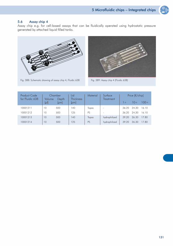
5 Microfluidic chips – Integrated chips
131
5.6 Assay chip 4 Assay chip e.g. for cell-based assays that can be fluidically operated using hydrostatic pressure generated by attached liquid filled tanks.
Fig. 388: Schematic drawing of assay chip 4, Fluidic 638Fl. 669
Fig. 389: Assay chip 4 (Fluidic 638)
10001211
10001212
10001213
10001214
10
10
10
10
500
500
500
500
140
125
140
125
Topas
PS
Topas
PS
-
-
hydrophilized
hydrophilized
Product Codefor Fluidic 638
ChamberVolume[µl]
Depth[µm]
Material SurfaceTreatment
Price [€/chip]
1+ 10+ 100+
LidThickness[µm]
36.20
36.20
39.20
39.20
24.30
24.30
26.30
26.30
16.10
16.10
17.80
17.80

132
6 Microfluidic chips – Glass
Microfluidic chips – Glass
Glass is the material of choice if elevated temperatures or organic solvents come into play. This chapters shows standard chips in glass in the format of a microscopy slide with through holes as fluidic interface. Droplet generator chips or meander chips are off-the-shelf devices in glass. Custom-designs can be realized on demand.
133
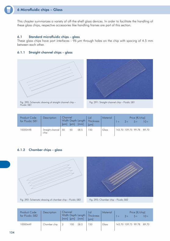
6 Microfluidic chips – Glass
134
Fig. 390: Schematic drawing of straight channel chip – Fluidic 581
Fig. 391: Straight channel chip – Fluidic 581
10000448
Product Codefor Fluidic 581
Price [€/chip]3+ 5+ 10+
109.75 99.78 89.70
Description
Glass
Material
150
Lid Thickness[µm]
Straight channel chip
Channel
50 58.5
Width[µm]
Depth[µm]
Length[mm]
50
1+
143.70
6.1.2 Chamber chips – glass
Fig. 392: Schematic drawing of chamber chip – Fluidic 582 Fig. 393: Chamber chip – Fluidic 582
10000449
Product Codefor Fluidic 582
Price [€/chip]3+ 5+ 10+
109.75 99.78 89.70
Description
Glass
Material
150
Lid Thickness[µm]
Chamber chip
Channel
3 58.5
Width[mm]
Depth[µm]
Length[mm]
100
1+
143.70
This chapter summarizes a variety of off-the-shelf glass devices. In order to facilitate the handling of these glass chips, respective accessories like handling frames are part of this section.
6.1 Standard microfluidic chips – glassThese glass chips have port interfaces - 96 µm through holes on the chip with spacing of 4.5 mm between each other.
6.1.1 Straight channel chips – glass
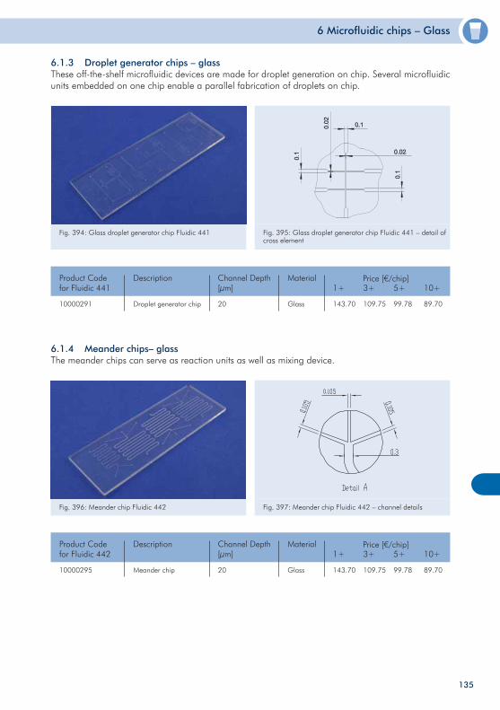
6 Microfluidic chips – Glass
135
6.1.3 Droplet generator chips – glassThese off-the-shelf microfluidic devices are made for droplet generation on chip. Several microfluidic units embedded on one chip enable a parallel fabrication of droplets on chip.
Fig. 394: Glass droplet generator chip Fluidic 441 Fig. 395: Glass droplet generator chip Fluidic 441 – detail of cross element
10000291 20
Product Codefor Fluidic 441
Channel Depth[µm]
Glass
Material
6.1.4 Meander chips– glassThe meander chips can serve as reaction units as well as mixing device.
Fig. 396: Meander chip Fluidic 442 Fig. 397: Meander chip Fluidic 442 – channel details
Price [€/chip]
Droplet generator chip
Description1+
143.70 109.75
3+
99.78
5+
89.70
10+
10000295 20
Product Codefor Fluidic 442
Channel Depth[µm]
Glass
Material Price [€/chip]
Meander chip
Description1+
143.70 109.75
3+
99.78
5+
89.70
10+
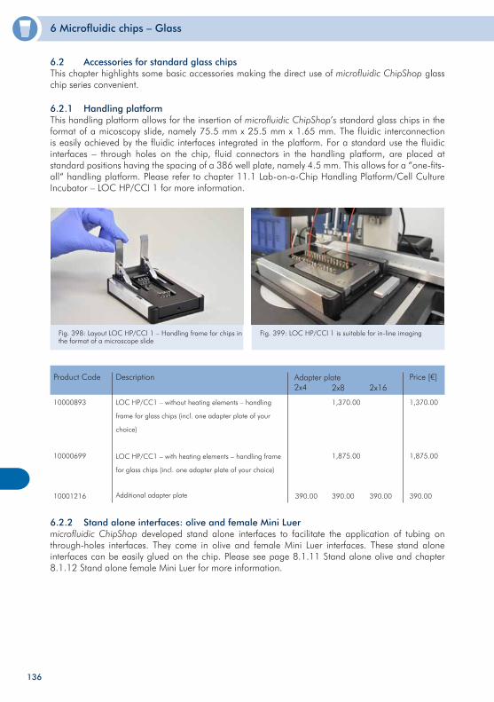
6 Microfluidic chips – Glass
136
6.2 Accessories for standard glass chips This chapter highlights some basic accessories making the direct use of microfluidic ChipShop glass chip series convenient.
6.2.1 Handling platformThis handling platform allows for the insertion of microfluidic ChipShop’s standard glass chips in the format of a micoscopy slide, namely 75.5 mm x 25.5 mm x 1.65 mm. The fluidic interconnection is easily achieved by the fluidic interfaces integrated in the platform. For a standard use the fluidic interfaces – through holes on the chip, fluid connectors in the handling platform, are placed at standard positions having the spacing of a 386 well plate, namely 4.5 mm. This allows for a “one-fits-all“ handling platform. Please refer to chapter 11.1 Lab-on-a-Chip Handling Platform/Cell Culture Incubator – LOC HP/CCI 1 for more information.
Fig. 398: Layout LOC HP/CCI 1 – Handling frame for chips in the format of a microscope slide
Fig. 399: LOC HP/CCI 1 is suitable for in-line imaging
6.2.2 Stand alone interfaces: olive and female Mini Luermicrofluidic ChipShop developed stand alone interfaces to facilitate the application of tubing on through-holes interfaces. They come in olive and female Mini Luer interfaces. These stand alone interfaces can be easily glued on the chip. Please see page 8.1.11 Stand alone olive and chapter 8.1.12 Stand alone female Mini Luer for more information.
10000893
10000699
10001216
LOC HP/CC1 – without heating elements – handling
frame for glass chips (incl. one adapter plate of your
choice)
LOC HP/CC1 – with heating elements – handling frame
for glass chips (incl. one adapter plate of your choice)
Additional adapter plate
Product Code Description Price [€]
1,370.00
1,875.00
390.00
Adapter plate2x4 2x8 2x16
390.00
1,370.00
1,875.00
390.00 390.00

137
138
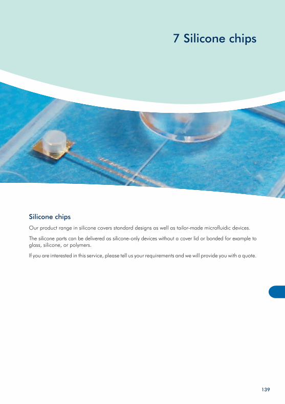
7 Silicone chips
Silicone chips
Our product range in silicone covers standard designs as well as tailor-made microfluidic devices.
The silicone parts can be delivered as silicone-only devices without a cover lid or bonded for example to glass, silicone, or polymers.
If you are interested in this service, please tell us your requirements and we will provide you with a quote.
139
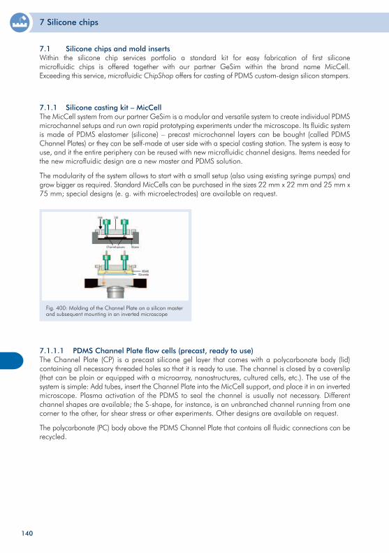
7 Silicone chips
7.1.1 Silicone casting kit – MicCellThe MicCell system from our partner GeSim is a modular and versatile system to create individual PDMSmicrochannel setups and run own rapid prototyping experiments under the microscope. Its fluidic system is made of PDMS elastomer (silicone) – precast microchannel layers can be bought (called PDMS Channel Plates) or they can be self-made at user side with a special casting station. The system is easy to use, and it the entire periphery can be reused with new microfluidic channel designs. Items needed for the new microfluidic design are a new master and PDMS solution.
The modularity of the system allows to start with a small setup (also using existing syringe pumps) and grow bigger as required. Standard MicCells can be purchased in the sizes 22 mm x 22 mm and 25 mm x 75 mm; special designs (e. g. with microelectrodes) are available on request.
Fig. 400: Molding of the Channel Plate on a silicon master and subsequent mounting in an inverted microscope
7.1.1.1 PDMS Channel Plate flow cells (precast, ready to use)The Channel Plate (CP) is a precast silicone gel layer that comes with a polycarbonate body (lid) containing all necessary threaded holes so that it is ready to use. The channel is closed by a coverslip (that can be plain or equipped with a microarray, nanostructures, cultured cells, etc.). The use of the system is simple: Add tubes, insert the Channel Plate into the MicCell support, and place it in an inverted microscope. Plasma activation of the PDMS to seal the channel is usually not necessary. Different channel shapes are available; the S-shape, for instance, is an unbranched channel running from one corner to the other, for shear stress or other experiments. Other designs are available on request.
The polycarbonate (PC) body above the PDMS Channel Plate that contains all fluidic connections can be recycled.
140
7.1 Silicone chips and mold insertsWithin the silicone chip services portfolio a standard kit for easy fabrication of first silicone microfluidic chips is offered together with our partner GeSim within the brand name MicCell. Exceeding this service, microfluidic ChipShop offers for casting of PDMS custom-design silicon stampers.
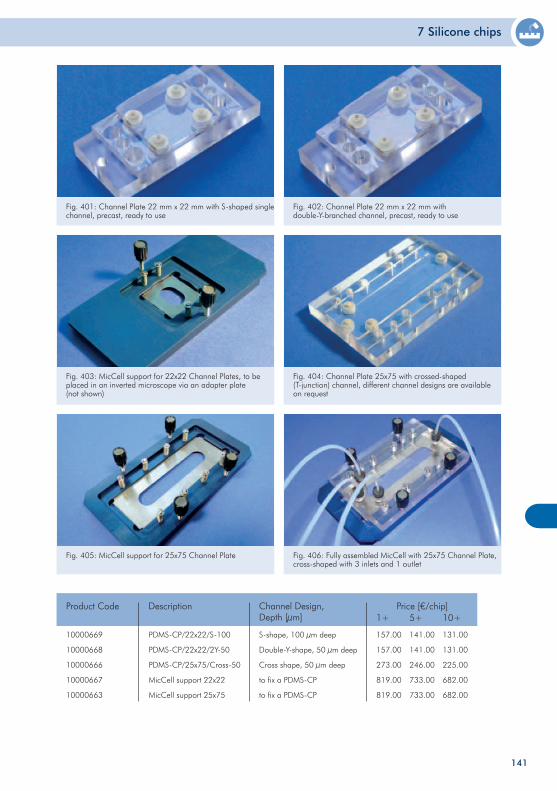
7 Silicone chips
Fig. 403: MicCell support for 22x22 Channel Plates, to be placed in an inverted microscope via an adapter plate (not shown)
Fig. 404: Channel Plate 25x75 with crossed-shaped (T-junction) channel, different channel designs are available on request
Fig. 405: MicCell support for 25x75 Channel Plate Fig. 406: Fully assembled MicCell with 25x75 Channel Plate, cross-shaped with 3 inlets and 1 outlet
10000669
10000668
10000666
10000667
10000663
PDMS-CP/22x22/S-100
PDMS-CP/22x22/2Y-50
PDMS-CP/25x75/Cross-50
MicCell support 22x22
MicCell support 25x75
Product Code Price [€/chip]1+ 5+ 10+
157.00
157.00
273.00
819.00
819.00
141.00
141.00
246.00
733.00
733.00
131.00
131.00
225.00
682.00
682.00
Description
S-shape, 100 µm deep
Double-Y-shape, 50 µm deep
Cross shape, 50 µm deep
to fix a PDMS-CP
to fix a PDMS-CP
Channel Design,Depth [µm]
141
Fig. 401: Channel Plate 22 mm x 22 mm with S-shaped single channel, precast, ready to use
Fig. 402: Channel Plate 22 mm x 22 mm with double-Y-branched channel, precast, ready to use
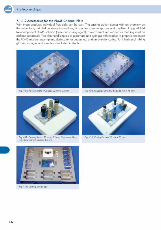
7 Silicone chips
Fig. 407: Polycarbonate (PC) body 22 mm x 22 mm Fig. 408: Polycarbonate (PC) body 25 mm x 75 mm
Fig. 411: Casting Station box
Fig. 409: Casting Station 22 mm x 22 mm. Top: assembled, including channel spacers (brown)
Fig. 410: Casting Station 25 mm x 75 mm
142
7.1.1.2 Accessories for the PDMS Channel PlateWith these products individual flow cells can be cast. The casting station comes with an overview on the technology, detailed hands-on instructions, PC-bodies, channel spacers and one liter of Sylgard 184 two-component PDMS solution (base and curing agent); a microstructured master for molding must be ordered separately. You also need single-use glassware and syringes with needles to prepare and inject the PDMS mixture, a pump and desiccator for degassing, and an oven for curing. An initial set of mixing glasses, syringes and needles is included in the box.
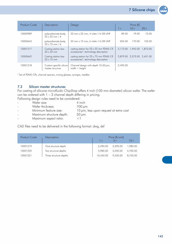
7 Silicone chips
143
10000989
10000643
10001217
10000642
10001218
polycarbonate-body,22 x 22 mm / 4
polycarbonate-body,25 x 75 mm / 6
Casting station box22 x 22 mm
Casting station box25 x 75 mm
Custom specific silicon master structure
Product Code Price [€]1+ 10+ 20+
89.00
204.00
2,173.00
2,879.00
2,490.00
Description
22 mm x 22 mm, 4 inlets 1/4-28 UNF
25 mm x 75 mm, 6 inlets 1/4-28 UNF
casting station for 22 x 22 mm PDMS-CP,accessories*, technology description
casting station for 25 x 75 mm PDMS-CP,accessories*, technology description
Channel design with depth 10-50 µm, width > height
Design
79.00
170.00
1,942.00
2,572.00
73.00
152.00
1,873.00
2,451.00
* Set of PDMS-CPs, channel spacers, mixing glasses, syringes, needles
7.2 Silicon master structuresFor casting of silicone microfluidic ChipShop offers 4 inch (100 mm diameter) silicon wafer. The wafer can be ordered with 1 – 3 channel depth differing in pricing.Following design rules need to be considered:- Wafer size: 4 inch- Wafer thickness: 700 µm- Minimum feature size: 10 µm, less upon request at extra cost- Maximum structure depth: 50 µm- Maximum aspect ratio: <1
CAD files need to be delivered in the following format: dwg, dxf
10001219
10001220
10001221
One structure depth
Two structure depths
Three structure depths
Product Code Price [€/unit]
2,490.00
5,980.00
10,450.00
Description
2,290.00
5,250.00
9,550.00
1,980.00
4,700.00
8,750.00
1+ 3+ 10+
144
8 Accessories
Accessories
With the help of our Lab-on-a-Chip Catalogue, it is our aim to ensure that you have all the necessary equipment for an easy and immediate start with our microfluidic products. This includes not only our wide variety of off-the-shelf microfluidic chips but also all accessories required to run microfluidic chips, such as fluidic interfaces, tubings, complete accessory kits, and special reagents.
If you have any additional wishes that might help you with your microfluidic work, please do not hesitate to contact us.
145
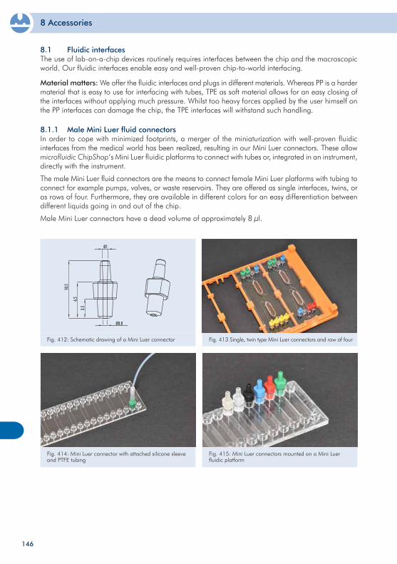
8 Accessories
8.1 Fluidic interfacesThe use of lab-on-a-chip devices routinely requires interfaces between the chip and the macroscopic world. Our fluidic interfaces enable easy and well-proven chip-to-world interfacing.
Material matters: We offer the fluidic interfaces and plugs in different materials. Whereas PP is a harder material that is easy to use for interfacing with tubes, TPE as soft material allows for an easy closing of the interfaces without applying much pressure. Whilst too heavy forces applied by the user himself on the PP interfaces can damage the chip, the TPE interfaces will withstand such handling.
Fig. 412: Schematic drawing of a Mini Luer connector Fig. 413 Single, twin type Mini Luer connectors and row of four
Fig. 414: Mini Luer connector with attached silicone sleeve and PTFE tubing
Fig. 415: Mini Luer connectors mounted on a Mini Luer fluidic platform
8.1.1 Male Mini Luer fluid connectorsIn order to cope with minimized footprints, a merger of the miniaturization with well-proven fluidic interfaces from the medical world has been realized, resulting in our Mini Luer connectors. These allow microfluidic ChipShop‘s Mini Luer fluidic platforms to connect with tubes or, integrated in an instrument, directly with the instrument.
The male Mini Luer fluid connectors are the means to connect female Mini Luer platforms with tubing to connect for example pumps, valves, or waste reservoirs. They are offered as single interfaces, twins, or as rows of four. Furthermore, they are available in different colors for an easy differentiation between different liquids going in and out of the chip.
Male Mini Luer connectors have a dead volume of approximately 8 µl.
146
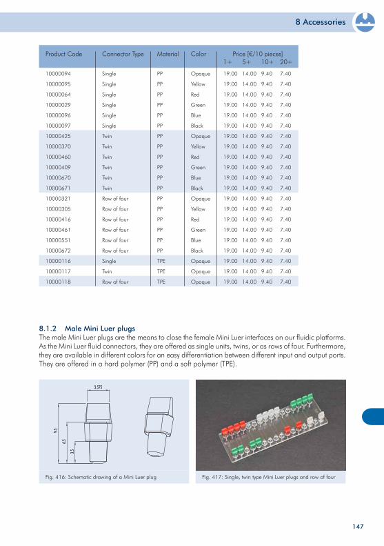
8 Accessories
10000094
10000095
10000064
10000029
10000096
10000097
10000425
10000370
10000460
10000409
10000670
10000671
10000321
10000305
10000416
10000461
10000551
10000672
10000116
10000117
10000118
Single
Single
Single
Single
Single
Single
Twin
Twin
Twin
Twin
Twin
Twin
Row of four
Row of four
Row of four
Row of four
Row of four
Row of four
Single
Twin
Row of four
Product Code Price [€/10 pieces]1+
19.00
19.00
19.00
19.00
19.00
19.00
19.00
19.00
19.00
19.00
19.00
19.00
19.00
19.00
19.00
19.00
19.00
19.00
19.00
19.00
19.00
Connector Type
PP
PP
PP
PP
PP
PP
PP
PP
PP
PP
PP
PP
PP
PP
PP
PP
PP
PP
TPE
TPE
TPE
Material
Opaque
Yellow
Red
Green
Blue
Black
Opaque
Yellow
Red
Green
Blue
Black
Opaque
Yellow
Red
Green
Blue
Black
Opaque
Opaque
Opaque
Color5+
14.00
14.00
14.00
14.00
14.00
14.00
14.00
14.00
14.00
14.00
14.00
14.00
14.00
14.00
14.00
14.00
14.00
14.00
14.00
14.00
14.00
10+
9.40
9.40
9.40
9.40
9.40
9.40
9.40
9.40
9.40
9.40
9.40
9.40
9.40
9.40
9.40
9.40
9.40
9.40
9.40
9.40
9.40
20+
7.40
7.40
7.40
7.40
7.40
7.40
7.40
7.40
7.40
7.40
7.40
7.40
7.40
7.40
7.40
7.40
7.40
7.40
7.40
7.40
7.40
147
8.1.2 Male Mini Luer plugsThe male Mini Luer plugs are the means to close the female Mini Luer interfaces on our fluidic platforms. As the Mini Luer fluid connectors, they are offered as single units, twins, or as rows of four. Furthermore, they are available in different colors for an easy differentiation between different input and output ports. They are offered in a hard polymer (PP) and a soft polymer (TPE).
Fig. 416: Schematic drawing of a Mini Luer plug Fig. 417: Single, twin type Mini Luer plugs and row of four
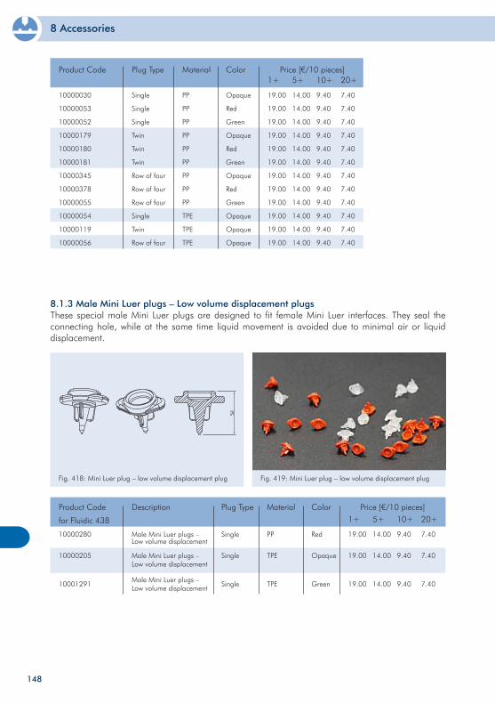
8 Accessories
10000030
10000053
10000052
10000179
10000180
10000181
10000345
10000378
10000055
10000054
10000119
10000056
Single
Single
Single
Twin
Twin
Twin
Row of four
Row of four
Row of four
Single
Twin
Row of four
Product Code Price [€/10 pieces]1+
19.00
19.00
19.00
19.00
19.00
19.00
19.00
19.00
19.00
19.00
19.00
19.00
Plug Type
PP
PP
PP
PP
PP
PP
PP
PP
PP
TPE
TPE
TPE
Material
Opaque
Red
Green
Opaque
Red
Green
Opaque
Red
Green
Opaque
Opaque
Opaque
Color5+
14.00
14.00
14.00
14.00
14.00
14.00
14.00
14.00
14.00
14.00
14.00
14.00
10+
9.40
9.40
9.40
9.40
9.40
9.40
9.40
9.40
9.40
9.40
9.40
9.40
20+
7.40
7.40
7.40
7.40
7.40
7.40
7.40
7.40
7.40
7.40
7.40
7.40
148
8.1.3 Male Mini Luer plugs – Low volume displacement plugs These special male Mini Luer plugs are designed to fit female Mini Luer interfaces. They seal the connecting hole, while at the same time liquid movement is avoided due to minimal air or liquid displacement.
Fig. 418: Mini Luer plug – low volume displacement plug Fig. 419: Mini Luer plug – low volume displacement plug
10000280
10000205
10001291
Single
Single
Single
Product Code
for Fluidic 438
Plug Type
PP
TPE
TPE
Material
Red
Opaque
Green
Color Price [€/10 pieces]1+
19.00
19.00
19.00
5+
14.00
14.00
14.00
10+
9.40
9.40
9.40
20+
7.40
7.40
7.40
Male Mini Luer plugs –Low volume displacement
Male Mini Luer plugs –Low volume displacement
Male Mini Luer plugs –Low volume displacement
Description
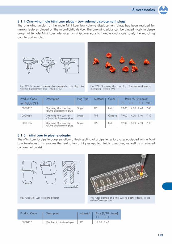
8 Accessories
149
8.1.4 One-wing male Mini Luer plugs – Low volume displacement plugsThe one-wing version of the male Mini Luer low volume displacement plugs has been realized for narrow features placed on the microfluidic device. The one-wing plugs can be placed nicely in dense arrays of female Mini Luer interfaces on chip, are easy to handle and close safely the matching counterpart on chip.
Fig. 420: Schematic drawing of one-wing Mini Luer plug – low volume displacement plug – Fluidic 793
Fig. 421: One-wing Mini Luer plug – low volume displace-ment plug – Fluidic 793
10001067
10001068
10001105
Single
Single
Single
Product Code
for Fluidic 793
Plug Type
PP
TPE
TPE
Material
Red
Opaque
Red
Color Price [€/10 pieces]1+
19.00
19.00
19.00
5+
14.00
14.00
14.00
10+
9.40
9.40
9.40
20+
7.40
7.40
7.40
One-wing Mini Luer low volume displacement plug
One-wing Mini Luer low volume displacement plug
One-wing Mini Luer low volume displacement plug
Description
8.1.5 Mini Luer to pipette adapterThe Mini Luer to pipette adapters allow a flush sealing of a pipette tip to a chip equipped with a Mini Luer interfaces. This enables the realization of higher applied fluidic pressures, as well as a reduced contamination risk.
Fig. 422: Mini Luer to pipette adapter Fig. 423: Example of a Mini Luer to pipette adapter in use with a Chamber chip
10000057 PP
Product Code Material Price [€/10 pieces]1+
19.00 9.40
10+
Mini Luer to pipette adapter
Description
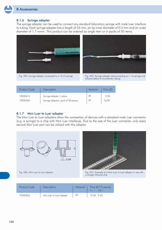
8 Accessories
150
Fig. 426: Mini Luer to Luer adaptor Fig. 427: Example of a Mini Luer to Luer adaptor in use with a straight channel chip
10000063 PP
Product Code Material Price [€/10 pieces]1+
19.00 9.40
10+
Mini Luer to Luer adapter
Description
8.1.7 Mini Luer to Luer adapterThe Mini Luer to Luer adapters allow the connection of devices with a standard male Luer connector (e.g. a syringe) to a chip with Mini Luer interfaces. Due to the size of the Luer connector, only every second Mini Luer port can be utilized with this adapter.
Fig. 424: Syringe adapter connected to a 10 ml syringe Fig. 425: Syringe adapter interconnecting an 1 ml syringe and silicone sleeve of microfluidic tubing
10000614
10000360
Syringe adapter; 1 piece
Syringe adapters; pack of 50 pieces
Product Code Description Price [€]
2.50
76.00
PP
PP
Material
8.1.6 Syringe adapterThe syringe adapter can be used to connect any standard laboratory syringe with male Luer interface to tubing. Each syringe adapter has a length of 55 mm, an tip inner diameter of 0.5 mm and an outer diameter of 1.7 mmm. This product can be ordered as single item or in packs of 50 items.
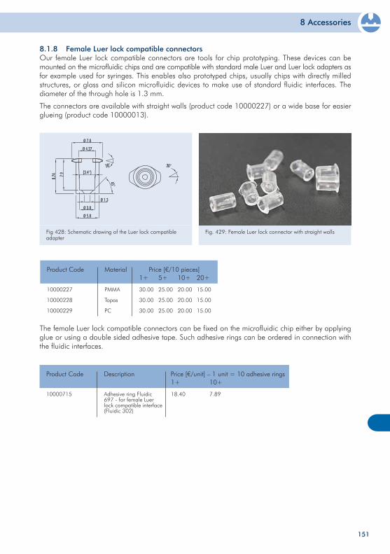
8 Accessories
151
The female Luer lock compatible connectors can be fixed on the microfluidic chip either by applying glue or using a double sided adhesive tape. Such adhesive rings can be ordered in connection with the fluidic interfaces.
10000715 Adhesive ring Fluidic 697 - for female Luer lock compatible interface (Fluidic 302)
Product Code Description Price [€/unit] – 1 unit = 10 adhesive rings1+
18.40
10+
7.89
10000227
10000228
10000229
PMMA
Topas
PC
Product Code Material Price [€/10 pieces]1+
30.00
30.00
30.00
5+
25.00
25.00
25.00
10+
20.00
20.00
20.00
20+
15.00
15.00
15.00
8.1.8 Female Luer lock compatible connectorsOur female Luer lock compatible connectors are tools for chip prototyping. These devices can be mounted on the microfluidic chips and are compatible with standard male Luer and Luer lock adapters as for example used for syringes. This enables also prototyped chips, usually chips with directly milled structures, or glass and silicon microfluidic devices to make use of standard fluidic interfaces. The diameter of the through hole is 1.3 mm.
The connectors are available with straight walls (product code 10000227) or a wide base for easier glueing (product code 10000013).
Fig 428: Schematic drawing of the Luer lock compatible adapter
Fig. 429: Female Luer lock connector with straight walls
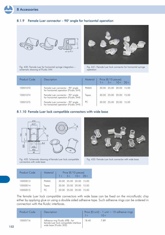
8 Accessories
8.1.10 Female Luer lock compatible connectors with wide base
Fig. 432: Schematic drawing of female Luer lock compatible connectors with wide base
Fig. 433: Female Luer lock connector with wide base
152
10000013
10000014
10000015
PMMA
Topas
PC
Product Code Material Price [€/10 pieces]1+
30.00
30.00
30.00
5+
25.00
25.00
25.00
10+
20.00
20.00
20.00
20+
15.00
15.00
15.00
The female Luer lock compatible connectors with wide base can be fixed on the microfluidic chip either by applying glue or using a double sided adhesive tape. Such adhesive rings can be ordered in connection with the fluidic interfaces.
10000716 Adhesive ring Fluidic 698 - for female Luer lock compatible interface wide base (Fluidic 303)
Product Code Description Price [€/unit] – 1 unit = 10 adhesive rings1+
18.40
10+
7.89
8.1.9 Female Luer connector – 90° angle for horizontal operation
Fig. 430: Female Luer for horizontal syringe integration – schematic drawing of Fluidic 544
Fig. 431: Female Luer lock connector for horizontal syringe operation
10001073
10001074
10001075
PMMA
Topas
PC
Product Code Material Price [€/10 pieces]
Female Luer connector - 90° angle for horizontal operation (Fluidic 544)
Female Luer connector - 90° angle for horizontal operation (Fluidic 544)
Female Luer connector - 90° angle for horizontal operation (Fluidic 544)
Description1+
30.00
30.00
30.00
5+
25.00
25.00
25.00
10+
20.00
20.00
20.00
20+
15.00
15.00
15.00
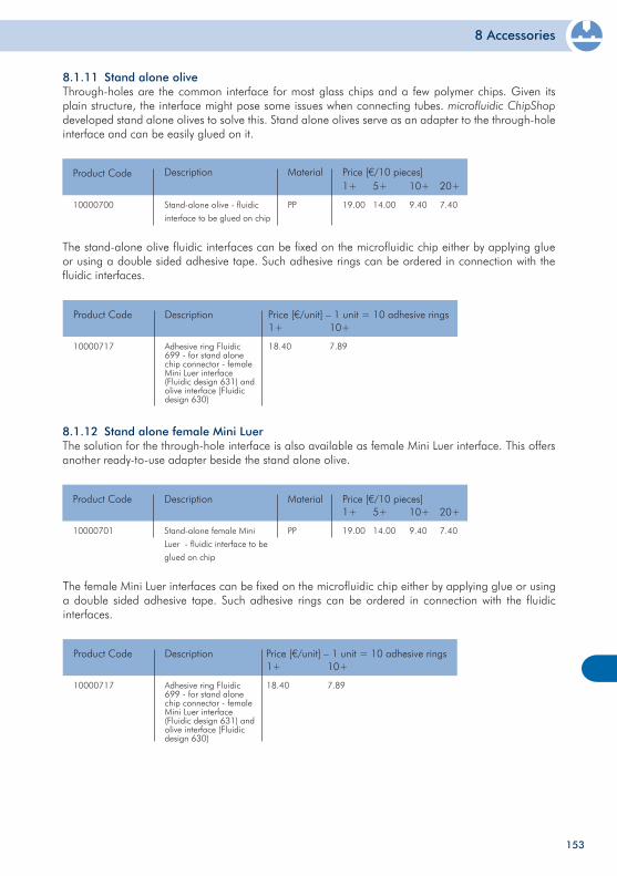
8 Accessories
153
8.1.12 Stand alone female Mini LuerThe solution for the through-hole interface is also available as female Mini Luer interface. This offers another ready-to-use adapter beside the stand alone olive.
10000701 PP
Product Code Material Price [€/10 pieces]1+
19.00 14.00
5+
Stand-alone female Mini
Luer - fluidic interface to be
glued on chip
Description10+
9.40 7.40
20+
10000717 Adhesive ring Fluidic 699 - for stand alone chip connector - female Mini Luer interface (Fluidic design 631) and olive interface (Fluidic design 630)
Product Code Description Price [€/unit] – 1 unit = 10 adhesive rings1+
18.40
10+
7.89
10000717 Adhesive ring Fluidic 699 - for stand alone chip connector - female Mini Luer interface (Fluidic design 631) and olive interface (Fluidic design 630)
Product Code Description Price [€/unit] – 1 unit = 10 adhesive rings1+
18.40
10+
7.89
The female Mini Luer interfaces can be fixed on the microfluidic chip either by applying glue or using a double sided adhesive tape. Such adhesive rings can be ordered in connection with the fluidic interfaces.
10000700 PP
Product Code Material Price [€/10 pieces]1+
19.00 14.00
5+
Stand-alone olive - fluidic
interface to be glued on chip
Description10+
9.40 7.40
20+
The stand-alone olive fluidic interfaces can be fixed on the microfluidic chip either by applying glue or using a double sided adhesive tape. Such adhesive rings can be ordered in connection with the fluidic interfaces.
8.1.11 Stand alone oliveThrough-holes are the common interface for most glass chips and a few polymer chips. Given its plain structure, the interface might pose some issues when connecting tubes. microfluidic ChipShop developed stand alone olives to solve this. Stand alone olives serve as an adapter to the through-hole interface and can be easily glued on it.
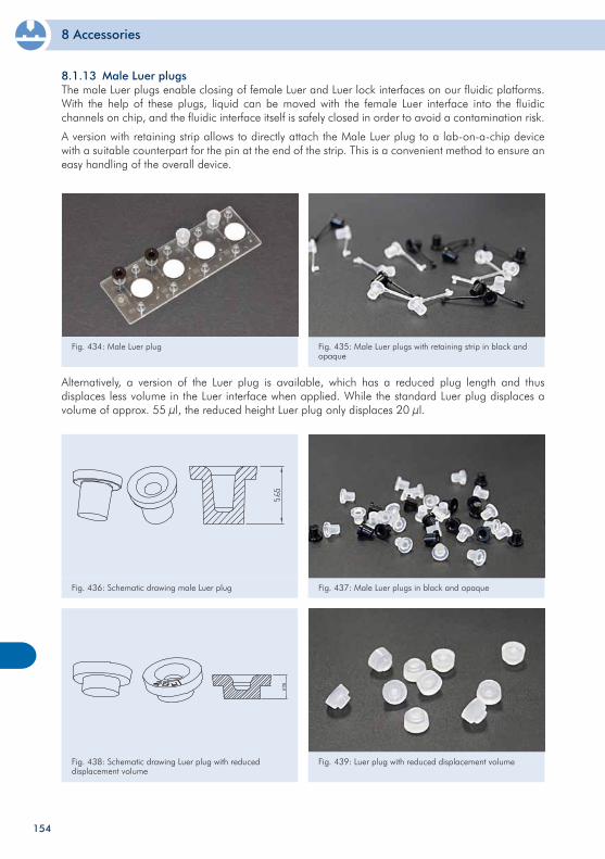
8 Accessories
154
Fig. 434: Male Luer plug Fig. 435: Male Luer plugs with retaining strip in black and opaque
Alternatively, a version of the Luer plug is available, which has a reduced plug length and thus displaces less volume in the Luer interface when applied. While the standard Luer plug displaces a volume of approx. 55 µl, the reduced height Luer plug only displaces 20 µl.
Fig. 436: Schematic drawing male Luer plug Fig. 437: Male Luer plugs in black and opaque
Fig. 438: Schematic drawing Luer plug with reduced displacement volume
Fig. 439: Luer plug with reduced displacement volume
8.1.13 Male Luer plugsThe male Luer plugs enable closing of female Luer and Luer lock interfaces on our fluidic platforms. With the help of these plugs, liquid can be moved with the female Luer interface into the fluidic channels on chip, and the fluidic interface itself is safely closed in order to avoid a contamination risk.
A version with retaining strip allows to directly attach the Male Luer plug to a lab-on-a-chip device with a suitable counterpart for the pin at the end of the strip. This is a convenient method to ensure an easy handling of the overall device.
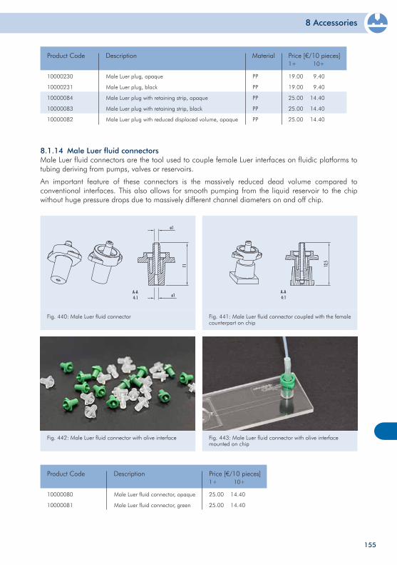
8 Accessories
155
Fig. 442: Male Luer fluid connector with olive interface Fig. 443: Male Luer fluid connector with olive interface mounted on chip
8.1.14 Male Luer fluid connectorsMale Luer fluid connectors are the tool used to couple female Luer interfaces on fluidic platforms to tubing deriving from pumps, valves or reservoirs.
An important feature of these connectors is the massively reduced dead volume compared to conventional interfaces. This also allows for smooth pumping from the liquid reservoir to the chip without huge pressure drops due to massively different channel diameters on and off chip.
Fig. 440: Male Luer fluid connector Fig. 441: Male Luer fluid connector coupled with the female counterpart on chip
10000080
10000081
Male Luer fluid connector, opaque
Male Luer fluid connector, green
Product Code Description
25.00
25.00
Price [€/10 pieces]
14.40
14.40
1+ 10+
10000230
10000231
10000084
10000083
10000082
Male Luer plug, opaque
Male Luer plug, black
Male Luer plug with retaining strip, opaque
Male Luer plug with retaining strip, black
Male Luer plug with reduced displaced volume, opaque
Product Code Description
19.00
19.00
25.00
25.00
25.00
Price [€/10 pieces]
9.40
9.40
14.40
14.40
14.40
1+ 10+
PP
PP
PP
PP
PP
Material
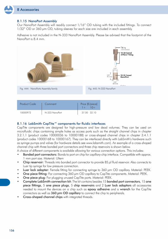
8 Accessories
156
Fig. 444: NanoPorts Assembly family Fig. 445: N-333 NanoPort
10000972 N-333 NanoPort
Product Code Comment Price [€/piece]1+
37.00
10+
32.10
8.1.16 LabSmith CapTite™ components for fluidic interfacesCapTite components are designed for high-pressure and low dead volumes. They can be used on microfluidic chips containing simple holes as access ports such as the straight channel chips in chapter 3.2.1.1 (product codes 10000036 to 10000188) or cross-shaped channel chips in chapter 3.4.1.1 (product codes 10000168 to 10000167). They can be interfaced directly with LabSmith’s hardware such as syringe pumps and valves (for hardware details see www.labsmith.com). An example of a cross-shaped channel chip with three bonded port connectors and three chip reservoirs is shown below.A choice of different components is available allowing for various connection options. This includes:• Bondedportconnectors: Bonds to port on chip for capillary-chip interface. Compatible with approx. 1 mm port size. Material: Ultem• Chipreservoir: Threads into bonded port connector to provide 85 µl fluid reservoir. Also connects to Luer tip syringe for low pressure connection.• Luerlockadapter: Female fitting for connecting syringe to 360 µm OD capillary. Material: PEEK.• Onepiecefitting: For connecting 360 µm OD capillary to CapTite components. Material: PEEK.• Onepieceplug: For plugging unused CapTite ports. Material: PEEK. • CompleteLabSmithconnectionkit: The kit contains besides 15 bonded port connectors, 15 one piece fittings, 5 one piece plugs, 5 chip reservoirs and 2 Luer lock adaptors all accessories needed to mount the devices on a chip such as epoxy adhesive and a wrench for the CapTite connectors as well as 360 µm OD capillary to connect the chip to peripherals.• Cross-shapedchannelchips with integrated threads.
8.1.15 NanoPort AssemblyOur NanoPort Assembly will readily connect 1/16” OD tubing with the included fittings. To connect 1/32” OD or 360 µm OD, tubing sleeves for each size are included in each assembly.
Adhesive is not included in the N-333 NanoPort Assembly. Please be advised that the footprint of the NanoPort is 8.4 mm.
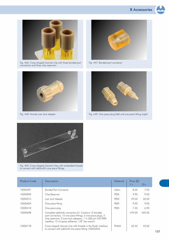
8 Accessories
157
Fig. 450: Cross-shaped channel chips with embedded threads to connect with LabSmith’s one piece fittings
10000391
10000909
10000315
10000404
10000418
10000698
10000178
Bonded Port Connector
Chip Reservoir
Luer lock Adapter
One piece fitting
One piece plug
Complete LabSmith connection kit. Contains 15 bonded port connectors, 15 one piece fittings, 5 one piece plugs, 5 chip reservoirs, 2 Luer-Lock adaptors, 1 m 360 µm OD PEEK capillary, 12 ml epoxy adhesive, 1/8” hex wrench
Cross-shaped channel chip with threads in the fluidic interface to connect with LabSmith one piece fitting (10000404)
Product Code Description Price [€]1+
8.50
9.90
29.00
9.90
7.50
470.00
62.40
10+
7.95
9.00
26.00
9.00
6.90
425.00
43.60
Ultem
PEEK
PEEK
PEEK
PEEK
PMMA
Material
Fig. 446: Cross-shaped channel chip with three bonded port connectors and three chip reservoirs
Fig. 447: Bonded port connector
Fig. 448: Female Luer lock adapter Fig. 449: One piece plug (left) and one piece fitting (right)

8 Accessories
158
8.2.1 Tanks The “tank” solution allows the storage of liquids in separate tanks, which are simply plugged onto the chip. The openings can be sealed with a heat-sealing aluminum foil, which is piercable. Liquid actuation can also be done via tanks either by a mechanical piston or pneumatic pressure.
Tanks are provided either with on open top or can be closed with an attached cap This cap can furthermore possess various features, such as a Mini Luer interface for pneumatic actuation or an integrated venting membrane. Below an overview of available tanks and their most important features is given.
Fig. 451: Tanks mounted on a microfluidic chip Fig. 452: Blister pouches of different volumes integrated in a complex microfluidic chip
8.2 Liquid storageOne issue that often occurs with microfluidics is the storage of liquid reagents on chip. This frequently conflicts with either dry-stored reagents on the chip, the available space, or the volume of the liquid. microfluidic ChipShop has developed several solutions to deal with this issue, including our so-called “tank” solution, as well as blister pouches.
200
200
200
200
500
500
500
500
500
500
500
500
500
500
1000
4500
4500
4500
4500
CapTank to Chip Interface Type
Single
Single
Single
Single
Single
Double
Triple
Single
Double
Triple
Single
Double
Triple
Single
Row of four
Row of four
Row of four
Row of four
Row of four
933
934
833
926
387
388
389
823
824
825
229
230
231
639
603
232
233
234
235
Design Feature Volume[µl]
Fluidic Design
Tank Format
Luer
Luer
Luer
Mini Luer
Luer
Luer
Luer
Luer
Luer
Luer
Piercing interface
Piercing interface
Piercing interface
Luer
Luer
Luer
Luer
Large interaction
Large interaction
Yes
Yes
Yes
Yes
No
No
No
No
No
No
No
No
No
Yes
No
No
Yes
No
Yes
-
Mini Luer interface in cap
Venting cap
-
-
-
-
Large opening
Large opening
Large opening
-
-
-
Mini Luer interf. in cap; venting membrane opt.
-
-
Mini Luer interface in cap
-
Mini Luer interface in cap
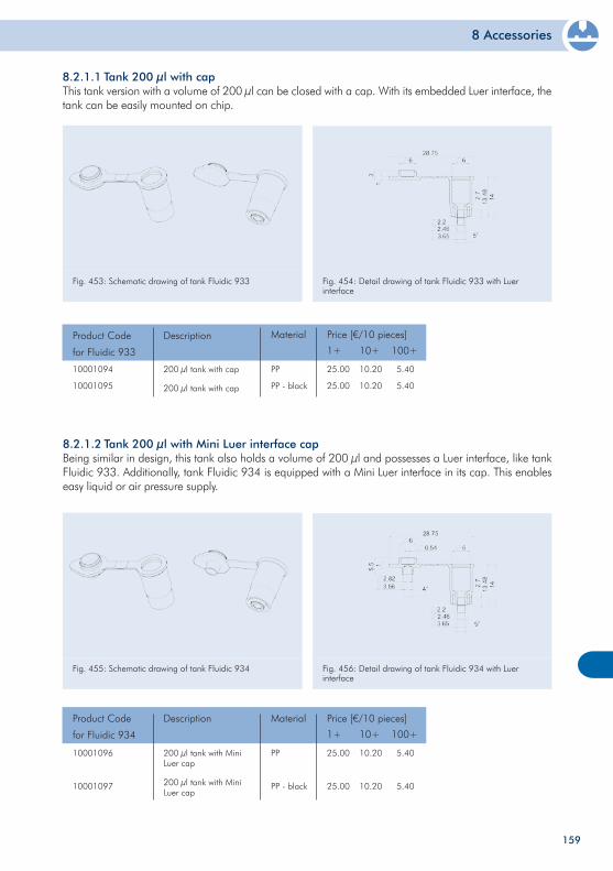
8 Accessories
159
Fig. 455: Schematic drawing of tank Fluidic 934 Fig. 456: Detail drawing of tank Fluidic 934 with Luer interface
10001096
10001097
200 µl tank with Mini Luer cap
200 µl tank with Mini Luer cap
Product Code
for Fluidic 934
Description Price [€/10 pieces]
1+
25.00
25.00
10+
10.20
10.20
100+
5.40
5.40
PP
PP - black
Material
8.2.1.2 Tank 200 µl with Mini Luer interface capBeing similar in design, this tank also holds a volume of 200 µl and possesses a Luer interface, like tank Fluidic 933. Additionally, tank Fluidic 934 is equipped with a Mini Luer interface in its cap. This enables easy liquid or air pressure supply.
8.2.1.1 Tank 200 µl with capThis tank version with a volume of 200 µl can be closed with a cap. With its embedded Luer interface, the tank can be easily mounted on chip.
Fig. 453: Schematic drawing of tank Fluidic 933 Fig. 454: Detail drawing of tank Fluidic 933 with Luer interface
10001094
10001095
200 µl tank with cap
200 µl tank with cap
Product Code
for Fluidic 933
Description Price [€/10 pieces]
1+
25.00
25.00
10+
10.20
10.20
100+
5.40
5.40
PP
PP - black
Material
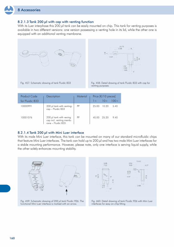
8 Accessories
160
8.2.1.4 Tank 200 µl with Mini Luer interfaceWith its male Mini Luer interface, this tank can be mounted on many of our standard microfluidic chips that feature Mini Luer interfaces. The tank can hold up to 200 µl and has two male Mini Luer interfaces for a stable mounting performance. However, please note, only one interface is serving liquid supply, while the other solely enhances mounting stability.
8.2.1.3 Tank 200 µl with cap with venting functionWith its Luer interphase this 200 µl tank can be easily mounted on chip. This tank for venting purposes is available in two different versions: one version possessing a venting hole in its lid, while the other one is equipped with an additional venting membrane.
Fig. 457: Schematic drawing of tank Fluidic 833 Fig. 458: Detail drawing of tank Fluidic 833 with cap for venting purposes
10000991
10001076
200 µl tank with venting-cap – Fluidic 833
200 µl tank with vening cap incl. venting memb-rane – Fluidic 833
Product Code
for Fluidic 833
Description Price [€/10 pieces]
1+
25.00
40.00
10+
10.20
25.20
100+
5.40
9.40
PP
PP
Material
Fig. 459: Schematic drawing of 200 µl tank Fluidic 926. The functional Mini Luer interface is marked with an arrow.
Fig. 460: Detail drawing of tank Fluidic 926 with Mini Luer interfaces for easy on-chip fitting
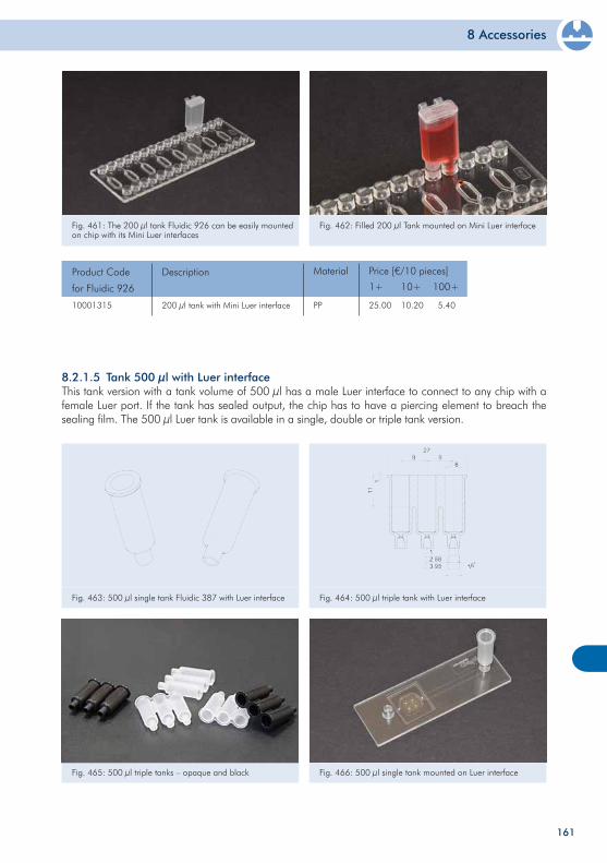
8 Accessories
161
Fig. 463: 500 µl single tank Fluidic 387 with Luer interface Fig. 464: 500 µl triple tank with Luer interface
8.2.1.5 Tank 500 µl with Luer interface This tank version with a tank volume of 500 µl has a male Luer interface to connect to any chip with a female Luer port. If the tank has sealed output, the chip has to have a piercing element to breach the sealing film. The 500 µl Luer tank is available in a single, double or triple tank version.
Fig. 465: 500 µl triple tanks – opaque and black Fig. 466: 500 µl single tank mounted on Luer interface
Fig. 461: The 200 µl tank Fluidic 926 can be easily mounted on chip with its Mini Luer interfaces
Fig. 462: Filled 200 µl Tank mounted on Mini Luer interface
10001315 200 µl tank with Mini Luer interface
Product Code
for Fluidic 926
Description Price [€/10 pieces]
1+
25.00
10+
10.20
100+
5.40PP
Material
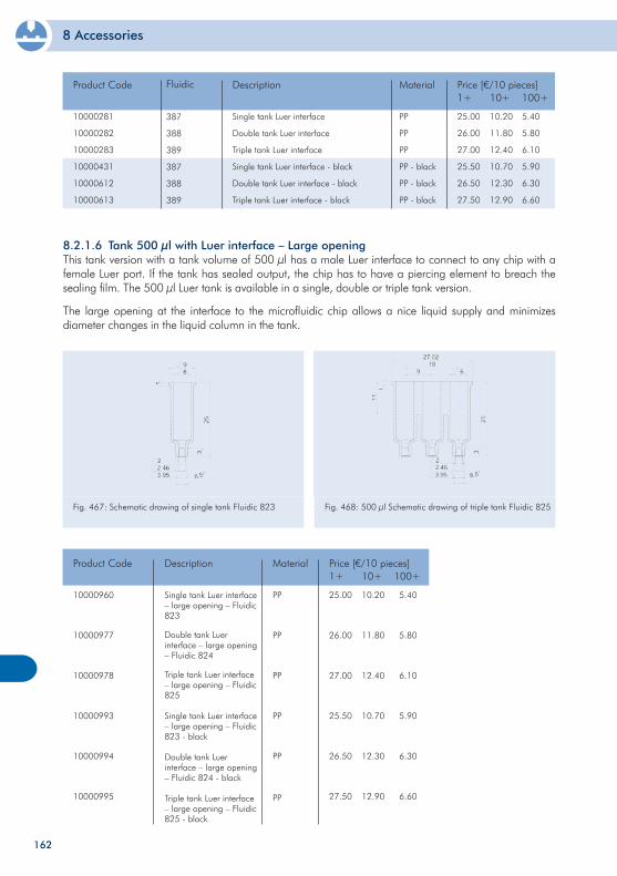
8 Accessories
162
8.2.1.6 Tank 500 µl with Luer interface – Large opening This tank version with a tank volume of 500 µl has a male Luer interface to connect to any chip with a female Luer port. If the tank has sealed output, the chip has to have a piercing element to breach the sealing film. The 500 µl Luer tank is available in a single, double or triple tank version.
The large opening at the interface to the microfluidic chip allows a nice liquid supply and minimizes diameter changes in the liquid column in the tank.
Fig. 467: Schematic drawing of single tank Fluidic 823 Fig. 468: 500 µl Schematic drawing of triple tank Fluidic 825
10000960
10000977
10000978
10000993
10000994
10000995
Single tank Luer interface – large opening – Fluidic 823
Double tank Luer interface – large opening – Fluidic 824
Triple tank Luer interface – large opening – Fluidic 825
Single tank Luer interface – large opening – Fluidic 823 - black
Double tank Luer interface – large opening – Fluidic 824 - black
Triple tank Luer interface – large opening – Fluidic 825 - black
Product Code Description Price [€/10 pieces]1+
25.00
26.00
27.00
25.50
26.50
27.50
10+
10.20
11.80
12.40
10.70
12.30
12.90
100+
5.40
5.80
6.10
5.90
6.30
6.60
PP
PP
PP
PP
PP
PP
Material
10000281
10000282
10000283
10000431
10000612
10000613
Single tank Luer interface
Double tank Luer interface
Triple tank Luer interface
Single tank Luer interface - black
Double tank Luer interface - black
Triple tank Luer interface - black
Product Code Description Price [€/10 pieces]1+
25.00
26.00
27.00
25.50
26.50
27.50
10+
10.20
11.80
12.40
10.70
12.30
12.90
100+
5.40
5.80
6.10
5.90
6.30
6.60
PP
PP
PP
PP - black
PP - black
PP - black
MaterialFluidic
387
388
389
387
388
389
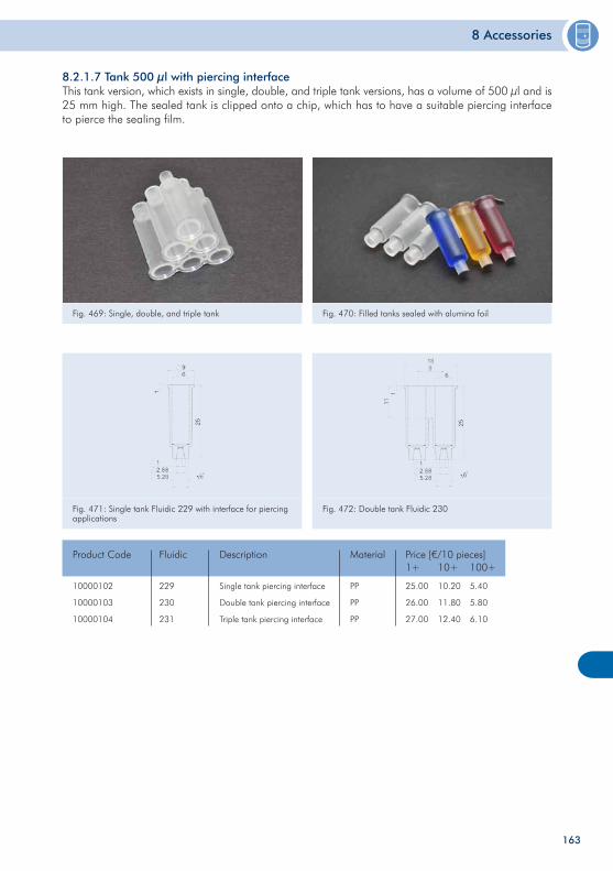
8 Accessories
163
Fig. 469: Single, double, and triple tank Fig. 470: Filled tanks sealed with alumina foil
8.2.1.7 Tank 500 µl with piercing interfaceThis tank version, which exists in single, double, and triple tank versions, has a volume of 500 µl and is 25 mm high. The sealed tank is clipped onto a chip, which has to have a suitable piercing interface to pierce the sealing film.
Fig. 471: Single tank Fluidic 229 with interface for piercing applications
Fig. 472: Double tank Fluidic 230
10000102
10000103
10000104
Single tank piercing interface
Double tank piercing interface
Triple tank piercing interface
Product Code Description Price [€/10 pieces]1+
25.00
26.00
27.00
10+
10.20
11.80
12.40
100+
5.40
5.80
6.10
PP
PP
PP
Material
229
230
231
Fluidic
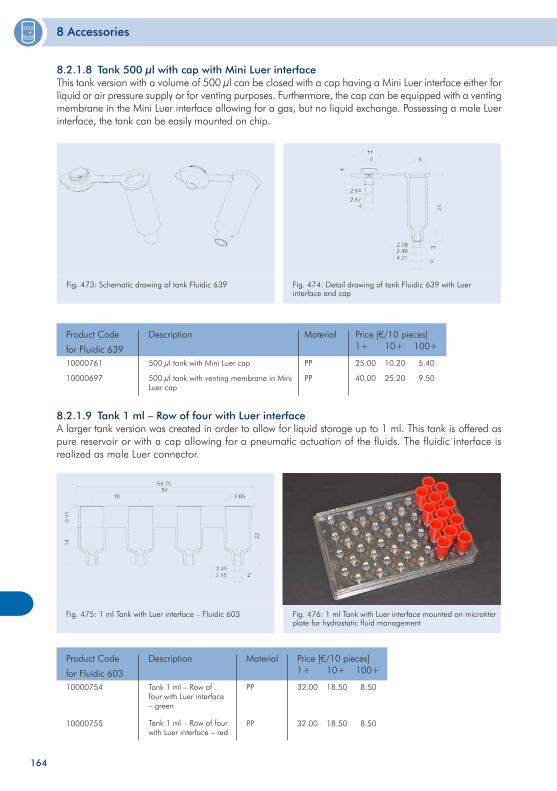
8 Accessories
164
8.2.1.8 Tank 500 µl with cap with Mini Luer interface This tank version with a volume of 500 µl can be closed with a cap having a Mini Luer interface either for liquid or air pressure supply or for venting purposes. Furthermore, the cap can be equipped with a venting membrane in the Mini Luer interface allowing for a gas, but no liquid exchange. Possessing a male Luer interface, the tank can be easily mounted on chip.
Fig. 473: Schematic drawing of tank Fluidic 639 Fig. 474: Detail drawing of tank Fluidic 639 with Luer interface and cap
10000761
10000697
500 µl tank with Mini Luer cap
500 µl tank with venting membrane in Mini Luer cap
Product Code
for Fluidic 639
Description Price [€/10 pieces]1+
25.00
40.00
10+
10.20
25.20
100+
5.40
9.50
PP
PP
Material
10000754
10000755
Tank 1 ml – Row of four with Luer interface – green
Tank 1 ml – Row of four with Luer interface – red
Product Code
for Fluidic 603
Description Price [€/10 pieces]1+
32.00
32.00
10+
18.50
18.50
100+
8.50
8.50
PP
PP
Material
8.2.1.9 Tank 1 ml – Row of four with Luer interface A larger tank version was created in order to allow for liquid storage up to 1 ml. This tank is offered as pure reservoir or with a cap allowing for a pneumatic actuation of the fluids. The fluidic interface is realized as male Luer connector.
Fig. 475: 1 ml Tank with Luer interface – Fluidic 603 Fig. 476: 1 ml Tank with Luer interface mounted on microtiter plate for hydrostatic fluid management
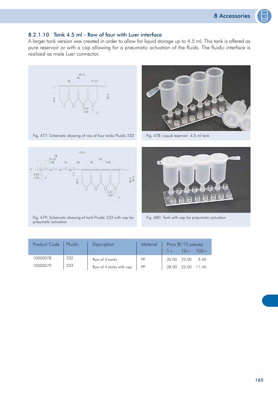
8 Accessories
165
10000078
10000079
Row of 4 tanks
Row of 4 tanks with cap
Product Code Description Price [€/10 pieces]1+
35.00
38.00
10+
22.00
25.00
100+
9.40
11.40
PP
PP
Material
Fig. 479: Schematic drawing of tank Fluidic 233 with cap for pneumatic actuation
Fig. 480: Tank with cap for pneumatic actuation
Fig. 477: Schematic drawing of row of four tanks Fluidic 232 Fig. 478: Liquid reservoir: 4.5 ml tank
8.2.1.10 Tank 4.5 ml - Row of four with Luer interfaceA larger tank version was created in order to allow for liquid storage up to 4.5 ml. This tank is offered as pure reservoir or with a cap allowing for a pneumatic actuation of the fluids. The fluidic interface is realized as male Luer connector.
Fluidic
232
233
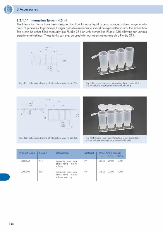
8 Accessories
166
Fig. 483: Schematic drawing of Interaction Tank Fluidic 235 Fig. 484: Liquid reservoir: Interaction Tank Fluidic 235 – 4.5 ml volume mounted on a microfluidic chip
8.2.1.11 Interaction Tanks – 4.5 ml The Interaction Tanks have been designed to allow for easy liquid access, storage and exchange in lab-on-a-chip devices. In particular if larger areas like membrane should be exposed to liquids, the Interaction Tanks can be either filled manually like Fluidic 234 or with pumps like Fluidic 235 allowing for various experimental settings. These tanks can e.g. be used with our open membrane chip Fluidic 219.
Fig. 481: Schematic drawing of Interaction Tank Fluidic 234 Fig. 482: Liquid reservoir: Interaction Tank Fluidic 234 – 4.5 ml volume mounted on a microfluidic chip
10000864
10000904
Interaction tank – row of four tanks – 4.5 ml volume
Interaction tank – row of four tanks – 4.5 ml volume, with cap
Product Code Description Price [€/10 pieces]1+
35.00
35.00
10+
22.00
22.00
100+
9.40
9.40
PP
PP
MaterialFluidic
234
235
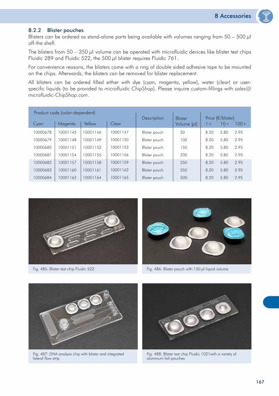
8 Accessories
Fig. 485: Blister test chip Fluidic 522 Fig. 486: Blister pouch with 150 µl liquid volume
8.2.2 Blister pouchesBlisters can be ordered as stand-alone parts being available with volumes ranging from 50 – 500 µl off-the shelf.
The blisters from 50 – 350 µl volume can be operated with microfluidic devices like blister test chips Fluidic 289 and Fluidic 522, the 500 µl blister requires Fluidic 761.
For convenience reasons, the blisters come with a ring of double sided adhesive tape to be mounted on the chips. Afterwards, the blisters can be removed for blister replacement.
All blisters can be ordered filled either with dye (cyan, magenta, yellow), water (clear) or user-specific liquids (to be provided to microfluidic ChipShop). Please inquire custom-fillings with [email protected].
167
Fig. 487: DNA analysis chip with blister and integrated lateral flow strip
Fig. 488: Blister test chip Fluidic 1021with a variety of aluminum foil pouches
10000678
10000679
10000680
10000681
10000682
10000683
10000684
Blister pouch
Blister pouch
Blister pouch
Blister pouch
Blister pouch
Blister pouch
Blister pouch
Description Price [€/blister]1+
8.20
8.20
8.20
8.20
8.20
8.20
8.20
10+
5.80
5.80
5.80
5.80
5.80
5.80
5.80
100+
2.95
2.95
2.95
2.95
2.95
2.95
2.95
50
100
150
200
250
350
500-
BlisterVolume [µl]
Product code (color-dependent)
Cyan Magenta Yellow Clear
10001145
10001148
10001151
10001154
10001157
10001160
10001163
10001146
10001149
10001152
10001155
10001158
10001161
10001164
10001147
10001150
10001153
10001156
10001159
10001162
10001165
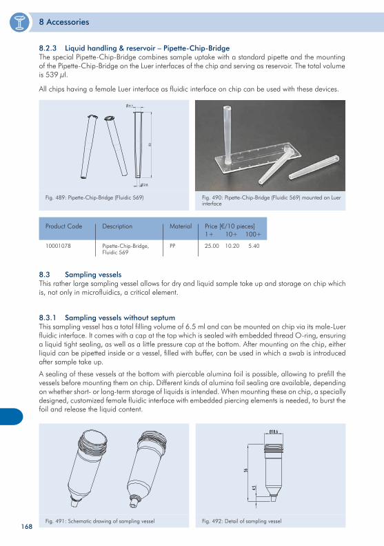
8 Accessories
168
8.3.1 Sampling vessels without septumThis sampling vessel has a total filling volume of 6.5 ml and can be mounted on chip via its male-Luer fluidic interface. It comes with a cap at the top which is sealed with embedded thread O-ring, ensuring a liquid tight sealing, as well as a little pressure cap at the bottom. After mounting on the chip, either liquid can be pipetted inside or a vessel, filled with buffer, can be used in which a swab is introduced after sample take up.
A sealing of these vessels at the bottom with piercable alumina foil is possible, allowing to prefill the vessels before mounting them on chip. Different kinds of alumina foil sealing are available, depending on whether short- or long-term storage of liquids is intended. When mounting these on chip, a specially designed, customized female fluidic interface with embedded piercing elements is needed, to burst the foil and release the liquid content.
Fig. 491: Schematic drawing of sampling vessel Fig. 492: Detail of sampling vessel
8.2.3 Liquid handling & reservoir – Pipette-Chip-BridgeThe special Pipette-Chip-Bridge combines sample uptake with a standard pipette and the mounting of the Pipette-Chip-Bridge on the Luer interfaces of the chip and serving as reservoir. The total volume is 539 µl.
All chips having a female Luer interface as fluidic interface on chip can be used with these devices.
Fig. 489: Pipette-Chip-Bridge (Fluidic 569)Fl. 569
2.6
53
4.1
Fig. 490: Pipette-Chip-Bridge (Fluidic 569) mounted on Luer interface
8.3 Sampling vessels This rather large sampling vessel allows for dry and liquid sample take up and storage on chip which is, not only in microfluidics, a critical element.
10001078 Pipette-Chip-Bridge, Fluidic 569
Product Code Description Price [€/10 pieces]1+
25.00
10+
10.20
100+
5.40PP
Material
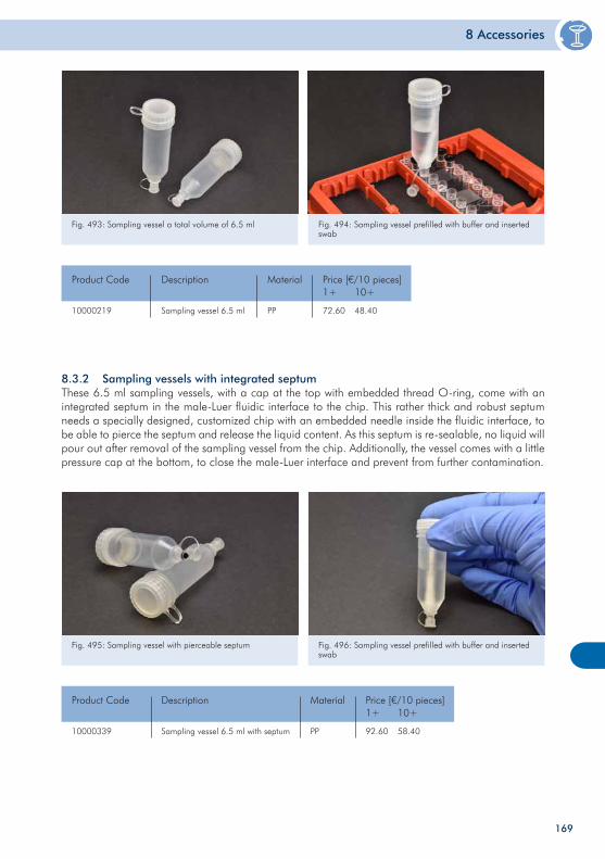
8 Accessories
169
8.3.2 Sampling vessels with integrated septum These 6.5 ml sampling vessels, with a cap at the top with embedded thread O-ring, come with an integrated septum in the male-Luer fluidic interface to the chip. This rather thick and robust septum needs a specially designed, customized chip with an embedded needle inside the fluidic interface, to be able to pierce the septum and release the liquid content. As this septum is re-sealable, no liquid will pour out after removal of the sampling vessel from the chip. Additionally, the vessel comes with a little pressure cap at the bottom, to close the male-Luer interface and prevent from further contamination.
Fig. 493: Sampling vessel a total volume of 6.5 ml Fig. 494: Sampling vessel prefilled with buffer and inserted swab
10000219 Sampling vessel 6.5 ml
Product Code Description Price [€/10 pieces]1+
72.60
10+
48.40PP
Material
Fig. 495: Sampling vessel with pierceable septum Fig. 496: Sampling vessel prefilled with buffer and inserted swab
10000339 Sampling vessel 6.5 ml with septum
Product Code Description Price [€/10 pieces]1+
92.60
10+
58.40PP
Material
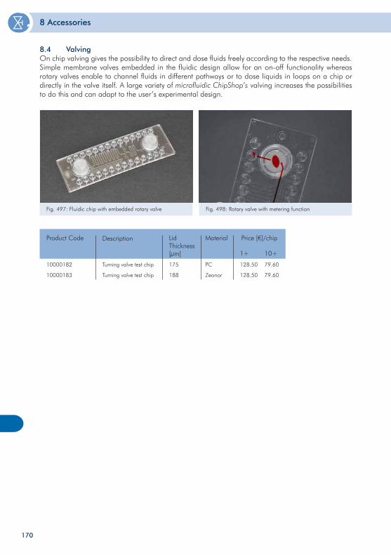
8 Accessories
170
10000182
10000183
175
188
PC
Zeonor
Product Code Lid Thickness[µm]
Material Price [€]/chip
1+ 10+
128.50
128.50
79.60
79.60
Description
Turning valve test chip
Turning valve test chip
Fig. 497: Fluidic chip with embedded rotary valve
8.4 Valving On chip valving gives the possibility to direct and dose fluids freely according to the respective needs. Simple membrane valves embedded in the fluidic design allow for an on-off functionality whereas rotary valves enable to channel fluids in different pathways or to dose liquids in loops on a chip or directly in the valve itself. A large variety of microfluidic ChipShop’s valving increases the possibilities to do this and can adapt to the user’s experimental design.
Fig. 498: Rotary valve with metering function
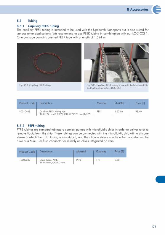
8 Accessories
171
8.5 Tubing
8.5.2 PTFE tubing PTFE tubings are standard tubings to connect pumps with microfluidic chips in order to deliver to or to remove liquid from the chip. These tubings can be connected with the microfluidic chip with a silicone sleeve in which the PTFE tubing is introduced, and the silicone sleeve can be either mounted on the olive of a Mini Luer fluid connector or directly on olives integrated on chip.
10000032 Micro tubes, PTFE, ID: 0.5 mm, OD:1.0 mm
Product Code Description Price [€]
9.50
Quantity
1 mPTFE
Material
Fig. 499: Capillary PEEK tubing Fig. 500: Capillary PEEK tubing in use with the Lab-on-a-Chip Cell Culture Incubator – LOC CCI 1
8.5.1 Capillary PEEK tubing The capillary PEEK tubing is intended to be used with the Upchurch Nanoports but is also suited for various other applications. We recommend to use PEEK tubing in combination with our LOC CCI 1. One package contains one red PEEK tube with a length of 1.524 m.
40010468 Capillary PEEK tubing, redID: 0.127 mm (0.005“), OD: 0.79375 mm (1/32“)
Product Code Description Price [€]
98.40PEEK
Material Quantity
1.524 m
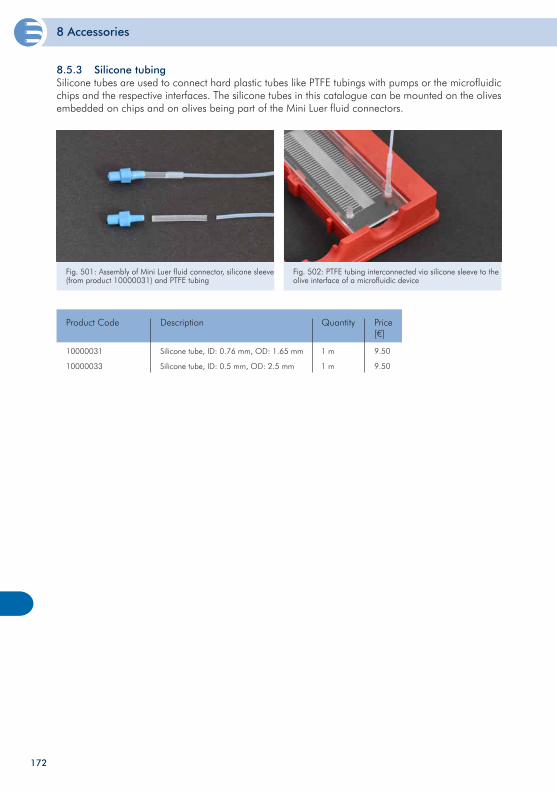
8 Accessories
172
Fig. 501: Assembly of Mini Luer fluid connector, silicone sleeve (from product 10000031) and PTFE tubing
Fig. 502: PTFE tubing interconnected via silicone sleeve to the olive interface of a microfluidic device
10000031
10000033
Silicone tube, ID: 0.76 mm, OD: 1.65 mm
Silicone tube, ID: 0.5 mm, OD: 2.5 mm
Product Code Description Price[€]
9.50
9.50
Quantity
1 m
1 m
8.5.3 Silicone tubing Silicone tubes are used to connect hard plastic tubes like PTFE tubings with pumps or the microfluidic chips and the respective interfaces. The silicone tubes in this catalogue can be mounted on the olives embedded on chips and on olives being part of the Mini Luer fluid connectors.
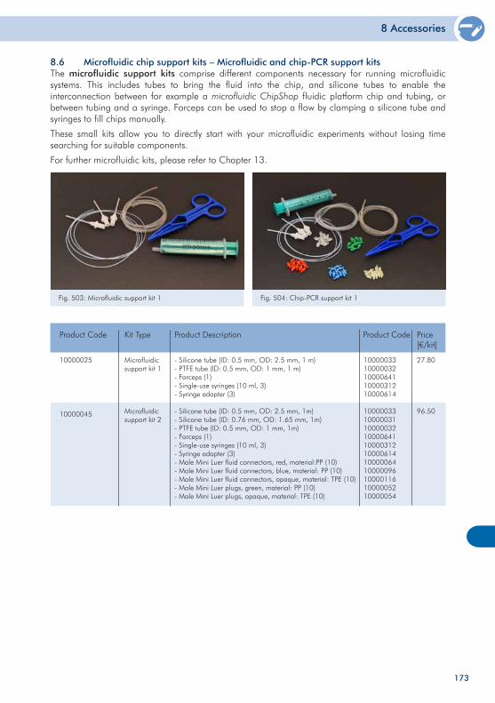
8 Accessories
173
8.6 Microfluidic chip support kits – Microfluidic and chip-PCR support kits The microfluidic support kits comprise different components necessary for running microfluidic systems. This includes tubes to bring the fluid into the chip, and silicone tubes to enable the interconnection between for example a microfluidic ChipShop fluidic platform chip and tubing, or between tubing and a syringe. Forceps can be used to stop a flow by clamping a silicone tube and syringes to fill chips manually.
These small kits allow you to directly start with your microfluidic experiments without losing time searching for suitable components.
For further microfluidic kits, please refer to Chapter 13.
10000025
10000045
Microfluidic support kit 1
Microfluidic support kit 2
Product Code Kit Type Price[€/kit]
27.80
96.50
- Silicone tube (ID: 0.5 mm, OD: 2.5 mm, 1 m)- PTFE tube (ID: 0.5 mm, OD: 1 mm, 1 m)- Forceps (1)- Single-use syringes (10 ml, 3)- Syringe adapter (3)
- Silicone tube (ID: 0.5 mm, OD: 2.5 mm, 1m)- Silicone tube (ID: 0.76 mm, OD: 1.65 mm, 1m)- PTFE tube (ID: 0.5 mm, OD: 1 mm, 1m)- Forceps (1)- Single-use syringes (10 ml, 3)- Syringe adapter (3)- Male Mini Luer fluid connectors, red, material:PP (10)- Male Mini Luer fluid connectors, blue, material: PP (10)- Male Mini Luer fluid connectors, opaque, material: TPE (10)- Male Mini Luer plugs, green, material: PP (10)- Male Mini Luer plugs, opaque, material: TPE (10)
Product Description
1000003310000032100006411000031210000614
1000003310000031100000321000064110000312100006141000006410000096100001161000005210000054
Product Code
Fig. 503: Microfluidic support kit 1 Fig. 504: Chip-PCR support kit 1
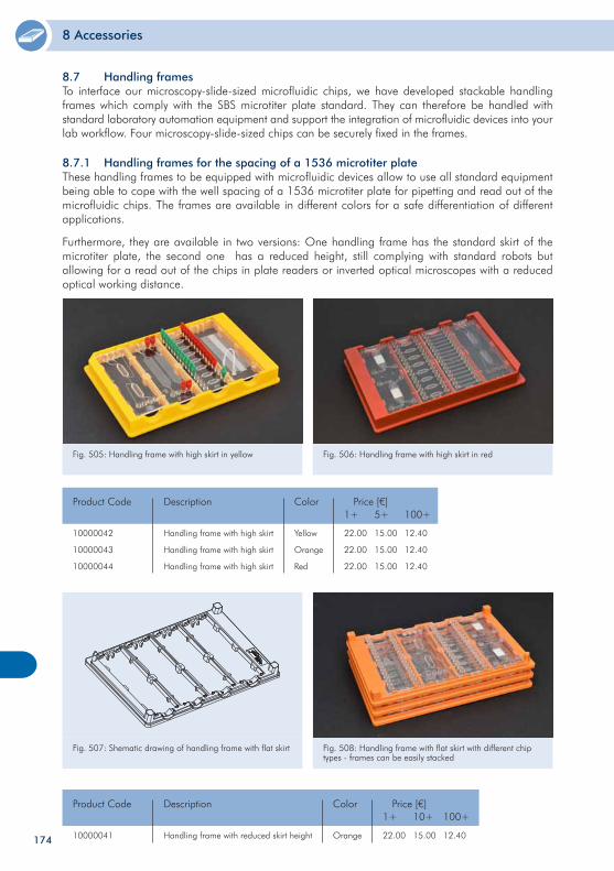
8 Accessories
174
Fig. 507: Shematic drawing of handling frame with flat skirt Fig. 508: Handling frame with flat skirt with different chip types - frames can be easily stacked
10000041 Handling frame with reduced skirt height
Product Code Description Price [€]1+
22.00
10+
15.00
100+
12.40Orange
Color
10000042
10000043
10000044
Handling frame with high skirt
Handling frame with high skirt
Handling frame with high skirt
Product Code Description Price [€]1+
22.00
22.00
22.00
5+
15.00
15.00
15.00
100+
12.40
12.40
12.40
Yellow
Orange
Red
Color
Fig. 505: Handling frame with high skirt in yellow Fig. 506: Handling frame with high skirt in red
8.7.1 Handling frames for the spacing of a 1536 microtiter plate These handling frames to be equipped with microfluidic devices allow to use all standard equipment being able to cope with the well spacing of a 1536 microtiter plate for pipetting and read out of the microfluidic chips. The frames are available in different colors for a safe differentiation of different applications.
Furthermore, they are available in two versions: One handling frame has the standard skirt of the microtiter plate, the second one has a reduced height, still complying with standard robots but allowing for a read out of the chips in plate readers or inverted optical microscopes with a reduced optical working distance.
8.7 Handling frames To interface our microscopy-slide-sized microfluidic chips, we have developed stackable handling frames which comply with the SBS microtiter plate standard. They can therefore be handled with standard laboratory automation equipment and support the integration of microfluidic devices into your lab workflow. Four microscopy-slide-sized chips can be securely fixed in the frames.
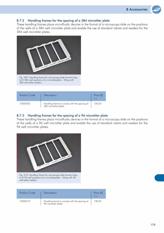
8 Accessories
175
8.7.3 Handling frames for the spacing of a 96 microtiter plateThese handling frames place microfluidic devices in the format of a microscopy slide on the positions of the wells of a 96 well microtiter plate and enable the use of standard robots and readers for the 96 well microtiter plates.
Fig. 510: Handling frame for microscopy slide format chips to fit 96 well positions of a microtiterplate – fitting with 96 well plate readers
10000419 Handling frame to comply with the spacing of 96 microtiter plates
Product Code Description Price [€]1+
128.50
Fig. 509: Handling frame for microscopy slide format chips to fit 384 well positions of a microtiterplate – fitting with 384 well plate readers
10000302 Handling frame to comply with the spacing of 384 microtiter plates
Product Code Description Price [€]1+
128.50
8.7.2 Handling frames for the spacing of a 384 microtiter plate These handling frames place microfluidic devices in the format of a microscopy slide on the positions of the wells of a 384 well microtiter plate and enable the use of standard robots and readers for the 384 well microtiter plates.
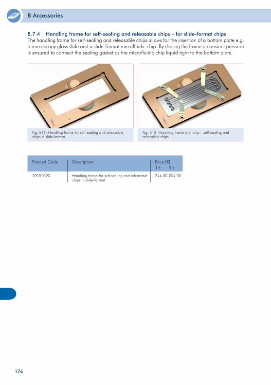
8 Accessories
Fig. 511: Handling frame for self-sealing and releasable chips in slide-format
8.7.4 Handling frame for self-sealing and releasable chips – for slide-format chips The handling frame for self-sealing and releasable chips allows for the insertion of a bottom plate e.g. a microscopy glass slide and a slide-format microfluidic chip. By closing the frame a constant pressure is ensured to connect the sealing gasket as the microfluidic chip liquid tight to the bottom plate.
Fig. 512: Handling frame with chip – self-sealing and releasable chips
10001090 Handling-frame for self-sealing and releasable chips in slide-format
Product Code Description Price [€]1+
244.00
5+
204.00
176
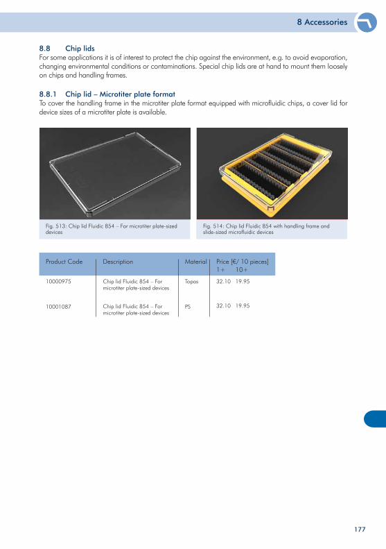
8 Accessories
177
8.8 Chip lids For some applications it is of interest to protect the chip against the environment, e.g. to avoid evaporation, changing environmental conditions or contaminations. Special chip lids are at hand to mount them loosely on chips and handling frames.
8.8.1 Chip lid – Microtiter plate format To cover the handling frame in the microtiter plate format equipped with microfluidic chips, a cover lid for device sizes of a microtiter plate is available.
Fig. 513: Chip lid Fluidic 854 – For microtiter plate-sized devices
Fig. 514: Chip lid Fluidic 854 with handling frame and slide-sized microfluidic devices
10000975
10001087
Chip lid Fluidic 854 – For microtiter plate-sized devices
Chip lid Fluidic 854 – For microtiter plate-sized devices
Product Code Description Price [€/ 10 pieces]1+
32.10
32.10
10+
19.95
19.95
Topas
PS
Material
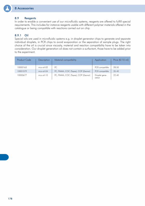
8 Accessories
178
8 Accessories
8.9 Reagents In order to enable a convenient use of our microfluidic systems, reagents are offered to fulfill special requirements. This includes for instance reagents usable with different polymer materials offered in the catalogue or being compatible with reactions carried out on chip.
8.9.1 Oil Special oils are used in microfluidic systems e.g. in droplet generator chips to generate and separate individual droplets, in PCR chips to avoid evaporation or the separation of sample plugs. The right choice of the oil is crucial since viscosity, material and reaction compatibility have to be taken into consideration. Our droplet generation oil does not contain a surfactant, those have to be added prior to the experiment.
10000163
10001079
10000677
mcs-oil-02
mcs-oil-04
mcs-oil-10
Product Code Description Price [€/10 ml]
28.50
35.40
22.40
PCR compatible
PCR compatible
Droplet gene-ration
Application
PC
PC, PMMA, COC (Topas), COP (Zeonor)
PC, PMMA, COC (Topas), COP (Zeonor)
Material compatibility
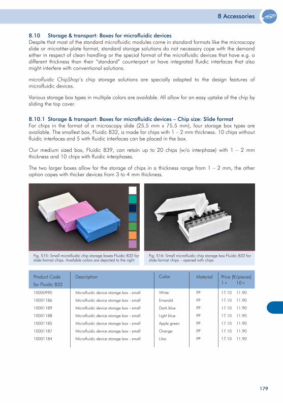
8 Accessories
179
8.10 Storage & transport: Boxes for microfluidic devicesDespite that most of the standard microfluidic modules come in standard formats like the microscopy slide or microtiter-plate format, standard storage solutions do not necessary cope with the demand either in respect of clean handling or the special format of the microfluidic devices that have e.g. a different thickness than their “standard” counterpart or have integrated fluidic interfaces that also might interfere with conventional solutions.
microfluidic ChipShop’s chip storage solutions are specially adapted to the design features of microfluidic devices.
Various storage box types in multiple colors are available. All allow for an easy uptake of the chip by sliding the top cover.
8.10.1 Storage & transport: Boxes for microfluidic devices – Chip size: Slide formatFor chips in the format of a microscopy slide (25.5 mm x 75.5 mm), four storage box types are available. The smallest box, Fluidic 832, is made for chips with 1 – 2 mm thickness. 10 chips without fluidic interfaces and 5 with fluidic interfaces can be placed in the box.
Our medium sized box, Fluidic 839, can retain up to 20 chips (w/o interphase) with 1 – 2 mm thickness and 10 chips with fluidic interphases.
The two larger boxes allow for the storage of chips in a thickness range from 1 – 2 mm, the other option copes with thicker devices from 3 to 4 mm thickness.
Fig. 515: Small microfluidic chip storage boxes Fluidic 832 for slide-format chips. Available colors are depicted to the right
Fig. 516: Small microfluidic chip storage box Fluidic 832 for slide-format chips – opened with chips
Product Code
for Fluidic 832
Description Price [€/pieces]1+
17.10
17.10
17.10
17.10
17.10
17.10
17.10
10+
11.90
11.90
11.90
11.90
11.90
11.90
11.90
PP
PP
PP
PP
PP
PP
PP
MaterialColor
Microfluidic device storage box - small
Microfluidic device storage box - small
Microfluidic device storage box - small
Microfluidic device storage box - small
Microfluidic device storage box - small
Microfluidic device storage box - small
Microfluidic device storage box - small
White
Emerald
Dark blue
Light blue
Apple green
Orange
Lilac
10000990
10001186
10001189
10001188
10001185
10001187
10001184
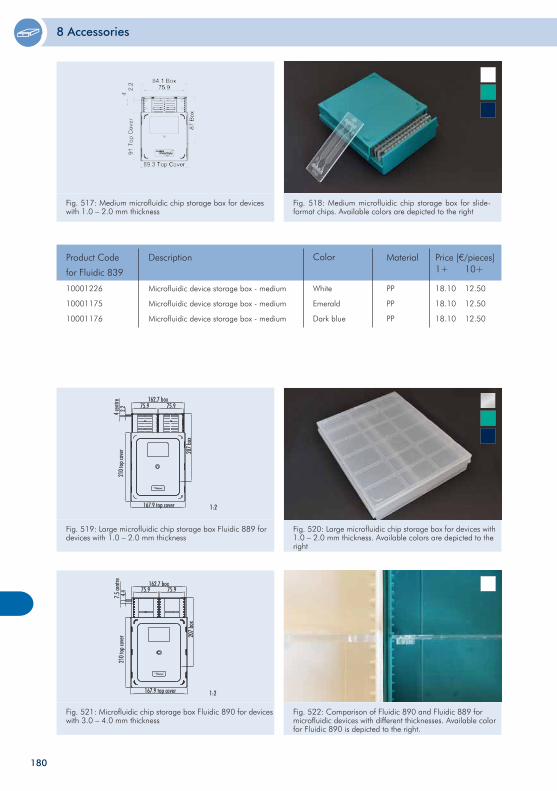
8 Accessories
180
Fig. 519: Large microfluidic chip storage box Fluidic 889 for devices with 1.0 – 2.0 mm thickness
Fig. 520: Large microfluidic chip storage box for devices with 1.0 – 2.0 mm thickness. Available colors are depicted to the right
Fig. 517: Medium microfluidic chip storage box for devices with 1.0 – 2.0 mm thickness
Fig. 518: Medium microfluidic chip storage box for slide-format chips. Available colors are depicted to the right
Product Code
for Fluidic 839
Description Price [€/pieces]1+
18.10
18.10
18.10
10+
12.50
12.50
12.50
PP
PP
PP
MaterialColor
Microfluidic device storage box - medium
Microfluidic device storage box - medium
Microfluidic device storage box - medium
White
Emerald
Dark blue
10001226
10001175
10001176
Fig. 521: Microfluidic chip storage box Fluidic 890 for devices with 3.0 – 4.0 mm thickness
Fig. 522: Comparison of Fluidic 890 and Fluidic 889 for microfluidic devices with different thicknesses. Available color for Fluidic 890 is depicted to the right.
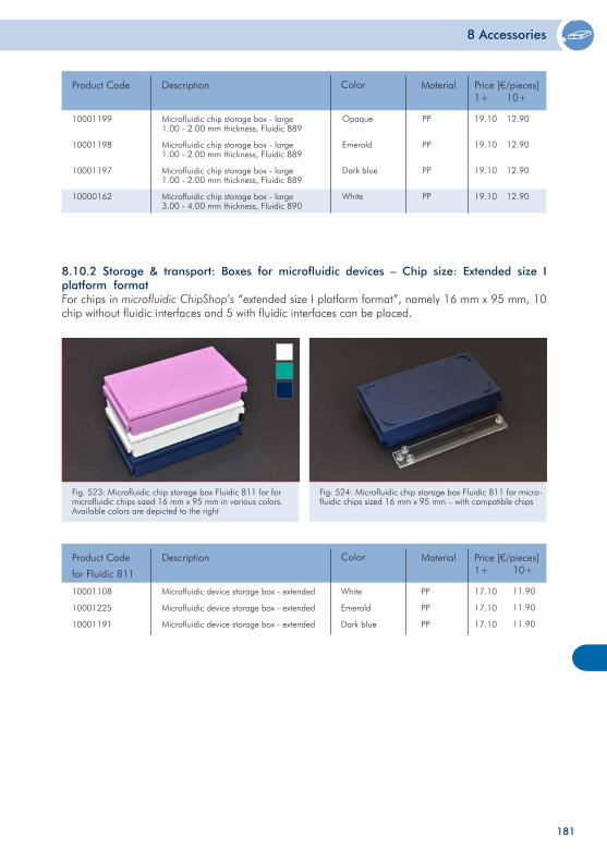
8 Accessories
181
8.10.2 Storage & transport: Boxes for microfluidic devices – Chip size: Extended size I platform formatFor chips in microfluidic ChipShop’s “extended size I platform format”, namely 16 mm x 95 mm, 10 chip without fluidic interfaces and 5 with fluidic interfaces can be placed.
Fig. 523: Microfluidic chip storage box Fluidic 811 for for microfluidic chips sized 16 mm x 95 mm in various colors. Available colors are depicted to the right
Fig. 524: Microfluidic chip storage box Fluidic 811 for micro-fluidic chips sized 16 mm x 95 mm – with compatible chips
Product Code Description Price [€/pieces]1+ 10+
MaterialColor
Microfluidic chip storage box - large1.00 - 2.00 mm thickness, Fluidic 889
Microfluidic chip storage box - large1.00 - 2.00 mm thickness, Fluidic 889
Microfluidic chip storage box - large1.00 - 2.00 mm thickness, Fluidic 889
Microfluidic chip storage box - large3.00 - 4.00 mm thickness, Fluidic 890
Opaque
Emerald
Dark blue
White
PP
PP
PP
PP
19.10
19.10
19.10
19.10
12.90
12.90
12.90
12.90
10001199
10001198
10001197
10000162
Product Code
for Fluidic 811
Description Price [€/pieces]1+
17.10
17.10
17.10
10+
11.90
11.90
11.90
PP
PP
PP
MaterialColor
Microfluidic device storage box - extended
Microfluidic device storage box - extended
Microfluidic device storage box - extended
White
Emerald
Dark blue
10001108
10001225
10001191
182
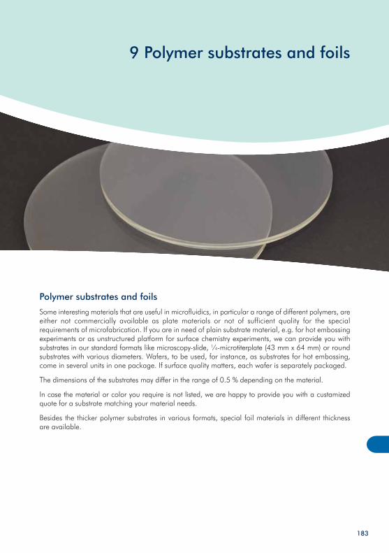
9 Polymer substrates and foils
Polymer substrates and foils
Some interesting materials that are useful in microfluidics, in particular a range of different polymers, are either not commercially available as plate materials or not of sufficient quality for the special requirements of microfabrication. If you are in need of plain substrate material, e.g. for hot embossing experiments or as unstructured platform for surface chemistry experiments, we can provide you with substrates in our standard formats like microscopy-slide, ¼-microtiterplate (43 mm x 64 mm) or round substrates with various diameters. Wafers, to be used, for instance, as substrates for hot embossing, come in several units in one package. If surface quality matters, each wafer is separately packaged.
The dimensions of the substrates may differ in the range of 0.5 % depending on the material.
In case the material or color you require is not listed, we are happy to provide you with a custamized quote for a substrate matching your material needs.
Besides the thicker polymer substrates in various formats, special foil materials in different thickness are available.
183
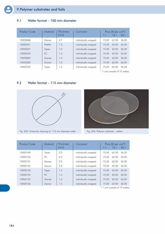
9 Polymer substrates and foils
9.2 Wafer format – 115 mm diameter
Fig. 525: Schematic drawing of 115 mm diameter wafer Fig. 526: Polymer substrate – wafers
10000149
10000150
10000151
10000152
10000153
10000154
10000155
10000156
Topas
PC
Zeonex
Zeonor
Topas
PC
Zeonex
Zeonor
Product Code Material Price [€/per unit*]1+
75.00
75.00
75.00
75.00
75.00
75.00
75.00
75.00
10+
62.00
62.00
62.00
62.00
62.00
62.00
62.00
62.00
50+
36.00
36.00
36.00
36.00
36.00
36.00
36.00
36.00
* 1 unit consists of 10 wafers
Comment
184
Thickness[mm]
2.0
2.0
2.0
2.0
1.5
1.5
1.5
1.5
individually wrapped
individually wrapped
individually wrapped
individually wrapped
individually wrapped
individually wrapped
individually wrapped
individually wrapped
9.1 Wafer format – 100 mm diameter
10000868
10000241
10000257
10000240
10000869
10000383
10000703
Zeonor
PMMA
Topas
PC
Zeonex
Zeonor
Topas
Product Code Material Price [€/per unit*]1+
75.00
75.00
75.00
75.00
75.00
75.00
75.00
10+
62.00
62.00
62.00
62.00
62.00
62.00
62.00
50+
36.00
36.00
36.00
36.00
36.00
36.00
36.00
* 1 unit consists of 10 wafers
CommentThickness[mm]
0.7
1.0
1.0
1.0
1.0
1.0
1.5
individually wrapped
individually wrapped
individually wrapped
individually wrapped
individually wrapped
individually wrapped
individually wrapped
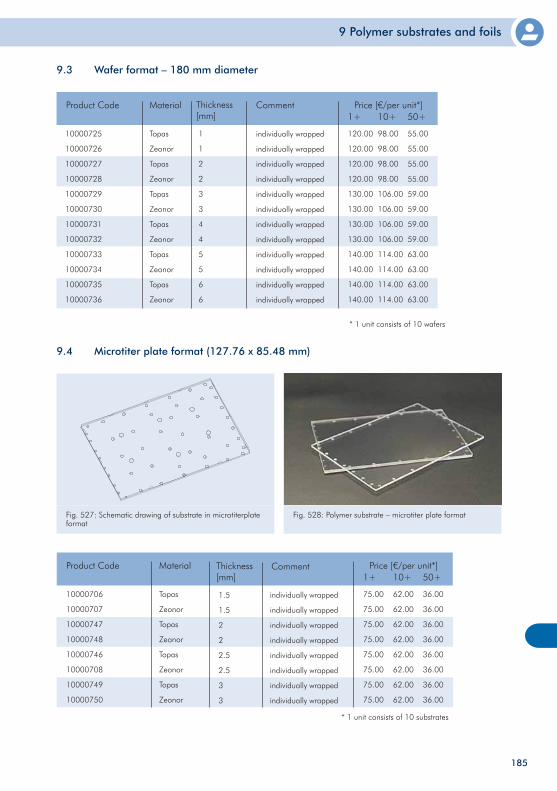
9 Polymer substrates and foils
185
10000706
10000707
10000747
10000748
10000746
10000708
10000749
10000750
Topas
Zeonor
Topas
Zeonor
Topas
Zeonor
Topas
Zeonor
Product Code Material Price [€/per unit*]1+
75.00
75.00
75.00
75.00
75.00
75.00
75.00
75.00
10+
62.00
62.00
62.00
62.00
62.00
62.00
62.00
62.00
50+
36.00
36.00
36.00
36.00
36.00
36.00
36.00
36.00
* 1 unit consists of 10 substrates
individually wrapped
individually wrapped
individually wrapped
individually wrapped
individually wrapped
individually wrapped
individually wrapped
individually wrapped
CommentThickness[mm]
1.5
1.5
2
2
2.5
2.5
3
3
Fig. 527: Schematic drawing of substrate in microtiterplate format
Fig. 528: Polymer substrate – microtiter plate format
9.4 Microtiter plate format (127.76 x 85.48 mm)
9.3 Wafer format – 180 mm diameter
10000725
10000726
10000727
10000728
10000729
10000730
10000731
10000732
10000733
10000734
10000735
10000736
Topas
Zeonor
Topas
Zeonor
Topas
Zeonor
Topas
Zeonor
Topas
Zeonor
Topas
Zeonor
Product Code Material Price [€/per unit*]1+
120.00
120.00
120.00
120.00
130.00
130.00
130.00
130.00
140.00
140.00
140.00
140.00
10+
98.00
98.00
98.00
98.00
106.00
106.00
106.00
106.00
114.00
114.00
114.00
114.00
50+
55.00
55.00
55.00
55.00
59.00
59.00
59.00
59.00
63.00
63.00
63.00
63.00
* 1 unit consists of 10 wafers
CommentThickness[mm]
1
1
2
2
3
3
4
4
5
5
6
6
individually wrapped
individually wrapped
individually wrapped
individually wrapped
individually wrapped
individually wrapped
individually wrapped
individually wrapped
individually wrapped
individually wrapped
individually wrapped
individually wrapped
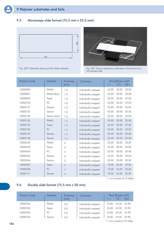
9 Polymer substrates and foils
186
* 1 unit consists of 10 slides
10000000
10000001
10000002
10000130
10000131
10000132
10000133
10000134
10000135
10000136
10000137
10000138
10000452
10000443
10000454
10000455
10000456
10000457
10000458
10000141
PMMA
PMMA black
Topas
PC
Zeonex
Zeonor
Zeonor black
PMMA
Topas
PC
Zeonex
Zeonor
PMMA
Topas
PC
Zeonex
Zeonor
Topas
PC
Zeonex
Product Code Material Price [€/per unit*]1+
55.00
55.00
55.00
55.00
55.00
55.00
55.00
55.00
55.00
55.00
55.00
55.00
55.00
55.00
55.00
55.00
55.00
75.00
75.00
75.00
10+
30.00
30.00
30.00
30.00
30.00
30.00
30.00
30.00
30.00
30.00
30.00
30.00
30.00
30.00
30.00
30.00
30.00
35.00
35.00
35.00
50+
22.00
22.00
22.00
22.00
22.00
22.00
22.00
22.00
22.00
22.00
22.00
22.00
22.00
22.00
22.00
22.00
22.00
22.00
22.00
22.00
Individually wrapped
Individually wrapped
Individually wrapped
Individually wrapped
Individually wrapped
Individually wrapped
Individually wrapped
Individually wrapped
Individually wrapped
Individually wrapped
Individually wrapped
Individually wrapped
Individually wrapped
Individually wrapped
Individually wrapped
Individually wrapped
Individually wrapped
Individually wrapped
Individually wrapped
Individually wrapped
CommentThickness[mm]
1.0
1.0
1.0
1.0
1.0
1.0
1.0
1.5
1.5
1.5
1.5
1.5
2
2
2
2
2
4
4
4
9.6 Double slide format (75.5 mm x 50 mm)
* 1 unit consists of 10 slides
10000762
10000763
10000764
10000765
PMMA
Topas
PC
Zeonor
Product Code Material Price [€/per unit*]1+
76.00
76.00
76.00
76.00
10+
44.50
44.50
44.50
44.50
50+
24.90
24.90
24.90
24.90
Individually wrapped
Individually wrapped
Individually wrapped
Individually wrapped
CommentThickness[mm]
2.0
2.0
2.0
2.0
Fig. 529: Schematic drawing of the slide substrate Fig. 530: Various polymeric substrates in the format of a microscopy slide
9.5 Microscopy slide format (75.5 mm x 25.5 mm)
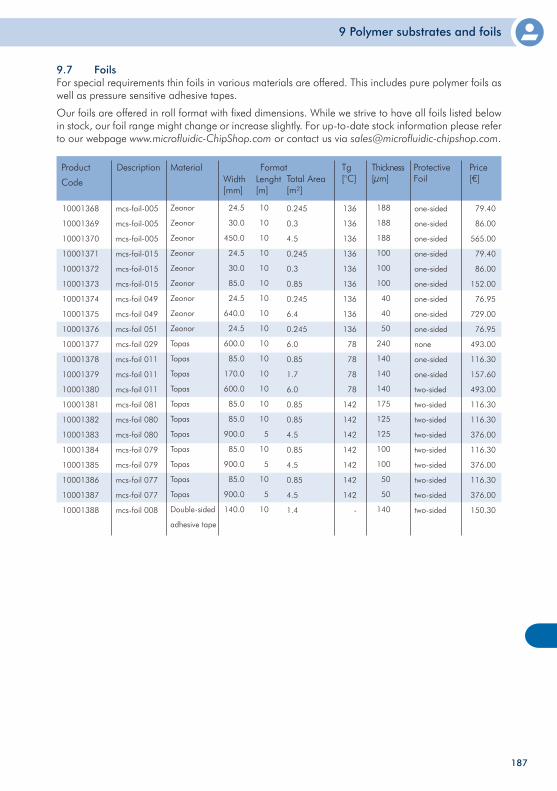
9 Polymer substrates and foils
187
9.7 Foils For special requirements thin foils in various materials are offered. This includes pure polymer foils as well as pressure sensitive adhesive tapes.
Our foils are offered in roll format with fixed dimensions. While we strive to have all foils listed below in stock, our foil range might change or increase slightly. For up-to-date stock information please refer to our webpage www.microfluidic-ChipShop.com or contact us via [email protected].
10001368
10001369
10001370
10001371
10001372
10001373
10001374
10001375
10001376
10001377
10001378
10001379
10001380
10001381
10001382
10001383
10001384
10001385
10001386
10001387
10001388
mcs-foil-005
mcs-foil-005
mcs-foil-005
mcs-foil-015
mcs-foil-015
mcs-foil-015
mcs-foil 049
mcs-foil 049
mcs-foil 051
mcs-foil 029
mcs-foil 011
mcs-foil 011
mcs-foil 011
mcs-foil 081
mcs-foil 080
mcs-foil 080
mcs-foil 079
mcs-foil 079
mcs-foil 077
mcs-foil 077
mcs-foil 008
Product
Code
Description Price[€]
79.40
86.00
565.00
79.40
86.00
152.00
76.95
729.00
76.95
493.00
116.30
157.60
493.00
116.30
116.30
376.00
116.30
376.00
116.30
376.00
150.30
one-sided
one-sided
one-sided
one-sided
one-sided
one-sided
one-sided
one-sided
one-sided
none
one-sided
one-sided
two-sided
two-sided
two-sided
two-sided
two-sided
two-sided
two-sided
two-sided
two-sided
Zeonor
Zeonor
Zeonor
Zeonor
Zeonor
Zeonor
Zeonor
Zeonor
Zeonor
Topas
Topas
Topas
Topas
Topas
Topas
Topas
Topas
Topas
Topas
Topas
Double-sided
adhesive tape
Material
188
188
188
100
100
100
40
40
50
240
140
140
140
175
125
125
100
100
50
50
140
Thickness[µm]
Format
136
136
136
136
136
136
136
136
136
78
78
78
78
142
142
142
142
142
142
142
-
Tg[°C]
Protective FoilLenght
[m]Width[mm]
Total Area[m²]
24.5
30.0
450.0
24.5
30.0
85.0
24.5
640.0
24.5
600.0
85.0
170.0
600.0
85.0
85.0
900.0
85.0
900.0
85.0
900.0
140.0
10
10
10
10
10
10
10
10
10
10
10
10
10
10
10
5
10
5
10
5
10
0.245
0.3
4.5
0.245
0.3
0.85
0.245
6.4
0.245
6.0
0.85
1.7
6.0
0.85
0.85
4.5
0.85
4.5
0.85
4.5
1.4
188
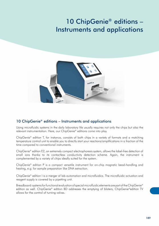
10 ChipGenie® editions – Instruments and applications
10 ChipGenie® editions – Instruments and applications
Using microfluidic systems in the daily laboratory life usually requires not only the chips but also the relevant instrumentation. Here, our ChipGenie® editions come into play.
ChipGenie® edition T, for instance, consists of both chips in a variety of formats and a matching temperature control unit to enable you to directly start your reactions/amplifications in a fraction of the time compared to conventional instruments.
ChipGenie® edition E2, an extremely compact electrophoresis system, allows the label-free detection of small ions thanks to its contactless conductivity detection scheme. Again, the instrument is complemented by a variety of chips ideally suited for the system.
ChipGenie® edition P is a compact versatile instrument for on-chip magnetic bead-handling and heating, e.g. for sample preparation like DNA extraction.
ChipGenie® edition I is a merger of lab-automation and microfluidics. The microfluidic actuation and reagent supply is covered by a pipetting unit.
Breadboard-systems for functional evaluation of special microfluidic elements are part of the ChipGenie® edition as well. ChipGenie® edition BD addresses the emptying of blisters, ChipGenie®edition TV allows for the control of turning valves.
189
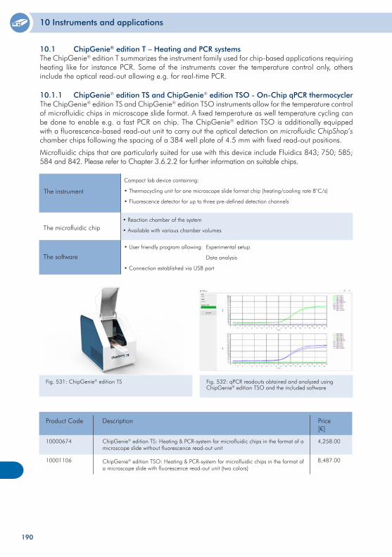
10 Instruments and applications
190
10.1 ChipGenie® edition T – Heating and PCR systemsThe ChipGenie® edition T summarizes the instrument family used for chip-based applications requiring heating like for instance PCR. Some of the instruments cover the temperature control only, others include the optical read-out allowing e.g. for real-time PCR.
10.1.1 ChipGenie® edition TS and ChipGenie® edition TSO - On-Chip qPCR thermocyclerThe ChipGenie® edition TS and ChipGenie® edition TSO instruments allow for the temperature control of microfluidic chips in microscope slide format. A fixed temperature as well temperature cycling can be done to enable e.g. a fast PCR on chip. The ChipGenie® edition TSO is additionally equipped with a fluorescence-based read-out unit to carry out the optical detection on microfluidic ChipShop’s chamber chips following the spacing of a 384 well plate of 4.5 mm with fixed read-out positions.
Microfluidic chips that are particularly suited for use with this device include Fluidics 843; 750; 585; 584 and 842. Please refer to Chapter 3.6.2.2 for further information on suitable chips.
Fig. 531: ChipGenie® edition TS
10000674
10001106
ChipGenie® edition TS: Heating & PCR-system for microfluidic chips in the format of a microscope slide without fluorescence read-out unit
ChipGenie® edition TSO: Heating & PCR-system for microfluidic chips in the format of a microscope slide with fluorescence read-out unit (two colors)
Product Code Price [€]
4,258.00
8,487.00
Description
The instrument
Compact lab device containing:
• Thermocycling unit for one microscope slide format chip (heating/cooling rate 8°C/s)
• Fluorescence detector for up to three pre-defined detection channels
The microfluidic chip• Reaction chamber of the system
• Available with various chamber volumes
The software
• User friendly program allowing: Experimental setup
Data analysis
• Connection established via USB port
Fig. 532: qPCR readouts obtained and analyzed using ChipGenie® edition TSO and the included software
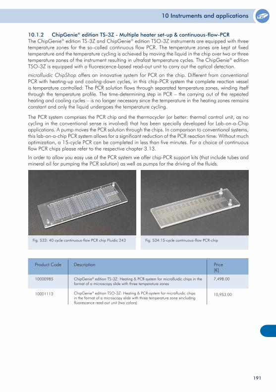
10 Instruments and applications
191
10000985
10001113
ChipGenie® edition TS-3Z: Heating & PCR-system for microfluidic chips in the format of a microscopy slide with three temperature zones
ChipGenie® edition TSO-3Z: Heating & PCR-system for microfluidic chips in the format of a microscopy slide with three temperature zone sincluding fluorescence read-out unit (two colors)
Product Code Price [€]
7,498.00
10,953.00
Description
Fig. 534:15-cycle continuous-flow PCR-chip Fig. 533: 40 cycle continuous-flow PCR chip Fluidic 243
10.1.2 ChipGenie® edition TS-3Z - Multiple heater set-up & continuous-flow-PCRThe ChipGenie® edition TS-3Z and ChipGenie® edition TSO-3Z instruments are equipped with three temperature zones for the so-called continuous flow PCR. The temperature zones are kept at fixed temperature and the temperature cycling is achieved by moving the liquid in the chip over two or three temperature zones of the instrument resulting in ultrafast temperature cycles. The ChipGenie® edition TSO-3Z is equipped with a fluorescence-based read-out unit to carry out the optical detection.
microfluidic ChipShop offers an innovative system for PCR on the chip. Different from conventional PCR with heating-up and cooling-down cycles, in this chip-PCR system the complete reaction vessel is temperature controlled: The PCR solution flows through separated temperature zones, winding itself through the temperature profile. The time-determining step in PCR – the carrying out of the repeated heating and cooling cycles – is no longer necessary since the temperature in the heating zones remains constant and only the liquid undergoes the temperature cycling.
The PCR system comprises the PCR chip and the thermocycler (or better: thermal control unit, as no cycling in the conventional sense is involved) that has been specially developed for Lab-on-a-Chip applications. A pump moves the PCR solution through the chips. In comparison to conventional systems, this lab-on-a-chip PCR system allows for a significant reduction of the PCR reaction time: Without much optimization, a 15-cycle PCR can be completed in less than five minutes. For a choice of continuous flow PCR chips please refer to the respective chapter 3.13.
In order to allow you easy use of the PCR system we offer chip-PCR support kits (that include tubes and mineral oil for pumping the PCR solution) as well as pumps for the driving of the fluids.
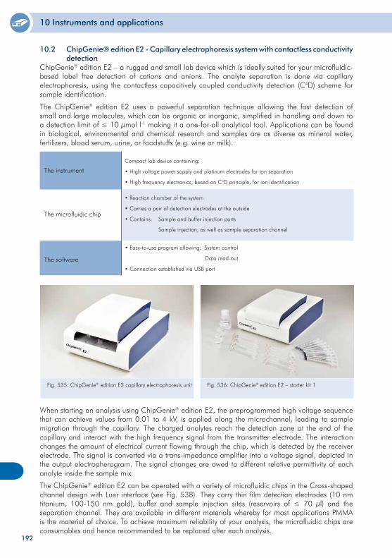
10 Instruments and applications
192
10.2 ChipGenie® edition E2 - Capillary electrophoresis system with contactless conductivity detectionChipGenie® edition E2 – a rugged and small lab device which is ideally suited for your microfluidic-based label free detection of cations and anions. The analyte separation is done via capillary electrophoresis, using the contactless capacitively coupled conductivity detection (C4D) scheme for sample identification.
The ChipGenie® edition E2 uses a powerful separation technique allowing the fast detection of small and large molecules, which can be organic or inorganic, simplified in handling and down to a detection limit of ≤ 10 µmol l-1 making it a one-for-all analytical tool. Applications can be found in biological, environmental and chemical research and samples are as diverse as mineral water, fertilizers, blood serum, urine, or foodstuffs (e.g. wine or milk).
The instrument Compact lab device containing:
• High voltage power supply and platinum electrodes for ion separation
• High frequency electronics, based on C4D principle, for ion identification
The microfluidic chip
• Reaction chamber of the system
• Carries a pair of detection electrodes at the outside
• Contains: Sample and buffer injection ports
Sample injection, as well as sample separation channel
The software
• Easy-to-use program allowing: System control
Data read-out
• Connection established via USB port
When starting an analysis using ChipGenie® edition E2, the preprogrammed high voltage sequence that can achieve values from 0.01 to 4 kV, is applied along the microchannel, leading to sample migration through the capillary. The charged analytes reach the detection zone at the end of the capillary and interact with the high frequency signal from the transmitter electrode. The interaction changes the amount of electrical current flowing through the chip, which is detected by the receiver electrode. The signal is converted via a trans-impedance amplifier into a voltage signal, depicted in the output electropherogram. The signal changes are owed to different relative permittivity of each analyte inside the sample mix.
The ChipGenie® edition E2 can be operated with a variety of microfluidic chips in the Cross-shaped channel design with Luer interface (see Fig. 538). They carry thin film detection electrodes (10 nm titanium, 100-150 nm gold), buffer and sample injection sites (reservoirs of ≤ 70 µl) and the separation channel. They are available in different materials whereby for most applications PMMA is the material of choice. To achieve maximum reliability of your analysis, the microfluidic chips are consumables and hence recommended to be replaced after each analysis.
Fig. 535: ChipGenie® edition E2 capillary electrophoresis unit Fig. 536: ChipGenie® edition E2 – starter kit 1
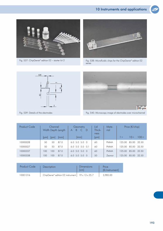
10 Instruments and applications
10000028
10000027
10000337
10000338
50
50
100
100
87.0
87.0
87.0
87.0
6.0
6.0
6.0
6.0
60
60
60
50
Product Code ChannelWidth
[µm]
Depth
[µm]
Geometry Price [€/chip]
1+ 10+ 100+
Length
[mm]
125.00
125.00
125.00
125.00
85.00
85.00
85.00
85.00
32.50
32.50
32.50
32.50
50
50
100
100
A B C D
[mm]
5.0
5.0
5.0
5.0
5.0
5.0
5.0
5.0
0
0.1
0
0
LidThick-ness[µm]
PMMA
PMMA
PMMA
Zeonor
Mate-rial
10001316
Product Code
ChipGenie® edition E2 instrument
Description
3,985.00
Price[€/instrument]
Fig. 537: ChipGenie® edition E2 – starter kit 2 Fig. 538: Microfluidic chips for the ChipGenie® edition E2 series
Fig. 539: Details of the electrodes Fig. 540: Microscopy image of electrodes over microchannel
Dimensions[cm]
19 x 13 x 25.7
193
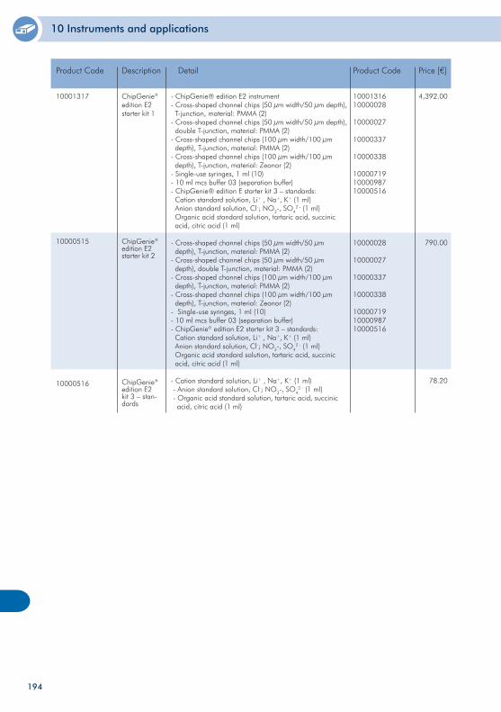
10 Instruments and applications
10001317
10000515
10000516
ChipGenie® edition E2starter kit 1
ChipGenie® edition E2starter kit 2
ChipGenie® edition E2 kit 3 – stan-dards
Product Code Description Price [€]
4,392.00
790.00
78.20
- ChipGenie® edition E2 instrument- Cross-shaped channel chips (50 µm width/50 µm depth), T-junction, material: PMMA (2)- Cross-shaped channel chips (50 µm width/50 µm depth), double T-junction, material: PMMA (2)- Cross-shaped channel chips (100 µm width/100 µm depth), T-junction, material: PMMA (2)- Cross-shaped channel chips (100 µm width/100 µm depth), T-junction, material: Zeonor (2)- Single-use syringes, 1 ml (10) - 10 ml mcs buffer 03 (separation buffer)- ChipGenie® edition E starter kit 3 – standards: Cation standard solution, Li+ , Na+, K+ (1 ml) Anion standard solution, Cl-; NO3-, SO4
2 - (1 ml) Organic acid standard solution, tartaric acid, succinic acid, citric acid (1 ml)
- Cross-shaped channel chips (50 µm width/50 µm depth), T-junction, material: PMMA (2)- Cross-shaped channel chips (50 µm width/50 µm depth), double T-junction, material: PMMA (2)- Cross-shaped channel chips (100 µm width/100 µm depth), T-junction, material: PMMA (2)- Cross-shaped channel chips (100 µm width/100 µm depth), T-junction, material: Zeonor (2)- Single-use syringes, 1 ml (10) - 10 ml mcs buffer 03 (separation buffer)- ChipGenie® edition E2 starter kit 3 – standards: Cation standard solution, Li+ , Na+, K+ (1 ml) Anion standard solution, Cl-; NO3-, SO4
2 - (1 ml) Organic acid standard solution, tartaric acid, succinic acid, citric acid (1 ml)
- Cation standard solution, Li+ , Na+, K+ (1 ml) - Anion standard solution, Cl-; NO3-, SO4
2 - (1 ml) - Organic acid standard solution, tartaric acid, succinic acid, citric acid (1 ml)
Detail
1000131610000028
10000027
10000337
10000338
100007191000098710000516
10000028
10000027
10000337
10000338
100007191000098710000516
Product Code
194
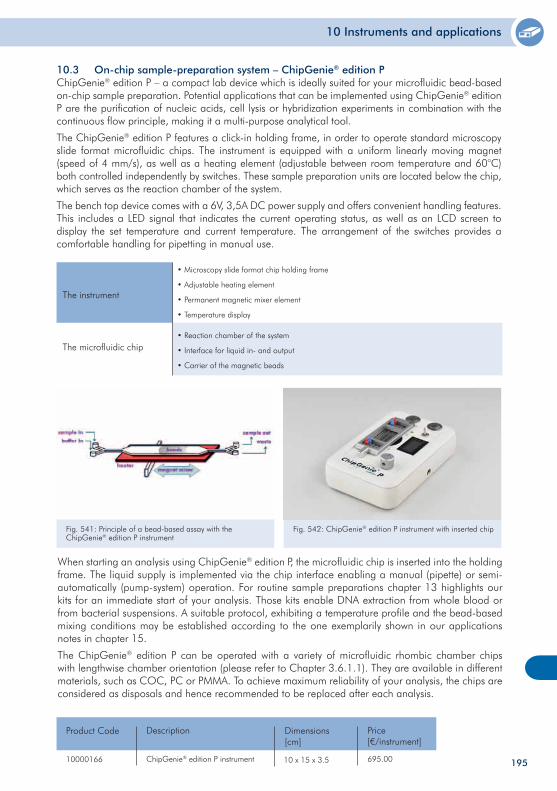
10 Instruments and applications
10.3 On-chip sample-preparation system – ChipGenie® edition P ChipGenie® edition P – a compact lab device which is ideally suited for your microfluidic bead-based on-chip sample preparation. Potential applications that can be implemented using ChipGenie® edition P are the purification of nucleic acids, cell lysis or hybridization experiments in combination with the continuous flow principle, making it a multi-purpose analytical tool.
The ChipGenie® edition P features a click-in holding frame, in order to operate standard microscopy slide format microfluidic chips. The instrument is equipped with a uniform linearly moving magnet (speed of 4 mm/s), as well as a heating element (adjustable between room temperature and 60°C) both controlled independently by switches. These sample preparation units are located below the chip, which serves as the reaction chamber of the system.
The bench top device comes with a 6V, 3,5A DC power supply and offers convenient handling features. This includes a LED signal that indicates the current operating status, as well as an LCD screen to display the set temperature and current temperature. The arrangement of the switches provides a comfortable handling for pipetting in manual use.
The instrument
• Microscopy slide format chip holding frame
• Adjustable heating element
• Permanent magnetic mixer element
• Temperature display
The microfluidic chip• Reaction chamber of the system
• Interface for liquid in- and output
• Carrier of the magnetic beads
When starting an analysis using ChipGenie® edition P, the microfluidic chip is inserted into the holding frame. The liquid supply is implemented via the chip interface enabling a manual (pipette) or semi-automatically (pump-system) operation. For routine sample preparations chapter 13 highlights our kits for an immediate start of your analysis. Those kits enable DNA extraction from whole blood or from bacterial suspensions. A suitable protocol, exhibiting a temperature profile and the bead-based mixing conditions may be established according to the one exemplarily shown in our applications notes in chapter 15.
The ChipGenie® edition P can be operated with a variety of microfluidic rhombic chamber chips with lengthwise chamber orientation (please refer to Chapter 3.6.1.1). They are available in different materials, such as COC, PC or PMMA. To achieve maximum reliability of your analysis, the chips are considered as disposals and hence recommended to be replaced after each analysis.
Fig. 541: Principle of a bead-based assay with the ChipGenie® edition P instrument
Fig. 542: ChipGenie® edition P instrument with inserted chip
10000166
Product Code
ChipGenie® edition P instrument
Description
695.00
Price[€/instrument]
Dimensions[cm]
10 x 15 x 3.5 195
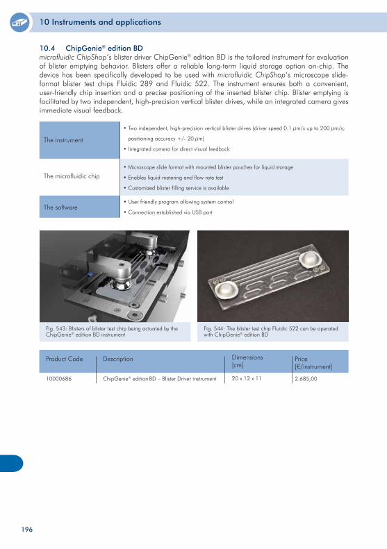
10 Instruments and applications
10.4 ChipGenie® edition BD microfluidic ChipShop’s blister driver ChipGenie® edition BD is the tailored instrument for evaluation of blister emptying behavior. Blisters offer a reliable long-term liquid storage option on-chip. The device has been specifically developed to be used with microfluidic ChipShop‘s microscope slide-format blister test chips Fluidic 289 and Fluidic 522. The instrument ensures both a convenient, user-friendly chip insertion and a precise positioning of the inserted blister chip. Blister emptying is facilitated by two independent, high-precision vertical blister drives, while an integrated camera gives immediate visual feedback.
The instrument
• Two independent, high-precision vertical blister drives (driver speed 0.1 µm/s up to 200 µm/s;
positioning accuracy +/- 20 µm)
• Integrated camera for direct visual feedback
The microfluidic chip• Microscope slide format with mounted blister pouches for liquid storage
• Enables liquid metering and flow rate test
• Customized blister filling service is available
The software
10000686
Product Code
ChipGenie® edition BD – Blister Driver instrument
Description
2.685,00
Price[€/instrument]
Dimensions[cm]
20 x 12 x 11
Fig. 543: Blisters of blister test chip being actuated by the ChipGenie® edition BD instrument
Fig. 544: The blister test chip Fluidic 522 can be operated with ChipGenie® edition BD
• User friendly program allowing system control
• Connection established via USB port
196
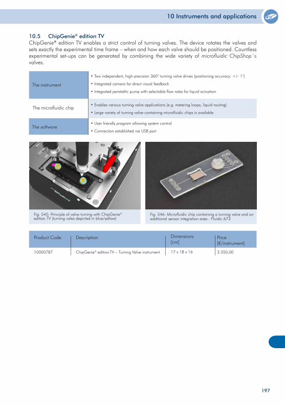
10 Instruments and applications
197
10.5 ChipGenie® edition TV ChipGenie® edition TV enables a strict control of turning valves. The device rotates the valves and sets exactly the experimental time frame – when and how each valve should be positioned. Countless experimental set-ups can be generated by combining the wide variety of microfluidic ChipShop´s valves.
10000787
Product Code
ChipGenie® edition TV – Turning Valve instrument
Description
3.350,00
Price[€/instrument]
Dimensions[cm]
17 x 18 x 16
The instrument
• Two independent, high-precision 360° turning valve drives (positioning accuracy: +/- 1°)
• Integrated camera for direct visual feedback
• Integrated peristaltic pump with selectable flow rates for liquid actuation
The microfluidic chip• Enables various turning valve applications (e.g. metering loops, liquid routing)
• Large variety of turning valve-containing microfluidic chips is available
The software
Fig. 545: Principle of valve turning with ChipGenie® edition TV (turning vales depicted in blue/yellow)
Fig. 546: Microfluidic chip containing a turning valve and an additional sensor integration area - Fluidic 673
• User friendly program allowing system control
• Connection established via USB port
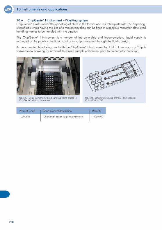
10 Instruments and applications
198
10.6 ChipGenie® I instrument – Pipetting system ChipGenie® I instrument offers pipetting of chips in the format of a microtiterplate with 1536 spacing. Microfluidic chips having the size of a microscopy slide can be fitted in respective microtiter plate sized handling frames to be handled with the pipettor.
The ChipGenie® I instrument is a merger of lab-on-a-chip and labautomation, liquid supply is managed by the pipettor, the liquid control on chip is ensured through the fluidic design.
As an example chips being used with the ChipGenie® I instrument the IFSA 1 Immunoassay Chip is shown below allowing for a microfilter-based sample enrichment prior to colorimetric detection.
10000805 ChipGenie® edition I pipetting instrument
Product Code Short product description
Fig. 547: Chips in microtiter sized handling frame placed in ChipGenie® edition I instrument
Fig. 548: Schematic drawing of IFSA 1 Immunoassay Chip – Fluidic 249
Price [€]
14,240.00

199
200
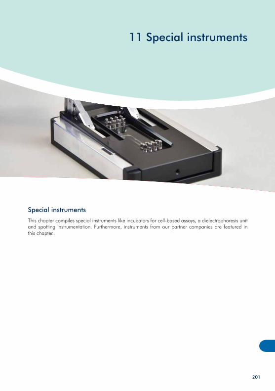
11 Special instruments
Special instruments
This chapter compiles special instruments like incubators for cell-based assays, a dielectrophoresis unit and spotting instrumentation. Furthermore, instruments from our partner companies are featured in this chapter.
201
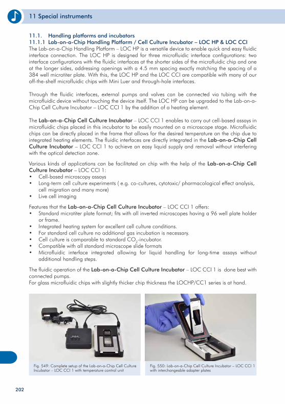
11 Special instruments
11.1. Handling platforms and incubators11.1.1 Lab-on-a-Chip Handling Platform / Cell Culture Incubator – LOC HP & LOC CCIThe Lab-on-a-Chip Handling Platform – LOC HP is a versatile device to enable quick and easy fluidic interface connection. The LOC HP is designed for three microfluidic interface configurations: two interface configurations with the fluidic interfaces at the shorter sides of the microfluidic chip and one at the longer sides, addressing openings with a 4.5 mm spacing exactly matching the spacing of a 384 well microtiter plate. With this, the LOC HP and the LOC CCI are compatible with many of our off-the-shelf microfluidic chips with Mini Luer and through-hole interfaces.
Through the fluidic interfaces, external pumps and valves can be connected via tubing with the microfluidic device without touching the device itself. The LOC HP can be upgraded to the Lab-on-a-Chip Cell Culture Incubator – LOC CCI 1 by the addition of a heating element.
The Lab-on-a-Chip Cell Culture Incubator – LOC CCI 1 enables to carry out cell-based assays in microfluidic chips placed in this incubator to be easily mounted on a microscope stage. Microfluidic chips can be directly placed in the frame that allows for the desired temperature on the chip due to integrated heating elements. The fluidic interfaces are directly integrated in the Lab-on-a-Chip Cell Culture Incubator – LOC CCI 1 to achieve an easy liquid supply and removal without interfering with the optical detection zone.
Various kinds of applications can be facilitated on chip with the help of the Lab-on-a-Chip Cell Culture Incubator – LOC CCI 1:• Cell-based microscopy assays • Long-term cell culture experiments ( e.g. co-cultures, cytotoxic/ pharmacological effect analysis, cell migration and many more)• Live cell imaging
Features that the Lab-on-a-Chip Cell Culture Incubator – LOC CCI 1 offers:• Standard microtiter plate format; fits with all inverted microscopes having a 96 well plate holder or frame.• Integrated heating system for excellent cell culture conditions.• For standard cell culture no additional gas incubation is necessary.• Cell culture is comparable to standard CO2-incubator. • Compatible with all standard microscope slide formats • Microfluidic interface integrated allowing for liquid handling for long-time assays without additional handling steps.
The fluidic operation of the Lab-on-a-Chip Cell Culture Incubator – LOC CCI 1 is done best with connected pumps. For glass microfluidic chips with slightly thicker chip thickness the LOCHP/CC1 series is at hand.
Fig. 549: Complete setup of the Lab-on-a-Chip Cell Culture Incubator – LOC CCI 1 with temperature control unit
Fig. 550: Lab-on-a-Chip Cell Culture Incubator – LOC CCI 1 with interchangeable adapter plates
202
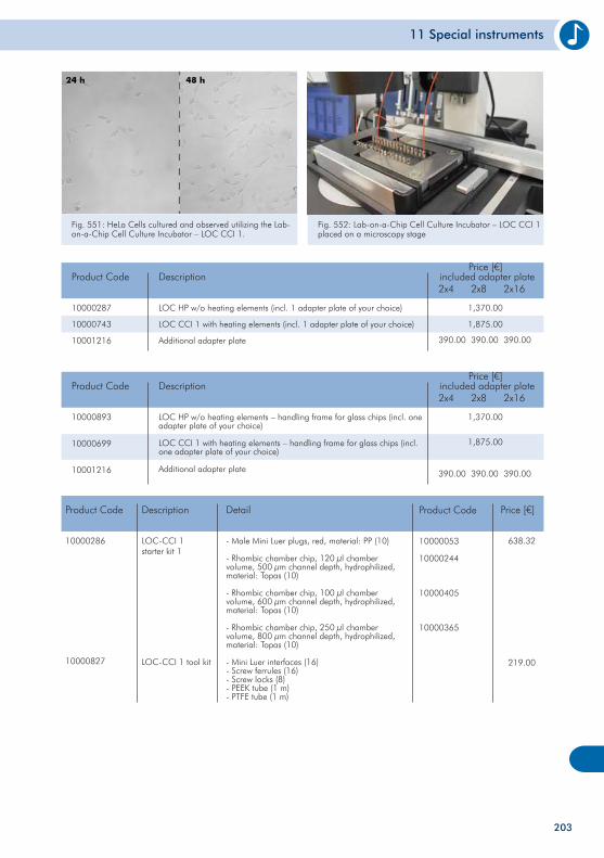
11 Special instruments
10000286
10000827
LOC-CCI 1starter kit 1
LOC-CCI 1 tool kit
Product Code Description Price [€]
638.32
219.00
- Male Mini Luer plugs, red, material: PP (10)
- Rhombic chamber chip, 120 µl chambervolume, 500 µm channel depth, hydrophilized,material: Topas (10)
- Rhombic chamber chip, 100 µl chambervolume, 600 µm channel depth, hydrophilized,material: Topas (10)
- Rhombic chamber chip, 250 µl chambervolume, 800 µm channel depth, hydrophilized,material: Topas (10)
- Mini Luer interfaces (16)- Screw ferrules (16)- Screw locks (8)- PEEK tube (1 m)- PTFE tube (1 m)
Detail
10000053
10000244
10000405
10000365
Product Code
203
10000893
10000699
10001216
Product Code
LOC HP w/o heating elements – handling frame for glass chips (incl. one adapter plate of your choice)
LOC CCI 1 with heating elements – handling frame for glass chips (incl. one adapter plate of your choice)
Additional adapter plate
Description
1,370.00
1,875.00
included adapter plate2x4 2x8 2x16
390.00 390.00 390.00
Price [€]
10000287
10000743
10001216
Product Code
LOC HP w/o heating elements (incl. 1 adapter plate of your choice)
LOC CCI 1 with heating elements (incl. 1 adapter plate of your choice)
Additional adapter plate
Description
1,370.00
1,875.00
included adapter plate2x4 2x8 2x16
390.00 390.00 390.00
Price [€]
Fig. 551: HeLa Cells cultured and observed utilizing the Lab-on-a-Chip Cell Culture Incubator – LOC CCI 1.
Fig. 552: Lab-on-a-Chip Cell Culture Incubator – LOC CCI 1 placed on a microscopy stage
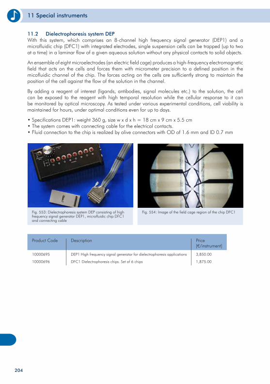
11 Special instruments
11.2 Dielectrophoresis system DEP With this system, which comprises an 8-channel high frequency signal generator (DEP1) and a microfluidic chip (DFC1) with integrated electrodes, single suspension cells can be trapped (up to two at a time) in a laminar flow of a given aqueous solution without any physical contacts to solid objects.
An ensemble of eight microelectrodes (an electric field cage) produces a high-frequency electromagnetic field that acts on the cells and forces them with micrometer precision to a defined position in the micofluidic channel of the chip. The forces acting on the cells are sufficiently strong to maintain the position of the cell against the flow of the solution in the channel.
By adding a reagent of interest (ligands, antibodies, signal molecules etc.) to the solution, the cell can be exposed to the reagent with high temporal resolution while the cellular response to it can be monitored by optical microscopy. As tested under various experimental conditions, cell viability is maintained for hours, under optimal conditions even for up to days.
• Specifications DEP1: weight 360 g, size w x d x h = 18 cm x 9 cm x 5.5 cm• The system comes with connecting cable for the electrical contacts.• Fluid connection to the chip is realized by olive connectors with OD of 1.6 mm and ID 0.7 mm
Fig. 553: Dielectrophoresis system DEP consisting of high frequency signal generator DEP1, microfluidic chip DFC1 and connecting cable
Fig. 554: Image of the field cage region of the chip DFC1
10000695
10000696
Product Code
DEP1 High frequency signal generator for dielectrophoresis applications
DFC1 Dielectrophoresis chips. Set of 6 chips
Description
3,850.00
1,875.00
Price[€/instrument]
204
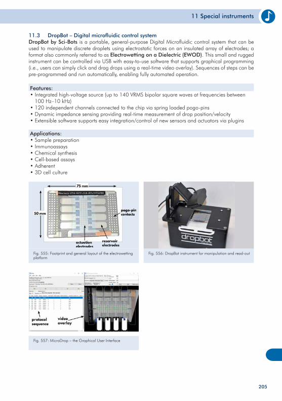
11 Special instruments
205
11.3 DropBot – Digital microfluidic control system DropBot by Sci-Bots is a portable, general-purpose Digital Microfluidic control system that can be used to manipulate discrete droplets using electrostatic forces on an insulated array of electrodes; a format also commonly referred to as Electrowetting on a Dielectric (EWOD). This small and rugged instrument can be controlled via USB with easy-to-use software that supports graphical programming (i.e., users can simply click and drag drops using a real-time video overlay). Sequences of steps can be pre-programmed and run automatically, enabling fully automated operation.
Features:• Integrated high-voltage source (up to 140 VRMS bipolar square waves at frequencies between 100 Hz–10 kHz)• 120 independent channels connected to the chip via spring loaded pogo-pins• Dynamic impedance sensing providing real-time measurement of drop position/velocity• Extensible software supports easy integration/control of new sensors and actuators via plugins
Applications:• Sample preparation• Immunoassays• Chemical synthesis• Cell-based assays• Adherent• 3D cell culture
Fig. 555: Footprint and general layout of the electrowetting platform
Fig. 556: DropBot instrument for manipulation and read-out
Fig. 557: MicroDrop – the Graphical User Interface
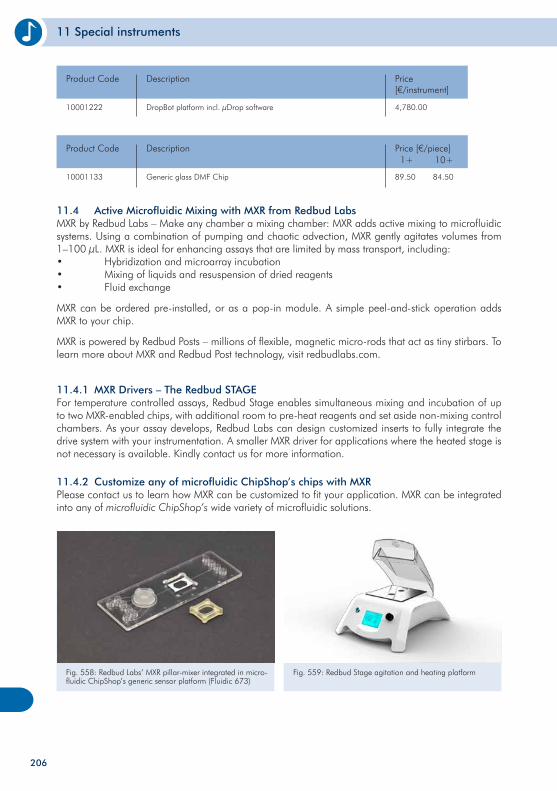
11 Special instruments
10001222
Product Code
DropBot platform incl. µDrop software
Description
4,780.00
Price[€/instrument]
11.4 Active Microfluidic Mixing with MXR from Redbud Labs MXR by Redbud Labs – Make any chamber a mixing chamber: MXR adds active mixing to microfluidic systems. Using a combination of pumping and chaotic advection, MXR gently agitates volumes from 1–100 µL. MXR is ideal for enhancing assays that are limited by mass transport, including:• Hybridization and microarray incubation• Mixing of liquids and resuspension of dried reagents• Fluid exchange
MXR can be ordered pre-installed, or as a pop-in module. A simple peel-and-stick operation adds MXR to your chip.
MXR is powered by Redbud Posts – millions of flexible, magnetic micro-rods that act as tiny stirbars. To learn more about MXR and Redbud Post technology, visit redbudlabs.com.
11.4.1 MXR Drivers – The Redbud STAGE For temperature controlled assays, Redbud Stage enables simultaneous mixing and incubation of up to two MXR-enabled chips, with additional room to pre-heat reagents and set aside non-mixing control chambers. As your assay develops, Redbud Labs can design customized inserts to fully integrate the drive system with your instrumentation. A smaller MXR driver for applications where the heated stage is not necessary is available. Kindly contact us for more information.
11.4.2 Customize any of microfluidic ChipShop’s chips with MXR Please contact us to learn how MXR can be customized to fit your application. MXR can be integrated into any of microfluidic ChipShop’s wide variety of microfluidic solutions.
Fig. 558: Redbud Labs’ MXR pillar-mixer integrated in micro-fluidic ChipShop’s generic sensor platform (Fluidic 673)
Fig. 559: Redbud Stage agitation and heating platform
206
10001133
Product Code
Generic glass DMF Chip
Description
89.50
Price [€/piece]
84.50
1+ 10+
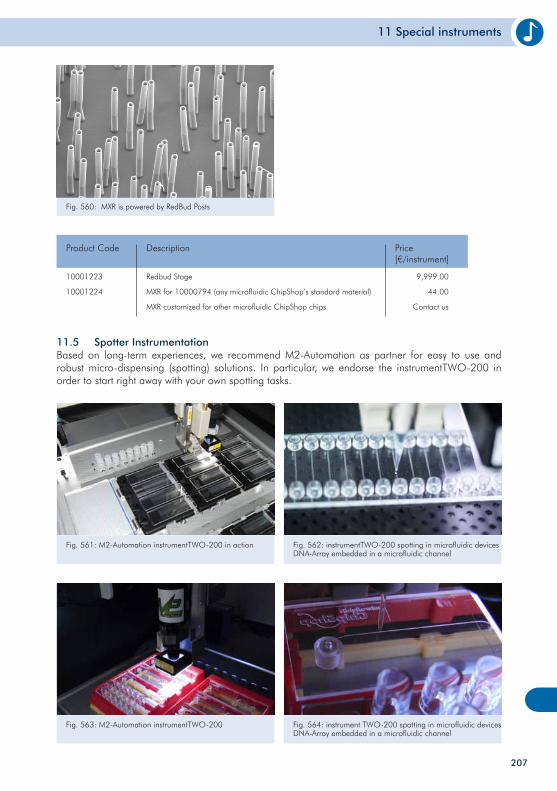
11 Special instruments
207
Fig. 560: MXR is powered by RedBud Posts
10001223
10001224
Product Code
Redbud Stage
MXR for 10000794 (any microfluidic ChipShop’s standard material)
MXR customized for other microfluidic ChipShop chips
Description
9,999.00
44.00
Contact us
Price[€/instrument]
11.5 Spotter InstrumentationBased on long-term experiences, we recommend M2-Automation as partner for easy to use and robust micro-dispensing (spotting) solutions. In particular, we endorse the instrumentTWO-200 in order to start right away with your own spotting tasks.
Fig. 561: M2-Automation instrumentTWO-200 in action Fig. 562: instrumentTWO-200 spotting in microfluidic devices DNA-Array embedded in a microfluidic channel
Fig. 563: M2-Automation instrumentTWO-200 Fig. 564: instrument TWO-200 spotting in microfluidic devices DNA-Array embedded in a microfluidic channel
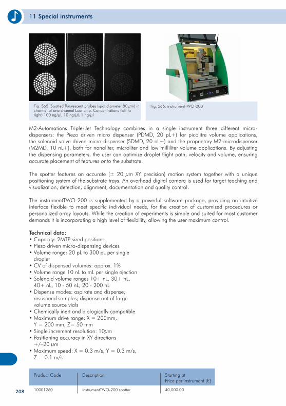
11 Special instruments
Technical data:• Capacity: 2MTP-sized positions • Piezo driven micro-dispensing devices• Volume range: 20 pL to 300 pL per single droplet• CV of dispensed volumes: approx. 1% • Volume range 10 nL to mL per single ejection• Solenoid volume ranges 10+ nL, 30+ nL, 40+ nL, 10 - 50 nL, 20 - 200 nL • Dispense modes: aspirate and dispense; resuspend samples; dispense out of large volume source vials • Chemically inert and biologically compatible • Maximum drive range: X = 200mm, Y = 200 mm, Z= 50 mm • Single increment resolution: 10µm • Positioning accuracy in XY directions +/–20 µm • Maximum speed: X = 0.3 m/s, Y = 0.3 m/s, Z = 0.1 m/s
Fig. 566: instrumentTWO-200
10001260 instrumentTWO-200 spotter
Product Code Description Starting at Price per instrument [€]
40,000.00208
M2-Automations Triple-Jet Technology combines in a single instrument three different micro-dispensers: the Piezo driven micro dispenser (PDMD, 20 pL+) for picolitre volume applications, the solenoid valve driven micro-dispenser (SDMD, 20 nL+) and the proprietary M2-microdispenser (M2MD, 10 nL+), both for nanoliter, microliter and low milliliter volume applications. By adjusting the dispensing parameters, the user can optimize droplet flight path, velocity and volume, ensuring accurate placement of features onto the substrate.
The spotter features an accurate (± 20 µm XY precision) motion system together with a unique positioning system of the substrate trays. An overhead digital camera is used for target teaching and visualization, detection, alignment, documentation and quality control.
The instrumentTWO-200 is supplemented by a powerful software package, providing an intuitive interface flexible to meet specific individual needs, for the creation of customized procedures or personalized array layouts. While the creation of experiments is simple and suited for most customer demands it is incorporating a high level of flexibility, allowing the user maximum control.
Fig. 565: Spotted fluorescent probes (spot diameter 80 µm) in channel of one channel Luer chip. Concentrations (left to right) 100 ng/µl, 10 ng/µl, 1 ng/µl

209
210
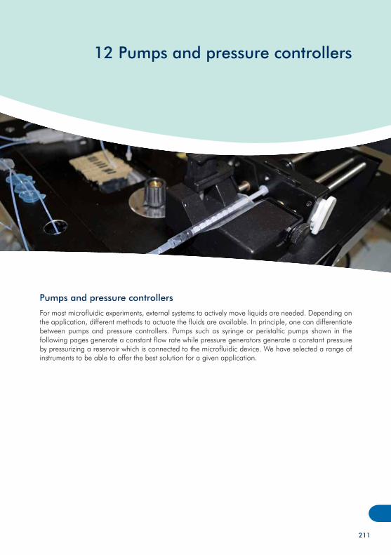
12 Pumps and pressure controllers
Pumps and pressure controllers
For most microfluidic experiments, external systems to actively move liquids are needed. Depending on the application, different methods to actuate the fluids are available. In principle, one can differentiate between pumps and pressure controllers. Pumps such as syringe or peristaltic pumps shown in the following pages generate a constant flow rate while pressure generators generate a constant pressure by pressurizing a reservoir which is connected to the microfluidic device. We have selected a range of instruments to be able to offer the best solution for a given application.
211
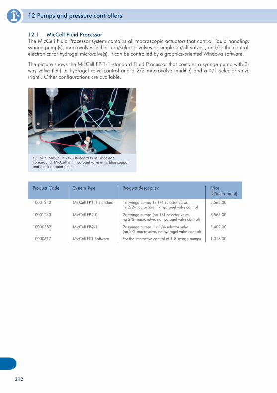
12 Pumps and pressure controllers
212
12.1 MicCell Fluid Processor The MicCell Fluid Processor system contains all macroscopic actuators that control liquid handling: syringe pump(s), macrovalves (either turn/selector valves or simple on/off valves), and/or the control electronics for hydrogel microvalve(s). It can be controlled by a graphics-oriented Windows software.
The picture shows the MicCell FP-1-1-standard Fluid Processor that contains a syringe pump with 3-way valve (left), a hydrogel valve control and a 2/2 macrovalve (middle) and a 4/1-selector valve (right). Other configurations are available.
Fig. 567: MicCell FP-1-1-standard Fluid Processor. Foreground: MicCell with hydrogel valve in its blue support and black adapter plate
10001242
10001243
10000382
10000617
MicCell FP-1-1-standard
MicCell FP-2-0
MicCell FP-2-1
MicCell FC1 Software
Product Code Price[€/instrument]
5,565.00
5,565.00
7,402.00
1,018.00
System Type
1x syringe pump, 1x 1/4-selector valve,1x 2/2-macrovalve, 1x hydrogel valve control
2x syringe pumps (no 1/4-selector valve,no 2/2-macrovalve, no hydrogel valve control)
2x syringe pumps, 1x 1/4-selector valve(no 2/2-macrovalve, no hydrogel valve control)
For the interactive control of 1-8 syringe pumps
Product description
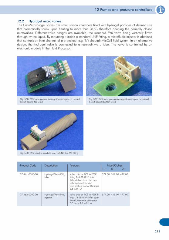
12 Pumps and pressure controllers
213
12.2 Hydrogel micro valvesThe GeSiM hydrogel valves are small silicon chambers filled with hydrogel particles of defined size that dramatically shrink upon heating to more than 34°C, therefore opening the normally closed microvalves. Different valve designs are available, the standard PV6 valve being vertically flown through by the liquid. By mounting it inside a standard UNF fitting, a microfludic injector is obtained that controls an inlet channel of a branched (e.g. T/Y-shaped) MicCell fluid system. In an alternative design, the hydrogel valve is connected to a reservoir via a tube. The valve is controlled by an electronic module in the Fluid Processor.
Fig. 568: PV6 hydrogel-containing silicon chip on a printed circuit board (top view)
Fig. 569: PV6 hydrogel-containing silicon chip on a printed circuit board (bottom view)
Fig. 570: PV6 injector, ready to use, in UNF 1/4-28 fitting
07-461-0000-00
07-462-0000-00
Hydrogel-Valve PV6, tube
Hydrogel-Valve PV6, injector
Product Code Description
Valve chip on PCB in PEEK fitting 1/4-28 UNF; inlet: Teflon tube OD=1.58 mm with Upchurch ferrule, electrical connector DC input 3.5 V/0.1 A
Valve chip on PCB in PEEK fit-ting 1/4-28 UNF; inlet: open funnel, electrical connector DC input 3.5 V/0.1 A
Features Price [€/chip]1+ 5+ 10+
577.00
577.00
519.00
419.00
477.00
477.00
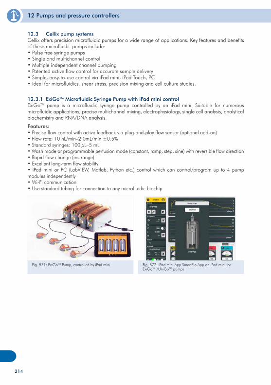
12 Pumps and pressure controllers
214
12.3 Cellix pump systems Cellix offers precision microfluidic pumps for a wide range of applications. Key features and benefits of these microfluidic pumps include:• Pulse free syringe pumps• Single and multichannel control• Multiple independent channel pumping• Patented active flow control for accurate sample delivery• Simple, easy-to-use control via iPad mini, iPod Touch, PC• Ideal for microfluidics, shear stress, precision mixing and cell culture studies.
Fig. 571: ExiGoTM Pump, controlled by iPad mini Fig. 572: iPad mini App SmartFlo App on iPad mini for ExiGoTM /UniGoTM pumps
12.3.1 ExiGoTM Microfluidic Syringe Pump with iPad mini controlExiGoTM pump is a microfluidic syringe pump controlled by an iPad mini. Suitable for numerous microfluidic applications, precise multichannel mixing, electrophysiology, single cell analysis, analytical biochemistry and RNA/DNA analysis.
Features:• Precise flow control with active feedback via plug-and-play flow sensor (optional add-on)• Flow rate: 10 nL/min–2 0mL/min ±0.5%• Standard syringes: 100 µL–5 mL• Wash mode or programmable perfusion mode (constant, ramp, step, sine) with reversible flow direction• Rapid flow change (ms range)• Excellent long-term flow stability• iPad mini or PC (LabVIEW, Matlab, Python etc.) control which can control/program up to 4 pump modules independently• Wi-Fi communication• Use standard tubing for connection to any microfluidic biochip
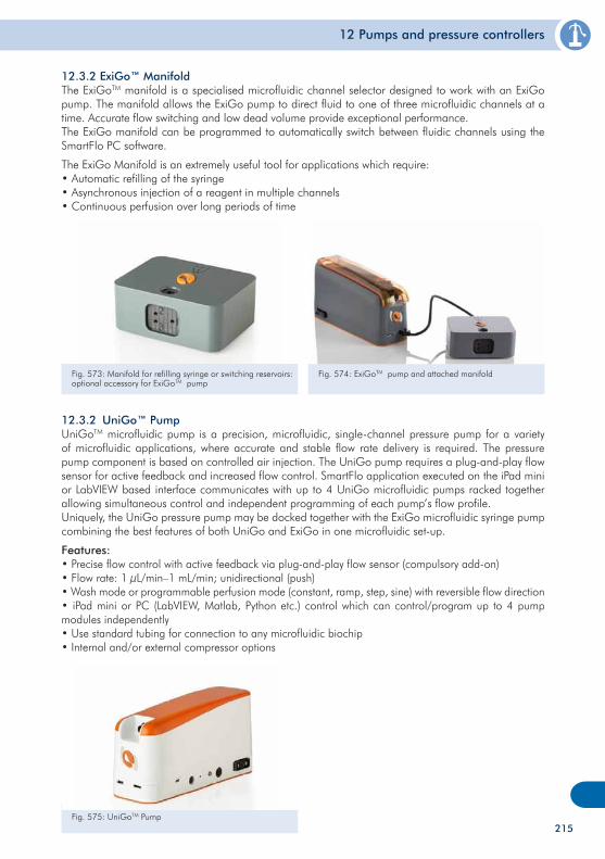
12 Pumps and pressure controllers
12.3.2 UniGo™ PumpUniGoTM microfluidic pump is a precision, microfluidic, single-channel pressure pump for a variety of microfluidic applications, where accurate and stable flow rate delivery is required. The pressure pump component is based on controlled air injection. The UniGo pump requires a plug-and-play flow sensor for active feedback and increased flow control. SmartFlo application executed on the iPad mini or LabVIEW based interface communicates with up to 4 UniGo microfluidic pumps racked together allowing simultaneous control and independent programming of each pump’s flow profile.Uniquely, the UniGo pressure pump may be docked together with the ExiGo microfluidic syringe pump combining the best features of both UniGo and ExiGo in one microfluidic set-up.
Features:• Precise flow control with active feedback via plug-and-play flow sensor (compulsory add-on)• Flow rate: 1 µL/min–1 mL/min; unidirectional (push)• Wash mode or programmable perfusion mode (constant, ramp, step, sine) with reversible flow direction• iPad mini or PC (LabVIEW, Matlab, Python etc.) control which can control/program up to 4 pump modules independently• Use standard tubing for connection to any microfluidic biochip• Internal and/or external compressor options
Fig. 575: UniGoTM Pump
Fig. 573: Manifold for refilling syringe or switching reservoirs: optional accessory for ExiGoTM pump
Fig. 574: ExiGoTM pump and attached manifold
12.3.2 ExiGo™ ManifoldThe ExiGoTM manifold is a specialised microfluidic channel selector designed to work with an ExiGo pump. The manifold allows the ExiGo pump to direct fluid to one of three microfluidic channels at a time. Accurate flow switching and low dead volume provide exceptional performance.The ExiGo manifold can be programmed to automatically switch between fluidic channels using the SmartFlo PC software.
The ExiGo Manifold is an extremely useful tool for applications which require:• Automatic refilling of the syringe• Asynchronous injection of a reagent in multiple channels• Continuous perfusion over long periods of time
215
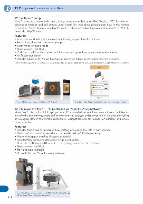
12 Pumps and pressure controllers
12.3.4 Kima™ PumpKimaTM pump is a microfluidic recirculating pump controlled by an iPod Touch or PC. Suitable for continuous microbe and cell culture under shear flow mimicking physiological flow in the human vasculature. Applications include biofilm studies, cell culture in biochips with adherent cells (HUVECs), stem cells, HepG2 cells.
Features:• Fits inside standard CO2 incubator maintaining temperature, humidity etc• Recirculating long term perfusion pump• Wash mode or pump mode• Dead volume: <300 µL• iPod Touch or PC control option which can control up to 4 pump modules independently• Wi-Fi communication• Includes tubing kit for Vena8 biochips or alternative tubing kits for other biochips availableNOTE: the Kima pump is not suitable for shear stressed based assays because the pump delivers liquid in pulses (not continuous flow).
Fig. 576: Kima pump, controlled by iPod Touch
12.3.5 Mirus Evo Pro™ — PC Controlled via VenaFlux Assay SoftwareMirus Evo Pro is a microfluidic syringe pump PC controlled via VenaFlux assay software. Suitable for microfluidic applications, single cell analysis and cell analysis under shear flow in biochips mimicking physiological flow in the human vasculature. Compatible with cell suspension samples and whole blood samples.
Features:• Includes MultiFlow8 for precision flow splitting with equal flow rate in each channel• MultiFlow8 contains 8 valves which can be switched on/off independently• Higher throughput enabling 8 assays in parallel• Patented flow damper to decrease syringe pump pulses• Flow rate: 100 nL/min–10 mL/min ±1% (syringes available: 50 µL–5 mL)• Dead volume: ~600 µL• Flow direction reversible• PC controlled via VenaFlux assay software
Fig. 578: Mirus Evo nanopump with MultiFlow8: controlled by PC software, VenaFlux assay (included)
Fig. 577: iPod Touch app for Kima pump showing perfusion
216
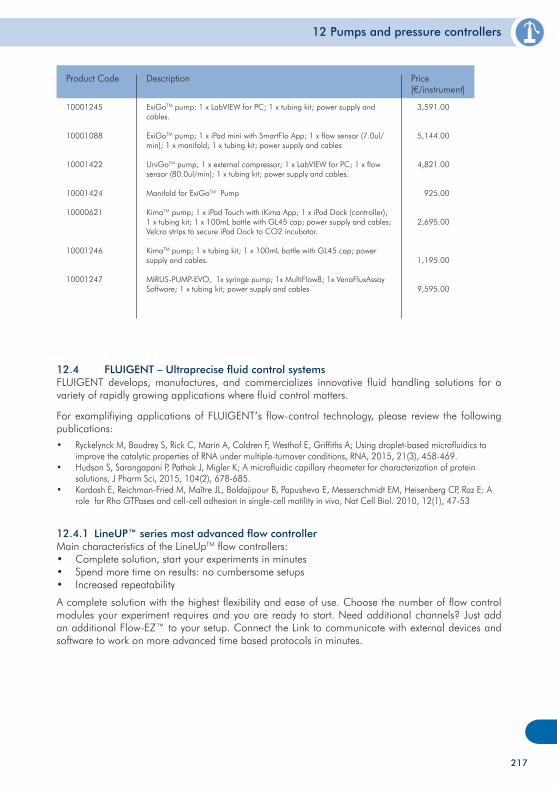
12 Pumps and pressure controllers
10001245
10001088
10001422
10001424
10000621
10001246
10001247
Product Code
ExiGoTM pump; 1 x LabVIEW for PC; 1 x tubing kit; power supply and cables.
ExiGoTM pump; 1 x iPad mini with SmartFlo App; 1 x flow sensor (7.0ul/min); 1 x manifold; 1 x tubing kit; power supply and cables
UniGoTM pump; 1 x external compressor; 1 x LabVIEW for PC; 1 x flow sensor (80.0ul/min); 1 x tubing kit; power supply and cables.
Manifold for ExiGoTM Pump
KimaTM pump; 1 x iPod Touch with iKima App; 1 x iPod Dock (controller); 1 x tubing kit; 1 x 100mL bottle with GL45 cap; power supply and cables; Velcro strips to secure iPod Dock to CO2 incubator.
KimaTM pump; 1 x tubing kit; 1 x 100mL bottle with GL45 cap; power supply and cables.
MIRUS-PUMP-EVO, 1x syringe pump; 1x MultiFlow8; 1x VenaFluxAssay Software; 1 x tubing kit; power supply and cables
Description
3,591.00
5,144.00
4,821.00
925.00
2,695.00
1,195.00
9,595.00
Price[€/instrument]
12.4 FLUIGENT – Ultraprecise fluid control systemsFLUIGENT develops, manufactures, and commercializes innovative fluid handling solutions for a variety of rapidly growing applications where fluid control matters.
For examplifiying applications of FLUIGENT’s flow-control technology, please review the following publications:
• Ryckelynck M, Baudrey S, Rick C, Marin A, Coldren F, Westhof E, Griffiths A; Using droplet-based microfluidics to improve the catalytic properties of RNA under multiple-turnover conditions, RNA, 2015, 21(3), 458-469.• Hudson S, Sarangapani P, Pathak J, Migler K; A microfluidic capillary rheometer for characterization of protein solutions, J Pharm Sci, 2015, 104(2), 678-685.• Kardash E, Reichman-Fried M, Maître JL, Boldajipour B, Papusheva E, Messerschmidt EM, Heisenberg CP, Raz E: A role for Rho GTPases and cell-cell adhesion in single-cell motility in vivo, Nat Cell Biol. 2010, 12(1), 47-53
12.4.1 LineUP™ series most advanced flow controllerMain characteristics of the LineUpTM flow controllers:• Complete solution, start your experiments in minutes• Spend more time on results: no cumbersome setups• Increased repeatability
A complete solution with the highest flexibility and ease of use. Choose the number of flow control modules your experiment requires and you are ready to start. Need additional channels? Just add an additional Flow-EZ™ to your setup. Connect the Link to communicate with external devices and software to work on more advanced time based protocols in minutes.
217
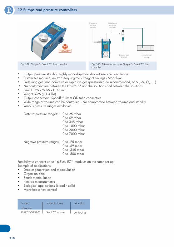
12 Pumps and pressure controllers
• Output pressure stability: highly monodispersed droplet size - No oscillation• System settling time: no transitory regime - Reagent savings - Stop-flows• Pressuring gas: non-corrosive or explosive gas (pressurized air recommended, or N2, Ar, O2, …) • No contamination between the Flow™-EZ and the solutions and between the solutions• Size: L 125 x W 55 x H 75 mm • Weight: 625 g (1.4 lbs)• Output connectors: Speedfit® 4mm OD tube connectors• Wide range of volume can be controlled - No compromise between volume and stability• Various pressure ranges available:
Postitive pressure ranges: 0 to 25 mbar 0 to 69 mbar 0 to 345 mbar 0 to 1000 mbar 0 to 2000 mbar 0 to 7000 mbar
Negative pressure ranges: 0 to -25 mbar 0 to -69 mbar 0 to -345 mbar 0 to -800 mbar
Possibility to connect up to 16 Flow EZ™ modules on the same set-up.Example of applications:• Droplet generation and manipulation• Organ-on-chip• Beads manipulation• Kinetics measurements• Biological applications (blood / cells)• Microfluidic flow control
11-0890-0000-00
Product
referenceFlow EZ™ module
Product Name Price [€]
contact us
Fig. 579: Fluigent’s Flow-EZ™ flow controller Fig. 580: Schematic set-up of Fluigent’s Flow-EZ™ flow controller
218
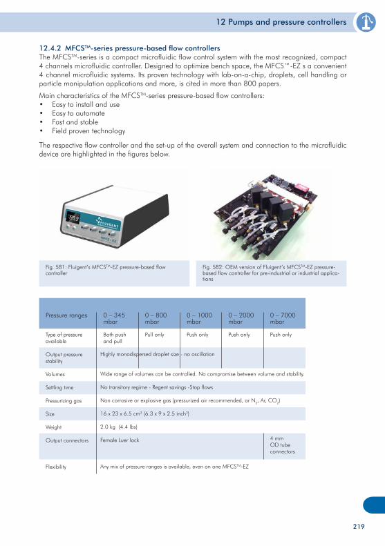
12 Pumps and pressure controllers
12.4.2 MFCSTM-series pressure-based flow controllersThe MFCSTM-series is a compact microfluidic flow control system with the most recognized, compact 4 channels microfluidic controller. Designed to optimize bench space, the MFCS™-EZ s a convenient 4 channel microfluidic systems. Its proven technology with lab-on-a-chip, droplets, cell handling or particle manipulation applications and more, is cited in more than 800 papers.
Main characteristics of the MFCSTM-series pressure-based flow controllers:• Easy to install and use• Easy to automate• Fast and stable• Field proven technology
The respective flow controller and the set-up of the overall system and connection to the microfluidic device are highlighted in the figures below.
Fig. 581: Fluigent’s MFCSTM-EZ pressure-based flow controller
Fig. 582: OEM version of Fluigent’s MFCSTM-EZ pressure-based flow controller for pre-industrial or industrial applica-tions
Type of pressure available
Output pressure stability
Volumes
Settling time
Pressurizing gas
Size
Weight
Output connectors
Flexibility
Pressure ranges 0 – 345 mbar
0 – 800 mbar
0 – 1000 mbar
0 – 2000 mbar
0 – 7000 mbar
Both push and pull
Pull only
Push only Push only Push only
Highly monodispersed droplet size - no oscillation
Wide range of volumes can be controlled. No compromise between volume and stability.
No transitory regime - Regent savings -Stop flows
Non corrosive or explosive gas (pressurized air recommended, or N2, Ar, CO2)
16 x 23 x 6.5 cm3 (6.3 x 9 x 2.5 inch3)
2.0 kg (4.4 lbs)
Female Luer lock
Any mix of pressure ranges is available, even on one MFCSTM-EZ
4 mm OD tube connectors
219
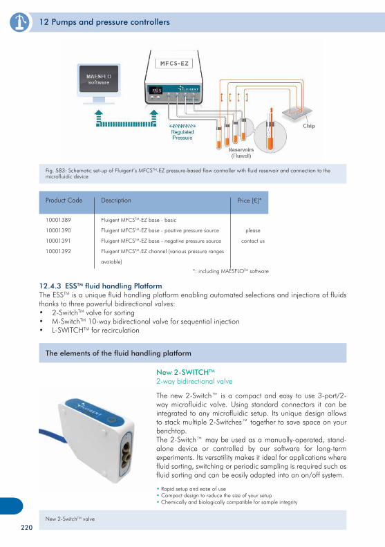
12 Pumps and pressure controllers
10001389
10001390
10001391
10001392
Product Code
Fluigent MFCSTM-EZ base - basic
Fluigent MFCSTM-EZ base - positive pressure source
Fluigent MFCSTM-EZ base - negative pressure source
Fluigent MFCSTM-EZ channel (various pressure ranges
avaiable)
Description
please
contact us
Price [€]*
*: including MAESFLOTM software
12.4.3 ESSTM fluid handling PlatformThe ESSTM is a unique fluid handling platform enabling automated selections and injections of fluids thanks to three powerful bidirectional valves:• 2-SwitchTM valve for sorting• M-SwitchTM 10-way bidirectional valve for sequential injection• L-SWITCHTM for recirculation
The elements of the fluid handling platform
New 2-SwitchTM valve
New 2-SWITCHTM 2-way bidirectional valve
The new 2-Switch™ is a compact and easy to use 3-port/2-way microfluidic valve. Using standard connectors it can be integrated to any microfluidic setup. Its unique design allows to stack multiple 2-Switches™ together to save space on your benchtop.The 2-Switch™ may be used as a manually-operated, stand-alone device or controlled by our software for long-term experiments. Its versatility makes it ideal for applications where fluid sorting, switching or periodic sampling is required such as fluid sorting and can be easily adapted into an on/off system.
• Rapid setup and ease of use• Compact design to reduce the size of your setup• Chemically and biologically compatible for sample integrity
Operation features of Fluigent’s MFCSTM-EZ Fig. 583: Schematic set-up of Fluigent’s MFCSTM-EZ pressure-based flow controller with fluid reservoir and connection to the microfluidic device
220
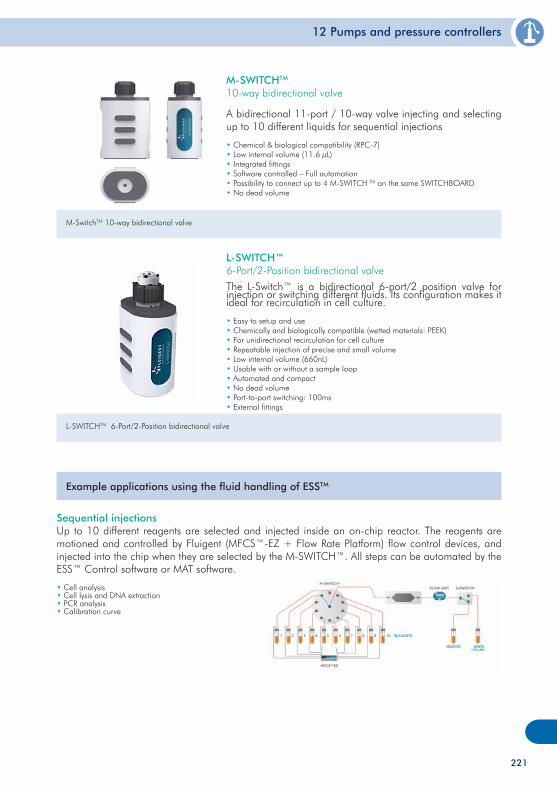
12 Pumps and pressure controllers
M-SwitchTM 10-way bidirectional valve
M-SWITCHTM 10-way bidirectional valve
A bidirectional 11-port / 10-way valve injecting and selecting up to 10 different liquids for sequential injections
• Chemical & biological compatibility (RPC-7)• Low internal volume (11.6 µL)• Integrated fittings• Software controlled – Full automation• Possibility to connect up to 4 M-SWITCH TM on the same SWITCHBOARD• No dead volume
L-SWITCHTM 6-Port/2-Position bidirectional valve
L-SWITCH™6-Port/2-Position bidirectional valve
The L-Switch™ is a bidirectional 6-port/2 position valve for injection or switching different fluids. Its configuration makes it ideal for recirculation in cell culture.
• Easy to setup and use• Chemically and biologically compatible (wetted materials: PEEK)• For unidirectional recirculation for cell culture• Repeatable injection of precise and small volume• Low internal volume (660nL)• Usable with or without a sample loop• Automated and compact• No dead volume• Port-to-port switching: 100ms• External fittings
Example applications using the fluid handling of ESSTM
Sequential injectionsUp to 10 different reagents are selected and injected inside an on-chip reactor. The reagents are motioned and controlled by Fluigent (MFCS™-EZ + Flow Rate Platform) flow control devices, and injected into the chip when they are selected by the M-SWITCH™. All steps can be automated by the ESS™ Control software or MAT software.
• Cell analysis• Cell lysis and DNA extraction• PCR analysis• Calibration curve
221
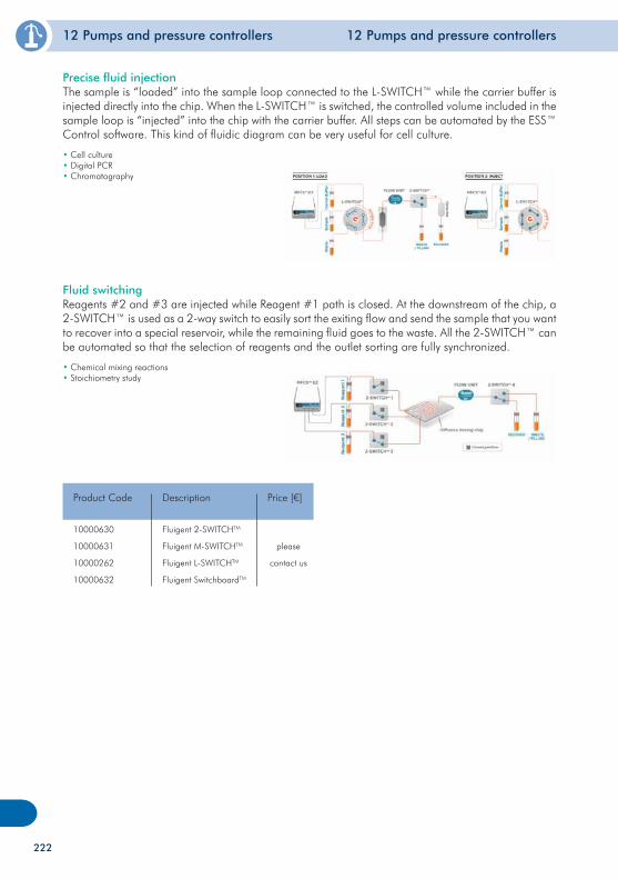
12 Pumps and pressure controllers 12 Pumps and pressure controllers
Fluid switchingReagents #2 and #3 are injected while Reagent #1 path is closed. At the downstream of the chip, a 2-SWITCH™ is used as a 2-way switch to easily sort the exiting flow and send the sample that you want to recover into a special reservoir, while the remaining fluid goes to the waste. All the 2-SWITCH™ can be automated so that the selection of reagents and the outlet sorting are fully synchronized.
• Chemical mixing reactions• Stoichiometry study
10000630
10000631
10000262
10000632
Product Code
Fluigent 2-SWITCHTM
Fluigent M-SWITCHTM
Fluigent L-SWITCHTM
Fluigent SwitchboardTM
Description
please
contact us
Price [€]
Precise fluid injectionThe sample is “loaded” into the sample loop connected to the L-SWITCH™ while the carrier buffer is injected directly into the chip. When the L-SWITCH™ is switched, the controlled volume included in the sample loop is “injected” into the chip with the carrier buffer. All steps can be automated by the ESS™ Control software. This kind of fluidic diagram can be very useful for cell culture.
• Cell culture• Digital PCR• Chromatography
222
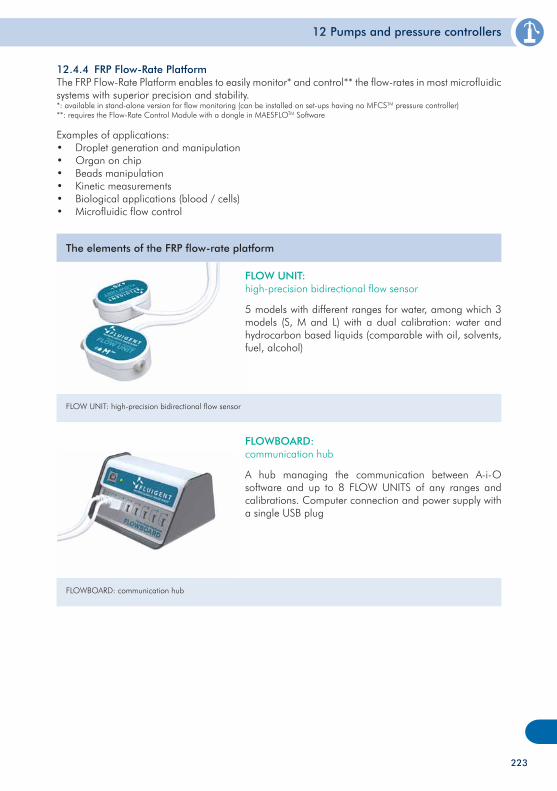
12 Pumps and pressure controllers
12.4.4 FRP Flow-Rate PlatformThe FRP Flow-Rate Platform enables to easily monitor* and control** the flow-rates in most microfluidic systems with superior precision and stability.*: available in stand-alone version for flow monitoring (can be installed on set-ups having no MFCSTM pressure controller)**: requires the Flow-Rate Control Module with a dongle in MAESFLOTM Software
Examples of applications:• Droplet generation and manipulation• Organ on chip• Beads manipulation• Kinetic measurements• Biological applications (blood / cells)• Microfluidic flow control
The elements of the FRP flow-rate platform
FLOW UNIT: high-precision bidirectional flow sensor
FLOW UNIT: high-precision bidirectional flow sensor
5 models with different ranges for water, among which 3 models (S, M and L) with a dual calibration: water and hydrocarbon based liquids (comparable with oil, solvents, fuel, alcohol)
FLOWBOARD: communication hub
FLOWBOARD: communication hub
A hub managing the communication between A-i-O software and up to 8 FLOW UNITS of any ranges and calibrations. Computer connection and power supply with a single USB plug
223
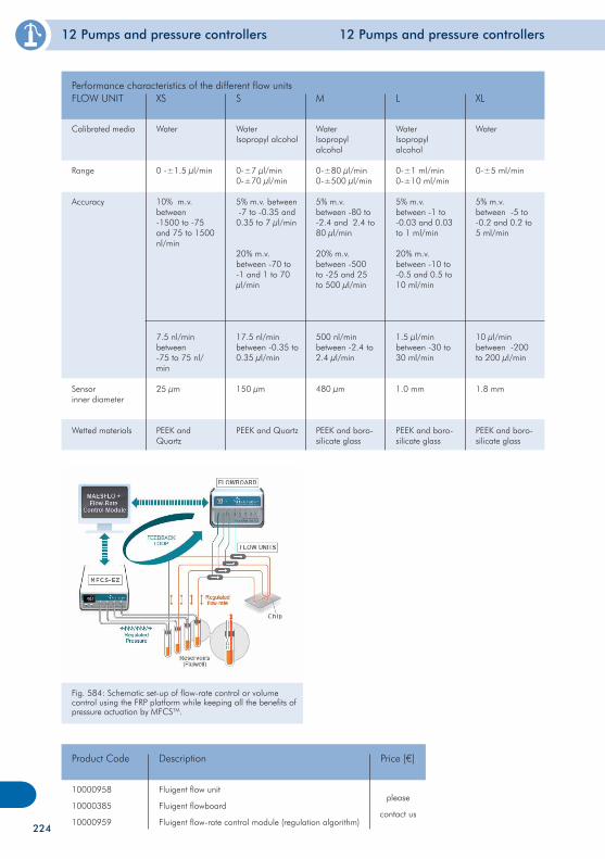
12 Pumps and pressure controllers 12 Pumps and pressure controllers
Calibrated media
Range
Accuracy
Sensor inner diameter
Wetted materials
Performance characteristics of the different flow unitsFLOW UNIT XS S M L XL
Water
0 -±1.5 µl/min
10% m.v. between -1500 to -75 and 75 to 1500 nl/min
7.5 nl/min between -75 to 75 nl/min
25 µm
PEEK and Quartz
WaterIsopropyl alcohol
0-±7 µl/min 0-±70 µl/min
5% m.v. between -7 to -0.35 and 0.35 to 7 µl/min
20% m.v. between -70 to -1 and 1 to 70 µl/min
17.5 nl/min between -0.35 to 0.35 µl/min
150 µm
PEEK and Quartz
WaterIsopropyl alcohol
0-±80 µl/min0-±500 µl/min
5% m.v. between -80 to -2.4 and 2.4 to 80 µl/min
20% m.v. between -500 to -25 and 25 to 500 µl/min
500 nl/min between -2.4 to 2.4 µl/min
480 µm
PEEK and boro-silicate glass
WaterIsopropyl alcohol
0-±1 ml/min0-±10 ml/min
5% m.v. between -1 to -0.03 and 0.03 to 1 ml/min
20% m.v. between -10 to -0.5 and 0.5 to 10 ml/min
1.5 µl/min between -30 to 30 ml/min
1.0 mm
PEEK and boro-silicate glass
Water
0-±5 ml/min
5% m.v. between -5 to -0.2 and 0.2 to 5 ml/min
10 µl/min between -200 to 200 µl/min
1.8 mm
PEEK and boro-silicate glass
Fig. 584: Schematic set-up of flow-rate control or volume control using the FRP platform while keeping all the benefits of pressure actuation by MFCSTM.
10000958
10000385
10000959
Product Code
Fluigent flow unit
Fluigent flowboard
Fluigent flow-rate control module (regulation algorithm)
Description
please
contact us
Price [€]
224
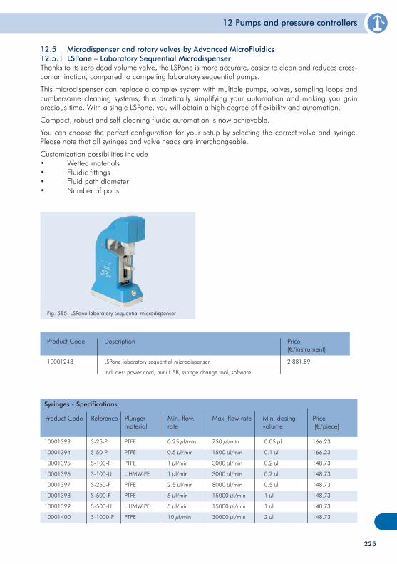
12 Pumps and pressure controllers
12.5 Microdispenser and rotary valves by Advanced MicroFluidics12.5.1 LSPone – Laboratory Sequential MicrodispenserThanks to its zero dead volume valve, the LSPone is more accurate, easier to clean and reduces cross-contamination, compared to competing laboratory sequential pumps.
This microdispensor can replace a complex system with multiple pumps, valves, sampling loops and cumbersome cleaning systems, thus drastically simplifying your automation and making you gain precious time. With a single LSPone, you will obtain a high degree of flexibility and automation.
Compact, robust and self-cleaning fluidic automation is now achievable.
You can choose the perfect configuration for your setup by selecting the correct valve and syringe. Please note that all syringes and valve heads are interchangeable.
Customization possibilities include• Wetted materials• Fluidic fittings• Fluid path diameter• Number of ports
Fig. 585: LSPone laboratory sequential microdispenser
10001248
Product Code
LSPone laboratory sequential microdispenser
Includes: power cord, mini USB, syringe change tool, software
Description
2 881.89
Price[€/instrument]
10001393
10001394
10001395
10001396
10001397
10001398
10001399
10001400
Product Code
S-25-P
S-50-P
S-100-P
S-100-U
S-250-P
S-500-P
S-500-U
S-1000-P
Reference Plunger material
Min. flow.rate
PTFE
PTFE
PTFE
UHMW-PE
PTFE
PTFE
UHMW-PE
PTFE
0.25 µl/min
0.5 µl/min
1 µl/min
1 µl/min
2.5 µl/min
5 µl/min
5 µl/min
10 µl/min
Max. flow rate
750 µl/min
1500 µl/min
3000 µl/min
3000 µl/min
8000 µl/min
15000 µl/min
15000 µl/min
30000 µl/min
Price [€/piece]
166.23
166.23
148.73
148.73
148.73
148.73
148.73
148.73
Min. dosing volume
0.05 µl
0.1 µl
0.2 µl
0.2 µl
0.5 µl
1 µl
1 µl
2 µl
Syringes - Specifications
225
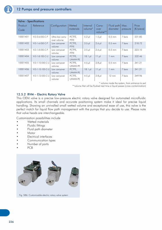
12 Pumps and pressure controllers
Ultra-low carry-over volumeLow carryover volumeLow carryover volumeLow carryover volumeLow carryover volumeLow carryover volumeLow carryover volume
Product
Code
Reference Wetted materials
Internal volume*
PCTFE, PTFEPCTFE, PTFEPCTFE, PTFEPCTFE, UHMW-PEPCTFE, UHMW-PEPCTFE, UHMW-PEPCTFE, UHMW-PE
5.2 µl
3.5 µl
3.5 µl
18.1 µl
4.5 µl
18.1 µl
4.5 µl
Carry-over volume**
1.5 µl
2.6 µl
2.6 µl
11 µl
2.8 µl
11 µl
2.8 µl
Price[€/piece]
231.85
218.72
223.10
332.46
341.21
341.21
349.96
Fluid path diameter
0.5 mm
0.5 mm
0.5 mm
1 mm
0.5 mm
1 mm
12 mm
Valve - Specifications
Max. pressure
7 bars
7 bars
7 bars
7 bars
7 bars
7 bars
7 bars
Configuration
V-D-2-6-050-C-P
V-D-1-6-050-C-P
V-D-1-8-050-C-P
V-D-1-8-100-C-U
V-D-1-10-050-C-U
V-D-1-10-100-C-U
V-D-1-12-050-C-U
* volume inside the system, from entrance to exit**volume that will be flushed next time a liquid passes (cross-contamination)
10001401
10001402
10001403
10001404
10001405
10001406
10001407
12.5.2 RVM – Electric Rotary ValveThis OEM valve is a precise low-pressure electric rotary valve designed for automated microfluidic applications. Its small channels and accurate positioning system make it ideal for precise liquid handling. Showing an unrivalled small wetted volume and exceptional ease of use, this valve is the perfect match for liquid flow path management with the pumps that you decide to use. Please note that valve heads are interchangeable.
Customization possibilities include• Wetted materials• Fluidic fittings• Fluid path diameter• Motor• Electrical interfaces• Communication types• Number of ports• PCB
Fig. 586: Customizable electric rotary valve system
226
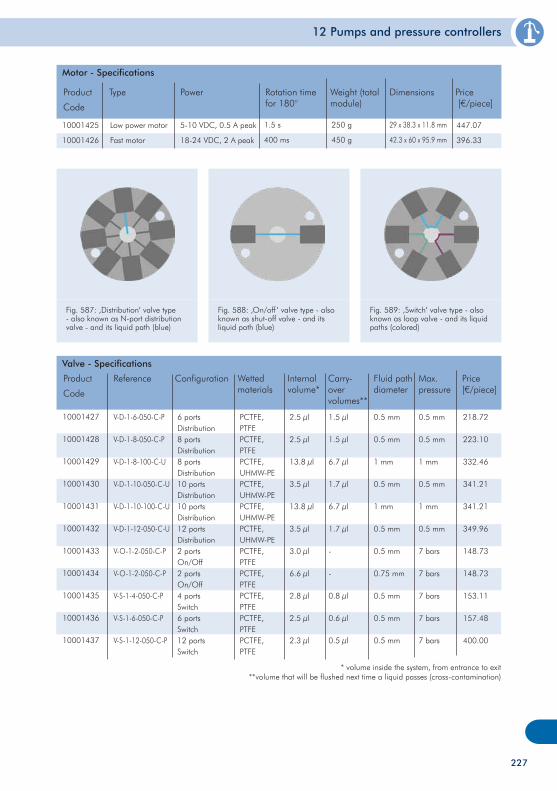
12 Pumps and pressure controllers
10001425
10001426
Product
Code
Type Power
Low power motor
Fast motor
5-10 VDC, 0.5 A peak
18-24 VDC, 2 A peak
Rotation time for 180°
1.5 s
400 ms
Price [€/piece]
447.07
396.33
Weight (total module)
250 g
450 g
Motor - Specifications
Dimensions
29 x 38.3 x 11.8 mm
42.3 x 60 x 95.9 mm
Fig. 587: ‚Distribution‘ valve type - also known as N-port distribution valve - and its liquid path (blue)
Fig. 588: ‚On/off‘ valve type - also known as shut-off valve - and its liquid path (blue)
Fig. 589: ‚Switch‘ valve type - also known as loop valve - and its liquid paths (colored)
6 portsDistribution8 portsDistribution8 portsDistribution10 portsDistribution10 portsDistribution12 portsDistribution2 portsOn/Off2 portsOn/Off4 portsSwitch6 portsSwitch12 portsSwitch
Product
Code
Reference Wetted materials
Internal volume*
PCTFE, PTFEPCTFE, PTFEPCTFE, UHMW-PEPCTFE, UHMW-PEPCTFE, UHMW-PEPCTFE, UHMW-PEPCTFE, PTFEPCTFE, PTFEPCTFE, PTFEPCTFE, PTFEPCTFE, PTFE
2.5 µl
2.5 µl
13.8 µl
3.5 µl
13.8 µl
3.5 µl
3.0 µl
6.6 µl
2.8 µl
2.5 µl
2.3 µl
Carry-over volumes**
1.5 µl
1.5 µl
6.7 µl
1.7 µl
6.7 µl
1.7 µl
-
-
0.8 µl
0.6 µl
0.5 µl
Price[€/piece]
218.72
223.10
332.46
341.21
341.21
349.96
148.73
148.73
153.11
157.48
400.00
Fluid path diameter
0.5 mm
0.5 mm
1 mm
0.5 mm
1 mm
0.5 mm
0.5 mm
0.75 mm
0.5 mm
0.5 mm
0.5 mm
Valve - Specifications
Max. pressure
0.5 mm
0.5 mm
1 mm
0.5 mm
1 mm
0.5 mm
7 bars
7 bars
7 bars
7 bars
7 bars
Configuration
V-D-1-6-050-C-P
V-D-1-8-050-C-P
V-D-1-8-100-C-U
V-D-1-10-050-C-U
V-D-1-10-100-C-U
V-D-1-12-050-C-U
V-O-1-2-050-C-P
V-O-1-2-050-C-P
V-S-1-4-050-C-P
V-S-1-6-050-C-P
V-S-1-12-050-C-P
10001427
10001428
10001429
10001430
10001431
10001432
10001433
10001434
10001435
10001436
10001437
227
* volume inside the system, from entrance to exit**volume that will be flushed next time a liquid passes (cross-contamination)
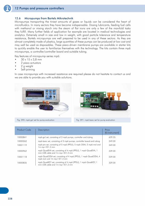
12 Pumps and pressure controllers
12.6 Micropumps from Bartels MikrotechnikMicropumps transporting the tiniest amounts of gases or liquids can be considered the heart of microfluidics. In many sectors they have become indispensable. Dosing lubricants, feeding fuel cells with methanol or mixing starch into the steam of flat irons are only a few of the manifold tasks they fulfill. Many further fields of application for example are located in medical technologies and analytics. Extremely small in size and low in weight, with good particle tolerance and temperature resistance, Bartels micropumps are well prepared to be used in any of these sectors. As they are almost completely made of plastics, large quantities of these pumps can be produced at low cost and may well be used as disposables. These piezo-driven membrane pumps are available in starter kits to quickly enable the user to familiarize themselves with the technology. The kits contain three mp6 micropumps, a controller/controller board and suitable tubing.
Key features of micropump-series mp6:• 30 x 15 x 3,8 mm• 2 piezo actuators• 2 g weight• Self-priming
In case micropumps with increased resistance are required please do not hesitate to contact us and we are able to provide you with suitable solutions.
10000841
10000262
10001119
10000962
10001118
10000835
Product Code
mp6-go! set, consisting of 3 mp6 pumps, controller and tubing
mp6-basic set, consisting of 3 mp6 pumps, controller board and tubing
mp6-pro set, consisting of 5 mp6 (PPSU), 5 mp6-OEM, 5 mp6-mol and 1m mp-t ID1.3 mm
mp6-QuadEVA set, consisting of 4 mp6 (PPSU), 1 mp6-QuadEVA, 1 mini USB cable and 1m mp-t ID1.3 mm
mp6-QuadOEM set, consisting of 4 mp6 (PPSU), 1 mp6-QuadOEM, 4 mp6-mol und 1m mp-t ID1.3 mm
mp6-QuadKEY set, consisting of 4 mp6 (PPSU), 1 mp6-QuadKEY, 1 mini USB cable and 1m mp-t ID1.3 mm
Description
629.35
249.00
349.00
339.00
229.00
329.00
Price[€/instrument]
Fig. 590: mp6-go! set for pump evaluation Fig. 591: mp6 basic set for pump evaluation
228
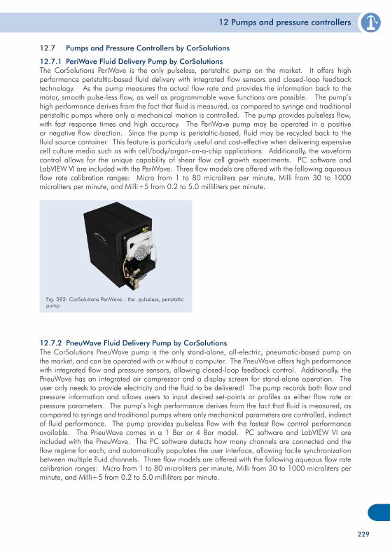
12 Pumps and pressure controllers
229
12.7 Pumps and Pressure Controllers by CorSolutions
12.7.1 PeriWave Fluid Delivery Pump by CorSolutionsThe CorSolutions PeriWave is the only pulseless, peristaltic pump on the market. It offers high performance peristaltic-based fluid delivery with integrated flow sensors and closed-loop feedback technology. As the pump measures the actual flow rate and provides the information back to the motor, smooth pulse-less flow, as well as programmable wave functions are possible. The pump’s high performance derives from the fact that fluid is measured, as compared to syringe and traditional peristaltic pumps where only a mechanical motion is controlled. The pump provides pulseless flow, with fast response times and high accuracy. The PeriWave pump may be operated in a positive or negative flow direction. Since the pump is peristaltic-based, fluid may be recycled back to the fluid source container. This feature is particularly useful and cost-effective when delivering expensive cell culture media such as with cell/body/organ-on-a-chip applications. Additionally, the waveform control allows for the unique capability of shear flow cell growth experiments. PC software and LabVIEW VI are included with the PeriWave. Three flow models are offered with the following aqueous flow rate calibration ranges: Micro from 1 to 80 microliters per minute, Milli from 30 to 1000 microliters per minute, and Milli+5 from 0.2 to 5.0 milliliters per minute.
12.7.2 PneuWave Fluid Delivery Pump by CorSolutionsThe CorSolutions PneuWave pump is the only stand-alone, all-electric, pneumatic-based pump on the market, and can be operated with or without a computer. The PneuWave offers high performance with integrated flow and pressure sensors, allowing closed-loop feedback control. Additionally, the PneuWave has an integrated air compressor and a display screen for stand-alone operation. The user only needs to provide electricity and the fluid to be delivered! The pump records both flow and pressure information and allows users to input desired set-points or profiles as either flow rate or pressure parameters. The pump’s high performance derives from the fact that fluid is measured, as compared to syringe and traditional pumps where only mechanical parameters are controlled, indirect of fluid performance. The pump provides pulseless flow with the fastest flow control performance available. The PneuWave comes in a 1 Bar or 4 Bar model. PC software and LabVIEW VI are included with the PneuWave. The PC software detects how many channels are connected and the flow regime for each, and automatically populates the user interface, allowing facile synchronization between multiple fluid channels. Three flow models are offered with the following aqueous flow rate calibration ranges: Micro from 1 to 80 microliters per minute, Milli from 30 to 1000 microliters per minute, and Milli+5 from 0.2 to 5.0 milliliters per minute.
Fig. 592: CorSolutions PeriWave – the pulseless, peristaltic pump
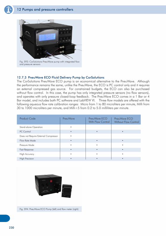
12 Pumps and pressure controllers
230
12.7.3 PneuWave ECO Fluid Delivery Pump by CorSolutionsThe CorSolutions PneuWave ECO pump is an economical alternative to the PneuWave. Although the performance remains the same, unlike the PneuWave, the ECO is PC control only and it requires an external compressed gas source. For constrained budgets, the ECO can also be purchased without flow control. In this case, the pump has only integrated pressure sensors (no flow sensors), and operates with only pressure closed-loop feedback. The PneuWave ECO comes in a 1 Bar or 4 Bar model, and includes both PC software and LabVIEW VI. Three flow models are offered with the following aqueous flow rate calibration ranges: Micro from 1 to 80 microliters per minute, Milli from 30 to 1000 microliters per minute, and Milli+5 from 0.2 to 5.0 milliliters per minute.
Stand-alone Operation
PC Control
Does not Require External Compressor
Flow Rate Mode
Pressure Mode
Fast Response
High Accuracy
High Precision
Product Code
•
•
•
•
•
•
•
•
PneuWave PneuWave ECOWith Flow Control
PneuWave ECOWithout Flow Control
•
•
•
•
•
•
•
•
•
•
•
•
Fig. 594: PneuWave ECO Pump (left) and flow meter (right)
Fig. 593: CorSolutions PneuWave pump with integrated flow and pressure sensors
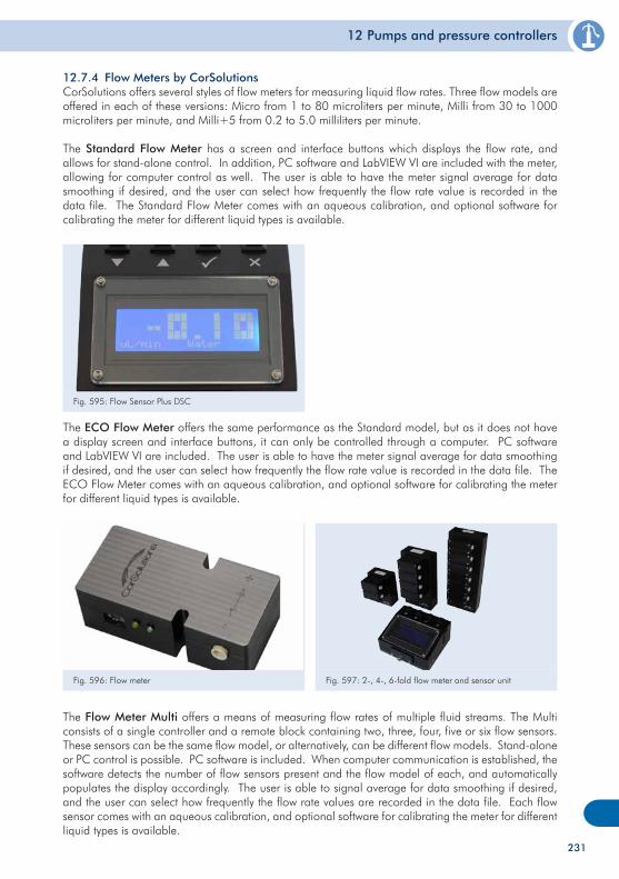
12 Pumps and pressure controllers
231
Fig. 595: Flow Sensor Plus DSC
Fig. 596: Flow meter
12.7.4 Flow Meters by CorSolutionsCorSolutions offers several styles of flow meters for measuring liquid flow rates. Three flow models are offered in each of these versions: Micro from 1 to 80 microliters per minute, Milli from 30 to 1000 microliters per minute, and Milli+5 from 0.2 to 5.0 milliliters per minute.
The Standard Flow Meter has a screen and interface buttons which displays the flow rate, and allows for stand-alone control. In addition, PC software and LabVIEW VI are included with the meter, allowing for computer control as well. The user is able to have the meter signal average for data smoothing if desired, and the user can select how frequently the flow rate value is recorded in the data file. The Standard Flow Meter comes with an aqueous calibration, and optional software for calibrating the meter for different liquid types is available.
The ECO Flow Meter offers the same performance as the Standard model, but as it does not have a display screen and interface buttons, it can only be controlled through a computer. PC software and LabVIEW VI are included. The user is able to have the meter signal average for data smoothing if desired, and the user can select how frequently the flow rate value is recorded in the data file. The ECO Flow Meter comes with an aqueous calibration, and optional software for calibrating the meter for different liquid types is available.
The Flow Meter Multi offers a means of measuring flow rates of multiple fluid streams. The Multi consists of a single controller and a remote block containing two, three, four, five or six flow sensors. These sensors can be the same flow model, or alternatively, can be different flow models. Stand-alone or PC control is possible. PC software is included. When computer communication is established, the software detects the number of flow sensors present and the flow model of each, and automatically populates the display accordingly. The user is able to signal average for data smoothing if desired, and the user can select how frequently the flow rate values are recorded in the data file. Each flow sensor comes with an aqueous calibration, and optional software for calibrating the meter for different liquid types is available.
Fig. 597: 2-, 4-, 6-fold flow meter and sensor unit
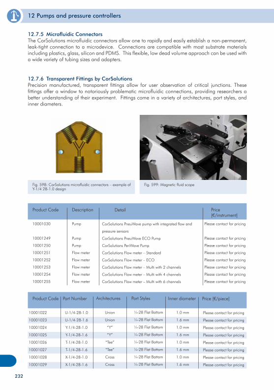
12 Pumps and pressure controllers
232
Fig. 598: CorSolutions microfluidic connectors – example of Y-1/4 28-1.0 design
Fig. 599: Magnetic fluid scope
12.7.6 Transparent Fittings by CorSolutionsPrecision manufactured, transparent fittings allow for user observation of critical junctions. These fittings offer a window to notoriously problematic microfluidic connections, providing researchers a better understanding of their experiment. Fittings come in a variety of architectures, port styles, and inner diameters.
12.7.5 Microfluidic ConnectorsThe CorSolutions microfluidic connectors allow one to rapidly and easily establish a non-permanent, leak-tight connection to a microdevice. Connections are compatible with most substrate materials including plastics, glass, silicon and PDMS. This flexible, low dead volume approach can be used with a wide variety of tubing sizes and adapters.
10001030
10001249
10001250
10001251
10001252
10001253
10001254
10001255
Product Code
Pump
Pump
Pump
Flow meter
Flow meter
Flow meter
Flow meter
Flow meter
Description
Please contact for pricing
Please contact for pricing
Please contact for pricing
Please contact for pricing
Please contact for pricing
Please contact for pricing
Please contact for pricing
Please contact for pricing
Price[€/instrument]
CorSolutions PneuWave pump with integrated flow and
pressure sensors
CorSolutions PneuWave ECO Pump
CorSolutions PeriWave Pump
CorSolutions Flow meter – Standard
CorSolutions Flow meter – ECO
CorSolutions Flow meter – Multi with 2 channels
CorSolutions Flow meter – Multi with 4 channels
CorSolutions Flow meter – Multi with 6 channels
Detail
10001022
10001023
10001024
10001025
10001026
10001027
10001028
10001029
Product Code
U-1/4-28-1.0
U-1/4-28-1.6
Y-1/4-28-1.0
Y-1/4-28-1.6
T-1/4-28-1.0
T-1/4-28-1.6
X-1/4-28-1.0
X-1/4-28-1.6
Part Number Architectures Port Styles
Union
Union
“Y”
“Y”
“Tee”
“Tee”
Cross
Cross
¼-28 Flat Bottom
¼-28 Flat Bottom
¼-28 Flat Bottom
¼-28 Flat Bottom
¼-28 Flat Bottom
¼-28 Flat Bottom
¼-28 Flat Bottom
¼-28 Flat Bottom
Inner diameter
1.0 mm
1.6 mm
1.0 mm
1.6 mm
1.0 mm
1.6 mm
1.0 mm
1.6 mm
Price [€/piece]
Please contact for pricing
Please contact for pricing
Please contact for pricing
Please contact for pricing
Please contact for pricing
Please contact for pricing
Please contact for pricing
Please contact for pricing
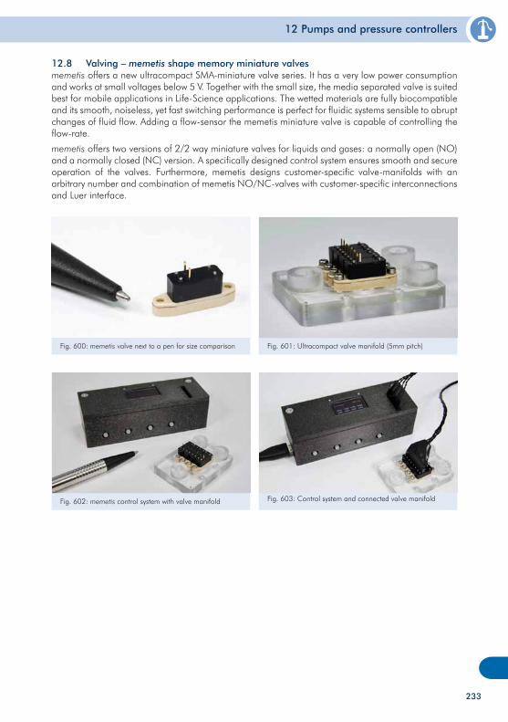
12 Pumps and pressure controllers
233
12.8 Valving – memetis shape memory miniature valves memetis offers a new ultracompact SMA-miniature valve series. It has a very low power consumption and works at small voltages below 5 V. Together with the small size, the media separated valve is suited best for mobile applications in Life-Science applications. The wetted materials are fully biocompatible and its smooth, noiseless, yet fast switching performance is perfect for fluidic systems sensible to abrupt changes of fluid flow. Adding a flow-sensor the memetis miniature valve is capable of controlling the flow-rate.
memetis offers two versions of 2/2 way miniature valves for liquids and gases: a normally open (NO) and a normally closed (NC) version. A specifically designed control system ensures smooth and secure operation of the valves. Furthermore, memetis designs customer-specific valve-manifolds with an arbitrary number and combination of memetis NO/NC-valves with customer-specific interconnections and Luer interface.
Fig. 600: memetis valve next to a pen for size comparison Fig. 601: Ultracompact valve manifold (5mm pitch)
Fig. 603: Control system and connected valve manifoldFig. 602: memetis control system with valve manifold
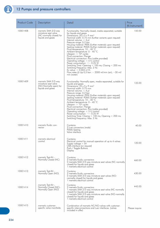
12 Pumps and pressure controllers
234
10001408
10001409
10001410
10001411
10001412
10001413
10001414
10001415
Product Code
memetis SMA 2/2-way miniature seat valve (NC-normally closed) for liquids and gases
memetis SMA 2/2-way miniature seat valve (NO-Normally open) for liquids and gases
memetis fluidic con-nector
memetis electrical control
memetis Test-Kit – Normally Closed (NC)
memetis Test-Kit – Normally Open (NO)
memetis Test-Kit – Normally Closed (NC)-Normally Open (NO)
memetis customer-specific valve manifolds
Description
150.00
135.00
40.00
120.00
460.00
430.00
445.00
Please inquire
Price[€/instrument]
Functionality: Normally closed, media-separated, suitable for liquids and gasesDimensions: 20 x 5 x 9 mm³Nominal width: 0.75 mm (further variants upon request)Internal volume: < 4 µlPressure range: 0-2 barHousing material: PEEK (further materials upon request)Sealing material: PDMS (further materials upon request)Fluid temperature: 10 – 40 °CAmbient temperature: 0 – 40 °CLifespan: > 106 cyclesFluid connection: FlangeElectrical connection: Pins (cable provided)Operating voltage: < 5 V, controlPower consumption: ¬~ 0.25 WSwitching Time: Opening < 100 ms; Closing < 200 msSwitching Frequency: Max. 2 HzKv value: > 0.004 m3/hFlow rates @ Δp 0,5 bar: ~ 2000 ml/min (air), ~30 ml/min (water)
Functionality: Normally open, media-separated, suitable for liquids and gasesDimensions: 20 x 5 x 9 mm3
Nominal width: 0.75 mmInternal volume: < 4 µlPressure range: 0-2 barHousing material: PEEK (further materials upon request)Sealing material: PDMS (further materials upon request)Fluid temperature: 10 – 40 °CAmbient temperature: 0 – 40 °CLifespan: > 106 cyclesFluid connection: FlangeElectrical connection: Pins (cable provided)Operating voltage: < 5 V, controlPower consumption: ¬~ 0.25 WSwitching Time: Closing < 100 ms; Opening < 200 msSwitching Frequency: Max. 2 Hz
Contains: 2 Luer connectors (male)PDMS SealingValve interface
Contains:Electrical control for manual operation of up to 4 valvesSupply voltage = 5VUSB-interface (on request)Push-/ Toggle-ButtonsDisplay
Contains: 2 memetis fluidic connectors2 memetis SMA 2/2-way miniature seat valves (NC-normally closed) for liquids and gases1 memetis electrical control
Contains: 2 memetis fluidic connectors2 memetis SMA 2/2-way miniature seat valves (NO-normally closed) for liquids and gases1 memetis electrical control
Contains: 2 memetis fluidic connectors1 memetis SMA 2/2-way miniature seat valve (NC-normally closed) for liquids and gases1 memetis SMA 2/2-way miniature seat valve (NO-normally closed) for liquids and gases1 memetis electrical control
Combination of memetis NC/NO-valves with customer-specific interconnections and Luer interfaces. (valves included in offer)
Detail

235
236
13 Microfluidic kits
Microfluidic kits
To run microfluidic experiments some basics like tubes, connectors, or reagents are necessary, or diffe-rent options of tubes and fluidic interfaces might be of interest. In order to allow for a choice between the options, this chapter has several selections of kits comprising interfaces, chips with instrument, selection of chip types, handling frames or further accessories.
237
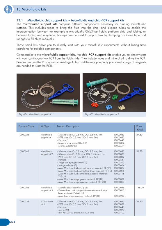
13 Microfluidic kits
13.1 Microfluidic chip support kits – Microfluidic and chip-PCR support kits The microfluidic support kits comprise different components necessary for running microfluidic systems. This includes tubes to bring the fluid into the chip, and silicone tubes to enable the interconnection between for example a microfluidic ChipShop fluidic platform chip and tubing, or between tubing and a syringe. Forceps can be used to stop a flow by clamping a silicone tube and syringes to fill chips manually.
These small kits allow you to directly start with your microfluidic experiments without losing time searching for suitable components.
Comparable to the microfluidic support kits, the chip-PCR support kits enable you to directly startwith your continuous-flow PCR from the fluidic side. They include tubes and mineral oil to drive the PCR. Besides this and the PCR system consisting of chip and thermocycler, only your own biological reagents are needed to start the PCR.
Fig. 604: Microfluidic support kit 1 Fig. 605: Microfluidic support kit 2
10000025
10000045
10000085
10000238
Microfluidic support kit 1
Microfluidic support kit 2
Microfluidic support kit 3
PCR support kit 1
Product Code Kit Type Price[€/kit]
27.80
96.50
146.20
32.90
- Silicone tube (ID: 0.5 mm, OD: 2.5 mm, 1m)- PTFE tube (ID: 0.5 mm, OD: 1 mm, 1m)- Forceps (1)- Single-use syringes (10 ml, 3)- Syringe adapter (3)
- Silicone tube (ID: 0.5 mm, OD: 2.5 mm, 1m)- Silicone tube (ID: 0.76 mm, OD: 1.65 mm, 1m)- PTFE tube (ID: 0.5 mm, OD: 1 mm, 1m)- Forceps (1)- Single-use syringes (10 ml, 3)- Syringe adapter (3)- Male Mini Luer fluid connectors, red, material: PP (10)- Male Mini Luer fluid connectors, blue, material: PP (10)- Male Mini Luer fluid connectors, opaque, material: TPE (10)- Male Mini Luer plugs, green, material: PP (10)- Male Mini Luer plugs, opaque, material: TPE (10)
- Microfluidic support kit 2 plus:- Female Luer Lock compatible connectors with wide base, material: PMMA (10)- Male Luer plugs, opaque, material: PP (10)
- Silicone tube (ID: 0.5 mm, OD: 2.5 mm, 1m)- PTFE tube (ID: 0.5 mm, OD: 1 mm, 1m)- Forceps (1)- mcs-oil-04- mcs-foil 007 (3 sheets, 8 x 13,5 cm)
Product Description
238
1000003310000032100006411000031210000614
100000331000003110000032100006411000031210000614100000641000009610000116
1000005210000054
1000004510000013
10000230
1000003310000032100006411000107910000702
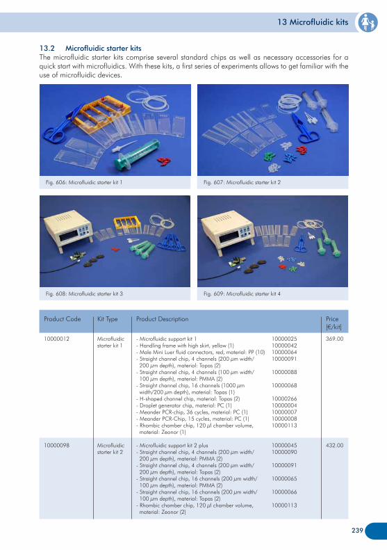
13 Microfluidic kits
Fig. 606: Microfluidic starter kit 1 Fig. 607: Microfluidic starter kit 2
13.2 Microfluidic starter kitsThe microfluidic starter kits comprise several standard chips as well as necessary accessories for a quick start with microfluidics. With these kits, a first series of experiments allows to get familiar with the use of microfluidic devices.
239
Fig. 608: Microfluidic starter kit 3 Fig. 609: Microfluidic starter kit 4
10000012
10000098
Microfluidic starter kit 1
Microfluidic starter kit 2
Product Code Kit Type Price[€/kit]
369.00
432.00
- Microfluidic support kit 1- Handling frame with high skirt, yellow (1)- Male Mini Luer fluid connectors, red, material: PP (10)- Straight channel chip, 4 channels (200 µm width/ 200 µm depth), material: Topas (2)- Straight channel chip, 4 channels (100 µm width/ 100 µm depth), material: PMMA (2)- Straight channel chip, 16 channels (1000 µm width/200 µm depth), material: Topas (1)- H-shaped channel chip, material: Topas (2)- Droplet generator chip, material: PC (1)- Meander PCR-chip, 36 cycles, material: PC (1)- Meander PCR-Chip, 15 cycles, material: PC (1)- Rhombic chamber chip, 120 µl chamber volume, material: Zeonor (1)
- Microfluidic support kit 2 plus- Straight channel chip, 4 channels (200 µm width/ 200 µm depth), material: PMMA (2)- Straight channel chip, 4 channels (200 µm width/ 200 µm depth), material: Topas (2)- Straight channel chip, 16 channels (200 µm width/ 100 µm depth), material: PMMA (2)- Straight channel chip, 16 channels (200 µm width/ 100 µm depth), material: Topas (2)- Rhombic chamber chip, 120 µl chamber volume, material: Zeonor (2)
Product Description
10000025100000421000006410000091
10000088
10000068
1000026610000004100000071000000810000113
1000004510000090
10000091
10000065
10000066
10000113
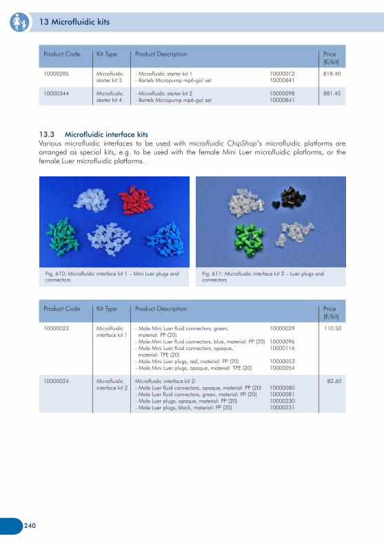
13 Microfluidic kits
240
13.3 Microfluidic interface kitsVarious microfluidic interfaces to be used with microfluidic ChipShop’s microfluidic platforms are arranged as special kits, e.g. to be used with the female Mini Luer microfluidic platforms, or the female Luer microfluidic platforms.
10000285
10000344
Microfluidic starter kit 3
Microfluidic starter kit 4
Product Code Kit Type Price[€/kit]
818.40
881.45
- Microfluidic starter kit 1- Bartels Micropump mp6-go! set
- Microfluidic starter kit 2- Bartels Micropump mp6-go! set
Product Description
1000001210000841
1000009810000841
Fig. 610: Microfluidic interface kit 1 – Mini Luer plugs and connectors
Fig. 611: Microfluidic interface kit 2 – Luer plugs and connectors
10000023
10000024
Microfluidic interface kit 1
Microfluidic interface kit 2
Product Code Kit Type Price[€/kit]
110.50
82.60
- Male Mini Luer fluid connectors, green, material: PP (20)- Male Mini Luer fluid connectors, blue, material: PP (20)- Male Mini Luer fluid connectors, opaque, material: TPE (20)- Male Mini Luer plugs, red, material: PP (20)- Male Mini Luer plugs, opaque, material: TPE (20)
Microfluidic interface kit 2:- Male Luer fluid connectors, opaque, material: PP (20)- Male Luer fluid connectors, green, material: PP (20)- Male Luer plugs, opaque, material: PP (20)- Male Luer plugs, black, material: PP (20)
Product Description
10000029
1000009610000116
1000005310000054
10000080100000811000023010000231
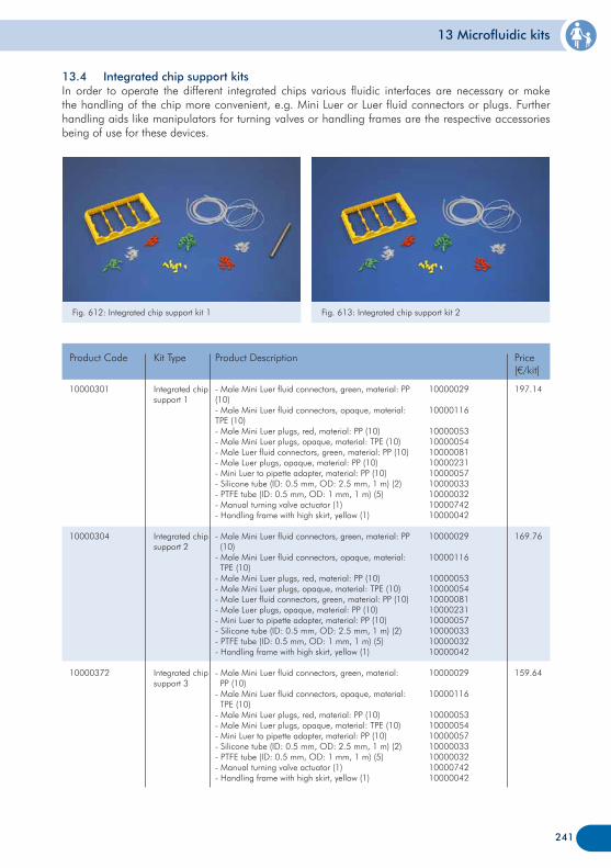
13 Microfluidic kits
241
13.4 Integrated chip support kitsIn order to operate the different integrated chips various fluidic interfaces are necessary or make the handling of the chip more convenient, e.g. Mini Luer or Luer fluid connectors or plugs. Further handling aids like manipulators for turning valves or handling frames are the respective accessories being of use for these devices.
Fig. 612: Integrated chip support kit 1 Fig. 613: Integrated chip support kit 2
10000301
10000304
10000372
Integrated chip support 1
Integrated chip support 2
Integrated chip support 3
Product Code Kit Type Price[€/kit]
197.14
169.76
159.64
- Male Mini Luer fluid connectors, green, material: PP (10)- Male Mini Luer fluid connectors, opaque, material: TPE (10)- Male Mini Luer plugs, red, material: PP (10)- Male Mini Luer plugs, opaque, material: TPE (10)- Male Luer fluid connectors, green, material: PP (10)- Male Luer plugs, opaque, material: PP (10)- Mini Luer to pipette adapter, material: PP (10)- Silicone tube (ID: 0.5 mm, OD: 2.5 mm, 1 m) (2)- PTFE tube (ID: 0.5 mm, OD: 1 mm, 1 m) (5)- Manual turning valve actuator (1)- Handling frame with high skirt, yellow (1)
- Male Mini Luer fluid connectors, green, material: PP (10)- Male Mini Luer fluid connectors, opaque, material: TPE (10)- Male Mini Luer plugs, red, material: PP (10)- Male Mini Luer plugs, opaque, material: TPE (10)- Male Luer fluid connectors, green, material: PP (10)- Male Luer plugs, opaque, material: PP (10)- Mini Luer to pipette adapter, material: PP (10)- Silicone tube (ID: 0.5 mm, OD: 2.5 mm, 1 m) (2)- PTFE tube (ID: 0.5 mm, OD: 1 mm, 1 m) (5)- Handling frame with high skirt, yellow (1)
- Male Mini Luer fluid connectors, green, material: PP (10)- Male Mini Luer fluid connectors, opaque, material: TPE (10)- Male Mini Luer plugs, red, material: PP (10)- Male Mini Luer plugs, opaque, material: TPE (10)- Mini Luer to pipette adapter, material: PP (10)- Silicone tube (ID: 0.5 mm, OD: 2.5 mm, 1 m) (2)- PTFE tube (ID: 0.5 mm, OD: 1 mm, 1 m) (5)- Manual turning valve actuator (1)- Handling frame with high skirt, yellow (1)
Product Description
10000029
10000116
100000531000005410000081100002311000005710000033100000321000074210000042
10000029
10000116
1000005310000054100000811000023110000057100000331000003210000042
10000029
10000116
10000053100000541000005710000033100000321000074210000042
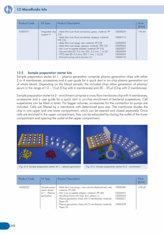
13 Microfluidic kits
242
10000371 Integrated chip support 4
Product Code Kit Type Price[€/kit]
144.64- Male Mini Luer fluid connectors, green, material: PP (10)- Male Mini Luer fluid connectors, opaque, material: TPE (10)- Male Mini Luer plugs, red, material: PP (10)- Male Mini Luer plugs, opaque, material: TPE (10)- Mini Luer to pipette adapter, material: PP (10)- Silicone tube (ID: 0.5 mm, OD: 2.5 mm, 1 m) (2)- PTFE tube (ID: 0.5 mm, OD: 1 mm, 1 m) (5)- Manual turning valve actuator (1)
Product Description
10000029
10000116
100000531000005410000057100000331000003210000742
13.5 Sample preparation starter kitsSample preparation starter kit 1 – plasma generation comprise plasma generation chips with either 2 or 4 membranes, accessories and a user guide for a quick start in on-chip plasma generation out of whole blood. Depending on the blood sample, the included chips allow generation of plasma/serum in the range of 12 – 15 µl (Chip with 4 membranes) and 20 – 35 µl (Chip with 2 membranes).
Sample preparation starter kit 2 – enrichment comprise a cross-flow membrane chip with 4 membranes, accessories and a user guide for a quick start in on-chip enrichment of bacterial suspensions. Cell suspensions can be filled in tanks. For bigger volumes, accessories for the connection to pumps are included. Cells are filtered by a membrane with determined pore size. The membrane divides the chip in one upper and one lower compartment, which can be opened and closed separately. Once cells are enriched in the upper compartment, they can be exhausted by closing the outlet of the lower compartment and opening the outlet of the upper compartment.
Fig. 614: Sample preparation starter kit 1 – plasma generation Fig. 615: Sample preparation starter kit 2 – enrichment
10000507 Sample prepa-ration starter kit 1 - Plasma generation
Product Code Kit Type Price[€/kit]
678.30 - Male Mini Luer plugs - Low volume displacement, red, material: PP (40)- Mini Luer to pipette adapter, material: PP (40)- Handling frame with high skirt, yellow (1)- Plasma generation chips with 4 membranes, material: Topas (5)- Plasma generation chips with 2 membranes, material: Topas (5)
Product Description
10000280
100000571000004210000021
10000439
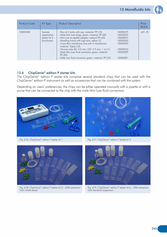
13 Microfluidic kits
243
10000508 Sample preparation starter kit 2 - Enrichment
Product Code Kit Type Price[€/kit]
631.70- Row of 4 tanks with cap, material: PP (10)- Male Mini Luer plugs, green, material: PP (40)- Mini Luer to pipette adapter, material PP (40) - Handling frame with high skirt, yellow (1)- Cross-flow membrane chip with 4 membranes, material: Topas (10) - Silicone tube (ID: 0.5 mm, OD: 2.5 mm, 1 m) (1)- Male Mini Luer fluid connector, green, material: PP (20) - Male Luer fluid connector, green, material: PP (10)
Product Description
1000007910000052100000571000004210000022
1000003310000029
10000081
13.6 ChipGenie® edition P starter kitsThe ChipGenie® edition P starter kits comprise several standard chips that can be used with the ChipGenie® edition P instrument as well as accessories that can be combined with the system.
Depending on users’ preferencies, the chips can be either operated manually with a pipette or with a pump that can be connected to the chip with the male Mini Luer fluid connectors.
Fig. 616: ChipGenie® edition P starter kit 1 Fig. 617: ChipGenie® edition P starter kit 2
Fig. 618: ChipGenie® edition P starter kit 3 – DNA extraction from whole blood
Fig. 619: ChipGenie® edition P starter kit 5 – DNA extraction from bacterial suspension
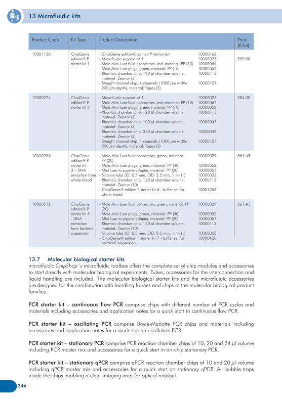
13 Microfluidic kits
244
10001138
10000274
10000239
10000512
ChipGenie edition® P starter kit 1
ChipGenie edition® P starter kit 2
ChipGenie edition® P starter kit 3 – DNA extraction from whole blood
ChipGenie edition® P starter kit 5 - DNA extraction from bacterial suspension
Product Code Kit Type Price[€/kit]
759.00
384.00
561.43
561.43
- ChipGenie edition® edition P instrument- Microfluidic support kit 1- Male Mini Luer fluid connectors, red, material: PP (10)- Male Mini Luer plugs, green, material: PP (10)- Rhombic chamber chip, 120 µl chamber volume, material: Zeonor (3)- Straight channel chip, 4 channels (1000 µm width/ 200 µm depth), material: Topas (3)
- Microfluidic support kit 1- Male Mini Luer fluid connectors, red, material: PP (10)- Male Mini Luer plugs, green, material: PP (10)- Rhombic chamber chip, 120 µl chamber volume, material: Zeonor (3)- Rhombic chamber chip, 100 µl chamber volume, material: Zeonor (3)- Rhombic chamber chip, 250 µl chamber volume, material: Zeonor (3)- Straight channel chip, 4 channels (1000 µm width/ 200 µm depth), material: Topas (3)
- Male Mini Luer fluid connectors, green, material: PP (20)- Male Mini Luer plugs, green, material: PP (40)- Mini Luer to pipette adapter, material: PP (20) - Silicone tube (ID: 0.5 mm, OD: 2.5 mm, 1 m) (1)- Rhombic chamber chip, 120 µl chamber volume, material: Zeonor (10)- ChipGenie® edition P starter kit 6 - buffer set for whole blood
- Male Mini Luer fluid connectors, green, material: PP (20)- Male Mini Luer plugs, green, material: PP (40)- Mini Luer to pipette adapter, material: PP (20) - Rhombic chamber chip, 120 µl chamber volume, material: Zeonor (10)- Silicone tube (ID: 0.5 mm, OD: 2.5 mm, 1 m) (1)- ChipGenie® edition P starter kit 7 - buffer set for bacterial suspension
Product Description
1000016610000025100000641000005210000113
10000107
10000025100000641000005210000113
10000047
10000049
10000107
10000029
10000052100000571000003310000113
10001256
10000029
100000521000005710000113
1000003310000420
13.7 Molecular biological starter kitsmicrofluidic ChipShop´s microfluidic toolbox offers the complete set of chip modules and accessories to start directly with molecular biological experiments. Tubes, accessories for the interconnection and liquid handling are included. The molecular biological starter kits and the microfluidic accessories are designed for the combination with handling frames and chips of the molecular biological product families.
PCR starter kit – continuous flow PCR comprise chips with different number of PCR cycles and materials including accessories and application notes for a quick start in continuous flow PCR.
PCR starter kit – oscillating PCR comprise Boyle-Mariotte PCR chips and materials including accessories and application notes for a quick start in oscillation PCR.
PCR starter kit – stationary PCR comprise PCR reaction chamber chips of 10, 20 and 24 µl volume including PCR master mix and accessories for a quick start in on-chip stationary PCR.
PCR starter kit – stationary qPCR comprise qPCR reaction chamber chips of 10 and 20 µl volume including qPCR master mix and accessories for a quick start on stationary qPCR. Air bubble traps inside the chips enabling a clear imaging area for optical readout.
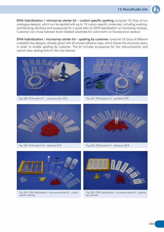
13 Microfluidic kits
DNA hybridization / microarray starter kit – custom specific spotting comprise 10 chips of two catalogue designs, which can be spotted with up to 10 custom specific molecules, including washing- and blocking solutions and accessories for a quick start on DNA hybridization or microarray analysis. Customer can chose between biotin labeled substrates for colorimetric or fluorescence readout.
DNA hybridization / microarray starter kit – spotting by customer comprise 10 chips of different unsealed chip designs, already glued with structured adhesive tape, which leaves the structures open, in order to enable spotting by customer. The kit includes accessories for the interconnection and optical clear sealing foils for the chip devices.
245
Fig. 620: PCR starter kit 1 - continuous flow PCR Fig. 621: PCR starter kit 2 - oscillation PCR
Fig. 624: DNA hybridization / microarray starter kit - custom specific spotting
Fig. 625: DNA hybridization / microarray starter kit - spotting by customer
Fig. 622: PCR starter kit 3 - stationary PCR Fig. 623: PCR starter kit 4 - stationary qPCR
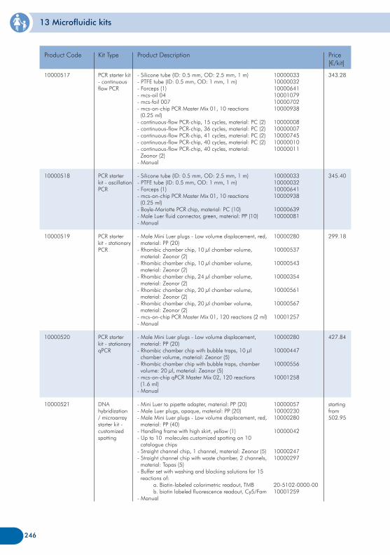
13 Microfluidic kits
10000517
10000518
10000519
10000520
10000521
PCR starter kit - continuous flow PCR
PCR starter kit - oscillation PCR
PCR starter kit - stationary PCR
PCR starter kit - stationary qPCR
DNA hybridization / microarray starter kit - customized spotting
Product Code Kit Type Price[€/kit]
343.28
345.40
299.18
427.84
starting from 502.95
- Silicone tube (ID: 0.5 mm, OD: 2.5 mm, 1 m)- PTFE tube (ID: 0.5 mm, OD: 1 mm, 1 m)- Forceps (1)- mcs-oil 04- mcs-foil 007- mcs-on-chip PCR Master Mix 01, 10 reactions (0.25 ml)- continuous-flow PCR-chip, 15 cycles, material: PC (2)- continuous-flow PCR-chip, 36 cycles, material: PC (2)- continuous-flow PCR-chip, 41 cycles, material: PC (2)- continuous-flow PCR-chip, 40 cycles, material: PC (2)- continuous-flow PCR-chip, 40 cycles, material: Zeonor (2)- Manual
- Silicone tube (ID: 0.5 mm, OD: 2.5 mm, 1 m)- PTFE tube (ID: 0.5 mm, OD: 1 mm, 1 m)- Forceps (1)- mcs-on-chip PCR Master Mix 01, 10 reactions (0.25 ml)- Boyle-Mariotte PCR chip, material: PC (10)- Male Luer fluid connector, green, material: PP (10)- Manual
- Male Mini Luer plugs - Low volume displacement, red, material: PP (20)- Rhombic chamber chip, 10 µl chamber volume, material: Zeonor (2)- Rhombic chamber chip, 10 µl chamber volume, material: Zeonor (2)- Rhombic chamber chip, 24 µl chamber volume, material: Zeonor (2)- Rhombic chamber chip, 20 µl chamber volume, material: Zeonor (2)- Rhombic chamber chip, 20 µl chamber volume, material: Zeonor (2)- mcs-on-chip PCR Master Mix 01, 120 reactions (2 ml)- Manual
- Male Mini Luer plugs - Low volume displacement, material: PP (20)- Rhombic chamber chip with bubble traps, 10 µl chamber volume, material: Zeonor (5)- Rhombic chamber chip with bubble traps, chamber volume: 20 µl, material: Zeonor (5)- mcs-on-chip qPCR Master Mix 02, 120 reactions (1.6 ml)- Manual
- Mini Luer to pipette adapter, material: PP (20)- Male Luer plugs, opaque, material: PP (20)- Male Mini Luer plugs - Low volume displacement, red, material: PP (40)- Handling frame with high skirt, yellow (1)- Up to 10 molecules customized spotting on 10 catalogue chips- Straight channel chip, 1 channel, material: Zeonor (5)- Straight channel chip with waste chamber, 2 channels, material: Topas (5)- Buffer set with washing and blocking solutions for 15 reactions of: a. Biotin-labeled colorimetric readout, TMB b. biotin labeled fluorescence readout, Cy5/Fam- Manual
Product Description
100000331000003210000641100010791000070210000938
1000000810000007100007451000001010000011
10000033100000321000064110000938
1000063910000081
10000280
10000537
10000543
10000354
10000561
10000567
10001257
10000280
10000447
10000556
10001258
100000571000023010000280
10000042
1000024710000297
20-5102-0000-0010001259
246
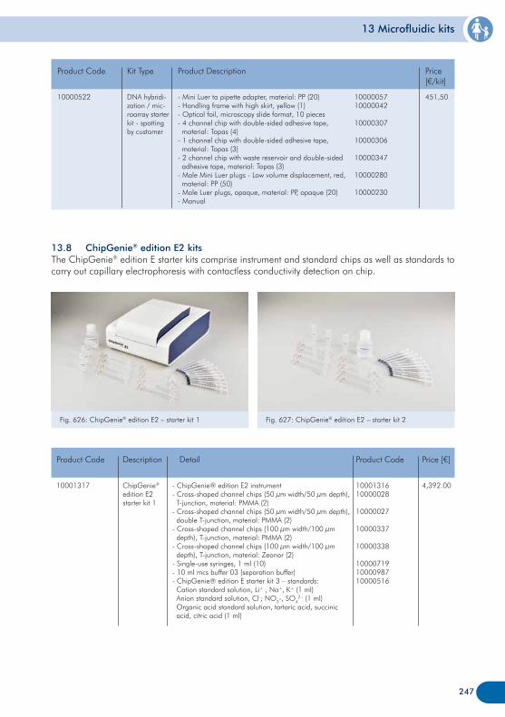
13 Microfluidic kits
13.8 ChipGenie® edition E2 kitsThe ChipGenie® edition E starter kits comprise instrument and standard chips as well as standards to carry out capillary electrophoresis with contactless conductivity detection on chip.
Fig. 627: ChipGenie® edition E2 – starter kit 2Fig. 626: ChipGenie® edition E2 – starter kit 1
247
10000522 DNA hybridi-zation / mic-roarray starter kit - spotting by customer
Product Code Kit Type Price[€/kit]
451,50- Mini Luer to pipette adapter, material: PP (20)- Handling frame with high skirt, yellow (1)- Optical foil, microscopy slide format, 10 pieces- 4 channel chip with double-sided adhesive tape, material: Topas (4)- 1 channel chip with double-sided adhesive tape, material: Topas (3)- 2 channel chip with waste reservoir and double-sided adhesive tape, material: Topas (3)- Male Mini Luer plugs - Low volume displacement, red, material: PP (50)- Male Luer plugs, opaque, material: PP, opaque (20)- Manual
Product Description
1000005710000042
10000307
10000306
10000347
10000280
10000230
10001317 ChipGenie® edition E2starter kit 1
Product Code Description Price [€]
4,392.00 - ChipGenie® edition E2 instrument- Cross-shaped channel chips (50 µm width/50 µm depth), T-junction, material: PMMA (2)- Cross-shaped channel chips (50 µm width/50 µm depth), double T-junction, material: PMMA (2)- Cross-shaped channel chips (100 µm width/100 µm depth), T-junction, material: PMMA (2)- Cross-shaped channel chips (100 µm width/100 µm depth), T-junction, material: Zeonor (2)- Single-use syringes, 1 ml (10) - 10 ml mcs buffer 03 (separation buffer)- ChipGenie® edition E starter kit 3 – standards: Cation standard solution, Li+ , Na+, K+ (1 ml) Anion standard solution, Cl-; NO3-, SO4
2 - (1 ml) Organic acid standard solution, tartaric acid, succinic acid, citric acid (1 ml)
Detail
1000131610000028
10000027
10000337
10000338
100007191000098710000516
Product Code
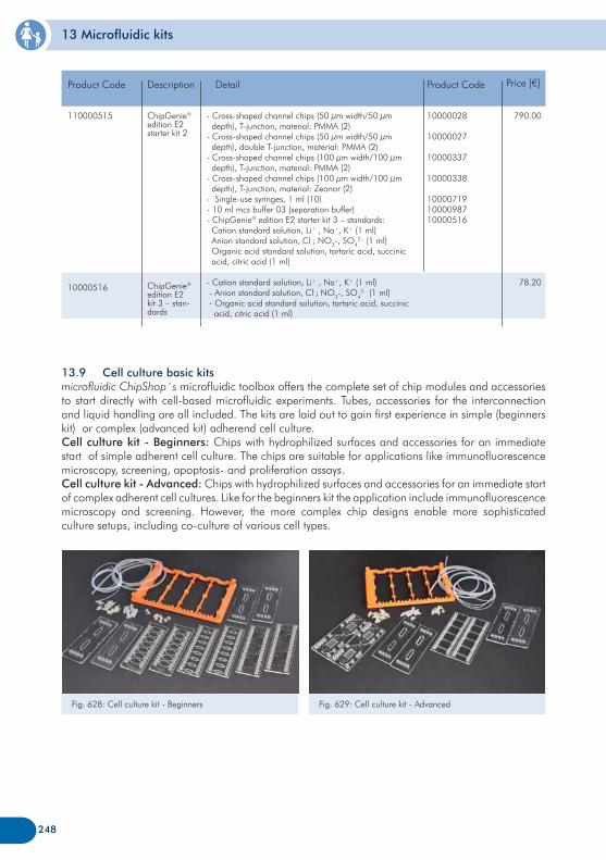
13 Microfluidic kits
13.9 Cell culture basic kitsmicrofluidic ChipShop´s microfluidic toolbox offers the complete set of chip modules and accessories to start directly with cell-based microfluidic experiments. Tubes, accessories for the interconnection and liquid handling are all included. The kits are laid out to gain first experience in simple (beginners kit) or complex (advanced kit) adherend cell culture. Cell culture kit - Beginners: Chips with hydrophilized surfaces and accessories for an immediate start of simple adherent cell culture. The chips are suitable for applications like immunofluorescence microscopy, screening, apoptosis- and proliferation assays.Cell culture kit - Advanced: Chips with hydrophilized surfaces and accessories for an immediate start of complex adherent cell cultures. Like for the beginners kit the application include immunofluorescence microscopy and screening. However, the more complex chip designs enable more sophisticated culture setups, including co-culture of various cell types.
Fig. 629: Cell culture kit - AdvancedFig. 628: Cell culture kit - Beginners
248
110000515
10000516
ChipGenie® edition E2starter kit 2
ChipGenie® edition E2 kit 3 – stan-dards
Product Code Description
790.00
78.20
- Cross-shaped channel chips (50 µm width/50 µm depth), T-junction, material: PMMA (2)- Cross-shaped channel chips (50 µm width/50 µm depth), double T-junction, material: PMMA (2)- Cross-shaped channel chips (100 µm width/100 µm depth), T-junction, material: PMMA (2)- Cross-shaped channel chips (100 µm width/100 µm depth), T-junction, material: Zeonor (2)- Single-use syringes, 1 ml (10) - 10 ml mcs buffer 03 (separation buffer)- ChipGenie® edition E2 starter kit 3 – standards: Cation standard solution, Li+ , Na+, K+ (1 ml) Anion standard solution, Cl-; NO3-, SO4
2 - (1 ml) Organic acid standard solution, tartaric acid, succinic acid, citric acid (1 ml)
- Cation standard solution, Li+ , Na+, K+ (1 ml) - Anion standard solution, Cl-; NO3-, SO4
2 - (1 ml) - Organic acid standard solution, tartaric acid, succinic acid, citric acid (1 ml)
Detail
10000028
10000027
10000337
10000338
100007191000098710000516
Product Code Price [€]
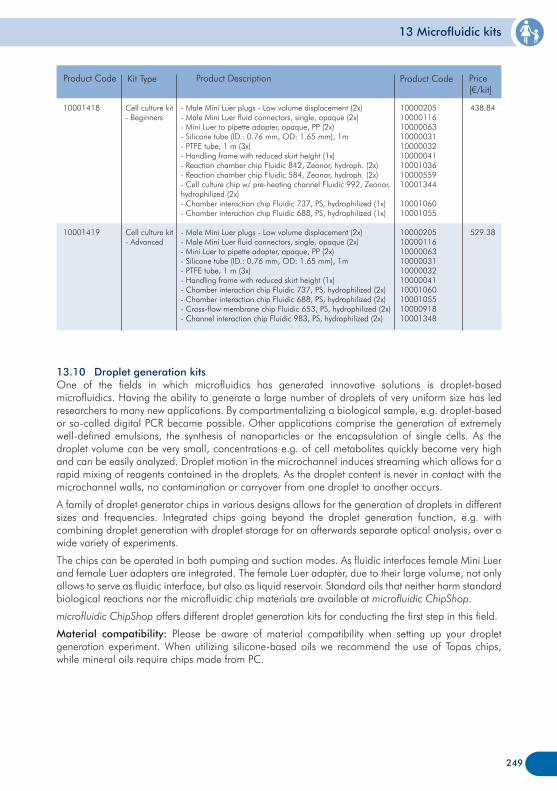
13 Microfluidic kits
10001418
10001419
Cell culture kit - Beginners
Cell culture kit - Advanced
Product Code Kit Type Price[€/kit]
438.84
529.38
- Male Mini Luer plugs - Low volume displacement (2x)- Male Mini Luer fluid connectors, single, opaque (2x)- Mini Luer to pipette adapter, opaque, PP (2x)- Silicone tube (ID.: 0.76 mm, OD: 1.65 mm), 1m- PTFE tube, 1 m (3x)- Handling frame with reduced skirt height (1x)- Reaction chamber chip Fluidic 842, Zeonor, hydroph. (2x)- Reaction chamber chip Fluidic 584, Zeonor, hydroph. (2x)- Cell culture chip w/ pre-heating channel Fluidic 992, Zeonor, hydrophilized (2x)- Chamber interaction chip Fluidic 737, PS, hydrophilized (1x)- Chamber interaction chip Fluidic 688, PS, hydrophilized (1x)
- Male Mini Luer plugs - Low volume displacement (2x)- Male Mini Luer fluid connectors, single, opaque (2x)- Mini Luer to pipette adapter, opaque, PP (2x)- Silicone tube (ID.: 0.76 mm, OD: 1.65 mm), 1m- PTFE tube, 1 m (3x)- Handling frame with reduced skirt height (1x)- Chamber interaction chip Fluidic 737, PS, hydrophilized (2x)- Chamber interaction chip Fluidic 688, PS, hydrophilized (2x)- Cross-flow membrane chip Fluidic 653, PS, hydrophilized (2x)- Channel interaction chip Fluidic 983, PS, hydrophilized (2x)
Product Description
249
100002051000011610000063100000311000003210000041100010361000055910001344
1000106010001055
10000205100001161000006310000031100000321000004110001060100010551000091810001348
Product Code
13.10 Droplet generation kitsOne of the fields in which microfluidics has generated innovative solutions is droplet-based microfluidics. Having the ability to generate a large number of droplets of very uniform size has led researchers to many new applications. By compartmentalizing a biological sample, e.g. droplet-based or so-called digital PCR became possible. Other applications comprise the generation of extremely well-defined emulsions, the synthesis of nanoparticles or the encapsulation of single cells. As the droplet volume can be very small, concentrations e.g. of cell metabolites quickly become very high and can be easily analyzed. Droplet motion in the microchannel induces streaming which allows for a rapid mixing of reagents contained in the droplets. As the droplet content is never in contact with the microchannel walls, no contamination or carryover from one droplet to another occurs.
A family of droplet generator chips in various designs allows for the generation of droplets in different sizes and frequencies. Integrated chips going beyond the droplet generation function, e.g. with combining droplet generation with droplet storage for an afterwards separate optical analysis, over a wide variety of experiments.
The chips can be operated in both pumping and suction modes. As fluidic interfaces female Mini Luer and female Luer adapters are integrated. The female Luer adapter, due to their large volume, not only allows to serve as fluidic interface, but also as liquid reservoir. Standard oils that neither harm standard biological reactions nor the microfluidic chip materials are available at microfluidic ChipShop.
microfluidic ChipShop offers different droplet generation kits for conducting the first step in this field.
Material compatibility: Please be aware of material compatibility when setting up your droplet generation experiment. When utilizing silicone-based oils we recommend the use of Topas chips, while mineral oils require chips made from PC.
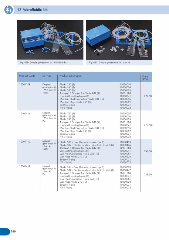
13 Microfluidic kits
Fig. 631: Droplet generation kit - Luer kitFig. 630: Droplet generation kit - Mini Luer kit
10001109
10001416
10001110
10001417
Droplet generation kit - Mini Luer kitTopas
Droplet generation kit - Mini Luer kitPC
Droplet generation kit - Luer kitTopas
Droplet generation kit - Luer kitPC
Product Code Kit Type Price[€/kit]
277.50
277.50
248.50
248.50
- Fluidic 162 (2)- Fluidic 163 (2)- Fluidic 285 (1)- Transport & Storage Box Fluidic 832 (1)- Low Skirt Handling Frame (1)- Mini Luer Fluid Connectors Fluidic 331 (10)- Mini Luer Plugs Fluidic 334 (10)- Silicone Tubing- PTFE Tubing
- Fluidic 162 (2)- Fluidic 163 (2)- Fluidic 285 (1)- Transport & Storage Box Fluidic 832 (1)- Low Skirt Handling Frame (1)- Mini Luer Fluid Connectors Fluidic 331 (10)- Mini Luer Plugs Fluidic 334 (10)- Silicone Tubing- PTFE Tubing
- Fluidic 536 – Four Elements on one chip (2)- Fluidic 537 – Double emulsion (droplet in droplet) (2)- Transport & Storage Box Fluidic 832 (1)- Low Skirt Handling Frame (1)- Luer Fluid Connectors Fluidic 263 (10)- Luer Plugs Fluidic 270 (10)- Silicone Tubing- PTFE Tubing
- Fluidic 536 – Four Elements on one chip (2)- Fluidic 537 – Double emulsion (droplet in droplet) (2)- Transport & Storage Box Fluidic 832 (1)- Low Skirt Handling Frame (1)- Luer Fluid Connectors Fluidic 263 (10)- Luer Plugs Fluidic 270 (10)- Silicone Tubing- PTFE Tubing
Product Description
100000051000000610000175100011881000004110000096100000521000003110000032
100000031000000410000176100011881000004110000096100000521000003110000032
1000043310000466100011881000004110000081100002301000003110000032
1000050910000467100011881000004110000081100002301000003110000032
250

251
252
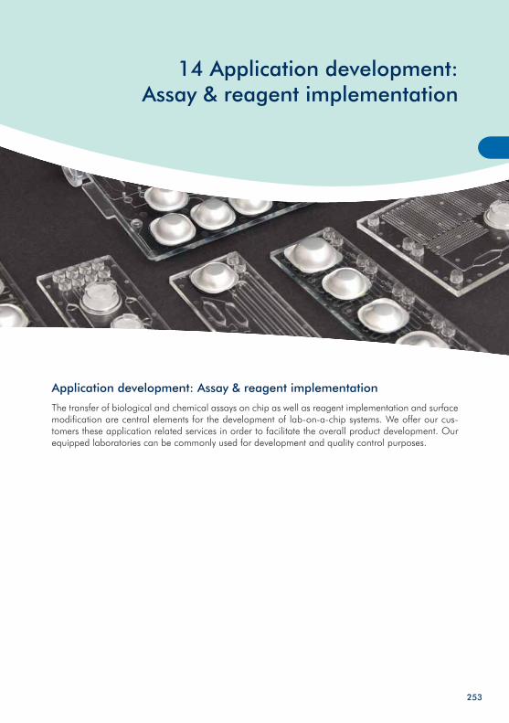
14 Application development: Assay & reagent implementation
Application development: Assay & reagent implementation
The transfer of biological and chemical assays on chip as well as reagent implementation and surface modification are central elements for the development of lab-on-a-chip systems. We offer our cus-tomers these application related services in order to facilitate the overall product development. Our equipped laboratories can be commonly used for development and quality control purposes.
253
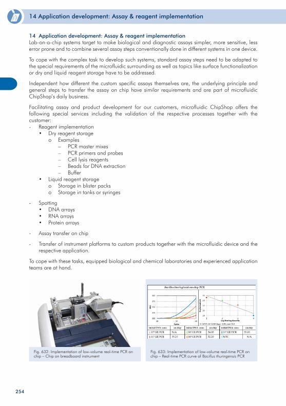
14 Application development: Assay & reagent implementation
254
14 Application development: Assay & reagent implementationLab-on-a-chip systems target to make biological and diagnostic assays simpler, more sensitive, less error prone and to combine several assay steps conventionally done in different systems in one device. To cope with the complex task to develop such systems, standard assay steps need to be adapted to the special requirements of the microfluidic surrounding as well as topics like surface functionalization or dry and liquid reagent storage have to be addressed.
Independent how different the custom specific assays themselves are, the underlying principle and general steps to transfer the assay on chip have similar requirements and are part of microfluidic ChipShop’s daily business.
Facilitating assay and product development for our customers, microfluidic ChipShop offers the following special services including the validation of the respective processes together with the customer:- Reagent implementation • Dry reagent storage o Examples – PCR master mixes – PCR primers and probes – Cell lysis reagents – Beads for DNA extraction – Buffer • Liquid reagent storage o Storage in blister packs o Storage in tanks or syringes
- Spotting • DNA arrays • RNA arrays • Protein arrays
- Assay transfer on chip
- Transfer of instrument platforms to custom products together with the microfluidic device and the respective application.
To cope with these tasks, equipped biological and chemical laboratories and experienced application teams are at hand.
Fig. 632: Implementation of low-volume real-time PCR on chip – Chip on breadboard instrument
Fig. 633: Implementation of low-volume real-time PCR on chip – Real-time PCR curve of Bacillus thuringensis PCR
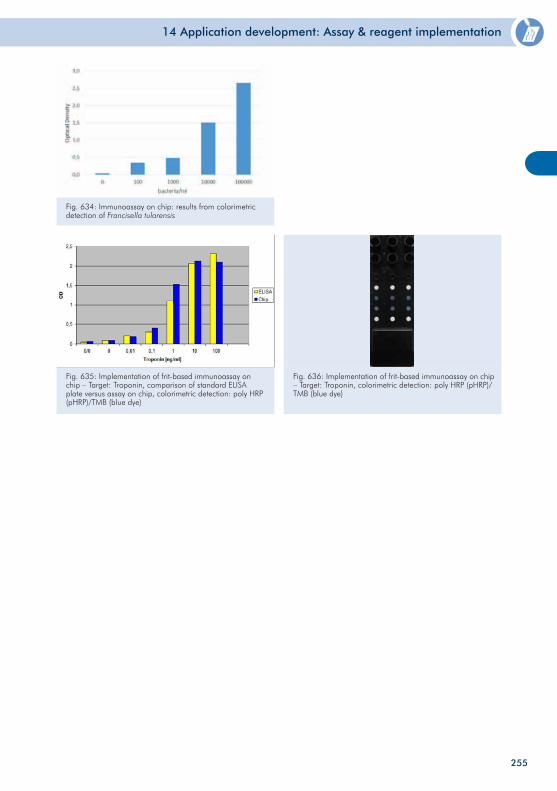
14 Application development: Assay & reagent implementation
255
Fig. 634: Immunoassay on chip: results from colorimetric detection of Francisella tularensis
Fig. 635: Implementation of frit-based immunoassay on chip – Target: Troponin, comparison of standard ELISA plate versus assay on chip, colorimetric detection: poly HRP (pHRP)/TMB (blue dye)
Fig. 636: Implementation of frit-based immunoassay on chip – Target: Troponin, colorimetric detection: poly HRP (pHRP)/TMB (blue dye)
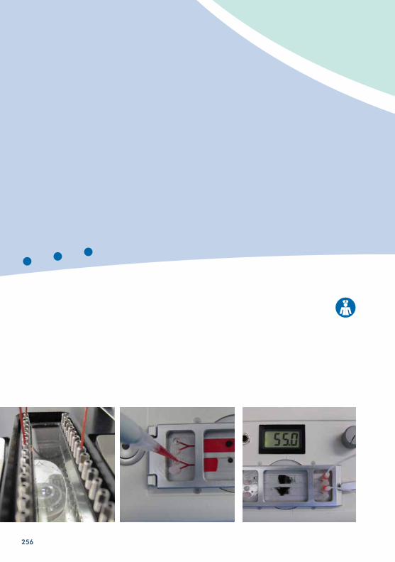
256
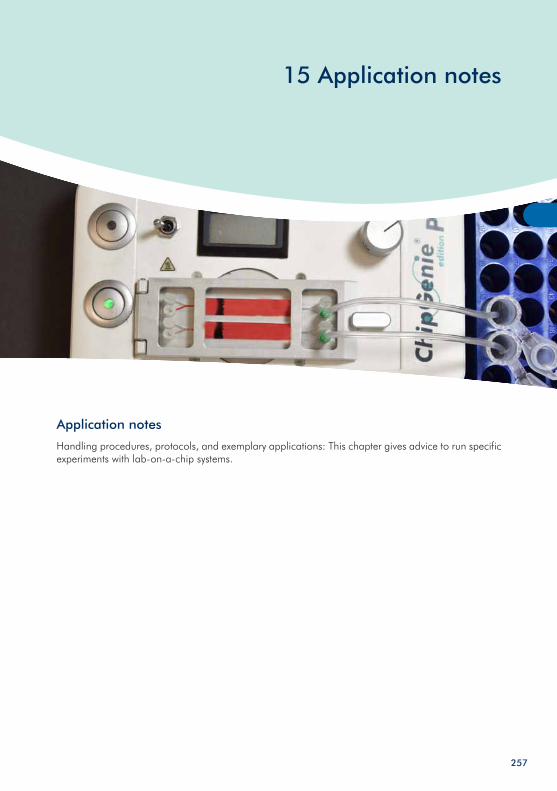
15 Application notes
Application notes
Handling procedures, protocols, and exemplary applications: This chapter gives advice to run specific experiments with lab-on-a-chip systems.
257
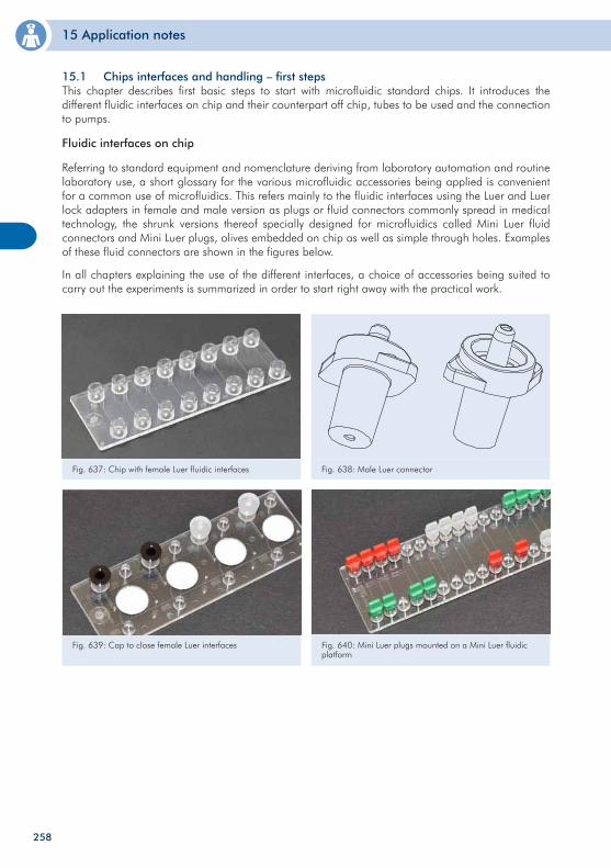
15 Application notes
15.1 Chips interfaces and handling – first steps This chapter describes first basic steps to start with microfluidic standard chips. It introduces the different fluidic interfaces on chip and their counterpart off chip, tubes to be used and the connection to pumps.
Fluidic interfaces on chip
Referring to standard equipment and nomenclature deriving from laboratory automation and routine laboratory use, a short glossary for the various microfluidic accessories being applied is convenient for a common use of microfluidics. This refers mainly to the fluidic interfaces using the Luer and Luer lock adapters in female and male version as plugs or fluid connectors commonly spread in medical technology, the shrunk versions thereof specially designed for microfluidics called Mini Luer fluid connectors and Mini Luer plugs, olives embedded on chip as well as simple through holes. Examples of these fluid connectors are shown in the figures below.
In all chapters explaining the use of the different interfaces, a choice of accessories being suited to carry out the experiments is summarized in order to start right away with the practical work.
Fig. 637: Chip with female Luer fluidic interfaces Fig. 638: Male Luer connector
Fig. 639: Cap to close female Luer interfaces Fig. 640: Mini Luer plugs mounted on a Mini Luer fluidic platform
258
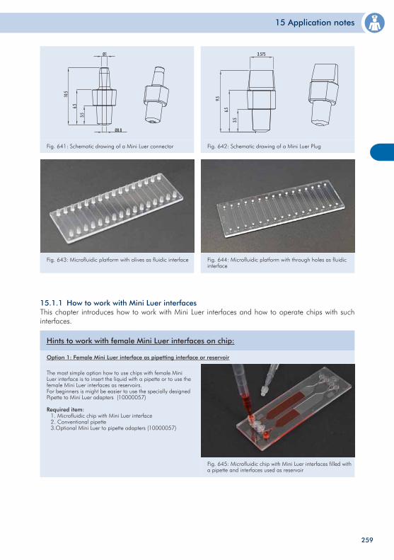
15 Application notes
Fig. 641: Schematic drawing of a Mini Luer connector Fig. 642: Schematic drawing of a Mini Luer Plug
Fig. 643: Microfluidic platform with olives as fluidic interface Fig. 644: Microfluidic platform with through holes as fluidic interface
15.1.1 How to work with Mini Luer interfaces This chapter introduces how to work with Mini Luer interfaces and how to operate chips with such interfaces.
Fig. 645: Microfluidic chip with Mini Luer interfaces filled with a pipette and interfaces used as reservoir
The most simple option how to use chips with female Mini Luer interface is to insert the liquid with a pipette or to use the female Mini Luer interfaces as reservoirs.For beginners is might be easier to use the specially designed Pipette to Mini Luer adapters (10000057)
Required item: 1. Microfluidic chip with Mini Luer interface 2. Conventional pipette 3.Optional Mini Luer to pipette adapters (10000057)
Hints to work with female Mini Luer interfaces on chip:
Option 1: Female Mini Luer interface as pipetting interface or reservoir
259
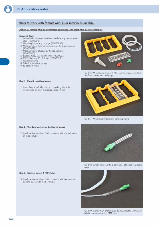
15 Application notes
Fig. 646: Microfluidic chip with Mini Luer interfaces with Mini Luer fluid connectors and plugs
Required item: 1. Microfluidic chip with Mini Luer interface, e.g. micro mixer chip (10000020) 2. Handling frame, e.g. orange (10000043) 3. Male Mini Luer fluid connectors, e.g. the green version (10000029) 4. Male Mini Luer plugs, e.g. the red version (10000053) 5. Silicone tube, e.g. ID: 0.5 mm (10000033) 6. PTFE tube, e.g. ID: 0.5 mm (10000032) 7. Peristaltic pump 8. Tube for peristaltic pump 9. Eppendorf vessel
Hints to work with female Mini Luer interfaces on chip:
Option 2: Female Mini Luer interface combined with male Mini Luer counterpart
Fig. 647: Micromixer inserted in handling frame
1. Insert the microfluidic chip in a handling frame for microfluidic chips in microscopy slide format
Step 1: Chip & handling frame
Fig. 648: Green Mini Luer fluid connector attached to silicone sleeve
2. Interface the Mini Luer fluid connector with a small piece of silicone tube
Step 2: Mini Luer connector & silicone sleeve
Fig. 649: Connection of Mini Luer fluid connector with moun-ted silicone sleeve with a PTFE tube
3. Interface the Mini Luer fluid connector with the mounted silicone sleeve with the PTFE tube
Step 3: Silicone sleeve & PTFE tube
260
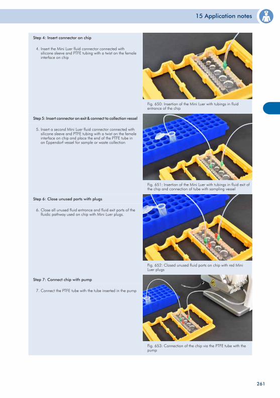
15 Application notes
Fig. 650: Insertion of the Mini Luer with tubings in fluid entrance of the chip
4. Insert the Mini Luer fluid connector connected with silicone sleeve and PTFE tubing with a twist on the female interface on chip
Step 4: Insert connector on chip
Fig. 651: Insertion of the Mini Luer with tubings in fluid exit of the chip and connection of tube with sampling vessel
5. Insert a second Mini Luer fluid connector connected with silicone sleeve and PTFE tubing with a twist on the female interface on chip and place the end of the PTFE tube in an Eppendorf vessel for sample or waste collection
Step 5: Insert connector on exit & connect to collection vessel
Fig. 652: Closed unused fluid ports on chip with red Mini Luer plugs
6. Close all unused fluid entrance and fluid exit ports of the fluidic pathway used on chip with Mini Luer plugs.
Step 6: Close unused ports with plugs
Fig. 653: Connection of the chip via the PTFE tube with the pump
7. Connect the PTFE tube with the tube inserted in the pump
Step 7: Connect chip with pump
261
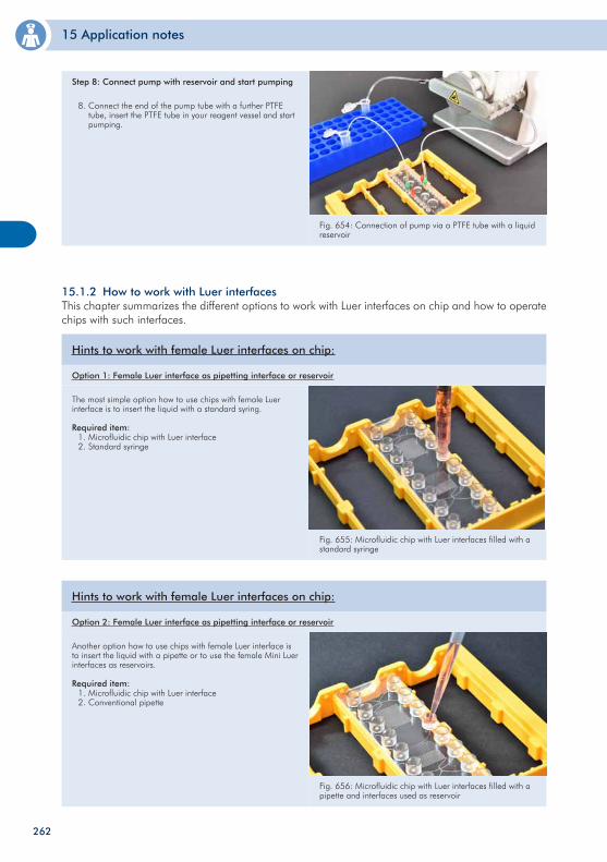
15 Application notes
Fig. 654: Connection of pump via a PTFE tube with a liquid reservoir
8. Connect the end of the pump tube with a further PTFE tube, insert the PTFE tube in your reagent vessel and start pumping.
Step 8: Connect pump with reservoir and start pumping
15.1.2 How to work with Luer interfacesThis chapter summarizes the different options to work with Luer interfaces on chip and how to operate chips with such interfaces.
Fig. 655: Microfluidic chip with Luer interfaces filled with a standard syringe
The most simple option how to use chips with female Luer interface is to insert the liquid with a standard syring.
Required item: 1. Microfluidic chip with Luer interface 2. Standard syringe
Hints to work with female Luer interfaces on chip:
Option 1: Female Luer interface as pipetting interface or reservoir
Fig. 656: Microfluidic chip with Luer interfaces filled with a pipette and interfaces used as reservoir
Another option how to use chips with female Luer interface is to insert the liquid with a pipette or to use the female Mini Luer interfaces as reservoirs.
Required item: 1. Microfluidic chip with Luer interface 2. Conventional pipette
Hints to work with female Luer interfaces on chip:
Option 2: Female Luer interface as pipetting interface or reservoir
262
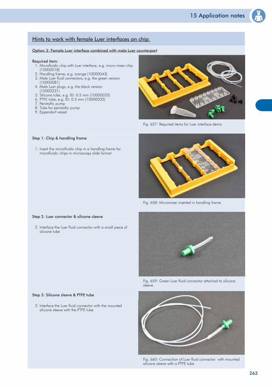
15 Application notes
Fig. 657: Required items for Luer interface demo
Required item: 1. Microfluidic chip with Luer interface, e.g. micro mixer chip (10000018) 2. Handling frame, e.g. orange (10000043) 3. Male Luer fluid connectors, e.g. the green version (10000081) 4. Male Luer plugs, e.g. the black version (10000231) 5. Silicone tube, e.g. ID: 0.5 mm (10000033) 6. PTFE tube, e.g. ID: 0.5 mm (10000032) 7. Peristaltic pump 8. Tube for peristaltic pump 9. Eppendorf vessel
Hints to work with female Luer interfaces on chip:
Option 3: Female Luer interface combined with male Luer counterpart
Fig. 658: Micromixer inserted in handling frame
1. Insert the microfluidic chip in a handling frame for microfluidic chips in microscopy slide format
Step 1: Chip & handling frame
Fig. 659: Green Luer fluid connector attached to silicone sleeve
2. Interface the Luer fluid connector with a small piece of silicone tube
Step 2: Luer connector & silicone sleeve
Fig. 660: Connection of Luer fluid connector with mounted silicone sleeve with a PTFE tube
3. Interface the Luer fluid connector with the mounted silicone sleeve with the PTFE tube
Step 3: Silicone sleeve & PTFE tube
263
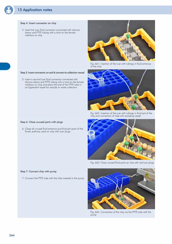
15 Application notes
Fig. 661: Insertion of the Luer with tubings in fluid entrance of the chip
4. Insert the Luer fluid connector connected with silicone sleeve and PTFE tubing with a twist on the female interface on chip
Step 4: Insert connector on chip
Fig. 662: Insertion of the Luer with tubings in fluid exit of the chip and connection of tube with sampling vessel
5. Insert a second Luer fluid connector connected with silicone sleeve and PTFE tubing with a twist on the female interface on chip and place the end of the PTFE tube in an Eppendorf vessel for sample or waste collection
Step 5: Insert connector on exit & connect to collection vessel
Fig. 663: Close unused fluid ports on chip with red Luer plugs
6. Close all unused fluid entrance and fluid exit ports of the fluidic pathway used on chip with Luer plugs.
Step 6: Close unused ports with plugs
Fig. 664: Connection of the chip via the PTFE tube with the pump
7. Connect the PTFE tube with the tube inserted in the pump
Step 7: Connect chip with pump
264
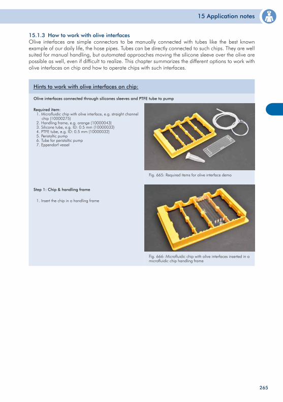
15 Application notes
15.1.3 How to work with olive interfacesOlive interfaces are simple connectors to be manually connected with tubes like the best known example of our daily life, the hose pipes. Tubes can be directly connected to such chips. They are well suited for manual handling, but automated approaches moving the silicone sleeve over the olive are possible as well, even if difficult to realize. This chapter summarizes the different options to work with olive interfaces on chip and how to operate chips with such interfaces.
Fig. 665: Required items for olive interface demo
Required item: 1. Microfluidic chip with olive interface, e.g. straight channel chip (10000275) 2. Handling frame, e.g. orange (10000043) 3. Silicone tube, e.g. ID: 0.5 mm (10000033) 4. PTFE tube, e.g. ID: 0.5 mm (10000032) 5. Peristaltic pump 6. Tube for peristaltic pump 7. Eppendorf vessel
Hints to work with olive interfaces on chip:
Olive interfaces connected through silicones sleeves and PTFE tube to pump
Fig. 666: Microfluidic chip with olive interfaces inserted in a microfluidic chip handling frame
1. Insert the chip in a handling frame
Step 1: Chip & handling frame
265
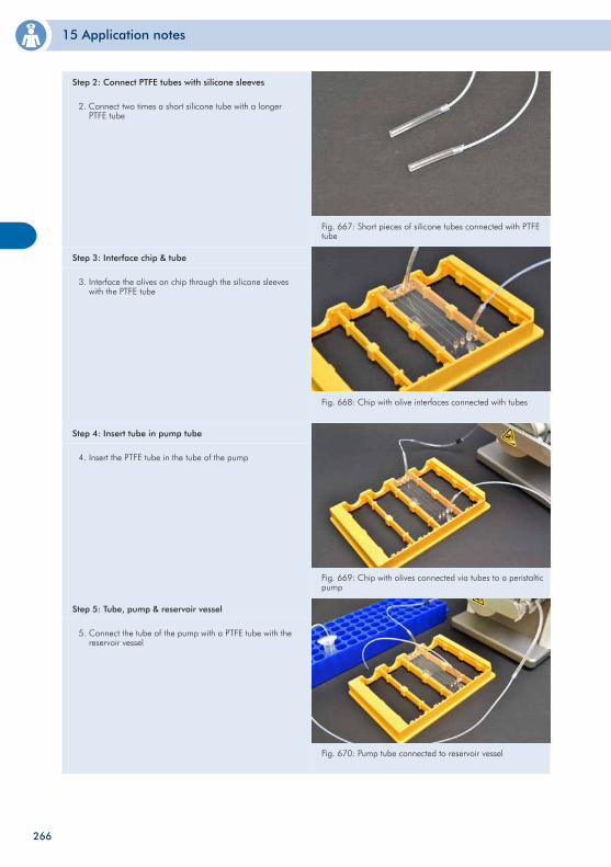
15 Application notes
Fig. 667: Short pieces of silicone tubes connected with PTFE tube
2. Connect two times a short silicone tube with a longer PTFE tube
Step 2: Connect PTFE tubes with silicone sleeves
Fig. 668: Chip with olive interfaces connected with tubes
3. Interface the olives on chip through the silicone sleeves with the PTFE tube
Step 3: Interface chip & tube
Fig. 669: Chip with olives connected via tubes to a peristaltic pump
4. Insert the PTFE tube in the tube of the pump
Step 4: Insert tube in pump tube
Fig. 670: Pump tube connected to reservoir vessel
5. Connect the tube of the pump with a PTFE tube with the reservoir vessel
Step 5: Tube, pump & reservoir vessel
266
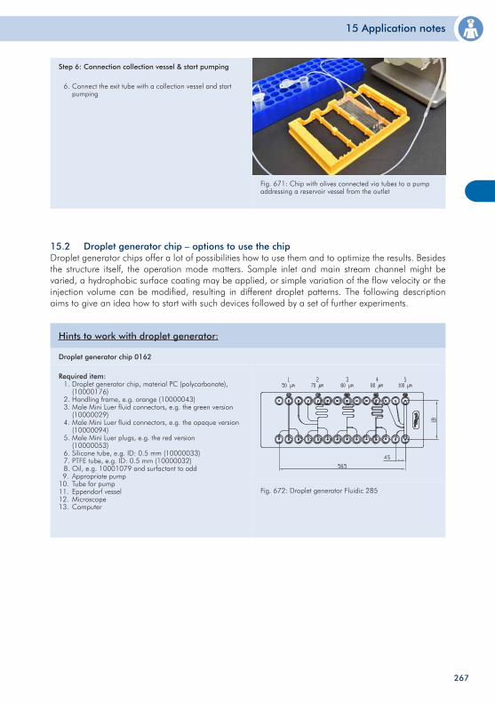
15 Application notes
Fig. 671: Chip with olives connected via tubes to a pump addressing a reservoir vessel from the outlet
6. Connect the exit tube with a collection vessel and start pumping
Step 6: Connection collection vessel & start pumping
15.2 Droplet generator chip – options to use the chip Droplet generator chips offer a lot of possibilities how to use them and to optimize the results. Besides the structure itself, the operation mode matters. Sample inlet and main stream channel might be varied, a hydrophobic surface coating may be applied, or simple variation of the flow velocity or the injection volume can be modified, resulting in different droplet patterns. The following description aims to give an idea how to start with such devices followed by a set of further experiments.
Fig. 672: Droplet generator Fluidic 285
Required item: 1. Droplet generator chip, material PC (polycarbonate), (10000176) 2. Handling frame, e.g. orange (10000043) 3. Male Mini Luer fluid connectors, e.g. the green version (10000029) 4. Male Mini Luer fluid connectors, e.g. the opaque version (10000094) 5. Male Mini Luer plugs, e.g. the red version (10000053) 6. Silicone tube, e.g. ID: 0.5 mm (10000033) 7. PTFE tube, e.g. ID: 0.5 mm (10000032) 8. Oil, e.g. 10001079 and surfactant to add 9. Appropriate pump10. Tube for pump11. Eppendorf vessel12. Microscope13. Computer
Hints to work with droplet generator:
Droplet generator chip 0162
267
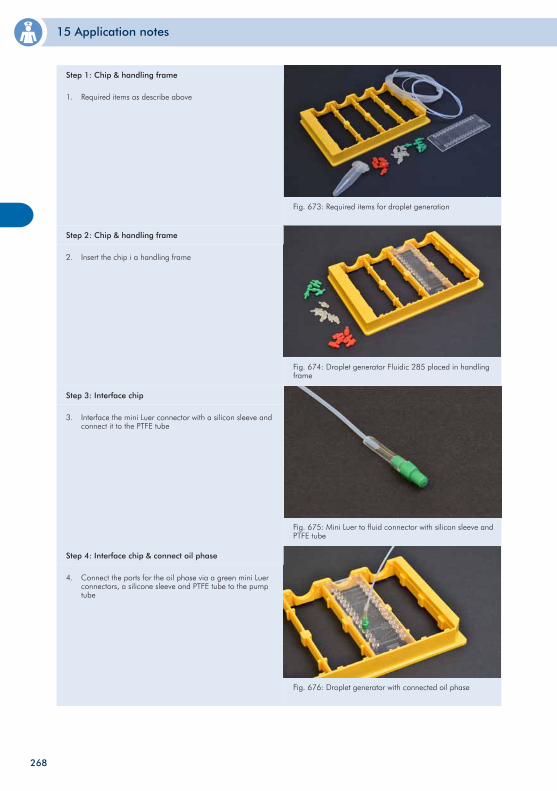
15 Application notes
Fig. 674: Droplet generator Fluidic 285 placed in handling frame
2. Insert the chip i a handling frame
Step 2: Chip & handling frame
Fig. 675: Mini Luer to fluid connector with silicon sleeve and PTFE tube
3. Interface the mini Luer connector with a silicon sleeve and connect it to the PTFE tube
Step 3: Interface chip
Fig. 676: Droplet generator with connected oil phase
4. Connect the ports for the oil phase via a green mini Luer connectors, a silicone sleeve and PTFE tube to the pump tube
Step 4: Interface chip & connect oil phase
Fig. 673: Required items for droplet generation
1. Required items as describe above
Step 1: Chip & handling frame
268
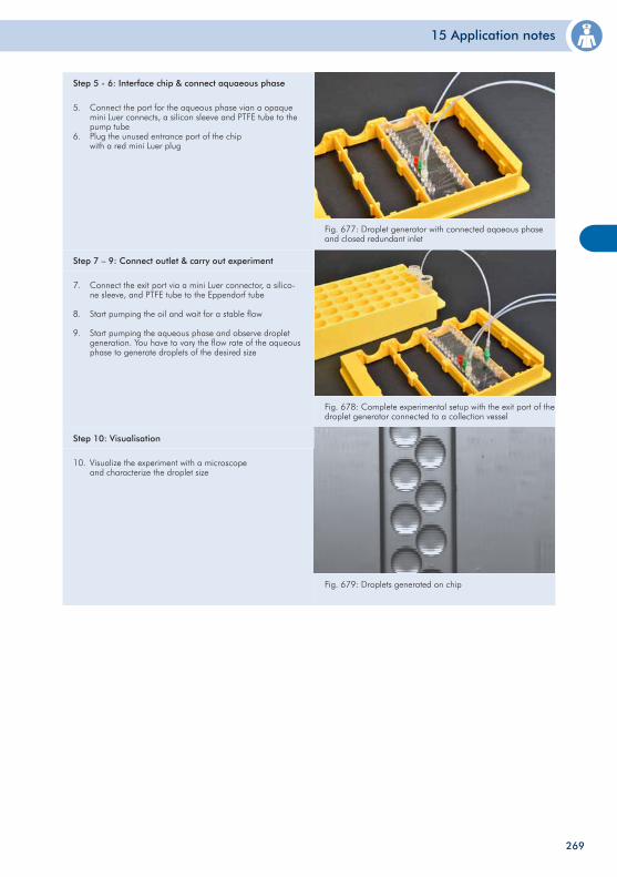
15 Application notes
Fig. 678: Complete experimental setup with the exit port of the droplet generator connected to a collection vessel
7. Connect the exit port via a mini Luer connector, a silico- ne sleeve, and PTFE tube to the Eppendorf tube
8. Start pumping the oil and wait for a stable flow
9. Start pumping the aqueous phase and observe droplet generation. You have to vary the flow rate of the aqueous phase to generate droplets of the desired size
Step 7 – 9: Connect outlet & carry out experiment
Fig. 679: Droplets generated on chip
10. Visualize the experiment with a microscope and characterize the droplet size
Step 10: Visualisation
Fig. 677: Droplet generator with connected aqaeous phase and closed redundant inlet
5. Connect the port for the aqueous phase vian a opaque mini Luer connects, a silicon sleeve and PTFE tube to the pump tube 6. Plug the unused entrance port of the chip with a red mini Luer plug
Step 5 - 6: Interface chip & connect aquaeous phase
269
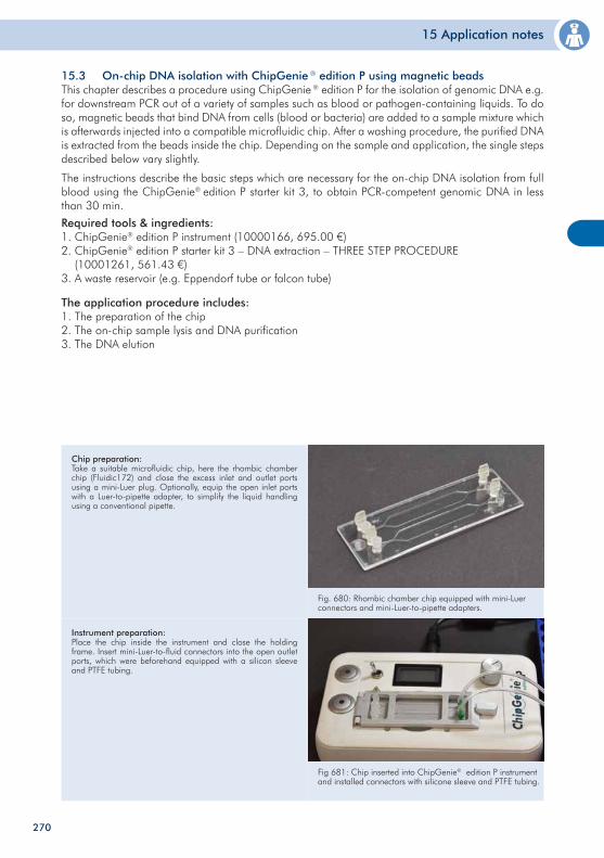
15 Application notes
15.3 On-chip DNA isolation with ChipGenie ® edition P using magnetic beadsThis chapter describes a procedure using ChipGenie ® edition P for the isolation of genomic DNA e.g. for downstream PCR out of a variety of samples such as blood or pathogen-containing liquids. To do so, magnetic beads that bind DNA from cells (blood or bacteria) are added to a sample mixture which is afterwards injected into a compatible microfluidic chip. After a washing procedure, the purified DNA is extracted from the beads inside the chip. Depending on the sample and application, the single steps described below vary slightly.
The instructions describe the basic steps which are necessary for the on-chip DNA isolation from full blood using the ChipGenie® edition P starter kit 3, to obtain PCR-competent genomic DNA in less than 30 min.
Fig. 680: Rhombic chamber chip equipped with mini-Luer connectors and mini-Luer-to-pipette adapters.
Required tools & ingredients:1. ChipGenie® edition P instrument (10000166, 695.00 €)2. ChipGenie® edition P starter kit 3 – DNA extraction – THREE STEP PROCEDURE (10001261, 561.43 €)3. A waste reservoir (e.g. Eppendorf tube or falcon tube)
The application procedure includes:1. The preparation of the chip2. The on-chip sample lysis and DNA purification3. The DNA elution
Chip preparation:Take a suitable microfluidic chip, here the rhombic chamber chip (Fluidic172) and close the excess inlet and outlet ports using a mini-Luer plug. Optionally, equip the open inlet ports with a Luer-to-pipette adapter, to simplify the liquid handling using a conventional pipette.
Fig 681: Chip inserted into ChipGenie® edition P instrument and installed connectors with silicone sleeve and PTFE tubing.
Instrument preparation:Place the chip inside the instrument and close the holding frame. Insert mini-Luer-to-fluid connectors into the open outlet ports, which were beforehand equipped with a silicon sleeve and PTFE tubing.
270
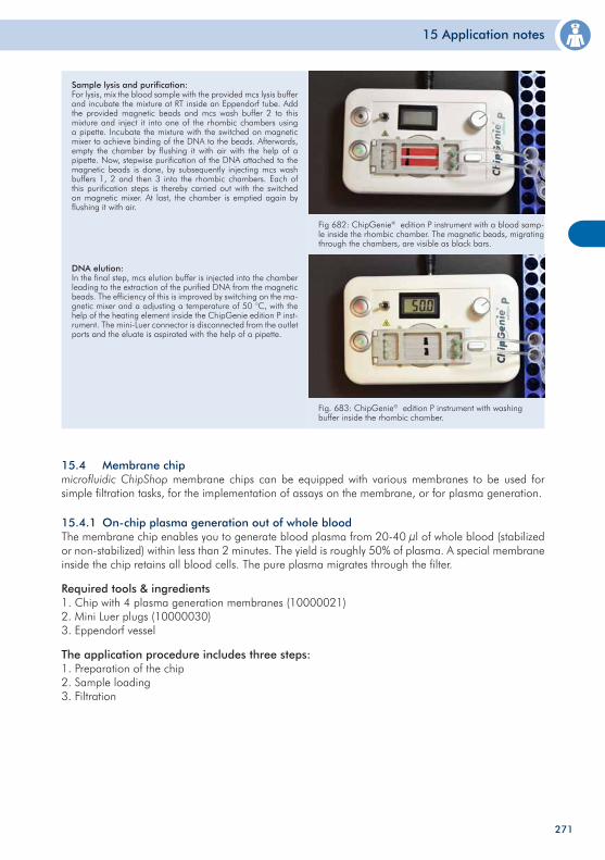
15 Application notes
Fig 682: ChipGenie® edition P instrument with a blood samp-le inside the rhombic chamber. The magnetic beads, migrating through the chambers, are visible as black bars.
Fig. 683: ChipGenie® edition P instrument with washing buffer inside the rhombic chamber.
Sample lysis and purification:For lysis, mix the blood sample with the provided mcs lysis buffer and incubate the mixture at RT inside an Eppendorf tube. Add the provided magnetic beads and mcs wash buffer 2 to this mixture and inject it into one of the rhombic chambers using a pipette. Incubate the mixture with the switched on magnetic mixer to achieve binding of the DNA to the beads. Afterwards, empty the chamber by flushing it with air with the help of a pipette. Now, stepwise purification of the DNA attached to the magnetic beads is done, by subsequently injecting mcs wash buffers 1, 2 and then 3 into the rhombic chambers. Each of this purification steps is thereby carried out with the switched on magnetic mixer. At last, the chamber is emptied again by flushing it with air.
DNA elution: In the final step, mcs elution buffer is injected into the chamber leading to the extraction of the purified DNA from the magnetic beads. The efficiency of this is improved by switching on the ma-gnetic mixer and a adjusting a temperature of 50 °C, with the help of the heating element inside the ChipGenie edition P inst-rument. The mini-Luer connector is disconnected from the outlet ports and the eluate is aspirated with the help of a pipette.
15.4 Membrane chip microfluidic ChipShop membrane chips can be equipped with various membranes to be used for simple filtration tasks, for the implementation of assays on the membrane, or for plasma generation.
15.4.1 On-chip plasma generation out of whole blood The membrane chip enables you to generate blood plasma from 20-40 µl of whole blood (stabilized or non-stabilized) within less than 2 minutes. The yield is roughly 50% of plasma. A special membrane inside the chip retains all blood cells. The pure plasma migrates through the filter.
Required tools & ingredients1. Chip with 4 plasma generation membranes (10000021)2. Mini Luer plugs (10000030)3. Eppendorf vessel
The application procedure includes three steps:1. Preparation of the chip2. Sample loading3. Filtration
271
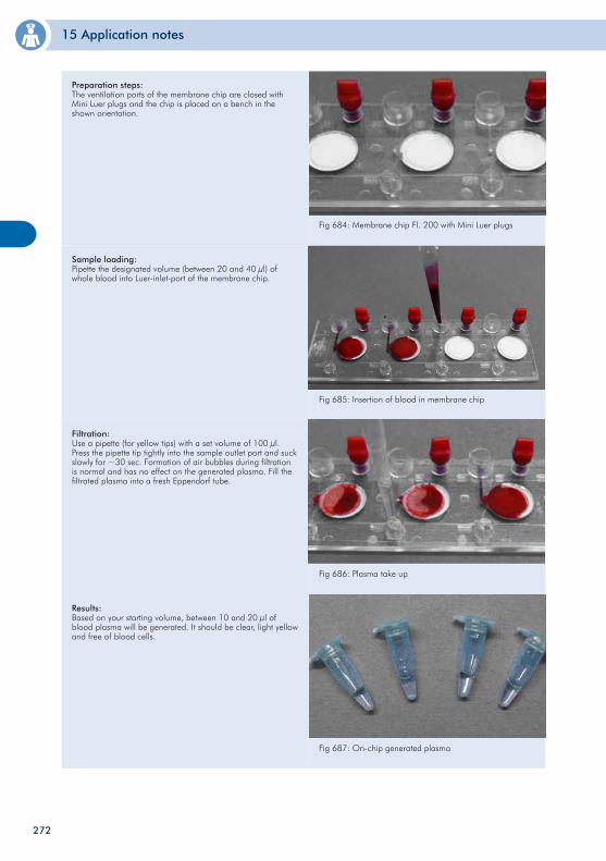
15 Application notes
Fig 684: Membrane chip Fl. 200 with Mini Luer plugs
Fig 685: Insertion of blood in membrane chip
Preparation steps: The ventilation ports of the membrane chip are closed with Mini Luer plugs and the chip is placed on a bench in the shown orientation.
Sample loading: Pipette the designated volume (between 20 and 40 µl) of whole blood into Luer-inlet-port of the membrane chip.
Fig 686: Plasma take up
Filtration: Use a pipette (for yellow tips) with a set volume of 100 µl. Press the pipette tip tightly into the sample outlet port and suck slowly for ~30 sec. Formation of air bubbles during filtration is normal and has no effect on the generated plasma. Fill the filtrated plasma into a fresh Eppendorf tube.
Fig 687: On-chip generated plasma
Results: Based on your starting volume, between 10 and 20 µl of blood plasma will be generated. It should be clear, light yellow and free of blood cells.
272
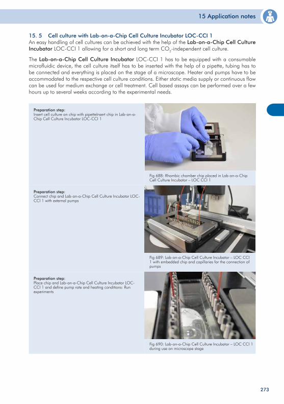
15 Application notes
273
15. 5 Cell culture with Lab-on-a-Chip Cell Culture Incubator LOC-CCI 1 An easy handling of cell cultures can be achieved with the help of the Lab-on-a-Chip Cell Culture Incubator LOC-CCI 1 allowing for a short and long term CO2-independent cell culture.
The Lab-on-a-Chip Cell Culture Incubator LOC-CCI 1 has to be equipped with a consumable microfluidic device, the cell culture itself has to be inserted with the help of a pipette, tubing has to be connected and everything is placed on the stage of a microscope. Heater and pumps have to be accommodated to the respective cell culture conditions. Either static media supply or continuous flow can be used for medium exchange or cell treatment. Cell based assays can be performed over a few hours up to several weeks according to the experimental needs.
Fig 688: Rhombic chamber chip placed in Lab-on-a-ChipCell Culture Incubator – LOC CCI 1
Fig 689: Lab-on-a-Chip Cell Culture Incubator – LOC CCI 1 with embedded chip and capillaries for the connection of pumps
Preparation step: Insert cell culture on chip with pipetteInsert chip in Lab-on-a-Chip Cell Culture Incubator LOC-CCI 1
Preparation step: Connect chip and Lab-on-a-Chip Cell Culture Incubator LOC-CCI 1 with external pumps
Fig 690: Lab-on-a-Chip Cell Culture Incubator – LOC CCI 1 during use on microscope stage
Preparation step: Place chip and Lab-on-a-Chip Cell Culture Incubator LOC-CCI 1 and define pump rate and heating conditions: Run experiments
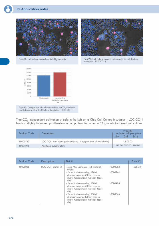
15 Application notes
274
Fig 691: Cell culture carried out in CO2-incubator Fig 692: Cell culture done in Lab-on-a-Chip Cell Culture Incubator – LOC CCI 1
Fig 693: Comparison of cell culture done in CO2-incubator and Lab-on-a-Chip Cell Culture Incubator – LOC CCI 1
That CO2-independent cultivation of cells in the Lab-on-a-Chip Cell Culture Incubator – LOC CCI 1 leads to slightly increased proliferation in comparison to common CO2-incubator-based cell culture.
10000743
10001216
Product Code
LOC CCI 1 with heating elements (incl. 1 adapter plate of your choice)
Additional adapter plate
Description
1,875.00
included adapter plate2x4 2x8 2x16
390.00 390.00 390.00
Price [€]
10000286 LOC-CCI 1 starter kit 1
Product Code Price [€]
638.32
Description
- Male Mini Luer plugs, red, material: PP (10)- Rhombic chamber chip, 120 µl chamber volume, 500 µm channel depth, hydrophilized, material: Topas (10)- Rhombic chamber chip, 100 µl chamber volume, 600 µm channel depth, hydrophilized, material: Topas (10)- Rhombic chamber chip, 250 µl chamber volume, 800 µm channel depth, hydrophilized, material: Topas (10)
Detail
10000053
10000244
10000405
10000365

275
276
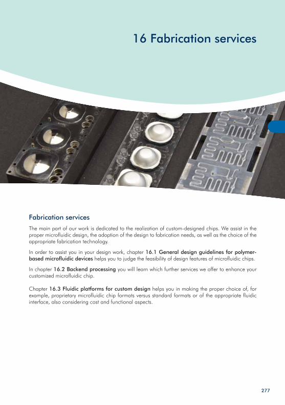
16 Fabrication services
Fabrication services
The main part of our work is dedicated to the realization of custom-designed chips. We assist in the proper microfluidic design, the adoption of the design to fabrication needs, as well as the choice of the appropriate fabrication technology.
In order to assist you in your design work, chapter 16.1 General design guidelines for polymer-based microfluidic devices helps you to judge the feasibility of design features of microfluidic chips.
In chapter 16.2 Backend processing you will learn which further services we offer to enhance your customized microfluidic chip.
Chapter 16.3 Fluidic platforms for custom design helps you in making the proper choice of, for example, proprietary microfluidic chip formats versus standard formats or of the appropriate fluidic interface, also considering cost and functional aspects.
277
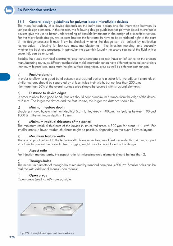
16 Fabrication services
16.1 General design guidelines for polymer-based microfluidic devices The manufacturability of a device depends on the individual design and the interaction between its various design elements. In this respect, the following design guidelines for polymer-based microfluidic devices give the user a better understanding of possible limitations in the design of a specific structure. For the microfluidic design, two aspects besides the functionality have to be considered right at the start of the design process: It must firstly be checked whether the design can be realized by replicative technologies – allowing for low-cost mass-manufacturing – like injection molding, and secondly whether the back-end processes, in particular the assembly (usually the secure sealing of the fluid with a cover lid), can be ensured.
Besides the purely technical constraints, cost considerations can also have an influence on the chosen manufacturing route, as different methods for mold insert fabrication have different technical constraints (minimum feature size, maximum height, surface roughness, etc.) as well as different cost ranges.
a) Feature densityIn order to allow for a good bond between a structured part and a cover foil, two adjacent channels or similar features should be separated by at least twice their width, but not less than 200 µm.Not more than 50% of the overall surface area should be covered with structural elements.
b) Distance to device edgesIn order to allow for a good bond, features should have a minimum distance from the edge of the device of 2 mm. The larger the device and the feature size, the larger this distance should be.
c) Minimum feature depthStructures should have a minimum depth of 5 µm for features < 100 µm. For features between 100 and 1000 µm, the minimum depth is 15 µm.
d) Minimum residual thickness of the deviceThe minimum residual thickness of the device in structured areas is 500 µm for areas > 1 cm2. For smaller areas, a lower residual thickness might be possible, depending on the overall device layout.
e) Maximum feature widthThere is no practical limit to the feature width, however in the case of features wider than 4 mm, support structures to prevent the cover lid from sagging might have to be included in the design.
f) Aspect ratioFor injection molded parts, the aspect ratio for microstructured elements should be less than 2.
g) Through-holesThe minimum diameter of through-holes realized by standard core pins is 500 µm. Smaller holes can be realized with additional means upon request.
h) Open areasOpen areas (see Fig. 694) are possible.
Fig. 694: Through-holes, open and structured areas
278
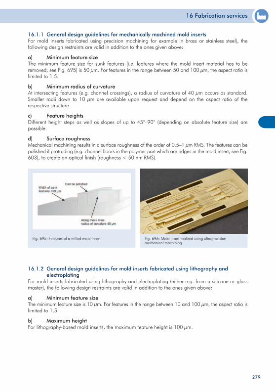
16 Fabrication services
16.1.1 General design guidelines for mechanically machined mold inserts For mold inserts fabricated using precision machining for example in brass or stainless steel), the following design restraints are valid in addition to the ones given above:
a) Minimum feature sizeThe minimum feature size for sunk features (i.e. features where the mold insert material has to be removed; see Fig. 695) is 50 µm. For features in the range between 50 and 100 µm, the aspect ratio is limited to 1.5.
b) Minimum radius of curvatureAt intersecting features (e.g. channel crossings), a radius of curvature of 40 µm occurs as standard. Smaller radii down to 10 µm are available upon request and depend on the aspect ratio of the respective structure
c) Feature heightsDifferent height steps as well as slopes of up to 45°–90° (depending on absolute feature size) are possible.
d) Surface roughnessMechanical machining results in a surface roughness of the order of 0.5–1 µm RMS. The features can be polished if protruding (e.g. channel floors in the polymer part which are ridges in the mold insert; see Fig. 603), to create an optical finish (roughness < 50 nm RMS).
Fig. 695: Features of a milled mold insert
16.1.2 General design guidelines for mold inserts fabricated using lithography and electroplating For mold inserts fabricated using lithography and electroplating (either e.g. from a silicone or glass master), the following design restraints are valid in addition to the ones given above:
a) Minimum feature sizeThe minimum feature size is 10 µm. For features in the range between 10 and 100 µm, the aspect ratio is limited to 1.5.
b) Maximum heightFor lithography-based mold inserts, the maximum feature height is 100 µm.
Fig. 696: Mold insert realized using ultraprecision mechanical machining
279
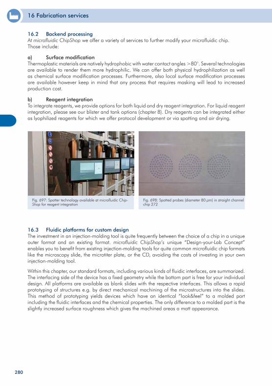
16 Fabrication services
280
16.3 Fluidic platforms for custom design The investment in an injection-molding tool is quite frequently between the choice of a chip in a unique outer format and an existing format. microfluidic ChipShop‘s unique “Design-your-Lab Concept” enables you to benefit from existing injection-molding tools for quite common microfluidic chip formats like the microscopy slide, the microtiter plate, or the CD, avoiding the costs of investing in your own injection-molding tool.
Within this chapter, our standard formats, including various kinds of fluidic interfaces, are summarized. The interfacing side of the device has a fixed geometry while the bottom part is free for your individual design. All platforms are available as blank slides with the respective interfaces. This allows a rapid prototyping of structures e.g. by direct mechanical machining of the microstructures into the slides. This method of prototyping yields devices which have an identical “look&feel” to a molded part including the fluidic interfaces and the chemical properties. The only difference to a molded part is the slightly increased surface roughness which gives the machined areas a matt appearance.
16.2 Backend processingAt microfluidic ChipShop we offer a variety of services to further modify your microfluidic chip.Those include:
a) Surface modificationThermoplastic materials are natively hydrophobic with water contact angles >80°. Several technologies are available to render them more hydrophilic. We can offer both physical hydrophilization as well as chemical surface modification processes. Furthermore, also local surface modification processes are available however keep in mind that any process that requires masking will lead to increased production cost.
b) Reagent integrationTo integrate reagents, we provide options for both liquid and dry reagent integration. For liquid reagent integration, please see our blister and tank options (chapter 8). Dry reagents can be integrated either as lyophilized reagents for which we offer protocol development or via spotting and air drying.
Fig. 697: Spotter technology available at microfluidic Chip-Shop for reagent integration
Fig. 698: Spotted probes (diameter 80 µm) in straight channel chip 272
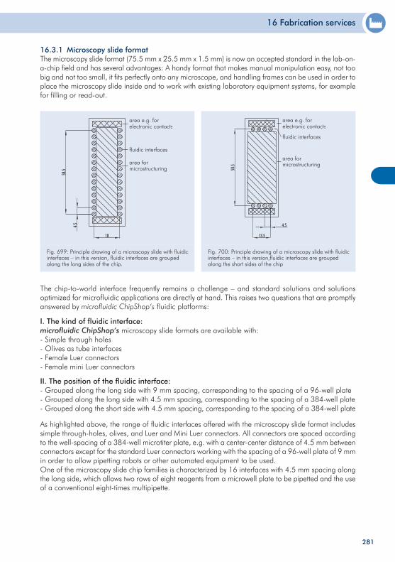
16 Fabrication services
281
II. The position of the fluidic interface:- Grouped along the long side with 9 mm spacing, corresponding to the spacing of a 96-well plate- Grouped along the long side with 4.5 mm spacing, corresponding to the spacing of a 384-well plate- Grouped along the short side with 4.5 mm spacing, corresponding to the spacing of a 384-well plate
As highlighted above, the range of fluidic interfaces offered with the microscopy slide format includes simple through-holes, olives, and Luer and Mini Luer connectors. All connectors are spaced according to the well-spacing of a 384-well microtiter plate, e.g. with a center-center distance of 4.5 mm between connectors except for the standard Luer connectors working with the spacing of a 96-well plate of 9 mm in order to allow pipetting robots or other automated equipment to be used.One of the microscopy slide chip families is characterized by 16 interfaces with 4.5 mm spacing along the long side, which allows two rows of eight reagents from a microwell plate to be pipetted and the use of a conventional eight-times multipipette.
Fig. 699: Principle drawing of a microscopy slide with fluidicinterfaces – in this version, fluidic interfaces are grouped along the long sides of the chip.
Fig. 700: Principle drawing of a microscopy slide with fluidic interfaces – in this version,fluidic interfaces are grouped along the short sides of the chip
16.3.1 Microscopy slide format The microscopy slide format (75.5 mm x 25.5 mm x 1.5 mm) is now an accepted standard in the lab-on-a-chip field and has several advantages: A handy format that makes manual manipulation easy, not too big and not too small, it fits perfectly onto any microscope, and handling frames can be used in order to place the microscopy slide inside and to work with existing laboratory equipment systems, for example for filling or read-out.
The chip-to-world interface frequently remains a challenge – and standard solutions and solutions optimized for microfluidic applications are directly at hand. This raises two questions that are promptly answered by microfluidic ChipShop‘s fluidic platforms:
I. The kind of fluidic interface:microfluidic ChipShop‘s microscopy slide formats are available with:- Simple through holes- Olives as tube interfaces- Female Luer connectors- Female mini Luer connectors
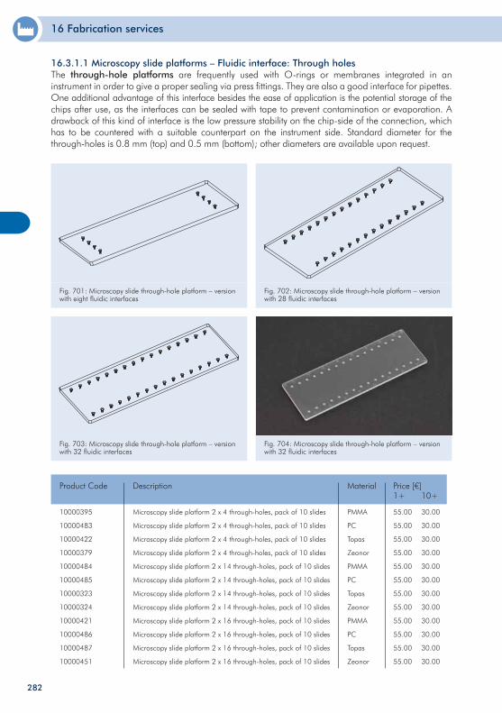
16 Fabrication services
282
10000395
10000483
10000422
10000379
10000484
10000485
10000323
10000324
10000421
10000486
10000487
10000451
Microscopy slide platform 2 x 4 through-holes, pack of 10 slides
Microscopy slide platform 2 x 4 through-holes, pack of 10 slides
Microscopy slide platform 2 x 4 through-holes, pack of 10 slides
Microscopy slide platform 2 x 4 through-holes, pack of 10 slides
Microscopy slide platform 2 x 14 through-holes, pack of 10 slides
Microscopy slide platform 2 x 14 through-holes, pack of 10 slides
Microscopy slide platform 2 x 14 through-holes, pack of 10 slides
Microscopy slide platform 2 x 14 through-holes, pack of 10 slides
Microscopy slide platform 2 x 16 through-holes, pack of 10 slides
Microscopy slide platform 2 x 16 through-holes, pack of 10 slides
Microscopy slide platform 2 x 16 through-holes, pack of 10 slides
Microscopy slide platform 2 x 16 through-holes, pack of 10 slides
Product Code Price [€]1+ 10+
55.00
55.00
55.00
55.00
55.00
55.00
55.00
55.00
55.00
55.00
55.00
55.00
30.00
30.00
30.00
30.00
30.00
30.00
30.00
30.00
30.00
30.00
30.00
30.00
Description
PMMA
PC
Topas
Zeonor
PMMA
PC
Topas
Zeonor
PMMA
PC
Topas
Zeonor
Material
Fig. 701: Microscopy slide through-hole platform – version with eight fluidic interfaces
Fig. 702: Microscopy slide through-hole platform – version with 28 fluidic interfaces
Fig. 703: Microscopy slide through-hole platform – version with 32 fluidic interfaces
Fig. 704: Microscopy slide through-hole platform – version with 32 fluidic interfaces
16.3.1.1 Microscopy slide platforms – Fluidic interface: Through holes The through-hole platforms are frequently used with O-rings or membranes integrated in an instrument in order to give a proper sealing via press fittings. They are also a good interface for pipettes. One additional advantage of this interface besides the ease of application is the potential storage of the chips after use, as the interfaces can be sealed with tape to prevent contamination or evaporation. A drawback of this kind of interface is the low pressure stability on the chip-side of the connection, which has to be countered with a suitable counterpart on the instrument side. Standard diameter for the through-holes is 0.8 mm (top) and 0.5 mm (bottom); other diameters are available upon request.
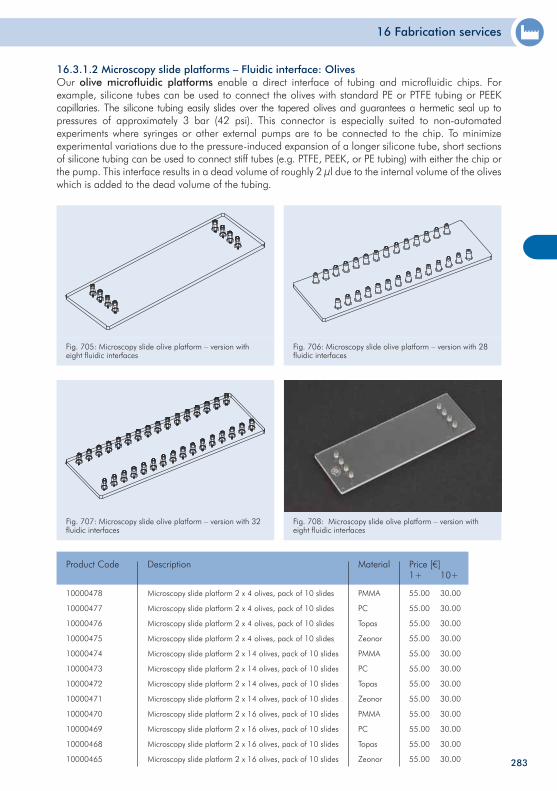
16 Fabrication services
283
Fig. 707: Microscopy slide olive platform – version with 32 fluidic interfaces
Fig. 708: Microscopy slide olive platform – version with eight fluidic interfaces
10000478
10000477
10000476
10000475
10000474
10000473
10000472
10000471
10000470
10000469
10000468
10000465
Microscopy slide platform 2 x 4 olives, pack of 10 slides
Microscopy slide platform 2 x 4 olives, pack of 10 slides
Microscopy slide platform 2 x 4 olives, pack of 10 slides
Microscopy slide platform 2 x 4 olives, pack of 10 slides
Microscopy slide platform 2 x 14 olives, pack of 10 slides
Microscopy slide platform 2 x 14 olives, pack of 10 slides
Microscopy slide platform 2 x 14 olives, pack of 10 slides
Microscopy slide platform 2 x 14 olives, pack of 10 slides
Microscopy slide platform 2 x 16 olives, pack of 10 slides
Microscopy slide platform 2 x 16 olives, pack of 10 slides
Microscopy slide platform 2 x 16 olives, pack of 10 slides
Microscopy slide platform 2 x 16 olives, pack of 10 slides
Product Code1+ 10+
55.00
55.00
55.00
55.00
55.00
55.00
55.00
55.00
55.00
55.00
55.00
55.00
30.00
30.00
30.00
30.00
30.00
30.00
30.00
30.00
30.00
30.00
30.00
30.00
Description
PMMA
PC
Topas
Zeonor
PMMA
PC
Topas
Zeonor
PMMA
PC
Topas
Zeonor
Price [€]Material
16.3.1.2 Microscopy slide platforms – Fluidic interface: Olives Our olive microfluidic platforms enable a direct interface of tubing and microfluidic chips. For example, silicone tubes can be used to connect the olives with standard PE or PTFE tubing or PEEKcapillaries. The silicone tubing easily slides over the tapered olives and guarantees a hermetic seal up to pressures of approximately 3 bar (42 psi). This connector is especially suited to non-automated experiments where syringes or other external pumps are to be connected to the chip. To minimize experimental variations due to the pressure-induced expansion of a longer silicone tube, short sections of silicone tubing can be used to connect stiff tubes (e.g. PTFE, PEEK, or PE tubing) with either the chip or the pump. This interface results in a dead volume of roughly 2 µl due to the internal volume of the olives which is added to the dead volume of the tubing.
Fig. 705: Microscopy slide olive platform – version with eight fluidic interfaces
Fig. 706: Microscopy slide olive platform – version with 28fluidic interfaces
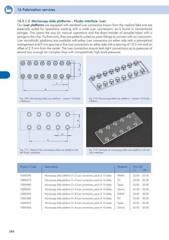
16 Fabrication services
284
Fig. 709: Microscopy slide Luer platform – version 16 fluidic interfaces
Fig. 710: Microscopy slide Luer platform – version 16 fluidicinterfacs
Fig. 711: Detail of the microscopy slide Luer platform with ten fluidic interfaces
Fig. 712: Example of microscopy slide Luer platform with ten Luer interfaces
10000393
10000479
10000480
10000481
10000403
10000482
10000407
10000406
Microscopy slide platform 2 x 5 Luer connectors, pack of 10 slides
Microscopy slide platform 2 x 5 Luer connectors, pack of 10 slides
Microscopy slide platform 2 x 5 Luer connectors, pack of 10 slides
Microscopy slide platform 2 x 5 Luer connectors, pack of 10 slides
Microscopy slide platform 2 x 8 Luer connectors, pack of 10 slides
Microscopy slide platform 2 x 8 Luer connectors, pack of 10 slides
Microscopy slide platform 2 x 8 Luer connectors, pack of 10 slides
Microscopy slide platform 2 x 8 Luer connectors, pack of 10 slides
Product Code Price [€]1+ 10+
55.00
55.00
55.00
55.00
55.00
55.00
55.00
55.00
30.00
30.00
30.00
30.00
30.00
30.00
30.00
30.00
Description
PMMA
PC
Topas
Zeonor
PMMA
PC
Topas
Zeonor
Material
16.3.1.3 Microscopy slide platforms – Fluidic interface: Luer Our Luer platforms are equipped with standard Luer connectors known from the medical field and are especially suited for operations working with a male Luer counterpart, as is found in conventional syringes. This opens the way for manual operations and the direct transfer of samples taken with a syringe to the chip. Furthermore, they are perfectly suited as press-fittings to connect with an instrument. Luer microfluidic platforms are available with either Luer connectors on either side with a symmetrical arrangement and 9 mm spacing or five Luer connectors on either side with a spacing of 13.5 mm and an offset of 2.5 mm from the center. The Luer connectors ensure leak-tight connections up to pressures of several bar, enough for complex chips with comparatively high back-pressures.
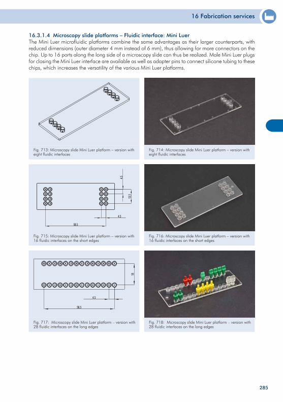
16 Fabrication services
285
Fig. 713: Microscopy slide Mini Luer platform – version with eight fluidic interfaces
Fig. 714: Microscopy slide Mini Luer platform – version with eight fluidic interfaces
Fig. 715: Microscopy slide Mini Luer platform – version with 16 fluidic interfaces on the short edges
Fig. 716: Microscopy slide Mini Luer platform – version with 16 fluidic interfaces on the short edges
Fig. 717: Microscopy slide Mini Luer platform – version with 28 fluidic interfaces on the long edges
Fig. 718: Microscopy slide Mini Luer platform – version with 28 fluidic interfaces on the long edges
16.3.1.4 Microscopy slide platforms – Fluidic interface: Mini Luer The Mini Luer microfluidic platforms combine the same advantages as their larger counterparts, with reduced dimensions (outer diameter 4 mm instead of 6 mm), thus allowing for more connectors on the chip. Up to 16 ports along the long side of a microscopy slide can thus be realized. Male Mini Luer plugs for closing the Mini Luer interface are available as well as adapter pins to connect silicone tubing to these chips, which increases the versatility of the various Mini Luer platforms.
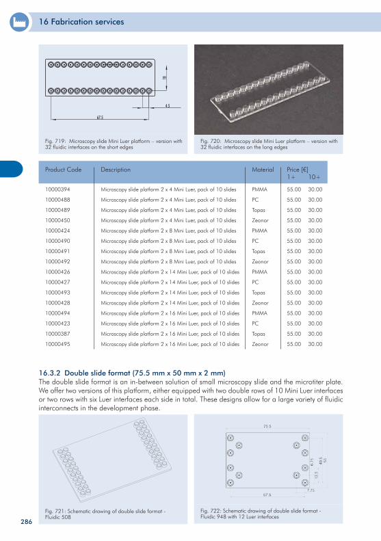
16 Fabrication services
286
16.3.2 Double slide format (75.5 mm x 50 mm x 2 mm)The double slide format is an in-between solution of small microscopy slide and the microtiter plate. We offer two versions of this platform, either equipped with two double rows of 10 Mini Luer interfaces or two rows with six Luer interfaces each side in total. These designs allow for a large variety of fluidic interconnects in the development phase.
10000394
10000488
10000489
10000450
10000424
10000490
10000491
10000492
10000426
10000427
10000493
10000428
10000494
10000423
10000387
10000495
Microscopy slide platform 2 x 4 Mini Luer, pack of 10 slides
Microscopy slide platform 2 x 4 Mini Luer, pack of 10 slides
Microscopy slide platform 2 x 4 Mini Luer, pack of 10 slides
Microscopy slide platform 2 x 4 Mini Luer, pack of 10 slides
Microscopy slide platform 2 x 8 Mini Luer, pack of 10 slides
Microscopy slide platform 2 x 8 Mini Luer, pack of 10 slides
Microscopy slide platform 2 x 8 Mini Luer, pack of 10 slides
Microscopy slide platform 2 x 8 Mini Luer, pack of 10 slides
Microscopy slide platform 2 x 14 Mini Luer, pack of 10 slides
Microscopy slide platform 2 x 14 Mini Luer, pack of 10 slides
Microscopy slide platform 2 x 14 Mini Luer, pack of 10 slides
Microscopy slide platform 2 x 14 Mini Luer, pack of 10 slides
Microscopy slide platform 2 x 16 Mini Luer, pack of 10 slides
Microscopy slide platform 2 x 16 Mini Luer, pack of 10 slides
Microscopy slide platform 2 x 16 Mini Luer, pack of 10 slides
Microscopy slide platform 2 x 16 Mini Luer, pack of 10 slides
Product Code Price [€]1+ 10+
55.00
55.00
55.00
55.00
55.00
55.00
55.00
55.00
55.00
55.00
55.00
55.00
55.00
55.00
55.00
55.00
30.00
30.00
30.00
30.00
30.00
30.00
30.00
30.00
30.00
30.00
30.00
30.00
30.00
30.00
30.00
30.00
Description
PMMA
PC
Topas
Zeonor
PMMA
PC
Topas
Zeonor
PMMA
PC
Topas
Zeonor
PMMA
PC
Topas
Zeonor
Material
Fig. 721: Schematic drawing of double slide format - Fluidic 508
Fig. 722: Schematic drawing of double slide format - Fluidic 948 with 12 Luer interfaces
Fig. 719: Microscopy slide Mini Luer platform – version with 32 fluidic interfaces on the short edges
Fig. 720: Microscopy slide Mini Luer platform – version with 32 fluidic interfaces on the long edges
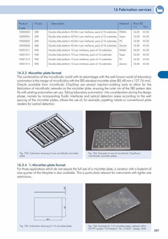
16 Fabrication services
287
16.3.4 ¼ Microtiter-plate format For those applications which do not require the full size of a microtiter plate, a variation with a footprint of one-quarter of the titerplate is also available. This is particularly relevant for instruments with tighter size restrictions.
Fig. 725: Schematic drawing of 1/4 microtiter-plate Fig. 726: Example for 1/4 microtiter-plate, realized within EU-FP7 project “CD-Medics“, No. 216031. Design: IMM
16.3.3 Microtiter plate format The combination of the microfluidic world with its advantages with the well-known world of laboratoryautomation is the merger of microfluidics with the SBS standard microtiter plate (85.48 mm x 127.76 mm). Directly available from microfluidic ChipShop are several injection-molding tools to allow for the fabrication of microfluidic networks on the microtiter plate, ensuring the outer rim of the SBS pattern also fits with existing automation set-ups. Taking laboratory automation into consideration during the design phase, namely by incorporating fluidic interfaces and optical detection areas according to the well spacing of the microtiter plates, allows the use of, for example, pipetting robots or conventional plate readers for optical detection.
Fig. 723: Schematic drawing of one microfluidic microtiter plate
Fig. 724: Example of one of microfluidic ChipShop‘s microfluidic microtiter plates
10000503
10000504
10000505
10000506
10001311
10001312
10001313
10001314
Double slide platform 40 Mini Luer interfaces, pack of 10 substrates
Double slide platform 40 Mini Luer interfaces, pack of 10 substrates
Double slide platform 40 Mini Luer interfaces, pack of 10 substrates
Double slide platform 40 Mini Luer interfaces, pack of 10 substrates
Double slide platform 12 Luer interfaces, pack of 10 substrates
Double slide platform 12 Luer interfaces, pack of 10 substrates
Double slide platform 12 Luer interfaces, pack of 10 substrates
Double slide platform 12 Luer interfaces, pack of 10 substrates
Product
Code
Price [€]1+ 10+
76.00
76.00
76.00
76.00
76.00
76.00
76.00
76.00
44.50
44.50
44.50
44.50
44.50
44.50
44.50
44.50
Description
PMMA
Topas
PC
Zeonor
PMMA
Topas
PC
Zeonor
MaterialFluidic
508
508
508
508
948
948
948
948
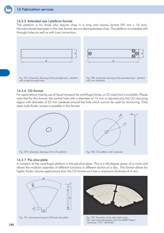
16 Fabrication services
288
Fig. 729: Schematic drawing of the CD-platform Fig. 730: CD-platform with measures
16.3.7 Pie-slice plateA variation of the centrifugal platform is the pie-slice plate. This is a 60-degree sector of a circle and allows the modular assembly of different functions in different sectors of a disc. This format allows for higher fluidic volume applications than the CD format as it has a maximum thickness of 4 mm.
Fig. 731: Geometrical layout of the pie slice plate Fig. 732: Examples of pie slice plate chips. The chips were developed within the BMBF-Project “ZentriLab“, FKZ 16SV2350.
Fig. 727: Schematic drawing of the extended size I platform with simple through-holes
Fig. 728: Schematic drawing of the extended size I platform with Luer interfaces
16.3.6 CD-format For applications making use of liquid transport by centrifugal forces, a CD-sized tool is available. Please note that for this format, the central hole with a diameter of 15 mm is required plus the CD clamping region with diameter of 25 mm centered around the hole which cannot be used for structuring. Only open-hole fluidic access is possible in this format.
16.3.5 Extended size I platform format This platform is for those who require chips in a long and narrow format (95 mm x 16 mm). Microstructured examples in this chip format are our electrophoresis chips. The platform is available with through-holes as well as with Luer connectors.

289
290
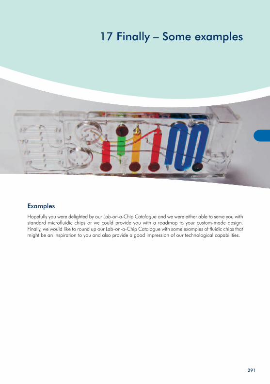
17 Finally – Some examples
Examples
Hopefully you were delighted by our Lab-on-a-Chip Catalogue and we were either able to serve you with standard microfluidic chips or we could provide you with a roadmap to your custom-made design. Finally, we would like to round up our Lab-on-a-Chip Catalogue with some examples of fluidic chips that might be an inspiration to you and also provide a good impression of our technological capabilities.
291
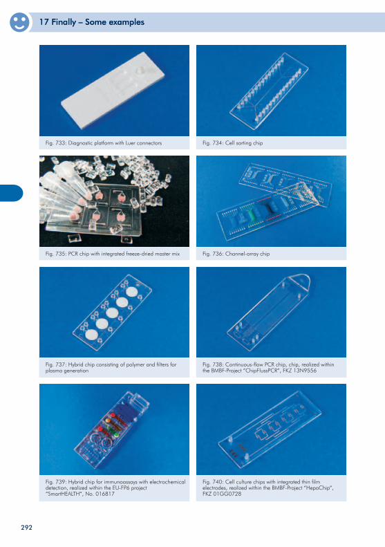
17 Finally – Some examples17 Finally – Some examples
Fig. 733: Diagnostic platform with Luer connectors Fig. 734: Cell sorting chip
Fig. 735: PCR chip with integrated freeze-dried master mix Fig. 736: Channel-array chip
Fig. 737: Hybrid chip consisting of polymer and filters for plasma generation
Fig. 738: Continuous-flow PCR chip, chip, realized within the BMBF-Project “ChipFlussPCR“, FKZ 13N9556
Fig. 739: Hybrid chip for immunoassays with electrochemical detection, realized within the EU-FP6 project “SmartHEALTH“, No. 016817
Fig. 740: Cell culture chips with integrated thin film electrodes, realized within the BMBF-Project “HepaChip“, FKZ 01GG0728
292
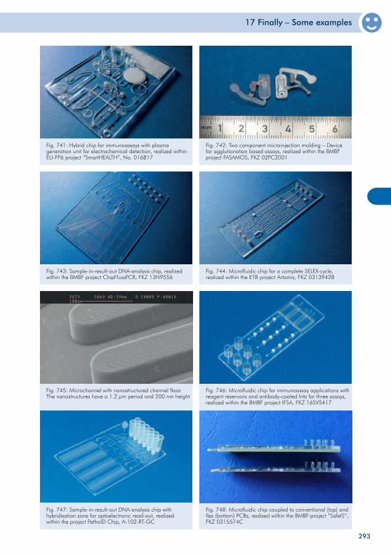
17 Finally – Some examples
Fig. 741: Hybrid chip for immunoassays with plasma generation unit for electrochemical detection, realized within EU-FP6 project “SmartHEALTH”, No. 016817
Fig. 742: Two component microinjection molding – Device for agglutionation based assays, realized within the BMBF project FASAMOS, FKZ 02PC2001
Fig. 743: Sample-in-result-out DNA-analysis chip, realized within the BMBF project ChipFlussPCR, FKZ 13N9556
Fig. 744: Microfluidic chip for a complete SELEX-cycle, realized within the ETB project Artamis, FKZ 03139428
Fig. 745: Microchannel with nanostructured channel floor. The nanostructures have a 1.2 µm period and 200 nm height
Fig. 746: Microfluidic chip for immunoassay applications with reagent reservoirs and antibody-coated frits for three assays, realized within the BMBF project IFSA, FKZ 16SV5417
Fig. 747: Sample-in-result-out DNA-analysis chip with hybridisation zone for optoelectronic read-out, realized within the project PathoID Chip, A-102-RT-GC
Fig. 748: Microfluidic chip coupled to conventional (top) and flex (bottom) PCBs, realized within the BMBF-project “SafeIS”, FKZ 0315574C
293
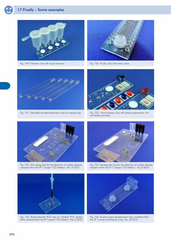
17 Finally – Some examples
Fig. 749: Filtration chip with liquid reservoir Fig. 750: Fluidic chip with rotary valve
Fig. 751: Extended size electrophoresis chip for sequencing Fig. 752: Immunoassay chip with plasma generation unit and blister pouches
Fig. 753: HLA typing chip for the detection of coeliac disease, realized within the FP 7 project “CD-Medics”, No. 216031
Fig. 754: Serology test chip for the detection of coeliac disease, realized within the FP 7 project “CD-Medics”, No.216031
Fig. 755: Boyle-Mariotte PCR chip for ultrafast PCR, design: IMM, realized within the FP 7 project “CD-Medics”, No. 216031
Fig. 756: Enyzme-assay development chip, realized within the FP 7 project Multisense Chip, No. 261810
294
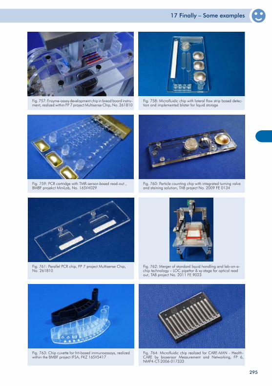
17 Finally – Some examples
Fig. 757: Enzyme-assay development chip in bread board instru-ment, realized within FP 7 project Multisense Chip, No. 261810
Fig. 758: Microfluidic chip with lateral flow strip based detec-tion and implemented blister for liquid storage
Fig. 759: PCR cartridge with TMR-sensor-based read-out , BMBF projekct MiniLab, No. 16SV4029
Fig. 760: Particle counting chip with integrated turning valve and staining solution, TAB project No. 2009 FE 0134
Fig. 762: Merger of standard liquid handling and lab-on-a-chip technology – LOC pipettor & xy-stage for optical read out, TAB project No. 2011 FE 9023
Fig. 761: Parallel PCR chip, FP 7 project Multisense Chip, No. 261810
295
Fig. 763: Chip cuvette for frit-based immunoassays, realized within the BMBF project IFSA, FKZ 16SV5417
Fig. 764: Microfluidic chip realized for CARE-MAN - Health-CARE by biosensor Measurement and Networking, FP 6, NMP4-CT-2006-017333
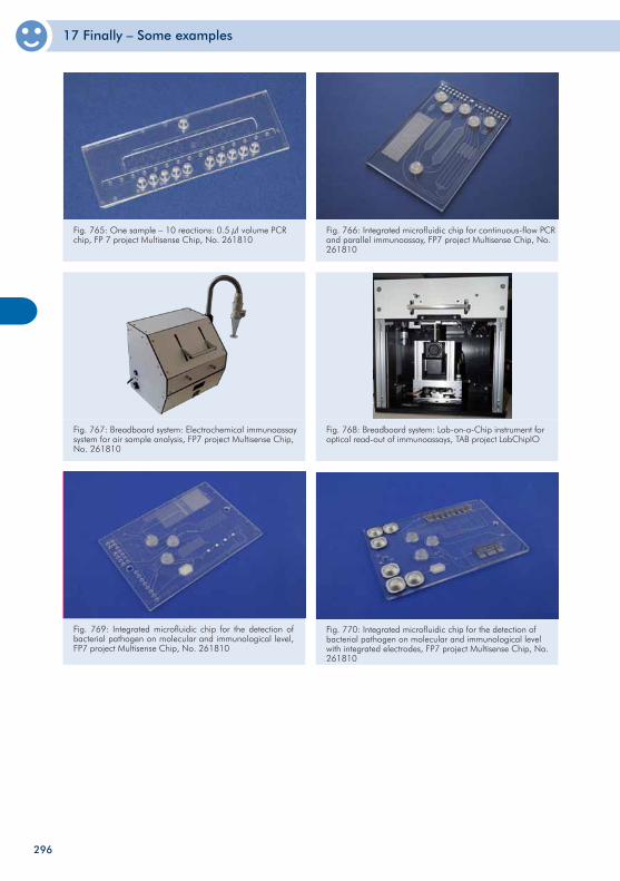
17 Finally – Some examples
Fig. 765: One sample – 10 reactions: 0.5 µl volume PCR chip, FP 7 project Multisense Chip, No. 261810
Fig. 766: Integrated microfluidic chip for continuous-flow PCR and parallel immunoassay, FP7 project Multisense Chip, No. 261810
Fig. 767: Breadboard system: Electrochemical immunoassay system for air sample analysis, FP7 project Multisense Chip, No. 261810
Fig. 768: Breadboard system: Lab-on-a-Chip instrument for optical read-out of immunoassays, TAB project LabChipIO
Fig. 769: Integrated microfluidic chip for the detection of bacterial pathogen on molecular and immunological level, FP7 project Multisense Chip, No. 261810
296
Fig. 770: Integrated microfluidic chip for the detection of bacterial pathogen on molecular and immunological level with integrated electrodes, FP7 project Multisense Chip, No. 261810
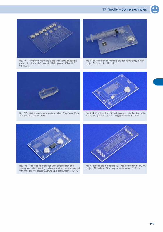
17 Finally – Some examples
297
Fig. 771: Integrated microfluidic chip with complete sample preparation for miRNA analysis, BMBF project IMRA, FKZ 0316078A
Fig. 772: Selective cell counting chip for hematology, BMBF project MrCyte, FKZ 13N12018
Fig. 773: Miniaturized spectrometer module, ChipGenie Optic TAB project 2013 FE 9021
Fig. 774: Cartridge for CTC isolation and lysis. Realized within the EU-FP7 project „CanDo“, project number: 610472
Fig. 776: Pearl chain mixer module. Realized within the EU-FP7 project „Nanodem“, Grant Agreement number: 318372
Fig. 775: Integrated cartridge for DNA amplification and subsequent detection using a silicone photonic sensor. Realized within the EU-FP7 project „CanDo“, project number: 610472
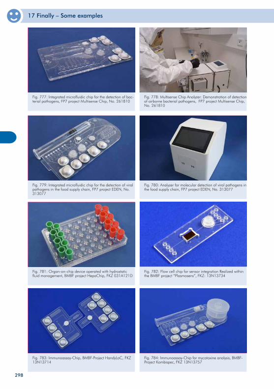
17 Finally – Some examples
Fig. 777: Integrated microfluidic chip for the detection of bac-terial pathogens, FP7 project Multisense Chip, No. 261810
Fig. 778: Multisense Chip Analyzer: Demonstration of detection of airborne bacterial pathogens, FP7 project Multisense Chip, No. 261810
Fig. 779: Integrated microfluidic chip for the detection of viral pathogens in the food supply chain, FP7 project EDEN, No. 313077
Fig. 780: Analyzer for molecular detection of viral pathogens in the food supply chain, FP7 project EDEN, No. 313077
Fig. 781: Organ-on-chip device operated with hydrostatic fluid management, BMBF project HepaChip, FKZ 031A121D
298
Fig. 782: Flow cell chip for sensor integration Realized within the BMBF project “Plasmosens”, FKZ: 13N13734
Fig. 783: Immunoassay-Chip, BMBF-Project HandyLoC, FKZ 13N13714
Fig. 784: Immunoassay-Chip for mycotoxine analysis, BMBF-Project Kombispec, FKZ 13N13757
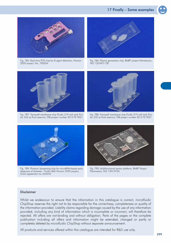
17 Finally – Some examples
299
Disclaimer
Whilst we endeavour to ensure that the information in this catalogue is correct, microfluidic ChipShop reserves the right not to be responsible for the correctness, completeness or quality of the information provided. Liability claims regarding damage caused by the use of any information provided, including any kind of information which is incomplete or incorrect, will therefore be rejected. All offers are not-binding and without obligation. Parts of the pages or the complete publication including all offers and information might be extended, changed or partly or completely deleted by microfluidic ChipShop without separate announcement.
All products and services offered within this catalogue are intended for R&D use only.
Fig. 785: Real-time PCR chip for B-agent detection, Horizon 2020 project, No. 700264
Fig. 786: Plasma generation chip, BMBF project Hämatoram, FKZ 13GW0112B
Fig. 787: Transwell membrane chip Fluidic 219 with tank Flui-dic 234 as fluid reservoir, TAB project number 2013 FE 9021
Fig. 788: Transwell membrane chip Fluidic 219 with tank Flui-dic 235 as fluid reservoir, TAB project number 2013 FE 9021
Fig. 789: Photonic biosensing chip for microRNA-based early diagnosis of diseases - Fluidic 866 Horizon 2020 project, Grant agreement no: 644242
Fig. 790: Multifunctional sensor platform, BMBF Project Plasmosens, FKZ 13N13734
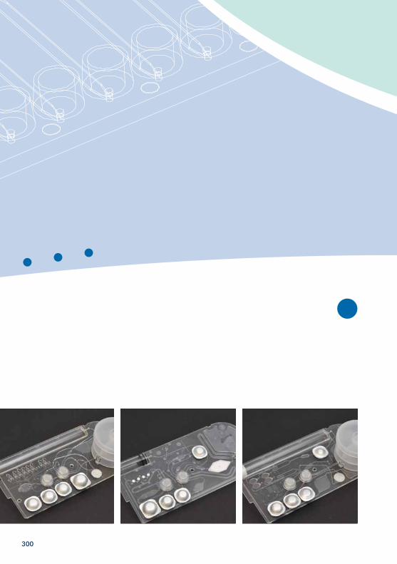
300
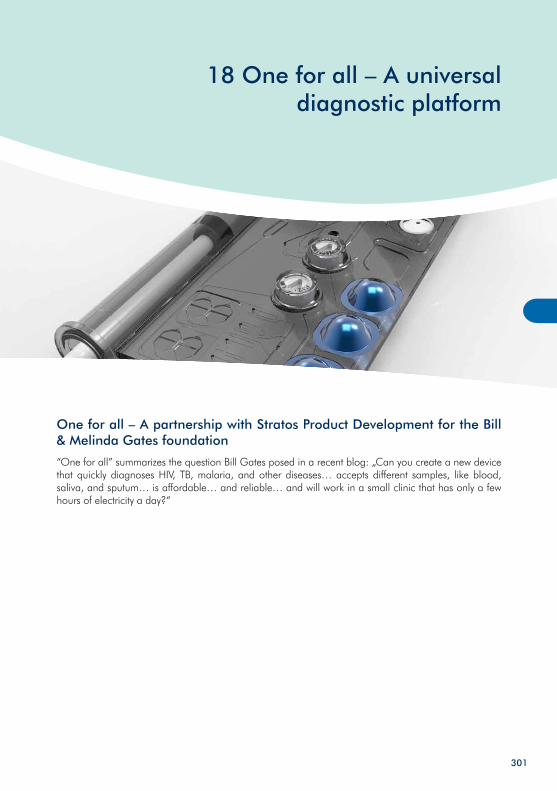
18 One for all – A universal diagnostic platform
301
One for all – A partnership with Stratos Product Development for the Bill & Melinda Gates foundation
“One for all” summarizes the question Bill Gates posed in a recent blog: „Can you create a new device that quickly diagnoses HIV, TB, malaria, and other diseases… accepts different samples, like blood, saliva, and sputum… is affordable… and reliable… and will work in a small clinic that has only a few hours of electricity a day?“
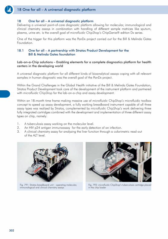
18 One for all – A universal diagnostic platform
302
Fig. 791: Stratos breadboard unit – operating molecular, immunological and clinical chemistry assays
Fig. 792: microfluidic ChipShop’s tuberculosis cartridge placed in the chip loader
18 One for all – A universal diagnostic platformDelivering a universal point-of-care diagnostic platform allowing for molecular, immunological and clinical chemistry assays in combination with handling of different sample matrices like sputum, plasma, urine etc. is the overall goal of microfluidic ChipShop‘s ChipGenie® edition Dx series.
One of the trigger for this platform was the PanDx project carried out for the Bill & Melinda Gates Foundation.
18.1 One for all – A partnership with Stratos Product Development for the Bill & Melinda Gates foundation
Lab-on-a-Chip solutions – Enabling elements for a complete diagnostics platform for health centers in the developing world
A universal diagnostic platform for all different kinds of bioanalytical assays coping with all relevant samples in human diagnostic was the overall goal of the PanDx project.
Within the Grand Challenges in the Global Health initiative of the Bill & Melinda Gates Foundation, Stratos Product Development took care of the development of the instrument platform and partnered with microfluidic ChipShop for the lab-on-a-chip and assay development.
Within an 18-month time frame making massive use of microfluidic ChipShop’s microfluidic toolbox concept to speed up assay development, a fully working breadboard instrument capable of all three assay types was realized by Stratos, complemented by microfluidic ChipShop’s work delivering three fully integrated cartridges combined with the development and implementation of three different assay types on chip, namely:
1. A tuberculosis assay working on the molecular level. 2. An HIV p24 antigen immunoassay for the early detection of an infection.3. A clinical chemistry assay for analyzing the liver function through a colorimetric read-out of the ALT level.
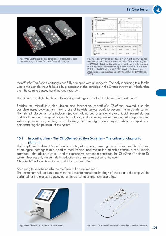
18 One for all
303
microfluidic ChipShop’s cartridges are fully equipped with all reagents. The only remaining task for the user is the sample input followed by placement of the cartridge in the Stratos instrument, which takes over the complete assay handling and read-out.
The pictures highlight the three fully working cartridges as well as the breadboard instrument.
Besides the microfluidic chip design and fabrication, microfluidic ChipShop covered also the complete assay development making use of its wide service portfolio beyond the microfabrication. The related fabrication tasks include injection molding and assembly, dry and liquid reagent storage and lyophilization, biological reagent formulation, surface tuning, membrane and frit integration, and valve implementation, leading to a fully integrated cartridge as a complete lab-on-a-chip device, demonstrating the potential of the system.
Fig. 793: Cartridges for the detection of tuberculosis, early HIV infection, and liver function (from left to right)
Fig. 794: Experimental results of a HLA-real-time PCR perfor-med on chip and in a conventional RT- PCR instrument (Biorad CFX96TM) - Gärtner, Claudia, et al. „Lab-on-a-chip enabled HLA diagnostic: combined sample preparation and real time PCR for HLA-B57 diagnosis.“ SPIE Sensing Technology+ Applications. International Society for Optics and Photonics, 2015.
18.2 In continuation – The ChipGenie® edition Dx series – The universal diagnostic platformThe ChipGenie® edition Dx platform is an integrated system covering the detection and identification of biological pathogens in a bleed-to-read fashion. Realized as lab-on-achip system, a consumable cartridge – the lab-on-a-chip – and the respective instrument constitute the ChipGenie® edition Dx system, leaving only the sample introduction as a handson-action to the user.ChipGenie® edition Dx – Starting point for customization
According to specific needs, the platform will be customized:The instrument will be equipped with the detection/sensor technology of choice and the chip will be designed for the respective assay panel, target samples and user-scenarios.
Fig. 795: ChipGenie® edition Dx instrument Fig. 796: ChipGenie® edition Dx cartridge – molecular assay
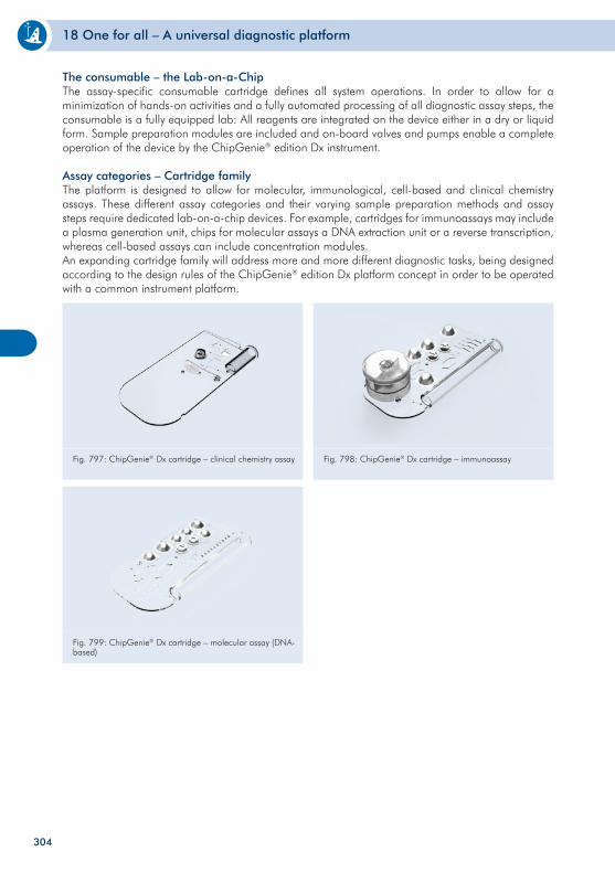
18 One for all – A universal diagnostic platform
304
The consumable – the Lab-on-a-ChipThe assay-specific consumable cartridge defines all system operations. In order to allow for a minimization of hands-on activities and a fully automated processing of all diagnostic assay steps, the consumable is a fully equipped lab: All reagents are integrated on the device either in a dry or liquid form. Sample preparation modules are included and on-board valves and pumps enable a complete operation of the device by the ChipGenie® edition Dx instrument.
Assay categories – Cartridge familyThe platform is designed to allow for molecular, immunological, cell-based and clinical chemistry assays. These different assay categories and their varying sample preparation methods and assay steps require dedicated lab-on-a-chip devices. For example, cartridges for immunoassays may include a plasma generation unit, chips for molecular assays a DNA extraction unit or a reverse transcription, whereas cell-based assays can include concentration modules.An expanding cartridge family will address more and more different diagnostic tasks, being designed according to the design rules of the ChipGenie® edition Dx platform concept in order to be operated with a common instrument platform.
Fig. 797: ChipGenie® Dx cartridge – clinical chemistry assay Fig. 798: ChipGenie® Dx cartridge – immunoassay
Fig. 799: ChipGenie® Dx cartridge – molecular assay (DNA-based)

305

306

19 Literature
307
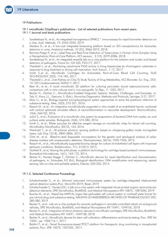
19 Literature
308
19 Publications
19.1 microfluidic ChipShop’s publications - List of selected publications from recent years.19.1.1 Journal and book publications
1. Sandetskaya N., et al., An integrated homogeneous SPARCL™ immunoassay for rapid biomarker detection on a chip, Anal. Methods, 19, 2542-2550, 2019.
2. Martens D., et al., A low-cost integrated biosensing platform based on SiN nanophotonics for biomarker detection in urine, Analytical methods, 10 (25), 3066-3073, 2018
3. Ramirez-Priego P., et al., Label-Free and Real-Time Detection of Tuberculosis in Human Urine Samples Using a Nanophotonic Point-of-Care Platform, ACS sensors, 3 (10), 2079-2086, 2018
4. Sandetskaya N., et al., An integrated versatile lab-on-a-chip platform for the isolation and nucleic acid-based detection of pathogens, Future Sci. OA 3(2), FSO177, 2017
5. Theobald J., et al., Monitoring cytochrome P450 activity in living hepatocytes by chromogenic substrates in response to drug treatment or during cell maturation, Arch.Toxicol., 1-17, 2017
6. Smith S.,et al., Microfluidic Cartridges for Automated, Point-of-Care Blood Cell Counting, SLAS TECHNOLOGY, 22(2), 176-185, 2017.
7. Theobald J., et al., Liver-Kidney-on-Chip To Study Toxicity of Drug Metabolites, ACS Biomater. Sci. Eng., DOI: 10.1021/acsbiomaterials.7b00417, 2017.
8. Beer M., et al., A novel microfluidic 3D platform for culturing pancreatic ductal adenocarcinoma cells: comparison with in vitro cultures and in vivo xenografts, Sci Rep., 7, 1325, 2017.
9. Becker H., Gärtner C., Microfluidics-Enabled Diagnostic Systems: Markets, Challenges, and Examples, in: Taly, V., Viovy, J.L., Descroix, S. (Eds.), Microchip Diagnostics: Methods and Protocols, Springer, 3-21, 2017.
10. Marx U., et al., Biology-inspired microphysiological system approaches to solve the prediction dilemma of substance testing. Altex, 33(3), 272-321, 2016.
11. Raasch M., et al., An integrative microfluidically supported in vitro model of an endothelial barrier combined with cortical spheroids simulates effects of neuroinflammation in neocortex development. Biomicrofluidics, 10(4), 044102, 2016.
12. Julich S., et al., Evaluation of a microfluidic chip system for preparation of bacterial DNA from swabs, air, and surface water samples. Biologicals, 44(6), 574-580, 2016.
13. Smith S., et al., Blister pouches for effective reagent storage on microfluidic chips for blood cell counting. Microfluidics Nanofluidics, 20(12), 163, 2016.
14. Wienhold T., et al., All-polymer photonic sensing platform based on whispering-gallery mode microgoblet lasers. Lab Chip 15(18), 3800-3806, 2015.
15. Ortiz M., et al. Bleed-to-read disposable microsystems for the genetic and serological analysis of celiac disease markers with amperometric detection. Electrophoresis, 36(16), 1920-1926, 2015.
16. Raasch M., et al., Microfluidically supported biochip design for culture of endothelial cell layers with improved perfusion conditions. Biofabrication, 7(1), 015013, 2015.
17. Gottheil R., et al, Moving the solid phase: a platform technology for cartridge based sandwich immunoassays. Biomedical Microdevices, 16(1), 163-172, 2014.
18. Becker H., Hansen-Hagge T., Gärtner C., Microfluidic devices for rapid identification and characterization of pathogens, in: Schaudies, R.P. (Ed.), Biological identification: DNA amplification and sequencing, optical sensing, lab-on-chip and portable systems, Elsevier, 220-250, 2014.
19.1.2. Selected Conference Proceedings
1. Schattschneider S., et al., Minimal instrument immunoassay system by cartridge-integrated inkjet-printed optical detection system,Proc. MicroTAS 2019, Basel, 2019
2. Schattschneider S., Handy-LOC: a lab-on-a-chip system with integrated ink-jet printed organic semiconductor detection elements, SPIE Microfluidics, BioMEMS, and Medical Microsystems XVII 10875, 108750M, 2019
3. Busche M., et al., HepaChip-MWP-An organ-like perfusable cell culture system in multiwell plate format for pre-clinical drug and substance testing, NAUNYN-SCHMIEDEBERGS ARCHIVES OF PHARMACOLOGY 392, S80-S80, 2019
4. Becker H., et al., Lab-on-a-chip analyzer for zoonotic pathogens in remotely-controlled robotic air and ground vehicles, SPIE Microfluidics, BioMEMS, and Medical Microsystems XVI 10491, 104910L, 2018
5. Becker H., et al., Integration of silicon photonic devices in microfluidic cartridges, SPIE Microfluidics, BioMEMS, and Medical Microsystems XVI 10491, 1049108, 2018
6. Becker H., et al., Microfluidic devices for stem-cell cultivation, differentiation and toxicity testing, Proc. SPIE Vol 10061, pp. 1006116-1, 2017.
7. Baldini F., et al., Novel fluorescence-based POCT platform for therapeutic drug monitoring in transplanted patients, Proc. SPIE 10072, 100720C, 2017.
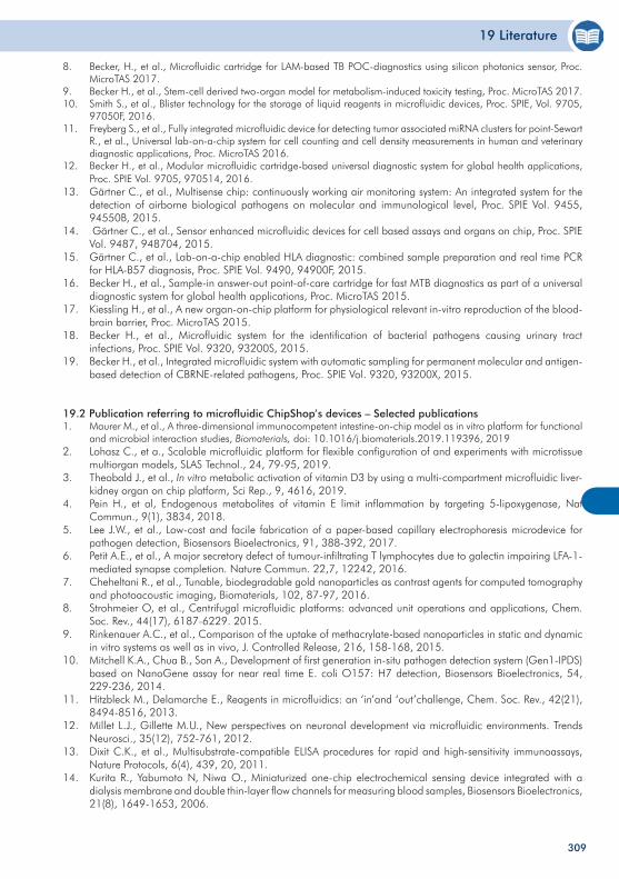
19 Literature
309
8. Becker, H., et al., Microfluidic cartridge for LAM-based TB POC-diagnostics using silicon photonics sensor, Proc. MicroTAS 2017.
9. Becker H., et al., Stem-cell derived two-organ model for metabolism-induced toxicity testing, Proc. MicroTAS 2017.10. Smith S., et al., Blister technology for the storage of liquid reagents in microfluidic devices, Proc. SPIE, Vol. 9705,
97050F, 2016.11. Freyberg S., et al., Fully integrated microfluidic device for detecting tumor associated miRNA clusters for point-Sewart
R., et al., Universal lab-on-a-chip system for cell counting and cell density measurements in human and veterinary diagnostic applications, Proc. MicroTAS 2016.
12. Becker H., et al., Modular microfluidic cartridge-based universal diagnostic system for global health applications, Proc. SPIE Vol. 9705, 970514, 2016.
13. Gärtner C., et al., Multisense chip: continuously working air monitoring system: An integrated system for the detection of airborne biological pathogens on molecular and immunological level, Proc. SPIE Vol. 9455, 94550B, 2015.
14. Gärtner C., et al., Sensor enhanced microfluidic devices for cell based assays and organs on chip, Proc. SPIE Vol. 9487, 948704, 2015.
15. Gärtner C., et al., Lab-on-a-chip enabled HLA diagnostic: combined sample preparation and real time PCR for HLA-B57 diagnosis, Proc. SPIE Vol. 9490, 94900F, 2015.
16. Becker H., et al., Sample-in answer-out point-of-care cartridge for fast MTB diagnostics as part of a universal diagnostic system for global health applications, Proc. MicroTAS 2015.
17. Kiessling H., et al., A new organ-on-chip platform for physiological relevant in-vitro reproduction of the blood-brain barrier, Proc. MicroTAS 2015.
18. Becker H., et al., Microfluidic system for the identification of bacterial pathogens causing urinary tract infections, Proc. SPIE Vol. 9320, 93200S, 2015.
19. Becker H., et al., Integrated microfluidic system with automatic sampling for permanent molecular and antigen-based detection of CBRNE-related pathogens, Proc. SPIE Vol. 9320, 93200X, 2015.
19.2 Publication referring to microfluidic ChipShop’s devices – Selected publications1. Maurer M., et al., A three-dimensional immunocompetent intestine-on-chip model as in vitro platform for functional
and microbial interaction studies, Biomaterials, doi: 10.1016/j.biomaterials.2019.119396, 20192. Lohasz C., et a., Scalable microfluidic platform for flexible configuration of and experiments with microtissue
multiorgan models, SLAS Technol., 24, 79-95, 2019.3. Theobald J., et al., In vitro metabolic activation of vitamin D3 by using a multi-compartment microfluidic liver-
kidney organ on chip platform, Sci Rep., 9, 4616, 2019.4. Pein H., et al, Endogenous metabolites of vitamin E limit inflammation by targeting 5-lipoxygenase, Nat
Commun., 9(1), 3834, 2018.5. Lee J.W., et al., Low-cost and facile fabrication of a paper-based capillary electrophoresis microdevice for
pathogen detection, Biosensors Bioelectronics, 91, 388-392, 2017.6. Petit A.E., et al., A major secretory defect of tumour-infiltrating T lymphocytes due to galectin impairing LFA-1-
mediated synapse completion. Nature Commun. 22,7, 12242, 2016.7. Cheheltani R., et al., Tunable, biodegradable gold nanoparticles as contrast agents for computed tomography
and photoacoustic imaging, Biomaterials, 102, 87-97, 2016.8. Strohmeier O, et al., Centrifugal microfluidic platforms: advanced unit operations and applications, Chem.
Soc. Rev., 44(17), 6187-6229. 2015.9. Rinkenauer A.C., et al., Comparison of the uptake of methacrylate-based nanoparticles in static and dynamic
in vitro systems as well as in vivo, J. Controlled Release, 216, 158-168, 2015.10. Mitchell K.A., Chua B., Son A., Development of first generation in-situ pathogen detection system (Gen1-IPDS)
based on NanoGene assay for near real time E. coli O157: H7 detection, Biosensors Bioelectronics, 54, 229-236, 2014.
11. Hitzbleck M., Delamarche E., Reagents in microfluidics: an ‘in’and ‘out’challenge, Chem. Soc. Rev., 42(21), 8494-8516, 2013.
12. Millet L.J., Gillette M.U., New perspectives on neuronal development via microfluidic environments. Trends Neurosci., 35(12), 752-761, 2012.
13. Dixit C.K., et al., Multisubstrate-compatible ELISA procedures for rapid and high-sensitivity immunoassays, Nature Protocols, 6(4), 439, 20, 2011.
14. Kurita R., Yabumoto N, Niwa O., Miniaturized one-chip electrochemical sensing device integrated with a dialysis membrane and double thin-layer flow channels for measuring blood samples, Biosensors Bioelectronics, 21(8), 1649-1653, 2006.

310

311
312
20 Order form
313
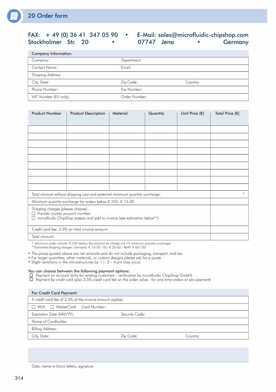
20 Order form
You can choose between the following payment options: Payment on account (only for existing customers - verification by microfluidic ChipShop GmbH) Payment by credit card (plus 3.5% credit card fee on the order value - for one-time orders or pre-payment)
FAX:+49(0)36413470590•E-Mail:[email protected] Str. 20 • 07747 Jena • Germany
Company Information
Company: Department:
Contact Name: Email:
Shipping Address:
City, State: Zip Code: Country:
Phone Number: Fax Number:
VAT Number (EU only): Order Number:
Product Number Product Description Material Quantity Unit Price [€] Total Price [€]
Total amount without shipping cost and potential minimum quantity surcharge: *
Minimum quantity surcharge for orders below € 250: € 15.00
Shipping charges (please choose): Provide courier account number: microfluidic ChipShop prepay and add to invoice (see estimation below**)
Credit card fee: 3.5% on total invoice amount
Total amount:
* Minimum order volume: € 250 (below this amount we charge a € 15 minimum quantity surcharge)**Estimated shipping charges: Germany: € 15-30 / EU: € 20-60 / RoW: € 60-120
For Credit Card Payment:
A credit card fee of 3.5% of the invoice amount applies.
VISA MasterCard Card Number:
Expiration Date (MM/YY): Security Code:
Name of Cardholder:
Billing Address:
City, State: Zip Code: Country:
Date, name in block letters, signature
• The prices quoted above are net amounts and do not include packaging, transport, and tax.• For larger quantities, other materials, or custom designs please ask for a quote.• Slight variations in the microstructures by +/- 3 – 4 µm may occur.
314