integration of microcolumns and microfluidic fractionators on multitasking centrifugal microfluidic...
TRANSCRIPT

Anal Bioanal Chem (2006) 385: 596–605DOI 10.1007/s00216-006-0436-z
ORIGINAL PAPER
Elizabeth A. Moschou . Adrianne D. Nicholson .Guangyao Jia . Jim V. Zoval . Marc J. Madou .Leonidas G. Bachas . Sylvia Daunert
Integration of microcolumns and microfluidic fractionatorson multitasking centrifugal microfluidic platformsfor the analysis of biomoleculesReceived: 12 January 2006 / Revised: 16 March 2006 / Accepted: 17 March 2006 / Published online: 9 May 2006# Springer-Verlag 2006
Abstract This work demonstrates the development ofmicrofluidic compact discs (CDs) for protein purificationand fractionation integrating a series of microfluidicfeatures, such as microreservoirs, microchannels, andmicrofluidic fractionators. The CDs were fabricated withpolydimethylsiloxane (PDMS), and each device containedmultiple identical microfluidic patterns. Each patternemployed a microfluidic fractionation feature with opera-tion that was based on the redirection of fluid into anisolation chamber as a result of an overflow. This featureoffers the advantage of automated operation without theneed for any external manipulation, which is independentof the size and the charge of the fractionated molecules.The performance of the microfluidic fractionator wasevaluated by its integration into a protein purificationmicrofluidic architecture. The microfluidic architectureemployed a microchamber that accommodated a mono-lithic microcolumn, the fractionator, and an isolationchamber, which was also utilized for the optical detectionof the purified protein. The monolithic microcolumn waspolymerized “in situ” on the CD from a monolith precursorsolution by microwave-initiated polymerization. Thistechnique enabled the fast, efficient, and simultaneouspolymerization of monoliths on disposable CD micro-fluidic platforms. The design of the CD employed allowsthe integration of various processes on a single microfluidicdevice, including protein purification, fractionation, isola-tion, and detection.
Keywords Microfluidic . Compact disk .Microwave-polymerized monolithic microcolumns .Biomolecules . Lab-on-a-chip
Introduction
The development of fast, accurate, and low-cost analyticalprocedures for the high-throughput analysis of smallaliquots of samples has received great attention over thepast few years [1, 2]. The key parameters that contribute tothe advancement of such sample analysis today areminiaturization, automation, and successful integration ofvarious analytical techniques onto a single microfluidicplatform [3, 4]. Microfluidic chips can be made out ofglass, silicon, or polymeric materials [5], and theiroperation is based on the manipulation of fluids througha microfluidic architecture [6–8]. The appropriate design ofthe microfluidic pattern employed can allow the integrationof various chemical processes onto a single device, theso-called micro total analysis system (μTAS) or lab-on-a-chip [9, 10]. Lab-on-a-chip devices offer the advantages ofsimple operation, portability, and low cost of fabrication,which allows for the development of disposable platformsthat can reduce the time and cost of analysis [11].Furthermore, these platforms can accommodate severalmicrofluidic networks on the same device, permitting theanalysis of multiple samples in parallel.
Compact disc (CD) microfluidic platforms offer anumber of unique advantages over other μTAS platforms[12, 13]. CDmicrofluidic devices utilize the spinning of theplatform to enable the pumping of the fluids in themicrofluidic network [14, 15]. As a result, CD-based μTASeliminates the need for internal moving parts or highvoltage potentials for pumping [16]. In addition, centrif-ugal microfluidics pumping is not affected by matrixeffects, like those present in variable ionic strength samples[17]. Further, air bubble formation does not affect theoperation of the CD microfluidics, unlike the electro-kinetically pumped systems, where air bubbles may causethe stoppage of the electrokinetic flow. CD-based platforms
E. A. Moschou . A. D. Nicholson .L. G. Bachas . S. Daunert (*)Department of Chemistry, University of Kentucky,Lexington, KY 40506-0055, USAe-mail: [email protected].: +1-859-2577060Fax: +1-859-3231069
G. Jia . J. V. Zoval . M. J. MadouDepartment of Mechanical and Aerospace Engineering,University of California,Irvine, CA 92697, USA
can be used in parallel analyses, because the conditionsapplied to each of the microfluidic networks alignedthroughout the chip are identical. Another great advantageof the CDs is their ability for on-chip product isolation andanalyte detection [18, 19]. These characteristics improvethe analysis time, minimize errors, and extend the degree ofautomation for the analysis of multiple samples. Therefore,the fabrication of CD platforms could lead to the devel-opment of sophisticated and highly efficient devices, whichcould integrate various steps of an analytical procedure,such as sample pretreatment, sample analysis, productisolation, and analyte detection on a single device.
The field of protein isolation and purification comprisesone of the main applications of microchip analysis today[20]. While the majority of the μTAS methods developedfor protein analysis have employed electrokinetic fluidpropulsion [21, 22] other techniques have also started toemerge [23, 24]. Even though many examples of micro-fluidic systems have been developed so far for thepurification of biomolecules, there is still a great need forthe development of multitask devices that can integrate themultiple steps of separation, fractionation, isolation, anddetection onto a single lab-on-a-chip [25]. One approachfor integrating the step of fraction collection of DNAfragments after electrophoretic separation on a microfluidicdevice was presented by Guttman’s group [26]. Thefractionating unit presented operated by redirecting thesample zones of the DNA fragments after separation intocollection wells using voltage manipulations. Shapedaddressable electric fields have also been utilized byBurns and colleagues [27] in an electrophoretic micro-fluidic device for the improved fractionation of chargedmolecules. Another approach for sample fractionation waspresented by Hattori et al. [28] with the utilization of a size-based fractionation chip for the electrophoretic enrichmentof macromolecules in biological samples. The chip wasbased on a nano-pillar anisotropic array, which wasfabricated at the junction of the main channel with abranch that played the role of a molecular sieve. The use ofan array of micron-scale posts for the fabrication of amolecular sieving matrix for sorting DNA was alsopresented by Cox and co-workers [29]. The molecularsieve was integrated in a microfluidic device, with themicrochannels of the device spatially shaping the electricfields and sorting the DNA molecules like a prism deflectslight.
In this work, we address the need for the integration ofthe steps of fractionation, isolation, and analyte detection inbiomolecule analysis into a single microfluidic chip withthe development of multitasking CD microfluidic plat-forms. The CD platform was made of polydimethylsiloxane(PDMS) that was arranged into a closed-channel disposablemicrofluidic device using a polycarbonate cover. The PDMSCD incorporates a family of identical microfluidic networksthat can be used for multiple sample analyses. Eachmicrofluidic network is based on a pattern of microchannelsand microreservoirs with appropriate size and orientation inorder to integrate multiple microfluidic features into a singlenetwork. These features include microreservoirs for the
analyte and reagent introduction, reservoirs for the integra-tion of microcolumns, fraction collectors, and isolationreservoirs for the storage and detection of the purifiedsamples. The microcolumns employed were based onmethacrylate monoliths, which were polymerized in situon the CD using microwave-initiated polymerization. Thistechnique was coupled here for the first time withmicrofluidics, and was able to provide fast and efficientpolymerization of the monolithic columns on disposable CDmicrofluidic platforms. The design of the CD allows thepurification of the protein of interest within the monolith,with the subsequent fractionation and isolation of the whole-column fraction containing the target protein in the isolationchamber. The microfluidic device is optically transparent,allowing the fluorescence determination of the isolatedprotein directly on the CD. The CD microfluidic platformspresented in this work introduce an attractive strategy for theintegration of the multiple steps involved in the process ofbiomolecule purification from small-volume samples,including biomolecule purification, sample fractionation,isolation, and detection on a single and disposable lab-on-a-CD.
Experimental
Reagents
Ethylene dimethacrylate (EDMA), 2-hydroxyethylmethacrylate (HEMA), [2-(methacryloyloxy)ethyl]ammo-nium chloride (META), azobisisobutyronitrile (AIBN),3-methacryloyloxypropyl trimethoxysilane (MPTS), cyclo-hexanol, and dodecanol were obtained from Aldrich(Milwaukee, WI). Polydimethylsiloxane (PDMS) Sylgard184 was obtained from Dow Corning (Midland, MI). Allaqueous solutions were prepared with 18-MΩ deionizedwater produced by a Milli-Q water purification system(Millipore, Bedford, MA).
Methods
Preparation and testing of monolithic columnspolymerized in glass capillaries
The monolithic columns were prepared by thermal ormicrowave-initiated polymerization of the monolith pre-cursor solution in MPTS-treated glass capillaries with innerdiameter 0.21 cm (VWR, Cleveland, OH). The monolithprecursor solutions used were based on the methacrylatemonomers EDMA, HEMA, and META, and the porogenicsolvents cyclohexanol and dodecanol. AIBN was used asthe initiator for both the thermal and microwave polymer-ization of the monolith. For the preparation of themonoliths, one end of each capillary was sealed with aSeal View sealing tape (purchased from Norton, Akron,OH), each capillary was filled with 30 μL freshly preparedmonolith precursor solution, and the other end of thecapillary was also sealed to prevent evaporation of the
597

monomers during the curing process. The temperature-cured monoliths were polymerized at 55 °C for 20 h. Themicrowave-cured monoliths were polymerized in three 5-sintervals at 30 % power using a turntable domesticmicrowave oven (Model No JES0601T012, GeneralElectric, Louisville, KY) with a maximum power level of650 W (precautions for the use of microwave ovens areprovided in ref. [30]). After the polymerization wascomplete, the top of the capillary column was attached toa manifold pump tubing for pumping the testing bufferthrough the monolith using a peristaltic pump (GilsonMiniplus 2). The columns were finally treated with thetesting buffer (0.01 M sodium phosphate, pH 7.5) for 1 hfor the removal of any unreacted monomers.
The fusion protein enhanced green fluorescent pro-tein-β-lactamase denoted as EGFP fusion (pI 5.35) wasexpressed and purified as reported earlier [31] and wasused for the evaluation of the ion-exchange properties ofthe methacrylate-based monolithic columns. The deliveryof the fluids during the testing of the monolithspolymerized in glass capillaries was performed using theperistaltic pump. A 50-μL aliquot of 2.0×10⁻⁷ M EGFPfusion solution in the testing buffer was loaded on thecolumn. After washing the column with the testing buffer,the elution of the protein was performed using 0.1 Mphosphate buffer solutions containing various concentra-tions of NaCl (0.1–1.0 M). Aliquots of 30 μL werecollected in separate wells on a Fluoronunc Maxisorp 96-well microtiter plate (Nalge Nunc International, Rochester,NY). The fluorometric detection of the EGFP fusionprotein (λex 488 nm; λem 508 nm) in the testing and elutionsamples was performed using a Cytofluor multiwellplate-reader Series-4000 from Perseptive Biosystems(Cambridge, MA).
Design of CD microfluidic platforms
The design of the microfluidic architectures incorporatedon the CD microfluidic platform and a picture of thecorresponding PDMS microfluidic network are shown inFig. 1. Each microfluidic network developed was 200-μmdeep, and contained a loading chamber (L) of 9-mmdiameter, which was used to accommodate the loading ofthe protein sample and reagent solutions on the CD throughthe access port (l). This reservoir was connected through a150-μm-wide microfluidic channel to the column chamber(C). The latter had a volume of 2.5 μL and was designed toincorporate a monolithic microcolumn. The lower side ofchamber C accommodated a side microchannel of 150-μmwidth, equipped with an access port (c). This channel wasdesigned for the introduction of the monolith precursorsolution into the column chamber, reassuring the completefilling of the chamber with the precursor solution beforepolymerization. A 150-μm-wide main microchannel (M)connected the end of the column chamber C straight downto the waste chamber (W). Chamber W had a diameter of9 mm and was capable of collecting waste solutions up to11-μL volume. The main microchannel M directed the first
11 μL of the waste solution to flow down the mainmicrochannel to the waste chamber W. The waste chamberwas equipped with a venting channel that was positionedon the top of chamber W. In addition, the mainmicrochannel was equipped with a 50-degree-tilted sidemicrochannel (F) with a width of 75 μm and length of5 mm. This microchannel played the role of a fractionatoron the microfluidic architecture, directing the fractionationsolution into the collection and detection reservoir (D). Theadequate length, the tilted orientation of the microchannelupwards, towards the center of the CD device, and thesignificantly smaller width of the microchannel F (75 μmversus the 150 μm width of the main channel M) created aburst valve at the connection between the microchannel FandM. This burst valve was capable of restricting the directand free flow of the fluid exiting the microcolumn into thefractionator F. Upon the spinning of the CD at high angularvelocities, the increased centripetal force developed inaddition to the absence of any venting port, developed thesufficient back pressure to break the burst valve at the en-trance of the fractionator F. Additionally, the top of thefractionator microchannel F was carefully chosen to extendlower than the level of the bottom part of the microcolumnreservoir, to avoid the partial release of the elution solutionfrom the microcolumn into the isolation chamber.
The pattern of the series of access ports designed on thepolycarbonate cover of the microfluidic device is shown inFig. 1b. The access ports (v) were designed to provide theair venting of the microfluidic network, preventing thedevelopment of backpressure and ensuring the appropriatepumping of the fluids on the CD. The access port (c) wasused for the loading of the monolith precursor solution intothe chamber C of the microfluidic device. The access port(l) was designed for the introduction of the reagents andthe protein sample into chamber (L) of the CD. Finally, theaccess port (r) was designed to ensure the venting of thechamber D, for the efficient operation of the fractionatormicrofluidic architecture, and the removal of the elutedprotein from the CD.
Preparation and pretreatment of PDMS CDmicrofluidic platforms
The PDMS CD microfluidic platforms were prepared bycasting the silicone elastomer Sylgard 184 on a photoresistwafer containing the microfluidic pattern. For the fabrica-tion of the photoresist wafer, an SU-8 photolithographyprocess was used. Initially, SU-8 100 (Microchem,Newton, MA) was spin-coated on a 6″ Si wafer (AddisonEngineering, San Jose, CA) to obtain a 200-μm-thick film,which was then pre-baked at 70 °C for 20 min and softbaked at 95 °C for 2 h on a leveled hotplate. The fluidicpatterns were transferred to the photoresist using a contactmask aligner (Karl Suss MA6) and by UV irradiation(600 mJ cm−2) through a mask. The mask used containedthe pattern of the fluidic networks, and was designed usingAutoCAD software (AutoCAD 2000, Autodesk, SanRafael, CA). The wafer with the lithographically patterned
598

photoresist film was first baked at 70 °C for 5 min,followed by another step of post-baking at 100 °C for30 min. After immersion in the developer (Microchem,Newton, MA), the unexposed SU-8 photoresist wasremoved, revealing the pattern of the fluidic networks onthe wafer. For the fabrication of the CD, PDMS was castonto the wafer and was cured at 60 °C for 3 h. The PDMSplatform was then removed from the wafer and was cut intoa 12-cm-diameter disk.
The CDs were placed in a fume hood, and each CD wascovered with an opaque protector cover, which protectedthe CD except for the chambers designated for the
polymerization of the monoliths (chamber C, Fig. 1). Thecovered CD was then irradiated for 15 min with UV lightusing a TripleBright 185-nm lamp obtained from UVSystems (Renton, WA). This ozonation treatment resultedin the formation of silanol groups on the surface of thecolumn chamber of the PDMS, making it suitable forcrosslinking with MPTS. The cover was removed from theCD, and the column chambers were cleaned sequentiallywith 0.2 M NaOH, 0.2 M HCl, water, and acetone. Thecolumn chambers were then functionalized with MPTSduring three 30-min steps, which were followed by anacetone wash and drying under nitrogen. The treated CDswere covered with polycarbonate covers containing apattern of access ports, complementing the design of thenetworks on the PDMS. These access ports were used forthe loading of the reagents on the CD.
Microwave-initiated polymerization and testingof monolithic columns on PDMS CDs
The monolithic columns were polymerized on the PDMSCDs through microwave-initiated polymerization. Afreshly prepared monolith precursor solution was degassedfor 10 min for oxygen removal. The PDMS CD was thenplaced in the microwave and exposed to microwaves for2 min at 100 % power. Subsequently, the monolithprecursor solution was exposed to microwaves for 10 s at30 % power. An aliquot of the precursor mixture was thenloaded on the column chamber C of the PDMS CD,through the access port (c). The access ports of the cover ofthe PDMS CD (v, l, c, and r shown in Fig. 1) were sealedwith an additional piece of plain PDMS. The CD was thenexposed to microwave irradiation for 4 min at 100 % powerfor the completion of the monolith polymerization.
After polymerization, the monolith was washed with thetesting buffer solution of 0.01 M sodium phosphate, pH7.5, to remove any unreacted monomers. The testing of theion-exchange properties of the monolith integrated on thePDMS CD microfluidic platform was carried out usingthe CD-spinning instrument described in previous work[32]. The instrumentation consists of a stepper motorpowered by a power supply and equipped with a controller(PIC-Servo, HdB Electronics, Redwood City, CA), whichprovides the spinning of the CD and the pumping of thefluids. A fluorometer (Cary Eclipse Fluorescent Spectro-photometer purchased from Varian, Walnut Creek, CA)equipped with a fiber optic attachment was used for thefluorometric detection of the protein sample directly on theCD. This was accomplished by positioning the fiber optictip approximately 2 mm above the detection chamber D ofthe CD (Fig. 1). The PDMS CD microfluidic platform,which contained the monolithic column polymerized inchamber C, was placed on the motor. The delivery of thefluids on the microfluidic networks of the CD wasperformed by spinning the CD at angular velocitiesranging from 850 to 1,150 rpm. For the protein ion-exchange experiments, a 4-μL aliquot of 3.1×10⁻⁶ MEGFP fusion protein solution was loaded on the loading
Fig. 1 a Design pattern of the microfluidic networks incorporatedon the CD. Each network contains a loading chamber (L) for loadingthe sample and buffer solutions through the access port l on thedevice. The network also contains the column chamber (C), which isfilled up with the monolith precursor solution through the accessport c, and after polymerization accommodates the monolithiccolumn. The main microchannel (M) of the microfluidic architectureis used to direct the matrix and wash solutions to the waste chamber(W), while the fractionator (F) directs the purified protein solution tothe detection chamber (D) for isolation and detection. This chamberis equipped with the access port r, which accommodates air ventingof the network, and is also used for the removal of the isolatedprotein from the device. The access ports v provide air venting of thenetwork for proper fluid pumping. b Design of the access portpattern fabricated on the polycarbonate cover, which is aligned ontop of each microfluidic network on the PDMS CD. c Picture of themicrofluidic architecture on the PDMS CD. d Picture of themonolithic column polymerized “in situ” in the column chamber ofthe microfluidic device
599
chamber L of the CD though the loading access port (l).The protein sample was delivered through the monolithpolymerized in chamber C by spinning the CD at 850 rpm.After washing the column with 7 μL testing buffer, whichwas loaded on chamber L of the CD, the protein was elutedinto the detection chamber (D). This was performed byloading 5 μL of the elution buffer (0.1 M phosphate buffer,0.1 M NaCl, pH 6.0) in chamber L and spinning the CD at1,150 rpm. After spinning the CD down to a stop, thefluorescence intensity of the eluted protein was immedi-ately measured at an excitation wavelength of 488 nm andemission wavelength of 508 nm using the Cary EclipseFluorescent Spectrophotometer.
Results and discussion
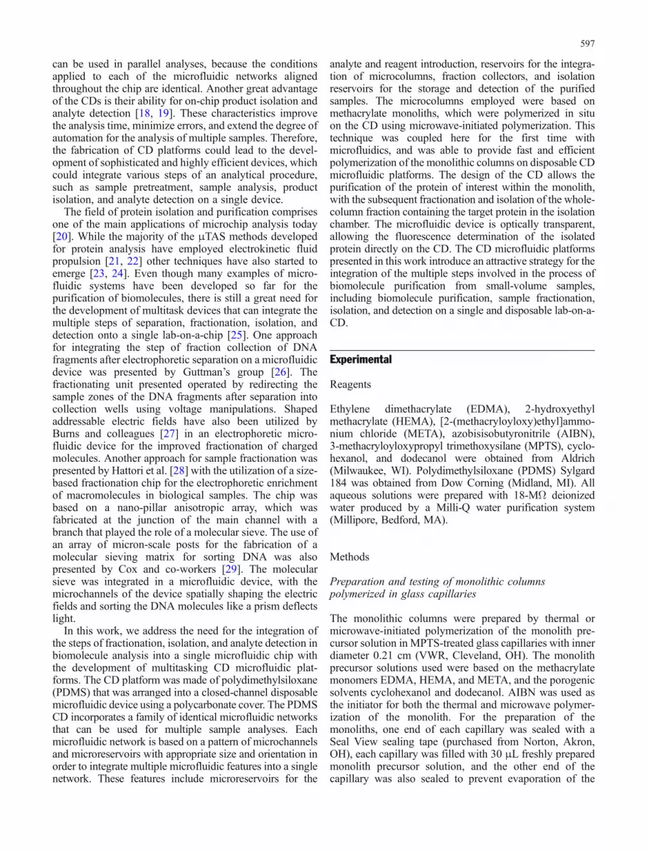
In this work, we present the development of multitaskingCD microfluidic platforms addressing the need for inte-gration of the multiple analytical steps involved in theprocess of biomolecule purification on a single micro-fluidic device. The operation of the PDMS CD incorporat-ing the microfluidic architecture shown in Fig. 1 was basedon loading a protein sample with volume of 4 μL inchamber L of the CD. Spinning of the CD resulted in theflow of the sample solution through the column chamber(C), where the protein interacted with the monolith, andthen through the microchannel M into the waste chamberW. Next, 7 μL of wash solution was loaded in chamber L.Upon spinning the CD, the wash solution helped removenon-specifically adsorbed compounds from the monolith inchamber C, and was subsequently directed throughmicrochannel M. At this point, the centripetal force ofthe 7-μL wash solution, which developed by spinning theCD, overcame the centripetal force of the smaller 4-μLvolume, which was present in the partly filled wastechamber. This resulted in the partly filled waste reservoirbeing filled with the wash solution up to the top of thewaste reservoir, where it is connected with the ventingmicrochannel. Capillary forces restricting the waste solu-tion from filling the venting microchannel resulted in theexcess wash solution filling the lower part of microchannelM. Intentionally, we used a total volume of sample andwash solutions that was slightly less than the total volumeof the microchannel M and waste chamber W. As a result,there was a volume of the microchannel M that remainedunfilled with liquid (Fig. 2a).
The protein was eluted from the monolith column byspinning the CD. After passing through the column theeluted solution arrived at the top of the microchannel M.The centripetal force applied on the 5 μL elution solution,however, was not sufficient to overcome the capillaryforces (surface tension) of the thin venting microchannelabove chamber W along with the centripetal forcesdeveloped on the solution of higher volume in W, andprohibited the displacement of the waste solution by theelution solution. The result was that the elution solutionwas forced to be redirected to the only microfluidic spaceavailable to be filled, the fractionation channel F and the
isolation chamber D, displacing the air present in thesefeatures through the venting port (r). The intentionalformation of the air pocket at microchannel M was theresult of careful selection of the combination of solutionvolumes, the angular velocities employed during thespinning of the CD, and the small width of the ventingchannel above chamber W, which collectively generatedsufficient backpressure to redirect the flow of the elutionsolution through the fractionator F to chamber D.Additionally, the presence of the air pocket at the top ofthe main microchannel obstructed any contact taking placebetween the waste and elution solutions, preventing anymixing and contamination of the eluate with the washsolutions. Besides the intentional formation of the airpocket, no other air bubbles were observed to be trapped inthe microchannel M during all our studies with this CDstructure (more than 100). As can be seen in Fig. 2b–d, thisfractionator F was able to separate the matrix solution
Fig. 2 a Principle of operation of the microfluidic fractionatorintegrated on the CD microfluidic device. After spinning the CD,first the matrix and then the wash solutions are directed toward thelower part of the microfluidic architecture, filling up the wastechamber and overflowing to the lower part of the mainmicrochannel. The top part of the main microchannel, up until theconnection with the fractionator, is filled up with trapped air that isforming an air pocket. This air pocket prevents the flow of theelution solution to the bottom part of the microfluidic architectureand the mixing with the waste solution, directing the elution solutionthrough the fractionator to the isolation chamber. b–d Imagesobtained using colored solutions in order to visualize the operationof the microfluidic architecture during the direction of the matrixsolution (yellow) (b) and the wash solution (green) (c) to the wastechamber. d Fractionation of the elution solution (red) through thefractionator to the detection chamber of the microfluidic architecture
600
(yellow fluid) and wash solution (green fluid) from theeluate (red fluid), allowing the isolation of the elutedsolution of the biomolecule in the detection chamber D.The advantages of the developed fractionator includeautomated operation without the need of any externalmanipulation, and versatile operation that is independent ofthe size or the charge of the fractionated molecules.
Composition and thermal polymerizationof monolithic columns
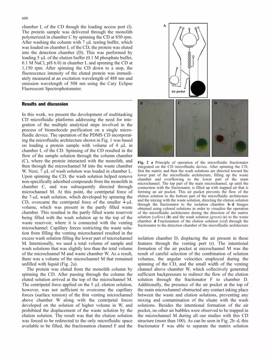
The commonly used porogenic solvent hexane [33] and themonomer glycidyl methacrylate [34] that requires function-alization with primary amines were chemically incom-patible with PDMS, causing swelling and deformation ofthe CD. This highlights the importance of the chemicalcompatibility of the components of the monolith precursorsolution with the materials from which the microfluidicdevice is prepared. The monomers that were found to bechemically compatible with PDMS and polycarbonate, andwere further employed for the development of monoliths,were the methacrylate monomers [2-(methacryloyloxy)ethyl]ammonium chloride (META), ethylene dimethacry-late (EDMA), and 2-hydroxyethyl methacrylate (HEMA)(Fig. 3a). The METAmonomer contains positively chargedquaternary ammonium groups, and was selected to providethe anion-exchange functionality of the monolith. TheEDMA monomer serves as the crosslinking agent, whereasHEMA plays the role of the methacrylate monolithbackbone. The porogenic solvents used for the develop-ment of the pores in the methacrylate monoliths werecyclohexanol and dodecanol. These two solvents, besidesbeing chemically compatible with the microfluidicplatform, were found to create monoliths with larger poresizes, and therefore lower backpressure, than otherporogenic solvents, such as acetone, THF, ethylpropionate,and dioxane [35].
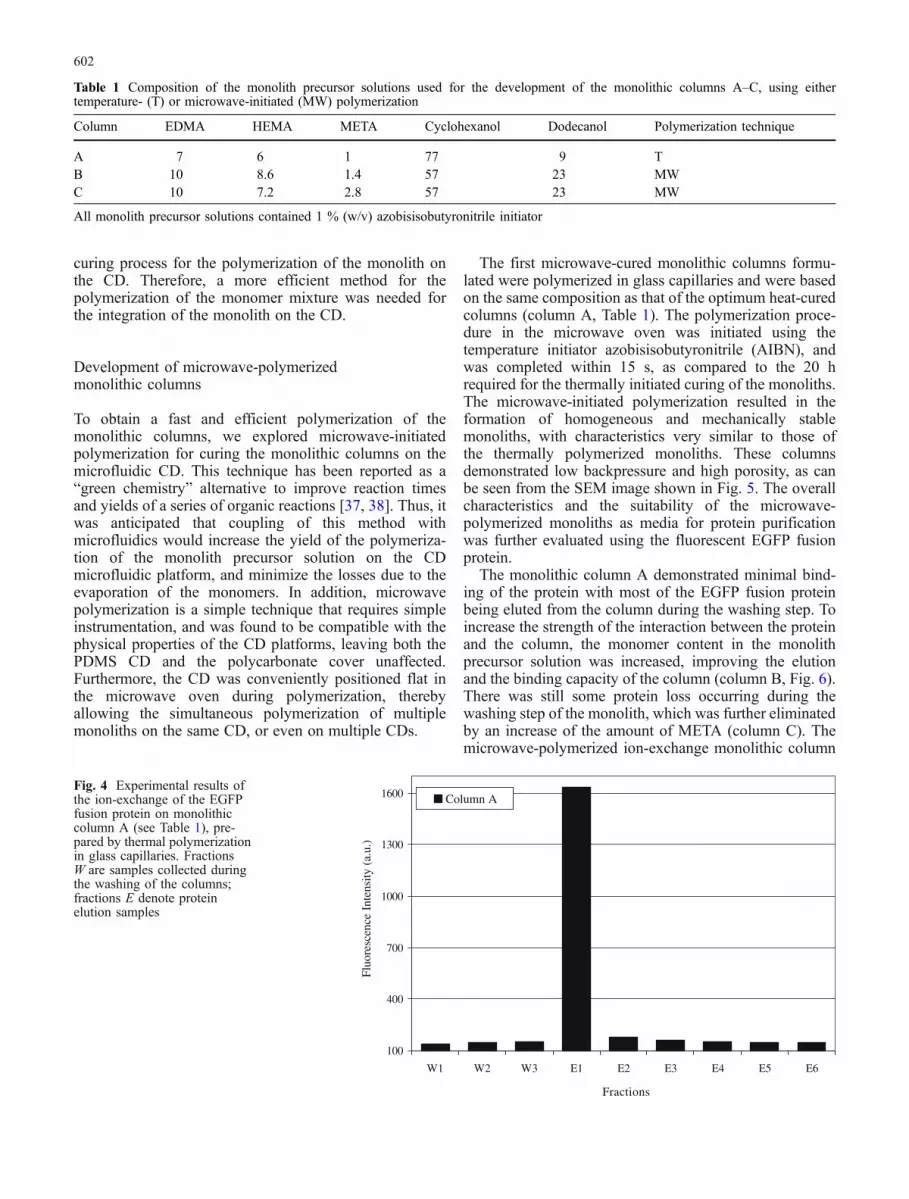
To evaluate the performance of the monolithic columnsdeveloped, the monoliths were initially polymerized inglass capillaries using temperature-initiated free-radicalpolymerization. This widely used method was originallyselected for curing the monolith precursor solution becauseit is a simple polymerization process. Additionally, it couldbe suitable for the simultaneous polymerization of multiplemonoliths, and is compatible with the physical character-istics of the PDMS CDs [36]. Various parameters,including the total porogen to monomer content, theconcentration of the META monomer employed, and theratio of dodecanol to cyclohexanol, were studied in order tooptimize the composition of the monolithic columns. Thebest methacrylate composition was based on a monolithprecursor solution with a 14:86 (v/v) total monomer toporogen content, 1 % (v/v) META monomer, and 9 %(v/v) dodecanol (Table 1, column A). This monolithprecursor solution was found to produce mechanicallystable monoliths with low backpressure, allowing theelution of the loaded protein in the first elution fraction(Fig. 4). The elution of the protein within a single fractionis preferred, because this greatly simplifies the CDmicrofluidic arrangement, requiring a single collectionchamber (chamber D) as shown in Fig. 1. It should bementioned, however, that the design of CD networks withmore than one collection chamber is indeed possible.
After selecting the monolith precursor solution compo-sition, the thermally polymerized monolithic column wasevaluated on the CD microfluidic platform. A 3-μL aliquotof the monolith precursor solution was loaded in thecolumn chamber of the PDMS CD through the access port(c). The access ports on the polycarbonate cover were thentaped with Seal View tape. The CD was placed in athermostated incubator for 20 h at 55 °C to complete thetemperature-initiated polymerization of the monolith. Atthe end of the polymerization time, the monomer mixturewas found to have evaporated, preventing the polymeriza-tion of the monolith on the CD. It was concluded that thetemperature-initiated polymerization was not an efficient
h
185 nm
CH3 – C – C – O – CH2 – CH2 – OH
H2C OCH3 – C – C – O – CH2 – CH2 – O – C – C – CH3
H2C O O CH2
CH3 – C – C – O – CH2 – CH2 – N(CH3)3+ Cl-
H2C O
A
B
I I
III
(CH3O)3Si-(CH2)3-COO-C(CH3)=CH2
IV
OH
OH
OH O – Si – (CH2)3 – COO – C(CH3) = CH2
OCH3
OC 3OH
OH
CH3
CH3
CH3
ν
3 2 2
2
3 2 2 – 3
2 2
3 2 2 ( 3 3+ -
2 II
III
– – (CH2)3 ( 3 2
3
3
OH
– (CH2)3 3 2
3
H3
Fig. 3 a Structures of the methacrylate monomers used for thedevelopment of the ion-exchange monolithic columns: I 2-hydroxy-ethyl methacrylate (HEMA), II ethylene dimethacrylate (EDMA),and III [2-(methacryloyloxy)ethyl]ammonium chloride (META).
b Functionalization of the surface of the PDMS CD for the covalentimmobilization of the monolithic column. The PDMS is firstirradiated with UV light (λ 185 nm) for the introduction of silanolgroups, which are further functionalized using MPTS
601
curing process for the polymerization of the monolith onthe CD. Therefore, a more efficient method for thepolymerization of the monomer mixture was needed forthe integration of the monolith on the CD.
Development of microwave-polymerizedmonolithic columns
To obtain a fast and efficient polymerization of themonolithic columns, we explored microwave-initiatedpolymerization for curing the monolithic columns on themicrofluidic CD. This technique has been reported as a“green chemistry” alternative to improve reaction timesand yields of a series of organic reactions [37, 38]. Thus, itwas anticipated that coupling of this method withmicrofluidics would increase the yield of the polymeriza-tion of the monolith precursor solution on the CDmicrofluidic platform, and minimize the losses due to theevaporation of the monomers. In addition, microwavepolymerization is a simple technique that requires simpleinstrumentation, and was found to be compatible with thephysical properties of the CD platforms, leaving both thePDMS CD and the polycarbonate cover unaffected.Furthermore, the CD was conveniently positioned flat inthe microwave oven during polymerization, therebyallowing the simultaneous polymerization of multiplemonoliths on the same CD, or even on multiple CDs.
The first microwave-cured monolithic columns formu-lated were polymerized in glass capillaries and were basedon the same composition as that of the optimum heat-curedcolumns (column A, Table 1). The polymerization proce-dure in the microwave oven was initiated using thetemperature initiator azobisisobutyronitrile (AIBN), andwas completed within 15 s, as compared to the 20 hrequired for the thermally initiated curing of the monoliths.The microwave-initiated polymerization resulted in theformation of homogeneous and mechanically stablemonoliths, with characteristics very similar to those ofthe thermally polymerized monoliths. These columnsdemonstrated low backpressure and high porosity, as canbe seen from the SEM image shown in Fig. 5. The overallcharacteristics and the suitability of the microwave-polymerized monoliths as media for protein purificationwas further evaluated using the fluorescent EGFP fusionprotein.
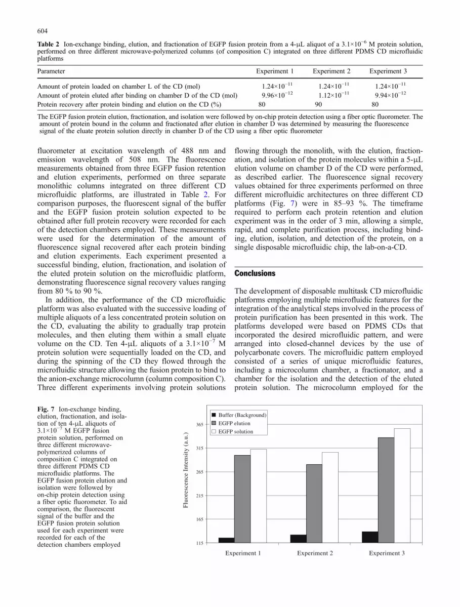
The monolithic column A demonstrated minimal bind-ing of the protein with most of the EGFP fusion proteinbeing eluted from the column during the washing step. Toincrease the strength of the interaction between the proteinand the column, the monomer content in the monolithprecursor solution was increased, improving the elutionand the binding capacity of the column (column B, Fig. 6).There was still some protein loss occurring during thewashing step of the monolith, which was further eliminatedby an increase of the amount of META (column C). Themicrowave-polymerized ion-exchange monolithic column
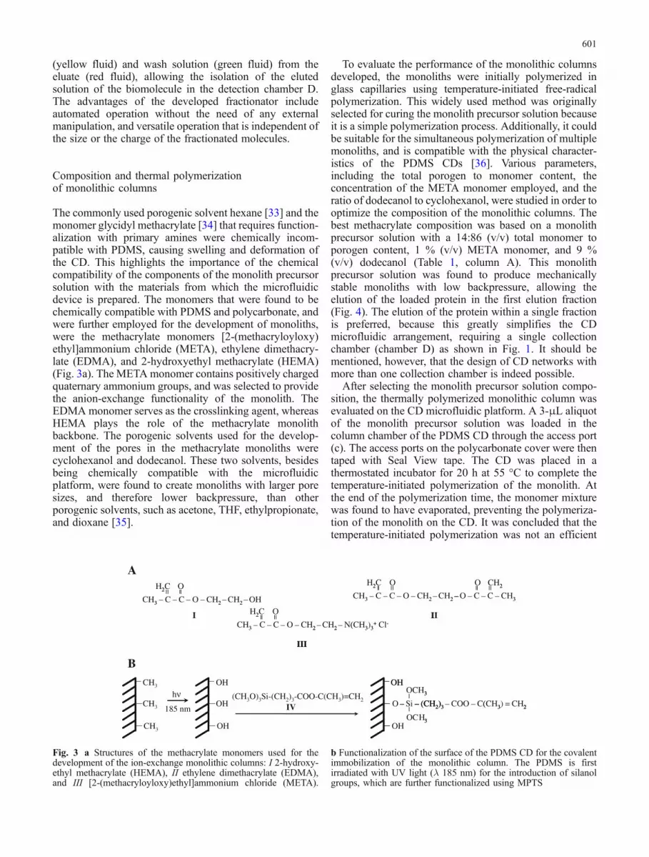
Table 1 Composition of the monolith precursor solutions used for the development of the monolithic columns A–C, using eithertemperature- (T) or microwave-initiated (MW) polymerization
Column EDMA HEMA META Cyclohexanol Dodecanol Polymerization technique
A 7 6 1 77 9 TB 10 8.6 1.4 57 23 MWC 10 7.2 2.8 57 23 MW
All monolith precursor solutions contained 1 % (w/v) azobisisobutyronitrile initiator
100
400
700
1000
1300
1600
W1 W2 W3 E1 E2 E3 E4 E5 E6
Fractions
Column A
Fluo
resc
ence
Int
ensi
ty (
a.u.
)
Fig. 4 Experimental results ofthe ion-exchange of the EGFPfusion protein on monolithiccolumn A (see Table 1), pre-pared by thermal polymerizationin glass capillaries. FractionsW are samples collected duringthe washing of the columns;fractions E denote proteinelution samples
602
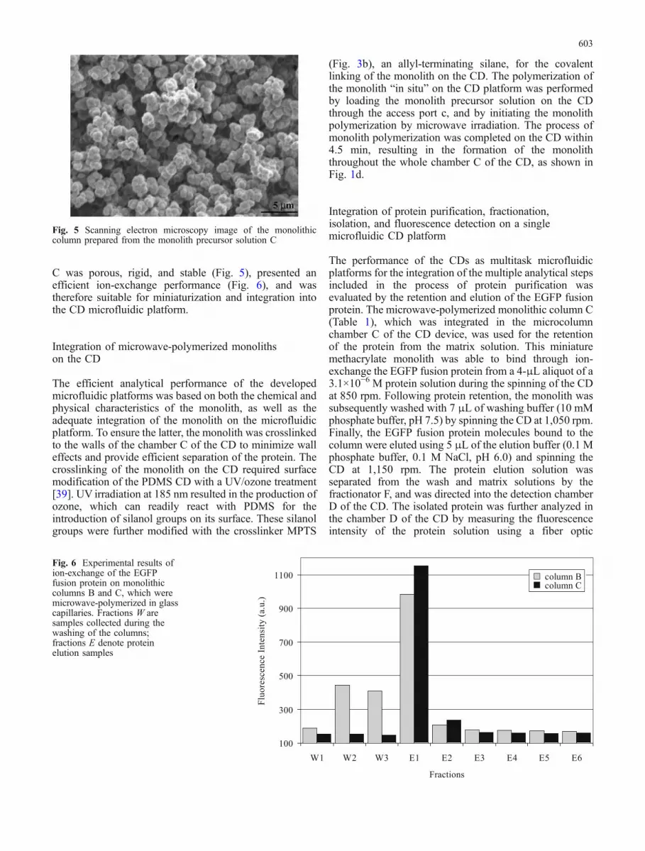
C was porous, rigid, and stable (Fig. 5), presented anefficient ion-exchange performance (Fig. 6), and wastherefore suitable for miniaturization and integration intothe CD microfluidic platform.
Integration of microwave-polymerized monolithson the CD
The efficient analytical performance of the developedmicrofluidic platforms was based on both the chemical andphysical characteristics of the monolith, as well as theadequate integration of the monolith on the microfluidicplatform. To ensure the latter, the monolith was crosslinkedto the walls of the chamber C of the CD to minimize walleffects and provide efficient separation of the protein. Thecrosslinking of the monolith on the CD required surfacemodification of the PDMS CD with a UV/ozone treatment[39]. UV irradiation at 185 nm resulted in the production ofozone, which can readily react with PDMS for theintroduction of silanol groups on its surface. These silanolgroups were further modified with the crosslinker MPTS
(Fig. 3b), an allyl-terminating silane, for the covalentlinking of the monolith on the CD. The polymerization ofthe monolith “in situ” on the CD platform was performedby loading the monolith precursor solution on the CDthrough the access port c, and by initiating the monolithpolymerization by microwave irradiation. The process ofmonolith polymerization was completed on the CD within4.5 min, resulting in the formation of the monoliththroughout the whole chamber C of the CD, as shown inFig. 1d.
Integration of protein purification, fractionation,isolation, and fluorescence detection on a singlemicrofluidic CD platform
The performance of the CDs as multitask microfluidicplatforms for the integration of the multiple analytical stepsincluded in the process of protein purification wasevaluated by the retention and elution of the EGFP fusionprotein. The microwave-polymerized monolithic column C(Table 1), which was integrated in the microcolumnchamber C of the CD device, was used for the retentionof the protein from the matrix solution. This miniaturemethacrylate monolith was able to bind through ion-exchange the EGFP fusion protein from a 4-μL aliquot of a3.1×10−6 M protein solution during the spinning of the CDat 850 rpm. Following protein retention, the monolith wassubsequently washed with 7 μL of washing buffer (10 mMphosphate buffer, pH 7.5) by spinning the CD at 1,050 rpm.Finally, the EGFP fusion protein molecules bound to thecolumn were eluted using 5 μL of the elution buffer (0.1 Mphosphate buffer, 0.1 M NaCl, pH 6.0) and spinning theCD at 1,150 rpm. The protein elution solution wasseparated from the wash and matrix solutions by thefractionator F, and was directed into the detection chamberD of the CD. The isolated protein was further analyzed inthe chamber D of the CD by measuring the fluorescenceintensity of the protein solution using a fiber optic
Fig. 5 Scanning electron microscopy image of the monolithiccolumn prepared from the monolith precursor solution C
100
300
500
700
900
1100
W1 W2 W3 E1 E2 E3 E4 E5 E6
Fractions
Flu
ore
scen
ce I
nte
nsit
y (
a.u
.)
column B
column C
column B
column C
Fig. 6 Experimental results ofion-exchange of the EGFPfusion protein on monolithiccolumns B and C, which weremicrowave-polymerized in glasscapillaries. Fractions W aresamples collected during thewashing of the columns;fractions E denote proteinelution samples
603
fluorometer at excitation wavelength of 488 nm andemission wavelength of 508 nm. The fluorescencemeasurements obtained from three EGFP fusion retentionand elution experiments, performed on three separatemonolithic columns integrated on three different CDmicrofluidic platforms, are illustrated in Table 2. Forcomparison purposes, the fluorescent signal of the bufferand the EGFP fusion protein solution expected to beobtained after full protein recovery were recorded for eachof the detection chambers employed. These measurementswere used for the determination of the amount offluorescence signal recovered after each protein bindingand elution experiments. Each experiment presented asuccessful binding, elution, fractionation, and isolation ofthe eluted protein solution on the microfluidic platform,demonstrating fluorescence signal recovery values rangingfrom 80 % to 90 %.
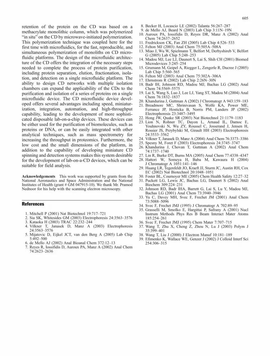
In addition, the performance of the CD microfluidicplatform was also evaluated with the successive loading ofmultiple aliquots of a less concentrated protein solution onthe CD, evaluating the ability to gradually trap proteinmolecules, and then eluting them within a small eluatevolume on the CD. Ten 4-μL aliquots of a 3.1×10⁻⁷ Mprotein solution were sequentially loaded on the CD, andduring the spinning of the CD they flowed through themicrofluidic structure allowing the fusion protein to bind tothe anion-exchange microcolumn (column composition C).Three different experiments involving protein solutions
flowing through the monolith, with the elution, fraction-ation, and isolation of the protein molecules within a 5-μLelution volume on chamber D of the CD were performed,as described earlier. The fluorescence signal recoveryvalues obtained for three experiments performed on threedifferent microfluidic architectures on three different CDplatforms (Fig. 7) were in 85–93 %. The timeframerequired to perform each protein retention and elutionexperiment was in the order of 3 min, allowing a simple,rapid, and complete purification process, including bind-ing, elution, isolation, and detection of the protein, on asingle disposable microfluidic chip, the lab-on-a-CD.
Conclusions
The development of disposable multitask CD microfluidicplatforms employing multiple microfluidic features for theintegration of the analytical steps involved in the process ofprotein purification has been presented in this work. Theplatforms developed were based on PDMS CDs thatincorporated the desired microfluidic pattern, and werearranged into closed-channel devices by the use ofpolycarbonate covers. The microfluidic pattern employedconsisted of a series of unique microfluidic features,including a microcolumn chamber, a fractionator, and achamber for the isolation and the detection of the elutedprotein solution. The microcolumn employed for the
Table 2 Ion-exchange binding, elution, and fractionation of EGFP fusion protein from a 4-μL aliquot of a 3.1×10⁻⁶ M protein solution,performed on three different microwave-polymerized columns (of composition C) integrated on three different PDMS CD microfluidicplatforms
Parameter Experiment 1 Experiment 2 Experiment 3
Amount of protein loaded on chamber L of the CD (mol) 1.24×10⁻¹¹ 1.24×10⁻¹¹ 1.24×10⁻¹¹
Amount of protein eluted after binding on chamber D of the CD (mol) 9.96×10⁻¹² 1.12×10⁻¹¹ 9.94×10⁻¹²
Protein recovery after protein binding and elution on the CD (%) 80 90 80
The EGFP fusion protein elution, fractionation, and isolation were followed by on-chip protein detection using a fiber optic fluorometer. Theamount of protein bound in the column and fractionated after elution in chamber D was determined by measuring the fluorescencesignal of the eluate protein solution directly in chamber D of the CD using a fiber optic fluorometer
115
165
215
265
315
365
Experiment 1 Experiment 2 Experiment 3
Buffer (Background)
EGFP elution
EGFP solution
Flu
ores
cenc
e In
tens
ity
(a.u
.)
Fig. 7 Ion-exchange binding,elution, fractionation, and isola-tion of ten 4-μL aliquots of3.1×10−7 M EGFP fusionprotein solution, performed onthree different microwave-polymerized columns ofcomposition C integrated onthree different PDMS CDmicrofluidic platforms. TheEGFP fusion protein elution andisolation were followed byon-chip protein detection usinga fiber optic fluorometer. To aidcomparison, the fluorescentsignal of the buffer and theEGFP fusion protein solutionused for each experiment wererecorded for each of thedetection chambers employed
604
retention of the protein on the CD was based on amethacrylate monolithic column, which was polymerized“in situ” on the CD by microwave-initiated polymerization.This polymerization technique was coupled here for thefirst time with microfluidics, for the fast, reproducible, andsimultaneous polymerization of monoliths on CD micro-fluidic platforms. The design of the microfluidic architec-ture of the CD offers the integration of the necessary stepsneeded to complete the process of protein purification,including protein separation, elution, fractionation, isola-tion, and detection on a single microfluidic platform. Theability to design CD networks with multiple isolationchambers can expand the applicability of the CDs to thepurification and isolation of a series of proteins on a singlemicrofluidic device. The CD microfluidic device devel-oped offers several advantages including speed, miniatur-ization, integration, automation, and high-throughputcapability, leading to the development of more sophisti-cated disposable lab-on-a-chip devices. These devices canbe either used for the purification of biomolecules, such asproteins or DNA, or can be easily integrated with otheranalytical techniques, such as mass spectrometry forincreasing the throughput in proteomics. Furthermore, thelow cost and the small dimensions of the platform, inaddition to the capability of developing miniature CDspinning and detection systems makes this system desirablefor the development of lab-on-a-CD devices, which can besuitable for field analysis.
Acknowledgements This work was supported by grants from theNational Aeronautics and Space Administration and the NationalInstitutes of Health (grant # GM 047915-10). We thank Mr. PramodNednoor for his help with the scanning electron microscopy.
References
1. Mitchell P (2001) Nat Biotechnol 19:717–7212. Sia SK, Whitesides GM (2003) Electrophoresis 24:3563–35763. Kataoka H (2003) TRAC 22:232–2444. Vilkner T, Janasek D, Manz A (2003) Electrophoresis
24:3563–35765. Mijatovic D, Eijkel JCT, van den Berg A (2005) Lab Chip
5:492–5006. de Mello AJ (2002) Anal Bioanal Chem 372:12–137. Reyes R, Iossifidis D, Auroux PA, Manz A (2002) Anal Chem
74:2623–2636
8. Becker H, Locascio LE (2002) Talanta 56:267–2879. de Mello AJ, Beard N (2003) Lab Chip 3:11N–19N10. Auroux PA, Iossifidis D, Reyes DR, Manz A (2002) Anal
Chem 74:2637–265211. Fredrickson CK, Fan ZH (2005) Lab Chip 4:526–53312. Felton MJ (2003) Anal Chem 75:505A–508A13. Miao J, Wu W, Spielmann T, Belfort M, Derbyshireb V, Belfort
G (2005) Lab Chip 5:248–25314. Madou MJ, Lee LJ, Daunert S, Lai S, Shih CH (2001) Biomed
Microdevices 3:245–25415. Grumann M, Geipel A, Riegger L, Zengerle R, Ducree J (2005)
Lab Chip 5:560–56516. Felton MJ (2003) Anal Chem 75:302A–306A17. Ehrnstrom R (2002) Lab Chip 2:26N–30N18. Badr IH, Johnson RD, Madou MJ, Bachas LG (2002) Anal
Chem 74:5569–557519. Lai S, Wang S, Luo J, Lee LJ, Yang ST, Madou M (2004) Anal
Chem 76:1832–183720. Khandurina J, Guttman A (2002) J Chromatogr A 943:159–18321. Breadmore MC, Shrinivasan S, Wolfe KA, Power ME,
Ferrance JP, Hosticka B, Norris PM, Landers JP (2002)Electrophoresis 23:3487–3495
22. Hong JW, Quake SR (2003) Nat Biotechnol 21:1179–118323. Lion N, Rohner TC, Dayon L, Arnaud IL, Damoc E,
Youhnovski N, Wu ZY, Roussel C, Josserand J, Jensen H,Rossier JS, Przybylski M, Girault HH (2003) Electrophoresis24:3533–3562
24. Vilkner T, Janasek D, Manz A (2004) Anal Chem 76:3373–338625. Spesny M, Foret F (2003) Electrophoresis 24:3745–374726. Khandurina J, Chovan T, Guttman A (2002) Anal Chem
74:1737–174027. Lin R, Burke DT, Burns MA (2005) Anal Chem 77:4338–434728. Hattori W, Someya H, Baba M, Kawaura H (2004)
J Chromatogr A 1051:141–14629. Huang LR, Tegenfeldt JO, Kraeft JJ, Sturm JC, Austin RH, Cox
EC (2002) Nat Biotechnol 20:1048–105130. Foster BL, Cournoyer ME (2005) Chem Health Safety 12:27–3231. Puckett LG, Lewis JC, Bachas LG, Daunert S (2002) Anal
Biochem 309:224–23132. Johnson RD, Badr IHA, Barrett G, Lai S, Lu Y, Madou MJ,
Bachas LG (2001) Anal Chem 73:3940–394633. Yu C, Davey MH, Svec F, Frechet JM (2001) Anal Chem
73:5088–509634. Svec F, Frechet JMJ (1995) J Chromatogr A 702:89–9535. Grasselli M, Smolko E, Hargittai P, Safrany A (2001) Nucl
Instrum Methods Phys Res B Beam Interact Mater Atoms185:254–261
36. Svec F, Frechet JMJ (1995) Chem Mater 7:707–71537. Wang T, Zhu X, Cheng Z, Zhou N, Lu J (2003) Polym J
35:399–40138. Wang T, Liu J (2000) J Electron Manuf 10:181–18939. Efimenko K, Wallace WE, Genzer J (2002) J Colloid Interf Sci
254:306–315
605