tunable microfluidic optical devices with an integrated microlens array
TRANSCRIPT
University of PennsylvaniaScholarlyCommons
Departmental Papers (MSE) Department of Materials Science & Engineering
8-1-2006
Tunable Microfluidic Optical Devices withIntegrated Microlens ArrayKuang-Sheng HongUniversity of Pennsylvania
Jing WangUniversity of Pennsylvania
Alexey SharonovUniversity of Pennsylvania
Dinesh ChandraUniversity of Pennsylvania
Joanna AizenbergBell Laboratories
See next page for additional authors
Postprint version. Published in Journal of Micromechanics and Microengineering, Volume 16, Issue 8, August 2006, pages 1660-1666.
This paper is posted at ScholarlyCommons. http://repository.upenn.edu/mse_papers/90For more information, please contact [email protected].

Author(s)Kuang-Sheng Hong, Jing Wang, Alexey Sharonov, Dinesh Chandra, Joanna Aizenberg, and Shu Yang
This journal article is available at ScholarlyCommons: http://repository.upenn.edu/mse_papers/90
J. Micromech. Microeng.
1
Tunable Microfluidic Optical Devices with Integrated Microlens Array
Kuang-Sheng Hong1, Jing Wang2, Alexey Sharonov3, Dinesh Chandra1, Joanna
Aizenberg4, and Shu Yang1*
1Department of Materials Science and Engineering, University of Pennsylvania, 3231
Walnut Street, Philadelphia, PA 19104
2 Department of Mechanical Engineering & Applied Mechanics, University of
Pennsylvania, Philadelphia, PA 19104
3Department of Chemistry, University of Pennsylvania, Philadelphia, PA 19104
4Bell Laboratories, Lucent Technologies, Murray Hill, NJ 07974
Email: [email protected]
Key words: microlens arrays, variable focus, variable transmission, fluidic channels
(Some figures in this article are in colour only in the electronic version)
J. Micromech. Microeng.
2
Abstract
The interest in dynamically tuning light has attracted great attention to the fabrication
of tunable microlens arrays. Here we discuss the fabrication and characterization of a
simple, robust, yet tunable microfluidic optical device with integrated microlens
array. The microfluidic device with desired channel structure was micromachined on
a polycarbonate plate with a resolution up to 100 μm, followed by thermal bonding
two plates above their glass transition temperature. The microlens arrays were replica
molded on a glass slide, which was then attached to the polycarbonate plates. By
simply actuating the liquids with variable refractive index into the fluidic channel to
immerse the lens arrays without moving or deformation of microlenses, a large
change of focal length of more than 10 times (f = 0.74 to 8.53) was achieved. When a
dye-containing liquid was pumped into the microfluidic channel to cover the lenses,
the light transmission through the lenses was reduced from about 95% to 55% when
the dye concentration was increased to 10 w/v %. The knowledge we gain from these
studies will provide important insights to construct new, adaptive, micro-scale optical
devices with multiple functionalities.
J. Micromech. Microeng.
3
1. Introduction
Recently the fabrication of dynamically adjustable optical structures have
attracted great attention due to the importance of the tunability of optical properties
for various device applications , including tunable photonic waveguides[1], miniature
optical sensing[2], electronic display[3], and wide-zoom cell phone and PDA
cameras[4]. Of many optical components, microlens arrays have played an import
role in focusing, detection, imaging and coupling of light. However, most synthetic
microlenses only have simple functions, and their optical properties are fixed. In
comparison, millions of years of evolution have perfected many of the optical features
of biologically formed lenses with a wide range of tunability, including variable
focus, double vision, wide field-of-view, tunable transmission and wavelength
selectivity.[5, 6] It will be highly desirable to have compact, multifunctional, and
tunable microlens arrays that mimic the biological design and functions.
Several tunable microlenses have been demonstrated. For example, in
gradient index (GRIN) lenses, the refractive index of a lens can be controlled using an
electrostatic potential.[7, 8] A microlens made of flexible polymeric materials, which
are either filled with liquid[9, 10] or placed on a microfluidic chip[11, 12], deforms
upon mechanical actuation of liquids, thus, tuning the lens focal length.[11] Similar
approach has been applied to a microdoublet lens, consisting of a tunable liquid-filled
lens and a solid negative lens.[13, 14] The liquid-filled lens can either change the
shape into bi-convex or meniscus under pressure of pumping liquid or be filled with
liquids with different refractive indices, which minimizes optical aberrations and
maximize the tunability of focal length or field-of-view. In a quite different approach,
we have recently demonstrated a conducting liquid as a tunable microlens.[15, 16]
The liquid lens can reversibly change its position and curvature in response to
J. Micromech. Microeng.
4
applying voltage between the droplet and a planar electrode embedded in a dielectric
substrate at a certain distance from the liquid - solid interface. Another approach to
change lens focus is to use responsive hydrogels as lens materials that will change
lens shape in response to external stimuli.[17] Nevertheless, most of the reported
examples of tunable lenses have rather limited tunable range and complexity.
An interesting feature of the lens design has been described in a light-sensitive
brittlestar. This organism forms a pore network surrounding the lenses,[6] which is
used for the diurnal transport of pigment-filled chromatophore cells. This design
feature is a key component of an adaptive optical device that provides transmission
tunability, diaphragm action, wavelength selectivity, minimization of the “cross-talk”
between the lenses, and improved angular selectivity.[18] The variable transmission
and wavelength selectivity are of particular interest in applications, including
electronic display[3], a high contrast spatial light modulator[7], and gray scale
photolithography[19]. Inspired by the unique lens design and the consequent
outstanding optical properties in brittlestars, we search for novel approaches to create
a structure that combines microlens arrays with microfluidics.[20] Here we present a
simple and effective fluidic channel that can be easily fabricated and integrated with
microlens arrays, allowing dynamic tuning of the refractive index and light absorption
of the surrounding medium to achieve a wide zooming range (up to 10 times) and
variable transmission.
2. Materials, Design and Fabrication
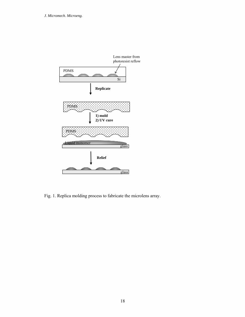
2.1. Fabrication of microlens arrays. The microlens arrays were fabricated using the
replica molding technique (see Fig. 1). First, the microlens array master were
fabricated through photoresist reflow on the silicon wafer.[21] A Silicon wafer was
J. Micromech. Microeng.
5
cleaned by sonication in isopropyl alcohol and acetone for 20 minutes, respectively,
followed by the exposure to oxygen plasma (Harrick Plasma Cleaner, NY, USA) for 5
minutes to generate hydroxyl groups on the surface. Photoresist Shipley 1818 (Rohm
& Haas Electronic Materials, MA, USA) was spun on the pre-cleaned silicon wafer at
1000 rpm for 30 sec, pre-exposure baked at 115 oC for 60 seconds and cooled to room
temperature. The film was then exposed to an ultraviolet light at 365 nm (BLAK-
RAY lamp, Model B) for 30 seconds through a photomask (dots, 100 µm in diameter
and 150 µm pitch). The film was post-exposure baked at 115 oC for 60 seconds, and
developed in CD-30 Developer (Rohm & Haas Electronic Materials, MA, USA). A
poly(dimethylsiloxane) (PDMS) precursor (RTV 615, GE Silicones, NY, USA) was
mixed with its curing agent in a ratio of 10:1 by weight, and cured at 65 oC for two
hours to replicate the master. Glass cover slips (VWR Micro Slides, precleaned,
plain, 25 x 75 mm) served as the substrates for the microlens arrays throughout the
experiment. They were rinsed with acetone, alcohol, followed by immersing in a
0.1M aqueous potassium hydroxide (KOH) solution for 15 minuets to remove any
contaminants and generate hydroxyl groups on glass. The substrates were then rinsed
with DI water and air-dried. For rigid lenses, Norland 68 (Norland Products. Inc., NJ,
USA) was molded on a pre-treated glass substrate using the PDMS stamp by exposing
to UV light for 10 minutes.
2.2. Design and fabrication of microfluidic channel. The channel design and
dimension is shown in Fig.2. The microfluidic devices were fabricated from two
polycarbonate plates (Ensinger Ltd., Pontyclun, UK). One of which was machined
with Computer Numerical Control (CNC) machining system (Fadal VMC15XT
milling machine, CA) (see Fig. 3A). Specifically, the microconduits and chamber
J. Micromech. Microeng.
6
were machined in a 250 µm thick polycarbonate plate. The conduits had a square
cross-section with width and depth of 250 µm, respectively. In order to reduce the
surface roughness, the conduit and chamber inner surfaces were polished
subsequently. After machining and cleaning with isopropyl alcohol, the plate was
bonded with second polycarbonate plate (250 µm thick), which would serve as the
transparent window, in a hot press machine (Twelve Ton Press No. 3850, CARVER
Inc., IN) at 140 °C and the press force was 1340 Newton (Fig. 3B). After 50 minutes
of pressing, the hot plates were cooled to ambient temperature under pressure. The
PC plates with the microfluidic channel were flipped facing down and bond together
with the glass slide with microlens arrays through a double-sided tape at four corners
(Fig. 3C). Finally, two plastic tubings were glued to the end of the channel as inlet
and outlet, respectively (Fig. 3D), for actuation of fluids. Fluids with different indices, including phenylmethylsiloxane homopolymer
(PMM-0011, n=1.470, viscosity at 25oC, 10-20 cSt.), dimethylsiloxane-ethylene oxide
block copolymer (DBE-712, n = 1.4416, viscosity at 25oC, 20 cSt.), and
trimethylsiloxy terminated polydimethysiloxane (DMS-T11, n = 1.399, viscosity at
25oC, 10 cSt.), were used as received from Gelest Inc. (PA, USA).
2.3. Optical characterization: The microlens arrays were observed using Olympus
BX51 optical microscopy in transmission mode with a 40 x objective. Images were
taken using a Color CCD camera (HANDYCAM, DCR-PC 330, Sony Corporation).
The geometry and sizes of the fabricated lenses were studied using Scanning Electron
Microscopy (SEM) and Atomic Force Microscopy (AFM) on a JEOL 6300F FEG
HRSEM and Digital Instruments Dimension 3000, respectively, at the Penn Regional
Nanotechnology Facility (PRN). Focal length of microlens arrays in different
J. Micromech. Microeng.
7
reflective index liquids was measured using Olympus IX81 inverted microscope with
an oil-immersion objective (Olympus 60 x, numerical aperture = 1.45) and an
appropriate set of filters (540LP and 630SP, Omega Optical).[22] 514.5 nm circularly
polarized light from an Ar+ ion laser (National Laser Company, Salt Lake City, Utah,
USA) was used as a source of excitation. QuickTime 5 Professional, MATLAB
(Mathworks Inc.), and custom Labview software were used to analyze the optical
properties of the microlenses.
3. Results and Discussion
3.1. Calculation of the Focal Length of the Microlenses. For image formed by
refraction at a spherical surface, the image focal length (f) is defined as[23]
(1)
where R is the lens radius, and n1 is the refractive index of the surrounding medium,
and n2 is the refractive index of the lens. For a thin, hemispherical lens, R can be
defined as[21]
2 2( / 2)
2D hR
h+
= (2)
where D is the base diameter of lens and h is the thickness, respectively. The focal
length of the lens, therefore, is a function of lens shape (lens diameter and thickness),
and index contrast between the lens material and the surrounding medium. In our
experiment, microlens arrays from optical adhesive Norland 68 (n = 1.54) were
replicated from a PDMS mold under UV exposure. A lens master for replication was
fabricated by resist reflow.[21] Lenses with a diameter of 100 µm and a pitch of 150
µm were used throughout the experiment. Limited by the resolution of the photomask
printed on the transparency, edge roughness and inhomogeneity of the lens diameter
2 2 1/( )f n R n n= −

J. Micromech. Microeng.
8
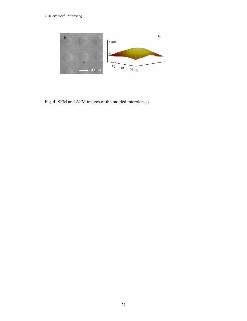
was observed, resulting in some variation of the lens thickness. Since the lenses were
relatively large and thin, the lens thickness was estimated as ~3 µm according to the
scanning electron microscopy (SEM) and atomic force microscopy (AFM)
measurement (see Fig. 4) to provide the guidance for the calculation of the lens focal
length by eq 1 and 2. For example, for n1 = 1.0 (air), n2=1.54 (Norland 68), D = 100
µm, and h = 3 µm, the focal length is 1.15 mm. More uniform lens arrays can be
obtained from a higher resolution photomask.
3.2. Design of the fluidic channel with integrated microlens arrays. The integration
of microlens arrays with a fluidic channel offers an attractive possibility to achieve a
wide range of tunability of the lens optical properties, including varied focal length,
transmission, numerical aperture and wavelength selectivity. Recently we have
developed an electrowetting pump in recirculating fluidic channels that can digitally
tune the optical fiber properties.[1, 24, 25] The electrically controlled and fully
reversible motion of the fluid plugs in these channels alters the refractive index profile
experienced by the optical waveguide modes of the fiber. When combined with in-
fiber gratings and etched fibers, this fluidic system yields dynamically adjustable
narrow and broadband fiber filters, respectively. The non-mechanical operation, low
power consumption, fast switching speeds (on the order of milliseconds), and
excellent optical characteristics indicates a promising potential for electrowetting-
actuated fluidic tuning in many photonic components.
Using the similar concept of dynamically tuning the optical properties using
microfluidics without mechanically moving the optical components, here we attempt
to fabricate a simple, robust, yet effective fluidic channel that can be integrated with
microlens arrays. Registration marks to align the channel with the microlens arrays
J. Micromech. Microeng.
9
are not necessary. Control of fluid movement can be separated from the lens/channel.
In our experiment, two polycarbonate (PC) plates, one of which was milled the
desired channel structure by computer controlled micromaching with a resolution up
to 100 μm, were bonded together through hot pressing at 140oC, close to the glass
transition temperature of PC, 148oC (see Fig. 3). PC is highly transparent, which is
essential for accurate measurement of variable focal lengths and transmission. A
glass slide with molded microlens array were then attached to the bottom PC plate
using double-sided tape to ensure flat contact, which minimizes measurement errors
caused by possible non-flatness in polycarbonate plates. Glass can be easily cleaned
using acetone or alcohol for recirculation of different liquids. Liquids with different
refractive indices, dye concentrations, and pH values were actuated in and out of the
channel using a syringe pump. In most cases, after we introduced the liquids, we
either kept the liquid still in the channel or use a slow pump rate of 50 μl/min to
minimize any disturbance to the microlenses and optical measurement. However, we
did not observe any damage to the microfluidic channel or detachment of the
microlenses with a pump rate up to 200 μl/min. The pump rate can be increased to a
few mL/min when the microlens array/glass is permanently bonded to the PC plate. It
can be achieved by casting a thin, uniform layer of epoxy (e.g. SU8) at the corners of
the glass slide. After placing the PC microfluidic channel on top of the glass slide, the
whole device is heated above the glass transition temperature of epoxy, followed by
UV or thermal curing of the epoxy to glue glass and PC plates together.
3.3. Variable focal length of rigid lenses tuned by the refractive index of surrounding
liquid. Microlens with variable focal length over a wide range is of great interest to
increase the efficiency of the light detection, recording, imaging, and coupling.
J. Micromech. Microeng.
10
Although many approaches have been proposed, including change of the refractive
index and shape of the lenses, here we demonstrate that it is more straightforward and
efficient to vary the refractive index of the surrounding medium to achieve high focal
length adjustment.
First, we fabricate a rigid lens array from optical adhesive, Norland 68. The lens
shape and position are fixed, and liquids with different indices are actuated into the
fluidic channel to cover the lens array. The focus length of the lens array increases
along with the increase of the liquid’s refractive index. The zooming range will
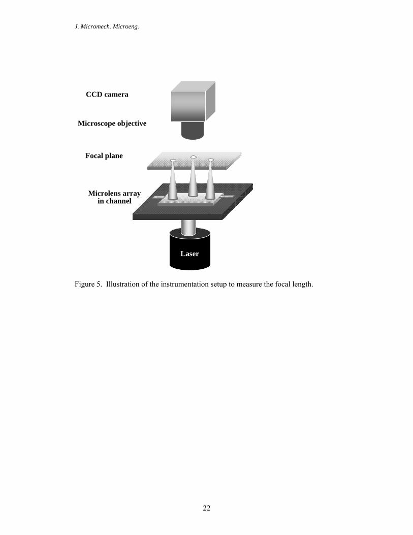
depend on the geometry of the lens and the index contrast. The focal length was
measured using the setup shown in Figure 5. The collimated laser beam is 2 mm in
diameter with a peak wavelength of 448 nm. It was aligned to be normal to the lens
arrays. The focal point was defined as the smallest and most intense focal spot
observed through a CCD camera. The position of the focal plane of the lens arrays
were adjusted using a micromanipulator in the z-direction with a resolution of 1 µm.
The relative distance from the focal plane to a zero reference point was recorded as
the focal length. The accuracy of the measurements is limited by our ability to
visually identify the focal plane.
To facilitate the smooth actuation, liquids with low viscosity (≤ 20 cSt.) were
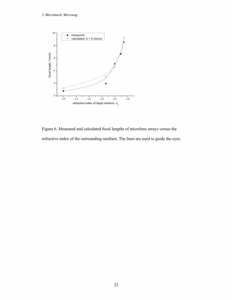
chosen in our experiment. By simply actuating the liquids with variable refractive
index, ranging from n = 1.00 (air) to n = 1.47 (phenylmethylsiloxane homopolymer,
PMM-0011), into the fluidic channel to immerse the lens arrays, a large change of
focal length, more than 10 times (f = 0.74 to 8.53), was achieved (see Figure 6). The
tunable range of focal length can be further increased using fluids with index closely
match to that of Norland 68, n =1.54. For example, by varying the concentration of
aqueous solution of sodium dichromate (Na2Cr2O7 • 2 H2O) while keeping the low
J. Micromech. Microeng.
11
viscosity, we can fine-tune the refractive index from 1.33 to 1.5.[1] The dynamical
tuning of focal length presented here is large, yet achieved by a simple and
straightforward method without moving or deformation of microlenses.
In comparison, in the liquid crystal immersed GRIN lenses, change of refractive
index upon application of a voltage is small, Δn ≈ 0.1-0.2, resulting in a relatively
small optical path modulation.[7] In the electrowetting tunable liquid lens, the contact
angle change becomes saturated at high voltages due to the electrostatic charge
accumulated on the surface or the boundary limitation of the electrodes. Thus, the
change of focal length is limited to 30 %.[15, 16] In the liquid filled lens or membrane
lens assembled in the microfluidic devices, lens shape is mechanically deformed by
the application of liquids, and a maximum of focal length change up to 6 times has
been demonstrated.[10] When using a more sophisticated microfluidic chip, which
consists of a double PDMS membrane lens, focal length change can be increased to
more than 20 times.[12] Nevertheless, the tunable range is dependent on the
applicable force (or the volume of the fluid pumped in and out of the lens chamber),
which will be limited by the mechanical strength of the lens materials.
Since the lens thickness was estimated ~3 µm, we calculated the focal lengths as
reference and compared to the experimental results. As seen from Figure 6, within
the measurement error the measured image focal length (0.74 to 8.53mm) agrees
reasonably well with the expected values (1.19-9.2 mm). The errors could be due to
the variation of lens thickness, the inhomogenity of lens diameter originated from the
photomask, and the uncertainty in identifying the exact location of the focal planes,
especially when the focal length is small.
J. Micromech. Microeng.
12
3.4. Variable transmission using dye-containing solutions. To mimic the transmission
tunability in the brittlestar optical system achieved by the migration of pigment-filled
chromatophore cells in the channeled network surrounding the lenses, we previously
assembled a simple microfluidic device to actuate photoactive liquids within the
synthetic porous microlens array.[20] When a dye-containing liquid was pumped
through the pores surrounding the lens, we illustrated the reduction in light
transmission through the lenses, whose intensity can be adjusted by the dye
concentration and/or thickness of the dye layer covering the lens.
Recently a PDMS microfluidic channel filled with light-absorbing dye at
desired concentrations has been demonstrated as a tunable photomask.[19] The
opacity of the photomask features can be tailored to an arbitrary gray-scale level to
produce three-dimensional (3D) microstructures. Clearly such strategy can be applied
to microlens arrays filled with desired dye solutions to control the degree of
illumination through the lens. It offers a simple and low-cost approach for 3D
imaging and lithography with spatial resolution. For a given dye solution, detailed
study is needed to predict the transmission through the lens as a function of the dye
concentrations.
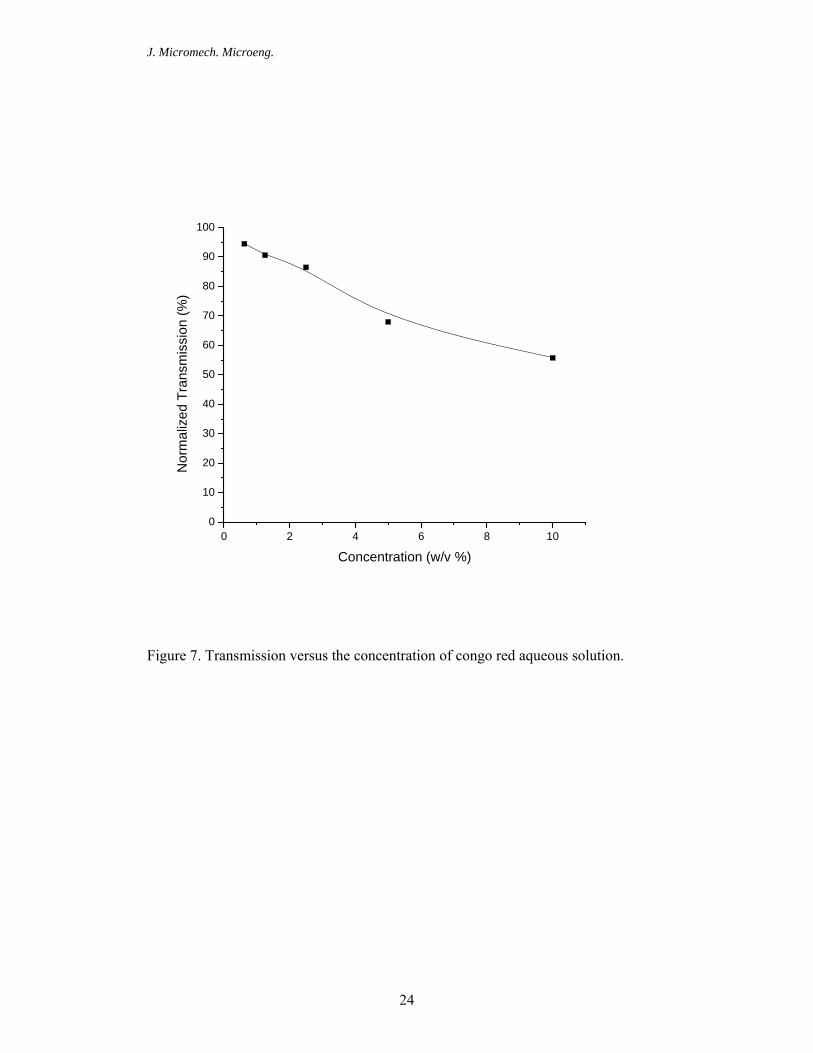
Congo red, a red-brownish azo dye, was dissolved in water at different
concentrations to demonstrate the transmission tunability (see Figure 7). A standard
optical microscope equipped with a CCD camera was used to capture optical images
in transmission mode through the microlens arrays. The initial focal plane of the lens
arrays in water and the light intensity passing through the lenses were observed and
recorded as a reference. The microfluidic device containing aqueous solution of a dye
was then fixed at the measured focal plane, and the light intensity passing through the
lenses was recorded again as the final state. Transmission was defined as the ratio of
J. Micromech. Microeng.
13
the final state light intensity to the initial state light intensity. As seen in Figure 7, the
transmission varied from about 95% to 55% when the dye concentration was
increased to 10 w/v %. Further decrease of transmission was not investigated because
of the solubility of congo red in the aqueous solution. Dyes with higher solubility
could be used in the future, allowing broader range of tunability. Since most dyes are
wavelength selective, it is possible to mix a variety of dye molecules to enable a wide
range of spectral response though the microlens arrays. The sensitivity to specific
colors is quite common in biological eyes to view objects under murky conditions,
and detect fine shades of colors.
We have shown the wide range tunability of focal length and transmission
from rigid lenses, whose shape and position are fixed once fabricated, by changing the
refractive index and light absorption ability of the liquids surrounding the lens arrays.
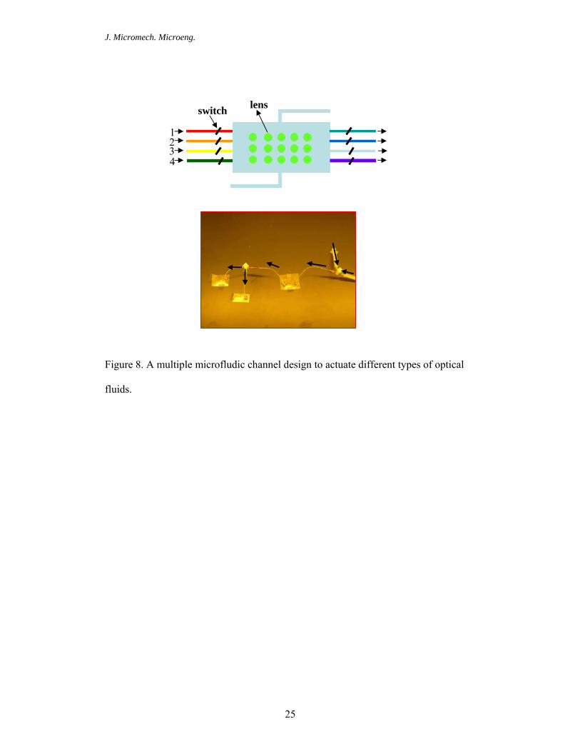
However, such tuning of optical properties is rather discreet. To fine-tune the optical
properties, we are investigating a multiple channel design (see Fig. 8) to separately or
simultaneously pump multiple liquids with different optical characteristics (variable
refractive index, light absorbing, light responsive, wavelength selective, etc.). Similar
strategy has been tested by us previously to independently pump multiple microfluidic
plugs into or out of overlap with an optical fiber, allowing for a variety of different
configurations to modulate the fiber transmission.[25] In a separate effort, we have
fabricated soft lenses from hydrogels, which could change the shape, volume and
refractive index continuously in response to external stimuli (pH, temperature, etc.).
The results will be reported elsewhere.[26]
4. Conclusions
J. Micromech. Microeng.
14
We present a simple, robust and cost-effective method that combines micromachining
and soft lithography to fabricate microfluidic devices integrated with microlens
arrays. The microfluidic device with desired channel structure was fabricated using
computer controlled micromachining of a polycarbonate plate with a resolution up to
100 μm, followed by thermal bonding two plates above their glass transition
temperature. The microlens arrays (100 μm in diameter, 3 μm thick) were patterned
on glass through replica molding, which was then attached to the polycarbonate
plates. By simply actuating the liquids with variable refractive index into the fluidic
channel to immerse the lens arrays without moving or deformation of microlenses, a
large change of focal length of more than 10 times (f = 0.74 to 8.53) was achieved.
When a dye-containing liquid was pumped into the microfluidic channel to cover the
lenses, the light transmission through the lenses was reduced from about 95% to 55%
when the dye concentration was increased to 10 w/v %. The knowledge we gain from
these studies will provide important insights to construct new, adaptive, micro-scale
optical devices with multiple functionalities.
Acknowledgments.
This work is supported by the National Science Fundation (BES-0438004), National
Institutes of Health (U01DE014964), and ACS PRF G grant. KH would like to thank
Dr. Hei Lui for her help with Auto-CAD, and Dr. Byong Kim for his help with
fluorescent imaging.
J. Micromech. Microeng.
15
References
[1] Mach P, Krupenkin T, Yang S and Rogers J A 2002 Dynamic tuning of optical waveguides with electrowetting pumps and recirculating fluid channels Appl. Phys. Lett. 81 202-4
[2] Saurei L, Mathieu G and Berge B 2004 Design of an autofocus lens for VGA 1/4 -in. CCD and CMOS sensors Proc. SPIE: Inter. Soc. Opt. Eng. 5249 288
[3] Hayes R A and Feenstra B J 2003 Video-speed electronic paper based on electrowetting Nature 425 383-5
[4] Hatcher M 2003 Liquid lenses eye commercial breakthrough Opt. Laser Eur. 16
[5] Land M F and Nilsson D-E 2002 Animal Eyes (New York: Oxford University Press)
[6] Aizenberg J, Tkachenko A, Weiner S, Addadi L and Hendler G 2001 Calcitic microlenses as part of the photoreceptor system in brittlestars Nature 412 819
[7] Commander L G, Day S E and Selviah D R 2000 Variable focal length microlenses Opt. Commun. 177 157-70
[8] Kulishov M 2000 Tunable electro-optic microlens array. I. Planar geometry Appl. Opt. 39 2332-9
[9] Sugiura N and Morita S 1993 Variable-Focus Liquid-Filled Optical Lens Appl. Opt. 32 4181-6
[10] Zhang D-Y, Lien V, Berdichevsky Y, Choi J and Lo Y-H 2003 Fluidic adaptive lens with high focal length tunability Appl. Phys. Lett. 82 3171-2
[11] Chen J, Wang W S, Fang J and Varahramyan K 2004 Variable-focusing microlens with microfluidic chip J. Micromech. Microeng. 14 675-80
[12] Agarwall M, Gunasekaran R A, Coane P and Varahramyan K 2004 Polymer-based variable focal length microlens system J. Micromech. Microeng. 14 1665-73
[13] Chronis N, Liu G L, Jeong K H and Lee L P 2003 Tunable liquid-filled microlens array integrated with microfluidic network Opt. Exp. 11 2370-8
[14] Jeong K H, Liu G L, Chronis N and Lee L P 2004 Tunable microdoublet lens array Opt. Exp. 12 2494-500
[15] Krupenkin T, Yang S and Mach P 2003 Tunable liquid microlens Appl. Phys. Lett. 82 316
[16] Yang S, Krupenkin T N, Mach P and Chandross E A 2003 Tunable and Latchable Liquid Microlens with Photopolymerizable Components Adv. Mater. 15 940-3
[17] Kim J, Serpe M J and Lyon L A 2004 Hydrogel microparticles as dynamically tunable microlenses J. Am. Chem. Soc. 126 9512-3
[18] Aizenberg J and Hendler G 2004 Designing efficient microlens arrays: lessons from Nature J. Mater. Chem. 14 2066
[19] Chen C, Hirdes D and Folch A 2003 Gray-scale photolithography using microfluidic photomasks Proc. Nat. Acad. Soc. USA 100 1499–504
[20] Yang S, Chen G, Megens M, Ullal C K, Han Y J, Rapaport R, Thomas E L and Aizenberg J 2005 Functional biomimetic microlens arrays with integrated pores Adv. Mater. 17 435-8
[21] Wu H K, Odom T W and Whitesides G M 2002 Reduction photolithography using microlens arrays: Applications in gray scale photolithography Anal. Chem. 74 3267-73
[22] Mei E, Sharonov A, Ferris J H and Hochstrasser R M 2005 Direct visualization of nanopatterns by single-molecule imaging Appl. Phys. Lett. 86 043102
[23] Hecht E 2002 Optics (Reading, MA: Addison Wesley) [24] Hsieh J, Mach P, Cattaneo F, Yang S, Krupenkine T, Baldwin K and Rogers J
A 2003 Tunable microfluidic optical-fiber devices based on electrowetting pumps and plastic microchannels IEEE Photonics Technol. Lett. 15 81-3

J. Micromech. Microeng.
16
[25] Cattaneo F, Baldwin K, Yang S, Krupenkine T, Ramachandran S and Rogers J A 2003 Digitally tunable microfluidic optical fiber devices J. Microelectromech. Sys. 12 907-12
[26] Chandra, D, Hong, K, and Yang, S 2006, Manuscript in preparation.
J. Micromech. Microeng.
17
Captions of Figures:
Figure 1. Replica molding process to fabricate the microlens array.
Figure 2. Design and dimensions of the fluidic channel integrated with microlens
arrays. Illustrative images: (a) Top view, (b) side view, and (c) 3-D view. (d) Actual
image of the fluidic channel device used in the experiment.
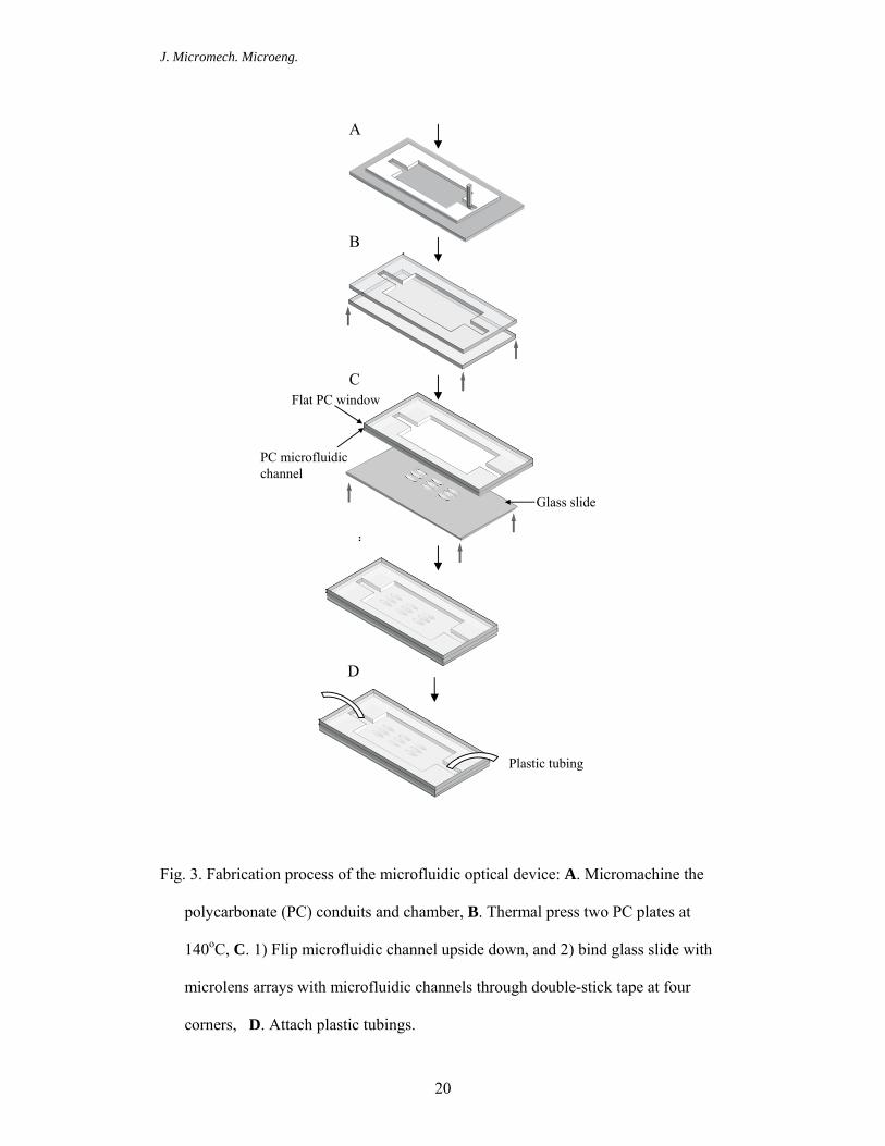
Figure 3. Fabrication process of the microfluidic optical device: A. Micromachine the
polycarbonate (PC) conduits and chamber, B. Thermal press two PC plates at
140oC, C. 1) Flip microfluidic channel upside down, and 2) bind glass slide with
microlens arrays with microfluidic channels through double-stick tape at four
corners, D. Attach plastic tubings.
Figure 4. SEM and AFM images of the molded microlenses.
Figure 5. Illustration of the instrumentation setup to measure the focal length.
Figure 6. Measured and calculated focal lengths of microlens arrays versus the
refractive index of the surrounding medium. The lines are used to guide the eyes.
Figure 7: Transmission versus the concentration of congo red aqueous solution.
Figure 8. A multiple microfludic channel design to actuate different types of optical
fluids.
J. Micromech. Microeng.
18
Fig. 1. Replica molding process to fabricate the microlens array.
PDMS
PDMS
Replicate
Relief
PDMS
Liquid monomer
1) mold 2) UV cure
Si
Lens master from photoresist reflow
glass
glass

J. Micromech. Microeng.
19
Figure 2. Design and dimensions of the fluidic channel integrated with microlens
arrays. Illustrative images: (a) Top view, (b) side view, and (c) 3-D view. (d)
Actual image of the fluidic channel device used in the experiment.
a c
b d
Glass slide outlet
Microlens array 0.
7 cm
1.2 cm 1.0 cm
0.3 cm
Glass slide
Fluidic channel
PC window
inlet
J. Micromech. Microeng.
20
Fig. 3. Fabrication process of the microfluidic optical device: A. Micromachine the
polycarbonate (PC) conduits and chamber, B. Thermal press two PC plates at
140oC, C. 1) Flip microfluidic channel upside down, and 2) bind glass slide with
microlens arrays with microfluidic channels through double-stick tape at four
corners, D. Attach plastic tubings.
A
B
C
D
Plastic tubing
Flat PC window
PC microfluidic channel
Glass slide
J. Micromech. Microeng.
21
Fig. 4. SEM and AFM images of the molded microlenses.
b
100 μm
a
20 40 60 μm
4 μm
2
J. Micromech. Microeng.
22
Figure 5. Illustration of the instrumentation setup to measure the focal length.
Laser
CCD camera
Microscope objective
Focal plane
Microlens array in channel
J. Micromech. Microeng.
23
1.0 1.1 1.2 1.3 1.4 1.50
2
4
6
8
10
foca
l len
gth,
f (m
m)
refractive index of liquid medium, n1
measured calculated, h = 3 micron
Figure 6. Measured and calculated focal lengths of microlens arrays versus the
refractive index of the surrounding medium. The lines are used to guide the eyes.
J. Micromech. Microeng.
24
0 2 4 6 8 100
10
20
30
40
50
60
70
80
90
100
Nor
mal
ized
Tra
nsm
issi
on (%
)
Concentration (w/v %)
Figure 7. Transmission versus the concentration of congo red aqueous solution.
J. Micromech. Microeng.
25
Figure 8. A multiple microfludic channel design to actuate different types of optical
fluids.
switch lens
1 234