evaluation of manufacturing processes for microfluidic devices
TRANSCRIPT
1 2 3 4 5 6 7 8 9 10 11 12 13 14 15 16 17 18 19 20 21 22 23 24 25 26 27 28 29 30 31 32 33 34 35 36 37 38 39 40 41 42 43 44 45 46 47 48 49 50 51 52 53 54 55 56 57 58 59 60 61 62 63 64 65
1
Evaluation of Micro-Mechanical Manufacturing Processes for Micro-fluidic Devices A.L. Jáuregui – H.R. Siller* – C.A. Rodríguez - A. Elías-Zúñiga
A.L. Jáuregui – A. Elías-Zúñiga
Department of Mechanical Engineering
Instituto Tecnológico y de Estudios Superiores de Monterrey
Eugenio Garza Sada 2501 Sur, C.P. 64849. Monterrey, N.L., México.
H.R. Siller – C.A. Rodríguez
Center for Innovation in Design and Technology
Instituto Tecnológico y de Estudios Superiores de Monterrey
Eugenio Garza Sada 2501 Sur, C.P. 64849. Monterrey, N.L., México. Ph: +52 (81) 8358-2000
Fax: 52(81) 8358-4123
e-mail: [email protected]
Abstract
In this paper several micro-mechanical manufacturing technologies were studied in order to
characterize their performance for prototyping miniaturized geometries known as micro-channels,
which are the main geometric features of micro-fluidic devices. The technologies used were
Micro-End Milling, Wire Electro Discharge Machining/Sandblasting and Abrasive Water Jet.
Their capabilities were compared with Lithography capabilities, which is the conventional process
for micro-channel manufacturing. The evaluation consists in a comprehensive study of surface
quality and topography, made with the help of advanced contact and non-contact profilometers
over each prototype. Also economical considerations have been taken into account in order to
choose the most appropriate manufacturing process for the prototyping of micro-fluidic devices.
The results show that Micro-End Milling process can compete with Lithography, in terms of
achieving acceptable levels of product quality and economics.
Keywords: micro-fluidic devices, micro-channels, micro-mechanical processes.
Abbreviations
AWJ: Abrasive Water-Jet; CNC: Computer Numerical Control; DNA: Deoxyribonucleic acid;
DWT: Dynamic Water Technology; HDMS: Hexamethyldisilazane;
IFB: Integrated Flying Bridge; PDMS: Polydimethylsiloxane; PMMA: Polymethyl methacrylate;
UV: Ultra Violet;; TTL: Trough the Lens; WEDM: Wire Electro-Discharge Machining;
*ManuscriptClick here to download Manuscript: Jauregui_IJAMT_majorrev.doc Click here to view linked References
1 2 3 4 5 6 7 8 9 10 11 12 13 14 15 16 17 18 19 20 21 22 23 24 25 26 27 28 29 30 31 32 33 34 35 36 37 38 39 40 41 42 43 44 45 46 47 48 49 50 51 52 53 54 55 56 57 58 59 60 61 62 63 64 65
2
Introduction
The need to fabricate micro scale systems for their use in engineering, medicine,
robotics and informatics, has encouraged the development of new manufacturing
processes capable to conform miniaturized geometric features. These features
must offer diverse functionalities for the integration of mechanical and electronic
elements, sensors, actuators, pumps and other micro-systems for their use in
different applications such as: optical switches, micro-conveyors, micro-fluidic
devices, micro-turbines, micro-cantilevers and so on.
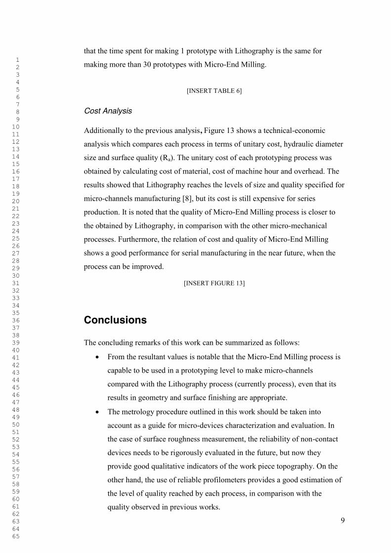
Nowadays, in the specific case of micro-fluidic devices, their applications have
growth in areas like medicine or biotechnology for the separation of molecules,
the transportation of DNA or the implementation of drug delivery systems (e.g.
the release of insulin for diabetic’s treatments). The main geometric elements of
micro fluidic devices are the named micro-channels, whose main function is the
release and transportation of fluids (e.g. Figure 1). Precisely, the particular
research of this work is focused on the evaluation of micro-mechanical
manufacturing processes for micro-fluidic devices, in order to characterize and
analyze their performance in the micro-channel prototyping.
[INSERT FIGURE 1]
Literature Review
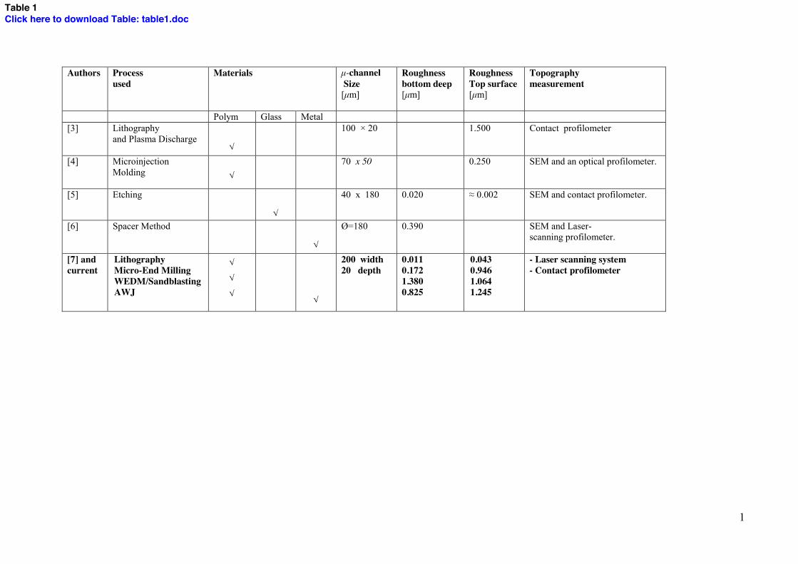
In the case of micro-channels manufacturing for micro-fluidic devices, a variety
of processes and techniques are documented in the literature. These are mainly
non-mechanical manufacturing processes like Plasma Etching, Lithography or
Spacer Method. They are summarized in Table 1 in order to observe and compare
their capability for reaching acceptable levels of dimensional and surface quality.
The metrology equipment used in each work is also included for better
understanding of the roughness and topography measurement.
As it can be seen in the Table 1, all the prototypes remain in dimensional values
below 200 microns, which is the upper limit of micro-channels according to the
classification made by Kandlikar [2]. It is also shown that the predominant
measurement technology for surface roughness and topography is the Scanning
Electron Microscope (SEM).
1 2 3 4 5 6 7 8 9 10 11 12 13 14 15 16 17 18 19 20 21 22 23 24 25 26 27 28 29 30 31 32 33 34 35 36 37 38 39 40 41 42 43 44 45 46 47 48 49 50 51 52 53 54 55 56 57 58 59 60 61 62 63 64 65
3
The Table 1 also presents briefly the contribution of the current work, in which
the manufacturing processes studied are Lithography, Micro-End Milling, a
combination of Wire Electro-Discharge Machining (WEDM) / Sand Blasting, and
Abrasive Water Jet cutting. The details of the experimental deployment are
explained in the following sections.
[INSERT TABLE 1]
Experimental Work
The experimental stage of this work consists in the fabrication of several
prototypes using different manufacturing processes: Lithography, which is one of
the conventional processes for the manufacturing of micro-fluidic devices, Micro-
End Milling, WEDM/Sandblasting and Abrasive Water Jet, which are micro-
mechanical manufacturing processes.
The materials used in prototyping processes are mainly polymers: PDMS
(Polydimethylsiloxane) for Lithography, PMMA (Polymethyl methacrylate) for
WEDM/Sandblasting and Micro End Milling, and aluminum alloy for Abrasive
Water Jet. The geometry used for the comparison was taken of the work by
Hosokawa [8], in order to make a valid generalization of geometric features in
micro-fluidic devices. This design consists on a serpentine micro-channel with a
square cross section of 0.02 mm depth and 0.2 mm width. For the comparison of
surface finish and topography of each prototype, advanced profilometers and a
laser TTL (Trough The Lens) optical system were used as metrology equipment
(see Figure 2).
[INSERT FIGURE 2]
Lithography
The Lithography process applied to micro-scale systems is commonly used for the
fabrication of integrated circuits. Lithography is characterized for the reaching of
accurate tolerances and smooth surface finishing. This process consists in
transferring a pattern to a photosensitive material, which changes its physical
properties according to a given pattern, when is exposed to a radiation source like
1 2 3 4 5 6 7 8 9 10 11 12 13 14 15 16 17 18 19 20 21 22 23 24 25 26 27 28 29 30 31 32 33 34 35 36 37 38 39 40 41 42 43 44 45 46 47 48 49 50 51 52 53 54 55 56 57 58 59 60 61 62 63 64 65
4
UV Light. In this experimental work, the machine used to make the prototype is a
mask aligner from Electronic Vision Group EVG model 620.
The prototyping procedure can be described as follows: the first material used in
the prototyping process is silicon, in the form of a wafer that serves as a mask.
Before the mask is finished, a small quantity of polymer and a curing agent are
mixed. The polymeric mixture is poured into the silicon mold, and forms the
stamp geometry by solidification (see Figure 3). The materials used in the wafer
covering procedure are:
HDMS (Hexamethyldisilazane): Promotes adhesion of the resist to the oxide
on the wafer surface.
AZ 4620. Is the trade mark of a photo-resist material and is used as a cover for
the silicon mask.
Curing agent. Is used to promote or control the curing reaction.
The experimental deployment of this particular prototyping process is explained
in Figure 4.
[INSERT FIGURE 3]
[INSERT FIGURE 4]
Micro-End Milling
The machining processes for miniaturized parts such as Micro-Turning, Micro-
End Milling or Micro-Drilling are commonly used to make small complex
geometric features in many applications such as electronics or bio-chemical
analysis. But their application in micro-fluidic devices is very limited according to
the Literature Review, in spite of their capabilities to achieve good quality levels.
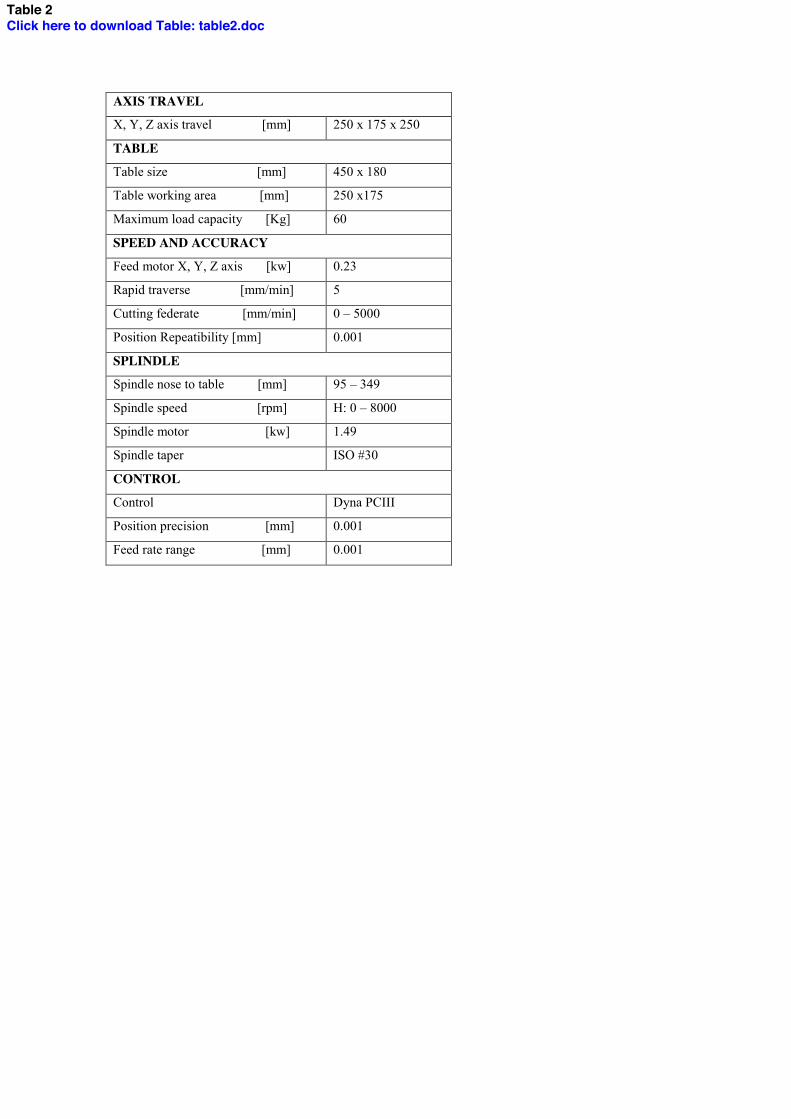
In the case of this work, the selected machining process was Micro-End Milling,
and it was performed in a CNC Machining Center (Table 2) with the steps and
machining conditions explained in Figure 5. In addition, the prototype was made
in PMMA as an approximation of the polymeric materials used in micro-fluidic
devices.
[INSERT TABLE 2]
[INSERT FIGURE 5]
1 2 3 4 5 6 7 8 9 10 11 12 13 14 15 16 17 18 19 20 21 22 23 24 25 26 27 28 29 30 31 32 33 34 35 36 37 38 39 40 41 42 43 44 45 46 47 48 49 50 51 52 53 54 55 56 57 58 59 60 61 62 63 64 65
5
Electro-Discharge Machining/Sandblasting
The fabrication of a prototype using the WEDM/Sandblasting combined
technology can help to observe its capability of manufacturing small geometric
features. In the case of the experimental work presented here, a stainless steel
stencil is made with a Wire Electro-Discharge Machine model ONA WEDM
AE400 (see Table 3 for specification). Later, a Sandblasting process will
complement the channel printing in a PMMA sample (Figure 6).
[INSERT TABLE 3]
[INSERT FIGURE 6]
The stencil serves to transfer the design into the PMMA sample with the Sand-
blasting machine, which original application is the cleaning of hard surfaces by
forcing solid sand particles at high pressure. The outlet load of the pressure
corresponds to 408 Kg and the abrasive used is silica sand 90/10 (the particle size
corresponds to 0.149 mm).
Abrasive Water-Jet Machining
The non-traditional machining processes denominated Abrasive Water Jet, is now
gaining acceptance for its ability to deal with very hard materials, complex 2D
parts and tight accuracy requirements. The Abrasive Water Jet machine used for
the prototyping stage corresponds to an IFB (Integrated Flying Bridge) DWT
(Dynamic Water Technology), which main characteristics are listed in Table 4.
The design of the trajectory consists in a serpentine channel form, and the control
of the machine uses a 2D Flowpath FLOW’s propietary Software. Figure 7 shows
a magnified view of the prototype sample taking as reference a coin of 17 mm of
diameter.
[INSERT FIGURE 7]
[INSERT TABLE 4]
1 2 3 4 5 6 7 8 9 10 11 12 13 14 15 16 17 18 19 20 21 22 23 24 25 26 27 28 29 30 31 32 33 34 35 36 37 38 39 40 41 42 43 44 45 46 47 48 49 50 51 52 53 54 55 56 57 58 59 60 61 62 63 64 65
6
In order to decrease the material removal rate for controlling the micro-channel
depth, a special abrasive was used (HPA #100) and the initial parameters like
pressure, distance of the nozzle, velocity, and material thickness were calculated.
After making previous calibration runs, it was determined that the minimum
micro-channel depth was 0.1524 mm, obtained with the following parameters:
feedrate of 1143 mm/min, height of 3.81 mm, thickness of 0.762 mm and water
pressure of 107,484 KPa [9].
Discussion of Results
In spite of the fact that two kind of materials were used in the prototyping stage
(see Figure 8), the characterization made serves to establish a valid reference for
comparing the micro-mechanical manufacturing processes and the conventional
fabrication procedure for micro-fluidic devices. The experimental results can be
discussed comparing the capabilities of each process, for reaching acceptable
values in terms of productivity, surface topography, hydraulic diameter size [1]
and average surface roughness (Ra) inside the work piece micro-channels.
[INSERT FIGURE 8]
Topography Analysis
The measurements of topography were made with the TTL laser system, in which
the cross section of each prototype was scanned in order to establish a size and
shape comparison among each prototype. As it can be seen in Figure 9, the most
reliable process in terms of reaching the shape and size of the micro-channels
design (0.2 mm width and 0.02 mm depth) is the Lithography process. However,
the Micro-End Milling process approaches the shape of the original design, with a
minimum of topography defects in comparison with the other micro-mechanical
processes. It is important to mention that the size of the micro-channels made with
Micro-End Milling depends on the diameter of the tool used. It is expected that
with the use of smaller tools, the specified size could be reached.
[INSERT FIGURE 9]
1 2 3 4 5 6 7 8 9 10 11 12 13 14 15 16 17 18 19 20 21 22 23 24 25 26 27 28 29 30 31 32 33 34 35 36 37 38 39 40 41 42 43 44 45 46 47 48 49 50 51 52 53 54 55 56 57 58 59 60 61 62 63 64 65
7
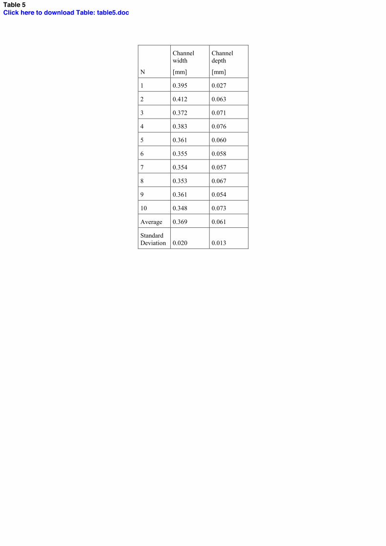
Once this last process has been selected, its capability to reach a good dimensional
stability has been studied by measuring ten different transversal sections (Figure
10). Table 5 shows the results of these measurements, in which it can be seen that
the variation is approximately the same in both depth and width dimensions. This
variability can be a result of built up edge when milling soft materials and the
precision of the machine tool used for this experimentation.
[INSERT FIGURE 10]
[INSERT TABLE 5]
Surface Roughness Analysis
The evaluation of surface quality inside the micro-channels was made measuring
the average surface roughness value (Ra), which plays and important role in the
generation of turbulences in the fluid flow through the channel. The systems used
to make the measurement are the contact (profilometer) and non-contact (laser
scanning system) devices described previously. The resultant values obtained with
each device are evaluated through surface filtering analysis [10] and compared in
Figure 11.
[INSERT FIGURE 11]
As it can be seen in the Figure 11, there is a discrepancy between the values
taking by the profilometer and those measured by the non contact device. This is
mainly due to a lack of standardization of the surface roughness parameters
captured by non-contact devices. Nevertheless, the trend of the measurements is
the same with both devices, in which the minimum values observed are those
measured on the prototype made by Lithography process, followed by those
measured on the prototype made by Micro-End Milling. Due to the fact that the
surface roughness parameters of contact devices are well standardized and are
generally used in the literature, they will be taken as reference for further
comparisons.
For Micro-End Milling (the most competitive process in this comparison) it is
needed a deeper characterization of the machined surfaces. For this specific case,
the roughness profile obtained from the profilometer is displayed in Figure 12, in
1 2 3 4 5 6 7 8 9 10 11 12 13 14 15 16 17 18 19 20 21 22 23 24 25 26 27 28 29 30 31 32 33 34 35 36 37 38 39 40 41 42 43 44 45 46 47 48 49 50 51 52 53 54 55 56 57 58 59 60 61 62 63 64 65
8
which the parameters used (cutoff of 0.08 mm and 5 samples) and the peaks
recorded can be seen.
[INSERT FIGURE 12]
In order to evaluate the experimental values of surface roughness and the ideal
values, it is necessary the estimation of theoretical roughness (Rth), using the
Equation 1 [12]:
)/(32
2
nfRf
Rz
zth (1)
where:
fz= feed per revolution equal to 0.00125 mm
R=corner tool radius equal to 0.01 mm
n= number of flutes equal to 2
The second term of the denominator is used for distinguishing between climb and
up milling, but it does not apply for the slotting operation performed in this study.
The resultant value of Rth = 0.00488 µm is far away from the experimental one
(Ra=0.1725 m), which suggests that there is an influence of other factors in the
surface generation, in addition to the tool geometry and process parameters. These
factors could be chatter, engagement of the cutting tool, run out, built up edge,
tool coatings and cutting fluids [13].
Productivity Analysis
The evaluation of productivity of each micro-mechanical process consists on the
calculation of cycle times by using the programmed feed rate of each process and
taking as reference the micro-channel geometry which has a length of 65 mm. For
the specific case of Lithography, cycle time was 209 minutes taking into account
the duration of all procedures needed for finishing the prototype. It is important to
mention that non productive times like set-up time, programming time and
material handling time were not considered for the calculation. As it can be seen
in Table 6, Abrasive Water Jet showed superior productivity than the other
processes, but it has been demonstrated in previous paragraphs that, as well as
WEDM/Sandblasting, the process quality is poor. For the case of Micro-End
Milling, productivity is acceptable in comparison with Lithography since the fact
1 2 3 4 5 6 7 8 9 10 11 12 13 14 15 16 17 18 19 20 21 22 23 24 25 26 27 28 29 30 31 32 33 34 35 36 37 38 39 40 41 42 43 44 45 46 47 48 49 50 51 52 53 54 55 56 57 58 59 60 61 62 63 64 65
9
that the time spent for making 1 prototype with Lithography is the same for
making more than 30 prototypes with Micro-End Milling.
[INSERT TABLE 6]
Cost Analysis
Additionally to the previous analysis, Figure 13 shows a technical-economic
analysis which compares each process in terms of unitary cost, hydraulic diameter
size and surface quality (Ra). The unitary cost of each prototyping process was
obtained by calculating cost of material, cost of machine hour and overhead. The
results showed that Lithography reaches the levels of size and quality specified for
micro-channels manufacturing [8], but its cost is still expensive for series
production. It is noted that the quality of Micro-End Milling process is closer to
the obtained by Lithography, in comparison with the other micro-mechanical
processes. Furthermore, the relation of cost and quality of Micro-End Milling
shows a good performance for serial manufacturing in the near future, when the
process can be improved.
[INSERT FIGURE 13]
Conclusions
The concluding remarks of this work can be summarized as follows:
From the resultant values is notable that the Micro-End Milling process is
capable to be used in a prototyping level to make micro-channels
compared with the Lithography process (currently process), even that its
results in geometry and surface finishing are appropriate.
The metrology procedure outlined in this work should be taken into
account as a guide for micro-devices characterization and evaluation. In
the case of surface roughness measurement, the reliability of non-contact
devices needs to be rigorously evaluated in the future, but now they
provide good qualitative indicators of the work piece topography. On the
other hand, the use of reliable profilometers provides a good estimation of
the level of quality reached by each process, in comparison with the
quality observed in previous works.
1 2 3 4 5 6 7 8 9 10 11 12 13 14 15 16 17 18 19 20 21 22 23 24 25 26 27 28 29 30 31 32 33 34 35 36 37 38 39 40 41 42 43 44 45 46 47 48 49 50 51 52 53 54 55 56 57 58 59 60 61 62 63 64 65
10
The surface roughness evaluation plays an important role in micro channel
flows. The estimation of the Ra parameter helps to characterize its effect in
the friction and pressure behavior of the fluid performance.
The economy of the manufacturing process of micro-fluidic devices, will
impact directly the growing use of this kind of devices in the health sector.
As a future work, it is expected to perform analysis and evaluation of materials
commonly used for the fabrication of micro fluidic devices such as biocompatible
polymers. Also, it stimulates the implementation of the machining of test probes
in cryogenic state in further experimentation.
Acknowledgements
The authors would like to thank the Council of Science and Technology (CONACYT ) project
Synthesis and constitutive modeling of biocompatible polymers for micro fluidic devices # 61061,
and to the CONACYT Postdoctoral Scholarships. The team would like to extend their gratitude to
the Intelligent Machines and Nano-materials research groups at ITESM Campus Monterrey, to the
Micromechanics and Mechatronics Group at CCADET (UNAM), the Association for
Manufacturing Technology (ATM) and the Center for Solid State Electronics Research at Fulton
School of Engineering, in Arizona State University (ASU). Also, thanks to the participation of
Gilberto García from 3G Herramientas and Alejandro Guerrero from Mahr Metrology.
References
1. EPIGEM chips (2008) available online at http://www.epigem.co.uk/products-fluidics.htm
(accesed 07/2008)
2. Kandlikar G, Steinke M (2003) Predicting Heat Transfer During Flow Boiling in Mini-channels
and Micro-channels. ASHRAE Trans 109: CH-03-13-1.
3. Bubendorfer A, Lui X, Ellis A (2007) Microfabrication of PDMS micro-channels using SU-
8/PMMA moldings and their sealing to polystyrene substrates. Smart Mater Struct 16: 367-371.
4. Loke Y, Tor S, Chun J, Loh N, Hardt D (2007) Micro-injection molding of cyclic olefin
copolymer using metallic glass insert. Manufacturing Systems and Technology (MST) Collection
at MIT online DSPACE. Available at http://dspace.mit.edu/handle/1721.1/35813?show=full.
5. Swierkowski S, Balch J, Brewer L, Copeland A, Davidson J, Fitch P, Kimbrough J, Madabhushi
R, Pastrone R, Richardson P, Tarte L (1999) Large micro-channel array fabrication and results for
DNA sequencing. Proc. SPIE 3606: DOI:10.1117/12.350050.
6. Hakamada M, Asao Y, Saito N, Mabuchi M (2008) Micro-fluidic flows in metallic micro-
channels fabricated by the spacer method. J Micromech Microeng 18: 075029.
1 2 3 4 5 6 7 8 9 10 11 12 13 14 15 16 17 18 19 20 21 22 23 24 25 26 27 28 29 30 31 32 33 34 35 36 37 38 39 40 41 42 43 44 45 46 47 48 49 50 51 52 53 54 55 56 57 58 59 60 61 62 63 64 65
11
7. Jáuregui AL, Siller HR, Rodriguez CA, Elias A (2008) Evaluation of Micro-mechanical
manufacturing processes for micro-fluidic devices. Master of Science Thesis. Tecnológico de
Monterrey.
8. Hosokawa K, Hanada K, Maeda R (2002) A polydimethylsiloxane (PDMS) deformable
diffraction grating for monitoring of local pressure in micro-fluidics devices. J Micromech
Microeng 12:1-6.
9. Jáuregui AL, Rodríguez CA, Rivera-Solorio C, Elías A, Siller HR (2008) Fabricación y
prototipado de canales para sistemas micro-fluídicos del sector salud. Memorias del XIV Congreso
Anual Internacional de la Sociedad Mexicana de Ingeniería Mecánica (In Spanish).
10. Mainsah E, Greenwood J, Chetwynd D (2001) Metrology properties of Engineering Surfaces.
Kluwer Academic Pub. Group, Boston MA.
11. Dornfeld D, Lee D (2008) Precision Manufacturing. Springer Science + Bussiness Media, New
York NY.
12. Montgomery D, Altintas Y (1991) Mechanism of cutting forces and surface generation in
dynamic milling. J Eng Ind-T ASME 113: 160-168.
13. Siller HR, Vila C, Rodriguez CA, Abellan, JV (2009) Study of face milling of hardened AISI
D3 steel with a special design of carbide tools. Intl J Adv Manuf Technol 40:12-25.
List of Figures
Figure 1. Micro-fluidic devices for biological analysis, fabricated by Epigem [1].
Figure 2. Metrology equipment used for micro-channels quality evaluation: Laser TTL scanning
system and advanced contact profilometer.
Figure 3. Lithographed micro-channel prototype: Mold of silicon with the channel geometry, and
PDMS stamp of the channel lightly visible.
Figure 4. Complete procedure of micro-channel prototyping by the Lithography process.
Figure 5. Complete procedure of micro-channel prototyping by the Micro-End Milling process.
Figure 6. Stainless steel stencil fabricated by WEDM process and sandblasted PMMA sample.
Figure 7. Magnified view of prototype micro-channels made by the Abrasive Water Jet process.
Size comparison against a 10 ¢ Mexican coin (diameter=17 mm).
Figure 8. Prototype/Material/Manufacturing process relation.
Figure 9. Micro-channels cross section for each prototyping process, taken by the Laser TTL
scanning system.
Figure 10. Location of cross section measurements of Micro-End milled prototype.
Figure 11. Average surface roughness (Ra) comparison with different measurement devices.
Figure 12. Detail of surface roughness characterization in Micro-End milled prototypes.

1 2 3 4 5 6 7 8 9 10 11 12 13 14 15 16 17 18 19 20 21 22 23 24 25 26 27 28 29 30 31 32 33 34 35 36 37 38 39 40 41 42 43 44 45 46 47 48 49 50 51 52 53 54 55 56 57 58 59 60 61 62 63 64 65
12
Figure 13. Comparison of hydraulic diameter (channel size), surface roughness and economics of
manufacturing process for micro-fluidic devices micro-channels (based on [11] with original
experimental results).
List of Tables
Table 1. Literature review of manufacturing processes for micro-channels in microfluidic devices.
Table 2. CNC machining center specifications.
Table 3. Wire Electric-Discharge machine specifications.
Table 4. Abrasive Water Jet machine characteristics.
Table 5. Cross section measurements of Micro-End milled prototype.
Table 6. Cycle time calculations for each prototyping process.
Figure 1Click here to download high resolution image
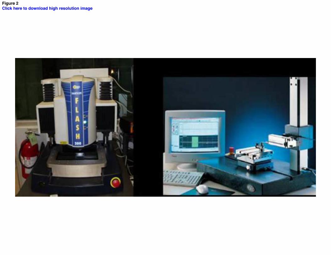
Figure 2Click here to download high resolution image
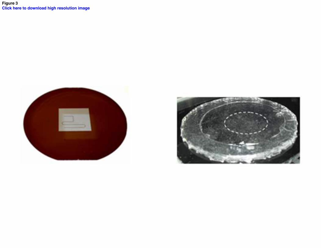
Figure 3Click here to download high resolution image
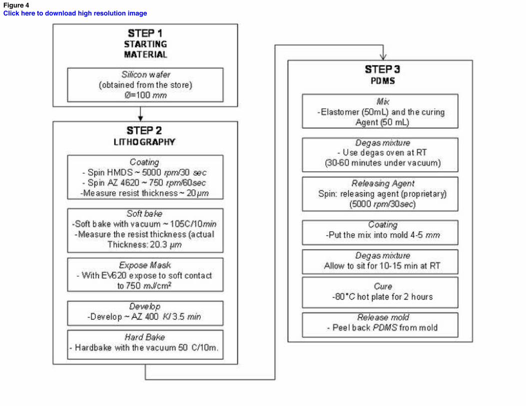
Figure 4Click here to download high resolution image
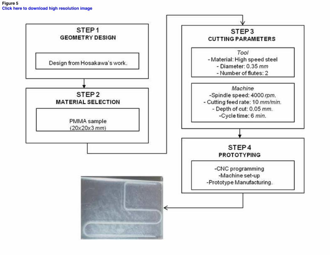
Figure 5Click here to download high resolution image
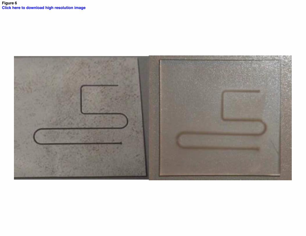
Figure 6Click here to download high resolution image
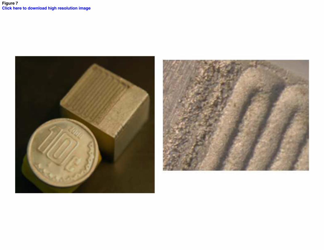
Figure 7Click here to download high resolution image
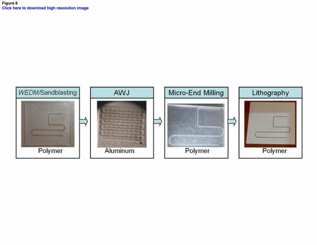
Figure 8Click here to download high resolution image
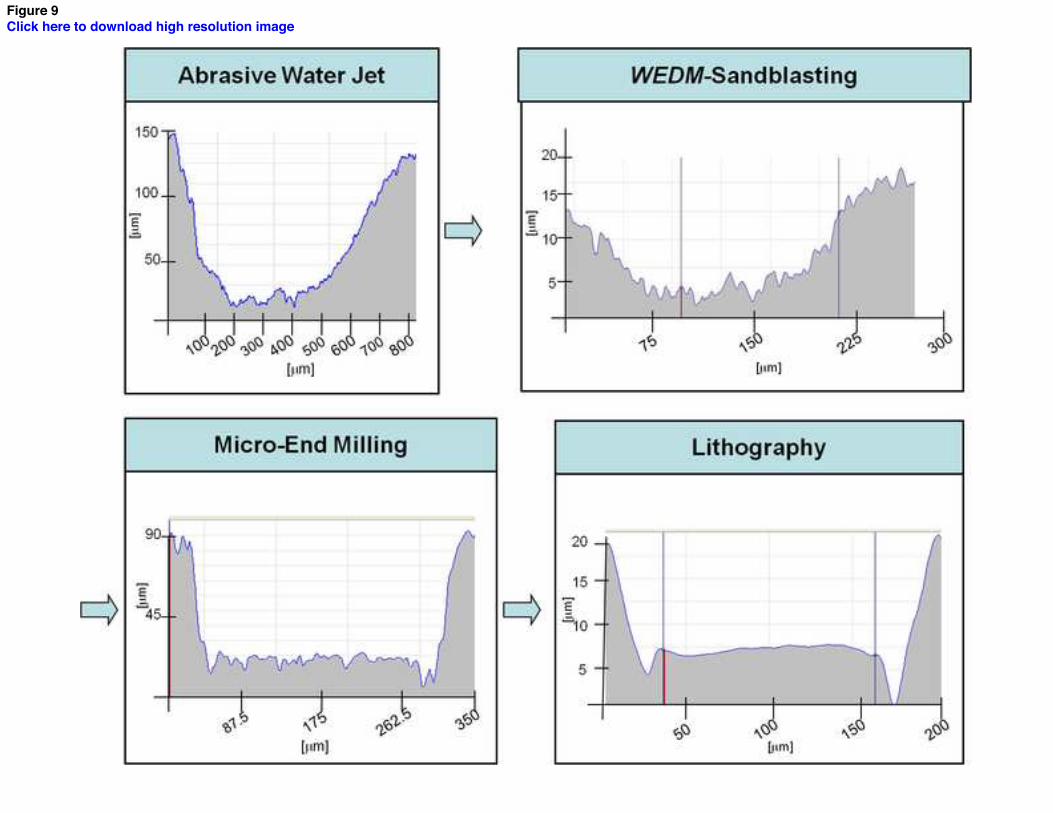
Figure 9Click here to download high resolution image
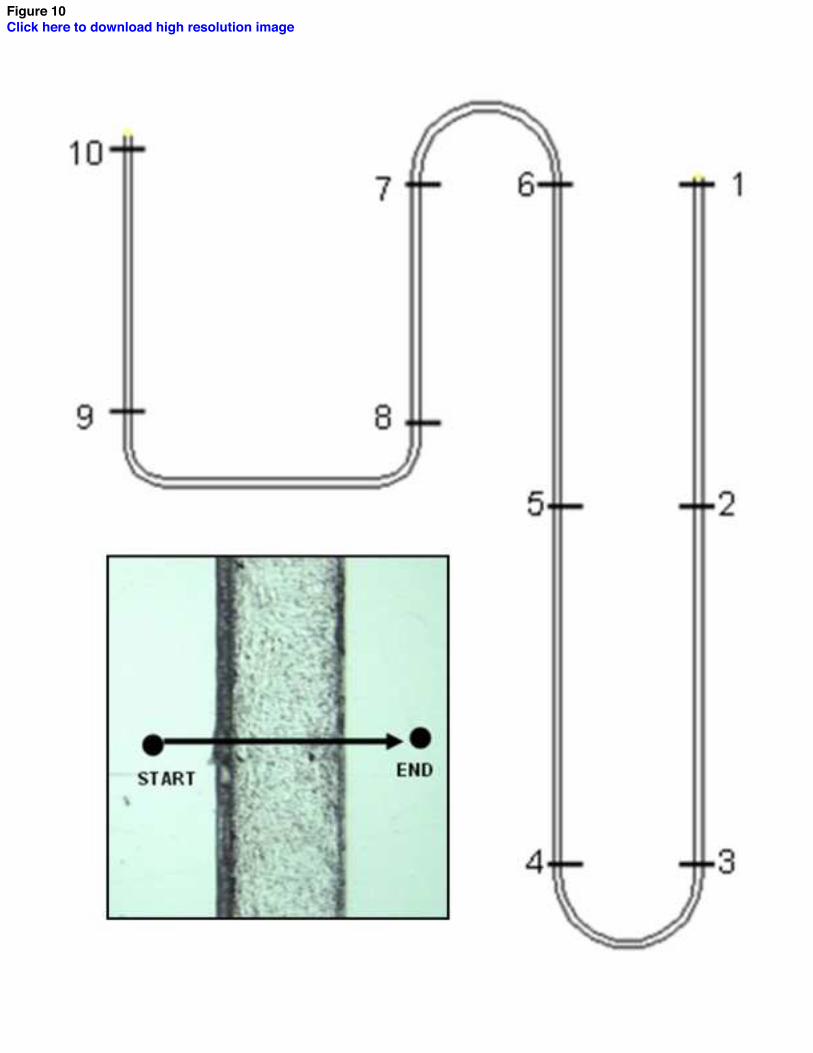
Figure 10Click here to download high resolution image
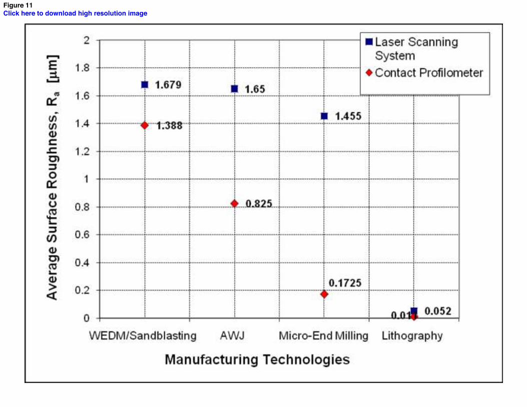
Figure 11Click here to download high resolution image
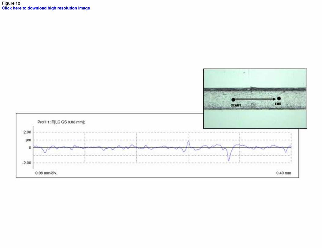
Figure 12Click here to download high resolution image
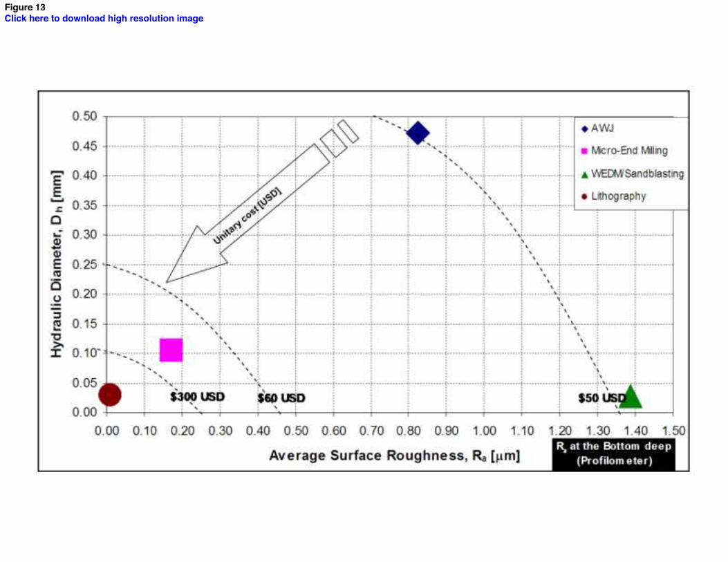
Figure 13Click here to download high resolution image
1
Authors Process used
Materials
μ-channel Size [μm]
Roughness bottom deep [μm]
Roughness Top surface [μm]
Topography measurement
Polym Glass Metal [3]
Lithography and Plasma Discharge
√
100 × 20
1.500
Contact profilometer
[4]
Microinjection Molding
√
70 x 50
0.250
SEM and an optical profilometer.
[5]
Etching
√
40 x 180
0.020
≈ 0.002
SEM and contact profilometer.
[6]
Spacer Method
√
Ø=180 0.390
SEM and Laser- scanning profilometer.
[7] and current
Lithography Micro-End Milling WEDM/Sandblasting AWJ
√ √ √
√
200 width 20 depth
0.011 0.172 1.380 0.825
0.043 0.946 1.064 1.245
- Laser scanning system - Contact profilometer
Table 1Click here to download Table: table1.doc
AXIS TRAVEL
X, Y, Z axis travel [mm] 250 x 175 x 250
TABLE
Table size [mm] 450 x 180
Table working area [mm] 250 x175
Maximum load capacity [Kg] 60
SPEED AND ACCURACY
Feed motor X, Y, Z axis [kw] 0.23
Rapid traverse [mm/min] 5
Cutting federate [mm/min] 0 – 5000
Position Repeatibility [mm] 0.001
SPLINDLE
Spindle nose to table [mm] 95 – 349
Spindle speed [rpm] H: 0 – 8000
Spindle motor [kw] 1.49
Spindle taper ISO #30
CONTROL
Control Dyna PCIII
Position precision [mm] 0.001
Feed rate range [mm] 0.001
Table 2Click here to download Table: table2.doc

Voltage [V] 220
Power [kVA] 13
Air supply [bar mm] 6
Frequency [Hz] 60
Current [A] 34
Feedrate [mm/min] 58
Table 3Click here to download Table: table3.doc

Maximum Pressure [KPa] 414
Linear positional accuracy [mm] ± 0.08
Repeatability [mm] 0.05
Rapid Traverse Maximum [m/min] 12.5
Net cutting area [m] 1.2 x 2.4
Table 4Click here to download Table: table4.doc
N
Channel width
[mm]
Channel depth
[mm]
1 0.395 0.027
2 0.412 0.063
3 0.372 0.071
4 0.383 0.076
5 0.361 0.060
6 0.355 0.058
7 0.354 0.057
8 0.353 0.067
9 0.361 0.054
10 0.348 0.073
Average 0.369 0.061
Standard Deviation 0.020 0.013
Table 5Click here to download Table: table5.doc

Prototyping Process Feed rate
[mm/min]
Cycle Time/Prototype
[min]
Litography N/A 209
WEDM/Sandblasting 58 2
Micro-End Milling 10 6.5
Abrasive Water Jet 1143 0.06
Table 6Click here to download Table: table6.doc