location, selection, and maintenance of highway
TRANSCRIPT
NATIONAL COOPERATIVE HIGHWAY RESEARCH PROGRAM
REPORT 118
AREAS OF INTEREST:
HIGHWAY DESIGN
BRIDGE DESIGN
HIGHWAY SAFETY
TRAFFIC CONTROL AND OPERATIONS
HIGHWAY RESEARCH BOARD
LOCATION, SELECTION, AND MAINTENANCE OF HIGHWAY TRAFFIC BA.RRIERS
J. D. MICHIE AND M. E. BRONSTAD
SOUTHWEST RESEARCH INSTITUTE
SAN ANTONIO, TEXAS
RESEARCH SPONSORED BY THE AMERICAN ASSOCIATION
OF STATE HIGHWAY OFFICALS IN COOPERATION
WITH THE FEDERAL HIGHWAY ADMINISTRATION
DIVISION OF ENGINEERING NATIONAL RESEARCH COUNCIL
NATIONAL ACADEMY OF SCIENCES-NATIONAL ACADEMY OF ENGINEERING 1971
-
=
NATIONAL COOPERATIVE HIGHWAY RESEARCH PROGRAM
Systematic, well-designed research provides the most effective approach to the solution of many problems facing highway administrators and engineers. Often, highway problems are of local interest and can best be studied by highway departments individually or in cooperation with their state universities and others. However, the accelerating growth of highway transportation develops increasingly complex problems of wide interest to highway authorities. · fhese problems are best studied through a coordinated program of cooperative research.
In recognition of these needs, the highway administrators of the American Association of State Highway Officials initiated in 1962 an objective national highway research program employing modern scientific techniques. This program is supported on a continuing basis by funds from participating member states of the Association and it receives the full cooperation and support of the Federal Highway Administration, United States Department of Transportation.
The Highway Research Board of the National Academy of Sciences-National Research Council was requested by the Association to administer the research program because of the Board's recognized objectivity and understanding of modern research practices. The Board is uniquely suited fnr thi~ p11rpnc;:.p !l~ • it m~int~in~ ~n PvtPn~lvP f"nmmlttPP
structure from which authorities on any highway transportation subject may be drawn; it possesses avenues of communications and cooperation with federal, slalt:, and lucal governmental agencies, universities, and industry; its relationship to its parent organization, the National Academy of Sciences, a private, nonprofit institution, is an insurance of objectvity; it maintains a full-time research correlation staff of specialists in highway transportation matters to bring the findings of research directly to those who are in a position to use them.
The program is developed on the basis of research needs identified by chief administrators of the highway departments and by committees of AASHO. Each year, specific areas of research needs to be included in the program are proposed to the Academy and the Board by the American Association of State Highway Officials. Research projects to fulfill these needs are defined by the Board, and qualified research agencies are selected from those that have submitted proposals. Administration and surveillance of research contracts are responsibilities of the Academy and its Highway Research Board.
The needs for highway research are many, and the National Cooperative Highway Research Program can make significant contributions to the solution of highway transportation problems of mutual concern to many responsible groups. The program, however, is intended to complement rather than to substitute for or duplicate other highway research programs.
NCHRP Report 118
Project 15-1 (2) FY '69 ISBN 0-309-01909-5 L. C. Catalog Card No. 70-173641
Price $5.20
This report is one of a series of reports issued from a continuing research program conducted under a three-way agreement entered into in June 1962 by and among the National Academy of SciencesNational Research Council, the American Association of State Highway Officials, and the Federal Highway Administration. Individual fiscal agreements are executed annually by the Academy-Research Council, the Federal Highway Administration, and participating state highway departments, members of the American Association of State Highway Officials.
This report was prepared by the contracting research agency. It has been reviewed by the appropriate Advisory Panel for clarity, documentation, and fulfillment of the contract. It has been accepted by the Highway Research Board and published in the interest of effective dissemination of findings and their application in the formulation of policies, procedures, and practices in the subject problem area.
The opinions and conclusions expressed or implied in these reports -are those of the research agencies that performed the research. They are not necessarily those of the Highway Research Board, the National Academy of Sciences, the Federal Highway Administration, the American Association of State Highway Officials, nor of the individual states participating in the Program.
Published reports of the
NATIONAL COOPERATIVE HIGHWAY RESEARCH PROGRAM
are available from:
Highway Research Board National Academy of Sciences 2101 Constitution Avenue Washington, D.C. 20418
( See last pages for list of published titles and prices)
FOREWORD By Staff
Highway Research Board
This report is recommended to highway design engineers, bridge engineers, safety engineers, maintenance engineers, and others concerned with highway safety hardware. It co'ntains a compilation of the most advanced practices for locating, selecting, and maintaining highway traffic barrier systems as selected from a comprehensive literature review, a state-of-the-art survey, and the advice of a selected group of acknowledged experts. It is believed that this report, which is intended to supersede the widely distributed NCHRP Report 54, "Location, Selection and Maintenance of Highway Guardrails and Medi an Barriers," will contribute to the effort toward producing safer highways.
There is a pressing need on the part of design engineers for a choice of effective highway traffic barrier systems. Although the problem is one currently receiving extensive attention, it is recognized that considerable time will elapse before all work to identify or develop the effective systems will be completed. Many sources have been generating usable information that needed to be consolidated into an up-todate, concise instructional manual that can provide immediate how-to-do-it guidance for engineers requiring knowledge of the various features of the commonly used, tried and proven barrier systems now in existence that should be recognized as interim standards until research has satisfied the ultimate needs in this area.
This report presents the results of the synthesis of existing information on warrants, service requirements, and performance criteria for all traffic barrier systems. For this purpose, "all traffic barrier systems" is defined to encompass guardrails, median barriers, bridge rails, and crash cushions. The result is a one-volume source of traffic barrier devices that are available to engineers to provide the highest level of highway safety capability available from the current technology.
Southwest Research Institute, in conducting this phase of NCHRP Project 15-1 (2), "Guardrail Performance and Design," worked jointly with special NCHRP advisory groups consisting of John L. Beaton, California Division of Highways; Malcolm D. Graham, New York Department of Transportation; James D. Lacy, Federal Highway Administration; Paul C. Skeels, General Motors Proving Ground (retired); John N. Clary, Virginia Department of Highways; Robert M. Olson, Texas Transportation Institute; and F. J. Tamanini, Federal Highway Administration, that provided advice and counsel as to the contents of this report. Although the report originated with the research agency, each recommendation has the consensus endorsement of the advisory groups and NCHRP Advisory Panel C22-1, which had over-all advisory responsibility. Generally, where recommendations are founded on less than clear-cut evidence, the judgment of the advisory groups prevailed. It should be recognized that where no consensus of the advisory groups was evident, no recommendation is presented.
Inasmuch as this report is intended to be a design aid, references and supporting documentation have generally been limited in order to preserve a clear, straight-
forward presentation. It should also· be noted that the selected designs included certainly will be refined and upgraded in the future, and a designer is obligated to periodically obtain the latest revisions from the issuing agency.
The reader should be aware that at the time this report was in preparation, Task Force 13 of the AASHO-ARBA Subcommittee on New Highway Materials was preparing a document entitled "A Guide to Standardized Highway Barrier Rail Hardware," issued in March 1971. The AASHO-ARBA Task Force 13 Guide shows standard components for many of the barrier systems included herein. It is obvious that the use of standard components will minimize the cost of traffic barrier systems and the designer is strongly urged to refer to "A Guide to Standardized Highway Barrier Rail Hardware," available from ARBA.
This report covers the first two tasks of the 18-month Phase II continuation of research under NCHRP Project 15-1 (2). Previous publications from the research include NCHRP Report 54, "Location, Selection, and Maintenance of Highway Guardrails and Median Barriers," superseded by this report, and NCHRP Report 115, "Guardrail Performance and Design." Continuing work includes full-scale crash test evaluation of new concepts for end designs for guardrail. It is anticipated that the next report on this project will be issued in 1972.
CONTENTS
SUMMARY
PART I
1 CHAPTER ONE Introduction
Purpose
Definitions
Content
2 CHAPTER TWO Warrants
General Approach
Determination of Need
8 CHAPTER THREE Service Requirements
Dynamic Performance
Cost Considerations
Other Considerations
9 CHAPTER FOUR Performance Criteria
Vehicle Impact Characteristics
Dynamic Performance Criteria
12 CHAPTER FIVE Design and Selection Procedures
Longitudinal Barriers
Crash Cushion Barriers
22 CHAPTER six Maintenance and Upgrading of Existing Installations
PART II
24 APPENDIX A Example Warrant Problems
28 APPENDIX B Traffic Barrier Installation Priority Sequence
33 APPENDIX C Installation Layout Details for Longitudinal Barriers
43 APPENDIX D Longitudinal Barrier Systems
78 APPENDIX E Mechanics of Crash Cushions
82 APPENDIX F Crash Cushion Barrier Systems
91 APPENDIX G Summary of Full-Scale Crash Test Results for Selected Barrier Systems
95 APPENDIX H References
ACKNOWLEDGMENTS
The work reported herein was conducted at Southwest Research Institute by the Department of Structural Research. Jarvis D . Mickie, Group Leader, served as principal investigator. He was assisted by Maurice E. Bronstad, Senior Research Engineer.
To a large extent, this report reflects the in-depth traffic barrier experience of two special NCHRP advisory groups. The Task 1 ad hoc group, consisting of J. L. Beaton, California Division of Highways; M. D. Graham, New York Department of Transportation; J. D. Lacy, FHWA (Traffic Operations); and P. C. Skeels, General Motors Proving Ground (retired), extensively reviewed NCHRP Report 54 and provided recommendations and information to update its content. The Task 2 ad hnr. grnnp, consisting of M . D . Graham; R. M. Olson, Texas Transportation Institute; P. C. Skeels; J. N. Clary, Virginia Department of Highways; and F. J. Tamanini and J. G. Viner, FHWA (Research), made recommendations as to content, supplied basic information, and reviewed preliminary drafts of this document. In the areas of crash cushions and bridge rails, J. G. Viner and R. M. Olson provided considerable documentation and assistance. HRB Committee A20A4 (chaired by E. F. Nordlin, California Division of Highways) and AASHO Design Committee (I. C. Jenkins, FHWA, survey coordinator) reviewed a preliminary draft of the updated version of NCHRP Report 54 and made valuable comments. Finally, K. J. Boedecker, of U. S. Steel, and G. A. Alison, of the Aluminum Association, assisted NCHRP Advisory Panel C22-1 in the review of the final draft.
From Southwest Research Institute, the authors acknowledge the technical and administrative contributions of R. C. DeHart and L. U. Rastrelli.
SUMMARY
CHAPTER ONE
INTRODUCTION
PURPOSE
LOCATION, SELECTION, AND MAINTENANCE OF
HIGHWAY TRAFFIC BARRIERS
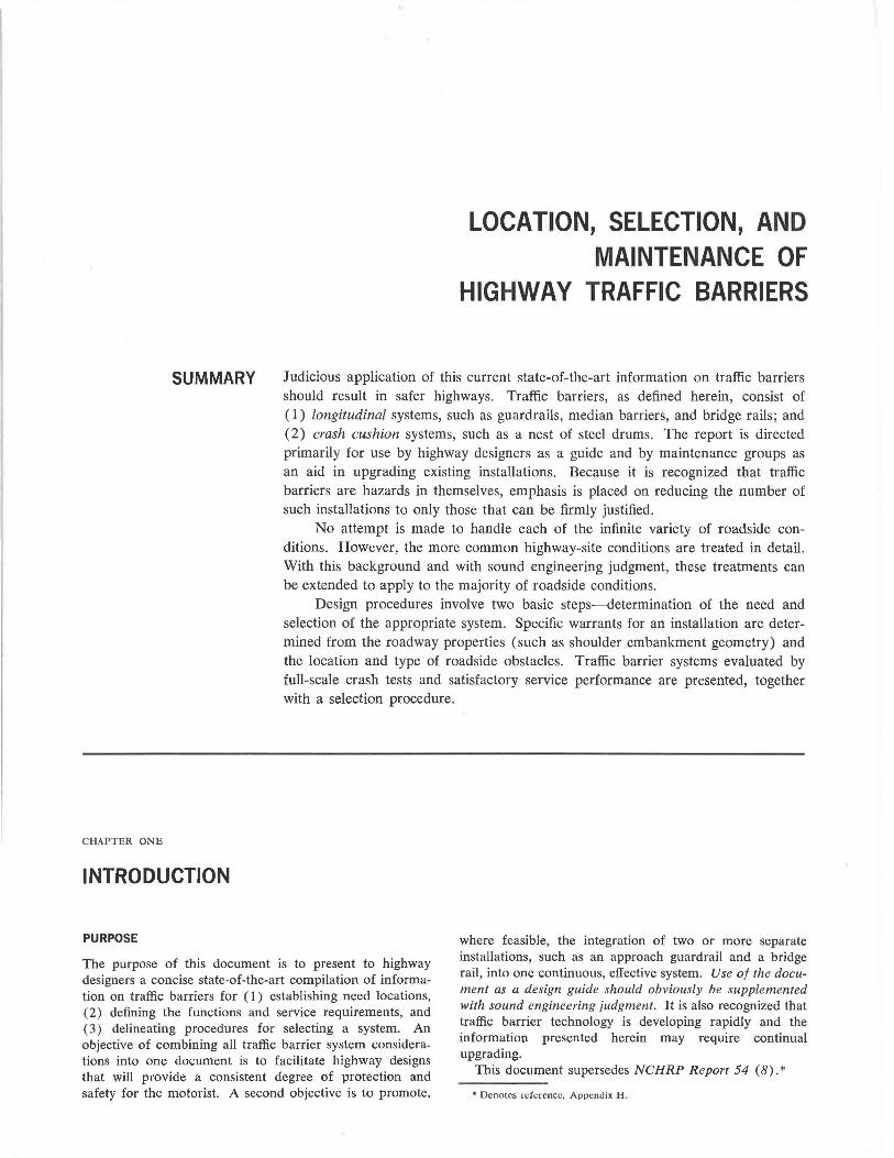
Judicious application of this current state-of-the-art information on traffic barriers should result in safer highways. Traffic barriers, as defined herein, consist of ( 1) longitudinal systems, such as guardrails, median barriers, and bridge rails; and (2) crash cushion systems, such as a nest of steel drums. The report is directed primarily for use by highway designers as a guide and by maintenance groups as an aid in upgrading existing installations. Because it is recognized that traffic barriers are hazards in themselves, emphasis is placed on reducing the number of such installations to only those that can be firmly justified.
No attempt is made to handle each of the infinite variety of roadside conditions. However, the more common highway-site conditions are treated in detail. With this background and with sound engineering judgment, these treatments can be extended to apply to the majority of roadside conditions.
Design procedures involve two basic steps---determination of the need and selection of the appropriate system. Specific warrants for an installation are determined from the roadway properties (such as shoulder embankment geometry) and the location and type of roadside obstacles. Traffic barrier systems evaluated by full-scale crash tests and satisfactory service performance are presented, together with a selection procedure.
The purpose of this document is to present to highway designers a concise state-of-the-art compilation of information on traffic barriers for ( I ) establishing need locations, (2) defining the functions and service requirements, and ( 3) delineating procedures for selecting a system. An objective of combining all traffic barrier system considerations into one document is to facilitate highway designs that will provide a consistent degree of protection and safety for the motorist. A second objective is to promote,
where feasible, the integration of two or more separate installations, such as an approach guardrail and a bridge rail, into one continuous, effective system. Use of the document as a design guide should obviously be supplemented with sound engineering judgment. It is also recognized that traffic barrier technology is developing rapidly and the information presented herein may require continual upgrading.
This document supersedes NCH RP Report 54 (8). *
* Denotes reference, Appendix H .
2
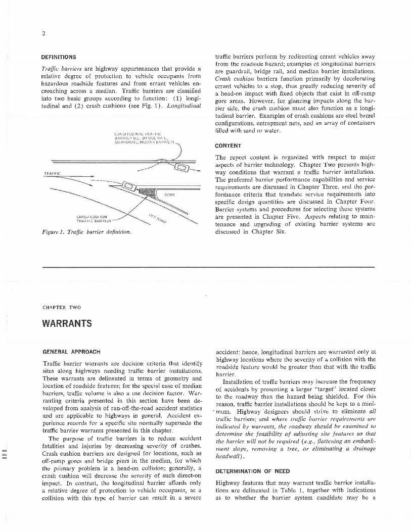
DEFINITIONS
Traffic barriers are highway appurtenances that provide a relative degree of protection to vehicle occupants from hazardous roadside features and from errant vehicles encroaching across a median. Traffic barriers are classified into two basic groups according to function: (1) longitudinal and ( 2) crash cushions ( see Fig. 1). Longitudinal
CRASH CUSHION TRAFFIC BARRlcR
LONGITUDINAL TRAFFIC BARRIER le.g, BRIDGE RAIL, GUARDRAIL , MEDIAN BARRIER I
Figure 1. Traffic barrier definition.
CHAPTER TWO
WARRANTS
GENERAL APPROACH
Traffic barrier warrants are decision criteria that identify sites along highways needing traffic barrier installations. These warrants are delineated in terms of geometry and location of roadside features; for the special case of median barriers, traffic volume is also a use decision factor. Warranting criteria presented in this section have been developed from analysis of ran-off-the-road accident statistics and are applicable to highways in general. Accident experience records for a specific site normally supersede the traffic barrier warrants presented in this chapter.
The purpose of traffic barriers is to reduce accident fatalities and injuries by decreasing severity of crashes. Crash cushion barriers are designed for locations, such as off-ramp gores and bridge piers in the median, for which the primary problem is a head-on collision; generally, a crash cushion will decrease the severity of such direct-on impact. In contrast, the longitudinal barrier affords only a relative degree of protection to vehicle occupants, as a collision with this type of barrier can result in a severe
traffic barriers perform by redirecting errant vehicles away from the roadside hazard; examples of longitudinal barriers are guardrail, bridge rail, and median barrier installations. Crash cushion barriers function primarily by decelerating errant vehicles to a stop, thus greatly reducing severity of a head-on impact with fixed objects that exist in off-ramp gore areas. However, for glancing impacts along the barrier side, the crash cushion must also function as a longitudinal hurrier. Examples of crash cushions are steel barrel configurations, entrapment nets, and an array of containers filled with sand or water.
CONTENT
The report content is organized with respect to major aspects of barrier technology. Chapter Two presents highway conditions that warrant a traffic barrier installation. The preferred barrier performance capabilities and service requirements are discussed in Chapter Three, and the perfonhance criteria that translate service requirements into specific design quantities are discussed in Chapter Four. Barrier systems and procedures for selecting these systems are presented in Chapter Five. Aspects relating to maintenance and upgrading of existing barrier systems are discussed in Chapter Six.
accident; hence, longitudinal barriers are warranted only at highway locations where the severity of a collision with the roadside feature would be greater than that with the traffic h::irrier.
Installation of traffic barriers may increase the frequency of accidents by presenting a larger "target" located closer to the roadway than the hazard being shielded. For this reason, traffic barrier installations should be kept to a mini-
. mum. Highway 'designers should strive to eliminate all traffic barriers; and where traffic barrier requirements are indicated by warrants, the roadway should be examined to determine the feasibility of adjusting site features so that the barrier will not be required ( e.g., flattening an embankment slope, removing a tree, or eliminating a drainage headwall).
DETERMINATION OF NEED
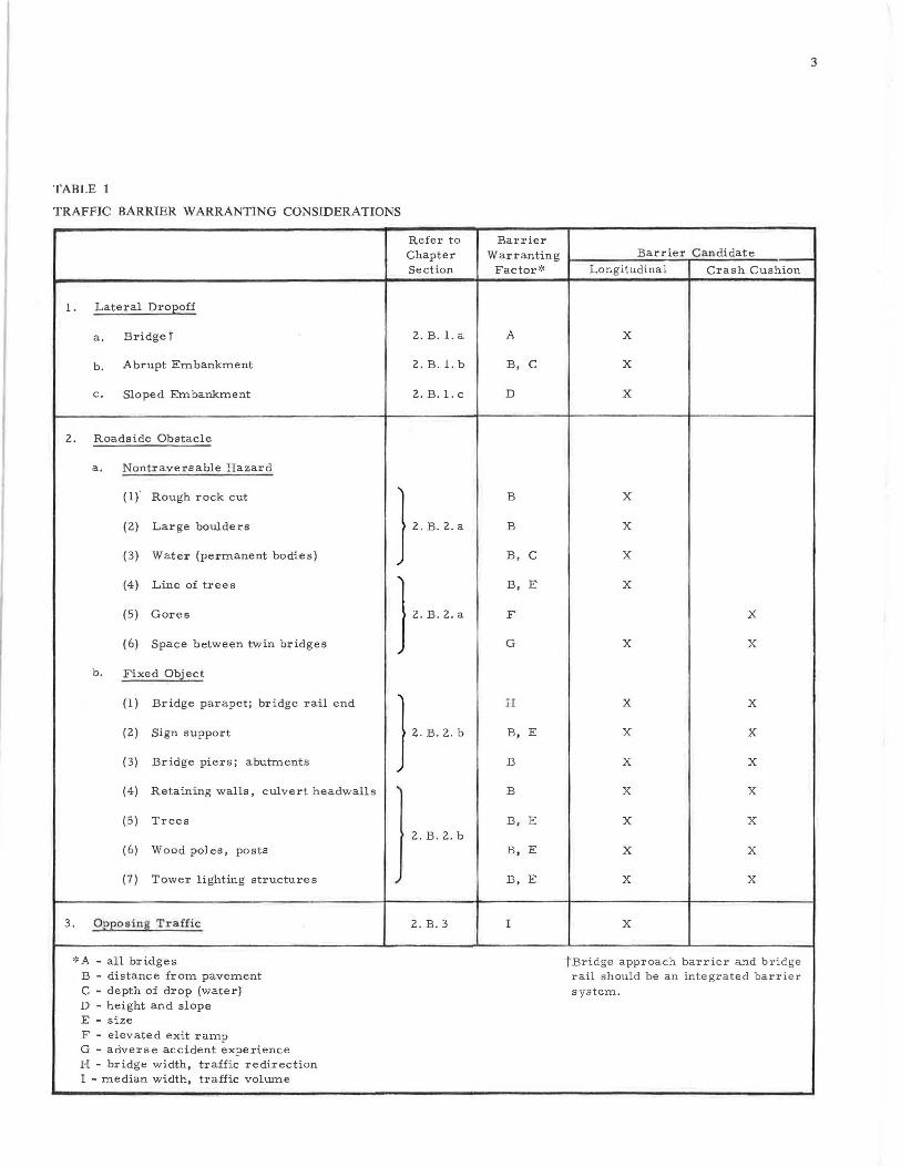
Highway features that may warrant traffic barrier installations are delineated in Table 1, together with indications as to whether the barrier system candidate may be a
3
TABLE 1
TRAFFIC BARRIER WARRANTING CONSIDERATIONS
Refer to Barrier Chapter Warranting Barrier Candidate
Section Factor'~ Longitudinal Crash Cushion
1. Lateral Droeoff
a. Bridget 2. B. 1. a A X
b. Abrupt Embankment 2. B. 1. b B, C X
C, Sloped Embankment 2. B. 1. c D X
2. Roadside Obstacle
a, Nontraversable Hazard
( l) ' Rough rock cut
} B X
(2) Large boulders 2. B. 2. a B X
(3) Water (permanent bodies) B, C X
(4) Line of trees
} 2 B 2 '
B, E X
(5) Gores F X
(6) Space between twin bridges G X X
b. Fixed Object
(1) Bridge parapet; bridge rail end
} H X X
(2) Sign support 2. B . 2 . b B, E X X
(3) Bridge piers; abutments B X X
(4) Retaining walls, culvert headwalls ' B X X
(5) Trees B, E X X 2. B. 2. b
(6) Wood poles, posts B, E X X
(7) Tower lighting structures ~ B, E X X
3. Oeeosing Traffic 2. B. 3 I X
,:,A - all bridges tBridge approach barrier and bridge B - distance from pavement rail should be an integrated barrier C - depth of drop (water} system. D - height and slope E - size F - elevated exit ramp G - adverse accident experience H - bridge width, traffic redirection I - median width, traffic volume
-
4
longitudinal or a crash cushion design, or both. The three principal features are ( l) lateral dropoff, (2) obstacle, and (3) opposing iraffic. The highway features are discussed in more detail in the following.
Lateral Dropoff
Lateral dropoffs are further classified as ( 1) bridge structures, (2) abrupt embankments, and ( 3) sloped embankments, to facilitate warranting analysis.
Bridge Structure
All bridge structures warrant longitudinal barrier installations (e.g., bridge rail).
Abrupt Embankment
Shoulder dropoffs having a slope greater than 1 : 1, depth greater than 2 ft, and located within 30 ft of traveled way warrant a longitudinal barrier installation. Because an abrupt embankment may extend a considerable length along the roadway, the probability of an errant vehicle contacting the dropoff is greater than that of a vehicle hitting a roadside fixed object. For this reason, banier installations may be needed at dropoffs located more than 30 ft from the traveled way to provide roadsides with a consistent degree of safety.
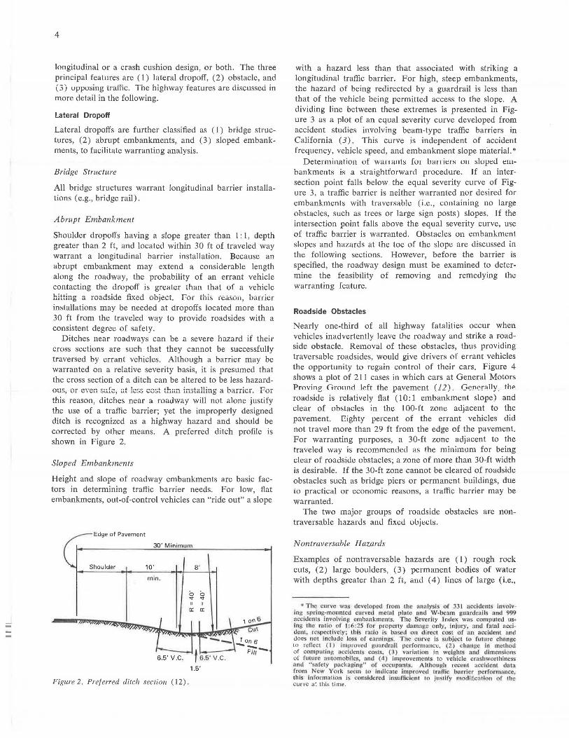
Ditches near roadways can be a severe hazard if their cross sections are such that they cannot be successfully traversed by errant vehicles. Although a barrier may be warranted on a relative severity basis, it is presumed that the cross section of a ditch can be altered to be less hazard-ous, or even s~fe, G.t le$S cost than installing a barrier. For this reason, ditches near a roadway will not alone justify the use of a traffic barrier; yet the improperly designed ditch is recognized as a highway hazard and should be corrected by other means. A preferred ditch profile is shown in Figure 2.
Sloped Embankments
Height and slope of roadway embankments are basic factors in determining traffic barrier needs. For low, flat embankments, out-of-control vehicles can "ride out" a slope
Edge of Pavement
30 ' Minimum
Shoulder 10 '
min.
Figure 2. Preferred ditch section (12) .
8'
~ ~ II II
c:: c::
1.5 '
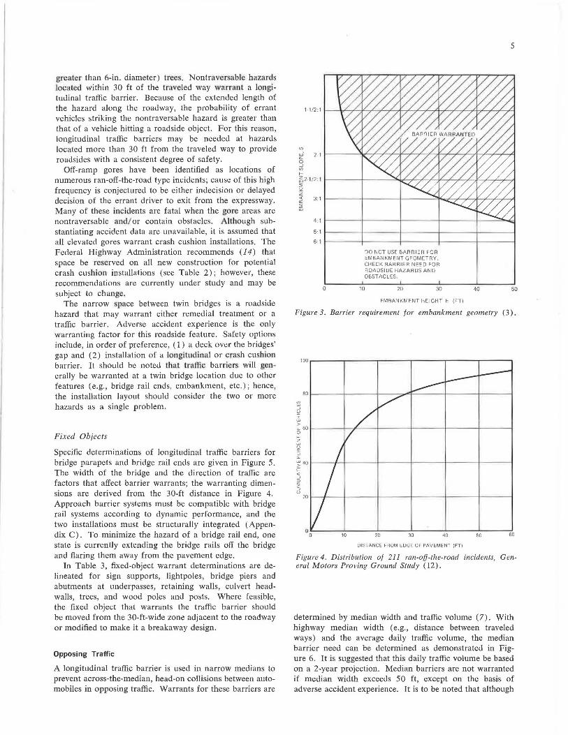
with a hazard less than that associated with striking a longitudinal traffic barrier. For high, steep embankments, the hazard of being redirected by a guardrail is less than that of the vehicle being permitted access to the slope. A dividing line between these extremes is presented in Figure 3 as a plot of an equal severity curve developed from accident studies involving beam-type traffic barriers in California (3). This curve is independent of accident frequency, vehicle speed, and embankment slope material.*
Determination of wanants fo1 l,a11ie1s ou slopeu e1ubankments is a straightforward procedure. If an intersection point falls below the equal severity curve of Figure 3, a traffic barrier is neither warranted nor desired for embankments with traversable (i.e., containing no large obstacles, such as trees or large sign posts) slopes. If the intersection point falls above the equal severity curve, use of traffic barrier is warranted. Obstacles on embankment slopes and hazards at the toe of the slope are discussed in the following sections. However, before the barrier is specified, the roadway design must be examined to determine the feasibility of removing and remedying the warranting feature.
Roadside Obstacles
Nearly one-third of all highway fatalities occur when vehicles inadvertently leave the roadway and strike a roadside obstacle. Removal of these obstacles, thus providing traversable roadsides, would give drivers of errant vehicles the opportunity to regain control of their cars. Figure 4 shows a plot of 211 cases in which cars at General Motors Proving Ground left the pfl_vement (12). Generally, the roadside is relatively flat ( 10: 1 embankment slope) and clear of obstacles in the 100-ft zone adjacent to the pavement. Eighty percent of the errant vehicles did not travel more than 29 ft from the edge of the pavement. For warranting purposes, a 30-ft zone adjacent to the traveled way is recommended as the minimum for being clear of roadside obstacles; a zone of more than 30-ft width is desirable. If the 30-ft zone cannot be cleared of roadside obstacles such as bridge piers or permanent buildings, due to practical or economic reasons, a traffic barrier may be warranted.
The two major groups of roadside obstacles are nontraversable hazards anu fixeJ objects.
Nontraversable Hazards
Examples of non traversable hazards are ( 1) rough rock cuts, ( 2) large boulders, ( 3) permanent bodies of water with depths greater than 2 ft, and ( 4) lines of large (i.e.,
• T he curl'c wns developed from the :1n:1Jysis oJ 3 I nccidc111s involving s1, riug-monntcd cur\'Cd mc1111 pinto and W-benm guordrnlls nnd 999 acddcn ts involving cmhnnkmcnts. 1110 S ·ve rily Index wns compmccJ using Che ratio ·<> f I :6:25 for prop.rty clnmn.!le only, injury, and fotol r,cdclanl, rcspcc tlvct.y ; this rnlio is bn~cd on direct cost of an accident und docs not include loss or ea rnin 11s. he curve is subject to future change to rcncct ( I ) imt" ovcd 11uard rnil pcrfomrnuce, (2) 11111111 In method of compu1lng 11ccidc111s costs, (3) vnriatio n in weigh ts and dimensions of future 1111tomobilc5, nnd ( 4) Improvements to vcll iclc crnshwonhincss find ''sa fely packaging" of occupant~. /\ hhou(!h recent accident dntn from No, York ccni 10 indicn1 • imprOl'cd trnffic bnrri r performance this inro,mn1io11 is coosl<lorccl l11x11fficicnt 111 J11~1lfy n10<lificn1lo11 r 111J curve at this time.
greater than 6-in. diameter) trees. Nontraversable hazards .located within 30 ft of the traveled way warrant a longitudinal traffic barrier. Because of the extended length of the hazard along the roadway, the probability of errant vehicles striking the nontraversable hazard is greater than that of a vehicle hitting a roadside object. For this reason, longitudinal traffic barriers may be needed at hazards located more than 30 ft from the traveled way to provide roadsides with a consistent degree of safety.
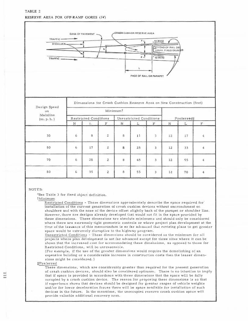
Off-ramp gores have been identified as locations of numerous ran-off-the-road type incidents; cause of this high frequency is conjectured to be either indecision or delayed decision of the errant driver to exit from the expressway. Many of these incidents are fatal when the gore areas are nontraversable and/ or contain obstacles. Although substantiating accident data are unavailable, it is assumed that all elevated gores warrant crash cushion installations. The Federal Highway Administration recommends (14) that space be re erved on all new construction for potential crash cushion installations (see Table 2); however, these recommendations are currently under study and may be subject to change.
The narrow pace between twin bridges is a roadside hazard that may warrant either remedial treatment or a traffic barrier. Adverse accident experience is the only warranting factor for this roadside feature. Safety options include, in order of preference, ( 1) a deck over the bridges' gap and (2) installation of a longitudinal or era h cushion barrier. It should be noted that traffic barriers will generally be warranted at a twin bridge location due to other features (e.g., bridge rail ends, embankment, etc.); hence, the installation layout should consider the two or more hazards as a single problem.
Fixed Obiects
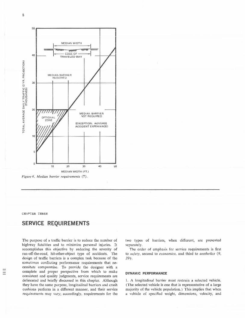
Specific determinations of longitudinal traffic barriers for bridge parapets and bridge rail ends are given in Figure 5. The width of the bridge and the direction of traffic are factors that affect barrier warrants; the warranting dimensions are derived from the 30-ft distance in Figure 4. Approach barrier systems must be compatible with bridge rail systems according to dynamic performance, and the two installations must be structurally integrated (Appendix C). To minimize the hazard of a bridge rail end, one state is currently extending the bridge rails off the bridge and flaring them away from the pavement edge.
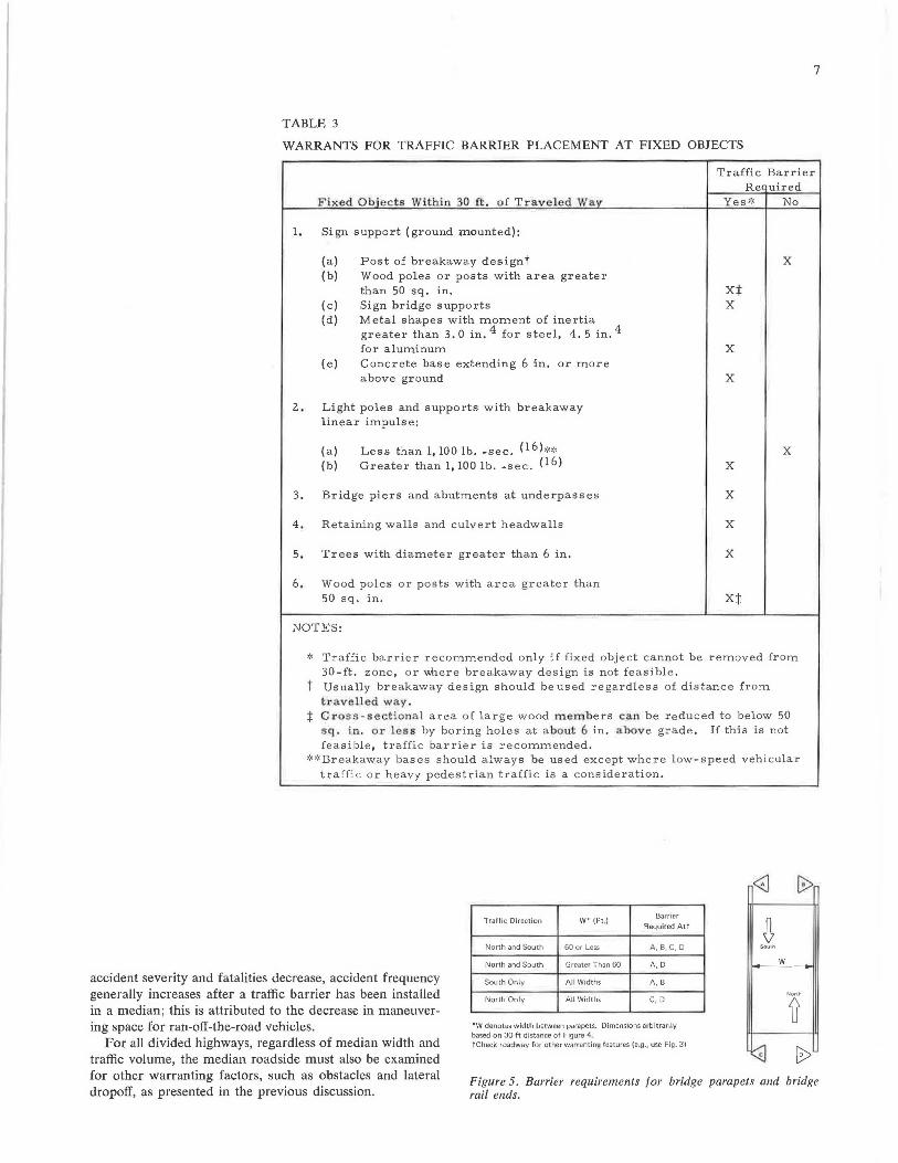
In Table 3, fixed-object warrant determinations are delineated for sign supports, lightpoles, bridge piers and abutments at underpasses, retaining walls, culvert headwalls, trees, and wood poles and posts. Where feasible, the fixed object that warrants the traffic barrier should be moved from the 30-ft-wide zone adjacent to the roadway or modified to make it a breakaway design.
Opposing Traffic
A longitudinal traffic barrier is used in narrow medians to prevent across-the-median, head-on collisions between automobiles in opposing traffic. Warrants for these barriers are
5
"' w· 2: 1 1----'l.'--.'-.'-.'-l'--,,:-.,.-.,.'-,.lc...,..C...,..::....,.<----,,;......'--,,~'--,.q 0.. 0 __J
"' f-di 2-1/2 ; 1 1----+------'- C.-,'--,C.-,<-j~~,,,__,L--.,.l'--,,L--.,,L--.,,<-~1 :;;
"' z ;'f; 3:1 t----+----+---..C:,'-"--,"--,.£-,.f'--,,.<-.,h,L....,.'1
~
4:1 t----+----+----1----+---="""'d
5:1 1----+------1------1----+-----I
6:1 - - ---i-----------t----+-----1
0 10
DO NOT USE BARRIER FOR EMBANKMENT GEOMETRY, CHECK BARRIER NEED FOR ROADSIDE HAZARDS AND OBSTACLES.
20 30
EMBANKMENT HEIGHT h (FT)
40 50
Figure 3. Barrier requirement for embankment geometry (3) .
u, w __J
"' I w > ~ 60 1----~~ ---- ---- -+-----11----1 0 f-
~ u a: w 0..
~40 1--- --.~----1--- ---l-----1---~ 11--- - -t f
" __J
::, :;; ::, u
20 1----1---1-----------+--- --11-- - -1
10 20 30 40 50
DISTANCE FROM EDGE OF PAVEMENT (FT)
Figure 4. Dislribulion of 211 ran-off-the-road incidents, Genera/ Motors Proving Ground Study ( 12).
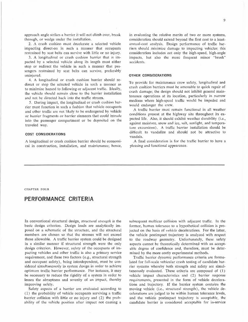
determined by median width and traffic volume (7). With highway median width (e.g., distance between traveled ways) and the average daily traffic volume, the median barrier need can be determined as demonstrated in Figure 6. It is suggested that this daily traffic volume be based on a 2-year projection. Median barriers are not warranted if median width exceeds 50 ft, except on the basis of adverse accident experience. It is to be noted that although
iiiii iiiii -
TABLE 2
RESERVE AREA FOR OFF-RAMP GORES (14)
(
CflASH CUSHION RESERVE AREA
TRAFFIC-----~ t ~ EDGE OF PAVEMENT
SHOULDE~,._c------1• ""'- _ Ft I~
--.......... ~ 1 r - t i:;;:-END OF RAIL ORI ' N :::- --..,,..i__ L EOUIV. FIXED OBJEGlr*
fi;wi~===~-'!L __ L/ ______ 1-; ___ F_..1_~_,<=---_,o...,:1M_1_N~--,t~
TRAFFIC ----~
L
I
FACE OF RAIL OR PARAPET
Dimensions for Crash Cushion Reserve Area on New Construction (feet) Design Speed
on Minimumt Mainline (m.p.h.) Restricted Conditions Unrestricted Conditions Preferred-.
N L F N L F N L F
30 6 8 2 8 11 3 12 17 4
50 6 17 2 8 25 3 12 33 4
70 6 28 2 8 45 3 12 55 4
80 6 35 2 8 55 3 12 70 4
NOTES:
'~See Table 3 for fixed object definition. tMinimum
Restricted Conditions - These dimensions approximately describe the space required for installation of the current generation of crash cushion devices without encroachment on shoulders and with the nose of the device offset slightly back of the parapet or shoulder line. However, there are designs already developed that would not fit in the space provided by these dimensions. These dimensions are absolute minimums and should only be considered where there are extremely tight geometric controls or where project plan development at the time of the issuance of this memorandum is so fa.r advauct<tl lhat revising plans to get greater space would be extremely disruptive to the highway program. Unrestricted Conditions - These dimensions should be considered as the minimum for all projects where plan development is not far advanced except for those sites where it can be shown that the increased cost for accommodating these dimensions, as opposed to those for Restricted Conditions, will be unreasonable. (For example, if the use of the greater dimensions would require the demolishing of an expensive building or a considerable increase in construction costs then the lesser dimensions might be considered.)
:j:Preferred These dimensions, which are considerably greater than required for the present generation of crash cushion devices, should also be considered optimum. There is no intention to imply that if space is provided in accordance with these dimensions that the space will be fully occupied by a crash cushion device. The reason for proposing these dimensions is so that if experience shows that devices should be designed for greater ranges of vehicle weights and/or for lower deceleration forces there will be space available for installation oJ such devices in the future. In the meantime, the unoccupied reserve crash cushion space will provide valuable additional recovery area.
7
TABLE 3
WARRANTS FOR TRAFFIC BARRIER PLACEMENT AT FIXED OBJECTS
Traffic Barrier Rec uired
Fixed Obiects Within 30 ft . of Traveled Wav Yes•:, No
1. Sign support ( ground mounted):
(a) (b}
(c) (d)
(e)
Post of breakaway designt Wood poles or posts with area greater than 50 sq. in. Sign bridge supports Metal shapes with moment of inertia greater than 3. 0 in. 4 for steel, 4. 5 in. 4
for aluminum Concrete base extending 6 in. or more above ground
2. Light poles and supports with breakaway linear impulse:
(a) (b)
Less than l, 100 lb. -sec. (l6);..,~ Greater than l, 100 lb. -sec. (16)
3. Bridge piers and abutments at underpasses
4. Retaining walls and culvert headwalls
5 , Trees with diameter greater than 6 in.
6. Wood poles or posts with area greater than 50 sq. in.
NOTES :
xt X
X
X
X
X
X
X
X
X
,:, Traffic barrier recommended only if fixed object cannot be removed from 30-ft. zone, or where breakaway design is n ot feasible.
t Usually breakaway design should be used regardless of distance from travelled way .
:j: C::ross-sectional area of large wood members can be reduced to below 50 sq, in. or less by boring holes at about 6 in, above grade. If this is not feasible, traffic barrier is recommended.
,:o:, Breakaway bases should always be used except where low-speed vehicular tra ffic o r heavy pedestrian traffic is a consideration.
accident severity and fatalities decrease, accident frequency generally increases after a traffic barrier has been installed in a median; this is attributed to the decrease in maneuvering space for ran-off-the-road vehicles.
For all divided highways, regardless of median width and traffic volume, the median roadside must also be examined for other warranting factors, such as obstacles and lateral dropoff, as presented in the previous discussion.
Traffic Direction W' (Ft ,) Barrier
Required Att
North and South 60 or Less A, B, C, D
North and South Greater Than 60 A,D
South Only All Widths A, B
North Only All Widths C, D
*W denotes width between parapets. Dimensions arbitrarily based on 30-ft distance of Figure 4. tCheck roadway for other warranting features (e.g., use Fig. 3)
<8 ~
~ Sou•h
w
Nonh
~ (rj b
Figure 5. Barrier requirements for bridge parapets and bridge rail ends.
----
8
z 0 ~ ~ 0 cc: Cl.
cc:
40
MEDIAN WIDTH 1--- -I • "'wt\9/P wMli \\/i1M» EDGE OF----;
TRAVELED WAY
MEDIAN BARRIER REQUIRED
>- 30 1-----1-----+----+~'----+----t !:! u-u: ~ u. 2 <t <t CC:tll f- :::i
~'.E -f<t-0 UJ (.!) <t cc: UJ > <t ..J <t .... 0 f-
5
MEDIAN BARRIER NOT REQUIRED
(EXCEPTION: ADVERSE ACCIDENT EXPERIENCE)
0---------------------10 20 30
MEDIAN WIDTH (FT.)
Figure 6. Median barrier requirements (7).
CHAPTER THREE
SERVICE REQUIREMENTS
40 50
The purpose of a traffic barrier is to reduce the number of highway fatalities and to minimize personal injuries. It accomplishes this objective by reducing the severity of ran-off-the-road, hit-other-object type of accidents. The design of traffic barriers is a complex task because of the sometimes conflicting performance requirements that necessitate compromise. To provide the designer with a complete and proper perspective from which to make consistent and quality judgments, service requirements are delineated and briefly discussed in this chapter. Although they have the same purpose, longitudinal barriers and crash cushions perform in a different manner, and their service requirements may vary; accordingly, requirements for the
two types of barriers, when different, are presented separately.
The order of emphasis for service requirements is first to safety, second to economics, and third to aesthetics (9, 39).
DYNAMIC PERFORMANCE
1. A longitudinal barrier must restrain a selected vehicle. (The selected vehicle is one that is representative of a large majority of the vehicle population.) This implies that when a vehicle of specified weight, dimensions, velocity, and
approach angle strikes a barrier it will not climb over, break through, or wedge under the installation.
2. A crash cushion must decelerate a selected vehicle impacting direct-on in such a manner that occupants restrained by seat belts can survive with little or no injury.
3. A longitudinal or crash cushion barrier that is impacted by a selected vehicle along its length must either stop or redirect the vehicle in such a manner that passengers restrained by seat belts can survive, preferably uninjured.
4. A longitudinal or crash cushion barrier should redirect or stop the selected vehicle in such a manner as to minimize hazard to following or adjacent traffic. Ideally, the vehicle should remain close to the barrier installation and not be directed back into the traffic stream.
5. During impact, the longitudinal or crash cushion barrier must function in such a fashion that vehicle occupants and other traffic are not likely to be endangered by vehicle or barrier fragments or barrier elements that could intrude into the passenger compartment or be deposited on the traveled way.
COST CONSIDERATIONS
A longitudinal or crash cushion barrier should be economical in construction, installation, and maintenance; hence,
CHAPTER FOUR
PERFORMANCE CRITERIA
In conventional structural design, structural strength is the basic design criterion. Design loads are analytically imposed on a schematic of the structure, and the structural members are chosen so that the stresses will not exceed those allowable. A traffic barrier system could be designed in a similar manner if structural strength were the only design criterion. However, safety of the occupants of impacting vehicles and other traffic is also a primary service requirement, and these two factors ( e.g., structural strength and occupant safety), being interdependent, must be considered simultaneously in system design in order to achieve optimum traffic barrier performance. For instance, it may be necessary to reduce the rigidity of a system in order to lessen the abruptness and severity of an impact, thereby improving safety.
Safety aspects of a barrier are evaluated according to ( 1) the probability of vehicle occupants surviving a traffic barrier collision with little or no injury and (2) the probability of the vehicle position after impact not causing a
9
in evaluating the relative merits of two or more systems, consideration should extend beyond the first cost to a leastannual-cost analysis. Design performance of traffic barriers should minimize damage to impacting vehicles; this consideration includes not only the high-speed, high-angle impacts, but also the more frequent minor "brush" accidents.
OTHER CONSIDERATIONS
To provide for maintenance crew safety, longitudinal and crash cushion barriers must be amenable to quick repair of crash damage; the design should not inhibit general maintenance operations at its location, particularly in narrow medians where high-speed traffic would be impeded and would endanger the crew.
A traffic barrier must remain functional in all weather conditions present at the highway site throughout its expected life. Also, it should exhibit weather durability (i.e., against moisture, snow and ice, salt, sunlight, and temperature excursions). A traffic barrier installation should be difficult to vandalize and should not be attractive to vandals.
A final consideration is for the traffic barrier to have a pleasing and functional appearance.
subsequent multicar collision with adjacent traffic. In the former, human tolerance to a hypothetical collision is projected on the basis of vehicle decelerations. For the latter, the vehicle postimpact trajectory is analyzed with respect to the roadway geometry. Unfortunately, these safety aspects cannot be theoretically determine.d with an acceptable degree of confidence and, therefore, must be determined by the more costly experimental methods.
Traffic barrier dynamic performance criteria are formulated for full-scale vehicular crash testing of candidate barrier systems whereby both strength and safety are simultaneously evaluated. These criteria are composed of ( 1) vehicle impact characteristics and (2) barrier response requirements, presented in the form of vehicle decelerations and trajectory. If the barrier system contains the moving vehicle (i .e., structural strength), the vehicle decelerations are judged to be within human tolerance levels, and the vehicle postimpact trajectory is acceptable, the candidate barrier is considered acceptable for in-service
10
experimental use. After the system has been carefully monitored and evaluated in service and its effectiveness has been established, the system is judged to be operational.
VEHICLE IMPACT CHARACTERISTICS
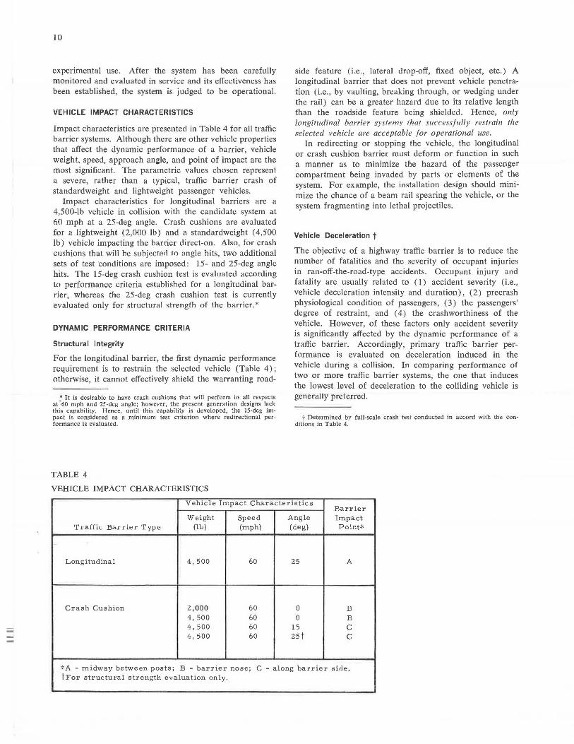
Impact characteristics are presented in Table 4 for all traffic barrier systems. Although there are other vehicle properties that affect the dynamic performance of a barrier, vehicle weight, speed, approach ani:le, and point of impact are the most significant. The parametric values chosen represent a severe, rather than a typical, traffic barrier crash of standardweight and lightweight passenger vehicles.
Impact characteristics for longitudinal barriers are a 4,500-lb vehicle in collision with the candidate system at 60 mph at a 25-deg angle. Crash cushions are evaluated for a lightweight (2,000 lb) and a standardweight (4,500 lb) vehicle impacting the barrier direct-on. Also, for crash cushions that will be subjected to angle hits, two additional sets of test conditions are imposed: 15- and 25-deg angle hits. The 15-deg crash cushion test is evaluated according to performance criteria established for a longitudinal barrier, whereas the 25-deg crash cushion test is currently evaluated only for structural strength of the barrier.*
DYNAMIC PERFORMANCE CRITERIA
Structural Integrity
For the longitudinal barrier, the first dynamic performance requirement is to restrain the selected vehicle (Table 4); otherwise, it cannot effectively shield the warranting road-
• It is desirable to have crash cushions that will perform in all respects at· 60 mph and 25-deg angle; however, the present generation designs lack this capability. Hence, until this capability is developed, the 15-deg impact is considered as a minimum test criterion where redirectional performance Is evaluated.
TABLE 4
VEHICLE IMP ACT CHARACTERISTICS
side feature ( i.e., lateral drop-off, fixed object, etc.) A longitudinal barrier that does not prevent vehicle penetration (i.e., by vaulting, breaking through, or wedging under the rail) can be a greater hazard due to its relative length than the roadside feature being shielded. Hence, only longitudinal barrier systems that successfully restrain the selected vehicle are acceptable for operational use.
In redirecting or stopping the vehicle, the longitudinal or crash cushion barrier must deform or function in such a manner as to minimize the hazard of the passenger compartment being invaded by parts or elements of the system. For example, the installation design should minimize the chance of a beam rail spearing the vehicle, or the system fragmenting into lethal projectiles.
Vehicle Deceleration t The objective of a highway traffic barrier is to reduce the number of fatalities and the severity of occupant injuries in ran-off-the-road-type accidents. Occupant injury and fatality are usually related to (1) accident severity (i.e., vehicle deceleration intensity and duration), (2) precrash physiological condition of passengers, ( 3) the passengers' degree of restraint, and ( 4) the crashworthiness of the vehicle. However, of these factors only accident severity is significantly affected by the dynamic performance of a traffic barrier. Accordingly, primary traffic barrier performance is evaluated on deceleration induced in the vehicle during a collision. In comparing performance of two or more traffic barrier systems, the one that induces the lowest level of deceleration to the colliding vehicle is generally preferred.
t Determined by full-scale crash test conducted in accord with the conditions in Table 4.
Vehicle Impact Characteristics Barrier
Weight Speed Angle Impact Ti·aHic Bal'l·ler· Type (11..,) (mph) (deg) Point*
,_
Langi tudina 1 4,500 60 25 A
Crash Cushion 2,000 60 0 B 4,500 60 0 B 4,500 60 15 C 4,500 60 zst C
'-'A - midway between posts; B - barrier nose; C - along barrier side_ tFor structural strength evaluation only.
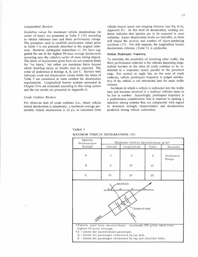
Longitudinal Barriers
Guideline values for maximum vehicle decelerations (at center of mass) are presented in Table 5 (JO) according to vehicle reference axes and three performance ratings. The procedure used to establish deceleration values given in Table 5 is not precisely described in the original reference. However, subsequent researchers (J, 26) have suggested the use of the highest 50-msec average deceleration occurring near the vehicle's center of mass during impact. The limits of deceleration given here are not nominal limits for "no injury," but rather are maximum limits beyond which disabling injury or fatality may be expected. The order of preference is Ratings A, B, and C. Barriers with full-scale crash test deceleration values within the limits of Table 5 are considered to have satisfied the deceleration requirements. Longitudinal barrier systems presented in Chapter Five are evaluated according to this rating system and the test results are presented in Appendix G.
Crash Cushion Barriers
For direct-on tests of crash cushions (i.e., where vehicle lateral deceleration is minimum), a maximum average permissible vehicle deceleration is 12 g's, as calculated from
TABLE 5
11
vehicle impact speed and stopping distance (see Eq. E-5a, Appendix E) . At this level of deceleration, existing evidence indicates that injuries are to be expected in most collisions. Lesser deceleration levels are desirable, as these will reduce the severity and number of injury-producing accidents (I 5). For side impacts, the longitudinal barrier deceleration criterion (Table 5) is applicable.
Vehicle Postimpact Trajectory
To minimize the possibility of involving other traffic, the third performance criterion is for vehicles impacting longitudinal barriers or the sides of crash cushions to be redirected in a trajectory nearly parallel to the pavement edge. For normal or angle hits on the nose of crash cushions, vehicle postimpact trajectory is judged satisfactory if the vehicle is not rebounded into the main traffic streams.
Accidents in which a vehicle is redirected into the traffic lane and becomes involved in a multicar collision seem to be few in number. Accordingly, postimpact trajectory is a performance consideration that is reserved in making a selection among systems that are comparable with regard to structural strength characteristics and decelerations produced during vehicle redirection.
MAXIMUM VEHICLE DECELERATIONS (JO)
Barrier Performa,:ice
Ratingt
Maximum Vehicle Decelerations (g's),.,
Lateral Longitudinal Total Remarks
A 3
B 5
C 15
5
10
25
'
enter-of-mass
:9 .>-
\
6
12
25
Preferred Range
'~Vehicle rigid body decelerat1·ons,· · 500 maximum g sec onset rate; highest 50 msec average.
t A - limits for unrestrained passenger. B - limits for, passenger restrained by lap belt. C - limits for passenger restrained by lap and shoulder belts.
12
CHAPTER FIVE
DESIGN AND SELECTION PROCEDURES
Present technology precludes the mathematical design of a traffic barrier with a predictable vehicle redirection or deceleration performance. Although the interaction between barrier and vehicle has been mathematically characterized, it has been discovered that small variations in designs or in construction details can have adverse effects on the safety performance of an otherwise sound and adequate barrier system. Consequently, barrier systems have evolved from a trial-and-error process in which emphasis is placed on full-scale crash testing of a developing prototype design.
Barrier systems shown in this report are classified according to their stage of development. An R&D ( research and development) device is a design in the primary stage of research and test evaluation; test results and laboratory findings are considered inadequate to justify highway installation. An experimental device is a barrier that has performed satisfactorily (see "Dynamic Performance Criteria," Chapter Four) in full-scale crash tests and promises satisfactory service performance; the device can be installed on highways on a trial basis during which in-service performance is extensively monitored and documented. Finally, an experimental barrier system that demonstrates satisfactory in-service performance is reclassified as an operational device.
Several longitudinal and crash cushion barrier designs are presented in this document; there are other barrier systems, but adequate information is not available to permit their classification.
The characteristics of barrier designs, selection criteria, and design procedures of this chapter will aid the highway designer in choosing the best applicable system.
LONGITUDINAL BARRIERS
Characteristics of Systems
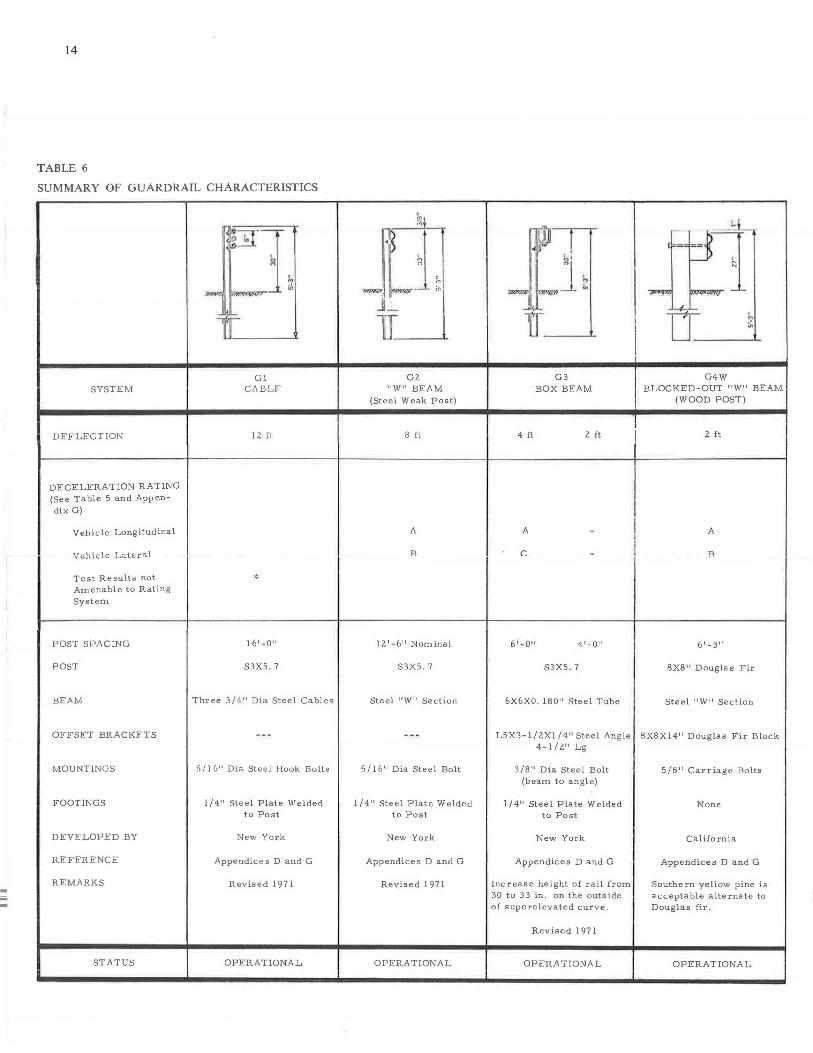
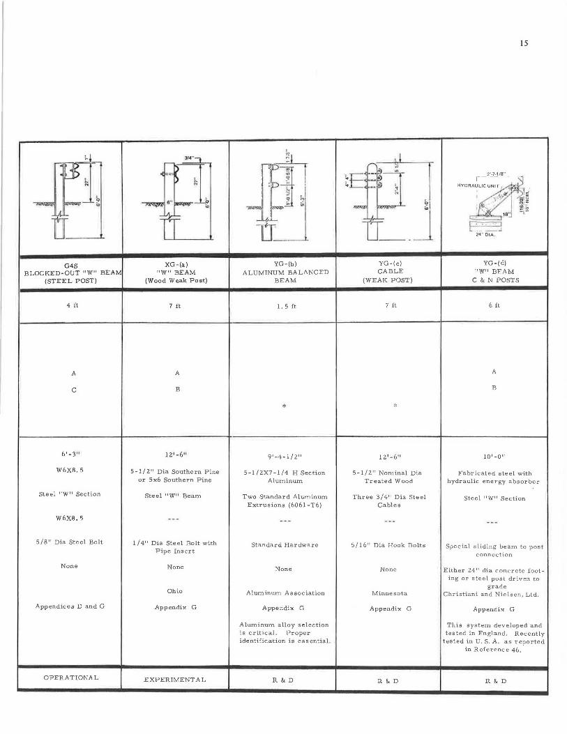
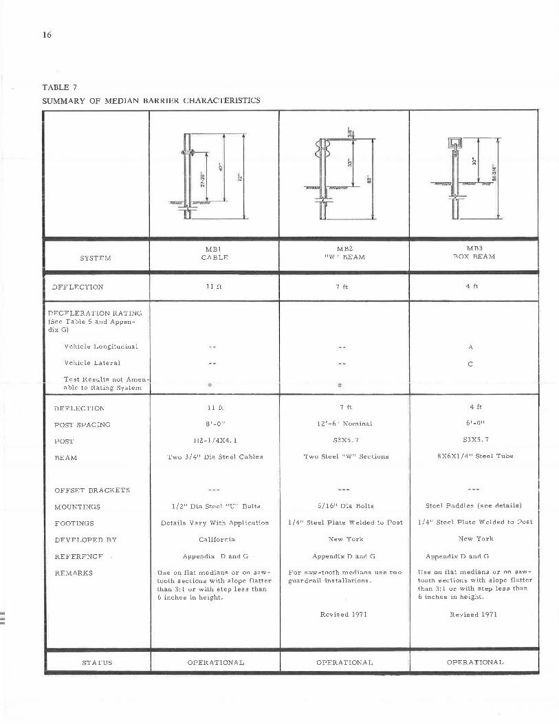
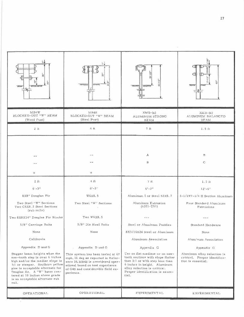
Summaries of basic characteristics of guardrail, median barrier, and bridge rail systems are presented in Tables 6, 7, and 8, respectively. Deflection, an important system characteristic, is the maximum lateral deflection that a system experiences during impact and redirection of a selected vehicle (see Table 4); deflections of systems vary from O to 12 ft for guardrail and median barriers and from 0 to 2 ft for bridge rails. Barrier performance is rated in terms of vehicle deceleration, test results, and the rating scale presented in Table 5. Other characteristics are (I) post type and spacing, (2) beam type and mounting detail, and ( 3) footing type or connection to bridge. Selected designs for operational longitudinal barrier systems are contained in Appendix D.
Selection Criteria
An appropriate longitudinal barrier system is selected by a straightforward procedure. The factors considered are relatively few in number. Principally, these factors are ( 1) the unobstructed space available for lateral deflection (i.e., for guardrail and median barriers) or maximum desired deflection for a bridge rail, (2) the roadway or bridge structure cross section, and (3) the installation and maintenance costs.
Deflection
The major factor in selecting a guardrail or median barrier system is matching dynamic lateral deflection characteristics of a system to the space available at the highway site. Because this lateral deflection varies with vehicular dynamics, a selected test ( e.g., 4,000- to 4,500-lb vehicle, 60 to 65 mph, and 25-deg impact angle) was used in determining deflection (Tables 6, 7, and 8). For the systems to perform in a similar manner in actual service, minimum unobstructed distances behmd guardrails and median barriers must be equal to or greater than this deflection. For example, if the roadside hazard is located 3 ft behind the proposed guardrail line, the guardrail system should be selected from those of Table 6 that indicate deflection of less than 3 ft. Similarly, if a barrier is to be placed in the center of a 10-ft median, the median barrier system should be selected from those of Table 7 that indicate a deflection of less than 5 ft ( one-half the median width). For bridge rails, a maximum allowable dynamic lateral deflection of 2 ft beyond the outermost edge of the bridge deck is considered a reasonable performance criterion from the standpoint of preventing the vehicle from falling through the space between the edge of the bridge and the rail (J ) .
Roadway and Bridge Cross Section
Roadway and bridge cross section can significantly affect traffic barrier performance. Curbs, dikes, sloped shoulders, and stepped medians can cause errant vehicles to vault a barrier or to strike it so that the vehicle overturns. Optimum barrier system performance is provided by a level surface in front of the barrier. Preferably, curbs and dikes should be behind the barriers; if, however, curbs and dikes must be in front of the barrier, they should be of the low, mountable type. Where barriers are installed on superelevated sections of highway, the vertical axis of the barrier should be inclined in order to remain perpendicular to the
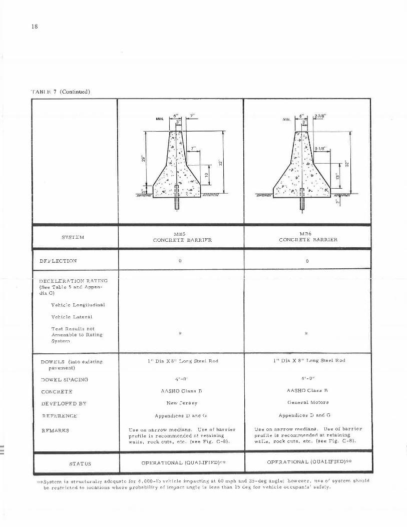
pavement surface. This is particularly important for sloped-face concrete barriers.
Stepped * median sections affect selection of median barriers. Cable and box beam systems (Table 7) are limited to flat medians or stepped sections with slopes flatter than 2: 1 or steps less than 6 in. high. Cable or rail heights must be adjusted so that proper contact is made with the vehicle (see Figs. C-10, C-11, C-12 of Appendix C). A median with a large step might use two guardrails (see Fig. C-9c of Appendix C) . In a step median, the two sides of a rigid concrete barrier should be adjusted (see Fig. C-9d of Appendix C).
Installation and Maintenance Costs
Although cost of installation generally increases as system rigidity t increases, cost of repair and maintenance generally decreases. Because of wide variations in both installation and maintenance costs in different localities, representative unit prices cannot be established. Therefore, if two or more guardrail systems satisfy lateral deflection requirements, final system selection must be made on the basis of local ( l) preference, (2) material availability and costs, ( 3) installation costs, and ( 4) maintenance and repair costs.
Design Procedure for a New Installation
For any new longitudinal barrier installation, the recommended design procedure is as follows:
1. Establish "point-of-need" or "length-of-need" by warranting procedures of Chapter Two.
2. Based on the unobstructed space available for system deflection, select a barrier system from Table 6, 7, or 8. For bridge rail selection, the system must be structurally compatible with the bridge.
3. Determine design particulars for the selected system, such as terminal treatments and adjustments for highway curvature.
4. Make installation layout drawings. Note that for guardrails and median barriers, installations should be extended a reasonable distance upstream beyond the warranted area to prevent vehicle access to a warranting feature. A method for establishing this necessary extension is presented in Appendix C. For highways with two-way traffic, the installation should also be extended downstream. For barriers placed on sloped shoulders, the rail height must be adjusted according to the method presented in Appendix C. Furthermore, terminal sections should occur outside the length-of-need so that within this length the protective system is at its typical design condition.
Bridge rails should be extended upstream ( see Fig. 5) as approach guardrail, or the approach rail-bridge rail combination should be a structurally integrated system with consistent dynamic performance.
* The median between roadways of different elevations is referred to as a "stepped'' median.
t A concrete barrier is the most rigid, a cable system most flexible, of the longitudinal barrier systems.
13
5. Make a field review, near the completion of highway construction, before setting the final installation limits. Short gaps between installations should be avoided.
CRASH CUSHION BARRIERS
Characteristics of Systems
A discussion of the mechanics of crash cushion behavior is presented in Appendix E. Several crash cushion systems are listed in Table 9 and grouped according to their current (March 1971) status. Unless otherwise noted, the experimental and operational systems have been evaluated by the design criteria (Chapter Four) and their dynamic performance judged acceptable. Characteristics such as developer, testing agency, and in-service experience are given for the systems in Appendix F.
Selection Criteria
An appropriate crash cushion is selected by a direct procedure. The factors to be considered are ( 1) the space available for the cushion and (2) the installation, maintenance, and damage repair costs.
Space
The crash cushion designs shown in Appendix F require specific width and length to decelerate the selected vehicle. If this space is available to the highway site, the current version of the designs can be used; however, if the space is restricted in either width or length, a change in crash cushion design may be necessary and may result in performance compromise (such as higher deceleration forces). The designs· in Appendix F vary in their susceptibility to being adjusted to highway sites. Modifications to a proved system design must be made with extreme caution, as experience has shown that a change in a seemingly insignificant detail has produced catastrophic barrier performance.
Costs
In evaluating crash cushion costs, the three factors of installation, maintenance, and damage repair should be considered. As an example, a crash cushion design with high initial cost may require minimum maintenance and be amenable to quick and inexpensive repairs; consequently, it may be the more cost effective system.
Other accident costs, such as those related to vehicle damage, traffic delay time, hospital, and loss of earnings, are dependent on the crash cushion dynamic performance. At the present time, accident data that establish the relative performance among crash cushions are lacking. Consequently, the systems must be assumed to be equal in performance, and, hence, these cost elements are not presently a selection criterion.
Design Procedure for a New Installation
The recommended design procedure for a new crash cushion installation is as follows:
1. Establish the need by the warranting procedures of Chapter Two.
iiiiii
14
TABLE 6
SUMMARY OF GUARDRAIL CHARACTERISTICS
SYSTEM
DEFLECTION
DECELERATION RATING (See Table 5 and Appendix G)
Vehicle Longitudinal
Vehicle L~teral
Test Results not Amenable to Rating System
POST SPACING
POST
BEAM
OFFSET BRACKETS
MOUNTINGS
FOOTINGS
DEVELOPED BY
REFERENCE
REMARKS
STATUS
-I
~~~]! lI~
Gl CABLE
12 ft
*
16'-0"
S3X5 . 7
Three 3/4" Dia Steel Cables
5 / 16" Dia Steel Hook Bolts
1/4" Steel Plate Welded to Post
New York
Appendices D and G
Revised 1971
OPERATIONAL
~I
_lj '"' ,n
J.1-
lI G2
"W" BEAM (Steel Weak Post)
8 ft
A
Fl
12 1 -6 11 Nominal
S3X5. 7
Steel 11 W 11 Section
5/16" Dia Steel Bolt
l / 4" Steel Plate Welded to Post
New York
Appendices D and G
Revised 1971
OPERATIONAL
-I• ~ . r
-~·l ii, iii -
tr G3
BOX BEAM
4 ft
A
C
2 ft
4 1-0 11
-
-ti:l TI i,
;;.
G4W BLOCKED-OUT "W" BEAM
(WOOD POST)
I
I 2 ft
A
Fl
6 1 -3 11
S3X5. 7 8X8" Douglas Fir
6X6XO. 180" Steel Tube Steel "W" Section
L5X3-l /2Xl /4" Steel Angle 8X8Xl4" Douglas Fir Block 4-1/Z" Lg
3/8" Dia Steel Bolt 5/8" Carriage Bolts (beam to angle)
1/4" Steel Plate Welded None to Post
New York
Appendices D and G
Increase height of rail from 30 to 3 3 in. on the outside of superelevated curve.
Revised 1971
OPERATIONAL
California
Appendices D and G
Southern yellow pine is acceptable alternate to Douglas fir.
OPERA TIO NA L
~
.~ i:;
....,,,.,._ ~ - ~
LA._
n G4S
B LOC KED-OUT 11w11 BEAM (STEE L POST)
4 ft
A
C
W6X8. 5
Ste e l 11 W 11 Section
W6XB. 5
5/8" Dia Steel Bolt
None
Appendices D and G
OPERATIONAL
314"--, -
~ ,f ==
~ 6'' ~ '°
IT XG -(a)
" W " BEAM (Wood Weak Post )
7 ft
A
B
1 2 1 - 611
5-1/2" Dia Southern Pine or 5x6 Southern Pine
Steel 11 w11 Beam
l /4" Dia Steel Bolt with Pipe Insert
None
Ohio
Appendix G
EXPERIMENTAL
~I
'U]l I
:D ~ s 9 ".'
~ ;.. .. .,,,..,,,. -14 ~ -a
YG-(b)
ALUMINUM BALANCED BEAM
1. 5 ft
*
9'-4-1/2"
5-l /2X7-l/4 H Section Aluminum
Two Standard Aluminum Extrusions (6061-T6)
Standard Hardware
None
Aluminum Association
Appendix G
Aluminum alloy selection is critical. Proper identification is essential.
R&D
t111 TI __ j
YG-(c) CABLE
(WEAK POST)
7 ft
12 1-6•1
5-1/2" Nominal Dia Treated Wood
Three 3 / 4 11 Dia Ste el Cables
5 / 1 6" Dia Hook Bolts
None
M inne s o ta
Appendix G
R&D
15
2'-7-1/8 "
"""''.~, I ,,,\ I ij ~ ~ 1(0
\• L~ . 18 " ;,.-. ; - ~ -pg
24" DIA.
YG-(d)
"W" BEAM C & N POSTS
6 ft
A
B
10 1 -0 11
Fabricated ste el with hydraulic energy absorber
Stee l 11 W11 S ection
Spe cial sli d in g bea m to post connec t io n
Either 24 11 dia conc r ete footing or s te el pos t driv en t o
grade Christia n i a nd N i els en , L t d .
Appendix G
This system dev e loped and tested in England. Recently
tested in U . S. A. a s reported in Referenc e 46.
R&D
iiiiii
16
TABLE 7
SUMMARY OF MEDIAN BARRIER CHARACTERISTICS
SYSTEM
DEFLECTION
DECELERATION RATING (See Table 5 and Appendix G)
Vehicle Longitudinal
Vehicle Lateral
Test Results not Amenable to Rating System
DEFLECTION
POST SPACING
POST
BEAM
OFFSET BRACKETS
MOUNTINGS
FOOTINGS
DEVELOPED BY
REFERENCE
REMARKS
STATUS
-..:w,,r I~,--__ .,,,1,,---'---
=f E __ ____._
MBl CABLE
11 ft
11 ft
s• -0 11
H2-l/4X4. 1
Two 3/4" Dia Steel Cables
1/2" Dia Steel "U" Bolts
Details Vary With Application
California
Appendix D and G
Use on flat medians or on sawtooth sections with slope flatter than 3: 1 or with step less than 6 inches in height.
OPERATIONAL
MB2 "W" BEAM
7 ft
*
7 ft
12 1 -6 11 Nominal
S3X5. 7
Two Steel "W" Sections
5 / 16" Dia Bolts
1/4" Steel Plate Welded to Post
New York
Appendix D and G
For saw-tooth medians use two guardrail installations.
Revised 1971
OPERATIONAL
TL~ MB3
BOX BEAM
4 ft
A
C
4 ft
6 1-0 11
S3X5. 7
8X6Xl /4" Steel Tube
Steel Paddles (see details)
1 / 4" Steel Plate Welded to Post
New York
Appendix D and G
Use on flat medians or on sawtooth sections with slope flatter than 3: 1 or with step less than 6 inches in height.
Revised 1971
OPERATIONAL
MB4W BLOCKED-OUT "W" BEAM
(Wood Post)
2 ft
* 2 ft
6 1-3 11
8X8" Douglas Fir
Two Steel "W" Sections Two C6X8. 2 Steel Sections
(rub rails)
Two 8X8Xl4" Douglas Fir Blocks
5/8" Carriage Bolts
None
California
Appendix D and G
Stagger beam heights when the saw-tooth step is over 6 inches high and/or the median slope is 3:1 or steeper. Southern yellow pine is acceptable alternate for Douglas fir . A "W" beam centered at 10 inches above grade is an acceptable alternate rub rail.
OPERATIONAL
SJJ. · ·• r ..JP <[_ j ~ 'l.J)
't -. ::.
MB4S BLOCKED-OUT "W" BEAM
(Steel Post)
4 ft
4 ft
61 -3 11
W6X8. 5
Two Steel "W" Sections
Two W6X8. 5
5 /8 11 Dia Steel Bolts
None
Appendix D and G
This system has been tested at 67 mph, 16 deg as reported in Reference 26. MB4S is considered operational based on test experience of G4S and considerable field experience.
OPERATIONAL
~ ~ : i;.
' N
;;; ~lt!ll!f. ., .. .,. ...... , "'
-= ~= = ~=
XMB-(a) ALUMINUM STRONG
BEAM
7 ft
A
B
7 ft
6' -3"
Aluminum I or Steel S3X5. 7
Aluminum Extrusion (6351-T51)
Steel or Aluminum Paddles
8X3/16X24 Steel or Aluminum
Aluminum .flssociation
Appendix G
Use on flat medians or on sawtooth sections with slope flatter than 3: 1 or with step less than 6 inches in height. Aluminum alloy selection is critical. Proper identification is es sential.
EXPERIMENTAL
17
~1 CJ
31 (] [ ~
~
~ "' "' = :0:
TI XMB-(b)
ALUMINUM BALANCED BEAM
1. 5 ft
B
C
1. 5 ft
12 1 -6 11
5-l/2X7-l/4 H Section Aluminum
Four Standard Aluminum Extrusions
Standard Hardware
None
Aluminum Association
Appendix G
Aluminum alloy selection is critical. Proper identification is essential.
EXPERIMENTAL
18
TABLE 7 (Continued)
SYSTEM
DEFLECTION
DECELERATION RATING (See Table 5 and Appendix G)
Vehicle Longitudinal
Vehicle Lateral
Test Results not Amenable to Rating System
DOWELS (into existing pavement)
DOWEL SPACING
CONCRETE
DEVELOPED BY
REFERENCE
REMARKS
STATUS
MIN.
.• .. . .,, . : \ 7"
-~ td· . ·..:· .. ;--+-----0
- _.:'. -~.- .... . _-.. \ ,_ : ·, . .;. ,, r1 . ,,,.·. : ~ .: . .. · ·· 'II:' ::",·· ,,.,~~"
l J
MBS CONCRETE BARRIER
0
l" Dia X 8 11 Long Steel Rod
4'-QII
AASHO Class B
New Jersey
Appendices D and G
"' "'
Use on narrow medians. Use of barrier profile is recommended at retaining walls, rock cuts, etc. (see Fig. C-8).
OPERATIONAL (QUALIFIED)':":'
MIN 6"
i.-:..-3" -
"" : •P .'::· \ 9-1/B" ·, ~
.,. . ...
. p · ..
p' . . t, ~ ~
... ,·_·~_'_\ - ~1:l ... :v ·. ~.. . . . · . ' p', r, "· . ' •ti. ,- ~
·· . · · : I I ·, . 1->:==--l I ·q,=·"
MB6 CONCRETE BARRIER
0
l" Dia X 8" Long Steel Rod
4 1 -0 11
AASHO Class B
General Motors
Appendices D and G
Use on narrow medians. Use of barrier profile is recommended at retaining walls, rock cuts, etc. (see Fig. C-8).
OPERATIONAL (QUALIFIED)'":'
,:<>:<System is structurally adequate for 4, 000-lb vehicle impacting at 60 mph and 25-deg angle; however, use of system should be restricted to locations where probability of impact angle is less than 15 deg for vehicle occupants' safety.
19
2. Based on space available at the site and costs, select an operational era h cushion type listed in Table 9 and further described in Appendix F.
3. Use the latest improved version of the selected barrier, as confirmed by testing-without modification, if possible.
4. Modify the basic design to suit the site according to procedures established by the crash cushion developer.
---
20
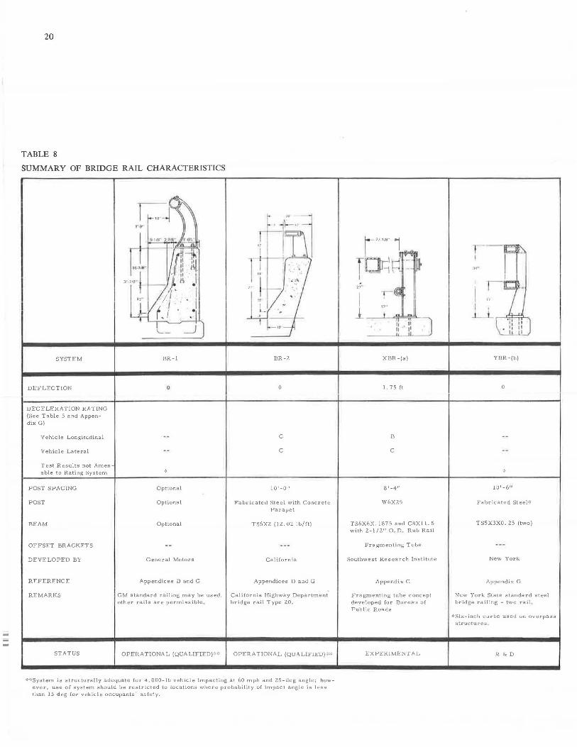
TABLE 8
SUMMARY OF BRIDGE RAIL CHARACTERISTICS
SYSTEM
DEFLECTION
DECELERATION RATING (See Table S and Appendix G)
Ve hie le Longitudinal
Vehicle Lateral
Test Results not Amenable to Rating System
POST SPACING
POST
BEAM
OFFSET BRACKETS
DEVELOPED BY
REFERENCE
REMARKS
STATUS
BR-1
0
Optional
Optional
Optional
BR-2
0
C
C
10 1 -0 11
Fabricated Steel with Concrete Parapet
TS6X2 (12. 02 lb/ft)
General Motors California
Appendices D and G Appendices D and G
GM standard railing may be used, California Highway Department other rails are permissible . bridge rail Type 20.
OPERATIONAL (QUALIFIED) ''''' OPERATIONAL (QUI\LIFIED) ''"''
**System is structurally adequate for 4,000-lb vehicle impacting at 60 mph and 25-deg angle~ however, use of system should be restricted to locations where probability of impact angle is less than 15 deg for vehicle occupants 1 safety.
XBR-(a)
I. 75 ft
B
C
8 1 -4 11
W6X25
TS6X6X. 1875 and CSX! I. 5 with 2-1/2 11 O. D . Rub Rail
Fragmenting Tube
Southwest Research Institute
Appendix G
Fragmenting tube concept developed for Bureau of Pub I ic Roads
EXPERIMENTAL
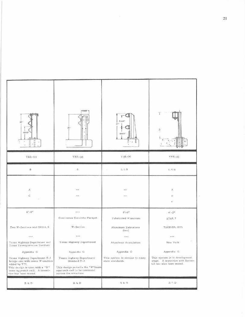
YBR-(b)
0
lQ I -6 11
Fabricated Steel:)'
TS5X3XO. 25 (two)
New York
Appendix G
New York State standard steel bridge railing - two rail.
,:,six-inch curbe used on overpass structures .
.\t 1< D
<.
!~~~ 27" < .
f3 1rr(
I n ~ ,, ii 11
" t!
YBR-(c)
0
A
C
8 1 -4•1
.. ]
Two W-Sections and C8Xl 1. 5
T exas Highway Department and T exas Transportation Institute
Appendix G
Texas Highway Department T-1 bridge rail with low e r W-section added by TT!, This design is used with a 11 W 11
beam approach rail. A transition has been tested.
R&D
&,S/8-,
~~ n -
I
. '
- J
YBR-(d)
0
Continuous Concrete Parapet
W-Section
Texas Highway D epartment
Appendix G
Texas Highway Department Standard T-2
This design permits the 11 W11 beam approach rail to be continued across the structure
R&D
1- ~ r-._
,,I:. 27" -~(j
' 12. , 12 .. ' 1 A ~ .. l
YBR-(e)
1. 4 ft
Fabricated Aluminum
Aluminum Extrusions (two)
Aluminum Association
Appendix G
This system is similar to many state standards
R&D
T -[t I
~:
r 6-L I - . •,
' , 1,~
{ ,_ ~ u.~ .n:-.i Yi'' Yi'
YJ3R-(f)
I 5 ft
A
B
4r_ztt
S 3X5 , 7
TS6X6XO, 1875
New York
Appendix G
This system is in development stage . A transition with System G3 has also been tested .
R '· D
21
-iii -
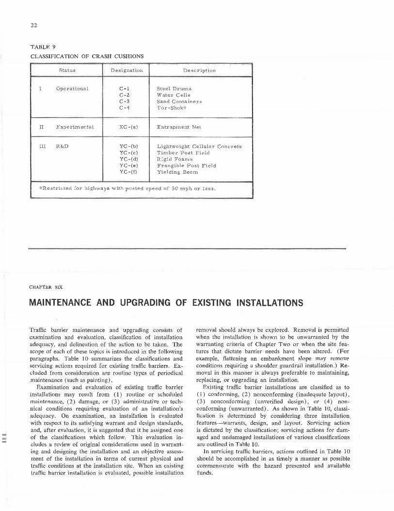
22
TABLE 9
CLASSIFICATION OF CRASH CUSHIONS -
Status Designation Description
I Operational C-1 Steel Drums C-2 Wate r Cell s C-3 Sand Containers C-4 Tor -Shok':'
II Experim ental XC- (a) Entrapment Net
III R&D YC-{b) Lightweight Cellular Concrete YC-(c) Timber Post Field YC-{d) Rigid Foams YC-(e) Frangible Post Field YC-(f) Yielding B e am
~'Restricted for highways with poste d spe e d of 50 mph or, l ess .
CHAPTER SIX
MAINTENANCE AND UPGRADING OF EXISTING INSTALLATIONS
Traffic barrier maintenance and upgrading consists of examination and evaluation, classification of installation adequacy, and delineation of the action to be taken. The scope of each of these topics is introduced in the following paragraphs. Table 10 summarizes the classifications and servicing actions required for existing traffic barriers. Excluded from consideration are routine types of periodical maintenance (such as painting).
Examination and evaluation of existing traffic barri~r installations may result from ( 1) routine or scheduled maintenance, (2) damage, or (3) administrative or technical conditions requiring evaluation of an installation's adequacy. On examination, an installation is evaluated with respect to its satisfying warrant and design standards, and, after evaluation, it is suggested that it be assigned one of the classifications which follow. This evaluation includes a review of original considerations used in warranting and designing the installation and an objective assessment of the installation in terms of current physical and traffic conditions at the installation site. When an existing traffic barrier installation is evaluated, possible installation
removal should always be explored. Removal is permitted when the installation is shown to be unwarranted by the warranting criteria of Chapter Two or when the site features that dictate barrier needs have been altered. (For example, flattening an embankment slope m11y remove conditions requiring a shoulder guardrail installation.) Removal in this manner is always preferable to maintaining, replacing, or upgrading an installation.
Existing traffic barrier installations are classified as to (1) conforming, ( 2) nonconforming ( inadequate layout) , (3) nonconforming ( unverified design) , or ( 4) nonconforming (unwarranted). As shown in Table 10, classification is determined by considering three installation. features-warrants, design, and layout. Servicing action is dictated by the classification; servicing actions for damaged and undamaged installations of various classifications are outlined in Table 10.
In servicing traffic barriers, actions outlined in Table 10 should be accomplished in as timely a manner as possible commensurate with the hazard presented and available funds.
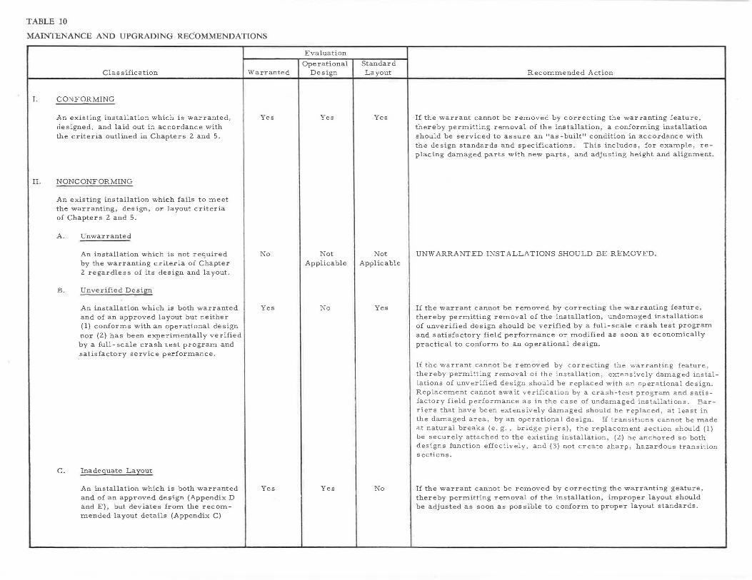
TABLE 10
MAINTENANCE AND UPGRADING RECOMMENDATIONS
Classification
I. CONFORMING
An existing installation which is warranted, designed, and laid out in accordance with the criteria outlined in Chapters 2 and 5.
II. NONCONFORMING
An existing installation which fails to meet the warranting, design, or layout criteria of Chapters 2 and 5.
A. Unwarranted
An installation which is not required by the warranting criteria of Chapter 2 regardless of its design and layout.
B. Unverified Design
c.
An installation which is both warranted and of an approved layout but neither ( 1) conforms with an operational de sign nor (2) has been experimentally verified by a full-scale crash test program and satisfactory service performance.
Inadequate Lay out
An installation which is both warranted and of an approved design (Appendix D and E), but deviates from the recommended layout details (Appendix C)
Warranted
Yes
No
Yes
Yes
Evaluation
Ope rational Design
Yes
Not Applicable
No
Yes
Standard Layout
Yes
Not Applicable
Yes
No
Recommended Action
If the warrant cannot be removed by correcting the war ranting feature, thereby permitting removal of the installation, a conforming installation should be serviced to assure an "as-built" condition in accordance with the design standards and specifications. This includes, for example, replacing damaged parts with new parts, and adjusting height and alignment .
UNWARRANTED INSTALLATIONS SHOULD BE REMOVED.
If the warrant cannot be removed by correcting the warranting feature, thereby permitting removal of the installation, undamaged installations of unverified design should be verified by a full-scale crash test program and satisfactory field performance or modified as soon as economically practical to conform to an operational design.
If the warrant cannot be removed by correcting the warranting feature, thereby permitting removal of the installation, extensively damaged installations of unverified design should be replaced with an operational design . Replacement cannot await verification by a crash-test program and satisfactory field performance as in the case of undamaged installations . Barriers that have been extensively damaged should be replaced , at least in the damaged area, by an operational design. If transitions cannot be made at natural breaks (e.g., bridge piers), the replacement section should (1) be securely attached to the existing installation, (2) be anchored so both designs function effectively, and (3) not create sharp, hazardous transition sections.
If the warrant cannot be removed by correcting the warranting geature, thereby permitting removal of the installation, improper layout should be adjusted as soon as possible to conform to proper layout standards .
-
24
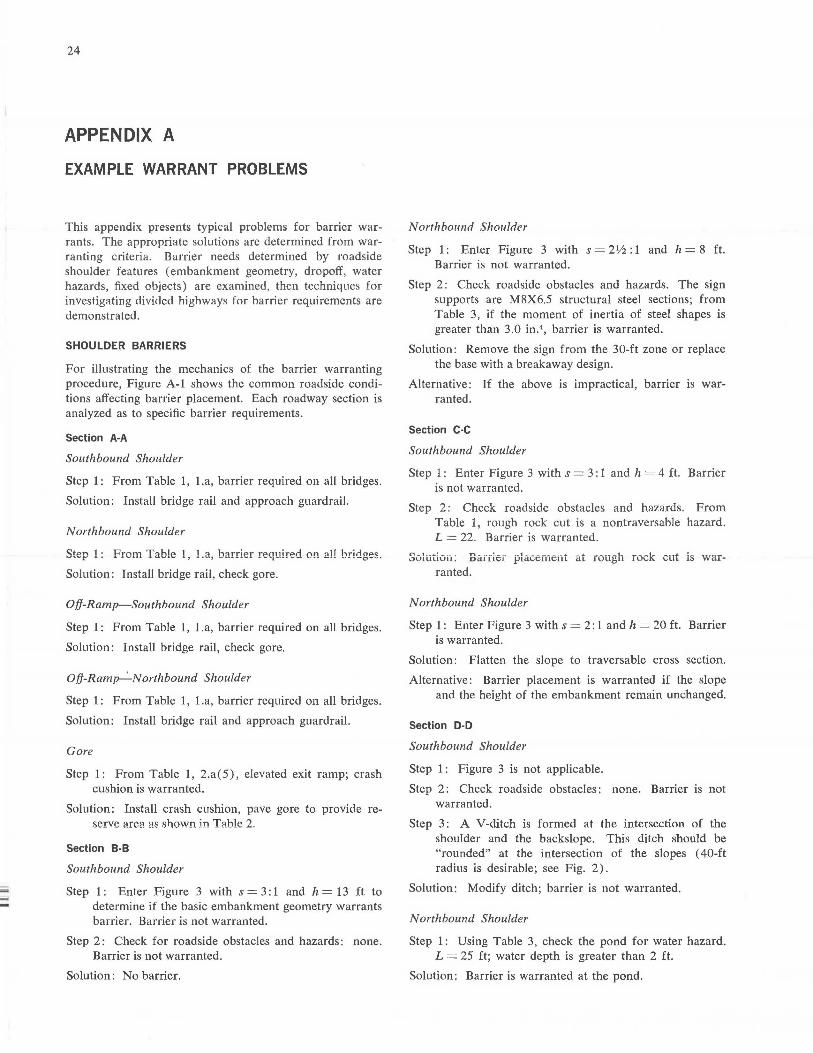
APPENDIX A
EXAMPLE WARRANT PROBLEMS
This appendix presents typical problems for barrier warrants. The appropriate solutions are determined from warranting criteria. Barrier needs determined by roadside shoulder features ( embankment geometry, dropoff, water hazards, fixed objects) are examined, then techniques for investigating cliviclecl highways for harrier requirements are demonstrated.
SHOULDER BARRIERS
For illustrating the mechanics of the barrier warranting procedure, Figure A-1 shows the common roadside conditions affecting barrier placement. Each roadway section is analyzed as to specific barrier requirements.
Section A-A
Southbound Shoulder
Step 1: From Table 1, 1.a, barrier required on all bridges.
Solution: Install bridge rail and approach guardrail.
Northbound Shoulder
Solution: Install bridge rail, check gore.
Off-Ramp-Southbound Shoulder
Step 1: From Table 1, 1.a, barrier required on all bridges.
Solution: Install bridge rail, check gore.
0/j-Ram~Northbound Shoulder
Step 1: From Table 1, 1.a, barrier required on all bridges.
Solution: Install bridge rail and approach guardrail.
Gore
Step 1: From Table 1, 2.a( 5), elevated exit ramp; crash cushion is warranted.
Solution: Install crash cushion, pave gore to provide re-serve area as shown in Table 2.
Section B-B
Southbound Shoulder
Step 1: Enter Figure 3 with s = 3: 1 and h = 13 ft to determine if the basic embankment geometry warrants barrier. Barrier is not warranted.
Step 2: Check for roadside obstacles and hazards: none. Barrier is not warranted.
Solution: No barrier.
Northbound Shor~lder
Step 1: Enter Figure 3 with s = 2Y2: 1 and h = 8 ft. Barrier is not warranted.
Step 2: Check roadside obstacles and hazards. The sign supports are M8X6.5 structural steel sections; from Table 3, if the moment of inertia of steel shapes is greater than 3.0 in.4 , barrier is warranted.
Solution: Remove the sign from the 30-ft zone or replace the base with a breakaway design.
Alternative: If the above is impractical, barrier is warranted.
Section C-C
Southbound Shoulder
Step 1 : Enter Figure 3 with s = 3 : 1 and h = 4 ft. Barrier is not warranted.
Step 2: Check roadside obstacles and hazards. From Table 1, rough rock cut is a nontraversable hazard. L = 22. Barrier is warranted.
Solutiou: Barfier placenient at rough rock cut 1s warranted.
Northbound Shoulder
Step 1: Enter Figure 3 with s = 2: 1 and h = 20 ft. Barrier is warranted.
Solution: Flatten the slope to traversable cross section.
Alternative: Barrier placement is warranted if the slope and the height of the embankment remain unchanged.
Section D-D
Southbound Shoulder
Step 1 : Figure 3 is not applicable.
Step 2: Check roadside obstacles: none. Barrier is not warranted.
Step 3 : A V-ditch is formed at the intersection of the shoulder and the backslope. This ditch should be "rounded" at the intersection of the slopes ( 40-ft radius is desirable; see Fig. 2).
Solution: Modify ditch; barrier is not warranted.
Northbound Shoulder
Step 1: Using Table 3, check the pond for water hazard. L = 25 ft; water depth is greater than 2 ft.
Solution: Barrier is warranted at the pond.
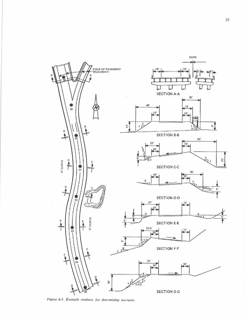
w > a: ::, u '/,,
-E
+
EDGE OF PAVEMENT ll.----.,W'47'1- (ROADWAY)
C C
1= =+ 21
1:1 u w > E a:
+ ::, u 0 M
GORE
SECTION A-A 30'
49'
22'
SECTION C-C 25'
SECTION D-D
. ~ II A l~ ~ t :--~ SECTION E-E
f =- ,,~ "'...&--.--~ ------=:;;/, ~, , ~o· ~ ~ ..;;......~~10·
6 SECTION F-F
30'
SECTION G-G
Figure A-1. Example roadway for determining warrants.
25
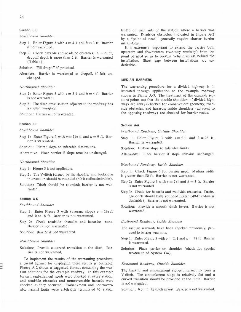
26
Section E-E r, _ .1.1. ~ _ , nr _ , _, _ iJUUlfl.UUUflU .JrlUUlUt'f
Step l : Enter Figure 3 with s = 4: l and h = 3 ft. Barrier is not warranted.
Step 2: Check hazards and roadside obstacies. L = 22 ft; dropoff depth is more than 2 ft. Barrier is warranted (Table 1).
Solution: Fill dropoff if practical.
Alternate: Barrier is warranted at dropoff, if left unchanged.
Northbound Shoulder
Step l : Enter Figure 3 with s = 3: 1 and h = 4 ft. Barrier is not warranted.
Step 2: The ditch cross section adjacent to the roadway has a curved transition.
Solution : Barrier is not warranterl .
Section F-F
Southbound Shoulder
Step 1: Enter Figure 3 with s = I Yz : 1 and h = 9 ft. Barrier is warranted.
Solution: Flatten slope to tolerable dimensions.
Alternative: Place barrier if slope remains unchanged.
Northbound Shoulder
Step l : Figure 3 is not applicable.
Step 2: The V-ditch formed by the shoulder and backs lope intersection should be rounded ( 40-ft radius desirable).
Solution: Ditch should be rounded; barrier is not warranted.
Section G·G
Southbound Shoulder
Step 1 : Enter Figure 3 with ( average slope) s = 21/2 : 1 and h = 18 ft. Barrier is not warranted.
Step 2: Check roadside obstacles and hazards: none. Barrier is not warranted.
Solution: Barrier is not warranted.
Northbound Shoulder
Solution: Provide a curved transition at the ditch. Barrier is not warranted.
To implement the results of the warranting procedure, a useful format for displaying these results is desirable. Figure A-2 shows a suggested format containing the warrant solutions for the example roadway. In this example format, embankment needs were checked at every station, and roadside obstacles and nontraversable hazards were checked as they occurred. Embankment and nontraversable hazard limits were arbitrarily terminated 1h station
length on each side of the station where a barrier was warranted. Roadside obstacles, indicated in Figure A-2 by a "point of need," generally require shorter barrier installations.
It is extremely important to extend the barrier both upstream and downstream (two-way roadway) from the point of need so as to prevent vehicle access behind the installation. Short gaps between installations are undesirable.
MEDIAN BARRIERS
The warranting procedure for a divided highway is illustrated through application to the example roadway shown in Figure A-3. The treatment of the example sections points out that the outside shoulders of divided highways are always checked for embankment geometry, roadside obstacles, and hazards; inside shoulders (adjacent to the opposing roadw~y) are checked for barrier needs.
Section A-A
Westbound Roadway, Outside Shoulder
Step 1 : Enter Figure 3 with s = 2: 1 and h = 26 ft. Barrier is warranted.
Solution: Flatten slope to tolerable limits.
Alternative: Place barrier if slope remains unchanged.
!f,.cstb..Jund ... ~cadv.-iay, In~idc Shoulder
Step 1 : Check Figure 6 for barrier need. Median width is greater than 50 ft. Barrier is not warranted.
Step 2: Enter Figure 3 with s = 7: 1 and h = 3 ft. Barrier is not warranted.
Step 3: Check for hazards and roadside obstacles. Drainage ditch should have rounded invert ( 40-ft radius is desirable) . Barrier is not warranted.
Solution: Provide a smooth ditch invert. Barrier is not warranted.
Eastbound Roadway, Inside Shoulder
The median warrants have been checked previously; proceed to barrier warrants.
Step 1 : Enter Figure 3 with s = 2: 1 and h = 18 ft. Barrier is warranted.
Solution: Place barrier on shoulder ( check for special treatment of System 04).
Eastbound Roadway, Outside Shoulder
The backfill and embankment slopes intersect to form a V-ditch. The embankment slope is relatively flat and a curved transition should be provided at the ditch. Barrier is not warranted.
Solution: Round the ditch invert. Barrier is not warranted.
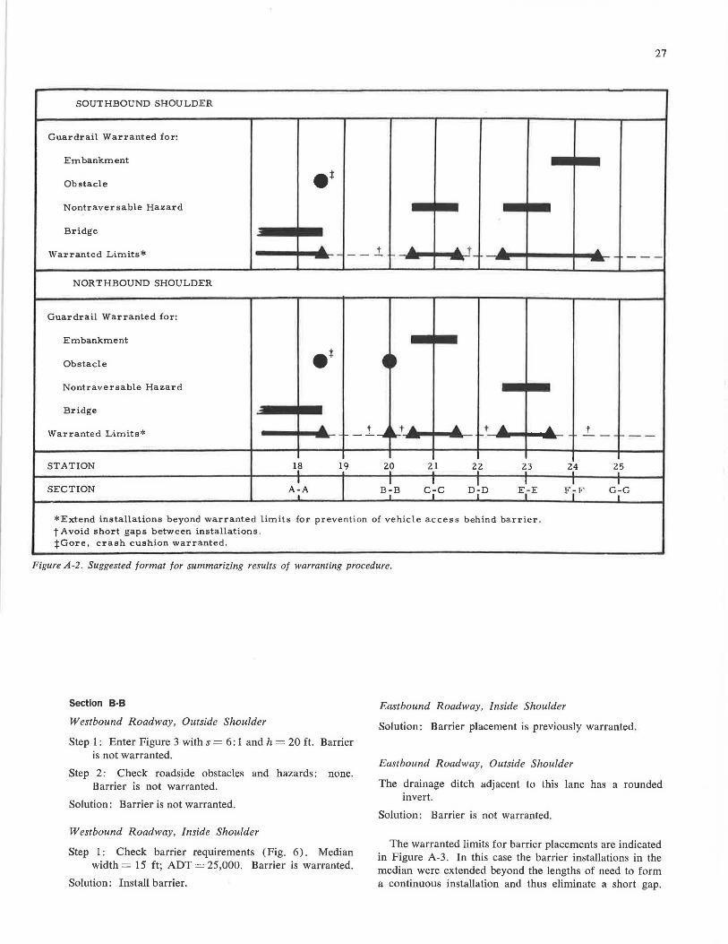
27
SOUTHBOUND SHOULDER
Guardrail Warranted for:
Embankment
Obstacle et Nontraversable Hazard
Bridge
... _ __ i ..,. ... .. r_ .... .. Warranted Limits* - ---- - -
NORTHBOUND SHOULDER
Guardrail Warranted for:
Embankment
Obstacle .t -t Nontraversable Hazard
Bridge
Warranted Limits* ....
- - 1_--.4 ~ t .... .... t .... .... t .... - ---,_ __ STATION 1~ 19 20 21 22 23 24 25
I I I I I
I I I D~D
I I I SECTION A-A B-B c ,c E-E F I F G-G
I I I I I
*Extend installations beyond warranted limits for prevention of vehicle access behind barrier . t Avoid short gaps between installations. tGore, crash cushion warranted .
Figure A-2. Suggested format for summarizing results of warranting procedure.
Section B-8
Westbound Roadway, Outside Shoulder
Step 1 : Enter Figure 3 with s = 6: 1 and h = 20 ft. Barrier is not warranted.
Step 2: Check roadside obstacles and hazards : none. Barrier is not warranted.
Solution: Barrier is not warranted.
Westbound Roadway, Inside Shoulder
Step 1: Check barrier requirements (Fig. 6) . Median width= 15 ft; ADT = 25,000. Barrier is warranted.
Solution: Install barrier.
Eastbound Roadway, Inside Shoulder
Solution: Barrier placement is previously warranted.
Eastbound Roadway, Outside Shoulder
The drainage ditch adjacent to this lane has a rounded invert.
Solution: Barrier is not warranted.
The warranted limits for barrier placements are indicated in Figure A-3. In this case the barrier installations in the median were extended beyond the lengths of need to form a continuous installation and thus eliminate a short gap.
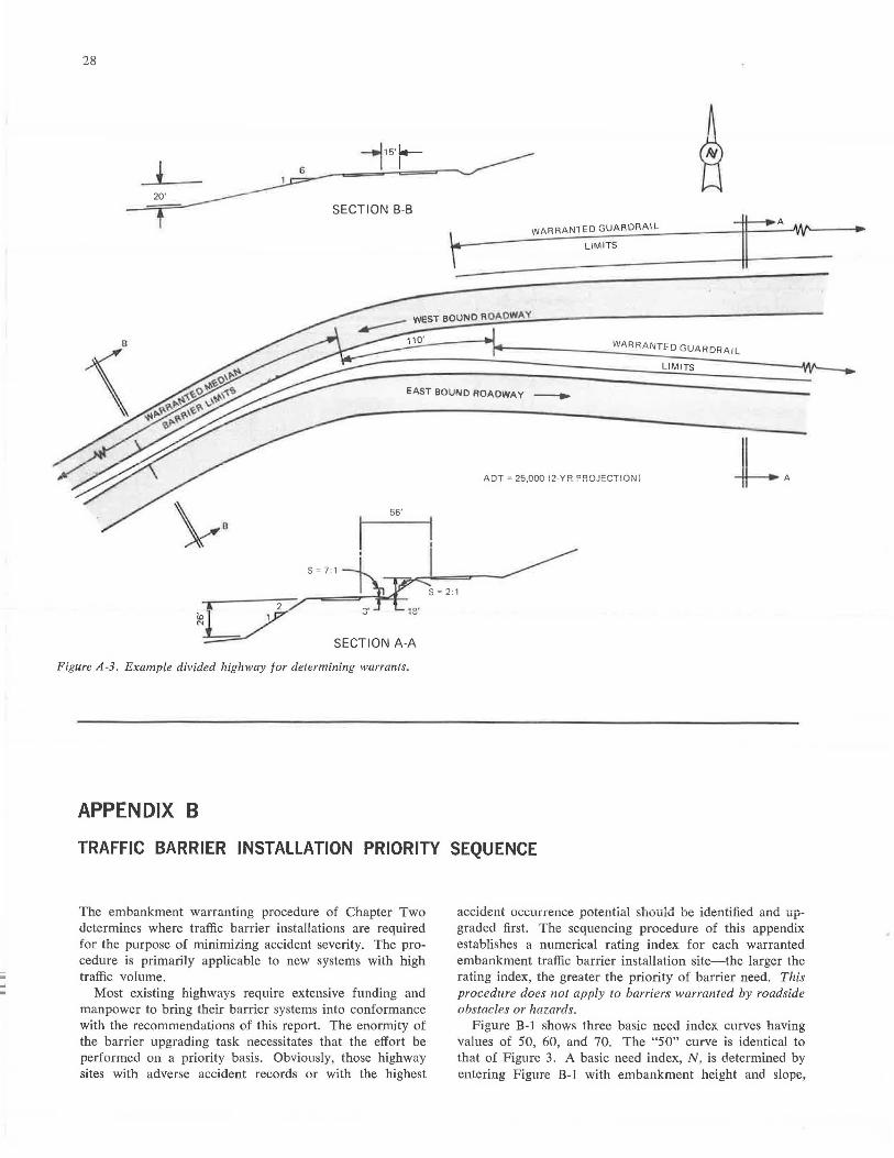
-
28
20'
SECTION B-B
t WARRANTED GUARDRAIL
LIMITS
WARR AN TED GUARDRAIL
LIMITS
EAST BOUND ROADWAY -.
A DT = 25,000 {2 Y R PR OJECT! O!'Jl
56'
SECTION A-A
Figure A-3. Example divided highway for determining warrants.
APPENDIX B
TRAFFIC BARRIER INSTALLATION PRIORITY SEQUENCE
The embankment warranting procedure of Chapter Two determines where traffic barrier installations are required for the purpose of minimizing accident severity. The procedure is primarily applicable to new systems with high traffic volume.
Most existing highways require extensive funding and manpower to bring their barrier systems into conformance with the recommendations of this report. The enormity of the barrier upgrading task necessitates that the effort be performed on a priority basis. Obviously, those highway sites with adverse accident records or with the highest
accident occurrence potential should be identified and upgraded first. The sequencing procedure of this appendix establishes a numerical rating index for each warranted embankment traffic barrier installation site-the larger the rating index, the greater the priority of barrier need. This procedure does not apply to barriers warranted by roadside obstacles or hazards.
Figure B-1 shows three basic need index curves having values of 50, 60, and 70. The "50" curve is identical to that of Figure 3. A basic need index, N , is determined by entering Figure 8-1 with embankment height and slope,
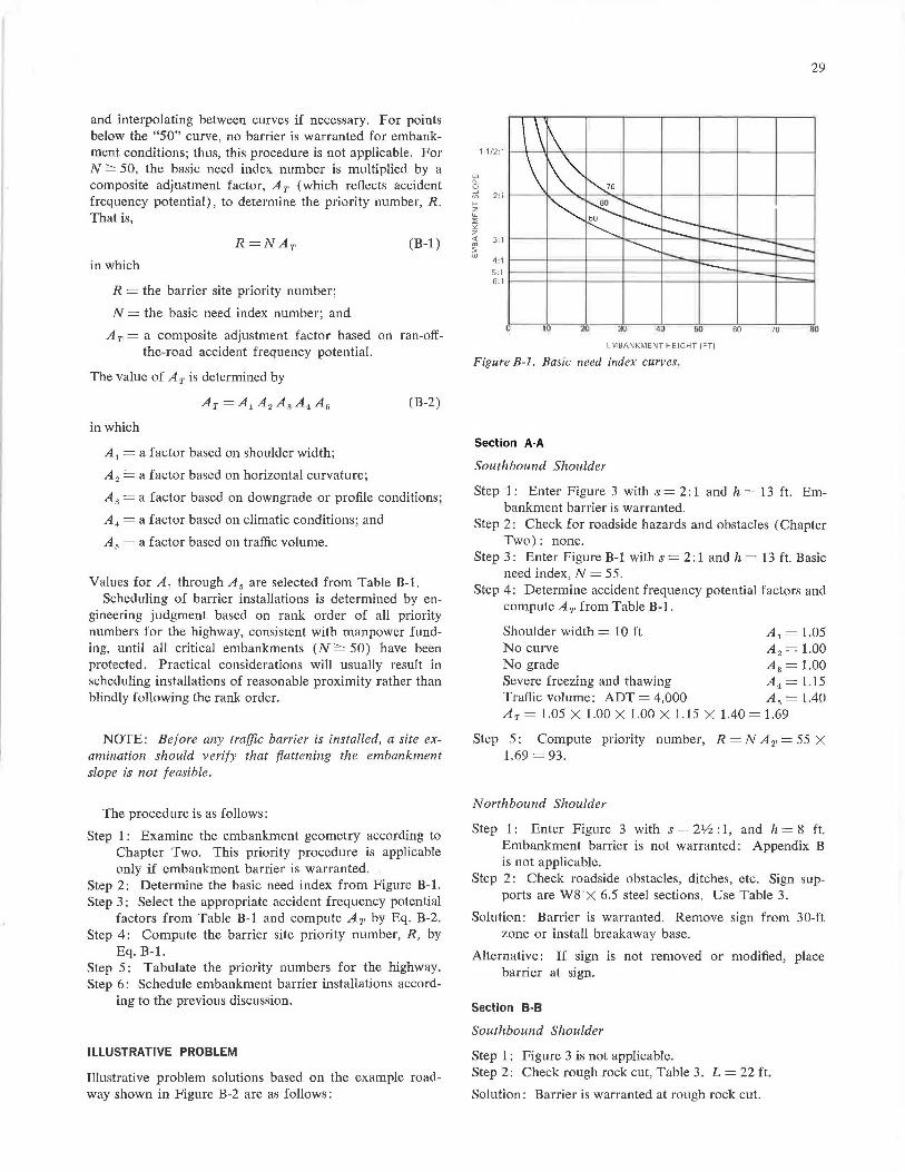
and interpolating between curves if necessary. For points below the "50" curve, no barrier is warranted for embankment conditions; thus, this procedure is not applicable. For N ~ 50, the basic need index number is multiplied by a composite adjustment factor, AT (which reflects accident frequency potential), to determine the priority number, R. That is,
(B-1)
in which
R = the barrier site priority number;
N = the basic need index number; and
AT= a composite adjustment factor based on ran-off-the-road accident frequency potential.
The value of AT is determined by
(B-2)
in which
A1 = a factor based on shoulder width;
A 2 == a factor based on horizontal curvature;
A 3 = a factor based on downgrade or profile conditions;
A 4 = a factor based on climatic conditions; and
A 5 = a factor based on traffic volume.
Values for A 1 through A 5 are selected from Table B-1. Scheduling of barrier installations is determined by en
gineering judgment based on rank order of all priority numbers for the highway, consistent with manpower funding, until all critical embankments (N ~ 50) have been protected. Practical considerations will usually result in scheduling installations of reasonable proximity rather than blindly following the rank order.
NOTE: Before any traffic barrier is installed, a site examination should verify that flattening the embankment slope is not feasible.
The procedure is as follows:
Step 1 : Examine the embankment geometry according to Chapter Two. This priority procedure is applicable only if embankment barrier is warranted.
Step 2: Determine the basic need index from Figure B-1. Step 3: Select the appropriate accident frequency potential
factors from Table B-1 and compute A 7, by Eq. B-2. Step 4: Compute the barrier site priority number, R, by
Eq.B-1. Step 5: Tabulate the priority numbers for the highway. Step 6: Schedule embankment barrier installations accord
ing to the previous discussion.
ILLUSTRATIVE PROBLEM
Illustrative problem solutions based on the example roadway shown in Figure B-2 are as follows:
29
4:1 1---+---t---~---1--=--.....i:c--- -l---li-==,,,_~ 5: 1 ,---+-- -t----t---1---1------==i--=-:Jc:---I 6:1 1---l-----l---l----l--~----1---1e----=:= ...
JO 40 50
EMBANKMENT HEIGHT (FTI
Figure B-1. Basic need index curves.
Section A-A
Southbound Shoulder
60 70 ao
Step 1: -Enter Figure 3 with s = 2: 1 and h = 13 ft. Embankment barrier is warranted.
Step 2: Check for roadside hazards and obstacles ( Chapter Two): none.
Step 3: Enter Figure B-1 with s = 2: 1 and h = 13 ft. Basic need index, N = 55.
Step 4: Determine accident frequency potential factors and compute AT from Table B-1.
Shoulder width= 10 ft A 1 = 1.05 No curve A 2 = 1.00 No grade A 3 = 1.00 Severe freezing and thawing A 4 = 1.15 Traffic volume: ADT = 4,000 A 5 = 1.40 AT= 1.05 X 1.00 X 1.00 X 1.15 X 1.40 = 1.69
Step 5: Compute priority number, R = N A 1, = 55 X 1.69 = 93.
Northbound Shoulder
Step 1: Enter Figure 3 with s = 21h: 1, and h = S ft. Embankment barrier is not warranted: Appendix B is not applicable.
Step 2: Check roadside obstacles, ditches, etc. Sign supports are ws ·x 6.5 steel sections. Use Table 3.
Solution: Barrier is warranted. Remove sign from 30-ft zone or install breakaway base.
Alternative: If sign is not removed or modified, place barrier at sign.
Section B-8
Southbound Shoulder
Step 1: Figure 3 is not applicable. Step 2: Check rough rock cut, Table 3. L = 22 ft.
Solution: Barrier is warranted at rough rock cut.
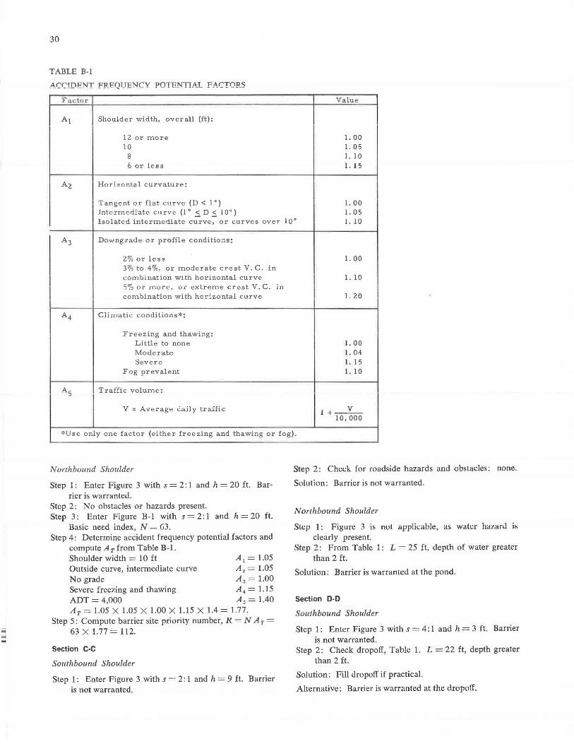
-
30
TABLE B-1
ArrTnPNT PRPQTTPNrV P()TPNTTAT FArTnR«
Factor Value
A1 Shoulder width, overall (ft):
12 or more l. 00 10 l. 05
8 l. l 0 6 or less l. 15
A2 Horizontal curvature:
Tangent or flat curve (D < 1 °) l. 00 Intermediate curve {1° .5.D.5.10°) l. 05 Isolated intermediate curve, or curves over 10° l. 10
A3 Downgrade or profile conditions:
2% or less l. 00 3% to 4%, or moderate crest V. C. in combination with horizontal curve l. 10 5% or more, or extreme crest V. C. in combination with horizontal curve l. 20
A4 Climatic conditions * :
Freezing and thawing: Little to none l. 00 Moderate 1. 04 Severe 1. 15
Fog prevalent 1. 10
A5 Traffic volume:
V : Av e rage daily traffic 1 +--v-10,000
*Use only one factor (either freezing and thawing or fog).
Northbound Shoulder
Step 1: Enter Figure 3 with s = 2: 1 and h = 20 ft. Barrier is warranted.
Step 2: No obstacles or hazards present. Step 3 : Enter Figure B-1 with s = 2: 1 and h = 20 ft.
Basic need index, N - 63. Step 4: Determine accident frequency potential factors and
compute Ar from Table B-1. Shoulder width= 10 ft A 1 = 1.05 Outside curve, intermediate curve A 2 = 1.05 No grade A 3 = 1.00 Severe freezing and thawing A 4 = 1.15 ADT = 4,000 A 5 = 1.40 Ar= 1.05 X 1.05 X 1.00 X 1.15 X 1.4 = 1.77.
Step 5: Compute barrier site priority number, R = NA r = 63 X 1.77 = 112.
Section C·C
Southbound Shoulder
Step 1: Enter Figure 3 with s = 2: 1 and h = 9 ft. Barrier is not warranted.
Step 2: Check for roadside hazards and obstacles: none.
Solution: Barrier is not warranted.
Northbound Shoulder
Slt:p 1: Figurn 3 is nol applicable, as walt:r hazanl is clearly present.
Step 2: From Table 1: L = 25 ft, depth of water greater than 2 ft.
Solution: Barrier is warranted at the pond.
Section D-D
Southbound Shoulder
Step 1: Enter Figure 3 with s = 4: 1 and h = 3 ft. Barrier is not warranted.
Step 2: Check dropoff, Table 1. L = 22 ft, depth greater than 2 ft.
Solution: Fill dropoff if practical.
Alternative: Barrier is warranted at the dropoff.
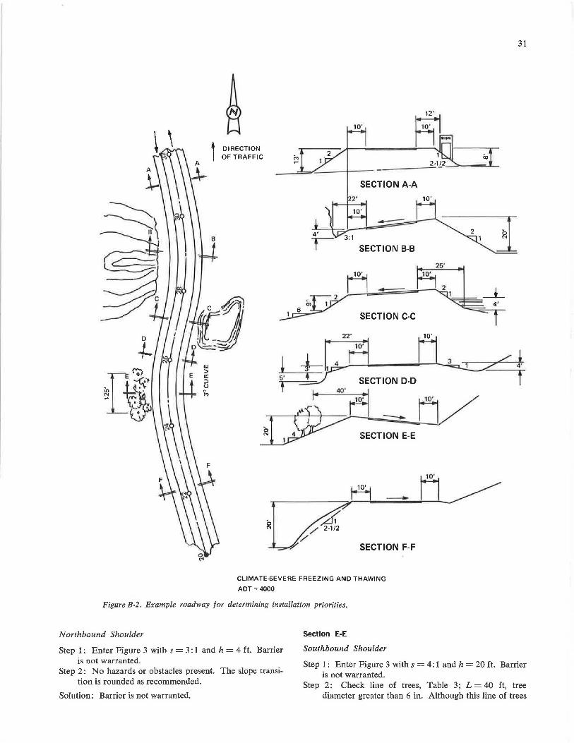
DIRECTION OF TRAFFIC M -
4'
T
31
SECTION A-A
10' --3:1
SECTION B-B
--SECTION C-C
w > a: ::i (.J
-i-t'.a LJ ~ ~ SECTION D-D
0 N SECTION E-E
-~
/ 2-1/2
/ ~ SECTION F-F
CLIMATE-SEVERE FREEZING AND THAWING
ADT = 4000
Figure B-2. Example roadway for determining installation priorities.
Northbound Shoulder
Step 1 : Enter Figure 3 with s = 3 : 1 and h = 4 ft. Barrier is not warranted.
Step 2: No hazards or obstacles present. The slope transition is rounded as recommended.
Solution: Barrier is not warranted.
Section E-E
Southbound Shoulder
Step 1 : Enter Figure 3 with s = 4: 1 and h = 20 ft. Barrier is not warranted.
Step 2: Check line of trees, Table 3; L = 40 ft, tree diameter greater than 6 in. Although this line of trees
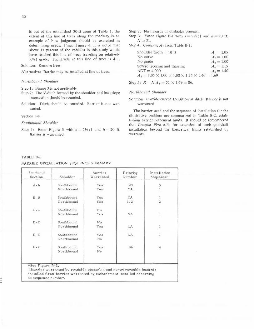
.iii
32
is out of the established 30-ft zone of Table 1, the extent of this line of trees along the roadway is an example of how judgment should be exercised in determining needs. From Figure 4, it is noted that about 13 percent of the vehicles in this study would have reached this line of trees traveling on relatively level grade. The grade at this line of trees is 4: 1.
Solution: Remove trees.
Alternative: Barrier may be installed at line of trees.
Northbound Shoulder
Step l : Figure 3 is not applicable. Step 2: The V-diteh formed by the shoulder and backslope
intersection should be rounded.
Solution: Ditch should be rounded. Barrier is not war-ranted.
Section F·F
Southbound Shoulder
Step 1 : Enter Figure 3 with s = 2112 : 1 and h = 20 ft. Barrier is warranted .
TABLE B-2
BARRIER INSTALLATION SEQUENCE SUMMARY
Road,..:,a y):~ R;arriter Section Shoulder Warranted
A-A Southbound Yes Northbound Yes
B-B Southbound Yes Northbound Yes
C-C Southbound No Northbound Yes
D-D Southbound No Northbound Yes
E-E Southbound Yes Northbound No
F-F Southbound Yes Northbound No
,:,see Figure B-2.
Step 2: No hazards or obstacles present. Step 3: Enter Figure B-1 with s = 21/2: 1 and h = 20 ft;
N= 51. Step 4: Compute AT from Table B-1:
Shoulder width= 10 ft A 1 = 1.05 No curve A 2 = 1.UU No grade A 3 = 1.00 Severe freezing and thawing A 4 = 1.15 AOT = 4,000 A 6 = 1.40 AT= 1.05 X 1.00 X 1.00 X 1.15 X 1.40 = 1.69
Step 5: R=NAT=51 X 1.69=86.
Northbound Shoulder
Solution: Provide curved transition at ditch. Barrier is not warranted.
The barrier need and the sequence of installation for the illustrative problem are summarized in Table B-2, establishing barrier placement limits. It should be remembered that Chapter Five calls for extension of each guardrail installation beyond the theoretical limits established by warrants.
Priority Installation Number Sequencet
93 3 NA 1
NA 1 112 2
NA 1
NA 1
NA 1
86 4
tBarrier warranted by roadside obstacles and nontraversable hazards installed fir st; barrier warranted by embankment installed according to sequence number .
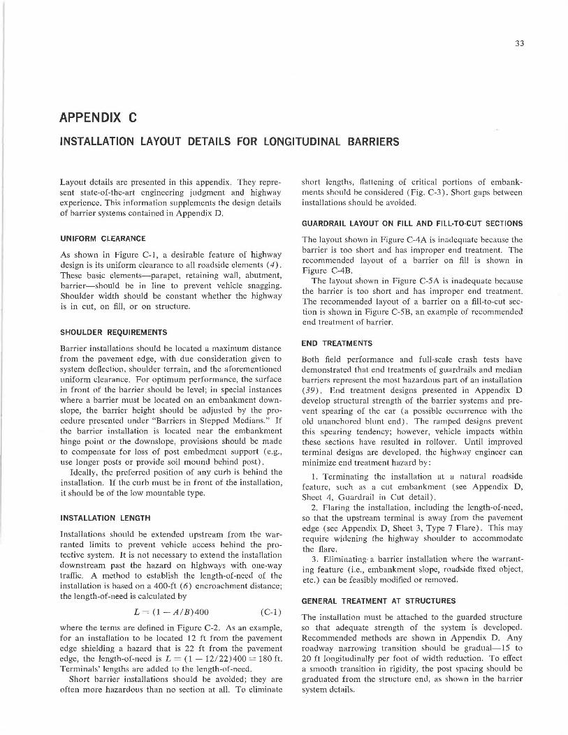
33
APPENDIX C
INSTALLATION LAYOUT DETAILS FOR LONGITUDINAL BARRIERS
Layout details are presented in this appendix. They represent state-of-the-art engineering judgment and highway experience. This information supplements the design details of barrier systems contained in Appendix D.
UNIFORM CLEARANCE
As shown in Figure C-1, a desirable feature of highway design is its uniform clearance to all roadside elements ( 4). These basic elements-parapet, retaining wall, abutment, barrier-should be in line to prevent vehicle snagging. Shoulder width should be constant whether the highway is iil cut, on fill, or on structure.
SHOULDER REQUIREMENTS
Barrier installations should be located a maximum distance from the pavement edge, with due consideration given to system deflection, shoulder terrain, and the aforementioned uniform clearance. For optimum performance, the surface in front of the barrier should be level; in special instances where a barrier must be located on an embankment downslope, the barrier height should be adjusted by the procedure presented under "Barriers in Stepped Medians." If the barrier installation is located near the embankment hinge point or the downslope, provisions should be made to compensate for loss of post embedment support (e.g., use longer posts or provide soil mound behind post) .
Ideally, the preferred position of any curb is behind the installation. If the curb must be in front of the installation, it should be of the low mountable type.
INSTALLATION LENGTH
Installations should be extended upstream from the warranted limits to prevent vehicle access behind the protective system. It is not necessary to extend the installation downstream past the hazard on highways with one-way traffic. A method to establish the length-of-need of the installation is based on a 400-ft (6) encroachment distance; the length-of-need is calculated by
L = (1 - A I B) 400 (C-1)
where the terms are defined in Figure C-2. As an example, for an installation to be located 12 ft from the pavement edge shielding a hazard that is 22 ft from the pavement edge, the length-of-need is L = (1 - 12/22)400 = 180 ft. Terminals' lengths are added to the length-of-need.
Short barrier installations should be avoided; they are often more hazardous than no section at all. To eliminate
short lengths, flattening of critical portions of embankments should be considered (Fig. C-3). Short gaps between installations should be avoided.
GUARDRAIL LAYOUT ON FILL AND FILL-TO-CUT SECTIONS
The layout shown in Figure C-4A is inadequate because the barrier is too short and has improper end treatment. The recommended layout of a barrier on fill is shown in Figure C-4B.
The layout shown in Figure C-5A is inadequate because the barrier is too short and has improper end treatment. The recommended layout of a barrier on a fill-to-cut section is shown in Figure C-5B, -an example of recommended end treatment of barrier.
END TREATMENTS
Both field performance and full-scale crash tests have demonstrated that end treatments of guardrails and median barriers represent the most hazardous part of an insta11ation (39) . End treatment designs presented in Appendix D develop structural strength of the barrier systems and prevent spearing of the car (a possible occurrence with the old unanchored blunt end). The ramped designs prevent this spearing tendency; however, vehicle impacts within these sections have resulted in rollover. Until improved terminal designs are developed, the highway engineer can minimize end treatment hazard by:
1. Terminating the installation at a natural roadside feature, such as a cut embankment (see Appendix D, Sheet 4, Guardrail in Cut detail).
2. Flaring the installation, including the length-of-need, so that the upstream terminal is away from the pavement edge (see Appendix D , Sheet 3, Type 7 Flare). This may require widening the highway shoulder to accommodate the flare.
3. Eliminating- a barrier installation where the warranting feature (i.e., embankment slope, roadside fixed object, etc.) can be feasibly modified or removed.
GENERAL TREATMENT AT STRUCTURES
The installation must be attached to the guarded structure so that adequate strength of the system is developed. Recommended methods are shown in Appendix D. Any roadway narrowing transition should be gradual-15 to 20 ft longitudinally per foot of width reduction. To effect a smooth transition in rigidity, the post spacing should be graduated from the structure end, as shown in the barrier system details.
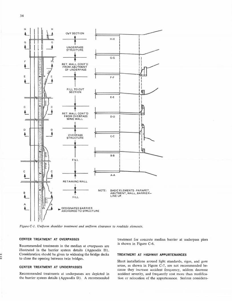
-
34
H H
L
F
L _J
E
L
C
L
D
L
C
L
B 8
L A
L
-1 ======:;----.--------T7- '1 H-H
Cl.IT SECTION
l I I
UNDERPASS I
STRU~USE {::t==:==:::G::-G:::::j"~~~t-i 1--~
RET. WALL CONT'D ~==========::r---~'1:W~ll....u FROM ABUTMENT
--t-OF UNDERPASS t F-F
11 1, I 1 11 /
+F\ttcWocNuT fi-=====E=-E=:::r-----!-11 .;:i~u-_./'
11
~
11
RET. WALL CONT'D 11======~=====~:::=::t=.I FROM OVERPASS T D-D I I
WING WALL
J,ASS l~:::=:::::r--~~~I STRUCTURE T C-C I l ~
1 , 1 11 1 I~
B-B l -----FILL I
--+- I
RETAINING WALL
FILL
+ : A-A
NOTE : BASIC ELEMENTS-PARAPET, ABUTMENT, WALL, BARRIERLINE UP.
DESIGNATES BARRIER • ANCHORED TO STRUCTURE
Figure C-1 . Uniform shoulder treatment and uniform clearance to roadside elements.
CENTER TREATMENT AT OVERPASSES
Recommended treatments in the median at overpasses are illustrated in the barrier system details (Appendix D). Consideration should be given to widening the bridge decks to close the opening between twin bridges.
CENTER TREATMENT AT UNDERPASSES
Recommended treatments at underpasses are depicted in the barrier system details ( Appendix D) . A recommended
treatment for concrete median barrier at underpass piers is shown in Figure C-6.
TREATMENT AT HIGHWAY APPURTENANCES
Short installations around light standards, signs, and gore areas, as shown in Figure C-7, are not recommended because they increase accident frequency, seldom decrease accident severity, and frequently cost more than modification or relocation of the appurtenance. Serious considera-
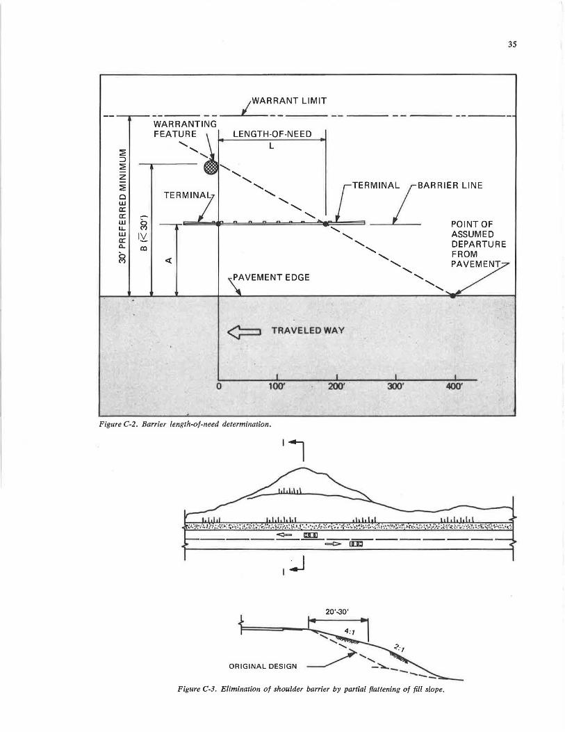
~ ::J ~ z ~ Cl w cc cc w LL w a: a.
~
WARRANTING FEATURE LENGTH-OF-NEED
L
TERMINAL/ BARRIER LINE
=~~~~:!!:====2:::::!!::::e:~~,~=== _L POINT OF '- ASSUMED
<(
PAVEMENT EDGE
¢=::, TRAVELED WAY
0 100' 200'
'-........ DEPARTURE '- FROM
......._ PAVEMENT
'
300•
' ',
400'
Figure C-2. Barrier length-of-need determination.
'l
I ~
20'-30'
ORIGINAL DESIGN
Figure C-3. Elimination of shoulder barrier by partial flattening of fill slope.
35

ULIJ _ _ - - ·-- -
FILL REQUIRING BARRIER
SHALLOW FILL
NO' A-IMFROPER RAIL-ENO TREATMENT
TRAINING END EXTENDED APPROACH END EXTENDED
FILL REQUIRING BARRIER
1 END TO BE ANCHORED 31
._;;---¢=,
c::::::>
2 ___. 3
8-RECOMMENDED RAIL-cNO TREATMENT
Figure C-4. Barrier terminal treatment for roadside fill condition.
;--
SHALLOW FILL
APPROACH END FLARED AND ANCHORED SHOULDER WIDENED AS REQUIRED t
~
SECTION 1-1
SECTION 2-2
SECTION 3-3
~ I I ~~-
(.;l
°'
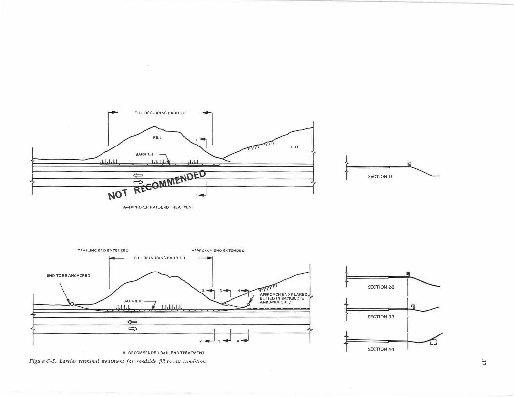
FILL REQUIRING BARRIER
N01' A-IMPROPER RAIL-END TREATMENT
TRAILING END EXTEN!)ED APPROACH END EXTENDED
[ FILL REQUIRING BARRIER
END TO BE ANCHORED
¢:::::,
r::::::::>
2
B-RECOMMENDED RAIL-END TREATMENT
Figure C-5. Barrier terminal treatment for roadside fill-to-cut condition.
3
t .!ii. ~ SECTION 1-1
SECTION 2-2 I SECTION 3-3
I t I /, L.J
SECTION 4-4
w -..;a
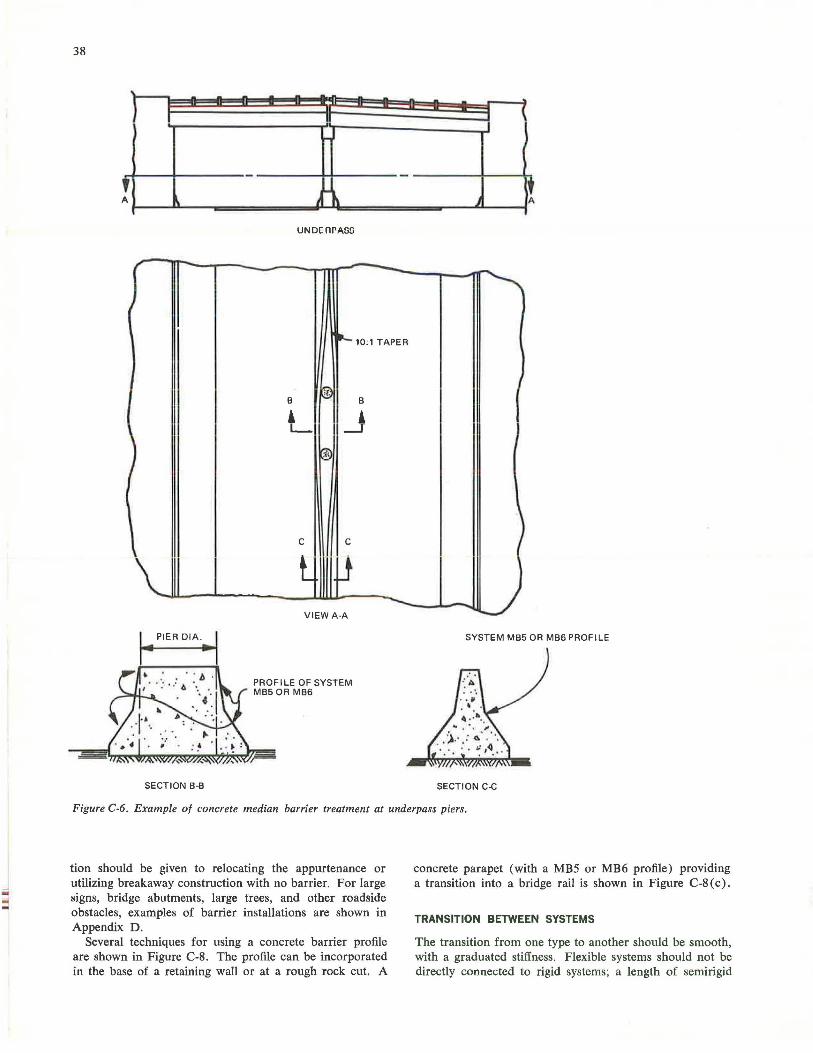
38
' h n D Q
-
' A \
r
I
,
SECTION B-8
I -II I ... ...
-.. ' t\
UND[nPAOO
-~ 10:1 TAPER
B g}
B
L _J l
C C
l l1 VIEWA A
PROFILE OF SYSTEM MB5 OR MB6
I
Q I n n
I
t j A
-I
' )
J SYSTEM MB5 OR MB6 PROFILE
SECTION C-C
Figure C-6. Example of concrete median barrier treatment at underpass piers.
tion should be given to relocating the appurtenance or utilizing breakaway construction with no barrier. For large signs, bridge abutments, large trees, and other roadside obstacles, examples of barrier installations are shown in Appendix D.
Several techniques for using a concrete barrier profile are shown in Figure C-8. The profile can be incorporated in the base of a retaining wall or at a rough rock cut. A
concrete parapet (with a MB5 or MB6 profile) providing a transition into a bridge rail is shown in Figure C-8 ( c).
TRANSITION BETWEEN SYSTEMS
The transition from one type to another should be smooth, with a graduated stiffness. Flexible systems should not be directly connected to rigid systems; a length of semirigid
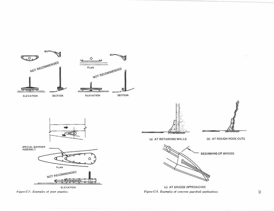
~ ~
ot-J\\'J\\:.~o\:.O ~o1 ?,'2.C
~ ELEVATION
SPECIAL BARRIER ASSEMBLY
SECTION
PLAN
'!
II
0 fY ~
PLAN
~o..., ?,\:.co\'J\\'J\'2.~o\:.O
1 ;;&: II
ELEVATION SECTION
0
, •. ·•.·
.,T:.
(a) AT RETAINING WALLS (bl AT ROUGH ROCK CUTS
BEGINNING OF BRIDGE
ELEVATION (c) AT BRIDGE APPROACHES
Figure C-7. Examples of poor practice. Figure C-8. Examples of concrete guardrail applications. w \0
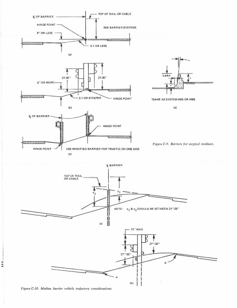
I I -iii -
ct_ OF BARRIER
HINGE POINT
6" OR LESS
6"0R MORE
t\\\\\\\\\\\\\l
ct_ OF BARRIER
(al
HINGE POINT
(bl
HINGE POINT
USE MODIFIED BARRIER FOR TRAFFIC ON ONE SIDE
(cl
ct_ BARRIER
Figure C-10. Median barrier vehicle trajectory considerations.
"SAME AS SYSTEM MB5 OR MB6
(d)
Figure C-9. Barriers for stepped medians.
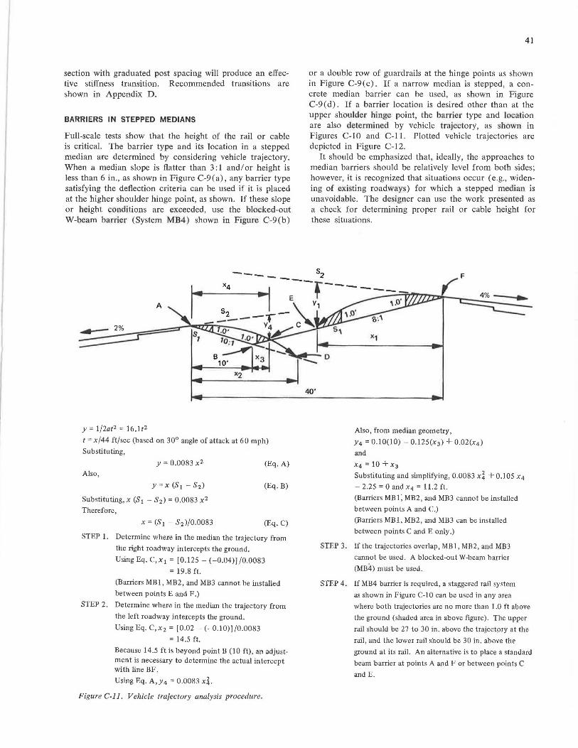
section with graduated post spacing will produce an effective stiffness transition. Recommended transitions are shown in Appendix D.
BARRIERS IN STEPPED MEDIANS
Full-scale tests show that the height of the rail or cable is critical. The barrier type and its location in a stepped median are determined by considering vehicle trajectory. When a median slope is flatter than 3: l and/ or height is less than 6 in., as shown in Figure C-9(a), any barrier type satisfying the deflection criteria can be used if it is placed at the higher shoulder hinge point, as shown. If these slope or height conditions are exceeded, use the blocked-out W-beam barrier (System MB4) shown in Figure C-9(b)
A
.....- 2%
y = l/2at2 = 16.lt2
t = x/44 ft/sec (based on 30° angle of attack at 60 mph)
Substituting,
y = 0.0083 x2
Also,
y = x (S1 - S2)
Substituting, x (S 1 - S 2 ) = 0.0083 x2
Therefore,
(Eq. A)
(Eq. B)
(Eq. C)
STEP 1. Determine where in the median the trajectory from
the right roadway intercepts the ground.
UsingEq.C,x 1 = [0.125 -(-0.04)]/0.0083
= 19.8 ft.
(Barriers MBl, MB2, and MB3 cannot be installed
between points E and F.)
STEP 2. Determine where in the median the trajectory from
the left roadway intercepts the ground.
UsingEq.C,x2 = [0.02-( - 0.10)]/0.0083
= 14.5 ft.
Because 14.5 ft is beyond point B (10 ft), an adjustment is necessary to detennine the actual intercept with line BF.
Using Eq. A, y 4 = 0.0083 xi. Figure C-11. Vehicle trajectory analysis procedure.
41
or a double row of guardrails at the hinge points as shown in Figure C-9(c). If a narrow median is stepped, a concrete median barrier can be used, as shown in Figure C-9(d). If a barrier location is desired other than at the upper shoulder hinge point, the barrier type and location are also determined by vehicle trajectory, as shown in Figures C-10 and C-11. Plotted vehicle trajectories are depicted in Figure C-12.
It should be emphasized that, ideally, the approaches to median barriers should be relatively level from both sides; however, it is recognized that situations occur ( e.g., widening of existing roadways) for which a stepped median is unavoidable. The de igner can use the work presented as a check for determining proper rail or cable height for these situations.
40'
Also, from median geometry,
Y4 = 0.10(10) - 0.125(x 3 ) + 0.02(x4 )
and
X4 = 10 + X3
Substituting and simplifying, 0.0083 xi + 0.105 x4
- 2.25 = 0 and x 4 = 11.2 ft.
(Barriers MBl, MB2, and MB3 cannot be installed
between points A and C.)
(Barriers MB1, MB2, and MB3 can be installed
between points C and E only.)
STEP 3. If the trajectories overlap, MBl, MB2 , and MB3
cannot be used . A blocked-out W-beam barrier
(MB4) must be used.
STEP 4. If MB4 barrier is required, a staggered rail system
as shown in Figure C-10 can be used in any area
where both trajectories are no more than 1.0 ft above
the ground (shaded area in above figure). The upper
rail should be 27 to 30 in . above the trajectpry at the
rail, and the lower rail should be 30 in. above the
ground at its rail. An alternative is to place a standard
beam barrier at points A and For between points C
and E.
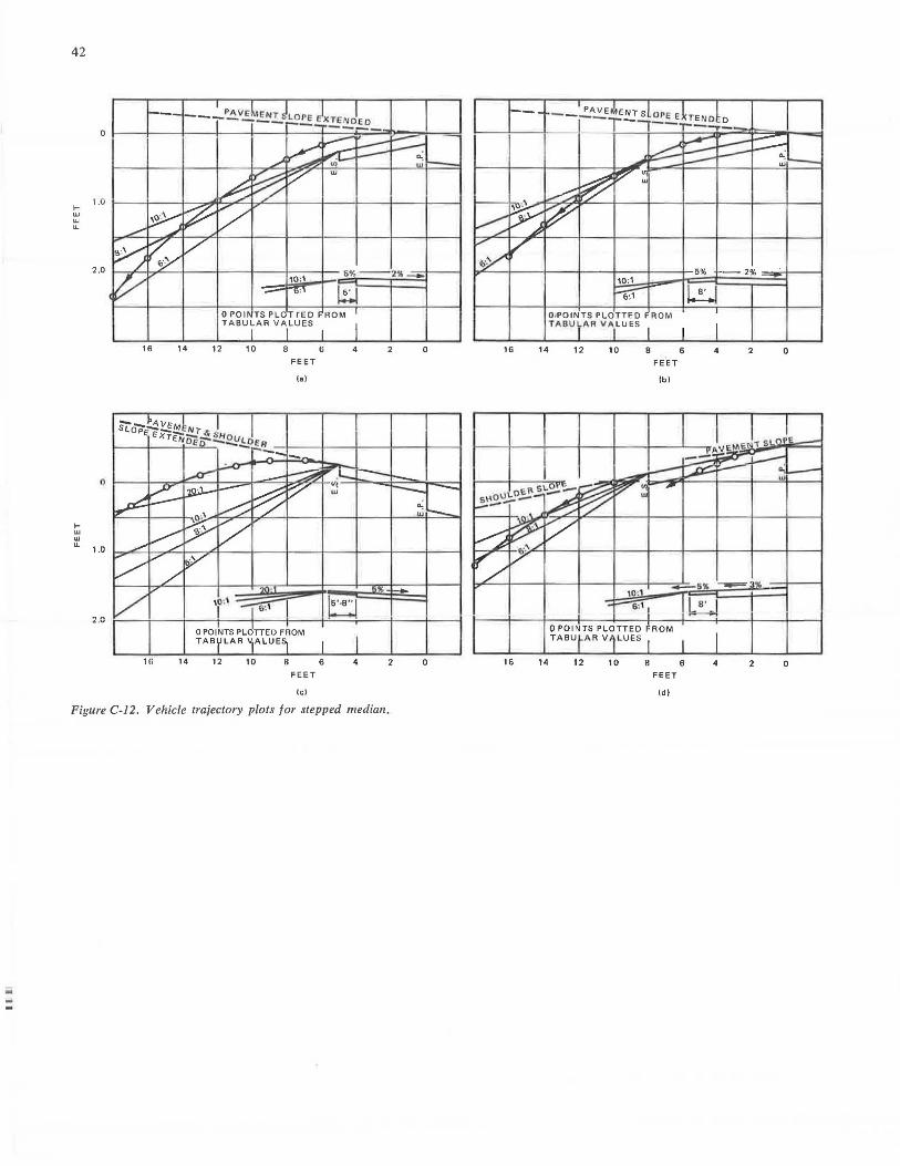
42
... w w u.
... w w u.
0
1.0
2 .0
(I
1.0
~ .C
16 14
1R 14
12 10 8
FEET
(a)
0 POINTS PLOTTED FROM TAB LAA V.ALUES
12 10 8
FEET
le)
6 4
6 4 2
Figure C-12. Vehicle trajectory plots for stepped median.
0
0
10:1
6:1 ~ OIPOINTS PLOTTED ROM TABULAR VALUES
16 14 12 10 8 6 4 2
FEET
lb)
b'~-+---t---11---1-- --t----::.:':= 6% --..= 3
16 14
t0 :1
Q POINTS PLOTTED FROM TABU ARV LUES
12 10 8
FEET
(di
6 4 2
0
0
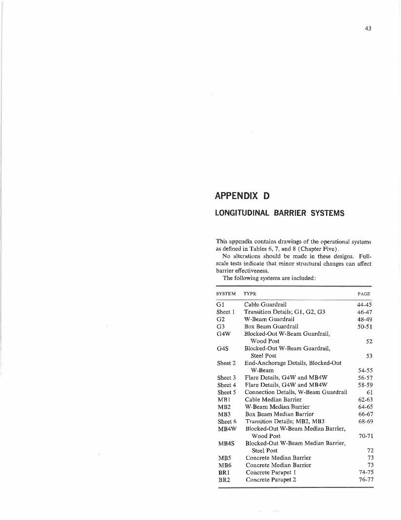
43
APPENDIX D
LONGITUDINAL BARRIER SYSTEMS
This appendix contains drawings of the operational systems as defined in Tables 6, 7, and 8 (Chapter Five).
No alterations should be made in these designs. Fullscale tests indicate that minor structural changes can affect barrier effectiveness.
The following systems are included:
SYSTEM TYPE PAGE
Gl Cable Guardrail 44-45 Sheet 1 Transition Details; Gl, G2, G3 46-47 G2 W-Beam Guardrail 48-49 G3 Box Beam Guardrail 50-51 G4W Blocked-Out W-Beam Guardrail,
Wood Post 52 G4S Blocked-Out W-Beam Guardrail,
Steel Post 53 Sheet 2 End-Anchorage Details, Blocked-Out
W-Beam 54-55 Sheet 3 Flare Details, G4W and MB4W 56-57 Sheet 4 Flare Details, G4W and MB4W 58-59 Sheet 5 Connection Details, W-Beam Guardrail 61 MB1 Cable Median Barrier 62-63 MB2 W-Beam Median Barrier 64-65 MB3 Box Beam Median Barrier 66-67 Sheet 6 Transition Details; MB2, MB3 68-69 MB4W Blocked-Out W-Beam Median Barrier,
Wood Post 70-71 MB4S Blocked-Out W-Beam Median Barrier,
Steel Post 72 MB5 Concrete Median Barrier 73 MB6 Concrete Median Barrier 73 BRl Concrete Parapet 1 74-75 BR2 Concrete Parapet 2 76-77
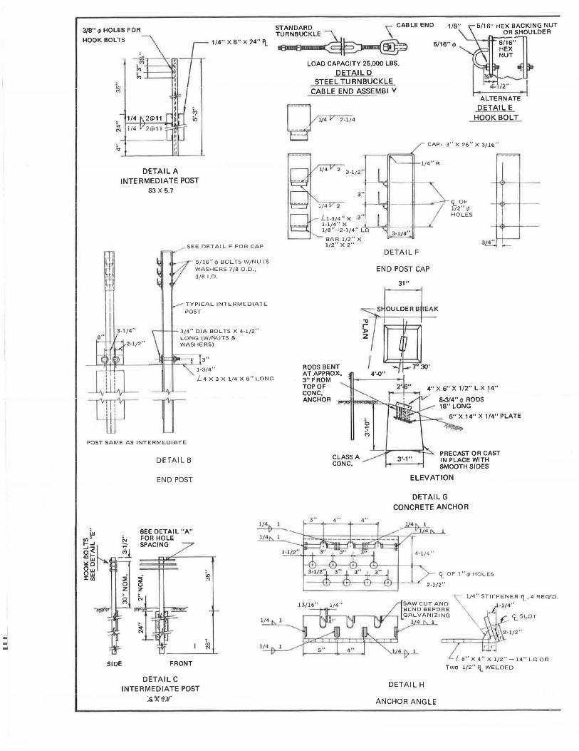
3/8" <I> HOLES FOR STANDARD CABLE END 1/8" 5/16·· HEX BACKING NUT
OR SHOULDER
.\ HOOK BOLTS 1/4" X 8" X 24" F\.. rn=~~ ~~ 5/16' ',t, 5/16'1 HEX
~ M +-- --4,"'11
M ---'---li'
114
~ 114
DETAIL A INTERMEDIATE POST
SJ X 5.7
..,.- SEE DETAIL F FOR CAP
5/16" </> BOLTS W/NUTS WASHERS 7/8 O .D ., 3/8 I.D.
TYPICAL INTERMEDIATE
POST
_[l[L
vu l 4 X 3 X 1/4 X 8" LONG
POST SAME AS INTERMEDIATE
SIDE
DETAIL B
END POST
SEE DETAIL "A" FOR HOLE SPACING
FRONT
DETAILC INTERMEDIATE POST
:s. ,g e;v-··
co "'
1/ 4 ~ I
)/4
1/4 l
1/~
LOAD CAPACITY 25,000 LBS.
DETAIL D STEEL TURNBUCKLE
CABLE END ASSEMBI V
2 3-1/2"
2
l!-3/4" X 3" l·l/4" X J__ 1/8 "-2-1/4" LG
-..,_ BAR 1/2" X 1/2" X 2"
DETAIL F
END POST CAP
31"
RODS BENT / 7 30'
NUT
l'lUt--l ~
ALTERNATE
DETAIL E HOOK BOLT
3" X 26" X 3/16"
<i_ OF 1/2" ,t, HOLES
TOP OF 2.l.. 4" X 6" X 1/2" L X ,14" CONC, ~ • 1 ANCHOR . 8•314" ,t, RODS
3 "
CLASS A CONC.
18" LONG
6" X 14" X 1/4" PLATE
~
PRECAST OR CAST IN PLACE WITH SMOOTH SIDES
ELEVATION
DETAILG CONCRETE ANCHOR
DETAIL H
ANCHOR ANGLE
<i_ OF l"r/) HOLES
'\:° 1/4 " STIFFENER 'l_, 4 REQ'D.
·l/4"
<i_ SLOT
- la" X 4" X l/2"-14" LG OR
Two -1/2" fl. WELDED
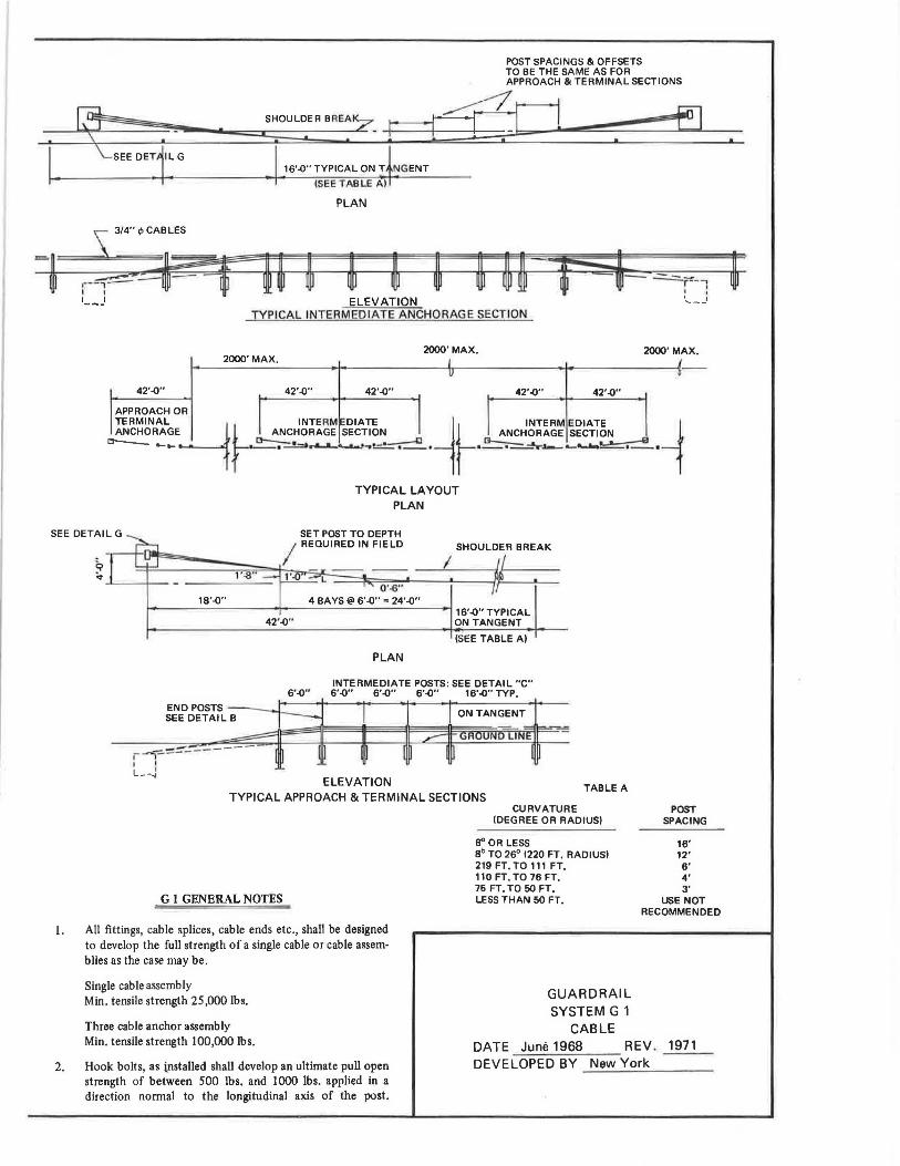
SHOULDER BREA7
• .
POST SPACINGS & OFFSETS TO BE THE SAME AS FOR APPROACH & TERMINAL SECTIONS
EL£D Fl I. . [ ,..~ .. m,c:, ON ! i•Gm
{SEE TABLE A)
s 3/4" ,P CABLES
,--~_!_~- -, I I , __ J
PLAN
ELEVATION TYPICAL INTERMEDIATE ANCHORAG E SECT ION
2000'MAX. 2000'MAX.
42'-0" 42'-0" 42'-0" 42'-0"
APPROACH OR
f 2000' MAX.
42'-0"
ANCHORAGE L. ~HORAGE SECTION L ANCHORAGE SECTION TERMINAL Lt INTE RM DIATE ~ INTERM EDIATE 1
ct--_ -... f __ ._.::..!::l......._......., .... -•-.--O . i . ..!:::::.-~-- .... ---·--·
SEE DETAIL G
TYPICAL LAYOUT PLAN
18'-0" 4 BAYS@ 6'-0" • 24'-0" 16'-0" TYPICAL
42'-0" ON TANGENT
END POSTS ---...J SEE DETAIL B
(SEE TABLE A)
PLAN
INTERMEDIATE POSTS : SEE DETAIL "C" 6 '-0" 6'-0" 6 ' -0" 6 '-0" 16'-0" TYP.
r -?~~-------' I l--~
ELEVATION TYPICAL APPROACH & TERMINAL SECTIONS
TABLE A
CURVATURE
G 1 GENERAL NOTES
(DEGREE OR RADIUS)
8" OR LESS Sb TO 26°' (220 FT. RADIUS) 219 FT. TO 111 FT. 110 FT. TO 76 FT. 75 FT. TO 50 FT, LESS THAN 50 FT,
I. All fittings, cable splices, cable ends etc., shall be designed to develop the full strength of a single cable or cable assemblies as the case may be .
Single cable assembly Min. tensile strength 25 ,000 lbs. GUARDRAIL
SYSTEM G 1 CABLE
POST SPACING
16' 12' 6' 4' 3'
USE NOT RECOMMENDED
Three cable anchor assembly Min. tensile strength 100,000 lbs. DATE June 1968 REV . 1971
2. Hook bolts, as installed shall develop an ultimate pull open strength of between 500 lbs, and 1000 lbs. applied in a direction normal to the longitudinal axis of the post.
DEVELOPED BY New York
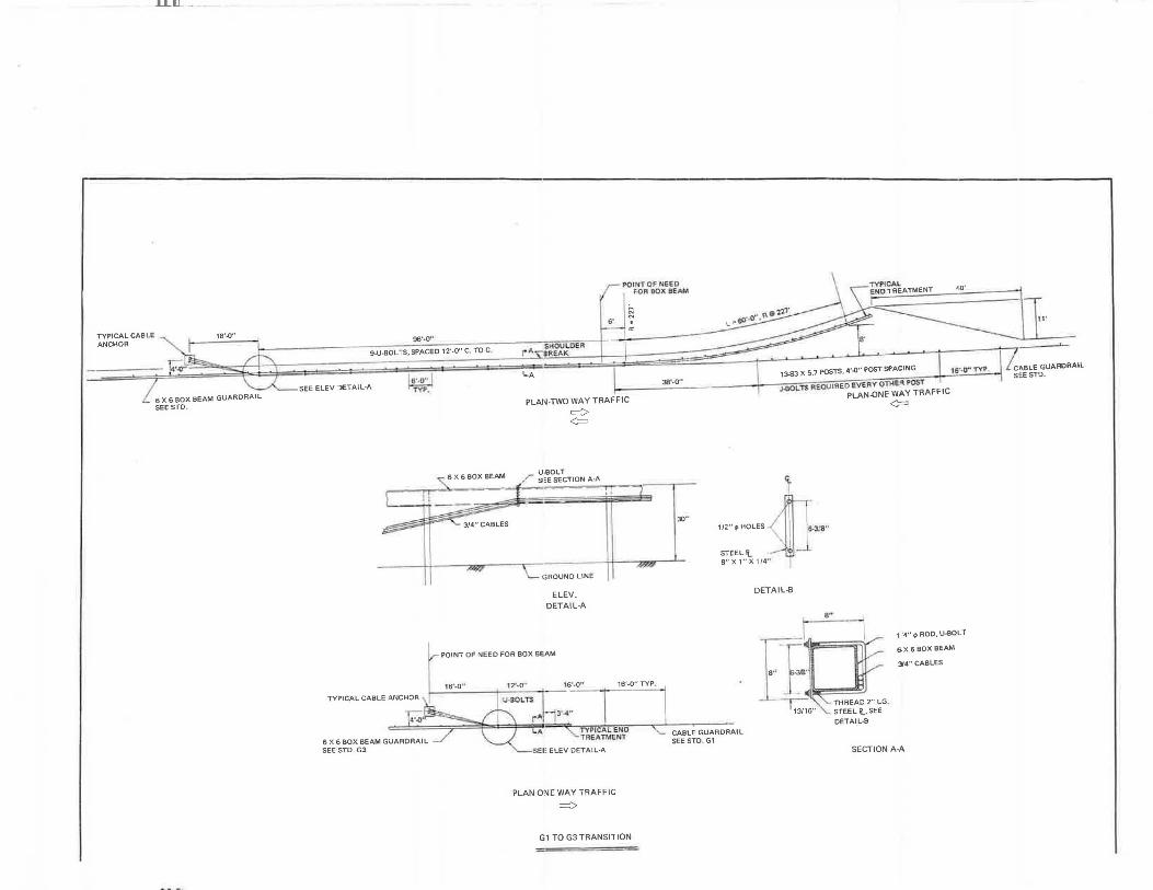
TYPICAL CABLE ANCHOR
.LILlJ_ .. - - -
6 X 6 BOX BEAM GUARDRAIL SEE STD.
s·
96'·0"
POINT OF NE-EO FOR BOX BEAM
~ . a:
\ 40'
9-U-BOLTS, SPACED 12'-0" C. TO C.
6',0" SEE ELEV JETAIL·A m:
3/4" CABLES
I..A
PLAN-lWO WAY TRAFFIC
~ <=
U-60LT Sl::E SECTION A·A
GAOUNOUNE
ELEV. DETAIL-A
POINT OF NEED FOR BOX BEAM
18"-0 .. 12'·0" 16',0" 16'-0" TYP.
:r-4••
TYi'TCAlENO TREATMENT
PLAN-ONE WAY TRAFFIC
~
G1 TO G3 TRANSITION
38'·0"
30"
13,.53 X 5.7 POsTS, 4'.0" POST SPACING I 115"·0'' 1YP.
J.SOLT$ REOU!RED EVERY OTI-1£'1 l'OST PLAN-ONE WAY TRAFFIC
<t. I
1/2" ~ HOLES ,1]'. \ ·, o-3/8' '
' I STEEL'!. Ill __I.
8" X 1" X 1/4 "'
OETAIL·B
II --r,;,6 ..
8"
THREAD 2" LG STEEL '!.,SEE
OETAIL-8
<=
1 '4" ~ ROD, U-BOLT
6X 6 eox BEAM
34"CABLES
CABLE GUARDRAIL SEE STD. G1
SECTION A-A
II'
CABLE GUARDRAIL S!:E STD.
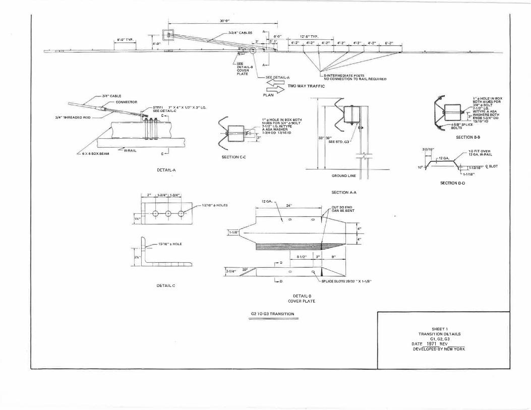
6'-0"TYP.
\'I-RAIL CJ
DETAIL-A
DETAIL C
30'-0"
3-3/4" CABLES 12'-6"TYP.
4'-2"
J se~t..·A 25 1WOWAYTRAFFIC
PLAN
~ 1"4>HOLE IN BOX BOTH SIDES FOR 3/4" 4' BOLT 7-1/2" LG, W/TYPE AASA WASHER 1-3/4 00 13/16 ID .
.
SECTION C-C
33"130" SEESTO.G3 ,#
GROUND LINE
4 '•2"
1l SECTION A-A
13/16" 4' HOLES
)1-r1r
i2GA.
D
24';
0
8-1/2"
DETAIL·B COVER PLATE
G2 TO G3 TRANSITION
4"
...
9"
6',3"
10•
1'',p HOLE IN BOX 80TH SIDES FOR 3/<"l) BOLT 7·112" LG.
:,s W/TYPl: AASA
:__E, WASHERS BOTH ENOS 1,314" 00 13/18" 10
4-S;&•• SPLICE BOLTS
SECTION B-B
'* I t-nf1S" 't_ SLOT
SECTION D-D
SHEET 1 TRANSITION DETAILS
Gl, G2, G3 DATE 1971 REV DEVELOPED BY NEW YORK
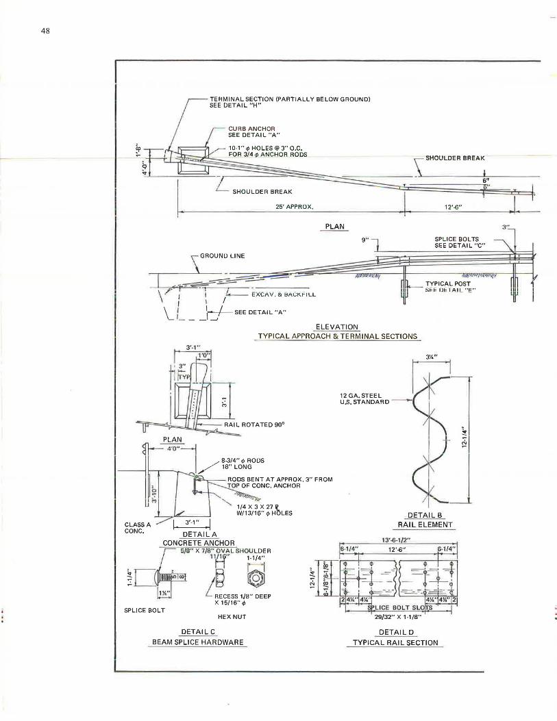
48
TERMINAL SECTION (PARTIALLY BELOW GROUND) SEE DETAIL "H"
CURB ANCHOR SEE DETAIL "A"
,,,- 10-1" </> HOLES @3" O.C. FOR 3/4 </> ANCHOR RODS
SHOULDER BREAK
25' APPROX.
s=GROUN~ LINE
I -~~-=-- .. ,,,. - -- -----\ .r· i \ /4-- EXCAV. & BACK.FILL
\ I 1r---/--sEE DETAIL "A"
-'-- _\.....J
PLAN
9 "
ELEVATION
I.
\ SHOULDER BREAK.
6''
12' -6"
SPLICE BOLTS SEE DETAIL "C"
SEI: IJ~ I All_ "E "'
TYPICAL APPROACH & TERMINAL SECTIONS
PLAN
18" LONG
12 GA.STEEL U.S. STANDARD
ll'O" j ---It--...--- ~ /
8-3/4" </> RODS
CLASS A CONC.
SPLICE BOLT
r-.__- - RODS BENT AT APPROX. 3" FROM - JOPOFCONC.ANCHOR
HEX NUT
DETAIL C
BEAM SPLICE HARDWARE
6-1/4"
DETAIL B RAIL ELEMENT
13'-6-1 2"
12'-6" 6-1/4"
DETAIL D
TYPICAL RAIL SECTION
. I 3"
iii
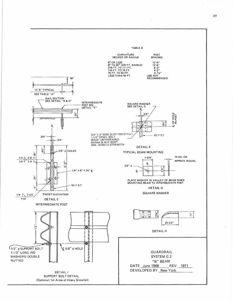
r I I
J 18"
T ~ 12'-6" TYPICAL
SEE TABLE "A"
RAIL SECTION
TABLE A
CURVATURE DEGREE OR RADIUS
8° OR LESS 8° TO 26° (220 FT. RADIUS) 219 FT. TO 111 FT. 110 FT. TO 76 FT. 75 FT. TO 50 FT. LESS THAN 50 FT.
POST SPACING
12'-6" 12'-6" 6'-3" 4'-2" 3'-1Y,"
USE NOT RECOMMENDED
SEE DETAIL "B & D" INTERMEDIATE
~~~~ posTSEE DETAIL "F"
3/4" 3/4"
~ 1/4 2 @ 11
3/4" X 3" NOM. SLOT FOR 5/ 16.P X 1-1/2" STEEL BOLT W/5/8" UNTH AEAOED SHANK & NUT 40001/ MIN. TENS ILE STRENGTH
DETAIL F
TYPICAL BEAM MOUNTING
1-3/4" 10 GA . OR
1/4" X8" X 24" l
~*APPROX. EQUAL
3/8".P~~
'le - ITJ~- ~
1/4 2-3/8
TYP DETAIL E
INTERMEDIATE POST
SJ X 5.7
1/2" ¢ SUPPORT BOLT 1-1/2" LONG (NO WASHERS) DOUBLE NUTTED
i 5/8" ¢ HOLE ,1 I 11 11 .,.u..
DETAIL I SUPPORT BOLT DETAIL
(Optional; for Areas of Heavy Snowfall)
PLACE WASHER IN VALLEY OF BEAM WHEN MOUNTING BEAM TO INTERMEDIATE POST
DETAIL G
SQUARE WASHER
00~ r5____._~ I ! 27-1/2" I
DETAIL H
GUARDRAIL SYSTEM G 2 "W" BEAM
DATE June 1968 REV . 1971 DEVELOPED BY New York
49
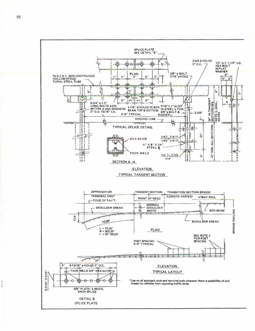
50
ts 6 X 6 X .1 875 CONTINUOUS HOLLOW STA UC· TURAL STEEL TUBE
BOX BEAM ~',:
%" X8"X24 " _.-STEEL It. -
TACK WELD l.~/4~~~~ TYP
2-6/8 ,jJ HOLES 3"C,C.
"' en z 2 I-
;, u N w en
.J
.J <t z ~
;, ~
1/2" <I> X 1-1/2" LG. HEX BOLT W/FLAT WASHl!A
6"
I
~ II 111 11 111
# I
I 11 11,
w-11 II II II
SECTION A-A - -LL.Ji
APPROACH OR
TERMINAL ENO•
EDGE OF PAV'T,
L ~ 72.00' R = 203.25' I ~ 20" -05.93'
27"
DETAIL B SPLICE PLATE
ELEVATION
TYPICAL TANGENT SECTION
TRANSITION SECTION BRIDGE
PLAN
POST SPACING 6'-0" TYPICAL
(LENGTH VARIES)
ELEVATION
TYPICAL LAYOUT
H'WAY RAIL
SEE NOTE 2 FOR POST SPACING
•use on all approach ends and terminal ends wherever there is possibility of end Impact by vehicles from opposing traffic lanes.
.. iio -
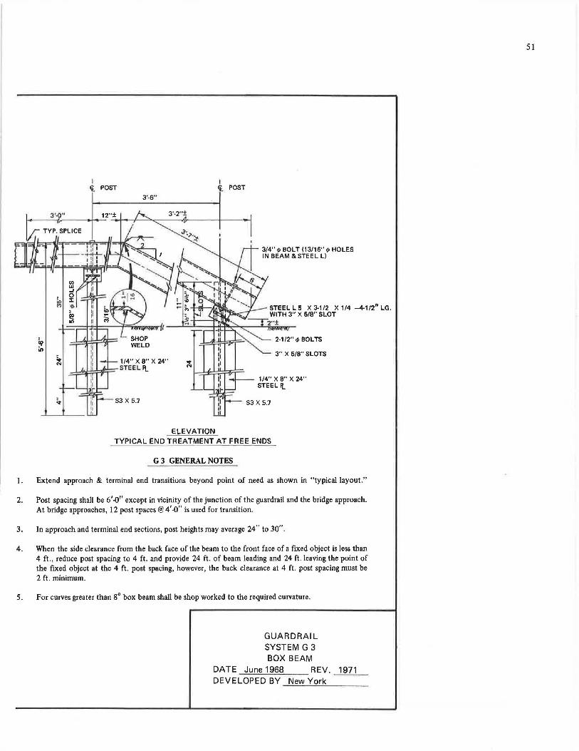
I I 't, POST i POST
3'·6"
3'-0" 12"± i--------f~-- -- -+--T-- ....... ---n.-----~-
i:n M
ELEVATION
3/4" q, BOLT (13/16" <I> HOLES IN BEAM & STEEL L)
3" X 5/8" SLOTS
1/4" X 8" X 24" STEEL I(_
TYPICAL END TREATMENT AT FREE ENDS
G 3 GENERAL NOTES
1. Extend approach & terminal end transitions beyond point of need as shown in "typical layout."
2. Post spacing shall be 6'-0'' except in vicinity of the junction of the guardrail and the bridge approach. At bridge approaches, 12 post spaces@ 4'-0" is used for transition.
3. In approach and terminal end sections, post heights may average 24" to 30".
4. When the side clearance from the back face of the beam to the front face of a fixed object is less than 4 ft., reduce post spacing to 4 ft. and provide 24 ft. of beam leading and 24 ft. leaving the point of the fixed object at the 4 ft. post spacing, however, the back clearance at 4 ft. post spacing must be 2 ft. minimum.
5. For curves greater than 8° box beam shall be shop worked to the required curvature.
GUARDRAIL SYSTEM G 3 BOX BEAM
DATE June 1968 REV. 1971 DEVELOPED BY New York
51
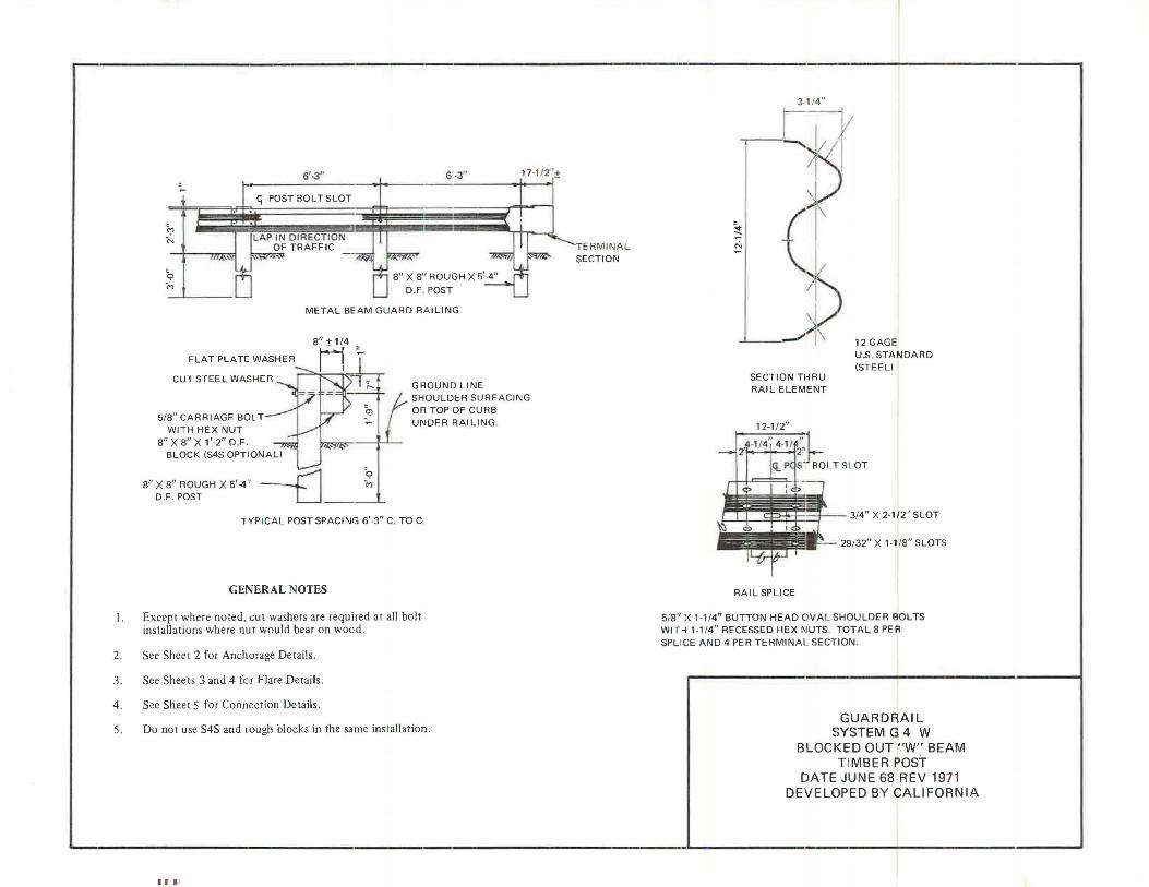
'? "' ~ (")
!
6'·3"
G_ POST BOLT SLOT
LAP IN DIRECTION OF TRAFFIC
6'-3'' 17-1/ 2 ''.±
METAL BEAM GUARD RA I LING
CUT STEEL WASHER
5/8"CARRIAGE BOLT WI T H HEX NUT
8" X 8" X 1'-2" D.F. BLOCK (S4S OPTIONAL)
~
8" X 8" ROUGH X 5'-4" _j-1 D,F. POST LJ ___ _,_
Cj>
"'
GROUND LINE SHOULDER SURFACING OR TOP OF CURB UNDER RAILING
TYP ICAL POST SPACING 6'-3" C. TO C
GENERAL NOTES
I. Except where noted. cut washers are required at all bolt installations where nut would bear on woed.
2. See Sheet 2 for Anchorage Details .
3. See Sheets 3 and 4 for Flare Details.
4. See Sheet 5 for Connection Details.
5. Do not use S4S and rough blocks in the same ins tallation.
1 1' I
TERMINAL SECTION
3-1!4''
------.
~
"'
SECTION THRU RAIL ELEMENT
12 GAGE U.S. STANDARD (STEEL)
j I I 9?f-F=r--- 3/4" X 2-1 /2'' SLOT
29/32" X 1-1/8" SLOTS
RAI L SP LI CE
5i8" X 1-1/4" BUTTON HEAD OVAL SHOULDER BOLTS WI T H 1-1/4" RECESSED HEX MUTS. TOTAL 8 PER SPLICE AND 4 PER TERMINAL SECTION.
GUARDRAIL SYSTEM G 4 W
BLOCKED OUT "W" BEAM T IMBER POST
DATE JUNE 68 REV 1971 DEVELOPED BY CALIFORNIA
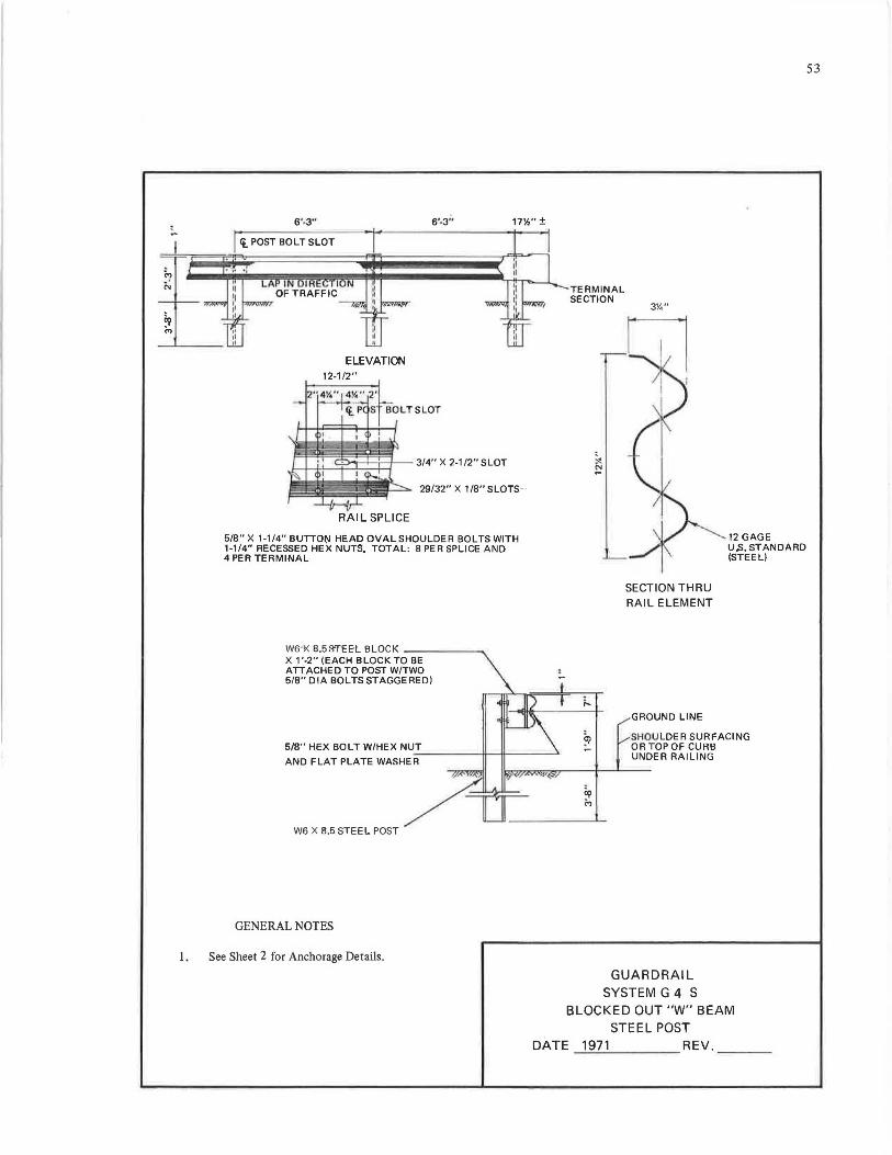
6'-3" 6'-3" 17'h" ±
<t_ POST BOLT SLOT
.-.. •'
ELEVATION 12-1/2"
RAIL SPLICE
3/4" X 2-1/2" SLOT
29/32" X 1 /8" SLOTS-·
5/8" X 1-1/4" BUTTO~ HEAD OVAL SHOULDER BOLTS WITH 1-1/4" RECESSED HEX NUTS. TOTAL: 8 PER SPLICE AND 4 PER TERMINAL
ws-K B.5S'fEEL BLOCK ------.. X 1 '-2" (EACH BLOCK TO BE ATTACHED TO POST W/TWO 5/8" DIA BOLTS STAGGERED)
W6 X 8.5 STEEL POST
GENERAL NOTES
I . See Sheet 2 for Anchorage Details.
TERMINAL SECTION
3%"
SECTION THRU RAIL ELEMENT
12 GAGE U.S. STANDARD (STEEL)
GROUND LINE
SHOU LDER SURFACING OR TOP OF CURB UNDER RAILING
GUARDRAIL SYSTEM G 4 S
BLOCKED OUT "W" BEAM STEEL POST
DA TE _.,:_;19:...:.7_:_1 ____ REV. __ _
53
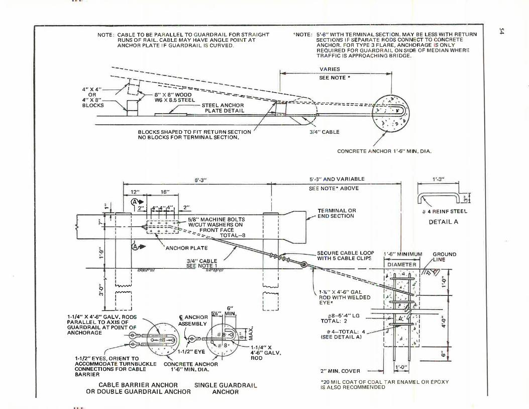
NOTE : CABLE TO BE PARALLEL TO GUARDRAIL FOR STRA IGHT RUNS OF RAIL. CABLE MAY HAVE ANGLE POI NT AT ANCHOR PLATE IF GUARDRAIL IS CURVED.
-·--.,.__ -------
* NOTE: 5'-6" WITH TERMINAL SECTION. MAY BE LESS WITH RETURN SECTIONS IF SEPARATE RODS CONNECT TO CONCRETE ANCHOR. FOR TYPE 3 FLARE, ANCHORAGE IS ONLY REQUIRED FOR GU,\ RDRAIL ON SIDE OF MEDIAN WHEAi= TR A FFIC IS APPROACHING BRIDGE.
VA RIES
SEE NOTE• ---------- r
--/C_../ --::::-=---- -------4"X4" ~ ----:::--:::::- -----::._- --
OR --' 8'' X 8'' WOOD --:...::-~-.:::-- ------4" X 8" W6 X 8.5 STEEL --,,,._-=- """= &£"" :::-::: .,._ __
1 BLOCKS~ STEEL ANCHOR ~ - - --,.---=--=--==:=====.:,
PLATE DETAIL
BLOCKS SHAPED TO FIT RETURN SECTION NO BLOCKS FOR TERMINAL SECTION.
6'-3"
12" 16"
I I I I I I I ,. :...~• I r--------~ _ 5/8 MACHINE BOLTS ,- I ~+ ._. + +~ . - ~=====:::::--' W/CUTWASHERSON
1 L~ :;L ;!-__ +:_i~:::-,:-_ FRONT FACE
~
Q (')
I °'i - -"'":::-.,.__ TOTAL-8
ANCHOR PLATE
3/4" CABLE 1 SEE NOTE 1 I I ltlSIIP-'M ~ I I
I I ~
,vv-\ I I I I I I L __ _J
1-1/4" X 4'-6" GALV. RODS PARALLEL TO AXIS OF GUARDRAIL AT POINT OF ANCHORAGE
~
>< <(
I ::iE .
I I
~ ~ I I I I L __ ..J
{_.--@3 1-1/2" EYES, ORIENT TO ACCOMMODATE TURNBUCKLE CONNECTIONS FOR CA BLE BARRIER
1-1 /4" X 4'-6" GALV. ROD
K 1 : l l
CONCRETE ANCHOR 1'-6" MIN. DIA.
CABLE BARRIER ANCHOR OR DOUBLE GUARDRAIL ANCHOR
SINGLE GUARDRAI L ANCHOR
i ·,
3/4" CABLE
CONCRETE J\ NCHOR 1'-6" MIN. DIA.
5'4:l" AND VARIABLE
SEE NOTE* ABOVE
TE RMINAL OR END SECTION
'.:::.:::..::::--:::::-..:....... --~~-:::...."":.
1-%" X 4'-6" GAL ROD WITH WELDED EYE•
#8--5'-4" LG TOTAL: 2
#4-TOTAL: 4_. (SEE DETAIL A)
1, .,,, . ..,
k u~ # 4 REINF STEEL
DETAIL A
1 '-6" MINIMUM GROUND t.. • I /LINE DIAMETER ......_...... ~
"' .
9 -
q .,
I
i.:__u_·_ . . ~· ' ' :..J ____ t-
(0
2" MIN. COVER J h·-0:· 1 *20 MIL COAT OF COAL TAR ENAMEL OR EPOXY IS ALSO RECOMMENDED
Vl ~
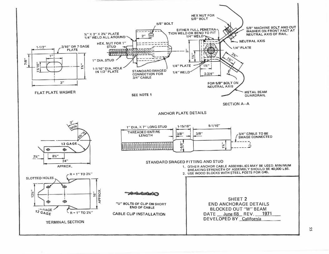
~ ....
1-1/2"
1. 3" l FLAT PLATE WASHER
-$- ~
2%~ L 8Y." .I 24" -
.,,. "AGE 12 G" ,,GE
APPROX.
I
$
~ -
TERMINAL SECTION
HEX NUT FOR 5/8" BOLT
5/8" BOLT
Y," X 3" X 2:Y.." PLATE 1/4" WELD ALL AROUND
HEX. NUT FOR 1" STUD
1-1/16" DIA. HOLE IN 1/2" PLATE STANDARDSWAGED
CONNECTION FOR 3/4" CABLE
SEE NOTE 1
EITHER FULL PENETRA· TION WELD OR BEND TO FIT
1/4"WELD
2-3/4"
5/8" MACHINE BOLT AND CUT WASHER 0:'11 FRONT FACT AT NEUTRAL AXIS OF AAIL.
NEUTRAL AXIS
METAL BEAM GUARDRAIL
SECTION A-A
ANCHOR PLATE DETAILS
'° I~ - a: D.. D.. <{
1" DIA. X 7" LONG STUD
THREADED ENTIRE LENGTH
5-1 /16"
:,:! -
3/ 4" CA"SLE TO BE [_s~A_GF:_ CONNECTED
I ,, -----...,
STANDARD SWAGED FITTING AND STUD
"U" BOLTS OF CUP ON SHORT END OF CABLE
CABLE CLIP INSTALLATION
1. OTHER ANCHOR CABLE ASSEMBLIES MAY BE USED. MINIMUM BREAKING STRENGTH OF ASSEMBLY SHOULD BE 40,000 LBS .
2. USE WOOD BLOCKS WITH $TEEL POSTS FOR G4S.
SHEET 2 END ANCHORAGE DETAILS BLOCKED OUT "W" BEAM
DATE June 68 REV. 1971 DEVELOPED BY California
V, V,
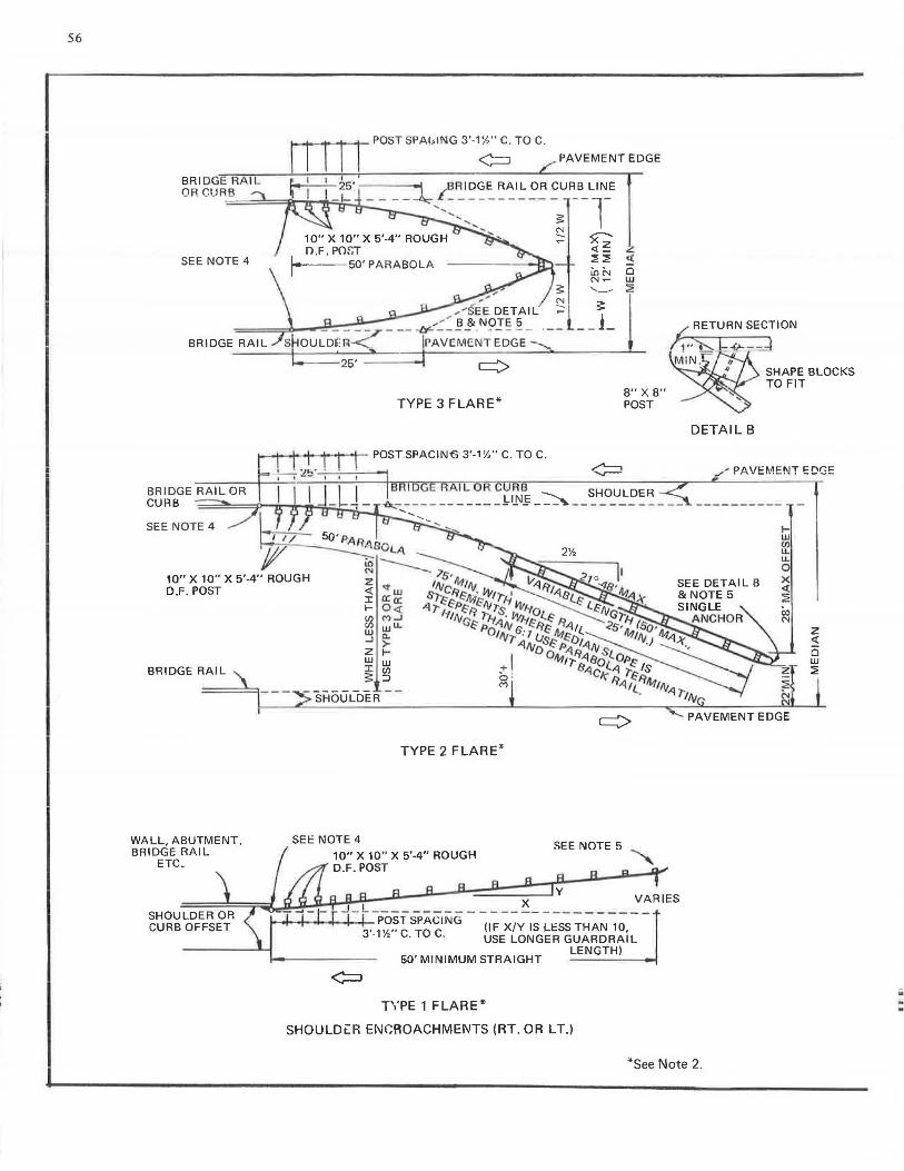
56
1--1~,.._...t---'r- POST SPA(,tNG 3'-1'h" C. TO C.
<=:J PAVEMENT EDGE
SEE NOTE 4
SEE NOTE 4
10" X 10" X 5'-4" ROUGH O.F. POST
BRIDGE RAIL
~ UJ ...J
z UJ UJ J: Ill ~ ::)
TYPE 3 FLARE*
- SHOUL-DER
TYPE 2 FLARE*
5G' MINIMUM STRAIGHT
TYPE 1 FLARE*
SEE NOTE 5
SHOULD LR ENCflOACHMEI\ITS (RT. OR LT.)
8" X 8" POST
f;. RETURN SECTION
1"°'b. l-: .f>-- -d SHAPE BLOCKS TO FIT
DETAIL B
/ PAVEMENT EDGE
SEE DETAIL B
1-UJ Ill u.. u.. 0 X <( ~ co N
PAVEMENT EDGE
z <(
ci w :i?
*See Note 2.
;; -.
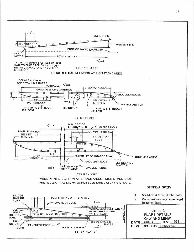
*NOTE 'X': WHEN 3' OFFSET CAUSES RAIL TO ENCROACH ON SHOULDER INSTALL GUARDRAIL AT EDGE OF SHOULDER
SEE NOTE 5
TYPE 7 FLARE*
SHOULDER INSTALLATION AT SIGI\I STANDARDS
DOUBLE ANCHOR SEE DETAIL B & NOTE 5 ......-,.......
VARIABLE '-r-'
DOUBLE ANCHOR SEE DET Al L B - - - - - - -& NOTE 5
TYPE 6 FLARE*
- ---i---t--t---t-MULTIPLES OF GUARDRAI~
BRIDGE RAIL OR CURB
:i;EE NOTE 4
--,- - ----------SHOULDER EDGE SEE DETAIL B
& NOTE 5 PAVEMENT EDGE
TYPE 5 FLARE*
MEDIAN INSTALLATION AT BRIDGE AND/OR SIGN STANDARDS WHERE CLEARANCE SHOWN CANNOT BE OBTAINED USE TYPE 6 FLARE.
POST SPACING 3'-1-1/2" C TO C
cu
BRIDGE ~ RAIL 2
57
DOUBLE ANCHOR
GENERAL NOTES
1. See Sheet 4 for applicable notes. 2. Crash cushions may be preferred
treatment here.
SHEET 3 FLARE DETAILS G4W AND MB4W
SEE SEE DETAIL B & _J NOTE :,.:.._-,,,.:::::::::.... ________ -::,--------r-.......a-.--J'-... .................. N;:;-O~T:;:;Ei='"c5- DATE June 68 REV. 1971
CURB DOUBLE ANCHOR '-V DEVELOPED BY C Ii ornia
TYPE 4 FLARE*
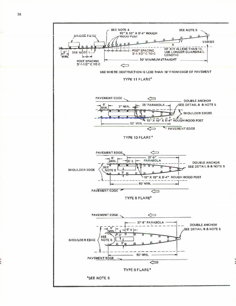
. .
58
POST SPACING 3'-1-1/2" C TO C
SEE NOTE 4 10" X 10" X 5'-4" ROUGH vliOOD POS 1
SEE NOTE 5
Y VAR IES X
t f 1 I i i I PosT sPAcir-l"G- - - -uTx7v-1s iess TH-AN 1 o~ -
3'-1-1/2" c TO c USE LONGER GUARDRAIL LENGTH)
---- --- -- 50' MINIMUM STRAIGHT
USE WHERE OBSTRUCTION IS LESS THAN 18' FROM EDGE OF PAVEMENT
TYPE 11 FLARE*
PAVEMENT EDGE ::::::,_ DOUBLE ANCHOR
IM~~.r 3" MIN. i1==- 25· PARABOLA 41SEE DETAIL B & NOTE 5
_-: : -1: ~: ~;-----.\,rr -: -=- -JO ;;_ SHOULOER EOGES
~ ·,o-;; x 10"-X ir.; .. ROUGH wooD POST ,___----~50'MiN.-~~~~--.i
IC PAVEME NT EDGE
TYPE 10 FLARE*
PAVEMENT EDGE...,, ~
PAVEMENT EDGE ;,
TYPE 9 FLARE*
PAVEMENT EDGE :::::,,
. r=--=- 37'-6" PARABOLA J - ~~~~f ~ --l •· ± E---~ -;=c ('EE~~~~~~ :~c:gT~ s
SHOULDEREDGE ~~9(\i: :__ : : ~ I f 50'MIN.~
PAVEMENT EDGE ::::::,..
TYPE 8 FLARE*
*SEE NOTE 6
. .
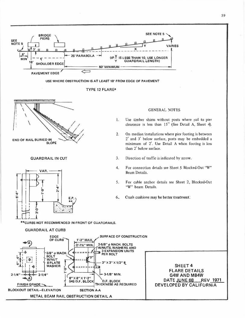
SEE NOTE 5"
PAVEMENT EDGE/ <==1
USE WHERE OBSTRUCTION IS AT LEAST 18' FROM EDGE OF PAVEMENT
\ \
\
END OF RAIL BURIED IN SLOPE
GUARDRAIL IN CUT
VAR . ---1
:r ll)
t~J
TYPE 12 FLARE*
GENERAL NOTES
l . Use timber shims without posts where rail to pier clearance is less than 15 11 (See Detail A, Sheet 4).
2. On median ·installations where pier footing is between 2' and 3' below surface, posts may be embedded a minimum of 2'. Use Detail A when footing is less than 2' below surface.
3. Direction of traffic is indicated by arrow.
4.
5.
6.
For connection details see Sheet 5 Blocked-Out "W" Beam Details.
For cable anchor details see Sheet 2, Blocked-Out "W" beam Details.
Crash cushions may be better treatment:
**CURBS NOT RECOMMENDED IN FRONT OF GUARDRAILS.
GUARDRAIL AT CURB
~t: ,l.r• • , I
' :t: : ! I .. ..... -' I
st I I ...t,_: I "J' I
I '
SURFACE OF CONSTRUCTION
2-5/8" </J MACH. BOLTS ....-'----,,.---1,;1 W/NUTS, WASHERS AND
3 EXPANSION UNITS PER BOLT
8" X 8" X 1'-2" 545 D.F. BLOCK D.F. BLOCK
THICKNESS AS REQUIRED FINISH GRADE ........... - ------1 BLOCKOUT DETAIL-ELEVATION SECTION A-A
METAL BEAM RAIL OBSTRUCTION DETAIL A
SHEET 4 FLARE DETAILS G4WAND MB4W
DATE JUNE 68 REV 1971 DEVELOPED BY CALI FURNIA
59

... .. ..
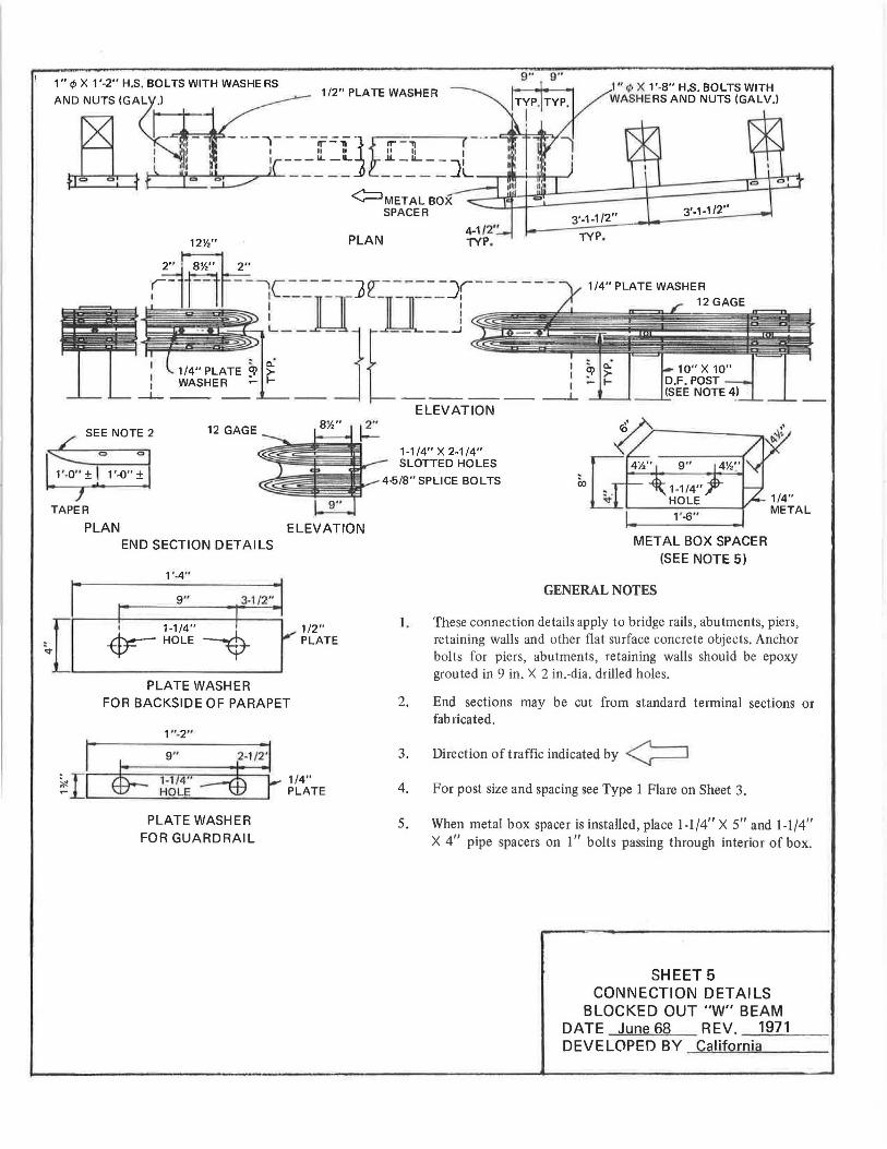
I I I
1211,"
2" SY." 2"
~----
SEE NOTE 2
0 C,
1 '-0" ±
TAPER
PLAN
12 GAGE
1/2" PLATE WASHER 1" rt> X 1'-8" H.S. BOLTS WITH WASHERS AND NUTS (GALV.I
PLAN 4-1 /2" TYP. TYP.
1/4" PLATE WASHER
c.. I • c.." >- 1 ~ >-1- I .- 1-
-- ----- ---- -L
811,''
ELEVATION
ELEVATION
1-1/4" X 2-1/4" SLOTTED HOLES
4-5/8" SPLICE BOLTS CX)
10" X 10" D.F. POST (SEE NOTE 4)
END SECTION DETAILS METAL BOX SPACER (SEE NOTE 5)
1'-4"
9" 3-1/2" r r 1 1-1 /4" I -Etr- HOLE --$-
PLATE WASHER
I
1 /2" I," PLATE
FOR BACKSIDE OF PARAPET
1 "-2"
PLATE WASHER FOR GUARDRAIL
1/4" PLATE
1.
GENERAL NOTES
These connection details apply to bridge rails, abutments, piers, retaining walls and other flat surface concrete objects. Anchor bolts for piers , abutments, retaining walls should be epoxy grouted in 9 in. X 2 in.-dia. drilled holes.
2. End sections may be cut from standard terminal sections or fabricated.
3. Direction of traffic indicated by ¢J 4. For post size and spacing see Type 1 Flare on Sheet 3.
5. When metal box spacer is installed, place 1-1/4" X 5" and 1-1/4" X 4" pipe spacers on 1" bolts passing through interior of box.
SHEET 5 CONNECTION DETAILS
BLOCKED OUT "W" BEAM DATE June 68 REV. 1971 DEVELOPED BY California

. .
62
EXPANDED MESH PANF:I
STEEL OR
STEEL OR ALUMINUM WIRE TIES
!~~~.!..t;J~,.M,_ ___ ~--~;:;..~::::;:1~--..,-..,--....... ',._., 8;;:-;:---"':~ ~
A!J DETAIL A
END POST ASSEMBLY 2-1/4" X 4.1#'X 72" LONG H SECTION POST
r~~·rE : THE U BOLTS OF THE CABLE CLAMPS
SHALL BE PLACED ACROSS THE LAY OF Tl-IE TENSION CABLES AT ALL LOCATIONS
3/4" TENSION CABLE
DETAIL B LINE POST ASSEMBLY
EXPANDED MESH PANEL (INSTALL OUTSIDE OF CABLE CLAMP)
2-1/4" H SECTION POST 4.1#PER FT. MIN .
1-3/4" MAX COLO SWAGEDTYPE CABLE PULL
2-1/4"X4.1#X 88" LONG H :;tl,; I IUN l'U:; I 1
8'-0" ± 3" C TO C
7 GA. TENSION WIRE
GROUND LINE
w w Vl
148'-0"±3" CTO C +j
CABLE BARRIER WITHOUT EXPANDED MESH
HEADLIGHT SCREEN
NOTE A: NORMAL HEIGHT 2'-3" TO 2'-4", 2'-6" FOR SPECIAL CASES WHERE DIRECTED BY THE ENGINEER.
2" MAX PIPE TYPE TURNBUCKLE BODY WtTH 12' TAKE-UP
2-3/4" TENSION
/ CABLES
DETAIL C LINE TURNBUCKLE
ii -.
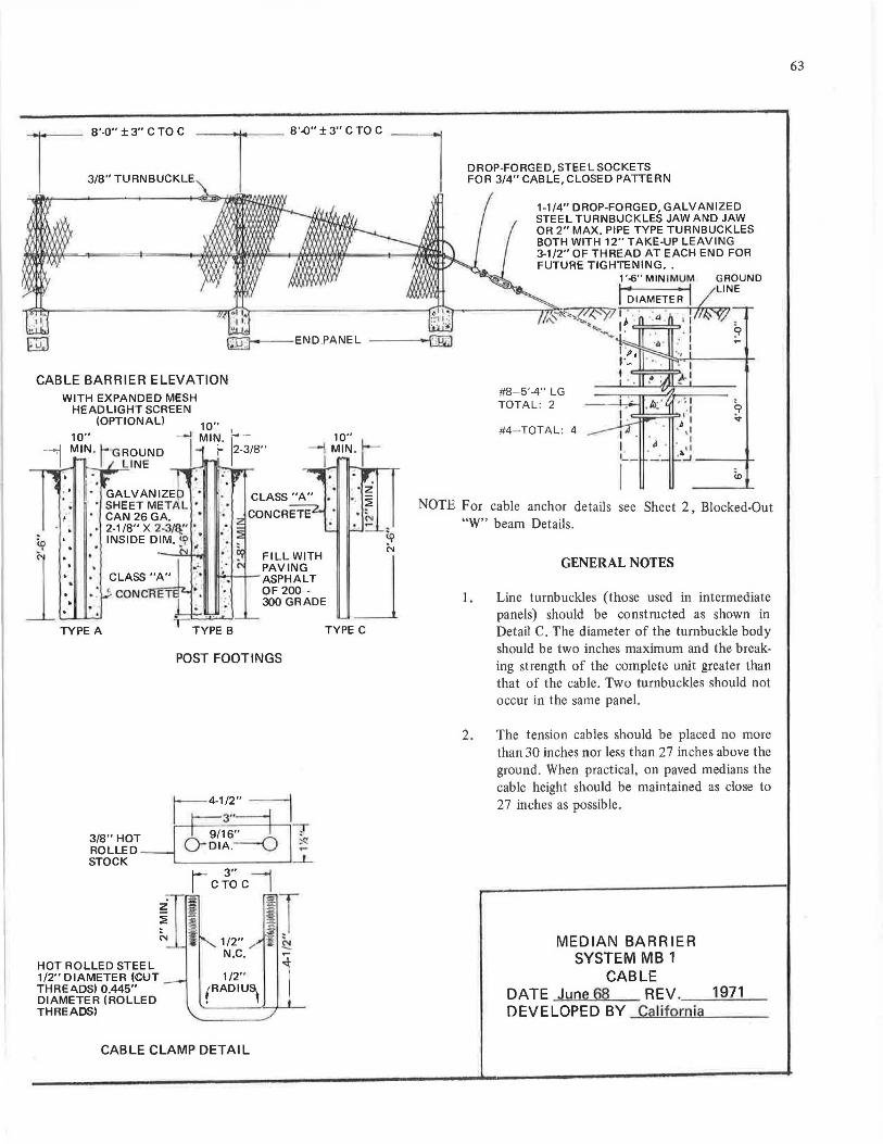
CABLE BARRIER ELEVATION WITH EXPANDED MESH
HEADLIGHT SCREEN (OPTIONAL)
TYPE A
3/8" HOT ROLLED STOCK
HOT ROLLED STEEL 1/2" DIAMETER 4CUT THREA.DS) 0.445" DIAMETER (ROLLED THREADS)
N
POST FOOTINGS
I- 3" -"'1 I CTO C I
IT 1/2" i h N.C. ...
1 1 /2" (RADIU~
CABLE CLAMP DETAIL
~ N
J TYPE C
DROP-FORGED, STEEL SOCKETS FOR 3/4" CABLE, CLOSED PATTERN
1-1/4" DROP-FORGED, GALVANIZED STEEL TURNBUCKLES JAW AND JAW OR 2" MAX. PIPE TYPE TURNBUCKLES BOTH WITH 12" TAKE-UP LEAVING 3-1/2" OF THREAD AT EACH END FOR FUTURE TIGHTENING • .
#8-5'-4" LG TOTAL: 2
#4-TOTAL: 4 d . , ___ .
NOTE For cable anchor details see Sheet 2, Blocked-Out "W" beam Details.
GENERAL NOTES
1. Line turnbuckles (those used in intermediate panels) should be constructed as shown in Detail C. The diameter of the turnbuckle body should be two inches maximum and the breaking strength of the complete unit greater than that of the cable. Two turnbuckles should not occur in the same panel.
2. The tension cables should be placed no more than 30 inches nor less than 27 inches above the ground. When practical, on paved medians the cable height should be maintained as close to 27 inches as possible.
MEDIAN BARRIER SYSTEM MB 1
CABLE DATE June68 REV . 1971 DEVELOPED BY California
63
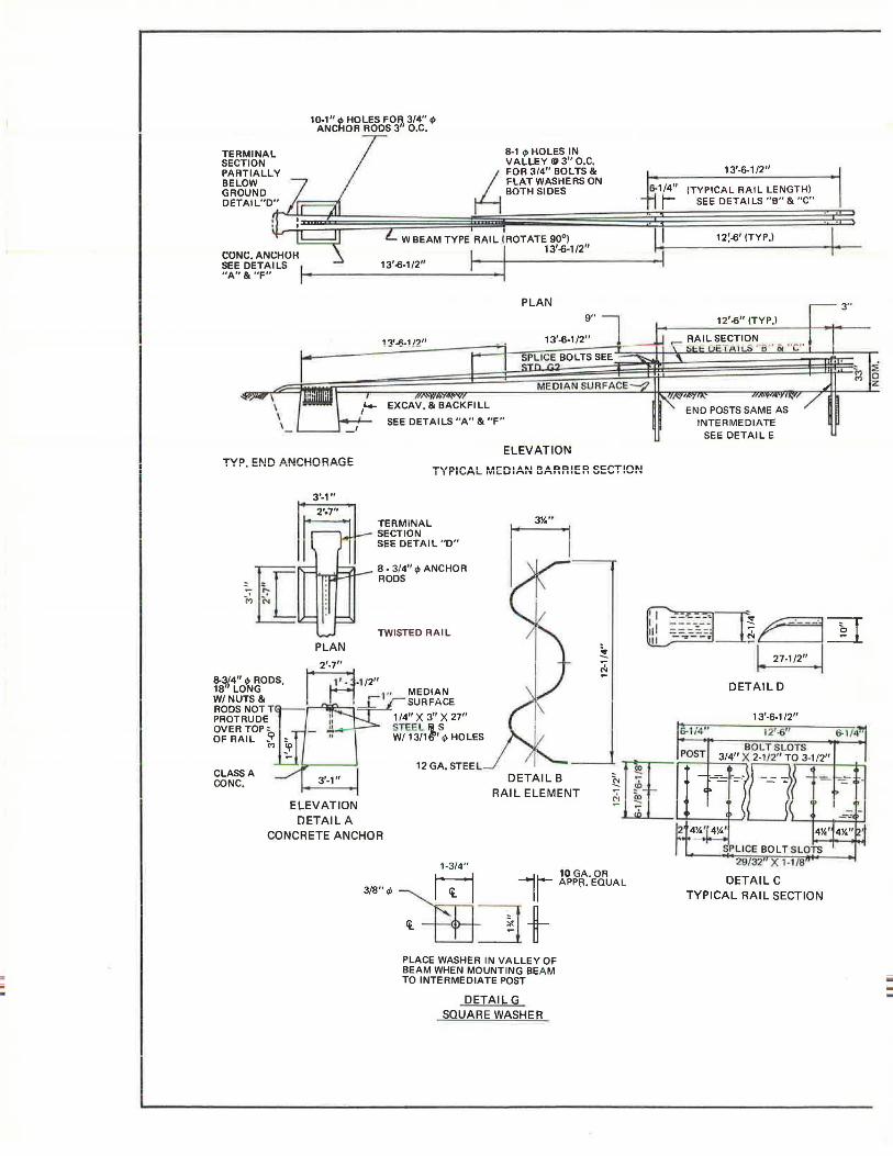
ii iii .
TERMINAL SECTION PARTIALLY BELOW GROUND OETAIL"D"
1<>-1" .p HOLES FOR 3/4" IP ANCHOR ROOS 3" O.C.
8-1 .p HOLES IN VALLEY@ 3" O.C. FOR 3/411 BOLTS & FLAT WASHERS ON BOTH SIDES
w BEAM TYPE RAIL (ROTATE 90°) 11
CONC. ANt;HUH 13'-o-1/211
~~ ~~i~ILSI L -· - - --~::....::._;_:_ ___ _:__ I I 13
1
-o·l/2
TYP. E!'!D ANCHOR6.GE
PLAN
13'-13-1 /2"
EXCAV, & BACKFILL
SEE DETAILS "A" & "F"
PLAN
ELEVATION
T''t"PICAL rv1ED:AN BARRIER SECT!Ol'J
TWISTED RAIL
2'-7''
.. RODS rn-1/2" t0~11otG • 1" MEDIAN
W/NUTS& ___[" SURFACE Jl RODS NOT Ttn l /4" X 3" X 27" I ' PROTRUDE ~TEE Ii S OVER TOP~ - W/ 13/11r' .p HOLES OF RAIL <'> to
-· __ _.... - 12 GA. STEEL
CLASS A 3,_1,, DETAIL B CONC. RAIL ELEMENT
ELEVATION DETAIL A
CONCRETE ANCHOR
3/8" ,t,
1-3/4"
is 10 GA.OR II APPfl, EQUAL
~t PLACE WASHER IN VALLEY OF BEAM WHEN MOUNTING BE AM TO INTERMEDIATE POST
DETAILG SQUARE WASHER
13'-6-1/2"
(TYPICA L RAIL LENGTH) SEE DETAILS "B" & "C"
12:-01 (TYP.I
12'-o" (TYP.)
END POSTS SAME AS INTERMEDIATE
SEE DETAIL E
, .
3"
--___ , =11~ ~:&::::: II· - ------ - 0 = =:.:.:· N ...
- -- - -· - ,. 27-1/2" • I DETAILD
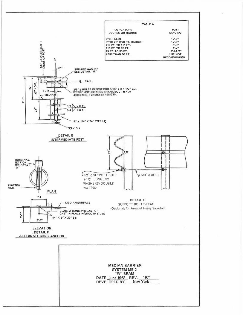
in M
'? in
TERMINAL SECTION SEE DETAI L ''D"
9 M
i 0 z
1:l
;i. N
3'-1
3'-6"
SQUARE WASHER SEE DETAIL "G"
TABLE A
CURVATURE DEGREE OR RADIUS
8° OR LESS 8° TO 26° (220 FT. RADIUSI 219 FT. TO 111 FT. 110 FT. TO 76 FT. 75 FT. TO 50 FT. LESS THAN 50 FT.
3/8" 4> HOLES IN POST FOR 6/16" <I> X 1-1/2" LG. W/ 5/8" UNTHREADED SHANK BOLT & NUT 4000# MIN. TENSILE STRE NGTH.
2@ 11
2@ 11
8" X 1/4" X 24" STEEL\'.
"-----._ S3 X 5. 7
DETAIL E INTERMEDIATE POST
POST SPACING
12'-6" 12'-6" 6'-3" 4'-2"
3'-1-1/2" USE NOT
RECOMMENDED
II I II I
I
1 /2" ¢ SUPPORT SOLT 1-1/2'' LONG (NO WASHERS) DOUBLE NUTTED
<£ 5/8" Q HOLE II I ,,
MEDIAN SURFACE
CLASS A CONC. PRECAST OR CAST IN PLACE W/SMOOTH SIDES
1/4" X 3" X 27" \'.S
11 ....... ,.,11 .
DETAIL H SUPPORT SOLT DETAIL
(Optional; for Areas of Heavy Snowfall)
ELEVATION DETAIL F
ALTERNATECONC. ANCHOR
MEDIAN BARRIER SYSTEM MB 2
"W" BEAM DATE June 1968 REV. 1971 DEVELOPED BY New York
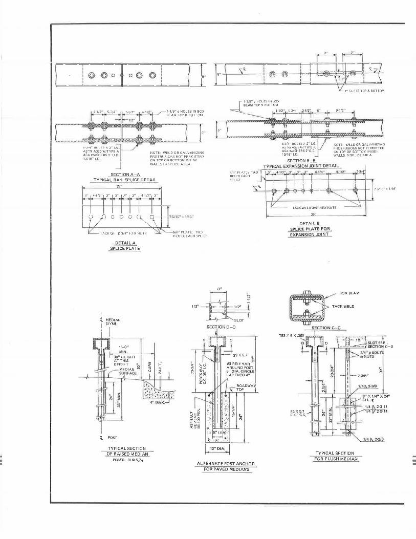
• 'I" 11?" 'I' · 1 14 117'" 5 31=:1 ~ 314' 4 1/2"'
,,- 1 1/B" <I HOLES IN BOX ' 81:AM TOP & BOTTOM
8-3/4" BOLTS X 2 " LG. ASTM A325 W/TYPE A ASA WASHERS 2"0 D 13/18" 1,0
NOTE: WELD OR GALVANIZING PROTRUSIONS NOT PERMITTED nN TllP nR RllTTllM IN~1m:
WALLS IN SPLICE AREA
SECTION A-A TYPICAL RAIL SPLICE DET Al L
1"
3" 4-1/2" I 3" 3" 3" , 3" 4 1/2" 3"
~ .. o .... _ j..J_~ __ o __ o __ o __ Q_~ __ o....,.....,}" "" TACK WELD 3/4" HEX NUTS
DETAIL A SPLICE PLATE
5 I" PLATE: TWO REO'D EACH SPLICE
1/2 11
s··-1-\ ------"-s<l_i-@-@--+- - ! -~~ I 1/8" rp HOLES IN BOX SE.Ml TOP & BOTTOM
-_ , ,,n+s-314"_..3·..;.•n""··----~----
NOTE: WELD OR GALVANIZING PROTRUSIONS NOT PERMITTED ON TOP OR BOTTOM INSIDE WALLS IN SPLICE AREA
T YPI CAL EXPANSION JOINT DETAIL 5/8"PLATE: rwol 0,1141
' ..9-112"" REO'D EACH SPLICE
1/2"
DETAIL B SPLICE PLATE FOR EXPANSION JOINT
7-5/16" ± 1/16"
.I
SLOT
SECTION D-D
~BOXBEAM
~ TACKWELD
SEOT IOI~ C--C
1'- 0" MIN .
JO" HEIGHT AT THIS
(i_ POST
TYPICAL SECTION OF RAISED MEDIAN
POSTS: 31 @ 5,7"
a, a: :, (.)
ROADWAY TOP
ALTERNATE POST ANCHOR FOR PAVED MEDIANS
1 /~ 2-3/8
TYPICAL SECTION FOR FLUSH MEDIAN --
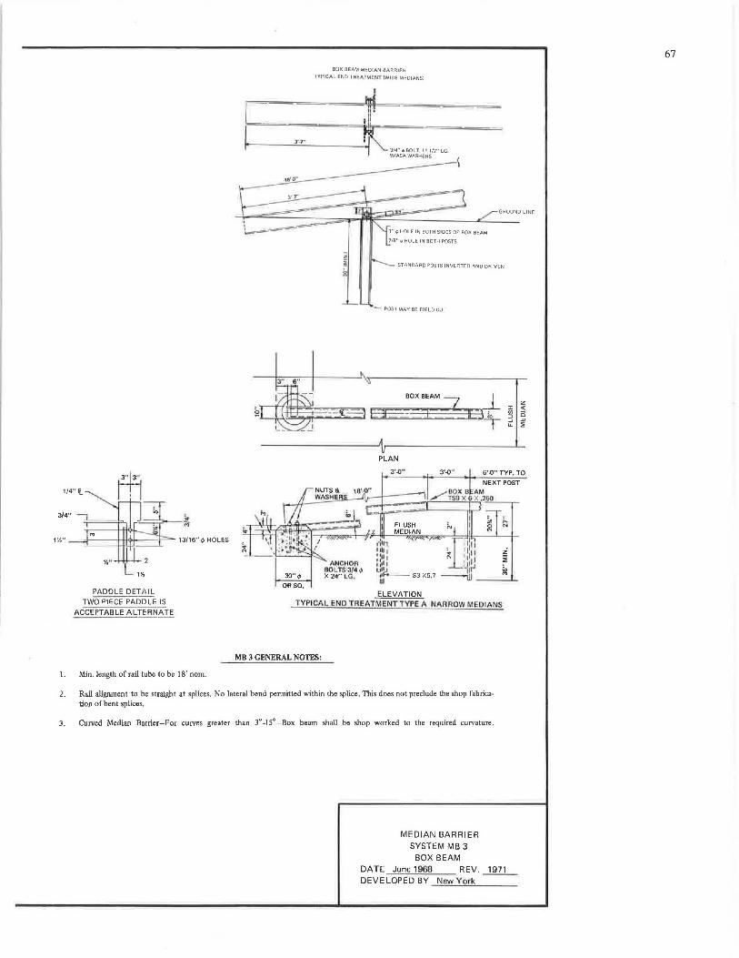
L l '.,.,
BOX BEAM MEDIAN BARRIER
TYPICAL END TREATMENT (WIDE MEDIANS)
GROUND LINE
PADDLE DETAIL TWO PIECE PADDLE IS
ACCEPTABLE ALTERNATE
I. Min. length of rail tube to be 18' nom.
!!
30",P
OASQ,
ANCtJOA BOLTS·3/4 ,p X 24" LG.
STANDARD POSTS INVERTED ANO DRIVEN
POST MAY BE FIELD CUT
BOX BEAM ~-=3+ SE ::t T
PLAN
3'-0"
ELEVATION TYPICAL END TREATMENT TYPE A NARROW MEDIANS
MB 3 GENERAL NOTES:
2. Rail alignment to be straight at splices. No lateral bend permitted within the splice. This does not preclude the shop fabrication of bent splices.
3. Curved Median Barrier-For curves greater than 3° -15° -Box beam shall be shop worked to the required curvature.
MEDIAN BARRIER SYSTEM MB 3
BOX BEAM
:,:
"' :::, .J u.
DATE June 1968 REV . ....1fill__ DEVELOPED BY New York
z <(
0 w :;
67
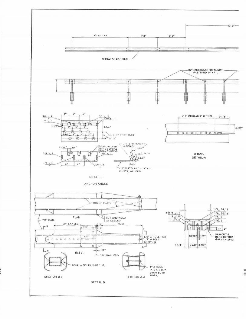
'
i ! J
1/ 4
1/ 4
1/4
1/4
PLAN "VJ" f1A I L
0 0 0 -
(c__~ mv.
12'-6" TYP n'-3"
W-MEDIAN BA RRIE ~
DETAIL F
ANCHOR ANGLE
1 /2"
I
I .J
-;- 1/4" STIFFENER'(_, 4 REQ' D,
l·l/4"
.'i. SLOT
' L LB" X 4" X 1/2" -14" LG 2 -1/ 2" '1_ WELDED
"W" RAIL END
~! J
-
1---------------,2·.5"-
6'-3 ..
TENED TO RAIL ~ [DIAT[ rooro NOT /-
1
'J l
9'1"</>HOLES3"C TOC
\
/
2-9/16 1/4
3 1/4
3 "' 1/4
1-1/4"
W-RAIL DETAIL-A
13/ 16'
2-7/8" 2-7/8"
"
J
9 I •I 4"
SAW CUT & BEND BEFORE GALVANIZING
I 5·1/!!"
~ 8·3/4" ,p BOLTS, 9-1/2" LG , 1" ¢ HOLE IN 6 X B BOX BEAM BOTH SIDES SECTION B-B SECTION A -A
DETAIL D
--
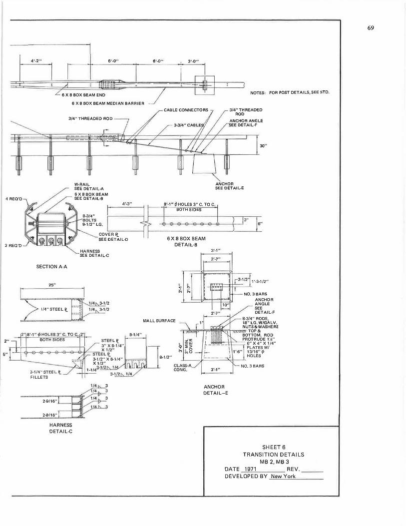
4 REO'D
2 REQ'D
2"
5"
4' -2" 6 '-0 " 6'-0 " 3 •.0 --
NOTES: FOR POST DETAILS.SEE STD.
6 X 8 BOX BEAM MEDIAN BARRIER
SECTION A-A
25"
1/4" STEEL I!.
HARNESS DETAIL-C
W-RAIL SEE DETAIL-A 6X8 BOX BEAM SEE DETAIL-8
3/4" THREADED ROD
ANCHOR ANGLE EE DETAIL·F
ANCHOR SEE DETAIL-E
4'-3" 8'-1" .~ HOLES 3" C. TO C.
N~" {~~ .. B.~ ~.SID.~ • •• ~''
:st~LG. ~~-'~' 16" COVER ft_ t---------------'·-----1.-SEE DETAIL-D 6 X 8 BOX BEAM
HARNESS SEE DETAI L-C
DETAIL-B
MALL SURFACE
ANCHOR ANGLE SEE OETAIL-F
8-3/4" RODS, 18" LG. W/GALV.
,=,..\;m;\;.=,i=;;,,!fflffll{,;;;=h=«N:;;Uigf :ASHE RS
3'-1"
ANCHOR DETAIL-E
BOTTOM. ROD PROTRUDE 1)',"
6"X4"X1/4" PLATESW/
1'-6" 13/16" ~ HOLES
SHEET 6 TRANSITION DETAILS
MB 2, MB 3 DATE 1971 REV.~-~ DEVELOP ED BY ....:.N.;..;:e""'w'-Y.:....o=:..;r.:.;.k ___ _
69
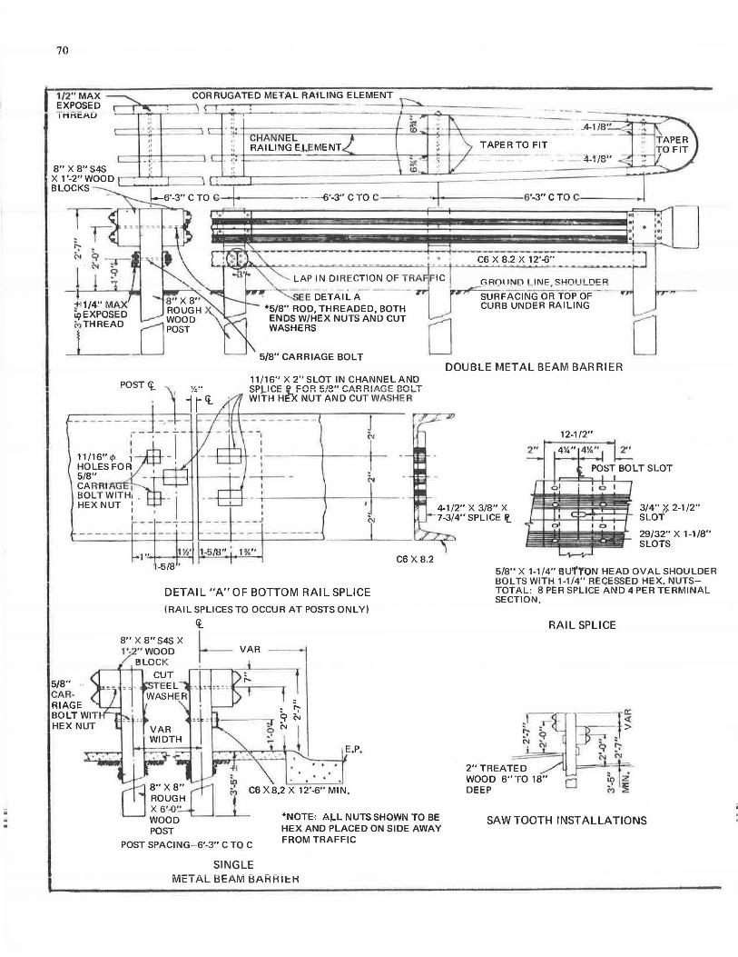
. .
70
1/2" MAX EXPOSED I MMCAU
CORRUGATED METAL RAtLING ELEMENT
- i·-·--,· •:
TAPER TO FIT
- - :il-W'
C6 X 8.2 X 12'-6"
LAP IN DIRECTION OF TRA FIC r.RQI IND L!NE,!3HOULOER
~FACING OR TOP~ r j CURB UNDER RAILING
EE DETAIL A *5/8" ROD, THREADED, BOTH ;:t-11/4" MAX
iqEXPOSED MTHREAD
t ENDS W/HEX NUTS AND CUT WASHERS
5/8" CARRIAGE BOLT D D
5/8"
11/16" X 2" SLOT IN CHANNEL ANO CDI ire c, enc ~/0" f"'l\DOI /\~C Dl"'\I T
wfrHH1hc NLiT~ANocuT·wAsHE~R ... .
,-1
11 /16'' </) 1 HOLES FOR 5/8" I
CAR-A- 1
J N
--+--t---tt- - ,-----+-------.-<>------1 I --,- -1
BOLT WITH! _ _ 1.
HEX NUT 1 I I L _____ _
I
1Y.' 1-5/8" ' 1 %" 1 • .. • +----t---1
-5/8'
DETAIL "A"OF BOTTOM RAIL SPLICE
(RAIL SPLICES TO OCCUR AT POSTS ONLY)
<t_
C6 X 8.2
CAR· RIAGE BOLT WIT HEX NUT
. ' . io • . ·' C6 X.8.2 X 12'-6" MIN.
i *NOTE: A.1-L NUTS SHOWN TO BE HEX AND PLACED ON SIDE AWAY
POST SPACING-6'-3" C TO C FROM TRAFFIC
SINGLE METAL BEAM BARRiER
DOUBLE METAL BEAM BARRIER
12-1/2"
3/4" X, 2-1 /2" SLOT
29/32" X 1-1/8" SLOTS
5/8" X 1-1/4" BUl!'TON HEAD OVAL SHOULDER BOLTS WITH 1-1 /4" RECESSED HEX. NUTSTOTAL: 8 PER SPLICE AND 4 PER TERMINAL SECTION,
2"TREATED WOOD 6"TO 18" DEEP
RAIL SPLICE
··-- a: <(
-~-·+>
SAWTOOTH INSTALLATIONS
iii ... -
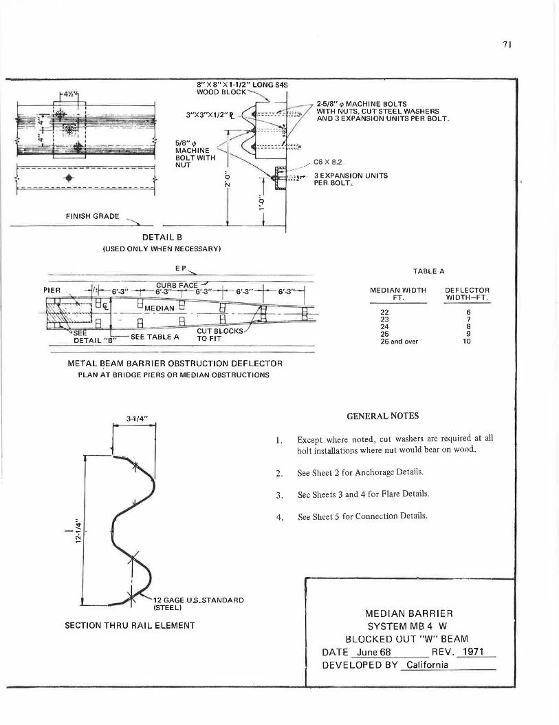
8" X 8" X 1-1/2" LONG S4S WOOD BLOCK
-~
2-5/8" </) MACHINE BOLTS WITH NUTS, CUT STEEL WASHERS AND 3 EXPANSION UNITS PER BOLT.
,,- C6 X 82
- - - + ____ _________ : f ----- -- - -- --~ ,.-.-. ,.-- 3 EXPANSION UNITS '"~ PER BOLT ..
FINISH GRADE
DETAIL B (USED ONLY WHEN NECESSARY)
EP
METAL BEAM BARRIER OBSTRUCTION DEFLECTOR PLAN AT BRIDGE PIERS OR MEDIAN OBSTRUCTIONS
3--1/4"
1.
2.
3.
TABLE A
MEDIAN WIDTH
22 23 24 25
FT.
26 and over
GENERAL NOTES
DEFLECTOR WIDTH-FT.
6 7 8 9
10
Except where noted, cut washers are required at all bolt installations where nut would bear on wood.
See Sheet 2 for Anchorage Details.
See Sheets 3 and 4 for Flare Details.
4. See Sheet 5 for Connection Details. !t -- . N ...
12 GAGE u.s_sTANDARD (STEEL)
SECTION THRU RAIL ELEMENT MEDIAN BARRIER SYSTEM MB 4 W
l:3LOCKED OUT "W" BEAM
DATE June 68 REV. 1971
DEVELOPED BY California ---------
71
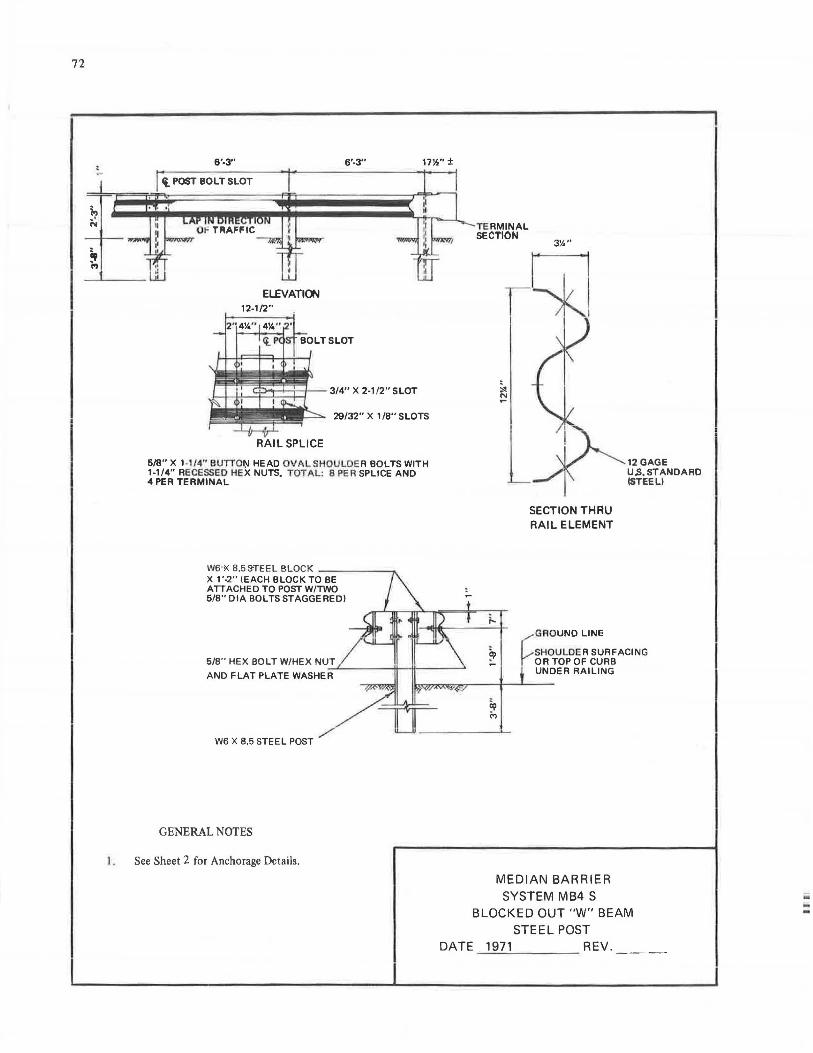
-.
72
6'-3" 6'-3" 17W'±
(l POST BOLT SLOT
ELEVATION
29/32" X 1 /8" SLOTS
6/8" X 1-114" BUTTO~ HEAD OVAL SHOULDE R BOLTS WITH 1-1/4" RECESSED HEX NUTS. TOTAL: 8 PER SPLICE AND 4 PER TERMINAL
W6 K 8.53'1"1':EL BLOCK - ----X 1'-2" (EACH BLOCK TO BE ATTACHED TO POST W/TWO 6/8" DIA BOLTS STAGGERED)
W6 X 8.5 STEEL POST
GENERAL NOTES
I. See Sheet 2 for Anchorage Details.
TE RMINAL SECTION
;...
3%"
SECTION THAU RAIL ELEMENT
12GAGE U.S. STANDARD ISTEELl
,....- GROUND LINE
SHOULDER SURFACING OR TOP OF CURB UNDER RAILING
MEDIAN BARRIER SYSTEM MB4 S
BLOCKED OUT "W" BEAM STEEL POST
DATE 1971 REV.~~-
--
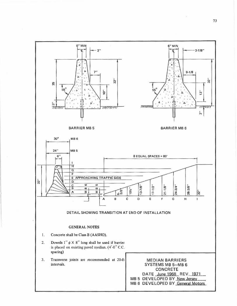
73
6"MIN rn 2" rn --+------.-
f----2-7/8"
9-1/8
<1 • • , · t I •. 0
A "
•· : . ' . : : • . • . • ' ' t--71'1"1:=r....,.......
BARRIER MB 5 BARRIER MB 6
30" MB6
24" MB 5
8 EQUAL SPACES= 80'
DETAIL SHOWING TRANSITION AT END OF INSTALLATION
GENERAL NOTES
1. Concrete shall be Class B (AASHO).
2. Dowels I" qJ X 8" long shall be used if barrier is placed on existing paved median. (4'-0" C.C. spacing)
3. Transverse joints are recommended at 20-ft intervals.
MEDIAN BARRIERS SYSTEMS MB 5-MB 6
CONCRETE DATE June 1968 REV. 1971
MB 5 DEVELOPED BY New Jersey MB 6 DEVELOPED BY General Motors
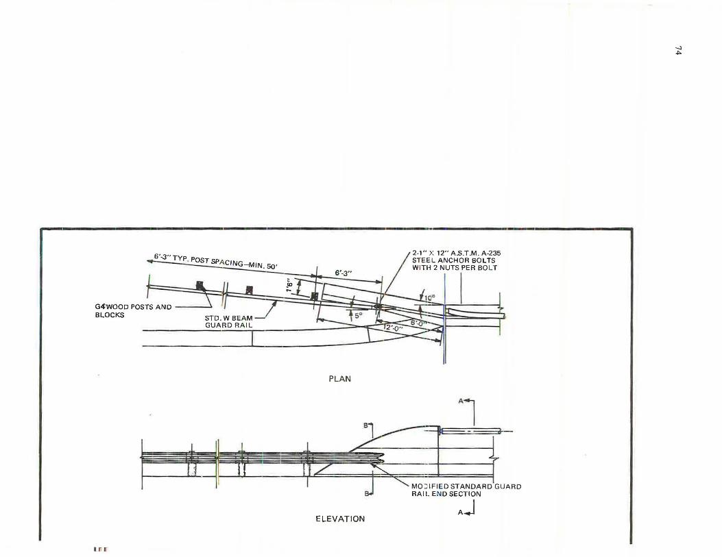
I. l! J
6'-3" TYP. POST SPA CING- MIN. 50'
G.<fWOOD POSTS AND ----' BLOCKS
PLAN
ELEVATION
I JI I
2-1" X 12" A.S.T.M. A-235 STEE:IL ANCHOR SOL TS WITH 2 NUTS PER BO LT
Al
MOIDIFI ED STANDARD GUARD RAIL END SECTION
Aj
-.J .,.
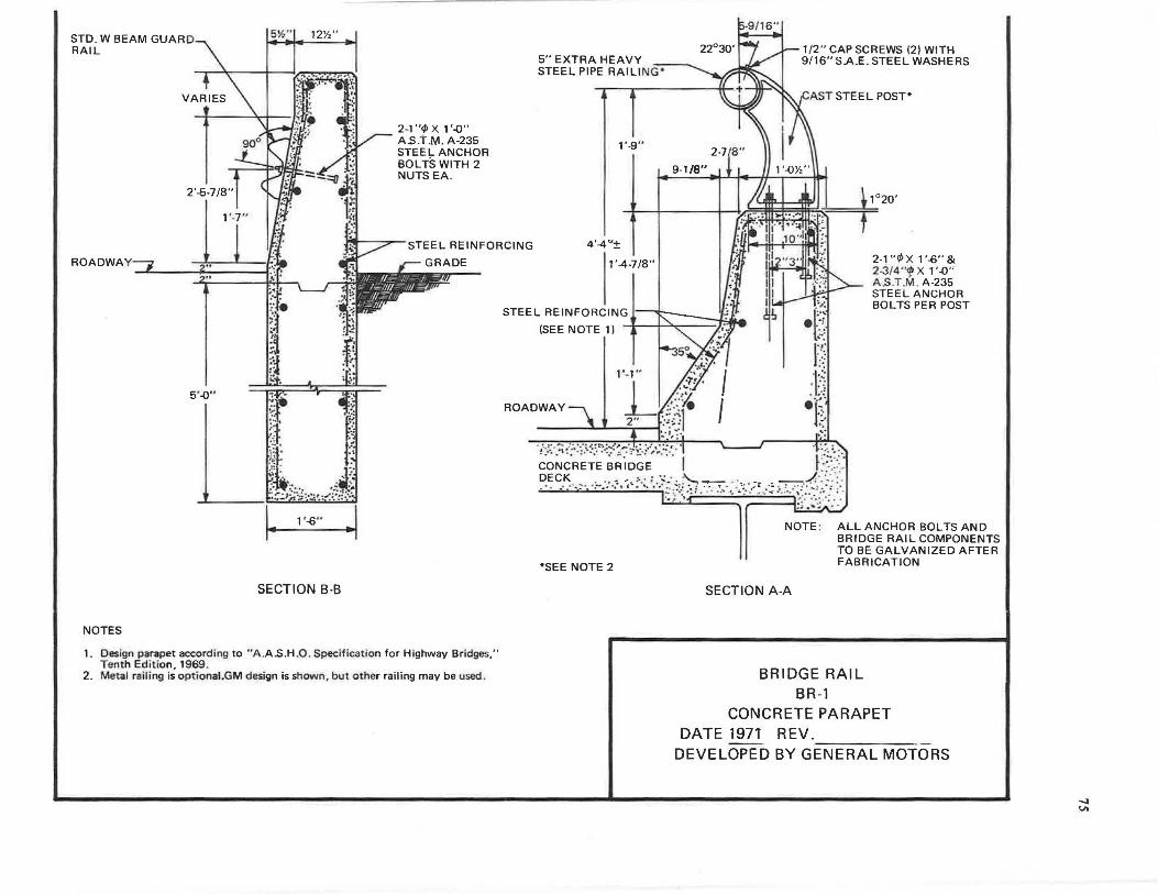
STD. W BEAM GUAR D RAIL
sY."I 12y," ....
2-1 "</> X 1 '-0" A.S.T .M. A-235 STEEL ANCHOR BOLTS WITH 2 NUTS EA.
5" EXTRA HEAVY STEEL PIPE RAILING ..
1'-9"
1/2" CAP SCREWS (2) WITH 9/16" SAE. STEEL WASHERS
.t_ 1°20'
f STEEL REINFORCING 4'-4 "±
ROADWAY
5 '-0" ~ .... --~-1· ·-:: ;::S:
::.l=.t.. t:~ ~· "" § =.. '~·
:.·,..,:\,, .. , .. .,/~~ ·~_:#_.._-... _~--· ·
1- 1'-6" -1
SECTION B-B
NOTES
1. Design parapet according to ·• A .A.S.H .0 . Specification for Highway Bridges," Tenth Edition, 1969.
2. Metal ra iling is optional.GM design is shown , but other railing may be used .
I 1'-4-7/8"
STEEL REINFORCING I~
2-1"¢X 1'-6"& 2-3/4'"1> X 1 '-0" A.S .T.M . A-235 STEEL ANCHOR BOLTS PER POST
(SEE NOTE 1)
1 '-1"
ROADWAY
, . ~· ·t:..:·~?:-::·J:-:.~-~-=~·/;'~~=-:··~,;~::_,:·1 ~ ·i :;. :~ ·.
C·O~C.RETE B~iD?E .•. · .· \ ~~\:
?.~~~·-:· -:-::--:-.·;,:·-:.'.·-~~/) .7 · .. :·:':;;~,-~-~:
•SEE NOTE 2
NOTE : ALL ANCHOR BOLTS AND BRIDGE RAIL COMPONENTS TO BE GALVANIZED AFTER FABRICATION
SECTION A-A
BRIDGE RAIL BR-1
CONCRETE PARAPET DATE 1971 REV. -----
DEVELOPED BY GENERAL MOTORS
-..J VI
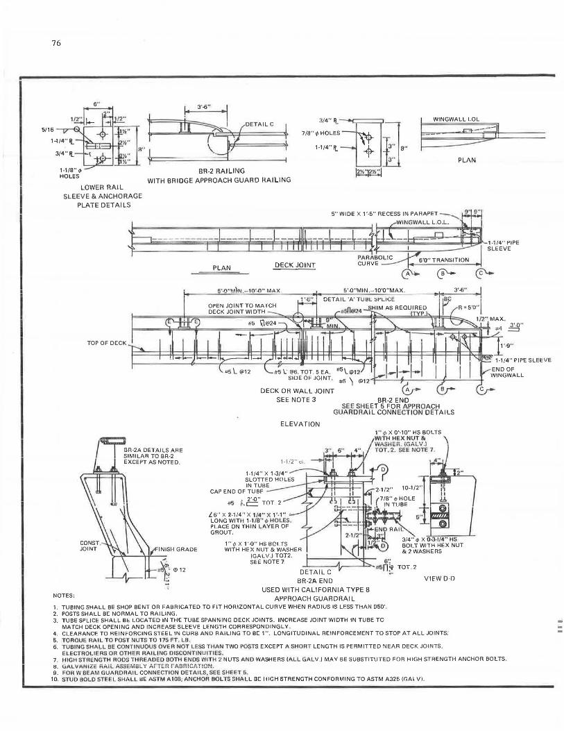
;;
76
5/16
1-1/8"<1> HOLES
6"
LOWER RAIL SLEEVE & ANCHORAGE
PLATE DETAILS
PLAN
BR-2 RAILING WITH BRIDGE APPROACH GUARD RAILING
PLAN DECK JOINT
5'-'l"M)N.-10'"'1"' MAX. 5'-0"MIN.-10'0"MAX. 3'-6"
NOTES:
TOP OF DECK
BR-2A DETAILS ARE SIMILAR TO BR-2 EXCEPT AS NOTED.
INISH GRADE
#t@12
#5 l ' @6, TOT. 5 EA. #5 \.@12 I SIDE OF JOINT. #fi) C@l 2 4~-.;_,t,_; _ _ __,_4:...........!..-:_-1,.
DECK OR WALL JOINT dir SEE NOTE 3
ELEVATION
1-1 /2" cl .
1-1/4" X 1-3/4" SLOTTED HOLES IN TUBE
CAP END OF TUBE
#5
l6" X 2-114" X 1/4" X 1'-1" . LONG WITH 1-1/8'' c/> HOLES. PLACE ON THIN LAVER OF GROUT.
1"cpX 1'-0" HS BOLTS WITH HEX NUT & WASHER
(GALVJ TOT2. SEE NOTE 1
BR -2A END
BR-2 END SEE SHEET 5 FOR APPROACH
GUARDRAIL CONNECTION DETAILS
1" </> X 0'-10" HS BOLTS WITH HEX NUT &
!.,-,ASHER . (GALV .) TOT. 2. SEE NOTE 7 .
RAi l
3/4" c/> X 0-3-1/4" HS BOLT WITH HEX NUT &2WASHERS
VIEW 0-0
USED WITH CALIFORNIA TYPE 8 APPROACH GUARDRAIL
1. TUBING SHALL BE SHOP BENT OR FABRICATED TO FIT HORIZONTAL CURVE WHEN RADIUS IS LESS THAN 950'. 2. POSTS SHALL BE NORMAL TO RAILING . 3. TUBE SPLICE SHALL BE LOCATED IN THE TUBE SPANNING DECK JOINTS. INCREASE JOINT WIDTH IN TUBE TO
MATCH DECK OPENING AND INCREASE SLEEVE LENGTH CORRESPONDINGLY . 4. CLEARANCE TO REINFORCING STEEL IN CURB AND RAILING TO BE 1". LONGITUDINAL REINFORCEMENT TO STOP AT ALL JOINTS: 5. TOROUE RAIL TO POST NUTS TO 175 FT. LB. 6. 7 UB1NG SHALL BE CONTINUOUS OVER NOT LESS THAN TWO POSTS EXCEPT A SHORT LENGTH IS PERMITTED NEAR DECK JOINTS,
ELECTROLlERS OR OTHER RAILING DISCONTINUITIES.
1-114" PIPE SLEEVE
7. HIGH STRENGTH RODS THREAOEO BOTH ENDS WITH 2 NUTS AND WASHERS IALL GA LV.) MAY BE SUBSTITUTED FOR HIGH STRENGTH ANCHOR BOLTS. ii. uALVANIZE RAI L ASS-MBLY Arrcn rAB!'!!CATION . 9. FOR W BEAM GUARDRAIL CONNECTION DETAILS, SEE SHEET 5 .
10. STUD BOLO STEEL SHALL ~E ASTM A 108; ANCHOR BOLTS SHALL B[ IIIGH STRENGTH CONFORMING TO ASTM A325 IGALV) .
-
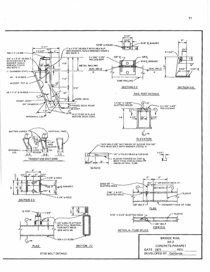
3/4" </> X 0'-8" HS BOLT WITH HEX NUT & WASHER. (GALVWRENCH TIGHT) SEE NOTE 7:
1" CHAMFER (TYP.)
#5 @24 MAX.
#4 CONT . TOT. 6
WINGWALL ---1-"""11" LOL
1'•11"
5-1/2"
13116 .. r/J HOLES 5/16" It_ WASHER
1" <I> X 1 '-0" HS BOLT WITH HEX NUT ANO WASHER. (GALV-WRENCH TIGHT.I SEE NOTE 7.
2 X 3/4" X 0'8" ROLLEO BAR
R 1-1/2"
METAL RAILING SEAL WELO
~ SEALWELD -
G
1'-2"
3'-3"
10"
>-TRANS. DECK REINF ...;...-r--;,,,_5'o:::=-::#-;:-5-;:::CO~NT.
#6~ 0 @ 12 TO BE IN PLACE BEFORE DECK CONC •
• -~ERTICrj)~L F~CE
1 1/4" · PIPE . ·
SLEEVE
G
SECTION F-F
1-1/16" X J-9/16" SLOTTED HOLES
RAIL POST DETAILS
I • 1~is·~1 2-1/4"
ELEVATION
TACK WELD 3/8" NUT INSIDE OF SLEE VE FOR 3/8" HEX HEAD BOLT WITH WASHER (TOTAL 11
2 X 3/4" X 0'8" ROLLED SAR
77
5"
2W '
SECTION G-G
A-A _!!:!L ~ 1/2" r/J HOLES NEAR & FAR SIDE
SLEEVE FOR~'.EO OF 3/16" ij BENT THUS; FOR SLIDING Ffr INSIDE OF RAIL TUBE.
1-1/2"
~ TRANSITION SECTIONS
SLEEVE 9"
SECTION E-E
1-1/4"<t>HOLE
ft. PARAPET
1-1/4"4>HOLE
3/4" <I> BOLTS ATTACH WITH "ULL PENETRATION BUTT WELD. (SEE NOTE 10)
TS6 X 2 X 0 .250
SECTION J.J
STUD BOLT DETAILS
EDGE OF SLOTTED HOLE
7/16" X 4-1/2" SLOTTED HOLE
7/16" X 4-1/2" SLOTTEO HOLE ;: SLEEVE
~~= J_* ;/8" BOLT
DETAIL A-TUBE SPLICE VIEWH-H
BRIDGE RAIL BR-2
CONCRETE PARAPET DATE 1971 REV . - --- --- - ---DEVELOPED BY California
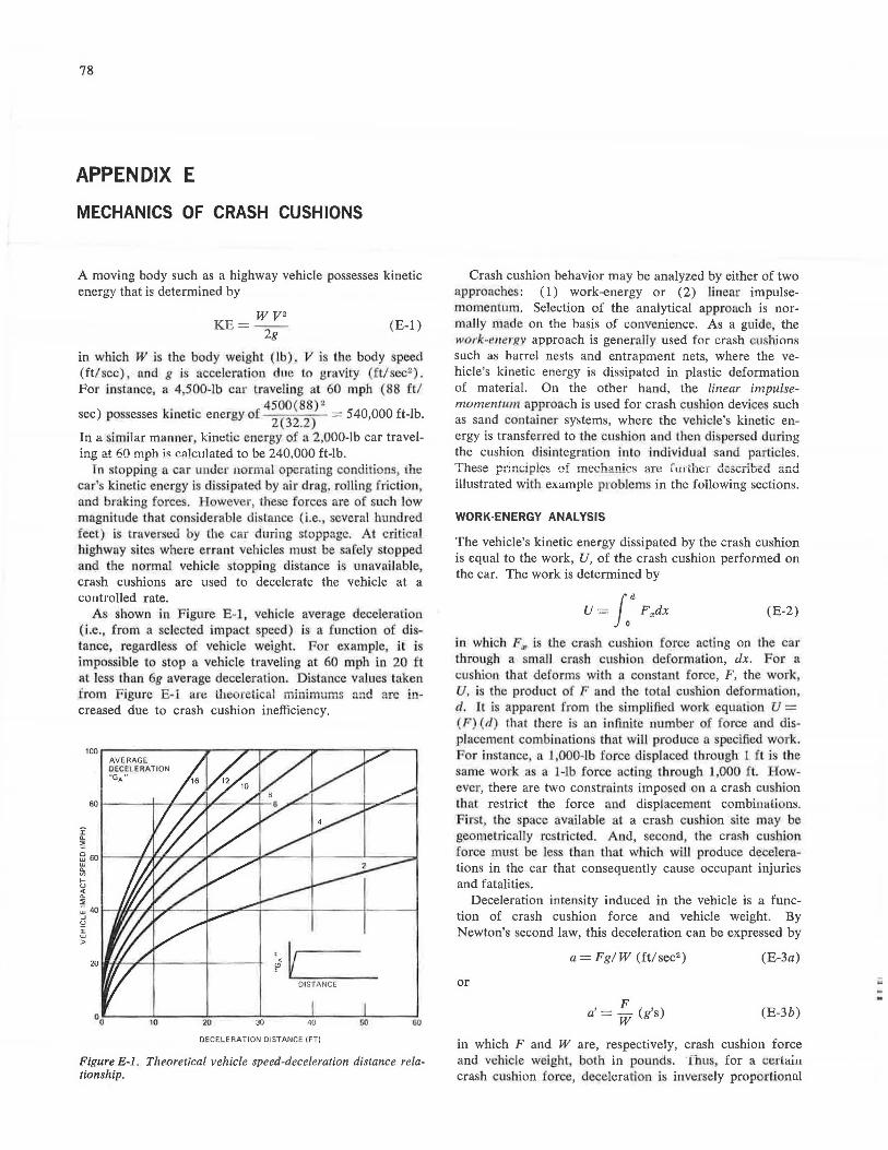
78
APPENDIX E
MECHANICS OF CRASH CUSHIONS
A moving body such as a highway vehicle possesses kinetic energy that is determined by
KE= wv2 2g
(E-1)
in which W is the body weight (lb), V is the body speed (ft/sec), and g is acceleration dne to gravity (ft/sec2 ).
For instance, a 4,500-lb car traveling at 60 mph (88 ft/ . . 4500(88)~
sec) possesses kinetic energy of 2
(32
_2
) = 540,000 ft-lb.
In a similar manner kinetic energy of a 2,000-lb car traveling at 60 mph is calculated to be 240,000 ft-lb.
Tn stopping a car un<ler normal operating conditions, the car's kinetic energy i dissipated by air drag rolling friction and braking forces. However, 1hese forces are of such low magnitude that considerable ui ta.nee (i.e., several hundred feet) is traverse<l by tie car during stoppage. At critical highway sites where errant vehicles must be safely stopped and the normal vehicle stopping distance is unavailable, crash cushions are used to decelerate the vehicle at a l:Ontrolled rate.
As shown in Figure E-1, vehicle average deceleration (i.e., from a selected impact speed) is a function of distance, regardless of vehicle weight. For example, it is impossible to stop a vehicle traveling at 60 mph in 20 ft at less than 6g average deceleration. Distance values taken from Figure E-1 are lite retical mini.mums and are increased due to crash cushion inefficiency.
i ~
AVERAGE DECELERATION "GA"
5! 60 I----JL..JL+-4- ,iL----,,,i""-- --1--- -L----:.1 ~ U)
tu "' !!E ~401--ffJ~~"""'"'----l--ca.,..,,.:::...jr-----+---~,1---~ - ~ ...J
!e :i: w > ~v
DISTANCE
20 JO 40 GO 60 00.-----,.._o ___ ...._ __ __. ___ __._ ___ .._ __ __.
DECELERATION DISTANCE IFTI
Figure E-1. Theoretical vehicle speed-deceleration distance relationship.
Crash cushion behavior may be analyzed by either of two approaches: (1) work-energy or (2) linear impulsemomentum. Selection of the analytical approach is normally made on the basis of convenience. As a guide, the work-em!rRY approach is genera'lly used for crash u. hions such as barrel nests and entrapment nets, where the vehicle's kinetic energy is dissipated in plastic deformation of material. On the other hand, the linear impulsemomentum approach is used for crash cushion devices such as sand container systems, where the vehicle's kinetic energy is transferred to the cu. hion and then dispersed during the cushion disintegration into individual sand particles. These principles of mechanics ~re r u1 thu described and illustrated with example problems in the following sections.
WORK-ENERGY ANALYSIS
The vehicle's kinetic energy dissipated by the crash cushion is equal to the work, U, of the crash cushion performed on the car. The work is determined by
U = f0
a F.,dx (E-2)
in which F.,, is the crash cushion force acting on the car through a small crash cu hion deformation, dx. For a cushion that deforms with a constanl force, F, the work, U, is the product of F and the total cushion deformation , d. It is apparent from the simplified work equation U = ( F) (d) that there is an infinite number of force and displacement combinations that will produce a specified work. For instance a 1,000-lb force displaced through 1 ft is the same work a a 1-lb force acti ng through 1,000 ft. However, there are two constraints imposed on a crash cushion that restrict the force and displacement combinulions. F irst, the space available at a crash cushion site may be geometrically restricted. And, second, the crash cushion force must be less than that which will produce decelerations in the car that consequently cause occupant injuries and fatalities.
Deceleration intensity induced in the vehicle is a function of crash cushion force and vehicle weight. By Newton's second law, this deceleration can be expressed by
a= Fg/ W (ft/ sec2 ) (E-3a)
or
a'=!_ (g's) w (E-3b)
in which F and W are, respectively, crash cushion force and vehicle weight, both in pounds. Thus for a l:CCLam crash cushion force, deceleration b inversely proportionul
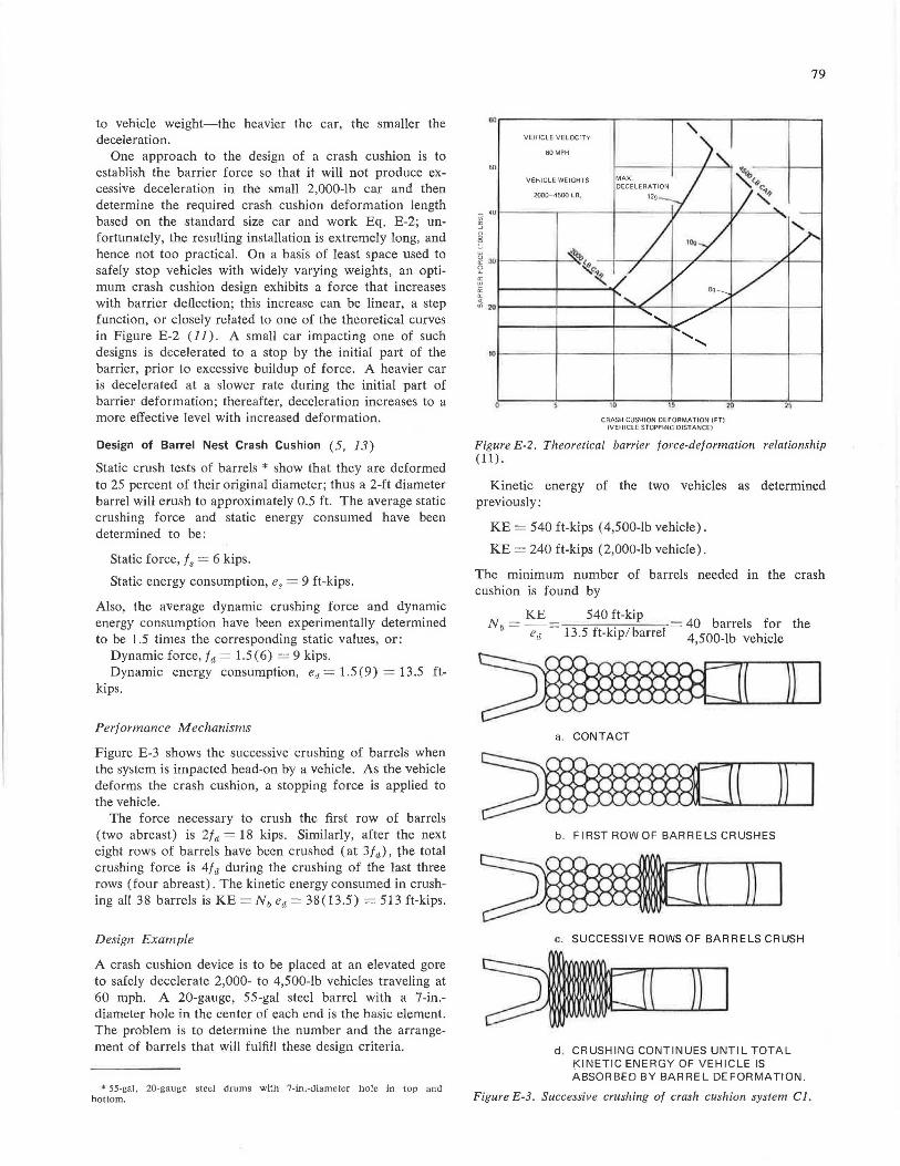
to vehicle weight-the heavier the car, the smaller the deceleration.
One approach to the design of a crash cushion is to establish the barrier force so that it will not produce excessive deceleration in the small 2,000-lb car and then determine the required crash cushion deformation length based on the standard size car and work Eq. E-2; unfortunately, the resulting installation is extremely long, and hence not too practical. On a basis of least space used to safely stop vehicles with widely varying weights, an optimum crash cushion design exhibits a force that increases with barrier deflection; this increase can be linear, a step function, or closely related to one of the theoretical curves in Figure E-2 (11). A small car impacting one of such designs is decelerated to a stop by the initial part of the barrier, prior to excessive buildup of force. A heavier car is decelerated at a slower rate during the initial part of barrier deformation; thereafter, deceleration increases to a more effective level with increased deformation.
Design of Barrel Nest Crash Cushion (5, 13)
Static crush tests of barrels * show that they are deformed to 25 percent of their original diameter; thus a 2-ft diameter barrel will erush to approximately 0.5 ft. The average static crushing force and static energy consumed have been determined to be:
Static force, f 8 = 6 kips.
Static energy consumption, e8 = 9 ft-kips.
Also, the average dynamic crushing force and dynamic energy consumption have been experimentally determined to be 1.5 times the corresponding static values, or:
Dynamic force, f d = 1.5 ( 6) = 9 kips. Dynamic energy consumption, ea= 1.5 (9) = 13.5 ft
kips.
Performance Mechanisms
Figure E-3 shows the successive crushing of barrels when the system is impacted head-on by a vehicle. As the vehicle deforms the crash cushion, a stopping force is applied to the vehicle.
The force necessary to crush the first row of barrels (two abreast) is 2/ d = 18 kips. Similarly, after the next eight rows of barrels have been crushed ( at 3 fa), the total crushing force is 4/ d during the crushing of the last three rows (four abreast). The kinetic energy consumed in crushing all 38 barrels is KE= Nb ed = 38(13.5) = 513 ft-kips.
Design Example
A crash cushion device is to be placed at an elevated gore to safely decelerate 2,000- to 4,500-lb vehicles traveling at 60 mph. A 20-gauge, 55-gal steel barrel with a ?-in.diameter hole in the center of each end is the basic element. The problem is to determine the number and the arrangement of barrels that will fulfill these design criteria.
• 55-gal, 20-gauge steel drums with 7-in.-diameter hole in top and bottom.
79
~,---------.-- ---.-----.----,--~
50
VEHICLE VELOCITY
60MPH
VEHICLE WEIGHTS
2000- 4500 LB.
101------1'-----t----+----+----+------f
0 ID 15
CRASH CUSHION DEFORMATION (FT) lVEHICLE STOPPING DISTANCE!
26
Figure E-2. Theoretical barrier force-deformation relationship (11).
Kinetic energy of the two vehicles as determined previously:
KE = 540 ft-kips ( 4,500-lb vehicle).
KE= 240 ft-kips (2,000-lb vehicle).
The minimum number of barrels needed in the crash cushion is found by
Nb= KE= 540 ~t-kip = 40 barrels for the ea 13.5 ft-kip/barrel 4,500-lb vehicle
a. CONTACT
b. FIRST ROW OF BARRELS CRUSHES
c. SUCCESSIVE ROWS OF BARRELS CRUSH
d . CRUSHING CONTINUES UNTIL TOTAL KINETIC ENERGY OF VEHICLE IS ABSORBED BY BARREL DEFORMATION.
Figure E-3. Successive crushing of crash cushion system CJ.
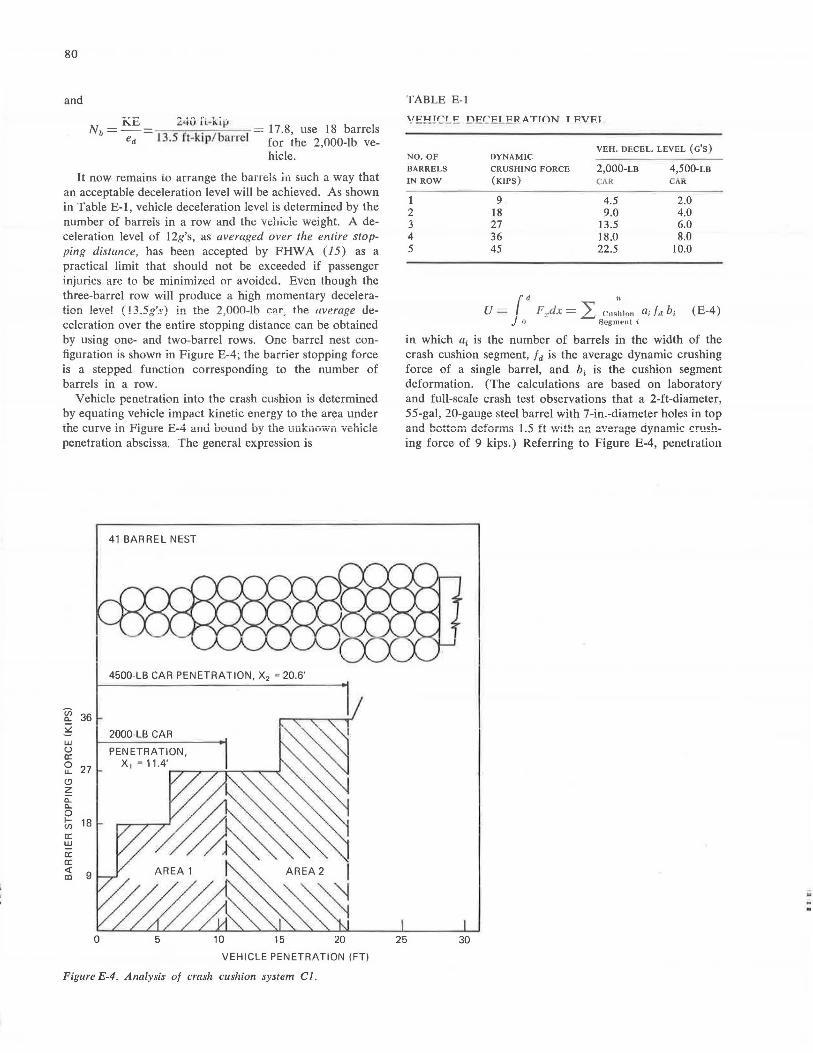
80
and
KE 240 [i. ... kiV Nb=-= . = 17.8, use 18 barrels
e<l 13.5 ft-ktp/ba rrel for the 2 000-lb ve-, hicle.
It now remains to arrange the barrels in such a way that an acceptable deceleration level will be achieved. As shown in Table E-1, vehicle deceleration level is determined by the number of barreis in a row and the vehicle weight. A deceleration level of 12g's, as averaged over the entire stopping distance, has been accepted by FHWA (15) as a practical limit that should not be exceeded if passenger injuries are to be minimized or avoided. Even though the three-barrel row will produce a high momentary deceleration !eve! ( l3.5g's) in the 2,000-lb c;ir; the average deceleration over the entire stopping distance can be obtained by using one- and two-barrel rows. One barrel nest configuration is shown in Figure E-4; the barrier stopping force is a stepped function corresponding to the number of barrels in a row.
Vehicle penetration into the crash cushion is determined by equating vehicle impact kinetic energy to the area under the curve in Figure E-4 anU bOLtnd by the unknow·n vehicle penetration abscissa. The general expression is
R! 36 ~
UJ u a: ~ 27 (.'.) z 0.. 0.. 0 tfi 18 a: UJ
a: a: ~ 9
0
41 BARREL NEST
4500-LB CAR PENETRATION, X2 = 20.6'
2000-LB CAR
PENETRATION,
X 1 = 11.4',......,~~~...-~---
5 10 15 20
VEHICLE PENETRATION (FT)
Figure E-4. Analysis of crash cushion system Cl.
TABLE E-1
"PJ.flr'T P TYPr'PT PR ATTON T FVFT
NO. OF DYNAMIC VEH. DECEL. LEVEL (G'S)
BARRELS CRUSHING FORCE 2,000-LB 4,500-LB IN ROW (KIPS) CAR CAR
1 9 4.5 2.0 2 18 9.0 4.0 3 27 13.5 6.0 4 36 18.0 8.0 5 45 22.5 10.0
rd " U - F ~dx = ) r.ushinn a.; f r1 bi (E-4)
J o - .-- Segnwnt i
in which a.1 is the number of barrels in the width of the crash cushion segment, fa is the average dynamic crushing force of a single barrel, and b, is the cushion segment deformation. (The calculations are based on laboratory and full-scale crash test observations that a 2-ft-diameter, 55-gal, 20-gauge steel barrel with 7-in.-diameter holes in top and bottom deforms 1.5 ft \Vith an average dynamic crush-ing force of 9 kips.) Referring to Figure E-4, penetration
25 30
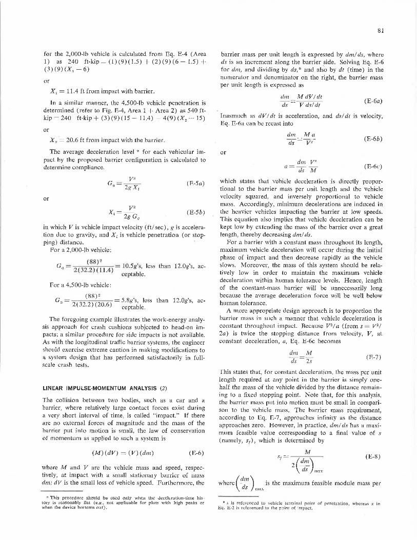
for the 2,000-lb vehicle is calculated from Eq. E-4 (Area 1) as 240 ft-kip= (1)(9)(1.5) + (2)(9)(6-1.5) + (3) (9) (X1 - 6)
or
X 1 = 11.4 ft from impact with barrier.
In a similar manner, the 4,500-lb vehicle penetration is determined (refer to Fig. E-4, Area 1 + Area 2) as 540 ftkip = 240 ft-kip+ (3) (9) (15 - 11.4) + 4(9) (X2 - 15)
or
X 2 = 20.6 ft from impact with the barrier.
The average deceleration level * for each vehicular impact by the proposed barrier configuration is calculated to determine compliance.
or y2
X·=--' 2g Ga
(E-5a)
(E-5b)
in which V is vehicle impact velocity (ft/ sec), g is acceleration due to gravity, and Xi is vehicle penetration ( or stopping) distance.
For a 2,000-lb vehicle:
(88) 2 _ I
Ga= Z( 32_2)(1J.4)-10.5gs, less than 12.0g's, ac-ceptable.
For a 4,500-lb vehicle:
(88) 2 , , Ga =
2(
22)(
2 6 =5.8gs, less than 12.0gs, ac-
3 · O. ) ceptable.
The foregoing example illustrates the work-energy analysis approach for crash cushions subjected to head-on impacts; a similar procedure for side impacts is not available. As with the longitudinal traffic barrier systems, the engineer should exercise extreme caution in making modifications to a system design that has performed satisfactorily in fullscale crash tests.
LINEAR IMPULSE-MOMENTUM ANALYSIS (2)
The collision between two bodies, such as a car and a barrier, where relatively large contact forces exist during a very short interval of time, is called "impact." If there are no external forces of magnitude and the mass of the barrier put into motion is small, the law of conservation of momentum as applied to such a system is
(M) (dV) = (V) (dm) (E-6)
where M and V are the vehicle mass and speed, respectively, at impact with a small stationary bal'fier uI mass dm; dV is the small loss of vehicle speed. Furthermore, the
* This procedure should be used only when the deceleration-time history is reasonably flat (e.g., not applicable for plots with high peaks or when the device bottoms out).
81
barrier mass per unit length is expressed by dm/ ds, where ds is an increment along the barrier .side. Solving Eq. E-6 for dm, and dividing by ds, * and also by dt (time) in the numerator and denominator on the right, the barrier mass per unit length is expressed as
dm M dV/dt ds V ds!dt
(E-6a)
Inasmuch as dV I dt is acceleration, and ds! dt is velocity, Eq. E-6a can be recast into
or
dm Ma ds V 2
dm V2
a=ds M
(E-6b)
(E-6c)
which states that vehicle deceleration is directly proportional to the barrier mass per unit length and the vehicle velocity squared, and inversely proportional to vehicle mass. Accordingly, minimum decelerations are induced in the heavier vehicles impacting the barrier at low speeds. This equation also implies that vehicle deceleration can be kept low by extending the mass of the barrier over a great length, thereby decreasing dm/ ds.
For a barrier with a constant mass throughout its length, maximum vehicle deceleration will occur during the initial phase of impact and then decrease rapidly as the vehicle slows. Moreover, the mass of this system should be relatively low in order to maintain the maximum vehicle deceleration within human tolerance levels. Hence, length of the constant-mass barrier will be unnecessarily long because the average deceleration force will be well below human tolerance.
A more appropriate design approach is to proportion the barrier mass in such a manner that vehicle deceleration is constant throughout impact. Because V 2 / a (from s = V 2/
2a) is twice the stopping distance from velocity, V, at constant deceleration, a, Eq. E-6c becomes
dm M
ds 2s (E-7)
This states that, for constant deceleration, the mass per unit length required at any point in the barrier is simply onehalf the mass of the vehicle divided by the distance remaining to a fixed stopping point. Note that, for this analysis, the barrier mass put into motion must be small in comparison to the vehicle mass. The barrier mass requirement, according to Eq. E-7, approaches infinity as the distance approaches zero. However, in practice, dm/ ds has a maximum feasible value corresponding to a final value of s (namely, s1), which is determined by
M
s1= ( ) 2
~; mnx
(E-8)
where (ddm) is the maximum feasible module mass per S max
* s is referenced to vehicle termina] point of penetration, whereas x in Eq. E-2 is referenced to the point of impact.
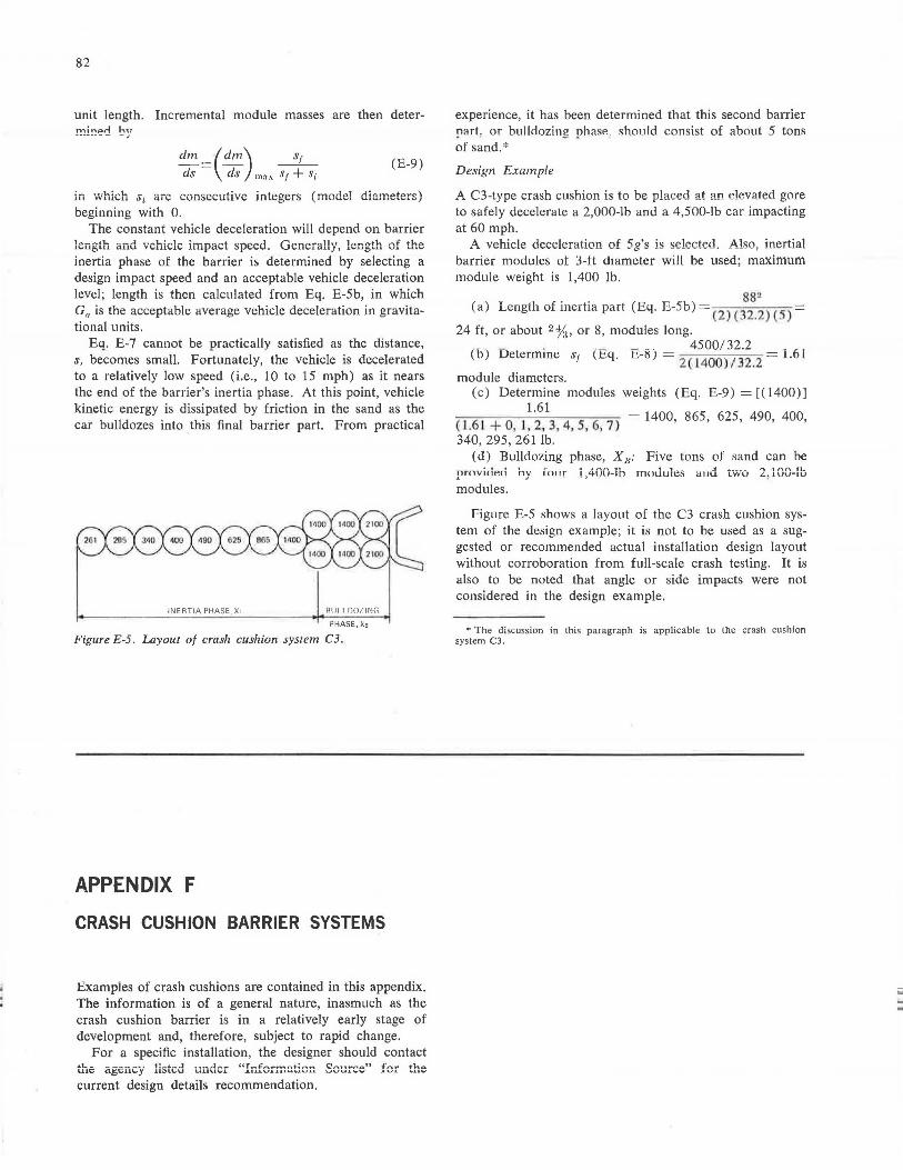
82
unit length. Incremental module masses are then deter!!!!!'!~<l by
dm _(dm) s1
ds- ds mnx St+ Si (E-9)
m which s;. are consecutive integers (model diameters) beginning with 0.
The constant vehicle deceleration will depend on barrier length and vehicle impact speed. Generally, length of the inertia phase of the barrier is determined by selecting a design impact speed and an acceptable vehicle deceleration level; length is then calculated from Eq. E-Sb, in which Ga is the acceptable average vehicle deceleration in gravitational units.
Eq. E-7 cannot be practically satisfied as the distance, s, becomes small. Fortunately, the vehicle is decelerated to a relatively low speed (i.e., 10 to 15 mph) as it nears the end of the barrier's inertia phase. At this point, vehicle kinetic energy is dissipated by friction in the sand as the car bulldozes into this final barrier part. From practical
INERTIA PHASE, x, Alli I r1071N\1
PHASE, Xe
Figure E-5. Layout of crash cushion system C3.
APPENDIX F
CRASH CUSHION BARRIER SYSTEMS
Examples of crash cushions are contained in this appendix. The information is of a general nature, inasmuch as the crash cushion barrier is in a relatively early stage of development and, therefore, subject to rapid change.
For a specific installation, the designer should contact the agency listed under "1u.fcrrn.G.ticrr Source" fer the current design details recommendation.
experience, it has been determined that this second barrier part. or bullclozing phase. should consist of about 5 tons of sand.*
Design Example
A C3-type crash cushion is to be placed at an elevated gore to safely decelerate a 2,000-lb and a 4,500-lb car impacting at 60 mph.
A vehicle deceleration of 5g's is selected, Also, inertial barrier modules ot 3-ft diameter will be used; maximum module weight is 1,400 lb.
(a) Length of inertia part (Eq. E-5b) = (2
) (38J~) (S)
24 ft, or about 2%, or 8, modules long. . _ . . _ -· 4500/32.2 ,
lb) Uetermme s1 lEq. h-15) = 2
( 1400
)132
.2
Loi
module diameters. (c) Determine modules weights (Eq. E-9) = [(1400)]
1.61 S (J .61 + 0, l, 2, 3, 4, 5, 6, 7) = 1400, 865, 62 , 490, 400, 340, 295, 261 lb.
( d) Bulldozing phase, X 11 : Five tons of sand can be provided modules.
by fo1_1r , , __ .1 ... ___ _
TTI(lUUlt::S a11u LWU
Figure E-5 shows a layout of the C3 crash cushion system of the design example; it is not to be used as a suggested or recommended actual installation design layout without corroboration from full-scale crash testing. It is also to be noted that angle or side impacts were not considered in the design example.
• The discussion in this paragraph is applicable to the crash cushion system C3.
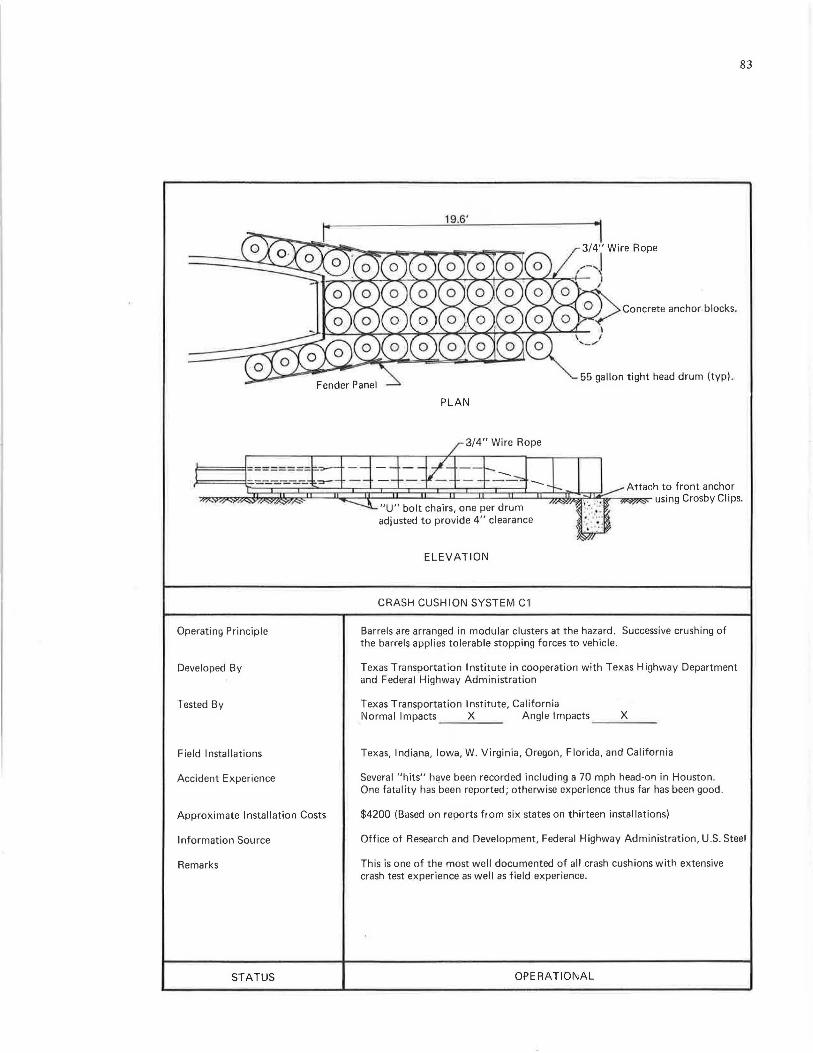
l=======l=======
Operating Principle
Developed By
Tested By
Field Installations
Accident Experience
Approximate Installation Costs
Information Source
Remarks
STATUS
19.6'
PLAN
3/4" Wire Rope
~--.I )
Concrete anchor.blocks .
55 gallon tight head drum (typ).
83
"U" bolt chairs, one per drum adjusted to provide 4" clearance
Attach to front anchor using Crosby Clips.
ELEVATION
CRASH CUSHION SYSTEM C1
Barrels are arranged in modular clusters at the hazard. Successive crushing of the barrels applies tolerable stopping forces to vehicle.
Texas Transportation Institute in cooperation with Texas Highway Department and Federal Highway Administration
Texas Transportation Institute, California Normal Impacts X Angle lmpacts _ __ X _ _ _
Texas, Indiana, Iowa, W. Virginia, Oregon, Florida, and California
Several "hits" h~ve been recorded including a 70 mph head-on in Houston. One fatality has been reported; otherwise experience thus far has been good.
$4200 (Based on reports from six states on thirteen installations)
Office of Research and Development, Federal Highway Administration, U.S. Steel
This is one of the most well documented of all crash cushions with extensive crash test experience as well as field experience.
OPERATIONAL
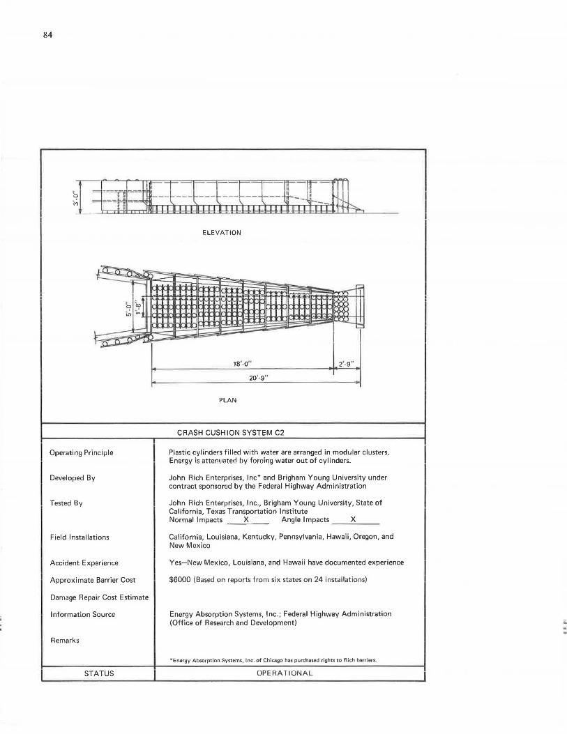
84
~rt«Laiiaii.Ill ELEVATION
-LJ • ..L "~ t-=: ~- --~--::..
'a ~] - II .
il, ~ 11
-I=--:::: -11',~ -
10' -o" 2·.9"
20 '.9"
PLAN
CRASH CUSHION SYSTEM C2
Operating Principle Plastic cylinders filled with water are arranged in modular clusters. Energy is attenuated by forcing water out of cylinders.
Developed By John Rich Enterprises, Inc* and Brigham Young University under contract sponsored by the Federal Highway Administration
Tested By John Rich Enterprises, Inc., Brigham Young University, State of California, Texas Transportation Institute Normal Impacts X Angle Impacts X
Field Installations California, Louisiana, Kentucky, Pennsylvania, Hawaii, Oregon, and New Mexico
Accident Experience Yes-New Mexico, Louisiana, and Hawaii have documented experience
Approximate Barrier Cost $6000 (Based on reports from six states on 24 installations)
Damage Repair Cost Estimate
Information Source Energy Absorption Systems, Inc.; Federal Highway Administration (Office of Research and Development) iii
Remarks
*Energy Absorption Systems, Inc. of Chicago has purchased rights to Rich barriers.
STATUS OPERA TiONAL
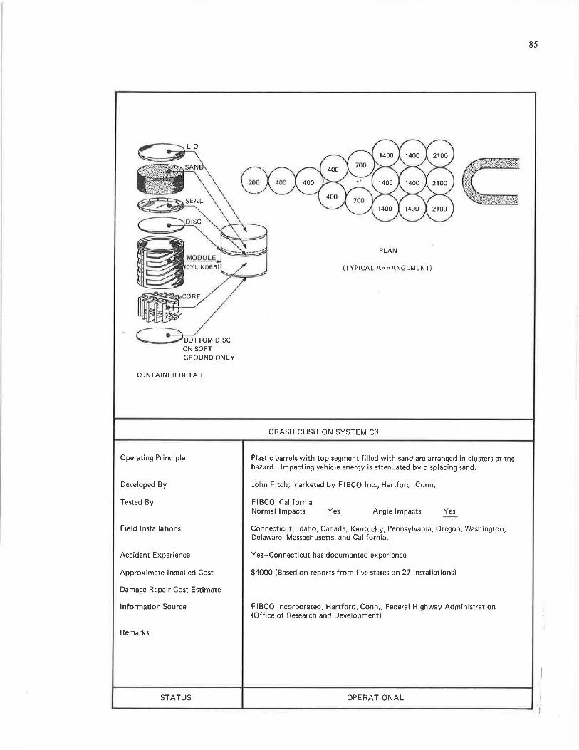
ON SOFT GROUND ONLY
CONTAINER DETAIL
Operating Principle
Developed By
Tested By
Field Installations
Accident Experience
Approximate Installed Cost
Damage Repair Cost Estimate
Information Source
Remarks
STATUS
PLAN
(TYPICAL ARRANGEMENT)
CRASH CUSHION SYSTEM C3
Plastic barrels with top segment filled with sand are arranged in clusters at the hazard. Impacting vehicle energy is attenuated by displacing sand.
John Fitch; marketed by Fl BCO Inc., Hartford, Conn.
FIBCO, California Normal Impacts Yes Angle Impacts Yes
Connecticut, Idaho, Canada, Kentucky, Pennsylvania, Oregon, Washington, Delaware, Massachusetts, and California.
Yes-Connecticut has documented experience
$4000 (Based on reports from five states on 27 installations)
FIBCO Incorporated, Hartford, Conn., Federal Highway Administration (Office of Research and Development)
OPERATIONAL
85
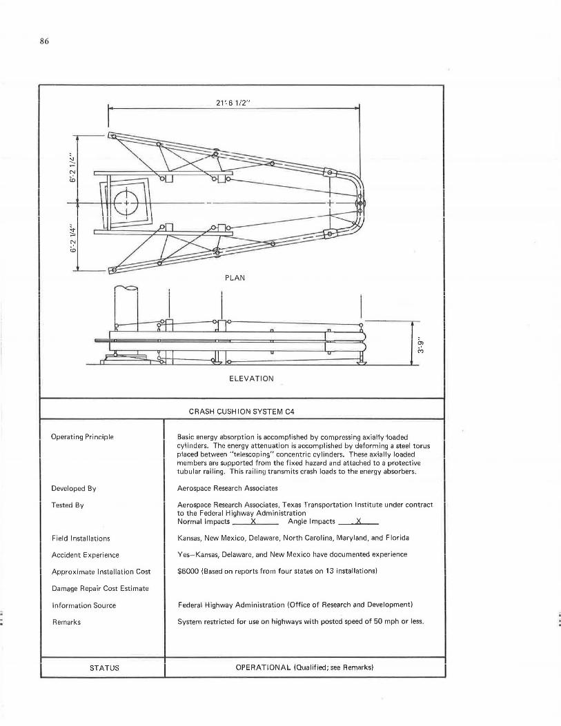
86
21'-6 1/2"
PLAN
0)
~
_rE.~~H::=:==4lb===:::::~=======~-_L
Operating Principle
Developed By
Tested By
Field Installations
Accident Experience
Approximate Installation Cost
Damage Repair Cost Estimate
Information Source
Remarks
STATUS
ELEVATION
CRASH CUSHION SYSTEM C4
Basic energy absorption is accomplished by compressing axially ·1oaded cylinders. The energy attenuation is accomplished by deforming a steel torus placed between "telescoping" concentric cylinders. These axially loaded members are supported from the fixed hazard and attached to a protective tubular railing. This railing transmits crash loads to the energy absorbers.
Aerospace Research Associates
Aerospace Research Associates, Texas Transportation Institute under contract to the Federal Highway Administration Normal Impacts Angle Impacts X
Kansas, New Mexico, Delaware, North Carolina, Maryland, and Florida
Yes- Kansas, Delaware, and New Mexico have documented experience
$6000 (Based on reports from four states on 13 installations)
Federal Highway Administration (Office of Research and Development)
System restricted for use on highways with posted speed of 50 mph or less.
OPERATIONAL (Qualified; see Remarks)
ii
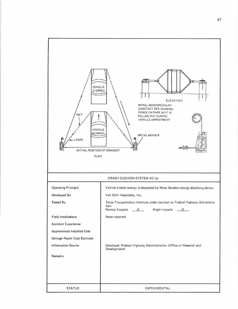
I I
I I
I I
I
'
I I
I \ \ \ \
" \
\ \
\
\ \
\ \
\ \
' \
ELEVATION
METAL BENDERS EXERT CONSTANT RESTRAINING FORCE ON TAPE AS IT IS PULLED OUT DURING VEHICLE ARRESTMENT
METAL BENDER
,/ ------------------~---
INITIAL POSITION OF DRAGNET
PLAN
Operating Principle
Developed By
Tested By
Field Installations
Accident Experience
Approximate Installed Cost
Damage Repair Cost Estimate
Information Source
Remarks
STATUS
CRASH CUSHION SYSTEM XC-(a)
Vehicle kinetic energy is dissipated by Metal Benders energy absorbing device.
Van Zelm Associates, Inc.
Texas Transportation Institute under contract to Federal Highway Administration. Normal Impacts X Angle Impacts __ X __
None reported
Developer, Federal Highway Administration (Office of Research and Development)
EXPERIMENTAL
87

88
36'
PLAN
VERMICULITE CONCRETE (30 LBS/CF 50 psi)
CABLE ANCHORAGE
Attenuation System :
Operating Principle
Developed By
Tested By
Field Installations
Accident Experience
Approximate Installed Cost
Damage Repair Cost Estimate
Information Source
Remarks
STATUS
-mii=
ELEVATION
CRASH CUSHION SYSTEM YC-(b)
Lightweight cellular concrete
Vehicle impacting energy is absorbed by successively crushing lightweight concrete modules.
Texas Transportation Institute under contract with Federal Highway Administration
Texas Transportation Institute Normal Impacts X Anylll lmpacls ___ x __ _
None
Federal Highway Administration (Office of Research and Development)
R&D
ii iii .
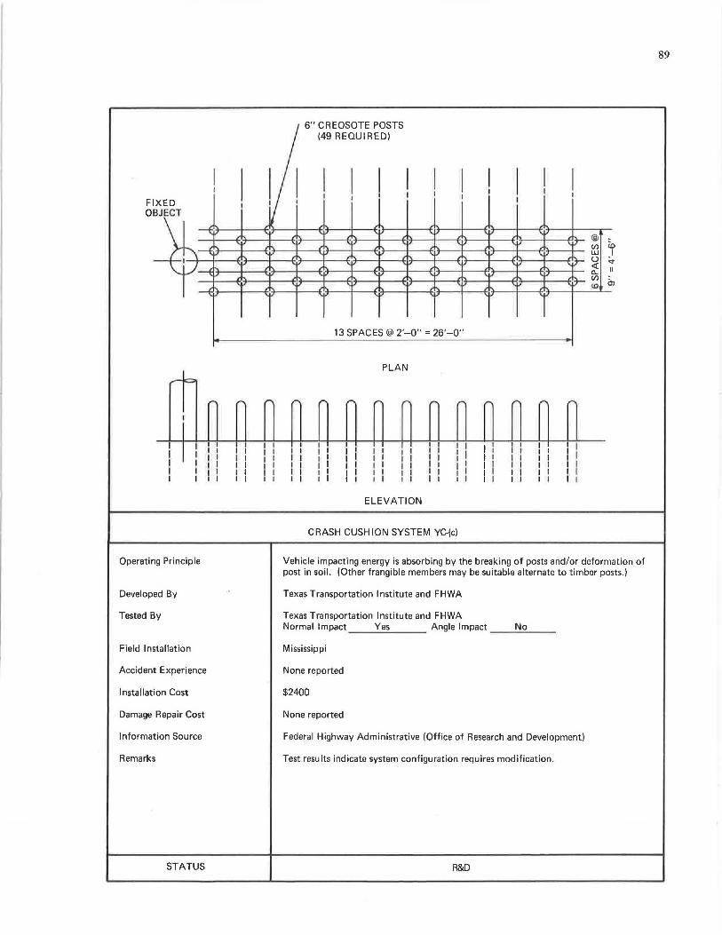
89
6" CREOSOTE POSTS (49 REQUIRED)
I I I I I I I I I I I I I I I I I I I I ! I FIXED I !
I OBJECT
• , ""
,, , ' ' ,v '
,,, ' @ ... ' '"
I' ,.r,. "" '"' ,r-. U) CD ,I'\' ' '"' '"' '"' \ II w I
" r u ~ " ' 'I' <x: ' --(~ ' '" ' " II
" ,v '"' ,v '"' c..
'" .tr-. U) Ol
~ '"' , ,v ' '"
'V
" <O
v ' '"' V
13 SPACES@ 2'-0" = 26'-0"
PLAN -IC::
,.. ,.... ,.. ,..... ,.. ,... ,.. ,... ,... ,... ,... ,... ,,... ,... I
I I I I I I I I ! I I I I I I I I I I I I I I I I I I I I I I I I I
I 1 I I I I I I I ' I I I I I ' I I I I I I I I I I
I I I I I I I I I I I I I I I I I I I I I I I I I I
I I I I I I I I 1 I I I I I I I I I I I I I I I I I I I I I ' I I I I I I I I I I I I I I I I I I I I I I
ELEVATION
CRASH CUSHION SYSTEM YC-(c)
Operating Principle Vehicle impacting energy is absorbing by the breaking of posts and/or deformation of post in soil. (Other frangible members may be suitable alternate to timber posts.)
Developed By Texas Transportation Institute and FHWA
Tested By Texas Transportation Institute and FHWA Normal Impact Yes Angle Impact No
Field Installation Mississippi
Accident Experience I\Jone reported
I nstal lat ion Cost $2400
Damage Repair Cost None reported
Information Source Federal Highway Administrative (Office of Research and Development)
Remarks Test results indicate system configuration requires modification.
STATUS R&D
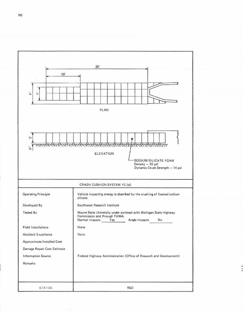
90
10'
I ~11] I I I I
Mc 1o111,-..,.., ,..... ... ,11' ...... .., ,.....
Operating Principle
Developed By
Tested By
Field lnstollotions
Accident Experience
Approximate Installed Cost
Damage Repair Cost Estimate
Information Source
Remarks
STATUS
30'
I
I I I I I I I le. J
I I I l
PLAN
I j
1 .., I .._......_ If'- ,, .v,~,· ·,~"'I'""~"'~,.,,,
ELEVATION
SODIUM SILICATE FOAM Density - 10 psf Dynamic Crush Strength - 14 psi
CRASH CUSHION SYSTEM YC-(d)
Vehicle impacting energy is absorbed by the crushing of foamed sodium silic.:itc.
Southwest Research Institute
Wayne State University under contract with Michigan State Highway Commission and through FHWA. Normal Impacts Yes Angle Impacts No
Nona
None
Federal Highway Administration (Office of Research and Development)
R&D
iii -
91
APPENDIX G
SUMMARY OF FULL-SCALE CRASH TEST RESULTS FOR
SELECTED BARRIER SYSTEMS
Table G-1 contains a summary of published full-scale crash test results on barrier systems presented in this document. In general, the tests were conducted in accord with recommendations of HRB Circular 482 (i.e., 4,000-lb car, 60 mph, and 25-deg impact angle). In several cases, test conditions significantly differed from the recommended values; nevertheless, results from these "off-spec" tests provide the designer with some insight into a barrier's performance.
Acquiring and reporting the test results from the various tests have lacked uniformity in both selection of parameters and measuring techniques. For instance, vehicle deceleration data are derived from micromotion analysis of highspeed cine, electronic instrumentation, and mechanical impactographs. Furthermore, instruments such as accelerometers are sensitive to mounting location, recording/ playback equipment, filtering devices, and other variables. Accordingly, caution should be exercised in using test result values for purposes other than first-order approximation.
To determine deceleration ratings for barrier systems in Tables 6, 7, and 8, specific tests were selected that closely agreed with test conditions of Table 4; these tests are denoted in Table G-1.
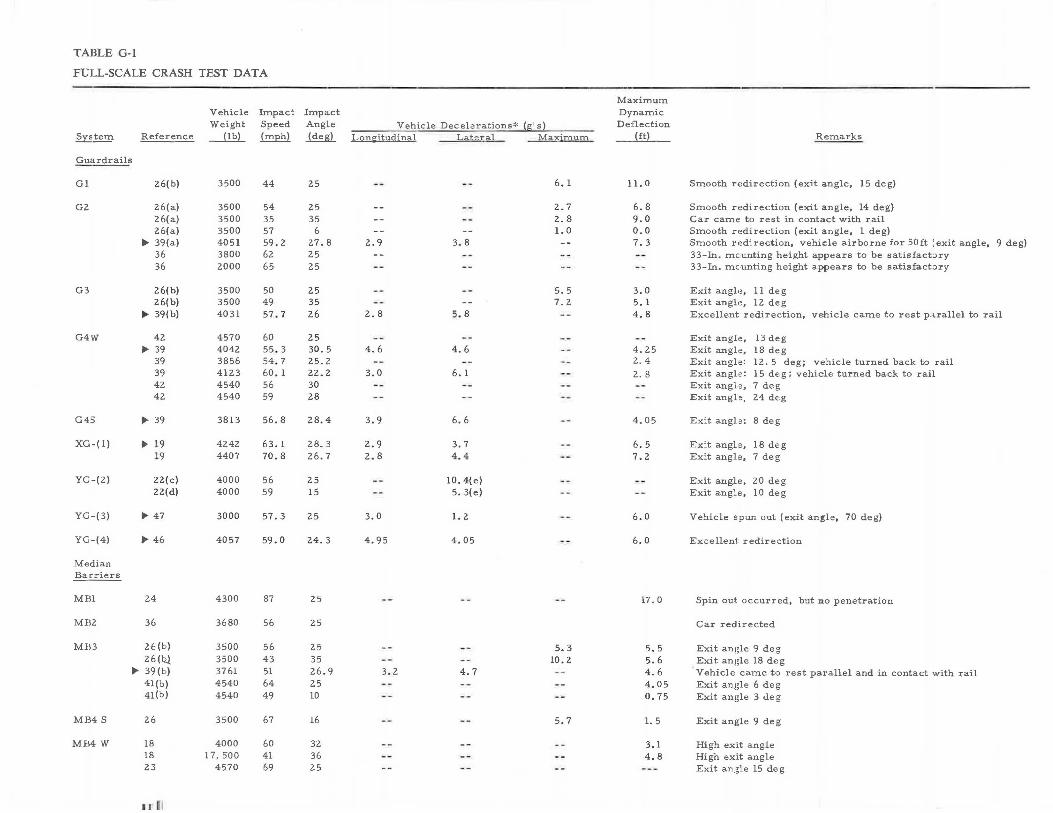
TABLE G-1
FULL-SCALE CRASH TEST DATA
Maximum Vehicle Impact Impact Dynamic Weight Speed Angle Vehicle Decelerations* (fli' s) D,e:flection
~tem Reference -...@L {mph) ~ Loni;::itudinal L;i.teral Maxiro\!:tn __ _lliL_ Remarks
Guardrails
Gl 26(b) 3500 44 25 -- -- 6. 1 11. 0 Smooth redirection (exit angle, 15 deg)
G2 26(a) 3500 54 25 -- -- 2.7 6.8 Smooth redirection (exit angle, 14 deg) 26(a) 3500 35 35 -- -- 2.8 9.0 Car came to rest in contact with rail 26(a) 3500 57 6 -- -- 1. 0 0.0 Smooth redirection (exit angle, 1 deg)
II> 39(a) 4051 59 . 2 27.8 2.9 3.8 -- 7. 3 Smooth redirection, vehicle airborne for son :exit angle, 9 deg) 36 3800 62 25 -- -- -- 33-In. mc,unting height appears to be satisfacbry 36 2000 65 25 -- -- -- -- 33-In. mc,unting height appears to be satisfacbry
G3 26(b) 3500 50 25 -- -- 5.5 3,0 Exit angle, 11 deg 26(b) 3500 49 35 -- 7.2 5. 1 Exit angle, 12 deg
II> 39(b) 4031 57.7 26 2.8 5.8 -- 4.8 Excellent redirection, vehicle came to rest parallel to rail
G4W 42 4570 60 25 -- -- -- -- Exit angfo, 13 deg IJ, 39 4042 55 . 3 30.5 4.6 4.6 -- 4.25 Exit angl,e, 18 deg
39 3856 54.7 25.2 -- -- -- 2.4 Exit angl,e: 12. 5 deg; vehicle turned back to rail 39 4123 60. 1 22.2 3.0 6. 1 -- 2. 8 Exit angl,e: 15 deg; vehicle turned back to rail 42 4540 56 30 -- - -- -- Exit angl,e, 7 deg 42 4540 59 28 -- -- -- -- Exit angl,e, 24 deg
G4S IJ,, 39 3813 56.8 28.4 3.9 6.6 -- 4.05 Exit ang1=: 8 deg
XG-(1) IJ, 19 4242 63. 1 28.3 2.9 3.7 -- 6.5 Ex:t angle, 18 deg 19 4407 70.8 26.7 2.8 4.4 -- 7.2 Ex:.t angle, 7 deg
YG-(2) 22(c) 4000 56 25 -- 10. 4(e) -- -- Exit angle, 20 deg 22(d) 4000 59 15 -- 5. 3(e) -- -- Exit angle, 10 deg
YG-(3) IJ, 47 3000 57.3 25 3.0 1. 2 -- 6.0 Vehicle spun out (exit angle, 70 deg)
YG-(4) IJ, 46 4057 59. 0 24.3 4. 95 4.05 -- 6.0 Excellent redirection
Median
~~
MBl 24 4300 87 25 -- -- 17. 0 Spin out occurred, but no penetration
MB2 36 3680 56 25 Car redirected
Mil3 26(b) 3500 56 25 -- -- 5.3 5.5 Exit angle 9 deg 26(b.l. 3500 43 35 -- -- 10. 2 5.6 Exit angle 18 deg
,,._ 39(b) 3761 51 26.9 3.2 4.7 -- 4.6 Vehicle came to rest parallel and in contact with rail 4l(b) 4540 64 25 . - -- -- 4.05 Exit angle 6 deg 4l(b) 4540 49 10 -- -- -- 0.75 Exit angle 3 deg
MB4 S 26 3500 67 16 -- -- 5.7 1. 5 Exit angle 9 deg
MEl4 W 18 4000 60 32 -- -- -- 3.1 High exit angle 18 1 7, 500 41 36 -- -- 4.8 High exit angle 23 4570 69 25 -- -- -- --- Exit angle 15 deg
,di
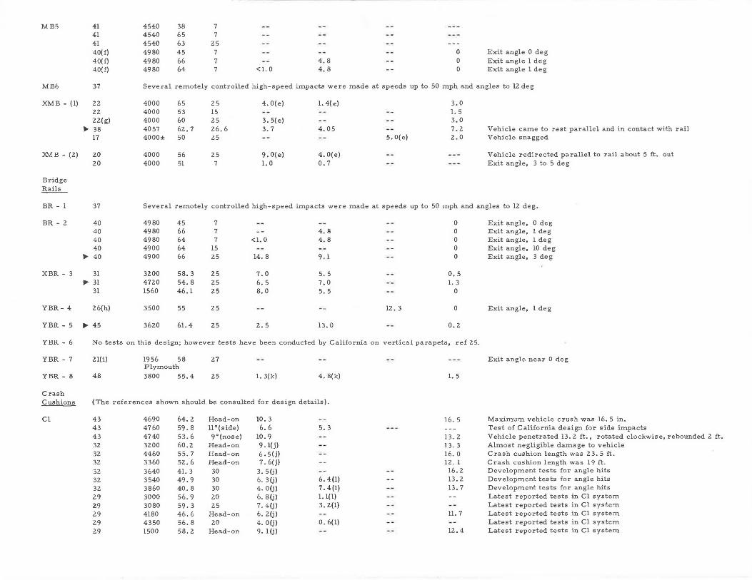
MB5 41 4540 38 7
MB6
XMB - (1)
XMB - (2)
Bridge Rails
BR - 1
BR - 2
XBR - 3
YBR- 4
YBR - 5
YBR - 6
YBR - 7
YBR - 8
Crash Cushions
Cl
41 41 40(£) 40(£} 40(f)
4540 4540 4980 4980 4980
65 7 63 25 45 7 66 7 64 7
-- -- -- 0 Exit angle O deg
-- 4.8 -- 0 Exit angle 1 deg <l. 0 4.8 -- 0 Exit angle 1 deg
37 Several remotely controlled high-speed impacts were made at speeds up to 50 mph and angles to 12 deg
22 4000 65 25 4. O(e) 1. 4(e) 3.0 22 4000 53 15 -- 1. 5 22(g) 4000 60 25 3. 5(e) -- -- 3.0
Ii>- 38 4057 62. 7 26.6 3. 7 4. 05 -- 7.2 Vehicle came to rest parallel and in contact with rail 17 4000± 50 25 -- -- 5. O(e) 2.0 Vehicle snagged
20 4000 56 25 9, O(e) 4. O(e) -- --- Vehicle redirected parallel to rail about 5 ft. out 20 4000 51 7 1. 0 0.7 -- --- Exit angle, 3 to 5 deg
37 Several remotely controlled high-speed impacts were made at speeds up to 50 mph and angles to 12 deg .
40 4980 45 7 0 40 4980 66 7 -- 4.8 0 40 4980 64 7 <l. 0 4.8 0 40 4900 64 15 0
Iii' 40 4900 66 25 14. 8 9.1 0
31 3200 58.3 25 7.0 5.5 0,5 ~ 31 4720 54.8 25 6.5 7,0 1. 3
31 1560 46.1 25 8.0 5.5 0
26(h) 3500 55 25 12. 3 0
llJI, 45 3620 61. 4 25 2.5 13.0 0.2
No tests on this design; however tests have been conducted by California on vertical parapets, ref 25.
2l(i)
48
1956 58 Plymouth
3800 55.4
27
25 1. 3(k) 4. 8(k)
(The references shown should be consulted for design details).
43 4690 64.2 43 4760 59.8 43 4740 53.6 32 3200 60.2 32 4460 55. 7 32 3360 52. 6
32 3640 41. 3 32 3540 49.9 32 3860 40.8 29 3000 56.9 29 3080 59. 3 29 4180 46.6 29 4350 56.8 29 1500 58.2
Head-on 11 °(side) 9°(nose)
Head-on Head-on Head-on 30 30 30 20 25
Head-on 20
Head-on
10. 3 6.6
10. 9 9. l(j) 6, 5(j) 7. 6(j)
3. S(j) 6. 3(j) 4. O(j) 6. 8(j) 7. 4(j) 6. 2(j) 4. O(j) 9. l(j)
5. 3
6. 4(1) 7. 4(1) 1. 1(1) 3. 2(1)
o. 6(1)
1. 5
16. 5
13.2 13. 3 16. O 12. 1
16. 2 13. 2 13. 7
11. 7
12. 4
Exit angle, 0 deg Exit angle, 1 deg Exit angle, 1 deg Exit angle, 10 deg Exit angle, 3 deg
Exit angle, 1 deg
Exit angle near O deg
Maximum vehicle crush was 16. 5 in. Test of California design for side impacts Vehicle penetrated 13. 2 ft., rotated clockwise, rebounded 2 ft . Almost negligible damage to vehiclie Crash cushion length was 23. 5 ft. Crash cushion length was 19 ft. Development tests for angle hits Development tests for angle hits Development tests for angle hits Latest reported tests in Cl system Latest reported tests in Cl system Latest reported tests in Cl system Latest reported tests in Cl system Latest reported tests in Cl system
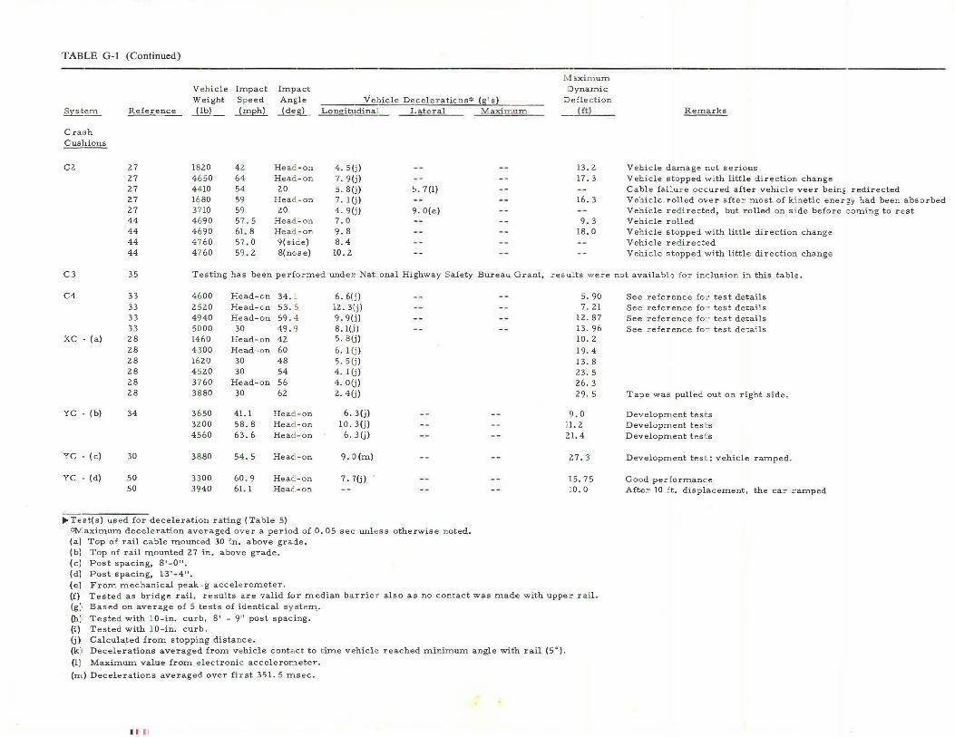
TABLE G-1 (Continued)
Syst~
Cra:sh Cushions
Cl
Reference
27 27 27 27 27 44 44 44 44
V e h icle Weight
J.lli_
1820 4 6 50 4 4 10 16 80 3710 4 690 4 690 4 7 60 4 7 60
Impact Sp eed
~
4 2 64 54 59 59 57 . 5 61. 8 5 7 .0 59 . 2
Impact Angle
~
Head -on Head -on 20
Head.-on 20
Head -on Head -on 9(side) 8(nc,se)
Vehicle Decele r atic,ns* ~ Longitudinal Lateral Maxunum
4. 5(j) -- --7. 9(j) -- --5 . 8(j) 5. 7(1 ) --7. 1 (j) -- --4 . 9(j) 9. O(e) --7 . 0 -- --9.8 -- --8.4 -- --
10. 2 -- --
M ~xim um Dynamic
Defle c tion
®
13. 2 17. 3
--16. 3
--9. 3
18 . 0
----
Remarks
Vehicle damage not serious Vehicle stopped with little direction change Cable faLu r e occured after vehicle veer bein~ redirected Vehicle rolled over after most of k i netic energy had been absorbed Vehicle red irected, but rolled on s i de before c oming to rest Vehicle rolled Vehicle stopped with little direction change Vehicle red irected Vehicle stopped with littl,;, direction change
C3 35 Te s ting has been perfo rmed unde r National Highway Safety Bureau Grant, re s ults w ere not availabl ,e fo r inclusion i:i this tab le.
C4 33 33 33 33
XC - (a) 28
YC - (b)
YC - (c)
YC - (d)
28 28 28 28 28
34
30
50 50
4 600 2 520 49 40 50 00 14 60 4 300 1620 4 520 37 60 38 80
3 650 3200 4 5 60
38 80
3 300 39 40
Head-on 34 . :. Head-on 53. 5 Head-on 59. 4
30 49. 9 Head-on 42 Head-on 60
30 48 30 54
Head-on 56 30 62
41.1 Head -on 58.8 Head -on 63.6 Head -on
54 .5 Head -on
60 . 9 Head -on 61. 1 Head -on
11>-Test(s) us e d for deceleration rating (Table 5)
6. 6(j) --12. 3{j) --9 . 9(j) --8. l(.i) --5. 8(j)
6. 1 (j ) 5. 5 (j ) 4 . 1 (j ) 4. O(j) 2. 4(j)
6. 3(j) --10. 3(j)
6. 3(j) --
9.0(m) --7. 7(j) - - --
~<N:aximum deceleration averaged o v er a period of O. 05 sec unle ss otherwise n oted. (a) Top of rail c a ble mount ed 30 in. above grade. (b) Top of rail mounted 27 in. above grade. (c) Post spacing, 8'-0". (dJ Post spacing, 13'-4". (el From mechanical peak-g accele rometer.
-- 5. 90
-- 7 . 21 -- 12 . 87
-- 13 . 96 10 . 2 19. 4 13. 8 23. 5 26. 3 29 . 5
-- 9.0 11. 2
-- :~l. 4
Z7. 3
-- 15.7 5 10 .0
(f) Tested as br i dge rail, results are valid for median barrier also as no contact was made with uppe r r ail. (g :, Based on average of 5 tests of identical s y st em.
(h:, Tested with 10-in. cur b , 8' - 9" post spacing. (i) Tested with 10-in. curb . (j) Calculated from stoppi ng distan ce. (k) Decel erations averaged from v ehicle conta ct to t ime vehicle reached minim um angle with rail (5°).
(lJ Maximum value from e lec t ronic acceleron'.leter.
(rn) Decelerations averaged over fi r st 351. 5 msec.
II I
See reference fo= test details See reference fo :- test details See reference fo r test de,ails See reference fo r test de~ails
Ta?e was pulled out on right side.
Developrn ent tes t s De•,eloprn ent tes t s Developn,ent tes t s
Developrn ent tes t ; vehicle ramped .
Good per fo rmance After 10 ft. displacement, the car ramped
APPENDIX H
REFERENCES
1. DELEYs, N. J., "Investigation of a Torsion Post-Beam Rail Type of Bridge Railing." Rep. No. VJ-2363-V-1, Cornell Aeronautical Laboratory (Nov. 1970).
2. "Design of the Fitch Inertia Barrier." Unpublished notes, Fibco, Inc., Douglaston, N.Y.
3. GLENNON, J. C., TAMBURRI, T. N., "Objective Criteria for Guardrail Installation." Hwy. Res. Record No. 174 (1967) pp. 184-206.
4. "Highway Guardrail: Determination of Need and Geometric Requirements, with Particular Reference to Beam-Type Guardrail." HRB Spec. Rep. 81 ( 1964) 41 pp.
5. HIRSCH, T. J., IVEY, D. L., and WHITE, M. C., "The Modular Crash Cushion-Research Findings and Field Experience." HRB Spec. Rep. 107 (1970) pp. 140-148.
6. HUTCHINSON, J. w., and KENNEDY, T. w., "Medians of Divided Highways-Frequency and Nature of Vehicle Encroachments." Bull. 487, Univ. of Illinois Eng. Exper. Station (1966).
7. "Manual Change Transmittal No. MC-70-80." California Div. of Highways, Fig. 2 (Dec. 22, 1970).
8. MICHIE, J. D., and CALCOTE, L. R., "Location, Selection, and Maintenance of Highway Guardrails and Median Barriers." NCHRP Rep. 54 (1968) 63 pp.
9. OLSON, R. M., ET AL., "Tentative Service Requirements for Bridge Rail Systems." NCHRP Rep. 86 (1970) 62 pp.
10. SHOEMAKER, N. E., and RADT, H. S., "Summary Report of Highway Barrier Analysis and Test Program." Rep. No. VJ-1472-V-3, Cornell Aeronautical Laboratory (July 1961).
11. SHOEMAKER, N. E., "Research and Design of an Impact Absorbing Barrier for Fixed Highway Objects." Rep. VJ-2501-V-Z, Cornell Aeronautical Laboratory (June 1968).
12. SKEELS, P. C., "The Role of the Highway in a Safe Transportation System." Presented at 65th Ann. Conv., American Road Builders Assn. (Feb. 1968).
13. TAMANINI, F. J., "Designing 'Fail-Safe' Structures for Highway Safety." Transp. Eng. lour., ASCE, Vol. 97, No. TE2 (May 1971).
14. U.S. Dept. of Transportation, Federal Highway Administration, Instructional Memo. 40-1-70, "Impact Attenuators in Gores" (July 1970).
15. U.S. Dept. of Transportation, Federal Highway Administration, Instructional Memo. 40-1-71.
16. U.S. Dept. of Transportation, Federal Highway Administration, Tech. Order T0-20.
95
CRASH TEST REFERENCES
17. ARMSTRONG, M. D., ET AL., "Full-Scale Impact Tests on Low-Cost Barrier Systems, Lighting Poles and Sign Supports." Ontario Dept. of Highways Report (June 1968).
18. BEATON, J. L., and FIELD, R. N., "Dynamic Full-Scale Tests of Median Barriers." HRB Bull. 266 ( 1960) pp. 78-125.
19. BRONSTAD, M. E., and BURKET, R. B., "Evaluation of Timber Weak-Post Guardrail Systems." Hwy. Res. Record No. 343 (1971) pp. 34-56.
20. "Development of Aluminum Barrier Systems." A report by Task Force on Median Barriers, Highway Applications Committee, The Aluminum Assn. (1969).
21. "Dynamic Tests of Aluminum Bridge Rails." Task Group on Highway Barriers, Lehigh Univ. (1963).
22. "Dynamic Tests of Aluminum Median Barriers." Task Group on Median Barriers, Highway Application Committee, The Aluminum Association, Lehigh Univ. ( 1967).
23. FIELD, R. N., and PRYSOCK, R. H., "Dynamic FullScale Impact Tests of Double Block-Out Metal Beam Barriers and Metal Beam Guard Railing-Series X." California Div. of Highways (Feb. 1965).
24. FIELD, R. N., "Dynamic Full-Scale Impact Tests of Cable-Type Median Barriers-Series VII." California Div. of Highways (Mar. 1964).
25. FIELD, R. N., and BEATON, J. L., "Final Report of Full-Scale Dynamic Tests of Bridge Curbs and Rails." California Div. of Highways (Aug. 30, 1957).
26. GRAHAM, M. D., ET AL., "New Highway Barriers: The Practical Application of Theoretical Design." Hwy. Res. Record No. 174 (1967) pp. 88-183.
27. HAYES, G. G., IVEY, D. L., and HIRSCH, T. J., "Performance of the Hi-Dro Cushion Vehicle Impact Attenuator." Hwy. Res. Record No. 343 (1971) pp. 93-99.
28. HIRSCH, T. J., HAYES, G. G., and IVEY, D. L., "Dragnet Vehicle Arresting System." Tentative progress memorandum on Contract No. CPR-11-5851, Tech. Memo. 505-4, Texas Transportation Inst., Texas A & M Univ. (Feb. 28, 1969).
29. HIRSCH, T. J., HAYES, G. G., and IVEY, D. L., "Modular Crash Cushion." Tentative progress memorandum on Contract No. CPR-11-5851, Tech. Memo. 505-lS, Suppl. to 505-1, Texas Transportation Inst., Texas A & M Univ. (Sept. 1970).
30. HIRSCH, T. J., SMITH, H. L., and IVEY, D. L., "Timber Post Energy Absorbing Protective Barrier." Tentative progress memorandum, Contract No. CPR-11-5851,
96
Tech. Memo. 505-5, Texas Transportation Inst., Texas A & M Univ. (Apr. 30, 1969).
31. HIRSCH, T. J., STOCKER, A. J., and IVEY, D. L., "Energy-Absorbing Bridge Rail (Fragmenting Tube)." Tech. Memo. 505-8, TTI, Texas A & M Res. Foundation, prepared for BPR (Feb. 1970).
32. HIRSCH, T. J., IVEY, D. L., and WHITE, M. C., "The Modular Crash-Cushion, Research Findings and Field Experience." HRB Spec. Rep. 107 (1970) pp. 140-148.
33. HIRSCH, T. J., "Tor-Shok Energy Absorbing Protective Barrier." Tentative progress memorandum, Contract No. CPR-11-5851, Tech. Memo. 505-2, Texas Transportation Inst., Texas A & M Univ. (July 31, 1968).
34. IVEY, D. L., Buth, E., and Hirsch, T. J., "Feasibility of Lightweight Cellular Concrete for Vehicle Crash Cushions." Hwy. Res. Record No. 306 ( 1970) pp. 50-57.
35. KuDzic; W. J., ScHNEGLER, L. T., and HOUGH, M., "The Fitch Inertial Barrier and Its Performance in Connecticut." (Sept. 1970).
.., r T ,, , T _• ,. 1° 1 ° l"'I ,1 ____ , T"lo ____ _ 1. T _ _.._
.Jo. Leuer u, .r ,1 rv1s 1v11cr11e~ ~~uuu1wesL J\.esearcri 111.sL.:
from William C. Burnett, New York Dept. of Transportation (May 27, 1970).
37. LUNDSTROM, L. C., SKEELS, P. C., ENGLUND, B. R., and ROGERS, P. A., "A Bridge Parapet Designed for Safety-General Motors Proving Ground Circular Test Track Project." Hwy. Res. Record No. 83 (1965) pp. 169-187.
38. MICHIE, J. D., and BRONSTAD, M. E., "Full-Scale Crash Test Evaluation of Aluminum Strong-Beam Median Barrier." Test AA-1, SwRI Project 03-2707-04 for The Aluminum Association (Feb. 1970).
39. MICHIE, J. D., CALCOTE, L. R., and BRONSTAD, M. E., "Guardrail Performance and Design." NCHR.P Rep. 115 (1971) 70 pp.
40. NoRDLIN, E. F., ET AL., "Dynamic Tests of the California Type 20 Bridge Barrier Rail." Res. Rep. No.
M&R HRB 636459, California Div. of Highways ( Jan. 1971) .
41. NORDLIN, E. F., and FIELD, R. N., "Dynamic Tests of Steel Box Beam and Concrete Median Barriers." Hwy. Res. Record No. 222 ( 1968) pp. 53-88.
42. NoRDLJN, E. F., FIELD, R. N., and FOLSON, J. J., "Dynamic Tests of Short Sections of Corrugated Metal Beam Guardrail." Hwy. Res. Record No. 259 (1969) pp. 3'i-'i0.
43. NORDLIN, E. F., WOODSTROM, J. H., and DOTY, R. N., "Dynamic Test of an Energy-Absorbing Barrier Employing Steel Drums." Hwy. Res. Record No. 343 (1971) pp. 123-141.
44. NoRDLIN, E. F., WooDSTROM, J. H., and DoTY, R. N., "Dynamic Tests of an Energy-Absorbing Barrier Employing Water-Filled Cells." Hwy. Res. Record No. 343 ( 1971) pp. 100-122.
45. OLSON, R. M., SMITH, H. L., IVEY, D. L., and HIRSCH, T. J., "Texas Tl Bridge Rail Systems." Tech. Memo. 505-10, Texas Transportation Inst. (Apr. 1971).
46. Quarterly Prog. Rep. No. 4, NCHRP Contract HR66-15-1 (2) /1, Southwest Research Inst. (Mar. 26, 1971) .
47. s~uTn, FL L., IvnY, D. L., and T AYLOR, I. J., .. v-chicic Containment and Redirection by Minnesota-Type Cable Guardrail Systems." Unpubl. rep., Minnesota Dept. of Highways ( Mar. 1969).
48. STOCKER, A. J ., IVEY, D. L., and H IRSCH, T. J ., "New York Box-Beam Bridge Rail-Guardrail." Tech. Memo. 505-12, Texas Transportation Inst. (May 1971).
49. WooLAM, W. E., and GARZA, L. R., "Design, Fabrication and Installation of a Fragmenting Tube Type Energy Absorber in Conjunction with a Bridge Rail." Hwy. Res. Record No. 302 (1970) pp. 21-27.
50. ZOBEL, E. C., DUGOFF, H. J., ET AL., "Investigation of the Dynamic Impact on Roadside Obstacles." A report on the Michigan State Highway Department HP and R Study at Wayne State University (Feb. 5, 1971).