bethel highway maintenance garage 14448.10
TRANSCRIPT
BETHEL
HIGHWAY MAINTENANCE
GARAGE
14448.10

Updated 8/01/07
STATE PROJECT
August 01, 2007 Supersedes August 4, 2004
BIDDING INSTRUCTIONS
FOR ALL PROJECTS: 1. Use pen and ink to complete all paper Bids. 2. As a minimum, the following must be received prior to the time of Bid opening:
For a Paper Bid: a) a copy of the Notice to Contractors, b) the completed Acknowledgement of Bid Amendments form, c) the completed Schedule of Items, d) two copies of the completed and signed Contract Offer, Agreement & Award form, e) a Bid Guaranty, and f) any other certifications or Bid requirements listed in the Bid Documents as due by Bid opening.
For an Electronic Bid:
a) a completed Bid using Expedite® software and submitted via the Bid Express™ web-based service, b) a Bid Guaranty (as described below) or a faxed copy of a Bid Bond (with original to be delivered within 72 hours), and c) any other certifications or Bid requirements listed in the Bid Documents as due by Bid opening.
3. Include prices for all required items in the Schedule of Items. (“Zero is not considered a Bid
price.”) 4. Include a Bid Guaranty. Acceptable forms are:
a. a properly completed and signed Bid Bond on the Department’s prescribed form (or on a form that does not contain any significant variations from the Department’s form as determined by the Department) for 5% of the Bid Amount or
b. an Official Bank Check, Cashier’s Check, Certified Check, U.S. Postal Money
Order or Negotiable Certificate of Deposit in the amount stated in the Notice to Contractors.
5. If a paper Bid is to be sent, Federal Express overnight delivery is suggested as the package is
delivered directly to the DOT Headquarters Building located at 16 Child Street in Augusta. Other means, such as U.S. Postal Service’s Express Mail has proven not to be reliable.
IN ADDITION, FOR FEDERAL AID PROJECTS: 6. Complete the DBE Proposed Utilization form in the proper amounts, and deliver to the Civil
Rights Office, or fax to (207)624-3431 by 4:30 PM on bid opening day. If you need further information regarding Bid preparation, call the DOT Contracts Section at (207)624-3410. For complete bidding requirements, refer to Section 102 of the Maine Department of Transportation, Standard Specifications, Revision of December 2002.
January 30, 2004 Supercedes February 11, 2003
Page 1 of 1
NOTICE The Maine Department of Transportation is attempting to improve the way Bid Amendments/Addendums are handled, and allow for an electronic downloading of bid packages from our website, while continuing to maintain a planholders list. Prospective bidders, subcontractors or suppliers who wish to download a copy of the bid package and receive a courtesy notification of project specific bid amendments, must provide an email address to Diane Barnes or Mike Babb at the MDOT Contracts mailbox at: [email protected]. Each bid package will require a separate request. Additionally, interested parties will be responsible for reviewing and retrieving the Bid Amendments from our web site, and acknowledging receipt and incorporating those Bid Amendments in their bids using the Acknowledgement of Bid Amendment Form. The downloading of bid packages from the MDOT website is not the same as providing an electronic bid to the Department. Electronic bids must be submitted via http://www.BIDX.com. For information on electronic bidding contact Larry Childs at [email protected].
NOTICE
For security and other reasons, all Bid Packages which are mailed, shall be provided in double (one envelope inside the other) envelopes. The Inner Envelope shall have the following information provided on it: Bid Enclosed - Do Not Open PIN: Town: Date of Bid Opening:
Name of Contractor with mailing address and telephone number:
In Addition to the usual address information, the Outer Envelope should have written or typed on it: Double Envelope: Bid Enclosed PIN: Town: Date of Bid Opening: Name of Contractor:
This should not be much of a change for those of you who use Federal Express or similar services.
Hand-carried Bids may be in one envelope as before, and should be marked with the following infrormation: Bid Enclosed: Do Not Open PIN: Town: Name of Contractor:
October 16, 2001
STATE OF MAINE DEPARTMENT OF TRANSPORTATION Bid Guaranty-Bid Bond Form
KNOW ALL MEN BY THESE PRESENTS THAT , of the City/Town of and State of as Principal, and as Surety, a Corporation duly organized under the laws of the State of and having a usual place of Business in and hereby held and firmly bound unto the Treasurer of the State of Maine in the sum of ,for payment which Principal and Surety bind themselves, their heirs, executers, administrators, successors and assigns, jointly and severally. The condition of this obligation is that the Principal has submitted to the Maine Department of Transportation, hereafter Department, a certain bid, attached hereto and incorporated as a part herein, to enter into a written contract for the construction of and if the Department shall accept said bid and the Principal shall execute and deliver a contract in the form attached hereto (properly completed in accordance with said bid) and shall furnish bonds for this faithful performance of said contract, and for the payment of all persons performing labor or furnishing material in connection therewith, and shall in all other respects perform the agreement created by the acceptance of said bid, then this obligation shall be null and void; otherwise it shall remain in full force, and effect. Signed and sealed this day of 20 WITNESS: PRINCIPAL: By By: By: WITNESS SURETY: By By: Name of Local Agency:
NOTICE
Bidders: Please use the attached “Request for Information” form when faxing questions and comments concerning specific Contracts that have been Advertised for Bid. Include additional numbered pages as required. Questions are to be faxed to the number listed in the Notice to Contractors. This is the only allowable mechanism for answering Project specific questions. Maine DOT will not be bound to any answers to Project specific questions received during the Bidding phase through other processes.
State of Maine Department of Transportation
REQUEST FOR INFORMATION Date _______________ Time __________ Information Requested: PIN: __________ Town(s): _________________________ ________________________________________________________________________________________________________________________________________________________________________________________________________________________________________________________________________________________________________________________________________________________________________________________________________________________________________________________________________________________________________________________________________________________________________________________________________________________________________________ Request by: _______________________________ Phone: (______)_____________________ Bid Date: _________________________________ Fax: (_____)________________________ Complete top portion of form and transmit to the number listed in the Notice to Contractors RFI No: ________ RFI received: __________________________________________
Response:____________________________________________________________________________________________________________________________________________________________________________________________________________________________________________________________________________________________________________________________________________________________________________________________________________________________________________________________________________________________________________________________________________________________________________________ Response By:________________________________ Date: __________________
September 14, 2007
Vendor Registration Prospective Bidders must register as a vendor with the Department of Administrative & Financial Services if the vendor is awarded a contract. Vendors will not be able to receive payment without first being registered. Vendors/Contractors will find information and register through the following link – http://www.maine.gov/purchases/vendorinfo/vss.htm .
Bethel 14448.10
Highway Maintenance Garage August 3, 2004
Supercedes March 17, 2004
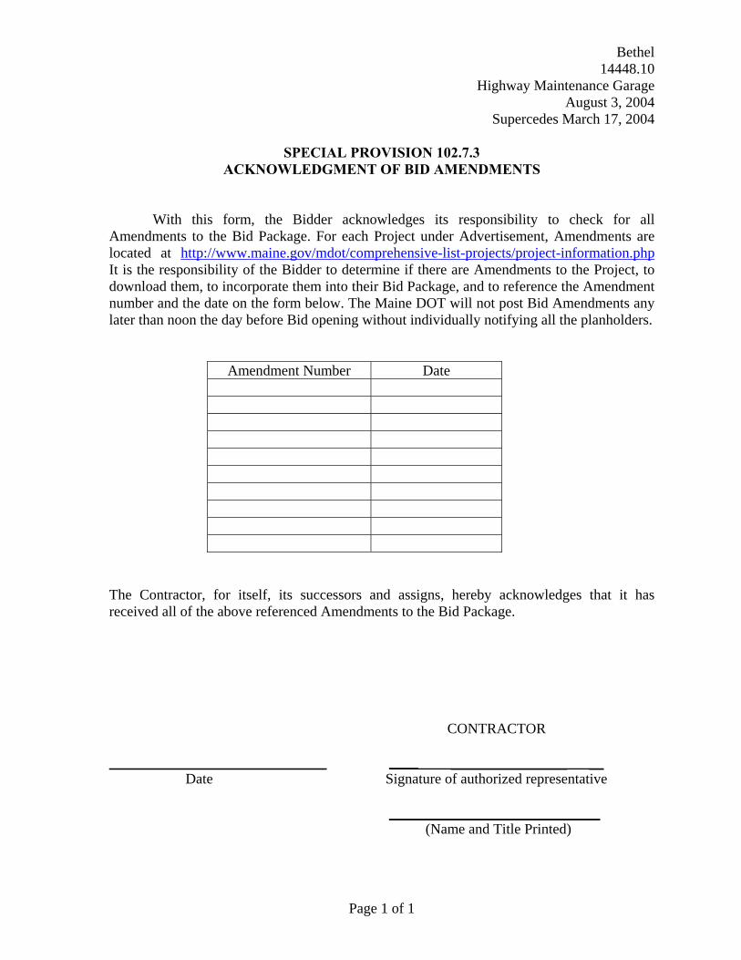
SPECIAL PROVISION 102.7.3 ACKNOWLEDGMENT OF BID AMENDMENTS
With this form, the Bidder acknowledges its responsibility to check for all
Amendments to the Bid Package. For each Project under Advertisement, Amendments are located at http://www.maine.gov/mdot/comprehensive-list-projects/project-information.php It is the responsibility of the Bidder to determine if there are Amendments to the Project, to download them, to incorporate them into their Bid Package, and to reference the Amendment number and the date on the form below. The Maine DOT will not post Bid Amendments any later than noon the day before Bid opening without individually notifying all the planholders.
Amendment Number Date
The Contractor, for itself, its successors and assigns, hereby acknowledges that it has received all of the above referenced Amendments to the Bid Package.
CONTRACTOR ____ ________________ __ Date Signature of authorized representative _____________________________ (Name and Title Printed)
Page 1 of 1
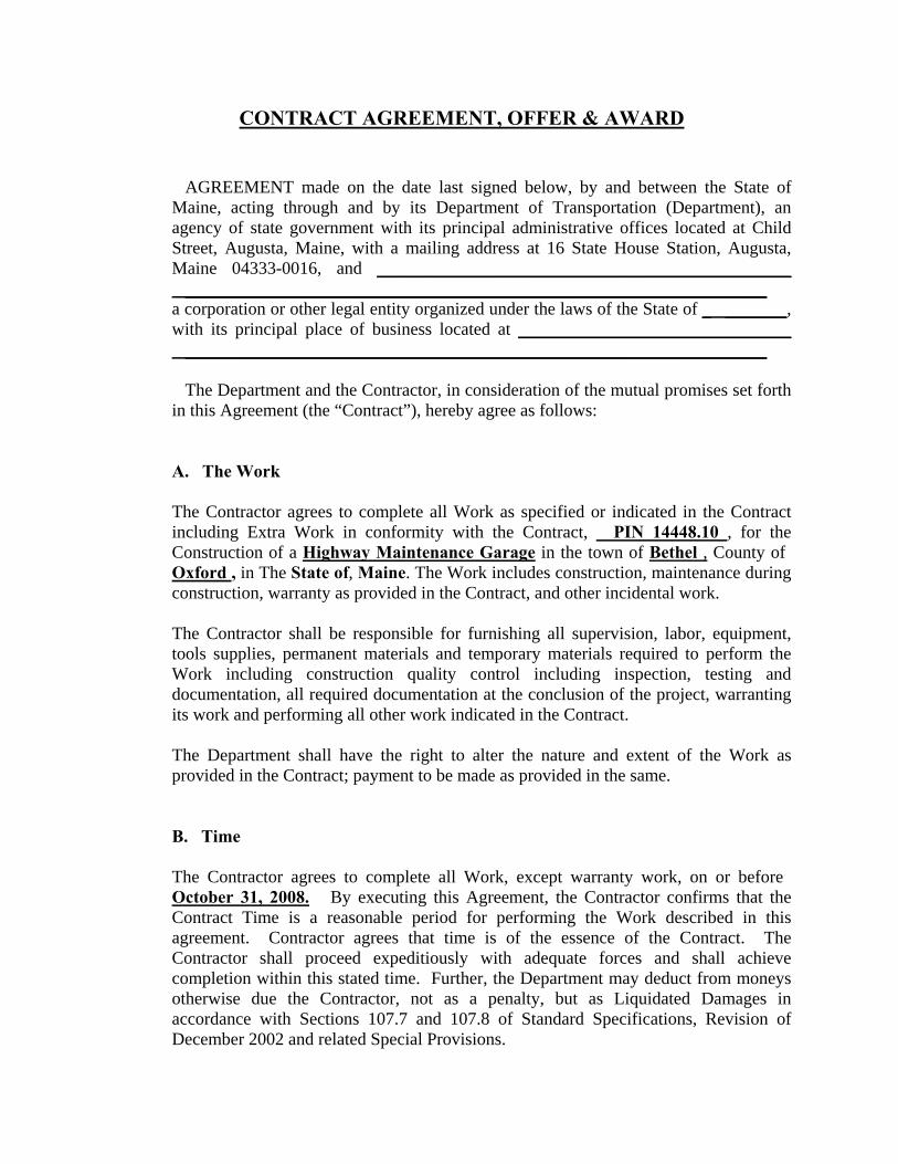
CONTRACT AGREEMENT, OFFER & AWARD
AGREEMENT made on the date last signed below, by and between the State of Maine, acting through and by its Department of Transportation (Department), an agency of state government with its principal administrative offices located at Child Street, Augusta, Maine, with a mailing address at 16 State House Station, Augusta, Maine 04333-0016, and _______________________________________________ __________________________________________________________________ a corporation or other legal entity organized under the laws of the State of _ _______, with its principal place of business located at _______________________________ __________________________________________________________________
The Department and the Contractor, in consideration of the mutual promises set forth in this Agreement (the “Contract”), hereby agree as follows:
A. The Work
The Contractor agrees to complete all Work as specified or indicated in the Contract including Extra Work in conformity with the Contract, PIN 14448.10 , for the Construction of a Highway Maintenance Garage in the town of Bethel , County of Oxford , in The State of, Maine. The Work includes construction, maintenance during construction, warranty as provided in the Contract, and other incidental work. The Contractor shall be responsible for furnishing all supervision, labor, equipment, tools supplies, permanent materials and temporary materials required to perform the Work including construction quality control including inspection, testing and documentation, all required documentation at the conclusion of the project, warranting its work and performing all other work indicated in the Contract. The Department shall have the right to alter the nature and extent of the Work as provided in the Contract; payment to be made as provided in the same.
B. Time
The Contractor agrees to complete all Work, except warranty work, on or before October 31, 2008. By executing this Agreement, the Contractor confirms that the Contract Time is a reasonable period for performing the Work described in this agreement. Contractor agrees that time is of the essence of the Contract. The Contractor shall proceed expeditiously with adequate forces and shall achieve completion within this stated time. Further, the Department may deduct from moneys otherwise due the Contractor, not as a penalty, but as Liquidated Damages in accordance with Sections 107.7 and 107.8 of Standard Specifications, Revision of December 2002 and related Special Provisions.

C. Price
The LUMP SUM Bid Price will be used as the basis for determining the amounts of the required Performance Surety Bond and Payment Surety Bond, and that the amount of this offer is Section 0001 Building $______________________________________ Section 0002 Alternative Fuel Option $__________________________ Performance Bond and Payment Bond each being 100% of the amount awarded under this Contract (see award amount in Section G below).
D. Contract
This Contract, which may be amended, modified, or supplemented in writing only, consists of the Contract documents as defined in the Plans, Standard Specifications, Revision of December 2002, Standard Details, Revision of 2002 as updated through advertisement, Supplemental Specifications, Special Provisions, Contract Agreement; and Contract Bonds. It is agreed and understood that this Contract will be governed by the documents listed above.
E. Certifications
By signing below, the Contractor hereby certifies that to the best of the Contractor’s knowledge and belief: 1. All of the statements, representations, covenants, and/or certifications required or
set forth in the Bid and the Bid Documents, including those in Appendix A to the Division 100 General Conditions (Federal Contract Provisions Supplement), and the Contract are still complete and accurate as of the date of this Agreement.
2. The Contractor knows of no legal, contractual, or financial impediment to entering
into this Contract. 3. The person signing below is legally authorized by the Contractor to sign this
Contract on behalf of the Contractor and to legally bind the Contractor to the terms of the Contract.

F. Offer
The undersigned, having carefully examined the site of work, the Plans, Standard Specifications, Revision of December 2002,Standard Details, Revision of December 2002 as updated through advertisement, Supplemental Specifications, Special Provisions, Contract Agreement; and Contract Bonds contained herein for construction of: A Highway Maintenance Garage in the Town of Bethel, State of Maine, on which bids will be received until the time specified in the “Notice to Contractors” do(es) hereby bid and offer to enter into this contract to supply all the materials, tools, equipment and labor to construct the whole of the Work in strict accordance with the terms and conditions of this Contract”.
The Offeror agrees to perform the work required at the price specified above and in” strict accordance with the terms of this solicitation, and to provide the appropriate insurance and bonds if this offer is accepted by the Government in writing.
As Offeror also agrees:
First: To do any extra work, which may be ordered by the Resident, and to accept as full compensation the amount determined upon a “Force Account” basis as provided in the Standard Specifications, Revision of December 2002, and as addressed in the contract documents, including Section 109.
Second: That the bid bond at 5% of the bid amount or the official bank check, cashier’s check, certificate of deposit or U. S. Postal Money Order in the amount given in the “Notice to Contractors”, payable to the Treasurer of the State of Maine and accompanying this bid, shall be forfeited, as liquidated damages, if in case this bid is accepted, and the undersigned shall fail to abide by the terms and conditions of the offer and fail to furnish satisfactory insurance and Contract bonds under the conditions stipulated in the Specifications within 15 days of notice of intent to award the contract.
Third: To begin the Work as stated in Section 107.2 of the Standard Specifications, Revision of December 2002, and complete the Work within the time limits given in the Special Provisions of this Contract.
Fourth: That this offer shall remain open for 30 calendar days after the date of opening of bids.
Fifth: The Bidder hereby certifies, to the best of its knowledge and belief that: the Bidder has not, either directly or indirectly, entered into any agreement, participated in any collusion, or otherwise taken any action in restraint of competitive bidding in connection with its bid, and its subsequent contract with the Department.
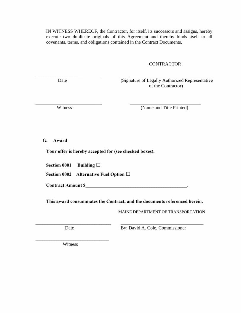
IN WITNESS WHEREOF, the Contractor, for itself, its successors and assigns, hereby execute two duplicate originals of this Agreement and thereby binds itself to all covenants, terms, and obligations contained in the Contract Documents.
CONTRACTOR ____________________________ _______________________________________ Date (Signature of Legally Authorized Representative of the Contractor) ____________________________ ______________________________ Witness (Name and Title Printed)
G. Award
Your offer is hereby accepted for (see checked boxes).
Section 0001 Building □
Section 0002 Alternative Fuel Option □ Contract Amount $___________________________________________. This award consummates the Contract, and the documents referenced herein. MAINE DEPARTMENT OF TRANSPORTATION ________________________________ ___________________________________ Date By: David A. Cole, Commissioner _______________________________ Witness

CONTRACT AGREEMENT, OFFER & AWARD
AGREEMENT made on the date last signed below, by and between the State of Maine, acting through and by its Department of Transportation (Department), an agency of state government with its principal administrative offices located at Child Street, Augusta, Maine, with a mailing address at 16 State House Station, Augusta, Maine 04333-0016, and _______________________________________________ __________________________________________________________________ a corporation or other legal entity organized under the laws of the State of _ _______, with its principal place of business located at _______________________________ __________________________________________________________________
The Department and the Contractor, in consideration of the mutual promises set forth in this Agreement (the “Contract”), hereby agree as follows:
A. The Work
The Contractor agrees to complete all Work as specified or indicated in the Contract including Extra Work in conformity with the Contract, PIN 14448.10 , for the Construction of a Highway Maintenance Garage in the town of Bethel , County of Oxford , in The State of, Maine. The Work includes construction, maintenance during construction, warranty as provided in the Contract, and other incidental work. The Contractor shall be responsible for furnishing all supervision, labor, equipment, tools supplies, permanent materials and temporary materials required to perform the Work including construction quality control including inspection, testing and documentation, all required documentation at the conclusion of the project, warranting its work and performing all other work indicated in the Contract. The Department shall have the right to alter the nature and extent of the Work as provided in the Contract; payment to be made as provided in the same.
B. Time
The Contractor agrees to complete all Work, except warranty work, on or before October 31, 2008. By executing this Agreement, the Contractor confirms that the Contract Time is a reasonable period for performing the Work described in this agreement. Contractor agrees that time is of the essence of the Contract. The Contractor shall proceed expeditiously with adequate forces and shall achieve completion within this stated time. Further, the Department may deduct from moneys otherwise due the Contractor, not as a penalty, but as Liquidated Damages in accordance with Sections 107.7 and 107.8 of Standard Specifications, Revision of December 2002 and related Special Provisions.
C. Price
The LUMP SUM Bid Price will be used as the basis for determining the amounts of the required Performance Surety Bond and Payment Surety Bond, and that the amount of this offer is Section 0001 Building $______________________________________ Section 0002 Alternative Fuel Option $__________________________ Performance Bond and Payment Bond each being 100% of the amount awarded under this Contract (see award amount in Section G below).
D. Contract
This Contract, which may be amended, modified, or supplemented in writing only, consists of the Contract documents as defined in the Plans, Standard Specifications, Revision of December 2002, Standard Details, Revision of 2002 as updated through advertisement, Supplemental Specifications, Special Provisions, Contract Agreement; and Contract Bonds. It is agreed and understood that this Contract will be governed by the documents listed above.
E. Certifications
By signing below, the Contractor hereby certifies that to the best of the Contractor’s knowledge and belief: 1. All of the statements, representations, covenants, and/or certifications required or
set forth in the Bid and the Bid Documents, including those in Appendix A to the Division 100 General Conditions (Federal Contract Provisions Supplement), and the Contract are still complete and accurate as of the date of this Agreement.
2. The Contractor knows of no legal, contractual, or financial impediment to entering
into this Contract. 3. The person signing below is legally authorized by the Contractor to sign this
Contract on behalf of the Contractor and to legally bind the Contractor to the terms of the Contract.
F. Offer
The undersigned, having carefully examined the site of work, the Plans, Standard Specifications, Revision of December 2002,Standard Details, Revision of December 2002 as updated through advertisement, Supplemental Specifications, Special Provisions, Contract Agreement; and Contract Bonds contained herein for construction of: A Highway Maintenance Garage in the Town of Bethel, State of Maine, on which bids will be received until the time specified in the “Notice to Contractors” do(es) hereby bid and offer to enter into this contract to supply all the materials, tools, equipment and labor to construct the whole of the Work in strict accordance with the terms and conditions of this Contract”.
The Offeror agrees to perform the work required at the price specified above and in” strict accordance with the terms of this solicitation, and to provide the appropriate insurance and bonds if this offer is accepted by the Government in writing.
As Offeror also agrees:
First: To do any extra work, which may be ordered by the Resident, and to accept as full compensation the amount determined upon a “Force Account” basis as provided in the Standard Specifications, Revision of December 2002, and as addressed in the contract documents, including Section 109.
Second: That the bid bond at 5% of the bid amount or the official bank check, cashier’s check, certificate of deposit or U. S. Postal Money Order in the amount given in the “Notice to Contractors”, payable to the Treasurer of the State of Maine and accompanying this bid, shall be forfeited, as liquidated damages, if in case this bid is accepted, and the undersigned shall fail to abide by the terms and conditions of the offer and fail to furnish satisfactory insurance and Contract bonds under the conditions stipulated in the Specifications within 15 days of notice of intent to award the contract.
Third: To begin the Work as stated in Section 107.2 of the Standard Specifications, Revision of December 2002, and complete the Work within the time limits given in the Special Provisions of this Contract.
Fourth: That this offer shall remain open for 30 calendar days after the date of opening of bids.
Fifth: The Bidder hereby certifies, to the best of its knowledge and belief that: the Bidder has not, either directly or indirectly, entered into any agreement, participated in any collusion, or otherwise taken any action in restraint of competitive bidding in connection with its bid, and its subsequent contract with the Department.
IN WITNESS WHEREOF, the Contractor, for itself, its successors and assigns, hereby execute two duplicate originals of this Agreement and thereby binds itself to all covenants, terms, and obligations contained in the Contract Documents.
CONTRACTOR ____________________________ _______________________________________ Date (Signature of Legally Authorized Representative of the Contractor) ____________________________ ______________________________ Witness (Name and Title Printed)
G. Award
Your offer is hereby accepted for (see checked boxes).
Section 0001 Building □
Section 0002 Alternative Fuel Option □ Contract Amount $_____________________________________________. This award consummates the Contract, and the documents referenced herein. MAINE DEPARTMENT OF TRANSPORTATION ________________________________ ___________________________________ Date By: David A. Cole, Commissioner _______________________________ Witness
CONTRACT AGREEMENT, OFFER & AWARD
AGREEMENT made on the date last signed below, by and between the State of Maine, acting through and by its Department of Transportation (Department), an agency of state government with its principal administrative offices located at Child Street Augusta, Maine, with a mailing address at 16 State House Station, Augusta, Maine 04333-0016, and _________(Name of the firm bidding the job)__________________ a corporation or other legal entity organized under the laws of the State of Maine, with its principal place of business located at ___(address of the firm bidding the job) _____ ________________________________________________________________________ The Department and the Contractor, in consideration of the mutual promises set forth in this Agreement (the “Contract”), hereby agree as follows: A. The Work.
The Contractor agrees to complete all Work as specified or indicated in the Contract including Extra Work in conformity with the Contract, PIN No. ____1224.00 ________________________________________________________________ , for the ________Hot Mix Asphalt Overlay in the town/city of ________West Eastport , County of ______Washington , Maine. The Work includes construction, maintenance during construction, warranty as provided in the Contract, and other incidental work. The Contractor shall be responsible for furnishing all supervision, labor, equipment, tools supplies, permanent materials and temporary materials required to perform the Work including construction quality control including inspection, testing and documentation, all required documentation at the conclusion of the project, warranting its work and performing all other work indicated in the Contract. The Department shall have the right to alter the nature and extent of the Work as provided in the Contract; payment to be made as provided in the same.
B. Time.
The Contractor agrees to complete all Work, except warranty work, on or before ____November 15, 2003. Further, the Department may deduct from moneys otherwise due the Contractor, not as a penalty, but as Liquidated Damages in accordance with Sections 107.7 and 107.8 of the State of Maine Department of Transportation Standard Specifications, Revision of December 2002.
C. Price.
The quantities given in the Schedule of Items of the Bid Package will be used as the basis for determining the original Contract amount and for determining the amounts of the required Performance Surety Bond and Payment Surety Bond, and that the amount of this offer is ____(Place bid here in alphabetical form such as One Hundred and Two dollars and 10 cents) ________________________________ $_ (repeat bid here in numerical terms, such as $102.10)__________ Performance Bond and Payment Bond each being 100% of the amount of this Contract.
D. Contract.
This Contract, which may be amended, modified, or supplemented in writing only, consists of the Contract documents as defined in the Plans, Standard Specifications, Revision of December 2002, Standard Details Revision of December 2002, Supplemental Specifications, Special Provisions, Contract Agreement; and Contract Bonds. It is agreed and understood that this Contract will be governed by the documents listed above.
E. Certifications.
By signing below, the Contractor hereby certifies that to the best of the Contractor’s knowledge and belief: 1. All of the statements, representations, covenants, and/or certifications required or
set forth in the Bid and the Bid Documents, including those in Appendix A to Division 100 of the Standard Specifications Revision of December 2002 (Federal Contract Provisions Supplement), and the Contract are still complete and accurate as of the date of this Agreement.
2. The Contractor knows of no legal, contractual, or financial impediment to entering
into this Contract. 3. The person signing below is legally authorized by the Contractor to sign this
Contract on behalf of the Contractor and to legally bind the Contractor to the terms of the Contract.
F. Offer.
The undersigned, having carefully examined the site of work, the Plans, Standard Specifications, Revision of December 2002, Standard Details Revision of December 2002, Supplemental Specifications, Special Provisions, Contract Agreement; and Contract Bonds contained herein for construction of:
________PIN 1234.00 West Eastport, Hot Mix Asphalt Overlay ,
State of Maine, on which bids will be received until the time specified in the “Notice to Contractors” do(es) hereby bid and offer to enter into this contract to supply all the materials, tools, equipment and labor to construct the whole of the Work in strict accordance with the terms and conditions of this Contract at the unit prices in the attached “Schedule of Items”.
The Offeror agrees to perform the work required at the price specified above and in accordance with the bids provided in the attached “Schedule of Items” in strict accordance with the terms of this solicitation, and to provide the appropriate insurance and bonds if this offer is accepted by the Government in writing.
As Offeror also agrees:
First: To do any extra work, not covered by the attached “Schedule of Items”, which may be ordered by the Resident, and to accept as full compensation the amount determined upon a “Force Account” basis as provided in the Standard Specifications, Revision of December 2002, and as addressed in the contract documents.
Second: That the bid bond at 5% of the bid amount or the official bank check, cashier’s check, certificate of deposit or U. S. Postal Money Order in the amount given in the “Notice to Contractors”, payable to the Treasurer of the State of Maine and accompanying this bid, shall be forfeited, as liquidated damages, if in case this bid is accepted, and the undersigned shall fail to abide by the terms and conditions of the offer and fail to furnish satisfactory insurance and Contract bonds under the conditions stipulated in the Specifications within 15 days of notice of intent to award the contract.
Third: To begin the Work on the date specified in the Engineer’s “Notice to Commence Work” as stated in Section 107.2 of the Standard Specifications Revision of 2002 and complete the Work within the time limits given in the Special Provisions of this Contract.
Fourth: The Contractor will be bound to the Disadvantaged Business Enterprise (DBE) Requirements contained in the attached Notice (Additional Instructions to Bidders) and submit a completed Contractor’s Disadvantaged Business Enterprise Utilization Plan by 4:30pm on the day of bid opening to the Contracts Engineer.
Fifth: That this offer shall remain open for 30 calendar days after the date of opening of bids.
Sixth: The Bidder hereby certifies, to the best of its knowledge and belief that: the Bidder has not, either directly or indirectly, entered into any agreement, participated in any collusion, or otherwise taken any action in restraint of competitive bidding in connection with its bid, and its subsequent contract with the Department.
IN WITNESS WHEREOF, the Contractor, for itself, its successors and assigns, hereby execute two duplicate originals of this Agreement and thereby binds itself to all covenants, terms, and obligations contained in the Contract Documents. CONTRACTOR ____________________________ ______________(Sign Here)_______________ Date (Signature of Legally Authorized Representative of the Contractor) ____(Witness Sign Here)__ __ __________(Print Name Here)____________ Witness (Name and Title Printed) G. Award.
Your offer is hereby accepted. This award consummates the Contract, and the documents referenced herein.
MAINE DEPARTMENT OF TRANSPORTATION ________________________________ __________________________________ Date By: David A. Cole, Commissioner ________________________________ (Witness)
BOND # _____________________
CONTRACT PERFORMANCE BOND (Surety Company Form)
KNOW ALL MEN BY THESE PRESENTS: That ______________________________ ___________________ and the State of _________________________, as principal, and………………………………………............................................................................., a corporation duly organized under the laws of the State of ........................ and having a usual place of business ...................... .................................................................................., as Surety, are held and firmly bound unto the Treasurer of the State of Maine in the sum of ______________________________________ and 00/100 Dollars ($ ), to be paid said Treasurer of the State of Maine or his successors in office, for which payment well and truly to be made, Principal and Surety bind themselves, their heirs, executors and administrators, successors and assigns, jointly and severally by these presents.
The condition of this obligation is such that if the Principal designated as Contractor in the Contract to construct Project Number ____________ in the Municipality of ______________________ promptly and faithfully performs the Contract, then this obligation shall be null and void; otherwise it shall remain in full force and effect.
The Surety hereby waives notice of any alteration or extension of time made by the State of Maine.
Signed and sealed this .................................. day of ............................................, 20….. .
WITNESSES: SIGNATURES: CONTRACTOR: Signature.................................................... ..........................................…........................ Print Name Legibly ................................... Print Name Legibly ...……......................... SURETY: Signature ................................................... .....……........................................................ Print Name Legibly .................................. Print Name Legibly ..................................... SURETY ADDRESS: NAME OF LOCAL AGENCY: .................................................................. ADDRESS .................................................. .................................................................. ..……………............................................... .................................................................. .......…………….......................................... TELEPHONE........................................... .......……………..........................................
vii
BOND # _______________________
CONTRACT PAYMENT BOND (Surety Company Form)
KNOW ALL MEN BY THESE PRESENTS: That ______________________________ _______________________ and the State of ______________________, as principal, and....................................................................….................................................................. a corporation duly organized under the laws of the State of .......................... and having a usual place of business in .....................…………………………………………………., as Surety, are held and firmly bound unto the Treasurer of the State of Maine for the use and benefit of claimants as herein below defined, in the sum of __________________________________________ and 00/100 Dollars ($ ) for the payment whereof Principal and Surety bind themselves, their heirs, executors and administrators, successors and assigns, jointly and severally by these presents. The condition of this obligation is such that if the Principal designated as Contractor in the Contract to construct Project Number ____________ in the Municipality of _________________________ promptly satisfies all claims and demands incurred for all labor and material, used or required by him in connection with the work contemplated by said Contract, and fully reimburses the obligee for all outlay and expense which the obligee may incur in making good any default of said Principal, then this obligation shall be null and void; otherwise it shall remain in full force and effect.
A claimant is defined as one having a direct contract with the Principal or with a Subcontractor of the Principal for labor, material or both, used or reasonably required for use in the performance of the contract. Signed and sealed this ............................. day of ...………......................................., 20 ... . WITNESS: SIGNATURES: CONTRACTOR: Signature……............................................ ......…............................................................. Print Name Legibly .........................…….. Print Name Legibly .….................................
SURETY: Signature.................................................... ...…............................................................... Print Name Legibly .................................. Print Name Legibly .….................................. SURETY ADDRESS: NAME OF LOCAL AGENCY: ...…............................................................ ADDRESS …................................................ ................................................................... …………….................................................... TELEPHONE ........................................... ………………................................................
viii

March 14, 2007 Supersedes March 3, 1966
Non-federal Projects Only
NOTICE TO CONTRACTORS - PREFERRED EMPLOYEES
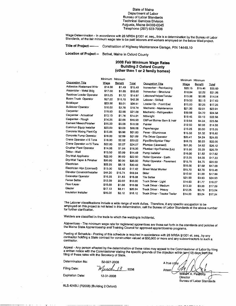
Sec. 1303. Public Works; minimum wage In the employment of laborers in the construction of public works, including state highways, by the State or by persons contracting for the construction, preference must first be given to citizens of the State who are qualified to perform the work to which the employment relates and, if they can not be obtained in sufficient numbers, then to citizens of the United States. Every contract for public works construction must contain a provision for employing citizens of this State or the United States. The hourly wage and benefit rate paid to laborers employed in the construction of public works, including state highways, may not be less than the fair minimum rate as determined in accordance with section 1308. Any contractor who knowingly and willfully violates this section is subject to a fine of not less than $250 per employee violation. Each day that any contractor employs a laborer at less than the wage and benefit minimum stipulated in this section constitutes a separate violation of this section. [1997, c. 757, §1 (amd).]
1 of 1
Bethel 14448.10
Highway Maintenance Garage
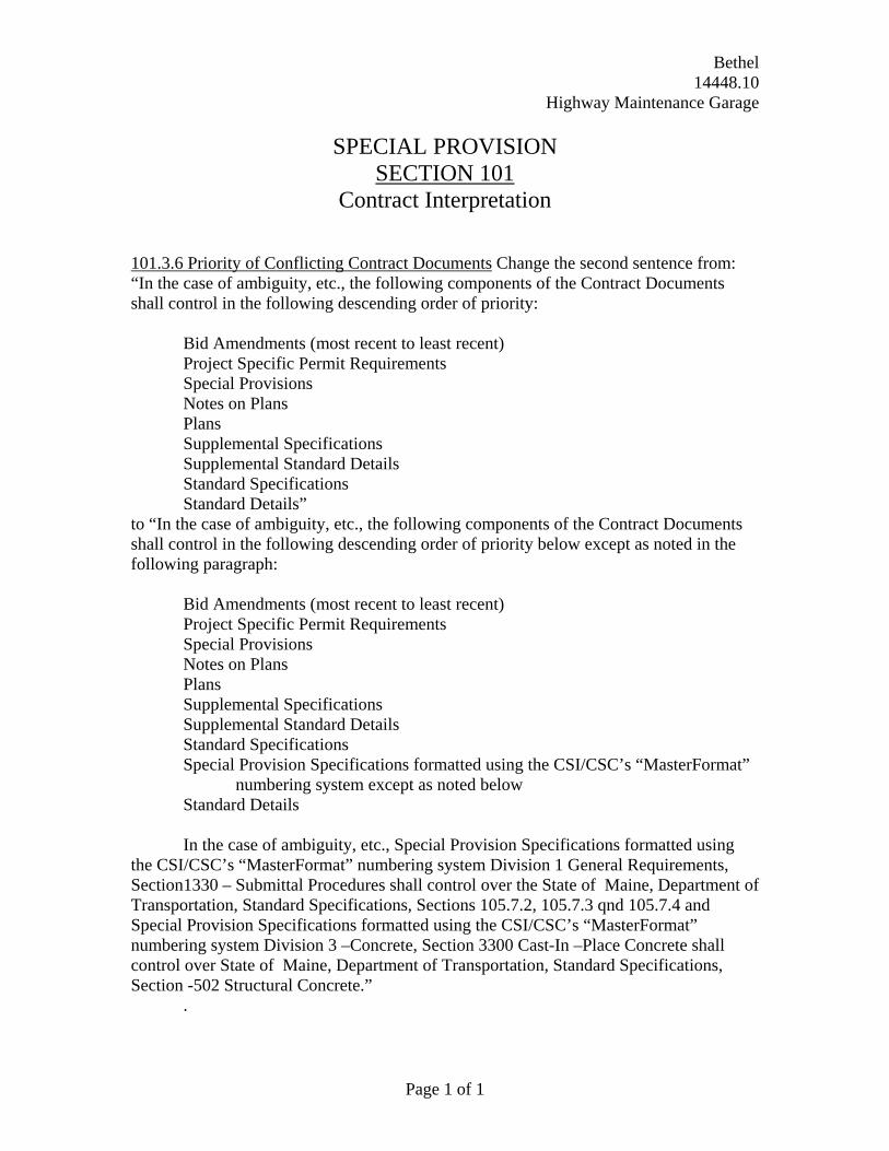
SPECIAL PROVISION SECTION 101
Contract Interpretation
Page 1 of 1
101.3.6 Priority of Conflicting Contract Documents Change the second sentence from: “In the case of ambiguity, etc., the following components of the Contract Documents shall control in the following descending order of priority: Bid Amendments (most recent to least recent) Project Specific Permit Requirements Special Provisions Notes on Plans Plans Supplemental Specifications
Supplemental Standard Details Standard Specifications Standard Details” to “In the case of ambiguity, etc., the following components of the Contract Documents shall control in the following descending order of priority below except as noted in the following paragraph: Bid Amendments (most recent to least recent) Project Specific Permit Requirements Special Provisions Notes on Plans Plans Supplemental Specifications
Supplemental Standard Details Standard Specifications
Special Provision Specifications formatted using the CSI/CSC’s “MasterFormat” numbering system except as noted below
Standard Details
In the case of ambiguity, etc., Special Provision Specifications formatted using the CSI/CSC’s “MasterFormat” numbering system Division 1 General Requirements, Section1330 – Submittal Procedures shall control over the State of Maine, Department of Transportation, Standard Specifications, Sections 105.7.2, 105.7.3 qnd 105.7.4 and Special Provision Specifications formatted using the CSI/CSC’s “MasterFormat” numbering system Division 3 –Concrete, Section 3300 Cast-In –Place Concrete shall control over State of Maine, Department of Transportation, Standard Specifications, Section -502 Structural Concrete.”
.
Bethel 14448.10
Highway Maintenance Garage
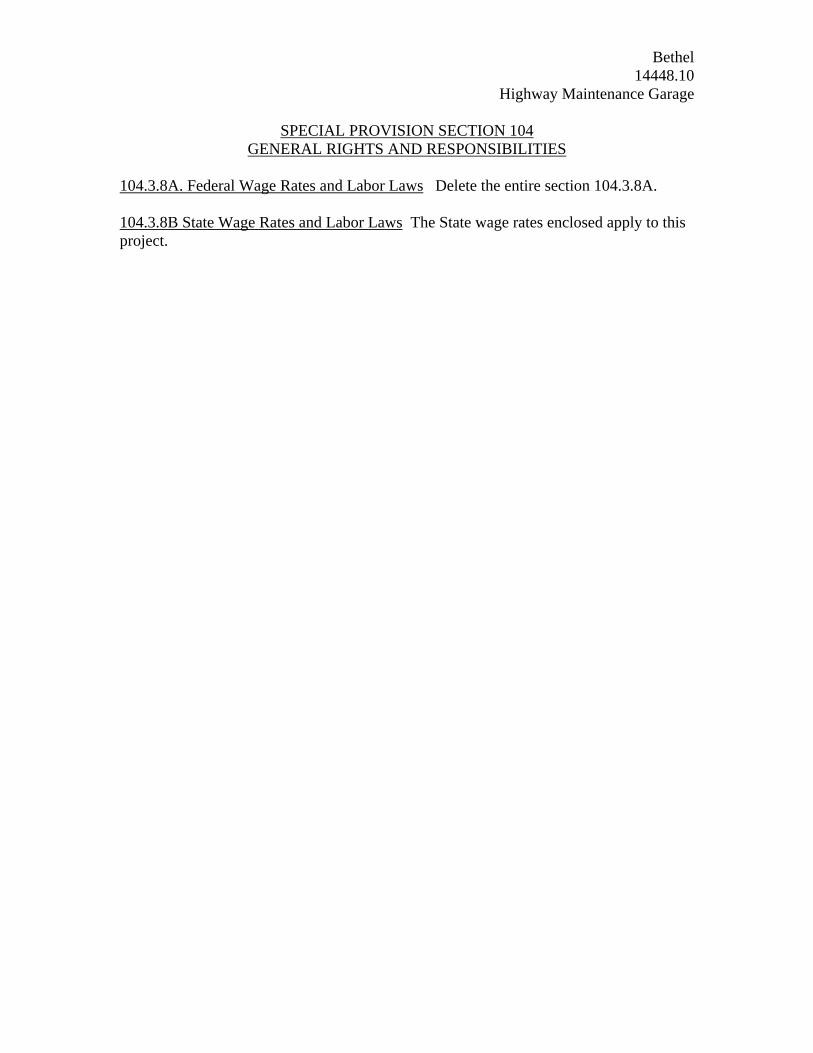
SPECIAL PROVISION SECTION 104 GENERAL RIGHTS AND RESPONSIBILITIES
104.3.8A. Federal Wage Rates and Labor Laws Delete the entire section 104.3.8A. 104.3.8B State Wage Rates and Labor Laws The State wage rates enclosed apply to this project.
Bethel 14448.10
Highway Maintenance Garage March 13, 2008
SPECIAL PROVISION SECTION 107
Time (Contract Time)
1. The contractor will be allowed to commence work anytime provided that all
required submittals have been received and approved by MaineDOT.
2. The completion date for this project is October 31, 2008.
Bethel 14448.10
Highway Maintenance Garage March 21, 2008
SPECIAL PROVISION Contract Time
Within 14 Days of Contract Execution and before beginning any on-site activities,
the Contractor shall provide the Department with its Schedule of Work in a Critical Path Method (CPM) in the form of an activity on node (AON) diagram. The progress of the Work shall be compared against the Schedule of Work at each Progress Meeting. If the Department determines that the Contractor’s actual progress is one or more week behind the Schedule of Work, then the Contractor shall either increase Project resources to get back on schedule or submit a revised Schedule of Work and demonstrate that there is sufficient labor, equipment and materials to assure the timely completion of the work.
Progress Meetings shall be held at least every two weeks, throughout the duration
of the Contract. In lieu of a Progress Meeting, the Resident and the Superintendent may exchange written communication (letter, fax, or e-mail) before or on the scheduled Progress Meeting date that indicates there is no need for the meeting because the Work is on schedule, compensation is current, communication is ongoing, and there are no significant outstanding or anticipated issues, Disputes or claims. The Superintendent's written communication shall also contain a description of (A) progress of the Project since the last Progress Meeting or communication in lieu thereof and (B) expected activities before the next scheduled Progress Meeting.
When the Contractor becomes aware of facts or circumstances that may cause the
Contractor to seek additional compensation, time, or any other change in Contract requirements ("Issue"), then the Contractor shall notify the Resident within 48 hours. The notice must describe the basic nature and extent of the Issue.
If the Contractor be delayed at any time in the progress of the work by any act or
neglect of the Owner or the Architect, or of any employee of either, or by any separate Contractor employed by the Owner, or by changes ordered in the work, or by strikes, lockouts, fire, unusual delay in transportation, unavoidable casualties or any causes beyond the Contractor's control, or by any cause which the Department shall decide to justify the delay, then the time of completion shall be extended for such reasonable time as the Department may decide or the Department may choose to compensate the Contractor for additional resources, additional men, additional hours, or both, or provide additional equipment needed to assure the timely completion of the work. No such extension shall be made for delay occurring more than seven days before claim therefor is made in writing to the Department. In case of a continuing cause of delay, only one claim is necessary. If no schedule or agreement stating the dates upon which drawings shall be furnished is made, then no claim for delay shall be allowed on account of failure to furnish drawings and not then unless such claim be reasonable. If, in the opinion of
Page 1 of 2
Bethel 14448.10
Highway Maintenance Garage March 21, 2008
the Department, progress of the work is such that the contract completion date cannot be met for causes other than those stated above, the Department may request the Contractor to work additional men, additional hours, or both, or provide additional equipment. Costs of all such additional work shall be borne by the Contractor. This article does not exclude the recovery of damages for delay by either party under other provisions in the Contract Document.
Page 2 of 2
March 12, 2008 Supersedes March 12, 2008
Page 1 of 21
SPECIAL PROVISION DIVISION 400 PAVEMENTS
SECTION 401 - HOT MIX ASPHALT PAVEMENT
401.01 Description The Contractor shall furnish and place one or more courses of Hot Mix Asphalt Pavement (HMA) on an approved base in accordance with the contract documents and in reasonably close conformity with the lines, grades, thickness, and typical cross sections shown on the plans or established by the Resident. The Department will accept this work under Quality Assurance provisions, in accordance with these specifications and the requirements of Section 106 – Quality, the provisions of AASHTO M 323 except where otherwise noted in sections 401 and 703 of these specifications, and the Maine DOT Policies and Procedures for HMA Sampling and Testing.
401.02 Materials Materials shall meet the requirements specified in Section 700 - Materials:
Asphalt Cement 702.01 Aggregates for HMA Pavement 703.07 HMA Mixture Composition 703.09
401.021 Recycled Asphalt Materials Recycled Asphalt Pavement (RAP) may be introduced into the mixture at percentages approved by the Department. If approved by the Department, the Contractor shall provide documentation stating the source, average residual asphalt content, and stockpile gradations showing RAP materials have been sized to meet the maximum aggregate size requirements of each mix designation. The Department will obtain samples for verification and approval prior to its use. In the event that RAP source or properties change, the Contractor shall notify the Department of the change and submit new documentation stating the new source or properties a minimum of 72 hours prior to the change to allow for obtaining new samples and approval. 401.03 Composition of Mixtures The Contractor shall compose the Hot Mix Asphalt Pavement with aggregate, Performance Graded Asphalt Binder (PGAB), and mineral filler if required. HMA shall be designed and tested according to AASHTO T312 and the volumetric criteria in Table 1. The Contractor shall size, uniformly grade, and combine the aggregate fractions in proportions that provide a mixture meeting the grading requirements of the Job Mix Formula (JMF). The Contractor may use a maximum of 15% reclaimed asphalt pavement (RAP) in any base, binder, surface, or shim course. The Contractor may be allowed to use more than 15% RAP, up to a maximum of 25% RAP, in a base, binder, or shim course provided that PG 58-34 asphalt binder is used in the mixture.
The Contractor shall submit for Department approval a JMF to the Central Laboratory in Bangor for each mixture to be supplied. The Department may approve 1 active design per nominal maximum size, per traffic level, per plant, plus a 9.5mm “fine” mix @ 50 gyrations for shimming and where required, a non-RAP design for bridge decks. The Department shall then have 15 calendar days in which to process a new design before approval. The JMF shall establish a single percentage of aggregate passing each sieve size within the limits shown in section 703.09. The mixture shall be designed and produced, including all production tolerances, to comply with the allowable control points for the particular type of mixture as outlined in 703.09. The JMF shall state the original source, gradation, and percentage to be used of each portion of the aggregate and mineral filler if required. It shall also state the proposed PGAB content, the name and location of the refiner, the supplier, the source of PGAB submitted for approval, the type of PGAB modification if applicable, and the location of the terminal if applicable.
In addition, the Contractor shall provide the following information with the proposed JMF:
March 12, 2008 Supersedes March 12, 2008
Page 2 of 21
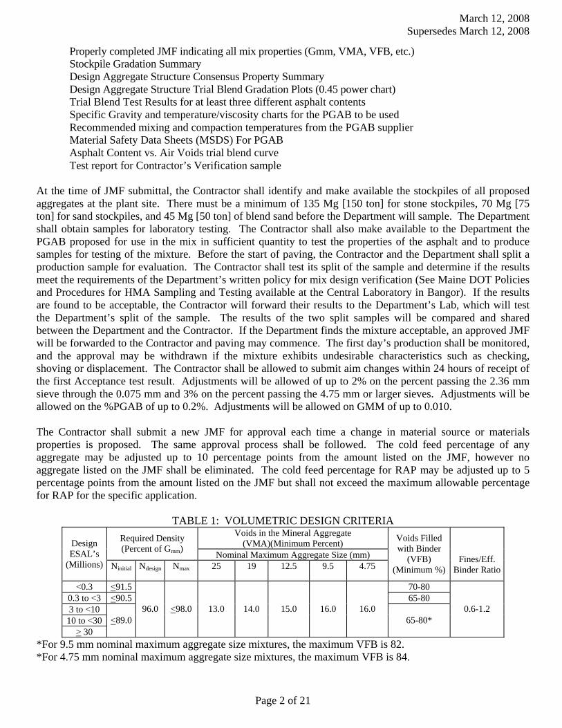
Properly completed JMF indicating all mix properties (Gmm, VMA, VFB, etc.) Stockpile Gradation Summary Design Aggregate Structure Consensus Property Summary Design Aggregate Structure Trial Blend Gradation Plots (0.45 power chart) Trial Blend Test Results for at least three different asphalt contents
Specific Gravity and temperature/viscosity charts for the PGAB to be used Recommended mixing and compaction temperatures from the PGAB supplier
Material Safety Data Sheets (MSDS) For PGAB Asphalt Content vs. Air Voids trial blend curve
Test report for Contractor’s Verification sample At the time of JMF submittal, the Contractor shall identify and make available the stockpiles of all proposed aggregates at the plant site. There must be a minimum of 135 Mg [150 ton] for stone stockpiles, 70 Mg [75 ton] for sand stockpiles, and 45 Mg [50 ton] of blend sand before the Department will sample. The Department shall obtain samples for laboratory testing. The Contractor shall also make available to the Department the PGAB proposed for use in the mix in sufficient quantity to test the properties of the asphalt and to produce samples for testing of the mixture. Before the start of paving, the Contractor and the Department shall split a production sample for evaluation. The Contractor shall test its split of the sample and determine if the results meet the requirements of the Department’s written policy for mix design verification (See Maine DOT Policies and Procedures for HMA Sampling and Testing available at the Central Laboratory in Bangor). If the results are found to be acceptable, the Contractor will forward their results to the Department’s Lab, which will test the Department’s split of the sample. The results of the two split samples will be compared and shared between the Department and the Contractor. If the Department finds the mixture acceptable, an approved JMF will be forwarded to the Contractor and paving may commence. The first day’s production shall be monitored, and the approval may be withdrawn if the mixture exhibits undesirable characteristics such as checking, shoving or displacement. The Contractor shall be allowed to submit aim changes within 24 hours of receipt of the first Acceptance test result. Adjustments will be allowed of up to 2% on the percent passing the 2.36 mm sieve through the 0.075 mm and 3% on the percent passing the 4.75 mm or larger sieves. Adjustments will be allowed on the %PGAB of up to 0.2%. Adjustments will be allowed on GMM of up to 0.010. The Contractor shall submit a new JMF for approval each time a change in material source or materials properties is proposed. The same approval process shall be followed. The cold feed percentage of any aggregate may be adjusted up to 10 percentage points from the amount listed on the JMF, however no aggregate listed on the JMF shall be eliminated. The cold feed percentage for RAP may be adjusted up to 5 percentage points from the amount listed on the JMF but shall not exceed the maximum allowable percentage for RAP for the specific application.
TABLE 1: VOLUMETRIC DESIGN CRITERIA Voids in the Mineral Aggregate
(VMA)(Minimum Percent) Required Density (Percent of Gmm)
Nominal Maximum Aggregate Size (mm) Design ESAL’s
(Millions) Ninitial Ndesign Nmax 25
19
12.5
9.5
4.75
Voids Filled with Binder
(VFB) (Minimum %)
Fines/Eff. Binder Ratio
<0.3 <91.5 70-80 0.3 to <3 <90.5 65-80 3 to <10
10 to <30 > 30
<89.0 96.0 <98.0 13.0 14.0 15.0 16.0 16.0
65-80* 0.6-1.2
*For 9.5 mm nominal maximum aggregate size mixtures, the maximum VFB is 82. *For 4.75 mm nominal maximum aggregate size mixtures, the maximum VFB is 84.
March 12, 2008 Supersedes March 12, 2008
Page 3 of 21
401.04 Temperature Requirements After the JMF is established, the temperatures of the mixture shall conform to the following tolerances: In the truck at the mixing plant – allowable range 135° to 163°C [275 to 325°F] At the Paver – allowable range 135° to 163°C [275 to 325°F] The JMF and the mix subsequently produced shall meet the requirements of Tables 1 and Section 703.07.
401.05 Performance Graded Asphalt Binder Unless otherwise noted in Special Provision 403 - Hot Bituminous Pavement, PGAB shall be 64-28, except that for mixtures containing greater than 15% but no more than 25% RAP the PGAB shall be PG 58-34. The PGAB shall meet the applicable requirements of AASHTO M320 - Standard Specification for PGAB. The Contractor shall provide the Department with an approved copy of the Quality Control Plan for PGAB in accordance with AASHTO R 26 Certifying Suppliers of PGAB.
401.06 Weather and Seasonal Limitations The State is divided into two paving zones as follows:
a. Zone 1 Areas north of US Route 2 from Gilead to Bangor and north of Route 9 from Bangor to Calais.
b. Zone 2 Areas south of Zone 1 including the US Route 2 and Route 9 boundaries.
The Contractor may place Hot Mix Asphalt Pavement for use other than a traveled way wearing course in either Zone between the dates of April 15th and November 15th, provided that the air temperature as determined by an approved thermometer (placed in the shade at the paving location) is 4°C [40°F] or higher and the area to be paved is not frozen. The Contractor may place Hot Mix Asphalt Pavement as traveled way wearing course in Zone 1 between the dates of May 1st and the Saturday following October 1st and in Zone 2 between the dates of April 15th and the Saturday following October 15th, provided the air temperature determined as above is 10°C [50°F] or higher. For the purposes of this Section, the traveled way includes truck lanes, ramps, approach roads and auxiliary lanes. The atmospheric temperature for all courses on bridge decks shall be 10°C [50°F] or higher.
Hot Mix Asphalt Pavement used for curb, driveways, sidewalks, islands, or other incidentals is not subject to seasonal limitations, except that conditions shall be satisfactory for proper handling and finishing of the mixture. Unless otherwise specified, the Contractor shall not place Hot Mix Asphalt Pavement on a wet or frozen surface and the air temperature shall be 4°C [40°F] or higher.
On all sections of overlay with wearing courses less than 25 mm [1 in] thick, the wearing course for the travelway and adjacent shoulders shall be placed between the dates of May 15th and the Saturday following September 15th.
On all sections of overlay with wearing courses less than 1 inch thick, the wearing course for the travelway and adjacent shoulders shall be placed between the dates of June 1st and the Saturday following September 1st if the work is to be performed, either by contract requirement, or Contractor option, during conditions defined as “night work”. 401.07 Hot Mix Asphalt Plant 401.071 General Requirements HMA plants shall conform to AASHTO M156.
a. Truck Scales When the hot mix asphalt is to be weighed on scales meeting the requirements of Section 108 - Payment, the scales shall be inspected and sealed by the State Sealer as often as the Department deems necessary to verify their accuracy.
March 12, 2008 Supersedes March 12, 2008
Page 4 of 21
Plant scales shall be checked prior to the start of the paving season, and each time a plant is moved to a new location. Subsequent checks will be made as determined by the Resident. The Contractor will have at least ten 20 Kg [50 pound] masses for scale testing.
401.072 Automation of Batching Batch plants shall be automated for weighing, recycling, and monitoring the system. In the case of a malfunction of the printing system, the requirements of Section 401.074 c. of this specification will apply.
The batch plant shall accurately proportion the various materials in the proper order by weight. The entire batching and mixing cycle shall be continuous and shall not require any manual operations. The batch plant shall use auxiliary interlock circuits to trigger an audible alarm whenever an error exceeding the acceptable tolerance occurs. Along with the alarm, the printer shall print an asterisk on the delivery slip in the same row containing the out-of-tolerance weight. The automatic proportioning system shall be capable of consistently delivering material within the full range of batch sizes. When RAP is being used, the plant must be capable of automatically compensating for the moisture content of the RAP.
All plants shall be equipped with an approved digital recording device. The delivery slip load ticket shall contain information required under Section 108.1.3 - Provisions Relating to Certain Measurements, Mass and paragraphs a, b, and c of Section 401.073
401.073 Automatic Ticket Printer System on Automatic HMA Plant An approved automatic ticket printer system shall be used with all approved automatic HMA plants. The requirements for delivery slips for payment of materials measured by weight, as given in the following Sections, shall be waived: 108.1.3 a., 108.1.3 b., 108.1.3 c., and 108.1.3 d. The automatic printed ticket will be considered as the Weight Certificate.
The requirements of Section 108.1.3 f. - Delivery Slips, shall be met by the weigh slip or ticket, printed by the automatic system, which accompanies each truckload, except for the following changes:
a. The quantity information required shall be individual weights of each batch or total net weight of
each truckload. b. Signatures (legible initials acceptable) of Weighmaster (required only in the event of a malfunction
as described in 401.074 c.). c. The MDOT designation for the JMF.
401.074 Weight Checks on Automatic HMA Plant At least twice during each 5 days of production either of the following checks will be performed:
a. A loaded truck may be intercepted and weighed on a platform scale that has been sealed by the State
Sealer of Weights and Measures within the past 12 months. Whenever the discrepancy in net weights is greater than 1.0%, but does not exceed 1.5%, the plant inspector will notify the producer to take corrective action; payment will still be governed by the printed ticket. The producer will be allowed a period of two days to make any needed repairs to the plant and/or platform scales so that the discrepancy in net weights between the two is less than 1.0%. If the discrepancy exceeds 1.5%, the plant will be allowed to operate as long as payment is determined by truck platform scale net weight. Effective corrective action shall be taken within two working days.
b. Where platform scales are not readily available, a check will be made to verify the accuracy and
sensitivity of each scale within the normal weighing range and to assure that the interlocking devices and automatic printer system are functioning properly.

March 12, 2008 Supersedes March 12, 2008
Page 5 of 21
c. In the event of a malfunction of the automatic printer system, production may be continued without the use of platform truck scales for a period not to exceed the next two working days, providing total weights of each batch are recorded on weight tickets and certified by a Licensed Public Weighmaster.
401.08 Hauling Equipment Trucks for hauling Hot Mix Asphalt Pavement shall have tight, clean, and smooth metal dump bodies, which have been thinly coated with a small amount of approved release agent to prevent the mixture from adhering to the bodies.
All truck dump bodies shall have a cover of canvas or other water repellent material capable of heat retention, which completely covers the mixture. The cover shall be securely fastened on the truck, unless unloading.
All truck bodies shall have an opening on both sides, which will accommodate a thermometer stem. The opening shall be located near the midpoint of the body, at least 300 mm [12 in] above the bed.
401.09 Pavers Pavers shall be self-contained, self-propelled units with an activated screed (heated if necessary) capable of placing courses of Hot Mix Asphalt Pavement in full lane widths on the main line, shoulder or similar construction. On projects with no price adjustment for smoothness, pavers shall be of sufficient class and size to place Hot Mix Asphalt Pavement over the full width of the mainline travel way with a 3 m [10 ft] minimum main screed with activated extensions. The Contractor shall place Hot Mix Asphalt Pavement on the main line with a paver using an automatic grade and slope controlled screed, unless otherwise authorized by the Department. The controls shall automatically adjust the screed and increase or decrease the layer thickness to compensate for irregularities in the preceding course. The controls shall maintain the proper transverse slope and be readily adjustable so that transitions and superelevated curves can be properly paved. The controls shall operate from a fixed or moving reference such as a grade wire or ski type device (floating beam) with a minimum length of 10 m [30 ft], a non-contact grade control with a minimum span of 7.3 m [24 ft], except that a 12 m [40 ft] reference shall be used on Expressway projects.
The Contractor shall operate the paver in such a manner as to produce a visually uniform surface texture and a thickness within the requirements of Section 401.101 - Surface Tolerances. The paver shall have a receiving hopper with sufficient capacity for a uniform spreading operation and a distribution system to place the mixture uniformly, without segregation in front of the screed. The screed assembly shall produce a finished surface of the required evenness and texture without tearing, shoving, or gouging the mixture. Pavers with extendible screeds shall have auger extensions and tunnel extenders as per the manufacturer’s recommendations, a copy of which shall be available if requested.
The Contractor shall have the paver at the project site sufficiently before the start of paving operations to be inspected and approved by the Department. The Contractor shall repair or replace any paver found worn or defective, either before or during placement, to the satisfaction of the Department. Pavers that produce an unevenly textured or non-uniform mat will be repaired or replaced before continuing to place HMA on MDOT projects. On a daily basis, the Contractor shall perform nuclear density testing across the mat being placed, at 300 mm [12 in] intervals. If the values vary by more than 2.0% from the mean, the Contractor shall make adjustments until the inconsistencies are remedied. Failure to replace or repair defective placement equipment may result in a letter of suspension of work and notification of a quality control violation resulting in possible monetary penalties as governed by Section 106 - Quality
March 12, 2008 Supersedes March 12, 2008
Page 6 of 21
401.10 Rollers Rollers shall be static steel, pneumatic tire, or approved vibrator type. Rollers shall be in good mechanical condition, capable of starting and stopping smoothly, and be free from backlash when reversing direction. Rollers shall be equipped and operated in such a way as to prevent the picking up of hot mixed material by the roller surface. The use of rollers, which result in crushing of the aggregate or in displacement of the HMA will not be permitted. Any Hot Mix Asphalt Pavement that becomes loose, broken, contaminated, shows an excess or deficiency of Performance Graded Asphalt Binder, or is in any other way defective shall be removed and replaced at no additional cost with fresh Hot Mix Asphalt Pavement, which shall be immediately compacted to conform to the adjacent area.
The type of rollers to be used and their relative position in the compaction sequence shall generally be the Contractor’s option, provided specification densities are attained and with the following requirements:
a. On variable-depth courses, the first lift of pavement over gravel, reclaimed pavement, an irregular surface, or on bridges, at least one roller shall be 14.5 Mg [16 ton] pneumatic-tired. Unless otherwise allowed by the Resident, pneumatic-tired rollers shall be equipped with skirting to minimize the pickup of HMA materials from the paved surface. When required by the Resident, the roller shall be ballasted to 18.1 Mg [20 ton]. b. Compaction with a vibratory or steel wheel roller shall precede pneumatic-tired rolling, unless otherwise authorized by the Department.
c. Vibratory rollers shall not be operated in the vibratory mode when checking or cracking of the mat occurs, or on bridge decks.
d. Any method, which results in cracking or checking of the mat, will be discontinued and corrective action taken.
The maximum operating speed for a steel wheel or pneumatic roller shall not exceed the manufacturer’s recommendations, a copy of which shall be available if requested.
401.101 Surface Tolerances The Department will check surface tolerance utilizing the following methods :
a.) A 5 m [16 ft] straightedge or string line placed directly on the surface, parallel to the centerline of pavement. b.) A 3 m [10 ft] straightedge or string line placed directly on the surface, transverse to the centerline of pavement.
The Contractor shall correct variations exceeding 6 mm [¼ in] by removing defective work and replacing it with new material as directed by the Department. The Contractor shall furnish a 10 foot straightedge for the Departments use. 401.11 Preparation of Existing Surface The Contractor shall thoroughly clean the surface upon which Hot Mix Asphalt Pavement is to be placed of all objectionable material. When the surface of the existing base or pavement is irregular, the Contractor shall bring it to uniform grade and cross section. All surfaces shall have a tack coat applied prior to placing any new HMA course. Tack coat shall conform to the requirements of Section 409 – Bituminous Tack Coat, Section 702 – Bituminous Material, and all applicable sections of the contract.
401.12 Hot Mix Asphalt Documentation The Contractor and the Department shall agree on the amount of Hot Mix Asphalt Pavement that has been placed each day.

March 12, 2008 Supersedes March 12, 2008
Page 7 of 21
401.13 Preparation of Aggregates The Contractor shall dry and heat the aggregates for the HMA to the required temperature. The Contractor shall properly adjust flames to avoid physical damage to the aggregate and to avoid depositing soot on the aggregate.
401.14 Mixing The Contractor shall combine the dried aggregate in the mixer in the amount of each fraction of aggregate required to meet the JMF. The Contractor shall measure the amount of PGAB and introduce it into the mixer in the amount specified by the JMF.
The Contractor shall produce the HMA at the temperature established by the JMF.
The Contractor shall dry the aggregate sufficiently so that the HMA will not flush, foam excessively, or displace excessively under the action of the rollers. The Contractor shall introduce the aggregate into the mixer at a temperature of not more than 14°C [25°F] above the temperature at which the viscosity of the PGAB being used is 0.150 Paοs.
The Contractor shall store and introduce into the mixer the Performance Graded Asphalt Binder at a uniformly maintained temperature at which the viscosity of the PGAB is between 0.150 Paοs and 0.300 Paοs. The aggregate shall be coated completely and uniformly with a thorough distribution of the PGAB. The Contractor shall determine the wet mixing time for each plant and for each type of aggregate used.
401.15 Spreading and Finishing On areas where irregularities or unavoidable obstacles make the use of mechanical spreading and finishing equipment impracticable, the Contractor shall spread, rake, and lute the HMA with hand tools to provide the required compacted thickness.
On roads opened to two-way traffic, the Contractor shall place each course over the full width of the traveled way section being paved that day, unless otherwise noted by the Department in Section 403 - Hot Bituminous Pavement.
401.16 Compaction Immediately after the Hot Mix Asphalt Pavement has been spread, struck off, and any surface irregularities adjusted, the Contractor shall thoroughly and uniformly compact the HMA by rolling.
The Contractor shall roll the surface when the mixture is in the proper condition and when the rolling does not cause undue displacement, cracking, or shoving. The Contractor shall prevent adhesion of the HMA to the rollers or vibrating compactors without the use of fuel oil or other petroleum based release agents.
The Contractor shall immediately correct any displacement occurring as a result of the reversing of the direction of a roller or from other causes to the satisfaction of the Department. Any operation other than placement of variable depth shim course that results in breakdown of the aggregate shall be discontinued. Any new pavement that shows obvious cracking, checking, or displacement shall be removed and replaced for the full lane width as directed by the Resident at no cost to the Department. Along forms, curbs, headers, walls, and other places not accessible to the rollers, the Contractor shall thoroughly compact the HMA with mechanical vibrating compactors. The Contractor shall only use hand tamping in areas inaccessible to all other compaction equipment. On depressed areas, the Contractor may use a trench roller or cleated compression strips under a roller to transmit compression to the depressed area.
Any HMA that becomes unacceptable due to cooling, cracking, checking, segregation or deformation as a result of an interruption in mix delivery shall be removed and replaced, with material that meets contract specifications at no cost to the Department.
March 12, 2008 Supersedes March 12, 2008
Page 8 of 21
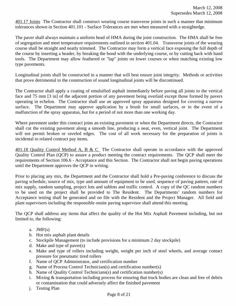
401.17 Joints The Contractor shall construct wearing course transverse joints in such a manner that minimum tolerances shown in Section 401.101 - Surface Tolerances are met when measured with a straightedge.
The paver shall always maintain a uniform head of HMA during the joint construction. The HMA shall be free of segregation and meet temperature requirements outlined in section 401.04. Transverse joints of the wearing course shall be straight and neatly trimmed. The Contractor may form a vertical face exposing the full depth of the course by inserting a header, by breaking the bond with the underlying course, or by cutting back with hand tools. The Department may allow feathered or "lap" joints on lower courses or when matching existing low type pavements.
Longitudinal joints shall be constructed in a manner that will best ensure joint integrity. Methods or activities that prove detrimental to the construction of sound longitudinal joints will be discontinued.
The Contractor shall apply a coating of emulsified asphalt immediately before paving all joints to the vertical face and 75 mm [3 in] of the adjacent portion of any pavement being overlaid except those formed by pavers operating in echelon. The Contractor shall use an approved spray apparatus designed for covering a narrow surface. The Department may approve application by a brush for small surfaces, or in the event of a malfunction of the spray apparatus, but for a period of not more than one working day.
Where pavement under this contract joins an existing pavement or when the Department directs, the Contractor shall cut the existing pavement along a smooth line, producing a neat, even, vertical joint. The Department will not permit broken or raveled edges. The cost of all work necessary for the preparation of joints is incidental to related contract pay items.
401.18 Quality Control Method A, B & C The Contractor shall operate in accordance with the approved Quality Control Plan (QCP) to assure a product meeting the contract requirements. The QCP shall meet the requirements of Section 106.6 - Acceptance and this Section. The Contractor shall not begin paving operations until the Department approves the QCP in writing.
Prior to placing any mix, the Department and the Contractor shall hold a Pre-paving conference to discuss the paving schedule, source of mix, type and amount of equipment to be used, sequence of paving pattern, rate of mix supply, random sampling, project lots and sublots and traffic control. A copy of the QC random numbers to be used on the project shall be provided to The Resident. The Departments’ random numbers for Acceptance testing shall be generated and on file with the Resident and the Project Manager. All field and plant supervisors including the responsible onsite paving supervisor shall attend this meeting. The QCP shall address any items that affect the quality of the Hot Mix Asphalt Pavement including, but not limited to, the following:
a. JMF(s) b. Hot mix asphalt plant details c. Stockpile Management (to include provisions for a minimum 2 day stockpile) d. Make and type of paver(s) e. Make and type of rollers including weight, weight per inch of steel wheels, and average contact
pressure for pneumatic tired rollers f. Name of QCP Administrator, and certification number g. Name of Process Control Technician(s) and certification number(s) h. Name of Quality Control Technicians(s) and certification number(s) i. Mixing & transportation including process for ensuring that truck bodies are clean and free of debris
or contamination that could adversely affect the finished pavement j. Testing Plan

March 12, 2008 Supersedes March 12, 2008
Page 9 of 21
k. Laydown operations including longitudinal joint construction, procedures for avoiding paving in inclement weather, type of release agent to be used on trucks tools and rollers, compaction of shoulders, tacking of all joints, methods to ensure that segregation is minimized, procedures to determine the maximum rolling and paving speeds based on best engineering practices as well as past experience in achieving the best possible smoothness of the pavement
l. Examples of Quality Control forms including a daily plant report and a daily paving report m. Silo management and details (can show storage for use on project of up to 36 hours) n. Provisions for varying mix temperature due to extraordinary conditions o. Name and responsibilities of the Responsible onsite Paving Supervisor p. Method for calibration/verification of Density Gauge q. A note that all testing will be done in accordance with AASHTO and the Maine DOT Policies and
Procedures for HMA Sampling and Testing. r. A note detailing conditions under which the percent of RAP will vary from that specified on the
JMF. s. A note detailing when production will be halted due to QC testing results.
The QCP shall include the following technicians together with these minimum requirements: a. QCP Administrator - A qualified individual shall administer the QCP. The QCP Administrator must be a full-time employee of or a consultant engaged by the Contractor or paving subcontractor. The QCP Administrator shall have full authority to institute any and all actions necessary for the successful operation of the QCP. The QCP Administrator (or its designee in the QCP Administrator’s absence) shall be available to communicate with the Department at all times. The QCP Administrator shall be certified as a Quality Assurance Technologist certified by the New England Transportation Technician Certification Program (NETTCP).
b. Process Control Technician(s) (PCT) shall utilize test results and other quality control practices to assure the quality of aggregates and other mix components and control proportioning to meet the JMF(s). The PCT shall inspect all equipment used in mixing to assure it is operating properly and that mixing conforms to the mix design(s) and other Contract requirements. The QCP shall detail how these duties and responsibilities are to be accomplished and documented, and whether more than one PCT is required. The Plan shall include the criteria to be utilized by the PCT to correct or reject unsatisfactory materials. The PCT shall be certified as a Plant Technician by the NETTCP.
c. Quality Control Technician(s) (QCT) shall perform and utilize quality control tests at the job site to assure that delivered materials meet the requirements of the JMF(s). The QCT shall inspect all equipment utilized in transporting, laydown, and compacting to assure it is operating properly and that all laydown and compaction conform to the Contract requirements. The QCP shall detail how these duties and responsibilities are to be accomplished and documented, and whether more than one QCT is required. The QCP shall include the criteria utilized by the QCT to correct or reject unsatisfactory materials. The QCT shall be certified as a Paving Inspector by the NETTCP.
The QCP shall detail the coordination of the activities of the Plan Administrator, the PCT and the QCT. The Project Superintendent shall be named in the QCP, and the responsibilities for successful implementation of the QCP shall be outlined.
March 12, 2008 Supersedes March 12, 2008
Page 10 of 21
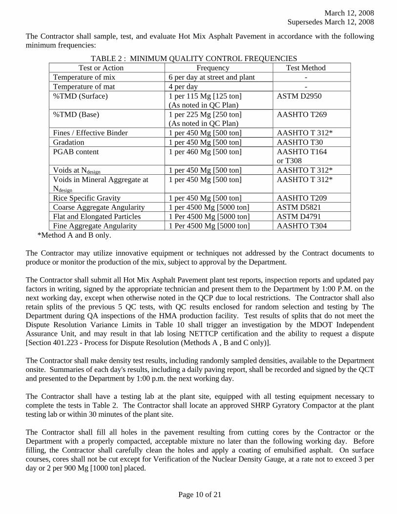
The Contractor shall sample, test, and evaluate Hot Mix Asphalt Pavement in accordance with the following minimum frequencies:
TABLE 2 : MINIMUM QUALITY CONTROL FREQUENCIES
Test or Action Frequency Test Method Temperature of mix 6 per day at street and plant - Temperature of mat 4 per day - %TMD (Surface) 1 per 115 Mg [125 ton]
(As noted in QC Plan) ASTM D2950
%TMD (Base) 1 per 225 Mg [250 ton] (As noted in QC Plan)
AASHTO T269
Fines / Effective Binder 1 per 450 Mg [500 ton] AASHTO T 312* Gradation 1 per 450 Mg [500 ton] AASHTO T30 PGAB content 1 per 460 Mg [500 ton] AASHTO T164
or T308 Voids at Ndesign 1 per 450 Mg [500 ton] AASHTO T 312* Voids in Mineral Aggregate at Ndesign
1 per 450 Mg [500 ton] AASHTO T 312*
Rice Specific Gravity 1 per 450 Mg [500 ton] AASHTO T209 Coarse Aggregate Angularity 1 per 4500 Mg [5000 ton] ASTM D5821 Flat and Elongated Particles 1 Per 4500 Mg [5000 ton] ASTM D4791 Fine Aggregate Angularity 1 Per 4500 Mg [5000 ton] AASHTO T304
*Method A and B only.
The Contractor may utilize innovative equipment or techniques not addressed by the Contract documents to produce or monitor the production of the mix, subject to approval by the Department. The Contractor shall submit all Hot Mix Asphalt Pavement plant test reports, inspection reports and updated pay factors in writing, signed by the appropriate technician and present them to the Department by 1:00 P.M. on the next working day, except when otherwise noted in the QCP due to local restrictions. The Contractor shall also retain splits of the previous 5 QC tests, with QC results enclosed for random selection and testing by The Department during QA inspections of the HMA production facility. Test results of splits that do not meet the Dispute Resolution Variance Limits in Table 10 shall trigger an investigation by the MDOT Independent Assurance Unit, and may result in that lab losing NETTCP certification and the ability to request a dispute [Section 401.223 - Process for Dispute Resolution (Methods A , B and C only)]. The Contractor shall make density test results, including randomly sampled densities, available to the Department onsite. Summaries of each day's results, including a daily paving report, shall be recorded and signed by the QCT and presented to the Department by 1:00 p.m. the next working day.
The Contractor shall have a testing lab at the plant site, equipped with all testing equipment necessary to complete the tests in Table 2. The Contractor shall locate an approved SHRP Gyratory Compactor at the plant testing lab or within 30 minutes of the plant site. The Contractor shall fill all holes in the pavement resulting from cutting cores by the Contractor or the Department with a properly compacted, acceptable mixture no later than the following working day. Before filling, the Contractor shall carefully clean the holes and apply a coating of emulsified asphalt. On surface courses, cores shall not be cut except for Verification of the Nuclear Density Gauge, at a rate not to exceed 3 per day or 2 per 900 Mg [1000 ton] placed.
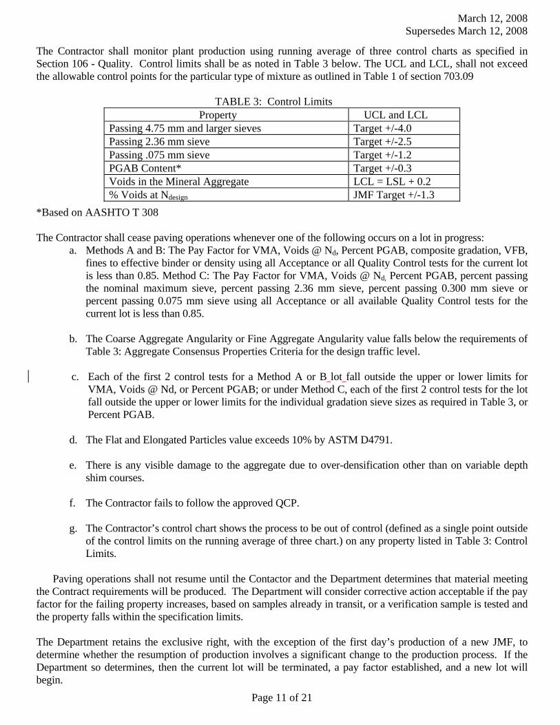
March 12, 2008 Supersedes March 12, 2008
Page 11 of 21
The Contractor shall monitor plant production using running average of three control charts as specified in Section 106 - Quality. Control limits shall be as noted in Table 3 below. The UCL and LCL, shall not exceed the allowable control points for the particular type of mixture as outlined in Table 1 of section 703.09
TABLE 3: Control Limits
Property UCL and LCL Passing 4.75 mm and larger sieves Target +/-4.0 Passing 2.36 mm sieve Target +/-2.5 Passing .075 mm sieve Target +/-1.2 PGAB Content* Target +/-0.3 Voids in the Mineral Aggregate LCL = LSL + 0.2 % Voids at Ndesign JMF Target +/-1.3
*Based on AASHTO T 308 The Contractor shall cease paving operations whenever one of the following occurs on a lot in progress:
a. Methods A and B: The Pay Factor for VMA, Voids @ Nd, Percent PGAB, composite gradation, VFB, fines to effective binder or density using all Acceptance or all Quality Control tests for the current lot is less than 0.85. Method C: The Pay Factor for VMA, Voids @ Nd, Percent PGAB, percent passing the nominal maximum sieve, percent passing 2.36 mm sieve, percent passing 0.300 mm sieve or percent passing 0.075 mm sieve using all Acceptance or all available Quality Control tests for the current lot is less than 0.85.
b. The Coarse Aggregate Angularity or Fine Aggregate Angularity value falls below the requirements of
Table 3: Aggregate Consensus Properties Criteria for the design traffic level. c. Each of the first 2 control tests for a Method A or B lot fall outside the upper or lower limits for
VMA, Voids @ Nd, or Percent PGAB; or under Method C, each of the first 2 control tests for the lot fall outside the upper or lower limits for the individual gradation sieve sizes as required in Table 3, or Percent PGAB.
d. The Flat and Elongated Particles value exceeds 10% by ASTM D4791. e. There is any visible damage to the aggregate due to over-densification other than on variable depth
shim courses. f. The Contractor fails to follow the approved QCP. g. The Contractor’s control chart shows the process to be out of control (defined as a single point outside
of the control limits on the running average of three chart.) on any property listed in Table 3: Control Limits.
Paving operations shall not resume until the Contactor and the Department determines that material meeting
the Contract requirements will be produced. The Department will consider corrective action acceptable if the pay factor for the failing property increases, based on samples already in transit, or a verification sample is tested and the property falls within the specification limits.
The Department retains the exclusive right, with the exception of the first day’s production of a new JMF, to determine whether the resumption of production involves a significant change to the production process. If the Department so determines, then the current lot will be terminated, a pay factor established, and a new lot will begin.
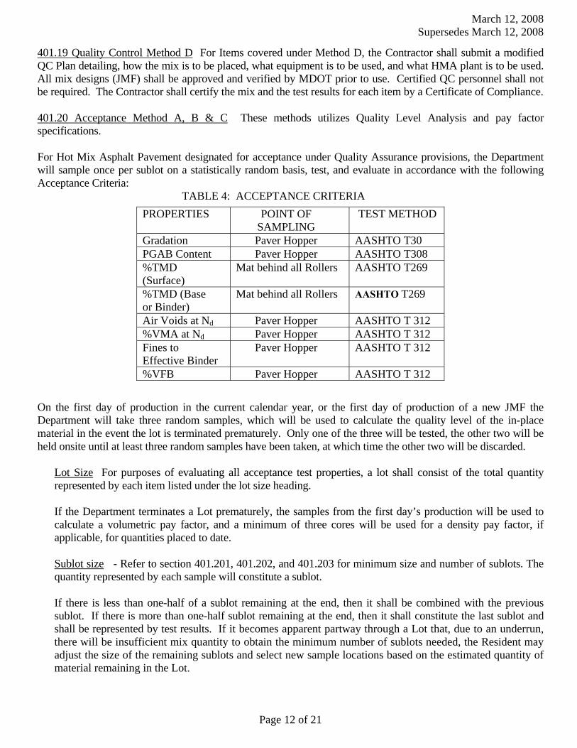
March 12, 2008 Supersedes March 12, 2008
Page 12 of 21
401.19 Quality Control Method D For Items covered under Method D, the Contractor shall submit a modified QC Plan detailing, how the mix is to be placed, what equipment is to be used, and what HMA plant is to be used. All mix designs (JMF) shall be approved and verified by MDOT prior to use. Certified QC personnel shall not be required. The Contractor shall certify the mix and the test results for each item by a Certificate of Compliance.
401.20 Acceptance Method A, B & C These methods utilizes Quality Level Analysis and pay factor specifications. For Hot Mix Asphalt Pavement designated for acceptance under Quality Assurance provisions, the Department will sample once per sublot on a statistically random basis, test, and evaluate in accordance with the following Acceptance Criteria:
TABLE 4: ACCEPTANCE CRITERIA
PROPERTIES POINT OF SAMPLING
TEST METHOD
Gradation Paver Hopper AASHTO T30 PGAB Content Paver Hopper AASHTO T308 %TMD (Surface)
Mat behind all Rollers AASHTO T269
%TMD (Base or Binder)
Mat behind all Rollers AASHTO T269
Air Voids at Nd Paver Hopper AASHTO T 312 %VMA at Nd Paver Hopper AASHTO T 312 Fines to Effective Binder
Paver Hopper AASHTO T 312
%VFB Paver Hopper AASHTO T 312
On the first day of production in the current calendar year, or the first day of production of a new JMF the Department will take three random samples, which will be used to calculate the quality level of the in-place material in the event the lot is terminated prematurely. Only one of the three will be tested, the other two will be held onsite until at least three random samples have been taken, at which time the other two will be discarded.
Lot Size For purposes of evaluating all acceptance test properties, a lot shall consist of the total quantity represented by each item listed under the lot size heading. If the Department terminates a Lot prematurely, the samples from the first day’s production will be used to calculate a volumetric pay factor, and a minimum of three cores will be used for a density pay factor, if applicable, for quantities placed to date.
Sublot size - Refer to section 401.201, 401.202, and 401.203 for minimum size and number of sublots. The quantity represented by each sample will constitute a sublot.
If there is less than one-half of a sublot remaining at the end, then it shall be combined with the previous sublot. If there is more than one-half sublot remaining at the end, then it shall constitute the last sublot and shall be represented by test results. If it becomes apparent partway through a Lot that, due to an underrun, there will be insufficient mix quantity to obtain the minimum number of sublots needed, the Resident may adjust the size of the remaining sublots and select new sample locations based on the estimated quantity of material remaining in the Lot.
March 12, 2008 Supersedes March 12, 2008
Page 13 of 21
Acceptance Testing The Department will obtain samples of Hot Mix Asphalt Pavement in conformance with AASHTO T168 Sampling Bituminous Paving Mixtures, and the Maine DOT Policies and Procedures for HMA Sampling and Testing, which will then be transported by the Contractor to the designated MDOT Laboratory within 48 hours (except when otherwise noted in the project specific QCP due to local restrictions), as directed by MDOT in approved transport containers to be provided by the Department, unless otherwise directed by the Resident. The Department will take the sample randomly within each sublot. Target values shall be as specified in the JMF. The Department will use Table 5 for calculating pay factors for gradation, PGAB Content, Air Voids at Ndesign, VMA, Fines to Effective Binder and VFB. The Department will withhold reporting of the test results for the Acceptance sample until 7:00 AM, on the second working day of receipt of the sample, or after receipt of the Contractors results of the Acceptance sample split. Upon conclusion of each lot, where there is a minimum of four sublots, results shall be examined for statistical outliers, as stated in Section 106.7.2 - Statistical Outliers.
Isolated Areas During the course of inspection, should it appear that there is an isolated area that is not representative of the lot based on a lack of observed compactive effort, excessive segregation or any other questionable practice, that area may be isolated and tested separately. An area so isolated that has a calculated pay factor below 0.80, based on three random tests shall be removed and replaced at the expense of the Contractor for the full lane width and a length not to be less than 50 m [150 ft].
Pavement Density The Department will measure pavement density using core samples tested according to AASHTO T-166. The Department will randomly determine core locations. The Contractor shall cut 6 inch diameter cores at no additional cost to the Department by the end of the working day following the day the pavement is placed, and immediately give them to the Department. The cores will be placed in a transport container provided by the Department and transported by the Contractor to the designated MDOT Lab as directed by the Department. Pre-testing of the cores will not be allowed. At the time of sampling, the Contractor and the Department shall mutually determine if a core is damaged. If it is determined that the core(s) is damaged, the Contractor shall cut new core(s) at the same offset and within 1 m [3 ft] of the initial sample. At the time the core is cut, the Contractor and the Department will mutually determine if saw cutting of the core is needed, and will mark the core at the point where sawing is needed. The core may be saw cut by the Contractor in the Department's presence onsite, or in an MDOT Lab by The Department, without disturbing the layer being tested to remove lower layers of Hot Mix Asphalt Pavement, gravel, or RAP. No recuts are allowed at a test location after the core has been tested. Upon conclusion of each lot, density results shall be examined for statistical outliers as stated in Section 106.7.2. On all sections of overlay with wearing courses designed to be 19 mm [3/4 in] or less in thickness, there shall be no pay adjustment for density otherwise noted in Section 403 - Hot Bituminous Pavement. For overlays designed to be 19 mm [3/4 in] or less in thickness, density shall be obtained by the same rolling train and methods as used on mainline travelway surface courses with a pay adjustments for density, unless otherwise directed by the Department. There shall be no pay adjustment for density on shoulders unless otherwise noted in Section 403 - Hot Bituminous Pavement. Density for shoulders shall be obtained by the same rolling train and methods as used on mainline travelway, unless otherwise directed by the Department. Efforts to obtain optimum compaction will not be waived by the Department unless it is apparent during construction that local conditions make densification to this point detrimental to the finished pavement surface course. 401.201 Method A Lot Size will be the entire production per JMF for the project, or if so agreed at the Pre-paving Conference, equal lots of up to 4050 Mg [4500 tons], with unanticipated over-runs of up to 1350 Mg [1500 ton] rolled into the last lot. Sublot sizes shall be 675 Mg [750 ton] for mixture properties, 450 Mg [500 ton] for base or binder densities and 225 Mg [250 ton] for surface densities. The minimum number of sublots for mixture properties shall be 4, and the minimum number of sublots for density shall be five.

March 12, 2008 Supersedes March 12, 2008
Page 14 of 21
TABLE 5: METHOD A ACCEPTANCE LIMITS Property USL and LSL
Passing 4.75 mm and larger sieves Target +/-7% Passing 2.36 mm to 1.18 mm sieves Target +/-4% Passing 0.60 mm Target +/-3% Passing 0.30 mm to 0.075 mm sieve Target +/-2% PGAB Content Target +/-0.4% Air Voids 4.0% +/-1.5% Fines to Effective Binder 0.6 to 1.2 Voids in the Mineral Aggregate LSL Only from Table 1 Voids Filled with Binder Table 1 values plus a 4%
production tolerance for USL only % TMD (In place density) 95.0% +/- 2.5%
401.202 Method B Lot Size will be the entire production per JMF for the project and shall be divided into 3 equal sublots for Mixture Properties and 3 equal sublots for density.
TABLE 6: METHOD B ACCEPTANCE LIMITS
Property USL and LSL Percent Passing 4.75 mm and larger sieves Target +/-7 Percent Passing 2.36 mm to 1.18 mm sieves Target +/-5 Percent Passing 0.60 mm Target +/-4 Percent Passing 0.30 mm to 0.075 mm sieve Target +/-3 PGAB Content Target +/-0.5 Air Voids 4.0% +/-2.0 Fines to Effective Binder 0.6 to 1.4 Voids in the Mineral Aggregate LSL from Table 1 Voids Filled with Binder Table1 plus a 4% production tolerance for USL. % TMD (In-place Density) 95.0% +/- 2.5%
401.203 Testing Method C Lot Size will be the entire production per JMF for the project, or if so agreed at the Pre-paving Conference, equal lots of up to 4050 Mg [4500 tons], with unanticipated over-runs of up to 1350 Mg [1500 ton] rolled into the last lot. Sublot sizes shall be 675 Mg [750 ton] for mixture properties, 450 Mg [500 ton] for base or binder densities and 225 Mg [250 ton] for surface densities. The minimum number of sublots for mixture properties shall be 4, and the minimum number of sublots for density shall be five.
TABLE 7: METHOD C ACCEPTANCE LIMITS
Property USL and LSL Passing 4.75 mm and larger sieves Target +/-7% Passing 2.36 mm to 1.18 mm sieves Target +/-4% Passing 0.60 mm Target +/-3% Passing 0.30 mm to 0.075 mm sieve Target +/-2% PGAB Content Target +/-0.4% Air Voids 4.0% +/-1.5% Fines to Effective Binder 0.6 to 1.2 Voids in the Mineral Aggregate LSL Only from Table 1 Voids Filled with Binder Table 1 values plus a 4% production
tolerance for USL only % TMD (In place density) 95.0% +/- 2.5%

March 12, 2008 Supersedes March 12, 2008
Page 15 of 21
401.204 Testing Method D For hot mix asphalt items designated as Method D in Section 403 - Hot Bituminous Pavement, one sample will be taken from the paver hopper or the truck body per 225 Mg [250 ton] per pay item. The mix will be tested for gradation and PGAB content. Disputes will not be allowed. If the mix is within the tolerances listed in Table 8: Method D Acceptance Limits, the Department will pay the contract unit price. If the test results for each 225 Mg [250 ton] increment are outside these limits, the following deductions (Table 8b) shall apply to the HMA quantity represented by the test.
TABLE 8: METHOD D ACCEPTANCE LIMITS
Property USL and LSL Percent Passing 4.75 mm and larger sieves Target +/-7 Percent Passing 2.36 mm to 1.18 mm sieves Target +/-5 Percent Passing 0.60 mm Target +/-4 Percent Passing 0.30 mm to 0.075 mm sieve Target +/-3 PGAB Content Target +/-0.5 % TMD (In-place Density) 95.0% +/- 2.5%
TABLE 8b Method “D” Price Adjustments
PGAB Content -5% 2.36 mm sieve -2% 0.30 mm sieve -1% 0.075 mm sieve -2%
Density -10%* *Only applies when called for in Section 403 - Hot Bituminous Pavement. Contractor shall cut two 150 mm [6 in] cores, which shall be tested for percent TMD per AASHTO T-269. If the average for the two tests falls below 92.5% the disincentive shall apply. 401.21 Method of Measurement The Department will measure Hot Mix Asphalt Pavement by the Mg [ton] in accordance with Section 108.1 - Measurement of Quantities for Payment.
401.22 Basis of Payment The Department will pay for the work, in place and accepted, in accordance with the applicable sections of this Section, for each type of HMA specified. The Department will pay for the work specified in Section 401.11, for the HMA used, except that cleaning objectionable material from the pavement and furnishing and applying bituminous material to joints and contact surfaces is incidental.
Payment for this work under the appropriate pay items shall be full compensation for all labor, equipment, materials, and incidentals necessary to meet all related contract requirements, including design of the JMF, implementation of the QCP, obtaining core samples, transporting cores and samples, filling core holes, applying emulsified asphalt to joints, and providing testing facilities and equipment.
The Department will make a pay adjustment for quality as specified below.
401.221 Pay Adjustment The Department will sample, test, and evaluate Hot Mix Asphalt Pavement in accordance with Section 106 - Quality and Section 401.20 - Acceptance, of this Specification.
401.222 Pay Factor (PF) The Department will use the following criteria for pay adjustment using the pay adjustment factors under Section 106.7 - Quality Level Analysis:
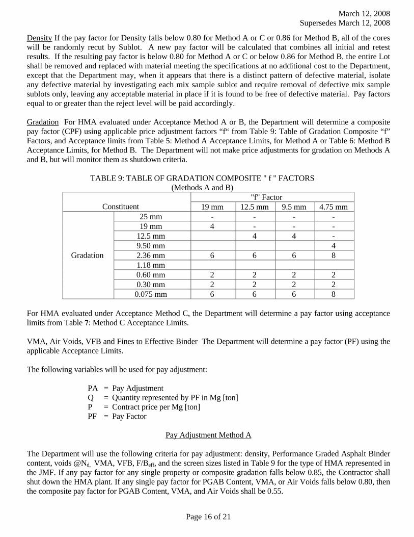
March 12, 2008 Supersedes March 12, 2008
Page 16 of 21
Density If the pay factor for Density falls below 0.80 for Method A or C or 0.86 for Method B, all of the cores will be randomly recut by Sublot. A new pay factor will be calculated that combines all initial and retest results. If the resulting pay factor is below 0.80 for Method A or C or below 0.86 for Method B, the entire Lot shall be removed and replaced with material meeting the specifications at no additional cost to the Department, except that the Department may, when it appears that there is a distinct pattern of defective material, isolate any defective material by investigating each mix sample sublot and require removal of defective mix sample sublots only, leaving any acceptable material in place if it is found to be free of defective material. Pay factors equal to or greater than the reject level will be paid accordingly.
Gradation For HMA evaluated under Acceptance Method A or B, the Department will determine a composite pay factor (CPF) using applicable price adjustment factors “f“ from Table 9: Table of Gradation Composite “f” Factors, and Acceptance limits from Table 5: Method A Acceptance Limits, for Method A or Table 6: Method B Acceptance Limits, for Method B. The Department will not make price adjustments for gradation on Methods A and B, but will monitor them as shutdown criteria.
TABLE 9: TABLE OF GRADATION COMPOSITE " f " FACTORS (Methods A and B)
"f" Factor Constituent 19 mm 12.5 mm 9.5 mm 4.75 mm
25 mm - - - - 19 mm 4 - - -
12.5 mm 4 4 - 9.50 mm 4 2.36 mm 6 6 6 8 1.18 mm 0.60 mm 2 2 2 2 0.30 mm 2 2 2 2
Gradation
0.075 mm 6 6 6 8 For HMA evaluated under Acceptance Method C, the Department will determine a pay factor using acceptance limits from Table 7: Method C Acceptance Limits. VMA, Air Voids, VFB and Fines to Effective Binder The Department will determine a pay factor (PF) using the applicable Acceptance Limits. The following variables will be used for pay adjustment:
PA = Pay Adjustment Q = Quantity represented by PF in Mg [ton]
P = Contract price per Mg [ton] PF = Pay Factor
Pay Adjustment Method A
The Department will use the following criteria for pay adjustment: density, Performance Graded Asphalt Binder content, voids @Nd, VMA, VFB, F/Beff, and the screen sizes listed in Table 9 for the type of HMA represented in the JMF. If any pay factor for any single property or composite gradation falls below 0.85, the Contractor shall shut down the HMA plant. If any single pay factor for PGAB Content, VMA, or Air Voids falls below 0.80, then the composite pay factor for PGAB Content, VMA, and Air Voids shall be 0.55.
March 12, 2008 Supersedes March 12, 2008
Page 17 of 21
Density: For mixes having a density requirement, the Department will determine a pay factor using Table 5: Method A Acceptance Limits:
PA = (density PF- 1.0)(Q)(P)x0.50 PGAB Content, VMA and Air Voids: The Department will determine a pay adjustment using Table 5: Method A Acceptance Limits as follows:
PA = (voids @ Nd PF- 1.0)(Q)(P)x0.20 + (VMA @ Nd PF- 1.0)(Q)(P)x0.20 + (PGAB PF- 1.0)(Q)(P)x0.10
VFB and Fines to Effective Binder The Department will determine a pay factor (PF) using Table 5: Method A Acceptance Limits. The Department will not make price adjustments for VFB or Fines to Effective Binder, but will monitor them as shutdown criteria.
Pay Adjustment Method B
The Department will use the following criteria for pay adjustment: density, Performance Graded Asphalt Binder content, voids @Nd, VMA, VFB, F/Beff, and the screen sizes listed in Table 9 for the type of HMA represented in the JMF. If any pay factor for any single property or composite gradation falls below 0.90, the Contractor shall shut down the HMA plant. If any single pay factor for PGAB Content, VMA, or Air Voids falls below 0.86, then the composite pay factor for PGAB Content, VMA, and Air Voids shall be 0.70. Density: For mixes having a density requirement, the Department will determine a pay factor using Table 6: Method B Acceptance Limits:
PA = (density PF- 1.0)(Q)(P)x0.50 PGAB Content, VMA and Air Voids: The Department will determine a pay adjustment using Table 6: Method B Acceptance Limits as follows:
PA = (voids @ Nd PF- 1.0)(Q)(P)x0.20 + (VMA @ Nd PF- 1.0)(Q)(P)x0.20 + (PGAB PF- 1.0)(Q)(P)x0.10
VFB and Fines to Effective Binder The Department will determine a pay factor (PF) using Table 6: Method B Acceptance Limits. The Department will not make price adjustments for VFB or Fines to Effective Binder, but will monitor them as shutdown criteria.
Pay Adjustment Method C The Department will use density, Performance Graded Asphalt Binder content, and the screen sizes listed in Table 7 for the type of HMA represented in the JMF. If any pay factor for any single property falls below 0.85, the Contractor shall shut down the HMA plant. If the PGAB content falls below 0.80, then the PGAB pay factor shall be 0.55. If the percent passing the nominal maximum sieve, the 2.36 mm sieve, the 0.300 mm sieve or the 0.075 mm sieve for Method C falls below 0.80, then the composite pay factor for the four sieves shall be 0.55. Density: For mixes having a density requirement, the Department will determine a pay factor using Table 7: Method C Acceptance Limits: PA = (density PF- 1.0)(Q)(P)x0.50
March 12, 2008 Supersedes March 12, 2008
Page 18 of 21
PGAB Content and Gradation The Department will determine a pay factor using Table 7: Method C Acceptance Limits. The Department will calculate the price adjustment for Mixture Properties as follows:
PA = (% Passing Nom. Max PF-1.0)(Q)(P)X0.05+(% passing 2.36 mm PF-1.0)(Q)(P)X0.05+(%passing 0.30 mm PF-1.0)(Q)(P)X0.05+(%passing 0.075 mm PF-1.0)(Q)(P)X0.10+(PGAB PF-1.0)(Q)(P)X0.25
VMA, Air Voids, VFB and Fines to Effective Binder The Department will determine a pay factor (PF) using Table 7: Method C Acceptance Limits. The Department will not make price adjustments for VMA, Air Voids, VFB or Fines to Effective Binder, but will monitor them as shutdown criteria.
Pay Adjustment Method D
The Department will use density, Performance Graded Asphalt Binder content, and the screen sizes listed in Table 8b for the type of HMA represented in the JMF. If test results do not meet the Table 8 requirements, deducts as shown in Table 8b shall be applied to the quantity of mix represented by the test.
401.223 Process for Dispute Resolution (Methods A B & C only)
a. Dispute Resolution sampling At the time of Hot-Mix Asphalt sampling, the Department will obtain a
split sample of each Acceptance test random sample for possible dispute resolution testing. The Contractor shall also obtain a split sample of the HMA at this same time. If the Contractor wishes to retain the option of requesting dispute testing of the initial Acceptance sample, the Contractor will test their split of the
Acceptance sample and shall report their results to the Resident, with a copy to the QA Engineer at the
Central Laboratory in Bangor by 7:00 AM, on the second working day from time of QA sampling, otherwise dispute resolution will not be initiated. The Department’s dispute resolution split sample will be properly labeled and stored for a period of not more than two weeks, or until the sample is tested.
b. Disputing Acceptance results The Contractor may dispute the Department’s Acceptance results and
request (Methods A, B, & C) that the dispute resolution split sample be tested by notifying the Department’s Resident and the QA Engineer at the Central Laboratory in Bangor in writing within two working days after receiving the results of the Acceptance test. The following shall be provided in the request:
Acceptance sample reference number The specific test result(s) or property(ies) being disputed, and The complete, signed report of the Contractor’s testing (In a lab certified by the NETTCP and
MDOT) of their split of the Acceptance sample indicating that the variances in Table10: Dispute Resolution Variance Limits, for the specific test result(s) or property(ies) were exceeded.
c. Disputable items The Contractor may dispute any or all of the following test results when the
difference between the Department’s value and the Contractor’s value for that test equals or exceeds the corresponding allowable variation in Table 10: Dispute Resolution Variance Limits, PGAB content, Gmb, and Gmm. In addition, if the allowable variation for these tests is not met or exceeded, the Contractor may dispute either or both of the following material properties provided the difference between results for them equals or exceeds the corresponding allowable variation in Table 10: Voids at Ndesign, and VMA. For Method C only, % passing may only be disputed on sieves which are used for price adjustments
d. Outcome The value of any disputed result or property reported for the initial Acceptance sample
shall stand if the value reported for the dispute resolution sample is not closer to the value the Contractor reported for their split sample than to the value reported for the initial Acceptance sample. If the value
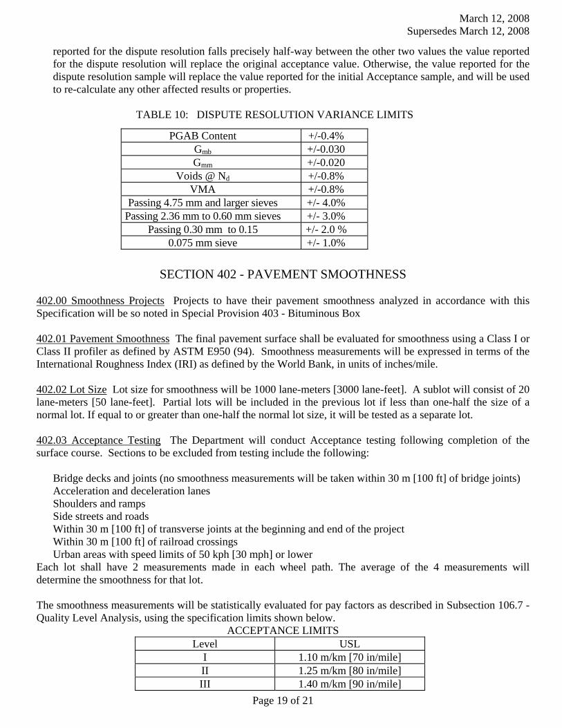
March 12, 2008 Supersedes March 12, 2008
Page 19 of 21
reported for the dispute resolution falls precisely half-way between the other two values the value reported for the dispute resolution will replace the original acceptance value. Otherwise, the value reported for the dispute resolution sample will replace the value reported for the initial Acceptance sample, and will be used to re-calculate any other affected results or properties.
TABLE 10: DISPUTE RESOLUTION VARIANCE LIMITS
SECTION 402 - PAVEMENT SMOOTHNESS
402.00 Smoothness Projects Projects to have their pavement smoothness analyzed in accordance with this Specification will be so noted in Special Provision 403 - Bituminous Box
402.01 Pavement Smoothness The final pavement surface shall be evaluated for smoothness using a Class I or Class II profiler as defined by ASTM E950 (94). Smoothness measurements will be expressed in terms of the International Roughness Index (IRI) as defined by the World Bank, in units of inches/mile. 402.02 Lot Size Lot size for smoothness will be 1000 lane-meters [3000 lane-feet]. A sublot will consist of 20 lane-meters [50 lane-feet]. Partial lots will be included in the previous lot if less than one-half the size of a normal lot. If equal to or greater than one-half the normal lot size, it will be tested as a separate lot. 402.03 Acceptance Testing The Department will conduct Acceptance testing following completion of the surface course. Sections to be excluded from testing include the following:
Bridge decks and joints (no smoothness measurements will be taken within 30 m [100 ft] of bridge joints) Acceleration and deceleration lanes
Shoulders and ramps Side streets and roads
Within 30 m [100 ft] of transverse joints at the beginning and end of the project Within 30 m [100 ft] of railroad crossings Urban areas with speed limits of 50 kph [30 mph] or lower
Each lot shall have 2 measurements made in each wheel path. The average of the 4 measurements will determine the smoothness for that lot. The smoothness measurements will be statistically evaluated for pay factors as described in Subsection 106.7 - Quality Level Analysis, using the specification limits shown below.
ACCEPTANCE LIMITS Level USL
I 1.10 m/km [70 in/mile] II 1.25 m/km [80 in/mile] III 1.40 m/km [90 in/mile]
PGAB Content +/-0.4% Gmb +/-0.030 Gmm +/-0.020
Voids @ Nd +/-0.8% VMA +/-0.8%
Passing 4.75 mm and larger sieves +/- 4.0% Passing 2.36 mm to 0.60 mm sieves +/- 3.0%
Passing 0.30 mm to 0.15 +/- 2.0 % 0.075 mm sieve +/- 1.0%
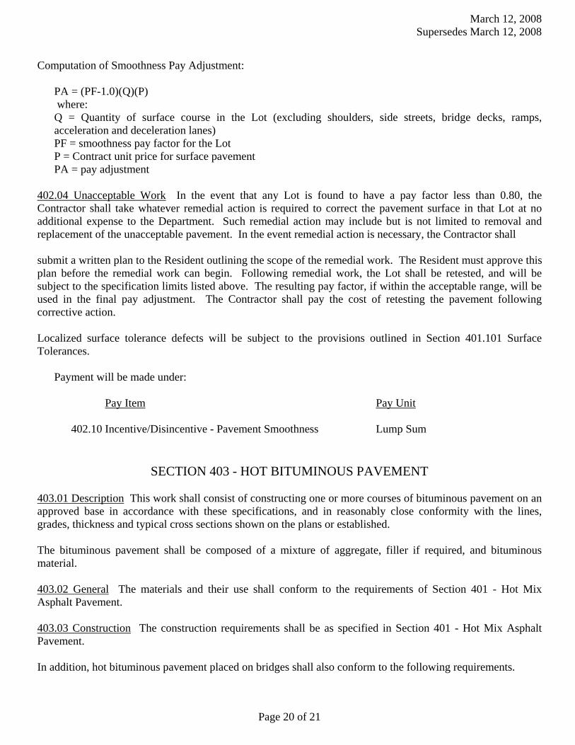
March 12, 2008 Supersedes March 12, 2008
Page 20 of 21
Computation of Smoothness Pay Adjustment: PA = (PF-1.0)(Q)(P) where:
Q = Quantity of surface course in the Lot (excluding shoulders, side streets, bridge decks, ramps, acceleration and deceleration lanes)
PF = smoothness pay factor for the Lot P = Contract unit price for surface pavement PA = pay adjustment 402.04 Unacceptable Work In the event that any Lot is found to have a pay factor less than 0.80, the Contractor shall take whatever remedial action is required to correct the pavement surface in that Lot at no additional expense to the Department. Such remedial action may include but is not limited to removal and replacement of the unacceptable pavement. In the event remedial action is necessary, the Contractor shall submit a written plan to the Resident outlining the scope of the remedial work. The Resident must approve this plan before the remedial work can begin. Following remedial work, the Lot shall be retested, and will be subject to the specification limits listed above. The resulting pay factor, if within the acceptable range, will be used in the final pay adjustment. The Contractor shall pay the cost of retesting the pavement following corrective action. Localized surface tolerance defects will be subject to the provisions outlined in Section 401.101 Surface Tolerances. Payment will be made under:
Pay Item Pay Unit
402.10 Incentive/Disincentive - Pavement Smoothness Lump Sum
SECTION 403 - HOT BITUMINOUS PAVEMENT
403.01 Description This work shall consist of constructing one or more courses of bituminous pavement on an approved base in accordance with these specifications, and in reasonably close conformity with the lines, grades, thickness and typical cross sections shown on the plans or established. The bituminous pavement shall be composed of a mixture of aggregate, filler if required, and bituminous material.
403.02 General The materials and their use shall conform to the requirements of Section 401 - Hot Mix Asphalt Pavement.
403.03 Construction The construction requirements shall be as specified in Section 401 - Hot Mix Asphalt Pavement. In addition, hot bituminous pavement placed on bridges shall also conform to the following requirements.
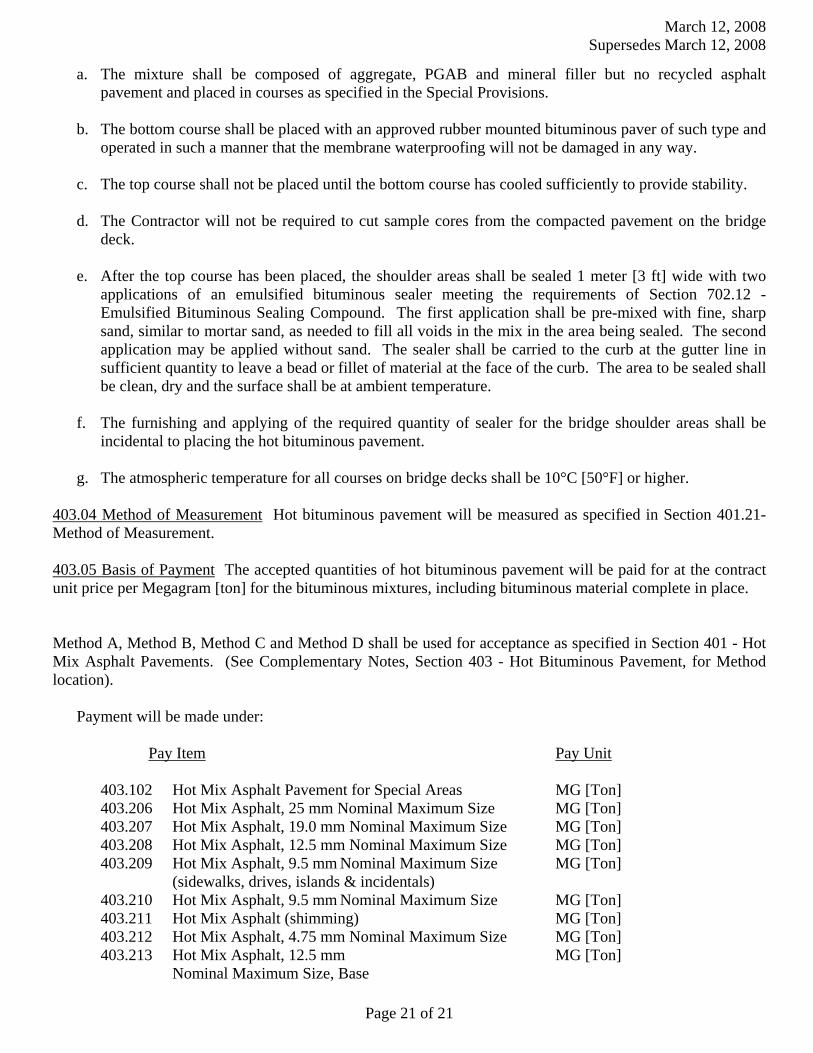
March 12, 2008 Supersedes March 12, 2008
Page 21 of 21
a. The mixture shall be composed of aggregate, PGAB and mineral filler but no recycled asphalt pavement and placed in courses as specified in the Special Provisions.
b. The bottom course shall be placed with an approved rubber mounted bituminous paver of such type and operated in such a manner that the membrane waterproofing will not be damaged in any way.
c. The top course shall not be placed until the bottom course has cooled sufficiently to provide stability.
d. The Contractor will not be required to cut sample cores from the compacted pavement on the bridge deck.
e. After the top course has been placed, the shoulder areas shall be sealed 1 meter [3 ft] wide with two applications of an emulsified bituminous sealer meeting the requirements of Section 702.12 - Emulsified Bituminous Sealing Compound. The first application shall be pre-mixed with fine, sharp sand, similar to mortar sand, as needed to fill all voids in the mix in the area being sealed. The second application may be applied without sand. The sealer shall be carried to the curb at the gutter line in sufficient quantity to leave a bead or fillet of material at the face of the curb. The area to be sealed shall be clean, dry and the surface shall be at ambient temperature.
f. The furnishing and applying of the required quantity of sealer for the bridge shoulder areas shall be incidental to placing the hot bituminous pavement.
g. The atmospheric temperature for all courses on bridge decks shall be 10°C [50°F] or higher.
403.04 Method of Measurement Hot bituminous pavement will be measured as specified in Section 401.21- Method of Measurement.
403.05 Basis of Payment The accepted quantities of hot bituminous pavement will be paid for at the contract unit price per Megagram [ton] for the bituminous mixtures, including bituminous material complete in place.
Method A, Method B, Method C and Method D shall be used for acceptance as specified in Section 401 - Hot Mix Asphalt Pavements. (See Complementary Notes, Section 403 - Hot Bituminous Pavement, for Method location). Payment will be made under:
Pay Item Pay Unit
403.102 Hot Mix Asphalt Pavement for Special Areas MG [Ton] 403.206 Hot Mix Asphalt, 25 mm Nominal Maximum Size MG [Ton] 403.207 Hot Mix Asphalt, 19.0 mm Nominal Maximum Size MG [Ton] 403.208 Hot Mix Asphalt, 12.5 mm Nominal Maximum Size MG [Ton] 403.209 Hot Mix Asphalt, 9.5 mm Nominal Maximum Size MG [Ton] (sidewalks, drives, islands & incidentals) 403.210 Hot Mix Asphalt, 9.5 mm Nominal Maximum Size MG [Ton] 403.211 Hot Mix Asphalt (shimming) MG [Ton] 403.212 Hot Mix Asphalt, 4.75 mm Nominal Maximum Size MG [Ton]
403.213 Hot Mix Asphalt, 12.5 mm MG [Ton] Nominal Maximum Size, Base

Bethel 14448.10
Highway Maintenance Garage March 13, 2008
SPECIAL PROVISION SECTION 815
Buildings
815.10 Description The work shall consist of the furnishing and construction of
the building, site, paving and utility work in accordance with the contract documents. 815.50 Method of Measurement Each building will be measured for payment as
one lump sum, complete in place and accepted. The final grading of the drainage on the north side of the garage, the catch basin,
connected outlet pipe and riprap apron will be the responsibility of the Department. The Contractor shall install underdrain with crushed stone and backfill to finish grade.
815.60 Basis of Payment Each building will be paid for at the contract lump sum
price which shall be full compensation for the work indicated on the plans and as called for in the contract, including excavation, compacted fill, grading, paving, labor, equipment and materials for building construction, trenching, temporarily disconnecting existing sewer, water, electric and telephone lines and reconnecting utilities to new building, test pits and field verification of existing utilities, demolition of existing garage and disposal of construction/demolition debris, and other contract related incidentals necessary to complete the work .
If the actual loading of the building results in changes to the design of the
foundation as determined by the Engineer, the cost of additional concrete, reinforcing steel, labor, equipment, materials necessary to perform the work will be incidental to the contract and no additional payment will be made.
Payment will be made under:
Pay Item Pay Unit 815.00 Buildings Lump Sum
1 of 1
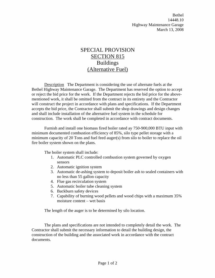
Bethel 14448.10
Highway Maintenance Garage March 13, 2008
SPECIAL PROVISION
SECTION 815 Buildings
(Alternative Fuel)
Description The Department is considering the use of alternate fuels at the
Bethel Highway Maintenance Garage. The Department has reserved the option to accept or reject the bid price for the work. If the Department rejects the bid price for the above-mentioned work, it shall be omitted from the contract in its entirety and the Contractor will construct the project in accordance with plans and specifications. If the Department accepts the bid price, the Contractor shall submit the shop drawings and design changes and shall include installation of the alternative fuel system in the schedule for construction. The work shall be completed in accordance with contract documents.
Furnish and install one biomass fired boiler rated ay 750-900,000 BTU input with
minimum documented combustion efficiency of 85%, silo type pellet storage with a minimum capacity of 20 Tons and fuel feed auger(s) from silo to boiler to replace the oil fire boiler system shown on the plans.
The boiler system shall include:
1. Automatic PLC controlled combustion system governed by oxygen sensors
2. Automatic ignition system 3. Automatic de-ashing system to deposit boiler ash to sealed containers with
no less than 55 gallon capacity 4. Flue gas recirculation system 5. Automatic boiler tube cleaning system 6. Backburn safety devices 7. Capability of burning wood pellets and wood chips with a maximum 35%
moisture content – wet basis The length of the auger is to be determined by silo location.
The plans and specifications are not intended to completely detail the work. The
Contractor shall submit the necessary information to detail the building design, the construction of the building and the associated work in accordance with the contract documents.
Page 1 of 2

Bethel 14448.10
Highway Maintenance Garage March 13, 2008
The intent is to obtain an installation of an alternative fuel heating system and equipment, complete in every detail within and about the building, and with all facilities properly interconnected. The Contractor shall submit to the Department all shop drawings and information necessary to demonstrate the details of construction and design. The Contractor shall furnish and install all such parts as may be necessary to complete the system in accordance with the best trade practice and applicable codes to the satisfaction of the Engineer. Where building construction makes it advisable or necessary to change the location of equipment, the Contractor shall perform such work without cost to the Owner on written request of the Engineer. Any doubt as to the intended location of the equipment shall be resolved by the Engineer before proceeding with the installation. Upon completion, the systems and all equipment throughout the structures shall operate properly and function as intended.
Method of Measurement The alternative fuel heating system will be measured for
payment as one lump sum, complete in place and accepted. Basis of Payment The alternative fuel heating system will be paid for at the
contract lump sum price which shall be full compensation for the work indicated on the plans and as called for in the contract, including labor, equipment and materials for construction and other contract related incidentals necessary to complete the work .
Payment will be made under:
Pay Item Pay Unit 815.00 Building - Alternative Fuel Option Lump Sum
Page 2 of 2

Bethel 14448.10
Highway Maintenance Garage March 13, 2008
SPECIAL PROVISION SECTION 656
Temporary Soil Erosion and Water Pollution Control
The following information and requirements will constitute the Soil Erosion and Water Pollution Control Plan for this Project. The soil erosion and water pollution control measures associated with this work are as follows:
1. All work shall be done in accordance with the latest revision of the Maine Department of Transportation Best Management Practices for Erosion and Sediment Control (a.k.a. Best Management Practices manual or BMP Manual). The "Table of Contents" of the latest version is dated "1/19/00” (available at http://www.state.me.us/mdot/mainhtml/bmp/bmpjan2000.pdf.) Procedures specified shall be according to the BMP Manual unless stated otherwise.
2. The on-site person responsible for implementation of this plan, shall be the Contractor’s Superintendent or other supervisory employee (the “Environmental Coordinator”) with the authority to immediately remedy any deficient controls and shall provide the Resident with their numbers (telephone number, cellular phone and pager numbers, if applicable) where the Environmental Coordinator can be reached 24 hours a day.
3. If the Work includes the handling or storage of petroleum products or Hazardous Materials including the on site fueling of Equipment, the Resident must be provided with a Spill Prevention Control and Countermeasure Plan (SPCCP) plan. At a minimum, the SPCCP shall include:
• The name and emergency response numbers (telephone number, cellular phone and pager numbers, if applicable) of the Contractor's representative responsible for spill prevention;
• General description and location of (1) handling, transfer, storage, and containment facilities of such products or Materials ("activities and facilities") and (2) potential receptors of such products or Materials including oceans, lakes, ponds, rivers, streams, wetlands, and sand and gravel aquifers ("sensitive resources") including the distances between said activities and facilities and said sensitive resources;
• Description of preventative measures to be used to minimize the possibility of a spill including Equipment and/or Materials to be used to prevent discharges including absorbent Materials,
• A contingency response plan to be implemented if a spill should occur including a list of emergency phone/pager numbers including the Contractor's representative, MDEP Spill Response, the Resident, and local police and fire authorities. For a related provision, see Standard Specification, Section, 105.2.2 - Project Specific Emergency Planning.
4. The Environmental Coordinator must inspect and maintain daily all controls for the duration of the project.
5. Any costs related to this plan shall be considered incidental to the contract.
Special Provision 656 - Page 1 of 1
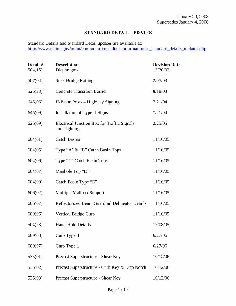
January 29, 2008 Supersedes January 4, 2008
Page 1 of 2
STANDARD DETAIL UPDATES
Standard Details and Standard Detail updates are available at: http://www.maine.gov/mdot/contractor-consultant-information/ss_standard_details_updates.php Detail # Description Revision Date 504(15) Diaphragms 12/30/02 507(04) Steel Bridge Railing 2/05/03 526(33) Concrete Transition Barrier 8/18/03 645(06) H-Beam Posts – Highway Signing 7/21/04 645(09) Installation of Type II Signs 7/21/04 626(09) Electrical Junction Box for Traffic Signals 2/25/05
and Lighting 604(01) Catch Basins 11/16/05 604(05) Type “A” & “B” Catch Basin Tops 11/16/05 604(06) Type “C” Catch Basin Tops 11/16/05 604(07) Manhole Top “D” 11/16/05 604(09) Catch Basin Type “E” 11/16/05 606(02) Multiple Mailbox Support 11/16/05 606(07) Reflectorized Beam Guardrail Delineator Details 11/16/05 609(06) Vertical Bridge Curb 11/16/05 504(23) Hand-Hold Details 12/08/05 609(03) Curb Type 3 6/27/06 609(07) Curb Type 1 6/27/06 535(01) Precast Superstructure - Shear Key 10/12/06 535(02) Precast Superstructure - Curb Key & Drip Notch 10/12/06 535(03) Precast Superstructure - Shear Key 10/12/06
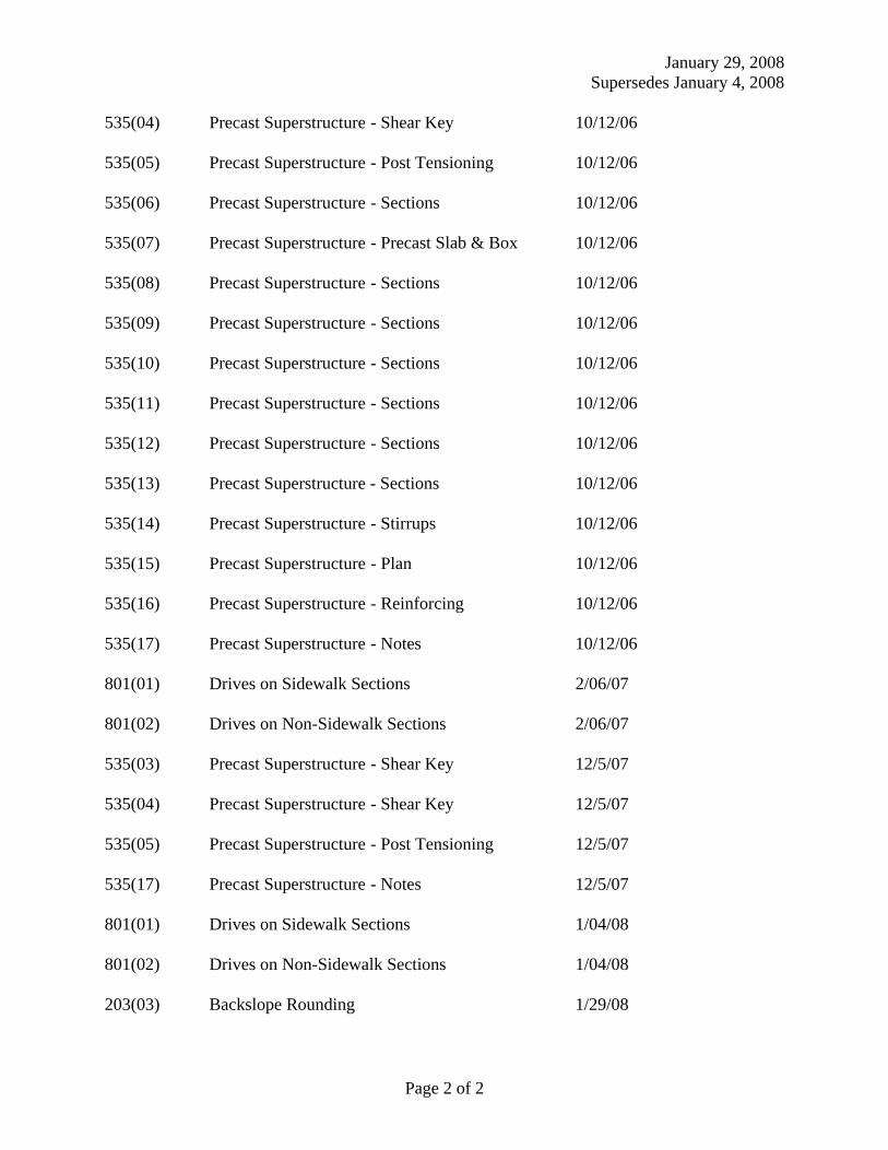
January 29, 2008 Supersedes January 4, 2008
Page 2 of 2
535(04) Precast Superstructure - Shear Key 10/12/06 535(05) Precast Superstructure - Post Tensioning 10/12/06 535(06) Precast Superstructure - Sections 10/12/06 535(07) Precast Superstructure - Precast Slab & Box 10/12/06 535(08) Precast Superstructure - Sections 10/12/06 535(09) Precast Superstructure - Sections 10/12/06 535(10) Precast Superstructure - Sections 10/12/06 535(11) Precast Superstructure - Sections 10/12/06 535(12) Precast Superstructure - Sections 10/12/06 535(13) Precast Superstructure - Sections 10/12/06 535(14) Precast Superstructure - Stirrups 10/12/06 535(15) Precast Superstructure - Plan 10/12/06 535(16) Precast Superstructure - Reinforcing 10/12/06 535(17) Precast Superstructure - Notes 10/12/06 801(01) Drives on Sidewalk Sections 2/06/07 801(02) Drives on Non-Sidewalk Sections 2/06/07 535(03) Precast Superstructure - Shear Key 12/5/07 535(04) Precast Superstructure - Shear Key 12/5/07 535(05) Precast Superstructure - Post Tensioning 12/5/07 535(17) Precast Superstructure - Notes 12/5/07 801(01) Drives on Sidewalk Sections 1/04/08 801(02) Drives on Non-Sidewalk Sections 1/04/08 203(03) Backslope Rounding 1/29/08
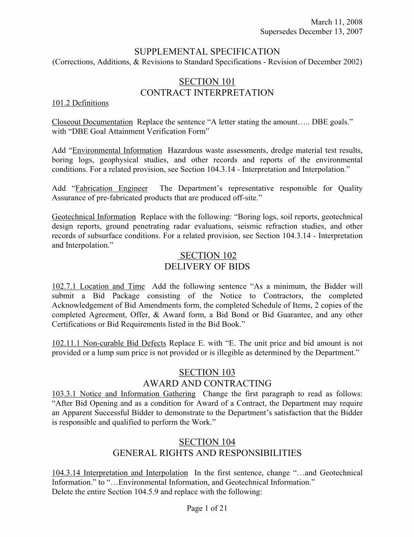
March 11, 2008 Supersedes December 13, 2007
Page 1 of 21
SUPPLEMENTAL SPECIFICATION (Corrections, Additions, & Revisions to Standard Specifications - Revision of December 2002)
SECTION 101
CONTRACT INTERPRETATION 101.2 Definitions Closeout Documentation Replace the sentence “A letter stating the amount….. DBE goals.” with “DBE Goal Attainment Verification Form” Add “Environmental Information Hazardous waste assessments, dredge material test results, boring logs, geophysical studies, and other records and reports of the environmental conditions. For a related provision, see Section 104.3.14 - Interpretation and Interpolation.” Add “Fabrication Engineer The Department’s representative responsible for Quality Assurance of pre-fabricated products that are produced off-site.” Geotechnical Information Replace with the following: “Boring logs, soil reports, geotechnical design reports, ground penetrating radar evaluations, seismic refraction studies, and other records of subsurface conditions. For a related provision, see Section 104.3.14 - Interpretation and Interpolation.”
SECTION 102 DELIVERY OF BIDS
102.7.1 Location and Time Add the following sentence “As a minimum, the Bidder will submit a Bid Package consisting of the Notice to Contractors, the completed Acknowledgement of Bid Amendments form, the completed Schedule of Items, 2 copies of the completed Agreement, Offer, & Award form, a Bid Bond or Bid Guarantee, and any other Certifications or Bid Requirements listed in the Bid Book.” 102.11.1 Non-curable Bid Defects Replace E. with “E. The unit price and bid amount is not provided or a lump sum price is not provided or is illegible as determined by the Department.”
SECTION 103 AWARD AND CONTRACTING
103.3.1 Notice and Information Gathering Change the first paragraph to read as follows: “After Bid Opening and as a condition for Award of a Contract, the Department may require an Apparent Successful Bidder to demonstrate to the Department’s satisfaction that the Bidder is responsible and qualified to perform the Work.”
SECTION 104 GENERAL RIGHTS AND RESPONSIBILITIES
104.3.14 Interpretation and Interpolation In the first sentence, change “…and Geotechnical Information.” to “…Environmental Information, and Geotechnical Information.” Delete the entire Section 104.5.9 and replace with the following:
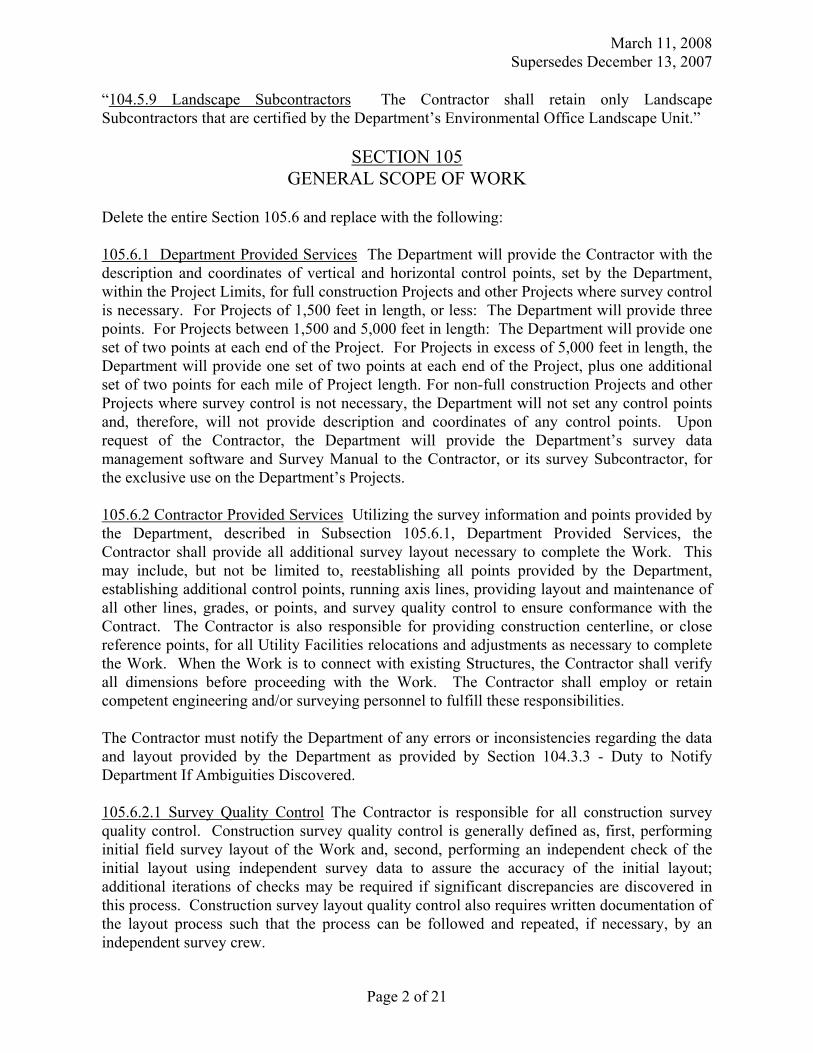
March 11, 2008 Supersedes December 13, 2007
Page 2 of 21
“104.5.9 Landscape Subcontractors The Contractor shall retain only Landscape Subcontractors that are certified by the Department’s Environmental Office Landscape Unit.”
SECTION 105 GENERAL SCOPE OF WORK
Delete the entire Section 105.6 and replace with the following: 105.6.1 Department Provided Services The Department will provide the Contractor with the description and coordinates of vertical and horizontal control points, set by the Department, within the Project Limits, for full construction Projects and other Projects where survey control is necessary. For Projects of 1,500 feet in length, or less: The Department will provide three points. For Projects between 1,500 and 5,000 feet in length: The Department will provide one set of two points at each end of the Project. For Projects in excess of 5,000 feet in length, the Department will provide one set of two points at each end of the Project, plus one additional set of two points for each mile of Project length. For non-full construction Projects and other Projects where survey control is not necessary, the Department will not set any control points and, therefore, will not provide description and coordinates of any control points. Upon request of the Contractor, the Department will provide the Department’s survey data management software and Survey Manual to the Contractor, or its survey Subcontractor, for the exclusive use on the Department’s Projects. 105.6.2 Contractor Provided Services Utilizing the survey information and points provided by the Department, described in Subsection 105.6.1, Department Provided Services, the Contractor shall provide all additional survey layout necessary to complete the Work. This may include, but not be limited to, reestablishing all points provided by the Department, establishing additional control points, running axis lines, providing layout and maintenance of all other lines, grades, or points, and survey quality control to ensure conformance with the Contract. The Contractor is also responsible for providing construction centerline, or close reference points, for all Utility Facilities relocations and adjustments as necessary to complete the Work. When the Work is to connect with existing Structures, the Contractor shall verify all dimensions before proceeding with the Work. The Contractor shall employ or retain competent engineering and/or surveying personnel to fulfill these responsibilities. The Contractor must notify the Department of any errors or inconsistencies regarding the data and layout provided by the Department as provided by Section 104.3.3 - Duty to Notify Department If Ambiguities Discovered. 105.6.2.1 Survey Quality Control The Contractor is responsible for all construction survey quality control. Construction survey quality control is generally defined as, first, performing initial field survey layout of the Work and, second, performing an independent check of the initial layout using independent survey data to assure the accuracy of the initial layout; additional iterations of checks may be required if significant discrepancies are discovered in this process. Construction survey layout quality control also requires written documentation of the layout process such that the process can be followed and repeated, if necessary, by an independent survey crew.

March 11, 2008 Supersedes December 13, 2007
Page 3 of 21
105.6.3 Survey Quality Assurance It is the Department’s prerogative to perform construction survey quality assurance. Construction survey quality assurance may, or may not, be performed by the Department. Construction survey quality assurance is generally defined as an independent check of the construction survey quality control. The construction survey quality assurance process may involve physically checking the Contractor’s construction survey layout using independent survey data, or may simply involve reviewing the construction survey quality control written documentation. If the Department elects to physically check the Contractor’s survey layout, the Contractor’s designated surveyor may be required to be present. The Department will provide a minimum notice of 48 hours to the Contractor, whenever possible, if the Contractor’s designated surveyor’s presence is required. Any errors discovered through the quality assurance process shall be corrected by the Contractor, at no additional cost to the Department. 105.6.4 Boundary Markers The Contractor shall preserve and protect from damage all monuments or other points that mark the boundaries of the Right-of-Way or abutting parcels that are outside the area that must be disturbed to perform the Work. The Contractor indemnifies and holds harmless the Department from all claims to reestablish the former location of all such monuments or points including claims arising from 14 MRSA § 7554-A. For a related provision, see Section 104.3.11 - Responsibility for Property of Others.
SECTION 106 QUALITY
106.4.3 Testing Change the first sentence in paragraph three from “…maintain records of all inspections and tests.” to “…maintain original documentation of all inspections, tests, and calculations used to generate reports.” 106.6 Acceptance Add the following to paragraph 1 of A: “This includes Sections 401 - Hot Mix Asphalt, 402 - Pavement Smoothness, and 502 - Structural Concrete - Method A - Air Content.” Add the following to the beginning of paragraph 3 of A: “For pay factors based on Quality Level Analysis, and” 106.7.1 Standard Deviation Method Add the following to F: “Note: In cases where the mean of the values is equal to either the USL or the LSL, then the PWL will be 50 regardless of the computed value of s.” Add the following to H: “Method C Hot Mix Asphalt: PF = [55 + (Quality Level *0.5)] * 0.01”
SECTION 107 TIME
107.3.1 General Add the following: “If a Holiday occurs on a Sunday, the following Monday shall be considered a Holiday. Sunday or Holiday work must be approved by the Department, except that the Contractor may work on Martin Luther King Day, President’s Day, Patriot’s Day, the Friday after Thanksgiving, and Columbus Day without the Department’s approval.”
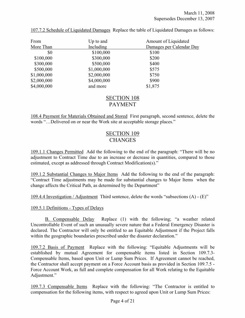
March 11, 2008 Supersedes December 13, 2007
Page 4 of 21
107.7.2 Schedule of Liquidated Damages Replace the table of Liquidated Damages as follows: From Up to and Amount of Liquidated More Than Including Damages per Calendar Day $0 $100,000 $100 $100,000 $300,000 $200 $300,000 $500,000 $400 $500,000 $1,000,000 $575 $1,000,000 $2,000,000 $750 $2,000,000 $4,000,000 $900 $4,000,000 and more $1,875
SECTION 108 PAYMENT
108.4 Payment for Materials Obtained and Stored First paragraph, second sentence, delete the words “…Delivered on or near the Work site at acceptable storage places.”
SECTION 109 CHANGES
109.1.1 Changes Permitted Add the following to the end of the paragraph: “There will be no adjustment to Contract Time due to an increase or decrease in quantities, compared to those estimated, except as addressed through Contract Modification(s).” 109.1.2 Substantial Changes to Major Items Add the following to the end of the paragraph: “Contract Time adjustments may be made for substantial changes to Major Items when the change affects the Critical Path, as determined by the Department” 109.4.4 Investigation / Adjustment Third sentence, delete the words “subsections (A) - (E)” 109.5.1 Definitions - Types of Delays
B. Compensable Delay Replace (1) with the following; “a weather related Uncontrollable Event of such an unusually severe nature that a Federal Emergency Disaster is declared. The Contractor will only be entitled to an Equitable Adjustment if the Project falls within the geographic boundaries prescribed under the disaster declaration.” 109.7.2 Basis of Payment Replace with the following: “Equitable Adjustments will be established by mutual Agreement for compensable items listed in Section 109.7.3- Compensable Items, based upon Unit or Lump Sum Prices. If Agreement cannot be reached, the Contractor shall accept payment on a Force Account basis as provided in Section 109.7.5 - Force Account Work, as full and complete compensation for all Work relating to the Equitable Adjustment.” 109.7.3 Compensable Items Replace with the following: “The Contractor is entitled to compensation for the following items, with respect to agreed upon Unit or Lump Sum Prices:
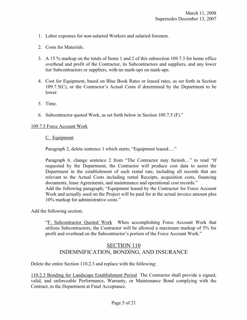
March 11, 2008 Supersedes December 13, 2007
Page 5 of 21
1. Labor expenses for non-salaried Workers and salaried foremen.
2. Costs for Materials.
3. A 15 % markup on the totals of Items 1 and 2 of this subsection 109.7.3 for home office
overhead and profit of the Contractor, its Subcontractors and suppliers, and any lower tier Subcontractors or suppliers, with no mark-ups on mark-ups.
4. Cost for Equipment, based on Blue Book Rates or leased rates, as set forth in Section
109.7.5(C), or the Contractor’s Actual Costs if determined by the Department to be lower.
5. Time.
6. Subcontractor quoted Work, as set forth below in Section 109.7.5 (F).”
109.7.5 Force Account Work
C. Equipment
Paragraph 2, delete sentence 1 which starts; “Equipment leased….”
Paragraph 6, change sentence 2 from “The Contractor may furnish…” to read “If requested by the Department, the Contractor will produce cost data to assist the Department in the establishment of such rental rate, including all records that are relevant to the Actual Costs including rental Receipts, acquisition costs, financing documents, lease Agreements, and maintenance and operational cost records.” Add the following paragraph; “Equipment leased by the Contractor for Force Account Work and actually used on the Project will be paid for at the actual invoice amount plus 10% markup for administrative costs.”
Add the following section;
“F. Subcontractor Quoted Work When accomplishing Force Account Work that utilizes Subcontractors, the Contractor will be allowed a maximum markup of 5% for profit and overhead on the Subcontractor’s portion of the Force Account Work.”
SECTION 110
INDEMNIFICATION, BONDING, AND INSURANCE
Delete the entire Section 110.2.3 and replace with the following: 110.2.3 Bonding for Landscape Establishment Period The Contractor shall provide a signed, valid, and enforceable Performance, Warranty, or Maintenance Bond complying with the Contract, to the Department at Final Acceptance.

March 11, 2008 Supersedes December 13, 2007
Page 6 of 21
The bond shall be in the full amount for all Pay Items for work pursuant to Sec 621, Landscape, payable to the “Treasurer - State of Maine,” and on the Department’s forms, on exact copies thereof, or on forms that do not contain any significant variations from the Department’s forms as solely determined by the Department. The Contractor shall pay all premiums and take all other actions necessary to keep said bond in effect for the duration of the Landscape Establishment Period described in Special Provision 621.0036 - Establishment Period. If the Surety becomes financially insolvent, ceases to be licensed or approved to do business in the State of Maine, or stops operating in the United States, the Contractor shall file new bonds complying with this Section within 10 Days of the date the Contractor is notified or becomes aware of such change. All Bonds shall be procured from a company organized and operating in the United States, licensed or approved to do business in the State of Maine by the State of Maine Department of Business Regulation, Bureau of Insurance, and listed on the latest Federal Department of the Treasury listing for “Companies Holding Certificates of Authority as Acceptable Sureties on Federal Bonds and as Acceptable Reinsuring Companies.” By issuing a bond, the Surety agrees to be bound by all terms of the Contract, including those related to payment, time for performance, quality, warranties, and the Department’s self-help remedy provided in Section 112.1 - Default to the same extent as if all terms of the Contract are contained in the bond(s). Regarding claims related to any obligations covered by the bond, the Surety shall provide, within 60 Days of Receipt of written notice thereof, full payment of the entire claim or written notice of all bases upon which it is denying or contesting payment. Failure of the Surety to provide such notice within the 60-day period constitutes the Surety’s waiver of any right to deny or contest payment and the Surety’s acknowledgment that the claim is valid and undisputed.
SECTION 202 REMOVING STRUCTURES AND OBSTRUCTIONS
202.02 Removing Buildings Make the following change to the last sentence in the final paragraph, change “…Code of Maine Regulations 401.” to “…Department of Environmental Protection Maine Solid Waste Management Rules, 06-096 CMR Ch. 401, Landfill Siting, Design and Operation.”
SECTION 203 EXCAVATION AND EMBANKMENT
203.01 Description Under b. Rock Excavation; add the following sentence: “The use of perchlorate is not allowed in blasting operations.”
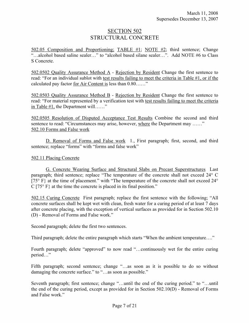
March 11, 2008 Supersedes December 13, 2007
Page 7 of 21
SECTION 502 STRUCTURAL CONCRETE
502.05 Composition and Proportioning; TABLE #1; NOTE #2; third sentence; Change “…alcohol based saline sealer…” to “alcohol based silane sealer…”. Add NOTE #6 to Class S Concrete. 502.0502 Quality Assurance Method A - Rejection by Resident Change the first sentence to read: “For an individual sublot with test results failing to meet the criteria in Table #1, or if the calculated pay factor for Air Content is less than 0.80……” 502.0503 Quality Assurance Method B - Rejection by Resident Change the first sentence to read: “For material represented by a verification test with test results failing to meet the criteria in Table #1, the Department will……” 502.0505 Resolution of Disputed Acceptance Test Results Combine the second and third sentence to read: “Circumstances may arise, however, where the Department may ……” 502.10 Forms and False work D. Removal of Forms and False work 1., First paragraph; first, second, and third sentence; replace “forms” with “forms and false work” 502.11 Placing Concrete G. Concrete Wearing Surface and Structural Slabs on Precast Superstructures Last paragraph; third sentence; replace “The temperature of the concrete shall not exceed 24° C [75° F} at the time of placement.” with “The temperature of the concrete shall not exceed 24° C [75° F} at the time the concrete is placed in its final position.” 502.15 Curing Concrete First paragraph; replace the first sentence with the following; “All concrete surfaces shall be kept wet with clean, fresh water for a curing period of at least 7 days after concrete placing, with the exception of vertical surfaces as provided for in Section 502.10 (D) - Removal of Forms and False work.” Second paragraph; delete the first two sentences. Third paragraph; delete the entire paragraph which starts “When the ambient temperature….” Fourth paragraph; delete “approved” to now read “…continuously wet for the entire curing period…” Fifth paragraph; second sentence; change “…as soon as it is possible to do so without damaging the concrete surface.” to “…as soon as possible.” Seventh paragraph; first sentence; change “…until the end of the curing period.” to “…until the end of the curing period, except as provided for in Section 502.10(D) - Removal of Forms and False work.”
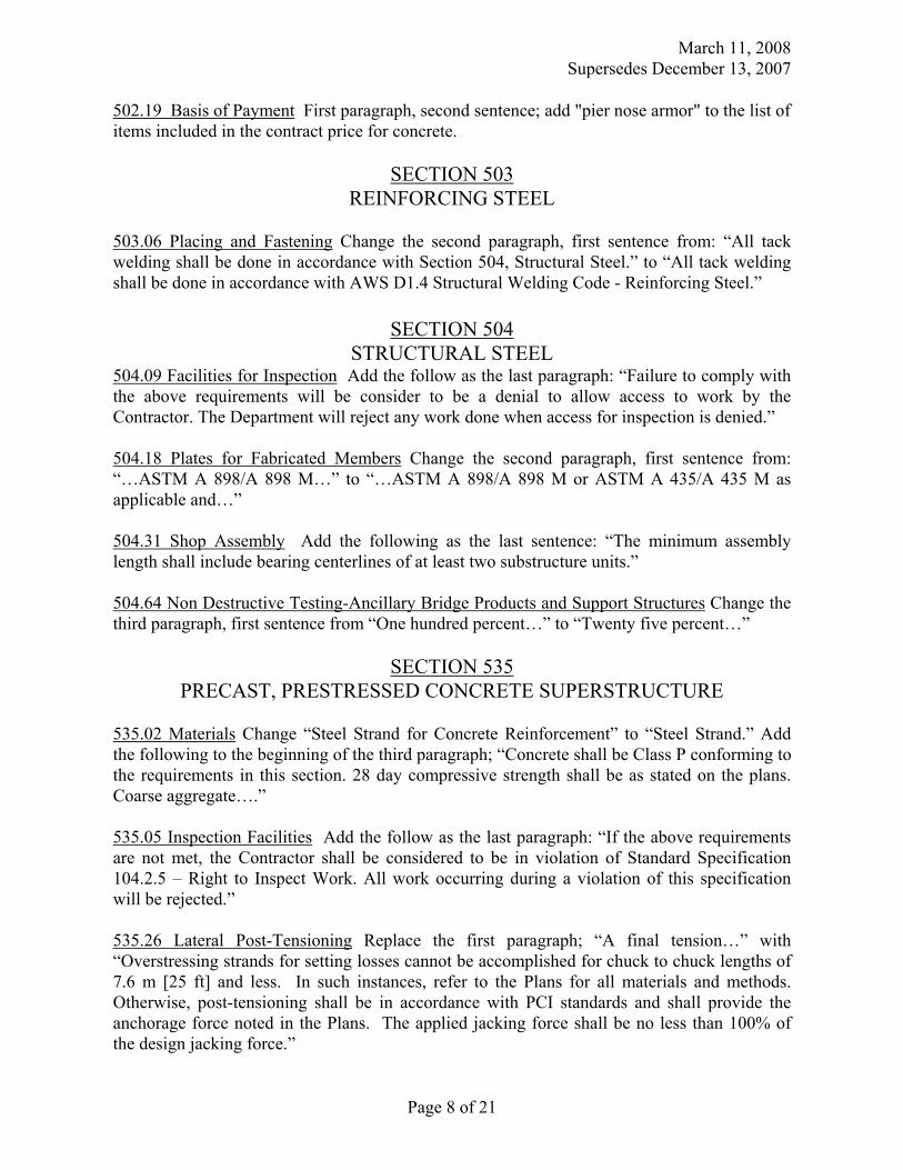
March 11, 2008 Supersedes December 13, 2007
Page 8 of 21
502.19 Basis of Payment First paragraph, second sentence; add "pier nose armor" to the list of items included in the contract price for concrete.
SECTION 503 REINFORCING STEEL
503.06 Placing and Fastening Change the second paragraph, first sentence from: “All tack welding shall be done in accordance with Section 504, Structural Steel.” to “All tack welding shall be done in accordance with AWS D1.4 Structural Welding Code - Reinforcing Steel.”
SECTION 504 STRUCTURAL STEEL
504.09 Facilities for Inspection Add the follow as the last paragraph: “Failure to comply with the above requirements will be consider to be a denial to allow access to work by the Contractor. The Department will reject any work done when access for inspection is denied.” 504.18 Plates for Fabricated Members Change the second paragraph, first sentence from: “…ASTM A 898/A 898 M…” to “…ASTM A 898/A 898 M or ASTM A 435/A 435 M as applicable and…” 504.31 Shop Assembly Add the following as the last sentence: “The minimum assembly length shall include bearing centerlines of at least two substructure units.” 504.64 Non Destructive Testing-Ancillary Bridge Products and Support Structures Change the third paragraph, first sentence from “One hundred percent…” to “Twenty five percent…”
SECTION 535 PRECAST, PRESTRESSED CONCRETE SUPERSTRUCTURE
535.02 Materials Change “Steel Strand for Concrete Reinforcement” to “Steel Strand.” Add the following to the beginning of the third paragraph; “Concrete shall be Class P conforming to the requirements in this section. 28 day compressive strength shall be as stated on the plans. Coarse aggregate….” 535.05 Inspection Facilities Add the follow as the last paragraph: “If the above requirements are not met, the Contractor shall be considered to be in violation of Standard Specification 104.2.5 – Right to Inspect Work. All work occurring during a violation of this specification will be rejected.” 535.26 Lateral Post-Tensioning Replace the first paragraph; “A final tension…” with “Overstressing strands for setting losses cannot be accomplished for chuck to chuck lengths of 7.6 m [25 ft] and less. In such instances, refer to the Plans for all materials and methods. Otherwise, post-tensioning shall be in accordance with PCI standards and shall provide the anchorage force noted in the Plans. The applied jacking force shall be no less than 100% of the design jacking force.”
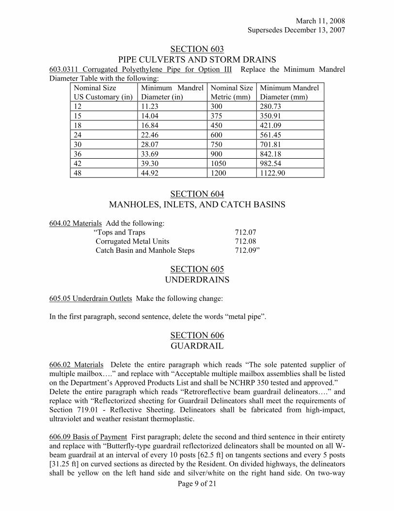
March 11, 2008 Supersedes December 13, 2007
Page 9 of 21
SECTION 603 PIPE CULVERTS AND STORM DRAINS
603.0311 Corrugated Polyethylene Pipe for Option III Replace the Minimum Mandrel Diameter Table with the following:
Nominal Size US Customary (in)
Minimum Mandrel Diameter (in)
Nominal SizeMetric (mm)
Minimum Mandrel Diameter (mm)
12 11.23 300 280.73 15 14.04 375 350.91 18 16.84 450 421.09 24 22.46 600 561.45 30 28.07 750 701.81 36 33.69 900 842.18 42 39.30 1050 982.54 48 44.92 1200 1122.90
SECTION 604
MANHOLES, INLETS, AND CATCH BASINS 604.02 Materials Add the following: “Tops and Traps 712.07 Corrugated Metal Units 712.08 Catch Basin and Manhole Steps 712.09”
SECTION 605 UNDERDRAINS
605.05 Underdrain Outlets Make the following change: In the first paragraph, second sentence, delete the words “metal pipe”.
SECTION 606 GUARDRAIL
606.02 Materials Delete the entire paragraph which reads “The sole patented supplier of multiple mailbox….” and replace with “Acceptable multiple mailbox assemblies shall be listed on the Department’s Approved Products List and shall be NCHRP 350 tested and approved.” Delete the entire paragraph which reads “Retroreflective beam guardrail delineators….” and replace with “Reflectorized sheeting for Guardrail Delineators shall meet the requirements of Section 719.01 - Reflective Sheeting. Delineators shall be fabricated from high-impact, ultraviolet and weather resistant thermoplastic. 606.09 Basis of Payment First paragraph; delete the second and third sentence in their entirety and replace with “Butterfly-type guardrail reflectorized delineators shall be mounted on all W-beam guardrail at an interval of every 10 posts [62.5 ft] on tangents sections and every 5 posts [31.25 ft] on curved sections as directed by the Resident. On divided highways, the delineators shall be yellow on the left hand side and silver/white on the right hand side. On two-way
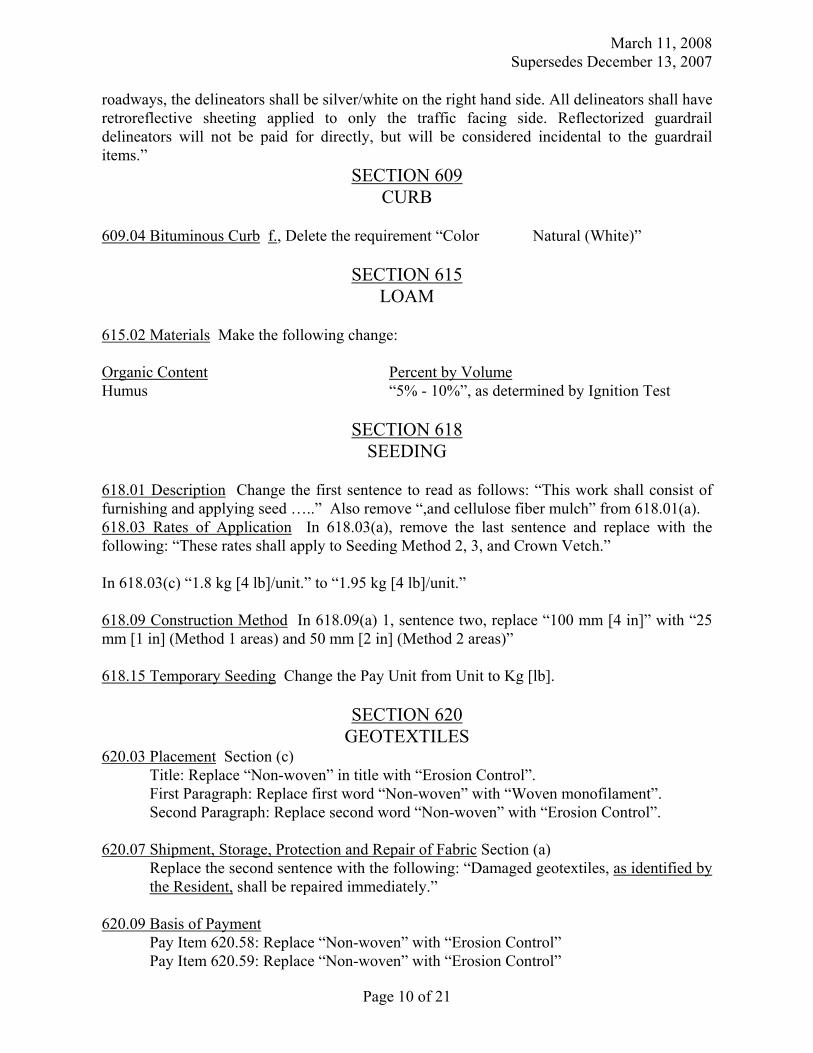
March 11, 2008 Supersedes December 13, 2007
Page 10 of 21
roadways, the delineators shall be silver/white on the right hand side. All delineators shall have retroreflective sheeting applied to only the traffic facing side. Reflectorized guardrail delineators will not be paid for directly, but will be considered incidental to the guardrail items.”
SECTION 609 CURB
609.04 Bituminous Curb f., Delete the requirement “Color Natural (White)”
SECTION 615 LOAM
615.02 Materials Make the following change: Organic Content Percent by Volume Humus “5% - 10%”, as determined by Ignition Test
SECTION 618 SEEDING
618.01 Description Change the first sentence to read as follows: “This work shall consist of furnishing and applying seed …..” Also remove “,and cellulose fiber mulch” from 618.01(a). 618.03 Rates of Application In 618.03(a), remove the last sentence and replace with the following: “These rates shall apply to Seeding Method 2, 3, and Crown Vetch.” In 618.03(c) “1.8 kg [4 lb]/unit.” to “1.95 kg [4 lb]/unit.” 618.09 Construction Method In 618.09(a) 1, sentence two, replace “100 mm [4 in]” with “25 mm [1 in] (Method 1 areas) and 50 mm [2 in] (Method 2 areas)” 618.15 Temporary Seeding Change the Pay Unit from Unit to Kg [lb].
SECTION 620 GEOTEXTILES
620.03 Placement Section (c) Title: Replace “Non-woven” in title with “Erosion Control”.
First Paragraph: Replace first word “Non-woven” with “Woven monofilament”. Second Paragraph: Replace second word “Non-woven” with “Erosion Control”. 620.07 Shipment, Storage, Protection and Repair of Fabric Section (a)
Replace the second sentence with the following: “Damaged geotextiles, as identified by the Resident, shall be repaired immediately.”
620.09 Basis of Payment Pay Item 620.58: Replace “Non-woven” with “Erosion Control” Pay Item 620.59: Replace “Non-woven” with “Erosion Control”
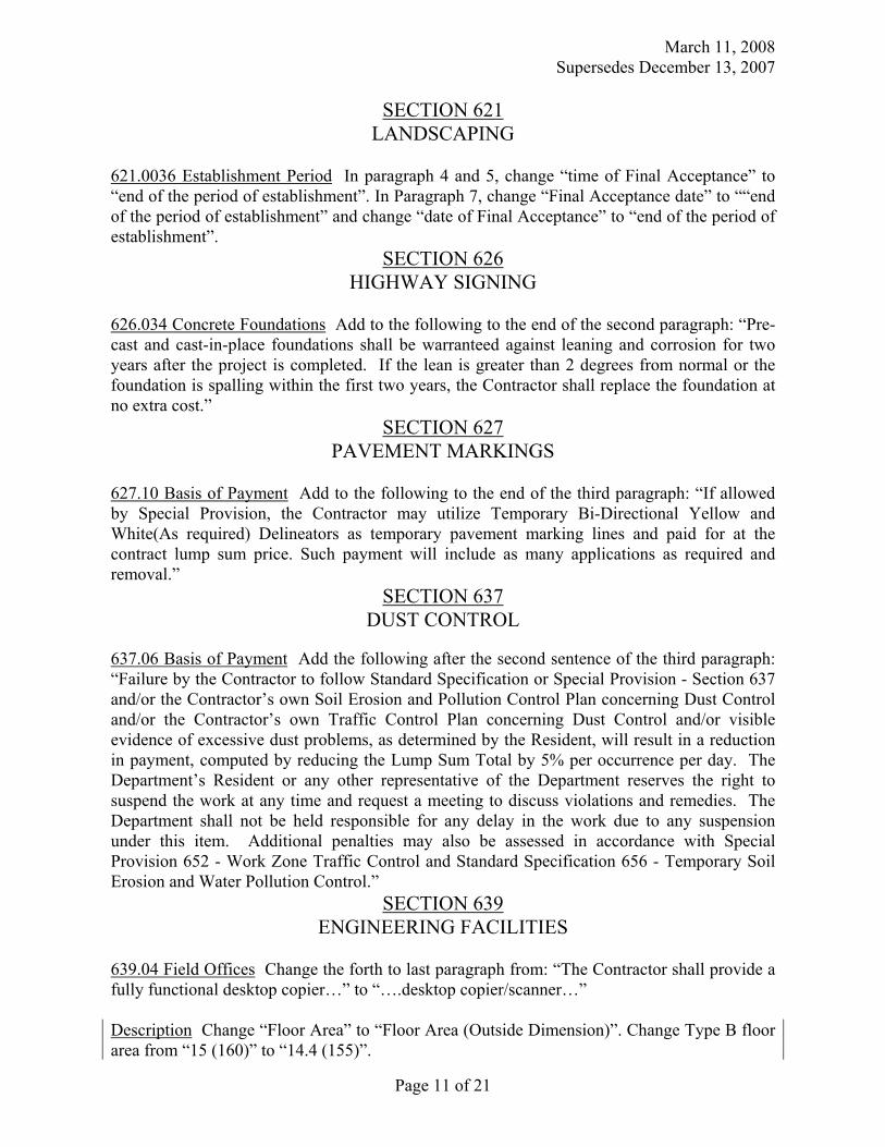
March 11, 2008 Supersedes December 13, 2007
Page 11 of 21
SECTION 621 LANDSCAPING
621.0036 Establishment Period In paragraph 4 and 5, change “time of Final Acceptance” to “end of the period of establishment”. In Paragraph 7, change “Final Acceptance date” to ““end of the period of establishment” and change “date of Final Acceptance” to “end of the period of establishment”.
SECTION 626 HIGHWAY SIGNING
626.034 Concrete Foundations Add to the following to the end of the second paragraph: “Pre-cast and cast-in-place foundations shall be warranteed against leaning and corrosion for two years after the project is completed. If the lean is greater than 2 degrees from normal or the foundation is spalling within the first two years, the Contractor shall replace the foundation at no extra cost.”
SECTION 627 PAVEMENT MARKINGS
627.10 Basis of Payment Add to the following to the end of the third paragraph: “If allowed by Special Provision, the Contractor may utilize Temporary Bi-Directional Yellow and White(As required) Delineators as temporary pavement marking lines and paid for at the contract lump sum price. Such payment will include as many applications as required and removal.”
SECTION 637 DUST CONTROL
637.06 Basis of Payment Add the following after the second sentence of the third paragraph: “Failure by the Contractor to follow Standard Specification or Special Provision - Section 637 and/or the Contractor’s own Soil Erosion and Pollution Control Plan concerning Dust Control and/or the Contractor’s own Traffic Control Plan concerning Dust Control and/or visible evidence of excessive dust problems, as determined by the Resident, will result in a reduction in payment, computed by reducing the Lump Sum Total by 5% per occurrence per day. The Department’s Resident or any other representative of the Department reserves the right to suspend the work at any time and request a meeting to discuss violations and remedies. The Department shall not be held responsible for any delay in the work due to any suspension under this item. Additional penalties may also be assessed in accordance with Special Provision 652 - Work Zone Traffic Control and Standard Specification 656 - Temporary Soil Erosion and Water Pollution Control.”
SECTION 639 ENGINEERING FACILITIES
639.04 Field Offices Change the forth to last paragraph from: “The Contractor shall provide a fully functional desktop copier…” to “….desktop copier/scanner…” Description Change “Floor Area” to “Floor Area (Outside Dimension)”. Change Type B floor area from “15 (160)” to “14.4 (155)”.
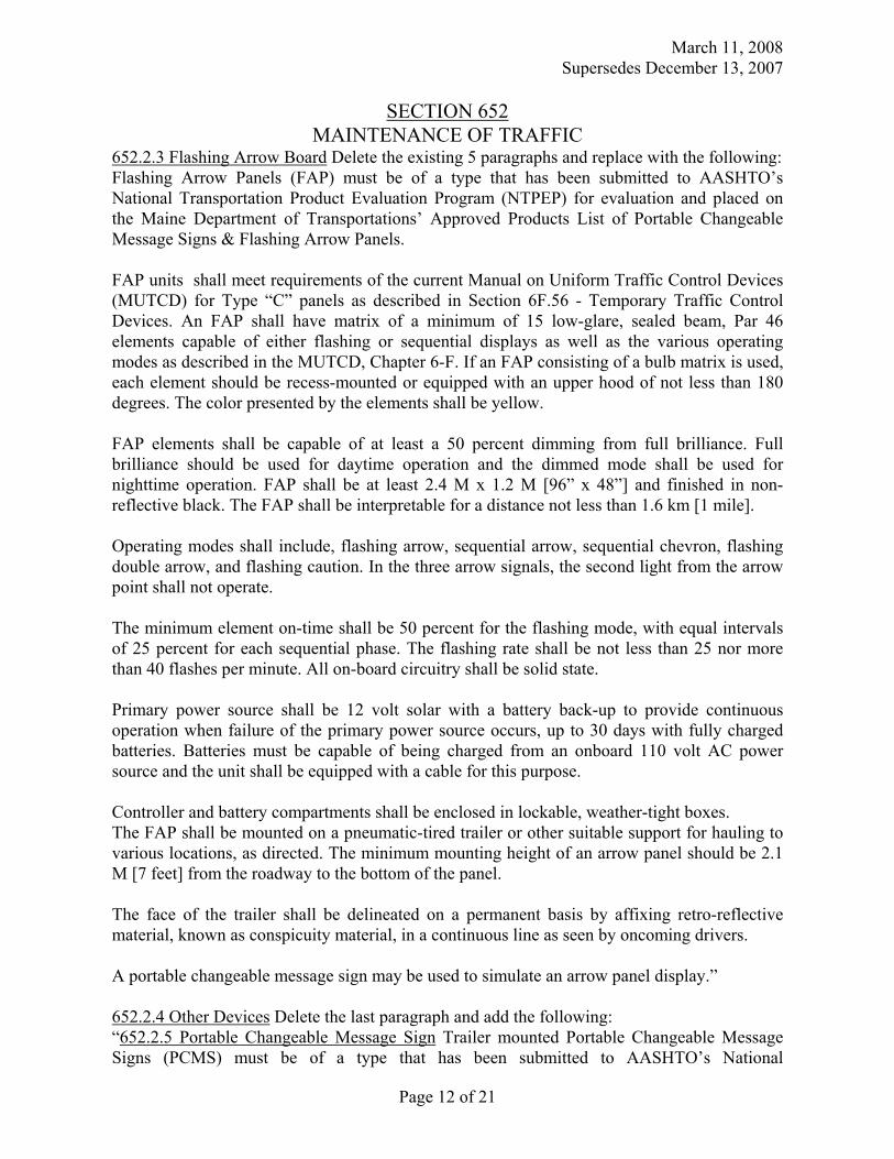
March 11, 2008 Supersedes December 13, 2007
Page 12 of 21
SECTION 652 MAINTENANCE OF TRAFFIC
652.2.3 Flashing Arrow Board Delete the existing 5 paragraphs and replace with the following: Flashing Arrow Panels (FAP) must be of a type that has been submitted to AASHTO’s National Transportation Product Evaluation Program (NTPEP) for evaluation and placed on the Maine Department of Transportations’ Approved Products List of Portable Changeable Message Signs & Flashing Arrow Panels. FAP units shall meet requirements of the current Manual on Uniform Traffic Control Devices (MUTCD) for Type “C” panels as described in Section 6F.56 - Temporary Traffic Control Devices. An FAP shall have matrix of a minimum of 15 low-glare, sealed beam, Par 46 elements capable of either flashing or sequential displays as well as the various operating modes as described in the MUTCD, Chapter 6-F. If an FAP consisting of a bulb matrix is used, each element should be recess-mounted or equipped with an upper hood of not less than 180 degrees. The color presented by the elements shall be yellow. FAP elements shall be capable of at least a 50 percent dimming from full brilliance. Full brilliance should be used for daytime operation and the dimmed mode shall be used for nighttime operation. FAP shall be at least 2.4 M x 1.2 M [96” x 48”] and finished in non-reflective black. The FAP shall be interpretable for a distance not less than 1.6 km [1 mile]. Operating modes shall include, flashing arrow, sequential arrow, sequential chevron, flashing double arrow, and flashing caution. In the three arrow signals, the second light from the arrow point shall not operate. The minimum element on-time shall be 50 percent for the flashing mode, with equal intervals of 25 percent for each sequential phase. The flashing rate shall be not less than 25 nor more than 40 flashes per minute. All on-board circuitry shall be solid state. Primary power source shall be 12 volt solar with a battery back-up to provide continuous operation when failure of the primary power source occurs, up to 30 days with fully charged batteries. Batteries must be capable of being charged from an onboard 110 volt AC power source and the unit shall be equipped with a cable for this purpose. Controller and battery compartments shall be enclosed in lockable, weather-tight boxes. The FAP shall be mounted on a pneumatic-tired trailer or other suitable support for hauling to various locations, as directed. The minimum mounting height of an arrow panel should be 2.1 M [7 feet] from the roadway to the bottom of the panel. The face of the trailer shall be delineated on a permanent basis by affixing retro-reflective material, known as conspicuity material, in a continuous line as seen by oncoming drivers. A portable changeable message sign may be used to simulate an arrow panel display.” 652.2.4 Other Devices Delete the last paragraph and add the following: “652.2.5 Portable Changeable Message Sign Trailer mounted Portable Changeable Message Signs (PCMS) must be of a type that has been submitted to AASHTO’s National
March 11, 2008 Supersedes December 13, 2007
Page 13 of 21
Transportation Product Evaluation Program (NTPEP) for evaluation and placed on the Maine Department of Transportations’ Approved Products List of Portable Changeable Message Signs & Flashing Arrow Panels. The PCMS unit shall meet or exceed the current specifications of the Manual on Uniform Traffic Control Devices (MUTCD), 6F.55. The front face of the sign should be covered with a low-glare protective material. The color of the LED elements shall be amber on a black background. The PCMS should be visible from a distance of 0.8 km [0.5 mile] day and night and have a minimum 15º viewing angle. Characters must be legible from a distance of at least 200 M [650 feet]. The message panel should have adjustable display rates (minimum of 3 seconds per phase), so that the entire message can be read at least twice at the posted speed, the off-peak 85th-percentile speed prior to work starting, or the anticipated operating speed. Each message shall consist of either one or two phases. A phase shall consist of up to eight characters per line. The unit must be capable of displaying at least three lines of text with eight characters per line. Each character shall be 457 mm [18”] high. Each character module shall use at least a five wide and seven high pixel matrix. The text of the messages shall not scroll or travel horizontally or vertically across the face of the sign. Units shall automatically adjust their brightness under varying light conditions to maintain legibility. The control system shall include a display screen upon which messages can be reviewed before being displayed on the message sign. The control system shall be capable of maintaining memory when power is unavailable. Message must be changeable with either a notebook computer or an on-board keypad. The controller shall have the capability to store a minimum of 200 user-defined and 200 pre-programmed messages. Controller and battery compartments shall be enclosed in lockable, weather-tight boxes. PCMS units shall have the capability of being made programmable by means of wireless communications. PCMS units shall also be fully capable of having an on-board radar system installed if required for a particular application. PCMS’ primary power source shall be solar with a battery back-up to provide continuous operation when failure of the primary power source occurs. Batteries must be capable of being charged from a 110 volt AC power source. The unit must also be capable of being operated solely from a 110 volt AC power source and be equipped with a cable for this purpose. The PCMS shall be mounted on a trailer in such a way that the bottom of the message sign panel shall be a minimum of 2.1 M [7 ft] above the roadway in urban areas and 1.5 M [5 ft] above the roadway in rural areas when it is in the operating mode. PCMS trailers should be of a heavy duty type with a 51 mm [2”] ball hitch and a minimum of four leveling jacks (at each corner). The sign shall be capable of being rotated 360° relative to the trailer. The face of the trailer shall be delineated on a permanent basis by affixing retro-reflective material, known as conspicuity material, in a continuous line as seen by oncoming drivers.” 652.3.3 Submittal of Traffic Control Plan In item e. change “A list of all certified flaggers…” to “A list of all the Contractor’s certified flaggers…”
March 11, 2008 Supersedes December 13, 2007
Page 14 of 21
In the last paragraph add the following as the second sentence: “The Department will review and provide comments to the Contractor within 14 days of receipt of the TCP.” 652.3.5 Installation of Traffic Control Devices In the first paragraph, first sentence; change “Signs shall be erected…” to “Portable signs shall be erected..” In the third sentence; change “Signs must be erected so that the sign face…” to “Post-mounted signs must also be erected so that the sign face…” 652.4 Flaggers Replace the first paragraph with the following; “The Contractor shall furnish flaggers as required by the TCP or as otherwise specified by the Resident. All flaggers must have successfully completed a flagger test approved by the Department and administered by a Department-approved Flagger-Certifier who is employing that flagger. All flaggers must carry an official certification card with them while flagging that has been issued by their employer. Flaggers shall wear safety apparel meeting ANSI 107-1999 Class 2 risk exposure and clearly identify the wearer as a person, shall be visible at a minimum distance of 300 m [1000 ft], and shall wear a hardhat with retroreflectivity. For nighttime conditions, Class 3 apparel should be considered, retroreflective or flashing SLOW/STOP paddles shall be used, and except in emergency situations the flagger station shall be illuminated to assure visibility.” Second paragraph, first sentence; change “…have sufficient distance to stop before entering the workspace.” to “…have sufficient distance to stop at the intended stopping point.” Third sentence; change “At a spot obstruction…” to “At a spot obstruction with adequate sight distance,…” Fourth paragraph, delete and replace with “Flaggers shall be provided as a minimum, a 10 minute break, every 2 hours and a 30 minute or longer lunch period away from the work station. Flaggers may only receive 1 unpaid break per day; all other breaks must be paid. Sufficient certified flaggers shall be available onsite to provide for continuous flagging operations during break periods. Breaker flaggers will not be paid for separately, but shall be considered incidental to the appropriate pay item.” 652.8.2 Other Items Replace the last paragraph with the following: “There will be no payment made under any 652 pay items after the expiration of the adjusted total contract time.”
SECTION 653 POLYSTYRENE PLASTIC INSULATION
653.05 Placing Backfill In the second sentence; change “…shall be not less than 150 mm [6 in] loose measure.” to “…shall be not less than 250 mm [10 in] loose measure.” In the third sentence; change “…crawler type bulldozer of not more than 390 kg/m2 [80 lb/ft2] ground contact pressure…” to “…crawler type bulldozer of not more than 4875 kg/m2 [2000 lb/ft2] ground contact pressure…” 653.06 Compaction In the last sentence; change “…not more than 390 kg/m2 [80 lb/ft2] ground contact…” to “…not more than 4875 kg/m2 [2000 lb/ft2] ground contact…”
March 11, 2008 Supersedes December 13, 2007
Page 15 of 21
SECTION 656 TEMPORARY SOIL EROSION AND WATER POLLUTION CONTROL
656.5.1 If Pay Item 656.75 Provided Replace the second paragraph with the following: “Failure by the Contractor to follow Standard Specification or Special Provision - Section 656 and/or the Contractor’s own Soil Erosion and Pollution Control Plan will result in a reduction in payment, computed by reducing the Lump Sum Total by 5% per occurrence per day. The Department’s Resident or any other representative of the Department reserves the right to suspend the work at any time and request a meeting to discuss violations and remedies. The Department shall not be held responsible for any delay in the work due to any suspension under this item.”
SECTION 701 STRUCTURAL CONCRETE RELATED MATERIALS
701.10 Fly Ash - Chemical Requirements Change all references from “ASTM C311” to “ASTM C114”.
SECTION 703 AGGREGATES
703.05 Aggregate for Sand Leveling Change the percent passing the 9.5 mm [3/8 in] sieve from “85 – 10” to “85 – 100” 703.06 Aggregate for Base and Subbase Delete the first paragraph: “The material shall have…” and replace with “The material shall have a minimum degradation value of 15 as determined by Washington State DOT Test Method T113, Method of Test for Determination of Degradation Value (March 2002 version), except that the reported degradation value will be the result of testing a single specimen from that portion of a sample that passes the 12.5 mm [½ in] sieve and is retained on the 2.00 mm [No. 10] sieve, minus any reclaimed asphalt pavement used." 703.07 Aggregates for HMA Pavements Delete the forth paragraph: “The composite blend shall have…” and replace with “The composite blend, minus any reclaimed asphalt pavement used, shall have a Micro-Deval value of 18.0 or less as determined by AASHTO T 327. In the event the material exceeds the Micro Deval limit, a Washington Degradation test shall be performed. The material shall be acceptable if it has a value of 30 or more as determined by Washington State DOT Test Method T 113, Method of Test for Determination of Degradation Value (March 2002 version) except that the reported degradation value will be the result of testing a single composite specimen from that portion of the sample that passes the 12.5mm [1/2 inch] sieve and is retained on the 2.00mm [No 10] sieve, minus any reclaimed asphalt pavement used." 703.09 HMA Mixture Composition The coarse and fine aggregate shall meet the requirements of Section 703.07. The several aggregate fractions for mixtures shall be sized, graded, and combined in such proportions that the resulting composite blends will meet the grading requirements of the following table.
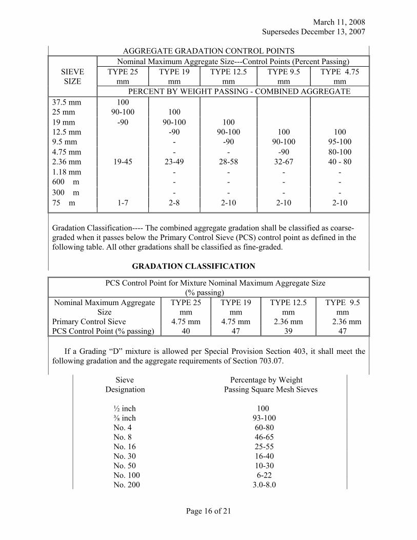
March 11, 2008 Supersedes December 13, 2007
Page 16 of 21
AGGREGATE GRADATION CONTROL POINTS Nominal Maximum Aggregate Size---Control Points (Percent Passing)
SIEVE SIZE
TYPE 25 mm
TYPE 19 mm
TYPE 12.5 mm
TYPE 9.5 mm
TYPE 4.75 mm
PERCENT BY WEIGHT PASSING - COMBINED AGGREGATE 37.5 mm 100 25 mm 90-100 100 19 mm -90 90-100 100 12.5 mm -90 90-100 100 100 9.5 mm - -90 90-100 95-100 4.75 mm - - -90 80-100 2.36 mm 19-45 23-49 28-58 32-67 40 - 80 1.18 mm - - - - 600 �m - - - - 300 �m - - - - 75 �m 1-7 2-8 2-10 2-10 2-10
Gradation Classification---- The combined aggregate gradation shall be classified as coarse-graded when it passes below the Primary Control Sieve (PCS) control point as defined in the following table. All other gradations shall be classified as fine-graded. GRADATION CLASSIFICATION
If a Grading “D” mixture is allowed per Special Provision Section 403, it shall meet the
following gradation and the aggregate requirements of Section 703.07.
Sieve Percentage by Weight Designation Passing Square Mesh Sieves ½ inch 100 ⅜ inch 93-100 No. 4 60-80 No. 8 46-65 No. 16 25-55 No. 30 16-40 No. 50 10-30 No. 100 6-22 No. 200 3.0-8.0
PCS Control Point for Mixture Nominal Maximum Aggregate Size (% passing) Nominal Maximum Aggregate
Size TYPE 25
mm TYPE 19
mm TYPE 12.5
mm TYPE 9.5
mm Primary Control Sieve 4.75 mm 4.75 mm 2.36 mm 2.36 mm PCS Control Point (% passing) 40 47 39 47

March 11, 2008 Supersedes December 13, 2007
Page 17 of 21
703.18 Common Borrow Replace the first paragraph with the following: “Common borrow shall consist of earth, suitable for embankment construction. It shall be free from frozen material, perishable rubbish, peat, and other unsuitable material including material currently or previously contaminated by chemical, radiological, or biological agents unless the material is from a DOT project and authorized by DEP for use.” 703.22 Underdrain Backfill Material Change the first paragraph from “…for Underdrain Type B…” to “…for Underdrain Type B and C…”
SECTION 706 NON-METALLIC PIPE
706.06 Corrugated Polyethylene Pipe for Underdrain, Option I and Option III Culvert Pipe Change the first sentence from “…300 mm diameters to 900 mm” to “…300 mm diameters to 1200 mm” Delete, in it’s entirety, the last sentence which begins “This pipe and resins…” and replace with the following; “The manufacturing plants of polyethylene pipe shall be certified by the Eastern States Consortium. Polyethylene pipe shall be accepted based on third party certification by the AASHTO’s National Transportation Product Evaluation Program.”
SECTION 709
REINFORCING STEEL AND WELDED STEEL WIRE FABIC 709.03 Steel Strand Change the second paragraph from “…shall be 12mm [½ inch] AASHTO M203M/M203 (ASTM A416/A416M)…” to “…shall be 15.24 mm [0.600 inch] diameter AASHTO M203 (ASTM A416)…”
SECTION 710 FENCE AND GUARDRAIL
710.03 Chain Link Fabric Add the following sentence: “Chain Link fabric for PVC coated shall conform to the requirements of AASHTO M181, Type IV-Class B.” 710.07 Guardrail Posts Section b. change “…AASHTO M183/M183M…” to “…AASHTO M 270M/M 270 Grade 250 (36)…”
SECTION 712 MISCELLANEOUS HIGHWAY MATERIALS
712.06 Precast Concrete Units In the first paragraph, change “…ASTM C478M…” to “…AASHTO M199…” Delete the second paragraph and replace with the following; “Approved structural fibers may be used as a replacement of 6 x 6 #10 gauge welded wire fabric when used at an approved dosage rate for the construction of manhole and catch basin units. The material used shall be one of the products listed on the Maine Department of Transportation’s Approved Product List of Structural Fiber Reinforcement.” Delete the fifth paragraph and replace with the following; “The concrete mix design shall be approved by the Department. Concrete shall contain 6% air content, plus or minus 1½% tolerance when tested according to AASHTO T152. All concrete shall develop a minimum compressive strength of 28 MPa [4000 psi] in 28 days when tested according to AASHTO T22. The absorption of a
March 11, 2008 Supersedes December 13, 2007
Page 18 of 21
specimen, when tested according to AASHTO T280, Test Method “A”, shall not exceed nine percent of the dry mass.” Add the following: “712.07 Tops, and Traps These metal units shall conform to the plan dimensions and to the following specification requirements for the designated materials. Gray iron or ductile iron castings shall conform to the requirements of AASHTO M306 unless otherwise designated.” 712.08 Corrugated Metal Units The units shall conform to plan dimensions and the metal to AASHTO M36/M36M. Bituminous coating, when specified, shall conform to AASHTO M190 Type A. 712.09 Catch Basin and Manhole Steps Steps for catch basins and for manholes shall conform to ASTM C478M [ASTM C478], Section 13 for either of the following material:
(a) Aluminum steps-ASTM B221M, [ASTM B211] Alloy 6061-T6 or 6005-T5. (b) Reinforced plastic steps Steel reinforcing bar with injection molded plastic coating copolymer polypropylene. Polypropylene shall conform to ASTM D 4101.
712.23 Flashing Lights Flashing Lights shall be power operated or battery operated as specified.
(a) Power operated flashing lights shall consist of housing, adapters, lamps, sockets, reflectors, lens, hoods and other necessary equipment designed to give clearly visible signal indications within an angle of at least 45 degrees and from 3 to 90 m [10 to 300 ft] under all light and atmospheric conditions. Two circuit flasher controllers with a two-circuit filter capable of providing alternate flashing operations at the rate of not less than 50 nor more than 60 flashes per minute shall be provided. The lamps shall be 650 lumens, 120 volt traffic signal lamps with sockets constructed to properly focus and hold the lamp firmly in position. The housing shall have a rotatable sun visor not less than 175 mm [7 in] in length designed to shield the lens. Reflectors shall be of such design that light from a properly focused lamp will reflect the light rays parallel. Reflectors shall have a maximum diameter at the point of contact with the lens of approximately 200 mm [8 in]. The lens shall consist of a round one-piece convex amber material which, when mounted, shall have a visible diameter of approximately 200 mm [8 in]. They shall distribute light and not diffuse it. The distribution of the light shall be asymmetrical in a downward direction. The light distribution of the lens shall not be uniform, but shall consist of a small high intensity portion with narrow distribution for long distance throw and a larger
March 11, 2008 Supersedes December 13, 2007
Page 19 of 21
low intensity portion with wide distribution for short distance throw. Lenses shall be marked to indicate the top and bottom of the lens.
(b) Battery operated flashing lights shall be self- illuminated by an electric lamp behind the lens. These lights shall also be externally illuminated by reflex-reflective elements built into the lens to enable it to be seen by reflex-reflection of the light from the headlights of oncoming traffic. The batteries must be entirely enclosed in a case. A locking device must secure the case. The light shall have a flash rate of not less than 50 nor more than 60 flashes per minute from minus 30 °C [minus 20 °F] to plus 65 °C [plus 150 °F]. The light shall have an on time of not less than 10 percent of the flash cycle. The light beam projected upon a surface perpendicular to the axis of the light beam shall produce a lighted rectangular projection whose minimum horizontal dimension shall be 5 degrees each side of the horizontal axis. The effective intensity shall not have an initial value greater than 15.0 candelas or drop below 4.0 candelas during the first 336 hours of continuous flashing. The illuminated lens shall appear to be uniformly bright over its entire illuminated surface when viewed from any point within an angle of 9 degrees each side of the vertical axis and 5 degrees each side of the horizontal axis. The lens shall not be less than 175 mm [7 in] in diameter including a reflex-reflector ring of 13 mm [½ in] minimum width around the periphery. The lens shall be yellow in color and have a minimum relative luminous transmittance of 0.440 with a luminance of 2854° Kelvin. The lens shall be one-piece construction. The lens material shall be plastic and meet the luminous transmission requirements of this specification. The case containing the batteries and circuitry shall be constructed of a material capable of withstanding abuse equal to or greater than 1.21 mm thick steel [No. 18 U.S. Standard Gage Steel]. The housing and the lens frame, if of metal shall be properly cleaned, degreased and pretreated to promote adhesion. It shall be given one or more coats of enamel which, when dry shall completely obscure the metal. The enamel coating shall be of such quality that when the coated case is struck a light blow with a sharp tool, the paint will not chip or crack and if scratched with a knife will not powder. The case shall be so constructed and closed as to exclude moisture that would affect the proper operation of light. The case shall have a weep hole to allow the escape of moisture from condensation. Photoelectric controls, if provided, shall keep the light operating whenever the ambient light falls below 215 lx [20 foot candles]. Each light shall be plainly marked as to the manufacturer's name and model number. If required by the Resident, certification as to conformance to these specifications shall be furnished based on results of tests made by an independent testing laboratory. All lights are subject to random inspection and testing. All necessary random samples shall be provided to the Resident upon request without cost to the Department. All such samples shall be returned to the Contractor upon completion of the tests.
712.32 Copper Tubing Copper tubing and fittings shall conform to the requirements of ASTM B88M Type A [ASTM B88, Type K] or better. 712.33 Non-metallic Pipe, Flexible Non-metallic pipe and pipe fittings shall be acceptable flexible pipe manufactured from virgin polyethylene polymer suitable for transmitting liquids intended for human or animal consumption.
March 11, 2008 Supersedes December 13, 2007
Page 20 of 21
712.34 Non-metallic Pipe, Rigid Non-metallic pipe shall be Schedule 40 polyvinylchloride (PVC) that meets the requirement of ASTM D1785. Fittings shall be of the same material. 712.341 Metallic Pipe Metallic pipe shall be ANSI, Standard B36.10, Schedule 40 steel pipe conforming to the requirements of ASTM A53 Types E or S, Grade B. End plates shall be steel conforming to ASTM A36/A36M. Both the sleeve and end plates shall be hot dip galvanized. Pipe sleeve splices shall be welded splices with full penetration weld before galvanizing. 712.35 Epoxy Resin Epoxy resin for grouting or sealing shall consist of a mineral filled thixotropic, flexible epoxy resin having a pot life of approximately one hour at 10°C [50°F]. The grout shall be an approved product suitable for cementing steel dowels into the preformed holes of curb inlets and adjacent curbing. The sealant shall be an approved product, light gray in color and suitable for coating the surface. 712.36 Bituminous Curb The asphalt cement for bituminous curb shall be of the grade required for the wearing course, or shall be Viscosity Grade AC-20 meeting the current requirements of Subsection 702.01 Asphalt Cement. The aggregate shall conform to the requirements of Subsection 703.07. The coarse aggregate portion retained on the 2.36 mm [No. 8] sieve may be either crushed rock or crushed gravel. The mineral constituents of the bituminous mixture shall be sized and graded and combined in a composite blend that will produce a stable durable curbing with an acceptable texture. Bituminous material for curb shall meet the requirements of Section 403 - Hot Bituminous Pavement. 712.37 Precast Concrete Slab Portland cement concrete for precast slabs shall meet the requirements of Section 502 - Structural Concrete, Class A. The slabs shall be precast to the dimension shown on the plans and cross section and in accordance with the Standard Detail plans for Concrete Sidewalk Slab. The surface shall be finished with a float finish in accordance with Subsection 502.14(c). Lift devices of sufficient strength to hold the slab while suspended from cables shall be cast into the top or back of the slab. 712.38 Stone Slab Stone slabs shall be of granite from an acceptable source, hard, durable, predominantly gray in color, free from seams which impair the structural integrity and be of smooth splitting character. Natural color variations characteristic of the deposit will be permitted. Exposed surfaces shall be free from drill holes or indications of drill holes. The granite slabs in any one section of backslope must be all the same finish. The granite slabs shall be scabble dressed or sawed to an approximately true plane having no projections or depressions over 13 mm [½ in] under a 600 mm [2 ft] straightedge or over 25 mm [1 in] under a 1200 mm [4 ft] straightedge. The arris at the intersection of the top surface and exposed front face shall be pitched so that the arris line is uniform throughout the length of the installed slabs. The sides shall be square to the exposed face unless the slabs are to be set
March 11, 2008 Supersedes December 13, 2007
Page 21 of 21
on a radius or other special condition which requires that the joints be cut to fit, but in any case shall be so finished that when the stones are placed side by side no space more than 20 mm [3/4 in] shall show in the joint for the full exposed height. Liftpin holes in all sides will be allowed except on the exposed face.
SECTION 717 ROADSIDE IMPROVEMENT MATERIAL
717.03 C. Method #3 - Roadside Mixture #3 Change the seed proportions to the following: Crown Vetch 25% Perennial Lupine 25% Red Clover 12.5% Annual Rye 37.5% 717.05 Mulch Binder Change the third sentence to read as follows: “Paper fiber mulch may be used as a binder at the rate of 2.3 kg/unit [5 lb/unit].”
SECTION 720 STRUCTURAL SUPPORTS FOR HIGHWAY SIGNS, LUMINAIRES, AND
TRAFFIC SIGNALS 720.08 U-Channel Posts Change the first sentence from “…, U-Channel posts…” to “…, Rib Back U-Channel posts…”
SECTION 722 GEOTEXTILES
722.01 Stabilization/Reinforcement Geotextile Add the following to note #3; “The strengths specified in the columns labeled”<50%” and “≥ 50%” refer to the elongation at which the geotextile material was tested. For example; if a fabric is tested at 15% elongation then it must meet or exceed the minimum strength shown in the “<50%” column. Submittals must include the percent elongation at which the material was tested.” 722.02 Drainage Geotextile Add the following to note #3; “The strengths specified in the columns labeled”<50%” and “≥ 50%” refer to the elongation at which the geotextile material was tested. For example; if a fabric is tested at 15% elongation then it must meet or exceed the minimum strength shown in the “<50%” column. Submittals must include the percent elongation at which the material was tested.” 722.01 Erosion Control Geotextile Add the following note to Elongation in the Mechanical Property Table; “The strengths specified in the columns labeled”<50%” and “≥ 50%” refer to the elongation at which the geotextile material was tested. For example; if a fabric is tested at 15% elongation then it must meet or exceed the minimum strength shown in the “<50%” column. Submittals must include the percent elongation at which the material was tested.”

Table of Contents Division Section Title DIVISION 1 - GENERAL REQUIREMENTS 01100 SUMMARY OF WORK 01250 CONTRACT MODIFICATION PROCEDURES 01290 PAYMENT PROCEDURES – SPECIAL PROVISION SECTION 108 01310 PROJECT MANAGEMENT AND COORDINATION 01330 SUBMITTAL PROCEDURES 01500 TEMPORARY FACILITIES AND CONTROLS 01770 CLOSEOUT PROCEDURES 01782 OPERATION AND MAINTENANCE DATA 01820 DEMONSTRATION AND TRAINING DIVISION 2 - SITE CONSTRUCTION 02230 SITE CLEARING AND GRUBBING 02250 DEWATERING 02315 COMMON EXCAVATION, EMBANKMENT AND COMPACTION 02317 TRENCHING FOR SITE UTILITIES 02320 SLOPE PROTECTION AND EROSION CONTROL 02510 WATER DISTRIBUTION 02535 SANITARY SEWER PIPING 02635 STORM DRAINAGE PIPING 02640 MANHOLES AND COVERS 02741 BITUMINOUS CONCRETE PAVING 02832 SEGMENTAL RETAINING WALLS 02921 SEEDING DIVISION 3 - CONCRETE 03300 CAST-IN-PLACE CONCRETE DIVISION 5 - METALS 05210 STEEL JOISTS 05310 STEEL DECK 05400 COLD FORMED METAL FRAMING 05500 METAL FABRICATIONS 05521 PIPE AND TUBE RAILINGS DIVISION 6 - WOOD AND PLASTICS 06100 ROUGH CARPENTRY 06200 FINISH CARPENTRY 06670 CELLULAR PVC FABRICATIONS DIVISION 7 - THERMAL AND MOISTURE PROTECTION 07150 DAMPPROOFING 07210 BUILDING INSULATION 07841 THROUGH-PENETRATION FIRESTOP SYSTEMS 07920 JOINT SEALANTS
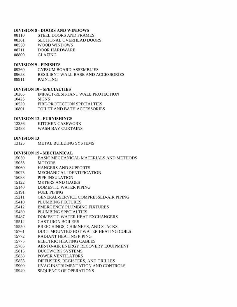
DIVISION 8 - DOORS AND WINDOWS 08110 STEEL DOORS AND FRAMES 08361 SECTIONAL OVERHEAD DOORS 08550 WOOD WINDOWS 08711 DOOR HARDWARE 08800 GLAZING DIVISION 9 - FINISHES 09260 GYPSUM BOARD ASSEMBLIES 09653 RESILIENT WALL BASE AND ACCESSORIES 09911 PAINTING DIVISION 10 - SPECIALTIES 10265 IMPACT-RESISTANT WALL PROTECTION 10425 SIGNS 10520 FIRE-PROTECTION SPECIALTIES 10801 TOILET AND BATH ACCESSORIES DIVISION 12 - FURNISHINGS 12356 KITCHEN CASEWORK 12488 WASH BAY CURTAINS DIVISION 13 13125 METAL BUILDING SYSTEMS DIVISION 15 - MECHANICAL 15050 BASIC MECHANICAL MATERIALS AND METHODS 15055 MOTORS 15060 HANGERS AND SUPPORTS 15075 MECHANICAL IDENTIFICATION 15083 PIPE INSULATION 15122 METERS AND GAGES 15140 DOMESTIC WATER PIPING 15191 FUEL PIPING 15211 GENERAL-SERVICE COMPRESSED-AIR PIPING 15410 PLUMBING FIXTURES 15412 EMERGENCY PLUMBING FIXTURES 15430 PLUMBING SPECIALTIES 15487 DOMESTIC WATER HEAT EXCHANGERS 15512 CAST-IRON BOILERS 15550 BREECHINGS, CHIMNEYS, AND STACKS 15761 DUCT MOUNTED HOT WATER HEATING COILS 15772 RADIANT HEATING PIPING 15775 ELECTRIC HEATING CABLES 15785 AIR-TO-AIR ENERGY RECOVERY EQUIPMENT 15815 DUCTWORK SYSTEMS 15838 POWER VENTILATORS 15855 DIFFUSERS, REGISTERS, AND GRILLES 15900 HVAC INSTRUMENTATION AND CONTROLS 15940 SEQUENCE OF OPERATIONS
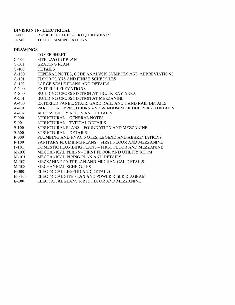
DIVISION 16 - ELECTRICAL 16000 BASIC ELECTRICAL REQUIREMENTS 16740 TELECOMMUNICATIONS DRAWINGS COVER SHEET C-100 SITE LAYOUT PLAN C-101 GRADING PLAN C-400 DETAILS A-100 GENERAL NOTES, CODE ANALYSIS SYMBOLS AND ABBREVIATIONS A-101 FLOOR PLANS AND FINISH SCHEDULES A-102 LARGE SCALE PLANS AND DETAILS A-200 EXTERIOR ELEVATIONS A-300 BUILDING CROSS SECTION AT TRUCK BAY AREA A-301 BUILDING CROSS SECTION AT MEZZANINE A-400 EXTERIOR PANEL, STAIR, GARD RAIL, AND HAND RAIL DETAILS A-401 PARTITION TYPES, DOORS AND WINDOW SCHEDULES AND DETAILS A-402 ACCESSIBILITY NOTES AND DETAILS S-000 STRUCTURAL – GENERAL NOTES S-001 STRUCTURAL – TYPICAL DETAILS S-100 STRUCTURAL PLANS – FOUNDATION AND MEZZANINE S-500 STRUCTURAL – DETAILS P-000 PLUMBING AND HVAC NOTES, LEGEND AND ABBREVIATIONS P-100 SANITARY PLUMBING PLANS – FIRST FLOOR AND MEZZANINE P-101 DOMESTIC PLUMBING PLANS – FIRST FLOOR AND MEZZANINE M-100 MECHANICAL PLANS – FIRST FLOOR AND UTILITY ROOM M-101 MECHANICAL PIPING PLAN AND DETAILS M-102 MEZZANINE PART PLAN AND MECHANICAL DETAILS M-103 MECHANICAL SCHEDULES E-000 ELECTRICAL LEGEND AND DETAILS ES-100 ELECTRICAL SITE PLAN AND POWER RISER DIAGRAM E-100 ELECTRICAL PLANS FIRST FLOOR AND MEZZANINE

SUMMARY OF WORK 01100 - 1 MDOT – REGION 3 HIGHWAY MAINTENANCE GARAGE BETHEL, MAINE PIN NO. 14448.10
SECTION 01100 – SUMMARY OF WORK
PART 1 - GENERAL
1.1 RELATED DOCUMENTS
A. If the Contractor discovers any ambiguity, error, omission, conflict, or discrepancy, Special Provision Section 101.3.6 Priority of Conflicting Contract Documents shall control.
1. Drawings and general provisions of the Contract, including General and Supplementary Conditions and other Division 1 Specification Sections, apply to this Section.
2. State of Maine Department of Transportation, “Standard Specifications,” Revision December 2002, and any revisions thereto, apply to this Section.
3. State of Maine Department of Transportation Standard Details revised 2002 4. State of Maine Department of Transportation Best Management Practices for Erosion and
Sediment control the “table of contents” of the latest version is dated 1/19/00. 5. Any supplements to any of the above specifications and or standards issued prior to
issuance of this specification.
1.2 SECTION INCLUDES
A. Work Covered by Contract Documents
B. Contract Method
C. Contractor’s Use of Premises
D. Work Under Other Contracts
E. Future Work
F. Products Ordered in Advance
G. Specification Formats and Conventions
H. Drawings Furnished
I. Examination of the SiteContractor’s Duties
K. Weather Protection
SUMMARY OF WORK 01100 - 2 MDOT – REGION 3 HIGHWAY MAINTENANCE GARAGE BETHEL, MAINE PIN NO. 14448.10
1.3 WORK COVERED BY CONTRACT DOCUMENTS
A. Project Identification: Project consists of the construction of a new 12,000 square foot pre-engineered metal building, including all site work, mechanical, plumbing, and electrical work as defined in this project manual and the plans. The various items of work for this project are hereinafter specified under the respective branch headings of the work or shown on the accompanying drawings and shall be included in the contracts made for the completion of any respective divisions of the work. Such contracts shall also include necessary details reasonably incidental to the proper execution and completion of such work.
1. Project Location: Bethel, Maine 2. Owner: Maine Department of Transportation.
B. Whenever a conflict, contradiction, or discrepancy between any statutes, regulations, plans or specifications, or if the Contractor request clarification of his responsibilities hereunder, it is the Contractor’s responsibility to obtain the advance written approval of the Department prior to deviating from any of the specifications.
C. Engineer Identification: The Contract Documents were prepared for the Project by Allied Engineering, Inc.
1.4 DEFINITIONS:
A. Engineer: shall mean the engineer or architect who’s seal is stamped on the drawing relating to the work.
1.5 CONTRACT METHOD:
A. Project will be constructed under a single contract.
1.6 CONTRACTOR’S USE OF PREMISES
A. Confine operations at site to areas permitted by:
1. Law, Ordinances, Permits, Contract Documents. 2. As defined by limit of work line on Site Plan. 3. As designated by Owner for location of office and storage of material areas.
B. Do not unreasonably encumber site with materials or equipment.
C. Do not load structure with weight that will endanger structure
D. Assume full responsibility for protection and safekeeping of products stored on premises
E. Obtain and pay for use of additional storage or work areas needed for operations
SUMMARY OF WORK 01100 - 3 MDOT – REGION 3 HIGHWAY MAINTENANCE GARAGE BETHEL, MAINE PIN NO. 14448.10
1.7 WORK UNDER OTHER CONTRACTS
A. Cooperate fully with separate contractors so work on those contracts may be carried out smoothly, without interfering with or delaying work under this Contract.
1.8 SPECIFICATION FORMATS AND CONVENTIONS
A. Specification Format: The Specifications are organized into Divisions and Sections using the 16-division format and CSI/CSC's "MasterFormat" numbering system. 1. Any and all references in these specification sections to “DIVISION” refer to the CSI
specification Division, unless specifically described otherwise.
B. Specification Content: The Specifications use certain conventions for the style of language and the intended meaning of certain terms, words, and phrases when used in particular situations. These conventions are as follows:
1. Abbreviated Language: Language used in the Specifications and other Contract Documents is abbreviated. Words and meanings shall be interpreted as appropriate. Words implied, but not stated, shall be inferred as the sense requires. Singular words shall be interpreted as plural, and plural words shall be interpreted as singular where applicable as the context of the Contract Documents indicates.
2. Imperative mood and streamlined language are generally used in the Specifications. Requirements expressed in the imperative mood are to be performed by Contractor. Occasionally, the indicative or subjunctive mood may be used in the Section Text for clarity to describe responsibilities that must be fulfilled indirectly by Contractor or by others when so noted.
a. The words "shall," "shall be," or "shall comply with," depending on the context, are implied where a colon (:) is used within a sentence or phrase.
1.9 DEFINITIONS:
A. Owner's Representative: All references to Owner's Representative in the Contract Documents shall in all cases refer to the Architect/Engineer. The Architect/Engineer will represent the Owner during construction and until final payment is due. The Architect/Engineer will advise and consult with the Owner. The Owner's instructions to the Contractor shall be forwarded through the Architect/Engineer.
B. Architect/Engineer: The project architect and/or engineer whose name appears on the plans and/or specifications for the project, acting directly or through an authorized representa-tive.
C. Project Manual: The Project Manual consist of the contract, general conditions, special provisions, the plans and specifications including all addenda and all other modifications thereof, that were incorporated in the documents prior to their execution.
SUMMARY OF WORK 01100 - 4 MDOT – REGION 3 HIGHWAY MAINTENANCE GARAGE BETHEL, MAINE PIN NO. 14448.10
D. Contract/ Agreement: A written agreement between the owner and the successful bidder, by which the contractor is bound to perform the work specified, in accordance with plans, specifications, general conditions, and special provisions, that are a part of the contract documents, together with all supplemental agreements by which the owner is bound to compensate the contractor at mutually established and accepted rates or prices.
1.10 DRAWINGS FURNISHED
A. On the award of the contract, Owner will issue to the Contractor 3 sets of the “Contract Drawings and Specifications” for use in his office and on the job. The owner will also furnish such additional copies as may be required for submission to public authorities to accompany applications for permits
B. Additional copies of drawings and specifications will be issued at cost of reproduction.
C. It is the intention that these specifications and the drawings accompanying same shall provide for this Project to be completed in all its respective parts. Any work shown on the drawings and not particularly described in the specifications, or vice versa, shall be furnished by the Contractor as part of his contract.
1.11 EXAMINATION OF THE SITE
A. All Contractors’ submitting proposals for the work shall first examine the site and all conditions thereon. All proposals shall take into consideration all such conditions as may affect the work under this contract.
1.12 CONTRACTORS DUTIES
A. Asbestos-Free Materials: Contractor shall provide certification that all materials used for construction under this contract are 100% asbestos-free.
B. Except as specifically noted, provide and pay for:
1. Labor, materials and equipment. 2. Tools, construction equipment and machinery 3. Water, heat and utilities required for construction 4. Other facilities and services necessary for proper execution and completion of work
C. Secure and pay for all permits, government fees, and licenses that are applicable at the time of bid for proper execution and completion of the work
D. Promptly submit written notice to the Department of observed variance of Contract Documents from legal requirements.
1. Appropriate Modifications to Contract Documents will adjust necessary changes to comply with Codes and Regulations.
SUMMARY OF WORK 01100 - 5 MDOT – REGION 3 HIGHWAY MAINTENANCE GARAGE BETHEL, MAINE PIN NO. 14448.10
2. Assume responsibility for work known to be contrary to such requirements without notice
E. WEATHER PROTECTION:
1. During the construction period, it is the Contractor’s responsibility that the building be under constant protection from the weather. Should there be any weather damage to the building’s interior; such damage is to be rectified to the satisfaction of the Department without cost to the owner.
F. Shop drawings and submittals may commence upon entering a contract with the Owner.
PART 2 - PRODUCTS
2.1 MATERIALS:
A. All materials used for construction under this contract shall be 100% asbestos-free
PART 3 - NOT USED
END OF SECTION 01100
CONTRACT MODIFICATION PROCEDURES 01250 - 1 MDOT - REGION 3 HIGHWAY MAINTENANCE GARAGE BETHEL, MAINE PIN NO. 14448.10
SECTION 01250 - CONTRACT MODIFICATION PROCEDURES
PART 1 - GENERAL
1.1 RELATED DOCUMENTS
A. If the Contractor discovers any ambiguity, error, omission, conflict, or discrepancy, Special Provision Section 101.3.6 Priority of Conflicting Contract Documents shall control.
1. Drawings and general provisions of the Contract, including General and Supplementary Conditions and other Division 1 Specification Sections, apply to this Section.
2. State of Maine Department of Transportation, “Standard Specifications,” Revision December 2002, and any revisions thereto, apply to this Section.
1.2 SUMMARY
A. This Section specifies administrative and procedural requirements for handling and processing Contract modifications.
1.3 PROPOSAL REQUESTS
A. Owner-Initiated Proposal Requests: The Department will issue a detailed description of proposed changes in the Work that may require adjustment to the Contract Sum or the Contract Time. If necessary, the description will include supplemental or revised Drawings and Specifications.
1. Proposal Requests issued by the Department are for information only. Do not consider them instructions either to stop work in progress or to execute the proposed change.
2. Within the time specified in the Proposal Request after receipt of Proposal Request, submit a quotation estimating cost adjustments to the Contract Sum and the Contract Time necessary to execute the change.
a. Include a list of quantities of products required or eliminated and unit costs, with total amount of purchases and credits to be made. If requested, furnish survey data to substantiate quantities.
b. Indicate, delivery charges, equipment rental, and amounts of trade discounts. c. Include an updated Contractor's Construction Schedule that indicates the effect of
the change, including, but not limited to, changes in activity duration, start and finish times, and activity relationship. Use available total float before requesting an extension of the Contract Time.
CONTRACT MODIFICATION PROCEDURES 01250 - 2 MDOT - REGION 3 HIGHWAY MAINTENANCE GARAGE BETHEL, MAINE PIN NO. 14448.10
B. Contractor-Initiated Proposals: If latent or unforeseen conditions require modifications to the Contract, Contractor may propose changes by submitting a request for a change to the Department.
1. Include a statement outlining reasons for the change and the effect of the change on the Work. Provide a complete description of the proposed change. Indicate the effect of the proposed change on the Contract Sum and the Contract Time.
2. Include a list of quantities of products required or eliminated and unit costs, with total amount of purchases and credits to be made. If requested, furnish survey data to substantiate quantities.
3. Indicate applicable taxes, delivery charges, equipment rental, and amounts of trade discounts.
4. Include an updated Contractor's Construction Schedule that indicates the effect of the change, including, but not limited to, changes in activity duration, start and finish times, and activity relationship. Use available total float before requesting an extension of the Contract Time.
5. Comply with requirements in Division 1 Section "Product Requirements" if the proposed change requires substitution of one product or system for product or system specified.
C. Proposal Request Form: For Change Order proposals, use standard forms and number the Request For Proposals (RFP) in alpha numerical order that they are submitted. (RFP#xx).
1.4 CHANGE ORDER PROCEDURES
A. Maine Department of Transportation will issue a Change Order for signatures of the Department and Contractor on the MDOT required form.
PART 2 - PRODUCTS (Not Used)
PART 3 - EXECUTION (Not Used)
END OF SECTION 01250
PAYMENT PROCEDURES 01290 - 1 SPECIAL PROVISION SECTION 108 MDOT – REGION 3 HIGHWAY MAINTENANCE GARAGE BETHEL, MAINE PIN NO. 14448.10
SPECIAL PROVISION SECTION 108
PAYMENT (Progress Payments)
Subsection 108.2.1 Generation of Progress Payment Estimates is deleted and replaced with the following specification in AIA format: SECTION 01290 – PAYMENT PROCEDURES PART 1 – GENERAL 1.1 RELATED DOCUMENTS A. Drawings and general provisions of the Contract, including General and Supplementary Conditions and other Division 1 Specification Sections, apply to this Section. 1.2 SUMMARY A. This section specifies administrative and procedural requirements necessary to prepare and process Applications for Payment. 1.3 DEFINITIONS A. Schedule of Values: A statement furnished by Contractor allocating portions of the Contract Sum to various portions of the Work and used as the basis for reviewing Contractor’s Applications for Payment. 1.4 SCHEDULE OF VALUES A. Coordination: Coordinate preparation of the Schedule of Values with preparation of Contractor’s Construction Schedule. 1. Within 10 days after Contract execution, the Contractor shall submit a Schedule of Values breakdown to the Resident itemized by the individual specification sections, including a separate line item for Region 1, General Requirements. This breakdown shall appear in the monthly payment requisition. 2. Correlate line items in the Schedule of Values with other required administrative forms and schedules, including the following: a. Application for Payment forms with Continuation Sheets b. Submittals Schedule
PAYMENT PROCEDURES 01290 - 2 SPECIAL PROVISION SECTION 108 MDOT – REGION 3 HIGHWAY MAINTENANCE GARAGE BETHEL, MAINE PIN NO. 14448.10
3. Submit the Schedule of Values to Resident no later than 15 days prior to date scheduled for submittal of initial Application for Payment. 4. Subschedules: Where the Work is separated into phases (ie. Division 15000 Mechanical and 16000 Electrical) requiring separately phased payments, provide subschedules showing values correlated with each phase of payment. B. Format and Content: Use the Table of Contents in the Contract Book as a guide to establish line items for the Schedule of Values. Provide at least one line item for each Specification Section. 1. Identification: Including the following Project identification on the Schedule of Values: a. Project name and location b. Name of Engineer c. Project Number d. Contractor’s name and address e. Date of submittal 2. Arrange the Schedule of Values in tabular form with separate columns to indicate the following for each item listed: a. Related Specification Section or Division b. Description of the Work c. Name of subcontractor d. Name of manufacturer or fabricator e. Name of supplier f. Change Orders (numbers) that affect value g. Dollar value 1) Percentage of the Contract Sum to nearest one-hundredth percent, adjusted to total 100 percent. 3. Provide a breakdown of the Contract Sum in enough detail to facilitate continued evaluation of Applications for Payment and progress reports. Coordinate with the Contract Book table of contents. Provide several line items for principal subcontract amounts, where appropriate. 4. Round amounts to nearest whole dollar; total shall equal the Contract Sum. 5. Provide a separate line item in the Schedule of Values for each part of the Work where Applications for Payment may include materials or equipment purchased or fabricated and stored, but not yet installed. a. Differentiate between items stored on site and items stored off site. Include evidence of insurance or bonded warehousing if required. 6. Provide separate line items in the Schedule of Values for initial cost of materials, for each subsequent stage of completion, and for total installed value of that part of the Work. 7. Allowances: Provide a separate line item in the Schedule of Values for each allowance. Show line-item value of unit-cost allowances, as a product of the unit cost, multiplied by measured quantity. Use information indicated in the Contract Documents to determine quantities.
PAYMENT PROCEDURES 01290 - 3 SPECIAL PROVISION SECTION 108 MDOT – REGION 3 HIGHWAY MAINTENANCE GARAGE BETHEL, MAINE PIN NO. 14448.10
8. Each item in the Schedule of Values and Application for Payment shall be complete. Include total cost and proportionate share of general overhead and profit for each item. a. Temporary facilities and other major cost items that are not direct cost of actual work in place may be shown either as separate line items in the Schedule of Values or distributed as general overhead expense, at Contractors option. 9. Schedule Updating: Update and resubmit the Schedule of Values before the next Application for Payment when Change Orders or Construction Change Directives result in a change in the Contract Sum. 1.5 APPLICATIONS FOR PAYMENT A. Each Application for Payment shall be consistent with previous applications and payments as certified by Resident and paid for by Owner. 1. Initial Application for Payment and Final Application for Payment involve additional requirements. B. The Contractor shall present Application for Payment based on materials incorporated into the work and labor performed and a reasonable amount of materials obtained and stored not less than 5 work days prior to the scheduled monthly progress requisition. Payments shall be authorized for the amount stated in the application, less the retainage specified in State of Maine Department of Transportation Specifications, provided the Resident is satisfied with the correctness of the amount stated. Resident may request that the Contractor submit backup documentation, including copies of receipts, invoices, and itemized payments to Subcontractors. C. Progress estimate payments may be paid once every two weeks or at longer intervals as agreed to by the Contractor and the Resident. D. Payment Application Forms: Use AIA Document G702 and AIA Document G703 Continuation Sheets as form for Applications for Payment, or equivalent form accepted by the Resident. E. Application Preparation: Complete every entry on form. Notarize and execute by a person authorized to sign legal documents on behalf of Contractor. Resident will return incomplete applications without action. 1. Entries shall match data on the Schedule of Values and Contractor’s Construction Schedule. Use updated schedules if revisions were made. 2. Include amounts of Change Orders and Construction Change Directives issued before last day of construction period covered by application. F. Transmittal: Submit 3 signed and notarized original copies of each Application for Payment to Resident for monthly payment requisitions. Resident will review Application for Payment, Schedule of Values, and Contractor’s Construction Schedule, and will provide approval for payment if warranted. 1. Transmit each copy with a transmittal form listing attachments and recording appropriate information about application. G. Waivers of Mechanic’s Lien: With each Application for Payment, submit waivers of mechanic’s lien from every entity who is lawfully entitled to file a mechanic’s lien arising out of the Contract and related to the Work covered by the payment.

PAYMENT PROCEDURES 01290 - 4 SPECIAL PROVISION SECTION 108 MDOT – REGION 3 HIGHWAY MAINTENANCE GARAGE BETHEL, MAINE PIN NO. 14448.10
H. Initial Application for Payment: Administrative actions and submittals that must precede or coincide with submittal of first Application for Payment include the following: 1. List of subcontractors 2. Schedule of Values 3. Contractor’s Construction Schedule (preliminary if not final) 4. Products list 5. Schedule of unit prices 6. Submittals Schedule (preliminary if not final) 7. List of Contractor’s staff assignments 8. List of Contractor’s principal consultants 9. Report of preconstruction conference 10. Certificates of insurance and insurance policies 11. Performance and payment bonds I. Final Payment Application: Submit final Application for Payment with releases and supporting documentation not previously submitted and accepted, including, but not limited, to the following: 1. Evidence of completion of Project closeout requirements 2. Insurance certificates for products and completed operations where required and proof that taxes, fees, and similar obligations were paid 3. Updated final statement, accounting for final changes to the Contract Sum 4. AIA Document G706, “Contractor’s Affidavit of Payment of Debts and Claims” 5. AIA Document G707, “Consent of Surety to Final Payment” 6. Evidence that claims have been settled 7. Final meter readings for utilities, a measured record of stored fuel, and similar data as of date of Substantial Completion or when Owner took possession of and assumed responsibility for corresponding elements of the Work 8. Final, liquidated damages settlement statement PART 2 – PRODUCTS (Not used) PART 3 – EXECUTION (Not used)
END OF SECTION 01290
PROJECT MANAGEMENT AND COORDINATION 01310 - 1 MDOT – REGION 3 HIGHWAY MAINTENANCE GARAGE BETHEL, MAINE PIN NO. 14448.10
SECTION 01310 – PROJECT MANAGEMENT AND COORDINATION
PART 1 - GENERAL
1.1 RELATED DOCUMENTS
A. If the Contractor discovers any ambiguity, error, omission, conflict, or discrepancy, Special Provision Section 101.3.6 Priority of Conflicting Contract Documents shall control.
1. Drawings and general provisions of the Contract, including General and Supplementary Conditions and other Division 1 Specification Sections, apply to this Section.
2. State of Maine Department of Transportation, “Standard Specifications,” Revision December 2002, and any revisions thereto, apply to this Section.
1.2 SUMMARY
A. This Section includes administrative provisions for coordinating construction operations on Project including, but not limited to, the following:
1. General project coordination procedures. 2. Conservation. 3. Coordination Drawings. 4. Administrative and supervisory personnel. 5. Project meetings.
B. The General contractor shall be responsible for over all coordination of the project
1. Each contractor shall participate in coordination requirements. Certain areas of responsibility will be assigned to a specific contractor.
C. Related Sections: The following Sections contain requirements that relate to this Section: 1. Division 1 Section 01770 “Closeout Procedures" for coordinating Contract closeout.
1.3 COORDINATION
A. Coordination: Coordinate construction operations included in various Sections of the Specifications to ensure efficient and orderly installation of each part of the Work. Coordinate construction operations, included in different Sections, that depend on each other for proper installation, connection, and operation. Coordinate sequence of work to accommodate Owner’s occupancy.
B. If necessary, prepare memoranda for distribution to each party involved, outlining special procedures required for coordination. Include such items as required notices, reports, and list of attendees at meetings.
PROJECT MANAGEMENT AND COORDINATION 01310 - 2 MDOT – REGION 3 HIGHWAY MAINTENANCE GARAGE BETHEL, MAINE PIN NO. 14448.10
C. Coordination of Security: All security coordination shall be through the General contractor. The Contractor shall be expected to keep the Department informed of any deviation in the normal work schedule. The Department shall be given a minimum of two (2) hours notice when a Contractor is not going to be working on a scheduled day because of inclement weather, lack of material etc.
D. Administrative Procedures: Coordinate scheduling and timing of required administrative procedures with other construction activities and activities of other contractors to avoid conflicts and to ensure orderly progress of the Work. Such administrative activities include, but are not limited to, the following:
1. Preparation of Contractor's Construction Schedule. 2. Preparation of the Schedule of Values. 3. Installation and removal of temporary facilities and controls. 4. Delivery and processing of submittals. 5. Attendance of the Preconstruction Conference 6. Attendance of Progress meetings. 7. Preinstallation conferences. 8. Project closeout activities.
E. Conservation: Coordinate construction activities to ensure that operations are carried out with consideration given to conservation of energy, water, and materials.
1. Salvage materials and equipment involved in performance of, but not actually incorporated into, the Work.
1.4 SUBMITTALS
A. Schedule and coordinate submittals specified in Section 01330 – Submittal Procedures.
B. Coordinate work of various sections having interdependent responsibilities for installing, connecting to, and placing in service such equipment.
C. Coordinate requests for substitutions to assure compatibility of space, of operating elements, and affect on work of other sections.
D. Coordination Drawings: Prepare Coordination Drawings if limited space availability necessitates maximum utilization of space for efficient installation of different components or if coordination is required for installation of products and materials fabricated by separate entities.
1. Indicate relationship of components shown on separate Shop Drawings. 2. Indicate required installation sequences. 3. Refer to Division 15 Section "Basic Mechanical Materials and Methods" and Division 16
Section "Basic Electrical Materials and Methods" for specific Coordination Drawing requirements for mechanical and electrical installations.
E. Staff Names: Within 5 days of starting construction operations, submit a list of principal staff assignments, including superintendent and other personnel in attendance at Project site. Identify

PROJECT MANAGEMENT AND COORDINATION 01310 - 3 MDOT – REGION 3 HIGHWAY MAINTENANCE GARAGE BETHEL, MAINE PIN NO. 14448.10
individuals and their duties and responsibilities; list addresses and telephone numbers, including home and office telephone numbers. Provide names, addresses, and telephone numbers of individuals assigned as standbys in the absence of individuals assigned to Project.
1. Post copies of list in Project meeting room, in temporary field office, and by each temporary telephone.
1.5 PRECONSTRUCTION CONFERENCE
A. The successful low bid Contractor will be required to attend a Pre-construction Conference Meeting. At said meeting, the Contractor shall supply to the Department and the Engineer, in writing, the name of the Project Foreman and/or Manufacturer's Approved Applicator directing all phases of the installation.
1.6 PROGRESS MEETINGS
A. The Department will schedule and administer monthly construction progress meetings, and called meetings, throughout the progress of the work.
B. The Department will preside at meetings, record minutes, and distribute copies after meeting to the owner and the General contractor. The General contractor shall be responsible to provide copies of the minutes to any subcontractors that attend the meetings.
C. Location of Meetings: Job site.
1. The Preconstruction meeting may be held at the owner’s facility in close proximity to the job site.
D. Attendance: The Contractor, Job Superintendent, and the Resident.
E. Minimum Agenda:
1. Review of work progress. 2. Field observations, problems and decisions. 3. Identification of problems, which impede planned progress. 4. Review of submittals schedule and status of submittals. 5. Review of off-site fabrication and delivery schedules. 6. Maintenance of progress schedule. 7. Corrective measures to regain projected schedules. 8. Planned progress during succeeding work period. 9. Coordination of projected progress. 10. Maintenance of quality and work standards. 11. Effect of proposed changes on progress schedule and coordination. 12. Other business relating to work. 13. Review of Contractor's Application for Payment. 14. Preinstallation conferences may also be held at the Progress meetings.
PROJECT MANAGEMENT AND COORDINATION 01310 - 4 MDOT – REGION 3 HIGHWAY MAINTENANCE GARAGE BETHEL, MAINE PIN NO. 14448.10
1.7 PROJECT CLOSEOUT
A. Coordinate completion and cleanup of work of separate sections in preparation for completion.
B. After Owner's occupancy of premises, coordinate access to site by various sections for correction of defective work and work not in accordance with Contract Documents to minimize disruption of Owner's activities.
C. Assemble and coordinate closeout submittals specified.
PART 2 - PRODUCTS (Not Used)
PART 3 - EXECUTION (Not Used)
END OF SECTION 01310
SUBMITTAL PROCEDURES 01330 - 1 MDOT – REGION 3 HIGHWAY MAINTENANCE GARAGE BETHEL, MAINE PIN NO. 14448.10
SECTION 01330 - SUBMITTAL PROCEDURES
PART 1 - GENERAL
1.1 RELATED DOCUMENTS
A. If the Contractor discovers any ambiguity, error, omission, conflict, or discrepancy, Special Provision Section 101.3.6 Priority of Conflicting Contract Documents shall control.
1. Drawings and general provisions of the Contract, including General and Supplementary Conditions and other Division 1 Specification Sections, apply to this Section.
2. State of Maine Department of Transportation, “Standard Specifications,” Revision December 2002, and any revisions thereto, apply to this Section.
1.2 SUMMARY
A. This Section includes administrative and procedural requirements for submitting Shop Drawings, Product Data, Samples, and other miscellaneous submittals.
B. Related Sections include the following:
1. Standard General Conditions. 2. Supplemental Conditions. 3. Division 1 Section "Operation and Maintenance Data".
1.3 DEFINITIONS
A. Action Submittals: Written and graphic information that requires the Department's responsive action.
B. Informational Submittals: Written information that does not require the Department's approval. Submittals may be rejected for not complying with requirements.
1.4 SUBMITTAL PROCEDURES
A. General: Electronic copies of CAD Drawings of the Contract Drawings will not be provided for Contractor's use in preparing submittals.
B. Submittal Requirements: Submittals shall have a separate cover sheet for each Division. Submittals for more than one Division shall not be combined.
1. Apply Contractor's stamp, signed or initialed certifying to review, verification of products, field dimensions and field construction criteria, and coordination of information with requirements of work and Contract Documents.
SUBMITTAL PROCEDURES 01330 - 2 MDOT – REGION 3 HIGHWAY MAINTENANCE GARAGE BETHEL, MAINE PIN NO. 14448.10
2. Submittals that do not have an approval stamp and signature in compliance with this Section shall be returned without review by the Department. The Contractor shall be fully responsible for any delays due to returned shop drawings, product data sheets.
3. Do not fabricate products or begin work or which requires submittals until return of submittals with Department’s and Engineer’s review. All work shall be in conformity with reviewed shop drawings
4. When shop drawings and/or submitted data sheets do not meet the product/materials shown or specified, the Department and Engineer will review submissions no more than two (2) times. After the second review the Contractor shall have the cost to review all subsequent submissions reimbursed to the Owner at the Engineer’s published standard billing rate for personnel involved. Such costs shall be deducted from the amounts otherwise due the Contractor
C. Standards:
1. Materials: Any material specified by reference to the number, symbol, or title of a specified standard such as Commercial Standard, a Federal Specification, a trade association standard, or other similar standard, shall comply with the requirements in the latest revision thereof, and any amendment or supplement thereto, in effect on the date of invitation for proposals, except as limited to type, class of grade, or modified in such reference, and except as otherwise indicated.
2. Standards: The Standard referred to, except as modified in the specifications, shall have full force and effect as though printed in these specifications. These standards are not furnished to bidders for the reason that the manufacturers and trades involved are assumed to be familiar with their requirements. The Engineer will furnish, upon request, information as to how copies of the standards referred to may be obtained.
3. Serial Numbers: Where A.S.T.M. Serial Numbers are used, they refer to the latest tentative specifications; standard specifications; standard method or standard method of testing, issued by the American Society for Testing and Materials.
D. Certificate of Conformance: Except where tests and/or inspections in connection with structural materials are specified or required by applicable laws, rules and regulations, manufacturer's certificates covering conformance with the requirements of the above mentioned Federal Specifications and Commercial Standards may be accepted in lieu of such tests. Such certificates shall be furnished to the Department for all items so specified.
1. Submit to the Department manufacturer's certificates covering conformance with the requirements of asbestos-free materials on all materials.
E. Coordination: Coordinate preparation and processing of submittals with performance of construction activities.
1. Coordinate each submittal with fabrication, purchasing, testing, delivery, other submittals, and related activities that require sequential activity.
2. Contractor shall be fully responsible for observing the need for and making any changes in the arrangement of piping, connections, wiring, manner of installing and the like which may be required by the equipment he proposes to supply. If the drawings show variations from contract drawings or specifications whether because of standard shop practice or other reasons, the Contractor will not be relieved of the responsibility for completing the
SUBMITTAL PROCEDURES 01330 - 3 MDOT – REGION 3 HIGHWAY MAINTENANCE GARAGE BETHEL, MAINE PIN NO. 14448.10
work in full accordance with the Contract Documents even though such shop drawings are approved by the Department.
a. Shop drawings, product data sheets that do not have an approval stamp and signature in compliance with this Section shall be returned without review by the Department. The Contractor shall be fully responsible for any delays due to returned shop drawings, product data sheets.
3. Within 30 days after the date of the Letter of Intent and before any material or equipment is purchased, the Contractor shall submit to the Department manufacturer's data, catalog cuts, samples, or other information as required by individual Specification Sections.
a. Deviations from the contract, deemed necessary, will only be considered when accompanied by a letter (identifying the item specified, the item proposed, and any cost variation) outlining specific reasons for requesting such deviation. If these conditions are not met, the submittal shall be returned to the Contractor for corrective action. The adequacy and accuracy of submittals and their compliance with contract documents are the responsibility of the Contractor. All approval actions taken by the Department will in no way relieve the Contractor of his quality control requirements.
F. Processing Time: Allow enough time for submittal review, including time for resubmittals, as follows. Time for review shall commence on Department's receipt of submittal.
1. Initial Review: Allow 15 days for initial review of each submittal. Delete subparagraph below if not required.
2. If intermediate submittal is necessary, process it in same manner as initial submittal. 3. Allow 15 days for processing each resubmittal. 4. No extension of the Contract Time will be authorized because of failure to transmit
submittals enough in advance of the Work to permit processing.
G. Identification: Place a permanent label or title block on each submittal for identification.
1. Indicate name of firm or entity that prepared each submittal on label or title block. 2. Provide a space approximately 4 by 5 inches on label or beside title block to record
Contractor's review and approval markings and action taken by Department. 3. Include the following information on label for processing and recording action taken:
a. Project name. b. Date. c. Name and address of Engineer. d. Name and address of Contractor. e. Name and address of subcontractor. f. Name and address of supplier. g. Name of manufacturer. h. Unique identifier, including revision number. i. Number and title of appropriate Specification Section. j. Drawing number and detail references, as appropriate. k. Other necessary identification.
SUBMITTAL PROCEDURES 01330 - 4 MDOT – REGION 3 HIGHWAY MAINTENANCE GARAGE BETHEL, MAINE PIN NO. 14448.10
H. Deviations: Highlight, encircle, or otherwise identify deviations from the Contract Documents on submittals.
I. Additional Copies: Unless additional copies are required for final submittal, and unless Department observes noncompliance with provisions of the Contract Documents, initial submittal may serve as final submittal.
1. Submit six (6) copies of Shop Drawings, Product Data and Manufacturer's Instructions to the Department.
2. Additional copies submitted for maintenance manuals will not be marked with action taken and will be returned.
J. Transmittal: Package each submittal individually and appropriately for transmittal and handling. Transmit each submittal using a transmittal form. The Department will discard submittals received from sources other than Contractor.
1. On an attached separate sheet, prepared on Contractor's letterhead, record relevant information, requests for data, revisions other than those requested by Department on previous submittals, and deviations from requirements of the Contract Documents, including minor variations and limitations. Include the same label information as the related submittal.
2. Include Contractor's certification stating that information submitted complies with requirements of the Contract Documents.
3. Transmittal Form: Provide locations on form for the following information:
a. Project name. b. Date. c. Destination (To:). d. Source (From:). e. Names of subcontractor, manufacturer, and supplier. f. Category and type of submittal. g. Submittal purpose and description. h. Submittal and transmittal distribution record. i. Remarks. j. Signature of transmitter.
K. Distribution: Furnish copies of final submittals to manufacturers, subcontractors, suppliers, fabricators, installers, authorities having jurisdiction, and others as necessary for performance of construction activities. Show distribution on transmittal forms.
L. Use for Construction: Use only final submittals with mark indicating action taken by Department in connection with construction.
SUBMITTAL PROCEDURES 01330 - 5 MDOT – REGION 3 HIGHWAY MAINTENANCE GARAGE BETHEL, MAINE PIN NO. 14448.10
PART 2 - PRODUCTS
2.1 ACTION SUBMITTALS
A. Product Data: Collect information into a single submittal for each element of construction and type of product or equipment.
1. Within 30 days after the date of the Letter of Intent and before any material or equipment is purchased, the Contractor shall submit to the Department manufacturer's data, catalog cuts, samples, or other information as required for the items listed in each section.
a. Deviations from the contract, deemed necessary, will only be considered when accompanied by a letter (identifying the item specified, the item proposed, and any cost variation) outlining specific reasons for requesting such deviation. If these conditions are not met, the submittal shall be returned to the Contractor for corrective action. The adequacy and accuracy of submittals and their compliance with contract documents are the responsibility of the Contractor. All approval actions taken by the Department will in no way relieve the Contractor of his quality control requirements.
2. If information must be specially prepared for submittal because standard printed data are not suitable for use, submit as Shop Drawings, not as Product Data.
3. Mark each copy of each submittal to show which products and options are applicable. 4. Include the following information, as applicable:
a. Manufacturer's written recommendations. b. Manufacturer's product specifications. c. Manufacturer's installation instructions. d. Manufacturer's catalog cuts. e. Wiring diagrams showing factory-installed wiring. f. Printed performance curves. g. Operational range diagrams. h. Standard product operating and maintenance manuals. i. Compliance with recognized trade association standards. j. Compliance with recognized testing agency standards. k. Application of testing agency labels and seals. l. Notation of coordination requirements.
B. Shop Drawings: Prepare Project-specific information, drawn accurately to scale. Do not base Shop Drawings on reproductions of the Contract Documents or standard printed data.
1. Preparation: Include the following information, as applicable:
a. Shop drawings shall be drawn to scale, shall show all necessary working dimensions and such details, sections, plans and elevations (all properly cross-referenced to the contract drawings) as are necessary to clearly delineate
SUBMITTAL PROCEDURES 01330 - 6 MDOT – REGION 3 HIGHWAY MAINTENANCE GARAGE BETHEL, MAINE PIN NO. 14448.10
arrangements, construction and connection with other work. They shall be numbered consecutively and dated and shall indicate the project name, the names of the Contractor and the Subcontractor, the name and description of the equipment or articles shown, the manufacturer's name, the kinds, types, grades, thicknesses and finishes of materials, including all fittings, fastenings and the like and the locations at which materials or equipment are to be installed in the work. Marked-up copies of standard drawings showing typical conditions and details and indicating their specific application to the work will not be acceptable. Shop drawings shall be accompanied by a letter of transmittal identifying the items of work submitted. Shop drawings shall be submitted in such time as to cause no delay in the orderly progress of work, under the contract, due allowance being made for checking and such correcting, resubmission, and rechecking as may be necessary. The approval of the shop drawings will be general and shall not relieve the Contractor from sole responsibility for errors or omissions of any sort, nor for proper fitting and construction on work or the finishing of materials or work required by the contract documents but not shown or indicated on the shop drawings. Approval will not imply verification of required quantity of material, nor correctness of dimensions. Requests by the Department for changes and corrections on shop drawings shall not be construed as an order for extra work under the contract.
b. Present shop drawings in a clear and thorough manner. Title each drawing with project name and number. Identify each element of drawings by reference to sheet number and detail, schedule or room number of contract documents.
c. Dimensions. d. Identification of field dimensions, show relation to adjacent or critical features or
work or products. e. Identification of products. f. Fabrication and installation drawings. g. Roughing-in and setting diagrams. h. Wiring diagrams showing field-installed wiring, including power, signal, and
control wiring. i. Shopwork manufacturing instructions. j. Templates and patterns. k. Schedules. l. Design calculations. m. Compliance with specified standards. n. Notation of coordination requirements. o. Notation of dimensions established by field measurement.
2. Wiring Diagrams: Differentiate between manufacturer-installed and field-installed wiring.
3. Sheet Size: Except for templates, patterns, and similar full-size drawings, submit Shop Drawings on sheets at least 8-1/2 by 11 inches but no larger than 30 by 40 inches.
4. Number of Copies: Submit one correctable, translucent, reproducible print and one blue- or black-line print of each submittal. The Department will return the reproducible print.
SUBMITTAL PROCEDURES 01330 - 7 MDOT – REGION 3 HIGHWAY MAINTENANCE GARAGE BETHEL, MAINE PIN NO. 14448.10
C. Samples: Prepare physical units of materials or products, including the following:
1. Samples properly identified and described, shall be submitted in the number specifically called for in the body of the specification or as may be required by the Department. They shall be submitted and resubmitted until approved. No approval of a sample shall be taken in itself to change or modify any contract requirement. Finishes, materials or workmanship in the completed buildings shall match the approved samples.
2. Comply with requirements in Division 1 Section "Quality Requirements" for mockups. 3. Samples for Initial Selection: Submit manufacturer's color charts consisting of units or
sections of units showing the full range of colors, textures, and patterns available.
PART 3 - EXECUTION
3.1 CONTRACTOR'S REVIEW
A. Review each submittal and check for compliance with the Contract Documents. Note corrections and field dimensions. Mark with approval stamp before submitting to Department.
B. Approval Stamp: Stamp each submittal with a uniform, approval stamp. Include Project name and location, submittal number, Specification Section title and number, name of reviewer, date of Contractor's approval, and statement certifying that submittal has been reviewed, checked, and approved for compliance with the Contract Documents.
3.2 ENGINEER'S [AND CONSTRUCTION MANAGER'S] ACTION
A. General: Department will not review submittals that do not bear Contractor's approval stamp and will return them without action.
B. Action Submittals: Department will review each submittal, make marks to indicate corrections or modifications required, and return it. Department will stamp each submittal with an action stamp and will mark stamp appropriately to indicate action taken, as follows:
1. REVIEWED, 2. REVIEWED W/NOTES – No Resubmission 3. REVIEWED W/NOTES – Resubmission Required, 4. NOT ACCEPTABLE
C. Informational Submittals: Department will review each submittal and will not return it, or will reject and return it if it does not comply with requirements.
D. Submittals not required by the Contract Documents will not be reviewed and may be discarded.
END OF SECTION 01330
TEMPORARY FACILITIES AND CONTROLS 01500 - 1 MDOT – REGION 3 HIGHWAY MAINTENANCE GARAGE BETHEL, MAINE PIN NO. 14448.10
SECTION 01500 - TEMPORARY FACILITIES AND CONTROLS
PART 1 - GENERAL
1.1 RELATED DOCUMENTS
A. If the Contractor discovers any ambiguity, error, omission, conflict, or discrepancy, Special Provision Section 101.3.6 Priority of Conflicting Contract Documents shall control.
1. Drawings and general provisions of the Contract, including General and Supplementary Conditions and other Division 1 Specification Sections, apply to this Section.
2. State of Maine Department of Transportation, “Standard Specifications,” Revision December 2002, and any revisions thereto, apply to this Section.
1.2 SUMMARY
A. This Section includes requirements for temporary facilities and controls, including temporary utilities, support facilities, and security and protection facilities.
B. Temporary utilities include, but are not limited to, the following:
1. Water service and distribution. 2. Sanitary facilities, including toilets, wash facilities, and drinking-water facilities. 3. Heating and cooling facilities. 4. Electric power service. 5. Lighting. 6. Telephone service.
C. Support facilities include, but are not limited to, the following:
1. Temporary roads and paving. 2. Dewatering facilities and drains. 3. Field offices. 4. Storage and fabrication sheds.
D. Related Sections include the following:
1. Division 1 Section "Submittal Procedures" for procedures for submitting copies of implementation and termination schedule and utility reports.
2. Division 1 Section "Execution Requirements" for progress cleaning requirements. 3. Divisions 2 through 16 for temporary heat, ventilation, and humidity requirements for
products in those Sections.
TEMPORARY FACILITIES AND CONTROLS 01500 - 2 MDOT – REGION 3 HIGHWAY MAINTENANCE GARAGE BETHEL, MAINE PIN NO. 14448.10
1.3 DEFINITIONS
A. Permanent Enclosure: As determined by the Department, permanent or temporary roofing is complete, insulated, and weathertight; exterior walls are insulated and weathertight; and all openings are closed with permanent construction or substantial temporary closures.
1.4 USE CHARGES
A. General: Cost or use charges for temporary facilities are not chargeable to Owner or Engineer and shall be included in the Contract Sum. Allow other entities to use temporary services and facilities without cost, including, but not limited to, the following:
1. Owner's construction forces. 2. Occupants of Project. 3. Engineer 4. Architect. 5. Testing agencies. 6. Personnel of authorities having jurisdiction.
B. Water Service: Use water from Owner's existing water system without metering and without payment of use charges.
C. Electric Power Service: Pay electric power service use charges, whether metered or otherwise, for electricity used by all entities engaged in construction activities at Project site.
D. Telephone/Fax Machine: Pay all charges if Contractor chooses to install a telephone/fax machine for all entities engaged in construction activities at Project site.
E. Temporary Heat: Pay labor and fuel charges for temporary heat for all entities engaged in construction activities at Project Site.
1.5 PROJECT CONDITIONS
A. Temporary Utilities: At earliest feasible time, when acceptable to Owner, change over from use of temporary service to use of permanent service.
1. Temporary Use of Permanent Facilities: Installer of each permanent service shall assume responsibility for operation, maintenance, and protection of each permanent service during its use as a construction facility before Owner's acceptance, regardless of previously assigned responsibilities.
B. Conditions of Use: The following conditions apply to use of temporary services and facilities by all parties engaged in the Work:
1. Keep temporary services and facilities clean and neat.
TEMPORARY FACILITIES AND CONTROLS 01500 - 3 MDOT – REGION 3 HIGHWAY MAINTENANCE GARAGE BETHEL, MAINE PIN NO. 14448.10
2. Relocate temporary services and facilities as required by progress of the Work.
PART 2 - PRODUCTS not used
2.1 EQUIPMENT
A. General: Provide equipment suitable for use intended.
B. Field Offices: Not required.
C. Fire Extinguishers: Hand carried, portable, UL rated. Provide class and extinguishing agent as indicated or a combination of extinguishers of NFPA-recommended classes for exposures.
1. Comply with NFPA 10 and NFPA 241 for classification, extinguishing agent, and size required by location and class of fire exposure.
D. Self-Contained Toilet Units: Single-occupant units of chemical, aerated re-circulation, or combustion type; vented; fully enclosed with a glass-fiber-reinforced polyester shell or similar nonabsorbent material.
E. Drinking-Water Fixtures: Drinking-water fountains, containerized, tap-dispenser, bottled-water drinking-water units, including paper cup supply.
F. Heating Equipment: Unless Owner authorizes use of permanent heating system, provide vented, self-contained, liquid-propane-gas or fuel-oil heaters with individual space thermostatic control.
1. Use of gasoline-burning space heaters, open-flame heaters, or salamander-type heating units is prohibited.
2. Heating Units: Listed and labeled, by a testing agency acceptable to authorities having jurisdiction, and marked for intended use for type of fuel being consumed.
G. Electrical Outlets: Properly configured, NEMA-polarized outlets to prevent insertion of 110- to 120-V plugs into higher-voltage outlets; equipped with ground-fault circuit interrupters, reset button, and pilot light.
H. Power Distribution System Circuits: Where permitted and overhead and exposed for surveillance, wiring circuits, not exceeding 125-V ac, 20-A rating, and lighting circuits may be nonmetallic sheathed cable.
TEMPORARY FACILITIES AND CONTROLS 01500 - 4 MDOT – REGION 3 HIGHWAY MAINTENANCE GARAGE BETHEL, MAINE PIN NO. 14448.10
PART 3 - EXECUTION
3.1 INSTALLATION, GENERAL
A. Locate facilities where they will serve Project adequately and result in minimum interference with performance of the Work and minimum interference with Department activities. Relocate and modify facilities as required. Facility location shall be acceptable to the Department.
B. Provide each facility ready for use when needed to avoid delay. Maintain and modify as required. Do not remove until facilities are no longer needed or are replaced by authorized use of completed permanent facilities.
3.2 TEMPORARY UTILITY INSTALLATION
A. General: Engage appropriate local utility company to install temporary service or connect to existing service. Where utility company provides only part of the service, provide the remainder with matching, compatible materials and equipment. Comply with utility company recommendations.
1. Arrange with utility company, Owner, and existing users for time when service can be interrupted, if necessary, to make connections for temporary services.
2. Provide adequate capacity at each stage of construction. Before temporary utility is available, provide trucked-in services.
3. Obtain easements to bring temporary utilities to Project site where Owner's easements cannot be used for that purpose.
B. Water Service: Use of Owner's existing water service facilities will be permitted, as long as facilities are cleaned and maintained in a condition acceptable to Owner. At Substantial Completion, restore these facilities to condition existing before initial use.
1. Provide rubber hoses as necessary to serve Project site.
C. Sanitary Facilities: Provide temporary toilets, and drinking-water. Comply with regulations and health codes for type, number, location, operation, and maintenance of fixtures and facilities.
1. Disposable Supplies: Provide toilet tissue, paper towels, paper cups, and similar disposable materials for each facility. Maintain adequate supply. Provide covered waste containers for disposal of used material.
2. Toilets: Install self-contained toilet units. 3. Drinking-Water Facilities: Provide bottled-water, drinking-water units.
D. Heating and Cooling: Provide temporary heating and cooling required by construction activities for curing or drying of completed installations or for protecting installed construction from
TEMPORARY FACILITIES AND CONTROLS 01500 - 5 MDOT – REGION 3 HIGHWAY MAINTENANCE GARAGE BETHEL, MAINE PIN NO. 14448.10
adverse effects of low temperatures or high humidity. Select equipment from that specified that will not have a harmful effect on completed installations or elements being installed.
1. Maintain a minimum temperature of 50 deg F (10 deg C) in permanently enclosed portions of building for normal construction activities, and 65 deg F (18.3 deg C) for finishing activities and areas where finished Work has been installed.
2. Cold weather protection is required when the average nighttime temperatures fall below 40 degrees F. It shall be considered necessary during the period of rough construction and up to the time when the work is entirely closed in and the heating apparatus is in permanent position, ready for operation on a temporary basis by the Contractor. This work shall include protection of work exposed to the elements, against adverse dampness and cold, by covering, enclosing, heating materials and work under construction, and providing suitable working conditions for all trades employed on the work. This cold weather protection shall be provided by the Contractor at his own expense.
3. Temporary heat shall be considered the period when temporary heating is required from the time the work is entirely closed in and the heating apparatus is in permanent position and ready for operation, until the building and equipment is occupied by the Owner or designated as substantially complete by the Engineer.
4. Temporary heating for protection shall be provided from the permanent heating system when necessary to prevent freezing within the building, to dry out the building and to provide suitable working conditions for the installation and curing of materials. A temperature of not less than 50 degrees F nor more than the maximum design temperatures shall be maintained throughout the entire building.
E. Ventilation and Humidity Control: Provide temporary ventilation required by construction activities for curing or drying of completed installations or for protecting installed construction from adverse effects of high humidity. Select equipment from that specified that will not have a harmful effect on completed installations or elements being installed. Coordinate ventilation requirements to produce ambient condition required and minimize energy consumption.
F. Electric Power Service: Provide weatherproof, grounded electric power service and distribution system of sufficient size, capacity, and power characteristics during construction period. Include meters, transformers, overload-protected disconnecting means, automatic ground-fault interrupters, and main distribution switchgear.
G. Electric Distribution: Provide receptacle outlets adequate for connection of power tools and equipment.
1. Provide waterproof connectors to connect separate lengths of electrical power cords if single lengths will not reach areas where construction activities are in progress. Do not exceed safe length-voltage ratio.
2. Provide warning signs at power outlets other than 110 to 120 V. 3. All work shall conform with The National Electric Code.
H. Lighting: Provide temporary lighting with local switching that provides adequate illumination for construction operations and traffic conditions.
1. Install and operate temporary lighting that fulfills security and protection requirements without operating entire system.

TEMPORARY FACILITIES AND CONTROLS 01500 - 6 MDOT – REGION 3 HIGHWAY MAINTENANCE GARAGE BETHEL, MAINE PIN NO. 14448.10
2. Install exterior-yard site lighting that will provide adequate illumination for construction operations, traffic conditions, and signage visibility when the Work is being performed.
I. Telephone Service: 1. Contractor shall have phone service on site, Cell phones are acceptable.
2. At the job site, post a list of important telephone numbers.
a. Police and fire departments. b. Ambulance service. c. Contractor's home office. d. Architect's office. e. Engineers' offices. f. Owner's office. g. Principal subcontractors' field and home offices.
3.3 SUPPORT FACILITIES INSTALLATION
A. General: Comply with the following:
1. Locate field offices, storage sheds, sanitary facilities, and other temporary construction and support facilities for easy access.
2. Maintain support facilities until near Completion. Remove before completion. Personnel remaining after Substantial Completion will be permitted to use permanent facilities, under conditions acceptable to Owner.
3. Provide dust-control treatment that is nonpolluting and nontracking. Reapply treatment as required to minimize dust.
B. Traffic Controls: Provide temporary traffic controls at junction of temporary roads with public roads. Include warning signs for public traffic and "STOP" signs for entrance onto public roads. Comply with requirements of authorities having jurisdiction.
C. Dewatering Facilities and Drains: Comply with requirements in applicable Division 2 Sections for temporary drainage and dewatering facilities and operations not directly associated with construction activities included in individual Sections. Where feasible, use same facilities. Maintain Project site, excavations, and construction free of water.
D. Storage and Fabrication Sheds: Provide sheds sized, furnished, and equipped to accommodate materials and equipment involved, including temporary utility services. Sheds may be open shelters or fully enclosed spaces within building or elsewhere on-site.
1. Location of storage sheds shall be approved by the Owner. 2. All materials paid for by the Owner shall be under secure lock and key when site is
unsupervised. Should a loss occur, such loss will be the Contractor's responsibility.
E. Temporary Stairs: Until permanent stairs are available, provide temporary stairs where ladders are not adequate. Cover finished, permanent stairs with protective covering of plywood or similar material so finishes will be undamaged at time of acceptance.
TEMPORARY FACILITIES AND CONTROLS 01500 - 7 MDOT – REGION 3 HIGHWAY MAINTENANCE GARAGE BETHEL, MAINE PIN NO. 14448.10
F. Barricades, Warning Signs, and Lights: Comply with standards and code requirements for erecting structurally adequate barricades. Paint with appropriate colors, graphics, and warning signs to inform personnel and public of possible hazard. Where appropriate and needed, provide lighting, including flashing red or amber lights.
G. Temporary Pumping: Provide all necessary labor and equipment to keep all portions of the excavation free from water and shall maintain pumps in operation as may be required. This will include a wellpoint system if required by the work.
H. Exposed Excavation: Provide fences, barricades, lights and other similar items around exposed excavations until such excavations have been completely filled.
I. Termination and Removal: Remove each temporary facility when need for its service has ended, when it has been replaced by authorized use of a permanent facility, or no later than Completion. Complete or, if necessary, restore permanent construction that may have been delayed because of interference with temporary facility. Repair damaged Work, clean exposed surfaces, and replace construction that cannot be satisfactorily repaired.
1. Materials and facilities that constitute temporary facilities are the property of Contractor. Owner reserves right to take possession of Project identification signs.
2. At Substantial Completion, clean and renovate permanent facilities used during construction period. Comply with final cleaning requirements in Division 1 Section "Closeout Procedures."
END OF SECTION 01500

CLOSEOUT PROCEDURES 01770 - 1 MDOT – REGION 3 HIGHWAY MAINTENANCE GARAGE BETHEL, MAINE PIN NO. 14448.10
SECTION 01770 - CLOSEOUT PROCEDURES
PART 1 - GENERAL
1.1 RELATED DOCUMENTS
A. If the Contractor discovers any ambiguity, error, omission, conflict, or discrepancy, Special Provision Section 101.3.6 Priority of Conflicting Contract Documents shall control.
1. Drawings and general provisions of the Contract, including General and Supplementary Conditions and other Division 1 Specification Sections, apply to this Section.
2. State of Maine Department of Transportation, “Standard Specifications,” Revision December 2002, and any revisions thereto, apply to this Section.
1.2 SUMMARY
A. This Section includes administrative and procedural requirements for contract closeout, including, but not limited to, the following:
1. Inspection procedures. 2. Project Record Documents. 3. Operation and maintenance manuals. 4. Warranties. 5. Instruction of Owner's personnel. 6. Final cleaning.
B. Related Sections include the following:
1. Supplementary Conditions for Certificates of Insurance for Products and Completed Operations.
2. Division 1 Section "Payment Procedures" for requirements for Applications for Payment for Substantial and Final Completion.
3. Divisions 2 through 16 Sections for specific closeout and special cleaning requirements for products of those Sections.
1.3 FINAL COMPLETION
A. Preliminary Procedures: Before requesting final inspection, complete the following. List items below that are incomplete in request.
1. Prepare a list of items to be completed and corrected (punch list), the value of items on the list, and reasons why the Work is not complete.
2. Advise Owner of pending insurance changeover requirements.

CLOSEOUT PROCEDURES 01770 - 2 MDOT – REGION 3 HIGHWAY MAINTENANCE GARAGE BETHEL, MAINE PIN NO. 14448.10
3. Submit specific warranties, workmanship bonds, maintenance service agreements, final certifications, and similar documents.
4. Obtain and submit releases permitting Owner unrestricted use of the Work and access to services and utilities. Include occupancy permits, operating certificates, and similar releases.
5. Prepare and submit Project Record Documents, operation and maintenance manuals, damage or settlement surveys, property surveys and similar final record information.
6. Deliver tools, spare parts, extra materials, and similar items to location designated by Owner. Label with manufacturer's name and model number where applicable.
7. Make final changeover of permanent locks and deliver keys to Owner. Advise Owner's personnel of changeover in security provisions.
8. Complete startup testing of systems. 9. Submit test/adjust/balance records. 10. Terminate and remove temporary facilities from Project site, along with mockups,
construction tools, and similar elements. 11. Advise Owner of changeover in heat and other utilities. 12. Submit changeover information related to Owner's occupancy, use, operation, and
maintenance. 13. Complete final cleaning requirements, including touchup painting. 14. Touch up and otherwise repair and restore marred exposed finishes to eliminate visual
defects. 15. Submit a final application for payment according to Section 108 Progress Payments. 16. Submit evidence of final, continuing insurance coverage complying with insurance
requirements. 17. Instruct Owner's personnel in operation, adjustment, and maintenance of products,
equipment, and systems.
B. Inspection: Submit a written request for final inspection for acceptance. On receipt of request, the Resident will either proceed with inspection or notify Contractor of unfulfilled requirements.
1. Reinspection: Request reinspection when the Work identified in previous inspections as incomplete is completed or corrected.
1.4 LIST OF INCOMPLETE ITEMS (PUNCH LIST)
A. Preparation: Submit three copies of list. Include name and identification of each space and area affected by construction operations for incomplete items and items needing correction including, if necessary, areas disturbed by Contractor that are outside the limits of construction.
1. Organize list of spaces in sequential order, 2. Organize items applying to each space by major element, including categories for ceiling,
individual walls, floors, equipment, and building systems. 3. Include the following information at the top of each page:
a. Project name. b. Date. c. Name of Engineer.
CLOSEOUT PROCEDURES 01770 - 3 MDOT – REGION 3 HIGHWAY MAINTENANCE GARAGE BETHEL, MAINE PIN NO. 14448.10
d. Name of Contractor. e. Page number.
1.5 PROJECT RECORD DOCUMENTS
A. General: Do not use Project Record Documents for construction purposes. Protect Project Record Documents from deterioration and loss. Provide access to Project Record Documents for Resident's reference during normal working hours.
B. Record Drawings: Maintain and submit one set of blue- or black-line white prints of Contract Drawings and Shop Drawings.
1. Mark Record Prints to show the actual installation where installation varies from that shown originally. Require individual or entity who obtained record data, whether individual or entity is Installer, subcontractor, or similar entity, to prepare the marked-up Record Prints.
a. Give particular attention to information on concealed elements that cannot be readily identified and recorded later.
b. Accurately record information in an understandable drawing technique. c. Record data as soon as possible after obtaining it. Record and check the markup
before enclosing concealed installations. d. Mark Contract Drawings or Shop Drawings, whichever is most capable of showing
actual physical conditions, completely and accurately. Where Shop Drawings are marked, show cross-reference on Contract Drawings.
2. Mark record sets with erasable, red-colored pencil. Use other colors to distinguish between changes for different categories of the Work at the same location.
3. Mark important additional information that was either shown schematically or omitted from original Drawings.
4. Note Construction Change Directive numbers, Change Order numbers, alternate numbers, and similar identification where applicable.
5. Identify and date each Record Drawing; include the designation "AS-BUILT DRAWINGS" in a prominent location. Organize into manageable sets; bind each set with durable paper cover sheets. Include identification on cover sheets.
C. Record Product Data: Submit one copy of each Product Data submittal. Mark one set to indicate the actual product installation where installation varies substantially from that indicated in Product Data.
1. Give particular attention to information on concealed products and installations that cannot be readily identified and recorded later.
2. Include significant changes in the product delivered to Project site and changes in manufacturer's written instructions for installation.
3. Note related Change Orders, Record Drawings, where applicable.
D. Miscellaneous Record Submittals: Assemble miscellaneous records required by other Specification Sections for miscellaneous record keeping and submittal in connection with actual
CLOSEOUT PROCEDURES 01770 - 4 MDOT – REGION 3 HIGHWAY MAINTENANCE GARAGE BETHEL, MAINE PIN NO. 14448.10
performance of the Work. Bind or file miscellaneous records and identify each, ready for continued use and reference.
1.6 OPERATION AND MAINTENANCE MANUALS
A. Assemble a complete set of operation and maintenance data indicating the operation and maintenance of each system, subsystem, and piece of equipment not part of a system. Include operation and maintenance data required in individual Specification Sections.
1.7 WARRANTIES
A. Submittal Time: Submit written warranties on request of Resident for designated portions of the Work where commencement of warranties other than date of Substantial Completion is indicated..
B. Partial Occupancy: Submit properly executed warranties within 10 days of completion of designated portions of the Work that are completed and occupied or used by Owner during construction period by separate agreement with Contractor.
C. Organize warranty documents into an orderly sequence based on the table of contents of the Project Manual.
1. Bind warranties and bonds in heavy-duty, 3-ring, vinyl-covered, loose-leaf binders, thickness as necessary to accommodate contents, and sized to receive 8-1/2-by-11-inch paper.
2. Provide heavy paper dividers with plastic-covered tabs for each separate warranty. Mark tab to identify the product or installation. Provide a typed description of the product or installation, including the name of the product and the name, address, and telephone number of Installer.
3. Identify each binder on the front and spine with the typed or printed title "WARRANTIES," Project name, and name of Contractor.
D. Provide additional copies of each warranty to include in operation and maintenance manuals.
PART 2 - PRODUCTS
2.1 MATERIALS
A. Cleaning Agents: Use cleaning materials and agents recommended by manufacturer or fabricator of the surface to be cleaned. Do not use cleaning agents that are potentially hazardous to health or property or that might damage finished surfaces.
PART 3 - EXECUTION
CLOSEOUT PROCEDURES 01770 - 5 MDOT – REGION 3 HIGHWAY MAINTENANCE GARAGE BETHEL, MAINE PIN NO. 14448.10
3.1 DEMONSTRATION AND TRAINING
A. Instruction: Instruct Owner's personnel to adjust, operate, and maintain systems, subsystems, and equipment not part of a system.
1. Provide instructors experienced in operation and maintenance procedures. 2. Provide instruction at mutually agreed-on times. For equipment that requires seasonal
operation, provide similar instruction at the start of each season. 3. Schedule training with Owner with at least seven days' advance notice. 4. Coordinate instructors, including providing notification of dates, times, length of
instruction, and course content.
B. Program Structure: Develop an instruction program that includes individual training modules for each system and equipment not part of a system, as required by individual Specification Sections. For each training module, develop a learning objective and teaching outline. Include instruction for the following:
1. System design and operational philosophy. 2. Review of documentation. 3. Operations. 4. Adjustments. 5. Troubleshooting. 6. Maintenance. 7. Repair.
3.2 FINAL CLEANING
A. General: Provide final cleaning. Conduct cleaning and waste-removal operations to comply with local laws and ordinances and Federal and local environmental and antipollution regulations.
B. Cleaning: Employ experienced workers or professional cleaners for final cleaning. Clean each surface or unit to condition expected in an average commercial building cleaning and maintenance program. Comply with manufacturer's written instructions.
1. Complete the following cleaning operations before requesting inspection for certification of Substantial Completion for entire Project or for a portion of Project:
a. Clean Project site, yard, and grounds, in areas disturbed by construction activities, including landscape development areas, of rubbish, waste material, litter, and other foreign substances.
b. Sweep paved areas broom clean. Remove petrochemical spills, stains, and other foreign deposits.
c. Rake grounds that are neither planted nor paved to a smooth, even-textured surface.
d. Remove tools, construction equipment, machinery, and surplus material from Project site.
e. Remove snow and ice to provide safe access to building.
CLOSEOUT PROCEDURES 01770 - 6 MDOT – REGION 3 HIGHWAY MAINTENANCE GARAGE BETHEL, MAINE PIN NO. 14448.10
f. Clean exposed exterior and interior hard-surfaced finishes to a dirt-free condition, free of stains, films, and similar foreign substances. Avoid disturbing natural weathering of exterior surfaces. Restore reflective surfaces to their original condition.
g. Remove debris and surface dust from limited access spaces, including roofs, plenums, shafts, trenches, equipment vaults, manholes, attics, and similar spaces.
h. Sweep concrete floors broom clean in unoccupied spaces. i. Vacuum carpet and similar soft surfaces, removing debris and excess nap;
shampoo if visible soil or stains remain. j. Clean transparent materials, including mirrors and glass in doors and windows.
Remove glazing compounds and other noticeable, vision-obscuring materials. Replace chipped or broken glass and other damaged transparent materials. Polish mirrors and glass, taking care not to scratch surfaces.
k. Remove labels that are not permanent. l. Touch up and otherwise repair and restore marred, exposed finishes and surfaces.
Replace finishes and surfaces that cannot be satisfactorily repaired or restored or that already show evidence of repair or restoration.
1) Do not paint over "UL" and similar labels, including mechanical and electrical nameplates.
m. Wipe surfaces of mechanical and electrical equipment, and similar equipment. Remove excess lubrication, paint and mortar droppings, and other foreign substances.
n. Replace parts subject to unusual operating conditions. o. Clean plumbing fixtures to a sanitary condition, free of stains, including stains
resulting from water exposure. p. Replace disposable air filters and clean permanent air filters. Clean exposed
surfaces of diffusers, registers, and grills. q. Clean ducts, blowers, and coils if units were operated without filters during
construction. r. Clean light fixtures, lamps, globes, and reflectors to function with full efficiency.
Replace burned-out bulbs, and those noticeably dimmed by hours of use, and defective and noisy starters in fluorescent and mercury vapor fixtures to comply with requirements for new fixtures.
s. Leave Project clean and ready for occupancy.
C. Pest Control: Engage an experienced, licensed exterminator to make a final inspection and rid Project of rodents, insects, and other pests. Prepare a report.
D. Comply with safety standards for cleaning. Do not burn waste materials. Do not bury debris or excess materials on Owner's property. Do not discharge volatile, harmful, or dangerous materials into drainage systems. Remove waste materials from Project site and dispose of lawfully.
END OF SECTION 01770
OPERATION AND MAINTENANCE DATA 01782 - 1 MDOT – REGION 3 HIGHWAY MAINTENANCE GARAGE BETHEL, MAINE PIN NO. 14448.10
SECTION 01782 - OPERATION AND MAINTENANCE DATA
PART 1 - GENERAL
1.1 RELATED DOCUMENTS
A. If the Contractor discovers any ambiguity, error, omission, conflict, or discrepancy, General Conditions Section 101.3.6 Priority of Conflicting Contract Documents shall control.
1. Drawings and general provisions of the Contract, including General and Supplementary
Conditions and other Division 1 Specification Sections, apply to this Section. 2. State of Maine Department of Transportation, “Standard Specifications,” Revision
December 2002, and any revisions thereto, apply to this Section.
1.2 SUMMARY
A. This Section includes administrative and procedural requirements for preparing operation and maintenance manuals, including the following:
1. Emergency data. 2. Operation data for systems, subsystems, and equipment. 3. Maintenance data for the care and maintenance of systems and equipment.
B. Related Sections include the following:
1. Division 1 Section "Closeout Procedures” for submitting operation and maintenance manuals.
2. Division 2 through 16 Sections for specific operation and maintenance manual requirements for the Work in those Sections.
PART 2 - PRODUCTS
2.1 MANUALS, GENERAL
A. Organization: Unless otherwise indicated, organize each data manual into a separate section for each system and subsystem, and a separate section for each piece of equipment not part of a system. Each manual shall contain the following materials, in the order listed:
1. Title page. 2. Table of contents. 3. Manual contents.
OPERATION AND MAINTENANCE DATA 01782 - 2 MDOT – REGION 3 HIGHWAY MAINTENANCE GARAGE BETHEL, MAINE PIN NO. 14448.10
B. Title Pages: Enclose title page in transparent plastic sleeve. Include the following information: 1. Subject matter included in manual. 2. Name and address of Project. 3. Name and address of Owner. 4. Date of submittal. 5. Name, address, and telephone number of Contractor 6. Cross-reference to related systems in other operation and maintenance manuals.
C. Table of Contents: List each product included in data manual, identified by product name, indexed to the content of the volume, and cross-referenced to Specification Section number in Contract Book. 1. Manual Contents: Organize into sets of manageable size. Arrange contents
alphabetically by system, subsystem, and equipment. If possible, assemble instructions for subsystems, equipment, and components of one system into a single binder. Use Heavy-duty, 3-ring, vinyl-covered, loose-leaf binders, in thickness necessary to accommodate contents, sized to hold 8 ½ by 11 inch paper; with clear plastic sleeve on spine to hold label describing contents and with pockets inside covers to hold folded oversize sheets. Identify each binder on front and spine, with printed title “OPERATION AND MAINTENANCE MANUAL”, Project title or name, and subject matter of contents. Indicate volume number for multiple-volume sets.
2.2 EMERGENCY DATA
A. Content: Organize data into a separate section for each of the following:
1. Type of emergency. 2. Emergency instructions. 3. Emergency procedures.
2.3 OPERATION DATA
A. Content: In addition to requirements in this Section, include operation data required in individual Specification Sections and the following information:
1. System, subsystem, and equipment descriptions. 2. Performance and design criteria if Contractor is delegated design responsibility. 3. Operating standards. 4. Operating procedures. 5. Operating logs. 6. Wiring diagrams. 7. Control diagrams. 8. Piped system diagrams. 9. Precautions against improper use. 10. License requirements including inspection and renewal dates.
OPERATION AND MAINTENANCE DATA 01782 - 3 MDOT – REGION 3 HIGHWAY MAINTENANCE GARAGE BETHEL, MAINE PIN NO. 14448.10
B. Descriptions: Include the following:
1. Product name and model number. 2. Manufacturer's name. 3. Equipment identification with serial number of each component. 4. Equipment function. 5. Operating characteristics. 6. Limiting conditions. 7. Performance curves. 8. Engineering data and tests. 9. Complete nomenclature and number of replacement parts.
C. Operating Procedures: Include the following, as applicable:
1. Startup procedures. 2. Equipment or system break-in procedures. 3. Routine and normal operating instructions. 4. Regulation and control procedures. 5. Instructions on stopping. 6. Normal shutdown instructions. 7. Seasonal and weekend operating instructions. 8. Required sequences for electric or electronic systems. 9. Special operating instructions and procedures.
D. Systems and Equipment Controls: Describe the sequence of operation, and diagram controls as installed.
E. Piped Systems: Diagram piping as installed, and identify color-coding where required for identification.
2.4 PRODUCT MAINTENANCE DATA
A. Content: Organize manual into a separate section for each product, material, and finish. Include source information, product information, maintenance procedures, repair materials and sources, and warranties and bonds.
2.5 SYSTEMS AND EQUIPMENT MAINTENANCE DATA
A. Content: For each system, subsystem, and piece of equipment not part of a system, include source information, manufacturers' maintenance documentation, maintenance procedures, maintenance and service schedules, spare parts list and source information, maintenance service contracts, and warranty and bond information.
OPERATION AND MAINTENANCE DATA 01782 - 4 MDOT – REGION 3 HIGHWAY MAINTENANCE GARAGE BETHEL, MAINE PIN NO. 14448.10
PART 3 - EXECUTION
3.1 MANUAL PREPARATION
A. Emergency Data: Assemble a complete set of emergency information indicating procedures for use by emergency personnel and by Owner's operating personnel for emergencies.
B. Product Maintenance Data: Assemble a complete set of maintenance data indicating care and maintenance of each product, material, and finish incorporated into the Work.
C. Operation and Maintenance Data: Assemble a complete set of operation and maintenance data indicating operation and maintenance of each system, subsystem, and piece of equipment not part of a system.
1. Engage a factory-authorized service representative to assemble and prepare information for each system, subsystem, and piece of equipment not part of a system.
2. Prepare a separate manual for each system and subsystem, in the form of an instructional manual for use by Owner's operating personnel.
D. Manufacturers' Data: Where manuals contain manufacturers' standard printed data, include only sheets pertinent to product or component installed. Mark each sheet to identify each product or component incorporated into the Work. If data include more than one item in a tabular format, identify each item using appropriate references from the Contract Documents. Identify data applicable to the Work and delete references to information not applicable.
1. Prepare supplementary text if manufacturers' standard printed data are not available and where the information is necessary for proper operation and maintenance of equipment or systems.
E. Comply with Division 1 Section "Closeout Procedures" for the schedule for submitting operation and maintenance documentation.
END OF SECTION 01782

DEMONSTRATION AND TRAINING 01820 - 1
MDOT – REGION 3 HIGHWAY MAINTENANCE GARAGE BETHEL, MAINE PIN NO. 14448.10
SECTION 01820 – DEMONSTRATION AND TRAINING
PART 1 - GENERAL
1.1 RELATED DOCUMENTS
A. If the Contractor discovers any ambiguity, error, omission, conflict, or discrepancy, General Conditions Section 101.3.6 Priority of Conflicting Contract Documents shall control.
1. Drawings and general provisions of the Contract, including General and Supplementary
Conditions and other Division 1 Specification Sections, apply to this Section. 2. State of Maine Department of Transportation, “Standard Specifications,” Revision
December 2002, and any revisions thereto, apply to this Section.
1.2 SUMMARY
A. This Section includes administrative and procedural requirements for instructing Owner’s personnel, including the following:
1. Demonstration of operation of systems, subsystems, and equipment. 2. Training in operation and maintenance of systems, subsystems, and equipment.
1.3 COORDINATION
A. Coordinate instruction schedule with Owner’s operations. Adjust schedule as required to minimize disrupting Owner’s operations.
B. Coordinate instructors, including providing notification of dates, times, and length of instruction time.
C. Coordinate content of training with content of approved emergency, operation, and maintenance manuals. Do not begin instruction until operation and maintenance data has been reviewed and approved by Resident.
PART 2 - PRODUCTS
2.1 INSTRUCTION PROGRAM
A. Program Structure: Develop instruction that includes individual training for each system and equipment not part of a system, as required by individual Specification Sections, and as follows:
1. Motorized doors.
DEMONSTRATION AND TRAINING 01820 - 2
MDOT – REGION 3 HIGHWAY MAINTENANCE GARAGE BETHEL, MAINE PIN NO. 14448.10
2. Equipment 3. Fire-protection systems. 4. Heat generation. 5. HVAC systems. 6. HVAC instrumentation and controls. 7. Electrical service and distribution. 8. Lighting equipment and controls.
B. Training: For each instruction, including the following:
1. Basis of System Design, Operational Requirements, and Criteria, including the following: a. System, subsystem, and equipment descriptions. b. Performance and design criteria if Contractor is delegated design responsibility. c. Operating standards. d. Regulatory requirements. e. Equipment function. f. Operating characteristics. g. Limiting conditions. h. Performance curves.
2. Documentation: Review the following items in detail: a. Emergency manuals. b. Operations manuals. c. Maintenance manuals. d. Project Record Documents. e. Identification systems. f. Warranties and bonds. g. Maintenance service agreements and similar continuing commitments.
3. Emergencies: Include the following, as applicable: a. Instructions on meaning of warnings, trouble indications, and error messages. b. Instructions on stopping. c. Shutdown instructions for each type of emergency. d. Operating instructions for conditions outside of normal operating limits. e. Sequences for electric or electronic systems. f. Special operating instructions and procedures.
4. Operations: Include the following, as applicable: a. Startup procedures. b. Equipment of system break-in procedures. c. Routine and normal operating instructions. d. Regulation and control procedures. e. Control sequences. f. Safety procedures. g. Instructions on stopping. h. Normal shutdown instructions. i. Operating procedures for emergencies. j. Operating procedures for system, subsystem, or equipment failure.

DEMONSTRATION AND TRAINING 01820 - 3
MDOT – REGION 3 HIGHWAY MAINTENANCE GARAGE BETHEL, MAINE PIN NO. 14448.10
k. Seasonal and weekend operating instructions. l. Required sequences for electric or electronic systems. m. Special operating instructions and procedures.
5. Adjustments: Include the following: a. Alignments. b. Checking adjustments. c. Noise and vibration adjustments. d. Economy and efficiency adjustments.
6. Troubleshooting: Include the following: a. Diagnostic instructions. b. Test and inspection procedures.
7. Maintenance: Include the following: a. Inspection procedures. b. Types of cleaning agents to be used and methods of cleaning. c. List of cleaning agents and methods of cleaning detrimental to product. d. Procedures for routine cleaning e. Procedures for preventive maintenance. f. Procedures for routine maintenance. g. Instruction on use of special tools.
8. Repairs: Include the following: a. Diagnosis instructions. b. Repair instructions. c. Disassembly; component removal, repair and replacement; and reassembly
instructions. d. Instructions for identifying parts and components. e. Review of spare parts needed for operation and maintenance.
C. Operating Procedures: Include the following, as applicable:
1. Startup procedures. 2. Equipment or system break-in procedures. 3. Routine and normal operating instructions. 4. Regulation and control procedures. 5. Instructions on stopping. 6. Normal shutdown instructions. 7. Seasonal and weekend operating instructions. 8. Required sequences for electric or electronic systems. 9. Special operating instructions and procedures.
PART 3 - EXECUTION
3.1 PREPARATION

DEMONSTRATION AND TRAINING 01820 - 4
MDOT – REGION 3 HIGHWAY MAINTENANCE GARAGE BETHEL, MAINE PIN NO. 14448.10
A. Assemble educational materials necessary for instruction, including documentation.
B. Set up instructional equipment at instruction location.
3.2 INSTRUCTION
A. Engage qualified instructors to instruct Owner’s personnel to adjust, operate, and maintain systems, subsystems, and equipment not part of a system.
B. Scheduling: Provide instruction at mutually agreed on times.
C. Evaluation: At conclusion of each training module, assess and document each participant’s mastery of module by use of an oral performance-based test.
D. Cleanup: Restore systems and equipment to condition existing before initial training use.
END OF SECTION 01820

SECTION 02230 - SITE CLEARING AND GRUBBING
PART 1 - GENERAL
1.1 RELATED DOCUMENTS
A. If the Contractor discovers any ambiguity, error, omission, conflict, or discrepancy, General Conditions Section 101.3.6 Priority of Conflicting Contract Documents shall control.
1. Drawings and general provisions of the Contract, including General and Supplementary
Conditions and other Division 1 Specification Sections, apply to this Section. 2. State of Maine Department of Transportation, “Standard Specifications,” Revision
December 2002, and any revisions thereto, apply to this Section.
1.2 SECTION INCLUDES
A. Removal of surface debris.
B. Clear site of plant life and grass.
C. Removal of trees, shrubs, and other plants.
D. Remove root system of trees, brush and shrubs.
E. Removal of paving, curbs, and existing gravel.
F. Removal of culverts, catch basins, manholes and other drainage features.
G. Removal of fences, posts, bollards, poles, signs, gates and other minor structures.
H. Removal and stockpiling of topsoil.
1.3 RELATED SECTIONS
A. Section 02250 - Dewatering
B. Section 02315 - Common Excavation, Embankment and Compaction
C. Section 02317- Trenching.
1.4 DEFINITIONS
A. Loam 1. Friable clay loam surface soil found in depth of not less than 4 inches. 2. Satisfactory topsoil is free of subsoil, clay lumps, stones, and other objects over 2 inches in
diameter, and without weeds, roots and other objectionable material.
1.5 REGULATORY REQUIREMENTS
A. Obtain required permits from authorities.
B. Notify affected utility companies before starting work and comply with their requirements.
SITE CLEARING AND GRUBBING 02230 - 1 MDOT – REGION 3 HIGHWAY MAINTENANCE GARAGE BETHEL, MAINE PIN NO. 14448.10
C. Do not close or obstruct roadways without permits.
D. Conform to applicable code for disposal of debris.
E. Conform to applicable regulatory procedures when hazardous or contaminated materials are discovered.
F. Dispose of all demolition and construction debris offsite in accordance with local requirements.
1.6 PROJECT CONDITIONS
A. Conform to applicable regulations relating to environmental requirements, disposal of debris, and use of herbicides.
B. Coordinate clearing work with utility companies.
C. Protect utilities to remain from damage.
D. Protect trees, plants, and other features designated to remain as final landscaping.
E. Provide protection necessary to prevent damage to existing improvements, trees, or vegetation indicated.
F. Provide traffic control as required, in accordance with the U.S. Department of Transporation "Manual of Uniform Traffic Control Devices" and Maine Department of Transportation (MDOT) requirements.
G. Conduct site clearing operations to ensure minimum interference with roads, streets, walks and other adjacent occupied or used facilities. Do not close or obstruct streets, walks, or other occupied or used facilities without permission from authorities having jurisdiction. Thoroughly clean and/or sweep streets and roadways on a daily basis or more frequently as required by the governing authority
H. Promptly repair damage to adjacent facilities caused by the clearing and grubbing operations, at no cost to the Owner.
I. Protect bench marks, survey control points, and existing structures from damage or displacement.
PART 2 PRODUCTS
2.1 MATERIALS
A. Herbicide: Use an approved chemical registered in the State of Maine for stump or basal bark treatment.
PART 3 EXECUTION
3.1 PREPARATION
A. Locate and identify utilities to remain.
B. Verify that existing plants designated to be relocated are tagged or identified.
C. Identify a waste area for placing removed materials.
SITE CLEARING AND GRUBBING 02230 - 2 MDOT – REGION 3 HIGHWAY MAINTENANCE GARAGE BETHEL, MAINE PIN NO. 14448.10
3.2 PROTECTION
A. Protect utilities to remain from damage.
B. Protect existing trees and other vegetation indicated or directed by the Owner to remain in place, against unnecessary cutting, breaking, or skinning of roots, skinning or bruising of bark, smothering of trees by stockpiling construction materials or excavated materials within the drip line, excess foot or vehicular traffic, or parking of vehicles within dripline.
C. Pollution Controls: Use water sprinkling to limit to the lowest practical level the amount of dust and dirt rising and scattering in the air. Do not use water when it may create hazardous conditions, ice, flooding or pollution.
D. Clean adjacent structures and improvements of dust, dirt and debris caused by clearing and grubbing or earthwork operations. Return adjacent areas to condition existing prior to the start of the work.
3.3 CLEARING
A. Clear areas required for access to site and execution of Work.
B. Remove trees, shrubs, and stumps within marked areas and as directed by Owner.
C. Remove roots to a depth of 18 inches.
D. Clear undergrowth and deadwood, including blown down or uprooted trees, without disturbing subsoil.
E. Apply herbicide to remaining stumps to inhibit growth.
F. Carefully and cleanly cut roots and branches of trees indicated to be left standing, where such roots and branches obstruct new construction.
G. Stumps not required to be removed: Cut flush with ground elevation.
H. Retain root systems intact in areas where erosion is likely.
I. Tree wound paint: 1. Apply to all cut surfaces of trees to remain and to all surgically repaired areas damaged by
construction. 2. Apply material recommended by the tree wound paint manufacturer for trees which are not
readily affected by the standard applications.
3.4 REMOVAL
A. Remove paving, curbs, poles, posts, signs, fences, gates, culvert and minor structures to facilitate construction. Where required by these Drawings, or directed by Owner, preserve those curbs, poles, posts, signs, fences, gates, culverts, minor structures, and other features called for to be reset. Reset removed objects immediately upon completion of backfilling, unless otherwise directed by Owner.
B. Remove portions of existing pavement; as indicated. Neatly saw cut edges at right angle to surface with a paving saw or compressed air cutter satisfactory to Owner.
C. Remove debris from site.
SITE CLEARING AND GRUBBING 02230 - 3 MDOT – REGION 3 HIGHWAY MAINTENANCE GARAGE BETHEL, MAINE PIN NO. 14448.10

3.5 GRUBBING
A. Limits of grubbing: Coincide with limits of clearing.
B. Use only hand methods for grubbing inside drip line of trees indicated to be left standing.
C. Remove all stumps, roots over 2 inches in diameter, and matted roots within limit of grubbing to depths of organics or maximum depths shown below: 1. Walks - 18 inches. 2. Roads - 24 inches. 3. Parking Areas - 24 inches. 4. Lawn Areas - 12 inches.
3.6 TOPSOIL REMOVAL
A. Remove vegetation from areas before stripping.
B. Strip topsoil to whatever depths encountered, avoiding its intermingling with the underlying subsoil or other objectionable material.
C. Prevent topsoil from mixing with underlying subsoil or other objectionable material.
D. Stockpiling: 1. Stockpile in areas on site as directed by Owner. 2. Locate out of natural drainageways. 3. Construct to freely drain surface water to a height not to exceed 8 feet with side slopes of
1.5:1 to 2:1. 4. Erect silt fence surrounding stockpile immediately following formation. 5. Cover if required to prevent wind-blown dust. 6. Apply temporary seeding if piles remain for a period of greater than ten days.
3.7 DISPOSAL
A. Burning of Materials: Burning will not be permitted.
B. Removal: Remove material, debris, rock and extracted plant life from site daily as it accumulates and legally dispose of.
C. Dumping: Dispose of material in an approved off site legally operated disposal area.
D. Chipping: Reduce to dimensions of less than 2 inches by use of an approved chipping machine and dispose of at an approved off site, legally operated disposal area.
E. Trucks removing demolition debris from the site shall be covered or shall be of a closed body design to prevent the accidental throwing upon any way of tacks, nails, wire, scrap metal, glass, crockery, or other substances injurious to the feet of persons or animals or to tires or wheels of vehicles.
3.8 RESTORATION
A. Restore any improvements damaged by or removed by this work to original condition, as acceptable to Owners or other parties or authorities having jurisdiction including but not limited to fences, curbs, signs, trees, shrubs, vegetation, poles, and posts.
B. Repair or replace trees and vegetation damaged by construction operations, in a manner SITE CLEARING AND GRUBBING 02230 - 4 MDOT – REGION 3 HIGHWAY MAINTENANCE GARAGE BETHEL, MAINE PIN NO. 14448.10
SITE CLEARING AND GRUBBING 02230 - 5 MDOT – REGION 3 HIGHWAY MAINTENANCE GARAGE BETHEL, MAINE PIN NO. 14448.10
acceptable to Owner.
C. Retain qualified tree surgeon to repair specimen tree damage.
D. Replace trees damaged beyond repair.
END OF SECTION 02230
SECTION 02250 – DEWATERING
PART 1 - GENERAL
1.1 RELATED DOCUMENTS
A. If the Contractor discovers any ambiguity, error, omission, conflict, or discrepancy, General Conditions Section 101.3.6 Priority of Conflicting Contract Documents shall control.
1. Drawings and general provisions of the Contract, including General and Supplementary
Conditions and other Division 1 Specification Sections, apply to this Section. 2. State of Maine Department of Transportation, “Standard Specifications,” Revision
December 2002, and any revisions thereto, apply to this Section.
1.2 SECTION INCLUDES
A. Furnish, operate and maintain dewatering equipment for control, collection, and disposal of ground and surface water entering trenches and excavations.
1.3 RELATED SECTIONS
A. Section 02315- Common Excavation, Embankment and Compaction.
B. Section 02317- Trenching for Site Utilities.
C. Section 02230 - Site Clearing and Grubbing
1.4 DESIGN REQUIREMENTS
A. Design dewatering facilities including drains, piping and pumping.
1.5 SUBMITTALS
A. Prior to start of excavation and trenching, submit dewatering design and methods to Owner for review.
PART 2 PRODUCTS
2.1 EQUIPMENT
A. Provide pumps, drains, piping and other facilities necessary to keep excavations and trenches free of water including spare units available for immediate use in the event of equipment failure.
PART 3 EXECUTION
3.1 PROTECTION
A. Protect watercourses, sewer systems and adjacent properties from siltation by use of sediment ponds or other measures acceptable to Owner.
DEWATERING 02250 - 1 MDOT – REGION 3 HIGHWAY MAINTENANCE GARAGE
B. Keep excavations clear of groundwater, surface water, seepage, sewage and stormwater.
BETHEL, MAINE PIN NO. 14448.10
DEWATERING 02250 - 2 MDOT – REGION 3 HIGHWAY MAINTENANCE GARAGE BETHEL, MAINE PIN NO. 14448.10
3.2 INSTALLATION
A. Install, construct and maintain equipment and facilities required for work of this section.
B. Dispose of water removed from Work in a suitable manner which will not interfere with other work, cause erosion, damage pavements, other surfaces or property and is acceptable to Owner:
C. Remove dewatering equipment and facilities when no longer required.
D. Backfill excavations in accordance with 02315.
E. Repair damage resulting from dewatering operations.
END OF SECTION 02250
SECTION 02315 -COMMON EXCAVATION, EMBANKMENT AND COMPACTION
PART 1 - GENERAL
1.1 RELATED DOCUMENTS
A. If the Contractor discovers any ambiguity, error, omission, conflict, or discrepancy, General Conditions Section 101.3.6 Priority of Conflicting Contract Documents shall control.
1. Drawings and general provisions of the Contract, including General and Supplementary
Conditions and other Division 1 Specification Sections, apply to this Section. 2. State of Maine Department of Transportation, “Standard Specifications,” Revision
December 2002, and any revisions thereto, apply to this Section.
1.2 SECTION INCLUDES
A. Excavation, backfill and compaction for building volume below grade, footings, slabs-on-grade, and utilities within the building.
B. Excavation, backfill and compaction for areas outside of the building.
C. The following soils report, boring logs, supplemental reports, letters, etc. are included and hereby made a part of these specifications. Construct project in accordance with the recommendations contained in these reports. All references in the construction documents to "Geotechnical Report" or "Soils Report" are to the following:
"Geotechnical Design Report for Bethel Highway Maintenance Garage, Bethel, Maine prepared by MaineDOT Highway Program Geotechnical Section and dated December 2007
1.3 RELATED SECTIONS
A. Section 02250 - Dewatering.
B. Section 02317 - Trenching.
1.4 REFERENCES
A. ASTM C 136 - Standard Test Method for Sieve Analysis of Fine and Coarse Aggregates; 1996a.
B. ASTM D 698 - Test Method for Laboratory Compaction Characteristics of Soil Using Standard Effort (12,400 ft-lbf/ft3 (600 kN-m/m3)); 1991.
C. ASTM D 1557 - Test Method for Laboratory Compaction Characteristics of Soil Using Modified Effort (56,000 ft-lbf/ft3 (2,700 kN m/m3)); 1991.
D. ASTM D 2487 - Standard Classification of Soils for Engineering Purposes (Unified Soil Classification System); 1998.
E. ASTM D 2922 - Standard Test Methods for Density of Soil and Soil-Aggregate in Place by
COMMON EXCAVATION, EMBANKMENT AND COMPACTION 02315 - 1 MDOT – REGION 3 HIGHWAY MAINTENANCE GARAGE BETHEL, MAINE PIN NO. 14448.10
Nuclear Methods (Shallow Depth); 1996.
F. ASTM D 3017 - Standard Test Method for Water Content of Soil and Rock in Place by Nuclear Methods (Shallow Depth); 1996.
G. ASTM D 4318 - Standard Test Method for Liquid Limit, Plastic Limit, and Plasticity Index of Soils; 1998.
1.5 DEFINITIONS
A. Common excavation: Excavated material meeting the description of MDOT Specification Section 203.01, except common excavation shall include the removal and disposal of boulders, solid mortared stone masonry, and concrete masonry when each is less than 2 cubic yards in volume.
1.6 SUBMITTALS
A. Samples: 75 lb (34 kg) sample of each type of fill; submit in air-tight containers to testing laboratory.
B. Materials Sources: Submit name of imported materials source.
C. Fill Composition Test Reports: Results of laboratory tests on proposed and actual materials used.
D. Compaction Density Test Reports.
E. Moisture Density Test Reports: Results of ASTM D1557 laboratory tests.
1.7 PROJECT CONDITIONS
A. Verify that survey bench mark and intended elevations for the Work are as indicated.
B. Protect plants, lawns, and other features to remain.
C. Protect bench marks, survey control points, existing structures, fences, sidewalks, paving, and curbs from excavating equipment and vehicular traffic.
D. Protect above or below grade utilities which are to remain.
E. Repair damage.
F. Underpin adjacent structures which may be damaged by excavation work, including service utilities and pipe chases.
G. Notify Owner of unexpected subsurface conditions and discontinue work in affected area until notification to resume work.
H. Protect excavations and soil adjacent to and beneath foundations from frost.
I. Grade excavation top perimeter to prevent surface water runoff into excavations.
J. Protect excavations by shoring, bracing, sheet piling, underpinning or other methods required to prevent cave-in or loose soil from falling into excavation.
COMMON EXCAVATION, EMBANKMENT AND COMPACTION 02315 - 2 MDOT – REGION 3 HIGHWAY MAINTENANCE GARAGE BETHEL, MAINE PIN NO. 14448.10
K. Maintenance of existing flows: 1. Keep existing sewers and drains in operation. 2. If existing sewers and drains are disturbed, provide for maintenance of such flows until
work is completed. 3. Do not allow raw sewage to flow on ground surface or stand in excavation.
L. Provide sufficient quantities of fill to meet project schedule and requirements. When necessary, store materials on site in advance of need.
M. When fill materials need to be stored on site, locate stockpiles where indicated. 1. Separate differing materials with dividers or stockpile separately to prevent intermixing. 2. Prevent contamination. 3. Protect stockpiles from erosion and deterioration of materials.
PART 2 PRODUCTS
2.1 MATERIALS
A. Subsoil: Reused, meeting the requirements of Common Borrow.
B. Common Borrow: MDOT 703.18; Earth, suitable for embankment construction, free from frozen material, perishable rubbish, peat , organics and other unsuitable material, with sufficient moisture content to provide the required compaction and stable embankment, moisture content shall not exceed 4 percent above optimum. Determine optimum moisture content in accordance with ASTM D698 (Cohesive Soils) or D1557 (Granular Soils).
C. Granular Borrow: MDOT 703.19; Mixture of sand, gravel and silt or reclaimed asphalt, concrete, brick, crushed rock that is crushed and blended with sand, free from vegetable matter, lumps or balls of clay and other deleterious substances. The gradation of that portion passing a 3 inch sieve shall meet the following requirements: 1. No. 40 sieve: 0 to 70 percent passing by weight. 2. No. 200 sieve: 0 to 20 percent passing by weight. 3. Granular borrow shall contain no particles or fragments with a maximum dimension in
excess of one-half of the compacted thickness of the layer being placed. Granular borrow shall not contain particles of rock which will not pass the 6 inch square mesh sieve.
D. Gravel Borrow: MDOT 703.20; Gravel borrow shall consist of well graded granular material having no rocks with a maximum dimension of over 6 inches. The gradation of that portion passing a 3 inch sieve shall meet the following requirements: 1. 1/4 inch sieve: 0 to 70 percent passing by weight. 2. No. 200 sieve: 0 to 10 percent passing by weight. 3. Gravel borrow shall contain no particles or fragments with a maximum dimension in
excess of one-half of the compacted thickness of the layer being placed.
E. Aggregate Base: MDOT 703.06 Type 'A' Crushed Gravel, of hard durable particles free from vegetable matter, lumps or balls of clay and other deleterious substances. The gradation of that part that passes a 3 inch sieve shall meet the following requirements: 1. 1/2 inch sieve: 45 to 70 percent passing by weight 2. 1/4 inch sieve: 30 to 55 percent passing by weight 3. No. 40 sieve: 0 to 20 percent passing by weight
COMMON EXCAVATION, EMBANKMENT AND COMPACTION 02315 - 3 MDOT – REGION 3 HIGHWAY MAINTENANCE GARAGE BETHEL, MAINE PIN NO. 14448.10

4. No. 200 sieve: 0 to 5 percent passing by weight 5. Type A aggregate shall not contain particles of rock which will not pass the 2 inch square
mesh sieve.
F. Aggregate Subbase: MDOT 703.06, Type 'D' Gravel, of hard durable particles free from vegetable matter, lumps or balls of clay and other deleterious substances. The gradation of that part that passes a 3 inch sieve shall meet the following requirements: 1. 1/4 inch sieve: 25 to 70 percent passing by weight 2. No. 40 sieve: 0 to 30 percent passing by weight 3. No. 200 sieve: 0 to 7 percent passing by weight 4. Type D aggregate shall not contain particles of rock which will not pass the 6 inch square
mesh sieve.
G. Select Fill: Screened or crushed gravel of hard durable particles free from vegetable matter, lumps or balls of clay and other deleterious substances. The gradation of that part that passes a 4 inch sieve shall meet the following requirements: 1. 4 inch sieve: 100 percent passing by weight 2. 3 inch sieve: 90 to 100 percent passing by weight 3. 1/4 inch sieve: 25 to 90 percent passing by weight 4. No. 40 sieve: 0 to 30 percent passing by weight 5. No. 200 sieve: 0 to 5 percent passing by weight
H. Crushed Stone : MDOT 703.22 Underdrain backfill Type 'C' meeting the following requirements: 1. 1 inch sieve: 100 percent passing by weight. 2. 3/4 inch sieve: 90 to 100 percent passing by weight. 3. 3/8 inch sieve: 0 to 75 percent passing by weight. 4. No. 4 sieve: 0 to 25 percent passing by weight. 5. No. 10 sieve: 0 to 5 percent passing by weight.
2.2 ACCESSORIES
A. Water for sprinkling: Fresh and free from oil, acid, and injurious alkali or vegetable matter.
B. Geotextile Fabric: Non-biodegradable, non-woven, Mirafi 500x.
C. Calcium chloride: ASTM D98 commercial grade except as waived by Owner.
2.3 SOURCE QUALITY CONTROL
A. Where fill materials are specified by reference to a specific standard, test and analyze samples for compliance before delivery to site.
B. If tests indicate materials do not meet specified requirements, change material and retest. Materials failing to meet specified requirements, if used prior to acceptance, shall be removed and replaced at no cost to Owner.
C. Provide materials of each type from same source throughout the Work.
PART 3 EXECUTION
3.1 EXAMINATION
COMMON EXCAVATION, EMBANKMENT AND COMPACTION 02315 - 4 MDOT – REGION 3 HIGHWAY MAINTENANCE GARAGE BETHEL, MAINE PIN NO. 14448.10
A. Identify required lines, levels, contours, and datum locations.
B. Examine the areas and conditions under which excavating and filling is to be performed and notify Owner in writing of conditions detrimental to proper and timely completion of work
C. Correct unsatisfactory conditions in a manner acceptable to Owner prior to proceeding with work.
D. Maintain in operating condition existing utilities, active utilities and drainage systems encountered in utility installation. Repair any surface or subsurface improvements shown on Drawings.
E. Verify subdrainage, dampproofing, or waterproofing installation has been inspected.
F. Verify structural ability of unsupported walls to support imposed loads by the fill.
3.2 INSPECTION
A. Verify stockpiled fill to be reused is approved.
B. Verify areas to be backfilled are free of debris, snow, ice or water, and surfaces are not frozen.
3.3 PREPARATION
A. When necessary, compact subgrade surfaces to density requirements for embankment, aggregate base and aggregate subbase materials.
B. Identify known underground utilities. Stake and flag locations.
C. Identify and flag surface and aerial utilities.
D. Notify utility companies of work to be done.
E. Locate, identify, and protect utilities that remain and protect from damage.
F. Scarify subgrade surface to a depth of 6 inches (150 mm) to identify soft spots.
G. Cut out soft areas of subgrade not capable of compaction in place. Backfill with gravel borrow.
3.4 FOUNDATION PREPARATION
A. Construct building pad in such a manner as to provide positive drainage of surface water off the pad and to protect the pad surface and subgrade. Temporary ditches shall be constructed to carry any surface runoff away from the pad area, as directed by the Owner. At the start of building construction, the pad shall be prepared for foundations and temporary ditches properly backfilled.
B. Topsoil and pavement shall be removed from the proposed building area and 10 feet beyond the building area. The exposed substrate shall be proofrolled with a 10 ton vibratory roller compactor. Any areas that yield after 3-5 passes of the compaction equipment shall be over-excavated and replaced with compacted gravel borrow in dry, non-freezing conditions and select fill in other conditions.
C. Borrow for use beneath the building shall meet the requirements of gravel borrow.
COMMON EXCAVATION, EMBANKMENT AND COMPACTION 02315 - 5 MDOT – REGION 3 HIGHWAY MAINTENANCE GARAGE
D. Should foundation subgrades become loose, soft or difficult to work, the unsuitable soils shall
BETHEL, MAINE PIN NO. 14448.10
be removed and replaced with additional gravel borrow if above the groundwater table in the event of dry, non-freezing conditions or select fill in other conditions, or crushed stone if below the groundwater table and underlain by geotechnical fabric.
E. Excavations below foundations to provide the 6" working mat and/or to remove unsuitable soils shall continue laterally, from the footing edges, a distance equal to the depth of the excavation below the bottom of the footing (1H/1V).
F. All footings shall be underlain by compacted native soil or compacted gravel borrow meeting the requirements of MaineDOT 703.20.
G. All slab-on-grades shall be underlain by compacted native soil or compacted gravel borrow meeting the requirements of MaineDOT 703.20.
H. Soil fill placed adjacent to foundations shall be approved native soil material or gravel borrow meeting the requirements of MaineDOT 703.20.
I. Place all fill in horizontal lifts and compact such that the desired density is achieved throughout the lift thickness with 3 to 5 passes of the compaction equipment. Loose lift thickness for soil fills shall not exceed 8 inches.
J. Sub-slab fill shall be compacted to at least 95 percent of its maximum dry density as determined by ASTM D-1557.
K. Exterior foundation backfill shall be compacted to at least 95 percent of its maximum dry density as determined by ASTM D-1557.
L. Crushed stone shall be compacted to 100 percent of its dry rodded unit weight as determined by ASTM C-29.
M. An exterior perimeter foundation drainage system using rigid 6" diameter SDR-35 pipe shall be provided with 6 inches of crushed stone wrapped in geotextile fabric. Set the foundation drain adjacent to the footing, as noted in the Geotechnical Design Report.
N. Exterior foundation backfill shall be sealed with a surficial layer of clayey or loamy soil in areas that are not paved or occupied by entrance slabs.
3.5 EXCAVATING
A. Underpin adjacent structures which may be damaged by excavating work.
B. Notify Engineer of unexpected subsurface conditions and discontinue affected Work in area until notified to resume work.
C. Excavate materials encountered when establishing required subgrade elevations in accordance with MDOT Specification Section 203.04 and 203.05.
D. Remove lumped subsoil, boulders, solid mortared stone masonry, concrete masonry and rock up to 2 cubic yards, measured by volume.
E. Conform to elevations, contours, dimensions, line and grade shown on the Drawings.
F. When excavation through roots is necessary, perform work by hand and cut roots with a sharp axe.
COMMON EXCAVATION, EMBANKMENT AND COMPACTION 02315 - 6 MDOT – REGION 3 HIGHWAY MAINTENANCE GARAGE BETHEL, MAINE PIN NO. 14448.10
G. Slope banks of excavations deeper than 4 feet (1.2 meters) to angle of repose or less until shored. All excavations shall be consistent with OSHA regulations.
H. Do not excavate wet subsoil.
I. Remove all existing fill soils from beneath foundations.
J. Do not interfere with 45 degree bearing splay of foundations.
K. Correct areas that are over-excavated and load-bearing surfaces that are disturbed at no cost to Owner.
L. Grade top perimeter of excavation to prevent surface water from draining into excavation.
M. Remove excavated material that is unsuitable for re-use from site.
N. Surplus Material: 1. Make arrangements to provide suitable disposal areas off-site or at the maintenance lot per
MDOT 203.06. 2. Deposit and grade material to the satisfaction of the owner of the property on which the
material is deposited, where off-site disposal is required. 3. Obtain any necessary permits for disposal. 4. Provide suitable watertight vehicles to haul soft or wet materials over streets or pavements
to prevent deposits on same. 5. Keep crosswalks, streets, and pavements clean and free of debris. 6. Clean up materials dropped from vehicles as often as directed by Owner.
O. Excavate the floor slab area one foot below bottom of slab in native granular soil areas (northwest building half) and two feet below bottom of slab in native organic soil areas (southeast building half).
3.6 FILLING AND SUBGRADE PREPARATION
A. Topsoil and pavement shall be removed from proposed fill and pavement areas.
B. Proofroll subgrades using a 10-ton vibratory roller-compactor, unless otherwise noted. Any areas that continue to yield after 3 to 5 passes of the compaction equipment shall be over-excavated and replaced with clean gravel borrow in dry, non-freezing conditions, and select fill in other conditions.
C. Pavement subgrade shall consist of Gravel Borrow compacted to at least 95 percent of its maximum dry density as detemined by ASTM D-1557.
D. Landscape subgrade shall consist of common borrow compacted to at least 90% of its maximum dry density as determined by ASTM D-1557.
E. Place and compact fill materials in continuous layers not exceeding 8 inches loose depth upon compacted material.
F. Fill to contours and elevations indicated using unfrozen materials.
G. Fill up to subgrade elevations unless otherwise indicated.
COMMON EXCAVATION, EMBANKMENT AND COMPACTION 02315 - 7 MDOT – REGION 3 HIGHWAY MAINTENANCE GARAGE BETHEL, MAINE PIN NO. 14448.10
H. Employ a placement method that does not disturb or damage other work.
I. Systematically fill to allow maximum time for natural settlement. Do not fill over porous, wet, frozen or spongy subgrade surfaces.
J. Maintain optimum moisture content of fill materials to attain required compaction density.
K. Slope grade away from building minimum 2 inches in 10 ft (50 mm in 3 m), unless noted otherwise. Make gradual grade changes. Blend slope into level areas.
L. Correct areas that are over-excavated. 1. Load-bearing foundation surfaces: Use Gravel Borrow, flush to required elevation,
compacted to 95 percent of maximum dry density. 2. Other Areas: Use Granular Borrow, flush to required subgrade elevation, compacted to
minimum 95 percent of maximum dry density. Use select fill or crushed stone as necessary to backfill wet areas of overexcavation.
M. Compaction Density Unless Otherwise Specified or Indicated: 1. Under slabs-on-grade, pavement, and similar construction: 95 percent of maximum dry
density. 2. At other locations: 90 percent of maximum dry density.
N. Leave stockpile areas completely free of excess fill materials.
O. Reshape and re-compact fills subjected to vehicular traffic.
P. Frost: 1. Do not excavate to full indicated depth when freezing temperatures may be expected unless
fill material or structures can be constructed immediately after the excavation has been completed. Protect the excavation from frost if placing of fill or structure is delayed.
2. Fill shall not be placed over frozen soil. Soil that is frozen shall be removed prior to placement of compacted fill. Remove all frozen uncompacted soil prior to placing additional fill for compaction.
Q. Native soils can undergo substantial strength loss when subjected to construction traffic and excavation activities, particularly during periods of precipitation and shallow groundwater levels. Care must be exercised to minimize disturbance of the bearing soils. Should the subgrade become yielding or difficult to work, disturbed areas shall be excavated and backfilled in accordance with Section 3.06
R. Clean granular soil meeting the select fill gradation shall be provided to a depth of 4.0 feet below the top of entrance slabs and sidewalks in contact with the structure. The thickness of select fill shall extend horizontally from the structure outward to a point at least one foot beyond the width of the slab or sidewalk. The select fill shall have a gradual transition up to the bottom of the adjacent subbase at a 1V to 3H slope or flatter.
3.7 CONSTRUCTION OF AGGREGATE BASE AND SUBBASE COURSE
A. Place and compact aggregate base and subbase course materials in continuous layers not exceeding 12 inches loose depth upon compacted material, unless noted otherwise.
B. Employ a placement method so not to disturb or damage structures and utilities.
COMMON EXCAVATION, EMBANKMENT AND COMPACTION 02315 - 8 MDOT – REGION 3 HIGHWAY MAINTENANCE GARAGE BETHEL, MAINE PIN NO. 14448.10
C. Spread well-mixed materials having no pockets of either fine or coarse material.
D. Do not segregate large or fine particles.
E. Compact by mechanical means to obtain 95 percent of maximum dry density as determined in accordance with ASTM D1557. Base course material shall be compacted with a minimum of two passes with self propelled vibratory compaction equipment.
F. Maintain surface, compaction and stability until pavement course has been placed.
G. Conform to elevations, contours, dimensions, line and grade shown on the Drawings.
3.8 DUST CONTROL
A. Upon request of Owner, implement the following dust control measures: 1. Apply water and calcium chloride as directed by Owner. 2. Spread calcium chloride uniformly over designated area. 3. Apply water with equipment having a tank with pressure pump and nozzle equipped spray
bar acceptable to Owner.
3.9 TOLERANCES
A. Top surface of base and subbase course: Plus or minus 3/8 inch.
3.10 FIELD QUALITY CONTROL
A. Provide for visual inspection of load-bearing excavated surfaces before placement of foundations.
B. Compaction density testing will be performed by the Owner on compacted fill in accordance with ASTM D2922.
C. Evaluate results in relation to compaction curve determined by testing uncompacted material in accordance with ASTM D 698 ("standard Proctor") or ASTM D 1557 ("modified Proctor") as appropriate for soil type.
D. If tests indicate work does not meet specified requirements, remove work, replace and retest at no cost to Owner.
E. Frequency of Tests: 1. Building subgrade areas, including 10'-0" outside exterior building lines: In fill areas, not
less than one compaction test on each lift for every 2,500 square feet. Proofroll cut areas. 2. Areas of construction exclusive of building subgrade: In fill areas, not less than one
compaction test on each lift for every 10,000 square feet. Proofroll cut areas.
3.11 PROTECTION
A. Prevent displacement of banks and keep loose soil from falling into excavation; maintain soil stability.
B. Protect bottom of excavations and soil adjacent to and beneath foundation from freezing.
C. Protect newly graded areas from traffic and erosion and keep free of trash and debris.
COMMON EXCAVATION, EMBANKMENT AND COMPACTION 02315 - 9 MDOT – REGION 3 HIGHWAY MAINTENANCE GARAGE BETHEL, MAINE PIN NO. 14448.10
COMMON EXCAVATION, EMBANKMENT AND COMPACTION 02315 - 10 MDOT – REGION 3 HIGHWAY MAINTENANCE GARAGE BETHEL, MAINE PIN NO. 14448.10
D. Repair and re-establish grades in settled, eroded and rutted areas within specified tolerances.
E. Slope fill surfaces to shed water.
END OF SECTION 02315
SECTION 02317 - TRENCHING FOR SITE UTILITIES
PART 1 - GENERAL
1.1 RELATED DOCUMENTS
A. If the Contractor discovers any ambiguity, error, omission, conflict, or discrepancy, General Conditions Section 101.3.6 Priority of Conflicting Contract Documents shall control.
1. Drawings and general provisions of the Contract, including General and Supplementary
Conditions and other Division 1 Specification Sections, apply to this Section. 2. State of Maine Department of Transportation, “Standard Specifications,” Revision
December 2002, and any revisions thereto, apply to this Section.
1.2 SECTION INCLUDES
A. Excavation of trenches for utilities.
B. Excavation for structures.
C. Compacted bedding and compacted backfilling over utilities to subgrade elevations.
D. Compacted base and compacted backfilling for structures to subgrade elevations.
E. Compaction requirements.
F. Dust control.
1.3 RELATED SECTIONS
A. Section 02510 - Water Distribution.
B. Section 02535 - Sanitary Sewer Piping.
C. Section 02635 - Storm Drainage Piping.
1.4 REFERENCES
A. ASTM C 136 - Standard Test Method for Sieve Analysis of Fine and Coarse Aggregates; 1996a.
B. ASTM D 698 - Test Method for Laboratory Compaction Characteristics of Soil Using Standard Effort (12,400 ft-lbf/ft3 (600 kN-m/m3)); 1991.
C. ASTM D 1557 - Test Method for Laboratory Compaction Characteristics of Soil Using Modified Effort (56,000 ft-lbf/ft3 (2,700 kN m/m3)); 1991.
D. ASTM D 2487 - Standard Classification of Soils for Engineering Purposes (Unified Soil Classification System); 1998.
E. ASTM D 2922 - Standard Test Methods for Density of Soil and Soil-Aggregate in Place by Nuclear Methods (Shallow Depth); 1996.
TRENCHING FOR SITE UTILITIES 02317 - 1 MDOT – REGION 3 HIGHWAY MAINTENANCE GARAGE BETHEL, MAINE PIN NO. 14448.10
F. ASTM D 3017 - Standard Test Method for Water Content of Soil and Rock in Place by Nuclear Methods (Shallow Depth); 1996.
G. ASTM D 4318 - Standard Test Method for Liquid Limit, Plastic Limit, and Plasticity Index of Soils; 1998.
1.5 DEFINITIONS
A. Finish Grade Elevations: Indicated on drawings.
B. Subgrade Elevations: As Indicated on drawings or the bottom of aggregate subbase gravel in paved areas, the bottom of loam in seeded areas, or to 1 foot below finished floor elevation.
1.6 SUBMITTALS
A. Samples: 75 lb (34 kg) sample of each type of fill; submit in air-tight containers to testing laboratory.
B. Materials Sources: Submit name of imported materials source.
C. Fill Composition Test Reports: Results of laboratory tests on proposed and actual materials used.
D. Compaction Density Test Reports.
1.7 PROJECT CONDITIONS
A. Provide sufficient quantities of fill to meet project schedule and requirements. When necessary, store materials on site in advance of need.
B. When fill materials need to be stored on site, locate stockpiles where designated. 1. Separate differing materials with dividers or stockpile separately to prevent intermixing. 2. Prevent contamination. 3. Protect stockpiles from erosion and deterioration of materials.
C. Verify that survey bench marks and intended elevations for the Work are as indicated.
D. Protect plants, lawns, and other features to remain.
E. Protect bench marks, survey control points, existing structures, fences, sidewalks, paving, and curbs from excavating equipment and vehicular traffic.
F. Protect excavations by shoring, bracing, sheet piling, underpinning or other methods required to prevent cave-in or loose soil from falling into excavation.
G. Protect above or below grade utilities which are to remain. Repair any damage caused by construction of this project at no cost to Owner.
H. Underpin adjacent structures which may be damaged by excavation work, including service utilities and pipe chases
I. Protect above or below grade utilities which are to remain.
J. Grade excavation top perimeter to prevent surface water runoff into excavations
K. Repair damage.
TRENCHING FOR SITE UTILITIES 02317 - 2 MDOT – REGION 3 HIGHWAY MAINTENANCE GARAGE BETHEL, MAINE PIN NO. 14448.10

L. Underpin adjacent structures which may be damaged by excavation work, including service utilities and pipe chases.
M. Protect excavations and soil adjacent to and beneath foundations from frost.
N. Grade excavation top perimeter to prevent surface water runoff into excavations.
O. Maintenance of existing flows: 1. Keep existing sewers and drains in operation. 2. If existing sewers and drains are disturbed, provide for maintenance of such flows until
work is completed. 3. Do not allow raw sewage to flow on ground surface or stand in excavation.
PART 2 PRODUCTS
2.1 MATERIALS
A. Type B Underdrain Sand: MDOT 703.22; Granular material meeting the requirements of MDOT 703.22, Type B Underdrain Backfill, with the following limits: 1. 1 inch sieve: 95 to 100 percent passing by weight 2. 1/2 inch sieve: 75 to 100 percent passing by weight 3. No. 4 sieve: 50 to 100 percent passing by weight 4. No. 20 sieve: 15 to 80 percent passing by weight 5. No. 50 sieve: 0 to 15 percent passing by weight 6. No. 200 sieve: 0 to 5 percent passing by weight 7. Type B backfill shall not contain particles of rock which will not pass the 1-1/2 inch square
mesh sieve.
B. Type C Underdrain Stone: MDOT 703.22; Crushed material meeting the requirements of MDOT 703.22, Type C Crushed Stone, with the following limits: 1. 1 inch sieve: 100 percent passing by weight 2. 3/4 inch sieve: 90 to 100 percent passing by weight 3. 3/8 inch sieve: 0 to 75 percent passing by weight 4. No. 4 sieve: 0 to 25 percent passing by weight 5. No. 10 sieve: 0 to 5 percent passing by weight
C. Sand Bedding & Backfill ; free of silt, clay, loam, friable or soluble materials, and organic matter. 1. Graded in accordance with the following limits:
a. 3/8 Inch sieve: 100 percent passing by weight b. No. 4 (4.75 mm) sieve: 95 to 100 percent passing. c. No. 200 (75 micro m) sieve: 0 to 5 percent passing by weight.
2.2 ACCESSORIES
A. Geotextile Fabric: Non-biodegradable, non-woven, Mirafi 500x.
B. Water for sprinkling: Fresh and free from oil, acid and injurious alkali or vegetable matter.
C. Calcium Chloride: ASTM D98 commercial grade except as waived by the Owner.
TRENCHING FOR SITE UTILITIES 02317 - 3 MDOT – REGION 3 HIGHWAY MAINTENANCE GARAGE BETHEL, MAINE PIN NO. 14448.10
2.3 SOURCE QUALITY CONTROL
A. If tests indicate materials do not meet specified requirements, change material and retest. Materials not meeting specified requirements, if used prior to acceptance, shall be removed and replaced at no cost to Owner.
PART 3 EXECUTION
3.1 EXAMINATION
A. Identify required lines, levels, contours, and datum locations.
B. Examine the areas and conditions under which excavating and filling is to be performed and notify Owner in writing of conditions detrimental to proper and timely completion of work
C. Correct unsatisfactory conditions in a manner acceptable to Owner prior to proceeding with work
D. Maintain in operating condition existing utilities, active utilities and drainage systems encountered in utility installation. Repair any surface or subsurface improvements shown on Drawings.
E. Locate, identify, and protect utilities that remain and protect from damage.
F. Notify utility company to remove and relocate utilities.
3.2 INSPECTION
A. Verify stockpiled fill to be reused is approved.
B. Verify areas to be backfilled are free of debris, snow, ice or water, and surfaces are not frozen.
3.3 PREPARATION
A. When necessary, compact subgrade surfaces to density requirements for embankment, aggregate base and aggregate subbase materials.
B. Identify known underground utilities. Stake and flag locations.
C. Identify and flag surface and aerial utilities.
D. Notify utility companies of work to be done.
E. Cut out soft areas of subgrade not capable of compaction in place. Backfill with Type B Underdrain Sand Backfill and compact to density equal to requirements for subsequent backfill material.
F. Until ready to backfill, maintain excavations and prevent loose soil from falling into excavation.
3.4 GENERAL REQUIREMENTS
A. Refer to Section 02315 Common Excavation, Embankment and Compaction.
TRENCHING FOR SITE UTILITIES 02317 - 4 MDOT – REGION 3 HIGHWAY MAINTENANCE GARAGE
B. Provide trenching and backfilling for water service, sewerage pipes, conduits and structures. Water and sewerage lines separation shall be minimum 10 feet horizontally and 18 inches vertically. Lay all piping in open trench. Maintain access to fire hydrants by fire-fighting
BETHEL, MAINE PIN NO. 14448.10
equipment.
C. Sheet and brace trenches and remove water as necessary to fully protect workmen and adjacent facilities, in keeping with local regulations or, in the absence thereof, with the provisions of the "Manual of Accident Prevention in Construction," of the Associated General Contractors of America, Inc. Under no circumstances lay pipe or install appurtenances in water. Keep the trench free from water until pipe joint material has hardened. Sheeting left in place shall be cut off not less than 2 feet below finished grade. Sheeting shall not be removed until the trench is substantially backfilled.
D. It shall be noted that excavation under this contract shall be unclassified.
E. Grade the bottom of the trenches evenly to insure uniform bearing for full length of all pipes. Excavate all rock, cemented gravel, old masonry, or other hard material to at least 6 inches below the pipe at all points. Refill such space and all other cuts below grade with sand or fine gravel firmly compacted.
F. Should soil conditions necessitate special supports for piping and/or appurtenances, including the removal of unsuitable material and refilling with gravel or other material, such work shall be performed as necessary.
G. Backfill trenches only after piping has been inspected, tested and the locations of pipe and appurtenances have been recorded. Backfill by hand around pipe and for a depth of 1 foot above the pipe. Use earth without rock fragments or large stones and tamps, as specified, in layers not exceeding 6 inches in thickness, taking care not to disturb the pipe or injure the pipe coating. Compact the remainder of the backfill as specified with a rammer of suitable weight, or with an approved mechanical tamper, provided that under pavements, walks and other surfacing, the backfill shall be tamped as specified. Exclude all cinders, rubbish and scrap metal from trenches in which metal pipes are laid.
3.5 ELECTRICAL/TELEPHONE
A. Refer to the Handbook of Standard Requirements for Electric Service and Meter Installation for installation requirements for primary electric service, secondary electric service, telephone service and cable services. Pull ropes shall be installed in all conduits.
3.6 TRENCHING
A. Notify Engineer of unexpected subsurface conditions and discontinue affected Work in area until notified to resume work.
B. Slope banks of excavations deeper than 4 feet (1.2 meters) to angle of repose or less until shored. All excavations shall be consistent with OSHA requirements.
C. Do not interfere with 45 degree bearing splay of foundations.
D. Excavate subsoil required for piping and appurtenances.
E. Cut trenches wide enough to enable installation and allow inspection of installed utilities.
F. Hand trim excavations. Remove loose matter.
G. Remove large stones and other hard matter which could damage piping or impede consistent backfilling or compaction.
TRENCHING FOR SITE UTILITIES 02317 - 5 MDOT – REGION 3 HIGHWAY MAINTENANCE GARAGE BETHEL, MAINE PIN NO. 14448.10
H. Remove excavated material that is unsuitable for re-use from site.
I. Stockpile excavated material to be re-used in area designated on site. Do not store excavated materials adjacent to excavations where they would surcharge sideslopes.
J. Correct unauthorized excavation with heavy gravel or as directed by Owner at no cost to Owner.
K. Fill over-excavated areas under pipe bearing surfaces with Sand Bedding, Type B Underdrain Sand or Type C Underdrain Stone or as directed by Owner
L. Do not store excavated material adjacent to excavations where they could surcharge sideslopes.
M. Remove excess excavated material from site.
N. Surplus Material: 1. Make arrangements to provide suitable disposal areas off-site or at the maintenance lot. 2. Deposit and grade material to the satisfaction of the owner of the property on which the
material is deposited, where off-site disposal is required. 3. Obtain any necessary permits for disposal. 4. Provide suitable watertight vehicles to haul soft or wet materials over streets or pavements
to prevent deposits on same. 5. Keep crosswalks, streets, and pavements clean and free of debris. 6. Clean up materials dropped from vehicles as often as directed by Owner.
3.7 REPAIRS TO EXISTING PIPES, CONDUIT AND WATER LINES
A. Remove damaged or broken portions of pipe or conduit and replace with a pipe or conduit of the same size and material, unless otherwise directed by Owner, designed to serve same function as existing pipe or conduit.
B. Make connections for repair with flexible couplings to satisfaction of Owner.
C. Maintain inventory of suitable repair materials on site.
D. Make repairs immediately following discovery of damage.
E. Do not backfill until repairs have been completed to satisfaction of Owner.
3.8 BACKFILLING
A. Place and compact bedding material to grade of underside of pipe in trench bottom as soon as excavation reaches grade.
B. Compact bedding material to provide firm laying base.
C. Underslab utilities shall be installed on sand bedding material and backfilled with sand backfill.
D. After pipe is laid to grade, place bedding material uniformly on each side of pipe up to spring line while carefully compacting bedding material under haunches of pipe.
E. Support pipe and conduit during placement and compaction of bedding fill.
F. Place and compact base material to grade of underside of appurtenant structures in bottom of excavation as soon as excavation reaches grade.
TRENCHING FOR SITE UTILITIES 02317 - 6 MDOT – REGION 3 HIGHWAY MAINTENANCE GARAGE BETHEL, MAINE PIN NO. 14448.10
G. Compact base material for appurtenant structures to provide a firm laying base.
H. Place and compact backfill materials in continuous layers not exceeding 8" in areas of paving, slabs-on-grade, and similar construction. Lift thickness not to exceed 16" in lawn or field areas.
I. Backfill to contours and elevations indicated using unfrozen materials.
J. Install geotextile fabric in accordance with manufacturer's recommendations and where shown on Drawings.
K. Employ a placement method that does not disturb or damage other work or existing pipe.
L. Systematically fill to allow maximum time for natural settlement. Do not fill over porous, wet, frozen or spongy subgrade surfaces.
M. Maintain optimum moisture content of fill materials to attain required compaction density.
N. Slope grade away from building minimum 2 inches in 10 ft (50 mm in 3 m), unless noted otherwise. Make gradual grade changes. Blend slope into level areas.
O. Correct areas that are over-excavated. 1. Thrust bearing surfaces: Fill with concrete. 2. Other areas: Use common borrow in lawn areas or granular borrow in paved/building
areas, flush to required elevation, compacted to minimum 95 percent of maximum dry density
P. Leave stockpile areas completely free of excess fill materials.
Q. Upon completion of backfilling in paved areas, sweep undisturbed pavement.
R. Upon request of Owner implement the following dust control measures during the interim period between backfilling and capping of the trench: 1. Apply water and calcium chloride as directed by Owner. 2. Spread calcium chloride uniformly over designated areas. 3. Apply water with equipment having a tank with pressure pump and nozzle equipped spray
bar acceptable to Owner.
S. Compaction Density Unless Otherwise Specified or Indicated: 1. Under paving, slabs-on-grade, and similar construction: 95 percent of maximum dry
density based upon ASTM D-1557. 2. At other locations: 90 percent of maximum dry density.
T. Reshape and re-compact fills subjected to vehicular traffic.
3.9 TOLERANCES
A. Top Surface of General Backfilling: Plus or minus 1 inch (25 mm) from required elevations.
3.10 FIELD QUALITY CONTROL
A. Compaction density testing will be performed by Owner on compacted fill in accordance with ASTM D2922.
TRENCHING FOR SITE UTILITIES 02317 - 7 MDOT – REGION 3 HIGHWAY MAINTENANCE GARAGE
B. Evaluate results in relation to compaction curve determined by testing uncompacted material in accordance with ASTM D 698 ("standard Proctor") or ASTM D 1557 ("modified Proctor") as appropriate for soil type.
BETHEL, MAINE PIN NO. 14448.10
TRENCHING FOR SITE UTILITIES 02317 - 8 MDOT – REGION 3 HIGHWAY MAINTENANCE GARAGE BETHEL, MAINE PIN NO. 14448.10
C. If tests indicate work does not meet specified requirements, remove work, replace and retest at no cost to Owner.
D. Frequency of Tests: 1 test for each 200'-0" of trench for the first and every other lift of compacted trench backfill not including pipe bedding.
3.11 CLEAN-UP
A. Leave unused materials in a neat, compact stockpile.
B. Remove unused stockpiled materials, leave area in a clean and neat condition. Grade stockpile area to prevent standing surface water.
C. Leave borrow areas in a clean and neat condition. Grade to prevent standing surface water.
END OF SECTION 02317
SECTION 02320 - SLOPE PROTECTION AND EROSION CONTROL
PART 1 - GENERAL
1.1 RELATED DOCUMENTS
A. If the Contractor discovers any ambiguity, error, omission, conflict, or discrepancy, General Conditions Section 101.3.6 Priority of Conflicting Contract Documents shall control.
1. Drawings and general provisions of the Contract, including General and Supplementary
Conditions and other Division 1 Specification Sections, apply to this Section. 2. State of Maine Department of Transportation, “Standard Specifications,” Revision
December 2002, and any revisions thereto, apply to this Section.
1.2 SECTION INCLUDES
A. Temporary silt fence.
B. Erosion Control Mesh.
C. Hay bales, temporary erosion checks.
D. Stone check dams.
E. Wood waste compost/bark filter berm.
F. Plain riprap - machine placed stones on filter fabric.
1.3 RELATED SECTIONS
A. Section 02230- Site Clearing and Grubbing.
B. Section 02315 - Common Excavation, Embankment and Compaction.
1.4 ENVIRONMENTAL REQUIREMENTS
A. Conform to Maine Department of Environmental Protection publication "Maine Erosion and Sediment Control Handbook for Construction: Best Management Practices".
B. Maintain erosion control installations in a functional condition at all times. Inspect after each rainfall and at least daily during prolonged rainfall. Immediately correct deficiencies
PART 2 PRODUCTS
2.1 MATERIALS
A. Silt Fence: MDOT Section 656.03.
B. Compost/Bark Berm: As indicated on details.
C. Erosion Control Mesh: MDOT Section 717.061.
D. Hay Bales: Baled hay approximately 14" by 18" by 30" securely tied to form a firm bale.
SLOPE PROTECTION AND EROSION CONTROL 02320 - 1 MDOT – REGION 3 HIGHWAY MAINTENANCE GARAGE BETHEL, MAINE PIN NO. 14448.10
SLOPE PROTECTION AND EROSION CONTROL 02320 - 2 MDOT – REGION 3 HIGHWAY MAINTENANCE GARAGE BETHEL, MAINE PIN NO. 14448.10
E. Plain Riprap: MDOT Section 703.26.
F. Stone check dams: Crushed stone.
G. Filter Fabric: Mirafi 600x or Approved Equal.
PART 3 EXECUTION
3.1 EXAMINATION
A. Verify that surfaces are ready to receive work.
B. Beginning of installation means installer accepts existing surface conditions.
3.2 INSTALLATION
A. Install silt fences before beginning excavation. Use compost/bark berms in place of silt fence only in wooded areas. It is the Contractor's option to use the compost/bark berm provided its use is in accordance with the MDEP Best Management Practices Manual.
B. Install silt fences in accordance with MDOT 656.08.
C. Install erosion control mesh in accordance with MDOT 613:
D. Install hay bales in accordance with MDOT Section 656:
E. Install plain riprap in accordance with MDOT 610 with the exception that plain riprap shall be installed on filter fabric installed per manufacturer's recommendations:
3.3 MAINTENANCE
A. Maintain erosion control installations in a functional condition at all times. Inspect after each rainfall and at least daily during prolonged rainfall. Immediately correct deficiencies
B. Make a daily review of the location of erosion control measures in areas where construction activity causes drainage runoff to ensure that erosion control measures are properly located for effectiveness.
C. Where deficiencies exist, install additional erosion control measures as approved or directed by the Owner. No additional payment shall be made for additional erosion control measures which may be required.
3.4 TEMPORARY EROSION CONTROL REMOVAL
A. Remove temporary silt fence and hay bales when no longer needed and dispose of in a proper manner.
END OF SECTION 02320
SECTION 02510 - WATER DISTRIBUTION
PART 1 - GENERAL
1.1 RELATED DOCUMENTS
A. If the Contractor discovers any ambiguity, error, omission, conflict, or discrepancy, General Conditions Section 101.3.6 Priority of Conflicting Contract Documents shall control.
1. Drawings and general provisions of the Contract, including General and Supplementary
Conditions and other Division 1 Specification Sections, apply to this Section. 2. State of Maine Department of Transportation, “Standard Specifications,” Revision
December 2002, and any revisions thereto, apply to this Section.
1.2 SECTION INCLUDES
A. Pipe and fittings for site domestic water lines.
B. Valves.
1.3 RELATED SECTIONS
A. Section 02250 - Dewatering
B. Section 02317 - Trenching for Site Utilities.
1.4 REFERENCES
A. ASTM D 3035 - Standard Specification for Polyethylene (PE) Plastic Pipe (DR-PR) Based on Controlled Outside Diameter; 1995.
B. AWWA C600 - Installation of Ductile-Iron Water Mains and Their Appurtenances; American Water Works Association; 1993 (ANSI/AWWA C600).
C. AWWA C901 - Polyethylene (PE) Pressure Pipe and Tubing, 1/2 In. (13 mm) Through 3 In. (76 mm), for Water Service; American Water Works Association; 1996 (ANSI/AWWA C901).
1.5 SUBMITTALS
A. Product Data: Provide data on pipe materials, pipe fittings, valves and accessories.
B. Manufacturer's Certificate: Certify that products meet or exceed specified requirements.
C. Project Record Documents: Record actual locations of piping mains, valves, connections, thrust restraints, and invert elevations. Identify and describe unexpected variations to subsoil conditions or discovery of uncharted utilities.
1.6 QUALITY ASSURANCE
A. Perform Work in accordance with Department of Human Services, Division of Health Engineering requirements.
WATER DISTRIBUTION 02510 - 1 MDOT – REGION 3 HIGHWAY MAINTENANCE GARAGE BETHEL, MAINE PIN NO. 14448.10
1.7 DELIVERY, STORAGE, AND HANDLING
A. Unload materials so as to avoid shock or damage. Handle and store all pipe in such a manner as to avoid deterioration or other injury thereto. Place no pipe within pipe of larger size. Store pipe and fittings on sills above storm drainage level and delivery for laying after trenches are excavated.
PART 2 PRODUCTS
2.1 MATERIALS
A. Polyethylene Pipe: ASTM D 3035, for 100 psig (710 kPa) pressure rating: 1. Fittings: AWWA C901, molded or fabricated. 2. Joints: Compression.
B. Trace Wire: Magnetic detectable conductor, clear plastic covering, imprinted with "Water Service " in large letters.
C. Gate Valves Up To 3 Inches (75 mm): 1. Brass or Bronze body, non-rising stem, inside screw, single wedge or disc, compression
ends, with control rod, and extension box.
D. Ball Valves Up To 2 Inches (50 mm): 1. Brass body, teflon coated brass ball, rubber seats and stem seals, Tee stem pre-drilled for
control rod, AWWA inlet end, compression outlet, with control rod, and extension box.
PART 3 EXECUTION
3.1 EXAMINATION
A. Confirm that MDOT has evaluated existing well.
3.2 TRENCHING
A. See section 02315 and 02317 for additional requirements.
B. Backfill around sides and to top of pipe with cover fill, tamp in place and compact, then complete backfilling.
3.3 INSTALLATION - PIPE
A. Service line from existing well shall be furnished and installed to serve the project. The project contract work shall connect to existing water service and shall include all water lines, valves, and appurtenances as shown on the drawings, except as indicated otherwise.
B. Pipe-Laying - General: 1. The interior of all pipe shall be clean and joint surfaces wiped clean and dry before the pipe
is lowered into trench. Lower each pipe, fitting and valve into the trench carefully and lay true to line and without objectionable breaks in grade. The depth of cover below finished grade shall be not less than 5'-6" and the standard cover shall be 6'-0".
2. Provide uniform bearing for all pipe in trenches. Do not allow trench water or dirt to enter the pipe after laying. Insert a watertight plug in the open end of the piping while laying of pipe is not in progress.
WATER DISTRIBUTION 02510 - 2 MDOT – REGION 3 HIGHWAY MAINTENANCE GARAGE BETHEL, MAINE PIN NO. 14448.10
WATER DISTRIBUTION 02510 - 3 MDOT – REGION 3 HIGHWAY MAINTENANCE GARAGE BETHEL, MAINE PIN NO. 14448.10
3. Do not lay pipe closer than 10 feet to a sewer. At cross-overs with sewers, no joint in the water line shall be closer than 6 feet from the cross- over point. A minimum vertical distance of 18 inches between the outside of the water main and the outside of the sewer shall be maintained when the water main is either above or below the sewer. Provide valves, plugs or caps, as required, where pipe ends are left for future connections.
C. All pipe shall be laid with standard provisions for expansion and contraction and in accordance with manufacturer's recommendations.
D. Install suitable fittings at all changes in direction, dead ends and branch connections, provided that double strap saddles, in lieu of tees, may be used for service taps.
E. Before setting each valve, make sure that the interior is clean, and test opening and closing. Set valves and stops with stems plumb and at the exact location shown. Provide brick laid flat, or other similar foot-pieces, under each curb box. Valve and service boxes shall be plumb, with tops at finished grade.
F. Route pipe in straight line or as depicted on the plans.
G. Install pipe to allow for expansion and contraction without stressing pipe or joints.
H. Slope water pipe and position drains at low points.
I. Connect to building water outlets.
3.4 FIELD QUALITY CONTROL
A. Perform field inspection and testing in accordance with Section 01400.
B. Pressure test water piping to 100 psi (689.5 kPa).
C. If tests indicate Work does not meet specified requirements, remove Work, replace and retest at no cost to Owner.
END OF SECTION 02510
SECTION 02535 - SANITARY SEWER PIPING
PART 1 - GENERAL
1.1 RELATED DOCUMENTS
A. If the Contractor discovers any ambiguity, error, omission, conflict, or discrepancy, General Conditions Section 101.3.6 Priority of Conflicting Contract Documents shall control.
1. Drawings and general provisions of the Contract, including General and Supplementary
Conditions and other Division 1 Specification Sections, apply to this Section. 2. State of Maine Department of Transportation, “Standard Specifications,” Revision
December 2002, and any revisions thereto, apply to this Section.
1.2 SECTION INCLUDES
A. Sanitary sewerage drainage piping, fittings, and accessories.
1.3 RELATED SECTIONS
A. Section 02250 - Dewatering
B. Section 02315 - Common Excavation Embankment and Compaction.
C. Section 02317 - Trenching.
D. Section 02640 - Manholes and Covers.
1.4 REFERENCES
A. ASTM D 2321 - Standard Practice for Underground Installation of Thermoplastic Pipe for Sewers and Other Gravity-Flow Applications; 1989 (Reapproved 1995).
B. ASTM D 2729 - Standard Specification for Poly(Vinyl Chloride) (PVC) Sewer Pipe and Fittings; 1996a.
C. ASTM D 3034 - Standard Specification for Type PSM Poly(Vinyl Chloride) (PVC) Sewer Pipe and Fittings; 1998.
1.5 SUBMITTALS
A. Product Data: Provide data indicating pipe, pipe accessories.
1.6 REGULATORY REQUIREMENTS
A. Perform work in accordance with the Subsurface Wastewater Disposal Rules.
1.7 PROJECT CONDITIONS
A. Coordinate the Work with termination of sanitary sewer connection outside building, connection to existing pump station, and trenching.
SANITARY SEWER PIPING 02535 - 1 MDOT – REGION 3 HIGHWAY MAINTENANCE GARAGE BETHEL, MAINE PIN NO. 14448.10
PART 2 PRODUCTS
2.1 SEWER PIPE MATERIALS
A. Plastic Pipe: ASTM D 3034, Type PSM, Poly(Vinyl Chloride) (PVC) material rated SDR 35; inside nominal diameter of 6 inches (20.3 mm), bell and spigot style solvent sealed joint end.
B. Pipe shall be continually marked with manufacturer's name, pipe size, cell classification, SDR rating, and ASTM classification.
C. Pipe joints shall be integrally molded bell ends in accordance with ASTM D-3034 Table 2, with factory supplied elastomeric gaskets and lubricant.
D. Fittings: Same material as pipe molded or formed to suit pipe size and end design, in required tee, bends, elbows, cleanouts, reducers, traps and other configurations required.
PART 3 EXECUTION
3.1 TRENCHING
A. See Section 02317 for additional requirements.
B. Backfill around sides and to top of pipe with cover fill, tamp in place and compact, then complete backfilling.
3.2 INSTALLATION - PIPE
A. Make all required connections to existing sewers. Carry out such work in accordance with local standards. Observe care to prevent debris from entering sewers. Check the invert elevations of existing sewers to which connections are to be made, and if appreciable difference from elevations noted on the drawings, or if they involve any difficulty in obtaining necessary drainage, notify the Engineer immediately so that appropriate corrective action may be taken.
B. Commence at the lowest point in the system and lay the pipe with the bell-end upgrade. Test pipe for soundness and clean interior and joint surfaces before lowering the pipe into the trench. Lay pipe in straight lines and on uniform grades between points where changes in alignment or grade are shown. Bed the pipe barrel uniformly.
C. Comply fully with manufacturer's instructions for sewer pipe jointing, using sealing or lubricating compound as supplied by the manufacturer, and apply proper pressure to seal the spigot in the bell.
D. As soon as the joint material has set, pack fine earth carefully around the joints, and around and over the pipe. Carry this backfill operation to a depth of at least 12 inches above the top of the pipe. Care shall be used in tamping backfill under lower parts of the pipe to give proper support, especially in shallow trenches.
E. Flush all sanitary sewers, including building connections, with water in sufficient volume to obtain free flow through each line. Remove any obstructions and correct any defects discovered.
F. Verify that trench cut is ready to receive work and excavations, dimensions, and elevations are as indicated on layout drawings.
SANITARY SEWER PIPING 02535 - 2 MDOT – REGION 3 HIGHWAY MAINTENANCE GARAGE BETHEL, MAINE PIN NO. 14448.10
SANITARY SEWER PIPING 02535 - 3 MDOT – REGION 3 HIGHWAY MAINTENANCE GARAGE BETHEL, MAINE PIN NO. 14448.10
G. Install pipe, fittings, and accessories in accordance with ASTM D 2321 and manufacturer's instructions. Seal joints watertight.
H. Lay pipe to slope gradients noted on layout drawings; with maximum variation from true slope of 1/8 inch (3 mm) in 10 feet (3 m).
I. Connect to building sanitary sewer outlet.
3.3 FIELD QUALITY CONTROL
A. Perform field inspection and testing in accordance with the requirements of the servicing utility.
B. If tests indicate Work does not meet specified requirements, remove Work, replace and retest at no cost to Owner.
3.5 PROTECTION
A. Protect pipe and bedding cover from damage or displacement until backfilling operation is in progress.
END OF SECTION 02535

SECTION 02635 - STORM DRAINAGE PIPING
PART 1 - GENERAL
1.1 RELATED DOCUMENTS
A. If the Contractor discovers any ambiguity, error, omission, conflict, or discrepancy, General Conditions Section 101.3.6 Priority of Conflicting Contract Documents shall control.
1. Drawings and general provisions of the Contract, including General and Supplementary
Conditions and other Division 1 Specification Sections, apply to this Section. 2. State of Maine Department of Transportation, “Standard Specifications,” Revision
December 2002, and any revisions thereto, apply to this Section.
1.2 SECTION INCLUDES
A. Storm drainage piping, fittings, and accessories.
B. Foundation drainage piping and accessories.
1.3 RELATED SECTIONS
A. Section 02250 - Dewatering
B. Section 02315 - Common Excavation, Embankment and Compaction
C. Section 02317 - Trenching for Site Utilities.
D. Section 02640 - Manholes and Covers.
1.4 REFERENCES
A. ASTM D 1785 - Standard Specification for Poly(Vinyl Chloride) (PVC) Plastic Pipe, Schedules 40, 80, and 120; 1996b.
B. ASTM D 2321 - Standard Practice for Underground Installation of Thermoplastic Pipe for Sewers and Other Gravity-Flow Applications; 1989 (Reapproved 1995).
C. ASTM D 2729 - Standard Specification for Poly(Vinyl Chloride) (PVC) Sewer Pipe and Fittings; 1996a.
D. ASTM D 3034 - Standard Specification for Type PSM Poly(Vinyl Chloride) (PVC) Sewer Pipe and Fittings; 1998.
1.5 SUBMITTALS
A. Product Data: Provide data indicating pipe, pipe accessories.
B. Project Record Documents: 1. Record location of pipe runs, connections, cleanouts, and invert elevations.
STORM DRAINAGE PIPING 02635 - 1 MDOT – REGION 3 HIGHWAY MAINTENANCE GARAGE
2. Identify and describe unexpected variations to subsoil conditions or discovery of uncharted utilities.
BETHEL, MAINE PIN NO. 14448.10

1.6 PROJECT CONDITIONS
A. Coordinate the Work with termination of storm sewer connection outside building, trenching, connection to foundation drainage system.
PART 2 PRODUCTS
2.1 STORM DRAIN PIPE MATERIALS
A. Corrugated Polyethylene Pipe (PE): Pipe complying with AASHTO M294 and MP7, and ASTM D3550. Interior of pipes shall be smooth, and shall have an "n" value of not less than 0.010. Pipes shall be joined with gasketed bell and spigot joints complying with ASSHTO M252 and M294. Gaskets shall comply with ASTM F477 and ASTM D1149. Provide minimum coverage per manufacturer's sepcifications. 1. Acceptable Manufacturers of Corrugated Polyethylene Pipe: Hancor "Sure Lok", or Equal.
B. Plastic Pipe: ASTM D 3034, Type PSM, Poly(Vinyl Chloride) (PVC) material; inside nominal diameter of specified inches, bell and spigot style solvent sealed joint end.
C. Building foundation drain: 4" dia. SDR-35 perforated underdrain pipe.
2.2 UNDERDRAIN PIPE MATERIALS
A. Pipe shall conform to ASTM/ANSI D 2729 or ASTM F 810. Minimum crush length shall be 1500 PSI. Standard laying length shall be 10 ft. with bell and spigot ends. Perforations shall be 5/8" or 3/4" holes on 5" centers and in three rows 120 degrees apart.
2.3 PIPE ACCESSORIES
A. Fittings: Same material as pipe molded or formed to suit pipe size and end design, in required tee, bends, elbows, cleanouts, reducers, traps and other configurations required.
PART 3 EXECUTION
3.1 TRENCHING
A. See Section 02317 for additional requirements.
B. Backfill around sides and to top of pipe with cover fill, tamp in place and compact, then complete backfilling.
3.2 INSTALLATION - PIPE
A. Verify that trench cut is ready to receive work and excavations, dimensions, and elevations are as indicated on layout drawings.
B. Install pipe, fittings, and accessories in accordance with manufacturer's instructions. Seal watertight.
C. Install pipe, fittings, and accessories in accordance with ASTM D 2321 and manufacturer's instructions. Seal joints watertight.
D. Lay pipe to slope gradients noted on layout drawings; with maximum variation from true slope of 1/8 inch (3 mm) in 10 feet (3 m).
STORM DRAINAGE PIPING 02635 - 2 MDOT – REGION 3 HIGHWAY MAINTENANCE GARAGE BETHEL, MAINE PIN NO. 14448.10

STORM DRAINAGE PIPING 02635 - 3 MDOT – REGION 3 HIGHWAY MAINTENANCE GARAGE BETHEL, MAINE PIN NO. 14448.10
3.3 FIELD QUALITY CONTROL
A. Perform field inspection and testing in accordance requirements of local authorities having jurisdiction.
3.4 PROTECTION
A. Protect pipe and bedding cover from damage or displacement until backfilling operation is in progress.
END OF SECTION 02635

SECTION 02640 - MANHOLES AND COVERS
PART 1 - GENERAL
1.1 RELATED DOCUMENTS
A. If the Contractor discovers any ambiguity, error, omission, conflict, or discrepancy, General Conditions Section 101.3.6 Priority of Conflicting Contract Documents shall control.
1. Drawings and general provisions of the Contract, including General and Supplementary
Conditions and other Division 1 Specification Sections, apply to this Section. 2. State of Maine Department of Transportation, “Standard Specifications,” Revision
December 2002, and any revisions thereto, apply to this Section.
1.2 SECTION INCLUDES
A. Modular precast catch basins with frames and grates.
1.3 RELATED SECTIONS
A. Section 02250 - Dewatering
B. Section 02315 - Common Excavation, Embankment, and Compaction.
C. Section 02317 - Trenching
1.4 REFERENCES
A. ASTM C 478 - Standard Specification for Precast Reinforced Concrete Manhole Sections; 1997.
B. ASTM C 478M - Standard Specification for Precast Reinforced Concrete Manhole Sections (Metric); 1997.
C. ASTM C 923 - Standard Specification for Resilient Connectors Between Reinforced Concrete Manhole Structures, Pipes and Laterals; 1996.
D. ASTM C 923M - Standard Specification for Resilient Connectors Between Reinforced Concrete Manhole Structures, Pipes and Laterals (Metric); 1996.
1.5 SUBMITTALS
A. Shop Drawings: Indicate catch basin locations, elevations, piping sizes and elevations of penetrations.
B. Product Data: Provide catch basin grate, component construction, features, configuration, and dimensions.
1.6 QUALITY ASSURANCE
A. Manufacturer: Company specializing in manufacturing products specified in this section with
MANHOLES AND COVERS 02640 - 1 MDOT – REGION 3 HIGHWAY MAINTENANCE GARAGE BETHEL, MAINE PIN NO. 14448.10
minimum three years documented experience.
PART 2 PRODUCTS
2.1 MATERIALS
A. Catch Basin Sections: Reinforced precast concrete in accordance with ASTM C 478 (ASTM C 478M), with gaskets in accordance with ASTM C 923 (ASTM C 923M). 1. Use concrete that will attain a 28-day compressive strength of not less than 4,000 psi. 2. Reinforcing: H-20 loading. 3. Horizontal Joints:
a. Tongue and Groove formed of concrete to receive a flexible plastic gasket. b. Joints to be watertight. c. Cast to allow installation to be vertical and in true alignment.
4. Provide two tapered lifting holes 180 degrees apart in each section for handling and placing.
5. Base Section: Cast holes for pipes to provide invert elevations as required by Drawings. 6. Pipe to Structure Joints:
a. Flexible sleeves, rubber quality, ASTM C-443 and C361 cast into base. b. If pre-manufactured adaptor cannot be installed, use rubber concrete adaptor designed
to provide a watertight seal between pipe and structure.
B. Mortar and Grout : ASTM C270, using the proportion specification. 1. Masonry below grade and in contact with eath: Type S.
C. Concrete Masonry Units: ANSI/ASTM C139.
D. Manhole Brick: ANSI/ASTM C32, Grade MS.
E. Sewer Brick: ANSI/ASTM C32, Grade SS.
F. Masonry Mortar: ANSI/ASTM C270, Type M.
G. Catch Basin Frames and Gratings: Grey cast iron, ANSI/ASTM A 48, Class 30 B.
PART 3 EXECUTION
3.1 EXAMINATION
A. Verify items provided by other sections of Work are properly sized and located.
B. Verify that built-in items are in proper location, and ready for roughing into Work.
C. Verify excavation for catch basin is correct.
3.2 PREPARATION
A. Coordinate placement of inlet and outlet pipe or duct sleeves required by other sections.
3.3 PRECAST CONCRETE STRUCTURES
A. Precast Concrete Structures: Place precast concrete sections as shown on drawings. Where structures occur in pavement, set tops of frames and covers flush with finish surface. Elsewhere, set tops 3" above finish surface, unless otherwise indicated.
MANHOLES AND COVERS 02640 - 2 MDOT – REGION 3 HIGHWAY MAINTENANCE GARAGE BETHEL, MAINE PIN NO. 14448.10
MANHOLES AND COVERS 02640 - 3 MDOT – REGION 3 HIGHWAY MAINTENANCE GARAGE BETHEL, MAINE PIN NO. 14448.10
1. Use epoxy bonding compound where manhole steps are mortared into structure walls 2. Provide rubber joint gasket complying with ASTM C443. 3. Place base section level on 12 inch layer of crushed stone. 4. Fix inlet and outlet stubs into sleeves with stainless steel pipe clamp. 5. Place barrel sections, cones or tops of the appropriate combination of heights to meet
grades required by Drawings or existing conditions. 6. Seal horizontal joints as recommended by manufacturer. 7. Apply lubricant to inside tongue and rubber gaskets immediately prior to joining sections. 8. Fill lifting holes with non-shrink mortar. 9. Place frame and grate on top or otherwise prevent accidental entry by unauthorized persons
until ready for adjustment to grade. 10. Repair damaged coating of frames and covers with coal-tar-pitch varnish.
3.4 MASONRY WORK
A. Laying Brick: 1. Use clean bricks. 2. Lay brick by methods consistent with the trade acceptable to Owner 3. Lay in a full bed of mortar and joint without subsequent grouting, flushing, or filling, and
thoroughly bond. 4. Bring casting rim to grade with brick and coat outside with mortar; minimum thickness 3/8
inch with troweled waterproof surface.
3.5 FIELD QUALITY CONTROL
A. Perform field inspection and testing in accordance with the requirements of the servicing utility.
B. Provide copies of test report to owner and servicing utility, documenting results and compliance with requirements in advance of requesting a certificate of occupancy.
C. If tests indicate Work does not meet specified requirements, remove Work, replace and retest at no cost to Owner.
END OF SECTION 02640
SECTION 02741 - BITUMINOUS CONCRETE PAVING
PART 1 - GENERAL
1.1 RELATED DOCUMENTS
A. If the Contractor discovers any ambiguity, error, omission, conflict, or discrepancy, General Conditions Section 101.3.6 Priority of Conflicting Contract Documents shall control.
1. Drawings and general provisions of the Contract, including General and Supplementary
Conditions and other Division 1 Specification Sections, apply to this Section. 2. State of Maine Department of Transportation, “Standard Specifications,” Revision
December 2002, and any revisions thereto, apply to this Section.
1.2 SECTION INCLUDES
A. Hot bituminous concrete paving.
B. Hot bituminous concrete sidewalk paving.
1.3 RELATED SECTIONS
A. Section 02315 - Common Excavation, Embankment and Compaction.
B. Section 02317 - Trenching.
1.4 REFERENCES
A. State of Maine Department of Transportation Standard Specifications Highways and Bridges, latest revision, hereafter designated as MDOT Specifications.
1.5 QUALITY ASSURANCE
A. Perform Work in accordance with MDOT Section 403.
B. Mixing Plant: Conform to MDOT Section 401.
C. Obtain materials from same source throughout.
1.6 REGULATORY REQUIREMENTS
A. Conform to applicable code for paving work on public property.
1.7 ENVIRONMENTAL REQUIREMENTS
A. Weather and seasonal limitations as required by MDOT Section 401.07 shall apply to this Section.
1.8 TESTS
A. Submit proposed mix design of each class of mix for review prior to commencement of work.
BITUMINOUS CONCRETE PAVING 02741 - 1 MDOT – REGION 3 HIGHWAY MAINTENANCE GARAGE BETHEL, MAINE PIN NO. 14448.10
1. Mix design must be for current year.
PART 2 PRODUCTS
2.1 MATERIALS -
A. Asphalt Cement: MDOT Section 702.
B. Hot Bituminous Pavement: MDOT Section 401.02 through 401.06.
C. Mineral Filler: MDOT Section 703.
D. Emulsified Bituminous Sealing Compound: MDOT Section 702.12
E. Tack Coat: Emulsified asphalt, RS-1 of HFMS-1.
PART 3 EXECUTION
3.1 EXAMINATION
A. Verify that compacted subgrade is dry and ready to support paving and imposed loads.
B. Verify gradients and elevations of base are correct.
C. Beginning of installation means acceptance of substrate.
3.2 PREPARATION AND PLACEMENT
A. Tack Coat shall be applied to any existing pavement at a rate of approximately 0.025 gal/sq yd, and on milled pavement approximately 0.05 gal/sq yd, prior to placing new course. All joints between existing and new pavement will be tacked.
B. Prepare and place plant mix hot bituminous pavement in accordance with MDOT Sections 301 and 401. 1. Compaction of the new Hot Mix Asphalt Pavement will be obtained using a minimal roller
train consisting of a 3-5 ton vibratory roller. 2. An approved release agent is required to ensure the mixture does not adhere to hand tools,
rollers, pavers and truck bodies. The use of petroleum base fuel oils will not be permitted. 3. The Department will pay for the work specified in subsection 401.11 for the HMA used,
except that cleaning objectionable material from the pavement and furnishing and applying Item 409.15 bituminous material to joints and contact surfaces is incidental.
3.3 TOLERANCES
A. Flatness: Conform to requirements of MDOT Section 401.20.
B. Compacted Thickness: Conform to requirements of MDOT Section 401.17.
C. Variation from True Elevation: Conform to requirements of MDOT Section 403.
3.4 FIELD QUALITY CONTROL
A. Provide field inspection and testing. Take samples and perform tests in accordance with MDOT Specifications Section 401.19 Method C
BITUMINOUS CONCRETE PAVING 02741 - 2 MDOT – REGION 3 HIGHWAY MAINTENANCE GARAGE BETHEL, MAINE PIN NO. 14448.10
B. Refer to Special Provision Section 403 - Attached
3.5 PROTECTION
A. Immediately after placement, protect pavement from mechanical injury for 5 days.
3.6 ATTACHMENTS
A. Special Provision Section 401 - Hot Mix Asphalt
B. Special Provision Section 403 - Hot Mix Asphalt
C. Special Provision Section 409 – Bituminous Tack Coat
END OF SECTION 02741
BITUMINOUS CONCRETE PAVING 02741 - 3 MDOT – REGION 3 HIGHWAY MAINTENANCE GARAGE BETHEL, MAINE PIN NO. 14448.10

Bethel 14448.10
Highway Maintenance Garage March 13, 2008
Page 1 of 1
SPECIAL PROVISION SECTION 401
HOT MIX ASPHALT
All hot mix asphalt pavement shall be covered under quality control Method C.

Bethel 14448.10
Highway Maintenance Garage March 13, 2008
Page 1 of 2
SPECIAL PROVISION SECTION 403
HOT MIX ASPHALT
Desc. of Grad. Item Bit Cont. Total No. Of Comp. Course Design Number % of Mix Thick Layers Notes
Wearing 9.5mm 403.210 N/A 1 ¾ ” 1 1,4,9,17 Base 19.0mm 403.207 N/A 2 ½ ” 1 1,4,9,17 COMPLEMENTARY NOTES 1. All work under this contract shall conform to the Standard Specification Revision of 2002 – Section 401-Hot Mix Asphalt Pavement; with the following revisions. 4. The design traffic level for mix placed shall be 0.3 to <3 million ESALS. The design, verification, Quality Control, and acceptance tests for this mix will be performed at 50 Gyrations and shall be a fine sided mix. The contractor may use a 12.5 mm mixture at their option. 9. Section 106.6 Acceptance, (2) Method C - For hot mix asphalt items designated as Method C in Special Provision Section 403 --Hot Mix Asphalt, one sample will be taken from the paver hopper or the truck body per 250 ton, per pay item. The mix will be tested for gradation and PGAB content. Disputes will not be allowed. If the mix is within the tolerances listed in Table 9, below the Department will pay the contract unit price.
Table 9 Property USL and LSL
Method C Percent Passing 4.75 mm [No. 4] and larger sieves
Target ± 7
Percent Passing 2.36 mm [No. 8] to 1.18 mm [No. 16] sieves
Target ± 5
Percent Passing 0.60 mm [No. 30] Target ± 4 Percent Passing 0.30 mm {No. 50] to 0.075 mm [No. 200] sieve
Target ± 3
PGAB Content Target ± 0.5 In –Place Density Minimum 92.0
If the test results for each 250 ton increment are outside these limits the following deductions (Table 9b) shall apply to the HMA quantity represented by the test. A second consecutive failing test shall result in cessation of production
TABLE 9b PGAB Content -5% 2.36 mm sieve -2% 0.30 mm sieve -1%
0.075 mm sieve -2% In-Place Density - 5%
17. The Contractor shall cut one 6 inch core per 250 ton per pay item., which shall be tested for percent TMD per AASHTO T-269. If the test result is below 92.0%, the area represented by the test will be isolated and tested separately. A minimum of three cores shall be randomly selected from the isolated area. If the core results from the isolated area average below 92.0 %, the effected area shall be removed and replaced at the expense of the Contractor for the full lane width to the limits determined by the Department..

Bethel 14448.10
Highway Maintenance Garage March 13, 2008
Page 2 of 2
Tack Coat A tack coat of emulsified asphalt, RS-1 or HFMS-1, Item 409.15 shall be applied to any existing pavement at a rate of approximately 0.025 gal/yd², and on milled pavement approximately 0.05 gal/yd², prior to placing a new course. All joints between existing and new pavement will be tacked. Cleaning objectionable material from the pavement and furnishing and applying Item 409.15 bituminous material to joints and contact surfaces is incidental.

Bethel 14448.10
Highway Maintenance Garage March 13, 2008
Page 1 of 1
SPECIAL PROVISION SECTION 403
HOT MIX ASPHALT
403.05 Basis of Payment Delete the first and third paragraphs and replace with the following:
Hot Bituminous Pavement will not be paid for separately but will be incidental to Item related contract items.
Bethel
14448.10 Highway Maintenance Garage
March 13, 2008
Page 1 of 1
SPECIAL PROVISION
SECTION 409 BITUMINOUS TACK COAT
409.09 Basis of Payment Delete the section and replace with the following:
Bituminous Tack Coat will not be paid for separately but will be incidental to Item related contract items.
SECTION 02832 - SEGMENTAL RETAINING WALLS
PART 1 GENERAL
1.1 RELATED DOCUMENTS
A. If the Contractor discovers any ambiguity, error, omission, conflict, or discrepancy, General Conditions Section 101.3.6 Priority of Conflicting Contract Documents shall control.
1. Drawings and general provisions of the Contract, including General and Supplementary
Conditions and other Division 1 Specification Sections, apply to this Section. 2. State of Maine Department of Transportation, “Standard Specifications,” Revision
December 2002, and any revisions thereto, apply to this Section.
1.2 SECTION INCLUDES
A. Segmental retaining walls made of modular concrete units without soil reinforcement.
1.3 RELATED SECTIONS
A. Section 02230 Site Clearing and Grubbing
B. Section 02315 Common Excavation, Embankment, and Compaction
1.4 REFERENCES
A. ASTM C 1372 - Standard Specification for Segmental Retaining Wall Units; 2004.
1.5 SUBMITTALS
A. Concrete Units: 1. Manufacturer's product data. 2. Test data on unit strength and shear resistance between units. 3. Manufacturer's certification that units meet requirements of specification. 4. Storage and handling requirements and recommendations. 5. Installation methods.
1.6 QUALITY ASSURANCE
A. Design Engineer Qualifications: Provide design by or under direct supervision of Professional Engineer experienced in the work of this section and licensed in the State in which the Project is located and: 1. Having minimum of five years documented experience in design of reinforced soil
structures.
B. Preconstruction Soil Testing: Engage a qualified independent testing agency to test soil reinforcement and backfill materials for compliance with design criteria.
C. Product Testing: Performed by qualified independent testing agency or by manufacturer and witnessed by qualified independent testing agency.
SEGMENTAL RETAINING WALLS 02832 - 1 MDOT – REGION 3 HIGHWAY MAINTENANCE GARAGE BETHEL, MAINE PIN NO. 14448.10

1.7 DELIVERY, STORAGE, AND PROTECTION
A. Store products above ground on wood pallets or blocking, in manufacturer's unopened packaging, until ready for installation.
B. Prevent excessive soil and mud from coming in contact with face of concrete units.
C. Protect material from damage. Do not use damaged material. Remove damaged material from the site.
D. Store and dispose of solvent-based materials, and materials used with solvent-based materials, in accordance with requirements of local authorities having jurisdiction.
PART 2 PRODUCTS
2.1 MANUFACTURERS
A. Segmental Concrete Units: 1. Licensee of Redi-Rock Wall Systems or other Engineer approved manufacturer.
2.2 RETAINING WALLS
A. Contractor is responsible for design of the retaining walls.
B. Design Standard: Design retaining walls to be capable of withstanding the effects of gravity loads due to soil pressures resulting from grades indicated, determined in accordance with NCMA TR 127 Design Manual for Segmental Retaining Walls; perform all stability analyses specified in this standard. 1. In addition, comply with applicable local, state, and federal codes and regulations. 2. This design method considers potential failure modes categorized by external, internal,
local, compound, and global stability. 3. Provide engineering services as required for analysis for all modes of stability. 4. Use of design software for calculations is permitted. 5. Submit complete shop drawings showing all features of the design.
C. Shear Resistance: Design the wall not to exceed the capacity of materials and soils to resist shear: 1. Shear Resistance Between Units: Determine in accordance with NCMA SRWU-2.
D. Drainage: Design to prevent water accumulation in retained soil: use drainage fill and drainage pipe as required: provide outlets as required to prevent water accumulation.
2.3 MATERIALS
A. Retaining Wall Units: Machine-formed concrete blocks of shapes and sizes suitable for the retaining wall configuration required and complying with ASTM C 1372 and the following: 1. Face Color: Natural limestone. 2. Texture: Split face, on all exposed surfaces.
B. Cap Units: Portland cement concrete machine-formed solid blocks, matching segmental concrete units, complying with ASTM C 1372, with abutting edges saw cut or formed to provide tight fitting, flush end-to-end joints.
SEGMENTAL RETAINING WALLS 02832 - 2 MDOT – REGION 3 HIGHWAY MAINTENANCE GARAGE BETHEL, MAINE PIN NO. 14448.10
C. Drainage Filter: Geosynthetic textile. 1. Apparent Opening Size: 70 to 100 U.S. Sieve size, when tested in accordance with ASTM
D 4751. 2. Permittivity: 0.5 per second, minimum, when tested in accordance with ASTM D 4491. 3. Durability: Comply with minimum requirements of AASHTO M 288 Class 1; minimum
mass of 8 oz/sq yard.
D. Aggregate for Leveling Pad: As specified by wall designer.
E. Drainage Fill: Clean, freely draining aggregate placed within, between, or immediately behind segmental units; do not use pea gravel; use one of the following: 1. Aggregate as approved by wall designer.
F. Backfill: Compacted soil placed behind drainage fill; do not use heavy clay or organic soils; comply with one of the following: 1. Use site-excavated or other soil approved by wall designer.
G. Drainage Pipe: Perforated PVC, complying with ASTM D 3034; or corrugated HDPE complying with ASTM F 405.
PART 3 EXECUTION
3.1 EXAMINATION
A. Verify location of existing structures and utilities prior to excavation.
B. Protect adjacent structures from the effects of excavation.
C. Verify that layout dimensions are correct and substrate is in proper condition for installation.
D. Notify Owner of unsatisfactory conditions.
E. Do not proceed with installation until unsatisfactory conditions have been corrected.
3.2 PREPARATION
A. Excavation: 1. Excavate to lines and grades shown on drawings or as required for installation of wall. 2. Do not disturb embankment or foundation beyond lines. Minimize over-excavation; fill
over-excavated areas with compacted reinforced backfill or leveling pad material at Contractor's expense.
3. After excavation, and prior to placement of leveling materials, Wall Designer will examine bearing soil surface to verify strength meets or exceeds design requirements and assumptions.
4. Replace unsuitable bearing soil as directed by Wall Designer.
B. Leveling Pad: 1. Depth: As shown on drawings. 2. Compact aggregate to lines and grades on drawings, in lifts 6 inches thick, maximum. 3. Use only hand-operated compaction equipment within 36 inches of back of wall.
C. Verify level grade before proceeding.
D. Install drainage collection pipe with a continuous fall in the direction of flow. Cap open ends as SEGMENTAL RETAINING WALLS 02832 - 3 MDOT – REGION 3 HIGHWAY MAINTENANCE GARAGE BETHEL, MAINE PIN NO. 14448.10
SEGMENTAL RETAINING WALLS 02832 - 4 MDOT – REGION 3 HIGHWAY MAINTENANCE GARAGE BETHEL, MAINE PIN NO. 14448.10
necessary to prevent soil and debris from entering.
3.3 INSTALLATION
A. Install in accordance with drawings, manufacturer instructions, and applicable codes and regulations.
3.4 FIELD QUALITY CONTROL
A. Owner will engage inspection and testing services, including independent laboratories, to provide quality assurance and testing services during construction. Contractor will secure necessary construction control testing during construction.
B. Correct work found deficient and not in accordance with drawings and specifications at no cost to Owner.
3.5 PROTECTION
A. Prevent damage to wall and earthwork by subsequent construction and uncontrolled runoff until substantial completion; repair damage due to failure to protect wall or earthwork at no cost to Owner.
B. Do not operate equipment with wheel loads in excess of 150 psf live load within 10 feet from the wall face.
C. Do not place temporary soil or fill stockpiles adjacent to wall.
END OF SECTION 02832
SECTION 02921 – SEEDING
PART 1 - GENERAL
1.1 RELATED DOCUMENTS
A. If the Contractor discovers any ambiguity, error, omission, conflict, or discrepancy, General Conditions Section 101.3.6 Priority of Conflicting Contract Documents shall control.
1. Drawings and general provisions of the Contract, including General and Supplementary
Conditions and other Division 1 Specification Sections, apply to this Section. 2. State of Maine Department of Transportation, “Standard Specifications,” Revision
December 2002, and any revisions thereto, apply to this Section.
1.2 SECTION INCLUDES
A. Preparation of subsoil.
B. Seeding and Hydroseeding, mulching and fertilizer.
C. Maintenance.
1.3 RELATED SECTIONS
A. Section 02315 - Common Excavation, Embankment and Compaction.
B. Section 02317 - Trenching.
1.4 DEFINITIONS
A. Weeds: Include Dandelion, Jimsonweed, Quackgrass, Horsetail, Morning Glory, Rush Grass, Mustard, Lambsquarter, Chickweed, Cress, Crabgrass, Canadian Thistle, Nutgrass, Poison Oak, Blackberry, Tansy Ragwort, Bermuda Grass, Johnson Grass, Poison Ivy, Nut Sedge, Nimble Will, Bindweed, Bent Grass, Wild Garlic, Perennial Sorrel, and Brome Grass.
1.5 REGULATORY REQUIREMENTS
A. Comply with regulatory agencies for fertilizer and herbicide composition.
1.6 DELIVERY, STORAGE, AND HANDLING
A. Deliver grass seed mixture in sealed containers. Seed in damaged packaging is not acceptable. Deliver seed mixture in containers showing percentage of seed mix, year of production, net weight, date of packaging, and location of packaging.
B. Deliver fertilizer in waterproof bags showing weight, chemical analysis, and name of manufacturer.
1.7 MAINTENANCE SERVICE
A. Maintain seeded areas immediately after placement until grass is well established and exhibits a SEEDING 02921 - 1 MDOT – REGION 3 HIGHWAY MAINTENANCE GARAGE BETHEL, MAINE PIN NO. 14448.10
vigorous growing condition for two cuttings.
PART 2 PRODUCTS
2.1 SEED MIXTURE
A. Seed Mixture: 1. Kentucky Blue Grass: 45 percent. 2. Creeping Red Fescue Grass: 45 percent. 3. Annual Ryegrass: 10 percent.
2.2 SOIL MATERIALS
A. Topsoil: Either stripped from site or imported, friable loam; free of subsoil, large clods, lumps, roots, grass, excessive amounts of weeds, stone and foreign matter 2" or greater and smaller stones in excessive quantities as determined by the Owner; acidity range (pH) of 5.5 to 7.5; containing a minimum of 4 percent and a maximum of 25 percent organic matter.
2.3 ACCESSORIES
A. Mulching Material: Oat or wheat straw, free from weeds, foreign matter detrimental to plant life, and dry. Hay or chopped cornstalks are not acceptable.
B. Fertilizer: Use only fertilizer recommended for intended use, with fifty percent of the elements derived from organic sources; of proportion necessary to eliminate any deficiencies of topsoil, to the following proportions: Nitrogen10 percent, phosphoric acid 20 percent, and soluble potash 20 percent.
C. Water: Clean, fresh and free of substances or matter which could inhibit vigorous growth of grass.
D. Erosion Fabric: Jute matting, open weave.
E. Lime: Ground limestone, dolomite type, minimum 95 percent carbonates.
F. Anti-Desiccant: Emulsion type, film forming agent. Mix according to manufacturer's direction.
PART 3 EXECUTION
3.1 EXAMINATION
A. Verify that prepared soil base is ready to receive the work of this Section.
B. Beginning of installation means acceptance of existing conditions.
3.2 PREPARATION OF SUBSOIL
A. Prepare subsoil to eliminate uneven areas and low spots. Maintain lines, levels, profiles and contours. Make changes in grade gradual. Blend slopes into level areas.
B. Remove foreign materials, weeds, and undesirable plants and their roots. Remove contaminated subsoil.
SEEDING 02921 - 2 MDOT – REGION 3 HIGHWAY MAINTENANCE GARAGE
C. Scarify subsoil to a depth of 4 inches where topsoil is to be placed. Repeat cultivation in areas where equipment used for hauling and spreading topsoil has compacted subsoil.
BETHEL, MAINE PIN NO. 14448.10
3.3 PLACING TOPSOIL
A. Spread topsoil to a minimum depth of 4 inches over area to be seeded. Rake smooth
B. Place topsoil during dry weather and on dry unfrozen subgrade.
C. Remove vegetable matter and foreign non-organic material from topsoil while spreading.
D. Grade topsoil to eliminate rough, low or soft areas and to ensure positive drainage. Maintain levels, profiles and contours of subgrade.
E. Manually spread topsoil around trees, plants, buildings and other appurtenances to prevent damage.
F. Stockpile surplus topsoil on site.
G. Leave stockpile area and site clean, raked, and ready for seeding.
3.4 TOLERANCES
A. Top of topsoil: Plus or minus 1/10th foot.
3.5 FERTILIZING AND LIMING
A. Apply fertilizer and lime in accordance with manufacturer's instructions.
B. Apply after smooth raking of topsoil.
C. Do not apply fertilizer and lime at same time or with same machine as will be used to apply seed.
D. Mix thoroughly into upper 2 inches (50 mm) of topsoil.
E. Lightly water to aid the dissipation of fertilizer.
3.6 SEEDING
A. Seed disturbed areas not designated for any other treatment.
B. Apply seed at a rate of 1.03 lbs per 1000 sq ft (5 Kg per 1000 sq m) evenly in two intersecting directions. Rake in lightly.
C. Do not seed areas in excess of that which can be mulched on same day.
D. Do not sow immediately following rain, when ground is too dry, or during windy periods.
E. Immediately following seeding, apply much. Maintain clear of shrubs and trees.
F. Apply water with a fine spray immediately after each area has been mulched. Saturate to 4 inches (100 mm) of soil.
G. Anchor mulch in place with erosion control mesh.
3.7 HYDROSEEDING
A. Seed disturbed areas not designated for any other treatment.
B. Apply seeded slurry with a hydraulic seeder at a rate of 25 lbs lime, 30 lbs of 10-10-10
SEEDING 02921 - 3 MDOT – REGION 3 HIGHWAY MAINTENANCE GARAGE BETHEL, MAINE PIN NO. 14448.10
SEEDING 02921 - 4 MDOT – REGION 3 HIGHWAY MAINTENANCE GARAGE BETHEL, MAINE PIN NO. 14448.10
fertilizer, 3 lbs seed, and 5 lbs birdsfoot trefoil per 1000 sq ft (308 Kg per 1000 sq m) evenly in two intersecting directions, with a hydraulic seeder in accordance with MDOT Specification Section 618.07.
C. Do not hydroseed area in excess of that which can be mulched on same day.
D. Immediately following seeding, apply much. Maintain clear of shrubs and trees.
E. Apply water with a fine spray immediately after each area has been mulched. Saturate to 4 inches (100 mm) of soil.
3.8 SEED PROTECTION
A. Cover seeded slopes where grade is 4 inches per foot (328 mm per m) or greater with erosion fabric. Roll fabric onto slopes without stretching or pulling.
B. Lay fabric smoothly on surface, bury top end of each section in 6 inch (150 mm) deep excavated topsoil trench. Provide 12 inch (300 mm) overlap of adjacent rolls. Backfill trench and rake smooth, level with adjacent soil.
C. Secure outside edges and overlaps at 36 inch (900 mm) intervals with stakes.
D. Lightly dress slopes with topsoil to ensure close contact between fabric and soil.
E. At sides of ditches, lay fabric laps in direction of water flow. Lap ends and edges minimum 6 inches (150 mm).
3.9 MAINTENANCE
A. Mow grass at regular intervals to maintain at a maximum height of 2-1/2 inches (65 mm). Do not cut more than 1/3 of grass blade at any one mowing.
B. Neatly trim edges and hand clip where necessary.
C. Immediately remove clippings after mowing and trimming.
D. Water to prevent grass and soil from drying out.
E. Roll surface to remove minor depressions or irregularities.
F. Control growth of weeds. Apply herbicides in accordance with manufacturer's instructions. Remedy damage resulting from improper use of herbicides.
G. Immediately reseed areas which show bare spots.
H. Protect seeded areas with warning signs during maintenance period.
END OF SECTION 02921
CAST-IN-PLACE CONCRETE 03300 - 1 MDOT - REGION 3 HIGHWAY MAINTENANCE GARAGE BETHEL, MAINE PIN NO. 14448.10
SECTION 03300 – CAST-IN-PLACE CONCRETE
PART 1 - GENERAL
1.1 RELATED DOCUMENTS
A. If the Contractor discovers any ambiguity, error, omission, conflict, or discrepancy, Special Provision Section 101.3.6 Priority of Conflicting Contract Documents shall control.
1. Drawings and general provisions of the Contract, including General and Supplementary
Conditions and other Division 1 Specification Sections, apply to this Section. 2. State of Maine Department of Transportation, “Standard Specifications,” Revision
December 2002, and any revisions thereto, apply to this Section. a. This section shall supercede State of Maine Department of Transportation,
“Standard Specifications section 502, except as noted herein.
1.2 SUMMARY
A. This Section specifies cast-in place concrete, including formwork, reinforcement, concrete materials, mix design, placement procedures, and finishes, and under slab vapor barrier system.
B. Related Sections include the following:
1. Division 2 Section "Earthwork" for drainage fill under slabs-on-grade.
1.3 DEFINITIONS
A. Cementitious Materials: Portland cement alone or in combination with one or more of blended hydraulic cement, fly ash and other pozzolans, ground granulated blast-furnace slag, and silica fume.
1.4 REFERENCES
A. American Concrete Institute (ACI):
1. 117 - Specifications for Tolerances for Concrete Construction and Materials 2. 301 - Specifications for Structural Concrete for Buildings 3. 305R - Hot Weather Concreting 4. 306R - Cold Weather Concreting 5. 309R - Guide for Consolidation of Concrete 6. 315 - Manual of Standard Practice for Detailing Reinforced Concrete 7. 347 - Recommended Practice for Concrete Formwork

CAST-IN-PLACE CONCRETE 03300 - 2 MDOT - REGION 3 HIGHWAY MAINTENANCE GARAGE BETHEL, MAINE PIN NO. 14448.10
8. 318 - Building Code Requirements for Reinforced Concrete 9. 544.1R - State-of-the-Art Report of Fiber Reinforced Concrete 10. 554.2R - Measurement of Properties of Fiber Reinforced Concrete
B. American Society for Testing and Materials (ASTM):
1. A 185 - Welded Steel Wire Fabric for Concrete Reinforcement 2. A 615 - Deformed and Plain Billet-Steel Bars for Concrete Reinforcement 3. C 33 - Concrete Aggregate 4. C 39 - Compressive Strength of Cylindrical Concrete Specimens 5. C 94 - Ready-Mixed Cement 6. C 150 - Portland Cement 7. C 260 - Air-Entraining Admixtures for Concrete 8. C 309 - Liquid Membrane-Forming Compounds for Curing Concrete 9. C 494 - Chemical Admixtures for Concrete 10. C 1018 Standard Test Method for Flexural Toughness and First-Crack Strength of
Fiber-Reinforced Concrete (Using Beam with Third-Point Loading) 11. C 1116 - Type III, Sections 4.1.3 and 4.2, and Performance Level I, Toughness Index
I5 outlined in Section 21, Note 17, Standard Specification for Fiber-Reinforced Concrete and Shotcrete
C. Federal Specifications (FS):
1. TT-C-800 - Curing Compound, Concrete, for New and Existing Surfaces
D. Concrete Reinforcing Steel Institute (CRSI):
1. CRSI - Manual of Standard Practice and Recommended Practice for Placing Reinforcing Bars (MSP-latest edition)
E. American Welding Society (AWS)
F. Scaffolding and Shoring Institute (SSI):
1. Scaffolding and Shoring Safety Rules
1.5 SUBMITTALS
A. Product Data: For each type of manufactured material and product indicated.
B. Design Mixes: For each concrete mix. Include alternate mix designs when characteristics of materials, project conditions, weather, test results, or other circumstances warrant adjustments.
1. Provide cement manufacturer's letter of certification and chemical content test results stating that the Portland cement is in compliance with ASTM designation C 150.
2. Indicate amounts of mix water to be withheld for later addition at Project site.
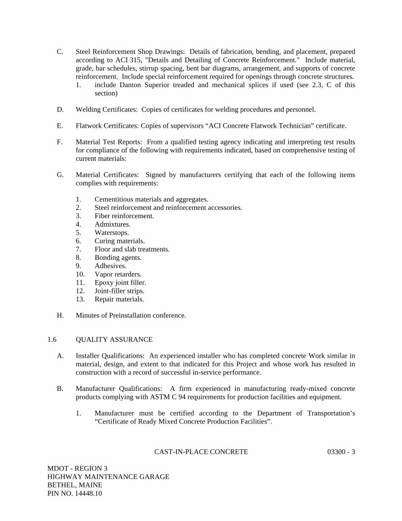
CAST-IN-PLACE CONCRETE 03300 - 3 MDOT - REGION 3 HIGHWAY MAINTENANCE GARAGE BETHEL, MAINE PIN NO. 14448.10
C. Steel Reinforcement Shop Drawings: Details of fabrication, bending, and placement, prepared according to ACI 315, "Details and Detailing of Concrete Reinforcement." Include material, grade, bar schedules, stirrup spacing, bent bar diagrams, arrangement, and supports of concrete reinforcement. Include special reinforcement required for openings through concrete structures. 1. include Danton Superior treaded and mechanical splices if used (see 2.3, C of this
section)
D. Welding Certificates: Copies of certificates for welding procedures and personnel.
E. Flatwork Certificates: Copies of supervisors “ACI Concrete Flatwork Technician” certificate.
F. Material Test Reports: From a qualified testing agency indicating and interpreting test results for compliance of the following with requirements indicated, based on comprehensive testing of current materials:
G. Material Certificates: Signed by manufacturers certifying that each of the following items complies with requirements:
1. Cementitious materials and aggregates. 2. Steel reinforcement and reinforcement accessories. 3. Fiber reinforcement. 4. Admixtures. 5. Waterstops. 6. Curing materials. 7. Floor and slab treatments. 8. Bonding agents. 9. Adhesives. 10. Vapor retarders. 11. Epoxy joint filler. 12. Joint-filler strips. 13. Repair materials.
H. Minutes of Preinstallation conference.
1.6 QUALITY ASSURANCE
A. Installer Qualifications: An experienced installer who has completed concrete Work similar in material, design, and extent to that indicated for this Project and whose work has resulted in construction with a record of successful in-service performance.
B. Manufacturer Qualifications: A firm experienced in manufacturing ready-mixed concrete products complying with ASTM C 94 requirements for production facilities and equipment.
1. Manufacturer must be certified according to the Department of Transportation’s “Certificate of Ready Mixed Concrete Production Facilities”.

CAST-IN-PLACE CONCRETE 03300 - 4 MDOT - REGION 3 HIGHWAY MAINTENANCE GARAGE BETHEL, MAINE PIN NO. 14448.10
2. Owner shall provide all concrete material testing and concrete cylinder samples for this project. Contractor shall coordinate schedule of installations with the Owner to allow ample time for the owner to schedule appropriate testing.
C. Source Limitations: Obtain each type or class of cementitious material of the same brand from the same manufacturer's plant, each aggregate from one source, and each admixture from the same manufacturer.
D. Welding: Qualify procedures and personnel according to AWS D1.4, "Structural Welding Code--Reinforcing Steel."
E. ACI Publications: Comply with the following, unless more stringent provisions are indicated:
1. ACI 301, "Specification for Structural Concrete." 2. ACI 117, "Specifications for Tolerances for Concrete Construction and Materials."
F. Preinstallation Conference: The contractor shall Conduct conference at Project.
1. Flatwork (interior and exterior slabs) Preinstallation Conference: Conduct conference at Project site to review all details and requirements for the batching, mixing, transporting, placing, finishing, and curing all interior and exterior flatwork operations. Require representatives of each entity directly concerned with flatwork operation to attend, including the following:
a. Contractor and Contractor's superintendent. b. Ready-mix concrete producer. c. Flatwork subcontractors. d. Maine Department of Transportation’s representative.
1.7 DELIVERY, STORAGE, AND HANDLING
A. Deliver, store, and handle steel reinforcement to prevent bending and damage.
PART 2 - PRODUCTS
2.1 FORM-FACING MATERIALS
A. Smooth-Formed Finished Concrete: Form-facing panels that will provide continuous, true, and smooth concrete surfaces. Furnish in largest practicable sizes to minimize number of joints.
1. Exterior-grade plywood panels, suitable for concrete forms, complying with DOC PS 1, and as follows:
a. High-density overlay, Class 1, or better.
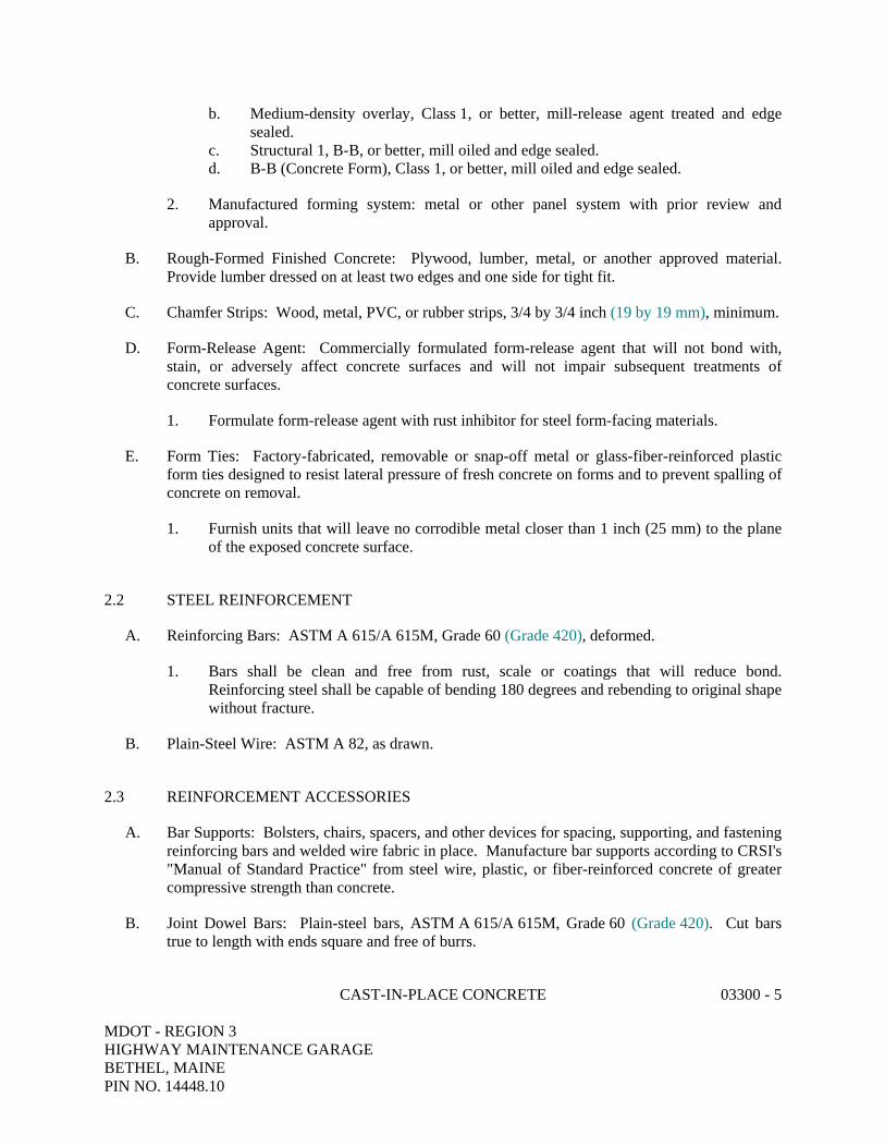
CAST-IN-PLACE CONCRETE 03300 - 5 MDOT - REGION 3 HIGHWAY MAINTENANCE GARAGE BETHEL, MAINE PIN NO. 14448.10
b. Medium-density overlay, Class 1, or better, mill-release agent treated and edge sealed.
c. Structural 1, B-B, or better, mill oiled and edge sealed. d. B-B (Concrete Form), Class 1, or better, mill oiled and edge sealed.
2. Manufactured forming system: metal or other panel system with prior review and approval.
B. Rough-Formed Finished Concrete: Plywood, lumber, metal, or another approved material. Provide lumber dressed on at least two edges and one side for tight fit.
C. Chamfer Strips: Wood, metal, PVC, or rubber strips, 3/4 by 3/4 inch (19 by 19 mm), minimum.
D. Form-Release Agent: Commercially formulated form-release agent that will not bond with, stain, or adversely affect concrete surfaces and will not impair subsequent treatments of concrete surfaces.
1. Formulate form-release agent with rust inhibitor for steel form-facing materials.
E. Form Ties: Factory-fabricated, removable or snap-off metal or glass-fiber-reinforced plastic form ties designed to resist lateral pressure of fresh concrete on forms and to prevent spalling of concrete on removal.
1. Furnish units that will leave no corrodible metal closer than 1 inch (25 mm) to the plane of the exposed concrete surface.
2.2 STEEL REINFORCEMENT
A. Reinforcing Bars: ASTM A 615/A 615M, Grade 60 (Grade 420), deformed.
1. Bars shall be clean and free from rust, scale or coatings that will reduce bond. Reinforcing steel shall be capable of bending 180 degrees and rebending to original shape without fracture.
B. Plain-Steel Wire: ASTM A 82, as drawn.
2.3 REINFORCEMENT ACCESSORIES
A. Bar Supports: Bolsters, chairs, spacers, and other devices for spacing, supporting, and fastening reinforcing bars and welded wire fabric in place. Manufacture bar supports according to CRSI's "Manual of Standard Practice" from steel wire, plastic, or fiber-reinforced concrete of greater compressive strength than concrete.
B. Joint Dowel Bars: Plain-steel bars, ASTM A 615/A 615M, Grade 60 (Grade 420). Cut bars true to length with ends square and free of burrs.

CAST-IN-PLACE CONCRETE 03300 - 6 MDOT - REGION 3 HIGHWAY MAINTENANCE GARAGE BETHEL, MAINE PIN NO. 14448.10
C. Rebar couplers, male and female threaded splices connectors for hairpin reinforcing: 1. If the contractor elects not to drill forms for placement of hairpins threaded splice
connections shall be use equal to Dayton Superior concrete accessories.
2.4 CONCRETE MATERIALS
A. Portland Cement: ASTM C 150, Type II.
B. Normal-Weight Aggregate: ASTM C 33, uniformly graded, and as follows:
1. Nominal Maximum Aggregate Size: 3/4 inch (19 mm).
C. Water: Potable and complying with ASTM C 94.
2.5 ADMIXTURES
A. General: Admixtures certified by manufacturer to contain not more than 0.1 percent water-soluble chloride ions by mass of cementitious material and to be compatible with other admixtures and cementitious materials. Do not use admixtures containing calcium chloride.
B. Air-Entraining Admixture: ASTM C 260. Sika AER by the Sika Chemical Corp. or approved equal.
C. Water-Reducing Admixture: ASTM C 494, Type A. Eucon W12-75 by the Euclid Chemical Corp. “Pozzolith 200N by Master Builders “Plastocrete 161” by the Sika Chemical Corp. or approved equal.
D. Non-Corrosive Accelerator: ASTM C 494, Type C or E, Accelguard 80 by the Euclid Chemical Co. or "Polar Set" by W. R. Grace and Co. or approved equal.
a. Non –corrosive accelerator shall have long-term test data proving its non-corrosive effect on reinforcing steel.
2.6 FIBER REINFORCEMENT
A. Synthetic Fiber: Fibrillated or monofilament polypropylene fibers engineered and designed for use in concrete, complying with ASTM C 1116, Type III, 1/2 to 1-1/2 inches (13 to 38 mm) long. “Fibermesh” by Fibermesh, Division of Synthetic Industries.
2.7 WATERSTOPS
A. Self-Expanding Strip Waterstops: Manufactured rectangular or trapezoidal strip, sodium bentonite or other hydrophylic material for adhesive bonding to concrete. Parastop II by Paramount Technical Products, Inc. or approved equal.

CAST-IN-PLACE CONCRETE 03300 - 7 MDOT - REGION 3 HIGHWAY MAINTENANCE GARAGE BETHEL, MAINE PIN NO. 14448.10
2.8 VAPOR RETARDERS
A. Vapor Retarder: Provide water-resistant barrier consisting of high density, polyethylene meeting the following specifications: 1. Water Vapor Transmission: 0.006 gr./sq.ft./hr per ASTM E96. 2. Permeance Rating: 0.01 gr./sq.ft./hr per ASTM E96. 3. Puncture Resistance: 204 lbs/sq.ft. per GRI-GS-1-86. 4. Tensile Strength: 54.2 lbs. @ 1139% strain/MD and 55.5 lbs. @ 1009% strain/CMD per
ASTM D638. 5. Tear Resistance: 7.40 lbs/ft. MD and 8.22 lbs/ft. CMD per ASTM D1004. 6. Low Temperature Brittleness: Pass both machine direction and cross machine direction
per ASTM D1790 (15 min. @ 15 deg F.) 7. Meets to ASTM E 1745, Class A and B standards for underslab vapor retarders. 8. Product: Subject to compliance with requirements, provide Stego Wrap by Stego
Industries, LLC, 15 mil thick vapor retarder. (877) 464-7834.
2.9 CURING MATERIALS
A. Curing materials shall be in accordance with State of Maine Department of Transportation, “Standard Specifications,” Revision 2002 section 701.06
2.9 RELATED MATERIALS
A. Perimeter Isolation Joint: 2 lb. density, cross linked polyethylene with removable strip-off equal to ISO-STRIP as manufactured for Century Floors, Topsham, Maine.
B. Epoxy Joint Filler: Two-component, semirigid, 100 percent solids, epoxy resin with a Shore A hardness of 80 per ASTM D 2240.
C. Deicer Protection (Exterior Concrete): Saltgard as manufactured by Pro So Co, Inc., or approved equal.
D. Water and Oil Repellent: A clear penetrating silane compound with oil repellency additives. Water and oil repellent shall be Sure Klean Weather Seal SLX100 as manufactured by Pro So Co, Inc. or approved equal.
E. Bonding Agent: ASTM C 1059, Type II, non-redispersible, acrylic emulsion or styrene butadiene.
F. Epoxy-Bonding Adhesive: A two-component, solvent-free, moisture-insensitive structural epoxy adhesive in compliance with ASTM C 881, Type I and Type II, Grade 2, Class B and C, and shall be Sikadur 32, Hi-Mod by Sika Corp. or approved equal.
G. Doweling Adhesive: A two-component, vinylester blend resin equal to HI HY150 adhesive as manufactured by Hilti Fastening Systems, Tulsa, Oklahoma or approved equal.
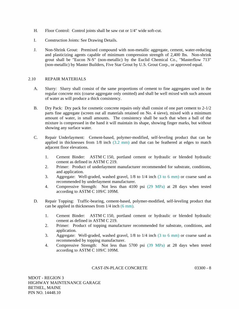
CAST-IN-PLACE CONCRETE 03300 - 8 MDOT - REGION 3 HIGHWAY MAINTENANCE GARAGE BETHEL, MAINE PIN NO. 14448.10
H. Floor Control: Control joints shall be saw cut or 1/4" wide soft-cut.
I. Construction Joints: See Drawing Details.
J. Non-Shrink Grout: Premixed compound with non-metallic aggregate, cement, water-reducing and plasticizing agents capable of minimum compression strength of 2,400 lbs. Non-shrink grout shall be "Eucon N-S" (non-metallic) by the Euclid Chemical Co., "Masterflow 713" (non-metallic) by Master Builders, Five Star Grout by U.S. Grout Corp., or approved equal.
2.10 REPAIR MATERIALS
A. Slurry: Slurry shall consist of the same proportions of cement to fine aggregates used in the regular concrete mix (coarse aggregate only omitted) and shall be well mixed with such amount of water as will produce a thick consistency.
B. Dry Pack: Dry pack for cosmetic concrete repairs only shall consist of one part cement to 2-1/2 parts fine aggregate (screen out all materials retained on No. 4 sieve), mixed with a minimum amount of water, in small amounts. The consistency shall be such that when a ball of the mixture is compressed in the hand it will maintain its shape, showing finger marks, but without showing any surface water.
C. Repair Underlayment: Cement-based, polymer-modified, self-leveling product that can be applied in thicknesses from 1/8 inch (3.2 mm) and that can be feathered at edges to match adjacent floor elevations.
1. Cement Binder: ASTM C 150, portland cement or hydraulic or blended hydraulic cement as defined in ASTM C 219.
2. Primer: Product of underlayment manufacturer recommended for substrate, conditions, and application.
3. Aggregate: Well-graded, washed gravel, 1/8 to 1/4 inch (3 to 6 mm) or coarse sand as recommended by underlayment manufacturer.
4. Compressive Strength: Not less than 4100 psi (29 MPa) at 28 days when tested according to ASTM C 109/C 109M.
D. Repair Topping: Traffic-bearing, cement-based, polymer-modified, self-leveling product that can be applied in thicknesses from 1/4 inch (6 mm).
1. Cement Binder: ASTM C 150, portland cement or hydraulic or blended hydraulic cement as defined in ASTM C 219.
2. Primer: Product of topping manufacturer recommended for substrate, conditions, and application.
3. Aggregate: Well-graded, washed gravel, 1/8 to 1/4 inch (3 to 6 mm) or coarse sand as recommended by topping manufacturer.
4. Compressive Strength: Not less than 5700 psi (39 MPa) at 28 days when tested according to ASTM C 109/C 109M.
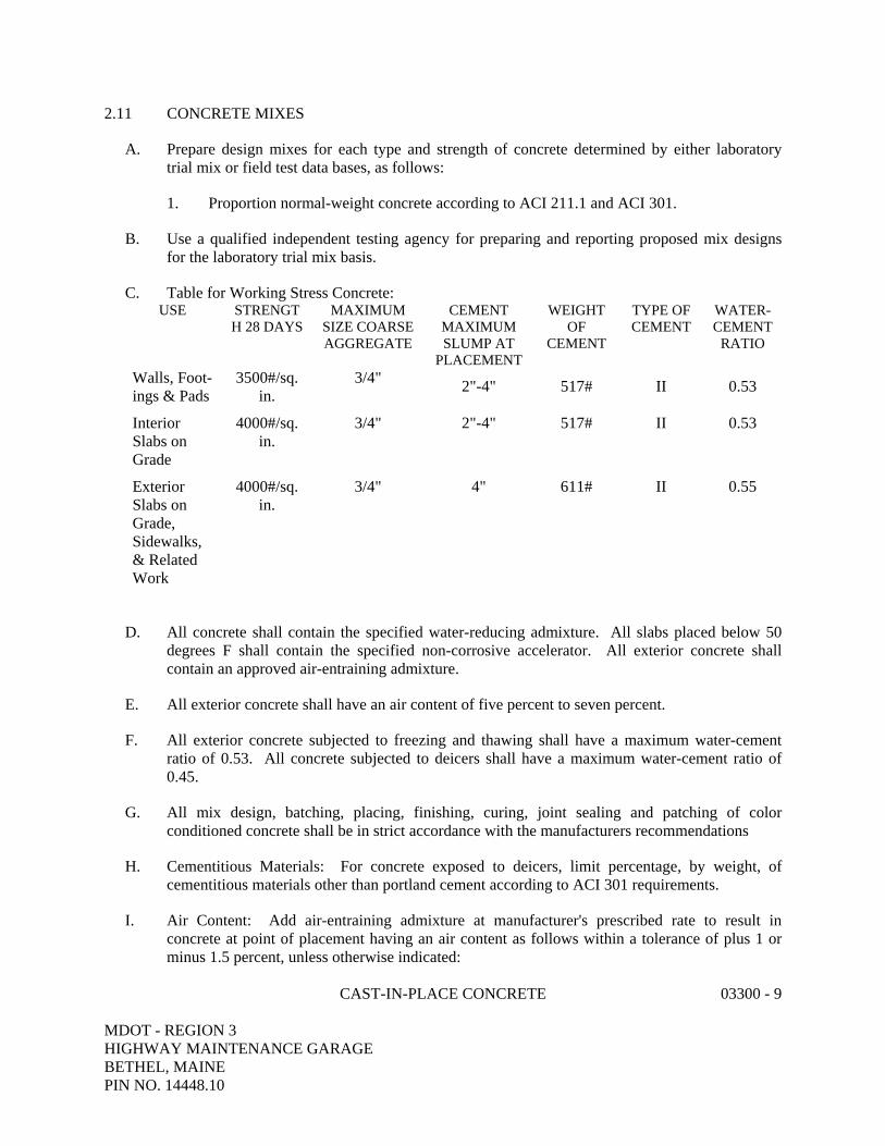
CAST-IN-PLACE CONCRETE 03300 - 9 MDOT - REGION 3 HIGHWAY MAINTENANCE GARAGE BETHEL, MAINE PIN NO. 14448.10
2.11 CONCRETE MIXES
A. Prepare design mixes for each type and strength of concrete determined by either laboratory trial mix or field test data bases, as follows:
1. Proportion normal-weight concrete according to ACI 211.1 and ACI 301.
B. Use a qualified independent testing agency for preparing and reporting proposed mix designs for the laboratory trial mix basis.
C. Table for Working Stress Concrete: USE STRENGT
H 28 DAYS MAXIMUM
SIZE COARSE AGGREGATE
CEMENT MAXIMUM SLUMP AT LACEMENT P
WEIGHT OF
CEMENT
TYPE OF CEMENT
WATER-CEMENT
RATIO
Walls, Foot-ngs & Pads i
3500#/sq. in.
3/4" 2"-4"
517#
II
0.53
Interior Slabs on
rade G
4000#/sq.
in.
3/4"
2"-4"
517#
II
0.53
Exterior Slabs on Grade, Sidewalks, & Related Work
4000#/sq.
in.
3/4"
4"
611#
II
0.55
D. All concrete shall contain the specified water-reducing admixture. All slabs placed below 50 degrees F shall contain the specified non-corrosive accelerator. All exterior concrete shall contain an approved air-entraining admixture.
E. All exterior concrete shall have an air content of five percent to seven percent.
F. All exterior concrete subjected to freezing and thawing shall have a maximum water-cement ratio of 0.53. All concrete subjected to deicers shall have a maximum water-cement ratio of 0.45.
G. All mix design, batching, placing, finishing, curing, joint sealing and patching of color conditioned concrete shall be in strict accordance with the manufacturers recommendations
H. Cementitious Materials: For concrete exposed to deicers, limit percentage, by weight, of cementitious materials other than portland cement according to ACI 301 requirements.
I. Air Content: Add air-entraining admixture at manufacturer's prescribed rate to result in concrete at point of placement having an air content as follows within a tolerance of plus 1 or minus 1.5 percent, unless otherwise indicated:
CAST-IN-PLACE CONCRETE 03300 - 10 MDOT - REGION 3 HIGHWAY MAINTENANCE GARAGE BETHEL, MAINE PIN NO. 14448.10
1. Air Content: 6 percent for 3/4-inch- (19-mm-) nominal maximum aggregate size.
J. Do not air entrain concrete to trowel-finished interior floors. Do not allow entrapped air content to exceed 3 percent.
K. Limit water-soluble, chloride-ion content in hardened concrete to 0.15 percent by weight of cement.
L. Synthetic Fiber: Uniformly disperse in concrete mix at manufacturer's recommended rate, but not less than 1 lb/cu. yd. (0.60 kg/cu. m).
M. Admixtures: Use admixtures according to manufacturer's written instructions.
1. Use water-reducing admixture in concrete, as required, for placement and workability. 2. Use water-reducing and retarding admixture when required by high temperatures, low
humidity, or other adverse placement conditions.
2.12 FABRICATING REINFORCEMENT
A. Fabricate steel reinforcement according to CRSI's "Manual of Standard Practice."
2.13 CONCRETE MIXING
A. Ready-Mixed Concrete: Measure, batch, mix, and deliver concrete according to ASTM C 94, and furnish batch ticket information.
B. Ready-Mixed Concrete: Measure, batch, mix, and deliver concrete according to ASTM C 94 and ASTM C 1116, and furnish batch ticket information (floor slabs only).
PART 3 - EXECUTION
3.1 FORMWORK
A. Design, erect, shore, brace, and maintain formwork, according to ACI 301, to support vertical, lateral, static, and dynamic loads, and construction loads that might be applied, until concrete structure can support such loads.
1. Construct formwork so concrete members and structures are of size, shape, alignment, elevation, and position indicated, within tolerance limits of ACI 117. Excessive deflection of forms after concrete is poured shall be sufficient cause for rejection of that portion of concrete and formwork. Excessive deflection will be considered to be that which will produce visible and noticeable waves in the finished concrete.
2. Construct forms so that walls will key into each other at ends unless poured monolithically.
CAST-IN-PLACE CONCRETE 03300 - 11 MDOT - REGION 3 HIGHWAY MAINTENANCE GARAGE BETHEL, MAINE PIN NO. 14448.10
B. Limit concrete surface irregularities, designated by ACI 347R as abrupt or gradual, as follows:
1. Class A, 1/8 inch (3 mm). (Exposed concrete) 2. Class B, 1/4 inch (6 mm). (Non-exposed concrete)
C. Construct forms tight enough to prevent loss of concrete mortar.
D. All possible care shall be taken in the formwork to produce surfaces free from honeycomb or other defects.
E. Fabricate forms for easy removal without hammering or prying against concrete surfaces. Provide crush or wrecking plates where stripping may damage cast concrete surfaces. Provide top forms for inclined surfaces steeper than 1.5 horizontal to 1 vertical. Kerf wood inserts for forming keyways, reglets, recesses, and the like, for easy removal.
1. Do not use rust-stained steel form-facing material.
F. Set edge forms, bulkheads, and intermediate screed strips for slabs to achieve required elevations and slopes in finished concrete surfaces. Provide and secure units to support screed strips; use strike-off templates or compacting-type screeds.
G. Schedule the work and notify other trades in time so that provisions for their work in the formwork can be made without delaying progress of the project. Verify that all sleeves, pipes, etc., for electrical, plumbing, heating and ventilation, or other work are installed.
H. Chamfer exterior corners and edges of permanently exposed concrete, where indicated on drawings.
I. Form openings, chases, offsets, sinkages, keyways, reglets, blocking, screeds, and bulkheads required in the Work. Determine sizes and locations from trades providing such items.
J. Clean forms and adjacent surfaces to receive concrete. Remove chips, wood, sawdust, dirt, and other debris just before placing concrete.
K. Bolts, rods or other approved devices shall be used for internal ties. They shall be so arranged that when the forms are removed, no metal shall be within 1" of any surface.
L. Retighten forms and bracing before placing concrete, as required, to prevent mortar leaks and maintain proper alignment.
M. Coat contact surfaces of forms with form-release agent, according to manufacturer's written instructions, before placing reinforcement.
CAST-IN-PLACE CONCRETE 03300 - 12 MDOT - REGION 3 HIGHWAY MAINTENANCE GARAGE BETHEL, MAINE PIN NO. 14448.10
3.2 EMBEDDED ITEMS
A. Place and secure anchorage devices and other embedded items required for adjoining work that is attached to or supported by cast-in-place concrete. Use Setting Drawings, templates, diagrams, instructions, and directions furnished with items to be embedded.
1. Secure information about and provide for all openings, offsets, recessed nailing blocks, channel chases, anchors, ties, inserts, etc., in the formwork before concrete is poured.
2. Install anchor bolts, accurately located, to elevations required.
a. The setting of all anchor bolts and the grouting for all structural steel base plates shall be included as part of this contract. Bolts and base plates will be furnished under Section 05500 - Metal Fabrications, and Section 13125 – Metal Building Systems.
b. All column base plates, equipment bases, and other locations noted in the structural drawings shall be grouted with the specified non-shrink grout. All exposed grout shall be the specified non-metallic type.
3.3 REMOVING AND REUSING FORMS
A. General: Formwork that does not support weight of concrete may be removed after cumulatively curing at not less than 50 deg F (10 deg C) for 24 hours after placing concrete provided concrete is hard enough to not be damaged by form-removal operations and provided curing and protection operations are maintained.
B. Clean and repair surfaces of forms to be reused in the Work. Split, frayed, delaminated, or otherwise damaged form-facing material will not be acceptable for exposed surfaces. Apply new form-release agent.
C. When forms are reused, clean surfaces, remove fins and laitance, and tighten to close joints. Align and secure joints to avoid offsets. Do not use patched forms for exposed concrete surfaces unless approved by Engineer.
3.4 SHORES AND RESHORES
A. Comply with ACI 318 (ACI 318M), ACI 301, and recommendations in ACI 347R for design, installation, and removal of shoring and reshoring.
B. Plan sequence of removal of shores and reshore to avoid damage to concrete. Locate and provide adequate reshoring to support construction without excessive stress or deflection.
CAST-IN-PLACE CONCRETE 03300 - 13 MDOT - REGION 3 HIGHWAY MAINTENANCE GARAGE BETHEL, MAINE PIN NO. 14448.10
3.5 MOISTURE VAPOR RETARDER SYSTEM (UNDER FLOOR SLABS)
A. Moisture vapor retarder system shall be installed at all interior floor slabs and as otherwise indicated in the drawings in strict accordance with the manufacturer’s printed instructions and as follows.
1. Snap chalk line along inside perimeter of foundation walls at top of slab elevation. 2. Without wetting, clean a 3" wide band on the surface of the concrete below the chalk line
at approximately mid-slab height. Remove dirt, residual form release, or other bond inhibiting surface contaminates. Grind smooth any surface projections within the band.
3. While removing the contact paper on the backside, firmly press 2" wide manufacturer’s approved perimeter and penetration strip onto wall, parallel to the chalk line on the cleaned band at mid-slab elevation.
4. Remove contact paper on the face side. 5. Apply 12" wide manufacturer’s approved edge roll covering only the bottom 1" of
contact surface on the perimeter strip. Cut, fit, and seal corner details with manufacturer’s approved seaming tape.
6. Align top edge of isolation joint material to chalk line, and press material onto remaining 1" of exposed perimeter strip adhesive.
7. Roll out Vapor Barrier material, overlapping edge rolls and all seams by 3". Tape all seams with manufacturer’s approved seaming tape.
8. All tears, punctures, etc. to be repaired and taped as required to maintain the watertight integrity of the vapor barrier system.
3.6 STEEL REINFORCEMENT
A. General: Comply with CRSI's "Manual of Standard Practice" for placing reinforcement.
1. All steel bars and wire shall be of size, gauge and length indicated, accurately bent or formed to shapes detailed or scheduled by experienced shops using methods that will not injure the materials.
2. Steel reinforcing shall not be bent in a manner that will injure the material or the embedding concrete. Bars with kinks or bends not shown on the plans shall not be used. Heating of reinforcement for bending will not be permitted. Bars shall be bent once only (no rebending or straightening allowed) unless shown as such on the drawings.
3. All details of reinforcement not shown or indicated on the drawings or specifically called for in the specifications shall conform to ACI 315.
4. Lap all bars at splices, corners and intersections a minimum of 36 bar diameters unless otherwise indicated.
5. All intersecting concrete walls shall be tied with #4L bars 3'-0" long, bent 18" x 18" spaced 12" on center, outside face only unless otherwise indicated.
6. Splices of reinforcement shall not be made at points of maximum stress. Splice lengths shall be a minimum of 36 bar diameters unless otherwise indicated and shall provide sufficient lap to transfer the stress between bars by bond and shear. Stagger splices of
CAST-IN-PLACE CONCRETE 03300 - 14 MDOT - REGION 3 HIGHWAY MAINTENANCE GARAGE BETHEL, MAINE PIN NO. 14448.10
adjacent bars where possible. All splices and laps at corners and intersections shall be tied with wire at each end.
7. Where obstructions (pipes, conduit, ducts, etc.) prevent the intended placement of reinforcing, provide additional reinforcing as directed by the Engineer or his Representative around the obstruction to match that reinforcing interrupted.
8. Provide additional stirrups, ties, trim bars, etc., as directed around all openings, sleeves, pipes, and conduits, which pass through structural elements.
9. Do not cut or puncture vapor retarder. Repair damage and reseal vapor retarder before placing concrete.
B. Clean reinforcement of loose rust and mill scale, earth, ice, and other foreign materials.Accurately position, support, and secure reinforcement against displacement. Locate and support reinforcement with bar supports to maintain minimum concrete cover. Do not tack weld crossing reinforcing bars.
1. Coverage of bars (including stirrups and column ties) shall, unless otherwise shown, be as follows:
Footings: 3" soil face, 2" top Slabs (on grade): 2" soil face, 1-1/2" top face Slabs (elevated): 1" top and bottom Beam and Column (piers) 1-1/2" Walls: 2" clear to form at exterior
2. Misplaced Reinforcing: If any reinforcing bars are found to be misplaced after concrete has been placed, the Engineer shall be notified immediately and no correction or cutting shall be made without his direction. Misplaced bars shall not be bent or kinked. Any redesign and/or reinforcing required because of misplaced bars shall be at the Contractor's expense.
3. All reinforcing shall be kept separate from soil, pipe, conduit ducts, etc., by approved non-metallic separators.
4. Reinforcement shall not have welded joints unless indicated on the drawings or unless prior approval has been given by the Engineer. Welding shall conform to the requirements of the American Welding Society Structural Welding Code for reinforcing steel D1.4. Field welding shall be performed by AWS certified welders.
5. Shop- or field-weld reinforcement according to AWS D1.4, where indicated.
D. Set wire ties with ends directed into concrete, not toward exposed concrete surfaces.
E. Install welded wire fabric in longest practicable lengths on bar supports spaced to minimize sagging. Lap edges and ends of adjoining sheets at least one mesh spacing. Offset laps of adjoining sheet widths to prevent continuous laps in either direction. Lace overlaps with wire.
3.7 JOINTS
A. General: Construct joints true to line with faces perpendicular to surface plane of concrete.
CAST-IN-PLACE CONCRETE 03300 - 15 MDOT - REGION 3 HIGHWAY MAINTENANCE GARAGE BETHEL, MAINE PIN NO. 14448.10
B. Construction Joints: Install so strength and appearance of concrete are not impaired, at locations indicated or as approved by Engineer.
1. Place joints perpendicular to main reinforcement. Continue reinforcement across construction joints, unless otherwise indicated.
2. Space vertical joints in walls as indicated.
a. Wall control "V" joints shall have a depth of 1/8 times the thickness of the wall and be 1/2" wide at surface. "V" joints shall be placed as shown or as directed by the Engineer.
3. Use a bonding agent at locations where fresh concrete is placed against hardened or partially hardened concrete surfaces.
4. Use epoxy-bonding adhesive at locations where fresh concrete is placed against hardened or partially hardened concrete surfaces.
C. Contraction Joints in Slabs-on-Grade: Form weakened-plane contraction joints, sectioning concrete into areas as indicated. Construct contraction joints for a depth equal to at least one-fourth of concrete thickness, or 3/4" minimum for soff-cut as follows:
1. Sawed Joints: Form contraction joints with power saws equipped with shatterproof abrasive or diamond-rimmed blades. Cut 1/4" (maximum) wide joints into concrete when cutting action will not tear, abrade, or otherwise damage surface and before concrete develops random contraction cracks.
a. Floor slab control joints shall be placed as shown on the foundation plan. Unless otherwise noted, control joints shall be spaced at intervals not to exceed 18'-0" on center in both directions.
D. Isolation Joints in Slabs-on-Grade: After removing formwork, install joint-filler strips at slab junctions with vertical surfaces, such as column pedestals, foundation walls, and other locations, as indicated.
1. Terminate full-width joint-filler strips not less than 1/2 inch (12 mm) or more than 1 inch (25 mm) below finished concrete surface where joint sealants, specified in Division 7 Section "Joint Sealants," are indicated.
2. Install joint-filler strips in lengths as long as practicable. Where more than one length is required, lace or clip sections together.
E. Dowel Joints: Install dowel sleeves and dowels or dowel bar and support assemblies at joints where indicated.
1. All intersecting slab construction joints acting as control joints shall be doweled according to the following schedule unless otherwise indicated. Dowels shall be smooth, steel grade 60 with saw cut ends. Grease, wrap or cap one end.
CAST-IN-PLACE CONCRETE 03300 - 16 MDOT - REGION 3 HIGHWAY MAINTENANCE GARAGE BETHEL, MAINE PIN NO. 14448.10
Dowel Schedule
Dowel Dia. Length Spacing 5" Slab 5/8"
14"
12" 6
" Slab
3/4"
14"
12"
8" Slab
1"
14"
12"
3.8 WATERSTOPS
A. Self-Expanding Strip Waterstops: Install in construction joints and at other locations indicated, according to manufacturer's written instructions, bonding or mechanically fastening and firmly pressing into place. Install in longest lengths practicable.
1. Remove all protrusions and indentations 2" or over in all areas. 2. Lay waterstop flat against concrete surface and nail every 1" to 6" with case hardened
washered nails. 3. Overlap all joints a minimum of 2".
3.9 MIXING CONCRETE
A. General: The concrete shall be mixed in the quantities required for immediate use, and any which has developed initial set or exceed the time limit of ASTM C 94 shall not be used. No re-tempering of mortar or concrete shall be allowed under any circumstances. Concrete shall be proportioned, mixed and placed only in the presence of the Engineer or his Authorized Representative. The Contractor shall give ample notice to the Engineer before mixing is commenced. Aggregate size will be adjusted to suit conditions of work. Pumping of concrete shall be permitted only after approval by the Engineer of the Pumping Contractor and the pumping equipment and method to be employed. The Engineer shall be notified of dates when pumping of concrete shall be performed to permit his on-the-job inspection of the operations.
B. Final proportions shall be in accordance with approved mix designs. Adjustments to approved proportions, for whatever reason, shall be approved by the Engineer.
C. Add fibrous concrete reinforcing to all concrete used at slabs interior and exterior on grade.
3.10 CONCRETE PLACEMENT
A. Before placing concrete, verify that installation of formwork, reinforcement, and embedded items is complete and that required inspections have been performed.
B. Remove loose dirt, mud, standing water, and foreign matter from excavations or from cavities.
C. Thoroughly clean reinforcement and other embedded items free from loose rust and other matter. Assure reinforcing is held securely in place.
CAST-IN-PLACE CONCRETE 03300 - 17 MDOT - REGION 3 HIGHWAY MAINTENANCE GARAGE BETHEL, MAINE PIN NO. 14448.10
D. Thoroughly wet wood forms (except coated plywood), bottom and sides of trenches, base underslab, and adjacent concrete or masonry at least one hour in advance of placing concrete; securely close cleanout and inspection ports; repeat wetting as necessary to keep forms damp.
E. Equipment shall be maintained clean and of sufficient quantity and capacity to efficiently execute the work required.
F. Do not add water to concrete during delivery, at Project site, or during placement, unless approved by Engineer.
G. Before placing concrete, water may be added at Project site, subject to limitations of ACI 301.
H. Deposit concrete continuously or in layers of such thickness that no new concrete will be placed on concrete that has hardened enough to cause seams or planes of weakness. If a section cannot be placed continuously, provide construction joints as specified. Deposit concrete to avoid segregation.
I. Deposit concrete in forms in horizontal layers no deeper than 24 inches (600 mm) and in a manner to avoid inclined construction joints. Place each layer while preceding layer is still plastic, to avoid cold joints.
1. Consolidate placed concrete with mechanical vibrating equipment. Use equipment and procedures for consolidating concrete recommended by ACI 309R.
a. Concrete shall be vibrated into final position in forms with an internal type vibrating machine. The vibration shall have a frequency of not less than 8,000 vibrations per minute. The mechanical vibrating equipment shall be satisfactory to the Engineer.
b. The vibration shall be of sufficient intensity and duration to cause flow or settlement of the concrete and complete consolidation. Over vibration, especially of mixtures that are too wet, may cause segregation and will be avoided. A sufficient number of vibrators shall be provided to permit consolidation of each batch before the next batch is delivered and without delaying the delivery.
c. The vibrations shall be applied directly to the concrete, and vibration through the forms shall not be permitted. Vibration shall be applied at the point of deposit and in the area of freshly deposited concrete. The concrete shall be placed in layers of uniform thickness
d. Dropping of concrete a distance of more than 6 feet unless confined by closed chutes or pipes will not be permitted. The concrete shall be deposited at or as near as possible to its final position.
2. Do not use vibrators to transport concrete inside forms. Insert and withdraw vibrators vertically at uniformly spaced locations no farther than the visible effectiveness of the vibrator. Place vibrators to rapidly penetrate placed layer and at least 6 inches (150 mm) into preceding layer. Do not insert vibrators into lower layers of concrete that have begun to lose plasticity. At each insertion, limit duration of vibration to time necessary to consolidate concrete and complete embedment of reinforcement and other embedded items without causing mix constituents to segregate.
CAST-IN-PLACE CONCRETE 03300 - 18 MDOT - REGION 3 HIGHWAY MAINTENANCE GARAGE BETHEL, MAINE PIN NO. 14448.10
3. When conditions make puddling difficult, or where the reinforcement is congested, batches of mortar containing the same proportions of cement to sand used in the concrete shall be deposited in the forms. The operation of filling with the regularly specified mix shall be carried on at such a rate that the mix is at all times plastic and flows readily into the spaces between the bars.
4. In thin walls or inaccessible portions of the forms where rodding is impractical, the concrete shall be worked into place by tapping or hammering forms adjacent to the freshly deposited concrete.
5. The Contractor's attention is called to the importance of making the concrete dense, and he shall provide sufficient labor to the entire satisfaction of the Engineer to thoroughly consolidate the concrete, avoid air pockets and voids in exposed sections, and leave smooth, uniform surfaces after forms are removed.
6. Should any honeycombed concrete be disclosed upon removal of forms, the Contractor shall immediately cut out the said honeycombed portions back to solid concrete and shall fill the opening thus formed with a concrete of the same proportions as that specified for the section of work in which the fault occurs.
7. When placing fresh concrete upon hardened concrete, the latter shall be thoroughly roughened and cleaned of all loose material, scum or latency. The bonding compound shall be applied and the new concrete placed while the bonding compound is still tacky.
8. Joints in the concrete work shall be made only in places and the manner specified by the Engineer.
9. The Contractor's attention is called to the importance of properly and carefully placing concrete around reinforcement, as the reinforcing metal must not be exposed; and in cases where reinforcing metal becomes exposed on the surface, that portion of work must be removed and re-laid as the covering of same by plastering with cement mortar will not be allowed. All reinforcing rods or other reinforcing material shall be lightly tapped so that they will retain their original position.
10. No concrete shall be retempered except as allowed in ASTM C 94 nor shall set concrete be used as aggregate.
J. Deposit and consolidate concrete for floors and slabs in a continuous operation, within limits of construction joints, until placement of a panel or section is complete.
1. Consolidate concrete during placement operations so concrete is thoroughly worked around reinforcement and other embedded items and into corners.
2. Maintain reinforcement in position on chairs during concrete placement.
a. Reinforcement, unless otherwise indicated, shall be placed one-half the thickness of the slab.
3. Screed slab surfaces with a straightedge and strike off to correct elevations. 4. Slope surfaces uniformly to drains where required. 5. Begin initial floating using bull floats or darbies to form a uniform and open-textured
surface plane, free of humps or hollows, before excess moisture or bleedwater appears on the surface. Do not further disturb slab surfaces before starting finishing operations.
6. In addition to steel bar reinforcement, slabs shall be reinforced with fibrous concrete reinforcement which is to be added when the concrete is being batched in strict accordance with the manufacturer's recommendations.
CAST-IN-PLACE CONCRETE 03300 - 19 MDOT - REGION 3 HIGHWAY MAINTENANCE GARAGE BETHEL, MAINE PIN NO. 14448.10
7. Slabs shall be monolithically placed with control joints. Sawed control joints will be located as indicated on the drawings and/or as directed by the Engineer. Floors shall be cleaned of objects before saw cutting begins. A true, continuous saw cut is what is expected as a finish result.
K. Cold-Weather Placement: Comply with ACI 306.1 and as follows. Protect concrete work from physical damage or reduced strength that could be caused by frost, freezing actions, or low temperatures.
1. When air temperature has fallen to or is expected to fall below 40 deg F (4.4 deg C), uniformly heat water and aggregates before mixing to obtain a concrete mixture temperature of not less than 50 deg F (10 deg C) and not more than 80 deg F (27 deg C) at point of placement.
2. Do not use frozen materials or materials containing ice or snow. Do not place concrete on frozen subgrade or on subgrade containing frozen materials.
3. Do not use calcium chloride, salt, or other materials containing antifreeze agents or chemical accelerators, unless otherwise specified and approved in mix designs.
4. Contractor shall have on the job, ready to install, adequate equipment for heating the materials and the freshly placed concrete and for enclosing the work in accordance with the requirements specified herein.
L. Hot-Weather Placement: Place concrete according to recommendations in ACI 305R and as follows, when hot-weather conditions exist:
1. Cool ingredients before mixing to maintain concrete temperature below 90 deg F (32 deg C) at time of placement. Chilled mixing water or chopped ice may be used to control temperature, provided water equivalent of ice is calculated to total amount of mixing water. Using liquid nitrogen to cool concrete is Contractor's option.
2. Cover steel reinforcement with water-soaked burlap so steel temperature will not exceed ambient air temperature immediately before embedding in concrete.
3. Fog-spray forms, steel reinforcement, and subgrade just before placing concrete. Keep subgrade moisture uniform without standing water, soft spots, or dry areas.
M. Protection:
1. Concrete just placed shall be protected from rain in an approved manner until the concrete has set, or if a slab, the curing compound has dried.
2. Concrete, when placed in the forms, shall have a temperature of not less than 50 degrees F nor more than 90 degrees F. Freshly placed concrete and the surrounding air shall be maintained at a temperature of 50 degrees F or greater for a period of seven days after placing. If high early strength concrete is used, the aforementioned time period may be reduced to three days. The methods of protection and curing shall be such as to prevent evaporation of moisture from the concrete and injury to the surface.
3. Should it later develop that any concrete work has become injured in any way by freezing or otherwise, the defective concrete shall be repaired or replaced as directed by the Engineer at no added expense to the Owner. Repair materials shall include all reinforcement grouts, dry pack, admixtures, epoxy and aggregates as may be necessary
CAST-IN-PLACE CONCRETE 03300 - 20 MDOT - REGION 3 HIGHWAY MAINTENANCE GARAGE BETHEL, MAINE PIN NO. 14448.10
N. Deicer Protection:
1. Apply deicer protection to all exterior slabs on grade, and related work 30 days after concrete placement in strict accordance with manufacturer=s written recommendations.
3.11 PROTECTIVE COATING FOR STRUCTURAL STEEL
A. All structural steel columns and their bases which extend into or through concrete floors shall be thoroughly brush painted with two coats of foundation coating as specified in Section 07150 - Dampproofing, and applied in accordance with the manufacturer's directions, neatly cut off one inch below finish floor.
3.12 FINISHING FORMED SURFACES
A. Rough-Formed Finish: As-cast concrete texture imparted by form-facing material with tie holes and defective areas repaired and patched. Remove fins and other projections exceeding ACI 347R limits for class of surface specified.
B. Smooth-Formed Finish: As-cast concrete texture imparted by form-facing material, arranged in an orderly and symmetrical manner with a minimum of seams. Repair and patch tie holes and defective areas. Remove fins and other projections exceeding 1/8 inch (3 mm) in height.
1. Apply to concrete surfaces exposed to public view.
C. Rubbed Finish: Apply the following to smooth-formed finished concrete:
1. Smooth-Rubbed Finish: Not later than one day after form removal, moisten concrete surfaces and rub with carborundum brick or another abrasive until producing a uniform color and texture. Do not apply cement grout other than that created by the rubbing process.
D. Related Unformed Surfaces: At tops of walls, horizontal offsets, and similar unformed surfaces adjacent to formed surfaces, strike off smooth and finish with a texture matching adjacent formed surfaces. Continue final surface treatment of formed surfaces uniformly across adjacent unformed surfaces, unless otherwise indicated.
3.13 FINISHING FLOORS AND SLABS
A. General: Comply with recommendations in ACI 302.1R for screeding, restraightening, and finishing operations for concrete surfaces. Do not wet concrete surfaces.
1. All interior concrete floor slabs shall be finished true and smooth by steel troweling or finishing machine. All exterior slabs shall be broom finished.
2. When a section of the concrete floor is completed, it shall be left entirely undisturbed until the concrete is thoroughly hardened.
CAST-IN-PLACE CONCRETE 03300 - 21 MDOT - REGION 3 HIGHWAY MAINTENANCE GARAGE BETHEL, MAINE PIN NO. 14448.10
3. Adequate provisions will be made to eliminate the possibility of accidental encroachment upon the newly concreted area.
B. Float Finish: Consolidate surface with power-driven floats or by hand floating if area is small or inaccessible to power driven floats. Restraighten, cut down high spots, and fill low spots. Repeat float passes and restraightening until surface is left with a uniform, smooth, granular texture.
1. Apply float finish to surfaces indicated, to surfaces to receive trowel finish.
C. Trowel Finish: After applying float finish, apply first trowel finish and consolidate concrete by hand or power-driven trowel. Continue troweling passes and restraighten until surface is free of trowel marks and uniform in texture and appearance. Grind smooth any surface defects that would telegraph through applied coatings or floor coverings.
1. Apply a trowel finish to surfaces indicated and to floor and slab surfaces exposed to view. 2. Finish surfaces to the following tolerances, measured within 24 hours according to
ASTM E 1155/E 1155M for a randomly trafficked floor surface:
a. Tolerances will be in accordance with ACI Publication #117 - Class AX. Depression in floor between high spots shall not be greater than 3/16" in 10'-0" + 1/16", and the measurement will be taken by the straight edge method no later than the day after the concrete floor has been poured.
D. Broom Finish: Apply a broom finish to exterior concrete platforms.
1. Immediately after float finishing, slightly roughen trafficked surface by brooming with fiber-bristle broom perpendicular to main traffic route. Coordinate required final finish with Engineer before application.
3.14 MISCELLANEOUS CONCRETE ITEMS
A. Filling In: Fill in holes and openings left in concrete structures, unless otherwise indicated, after work of other trades is in place. Mix, place, and cure concrete, as specified, to blend with in-place construction. Provide other miscellaneous concrete filling indicated or required to complete Work.
B. Mechanical Equipment Pads: Provide 4" concrete pads reinforced with #3 Bars at 12” O.C. each way under all mechanical equipment supported on concrete floor slab unless otherwise indicated.
C. Foundation Insulation: Install foundation insulation using a dab of emulsified asphalt mastic in each corner and the center to adhere the insulation to the concrete wall. Insulation will be installed on the inside face of all perimeter foundation walls extending from the underside of floor slab to top of footing. Insulation furnished under Section 07200 - Insulation.
CAST-IN-PLACE CONCRETE 03300 - 22 MDOT - REGION 3 HIGHWAY MAINTENANCE GARAGE BETHEL, MAINE PIN NO. 14448.10
3.15 CONCRETE PROTECTION AND CURING
A. General: Protect freshly placed concrete from premature drying and excessive cold or hot temperatures. Comply with State of Maine Department of Transportation, “Standard Specifications,” Revision 2002 section 502.10.
3.16 JOINT FILLING
A. Prepare, clean, and install joint filler according to manufacturer's written instructions.
1. Defer joint filling until the completion of the project. Do not fill joints until construction traffic has permanently ceased.
B. Remove dirt, debris, saw cuttings, curing compounds, and sealers from joints; leave contact faces of joint clean and dry.
C. Install semirigid epoxy joint filler full depth in saw-cut joints and at least 2 inches (50 mm) deep in formed joints. Overfill joint and trim joint filler flush with top of joint after hardening.
D. Install isolation joints around columns in accordance with the drawings and manufacturer's recommendations.
E. Install perimeter isolation joints in accordance with the drawings and manufacturer's recommendations.
3.17 CONCRETE SURFACE REPAIRS
A. Defective Concrete: Repair and patch defective areas when approved by Engineer. Remove and replace concrete that cannot be repaired and patched to Engineer approval.
B. Patching Mortar: Mix dry-pack patching mortar, consisting of one part portland cement to two and one-half parts fine aggregate passing a No. 16 (1.2-mm) sieve, using only enough water for handling and placing.
C. Repairing Formed Surfaces: Surface defects include color and texture irregularities, cracks, spalls, air bubbles, honeycombs, rock pockets, fins and other projections on the surface, and stains and other discolorations that cannot be removed by cleaning.
1. Immediately after form removal, cut out honeycombs, rock pockets, and voids more than 1/2 inch (13 mm) in any dimension in solid concrete but not less than 1 inch (25 mm) in depth. Make edges of cuts perpendicular to concrete surface. Clean, dampen with water, and brush-coat holes and voids with bonding agent. Fill and compact with patching mortar before bonding agent has dried. Fill form-tie voids with patching mortar or cone plugs secured in place with bonding agent.
2. Repair defects on surfaces exposed to view by blending white portland cement and standard portland cement so that, when dry, patching mortar will match surrounding
CAST-IN-PLACE CONCRETE 03300 - 23 MDOT - REGION 3 HIGHWAY MAINTENANCE GARAGE BETHEL, MAINE PIN NO. 14448.10
color. Patch a test area at inconspicuous locations to verify mixture and color match before proceeding with patching. Compact mortar in place and strike off slightly higher than surrounding surface.
3. Repair defects on concealed formed surfaces that affect concrete's durability and structural performance as determined by Engineer.
D. Repairing Unformed Surfaces: Test unformed surfaces, such as floors and slabs, for finish and verify surface tolerances specified for each surface. Correct low and high areas. Test surfaces sloped to drain for trueness of slope and smoothness; use a sloped template.
1. Repair finished surfaces containing defects. Surface defects include spalls, popouts, honeycombs, rock pockets, crazing and cracks in excess of 0.01 inch (0.25 mm) wide or that penetrate to reinforcement or completely through unreinforced sections regardless of width, and other objectionable conditions.
2. After concrete has cured at least 14 days, correct high areas by grinding. 3. Correct localized low areas during or immediately after completing surface finishing
operations by cutting out low areas and replacing with patching mortar. Finish repaired areas to blend into adjacent concrete.
4. Correct other low areas scheduled to remain exposed with a repair topping. Cut out low areas to ensure a minimum repair topping depth of 1/4 inch (6 mm) to match adjacent floor elevations. Prepare, mix, and apply repair topping and primer according to manufacturer's written instructions to produce a smooth, uniform, plane, and level surface.
5. Repair defective areas, except random cracks and single holes 1 inch (25 mm) or less in diameter, by cutting out and replacing with fresh concrete. Remove defective areas with clean, square cuts and expose steel reinforcement with at least 3/4 inch (19 mm) clearance all around. Dampen concrete surfaces in contact with patching concrete and apply bonding agent. Mix patching concrete of same materials and mix as original concrete except without coarse aggregate. Place, compact, and finish to blend with adjacent finished concrete. Cure in same manner as adjacent concrete.
6. Repair random cracks and single holes 1 inch (25 mm) or less in diameter with patching mortar. Groove top of cracks and cut out holes to sound concrete and clean off dust, dirt, and loose particles. Dampen cleaned concrete surfaces and apply bonding agent. Place patching mortar before bonding agent has dried. Compact patching mortar and finish to match adjacent concrete. Keep patched area continuously moist for at least 72 hours.
E. Repair materials and installation not specified above may be used, subject to Engineer's approval.
3.18 FIELD QUALITY CONTROL
A. Testing Agency: Owner will engage a qualified independent testing and inspecting agency to sample materials, perform tests, and submit test reports during concrete placement. Sampling and testing for quality control may include those specified in this Article. 1. The contractor shall be responsible to notify MDOT a minimum of 48 Hours prior to all
required quality control testing.
CAST-IN-PLACE CONCRETE 03300 - 24 MDOT - REGION 3 HIGHWAY MAINTENANCE GARAGE BETHEL, MAINE PIN NO. 14448.10
B. Testing Services: Testing of composite samples of fresh concrete obtained according to ASTM C 172 shall be performed according to the following requirements: 1. A set of four (4) test cylinders shall be made for each 100 cubic yards, or fraction thereof,
of each class of concrete placed each day. Cylinders shall be made and cured by the Testing Agency in accordance with ASTM C 31. The properly marked cylinders shall be picked up by the approved testing agency and tested in accordance with ASTM C 39. The test results will be sent directly to the Engineer with location and date marked. In addition to the date cast, the date and time the cylinders are picked up for transportation to the lab shall be shown.
2. Description of the manner in which cylinders were stored for the first 24 hours and the succeeding 27 days shall also be indicated.
3. Air temperature, as well as the concrete temperature, shall be shown so that there is adequate data to evaluate varying and possibly low test results.
4. On-site slump tests will be made as directed:
a. Type II Cement: At placement maximum slump 4", minimum slump 2"
5. Air content shall be checked at least twice each day on air-entrained concrete in accordance with ASTM C 173 or ASTM C 231.
6. The owner shall perform or pay for all tests.
C. When strength of field-cured cylinders is less than 85 percent of companion laboratory-cured cylinders, Contractor shall evaluate operations and provide corrective procedures for protecting and curing in-place concrete.
D. Strength of each concrete mix will be satisfactory if every average of any three consecutive compressive-strength tests equals or exceeds specified compressive strength and no compressive-strength test value falls below specified compressive strength by more than 500 psi (3.4 MPa).
E. Test results shall be reported in writing to Engineer, concrete manufacturer, and Contractor within 48 hours of testing. Reports of compressive-strength tests shall contain Project identification name and number, date of concrete placement, name of concrete testing and inspecting agency, location of concrete batch in Work, design compressive strength at 28 days, concrete mix proportions and materials, compressive breaking strength, and type of break for both 7-and 28-day tests.
F. Nondestructive Testing: Impact hammer, sonoscope, or other nondestructive device may be permitted by Engineer but will not be used as sole basis for approval or rejection of concrete.
G. Additional Tests: Testing and inspecting agency shall make additional tests of concrete when test results indicate that slump, air entrainment, compressive strengths, or other requirements have not been met, as directed by Engineer. Testing and inspecting agency may conduct tests to determine adequacy of concrete by cored cylinders complying with ASTM C 42 or by other methods as directed by Engineer.
END OF SECTION 03300
STEEL JOISTS 05210 - 1 MDOT - REGION 3 HIGHWAY MAINTENANCE GARAGE BETHEL, MAINE PIN NO. 14448.10
SECTION 05210 - STEEL JOISTS
PART 1 - GENERAL
1.1 RELATED DOCUMENTS
A. If the Contractor discovers any ambiguity, error, omission, conflict, or discrepancy, General Conditions Section 101.3.6 Priority of Conflicting Contract Documents shall control.
1. Drawings and general provisions of the Contract, including General and Supplementary
Conditions and other Division 1 Specification Sections, apply to this Section. 2. State of Maine Department of Transportation, “Standard Specifications,” Revision
December 2002, and any revisions thereto, apply to this Section.
1.2 SUMMARY
A. This Section includes the following:
1. Open-web K-series el joists. 2. Joist accessories.
B. Related Sections include the following: 1. Division 5 Section "Metal Fabrications" for furnishing steel bearing plates. 2. Division 9 Section "Painting" for prime painting.
1.3 PERFORMANCE REQUIREMENTS
A. Structural Performance: Provide special joists and connections capable of withstanding the following design loads within limits and under conditions indicated:
1. Design Loads: a. Live Load: 125 psf b. Dead Load: 25 psf
B. Floor joists to withstand design loads with live load deflections no greater than the following: 1. Roof Joists: Vertical deflection of 1/360 of the span.
1.4 SUBMITTALS
A. Product Data: For each type of joist, accessory, and product indicated.
STEEL JOISTS 05210 - 2 MDOT - REGION 3 HIGHWAY MAINTENANCE GARAGE BETHEL, MAINE PIN NO. 14448.10
B. Shop Drawings: Show layout, mark, number, type, location, and spacings of joists. Include joining and anchorage details, bracing, bridging, accessories; splice and connection locations and details; and attachments to other construction.
1. Submit a letter of certification from the material fabricator sealed by a professional engineer licensed to practice in the State of Maine attesting that all shop drawings were prepared under his direct supervision.
2. Submit design calculations from the material fabricator sealed by a professional engineer licensed to practice in the State of Maine for all joist types and associated connections.
3. Indicate locations and details of anchorage devices and bearing plates to be embedded in other construction.
C. Welding Certificates: Copies of certificates for welding procedures and personnel.
D. Mill certificates signed by manufacturers of bolts certifying that their products comply with specified requirements.
E. Qualification Data: For firms and persons specified in "Quality Assurance" Article to demonstrate their capabilities and experience. Include lists of completed projects with project names and addresses, names and addresses of architects and owners, and other information specified.
1.5 QUALITY ASSURANCE
A. Manufacturer Qualifications: A firm experienced in manufacturing joists similar to those indicated for this Project and with a record of successful in-service performance.
1. Manufacturer must be certified by SJI to manufacture joists complying with SJI standard specifications and load tables.
2. Assumes responsibility for engineering special joists to comply with performance requirements. This responsibility includes preparation of Shop Drawings and comprehensive engineering analysis by a qualified professional engineer licensed to practice in the State of Maine.
3. Professional Engineer Qualifications: A professional engineer who is legally authorized to practice in the State of Maine and who is experienced in providing engineering services of the kind indicated. Engineering services are defined as those performed for installations of joists that are similar to those indicated for this Project in material, design, and extent.
B. SJI Specifications: Comply with SJI's "Standard Specifications Load Tables and Weight Tables for Steel Joists and Joist Girders" (hereafter, "Specifications"), applicable to types of joists indicated.
C. Steel Structures Painting Council - SSPC-PS 14.01 - Steel Joist Shop Paint System.
STEEL JOISTS 05210 - 3 MDOT - REGION 3 HIGHWAY MAINTENANCE GARAGE BETHEL, MAINE PIN NO. 14448.10
D. Welding: Qualify procedures and personnel according to AWS D1.1, "Structural Welding Code--Steel"; and AWS D1.3 "Structural Welding Code--Sheet Steel."
1.6 DELIVERY, STORAGE, AND HANDLING
A. Deliver, store, and handle joists as recommended in SJI's "Specifications."
B. Handle, transport, and store steel joists, steel joist substitutes, at the job site in a manner to prevent permanent distortion of any part or other damages affecting their structural integrity. Replace damaged items that cannot be restored to like-new condition. Store all items off the ground in a well-drained location protected from the weather and easily accessible for inspection and handling.
PART 2 - PRODUCTS
2.1 MATERIALS
A. Steel: Comply with SJI's "Specifications" for chord and web members.
B. Welding Electrodes: Comply with AWS standards.
2.2 PRIMERS
A. Primer: SSPC-Paint 15, Type I, red oxide; FS TT-P-636, red oxide; or manufacturer's standard shop primer complying with performance requirements of either of these red-oxide primers.
2.3 K-SERIES STEEL JOISTS
A. Manufacture steel joists of type indicated according to "Standard Specifications for Open Web Steel Joists, K-Series" in SJI's "Specifications," with steel-angle top- and bottom-chord members, under-slung ends, and parallel top chord.
1. Joist Type: K-series steel joists and KCS-type K-series steel joists.
B. Comply with AWS requirements and procedures for shop welding, appearance, quality of welds, and methods used in correcting welding work.
C. Provide holes in chord members for connecting and securing other construction to joists.
D. Do not camber joists.
STEEL JOISTS 05210 - 4 MDOT - REGION 3 HIGHWAY MAINTENANCE GARAGE BETHEL, MAINE PIN NO. 14448.10
2.4 JOIST ACCESSORIES
A. Bridging: Schematically indicated. Detail and fabricate according to SJI's "Specifications."
1. Furnish additional erection bridging if required.
B. Supply ceiling extensions, either extended bottom-chord elements or a separate extension unit of enough strength to support ceiling construction. Extend ends to within 1/2 inch of finished wall surface, unless otherwise indicated.
C. Supply miscellaneous accessories, including splice plates and bolts required by joist manufacturer to complete joist installation.
2.5 CLEANING AND SHOP PAINTING
A. Clean and prime steel joists, steel joist substitutes and steel trusses in accordance with SSPC-PS 14.01, Steel Joist Shop Paint System, except that paint shall conform to SJI specifications and shall be suitable for top coating. (At areas where steel joists, steel joist substitutes, and steel trusses are scheduled to receive a finish top coating, verify compatibility of primer.)
B. Apply one shop coat of primer to joists, joist accessories and trusses to be primed to provide a continuous, dry paint film not less than 1 mil thick.
PART 3 - EXECUTION
3.1 EXAMINATION
A. Examine supporting substrates, embedded bearing plates, and abutting structural framing, with Installer present, for compliance with requirements for installation tolerances and other conditions affecting performance.
B. Proceed with installation only after unsatisfactory conditions have been corrected.
3.2 INSTALLATION
A. Do not install joists until supporting construction is in place and secured.
B. Install joists and accessories plumb, square, and true to line; securely fasten to supporting construction according to SJI's "Specifications," joist manufacturer's written recommendations, and requirements in this Section.
1. Before installation, splice joists delivered to Project site in more than one piece. 2. Space, adjust, and align joists accurately in location before permanently fastening.
STEEL JOISTS 05210 - 5 MDOT - REGION 3 HIGHWAY MAINTENANCE GARAGE BETHEL, MAINE PIN NO. 14448.10
3. Install temporary bracing and erection bridging, connections, and anchors to ensure that joists are stabilized during construction.
4. Delay rigidly connecting bottom-chord extensions to columns or supports until dead loads have been applied.
C. Field weld joists to supporting metal stud bearing wall track. Coordinate welding sequence and procedure with placement of joists. Comply with AWS requirements and procedures for welding, appearance and quality of welds, and methods used in correcting welding work.
D. Bolt joists to supporting steel framework using carbon-steel bolts as required by SJI “Specifications”.
E. Install and connect bridging concurrently with joist erection, before construction loads are applied. Anchor ends of bridging lines at top and bottom chords if terminating at walls or beams.
3.3 REPAIRS AND PROTECTION
A. Touchup Painting: After installation, promptly clean, prepare, and prime or reprime field connections, rust spots, and abraded surfaces of prime-painted joists and accessories, bearing plates and abutting structural steel.
1. Clean and prepare surfaces by hand-tool cleaning, SSPC-SP 2, or power-tool cleaning, SSPC-SP 3.
2. Apply a compatible primer of the same type as the shop primer used on adjacent surfaces.
B. Provide final protection and maintain conditions, in a manner acceptable to manufacturer and Installer that ensure joists and accessories are without damage or deterioration at time of Substantial Completion.
END OF SECTION 05210
STEEL DECK 05310 - 1 MDOT - REGION 3 HIGHWAY MAINTENANCE GARAGE BETHEL, MAINE PIN NO. 14448.10
SECTION 05310 - STEEL DECK
PART 1 - GENERAL
1.1 RELATED DOCUMENTS
A. If the Contractor discovers any ambiguity, error, omission, conflict, or discrepancy, General Conditions Section 101.3.6 Priority of Conflicting Contract Documents shall control.
1. Drawings and general provisions of the Contract, including General and Supplementary
Conditions and other Division 1 Specification Sections, apply to this Section. 2. State of Maine Department of Transportation, “Standard Specifications,” Revision
December 2002, and any revisions thereto, apply to this Section.
1.2 SUMMARY
A. This Section includes the following: 1. Mezzanine Floor Deck.
B. Related Sections include the following: 1. Division 5 Section "Structural Steel" for shop-welded shear connectors. 2. Division 5 Section "Metal Fabrications" for framing deck openings with miscellaneous
steel shapes.
1.3 SUBMITTALS
A. Product Data: For each type of deck, accessory, and product indicated.
B. Shop Drawings: Show layout and types of deck panels, anchorage details, reinforcing channels, pans, and deck openings, special jointing, accessories, and attachments to other construction.
C. Product Certificates: Signed by steel deck manufacturers certifying that products furnished comply with requirements.
D. Welding Certificates: Copies of certificates for welding procedures and personnel.
1.4 QUALITY ASSURANCE
A. Installer Qualifications: An experienced installer who has completed steel deck similar in material, design, and extent to that indicated for this Project and whose work has resulted in construction with a record of successful in-service performance.

STEEL DECK 05310 - 2 MDOT - REGION 3 HIGHWAY MAINTENANCE GARAGE BETHEL, MAINE PIN NO. 14448.10
B. Welding: Qualify procedures and personnel according to AWS D1.1, "Structural Welding Code--Steel," and AWS D1.3, "Structural Welding Code--Sheet Steel."
C. AISI Specifications: Calculate structural characteristics of steel deck according to AISI's "Specification for the Design of Cold-Formed Steel Structural Members."
1.5 DELIVERY, STORAGE, AND HANDLING
A. Protect steel deck from corrosion, deformation, and other damage during delivery, storage, and handling.
B. Stack steel deck on platforms or pallets and slope to provide drainage. Protect with a waterproof covering and ventilate to avoid condensation.
1.6 PROJECT CONDITIONS
A. Design:
1. Steel deck shall be designed in accordance with the AISI "Specifications for the Design of Cold-Formed Steel Structural Members." Simple short spans shall be avoided, and all deck units shall extend over three or more supports unless absolutely impractical.
2. Design Loads: As specified on the drawings.
1.7 COORDINATION
A. Coordinate installation of sound-absorbing insulation strips in topside ribs of 3” acoustical deck with roofing installation specified in Division 7 to ensure protection of insulation strips against damage from effects of weather and other causes.
PART 2 - PRODUCTS
2.1 ROOF DECK
A. Steel Floor Deck (9/16"): Provide galvanized steel floor deck and all necessary accessories conforming to ASTM A 446, Grade E, galvanizing conforming to ASTM A 525, G60. Steel deck shall be 18-gauge with all required accessories for a complete and finished installation. Accessories to be of the same material as the deck unless otherwise indicated. Metal deck to be type Uniform UFS by United Steel Deck, Inc., or approved equal.
STEEL DECK 05310 - 3 MDOT - REGION 3 HIGHWAY MAINTENANCE GARAGE BETHEL, MAINE PIN NO. 14448.10
2.2 ACCESSORIES
A. General: Provide manufacturer's standard accessory materials for deck that comply with requirements indicated.
B. Reinforcing Plates: Provide .057” thick reinforcing plates for all openings less than 12 inches in diameter. Length and width of plates as required satisfying The Steel Deck Institute requirements.
C. Mechanical Fasteners: Corrosion-resistant, low-velocity, power-actuated or pneumatically driven carbon-steel fasteners; or self-drilling, self-threading screws.
D. Side-Lap Fasteners: Corrosion-resistant, hexagonal washer head; self-drilling, carbon-steel screws, No. 10 minimum diameter.
E. Flexible Closure Strips: Vulcanized, closed-cell, synthetic rubber.
F. Miscellaneous Sheet Metal Deck Accessories: Steel sheet, minimum yield strength of 33,000 psi, not less than 0.0359-inch design uncoated thickness, of same material and finish as deck; of profile indicated or required for application.
G. Steel Sheet Accessories: Steel sheet, of same material, finish, and thickness as deck, unless otherwise indicated.
H. End Closures: Provide end closures of minimum 22 gauge to close the ends at end walls, eaves, and openings through the roof.
I. Weld Washers: Uncoated steel sheet, shaped to fit deck rib, thickness as required by manufacturer.
PART 3 - EXECUTION
3.1 EXAMINATION
A. Examine supporting frame and field conditions for compliance with requirements for installation tolerances and other conditions affecting performance.
3.2 INSTALLATION, GENERAL
A. Install deck panels and accessories according to applicable specifications and commentary in SDI Publication No. 29, manufacturer's written instructions, and requirements in this Section.
B. Install temporary shoring before placing deck panels, if required to meet deflection limitations.
C. Locate decking bundles to prevent overloading of supporting members.
STEEL DECK 05310 - 4 MDOT - REGION 3 HIGHWAY MAINTENANCE GARAGE BETHEL, MAINE PIN NO. 14448.10
1. Exercise special care not to damage the material or overload the decking during the entire construction period. The maximum uniform distribution storage load shall not exceed the design live load.
D. Place deck panels on supporting frame and adjust to final position with ends accurately aligned and bearing on supporting frame before being permanently fastened. Do not stretch or contract side-lap interlocks.
1. Simple short spans shall be avoided, and all deck units shall extend over two or more supports unless absolutely impractical. Do not use unanchored deck units as a work or storage platform.
E. Place deck panels flat and square and fasten to supporting frame without warp or deflection.
F. Cut and neatly fit deck panels and accessories around openings and other work projecting through or adjacent to decking. Reinforce and frame openings through roof in accordance with the drawings for rigidity and load-carrying capacity. Holes or other openings required for the work of other trades shall be drilled or cut and reinforced by the respective trades; the deck manufacturer and the Engineer shall approve such holes or other openings larger than 6 inches in diameter.
G. Provide additional reinforcement and closure pieces at openings as required for strength, continuity of decking, and support of other work.
H. Comply with AWS requirements and procedures for manual shielded metal arc welding, appearance and quality of welds, and methods used for correcting welding work.
I. Mechanical fasteners may be used in lieu of welding to fasten deck. Locate mechanical fasteners and install according to deck manufacturer's written instructions.
3.3 DECK INSTALLATION
A. Immediately after placement and alignment, and after inaccuracies have been corrected, permanently fasten steel roof deck and floor deck units in place. Clamp or weight deck units to provide firm contact between deck units and structural supports while fastening is being performed. Decking shall be fastened as recommended by the manufacturer unless indicated otherwise on the drawings.
B. End Bearing: Install deck ends over supporting frame as per drawings or unless otherwise noted, with a minimum end bearing of 1-1/2 inches, with end joints as follows:
1. End Joints: Lapped 2 inches minimum
STEEL DECK 05310 - 5 MDOT - REGION 3 HIGHWAY MAINTENANCE GARAGE BETHEL, MAINE PIN NO. 14448.10
3.4 FIELD QUALITY CONTROL
A. Inspect the decking top surface for flatness after installation. Place a four-foot straightedge across the decking ribs over the structural supporting members at all locations. If the straightedge fails to touch the entire top surface of the decking or if top surfaces of abutting units are not in alignment, corrective measures or replacement shall be provided. After corrective measures or replacement has been performed, the decking shall be reinspected.
B. Field welds will be subject to inspection.
C. Testing agency will report test results promptly and in writing to Contractor and Engineer.
D. Remove and replace work that does not comply with specified requirements.
3.5 REPAIRS AND PROTECTION
A. Repair Painting: Wire brush and clean rust spots, welds, and abraded areas on both surfaces of prime-painted deck immediately after installation, and apply repair paint.
B. Provide final protection and maintain conditions to ensure that steel deck is without damage or deterioration at time of Substantial Completion.
END OF SECTION 05310
COLD-FORMED METAL FRAMING 05400 - 1 MDOT – REGION 3 HIGHWAY MAINTENANCE GARAGE BETHEL, MAINE PIN NO. 14448.10
SECTION 05400 - COLD-FORMED METAL FRAMING
PART 1 - GENERAL
1.1 RELATED DOCUMENTS
A. If the Contractor discovers any ambiguity, error, omission, conflict, or discrepancy, General Conditions Section 101.3.6 Priority of Conflicting Contract Documents shall control.
1. Drawings and general provisions of the Contract, including General and Supplementary Conditions and other Division 1 Specification Sections, apply to this Section.
2. State of Maine Department of Transportation, “Standard Specifications,” Revision December 2002, and any revisions thereto, apply to this Section.
1.2 SUMMARY
A. This Section includes the following: 1. Interior load-bearing wall framing.
B. Related Sections include the following:
1. Division 5 Section "Metal Fabrications" for masonry shelf angles and connections. 2. Division 6 Section "Rough Carpentry" for subflooring, wall sheathing, or roof sheathing
using wood-based structural-use panels, particleboard, fibrous-felted board, and foam-plastic sheathing.
3. Division 9 Section "Gypsum Board Assemblies".
1.3 DEFINITIONS
A. Minimum Uncoated Steel Thickness: Minimum uncoated thickness of cold-formed framing delivered to the Project site shall be not less than 95 percent of the thickness used in the cold-formed framing design. Lesser thicknesses shall be permitted at bends due to cold forming.
B. Producer: Entity that produces steel sheet coil fabricated into cold-formed members.
1.4 PERFORMANCE REQUIREMENTS
A. Structural Performance: Provide cold-formed metal framing capable of withstanding design loads within limits and under conditions indicated.
1. Design Loads: As specified on drawings.
COLD-FORMED METAL FRAMING 05400 - 2 MDOT – REGION 3 HIGHWAY MAINTENANCE GARAGE BETHEL, MAINE PIN NO. 14448.10
2. Deflection Limits: Design framing systems to withstand design loads without deflections greater than the following: a. Interior Load-Bearing Wall Framing: Horizontal deflection of 1/240 of the wall
height.
3. Design framing systems to provide for movement of framing members without damage or overstressing, sheathing failure, connection failure, undue strain on fasteners and anchors, or other detrimental effects when subject to a maximum ambient temperature change of 120 deg F (67 deg C).
4. Design framing system to maintain clearances at openings, to allow for construction tolerances, and to accommodate live load deflection of primary building structure as follows:
a. Upward and downward movement of 3/4 inch.
B. Design exterior non-load-bearing curtain-wall framing to accommodate horizontal deflection without regard for contribution of sheathing materials.
C. Design roof trusses according to AISI's "Design Guide for Cold-Formed Steel Trusses."
1.5 SUBMITTALS
A. Product Data: For each type of cold-formed metal framing product and accessory indicated.
B. Shop Drawings: Show layout, spacings, sizes, thicknesses, and types of cold-formed metal framing; fabrication; and fastening and anchorage details, including mechanical fasteners. Show reinforcing channels, opening framing, supplemental framing, strapping, bracing, bridging, splices, accessories, connection details, and attachment to adjoining Work.
1. Submit letter of certification from the material fabricator sealed by a professional engineer who is legally qualified to practice in jurisdiction where Project is located attesting that the shop drawings were prepared under his direct supervision.
C. Mill certificates signed by steel sheet producer indicating steel sheet complies with requirements.
D. Welding Certificates: Copies of certificates for welding procedures and personnel.
E. Qualification Data: For firms and persons specified in "Quality Assurance" Article to demonstrate their capabilities and experience. Include lists of completed projects with project names and addresses, names and addresses of architects and owners, and other information specified.
F. Product Test Reports: From a qualified testing agency indicating that each of the following complies with requirements, based on comprehensive testing of current products:
1. Expansion anchors.
COLD-FORMED METAL FRAMING 05400 - 3 MDOT – REGION 3 HIGHWAY MAINTENANCE GARAGE BETHEL, MAINE PIN NO. 14448.10
2. Power-actuated anchors. 3. Mechanical fasteners. 4. Vertical deflection clips. 5. Miscellaneous structural clips and accessories.
1.6 QUALITY ASSURANCE
A. Installer Qualifications: An experienced installer who has completed cold-formed metal framing similar in material, design, and extent to that indicated for this Project and whose work has resulted in construction with a record of successful in-service performance.
B. Engineering Responsibility: Engage a qualified professional engineer licensed to practice in the State of Maine, to prepare Shop Drawings, and other structural data.
C. Professional Engineer Qualifications: A professional engineer who is legally qualified to practice in jurisdiction where Project is located and who is experienced in providing engineering services of the kind indicated. Engineering services are defined as those performed for installations of cold-formed metal framing that are similar to those indicated for this Project in material, design, and extent.
D. Mill certificates signed by steel sheet producer indicating steel sheet complies with requirements, including uncoated steel thickness, yield strength, tensile strength, total elongation, chemical requirements, and galvanized-coating thickness.
E. Welding: Qualify procedures and personnel according to AWS D1.1, "Structural Welding Code--Steel," and AWS D1.3, "Structural Welding Code--Sheet Steel."
F. Fire-Test-Response Characteristics: Where metal framing is part of a fire-resistance-rated assembly, provide framing identical to that of assemblies tested for fire resistance per ASTM E 119 by a testing and inspecting agency acceptable to authorities having jurisdiction.
1. Fire-Resistance Ratings: Indicated by GA File Numbers in GA-600, "Fire Resistance Design Manual," or by design designations from UL's "Fire Resistance Directory" or from the listings of another testing and inspecting agency.
G. Comply with HUD's "Prescriptive Method for Residential Cold-Formed Steel Framing."
H. Preinstallation Conference: Conduct conference at Project site to comply with requirements in Division 1 Section "Project Meetings."
1.7 DELIVERY, STORAGE, AND HANDLING
A. Protect cold-formed metal framing from corrosion, deformation, and other damage during delivery, storage, and handling.
COLD-FORMED METAL FRAMING 05400 - 4 MDOT – REGION 3 HIGHWAY MAINTENANCE GARAGE BETHEL, MAINE PIN NO. 14448.10
B. Store cold-formed metal framing, protect with a waterproof covering, and ventilate to avoid condensation.
C. Deliver materials to the job site and store in ventilated dry locations. Storage area shall permit easy access for inspection and handling. If it is necessary to store materials outside, they shall be stacked off the ground, properly supported on a level platform and fully protected from the weather as approved by Engineer.
PART 2 - PRODUCTS
2.1 MANUFACTURERS
A. Available Manufacturers: Subject to compliance with requirements, manufacturers offering cold-formed metal framing that may be incorporated into the Work include, but are not limited to, the following:
B. Manufacturers: Subject to compliance with requirements, provide cold-formed metal framing by one of the following: 1. Dietrich Industries, Inc. 2. MarinoWare; Div. of Ware Industries, Inc. 3. U.S. Gypsum 4. United Metal Products, Inc.
2.2 MATERIALS
A. Steel Sheet: ASTM A 653/A 653M, structural steel, zinc coated, of grade and coating as follows:
1. Grade: 33. 2. Coating: G60.
B. Steel Sheet: ASTM A 570/A 570M, hot rolled or ASTM A 611, cold rolled; cleaned, pretreated, and primed with manufacturer's baked-on, lead- and chromate-free, rust-inhibitive primer complying with performance requirements in FS TT-P-664, of grade as follows:
1. Grade: 33 or C, Type 1.
2.3 LOAD-BEARING WALL FRAMING
A. Steel Studs: Manufacturer's standard C-shaped steel studs, of web depths indicated, punched, with stiffened flanges, complying with ASTM C 955, and as follows:
1. Minimum Uncoated-Steel Thickness: 0.0428 inch. 2. Flange Width: 2-1/2 inches.
COLD-FORMED METAL FRAMING 05400 - 5 MDOT – REGION 3 HIGHWAY MAINTENANCE GARAGE BETHEL, MAINE PIN NO. 14448.10
B. Steel Track: Manufacturer's standard U-shaped steel track, of web depths indicated, unpunched, with straight flanges, complying with ASTM C 955, and as follows:
1. Minimum Uncoated-Steel Thickness: 0.0677 inch. 2. Flange Width: 1-1/4 inches.
2.4 NON-LOAD-BEARING WALL FRAMING
A. Interior Studs: Heavy duty drywall studs, 1-5/8", 2-1/2", 3-5/8", 4", and 6", 1-1/4" minimum flange, 22 gauge minimum, with deflection not exceeding L/360 at 5 pounds per square foot wind load.
B. Steel Track: Manufacturer's standard U-shaped steel track, of web depths indicated, unpunched, with unstiffened flanges, complying with ASTM C 955, and as follows:
1. Matching steel studs. 2. Flange Width: 1-1/4 inches
C. Single Deflection Track: Manufacturer's single, deep-leg, U-shaped steel track; unpunched, with unstiffened flanges, of web depth to contain studs while allowing free vertical movement, with flanges designed to support horizontal and lateral loads, and as follows:.
1. Minimum Uncoated-Steel Thickness: 0.0428 inch. 2. Flange Width: 2 inches.
D. Vertical Deflection Clips: Manufacturer's standard head clips, capable of accommodating upward and downward vertical displacement of primary structure of 1 inch.
2.5 FRAMING ACCESSORIES
A. Fabricate steel-framing accessories of the same material and finish used for framing members, with minimum yield strength of 33,000 psi (230 MPa).
B. Provide accessories of manufacturer's standard thickness and configuration, unless otherwise indicated, as follows:
1. Supplementary framing. 2. Bracing, bridging, and solid blocking. 3. Web stiffeners. 4. End clips. 5. Foundation clips. 6. Stud kickers, knee braces, and girts. 7. Backer plates.

COLD-FORMED METAL FRAMING 05400 - 6 MDOT – REGION 3 HIGHWAY MAINTENANCE GARAGE BETHEL, MAINE PIN NO. 14448.10
2.6 ANCHORS, CLIPS, AND FASTENERS
A. Steel Shapes and Clips: ASTM A 36/A 36M, zinc coated by hot-dip process according to ASTM A 123.
B. Anchor Bolts: ASTM F 1554, Grade 36, threaded carbon-steel hex-headed bolts and carbon-steel nuts; and flat, hardened-steel washers; zinc coated by hot-dip process according to ASTM A 153/A 153M, Class.
C. Expansion Anchors: Fabricated from corrosion-resistant materials, with capability to sustain, without failure, a load equal to 5 times design load, as determined by testing per ASTM E 488 conducted by a qualified independent testing agency.
D. Power-Actuated Anchors: Fastener system of type suitable for application indicated, fabricated from corrosion-resistant materials, with capability to sustain, without failure, a load equal to 10 times design load, as determined by testing per ASTM E 1190 conducted by a qualified independent testing agency.
E. Mechanical Fasteners: Corrosion-resistant-coated, self-drilling, self-threading steel drill screws.
1. Head Type: Low-profile head beneath sheathing, manufacturer's standard elsewhere.
F. Welding Electrodes: Comply with AWS standards.
2.7 MISCELLANEOUS MATERIALS
A. Galvanizing Repair Paint: SSPC-Paint 20 or DOD-P-21035.
B. Cement Grout: Portland cement, ASTM C 150, Type I; and clean, natural sand, ASTM C 404. Mix at ratio of 1 part cement to 2-1/2 parts sand, by volume, with minimum water required for placement and hydration.
C. Nonmetallic, Nonshrink Grout: Premixed, nonmetallic, noncorrosive, nonstaining grout containing selected silica sands, portland cement, shrinkage-compensating agents, and plasticizing and water-reducing agents, complying with ASTM C 1107, with fluid consistency and 30-minute working time.
D. Thermal Insulation: ASTM C 665, Type I, unfaced mineral-fiber blankets produced by combining glass or slag fibers with thermosetting resins.

COLD-FORMED METAL FRAMING 05400 - 7 MDOT – REGION 3 HIGHWAY MAINTENANCE GARAGE BETHEL, MAINE PIN NO. 14448.10
2.8 FABRICATION
A. Fabricate cold-formed metal framing and accessories plumb, square, and true to line, and with connections securely fastened, according to manufacturer's written recommendations and requirements in this Section.
1. Fabricate framing assemblies using jigs or templates. 2. Cut framing members by sawing or shearing; do not torch cut. 3. Fasten cold-formed metal framing members by welding. Wire tying of framing members
is not permitted. Comply with AWS D1.3 requirements and procedures for welding, appearance and quality of welds, and methods used in correcting welding work.
4. Fasten cold-formed metal framing members by welding or screw fastening, as standard with fabricator. Wire tying of framing members is not permitted.
a. Comply with AWS D1.3 requirements and procedures for welding, appearance and quality of welds, and methods used in correcting welding work.
b. Locate mechanical fasteners and install according to Shop Drawings, with screw penetrating joined members by not less than three exposed screw threads.
5. Fasten other materials to cold-formed metal framing by welding, bolting, or screw fastening, according to Shop Drawings.
B. Reinforce, stiffen, and brace framing assemblies to withstand handling, delivery, and erection stresses. Lift fabricated assemblies to prevent damage or permanent distortion.
C. Fabrication Tolerances: Fabricate assemblies level, plumb, and true to line to a maximum allowable tolerance variation of 1/8 inch in 10 feet (1:960) and as follows:
1. Spacing: Space individual framing members no more than plus or minus 1/8 inch (3 mm) from plan location. Cumulative error shall not exceed minimum fastening requirements of sheathing or other finishing materials.
2. Squareness: Fabricate each cold-formed metal framing assembly to a maximum out-of-square tolerance of 1/8 inch (3 mm).
PART 3 - EXECUTION
3.1 EXAMINATION
A. Examine supporting substrates and abutting structural framing for compliance with requirements for installation tolerances and other conditions affecting performance. Proceed with installation only after unsatisfactory conditions have been corrected.
COLD-FORMED METAL FRAMING 05400 - 8 MDOT – REGION 3 HIGHWAY MAINTENANCE GARAGE BETHEL, MAINE PIN NO. 14448.10
3.2 PREPARATION
A. Before sprayed fire-resistive materials are applied, attach continuous angles, supplementary framing, or tracks to structural members indicated to receive sprayed fire-resistive materials.
B. After applying sprayed fire-resistive materials, remove only as much of these materials as needed to complete installation of cold-formed framing without reducing thickness of fire-resistive materials below that are required to obtain fire-resistance rating indicated. Protect remaining fire-resistive materials from damage.
C. Grout bearing surfaces uniform and level to ensure full contact of bearing flanges or track webs on supporting concrete or masonry construction.
3.3 INSTALLATION, GENERAL
A. Cold-formed metal framing may be shop or field fabricated for installation, or it may be field assembled.
B. Install cold-formed metal framing according to ASTM C 1007, unless more stringent requirements are indicated.
C. Provide stud walls at locations indicated on plans as "shear walls" for frame stability and lateral load resistance.
D. Provide insulation equal to that specified elsewhere in all double jamb studs and double header members which will not be accessible to the Insulation Contractor.
E. Install shop- or field-fabricated, cold-formed framing and securely anchor to supporting structure.
1. Bolt or weld wall panels at horizontal and vertical junctures to produce flush, even, true-to-line joints with maximum variation in plane and true position between fabricated panels not exceeding 1/16 inch (1.6 mm).
F. Install cold-formed metal framing and accessories plumb, square, and true to line, and with connections securely fastened, according to manufacturer's written recommendations and requirements in this Section.
1. Cut framing members by sawing or shearing; do not torch cut. 2. Fasten cold-formed metal framing members by welding or screw fastening, as standard
with fabricator. Wire tying of framing members is not permitted.
a. Comply with AWS D1.3 requirements and procedures for welding, appearance and quality of welds, and methods used in correcting welding work.
COLD-FORMED METAL FRAMING 05400 - 9 MDOT – REGION 3 HIGHWAY MAINTENANCE GARAGE BETHEL, MAINE PIN NO. 14448.10
b. Locate mechanical fasteners and install according to Shop Drawings, with screw penetrating joined members by not less than three exposed screw threads.
G. Install framing members in one-piece lengths, unless splice connections are indicated for track or tension members.
H. Install temporary bracing and supports to secure framing and support loads comparable in intensity to those for which structure was designed. Maintain braces and supports in place, undisturbed, until entire integrated supporting structure has been completed and permanent connections to framing are secured.
I. Do not bridge building expansion and control joints with cold-formed metal framing. Independently frame both sides of joints.
J. Install insulation in built-up exterior framing members, such as headers, sills, boxed joists, and multiple studs at openings, that are inaccessible on completion of framing work.
K. Fasten hole reinforcing plate over web penetrations that exceed size of manufacturer's standard punched openings.
L. Erection Tolerances: Install cold-formed metal framing level, plumb, and true to line to a maximum allowable tolerance variation of 1/8 inch in 10 feet (1:960) and as follows:
1. Space individual framing members no more than plus or minus 1/8 inch (3 mm) from plan location. Cumulative error shall not exceed minimum fastening requirements of sheathing or other finishing materials.
3.4 LOAD-BEARING WALL INSTALLATION
A. Install continuous top and bottom tracks sized to match studs. Align tracks accurately and securely anchor at corners and ends, and at spacings as follows:
1. Anchor Spacing: As shown on Shop Drawings.
B. Squarely seat studs against webs of top and bottom tracks. Fasten both flanges of studs to top and bottom tracks. Space studs as follows:
1. Stud Spacing: As indicated.
C. Set studs plumb, except as needed for diagonal bracing or required for nonplumb walls or warped surfaces and similar configurations.
D. Align floor framing over studs. Where framing cannot be aligned, continuously reinforce track to transfer loads.
E. Anchor studs abutting structural columns or walls, including masonry walls, to supporting structure as indicated.
COLD-FORMED METAL FRAMING 05400 - 10 MDOT – REGION 3 HIGHWAY MAINTENANCE GARAGE BETHEL, MAINE PIN NO. 14448.10
F. Install headers over wall openings wider than stud spacing. Locate headers above openings as indicated. Fabricate headers of compound shapes indicated or required to transfer load to supporting studs, complete with clip-angle connectors, web stiffeners, or gusset plates.
1. Frame wall openings with not less than a double stud at each jamb of frame as indicated on Shop Drawings.
2. Install runner tracks and jack studs above and below wall openings. Anchor tracks to jamb studs with clip angles or by welding, and space jack studs same as full-height wall studs.
G. Install supplementary framing, blocking, and bracing in stud framing indicated to support fixtures, equipment, services, casework, heavy trim, furnishings, and similar work requiring attachment to framing.
1. If type of supplementary support is not indicated, comply with stud manufacturer's written recommendations and industry standards in each case, considering weight or load resulting from item supported.
H. Install horizontal bridging in stud system, spaced 48 inches, unless noted otherwise on the drawings, apart. Fasten at each stud intersection.
1. Bridging: Cold-rolled steel channel, welded or mechanically fastened to webs of punched studs with a minimum of two screws into each flange of the clip angle.
2. Bridging: Combination of flat, taut, steel sheet straps of width and thickness indicated and stud-track solid blocking of width and thickness to match studs. Fasten flat straps to stud flanges and secure solid blocking to stud webs or flanges.
I. Install miscellaneous framing and connections, including supplementary framing, web stiffeners, clip angles, continuous angles, anchors, and fasteners, to provide a complete and stable wall-framing system.
3.5 NON-LOAD-BEARING WALL INSTALLATION
A. Install continuous tracks sized to match studs. Align tracks accurately and securely anchor to supporting structure as indicated.
B. Fasten both flanges of studs to top and bottom track, unless otherwise indicated. Space studs as follows:
1. Stud Spacing: As indicated.
C. Set studs plumb, except as needed for diagonal bracing or required for nonplumb walls or warped surfaces and similar requirements.
D. Isolate non-load-bearing steel framing from building structure to prevent transfer of vertical loads while providing lateral support.

COLD-FORMED METAL FRAMING 05400 - 11 MDOT – REGION 3 HIGHWAY MAINTENANCE GARAGE BETHEL, MAINE PIN NO. 14448.10
1. Install single deep-leg deflection tracks and anchor to building structure. 2. Install double deep-leg deflection tracks and anchor outer track to building structure. 3. Connect vertical deflection clips to infill studs and anchor to primary building structure.
E. Install horizontal bridging in wall studs, spaced in rows indicated on Shop Drawings but not more than 54 inches (1370 mm) apart. Fasten at each stud intersection.
1. Top Bridging for Single Deflection Track: Install row of horizontal bridging within 12 inches of single deflection track.
2. Bridging: Cold-rolled steel channel, welded or mechanically fastened to webs of punched studs.
F. Install miscellaneous framing and connections, including stud kickers, web stiffeners, clip angles, continuous angles, anchors, fasteners, and stud girts, to provide a complete and stable curtain-wall-framing system.
3.6 FIELD QUALITY CONTROL
A. Testing: Owner will engage a qualified independent testing agency to perform field quality-control testing.
B. Field and shop welds will be subject to inspection and testing.
C. Testing agency will report test results promptly and in writing to Contractor and Architect.
D. Remove and replace Work that does not comply with specified requirements.
E. Additional testing and inspecting, at Contractor's expense, will be performed to determine compliance of corrected Work with specified requirements.
3.7 REPAIRS AND PROTECTION
A. Galvanizing Repairs: Prepare and repair damaged galvanized coatings on fabricated and installed cold-formed metal framing with galvanized repair paint according to ASTM A 780 and manufacturer's written instructions.
B. Touchup Painting: Wire brush, clean, and paint scarred areas, welds, and rust spots on fabricated and installed prime-painted, cold-formed metal framing. Paint framing surfaces with same type of shop paint used on adjacent surfaces.
C. Protect paper-surfaced gypsum sheathing that will be exposed to weather for more than 30 days by covering exposed exterior surface of sheathing with a securely fastened air-infiltration barrier. Apply covering immediately after sheathing is installed.

COLD-FORMED METAL FRAMING 05400 - 12 MDOT – REGION 3 HIGHWAY MAINTENANCE GARAGE BETHEL, MAINE PIN NO. 14448.10
D. Protect cutouts, corners, and joints in sheathing by filling with a flexible sealant or by applying tape recommended by sheathing manufacturer at time sheathing is applied.
E. Provide final protection and maintain conditions, in a manner acceptable to manufacturer and Installer, that ensure cold-formed metal framing is without damage or deterioration at time of Substantial Completion.
END OF SECTION 05400

METAL FABRICATIONS 05500 - 1 MDOT - REGION 3 HIGHWAY MAINTENANCE GARAGE BETHEL, MAINE PIN NO. 14448.10
SECTION 05500 - METAL FABRICATIONS
PART 1 - GENERAL
1.1 RELATED DOCUMENTS
A. If the Contractor discovers any ambiguity, error, omission, conflict, or discrepancy, General Conditions Section 101.3.6 Priority of Conflicting Contract Documents shall control.
1. Drawings and general provisions of the Contract, including General and Supplementary
Conditions and other Division 1 Specification Sections, apply to this Section. 2. State of Maine Department of Transportation, “Standard Specifications,” Revision
December 2002, and any revisions thereto, apply to this Section.
1.2 SUMMARY
A. This Section includes the following:
1. Steel framing and supports for mechanical and electrical equipment. 2. Steel framing and supports for applications where framing and supports are not specified
in other Sections. 3. Metal floor plate and supports. 4. Cast nosings at Overhead Doors. 5. Pipe bollards.
B. Related Sections include the following:
1. Division 5 Section "Pipe and Tube Railings" for metal pipe and tube handrails and railings.
2. Division 6 Section "Rough Carpentry" for metal framing anchors and other rough hardware.
1.3 SUBMITTALS
A. Product Data: For the following:
1. Cast nosings. 2. Paint products. 3. Grout.
B. Shop Drawings: Detail fabrication and erection of each metal fabrication indicated. Include plans, elevations, sections, and details of metal fabrications and their connections. Show anchorage and accessory items.
METAL FABRICATIONS 05500 - 2 MDOT - REGION 3 HIGHWAY MAINTENANCE GARAGE BETHEL, MAINE PIN NO. 14448.10
C. Welding Certificates: Copies of certificates for welding procedures and personnel.
1.4 QUALITY ASSURANCE
A. Fabricator Qualifications: A firm experienced in producing metal fabrications similar to those indicated for this Project and with a record of successful in-service performance, as well as sufficient production capacity to produce required units.
B. Welding: Qualify procedures and personnel according to the following:
1. AWS D1.1, "Structural Welding Code--Steel." 2. Certify that each welder has satisfactorily passed AWS qualification tests for welding
processes involved and, if pertinent, has undergone recertification.
1.5 PROJECT CONDITIONS
A. Field Measurements: Where metal fabrications are indicated to fit walls and other construction, verify dimensions by field measurements before fabrication and indicate measurements on Shop Drawings. Coordinate fabrication schedule with construction progress to avoid delaying the Work.
1.6 COORDINATION
A. Coordinate installation of anchorages for metal fabrications. Furnish setting drawings, templates, and directions for installing anchorages, including sleeves, concrete inserts, anchor bolts, and items with integral anchors, that are to be embedded in concrete or masonry. Deliver such items to Project site in time for installation.
1.7 DELIVERY, STORAGE AND HANDLING
A. Deliver, store and handle all miscellaneous metal items in a manner to protect them from corrosion, deformation, and other types of damage. Store all miscellaneous items in an enclosed area free from contact with soil and weather
PART 2 - PRODUCTS
2.1 METALS, GENERAL
A. Metal Surfaces, General: For metal fabrications exposed to view in the completed Work, provide materials with smooth, flat surfaces without blemishes. Do not use materials with exposed pitting, seam marks, roller marks, rolled trade names, or roughness.
METAL FABRICATIONS 05500 - 3 MDOT - REGION 3 HIGHWAY MAINTENANCE GARAGE BETHEL, MAINE PIN NO. 14448.10
2.2 FERROUS METALS
A. Steel Plates, Shapes, and Bars: ASTM A36, 36 ksi.
B. Brackets, Flanges and Anchors: Cast or formed metal of the same type material and finish as supported rails, unless otherwise indicated.
C. Cast-in-Place Anchors in Concrete: Anchors of type indicated below, fabricated from corrosion-resistant materials capable of sustaining, without failure, the load imposed within a safety factor of 4, as determined by testing per ASTM E 488, conducted by a qualified independent testing agency.
1. Threaded or wedge type; galvanized ferrous castings, either ASTM A 47 (ASTM A 47M) malleable iron or ASTM A 27/A 27M cast steel. Provide bolts, washers, and shims as needed, hot-dip galvanized per ASTM A 153/A 153M.
D. Welding Rods and Bare Electrodes: Select according to AWS specifications for metal alloy welded.
2.3 PAINT
A. Shop Primers: Provide primers that comply with Division 9 Section "Painting."
B. Shop Primer for Ferrous Metal: Fast-curing, lead- and chromate-free, universal modified-alkyd primer complying with performance requirements in FS TT-P-664; selected for good resistance to normal atmospheric corrosion, compatibility with finish paint systems indicated, and capability to provide a sound foundation for field-applied topcoats despite prolonged exposure.
C. Bituminous Paint: Cold-applied asphalt mastic complying with SSPC-Paint 12, except containing no asbestos fibers, or cold-applied asphalt emulsion complying with ASTM D 1187.
2.4 FASTENERS
A. General: Provide Type 304 or 316 stainless-steel fasteners for exterior use and zinc-plated fasteners with coating complying with ASTM B 633, Class Fe/Zn 5, where built into exterior walls. Select fasteners for type, grade, and class required.
B. Bolts and Nuts: Regular hexagon-head bolts, ASTM A 307, Grade A; with hex nuts, ASTM A 563; and, where indicated, flat washers.
C. Anchor Bolts: ASTM F 1554, Grade 36.
D. Machine Screws: ASME B18.6.3.
E. Lag Bolts: ASME B18.2.1.
METAL FABRICATIONS 05500 - 4 MDOT - REGION 3 HIGHWAY MAINTENANCE GARAGE BETHEL, MAINE PIN NO. 14448.10
F. Wood Screws: Flat head, carbon steel, ASME B18.6.1.
G. Plain Washers: Round, carbon steel, ASME B18.22.1.
H. Lock Washers: Helical, spring type, carbon steel, ASME B18.21.1.
I. Expansion Anchors: Anchor bolt and sleeve assembly of material indicated below with capability to sustain, without failure, a load equal to six times the load imposed when installed in unit masonry and equal to four times the load imposed when installed in concrete, as determined by testing per ASTM E 488, conducted by a qualified independent testing agency.
1. Material: Carbon-steel components zinc-plated to comply with ASTM B 633, Class Fe/Zn 5.
2. Material: Alloy Group 1 or 2 stainless-steel bolts complying with ASTM F 593 and nuts complying with ASTM F 594.
J. Toggle Bolts: FS FF-B-588, tumble-wing type, class and style as needed.
2.5 GROUT
A. Nonshrink, Nonmetallic Grout: Factory-packaged, nonstaining, noncorrosive, nongaseous grout complying with ASTM C 1107. Provide grout specifically recommended by manufacturer for interior and exterior applications.
2.6 CONCRETE FILL
A. Concrete Materials and Properties: Comply with requirements in Division 3 Section "Cast-in-Place Concrete" for normal-weight, air-entrained, ready-mix concrete with a minimum 28-day compressive strength of 3000 psi, unless otherwise indicated.
2.7 DISSIMILAR MATERIALS
A. Where dissimilar metals are in contact or where aluminum is in contact with concrete, mortar, wood, or absorptive materials subject to wetting, protect the surfaces with a coat of bituminous paint, or a coat of primer conforming to prevent galvanic or corrosive action.
2.8 FABRICATION, GENERAL
A. Shop Assembly: Preassemble items in shop to greatest extent possible to minimize field splicing and assembly. Disassemble units only as necessary for shipping and handling limitations. Use connections that maintain structural value of joined pieces. Clearly mark units for reassembly and coordinated installation.
B. Shear and punch metals cleanly and accurately. Remove burrs.
METAL FABRICATIONS 05500 - 5 MDOT - REGION 3 HIGHWAY MAINTENANCE GARAGE BETHEL, MAINE PIN NO. 14448.10
C. Ease exposed edges to a radius of approximately 1/32 inch, unless otherwise indicated. Form bent-metal corners to smallest radius possible without causing grain separation or otherwise impairing work.
D. Weld corners and seams continuously to comply with the following:
1. Use materials and methods that minimize distortion and develop strength and corrosion resistance of base metals.
2. Obtain fusion without undercut or overlap. 3. Remove welding flux immediately. 4. At exposed connections, finish exposed welds and surfaces smooth and blended so no
roughness shows after finishing and contour of welded surface matches that of adjacent surface.
E. Provide for anchorage of type indicated; coordinate with supporting structure. Fabricate and space anchoring devices to secure metal fabrications rigidly in place and to support indicated loads. Anchorage not otherwise specified or indicated shall include slotted inserts, expansion shields, and powder-driven fasteners when approved for concrete; toggle bolts and through bolts for masonry; machine and carriage bolts for steel; through bolts, lag bolts, and screws for wood. Slotted inserts shall be of types required to engage with the anchors.
F. Cut, reinforce, drill, and tap metal fabrications as indicated to receive finish hardware, screws, and similar items.
G. Fabricate joints that will be exposed to weather in a manner to exclude water, or provide weep holes where water may accumulate.
H. Allow for thermal movement resulting from the following maximum change (range) in ambient and surface temperatures by preventing buckling, opening up of joints, overstressing of components, failure of connections, and other detrimental effects. Base engineering calculation on surface temperatures of materials due to both solar heat gain and nighttime-sky heat loss.
1. Temperature Change (Range): 120 deg F, ambient; 180 deg F, material surfaces.
I. Form exposed work true to line and level with accurate angles and surfaces and straight sharp edges.
J. Remove sharp or rough areas on exposed traffic surfaces.
K. Form exposed connections with hairline joints, flush and smooth, using concealed fasteners where possible. Use exposed fasteners of type indicated or, if not indicated, Phillips flat-head (countersunk) screws or bolts. Locate joints where least conspicuous.
2.9 MISCELLANEOUS FRAMING AND SUPPORTS
A. General: Provide steel framing and supports indicated and as necessary to complete the Work.
METAL FABRICATIONS 05500 - 6 MDOT - REGION 3 HIGHWAY MAINTENANCE GARAGE BETHEL, MAINE PIN NO. 14448.10
B. Fabricate units from structural-steel shapes, plates, and bars of welded construction, unless otherwise indicated. Fabricate to sizes, shapes, and profiles indicated and as necessary to receive adjacent construction retained by framing and supports. Cut, drill, and tap units to receive hardware, hangers, and similar items.
1. Furnish inserts if units must be installed after concrete is placed.
2.10 METAL FLOOR PLATE
A. Abrasive-Surface Floor Plate: Fabricate from steel plate, of thickness indicated on drawings,
with abrasive granules rolled into surface. Provide material with coefficient of friction of 0.6 or higher when tested according to ASTM C 1028.
2.11 CAST NOSINGS
A. Provide cast aluminum with cross-hatched abrasive surface. Size and length as shown on drawing. Provide 1 ¼” deep anchors at 12” on center.
B. Provide anchors for embedding units in concrete, either integral or applied to units, as standard with manufacturer.
C. Apply bituminous paint to concealed bottoms, sides, and edges of units set into concrete.
2.12 PIPE BOLLARDS
A. Fabricate pipe bollards from Schedule 80 steel pipe.
2.13 FINISHES, GENERAL
A. Comply with NAAMM's "Metal Finishes Manual for Architectural and Metal Products" for recommendations for applying and designating finishes.
B. Finish metal fabrications after assembly.
2.14 STEEL AND IRON FINISHES
A. Preparation for Shop Priming: Prepare uncoated ferrous-metal surfaces to comply with minimum requirements indicated below for SSPC surface-preparation specifications and environmental exposure conditions of installed metal fabrications:
1. Interiors (SSPC Zone 1A): SSPC-SP 3, "Power Tool Cleaning."
METAL FABRICATIONS 05500 - 7 MDOT - REGION 3 HIGHWAY MAINTENANCE GARAGE BETHEL, MAINE PIN NO. 14448.10
B. Apply shop primer to uncoated surfaces of metal fabrications, except those with galvanized finishes and those to be embedded in concrete, unless otherwise indicated. Comply with SSPC-PA 1, "Paint Application Specification No. 1," for shop painting.
PART 3 - EXECUTION
3.1 INSTALLATION, GENERAL
A. Fastening to In-Place Construction: Provide anchorage devices and fasteners where necessary for securing metal fabrications to in-place construction. Include threaded fasteners for concrete inserts, toggle bolts, through-bolts, lag bolts, wood screws, and other connectors.
B. Cutting, Fitting, and Placement: Perform cutting, drilling, and fitting required for installing metal fabrications. Set metal fabrications accurately in location, alignment, and elevation; with edges and surfaces level, plumb, true, and free of rack; and measured from established lines and levels.
C. Provide temporary bracing or anchors in formwork for items that are to be built into concrete or similar construction.
D. Fit exposed connections accurately together to form hairline joints. Weld connections that are not to be left as exposed joints but cannot be shop welded because of shipping size limitations.
E. Field Welding: Comply with the following requirements:
1. Use materials and methods that minimize distortion and develop strength and corrosion resistance of base metals.
2. Obtain fusion without undercut or overlap. 3. Remove welding flux immediately. 4. At exposed connections, finish exposed welds and surfaces smooth and blended so no
roughness shows after finishing and contour of welded surface matches that of adjacent surface.
F. Corrosion Protection: Coat concealed surfaces of aluminum that will come into contact with grout, concrete, wood, or dissimilar metals with a heavy coat of bituminous paint.
3.2 INSTALLING MISCELLANEOUS FRAMING AND SUPPORTS
A. General: Install framing and supports to comply with requirements of items being supported, including manufacturers' written instructions and requirements indicated on Shop Drawings, if any.
METAL FABRICATIONS 05500 - 8 MDOT - REGION 3 HIGHWAY MAINTENANCE GARAGE BETHEL, MAINE PIN NO. 14448.10
3.3 INSTALLING NOSINGS
A. Install with anchorage system indicated to comply with manufacturer's written instructions.
B. For nosings embedded in concrete, align nosings flush with upper slab levels.
3.4 INSTALLING PIPE BOLLARDS
A. Support and brace bollards in position in sonotube until concrete has been placed and cured.
B. Fill bollards solidly with concrete, mounding top surface.
3.5 ADJUSTING AND CLEANING
A. Touchup Painting: Cleaning and touchup painting of field welds, bolted connections, and abraded areas of shop paint are specified in Division 9 Section "Painting."
END OF SECTION 05500
PIPE AND TUBE RAILINGS 05521 - 1 MDOT - REGION 3 HIGHWAY MAINTENANCE GARAGE BETHEL, MAINE PIN NO. 14448.10
SECTION 05521 - PIPE AND TUBE RAILINGS
PART 1 - GENERAL
1.1 RELATED DOCUMENTS
A. If the Contractor discovers any ambiguity, error, omission, conflict, or discrepancy, General Conditions Section 101.3.6 Priority of Conflicting Contract Documents shall control.
1. Drawings and general provisions of the Contract, including General and Supplementary
Conditions and other Division 1 Specification Sections, apply to this Section. 2. State of Maine Department of Transportation, “Standard Specifications,” Revision
December 2002, and any revisions thereto, apply to this Section.
1.2 SUMMARY
A. This Section includes the following:
1. Steel pipe and tube handrails and railings.
1.3 PERFORMANCE REQUIREMENTS
A. General: In engineering handrails and railings to withstand structural loads indicated, determine allowable design working stresses of handrail and railing materials based on the following: 1. Structural Steel: AISC S335, "Specification for Structural Steel Buildings Allowable
Stress Design and Plastic Design with Commentary." 2. Cold-Formed Structural Steel: AISI SG-673, Part I, "Specification for the Design of
Cold-Formed Steel Structural Members."
B. Structural Performance of Handrails and Railings: Provide handrails and railings capable of withstanding the following structural loads without exceeding allowable design working stresses of materials for handrails, railings, anchors, and connections:
1. Top Rail of Guards: Capable of withstanding the following loads applied as indicated:
a. Concentrated load of 250 lbf applied at any point and in any direction. b. Uniform load of 50 lbf/ft. applied horizontally and concurrently with uniform load
of 100 lbf/ft. applied vertically downward. c. Concentrated and uniform loads above need not be assumed to act concurrently.
2. Handrails Not Serving As Top Rails: Capable of withstanding the following loads applied as indicated:
PIPE AND TUBE RAILINGS 05521 - 2 MDOT - REGION 3 HIGHWAY MAINTENANCE GARAGE BETHEL, MAINE PIN NO. 14448.10
a. Concentrated load of 200 lbf. applied at any point and in any direction. b. Uniform load of 50 lbf/ft. applied in any direction. c. Concentrated and uniform loads above need not be assumed to act concurrently.
C. Control of Corrosion: Prevent galvanic action and other forms of corrosion by insulating metals and other materials from direct contact with incompatible materials.
1.4 SUBMITTALS
A. Shop Drawings: Show fabrication and installation of handrails and railings. Include plans, elevations, sections, component details, and attachments to other Work.
1. For installed handrails and railings indicated to comply with design loads, include structural analysis data signed and sealed by the qualified professional engineer responsible for their preparation.
1.5 QUALITY ASSURANCE
A. Professional Engineer Qualifications: A professional engineer who is legally qualified to practice in jurisdiction where Project is located and who is experienced in providing engineering services of the kind indicated. Engineering services are defined as those performed for installations of handrails and railings that are similar to those indicated for this Project in material, design, and extent.
B. Source Limitations: Obtain each type of handrail and railing through one source from a single manufacturer.
1.6 STORAGE
A. Store handrails and railings in a dry, well-ventilated, weather tight place.
1.7 PROJECT CONDITIONS
A. Field Measurements: Verify handrail and railing dimensions by field measurements before fabrication and indicate measurements on Shop Drawings. Coordinate fabrication schedule with construction progress to avoid delaying the Work.
1.8 COORDINATION
A. Coordinate installation of anchorages for handrails and railings. Furnish setting drawings, templates, and directions for installing anchorages, including sleeves, concrete inserts, anchor bolts, and items with integral anchors, that are to be embedded in concrete or masonry. Deliver such items to Project site in time for installation.
PIPE AND TUBE RAILINGS 05521 - 3 MDOT - REGION 3 HIGHWAY MAINTENANCE GARAGE BETHEL, MAINE PIN NO. 14448.10
1.9 SCHEDULING
A. Schedule installation so handrails and railings are mounted only on completed walls. Do not support temporarily by any means that does not satisfy structural performance requirements.
PART 2 - PRODUCTS
2.1 METALS
A. General: Provide metal free from pitting, seam marks, roller marks, stains, discolorations, and other imperfections where exposed to view on finished units.
B. Steel and Iron: Provide steel and iron in the form indicated, complying with the following requirements:
1. Steel Pipe: ASTM A 53; finish, type, and weight class as follows:
a. Black finish, unless otherwise indicated.
2. Steel Plates, Shapes, and Bars: ASTM A 36/A 36M. 3. Iron Castings: Malleable iron complying with ASTM A 47, Grade 32510
(ASTM A 47M, Grade 22010).
C. Brackets, Flanges, and Anchors: Cast or formed metal of same type of material and finish as supported rails, unless otherwise indicated.
2.2 WELDING MATERIALS, FASTENERS, AND ANCHORS
A. Welding Electrodes and Filler Metal: Provide type and alloy of filler metal and electrodes as recommended by producer of metal to be welded and as required for color match, strength, and compatibility in fabricated items.
B. Fasteners for Anchoring Handrails and Railings to Other Construction: Select fasteners of type, grade, and class required to produce connections suitable for anchoring handrails and railings to other types of construction indicated and capable of withstanding design loads. 1. For steel handrails, railings, and fittings, use plated fasteners complying with
ASTM B 633, Class Fe/Zn 25 for electrodeposited zinc coating.
PIPE AND TUBE RAILINGS 05521 - 4 MDOT - REGION 3 HIGHWAY MAINTENANCE GARAGE BETHEL, MAINE PIN NO. 14448.10
2.3 PAINT
A. Shop Primer for Ferrous Metal: Fast-curing, lead- and chromate-free, universal modified-alkyd primer complying with performance requirements in FS TT-P-664; selected for good resistance to normal atmospheric corrosion, compatibility with finish paint systems indicated, and capability to provide a sound foundation for field-applied topcoats despite prolonged exposure.
2.4 FABRICATION
A. General: Fabricate handrails and railings to comply with requirements indicated for design, dimensions, member sizes and spacing, details, finish, and anchorage, but not less than that required to support structural loads.
B. Assemble handrails and railings in the shop to greatest extent possible to minimize field splicing and assembly. Disassemble units only as necessary for shipping and handling limitations. Clearly mark units for reassembly and coordinated installation. Use connections that maintain structural value of joined pieces.
C. Form changes in direction of railing members as follows: 1. By flush radius bends.
D. Form simple and compound curves by bending members in jigs to produce uniform curvature for each repetitive configuration required; maintain cylindrical cross section of member throughout entire bend without buckling, twisting, cracking, or otherwise deforming exposed surfaces of handrail and railing components.
E. Welded Connections: Fabricate handrails and railings for connecting members by welding. Cope components at perpendicular and skew connections to provide close fit, or use fittings designed for this purpose. Weld connections continuously to comply with the following:
1. Use materials and methods that minimize distortion and develop strength and corrosion resistance of base metals.
2. Obtain fusion without undercut or overlap. 3. Remove flux immediately. 4. At exposed connections, finish exposed surfaces smooth and blended so no roughness
shows after finishing and welded surface matches contours of adjoining surfaces.
F. Brackets, Flanges, Fittings, and Anchors: Provide wall brackets, flanges, miscellaneous fittings, and anchors to interconnect handrail and railing members to other work, unless otherwise indicated.
G. For removable railing posts, fabricate slip-fit sockets from steel tube whose ID is sized for a close fit with posts; limit movement of post without lateral load, measured at top, to not more
PIPE AND TUBE RAILINGS 05521 - 5 MDOT - REGION 3 HIGHWAY MAINTENANCE GARAGE BETHEL, MAINE PIN NO. 14448.10
than one-fortieth of post height. Provide socket covers designed and fabricated to resist being dislodged.
1. Provide chain with eye, snap hook, and staple across gaps formed by removable railing sections at locations indicated. Fabricate from same metal as railings.
H. Shear and punch metals cleanly and accurately. Remove burrs from exposed cut edges.
I. Ease exposed edges to a radius of approximately 1/32 inch (1 mm), unless otherwise indicated. Form bent-metal corners to smallest radius possible without causing grain separation or otherwise impairing the Work.
J. Cut, reinforce, drill, and tap components, as indicated, to receive finish hardware, screws, and similar items.
K. Provide wall returns at ends of wall-mounted handrails, unless otherwise indicated. Close ends of returns, unless clearance between end of railing and wall is 1/4 inch (6 mm) or less.
L. Toe Boards: Where indicated, provide toe boards at railings around openings and at edge of open-sided floors and platforms. Fabricate to dimensions and details indicated.
2.5 FINISHES, GENERAL
A. Comply with NAAMM's "Metal Finishes Manual for Architectural and Metal Products" for recommendations for applying and designating finishes.
2.6 STEEL FINISHES
A. Preparation for Shop Priming: Prepare uncoated ferrous-metal surfaces to comply with minimum requirements indicated below for SSPC surface-preparation specifications and environmental exposure conditions of installed handrails and railings:
1. Interiors (SSPC Zone 1A): SSPC-SP 7, "Brush-off Blast Cleaning."
B. Apply shop primer to prepared surfaces of handrail and railing components, unless otherwise indicated. Comply with requirements in SSPC-PA 1, "Paint Application Specification No. 1," for shop painting.
PART 3 - EXECUTION
3.1 EXAMINATION
PIPE AND TUBE RAILINGS 05521 - 6 MDOT - REGION 3 HIGHWAY MAINTENANCE GARAGE BETHEL, MAINE PIN NO. 14448.10
A. Examine gypsum board assemblies, where reinforced to receive anchors, to verify that locations of concealed reinforcements have been clearly marked for Installer. Locate reinforcements and mark locations if not already done.
3.2 INSTALLATION, GENERAL
A. Fit exposed connections together to form tight, hairline joints.
B. Perform cutting, drilling, and fitting required to install handrails and railings. Set handrails and railings accurately in location, alignment, and elevation; measured from established lines and levels and free from rack.
1. Do not weld, cut, or abrade surfaces of handrail and railing components that have been coated or finished after fabrication and that are intended for field connection by mechanical or other means without further cutting or fitting.
2. Set posts plumb within a tolerance of 1/16 inch in 3 feet (2 mm in 1 m). 3. Align rails so variations from level for horizontal members and from parallel with rake of
steps for sloping members do not exceed 1/4 inch in 12 feet (5 mm in 3 m).
C. Adjust handrails and railings before anchoring to ensure matching alignment at abutting joints. Space posts at interval indicated, but not less than that required by structural loads.
D. Fastening to In-Place Construction: Use anchorage devices and fasteners where necessary for securing handrails and railings and for properly transferring loads to in-place construction.
3.3 RAILING CONNECTIONS
A. Welded Connections: Use fully welded joints for permanently connecting railing components. Comply with requirements for welded connections in "Fabrication" Article whether welding is performed in the shop or in the field.
3.4 ANCHORING POSTS
A. Use steel pipe sleeves for installing posts as indicated on the drawings.
B. Install removable railing sections, where indicated, in slip-fit metal sleeves.
3.5 ATTACHING HANDRAILS TO WALLS
A. Attach handrails to wall with wall brackets. Provide bracket with 1-1/2-inch (38-mm) clearance from inside face of handrail and finished wall surface.
B. Locate brackets as indicated or, if not indicated, at spacing required to support structural loads.
PIPE AND TUBE RAILINGS 05521 - 7 MDOT - REGION 3 HIGHWAY MAINTENANCE GARAGE BETHEL, MAINE PIN NO. 14448.10
C. Secure wall brackets to building construction as follows: 1. For wood stud partitions, use hanger or lag bolts set into wood backing between studs.
Coordinate with carpentry work to locate backing members. 2. For steel-framed gypsum board assemblies, use hanger or lag bolts set into wood backing
between studs. Coordinate with stud installation to locate backing members.
3.6 CLEANING
A. Touchup Painting: Immediately after erection, clean field welds, bolted connections, and abraded areas of shop paint, and paint exposed areas with same material.
3.7 PROTECTION
A. Protect finishes of handrails and railings from damage during construction period with temporary protective coverings approved by railing manufacturer. Remove protective coverings at the time of Substantial Completion.
B. Restore finishes damaged during installation and construction period so no evidence remains of correction work. Return items that cannot be refinished in the field to the shop; make required alterations and refinish entire unit, or provide new units.
END OF SECTION 05521
ROUGH CARPENTRY 06100 - 1 MDOT - REGION 3 HIGHWAY MAINTENANCE GARAGE BETHEL, MAINE PIN NO. 14448.10
SECTION 06100 - ROUGH CARPENTRY
PART 1 - GENERAL
1.1 RELATED DOCUMENTS
A. If the Contractor discovers any ambiguity, error, omission, conflict, or discrepancy, General Conditions Section 101.3.6 Priority of Conflicting Contract Documents shall control.
1. Drawings and general provisions of the Contract, including General and Supplementary
Conditions and other Division 1 Specification Sections, apply to this Section. 2. State of Maine Department of Transportation, “Standard Specifications,” Revision
December 2002, and any revisions thereto, apply to this Section.
1.2 SUMMARY
A. This Section includes the following:
1. Framing with dimension lumber. 2. Wood blocking and nailers including for attaching miscellaneous finish items (millwork,
accessories, draperies, headboards, etc.). 3. Wood furring. 4. Utility shelving. 5. Plywood backing panels.
B. Related Sections include the following:
1. Division 6 Section “Sheathing.”
1.3 DEFINITIONS
A. Exposed Framing: Framing not concealed by other construction.
B. Dimension Lumber: Lumber of 2 inches nominal or greater but less than 5 inches nominal in least dimension.
C. Lumber grading agencies, and the abbreviations used to reference them, include the following:
1. NeLMA: Northeastern Lumber Manufacturers’ Association. 2. NLGA: National Lumber Grades Authority. 3. SPIB: The Southern Pine Inspection Bureau.
ROUGH CARPENTRY 06100 - 2 MDOT - REGION 3 HIGHWAY MAINTENANCE GARAGE BETHEL, MAINE PIN NO. 14448.10
1.4 SUBMITTALS
A. Product Data: For each type of process and factory-fabricated product. Indicate component materials and dimensions and include construction and application details.
1. Include data for wood-preservative treatment from chemical treatment manufacturer and certification by treating plant that treated materials comply with requirements. Indicate type of preservative used and net amount of preservative retained.
2. Include data for fire-retardant treatment from chemical treatment manufacturer and certification by treating plant that treated materials comply with requirements. Include physical properties of treated materials based on testing by a qualified independent testing agency.
3. For fire-retardant treatments specified to be High-Temperature (HT) type, include physical properties of treated lumber both before and after exposure to elevated temperatures, based on testing by a qualified independent testing agency according to ASTM D 5664.
4. For products receiving a waterborne treatment, include statement that moisture content of treated materials was reduced to levels specified before shipment to Project site.
5. Include copies of warranties from chemical treatment manufacturers for each type of treatment.
B. Fastener Patterns: Full-size templates for fasteners in exposed framing.
C. Material Certificates: For dimension lumber specified to comply with minimum allowable unit stresses. Indicate species and grade selected for each use and design values approved by the ALSC Board of Review.
D. Research/Evaluation Reports: For the following, showing compliance with building code in effect for Project:
1. Wood-preservative-treated wood. 2. Fire-retardant-treated wood. 3. Engineered wood products. 4. Power-driven fasteners. 5. Powder-actuated fasteners. 6. Expansion anchors. 7. Metal framing anchors.
1.5 QUALITY ASSURANCE
A. Source Limitations for Engineered Wood Products: Obtain each type of engineered wood product through one source from a single manufacturer.

ROUGH CARPENTRY 06100 - 3 MDOT - REGION 3 HIGHWAY MAINTENANCE GARAGE BETHEL, MAINE PIN NO. 14448.10
1.6 DELIVERY, STORAGE, AND HANDLING
A. Stack lumber flat with spacers between each bundle to provide air circulation. Provide for air circulation around stacks and under coverings.
PART 2 - PRODUCTS
2.1 WOOD PRODUCTS: GENERAL
A. Lumber: DOC PS 20 and applicable rules of grading agencies indicated. If no grading agency is indicated, provide lumber that complies with the applicable rules of any rules-writing agency certified by the ALSC Board of Review. Provide lumber graded by an agency certified by the ALSC Board of Review to inspect and grade lumber under the rules indicated.
1. Factory mark each piece of lumber with grade stamp of grading agency. 2. For exposed lumber indicated to receive a stained or natural finish, mark grade stamp on
end or back of each piece. 3. Where nominal sizes are indicated, provide actual sizes required by DOC PS 20 for
moisture content specified. Where actual sizes are indicated, they are minimum dressed sizes for dry lumber.
4. Provide dressed lumber, S4S, unless otherwise indicated.
2.2 WOOD-PRESERVATIVE-TREATED LUMBER
A. Preservative Treatment by Pressure Process: AWPA C2.
1. Preservative Chemicals: Acceptable to authorities having jurisdiction and containing no arsenic or chromium.
2. For exposed items indicated to receive a stained or natural finish, use chemical formulations that do not require incising, contain colorants, bleed through, or otherwise adversely affect finishes.
B. Kiln-dry lumber after treatment to a maximum moisture content of nineteen percent (19%). Do not use material that is warped or does not comply with requirements for untreated material.
C. Mark lumber with treatment quality mark of an inspection agency approved by the ALSC Board of Review.
1. For exposed lumber indicated to receive a stained or natural finish, mark end or back of each piece.
D. Application: Treat items indicated on Drawings, and the following:
1. Wood cants, nailers, curbs, equipment support bases, blocking, stripping, and similar members in connection with roofing, flashing, vapor barriers, and waterproofing.
ROUGH CARPENTRY 06100 - 4 MDOT - REGION 3 HIGHWAY MAINTENANCE GARAGE BETHEL, MAINE PIN NO. 14448.10
2. Wood sills, sleepers, blocking, furring, stripping, and similar concealed members in contact with masonry or concrete.
3. Wood framing and furring attached directly to the interior of below-grade exterior masonry or concrete walls.
4. Wood framing members that are less than 18 inches (460 mm) above the ground in crawlspaces or unexcavated areas.
5. Wood floor plates that are installed over concrete slabs-on-grade.
2.3 DIMENSION LUMBER FRAMING
A. Maximum Moisture Content: Nineteen percent (19%) for 2-inch nominal thickness or less.
B. Pressure Treated Lumber: Construction or No. 2 grade Southern yellow Pine.
C. Framing Lumber: Construction or No. 2 grade or better kiln dried spruce-pine-fir or douglas fir-larch.
D. Bridging, Bracing, and Blocking: Construction or No 2 grade or better kiln dried spruce-pine-fir or douglas fir-larch.
2.4 MISCELLANEOUS LUMBER
A. General: Provide miscellaneous lumber indicated and lumber for support or attachment of other construction, including the following:
1. Blocking. 2. Nailers. 3. Furring. 4. Grounds. 5. Utility shelving.
B. For items of dimension lumber size, provide Construction or No. 2 grade lumber with nineteen percent (19%) maximum moisture content of any species.
C. For blocking not used for attachment of other construction, Utility, Stud, or No. 3 grade lumber of any species may be used provided that it is cut and selected to eliminate defects that will interfere with its attachment and purpose.
D. For blocking and nailers used for attachment of other construction, select and cut lumber to eliminate knots and other defects that will interfere with attachment of other work.
E. For furring strips for installing plywood or hardboard paneling, select boards with no knots capable of producing bent-over nails and damage to paneling.
ROUGH CARPENTRY 06100 - 5 MDOT - REGION 3 HIGHWAY MAINTENANCE GARAGE BETHEL, MAINE PIN NO. 14448.10
2.5 PLYWOOD BACKING PANELS
A. Telephone and Electrical Equipment Backing Panels: DOC PS 1, Exposure 1, C-D Plugged, fire-retardant treated, in thickness indicated or, if not indicated, not less than 3/4-inch nominal thickness.
2.6 FASTENERS
A. General: Provide fasteners of size and type indicated that comply with requirements specified in this Article for material and manufacture.
1. Where rough carpentry is exposed to weather, in ground contact, pressure-preservative treated, or in area of high relative humidity, provide fasteners with hot-dip zinc coating complying with ASTM A 153.
B. Nails, Brads, and Staples: ASTM F 1667.
C. Power-Driven Fasteners: NES NER-272.
D. Wood Screws: ASME B18.6.1.
E. Lag Bolts: ASME B18.2.1 (ASME B18.2.3.8M).
F. Bolts: Steel bolts complying with ASTM A 307, Grade A; with ASTM A 563 hex nuts and, where indicated, flat washers.
G. Expansion Anchors: Anchor bolt and sleeve assembly of material indicated below with capability to sustain, without failure, a load equal to six (6) times the load imposed when installed in unit masonry assemblies and equal to four (4) times the load imposed when installed in concrete as determined by testing per ASTM E 488 conducted by a qualified independent testing and inspecting agency.
1. Material: Carbon-steel components, zinc plated to comply with ASTM B 633, Class Fe/Zn 5.
2. Material: Stainless steel with bolts and nuts complying with ASTM F 593 and ASTM F 594, Alloy Group 1 or 2 (ASTM F 738M and ASTM F 836M, Grade A1 or A4).
2.7 METAL FRAMING ANCHORS
A. Available Manufacturers: Subject to compliance with requirements, manufacturers offering products that may be incorporated into the Work include, but are not limited to, the following:
B. Basis-of-Design Products: Subject to compliance with requirements, provide products indicated on Drawings or comparable products by one (1) of the following:

ROUGH CARPENTRY 06100 - 6 MDOT - REGION 3 HIGHWAY MAINTENANCE GARAGE BETHEL, MAINE PIN NO. 14448.10
1. Simpson Strong-Tie Co., Inc. 2. USP Structural Connectors.
C. Allowable Design Loads: Provide products with allowable design loads, as published by manufacturer, that meet or exceed those of products of manufacturers listed. Manufacturer’s published values shall be determined from empirical data or by rational engineering analysis and demonstrated by comprehensive testing performed by a qualified independent testing agency.
D. Galvanized Steel Sheet: Hot-dip, zinc-coated steel sheet complying with ASTM A 653, G60 (Z180) coating designation.
1. Use for interior locations where stainless steel is not indicated.
E. Stainless-Steel Sheet: ASTM A 666, Type 304.
1. Use for exterior locations and where indicated.
F. Joist Hangers: U-shaped joist hangers with 2-inch-long seat and 1-1/4-inch- wide nailing flanges at least eighty-five percent (85%) of joist depth.
G. Top Flange Hangers: U-shaped joist hangers, full depth of joist, formed from metal strap with tabs bent to extend over and be fastened to supporting member.
1. Strap Width: 2 inches 2. Thickness: 0.050 inch
H. Bridging: Rigid, V-section, nailless type, 0.050 inch thick, length to suit joist size and spacing.
I. Post Bases: Adjustable-socket type for bolting in place with standoff plate to raise post 1 inch above base and with 2-inch-minimum side cover, socket 0.062 inch thick, and standoff and adjustment plates 0.108 inch thick.
J. Rafter Tie-Downs: Bent strap tie for fastening rafters or roof trusses to wall studs below, 1-1/2 inches wide by 0.050 inch thick. Tie fastens to side of rafter or truss, face of top plates, and side of stud below.
K. Floor-to-Floor Ties: Flat straps, with holes for fasteners, for tying upper floor wall studs to band joists and lower floor studs, 1-1/4 inches wide by 0.050 inch thick by 36 inches long.
L. Hold-Downs: Brackets for bolting to wall studs and securing to foundation walls with anchor bolts or to other hold-downs with threaded rods and designed with first of two (2) bolts placed seven (7) bolt diameters from reinforced base. See shear wall schedule on drawings.
ROUGH CARPENTRY 06100 - 7 MDOT - REGION 3 HIGHWAY MAINTENANCE GARAGE BETHEL, MAINE PIN NO. 14448.10
2.8 MISCELLANEOUS MATERIALS
A. Sill-Sealer Gaskets: Closed-cell neoprene foam, 1/4 inch thick, selected from manufacturer’s standard widths to suit width of sill members indicated.
B. Adhesives for Gluing Furring and Sleepers to Concrete or Masonry: Formulation complying with ASTM D 3498 that is approved for use indicated by adhesive manufacturer.
1. Use adhesives that have a VOC content of 70 g/L or less when calculated according to 40 CFR 59, Subpart D (EPA Method 24).
C. Water-Repellent Preservative: NWWDA-tested and -accepted formulation containing 3-iodo-2-propynyl butyl carbamate, combined with an insecticide containing chloropyrifos as its active ingredient.
PART 3 - EXECUTION
3.1 INSTALLATION: GENERAL
A. Set rough carpentry to required levels and lines, with members plumb, true to line, cut, and fitted. Fit rough carpentry to other construction; scribe and cope as needed for accurate fit. Locate furring, nailers, blocking, and similar supports to comply with requirements for attaching other construction.
B. Framing Standard: Comply with AF&PA’s “Details for Conventional Wood Frame Construction,” unless otherwise indicated.
C. Framing with Engineered Wood Products: Install engineered wood products to comply with manufacturer’s written instructions.
D. Metal Framing Anchors: Install metal framing to comply with manufacturer’s written instructions.
E. Do not splice structural members between supports, unless otherwise indicated.
F. Provide blocking and framing as indicated and as required to support facing materials, fixtures, specialty items, and trim.
1. Provide metal clips for fastening gypsum board or lath at corners and intersections where framing or blocking does not provide a surface for fastening edges of panels. Space clips not more than 16 inches o.c.
G. Provide fire blocking in furred spaces, stud spaces, and other concealed cavities as indicated and as follows:
ROUGH CARPENTRY 06100 - 8 MDOT - REGION 3 HIGHWAY MAINTENANCE GARAGE BETHEL, MAINE PIN NO. 14448.10
1. Fire block furred spaces of walls, at each floor level, at ceiling, and at not more than 96 inches o.c. with solid wood blocking or noncombustible materials accurately fitted to close furred spaces.
2. Fire block concealed spaces of wood-framed walls and partitions at each floor level, at ceiling line of top story, and at not more than 96 inches o.c. Where fire blocking is not inherent in framing system used, provide closely fitted solid wood blocks of same width as framing members and 2-inch nominal-thickness.
3. Fire block concealed spaces between floor sleepers with same material as sleepers to limit concealed spaces to not more than 100 sq. ft. and to solidly fill space below partitions.
4. Fire block concealed spaces behind combustible cornices and exterior trim at not more than 20 feet o.c.
H. Sort and select lumber so that natural characteristics will not interfere with installation or with fastening other materials to lumber. Do not use materials with defects that interfere with function of member or pieces that are too small to use with minimum number of joints or optimum joint arrangement.
I. Comply with AWPA M4 for applying field treatment to cut surfaces of preservative-treated lumber.
1. Use inorganic boron for items that are continuously protected from liquid water. 2. Use copper naphthenate for items not continuously protected from liquid water.
J. Securely attach rough carpentry work to substrate by anchoring and fastening as indicated, complying with the following:
1. NES NER-272 for power-driven fasteners. 2. Table 2304.9.1, “Fastening Schedule,” in ICC’s International Building Code.
K. Use common wire nails, unless otherwise indicated. Select fasteners of size that will not fully penetrate members where opposite side will be exposed to view or will receive finish materials. Make tight connections between members. Install fasteners without splitting wood; do not countersink nail heads, unless otherwise indicated.
L. For exposed work, arrange fasteners in straight rows parallel with edges of members, with fasteners evenly spaced, and with adjacent rows staggered.
1. Comply with approved fastener patterns where applicable. 2. Use finishing nails, unless otherwise indicated.
3.2 WOOD SLEEPER, BLOCKING, AND NAILER INSTALLATION
A. Install where indicated and where required for attaching other work. Form to shapes indicated and cut as required for true line and level of attached work. Coordinate locations with other work involved.
ROUGH CARPENTRY 06100 - 9 MDOT - REGION 3 HIGHWAY MAINTENANCE GARAGE BETHEL, MAINE PIN NO. 14448.10
B. Attach items to substrates to support applied loading. Recess bolts and nuts flush with surfaces, unless otherwise indicated.
3.3 WOOD FURRING INSTALLATION
A. Install level and plumb with closure strips at edges and openings. Shim with wood as required for tolerance of finish work.
B. Furring to Receive Plywood or Hardboard Paneling: Install 1-by-3-inch nominal-size furring at 24 inches o.c.
C. Furring to Receive Gypsum Board: Install 1-by-2-inch nominal-size furring vertically at 16 inches o.c.
3.4 STAIR FRAMING INSTALLATION
A. Provide stair framing members of size, space, and configuration indicated or, if not indicated, to comply with the following requirements:
1. Stringer Size: 2-by-12-inch nominal- size, minimum. 2. Stringer Material: Laminated-veneer lumber, parallel-strand lumber, or solid lumber. 3. Notching: Notch stringers to receive treads, risers, and supports; leave at least 3-1/2
inches (89 mm) of effective depth. 4. Stringer Spacing: At least three (3) stringers for each 36-inch (914-mm) clear width of
stair.
B. Provide stair framing with no more than 3/16-inch variation between adjacent treads and risers and no more than 3/8-inch variation between largest and smallest treads and risers within each flight.
3.5 PROTECTION
A. Protect rough carpentry from weather. If, despite protection, rough carpentry becomes wet, apply EPA-registered borate treatment. Apply borate solution by spraying to comply with EPA-registered label.
END OF SECTION 06100

FINISH CARPENTRY 06200 - 1 MDOT - REGION 3 HIGHWAY MAINTENANCE GARAGE BETHEL, MAINE PIN NO. 14448.10
SECTION 06200 - FINISH CARPENTRY
PART 1 - GENERAL
1.1 RELATED DOCUMENTS
A. If the Contractor discovers any ambiguity, error, omission, conflict, or discrepancy, General Conditions Section 101.3.6 Priority of Conflicting Contract Documents shall control.
1. Drawings and general provisions of the Contract, including General and Supplementary
Conditions and other Division 1 Specification Sections, apply to this Section. 2. State of Maine Department of Transportation, “Standard Specifications,” Revision
December 2002, and any revisions thereto, apply to this Section.
1.2 SUMMARY
A. This Section includes the following: 1. Interior standing and running trim for field-painted finish.
B. Related Sections include the following:
1. Division 6 Section "Rough Carpentry" for furring, blocking, and other carpentry work not exposed to view.
2. Division 9 Section "Painting" for priming and backpriming of finish carpentry.
1.3 DEFINITIONS
A. Inspection agencies, and the abbreviations used to reference them, include the following:
1. NELMA - Northeastern Lumber Manufacturers Association. 2. NHLA - National Hardwood Lumber Association. 3. NLGA - National Lumber Grades Authority. 4. RIS - Redwood Inspection Service. 5. SCMA - Southern Cypress Manufacturers Association. 6. SPIB - Southern Pine Inspection Bureau. 7. WCLIB - West Coast Lumber Inspection Bureau. 8. WWPA - Western Wood Products Association.
FINISH CARPENTRY 06200 - 2 MDOT - REGION 3 HIGHWAY MAINTENANCE GARAGE BETHEL, MAINE PIN NO. 14448.10
1.4 SUBMITTALS
A. Product Data: For each type of process and factory-fabricated product. Include construction details, material descriptions, dimensions of individual components and profiles, textures, and colors.
B. Samples for Verification:
1. For each species and cut of lumber and panel products with nonfactory-applied finish, with 1/2 of exposed surface finished, 50 sq. in. (300 sq. cm) for lumber and 8 by 10 inches (203 by 250 mm) for panels.
1.5 QUALITY ASSURANCE
A. Installer Qualifications: A qualified installer.
1.6 DELIVERY, STORAGE, AND HANDLING
A. Protect materials against weather and contact with damp or wet surfaces. Stack lumber, plywood, and other panels. Provide for air circulation within and around stacks and under temporary coverings.
B. Deliver interior finish carpentry only when environmental conditions meet requirements specified for installation areas. If finish carpentry must be stored in other than installation areas, store only where environmental conditions meet requirements specified for installation areas.
1.7 PROJECT CONDITIONS
A. Environmental Limitations: Do not deliver or install interior finish carpentry until building is enclosed and weatherproof, wet work in space is completed and nominally dry, and HVAC system is operating and maintaining temperature and relative humidity at occupancy levels during the remainder of the construction period.
PART 2 - PRODUCTS
2.1 MATERIALS, GENERAL
A. Lumber: DOC PS 20 and applicable grading rules of inspection agencies certified by the American Lumber Standards' Committee Board of Review.
FINISH CARPENTRY 06200 - 3 MDOT - REGION 3 HIGHWAY MAINTENANCE GARAGE BETHEL, MAINE PIN NO. 14448.10
1. Factory mark each piece of lumber with grade stamp of inspection agency indicating grade, species, moisture content at time of surfacing, and mill.
2. For exposed lumber, mark grade stamp on end or back of each piece, or omit grade stamp and provide certificates of grade compliance issued by inspection agency.
2.2 INTERIOR STANDING AND RUNNING TRIM
A. Lumber Trim for Opaque Finish (Painted): Finished lumber (S4S), of one of the following species and grades:
1. Grade: Premium or 2 Common eastern white pine; NELMA or NLGA. 2. Grade: 2 Common (Sterling) Idaho white, lodgepole, ponderosa, or sugar pine; NLGA or
WWPA. 3. Grade: 2 Common white woods; WWPA. 4. Grade: 2 Common spruce-pine-fir; NELMA, NLGA, WCLIB, or WWPA.
2.3 MISCELLANEOUS MATERIALS
A. Fasteners for Interior Finish Carpentry: Nails, screws, and other anchoring devices of type, size, material, and finish required for application indicated to provide secure attachment, concealed where possible.
1. Where finish carpentry materials are exposed in areas of high humidity, provide fasteners and anchorages with hot-dip galvanized coating complying with ASTM A 153/A 153M.
B. Sealants: Comply with requirements in Division 7 Section "Joint Sealants" for materials required for sealing siding work.
2.4 FABRICATION
A. Wood Moisture Content: Comply with requirements of specified inspection agencies and with manufacturer's written recommendations for moisture content of finish carpentry at relative humidity conditions existing during time of fabrication and in installation areas.
B. Back out or kerf backs of the following members, except members with ends exposed in finished work: 1. Interior standing and running trim, except shoe and crown molds.
C. Ease edges of lumber less than 1 inch (25 mm) in nominal thickness to 1/16-inch (1.5-mm) radius and edges of lumber 1 inch (25 mm) or more in nominal thickness to 1/8-inch (3-mm) radius.

FINISH CARPENTRY 06200 - 4 MDOT - REGION 3 HIGHWAY MAINTENANCE GARAGE BETHEL, MAINE PIN NO. 14448.10
PART 3 - EXECUTION
3.1 EXAMINATION
A. Examine substrates, with Installer present, for compliance with requirements for installation tolerances and other conditions affecting performance. Proceed with installation only after unsatisfactory conditions have been corrected.
3.2 PREPARATION
A. Clean substrates of projections and substances detrimental to application.
B. Before installing finish carpentry, condition materials to average prevailing humidity in installation areas for a minimum of 24 hours.
3.3 INSTALLATION, GENERAL
A. Do not use materials that are unsound, warped, improperly treated or finished, inadequately seasoned, or too small to fabricate with proper jointing arrangements.
1. Do not use manufactured units with defective surfaces, sizes, or patterns.
B. Install finish carpentry level, plumb, true, and aligned with adjacent materials. Use concealed shims where necessary for alignment.
1. Scribe and cut finish carpentry to fit adjoining work. Refinish and seal cuts as recommended by manufacturer.
2. Countersink fasteners, fill surface flush, and sand where face fastening is unavoidable. 3. Install to tolerance of 1/8 inch in 96 inches (3 mm in 2438 mm) for level and plumb.
Install adjoining finish carpentry with 1/32-inch (0.8-mm) maximum offset for flush installation and 1/16-inch (1.5-mm) maximum offset for reveal installation.
4. Coordinate finish carpentry with materials and systems in or adjacent to it. Provide cutouts for mechanical and electrical items that penetrate finish carpentry.
3.4 STANDING AND RUNNING TRIM INSTALLATION
A. Install with minimum number of joints practical, using full-length pieces from maximum lengths of lumber available. Do not use pieces less than 24 inches (610 mm) long, except where necessary. Stagger joints in adjacent and related standing and running trim. Cope at returns and miter at corners to produce tight-fitting joints with full-surface contact throughout length of joint. Use scarf joints for end-to-end joints. Plane backs of casings to provide uniform thickness across joints, where necessary for alignment.
FINISH CARPENTRY 06200 - 5 MDOT - REGION 3 HIGHWAY MAINTENANCE GARAGE BETHEL, MAINE PIN NO. 14448.10
1. Match color and grain pattern across joints. 2. Install trim after gypsum board joint finishing operations are completed.
3.5 ADJUSTING
A. Replace finish carpentry that is damaged or does not comply with requirements. Finish carpentry may be repaired or refinished if work complies with requirements and shows no evidence of repair or refinishing. Adjust joinery for uniform appearance.
3.6 CLEANING
A. Clean finish carpentry on exposed and semiexposed surfaces.
END OF SECTION 06200
CELLULAR PVC FABRICATIONS 06670-1 MDOT – REGION 3 HIGHWAY MAINTENANCE GARAGE BETHEL, MAINE PIN NO. 14448.10
SECTION 06670 – CELLULAR (PVC) FABRICATIONS
PART 1 - GENERAL
1.1 RELATED DOCUMENTS
A. If the Contractor discovers any ambiguity, error, omission, conflict, or discrepancy, General Conditions Section 101.3.6 Priority of Conflicting Contract Documents shall control.
1. Drawings and general provisions of the Contract, including General and Supplementary
Conditions and other Division 1 Specification Sections, apply to this Section. 2. State of Maine Department of Transportation, “Standard Specifications,” Revision
December 2002, and any revisions thereto, apply to this Section.
1.2 SECTION INCLUDES
A. Cellular PVC Trim Boards for architectural trim work.
1.3 REFERENCES
A. ASTM D792 – Density and specific gravity of plastic by displacement.
B. ASTM D570 – Water absorption of plastics.
C. ASTM D638 – Tensile Properties of plastics.
D. ASTM D1761 – Mechanical fasteners in wood.
E. ASTM E84 – Surface burning characteristics of building materials.
1.4 SUBMITTALS
A. Product Data: For each type of process and factory-fabricated product. Indicate component materials and dimensions and include construction and application details.
B. Samples: Submit three 6 inch long samples representative of texture, thickness, and widths shown and specified products.

CELLULAR PVC FABRICATIONS 06670-2 MDOT – REGION 3 HIGHWAY MAINTENANCE GARAGE BETHEL, MAINE PIN NO. 14448.10
1.5 DELIVERY, STORAGE, AND HANDLING
A. Store materials on a flat and level surface on a full shipping pallet. Handle materials to prevent damage to product edges and corners. Store materials under a protective covering to prevent jobsite dirt and residue from collecting on the material.
1.5 WARRANTY
B. Provide manufacturer’s 25 year warranty against defects in manufacturing that cause the products to rot, corrode, delaminate, or excessively swell from moisture.
PART 2 - PRODUCTS
2.1 MATERIALS
A. Acceptable Products: Azek Trimboards manufactured by Vycom Corporation, 801 Corey Street, Moosic, PA 18507.
B. Material: Expanded rigid poly vinyl chloride material with a small-cell microstructure and density of .55 grams/cm3. 1. Material shall have minimum physical and performance properties specified in the
following Section C.
C. Performance and physical characteristic requirements:
1. Density: .55 g/cm3
2. Water Absorption: .15%
3. Tensile Strength: 2256 psi
4. Tensile Modulus: 144,000 psi
5. Flexural Strength: 3329 psi
6. Flexural Modulus: 144,219 psi
7. Nail Hold: 35 Lbf/in of penetration
8. Screw Hold: 680 Lbf/in of penetration
9. Staple Hold: 180 Lbf/in of penetration
CELLULAR PVC FABRICATIONS 06670-3 MDOT – REGION 3 HIGHWAY MAINTENANCE GARAGE BETHEL, MAINE PIN NO. 14448.10
10. Gardner Impact: 109 in-lbs
11. Charpy Impact 4.5 ft-lbs
(@ 23 degrees C)
12. Coefficient of Linear Expansion:302 x 10-5 in/in/degrees F
13. Flame Spread Index: 20
2.2 ACCESSORY PRODUCTS
A. Fasteners shall be stainless steel nails or screws.
PART 3 – EXECUTION
3.1 INSTALLATION
A. Comply with manufacturer’s printed product catalog installation and technical bulletin instruc-tions.
B. Boards shall be cut using standard saws with carbide blades.
C. Pre-drill holes with metal twist drill bits.
D. Routing shall be accomplished with standard carbide-tipped router bits.
E. Nailing pattern shall be similar to nailing pattern for wood trim.
F. Allow for 1/8” movement for every 18 linear feet of running trim.
G. Glue butt joints with PVC cement.
END OF SECTION 06670
DAMPPROOFING 07150 - 1 MDOT - REGION 3 HIGHWAY MAINTENANCE GARAGE BETHEL, MAINE PIN NO. 14448.10
SECTION 07150 – DAMPPROOFING
PART 1 - GENERAL
1.1 RELATED DOCUMENTS
A. If the Contractor discovers any ambiguity, error, omission, conflict, or discrepancy, General Conditions Section 101.3.6 Priority of Conflicting Contract Documents shall control.
1. Drawings and general provisions of the Contract, including General and Supplementary
Conditions and other Division 1 Specification Sections, apply to this Section. 2. State of Maine Department of Transportation, “Standard Specifications,” Revision
December 2002, and any revisions thereto, apply to this Section.
1.2 WORK INCLUDES
A. Furnish all labor and materials necessary to complete all dampproofing work as herein specified, as indicated on the drawings or both.
1.3 RELATED WORK
A. Section 02200 - Earthwork
B. Section 03001 - Concrete
C. Section 05120 - Structural Steel
1.4 SUBMITTALS
A. Submit six (6) copies of manufacturer's product data to include the recommended application of each product used.
1.5 DELIVERY, STORAGE AND HANDLING
A. Protect emulsified asphalt against freezing while in transit or storage.
DAMPPROOFING 07150 - 2 MDOT - REGION 3 HIGHWAY MAINTENANCE GARAGE BETHEL, MAINE PIN NO. 14448.10
PART 2 - PRODUCTS
2.1 MATERIALS
A. Asphalt Primer shall be as recommended by emulsified asphalt coating manufacturer.
B. Emulsified Asphalt Foundation Dampproofing and Structural Coating Below Grade: Cold-Applied, Asphalt Emulsion Dampproofing: Asphalt-based emulsions recommended by the manufacturer for dampproofing use when applied according to the manufacturer’s instructions.
1. Trowel Grade: Emulsified asphalt mastic, prepared with mineral-colloid emulsifying agents suitable for application in a relatively thick film, complying with ASTM D 1187, Type 1.
a. Sealmastic, Type 3; W. R. Meadows b. Hydrocide 600; Sonneborn Building Products c. Dampproofing Asphalt Coatings Mastic; Euclid d. Karnak 920; Karnac Chemical Corp.
2. Spray Grade: Emulsified asphalt mastic, prepared with mineral-colloid emulsifying agents without fibrous reinforcement, complying with ASTM D 1227, Type 3.
a. Sealmastic, Type 1; W. R. Meadows b. Hydrocide 700B; Sonneborn Building Products c. Karnak 100; Karnac Chemical Corp.
PART 3 - EXECUTION
3.1 FOUNDATION DAMPPROOFING
A. Dampproof the earth backfilled side of all exterior foundation walls (not specified or indicated to receive membrane waterproofing) where interior concrete slab elevations are below finished exterior grade, the backfilled side of all interior foundation walls where the floor slabs are at different elevations on each side of the wall, and as otherwise indicated on the drawings.
B. The surface must be clean and free of all foreign matter. Do not apply over a frost-covered surface. All cracks, form tie holes, voids, honeycombs, etc., shall be filled and repaired with mortar to provide a sound structural surface.
C. All surfaces to be dampproofed shall be structurally sound and clean. Dirt and mud should be hosed off; oil and grease shall be removed with recommended solvents.
D. Never apply emulsified asphalt at temperatures below 40 degrees.
DAMPPROOFING 07150 - 3 MDOT - REGION 3 HIGHWAY MAINTENANCE GARAGE BETHEL, MAINE PIN NO. 14448.10
E. Treat thoroughly dry, old surfaces with high penetration asphalt primer and allow to dry thoroughly (one (1) day minimum).
F. Prime green concrete with a solution of emulsified asphalt diluted with one (1) part water to four (4) parts emulsion, and allow to dry before putting on the finish coat.
G. Trowel asphalt on the surfaces to be dampproofed in a continuous unbroken film free from pinholes and other surface breaks. Apply two (2) coats at a rate of 2 to 3 gallons per 100 sq. ft. per coat.
H. Neatly cut asphalt off 6" below finish grade and carry asphalt down the face of the wall and over the tops and edges of footings. Work thoroughly into all grooves and joints.
3.2 EMBEDDED STEEL COATING
A. Protect all steel embedded in gravel or concrete with a liberal coat of troweled emulsified asphalt mastic.
END OF SECTION 07150
BUILDING INSULATION 07210 - 1 MDOT - REGION 3 HIGHWAY MAINTENANCE GARAGE BETHEL, MAINE PIN NO. 14448.10
SECTION 07210 - BUILDING INSULATION
PART 1 - GENERAL
1.1 RELATED DOCUMENTS
A. If the Contractor discovers any ambiguity, error, omission, conflict, or discrepancy, General Conditions Section 101.3.6 Priority of Conflicting Contract Documents shall control.
1. Drawings and general provisions of the Contract, including General and Supplementary
Conditions and other Division 1 Specification Sections, apply to this Section. 2. State of Maine Department of Transportation, “Standard Specifications,” Revision
December 2002, and any revisions thereto, apply to this Section.
1.2 SUMMARY
A. This Section includes the following: 1. Under interior slab on grade insulation. 2. Perimeter foundation wall insulation. 3. Concealed building insulation for interior partitions.
1.3 RELATED WORK
A. Section 03300 – Cast in place concrete
B. Section 15772 – Radiant heating
1.4 SUBMITTALS
A. Product Data: For each type of product indicated. 1. For insulation, vapor barrier and PEX tube holding grid panel under interior concrete
slabs submit: a. Installation instructions. b. Product test reports. c. Research/Evaluation Reports. d. Product Data sheets.
1.5 QUALITY ASSURANCE
A. Source Limitations: Obtain each type of building insulation through one source.
BUILDING INSULATION 07210 - 2 MDOT - REGION 3 HIGHWAY MAINTENANCE GARAGE BETHEL, MAINE PIN NO. 14448.10
B. Fire-Test-Response Characteristics: Provide insulation and related materials with the fire-test-response characteristics indicated, as determined by testing identical products per test method indicated below by UL or another testing and inspecting agency acceptable to authorities having jurisdiction. Identify materials with appropriate markings of applicable testing and inspecting agency.
1. Surface-Burning Characteristics: ASTM E 84. 2. Fire-Resistance Ratings: ASTM E 119. 3. Combustion Characteristics: ASTM E 136.
1.6 DELIVERY, STORAGE, AND HANDLING
A. Protect insulation materials from physical damage and from deterioration by moisture, soiling, and other sources. Store inside and in a dry location. Comply with manufacturer's written instructions for handling, storing, and protecting during installation.
PART 2 - PRODUCTS
2.1 MANUFACTURERS
A. Available Manufacturers: Subject to compliance with requirements, manufacturers offering products that may be incorporated into the Work include, but are not limited to, the following:
1. Assembled insulation, vapor barrier and PEX tube holding grid panel under interior concrete slabs: sized for ¾” & 1” PEX tubing a) Crete – Heat LLC b) EZ Floor, Inc
2. Extruded Polystyrene Insulation at vertical foundation walls:
a. Dow Chemical Company b. Owens Corning Corporation c. Tenneco Building Products
3. Glass-Fiber Insulation:
a. CertainTeed Corporation. b. Johns Manville Corporation. c. Knauf Fiber Glass. d. Owens Corning.

BUILDING INSULATION 07210 - 3 MDOT - REGION 3 HIGHWAY MAINTENANCE GARAGE BETHEL, MAINE PIN NO. 14448.10
2.2 INSULATING MATERIALS
A. General: Provide insulating materials that comply with requirements and with referenced standards.
1. Preformed Units: Sizes to fit applications indicated; selected from manufacturer's standard thicknesses, widths, and lengths.
B. Under Interior Slab on Grade Insulation:
1. Assembled insulation, vapor barrier and PEX tube holding grid panel under concrete slabs:
a. 2 inch floor slab insulation: 2-7/8 inches total thickness with 2 inches of solid EPS foam providing an R 10 and a 1170 psf compressive strength rating. Each panel to cover 8 square feet with an integral 10 mil polystyrene film providing a perm rating of .51 perms and a fastener for ¾ inch and 1 inch PEX tubing. The panels are to have protrusions approximately 2.6 inches in diameter and a height of approximately 0.9 inches. The protrusions to be aligned in alternating rows 3 inches apart on center to allow for an accurate tube placement on a 3” grid system.
1) Material Properties: a) Flexural Strength in accordance with ASTM C203-99: Method 1,
Procedure A Modified with results as follows: Shell Covered Face in Tension: 240 kPa maximum fiber stress and Exposed EPS Foam Insulation Face in Tension: 457 kPa maximum fiber stress
b) Compressive Resistance in accordance with ASTM C165-00 Modified with results of 56 kPa compressive resistance.
c) Density testing in accordance with ASTM D1622-03 Modified with results as follows: foam 1.646 lb./ft3, and plastic shell and foam 1.95 lb./ft3.
d) Dimensional Stability testing in accordance with ASTM D2126-04 7 day @ -40°C (-40°F) and 7 day @ 70C (158°F), 97% RH.
e) Water Absorption testing in accordance with ASTM C272-01 Modified resulted in .83 % by Volume Absorbed.
f) Water Vapor Permeance testing was done in accordance with ASTM E96-00 Modified, Plastic Shell Facing Humidity resulting in 0.51 perms.
g) Thermal Resistance testing in accordance with ASTM C518 Modified resulting in R10.
C. Perimeter Foundation Wall Insulation: 2” thick polystyrene board equal to “Styrofoam” SM insulation as manufactured by Dow Chemical Co.
D. Unfaced Mineral-Fiber Blanket Insulation: ASTM C 665, Type I blankets without membrane facing; consisting of fibers manufactured from glass; with maximum flame-spread and smoke-

BUILDING INSULATION 07210 - 4 MDOT - REGION 3 HIGHWAY MAINTENANCE GARAGE BETHEL, MAINE PIN NO. 14448.10
developed indices of 25 and 50, respectively; passing ASTM E 136 for combustion characteristics.
PART 3 - EXECUTION
3.1 EXAMINATION
A. Examine substrates and conditions, with Installer present, for compliance with requirements for Sections in which substrates and related work are specified and other conditions affecting performance.
B. Proceed with installation only after unsatisfactory conditions have been corrected.
3.2 PREPARATION
A. Clean substrates of substances harmful to insulations or vapor retarders, including removing projections capable of puncturing vapor retarders or of interfering with insulation attachment
3.3 INSTALLATION, GENERAL
A. Comply with insulation manufacturer's written instructions applicable to products and application indicated.
B. Install insulation that is undamaged, dry, and unsoiled and that has not been left exposed at any time to ice and snow.
C. Extend insulation in thickness indicated to envelop entire area to be insulated. Cut and fit tightly around obstructions and fill voids with insulation. Remove projections that interfere with placement.
D. Water-Piping Coordination: If water piping is located on inside of insulated exterior walls, coordinate location of piping to ensure that it is placed on warm side of insulation and insulation encapsulates piping.
E. Apply single layer of insulation to produce thickness indicated, unless multiple layers are otherwise shown or required to make up total thickness.
3.4 INSTALLATION OF INSULATION, VAPOR BARRIER AND PEX TUBE HOLDING GRID PANEL UNDER CONCRETE SLABS:
A. Coordinate installation with PEX Tubing layout drawing provided under section 15772 Radiant heating.
BUILDING INSULATION 07210 - 5 MDOT - REGION 3 HIGHWAY MAINTENANCE GARAGE BETHEL, MAINE PIN NO. 14448.10
B. Apply insulation units to substrates by method indicated, complying with manufacturer's written instructions
3.5 INSTALLATION OF GENERAL BUILDING INSULATION
A. Apply insulation units to substrates by method indicated, complying with manufacturer's written instructions.
B. Install perimeter wall insulation in accordance with the manufacturer’s written instructions and as indicated.
C. Install mineral-fiber blankets in cavities formed by framing members according to the following requirements:
1. Use blanket widths and lengths that fill the cavities formed by framing members. If more than one length is required to fill cavity, provide lengths that will produce a snug fit between ends.
2. Place blankets in cavities formed by framing members to produce a friction fit between edges of insulation and adjoining framing members.
3.6 PROTECTION
A. Protect installed insulation from damage due to harmful weather exposures, physical abuse, and other causes. Provide temporary coverings or enclosures where insulation is subject to abuse and cannot be concealed and protected by permanent construction immediately after installation.
END OF SECTION 07210

THROUGH-PENETRATION FIRESTOP SYSTEMS 07841 - 1 MDOT - REGION 3 HIGHWAY MAINTENANCE GARAGE BETHEL, MAINE PIN NO. 14448.10
SECTION 07841 - THROUGH-PENETRATION FIRESTOP SYSTEMS
PART 1 - GENERAL
1.1 RELATED DOCUMENTS
A. If the Contractor discovers any ambiguity, error, omission, conflict, or discrepancy, General Conditions Section 101.3.6 Priority of Conflicting Contract Documents shall control.
1. Drawings and general provisions of the Contract, including General and Supplementary
Conditions and other Division 1 Specification Sections, apply to this Section. 2. State of Maine Department of Transportation, “Standard Specifications,” Revision
December 2002, and any revisions thereto, apply to this Section.
1.2 SUMMARY
A. This Section includes through-penetration firestop systems for penetrations through the following fire-resistance-rated assemblies, including both empty openings and openings containing penetrating items:
1. Floors. 2. Walls and partitions.
B. Related Sections include the following: 1. Division 15 Sections specifying duct and piping penetrations. 2. Division 16 Sections specifying cable and conduit penetrations.
1.3 PERFORMANCE REQUIREMENTS
A. General: For the following constructions, provide through-penetration firestop systems that are produced and installed to resist spread of fire according to requirements indicated, resist passage of smoke and other gases, and maintain original fire-resistance rating of assembly penetrated. 1. Fire-resistance-rated non-load-bearing walls, including partitions, with fire-protection-
rated openings. 2. Fire-resistance-rated floor assemblies.
B. F-Rated Systems: Provide through-penetration firestop systems with F-ratings indicated, as determined per ASTM E 814, but not less than that equaling or exceeding fire-resistance rating of constructions penetrated.
C. T-Rated Systems: For the following conditions, provide through-penetration firestop systems with T-ratings indicated, as well as F-ratings, as determined per ASTM E 814, where systems

THROUGH-PENETRATION FIRESTOP SYSTEMS 07841 - 2 MDOT - REGION 3 HIGHWAY MAINTENANCE GARAGE BETHEL, MAINE PIN NO. 14448.10
protect penetrating items exposed to potential contact with adjacent materials in occupiable floor areas: 1. Penetrations located in construction containing fire-protection-rated openings. 2. Penetrating items larger than 4-inch- (100-mm-) diameter nominal pipe or 16 sq. in. (100
sq. cm) in overall cross-sectional area.
D. For through-penetration firestop systems exposed to view, traffic, moisture, and physical damage, provide products that after curing do not deteriorate when exposed to these conditions both during and after construction.
1. For piping penetrations for plumbing and wet-pipe sprinkler systems, provide moisture-resistant through-penetration firestop systems.
2. For floor penetrations with annular spaces exceeding 4 inches (100 mm) in width and exposed to possible loading and traffic, provide firestop systems capable of supporting floor loads involved either by installing floor plates or by other means.
3. For penetrations involving insulated piping, provide through-penetration firestop systems not requiring removal of insulation.
E. For through-penetration firestop systems exposed to view, provide products with flame-spread ratings of less than 25 and smoke-developed ratings of less than 450, as determined per ASTM E 84.
1.4 SUBMITTALS
A. Product Data: For each type of through-penetration firestop system product indicated.
1.5 QUALITY ASSURANCE
A. Installer Qualifications: An experienced installer who has completed through-penetration firestop systems similar in material, design, and extent to that indicated for this Project and whose work has resulted in construction with a record of successful in-service performance.
B. Source Limitations: Obtain through-penetration firestop systems, for each kind of penetration and construction condition indicated, from a single manufacturer.
C. Fire-Test-Response Characteristics: Provide through-penetration firestop systems that comply with the following requirements and those specified in "Performance Requirements" Article:
1. Firestopping tests are performed by a qualified testing and inspecting agency. A qualified testing and inspecting agency is UL or another agency performing testing and follow-up inspection services for firestop systems acceptable to authorities having jurisdiction.
2. Through-penetration firestop systems are identical to those tested per ASTM E 814. Provide rated systems complying with the following requirements:
THROUGH-PENETRATION FIRESTOP SYSTEMS 07841 - 3 MDOT - REGION 3 HIGHWAY MAINTENANCE GARAGE BETHEL, MAINE PIN NO. 14448.10
a. Through-penetration firestop system products bear classification marking of qualified testing and inspecting agency.
b. Through-penetration firestop systems correspond to those indicated by reference to through-penetration firestop system designations listed by the following:
1) UL in "Fire Resistance Directory."
1.6 DELIVERY, STORAGE, AND HANDLING
A. Deliver through-penetration firestop system products to Project site in original, unopened containers or packages with intact and legible manufacturers' labels identifying product and manufacturer; date of manufacture; lot number; shelf life, if applicable; qualified testing and inspecting agency's classification marking applicable to Project; curing time; and mixing instructions for multicomponent materials.
B. Store and handle materials for through-penetration firestop systems to prevent their deterioration or damage due to moisture, temperature changes, contaminants, or other causes.
1.7 PROJECT CONDITIONS
A. Environmental Limitations: Do not install through-penetration firestop systems when ambient or substrate temperatures are outside limits permitted by through-penetration firestop system manufacturers or when substrates are wet due to rain, frost, condensation, or other causes.
B. Ventilate through-penetration firestop systems per manufacturer's written instructions by natural means or, where this is inadequate, forced-air circulation.
1.8 COORDINATION
A. Coordinate construction of openings and penetrating items to ensure that through-penetration firestop systems are installed according to specified requirements.
B. Coordinate sizing of sleeves, openings, core-drilled holes, or cut openings to accommodate through-penetration firestop systems.
PART 2 - PRODUCTS
2.1 PRODUCTS AND MANUFACTURERS
A. Available Manufacturers: Subject to compliance with requirements, manufacturers offering products that may be incorporated into the Work include, but are not limited to, the following:
1. A/D Fire Protection Systems Inc. 2. DAP Inc.
THROUGH-PENETRATION FIRESTOP SYSTEMS 07841 - 4 MDOT - REGION 3 HIGHWAY MAINTENANCE GARAGE BETHEL, MAINE PIN NO. 14448.10
3. Firestop Systems Inc. 4. Hilti Construction Chemicals, Inc. 5. Instant Firestop Mfg. Inc. 6. International Protective Coatings Corp. 7. Isolatek International. 8. Nelson Firestop Products. 9. NUCO Industries. 10. RectorSeal Corporation (The). 11. Specified Technologies Inc. 12. 3M Fire Protection Products. 13. Tremco. 14. United States Gypsum Company.
2.2 FIRESTOPPING, GENERAL
A. Compatibility: Provide through-penetration firestop systems that are compatible with one another, with the substrates forming openings, and with the items, if any, penetrating through-penetration firestop systems, under conditions of service and application, as demonstrated by through-penetration firestop system manufacturer based on testing and field experience.
B. Accessories: Provide components for each through-penetration firestop system that are needed to install fill materials and to comply with "Performance Requirements" Article. Use only components specified by through-penetration firestop system manufacturer and approved by the qualified testing and inspecting agency for firestop systems indicated. Accessories include, but are not limited to, the following items:
1. Permanent forming/damming/backing materials, including the following:
a. Slag-/rock-wool-fiber insulation. b. Sealants used in combination with other forming/damming/backing materials to
prevent leakage of fill materials in liquid state. c. Fire-rated form board. d. Fillers for sealants.
2. Temporary forming materials. 3. Substrate primers. 4. Collars. 5. Steel sleeves.
2.3 FILL MATERIALS
A. General: Provide through-penetration firestop systems containing the types of fill materials indicated in the Through-Penetration Firestop System Schedule at the end of Part 3 by reference to the types of materials described in this Article. Fill materials are those referred to in directories of the referenced testing and inspecting agencies as fill, void, or cavity materials.
THROUGH-PENETRATION FIRESTOP SYSTEMS 07841 - 5 MDOT - REGION 3 HIGHWAY MAINTENANCE GARAGE BETHEL, MAINE PIN NO. 14448.10
B. Cast-in-Place Firestop Devices: Factory-assembled devices for use in cast-in-place concrete floors and consisting of an outer metallic sleeve lined with an intumescent strip, a radial extended flange attached to one end of the sleeve for fastening to concrete formwork, and a neoprene gasket.
C. Latex Sealants: Single-component latex formulations that after cure do not re-emulsify during exposure to moisture.
D. Firestop Devices: Factory-assembled collars formed from galvanized steel and lined with intumescent material sized to fit specific diameter of penetrant.
E. Intumescent Putties: Nonhardening dielectric, water-resistant putties containing no solvents, inorganic fibers, or silicone compounds.
F. Mortars: Prepackaged, dry mixes consisting of a blend of inorganic binders, hydraulic cement, fillers, and lightweight aggregate formulated for mixing with water at Project site to form a nonshrinking, homogeneous mortar.
G. Pillows/Bags: Reusable, heat-expanding pillows/bags consisting of glass-fiber cloth cases filled with a combination of mineral-fiber, water-insoluble expansion agents and fire-retardant additives.
H. Silicone Foams: Multicomponent, silicone-based liquid elastomers that, when mixed, expand and cure in place to produce a flexible, nonshrinking foam.
I. Silicone Sealants: Moisture-curing, single-component, silicone-based, neutral-curing elastomeric sealants of grade indicated below:
1. Grade: Pourable (self-leveling) formulation for openings in floors and other horizontal surfaces and nonsag formulation for openings in vertical and other surfaces requiring a nonslumping, gunnable sealant, unless indicated firestop system limits use to nonsag grade for both opening conditions.
2.4 MIXING
A. For those products requiring mixing before application, comply with through-penetration firestop system manufacturer's written instructions for accurate proportioning of materials, water (if required), type of mixing equipment, selection of mixer speeds, mixing containers, mixing time, and other items or procedures needed to produce products of uniform quality with optimum performance characteristics for application indicated.
PART 3 - EXECUTION
3.1 EXAMINATION

THROUGH-PENETRATION FIRESTOP SYSTEMS 07841 - 6 MDOT - REGION 3 HIGHWAY MAINTENANCE GARAGE BETHEL, MAINE PIN NO. 14448.10
A. Examine substrates and conditions, with Installer present, for compliance with requirements for opening configurations, penetrating items, substrates, and other conditions affecting performance.
B. Proceed with installation only after unsatisfactory conditions have been corrected.
3.2 PREPARATION
A. Surface Cleaning: Clean out openings immediately before installing through-penetration firestop systems to comply with written recommendations of firestop system manufacturer and the following requirements:
1. Remove from surfaces of opening substrates and from penetrating items foreign materials that could interfere with adhesion of through-penetration firestop systems.
2. Clean opening substrates and penetrating items to produce clean, sound surfaces capable of developing optimum bond with through-penetration firestop systems. Remove loose particles remaining from cleaning operation.
3. Remove laitance and form-release agents from concrete.
B. Priming: Prime substrates where recommended in writing by through-penetration firestop system manufacturer using that manufacturer's recommended products and methods. Confine primers to areas of bond; do not allow spillage and migration onto exposed surfaces.
C. Masking Tape: Use masking tape to prevent through-penetration firestop systems from contacting adjoining surfaces that will remain exposed on completion of Work and that would otherwise be permanently stained or damaged by such contact or by cleaning methods used to remove smears from firestop system materials. Remove tape as soon as possible without disturbing firestop system's seal with substrates.
3.3 THROUGH-PENETRATION FIRESTOP SYSTEM INSTALLATION
A. General: Install through-penetration firestop systems to comply with "Performance Requirements" Article and firestop system manufacturer's written installation instructions and published drawings for products and applications indicated.
B. Install forming/damming/backing materials and other accessories of types required to support fill materials during their application and in the position needed to produce cross-sectional shapes and depths required to achieve fire ratings indicated.
1. After installing fill materials, remove combustible forming materials and other accessories not indicated as permanent components of firestop systems.
C. Install fill materials for firestop systems by proven techniques to produce the following results:
1. Fill voids and cavities formed by openings, forming materials, accessories, and penetrating items as required to achieve fire-resistance ratings indicated.

THROUGH-PENETRATION FIRESTOP SYSTEMS 07841 - 7 MDOT - REGION 3 HIGHWAY MAINTENANCE GARAGE BETHEL, MAINE PIN NO. 14448.10
2. Apply materials so they contact and adhere to substrates formed by openings and penetrating items.
3. For fill materials that will remain exposed after completing Work, finish to produce smooth, uniform surfaces that are flush with adjoining finishes.
3.4 CLEANING AND PROTECTION
A. Clean off excess fill materials adjacent to openings as Work progresses by methods and with cleaning materials that are approved in writing by through-penetration firestop system manufacturers and that do not damage materials in which openings occur.
B. Provide final protection and maintain conditions during and after installation that ensure through-penetration firestop systems are without damage or deterioration at time of Substantial Completion. If, despite such protection, damage or deterioration occurs, cut out and remove damaged or deteriorated through-penetration firestop systems immediately and install new materials to produce through-penetration firestop systems complying with specified requirements.
3.5 THROUGH-PENETRATION FIRESTOP SYSTEM SCHEDULE
A. Where UL-classified systems are indicated, they refer to the alpha-alpha-numeric designations listed in UL's "Fire Resistance Directory" under product Category XHEZ.
B. Firestop Systems with No Penetrating Items.. 1. Type of Fill Materials: One or more of the following:
a. Latex sealant. b. Silicone sealant. c. Intumescent putty. d. Mortar.
C. Firestop Systems for Metallic Pipes, Conduit, or Tubing. 1. Type of Fill Materials: One or more of the following:
a. Latex sealant. b. Silicone sealant. c. Intumescent putty. d. Mortar.
D. Firestop Systems for Nonmetallic Pipe, Conduit, or Tubing. 1. Type of Fill Materials: One or more of the following:
a. Latex sealant. b. Silicone sealant. c. Intumescent putty. d. Intumescent wrap strips.
THROUGH-PENETRATION FIRESTOP SYSTEMS 07841 - 8 MDOT - REGION 3 HIGHWAY MAINTENANCE GARAGE BETHEL, MAINE PIN NO. 14448.10
e. Firestop device.
E. Firestop Systems for Electrical Cables.: 1. Type of Fill Materials: One or more of the following:
a. Latex sealant. b. Silicone sealant. c. Intumescent putty. d. Silicone foam.
F. Firestop Systems for Cable Trays. 1. Type of Fill Materials: One or more of the following:
a. Latex sealant. b. Intumescent putty. c. Silicone foam. d. Pillows/bags.
G. Firestop Systems for Insulated Pipes. 1. Type of Fill Materials: One or more of the following:
a. Latex sealant. b. Intumescent putty. c. Silicone foam.
H. Firestop Systems for Miscellaneous Electrical Penetrants. 1. Type of Fill Materials: One or more of the following:
a. Latex sealant. b. Intumescent putty. c. Mortar.
I. Firestop Systems for Miscellaneous Mechanical Penetrations. 1. Type of Fill Materials: One or both of the following:
a. Latex sealant. b. Mortar.
J. Firestop Systems for Groupings of Penetrations. 1. Type of Fill Materials: One or more of the following:
a. Latex sealant. b. Mortar. c. Firestop device.
END OF SECTION 07841

JOINT SEALANTS 07920 - 1 MDOT - REGION 3 HIGHWAY MAINTENANCE GARAGE BETHEL, MAINE PIN NO. 14448.10
SECTION 07920 - JOINT SEALANTS
PART 1 - GENERAL
1.1 RELATED DOCUMENTS
A. If the Contractor discovers any ambiguity, error, omission, conflict, or discrepancy, General Conditions Section 101.3.6 Priority of Conflicting Contract Documents shall control.
1. Drawings and general provisions of the Contract, including General and Supplementary
Conditions and other Division 1 Specification Sections, apply to this Section. 2. State of Maine Department of Transportation, “Standard Specifications,” Revision
December 2002, and any revisions thereto, apply to this Section.
1.2 SUMMARY
A. This Section includes sealants for the following applications:
1. Exterior joints in the following vertical surfaces and nontraffic horizontal surfaces:
a. Control and expansion joints in cast-in-place concrete. b. Joints between metal panels. c. Joints between different materials listed above. d. Perimeter joints between materials listed above and frames of doors and windows. e. Control and expansion joints in ceiling and overhead surfaces. f. Other joints as indicated.
2. Exterior joints in the following horizontal traffic surfaces: a. Control, expansion, and isolation joints in cast-in-place concrete slabs. b. Joints between different materials listed above. c. Other joints as indicated.
3. Interior joints in the following vertical surfaces and horizontal nontraffic surfaces: a. Perimeter joints of exterior openings where indicated. b. Vertical control joints on exposed surfaces of interior concrete walls. c. Perimeter joints between interior wall surfaces and frames of interior doors and
windows. d. Joints between plumbing fixtures and adjoining walls, floors, and counters. e. Other joints as indicated.
4. Interior joints in the following horizontal traffic surfaces:
a. Control and expansion joints in cast-in-place concrete slabs. b. Other joints as indicated.
JOINT SEALANTS 07920 - 2 MDOT - REGION 3 HIGHWAY MAINTENANCE GARAGE BETHEL, MAINE PIN NO. 14448.10
B. Related Sections include the following:
1. Division 2 Section "Pavement Joint Sealants" for sealing joints in pavements, walkways, and curbing.
2. Division 7 Section "Firestopping" for fire-resistant building joint-sealant systems. 3. Division 8 Section "Glazing" for glazing sealants. 4. Division 9 Section "Gypsum Board Assemblies" for sealing perimeter joints of gypsum
board partitions to reduce sound transmission.
1.3 PERFORMANCE REQUIREMENTS
A. Provide elastomeric joint sealants that establish and maintain watertight and airtight continuous joint seals without staining or deteriorating joint substrates.
1.4 SUBMITTALS
A. Product Data: For each joint-sealant product indicated.
B. Samples for Initial Selection: Manufacturer's color charts consisting of strips of cured sealants showing the full range of colors available for each product exposed to view.
C. Product Certificates: Signed by manufacturers of joint sealants certifying that products furnished comply with requirements and are suitable for the use indicated.
D. SWRI Validation Certificate: For each elastomeric sealant specified to be validated by SWRI's Sealant Validation Program.
E. Qualification Data: For firms and persons specified in "Quality Assurance" Article to demonstrate their capabilities and experience. Include lists of completed projects with project names and addresses, names and addresses of architects and owners, and other information specified.
1.5 QUALITY ASSURANCE
A. Installer Qualifications: An experienced installer who has specialized in installing joint sealants similar in material, design, and extent to those indicated for this Project and whose work has resulted in joint-sealant installations with a record of successful in-service performance.
B. Source Limitations: Obtain each type of joint sealant through one source from a single manufacturer.
C. Preconstruction Compatibility and Adhesion Testing: Submit to joint sealant manufacturers, for testing indicated below, samples of materials that will contact or affect joint sealants.
JOINT SEALANTS 07920 - 3 MDOT - REGION 3 HIGHWAY MAINTENANCE GARAGE BETHEL, MAINE PIN NO. 14448.10
1. Use manufacturers standard test methods to determine whether priming and other specific joint preparation techniques are required to obtain rapid, optimum adhesion of joint sealants to joint substrates.
a. Perform tests under environmental conditions replicating those that will exist during installation.
2. Submit not fewer than nine pieces of each type of material, including joint substrates, shims, joint-sealant backings, secondary seals, and miscellaneous materials.
3. Schedule sufficient time for testing and analyzing results to prevent delaying the Work. 4. For materials failing tests, obtain joint sealant manufacturer's written instructions for
corrective measures, including the use of specially formulated primers. 5. Testing will not be required if joint sealant manufacturers submit joint preparation data
that are based on previous testing of current sealant products for adhesion to, and compatibility with, joint substrates and other materials matching those submitted.
D. Product Testing: Obtain test results for "Product Test Reports" Paragraph in "Submittals" Article from a qualified testing agency based on testing current sealant formulations within a 36-month period.
1. Testing Agency Qualifications: An independent testing agency qualified according to ASTM C 1021 to conduct the testing indicated, as documented according to ASTM E 548.
2. Test elastomeric joint sealants for compliance with requirements specified by reference to ASTM C 920, and where applicable, to other standard test methods.
3. Test elastomeric joint sealants according to SWRI's Sealant Validation Program for compliance with requirements specified by reference to ASTM C 920 for adhesion and cohesion under cyclic movement, adhesion-in peel, and indentation hardness.
4. Test other joint sealants for compliance with requirements indicated by referencing standard specifications and test methods.
1.6 DELIVERY, STORAGE, AND HANDLING
A. Deliver materials to Project site in original unopened containers or bundles with labels indicating manufacturer, product name and designation, color, expiration date, pot life, curing time, and mixing instructions for multicomponent materials.
B. Store and handle materials in compliance with manufacturer's written instructions to prevent their deterioration or damage due to moisture, high or low temperatures, contaminants, or other causes.

JOINT SEALANTS 07920 - 4 MDOT - REGION 3 HIGHWAY MAINTENANCE GARAGE BETHEL, MAINE PIN NO. 14448.10
1.7 PROJECT CONDITIONS
A. Environmental Limitations: Do not proceed with installation of joint sealants under the following conditions: 1. When ambient and substrate temperature conditions are outside limits permitted by joint
sealant manufacturer or are below 40 deg F (4.4 deg C). 2. When joint substrates are wet.
B. Joint-Width Conditions: Do not proceed with installation of joint sealants where joint widths are less than those allowed by joint sealant manufacturer for applications indicated.
C. Joint-Substrate Conditions: Do not proceed with installation of joint sealants until contaminants capable of interfering with adhesion are removed from joint substrates.
1.8 WARRANTY
A. General Warranty: Special warranties specified in this Article shall not deprive Owner of other rights Owner may have under other provisions of the Contract Documents and shall be in addition to, and run concurrent with, other warranties made by Contractor under requirements of the Contract Documents.
B. Special Installer's Warranty: Written warranty, signed by Installer agreeing to repair or replace elastomeric joint sealants that do not comply with performance and other requirements specified in this Section within specified warranty period.
1. Warranty Period: Two years from date of Substantial Completion.
C. Special warranties specified in this Article exclude deterioration or failure of elastomeric joint sealants from the following:
1. Movement of the structure resulting in stresses on the sealant exceeding sealant manufacturer's written specifications for sealant elongation and compression caused by structural settlement or errors attributable to design or construction.
2. Disintegration of joint substrates from natural causes exceeding design specifications. 3. Mechanical damage caused by individuals, tools, or other outside agents. 4. Changes in sealant appearance caused by accumulation of dirt or other atmospheric
contaminants.
PART 2 - PRODUCTS
2.1 PRODUCTS AND MANUFACTURERS
JOINT SEALANTS 07920 - 5 MDOT - REGION 3 HIGHWAY MAINTENANCE GARAGE BETHEL, MAINE PIN NO. 14448.10
A. Products: Subject to compliance with requirements, provide one of the products indicated for each type in the sealant schedules at the end of Part 3.
2.2 MATERIALS, GENERAL
A. Compatibility: Provide joint sealants, backings, and other related materials that are compatible with one another and with joint substrates under conditions of service and application, as demonstrated by sealant manufacturer based on testing and field experience.
B. Colors of Exposed Joint Sealants: As selected by Architect from manufacturer's full range for this characteristic.
2.3 ELASTOMERIC JOINT SEALANTS
A. Elastomeric Sealant Standard: Comply with ASTM C 920 and other requirements indicated for each liquid-applied chemically curing sealant in the Elastomeric Joint-Sealant Schedule at the end of Part 3, including those referencing ASTM C 920 classifications for type, grade, class, and uses.
B. Additional Movement Capability: Where additional movement capability is specified in the Elastomeric Joint-Sealant Schedule, provide products with the capability, when tested for adhesion and cohesion under maximum cyclic movement per ASTM C 719, to withstand the specified percentage change in the joint width existing at the time of installation and remain in compliance with other requirements of ASTM C 920 for uses indicated.
C. Stain-Test-Response Characteristics: Where elastomeric sealants are specified in the Elastomeric Joint-Sealant Schedule to be nonstaining to porous substrates, provide products that have undergone testing according to ASTM C 1248 and have not stained porous joint substrates indicated for Project.
D. Continuous-Immersion-Test-Response Characteristics: Where elastomeric sealants will be immersed continuously in water, provide products that have undergone testing according to ASTM C 1247, including initial six-week immersion period and additional immersion periods specified below, and have not failed in adhesion or cohesion when tested with substrates indicated for Project.
1. One additional four-week immersion period.
JOINT SEALANTS 07920 - 6 MDOT - REGION 3 HIGHWAY MAINTENANCE GARAGE BETHEL, MAINE PIN NO. 14448.10
2.4 SOLVENT-RELEASE JOINT SEALANTS
A. Acrylic-Based Solvent-Release Joint-Sealant Standard: Comply with ASTM C 1311 for each product of this description indicated in the Solvent-Release Joint-Sealant Schedule at the end of Part 3.
B. Butyl-Rubber-Based Solvent-Release Joint-Sealant Standard: Comply with ASTM C 1085 for each product of this description indicated in the Solvent-Release Joint-Sealant Schedule at the end of Part 3.
C. Pigmented Narrow Joint Sealant: For each product of this description indicated in the Solvent-Release Joint-Sealant Schedule at the end of Part 3 provide manufacturer's standard, solvent-release-curing, pigmented, synthetic-rubber sealant complying with AAMA 803.3 and formulated for sealing joints 3/16 inch (5 mm) or smaller in width.
2.5 LATEX JOINT SEALANTS
A. Latex Sealant Standard: Comply with ASTM C 834 for each product of this description indicated in the Latex Joint-Sealant Schedule at the end of Part 3.
2.6 PREFORMED JOINT SEALANTS
A. Preformed Silicone-Sealant System: For each product of this description indicated in the Preformed Joint-Sealant Schedule at the end of Part 3, provide manufacturer's standard system consisting of precured low-modulus silicone extrusion, in sizes to fit joint widths indicated, combined with a neutral-curing silicone sealant for bonding extrusions to substrates.
B. Preformed Foam Sealants: For each product of this description indicated in the Preformed Joint-Sealant Schedule at the end of Part 3, provide manufacturer's standard preformed, precompressed, impregnated, open-cell foam sealant manufactured from high-density urethane foam impregnated with a nondrying, water-repellent agent; factory produced in precompressed sizes and in roll or stick form to fit joint widths indicated and to develop a watertight and airtight seal when compressed to the degree specified by manufacturer; and complying with the following:
1. Properties: Permanently elastic, mildew resistant, nonmigratory, nonstaining, and compatible with joint substrates and other joint sealants.
2. Impregnating Agent: Manufacturer's standard. 3. Density: Manufacturer's standard. 4. Backing: Pressure-sensitive adhesive, factory applied to one side with protective
wrapping.
JOINT SEALANTS 07920 - 7 MDOT - REGION 3 HIGHWAY MAINTENANCE GARAGE BETHEL, MAINE PIN NO. 14448.10
2.7 JOINT-SEALANT BACKING
A. General: Provide sealant backings of material and type that are nonstaining; are compatible with joint substrates, sealants, primers, and other joint fillers; and are approved for applications indicated by sealant manufacturer based on field experience and laboratory testing.
B. Cylindrical Sealant Backings: ASTM C 1330, of type indicated below and of size and density to control sealant depth and otherwise contribute to producing optimum sealant performance:
1. Type C: Closed-cell material with a surface skin. 2. Type O: Open-cell material. 3. Type B: Bicellular material with a surface skin. 4. Type: Any material indicated above.
C. Elastomeric Tubing Sealant Backings: Neoprene, butyl, EPDM, or silicone tubing complying with ASTM D 1056, nonabsorbent to water and gas, and capable of remaining resilient at temperatures down to minus 26 deg F (minus 32 deg C). Provide products with low compression set and of size and shape to provide a secondary seal, to control sealant depth, and otherwise contribute to optimum sealant performance.
D. Bond-Breaker Tape: Polyethylene tape or other plastic tape recommended by sealant manufacturer for preventing sealant from adhering to rigid, inflexible joint-filler materials or joint surfaces at back of joint where such adhesion would result in sealant failure. Provide self-adhesive tape where applicable.
2.8 MISCELLANEOUS MATERIALS
A. Primer: Material recommended by joint sealant manufacturer where required for adhesion of sealant to joint substrates indicated, as determined from preconstruction joint-sealant-substrate tests and field tests.
B. Cleaners for Nonporous Surfaces: Chemical cleaners acceptable to manufacturers of sealants and sealant backing materials, free of oily residues or other substances capable of staining or harming joint substrates and adjacent nonporous surfaces in any way, and formulated to promote optimum adhesion of sealants with joint substrates.
C. Masking Tape: Nonstaining, nonabsorbent material compatible with joint sealants and surfaces adjacent to joints.
PART 3 - EXECUTION
3.1 EXAMINATION

JOINT SEALANTS 07920 - 8 MDOT - REGION 3 HIGHWAY MAINTENANCE GARAGE BETHEL, MAINE PIN NO. 14448.10
A. Examine joints indicated to receive joint sealants, with Installer present, for compliance with requirements for joint configuration, installation tolerances, and other conditions affecting joint-sealant performance.
B. Proceed with installation only after unsatisfactory conditions have been corrected.
3.2 PREPARATION
A. Surface Cleaning of Joints: Clean out joints immediately before installing joint sealants to comply with joint sealant manufacturer's written instructions and the following requirements:
1. Remove all foreign material from joint substrates that could interfere with adhesion of joint sealant, including dust, paints (except for permanent, protective coatings tested and approved for sealant adhesion and compatibility by sealant manufacturer), old joint sealants, oil, grease, waterproofing, water repellents, water, surface dirt, and frost.
2. Clean porous joint substrate surfaces by brushing, grinding, blast cleaning, mechanical abrading, or a combination of these methods to produce a clean, sound substrate capable of developing optimum bond with joint sealants. Remove loose particles remaining from above cleaning operations by vacuuming or blowing out joints with oil-free compressed air. Porous joint surfaces include the following:
a. Concrete.
3. Remove laitance and form-release agents from concrete. 4. Clean nonporous surfaces with chemical cleaners or other means that do not stain, harm
substrates, or leave residues capable of interfering with adhesion of joint sealants.
a. Metal. b. Glass.
B. Joint Priming: Prime joint substrates where recommended in writing by joint sealant manufacturer, based on preconstruction joint-sealant-substrate tests or prior experience. Apply primer to comply with joint sealant manufacturer's written instructions. Confine primers to areas of joint-sealant bond; do not allow spillage or migration onto adjoining surfaces.
C. Masking Tape: Use masking tape where required to prevent contact of sealant with adjoining surfaces that otherwise would be permanently stained or damaged by such contact or by cleaning methods required to remove sealant smears. Remove tape immediately after tooling without disturbing joint seal.
3.3 INSTALLATION OF JOINT SEALANTS
A. General: Comply with joint sealant manufacturer's written installation instructions for products and applications indicated, unless more stringent requirements apply.
JOINT SEALANTS 07920 - 9 MDOT - REGION 3 HIGHWAY MAINTENANCE GARAGE BETHEL, MAINE PIN NO. 14448.10
B. Sealant Installation Standard: Comply with recommendations of ASTM C 1193 for use of joint sealants as applicable to materials, applications, and conditions indicated.
C. Acoustical Sealant Application Standard: Comply with recommendations of ASTM C 919 for use of joint sealants in acoustical applications as applicable to materials, applications, and conditions indicated.
D. Install sealant backings of type indicated to support sealants during application and at position required to produce cross-sectional shapes and depths of installed sealants relative to joint widths that allow optimum sealant movement capability.
1. Do not leave gaps between ends of sealant backings. 2. Do not stretch, twist, puncture, or tear sealant backings. 3. Remove absorbent sealant backings that have become wet before sealant application and
replace them with dry materials.
E. Install bond-breaker tape behind sealants where sealant backings are not used between sealants and back of joints.
F. Install sealants by proven techniques to comply with the following and at the same time backings are installed:
1. Place sealants so they directly contact and fully wet joint substrates. 2. Completely fill recesses provided for each joint configuration. 3. Produce uniform, cross-sectional shapes and depths relative to joint widths that allow
optimum sealant movement capability.
G. Tooling of Nonsag Sealants: Immediately after sealant application and before skinning or curing begins, tool sealants according to requirements specified below to form smooth, uniform beads of configuration indicated; to eliminate air pockets; and to ensure contact and adhesion of sealant with sides of joint.
1. Remove excess sealants from surfaces adjacent to joint. 2. Use tooling agents that are approved in writing by sealant manufacturer and that do not
discolor sealants or adjacent surfaces. 3. Provide concave joint configuration per Figure 5A in ASTM C 1193, unless otherwise
indicated. 4. Provide flush joint configuration, per Figure 5B in ASTM C 1193, where indicated. 5. Provide recessed joint configuration, per Figure 5C in ASTM C 1193, of recess depth and
at locations indicated.
a. Use masking tape to protect adjacent surfaces of recessed tooled joints.
JOINT SEALANTS 07920 - 10 MDOT - REGION 3 HIGHWAY MAINTENANCE GARAGE BETHEL, MAINE PIN NO. 14448.10
3.4 CLEANING
A. Clean off excess sealants or sealant smears adjacent to joints as the Work progresses by methods and with cleaning materials approved in writing by manufacturers of joint sealants and of products in which joints occur.
3.5 PROTECTION
A. Protect joint sealants during and after curing period from contact with contaminating substances and from damage resulting from construction operations or other causes so sealants are without deterioration or damage at time of Substantial Completion. If, despite such protection, damage or deterioration occurs, cut out and remove damaged or deteriorated joint sealants immediately so installations with repaired areas are indistinguishable from the original work.
3.6 ELASTOMERIC JOINT-SEALANT SCHEDULE
A. Multicomponent Pourable Polysulfide Sealant.
1. Products: Provide one of the following:
a. Deck-O-Seal 125; W.R. Meadows, Inc. b. Deck-O-Seal 150; W.R. Meadows, Inc. c. Deck-O-Seal Two-Part; W.R. Meadows, Inc.
2. Type and Grade: M (multicomponent) and P (pourable). 3. Class: 25. 4. Uses Related to Exposure: T (traffic). 5. Uses Related to Joint Substrates: M, G, A, and, as applicable to joint substrates
indicated, O.
6. Applications: Concrete Floor Joints.
B. Medium-Modulus Neutral-Curing Silicone Sealant.
1. Products: Provide one of the following:
a. 791; Dow Corning. b. 795; Dow Corning. c. HiFlex 393; NUCO Industries, Inc. d. PSI-631; Polymeric Systems, Inc. e. SM5731 Poly-Glaze; Schnee-Morehead, Inc. f. SM5733 Poly-Glaze; Schnee-Morehead, Inc. g. Spectrem 2; Tremco. h. Tremsil 600; Tremco.
JOINT SEALANTS 07920 - 11 MDOT - REGION 3 HIGHWAY MAINTENANCE GARAGE BETHEL, MAINE PIN NO. 14448.10
2. Type and Grade: S (single component) and NS (nonsag). 3. Class: 25. 4. Use Related to Exposure: NT (nontraffic). 5. Uses Related to Joint Substrates: M, G, A, and, as applicable to joint substrates
indicated, O.
6. Stain-Test-Response Characteristics: Nonstaining to porous substrates per ASTM C 1248.
7. Applications: Exterior Door and Window Frames, Penetrations.
C. Mildew-Resistant Silicone Sealant: Where joint sealants of this type are indicated, provide products formulated with fungicide that are intended for sealing interior joints and other nonporous substrates that are subject to in-service exposures of high humidity and temperature extremes, and that comply with the following:
1. Products: Provide one of the following:
a. 786 Mildew Resistant; Dow Corning. b. Sanitary 1700; GE Silicones. c. NuFlex 302; NUCO Industries, Inc. d. 898 Silicone Sanitary Sealant; Pecora Corporation. e. PSI-611; Polymeric Systems, Inc. f. Tremsil 600 White; Tremco.
2. Type and Grade: S (single component) and NS (nonsag). 3. Class: 25. 4. Use Related to Exposure: NT (nontraffic). 5. Uses Related to Joint Substrates: G, A, and, as applicable to joint substrates indicated, O.
6. Applications: Wet Areas, Plumbing fixtures & countertops.
3.7 LATEX JOINT-SEALANT SCHEDULE
A. Latex Sealant: Where joint sealants of this type are indicated, provide products complying with the following:
1. Products: Provide one of the following:
a. Chem-Calk 600; Bostik Inc. b. NuFlex 330; NUCO Industries, Inc. c. LC 160 All Purpose Acrylic Caulk; Ohio Sealants, Inc. d. AC-20; Pecora Corporation. e. PSI-701; Polymeric Systems, Inc. f. Sonolac; Sonneborn Building Products Div., ChemRex, Inc. g. Tremflex 834; Tremco.

JOINT SEALANTS 07920 - 12 MDOT - REGION 3 HIGHWAY MAINTENANCE GARAGE BETHEL, MAINE PIN NO. 14448.10
2. Applications: All interior joints.
END OF SECTION 07920
STEEL DOORS AND FRAMES 08110 - 1 MDOT - REGION 3 HIGHWAY MAINTENANCE GARAGE BETHEL, MAINE PIN NO. 14448.10
SECTION 08110 - STEEL DOORS AND FRAMES
PART 1 - GENERAL
1.1 RELATED DOCUMENTS
A. If the Contractor discovers any ambiguity, error, omission, conflict, or discrepancy, General Conditions Section 101.3.6 Priority of Conflicting Contract Documents shall control.
1. Drawings and general provisions of the Contract, including General and Supplementary
Conditions and other Division 1 Specification Sections, apply to this Section. 2. State of Maine Department of Transportation, “Standard Specifications,” Revision
December 2002, and any revisions thereto, apply to this Section.
1.2 SUMMARY
A. This Section includes the following:
1. Steel doors. 2. Steel door frames. 3. Fire-rated door and frame assemblies.
B. Related Sections include the following: 1. Division 8 Section "Door Hardware” for door hardware and weather stripping. 2. Division 8 Section "Glazing" for glass in glazed openings in doors and frames. 3. Division 9 Section "Painting" for field painting factory-primed doors and frames.
1.3 DEFINITIONS
A. Steel Sheet Thicknesses: Thickness dimensions, including those referenced in ANSI A250.8, are minimums as defined in referenced ASTM standards for both uncoated steel sheet and the uncoated base metal of metallic-coated steel sheets.
1.4 SUBMITTALS
A. Product Data: For each type of door and frame indicated, include door designation, type, level and model, material description, core description, construction details, label compliance, sound and fire-resistance ratings, and finishes.
B. Shop Drawings: Show the following:
1. Elevations of each door design. 2. Details of doors including vertical and horizontal edge details.
STEEL DOORS AND FRAMES 08110 - 2 MDOT - REGION 3 HIGHWAY MAINTENANCE GARAGE BETHEL, MAINE PIN NO. 14448.10
3. Frame details for each frame type including dimensioned profiles. 4. Details and locations of reinforcement and preparations for hardware. 5. Details of each different wall opening condition. 6. Details of anchorages, accessories, joints, and connections. 7. Coordination of glazing frames and stops with glass and glazing requirements.
C. Samples for Verification: For each type of exposed finish required, prepare a sample not less than 3 by 5 inches (75 by 125 mm) and of same thickness and material indicated for final unit of Work.
D. Door Schedule: Use same reference designations indicated on Drawings in preparing schedule for doors and frames.
1.5 QUALITY ASSURANCE
A. Steel Door and Frame Standard: Comply with ANSI A 250.8, unless more stringent requirements are indicated.
B. Fire-Rated Door Assemblies: Assemblies complying with NFPA 80 that are listed and labeled by a testing and inspecting agency acceptable to authorities having jurisdiction, for fire-protection ratings indicated, based on testing according to NFPA 252.
1. Test Pressure: Test at atmospheric pressure.
C. Fire-Rated Window Assemblies: Assemblies complying with NFPA 80 that are listed and labeled by a testing and inspecting agency acceptable to authorities having jurisdiction, for fire ratings indicated, based on testing according to NFPA 257.
1.6 DELIVERY, STORAGE, AND HANDLING
A. Deliver doors and frames cardboard-wrapped or crated to provide protection during transit and job storage. Provide additional protection to prevent damage to finish of factory-finished doors and frames.
B. Inspect doors and frames on delivery for damage, and notify shipper and supplier if damage is found. Minor damages may be repaired provided refinished items match new work and are acceptable to Architect. Remove and replace damaged items that cannot be repaired as directed.
C. Store doors and frames at building site under cover. Place units on minimum 4-inch- high wood blocking. Avoid using nonvented plastic or canvas shelters that could create a humidity chamber. If door packaging becomes wet, remove cartons immediately. Provide minimum 1/4-inch spaces between stacked doors to permit air circulation.
STEEL DOORS AND FRAMES 08110 - 3 MDOT - REGION 3 HIGHWAY MAINTENANCE GARAGE BETHEL, MAINE PIN NO. 14448.10
PART 2 - PRODUCTS
2.1 MANUFACTURERS
A. Available Manufacturers: Subject to compliance with requirements, manufacturers offering products that may be incorporated into the Work include, but are not limited to, the following:
1. Steel Doors and Frames:
a. Amweld Building Products, Inc. b. Benchmark Commercial Doors; a division of General Products Co., Inc. c. Ceco Door Products; a United Dominion Company. d. Copco Door Co. e. Curries Company. f. Deansteel Manufacturing, Inc. g. Kewanee Corporation (The). h. Mesker Door, Inc. i. Pioneer Industries Inc. j. Republic Builders Products. k. Steelcraft; a division of Ingersoll-Rand.
2.2 MATERIALS
A. Hot-Rolled Steel Sheets: ASTM A 569/A 569M, Commercial Steel (CS), Type B; free of scale, pitting, or surface defects; pickled and oiled.
B. Cold-Rolled Steel Sheets: ASTM A 366/A 366M, Commercial Steel (CS), or ASTM A 620/A 620M, Drawing Steel (DS), Type B; stretcher-leveled standard of flatness.
C. Metallic-Coated Steel Sheets: ASTM A 653/A 653M, Commercial Steel (CS), Type B, with an A40 (ZF120) zinc-iron-alloy (galvannealed) coating; stretcher-leveled standard of flatness.
2.3 DOORS
A. General: Provide doors of sizes, thicknesses, and designs indicated.
B. Interior Doors: Provide doors complying with requirements indicated below by referencing ANSI 250.8 for level and model and ANSI A250.4 for physical-endurance level: 1. Level 3 and Physical Performance Level A (Extra Heavy Duty), Model 1 (Full Flush).
C. Exterior Doors: Provide doors complying with requirements indicated below by referencing ANSI A250.8 for level and model and ANSI A250.4 for physical-endurance level: 1. Level 3 and Physical Performance Level A (Extra Heavy Duty), Model 1 (Full Flush).
STEEL DOORS AND FRAMES 08110 - 4 MDOT - REGION 3 HIGHWAY MAINTENANCE GARAGE BETHEL, MAINE PIN NO. 14448.10
D. Vision Lite Systems: Manufacturer's standard kits consisting of glass lite moldings to accommodate glass thickness and size of vision lite indicated.
2.4 FRAMES
A. General: Provide steel frames for doors, and other openings that comply with ANSI A250.8 and with details indicated for type and profile. Conceal fastenings, unless otherwise indicated.
B. Frames of 0.053-inch- (1.3-mm-) thick steel sheet for:
1. Level 3 steel doors – interior.
C. Frames of 0.067-inch- (1.7-mm-) thick steel sheet for:
1. Level 3 steel doors – exterior.
D. Door Silencers: Except on weather-stripped frames, fabricate stops to receive three silencers on strike jambs of single-door frames and two silencers on heads of double-door frames.
E. Plaster Guards: Provide 0.016-inch- (0.4-mm-) thick, steel sheet plaster guards or mortar boxes to close off interior of openings; place at back of hardware cutouts where mortar or other materials might obstruct hardware operation.
F. Supports and Anchors: Fabricated from not less than 0.042-inch- (1.0-mm-) thick, electrolytic zinc-coated or metallic-coated steel sheet.
G. Inserts, Bolts, and Fasteners: Manufacturer's standard units. Where zinc-coated items are to be built into exterior walls, comply with ASTM A 153/A 153M, Class C or D as applicable.
2.5 FABRICATION
A. General: Fabricate steel door and frame units to comply with ANSI A250.8 and to be rigid, neat in appearance, and free from defects including warp and buckle. Where practical, fit and assemble units in manufacturer's plant. Clearly identify work that cannot be permanently factory assembled before shipment, to assure proper assembly at Project site.
B. Exterior Door Construction: For exterior locations and elsewhere as indicated, fabricate doors, panels, and frames from metallic-coated steel sheet. Close top and bottom edges of doors flush as an integral part of door construction or by addition of 0.053-inch- (1.3-mm-) thick, metallic-coated steel channels with channel webs placed even with top and bottom edges.
C. Interior Door Faces: Fabricate exposed faces of doors and panels, including stiles and rails of nonflush units, from the following material:
1. Cold-rolled steel sheet.
STEEL DOORS AND FRAMES 08110 - 5 MDOT - REGION 3 HIGHWAY MAINTENANCE GARAGE BETHEL, MAINE PIN NO. 14448.10
D. Core Construction: Manufacturer's standard core construction that produces a door complying with SDI standards.
E. Clearances for Non-Fire-Rated Doors: Not more than 1/8 inch (3.2 mm) at jambs and heads, except not more than 1/4 inch (6.4 mm) between pairs of doors. Not more than 3/4 inch (19 mm) at bottom.
F. Clearances for Fire-Rated Doors: As required by NFPA 80.
G. Single-Acting, Door-Edge Profile: Beveled edge.
H. Tolerances: Comply with SDI 117, "Manufacturing Tolerances for Standard Steel Doors and Frames."
I. Fabricate concealed stiffeners, reinforcement, edge channels, louvers, and moldings from either cold- or hot-rolled steel sheet.
J. Exposed Fasteners: Unless otherwise indicated, provide countersunk flat or oval heads for exposed screws and bolts.
K. Thermal-Rated (Insulating) Assemblies: At exterior locations and elsewhere as shown or scheduled, provide doors fabricated as thermal-insulating door and frame assemblies and tested according to ASTM C 236 or ASTM C 976 on fully operable door assemblies.
1. Unless otherwise indicated, provide thermal-rated assemblies with U-value of 0.41 Btu/sq. ft. x h x deg F (2.33 W/sq. m x K) or better.
L. Hardware Preparation: Prepare doors and frames to receive mortised and concealed hardware according to final door hardware schedule and templates provided by hardware supplier. Comply with applicable requirements in ANSI A250.6 and ANSI A115 Series specifications for door and frame preparation for hardware.
M. Frame Construction: Fabricate frames to shape shown. 1. For exterior applications, fabricate frames with mitered or coped and continuously
welded corners and seamless face joints. 2. For interior applications, fabricate knock-down frames with mitered or coped corners, for
field assembly.
N. Reinforce doors and frames to receive surface-applied hardware. Drilling and tapping for surface-applied hardware may be done at Project site.
O. Locate hardware as indicated on Shop Drawings or, if not indicated, according to ANSI A250.8.
P. Glazing Stops: Manufacturer's standard, formed from 0.032-inch- (0.8-mm-) thick steel sheet.
1. Provide nonremovable stops on outside of exterior doors and on secure side of interior doors for glass in doors.
2. Provide screw-applied, removable, glazing stops on inside of glass in doors.
STEEL DOORS AND FRAMES 08110 - 6 MDOT - REGION 3 HIGHWAY MAINTENANCE GARAGE BETHEL, MAINE PIN NO. 14448.10
2.6 FINISHES
A. Prime Finish: Manufacturer's standard, factory-applied coat of rust-inhibiting primer complying with ANSI A250.10 for acceptance criteria.
PART 3 - EXECUTION
3.1 INSTALLATION
A. General: Install steel doors, frames, and accessories according to Shop Drawings, manufacturer's data, and as specified.
B. Placing Frames: Comply with provisions in SDI 105, unless otherwise indicated. Set frames accurately in position, plumbed, aligned, and braced securely until permanent anchors are set. After wall construction is completed, remove temporary braces and spreaders, leaving surfaces smooth and undamaged.
1. Except for frames located in existing walls or partitions, place frames before construction of enclosing walls and ceilings.
2. In concrete construction, provide at least three completed opening anchors per jamb; install adjacent to hinge location on hinge jamb and at corresponding heights on strike jamb. Set frames and secure to adjacent construction with bolts and masonry anchorage devices.
3. In stud partitions, provide at least three wall anchors per jamb; install adjacent to hinge location on hinge jamb and at corresponding heights on strike jamb. Attach wall anchors to studs with screws.
4. Install fire-rated frames according to NFPA 80.
C. Door Installation: Comply with ANSI A250.8. Fit hollow-metal doors accurately in frames, within clearances specified in ANSI A250.8. Shim as necessary to comply with SDI 122 and ANSI/DHI A115.1G.
1. Fire-Rated Doors: Install within clearances specified in NFPA 80.
3.2 ADJUSTING AND CLEANING
A. Prime-Coat Touchup: Immediately after installation, sand smooth any rusted or damaged areas of prime coat and apply touch up of compatible air-drying primer.
B. Protection Removal: Immediately before final inspection, remove protective wrappings from doors and frames.
END OF SECTION 08110
SECTIONAL OVERHEAD DOORS 08361 - 1 MDOT - REGION 3 HIGHWAY MAINTENANCE GARAGE BETHEL, MAINE PIN NO. 14448.10
SECTION 08361 - SECTIONAL OVERHEAD DOORS
PART 1 - GENERAL
1.1 RELATED DOCUMENTS
A. If the Contractor discovers any ambiguity, error, omission, conflict, or discrepancy, General Conditions Section 101.3.6 Priority of Conflicting Contract Documents shall control.
1. Drawings and general provisions of the Contract, including General and Supplementary
Conditions and other Division 1 Specification Sections, apply to this Section. 2. State of Maine Department of Transportation, “Standard Specifications,” Revision
December 2002, and any revisions thereto, apply to this Section.
1.2 SUMMARY
A. This Section includes the following types of sectional overhead doors:
1. Doors with steel-framed steel panels. 2. Tracks configured for the following lift types:
a. Follow the roof slope.
B. Related Sections include the following: 1. Division 16 Section "Conductors and Cables" for electrical service and connections for
powered operators, and accessories. 2. Division 16 Section "Disconnect Switches and Circuit Breakers" for disconnect switches
and circuit breakers for powered operators.
1.3 DEFINITIONS
A. Operation Cycle: One complete cycle of a door begins with the door in the closed position. The door is then moved to the open position and back to the closed position.
1.4 PERFORMANCE REQUIREMENTS
A. Structural Performance: Provide sectional overhead doors capable of withstanding the effects of gravity loads and the following loads and stresses without evidencing permanent deformation of door components:
1. Wind Load: Uniform pressure (velocity pressure) of 20 lbf/sq. ft. (960 Pa), acting inward and outward.

SECTIONAL OVERHEAD DOORS 08361 - 2 MDOT - REGION 3 HIGHWAY MAINTENANCE GARAGE BETHEL, MAINE PIN NO. 14448.10
B. Operation-Cycle Requirements: Design sectional overhead door components and operator to operate for not less than 50,000 cycles.
1.5 SUBMITTALS
A. Product Data: For each type and size of sectional overhead door and accessory. Include details of construction relative to materials, dimensions of individual components, profiles, and finishes. Provide roughing-in diagrams, operating instructions, and maintenance information. Include the following:
1. Setting drawings, templates, and installation instructions for built-in or embedded anchor devices.
2. Summary of forces and loads on walls and jambs. 3. Motors: Show nameplate data and ratings; characteristics; mounting arrangements; size
and location of winding termination lugs, conduit entry, and grounding lug; and coatings.
B. Shop Drawings: For special components and installations not dimensioned or detailed in manufacturer's data sheets.
1. Wiring Diagrams: Detail wiring for power, signal, and control systems. Differentiate between manufacturer-installed and field-installed wiring and between components provided by door manufacturer and those provided by others.
C. Samples for Initial Selection: Manufacturer's color charts showing the full range of colors available for units with factory-applied finishes.
D. Installer Certificates: Signed by manufacturer certifying that installers comply with specified requirements.
E. Manufacturers' Certificates: Signed by manufacturers certifying that they comply with requirements specified in "Quality Assurance" Article. On request, submit evidence of manufacturing experience.
1.6 QUALITY ASSURANCE
A. Installer Qualifications: Engage an experienced installer who is an authorized representative of the sectional overhead door manufacturer for both installation and maintenance of units required for this Project.
B. Manufacturer Qualifications: Engage a firm experienced in manufacturing sectional overhead doors similar to those indicated for this Project and with a record of successful in-service performance.
C. Source Limitations: Obtain sectional overhead doors through one source from a single manufacturer.
SECTIONAL OVERHEAD DOORS 08361 - 3 MDOT - REGION 3 HIGHWAY MAINTENANCE GARAGE BETHEL, MAINE PIN NO. 14448.10
1. Obtain operators and controls from the sectional overhead door manufacturer.
D. Product Options: Drawings indicate size, profiles, and dimensional requirements of sectional overhead doors and accessories and are based on the specific system indicated. Other manufacturers' systems with equal performance and dimensional characteristics may be considered. Refer to Division 1 Section "Substitutions."
E. Listing and Labeling: Provide electrically operated fixtures specified in this Section that are listed and labeled.
1. The Terms "Listed" and "Labeled": As defined in NFPA 70, Article 100. 2. Listing and Labeling Agency Qualifications: A "Nationally Recognized Testing
Laboratory" as defined in OSHA Regulation 1910.7.
PART 2 - PRODUCTS
2.1 MANUFACTURERS
A. Available Manufacturers: Subject to compliance with requirements, manufacturers offering products that may be incorporated into the Work include, but are not limited to, the following:
1. Overhead Door Corporation.
a. Bases of design: Sectional Steel 418 with Isocyanurate R-11.69 and options as indicated elsewhere in this section.
2. Raynor Garage Doors. 3. Richard-Wilcox Doors. 4. Roll-Lite Door Corp.; Div. of Clopay Building Products Co. 5. Wayne-Dalton Corp.
2.2 STEEL SECTIONS
A. Construct door sections from galvanized, structural-quality carbon-steel sheets complying with ASTM A 653 (ASTM A 653M), commercial quality, with a minimum yield strength of 33,000 psi (225 MPa) and a minimum G60 (Z180) zinc coating. 1. Steel Sheet Thickness: 16 Gauge Galvanized Steel 2. Exterior Section Face: Flat, grooved, ribbed, or fluted, to suit manufacturer's standards.
B. Fabricate door panels from a single sheet to provide sections not more than 24 inches (600 mm) high and nominally 2 inches (50 mm) deep. Roll horizontal meeting edges to a continuous, interlocking, keyed, rabbeted, shiplap, or tongue-in-groove weathertight seal, with a reinforcing flange return.
1. For insulated doors, provide door sections with continuous thermal-break construction, separating faces of door.
SECTIONAL OVERHEAD DOORS 08361 - 4 MDOT - REGION 3 HIGHWAY MAINTENANCE GARAGE BETHEL, MAINE PIN NO. 14448.10
C. Enclose open section with not less than 16 gauge galvanized steel channel end stiles welded in place. Provide not less than 16 gauge galvanized intermediate stiles, cut to door section profile, spaced at not more than 48 inches (1200 mm) o.c., and welded in place.
D. Reinforce bottom section with a continuous channel or angle complying with bottom section profile and allowing installation of astragal.
E. Reinforce sections with continuous horizontal and diagonal reinforcement, as required to stiffen door and for wind loading. Provide galvanized steel bars, struts, trusses or strip steel, formed to depth and bolted or welded in place.
F. Provide reinforcement for hardware attachment.
G. Insulation: Manufacturer's standard rigid cellular polystyrene or polyurethane-foam-type thermal insulation, foamed in place to completely fill inner core of section, pressure bonded to face sheets to prevent delamination under wind load and with maximum flame-spread and smoke-developed indices of 75 and 450, respectively, according to ASTM E 84. Enclose insulation completely, with no exposed insulation material evident. 1. Steel Sheet Inside Face: 26 gauge galvanized Steel
H. Fabricate sections so finished door assembly is rigid and aligned, with tight hairline joints, and free of warp, twist, and deformation.
I. Finish galvanized steel door sections as follows:
1. General: Comply with NAAMM's "Metal Finishes Manual for Architectural and Metal Products" for recommendations for applying and designating finishes.
2. Surface Preparation: Clean galvanized surfaces with nonpetroleum solvent so surfaces are free of oil and surface contaminants.
3. Pretreat zinc-coated steel, after cleaning, with a conversion coating of type suited to organic coating applied over it.
4. Apply manufacturer's standard primer and finish coats to interior and exterior door faces after forming, according to coating manufacturer's written instructions for application, thermosetting, and minimum dry film thickness. a. Color and Gloss: As selected by Architect from manufacturer's full range of colors
and glosses.
2.3 TRACKS, SUPPORTS, AND ACCESSORIES
A. Tracks: Provide manufacturer's standard heavy duty 3” minimum width galvanized steel track system, sized for door size and weight, designed for lift type indicated and clearances shown, and complying with ASTM A 653 (ASTM A 653M), for minimum G60 (Z180) zinc coating. Provide complete track assembly including brackets, bracing, and reinforcement for rigid support of ball-bearing roller guides for required door type and size. Slot vertical sections of track at 2 inches (50 mm) o.c. for door-drop safety device. Slope tracks at proper angle from vertical or otherwise design to ensure tight closure at jambs when door unit is closed. Weld or bolt to track supports.

SECTIONAL OVERHEAD DOORS 08361 - 5 MDOT - REGION 3 HIGHWAY MAINTENANCE GARAGE BETHEL, MAINE PIN NO. 14448.10
B. Track Reinforcement and Supports: Provide galvanized steel track reinforcement and support members, complying with ASTM A 36 (ASTM A 36M) and ASTM A 123. Secure, reinforce, and support tracks as required for door size and weight to provide strength and rigidity without sag, sway, and vibration during opening and closing of doors.
C. Support and attach tracks to opening jambs with continuous angle welded to tracks and attached to wall. Support horizontal (ceiling) tracks with continuous angle welded to track and supported by laterally braced attachments to overhead structural members at curve and end of tracks.
D. Weatherseals: Provide replaceable, adjustable, continuous, compressible, heavy-duty commercial grade weather-stripping gaskets of flexible rubber, fitted to bottom, jambs, and at top of overhead door.
1. Provide motor-operated doors with combination bottom weatherseal and sensor edge.
E. Windows: Provide windows of type and size indicated and in arrangement shown. Set glazing in vinyl, rubber, or neoprene glazing channel for metal-framed doors and elastic glazing compound for wood doors, as required. Provide removable stops of same material as door section frames.
1. Size: Manufacturer's standard insulated panel for type of glazing indicated.
2.4 HARDWARE
A. General: Provide heavy-duty, corrosion-resistant hardware, with hot-dip galvanized, stainless-steel, or other corrosion-resistant fasteners, to suit door type.
B. Hinges: Provide heavy-duty galvanized steel hinges, of not less than 0.0747-inch- (1.9-mm-) thick uncoated steel, at each end stile and at each intermediate stile, per manufacturer's written recommendations for door size. Attach hinges to door sections through stiles and rails with bolts and lock nuts or lock washers and nuts. Use rivets or self-tapping fasteners where access to nuts is not possible. Provide double-end hinges, where required, for doors exceeding 16 feet (4.87 m) in width, unless otherwise recommended by door manufacturer.
C. Rollers: Provide heavy-duty rollers, with steel ball bearings in case-hardened steel races, mounted with varying projections to suit slope of track. Extend roller shaft through both hinges where double hinges are required. Provide 3-inch- (75-mm-) diameter roller tires for 3-inch (75-mm) track, 2-inch- (50-mm-) diameter roller tires for 2-inch (50-mm) track, and as follows:
1. Case-hardened steel tires.
D. Slide Bolt: Fabricate with side locking bolts to engage through slots in tracks for locking by padlock, located on single-jamb side, operable from inside only.
E. Fabricate locking device assembly with lock, spring-loaded dead bolt, operating handle, cam plate, and adjustable locking bar to engage through slots in tracks.
SECTIONAL OVERHEAD DOORS 08361 - 6 MDOT - REGION 3 HIGHWAY MAINTENANCE GARAGE BETHEL, MAINE PIN NO. 14448.10
1. Locking Bars: Single-jamb side, operable from inside only.
F. Chain Lock Keeper: Suitable for padlock.
G. Where door unit is power operated, provide safety interlock switch to disengage power supply when door is locked.
2.5 ELECTRIC DOOR OPERATORS
A. General: Provide electric door operator assembly of size and capacity recommended and provided by door manufacturer for door and operational life specified, complete with electric motor and factory-prewired motor controls, starter, gear-reduction unit, solenoid-operated brake, clutch, remote-control stations, control devices, integral gearing for locking door, and accessories required for proper operation.
B. Comply with NFPA 70.
C. Disconnect Device: Provide hand-operated disconnect or mechanism for automatically engaging sprocket-chain operator and releasing brake for emergency manual operation while disconnecting motor, without affecting timing of limit switch. Mount disconnect and operator so they are accessible from floor level. Include interlock device to automatically prevent motor from operating when emergency operator is engaged.
D. Design operator so motor may be removed without disturbing limit-switch adjustment and without affecting emergency auxiliary operator.
E. Provide control equipment complying with NEMA ICS 1, NEMA ICS 2, and NEMA ICS 6, with NFPA 70 Class 2 control circuit, maximum 24-V, ac or dc.
F. Door-Operator Type: Provide unit consisting of electric motor and the following:
1. Jackshaft type, with V-belt primary reduction, chain intermediate reduction, roller chain
drive, and floor-level disconnect-release for manual operation.
a. Provide specialized unit for clearances less than 18” at door jamb.
G. Electric Motors: Provide high-starting torque, reversible, continuous-duty, Class A insulated, electric motors, complying with NEMA MG 1, with overload protection, sized to start, accelerate, and operate door in either direction, from any position, at not less than 2/3 fps (0.2 m/s) and not more than 1 fps (0.3 m/s), without exceeding nameplate ratings or considering service factor. 1. Coordinate wiring requirements and electrical characteristics of motors with building
electrical system.
H. Remote-Control Station: Provide momentary-contact, 3-button control station with push-button controls labeled "Open," "Close," and "Stop."
SECTIONAL OVERHEAD DOORS 08361 - 7 MDOT - REGION 3 HIGHWAY MAINTENANCE GARAGE BETHEL, MAINE PIN NO. 14448.10
1. Provide interior units, full-guarded, surface-mounted, heavy-duty type, with general-purpose NEMA ICS 6, Type 1 enclosure.
2. Provide weatherproof enclosure of control station in Wash Bay.
I. Obstruction Detection Device: Provide each motorized door with indicated external automatic safety sensor able to protect full width of door opening. Activation of sensor immediately stops and reverses downward door travel.
1. Photoelectric Sensor: Manufacturer's standard system designed to detect an obstruction in door opening without contact between door and obstruction.
a. Self-Monitoring Type: Provide self-monitoring sensor designed to interface with door operator control circuit to detect damage to or disconnection of sensing device. When self-monitoring feature is activated, door operates to close only with constant pressure on close button.
J. Limit Switches: Provide adjustable switches, interlocked with motor controls and set to automatically stop door at fully opened and fully closed positions.
K. Radio Control: Provide radio control system consisting of the following:
1. 3-channel universal coaxial receiver to open, close, and stop door, 1 per operator. 2. Multifunction remote control. 3. Remote antenna mounting kit.
PART 3 - EXECUTION
3.1 EXAMINATION
A. Examine wall and overhead areas, including opening framing and blocking, with Installer present, for compliance with requirements for installation tolerances, clearances, and other conditions affecting performance of Work of this Section.
1. Proceed with installation only after unsatisfactory conditions have been corrected.
3.2 INSTALLATION
A. General: Install door, track, and operating equipment complete with necessary hardware, jamb and head mold strips, anchors, inserts, hangers, and equipment supports according to Shop Drawings, manufacturer's written instructions, and as specified.
B. Fasten vertical track assembly to framing at not less than 24 inches (600 mm) o.c. Hang horizontal track from structural overhead framing with angle or channel hangers welded and
SECTIONAL OVERHEAD DOORS 08361 - 8 MDOT - REGION 3 HIGHWAY MAINTENANCE GARAGE BETHEL, MAINE PIN NO. 14448.10
bolt fastened in place. Provide sway bracing, diagonal bracing, and reinforcement as required for rigid installation of track and door-operating equipment.
3.3 ADJUSTING
A. Lubricate bearings and sliding parts; adjust doors to operate easily, free from warp, twist, or distortion and fitting weathertight for entire perimeter.
B. Adjust belt-driven motors as follows:
1. Use adjustable motor-mounting bases for belt-driven motors. 2. Align pulleys and install belts. 3. Tension belt according to manufacturer's written instructions.
3.4 DEMONSTRATION
A. Startup Services: Engage a factory-authorized service representative to perform startup services and to train Owner's maintenance personnel as specified below:
1. Test and adjust controls and safeties. Replace damaged and malfunctioning controls and equipment.
2. Train Owner's maintenance personnel on procedures and schedules related to startup and shutdown, troubleshooting, servicing, and preventive maintenance.
3. Review data in the maintenance manuals. Refer to Division 1 Section "Contract Closeout."
4. Review data in the maintenance manuals. Refer to Division 1 Section "Operation and Maintenance Data."
5. Schedule training with Owner with at least 7 days' advance notice.
END OF SECTION 08361

WOOD WINDOWS 08550 - 1 MDOT - REGION 3 HIGHWAY MAINTENANCE GARAGE BETHEL, MAINE PIN NO. 14448.10
SECTION 08550 - WOOD WINDOWS
PART 1 - GENERAL
1.1 RELATED DOCUMENTS
A. If the Contractor discovers any ambiguity, error, omission, conflict, or discrepancy, General Conditions Section 101.3.6 Priority of Conflicting Contract Documents shall control.
1. Drawings and general provisions of the Contract, including General and Supplementary
Conditions and other Division 1 Specification Sections, apply to this Section. 2. State of Maine Department of Transportation, “Standard Specifications,” Revision
December 2002, and any revisions thereto, apply to this Section.
1.2 RELATED DOCUMENTS
A. Drawings and general provisions of the Contract, including General and Supplementary Conditions and Division 1 Specification Sections, apply to this Section.
1.3 SUMMARY
A. This Section includes the following vinyl-clad wood-framed window product types:
1. Double-hung windows.
B. R: Residential.
C. Performance grade number, included as part of the AAMA/NWWDA product designation code, is actual design pressure in pounds force per square foot used to determine structural test pressure and water test pressure.
D. Structural test pressure, for uniform load structural test, is equivalent to 150 percent of design pressure.
E. Minimum test size is smallest size permitted for performance class (gateway test size). Products must be tested at minimum test size or at a size larger than minimum test size to comply with requirements for performance class.
1.4 PERFORMANCE REQUIREMENTS
A. General: Provide wood windows capable of complying with performance requirements indicated, based on testing manufacturer's windows that are representative of those specified and that are of test size indicated below:
WOOD WINDOWS 08550 - 2 MDOT - REGION 3 HIGHWAY MAINTENANCE GARAGE BETHEL, MAINE PIN NO. 14448.10
1. Minimum size required by AAMA/NWWDA 101/I.S.2.
B. AAMA/NWWDA Performance Requirements: Provide wood windows of the performance class and grade indicated that comply with AAMA/NWWDA 101/I.S.2.
1. Performance Class: R. 2. Performance Grade: Minimum for performance class indicated. 3. Performance Grade: 60. 4. Exception to AAMA/NWWDA 101/I.S.2: In addition to requirements for performance
class and performance grade, design glass framing system to limit lateral deflections of glass edges to less than 1/175 of glass-edge length or 3/4 inch, whichever is less, at design pressure based on the following:
a. Testing performed according to AAMA/NWWDA 101/I.S.2, Uniform Load Deflection Test.
b. Structural computations.
C. Air Infiltration: Maximum rate not more than indicated when tested according to AAMA/NWWDA 101/I.S.2, Air Infiltration Test.
1. Maximum Rate: 0.3 cfm/sq. ft. of area at an inward test pressure of 1.57 lbf/sq. ft.
D. Water Resistance: No water leakage as defined in AAMA/NWWDA referenced test methods at a water test pressure equaling that indicated, when tested according to AAMA/NWWDA 101/I.S.2, Water Resistance Test.
1. Test Pressure: 15 percent of positive design pressure, but not less than 2.86 lbf/sq. ft. or more than 12 lbf/sq. ft.
E. Forced-Entry Resistance: Comply with Performance Level 10 requirements when tested according to ASTM F 588.
F. Thermal Transmittance: Provide wood windows with a whole-window U-value maximum indicated at 15-mph exterior wind velocity and winter condition temperatures when tested according to ASTM E 1423.
1. U-Value: 0.28.
G. Solar Heat-Gain Coefficient: Provide wood windows with a whole-window SHGC maximum of 0.44, determined according to NFRC 200 procedures.
H. Double-Hung Windows: Comply with AAMA/NWWDA 101/I.S.2 for the following tests:
1. Operating Force 2. Deglazing: When tested according to ASTM E 987.
WOOD WINDOWS 08550 - 3 MDOT - REGION 3 HIGHWAY MAINTENANCE GARAGE BETHEL, MAINE PIN NO. 14448.10
1.5 SUBMITTALS
A. Product Data: Include construction details, material descriptions, fabrication methods, dimensions of individual components and profiles, hardware, finishes, and operating instructions for each type of wood window indicated.
B. Samples for Initial Selection: For units with factory-applied color finishes.
1.6 QUALITY ASSURANCE
A. Installer Qualifications: An installer acceptable to wood window manufacturer for installation of units required for this Project.
B. Testing Agency Qualifications: An independent testing agency, acceptable to authorities having jurisdiction, with the experience and capability to conduct the testing indicated, as documented according to ASTM E 548.
C. Source Limitations: Obtain wood windows through one source from a single manufacturer.
D. Product Options: Information on Drawings and in Specifications establishes requirements for wood windows' aesthetic effects and performance characteristics. Aesthetic effects are indicated by dimensions, arrangements, alignment, and profiles of components and assemblies as they relate to sightlines, to one another, and to adjoining construction. Performance characteristics are indicated by criteria subject to verification by one or more methods including preconstruction testing, field testing, and in-service performance.
E. Product Options: Drawings indicate size, profiles, and dimensional requirements of wood windows and are based on the specific system indicated. Refer to Division 1 Section "Product Requirements."
1. Do not modify intended aesthetic effects, as judged solely by Architect, except with Architect's approval. If modifications are proposed, submit comprehensive explanatory data to Architect for review.
F. Fenestration Standard: Comply with AAMA/NWWDA 101/I.S.2, "Voluntary Specifications for Aluminum, Vinyl (PVC) and Wood Windows and Glass Doors," for minimum standards of performance, materials, components, accessories, and fabrication unless more stringent requirements are indicated.
1. Provide WDMA-certified wood windows with an attached label.
G. Glazing Publications: Comply with published recommendations of glass manufacturers and GANA's "Glazing Manual" unless more stringent requirements are indicated.
WOOD WINDOWS 08550 - 4 MDOT - REGION 3 HIGHWAY MAINTENANCE GARAGE BETHEL, MAINE PIN NO. 14448.10
1.7 PROJECT CONDITIONS
A. Field Measurements: Verify wood window openings by field measurements before fabrication and indicate measurements on Shop Drawings.
1. Established Dimensions: Where field measurements cannot be made without delaying the Work, establish opening dimensions and proceed with fabricating wood windows without field measurements. Coordinate wall construction to ensure that actual opening dimensions correspond to established dimensions.
1.8 WARRANTY
A. Special Warranty: Manufacturer's standard form in which manufacturer agrees to repair or replace wood windows that fail in materials or workmanship within specified warranty period. Failures include, but are not limited to, the following:
1. Failure to meet performance requirements. 2. Structural failures including excessive deflection. 3. Water leakage, air infiltration, or condensation. 4. Faulty operation of movable sash and hardware. 5. Deterioration of metals, metal finishes, and other materials beyond normal weathering. 6. Insulting glass failure.
B. Warranty Period for Glass: Five years from date of Substantial Completion.
PART 2 - PRODUCTS
2.1 MANUFACTURERS
A. Manufacturers: Subject to compliance with requirements, provide products by one of the following:
1. Vinyl-Clad Wood Windows:
a. Double-Hung Windows:
1) Andersen Commercial Group; Andersen Corp.
2.2 MATERIALS, GENERAL
A. Wood: Clear ponderosa pine or another suitable fine-grained lumber; kiln-dried to a moisture content of 6 to 12 percent at time of fabrication; free of visible finger joints, blue stain, knots, pitch pockets, and surface checks larger than 1/32 inch deep by 2 inches wide; water-repellent preservative treated.
WOOD WINDOWS 08550 - 5 MDOT - REGION 3 HIGHWAY MAINTENANCE GARAGE BETHEL, MAINE PIN NO. 14448.10
B. Vinyl for Cladding: Consisting of a rigid PVC sheath, made from PVC complying with ASTM D 4726, not less than 35-mil average thickness, in permanent, integral color, white finish, mechanically bonded to exterior wood sash and frame members.
C. Clad Trim and Glazing Stops: Clad-wood material; material and finish to match clad frame members.
D. Fasteners: Aluminum, nonmagnetic stainless steel, epoxy adhesive, or other materials warranted by manufacturer to be non-corrosive and compatible with wood window members, cladding, trim, hardware, anchors, and other components.
1. Exposed Fasteners: Unless unavoidable for applying hardware, do not use exposed fasteners. For application of hardware, use fasteners that match finish of member or hardware being fastened, as appropriate.
E. Anchors, Clips, and Accessories: Aluminum, nonmagnetic stainless steel, or zinc-coated steel or iron complying with ASTM B 633 for SC 3 severe service conditions; provide sufficient strength to withstand design pressure indicated.
F. Sliding-Type Weather Stripping: Provide woven-pile weather stripping of wool, polypropylene, or nylon pile and resin-impregnated backing fabric. Comply with AAMA 701/702.
1. Weather Seals: Provide weather stripping with integral barrier fin or fins of semirigid, polypropylene sheet or polypropylene-coated material.
2.3 GLAZING
A. Glass: Clear, insulating-glass with low-e coating or film.
B. Glazing System: Manufacturer's standard factory-glazing system that produces weathertight seal.
2.4 HARDWARE
A. General: Provide manufacturer's standard hardware fabricated from aluminum, stainless steel, carbon steel complying with AAMA 907, or other corrosion-resistant material compatible with wood and cladding; designed to smoothly operate, tightly close, and securely lock wood windows and sized to accommodate sash or ventilator weight and dimensions. Do not use aluminum in frictional contact with other metals.
B. Sill Cap/Track: Rigid PVC or other weather-resistant plastic with manufacturer's standard integral color track of thickness, dimensions, and profile indicated; designed to comply with performance requirements indicated and to drain to the exterior.
C. Locks and Latches: Designed to allow unobstructed movement of the sash across adjacent sash in direction indicated and operated from the inside only.
WOOD WINDOWS 08550 - 6 MDOT - REGION 3 HIGHWAY MAINTENANCE GARAGE BETHEL, MAINE PIN NO. 14448.10
2.5 INSECT SCREENS
A. General: Design windows and hardware to accommodate screens in a tight-fitting, removable arrangement, with a minimum of exposed fasteners and latches. Locate screens on inside of window and provide for each operable exterior sash or ventilator.
1. Aluminum Tubular Frame Screens: Comply with SMA 1004, "Specifications for Aluminum Tubular Frame Screens for Windows," Residential R-20 class.
B. Aluminum Insect Screen Frames: Manufacturer's standard aluminum alloy complying with SMA 1004. Fabricate frames with mitered or coped joints, concealed fasteners, and removable PVC spline/anchor concealing edge of frame.
1. Aluminum Tubular Framing Sections and Cross Braces: Roll-formed from aluminum sheet with minimum wall thickness as required for class indicated.
2. Finish: Baked-on organic coating; white color.
C. Glass-Fiber Mesh Fabric: 18-by-14 mesh of PVC-coated, glass-fiber threads; woven and fused to form a fabric mesh resistant to corrosion, shrinkage, stretch, impact damage, and weather deterioration in the following color. Comply with ASTM D 3656.
1. Mesh Color: Charcoal gray.
2.6 FABRICATION
A. General: Fabricate wood windows, in sizes indicated, that comply with AAMA/NWWDA 101/I.S.2 for performance class and performance grade indicated. Include a complete system for assembling components and anchoring windows.
B. General: Fabricate wood windows, in sizes indicated, that comply with requirements and that meet or exceed AAMA/NWWDA 101/I.S.2 performance requirements for the following window type and performance class. Include a complete system for assembling components and anchoring windows.
1. Awning Windows: R.
C. Fabricate wood windows that are reglazable without dismantling sash or ventilator framing.
D. Weather Stripping: Provide full-perimeter weather stripping for each operable sash and ventilator, unless otherwise indicated.
E. Factory machine windows for openings and hardware that is not surface applied.
F. Factory-Glazed Fabrication: Except for light sizes in excess of 100 united inches, glaze wood windows in the factory where practical and possible for applications indicated. Comply with requirements in Division 8 Section "Glazing" and with AAMA/NWWDA 101/I.S.2.
WOOD WINDOWS 08550 - 7 MDOT - REGION 3 HIGHWAY MAINTENANCE GARAGE BETHEL, MAINE PIN NO. 14448.10
G. Glazing Stops: Provide nailed or snap-on glazing stops coordinated with Division 8 Section "Glazing" and glazing system indicated. Provide glazing stops to match sash and ventilator frames.
H. Complete fabrication, assembly, finishing, hardware application, and other work in the factory to greatest extent possible. Disassemble components only as necessary for shipment and installation. Allow for scribing, trimming, and fitting at Project site.
PART 3 - EXECUTION
3.1 EXAMINATION
A. Examine openings, substrates, structural support, anchorage, and conditions, with Installer present, for compliance with requirements for installation tolerances; rough opening dimensions; levelness of sill plate; coordination with wall flashings, vapor retarders, and other built-in components; and other conditions affecting performance of work.
B. Proceed with installation only after unsatisfactory conditions have been corrected.
3.2 INSTALLATION
A. General: Comply with manufacturer's written instructions for installing windows, hardware, accessories, and other components; Drawings; and Shop Drawings.
B. Install windows level, plumb, square, true to line, without distortion or impeding thermal movement, anchored securely in place to structural support, and in proper relation to wall flashing and other adjacent construction.
C. Set sill members in bed of sealant or with gaskets, as indicated, for weathertight construction.
3.3 ADJUSTING
A. Adjust operating sashes and ventilators, screens, hardware, and accessories for a tight fit at contact points and weather stripping for smooth operation and weathertight closure. Lubricate hardware and moving parts.
3.4 PROTECTION AND CLEANING
A. Protect window surfaces from contact with contaminating substances resulting from construction operations. In addition, monitor window surfaces adjacent to and below exterior concrete and masonry surfaces during construction for presence of dirt, scum, alkaline deposits, stains, or other contaminants. If contaminating substances do contact window surfaces, remove contaminants immediately according to manufacturer's written recommendations.
WOOD WINDOWS 08550 - 8 MDOT - REGION 3 HIGHWAY MAINTENANCE GARAGE BETHEL, MAINE PIN NO. 14448.10
B. Clean exposed surfaces immediately after installing windows. Avoid damaging protective coatings and finishes. Remove excess sealants, glazing materials, dirt, and other substances.
C. Clean factory-glazed glass immediately after installing windows. Comply with manufacturer's written recommendations for final cleaning and maintenance. Remove nonpermanent labels and clean surfaces.
D. Remove and replace glass that has been broken, chipped, cracked, abraded, or damaged during construction period.
END OF SECTION 08550
DOOR HARDWARE 08711 - 1 MDOT - REGION 3 HIGHWAY MAINTENANCE GARAGE BETHEL, MAINE PIN NO. 14448.10
SECTION 08711 - DOOR HARDWARE
PART 1 - GENERAL
1.1 RELATED DOCUMENTS
A. If the Contractor discovers any ambiguity, error, omission, conflict, or discrepancy, General Conditions Section 101.3.6 Priority of Conflicting Contract Documents shall control.
1. Drawings and general provisions of the Contract, including General and Supplementary
Conditions and other Division 1 Specification Sections, apply to this Section. 2. State of Maine Department of Transportation, “Standard Specifications,” Revision
December 2002, and any revisions thereto, apply to this Section.
1.2 SUMMARY
A. This Section includes the following:
1. Commercial door hardware for the following:
a. Swinging doors.
B. Related Sections include the following:
1. Division 8 Section "Steel Doors and Frames" for astragals provided as part of a fire-rated labeled assembly and for door silencers provided as part of the frame.
2. Division 13 Section "Metal Building Systems" for door hardware, except cylinders.
C. Products furnished, but not installed, under this Section include the following. Coordinating, purchasing, delivering, and scheduling remain requirements of this Section.
1. Final replacement cores and keys to be installed by Owner.
1.3 SUBMITTALS
A. Product Data: Include installation details, material descriptions, dimensions of individual components and profiles, and finishes.
B. Door Hardware Schedule: Prepared by or under the supervision of supplier, detailing fabrication and assembly of door hardware, as well as procedures and diagrams. Coordinate the final Door Hardware Schedule with doors, frames, and related work to ensure proper size, thickness, hand, function, and finish of door hardware.
DOOR HARDWARE 08711 - 2 MDOT - REGION 3 HIGHWAY MAINTENANCE GARAGE BETHEL, MAINE PIN NO. 14448.10
1. Format: Comply with scheduling sequence and vertical format in DHI's "Sequence and Format for the Hardware Schedule."
2. Organization: Organize the Door Hardware Schedule into door hardware sets indicating complete designations of every item required for each door or opening.
a. Organize door hardware sets in same order as in the Door Hardware Schedule at the end of Part 3.
3. Content: Include the following information:
a. Type, style, function, size, label, hand, and finish of each door hardware item. b. Manufacturer of each item. c. Fastenings and other pertinent information. d. Location of each door hardware set, cross-referenced to Drawings, both on floor
plans and in door and frame schedule. e. Explanation of abbreviations, symbols, and codes contained in schedule. f. Mounting locations for door hardware. g. Door and frame sizes and materials.
4. Submittal Sequence: Submit the final Door Hardware Schedule at earliest possible date, particularly where approval of the Door Hardware Schedule must precede fabrication of other work that is critical in the Project construction schedule. Include Product Data, Samples, Shop Drawings of other work affected by door hardware, and other information essential to the coordinated review of the Door Hardware Schedule.
C. Keying Schedule: Prepared by or under the supervision of supplier, detailing Owner's final keying instructions for locks. Include schematic keying diagram and index each key set to unique door designations.
D. Product Test Reports: Based on evaluation of comprehensive tests performed by manufacturer and witnessed by a qualified testing agency, indicating current products comply with requirements.
E. Maintenance Data: For each type of door hardware to include in maintenance manuals specified in Division 1.
F. Warranties: Special warranties specified in this Section.
1.4 QUALITY ASSURANCE
A. Installer Qualifications: An experienced installer who has completed door hardware similar in material, design, and extent to that indicated for this Project and whose work has resulted in construction with a record of successful in-service performance.
B. Supplier Qualifications: Door hardware supplier with warehousing facilities in Project's vicinity and who is or employs a qualified Architectural Hardware Consultant, available during

DOOR HARDWARE 08711 - 3 MDOT - REGION 3 HIGHWAY MAINTENANCE GARAGE BETHEL, MAINE PIN NO. 14448.10
the course of the Work to consult with Contractor, Architect, and Owner about door hardware and keying.
C. Source Limitations: Obtain each type and variety of door hardware from a single manufacturer, unless otherwise indicated.
D. Regulatory Requirements: Comply with provisions of the following:
1. Where indicated to comply with accessibility requirements, comply with Americans with Disabilities Act (ADA), "Accessibility Guidelines for Buildings and Facilities (ADAAG)," ANSI A117.1, and FED-STD-795 as follows:
a. Handles, Pulls, Latches, Locks, and other Operating Devices: Shape that is easy to grasp with one hand and does not require tight grasping, tight pinching, or twisting of the wrist.
b. Door Closers: Comply with the following maximum opening-force requirements indicated:
1) Interior Hinged Doors: 5 lbf (22.2 N) applied perpendicular to door. 2) Fire Doors: Minimum opening force allowable by authorities having
jurisdiction.
c. Thresholds: Not more than 1/2 inch (13 mm) high. Bevel raised thresholds with a slope of not more than 1:2.
2. NFPA 101: Comply with the following for means of egress doors:
a. Latches, Locks, and Exit Devices: Not more than 15 lbf (67 N) to release the latch. Locks shall not require the use of a key, tool, or special knowledge for operation.
b. Door Closers: Not more than 30 lbf (133 N) to set door in motion and not more than 15 lbf (67 N) to open door to minimum required width.
c. Thresholds: Not more than 1/2 inch (13 mm) high.
E. Fire-Rated Door Assemblies: Provide door hardware for assemblies complying with NFPA 80 that are listed and labeled by a testing and inspecting agency acceptable to authorities having jurisdiction, for fire ratings indicated, based on testing according to NFPA 252.
1. Test Pressure: Test at atmospheric pressure.
F. Keying Conference: Conduct conference at Project site to comply with requirements in Division 1 Section "Project Meetings." Incorporate keying conference decisions into final keying schedule after reviewing door hardware keying system including, but not limited to, the following:
1. Function of building, flow of traffic, purpose of each area, degree of security required, and plans for future expansion.
2. Preliminary key system schematic diagram.
DOOR HARDWARE 08711 - 4 MDOT - REGION 3 HIGHWAY MAINTENANCE GARAGE BETHEL, MAINE PIN NO. 14448.10
3. Requirements for key control system. 4. Address for delivery of keys.
1.5 DELIVERY, STORAGE, AND HANDLING
A. Inventory door hardware on receipt and provide secure lock-up for door hardware delivered to Project site.
B. Tag each item or package separately with identification related to the final Door Hardware Schedule, and include basic installation instructions with each item or package.
1.6 COORDINATION
A. Coordinate layout and installation of recessed pivots and closers with floor construction. Cast anchoring inserts into concrete. Concrete, reinforcement, and formwork requirements are specified in Division 3 Section "Cast-in-Place Concrete."
B. Templates: Obtain and distribute to the parties involved templates for doors, frames, and other work specified to be factory prepared for installing door hardware. Check Shop Drawings of other work to confirm that adequate provisions are made for locating and installing door hardware to comply with indicated requirements.
1.7 WARRANTY
A. General Warranty: Special warranties specified in this Article shall not deprive Owner of other rights Owner may have under other provisions of the Contract Documents and shall be in addition to, and run concurrent with, other warranties made by Contractor under requirements of the Contract Documents.
B. Special Warranty: Written warranty, executed by manufacturer agreeing to repair or replace components of door hardware that fail in materials or workmanship within specified warranty period. Failures include, but are not limited to, the following:
1. Structural failures including excessive deflection, cracking, or breakage. 2. Faulty operation of operators and door hardware. 3. Deterioration of metals, metal finishes, and other materials beyond normal weathering.
C. Warranty Period: Three years from date of Substantial Completion, unless otherwise indicated.
D. Warranty Period for Manual Closers: 10 years from date of Substantial Completion.
DOOR HARDWARE 08711 - 5 MDOT - REGION 3 HIGHWAY MAINTENANCE GARAGE BETHEL, MAINE PIN NO. 14448.10
1.8 MAINTENANCE SERVICE
A. Maintenance Tools and Instructions: Furnish a complete set of specialized tools and maintenance instructions as needed for Owner's continued adjustment, maintenance, and removal and replacement of door hardware.
B. Maintenance Service: Beginning at Substantial Completion, provide six months' full maintenance by skilled employees of door hardware Installer. Include quarterly preventive maintenance, repair or replacement of worn or defective components, lubrication, cleaning, and adjusting as required for proper door hardware operation. Provide parts and supplies as used in the manufacture and installation of original products.
PART 2 - PRODUCTS
2.1 SCHEDULED DOOR HARDWARE
A. General: Provide door hardware for each door to comply with requirements in this Section[, door hardware sets indicated in door and frame schedule, and the Door Hardware Schedule at the end of Part 3.
B. Designations: Requirements for design, grade, function, finish, size, and other distinctive qualities of each type of door hardware are indicated in the Door Hardware Schedule at the end of Part 3. Products are identified by using door hardware designations, as follows:
1. Named Manufacturer's Products: Product designation and manufacturer are listed for each door hardware type required for the purpose of establishing minimum requirements. Manufacturers' names are abbreviated in the Door Hardware Schedule.
2. References to BHMA Standards: Provide products complying with these standards and requirements for description, quality, and function.
2.2 HINGES AND PIVOTS
A. Available Manufacturers: Subject to compliance with requirements, manufacturers offering products that may be incorporated into the Work include, but are not limited to, the following:
B. Manufacturers: Subject to compliance with requirements, provide products by one of the following:
1. Hinges:
a. Baldwin Hardware Corporation (BH). b. Bommer Industries, Inc. (BI). c. Hager Companies (HAG).
DOOR HARDWARE 08711 - 6 MDOT - REGION 3 HIGHWAY MAINTENANCE GARAGE BETHEL, MAINE PIN NO. 14448.10
d. McKinney Products Company; Div. of ESSEX Industries, Inc. (MCK). e. Sargent Manufacturing Company; Div. of ESSEX Industries, Inc. (SGT). f. Stanley Commercial Hardware; Div. of The Stanley Works (STH).
C. Standards: Comply with the following:
1. Butts and Hinges: BHMA A156.1. 2. Template Hinge Dimensions: BHMA A156.7.
D. Quantity: Provide the following, unless otherwise indicated:
1. Two Hinges: For doors with heights up to 60 inches (1524 mm). 2. Three Hinges: For doors with heights 61 to 90 inches (1549 to 2286 mm). 3. Four Hinges: For doors with heights 91 to 120 inches (2311 to 3048 mm).
E. Size: Provide the following, unless otherwise indicated, with hinge widths sized for door thickness and clearances required: Metal Thickness (inches) Maximum Door Size (inches)
Hinge Height (inches)
Standard Weight
Heavy Weight
32 by 84 by 1-3/8 3-1/2 0.123 - 36 by 84 by 1-3/8 4 0.130 - 36 by 84 by 1-3/4 4-1/2 0.134 0.180 42 by 90 by 1-3/4 4-1/2 0.134 0.180 48 by 120 by 1-3/4 5 0.146 0.190
F. Template Requirements: Except for hinges and pivots to be installed entirely (both leaves) into wood doors and frames, provide only template-produced units.
G. Hinge Weight: Unless otherwise indicated, provide the following:
1. Entrance Doors: Heavy-weight hinges. 2. Doors with Closers: Antifriction-bearing hinges. 3. Interior Doors: Standard-weight hinges.
H. Hinge Base Metal: Unless otherwise indicated, provide the following:
1. Exterior Hinges: Brass, with stainless-steel pin body and brass protruding heads. 2. Interior Hinges: Stainless steel, with stainless-steel pin. 3. Hinges for Fire-Rated Assemblies: Stainless steel, with stainless-steel pin.
I. Hinge Options: Comply with the following where indicated in the Door Hardware Schedule or on Drawings:
DOOR HARDWARE 08711 - 7 MDOT - REGION 3 HIGHWAY MAINTENANCE GARAGE BETHEL, MAINE PIN NO. 14448.10
1. Nonremovable Pins: Provide set screw in hinge barrel that, when tightened into a groove
in hinge pin, prevents removal of pin while door is closed; for the following applications:
a. Outswinging exterior doors.
2. Corners: Square.
J. Fasteners: Comply with the following:
1. Screws: Phillips flat-head screws; machine screws (drilled and tapped holes) for metal
doors. Finish screw heads to match surface of hinges.
2.3 LOCKS AND LATCHES
A. Manufacturers: Subject to compliance with requirements, provide products by one of the following:
1. Mechanical Locks and Latches:
a. Adams Rite Manufacturing Co. (ARM). b. Best Lock Corporation (BLC). c. Corbin Russwin Architectural Hardware; Div. of Yale Security Inc. (CR). d. Door Controls International (DCI). e. Glynn-Johnson; an Ingersoll-Rand Company (GJ). f. Lockwood Architectural Hardware; Div. of Lloyd Matheson Inc. (LAH). g. McKinney Products Company; Div. of ESSEX Industries, Inc. (MCK). h. Rockwood Manufacturing Company (RM). i. Sargent Manufacturing Company; Div. of ESSEX Industries, Inc. (SGT). j. Schlage Lock Company; an Ingersoll-Rand Company (SCH). k. Yale Security Inc.; Div. of Williams Holdings (YAL).
B. Standards: Comply with the following:
1. Mortise Locks and Latches: BHMA A156.13.
C. Mortise Locks: Stamped steel case with steel or brass parts; BHMA Grade 1; Series 1000.
D. Certified Products: Provide door hardware listed in the following BHMA directories:
1. Mechanical Locks and Latches: BHMA's "Directory of Certified Locks & Latches."
E. Lock Trim: Comply with the following:

DOOR HARDWARE 08711 - 8 MDOT - REGION 3 HIGHWAY MAINTENANCE GARAGE BETHEL, MAINE PIN NO. 14448.10
1. Lever: Wrought, forged, or cast. 2. Knob: Wrought, forged, or cast. 3. Escutcheon (Rose): Wrought, forged, or cast.
F. Lock Functions: Function numbers and descriptions indicated in the Door Hardware Schedule comply with the following: 1. Mortise Locks: BHMA A156.13.
G. Lock Throw: Comply with testing requirements for length of bolts to comply with labeled fire door requirements, and as follows: 1. Mortise Locks: Minimum 3/4-inch (19-mm) latchbolt throw.
H. Rabbeted Doors: Provide special rabbeted front and strike on locksets for rabbeted meeting stiles.
I. Backset: 2-3/4 inches (70 mm), unless otherwise indicated.
2.4 CYLINDERS AND KEYING
A. Available Manufacturers: Subject to compliance with requirements, manufacturers offering products that may be incorporated into the Work include, but are not limited to, the following:
B. Manufacturers: Subject to compliance with requirements, provide products by one of the following:
1. Cylinders: Same manufacturer as for locks and latches.
C. Standards: Comply with the following:
1. Cylinders: BHMA A156.5. 2. Key Control System: BHMA A156.5.
D. Cylinder Grade: BHMA Grade 1.
E. Cylinders: Manufacturer's standard tumbler type, constructed from brass or bronze, stainless steel, or nickel silver, and complying with the following:
1. Number of Pins: Five. 2. Mortise Type: Threaded cylinders with rings and straight- or clover-type cam. 3. Rim Type: Cylinders with back plate, flat-type vertical or horizontal tailpiece, and raised
trim ring.
F. Permanent Cores: Manufacturer's standard; finish face to match lockset; complying with the following:
DOOR HARDWARE 08711 - 9 MDOT - REGION 3 HIGHWAY MAINTENANCE GARAGE BETHEL, MAINE PIN NO. 14448.10
1. Removable Cores: Core insert, removable by use of a special key, and for use with only the core manufacturer's cylinder and door hardware.
G. Construction Keying: Comply with the following:
1. Construction Master Keys: Provide cylinders with feature that permits voiding of construction keys without cylinder removal. Provide 10 construction master keys.
H. Keying System: Unless otherwise indicated, provide a factory-registered keying system complying with the following requirements:
1. Master Key System: Cylinders are operated by a change key and a master key.
I. Keys: Provide nickel-silver keys complying with the following:
1. Stamping: Permanently inscribe each key with a visual key control number and include the following notation:
a. Notation: "DO NOT DUPLICATE."
2. Quantity: In addition to one extra blank key for each lock, provide the following: a. Master Keys: Five.
J. Key Control System: BHMA Grade 1 system, including key-holding hooks, labels, two sets of key tags with self-locking key holders, key-gathering envelopes, and temporary and permanent markers. Contain system in metal cabinet with baked-enamel finish.
1. Wall-Mounted Cabinet: Cabinet with hinged-panel door equipped with key-holding
panels and pin-tumbler cylinder door lock. 2. Capacity: Able to hold keys for 150 percent of the number of locks.
2.5 STRIKES
A. Standards: Comply with the following:
1. Strikes for Mortise Locks and Latches: BHMA A156.13.
B. Strikes: Provide manufacturer's standard strike with strike box for each latch or lock bolt, with curved lip extended to protect frame, finished to match door hardware set, unless otherwise indicated, and as follows:
1. Flat-Lip Strikes: For locks with three-piece antifriction latchbolts, as recommended by manufacturer.

DOOR HARDWARE 08711 - 10 MDOT - REGION 3 HIGHWAY MAINTENANCE GARAGE BETHEL, MAINE PIN NO. 14448.10
2.6 CLOSERS
A. Manufacturers: Subject to compliance with requirements, provide products by one of the following:
1. Surface-Mounted Closers: a. Corbin Russwin Architectural Hardware; Div. of Yale Security Inc. (CR). b. DORMA Door Controls Inc.; Member of The DORMA Group (DC). c. LCN Closers; an Ingersoll-Rand Company (LCN). d. Norton Door Controls; Div. of Yale Security Inc. (NDC). e. Sargent Manufacturing Company; Div. of ESSEX Industries, Inc. (SGT). f. Yale Security Inc.; Div. of Williams Holdings (YAL).
B. Standards: Comply with the following:
1. Closers: BHMA A156.4.
C. Surface Closers: BHMA [Grade 1] [Grade 2] [Grade 1, unless Grade 2 is indicated].
D. Certified Products: Provide door closers listed in BHMA's "Directory of Certified Door Closers."
2.7 PROTECTIVE TRIM UNITS
A. Manufacturers: Subject to compliance with requirements, provide products by one of the following:
1. Metal Protective Trim Units:
a. Baldwin Hardware Corporation (BH). b. Burns Manufacturing Incorporated (BM). c. Hager Companies (HAG). d. Hiawatha, Inc. (HIA). e. Ives: H. B. Ives (IVS). f. Pawling Corporation (PAW). g. Rockwood Manufacturing Company (RM).
B. Standard: Comply with BHMA A156.6.
C. Materials: Fabricate protection plates from the following:
1. Stainless Steel: 0.050 inch (1.3 mm) thick; beveled top and 2 sides.
D. Fasteners: Provide manufacturer's standard exposed fasteners for door trim units consisting of either machine or self-tapping screws.
DOOR HARDWARE 08711 - 11 MDOT - REGION 3 HIGHWAY MAINTENANCE GARAGE BETHEL, MAINE PIN NO. 14448.10
E. Furnish protection plates sized 1-1/2 inches (38 mm) less than door width on push side and 1/2 inch (13 mm) less than door width on pull side, by height specified in Door Hardware Schedule.
2.8 STOPS AND HOLDERS
A. Silencers for Metal Door Frames: BHMA Grade 1; neoprene or rubber, minimum diameter 1/2 inch (13 mm); fabricated for drilled-in application to frame.
2.9 DOOR GASKETING
A. Manufacturers: Subject to compliance with requirements, provide products by one of the following:
1. Door Gasketing (Weatherstripping):
a. Hager Companies (HAG). b. National Guard Products, Inc. (NGP). c. Pemko Manufacturing Co., Inc. (PEM). d. Reese Enterprises, Inc. (RE). e. Sealeze Corporation (SEL). f. Zero International, Inc. (ZRO).
2. Door Bottoms:
a. Hager Companies (HAG). b. National Guard Products, Inc. (NGP). c. Pemko Manufacturing Co., Inc. (PEM). d. Reese Enterprises, Inc. (RE). e. Zero International, Inc. (ZRO).
B. Standard: Comply with BHMA A156.22.
C. General: Provide continuous weather-strip gasketing on exterior doors and interior doors where indicated or scheduled. Provide noncorrosive fasteners.
1. Perimeter Gasketing: Apply to head and jamb, forming seal between door and frame. 2. Door Bottoms: Apply to bottom of door, forming seal with threshold when door is
closed.
D. Air Leakage: Not to exceed 0.50 cfm per foot (0.000774 cu. m/s per m) of crack length for gasketing other than for smoke control, as tested according to ASTM E 283.
E. Fire-Labeled Gasketing: Assemblies complying with NFPA 80 that are listed and labeled by a testing and inspecting agency acceptable to authorities having jurisdiction, for fire ratings indicated, based on testing according to UL 10B or NFPA 252.
DOOR HARDWARE 08711 - 12 MDOT - REGION 3 HIGHWAY MAINTENANCE GARAGE BETHEL, MAINE PIN NO. 14448.10
F. Replaceable Seal Strips: Provide only those units where resilient or flexible seal strips are easily replaceable and readily available from stocks maintained by manufacturer.
G. Gasketing Materials: Comply with ASTM D 2000 and AAMA 701/702.
2.10 THRESHOLDS
A. Manufacturers: Subject to compliance with requirements, provide products by one of the following:
1. Hager Companies (HAG). 2. National Guard Products, Inc. (NGP). 3. NT Dor-O-Matic Hardware Div.; an Ingersoll-Rand Company (NTD). 4. Pemko Manufacturing Co., Inc. (PEM). 5. Reese Enterprises, Inc. (RE). 6. Zero International, Inc. (ZRO).
B. Standard: Comply with BHMA A156.21.
2.11 FABRICATION
A. Manufacturer's Nameplate: Do not provide manufacturers' products that have manufacturer's name or trade name displayed in a visible location (omit removable nameplates) except in conjunction with required fire-rated labels and as otherwise approved by Architect.
1. Manufacturer's identification will be permitted on rim of lock cylinders only.
B. Base Metals: Produce door hardware units of base metal, fabricated by forming method indicated, using manufacturer's standard metal alloy, composition, temper, and hardness. Furnish metals of a quality equal to or greater than that of specified door hardware units and BHMA A156.18 for finishes. Do not furnish manufacturer's standard materials or forming methods if different from specified standard.
C. Fasteners: Provide door hardware manufactured to comply with published templates generally prepared for machine, wood, and sheet metal screws. Provide screws according to commercially recognized industry standards for application intended. Provide Phillips flat-head screws with finished heads to match surface of door hardware, unless otherwise indicated.
1. Concealed Fasteners: For door hardware units that are exposed when door is closed, except for units already specified with concealed fasteners. Do not use through bolts for installation where bolt head or nut on opposite face is exposed unless it is the only means of securely attaching the door hardware. Where through bolts are used on hollow door and frame construction, provide sleeves for each through bolt.

DOOR HARDWARE 08711 - 13 MDOT - REGION 3 HIGHWAY MAINTENANCE GARAGE BETHEL, MAINE PIN NO. 14448.10
2. Steel Machine or Wood Screws: For the following fire-rated applications:
a. Mortise hinges to doors. b. Strike plates to frames. c. Closers to doors and frames.
3. Steel Through Bolts: For the following fire-rated applications, unless door blocking is provided:
a. Closers to doors and frames.
4. Spacers or Sex Bolts: For through bolting of hollow metal doors. 5. Fasteners for Wood Doors: Comply with requirements of DHI WDHS.2,
"Recommended Fasteners for Wood Doors."
2.12 FINISHES
A. Standard: Comply with BHMA A156.18.
B. Protect mechanical finishes on exposed surfaces from damage by applying a strippable, temporary protective covering before shipping.
C. Appearance of Finished Work: Variations in appearance of abutting or adjacent pieces are acceptable if they are within one-half of the range of approved Samples. Noticeable variations in the same piece are not acceptable. Variations in appearance of other components are acceptable if they are within the range of approved Samples and are assembled or installed to minimize contrast.
D. BHMA Designations: Comply with base material and finish requirements indicated by the following:
1. BHMA 600: Primed for painting, over steel base metal. 2. BHMA 605: Bright brass, clear coated, over brass base metal. 3. BHMA 630: Satin stainless steel, over stainless-steel base metal. 4. BHMA 718: Satin aluminum, uncoated; aluminum base metal.
PART 3 - EXECUTION
3.1 EXAMINATION
A. Examine doors and frames, with Installer present, for compliance with requirements for installation tolerances, labeled fire door assembly construction, wall and floor construction, and other conditions affecting performance.
DOOR HARDWARE 08711 - 14 MDOT - REGION 3 HIGHWAY MAINTENANCE GARAGE BETHEL, MAINE PIN NO. 14448.10
B. Examine roughing-in for electrical power systems to verify actual locations of wiring connections before electrified door hardware installation.
C. Proceed with installation only after unsatisfactory conditions have been corrected.
3.2 PREPARATION
A. Steel Doors and Frames: Comply with DHI A115 series.
1. Surface-Applied Door Hardware: Drill and tap doors and frames according to SDI 107.
3.3 INSTALLATION
A. Mounting Heights: Mount door hardware units at heights indicated in following applicable publications, unless specifically indicated or required to comply with governing regulations:
1. Standard Steel Doors and Frames: DHI's "Recommended Locations for Architectural Hardware for Standard Steel Doors and Frames."
B. Install each door hardware item to comply with manufacturer's written instructions. Where cutting and fitting are required to install door hardware onto or into surfaces that are later to be painted or finished in another way, coordinate removal, storage, and reinstallation of surface protective trim units with finishing work specified in Division 9 Sections. Do not install surface-mounted items until finishes have been completed on substrates involved.
1. Set units level, plumb, and true to line and location. Adjust and reinforce attachment substrates as necessary for proper installation and operation.
2. Drill and countersink units that are not factory prepared for anchorage fasteners. Space fasteners and anchors according to industry standards.
C. Key Control System: Place keys on markers and hooks in key control system cabinet, as determined by final keying schedule.
D. Thresholds: Set thresholds for exterior and acoustical doors in full bed of sealant complying with requirements specified in Division 7 Section "Joint Sealants."
3.4 ADJUSTING
A. Initial Adjustment: Adjust and check each operating item of door hardware and each door to ensure proper operation or function of every unit. Replace units that cannot be adjusted to operate as intended. Adjust door control devices to compensate for final operation of heating and ventilating equipment and to comply with referenced accessibility requirements.
DOOR HARDWARE 08711 - 15 MDOT - REGION 3 HIGHWAY MAINTENANCE GARAGE BETHEL, MAINE PIN NO. 14448.10
1. Door Closers: Adjust sweep period so that, from an open position of 70 degrees, the door will take at least 3 seconds to move to a point 3 inches (75 mm) from the latch, measured to the leading edge of the door.
B. Six-Month Adjustment: Approximately six months after date of Substantial Completion, Installer shall perform the following:
1. Examine and readjust each item of door hardware as necessary to ensure function of doors, door hardware, and electrified door hardware.
2. Consult with and instruct Owner's personnel on recommended maintenance procedures. 3. Replace door hardware items that have deteriorated or failed due to faulty design,
materials, or installation of door hardware units.
3.5 CLEANING AND PROTECTION
A. Clean adjacent surfaces soiled by door hardware installation.
B. Clean operating items as necessary to restore proper function and finish.
C. Provide final protection and maintain conditions that ensure door hardware is without damage or deterioration at time of Substantial Completion.
3.6 DOOR HARDWARE SCHEDULE
A. HW-1 1. 3 Butts 2. 1 Lockset – Exit Function 3. 1 Closer 4. 1 Threshold 5. Weatherstripping 6. Door Bottom 7. 1 Kickplate
B. HW-2
1. 3 Butts 2. 1 Lockset – Store Room Function 3. 1 Closer 4. Silencers
C. HW-3
1. 3 Butts 2. 1 Lockset – Exit Function 3. 1 Closer 4. Silencers
DOOR HARDWARE 08711 - 16 MDOT - REGION 3 HIGHWAY MAINTENANCE GARAGE BETHEL, MAINE PIN NO. 14448.10
D. HW-4
1. 3 Butts 2. 1 Latchset – Passage Function 3. 1 Closer 4. Silencers
E. HW-5
1. 3 Butts 2. 1 Lockset – Privacy Function 3. 1 Closer 4. Silencers
F. HW-6
1. 3 Butts 2. 1 Latchset – Passage Function 3. 1 Door Stop 4. Silencers
END OF SECTION 08711

GLAZING 08800 - 1 MDOT - REGION 3 HIGHWAY MAINTENANCE GARAGE BETHEL, MAINE PIN NO. 14448.10
SECTION 08800 - GLAZING
PART 1 - GENERAL
1.1 RELATED DOCUMENTS
A. If the Contractor discovers any ambiguity, error, omission, conflict, or discrepancy, General Conditions Section 101.3.6 Priority of Conflicting Contract Documents shall control.
1. Drawings and general provisions of the Contract, including General and Supplementary
Conditions and other Division 1 Specification Sections, apply to this Section. 2. State of Maine Department of Transportation, “Standard Specifications,” Revision
December 2002, and any revisions thereto, apply to this Section.
1.2 SUMMARY
A. This Section includes glazing for the following products and applications, including those specified in other Sections where glazing requirements are specified by reference to this Section:
1. Division 9 Section for “Steel Doors and Frames”.
1.3 DEFINITIONS
A. Manufacturer: A firm that produces primary glass or fabricated glass as defined in referenced glazing publications.
B. Interspace: Space between lites of an insulating-glass unit that contains dehydrated air or a specified gas.
1.4 PERFORMANCE REQUIREMENTS
A. General: Provide glazing systems capable of withstanding normal thermal movement and wind and impact loads (where applicable) without failure, including loss or glass breakage attributable to the following: defective manufacture, fabrication, and installation; failure of sealants or gaskets to remain watertight and airtight; deterioration of glazing materials; or other defects in construction.
B. Glass Design: Glass thicknesses indicated are minimums and are for detailing only. Confirm glass thicknesses by analyzing Project loads and in-service conditions. Provide glass lites for various size openings in nominal thicknesses indicated, but not less than thicknesses and in strengths (annealed or heat treated) required to meet or exceed the following criteria:
GLAZING 08800 - 2 MDOT - REGION 3 HIGHWAY MAINTENANCE GARAGE BETHEL, MAINE PIN NO. 14448.10
1. Glass Thicknesses: Select minimum glass thicknesses to comply with ASTM E 1300.
C. Thermal Movements: Provide glazing that allows for thermal movements resulting from the following maximum change (range) in ambient and surface temperatures acting on glass framing members and glazing components. Base engineering calculation on surface temperatures of materials due to both solar heat gain and nighttime-sky heat loss.
1. Temperature Change (Range): 120 deg F (67 deg C), ambient; 180 deg F (100 deg C), material surfaces.
D. Thermal and Optical Performance Properties: Provide glass with performance properties specified based on manufacturer's published test data, as determined according to procedures indicated below:
1. For monolithic-glass lites, properties are based on units with lites 6 mm thick. 2. For insulating-glass units, properties are based on units with lites 6 mm thick and a
nominal 1/2-inch- (13-mm-) wide interspace. 3. Center-of-Glass U-Values: NFRC 100 methodology using LBL-35298 WINDOW 4.1
computer program, expressed as Btu/ sq. ft. x h x deg F (W/sq. m x K). 4. Center-of-Glass Solar Heat Gain Coefficient: NFRC 200 methodology using LBL-35298
WINDOW 4.1 computer program. 5. Solar Optical Properties: NFRC 300.
1.5 SUBMITTALS
A. Product Data: For each glass product and glazing material indicated.
B. Warranties: Special warranties specified in this Section.
C. Fire-Rated Door Assemblies: Assemblies complying with NFPA 80 that are listed and labeled by a testing and inspecting agency acceptable to authorities having jurisdiction, for fire ratings indicated, based on testing according to NFPA 252.
1.6 QUALITY ASSURANCE
A. Installer Qualifications: An experienced installer who has completed glazing similar in material, design, and extent to that indicated for Project and whose work has resulted in construction with a record of successful in-service performance.
B. Source Limitations for Clear Glass: Obtain clear float glass from one primary-glass manufacturer.
C. Source Limitations for Coated Glass: Obtain coated glass from one manufacturer for each type of coating and each type and class of float glass indicated.
GLAZING 08800 - 3 MDOT - REGION 3 HIGHWAY MAINTENANCE GARAGE BETHEL, MAINE PIN NO. 14448.10
D. Source Limitations for Insulating Glass: Obtain insulating-glass units from one manufacturer using the same type of glass and other components for each type of unit indicated.
E. Source Limitations for Glazing Accessories: Obtain glazing accessories from one source for each product and installation method indicated.
F. Safety Glass: Category II materials complying with testing requirements in 16 CFR 1201 and ANSI Z97.1.
1. Subject to compliance with requirements, permanently mark safety glass with certification label of Safety Glazing Certification Council or another certification agency acceptable to authorities having jurisdiction.
G. Insulating-Glass Certification Program: Permanently marked either on spacers or on at least one component lite of units with appropriate certification label of the following inspecting and testing agency:
1. Insulating Glass Certification Council. 2. Associated Laboratories, Inc. 3. National Accreditation and Management Institute.
1.7 DELIVERY, STORAGE, AND HANDLING
A. Protect glazing materials according to manufacturer's written instructions and as needed to prevent damage to glass and glazing materials from condensation, temperature changes, direct exposure to sun, or other causes.
B. For insulating-glass units that will be exposed to substantial altitude changes, comply with insulating-glass manufacturer's written recommendations for venting and sealing to avoid hermetic seal ruptures.
1.8 PROJECT CONDITIONS
A. Environmental Limitations: Do not proceed with glazing when ambient and substrate temperature conditions are outside limits permitted by glazing material manufacturers and when glazing channel substrates are wet from rain, frost, condensation, or other causes.
1. Do not install liquid glazing sealants when ambient and substrate temperature conditions are outside limits permitted by glazing sealant manufacturer or below 40 deg F (4.4 deg C).
1.9 WARRANTY
A. General Warranty: Special warranties specified in this Article shall not deprive Owner of other rights Owner may have under other provisions of the Contract Documents and shall be in
GLAZING 08800 - 4 MDOT - REGION 3 HIGHWAY MAINTENANCE GARAGE BETHEL, MAINE PIN NO. 14448.10
addition to, and run concurrent with, other warranties made by Contractor under requirements of the Contract Documents.
B. Manufacturer's Special Warranty on Insulating Glass: Written warranty, made out to Owner and signed by insulating-glass manufacturer agreeing to furnish replacements for insulating-glass units that deteriorate as defined in "Definitions" Article, f.o.b. the nearest shipping point to Project site, within specified warranty period indicated below.
1. Warranty Period: 10 years from date of Substantial Completion.
PART 2 - PRODUCTS
2.1 PRODUCTS AND MANUFACTURERS
A. Available Products: Subject to compliance with requirements, products that may be incorporated into the Work include, but are not limited to, the products indicated in schedules at the end of Part 3.
2.2 WIRED GLASS
A. Wired Glass: ASTM C 1036, Type II (patterned and wired glass, flat), Class 1 (clear), Quality q8 (glazing); 6.4 mm thick; of form and mesh pattern indicated below:
1. Polished Wired Glass: Form 1 (wired, polished both sides), and as follows:
a. Mesh m1 (diamond). b. Mesh m2 (square).
2. Patterned Wired Glass: Form 2 (patterned and wired), Mesh m1 (diamond).
B. Manufacturers: Subject to compliance with requirements, provide products by one of the following:
1. Polished Wired Glass:
a. Ashai Glass Co./Ama Glass Corp. b. Central Glass Co., Ltd. c. Nippon Sheet Glass Co., Ltd. d. Pilkington Glass Ltd.
2. Patterned Wired Glass:
a. AFG Industries, Inc. b. Ashai Glass Co./Ama Glass Corp. c. Central Glass Co., Ltd.

GLAZING 08800 - 5 MDOT - REGION 3 HIGHWAY MAINTENANCE GARAGE BETHEL, MAINE PIN NO. 14448.10
d. Guardian Industries. e. Nippon Sheet Glass Co., Ltd.
2.3 INSULATING GLASS
A. Insulating-Glass Units: Preassembled units consisting of sealed lites of glass separated by a dehydrated interspace, and complying with ASTM E 774 for Class CBA units and with requirements specified in this Article and in the Insulating-Glass Schedule at the end of Part 3.
1. Provide Kind HS (heat-strengthened) float glass in place of annealed glass where needed to resist thermal stresses induced by differential shading of individual glass lites and to comply with glass design requirements specified in "Performance Requirements" Article. Provide Kind FT (fully tempered) where safety glass is indicated.
B. Overall Unit Thickness and Thickness of Each Lite: Dimensions indicated in the Insulating-Glass Schedule at the end of Part 3 are nominal and the overall thicknesses of units are measured perpendicularly from outer surfaces of glass lites at unit's edge.
C. Sealing System: Dual seal, with primary and secondary sealants as follows:
1. Manufacturer's standard sealants.
D. Spacer Specifications: Manufacturer's standard spacer material and construction.
2.4 ELASTOMERIC GLAZING SEALANTS
A. General: Provide products of type indicated, complying with the following requirements:
1. Compatibility: Select glazing sealants that are compatible with one another and with other materials they will contact, including glass products, seals of insulating-glass units, and glazing channel substrates, under conditions of service and application, as demonstrated by sealant manufacturer based on testing and field experience.
2. Suitability: Comply with sealant and glass manufacturers' written instructions for selecting glazing sealants suitable for applications indicated and for conditions existing at time of installation.
3. Colors of Exposed Glazing Sealants: As selected by Architect from manufacturer's full range for this characteristic.
B. Elastomeric Glazing Sealant Standard: Comply with ASTM C 920 and other requirements indicated for each liquid-applied, chemically curing sealant in the Glazing Sealant Schedule at the end of Part 3, including those referencing ASTM C 920 classifications for type, grade, class, and uses.
1. Additional Movement Capability: Where additional movement capability is specified in the Glazing Sealant Schedule, provide products with the capability, when tested for adhesion and cohesion under maximum cyclic movement per ASTM C 719, to withstand

GLAZING 08800 - 6 MDOT - REGION 3 HIGHWAY MAINTENANCE GARAGE BETHEL, MAINE PIN NO. 14448.10
the specified percentage change in the joint width existing at time of installation and remain in compliance with other requirements in ASTM C 920 for uses indicated.
2.5 GLAZING GASKETS
A. Dense Compression Gaskets: Molded or extruded gaskets of material indicated below, complying with standards referenced with name of elastomer indicated below, and of profile and hardness required to maintain watertight seal:
1. Neoprene, ASTM C 864. 2. EPDM, ASTM C 864. 3. Silicone, ASTM C 1115. 4. Thermoplastic polyolefin rubber, ASTM C 1115.
2.6 MISCELLANEOUS GLAZING MATERIALS
A. General: Provide products of material, size, and shape complying with referenced glazing standard, requirements of manufacturers of glass and other glazing materials for application indicated, and with a proven record of compatibility with surfaces contacted in installation.
B. Cleaners, Primers, and Sealers: Types recommended by sealant or gasket manufacturer.
C. Setting Blocks: Elastomeric material with a Shore A durometer hardness of 85, plus or minus 5.
D. Spacers: Elastomeric blocks or continuous extrusions with a Shore A durometer hardness required by glass manufacturer to maintain glass lites in place for installation indicated.
E. Edge Blocks: Elastomeric material of hardness needed to limit glass lateral movement (side walking).
F. Cylindrical Glazing Sealant Backing: ASTM C 1330, Type O (open-cell material), of size and density to control glazing sealant depth and otherwise produce optimum glazing sealant performance.
2.7 FABRICATION OF GLASS AND OTHER GLAZING PRODUCTS
A. Fabricate glass and other glazing products in sizes required to glaze openings indicated for Project, with edge and face clearances, edge and surface conditions, and bite complying with written instructions of product manufacturer and referenced glazing standard, to comply with system performance requirements.
B. Clean-cut or flat-grind vertical edges of butt-glazed monolithic lites in a manner that produces square edges with slight kerfs at junctions with indoor and outdoor faces.
C. Grind smooth and polish exposed glass edges.
GLAZING 08800 - 7 MDOT - REGION 3 HIGHWAY MAINTENANCE GARAGE BETHEL, MAINE PIN NO. 14448.10
PART 3 - EXECUTION
A. Proceed with installation only after unsatisfactory conditions have been corrected.
3.2 PREPARATION
A. Clean glazing channels and other framing members receiving glass immediately before glazing. Remove coatings not firmly bonded to substrates.
3.3 GLAZING, GENERAL
A. Comply with combined written instructions of manufacturers of glass, sealants, gaskets, and other glazing materials, unless more stringent requirements are indicated, including those in referenced glazing publications.
B. Glazing channel dimensions, as indicated on Drawings, provide necessary bite on glass, minimum edge and face clearances, and adequate sealant thicknesses, with reasonable tolerances. Adjust as required by Project conditions during installation.
C. Protect glass edges from damage during handling and installation. Remove damaged glass from Project site and legally dispose of off Project site. Damaged glass is glass with edge damage or other imperfections that, when installed, could weaken glass and impair performance and appearance.
D. Apply primers to joint surfaces where required for adhesion of sealants, as determined by preconstruction sealant-substrate testing.
E. Install setting blocks in sill rabbets, sized and located to comply with referenced glazing publications, unless otherwise required by glass manufacturer. Set blocks in thin course of compatible sealant suitable for heel bead.
F. Do not exceed edge pressures stipulated by glass manufacturers for installing glass lites.
G. Provide spacers for glass lites where the length plus width is larger than 50 inches (1270 mm) as follows:
1. Locate spacers directly opposite each other on both inside and outside faces of glass. Install correct size and spacing to preserve required face clearances, unless gaskets and glazing tapes are used that have demonstrated ability to maintain required face clearances and to comply with system performance requirements.
2. Provide 1/8-inch (3-mm) minimum bite of spacers on glass and use thickness equal to sealant width. With glazing tape, use thickness slightly less than final compressed thickness of tape.
GLAZING 08800 - 8 MDOT - REGION 3 HIGHWAY MAINTENANCE GARAGE BETHEL, MAINE PIN NO. 14448.10
H. Provide edge blocking where indicated or needed to prevent glass lites from moving sideways in glazing channel, as recommended in writing by glass manufacturer and according to requirements in referenced glazing publications.
I. Set glass lites in each series with uniform pattern, draw, bow, and similar characteristics.
J. Where wedge-shaped gaskets are driven into one side of channel to pressurize sealant or gasket on opposite side, provide adequate anchorage so gasket cannot walk out when installation is subjected to movement.
K. Square cut wedge-shaped gaskets at corners and install gaskets in a manner recommended by gasket manufacturer to prevent corners from pulling away; seal corner joints and butt joints with sealant recommended by gasket manufacturer.
3.4 GASKET GLAZING (DRY)
A. Fabricate compression gaskets in lengths recommended by gasket manufacturer to fit openings exactly, with stretch allowance during installation.
B. Insert soft compression gasket between glass and frame or fixed stop so it is securely in place with joints miter cut and bonded together at corners.
C. Center glass lites in openings on setting blocks and press firmly against soft compression gasket by inserting dense compression gaskets formed and installed to lock in place against faces of removable stops. Start gasket applications at corners and work toward centers of openings. Compress gaskets to produce a weathertight seal without developing bending stresses in glass. Seal gasket joints with sealant recommended by gasket manufacturer.
D. Install gaskets so they protrude past face of glazing stops.
3.5 PROTECTION AND CLEANING
A. Protect exterior glass from damage immediately after installation by attaching crossed streamers to framing held away from glass. Do not apply markers to glass surface. Remove nonpermanent labels, and clean surfaces.
B. Protect glass from contact with contaminating substances resulting from construction operations, including weld splatter. If, despite such protection, contaminating substances do come into contact with glass, remove them immediately as recommended by glass manufacturer.
C. Examine glass surfaces adjacent to or below exterior concrete and other masonry surfaces at frequent intervals during construction, but not less than once a month, for build-up of dirt, scum, alkaline deposits, or stains; remove as recommended by glass manufacturer.
GLAZING 08800 - 9 MDOT - REGION 3 HIGHWAY MAINTENANCE GARAGE BETHEL, MAINE PIN NO. 14448.10
D. Remove and replace glass that is broken, chipped, cracked, abraded, or damaged in any way, including natural causes, accidents, and vandalism, during construction period.
E. Wash glass on both exposed surfaces in each area of Project not more than four days before date scheduled for inspections that establish date of Substantial Completion. Wash glass as recommended by glass manufacturer.
3.6 MONOLITHIC FLOAT-GLASS SCHEDULE
A. Uncoated Clear Float Glass: Where glass as designated below is indicated, provide Type I (transparent glass, flat), Class 1 (clear) glass lites complying with the following:
1. Uncoated Clear Fully Tempered Float (wire) Glass: Kind FT (fully tempered).
3.7 INSULATING-GLASS SCHEDULE
A. Insulating Glass: Where glass of this designation is indicated, provide uncoated insulating-glass units complying with the following:
1. Overall Unit Thickness and Thickness of Each Lite: 25 and 6 mm 2. Interspace Content: Air. 3. Indoor Lite: Type I (transparent glass, flat), Class 1 (clear) float glass.
a. Kind FT (fully tempered), Condition A (uncoated surfaces).
4. Outdoor Lite: Type I (transparent glass, flat) float glass.
a. Class 1 (clear).
b. Kind FT (fully tempered), Condition A (uncoated surfaces).
END OF SECTION 08800
GYPSUM BOARD ASSEMBLIES 09260 - 1 MDOT - REGION 3 HIGHWAY MAINTENANCE GARAGE BETHEL, MAINE PIN NO. 14448.10
SECTION 09260 - GYPSUM BOARD ASSEMBLIES
PART 1 - GENERAL
1.1 RELATED DOCUMENTS
A. If the Contractor discovers any ambiguity, error, omission, conflict, or discrepancy, General Conditions Section 101.3.6 Priority of Conflicting Contract Documents shall control.
1. Drawings and general provisions of the Contract, including General and Supplementary
Conditions and other Division 1 Specification Sections, apply to this Section. 2. State of Maine Department of Transportation, “Standard Specifications,” Revision
December 2002, and any revisions thereto, apply to this Section.
1.2 SUMMARY
A. This Section includes the following:
1. Interior gypsum wallboard. 2. Non-load-bearing steel framing.
B. Related Sections include the following:
1. Division 7 Section "Building Insulation" for insulation installed in gypsum board
assemblies.
1.3 DEFINITIONS
A. Gypsum Board Terminology: Refer to ASTM C 11 for definitions of terms for gypsum board assemblies not defined in this Section or in other referenced standards.
1.4 SUBMITTALS
A. Product Data: For each type of product indicated.
1.5 QUALITY ASSURANCE
A. Fire-Test-Response Characteristics: For gypsum board assemblies with fire-resistance ratings, provide materials and construction identical to those tested in assembly indicated according to ASTM E 119 by an independent testing and inspecting agency acceptable to authorities having jurisdiction.
GYPSUM BOARD ASSEMBLIES 09260 - 2 MDOT - REGION 3 HIGHWAY MAINTENANCE GARAGE BETHEL, MAINE PIN NO. 14448.10
1. Fire-Resistance-Rated Assemblies: Indicated by design designations from UL's "Fire Resistance Directory."
1.6 DELIVERY, STORAGE, AND HANDLING
A. Deliver materials in original packages, containers, or bundles bearing brand name and identification of manufacturer or supplier.
B. Store materials inside under cover and keep them dry and protected against damage from weather, direct sunlight, surface contamination, corrosion, construction traffic, and other causes. Stack gypsum panels flat to prevent sagging.
1.7 PROJECT CONDITIONS
A. Environmental Limitations: Comply with ASTM C 840 requirements or gypsum board manufacturer's written recommendations, whichever are more stringent.
PART 2 - PRODUCTS
2.1 MANUFACTURERS
A. Available Manufacturers: Subject to compliance with requirements, manufacturers offering products that may be incorporated into the Work include, but are not limited to, the following:
1. Steel Framing and Furring:
a. Clark Steel Framing Systems. b. Consolidated Systems, Inc. c. Dale Industries, Inc. - Dale/Incor. d. Dietrich Industries, Inc. e. MarinoWare; Division of Ware Ind. f. National Gypsum Company. g. Scafco Corporation. h. Unimast, Inc. i. Western Metal Lath & Steel Framing Systems.
2. Gypsum Board and Related Products:
a. American Gypsum Co. b. G-P Gypsum Corp. c. National Gypsum Company. d. United States Gypsum Co.
GYPSUM BOARD ASSEMBLIES 09260 - 3 MDOT - REGION 3 HIGHWAY MAINTENANCE GARAGE BETHEL, MAINE PIN NO. 14448.10
2.2 STEEL PARTITION AND FURRED WALL FRAMING
A. Components, General: As follows:
1. Comply with ASTM C 754 for conditions indicated. 2. Steel Sheet Components: Complying with ASTM C 645 requirements for metal and with
ASTM A 653/A 653M, G60, hot-dip galvanized zinc coating.
B. Steel Studs and Runners: ASTM C 645.
1. Minimum Base Metal Thickness: 0.027 inch. 2. Depth: 2 inches, 3-5/8 inches, and 6 inches as indicated.
C. Deep-Leg Deflection Track: ASTM C 645 top runner with 2-inch- deep flanges.
D. Proprietary Deflection Track: Steel sheet top runner manufactured to prevent cracking of gypsum board applied to interior partitions resulting from deflection of structure above; in thickness indicated for studs and in width to accommodate depth of studs. 1. Product: Subject to compliance with requirements, provide one of the following:
a. Delta Star, Inc., Superior Metal Trim; Superior Flex Track System (SFT). b. Metal-Lite, Inc.; Slotted Track.
E. Proprietary Firestop Track: Top runner manufactured to allow partition heads to expand and contract with movement of the structure while maintaining continuity of fire-resistance-rated assembly indicated; in thickness not less than indicated for studs and in width to accommodate depth of studs. 1. Product: Subject to compliance with requirements, provide one of the following:
a. Fire Trak Corp.; Fire Trak attached to studs with Fire Trak Slip Clip. b. Metal-Lite, Inc.; The System.
F. Hat-Shaped, Rigid Furring Channels: ASTM C 645.
1. Minimum Base Metal Thickness: 0.0312 inch . 2. Depth: As indicated.
G. Cold-Rolled Furring Channels: 0.0538-inch bare steel thickness, with minimum 1/2-inch- wide flange.
1. Depth: As indicated. 2. Tie Wire: ASTM A 641/A 641M, Class 1 zinc coating, soft temper, 0.0625-inch-
diameter wire, or double strand of 0.0475-inch- diameter wire.
H. Z-Shaped Furring: With slotted or nonslotted web, face flange of 1-1/4 inches , wall attachment flange of 7/8 inch, minimum bare metal thickness of 0.0179 inch, and depth required to fit insulation thickness indicated.

GYPSUM BOARD ASSEMBLIES 09260 - 4 MDOT - REGION 3 HIGHWAY MAINTENANCE GARAGE BETHEL, MAINE PIN NO. 14448.10
I. Fasteners for Metal Framing: Of type, material, size, corrosion resistance, holding power, and other properties required to fasten steel members to substrates.
2.3 INTERIOR GYPSUM WALLBOARD
A. Panel Size: Provide in maximum lengths and widths available that will minimize joints in each area and correspond with support system indicated.
B. Gypsum Wallboard: ASTM C 36.
1. Regular Type:
a. Thickness: 1/2 inch, unless otherwise indicated. b. Long Edges: Tapered. c. Location: As indicated.
2. Type X:
a. Thickness: 5/8 inch . b. Long Edges: Tapered. c. Location: As indicated.
2.4 TRIM ACCESSORIES
A. Interior Trim: ASTM C 1047.
1. Material: Galvanized or aluminum-coated steel sheet or rolled zinc. 2. Shapes:
a. Cornerbead: Use at outside corners. b. LC-Bead: J-shaped; exposed long flange receives joint compound; use at exposed
panel edges.
2.5 JOINT TREATMENT MATERIALS
A. General: Comply with ASTM C 475.
B. Joint Tape:
1. Interior Gypsum Wallboard: Paper.
C. Joint Compound for Interior Gypsum Wallboard: For each coat use formulation that is compatible with other compounds applied on previous or for successive coats.
1. Prefilling: At open joints and damaged surface areas, use setting-type taping compound.
GYPSUM BOARD ASSEMBLIES 09260 - 5 MDOT - REGION 3 HIGHWAY MAINTENANCE GARAGE BETHEL, MAINE PIN NO. 14448.10
2. Embedding and First Coat: For embedding tape and first coat on joints, fasteners, and trim flanges, use drying-type, all-purpose compound.
3. Fill Coat: For second coat, use drying-type, all-purpose compound. 4. Finish Coat: For third coat, use drying-type, all-purpose compound.
PART 3 - EXECUTION
3.1 EXAMINATION
A. Examine areas and substrates, with Installer present, and including welded hollow-metal frames, cast-in anchors, and structural framing, for compliance with requirements and other conditions affecting performance. Proceed with installation only after unsatisfactory conditions have been corrected.
3.2 INSTALLING STEEL FRAMING, GENERAL
A. Installation Standards: ASTM C 754, and ASTM C 840 requirements that apply to framing installation.
B. Install supplementary framing, blocking, and bracing at terminations in gypsum board assemblies to support fixtures, equipment services, heavy trim, grab bars, toilet accessories, furnishings, or similar construction. Comply with details indicated and with gypsum board manufacturer's written recommendations or, if none available, with United States Gypsum's "Gypsum Construction Handbook."
C. Isolate steel framing from building structure at locations indicated to prevent transfer of loading imposed by structural movement.
1. Isolate ceiling assemblies where they abut or are penetrated by building structure. 2. Isolate partition framing and wall furring where it abuts structure, except at floor. Install
slip-type joints at head of assemblies that avoid axial loading of assembly and laterally support assembly.
a. Use deep-leg deflection track where indicated. b. Use proprietary deflection track where indicated. c. Use proprietary firestop track where indicated.
D. Do not bridge building control and expansion joints with steel framing or furring members. Frame both sides of joints independently.
3.3 APPLYING AND FINISHING PANELS, GENERAL
A. Gypsum Board Application and Finishing Standards: ASTM C 840 and GA-216.
GYPSUM BOARD ASSEMBLIES 09260 - 6 MDOT - REGION 3 HIGHWAY MAINTENANCE GARAGE BETHEL, MAINE PIN NO. 14448.10
B. Install ceiling board panels across framing to minimize the number of abutting end joints and to avoid abutting end joints in the central area of each ceiling. Stagger abutting end joints of adjacent panels not less than one framing member.
C. Install gypsum panels with face side out. Butt panels together for a light contact at edges and ends with not more than 1/16 inch (1.5 mm) of open space between panels. Do not force into place.
D. Locate edge and end joints over supports, except in ceiling applications where intermediate supports or gypsum board back-blocking is provided behind end joints. Do not place tapered edges against cut edges or ends. Stagger vertical joints on opposite sides of partitions. Do not make joints other than control joints at corners of framed openings.
E. Attach gypsum panels to framing provided at openings and cutouts.
F. Do not attach gypsum panels across the flat grain of wide-dimension lumber, including floor joists and headers. Float gypsum panels over these members using resilient channels, or provide control joints to counteract wood shrinkage.
G. Isolate perimeter of non-load-bearing gypsum board partitions at structural abutments, except floors. Provide 1/4- to 1/2-inch- (6.4- to 12.7-mm-) wide spaces at these locations, and trim edges with U-bead edge trim where edges of gypsum panels are exposed. Seal joints between edges and abutting structural surfaces with acoustical sealant.
H. Space fasteners in gypsum panels according to referenced gypsum board application and finishing standard and manufacturer's written recommendations.
1. Space screws a maximum of 12 inches (304.8 mm) o.c. for vertical applications.
3.4 INSTALLING STEEL PARTITION AND FURRED WALL FRAMING
A. Install tracks (runners) at floors, ceilings, and structural walls and columns where gypsum board assemblies abut other construction.
B. Installation Tolerance: Install each steel framing and furring member so fastening surfaces vary not more than 1/8 inch from the plane formed by the faces of adjacent framing.
C. Extend partition framing full height to structural supports or substrates above suspended ceilings, except where partitions are indicated to terminate at suspended ceilings. Continue framing over frames for doors and openings and frame around ducts penetrating partitions above ceiling to provide support for gypsum board.
1. Cut studs 1/2 inch short of full height to provide perimeter relief. Do not fasten studs to top track to allow independent movement of studs and track.
2. For fire-resistance-rated and STC-rated partitions that extend to the underside of floor/roof slabs and decks or other continuous solid-structure surfaces to obtain ratings, install framing around structural and other members extending below floor/roof slabs and
GYPSUM BOARD ASSEMBLIES 09260 - 7 MDOT - REGION 3 HIGHWAY MAINTENANCE GARAGE BETHEL, MAINE PIN NO. 14448.10
decks, as needed to support gypsum board closures and to make partitions continuous from floor to underside of solid structure.
D. Install steel studs and furring at the following spacings:
1. Single-Layer Construction: 16 inches o.c., unless otherwise indicated. 2. Multilayer Construction: 16 inches o.c., unless otherwise indicated.
E. Install steel studs so flanges point in the same direction and leading edge or end of each panel can be attached to open (unsupported) edges of stud flanges first.
F. Frame door openings to comply with GA-600 and with gypsum board manufacturer's applicable written recommendations, unless otherwise indicated. Screw vertical studs at jambs to jamb anchor clips on door frames; install runner track section (for cripple studs) at head and secure to jamb studs.
1. Install two studs at each jamb, unless otherwise indicated. 2. Install cripple studs at head adjacent to each jamb stud, with a minimum 1/2-inch
clearance from jamb stud to allow for installation of control joint.
G. Frame openings other than door openings the same as required for door openings, unless otherwise indicated. Install framing below sills of openings to match framing required above door heads.
H. Z-Furring Members:
1. Erect insulation vertically and hold in place with Z-furring members spaced 24 inches o.c.
2. Except at exterior corners, securely attach narrow flanges of furring members to wall with concrete stub nails, screws designed for masonry attachment, or powder-driven fasteners spaced 24 inches o.c.
3. At exterior corners, attach wide flange of furring members to wall with short flange extending beyond corner; on adjacent wall surface, screw-attach short flange of furring channel to web of attached channel. At interior corners, space second member no more than 12 inches from corner and cut insulation to fit.
3.5 PANEL APPLICATION METHODS
A. Single-Layer Application:
1. On ceilings, apply gypsum panels before wall/partition board application to the greatest extent possible and at right angles to framing, unless otherwise indicated.
2. On partitions/walls, apply gypsum panels vertically (parallel to framing), unless otherwise indicated or required by fire-resistance-rated assembly, and minimize end joints. a. At stairwells and other high walls, install panels horizontally, unless otherwise
indicated or required by fire-resistance-rated assembly.
GYPSUM BOARD ASSEMBLIES 09260 - 8 MDOT - REGION 3 HIGHWAY MAINTENANCE GARAGE BETHEL, MAINE PIN NO. 14448.10
B. Single-Layer Fastening Methods: Apply gypsum panels to supports with steel drill screws.
3.6 INSTALLING TRIM ACCESSORIES
A. General: For trim with back flanges intended for fasteners, attach to framing with same fasteners used for panels. Otherwise, attach trim according to manufacturer's written instructions.
3.7 FINISHING GYPSUM BOARD ASSEMBLIES
A. General: Treat gypsum board joints, interior angles, edge trim, control joints, penetrations, fastener heads, surface defects, and elsewhere as required to prepare gypsum board surfaces for decoration. Promptly remove residual joint compound from adjacent surfaces.
B. Prefill open joints and damaged surface areas.
C. Apply joint tape over gypsum board joints, except those with trim having flanges not intended for tape.
D. Gypsum Board Finish Levels: Finish panels to levels indicated below, according to ASTM C 840, for locations indicated:
1. Level 4: Embed tape and apply separate first, fill, and finish coats of joint compound to
tape, fasteners, and trim flanges at panel surfaces that will be exposed to view, unless otherwise indicated.
END OF SECTION 09260

RESILIENT WALL BASE AND ACCESSORIES 09653 - 1 MDOT - REGION 3 HIGHWAY MAINTENANCE GARAGE BETHEL, MAINE PIN NO. 14448.10
SECTION 09653 - RESILIENT WALL BASE AND ACCESSORIES
PART 1 - GENERAL
1.1 RELATED DOCUMENTS
A. If the Contractor discovers any ambiguity, error, omission, conflict, or discrepancy, General Conditions Section 101.3.6 Priority of Conflicting Contract Documents shall control.
1. Drawings and general provisions of the Contract, including General and Supplementary
Conditions and other Division 1 Specification Sections, apply to this Section. 2. State of Maine Department of Transportation, “Standard Specifications,” Revision
December 2002, and any revisions thereto, apply to this Section.
1.2 SUMMARY
A. This Section includes the following:
1. Wall base. 2. Stair accessories. 3. Molding accessories.
1.3 SUBMITTALS
A. Product Data: For each type of product indicated.
B. Samples for Initial Selection: For each type of product indicated.
1.4 QUALITY ASSURANCE
A. Fire-Test-Response Characteristics: Provide resilient stair accessories with a critical radiant flux classification of Class I, not less than 0.45 W/sq. cm, as determined by testing identical products per ASTM E 648 by a testing and inspecting agency acceptable to authorities having jurisdiction.
1.5 DELIVERY, STORAGE, AND HANDLING
A. Store resilient products and installation materials in dry spaces protected from the weather, with ambient temperatures maintained within range recommended by manufacturer, but not less than 50 deg F or more than 90 deg F.
RESILIENT WALL BASE AND ACCESSORIES 09653 - 2 MDOT - REGION 3 HIGHWAY MAINTENANCE GARAGE BETHEL, MAINE PIN NO. 14448.10
1.6 PROJECT CONDITIONS
A. Maintain temperatures within range recommended by manufacturer, but not less than 70 deg F or more than 95 deg F, in spaces to receive floor tile during the following time periods:
1. 48 hours before installation. 2. During installation. 3. 48 hours after installation.
B. After post-installation period, maintain temperatures within range recommended by manufacturer, but not less than 55 deg F or more than 95 deg F.
C. Install resilient products after other finishing operations, including painting, have been completed.
PART 2 - PRODUCTS
2.1 MANUFACTURERS
A. Products: Subject to compliance with requirements, provide one of the products listed in other Part 2 articles.
2.2 COLORS AND PATTERNS
A. Colors and Patterns: As selected by Architect from manufacturer's full range.
2.3 RESILIENT WALL BASE
A. Wall Base: ASTM F 1861.
1. AFCO-USA, American Floor Products Company, Inc. 2. Armstrong World Industries, Inc. 3. Azrock Commercial Flooring, DOMCO 4. Burke Mercer Flooring Products 5. Endura 6. Johnsonite 7. Marley Flexco (USA), Inc. 8. Mondo Rubber International, Inc. 9. Musson, R. C. Rubber Co. 10. Nora Rubber Flooring, Freudenberg Building Systems, Inc. 11. Pirelli Rubber Flooring 12. Roppe Corporation
B. Type (Material Requirement): TS (rubber, vulcanized thermoset) or TP (rubber, thermoplastic).
RESILIENT WALL BASE AND ACCESSORIES 09653 - 3 MDOT - REGION 3 HIGHWAY MAINTENANCE GARAGE BETHEL, MAINE PIN NO. 14448.10
C. Group (Manufacturing Method): I (solid, homogeneous) or II (layered).
D. Style: Cove (with top-set toe); except Straight (non-toe) at stair skirt condition.
E. Minimum Thickness: 0.080 inch.
F. Height: 4 inches.
G. Lengths: Coils in manufacturer's standard length.
H. Outside Corners: Premolded.
I. Inside Corners: Premolded.
J. Surface: Smooth.
2.4 RESILIENT STAIR ACCESSORIES
A. Treads: FS RR-T-650.
1. AFCO-USA, American Floor Products Company, Inc. 2. Burke Mercer Flooring Products 3. Endura 4. Johnsonite 5. Marley Flexco (USA), Inc. 6. Mondo Rubber International, Inc. 7. Musson, R. C. Rubber Co. 8. Nora Rubber Flooring, Freudenberg Building Systems, Inc. 9. Pirelli Rubber Flooring 10. R.C.A. Rubber Company (The) 11. Roppe Corporation
B. Material: Rubber, Composition A.
C. Surface Design: Type 2 design (designed).
1. Type 2 Design: Raised-disc, Raised-square, or Raised-chevron pattern as selected by the Architect.
D. Nosing Style: Square, adjustable to cover angles between 60 and 90 degrees.
E. Nosing Height: 2 inches.
F. Size: Lengths and depths to fit each stair tread in one piece.
G. Risers: Smooth, flat, toeless, height and length to cover risers; produced by same manufacturer as treads and recommended by manufacturer for installation with treads.
RESILIENT WALL BASE AND ACCESSORIES 09653 - 4 MDOT - REGION 3 HIGHWAY MAINTENANCE GARAGE BETHEL, MAINE PIN NO. 14448.10
1. Thickness: 0.125 inch.
2.5 RESILIENT MOLDING ACCESSORY
A. Description: Nosing for sheet vinyl and resilient floor covering, Reducer strip for resinous, sheet vinyl, tile and resilient floor covering.
1. Burke Mercer Flooring Products 2. Johnsonite 3. Marley Flexco (USA), Inc. 4. Roppe Corporation
B. Material: Rubber.
C. Profile and Dimensions: As indicated.
2.6 INSTALLATION MATERIALS
A. Trowelable Leveling and Patching Compounds: Latex-modified, portland cement based or blended hydraulic cement based formulation provided or approved by resilient product manufacturers for applications indicated.
B. Adhesives: Water-resistant type recommended by manufacturer to suit resilient products and substrate conditions indicated.
C. Stair-Tread-Nose Filler: Two-part epoxy compound recommended by resilient tread manufacturer to fill nosing substrates that do not conform to tread contours.
PART 3 - EXECUTION
3.1 EXAMINATION
A. Examine substrates, with Installer present, for compliance with requirements for installation tolerances, moisture content, and other conditions affecting performance.
1. Verify that finishes of substrates comply with tolerances and other requirements specified in other Sections and that substrates are free of cracks, ridges, depressions, scale, and foreign deposits that might interfere with adhesion of resilient products.
2. Proceed with installation only after unsatisfactory conditions have been corrected.
3.2 PREPARATION
A. Prepare substrates according to manufacturer's written recommendations to ensure adhesion of resilient products.
RESILIENT WALL BASE AND ACCESSORIES 09653 - 5 MDOT - REGION 3 HIGHWAY MAINTENANCE GARAGE BETHEL, MAINE PIN NO. 14448.10
B. Concrete Substrates for Stair Accessories: Prepare according to ASTM F 710.
1. Verify that substrates are dry and free of curing compounds, sealers, and hardeners. 2. Alkalinity and Adhesion Testing: Perform tests recommended by manufacturer. Proceed
with installation only after substrates pass testing. 3. Moisture Testing:
a. Perform anhydrous calcium chloride test, ASTM F 1869. Proceed with installation only after substrates have maximum moisture-vapor-emission rate of 3 lb of water/1000 sq. ft. in 24 hours.
b. Perform tests recommended by manufacturer. Proceed with installation only after substrates pass testing.
C. Remove substrate coatings and other substances that are incompatible with adhesives and that contain soap, wax, oil, or silicone, using mechanical methods recommended by manufacturer. Do not use solvents.
D. Use trowelable leveling and patching compound to fill cracks, holes, and depressions in substrates.
E. Move resilient products and installation materials into spaces where they will be installed at least 48 hours in advance of installation.
1. Do not install resilient products until they are the same temperature as the space where they are to be installed.
F. Sweep and vacuum clean substrates to be covered by resilient products immediately before installation. After cleaning, examine substrates for moisture, alkaline salts, carbonation, and dust. Proceed with installation only after unsatisfactory conditions have been corrected.
3.3 RESILIENT WALL BASE INSTALLATION
A. Apply wall base to walls, columns, pilasters, casework and cabinets in toe spaces, and other permanent fixtures in rooms and areas where base is required.
B. Install wall base in lengths as long as practicable without gaps at seams and with tops of adjacent pieces aligned.
C. Tightly adhere wall base to substrate throughout length of each piece, with base in continuous contact with horizontal and vertical substrates.
D. Do not stretch wall base during installation.
E. On masonry surfaces or other similar irregular substrates, fill voids along top edge of wall base with manufacturer's recommended adhesive filler material.
F. Premolded Corners: Install premolded corners before installing straight pieces.
RESILIENT WALL BASE AND ACCESSORIES 09653 - 6 MDOT - REGION 3 HIGHWAY MAINTENANCE GARAGE BETHEL, MAINE PIN NO. 14448.10
3.4 RESILIENT ACCESSORY INSTALLATION
A. Resilient Stair Accessories:
1. Use stair-tread-nose filler to fill nosing substrates that do not conform to tread contours. 2. Tightly adhere to substrates throughout length of each piece. 3. Install skirt base material prior to risers and treads. Butt treads and risers tight to skirt. 4. For treads installed as separate, equal-length units, install to produce a flush joint
between units.
B. Resilient Molding Accessories: Butt to adjacent materials and tightly adhere to substrates throughout length of each piece. Install reducer strips at edges of floor coverings that would otherwise be exposed.
3.5 CLEANING AND PROTECTION
A. Perform the following operations immediately after completing resilient product installation:
1. Remove adhesive and other blemishes from exposed surfaces. 2. Sweep and vacuum surfaces thoroughly. 3. Damp-mop surfaces to remove marks and soil.
a. Do not wash surfaces until after time period recommended by manufacturer.
B. Protect resilient products from mars, marks, indentations, and other damage from construction operations and placement of equipment and fixtures during remainder of construction period. Use protection methods recommended in writing by manufacturer.
1. Apply protective floor polish to stair accessory surfaces that are free from soil, visible adhesive, and surface blemishes if recommended in writing by manufacturer.
a. Use commercially available product acceptable to manufacturer. b. Coordinate selection of floor polish with Owner's maintenance service.
2. Cover stair accessory products with undyed, untreated building paper until Substantial Completion.
3. Do not move heavy and sharp objects directly over stair accessories. Place plywood or hardboard panels over surfaces and under objects while they are being moved. Slide or roll objects over panels without moving panels.
END OF SECTION 09653
PAINTING 09911 - 1 MDOT - REGION 3 HIGHWAY MAINTENANCE GARAGE BETHEL, MAINE PIN NO. 14448.10
SECTION 09911 - PAINTING
PART 1 - GENERAL
1.1 RELATED DOCUMENTS
A. If the Contractor discovers any ambiguity, error, omission, conflict, or discrepancy, General Conditions Section 101.3.6 Priority of Conflicting Contract Documents shall control.
1. Drawings and general provisions of the Contract, including General and Supplementary
Conditions and other Division 1 Specification Sections, apply to this Section. 2. State of Maine Department of Transportation, “Standard Specifications,” Revision
December 2002, and any revisions thereto, apply to this Section.
1.2 SUMMARY
A. This Section includes surface preparation and field painting of exposed exterior and interior items and surfaces.
1. Surface preparation, priming, and finish coats specified in this Section are in addition to shop priming and surface treatment specified in other Sections.
B. Paint exposed surfaces, except where these Specifications indicate that the surface or material is not to be painted or is to remain natural. If an item or a surface is not specifically mentioned, paint the item or surface the same as similar adjacent materials or surfaces. If a color of finish is not indicated, Architect will select from standard colors and finishes available.
1. Painting includes field painting of exposed bare and covered pipes and ducts (including color coding), hangers, exposed steel and iron supports, and surfaces of mechanical and electrical equipment that do not have a factory-applied final finish.
C. Do not paint prefinished items, concealed surfaces, finished metal surfaces, operating parts, and labels.
1. Prefinished items include the following factory-finished components:
a. Architectural woodwork. b. Metal toilet enclosures. c. Finished mechanical and electrical equipment. d. Light fixtures.
2. Concealed surfaces include walls or ceilings in the following generally inaccessible spaces:
PAINTING 09911 - 2 MDOT - REGION 3 HIGHWAY MAINTENANCE GARAGE BETHEL, MAINE PIN NO. 14448.10
a. Foundation spaces. b. Furred areas. c. Ceiling plenums. d. Pipe spaces. e. Duct shafts.
3. Finished metal surfaces include the following:
a. Anodized aluminum. b. Stainless steel. c. Chromium plate. d. Copper and copper alloys. e. Bronze and brass.
4. Operating parts include moving parts of operating equipment and the following:
a. Valve and damper operators. b. Linkages. c. Sensing devices. d. Motor and fan shafts.
5. Labels: Do not paint over UL, FMG, or other code-required labels or equipment name, identification, performance rating, or nomenclature plates.
D. Related Sections include the following:
1. Division 5 Section "Structural Steel" for shop priming structural steel. 2. Division 5 Section “Metal Pipe Railings” for shop priming ferrous metal. 3. Division 5 Section "Metal Fabrications" for shop priming ferrous metal. 4. Division 6 Section “Finish Carpentry” for painted wood trim. 5. Division 8 Section "Steel Doors and Frames" for factory priming steel doors and frames. 6. Division 9 Section "Gypsum Board Assemblies" for surface preparation of gypsum
board.
1.3 DEFINITIONS
A. General: Standard coating terms defined in ASTM D 16 apply to this Section.
1. Flat refers to a lusterless or matte finish with a gloss range below 15 when measured at an 85-degree meter.
2. Eggshell refers to low-sheen finish with a gloss range between 20 and 35 when measured at a 60-degree meter.
3. Semigloss refers to medium-sheen finish with a gloss range between 35 and 70 when measured at a 60-degree meter.
4. Full gloss refers to high-sheen finish with a gloss range more than 70 when measured at a 60-degree meter.

PAINTING 09911 - 3 MDOT - REGION 3 HIGHWAY MAINTENANCE GARAGE BETHEL, MAINE PIN NO. 14448.10
1.4 SUBMITTALS
A. Product Data: For each paint system indicated. Include block fillers and primers.
1. Material List: An inclusive list of required coating materials. Indicate each material and cross-reference specific coating, finish system, and application. Identify each material by manufacturer's catalog number and general classification.
2. Manufacturer's Information: Manufacturer's technical information, including label analysis and instructions for handling, storing, and applying each coating material.
B. Samples for Initial Selection: For each type of finish-coat material indicated.
1. After color selection, Architect will furnish color chips for surfaces to be coated.
C. Qualification Data: For Applicator.
1.5 QUALITY ASSURANCE
A. Applicator Qualifications: A firm or individual experienced in applying paints and coatings similar in material, design, and extent to those indicated for this Project, whose work has resulted in applications with a record of successful in-service performance.
B. Source Limitations: Obtain primers for each coating system from the same manufacturer as the finish coats.
1.6 DELIVERY, STORAGE, AND HANDLING
A. Deliver materials to Project site in manufacturer's original, unopened packages and containers bearing manufacturer's name and label and the following information:
1. Product name or title of material. 2. Product description (generic classification or binder type). 3. Manufacturer's stock number and date of manufacture. 4. Contents by volume, for pigment and vehicle constituents. 5. Thinning instructions. 6. Application instructions. 7. Color name and number. 8. VOC content.
B. Store materials not in use in tightly covered containers in a well-ventilated area at a minimum ambient temperature of 45 deg F (7 deg C). Maintain storage containers in a clean condition, free of foreign materials and residue.
PAINTING 09911 - 4 MDOT - REGION 3 HIGHWAY MAINTENANCE GARAGE BETHEL, MAINE PIN NO. 14448.10
1. Protect from freezing. Keep storage area neat and orderly. Remove oily rags and waste daily.
1.7 PROJECT CONDITIONS
A. Apply waterborne paints only when temperatures of surfaces to be painted and surrounding air are between 50 and 90 deg F (10 and 32 deg C).
B. Apply solvent-thinned paints only when temperatures of surfaces to be painted and surrounding air are between 45 and 95 deg F (7 and 35 deg C).
C. Do not apply paint in snow, rain, fog, or mist; or when relative humidity exceeds 85 percent; or at temperatures less than 5 deg F (3 deg C) above the dew point; or to damp or wet surfaces.
1. Painting may continue during inclement weather if surfaces and areas to be painted are enclosed and heated within temperature limits specified by manufacturer during application and drying periods.
1.8 EXTRA MATERIALS
A. Furnish extra paint materials from the same production run as the materials applied and in the quantities described below. Package with protective covering for storage and identify with labels describing contents. Deliver extra materials to Owner.
1. Quantity: Furnish Owner with extra paint materials in quantities indicated below:
a. Exterior, Full-Gloss Alkyd Enamel: 1 gal. (3.8 L) of each color applied. b. Interior, Flat Acrylic Paint: 1 gal. (3.8 L) of each color applied. c. Interior, Low-Luster Acrylic Finish: 1 gal. (3.8 L) of each color applied. d. Interior, Semigloss Acrylic Enamel: 1 gal. (3.8 L) of each color applied. e. Interior, Full-Gloss Alkyd Enamel: 1 gal. (3.8 L) of each color required.
PART 2 - PRODUCTS
2.1 MANUFACTURERS
A. Manufacturers' Names: Shortened versions (shown in parentheses) of the following manufacturers' names are used in other Part 2 articles:
1. Benjamin Moore & Co. (Benjamin Moore). 2. ICI Paint Stores, Inc. (Dulux Paint). 3. PPG Industries, Inc. (Pittsburgh Paints). 4. Sherwin-Williams Co. (Sherwin-Williams).
PAINTING 09911 - 5 MDOT - REGION 3 HIGHWAY MAINTENANCE GARAGE BETHEL, MAINE PIN NO. 14448.10
2.2 PAINT MATERIALS, GENERAL
A. Material Compatibility: Provide primers, and finish-coat materials that are compatible with one another and with the substrates indicated under conditions of service and application, as demonstrated by manufacturer based on testing and field experience.
B. Material Quality: Provide manufacturer's best-quality paint material of the various coating types specified that are factory formulated and recommended by manufacturer for application indicated. Paint-material containers not displaying manufacturer's product identification will not be acceptable.
1. Proprietary Names: Use of manufacturer's proprietary product names to designate colors or materials is not intended to imply that products named are required to be used to the exclusion of equivalent products of other manufacturers. Furnish manufacturer's material data and certificates of performance for proposed substitutions.
C. Colors: As selected by Architect from manufacturer's full range.
2.3 EXTERIOR PRIMERS
A. Exterior Wood Primer for Full-Gloss Alkyd Enamels: Factory-formulated alkyd or latex primer for exterior application.
1. Benjamin Moore; Moorwhite Primer No. 100: Applied at a dry film thickness of not less than 2.1 mils (0.053 mm).
2. Dulux Paint; 2110-1200 Ultra-Hide Durus Exterior Alkyd Primecoat: Applied at a dry film thickness of not less than 1.9 mils (0.048 mm).
3. Pittsburgh Paints; 6-19 SpeedHide Exterior Wood Primer: Applied at a dry film thickness of not less than 2.2 mils (0.056 mm).
4. Sherwin-Williams; A-100 Exterior Latex Wood Primer B42W41: Applied at a dry film thickness of not less than 1.4 mils (0.036 mm).
B. Exterior Ferrous-Metal Primer: Factory-formulated rust-inhibitive metal primer for exterior application.
1. Benjamin Moore; IronClad Alkyd Low Lustre Metal & Wood Enamel No. 163: Applied at a dry film thickness of not less than 1.3 mils (0.033 mm).
2. Dulux Paint; 4160-XXXX Devguard Multi-Purpose Tank & Structural Primer: Applied at a dry film thickness of not less than 2.0 mils (0.051 mm).
3. Pittsburgh Paints; 7-858 Pittsburgh Paints Industrial Rust Inhibitive Steel Primer: Applied at a dry film thickness of not less than 1.5 mils (0.038 mm).
4. Sherwin-Williams; Kem Kromik Universal Metal Primer B50NZ6/B50WZ1: Applied at a dry film thickness of not less than 3.0 mils (0.076 mm).
C. Exterior Galvanized Metal Primer: Factory-formulated galvanized metal primer for exterior application.
PAINTING 09911 - 6 MDOT - REGION 3 HIGHWAY MAINTENANCE GARAGE BETHEL, MAINE PIN NO. 14448.10
1. Benjamin Moore; IronClad Latex Low-Lustre Metal & Wood Enamel No. 363: Applied at a dry film thickness of not less than 1.6 mils (0.041 mm).
2. Dulux Paint; 4160-XXXX Devguard Multi-Purpose Tank & Structural Primer: Applied at a dry film thickness of not less than 2.0 mils (0.051 mm).
3. Pittsburgh Paints; 90-709 Pitt-Tech One Pack Interior/Exterior Primer/Finish DTM Industrial Enamel: Applied at a dry film thickness of not less than 3.0 mils (0.076 mm).
4. Sherwin-Williams; Galvite HS Paint B50WZ3: Applied at a dry film thickness of not less than 2.0 mils (0.051 mm).
2.4 INTERIOR PRIMERS
A. Interior Gypsum Board Primer: Factory-formulated latex-based primer for interior application.
1. Benjamin Moore; Regal FirstCoat Interior Latex Primer & Underbody No. 216: Applied at a dry film thickness of not less than 1.0 mil (0.025 mm).
2. Dulux Paint; 1000-1200 Dulux Ultra Basecoat Interior Latex Wall Primer: Applied at a dry film thickness of not less than 1.2 mils (0.031 mm).
3. Pittsburgh Paints; 6-2 SpeedHide Interior Quick-Drying Latex Sealer: Applied at a dry film thickness of not less than 1.0 mil (0.025 mm).
4. Sherwin-Williams; PrepRite Masonry Primer B28W300 Series: Applied at a dry film thickness of not less than 3.0 mils (0.076 mm).
B. Interior Wood Primer for Acrylic-Enamel and Semigloss Alkyd-Enamel Finishes: Factory-formulated alkyd- or acrylic-latex-based interior wood primer.
1. Benjamin Moore; Moore's Alkyd Enamel Underbody No. 217: Applied at a dry film thickness of not less than 1.4 mils (0.036 mm).
2. Dulux Paint; 1000-1200 Dulux Ultra Basecoat Interior Latex Wall Primer: Applied at a dry film thickness of not less than 1.2 mils (0.031 mm).
3. Pittsburgh Paints; 6-855 SpeedHide Latex Enamel Undercoater: Applied at a dry film thickness of not less than 1.0 mil (0.025 mm).
4. Sherwin-Williams; PrepRite Classic Interior Primer B28W101 Series: Applied at a dry film thickness of not less than 1.6 mils (0.041 mm).
C. Interior Ferrous-Metal Primer: Factory-formulated quick-drying rust-inhibitive alkyd-based metal primer.
1. Benjamin Moore; IronClad Alkyd Low Lustre Medal and Wood Enamel No. 163: Applied at a dry film thickness of not less than 1.3 mils (0.033 mm).
2. Dulux Paint; 4160-6130 Devguard Multi-Purpose Tank & Structural Primer: Applied at a dry film thickness of not less than 2.0 mils (0.051 mm).
3. Pittsburgh Paints; 7-858 Pittsburgh Paints Industrial Rust Inhibitive Steel Primer: Applied at a dry film thickness of not less than 1.5 mils (0.038 mm).
4. Sherwin-Williams; Kem Kromik Universal Metal Primer B50NZ6/B50WZ1: Applied at a dry film thickness of not less than 3.0 mils (0.076 mm).
D. Interior Zinc-Coated Metal Primer: Factory-formulated galvanized metal primer.
PAINTING 09911 - 7 MDOT - REGION 3 HIGHWAY MAINTENANCE GARAGE BETHEL, MAINE PIN NO. 14448.10
1. Benjamin Moore; IronClad Latex Low Lustre Metal and Wood Enamel No. 363: Applied at a dry film thickness of not less than 1.6 mils (0.041 mm).
2. Dulux Paint; 4160-6130 Devguard Multi-Purpose Tank & Structural Primer: Applied at a dry film thickness of not less than 2.0 mils (0.051 mm).
3. Pittsburgh Paints; 90-709 Pitt-Tech One Pack Interior/Exterior Primer/Finish DTM Industrial Enamel: Applied at a dry film thickness of not less than 3.0 mils (0.076 mm).
4. Sherwin-Williams; Galvite Paint B50W3: Applied at a dry film thickness of not less than 2.0 mils (0.051 mm).
2.5 EXTERIOR FINISH COATS
A. Exterior Full-Gloss Alkyd Enamel: Factory-formulated full-gloss alkyd enamel for exterior application.
1. Benjamin Moore; Impervo Enamel No. 133: Applied at a dry film thickness of not less
than 1.7 mils (0.043 mm). 2. Dulux Paint; 4308-XXXX Devguard Alkyd Industrial Gloss Enamel: Applied at a dry
film thickness of not less than 2.0 mils (0.051 mm). 3. Pittsburgh Paints; 7-814 Pittsburgh Paints Industrial Gloss-Oil Interior/Exterior Enamel:
Applied at a dry film thickness of not less than 1.5 mils (0.038 mm). 4. Sherwin-Williams; Industrial Enamel B54 Series: Applied at a dry film thickness of not
less than 2.0 mils (0.051 mm).
2.6 INTERIOR FINISH COATS
A. Interior Flat Latex-Emulsion Size: Factory-formulated flat latex-based interior paint for gypsum board ceilings.
1. Benjamin Moore; Colorscapes Interior Latex Flat No. 515: Applied at a dry film thickness of not less than 1.4 mils (0.036 mm).
2. Dulux Paint; 1201-XXXX Dulux Ultra Velvet Sheen Interior Flat Latex Wall & Trim Finish: Applied at a dry film thickness of not less than 1.7 mils (0.043 mm).
3. Pittsburgh Paints; 6-700 Series SpeedHide Ultra Interior Wall Flat Latex 100 Percent Acrylic: Applied at a dry film thickness of not less than 1.0 mil (0.025 mm).
4. Sherwin-Williams; SuperPaint Flat Wall Paint A86 Series: Applied at a dry film thickness of not less than 1.5 mils (0.038 mm).
B. Interior Low-Luster Acrylic Enamel: Factory-formulated eggshell acrylic-latex interior enamel for gypsum board and plywood walls.
1. Benjamin Moore; Moore's Regal AquaVelvet No. 319: Applied at a dry film thickness of not less than 1.4 mils (0.036 mm).
2. Dulux Paint; 1403-XXXX Dulux Ultra Eggshell Interior Latex Wall & Trim Enamel: Applied at a dry film thickness of not less than 1.6 mils (0.041 mm).
PAINTING 09911 - 8 MDOT - REGION 3 HIGHWAY MAINTENANCE GARAGE BETHEL, MAINE PIN NO. 14448.10
3. Pittsburgh Paints; 89-Line Manor Hall Interior Eggshell Wall and Trim: Applied at a dry film thickness of not less than 1.4 mils (0.036 mm).
4. Sherwin-Williams; SuperPaint Interior Latex Satin Wall Paint A87 Series: Applied at a dry film thickness of not less than 1.6 mils (0.041 mm).
C. Interior Semigloss Alkyd Enamel: Factory-formulated semigloss alkyd enamel for interior application at metal doors, frames and wood.
1. Benjamin Moore; Satin Impervo Alkyd Low Lustre Enamel No. 235: Applied at a dry film thickness of not less than 1.3 mils (0.033 mm).
2. Dulux Paint; 1516-XXXX Ultra-Hide Alkyd Semi-Gloss Interior Wall & Trim Enamel: Applied at a dry film thickness of not less than 1.7 mils (0.043 mm).
3. Pittsburgh Paints; 27 Line Wallhide Low Odor Interior Enamel Wall and Trim Semi-Gloss Oil: Applied at a dry film thickness of not less than 1.5 mils (0.038 mm).
4. Sherwin-Williams; Classic 99 Interior Alkyd Semi-Gloss Enamel A-40 Series: Applied at a dry film thickness of not less than 1.7 mils (0.043 mm).
D. Interior Full-Gloss Alkyd Enamel for Metal Surfaces: Factory-formulated full-gloss alkyd interior enamel.
1. Benjamin Moore; Impervo Enamel No. 133: Applied at a dry film thickness of not less than 1.7 mils (0.043 mm).
2. Dulux Paint; 70XX Mirrolac Interior/Exterior Alkyd-Urethane Gloss Enamel: Applied at a dry film thickness of not less than 1.5 mils (0.038 mm).
3. Pittsburgh Paints; 7-814 Series Pittsburgh Paints Industrial Gloss-Oil Interior/Exterior Enamel: Applied at a dry film thickness of not less than 1.5 mils (0.038 mm).
4. Pittsburgh Paints; 54 Line Pittsburgh Paints Gloss-Oil Interior/Exterior Enamel: Applied at a dry film thickness of not less than 1.5 mils (0.038 mm).
5. Sherwin-Williams; ProMar 200 Alkyd Gloss Enamel B35W200 Series: Applied at a dry film thickness of not less than 1.6 mils (0.041 mm).
PART 3 - EXECUTION
3.1 EXAMINATION
A. Examine substrates, areas, and conditions, with Applicator present, for compliance with requirements for paint application. Comply with procedures specified in PDCA P4.
1. Proceed with paint application only after unsatisfactory conditions have been corrected and surfaces receiving paint are thoroughly dry.
2. Start of painting will be construed as Applicator's acceptance of surfaces and conditions within a particular area.
B. Coordination of Work: Review other Sections in which primers are provided to ensure compatibility of the total system for various substrates. On request, furnish information on characteristics of finish materials to ensure use of compatible primers.
PAINTING 09911 - 9 MDOT - REGION 3 HIGHWAY MAINTENANCE GARAGE BETHEL, MAINE PIN NO. 14448.10
1. Notify Architect about anticipated problems when using the materials specified over substrates primed by others.
3.2 PREPARATION
A. General: Remove hardware and hardware accessories, plates, machined surfaces, lighting fixtures, and similar items already installed that are not to be painted. If removal is impractical or impossible because of size or weight of the item, provide surface-applied protection before surface preparation and painting.
1. After completing painting operations in each space or area, reinstall items removed using workers skilled in the trades involved.
B. Cleaning: Before applying paint or other surface treatments, clean substrates of substances that could impair bond of the various coatings. Remove oil and grease before cleaning.
1. Schedule cleaning and painting so dust and other contaminants from the cleaning process will not fall on wet, newly painted surfaces.
C. Surface Preparation: Clean and prepare surfaces to be painted according to manufacturer's written instructions for each particular substrate condition and as specified.
1. Provide barrier coats over incompatible primers or remove and reprime.
2. Wood: Clean surfaces of dirt, oil, and other foreign substances with scrapers, mineral spirits, and sandpaper, as required. Sand surfaces exposed to view smooth and dust off.
a. Scrape and clean small, dry, seasoned knots, and apply a thin coat of white shellac or other recommended knot sealer before applying primer. After priming, fill holes and imperfections in finish surfaces with putty or plastic wood filler. Sand smooth when dried.
b. Prime, stain, or seal wood to be painted immediately on delivery. Prime edges, ends, faces, undersides, and back sides of wood, including cabinets, counters, cases, and paneling.
c. Seal tops, bottoms, and cutouts of unprimed wood doors with a heavy coat of varnish or sealer immediately on delivery.
3. Ferrous Metals: Clean ungalvanized ferrous-metal surfaces that have not been shop coated; remove oil, grease, dirt, loose mill scale, and other foreign substances. Use solvent or mechanical cleaning methods that comply with SSPC's recommendations.
a. Treat bare and sandblasted or pickled clean metal with a metal treatment wash coat
before priming. b. Touch up bare areas and shop-applied prime coats that have been damaged. Wire-
brush, clean with solvents recommended by paint manufacturer, and touch up with same primer as the shop coat.
PAINTING 09911 - 10 MDOT - REGION 3 HIGHWAY MAINTENANCE GARAGE BETHEL, MAINE PIN NO. 14448.10
4. Galvanized Surfaces: Clean galvanized surfaces with nonpetroleum-based solvents so surface is free of oil and surface contaminants. Remove pretreatment from galvanized sheet metal fabricated from coil stock by mechanical methods.
D. Material Preparation: Mix and prepare paint materials according to manufacturer's written instructions.
1. Maintain containers used in mixing and applying paint in a clean condition, free of foreign materials and residue.
2. Stir material before application to produce a mixture of uniform density. Stir as required during application. Do not stir surface film into material. If necessary, remove surface film and strain material before using.
3. Use only thinners approved by paint manufacturer and only within recommended limits.
E. Tinting: Tint each undercoat a lighter shade to simplify identification of each coat when multiple coats of same material are applied. Tint undercoats to match the color of the finish coat, but provide sufficient differences in shade of undercoats to distinguish each separate coat.
3.3 APPLICATION
A. General: Apply paint according to manufacturer's written instructions. Use applicators and techniques best suited for substrate and type of material being applied.
1. Paint colors, surface treatments, and finishes are indicated in the paint schedules. 2. Do not paint over dirt, rust, scale, grease, moisture, scuffed surfaces, or conditions
detrimental to formation of a durable paint film. 3. Provide finish coats that are compatible with primers used. 4. The term "exposed surfaces" includes areas visible when permanent or built-in fixtures,
grilles, convector covers, covers for finned-tube radiation, and similar components are in place. Extend coatings in these areas, as required, to maintain system integrity and provide desired protection.
5. Paint surfaces behind movable equipment and furniture the same as similar exposed surfaces. Before final installation of equipment, paint surfaces behind permanently fixed equipment or furniture with prime coat only.
6. Paint interior surfaces of ducts with a flat, nonspecular black paint where visible through registers or grilles.
7. Paint back sides of access panels and removable or hinged covers to match exposed surfaces.
8. Finish exterior doors on tops, bottoms, and side edges the same as exterior faces. 9. Sand lightly between each succeeding enamel or varnish coat.
B. Scheduling Painting: Apply first coat to surfaces that have been cleaned, pretreated, or otherwise prepared for painting as soon as practicable after preparation and before subsequent surface deterioration.
1. The number of coats and film thickness required are the same regardless of application method. Do not apply succeeding coats until previous coat has cured as recommended by
PAINTING 09911 - 11 MDOT - REGION 3 HIGHWAY MAINTENANCE GARAGE BETHEL, MAINE PIN NO. 14448.10
manufacturer. If sanding is required to produce a smooth, even surface according to manufacturer's written instructions, sand between applications.
2. Omit primer over metal surfaces that have been shop primed and touchup painted. 3. If undercoats, stains, or other conditions show through final coat of paint, apply
additional coats until paint film is of uniform finish, color, and appearance. Give special attention to ensure that edges, corners, crevices, welds, and exposed fasteners receive a dry film thickness equivalent to that of flat surfaces.
4. Allow sufficient time between successive coats to permit proper drying. Do not recoat surfaces until paint has dried to where it feels firm, and does not deform or feel sticky under moderate thumb pressure, and until application of another coat of paint does not cause undercoat to lift or lose adhesion.
C. Application Procedures: Apply paints and coatings by brush, roller, spray, or other applicators according to manufacturer's written instructions.
1. Brushes: Use brushes best suited for type of material applied. Use brush of appropriate size for surface or item being painted.
2. Rollers: Use rollers of carpet, velvet-back, or high-pile sheep's wool as recommended by manufacturer for material and texture required.
3. Spray Equipment: Use airless spray equipment with orifice size as recommended by manufacturer for material and texture required.
D. Minimum Coating Thickness: Apply paint materials no thinner than manufacturer's recommended spreading rate to achieve dry film thickness indicated. Provide total dry film thickness of the entire system as recommended by manufacturer.
E. Mechanical and Electrical Work: Painting of mechanical and electrical work is limited to items exposed in equipment rooms and occupied spaces.
F. Mechanical items to be painted include, but are not limited to, the following:
1. Pipes, hangers and supports. 2. Tanks that do not have factory-applied final finishes. 3. Visible portions of internal surfaces of metal ducts, without liner, behind air inlets and
outlets. 4. Duct, equipment, and pipe insulation having "all-service jacket" or other paintable jacket
material. 5. Mechanical equipment that is indicated to have a factory-primed finish for field painting.
G. Electrical items to be painted include, but are not limited to, the following:
1. Switchgear. 2. Panelboards. 3. Electrical equipment that is indicated to have a factory-primed finish for field painting.
H. Prime Coats: Before applying finish coats, apply a prime coat, as recommended by manufacturer, to material that is required to be painted or finished and that has not been prime

PAINTING 09911 - 12 MDOT - REGION 3 HIGHWAY MAINTENANCE GARAGE BETHEL, MAINE PIN NO. 14448.10
coated by others. Recoat primed and sealed surfaces where evidence of suction spots or unsealed areas in first coat appears, to ensure a finish coat with no burn-through or other defects due to insufficient sealing.
I. Pigmented (Opaque) Finishes: Completely cover surfaces as necessary to provide a smooth, opaque surface of uniform finish, color, appearance, and coverage. Cloudiness, spotting, holidays, laps, brush marks, runs, sags, ropiness, or other surface imperfections will not be acceptable.
J. Completed Work: Match approved samples for color, texture, and coverage. Remove, refinish, or repaint work not complying with requirements.
3.4 FIELD QUALITY CONTROL
A. Owner reserves the right to invoke the following test procedure at any time and as often as Owner deems necessary during the period when paint is being applied:
1. Owner will engage a qualified independent testing agency to sample paint material being used. Samples of material delivered to Project will be taken, identified, sealed, and certified in the presence of Contractor.
2. Owner may direct Contractor to stop painting if test results show material being used does not comply with specified requirements. Contractor shall remove noncomplying paint from Project site, pay for testing, and repaint surfaces previously coated with the noncomplying paint. If necessary, Contractor may be required to remove noncomplying paint from previously painted surfaces if, on repainting with specified paint, the two coatings are incompatible.
3.5 CLEANING
A. Cleanup: At the end of each workday, remove empty cans, rags, rubbish, and other discarded paint materials from Project site.
1. After completing painting, clean glass and paint-spattered surfaces. Remove spattered paint by washing and scraping without scratching or damaging adjacent finished surfaces.
3.6 PROTECTION
A. Protect work of other trades, whether being painted or not, against damage from painting. Correct damage by cleaning, repairing or replacing, and repainting, as approved by Architect.
B. Provide "Wet Paint" signs to protect newly painted finishes. After completing painting operations, remove temporary protective wrappings provided by others to protect their work.
PAINTING 09911 - 13 MDOT - REGION 3 HIGHWAY MAINTENANCE GARAGE BETHEL, MAINE PIN NO. 14448.10
1. After work of other trades is complete, touch up and restore damaged or defaced painted surfaces. Comply with procedures specified in PDCA P1.
3.7 EXTERIOR PAINT SCHEDULE
A. Wood: Provide the following finish systems over exterior wood:
1. Full-Gloss Alkyd-Enamel Finish: Two finish coats over a primer.
a. Primer: Exterior wood primer for full-gloss alkyd enamels. b. Finish Coats: Exterior full-gloss alkyd enamel.
B. Ferrous Metal: Provide the following finish systems over exterior ferrous metal. Primer is not required on shop-primed items.
1. Full-Gloss Alkyd-Enamel Finish: Two finish coats over a rust-inhibitive primer.
a. Primer: Exterior ferrous-metal primer. b. Finish Coats: Exterior full-gloss alkyd enamel.
C. Zinc-Coated Metal: Provide the following finish systems over exterior zinc-coated metal surfaces:
1. Full-Gloss Alkyd-Enamel Finish: Two finish coats over a galvanized metal primer.
a. Primer: Exterior galvanized metal primer. b. Finish Coats: Exterior full-gloss alkyd enamel.
3.8 INTERIOR PAINT SCHEDULE
A. Gypsum Board: Provide the following finish systems over interior gypsum board surfaces:
1. Flat Acrylic Finish: Two finish coats over a primer at ceilings.
a. Primer: Interior gypsum board primer. b. Finish Coats: Interior flat acrylic paint.
2. Low-Luster Acrylic-Enamel Finish: Two finish coats over a primer at walls.
a. Primer: Interior gypsum board primer. b. Finish Coats: Interior low-luster acrylic enamel.
B. Wood and Hardboard: Provide the following paint finish systems over new interior wood surfaces:
1. Low-Luster Acrylic-Enamel Finish: Two finish coats over a primer at walls.
PAINTING 09911 - 14 MDOT - REGION 3 HIGHWAY MAINTENANCE GARAGE BETHEL, MAINE PIN NO. 14448.10
a. Primer: Interior wood primer for acrylic-enamel and semigloss alkyd-enamel finishes.
b. Finish Coats: Interior low-luster acrylic enamel.
2. Semigloss Alkyd-Enamel Finish: Two finish coats over a primer at trim.
a. Primer: Interior wood primer for acrylic-enamel and semigloss alkyd-enamel finishes.
b. Finish Coats: Interior semigloss alkyd enamel.
C. Ferrous Metal: Provide the following finish systems over ferrous metal:
1. Full-Gloss Alkyd-Enamel Finish: Two finish coats over a primer.
a. Primer: Interior ferrous-metal primer. b. Finish Coats: Interior full-gloss alkyd enamel for wood and metal surfaces.
D. Zinc-Coated Metal: Provide the following finish systems over interior zinc-coated metal surfaces:
1. Full-Gloss Alkyd-Enamel Finish: Two finish coats over a primer.
a. Primer: Interior zinc-coated metal primer. b. Finish Coats: Interior full-gloss alkyd enamel for wood and metal surfaces.
E. All-Service Jacket over Insulation: Provide the following finish system on cotton or canvas insulation covering:
1. Flat Acrylic Finish: Two finish coats. Add fungicidal agent to render fabric mildew proof.
a. Finish Coats: Interior flat latex-emulsion size.
END OF SECTION 09911
IMPACT-RESISTANT WALL PROTECTION 10265 - 1 MDOT - REGION 3 HIGHWAY MAINTENANCE GARAGE BETHEL, MAINE PIN NO. 14448.10
SECTION 10265 - IMPACT-RESISTANT WALL PROTECTION
PART 1 - GENERAL
1.1 RELATED DOCUMENTS
A. If the Contractor discovers any ambiguity, error, omission, conflict, or discrepancy, General Conditions Section 101.3.6 Priority of Conflicting Contract Documents shall control.
1. Drawings and general provisions of the Contract, including General and Supplementary
Conditions and other Division 1 Specification Sections, apply to this Section. 2. State of Maine Department of Transportation, “Standard Specifications,” Revision
December 2002, and any revisions thereto, apply to this Section.
1.2 SUMMARY
A. This Section includes the following:
1. Fiberglass Reinforced Panels (FRP or RFP) at walls.
1.3 SUBMITTALS
A. Product Data: Include physical characteristics, such as durability, resistance to fading, and flame resistance, for each impact-resistant wall protection system component indicated.
B. Samples for Initial Selection: Manufacturer's color charts consisting of sections of vinyl plastic material showing the full range of colors and textures available for each impact-resistant wall protection system component indicated.
C. Material Test Reports: From a qualified testing agency indicating compliance of each impact-resistant wall protection system component with requirements indicated, based on tests performed by testing agency within the past five years.
D. Maintenance Data: For each impact-resistant wall protection system component to include in maintenance manuals specified in Division 1.
1.4 QUALITY ASSURANCE
A. Installer Qualifications: An experienced installer who has completed installation of impact-resistant wall protection system components similar in material, design, and extent to that indicated for this Project and whose work has resulted in construction with a record of successful in-service performance.
IMPACT-RESISTANT WALL PROTECTION 10265 - 2 MDOT - REGION 3 HIGHWAY MAINTENANCE GARAGE BETHEL, MAINE PIN NO. 14448.10
B. Manufacturer Qualifications: A firm experienced in manufacturing impact-resistant wall protection system components similar to those required for this Project and with a record of successful in-service performance.
C. Source Limitations: Obtain each color, grade, finish, and type of impact-resistant wall protection system component from a single source with resources to provide components of consistent quality in appearance and physical properties.
D. Fire-Test-Response Characteristics: Provide impact-resistant wall protection system components with the following surface-burning characteristics, as determined by testing materials identical to those required in this Section per ASTM E 84 by a testing and inspecting agency acceptable to authorities having jurisdiction. Identify impact-resistant wall protection system components with appropriate markings of applicable testing and inspecting agency.
1. Flame Spread: 25 or less. 2. Smoke Developed: 450 or less.
E. Impact Strength: Provide impact-resistant wall protection system components with a minimum impact resistance of 25.4 ft-lbf/in. (1356 J/m) of width when tested according to ASTM D 256, Test Method A.
1.5 DELIVERY, STORAGE, AND HANDLING
A. Store wall surface-protection materials in original undamaged packages and containers inside a well-ventilated area protected from weather, moisture, soiling, extreme temperatures, and humidity.
1. Maintain room temperature within the storage area at not less than 70 deg F (21 deg C) during the period plastic materials are stored. Keep sheet material out of direct sunlight to avoid surface distortion.
1.6 PROJECT CONDITIONS
A. Environmental Limitations: Do not install wall surface-protection system components until the space is enclosed and weatherproof and ambient temperature within the building is maintained at not less than 70 deg F (21 deg C) for not less than 72 hours before beginning installation. Do not install rigid plastic wall surface-protection systems until that temperature has been attained and is stabilized.
PART 2 - PRODUCTS
2.1 MANUFACTURERS
IMPACT-RESISTANT WALL PROTECTION 10265 - 3 MDOT - REGION 3 HIGHWAY MAINTENANCE GARAGE BETHEL, MAINE PIN NO. 14448.10
A. Available Manufacturers: Subject to compliance with requirements, manufacturers offering impact-resistant wall protection system products that may be incorporated into the Work include, but are not limited to, the following:
1. Graham FRP “Exceliner”
2. Kemlite Company “Glasbord”
3. Lasco “Lasco-lite”
4. Marlite “Sanilite”
5. Nudo “Fiberlite”
6. Sequentia “Structoglas”
7. Stabilit/Glasteel “Stabilit”
2.2 MATERIALS
A. Wall Covering Material: Fiberglas reinforced plastic panels. 1. Rockwell Hardness: 120 min. 2. Flexural Strength: 9,000 psi. min. 3. Tensile Strength: 4,500 psi min. 4. Color and Texture: As selected by the Architect from the manufacturer’s full line of
patterns and colors. 5. Sheet Size: 48 by 96 inches. 6. Sheet Thickness: 0.080 inch.
PART 3 - EXECUTION
3.1 EXAMINATION
A. Examine areas and conditions in which impact-resistant wall panel materials will be installed.
1. Complete finishing operations, including painting, before installing impact-resistant wall protection system components.
B. Proceed with installation only after unsatisfactory conditions have been corrected.
3.2 PREPARATION
A. General: Before installation, clean substrate to remove dust, debris, and loose particles.
IMPACT-RESISTANT WALL PROTECTION 10265 - 4 MDOT - REGION 3 HIGHWAY MAINTENANCE GARAGE BETHEL, MAINE PIN NO. 14448.10
3.3 INSTALLATION
A. Install components level, plumb, and true to line without distortions.
1. Do not use materials with chips, cracks, voids, stains, or other defects that might be visible in the finished Work.
END OF SECTION 10265
SIGNS 10425 - 1 MDOT - REGION 3 HIGHWAY MAINTENANCE GARAGE BETHEL, MAINE PIN NO. 14448.10
SECTION 10425 - SIGNS
PART 1 - GENERAL
1.1 RELATED DOCUMENTS
A. If the Contractor discovers any ambiguity, error, omission, conflict, or discrepancy, General Conditions Section 101.3.6 Priority of Conflicting Contract Documents shall control.
1. Drawings and general provisions of the Contract, including General and Supplementary
Conditions and other Division 1 Specification Sections, apply to this Section. 2. State of Maine Department of Transportation, “Standard Specifications,” Revision
December 2002, and any revisions thereto, apply to this Section.
1.2 SUMMARY
A. This Section includes the following types of signs:
1. Panel signs.
1.3 SUBMITTALS
A. General: Submit the following according to the Conditions of the Contract and Division 1 Specification Sections.
B. Product data for each type of sign specified, including details of construction relative to materials, dimensions of individual components, profiles, and finishes.
C. Shop drawings showing fabrication and erection of signs. Include plans, elevations, and large-scale sections of typical members and other components. Show anchors, grounds, layout, reinforcement, accessories, and installation details.
1. Provide message list for each sign required, including large-scale details of wording and lettering layout.
D. Samples: Provide the following samples of each sign component for initial selection of color, pattern and surface texture as required and for verification of compliance with requirements indicated.
1. Samples for initial selection of color, pattern, and texture:
a. Cast Acrylic Sheet and Plastic Laminate: Manufacturer's color charts consisting of actual sections of material including the full range of colors available for each material required.

SIGNS 10425 - 2 MDOT - REGION 3 HIGHWAY MAINTENANCE GARAGE BETHEL, MAINE PIN NO. 14448.10
1.4 QUALITY ASSURANCE
A. Sign Fabricator Qualifications: Firm experienced in producing signs similar to those indicated for this Project, with a record of successful in-service performance, and sufficient production capacity to produce sign units required without causing delay in the Work.
B. Single-Source Responsibility: For each separate sign type required, obtain signs from one source of a single manufacturer.
C. Design Concept: The Drawings indicate sizes, profiles, and dimensional requirements of signs and are based on the specific types and models indicated. Sign units by other manufacturers may be considered provided deviations in dimensions and profiles do not change the design concept as judged by the Architect. The burden of proof of equality is on the proposer.
1.5 PROJECT CONDITIONS
A. Field Measurements: Take field measurements prior to preparation of shop drawings and fabrication to ensure proper fitting. Show recorded measurements on final shop drawings. Coordinate fabrication schedule with construction progress to avoid delay.
PART 2 - PRODUCTS
2.1 MANUFACTURERS
A. Manufacturers: Subject to compliance with requirements, provide products by one of the following:
1. Manufacturers of Panel Signs:
a. ABC Architectural Signing System. b. Allenite. c. Andco Industries Corp. d. APCO Graphics, Inc. e. ASI Sign Systems, Inc. f. Best Manufacturing Company. g. Charleston Industries, Inc. h. DGS Corp. i. Diskey Sign Corp. j. Environmental Graphic Systems, Inc. k. Modulex. l. Mohawk Sign Systems. m. Poblocki & Sons, Inc. n. Spanjer Brothers, Inc. o. The Supersine Company. p. Vomar Products, Inc.
SIGNS 10425 - 3 MDOT - REGION 3 HIGHWAY MAINTENANCE GARAGE BETHEL, MAINE PIN NO. 14448.10
q. Welch Stencil Inc.
2.2 MATERIALS
A. Plastic Laminate: Provide high-pressure plastic laminate engraving stock with face and core plies in contrasting colors, in finishes and color combinations indicated or, if not indicated, as selected from the manufacturer's standards.
2.3 PANEL SIGNS
A. Panel Signs: Comply with requirements indicated for materials, thicknesses, finishes, colors, designs, shapes, sizes, and details of construction.
1. Produce smooth, even, level sign panel surfaces, constructed to remain flat under installed conditions within a tolerance of plus or minus 1/16 inch measured diagonally.
B. Unframed Panel Signs: Fabricate signs with edges mechanically and smoothly finished to conform with the following requirements:
1. Edge Condition: Square cut. 2. Edge Color for Plastic Laminate: Edge color same as background. 3. Corner Condition: Corners rounded to radius indicated.
C. Laminated Sign Panels: Permanently laminate face panels to backing sheets of material and thickness indicated using the manufacturer's standard process.
D. Graphic Content and Style: Provide sign copy that complies with the requirements indicated for size, style, spacing, content, position, material, finishes, and colors of letters, numbers, and other graphic devices.
E. Engraved Copy: Machine-engrave letters, numbers, symbols, and other graphic devices into sign panel on the face indicated to produce precisely formed copy, incised to uniform depth. Use high-speed cutters mechanically linked to master templates in a pantographic system or equivalent process capable of producing characters of the style indicated with sharply formed edges.
1. Engraved Plastic Laminate: Engrave through the exposed face ply of the plastic laminate sheet to expose the contrasting core ply.
a. Engrave the copy to produce a minimum indentation depth of 1/32 inch and a minimum stroke width of 1/4 inch.
SIGNS 10425 - 4 MDOT - REGION 3 HIGHWAY MAINTENANCE GARAGE BETHEL, MAINE PIN NO. 14448.10
2.4 FINISHES
A. Colors and Surface Textures: For exposed sign material that requires selection of materials with integral or applied colors, surface textures or other characteristics related to appearance, provide color matches indicated, or if not indicated, as selected by the Architect from the manufacturer's standards.
PART 3 - EXECUTION
3.1 INSTALLATION
A. General: Locate sign units and accessories where indicated, using mounting methods of the type described and in compliance with the manufacturer's instructions.
1. Install signs level, plumb, and at the height indicated, with sign surfaces free from distortion or other defects in appearance.
B. Wall-Mounted Panel Signs: Attach panel signs to wall surfaces using the methods indicated below:
1. Vinyl-Tape Mounting: Use double-sided foam tape to mount signs to smooth, nonporous surfaces. Do not use this method for vinyl-covered or rough surfaces.
3.2 CLEANING AND PROTECTION
A. After installation, clean soiled sign surfaces according to the manufacturer's instructions. Protect units from damage until acceptance by the Owner.
END OF SECTION 10425
FIRE-PROTECTION SPECIALTIES 10520 - 1 MDOT - REGION 3 HIGHWAY MAINTENANCE GARAGE BETHEL, MAINE PIN NO. 14448.10
SECTION 10520 - FIRE-PROTECTION SPECIALTIES
PART 1 - GENERAL
1.1 RELATED DOCUMENTS
A. If the Contractor discovers any ambiguity, error, omission, conflict, or discrepancy, General Conditions Section 101.3.6 Priority of Conflicting Contract Documents shall control.
1. Drawings and general provisions of the Contract, including General and Supplementary
Conditions and other Division 1 Specification Sections, apply to this Section. 2. State of Maine Department of Transportation, “Standard Specifications,” Revision
December 2002, and any revisions thereto, apply to this Section.
1.2 SUMMARY
A. This Section includes the following:
1. Portable fire extinguishers.
1.3 SUBMITTALS
A. Product Data: Include construction details, material descriptions, dimensions of individual components and profiles, and finishes for fire-protection cabinets.
1. Fire Extinguishers: Include rating and classification.
B. Maintenance Data: For fire extinguishers to include in maintenance manuals.
1.4 QUALITY ASSURANCE
A. Source Limitations: Obtain fire extinguishers through one source from a single manufacturer.
B. NFPA Compliance: Fabricate and label fire extinguishers to comply with NFPA 10, "Portable Fire Extinguishers."
C. Fire Extinguishers: Listed and labeled for type, rating, and classification by an independent testing agency acceptable to authorities having jurisdiction.
1. Provide fire extinguishers approved, listed, and labeled by FMG.

FIRE-PROTECTION SPECIALTIES 10520 - 2 MDOT - REGION 3 HIGHWAY MAINTENANCE GARAGE BETHEL, MAINE PIN NO. 14448.10
1.5 WARRANTY
A. Special Warranty: Manufacturer's standard form in which manufacturer agrees to repair or replace components of portable fire extinguishers that fail in materials or workmanship within specified warranty period.
1. Failures include, but are not limited to, the following:
a. Failure of hydrostatic test according to NFPA 10. b. Faulty operation of valves or release levers.
2. Warranty Period: Six years from date of Substantial Completion.
PART 2 - PRODUCTS
2.1 PORTABLE FIRE EXTINGUISHERS
A. Manufacturers: 1. JL Industries, Inc. 2. Kidde Fyrnetics. 3. Larsen's Manufacturing Company. 4. Modern Metal Products; Div. of Technico. 5. Potter Roemer; Div. of Smith Industries, Inc. 6. Watrous; Div. of American Specialties, Inc.
B. Multipurpose Dry-Chemical Type in Steel Container: UL-rated 4-A:60-B:C, 10-lb nominal capacity, with monoammonium phosphate-based dry chemical in enameled-steel container.
C. Accessories:
1. Mounting Bracket: Manufacturer's standard steel, designed to secure fire extinguisher to wall in location indicated on the drawings.
2. Identification: Lettering complying with authorities having jurisdiction for letter style, size, spacing, and location.
a. Identify fire extinguisher in fire-protection cabinet with the words “FIRE EXTINGUISHER."
1) Location: Applied to wall above unit. 2) Application Process: Pressure-sensitive vinyl letters. 3) Lettering Color: Red. 4) Orientation: Vertical.

FIRE-PROTECTION SPECIALTIES 10520 - 3 MDOT - REGION 3 HIGHWAY MAINTENANCE GARAGE BETHEL, MAINE PIN NO. 14448.10
PART 3 - EXECUTION
3.1 EXAMINATION
A. Examine fire extinguishers for proper charging and tagging.
1. Remove and replace damaged, defective, or undercharged units.
B. Proceed with installation only after unsatisfactory conditions have been corrected.
3.2 INSTALLATION
A. General: Install fire-protection specialties in locations and at mounting heights indicated or, if not indicated, at heights acceptable to authorities having jurisdiction.
3.3 ADJUSTING AND CLEANING
A. Remove temporary protective coverings and strippable films, if any, as fire-protection specialties are installed, unless otherwise indicated in manufacturer's written installation instructions.
END OF SECTION 10520
TOILET AND BATH ACCESSORIES 10801 - 1 MDOT - REGION 3 HIGHWAY MAINTENANCE GARAGE BETHEL, MAINE PIN NO. 14448.10
SECTION 10801 - TOILET AND BATH ACCESSORIES
PART 1 - GENERAL
1.1 RELATED DOCUMENTS
A. If the Contractor discovers any ambiguity, error, omission, conflict, or discrepancy, General Conditions Section 101.3.6 Priority of Conflicting Contract Documents shall control.
1. Drawings and general provisions of the Contract, including General and Supplementary
Conditions and other Division 1 Specification Sections, apply to this Section. 2. State of Maine Department of Transportation, “Standard Specifications,” Revision
December 2002, and any revisions thereto, apply to this Section.
1.2 SUMMARY
A. This Section includes the following:
1. Toilet and bath accessories. 2. Underlavatory guards.
B. Related Sections include the following:
1. Division 10 Section "Toilet Compartments" for compartments and screens.
1.3 SUBMITTALS
A. Product Data: Include construction details, material descriptions and thicknesses, dimensions, profiles, fastening and mounting methods, specified options, and finishes for each type of accessory specified.
B. Setting Drawings: For cutouts required in other work; include templates, substrate preparation instructions, and directions for preparing cutouts and installing anchoring devices.
C. Product Schedule: Indicating types, quantities, sizes, and installation locations by room of each accessory required. Use designations indicated in the Toilet and Bath Accessory Schedule and room designations indicated on Drawings in product schedule.
D. Maintenance Data: For accessories to include in maintenance manuals specified in Division 1. Provide lists of replacement parts and service recommendations.
TOILET AND BATH ACCESSORIES 10801 - 2 MDOT - REGION 3 HIGHWAY MAINTENANCE GARAGE BETHEL, MAINE PIN NO. 14448.10
1.4 QUALITY ASSURANCE
A. Source Limitations: Provide products of same manufacturer for each type of accessory unit and for units exposed to view in same areas, unless otherwise approved by Architect.
B. Product Options: Accessory requirements, including those for materials, finishes, dimensions, capacities, and performance, are established by specific products indicated in the Toilet and Bath Accessory Schedule. 1. Products of other manufacturers listed in Part 2 with equal characteristics, as judged
solely by Architect, may be provided.
1.5 COORDINATION
A. Coordinate accessory locations with other work to prevent interference with clearances required for access by disabled persons, proper installation, adjustment, operation, cleaning, and servicing of accessories.
B. Deliver inserts and anchoring devices set into concrete or masonry as required to prevent delaying the Work.
1.6 WARRANTY
A. General Warranty: Special warranty specified in this Article shall not deprive Owner of other rights Owner may have under other provisions of the Contract Documents and shall be in addition to, and run concurrent with, other warranties made by Contractor under requirements of the Contract Documents.
B. Manufacturer's Mirror Warranty: Written warranty, executed by mirror manufacturer agreeing to replace mirrors that develop visible silver spoilage defects within minimum warranty period indicated.
1. Minimum Warranty Period: 15 years from date of Substantial Completion.
PART 2 - PRODUCTS
2.1 MANUFACTURERS
A. Manufacturers: Subject to compliance with requirements, provide accessories by one of the following:
1. Toilet and Bath Accessories:
a. A & J Washroom Accessories, Inc.

TOILET AND BATH ACCESSORIES 10801 - 3 MDOT - REGION 3 HIGHWAY MAINTENANCE GARAGE BETHEL, MAINE PIN NO. 14448.10
b. American Specialties, Inc. c. Bobrick Washroom Equipment, Inc. d. Bradley Corporation. e. McKinney/Parker Washroom Accessories Corp.
2. Underlavatory Guards:
a. Brocar Products, Inc. b. Truebro, Inc.
B. Available Products: Subject to compliance with requirements, products that may be incorporated into the Work include, but are not limited to, those indicated in the Toilet and Bath Accessory Schedule at the end of Part 3.
C. Products: Subject to compliance with requirements, provide one of the products indicated for each designation in the Toilet and Bath Accessory Schedule at the end of Part 3.
2.2 MATERIALS
A. Stainless Steel: ASTM A 666, Type 304, with No. 4 finish (satin), in 0.0312-inch (0.8-mm) minimum nominal thickness, unless otherwise indicated.
B. Mirror Glass: ASTM C 1036, Type I, Class 1, Quality q2, nominal 6.0 mm thick, with silvering, electroplated copper coating, and protective organic coating complying with FS DD-M-411.
C. Galvanized Steel Mounting Devices: ASTM A 153/A 153M, hot-dip galvanized after fabrication.
D. Fasteners: Screws, bolts, and other devices of same material as accessory unit, tamper and theft resistant when exposed, and of galvanized steel when concealed.
2.3 FABRICATION
A. General: One, maximum 1-1/2-inch- (38-mm-) diameter, unobtrusive stamped manufacturer logo, as approved by Architect, is permitted on exposed face of accessories. On interior surface not exposed to view or back surface of each accessory, provide printed, waterproof label or stamped nameplate indicating manufacturer's name and product model number.
B. General: Names or labels are not permitted on exposed faces of accessories. On interior surface not exposed to view or on back surface of each accessory, provide printed, waterproof label or stamped nameplate indicating manufacturer's name and product model number.
C. Surface-Mounted Toilet Accessories: Unless otherwise indicated, fabricate units with tight seams and joints, and exposed edges rolled. Hang doors and access panels with continuous stainless-steel hinge. Provide concealed anchorage where possible.
TOILET AND BATH ACCESSORIES 10801 - 4 MDOT - REGION 3 HIGHWAY MAINTENANCE GARAGE BETHEL, MAINE PIN NO. 14448.10
D. Recessed Toilet Accessories: Unless otherwise indicated, fabricate units of all-welded construction, without mitered corners. Hang doors and access panels with full-length, stainless-steel hinge. Provide anchorage that is fully concealed when unit is closed.
E. Framed Glass-Mirror Units: Fabricate frames for glass-mirror units to accommodate glass edge protection material. Provide mirror backing and support system that permits rigid, tamper-resistant glass installation and prevents moisture accumulation.
1. Provide galvanized steel backing sheet, not less than 0.034 inch (0.85 mm) and full mirror size, with nonabsorptive filler material. Corrugated cardboard is not an acceptable filler material.
F. Keys: Provide universal keys for internal access to accessories for servicing and resupplying. Provide minimum of six keys to Owner's representative.
PART 3 - EXECUTION
3.1 INSTALLATION
A. Install accessories according to manufacturers' written instructions, using fasteners appropriate to substrate indicated and recommended by unit manufacturer. Install units level, plumb, and firmly anchored in locations and at heights indicated.
B. Secure mirrors to walls in concealed, tamper-resistant manner with special hangers, toggle bolts, or screws. Set units level, plumb, and square at locations indicated, according to manufacturer's written instructions for substrate indicated.
C. Install grab bars to withstand a downward load of at least 250 lbf (1112 N), when tested according to method in ASTM F 446.
3.2 ADJUSTING AND CLEANING
A. Adjust accessories for unencumbered, smooth operation and verify that mechanisms function properly. Replace damaged or defective items.
B. Remove temporary labels and protective coatings.
C. Clean and polish exposed surfaces according to manufacturer's written recommendations.
3.3 TOILET AND BATH ACCESSORY SCHEDULE
A. Paper Towel Dispenser (P.T.D.): Where this designation is indicated, provide stainless-steel paper towel dispenser complying with the following:
TOILET AND BATH ACCESSORIES 10801 - 5 MDOT - REGION 3 HIGHWAY MAINTENANCE GARAGE BETHEL, MAINE PIN NO. 14448.10
1. Surface-Mounted Type: Sized for minimum of 300 C-fold or 400 multifold paper towels without using special adapters; with hinged front equipped with tumbler lockset; and with refill indicators that are pierced slots at sides or front.
B. Toilet Tissue Dispenser (T.P.): Where this designation is indicated, provide toilet tissue dispenser complying with the following:
1. Mounting: Surface mounted with concealed anchorage. 2. Material: Stainless steel
3. Operation: Noncontrol delivery with mfr's standard spindle. 4. Capacity: Designed for 4-1/2- or 5-inch- (114- or 127-mm-) diameter-core tissue rolls.
C. Soap Dispenser (S.D.): Where this designation is indicated, provide soap dispenser complying with the following:
1. Liquid Soap Dispenser, Horizontal-Tank Type: Surface-mounted type, minimum 40-oz. (1182.9-mL) capacity tank with stainless-steel piston, springs, and internal parts designed to dispense soap in measured quantity by pump action; and stainless-steel cover with unbreakable window-type refill indicator.
a. Soap Valve: Designed for dispensing soap in liquid form.
D. Grab Bar (G.B.): Where this designation is indicated, provide stainless-steel grab bar complying with the following:
1. Stainless-Steel Nominal Thickness: Minimum 0.05 inch (1.3 mm). 2. Mounting: Concealed with manufacturer's standard flanges and anchors.
3. Gripping Surfaces: Manufacturer's standard slip-resistant texture.
4. Outside Diameter: 1-1/4 inches (32 mm) for medium-duty applications.
E. Sanitary Napkin Disposal Unit (S.N.D.): Where this designation is indicated, provide stainless-steel sanitary napkin disposal unit complying with the following:
1. Surface-Mounted Type: With seamless exposed walls; self-closing top cover; locking
bottom panel with stainless-steel, continuous hinge; and removable, reusable receptacle.
F. Mirror Unit: Where this designation is indicated, provide mirror unit complying with the following:
TOILET AND BATH ACCESSORIES 10801 - 6 MDOT - REGION 3 HIGHWAY MAINTENANCE GARAGE BETHEL, MAINE PIN NO. 14448.10
1. Stainless-Steel, Channel-Framed Mirror: Fabricate frame from stainless-steel channels in
manufacturer's standard satin or bright finish with square corners mitered to hairline joints and mechanically interlocked.
a. Shelf: Stainless steel in thickness recommended by manufacturer, but not less than thickness of mirror frame, approximately 5 inches (127 mm) deep by width of mirror, with edges turned down and returned for rigidity; secure shelf to bottom of mirror frame and provide concealed, rigid bracket supports for widths exceeding 36 inches (900 mm).
G. Shower Curtain Rod (Rod): Where this designation is indicated, provide stainless-steel shower curtain rod with 3-inch (75-mm) stainless-steel flanges designed for exposed fasteners, in length required for shower opening indicated, and complying with the following:
1. Normal-Duty Rod: 1-inch (25.4-mm) OD; fabricated from nominal 0.0375-inch- (0.95-
mm-) thick stainless steel.
H. Shower Curtain (Curtain): Where this designation is indicated, provide shower curtain complying with the following:
1. Antibacterial Shower Curtain: Minimum 10-oz. (284-g), nylon-reinforced vinyl or
0.008-inch- (0.2-mm-) thick vinyl material with integral antibacterial agent and corrosion-resistant grommets at minimum 6 inches (152 mm) o.c. through top hem.
a. Size: Minimum 6 inches (152 mm) wider than opening by 72 inches (1828 mm) high.
b. Color: White
2. Shower Curtain Hooks: Chrome-plated or stainless-steel, spring wire curtain hooks with snap fasteners, sized to accommodate specified curtain rod. Provide one hook per curtain grommet.
I. Folding Shower Seat: Where this designation is indicated, provide heavy-duty hinged seat designed to fold up against wall when not in use with stainless-steel support braces, hinges, frame, and fasteners; of all-welded construction; and complying with the following:
1. Products: Provide one of the following: 2. Configuration: L-shaped seat, designed for wheelchair access. 3. Seat Material: Phenolic or polymeric composite of slat-type or one-piece construction.
Color as selected by Architect from mfr's full range.
J. Robe Hook: Where this designation is indicated, provide robe hook complying with the following:
1. Products: Provide one of the following:
TOILET AND BATH ACCESSORIES 10801 - 7 MDOT - REGION 3 HIGHWAY MAINTENANCE GARAGE BETHEL, MAINE PIN NO. 14448.10
2. Double-Prong Unit: Stainless-steel, double-prong robe hook with rectangular wall bracket and backplate for concealed mounting.
K. Underlavatory Guard: Provide underlavatory guard at all exposed sink piping complying with the following:
1. Insulating Piping Coverings: White, antimicrobial, molded-vinyl covering for supply and
drain piping assemblies intended for use at accessible lavatories to prevent direct contact with and burns from piping. Provide components as required for applications indicated with flip tops at valves that allow service access without removing coverings.
END OF SECTION 10801
KITCHEN CASEWORK 12356 - 1 MDOT - REGION 3 HIGHWAY MAINTENANCE GARAGE BETHEL, MAINE PIN NO. 14448.10
SECTION 12356 - KITCHEN CASEWORK
PART 1 - GENERAL
1.1 RELATED DOCUMENTS
A. If the Contractor discovers any ambiguity, error, omission, conflict, or discrepancy, General Conditions Section 101.3.6 Priority of Conflicting Contract Documents shall control.
1. Drawings and general provisions of the Contract, including General and Supplementary
Conditions and other Division 1 Specification Sections, apply to this Section. 2. State of Maine Department of Transportation, “Standard Specifications,” Revision
December 2002, and any revisions thereto, apply to this Section.
1.2 SUMMARY
A. This Section includes the following: 1. Plastic-laminate-faced kitchen cabinets. 2. Plastic-laminate countertops.
1.3 DEFINITIONS
A. Exposed Surfaces of Casework: Surfaces visible when doors and drawers are closed, including visible surfaces in open cabinets or behind glass doors.
B. Semiexposed Surfaces of Casework: Surfaces behind opaque doors or drawer fronts, including interior faces of doors and interiors and sides of drawers. Bottoms of wall cabinets are defined as "semiexposed."
C. Concealed Surfaces of Casework: Surfaces not usually visible after installation, including sleepers, web frames, dust panels, bottoms of drawers, and ends of cabinets installed directly against and completely concealed by walls or other cabinets. Tops of wall cabinets and utility cabinets are defined as "concealed."
1.4 SUBMITTALS
A. Product Data: For the following:
1. Cabinets. 2. Plastic-laminate countertops. 3. Cabinet hardware.

KITCHEN CASEWORK 12356 - 2 MDOT - REGION 3 HIGHWAY MAINTENANCE GARAGE BETHEL, MAINE PIN NO. 14448.10
B. Shop Drawings: For cabinets and countertops. Include plans, elevations, details, and attachments to other work. Show materials, finishes, filler panels, hardware, edge and backsplash profiles, cutouts for plumbing fixtures, and methods of joining countertops.
C. Samples for Initial Selection: Manufacturer's color charts consisting of units or sections of units showing the full range of colors, textures, and patterns available for each type of material exposed to view.
D. Product Certificates: Signed by manufacturers of casework certifying that products furnished comply with requirements.
1.5 QUALITY ASSURANCE
A. Source Limitations for Cabinets: Obtain cabinets through one source from a single manufacturer.
B. Quality Standards: Unless otherwise indicated, comply with the following standards:
1. Cabinets: KCMA A161.1.
a. KCMA Certification: Provide cabinets with KCMA's "Certified Cabinet" seal affixed in a semiexposed location of each unit and showing compliance with the above standard.
1.6 PROJECT CONDITIONS
A. Environmental Limitations: Do not deliver or install kitchen casework until building is enclosed, wet-work is complete, and HVAC system is operating and will maintain temperature and relative humidity at occupancy levels during the remainder of the construction period.
B. Established Dimensions: Where kitchen casework is indicated to fit to other construction, establish dimensions for areas where casework is to fit. Coordinate construction to ensure that actual dimensions correspond to established dimensions. Provide fillers and scribes to allow for trimming and fitting.
C. Field Measurements: Where kitchen casework is indicated to fit to existing construction, verify dimensions of existing construction by field measurements before fabrication and indicate measurements on Shop Drawings. Provide fillers and scribes if necessary.
D. Field Measurements for Countertops: Verify dimensions of countertops by field measurements after base cabinets are installed but before countertop fabrication is complete. Coordinate fabrication schedule with construction progress to avoid delaying the Work.

KITCHEN CASEWORK 12356 - 3 MDOT - REGION 3 HIGHWAY MAINTENANCE GARAGE BETHEL, MAINE PIN NO. 14448.10
1.7 COORDINATION
A. Coordinate layout and installation of blocking and reinforcement in partitions for support of kitchen casework.
PART 2 - PRODUCTS
2.1 MANUFACTURERS
A. Available Manufacturers: Subject to compliance with requirements, manufacturers offering products that may be incorporated into the Work include, but are not limited to, the following:
1. Cabinets: Similar to “Rutland II” by Merillat Industries LLC. 2. Plastic Laminate for Countertops:
a. Formica Corp. b. Laminart. c. Nevamar Corp. d. Pioneer Plastics Corp. e. Westinghouse Electric Corp.; Specialty Products Div. f. Wilson: Ralph Wilson Plastics Co.
2.2 COLORS, TEXTURES, AND PATTERNS
A. Colors, Textures, and Patterns: As selected by Architect from manufacturer's full range for these characteristics.
2.3 CABINET MATERIALS
A. Exposed Materials: Comply with the following:
1. Plastic Laminate: High-pressure decorative laminate complying with NEMA LD 3, Grade VGS.
a. Where edges of solid-color plastic-laminate sheets will be visible after fabrication, provide through-color plastic laminate.
B. Semiexposed Materials: Unless otherwise indicated, provide the following: 1. Plastic Laminate: High-pressure decorative laminate complying with NEMA LD 3,
Grade VGS.

KITCHEN CASEWORK 12356 - 4 MDOT - REGION 3 HIGHWAY MAINTENANCE GARAGE BETHEL, MAINE PIN NO. 14448.10
2.4 COUNTERTOP MATERIALS
A. Plastic Laminate: High-pressure decorative laminate complying with NEMA LD 3.
1. Grade: HGS. 2. Grade: HGP. 3. Provide through-color plastic laminate. 4. Grade for Backer Sheet: BKL.
2.5 CASEWORK HARDWARE
A. General: Manufacturer's standard units complying with BHMA A156.9, of type, material, size, and finish as selected from manufacturer's standard choices.
B. Hinges: Concealed European-style hinges.
C. Drawer Guides: Epoxy-coated-metal, self-closing drawer guides; designed to prevent rebound when drawers are closed; with nylon-tired, ball-bearing rollers; and complying with BHMA A156.9, Type B05091.
2.6 CABINET CONSTRUCTION
A. Face Style: Flush overlay; door and drawer faces cover cabinet body members or face frames with only enough space between faces for operating clearance.
B. Face Frames: Frameless.
C. Door and Drawer Fronts: 1/2-inch-thick particleboard with plastic-laminate faces, backs, and edges. Provide same grade, pattern, color, and texture of plastic laminate for backs and edges as for faces.
D. Exposed Cabinet Ends: Plastic-laminate-faced particleboard.
E. Cabinet Tops and Bottoms: 5/8-inch-thick particleboard or 1/2-inch-thick plywood, fully supported by and secured in rabbets in end panels, front frame, and back rail.
F. Back, Top, and Bottom Rails: 3/4-by-2-1/2-inch solid wood, interlocking with end panels and rabbeted to receive top and bottom panels. Back rails secured under pressure with glue and with mechanical fasteners.
G. Wall-Hung Unit Back Panels: 3/16-inch-thick plywood fastened to rear edge of end panels and to top and bottom rails.
H. Base Unit Back Panels: 3/16-inch-thick plywood fastened to rear edge of end panels and to top and bottom rails.
KITCHEN CASEWORK 12356 - 5 MDOT - REGION 3 HIGHWAY MAINTENANCE GARAGE BETHEL, MAINE PIN NO. 14448.10
I. Front Frame Drawer Rails: 3/4-by-1-1/4-inch solid wood mortised and fastened into face frame.
J. Drawers: Fabricate with exposed fronts fastened to subfront with mounting screws from interior of body.
K. Shelves: 3/4-inch-thick laminate clad particleboard or 5/8-inch- thick laminate clad plywood.
L. Joinery: Rabbet backs flush into end panels and secure with concealed mechanical fasteners. Connect tops and bottoms of wall cabinets and bottoms and stretchers of base cabinets to ends and dividers with mechanical fasteners. Rabbet tops, bottoms, and backs into end panels.
M. Factory Finishing: To greatest extent possible, finish casework at factory. Defer only final touchup until after installation.
2.7 PLASTIC-LAMINATE COUNTERTOPS
A. Configuration: Provide countertops with the following front, cove (intersection of top with backsplash), backsplash, and end-splash style: 1. Front: Self-edge. 2. Backsplash: Square edge with scribe. 3. End Splash: Square edge with scribe.
B. Plastic-Laminate Substrate: Particleboard not less than 3/4 inch thick.
1. For countertops at sinks and lavatories, use phenolic-resin particleboard or exterior-grade plywood.
2. Build up countertop thickness to 1-1/2 inches at front, back, and ends with additional layers of particleboard laminated to top.
C. Backer Sheet: Provide plastic-laminate backer sheet on underside of countertop substrate.
PART 3 - EXECUTION
3.1 INSTALLATION
A. Install casework with no variations in flushness of adjoining surfaces; use concealed shims. Where casework abuts other finished work, scribe and cut for accurate fit. Provide filler strips, scribe strips, and moldings in finish to match casework face.
B. Install casework without distortion so doors and drawers fit openings and are aligned. Complete installation of hardware and accessories as indicated.
C. Install casework and countertop level and plumb to a tolerance of 1/8 inch in 8 feet.

KITCHEN CASEWORK 12356 - 6 MDOT - REGION 3 HIGHWAY MAINTENANCE GARAGE BETHEL, MAINE PIN NO. 14448.10
D. Fasten cabinets to adjacent units and to backing.
E. Fasten plastic-laminate countertops by screwing through corner blocks of base units into underside of countertop. Form seams using splines to align adjacent surfaces, and secure with glue and concealed clamping devices designed for this purpose.
3.2 ADJUSTING AND CLEANING
A. Adjust casework and hardware so doors and drawers are centered in openings and operate smoothly without warp or bind. Lubricate operating hardware as recommended by manufacturer.
B. Clean casework on exposed and semiexposed surfaces. Touch up factory-applied finishes to restore damaged or soiled areas.
END OF SECTION 12356
WASH BAY CURTAINS 12488 - 1 MDOT - REGION 3 HIGHWAY MAINTENANCE GARAGE BETHEL, MAINE PIN NO. 14448.10
SECTION 12488 – WASH BAY CURTAINS
PART 1 - GENERAL
1.1 RELATED DOCUMENTS
A. If the Contractor discovers any ambiguity, error, omission, conflict, or discrepancy, General Conditions Section 101.3.6 Priority of Conflicting Contract Documents shall control.
1. Drawings and general provisions of the Contract, including General and Supplementary
Conditions and other Division 1 Specification Sections, apply to this Section. 2. State of Maine Department of Transportation, “Standard Specifications,” Revision
December 2002, and any revisions thereto, apply to this Section.
1.2 SUMMARY
A. This Section includes industrial type vinyl curtains, accessories and mounting hardware.
B. Related Sections include the following:
1. Division 13 Section "Metal Building Systems."
1.3 SUBMITTALS
A. Product Data: For each type of curtain and hardware specified. Include installation and maintenance instructions.
B. Shop Drawings: Show location and extent of curtain and hardware, including hanging and anchorage details. Show relationship to adjoining work.
C. Samples: Of each type of curtain and hardware required.
D. Maintenance Data: For curtain, accessories, and hardware to include in the maintenance manuals specified in Division 1.
1.4 QUALITY ASSURANCE
A. Installer Qualifications: Engage an experienced installer who has completed industrial curtain and hardware installations similar in material, design, and extent to those indicated for this Project and with a record of successful in-service performance.
B. Source Limitations: Obtain curtain, accessories, and hardware through one source from a single manufacturer.
WASH BAY CURTAINS 12488 - 2 MDOT - REGION 3 HIGHWAY MAINTENANCE GARAGE BETHEL, MAINE PIN NO. 14448.10
1.5 PROJECT CONDITIONS
A. Field Measurements: Verify curtain and hardware dimensions by field measurements before fabrication and indicate measurements on Shop Drawings. Coordinate fabrication schedule with construction progress to avoid delaying the Work.
1.6 EXTRA MATERIALS
A. Furnish extra materials described below that match products installed, are packaged with protective covering for storage, and are identified with labels describing contents.
1. Floor Sweep: One 24’ section per curtain section
2. Tiebacks: One set.
3. Floor Tie-Down Extension Straps: Provide strap extensions of suitable length for concrete slab floor pitch elevations.
4. Curtain Cleaner: One 5 gallon container.
PART 2 - PRODUCTS
2.1 MANUFACTURERS
A. Available Manufacturers: Subject to compliance with requirements, manufacturers offering products that may be incorporated into the Work include, but are not limited to, the following:
1. Drapery and Curtain Hardware and Tracks:
a. Goff’s Enterprises, Incorporated 1228 Hickory Street Pewaukee, WI 53072 800-234-0337 262-691-4998 262-691-3255 Fax Email [email protected] www.goffscurtainwalls.com
2.2 CURTAIN TRACK HARDWARE
A. Provide the following components for a complete curtain wall assembly:
B. Track: 16 gage galvanized steel channel track similar to Goff’s HW150.
WASH BAY CURTAINS 12488 - 3 MDOT - REGION 3 HIGHWAY MAINTENANCE GARAGE BETHEL, MAINE PIN NO. 14448.10
C. Track Splice: 16 gage galvanized steel similar to Goff’s HW151.
D. Roller Hooks: Spaced 12” on center similar to Goff’s HW157 (steel).
E. Overlapping Curtain Track Trolley: Similar to Goff’s HW300.
F. End Mount Track Bracket: 16 gage galvanized steel similar to Goff’s HW153.
G. Hanging Track Splice: 16 gage galvanized steel with threaded rod hanging bracket similar to Goff’s HW161.
H. Hanging Track Bracket: 16 gage galvanized steel with threaded rod hanging bracket similar to Goff’s HW167.
I. Universal Track Connector: Similar to Goff’s HW100
J. Installation Fasteners: Manufacturer’s standard non-corrosive fasteners and anchors.
2.3 CURTAIN
A. Upper vinyl panel shall be 14 oz/sy (min) vinyl coated polyester.
B. Lower vinyl panel shall be 18 oz/sy (min) vinyl coated polyester with zinc plated chain sewn into the bottom edge hem; 28” high.
C. Middle panel shall be 20 mil (min) double polished clear vinyl; 52” high.
D. Polyester scrim at upper and lower panels shall be 9 x 9 x 1000 denier.
E. Curtain assembly shall comply with NFPA-701.
F. Vinyl Polyester Panel Temperature range: -40 degrees F to 180 degrees F.
G. Clear Vinyl Panel Temperature Range: -20 degrees F to 150 degrees F.
H. Stitching: All panels shall be secured together with double-locked mildew and rot resistant thread.
I. Grommets: Brass, placed along top edge of curtain at 12” on center.
J. Curtain Panel Attachment: 2” wide strips of industrial hook and loop fasteners at meeting vertical edges.
K. Curtain Height: 16 feet
L. Curtain Width: Full depth of wash bay plus 5% (drape).
M. Color: As selected by the Architect from the Manufacturer’s full range of 12 colors (min).
WASH BAY CURTAINS 12488 - 4 MDOT - REGION 3 HIGHWAY MAINTENANCE GARAGE BETHEL, MAINE PIN NO. 14448.10
2.4 ACCESSORIES
A. Floor Ties: Anchor pan shall be 4” diameter galvanized steel with flip-up “D” ring.
B. Anchor Straps: Heavy duty vinyl straps sewn to lower curtain panel. Strap shall have a rubber buckle slide for height adjustment and a steel spring clip hook for attachment to the floor tie “D” ring.
C. Floor Sweep: Manufacturer’s standard vinyl detachable strip anchored to the curtain with industrial hook and loop fasteners. Sweep shall be 12” high; full width of curtain panels.
D. Curtain Wall Cleaner: Manufacturer’s standard proprietary liquid cleaner specifically formulated for cleaning all portions of the curtain.
PART 3 - EXECUTION
3.1 EXAMINATION
A. Examine walls, ceilings, and structure for suitable conditions for track installation. Do not proceed until unsatisfactory conditions have been corrected.
3.2 INSTALLATION
A. Install curtain, hardware, and accessories according to manufacturer's written instructions. Install track level and plumb, and at the proper height and location in relation to fixed elements. Fix securely with clips, brackets, and anchors suited to type of mounting indicated.
B. Install curtain tie down anchors in concrete floor per manufacturer’s instructions at 6’-0” on center (max). Coordinate installation requirements with concrete work.
C. Isolate metal parts of hardware from concrete or mortar to prevent galvanic action. Use tape, thick coating, or another method, as recommended by manufacturer.
D. Install sweep in accordance with manufacturer’s printed instructions. Trim bottom edge of sweep to sloped profile of wash bay floor forming a cove style base at the curtain’s bottom edge.
3.3 ADJUSTING
A. Test operation of each unit to ensure unencumbered operation. Adjust units that do not operate smoothly.
END OF SECTION 12488
METAL BUILDING SYSTEMS 13125 - 1 MDOT - REGION 3 HIGHWAY MAINTENANCE GARAGE BETHEL, MAINE PIN NO. 14448.10
SECTION 13125 - METAL BUILDING SYSTEMS
PART 1 - GENERAL
1.1 RELATED DOCUMENTS
A. If the Contractor discovers any ambiguity, error, omission, conflict, or discrepancy, General Conditions Section 101.3.6 Priority of Conflicting Contract Documents shall control.
1. Drawings and general provisions of the Contract, including General and Supplementary
Conditions and other Division 1 Specification Sections, apply to this Section. 2. State of Maine Department of Transportation, “Standard Specifications,” Revision
December 2002, and any revisions thereto, apply to this Section.
1.2 SUMMARY
A. This Section includes the following:
1. Structural framing. 2. Factory Insulated sandwich Roof panel system. 3. Factory Insulated sandwich Wall panel system. 4. Accessories and trim.
B. Related Sections include, but are not limited to the following:
1. Division 3 Section "Cast-in-Place Concrete" for concrete foundations and anchor-bolt installation.
2. Division 7 Section "Building Insulation" for insulation installed at interior walls. 3. Division 8 Section “Hollow Metal Doors and Frames 4. Division 8 Section "Sectional Overhead Doors." 5. Division 8 Section "Door Hardware" for finish door hardware and keying not standard
with metal building system manufacturer. 6. Division 8 Section "Glazing" for glass and glazing not standard with metal building
system manufacturer. 7. Division 9 Section "Painting" for field-applied finishes not standard with metal building
system manufacturer.
1.3 DEFINITIONS
A. Bay Spacing: Dimension between main frames measured normal to frame (at centerline of frame) for interior bays, and dimension from centerline of first interior main frame measured perpendicular to end wall (outside face of end-wall girt).
METAL BUILDING SYSTEMS 13125 - 2 MDOT - REGION 3 HIGHWAY MAINTENANCE GARAGE BETHEL, MAINE PIN NO. 14448.10
B. Building Length: Dimension of the building measured perpendicular to main framing from end wall to end wall (outside face of girt to outside face of girt).
C. Building Width: Dimension of the building measured parallel to main framing from sidewall to sidewall (outside face of girt to outside face of girt).
D. Clear Span: Distance between supports of beams, girders, or trusses (measured from lowest level of connecting area of a column and a rafter frame, or knee).
E. Eave Height: Vertical dimension from finished floor to eave (the line along the sidewall formed by intersection of the planes of the roof and wall).
F. Clear Height under Structure: Vertical dimension from finished floor to lowest point of any part of primary or secondary structure, not including crane supports, located within clear span.
G. Terminology Standard: Refer to MBMA's "Low Rise Building Systems Manual" for definitions of terms for metal building system construction not otherwise defined in this Section or in referenced standards.
1.4 SYSTEM PERFORMANCE REQUIREMENTS
A. General: Provide a complete, integrated set of mutually dependent components and assemblies that form a metal building system capable of withstanding structural and other loads, thermally induced movement, and exposure to weather without failure or infiltration of water into building interior. Include primary and secondary framing, roof and wall panels, and accessories complying with requirements indicated, including those in this Article.
B. Metal Building System Design: Of size, spacing, slope, and spans indicated, and as follows:
1. Primary Frame Type: Provide the following:
a. Rigid Clear Span: Single sloped rigid framed uniform depth roof rafters, uniform columns, structural framing system without interior columns.
2. End-Wall Framing: Manufacturer's standard, for buildings not required to be expandable, as follows:
a. Provide primary frame, capable of supporting one-half of a bay design load, and end-wall columns.
3. Secondary Frame Type: Manufacturer's standard rafters and the following girts:
a. Partially inset-framed girts.
4. Clear height inside: 16’ minimum at the low point 5. Eave Height: as required to meet 16’ interior clear height.
METAL BUILDING SYSTEMS 13125 - 3 MDOT - REGION 3 HIGHWAY MAINTENANCE GARAGE BETHEL, MAINE PIN NO. 14448.10
6. Bay Spacing: See plans. 7. Roof Slope: 1 inch per 12 inches single sloped roof 8. Roof System: Factory-insulated high rib sandwich Roof panel system equal to Aluma-
Shield HR- 900 9. Exterior Wall System: Equal to Aluma-Shield-insulated sandwich wall panel system. 10. Accessories and Trim shall be by the roofing and siding manufacturer and shall be 26
gauge.
C. Structural Performance: Provide metal building systems capable of withstanding the effects of gravity loads and the following loads and stresses within limits and under conditions indicated:
1. Engineer metal building systems according to procedures in MBMA's "Low Rise Building Systems Manual."
2. Design Loads: As indicated. 3. Live Loads: Include vertical loads induced by the building occupancy indicated on
Drawings. Include loads induced by maintenance workers, materials, and equipment for roof live loads.
a. Building Occupancy: As indicated on drawings.
4. Roof Snow Loads: As indicated on the Drawings. 5. Wind Loads: As indicated on the Drawings. 6. Collateral Loads: Include additional dead loads other than the weight of metal building
system for permanent items such as sprinklers, mechanical systems, electrical systems, and ceilings.
7. Load Combinations: Design metal building systems to withstand the most critical effects of load factors and load combinations.
8. Deflection Limits: Engineer assemblies to withstand design loads with deflections no greater than the following:
a. Purlins and Rafters: Vertical deflection of L/240 of the span. b. Girts: Horizontal deflection of L/180 of the span. c. Roof Panels: Vertical deflection L/240 of the span. d. Wall Panels: Horizontal deflection of L/180 of the span.
9. Design secondary framing system to accommodate deflection of primary building structure and construction tolerances, and to maintain clearances at openings.
D. Seismic Performance: Design and engineer metal building systems capable of withstanding the effects of earthquake motions determined according to the 1999 BOCA Building Code and the ASCE 7-98, "Minimum Design Loads for Buildings and Other Structures": Section 9, "Earthquake Loads," whichever is more stringent.
E. Thermal Movements: Provide metal building roof and wall panel systems that allow for thermal movements resulting from the following maximum change (120 deg F, ambient; 180 deg F, material surfaces) in ambient and surface temperatures by preventing buckling, opening of joints, overstressing of components, failure of joint sealants, failure of connections, and other
METAL BUILDING SYSTEMS 13125 - 4 MDOT - REGION 3 HIGHWAY MAINTENANCE GARAGE BETHEL, MAINE PIN NO. 14448.10
detrimental effects. Base engineering calculation on surface temperatures of materials due to both solar heat gain and nighttime-sky heat loss.
F. Thermal Performance: Provide metal building roof and wall assemblies with the following average minimum thermal-resistance values (R-value) when tested according to ASTM C 1363 or ASTM C 518:
1. Roof Assemblies: R-30 2. Wall Assemblies: R-19.
G. Air Infiltration for Roof Panels: Provide roof panel assemblies with air leakage through assembly of not more than 0.06 cfm/sq. ft. of roof area when tested according to ASTM E 1680 at a negative test-air-pressure difference of 1.57 lbf/sq. ft.
H. Air Infiltration for Wall Panels: Provide wall panel assemblies with air leakage through assembly of not more than 0.06 cfm/sq. ft. of wall area when tested according to ASTM E 283 at a static-air-pressure difference of 6.24 lbf/sq. ft.
I. Water Penetration for Roof Panels: Provide roof panel assemblies with no water penetration as defined in the test method when tested according to ASTM E 1646 at a test pressure of 2.86 lbf/sq.ft.
J. Water Penetration for Wall Panels: Provide wall panel assemblies with no water penetration as defined in the test method when tested according to ASTM E 331 at a minimum differential pressure of 20 percent of inward-acting, wind-load design pressure of not less than 6.24 lbf/sq.ft and not more than 12 lbf/sq.ft.
K. Wind-Uplift Resistance: Provide roof panel assemblies that meet requirements of Factory Mutual (FM) for the following wind-uplift resistance:
1. Class I-90.
1.5 SUBMITTALS
A. Product Data: Include construction details, material descriptions, dimensions of individual components and profiles, and finishes for each type of the following metal building system components:
1. Structural-framing system. 2. Roof panels. 3. Wall panels. 4. Trim and closures. 5. Accessories.
B. Shop Drawings: For the following metal building system components. Include plans, elevations, sections, details, and attachments to other Work.
METAL BUILDING SYSTEMS 13125 - 5 MDOT - REGION 3 HIGHWAY MAINTENANCE GARAGE BETHEL, MAINE PIN NO. 14448.10
1. For installed components indicated to comply with design loads, include structural analysis data signed and sealed by the qualified professional engineer, registered in the State of Maine, responsible for their preparation.
2. Anchor-Bolt Plans: Include location, diameter, and projection of anchor bolts required to attach metal building to foundation. Indicate column reactions at each location.
3. Structural-Framing Drawings: Show complete fabrication of primary and secondary framing. Indicate welds and bolted connections, distinguishing between shop and field applications. Include transverse cross-sections.
4. Roof and Wall Panel Layout Drawings: Show layouts of panels on support framing, details of edge conditions, joints, panel profiles, corners, custom profiles, supports, anchorages, trim, flashings, closures, and special details. Distinguish between factory- and field-assembled work.
5. Accessory Drawings: Include details of the following items, at a scale of not less than 1-1/2 inches per 12 inches:
a. Louvers. b. Snow guards.
C. Erection Drawings: Provide to the owner one complete set of erection drawings, with all framing, sheet layout, and framing and trim details.
D. Samples for Initial Selection: Manufacturer's color charts showing the full range of colors available for each type of the following products with factory-applied color finishes:
1. Roof panels. 2. Wall panels. 3. Trim and closures. 4. Accessories.
E. Product Certificates: Signed by manufacturers of metal building systems certifying that products furnished comply with requirements.
1. Letter of Design Certification: Signed and sealed by a qualified professional engineer. Include the following:
a. Name and location of Project. b. Order number. c. Name of manufacturer. d. Name of Contractor. e. Building dimensions, including width, length, height, and roof slope. f. Indicate compliance with AISC standards for hot-rolled steel and AISI standards
for cold-rolled steel, including edition dates of each standard. g. Governing building code and year of edition. h. Design Loads: Include dead load, roof live load, collateral loads, roof snow load,
deflection, wind loads/speeds and exposure, seismic zone or effective peak velocity-related acceleration/peak acceleration, and auxiliary loads (cranes).
i. Load Combinations: Indicate that loads were applied acting simultaneously with concentrated loads, according to governing building code.
METAL BUILDING SYSTEMS 13125 - 6 MDOT - REGION 3 HIGHWAY MAINTENANCE GARAGE BETHEL, MAINE PIN NO. 14448.10
j. Building-Use Category: Indicate category of building use and its effect on load importance factors.
k. AISC Certification for Category MB: Include statement that metal building system and components were designed and produced in an AISC-Certified Facility by an AISC-Certified Manufacturer.
F. Welding Certificates: Copies of certificates for welding procedures and personnel.
G. Erector Certificates: Signed by manufacturer certifying that erectors comply with requirements.
H. Manufacturer Certificates: Signed by manufacturers certifying that they comply with requirements. Include evidence of manufacturing experience.
I. Qualification Data: For firms and persons specified in "Quality Assurance" Article to demonstrate their capabilities and experience. Include lists of completed projects with project names and addresses, names and addresses of architects and owners, and other information specified.
J. Material Test Reports: From a qualified testing agency indicating and interpreting test results of steel for compliance with requirements indicated.
K. Material Certificates: Signed by manufacturers certifying that each of the following items complies with requirements:
1. Thermal insulation. 2. Vapor retarder.
L. Product Test Reports: Based on evaluation of comprehensive tests performed by manufacturer and witnessed by a qualified testing agency, indicating the following current products comply with requirements:
1. Insulation and Vapor Retarder: Include reports for thermal resistance, fire-test-response characteristics, water-vapor transmission, and water absorption.
M. Surveys: Show final elevations and locations of major members. Engage a qualified engineer or land surveyor to perform surveys and certify their accuracy. Indicate discrepancies between actual installation and the Contract Documents.
N. Warranties: Special warranties specified in this Section.
1.6 QUALITY ASSURANCE
A. Erector Qualifications: An experienced erector who has specialized in erecting and installing work similar in material, design, and extent to that indicated for this Project and who is acceptable to manufacturer.

METAL BUILDING SYSTEMS 13125 - 7 MDOT - REGION 3 HIGHWAY MAINTENANCE GARAGE BETHEL, MAINE PIN NO. 14448.10
B. Professional Engineer Qualifications: A professional engineer licensed in the State of Maine and who is experienced in providing engineering services of the kind indicated. Engineering services are defined as those performed for installations of metal building systems that are similar to those indicated for this Project in material, design, and extent.
C. Manufacturer Qualifications: A firm experienced in manufacturing metal building systems similar to those indicated for this Project and with a record of successful in-service performance.
1. Member of MBMA. 2. AISC Certification for Category MB: An AISC-Certified Manufacturer that designs and
produces metal building systems and components in an AISC-Certified Facility. 3. Engineering Responsibility: Preparation of Shop Drawings, testing program
development, test result interpretation, and comprehensive engineering analysis by a qualified professional engineer licensed in the State of Maine.
D. Surveyor Qualifications: A land surveyor who is legally qualified to practice in jurisdiction where Project is located and who is experienced in providing surveying services of the kind indicated.
E. Testing Agency Qualifications: An independent testing agency, acceptable to authorities having jurisdiction, qualified according to ASTM E 329 to conduct the testing indicated, as documented according to ASTM E 548.
F. Source Limitations: Obtain each type of metal building system component through one source from a single manufacturer.
G. Product Options: Information on Drawings and in Specifications establishes requirements for system's aesthetic effects and performance characteristics. Aesthetic effects are indicated by dimensions, arrangements, alignment, and profiles of components and assemblies as they relate to sightlines, to one another, and to adjoining construction. Performance characteristics are indicated by criteria subject to verification by one or more methods including preconstruction testing, field-testing, or in-service performance.
H. Product Options: Drawings indicate size, profiles, and dimensional requirements of metal building system and are based on the specific system indicated. Other manufacturers' systems with equal performance characteristics may be considered.
1. Do not modify intended aesthetic effects, as judged solely by Architect, except with Architect's approval. If modifications are proposed, submit comprehensive explanatory data to Architect for review.
I. Welding: Qualify procedures and personnel according to AWS D1.1, "Structural Welding Code--Steel"; and AWS D1.3, "Structural Welding Code--Sheet Steel."
J. Structural Steel: Comply with AISC S335, "Specification for Structural Steel Buildings--Allowable Stress Design, Plastic Design"; or AISC S342, "Load and Resistance Factor Design Specification for Structural Steel Buildings," for design requirements and allowable stresses.
METAL BUILDING SYSTEMS 13125 - 8 MDOT - REGION 3 HIGHWAY MAINTENANCE GARAGE BETHEL, MAINE PIN NO. 14448.10
K. Cold-Formed Steel: Comply with AISI SG-671, "Specification for the Design of Cold-Formed Steel Structural Members," and AISI SG-911, "Load and Resistance Factor Design Specification for Steel Structural Members," for design requirements and allowable stresses.
1.7 DELIVERY, STORAGE, AND HANDLING
A. Deliver components, sheets, panels, and other manufactured items so as not to be damaged or deformed. Package roof and wall panels for protection during transportation and handling.
B. Handling: Unload, store, and erect roof and wall panels to prevent bending, warping, twisting, and surface damage.
C. Stack materials on platforms or pallets, covered with tarpaulins or other suitable weathertight and ventilated covering. Store roof and wall panels to ensure dryness. Do not store panels in contact with other materials that might cause staining, denting, or other surface damage.
D. Protect plastic insulation as follows:
1. Do not expose to sunlight, except to extent necessary for period of installation and concealment.
2. Protect against ignition at all times. Do not deliver plastic insulation materials to Project site before installation time.
3. Complete installation and concealment of plastic materials as rapidly as possible in each area of construction.
1.8 PROJECT CONDITIONS
A. Weather Limitations: Proceed with installation only when weather conditions permit roof and wall panel installation to be performed according to manufacturer's written instructions and warranty requirements.
B. Field Measurements: Verify metal building system foundations by field measurements before metal building fabrication and indicate measurements on Shop Drawings. Coordinate fabrication schedule with construction progress to avoid delaying the Work.
1.9 COORDINATION
A. Coordinate size and location of concrete foundations and casting of anchor-bolt inserts into foundation walls and footings. Concrete, reinforcement, and formwork requirements are specified in Division 3 Section "Cast-in-Place Concrete."
B. Coordinate installation of roof curbs, equipment supports, and roof penetrations, which are specified in Division 15 Section "Boiler breechings and accessories."

METAL BUILDING SYSTEMS 13125 - 9 MDOT - REGION 3 HIGHWAY MAINTENANCE GARAGE BETHEL, MAINE PIN NO. 14448.10
1.10 WARRANTY
A. General Warranty: Special warranties specified in this Article shall not deprive Owner of other rights Owner may have under other provisions of the Contract Documents and shall be in addition to, and run concurrent with, other warranties made by Contractor under requirements of the Contract Documents.
B. Special Warranty on Panels: Written warranty, executed by manufacturer agreeing to repair or replace roof and wall panels that fail in materials or workmanship within specified warranty period.
1. Warranty Period: Manufacturers extended 5 year warranty.
C. Special Warranty on Panel Finishes: Written warranty, signed by manufacturer agreeing to repair finish or replace metal panels that show evidence of deterioration of factory-applied finishes within specified warranty period. Deterioration of finish includes, but is not limited to, color fade, chalking, cracking, peeling, and loss of film integrity.
1. Warranty Period for Roof Panels: Manufacturers standard 20 year warranty. 2. Warranty Period for Wall Panels: Manufacturers standard 20 year warranty.
PART 2 - PRODUCTS
2.1 MANUFACTURERS
A. Available Manufacturers: Subject to compliance with requirements, manufacturers offering products that may be incorporated into the Work include, but are not limited to, the following:
1. Butler Manufacturing Company. 2. Ceco Building Systems. 3. Star Building Systems. 4. Steelox Systems Inc. 5. American Buildings Company. 6. Roofing Panels, wall panels, and building trim.
a. Aluma shield
2.2 STRUCTURAL-FRAMING MATERIALS
A. Structural-Steel Shapes: ASTM A 36/A 36M or ASTM A 529/A 529M.
B. Steel Plate, Bar, or Strip: ASTM A 572/A 572M; 50,000-psi minimum yield strength.
C. Steel Tubing or Pipe: ASTM A 53, Grade B.
METAL BUILDING SYSTEMS 13125 - 10 MDOT - REGION 3 HIGHWAY MAINTENANCE GARAGE BETHEL, MAINE PIN NO. 14448.10
D. Structural-Steel Sheet: Hot-rolled, ASTM A 570/A 570M, Grade 50 or Grade 55; hot-rolled, ASTM 568/A 568M; or cold-rolled, ASTM A 611, structural-quality, matte (dull) finish.
E. Zinc-Coated (Galvanized) Steel Sheet: ASTM A 653/A 653M, structural quality, Grade 50, with G60 coating designation; mill phosphatized.
F. Metallic-Coated Steel Sheet Prepainted with Coil Coating: Steel sheet metallic coated by the hot-dip process and prepainted by the coil-coating process to comply with ASTM A 755/A 755M and the following requirements:
1. Zinc-Coated (Galvanized) Steel Sheet: ASTM A 653/A 653M, G90 (Z275) coating designation; structural quality.
2. Aluminum-Zinc Alloy-Coated Steel Sheet: ASTM A 792/A 792M, Class AZ50 coating, Grade 40 (Class AZ; structural quality.
G. Non-High-Strength Bolts, Nuts, and Washers: ASTM A 307, Grade A; carbon-steel, hex-head bolts; carbon-steel nuts; and flat, unhardened steel washers.
1. Finish: Plain, uncoated.
H. High-Strength Bolts, Nuts, and Washers: ASTM A 325, Type 1, heavy hex steel structural bolts, heavy hex carbon-steel nuts, and hardened carbon-steel washers.
1. Finish: Plain, uncoated.
I. Anchor Rods, Bolts, Nuts, and Washers: As follows:
1. Unheaded Rods: ASTM A 36/A 36M. 2. Headed Bolts: ASTM A 307, Grade A; carbon-steel, hex-head bolts; and carbon-steel
nuts. 3. Washers: ASTM A 36/A 36M.
J. Primers: Lead free primer, as selected by manufacturer for resistance to normal atmospheric corrosion, compatibility with finish paint systems, capability to provide a sound foundation for field-applied topcoats despite prolonged exposure, and as follows: 1. Primer: Shall be lead free primer: SSPC-Paint 15, Type I, red oxide.
2.3 PANEL MATERIALS
A. Metallic-Coated Steel Sheet Prepainted with Coil Coating: Steel sheet metallic coated to meet G-90 galvanized steel process and prepainted by the coil-coating process to comply with ASTM A 755/A 755M and the following requirements:
METAL BUILDING SYSTEMS 13125 - 11 MDOT - REGION 3 HIGHWAY MAINTENANCE GARAGE BETHEL, MAINE PIN NO. 14448.10
B. Panel Sealants: Provide the following:
1. Sealant Tape: Pressure-sensitive, 100 percent solids, gray polyisobutylene compound sealant tape with release-paper backing. Provide permanently elastic, nonsag, nontoxic, nonstaining tape 1/2 inch wide and 1/8 inch thick.
2. Joint Sealant: ASTM C 920; one-part elastomeric polyurethane, polysulfide, or silicone-rubber sealant; of type, grade, class, and use classifications required to seal joints in panels and remain weathertight; and as recommended by metal siding system manufacturer.
2.4 INSULATION MATERIALS
A. Fire-Test-Response Characteristics for Insulation: Provide insulation and related materials with the fire-test-response characteristics indicated, as determined by testing identical products per test method indicated below by UL or another testing and inspecting agency acceptable to authorities having jurisdiction. Identify materials with appropriate markings of applicable testing and inspecting agency.
1. Surface-Burning Characteristics: ASTM E 84. 2. Fire-Resistance Ratings: ASTM E 119. 3. Combustion Characteristics: ASTM E 136.
2.5 MISCELLANEOUS MATERIALS
A. Bituminous Coating: Cold-applied asphalt mastic, SSPC-Paint 12, compounded for 15-mil dry film thickness per coat. Provide inert-type noncorrosive compound free of asbestos fibers, sulfur components, and other deleterious impurities.
B. Nonmetallic, Shrinkage-Resistant Grout: Premixed, nonmetallic, noncorrosive, nonstaining grout containing selected silica sands, portland cement, shrinkage compensating agents, plasticizing and water-reducing agents, complying with ASTM C 1107, of consistency suitable for application, and with a 30-minute working time.
C. Shop Primer for Galvanized Metal Surfaces: Lead free, zinc-oxide primer selected by manufacturer for compatibility with substrate. Comply with FS TT-P-641.
D. Finish Painting: Refer to Division 9 Section "Painting."
2.6 FABRICATION, GENERAL
A. General: Design components and field connections required for erection to permit easy assembly and disassembly.
METAL BUILDING SYSTEMS 13125 - 12 MDOT - REGION 3 HIGHWAY MAINTENANCE GARAGE BETHEL, MAINE PIN NO. 14448.10
1. Fabricate components in a manner that once assembled in the shop, they may be disassembled, repackaged, and reassembled in the field.
2. Mark each piece and part of the assembly to correspond with previously prepared erection drawings, diagrams, and instruction manuals.
3. Fabricate framing to produce clean, smooth cuts and bends. Punch holes of proper size, shape, and location. Cold-formed members shall be free of cracks, tears, and ruptures.
B. Primary Framing: Shop-fabricate framing components to indicated size and section with baseplates, bearing plates, stiffeners, and other items required for erection welded into place. Cut, form, punch, drill, and weld framing for bolted field assembly.
1. Make shop connections by welding or by using high-strength bolts. 2. Join flanges to webs of built-up members by a continuous submerged arc-welding
process. 3. Brace compression flange of primary framing by angles connected between frame web
and purlin or girt web, so flange compressive strength is within allowable limits for any combination of loadings.
4. Weld clips to frames for attaching secondary framing members. 5. Shop Priming: Prepare surfaces for shop priming according to SSPC-SP 2. Shop prime
primary structural members with specified primer after fabrication.
C. Secondary Framing: Shop-fabricate framing components to indicated size and section by roll-forming or break-forming, with baseplates, bearing plates, stiffeners, and other plates required for erection welded into place. Cut, form, punch, drill, and weld secondary framing for bolted field connections to primary framing.
1. Make shop connections by welding or by using non-high-strength bolts. 2. Shop Priming: Prepare surfaces for shop priming according to SSPC-SP 2. Shop prime
secondary structural members with specified primer after fabrication.
D. Factory Priming for Field-Painted Finish: Where field painting after installation is indicated, apply the specified air-dried primer immediately after cleaning and pretreating.
1. Prime primary, secondary, and end-wall steel framing members with specified primer to a minimum dry film thickness of 1 mil.
a. Prime secondary steel framing formed from metallic-coated steel sheet with red-oxide polyester paint, with a minimum dry film thickness of 0.5 mil on each side.
2. Prime galvanized members, after phosphoric acid pretreatment, with manufacturer's standard zinc dust, zinc-oxide primer.
E. Tolerances: Comply with MBMA's "Low Rise Building Systems Manual": Chapter IV, Section 9, "Fabrication and Erection Tolerances."
METAL BUILDING SYSTEMS 13125 - 13 MDOT - REGION 3 HIGHWAY MAINTENANCE GARAGE BETHEL, MAINE PIN NO. 14448.10
2.7 STRUCTURAL FRAMING
A. Primary Framing: Manufacturer's standard structural primary framing system, designed to withstand required loads and specified requirements. Primary framing includes transverse frames; rafter, and rake,; sidewall, intermediate, end-wall, and corner columns; and wind bracing.
1. General: Provide frames with attachment plates, bearing plates, and splice members. Factory drill for field-bolted assembly. Provide frame span and spacing indicated.
a. Slight variations in span and spacing may be acceptable if necessary to meet manufacturer's standard, as approved by Engineer.
2. Rigid Clear-Span Frames: I-shaped frame sections fabricated from shop-welded, built-up steel plates or structural-steel shapes.
3. Frame Configuration: Single sloped. 4. Exterior Column Type: Uniform depth. 5. Rafter Type: Uniform depth.
B. End-Wall Framing: Manufacturer's standard primary end-wall framing fabricated for field-bolted assembly to comply with the following:
1. End-Wall and Corner Columns: I-shaped sections fabricated from structural-steel shapes; shop-welded, built-up steel plates; or C-shaped, cold-formed, structural-steel sheet; with minimum thickness of 0.0747 inch.
2. End-Wall Rafters: C-shaped, cold-formed, structural-steel sheet; with minimum thickness of 0.0598 inch.
C. Secondary Framing: Manufacturer's standard secondary framing members, including purlins, girts, eave struts, flange bracing, base members, gable angles, clips, headers, jambs, and other miscellaneous structural members. Fabricate framing from cold-formed, structural-steel sheet or roll-formed, metallic-coated steel sheet prepainted with coil coating, unless otherwise indicated, to comply with the following:
1. Purlins: C- or Z-shaped sections; fabricated from minimum 0.075 inch thick and 0.064-inch- thick, respectively steel sheet, built-up steel plates, or structural-steel shapes; minimum 2-1/2-inch- wide flanges.
2. Girts: C- or Z-shaped sections; fabricated from minimum 0.075 inch thick and 0.064-inch- thick, respectively steel sheet, built-up steel plates, or structural-steel shapes. Form ends of Z-sections with stiffening lips angled 45 to 50 degrees to flange and with minimum 2-1/2-inch- wide flanges.
a. Max. Depth: 8.5 inches.

METAL BUILDING SYSTEMS 13125 - 14 MDOT - REGION 3 HIGHWAY MAINTENANCE GARAGE BETHEL, MAINE PIN NO. 14448.10
3. Eave Struts: Unequal-flange, C-shaped sections; fabricated from 0.075-inch- thick steel sheet, built-up steel plates, or structural-steel shapes; to provide adequate backup for both roof and wall panels.
4. Flange and Sag Bracing: Minimum 1-5/8-by-1-5/8-inch structural-steel angles, with a minimum thickness of 0.0598 inch, to stiffen primary frame flanges.
5. Base or Sill Angles: Minimum 3-by-2-by-0.0747-inch zinc-coated (galvanized) steel sheet.
6. Purlin and Girt Clips: Minimum 0.0747-inch- thick, zinc-coated (galvanized) steel sheet. 7. Roof end lap support angle: Minimum 2.5” horizontal leg material shall be the same as
the purlin it is attached to. 8. Secondary End-Wall Framing: Manufacturer's standard sections fabricated from
minimum 0.0747-inch- thick, zinc-coated (galvanized) steel sheet. 9. Framing for Openings: Channel shapes; fabricated from structural-steel shapes. Frame
head and jamb of door openings, and head, jamb, and sill of other openings. 10. Miscellaneous Structural Members: Manufacturer's standard sections fabricated from
cold-formed, structural-steel sheet; built-up steel plates; or zinc-coated (galvanized) steel sheet; designed to withstand required loads.
D. Bracing: Provide adjustable wind bracing as follows:
1. Rods: ASTM A 36/A 36M; ASTM A 572/A 572M, Grade D; or ASTM A 529/A 529M, Grade 50; 1/2-inch- diameter steel; threaded full length or threaded a minimum of 12 inches at each end.
2. Rigid Portal Frames: Fabricate from shop-welded, built-up steel plates or structural-steel shapes to match primary framing; of size required to withstand design loads.
3. Bracing: Provide wind bracing using any method specified above, at manufacturer's option.
E. Bolts: Provide shop-painted bolts unless structural-framing components are in direct contact with roof and wall panels. Provide zinc-plated bolts when structural-framing components are in direct contact with roof and wall panels.
2.8 ROOF PANELS 1. The factory-insulated roof panels shall be manufactured to provide 40" wide net coverage and shall be 4" thick. The panel shall be a composite of 26-gauge, stucco embossed metal skins bonded to a rigid polyurethane foam insulation core. The exterior face shall have 1-3/8”" high ribs on 13" centers and have a stucco embossed finish. The liner face shall have shal-low "V" grooves on 2 1/2" centers. The liner material shall be hot dipped galvanized (G-90) steel with Imperial White 4- mil vinyl plastisol finish. Panels will have an interlocking design with a repeating rib pattern to conceal the side joint.
a. Product/Manufacturer. Equal to "Aluma-shield HR-900" roof panels produced by Aluma shield 405 Fentress Boulevard Daytona Beach, FL. 1) The insulation properties of the insulated panel shall be 0.029 U-factor in
accordance with ASTM C236.

METAL BUILDING SYSTEMS 13125 - 15 MDOT - REGION 3 HIGHWAY MAINTENANCE GARAGE BETHEL, MAINE PIN NO. 14448.10
B. Roof Panel Accessories: Provide components required for a complete roof panel assembly including trim, copings, fascia, mullions, sills, corner units, ridge closures, clips, seam covers, battens, flashings, gutters, sealants, gaskets, fillers, closure strips, and similar items. Match materials and finishes of roof panels, unless otherwise indicated.
1. Closures: Provide closures at eave and ridge, fabricated of same metal as roof panels. 2. Backing Plates: Provide metal backing plates at panel end splices, fabricated from
material recommended by manufacturer.
C. Exterior Finish: Apply the following coil coating to roof panels and accessories:
1. Kynar 500 system: Manufacturer's standard Duranar paint system based on the Kynar 500 technology.
a. Durability: Provide coating field tested under normal range of weather conditions for a minimum of 20 years without significant peel, blister, flake, chip, crack, or check in finish; without chalking in excess of a chalk rating of 8 according to ASTM D 4214; and without fading in excess of five Hunter units.
2. Colors, Textures, and Glosses: The roof panels shall be Aluma shield standard Duranar PVDF “Evergreen” on the exterior and manufacturers 4- mil vinyl plastisol “Regal white on the inner panels.
D. Concealed Finish: Apply pretreatment and manufacturer's standard white or light-colored backer finish, consisting of prime coat and wash coat with a total minimum dry film thickness of 0.5 mil.
2.9 WALL PANELS
A. Wall Panels: Provide manufacturer's standard panels complying with the following:
1. The factory-insulated wall panel shall be manufactured to provide a 42" wide net coverage. The panel shall be ribbed exterior, embossed surface with continuous rib pattern on 8 1-2" centers to conceal the panel side lap bonded to a rigid foamed-in-place polyurethane foam insulation core. Joint weather tightness shall be provided by tongue and groove edge profile with field applied butyl caulk for vapor and condensation control. Maximum panel length is transportation controlled. Panels shall be attached to the supporting structural members at each panel joint (42" centers) with concealed clip and fasteners. The liner panel shall have shallow "V" grooves on 2 " centers. Material shall be hot dipped galvanized G-90 with 4- mil vinyl plastisol finish. The insulation properties of the insulated wall panels shall be 0.045 U Factor in accordance with ASTM C-236.
2. The panel shall be 2.5" thick. Product/Manufacturer. Equal to "Aluma shield AW-200" wall panels produced by Aluma shield 405 Fentress Boulevard Daytona Beach, FL.
B. Wall Panel Accessories: Provide components required for a complete wall panel assembly, including trim, copings, mullions, sills, corner units, clips, seam covers, battens, flashings,
METAL BUILDING SYSTEMS 13125 - 16 MDOT - REGION 3 HIGHWAY MAINTENANCE GARAGE BETHEL, MAINE PIN NO. 14448.10
sealants, gaskets, fillers, closure strips, and similar items. Match materials and finishes of panels.
1. Backing Plates: Provide metal backing plates at panel end splices, fabricated from material recommended by manufacturer.
C. Exposed Finish for Exterior and interior Panels: Apply the following coil coating: 1. Kynar 500 system: Manufacturer's standard Duranar paint system based on the Kynar
500 technology. a. Durability: Provide coating field tested under normal range of weather conditions
for a minimum of 20 years without significant peel, blister, flake, chip, crack, or check in finish; without chalking in excess of a chalk rating of 8 according to ASTM D 4214; and without fading in excess of five Hunter units
2. Colors, Textures, and Glosses: The wall panels shall be Aluma shield standard Duranar PVDF “Slate Blue” on the exterior and manufacturers 4- mil vinyl plastisol Regal white on the inner panels.
D. Concealed Finish: Apply pretreatment and manufacturer's standard white or light-colored backer finish, consisting of prime coat and wash coat with a total minimum dry film thickness of 0.5 mil.
2.10 DOORS AND FRAMES
A. Personnel Doors: Refer to Division 8 Section "Steel Doors and Frames."
1. Hardware: Refer to Division 8 Section "Door Hardware."
B. Service Doors: Provide the following:
1. Sectional Overhead Doors: Refer to Division 8 Section "Sectional Overhead Doors."
2.11 ACCESSORIES
A. General: Provide accessories as standard with metal building system manufacturer, and complying with the following:
1. Provide sheet metal accessories of same material and in same finish as roof and wall panels, unless otherwise indicated.
B. Fasteners: Self-tapping screws, bolts, nuts, self-locking rivets and bolts, end-welded studs, and other suitable fasteners designed to withstand design loads. Provide fasteners with heads matching color of roof or wall sheets by means of plastic caps or factory-applied coating. Comply with the following:

METAL BUILDING SYSTEMS 13125 - 17 MDOT - REGION 3 HIGHWAY MAINTENANCE GARAGE BETHEL, MAINE PIN NO. 14448.10
1. Fasteners for Roof and Wall Panels: Self-drilling or self-tapping 410 stainless or zinc-alloy steel hex washer head, with EPDM or PVC washer under heads of fasteners bearing on weather side of panels.
2. Fasteners for Flashing and Trim: Blind fasteners or self-drilling screws with hex washer head.
3. Blind Fasteners: High-strength aluminum or stainless-steel rivets.
C. Flashing and Trim: Form from 26 gauge, zinc-coated (galvanized) steel sheet or aluminum-zinc alloy-coated steel sheet prepainted with coil coating. Provide flashing and trim as required to seal against weather and to provide finished appearance. Locations include, but are not limited to, eaves, rakes, corners, bases, framed openings, ridges, fasciae, and fillers. Finish flashing and trim with same finish system as adjacent roof or wall panels.
D. Louvers: Refer to Division 10 Section "Louvers and Vents."
E. Snow Guards: Solid cast Aluminum fully adhered.
1. Metal-Type Guard: Solid cast Aluminum equal to M. J. Mullane Company, Inc. Erie, PA a. Color: Mill finish
F. Closures: Closed-cell, laminated polyethylene; minimum 1-inch- thick, flexible closure strips; cut or premolded to match roof and wall panel profile. Provide closure strips where indicated or necessary to ensure weathertight construction.
G. Pipe Flashing: Premolded, EPDM pipe collar with flexible aluminum ring bonded to base.
2.12 FINISHES, GENERAL
A. Comply with NAAMM's "Metal Finishes Manual for Architectural and Metal Products" for recommendations for applying and designating finishes.
B. Appearance of Finished Work: Variations in appearance of abutting or adjacent pieces are acceptable if they are within one-half of the range of approved Samples. Noticeable variations in the same piece are not acceptable. Variations in appearance of other components are acceptable if they are within the range of approved Samples and are assembled or installed to minimize contrast.
2.13 SOURCE QUALITY CONTROL
A. Correct deficiencies in or remove and replace structural framing that inspections and test reports indicate do not comply with requirements.
B. Additional testing, at Contractor's expense, will be performed to determine compliance of corrected Work with requirements.
METAL BUILDING SYSTEMS 13125 - 18 MDOT - REGION 3 HIGHWAY MAINTENANCE GARAGE BETHEL, MAINE PIN NO. 14448.10
C. Shop-bolted connections will be tested and inspected according to RCSC's "Allowable Stress Design Specification for Structural Joints Using ASTM A 325 or A 490 Bolts."
D. Shop-bolted connections will be tested and inspected according to RCSC's "Load and Resistance Factor Design Specification for Structural Joints Using ASTM A 325 or A 490 Bolts."
1. Direct-tension indicator gaps will be verified to comply with ASTM F 959, Table 2.
E. In addition to visual inspection, shop welding will be inspected and tested according to AWS D1.1 and the inspection procedures listed below, at testing agency's option:
1. Liquid-Penetrant Inspection: ASTM E 165. 2. Magnetic-Particle Inspection: ASTM E 709, performed on root pass and on finished
weld. Cracks or zones of incomplete fusion or penetration will not be accepted. 3. Radiographic Inspection: ASTM E 94 and ASTM E 142, minimum quality level 2-2T. 4. Ultrasonic Inspection: ASTM E 164.
F. In addition to visual inspection, shop-welded shear connectors will be inspected and tested according to requirements of AWS D1.1 for stud welding and as follows:
1. Bend tests will be performed when visual inspections reveal either less than a continuous 360-degree flash or welding repairs to any shear connector.
2. Tests will be conducted on additional shear connectors when weld fracture occurs on shear connectors already tested, according to requirements of AWS D1.1.
G. Testing agency will report test results promptly and in writing to Contractor and Engineer.
PART 3 - EXECUTION
3.1 EXAMINATION
A. Examine substrates, with Erector present, for compliance with requirements for installation tolerances and other conditions affecting performance of metal building system.
1. For the record, prepare written report, endorsed by Erector, listing conditions detrimental to performance of work.
2. Proceed with erection only after unsatisfactory conditions have been corrected.
B. Before erection proceeds, survey elevations and locations of concrete and masonry bearing surfaces, baseplates, and anchor bolts to receive structural framing. Verify compliance with requirements and metal building system manufacturer's tolerances.
1. Engage land surveyor to perform surveying.
METAL BUILDING SYSTEMS 13125 - 19 MDOT - REGION 3 HIGHWAY MAINTENANCE GARAGE BETHEL, MAINE PIN NO. 14448.10
3.2 PREPARATION
A. Clean substrates of substances, including oil, grease, rolling compounds, incompatible primers, and loose mill scale, that impair bond of erection materials.
B. Surface Preparation: Clean and prepare surfaces to be painted according to manufacturer's written instructions for each particular substrate condition and as specified.
3.3 ERECTION
A. Erect metal building system according to manufacturer's written instructions and erection drawings.
B. Do not field cut, drill, or alter structural members without written approval from metal building system manufacturer's professional engineer.
C. Set structural framing in locations and to elevations indicated and according to AISC specifications referenced in this Section. Maintain structural stability of frame during erection.
D. Baseplates: Clean concrete bearing surfaces of bond-reducing materials and roughen surfaces before setting baseplates. Clean bottom surface of baseplates.
1. Set baseplates for structural members on wedges, shims, or setting nuts. 2. Tighten anchor bolts after supported members have been positioned and plumbed. Do
not remove wedges or shims but, if protruding, cut off flush with edge of baseplates before packing with grout.
3. Pack grout solidly between bearing surfaces and plates so no voids remain. Finish exposed surfaces, protect installed materials, and allow to cure.
a. Comply with manufacturer's written instructions for proprietary grout materials.
E. Align and adjust framing members before permanently fastening. Before assembly, clean bearing surfaces and other surfaces that will be in permanent contact. Make adjustments to compensate for discrepancies in elevations and alignment.
1. Level and plumb individual members of structure. 2. Establish required leveling and plumbing measurements on mean operating temperature
of structure. Make allowances for difference between temperature at time of erection and mean temperature at which structure will be when completed and in service.
F. Primary Framing and End Walls: Erect framing true to line, level, plumb, rigid, and secure. Level baseplates to a true even plane with full bearing to supporting structures, set with double-nutted anchor bolts. Use grout to obtain uniform bearing and to maintain a level base-line elevation. Moist cure grout for not less than seven days after placement.
1. Make field connections using high-strength bolts. Tighten bolts by turn-of-the-nut method.

METAL BUILDING SYSTEMS 13125 - 20 MDOT - REGION 3 HIGHWAY MAINTENANCE GARAGE BETHEL, MAINE PIN NO. 14448.10
G. Secondary Framing: Erect framing true to line, level, plumb, rigid, and secure. Fasten secondary framing to primary framing using clips with field connections using non-high-strength bolts. Hold rigidly to a straight line by sag rods.
1. Provide rake or gable purlins with tight-fitting closure channels and fasciae. 2. Locate and space wall girts to suit door and window arrangements and heights. 3. Provide supplemental framing at entire perimeter of openings, including doors, windows,
louvers, ventilators, and other penetrations of roof and walls.
H. Bracing: Install bracing in roof and sidewalls where indicated on erection drawings.
1. Tighten rod and cable bracing to avoid sag. 2. Locate interior end bay bracing only where indicated.
I. Framing for Openings: Provide shapes of proper design and size to reinforce openings and to carry loads and vibrations imposed, including equipment furnished under mechanical and electrical work. Securely attach to building structural frame.
3.4 ROOF PANEL INSTALLATION
A. General: Provide roof panels of full length from eave to ridge when possible. Install panels perpendicular to purlins.
1. Field cutting by torch is not permitted. 2. Rigidly fasten roof panels per manufactures instructions 3. Fill all voids between wall panels and roof panels with field applied expanding foam
prior to installing trim. 4. Caulk the top and bottom roof sheets with Butyl caulk at the respective Eve strut, and or
purlin including at end laps. 5. Flash and seal roof panels with weather closures at eaves, rakes, and at perimeter of all
openings. Fasten with self-tapping screws. 6. Install screw fasteners with power tools having controlled torque adjusted to compress
neoprene washer tightly without damage to washer, screw threads, or panels. Install screws in predrilled holes.
7. Use aluminum or stainless-steel fasteners for exterior applications and galvanized fasteners for interior applications.
8. Locate and space fastenings in true vertical and horizontal alignment.
3.5 WALL PANEL INSTALLATION
A. General: Provide panels full height of building when possible. Install panels perpendicular to girts.
1. Arrange and nest side-lap joints so prevailing winds blow over, not into, lapped joints. Install panels with vertical edges plumb. Apply panels and associated items for neat and weathertight enclosure. Avoid "panel creep" or application not true to line.
METAL BUILDING SYSTEMS 13125 - 21 MDOT - REGION 3 HIGHWAY MAINTENANCE GARAGE BETHEL, MAINE PIN NO. 14448.10
2. Unless otherwise indicated, begin panel installation at corners with center of rib lined up with line of framing.
3. Field cutting by torch is not permitted. 4. Align bottom of wall panels and fasten with blind rivets, bolts, or self-tapping screws. 5. Fasten flashing and trim around openings and similar elements with self-tapping screws. 6. When two rows of panels are required, lap panels 4 inches minimum. Locate panel
splices over structural supports. 7. When building height requires two rows of panels at gable ends, align lap of gable panels
over wall panels at eave height. 8. Install screw fasteners with power tools having controlled torque adjusted to compress
neoprene washer tightly without damage to washer, screw threads, or panels. Install screws in predrilled holes.
9. Provide weather-resistant escutcheons for pipe and conduit penetrating exterior walls. 10. Flash and seal wall panels with weather closures under eaves and rakes, along lower
panel edges, and at perimeter of all openings. 11. Apply elastomeric sealant continuously between metal base channel (sill angle) and
concrete, and elsewhere as necessary for waterproofing. Handle and apply sealant and backup according to sealant manufacturer's written instructions.
12. Use aluminum or stainless-steel fasteners for exterior applications and galvanized fasteners for interior applications.
13. Locate and space fastenings in true vertical and horizontal alignment.
3.6 DOOR INSTALLATION
A. General: Comply with manufacturer's written instructions for installing doors, hardware, operators, and other door components (Provided for under Division 8). Coordinate installation with wall flashings and other components. Seal perimeter of each doorframe with elastomeric sealant used for panels.
B. Personnel Doors and Frames: Install doors and frames straight, level, and plumb. Securely anchor frames to building structure. Set units with maximum 1/8-inch clearance between door and frame at jambs and head and maximum 3/4-inch clearance between door and floor.
3.7 ACCESSORY INSTALLATION
A. General: Install accessories according to manufacturer's written instructions, with positive anchorage to building and weathertight mounting. Coordinate installation with flashings and other components.
B. Flashing and Trim: Comply with performance requirements, manufacturer's written installation instructions, and SMACNA's "Architectural Sheet Metal Manual." Provide for thermal expansion of metal units; conceal fasteners where possible, and set units true to line and level as indicated. Install work with laps, joints, and seams that will be permanently watertight and weather resistant.
METAL BUILDING SYSTEMS 13125 - 22 MDOT - REGION 3 HIGHWAY MAINTENANCE GARAGE BETHEL, MAINE PIN NO. 14448.10
1. Install exposed flashing and trim that is without excessive oil canning, buckling, and tool marks and that is true to line and levels indicated, with exposed edges folded back to form hems. Install sheet metal flashing and trim to fit substrates and to result in waterproof and weather-resistant performance.
2. Expansion Provisions: Provide for thermal expansion of exposed flashing and trim. Space movement joints at a maximum of 10 feet with no joints allowed within 24 inches of corner or intersection. Where lapped or bayonet-type expansion provisions cannot be used or would not be sufficiently weather resistant and waterproof, form expansion joints of intermeshing hooked flanges, not less than 1 inch deep, filled with mastic sealant (concealed within joints).
3. Separations: Separate metal from incompatible metal or corrosive substrates by coating concealed surfaces, at locations of contact, with asphalt mastic or other permanent separation as recommended by manufacturer.
C. Louvers: Set louvers complete with necessary hardware, anchors, dampers, weather guards, and equipment supports according to manufacturer's written instructions. Locate and place louver units level, plumb, and at indicated alignment with adjacent work.
1. Use concealed anchorages where possible. Provide brass or lead washers fitted to screws where required to protect metal surfaces and to make a weathertight connection.
2. Provide perimeter reveals and openings of uniform width for sealants and joint fillers. 3. Protect galvanized- and nonferrous-metal surfaces from corrosion or galvanic action by
applying a heavy coating of bituminous paint on surfaces that will be in contact with concrete, masonry, or dissimilar metals.
4. Install concealed gaskets, flashings, joint fillers, and insulation, as louver installation progresses, where required to make louver joints weathertight. Comply with Division 7 Section "Joint Sealants" for sealants applied during louver installation.
D. Pipe Flashing: Form flashing around pipe penetration and roof panels. Fasten and seal to roof panel as recommended by manufacturer.
E. Install vent strips integral with roof and soffit panels for weather tight assembly.
3.8 ERECTION AND LOCATION TOLERANCES
A. Structural-Steel Erection Tolerances: Comply with erection tolerance limits of AISC S303, "Code of Standard Practice for Steel Buildings and Bridges."
B. Roof Panel Installation Tolerances: Shim and align units within installed tolerance of 1/4 inch in 20 feet on slope and location lines as indicated and within 1/8-inch offset of adjoining faces and of alignment of matching profiles.
C. Wall Panel Installation Tolerances: Shim and align units within installed tolerance of 1/4 inch in 20 feet on level, plumb, and location lines as indicated and within 1/8-inch offset of adjoining faces and of alignment of matching profiles.
METAL BUILDING SYSTEMS 13125 - 23 MDOT - REGION 3 HIGHWAY MAINTENANCE GARAGE BETHEL, MAINE PIN NO. 14448.10
3.9 FIELD QUALITY CONTROL
A. Testing Agency: Owner reserves the right to engage a qualified independent testing agency to perform field quality-control testing.
B. Extent and Testing Methodology: Testing and verification procedures will be required of high-strength bolted connections.
1. Bolted connections will be visually inspected. 2. High-strength, field-bolted connections will be tested and verified according to
procedures in RCSC's "Load and Resistance Factor Design Specification for Structural Joints Using ASTM A 325 or A 490 Bolts."
3. Field-bolted connections will be tested and verified according to procedures in RCSC's "Load and Resistance Factor Design Specification for Structural Joints Using ASTM A 325 or A 490 Bolts."
C. Testing agency will report test results promptly and in writing to Contractor and Engineer.
3.10 ADJUSTING
A. Doors: After completing installation, lubricate, test, and adjust doors to operate easily, free from warp, twist, or distortion.
B. Windows: Adjust operating ventilators and hardware to provide a tight fit at contact points and weather stripping, for smooth operation and a weathertight closure.
C. Ventilators and Louvers: After completing installation, including work by other trades, lubricate, test, and adjust units to operate easily, free from warp, twist, or distortion.
1. Adjust louver blades to be weathertight when in closed position.
3.11 CLEANING AND PROTECTION
A. Touchup Painting: Cleaning and touchup painting of field welds, bolted connections, and abraded surfaces of shop-painted primary and secondary framing, accessories, and bearing plates are included in Division 9 Section "Painting."
B. Repair damaged galvanized coatings on exposed surfaces with galvanized repair paint according to ASTM A 780 and manufacturer's written instructions.
C. Roof and Wall Panels: Remove temporary protective coverings and strippable films, if any, as soon as each panel is installed. On completion of panel installation, clean finished surfaces as recommended by panel manufacturer and maintain in a clean condition during construction.
1. Replace panels that have been damaged or have deteriorated beyond successful repair by finish touchup or similar minor repair procedures.
METAL BUILDING SYSTEMS 13125 - 24 MDOT - REGION 3 HIGHWAY MAINTENANCE GARAGE BETHEL, MAINE PIN NO. 14448.10
D. Louvers: Provide temporary protective coverings where needed and approved by louver manufacturer. Remove protective covering at time of Substantial Completion.
1. Restore louvers and vents damaged during installation and construction period, so no evidence remains of correction work. If results of restoration are unsuccessful, as judged by Architect, remove damaged units and replace with new units.
a. Clean and touch up minor abrasions in finishes with air-dried coating that matches color and gloss of, and is compatible with, factory-applied finish coating.
2. Test operation of adjustable wall louvers and adjust as needed to produce fully functioning units.
END OF SECTION 13125
BASIC MECHANICAL MATERIALS AND METHODS 15050 - 1 MDOT - REGION 3 HIGHWAY MAINTENANCE GARAGE BETHEL, MAINE PIN NO. 14448.10
SECTION 15050 - BASIC MECHANICAL MATERIALS AND METHODS
PART 1 - GENERAL
1.1 RELATED DOCUMENTS
A. If the Contractor discovers any ambiguity, error, omission, conflict, or discrepancy, General Conditions Section 101.3.6 Priority of Conflicting Contract Documents shall control.
1. Drawings and general provisions of the Contract, including General and Supplementary
Conditions and other Division 1 Specification Sections, apply to this Section. 2. State of Maine Department of Transportation, “Standard Specifications,” Revision
December 2002, and any revisions thereto, apply to this Section.
1.2 SUMMARY
A. This Section includes the following:
1. Piping materials and installation instructions common to most piping systems. 2. Transition fittings. 3. Dielectric fittings. 4. Mechanical sleeve seals. 5. Sleeves. 6. Escutcheons. 7. Grout. 8. Equipment installation requirements common to equipment sections. 9. Painting and finishing. 10. Concrete bases. 11. Supports and anchorages.
1.3 DEFINITIONS
A. Finished Spaces: Spaces other than mechanical and electrical equipment rooms, furred spaces, pipe and duct shafts, unheated spaces immediately below roof, spaces above ceilings, unexcavated spaces, crawlspaces, and tunnels.
B. Exposed, Interior Installations: Exposed to view indoors. Examples include finished occupied spaces and mechanical equipment rooms.
C. Exposed, Exterior Installations: Exposed to view outdoors or subject to outdoor ambient temperatures and weather conditions. Examples include rooftop locations.

BASIC MECHANICAL MATERIALS AND METHODS 15050 - 2 MDOT - REGION 3 HIGHWAY MAINTENANCE GARAGE BETHEL, MAINE PIN NO. 14448.10
D. Concealed, Interior Installations: Concealed from view and protected from physical contact by building occupants. Examples include above ceilings and in duct shafts.
E. Concealed, Exterior Installations: Concealed from view and protected from weather conditions and physical contact by building occupants but subject to outdoor ambient temperatures. Examples include installations within unheated shelters.
F. The following are industry abbreviations for plastic materials:
1. ABS: Acrylonitrile-butadiene-styrene plastic. 2. CPVC: Chlorinated polyvinyl chloride plastic. 3. PE: Polyethylene plastic. 4. PVC: Polyvinyl chloride plastic.
G. The following are industry abbreviations for rubber materials:
1. EPDM: Ethylene-propylene-diene terpolymer rubber. 2. NBR: Acrylonitrile-butadiene rubber.
1.4 SUBMITTALS
A. Product Data: For the following:
1. Transition fittings. 2. Dielectric fittings. 3. Mechanical sleeve seals. 4. Escutcheons.
B. Welding certificates.
1.5 QUALITY ASSURANCE
A. Steel Support Welding: Qualify processes and operators according to AWS D1.1, "Structural Welding Code--Steel."
B. Steel Pipe Welding: Qualify processes and operators according to ASME Boiler and Pressure Vessel Code: Section IX, "Welding and Brazing Qualifications."
1. Comply with provisions in ASME B31 Series, "Code for Pressure Piping." 2. Certify that each welder has passed AWS qualification tests for welding processes
involved and that certification is current.
C. Electrical Characteristics for Mechanical Equipment: Equipment of higher electrical characteristics may be furnished provided such proposed equipment is approved in writing and connecting electrical services, circuit breakers, and conduit sizes are appropriately modified. If
BASIC MECHANICAL MATERIALS AND METHODS 15050 - 3 MDOT - REGION 3 HIGHWAY MAINTENANCE GARAGE BETHEL, MAINE PIN NO. 14448.10
minimum energy ratings or efficiencies are specified, equipment shall comply with requirements.
1.6 DELIVERY, STORAGE, AND HANDLING
A. Deliver pipes and tubes with factory-applied end caps. Maintain end caps through shipping, storage, and handling to prevent pipe end damage and to prevent entrance of dirt, debris, and moisture.
B. Store plastic pipes protected from direct sunlight. Support to prevent sagging and bending.
1.7 COORDINATION
A. Arrange for pipe spaces, chases, slots, and openings in building structure during progress of construction, to allow for mechanical installations.
B. Coordinate installation of required supporting devices and set sleeves in poured-in-place concrete and other structural components as they are constructed.
C. Coordinate requirements for access panels and doors for mechanical items requiring access that are concealed behind finished surfaces. Access panels and doors are specified in Division 8 Section "Access Doors and Frames."
PART 2 - PRODUCTS
2.1 PIPE, TUBE, AND FITTINGS
A. Refer to individual Division 15 piping Sections for pipe, tube, and fitting materials and joining methods.
B. Pipe Threads: ASME B1.20.1 for factory-threaded pipe and pipe fittings.
2.2 JOINING MATERIALS
A. Refer to individual Division 15 piping Sections for special joining materials not listed below.
B. Pipe-Flange Gasket Materials: Suitable for chemical and thermal conditions of piping system contents.
1. ASME B16.21, nonmetallic, flat, asbestos-free, 1/8-inch maximum thickness unless thickness or specific material is indicated.
a. Full-Face Type: For flat-face, Class 125, cast-iron and cast-bronze flanges. b. Narrow-Face Type: For raised-face, Class 250, cast-iron and steel flanges.
BASIC MECHANICAL MATERIALS AND METHODS 15050 - 4 MDOT - REGION 3 HIGHWAY MAINTENANCE GARAGE BETHEL, MAINE PIN NO. 14448.10
2. AWWA C110, rubber, flat face, 1/8 inch thick, unless otherwise indicated; and full-face or ring type, unless otherwise indicated.
C. Flange Bolts and Nuts: ASME B18.2.1, carbon steel, unless otherwise indicated.
D. Solder Filler Metals: ASTM B 32, lead-free alloys. Include water-flushable flux according to ASTM B 813.
E. Brazing Filler Metals: AWS A5.8, BCuP Series, copper-phosphorus alloys for general-duty brazing, unless otherwise indicated; and AWS A5.8, BAg1, silver alloy for refrigerant piping, unless otherwise indicated.
F. Welding Filler Metals: Comply with AWS D10.12 for welding materials appropriate for wall thickness and chemical analysis of steel pipe being welded.
G. Solvent Cements for Joining Plastic Piping: 1. PVC Piping: ASTM D 2564. Include primer according to ASTM F 656. 2. PVC to ABS Piping Transition: ASTM D 3138.
2.3 TRANSITION FITTINGS
A. AWWA Transition Couplings: Same size as, and with pressure rating at least equal to and with ends compatible with, piping to be joined. 1. Aboveground Pressure Piping: Pipe fitting. 2. Underground Piping NPS 1-1/2 and Smaller: Manufactured fitting or coupling. 3. Underground Piping NPS 2 and Larger: AWWA C219, metal sleeve-type coupling.
B. Flexible Transition Couplings for Underground Non-pressure Drainage Piping: ASTM C 1173 with elastomeric sleeve, ends same size as piping to be joined, and corrosion-resistant metal band on each end.
2.4 DIELECTRIC FITTINGS
A. Description: Combination fitting of copper alloy and ferrous materials with threaded, solder-joint, plain, or weld-neck end connections that match piping system materials.
B. Insulating Material: Suitable for system fluid, pressure, and temperature.
C. Dielectric Unions: Factory-fabricated, union assembly, for 250-psig minimum working pressure at 180 deg F.
D. Dielectric Flanges: Factory-fabricated, companion-flange assembly, for 150- or 300-psig minimum working pressure as required to suit system pressures.
BASIC MECHANICAL MATERIALS AND METHODS 15050 - 5 MDOT - REGION 3 HIGHWAY MAINTENANCE GARAGE BETHEL, MAINE PIN NO. 14448.10
E. Dielectric-Flange Kits: Companion-flange assembly for field assembly. Include flanges, full-face- or ring-type neoprene or phenolic gasket, phenolic or polyethylene bolt sleeves, phenolic washers, and steel backing washers.
1. Separate companion flanges and steel bolts and nuts shall have 150- or 300-psig minimum working pressure where required to suit system pressures.
F. Dielectric Couplings: Galvanized-steel coupling with inert and non-corrosive, thermoplastic lining; threaded ends; and 300-psig minimum working pressure at 225 deg F.
G. Dielectric Nipples: Electroplated steel nipple with inert and non-corrosive, thermoplastic lining; plain, threaded, or grooved ends; and 300-psig minimum working pressure at 225 deg F.
2.5 SLEEVES
A. Galvanized-Steel Sheet: 0.0239-inch minimum thickness; round tube closed with welded longitudinal joint.
B. Steel Pipe: ASTM A 53, Type E, Grade B, Schedule 40, galvanized, plain ends.
C. Cast Iron: Cast or fabricated "wall pipe" equivalent to ductile-iron pressure pipe, with plain ends and integral waterstop, unless otherwise indicated.
D. Stack Sleeve Fittings: Manufactured, cast-iron sleeve with integral clamping flange. Include clamping ring and bolts and nuts for membrane flashing.
1. Underdeck Clamp: Clamping ring with set screws.
E. Molded PVC: Permanent, with nailing flange for attaching to wooden forms.
F. PVC Pipe: ASTM D 1785, Schedule 40.
2.6 ESCUTCHEONS
A. Description: Manufactured wall and ceiling escutcheons and floor plates, with an ID to closely fit around pipe, tube, and insulation of insulated piping and an OD that completely covers opening.
B. One-Piece, Cast-Brass Type: With setscrew.
1. Finish: Polished chrome-plated.
C. Split Casting, Cast-Brass Type: With concealed hinge and setscrew.
1. Finish: Polished chrome-plated.
D. One-Piece, Stamped-Steel Type: With spring clips and chrome-plated finish.
BASIC MECHANICAL MATERIALS AND METHODS 15050 - 6 MDOT - REGION 3 HIGHWAY MAINTENANCE GARAGE BETHEL, MAINE PIN NO. 14448.10
E. Split-Plate, Stamped-Steel Type: With concealed hinge, setscrew or spring clips, and chrome-plated finish.
2.7 GROUT
A. Description: ASTM C 1107, Grade B, non-shrink and nonmetallic, dry hydraulic-cement grout.
1. Characteristics: Post-hardening, volume-adjusting, non-staining, non-corrosive, nongaseous, and recommended for interior and exterior applications.
2. Design Mix: 5000-psi, 28-day compressive strength. 3. Packaging: Premixed and factory packaged.
PART 3 - EXECUTION
3.1 PIPING SYSTEMS - COMMON REQUIREMENTS
A. Install piping according to the following requirements and Division 15 Sections specifying piping systems.
B. Drawing plans, schematics, and diagrams indicate general location and arrangement of piping systems. Indicated locations and arrangements were used to size pipe and calculate friction loss, expansion, pump sizing, and other design considerations. Install piping as indicated unless deviations to layout are approved on Coordination Drawings.
C. Install piping in concealed locations, unless otherwise indicated and except in equipment rooms and service areas.
D. Install piping indicated to be exposed and piping in equipment rooms and service areas at right angles or parallel to building walls. Diagonal runs are prohibited unless specifically indicated otherwise.
E. Install piping above accessible ceilings to allow sufficient space for ceiling panel removal.
F. Install piping to permit valve servicing.
G. Install piping at indicated slopes.
H. Install piping free of sags and bends.
I. Install fittings for changes in direction and branch connections.
J. Install piping to allow application of insulation.
K. Select system components with pressure rating equal to or greater than system operating pressure.
BASIC MECHANICAL MATERIALS AND METHODS 15050 - 7 MDOT - REGION 3 HIGHWAY MAINTENANCE GARAGE BETHEL, MAINE PIN NO. 14448.10
L. Install escutcheons for penetrations of walls, ceilings, and floors according to the following:
1. New Piping: a. Chrome-Plated Piping: One-piece, cast-brass type with polished chrome-plated
finish. b. Insulated Piping: One-piece, stamped-steel type with spring clips. c. Bare Piping at Wall and Floor Penetrations in Finished Spaces: One-piece,
stamped-steel type.
M. Sleeves are not required for core-drilled holes.
N. Permanent sleeves are not required for holes formed by removable PE sleeves.
O. Install sleeves for pipes passing through concrete and masonry walls and concrete floor and roof slabs.
P. Install sleeves for pipes passing through concrete and masonry walls, gypsum-board partitions, and concrete floor and roof slabs.
1. Cut sleeves to length for mounting flush with both surfaces.
a. Exception: Extend sleeves installed in floors of mechanical equipment areas or other wet areas 2 inches above finished floor level. Extend cast-iron sleeve fittings below floor slab as required to secure clamping ring if ring is specified.
2. Install sleeves in new walls and slabs as new walls and slabs are constructed. 3. Install sleeves that are large enough to provide 1/4-inch annular clear space between
sleeve and pipe or pipe insulation. Use the following sleeve materials:
a. Steel Pipe Sleeves: For pipes smaller than NPS 6. b. Steel Sheet Sleeves: For pipes NPS 6 and larger, penetrating gypsum-board
partitions. c. Stack Sleeve Fittings: For pipes penetrating floors with membrane waterproofing.
Secure flashing between clamping flanges. Install section of cast-iron soil pipe to extend sleeve to 2 inches above finished floor level. Refer to Division 7 Section "Sheet Metal Flashing and Trim" for flashing.
1) Seal space outside of sleeve fittings with grout.
4. Except for underground wall penetrations, seal annular space between sleeve and pipe or pipe insulation, using joint sealants appropriate for size, depth, and location of joint. Refer to Division 7 Section "Joint Sealants" for materials and installation.
Q. Aboveground, Exterior-Wall Pipe Penetrations: Seal penetrations using sleeves and mechanical sleeve seals. Select sleeve size to allow for 1-inch annular clear space between pipe and sleeve for installing mechanical sleeve seals.
1. Install steel pipe for sleeves smaller than 6 inches in diameter.
BASIC MECHANICAL MATERIALS AND METHODS 15050 - 8 MDOT - REGION 3 HIGHWAY MAINTENANCE GARAGE BETHEL, MAINE PIN NO. 14448.10
2. Install cast-iron "wall pipes" for sleeves 6 inches and larger in diameter. 3. Mechanical Sleeve Seal Installation: Select type and number of sealing elements
required for pipe material and size. Position pipe in center of sleeve. Assemble mechanical sleeve seals and install in annular space between pipe and sleeve. Tighten bolts against pressure plates that cause sealing elements to expand and make watertight seal.
R. Underground, Exterior-Wall Pipe Penetrations: Install cast-iron "wall pipes" for sleeves. Seal pipe penetrations using mechanical sleeve seals. Select sleeve size to allow for 1-inch annular clear space between pipe and sleeve for installing mechanical sleeve seals.
1. Mechanical Sleeve Seal Installation: Select type and number of sealing elements required for pipe material and size. Position pipe in center of sleeve. Assemble mechanical sleeve seals and install in annular space between pipe and sleeve. Tighten bolts against pressure plates that cause sealing elements to expand and make watertight seal.
S. Verify final equipment locations for roughing-in.
T. Refer to equipment specifications in other Sections of these Specifications for roughing-in requirements.
3.2 PIPING JOINT CONSTRUCTION
A. Join pipe and fittings according to the following requirements and Division 15 Sections specifying piping systems.
B. Ream ends of pipes and tubes and remove burrs. Bevel plain ends of steel pipe.
C. Remove scale, slag, dirt, and debris from inside and outside of pipe and fittings before assembly.
D. Soldered Joints: Apply ASTM B 813, water-flushable flux, unless otherwise indicated, to tube end. Construct joints according to ASTM B 828 or CDA's "Copper Tube Handbook," using lead-free solder alloy complying with ASTM B 32.
E. Brazed Joints: Construct joints according to AWS's "Brazing Handbook," "Pipe and Tube" Chapter, using copper-phosphorus brazing filler metal complying with AWS A5.8.
F. Threaded Joints: Thread pipe with tapered pipe threads according to ASME B1.20.1. Cut threads full and clean using sharp dies. Ream threaded pipe ends to remove burrs and restore full ID. Join pipe fittings and valves as follows:
1. Apply appropriate tape or thread compound to external pipe threads unless dry seal threading is specified.
2. Damaged Threads: Do not use pipe or pipe fittings with threads that are corroded or damaged. Do not use pipe sections that have cracked or open welds.
BASIC MECHANICAL MATERIALS AND METHODS 15050 - 9 MDOT - REGION 3 HIGHWAY MAINTENANCE GARAGE BETHEL, MAINE PIN NO. 14448.10
G. Welded Joints: Construct joints according to AWS D10.12, using qualified processes and welding operators according to Part 1 "Quality Assurance" Article.
H. Flanged Joints: Select appropriate gasket material, size, type, and thickness for service application. Install gasket concentrically positioned. Use suitable lubricants on bolt threads.
I. Plastic Piping Solvent-Cement Joints: Clean and dry joining surfaces. Join pipe and fittings according to the following:
1. Comply with ASTM F 402 for safe-handling practice of cleaners, primers, and solvent cements.
2. PVC Pressure Piping: Join schedule number ASTM D 1785, PVC pipe and PVC socket fittings according to ASTM D 2672. Join other-than-schedule-number PVC pipe and socket fittings according to ASTM D 2855.
3. PVC Non-pressure Piping: Join according to ASTM D 2855.
J. Plastic Non-pressure Piping Gasketed Joints: Join according to ASTM D 3212.
3.3 PIPING CONNECTIONS
A. Make connections according to the following, unless otherwise indicated:
1. Install unions, in piping NPS 2 and smaller, adjacent to each valve and at final connection to each piece of equipment.
2. Install flanges, in piping NPS 2-1/2 and larger, adjacent to flanged valves and at final connection to each piece of equipment.
3. Dry Piping Systems: Install dielectric unions and flanges to connect piping materials of dissimilar metals.
4. Wet Piping Systems: Install dielectric coupling and nipple fittings to connect piping materials of dissimilar metals.
3.4 EQUIPMENT INSTALLATION - COMMON REQUIREMENTS
A. Install equipment to allow maximum possible headroom unless specific mounting heights are not indicated.
B. Install equipment level and plumb, parallel and perpendicular to other building systems and components in exposed interior spaces, unless otherwise indicated.
C. Install mechanical equipment to facilitate service, maintenance, and repair or replacement of components. Connect equipment for ease of disconnecting, with minimum interference to other installations. Extend grease fittings to accessible locations.
D. Install equipment to allow right of way for piping installed at required slope.
BASIC MECHANICAL MATERIALS AND METHODS 15050 - 10 MDOT - REGION 3 HIGHWAY MAINTENANCE GARAGE BETHEL, MAINE PIN NO. 14448.10
3.5 PAINTING
A. Damage and Touchup: Repair marred and damaged factory-painted finishes with materials and procedures to match original factory finish.
3.6 CONCRETE BASES
A. Concrete Bases: Anchor equipment to concrete base according to equipment manufacturer's written instructions and according to seismic codes at Project.
1. Construct concrete bases of dimensions indicated, but not less than 4 inches larger in both directions than supported unit.
2. Install dowel rods to connect concrete base to concrete floor. Unless otherwise indicated, install dowel rods on 18-inch centers around the full perimeter of the base.
3. Install epoxy-coated anchor bolts for supported equipment that extend through concrete base, and anchor into structural concrete floor.
4. Place and secure anchorage devices. Use supported equipment manufacturer's setting drawings, templates, diagrams, instructions, and directions furnished with items to be embedded.
5. Install anchor bolts to elevations required for proper attachment to supported equipment. 6. Install anchor bolts according to anchor-bolt manufacturers written instructions. 7. Installation shall be in accordance with Division 3.
3.7 ERECTION OF METAL SUPPORTS AND ANCHORAGES
A. Refer to Division 5 Section "Metal Fabrications" for structural steel.
B. Cut, fit, and place miscellaneous metal supports accurately in location, alignment, and elevation to support and anchor mechanical materials and equipment.
C. Field Welding: Comply with AWS D1.1.
END OF SECTION 15050
MOTORS 15055 - 1 MDOT - REGION 3 HIGHWAY MAINTENANCE GARAGE BETHEL, MAINE PIN NO. 14448.10
SECTION 15055 - MOTORS
PART 1 - GENERAL
1.1 RELATED DOCUMENTS
A. If the Contractor discovers any ambiguity, error, omission, conflict, or discrepancy, General Conditions Section 101.3.6 Priority of Conflicting Contract Documents shall control.
1. Drawings and general provisions of the Contract, including General and Supplementary
Conditions and other Division 1 Specification Sections, apply to this Section. 2. State of Maine Department of Transportation, “Standard Specifications,” Revision
December 2002, and any revisions thereto, apply to this Section.
1.2 SUMMARY
A. This Section includes basic requirements for factory-installed motors.
B. Related Sections include the following: 1. Division 15 Sections for application of motors and reference to specific motor
requirements for motor-driven equipment.
1.3 DEFINITIONS
A. Factory-Installed Motor: A motor installed by motorized-equipment manufacturer as a component of equipment.
1.4 SUBMITTALS
A. Product Data for Field-Installed Motors: For each type and size of motor, provide nameplate data and ratings; shipping, installed, and operating weights; mounting arrangements; size, type, and location of winding terminations; conduit entry and ground lug locations; and information on coatings or finishes.
B. Qualification Data: For testing agency.
C. Operation and Maintenance Data: For field-installed motors to include in emergency, operation, and maintenance manuals.
MOTORS 15055 - 2 MDOT - REGION 3 HIGHWAY MAINTENANCE GARAGE BETHEL, MAINE PIN NO. 14448.10
1.5 QUALITY ASSURANCE
A. Testing Agency Qualifications: An independent testing agency, acceptable to authorities having jurisdiction, with the experience and capability to conduct the testing indicated, as documented according to ASTM E 548.
B. Electrical Components, Devices, and Accessories: Listed and labeled as defined in NFPA 70, Article 100, by a testing agency acceptable to authorities having jurisdiction, and marked for intended use.
C. Comply with NFPA 70.
1.6 PROJECT CONDITIONS
A. Existing Utilities: Do not interrupt utilities serving facilities occupied by Owner or others unless permitted under the following conditions and then only after arranging to provide temporary utility services according to requirements indicated:
1. Notify Architect at least two days in advance of proposed utility interruptions. Identify extent and duration of utility interruptions.
2. Indicate method of providing temporary utilities. 3. Do not proceed with utility interruptions without Architect's written permission.
1.7 COORDINATION
A. Coordinate features of motors, installed units, and accessory devices. Provide motors that are:
1. Compatible with the following:
a. Magnetic controllers. 2. Matched to torque and horsepower requirements of the load. 3. Matched to ratings and characteristics of supply circuit and required control sequence.
B. Coordinate motor support with requirements for driven load; access for maintenance and motor replacement; installation of accessories, belts, belt guards; and adjustment of sliding rails for belt tensioning.
PART 2 - PRODUCTS
2.1 MOTOR REQUIREMENTS
A. Motor requirements apply to factory-installed motors except as follows:
MOTORS 15055 - 3 MDOT - REGION 3 HIGHWAY MAINTENANCE GARAGE BETHEL, MAINE PIN NO. 14448.10
1. Manufacturer for a factory-installed motor requires ratings, performance, or characteristics, other than those specified in this Section, to meet performance specified.
2.2 MOTOR CHARACTERISTICS
A. Motors 1 HP and Larger: As scheduled.
B. Motors Smaller Than 3/4 HP: As scheduled.
C. Frequency Rating: 60 Hz.
D. Voltage Rating: NEMA standard voltage selected to operate on nominal circuit voltage to which motor is connected.
E. Service Factor: 1.15 for open dripproof motors; 1.0 for totally enclosed motors.
F. Duty: Continuous duty at ambient temperature of 105 deg F and at altitude of 3300 feet above sea level.
G. Capacity and Torque Characteristics: Sufficient to start, accelerate, and operate connected loads at designated speeds, at installed altitude and environment, with indicated operating sequence, and without exceeding nameplate ratings or considering service factor.
H. Enclosure: Open dripproof.
2.3 SINGLE-PHASE MOTORS
A. Type: One of the following, to suit starting torque and requirements of specific motor application:
1. Permanent-split capacitor. 2. Split-phase start, capacitor run. 3. Capacitor start, capacitor run.
B. Shaded-Pole Motors: For motors 1/20 hp and smaller only.
C. Thermal Protection: Internal protection to automatically open power supply circuit to motor when winding temperature exceeds a safe value calibrated to temperature rating of motor insulation. Thermal-protection device shall automatically reset when motor temperature returns to normal range.
D. Bearings: Ball type for belt-connected motors and other motors with high radial forces on motor shaft; sealed, pre-lubricated-sleeve type for other single-phase motors.
E. Source Quality Control: Perform the following tests on each motor according to NEMA MG 1:
1. Measure winding resistance.
MOTORS 15055 - 4 MDOT - REGION 3 HIGHWAY MAINTENANCE GARAGE BETHEL, MAINE PIN NO. 14448.10
2. Read no-load current and speed at rated voltage and frequency. 3. Measure locked rotor current at rated frequency. 4. Perform high-potential test.
PART 3 - EXECUTION
3.1 EXAMINATION
A. Examine areas to receive field-installed motors for compliance with requirements, installation tolerances, and other conditions affecting performance.
B. Examine roughing-in of conduit systems to verify actual locations of conduit connections before motor installation.
C. Proceed with installation only after unsatisfactory conditions have been corrected.
3.2 MOTOR INSTALLATION
A. Anchor each motor assembly to base, adjustable rails, or other support, arranged and sized according to manufacturer's written instructions. Attach by bolting. Level and align with load transfer link.
3.3 ADJUSTING
A. Align motors, pulleys and belts. Tension belts according to manufacturer's written instructions.
3.4 CLEANING
A. After completing equipment installation, inspect unit components. Remove paint splatters and other spots, dirt, and debris. Repair damaged finish to match original finish.
B. Clean motors, on completion of installation, according to manufacturer's written instructions.
END OF SECTION 15055
HANGERS AND SUPPORTS 15060 - 1 MDOT - REGION 3 HIGHWAY MAINTENANCE GARAGE BETHEL, MAINE PIN NO. 14448.10
SECTION 15060 - HANGERS AND SUPPORTS
PART 1 - GENERAL
1.1 RELATED DOCUMENTS
A. If the Contractor discovers any ambiguity, error, omission, conflict, or discrepancy, General Conditions Section 101.3.6 Priority of Conflicting Contract Documents shall control.
1. Drawings and general provisions of the Contract, including General and Supplementary
Conditions and other Division 1 Specification Sections, apply to this Section. 2. State of Maine Department of Transportation, “Standard Specifications,” Revision
December 2002, and any revisions thereto, apply to this Section.
1.2 SUMMARY
A. This Section includes hangers and supports for mechanical system piping and equipment.
B. Related Sections include the following:
1. Division 5 Section "Metal Fabrications" for materials for attaching hangers and supports to building structure.
1.3 DEFINITIONS
A. MSS: Manufacturers Standardization Society for the Valve and Fittings Industry.
B. Terminology: As defined in MSS SP-90, "Guidelines on Terminology for Pipe Hangers and Supports."
1.4 PERFORMANCE REQUIREMENTS
A. Design channel support systems for piping to support multiple pipes capable of supporting combined weight of supported systems, system contents, and test water.
1.5 SUBMITTALS
A. Product Data: For each type of pipe hanger, channel support system component, and thermal-hanger shield insert indicated.
B. Welding Certificates: Copies of certificates for welding procedures and operators.
HANGERS AND SUPPORTS 15060 - 2 MDOT - REGION 3 HIGHWAY MAINTENANCE GARAGE BETHEL, MAINE PIN NO. 14448.10
1.6 QUALITY ASSURANCE
A. Welding: Qualify processes and operators according to ASME Boiler and Pressure Vessel Code: Section IX, "Welding and Brazing Qualifications."
PART 2 - PRODUCTS
2.1 MANUFACTURERS
A. Manufacturers: Subject to compliance with requirements, provide products by one of the following:
1. Pipe Hangers: a. B-Line Systems, Inc. b. Carpenter & Patterson, Inc. c. Grinnell Corp. d. National Pipe Hanger Corp. e. Piping Technology & Products, Inc.
2. Channel Support Systems:
a. B-Line Systems, Inc. b. Grinnell Corp.; Power-Strut Unit. c. Thomas & Betts Corp. d. Unistrut Corp.
3. Powder-Actuated Fastener Systems:
a. Gunnebo Fastening Corp. b. Hilti, Inc. c. ITW Ramset/Red Head. d. Masterset Fastening Systems, Inc.
2.2 MANUFACTURED UNITS
A. Pipe Hangers, Supports, and Components: MSS SP-58, factory-fabricated components. Refer to "Hanger and Support Applications" Article in Part 3 for where to use specific hanger and support types.
1. Galvanized, Metallic Coatings: For piping and equipment that will not have field-applied finish.
2. Nonmetallic Coatings: On attachments for electrolytic protection where attachments are in direct contact with copper tubing.
HANGERS AND SUPPORTS 15060 - 3 MDOT - REGION 3 HIGHWAY MAINTENANCE GARAGE BETHEL, MAINE PIN NO. 14448.10
B. Channel Support Systems: MFMA-2, factory-fabricated components for field assembly.
1. Coatings: Manufacturer's standard finish, unless bare metal surfaces are indicated. 2. Nonmetallic Coatings: On attachments for electrolytic protection where attachments are
in direct contact with copper tubing.
2.3 MISCELLANEOUS MATERIALS
A. Powder-Actuated Drive-Pin Fasteners: Powder-actuated-type, drive-pin attachments with pullout and shear capacities appropriate for supported loads and building materials where used.
B. Mechanical-Anchor Fasteners: Insert-type attachments with pullout and shear capacities appropriate for supported loads and building materials where used.
C. Structural Steel: ASTM A 36/A 36M, steel plates, shapes, and bars, black and galvanized.
D. Grout: ASTM C 1107, Grade B, factory-mixed and packaged, non-shrink and nonmetallic, dry, hydraulic-cement grout.
1. Characteristics: Post hardening and volume adjusting; recommended for both interior and exterior applications.
2. Properties: Non-staining, non-corrosive, and nongaseous. 3. Design Mix: 5000-psi, 28-day compressive strength.
PART 3 - EXECUTION
3.1 HANGER AND SUPPORT APPLICATIONS
A. Specific hanger requirements are specified in Sections specifying equipment and systems.
B. Comply with MSS SP-69 for pipe hanger selections and applications that are not specified in piping system Specification Sections.
C. Horizontal-Piping Hangers and Supports: Unless otherwise indicated and except as specified in piping system Specification Sections, install the following types:
1. Adjustable Steel Clevis Hangers (MSS Type 1): For suspension of non-insulated or insulated stationary pipes, NPS 1/2 to NPS 30.
2. Yoke-Type Pipe Clamps (MSS Type 2): For suspension of 120 to 450 deg F pipes, NPS 4 to NPS 16, requiring up to 4 inches of insulation.
3. Carbon- or Alloy-Steel, Double-Bolt Pipe Clamps (MSS Type 3): For suspension of pipes, NPS 3/4 to NPS 24, requiring clamp flexibility and up to 4 inches of insulation.
4. Steel Pipe Clamps (MSS Type 4): For suspension of cold and hot pipes, NPS 1/2 to NPS 24, if little or no insulation is required.
HANGERS AND SUPPORTS 15060 - 4 MDOT - REGION 3 HIGHWAY MAINTENANCE GARAGE BETHEL, MAINE PIN NO. 14448.10
5. Pipe Hangers (MSS Type 5): For suspension of pipes, NPS 1/2 to NPS 4, to allow off-center closure for hanger installation before pipe erection.
6. Adjustable Swivel Split- or Solid-Ring Hangers (MSS Type 6): For suspension of non-insulated stationary pipes, NPS 3/4 to NPS 8.
7. Single Pipe Rolls (MSS Type 41): For suspension of pipes, NPS 1 to NPS 30, from two rods if longitudinal movement caused by expansion and contraction might occur.
8. Adjustable Roller Hangers (MSS Type 43): For suspension of pipes, NPS 2-1/2 to NPS 20, from single rod if horizontal movement caused by expansion and contraction might occur.
9. Complete Pipe Rolls (MSS Type 44): For support of pipes, NPS 2 to NPS 42, if longitudinal movement caused by expansion and contraction might occur but vertical adjustment is not necessary.
10. Pipe Roll and Plate Units (MSS Type 45): For support of pipes, NPS 2 to NPS 24, if small horizontal movement caused by expansion and contraction might occur and vertical adjustment is not necessary.
11. Adjustable Pipe Roll and Base Units (MSS Type 46): For support of pipes, NPS 2 to NPS 30, if vertical and lateral adjustment during installation might be required in addition to expansion and contraction.
D. Vertical-Piping Clamps: Unless otherwise indicated and except as specified in piping system Specification Sections, install the following types:
1. Extension Pipe or Riser Clamps (MSS Type 8): For support of pipe risers, NPS 3/4 to NPS 20.
E. Hanger-Rod Attachments: Unless otherwise indicated and except as specified in piping system Specification Sections, install the following types:
1. Steel Turnbuckles (MSS Type 13): For adjustment up to 6 inches for heavy loads.
F. Building Attachments: Unless otherwise indicated and except as specified in piping system Specification Sections, install the following types:
1. Top-Beam C-Clamps (MSS Type 19): For use under roof installations with bar-joist
construction to attach to top flange of structural shape. 2. Side-Beam or Channel Clamps (MSS Type 20): For attaching to bottom flange of beams,
channels, or angles. 3. Center-Beam Clamps (MSS Type 21): For attaching to center of bottom flange of beams. 4. Welded Beam Attachments (MSS Type 22): For attaching to bottom of beams if loads
are considerable and rod sizes are large. 5. C-Clamps (MSS Type 23): For structural shapes. 6. Top-Beam Clamps (MSS Type 25): For top of beams if hanger rod is required tangent to
flange edge. 7. Side-Beam Clamps (MSS Type 27): For bottom of steel I-beams.

HANGERS AND SUPPORTS 15060 - 5 MDOT - REGION 3 HIGHWAY MAINTENANCE GARAGE BETHEL, MAINE PIN NO. 14448.10
8. Steel-Beam Clamps with Eye Nuts (MSS Type 28): For attaching to bottom of steel I-beams for heavy loads.
9. Linked-Steel Clamps with Eye Nuts (MSS Type 29): For attaching to bottom of steel I-beams for heavy loads, with link extensions.
10. Malleable Beam Clamps with Extension Pieces (MSS Type 30): For attaching to structural steel.
11. Welded-Steel Brackets: For support of pipes from below or for suspending from above by using clip and rod. Use one of the following for indicated loads:
a. Light (MSS Type 31): 750 lb. b. Medium (MSS Type 32): 1500 lb. c. Heavy (MSS Type 33): 3000 lb.
12. Side-Beam Brackets (MSS Type 34): For sides of steel or wooden beams.
G. Saddles and Shields: Unless otherwise indicated and except as specified in piping system Specification Sections, install the following types:
1. Steel Pipe-Covering Protection Saddles (MSS Type 39): To fill interior voids with insulation that matches adjoining insulation.
2. Protection Shields (MSS Type 40): Of length recommended by manufacturer to prevent crushing insulation.
3.2 HANGER AND SUPPORT INSTALLATION
A. Pipe Hanger and Support Installation: Comply with MSS SP-69 and MSS SP-89. Install hangers, supports, clamps, and attachments as required to properly support piping from building structure.
B. Channel Support System Installation: Arrange for grouping of parallel runs of piping and support together on field-assembled channel systems.
1. Field assemble and install according to manufacturer's written instructions.
C. Install hangers and supports complete with necessary inserts, bolts, rods, nuts, washers, and other accessories.
D. Install hangers and supports to allow controlled thermal movement of piping systems, to permit freedom of movement between pipe anchors, and to facilitate action of expansion joints, expansion loops, expansion bends, and similar units.
E. Load Distribution: Install hangers and supports so that piping live and dead loads and stresses from movement will not be transmitted to connected equipment.
F. Pipe Slopes: Install hangers and supports to provide indicated pipe slopes and so maximum pipe deflections allowed by ASME B31.9, "Building Services Piping," is not exceeded.

HANGERS AND SUPPORTS 15060 - 6 MDOT - REGION 3 HIGHWAY MAINTENANCE GARAGE BETHEL, MAINE PIN NO. 14448.10
G. Insulated Piping: Comply with the following:
1. Attach clamps and spacers to piping.
a. Piping Operating above Ambient Air Temperature: Clamp may project through insulation.
b. Piping Operating below Ambient Air Temperature: Use thermal-hanger shield insert with clamp sized to match OD of insert.
c. Do not exceed pipe stress limits according to ASME B31.9.
2. Install MSS SP-58, Type 39 protection saddles, if insulation without vapor barrier is indicated. Fill interior voids with insulation that matches adjoining insulation.
3. Install MSS SP-58, Type 40 protective shields on cold piping with vapor barrier. Shields shall span arc of 180 degrees.
4. Shield Dimensions for Pipe: Not less than the following:
a. NPS 1/4 to NPS 3-1/2: 12 inches long and 0.048 inch thick. b. NPS 4: 12 inches long and 0.06 inch thick.
5. Insert Material: Length at least as long as protective shield.
3.3 EQUIPMENT SUPPORTS
A. Fabricate structural-steel stands to suspend equipment from structure above or to support equipment above floor.
B. Grouting: Place grout under supports for equipment and make smooth bearing surface.
3.4 METAL FABRICATION
A. Cut, drill, and fit miscellaneous metal fabrications for heavy-duty steel trapezes and equipment supports.
B. Fit exposed connections together to form hairline joints. Field-weld connections that cannot be shop-welded because of shipping size limitations.
C. Field Welding: Comply with AWS D1.1 procedures for shielded metal arc welding, appearance and quality of welds, and methods used in correcting welding work, and with the following:
1. Use materials and methods that minimize distortion and develop strength and corrosion resistance of base metals.
2. Obtain fusion without undercut or overlap. 3. Remove welding flux immediately. 4. Finish welds at exposed connections so no roughness shows after finishing and contours
of welded surfaces match adjacent contours.
HANGERS AND SUPPORTS 15060 - 7 MDOT - REGION 3 HIGHWAY MAINTENANCE GARAGE BETHEL, MAINE PIN NO. 14448.10
3.5 ADJUSTING
A. Hanger Adjustment: Adjust hangers to distribute loads equally on attachments and to achieve indicated slope of pipe.
3.6 PAINTING
A. Touching Up: Cleaning and touchup painting of field welds, bolted connections, and abraded areas of shop paint on miscellaneous metal are specified in Division 9 Section "Painting."
B. Galvanized Surfaces: Clean welds, bolted connections, and abraded areas and apply galvanizing-repair paint to comply with ASTM A 780.
END OF SECTION 15060
MECHANICAL IDENTIFICATION 15075 - 1 MDOT - REGION 3 HIGHWAY MAINTENANCE GARAGE BETHEL, MAINE PIN NO. 14448.10
SECTION 15075 - MECHANICAL IDENTIFICATION
PART 1 - GENERAL
1.1 RELATED DOCUMENTS
A. If the Contractor discovers any ambiguity, error, omission, conflict, or discrepancy, General Conditions Section 101.3.6 Priority of Conflicting Contract Documents shall control.
1. Drawings and general provisions of the Contract, including General and Supplementary
Conditions and other Division 1 Specification Sections, apply to this Section. 2. State of Maine Department of Transportation, “Standard Specifications,” Revision
December 2002, and any revisions thereto, apply to this Section.
1.2 SUMMARY
A. This Section includes mechanical identification materials and their installation.
1.3 SUBMITTALS
A. Product Data: For each type of product indicated.
B. Samples: For color, letter style, and graphic representation required for each identification material and device.
C. Valve numbering scheme.
1.4 QUALITY ASSURANCE
A. ANSI Compliance: Comply with "Scheme for the Identification of Piping Systems," for letter size, length of color field, colors, and viewing angles of identification devices for piping.
1.5 COORDINATION
A. Coordinate installation of identifying devices with completion of covering and painting of surfaces where devices are to be applied.
B. Coordinate installation of identifying devices with location of access panels and doors.
C. Install identifying devices before installing acoustical ceilings and similar concealment.
MECHANICAL IDENTIFICATION 15075 - 2 MDOT - REGION 3 HIGHWAY MAINTENANCE GARAGE BETHEL, MAINE PIN NO. 14448.10
PART 2 - PRODUCTS
2.1 EQUIPMENT IDENTIFICATION DEVICES
A. Equipment Markers: Engraved, color-coded laminated plastic. Include contact-type, permanent adhesive.
1. Terminology: Match schedules as closely as possible. 2. Data:
a. Name and plan number. b. Equipment service.
3. Size: 2-1/2 by 4 inches for control devices, dampers, and valves; 4-1/2 by 6 inches for equipment.
2.2 PIPING IDENTIFICATION DEVICES
A. Manufactured Pipe Markers, General: Preprinted, color-coded, with lettering indicating service, and showing direction of flow.
B. Shaped Pipe Markers: Preformed semirigid plastic formed to partially cover circumference of pipe and to attach to pipe with mechanical fasteners that do not penetrate insulation vapor barrier.
C. Self-Adhesive Pipe Markers: Plastic with pressure-sensitive, permanent-type, self-adhesive back.
2.3 VALVE TAGS
A. Valve Tags: Stamped or engraved with 1/4-inch letters for piping system abbreviation and 1/2-inch numbers, with numbering scheme approved by Architect. Provide 5/32-inch hole for fastener.
1. Material: 0.032-inch- thick brass. 2. Valve-Tag Fasteners: Brass wire-link or beaded chain; or S-hook.
PART 3 - EXECUTION
3.1 APPLICATIONS, GENERAL
MECHANICAL IDENTIFICATION 15075 - 3 MDOT - REGION 3 HIGHWAY MAINTENANCE GARAGE BETHEL, MAINE PIN NO. 14448.10
A. Products specified are for applications referenced in other Division 15 Sections. If more than single-type material, device, or label is specified for listed applications, selection is Installer's option.
3.2 EQUIPMENT IDENTIFICATION
A. Identify all major equipment with laminated-plastic equipment markers.
B. Install equipment markers with permanent adhesive on or near each major item of mechanical equipment.
1. Letter Size: Minimum 1/4 inch for name of units if viewing distance is less than 24 inches, 1/2 inch for viewing distances up to 72 inches, and proportionately larger lettering for greater viewing distances. Include secondary lettering two-thirds to three-fourths the size of principal lettering.
C. Locate markers where accessible and visible. Include markers for the following general categories of equipment:
1. Supply and exhaust fans 2. Unit heaters 3. Water heater
3.3 PIPING IDENTIFICATION
A. Install manufactured pipe markers indicating service on each piping system. Install with flow indication arrows showing direction of flow.
1. Pipes with OD, Including Insulation, Less Than 6 Inches: Pretensioned pipe markers. Use size to ensure a tight fit.
2. Pipes with OD, Including Insulation, Less Than 6 Inches: Self-adhesive pipe markers.
B. Locate pipe markers and color bands where piping is exposed in finished spaces; machine rooms; accessible maintenance spaces such as shafts, tunnels, and plenums; and exterior non-concealed locations as follows:
1. Near each valve and control device. 2. Near each branch connection, excluding short takeoffs for fixtures and terminal units.
Where flow pattern is not obvious, mark each pipe at branch. 3. Near penetrations through walls, floors, ceilings, and non-accessible enclosures. 4. At access doors, manholes, and similar access points that permit view of concealed
piping. 5. Near major equipment items and other points of origination and termination. 6. Spaced at maximum intervals of 50 feet along each run. Reduce intervals to 25 feet in
areas of congested piping and equipment.
MECHANICAL IDENTIFICATION 15075 - 4 MDOT - REGION 3 HIGHWAY MAINTENANCE GARAGE BETHEL, MAINE PIN NO. 14448.10
C. Apply “Electric Traced” labels to the outside of heat-traced insulation. A minimum of (2) labeles per 20 ft pipe drop are required.
3.4 VALVE-TAG INSTALLATION
A. Install tags on valves and control devices in piping systems, except check valves; valves within factory-fabricated equipment units; plumbing fixture supply stops; shutoff valves; faucets; convenience and lawn-watering hose connections; and HVAC terminal devices and similar roughing-in connections of end-use fixtures and units.
B. Valve-Tag Application Schedule: Tag valves according to size, shape, and color scheme and with captions similar to those indicated in the following:
1. Valve-Tag Size and Shape:
a. Cold Water: 1-1/2 inches, round. b. Hot Water: 1-1/2 inches, round.
2. Valve-Tag Color:
a. Cold Water: Natural. b. Hot Water: Natural.
3. Letter Color:
a. Cold Water: Black. b. Hot Water: Black.
3.5 ADJUSTING
A. Relocate mechanical identification materials and devices that have become visually blocked by other work.
3.6 CLEANING
A. Clean faces of mechanical identification devices.
END OF SECTION 15075
MECHANICAL SYSTEM INSULATION 15083 - 1 MDOT - REGION 3 HIGHWAY MAINTENANCE GARAGE BETHEL, MAINE PIN NO. 14448.10
SECTION 15083 – MECHANICAL SYSTEM INSULATION
PART 1 - GENERAL
1.1 RELATED DOCUMENTS
A. If the Contractor discovers any ambiguity, error, omission, conflict, or discrepancy, General Conditions Section 101.3.6 Priority of Conflicting Contract Documents shall control.
1. Drawings and general provisions of the Contract, including General and Supplementary
Conditions and other Division 1 Specification Sections, apply to this Section. 2. State of Maine Department of Transportation, “Standard Specifications,” Revision
December 2002, and any revisions thereto, apply to this Section.
1.2 SUMMARY
A. This Section includes preformed, rigid and flexible pipe insulation; insulating cements; field-applied jackets; accessories and attachments; and sealing compounds.
B. Related Sections include the following: 1. Division 15 Section "Hangers and Supports" for pipe insulation shields and protection
saddles.
1.3 SUBMITTALS
A. Product Data: Identify thermal conductivity, thickness, and jackets (both factory and field applied, if any), for each type of product indicated.
B. Material Test Reports: From a qualified testing agency acceptable to authorities having jurisdiction indicating, interpreting, and certifying test results for compliance of insulation materials, sealers, attachments, cements, and jackets with requirements indicated. Include dates of tests.
1.4 QUALITY ASSURANCE
A. Fire-Test-Response Characteristics: As determined by testing materials identical to those specified in this Section according to ASTM E 84, by a testing and inspecting agency acceptable to authorities having jurisdiction. Factory label insulation and jacket materials and sealer and cement material containers with appropriate markings of applicable testing and inspecting agency.
MECHANICAL SYSTEM INSULATION 15083 - 2 MDOT - REGION 3 HIGHWAY MAINTENANCE GARAGE BETHEL, MAINE PIN NO. 14448.10
1. Insulation Installed Indoors: Flame-spread rating of 25 or less, and smoke-developed rating of 50 or less.
1.5 DELIVERY, STORAGE, AND HANDLING
A. Packaging: Ship insulation materials in containers marked by manufacturer with appropriate ASTM specification designation, type and grade, and maximum use temperature.
B. Insulation must be stored and protected from moisture.
C. Follow manufacturer's recommended handling practices.
1.6 COORDINATION
A. Coordinate size and location of supports, hangers, and insulation shields specified in Division 15 Section "Hangers and Supports."
B. Coordinate clearance requirements with piping Installer for insulation application.
C. Coordinate installation and testing of steam or electric heat tracing.
1.7 SCHEDULING
A. Schedule insulation application after testing piping systems and, where required, after installing and testing heat-trace tape. Insulation application may begin on segments of piping that have satisfactory test results.
PART 2 - PRODUCTS
2.1 MANUFACTURERS
A. Available Manufacturers: Subject to compliance with requirements, manufacturers offering products that may be incorporated into the Work include, but are not limited to, the following:
B. Manufacturers: Subject to compliance with requirements, provide products by one of the following:
1. Mineral-Fiber Insulation:
a. CertainTeed Manson. b. Knauf FiberGlass GmbH. c. Owens-Corning Fiberglas Corp. d. Schuller International, Inc.
MECHANICAL SYSTEM INSULATION 15083 - 3 MDOT - REGION 3 HIGHWAY MAINTENANCE GARAGE BETHEL, MAINE PIN NO. 14448.10
2. Flexible Elastomeric Thermal Insulation:
a. Armstrong World Industries, Inc. b. Rubatex Corp.
2.2 INSULATION MATERIALS
A. Mineral Fiber Glass: Knauf Pipe Insulation; heavy density molded one piece; maximum temperature 1000°F.
1. Thermal Conductivity (k value) of .21 at 75°F mean temperature.
2. Conforming to ASTM C 547; ASTM C 585; NFPA 90A and 90B; noncombustible.
3. ASJ/SSL Jacketing conforming to ASTM C 1136, Type I (replacing HH-B-100B); with a maximum vapor transmission rating of .02 perms.
B. Flexible Elastomeric Thermal Insulation: Closed-cell materials. Comply with ASTM C 534, Type I for tubular materials and Type II for sheet materials.
1. Adhesive: As recommended by insulation material manufacturer. 2. Ultraviolet-Protective Coating: As recommended by insulation manufacturer.
C. Prefabricated Thermal Insulating Fitting Covers: Comply with ASTM C 450 for dimensions used in pre-forming insulation to cover valves, elbows, tees, and flanges.
2.3 FIELD-APPLIED JACKETS
A. Standard PVC Fitting Covers: Factory-fabricated fitting covers manufactured from 20-mil- thick, high-impact, ultraviolet-resistant PVC.
1. Shapes: 45- and 90-degree, short- and long-radius elbows, tees, valves, flanges, reducers, end caps, soil-pipe hubs, traps, mechanical joints, and P-trap and supply covers for lavatories for the disabled.
2. Adhesive: As recommended by insulation material manufacturer.
B. PVC Jacket: High-impact, ultraviolet-resistant PVC; 20 mils thick; roll stock ready for shop or field cutting and forming.
1. Adhesive: As recommended by insulation material manufacturer. 2. PVC Jacket Color: White.”
MECHANICAL SYSTEM INSULATION 15083 - 4 MDOT - REGION 3 HIGHWAY MAINTENANCE GARAGE BETHEL, MAINE PIN NO. 14448.10
2.4 ACCESSORIES AND ATTACHMENTS
A. Glass Cloth and Tape: Comply with MIL-C-20079H, Type I for cloth and Type II for tape. Woven glass-fiber fabrics, plain weave, pre-sized a minimum of 8 oz./sq. yd..
1. Tape Width: 4 inches.
B. Bands: 3/4 inch wide, in one of the following materials compatible with jacket: 1. Galvanized Steel: 0.005 inch thick. 2. Aluminum: 0.007 inch thick.
2.5 VAPOR RETARDERS
A. Mastics: Materials recommended by insulation material manufacturer that are compatible with insulation materials, jackets, and substrates.
PART 3 - EXECUTION
3.1 EXAMINATION
A. Examine substrates and conditions for compliance with requirements for installation and other conditions affecting performance of insulation application.
B. Proceed with installation only after unsatisfactory conditions have been corrected.
3.2 PREPARATION
A. Surface Preparation: Clean and dry pipe and fitting surfaces. Remove materials that will adversely affect insulation application.
3.3 GENERAL APPLICATION REQUIREMENTS
A. Apply insulation materials, accessories, and finishes according to the manufacturer's written instructions; with smooth, straight, and even surfaces; free of voids throughout the length of piping, including fittings, valves, and specialties.
B. Refer to schedules at the end of this Section for materials, forms, jackets, and thicknesses required for each piping system.
C. Use accessories compatible with insulation materials and suitable for the service. Use accessories that do not corrode, soften, or otherwise attack insulation or jacket in either wet or dry state.
MECHANICAL SYSTEM INSULATION 15083 - 5 MDOT - REGION 3 HIGHWAY MAINTENANCE GARAGE BETHEL, MAINE PIN NO. 14448.10
D. Apply insulation with longitudinal seams at top and bottom of horizontal pipe runs.
E. Apply multiple layers of insulation with longitudinal and end seams staggered.
F. Do not weld brackets, clips, or other attachment devices to piping, fittings, and specialties.
G. Seal joints and seams with vapor-retarder mastic on insulation indicated to receive a vapor retarder.
H. Keep insulation materials dry during application and finishing.
I. Apply insulation with tight longitudinal seams and end joints. Bond seams and joints with adhesive recommended by the insulation material manufacturer.
J. Apply insulation with the least number of joints practical.
K. Apply insulation over fittings, valves, and specialties, with continuous thermal and vapor-retarder integrity, unless otherwise indicated. Refer to special instructions for applying insulation over fittings, valves, and specialties.
L. Hangers and Anchors: Where vapor retarder is indicated, seal penetrations in insulation at hangers, supports, anchors, and other projections with vapor-retarder mastic.
1. Apply insulation continuously through hangers and around anchor attachments. 2. For insulation application where vapor retarders are indicated, extend insulation on
anchor legs at least 12 inches from point of attachment to pipe and taper insulation ends. Seal tapered ends with a compound recommended by the insulation material manufacturer to maintain vapor retarder.
3. Install insert materials and apply insulation to tightly join the insert. Seal insulation to insulation inserts with adhesive or sealing compound recommended by the insulation material manufacturer.
4. Cover inserts with jacket material matching adjacent pipe insulation. Install shields over jacket, arranged to protect the jacket from tear or puncture by the hanger, support, and shield.
M. Insulation Terminations: For insulation application where vapor retarders are indicated, taper insulation ends. Seal tapered ends with a compound recommended by the insulation material manufacturer to maintain vapor retarder.
N. Apply adhesives and mastics at the manufacturer's recommended coverage rate.
O. Maintain manufacturer's recommended temperatures and conditions for tapes, adhesives, mastics and cements.
P. Apply insulation with integral jackets as follows:
1. Pull jacket tight and smooth.
MECHANICAL SYSTEM INSULATION 15083 - 6 MDOT - REGION 3 HIGHWAY MAINTENANCE GARAGE BETHEL, MAINE PIN NO. 14448.10
2. Circumferential Joints: Cover with 3-inch- wide strips, of same material as insulation jacket. Secure strips with adhesive and outward clinching staples along both edges of strip and spaced 4 inches o.c.
3. Longitudinal Seams: Overlap jacket seams at least 1-1/2 inches. Apply insulation with longitudinal seams at bottom of pipe. Clean and dry surface to receive self-sealing lap. Staple laps with outward clinching staples along edge at 4 inches o.c.
a. Exception: Do not staple longitudinal laps on insulation having a vapor retarder.
4. Vapor-Retarder Mastics: Where vapor retarders are indicated, apply mastic on seams and joints and at ends adjacent to flanges, unions, valves, and fittings.
5. At penetrations in jackets for thermometers and pressure gages, fill and seal voids with vapor-retarder mastic.
Q. Roof Penetrations: Apply insulation for interior applications to a point even with top of roof flashing.
1. Seal penetrations with vapor-retarder mastic. 2. Apply insulation for exterior applications tightly joined to interior insulation ends. 3. Extend metal jacket of exterior insulation outside roof flashing at least 2 inches below top
of roof flashing. 4. Seal metal jacket to roof flashing with vapor-retarder mastic.
R. Exterior Wall Penetrations: For penetrations of below-grade exterior walls, terminate insulation flush with mechanical sleeve seal. Seal terminations with vapor-retarder mastic.
S. Interior Wall and Partition Penetrations: Apply insulation continuously through walls and floors.
T. Floor Penetrations: Apply insulation continuously through floor assembly.
1. For insulation with vapor retarders, seal insulation with vapor-retarder mastic where floor supports penetrate vapor retarder.
3.4 DUCTWORK MINERAL-FIBER INSULATION APPLICATION
A. Insulation Installation on Ducts and Plenums: Secure with adhesive and insulation pins.
1. Apply adhesives according to manufacturer's recommended coverage rates per unit area, for 100 percent coverage of duct and plenum surfaces.
2. Apply adhesive to entire circumference of ducts and to all surfaces of fittings and transitions.
3. Install either capacitor-discharge-weld pins and speed washers or cupped-head, capacitor-discharge-weld pins on sides and bottom of horizontal ducts and sides of vertical ducts as follows:
MECHANICAL SYSTEM INSULATION 15083 - 7 MDOT - REGION 3 HIGHWAY MAINTENANCE GARAGE BETHEL, MAINE PIN NO. 14448.10
a. On duct sides with dimensions 18 inches and smaller, place pins along longitudinal centerline of duct. Space 3 inches maximum from insulation end joints, and 16 inches o.c.
b. On duct sides with dimensions larger than 18 inches, place pins 16 inches o.c. each way, and 3 inches maximum from insulation joints. Install additional pins to hold insulation tightly against surface at cross bracing.
c. Pins may be omitted from top surface of horizontal, rectangular ducts and plenums. d. Do not over-compress insulation during installation. e. Impale insulation over pins and attach speed washers. f. Cut excess portion of pins extending beyond speed washers or bend parallel with
insulation surface. Cover exposed pins and washers with tape matching insulation facing.
4. For ducts and plenums with surface temperatures below ambient, install a continuous unbroken vapor barrier. Create a facing lap for longitudinal seams and end joints with insulation by removing 2 inches (50 mm) from 1 edge and 1 end of insulation segment. Secure laps to adjacent insulation section with 1/2-inch (13-mm) outward-clinching staples, 1 inch (25 mm) o.c. Install vapor barrier consisting of factory- or field-applied jacket, adhesive, vapor-barrier mastic, and sealant at joints, seams, and protrusions.
a. Repair punctures, tears, and penetrations with tape or mastic to maintain vapor-barrier seal.
b. Install vapor stops for ductwork and plenums operating below 50 deg F (10 deg C) at 18-foot (5.5-m) intervals. Vapor stops shall consist of vapor-barrier mastic applied in a Z-shaped pattern over insulation face, along butt end of insulation, and over the surface. Cover insulation face and surface to be insulated a width equal to 2 times the insulation thickness but not less than 3 inches (75 mm).
5. Overlap unfaced blankets a minimum of 2 inches on longitudinal seams and end joints. At end joints, secure with steel bands spaced a maximum of 18 inches o.c.
6. Install insulation on rectangular duct elbows and transitions with a full insulation section for each surface. Install insulation on round and flat-oval duct elbows with individually mitered gores cut to fit the elbow.
7. Insulate duct stiffeners, hangers, and flanges that protrude beyond insulation surface with 6-inch- wide strips of same material used to insulate duct. Secure on alternating sides of stiffener, hanger, and flange with pins spaced 6 inches o.c.
B. DUCTWORK FLEXIBLE FIBER GLASS BLANKET
1. Install Duct Wrap to obtain specified R-value using a maximum compression of 25%. Installed R-value shall be per ASHRAE 90.1-1999 or other design criteria.
2. Firmly butt all joints. 3. The longitudinal seam of the vapor retarder must be overlapped a minimum of 2 inches.
A 2-inch tab is provided on Knauf Friendly Feel™ Duct Wrap for the circumferential seam.
4. Where vapor retarder performance is required, all penetrations and damage to the facing shall be repaired using pressure-sensitive foil tape, or mastic prior to system startup.
MECHANICAL SYSTEM INSULATION 15083 - 8 MDOT - REGION 3 HIGHWAY MAINTENANCE GARAGE BETHEL, MAINE PIN NO. 14448.10
5. Pressure-sensitive foil tapes shall be a minimum 3 inches wide and shall be applied with moving pressure using a squeegee or other appropriate sealing tool.
6. Closure shall have a 25/50 Flame Spread/Smoke Developed Rating per UL 723. 7. Duct Wrap shall be additionally secured to the bottom of rectangular ductwork over 24
inches wide using mechanical fasteners on 18-inch centers. Care should be exercised to avoid over-compression of the insulation during installation.
8. Un-faced Duct Wrap shall be overlapped a minimum of 2 inches and fastened using 4-inch to 6-inch nails or skewers spaced 4 inches apart, or secured with a wire/banding system. Care should be exercised to avoid damage to the Duct Wrap.
3.5 MINERAL-FIBER PIPE INSULATION APPLICATION
A. Apply insulation to straight pipes and tubes as follows:
1. Secure each layer of preformed pipe insulation to pipe with wire, tape, or bands without deforming insulation materials.
2. Where vapor retarders are indicated, seal longitudinal seams and end joints with vapor-retarder mastic. Apply vapor retarder to ends of insulation at intervals of 15 to 20 feet to form a vapor retarder between pipe insulation segments.
3. For insulation with factory-applied jackets, secure laps with outward clinched staples at 6 inches o.c.
4. For insulation with factory-applied jackets with vapor retarders, do not staple longitudinal tabs but secure tabs with additional adhesive as recommended by the insulation material manufacturer and seal with vapor-retarder mastic.
B. Apply insulation to flanges as follows:
1. Apply preformed pipe insulation to outer diameter of pipe flange. 2. Make width of insulation segment the same as overall width of the flange and bolts, plus
twice the thickness of the pipe insulation. 3. Fill voids between inner circumference of flange insulation and outer circumference of
adjacent straight pipe segments with mineral-fiber blanket insulation. 4. Apply canvas jacket material with manufacturer's recommended adhesive, overlapping
seams at least 1 inch, and seal joints with vapor-retarder mastic.
C. Apply insulation to fittings and elbows as follows:
1. Apply pre-molded insulation sections of the same material as straight segments of pipe insulation when available. Secure according to manufacturer's written instructions.
2. When pre-molded insulation elbows and fittings are not available, apply mitered sections of pipe insulation, or glass-fiber blanket insulation, to a thickness equal to adjoining pipe insulation. Secure insulation materials with wire, tape, or bands.
3. Cover fittings with standard PVC fitting covers. 4. Cover fittings with heavy PVC fitting covers. Overlap PVC covers on pipe insulation
jackets at least 1 inch at each end. Secure fitting covers with manufacturer's attachments and accessories. Seal seams with tape and vapor-retarder mastic.
MECHANICAL SYSTEM INSULATION 15083 - 9 MDOT - REGION 3 HIGHWAY MAINTENANCE GARAGE BETHEL, MAINE PIN NO. 14448.10
D. Apply insulation to valves and specialties as follows:
1. Apply pre-molded insulation sections of the same material as straight segments of pipe insulation when available. Secure according to manufacturer's written instructions.
2. When pre-molded insulation sections are not available, apply glass-fiber blanket insulation to valve body. Arrange insulation to permit access to packing and to allow valve operation without disturbing insulation. For check valves, arrange insulation for access to strainer basket without disturbing insulation.
3. Apply insulation to flanges as specified for flange insulation application. 4. Use preformed standard PVC fitting covers for valve sizes where available. Secure
fitting covers with manufacturer's attachments and accessories. Seal seams with tape and vapor-retarder mastic.
5. Use preformed heavy PVC fitting covers for valve sizes where available. Secure fitting covers with manufacturer's attachments and accessories. Seal seams with tape and vapor-retarder mastic.
6. For larger sizes where PVC fitting covers are not available, seal insulation with canvas jacket and sealing compound recommended by the insulation material manufacturer.
3.6 FIELD-APPLIED JACKET APPLICATION
A. Apply PVC jacket where indicated on drawings and all wet areas (e.g. wash basy) with 1-inch overlap at longitudinal seams and end joints. Seal with manufacturer's recommended adhesive such that all seams are water tight.
3.7 FINISHES
A. Flexible Elastomeric Thermal Insulation: After adhesive has fully cured, apply two coats of the insulation manufacturer's recommended protective coating.
B. Color: Final color as selected by Architect. Vary first and second coats to allow visual inspection of the completed Work.
3.8 PIPING SYSTEM APPLICATIONS
A. Provide protective insulation as required to prevent personnel injury: Piping from zero to seven feet above all floors and access platforms including continuous blowoff, feedwater and boiler water sample, blowoff tank vent, flash tank vents and condensate tank vents, shot-type chemical feed, fire-tube boiler bottom blowoff after valves, valve by-passes, and any other related hot surface
B. All cold surfaces that may “sweat” must be insulated. Vapor barrier must be maintained, insulation shall be applied with a continuous, unbroken moisture and vapor seal. All hangers, supports, anchors, or other projections that are secured to cold surfaces shall be insulated and vapor sealed to prevent condensation.
MECHANICAL SYSTEM INSULATION 15083 - 10 MDOT - REGION 3 HIGHWAY MAINTENANCE GARAGE BETHEL, MAINE PIN NO. 14448.10
C. Freeze protection of above grade outdoor piping (over heat tracing tape): one inch thick insulation, with metal jacket, for all pipe sizes 3 inches and smaller, and 1-1/2 inch thick insulation for larger pipe. Provide for cold water make-up to cooling towers and for condenser water piping and chilled water piping.
D. Items Not Insulated: Unless otherwise indicated, do not apply insulation to the following systems, materials, and equipment:
1. Flexible connectors. 2. Vibration-control devices. 3. Drainage piping located in crawl spaces, unless otherwise indicated. 4. Below-grade piping, unless otherwise indicated. 5. Chrome-plated pipes and fittings, unless potential for personnel injury. 6. Air chambers, unions, strainers, check valves, plug valves, and flow regulators.
3.9 INSULATION APPLICATION SCHEDULE, GENERAL
A. Refer to insulation application schedules for required insulation materials, vapor retarders, and field-applied jackets.
B. Application schedules identify piping system and indicate pipe size ranges and material, thickness, and jacket requirements.
3.10 INTERIOR PIPE INSULATION APPLICATION SCHEDULE
A. Service: Domestic hot and tempered water.
1. Operating Temperature: 60 to 140 deg F. 2. Insulation Material: Mineral fiber. 3. Insulation Thickness: Apply the following insulation thicknesses:
a. Pipe 1-1/4” and less: 1”. b. Pipe 1-1/2” and larger: 1.5”.
4. Field-Applied Jacket: Yes. 5. Vapor Retarder Required: No. 6. Finish: None.
B. Service: Domestic cold water.
1. Operating Temperature: 35 to 60 deg F. 2. Insulation Material: Mineral fiber. 3. Insulation Thickness: Apply the following insulation thicknesses:
a. All pipe sizes: 1”.
MECHANICAL SYSTEM INSULATION 15083 - 11 MDOT - REGION 3 HIGHWAY MAINTENANCE GARAGE BETHEL, MAINE PIN NO. 14448.10
4. Field-Applied Jacket: Yes. 5. Vapor Retarder Required: Yes. 6. Finish: None.
C. Service: Heating hot-water supply and return. 1. Operating Temperature: 100 to 200 deg F. 2. Insulation Material: Mineral fiber. 3. Insulation Thickness: Apply the following insulation thicknesses:
a. Pipe 3” and less: 1”. b. Pipe 4” and larger: 1.5”.
4. Vapor Retarder Required: No. 5. Finish: None. 6. Field-Applied Jacket: Yes.”
3.11 DUCT AND PLENUM APPLICATION SCHEDULE
A. Supply and Exhaust Plenums (Insulate the entire plenum/duct from the inside face of the wall to the motorized isolation damper)- FG Blanket; R6.8; 2” thickness; VR: Yes; Jacket: No.
END OF SECTION 15083
METERS AND GAGES 15122 - 1 MDOT - REGION 3 HIGHWAY MAINTENANCE GARAGE BETHEL, MAINE PIN NO. 14448.10
SECTION 15122 - METERS AND GAGES
PART 1 - GENERAL
1.1 RELATED DOCUMENTS
A. If the Contractor discovers any ambiguity, error, omission, conflict, or discrepancy, General Conditions Section 101.3.6 Priority of Conflicting Contract Documents shall control.
1. Drawings and general provisions of the Contract, including General and Supplementary
Conditions and other Division 1 Specification Sections, apply to this Section. 2. State of Maine Department of Transportation, “Standard Specifications,” Revision
December 2002, and any revisions thereto, apply to this Section.
1.2 SUMMARY
A. This Section includes meters and gages for mechanical systems and water meters installed outside the building.
B. Related Sections include the following: 1. Mechanical equipment Sections that specify meters and gages as part of factory-
fabricated equipment.
1.3 SUBMITTALS
A. Product Data: Include scale range, ratings, and calibrated performance curves for each gage, fitting, specialty, and accessory specified.
B. Product Certificates: Signed by manufacturers of meters and gages certifying accuracies under specified operating conditions and compliance with specified requirements.
C. Maintenance Data: For gages.
PART 2 - PRODUCTS
2.1 MANUFACTURERS
A. Manufacturers: Subject to compliance with requirements, provide products by one of the following:
1. Liquid-in-Glass Thermometers:
METERS AND GAGES 15122 - 2 MDOT - REGION 3 HIGHWAY MAINTENANCE GARAGE BETHEL, MAINE PIN NO. 14448.10
a. Dresser Industries, Inc.; Instrument Div.; Weksler Instruments Operating Unit. b. Ernst Gage Co. c. Trerice: H. O. Trerice Co. d. Weiss Instruments, Inc.
2. Pressure Gages:
a. AMETEK, Inc.; U.S. Gauge Div. b. Dresser Industries, Inc.; Instrument Div.; Ashcroft Commercial Sales Operation. c. Dresser Industries, Inc.; Instrument Div.; Weksler Instruments Operating Unit. d. Ernst Gage Co. e. Marsh Bellofram. f. Noshok, Inc. g. Trerice: H. O. Trerice Co. h. Weiss Instruments, Inc. i. WIKA Instruments Corp. j. Winter's Thermogauges, Inc.
2.2 THERMOMETERS, GENERAL
A. Scale Range: Temperature ranges for services listed are as follows:
1. Domestic Hot and Tempered Water: 30 to 240 deg F, with 2-degree scale divisions. 2. Domestic Cold Water: 0 to 100 deg F, with 2-degree scale divisions. 3. Hot Water: 30 to 300 deg F, with 2-degree scale divisions.
B. Accuracy: Plus or minus 1 percent of range span or plus or minus one scale division to maximum of 1.5 percent of range span.
2.3 LIQUID-IN-GLASS THERMOMETERS
A. Description: ASTM E 1.
B. Case: Die cast and aluminum finished in baked-epoxy enamel, glass front, spring secured, 9- inches long.
C. Adjustable Joint: Finish to match case, 180-degree adjustment in vertical plane, 360-degree adjustment in horizontal plane, with locking device.
D. Tube: Red or blue reading, organic-liquid filled with magnifying lens.
E. Scale: Satin-faced non-reflective aluminum with permanently etched markings.
F. Stem: Copper-plated steel, aluminum, or brass for separable socket; of length to suit installation.
METERS AND GAGES 15122 - 3 MDOT - REGION 3 HIGHWAY MAINTENANCE GARAGE BETHEL, MAINE PIN NO. 14448.10
2.4 THERMOMETER WELLS
A. Description: Fitting with protective well for installation in threaded pipe fitting to hold test thermometer.
1. Material: Brass, for use in copper piping. 2. Material: Stainless steel, for use in steel piping. 3. Material: Steel, for use in steel piping. 4. Extension-Neck Length: Nominal thickness of 2 inches, but not less than thickness of
insulation. Omit extension neck for wells for piping not insulated. 5. Insertion Length: To extend to center of pipe. 6. Cap: Threaded, with chain permanently fastened to socket. 7. Heat-Transfer Fluid: Oil or graphite.
2.5 PRESSURE GAGES
A. Description: ASME B40.1, phosphor-bronze bourdon-tube type with bottom connection; dry type, unless liquid-filled-case type is indicated.
B. Case: Drawn steel, brass, or aluminum with 4-1/2-inch- diameter, glass lens.
C. Connector: Brass, NPS 1/4.
D. Scale: White-coated aluminum with permanently etched markings.
E. Accuracy: Grade B, plus or minus 2 percent of middle 50 percent of scale.
F. Range: Comply with the following:
1. Vacuum: 30 inches Hg of vacuum to 15 psig of pressure. 2. Fluids under Pressure: Two times the operating pressure.
2.6 PRESSURE-GAGE FITTINGS
A. Valves: NPS 1/4 brass or stainless steel needle type.
B. Snubbers: ASME B40.5, NPS 1/4 brass bushing with corrosion-resistant porous-metal disc of material suitable for system fluid and working pressure.
PART 3 - EXECUTION
3.1 GAGE INSTALLATION, GENERAL
METERS AND GAGES 15122 - 4 MDOT - REGION 3 HIGHWAY MAINTENANCE GARAGE BETHEL, MAINE PIN NO. 14448.10
A. Install gages, and accessories according to manufacturer's written instructions for applications where used.
3.2 THERMOMETER INSTALLATION
A. Install thermometers and adjust vertical and tilted positions.
B. Install in locations as shown on the plans.
C. Install thermometer wells in vertical position in piping tees where test thermometers are indicated.
3.3 PRESSURE-GAGE INSTALLATION
A. Install pressure gages in piping tees with pressure-gage valve located on pipe at most readable position.
B. Install pressure gages in the locations shown on the plans.
C. Install pressure-gage needle valve and snubber in piping to pressure gages.
3.4 CONNECTIONS
A. Piping installation requirements are specified in other Division 15 Sections. Drawings indicate general arrangement of piping and specialties. The following are specific connection requirements:
1. Install gages adjacent to machines and equipment to allow service and maintenance.
3.5 ADJUSTING AND CLEANING
A. Adjust gages to proper angle for best visibility.
B. Clean windows of gages and clean factory-finished surfaces. Replace cracked and broken windows, and repair scratched and marred surfaces with manufacturer's touchup paint.
END OF SECTION 15122

DOMESTIC WATER PIPING 15140 - 1 MDOT - REGION 3 HIGHWAY MAINTENANCE GARAGE BETHEL, MAINE PIN NO. 14448.10
SECTION 15140 - DOMESTIC WATER PIPING
PART 1 - GENERAL
1.1 RELATED DOCUMENTS
A. If the Contractor discovers any ambiguity, error, omission, conflict, or discrepancy, General Conditions Section 101.3.6 Priority of Conflicting Contract Documents shall control.
1. Drawings and general provisions of the Contract, including General and Supplementary
Conditions and other Division 1 Specification Sections, apply to this Section. 2. State of Maine Department of Transportation, “Standard Specifications,” Revision
December 2002, and any revisions thereto, apply to this Section.
1.2 SUMMARY
A. This Section includes domestic water piping from locations indicated to fixtures and equipment inside the building.
B. Related Sections include the following:
1. Division 15 Section "Meters and Gages" for thermometers, pressure gages, and fittings. 2. Division 15 Section "Plumbing Specialties" for water distribution piping specialties.
1.3 PERFORMANCE REQUIREMENTS
A. Provide components and installation capable of producing domestic water piping systems with the following minimum working-pressure ratings, unless otherwise indicated: 1. Domestic Water Service Piping: 160 psig. 2. Domestic Water Distribution Piping: 125 psig.
1.4 SUBMITTALS
A. Product Data: For pipe, tube, fittings, and couplings.
1.5 QUALITY ASSURANCE
A. Piping materials shall bear label, stamp, or other markings of specified testing agency.
B. Comply with NSF 61, "Drinking Water System Components-Health Effects; Sections 1 through 9," for potable domestic water piping and components.
DOMESTIC WATER PIPING 15140 - 2 MDOT - REGION 3 HIGHWAY MAINTENANCE GARAGE BETHEL, MAINE PIN NO. 14448.10
PART 2 - PRODUCTS
2.1 PIPING MATERIALS
A. Refer to Part 3 "Piping Applications" Article for applications of pipe, tube, fitting, and joining materials.
B. Transition Couplings for Aboveground Pressure Piping: Coupling or other manufactured fitting the same size as, with pressure rating at least equal to and ends compatible with, piping to be joined.
C. Transition Couplings for Underground Pressure Piping: AWWA C219, metal, sleeve-type coupling or other manufactured fitting the same size as, with pressure rating at least equal to and ends compatible with, piping to be joined.
2.2 COPPER TUBING
A. Soft Copper Tube: ASTM B 88, Types K and L, water tube, annealed temper.
1. Copper Pressure Fittings: ASME B16.18, cast-copper-alloy or ASME B16.22, wrought-copper, solder-joint fittings. Furnish wrought-copper fittings if indicated.
2. Bronze Flanges: ASME B16.24, Class 150, with solder-joint end. Furnish Class 300 flanges if required to match piping.
3. Copper Unions: MSS SP-123, cast-copper-alloy, hexagonal-stock body, with ball-and-socket, metal-to-metal seating surfaces and solder-joint or threaded ends.
B. Hard Copper Tube: ASTM B 88, Type L, water tube, drawn temper.
1. Copper Pressure Fittings: ASME B16.18, cast-copper-alloy or ASME B16.22, wrought- copper, solder-joint fittings. Furnish wrought-copper fittings if indicated.
2. Bronze Flanges: ASME B16.24, Class 150, with solder-joint end. Furnish Class 300 flanges if required to match piping.
3. Copper Unions: MSS SP-123, cast-copper-alloy, hexagonal-stock body, with ball-and-socket, metal-to-metal seating surfaces and solder-joint or threaded ends.
2.3 VALVES
A. Gate Valves 1. Flanged Ends 2-1/2" and Larger: Class 125, iron body, bronze mounted, bolted bonnet,
rising stem, OS&Y, solid wedge: Red-White 421, Nibco F617-0, Stockham G623, Milwaukee F2885 or approved equal.
2. Comply with the following standards: a. Bronze Valves: MSS SP - 80
DOMESTIC WATER PIPING 15140 - 3 MDOT - REGION 3 HIGHWAY MAINTENANCE GARAGE BETHEL, MAINE PIN NO. 14448.10
B. Ball Valves 1. Soldered Ends 2" and Smaller: 600# W.O.G., forged brass two piece body, hard chrome
plated forged brass ball, true adjustable packing nut ("O"-ring only type stem seal not acceptable), blow-out proof stem: Red-White 5049F, Nibco S-585-70, Stockham S216-BR-RS, Apollo 70-Series, approved or equal.
2. Comply with MSS SP-110.
C. Swing check valves: 1. Construct pressure containing parts of Valves as follows:
a. Bronze Valves: 125 or 150 psi: ANSI/ASTM B 62 2. Comply with the following standards for design, workmanship, material and testing:
a. Bronze Valves: MSS SP - 80 3. Construct valves of pressure casting free of any impregnating materials. Construct disc
and hanger as one piece. Support hanger pins by removable side plug. 4. Threaded Ends 2" and Smaller: Class 125, bronze body, screwed cap, "Y" pattern swing,
Teflon disc: Red-White 236, Nibco T-413B, Stockham B319, Milwaukee 509 or approved equal.
5. Soldered Ends 2" and Smaller: Class 125, bronze body, screwed cap, "Y" pattern swing, Teflon disc: Red-White 237, Nibco S-413-B, Stockham B309, Milwaukee 1509 or approved equal.
D. Refer to Division 15 Section "Plumbing Specialties" for balancing and drain valves.
PART 3 - EXECUTION
3.1 EXCAVATION
A. Refer to Division 2 for excavating, trenching, and backfilling.
3.2 PIPING APPLICATIONS
A. Transition and special fittings with pressure ratings at least equal to piping rating may be used in applications below, unless otherwise indicated.
B. Flanges may be used on aboveground piping, unless otherwise indicated.
C. Mechanically formed tee-branch outlets and brazed joints shall not be used.
D. Aboveground Domestic Water or Non-Potable Water Piping: Use the following piping materials for each size range:
1. NPS 4 and Smaller: Hard copper tube, Type L; copper pressure fittings; and soldered joints.
DOMESTIC WATER PIPING 15140 - 4 MDOT - REGION 3 HIGHWAY MAINTENANCE GARAGE BETHEL, MAINE PIN NO. 14448.10
3.3 VALVE APPLICATIONS
A. Drawings indicate valve types to be used. Where specific valve types are not indicated, the following requirements apply:
1. Shutoff Duty: Use bronze ball or gate valves for piping NPS 2 and smaller. Use cast-iron butterfly or gate valves with flanged ends for piping NPS 2-1/2 and larger.
2. Throttling Duty: Use bronze ball or globe valves for piping NPS 2 and smaller. Use cast-iron butterfly valves with flanged ends for piping NPS 2-1/2 and larger.
3. Drain Duty: Hose-end drain valves.
3.4 PIPING INSTALLATION
A. Refer to Division 2 for site water distribution and service piping.
B. Refer to Division 15 Section "Basic Mechanical Materials and Methods" for basic piping installation.
C. Extend domestic water service piping to exterior water distribution piping in sizes and locations indicated.
D. Install underground copper tubing according to CDA's "Copper Tube Handbook."
E. Install shutoff valve, hose-end drain valve, strainer, pressure gage, and test tee with valve, inside building at each domestic water service. Refer to Division 15 Section "Meters and Gages" for pressure gages, and to Division 15 Section "Plumbing Specialties" for drain valves and strainers.
F. Install aboveground domestic water piping level and plumb.
G. Fill water piping. Check components to determine that they are not air bound and that piping is full of water.
H. Perform the following steps before operation:
1. Close drain valves, hydrants, and hose bibbs. 2. Open shutoff valves to fully open position. 3. Open throttling valves to proper setting. 4. Remove plugs used during testing of piping and plugs used for temporary sealing of
piping during installation. 5. Remove and clean strainer screens. Close drain valves and replace drain plugs. 6. Remove filter cartridges from housings, and verify that cartridges are as specified for
application where used and that cartridges are clean and ready for use.
I. Check plumbing equipment and verify proper settings, adjustments, and operation. Do not operate water heaters before filling with water.
DOMESTIC WATER PIPING 15140 - 5 MDOT - REGION 3 HIGHWAY MAINTENANCE GARAGE BETHEL, MAINE PIN NO. 14448.10
3.5 JOINT CONSTRUCTION
A. Refer to Division 15 Section "Basic Mechanical Materials and Methods" for basic piping joint construction.
B. Soldered Joints: Use ASTM B 813, water-flushable, lead-free flux; ASTM B 32, lead-free-alloy solder; and ASTM B 828 procedure, unless otherwise indicated.
3.6 VALVE INSTALLATION
A. Install sectional valve close to water main on each branch and riser serving plumbing fixtures or equipment. Use ball valves for piping NPS 2 and smaller. Use gate valves for piping NPS 2-1/2 and larger.
B. Install shutoff valve on each water supply to equipment and on each water supply to plumbing fixtures without supply stops. Use ball valves for piping NPS 2 and smaller. Use gate valves for piping NPS 2-1/2 and larger.
C. Install drain valves for equipment, at base of each water riser, at low points in horizontal piping, and where required to drain water piping.
1. Install hose-end drain valves at low points in water mains, risers, and branches. 2. Install stop-and-waste drain valves where indicated.
3.7 HANGER AND SUPPORT INSTALLATION
A. Refer to Division 15 Section "Hangers and Supports" for pipe hanger and support devices. Install the following:
1. Vertical Piping: MSS Type 8 or Type 42, clamps. 2. Individual, Straight, Horizontal Piping Runs: According to the following:
a. 100 Feet and Less: MSS Type 1, adjustable, steel clevis hangers. b. Longer Than 100 Feet: MSS Type 43, adjustable roller hangers. c. Longer Than 100 Feet, if Indicated: MSS Type 49, spring cushion rolls.
3. Multiple, Straight, Horizontal Piping Runs 100 Feet or Longer: MSS Type 44, pipe rolls. Support pipe rolls on trapeze.
4. Base of Vertical Piping: MSS Type 52, spring hangers.
B. Install supports according to Division 15 Section "Hangers and Supports."
C. Support vertical piping and tubing at base and at each floor.
D. Rod diameter may be reduced 1 size for double-rod hangers, to a minimum of 3/8 inch.
DOMESTIC WATER PIPING 15140 - 6 MDOT - REGION 3 HIGHWAY MAINTENANCE GARAGE BETHEL, MAINE PIN NO. 14448.10
E. Install hangers for copper tubing with the following maximum horizontal spacing and minimum rod diameters:
1. NPS 3/4 and Smaller: 60 inches with 3/8-inch rod. 2. NPS 1 and NPS 1-1/4: 72 inches with 3/8-inch rod. 3. NPS 1-1/2 and NPS 2: 96 inches with 3/8-inch rod.
F. Install supports for vertical copper tubing every 10 feet.
G. Support piping and tubing not listed above according to MSS SP-69 and manufacturer's written instructions.
3.8 CONNECTIONS
A. Drawings indicate general arrangement of piping, fittings, and specialties.
B. Install piping adjacent to equipment and machines to allow service and maintenance.
C. Connect domestic water piping to exterior water service piping. Use transition fitting to join dissimilar piping materials.
D. Connect domestic water piping to service piping with shutoff valve, and extend and connect to the following: 1. Water Heaters: Cold-water supply and hot-water outlet piping in sizes indicated, but not
smaller than sizes of water heater connections. 2. Plumbing Fixtures: Cold- and hot-water supply piping in sizes indicated, but not smaller
than required by plumbing code. Refer to Division 15 Section "Plumbing Fixtures." 3. Equipment: Cold- and hot-water supply piping as indicated, but not smaller than
equipment connections. Provide shutoff valve and union for each connection. Use flanges instead of unions for NPS 2-1/2 and larger.
3.9 FIELD QUALITY CONTROL
A. Inspect domestic water piping as follows:
1. Do not enclose, cover, or put piping into operation until it is inspected and approved by authorities having jurisdiction.
2. During installation, notify authorities having jurisdiction at least 24 hours before inspection must be made. Perform tests specified below in presence of authorities having jurisdiction:
a. Roughing-in Inspection: Arrange for inspection of piping before concealing or closing-in after roughing-in and before setting fixtures.
b. Final Inspection: Arrange for final inspection by authorities having jurisdiction to observe tests specified below and to ensure compliance with requirements.
DOMESTIC WATER PIPING 15140 - 7 MDOT - REGION 3 HIGHWAY MAINTENANCE GARAGE BETHEL, MAINE PIN NO. 14448.10
3. Reinspection: If authorities having jurisdiction find that piping will not pass test or inspection, make required corrections and arrange for reinspection.
4. Reports: Prepare inspection reports and have them signed by authorities having jurisdiction.
B. Test domestic water piping as follows:
1. Test for leaks and defects in new piping and parts of existing piping that have been altered, extended, or repaired. If testing is performed in segments, submit separate report for each test, complete with diagram of portion of piping tested.
2. Leave uncovered and unconcealed new, altered, extended, or replaced domestic water piping until it has been tested and approved. Expose work that was covered or concealed before it was tested.
3. Cap and subject piping to static water pressure of 50 psig above operating pressure, without exceeding pressure rating of piping system materials. Isolate test source and allow to stand for four hours. Leaks and loss in test pressure constitute defects that must be repaired.
4. Repair leaks and defects with new materials and retest piping or portion thereof until satisfactory results are obtained.
5. Prepare reports for tests and required corrective action.
3.10 CLEANING
A. Clean and disinfect potable domestic water piping as follows:
1. Purge new piping and parts of existing domestic water piping that have been altered, extended, or repaired before using.
2. Use purging and disinfecting procedures prescribed by authorities having jurisdiction or, if methods are not prescribed, procedures described in either AWWA C651 or AWWA C652 or as described below:
a. Flush piping system with clean, potable water until dirty water does not appear at outlets.
b. Fill and isolate system according to either of the following:
1) Fill system or part thereof with water/chlorine solution with at least 50 ppm of chlorine. Isolate with valves and allow to stand for 24 hours.
2) Fill system or part thereof with water/chlorine solution with at least 200 ppm of chlorine. Isolate and allow to stand for three hours.
c. Flush system with clean, potable water until no chlorine is in water coming from system after the standing time.
d. Submit water samples in sterile bottles to authorities having jurisdiction. Repeat procedures if biological examination shows contamination.
DOMESTIC WATER PIPING 15140 - 8 MDOT - REGION 3 HIGHWAY MAINTENANCE GARAGE BETHEL, MAINE PIN NO. 14448.10
B. Prepare and submit reports of purging and disinfecting activities.
C. Clean interior of domestic water piping system. Remove dirt and debris as work progresses.
END OF SECTION 15140

FUEL PIPING 15191 - 1 MDOT - REGION 3 HIGHWAY MAINTENANCE GARAGE BETHEL, MAINE PIN NO. 14448.10
SECTION 15191 –FUEL PIPING
PART 1 - GENERAL
1.1 RELATED DOCUMENTS
A. If the Contractor discovers any ambiguity, error, omission, conflict, or discrepancy, General Conditions Section 101.3.6 Priority of Conflicting Contract Documents shall control.
1. Drawings and general provisions of the Contract, including General and Supplementary
Conditions and other Division 1 Specification Sections, apply to this Section. 2. State of Maine Department of Transportation, “Standard Specifications,” Revision
December 2002, and any revisions thereto, apply to this Section.
1.2 SUMMARY
A. This Section includes diesel fuel piping, specialties, and accessories within the building.
B. Related Sections include the following: 1. Division 15 Section "Basic Mechanical Materials and Methods" for flexible connectors. 2. Division 15 Section "Meters and Gages" for pressure gages. 3. Division 15 Section "Plumbing Specialties" for strainers.
1.3 PERFORMANCE REQUIREMENTS
A. Minimum Working-Pressure Rating: Unless otherwise indicated, minimum pressure requirement for fuel oil piping is 150 psig.
1.4 SUBMITTALS
A. Product Data: For the following:
1. Specialty valves.
2. Fuel oil tanks.
1.5 QUALITY ASSURANCE
A. Product Options: Drawings indicate size, profiles, and dimensional requirements of fuel transfer pumps and are based on the specific model indicated. Other manufacturers' products complying with requirements may be considered. Refer to Division 1 Section "Substitutions."
FUEL PIPING 15191 - 2 MDOT - REGION 3 HIGHWAY MAINTENANCE GARAGE BETHEL, MAINE PIN NO. 14448.10
B. Electrical Components, Devices, and Accessories: Listed and labeled as defined in NFPA 70, Article 100, by a testing agency acceptable to authorities having jurisdiction, and marked for intended use.
C. Comply with ASME B31.9, "Building Services Piping," for fuel oil piping materials, installation, inspection, and testing.
D. Comply with NFPA 30, "Flammable and Combustible Liquids Code," and NFPA 31, "Installation of Oil Burning Equipment," for fuel oil piping materials, components, installations, inspection, and testing.
PART 2 - PRODUCTS
2.1 MANUFACTURERS
A. Manufacturers: Subject to compliance with requirements, provide products by one of the following:
1. Oil Shutoff Valves:
a. Conbraco Industries, Inc.; Apollo Div. b. Nibco, Inc. c. Watts Industries, Inc.; Water Products Div.
2. Pressure-Reducing Valves:
a. Anderson, Greenwood & Co.; Kunkle Valve Div. b. Fulflo Specialties Co. c. IMI Cash Valve, Inc. d. Webster Heating.
3. Oil Safety Valves:
a. Suntec Industries, Inc. b. Webster Heating.
4. UL-Listed, Fuel Oil Transfer Pumps/Daytank Package:
a. Pryco Inc. b. Simplex c. Preferred Utilities
2.2 PIPING MATERIALS
A. Refer to Part 3 "Piping Applications" Article for applications of pipe, tube, and fitting materials.
FUEL PIPING 15191 - 3 MDOT - REGION 3 HIGHWAY MAINTENANCE GARAGE BETHEL, MAINE PIN NO. 14448.10
B. Steel Pipe: ASTM A 53, Type E or S, Grade B, Schedule 40, black.
1. Malleable-Iron Threaded Fittings: ASME B16.3, Class 150, standard pattern, with threaded ends according to ASME B1.20.1.
2. Unions: ASME B16.39, Class 150, malleable iron with brass-to-iron seat, ground joint, and threaded ends according to ASME B1.20.1.
3. Cast-Iron Flanges and Flanged Fittings: ASME B16.1, Class 125. 4. Steel Welding Fittings: ASME B16.9, wrought steel or ASME B16.11, forged steel. 5. Steel Threaded Fittings: ASME B16.11, forged steel with threaded ends according to
ASME B1.20.1. 6. Steel Flanges and Flanged Fittings: ASME B16.5. 7. Gasket Material: Thickness, material, and type suitable for fuel oil.
C. Hard Copper Tube: ASTM B 88, Type L, water tube, drawn temper.
1. Copper Fittings: ASME B16.22, wrought copper, streamlined pattern. 2. Brazing Filler Metals: AWS A5.8, Silver Classification BAg-1. Filler metal containing
phosphorus is prohibited. 3. Bronze Flanges and Flanged Fittings: ASME B16.24, Class 150. 4. Gasket Material: Thickness, material, and type suitable for fuel oil.
D. Soft Copper Tube: ASTM B 88, Type L, water tube, annealed temper.
1. Copper Fittings: ASME B16.22, wrought copper, streamlined pattern. 2. Brazing Filler Metals: AWS A5.8, Silver Classification BAg-1. Filler metal containing
phosphorus is prohibited.
E. Transition Fittings: Type, material, and end connections to match piping being joined.
F. Pipe Connectors: UL 567, swivel or compression type for connection to equipment.
G. Common Joining Materials: Refer to Division 15 Section "Basic Mechanical Materials and Methods" for joining materials not in this Section.
2.3 SPECIALTY VALVES
A. Oil Shutoff Valves: UL 842; metal-body ball valve with threaded ends according to ASME B1.20.1 for pipe threads.
B. Pressure-Reducing Valves: UL listed for fuel oil service. Include bronze body with 150-psig minimum pressure rating.
C. Oil Safety Valves: UL listed for fuel oil service. Include metal body; broken-line, oil shutoff feature; and 40-psig minimum pressure rating.

FUEL PIPING 15191 - 4 MDOT - REGION 3 HIGHWAY MAINTENANCE GARAGE BETHEL, MAINE PIN NO. 14448.10
2.4 OIL TANKS
A. Furnish and install 330-gallon, all-steel oil storage tanks as shown on the plans, 72” long x 27” wide x 44-1/2” tall; constructed with 14-gauge steel for the shell and 12-gauge steel for the heads. The tank shall be manufactured in conformance with Underwriters Laboratories' UL-80 specifications and so labeled. Tank shall be provided with two handles, one on each end for use in handling tank during installation. Each handle shall be installed in pressed indentation designed to allow tank to be stored and shipped on end with handle installed.
B. Tank shall include the following threaded connections: ½” drain fitting, three 2” on top centerline of the tank, and other fittings as required. Tank shall to be coated with primer.
C. Tanks shall be air tested at the factory but MUST be retested at the jobsite by the installer prior to installation.
D. Tanks shall be as manufactured by the Highland Tanks Co., or approved equal.
PART 3 - EXECUTION
3.1 CONCRETE BASES
A. Install a 4”concrete base of dimensions indicated for diesel fuel day tank. Refer to Division 3 Section "Cast-in-Place Concrete" and Division 15 Section "Basic Mechanical Materials and Methods."
3.2 PIPING APPLICATIONS
A. General: Flanges, unions, transition, and special fittings with pressure ratings same as or higher than system pressure rating may be used in applications below, unless otherwise indicated.
B. Piping, NPS 1 and Smaller: Hard copper tube, copper fittings, and brazed joints.
1. Option: Soft copper tube, copper fittings, and brazed joints may be used for runouts at individual appliances.
3.3 VALVE APPLICATIONS
A. Shutoff Valves, NPS 2 and Smaller: Use oil shutoff valve.
B. Gate and Check Valves, NPS 2 and Smaller: Use general-duty valves that comply with MSS SP-80, Class 125, bronze body, suitable for fuel oil service, with "WOG" indicated on body. Refer to Division 15 Section "Valves" for selection.
FUEL PIPING 15191 - 5 MDOT - REGION 3 HIGHWAY MAINTENANCE GARAGE BETHEL, MAINE PIN NO. 14448.10
1. Gate Valves: With solid wedge. 2. Swing Check Valves: With bronze disc. 3. Lift Check Valves: Vertical pattern; two-piece construction with bronze disc.
C. Drain Valves: Use hose-end drain valves that comply with MSS SP-110, bronze ball valve with outlet connection according to ASME B1.20.7 for garden-hose thread with cap. Refer to Division 15 Section "Plumbing Specialties" for selection.
3.4 PIPING INSTALLATION
A. Refer to Division 15 Section "Basic Mechanical Materials and Methods" for basic piping installation requirements.
B. Use eccentric reducer fittings to make reductions in pipe sizes. Install fittings with level side down.
C. Install strainer on inlet side of control valves, pressure-reducing valves, fuel oil pumps, and oil burner connections.
D. Install sediment traps at points where sediment or condensate may collect. Locate where readily accessible to permit cleaning and emptying. Do not install where condensate would be subject to freezing.
1. Construct sediment traps using tee fitting with bottom outlet plugged or capped. Use minimum-length nipple of 3 pipe diameters, but not less than 3 inches long, and same size as connected pipe. Install with space between bottom of drip and floor for removal of plug or cap.
E. Install pressure gages on suction and discharge piping of each fuel oil pump set.
3.5 JOINT CONSTRUCTION
A. Refer to Division 15 Section "Basic Mechanical Materials and Methods" for basic piping joint construction.
3.6 VALVE INSTALLATION
A. Install valves in accessible locations, protected from possible damage.
B. Install valves at branch connections to supply mains and at equipment.
C. Install drain valves at piping low points.
D. Refer to Division 15 Section "Valves" for general installation requirements.
FUEL PIPING 15191 - 6 MDOT - REGION 3 HIGHWAY MAINTENANCE GARAGE BETHEL, MAINE PIN NO. 14448.10
3.7 HANGER AND SUPPORT INSTALLATION
A. Refer to Division 15 Section "Hangers and Supports" for pipe hanger and support devices.
B. Support vertical steel pipe at each floor and at spacing not greater than 15 feet.
C. Install hangers for horizontal drawn-temper copper tubing with the following maximum spacing and minimum rod sizes:
1. NPS 1/2 and Smaller: Maximum span, 48 inches; minimum rod size, 3/8 inch. 2. NPS 3/4: Maximum span, 60 inches; minimum rod size, 3/8 inch.
D. Support vertical copper tube at each floor and at spacing not greater than 10 feet.
3.8 CONNECTIONS
A. Install piping adjacent to equipment to allow service and maintenance.
B. Connect piping to equipment with oil shutoff valve and union. Install union between valve and equipment.
C. Ground equipment.
1. Tighten electrical connectors and terminals according to manufacturer's published torque-tightening values. If manufacturer's torque values are not indicated, use those specified in UL 486A and UL 486B.
D. Electrical Connections: Wiring is specified in Division 16 Sections.
3.9 FIELD QUALITY CONTROL
A. Inspect and test fuel oil piping according to NFPA 30, "Testing" Paragraph and NFPA 31, "Tests of Piping" Paragraph; and according to requirements of authorities having jurisdiction.
B. Repair leaks and defects with new materials and retest system until satisfactory results are obtained.
C. Test and adjust controls and safeties. Replace damaged and malfunctioning controls and equipment.
D. Report test results promptly and in writing to Architect.
3.10 DEMONSTRATION
A. Train Owner's maintenance personnel on procedures and schedules for starting and stopping, troubleshooting, servicing, and maintaining fuel oil pump sets.

FUEL PIPING 15191 - 7 MDOT - REGION 3 HIGHWAY MAINTENANCE GARAGE BETHEL, MAINE PIN NO. 14448.10
B. Review data in maintenance manuals. Refer to Division 1 Section "Contract Closeout."
C. Review data in maintenance manuals. Refer to Division 1 Section "Operation and Maintenance Data."
D. Schedule training with Owner, through Architect, with at least seven days' advance notice.
END OF SECTION 15191
GENERAL-SERVICE COMPRESSED-AIR PIPING 15211 - 1 MDOT - REGION 3 HIGHWAY MAINTENANCE GARAGE BETHEL, MAINE PIN NO. 14448.10
SECTION 15211 - GENERAL-SERVICE COMPRESSED-AIR PIPING
PART 1 - GENERAL
1.1 RELATED DOCUMENTS
A. If the Contractor discovers any ambiguity, error, omission, conflict, or discrepancy, General Conditions Section 101.3.6 Priority of Conflicting Contract Documents shall control.
1. Drawings and general provisions of the Contract, including General and Supplementary
Conditions and other Division 1 Specification Sections, apply to this Section. 2. State of Maine Department of Transportation, “Standard Specifications,” Revision
December 2002, and any revisions thereto, apply to this Section.
1.2 SUMMARY
A. This Section includes piping and related specialties for general-service compressed-air systems operating at 200 psig and less.
B. Compressor with associated controls shall be provided by the Owner.
C. Related Sections include the following:
1. Division 15 Section "Meters and Gages" for thermometers and pressure gages. 2. Division 15 Section "Compressed-Air Equipment" for compressed-air equipment and
accessories.
1.3 DEFINITIONS
A. ABS: Acrylonitrile-butadiene-styrene plastic.
B. CR: Chlorosulfonated polyethylene synthetic rubber.
C. EPDM: Ethylene-propylene-diene terpolymer rubber.
D. FPM: Vinylidene fluoride-hexafluoropropylene copolymer rubber.
E. HDPE: High-density polyethylene plastic.
F. High-Pressure Compressed-Air Piping: System of compressed-air piping and specialties operating at pressures between 125 and 200 psig.
G. Low-Pressure Compressed-Air Piping: System of compressed-air piping and specialties operating at pressures of 125 psig and less.
GENERAL-SERVICE COMPRESSED-AIR PIPING 15211 - 2 MDOT - REGION 3 HIGHWAY MAINTENANCE GARAGE BETHEL, MAINE PIN NO. 14448.10
H. NBR: Acrylonitrile-butadiene rubber.
I. PE: Polyethylene plastic.
1.4 SUBMITTALS
A. Product Data: For the following:
1. Pipes, tubes, and fittings. 2. Flexible pipe connectors. 3. Safety valves. 4. Pressure regulators. 5. Filters. 6. Automatic drain valves. 7. Quick couplings. 8. Hose assemblies.
B. Coordination Drawings: For general-service compressed-air systems. Include relationship to other services that serve same work area.
C. Brazing Certificates: As required by ASME Boiler and Pressure Vessel Code, Section IX, or AWS B2.2.
D. Welding Certificates: As required by ASME Boiler and Pressure Vessel Code, Section IX.
E. Field quality-control test reports.
1.5 QUALITY ASSURANCE
A. Brazing: Qualify processes and operators according to ASME Boiler and Pressure Vessel Code: Section IX, "Welding and Brazing Qualifications," or AWS B2.2, "Standard for Brazing Procedure and Performance Qualification."
B. Welding: Qualify processes and operators according to ASME Boiler and Pressure Vessel Code: Section IX, "Welding and Brazing Qualifications."
C. Comply with ASME B31.1, "Power Piping," for high-pressure compressed-air piping.
D. Comply with ASME B31.9, "Building Services Piping," for low-pressure compressed-air piping.
PART 2 - PRODUCTS
2.1 MANUFACTURERS
GENERAL-SERVICE COMPRESSED-AIR PIPING 15211 - 3 MDOT - REGION 3 HIGHWAY MAINTENANCE GARAGE BETHEL, MAINE PIN NO. 14448.10
A. In other Part 2 articles where titles below introduce lists, the following requirements apply for product selection:
1. Available Manufacturers: Subject to compliance with requirements, manufacturers offering products that may be incorporated into the Work include, but are not limited to, the manufacturers specified.
2.2 PIPES, TUBES, AND FITTINGS
A. Copper Tube: ASTM B 88, Type K or L, seamless, drawn-temper, water tube. Provide Type K if indicated.
1. Wrought-Copper Fittings: ASME B16.22, solder-joint pressure type or MSS SP-73, wrought copper with dimensions for brazed joints.
2. Copper Unions: ASME B16.22 or MSS SP-123.
B. Transition Couplings for Metal Piping: Metal coupling or other manufactured fitting same size as, with pressure rating at least equal to and ends compatible with, piping to be joined.
2.3 JOINING MATERIALS
A. Refer to Division 15 Section "Basic Mechanical Materials and Methods" for joining materials not in this Section.
2.4 VALVES
A. Ball Valves 1. Soldered Ends 3" and Smaller: 600# W.O.G., cast bronze two piece body, hard chrome
plated forged brass ball, true adjustable packing nut ("O"-ring only type stem seal not acceptable), blow-out proof stem: Hammond 8511, Nibco S-585-70, Milwaukee BA150, Apollo 70-Series, approved or equal.
2. Comply with MSS SP-110.
B. Swing check valves:
1. Construct pressure containing parts of Valves as follows:
a. Bronze Valves: 125 or 150 psi: ANSI/ASTM B 62
2. Comply with the following standards for design, workmanship, material and testing:
a. Bronze Valves: MSS SP - 80
3. Construct valves of pressure casting free of any impregnating materials. Construct disc and hanger as one piece. Support hanger pins by removable side plug.
GENERAL-SERVICE COMPRESSED-AIR PIPING 15211 - 4 MDOT - REGION 3 HIGHWAY MAINTENANCE GARAGE BETHEL, MAINE PIN NO. 14448.10
4. Soldered Ends 2" and Smaller: Class 125, bronze body, screwed cap, Teflon disc: Hammond IB912, Nibco S-413-B, Stockham B309, Milwaukee 1509 or approved equal.
PART 3 - EXECUTION
3.1 PREPARATION
3.2 PIPING APPLICATIONS
A. Install nipples, flanges, unions, transition and special fittings, and valves with pressure ratings same as or higher than system pressure rating used in applications below, unless otherwise indicated.
B. Joining of Dissimilar Metal Piping: Use dielectric fittings. Refer to Division 15 Section "Basic Mechanical Materials and Methods" for dielectric fitting types.
1. NPS 2 and Smaller: Dielectric unions.
C. Specialty and Equipment Flanged Connections: Use cast-copper-alloy companion flange with gasket and brazed joint for connection to copper tube.
D. Use metal general-service compressed-air piping between air compressors and air receivers. Use of plastic piping for this application is prohibited.
3.3 VALVE APPLICATIONS
A. Medium-Pressure, Compressed-Air Piping: Use the following types of valves:
1. Ball Valves, NPS 2 and Smaller: Two-piece, 400-psig CWP rating, copper alloy. 2. Swing Check Valves, NPS 2 and Smaller: Type 4, Class 150, bronze.
3.4 PIPING INSTALLATION
A. Refer to Division 15 Section "Basic Mechanical Materials and Methods" for basic piping installation.
B. Install air and drain piping with 1 percent slope downward in direction of airflow.
C. Install eccentric reducers where piping is reduced in direction of flow, with bottoms of both pipes and reducer fitting flush.
D. Install branch connections to compressed-air mains from top of main. Provide drain leg and drain trap at end of each main and branch and at low points.
GENERAL-SERVICE COMPRESSED-AIR PIPING 15211 - 5 MDOT - REGION 3 HIGHWAY MAINTENANCE GARAGE BETHEL, MAINE PIN NO. 14448.10
E. Install flexible pipe connector on each connection to air compressors.
F. Install thermometer and pressure gage on discharge piping from each air compressor and on each receiver; install according to Division 15 Section "Meters and Gages."
3.5 VALVE INSTALLATION
A. Refer to Division 15 Section "Basic Mechanical Materials and Methods" for basic piping and valve installation.
B. Install shutoff valve at each connection to and from general-service compressed-air specialties, equipment, and accessories. Install strainer if indicated.
C. Install check valves to maintain correct direction of fluid flow to and from compressed-air piping specialties and equipment.
3.6 JOINT CONSTRUCTION
A. Refer to Division 15 Section "Basic Mechanical Materials and Methods" for basic piping joint construction.
B. Pressure-Seal Joints: Select correct type of O-ring seals. Make joints with fitting manufacturer's tools and according to fitting manufacturer's written instructions.
C. Join copper tubing with brazed joints. Use silver-composition or copper-phosphorus-composition filler metal and comply with CDA's "Copper Tube Handbook," Section VII, "Brazed Joints."
D. Dissimilar Metal Piping Material Joints: Use dielectric fittings.
3.7 HANGER AND SUPPORT INSTALLATION
A. Refer to Division 15 Section "Hangers and Supports" for pipe hanger and support devices. Install the following:
1. Vertical Piping: MSS Type 8 or 42, clamps. 2. Individual, Straight, Horizontal Piping Runs: According to the following:
a. 100 Feet and Less: MSS Type 1, adjustable, steel, clevis hangers. b. Longer Than 100 Feet: MSS Type 43, adjustable, roller hangers.
3. Multiple, Straight, Horizontal Piping Runs 100 Feet or Longer: MSS Type 44, pipe rolls. Support pipe rolls on trapeze.
4. Base of Vertical Piping: MSS Type 52, spring hangers.
B. Install supports according to Division 15 Section "Hangers and Supports."
GENERAL-SERVICE COMPRESSED-AIR PIPING 15211 - 6 MDOT - REGION 3 HIGHWAY MAINTENANCE GARAGE BETHEL, MAINE PIN NO. 14448.10
C. Support horizontal piping within 12 inches of each fitting and coupling.
D. Support vertical piping and tubing at base and at each floor.
E. Rod diameter may be reduced 1 size for double-rod hangers, with 3/8-inch minimum rods.
F. Install hangers for copper tubing with the following maximum horizontal spacing and minimum rod diameters: 1. NPS 1: 96 inches with 3/8-inch rod. 2. NPS 1-1/4: 108 inches with 3/8-inch rod. 3. NPS 1-1/2: 10 feet with 3/8-inch rod. 4. NPS 2: 11 feet with 3/8-inch rod.
G. Install supports for vertical copper tubing every 10 feet.
3.8 CONNECTIONS
A. Drawings indicate general arrangement of piping, fittings, and specialties.
B. Install piping adjacent to specialties and equipment to allow service and maintenance.
C. Connect piping to air compressors, accessories, and specialties with shutoff valve and union or flanged connection.
3.9 FIELD QUALITY CONTROL
A. Perform the following field tests and inspections and prepare test reports:
1. Test and adjust piping safety controls. Replace damaged and malfunctioning safety controls.
2. Piping Leak Tests: Test new and modified parts of existing piping. Cap and fill general-service compressed-air piping with oil-free dry air or gaseous nitrogen to pressure of 50 psig above system operating pressure, but not less than 150 psig. Isolate test source and let stand for four hours to equalize temperature. Refill system, if required, to test pressure; hold for two hours with no drop in pressure.
a. Repair leaks and retest until no leaks exist.
3. Report results in writing.
END OF SECTION 15211

PLUMBING FIXTURES 15410 - 1 MDOT - REGION 3 HIGHWAY MAINTENANCE GARAGE BETHEL, MAINE PIN NO. 14448.10
SECTION 15410 - PLUMBING FIXTURES
PART 1 - GENERAL
1.1 RELATED DOCUMENTS
A. If the Contractor discovers any ambiguity, error, omission, conflict, or discrepancy, General Conditions Section 101.3.6 Priority of Conflicting Contract Documents shall control.
1. Drawings and general provisions of the Contract, including General and Supplementary
Conditions and other Division 1 Specification Sections, apply to this Section. 2. State of Maine Department of Transportation, “Standard Specifications,” Revision
December 2002, and any revisions thereto, apply to this Section.
B. Related Sections include the following:
1. Division 15 Section "Basic Mechanical Materials and Methods"
2. Section 15140 - Domestic Water Piping: Material and installation of piping systems, valves, and piping specialties.
3. Division 15 Section "Plumbing Specialties" for backflow preventers and specialty fixtures not in this Section.
1.2 SUMMARY
A. Plumbing Fixtures
B. Emergency Plumbing Fixtures.
1.3 SUBMITTALS
A. Product Data: Include selected fixture and trim, fittings, accessories, appliances, appurtenances, equipment, and supports and indicate materials and finishes, dimensions, construction details, and flow-control rates for each type of fixture indicated.
B. Maintenance Data: For plumbing fixtures to include in maintenance manuals specified in Division 1.
PLUMBING FIXTURES 15410 - 2 MDOT - REGION 3 HIGHWAY MAINTENANCE GARAGE BETHEL, MAINE PIN NO. 14448.10
1.4 QUALITY ASSURANCE
A. Source Limitations: Obtain plumbing fixtures, faucets, and other components of each category through one source from a single manufacturer. Exception: If fixtures, faucets, or other components are not available from a single manufacturer, obtain similar products from other manufacturers specified for that category.
B. Electrical Components, Devices, and Accessories: Listed and labeled as defined in NFPA 70, Article 100, by a testing agency acceptable to authorities having jurisdiction, and marked for intended use.
C. Comply with Maine State Internal Plumbing Code, which is based on the 2000 edition of the Uniform Plumbing Code.
D. Regulatory Requirements: Comply with requirements in ICC A117.1, "Accessible and Usable Buildings and Facilities"; Public Law 90-480, "Architectural Barriers Act"; and Public Law 101-336, "Americans with Disabilities Act"; about plumbing fixtures for people with disabilities.
E. Regulatory Requirements: Comply with requirements in Public Law 102-486, "Energy Policy Act," about water flow and consumption rates for plumbing fixtures.
F. NSF Standard: Comply with NSF 61, "Drinking Water System Components--Health Effects," for fixture materials that will be in contact with potable water.
G. Select combinations of fixtures and trim, faucets, fittings, and other components that are compatible.
1.5 COORDINATION
A. Coordinate roughing-in and final plumbing fixture locations, and verify that fixtures can be installed to comply with original design and referenced standards.
PART 2 - PRODUCTS
2.1 GENERAL
A. Common Plumbing Fixture Requirements
1. Fixtures shall be water conservation type in accordance with local, state, and federal requirements.
2. Vitreous china, nonabsorbent, hard-burned, and vitrified throughout the body shall be provided. Porcelain enameled ware shall have specially selected, acid-resisting enamel
PLUMBING FIXTURES 15410 - 3 MDOT - REGION 3 HIGHWAY MAINTENANCE GARAGE BETHEL, MAINE PIN NO. 14448.10
coating evenly applied on surfaces. No fixture will be accepted that shows cracks, crazes, blisters, thin spots, or other flaws.
3. Fixture color shall be white except as specified herein. 4. Fixtures shall be equipped with appurtenances such as traps, faucets, stop valves, and
drain fittings. 5. Each fixture and piece of equipment requiring connections to the drainage system, except
grease interceptors, shall be equipped with a trap. 6. Brass expansion or toggle bolts capped with acorn nuts shall be provided for supports,
and polished chromium-plated pipe, valves, and fittings shall be provided where exposed to view.
7. Fixtures with the supply discharge below the rim shall be equipped with backflow preventers.
8. Fixture supports for off-the-floor lavatories, urinals, water closets, and other fixtures of similar size, design, and use, shall be of the chair-carrier type. The carrier shall provide the necessary means of mounting the fixture, with a foot or feet to anchor the assembly to the floor slab. Adjustability shall be provided to locate the fixture at the desired height and in proper relation to the wall. Support plates, in lieu of chair carrier, shall be fastened to the wall structure only where it is not possible to anchor a floor-mounted chair carrier to the floor slab.
2.2 TANK TYPE WATER CLOSETS
A. Manufacturers 1. American Standard, Inc. 2. Kohler Co. 3. Toto 4. Eljer
B. The 2-piece combination toilet shall be made of vitreous china. Toilet shall be 29” in length x 19-5/8”in width 30”in height. Toilet shall have an elongated bowl and be comfort height. Toilet shall have a 12” rough-in. Toilet shall have a water area of 11-1/8” x 9-1/2”. Toilet shall have the Ingenium flushing system with 1.6-gpf. Toilet shall have 2” glazed trap way. Toilet shall include A polished chrome trip lever. The 16.5” high bowl shall be ADA compliant when an open front toilet seat is installed. 1. Fixture: Kohler Wellworth K-11450. 2. Seat: K-4650-CA open front seat (with anti-microbial agent). 3. Supply and stop, K-7637; 3/8 NPT polished chrome angle supply with stop, handle type 4. Supply and stop, K-7639; 3/8 NPT polished chrome angle supply with stop, loose key
type 5. Closet bolt/wax ring and hardware installation kit.
2.3 LAVATORY FAUCETS
A. Faucet Manufacturers: 1. Kohler 2. Chicago
PLUMBING FIXTURES 15410 - 4 MDOT - REGION 3 HIGHWAY MAINTENANCE GARAGE BETHEL, MAINE PIN NO. 14448.10
3. Delta TECK Institutional 4. Zurn
B. ADA Single Handle Faucet: Kohler Model 15198-P heavy duty cast brass centerset faucet, 4" centers, single control, polished chrome plated finish with polished under spout, Metal hold-down package. The valve shall be a one-piece, self-contained ceramic disc valve, and allows both volume and temperature control. The valve shall feature temperature memory, allowing the faucet to be turned on and off at any temperature setting, and includes a high-temperature limit stop. 1. With cast ADA offset open grid strainer 2. Vandal Resistant 0.5 USGPM Flow Control Non-Aerating Spray Outlet 3. Vandal resistant 3-1/2” ADA compliant lever handle with color index.
2.4 LAVATORIES
A. Lavatory Manufacturers:
1. Zurn 2. American Standard 3. Kohler 4. Eljer
B. Typical for All Lavatories: 1. Coordinate hole punchings with faucet. 2. Drain: cast brass, solid-top, open-grid, C/O plug with 1-1/4” diameter 17-gauge tailpiece
and cast brass locknut for sink depths up to 2-1/4". Offset tailpiece for ADA applications. 3. P-trap: chrome plated, cast body p trap, tubular wall bend 10-1/2" CL, die cast nuts,
shallow escutcheon with 1-1/4" compression inlet x 1-1/2" compression outlet. 4. Supply line: loose key standard stop lavatory supply kit, two chrome-plated, solid brass
angle stops with round wheel handles, two 12" flexible chrome-plated lavatory risers complete with two chrome-plated steel flanges; connections: 1/2" sweat x 3/8" OD.
C. Typical for Wall-Hung Lavatories 1. Lavatory Shield: ADA rigid lavatory enclosure, vandal-guard, molded rigid vinyl, pipe-
cover protection system; conceals all lavatory piping and mixing valves. 2. Lavatory support: concealed arm lavatory carrier; rectangular steel uprights with welded
feet; cast iron adjustable header; steel sleeves; alignment truss; mounting fasteners.
D. Wall-Hung Lavatory: Kohler K-2035-4 The wall-mount lavatory shall be 22” in length, 18” in width. Lavatory shall be made of vitreous china. Lavatory shall have 4” centers. Lavatory shall have overflow. Lavatory shall be ADA compliant. Provide a Kohler K-8999 P-trap with 1-1/4” O.D. inlet and 1-1/2” O.D. outlet.
PLUMBING FIXTURES 15410 - 5 MDOT - REGION 3 HIGHWAY MAINTENANCE GARAGE BETHEL, MAINE PIN NO. 14448.10
2.5 SHOWERS
A. Transfer Shower Stall/ ADA
B. http://www.aquabath.com/Elements/products/001_adaco/002_adatr/002_cbffu/C02%20C4136BF-FUS-75inch-042006.pdf
1. Aqua Bath Model C4136BFFUS.The enclosure shall have inside dimensions of 36” W x 36” D x 78” H and outside dimensions of 41” W x 37” D x 84” H. The factory installed fold-up seat adds ¾” to outside dimensions.
2. The shower enclosure shall be molded from a single sheet of acrylic made with Lucite cast acrylic so as not to have any joints or seams, shall meet ANSI, Z124.2. Shower shall meet ADA guidelines and other standards for accessibility. Unit shall have a backside flame spread of less than 30.
3. Provide the optional ¾” threshold. To be ADA compliant, top of threshold cannot exceed ½” above finished floor material.
4. The unit shall be formed with an integral “trench drain system” so as to direct water to the center drain.
5. The enclosure shall be pre-drilled and equipped with the following factory installed accessories:
a. One grab bar 15-3/4” x 31-3/4” x 1-1/2” diameter, 18 gauge stainless steel wrap around and one 18” straight bar with 1-1/2” safety statute clearance, mounted with stainless steel bolts and secured from the rear with a 3" x 3" x 11" gauge metal mounting plates.
b. 34” “L” shaped phenolic fold-up seat. c. One wall bracket installed at 40” above floor in the center of back wall and two
wall brackets installed at 40” and 70” above the floor on valve wall. d. 1” diameter 18 gauge stainless steel curtain rod. e. Shower curtain - antibacterial, with hooks. f. Ribbed floor for slip resistance. g. Self caulking 2” brass drain with stainless steel strainer.
6. After grab bars, curtain rod, fold-up seat and wall brackets have been factory installed, they shall be sealed from backside making the unit completely waterproof.
C. Shower Faucets
1. Manufacturers
a. Symmons b. Powers
2. Supply Connections: ½”. Provide integral service stops. 3. Provide reverse coring as applicable. 4. Faucet: 5. ADA Pressure balanced shower mixing valve: Symmons Safety-mix Model 1-25-FSB-X.
a. Maximum Flow Rate: 2.5 gpm, unless otherwise indicated.

PLUMBING FIXTURES 15410 - 6 MDOT - REGION 3 HIGHWAY MAINTENANCE GARAGE BETHEL, MAINE PIN NO. 14448.10
b. Body Material: Cast brass. c. Finish: Polished chrome plate. d. Type: Single-handle pressure balance. e. Mounting: Concealed. f. Handle: Lever with adjustable stop screw to limit handle turn. Set limit to a
maximum shower temperature of 110 degrees F. g. Anti-scald Device: Integral with mixing valve. h. Supply Connections: ½”. Provide integral service stops. i. Shower Head Material: Metallic with chrome-plated finish. j. Head Type: Hand held, slide-bar mounted. Wall/hand shower to have flexible
metal hose, in-line vacuum breaker, wall connection, and flange. Provide 30” slide bar for hand shower mounting.
k. Spray Pattern: Fixed.
2.6 KITCHEN SINK
A. Install check valves at all HW and CW connections.
B. Kitchen Sink: Elkay LRADQ2521, counter-mounting, single compartment, Type 304stainless-steel fixture.
1. Products:
a. Elkay Manufacturing Co. b. Just Manufacturing Co. c. Kindred
2. Overall Size: 25” X 21-1/4”. 3. Faucet: K-15889-K Dual-control kitchen sink faucet with spray rinse accessory shall be
of metal construction. The valves shall be a one-piece, self-contained quarter turn, reversible ceramic disc valves. Product shall include 9” swing spout, separate spray rinse nozzle, chrome lever handles, and integral vacuum breaker. Product shall be chrome plated.
4. Hole punchings to accommodate faucet. 5. Supplies: Standard Stop Lavatory Supply Kit, Connections 3/8" IPS x 1/2" OD, Two
Chrome Plated, Solid Brass Angle Stops with Round Wheel Handles, Two 12" Braided Stainless Steel Lavatory Risers, Complete with Two Chrome-Plated Steel Flanges.
6. Drain Piping: Cast brass body with cast-brass open grid drain strainer, cast brass elbow and 1-1/4" 17-gauge tubular brass offset tailpiece for sink depth to 2-1/2".
7. Disposer: No. 8. Hot-Water Dispenser: No. 9. Protective Shielding Guards: Yes.
PLUMBING FIXTURES 15410 - 7 MDOT - REGION 3 HIGHWAY MAINTENANCE GARAGE BETHEL, MAINE PIN NO. 14448.10
PART 3 - EXECUTION
3.1 EXAMINATION
A. Examine roughing-in for water soil and for waste piping systems and supports to verify actual locations and sizes of piping connections and that locations and types of supports match those indicated, before plumbing fixture installation. Use manufacturer's roughing-in data if roughing-in data are not indicated.
B. Examine walls, floors, and cabinets for suitable conditions where fixtures are to be installed.
C. Proceed with installation only after unsatisfactory conditions have been corrected.
3.2 FIXTURE INSTALLATION
A. Assemble and support fixtures, trim, fittings, and other components according to manufacturers' written instructions.
B. Install fixtures level and plumb according to manufacturers' written instructions and roughing-in drawings.
C. Install water-supply piping with stop on each supply to each fixture to be connected to water distribution piping. Attach supplies to supports or substrate within pipe spaces behind fixtures. Install stops in locations where they can be easily reached for operation.
D. Install faucet-spout fittings with specified flow rates and patterns in faucet spouts if faucets are not available with required rates and patterns. Include adapters if required.
E. Install traps on fixture outlets as required.
F. Install disposer in outlet of sinks indicated to have disposer. Install switch where indicated or in wall adjacent to sink if location is not indicated.
G. Install hot-water dispensers in back top surface of sink or in counter with spout over sink.
H. Install escutcheons at piping wall ceiling penetrations in exposed, finished locations and within cabinets and millwork. Use deep-pattern escutcheons if required to conceal protruding fittings. Refer to Division 15 Section "Basic Mechanical Materials and Methods" for escutcheons.
I. Seal joints between fixtures and walls, floors, and counters using sanitary-type, one-part, mildew-resistant, silicone sealant. Match sealant color to fixture color.
PLUMBING FIXTURES 15410 - 8 MDOT - REGION 3 HIGHWAY MAINTENANCE GARAGE BETHEL, MAINE PIN NO. 14448.10
3.3 CONNECTIONS
A. Piping installation requirements are specified in other Division 15 Sections. Drawings indicate general arrangement of piping, fittings, and specialties.
B. Use chrome-plated brass or copper tube, fittings, and valves in locations exposed to view. Plain copper tube, fittings, and valves may be used in concealed locations.
C. Supply and Waste Connections to Plumbing Fixtures: Connect fixtures with water supplies, stops, risers, traps, and waste piping. Use size fittings required to match fixtures. Connect to plumbing piping.
D. Supply and Waste Connections to Fixtures and Equipment Specified in Other Sections: Connect fixtures and equipment with water supplies, stops, risers, traps, and waste piping specified. Use size fittings required to match fixtures and equipment. Connect to plumbing piping.
3.4 FIELD QUALITY CONTROL
A. Verify that installed fixtures are categories and types specified for locations where installed.
B. Check that fixtures are complete with trim, faucets, fittings, and other specified components.
C. Inspect installed fixtures for damage. Replace damaged fixtures and components.
D. Test installed fixtures after water systems are pressurized for proper operation. Replace malfunctioning fixtures and components, then retest. Repeat procedure until units operate properly.
3.5 ADJUSTING
A. Operate and adjust fixtures. Replace damaged and malfunctioning fixtures.
B. Adjust water pressure to produce proper flow and stream.
C. Adjust tempering devices to a maximum outlet temperature of 110 degrees F.
D. Replace washers and seals of leaking and dripping faucets and stops.
3.6 CLEANING
A. Clean fixtures, faucets, and other fittings with manufacturers' recommended cleaning methods and materials. Remove faucet spouts and strainers, remove sediment and debris, and reinstall strainers and spouts. Remove sediment and debris from drains.
PLUMBING FIXTURES 15410 - 9 MDOT - REGION 3 HIGHWAY MAINTENANCE GARAGE BETHEL, MAINE PIN NO. 14448.10
3.7 PROTECTION
A. Provide protective covering for installed fixtures and fittings.
B. Do not allow use of fixtures for temporary facilities unless allowed in Division 1.
3.8 CLEANING
A. After completing fixture installation, inspect unit. Remove paint splatters and other spots, dirt, and debris. Repair damaged finish to match original finish.
B. Clean fixtures, on completion of installation, according to manufacturer's written instructions.
END OF SECTION 15410
EMERGENCY PLUMBING FIXTURES 15412 - 1 MDOT - REGION 3 HIGHWAY MAINTENANCE GARAGE BETHEL, MAINE PIN NO. 14448.10
SECTION 15412 - EMERGENCY PLUMBING FIXTURES
PART 1 - GENERAL
1.1 RELATED DOCUMENTS
A. If the Contractor discovers any ambiguity, error, omission, conflict, or discrepancy, General Conditions Section 101.3.6 Priority of Conflicting Contract Documents shall control.
1. Drawings and general provisions of the Contract, including General and Supplementary
Conditions and other Division 1 Specification Sections, apply to this Section. 2. State of Maine Department of Transportation, “Standard Specifications,” Revision
December 2002, and any revisions thereto, apply to this Section.
1.2 SUMMARY
A. This Section includes the following emergency plumbing fixtures: 1. Eyewash equipment. 2. Water-tempering equipment.
1.3 DEFINITIONS
A. Accessible Fixture: Emergency plumbing fixture that can be approached, entered, and used by people with disabilities.
B. Cooled Water: Cooled potable water produced by water cooler.
C. Plumbed Emergency Plumbing Fixture: Fixture with fixed, potable-water supply.
D. PVC: Polyvinyl chloride plastic.
E. Tepid: Approximately 85 deg F temperature.
1. Allowable Variation: Plus or minus 5 deg F.
1.4 SUBMITTALS
A. Product Data: Include flow rates and capacities; shipping, installed, and operating weights; furnished specialties; and accessories for each product indicated.
B. Shop Drawings: Diagram power, signal, and control wiring and differentiate between manufacturer-installed and field-installed wiring.

EMERGENCY PLUMBING FIXTURES 15412 - 2 MDOT - REGION 3 HIGHWAY MAINTENANCE GARAGE BETHEL, MAINE PIN NO. 14448.10
C. Product Certificates: Submit certificates of performance testing specified in "Source Quality Control" Article.
D. Field Test Reports: Indicate and interpret test results for compliance with performance requirements.
E. Maintenance Data: For emergency plumbing fixtures to include in maintenance manuals specified in Division 1.
1.5 QUALITY ASSURANCE
A. Electrical Components, Devices, and Accessories: Listed and labeled as defined in NFPA 70, Article 100, by a testing agency acceptable to authorities having jurisdiction, and marked for intended use.
B. ANSI Standard: Comply with ANSI Z358.1, "Emergency Eyewash and Shower Equipment."
C. Regulatory Requirements: Comply with requirements in ICC A117.1, "Accessible and Usable Buildings and Facilities" and Public Law 101-336, "Americans with Disabilities Act" about plumbing fixtures for people with disabilities.
D. Regulatory Requirements: Comply with requirements in U.S. Architectural & Transportation Barriers Compliance Board's "Uniform Federal Accessibility Standards (UFAS), 1985-494-187" about plumbing fixtures for people with disabilities.
E. Regulatory Requirements: Comply with requirements in Public Law 102-486, "Energy Policy Act," about water flow and consumption rates for plumbing fixtures.
F. NSF Standard: Comply with NSF 61, "Drinking Water System Components--Health Effects," for fixture materials that will be in contact with potable water.
1.6 COORDINATION
A. Coordinate roughing-in and final plumbing fixture locations, and verify that fixtures can be installed to comply with original design and referenced standards.
PART 2 - PRODUCTS
2.1 MANUFACTURERS
A. For fixture descriptions in other Part 2 articles where the subparagraph titles "Available Products" and “Products” introduce a list of manufacturers and their products, the following requirements apply for product selection:

EMERGENCY PLUMBING FIXTURES 15412 - 3 MDOT - REGION 3 HIGHWAY MAINTENANCE GARAGE BETHEL, MAINE PIN NO. 14448.10
1. Available Products: Subject to compliance with requirements, products that may be incorporated into the Work include, but are not limited to, the products specified in other Part 2 articles.
2. Products: Subject to compliance with requirements, provide one of the products specified in other Part 2 articles.
2.2 EYE/FACE WASH UNIT
A. Hand-Held Drench Hoses: Plumbed, wall-mounting type with wall bracket.
1. Available Products: 2. Products:
a. Bradley Corporation; b. Chicago Faucet Co.; c. Guardian Equipment Co.; d. Haws Corporation Model 8905; e. Lab Safety Supply, Inc.; f. Speakman Co.;
3. Capacity: Deliver potable water at rate not less than 3.0 gpm for at least 15 minutes. 4. Supply Piping: NPS 1/2 chrome-plated brass or stainless steel with flow regulator and
stay-open control valve. 5. Control-Valve Actuator: Paddle. 6. Hose: Coiled, rubber, 12’ Length, re-coiling. 7. Spray Heads: Twin. 8. Provide Lawler 911E tempering valve with integral check stops, set outlet temperature at
80˚F and a Watts Series GG-U5-Y2, ½” size pressure reducing valve with pressure gage, set outlet pressure at 30/psig.
2.3 SOURCE QUALITY CONTROL
A. Certify performance of plumbed emergency plumbing fixtures by independent testing agency acceptable to authorities having jurisdiction.
PART 3 - EXECUTION
3.1 EXAMINATION
A. Examine roughing-in for water piping systems to verify actual locations of piping connections before plumbed emergency plumbing fixture installation. Proceed with installation only after unsatisfactory conditions have been corrected.
EMERGENCY PLUMBING FIXTURES 15412 - 4 MDOT - REGION 3 HIGHWAY MAINTENANCE GARAGE BETHEL, MAINE PIN NO. 14448.10
3.2 EMERGENCY PLUMBING FIXTURE INSTALLATION
A. Assemble emergency plumbing fixture piping, fittings, tempering valves, and other components according to manufacturer's written instructions.
B. Install fixtures level and plumb.
C. Fasten fixtures to substrate.
D. Install shutoff valves in water-supply piping to fixtures. Use ball, gate, or globe valve if specific type valve is not indicated. Install valves chained or locked in open position if permitted. Install valves in locations where they can easily be reached for operation. Refer to Division 15 Section "Valves" for general-duty shutoff valves.
1. Exception: Omit shutoff valves on valved supplies to group of plumbing fixtures that includes emergency plumbing fixture.
2. Exception: Omit shutoff valves on supplies to emergency equipment if prohibited by authorities having jurisdiction.
E. Install tempering valve at the maximum distance from fixture as indicated on the drawings. 1. After domestic system is flushed and hot water recirculation has been commissioned
adjust the tempering valve to deliver 85° F water at the fixture outlets.
F. Install dielectric fitting in supply piping to fixture if piping and fixture connections are made of different metals. Refer to Division 15 Section "Basic Mechanical Materials and Methods" for dielectric fittings.
G. Install escutcheons on piping wall and ceiling penetrations in exposed, finished locations. Refer to Division 15 Section "Basic Mechanical Materials and Methods" for escutcheons.
H. Fill self-contained fixtures with flushing fluid.
3.3 CONNECTIONS
A. Piping installation requirements are specified in other Division 15 Sections. Drawings indicate general arrangement of piping, fittings, and specialties.
B. Connect hot- and cold-water-supply piping to emergency plumbing fixtures with integral, hot- and cold-water-tempering system.

EMERGENCY PLUMBING FIXTURES 15412 - 5 MDOT - REGION 3 HIGHWAY MAINTENANCE GARAGE BETHEL, MAINE PIN NO. 14448.10
3.4 FIELD QUALITY CONTROL
A. Mechanical-Component Testing: After plumbing connections have been made, test for compliance with requirements. Verify ability to achieve indicated capacities and temperatures.
B. Electrical-Component Testing: After electrical circuitry has been energized, test for compliance with requirements.
1. Test and adjust controls and safeties.
C. Repair or replace malfunctioning units. Retest as specified above after repairs or replacements are made.
D. Report test results in writing.
3.5 ADJUSTING
A. Adjust or replace fixture flow regulators for proper flow.
B. Adjust equipment temperature settings.
END OF SECTION 15412

PLUMBING SPECIALTIES 15430 - 1 MDOT - REGION 3 HIGHWAY MAINTENANCE GARAGE BETHEL, MAINE PIN NO. 14448.10
SECTION 15430 - PLUMBING SPECIALTIES
PART 1 - GENERAL
1.1 RELATED DOCUMENTS
A. If the Contractor discovers any ambiguity, error, omission, conflict, or discrepancy, General Conditions Section 101.3.6 Priority of Conflicting Contract Documents shall control.
1. Drawings and general provisions of the Contract, including General and Supplementary
Conditions and other Division 1 Specification Sections, apply to this Section. 2. State of Maine Department of Transportation, “Standard Specifications,” Revision
December 2002, and any revisions thereto, apply to this Section.
1.2 SUMMARY
A. This Section includes the following plumbing specialties: 1. Hose bibs. 2. Drain valves. 3. Miscellaneous piping specialties. 4. Flashing materials. 5. Cleanouts. 6. Floor drains.
B. Related Sections include the following:
1. Division 15 Section "Meters and Gages" for water meters, thermometers, and pressure gages.
1.3 DEFINITIONS
A. The following are industry abbreviations for plastic piping materials:
1. ABS: Acrylonitrile-butadiene-styrene plastic. 2. PE: Polyethylene plastic. 3. PUR: Polyurethane plastic. 4. PVC: Polyvinyl chloride plastic.
PLUMBING SPECIALTIES 15430 - 2 MDOT - REGION 3 HIGHWAY MAINTENANCE GARAGE BETHEL, MAINE PIN NO. 14448.10
1.4 PERFORMANCE REQUIREMENTS
A. Provide components and installation capable of producing piping systems with following minimum working-pressure ratings, unless otherwise indicated:
1. Domestic Water Piping: 125 psig. 2. Drain and Vent Piping: 10-foot head of water.
1.5 SUBMITTALS
A. Product Data: Include rated capacities and shipping, installed, and operating weights. Indicate materials, finishes, dimensions, required clearances, and methods of assembly of components; and piping and wiring connections for the following: 1. Strainers. 2. Drain valves and hose bibbs. 3. Cleanouts and floor drains. 4. Sleave penetration systems.
B. Maintenance Data: For plumbing specialties to include in maintenance manuals. Include the following: 1. Hose bibs.
1.6 QUALITY ASSURANCE
A. Product Options: Drawings indicate size, profiles, and dimensional requirements of plumbing specialties and are based on the specific system indicated. Refer to Division 1 Section "Product Requirements."
B. Plumbing specialties shall bear label, stamp, or other markings of specified testing agency.
C. Electrical Components, Devices, and Accessories: Listed and labeled as defined in NFPA 70, Article 100, by a testing agency acceptable to authorities having jurisdiction, and marked for intended use.
D. ASME Compliance: Comply with ASME B31.9, "Building Services Piping," for piping materials and installation.
E. NSF Compliance:
1. Comply with NSF 14, "Plastics Piping Components and Related Materials," for plastic domestic water piping components. Include marking "NSF-pw" on plastic potable-water piping and "NSF-dwv" on plastic drain, waste, and vent piping.
2. Comply with NSF 61, "Drinking Water System Components--Health Effects, Sections 1 through 9," for potable domestic water plumbing specialties.

PLUMBING SPECIALTIES 15430 - 3 MDOT - REGION 3 HIGHWAY MAINTENANCE GARAGE BETHEL, MAINE PIN NO. 14448.10
PART 2 - PRODUCTS
2.1 MANUFACTURERS
A. In other Part 2 articles where subparagraph titles below introduce lists, the following requirements apply for product selection: 1. Available Manufacturers: Subject to compliance with requirements, manufacturers
offering products that may be incorporated into the Work include, but are not limited to, the manufacturers specified.
2.2 STRAINERS
A. Strainers: Y-pattern, unless otherwise indicated, and full size of connecting piping. Include ASTM A 666, Type 304, stainless-steel screens with 3/64-inch round perforations, unless otherwise indicated.
1. Pressure Rating: 125-psig minimum steam working pressure, unless otherwise indicated. 2. NPS 2 and Smaller: Bronze body, with female threaded ends. 3. NPS 2-1/2 and Larger: Cast-iron body, with interior AWWA C550 or FDA-approved,
epoxy coating and flanged ends. 4. Y-Pattern Strainers: Screwed screen retainer with centered blowdown.
a. Drain: Factory- or field-installed, hose-end drain valve. 5. Basket Strainers: Bolted flange or clamp cover, and basket with lift-out handle.
a. Type: Duplex with bronze or stainless-steel diverter valve and two baskets. b. Drain: Factory- or field-installed, hose-end drain valve.
2.3 DRAIN VALVES
A. Hose-End Drain Valves: MSS SP-110, NPS 3/4 ball valve, rated for 400-psig minimum CWP. Include two-piece, copper-alloy body with standard port, chrome-plated brass ball, replaceable seats and seals, blowout-proof stem, and vinyl-covered steel handle.
1. Inlet: Threaded or solder joint. 2. Outlet: Short-threaded nipple with ASME B1.20.7, garden-hose threads and cap.
B. Hose-End Drain Valve: MSS SP-80, gate valve, Class 125, ASTM B 62 bronze body, with NPS 3/4 threaded or solder-joint inlet and ASME B1.20.7, garden-hose threads on outlet and cap. Hose bibbs are prohibited for this application.
PLUMBING SPECIALTIES 15430 - 4 MDOT - REGION 3 HIGHWAY MAINTENANCE GARAGE BETHEL, MAINE PIN NO. 14448.10
2.4 MISCELLANEOUS PIPING SPECIALTIES
A. Water Hammer Arresters: ASSE 1010 or PDI-WH 201, metal-bellows type with pressurized metal cushioning chamber. Sizes indicated are based on ASSE 1010 or PDI-WH 201, Sizes A through F.
1. Available Manufacturers: 2. Manufacturers:
a. Josam Co. b. Smith, Jay R. Mfg. Co. c. Tyler Pipe; Wade Div. d. Zurn Industries, Inc.; Specification Drainage Operation.
B. Hose Bibbs: Bronze body with replaceable seat disc complying with ASME A112.18.1M for compression-type faucets. Include NPS 3/4 threaded or solder-joint inlet, of design suitable for pressure of at least 125 psig; integral or field-installed, nonremovable, drainable hose-connection vacuum breaker; and garden-hose threads complying with ASME B1.20.7 on outlet. 1. Finish: Rough bronze. 2. Operation: operating key. 3. Include operating key with each operating-key hose bibb. 4. Include integral wall flange with each chrome-plated hose bibb.
2.5 WHEEL-HANDLE WALL HYDRANTS
A. Available Manufacturers:
B. Manufacturers:
1. Arrowhead Brass Products, Inc. 2. B & K Industries, Inc. 3. Mansfield Plumbing Products, Inc. 4. NIBCO INC. 5. Sioux Chief Manufacturing Co., Inc. 6. Watts Industries, Inc.; Water Products Div. 7. Woodford Manufacturing Co. 8. Zurn Industries, Inc.; Jonespec Div.
C. Description: Frost-proof design (exterior units only) similar to ASME A112.21.3M, for wall mounting with wheel-handle operation, NPS 1/2 or NPS 3/4 threaded or solder-joint inlet, casing and operating rod to match wall thickness, and projecting outlet with ASME B1.20.7 garden-hose threads on outlet. Include wall clamp; integral vacuum breaker or nonremovable, drainable hose-connection vacuum breaker complying with ASSE 1011; and garden-hose threads complying with ASME B1.20.7 on outlet.
PLUMBING SPECIALTIES 15430 - 5 MDOT - REGION 3 HIGHWAY MAINTENANCE GARAGE BETHEL, MAINE PIN NO. 14448.10
D. Air Vents: Float type for automatic air venting.
1. Bolted Construction: Bronze body with replaceable, corrosion-resistant metal float and stainless-steel mechanism and seat; threaded NPS 1/2 minimum inlet; 125-psig minimum pressure rating at 140 deg F; and threaded vent outlet.
2. Welded Construction: Stainless-steel body with corrosion-resistant metal float, stainless-steel mechanism and seat, threaded NPS 3/8 minimum inlet, 150-psig minimum pressure rating, and threaded vent outlet.
2.6 SLEEVE PENETRATION SYSTEMS
A. Available Manufacturers:
B. Manufacturers:
1. ProSet Systems, Inc.
C. Description: UL 1479, through-penetration firestop assembly consisting of sleeve and stack fitting with firestopping plug.
1. Sleeve: Molded PVC plastic, of length to match slab thickness and with integral nailing flange on one end for installation in cast-in-place concrete slabs.
2. Stack Fitting: ASTM A 48, gray-iron, hubless-pattern, wye-branch stack fitting with neoprene O-ring at base and gray-iron plug in thermal-release harness in branch. Include PVC protective cap for plug.
a. Special Coating: Include corrosion-resistant interior coating on fittings for plastic chemical waste and vent stacks.
2.7 CLEANOUTS
A. Manufacturers 1. Smith, Jay R. Mfg. Co. 2. Zurn Industries, Inc., Specification Drainage Operation 3. Zurn Industries, Inc., Jonespec Div 4. Josam Co. 5. Tyler Pipe, Wade Div. 6. Watts Industries, Inc., Drainage Products Div.
B. All cleanouts to have bronze countersunk rectangular slotted plugs lubricated with non-hardening thread lubricant. Flush-with-floor cleanout tops shall have non-skid covers. Flashing flange with device suffix (-F-C) required on membrane floors.
PLUMBING SPECIALTIES 15430 - 6 MDOT - REGION 3 HIGHWAY MAINTENANCE GARAGE BETHEL, MAINE PIN NO. 14448.10
C. Unfinished Floors: Smith No. 4220 all cast iron adjustable floor level cleanout assembly with round heavy duty top. Smith No. 4231 all cast iron adjustable floor level cleanout assembly with round heavy duty top, inverted hub and neoprene gasket.
2.8 FLOOR DRAINS
A. Trench Drains: Comply with ASME A112.21.1M.
B. Trench Drains: Zurn-Z882, 12” wide trench drain system with integral pitch at 1% minimum. as indicated on the drawings. The entire trench assembly shall be constructed of high density polyethylene structural composite material. Provide cast iron dura coated slotted grate with H 20 load rating. The system shall be complete with interlocking ends and combination tie-down/leveling devices. Provide 4” no-hub outlet and piping as indicated on the drawings.
PART 3 - EXECUTION
3.1 INSTALLATION
A. Refer to Division 15 Section "Basic Mechanical Materials and Methods" for piping joining materials, joint construction, and basic installation requirements.
B. Install strainers on supply side of each control valve, pressure regulator, and solenoid valve.
C. Install expansion joints on vertical risers, stacks, and conductors if indicated.
D. Install cleanouts in aboveground piping and building drain piping according to the following, unless otherwise indicated:
1. Size same as drainage piping up to NPS 4. Use NPS 4 for larger drainage piping unless larger cleanout is indicated.
2. Locate at each change in direction of piping greater than 45 degrees. 3. Locate at minimum intervals of 50 feet for piping NPS 4 and smaller and 100 feet for
larger piping. 4. Locate at base of each vertical soil and waste stack.
E. Install cleanout deck plates with top flush with finished floor, for floor cleanouts for piping below floors.
F. Install flashing flange and clamping device with each stack and cleanout passing through floors with waterproof membrane.
G. Install floor drains at low points of surface areas to be drained. Set grates of drains flush with finished floor, unless otherwise indicated.
PLUMBING SPECIALTIES 15430 - 7 MDOT - REGION 3 HIGHWAY MAINTENANCE GARAGE BETHEL, MAINE PIN NO. 14448.10
1. Position floor drains for easy access and maintenance.
2. Install floor-drain flashing collar or flange so no leakage occurs between drain and adjoining flooring. Maintain integrity of waterproof membranes where penetrated.
3. Install individual traps for floor drains connected to sanitary building drain, unless otherwise indicated.
H. Fasten wall-hanging plumbing specialties securely to supports attached to building substrate if supports are specified and to building wall construction if no support is indicated.
I. Fasten recessed-type plumbing specialties to reinforcement built into walls.
J. Install wood-blocking reinforcement for wall-mounting and recessed-type plumbing specialties.
K. Install individual shutoff valve in each water supply to plumbing specialties. Use ball, gate, or globe valve if specific valve is not indicated. Install shutoff valves in accessible locations. Refer to Division 15 Section "Valves" for general-duty ball, butterfly, check, gate, and globe valves.
L. Install air vents at piping high points. Include ball, gate, or globe valve in inlet and drain piping from outlet to floor drain.
M. Install escutcheons at wall, floor, and ceiling penetrations in exposed finished locations and within cabinets and millwork. Use deep-pattern escutcheons if required to conceal protruding pipe fittings.
3.2 CONNECTIONS
A. Piping installation requirements are specified in other Division 15 Sections. Drawings indicate general arrangement of piping, fittings, and specialties.
B. Install piping adjacent to equipment to allow service and maintenance.
C. Connect plumbing specialties to piping specified in other Division 15 Sections.
D. Ground equipment.
E. Tighten electrical connectors and terminals according to manufacturer's published torque-tightening values. If manufacturer's torque values are not indicated, use those specified in UL 486A and UL 486B.
F. Connect plumbing specialties and devices that require power according to Division 16 Sections.
PLUMBING SPECIALTIES 15430 - 8 MDOT - REGION 3 HIGHWAY MAINTENANCE GARAGE BETHEL, MAINE PIN NO. 14448.10
3.3 PROTECTION
A. Protect drains during remainder of construction period to avoid clogging with dirt and debris and to prevent damage from traffic and construction work.
B. Place plugs in ends of uncompleted piping at end of each day or when work stops.
END OF SECTION 15430
DOMESTIC WATER HEAT EXCHANGERS 15487 - 1 MDOT - REGION 3 HIGHWAY MAINTENANCE GARAGE BETHEL, MAINE PIN NO. 14448.10
SECTION 15487 - DOMESTIC WATER HEAT EXCHANGERS
PART 1 - GENERAL
1.1 RELATED DOCUMENTS
A. If the Contractor discovers any ambiguity, error, omission, conflict, or discrepancy, General Conditions Section 101.3.6 Priority of Conflicting Contract Documents shall control.
1. Drawings and general provisions of the Contract, including General and Supplementary
Conditions and other Division 1 Specification Sections, apply to this Section. 2. State of Maine Department of Transportation, “Standard Specifications,” Revision
December 2002, and any revisions thereto, apply to this Section.
1.2 SUMMARY
A. This Section includes the following for domestic water systems: 1. Small-capacity, storage water heaters. 2. Compression tanks. 3. Accessories.
1.3 SUBMITTALS
A. Product Data: For each type and size of heat exchanger. Include rated capacities; shipping, installed, and operating weights; furnished specialties; and accessories.
B. Shop Drawings: Detail heat-exchanger assemblies and indicate dimensions, weights, loads, required clearances, method of field assembly, components, and location and size of each field connection. 1. Wiring Diagrams: Power, signal, and control wiring. Differentiate between
manufacturer-installed and field-installed wiring.
C. Product Certificates: Signed by manufacturers of heat exchangers certifying that products furnished comply with requirements.
D. Maintenance Data: For heat exchangers to include in maintenance manuals specified in Division 1.
E. Warranties: Special warranties specified in this Section.
DOMESTIC WATER HEAT EXCHANGERS 15487 - 2 MDOT - REGION 3 HIGHWAY MAINTENANCE GARAGE BETHEL, MAINE PIN NO. 14448.10
1.4 QUALITY ASSURANCE
A. Source Limitations: Obtain same type of heat exchangers through one source from a single manufacturer.
B. Product Options: Drawings indicate size, profiles, and dimensional requirements of heat exchangers and are based on specific units indicated. Other manufacturers' products complying with requirements may be considered. Refer to Division 1 Section "Substitutions."
C. Electrical Components, Devices, and Accessories: Listed and labeled as defined in NFPA 70, Article 100, by testing agency acceptable to authorities having jurisdiction, and marked for intended use.
D. ASME Compliance: Fabricate and label heat-exchanger, hot-water storage tanks to comply with ASME Boiler and Pressure Vessel Code: Section VIII, "Pressure Vessels," Division 1.
E. ASHRAE Standard: Comply with performance efficiencies prescribed in ASHRAE 90.1, "Energy Efficient Design of New Buildings except Low-Rise Residential Buildings."
1.5 WARRANTY
A. General Warranty: Special warranty specified in this Article shall not deprive Owner of other rights Owner may have under other provisions of the Contract Documents and shall be in addition to, and run concurrent with, other warranties made by Contractor under requirements of the Contract Documents.
B. Special Warranty: Written warranty, executed by manufacturer agreeing to repair or replace components of heat exchangers that fail in materials or workmanship within specified warranty period.
C. Warranty Period: Five years from date of Substantial Completion.
PART 2 - PRODUCTS
2.1 MANUFACTURERS
A. Available Manufacturers: Subject to compliance with requirements, manufacturers offering products that may be incorporated into the Work include, but are not limited to, the following:
B. Manufacturers: Subject to compliance with requirements, provide products by one of the following: 1. Small-Capacity, Storage Water Heaters:
a. Amtrol, Inc.
DOMESTIC WATER HEAT EXCHANGERS 15487 - 3 MDOT - REGION 3 HIGHWAY MAINTENANCE GARAGE BETHEL, MAINE PIN NO. 14448.10
b. Heat Transfer Products, Inc. c. HESco Industries, Inc. d. K-TAM Manufacturing, Inc. e. Smith: A. O. Smith Water Products Co. f. Viessmann Manufacturing Co. (US), Inc.
2.2 STORAGE WATER HEATERS
A. Description: Indirect fired.
B. Storage-Tank-Shell Construction: ASME-code stainless steel with 150-psig working-pressure rating. 1. Tappings: Factory fabricated of materials compatible with tank for piping connections,
relief valve, pressure gage, thermometer, blowdown, vent, anode rods, and controls as required. Attach tappings to tank before testing and labeling. Include ASME B1.20.1, pipe thread.
2. Interior Finish: Materials and thicknesses complying with NSF 61, barrier materials for potable-water tank linings. Extend finish into and through tank fittings and outlets.
3. Insulation: Suitable for operating temperature. Surround entire tank except connections and controls, 2” thick CFC free urethane foam. a. Commercial Application: Comply with ASHRAE 90.1.
4. Jacket: Steel, with enameled finish, unless otherwise indicated. 5. Anode Rods: Factory installed, magnesium.
C. Heating System: Copper coil assembly for heating fluid. Include working-pressure rating equal to or greater than heating-fluid supply pressure.
D. Temperature Control: Adjustable thermostat.
2.3 COMPRESSION TANKS
A. Description: Steel, pressure-rated tank constructed with welded joints and factory-installed, butyl-rubber diaphragm. Include air pre-charge to minimum system-operating pressure at tank.
B. Construction: 150-psig working-pressure rating.
C. Tappings: Factory-fabricated steel, welded to tank before testing and labeling. Include ASME B1.20.1, pipe thread.
D. Tank Interior Finish: Materials and thicknesses complying with NSF 61, barrier materials for potable-water tank linings. Extend finish into and through tank fittings and outlets.
E. Tank Exterior Finish: Manufacturer's standard, unless otherwise indicated.
F. Air-Charging Valve: Factory installed.
DOMESTIC WATER HEAT EXCHANGERS 15487 - 4 MDOT - REGION 3 HIGHWAY MAINTENANCE GARAGE BETHEL, MAINE PIN NO. 14448.10
2.4 HEAT-EXCHANGER ACCESSORIES
A. Combination Temperature and Pressure Relief Valves: ASME rated and stamped and complying with ASME PTC 25.3. Include relieving capacity at least as great as heat input and include pressure setting less than heat-exchanger working-pressure rating. Select relief valve with sensing element that extends into tank. 1. Option: Separate temperature and pressure relief valves are acceptable instead of
combination relief valve. 2. Exception: Omit combination temperature and pressure relief valve for tankless heat
exchanger, and furnish pressure relief valve for installation in piping.
B. Pressure Relief Valves: ASME rated and stamped and complying with ASME PTC 25.3. Include pressure setting less than heat-exchanger working-pressure rating.
C. Vacuum Relief Valves: Comply with ASME PTC 25.3. Furnish for installation in piping. 1. Exception: Omit if heat exchanger has integral vacuum-relieving device.
PART 3 - EXECUTION
3.1 HEAT-EXCHANGER INSTALLATION
A. Install heat exchangers on concrete bases, level and plumb, according to layout drawings, original design, and referenced standards. Maintain manufacturer's recommended clearances. Arrange units so controls and devices needing service are accessible.
B. Anchor heat exchangers to substrate.
C. Install seismic restraints for heat exchangers. Anchor to substrate.
D. Install temperature and pressure relief valves in top portion of storage tank shells of heat exchangers with storage. Use relief valves with sensing elements that extend into shells. Extend relief valve outlet with water piping in continuous downward pitch and discharge onto closest floor drain.
E. Install pressure relief valves in water piping for heat exchangers without storage. Extend relief valve outlet with water piping in continuous downward pitch and discharge onto closest floor drain.
F. Install vacuum relief valves in cold-water-inlet piping.
G. Install vacuum relief valves in heat-exchanger, storage tank shells that have copper lining.
H. Install heat-exchanger drain piping as indirect waste to spill into open drains or over floor drains. Install hose-end drain valves at low points in water piping for water heaters that do not have tank drains. Refer to Division 15 Section "Plumbing Specialties" for drain valves.
DOMESTIC WATER HEAT EXCHANGERS 15487 - 5 MDOT - REGION 3 HIGHWAY MAINTENANCE GARAGE BETHEL, MAINE PIN NO. 14448.10
I. Install thermometers on heat-exchanger inlet and outlet piping. Refer to Division 15 Section "Meters and Gages" for thermometers.
J. Install pressure gages on heat-exchanger piping. Refer to Division 15 Section "Meters and Gages" for pressure gages.
K. Fill heat exchanger with water.
L. Charge compression tank with air.
3.2 CONNECTIONS
A. Piping installation requirements are specified in other Division 15 Sections. Drawings indicate general arrangement of piping, fittings, and specialties.
B. Install piping adjacent to heat exchangers to allow service and maintenance.
C. Connect hot- and cold-water piping with shutoff valves and unions. Connect hot-water-circulating piping with shutoff valve, check valve, and union.
D. Connect steam and condensate piping with shutoff valves and unions.
E. Make connections with dielectric fittings where piping is made of dissimilar metal.
F. Electrical Connections: Power wiring and disconnect switches are specified in Division 16 Sections. Arrange wiring to allow unit servicing.
G. Ground equipment. 1. Tighten electrical connectors and terminals according to manufacturer's published torque-
tightening values. If manufacturer's torque values are not indicated, use those specified in UL 486A and UL 486B.
3.3 FIELD QUALITY CONTROL
A. Engage a factory-authorized service representative to perform startup service.
B. In addition to manufacturer's written installation and startup checks, perform the following: 1. Test and adjust controls and safeties. Replace damaged and malfunctioning controls and
equipment and retest until satisfactory results are achieved. 2. Verify that piping system tests are complete. 3. Check for piping connection leaks. 4. Check for clear relief valve inlets, outlets, and drain piping. 5. Check operation of circulators. 6. Test operation of safety controls, relief valves, and devices. 7. Energize electric circuits. 8. Adjust operating controls.
DOMESTIC WATER HEAT EXCHANGERS 15487 - 6 MDOT - REGION 3 HIGHWAY MAINTENANCE GARAGE BETHEL, MAINE PIN NO. 14448.10
9. Adjust hot-water-outlet temperature settings. Do not set above 140 deg F unless piping system application requires higher temperature.
3.4 DEMONSTRATION
A. Engage a factory-authorized service representative to train Owner's maintenance personnel to adjust, operate, and maintain heat exchangers. 1. Train Owner's maintenance personnel on procedures for starting and stopping,
troubleshooting, servicing, and maintaining equipment. 2. Review data in maintenance manuals. Refer to Division 1 Section "Contract Closeout." 3. Review data in maintenance manuals. Refer to Division 1 Section "Operation and
Maintenance Data." 4. Schedule training with Owner, through Architect, with at least seven days' advance
notice.
END OF SECTION 15487
CAST-IRON BOILERS 15512 - 1 MDOT - REGION 3 HIGHWAY MAINTENANCE GARAGE BETHEL, MAINE PIN NO. 14448.10
SECTION 15512 - CAST-IRON BOILERS
PART 1 - GENERAL
1.1 RELATED DOCUMENTS
A. If the Contractor discovers any ambiguity, error, omission, conflict, or discrepancy, General Conditions Section 101.3.6 Priority of Conflicting Contract Documents shall control.
1. Drawings and general provisions of the Contract, including General and Supplementary
Conditions and other Division 1 Specification Sections, apply to this Section. 2. State of Maine Department of Transportation, “Standard Specifications,” Revision
December 2002, and any revisions thereto, apply to this Section.
1.2 SUMMARY
A. This Section includes packaged, factory-fabricated and field-assembled, oil-fired, cast-iron boilers, trim, and accessories for generating hot water.
1.3 SUBMITTALS
A. Product Data: Include performance data, operating characteristics, furnished specialties, and accessories.
B. Source quality-control test reports.
C. Startup service reports.
D. Operation and Maintenance Data: For cast-iron boilers to include in emergency, operation, and maintenance manuals.
1.4 QUALITY ASSURANCE
A. ASME Compliance: Fabricate and label cast-iron boilers to comply with ASME Boiler and Pressure Vessel Code: Section VIII, Division 1.
B. I=B=R Compliance: Cast-iron boilers shall be tested and rated according to HI's "Testing and Rating Standard for Heating Boilers," with I=B=R emblem on a nameplate affixed to boiler.
CAST-IRON BOILERS 15512 - 2 MDOT - REGION 3 HIGHWAY MAINTENANCE GARAGE BETHEL, MAINE PIN NO. 14448.10
1.5 COORDINATION
A. Coordinate size and location of concrete bases. Cast anchor-bolt inserts into bases. Concrete, reinforcement, and formwork requirements are specified in Division 3.
PART 2 - PRODUCTS
2.1 MANUFACTURERS
A. Available Manufacturers: Subject to compliance with requirements, manufacturers offering products that may be incorporated into the Work include, but are not limited to, the following:
B. Manufacturers: Subject to compliance with requirements, provide products by one of the following:
1. Burnham Corporation. 2. Smith Cast Iron Boilers. 3. Weil-McLain; a United Dominion Company.
2.2 PACKAGED CAST-IRON BOILERS
A. Description: Factory-fabricated and field-assembled cast-iron boiler with cast-iron sections sealed pressure-tight, and held together with tie rods; including insulated jacket and flue-gas vent connection. Ship cast-iron sections disassembled with all materials and equipment for field assembly. Shall be HB Smith Model 28 or approved equal.
B. Maximum Pressure Rating: Water, 50 psig.
2.3 COMPONENTS
A. Cast-Iron Section Design: Wet leg joined using high-temperature sealant to seal flue-gas passages not in contact with heating medium, O-ring gaskets fiber roping, and held together with tie rods. Drain and blowdown tappings.
1. Return injection tube to equalize water flow to all sections. 2. Crown inspection tappings with brass plugs.
B. Combustion Chamber: Equipped with flame observation ports, front and back. Seal flue-gas passages between cast-iron sections with fiber rope and high-temperature sealant.
1. Combustion Chamber Access: Refractory lined, hinged, front.

CAST-IRON BOILERS 15512 - 3 MDOT - REGION 3 HIGHWAY MAINTENANCE GARAGE BETHEL, MAINE PIN NO. 14448.10
C. Casing:
1. Jacket: Sheet metal, with snap-in or interlocking closures and baked-enamel protective finish.
2. Insulation: Minimum 1-inch-thick fiberglass insulation surrounding the heat exchanger. 3. Access: For cleaning between cast-iron sections. 4. Draft Hood: Flue canopy and rear flue connection shall be constructed of aluminized
steel containing adjustable outlet damper assembly. 5. Steel rails to mount boiler on concrete base.
2.4 OIL BURNER
A. Burner: Welded construction with multi-vane, stainless-steel, flame-retention diffuser for fuel oil.
B. Blower: Forward-curved, centrifugal fan integral to burner, directly driven by motor; with adjustable, dual-blade damper assembly and locking quadrant to set air-fuel ratio.
1. Refer to Division 15 Section "Motors" for general requirements.
C. Oil Supply: Control devices and modulating control sequence shall comply with requirements in UL.
1. Two-stage, gear-type oil pump integral to and directly driven by blower shall be capable of producing 300-psig discharge pressure and 15-in. Hg vacuum. Include suction-line, manual, gate-type shutoff valve; removable-mesh-type oil strainer; 0- to 30-in. Hg vacuum; 0- to 30-psig vacuum-pressure gage; 0- to 300-psig oil-nozzle pressure gage; and nozzle-line, solenoid-safety-shutoff oil valve.
D. Pilot: Direct-electric-spark pilot ignition with 100 percent main-valve and pilot-safety shutoff solenoid using ultraviolet scanner flame-safety control.
E. Shall be set up for Lo-Hi-Lo firing as scheduled.
2.5 HOT-WATER BOILER TRIM
A. Include devices sized to comply with ANSI B31.9, "Building Services Piping."
B. Aquastat Controllers: Operating, Lo-Hi-Lo burner control, and high limit.
1. Safety Relief Valve: ASME rated 40 psig.
CAST-IRON BOILERS 15512 - 4 MDOT - REGION 3 HIGHWAY MAINTENANCE GARAGE BETHEL, MAINE PIN NO. 14448.10
C. Altitude and Temperature Gage: Minimum 3-1/2-inch diameter, combination water-pressure and -temperature gage. Gages shall have operating-pressure and -temperature ranges so normal operating range is at approximately 50 percent of full range.
D. Boiler Air Vent: Manual.
E. Drain Valve: Minimum NPS 3/4 hose-end gate valve.
2.6 BURNER OPERATING CONTROLS
A. Description: To maintain safe operating conditions, burner safety controls limit the operation of burner.
1. High Cutoff: Manual reset stops burner if operating conditions rise above maximum boiler design temperature.
2. Low-Water Cutoff Switch: Float and electronic probe shall prevent burner operation on low water. Cutoff switch shall be manual-reset type.
2.7 BOILER OPERATING CONTROLS
A. Contractor shall set all boiler aquastat controllers according to the following schedule.
1. Aquastat Controller Temperature Schedule: Control heating hot water temperature according to the following initial schedule. Schedule shall be adjustable.
a. Manual reset high limit aquastat shall be set at 220 deg F. b. Operating aquastat shall be set at 195 deg F, to enable the Lo-fire setting on the
burner, and shut down the burner at 200 deg F. c. The Lo-Hi-Lo burner control aquastat shall be set 185 deg F to enable the Hi-fire
setting on the burner.
2.8 Provide and install all safety controls as dictated NFPA 31 and the State of Maine Oil & Solid Fuel Board to include, but not necessarily be limited to thermal electric cut off switches at boiler and pump set interlocked for emergency shut down a service switch at boiler room entrances. Line voltage wiring shall be in accordance with Division 16
2.9 SOURCE QUALITY CONTROL
A. Burner and Hydrostatic Test: Factory adjust burner to eliminate excess oxygen, carbon dioxide, oxides of nitrogen, and carbon monoxide in flue gas and to achieve combustion efficiency; perform hydrostatic test.
CAST-IRON BOILERS 15512 - 5 MDOT - REGION 3 HIGHWAY MAINTENANCE GARAGE BETHEL, MAINE PIN NO. 14448.10
PART 3 - EXECUTION
3.1 BOILER INSTALLATION
A. Install boilers level on concrete base. Concrete base is specified in Division 15 Section "Basic Mechanical Materials and Methods," and concrete materials and installation requirements are specified in Division 3.
B. Concrete Bases: Anchor boilers to concrete base.
1. Install dowel rods to connect concrete base to concrete floor. Unless otherwise indicated, install dowel rods on 18-inch centers around full perimeter of base.
2. For supported equipment, install epoxy-coated anchor bolts that extend through concrete base and anchor into structural concrete floor.
3. Place and secure anchorage devices. Use setting drawings, templates, diagrams, instructions, and directions furnished with items to be embedded.
4. Install anchor bolts to elevations required for proper attachment to supported equipment. 5. Cast-in-place concrete materials and placement requirements are specified in Division 3.
C. Install oil-fired boilers according to NFPA 31.
D. Assemble boiler sections in sequence and seal between each section.
E. Assemble and install boiler trim.
F. Install electrical devices furnished with boiler but not specified to be factory mounted.
3.2 CONNECTIONS
A. Piping installation requirements are specified in other Division 15 Sections. Drawings indicate general arrangement of piping, fittings, and specialties.
B. Connect breeching full size to boiler outlet. Refer to Division 15 Section "Breechings, Chimneys, and Stacks" for venting materials.
3.3 STARTUP SERVICE
A. Engage a factory-authorized service representative to test, inspect, and adjust boiler components and equipment installation and to perform startup service.
B. Perform installation and startup checks according to manufacturer's written instructions.
C. Leak Test: Hydrostatic test. Repair leaks and retest until no leaks exist.

CAST-IRON BOILERS 15512 - 6 MDOT - REGION 3 HIGHWAY MAINTENANCE GARAGE BETHEL, MAINE PIN NO. 14448.10
D. Operational Test: Start units to confirm proper motor rotation and unit operation. Adjust air-fuel ratio and combustion.
E. Test and adjust controls and safeties. Replace damaged and malfunctioning controls and equipment.
F. Burner Test: Adjust burner to eliminate excess oxygen, carbon dioxide, oxides of nitrogen, and carbon monoxide in flue gas and to achieve combustion efficiency.
G. Adjust initial temperature set points.
H. Set field-adjustable switches and circuit-breaker trip ranges as indicated.
I. Prepare written report that documents testing procedures and results.
END OF SECTION 15512

BREECHINGS, CHIMNEYS, AND STACKS 15550 - 1 MDOT - REGION 3 HIGHWAY MAINTENANCE GARAGE BETHEL, MAINE PIN NO. 14448.10
SECTION 15550 - BREECHINGS, CHIMNEYS, AND STACKS
PART 1 - GENERAL
1.1 RELATED DOCUMENTS
A. If the Contractor discovers any ambiguity, error, omission, conflict, or discrepancy, General Conditions Section 101.3.6 Priority of Conflicting Contract Documents shall control.
1. Drawings and general provisions of the Contract, including General and Supplementary
Conditions and other Division 1 Specification Sections, apply to this Section. 2. State of Maine Department of Transportation, “Standard Specifications,” Revision
December 2002, and any revisions thereto, apply to this Section.
1.2 SUMMARY
A. This Section includes the following: 1. Type L pre-fabricated stacks and breeching systems.
B. Related Sections include the following: 1. Division 15 Section "Draft Control Devices" for induced-draft and mechanical fans and
motorized and barometric dampers.
1.3 SUBMITTALS
A. Product Data: For the following:
B. 1. Building-heating-appliance chimneys.
1.4 QUALITY ASSURANCE
A. Source Limitations: Obtain listed system components through one source from a single manufacturer.
PART 2 - PRODUCTS
2.1 MANUFACTURERS
A. In other Part 2 articles where titles below introduce lists, the following requirements apply to product selection:
BREECHINGS, CHIMNEYS, AND STACKS 15550 - 2 MDOT - REGION 3 HIGHWAY MAINTENANCE GARAGE BETHEL, MAINE PIN NO. 14448.10
1. Manufacturers: Subject to compliance with requirements, provide products by one of the manufacturers specified.
2.2 LISTED TYPE L VENT
A. Manufacturers: 1. American Metal Products Company. 2. Metal-Fab, Inc. 3. Selkirk Inc.; Selkirk Metalbestos.
B. Description: Double-wall metal vents tested according to UL 103 and rated for 1000 deg F continuously, or 1700 deg F for 10 minutes; with positive flue pressure complying with NFPA 211 and suitable for dual-fuel boilers.
C. Construction: Inner shell and outer jacket separated by at least a 2-inch air space, filled with high temperature, ceramic fiber insulation.
D. Inner Shell: ASTM A 666, Type 304 stainless steel.
E. Outer Jacket: Aluminized steel within the building envelope. All vent stack exposed to the outdoors shall be Type 304 stainless steel.
F. Accessories: Tees, elbows, increasers, draft-hood connectors, termination with bird screen, adjustable, storm collars, support assemblies, firestop spacers, and fasteners; fabricated from similar materials and designs as vent-pipe straight sections; all listed for same assembly. 1. Provide drain at base of stack. 2. Provide thru wall penetrations assembly.
PART 3 - EXECUTION
3.1 EXAMINATION
A. Examine areas and conditions for compliance with requirements for installation tolerances and other conditions affecting performance of work.
B. Proceed with installation only after unsatisfactory conditions have been corrected.
C. Chimney supports shall be strictly coordinated with building structure to allow installation in accordance with manufacturer’s recommendations.
3.2 INSTALLATION OF LISTED VENTS AND CHIMNEYS
BREECHINGS, CHIMNEYS, AND STACKS 15550 - 3 MDOT - REGION 3 HIGHWAY MAINTENANCE GARAGE BETHEL, MAINE PIN NO. 14448.10
A. Locate to comply with minimum clearances from combustibles and minimum termination heights according to product listing or NFPA 211, whichever is most stringent.
B. Seal between sections of positive-pressure vents according to manufacturer's written installation instructions, using sealants recommended by manufacturer.
C. Support vents at intervals recommended by manufacturer to support weight of vents and all accessories, without exceeding appliance loading.
D. Slope breechings down in direction of appliance, with condensate drain connection at lowest point piped to nearest drain.
E. Connect base section to foundation using anchor lugs of size and number recommended by manufacturer.
F. Join sections with acid-resistant joint cement to provide continuous joint and smooth interior finish.
G. Erect stacks plumb to finished tolerance of no more than 1 inch out of plumb from top to bottom.
3.3 CLEANING
A. After completing system installation, including outlet fittings and devices, inspect exposed finish. Remove burrs, dirt, and construction debris and repair damaged finishes.
B. Clean breechings internally, during and after installation, to remove dust and debris. Clean external surfaces to remove welding slag and mill film. Grind welds smooth and apply touchup finish to match factory or shop finish.
C. Provide temporary closures at ends of breechings, chimneys, and stacks that are not completed or connected to equipment.
END OF SECTION 15550
DUCT MOUNTED HOT WATER HEATING COILS 15761 - 1 MDOT - REGION 3 HIGHWAY MAINTENANCE GARAGE BETHEL, MAINE PIN NO. 14448.10
SECTION 15761 – DUCT MOUNTED HOT WATER HEATING COILS
PART 1 - GENERAL
1.1 RELATED DOCUMENTS
A. If the Contractor discovers any ambiguity, error, omission, conflict, or discrepancy, General Conditions Section 101.3.6 Priority of Conflicting Contract Documents shall control.
1. Drawings and general provisions of the Contract, including General and Supplementary Conditions and other Division 1 Specification Sections, apply to this Section.
2. State of Maine Department of Transportation, “Standard Specifications,” Revision December 2002, and any revisions thereto, apply to this Section.
1.2 SUMMARY
A. This Section includes HW heating air coils that are not an integral part of air-handling units.
1.3 SUBMITTALS
A. Product Data: For each type of product indicated. Include construction details, material descriptions, dimensions of individual components and profiles, and finishes for each air coil. Include rated capacity and pressure drop for each air coil.
B. Operation and Maintenance Data: For air coils to include in operation and maintenance manuals.
1.4 QUALITY ASSURANCE
A. Electrical Components, Devices, and Accessories: Listed and labeled as defined in NFPA 70, Article 100, by a testing agency acceptable to authorities having jurisdiction, and marked for intended use.
B. ASHRAE Compliance: Comply with ASHRAE 33 for methods of testing heating coils.
PART 2 - PRODUCTS
2.1 WATER COILS
A. Manufacturers: Subject to compliance with requirements, provide products by one of the following:
DUCT MOUNTED HOT WATER HEATING COILS 15761 - 2 MDOT - REGION 3 HIGHWAY MAINTENANCE GARAGE BETHEL, MAINE PIN NO. 14448.10
1. Trane. 2. McQuay 3. Aerofin Corporation. 4. Coil Company, LLC.
B. HC-1 shall be sized as required in Schedule on Drawings. Non glycol heating water system. Coil shall have a maximum of 0.1” wg air pressure drop and a maximum of 5 ft water pressure drop.
C. Performance Ratings: Tested and rated according to ARI 410 and ASHRAE 33.
D. Minimum Working-Pressure/Temperature Ratings: 200 psig, 325 deg F.
E. Source Quality Control: Factory tested to 300 psig.
F. Tubes: ASTM B 743 copper, minimum 0.020 inch thick.
G. Fins: Aluminum, minimum 0.006 inch thick.
H. Headers: Seamless copper tube with brazed joints, prime coated.
I. Frames: Galvanized-steel channel frame, minimum 0.052 inch thick for slip-in mounting.
PART 3 - EXECUTION
3.1 EXAMINATION
A. Examine ducts, plenums, and casings to receive air coils for compliance with requirements for installation tolerances and other conditions affecting coil performance.
B. Examine roughing-in for piping systems to verify actual locations of piping connections before coil installation.
C. Proceed with installation only after unsatisfactory conditions have been corrected.
3.2 INSTALLATION
A. Install coils level and plumb.
B. Install coils in metal ducts and casings constructed according to SMACNA's "HVAC Duct Construction Standards, Metal and Flexible."
C. Straighten bent fins on air coils.
D. Clean coils using materials and methods recommended in writing by manufacturers, and clean inside of casings and enclosures to remove dust and debris.
DUCT MOUNTED HOT WATER HEATING COILS 15761 - 3 MDOT - REGION 3 HIGHWAY MAINTENANCE GARAGE BETHEL, MAINE PIN NO. 14448.10
3.3 CONNECTIONS
A. Piping installation requirements are specified in other Division 15 Sections. Drawings indicate general arrangement of piping, fittings, and specialties.
B. Install piping adjacent to coils to allow service and maintenance.
C. Connect water piping with unions and shutoff valves to allow coils to be disconnected without draining piping. Control valves are specified in Division 15 Section "HVAC Instrumentation and Controls," and other piping specialties are specified in Division 15 Section "Hydronic Piping."
END OF SECTION 15761
RADIANT HEATING PIPING 15772 - 1 MDOT - REGION 3 HIGHWAY MAINTENANCE GARAGE BETHEL, MAINE PIN NO. 14448.10
SECTION 15772 - RADIANT HEATING PIPING
PART 1 - GENERAL
1.1 RELATED DOCUMENTS
A. If the Contractor discovers any ambiguity, error, omission, conflict, or discrepancy, General Conditions Section 101.3.6 Priority of Conflicting Contract Documents shall control.
1. Drawings and general provisions of the Contract, including General and Supplementary
Conditions and other Division 1 Specification Sections, apply to this Section. 2. State of Maine Department of Transportation, “Standard Specifications,” Revision
December 2002, and any revisions thereto, apply to this Section.
1.2 SUMMARY
A. This Section includes radiant heating piping, including pipes, fittings, and piping specialties.
B. Related Sections include the following: 1. Division 7 Section "Through-Penetration Firestop Systems" for materials and installation
requirements for sealing pipe penetrations through fire and smoke barriers. 2. Division 15 Section "Basic Mechanical Materials and Methods" for general piping
materials and installation requirements. 3. Division 15 Section "Hangers and Supports" for pipe supports, product descriptions, and
installation requirements. 4. Division 15 Section "Mechanical Identification" for labeling and identifying piping and
equipment. 5. Division 15 Section "Valves" for general-duty gate, globe, ball, and check valves. 6. Division 15 Section "Hydronic Piping" for pipes and connections to hydronic systems. 7. Division 15 Section "HVAC Instrumentation and Controls" for thermostats, controllers,
automatic control valves, and sensors.
1.3 DEFINITIONS
A. EPDM: Ethylene-propylene-diene terpolymer rubber.
B. PE: Polyethylene.
C. PEX: Crosslinked polyethylene.
RADIANT HEATING PIPING 15772 - 2 MDOT - REGION 3 HIGHWAY MAINTENANCE GARAGE BETHEL, MAINE PIN NO. 14448.10
1.4 SUBMITTALS
A. Product Data: Radiant heating piping specialties, including rated capacities and water flow and pressure drops of selected models.
B. Shop Drawings: Show piping layout and details drawn to scale per Drawing M-101 and Radian Floor Circuit Schedule on Drawing M-103, including valves, manifolds, controls, and support assemblies and their attachments to the building structure.
C. Maintenance Data: For manifolds and control devices to include in maintenance manuals specified in Division 1.
1.5 COORDINATION
A. Coordinate layout and installation of radiant heating piping and suspension system with building and structural components.
B. Coordinate size and location of access panels to allow access to manifolds concealed in ceilings, walls, and floors.
C. Coordinate thickening of slabs where required for adequate encasement of radiant heating piping components.
D. Revise locations and elevations from those indicated as required to suit field conditions and ensure integrity of piping and as approved by Architect.
PART 2 - PRODUCTS
2.1 MANUFACTURERS (Basis of Design: Rehau Inc., Contact Tom Fullerton III (207) 266-6886)
A. Manufacturers: Subject to compliance with requirements, provide products by one of the following: 1. Distribution Manifolds:
a. Heatway, Inc. b. Infloor Heating Systems. c. Rehau Inc. d. Tekmar Control Systems, Ltd. e. Wirsbo Co.
2. Mixing Valves: a. Heatlink USA Inc. b. Infloor Heating Systems. c. Rehau Inc.
RADIANT HEATING PIPING 15772 - 3 MDOT - REGION 3 HIGHWAY MAINTENANCE GARAGE BETHEL, MAINE PIN NO. 14448.10
d. Wirsbo Co. e.
3. Controls: a. Heatlink USA Inc. b. Infloor Heating Systems. c. Tekmar Control Systems, Ltd. d. Wirsbo Co.
4. Thermostats: a. Heatlink USA Inc. b. Infloor Heating Systems. c. Rehau Inc. d. Tekmar Control Systems, Ltd. e. Wirsbo Co.
2.2 HEAT-TRANSFER PIPES AND FITTINGS
A. RAUPEX O2 Barrier Pipe: ASTM F 876. 1. Fittings: EVERLOC, ASTM F 1807, copper or brass compression type.
2.3 PIPING SPECIALTIES
A. Radiant-Pipe Mounting Tracks: Aluminum, with pipe supports permitting pipe spacing at 2-inch intervals.
B. Heat-Emission Plates: Formed aluminum suitable for radiant heating piping, used on underside of wood floor, allowing even heat transfer and enhanced heat exchange.
2.4 RADIANT HEATING SPECIALTIES
A. Distribution Manifolds: Copper modular design with three way mixing valve, main shutoff and balancing valves with thermometers, zone shutoff and balancing valves with flow meter, and identification plate. 1. 4- Way Motorized Mixing Valve: Equal to Honeywell V5442N Rotary Mixing Valve,
125 psig, 230 deg F maximum operating pressure and temperature, cast iron or cast-bronze body, EPDM seals, and NPT threaded connections. Actuator shall provide floating control. 3 psi aximum pressure drop thru valve at design radiant heating flow.
2. Manifold: REHAU “Pro-Balance” manifold with gauges. Provide 1” supply and returns, isolation valves with thermometer housings, air vent/fill ports, visual flow gauges (GPM) on supply side, circuit balancing/isolation valves on return side, mounting brackets, maximum flow is 2 gpm per circuilt (16 gpm total).
3. Identification Plate: Valve plate shall identify room served and loop number. 4. If more than one loop serves a room, provide identification plates on manifolds to
identify rooms served.
RADIANT HEATING PIPING 15772 - 4 MDOT - REGION 3 HIGHWAY MAINTENANCE GARAGE BETHEL, MAINE PIN NO. 14448.10
5. Provide and install loose fitting protective plastic sleeves at radiant piping, at each location where the piping crosses at control joint. Sleeve shall be 12” long, centered on joint, furnished by the piping manufacturer.
6. Heating Manifold Cabinet: 45.3” x 27.6” x 6.3” (5 to 12 stations), galvanized steel with welded seams. Integral brackets allow for easy mounting of manifolds, adjustable cabinet mounting legs, steel door, and pipe knockouts.
2.5 CONTROLS
A. Thermostats: 32 to 160 deg F standard 24 V, 3 wire.
B. Heating Water Temperature Controller: Shall be equal to Tekmar #356 Mixing Control. System is based on a hot water reset schedule. A temperature sensor placed in the low temperature hot water supply header serving the radiant heat shall modulate a 3-way control valve to maintain loop temperature. 1. Reset Schedule: Control heating loop water supply temperature according to the
following initial schedule. Schedule shall be adjustable. Temperature control shall provide linear control of loop temperature from 70-120 deg F based upon outside air temperatures as follows: a. 120 deg F heating water when outside temperature is 20 deg F and below. b. 70 deg F heating water when outside temperature is 50 deg F. c. Valve in full bypass when outside temperature is 65 deg F and above.
2. Contractor shall include compatible temperature sensor with well, relays, etc. to provide a complete system, which is fully tested and ready for operation. Any components or labor not mentioned in the contract documents, but required for a functioning system, shall be provided.
C. Radiant Heating Control Sequence: Refer to Division 15, Section 15940, for radiant floor pump control.
PART 3 - EXECUTION
3.1 HEAT-TRANSFER PIPING INSTALLATION
A. Install piping downstream from manifolds without joints.
B. Secure piping in concrete floors by attaching pipes to concrete reinforcement using plastic tie straps. 1. Install a sleeve of foam-type insulation around tubing and extending for a minimum of 3
inches on each side of the slab penetration to protect the tubing passing through expansion joints.
C. Install heat-emission plates on underside of wood subfloor with space between each plate for plate expansion.
RADIANT HEATING PIPING 15772 - 5 MDOT - REGION 3 HIGHWAY MAINTENANCE GARAGE BETHEL, MAINE PIN NO. 14448.10
D. Install manifolds in accessible locations.
3.2 FIELD QUALITY CONTROL
A. Prepare radiant heating piping for testing as follows: 1. Temporarily restrain expansion joints so they are not damaged due to test pressure. If
temporary restraints are impractical, isolate expansion joints from testing. 2. Flush with clean water, and clean strainers. 3. Install relief valve set at a pressure no more than one-third higher than test pressure.
B. Perform the following tests: 1. Subject piping to hydrostatic test pressure that is not less than 1.5 times the design
pressure but not more than 100 psig. 2. After hydrostatic test pressure has been applied, examine piping, joints, and connections
for leakage. Eliminate leaks by tightening, repairing, or replacing components, and repeat hydrostatic test until there are no leaks.
3. Prepare a written report of testing.
3.3 ADJUSTING
A. After system balancing has been done, mark balancing (zone) valves to permanently indicate final position.
B. Perform the following adjustments before operating the system: 1. Open valves to fully open position. Close bypass valves. 2. Check operation of automatic valves. 3. Set temperature controls so all zones call for full flow.
3.4 CLEANING
A. After testing has been successfully completed, flush piping and clean strainer screens.
END OF SECTION 15772

ELECTRIC HEATING CABLES 15775 - 1 MDOT - REGION 3 HIGHWAY MAINTENANCE GARAGE BETHEL, MAINE PIN NO. 14448.10
SECTION 15775 - ELECTRIC HEATING CABLES
PART 1 - GENERAL
1.1 RELATED DOCUMENTS
A. If the Contractor discovers any ambiguity, error, omission, conflict, or discrepancy, General Conditions Section 101.3.6 Priority of Conflicting Contract Documents shall control.
1. Drawings and general provisions of the Contract, including General and Supplementary
Conditions and other Division 1 Specification Sections, apply to this Section. 2. State of Maine Department of Transportation, “Standard Specifications,” Revision
December 2002, and any revisions thereto, apply to this Section.
1.2 SUMMARY
A. This Section includes heating cables for the following applications:
1. Heat tracing. 2. Hot-water-temperature maintenance.
1.3 SUBMITTALS
A. Product Data: For each type of product indicated.
B. Shop Drawings: Diagram power, signal, and control wiring and differentiate between manufacturer-installed and field-installed wiring.
C. Field Test Reports: Indicate and interpret test results for compliance with performance requirements.
D. Maintenance Data: For electric heating cables to include in maintenance manuals specified in Division 1.
E. Warranties: Special warranties specified in this Section.
1.4 QUALITY ASSURANCE
A. Electrical Components, Devices, and Accessories: Listed and labeled as defined in NFPA 70, Article 100, by a testing agency acceptable to authorities having jurisdiction, and marked for intended use.
ELECTRIC HEATING CABLES 15775 - 2 MDOT - REGION 3 HIGHWAY MAINTENANCE GARAGE BETHEL, MAINE PIN NO. 14448.10
1.5 COORDINATION
A. Coordinate layout and installation of electric heating cables and system components with other construction.
1. Coordinate concrete, reinforcement, and formwork requirements specified in Division 3 Section "Cast-in-Place Concrete."
2. Coordinate with ceiling installation requirements. 3. Coordinate with roofing installer, for installation and roof penetrations specified in
Division 7 Sections.
1.6 WARRANTY
A. General Warranty: Special warranty specified in this Article shall not deprive Owner of other rights Owner may have under other provisions of the Contract Documents and shall be in addition to, and run concurrent with, other warranties made by Contractor under requirements of the Contract Documents.
B. Special Warranty: Written warranty, executed by manufacturer agreeing to repair or replace components of electric heating cables that fail in materials or workmanship within specified warranty period.
C. Warranty Period: 1 year from date of Substantial Completion.
PART 2 - PRODUCTS
2.1 MANUFACTURERS
A. Available Manufacturers: Subject to compliance with requirements, manufacturers offering products that may be incorporated into the Work include, but are not limited to, the following:
B. Manufacturers: Subject to compliance with requirements, provide products by one of the following: 1. Ari Industries. 2. Chromalox; Wiegard Industrial Division; Emerson Electric Company. 3. Nelson Heat Tracing Systems. 4. Omega Engineering Inc. 5. Raychem Corporation.
ELECTRIC HEATING CABLES 15775 - 3 MDOT - REGION 3 HIGHWAY MAINTENANCE GARAGE BETHEL, MAINE PIN NO. 14448.10
2.2 HEATING CABLES (Basis of Design is NELSON, Diamon Tech Services, Tel 508-887-8874)
A. Heat-Tracing Cables: Self-regulating, electric heating cables suitable for freeze protection of metal or plastic piping. Install at piping serving hose bibs located at the exterior wall as indicated on the drawings.
1. Nelson model #LTB-JT, 3watts/ft, 115v. 2. Cables: Pair of parallel No. 16 AWG tinned-copper bus wires embedded in cross-linked
conductive polymer core, which varies power output in response to temperature along its length.
3. Cable shall be capable of crossing over itself without overheating. 4. Heat Output: At least 90 percent of rating over a temperature range from 40 to 150 deg F
pipe temperature. 5. Cable Cover: Fabricated of cross-linked, modified, polyolefin dielectric jacket; tinned-
copper braid; and polyolefin outer jacket with ultraviolet inhibitor.
2.3 ACCESSORIES
A. Thermostat: Nelson model #TF4X40, 40 F preset, Nema 4X enclosure, 3 ft capillary with bulb, 22 amp rated switch.
B. Power Connection Kit: Nelson model # PLT-BC-J-03
C. Cable Installation Accessories: Tapes, cable ties, warning labels, end seals and splices, and installation clips.
PART 3 - EXECUTION
3.1 EXAMINATION
A. Examine surfaces and substrates to receive heating cables for compliance with requirements for installation, tolerances, and other conditions affecting performance.
1. Ensure surfaces and pipes in contact with electric heating cables are free of burrs and sharp protrusions.
2. Ensure pipe testing is complete. 3. Ensure surfaces and substrates are level and plumb.
B. Test cables for electrical continuity before installing.
C. Test cables for insulation resistance before installing.
D. Proceed with installation only after unsatisfactory conditions have been corrected.
ELECTRIC HEATING CABLES 15775 - 4 MDOT - REGION 3 HIGHWAY MAINTENANCE GARAGE BETHEL, MAINE PIN NO. 14448.10
3.2 INSTALLATION
A. Install (1) thermostat per heat traced pipe drop.
B. Fasten heat trace to piping at intervals per manufacturer’s instructions.
C. Cut cable to length required.
D. Install heater-to-cold lead connections in accessible locations. Do not embed in concrete or plaster.
E. Avoid crossing expansion, construction, or control joints with heating cables. Provide sufficient slack conductor in expansion loop.
F. Do not install heating cable mats across expansion, construction, or control joints.
G. Install cables and mats after applying bituminous binder course to lower base; ensure that second bituminous binder course is applied to cables before pouring finish topping.
H. Do not energize cables embedded in concrete, asphalt, or plaster until those assemblies are cured, except for brief testing.
3.3 CONNECTIONS
A. Electrical installation requirements are specified in Division 16 Sections. Drawings indicate general arrangement of wiring, conduit, and specialties.
B. Connect heating cables and other components to wiring systems.
C. Ground equipment.
1. Tighten electrical connectors and terminals according to manufacturer's published torque-tightening values. If manufacturer's torque values are not indicated, use those specified in UL 486A and UL 486B.
D. Apply the heating cable linearly on the pipe after piping has been successfully pressure-tested. Secure the heating cable to piping with cable ties or fiberglass tape.
E. Apply “Electric Traced” labels to the outside of the thermal insulation.
F. After installation and before and after installing the thermal insulation, subject heating cable to testing using a 2500-Vdc Megger, Minimum insulation resistance shall be 20 megohms or greater.
ELECTRIC HEATING CABLES 15775 - 5 MDOT - REGION 3 HIGHWAY MAINTENANCE GARAGE BETHEL, MAINE PIN NO. 14448.10
3.4 FIELD QUALITY CONTROL
A. Testing: Perform tests after installation but before application of coverings, such as insulation, plaster, or concrete.
1. Test cables for electrical continuity before energizing. 2. Test cables for insulation resistance before energizing. Remove cables if measured
resistance is less than 10 megohms to ground. 3. Test cables to verify rating and power input. Energize and measure voltage and current
simultaneously.
B. Repeat tests for continuity, insulation resistance, and input power after applying thermal insulation.
C. Repair or replace malfunctioning units. Retest as specified above after repairs or replacements are made.
3.5 ADJUSTING
A. Set field-adjustable switches and circuit-breaker trip ranges as indicated.
3.6 PROTECTION
A. Protect installed heating cables, including leads, from damage before Substantial Completion.
END OF SECTION 15775
AIR-TO-AIR ENERGY RECOVERY EQUIPMENT 15785 - 1 MDOT - REGION 3 HIGHWAY MAINTENANCE GARAGE BETHEL, MAINE PIN NO. 14448.10
SECTION 15785 - AIR-TO-AIR ENERGY RECOVERY EQUIPMENT
PART 1 - GENERAL
1.1 RELATED DOCUMENTS
A. If the Contractor discovers any ambiguity, error, omission, conflict, or discrepancy, General Conditions Section 101.3.6 Priority of Conflicting Contract Documents shall control.
1. Drawings and general provisions of the Contract, including General and Supplementary Conditions and Division 1 Specification Sections, apply to this Section.
2. State of Maine Department of Transportation, “Standard Specifications,” Revision December 2002, and any revisions thereto, apply to this Section.
1.2 SUMMARY
A. Section Includes:
1. Packaged energy recovery ventilator.
1.3 SUBMITTALS
A. Product Data: For each type of product indicated. Include rated capacities, furnished specialties, and accessories.
B. Detail equipment assemblies and indicate dimensions, weights, loads, required clearances, method of field assembly, components, and location and size of each field connection.
C. Wiring Diagrams: For power, signal, and control wiring.
D. Operation and Maintenance Data: For air-to-air energy recovery equipment to include in maintenance manuals.
1.4 QUALITY ASSURANCE
A. Electrical Components, Devices, and Accessories: Listed and labeled as defined in NFPA 70, by a qualified testing agency, and marked for intended location and application.
B. ARI Compliance: Capacity ratings for air-to-air energy recovery equipment shall comply with ARI 1060, "Rating Air-to-Air Energy Recovery Equipment."
AIR-TO-AIR ENERGY RECOVERY EQUIPMENT 15785 - 2 MDOT - REGION 3 HIGHWAY MAINTENANCE GARAGE BETHEL, MAINE PIN NO. 14448.10
C. ASHRAE Compliance:
1. Applicable requirements in ASHRAE 62.1-2004, Section 5 - "Systems and Equipment" and Section 7 - "Construction and Startup."
2. Capacity ratings for air-to-air energy recovery equipment shall comply with ASHRAE 84, "Method of Testing Air-to-Air Heat Exchangers."
D. NRCA Compliance: Roof curbs for roof-mounted equipment shall be constructed according to recommendations of NRCA.
E. UL Compliance: UL 1812.
1.5 COORDINATION
A. Coordinate layout and installation of air-to-air energy recovery equipment and suspension system with other construction that penetrates ceilings or is supported by them, including light fixtures, HVAC equipment, fire-suppression system, and partition assemblies.
B. Coordinate sizes and locations of concrete bases with actual equipment provided.
C. Coordinate sizes and locations of roof curbs, equipment supports, and roof penetrations with actual equipment provided.
PART 2 - PRODUCTS
2.1 PACKAGED ENERGY RECOVERY VENTILATOR
A. Manufacturers: Subject to compliance with requirements, provide products by one of the following:
1. Des Champs Technologies. 2. RenewAire LLC. 3. SEMCO Incorporated.
B. General
1. Packaged energy recovery ventilators basis of design RenewAire model HE1XINV (see ERU Shedule on drawings).
2. The energy recovery core shall be certified by ARI under its Standard 1060 for Energy Recovery Ventilators. Products not currently ARI Certified will not be accepted.
3. Unit shall be Listed under UL 1812, Standard for Ducted Air to Air Heat Exchangers. Due to ongoing product offerings and upgrades, some models and options are not included in UL Listing reports.
AIR-TO-AIR ENERGY RECOVERY EQUIPMENT 15785 - 3 MDOT - REGION 3 HIGHWAY MAINTENANCE GARAGE BETHEL, MAINE PIN NO. 14448.10
4. The energy recovery core shall meet NFPA 90A and 90B requirements for flame spread, not to exceed 25, and smoke generation, not to exceed 50, through an on going testing and verification program using UL Standard 723.
5. The RenewAire core shall be warranted to be free of manufacturing defects and to retain its functional characteristics, under circumstances of normal use, for a period of ten years from the date of purchase. Balance of Unit shall be warranted to be free of manufacturing defects and to retain its functional characteristics, under circumstances of normal use, for a period of two years from the date of purchase.
C. Unit Cabinet
1. Cabinet shall be constructed of 20 gauge galvanized steel with galvanized frame with lapped corners.
2. Unit shall include grey, baked on, polyester pre-painted galvanized steel package. 3. Unit shall have no screw penetrations on the roof. Construction shall be airtight and
prevent water leaks. 4. Unit shall have lifting and forklift holes in the unit base for rigging or lifting to mounting
location. 5. Cabinet shall be insulated throughout with a minimum 1" foil faced fire retardant material. 6. Main access panel(s) shall be removable with screw fasteners and handles to provide
access to all components. 7. Unit shall be capable of providing a constant volume of air at a specified external static
pressure at all fan operating speeds.
D. Blowers
1. Fan ratings are based on tests made in accordance with AMCA Standard 210. 2. Fans must be selected to operate on a stable, efficient part of the fan curve when
delivering air quantities scheduled against static of the system. 3. Fan blades shall be statically and dynamically balanced and tested prior to shipment. 4. Fans shall be provided with internal seismic vibration isolation mounts. 5. Fan discharges shall be as noted on the plans. Fan discharges shall be connected to outside
wall of unit with flexible duct collar. 6. Fans shall have pillow block bearings.
E. Motors
1. Motors shall be continuous duty and matched to the fan loads. Motors include motor starters.
2. Motors shall meet efficiency levels specified in Section 15050. 3. Motor selection must include a 15% service factor.
F. Electrical Requirements
1. Unit shall have single point power connection only. 2. Unit power shall be 208V, 3ph, 60 Hz. 3. All unit safety controls shall be factory mounted and wired, requiring only field
installation of remote sensing devices and wiring to unit mounted terminals.
AIR-TO-AIR ENERGY RECOVERY EQUIPMENT 15785 - 4 MDOT - REGION 3 HIGHWAY MAINTENANCE GARAGE BETHEL, MAINE PIN NO. 14448.10
G. Energy Transfer Performance
1. The energy recovery core shall be capable of transferring both sensible and latent energy between air streams. Latent energy transfer shall be accomplished through molecular transport by hydroscopic resin.
2. Passive Frost Control: The energy recovery core shall perform without the occurrence of condensation or frosting under normal operating conditions (defined as outside temperatures above -10°F and inside relative humidity below 40%). Occasional extreme conditions shall not affect the usual function or performance of the energy recovery core.
3. Positive Air stream Separation: Exhaust and fresh airstreams shall at all times travel in separate passages, and airstreams shall not mix. The exhaust air transfer ratio (EATR) shall be ARI-1060 certified as 0% at balanced pressure.
4. Laminar Flow: Airflow through the energy recovery core shall be laminar, avoiding deposition of particulates on the interior of the exchange plate material.
H. Filtration: Unit shall come equipped with 2" 30% efficient supply and exhaust filters.
a. Provide (2) extra replacement sets of filters.
I. Controls
1. Unit shall come equipped with solid state controls with an integral door interlocking disconnect.
2. All service connectors shall be quick disconnect type. 3. Unit circuitry shall allow the following operational characteristics:
a. Dry contacts for occupancy control.
J. Disconnects by Division 16.
PART 3 - EXECUTION
3.1 EXAMINATION
A. Examine areas and conditions, with Installer present, for compliance with requirements for installation tolerances and other conditions affecting performance of the Work.
B. Examine casing insulation materials and filter media before air-to-air energy recovery equipment installation. Reject insulation materials and filter media that are wet, moisture damaged, or mold damaged.
C. Examine roughing-in for electrical services to verify actual locations of connections before installation.
D. Proceed with installation only after unsatisfactory conditions have been corrected.

AIR-TO-AIR ENERGY RECOVERY EQUIPMENT 15785 - 5 MDOT - REGION 3 HIGHWAY MAINTENANCE GARAGE BETHEL, MAINE PIN NO. 14448.10
3.2 INSTALLATION
A. Install fixed-plate heat exchangers so supply and exhaust airstreams flow in opposite directions.
1. Install duct access doors in both supply and exhaust ducts, both upstream and downstream, for access to heat exchanger. Access doors and panels are specified in Division 15 Section "Duct Accessories."
B. Equipment Mounting: Install air-to-air energy recovery equipment on concrete bases. Comply with requirements for concrete bases specified in Section 15050 “Basic Mechanical Materials and Methods”.
C. Install seismic restraints according to manufacturers' written instructions.
D. Install units with clearances for service and maintenance.
E. Install new filters at completion of equipment installation and before testing, adjusting, and balancing.
3.3 CONNECTIONS
A. Comply with requirements for ductwork specified in Division 15 Section "Metal Ducts."
3.4 FIELD QUALITY CONTROL
A. Manufacturer's Field Service: Engage a factory-authorized service representative to inspect, test, and adjust components, assemblies, and equipment installations, including connections.
B. Perform tests and inspections.
1. Manufacturer's Field Service: Engage a factory-authorized service representative to inspect components, assemblies, and equipment installations, including connections, and to assist in testing.
C. Tests and Inspections:
1. Operational Test: After electrical circuitry has been energized, start units to confirm proper motor rotation and unit operation.
2. Adjust seals and purge. 3. Test and adjust controls and safeties. Replace damaged and malfunctioning controls and
equipment. 4. Set field-adjustable switches and circuit-breaker trip ranges as indicated.
D. Air-to-air energy recovery equipment will be considered defective if it does not pass tests and inspections.
AIR-TO-AIR ENERGY RECOVERY EQUIPMENT 15785 - 6 MDOT - REGION 3 HIGHWAY MAINTENANCE GARAGE BETHEL, MAINE PIN NO. 14448.10
E. Prepare test and inspection reports.
3.5 DEMONSTRATION
A. Engage a factory-authorized service representative to train Owner's maintenance personnel to adjust, operate, and maintain air-to-air energy recovery units.
END OF SECTION 15785
DUCTWORK SYSTEMS 15815 - 1 MDOT - REGION 3 HIGHWAY MAINTENANCE GARAGE BETHEL, MAINE PIN NO. 14448.10
SECTION 15815 – DUCTWORK SYSTEMS
PART 1 - GENERAL
1.1 RELATED DOCUMENTS
A. If the Contractor discovers any ambiguity, error, omission, conflict, or discrepancy, General Conditions Section 101.3.6 Priority of Conflicting Contract Documents shall control.
1. Drawings and general provisions of the Contract, including General and Supplementary
Conditions and other Division 1 Specification Sections, apply to this Section. 2. State of Maine Department of Transportation, “Standard Specifications,” Revision
December 2002, and any revisions thereto, apply to this Section.
1.2 SUMMARY
A. This Section includes rectangular, round, and flat-oval metal ducts and plenums for heating, ventilating, and air-conditioning systems in pressure classes from minus 2- to plus 10-inch wg.
B. Related Sections include the following: 1. Division 15 Section "Control Systems Equipment" for automatic volume-control dampers
and operators. 2. Division 15 Section "Testing, Adjusting, and Balancing" for air balancing and final
adjusting of manual-volume dampers.
1.3 DEFINITIONS
A. Thermal Conductivity and Apparent Thermal Conductivity (k-Value): As defined in ASTM C 168. In this Section, these values are the result of the formula Btu x in./h x sq. ft. x deg F or W/m x K at the temperature differences specified. Values are expressed as Btu or W.
1. Example: Apparent Thermal Conductivity (k-Value): 0.26 or 0.037.
1.4 SYSTEM DESCRIPTION
A. Duct system design, as indicated, has been used to select and size air-moving and -distribution equipment and other components of air system. Changes to layout or configuration of duct system must be specifically approved in writing by Engineer. Accompany requests for layout modifications with calculations showing that proposed layout will provide original design results without increasing system total pressure.
DUCTWORK SYSTEMS 15815 - 2 MDOT - REGION 3 HIGHWAY MAINTENANCE GARAGE BETHEL, MAINE PIN NO. 14448.10
1.5 SUBMITTALS
A. Louvers
1. Product Data: For each type of product indicated. For louvers specified to bear AMCA seal, include printed catalog pages showing specified models with appropriate AMCA Certified Ratings Seals.
B. Product Data: For the following:
1. Backdraft dampers. 2. Manual-volume dampers. 3. Duct-mounted access doors and panels. 4. Fabric ducts.
C. Welding Certificates: Copies of certificates indicating welding procedures and personnel comply with requirements in "Quality Assurance" Article.
D. Field Test Reports: Indicate and interpret test results for compliance with performance requirements.
E. Record Drawings: Indicate actual routing, fitting details, reinforcement, support, and installed accessories and devices.
F. Fabric Duct System 1. Product Data: Submit manufacturer’s specifications on materials and manufactured products
used for work of this section. 2. Building Code Data: Submit UL file number under which product is Classified by Under-
writer’s Laboratories.
1.6 QUALITY ASSURANCE
A. Welding Standards: Qualify welding procedures and welding personnel to perform welding processes for this Project according to AWS D1.1, "Structural Welding Code--Steel," for hangers and supports; AWS D1.2, "Structural Welding Code--Aluminum," for aluminum supporting members; and AWS D9.1, "Sheet Metal Welding Code," for duct joint and seam welding.
B. Comply with NFPA 90A, "Installation of Air Conditioning and Ventilating Systems," unless otherwise indicated.
C. Louver Air-Performance, Water-Penetration, Air-Leakage, and Wind-Driven Rain Ratings: Provide louvers complying with performance requirements indicated, as demonstrated by testing manufacturer's stock units identical to those provided, except for length and width according to AMCA 500-L.
DUCTWORK SYSTEMS 15815 - 3 MDOT - REGION 3 HIGHWAY MAINTENANCE GARAGE BETHEL, MAINE PIN NO. 14448.10
D. Louvers shall comply with recommendations in SMACNA's "Architectural Sheet Metal Manual" for fabrication, construction details, and installation procedures.
E. Fabric Duct Systems 1. Building Codes and Standards:
a. Product must be Classified by Underwriter’s Laboratories in accordance with the 25/50 flame spread / smoke developed requirements of NFPA 90-A.
b. All product sections must be labeled with the logo and classification marking of Under-writer’s Laboratories.
2. Design & Quality Control a. Manufacturer must have documented design support information including duct sizing,
vent and orifice location, vent and orifice sizing, length, and suspension. Parameters for de-sign, including maximum air temperature, velocity, pressure and fabric permeability, shall be considered and documented.
1.7 DELIVERY, STORAGE, AND HANDLING
A. Deliver sealant and fire stopping materials to site in original unopened containers or bundles with labels indicating manufacturer, product name and designation, color, expiration period for use, pot life, curing time, and mixing instructions for multi-component materials.
B. Store and handle sealant and fire stopping materials according to manufacturer's written recommendations.
C. Deliver and store stainless-steel sheets with mill-applied adhesive protective paper maintained through fabrication and installation.
D. Fabric Duct System 1. Protect fabric air dispersion systems from damage during shipping, storage and handling.
2. Where possible, store products inside and protect from weather. Where necessary to store outside, store above grade and enclose with a vented waterproof wrapping.
PART 2 - PRODUCTS
2.1 SHEET METAL MATERIALS
A. Galvanized, Sheet Steel, normal service: Lock-forming quality; ASTM A 653, G60 or better.
B. Reinforcement Shapes and Plates: Galvanized steel reinforcement where installed on galvanized, sheet metal ducts; compatible materials for aluminum and stainless-steel ducts.
C. Tie Rods: Galvanized steel, 1/4-inch minimum diameter for 36-inch length or less; 3/8-inch minimum diameter for lengths longer than 36 inches.
DUCTWORK SYSTEMS 15815 - 4 MDOT - REGION 3 HIGHWAY MAINTENANCE GARAGE BETHEL, MAINE PIN NO. 14448.10
2.2 SEALANT MATERIALS
A. Joint and Seam Sealants, General: The term "sealant" is not limited to materials of adhesive or mastic nature but includes tapes and combinations of open-weave fabric strips and mastics.
B.
1. Joint and Seam Tape: 2 inches wide; glass-fiber fabric reinforced. 2. Tape Sealing System: Woven-fiber tape impregnated with a gypsum mineral compound
and a modified acrylic/silicone activator to react exothermically with tape to form a hard, durable, airtight seal.
3. Joint and Seam Sealant: One-part, non-sag, solvent-release-curing, polymerized butyl sealant, formulated with a minimum of 75 percent solids.
4. Flanged Joint Mastics: One-part, acid-curing, silicone, elastomeric joint sealants, complying with ASTM C 920, Type S, Grade NS, Class 25, Use O.
5. All sealant used within the wash bay areas shall be water resistent.
2.3 HANGERS AND SUPPORTS
A. Hanger Materials: Galvanized, sheet steel or round, threaded steel rod.
1. Hangers Installed in Corrosive Atmospheres: Electro galvanized, all-thread rod or galvanized rods with threads painted after installation.
2. Straps and Rod Sizes: Comply with SMACNA's "HVAC Duct Construction Standards--Metal and Flexible" for sheet steel width and thickness and for steel rod diameters.
B. Duct Attachments: Sheet metal screws, blind rivets, or self-tapping metal screws; compatible with duct materials.
C. Trapeze and Riser Supports: Steel shapes complying with ASTM A 36/A 36M.
1. Supports for Galvanized-Steel Ducts: Galvanized steel shapes and plates. 2. Supports for Stainless-Steel Ducts: Stainless-steel support materials. 3. Supports for Aluminum Ducts: Aluminum support materials, unless materials are
electrolytically separated from ductwork.
2.4 RECTANGULAR DUCT FABRICATION
A. General: Fabricate ducts, elbows, transitions, offsets, branch connections, and other construction with galvanized, sheet steel, according to SMACNA's "HVAC Duct Construction Standards--Metal and Flexible." Comply with requirements for metal thickness, reinforcing types and intervals, tie-rod applications, and joint types and intervals.
1. Lengths: Fabricate rectangular ducts in lengths appropriate to reinforcement and rigidity class required for pressure classification.
DUCTWORK SYSTEMS 15815 - 5 MDOT - REGION 3 HIGHWAY MAINTENANCE GARAGE BETHEL, MAINE PIN NO. 14448.10
2. Materials: Free from visual imperfections such as pitting, seam marks, roller marks, stains, and discolorations.
B. Fabricate exhaust ductwork of galvanized steel, except as noted.
C. Static-Pressure Classifications: Unless otherwise indicated, construct ducts to the following: 1. General Exhaust Ducts: 2-inch wg, negative pressure.
D. Cross Breaking or Cross Beading: Cross break or cross bead duct sides 19 inches and larger and 0.0359 inch thick or less, with more than 10 sq. ft. of unbraced panel area, unless ducts are lined.
E. Fittings per SMACNA acceptable, specific fittings requirements below:
1. Fig. 2-3 Rectangular Elbows: Type RE2 square throat with vanes or Type RE1 radius. 2. Fig. 2-5 Rectangular Divided Flow Branches: Type 1, Type 2, Type 4A, or 4B. 3. Fig. 2-6 Branch Connections: 45-degree entry. 45-degree lead-in, bell-mouth, or spin-in. 4. Fig. 2-7 Offsets and Transitions 5. Fig. 2-8 Obstructions
2.5 FABRIC SUPPLY DUCTWORK
A. MANUFACTURER:
1. FlowCon, Fabric Air Diffusers. 2. DuctSox, Dura Tex (Basis of Design)
B. FABRIC AIR DISPERSION SYSTEM:
1. Air diffusers shall be constructed of a coated woven fire retardant fabric, equal to DuraTex by DuctSox complying with the following physical characteristics:
a. Fabric Construction: 100% Polyester b. Coating: Non-air permeable coating c. Weight: 5.5 oz./yd2 per ASTM D3776 d. Color: Coordinate with the owner for color selection. e. Air Permeability: 0 cfm/ft2 per ASTM D737, Frazier f. Temperature Range: 0 degrees F to 180 degrees F g. Fire Retardancy: Classified by Underwriters Laboratories in accordance with the flame
spread/smoke developed requirements of NFPA 90-A.
C. SYSTEMS FABRICATION REQUIREMENTS: 1. Dispersion by S-Vent as required. 2. Size, quantity, and location of S-Vent to be specified and approved by manufacturer. 3. Inlet connection to metal duct via fabric draw band supplied by manufacturer. 4. Lengths to include required zippers as specified by manufacturer. 5. System to include flow straighteners to balance airflow and distribution as needed. 6. Fabric system shall include connectors to accommodate suspension system listed below.
DUCTWORK SYSTEMS 15815 - 6 MDOT - REGION 3 HIGHWAY MAINTENANCE GARAGE BETHEL, MAINE PIN NO. 14448.10
7. Any deviation from a straight run shall be made using a gored elbow or an efficiency tee. Normal 90 degree elbows are 5 gores and the radius of the elbow is 1.5 times the diameter of the fabric duct.
D. DESIGN PARAMETERS:
1. Fabric air diffusers shall be designed at 0.5” as the standard. 2. Fabric air diffusers shall be limited to design temperatures between 0 degrees F and 180 de-
grees F (-17.8 degrees C and 82 degrees C). 3. Design CFM, static pressure and diffuser length shall be designed or approved by the manu-
facturer.
E. SUSPENSION HARDWARE: (one of following) 1. One Row Cable: System shall include std. cable system located 3” above top-dead-center
of fabric duct system. Hardware to include cable, eye bolts, cable clamps and turnbuckle(s) as required. System attachment shall be made using nylon snap clips spaced 24 inches.
2.6 LOUVERS
A. Manufacturers: Subject to compliance with requirements, provide products by one of the following:
1. Louvers:
a. American Warming and Ventilating, Inc. b. Arrow United Industries. c. Cesco Products. d. Construction Specialties, Inc. e. Greenheck. f. Ruskin Company; Tomkins PLC.
B. Louvers shall be AMCA Licensed.
C. Construction: 6063-T5 extruded aluminum alloy construction, drainable blades, all welded, drain gutters in head frame and each blade; downspouts in jambs to drain water from louver for minimum water cascade from blade to blade;
D. Extruded Aluminum Stationary Louvers
1. Based on Ruskin ELF375DX, or approved equal; 4 inch depth, 0.081” wall thickness, 37.5 degree angles blades, 5-3/32” blade centers. Performance Data: Based on testing 48 inch x 48 inch size unit in accordance with AMCA 500; free area: 54 percent, nominal; free area size: 8.58 square feet; Air Flow: 7,490 cubic feet per minute; Maximum Pressure Drop: 0.15 inches w.g.; Water Penetration: Maximum of 0.01 ounces per square foot of free area at an air flow of 873 feet per minute free area velocity when tested for 15 minutes..
2. Bird Screen: aluminum, ½” mesh, removable frame, re-wireable. 3. Finish:
DUCTWORK SYSTEMS 15815 - 7 MDOT - REGION 3 HIGHWAY MAINTENANCE GARAGE BETHEL, MAINE PIN NO. 14448.10
a. Factory applied prime coat finish for field painting. b. Aluminum Insect Screen
2.7 FLEXIBLE CONNECTORS
A. General: Flame-retarded or noncombustible fabrics, coatings, and adhesives complying with UL 181, Class 1.
B. Standard Metal-Edged Connectors: Factory fabricated with a strip of fabric 3-1/2 inches wide attached to two strips of 2-3/4-inch- wide, 0.028-inch- thick, galvanized, sheet steel or 0.032-inch aluminum sheets. Select metal compatible with connected ducts.
2.8 ACCESSORY HARDWARE
A. Adhesives: High strength, quick setting, neoprene based, waterproof, and resistant to gasoline and grease.
PART 3 - EXECUTION
3.1 DUCT INSTALLATION, GENERAL
A. Duct installation requirements are specified in other Division 15 Sections. Drawings indicate general arrangement of ducts, fittings, and accessories.
B. Construct and install each duct system for the specific duct pressure classification indicated.
C. Install ducts with fewest possible joints.
D. Install fabricated fittings for changes in directions, changes in size and shape, and connections.
E. Install couplings tight to duct wall surface with a minimum of projections into duct.
F. Install ducts, unless otherwise indicated, vertically and horizontally, parallel and perpendicular to building lines; avoid diagonal runs.
G. Install ducts close to walls, overhead construction, columns, and other structural and permanent enclosure elements of building.
H. Install ducts with a clearance of 1 inch, plus allowance for insulation thickness.
I. Coordinate layout with suspended ceiling, fire- and smoke-control dampers, lighting layouts, and similar finished work.
J. Electrical Equipment Spaces: Route ductwork to avoid passing through transformer vaults and electrical equipment spaces and enclosures.
DUCTWORK SYSTEMS 15815 - 8 MDOT - REGION 3 HIGHWAY MAINTENANCE GARAGE BETHEL, MAINE PIN NO. 14448.10
K. Non-Fire-Rated Partition Penetrations: Where ducts pass through interior partitions and exterior walls, and are exposed to view, conceal space between construction opening and duct or duct insulation with sheet metal flanges of same metal thickness as duct. Overlap opening on four sides by at least 1-1/2 inches.
3.2 DUCT ACCESSORIES INSTALLATION
A. Install duct accessories according to applicable details shown in SMACNA's "HVAC Duct Construction Standards--Metal and Flexible".
B. Install duct access panels for access to both sides of duct coils. Install duct access panels downstream from [volume dampers], [fire dampers], [smoke dampers], [turning vanes], [smoke detectors] and all other components that require servicing.
1. Install duct access panels to allow access to interior of ducts for cleaning, inspecting, adjusting, and maintaining per equipment manufacturers’ requirements.
2. Install access panels on side of duct where adequate clearance is available.
3.3 LOUVER INSTALLATION
A. Verify louver openings by field measurements before fabrication and indicate measurements on Shop Drawings. For new construction, or where field measurements cannot be made without delaying the Work, establish opening dimensions and proceed with fabricating louvers without field measurements. Coordinate construction to ensure that actual opening dimensions correspond to established dimensions.
B. Locate and place louvers and vents level, plumb, and at indicated alignment with adjacent work.
C. Use concealed anchorages where possible. Provide brass or lead washers fitted to screws where required to protect metal surfaces and to make a weather tight connection.
D. Form closely fitted joints with exposed connections accurately located and secured.
E. Provide perimeter reveals and openings of uniform width for sealants and joint fillers, as indicated.
F. Repair finishes damaged by cutting, welding, soldering, and grinding. Restore finishes so no evidence remains of corrective work. Return items that cannot be refinished in the field to the factory, make required alterations, and refinish entire unit or provide new units.
G. Install concealed gaskets, flashings, joint fillers, and insulation as louver installation progresses, where weather tight louver joints are required.
H. Clean exposed surfaces of louvers and vents that are not protected by temporary covering, to remove fingerprints and soil during construction period. Do not let soil accumulate until final cleaning.
DUCTWORK SYSTEMS 15815 - 9 MDOT - REGION 3 HIGHWAY MAINTENANCE GARAGE BETHEL, MAINE PIN NO. 14448.10
I. Before final inspection, clean exposed surfaces with water and a mild soap or detergent not harmful to finishes. Thoroughly rinse surfaces and dry.
J. Restore louvers and vents damaged during installation and construction so no evidence remains of corrective work. If results of restoration are unsuccessful, as determined by Architect, remove damaged units and replace with new units.
3.4 SEAM AND JOINT SEALING
A. General: Seal duct seams and joints according to the duct pressure class indicated and as described in SMACNA's "HVAC Duct Construction Standards--Metal and Flexible."
B. Pressure Classification Less Than 2-Inch wg: Transverse joints.
C. Seal externally insulated ducts before insulation installation.
3.5 HANGING AND SUPPORTING
A. Install rigid round, rectangular, and flat-oval metal duct with support systems indicated in SMACNA's "HVAC Duct Construction Standards--Metal and Flexible."
B. Support horizontal ducts within 24 inches of each elbow and within 48 inches of each branch intersection.
C. Support vertical ducts at a maximum interval of 16 feet and at each floor.
D. Install upper attachments to structures with an allowable load not exceeding one-fourth of failure (proof-test) load.
E. Install concrete inserts before placing concrete.
F. Install powder-actuated concrete fasteners after concrete is placed and completely cured.
3.6 CONNECTIONS
A. Connect equipment with flexible connectors according to Division 15 Section "Duct Accessories."
B. For branch, outlet and inlet, and terminal unit connections, comply with SMACNA's "HVAC Duct Construction Standards--Metal and Flexible."
3.7 ADJUSTING
A. Adjust volume-control dampers in ducts, outlets, and inlets to achieve design airflow.
DUCTWORK SYSTEMS 15815 - 10 MDOT - REGION 3 HIGHWAY MAINTENANCE GARAGE BETHEL, MAINE PIN NO. 14448.10
B. Adjust duct accessories for proper settings.
C. Refer to Division 15 Section "Testing, Adjusting, and Balancing" for detailed procedures.
3.8 CLEANING
A. After completing system installation, including outlet fittings and devices, inspect the system. Vacuum ducts before final acceptance to remove dust and debris.
3.9 FABRIC DUCT SYSTEM
A. INSTALLATION OF FABRIC AIR DISPERSION SYSTEM: 1. Install chosen suspension system in accordance with the requirements of the manufacturer.
Instructions for installation shall be provided by the manufacturer with product. B. CLEANING AND PROTECTION:
1. Clean air handling unit and ductwork prior to the fabric duct system unit-by-unit as it is in-stalled. Clean external surfaces of foreign substance which may cause corrosive deterioration of facing.
2. Temporary Closure: At ends of ducts which are not connected to equipment or distribution devices at time of ductwork installation, cover with polyethylene film or other covering which will keep the system clean until installation is completed.
3. If fabric duct systems become soiled during installation, they should be removed and cleaned following the manufacturers standard terms of laundry.
END OF SECTION 15815

POWER VENTILATORS 15838 - 1 MDOT - REGION 3 HIGHWAY MAINTENANCE GARAGE BETHEL, MAINE PIN NO. 14448.10
SECTION 15838 - POWER VENTILATORS
PART 1 - GENERAL
1.1 RELATED DOCUMENTS
A. If the Contractor discovers any ambiguity, error, omission, conflict, or discrepancy, General Conditions Section 101.3.6 Priority of Conflicting Contract Documents shall control.
1. Drawings and general provisions of the Contract, including General and Supplementary
Conditions and other Division 1 Specification Sections, apply to this Section. 2. State of Maine Department of Transportation, “Standard Specifications,” Revision
December 2002, and any revisions thereto, apply to this Section.
1.2 SUMMARY
A. This Section includes the following:
1. In-line centrifugal fans.
1.3 PERFORMANCE REQUIREMENTS
A. Project Altitude: Base air ratings on sea-level conditions.
B. Operating Limits: Classify according to AMCA 99.
1.4 SUBMITTALS
A. Product Data: Include rated capacities, furnished specialties, and accessories for each type of product indicated and include the following:
1. Certified fan performance curves with system operating conditions indicated. 2. Certified fan sound-power ratings. 3. Motor ratings and electrical characteristics, plus motor and electrical accessories. 4. Material gages and finishes, including color charts. 5. Dampers, including housings, linkages, and operators.
B. Maintenance Data: For power ventilators to include in maintenance manuals specified in Division 1.

POWER VENTILATORS 15838 - 2 MDOT - REGION 3 HIGHWAY MAINTENANCE GARAGE BETHEL, MAINE PIN NO. 14448.10
1.5 QUALITY ASSURANCE
A. Electrical Components, Devices, and Accessories: Listed and labeled as defined in NFPA 70, Article 100, by a testing agency acceptable to authorities having jurisdiction, and marked for intended use.
B. AMCA Compliance: Products shall comply with performance requirements and shall be licensed to use the AMCA-Certified Ratings Seal for sound and air performance.
C. NEMA Compliance: Motors and electrical accessories shall comply with NEMA standards.
D. UL Standard: Power ventilators shall comply with UL 705.
1.6 DELIVERY, STORAGE, AND HANDLING
A. Deliver fans as factory-assembled unit, to the extent allowable by shipping limitations, with protective crating and covering.
B. Lift and support units with manufacturer's designated lifting or supporting points.
1.7 COORDINATION
A. Coordinate installation of roof curbs, equipment supports, and roof penetrations.
PART 2 - PRODUCTS
2.1 MANUFACTURERS
A. Manufacturers: Subject to compliance with requirements, provide products by one of the following: 1. Cook 2. Penn Ventilation Companies, Inc. 3. Acme Engineering & Mfg. Corp. 4. Greenheck Fan Corp.
2.2 IN-LINE CENTRIFUGAL FANS
A. Refer to Fan Schedule on drawings.
B. Description: In-line, belt-driven centrifugal fans consisting of housing, wheel, fan shaft, bearings, motor, drive assembly, mounting brackets, belt guard and accessories.
POWER VENTILATORS 15838 - 3 MDOT - REGION 3 HIGHWAY MAINTENANCE GARAGE BETHEL, MAINE PIN NO. 14448.10
C. Housing: Galvanized steel, 20 GA. minimum, acoustically insulated.
D. Fan Wheels: Galvanized steel, centrifugal forward curve type. Balanced according to AMCA standard 204-96.
E. Accessories: 1. Isolation: Hanging vibration isolators.
2.3 MOTORS
A. Refer to Division 15 Section "Motors" for general requirements for factory-installed motors.
2.4 SOURCE QUALITY CONTROL
A. Fan Performance Ratings: Establish flow rate, pressure, power, air density, speed of rotation, and efficiency by factory tests and ratings according to AMCA 210, "Laboratory Methods of Testing Fans for Rating."
PART 3 - EXECUTION
3.1 INSTALLATION
A. Install power ventilators level and plumb.
B. Suspend units from structure according to requirements specified in Division 15 Section "Hangers and Supports."
C. Install units with clearances for service and maintenance.
D. Label units according to requirements specified in Division 15 Section "Mechanical Identification."
3.2 CONNECTIONS
A. Duct installation and connection requirements are specified in other Division 15 Sections. Drawings indicate general arrangement of ducts and duct accessories. Make final duct connections with flexible connectors. Flexible connectors are specified in Division 15 Section "Metal Ducts."
B. Install ducts adjacent to power ventilators to allow service and maintenance.
C. Ground equipment.
POWER VENTILATORS 15838 - 4 MDOT - REGION 3 HIGHWAY MAINTENANCE GARAGE BETHEL, MAINE PIN NO. 14448.10
D. Tighten electrical connectors and terminals according to manufacturer's published torque-tightening values. If manufacturer's torque values are not indicated, use those specified in UL 486A and UL 486B.
3.3 FIELD QUALITY CONTROL
A. Equipment Startup Checks:
1. Verify that shipping, blocking, and bracing are removed. 2. Verify that unit is secure on mountings and supporting devices and that connections to
ducts and electrical components are complete. Verify that proper thermal-overload protection is installed in motors, starters, and disconnect switches.
3. Verify that cleaning and adjusting are complete. 4. Disconnect fan drive from motor, verify proper motor rotation direction, and verify fan
wheel free rotation and smooth bearing operation. Reconnect fan drive system, align and adjust belts, and install belt guards.
5. Verify lubrication for bearings and other moving parts.
B. Starting Procedures:
1. Energize motor and adjust fan to indicated rpm. 2. Measure and record motor voltage and amperage.
C. Operational Test: After electrical circuitry has been energized, start units to confirm proper motor rotation and unit operation. Remove malfunctioning units, replace with new units, and retest.
D. Test and adjust controls and safeties. Replace damaged and malfunctioning controls and equipment.
E. Shut unit down and reconnect automatic temperature-control operators.
F. Refer to Division 15 Section "Testing, Adjusting, and Balancing" for testing, adjusting, and balancing procedures.
G. Replace fan and motor pulleys as required to achieve design airflow.
H. Repair or replace malfunctioning units. Retest as specified above after repairs or replacements are made.
3.4 ADJUSTING
A. Adjust belt tension.
B. Lubricate bearings.
POWER VENTILATORS 15838 - 5 MDOT - REGION 3 HIGHWAY MAINTENANCE GARAGE BETHEL, MAINE PIN NO. 14448.10
3.5 CLEANING
A. After completing system installation, including outlet fitting and devices, inspect exposed finish. Remove burrs, dirt, and construction debris and repair damaged finishes.
END OF SECTION 15838
DIFFUSERS, REGISTERS, AND GRILLES 15855 - 1 MDOT - REGION 3 HIGHWAY MAINTENANCE GARAGE BETHEL, MAINE PIN NO. 14448.10
SECTION 15855 - DIFFUSERS, REGISTERS, AND GRILLES PART 1 - GENERAL 1.1 RELATED DOCUMENTS
A. If the Contractor discovers any ambiguity, error, omission, conflict, or discrepancy, General Conditions Section 101.3.6 Priority of Conflicting Contract Documents shall control.
1. Drawings and general provisions of the Contract, including General and Supplementary
Conditions and other Division 1 Specification Sections, apply to this Section. 2. State of Maine Department of Transportation, “Standard Specifications,” Revision
December 2002, and any revisions thereto, apply to this Section. 1.2 SUMMARY
A. This Section includes ceiling- and wall-mounted diffusers, registers, and grilles. B. Related Sections include the following:
1. Division 15 Section "Testing, Adjusting, and Balancing" for balancing diffusers, registers,
and grilles. 1.3 DEFINITIONS
A. Diffuser: Circular, square, or rectangular air distribution outlet, generally located in the ceiling and
comprised of deflecting members discharging supply air in various directions and planes and arranged to promote mixing of primary air with secondary room air.
B. Grille: A louvered or perforated covering for an opening in an air passage, which can be located in
a sidewall, ceiling, or floor. C. Register: A combination grille and damper assembly over an air opening.
1.4 SUBMITTALS A. Product Data: For each model indicated, include the following:
1. Data Sheet: For each type of air outlet and inlet, and accessory furnished; indicate
construction, finish, and mounting details. 2. Performance Data: Include throw and drop, static-pressure drop, and noise ratings for each
type of air outlet and inlet. 3. Schedule of diffusers, registers, and grilles indicating drawing designation, room location,
quantity, model number, size, and accessories furnished.

DIFFUSERS, REGISTERS, AND GRILLES 15855 - 2 MDOT - REGION 3 HIGHWAY MAINTENANCE GARAGE BETHEL, MAINE PIN NO. 14448.10
1.5 QUALITY ASSURANCE
A. Product Options: Drawings and schedules indicate specific requirements of diffusers, registers,
and grilles and are based on the specific requirements of the systems indicated. Other manufacturers' products with equal performance characteristics may be considered. Refer to Division 1 Section "Substitutions."
B. NFPA Compliance: Install diffusers, registers, and grilles according to NFPA 90A, "Standard for
the Installation of Air-Conditioning and Ventilating Systems." PART 2 - PRODUCTS 2.1 MANUFACTURED UNITS
A. RETURN OR EXHAUST Return/Exhaust Grille, 45 degree deflection.
Material: steel (Price 530 and 530S Series) Provide damper as scheduled. Grilles of the sizes indicated on the plans. Grilles shall be 45 degree deflection fixed louver type with blades spaced 3/4" on center. The blades shall run parallel to the long dimension of the grille.
B. SUPPLY Louver Face Supply Grille
Material: steel (Price 520 Series). Grilles of the sizes indicated on the plans. Grilles shall be single deflection type with fixed, 45 degree blades spaced ¾” on center. The blades shall run parallel to the long dimension of the grille.
2.2 SOURCE QUALITY CONTROL
A. Testing: Test performance according to ASHRAE 70, "Method of Testing for Rating the
Performance of Air Outlets and Inlets." PART 3 - EXECUTION 3.1 EXAMINATION
DIFFUSERS, REGISTERS, AND GRILLES 15855 - 3 MDOT - REGION 3 HIGHWAY MAINTENANCE GARAGE BETHEL, MAINE PIN NO. 14448.10
A. Examine areas where diffusers, registers, and grilles are to be installed for compliance with requirements for installation tolerances and other conditions affecting performance of equipment. Do not proceed with installation until unsatisfactory conditions have been corrected.
3.2 INSTALLATION
A. Install diffusers, registers, and grilles level and plumb, according to manufacturer's written
instructions, Coordination Drawings, original design, and referenced standards. B. Install diffusers, registers, and grilles with airtight connection to ducts.
3.3 ADJUSTING
A. After installation, adjust diffusers, registers, and grilles to air patterns indicated, or as directed,
before starting air balancing. 3.4 CLEANING
A. After installation of diffusers, registers, and grilles, inspect exposed finish. Clean exposed surfaces
to remove burrs, dirt, and smudges. Replace diffusers, registers, and grilles that have damaged finishes.
END OF SECTION 15855
HVAC INSTRUMENTATION AND CONTROLS 15900 - 1 MDOT - REGION 3 HIGHWAY MAINTENANCE GARAGE BETHEL, MAINE PIN NO. 14448.10
SECTION 15900 - HVAC INSTRUMENTATION AND CONTROLS
PART 1 - GENERAL
1.1 RELATED DOCUMENTS
A. If the Contractor discovers any ambiguity, error, omission, conflict, or discrepancy, General Conditions Section 101.3.6 Priority of Conflicting Contract Documents shall control.
1. Drawings and general provisions of the Contract, including General and Supplementary Conditions and other Division 1 Specification Sections, apply to this Section.
2. State of Maine Department of Transportation, “Standard Specifications,” Revision December 2002, and any revisions thereto, apply to this Section.
1.2 SUMMARY
A. This Section includes control equipment for HVAC systems and components not supplied with factory-wired controls.
B. Related Sections include the following:
1. Division 15 Section "Sequence of Operation" for requirements that relate to this Section.
1.3 DEFINITIONS
A. DDC: Direct-digital controls.
1.4 SYSTEM DESCRIPTION
A. Furnish and install a complete Control System consisting of electric/electronic control components, and connections for controlling equipment and systems as specified herein. The system shall be complete in all respects including labor, materials, equipment, and services necessary, and shall be installed by personnel regularly employed by the manufacturer.
B. Control system consists of thermostats, actuators, CO and NO2 sensors, relays, transformers, other apparatus, and accessories to control mechanical systems.
1.5 SUBMITTALS
A. Product Data: Include manufacturer's technical literature for each control device. Indicate dimensions, capacities, performance characteristics, electrical characteristics, finishes for materials, and installation and startup instructions for each type of product indicated.

HVAC INSTRUMENTATION AND CONTROLS 15900 - 2 MDOT - REGION 3 HIGHWAY MAINTENANCE GARAGE BETHEL, MAINE PIN NO. 14448.10
1. Each control device labeled with setting or adjustable range of control.
B. Shop Drawings: Detail equipment assemblies and indicate dimensions, weights, loads, required clearances, method of field assembly, components, and location and size of each field connection.
1. Wiring Diagrams: Power, signal, and control wiring. Differentiate between manufacturer-installed and field-installed wiring.
2. Written description of sequence of operation. 3. Schedule of dampers including size, leakage, and flow characteristics. 4. Schedule of valves including leakage and flow characteristics.
C. Field Test Reports: Indicate and interpret test results for compliance with performance requirements.
D. Qualification Data: For firms and persons specified in "Quality Assurance" Article.
1.6 QUALITY ASSURANCE
A. Electrical Components, Devices, and Accessories: Listed and labeled as defined in NFPA 70, Article 100, by a testing agency acceptable to authorities having jurisdiction, and marked for intended use.
B. Comply with NFPA 90A, "Installation of Air Conditioning and Ventilation Systems."
1.7 CONTRACTOR QUALIFICATIONS
A. Qualified Bidders: System shall be as manufactured, installed and serviced by Maine Controls), Johnson Controls, Inc., Honeywell, Siemens, or approved bidders. Bids from franchised dealers, manufacturer's representatives, or from contractors who are authorized to represent the above named manufacturers must be pre-approved.
B. Personnel, Coverage and Response Capabilities: The BAS contractor shall have full time electronic service personnel within a 180 mile radius of the project location.
C. Past Projects: The BAS contractor shall have completed a minimum of twenty projects within the last five years that are at least equal in dollar value and scope to this project. A list of similar projects, dollar volume, scope, contact name and contact number shall be provided by the BAS contractor if asked for by the owner.
1.8 DELIVERY, STORAGE, AND HANDLING
A. Factory-Mounted Components: Where control devices specified in this Section are indicated to be factory mounted on equipment, arrange for shipping of control devices to unit manufacturer.
HVAC INSTRUMENTATION AND CONTROLS 15900 - 3 MDOT - REGION 3 HIGHWAY MAINTENANCE GARAGE BETHEL, MAINE PIN NO. 14448.10
1.9 COORDINATION
A. Coordinate location of thermostats and other exposed control sensors with plans and room details before installation.
B. Sheet Metal Subcontractor:
1. Setting of automatic control dampers, and necessary blank off plates. 2. Access doors where and as required.
C. Complying with the principle of "unit responsibility" all electrical work for automatic controls, except as otherwise specified, or shown on the electrical drawings shall be included in Division 15. Electrical work shall, in general, comply with the following, unless otherwise directed by Division 16:
1. All electrical work shall comply with the N.E.C. and local electrical codes. 2. All low voltage wiring in finished rooms shall be concealed below working heights and
exposed above. 3. Electrical work may include both line voltage and low voltage wiring, as required.
Coordinate with Division 16 for source panel locations. 4. Conduit network for power systems may be used for running control high voltage wiring. 5. All safety devices shall be wired through both hand and auto positions of motor starting
device to insure 100% safety shut-off. 6. All required magnetic starters shall be furnished by Division 16. Provide and install under
this section, all required control transformers, relays, switches, wiring and other devices necessary for control as specified herein.
7. The motor starter supplier shall provide auxiliary contacts as required for interlock by BAS Contractor; the supplier shall estimate an allowance of at least one auxiliary contract per starter. All interlock and control wiring shown on the electrical plans is by the electrical subcontractor.
8. Low voltage wiring shall be run in accordance with Division 16.
PART 2 - PRODUCTS
2.1 MANUFACTURERS
A. Manufacturers: Subject to compliance with requirements, provide products by one of the following: 1. Honeywell, Inc.; Home & Building Control. 2. Johnson Controls, Inc.; Controls Group. 3. Invensys Environmental Controls; Barber-Coleman/Robertshaw Products. 4. Siemens Building Technology.
B. Controls shall be of the following systems:
HVAC INSTRUMENTATION AND CONTROLS 15900 - 4 MDOT - REGION 3 HIGHWAY MAINTENANCE GARAGE BETHEL, MAINE PIN NO. 14448.10
1. Electric and Electronic components.
2. DDC components.
2.2 CONTROL PANELS
A. Central (Master) Control Panels: Fully enclosed, steel-rack-type cabinet with locking doors or locking removable backs. Match finish of panels.
B. Local Control Panels: Unitized cabinet with suitable brackets for wall or floor mounting, located adjacent to each system under automatic control. Provide common keying for all panels.
1. Fabricate panels of 0.06-inch- thick, furniture-quality steel, or extruded-aluminum alloy, totally enclosed, with hinged doors and keyed lock and with manufacturer's standard shop-painted finish.
2. Panel-Mounted Equipment: Relays, and automatic switches; except safety devices.
C. Alarm Panels: Indicating light for each alarm point, single horn, acknowledge switch, and test switch, mounted in hinged-cover enclosure.
1. Alarm Condition: Indicating light flashes and horn sounds. 2. Acknowledge Switch: Horn is silent and indicating light is steady. 3. Second Alarm: Horn sounds and indicating light is steady. 4. Alarm Condition Cleared: System is reset and indicating light is extinguished.
2.3 SENSORS
A. Electronic Sensors: Corrosion resistant; for duct mounting as required.
1. Thermistor temperature sensors as follows:
a. Accuracy: Plus or minus 0.5 deg F at calibration point. b. Wire: Twisted, shielded-pair cable. c. Insertion Elements in Ducts: Single point, 18 inches long; use where not affected
by temperature stratification or where ducts are smaller than 9 sq. ft.. d. Averaging Elements in Ducts: Use where prone to temperature stratification or
where ducts are larger than 9 sq. ft.; length as required.
HVAC INSTRUMENTATION AND CONTROLS 15900 - 5 MDOT - REGION 3 HIGHWAY MAINTENANCE GARAGE BETHEL, MAINE PIN NO. 14448.10
B. Room temperature sensor accessories include the following:
1. Thermostat Guards: Locking; heavy duty, transparent plastic; mounted on separate base.
C. Carbon Monoxide (CO) Gas Monitor/Transmitter
1. Provide and install a microprocessor-based system for continuous monitoring of carbon monoxide in the garage bay. Unit shall be equal to Sensor Electonic Coporation (SEC) model # SEC 1500.
2. Monitoring system shall include an electro-chemical sensor capable of detecting a range of carbon monoxide of 0-200 ppm. The unit shall come equipped with a factory calibrated, DPDT alarm relay set at 35 ppm (adjustable), wired to a 10-step LED indicator.
3. Contractor shall provide and install all devices, wiring, etc. as necessary to satisfy the power requirements of the unit.
4. All gas detectors shall have NEMA 4X weather proof enclosures. 5. Install number of sensors required by the manufacturer to provide complete coverage of
the maintenance area.
D. Nitrogen Dioxide (NO2) Gas Monitor/Transmitter
1. Provide a microprocessor-based system for continuous monitoring of nitrogen dioxide in the garage bays. Unit(s) shall be equal to Sensor Electonic Coporation (SEC) model # SEC 1500.
2. Monitoring system shall include an electro-chemical sensor capable of detecting a range of nitrogen dioxide of 0-20 ppm. The unit shall come equipped with a factory calibrated, DPDT alarm relay set at 5 ppm (adjustable), wired to a 10-step LED indicator.
3. Contractor shall provide and install all devices, wiring, etc. as necessary to satisfy the power requirements of the unit.
4. All gas detectors shall have NEMA 4X weather proof enclosures. 5. Install number of sensors required by the manufacturer to provide complete coverage of
the maintenance area.
E. CO and NO2 Callibration kit. 1. Provide (1) callibration kit with with adequate quatntiy of test gases to callibrate the total
number of CO and NO2 detectors for (2) future callibration performances. 2. Callibration kit shall be by provided by same manufacturer, equal to Sensor Electonic
Coporation as specified in Part 2. C & D of this same specification section. 3. Calibration kit shall be left with owner.
F. Space Occupancy Sensors For ERU-1 operation
1. Provide a low voltage occupancy sensor equal to: Sensor Switch Mfg, Model #CM-PDT, ceiling mounted, dual technology, low-voltage.
HVAC INSTRUMENTATION AND CONTROLS 15900 - 6 MDOT - REGION 3 HIGHWAY MAINTENANCE GARAGE BETHEL, MAINE PIN NO. 14448.10
2.4 THERMOSTATS
A. Combination Thermostat and Fan Switches: Line-voltage thermostat with push-button or lever-operated fan switch.
1. Label switches "FAN ON-OFF". 2. Mount on single electric switch box.
B. Low-Voltage, On-Off Thermostats: NEMA DC 3, 24-V, bimetal-operated, mercury-switch type, with adjustable or fixed anticipation heater, concealed set-point adjustment, 55 to 85 deg F set-point range, and 2 deg F maximum differential.
C. Line-Voltage, On-Off Thermostats: Bimetal-actuated, open contact or bellows-actuated, enclosed, snap-switch or equivalent solid-state type, with heat anticipator; listed for electrical rating; with concealed set-point adjustment, 55 to 85 deg F set-point range, and 2 deg F maximum differential.
2.5 CONTROL CABLE
A. Electronic and Fiber-Optic Cable for DDC Control Wiring: As required by the equipment manufacturer, and installed in accordance with Division 16.
B. Low voltage wiring (24V) shall be type THHN stranded No. 16 minimum.
C. Line voltage wiring (120V and higher) shall be No. 12 minimum.
D. All wiring shall be in accordance with Division 16.
PART 3 - EXECUTION
3.1 EXAMINATION
A. Verify that conditioned power supply is available to control units and operator workstation.
B. Verify that duct-, pipe-, and equipment-mounted devices and wiring are installed before proceeding with installation.
3.2 INSTALLATION
A. Install equipment level and plumb.
B. Verify location of thermostats and other exposed control sensors with plans and room details before installation. Locate all thermostats 48 inches above the floor.

HVAC INSTRUMENTATION AND CONTROLS 15900 - 7 MDOT - REGION 3 HIGHWAY MAINTENANCE GARAGE BETHEL, MAINE PIN NO. 14448.10
C. Install guards on thermostats in the following locations:
1. Garage bays.
D. Install damper motors on outside of duct in warm areas, not in locations exposed to outdoor temperatures.
3.3 OCCUPANCY SENSORS
A. Install ceiling mounted occupancy sensors per manufacturer’s recommendations for area of space being monitored. Low voltage sensors shall be wired in parallel to time delay relay at HOA.
B. Install sensors in the followring spaces: Office, Staff Room, Shower, Toilets, and Mechanicis Bay (Coordinate with ductwork and garage door).
3.4 CO AND NO2 GAS DETECTORS
A. Install CO detectors 4 ft above finished floor.
B. Install NO2 detectors 1 to 2 ft below roof decking.
C. Calibration kit shall be left with owner to perform future calibration.
3.5 ELECTRICAL WIRING AND CONNECTION INSTALLATION
A. Install raceways, boxes, and cabinets in accordance with Division 16.
B. Install building wire and cable in accordance with Division 16.
C. Connect manual-reset limit controls independent of manual-control switch positions.
3.6 CONNECTIONS
A. Ground equipment.
1. Tighten electrical connectors and terminals according to manufacturer's published torque-tightening values. If manufacturer's torque values are not indicated, use those specified in UL 486A and UL 486B.
HVAC INSTRUMENTATION AND CONTROLS 15900 - 8 MDOT - REGION 3 HIGHWAY MAINTENANCE GARAGE BETHEL, MAINE PIN NO. 14448.10
3.7 FIELD QUALITY CONTROL
A. Manufacturer's Field Service: Engage a factory-authorized service representative to inspect field-assembled components and equipment installation, including piping and electrical connections. Report results in writing.
1. Operational Test: After electrical circuitry has been energized, start units to confirm proper unit operation. Remove malfunctioning units, replace with new units, and retest.
2. Test and adjust controls and safeties. Replace damaged and malfunctioning controls and equipment, and retest.
3. Calibration test electronic controllers by disconnecting input sensors and stimulating operation with compatible signal generator.
B. Testing will include the field tests and the performance verification tests. Field tests shall demonstrate proper calibration of input and output devices, and the operation of specific equipment. Performance verification tests shall ensure proper execution of the sequence of operation and proper tuning of control loops.
END OF SECTION 15900

SEQUENCE OF OPERATIONS 15940 - 1 MDOT - REGION 3 HIGHWAY MAINTENANCE GARAGE BETHEL, MAINE PIN NO. 14448.10
SECTION 15940 - SEQUENCE OF OPERATIONS
PART 1 - GENERAL
1.1 RELATED DOCUMENTS
A. If the Contractor discovers any ambiguity, error, omission, conflict, or discrepancy, General Conditions Section 101.3.6 Priority of Conflicting Contract Documents shall control.
1. Drawings and general provisions of the Contract, including General and Supplementary Conditions and other Division 1 Specification Sections, apply to this Section.
2. State of Maine Department of Transportation, “Standard Specifications,” Revision December 2002, and any revisions thereto, apply to this Section.
1.2 SUMMARY
A. This Section includes control sequences for HVAC systems, subsystems, and equipment.
B. Related Sections include the following: Division 15 Section "HVAC Instrumentation and Controls" for control equipment and devices and submittal requirements.
1.3 DEFINITIONS
A. DDC: Direct-digital controls.
1.4 EMERGENCY VENTILATION SEQUENCES
A. Exhaust Fans (EF-1, EF-2, EF-3) and Supply Fans (SF-1, SF-2, SF-3): General garage, wash bay, and Mechanic’s bay CO and NO2 sensors, provided and installed under this section, shall automatically energize EF and SF fans upon detection of 3 ppm NO2 and/or 25 ppm CO. The sensors shall further activate an audible alarm upon rise of NO2 to 5 ppm and/or CO to 35 ppm. All associated control wiring and interlock shall be by this division. Coordinate with Division 16 for installation of combination starters to manually energize the exhaust fan and associated supply air fan. Provide time delay relays for each EF set at 15 minutes (adj) to prevent short cycling of operation by CO/NO2 sensors. EFs/SFs shall be interlocked for simultaneous operation as dictated by sensors and switches serving specific area monitored. Building shall incorporate (3) separate zones for ventilation. All SF MODs shall modulate open for 10 seconds (adj) before SF shall be engergized to minimize supply air impact force on duct sock. 1. EFs shall have manual operation thru HOA switch to allow operation of EF only for
summer ventilation or manual exhaust of garage. 2. Provide adequate quantity of sensors to detect gases for specific floor areas per approved
manufacturer’s recommendations.
SEQUENCE OF OPERATIONS 15940 - 2 MDOT - REGION 3 HIGHWAY MAINTENANCE GARAGE BETHEL, MAINE PIN NO. 14448.10
B. CO and NO2 sensors shall be commissioned by running vehichles inside the garage. A gasoline engine vehicle shall run for a length of time requred to alarm CO ppm. A diesel engine vehichal shall run for a length of time required to alarm NO2 ppm.
1.5 ENERGY RECOVERY UNIT (ERU-1) SEQUENCE
A. ERU-1 shall be enabled and disabled thru space occupancy sensors. Division 15 shall provide occupancy sensors, relays, and wiring from occupancy sensor power wiring to H/O/A at ERU-1. Time delay relay at H/O/A shall allow ERU-1 to operate for 30 minutes (adj.) when no motion is detected by all of the sensors. 1. Provide a wall mounted (in a standard light switch device box) ERU status, green
indicator light in the Office which will light up whenever ERU-1 is operating via fan current sensor. Label indicator light (engraved phenolic label) ERU-1 “ON”.
2. Occupancy sensor shall be selected and installed to provide adequate coverage to detect MINOR movement as recommended by approved manufacturer. This will require multiple sensors in some spaces.
3. Occupancy sensors shall be installed in the Double Maintenance Bays, the Office, and the Staff rooms.
B. ERU-1 Tempering Duct Coil: Discharge air sensor shall modulate heating control valve to maintain 70° F (adj) supply air to the spaces. Control valve shall be interlocked with Pump P-10.
1.6 HEATING-WATER SUPPLY TEMPERATURE-CONTROL SEQUENCES
A. Boiler Manufacture Supplied aquastat controller shall cycle the boiler as required to maintain heating hot water temperature (180ºF, setpoint adjustable). Burner shall have Lo-Hi-Lo operation.
B. Primary Loop Pump (P-1/P-2) shall be energized at outside temperatures below 65 deg F, in occupied mode and run continuously in (Lead/Lag). In unoccupied mode, the pump shall start and stop based on a call for heating from any of the zones served by P-1. At outside temperatures above 65 deg F, the pump shall be off except when the Domestic Hot Water Maker aquastat calls for heat.
C. Domestic Cold Water Service pump (P7) shall operate through VFD to maintain system pressure setpoint (60 psig, adj.).
D. Domestic Hot Water recirc. pump (P-9) shall operate continuously via manual switch with integral indicator light when “ON"
E. ERU-1 tempering coil pump (P10): Whenever control valve modulates open from 100% closed, the pump shall be energized.
F. Domestic Hot Water aquastat (setpoint 120 F, adj.) shall energize pump P-8 on call for hot water and de-energize pump when the aquastat is satisfied.

SEQUENCE OF OPERATIONS 15940 - 3 MDOT - REGION 3 HIGHWAY MAINTENANCE GARAGE BETHEL, MAINE PIN NO. 14448.10
G. Radiant floor heating pumps (P-3/P-4, P-5/P-6, and P-11/P-12) shall operate continuously (Lead/Lag) in occupied mode when temperature is below 65° F. Floor slab temperature sensor(s) shall moitor slab temperature. Space sensor shall modulate respective four way control valve to manifolds to maintain setpoint (65ºF, adjustable for Office and 55°F for Gararge Bays). Garage bay sensors shall average betwween the (2) shown on the drawings. Coordinate with Section 15772 for the complete installation and system control initiation.
H. Safety: To prevent boiler shocking, return water shall not exceed 30°F below supply water temperature (180 °F, adj.). If boioler return water temperature does exceed a delta 30°F between supply and return water temoperatures, slowly modulate 4-way control valve(s) to by pass radiant heating zones until maximum delta T is maintained. This scenario typically occurs at system start up or if zone maintenance has required a zone to be isolated for a period of time.
1.7 BOILER ROOM COMBUSTION AIR AND VENTILATION
A. Boiler Room Combustion-Air Control: Dampers shall be interlocked with the burner, and open any time that the burner ventilation is firing. Once the burner shuts down, the damper will close.
B. Dampers shall open when reverse acting room thermostat senses space temperature of 80 deg F or above. Damper shall close once space temperature drops below 80 deg F.
PART 2 - PRODUCTS (Not Applicable)
PART 3 - EXECUTION (Not Applicable)
END OF SECTION 15940

BASIC ELECTRICAL REQUIREMENTS 16000 - 1 MDOT - REGION 3 HIGHWAY MAINTENANCE GARAGE BETHEL, MAINE PIN NO. 14448.10
SECTION 16000 - BASIC ELECTRICAL REQUIREMENTS
PART 1 - GENERAL
1.1 RELATED DOCUMENTS
A. If the Contractor discovers any ambiguity, error, omission, conflict, or discrepancy, General Conditions Section 101.3.6 Priority of Conflicting Contract Documents shall control.
1. Drawings and general provisions of the Contract, including General and Supplementary Conditions and other Division 1 Specification Sections, apply to this Section.
2. State of Maine Department of Transportation, “Standard Specifications,” Revision December 2002, and any revisions thereto, apply to this Section.
1.2 WORK INCLUDED
A. Alternates: Refer to Division 1 to determine extent of, if any, work of this section that will be affected by any alternates if accepted.
B. Furnish all materials, equipment, labor, and supplies and perform all operations necessary to complete the electrical work in accordance with the intent of the drawings and these specifications.
C. Temporary Power and Lighting: Provide separate meter and service for construction area.
1. Power Distribution: Provide weatherproof, grounded circuits with ground-fault interruption features, with proper power characteristics and either permanently wired or plug-in connections as appropriate for intended use. Provide overcurrent-protected disconnect switch for each circuit at distribution panel. Space 4-gang convenience outlets (20-amp circuit) so that every portion of work can be reached with 100' extension cord.
2. Temporary Lighting: Provide lighting of intensity and quality sufficient for proper and safe performance of the work and for access thereto and security thereof. (Consult OSHA requirements.)
1.3 QUALITY ASSURANCE
A. All wiring shall be in accordance with the latest issue of the National Electrical Code.
B. The service equipment shall be grounded at the service entrance switch enclosure. This shall also be the grounding point for the service conduit, boxes, fittings and metal enclosed equipment used in the building wiring system. Any grounding methods allowed under Article 250 of the National Electrical Code may be used provided the ground resistance is less than 25 ohms. This resistance shall be tested.
BASIC ELECTRICAL REQUIREMENTS 16000 - 2 MDOT - REGION 3 HIGHWAY MAINTENANCE GARAGE BETHEL, MAINE PIN NO. 14448.10
C. Ground Resistance Testing:
1. Measure ground resistance with bridge type meter designed for testing grounds.
2. Record readings, conditions of soil, model of meter, date, and name of tester.
3. Conduct test in presence of Owner or his Representative. The test shall be made no less than 48 hours after a rain.
D. The Contractor shall show evidence, upon request, of having successfully completed at least five similar projects. Installation of each system shall be under the supervision of a factory-authorized organization.
E. The Contractor shall show evidence, upon request, that he maintains a fully equipped service organization capable of furnishing adequate inspection and service to the system.
F. All electrical equipment shall be approved by Underwriters Laboratories, Inc. Each system shall be products of a single manufacturer of established reputation and experience. The Contractor shall have supplied similar apparatus to comparable installations rendering satisfactory service for at least three years.
1.4 SYSTEM DESCRIPTION:
A. The utility providing service is Central Maine Power Co.
B. Provide secondary service to the building as indicated on the drawings. Coordinate service installation with Owner and utility.
C. All the utility charges for the service herein specified shall be paid by the Owner.
D. Meter socket, meter, instrument transformers, and metering conductors will be provided by the utility.
E. Prior to submission for review of any item of equipment, determine whether or not it will fit in the space provided. Any changes in the size or location of the material or equipment supplied, which may be necessary in order to meet field conditions or in order to avoid conflicts between trades, shall be brought to the immediate attention of the Architect/Engineer and approval received before such alterations are made.
1.5 SUBMITTALS
A. In accordance with Division 1, furnish the following:
1. Manufacturer's descriptive literature: For each type of product indicated.
2. Submit shop drawings that include engineering drawings of the system with specification sheets covering all component parts of the system and interconnection diagrams.
BASIC ELECTRICAL REQUIREMENTS 16000 - 3 MDOT - REGION 3 HIGHWAY MAINTENANCE GARAGE BETHEL, MAINE PIN NO. 14448.10
3. Certification:
a. Prior to final inspection, submit certification that the material is in accordance with the drawings and specifications and has been properly installed.
b. Submit certification of system operating test.
4. Manuals: Submit operating instructions including circuit diagrams and other information of system components.
1.6 PROJECT CONDITIONS
A. Regulatory Requirements:
1. Conform to the requirements of all laws and regulations applicable to the work.
2. Cooperate with all authorities having jurisdiction.
3. Compliance with laws and regulations governing the work on this project does not relieve the Contractor from compliance with more restrictive requirements contained in these specifications.
4. If the Contract Documents are found to be at variance with any law or regulation, the Contractor shall notify the Architect/Engineer promptly in writing. The Contractor shall assume full responsibility for any work contrary to law or regulation, and shall bear all costs for the corrections thereof.
5. Minimum Requirements: The National Electrical Code (NEC), Underwriters Laboratories, Inc. (UL), the National Fire Codes, and National Fire Protection Association (NFPA) are a minimum requirement for work under this section. Design drawings and other specification sections shall govern in those instances where requirements are greater than those specified in the NEC.
B. Permits, Fees, and Inspections:
1. Secure and pay for all permits, fees, licenses, inspections, etc., required for the work under Division 16.
2. Schedule and pay for all legally required inspections and cooperate with inspecting officers.
3. Provide Certificates of Inspection and Approval from all regulatory authorities having jurisdiction over the work in Division 16.
C. Drawings:
1. Do not scale the drawings. The general location of the apparatus and the details of the work are shown on the drawings, which form a part of this specification. Exact locations are to be determined at the building as the work progresses, and shall be subject to the Architect/Engineer's approval. Actual field conditions shall govern all dimensions.
BASIC ELECTRICAL REQUIREMENTS 16000 - 4 MDOT - REGION 3 HIGHWAY MAINTENANCE GARAGE BETHEL, MAINE PIN NO. 14448.10
2. Anything shown on the drawings and not mentioned in the specifications or vice versa shall be furnished as if it were both shown and specified.
3. It is not intended that the drawings shall show every wire, device, fitting, conduit or appliance, but it shall be a requirement to furnish without additional expense, all material and labor necessary to complete the systems in accordance with the NEC and the best practice of the trade.
1.7 WARRANTY
A. The Contractor shall guarantee all equipment and wiring free from inherent mechanical or electrical defects for one year from date of acceptance.
1.8 RELATED WORK
A. Division 2 - Site Construction
B. Division 15 - Mechanical
PART 2 - PRODUCTS
2.1 MATERIALS
A. Push-Button Switches: Modular, momentary-contact, low-voltage type connected to lighting control panels. Use for all permanently installed luminaires unless otherwise noted. Mount 4'-0" above finished floor at door entrance.
B. Switchbox type occupancy sensors: Adaptive-technology type, 120/277 V, adjustable time delay up to 20 minutes, 180-degree field of view, with a minimum coverage area of 900 sq. ft. Configure for manual-on/automatic-off operation.
C. Receptacles shall be ivory specification grade, mounted 24" above finished floor unless otherwise noted.
D. Duplex Receptacles With Ground-Fault Interrupter shall be an integral unit suitable for mounting in a standard outlet box.
1. Ground-Fault Interrupter shall consist of a differential current transformer, solid state sensing circuitry and a circuit interrupter switch. It shall be rated for operation on a 60 Hz, 120-volt, 20-ampere branch circuit. Device shall have nominal sensitivity to ground leakage current of five milliamperes and shall function to interrupt the current supply for any value of ground leakage current above five milliamperes on the load side of the device. Device shall have a minimum nominal tripping time of 1/30th of a second.
BASIC ELECTRICAL REQUIREMENTS 16000 - 5 MDOT - REGION 3 HIGHWAY MAINTENANCE GARAGE BETHEL, MAINE PIN NO. 14448.10
2. Receptacle shall be specification grade, rated 20 amperes, 125 volts for indoor use, NEMA 5-20R.
E. Weatherproof Receptacles shall consist of a duplex GFI receptacle, as specified, mounted in a weatherproof box with a gasketed, weatherproof, cast metal cover plate and cap over each receptacle opening. The cap shall be permanently attached to the cover plate by a spring-hinged flap. The weatherproof integrity shall not be affected when heavy-duty specification or hospital grade attachment plug caps are inserted. Cover plates on outlet boxes mounted flush in the wall shall be gasketed to the wall in a watertight manner.
F. Plates shall be 302 stainless steel.
G. Boxes shall be steel, minimum 2-1/2" deep or 1-1/2” deep plus plaster ring sized to set face of box flush will face of wall finish.
H. Light Fixtures: The light fixtures shall be as described on the drawings or other approved equal is also acceptable.
I. Disconnect Switches shall be heavy-duty type, horsepower rated.
J. Motor Starters:
1. Magnetic motor starters shall be combination circuit breaker or fused disconnect switch type, mounted in a common enclosure. Starters shall be two-pole with two melting alloy overload relays. Overload heater sizes and coil voltages shall be coordinated with Division 15. Thermal units shall be of one-piece construction and interchangeable. Starter shall be inoperative with any thermal unit removed. The disconnect operating handle shall be position indicating.
a. Provide a control device and pilot light on the cover of each combination starter. Control devices for motors with remote manual or automatic control shall be "hand-off-auto" switches. Control devices for locally controlled motors shall be "start-stop" pushbuttons.
b. 120-volt magnetic motor starters may consist of a circuit breaker or fused disconnect switch and a magnetic starter in separate enclosures mounted next to each other.
c. Control circuits shall operate at a maximum of 120 volts. Provide control transformers as required.
2. Starters shall be mounted within NEMA-1 enclosures unless specified otherwise.
3. All starters shall be lockable in the "off" position.
4. Overload heaters shall be sized for the motor nameplate full-load amperes per the manufacturer's recommendations.
K. Wiring Materials:
BASIC ELECTRICAL REQUIREMENTS 16000 - 6 MDOT - REGION 3 HIGHWAY MAINTENANCE GARAGE BETHEL, MAINE PIN NO. 14448.10
1. Wiring shall be enclosed in electrical rigid galvanized steel, intermediate metal conduit, or electrical metallic tubing sized in accordance with code requirements for the conductors. Type MC Cable shall be permitted where concealed in walls or ceilings.
a. Conduit fittings shall be steel compression type.
b. Terminations for all conduit shall have insulated bushings or insulated throat connectors in accordance with code requirements.
c. All conduits shall be substantially supported with approved clips or hangers spaced not to exceed ten feet on center. Minimum conduit size shall be 1/2".
2. Flexible Metal Conduit shall be used for all connections to motors and vibrating equipment and shall comply with Fed. Spec.WW-C-566.
3. Liquid-Tight Flexible Metal Conduit shall consist of flexible steel conduit with a liquid-tight PVC jacket over the conduit.
a. Fittings shall incorporate a threaded grounding cone, a steel or plastic compression ring, and a gland for tightening.
b. Liquid-tight flexible metal conduit shall be used in damp or wet locations when flexible metal conduit would otherwise be used.
c. Liquid-tight flexible metal conduit shall not penetrate the roof or exterior walls, and shall not be installed in lengths exceeding 72” except where necessary for flexibility.
4. Nonmetallic Conduit: Fed. Spec. W-C-1094, Type II or Type III shall apply. Conduit shall be minimum Schedule 40, heavy wall PVC or high density PE. Conduit shall be UL listed for use above ground and direct burial underground and be sunlight resistant.
5. All Wiring shall be type THW, XHHW, or THWN, UL labeled, copper conductors with 600-volt insulation, except as otherwise noted. Minimum size wire shall be No. 12 AWG.
6. Type MC Cable shall have minimum No. 12 AWG type THWN or XHHW insulated copper conductors with an internal bare or insulated copper ground wire.
L. Fire-Stop Material: Provide in accordance with Division 7.
M. Panelboards:
1. Provide standard manufacturer products. All components of panelboards shall be the product and assembly of the same manufacturer. All similar units of all panelboards shall be of the same manufacturer.
2. All panels shall be dead front safety type.
3. All panelboards shall be completely factory assembled with molded case circuit breakers.
BASIC ELECTRICAL REQUIREMENTS 16000 - 7 MDOT - REGION 3 HIGHWAY MAINTENANCE GARAGE BETHEL, MAINE PIN NO. 14448.10
4. Panels shall have main breaker or main lugs, bus size, voltage, phase, and flush or surface mounting all as scheduled on the drawings.
5. Panelboards shall have the following features:
a. Non-reduced size copper or aluminum bus bars and connection straps bolted together and rigidly supported on molded insulators. Bus bar taps shall be arranged for sequence phasing of branch circuit devices.
b. Full size neutral bar mounted on insulated supports.
c. Ground bar with sufficient terminals for all grounding wires. The ground bar shall be insulated and isolated where called for on the drawings.
d. Buses braced for the available short-circuit current, but not less than indicated on the drawings and never less than 10,000 amperes symmetrical. All panelboards shall be fully rated. Series rating is not allowed.
e. All breakers arranged so that it will be possible to substitute a two-pole breaker for two single pole breakers when frame size is 100 amperes or less.
f. Design interior so that protective devices can be replaced without removing adjacent units, main bus connectors and without drilling or tapping.
g. Unused circuit breaker spaces shall include all necessary bussing, device supports and connections required for future installation of 100-ampere frame size circuit breakers. Provide blank cover for each space.
h. Provide galvanized steel cabinets to house panelboards. Cabinets for panelboards may be factory primed and suitably treated with a corrosion-resisting paint finish meeting UL standard for outdoor applications.
i. Back and sides shall be of one-piece formed steel. Cabinets for panelboards may be of formed sheet steel with end and side panels welded, riveted or bolted as required.
j. Provide minimum of four interior mounted studs and necessary hardware for in and out adjustment of panel interior.
k. Fabricate trim of sheet steel consisting of frame with door attached by concealed hinges.
l. Surface trim shall have the same width and height as the box.
m. Provide doors with flush type latch and manufacturer's standard lock.
n. In making switching devices accessible, doors shall not uncover any live parts.
o. Provide concealed butt hinges welded to the doors and trims.
BASIC ELECTRICAL REQUIREMENTS 16000 - 8 MDOT - REGION 3 HIGHWAY MAINTENANCE GARAGE BETHEL, MAINE PIN NO. 14448.10
p. Provide keyed alike system for all panelboards.
q. Provide a directory card, metal holder, and transparent cover. Permanently mount holders on inside of doors.
r. Circuit breakers in panelboards shall be bolt on type on phase bus bar or branch circuit bar. Molded case circuit breakers shall have automatic, trip free, non-adjustable, inverse time, and instantaneous magnetic trips.
s. Panelboards used as service equipment shall be listed and labeled as suitable for use as service equipment.
N. Transient Voltage Surge Suppressors (TVSS):
1. Provide factory installed integral TVSS in service entrance panelboard. Field installed units shall not be acceptable.
2. UL Listed, UL1449.
3. Noise: less then 45 dBA at 5 feet.
4. 3 phase, 4 wire plus ground.
5. Dedication Modes:
a. Line to ground (L-G)
b. Line to Line (L-L)
c. Neutral to Ground (N-G)
d. Line to Neutral (L-N)
6. Category C with 8 x 20 microsecond waveform.
7. Joule rating shall meet or exceed ANSI/IEEE C62.41.
8. 5 year warranty from shipping data against part failure.
9. Quality Assurance
a. The specified system shall be thoroughly factory tested before shipment. Testing of each system shall include, but shall not be limited to, quality control checks, “Hi-Pot” tests at two times rated voltage plus 1000 volts per UL requirements, IEEE C62.41 Category B surge tests, UL ground leakage test, and operational and calibration tests.
BASIC ELECTRICAL REQUIREMENTS 16000 - 9 MDOT - REGION 3 HIGHWAY MAINTENANCE GARAGE BETHEL, MAINE PIN NO. 14448.10
b. The product shall be life cycle tested following suggested wait times as defined by ANSI/IEEE C62.45 and shall be capable of surviving 1000 sequential Category B surges of 10,000 Amps without failure.
c. The TVSS shall be provided with computer-generated graphs or oscillograms demonstrating the TVSS clamping voltage and operability. This test shall follow procedures outlined in ANSI/IEEE C62.45 for the installation category and applicable protection modes of the TVSS.
O. Grounding Conductors:
1. Grounding conductors shall be soft-drawn bare copper.
2. Insulated grounding wires shall be UL and NEC approved types, copper, with THWN or XHHW insulation color identified green, except where otherwise shown on the drawings or specified.
3. Wire shall not be less than shown on the drawings and not less than required by the NEC.
P. Ground Rods:
1. Ground rods shall be copperweld steel, 5/8" diameter by ten feet long. Each rod shall be die-stamped near the top with the name or trademark of the manufacturer and the length of the rod.
2. Ground rods shall have hard, clean, smooth, continuous copper jacket surface throughout the length of the rod.
Q. Ground Clamps:
1. Ground clamps shall be cast bronze or cast copper and shall be UL listed for grounding connections.
2. Ground clamps shall be sized for the specific conductor and electrode to be clamped.
R. Grounding Connections: Connections shall be of the exothermic type welding process as manufactured by Caldweld or approved equal.
S. Equipment Grounding Connections: Connections shall be of the compression type solderless connectors.
T. Duct Smoke Detector: System Sensor model DH100ACDC or approved equal. Provide complete with all power supplies, sampling tubes, detector heads, etc. as required for proper operation.
1. Duct smoke detectors shall be furnished and wired under Division 16 and installed under Division 15. Duct smoke detectors shall be connected to shut down associated supply fans on alarm.

BASIC ELECTRICAL REQUIREMENTS 16000 - 10 MDOT - REGION 3 HIGHWAY MAINTENANCE GARAGE BETHEL, MAINE PIN NO. 14448.10
U. Remote test/indicator station: System Sensor model SSK-451 or approved equal. Connect to monitor associated duct smoke detector, providing audible and visual indication of alarm and trouble conditions and key-operated test feature.
V. Lighting Controls – Refer to Lighting Control Panel Schedules on drawings for further information.
1. Lighting Control Panels: Hubbell LX series switching system or approved equal. Provide network clock/programmer in each lighting control panel.
2. Relays shall generally be configured for manual-on/time-off control with manual override for a programmable length of time. Where luminaires are controlled by dimmers, relays shall be configured for time-on/time-off control; dimmers shall be connected to the load sides of the control panel relays.
3. Programming Consultation & Training
a. A factory-authorized service representative shall attend two, four-hour meetings at the project site with the Architect and Owner’s Representative to determine final time schedules and programming. Meetings shall be scheduled with Owner’s Representative through the Architect prior to system start-up.
b. Provide the services of a factory-authorized service representative to train the Owner’s personnel in the operation and maintenance of the system. Provide eight hours of on-site training time. Training shall include but not be limited to a review of the installed system program, demonstration of programming steps needed to alter the time schedule and switch/relay grouping, system capabilities, and warranty and replacement parts information. Training time shall be divided into a maximum of three presentations to accommodate personnel from up to three shifts. Provide video recording of training in DVD format for inclusion in operation and maintenance manuals.
PART 3 - EXECUTION
3.1 INSTALLATION
A. General:
1. All work shall be in accordance with the National Electrical Code's requirements as amended to date, with the local electric utility company's rules, the Fire Underwriter's requirements, and all local, state and federal laws and regulations.
2. In general, all wiring in finished areas shall be concealed in walls or above ceilings. Where wiring cannot be concealed, exposed wiring shall be installed in conduit or EMT. Exposed wiring shall not be installed in finished areas without prior written authorization from the Engineer.
BASIC ELECTRICAL REQUIREMENTS 16000 - 11 MDOT - REGION 3 HIGHWAY MAINTENANCE GARAGE BETHEL, MAINE PIN NO. 14448.10
3. Conduits shall be of sizes required by the National Electrical Code. Exposed conduits shall be installed with runs parallel or perpendicular to walls and ceiling, with right-angle turns consisting of bends, fittings, or outlet boxes. No wire shall be installed until work that might cause damage to wires or conduits has been completed. Conduits shall be thoroughly cleaned of water or other foreign matter before wire is installed.
4. Where conduits, wireways and other electrical raceways pass through fire partitions, fire walls, or floor, install a fire-stop that provides an effective barrier against the spread of fire, smoke and gases. Comply with Division 7.
5. Where raceways puncture roof, coordinate with Division 7.
6. All splices shall be mechanically and electrically perfect, using crimp type wire connectors.
7. Provide all disconnect switches required by the NEC. Wire and connect disconnect switches indicated on the drawings as furnished under other divisions.
8. Locate motor starters at readily accessible locations that are as near the equipment served as possible and acceptable to the owner, unless specific locations are indicated on the drawings.
9. Mount disconnect switches and starters at a height of 60" above finished floor unless otherwise noted.
10. Provide all necessary hardware for mounting motor starters.
11. Locate panelboards so that the present and future conduits can be conveniently connected.
12. A typewritten schedule of circuits, approved by the Owner's Representative shall be on the panel directory cards. Type the room numbers and items served on the cards. Three-complete separate copies of all directories, neatly bound, shall be delivered to the Owner's Representative.
13. Mount the panelboard so that maximum height of circuit breakers above finished floor shall not exceed 78".
14. Circuit numbers indicated on the drawings are the actual numbers assigned to the circuit in the panelboard and shall not be varied without the consent of the Architect/Engineer.
15. Provide all necessary hardware for mounting panelboards.
16. Underground wiring may be installed in rigid nonmetallic conduit. In locations where nonmetallic conduits are used, change to heavy-wall metallic conduit of the same internal diameter before rising out of ground. Provide metallic conduit elbows.
a. Pitch conduits a minimum slope of 1:300 down toward manholes and handholes and away from buildings and equipment. Slope ducts from a high point in runs between two manholes to drain in both directions.
BASIC ELECTRICAL REQUIREMENTS 16000 - 12 MDOT - REGION 3 HIGHWAY MAINTENANCE GARAGE BETHEL, MAINE PIN NO. 14448.10
b. Provide a means for drainage, such a hole drilled in the bottom of the conduit, at low point of underground conduits. Coordinate drainage with Division 2.
17. Provide expansion fittings for all underground conduits in accordance with code requirements.
18. Feeder circuit wiring shall be in conduit or EMT.
19. In general, conductors shall be the same size from the last protective device to the load and shall have an ampacity the same as or greater than the ampacity of the protective device where the wire size is not shown on the drawings. Use the 60oC ampacity rating for wire sizes No. 14 through No. 1. For 120V circuits, home runs longer than 50 feet shall be minimum No. 10 AWG, longer than 100 feet shall be minimum No. 8 AWG, and longer than 180 feet shall be minimum No. 6 AWG.
B. Grounding:
1. The entire electrical system shall be permanently and effectively grounded in accordance with Code requirements.
2. The top of the ground rods shall be a minimum of 6" below finished grade.
3. All perimeter electrical splices and connections and all connections to ground rods, building steel, reinforcing rods, etc., shall be exothermic weld connections, Caldweld or approved equal.
4. Connection to water pipe shall be made with an approved ground clamp.
5. Connections to junction boxes, equipment frames, etc., shall be bolted.
6. Conduit Systems:
a. Ground all metallic conduit systems.
b. Conduit systems shall contain a grounding conductor sized per NEC Table 250-122 or as shown on the drawings. Increase conduit size where necessary to accommodate the grounding conductor.
7. Feeders and Branch Circuits: Install green or bare grounding conductors with all feeders and branch circuits.
8. Bare copper ground conductors shall be painted with bitumastic paint where they enter and leave concrete structures.
9. Bare copper ground conductors shall be a minimum of 30" below finished grade.
10. Lighting Fixtures: Conduits shall not be used for grounding fixtures. Green equipment grounding conductor must be bonded to all fixtures.
BASIC ELECTRICAL REQUIREMENTS 16000 - 13 MDOT - REGION 3 HIGHWAY MAINTENANCE GARAGE BETHEL, MAINE PIN NO. 14448.10
C. Install secondary service as shown on the drawings, as directed, and in conformance with the utility's requirements.
D. Identification: Provide tags on each end of all pulled wires giving location of other end. Provide phenolic nameplates for all panelboards, motor starters, and disconnect switches (except switches located at motors).
E. Record Drawings: The Contractor shall keep on the job a set of prints showing any changes to the installation. These shall be given to the Engineer at the completion of the work.
F. Testing and Adjusting:
1. The entire installation shall be free from short-circuits and improper grounds. Tests shall be made in the presence of the Engineer or his representatives.
2. Each individual lighting circuit shall be tested at the panel; and in testing for insulation resistance to ground, the lighting equipment shall be connected for proper operation. In no case shall the insulation resistance be less than that required by the National Electrical Code. Failures shall be corrected in a manner satisfactory to the Architect/Engineer.
3. Each system shall be completely tested and shall be adjusted for proper operation as required by the Engineer.
END OF SECTION 16000
TELECOMMUNICATIONS 16740 – 1 MDOT - REGION 3 HIGHWAY MAINTENANCE GARAGE BETHEL, MAINE PIN NO. 14448.10
SECTION 16740 - TELECOMMUNICATIONS
PART 1 - GENERAL
1.1 RELATED DOCUMENTS
A. If the Contractor discovers any ambiguity, error, omission, conflict, or discrepancy, General Conditions Section 101.3.6 Priority of Conflicting Contract Documents shall control.
1. Drawings and general provisions of the Contract, including General and Supplementary Conditions and other Division 1 Specification Sections, apply to this Section.
2. State of Maine Department of Transportation, “Standard Specifications,” Revision December 2002, and any revisions thereto, apply to this Section.
B. This work will comply with and follow the most current revision of the State of Maine Telecommunications Facilities and Wiring Specification. It is the responsibility of this section to contact the Bureau of Information Services Network Services Division and comply with all requirements and to verify the latest revision of the State of Maine Telecommunications Facilities and Wiring Specification is being used.
1.2 WORK INCLUDED
A. Furnish all labor, materials, equipment, and supplies, and perform all operations necessary to provide the following for the telecommunications systems, including but not limited to the data and telephone systems in accordance with the specification, drawings and the State of Maine Telecommunications Facilities and Wiring Specification. Work includes but shall not be limited to the following:
1. Data, voice and all other telecommunication cabling, connections, termination hardware, and faceplates as specified, shown on the drawings and as needed to provide a complete system.
a. All voice and data cabling will originate and terminate at the Telecom Room or Tel/Data backboard serving the area in which the workstations are located.
2. Cable supports and cable pathways to support all telecommunications cabling to be installed.
3. Provide and install all conduit, outlet boxes, and device rings for telecommunications outlet locations. a. At a minimum provide a 1” EMT conduit from an accessible ceiling to a 4x4x2 ½”
square box with the appropriate single gang or double gang device ring for the wall material to be used.

TELECOMMUNICATIONS 16740 – 2 MDOT - REGION 3 HIGHWAY MAINTENANCE GARAGE BETHEL, MAINE PIN NO. 14448.10
b. Provide bushings on all conduits and sleeves. c. Mount each location at the same height as an adjacent electrical outlet unless noted
otherwise.
4. Provide all ground wiring, connection to ground and a ground bar for the Telecom Room and/or tel/data backboards.
a. Provide a #4 AWG ground wire from the building grounding electrode conductor to the ground bar in the Telecom Room and tel/data backboards.
b. Ground all equipment and racks as required with a minimum #6 AWG grounding conductor to the ground bar.
5. Provide plywood distribution boards as specified. 6. Provide sleeves and fire-stopping for all through floor and through wall penetrations for
telecommunications cabling.
1.3 RELATED WORK
A. Section 16000 - Basic Electrical Requirements
B. State of Maine Telecommunications Facilities and Wiring Specification
1.4 SCHEDULING
A. Coordinate the installation with the State of Maine Office of Information Technology and the Owner. When applicable and when service is provided by the local Telephone Company and or Cable Company coordinate and comply with all requirements of all utilities. Provide timely notice to all on all work to be coordinated with others.
PART 2 - PRODUCTS
2.1 MATERIALS
A. Not Used
PART 3 - EXECUTION
3.1 INSTALLATION
A. The conduits shall be run in the shortest straight runs wherever possible. No section of conduit run shall be longer than 100 feet or contain more than two 90 degree bends. (A double offset is
TELECOMMUNICATIONS 16740 – 3 MDOT - REGION 3 HIGHWAY MAINTENANCE GARAGE BETHEL, MAINE PIN NO. 14448.10
equal to one 90 degree bend.). For sections of conduit runs longer than 100'-0" or containing more than two 90 degree bends, or containing a reverse bend, pull boxes shall be provided and installed.
B. Minimum radius of telecommunications conduit bends shall be as follows:
1. Size (Inches) Radius (Inches) 2. 1 9 3. 1-1/4 14 4. 1-1/2 17 5. 2 21 6. 2-1/2 25 7. 3 31 8. 3-1/2 36 9. 4 45
C. Do not run conduits in the floor slab unless specifically shown on the Drawings.
D. All conduits shall be left clean, dry, and free of debris or other obstructions.
E. A pull rope shall be left in all spare conduit runs. Pull rope shall be rated to 250 lbs.
F. Minimum conduit size shall be 1", but not less than specified or shown on the drawings. All conduit ends shall be equipped with insulated bushings.
G. All telephones that are mounted on walls shall be installed so that the highest device necessary to operate the telephone is 48" AFF, unless noted otherwise on the drawings.
H. Fire-stop around all conduits penetrating walls or floors. At all through wall and through floor penetrations for any conduits entering the telephone room, all conduit openings shall be sealed with a fire barrier sealant conforming to the electrical code (such as Nelson or Hilti fire-stopping products) to assure a positive seal against fire, smoke, rodents, moisture penetration.
I. Grounding:
1. Refer to State of Maine Telecommunications Facilities and Wiring Specification
END OF SECTION 16740