commander elite - personality garage doors
TRANSCRIPT

Owners Copy: SAVE THESE INSTRUCTIONS for future referen ce
MS105MYQSect ional and Til t Garage Door Opener
Instal lat ion and Operating Instru cti ons
This manual cont ains IMPORTANT SAFETY informationDO NOT PROCEED WITH THE INSTALLATION BEFORE READING THOROUGHLY
gomerlin.co m.augomerlin.co .nz
Commander Elite

CONTENTS PAGESAFETY INSTRUCTIONS . . . . . . . . . . .1BEFORE YOU BEGIN . . . . . . . . . . . . . .2DOOR TYPES . . . . . . . . . . . . . . . . . . . .2CARTON INVENTORY . . . . . . . . . . . . .3RAIL SIZES . . . . . . . . . . . . . . . . . . . . . .3TOOLS REQUIRED . . . . . . . . . . . . . . . .4HARDWARE PROVIDED . . . . . . . . . . . .4COMPLETED INSTALLATION . . . . . . . .4CONTROL PANEL . . . . . . . . . . . . . . . . .5ASSEMBLY . . . . . . . . . . . . . . . . . . . . . .6INSTALLATION . . . . . . . . . . . . . . . . .7-10OPERATE THE MANUAL RELEASE . .10ADJUSTMENT . . . . . . . . . . . . . . . .11-12INSTALL THE PROTECTORSYSTEM (OPTIONAL) . . . . . . . . . . . . .13
PROGRAM TRANSMITTER TOOPERATE OPENER LIGHT . . . . . . . .13INSTALL WIRELESS WALLBUTTON . . . . . . . . . . . . . . . . . . . . . . . .14TIMER TO CLOSE . . . . . . . . . . . . . . . .14INSTALL WARNING LABELS . . . . . . .15PARTIAL OPENING FEATURE . . . . . .15WIRELESS PROGRAMMING . . . . . . .16USING YOUR OPENER . . . . . . . . . . .17CARE OF YOUR OPENER . . . . . . . . .17REPLACE BATTERIES INREMOTE . . . . . . . . . . . . . . . . . . . . . . .17ACCESSORIES . . . . . . . . . . . . . . . . . .18REPLACEMENT PARTS . . . . . . . . . . .19TROUBLESHOOTING . . . . . . . . . . 20-21SPECIFICATIONS . . . . . . . . . . . . . . . .22WARRANTY . . . . . . . . . . . . . . . . . . . . .23
Warning: If your garage has no service entrance door, a E1702M outsidequick release must be installed. This accessory allows manual operationof the garage door from outside in case of power failure.
The Protecto r System TM must be used for all installationswher e the clo sing force as measured on the bottom of thedoor is over 400 N (40 kgf). Excessive force will interfere withthe proper operation of the Safety Reverse System or damagethe garage door.
SPECIAL NOTE: Merlin strongly recommends that TheProtector SystemTM be installed on all garage door openers.Inst aller s must ensure that the doors are installed in acomplian t manner as per AS/NZS 60335-2-95.
After ins tallation, ensure that the parts of the door do notextend over public foot paths or roads.
Install the wireless wall control (or any additional wall control) ina location wher e the garage doo r is visible, at a heig ht of atleast 1.5 m and out of the reach of children. Do not allowchildr en to operate push button (s) or transmitter(s). Seriouspersonal injury from a closing garage door may result frommisuse of the opener.
Permanently fasten the Warning Labels in Prominen t Places,adjacent to Wall Controls and on manual release mechanism asa reminder of safe operating procedures.
Activa te opener only when the door is in fu ll view, free ofobst ructions and the opener is prop erly adjusted. No oneshou ld enter or leave the garage while the doo r is in motion.
Aut omatic Door- The door may operate unexpectedly, thereforedo not allow anything to stay in the path of the door.
Do not allow children to play near the door, or with doorcont ro ls. Keep remot es away from children.
Discon nect electric powe r to the garage doo r opener beforemaking repair s or removin g covers.
If the supply cord is damaged, it must be replaced by themanufacturer, its service agent or similarly qualified persons inorder to avoid hazard.
This opener should not be installed in a damp or wet spaceexpo sed to weather.
To avoid damage to very light doors (such as fibreglass,aluminium or steel doors), an appropriate reinforcement shouldbe added. To do so, contact the door manufacturer.SAVE THESE INSTRUCTIONS
• Failure to comp ly with the follow ing instructions may result in serious personal injury or property damage.• Read and foll ow all inst ruct ions carefully.• The garage door opener is designe d and tested to offer safe service, provided it is ins talled and oper ated instrict accordanc e with the inst ructions in this manual.
These safety alert symbols mean WARNING : A possible risk to pers onal safety or propertydamage exists.
Keep garage door balanc ed. Do not let the garage dooropener compensate for a binding or sticking garage door.Sticking, binding or unbalanced doors must be repairedbefore installing this opener.
Do not wear rings, watches or loose cloth ing whileinstalling or servicing a garage door opener. Wear gloves,safety goggles and suitable protective clothing whereappropriate.
Frequent ly examine the door instal lat ion, in particularcable, springs and mountings for signs of wear, damage orimbalance. Do not use if repair or adjustment is neededsince springs and hardware are under extreme tensionand a fault can cause serious personal injury.
To avoid serious personal injury from entanglement,remove all ropes, chains and loc ks connected to thegarage door before installing the door opener.
Insta lla tio n and wiri ng must be in compliance with yourlocal building and electrical codes.
The safety reverse sys tem test is very impor tant. Yourgarage door MUST reverse on contact with a 40 mmobstacle placed on the floor. Failure to properly adjust theopener may result in serious personal injury from a closinggarage door. Repeat the test once a month and makeany necessary adjust ments.
This appliance is not intended for use by persons(including children) with reduced physical, sensory ormental capabilities, or lack of experience and knowledge,unless they have been given supervision or instructionconcerning use of the appliance by a person responsiblefor their safety.
Use the Manual Release only for the seperation of thecarriage from the drive and - if possible - ONLY with thedoor closed. Do not use the red handle to push the doorup or pull it down. Operation of the emergency release canlead to uncontrolled movements of the door, if springs areweak or broken or if the door is unbalanced. Mount therelease handle of the emergency release at a height lessthan 1.8 m from the floor.
START BY READING THESE IMPORTANT SAFETY INSTRUCTIONSWARNING!
1

2
BEFORE YOU BEGIN:1. Look at the wall and ceiling above the garage door. (The opener and header bracket must be securely fastened to structuralsupports).
2. Do you have a finished ceiling in your garage? If so, a support bracket and additional fastening hardware (not supplied) maybe required.
3. Do you have an access door in addition to the garage door? If not, model E1702M Outside Quick Release Accessory isrequired. This accessory allows manual operation of the garage door from outside in case of power failure.
4. Complete the following test to make sure your garage door is balanced and is not sticking or binding:• Lift the door about halfway. Release the door. If balanced, it should stay in place, supported entirely by its springs.• Raise and lower the door to see if there is any binding or sticking, 20 kgf is the absolute maximum allowable force to raise orlower the door in any position. If your door binds, sticks, or is out of balance, call a trained door technician.
DOOR TYPES
A. Sectional Door with curved trackB. One-Piece Door with Horizontal Track OnlyC. One-Piece Door without trackD. J-Type tilt Door fittings
NOTE: When installing an opener on J-Type (D) tiltdoors, ensure the PIVOT POSITION No. 1 is used.Pivot postitions 2 and 3 progressively increase theforce required to operate the door and are notrecommended, or approved with this opener.
To suit spring balanced Residential Sectional &Tilt doors up to 20 m2.
A C
PIVOT POSITION M10 Coach Screw
Pivot Position No. 1
See Detail
D
1
Electrical ConnectionA 240 V General Purpose Outlet (GPO) ie. Power Point must be available in close proximity to the powerhead.This fitting is not part of the Opener hardware and must be supplied by the consumer.
In the event of a power outage or the unit being disconnected from the power source, the door MUST be operated andsupervised so that it completes a full UP and DOWN cycle with no obstructions in place to ensure that the unitautomatically checks that the safety force settings are correct.
12
45
6 78
9
10
11
3
12
14
N2966N2966N2966N2966
13114A3361
For Service Call
Installation Date
132A2900
RISK OF ENTRAPMENTRepeat Safety Reverse Test monthly Doormust reverse on contact with a 40mm obstacleplaced on the floor Make necessary adjustments
AUTOMATIC DRIVE:Keep away from the area of the door since it mayoperate unexpectedly
EMERGENCY RELEASE:To release pull down firmly on the red handle
Manual
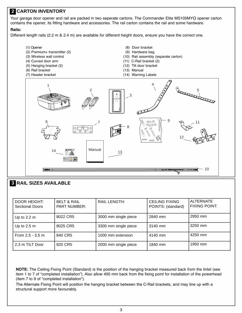
CARTON INVENTORY
(1) Opener(2) Premium+ transmitter (2)(3) Wireless wall control(4) Curved door arm(5) Hanging bracket (2)(6) Rail bracket(7) Header bracket
(8) Door bracket(9) Hardware bag(10) Rail assembly (separate carton)(11) C-Rail bracket (2)(12) Tilt door bracket(13) Manual(14) Warning Labels
Your garage door opener and rail are packed in two seperate cartons. The Commander Elite MS105MYQ opener cartoncontains the opener, its fitting hardware and accessories. The rail carton contains the rail and some hardware.Rails:Different length rails (2.2 m & 2.4 m) are available for different height doors, ensure you have the correct one.
2
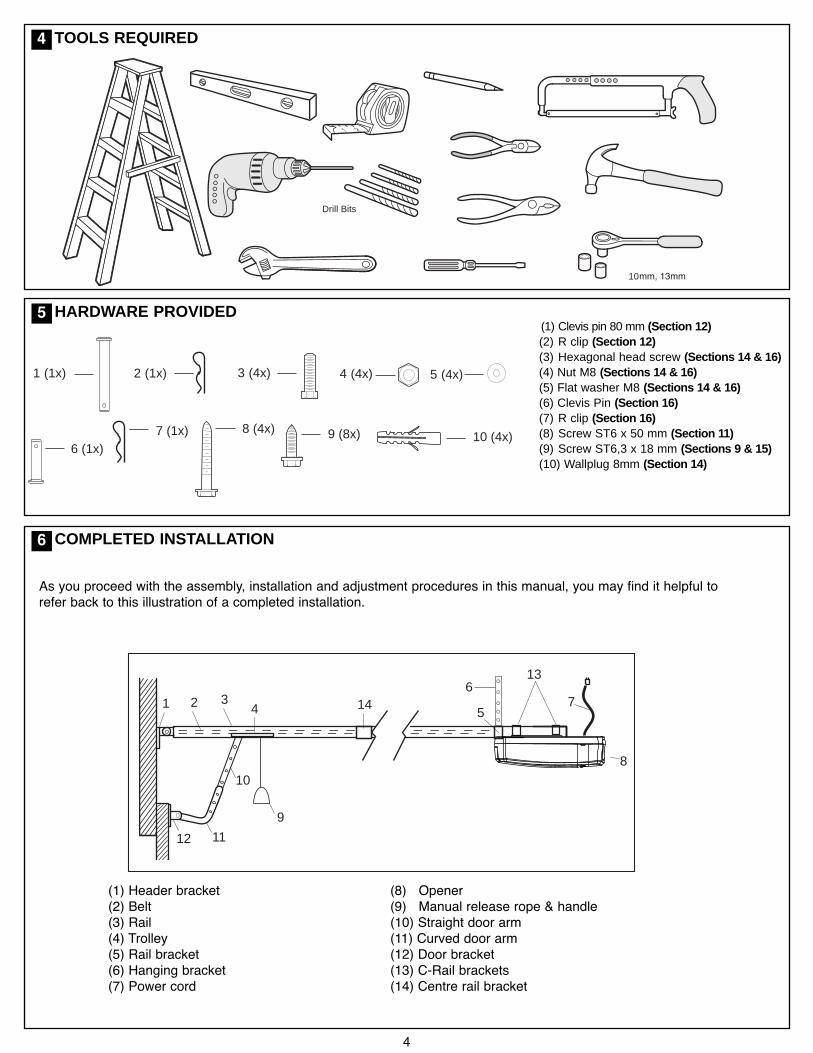
RAIL SIZES AVAILABLE3
DOOR HEIGHT:Sectional Doors
BELT & RAILPART NUMBER:
RAIL LENGTH: CEILING FIXINGPOINTS: (standard)
ALTERNATEFIXING POINT:
Up to 2.2 m 8022 CR5 3000 mm single piece 2840 mm 2950 mm
Up to 2.5 m 8025 CR5 3300 mm single piece 3140 mm 3250 mm
From 2.5 - 3.5 m 840 CR5 1000 mm extension 4140 mm 4250 mm
2.3 m TILT Door 820 CR5 2000 mm single piece 1840 mm 1950 mm
NOTE: The Ceiling Fixing Point (Standard) is the position of the hanging bracket measured back from the lintel (seeitem 1 to 7 of “completed installation”). Also allow 400 mm back from the fixing point for installation of the powerhead(item 7 to 9 of “completed installation”).The Alternate Fixing Point will position the hanging bracket between the C-Rail brackets, and may line up with astructural support more favourably.
3
4
4
1 2 34 5
7
8
9
10
11
6
12
13
14
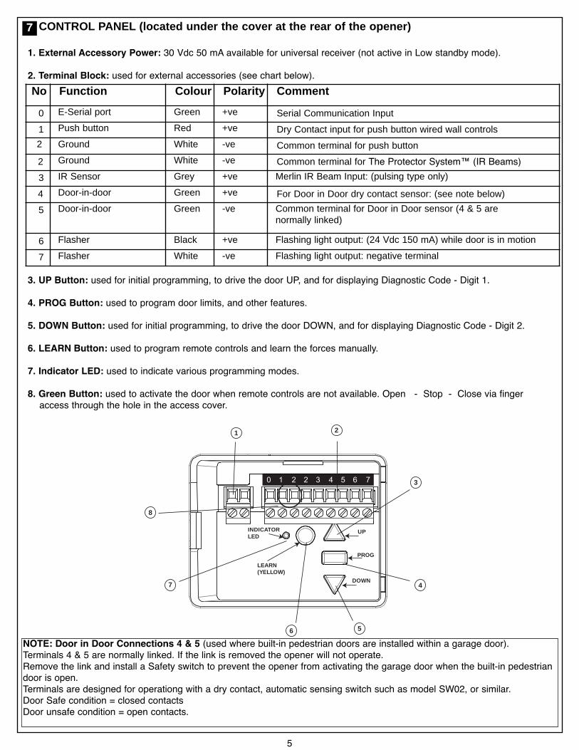
As you proceed with the assembly, installation and adjustment procedures in this manual, you may find it helpful torefer back to this illustration of a completed installation.
COMPLETED INSTALLATION
10 (4x)9 (8x)8 (4x)7 (1x)6 (1x)
1 (1x) 2 (1x) 3 (4x) 4 (4x) 5 (4x)
HARDWARE PROVIDED(1) Clevis pin 80 mm (Section 12)(2) R clip (Section 12)(3) Hexagonal head screw (Sections 14 & 16)(4) Nut M8 (Sections 14 & 16)(5) Flat washer M8 (Sections 14 & 16)(6) Clevis Pin (Section 16)(7) R clip (Section 16)(8) Screw ST6 x 50 mm (Section 11)(9) Screw ST6,3 x 18 mm (Sections 9 & 15)(10) Wallplug 8mm (Section 14)
Drill Bits
10
TOOLS REQUIRED4
5
6
(1) Header bracket(2) Belt(3) Rail(4) Trolley(5) Rail bracket(6) Hanging bracket(7) Power cord
(8) Opener(9) Manual release rope & handle(10) Straight door arm(11) Curved door arm(12) Door bracket(13) C-Rail brackets(14) Centre rail bracket
30 V DC
+ -
0 1 2 2 3 4 5 6 7
UP
DOWN
PROG
LEARN(YELLOW)
INDICATORLED
1 2
3
4
56
7
8
1. External Accessory Power: 30 Vdc 50 mA available for universal receiver (not active in Low standby mode).
2. Terminal Block: used for external accessories (see chart below).
3. UP Button: used for initial programming, to drive the door UP, and for displaying Diagnostic Code - Digit 1.
4. PROG Button: used to program door limits, and other features.
5. DOWN Button: used for initial programming, to drive the door DOWN, and for displaying Diagnostic Code - Digit 2.
6. LEARN Button: used to program remote controls and learn the forces manually.
7. Indicator LED: used to indicate various programming modes.
8. Green Button: used to activate the door when remote controls are not available. Open - Stop - Close via fingeraccess through the hole in the access cover.
CONTROL PANEL (located under the cover at the rear of the opener)
5
7
NOTE: Door in Door Connections 4 & 5 (used where built-in pedestrian doors are installed within a garage door).Terminals 4 & 5 are normally linked. If the link is removed the opener will not operate.Remove the link and install a Safety switch to prevent the opener from activating the garage door when the built-in pedestriandoor is open.Terminals are designed for operationg with a dry contact, automatic sensing switch such as model SW02, or similar.Door Safe condition = closed contactsDoor unsafe condition = open contacts.
No Funct ion Colo ur Polari ty Comment
0 E-Serial port Green +ve Serial Communication Input
1 Push button Red +ve Dry Contact input for push button wired wall controls
2 Ground White -ve Common terminal for push button
2 Ground White -ve Common terminal for The Protector System™ (IR Beams)3 IR Sensor Grey +ve Merlin IR Beam Input: (pulsing type only)
4 Door-in-door Green +ve For Door in Door dry contact sensor: (see note below)
5 Door-in-door Green -ve Common terminal for Door in Door sensor (4 & 5 arenormally linked)
6 Flasher Black +ve Flashing light output: (24 Vdc 150 mA) while door is in motion
7 Flasher White -ve Flashing light output: negative terminal
ASSEMBLY SECTION
6
36 - 38 mm
1
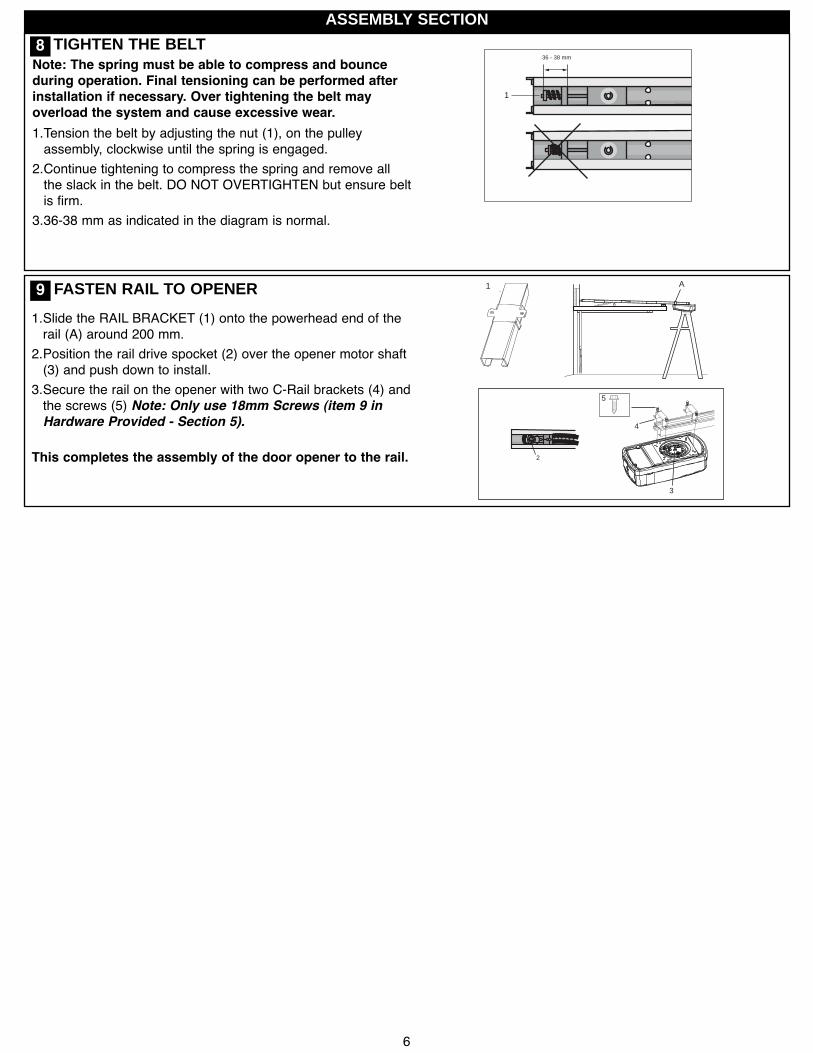
TIGHTEN THE BELT
3
4
2
A1
5
1.Slide the RAIL BRACKET (1) onto the powerhead end of therail (A) around 200 mm.
2.Position the rail drive spocket (2) over the opener motor shaft(3) and push down to install.
3.Secure the rail on the opener with two C-Rail brackets (4) andthe screws (5) Note: Only use 18mm Screws (item 9 inHardware Provided - Section 5).
This completes the assembly of the door opener to the rail.
FASTEN RAIL TO OPENER
8
9
Note: The spring must be able to compress and bounceduring operation. Final tensioning can be performed afterinstallation if necessary. Over tightening the belt mayoverload the system and cause excessive wear.1.Tension the belt by adjusting the nut (1), on the pulleyassembly, clockwise until the spring is engaged.
2.Continue tightening to compress the spring and remove allthe slack in the belt. DO NOT OVERTIGHTEN but ensure beltis firm.
3.36-38 mm as indicated in the diagram is normal.
7
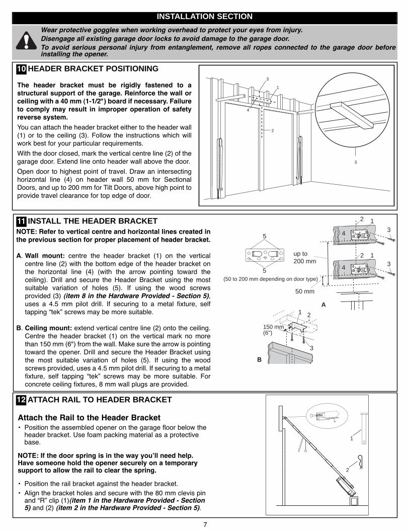
Wear protective goggles when working overhead to protect your eyes from injury.Disengage all existing garage door locks to avoid damage to the garage door.To avoid serious personal injury from entanglement, remove all ropes connected to the garage door beforeinstalling the opener.
INSTALLATION SECTION
3
1
2
4
3
The header bracket must be rigidly fastened to astructural support of the garage. Reinforce the wall orceiling with a 40 mm (1-1/2") board if necessary. Failureto comply may result in improper operation of safetyreverse system.You can attach the header bracket either to the header wall(1) or to the ceiling (3). Follow the instructions which willwork best for your particular requirements.With the door closed, mark the vertical centre line (2) of thegarage door. Extend line onto header wall above the door.Open door to highest point of travel. Draw an intersectinghorizontal line (4) on header wall 50 mm for SectionalDoors, and up to 200 mm for Tilt Doors, above high point toprovide travel clearance for top edge of door.
NOTE: Refer to vertical centre and horizontal lines created inthe previous section for proper placement of header bracket.
A. Wall mount: centre the header bracket (1) on the verticalcentre line (2) with the bottom edge of the header bracket onthe horizontal line (4) (with the arrow pointing toward theceiling). Drill and secure the Header Bracket using the mostsuitable variation of holes (5). If using the wood screwsprovided (3) (item 8 in the Hardware Provided - Section 5),uses a 4.5 mm pilot drill. If securing to a metal fixture, selftapping “tek” screws may be more suitable.
B. Ceiling mount: extend vertical centre line (2) onto the ceiling.Centre the header bracket (1) on the vertical mark no morethan 150 mm (6") from the wall. Make sure the arrow is pointingtoward the opener. Drill and secure the Header Bracket usingthe most suitable variation of holes (5). If using the woodscrews provided, uses a 4.5 mm pilot drill. If securing to a metalfixture, self tapping “tek” screws may be more suitable. Forconcrete ceiling fixtures, 8 mm wall plugs are provided.
2
50 mm
31
4
A
150 mm(6")
1 2
3
5
5
2
31
4
up to200 mm
(50 to 200 mm depending on door type)
INSTALL THE HEADER BRACKET
HEADER BRACKET POSITIONING
1
2
Attach the Rail to the Header Bracket• Position the assembled opener on the garage floor below theheader bracket. Use foam packing material as a protectivebase.
NOTE: If the door spring is in the way youʼll need help.Have someone hold the opener securely on a temporarysupport to allow the rail to clear the spring.• Position the rail bracket against the header bracket.• Align the bracket holes and secure with the 80 mm clevis pinand “R” clip (1)(item 1 in the Hardware Provided - Section5) and (2) (item 2 in the Hardware Provided - Section 5).
ATTACH RAIL TO HEADER BRACKET
10
11
12

8
Rail
Door50 mm spacer shouldbe used to determinethe correct mountingposition
HeaderBracket
50 mm (2”)above the highestpoint of travel
HeaderBracket
50 mm spacer shouldbe used to determinethe correct mountingposition
50 mm (2”)above the highestpoint of travel
Door
Rail
50 mm spacer shouldbe used to determinethe correct mountingposition
Door
Headerup to 200 mm (8”)above the highestpoint of travel
Bracket
Rail
POSITION THE OPENER
SECTIONAL DOOR OR TRACKED TILT DOORYou will need a 50 mm piece of timber or similarspacer to gauge the distance between door and rail.
1.Raise the opener onto support.
2.Open the door completely, place a 50 mm spacer betweenthe door and the rail (as shown).
3.The final positioning of the rail should be relatively parallelto the horizontal door panels.
ONE PIECE TILT DOORYou will need a 50 mm piece of timber or similar spacer togauge the distance between door and rail.
1.Raise the opener onto support.
2.Open the door completely, place a 50 mm spacer betweenthe door and the rail (as shown).
3.The top of the door should be level with the top of theopener. Do not position the opener more than 50 mmabove this point.Ensure the opener is not positioned too low as to cause ahazard to vehicles or persons.
13
Disengage the trolley mechanism (see section “Operating the manual release”) and slide it back towards the powerhead.Secure the hanging push arm up into the rail assembly temporarily using tape or rope, to avoid a hazard.
9
100-300 mm
1
A
(tilt door bracket)
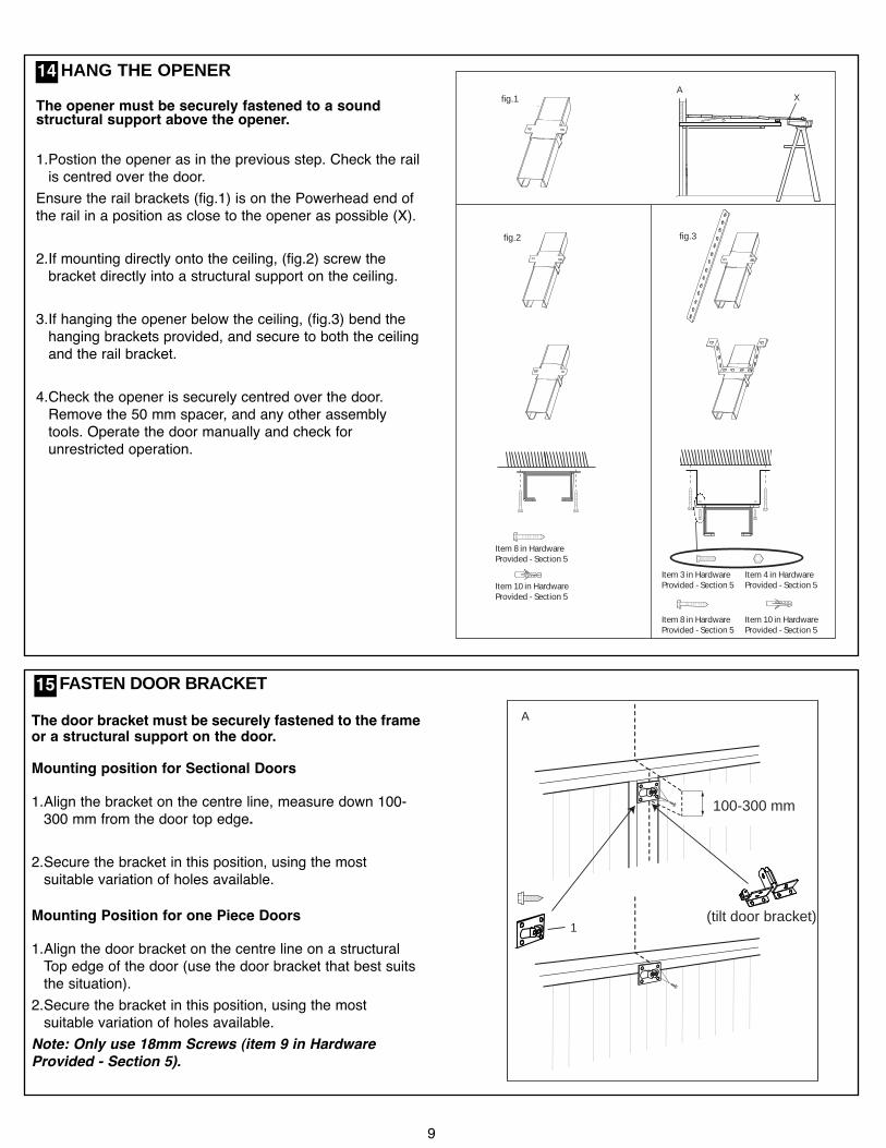
The door bracket must be securely fastened to the frameor a structural support on the door.
Mounting position for Sectional Doors
1.Align the bracket on the centre line, measure down 100-300 mm from the door top edge.
2.Secure the bracket in this position, using the mostsuitable variation of holes available.
Mounting Position for one Piece Doors
1.Align the door bracket on the centre line on a structuralTop edge of the door (use the door bracket that best suitsthe situation).
2.Secure the bracket in this position, using the mostsuitable variation of holes available.
Note: Only use 18mm Screws (item 9 in HardwareProvided - Section 5).
FASTEN DOOR BRACKET15
XA
fig.1
fig.2
Item 8 in HardwareProvided - Section 5
Item 10 in HardwareProvided - Section 5
fig.3
Item 8 in HardwareProvided - Section 5
Item 10 in HardwareProvided - Section 5
Item 3 in HardwareProvided - Section 5
Item 4 in HardwareProvided - Section 5
HANG THE OPENER14The opener must be securely fastened to a soundstructural support above the opener.
1.Postion the opener as in the previous step. Check the railis centred over the door.
Ensure the rail brackets (fig.1) is on the Powerhead end ofthe rail in a position as close to the opener as possible (X).
2.If mounting directly onto the ceiling, (fig.2) screw thebracket directly into a structural support on the ceiling.
3.If hanging the opener below the ceiling, (fig.3) bend thehanging brackets provided, and secure to both the ceilingand the rail bracket.
4.Check the opener is securely centred over the door.Remove the 50 mm spacer, and any other assemblytools. Operate the door manually and check forunrestricted operation.
10
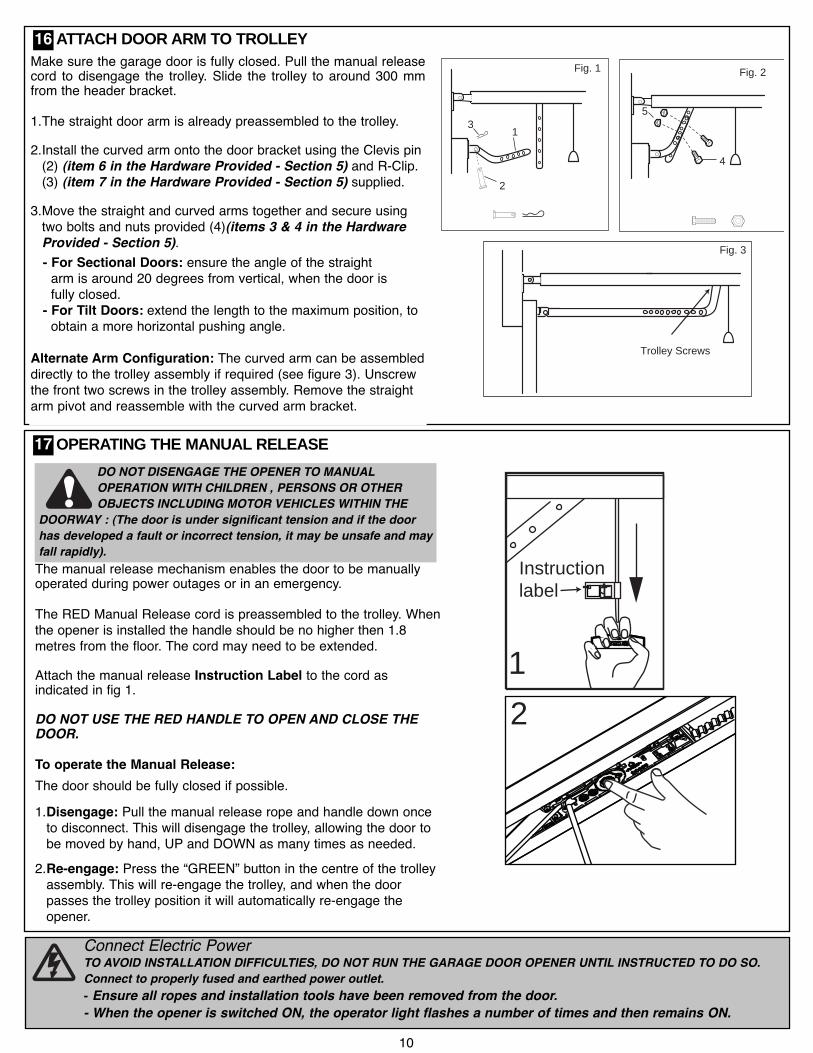
Connect Electric PowerTO AVOID INSTALLATION DIFFICULTIES, DO NOT RUN THE GARAGE DOOR OPENER UNTIL INSTRUCTED TO DO SO.Connect to properly fused and earthed power outlet.- Ensure all ropes and installation tools have been removed from the door.- When the opener is switched ON, the operator light flashes a number of times and then remains ON.
12
Instructionlabel
1
2
3
Trolley Screws
Fig. 1
Fig. 3
4
5
Fig. 2Make sure the garage door is fully closed. Pull the manual releasecord to disengage the trolley. Slide the trolley to around 300 mmfrom the header bracket.
1.The straight door arm is already preassembled to the trolley.
2.Install the curved arm onto the door bracket using the Clevis pin(2) (item 6 in the Hardware Provided - Section 5) and R-Clip.(3) (item 7 in the Hardware Provided - Section 5) supplied.
3.Move the straight and curved arms together and secure usingtwo bolts and nuts provided (4)(items 3 & 4 in the HardwareProvided - Section 5).- For Sectional Doors: ensure the angle of the straightarm is around 20 degrees from vertical, when the door isfully closed.
- For Tilt Doors: extend the length to the maximum position, toobtain a more horizontal pushing angle.
Alternate Arm Configuration: The curved arm can be assembleddirectly to the trolley assembly if required (see figure 3). Unscrewthe front two screws in the trolley assembly. Remove the straightarm pivot and reassemble with the curved arm bracket.
ATTACH DOOR ARM TO TROLLEY
OPERATING THE MANUAL RELEASE
The manual release mechanism enables the door to be manuallyoperated during power outages or in an emergency.
The RED Manual Release cord is preassembled to the trolley. Whenthe opener is installed the handle should be no higher then 1.8metres from the floor. The cord may need to be extended.
Attach the manual release Instruction Label to the cord asindicated in fig 1.
DO NOT USE THE RED HANDLE TO OPEN AND CLOSE THEDOOR.
To operate the Manual Release:The door should be fully closed if possible.1.Disengage: Pull the manual release rope and handle down onceto disconnect. This will disengage the trolley, allowing the door tobe moved by hand, UP and DOWN as many times as needed.
2.Re-engage: Press the “GREEN” button in the centre of the trolleyassembly. This will re-engage the trolley, and when the doorpasses the trolley position it will automatically re-engage theopener.
DO NOT DISENGAGE THE OPENER TO MANUALOPERATION WITH CHILDREN , PERSONS OR OTHEROBJECTS INCLUDING MOTOR VEHICLES WITHIN THE
DOORWAY : (The door is under significant tension and if the doorhas developed a fault or incorrect tension, it may be unsafe and mayfall rapidly).
16
17
11
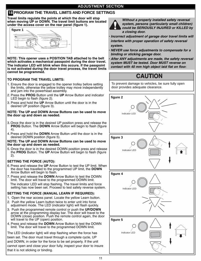
Without a properly installed safety reversalsystem, persons (particularly small children)could be SERIOUSLY INJURED or KILLED bya closing door.
• Incorrect adjustment of garage door travel limits willinterfere with proper operation of safety reversalsystem.• NEVER use force adjustments to compensate for abinding or sticking garage door.• After ANY adjustments are made, the safety reversalsystem MUST be tested. Door MUST reverse oncontact with 40 mm high object laid flat on floor.
To prevent damage to vehicles, be sure fully opendoor provides adequate clearance.
Indicator LED
Indicator LED
figure 2
figure 3
Indicator LED
figure 4
Indicator LED
figur e 5
Travel limits regulate the points at which the door will stopwhen moving UP or DOWN. The travel limit buttons are locatedunder the access cover on the rear panel (figure 1).
NOTE: This opener uses a POSITION TAB attached to the beltwhich activates a mechanical passpoint during the door travel.The indicator LED will blink when this occurs. If the passpointis not activated during the door travel process, the travel limitscannot be programmed.
TO PROGRAM THE TRAVEL LIMITS:1. Ensure the door is engaged to the opener trolley before settingthe limits, otherwise the yellow trolley may move independentlyand jam into the powerhead assembly.
2. Press the PROG Button until the UP Arrow Button and indicatorLED begin to flash (figure 2).
3. Press and hold the UP Arrow Button until the door is in thedesired UP position (figure 3).
NOTE: The UP and DOWN Arrow Buttons can be used to movethe door up and down as needed.
3.Once the door is in the desired UP position press and release thePROG Button. The DOWN Arrow Button will begin to flash (figure4).
4. Press and hold the DOWN Arrow Button until the door is in thedesired DOWN position (figure 5).
NOTE: The UP and DOWN Arrow Buttons can be used to movethe door up and down as needed.5. Once the door is in the desired DOWN position press and releasethe PROG Button. The UP Arrow Button will begin to flash (figure2).
SETTING THE FORCE (AUTO):6. Press and release the UP Arrow Button to test the UP limit. Whenthe door has travelled to the programmed UP limit, the DOWNArrow Button will begin to flash.
7. Press and release the DOWN Arrow Button to test the DOWNlimit. The door will travel to the programmed DOWN limit.The indicator LED will stop flashing. The travel limits and forcesetting has now been set. Proceed to test safety reverse system.
SETTING THE FORCE (MANUAL LEARN IF REQUIRED):1. Open the rear access panel. Locate the yellow Learn button.2. Push the yellow Learn button twice to enter unit into forceadjustment mode. The LED (indicator light) will flash quickly.
3. Push the programmed remote control or push the UP/DOWNarrow at the programming display bar. The door will travel to theDOWN (close) position. Push the remote control again, the doorwill travel to the UP (open) position.
4. Press and release the DOWN Arrow Button to test the DOWNlimit. The door will travel to the programmed DOWN limit.
The LED (indicator light) will stop flashing when the force hasbeen set. The door must travel through a complete cycle, UPand DOWN, in order for the force to be set properly. If the unitcannot open and close your door fully, inspect your door to insurethat it is not sticking or binding.
PROGRAM THE TRAVEL LIMITS AND FORCE SETTINGS
figure 1
ADJUSTMENT SECTION
18
12
Installers mus t ensure that the doors are ins talled in a complia nt manner as per AS/NZS 60335-2-95.
TRAVEL SPEED: Automatically selected:There are two travel speeds available for this opener.The speed is a function of door travel distance and is automatically set during the door travel limit setting process.* Travel distance longer then 1.6 metres = REGULAR speed* Travel distance shorter than 1.6 metres = SLOW speed (will suit tilt doors best.)
TRAVEL SPEED: Manually selected:The speed can be set manually if required, once the travel limits have been set, using the following method.To activate the alternate speed:PRESS and HOLD both the UP and DOWN arrows for 3 seconds.The courtesy lamp will flash once to confirm SLOWspeed and twice to confirm REGULAR speed.To deactivate the selected speed: Repeat the process above (toggle between the two settings).
PROGRAM THE TRAVEL SPEED (OPTIONAL)20
TEST THE SAFETY REVERSE SYSTEM
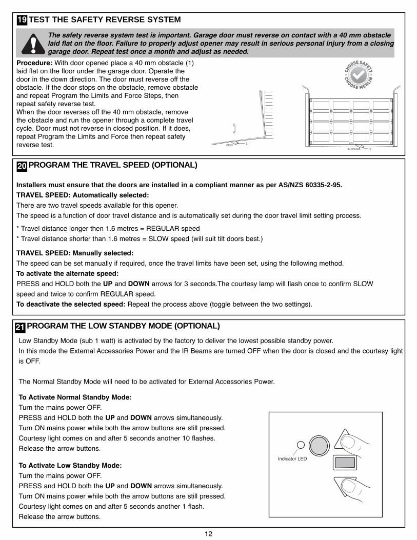
Procedure: With door opened place a 40 mm obstacle (1)laid flat on the floor under the garage door. Operate thedoor in the down direction. The door must reverse off theobstacle. If the door stops on the obstacle, remove obstacleand repeat Program the Limits and Force Steps, thenrepeat safety reverse test.When the door reverses off the 40 mm obstacle, removethe obstacle and run the opener through a complete travelcycle. Door must not reverse in closed position. If it does,repeat Program the Limits and Force then repeat safetyreverse test. 140mm
140 mm high
The safety reverse system test is important. Garage door must reverse on contact with a 40 mm obstaclelaid flat on the floor. Failure to properly adjust opener may result in serious personal injury from a closinggarage door. Repeat test once a month and adjust as needed.
19
Low Standby Mode (sub 1 watt) is activated by the factory to deliver the lowest possible standby power.In this mode the External Accessories Power and the IR Beams are turned OFF when the door is closed and the courtesy lightis OFF.
The Normal Standby Mode will need to be activated for External Accessories Power.
To Activate Normal Standby Mode:Turn the mains power OFF.PRESS and HOLD both the UP and DOWN arrows simultaneously.Turn ON mains power while both the arrow buttons are still pressed.Courtesy light comes on and after 5 seconds another 10 flashes.Release the arrow buttons.
To Activate Low Standby Mode:Turn the mains power OFF.PRESS and HOLD both the UP and DOWN arrows simultaneously.Turn ON mains power while both the arrow buttons are still pressed.Courtesy light comes on and after 5 seconds another 1 flash.Release the arrow buttons.
PROGRAM THE LOW STANDBY MODE (OPTIONAL)21
Indicator LED
SAFETY FIRST!Whilst Merlin have engineered safety features into your garage door opener, we urge you to consider fitting IR Beams to yournew garage door opener. In many countries these devices are compulsory to assist in preventing serious injury or propertydamage. For your own peace of mind and the safety of others please install this inexpensive safety device.
13
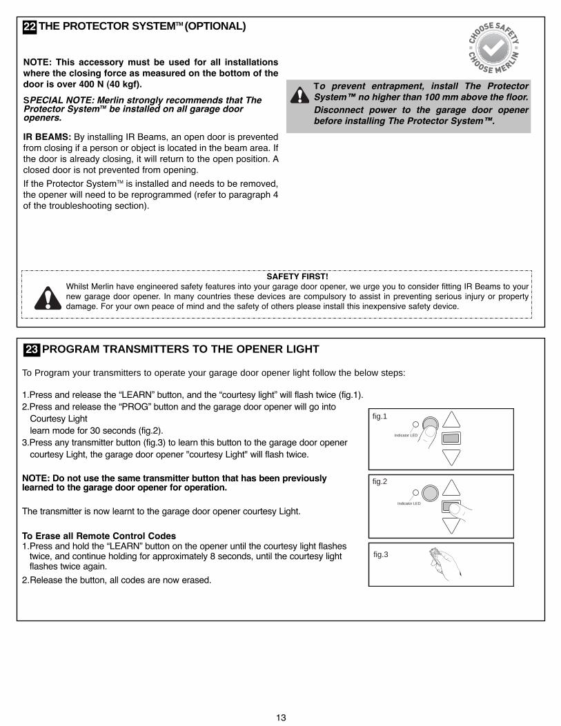
NOTE: This accessory must be used for all installationswhere the closing force as measured on the bottom of thedoor is over 400 N (40 kgf).SPECIAL NOTE: Merlin strongly recommends that TheProtector SystemTM be installed on all garage dooropeners.
IR BEAMS: By installing IR Beams, an open door is preventedfrom closing if a person or object is located in the beam area. Ifthe door is already closing, it will return to the open position. Aclosed door is not prevented from opening.If the Protector SystemTM is installed and needs to be removed,the opener will need to be reprogrammed (refer to paragraph 4of the troubleshooting section).
THE PROTECTOR SYSTEMTM (OPTIONAL)
To prevent entrapment, install The ProtectorSystem™ no higher than 100 mm above the floor.Disconnect power to the garage door openerbefore installing The Protector System™.
22
23 PROGRAM TRANSMITTERS TO THE OPENER LIGHTTo Program your transmitters to operate your garage door opener light follow the below steps:
1.Press and release the “LEARN” button, and the “courtesy light” will flash twice (fig.1).2.Press and release the “PROG” button and the garage door opener will go intoCourtesy Lightlearn mode for 30 seconds (fig.2).
3.Press any transmitter button (fig.3) to learn this button to the garage door openercourtesy Light, the garage door opener "courtesy Light" will flash twice.
NOTE: Do not use the same transmitter button that has been previouslylearned to the garage door opener for operation.
The transmitter is now learnt to the garage door opener courtesy Light.
To Erase all Remote Control Codes1.Press and hold the “LEARN” button on the opener until the courtesy light flashestwice, and continue holding for approximately 8 seconds, until the courtesy lightflashes twice again.
2.Release the button, all codes are now erased.
fig.3
fig.1
fig.2
Indicator LED
Indicator LED
14
TIMER TO CLOSE FEATURE (TTC)
The Timer to Close feature requires The Protector SystemTM
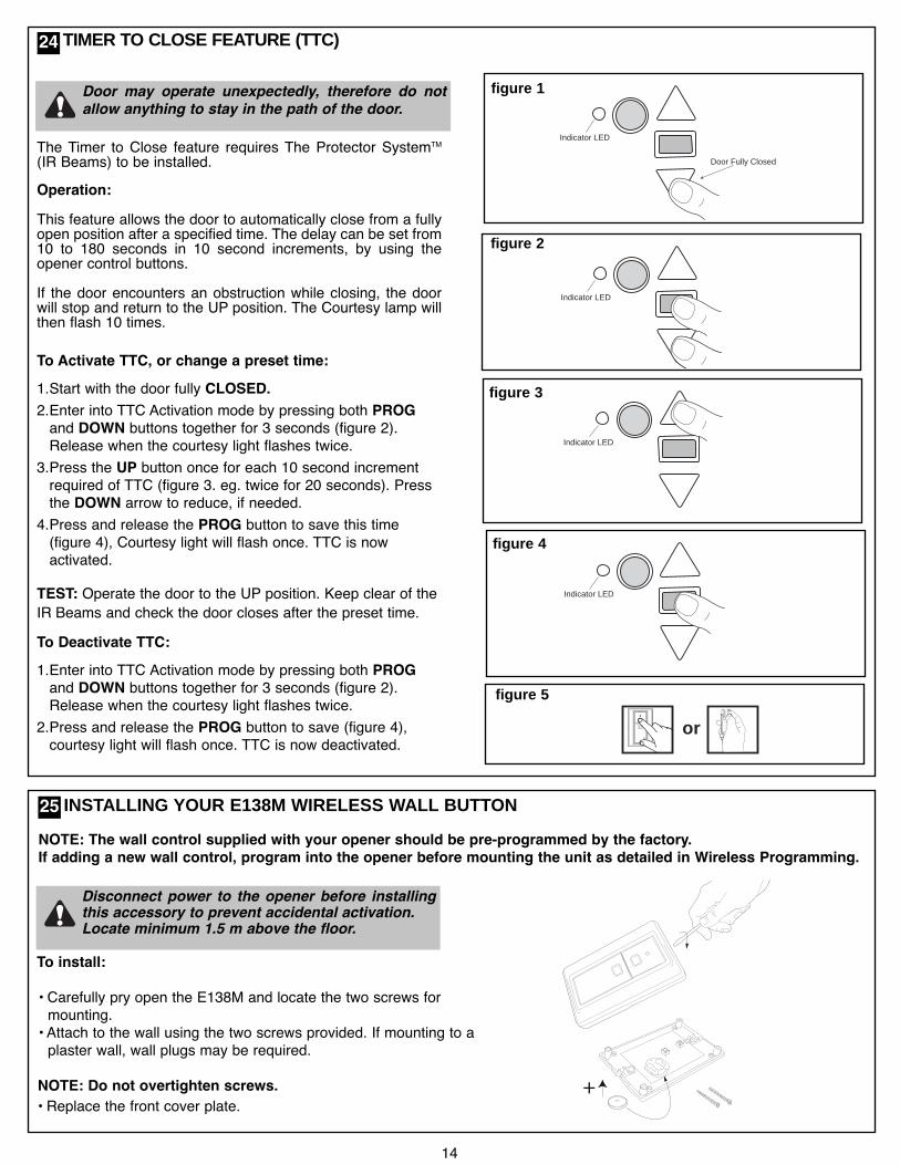
(IR Beams) to be installed.Operation:This feature allows the door to automatically close from a fullyopen position after a specified time. The delay can be set from10 to 180 seconds in 10 second increments, by using theopener control buttons.If the door encounters an obstruction while closing, the doorwill stop and return to the UP position. The Courtesy lamp willthen flash 10 times.
To Activate TTC, or change a preset time:1.Start with the door fully CLOSED.2.Enter into TTC Activation mode by pressing both PROGand DOWN buttons together for 3 seconds (figure 2).Release when the courtesy light flashes twice.
3.Press the UP button once for each 10 second incrementrequired of TTC (figure 3. eg. twice for 20 seconds). Pressthe DOWN arrow to reduce, if needed.
4.Press and release the PROG button to save this time(figure 4), Courtesy light will flash once. TTC is nowactivated.
TEST: Operate the door to the UP position. Keep clear of theIR Beams and check the door closes after the preset time.To Deactivate TTC:1.Enter into TTC Activation mode by pressing both PROGand DOWN buttons together for 3 seconds (figure 2).Release when the courtesy light flashes twice.
2.Press and release the PROG button to save (figure 4),courtesy light will flash once. TTC is now deactivated.
Indicator LED
Indicator LED
Door Fully Closed
figure 1
Indicator LED
figur e 4
or
figure 5
Door may operate unexpectedly, therefore do notallow anything to stay in the path of the door.
INSTALLING YOUR E138M WIRELESS WALL BUTTON
To install:
• Carefully pry open the E138M and locate the two screws formounting.• Attach to the wall using the two screws provided. If mounting to aplaster wall, wall plugs may be required.
NOTE: Do not overtighten screws.• Replace the front cover plate.
+
Disconnect power to the opener before installingthis accessory to prevent accidental activation.Locate minimum 1.5 m above the floor.
NOTE: The wall control supplied with your opener should be pre-programmed by the factory.If adding a new wall control, program into the opener before mounting the unit as detailed in Wireless Programming.
25
24
Indicator LED
figur e 2
figure 3
15
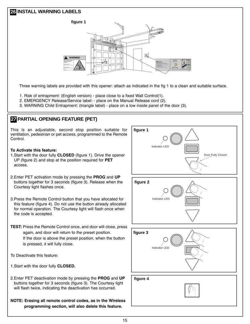
This is an adjustable, second stop position suitable forventilation, pedestrian or pet access, programmed to the RemoteControl.
To Activate this feature:1.Start with the door fully CLOSED (figure 1). Drive the openerUP (figure 2) and stop at the position required for PETaccess.
2.Enter PET activation mode by pressing the PROG and UPbuttons together for 3 seconds (figure 3). Release when theCourtesy light flashes once.
3.Press the Remote Control button that you have allocated forthis feature (figure 4). Do not use the button already allocatedfor normal operation. The Courtesy light will flash once whenthe code is accepted.
TEST: Press the Remote Control once, and door will close, pressagain, and door will return to the preset position.If the door is above the preset position, when the buttonis pressed, it will fully close.
To Deactivate this feature:
1.Start with the door fully CLOSED.
2.Enter PET deactivation mode by pressing the PROG and UPbuttons together for 3 seconds (figure 3). The Courtesy lightwill flash twice, indicating the deactivation has occurred.
NOTE: Erasing all remote control codes, as in the Wirelessprogramming section, will also delete this feature.
PARTIAL OPENING FEATURE (PET)
Indicator LED
Indicator LED
Door Fully Closed
figure 1
figure 3
or
27
1
serv
ice
ww
wm
@m
BBA
2
114A3361
For Service Call
Installation Date
3
132A2900
RISK OF ENTRAPMENTRepeat Safety Reverse Test monthly. Doormust reverse on contact with a 40mm obstacleplaced on the floor. Make necessary adjustments.
AUTOMATIC DRIVE:Keep away from the area of the door since it mayoperate unexpectedly.
EMERGENCY RELEASE:To release, pull down firmly on the red handle.
114A3361
For Service Call
Installation Date
ll
26 INSTALL WARNING LABELS
Three warning labels are provided with this opener: attach as indicated in the fig 1 to a clean and suitable surface.
1. Risk of entrapment: (English version) - place close to a fixed Wall Control(1).2. EMERGENCY Release/Service label: - place on the Manual Release cord (2).3. WARNING Child Entrapment: (triangle label) - place on a low inside panel of the door (3).
figure 4
figure 1
Indicator LED
figure 2
16
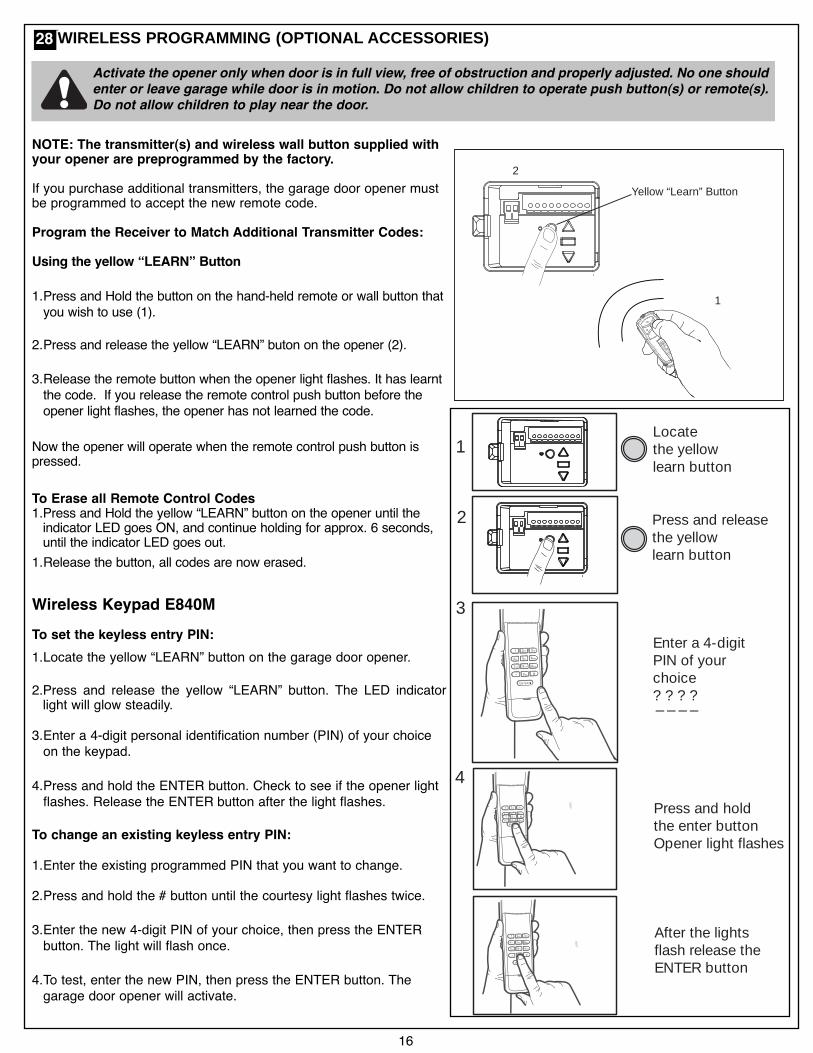
NOTE: The transmitter(s) and wireless wall button supplied withyour opener are preprogrammed by the factory.
If you purchase additional transmitters, the garage door opener mustbe programmed to accept the new remote code.
Program the Receiver to Match Additional Transmitter Codes:
Using the yellow “LEARN” Button
1.Press and Hold the button on the hand-held remote or wall button thatyou wish to use (1).
2.Press and release the yellow “LEARN” buton on the opener (2).
3.Release the remote button when the opener light flashes. It has learntthe code. If you release the remote control push button before theopener light flashes, the opener has not learned the code.
Now the opener will operate when the remote control push button ispressed.
To Erase all Remote Control Codes1.Press and Hold the yellow “LEARN” button on the opener until theindicator LED goes ON, and continue holding for approx. 6 seconds,until the indicator LED goes out.
1.Release the button, all codes are now erased.
Wireless Keypad E840MTo set the keyless entry PIN:1.Locate the yellow “LEARN” button on the garage door opener.
2.Press and release the yellow “LEARN” button. The LED indicatorlight will glow steadily.
3.Enter a 4-digit personal identification number (PIN) of your choiceon the keypad.
4.Press and hold the ENTER button. Check to see if the opener lightflashes. Release the ENTER button after the light flashes.
To change an existing keyless entry PIN:
1.Enter the existing programmed PIN that you want to change.
2.Press and hold the # button until the courtesy light flashes twice.
3.Enter the new 4-digit PIN of your choice, then press the ENTERbutton. The light will flash once.
4.To test, enter the new PIN, then press the ENTER button. Thegarage door opener will activate.
Activate the opener only when door is in full view, free of obstruction and properly adjusted. No one shouldenter or leave garage while door is in motion. Do not allow children to operate push button(s) or remote(s).Do not allow children to play near the door.
Yellow “Learn” Button
1
2
2
3
4
3
Press and releasethe yellowlearn button
Enter a 4-digitPIN of yourchoice? ? ? ?_ _ _ _
Press and holdthe enter buttonOpener light flashes
After the lightsflash release theENTER button
1Locatethe yellowlearn button
28WIRELESS PROGRAMMING (OPTIONAL ACCESSORIES)
USING YOUR OPENER
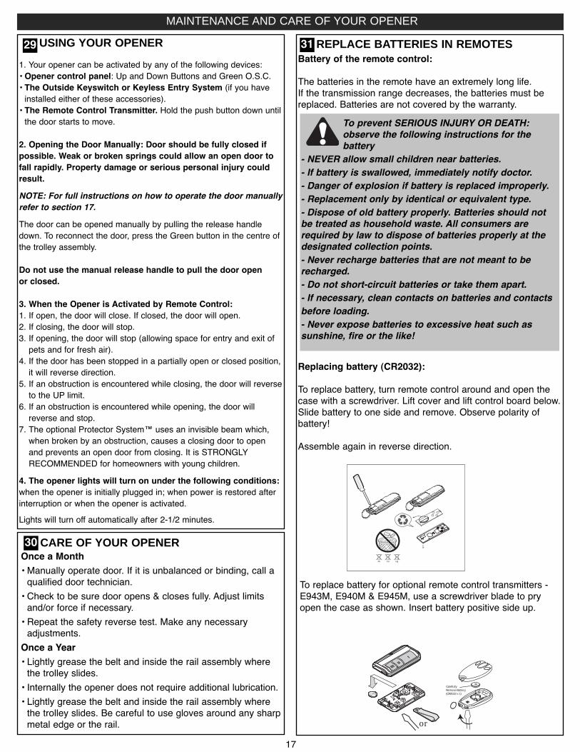
1. Your opener can be activated by any of the following devices:• Opener control panel: Up and Down Buttons and Green O.S.C.• The Outside Keyswitch or Keyless Entry System (if you haveinstalled either of these accessories).• The Remote Control Transmitter. Hold the push button down untilthe door starts to move.
2. Opening the Door Manually: Door should be fully closed ifpossible. Weak or broken springs could allow an open door tofall rapidly. Property damage or serious personal injury couldresult.NOTE: For full instructions on how to operate the door manuallyrefer to section 17.The door can be opened manually by pulling the release handledown. To reconnect the door, press the Green button in the centre ofthe trolley assembly.
Do not use the manual release handle to pull the door openor closed.
3. When the Opener is Activated by Remote Control:1. If open, the door will close. If closed, the door will open.2. If closing, the door will stop.3. If opening, the door will stop (allowing space for entry and exit ofpets and for fresh air).
4. If the door has been stopped in a partially open or closed position,it will reverse direction.
5. If an obstruction is encountered while closing, the door will reverseto the UP limit.
6. If an obstruction is encountered while opening, the door willreverse and stop.
7. The optional Protector System™ uses an invisible beam which,when broken by an obstruction, causes a closing door to openand prevents an open door from closing. It is STRONGLYRECOMMENDED for homeowners with young children.
4. The opener lights will turn on under the following conditions:when the opener is initially plugged in; when power is restored afterinterruption or when the opener is activated.Lights will turn off automatically after 2-1/2 minutes.
Once a Month• Manually operate door. If it is unbalanced or binding, call aqualified door technician.• Check to be sure door opens & closes fully. Adjust limitsand/or force if necessary.• Repeat the safety reverse test. Make any necessaryadjustments.
Once a Year• Lightly grease the belt and inside the rail assembly wherethe trolley slides.• Internally the opener does not require additional lubrication.• Lightly grease the belt and inside the rail assembly wherethe trolley slides. Be careful to use gloves around any sharpmetal edge or the rail.
Battery of the remote control:
The batteries in the remote have an extremely long life.If the transmission range decreases, the batteries must bereplaced. Batteries are not covered by the warranty.
Replacing battery (CR2032):
To replace battery, turn remote control around and open thecase with a screwdriver. Lift cover and lift control board below.Slide battery to one side and remove. Observe polarity ofbattery!
Assemble again in reverse direction.
REPLACE BATTERIES IN REMOTES
12VDC
Pb Cd Hg
CARE OF YOUR OPENER
To prevent SERIOUS INJURY OR DEATH:observe the following instructions for thebattery
- NEVER allow small children near batteries.- If battery is swallowed, immediately notify doctor.- Danger of explosion if battery is replaced improperly.- Replacement only by identical or equivalent type.- Dispose of old battery properly. Batteries should notbe treated as household waste. All consumers arerequired by law to dispose of batteries properly at thedesignated collection points.- Never recharge batteries that are not meant to berecharged.- Do not short-circuit batteries or take them apart.- If necessary, clean contacts on batteries and contactsbefore loading.- Never expose batteries to excessive heat such assunshine, fire or the like!
17
29 31
30
or
CarefullyRemove Battery(CR2032 x 1)
MAINTENANCE AND CARE OF YOUR OPENER
To replace battery for optional remote control transmitters -E943M, E940M & E945M, use a screwdriver blade to pryopen the case as shown. Insert battery positive side up.

004C5502Door bracket
178A0103Straight arm
012C0778Hanging brackets
083A0011Grease
004C5600Hardware bag
012C0788-1Header bracket
041A4020RSprocket assembly
041A4021RTrolley latch (belt)
041A4017-1Motor shaft adapter
041A4038Pulley assembly
012A1028Rail bracket
041A4039C-Rail bracket
Replacement belt packs041A4045-1 (2.2m)041A4045-2 (2.4m)
One piece rail asssembly7024CR5 2.4 m
002A1800Trolley with rope &
straight arm
041A4016RPosition tab (belt)
178A0104Curved arm
012A1027Tilt Door bracket
041A4036Centre Rail bracket
RAIL HARDWARE33
18
ACCESSORIES
65
7
4
E840M
760EE1702M774ANZ
E940M E943M E945M
8 9
3
E138M
12
E960M
1011
827AU M-BBU24V
32
NOTE: Use of any Chamberlain Group accessories are approved to use with this opener. This includes genuine Merlin accessories.Generic compatible accessories are NOT approved for use with this opener.
(1) Model E138M Wireless wall button(2) Model E960M 4 Channel remote control(3) Model E940M 1 Channel visor remote control(4) Model E943M 3 Channel visor remote control(5) Model E945M 3 Channel mini remote control(6) Model E840M Keyless entry system
(7) Model 774ANZ The Protector SystemTM
(8) Model E1702M Quick release lock(9) Model 760E Outside keyswitch(10) Model 827AU Remote LED light(11) Model M-BBU24V Battery Back up
19
REPLACEMENT PARTS
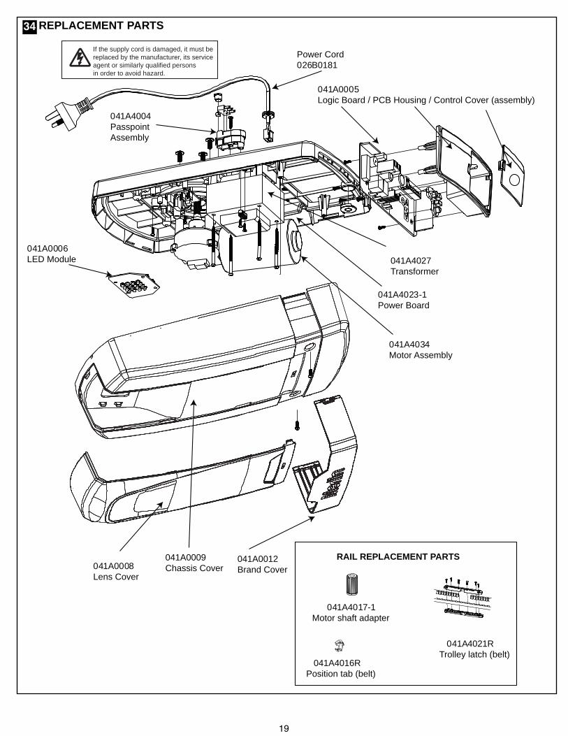
If the supply cord is damaged, it must bereplaced by the manufacturer, its serviceagent or similarly qualified personsin order to avoid hazard.
Power Cord026B0181
041A4004PasspointAssembly
041A4027Transformer
041A0005Logic Board / PCB Housing / Control Cover (assembly)
041A0006LED Module
041A0008Lens Cover
041A4034Motor Assembly
041A4023-1Power Board
041A0012Brand Cover
041A0009Chassis Cover
RAIL REPLACEMENT PARTS
041A4017-1Motor shaft adapter
041A4021RTrolley latch (belt)
041A4016RPosition tab (belt)
34
20
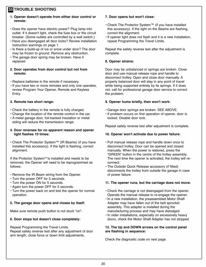
TROUBLE SHOOTING
7. Door opens but won't close:
• Check The Protector System™ (if you have installedthis accessory). If the light on the Beams are flashing,correct the alignment.• If opener light does not flash and it is a new installation,repeat Programming the Travel Limits.
Repeat the safety reverse test after the adjustment iscomplete.
8. Opener strains:
Door may be unbalanced or springs are broken. Closedoor and use manual release rope and handle todisconnect trolley. Open and close door manually. Aproperly balanced door will stay in any point of travelwhile being supported entirely by its springs. If it doesnot, call for professional garage door service to correctthe problem.
9. Opener hums briefly, then won't work:
• Garage door springs are broken. SEE ABOVE.• If problem occurs on first operation of opener, door islocked. Disable door lock.
Repeat safety reverse test after adjustment is complete.
10. Opener won't activate due to power failure:
• Pull manual release rope and handle down once todisconnect trolley. Door can be opened and closedmanually. When the power is restored, press the“GREEN” button in the centre of the trolley assembly.The next time the opener is activated, the trolley will re-connect.• The Outside Quick Release accessory (if fitted)disconnects the trolley from outside the garage in caseof power failure.
11. The opener runs, but the carriage does not move:
• Check the carriage is not disengaged from the opener.Operate the manual release to re-engage the opener.• In a new installation, the preassembled Motor ShaftAdapter may have fallen out of the belt sprocketassembly. This adapter is installed during themanufacturing process and may have dislodged.• In older installations, especially on excessively heavydoors, check the Motor Shaft Adapter has not stripped.
12. The Up and DOWN arrows on the control panelare flashing in sequence:
Check the diagnostic code on next page.
1. Opener doesn't operate from either door control orremote:
• Does the opener have electric power? Plug lamp intooutlet. If it doesn't light, check the fuse box or the circuitbreaker. (Some outlets are controlled by a wall switch.)• Have you disengaged all door locks? Review installationinstruction warnings on page 1.• Is there a build-up of ice or snow under door? The doormay be frozen to ground. Remove any obstruction.• The garage door spring may be broken. Have itreplaced.
2. Door operates from door control but not fromremote:
• Replace batteries in the remote if necessary.• If you have two or more remotes and only one operates,review Program Your Opener, Remote and KeylessEntry.
3. Remote has short range:
• Check the battery in the remote is fully charged.• Change the location of the remote control in the car.• A metal garage door, foil-backed insulation or metalsiding will reduce the transmission range.
4. Door reverses for no apparent reason and openerlight flashes 10 times:
• Check The Protector System™ (IR Beams) (if you haveinstalled this accessory). If the light is flashing, correctalignment.
If the Protector SystemTM is installed and needs to beremoved, the Opener will need to be reprogrammed asfollows:
• Remove the IR Beam wiring from the Opener.• Turn the power OFF for 5 seconds.• Turn the power ON for 5 seconds.• Again turn the power OFF for 5 seconds.• Turn the power back on and test the opener for normaloperation.
5. The garage door opens and closes by itself:
Make sure remote push button is not stuck "on".
6. Door stops but doesn't close completely:
Repeat Programming the Travel Limits.Repeat safety reverse test after any adjustment of doorarm length, close force or down limit adjustments.
35
21
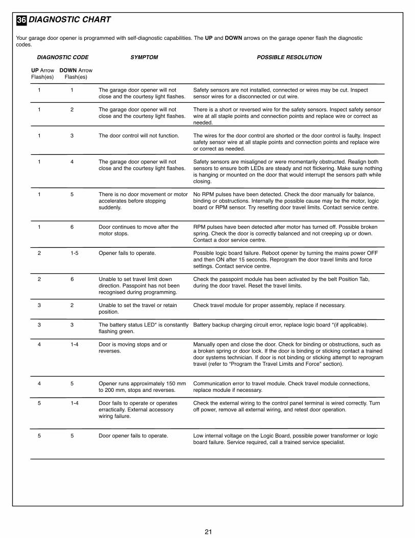
DIAGNOSTIC CHART
Your garage door opener is programmed with self-diagnostic capabilities. The UP and DOWN arrows on the garage opener flash the diagnosticcodes.
DIAGNOSTIC CODE
UP Arrow DOWN ArrowFlash(es) Flash(es)
1 1
1 2
1 3
1 4
1 5
1 6
2 1-5
2 6
3 2
3 3
4 1-4
4 5
5 1-4
5 5
SYMPTOM
The garage door opener will notclose and the courtesy light flashes.
The garage door opener will notclose and the courtesy light flashes.
The door control will not function.
The garage door opener will notclose and the courtesy light flashes.
There is no door movement or motoraccelerates before stoppingsuddenly.
Door continues to move after themotor stops.
Opener fails to operate.
Unable to set travel limit downdirection. Passpoint has not beenrecognised during programming.
Unable to set the travel or retainposition.
The battery status LED* is constantlyflashing green.
Door is moving stops and orreverses.
Opener runs approximately 150 mmto 200 mm, stops and reverses.
Door fails to operate or operateserractically. External accessorywiring failure.
Door opener fails to operate.
POSSIBLE RESOLUTION
Safety sensors are not installed, connected or wires may be cut. Inspectsensor wires for a disconnected or cut wire.
There is a short or reversed wire for the safety sensors. Inspect safety sensorwire at all staple points and connection points and replace wire or correct asneeded.
The wires for the door control are shorted or the door control is faulty. Inspectsafety sensor wire at all staple points and connection points and replace wireor correct as needed.
Safety sensors are misaligned or were momentarily obstructed. Realign bothsensors to ensure both LEDs are steady and not flickering. Make sure nothingis hanging or mounted on the door that would interrupt the sensors path whileclosing.
No RPM pulses have been detected. Check the door manually for balance,binding or obstructions. Internally the possible cause may be the motor, logicboard or RPM sensor. Try resetting door travel limits. Contact service centre.
RPM pulses have been detected after motor has turned off. Possible brokenspring. Check the door is correctly balanced and not creeping up or down.Contact a door service centre.
Possible logic board failure. Reboot opener by turning the mains power OFFand then ON after 15 seconds. Reprogram the door travel limits and forcesettings. Contact service centre.
Check the passpoint module has been activated by the belt Position Tab,during the door travel. Reset the travel limits.
Check travel module for proper assembly, replace if necessary.
Battery backup charging circuit error, replace logic board *(if applicable).
Manually open and close the door. Check for binding or obstructions, such asa broken spring or door lock. If the door is binding or sticking contact a traineddoor systems technician. If door is not binding or sticking attempt to reprogramtravel (refer to “Program the Travel Limits and Force” section).
Communication error to travel module. Check travel module connections,replace module if necessary.
Check the external wiring to the control panel terminal is wired correctly. Turnoff power, remove all external wiring, and retest door operation.
Low internal voltage on the Logic Board, possible power transformer or logicboard failure. Service required, call a trained service specialist.
36

22
Input Voltage.............................220 - 240 Vac, 50 - 60 Hz.Max. Pull Force ........................1000 N.Power .......................................225 Watt.Standby Power .........................0.8 Watt (door fully closed).Normal Torque ..........................7 Nm.Max door weight.......................150 kg.Max lift under spring tension ....20 kg.Max door area...........................Sectional Doors Tilt Doors 20 m2.
MotorType..........................................DC gearmotor permanent lubrication.Noise level ................................54 db at 1 metre.
Drive MechanismDrive .........................................Belt with one-piece trolley on steel rail.Length of Travel........................Adjustable to 3.0 m.LED light ...................................25 Watt equivalent.
Door Linkage ............................Adjustable door arm. Pull cord trolley release.SafetyPersonal ...................................Push button stop in UP and DOWN direction. Automatic safety reverse in both UP
and DOWN direction.Electronic..................................Automatic force adjustment.Electrical ...................................Transformer overload protector and low voltage push button wiring.Limit Device ..............................Mechanical Passpoint/RPM sensor.Limit Adjustment .......................Electronic.Soft-start/Soft-stopDimensionsLength (Overall)........................3.24 m.Headroom Required .................30 mm.Hanging Weight ........................12 kg.
ReceiverMemory Registers ....................64 handset codes.
4 keypad devices - 1 code each.OperatingFrequency.................................433.30/433.92/434.54 MHz.
SPECIFICATIONS - COMMANDER ELITE - MS105MYQ37
Warranty RegistrationTo validate your warranty you must complete
the registration form online at:gomerlin.com.au/warranty
orgomerlin.co.nz/warranty
© 2019, The Chamberlain Group Inc.
TM Trademark of The Chamberlain Group, Inc.® Registered Trademark of The Chamberlain Group, Inc.
CHAMBERLAIN LIMITED WARRANTYMerlin® Professional Commander Elite® MS105MYQSectional Garage Door OpenerChamberlain Australia Pty Limited / Chamberlain New Zealand Limited(Chamberlain), the manufacturer of Merlin® automatic garage door openers,is committed to manufacturing and supplying high quality goods. As part ofthis commitment, we seek to provide reliable service and support for ourgoods and are pleased to provide you, the original purchaser, with thisChamberlain Limited Warranty.The benefits given to you under this Chamberlain Limited Warranty are inaddition to any rights and remedies that you may have under Australian orNew Zealand consumer protection laws. Our goods come with guaranteesthat cannot be excluded under the Australian Consumer Law, or New ZealandConsumer Guarantess Act 1993. You are entitled to a replacement or refundfor a major failure and for compensation for any other reasonably foreseeableloss or damage. You are also entitled to have the goods repaired or replacedif the goods fail to be of acceptable quality and the failure does not amount toa major failure.Chamberlain’s warrantyWhat is coveredChamberlain warrants to the original purchaser of the Merlin Commander EliteMS105MYQ Sectional Door Opener (Unit) that all parts of the Unit, other thanremote controlled transmitters and accessories, globes and batteries, are freefrom defects in materials and workmanship for a period of 84 months or15,000 cycles (each opening & closing of the garage door equals 1 cycle)whichever comes first, from the date of purchase when installed by aProfessional dealer appointed or authorised by Chamberlain in a residentialpremise with a residential specified garage door that is designed for the solepurpose of a single-family dwelling.
Chamberlain warrants that the remote controlled transmitters (E960M)included with the Unit are free from defects in materials and workmanship fora period of 24 months from the date of purchase and all other accessoriesincluded with the Unit are free from defects in materials and workmanship fora period of 12 months from the date of purchase.What is not coveredBatteries and globes are not covered under the Chamberlain LimitedWarranty.Travel costs incurred by Chamberlain or the Professional Dealer in eithertravelling to or from areas outside a capital city metropolitan area. These costswill be at the purchaser’s expense.Additional access costs incurred by a Professional Dealer or Chamberlain inobtaining access where the Unit is not readily accessible. These cost will be atthe purchaser’s expense.Warranty ConditionsIt is a condition of this Chamberlain Limited Warranty that the Unit is sold,installed and serviced by a Professional Dealer appointed or authorised byChamberlain. A Merlin branded garage door opener purchased over theinternet and installed by a person other than a Professional Dealer will not becovered by this Chamberlain Limited Warranty.It is also a condition of this Chamberlain Limited Warranty that for theoperating life of the Unit:1 the garage door is spring balanced, is operable by hand and opensand closes with no more than a maximum of 20 kg of lifting weight;
2 the garage door and the Unit is professionally maintained and servicedby a Professional Dealer, at a minimum, during the third and fifth yearsof the Chamberlain Limited Warranty period such that the springbalanced door operates according to manufacturer specifications. Ifyour door binds, sticks, or is out of balance, then it must not be useduntil serviced by a trained door technician or Profesional Dealer. Thegarage door service fee will be at the purchaser’s expense;
3 the warranty is registered by completing the online form atwww.gomerlin.com.au or www.gomerlin.co.nz; and
4 you retain your sales docket or invoice as proof of purchase, and attach itto this manual to enable you to establish the date of purchase in theunlikely event of a warranty service being required.
Making a claimDuring the applicable Chamberlain Limited Warranty period, if you areconcerned that the Unit may be defective, call the Professional Dealer thatsold/installed the opener, or our service centre on the toll free number belowand a Chamberlain technician will diagnose the problem and arrange for thisto be rectified. Once the problem has been diagnosed, subject to your rightsunder the applicable Australian and New Zealand consumer protection lawswith respect to major failures, Chamberlain or its Professional Dealer willprovide you with either, repairs to the Unit or a replacement Unit.Repairs and replacement parts provided under this Chamberlain LimitedWarranty are provided free of charge and are warranted for the remainingportion of the original warranty period.
This Chamberlain Limited Warranty provides benefits which are in addition toyour other rights and remedies as a consumer.
Exclusions - what voids the warrantyIf our service centre determines that a warranty claim has been made in respectof a failure or defect arising under or out of any exclusion detailed below suchthat the claim is not covered under this Chamberlain Limited Warranty, we may,subject to your other rights and remedies as a consumer, charge you a fee torepair, replace and/or return the Unit to you.
This Chamberlain Limited Warranty does not cover any failure of, or defect in,the Unit due to:1 non-compliance with the instructions regarding specifications,
installation, operation, maintenance and testing of the Unit or of anyproduct with which the Unit is used;
2 any attempt by a person other than a Professional Dealer to repair,dismantle, reinstall or move the Unit to another location once it hasbeen installed;
3 use of any copy, imitation or replica garage door remotes with yourMerlin Unit;
4 tampering, neglect, abuse, wear and tear, accident, electrical storm,excessive use or conditions other than normal domestic use;
5 problems with, or relating to, the garage door or garage door hardware,including but not limited to the door springs, door rollers, dooralignment or hinges;
6 problems caused by electrical faults or replacement of batteries or lightbulbs, blown fuses, electrical surges, power surges or power strikes,fire, flood, rain, water, lightning or storms;
7 water or moisture ingress that causes corrosion or electricalmalfunction;
8 corrosion caused by sea air if located near a waterway, beach etc;9 fitment to a commercial door or in a commercial operating application,
installation of a residential garage door opener in a commercial orindustrial premises other than a single-family dwelling.
10 lack of proper maintenance, service or care of the door and Unit;11 any unauthorised modification to the Unit; or12 damage caused by insects, pests or other after sale damage caused
by events or accidents outside Chamberlain’s reasonable control andnot arising under normal and standard operating conditions.
NB: A General Purpose Outlet (GPO) ie: power point must be supplied by theconsumer as this electrical fitting does not form a part of the Unit (opener).If this Chamberlain Limited Warranty does not apply, you may have rightsavailable to you under the Australian and New Zealand consumer protectionlaws.Liability – Australia onlyExcept as set out in the Australian Consumer Law (being Schedule 2 of theCompetition and Consumer Act 2010) (as amended, consolidated or replaced):1 all other guarantees, warranties and representations in relation to the Unit or
its supply are excluded to the extent that Chamberlain can lawfully excludethem; and
2 under no circumstances will Chamberlain be liable for consequential,incidental or special damages arising in connection with the use, or inability touse, the Unit, other than those which were reasonably foreseeable as liable toresult from the failure.
Liability – New Zealand onlyExcept as set out in the Fair Trading Act 1986 and the Consumer Guarantees Act1993 (as amended, consolidated or replaced):1 all other guarantees, warranties and representations in relation to the Unit orits supply are excluded to the extent that Chamberlain can lawfully excludethem; and
2 under no circumstances will Chamberlain be liable for consequential,incidental or special damages arising in connection with the use, or inability touse, the Unit, other than those which were reasonably foreseeable as liable toresult from the failure.
NoteChamberlain reserves the right to change the design and specifications of theUnit without prior notification. Some features or accessories of the Unit may notbe available in certain markets or areas. Please check with your distributor.Chamberlain service centre contact detailsAustraliaPhone toll free 1800 638 234Fax toll free 1800 888 121Website: gomerlin.com.au
New ZealandPhone toll free 0800 653 667Fax toll free 0800 653 663Website: gomerlin.co.nzEmail: [email protected]
CChhaammbbeerrllaaiinn AAuussttrraalliiaa PPttyy.. LLttdd..Unit1, 75 Epping Road North Ryde NSW 2113(PO BOX 1446, Lane Cove NSW 1595)
114A5180B23